Adobe InDesign CS6 Products Programming Guide Volume 1: Fundamentals Plugin Vol1
plugin-programming-guide-vol1
User Manual:
Open the PDF directly: View PDF ![]() .
.
Page Count: 453 [warning: Documents this large are best viewed by clicking the View PDF Link!]
- Adobe® InDesign® CS6 Products Programming Guide Volume 1: Fundamentals
- Introduction
- Persistent Data and Data Conversion
- Commands
- Concepts
- Commands
- Command managers, databases, and undo support
- The command processor
- Scheduled commands
- Snapshots and interface implementation types
- Command history
- Undo and redo
- Notification within commands
- Error handling
- Key client APIs
- Extension patterns
- Notification
- Concepts
- Observers
- Responders
- Key client APIs
- Extension patterns
- Selection
- Model and UI Separation
- Multithreading
- Concepts
- Multithreading in InDesign
- Ensuring thread safety in your plug-in
- Thread-safety recipes
- Asynchronous exports
- Testing for thread safety
- Layout Fundamentals
- Terminology
- Concepts
- Documents and the layout hierarchy
- Spreads and pages
- Layers
- Master spreads and master pages
- Page items
- Guides and grids
- Layout-related preferences
- Coordinate systems
- The layout presentation and view
- Key client APIs
- Extension patterns
- Commands that manipulate page items
- Graphics Fundamentals
- Paths
- Graphic page items
- Colors and swatches
- Color management
- Graphic attributes
- Rendering attributes
- Stroke effects
- Transparency effects
- Data model for drawing
- Dynamics of drawing
- Client APIs
- Extension patterns
- Swatch-list state
- Catalog of graphic attributes
- Mappings between attribute domains
- Spread-drawing sequence
- Controlling the settings in a graphics port
- Drawing sequence for a page item
- Text Fundamentals
- Concepts
- Text content
- Text presentation
- Text composition
- Fonts
- Scriptable Plug-in Fundamentals
- Terminology
- Overview
- Scripting architecture
- How to make your plug-in scriptable
- Prerequisites
- Defining IDs
- Adding a new property to an existing script object
- Adding a new method to an existing script object
- Adding a new script object to make preferences scriptable
- Adding a new singleton script object
- Adding a new script object to make a boss with a UID scriptable
- Adding a new script object to make a boss with no UID scriptable
- Adding a new script object to make a C++ object with no boss scriptable
- Adding a new script object to make a panel scriptable
- Adding an error-string service
- Handling multiple concurrent requests
- Reviewing scripting resources
- Running versioned scripts
- Supporting IDML
- Maintaining IDML forward and backward compatibility
- Verifying that your plug-in’s data is round-tripped through IDML
- Tips for debugging the scripting architecture
- Scripting resources
- VersionedScriptElementInfo resource
- Object element
- Method element
- Property element
- Struct element
- TypeDef element
- Enum element
- Enumerator element
- Metadata element
- Provider element
- Suite element
- ScriptElementIDs, ScriptIDs, names, descriptions, and GUIDs
- ScriptID/name registration
- Scripting data types
- Script-object inheritance
- Overloading an existing method or property
- Versioning of scripting resources
- Client-specific scripting resources
- Elements that are not applicable to a particular object
- Key scripting APIs
- Scripting DOM reference
- Custom Script Events
- Glossary

ADOBE® INDESIGN® CS6
ADOBE INDESIGN CS6
PLUG-IN PROGRAMMING GUIDE
VOLUME 1: FUNDAMENTALS

2012 Adobe Systems Incorporated. All rights reserved.
Adobe® InDesign® CS6 Products Programming Guide Volume 1: Fundamentals
If this guide is distributed with software that includes an end user agreement, this guide, as well as the software
described in it, is furnished under license and may be used or copied only in accordance with the terms of such license.
Except as permitted by any such license, no part of this guide may be reproduced, stored in a retrieval system, or
transmitted, in any form or by any means, electronic, mechanical, recording, or otherwise, without the prior written
permission of Adobe Systems Incorporated. Please note that the content in this guide is protected under copyright law
even if it is not distributed with software that includes an end user license agreement.
The content of this guide is furnished for informational use only, is subject to change without notice, and should not be
construed as a commitment by Adobe Systems Incorporated. Adobe Systems Incorporated assumes no responsibility or
liability for any errors or inaccuracies that may appear in the informational content contained in this guide.
Please remember that existing artwork or images that you may want to include in your project may be protected under
copyright law. The unauthorized incorporation of such material into your new work could be a violation of the rights of
the copyright owner. Please be sure to obtain any permission required from the copyright owner.
Any references to company names in sample templates are for demonstration purposes only and are not intended to
refer to any actual organization.
Adobe, the Adobe logo, InCopy, and InDesign are either registered trademarks or trademarks of Adobe Systems
Incorporated in the United States and/or other countries. Windows s either a registered trademark or a trademark of
Microsoft Corporation in the United States and/or other countries. Mac OS is a trademark of Apple Computer,
Incorporated, registered in the United States and other countries. All other trademarks are the property of their
respective owners.
Adobe Systems Incorporated, 345 Park Avenue, San Jose, California 95110, USA. Notice to U.S. Government End Users.
The Software and Documentation are “Commercial Items,” as that term is defined at 48 C.F.R. §2.101, consisting of
“Commercial Computer Software” and “Commercial Computer Software Documentation,” as such terms are used in 48
C.F.R. §12.212 or 48 C.F.R. §227.7202, as applicable. Consistent with 48 C.F.R. §12.212 or 48 C.F.R. §§227.7202-1 through
227.7202-4, as applicable, the Commercial Computer Software and Commercial Computer Software Documentation are
being licensed to U.S. Government end users (a) only as Commercial Items and (b) with only those rights as are granted
to all other end users pursuant to the terms and conditions herein. Unpublished-rights reserved under the copyright
laws of the United States. Adobe Systems Incorporated, 345 Park Avenue, San Jose, CA 95110-2704, USA. For U.S.
Government End Users, Adobe agrees to comply with all applicable equal opportunity laws including, if appropriate, the
provisions of Executive Order 11246, as amended, Section 402 of the Vietnam Era Veterans Readjustment Assistance Act
of 1974 (38 USC 4212), and Section 503 of the Rehabilitation Act of 1973, as amended, and the regulations at 41 CFR
Parts 60-1 through 60-60, 60-250, and 60-741. The affirmative action clause and regulations contained in the preceding
sentence shall be incorporated by reference.
Document Update Status
CS6 Version edits Throughout, C5 changed to C6 and 7.0 to 8.0. Refer to chapter headers for other changes.
3
Contents
Introduction . . . . . . . . . . . . . . . . . . . . . . . . . . . . . . . . . . . . . . . . . . . . . . . . . . . . . . . . . . . . . . 7
About this guide . . . . . . . . . . . . . . . . . . . . . . . . . . . . . . . . . . . . . . . . . . . . . . . . . . . . . . . . . . . . . . . . . . . . . . . . . . . . . 7
Where to start . . . . . . . . . . . . . . . . . . . . . . . . . . . . . . . . . . . . . . . . . . . . . . . . . . . . . . . . . . . . . . . . . . . . . . . . . . . . . . . . 9
. . . . . . . . . . . . . . . . . . . . . . . . . . . . . . . . . . . . . . . . . . . . . . . . . . . . . . . . . . . . . . . . . . . . . . . . . . . . . . . . . . . . . . . . . . . . . . 9
1 Persistent Data and Data Conversion . . . . . . . . . . . . . . . . . . . . . . . . . . . . . . . . . . . . . . 10
Concepts . . . . . . . . . . . . . . . . . . . . . . . . . . . . . . . . . . . . . . . . . . . . . . . . . . . . . . . . . . . . . . . . . . . . . . . . . . . . . . . . . . . 10
Persistent objects . . . . . . . . . . . . . . . . . . . . . . . . . . . . . . . . . . . . . . . . . . . . . . . . . . . . . . . . . . . . . . . . . . . . . . . . . . . 11
Streams . . . . . . . . . . . . . . . . . . . . . . . . . . . . . . . . . . . . . . . . . . . . . . . . . . . . . . . . . . . . . . . . . . . . . . . . . . . . . . . . . . . . . 15
Missing plug-ins . . . . . . . . . . . . . . . . . . . . . . . . . . . . . . . . . . . . . . . . . . . . . . . . . . . . . . . . . . . . . . . . . . . . . . . . . . . . 16
Conversion of persistent data . . . . . . . . . . . . . . . . . . . . . . . . . . . . . . . . . . . . . . . . . . . . . . . . . . . . . . . . . . . . . . . . 20
Resources . . . . . . . . . . . . . . . . . . . . . . . . . . . . . . . . . . . . . . . . . . . . . . . . . . . . . . . . . . . . . . . . . . . . . . . . . . . . . . . . . . . 32
Advanced schema topics . . . . . . . . . . . . . . . . . . . . . . . . . . . . . . . . . . . . . . . . . . . . . . . . . . . . . . . . . . . . . . . . . . . . 38
2 Commands . . . . . . . . . . . . . . . . . . . . . . . . . . . . . . . . . . . . . . . . . . . . . . . . . . . . . . . . . . . . . . 40
Concepts . . . . . . . . . . . . . . . . . . . . . . . . . . . . . . . . . . . . . . . . . . . . . . . . . . . . . . . . . . . . . . . . . . . . . . . . . . . . . . . . . . . 40
Commands . . . . . . . . . . . . . . . . . . . . . . . . . . . . . . . . . . . . . . . . . . . . . . . . . . . . . . . . . . . . . . . . . . . . . . . . . . . . . . . . . 44
Command managers, databases, and undo support . . . . . . . . . . . . . . . . . . . . . . . . . . . . . . . . . . . . . . . . . . 48
The command processor . . . . . . . . . . . . . . . . . . . . . . . . . . . . . . . . . . . . . . . . . . . . . . . . . . . . . . . . . . . . . . . . . . . . 51
Scheduled commands . . . . . . . . . . . . . . . . . . . . . . . . . . . . . . . . . . . . . . . . . . . . . . . . . . . . . . . . . . . . . . . . . . . . . . . 53
Snapshots and interface implementation types . . . . . . . . . . . . . . . . . . . . . . . . . . . . . . . . . . . . . . . . . . . . . . 54
Command history . . . . . . . . . . . . . . . . . . . . . . . . . . . . . . . . . . . . . . . . . . . . . . . . . . . . . . . . . . . . . . . . . . . . . . . . . . . 55
Undo and redo . . . . . . . . . . . . . . . . . . . . . . . . . . . . . . . . . . . . . . . . . . . . . . . . . . . . . . . . . . . . . . . . . . . . . . . . . . . . . . 56
Notification within commands . . . . . . . . . . . . . . . . . . . . . . . . . . . . . . . . . . . . . . . . . . . . . . . . . . . . . . . . . . . . . . . 58
Error handling . . . . . . . . . . . . . . . . . . . . . . . . . . . . . . . . . . . . . . . . . . . . . . . . . . . . . . . . . . . . . . . . . . . . . . . . . . . . . . 58
Key client APIs . . . . . . . . . . . . . . . . . . . . . . . . . . . . . . . . . . . . . . . . . . . . . . . . . . . . . . . . . . . . . . . . . . . . . . . . . . . . . . 59
Extension patterns . . . . . . . . . . . . . . . . . . . . . . . . . . . . . . . . . . . . . . . . . . . . . . . . . . . . . . . . . . . . . . . . . . . . . . . . . . 60
3 Notification . . . . . . . . . . . . . . . . . . . . . . . . . . . . . . . . . . . . . . . . . . . . . . . . . . . . . . . . . . . . . . 73
Concepts . . . . . . . . . . . . . . . . . . . . . . . . . . . . . . . . . . . . . . . . . . . . . . . . . . . . . . . . . . . . . . . . . . . . . . . . . . . . . . . . . . . 73
Observers . . . . . . . . . . . . . . . . . . . . . . . . . . . . . . . . . . . . . . . . . . . . . . . . . . . . . . . . . . . . . . . . . . . . . . . . . . . . . . . . . . . 74
Responders . . . . . . . . . . . . . . . . . . . . . . . . . . . . . . . . . . . . . . . . . . . . . . . . . . . . . . . . . . . . . . . . . . . . . . . . . . . . . . . . . 86
Key client APIs . . . . . . . . . . . . . . . . . . . . . . . . . . . . . . . . . . . . . . . . . . . . . . . . . . . . . . . . . . . . . . . . . . . . . . . . . . . . . . 89
Extension patterns . . . . . . . . . . . . . . . . . . . . . . . . . . . . . . . . . . . . . . . . . . . . . . . . . . . . . . . . . . . . . . . . . . . . . . . . . . 90
4
4 Selection . . . . . . . . . . . . . . . . . . . . . . . . . . . . . . . . . . . . . . . . . . . . . . . . . . . . . . . . . . . . . . . . 95
Concepts . . . . . . . . . . . . . . . . . . . . . . . . . . . . . . . . . . . . . . . . . . . . . . . . . . . . . . . . . . . . . . . . . . . . . . . . . . . . . . . . . . . 95
Selection architecture . . . . . . . . . . . . . . . . . . . . . . . . . . . . . . . . . . . . . . . . . . . . . . . . . . . . . . . . . . . . . . . . . . . . . . . 96
Abstract selection bosses and suites . . . . . . . . . . . . . . . . . . . . . . . . . . . . . . . . . . . . . . . . . . . . . . . . . . . . . . . . . 99
Concrete selection bosses . . . . . . . . . . . . . . . . . . . . . . . . . . . . . . . . . . . . . . . . . . . . . . . . . . . . . . . . . . . . . . . . . . 100
Integrator suites . . . . . . . . . . . . . . . . . . . . . . . . . . . . . . . . . . . . . . . . . . . . . . . . . . . . . . . . . . . . . . . . . . . . . . . . . . . 108
CSB suites . . . . . . . . . . . . . . . . . . . . . . . . . . . . . . . . . . . . . . . . . . . . . . . . . . . . . . . . . . . . . . . . . . . . . . . . . . . . . . . . . . 109
Encapsulation . . . . . . . . . . . . . . . . . . . . . . . . . . . . . . . . . . . . . . . . . . . . . . . . . . . . . . . . . . . . . . . . . . . . . . . . . . . . . . 109
Suites and the user interface: an example . . . . . . . . . . . . . . . . . . . . . . . . . . . . . . . . . . . . . . . . . . . . . . . . . . . 109
Responsibilities . . . . . . . . . . . . . . . . . . . . . . . . . . . . . . . . . . . . . . . . . . . . . . . . . . . . . . . . . . . . . . . . . . . . . . . . . . . . 110
Custom suites . . . . . . . . . . . . . . . . . . . . . . . . . . . . . . . . . . . . . . . . . . . . . . . . . . . . . . . . . . . . . . . . . . . . . . . . . . . . . . 111
Selection extensions . . . . . . . . . . . . . . . . . . . . . . . . . . . . . . . . . . . . . . . . . . . . . . . . . . . . . . . . . . . . . . . . . . . . . . . 112
Selection observers . . . . . . . . . . . . . . . . . . . . . . . . . . . . . . . . . . . . . . . . . . . . . . . . . . . . . . . . . . . . . . . . . . . . . . . . 113
Selection-utility interface (ISelectionUtils) . . . . . . . . . . . . . . . . . . . . . . . . . . . . . . . . . . . . . . . . . . . . . . . . . . . 114
5 Model and UI Separation . . . . . . . . . . . . . . . . . . . . . . . . . . . . . . . . . . . . . . . . . . . . . . . . 115
Introduction . . . . . . . . . . . . . . . . . . . . . . . . . . . . . . . . . . . . . . . . . . . . . . . . . . . . . . . . . . . . . . . . . . . . . . . . . . . . . . . 115
Separating model and UI components . . . . . . . . . . . . . . . . . . . . . . . . . . . . . . . . . . . . . . . . . . . . . . . . . . . . . . 115
Detecting plug-ins that mix model and UI components . . . . . . . . . . . . . . . . . . . . . . . . . . . . . . . . . . . . . . 117
Conversion issues . . . . . . . . . . . . . . . . . . . . . . . . . . . . . . . . . . . . . . . . . . . . . . . . . . . . . . . . . . . . . . . . . . . . . . . . . . 119
6 Multithreading . . . . . . . . . . . . . . . . . . . . . . . . . . . . . . . . . . . . . . . . . . . . . . . . . . . . . . . . . 124
Concepts . . . . . . . . . . . . . . . . . . . . . . . . . . . . . . . . . . . . . . . . . . . . . . . . . . . . . . . . . . . . . . . . . . . . . . . . . . . . . . . . . . 124
Multithreading in InDesign . . . . . . . . . . . . . . . . . . . . . . . . . . . . . . . . . . . . . . . . . . . . . . . . . . . . . . . . . . . . . . . . . 125
Ensuring thread safety in your plug-in . . . . . . . . . . . . . . . . . . . . . . . . . . . . . . . . . . . . . . . . . . . . . . . . . . . . . . 127
Thread-safety recipes . . . . . . . . . . . . . . . . . . . . . . . . . . . . . . . . . . . . . . . . . . . . . . . . . . . . . . . . . . . . . . . . . . . . . . 133
Asynchronous exports . . . . . . . . . . . . . . . . . . . . . . . . . . . . . . . . . . . . . . . . . . . . . . . . . . . . . . . . . . . . . . . . . . . . . 134
Testing for thread safety . . . . . . . . . . . . . . . . . . . . . . . . . . . . . . . . . . . . . . . . . . . . . . . . . . . . . . . . . . . . . . . . . . . . 135
7 Layout Fundamentals . . . . . . . . . . . . . . . . . . . . . . . . . . . . . . . . . . . . . . . . . . . . . . . . . . . 137
Terminology . . . . . . . . . . . . . . . . . . . . . . . . . . . . . . . . . . . . . . . . . . . . . . . . . . . . . . . . . . . . . . . . . . . . . . . . . . . . . . . 137
Concepts . . . . . . . . . . . . . . . . . . . . . . . . . . . . . . . . . . . . . . . . . . . . . . . . . . . . . . . . . . . . . . . . . . . . . . . . . . . . . . . . . . 138
Documents and the layout hierarchy . . . . . . . . . . . . . . . . . . . . . . . . . . . . . . . . . . . . . . . . . . . . . . . . . . . . . . . 140
Spreads and pages . . . . . . . . . . . . . . . . . . . . . . . . . . . . . . . . . . . . . . . . . . . . . . . . . . . . . . . . . . . . . . . . . . . . . . . . . 144
Layers . . . . . . . . . . . . . . . . . . . . . . . . . . . . . . . . . . . . . . . . . . . . . . . . . . . . . . . . . . . . . . . . . . . . . . . . . . . . . . . . . . . . . 147
Master spreads and master pages . . . . . . . . . . . . . . . . . . . . . . . . . . . . . . . . . . . . . . . . . . . . . . . . . . . . . . . . . . . 152
Page items . . . . . . . . . . . . . . . . . . . . . . . . . . . . . . . . . . . . . . . . . . . . . . . . . . . . . . . . . . . . . . . . . . . . . . . . . . . . . . . . . 156
Guides and grids . . . . . . . . . . . . . . . . . . . . . . . . . . . . . . . . . . . . . . . . . . . . . . . . . . . . . . . . . . . . . . . . . . . . . . . . . . . 162
Layout-related preferences . . . . . . . . . . . . . . . . . . . . . . . . . . . . . . . . . . . . . . . . . . . . . . . . . . . . . . . . . . . . . . . . . 163
5
Coordinate systems . . . . . . . . . . . . . . . . . . . . . . . . . . . . . . . . . . . . . . . . . . . . . . . . . . . . . . . . . . . . . . . . . . . . . . . . 164
The layout presentation and view . . . . . . . . . . . . . . . . . . . . . . . . . . . . . . . . . . . . . . . . . . . . . . . . . . . . . . . . . . . 174
Key client APIs . . . . . . . . . . . . . . . . . . . . . . . . . . . . . . . . . . . . . . . . . . . . . . . . . . . . . . . . . . . . . . . . . . . . . . . . . . . . . 178
Extension patterns . . . . . . . . . . . . . . . . . . . . . . . . . . . . . . . . . . . . . . . . . . . . . . . . . . . . . . . . . . . . . . . . . . . . . . . . . 181
Commands that manipulate page items . . . . . . . . . . . . . . . . . . . . . . . . . . . . . . . . . . . . . . . . . . . . . . . . . . . . 183
8 Graphics Fundamentals . . . . . . . . . . . . . . . . . . . . . . . . . . . . . . . . . . . . . . . . . . . . . . . . . 189
Paths . . . . . . . . . . . . . . . . . . . . . . . . . . . . . . . . . . . . . . . . . . . . . . . . . . . . . . . . . . . . . . . . . . . . . . . . . . . . . . . . . . . . . . 189
Graphic page items . . . . . . . . . . . . . . . . . . . . . . . . . . . . . . . . . . . . . . . . . . . . . . . . . . . . . . . . . . . . . . . . . . . . . . . . 195
Colors and swatches . . . . . . . . . . . . . . . . . . . . . . . . . . . . . . . . . . . . . . . . . . . . . . . . . . . . . . . . . . . . . . . . . . . . . . . 220
Color management . . . . . . . . . . . . . . . . . . . . . . . . . . . . . . . . . . . . . . . . . . . . . . . . . . . . . . . . . . . . . . . . . . . . . . . . 226
Graphic attributes . . . . . . . . . . . . . . . . . . . . . . . . . . . . . . . . . . . . . . . . . . . . . . . . . . . . . . . . . . . . . . . . . . . . . . . . . . 229
Rendering attributes . . . . . . . . . . . . . . . . . . . . . . . . . . . . . . . . . . . . . . . . . . . . . . . . . . . . . . . . . . . . . . . . . . . . . . . 235
Stroke effects . . . . . . . . . . . . . . . . . . . . . . . . . . . . . . . . . . . . . . . . . . . . . . . . . . . . . . . . . . . . . . . . . . . . . . . . . . . . . . 236
Transparency effects . . . . . . . . . . . . . . . . . . . . . . . . . . . . . . . . . . . . . . . . . . . . . . . . . . . . . . . . . . . . . . . . . . . . . . . 236
Data model for drawing . . . . . . . . . . . . . . . . . . . . . . . . . . . . . . . . . . . . . . . . . . . . . . . . . . . . . . . . . . . . . . . . . . . . 248
Dynamics of drawing . . . . . . . . . . . . . . . . . . . . . . . . . . . . . . . . . . . . . . . . . . . . . . . . . . . . . . . . . . . . . . . . . . . . . . . 249
Client APIs . . . . . . . . . . . . . . . . . . . . . . . . . . . . . . . . . . . . . . . . . . . . . . . . . . . . . . . . . . . . . . . . . . . . . . . . . . . . . . . . . 256
Extension patterns . . . . . . . . . . . . . . . . . . . . . . . . . . . . . . . . . . . . . . . . . . . . . . . . . . . . . . . . . . . . . . . . . . . . . . . . . 259
Swatch-list state . . . . . . . . . . . . . . . . . . . . . . . . . . . . . . . . . . . . . . . . . . . . . . . . . . . . . . . . . . . . . . . . . . . . . . . . . . . 265
Catalog of graphic attributes . . . . . . . . . . . . . . . . . . . . . . . . . . . . . . . . . . . . . . . . . . . . . . . . . . . . . . . . . . . . . . . 270
Mappings between attribute domains . . . . . . . . . . . . . . . . . . . . . . . . . . . . . . . . . . . . . . . . . . . . . . . . . . . . . . 274
Spread-drawing sequence . . . . . . . . . . . . . . . . . . . . . . . . . . . . . . . . . . . . . . . . . . . . . . . . . . . . . . . . . . . . . . . . . . 275
Controlling the settings in a graphics port . . . . . . . . . . . . . . . . . . . . . . . . . . . . . . . . . . . . . . . . . . . . . . . . . . 277
Drawing sequence for a page item . . . . . . . . . . . . . . . . . . . . . . . . . . . . . . . . . . . . . . . . . . . . . . . . . . . . . . . . . . 277
9 Text Fundamentals . . . . . . . . . . . . . . . . . . . . . . . . . . . . . . . . . . . . . . . . . . . . . . . . . . . . . 279
Concepts . . . . . . . . . . . . . . . . . . . . . . . . . . . . . . . . . . . . . . . . . . . . . . . . . . . . . . . . . . . . . . . . . . . . . . . . . . . . . . . . . . 279
Text content . . . . . . . . . . . . . . . . . . . . . . . . . . . . . . . . . . . . . . . . . . . . . . . . . . . . . . . . . . . . . . . . . . . . . . . . . . . . . . . 280
Text presentation . . . . . . . . . . . . . . . . . . . . . . . . . . . . . . . . . . . . . . . . . . . . . . . . . . . . . . . . . . . . . . . . . . . . . . . . . . 294
Text composition . . . . . . . . . . . . . . . . . . . . . . . . . . . . . . . . . . . . . . . . . . . . . . . . . . . . . . . . . . . . . . . . . . . . . . . . . . 324
Fonts . . . . . . . . . . . . . . . . . . . . . . . . . . . . . . . . . . . . . . . . . . . . . . . . . . . . . . . . . . . . . . . . . . . . . . . . . . . . . . . . . . . . . . 347
10 Scriptable Plug-in Fundamentals . . . . . . . . . . . . . . . . . . . . . . . . . . . . . . . . . . . . . . . . . 356
Terminology . . . . . . . . . . . . . . . . . . . . . . . . . . . . . . . . . . . . . . . . . . . . . . . . . . . . . . . . . . . . . . . . . . . . . . . . . . . . . . . 356
Overview . . . . . . . . . . . . . . . . . . . . . . . . . . . . . . . . . . . . . . . . . . . . . . . . . . . . . . . . . . . . . . . . . . . . . . . . . . . . . . . . . . 358
Scripting architecture . . . . . . . . . . . . . . . . . . . . . . . . . . . . . . . . . . . . . . . . . . . . . . . . . . . . . . . . . . . . . . . . . . . . . . 360
How to make your plug-in scriptable . . . . . . . . . . . . . . . . . . . . . . . . . . . . . . . . . . . . . . . . . . . . . . . . . . . . . . . . 366
Scripting resources . . . . . . . . . . . . . . . . . . . . . . . . . . . . . . . . . . . . . . . . . . . . . . . . . . . . . . . . . . . . . . . . . . . . . . . . . 381
6
Key scripting APIs . . . . . . . . . . . . . . . . . . . . . . . . . . . . . . . . . . . . . . . . . . . . . . . . . . . . . . . . . . . . . . . . . . . . . . . . . . 424
Scripting DOM reference . . . . . . . . . . . . . . . . . . . . . . . . . . . . . . . . . . . . . . . . . . . . . . . . . . . . . . . . . . . . . . . . . . . 426
11 Custom Script Events . . . . . . . . . . . . . . . . . . . . . . . . . . . . . . . . . . . . . . . . . . . . . . . . . . . . 428
Concepts . . . . . . . . . . . . . . . . . . . . . . . . . . . . . . . . . . . . . . . . . . . . . . . . . . . . . . . . . . . . . . . . . . . . . . . . . . . . . . . . . . 428
Event types . . . . . . . . . . . . . . . . . . . . . . . . . . . . . . . . . . . . . . . . . . . . . . . . . . . . . . . . . . . . . . . . . . . . . . . . . . . . . . . . 428
Scripting resources . . . . . . . . . . . . . . . . . . . . . . . . . . . . . . . . . . . . . . . . . . . . . . . . . . . . . . . . . . . . . . . . . . . . . . . . . 429
C++ Interfaces . . . . . . . . . . . . . . . . . . . . . . . . . . . . . . . . . . . . . . . . . . . . . . . . . . . . . . . . . . . . . . . . . . . . . . . . . . . . . 430
Notes . . . . . . . . . . . . . . . . . . . . . . . . . . . . . . . . . . . . . . . . . . . . . . . . . . . . . . . . . . . . . . . . . . . . . . . . . . . . . . . . . . . . . . 433
Example . . . . . . . . . . . . . . . . . . . . . . . . . . . . . . . . . . . . . . . . . . . . . . . . . . . . . . . . . . . . . . . . . . . . . . . . . . . . . . . . . . . 433
Glossary . . . . . . . . . . . . . . . . . . . . . . . . . . . . . . . . . . . . . . . . . . . . . . . . . . . . . . . . . . . . . . . . 434

7
Introduction
This guide provide detailed information on the Adobe® InDesign® plug-in architecture. This C++-based
SDK can be used for creating plug-ins compatible with the CS6 versions of InDesign, InDesign Server, and
Adobe InCopy®.
The two volumes of this guide contain the most detailed information about plug-in development for
InDesign products. It is not designed to be a starting point. They pick up where Getting Started With Adobe
InDesign Plug-in Development leaves off, and this guide is more commonly used to understand particular
subjects deeply.
This Introduction contains:
“About this guide”
“Where to start”
About this guide
Using the guide
As usual, you can click cross-reference links to go to any chapter in the combined Programming Guide. This
has been confirmed in Acrobat and Acrobat Reader 8 and 9.
In Adobe Acrobat, you can go back to the page you were previously viewing by typing ALT-left arrow in
Windows or command-left arrow in Mac OS.
NOTE: This guide consists of two files. If either file is renamed, or if a file is moved to a different folder from
the other file, links between files will no longer work. The files are:
plugin-programming-guide-vol1.pdf (Volume 1: Plug-In Fundamentals)
plugin-programming-guide-vol2.pdf (Volume 2: Advanced Topics)
Guide content
This guide has two parts.
Volume 1: Fundamentals
Volume 1 covers topics that are most likely to be used in plug-in development or that provide the
foundation for additional features, including how persistent data is managed; how to use commands and
notifications; selection operations; fundamentals of text, layout, and graphics; and basics of scriptable
plug-ins and customized script events. This document also includes a glossary.
Chapter Update Status
CS6 Unchanged

Introduction About this guide 8
This “Introduction”
Chapter 1, “Persistent Data and Data Conversion
Chapter 2, “Commands
Chapter 3, “Notification
Chapter 4, “Selection
Chapter 5, “Model and UI Separation
Chapter 6, “Multithreading
Chapter 7, “Layout Fundamentals
Chapter 8, “Graphics Fundamentals
Chapter 9, “Text Fundamentals
Chapter 10, “Scriptable Plug-in Fundamentals
Chapter 11, “Custom Script Events
“Glossary”
Volume 2: Advanced topics
Volume 2 covers topics that are more specialized, including the design and architecture of tables; working
with change tracking; importing and exporting to PDF; making documents interactive; how links work;
implementing preflight rules; fundamentals of XML, snippets, and user interface; using the file library;
performance tuning, diagnostics, and specialized tools; and some operations specific to InCopy (notes and
assignments).
This “Introduction”
Chapter 1, “Tables
Chapter 2, “Track Changes
Chapter 3, “Printing
Chapter 4, “Import and Export
Chapter 5, “Rich Interactive Documents
Chapter 6, “Links
Chapter 7, “Implementing Preflight Rules
Chapter 8, “XML Fundamentals
Chapter 9, “Snippet Fundamentals
Chapter 10, “Shared Application Resources
Chapter 11, “User-Interface Fundamentals
Chapter 12, “Suppressed User Interface

Introduction Where to start 9
Chapter 13, “Using Adobe File Library
Chapter 14, “Performance Tuning
Chapter 15, “Performance Metrics API
Chapter 16, “Diagnostics
Chapter 17, “Tools
Chapter 18, “InCopy: Getting Started
Chapter 19, “InCopy: Notes
Chapter 20, “InCopy: Assignments
Where to start
For experienced InDesign developers
If you are an experienced InDesign plug-in developer, we recommend starting with Adobe InDesign Porting
Guide.
For new InDesign developers
If you are new to InDesign development, we recommend approaching the documentation as follows:
1. Getting Started With Adobe InDesign Plug-In Development provides an overview of the SDK, as well as a
tutorial that takes you through the tools and steps to build your first plug-in. It also introduces the
most common programming constructs for InDesign development. This includes an introduction to
the InDesign object model and basic information on user-interface options, scripting, localization, and
best practices for structuring your plug-in.
2. The SDK itself includes several sample projects. All samples are described in the “Samples” section of
the API Reference. This is a great opportunity to find sample code that does something similar to what
you want to do, and study it.
3. Adobe InDesign SDK Solutions provides step-by-step instructions (or “recipes”) for accomplishing
various tasks. If your particular task is covered by the Solutions guide, reading it can save you a lot of
time.
4. This SDK Programming Guide provides the most complete, in-depth information on plug-in
development for InDesign products.

10
1Persistent Data and Data Conversion
This chapter describes how an application stores and refers to persistent data as objects and streams. The
chapter also provides background information and implementation guidelines related to data conversion.
This chapter has the following objectives:
Describe how Adobe InDesign® stores data.
Explain how an object is made persistent.
Show how to refer to a persistent object.
Define a stream and explain how to create a new stream.
Identify when data conversion is used.
Describe the types of conversion providers.
Show how conversion providers are defined.
Describe schemas and their use.
For common procedures and troubleshooting related to converting persistent data, see the “Versioning
Persistent Data” chapter of Adobe InDesign SDK Solutions.
Concepts
Persistence
A persistent object can be removed from main memory and returned again, unchanged. A persistent
object can be part of a document (like a spread or page item) or part of the application (like a dialog box,
menu item, or default setting). Persistent objects can be stored in a database, to last beyond the end of a
session. Nonpersistent objects last only until memory is freed, when the destructor for the object is called.
Only persistent objects are stored in databases.
Databases
The application uses lightweight databases to store persistent objects. The host creates a database for
each document created. The host also creates a database for the clipboard storage space, the object
model information (the InDesign SavedData or Adobe InCopy® SavedData file), and the workspace
information (the InDesign Defaults or InCopy Defaults file).
Each document is contained in its own database. Each persistent object in the database has a UID, a
ClassID, and a stream of persistent data.
Chapter Update Status
CS6 Unchanged
CHAPTER 1: Persistent Data and Data Conversion Persistent objects 11
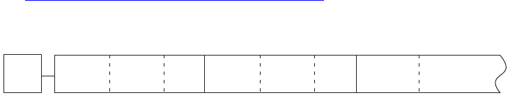
The stream with the persistent object data contains a series of records that correspond to the persistent
object. The object’s UID is stored with the object, as a key for the record. The variable-length records have
one segment for each persistent interface. Every segment has the same structure:
ImplementationID tag
int32 length
<data>
The following figure is a conceptual diagram of this structure; it does not represent the actual content of
any database. The format and content of the data are determined by the implementation of the interface.
See “Reading and writing persistent data” on page 14.
For each object, the ClassID value is stored in the table, and the ImplementationID values are stored in the
stream, but the InterfaceID value is not stored with either. Adding an existing implementation (that is, an
implementation supplied by the SDK) to an existing class can cause problems if another software
developer adds the same implementation to the class: one of the two plug-ins will fail on start-up. To avoid
this collision, create a new implementation for any persistent interface to be added to a class, using
ImplementationAlias. For an example, see <SDK>/source/sdksamples/dynamicpanel/DynPn.fr.
Persistent objects
This section discusses how persistent objects are created, deleted, and manipulated.
The application stores persistent objects in a database, and each object has a unique identifier within the
database. The methods for creating, instantiating, and using a persistent object are different from the
methods for nonpersistent objects.
Using persistent objects
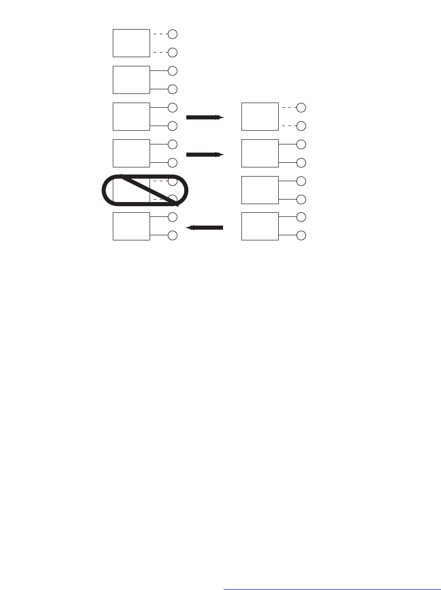
When a persistent object is created, its record exists in memory. Certain events, like a user’s request to save
a document, trigger the writing of the record to storage. (See the following figure.) A count is maintained
of the number of references to each persistent object. Any object with a reference count greater than zero
remains active in memory. If the reference count for a persistent object reaches zero, the object may be
asked to write itself to its database and be moved to the instance cache, which makes the object a
candidate for deletion from memory. Events that require access to the object, like drawing or
manipulating it, trigger the host to read the object back into memory. Because individual objects can be
saved and loaded, the host does not have to load the entire document into memory at once.
This figure shows creating and storing persistent objects:
ImplID Length Data ImplID Length Data ImplID Length
k<Foo>Boss object persistent data record
UID
CHAPTER 1: Persistent Data and Data Conversion Persistent objects 12
Creating a persistent object
Creating a new instance of a persistent object differs from creating a nonpersistent object, because it
requires a unique identifier to associate the object with its record in the database. For the CreateObject
and CreateObject2 methods used to create persistent objects, see
<SDK>/source/public/includes/CreateObject.h.
For examples of the creation of persistent objects, see the CreateWidgetForNode method in
<SDK>/source/sdksamples/paneltreeview/PnlTrvTVWidgetMgr.cpp or the StartupSomePalette method in
<SDK>/source/sdksamples/dynamicpanel/DynPnPanelManager.cpp.
You also can call IDataBase::NewUID method to create a new UID in the database. It adds an entry to the
database relating the UID to the class of the object being created; however, the object is not instantiated
yet, and no other information about it exists in the database.
Instantiating a persistent object
Before you instantiate a new object, use the InterfacePtr template to retrieve one of the object’s interfaces.
Pass the returned InterfacePtr to the IDatabase::Instantiate method, which calls the database to instantiate
the object.
There is only one object in memory for any UID and database. This method checks whether the object
already is in memory and, if so, returns a reference to that object. If the object is marked as changed, it is
written to the database. For more information, see “Reading and writing persistent data” on page 14. If the
object is not in memory, the method checks for previously stored data in the database. If data is found, the
method instantiates the object from this data. Otherwise, the method instantiates the object from the
object’s constructor. Each implementation has a constructor, so the boss and all its implementations are
instantiated.
Host Main memory Storage
Instantiate
(no storage)
Dirty
ReadWrite
Instantiate
(with storage)
NewUID
Reference count
reaches zero

CHAPTER 1: Persistent Data and Data Conversion Persistent objects 13
An object is stored to the database only if it is changed, making the default object data invalid. A single
object could exist and be used in several user sessions without ever being written to the database. A
persistent object whose data is not stored in the database is constructed from the object’s constructor.
Whether it instantiates a new object or returns a reference to an object previously instantiated,
IDatabase::Instantiate increments the reference count on the object and returns an IPMUnknown* to the
requested interface, if the interface is available.
Using commands and wrappers
There are commands for creating new objects of many of the existing classes (for example,
kNewDocCmdBoss, kNewPageItemCmdBoss, kNewStoryCmdBoss, and kNewUIDCmdBoss). When you
need to create an object, first look for a suite interface, utility interface, or facade interface to make
creating your object safe and easy. If no such interface exists, use a command if one is available, rather
than creating the object with general functions.
Using a command to create an object protects the database. Commands are transaction based; if you use a
command when the application already is in an error state, the command performs a protective
shut-down, which quits the application rather than permitting a potentially corrupting change to be made
to the document. Commands also provide notification for changes to the model, allowing observers to be
updated when the change is made, including changes made with undo and redo operations.
When you implement a new type of persistent object, also implement a command to create objects of that
type, using methods outlined in “Implementing persistent objects” on page 14.
Types of references to objects
There are four types of reference to a persistent object: UID, UIDRef, InterfacePtr, and UIDList. Each type of
reference serves a different purpose. Understanding these reference types makes working with persistent
objects easier.
UID is the type used for a unique identifier within the scope of a database. The UID value by itself is not
sufficient to identify the object outside the scope of the database. Like a record number, a UID value
has meaning only within a given database. UID values are useful for storing, passing, and otherwise
referring to boss objects, because UID values have no run-time dependencies, and there is an instance
cache ensuring fast access to the instantiated objects. kInvalidUID is a value used to identify a UID that
does not point at a valid object. Any time a UID is retrieved and needs to be tested to see if it points at
a valid object, the UID should be compared to kInvalidUID.
A UIDRef object contains two pieces of information: a pointer to a database and the UID of an object
within this database. A UIDRef is useful for referring to objects, because it identifies both the database
and the object. Using a UIDRef object is a common means of referring to a persistent object, especially
when the persistent object is to be passed around or stored, since a UIDRef does not require the
referenced object to be instantiated. A UIDRef object cannot itself be persistent data, because it has a
run-time dependency, the database pointer. An empty or invalid UIDRef object has kInvalidUID as its
UID and a nil pointer as its database pointer.
An InterfacePtr object contains a pointer to an interface (on any type of boss object) and identify an
instantiated object in main memory. While an InterfacePtr object on the boss is necessary for working
with the boss, it should not be used to track a reference to a persistent object, because this forces the
object to stay in memory. In many cases, a nil pointer returned from InterfacePtr does not indicate an
error state but simply means the requested interface does not exist on the specified boss.

CHAPTER 1: Persistent Data and Data Conversion Persistent objects 14
A UIDList object contains a list of UIDs and a single pointer to a database. This means all objects
identified by a UIDList must be within the same database. A UIDList is a class object and should be
used any time a list of objects is needed for a selection or a command.
Destroying an object
There are commands for deleting persistent objects. Use the command rather than calling the DeleteUID
method directly, to be sure of cleaning up all references to the object or item references contained in the
object.
When you implement a command to delete a persistent object, after you remove the references to the
object, use DeleteUID to delete the object from the database, as follows:
IDataBase::DBResultCode dbResult = database->DeleteUID(uid);
Implementing persistent objects
To make a boss object persistent, add the IPMPersist interface. Any boss with this interface is persistent
and, when an object of the boss is created, it is assigned a UID. Even though the object has a UID, and the
UID has an entry in the (ClassID, UID) pairings in a database, the object does not automatically store data. It
is up to the interface to store the data it needs. To implement this, add the ReadWrite method to the
interface (see “Reading and writing persistent data” on page 14), and make sure the PreDirty method is
called before information is changed (see “Marking changed data” on page 14).
NOTE: If you add an interface to an existing persistent boss, the interface also may be made persistent. If so,
you must obey the following implementation rules for it.
Adding the IPMPersist interface to a boss
All instances of IPMPersist must use the kPMPersistImpl implementation. For an example, see the
kPstLstDataBoss boss class definition in <SDK>/source/sdksamples/persistentlist/PstLst.fr
Creating an interface factory for a persistent interface
For a persistent implementation, use the CREATE_PERSIST_PMINTERFACE macro.
Reading and writing persistent data
To store data, your interface must support the ReadWrite method. This method does the actual reading
and writing of persistent data in the database. The method takes a stream argument containing the data
to be transferred. Read and write stream methods are generalized, so one ReadWrite method handles
transfers in both directions. For example, XferBool reads a boolean value for a read stream and writes a
boolean value for a write stream. For an example, see the BPIDataPersist::ReadWrite method in
<SDK>/source/sdksamples/basicpersistinterface/BPIDataPersist.cpp.
Marking changed data
When data changes for a persistent object that resides in memory, there is a difference between the
current version of the object and the object as it exists in the database’s storage. When this happens, the
object in memory is said to be dirty, meaning it does not match the version in storage. Before a persistent

CHAPTER 1: Persistent Data and Data Conversion Streams 15
object is modified, you must call the PreDirty method to mark the object as being changed, so it is written
to the database. For an example, see the BPIDataPersist::Set method in
<SDK>/source/sdksamples/basicpersistinterface/BPIDataPersist.cpp.
The PreDirty method called from within BPIDataPersist::Set is implementation-independent, so you can
rely on the version provided by HELPER_METHODS macros defined in HelperInterface.h
(DECLARE_HELPER_METHODS, DEFINE_HELPER_METHODS, and HELPER_METHODS_INIT).
Streams
This section discusses how streams are used to move information into and out of a document.
Streams are used by persistent objects to store their information to a database. Streams also are used by
the host application, to move data like placed images, information copied to the clipboard, and objects
stored in the database. IPMStream is the public interface to streams. Implementations of IPMStream
typically use the IXferBytes interface to move data.
Stream utility methods (in StreamUtil.h) are helpers for creating all the common types of streams used to
move information within or between InDesign databases. The stream utility methods and general read,
write, and copy methods are needed any time you work with a stream.
IPMStream methods
IPMStream is a generalized class for both reading and writing streams. Any particular stream
implementation is either a reading stream or a writing stream, and the type of stream can be determined
with the IPMStream::IsReading and IPMStream::IsWriting methods.
Any persistent implementation has a ReadWrite method, which uses a set of data-transferring methods on
the stream to read and write its data. (See “Reading and writing persistent data” on page 14.) The
IPMStream methods starting with the Xfer prefix are used for transferring the data type identified in the
method name. For example, XferByte transfers a byte, XferInt16 transfers a 16-bit integer, XferBool
transfers a Boolean value, and so on. All transferring methods are overloaded, so they can take a single
item or an array of items. (The XferByte(uchar, int32) version typically is used for buffers.) Streams also
handle byte swapping, if required. If swapping is not set (SetSwapping(bool16)), the default is to not do
byte-order swapping.
Additional IPMStream methods, XferObject and XferReference, transfer boss objects and references to
objects. XferObject transfers an owned object, and XferReference transfers a reference to an object not
owned by the object using the stream. To decide which method to use, think about what should happen
to the object if the owning object were deleted. If the object should still be available (as, for example, the
color a page item refers to), use XferReference. If the item is owned by the object and should be deleted
with the owner (as, for example, the page a document refers to), use XferObject.
Implementing a new stream
If you must read from or write to a location the host application does not recognize, you must create a new
type of stream. For example, you might need to create a new stream type to import and export files stored
on an FTP site or in a database.
CHAPTER 1: Persistent Data and Data Conversion Missing plug-ins 16
Stream boss
The first step in implementing a new stream is to define the boss. Typically, a stream boss contains
IPMStream and any interface required to identify the type of information in the stream, the target or
source of the stream, or both. This example creates kExtLinkPointerStreamWriteBoss, a pointer-based
read-stream boss:
Class
{
kExtLinkPointerStreamWriteBoss,
kInvalidClass,
{
IID_IPMSTREAM, kExtLinkPointerStreamWriteImpl,
IID_IPOINTERSTREAMDATA, kPointerStreamDataImpl,
}
};
IPMStream is the only interface all stream bosses have in common. In the preceding example, the
IPointerStreamData controls a stream that writes out to memory; it contains a buffer and a length.
The following is another example, showing kFileStreamReadBoss, a stream commonly used in importing:
Class
{
kFileStreamReadBoss,
kInvalidClass,
{
IID_IPMSTREAM, kFileStreamReadLazyImpl,
IID_IFILESTREAMDATA, kFileStreamDataImpl,
}
};
IPMStream interface and the IXferBytes class
When implementing your own stream, take advantage of the default implementations of IPMStream,
CStreamRead, and CStreamWrite. These default implementations use an abstract base class, IXferBytes, to
do the actual reading and writing. To implement a stream for a new data source, you must create an
IXferBytes subclass that can read and write to that data source.
Missing plug-ins
This section discusses how to open a document that contains data saved by a plug-in that is no longer
available.
Plug-ins you create can add data to the document. When your plug-in is present and loaded, it can open
and interpret the data; however, if the user removes the plug-in and then opens the document, or gives
the document to someone who does not have the plug-in, the plug-in is not available to interpret the
data.
You have two ways to handle such situations:
Control what warning is shown when the document is opened without the plug-in.
Implement code to update the data the next time the document is opened with the plug-in.
The rest of this section describes these options.
CHAPTER 1: Persistent Data and Data Conversion Missing plug-ins 17
Warning levels
The application can give a warning when it opens a document that contains data created by a plug-in that
is not available. There are three warning levels: critical, default, and ignore. By setting the warning level,
the plug-in can specify the relative importance of its data. Data created by the plug-in has the “default”
warning level unless you override the setting and identify the data as more important (critical) or less
important (ignored). This importance settings can be modified by adding resources to the plug-in’s boss
definition file:
CriticalTags — A “critical” warning tells the user the document contains data from missing plug-ins
and strongly advises the user not to open the document. If the user continues the open operation, the
application opens an untitled document that is a copy of the original, to preserve the original
document. Use this level when the data is visible in the document or contributes objects owned by
another object in the database, like text attributes, owned by the text model.
DefaultTags — A “default” warning tells the user the document contains data from missing plug-ins
and asks whether to continue the open operation. If the user continues the open operation, the
application opens the original document. Use this level when the data is self-contained and invisible
to the user, but the user might encounter missing function that would have been provided by the
plug-in.
IgnoreTags — An “ignore” warning provides no warning message at all; the application proceeds with
the open operation as if there were no missing plug-ins. Use this level when the data is invisible to the
user and completely self-contained. In this case, the user does not need to know the plug-in was
involved in the construction of this document. If the plug-in stored data in the document, but that
data is used only by this plug-in and does not reference objects supplied by other plug-ins, the user
sees no difference in the document when the plug-in is missing. For example, the plug-in might store
preferences information in every document for its own use.
You can set these warnings to use ClassID (when the plug-in creates new bosses) or ImplementationID
(when the plug-in adds interfaces to existing bosses) values as triggers. Use kImplementationIDSpace to
specify a list of ImplementationID values, and kClassIDSpace for ClassID values. You can put any number of
IDs in the list, but all the IDs must be of the same type. Use a second resource to mark IDs of another type.
the following examples set the warning level to ignore data stored by the PersistentList plug-in in the SDK
by adding two resources to PstLst.fr:
This example marks implementation IDs as ignored:
resource IgnoreTags(1)
{
kImplementationIDSpace,
{
kPstLstDataPersistImpl,
kPstLstUIDListImpl,
}
};
This example marks boss classes as ignored:
resource IgnoreTags(2)
{
kClassIDSpace,
{
kPstLstDataBoss,
}
};

CHAPTER 1: Persistent Data and Data Conversion Missing plug-ins 18
You do not need to mark any IDs that do not appear in the document (for example, data that was written
out to saved data) or implementations that are not persistent.
You do not need to mark IDs if you want the default behavior.
Missing plug-in alert
This alert is activated when a document is opened and contains data from one or more missing plug-ins
that cannot be ignored. The document contains a list of the plug-ins that added data to it. Each piece of
data added has an importance attached to it; this may be critical, default, or ignorable. Data marked as
ignorable does not cause the alert to be activated. Data marked as critical or default causes the alert to be
activated. In the case of critical data, the alert works more strongly; this is the only difference between
critical and default data.
The alert tells the user data is missing, presents a list of missing plug-ins, and allows the user to continue or
cancel the open operation. Each missing plug-in has the chance to add a string to the alert that specifies
additional useful information (for example, a URL for purchasing or downloading the plug-in). The alert is
modeled on the missing-font alert.
The “Don’t Warn Again For These Plug-ins” option is deselected by default. If this option is selected, the
alert is not activated the next time a document is opened and any subset of the listed plug-ins is missing
(and no other plug-ins are missing). This allows users accustomed to seeing (and ignoring) alerts
concerning specific plug-ins to automatically bypass the alert, while still getting warned about data from
any plug-ins newly found to be missing. The alert is activated again if a document is opened that uses
other missing plug-ins. The alert is activated again if the “Don’t Warn Again For These Plug-ins” option is
deselected.
Guidelines for handling a missing plug-in
If a plug-in creates persistent data in a document, these guidelines ensure that the document behaves
gracefully if a user tries to open it when the plug-in is missing or if the document has been edited by a user
who did not have the plug-in:
If your plug-in does not store data in documents, you do not need to take any special precautions.
If the data stored by your plug-in does not reference other data in the document and does not appear
visually in the document, mark the data as ignorable.
If editing the document without your plug-in could corrupt the document, mark the data as critical.
You can specify a string that is displayed when the plug-in is missing and the user opens a document
that contains data added by the plug-in. See the ExtraPluginInfo resource, which may provide
information like the URL of a site from which the missing plug-in can be obtained. See an example of
the use of this resource in <SDK>/source/sdksamples/transparencyeffect/TranFx.fr.
If your plug-in can check and restore the data’s integrity when opening a document edited without
the plug-in, supply a FixUpData method. For an example, see
<SDK>/source/sdksamples/persistentlist/PstLstPlugIn.cpp.
If you want your plug-in to handle the storage of its own data, use the application-supplied
mechanism that treats the plug-in’s data like a black box. (See “Black-box data storage” on page 19.)
CHAPTER 1: Persistent Data and Data Conversion Missing plug-ins 19
Data handling for missing plug-ins
If a document contains data placed there by a plug-in that is not available, the user can choose to open the
document anyway. If the data is completely self-contained, there may be no problem; however, if the
plug-in’s data depends on anything else in the document, undesirable things can happen.
Missing data not copied
InDesign maintains most data in a centrally managed model in which the core-content manager keeps
track of what information is added to the document, handles conversion of the data, and provides a
convenient mechanism for instantiating objects based on the data. This approach does not allow the data
to be copied when the plug-in is missing, however, because the content manager would not be able to
provide these services for the missing plug-in’s copied data, and that potentially can leave the document
in an invalid state. With the exception of those objects that hold onto only ClassID values, InDesign blocks
copying data associated with missing plug-ins.
This means no attribute is copied if the plug-in that supplies the attribute is missing. This applies to all
attributes: text, graphics, table, cjk, and so on. Furthermore, if a plug-in attached a data interface to an
existing attribute, and the plug-in is missing, the attribute is copied but the add-in data interface is not.
This is consistent with how InDesign handles UID-based objects.
Likewise, if a data interface is added to an XML element, the data interface is not copied if the plug-in that
supplied it is missing.
There are several features based on an object from a required plug-in holding a ClassID from an optional
plug-in, including adornments, text composer, pair-kern algorithm, section numbers, and unit defaults. In
these cases, the consequences of losing track of the plug-in that supplied the data is much less severe.
Conversion of these ClassIDs is quite unusual and could be handled if necessary by issuing new ClassIDs.
Error handling in the user interface when the plug-in is missing is much more graceful.
Black-box data storage
A second, simpler data-model storage mechanism was added for software developers requiring that data
(like text attributes) is copied with the text, and for developers who want to attach data to other ID objects,
such that it gets copied even when the source plug-in is missing. This mechanism is black-box data
storage.
In the simplest case, the black box is just a new persistent interface that sits on the object. A plug-in can
store data in the box or fetch data out of the box. The data is keyed by a ClassID, which is supplied by the
plug-in. Multiple plug-ins can store their data in the same black box, and each plug-in gets its own unique
streamed access to its data. The black box just keeps track of the key, the length of the data, and the data
stream. The software developer is responsible for handling everything else—conversion, swapping, and
so on. Users do not get a missing plug-in alert for data placed in a black box.
Any UID-based object could have a black box. In addition, attributes and small bosses (used for XML
elements) can have black boxes.
The following objects support black boxes:
kDocBoss — The root object of the document does not get copied.
kPageItemBoss— This includes all page item objects, including spreads, master pages, splines, frames,
images, and text frames.

CHAPTER 1: Persistent Data and Data Conversion Conversion of persistent data 20
Attributes— This includes text, graphic, table, cjk, and so on (that is, everything that appears in an
AttributeBossList).
For more information on the black-box mechanism, refer to IBlackBoxCommands, IBlackBoxCmdData, and
IBlackBoxData in the API reference.
FixUpData
Suppose that a hyperlink attribute is linked to another frame, and the user can double-click the link to go
to the frame. A plug-in supplies an observer, so if the frame is deleted, the link is severed. Now suppose
that you give the document containing the hyperlinks to someone who does not have the hyperlink
plug-in. This person edits the document, deletes the frame, saves the document, then returns the
document to you. The document is now corrupted, because your plug-in was unable to delete the
associated link, which now points to an undefined frame.
To restore the integrity of a document in this case, the plug-in can override the IPlugIn::FixUpData method.
This method is called when the document is opened, if the plug-in was used to store data in the document
and the document was edited and saved without the plug-in. In this case, the hyperlinks plug-in could
override FixUpData to scan all its objects, checking whether the linked frame UIDs were deleted; when the
document is opened with the plug-in, the method correctly severs the links.
Conversion of persistent data
This section describes types of conversion providers and the advantages of each type.
Converting persistent data from an old document to a new one is complex, because each plug-in can store
data independently in the document. When the host opens a document created with an older version of
the application or an older version of any plug-in used in the document, you must convert and update the
older data to match the new format.
Versioning persistent data is the process of converting persistent data in a database from one format to
another. The data in different formats usually resides in different databases; for example, data in a
database (document) from a previous version of InDesign versus that in a database (document) from a
newer version of InDesign. Just as each plug-in that has a persistent data implementation is responsible
for the order of reading and writing its own data (thus implicitly defining a data format), each plug-in also
is responsible for converting its own data from one format to another. Whether data in a database requires
conversion usually is determined when the database is opened.
There are two approaches to converting persistent data:
You can use the host’s conversion manager to manage the conversion process. This approach is the
most common. See “Converting data with the conversion manager” on page 21.
The plug-in that owns the data can manage when and how data is converted, using version
information or other data embedded with the object data. See “Converting data without the
conversion manager” on page 31.
When to convert persistent data
As a plug-in developer, you want to ensure that your users can open documents with persistent data from
an older version of your plug-in. To do this, your plug-in must provide data conversion functions. The best
time to consider your data-conversion strategy is when you realize that your plug-in will store some data
to a database. You need to implement data-conversion utilities in the following cases:

CHAPTER 1: Persistent Data and Data Conversion Conversion of persistent data 21
You change the order of IPMStream::Xfer* calls in the ReadWrite method.
You change a persistent object’s definition.
You renumber (change the value of) an ImplementationID or ClassID identifier.
You remove a plug-in and data from the removed plug-in might be in a document a user wants to
open.
In any of these cases, the conversion manager needs to be notified how to convert the persistent data for
use by the loaded plug-in.
Specifying how the persistent data format changed is somewhat different from adding persistent data to
or removing it from a document. Besides telling the conversion manager to add or delete any obsolete
data, the conversion provider has to be able to tell the conversion manager about every implementation
in the plug-in that was ever removed, to keep the content manager up to date about the various persistent
data formats.
NOTE: To provide a document for use with an earlier version of InDesign, use the InDesign Interchange file
format.
At the very least, the resources required to support data conversion can help you keep a log of how your
persistent data format has changed. Such a log can be useful.
Sample conversion scenario
Consider a plug-in with two released versions, 1 and 2, which use the same data format; in this case, both
versions of the plug-in have the same format version number, 1. A new release of the plug-in, version 3,
stores additional data, such as a time stamp. You must update the format version number to match the
current plug-in version number; so, for plug-in version 3, the format version also would be 3. Because you
changed the format version number, you must create a converter that converts from version 1 to version 3.
The following table shows an example of version changes:
For a fourth version of the plug-in, you again change the format, allowing a date stamp to be signed.
Change the plug-in and format version numbers to 4, and add an additional converter to convert from
version 3 to version 4. Conversions from version 1 to version 4 are done by the conversion manager, which
chains the converters together; the first converts from format version 1 to format version 3, and the second
converts from format version 3 to format version 4).
Converting data with the conversion manager
Each document contains header information about the content, which includes a list of all plug-ins that
wrote data to the document and the version number of the plug-in last used to write that data. When a
Plug-in version Format change Format version
1N/A (new plug-in)1.0
2No1.0
3Yes3
4Yes4

CHAPTER 1: Persistent Data and Data Conversion Conversion of persistent data 22
document is opened, the application checks whether any plug-ins are missing or out of date. If a plug-in is
missing, it might provide an alert embedded in the document. (See “Missing plug-ins” on page 16.)
If a plug-in is out of date, data written by the old plug-in must be updated to match the format required by
the loaded plug-in. A plug-in can register a conversion service to do the update. The InDesign conversion
manager (IConversionMgr) determines which conversions are required for opening the document and
calls the appropriate plug-in to do the conversion.
When the persistent data for any plug-in changes, this is a document format change. Any of the following
can change the document format:
Changes to the ReadWrite method — If the ReadWrite method is used to stream data to the document,
changing the ReadWrite method might change the document format; however, an implementation
might have a ReadWrite method that works with some other database or other data source, not with
the document itself. For example, a widget has a ReadWrite method used for streaming to and from
resources and to and from the SavedData file. Changes to a method that does not work with the
document database do not require any special conversion.
Changes to an object’s definition— If you add an implementation to (or remove an implementation
from) the definition of a persistent boss in the framework resource (.fr) file, you change how the object
is streamed. If you add a new implementation, an old version of the object will stream, but it will not
contain the data normally appearing for the implementation you added. This is fine if the data can be
initialized adequately from the implementation’s constructor; otherwise, you may need to add a
converter. If you change the implementation of an interface from one ImplementationID to another,
you must convert the data. If you remove an ImplementationID from a class, you should add a
converter to strip the old data from the object; otherwise, the obsolete data is carried around with the
object indefinitely.
Renumbering an ImplementationID or ClassID — If an ImplementationID or ClassID changes, you must
register a converter so occurrences of the ImplementationID or ClassID in old documents can be
updated. In practice, renumbering a ClassID or ImplementationID is a source of many bugs and
typically leads to corrupt documents, so we strongly recommend that you do not renumber an
ImplementationID or ClassID.
When you make a format change, you must do two things to maintain backward compatibility:
Update the version number of the plug-in whose data format you changed.
Provide a converter that can convert between the previous format and the new format.
Updating version numbers
Each plug-in has a plug-in version resource of type PluginVersion. The PluginVersion resource appears in
the boss definition file. The first entry of this resource describes the application's build number; on the
release build, this entry is the final-release version number. The second entry of the resource is the
plug-in’s ID, followed by three sets of version numbers, followed by an array of feature-set IDs. If any of the
IDs in this list matches the current feature-set ID, the plug-in is loaded. To see an example, open any
example .fr file in the SDK.
Each version number has a major number and a minor number. The first version number is the version of
the plug-in, which gets updated for every release of the plug-in. The second version number is the version
of the application with which the plug-in expects to run. This ensures that the user does not drop a plug-in
compiled for one version of the application into an installation of another version of the application. The
last number is the format version number, which indicates the version of the plug-in that last changed the
CHAPTER 1: Persistent Data and Data Conversion Conversion of persistent data 23
file format; this is the version number written into the document, and it is the number the conversion
manager checks to see whether conversion is required.
The format version number does not always match the plug-in’s version number. The format version
number does not generally change as often as the plug-in version number. The plug-in version number
changes for every release of a plug-in, but the format version number changes only if the format for the
data the plug-in stores in the document has changed and the conversion manager is required to convert
the data.
Adding a converter
Converters can be implemented as conversion services. InDesign supports two types of
service-provider-based data conversion:
Schema-based provider — Schema-based converters are configured through resources, are easier to
use than code-based converters, and cover most format-change needs. Use this type of converter
unless it cannot handle the special needs of your plug-in.
Code-based provider— If your implementation uses a special data-compression algorithm or other
storage optimizations, involves data of variable length, or uses virtual object store (VOS) objects,
schema-based converters cannot handle the necessary data format conversions. In this case, you must
implement your own custom conversion provider.
A conversion service is responsible for all conversions done by the plug-in. A converter might at first
handle only a single conversion, from the first format to the second. Later, if you change the format again,
you can add another conversion to the converter, to convert from the second format to the third.
Suppose you market a plug-in that supplies a date stamp. You had released two versions (version 1.0 and
version 2.0) of the plug-in without changing the persistent data created by the plug-in; so both releases
have the same format version number (1.0). For the third released version of the plug-in, you add a time
stamp. You must update the format version number to match the current plug-in version number; for
example, for plug-in version 3.0, the format version also must be 3.0.
Suppose for the fourth released version of the plug-in (version 4.0), you again change the format, allowing
a date stamp to be signed. You then change the format version number to 4.0 and add an additional
converter, capable of converting from format version 3.0 to format version 4.0. Conversions from format
version 1.0 to format version 4.0 can be done by the conversion manager, which chains the two converters
together, using the first converter to convert from format version 1.0 to format version 3.0, and using the
second converter to convert format version 3.0 to format version 4.0.)
Adding a converter (either schema-based or code-based) to your plug-in means adding a new boss with
two interfaces, IK2ServiceProvider and IConversionProvider. The IK2ServiceProvider implementation,
kConversionServiceImpl, is provided by the application. You need to supply the IConversionProvider
implementation. Here is a sample boss:
CHAPTER 1: Persistent Data and Data Conversion Conversion of persistent data 24
/**
This boss provides a conversion service to the conversion manager
to use the schema-based implementation.
*/
Class
{
kMyConversionProviderBoss,
kInvalidClass,
{
IID_ICONVERSIONPROVIDER, kMySchemaBasedConversionImpl,
IID_IK2SERVICEPROVIDER, kConversionServiceImpl,
}
Most of the work is done in the conversion provider supplied with the SDK.
The default implementation of IConversionMgr calls IConversionProvider::CountConversions and
IConversionProvider::GetNthConversion to determine which conversions are supported by the converter.
When you implement a new converter, CountConversions returns 1, and GetNthConversion returns
fromVersion set to the version number before your change and toVersion set to the version number
having your change in it. VersionID is a data type in the Public library; it consists of the PluginID value, the
major format version number, and the minor format version number.
For a new converter, fromVersion should be VersionID(yourPluginID, kOldPersistMajorVersionNumber,
kOldPersistMinorVersionNumber). The toVersion should be the new format version number.
Your new conversion is added as conversion index 0. For a new converter, it looks like this:
int32 TextConversionProvider::CountConversions() const
{
return 1;
}
void TextConversionProvider::GetNthConversion(
int32 i, VersionID* fromVersion, VersionID* toVersion) const
{
*fromVersion = VersionID(kTextPluginID, kOldPersistMajorVersionNumber,
kOldPersistMinorVersionNumber);
*toVersion = VersionID(kTextPluginID, kNewPersistMajorVersionNumber,
kNewPersistMinorVersionNumber);
}
When adding another change after a changed version already exists, the change numbers should chain
together so the conversion manager can do changes across multiple formats. So, if your plug-in used three
formats—starting with version 1, then changed in version 3, and changed again in version 4—your plug-in
should register one converter that handles the conversion from format version 1 to format version 3 and
another converter that handles the conversion from format version 3 to format version 4. If necessary, the
conversion manager can chain them together to convert a document from version 1 to version 4. The
methods would look like this:
CHAPTER 1: Persistent Data and Data Conversion Conversion of persistent data 25
const int32 kFirstFormatVersion = 1;
const int32 kSecondFormatVersion = 3;
const int32 kThirdFormatVersion = 4;
const int32 kFirstChange = 0;
const int32 kNewChange = 1;
int32 TextConversionProvider::CountConversions() const
{
return 2;
}
void TextConversionProvider::GetNthConversion(
int32 i, VersionID* fromVersion, VersionID* toVersion) const
{
if (i == kFirstChange)
{
*fromVersion = VersionID(kTextPluginID, kMajorVersionNumber,
kFirstPersistMinorVersionNumber);
*toVersion = VersionID(kTextPluginID, kMajorVersionNumber,
kSecondPersistMinorVersionNumber);
}
else if (i == kNewChange)
{
*fromVersion = VersionID(kTextPluginID, kMajorVersionNumber,
kSecondPersistMinorVersionNumber);
*toVersion = VersionID(kTextPluginID, kMajorVersionNumber,
kThirdPersistMinorVersionNumber);
}
}
Next, tell the conversion manager which information you changed. The default implementation of
IConversionMgr calls IConversionProvider::ShouldConvertImplementation with each implementation in
the document supplied by the plug-in. Depending on the data status of the implementation, the plug-in
must return kMustConvert when the content must be modified, kMustRemove when the data is obsolete
and must be removed, kMustStrip when the content must be stripped, or kNothingToConvert for all other
cases.
Using kTextFrameImpl as an example, define a method for
IConversionProvider::ShouldConvertImplementation, returning kMustConvert when the tag is
kTextFrameImpl and kNothingToConvert in all other cases. The plug-in should do this when the conversion
manager is converting that plug-in’s data and not performing another conversion, so check the conversion
index and make sure it is the one that you added. It might look like the following:

CHAPTER 1: Persistent Data and Data Conversion Conversion of persistent data 26
IConversionProvider::ConversionStatus
TextConversionProvider::ShouldConvertImplementation(
ImplementationID tag, ClassID context, int32 conversionIndex) const
{
IConversionProvider::ConversionStatus status =
IConversionProvider::kNothingToConvert;
switch (conversionIndex)
{
case 0:
if (tag == kTextFrameImpl)
status = IConversionProvider::kMustConvert;
break;
default:
break;
}
return status;
}
Next, implement ConvertTag to do the actual conversion. Suppose the TextFrame ReadWrite method
writes an integer value and a real value, and you are adding a boolean. The ConvertTag implementation
might look like the following, which illustrates what most converters look like:
ImplementationID TextConversionProvider::ConvertTag(
ImplementationID tag, ClassID forClass, int32 conversionIndex, int32 inLength,
IPMStream* inStream, IPMStream* outStream, IterationStatus whichIteration)
{
ImplementationID outTag = tag;
switch (conversionIndex)
{
case 0:
if (tag == kTextFrameImpl)
{
if (inLength > 0)
{
int32 passThruInt;
inStream->XferInt32(passThruInt);
outStream->XferInt32(passThruInt);
int32 passThruReal;
inStream->XferInt32(passThruReal);
outStream->XferInt32(passThruReal);
// Adding new field bool16 smartQuotes = kTrue;
outStream->XferInt32(smartQuotes);
}
}
break;
default:
break;
} return outTag;
}
If the converter needs to convert a class, it implements ShouldConvertClass and ConvertClass. This is
necessary only if the class is being deleted or is a container for some other data. (See “Containers and
embedded data” on page 28.)
CHAPTER 1: Persistent Data and Data Conversion Conversion of persistent data 27
Removing classes or implementations
If you remove a ClassID or an ImplementationID from a version of your plug-in, the identifier also must be
removed from documents as they are converted. The conversion manager removes an identifier for you if
you implement your converter to return invalid status. For example, to remove a tag, implement
ConvertTag as follows:
ImplementationID TextConversionProvider::ConvertTag(
ImplementationID tag, ClassID forClass, int32 conversionIndex, int32 inLength,
IPMStream* inStream, IPMStream* outStream, IterationStatus whichIteration)
{
ImplementationID outTag = tag;
switch (conversionIndex)
{
case 0:
if (tag == kTagToRemove)
outTag = kInvalidImpl;
break;
default:
break;
}
return outTag;
}
Deleting a class is similar: implement ConvertClass to return kInvalidClass.
Changing an implementation in one class
Suppose a boss is defined with an IBoolData interface, implemented as kPersistBoolTrue, meaning it
defaults to true. Suppose you change this to kPersistBoolFalse. When you read an old document with the
new boss, you want it to use the new implementation. You would then write a converter to take the data
stored as kPersistBoolTrue and switch it to be stored as kPersistBoolFalse. When you first access the boss, it
has the old value. If you do not make a converter, the boss will not read the old data, because there is no
interface in the new boss using the kPersistBoolTrue ImplementationID. Instead, the boss looks for
kPersistBoolFalse but does not find it, because the old boss did not have it; therefore, the value is false,
because it is the default value instead of the old value.
To change the ImplementationID of the data in the document, make a conversion method to catch the old
ImplementationID and change it to the new one. Do this only for your boss; do not change other bosses
using kPersistBoolTrue. Your method might look like this:
CHAPTER 1: Persistent Data and Data Conversion Conversion of persistent data 28
ImplementationID TextConversionProvider::ConvertTag(
ImplementationID tag, ClassID forClass, int32 conversionIndex, int32 inLength,
IPMStream* inStream, IPMStream* outStream, IterationStatus whichIteration)
{
ImplementationID outTag = tag;
switch (conversionIndex)
{
case 0:
if (tag == kPersistBoolTrue && forClass == kMyBoss)
outTag = kPersistBoolFalse;
bool16 theBool;
inStream->XferBool(theBool);
outStream->XferBool(theBool);
break;
default:
break;
}
return outTag;
}
forClass is the boss in which the data was found. The conversion should be done only if forClass is the one
you want changed.
Also implement ShouldConvertImplementation. forClass is either the class in which the data was found or
kInvalidClass if any class should match. The implementation of ShouldConvertImplementation looks like
this:
IConversionProvider::ConversionStatus
TextConversionProvider::ShouldConvertImplementation (
ImplementationID tag, ClassID forClass, int32 conversionIndex) const
{
IConversionProvider::ConversionStatus status =
IConversionProvider::kNothingToConvert;
switch (conversionIndex)
{
case 0:
if (tag == kTextFrameImpl &&
(forClass == kMyBoss ││ forClass == kInvalidClass))
status = IConversionProvider::kMustConvert;
break;
default:
break;
}
return status;
}
Containers and embedded data
InDesign does not have many instances of containers. One example is in the text attribute code. A text
style is a UID-based boss object containing an implementation, TextAttributeList, that contains a list of
attribute bosses (Bold, Point Size, Leading, and so on). These attribute bosses are not UID-based bosses;
instead, TextAttributeList streams the ClassID for a boss, followed by the boss’s data, then streams the next
boss in the list. TextAttributeList, therefore, must call the stream’s content tracker to notify the content
manager that a new class was added to the document.
The following example illustrates why this is important.

CHAPTER 1: Persistent Data and Data Conversion Conversion of persistent data 29
Suppose a new Red-Line plug-in adds an attribute to the style and the text does not compose correctly if
the Red-Line plug-in is removed. Red-Line can list the attribute as critical, so the host provides a strongly
worded warning when the user tries to open the document without the Red-Line plug-in. However, if
TextAttributeList does not register the attribute boss with the content manager, the application never
knows the attribute is in the document and cannot warn the user. Suppose the Red-Line plug-in is
updated, and the attribute boss in particular is updated to store its data differently. The Red-Line plug-in
registers a converter handling the format change. If the host does not know the attribute appears in the
document, the Red-Line converter is never called to perform the conversion. The document appears to
open correctly, but it crashes on the attribute’s ReadWrite method the first time the style is read.
For the Red-Line attribute to be converted, TextAttributeList must register a converter. If the content
manager was notified when the attribute was streamed, the conversion manager knows the attribute
needs to be converted. It even knows the attribute was streamed by TextAttributeList. But the conversion
manager has no way of knowing where the attribute is inside the data streamed by TextAttributeList;
therefore, TextAttributeList should register a converter that calls back to the conversion manager to
convert each piece of embedded data. Otherwise, the embedded data is not converted.
Content manager
The host has a content manager that tracks what data is stored in the document, which plug-in stored it,
and the format version number of the plug-in last used to write the data.
Think of this as a table attached to the root of the document: every ImplementationID part of the
document appears in the table. This table also includes all ClassID values in the document. The following
tables are an example.
This table shows version information:
This table shows class IDs in the document:
ImplementationID PluginID
Format version number (only
minor number)
kSpreadImpl kSpreadPluginID 0
kSpreadLayerImpl kLayerPluginID 0
kTextAttrAlignJustImpl kTextAttrPluginID 1
kCMSProfileListImpl kColorMgmtPluginID 3
...
ClassID Plug-in ID
Format version number (only
minor number)
kSpreadBoss kSpreadPluginID 1
kSpreadLayerBoss kLayerPluginID 1
kTextAttrAlignBodyBoss kTextAttrPluginID 3
kDocBoss kDocFrameworkPluginID 1
CHAPTER 1: Persistent Data and Data Conversion Conversion of persistent data 30
When an object is streamed to a document, the document receives the ClassID of the object and the data
streamed by each of the object’s ReadWrite methods. The data written by a ReadWrite method is marked
with the ImplementationID of the ReadWrite implementation; this way, when the data is read later, the
system knows which C++ class to instantiate to read the data. IContentMgr maintains an overall list of the
ClassID and ImplementationID values used in the document. When a new ClassID or ImplementationID is
added to the document, IContentMgr checks which plug-in supplied the ClassID or ImplementationID,
notes the plug-in ID and the format version number, and adds the new entry to the table.
The plug-in supplying a ClassID is the one supplying the class definition. Only the plug-in supplying the
original class definitions is considered; add-in classes do not count. The plug-in supplying an
ImplementationID is the one that registered a factory for the ImplementationID.
This data is used to detect missing plug-ins and manage document conversion. When the user opens a
document containing data supplied by a missing plug-in, the host alerts the user that the document
contains data from a missing plug-in. The host detects missing plug-ins by looking in the content manager
to see which plug-ins supplied data to the document and checking this list against the list of loaded
plug-ins to see whether any are missing.
This data also is used for document conversion. When the user opens a document, the default
implementation of IConversionMgr checks the format version number of the plug-ins supplying data to
the document and compares it with the format version number of loaded plug-ins. Any mismatch means a
conversion is required before the document can be opened. If there is a format version change without a
supplied data converter, the document will not open.
Conversion manager
When a document is opened, the conversion manager is called to check whether any data in the
document requires conversion. If the data requires conversion and a converter is available, the document
is converted and opens as an untitled document. If a converter cannot be found, the host displays an alert
message that warns the user the document cannot be opened because it cannot be converted.
This initial check, implemented in IConversionMgr::GetStatus, happens very early in the process of trying
to open the document, before any objects in the document are accessed (that is, before any of their
ReadWrite methods are called). This is critical, because a ReadWrite method will not succeed if the object
needs to be converted. The conversion manager accesses the content manager (converting it if necessary),
and uses the content manager to find out what plug-ins supplied data to the document. If any plug-ins
used in the document have different formats than the formats of the loaded plug-ins, conversion is
necessary. Next, the conversion manager sees whether there is a converter to convert from the format in
the document to the format associated with the loaded plug-in. If such a converter is available, conversion
is possible; the document may be closed and opened again as an untitled document.
If the GetStatus method returns with a result indicating conversion is not necessary, the open operation
proceeds without calling the conversion manager again. If the GetStatus method returns with a result
indicating conversion is necessary but impossible, the open operation is aborted. If the GetStatus method
returns with a result indicating conversion is required and a converter is available, the conversion
manager’s ConvertDocument method is called to perform the conversion.
The first thing ConvertDocument does is compile a list of the classes and implementations in the
document that must be converted. A plug-in may have many different implementations that wrote data to
the document, but only one of these implementations might require conversion. The conversion manager
uses the content manager to iterate over classes and implementations supplied by the plug-in, and the
conversion manager calls the converter to find out which classes and implementations require conversion.
Each class or implementation in the document that the converter says must be converted is added to the

CHAPTER 1: Persistent Data and Data Conversion Conversion of persistent data 31
list of classes or list of implementations to be converted. Other data written by the plug-in is ignored by
the converter; it is not converted.
The next step is to iterate over the UIDs in the document. For each UID, the conversion manager gets the
class of the UID. If the class is on the list of classes to be converted, the conversion manager calls a
converter for the class. If, as is more common, the class contains an implementation needing to be
converted, the conversion manager opens an input stream on the UID and iterates through the
implementations in the UID. If any implementation in the UID requires conversion, an output stream is
opened on the UID. Any implementation not requiring conversion is copied to the output stream. If an
implementation requires conversion, its converter is called. The converter gets passed the input stream
and the output stream. The converter reads from the input stream in the old format and writes to the
output stream in the new format.
After the UID iteration is completed, the content manager is called to update the format numbers for all
plug-ins that were outdated, to show their data was converted and is up to date. After this, it is safe for
ReadWrite methods to be called on objects in the document.
If any converter requires access to another object to do its conversion, it is called in the last phase of
conversion. For example, suppose there was one document-wide preference setting for whether text in
frames has smart quotes turned on, but you want to make this a per-frame setting. The text frame must
store a new flag that indicates whether smart quotes are on or off. The converter adds a new flag in the
first phase of conversion, but the converter cannot set the correct value for the flag until the preferences
are converted. So, the converter needs to be called once again, after the first phase is complete and it is
safe to instantiate the preferences, to get the value of the document-wide smart-quotes setting so the
converter can set the frame’s new smart-quotes setting accordingly.
Converting data without the conversion manager
To perform format conversion without the conversion manager, the persistent data itself must identify the
version of the plug-in that originally wrote the information. To use this method, add a version number to
the implementation classes, and implement the ReadWrite method to write the version number first
whenever the method writes data, as shown in the following figure. This method has the advantage of
forward compatibility.
The following figure shows persistent data with version number:
For example, suppose the first version of your plug-in stores two-byte values, fOne and fTwo, and uses a
byte value to store the data’s version number. The ReadWrite method for this implementation would be
something like the following example, which supports multiple versions (version 1 of the plug-in):
FooStuff::ReadWrite(IPMStream* stream, ImplementationID implementation)
{
stream->XferByte(0x01);
stream->XferByte(fOne);
stream->XferByte(fTwo);
}
The second version of this plug-in modifies the data format by adding a 16-bit integer value, fThree. In this
version, your ReadWrite method must be able to read data in either format, but it always must write data
ID Length ID Length
Data
k<Foo>Boss persistent data record
Vers. | Other
Data
Vers. | Other
CHAPTER 1: Persistent Data and Data Conversion Resources 32
back in the new format. The following example shows a ReadWrite method supporting multiple versions
(version 2 of the plug-in):
FooStuff::ReadWrite(IPMStream* stream, ImplementationID implementation)
{
uchar version = 0x02; //Always *write* version 2 data
stream->XferByte(version);
if (version == 0x01)
{
stream->XferByte(fOne);
stream->XferByte(fTwo);
}
else
{
stream->XferByte(fOne);
stream->XferByte(fTwo);
stream->XferInt16(fThree);
}
}
This code both reads and writes all data for this implementation. It could check whether the stream is a
reading or writing stream and perform only the needed operation, but the dual-purpose code actually is
simpler and accomplishes the same thing. If the stream is a ReadStream, the version is initialized as 0x02
but immediately replaced by the contents of the first byte in the stream, and the rest of the stream is
processed according to the version number found. If this plug-in encounters data claiming a version
number greater than 2, only the data it understands (processed by the else clause) is read. This method
allows the version 2 plug-in to work with data from both earlier and later versions. Each new version of the
plug-in using this method must preserve the portion of the stream previous versions created and add new
information only to the end.
When using this approach, the plug-in’s data version number must not change between versions of the
plug-in, but only when a data converter is being supplied to convert the data from one version to another.
Resources
This section explains the fundamental elements and ODFRez resources you need when incorporating a
converter in your plug-in.
PluginVersion resource, format numbers, and their macros
PluginVersion is a resource included in every InDesign and InCopy plug-in. Part of the resource is the
declaration of a persistent data format number, like the following:
kSDKDefPersistMajorVersionNumber, kSDKDefPersistMinorVersionNumber,
For an example, see the resource definition in <SDK>/source/sdksamples/basicdialog/BscDlg.fr.
Each plug-in specifies a different format number. These format numbers are stored in documents, so when
a document is opened, the content manager can determine whether data conversion is needed. This
determination is made by comparing the format numbers stored in the document for each plug-in with
the format numbers declared by loaded plug-ins. If the format numbers are different, the conversion
manager is called upon to do a data conversion.
Format number values must meet the following criteria:
Be greater than or equal to zero.

CHAPTER 1: Persistent Data and Data Conversion Resources 33
Increase with each format change.
Increment if the data format of any persistent class in a plug-in changes.
NOTE: If multiple persistent classes in a plug-in change their data formats at the same time, the data-format
version number needs to increment only once. How much you increment data format version numbers is
up to you.
Format-number values are just numbers; however, you might find it easier to use #define macros for
format numbers instead of using their values directly.
The following table lists format-number macros and their values from InDesign SDKs. See
<SDK>/source/sdksamples/common/SDKDef.h.
Setting up resources
With the first format change for a plug-in, you must add a converter (either schema-based or code-based)
to your plug-in (only one converter per plug-in). See “Adding a converter” on page 23.
Schemas
The schema resource defines which formats of which implementations the converter should handle. The
schema resource is defined in your .fr file and compiled using the ODFRC (Open Document Framework
Resource Compiler). See the following example and <SDK>/public/includes/Schema.fh.
Version Macro: Major Macro: Minor Tuple
1.0 kSDKDef_10_PersistMajorVersionNumber kSDKDef_10_PersistMinorVersionNumber {0,
307}
1.5 kSDKDef_15_PersistMajorVersionNumber kSDKDef_15_PersistMinorVersionNumber {1, 0}
1.0J kSDKDef_1J_PersistMajorVersionNumber kSDKDef_1J_PersistMinorVersionNumber {2, 1}
2.0 / 2.0J kSDKDef_20_PersistMajorVersionNumber kSDKDef_20_PersistMinorVersionNumber {4, 1}
CS / CSJ
(3.0 / 3.0J)
kSDKDef_30_PersistMajorVersionNumber kSDKDef_30_PersistMinorVersionNumber {5, 1}
CS2 / CS2J
(4.0 / 4.0J)
kSDKDef_40_PersistMajorVersionNumber kSDKDef_40_PersistMinorVersionNumber {6, 1}
CS3 / CS3J
(5.0 / 5.0J)
kSDKDef_50_PersistMajorVersionNumber kSDKDef_50_PersistMinorVersionNumber {7, 1}
CS4 / CS4J
(6.0 / 6.0J)
kSDKDef_60_PersistMajorVersionNumber kSDKDef_60_PersistMinorVersionNumber {8, 1}
CS5 / CS5J
(7.0 / 7.0J)
kSDKDef_70_PersistMajorVersionNumber kSDKDef_70_PersistMinorVersionNumber {9, 1}
CS6 / CS6J
(8.0 /8.0J)
kSDKDef_80_PersistMajorVersionNumber kSDKDef_80_PersistMinorVersionNumber {10, 1}
CHAPTER 1: Persistent Data and Data Conversion Resources 34
resource Schema(uniqueResourceID)
{
ImplementationID,
{ schemaFormatMajorNumber, schemaFormatMinorNumber },
{ // [0..n] SchemaFields go here (see SchemaFields.fh) }
};
Examples
When you define a schema resource, you explicitly state which format number of which implementation it
defines. It knows which plug-in contains the implementation, because it is defined implicitly to be the
plug-in that contains the schema resource. In other words, all schemas defined in plug-in A are for
implementations provided by plug-in A. The schema-based converter uses the information in this resource
(or the SchemaList resource) to determine how to map persistent data from one format to another.
In the following example, (1) identifies the schema resource ID. The value does not matter, as long as it is
unique among all schema resources compiled into the plug-in. The first item in the schema specifies the
implementation ID, and the second item specifies the format number as a tuple {1, 0}. Next comes the
schema field list. Curly brackets ( { } ) delimit the list, and commas separate the individual fields. Each field
has a type, name, and default value. It is extremely important each field name is unique and these values
are not reused when a field is deleted. Field names must be unique among the schemas that describe
different formats of the same implementation, because this is what allows data mapping between
different format numbers.
NOTE: Although it is not done in the following example, we recommend that you use #define macros for
each field name, to enhance readability.
The following is a schema resource from <SDK>/sdksamples/snapshot/Snap.fr:
resource Schema(1)
{
kSnapPrefsDataPersistImpl, // ImplementationID
{RezLong(1), RezLong(0)}, // format number
{
{PMString {0x0001, ""}}, // dialog default file name
{ClassID {0x0002, 0}}, // format class ID, fFormatClassID
{Real {0x0003, 1.0}}, // fScale
{Real {0x0004, 72.0}}, // fResolution
{Real {0x0005, 72.0}}, // fMinimumResolution
{Real {0x0006, 0.0}}, // fBleed
{Bool16 {0x0007, 0}}, // fDrawArea
{Bool16 {0x0008, 0}}, // fFullResolutionGraphics
{Bool16 {0x0009, 0}}, // fDrawGray
{Bool16 {0x000a, 0}}, // fAddAlpha
{Int32 {0x000b, 512}}, // fDrawingFlags, set default to IShape::kPrinting == 512
{Bool16 {0x000c, 0}}, // fIndexedColour
CHAPTER 1: Persistent Data and Data Conversion Resources 35
}
};
In the following example (based on the preceding Snap.fr example), there is a new schema resource ID (2).
Inside the schema, the following changes occurred:
The implementation ID has not changed, but the format number is specified as a tuple {1, 1}.
schemaFormatMinorNumber changed from 0 to 1.
In the schema field list, the fifth field (0x0005, fMinimumResolution) was deleted. During conversion,
the fifth field (Real) is stripped from the existing data.
The seventh field changed its type. It uses the same name but is now of type Bool8. This requires an
implicit conversion. (For a table of valid and invalid type conversions, see the “Versioning Persistent
Data” chapter of Adobe InDesign SDK Solutions.)
A new field (0x000d, fMaximumResolution) was added. On conversion, an element of type Int32 (with
a value of 3) is appended to the end of the existing data.
This example is a hypothetical schema resource:
resource Schema(2)
{
kSnapPrefsDataPersistImpl, // implementation ID
{RezLong(1), RezLong(1)}, // format number
{
{PMString {0x0001, ""}}, // dialog default file name
{ClassID {0x0002, 0}}, // format class ID, fFormatClassID
{Real {0x0003, 1.0}}, // fScale
{Real {0x0004, 72.0}}, // fResolution
{Real {0x0006, 0.0}}, // fBleed
{Bool8 {0x0007, 0}}, // fDrawArea
{Bool16 {0x0008, 0}}, // fFullResolutionGraphics
{Bool16 {0x0009, 0}}, // fDrawGray
{Bool16 {0x000a, 0}}, // fAddAlpha
{Int32 {0x000b, 512}}, // fDrawingFlags, set default IShape::kPrinting == 512
{Bool16 {0x000c, 0}}, // fIndexedColour
{Int32 {0x000d, 3}}, // minimum resolution enum
}
};
Default values
Default values in a schema are used only when the associated field is added to the data stream by
conversion. For example, if an implementation originally contained only one int32 value but now also
needs a bool16 value, the first schema lists only the int32 and the second schema lists both the int32 and
the bool16. When the conversion runs, the schema converter writes a bool16 into the output stream, using
the value specified as the default. Because the int32 already existed, the default value specified by the
schema is not used.
Suppose you have an implementation with two int32 values. In your constructor, you give them values of
11 and 52. The schema should reflect this. If you later decide 53 is a better default value for the second one,
change the schema to match. In this case, however, you do not need a new schema.
CHAPTER 1: Persistent Data and Data Conversion Resources 36
SchemaList
The SchemaList resource allows you to specify several schemas in one resource, for convenience. The
following example shows the two previous schema resources combined in one SchemaList.
Even if initially you have only one Schema inside your SchemaList, it is a good idea to create this resource
because, over the course of development, this SchemaList resource acts as a persistent data format log.
This example shows a hypothetical SchemaList resource:
resource SchemaList(uniqueResourceID)
{{
Schema // schemaTypeIdentifier
{
kSnapPrefsDataPersistImpl,
{RezLong(1), RezLong(0)},
{
{PMString {0x0001, ""}},
{ClassID {0x0002, 0}},
{Real {0x0003, 1.0}},
{Real {0x0004, 72.0}},
{Real {0x0005, 72.0}},
{Real {0x0006, 0.0}},
{Bool16 {0x0007, 0}},
{Bool16 {0x0008, 0}},
{Bool16 {0x0009, 0}},
{Bool16 {0x000a, 0}},
{Int32 {0x000b, 512}},
{Bool16 {0x000c, 0}},
}
};
Schema // schemaTypeIdentifier
{
kSnapPrefsDataPersistImpl,
{RezLong(1), RezLong(1)},
{
{PMString {0x0001, ""}},
{ClassID {0x0002, 0}},
{Real {0x0003, 1.0}},
{Real {0x0004, 72.0}},
{Real {0x0006, 0.0}},
{Bool8 {0x0007, 0}},
{Bool16 {0x0008, 0}},
{Bool16 {0x0009, 0}},
{Bool16 {0x000a, 0}},
{Int32 {0x000b, 512}},
{Bool16 {0x000c, 0}},
{Int32 {0x000d, 3}},
}
};
}}
The possible types for schemaTypeIdentifier (see the preceding example) are the following. See Schema.fh
for their definitions.
ClassSchema— Schema for classes in the current plug-in.

CHAPTER 1: Persistent Data and Data Conversion Resources 37
OtherClassSchema — Like ClassSchema, but you can specify it for another plug-in by an additional
PluginID field.
ImplementationSchema — Schema for implementations in the current plug-in.
Schema — Another name for ImplementationSchema, because this is the most common type.
OtherImplementationSchema — Like ImplementationSchema, but you can specify it for another
plug-in by an additional PluginID field.
DirectiveList
To instruct the schema-based converter to add or remove implementations or an entire boss, specify a
DirectiveList resource to your resource file, as shown in the following example. (The DirectiveList resource
formerly was known as BossDirective.) The DirectiveList resource is defined in your .fr file and compiled
using ODFRC.
resource DirectiveList(uniqueResourceID)
{
{ // [0..n] Directives go here }
};
A DirectiveList resource is required each time you do any of the following:
Add a new boss or remove an existing one.
Add an implementation to a boss or remove one from a boss.
Change the ID of a boss or implementation.
The DirectiveList resource serves several purposes:
Helps the conversion manager delete unnecessary data from a document when a boss or
implementation is removed.
Keeps the content manager up to date regarding a document’s contents.
Allows the conversion manager to do its job correctly, even when a boss or implementation moves to
a different plug-in.
The following table lists the possible directives.
Directive Description
IgnorePlugin Marks a plug-in as ignorable.
MoveClass Moves a boss class from one plug-in to another.
MoveClassToPlugin A boss was moved from one plug-in to another.
MoveImplementation Moves an implementation from one plug-in to another.
MoveImplementationToPlugin An implementation was moved from one plug-in to another.
RemoveAllImplementation Removes an implementation from all boss classes.
RemoveAllOtherImplementation Removes an implementation from all boss classes.

CHAPTER 1: Persistent Data and Data Conversion Advanced schema topics 38
NOTE: See Schema.fh. Fields vary by type of directive.
Advanced schema topics
Arrays of values
Suppose an implementation contains three Boolean flags followed by four uint32 values. The schema
could contain seven separate fields, or it could define two array fields, as in this example:
#define kBarOptions 1
#define kBarValues 2
resource Schema(2)
{
kBarImpl,
{1, 0},
{
{Bool16Array{kBarOptions, {kTrue, kFalse, kTrue}}},
{Uint32Array{kBarValues, {0, 0, 0, 0}}}
}
};
The number of default values statically determines the number of elements in each array. Note that the set
of default values is enclosed in braces.
FieldArray
If the quantity of array elements is dynamic or an array consists of structures rather than single elements,
use a FieldArray, which is a type of field, like Bool16, Uint32Array, or any of the other types in Schema.fh.
In the following example, the Bar implementation differs slightly from the previous example. Instead of
having three flags followed by four values, it has a value associated with each flag, and the number of (flag,
value) pairs is dynamic:
RemoveClass Removes a boss class from a plug-in.
RemoveImplementation Removes an implementation from a boss class.
RemoveOtherClass Removes a boss class from another plug-in.
RemoveOtherImplementation Removes an implementation from a boss class.
RemovePlugin Removes an entire plug-in.
RenumberPlugin Renumbers an entire plug-in.
ReplaceAllImplementation Replaces one implementation with another in all plug-ins.
ReplaceClass Replaces one boss class with another.
ReplaceImplementation Replaces one implementation with another in a specific plug-in.
Directive Description
CHAPTER 1: Persistent Data and Data Conversion Advanced schema topics 39
#define kBarPairs 1
#define kBarOption 2
#define kBarValue 3
resource Schema(3)
{
kBarImpl,
{1, 0},
{
{FieldArray{kBarPairs, {Uint16{0}}, {{Bool16{kBarOption, kFalse}},
{Uint32{kBarValue, 0}}}}}
}
};
The syntax looks slightly complicated because of ODFRC limitations, but it is fairly straightforward. The
schema contains only one field; its type is FieldArray, and its name is kBarPairs.
Following the field’s name is its iteration count. Because this is an attribute of the FieldArray, it has a type
but not a name. It also has a default value, which usually is zero. The counter might be a signed or
unsigned integer that is 8, 16, or 32 bits wide.
NOTE: The iteration count immediately precedes the iterated values. (If your implementation's persistent
data requires the count be elsewhere, you must write your own conversion provider.)
Following the iteration count is the list of iterated fields. Each has a type, name, and default value, like any
other field. The default value is not used unless the iteration count has a nonzero default. In the preceding
example, the output stream would simply be “0”. If the default iteration count were 2, the output would be
“2, kFalse, 0, kFalse, 0”.
FieldArrays can be nested up to three levels deep.
Conditional-field inclusion
An important variant of the FieldArray type is the FieldIf type. Use this construct to include a block of fields
zero times if a condition is not met or once if the condition is met. The conditional value can be of type
Bool8, Bool16, ClassID, or ImplementationID. If the conditional value is of type ClassID or
ImplementationID, the fields are included if the ID is valid.
The following is a slight variant of the preceding example:
resource Schema(4)
{
kBarImpl,
{1, 0},
{
{FieldIf{kBarPairs, {Bool16{kFalse}}, {{Bool16{kBarOption, kFalse}},
{Uint32{kBarValue, 0}}}}}
}
};
In this case, kBarOption and kBarValue are included zero or one times, depending on the Bool16 value.
FieldIf constructs can be nested up to three levels deep.
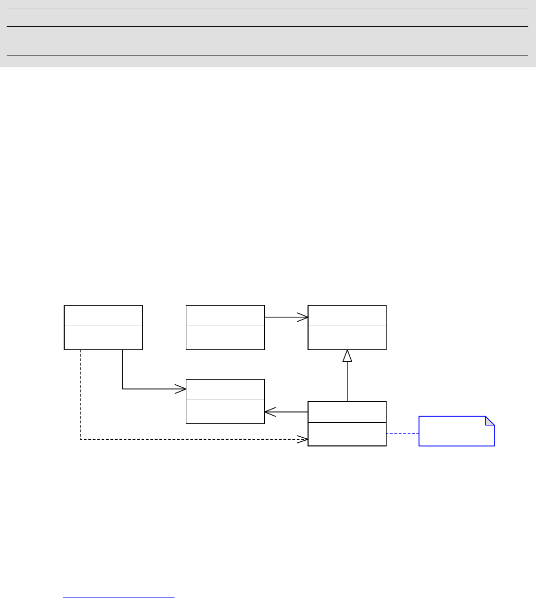
40
2Commands
This chapter describes InDesign’s command architecture. It also outlines how to find and use the
commands provided by the InDesign API, how to implement new commands of your own, and other
extension patterns associated with commands.
Concepts
This section introduces the generic command pattern, databases that provide persistence to the
application’s objects, and models that represent the application’s objects in memory.
Command pattern
The intent of the command pattern is as follows: “Encapsulate a request as an object, thereby letting you
parameterize clients with different requests, queue or log requests and support undoable operations.”
(This is described in Gamma, Helm, Johnson, and Vlissides, Design Patterns, Addison-Wesley, 1995.) The
structure of this pattern is shown in the following figure.
This pattern decouples the object that invokes an operation from the object that implements it. The client
wants an operation to be performed, the receiver knows how to perform the operation, and the two are
decoupled by this pattern. The command declares an interface for executing an operation. The client does
not send messages directly to the receiver; rather, the client creates a concrete command object and sets
its receiver. The concrete command implements execute by calling the corresponding operation on the
receiver. The invoker asks the command to carry out the request, which causes the receiver to perform the
operation.
Within the InDesign API, an implementation of the command pattern is used in situations where
preventing data corruption is paramount and users must be able to undo or redo changes. See
“Commands” on page 44.
Chapter Update Status
CS6 Edited Only the following changed:
• Removed obsolete text about CS2 from Commands section.
Client Invoker Command
+ Execute() : void
Receiver
+ Action() : void ConcreteCommand
+ Execute() : void receiver->Action();

CHAPTER 2: Commands Concepts 41
Databases and undoability
A persistent object has its state maintained outside the application runtime. It can be removed from main
memory and returned again, unchanged. The application maintains persistent objects in a database. A
database on disk is an opaque binary file in the operating system’s file system. This database file stores the
serialized state of a collection of objects. The set of objects stored in a particular database is collectively
known as a model. For example, an InDesign document file like Untitled-1.indd is a database file that
represents the state of an instance of a document model. See “Models” on page 41.”
Objects are stored in a database in the following format:
Objects that persist are stored as a tree of objects, each of which is associated with and persisted by a
database.
Each persistent object has a identifier, the UID, that identifies it uniquely within its database.
Each persistent object (except the root object) is owned and referred to by another object, the parent.
A persistent object also can be referenced by other objects, though this does not indicate any form of
ownership.
The class that represents a database is IDataBase.
For more detail, see Chapter 1, “Persistent Data and Data Conversion.”
Databases must be consistent and stable. Some databases also need to support undoability—the ability
for a user to undo or redo changes. For example, the ability to undo changes made to a document is
required; however, there is no requirement to undo changes made to the database that persists the user
interface state.
The table in “Command managers, databases, and undo support” on page 48 shows the databases that
exist and their support for undoability. If a database supports undoability, that support cannot be turned
off. All changes to objects that persist in the database must be undo-able. Turning off undo support is not
allowed, because it would disable error handling and increase the risk of document corruption.
NOTE: To change objects that persist in a database that supports undo, we recommend using commands.
If, however, you need to change data without showing something in the Edit > Undo menu, you can
bypass commands and wrap your changes in calls to CmdUtils::BeginAutoUndoSequence and
CmdUtils::EndAutoUndoSequence.
Models
A model is a collection of objects backed by a database for persistent storage. A model is a tree-structured
graph of objects. The ownership relationships between objects in a model defines this tree structure.
Ownership relationships are just parent-child relationships within the tree.
Document model
Documents are represented by the document model. The following figure shows an example of objects in a
document model (instance diagram):
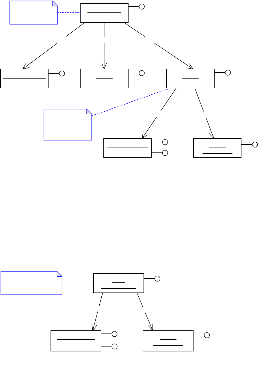
CHAPTER 2: Commands Concepts 42
The document (kDocBoss) is the root object in the document model. It owns a collection of spreads
(kSpreadBoss), stories (kTextStoryBoss), a workspace (kDocWorkspaceBoss), and so on. These objects may
own further objects specific to their domain. The document’s workspace owns objects like styles and
swatches, which can be used throughout the document.
The database file that provides persistence for a document model is an end-user document file; for
example, a file Untitled-1.indd saved from InDesign.
Defaults model
Global preference settings are represented by the defaults model. The following figure shows an example
of objects in the defaults model (instance diagram):
UID 75 :
kDocWorkspaceBoss IWorkspace
UID 91 :
kPMColorBoss IColorData
UID 125 :kStyleBoss IStyleInfo
ITextAttributes
UID 1 :kDocBoss IDocument
UID 60 :kSpreadBoss ISpread UID 41 :
kTextStoryBoss ITextModel
Document content
such as layout and
text.
Document
preference settings
such as styles and
swatches.
IStyleGroupManager
IDocument::GetDocWorkSpace
ISwatchList
ISpreadList IStoryList
UID 1 :
kWorkspaceBoss IWorkspace
UID 27 :kStyleBoss IStyleInfo
ITextAttributes
UID 42 :
kPMColorBoss IColorData
Global default preference
settings such as styles and
swatches.
ISwatchList
IStyleGroupManager
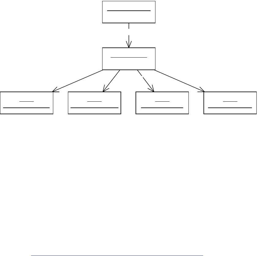
CHAPTER 2: Commands Concepts 43
The workspace (kWorkspaceBoss) is the root object in a defaults model. It owns the objects that represent
default preference settings like styles, swatches and so on. The defaults model is global and is accessed
from the session (kSessionBoss) via the ISession interface. When a new document is created, preference
settings can be copied from the defaults model into the document’s workspace (kDocWorkspaceBoss).
The database file that provides persistence for this model is an application defaults file. For example, the
file named InDesign Defaults is the database file used by InDesign to persist the defaults model.
Session model
A session of an application is represented by the session model. shows an example of objects in the
session model (instance diagram):
The session (kSessionBoss) is the root object in the session model. This model owns application-related
objects that must persist from session to session. For instance, user interface objects are found here,
together with other objects that store the application’s type system (the boss classes provided by all
registered plug-ins).
The database file that persists objects in this model is the application’s saved data file. For example, the file
named InDesign SavedData is the database file used by InDesign to persist the session model.
NOTE: Objects in the session model can be modified by calling mutator methods on their interfaces
directly. There is no need to modify them using commands. The database that persists this model does not
support undo.
Books, asset libraries, and other models
Several other features in an application have their own dedicated model, together with a database that
provides that model with persistence. Prominent examples are books, asset libraries, and the scrap. See
the table in “Command managers, databases, and undo support” on page 48 for the level of undo support
provided by their databases.
UID 2 :kAppBoss
UID 3 :
kActionManagerBoss
UID 4 :
kPanelManagerBoss
UID 5 :
kToolManagerBoss
UID 6 :
kDocumentListBoss
UID 1 :kSessionBoss
ISession
IApplication

CHAPTER 2: Commands Commands 44
Commands
This section describes how commands are used in the application. It includes sections on the CmdUtils
class, which is fundamental to the processing of commands, and how to use command sequences to
group multiple commands into one logical unit.
Within the application, the most prevalent use of commands by client code is to modify persistent objects
in the document model or defaults model. For example, plug-ins use commands to create frames in a
document or modify the default text style.
Commands encapsulate the changes made to persistent objects into a database transaction.
Encapsulating changes in this way helps prevent corruption. Furthermore, any change to the state of
persistent objects that needs to support undo must be made using a command.
Commands change persistent objects by doing the following:
Calling mutator methods on interfaces that exist on persistent objects.
Processing other commands (that call mutator methods on interfaces that exist on persistent objects).
Calling utilities that process commands (that call mutator methods on interfaces that exist on
persistent objects).
A mixture of the above.
A command is processed by the application; this means an instance of the command is passed to the
application to be executed. A command can change persistent data within only one database each time it
is processed. The processing of a command moves the database from one consistent state to another.
When a command is used to modify objects that persist in a database that supports undo, that command
can manifest on the Undo and Redo menu items, and the database automatically reverts the state of
affected objects on undo and restore the changed state on redo.
The InDesign API provides commands for plug-ins to use. See “Command processing and the CmdUtils
class” on page 45 s and “Key client APIs” on page 59.
Plug-ins also can introduce new commands using the command extension pattern. See “Command” on
page 60. This is required when a plug-in adds custom persistent data to a document, defaults, or other
objects that persist in a database that supports undo. The extension patterns named persistent interface
and persistent boss are ways in which custom persistent data can be added to a database. See “Persistent
interface” on page 63 and ““Persistent boss” on page 65.
Command parameters
Commands implement the protocol used to modify objects that persist in a database that supports undo.
A client initiates this protocol by instantiating a command and passing it off to the application for
processing. The client also is responsible for initializing the state of the command, including the setting of
parameters. In general, the command pattern supports two mechanisms for parameter passing:
The UIDList in the ICommand interface (the “item list”), which identifies a set of persistent objects; see
ICommand::SetItemList. On input, this might identify the set of page items on which the command
operates. For example, a page item move command (kMoveAbsoluteCmdBoss) would use this to
identify the set of items to be moved. On output, the item list might identify the set of object
manipulated by a command. For example, a page item create command (kNewPageItemCmdBoss)
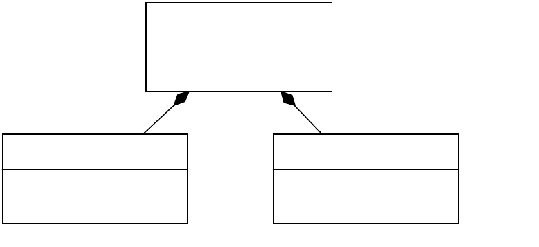
CHAPTER 2: Commands Commands 45
would provide the UIDs of the objects created as a result of the command being processed. The use of
the command’s item list is specific to each command; a command is not required to use the item list.
Data-carrying interfaces on the command’s boss class. For example, the command used to apply a
particular text style aggregates an IBoolData interface to define whether character styles should be
overridden, and an IRangeData interface to indicate the range of text that should be updated by the
command.
These two approaches for passing parameters are shown in the following figure. There is a command boss
class showing two aggregated interfaces, ICommand and a data-carrying interface (ISomeData).
Parameters can be passed through the item list in ICommand, the data-carrying interface, or both.
Command undoability
Each command has a property called undoability (see ICommand::Undoability), which determines
whether the command name can appear in Undo and Redo menu items (that is, whether the changes
made by the command can be undone or redone in a distinct step).
An undoability of kRegularUndo is used by commands whose changes need to appear as a separate
named step in Undo and Redo menu items. This is the default behavior.
An undoability of kAutoUndo is used by commands whose changes do not appear as a separate
named step; for example, commands whose changes should be undone or redone with an existing
step.
Changes made to objects that persist in a database that supports undo must be undoable. To achieve this,
the various extension patterns involved, such as commands and persistent interfaces, must be
implemented following the rules described in this chapter. The database then automatically reverts the
state of affected objects on undo and restores the changed state on redo. The undoability of a command
(kRegularUndo / kAutoUndo) has no effect on this behavior. It affects only whether the command appears as
a distinct step in Undo and Redo menu items.
Command processing and the CmdUtils class
Client code uses commands when changing objects that persist state in any database that supports undo.
For example, commands are used to change objects in the document model or the defaults model. The
«boss»
kSomeCommandBoss
«interface»
ICommand
+ GetItemList() : const UIDList*
+ SetItemList(const UIDList&) : void
«interface»
ISomeData
+ GetData()
+ SetData()

CHAPTER 2: Commands Commands 46
level of support for undo of each database is given in the table in “Command managers, databases, and
undo support” on page 48.
To change the objects, client code creates instances of one or more commands and submits these
instances to the application for execution. For example, to create frames in a document, a plug-in either
creates commands to be processed and passes them to the application or calls a helper class that
encapsulates both the creation and request for processing. The helper classes provided by the InDesign
API are introduced in “Command facades and utilities” on page 59.
Client code that must create commands uses the CmdUtils class. CmdUtils::CreateCommand creates an
instance of a specific command. The client code parameterizes the command, using the command’s item
list and data interfaces. The client code submits the command to the application for execution, by calling
CmdUtils::ProcessCommand. Client code can group the commands it processes into command sequences,
using methods and classes provided by CmdUtils. Guidance on processing commands and command
sequences is in “Command-processing APIs” on page 60 and the “Commands” chapter of Adobe InDesign
SDK Solutions.
The sequence of calls involved in processing a command is shown in the following figure. The client code
creates the command, populates the item list and other data interfaces, then passes the command off for
processing.

CHAPTER 2: Commands Commands 47
Command sequences
A command sequence (see ICommandSequence) groups a set of commands into a single undoable step
that changes the model from one consistent state into another. The command sequence manifests on the
Undo and Redo menu items as a single item.
Command sequences can be nested. For example, say you begin a sequence in one method, then call a
second method that begins a second sequence. The second sequence is said to be nested within the first.
When sequences are nested, only one sequence—the outermost one—appears on Undo and Redo menu
items.
Command sequences assimilate all commands are processed within their scope, whether the command is
processed directly from within the sequence or indirectly through subcommands (commands processed
by a command). See the “Commands” chapter of Adobe InDesign SDK Solutions for how to write code that
uses command sequences.
Client code CmdUtils A Command A Persistent
Interface
Some client code creates an
instance of a command using
CmdUtils::CreateCommand
The client sets the command
parameters, both through the
item list (shown here) or
through data carrying
interfaces.
The processing of the
command is initiated through
the client calling
CmdUtils::ProcessCommand.
Client code
creates
command, sets
parameters and
passes it for
processing. The
client should
also test error
state on return,
before
processing
further
commands.
CmdUtils should
be used for all
client
interactions with
the commands
sub-system. The
rest of the
internals are not
shown in this
diagram.
The update to some
interface on a (UID
based) boss object.
The call to PreDirty
allows the
application to track
the changes made
so that the
application can
undo or redo the
changes
automatically.
CreateCommand
construct
SetItemList
ProcessCommand
Do Set
PreDirty
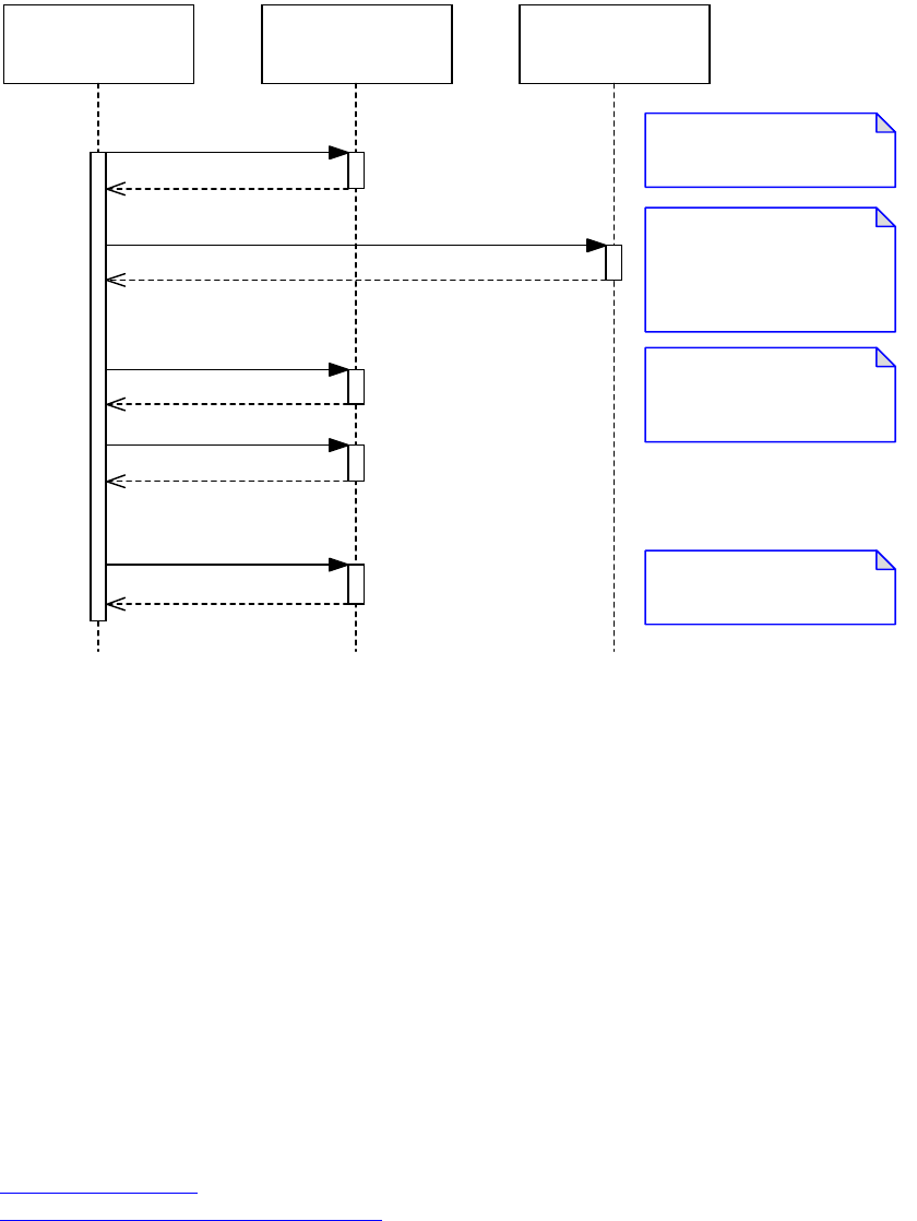
CHAPTER 2: Commands Command managers, databases, and undo support 48
A typical scenario for a command sequence is shown in the following figure. Between the
BeginCommandSequence and EndCommandSequence calls, all commands processed act as a single set
of changes; only one element will appear on Undo and Redo menu items.
A command sequence can change persistent objects in more that one database. (A command, on the
other hand, can change objects only in one database each time it is processed.) Operations that change
objects in two or more documents can be implemented using a command sequence. Such a set of
modifications manifests in Undo and Redo menu items for all affected documents.
A command sequence has limited support for error handling: the sequence either succeeds entirely or
fails. An abortable command sequence (see IAbortableCmdSeq) allows more sophisticated error handling,
to allow for fail/retry semantics. Abortable command sequences incur a significant performance overhead
and should be used only where absolutely necessary. Guidance on using these types of sequence is in the
“Commands” chapter of Adobe InDesign SDK Solutions.
Command managers, databases, and undo support
This section describes how command managers relate to the application’s databases.
The application object model realizes a tree-structured graph of boss objects. Within this tree are several
distinct models, notably the session model, the defaults model, and one or more document models (see
“Models” on page 41). Each model has a distinct database that provides persistence for its objects (see
“Databases and undoability” on page 41). Each database has an associated boss, called a command
manager. When commands are used to change objects in a model, the command manager is responsible
for executing the commands.
Client code CmdUtilsICommandSequence
The client creates a new
command sequence.
The client gives the sequence
a name, otherwise the
sequence uses the name of
the first command processed.
Multiple commands are
processed within the scope of
a sequence.
The client indicates the
sequence is complete.
BeginCommandSequence
ICommandSequence*=
SetName
ProcessCommand
ProcessCommand
EndCommandSequence

CHAPTER 2: Commands Command managers, databases, and undo support 49
The following figure shows that the application object model has several distinct databases that provide
persistence for its objects. The diagram shows some of the objects in an InDesign session (with two open
documents) and the databases with which these objects are associated. Each UID-based object refers to its
associated database through its IPMPersist interface. The defaults model, represented by an instance of
kWorkspaceBoss, persists in the InDesign Defaults database file. Each document model, represented by an
instance of kDocBoss, persists in an InDesign document database file. The session model, represented by
the instance of kSessionBoss and the child objects that do not belong to any other model, persists in the
InDesign SavedData database file.
Each database has an associated command manager (see objects in the following figure that have an
ICommandMgr interface). The command manager is responsible for managing database transactions and
executing the commands that change the objects that persist in the database. If an object has an
ICommandMgr interface, it is the root object of its associated database. This is shown in the figure. Key
objects that are command managers are listed in the table in “Command managers, databases, and undo
support” on page 48; for the complete list, refer to ICommandMgr in the API Reference.
NOTE: The class that represents a database is IDataBase. This class is an abstract C++ class, but it is not an
IPMUnknown interface.
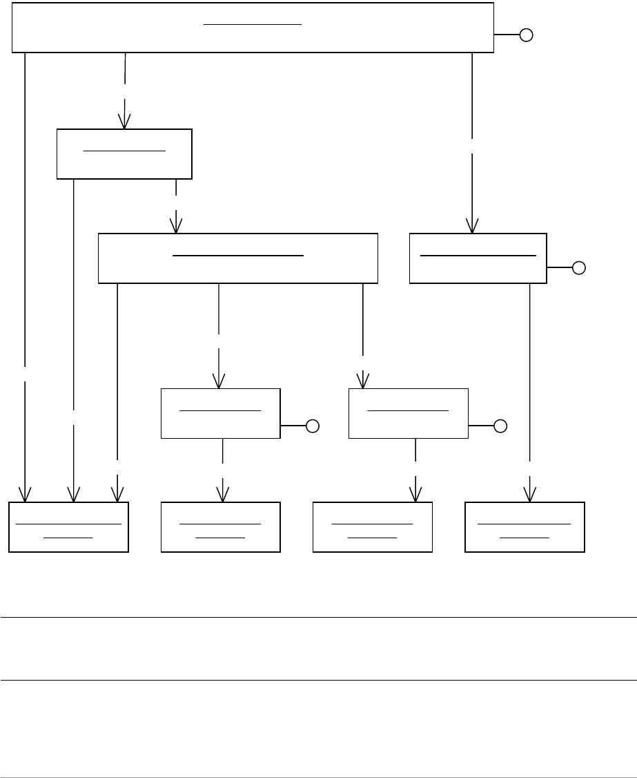
CHAPTER 2: Commands Command managers, databases, and undo support 50
The following figure shows models and databases in an indesign session (object diagram):
The following table shows frequently used databases and their support for undoability:
Command
manager / root
boss class Database
Undo
support Example filename and use
kSessionBoss Application SavedData None InDesign SavedData User interface objects
like tools, menus, panels, dialogs, controls,
and string translations. Objects that define
the application object model, like plug-ins
and boss classes.
kWorkspaceBoss Application Defaults Full InDesign Defaults Default resources like
swatches, fonts, and styles inherited by new
documents.
UID 1 :kSessionBoss
ICommandMgr
UID 2 :kAppBoss
UID 3 :kDocumentListBoss UID 1 :kWorkspaceBoss
ICommandMgr
UID 1 :kDocBoss
ICommandMgr
UID 1 :kDocBoss
ICommandMgr
InDesign SavedData :
IDataBase
Untitled-1.indd :
IDataBase
Untitled-2.indd :
IDataBase
InDesign Defaults :
IDataBase
IPMPersist
IPMPersist
IPMPersist IPMPersist IPMPersist IPMPersist
IDocumentList::GetNthDoc(1)
IDocumentList::GetNthDoc(0)
ISession::QueryWorkspace
IApplication::QueryDocumentList
ISession::QueryApplication

CHAPTER 2: Commands The command processor 51
Each database has a level of support for undo which is fixed when the database is created and can be one of
the following:
Full — The database fully supports undoable operations. The changes made by a transaction can be
reversed automatically on undo and restored on redo. Undo and rRdo menu items are fully supported.
Partial — The database can undo only the most recent operation. If an error occurs, the database is
rolled back to its state before the transaction began; however, once a transaction is committed, it is
irreversible. There is no support for Undo and Redo menu items.
None — The database does not support undoable operations. There is no support for error handling,
abortable command sequences, or Undo and Redo menu items.
NOTE: Undo support varies by product. In InDesign and InCopy, full undo support is provided for
documents and defaults. In InDesign Server, only partial undo support is provided for these databases; the
server has no concept of user undo and redo.
Objects that persist in a database with full or partial support for undo must be modified using commands.
For example, a plug-in must process commands to change document content such as spreads, pages, or
page items.
Objects that persist in a database without support for undo can be modified by calling mutator methods
on persistent interfaces directly. Commands are not required. For example, a plug-in can call interfaces on
user interface objects, such as widgets, that set state directly.
The command processor
This section describes how a command is passed through the application until it is processed.
The session (see the ISession interface) has a singleton instance of the command processor (see
kCommandProcessorBoss and the ICommandProcessor interface). The command processor is the core
application component to which all commands are submitted via CmdUtils.
The command processor’s structure is shown in the following figure. A command targets one or more
objects for change, and these objects persist in a particular database. Normally, client code creates a
command instance and sets this target by passing parameters to the command (see “Command
parameters” on page 44). The client code submits the command instance for processing using CmdUtils.
The following figure shows the internal collaboration between the objects involved.
kDocBoss InDesign Document Full Your.indd Document content like spreads,
pages, page items, and text.
kBookBoss InDesign Book Partial Your.indb A collection of InDesign
documents and associated resources.
kCatalogBoss InDesign Asset Library Partial Your.indl A collection of page items.
Clipboard/scrap Application
ClipboardScrap
Partial
Command
manager / root
boss class Database
Undo
support Example filename and use
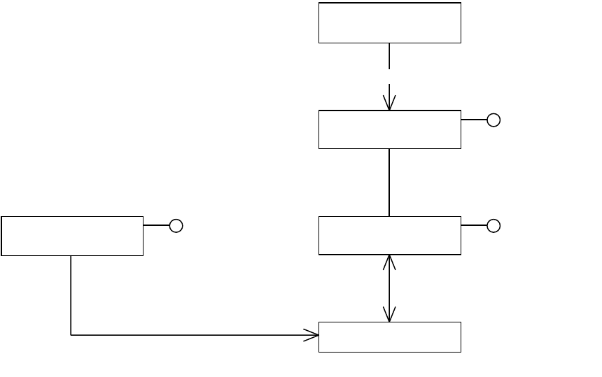
CHAPTER 2: Commands The command processor 52
The command processor examines the command and determines which database contains the objects
the command changes. Each database has an associated command manager boss (see ICommandMgr
interface), shown in the preceding figure as the boss class named kSomeModelRootBoss. For example, the
root of the document model is kDocBoss, and kDocBoss is a command manager. The command processor
calls the associated command manager to execute the command.
The following figure shows the internal processing of a command. The call to process a command is
passed to the session-wide command processor. This determines which database is targeted by the
command, and the command is passed to the command manager for the specified database. The
command manager processes the command, and the command updates an interface on a persistent (UID
based) boss object. On completion, control returns to the client that initiated the process.
«boss»
kSessionBoss
«boss»
kCommandProcessorBoss ICommandProcessor
«boss»
kSomeCommandBoss ICommand «boss»
kSomeModelRootBoss ICommandMgr
IDataBase
IDataBase::GetRootUID 1
IPMPersist::GetDataBase 1
changes objects that persist in
1
1..*
1
ISession::QueryCommandProcessor
1
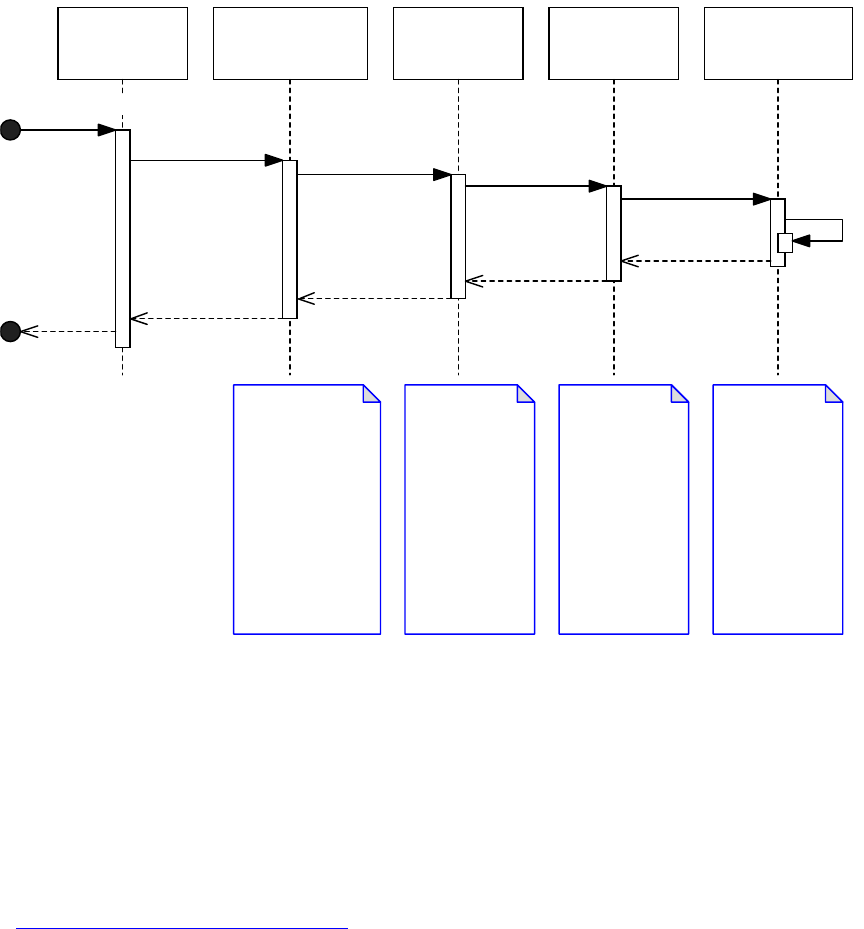
CHAPTER 2: Commands Scheduled commands 53
NOTE: Third party plug-ins should not interact directly with the command processor or command manager
interfaces. CmdUtils provides all methods needed by third parties for processing commands.
Scheduled commands
Commands can be scheduled for later processing, using CmdUtils::ScheduleCommand. The command is
placed in a queue and processed when the application is idle as part of the main event loop, before idle
tasks are processed. The sequence of calls involved in processing a scheduled command is shown in the
following figure. Compare this with the more normal case of immediately processing a command, shown
in “The command processor” on page 51. In the following figure, the scheduled command is passed to the
command processor (through the CmdUtils::ScheduleCommand call). At some later time, after all other
processing is complete and control is returned to the main application event loop, all scheduled
commands are processed.
Guidance on using scheduled commands is in the “Commands” chapter of Adobe InDesign SDK Solutions.
A CommandCmdUtils A Command
Manager
CommandProcessor A Persistent
Interface
The command is
passed to the
session wide
command
processor which
determines the
target database
and calls
ICmdManager::Do
for that database.
The command
manager
invokes the
command.
The command
updates the
persistent
interface.
Generally the
command will
derive from the
Command class,
providing an
implementation
of Do().
The persistent
interface calls
PreDirty before
making any
update to the
data.
ProcessCommand
ProcessCommand
Do DoImmediate Set
PreDirty

CHAPTER 2: Commands Snapshots and interface implementation types 54
Snapshots and interface implementation types
A snapshot is a copy of the state of an interface at a particular time. Undo and redo are achieved
automatically by the application, which keeps snapshots of the interfaces changed within an undoable
transaction. The snapshots are kept in the command history (see “Command history” on page 55) of the
database with which the interface is associated.
The way in which an IPMUnknown interface is implemented determines whether its data is persistent
and/or needs a snapshot to support undo or redo:
Regular interfaces store transient data that is not maintained on undo or redo. They are declared to
the object model using CREATE_PMINTERFACE, and their state is lost if they are removed from
memory. Data in a regular interface is not persistent, and no snapshot is taken.
Persistent interfaces are declared to the object model using the CREATE_PERSIST_PMINTERFACE
macro. They serialize their state to their associated database via the ReadWrite method and can be
removed from memory and returned again unchanged. Persistent interfaces that are part of a
database that supports undo also are called to serialize their state (again via their ReadWrite method)
to a snapshot. This mechanism is required to support undo and redo. See “Persistent interface” on
page 63.
Snapshot interfaces store transient data that must be maintained on undo and redo. They are declared
to the object model using the CREATE_SNAPSHOT_PMINTERFACE macro, and they serialize their state
in a snapshot via the SnapshotReadWrite method. Snapshot interfaces are aggregated on a boss that
A CommandA CmdManagerCommandProcessorCmdUtils A Persistent
Interface
Some client code schedules the
command. The command is
processed as part of the main
event loop after all other
processing has completed, and
before idle tasks are processed.
Processing of a scheduled command is identical to that of a non-scheduled
command. The only difference is with a non-scheduled command, client code is
responsible for the initiation, upon completion, control returns to the client. With
a scheduled command the event loop initiates processing, upon completion
control returns to the main event loop. If a scheduled command returns an error,
it is reported to the user, the error condition is cleared and processing resumes.
ScheduleCommand
ProcessScheduledCmds
ProcessCommand
Do
DoImmediate
Set
PreDirty

CHAPTER 2: Commands Command history 55
persists in a database that supports undo; however, their data is not persistent. Data maintained by a
snapshot interface is lost whenever the associated database is closed or when the command history
for the database is cleared. See “Snapshot interface” on page 66.
Snapshot view interfaces are similar to snapshot interfaces, which also store transient data that must
be maintained on undo and redo. The distinction is that a snapshot view interface depends on model
objects that persist in another database. A snapshot view interface is part of a user interface object
and must explicitly identify the database containing the model of interest. Also, the database on
which a snapshot view interface depends can change. For example, a widget that tracks some state in
the front document must change the database on which its snapshot view interface depends when
the front document changes. Snapshot view interfaces are declared to the object model using the
CREATE_VIEW_PMINTERFACE macro. See “Snapshot view interface” on page 71.
It also is possible to create a hybrid interface to allow the data that persists in the database to differ
from the data of which a snapshot is taken for undo and redo. This can be used by complex data
structures, like collections that need to optimize performance. Such an interface is declared to the
object model using the CREATE_PERSIST_SNAPSHOT_PMINTERFACE macro. Data is serialized to the
database via the ReadWrite method and to the snapshot via the SnapshotReadWrite method. For
example, consider this approach if you have a collection of some sort and want to serialize only those
objects that changed relative to the snapshot (rather than the entire collection).
Command history
Consider a database to be the state of the persistent object model. For example, a document database is
the state of the document object model (kDocBoss and all its dependents) at a particular time. Persistent
interfaces (on dependent objects) are called to serialize their state to the database when necessary, via
their ReadWrite method.
The command history (ICmdHistory) provides a history of the undoable operations that were performed
on each database. It records the state changes made by a particular command or command sequence, for
the purposes of undo and redo. The name of the first command or command sequence processed to
perform an operation on the model appears as a named step in the command history. These steps
manifest as Undo and Redo menu items. The command history is used to automatically revert the state of
affected objects on undo and to restore the changed state on redo.
The database and its command history are related but distinct states.
To maintain the command history, the database monitors which of its objects change when commands
are processed. It tracks the UIDs that are deleted, created, or undeleted. It tracks persistent interfaces,
snapshot interfaces and snapshot view interfaces that are modified, and it takes snapshots of them. This
information is kept in the command history as a set of CmdStackItem objects. (CmdStackItem is opaque
on the SDK; third parties cannot access its data.) When undo is invoked, the application automatically
reverts the database state to its previous revision, using this information. When redo is invoked, the
application automatically restores the database state to its next revision.
See the following figure. The command processor (kCommandProcessorBoss) aggregates the command
history (interface ICmdHistory), which is responsible for maintaining the state changes made by a
particular command or command sequence (which manifests on the Undo and Redo menu). This state,
represented as CmdStackItems, is used to move the model to previous and next states on undo and redo.
The CmdStackItem encapsulates all data required for an undo and redo that occurred while processing a
command or command sequence.
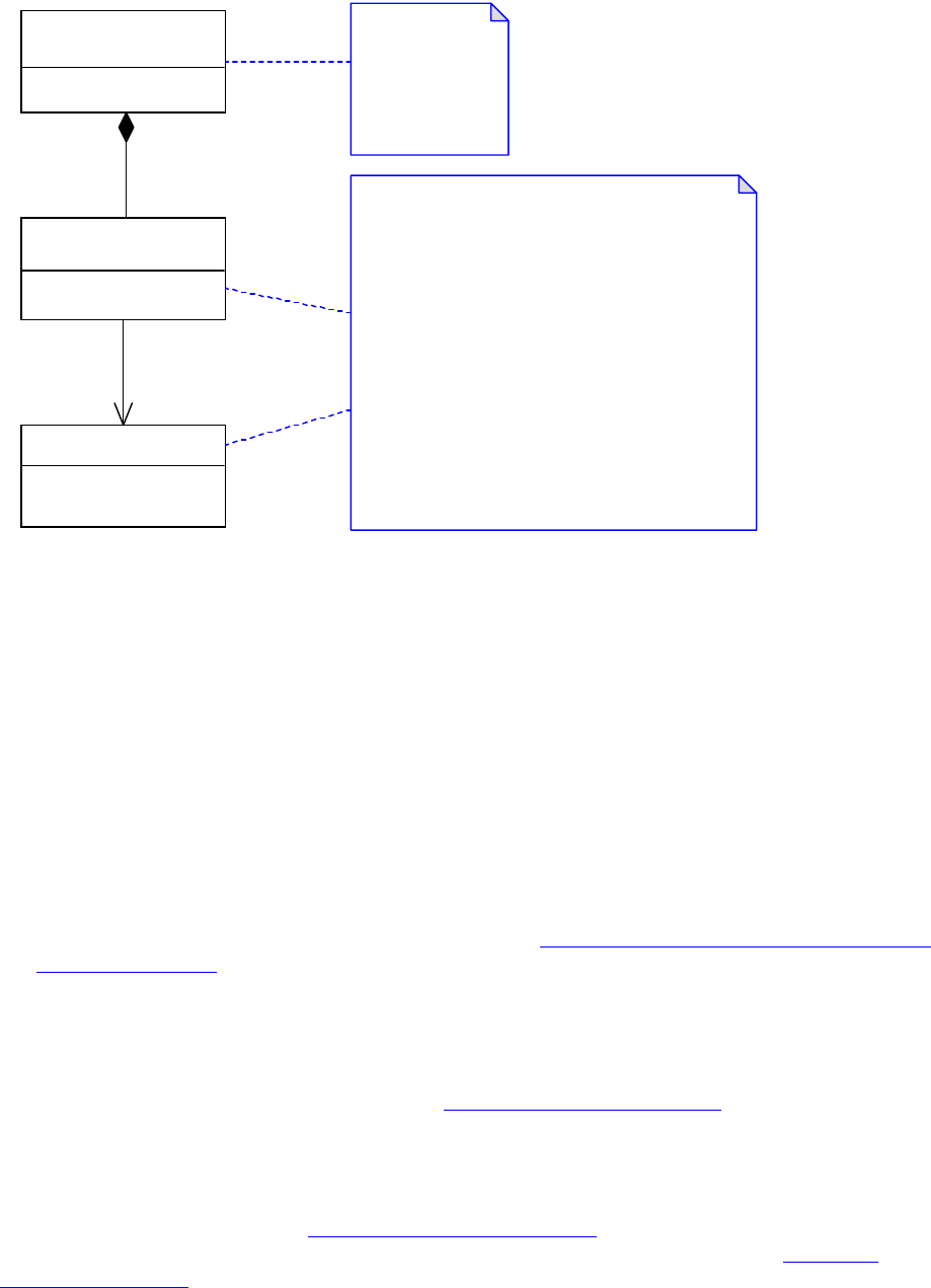
CHAPTER 2: Commands Undo and redo 56
Merging changes with an existing step in the command history
Sometimes it is desirable to extend the scope of an existing step shown in the Undo and Redo menus to
include functionality that occurs after the step finished. This can be done using either of the following:
A command with undoability of kAutoUndo.
A command sequence with undoability of kAutoUndo.
Undo and redo
To enable a user to undo or redo a change, the objects changed must:
Persist in a database that supports undo (see the table in “Command managers, databases, and undo
support” on page 48).
Be modified by processing commands.
The application maintains the state required for undo/redo of changes made to persistent objects, as
commands are processed. Each database that supports undo has a command history in which the
necessary information is recorded, as described in “Command history” on page 55. Each persistent
interface on a UID-based boss object has its ReadWrite method called to add the state to the command
history (for undo and redo) and to the database (to persist its state). On undo, the ReadWrite method is
called to reset the state back to that from before the action, and on Redo, the ReadWrite method is called
again to set the state back to that from the initial action. The sequence of calls to a persistent interface is
shown in the architecture figure in “Persistent interface” on page 63. Snapshot interfaces are called on
their SnapshotReadWrite method using a similar approach; see the architecture figure in “Snapshot
interface” on page 66.
«boss»
kCommandProcessorBoss
«interface»
ICmdHistory
CmdStackItem
The command
processor
aggregates a
command history
interface.
The command history maintains a set of
CmdStackItems (opaque in the SDK). These items
represent the set of UIDs added, deleted and modified.
For the modified persistent interfaces, the changes are
captured through a call to ReadWrite.
Any UID based object that has an associated snapshot
interface that has been modified, will have its state
captured through a call to its SnapshotReadWrite.
On undo/redo, the state that is maintained in the
CmdStackItem (opaque in the SDK), which is used to
reset the UID based objects (through calls to
ReadWrite and SnapshotReadWrite).
0..*
1
1
1
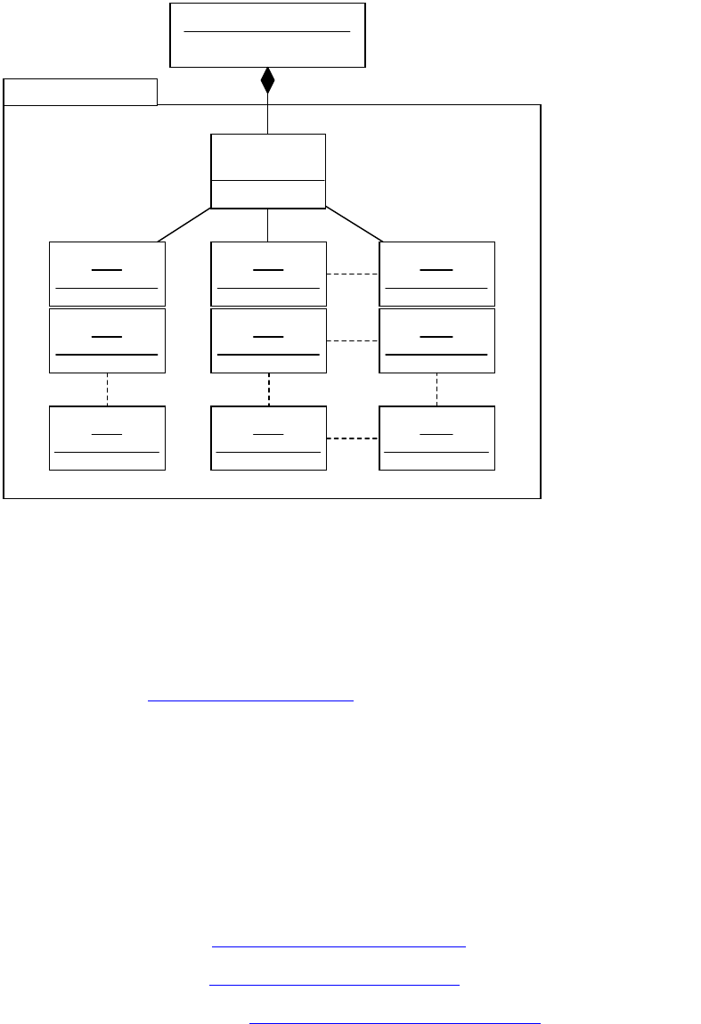
CHAPTER 2: Commands Undo and redo 57
The command processor records in the command history the set of undoable operations it has performed
(see the ICmdHistory interface on kCommandProcessorBoss). The steps in the command history appear in
Undo and Redo menu items and are modelled internally using CmdStackItems. (These are internal only.
Discussion is provided here to give some notion of how the command processor works.) This is shown in
the following figure.
The command history maintains a stack of CmdStackItem objects for each database that supports undo;
see the preceding figure. A CmdStackItem (opaque in the SDK) represents the set of changes made by the
sequence or command that manifests on the Undo and Redo menus. It contains data gathered during a
database transaction for the purposes of undo and redo. On undo/redo, the “current” CmdStackItem is
used to revert the state of the model. The CmdStackItem encapsulates all data required for an undo/redo
that occurred while processing a command or command sequence. This includes all changes to persistent
interface and snapshot interface data that were predirtied. The CmdStackItem also maintains any inval
handler cookies (see “Inval handler” on page 68) created as part of the sequence.
Each step has a name of either a command or a command sequence that performed the operation. On
undo, the application automatically reverts the database to its state before the operation was performed.
On redo, the application automatically restores the database to its state after the operation was
performed.
Extension patterns involved in undo and redo
The following extension patterns are called at undo or redo:
Persistent interfaces; see “Persistent interface” on page 63.
Snapshot interfaces; see “Snapshot interface” on page 66.
Snapshot view interfaces; see “Snapshot view interface” on page 71.
CmdHistory Internals
«interface»
ICmdHistory
DB1:
CmdStackItem1
DB1:
CmdStackItem2
DB1:
CmdStackItemN
DB2:
CmdStackItem1
DB2:
CmdStackItem2
DB2:
CmdStackItemN
DBN:
CmdStackItem1
DBN:
CmdStackItem2
DBN:
CmdStackItemN
kCommandProcessorBoss
1
1

CHAPTER 2: Commands Notification within commands 58
Inval cookies; see “Inval handler” on page 68.
Observers, via their LazyUpdate method; see Chapter 3, “Notification.”
Notification within commands
A command can initiate notification, so observers interested in changes to the objects it modifies are
notified. See Chapter 3, “Notification.”
Commands also can be processed within observers and responders. Take care with commands that modify
the model in this way. See Chapter 3, “Notification,” for further discussion of model changes within the
context of notification.
If you are implementing your own command, see “Command” on page 60 for additional information on
notification in the command extension pattern.
Error handling
In response to a user gesture or another event, the application calls a plug-in to carry out an action. For
example, the user creates a text frame. In this case, the plug-in creates and processes the commands that
perform the action. On detecting an error, a plug-in normally sets the global error code (see ErrorUtils) to
something other than kSuccess and returns. When control returns to the application, the global error code
is checked. If it is set, the database is reverted to the state it had before the modifications began. Extension
patterns that participated in the transaction being rolled back are called as follows:
1. Persistent interfaces, snapshot interfaces, and snapshot view interfaces modified by the transaction
are called to revert their state. See “Persistent interface” on page 63, Snapshot interface, and
“Snapshot view interface” on page 71.
2. Inval cookies created during the transaction are called to undo. See “Inval handler” on page 68).
When the application returns to its main event loop, it informs the user through an alert, using the string
associated with the error code that is set (see “Error string service” on page 62). The global error code is
then cleared, and the application continues.
Plug-in code that processes commands or command sequences must check for errors.
CmdUtils::ProcessCommand returns an error code that should be checked for kSuccess before continuing.
Alternatively, you can check the global error code using ErrorUtils. Details are in the “Commands” chapter
of Adobe InDesign SDK Solutions. If a plug-in tries to process a command while the global error code is set,
protective shutdown occurs to protect the integrity of the document or defaults databases (see
“Protective shutdown” on page 59).
Command implementation code also must check for errors. If a command encounters an error condition
within the scope of its Command::Do method, it should set the global error code using ErrorUtils and
return. Details on error handling is in the command extension pattern; see “Command” on page 60.
Plug-in code that requires more sophisticated error handling, to allow for fail/retry semantics, must use an
abortable command sequence. For information on using abortable command sequences, see the
“Commands” chapter of Adobe InDesign SDK Solutions.

CHAPTER 2: Commands Key client APIs 59
Protective shutdown
Protective shutdown is a mechanism that helps prevent document corruption. Any attempt to process a
command when the global error code is set (to something other than kSuccess) causes a protective
shutdown. The application creates a log file describing the problem it encountered and then exits.
Key client APIs
This section summarizes the APIs a plug-in can use to interact with commands.
Command facades and utilities
There are many command-related boss classes named k<whatever>CmdBoss, but in many cases you do
not need to instantiate these commands, as there are command facades and utilities in the API that
encapsulate parameterizing and processing these commands.
Interfaces like those in the following table are examples of command facades and utilities. These
encapsulate processing of many commands required by plug-in code. These interfaces are aggregated on
kUtilsBoss; the smart pointer class Utils makes it straightforward to acquire and call methods on these
interfaces. You can call their methods by writing code that follows this pattern:
Utils<IDocumentCommands>()->MethodName(...)
These utility classes abstract over low-level commands. Before using commands, always look for such a
utility to see if there is a method that serves your purpose on one of these interfaces. By doing so, you
avoid the increased chance of confusion and error that comes with processing commands. Your use case
may require you to process some commands, if the utilities do not provide all of the functionality you
require.
As used in the application, command “facade” and “utility” are just different names for the same thing, a
class that reduces and simplifies the amount of client code you need to write to change objects in the
model. They decouple client code from command creation, initialization, and processing.
When implementing custom commands, it is advisable to provide your own command facade or utility. If
you want to share your class with other plug-ins, implement it as an add-in interface on kUtilsBoss; for
API Used for manipulating...
IDocumentCommands Documents.
IPathUtils Frames and splines. See “Chapter 7, “Layout Fundamentals,” for other APIs that
help with layout.
IGraphicAttributeUtils Graphic attributes. See Chapter 8, “Graphics Fundamentals,” for other APIs that
help with graphics.
ITextModelCmds Text. See Chapter 9, “Text Fundamentals,” for other APIs that help with text.
ITableCommands Tables. See Chapter 1, “Tables,” for other APIs that help with tables.
IXMLUtils XML. See Chapter 8, “XML Fundamentals,” for other APIs that help with XML.
kUtilsBoss Refer to kUtilsBoss in the API Reference for a complete list of command facades
and utilities.

CHAPTER 2: Commands Extension patterns 60
example, see XDocBkFacade. If the class is used only by one plug-in, a C++ class is sufficient; for example,
see BPIHelper.
Command-processing APIs
The classes used when writing client code to process commands are listed in the following table.
NOTE: You must use CmdUtils to process commands. Do not use the ICommandProcessor or
ICommandMgr interfaces for this. Misuse of these interfaces can easily cause document corruption.
For information on finding and processing the commands provided by the API, see the “Commands”
chapter of Adobe InDesign SDK Solutions.
Extension patterns
This section summarizes the mechanisms a plug-in can use to extend the command subsystem.
Command
Description
Suppose:
You added a new persistent boss to a document or a persistent interface to an object in a document,
and you need to set custom data in these objects.
The API does not provide a command that sets the model data you need to change.
You want do some processing, and you concluded that a command provides the best pattern in which
to encapsulate it.
Architecture
To implement a command:
1. Define a new boss class in your plug-in that aggregates IID_ICOMMAND. If you require input
parameters over and above the command’s item list, aggregate further data interfaces to the boss
through which the parameters can be passed.
2. Provide an implementation of ICommand using Command as a base class.
API Description
CmdUtils Provides methods that create, process, or schedule commands and manage command
sequences.
PersistUtils Provides methods like GetDataBase, GetUID, and GetUIDRef, which are used to identify the
objects to be operated on by a command.
ErrorUtils Provides access to the global error code.

CHAPTER 2: Commands Extension patterns 61
3. Add client code that processes your new command. See the “Commands” chapter of Adobe InDesign
SDK Solutions.
4. For more guidance, refer to the Command page in the API Reference and see the following “Best
practices”.
Best practices
The Do method contains the code that modifies the model. The model is changed by calling mutator
methods on model interfaces, processing commands, processing commands in a command sequence,
or calling utilities that process commands for you.
If you encounter an error condition within your Do method, set the global error code
(ErrorUtils::PMSetGlobalErrorCode) and return. The application is responsible for reverting the model
back to its state before the Do method was called and informing the user of the error.
If you need more sophisticated flow control that allows for fail/retry semantics, use an abortable
command sequence (see IAbortableCmdSeq).
The Do method can change objects in only one database each time it is called. To change objects in more
than one database in one undoable step, use a command sequence (ICommandSequence).
Normally, the database containing the objects to be changed is passed using the command’s item list.
Alternatively, a command can target a predetermined database, by calling Command::SetTarget in its
constructor. It also can override Command::SetUpTarget and determine the database containing the
objects to be changed when the command is processed.
Normally, the DoNotify method contains the code that initiates notification, should you require it.
Initiate notification by calling ISubject::ModelChange (not ISubject::Change). Calling
ISubject::ModelChange when model objects are changed broadcasts regular and lazy notification (see
Chapter 3, “Notification”). The application calls DoNotify after the Do method of the command is
called; however, notification need not be restricted to this method.
Notification can be performed for each object that was modified using the ISubject interface of
affected objects. Notification also can be performed centrally. For example, many commands that
modify the document model notify change using the ISubject interface of the document (kDocBoss).
Sometimes commands use both these approaches. The benefit of using a centralized approach is that
an observer needs to attach to only one subject to receive the notification.
If you need to notify observers before the model is changed, call your DoNotify method from your Do
method before making any changes to the model.
Notification can result in the processing of further commands, which can result in global error code
being set. If further commands are processed, application shutdown occurs. If multiple subjects are
notified by a command, the global error code should be tested between notifications. If the error code
is set, the DoNotify method should return without calling further subjects, or it should consume the
error and reset the global error code.
The undoability of a command should be fixed at command construction (see
ICommand::GetUndoability). Its default value is kRegularUndo. If a different undoability is required, it
should be set in the command’s constructor. Refer to ICommand::Undoability in the API Reference.
A command must have a name (see Command::CreateName), if it has an undoability of kRegularUndo
and it returns kTrue for IsNameRequired. Such commands can appear in Undo and Redo menu items.
The name must have a translation, so it can be displayed in Undo and Redo menu items in a localized

CHAPTER 2: Commands Extension patterns 62
form. Commands with an undoability of kRegularUndo that override IsNameRequired to return kFalse
must pick up their name from a subcommand. Some commands create and process other commands
(subcommands) to make their changes and want to pick up the name of the first subcommand called
within their scope instead of providing their own name.
Commands with undoability of kAutoUndo do not need a name, because their changes merge with an
existing step in the Undo and Redo menu items.
The destructor of a command normally is empty. Do not change the model within the destructor.
See also
For documentation on commands: Command and ICommand in the API Reference.
For documentation on notification: ISubject and IObserver in the API Reference.
If you need error codes set by your command to map onto strings that describe the error condition:
“Error string service” on page 62.
For sample code: kBPISetDataCmdBoss, BPISetDataCmd, and BPIHelper from the BasicPersistInterface
plug-in.
Error string service
Description
Suppose error conditions can occur in your plug-in, and you need to inform the user of these errors.
Architecture
Sometimes, error conditions can occur in your plug-in, often within commands or command sequences.
When control is returned to the application by your plug-in, and the global error code is set to something
other than kSuccess, the user is informed and the model is reverted back to the last consistent state. An
error string service provides the ability to map error codes onto error strings. To handle this:
1. Provide an error string service. This service allows ODFRez resources in your plug-in to map error
codes onto strings that describe the error. Detailed documentation on how to define the error codes,
resources, and implementations involved is the API Reference for IErrorStringService.
2. On detecting the error condition, call ErrorUtils::PMSetGlobalErrorCode to set your error and return
control to the application. The application informs the user of the error.
See also
For sample code: BPIErrorStringService from the BasicPersistInterface plug-in.

CHAPTER 2: Commands Extension patterns 63
Persistent interface
Description
Suppose you need to add custom data to an existing object in the model and have that persist. For
example, you want frames in a document to have a set of custom properties that you control.
Architecture
The state of a persistent interface that is associated with a database that supports undo is captured by the
application before it is changed; its state is reverted on undo and restored on redo. The state is saved in the
command history (see “Command history” on page 55) for undo and redo, and in the database for
persistence. The following figure shows the typical sequence of calls made to modify persistent interface,
and when that modification subsequently is undone or redone.
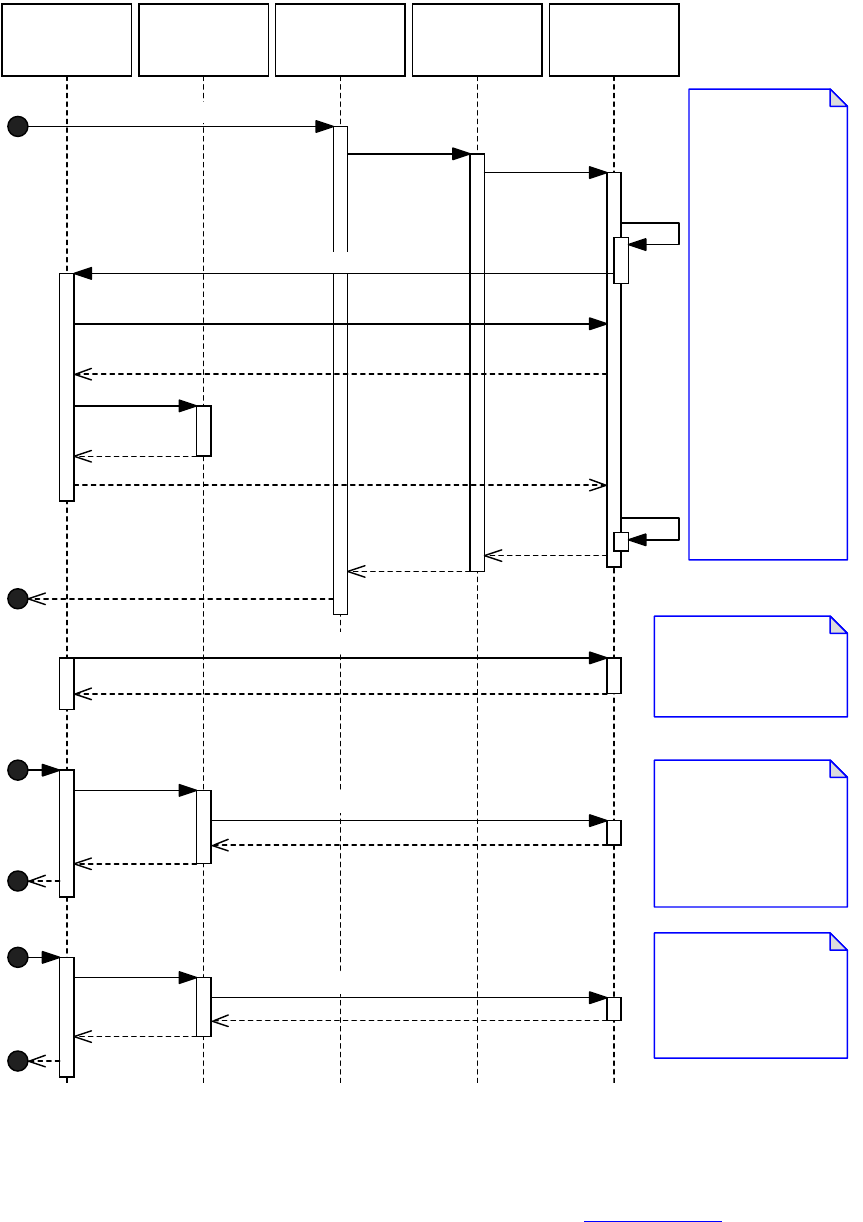
CHAPTER 2: Commands Extension patterns 64
To implement a persistent interface:
1. Aggregate your interface on the boss class in the model to which you want to add custom data that
persists. Use an add-in interface (an ODFRez AddIn statement) if you are adding the interface to an
existing boss class. To define a new type of persistent boss, see “Persistent boss.
2. Provide an abstract interface that uses IPMUnknown as a base class.
3. Provide an implementation of this abstract interface.
Application core ICmdHistory CmdUtils A Command A Persistent
Interface
Some entity
processes a
command which
results in a
persistent interface
being modified. The
persistent interface
calls PreDirty before
mutating the data,
which allows the
application core to
snapshot the state of
the interface for the
command history
before it is changed
(to allow the
modification to be
undone), and to
require it to be
streamed to the
database afterwards.
The application calls on
the persistent interface to
stream its data to the
database.
On undo, the command
history reverts the
persistent interface to the
state it had before the
modification was made.
On redo, the command
history restores the
persistent interface to the
state it had after the
modification was made.
ProcessCommand
DoImmediate
Set
PreDirty
PreDirty
ReadWrite
Push
Modify
ReadWrite
Undo
ReadWrite
Redo
ReadWrite

CHAPTER 2: Commands Extension patterns 65
4. Use CREATE_PERSIST_PMINTERFACE to make your implementation class available to the application
(instead of CREATE_PMINTERFACE).
5. Define a ReadWrite method for your implementation class. It gets called to serialize your data when
needed.
6. Call PreDirty within mutator methods before changing member variables that need to be serialized.
This gives the application the ability to recognize that this interface is about to change.
7. Call mutator methods to update the state of your interface. The application calls your ReadWrite
method to serialize your data when needed.
NOTE: If your interface persists in a document, you must consider what should happen when users who do
not have your plug-in open documents that contain your plug-in’s data. See the section on missing
plug-ins in Chapter 1, “Persistent Data and Data Conversion”.
See also
“Command” on page 60.
For sample code: IBPIData, BPIDataPersist and BPISetDataCmd from the BasicPersistInterface plug-in.
For documentation on persistence: Chapter 1, “Persistent Data and Data Conversion.”
“Persistent boss
Description
Suppose you need to add a new type of persistent object to the model. For example, you need to add a list
of custom style objects to defaults.
Architecture
To implement a persistent boss that has a UID:
1. Define a new boss class.
2. Aggregate IID_IPMPERSIST, and use the kPMPersistImpl implementation provided by the API.
3. Add persistent interfaces to the boss to store your custom data. See “Persistent interface” on page 63.
4. Choose a boss class to own the instances of your new persistent boss. Add a persistent interface into
the boss class you have chosen that stores the UIDs of the new persistent boss. For example, to add
custom styles to defaults, add this interface into kWorkspaceBoss.
NOTE: If your boss persists within a database that supports undo, such as a document or defaults, you must
create, modify, and delete the persistent boss using commands. Implement a create command to allocate a
new UID for each new instance of the peristent boss, and store this UID in an interface on boss that owns it.
The delete command deletes all child UIDs owned by the persistent boss, removes all references to the
persistent boss from the model, then deletes the UID.

CHAPTER 2: Commands Extension patterns 66
See also
For sample code: kPstLstDataBoss and PstLstUIDList from the PersistentList plug-in.
For documentation on persistence: Chapter 1, “Persistent Data and Data Conversion.”
“Command” on page 60.
Snapshot interface
Description
Suppose you have an object containing transient data, which depends on model objects that persist in a
database that supports undo, and:
Your object needs to be updated when the model objects are modified initially and on any
subsequent undo or redo.
You cannot use lazy notification to update your object, because it must be kept up to date with
changes to the model at all times.
Your object must be updated on undo or redo, before observers get called.
For example, the text state (see the ITextState interface) caches the text attributes that are applied to the
“text caret”; the next text insertion uses these attributes. This cache is implemented as a snapshot
interface and maintained on undo and redo.
Architecture
The state of an snapshot interface is captured by the application before it is changed; its state is reverted
on undo and restored on redo. The state is saved in the command history (see “Command history” on
page 55) for undo and redo. The following figure shows a typical sequence of calls for a snapshot interface
when it is modified, and when that modification is subsequently undone or redone.

CHAPTER 2: Commands Extension patterns 67
Often, an observer or responder is used to modify a snapshot interface, as shown in . Before changing any
data, the snapshot interface implementation calls PreDirty, indicating to the application that the
SnapshotReadWrite method should be called to capture the state of the interface (this state is associated
with the CmdStackItem for the current sequence)). On undo or redo, the SnapshotReadWrite method is
invoked with the data associated with that particular sequence on the Undo and Redo menus.
To implement a snapshot interface:
Application core ICmdHistory An Observer A Snapshot
Interface
Some change causes an observer to
be called which results in a snapshot
interface being modified. The
snapshot interface calls PreDirty
before mutating the data, which
allows the application core to
capture the state of the interface for
the command history before it is
changed (to allow the modification
to be undone).
On undo, the command history is
invoked. This leads to a
SnapshotReadWrite call on the
snapshot interface, to revert the state
of the interface back to the was it
was before the modification.
Similarly, on redo, the snapshot
interface has the SnapshotReadWrite
method called to restore the state to
the way it was after the modification.
Update
Set
PreDirty
PreDirty
SnapshotReadWrite
Push
Modify
Undo
Undo
SnapshotReadWrite
Redo
Redo
SnapshotReadWrite

CHAPTER 2: Commands Extension patterns 68
1. Add your interface to a persistent boss class that is part of the model on whose state your interface
depends. Check that this class aggregates IPMPersist, since the boss must have a UID to support a
snapshot interface. For example, if your object depends on objects in a document, you might choose
kDocBoss.
2. Provide an abstract interface that uses IPMUnknown as a base class.
3. Provide an implementation of this abstract interface.
4. Use CREATE_SNAPSHOT_PMINTERFACE to make your implementation class available to the
application (instead of CREATE_PMINTERFACE).
5. Define a SnapshotReadWrite method for your implementation class. It gets called to serialize
snapshots of your data when needed.
6. Call PreDirty within mutator methods before changing member variables you serialize in
SnapshotReadWrite.
7. When the model objects you depend on are changed, call mutator methods to modify the state of
your interface. You might need to track the change to the object using regular notification. The
application takes a snapshot of your interface, reverts the state on undo, and restores it on redo.
NOTE: Even though this extension pattern is very similar in its implementation to a persistent interface, its
effect is very different. The information in your snapshot interface is transient and not saved persistently
with a document, defaults, or whatever other model it is associated.
See also
For sample code: LnkWtchCache in the LinkWatcher plug-in and GTTxtEdtSnapshotInterface in the
GoToLastTextEdit plug-in.
Chapter 3, “Notification.”
Inval handler
Description
Suppose you have an object that depends on model objects that persist in a database that supports undo,
and:
Your object must be updated at undo and at redo when the model objects it depends on change.
You cannot use lazy notification (see Chapter 3, “Notification”) to update your object, because you
need it to be kept up to date with changes to the model at all times.
You cannot use a snapshot interface (see “Snapshot interface” on page 66) because you need to do
more than restore the state of an object within the application.
You need to program behavior that runs at undo and redo.
NOTE: This extension pattern is very rare. This is an advanced pattern and should be used only if absolutely
necessary.
For example, an observer might watch a subject that can be deleted from the model. Typically, such
observers are attached to the subject when it is created and detached just before it gets deleted. If an
CHAPTER 2: Commands Extension patterns 69
object is created, the observer is attached. If there is an undo at this point, the observer should be
detached; a subsequent redo should result in the observer being re-attached. Similarly, if an object is
deleted, the observer is detached. At this point, an undo should result in the observer being attached; a
subsequent redo should result in the observer being detached.
Consider an observer that attaches to a spread (see kSpreadBoss). When a spread is created, the observer
gets attached to the new spread. If the creation of the spread is undone, this observer must be detached
before the undo takes place. If the creation of the spread is redone, the observer must be reattached after
the redo takes place. The inval handler extension pattern allows for this. The GoToLastTextExit plug-in
provides sample code that shows how to use an inval handler to manage the attachment and detachment
of an observer that watches stories in a document.
Architecture
Inval handlers allow plug-in code to be called at undo and redo. There are two parts to the mechanism:
An inval handler (see IInvalHandler) that registers interest in a database that supports undo.
An inval cookie that gets called on undo and redo. The inval cookie is created by the inval handler at
the end of a transaction that contained changes in which the plug-in was interested.
Inval handlers are used in situations where a plug-in needs to achieve more than the restoration of the
state (through persistent interfaces and snapshot interfaces), and the lazy notification broadcast occurs
too late to meet this need. The plug-in has code that must be called immediately at undo or redo.
To implement an inval handler:
1. Provide an implementation of an inval handler (refer to the IInvalHandler class in the API Reference for
details. See GTTxtEdtInvalHandler for sample code).
2. Provide an implementation of an inval cookie (refer to the IInvalCookie class in the API Reference for
details. See GTTxtEdtInvalCookie for sample code).
3. Create an instance of the inval handler, and call DBUtils::AttachInvalHandler to associate this instance
with the database that retains the objects in which you are interested. The scope of this association
can be defined by the lifetime of the database or the enabling of particular functionality. For example,
an inval handler might be attached to a database when a document is opened.
4. After an inval handler is attached to a database, call DBUtils::StartCollectingInvals to indicate that the
inval handler is interested in participating in undo and redo. This usually occurs on some event
(through an observer or some other means). The StartCollectingInvals call informs the database that
the inval handler should be called at the end of the current transaction. If an undoable transaction is
ongoing, the inval handler is said to be “collecting invals.”
5. The plug-in code records the semantics of the change. Where this is recorded is
implementation-dependent: it could be in the state associated with the inval handler (recommended),
an inval handler cookie, or elsewhere.
6. Further changes of interest can occur within the same transaction. The plug-in code should record the
semantics of the changes; for example, by adding state to a list within the inval handler.
7. At the completion of the transaction, the IInvalHandler::EndCollectingInvals method is called. The
inval handler can return an instance of an inval cookie representing the change(s) of interest that
occurred. This inval cookie is kept in the command history for this database transaction. The inval
handler is now said to be “not collecting invals.”
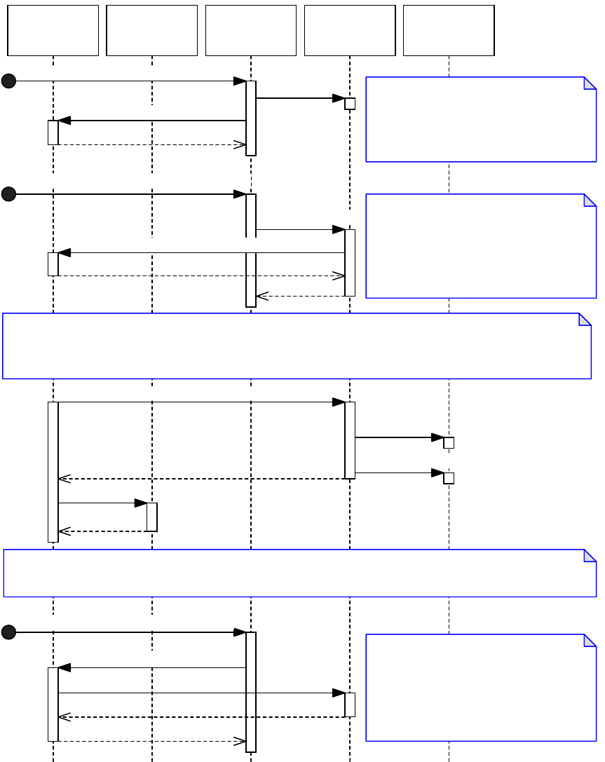
CHAPTER 2: Commands Extension patterns 70
8. The inval cookie is called on undo and redo of the transaction.
9. When the lifetime of an inval handler is over, call DBUtils::DetachInvalHandler to detach the inval
handler from the database. For example, an inval handler might be detached from a document
database when a document is closed.
The following figure shows the lifetime of a typical inval handler.
Observer (or
other type of
object)
An Inval HandlerApplication core An Inval CookieICmdHistory
New events in the model of interest for undo / redo cause the above sequence to be repeated and a new inval
cookie to be associated with the transaction.
An inval handler is created and associated
with the database that persists the objects
of interest. For example, an inval handler
might be attached when a document is
opened.
More events of interest for undo / redo can occur within the same transaction. The inval handler must be called to
record each event. At the end of the transaction, EndCollectingInvals is called. The inval handler returns the cookie
to be called on undo and redo of the transaction. See sequence diagram showing inval cookie calls.
When the lifetime of an inval handler is over,
DetachInvalHandler is called to detach the
inval handler from the database. For
example, an inval handler might be
detached when a document is closed.
StartCollectingInvals is called to indicate
that the inval handler is interested in
participating in undo and redo of a
transaction. This usually occurs on some
event (through an observer, or some other
means).
Event that causes attach to the model
new
DBUtils::AttachInvalHandler
Event in the model of interest for undo / redo
AddInvalInfo(info)
bool16= DBUtils::StartCollectingInvals
IInvalCookie*= EndCollectingInvals
new
AddInvalInfo(vector of info)
Push
Event that causes detach from the model
DBUtils::DetachInvalHandler
delete
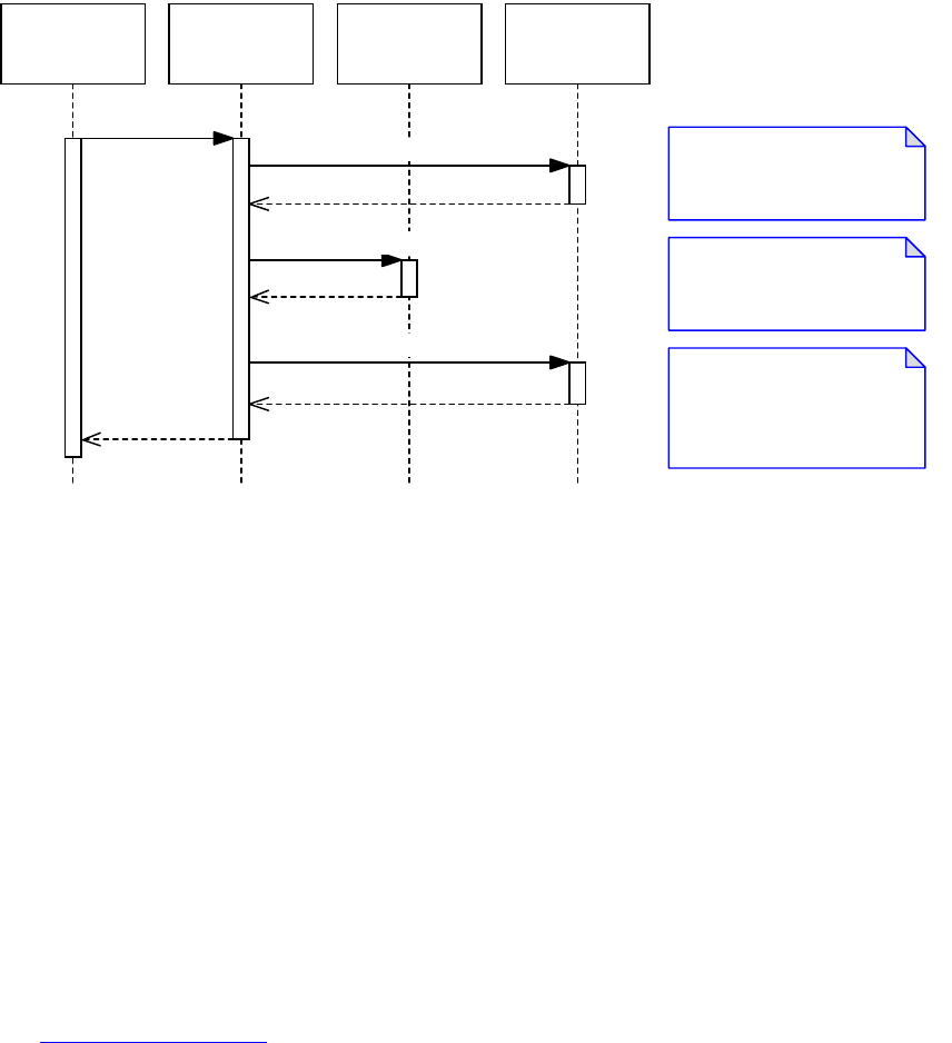
CHAPTER 2: Commands Extension patterns 71
The following figure shows the typical sequence of calls made to an inval cookie on undo. On undo, any
inval cookies that were previously associated with the CmdStackItem are called. The inval cookie setting
the error state aborts the undo (the model is reset to the state from before the undo).
There are times where the lifetime of an inval handler does not match that of the command history. Inval
handlers can be attached and detached at any time, asynchronously with anything else happening in the
model. This means there are entries in the command history that do not have corresponding inval cookies
for a particular inval handler. In this situation, the inval handler’s BeforeRevert_InvalAll and
AfterRevert_InvalAll methods are used to provide the opportunity to rebuild the required state directly.
There are times when an inval cookie instance can be asked to merge another instance. This causes the
IInvalCookie::Merge method to be called, to merge cookies that were returned by each call to
IInvalHander::EndCollectingInvals within one undoable transaction. For example, this can happen at the
end of an abortable command sequence.
See also
IInvalHandler, IInvalCookie, DBUtils::AttachInvalHandler, DBUtils::StartCollectingInvals, and
DBUtils::DetachInvalHandler in the API Reference.
For sample code: GTTxtEdtInvalHandler in the GoToLastTextEdit plug-in.
For documentation on how to detect change in other objects using observers and responders:
Chapter 3, “Notification.”
Snapshot view interface
Description
Suppose you have a user interface object like a widget, which has data that depends on model objects
that persist in a database that supports undo, and:
Your data needs to be updated when the model objects it depends on are modified or when
modifications are undone or redone.
Application core ICmdHistory An Inval CookieModel
Prior to the model state being
reverted, all inval cookies are
called.
After all inval cookies are
called, the model is reverted
(assuming no error).
After the model has been
reverted, all inval cookies are
called. Setting error here will
undo the "Undo".
Undo
ErrorCode= InvalBeforeUndo
ReadWrite / SnapshotReadWrite
ErrorCode= InvalAfterUndo

CHAPTER 2: Commands Extension patterns 72
You cannot use lazy notification to update your data, because it must be kept up to date with changes
to the model at all times.
NOTE: Use of this pattern is extremely rare in the application codebase. For example, it is used by interface
ILayoutControlData on the layout widget. The data in this interface is depended on by many other objects
and always must be kept in tight synchronzsation with the database. This is an advanced pattern and
should be used only if absolutely necessary.
Architecture
A snapshot is taken of the state of a snapshot view interface, before it is changed, reverted on undo, and
restored on redo. It is very similar to a snapshot interface (see “Snapshot interface” on page 66). The
distinction is that the database with which a snapshot interface is associated is fixed and implicitly defined
by the persistent boss on which it is aggregated. A snapshot view interface, on the other hand, is part of a
user interface object and must explicitly identify the database containing the model objects on which it
depends. Also, it is not one specific database. For example, a widget that tracks some state in the front
document must change the database on which its snapshot view interface depends, when the front
document changes.
To implement a snapshot view interface, follow the steps described under CViewInterface in the API
Reference.
See also
The CViewInterface template class in the API Reference.
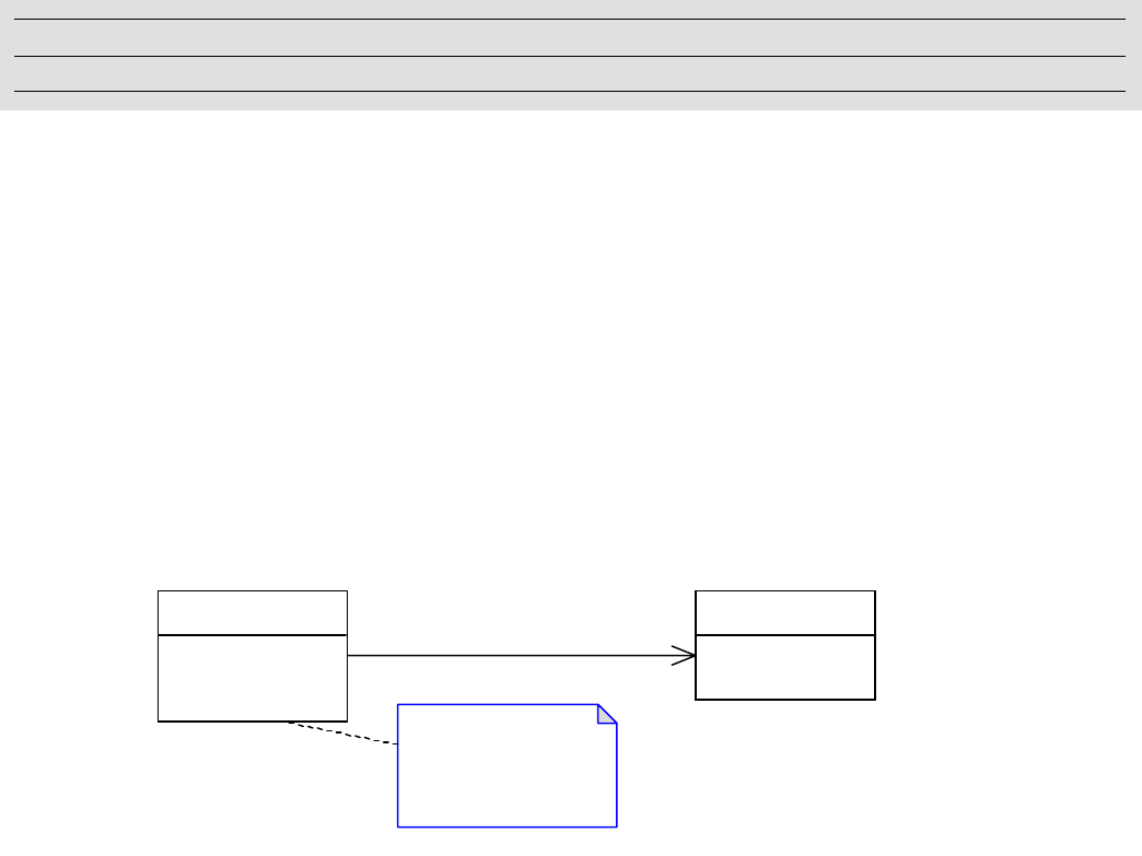
73
3Notification
Notification patterns inform interested parties of certain changes. This chapter describes the prevalent
notification patterns used by products in the InDesign family.
Concepts
Notification is a mechanism by which an interested object can be made aware of changes in other
components or subsystems. This section focusses on two prevalent notification patterns, the observer and
the responder.
Observer pattern
The observer pattern is described in Design Patterns by Gamma et al. The intent of the pattern is to “Define
a one to many dependency between objects so that when one object changes state, all its dependents are
notified and updated automatically.” The following figure shows the structure.
The pattern consists of a subject and one or more observers. A subject is an object that needs to inform
other objects that are interested in changes to the subject’s state. An observer is an object that needs to
keep its state consistent with the state of a subject. A subject can have an association with multiple
observers. An observer can observe multiple subjects.
The association between observers and subjects is managed through Attach and Detach calls. Any change
to the subject is declared through a call to the Notify method, which in turn calls Update on any associated
observers.
The subject supports three operations:
Attach — Associates a specific observer with a subject.
Detach — Detaches a specific observer from a subject.
Notify — Notifies all associated observers of some change to the subject.
Chapter Update Status
CS6 Unchanged
Subject
Attach(Observer) : void
Detach(Observer) : void
Notify() : void
Observer
Update() : void
Notify()
for all o in observers {
o->Update()
}
0..*
has observers
0..*
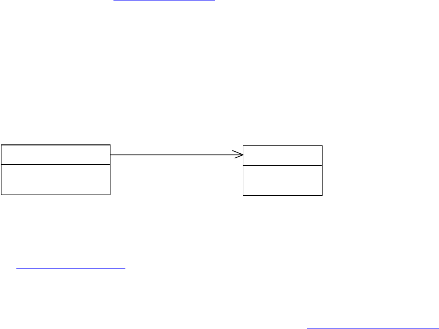
CHAPTER 3: Notification Observers 74
The observer supports one operation:
Update — Keeps the observer’s state consistent with the subject’s state.
Typically, when a client wants to be notified of changes in a subject, it calls Attach, passing an observer
that will be the recipient of update messages.
Any update to the subject that could be of interest to observers results in a call to the subject’s Notify
method. The subject, in turn, iterates through all attached observers, calling their Update operations.
At any point, a client can remove the observer from the subject, using Detach. The observer no longer
receives update events from that subject.
For more information, see “Observers” on page 74.
Responder pattern
With the observer pattern, notification is provided when an object is modified. The responder pattern
provides notification on an event. Notification consists of a signal sent from one party to a responder that
can react to the event. The application predefines a set of events and corresponding signals in which
responders can register interest. For example, signals are associated with document events like create,
open, save, and close. A responder that registers interest in the document open event is called each time a
document is opened. The following figure shows the structure.
The pattern consists of a signal manager and responders. The signal manager is the object responsible for
notifying responders of some event. A responder is an object that is called as a result of that event. A
responder registers its interest in a particular event using the service provider extension pattern. A
responder is a service provider, although this is not shown explicitly in the figure. For more information,
see “Responders” on page 86.
Observers
This section describes the implementation of the observer pattern (see “Observer pattern” on page 73)
within the application. The implementation consists of two interfaces, a subject (see the ISubject interface)
and an observer (see the IObserver interface), as shown in the following figure.
SignalManager
+ SignalResponder() : void
Responder
+ Respond() : void
1
has responders
0..*
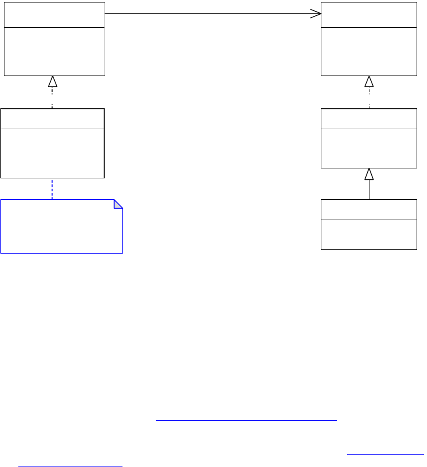
CHAPTER 3: Notification Observers 75
Subjects
A subject is an object potentially of interest to other objects. Within the application, any object that
maintains state of interest to other objects is a candidate for being a subject. An object with an ISubject
interface is a subject. The interface supports the following key operations:
AttachObserver — Associates a particular observer with the subject.
DetachObserver — Detached a particular observer from the subject.
Change — Notifies observers of a change to the subject. Observers get called on their
IObserver::Update method. See “Regular and lazy notification” on page 78.
ModelChange — Notifies observers of a change to a subject. Observers get called on their
IObserver::Update method and/or their IObserver::LazyUpdate method. See “Regular and lazy
notification” on page 78.
Change manager
Subjects within the application defer the functionality required to track the subject and observer
dependencies to the change manager (the IChangeManager signature interface). The ISubject interface
forms a facade over the change manager. It is unlikely third-party developers need to interact with the
change manager directly. It is not considered further here.
Observers
An observer is an object interested in changes to a subject. Any object within the application object model
can be an observer by aggregating the IObserver interface. The interface supports the following key
operations:
«interface»
ISubject
+ AttachObserver() : void
+ Change() : void
+ DetachObserver() : void
+ ModelChange() : void
«interface»
IObserver
+ AutoAttach() : void
+ AutoDetach() : void
+ LazyUpdate() : void
+ Update() : void
CSubject
+ AttachObserver() : void
+ Change() : void
+ DetachObserver() : void
+ ModelChange() : void
CObserver
+ AutoAttach() : void
+ AutoDetach() : void
+ LazyUpdate() : void
SomeObserver
+ Update() : void
A default implementation,
kCSubjectImpl, is provided. It is
unlikely that you would need
to specialise it.
«realize» «realize»
0..*0..*

CHAPTER 3: Notification Observers 76
AutoAttach and AutoDetach — Provided when the observer knows the subject with which it should
be associated. A client would then delegate the association of subject and observer to the observer.
See “Relating observers to subjects” on page 83 for a description of how to associate an observer with
a subject.
Update and LazyUpdate — Receives notification when a subject changes. An observer can get called
via its Update or LazyUpdate method, depending on how it chooses to receive notifications from the
subject. See “Regular and lazy notification” on page 78.
Message protocols
Normally, an observer attaching to a subject indicates a protocol of interest. This protocol (identified by
type PMIID) allows the observer to be called only for a subset of the total set of messages being broadcast
by the subject. Generally, the protocol is synonymous with a data interface on the subject. Observers
interested in changes to a specific data interface on the subject attach using the PMIID of the data
interface.
The following figure shows a subject, kSomeSubjectBoss, that aggregates a data interface, ISomeData. The
observer, kSomeObserverBoss, is interested in changes to this data interface. The observer attaches to the
subject, specifying IID_ISOMEDATA as the protocol of interest. This corresponds to the PMIID of the data
interface. After the data interface is modified, the ISubject::ModelChange or ISubject::Change method is
called to broadcast notification. Observers are called via their Update or LazyUpdate methods, with a
message protocol of IID_ISOMEDATA.
The object that actually modifies the data interface and calls the ISubject interface to broadcast
notification is not shown in this figure. If the subject object is part of a document or defaults, the object
that calls the mutator method on the data interface normally is a command (see Chapter 2, “Commands”).
The command calls ISubject::ModelChange if it performs notification. If the subject object is a user
interface object, mutator methods on the data interface itself normally call ISubject::Change to broadcast
notification.
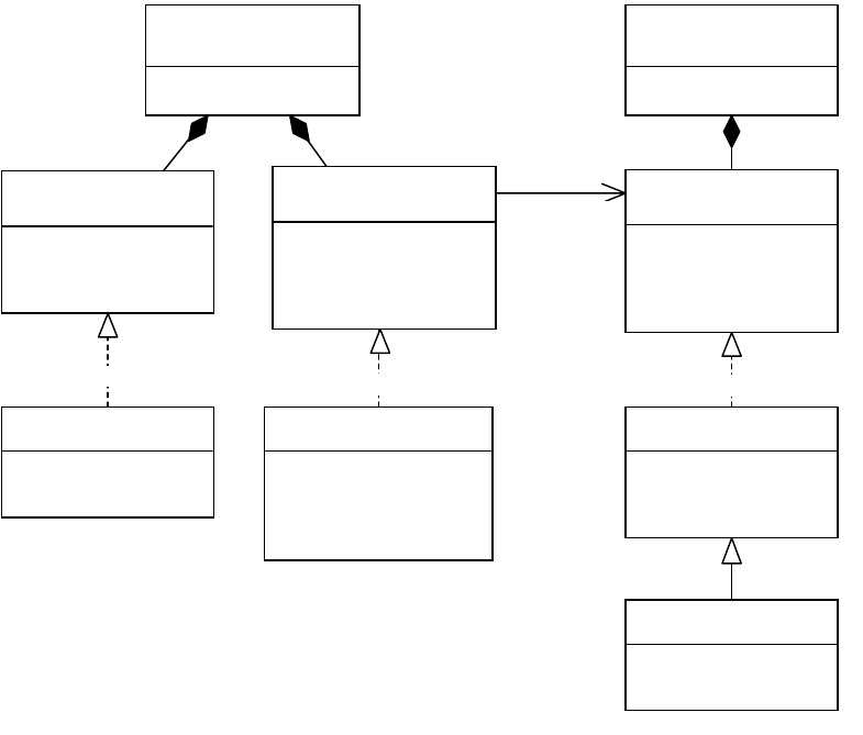
CHAPTER 3: Notification Observers 77
Subject and observer types
Within the application, subjects are split into distinct “types.” The type of object a subject is determines the
method on ISubject that is called to perform notification. The types of subject are as follows:
Model — An object that is part of the document model (see kDocBoss), the defaults model (see
kWorkspaceBoss), or another model that supports undo. The ISubject::ModelChange method is used
to broadcast notification when model objects change.
User interface — An object that is part of the user interface; for example a checkbox or button This is
distinct from an element in the user interface that is interested in model data. The ISubject::Change
method is used to broadcast notification when user interface objects change.
Within the application, observers are split into distinct “types.” The type of subject object an observer is
watching determines the type of observer. The types of observers are as follows:
Model — An observer attached to objects that persist in a document (see kDocBoss), defaults (see
kWorkspaceBoss), or another model that supports undo. Notification of model observers is done
through a call to ISubject::ModelChange.
User interface — An observer attached to a user interface object; for example a checkbox or button.
Selection — An observer watching an artifact of the current application selection.
Context — An observer watching some context, such as the active document.
«boss»
kSomeBoss
«interface»
ISubject
+ AttachObserver() : void
+ Change() : void
+ DetachObserver() : void
+ ModelChange() : void
CSubject
+ AttachObserver() : void
+ Change() : void
+ DetachObserver() : void
+ ModelChange() : void
«interface»
IObserver
+ AutoAttach() : void
+ AutoDetach() : void
+ LazyUpdate() : void
+ Update() : void
CObserver
+ AutoAttach() : void
+ AutoDetach() : void
+ LazyUpdate() : void
«boss»
kSomeObserverBoss
«interface»
ISomeData
+ Get() : void
+ Set() : void
SomeData
+ Get() : void
+ Set() : void
SomeObserver
+ Update() : void
«realize» «realize» «realize»
0..*0..*
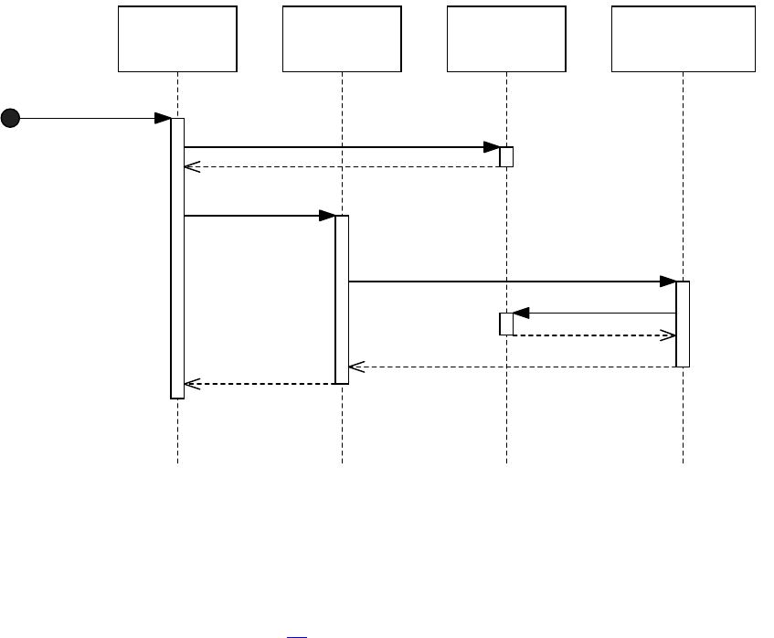
CHAPTER 3: Notification Observers 78
Hybrid — An observer watching multiple types of subjects. A particular observer may attach to any set
of objects; however we do not consider what requirements observers that attach to multiple types of
subjects might have.
Regular and lazy notification
The application supports two types of notification, regular and lazy. If an observer needs to be called as
soon as a subject broadcasts the change message, it should request regular notification. If the observer can
afford to wait until idle time before being notified that a change of interest occurred, it can register for lazy
notification. When an observer attaches to a subject, it defines whether it wants to attach for regular
notification, lazy notification, or both.
Regular notification
Regular notification is passed to an observer via the IObserver::Update method.
With regular notification, an observer is called within the scope of the call to a subject’s ISubject::Change
(or ISubject::ModelChange) method. The following figure shows the typical sequence of calls made when
a subject notifies an observer using regular notification.
A client object is called and modifies some data interface, then broadcasts notification about the changes
it makes. It mutates the state of a data interface and then calls ISubject::ModelChange. Observers get
called via IObserver::Update and can retrieve the state of the data interface. The subject and the data
interface are most often on the same boss object, but not always.
If a change is undone or redone, the observer is not notified. That is, the Update message is not
rebroadcast. See the figure on page 81 for the sequence of calls made on undo.
An ObserverA Data InterfaceA Client Object A Subject
Set
Change
Update
Get
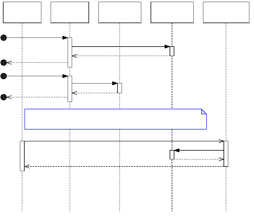
CHAPTER 3: Notification Observers 79
Lazy notification
Lazy notification is passed to observers via the IObserver::LazyUpdate method. Lazy notification is
available only to observers of subject objects associated with persistent databases supporting undo.
Lazy notification is used when observers do not need to be in tight synchronization with changes being
made to the subject objects they observe. Rather than participating in each change that occurs on a
subject object, observers using lazy notification are notified after all updates are made and the application
is idle.
When the state of an object in the model is changed (for instance, by a command), and notification is
required, the notification always is broadcast by calling ISubject::ModelChange. The
ISubject::ModelChange method queues a message to be broadcast later. Once the application is idle,
observers get called with this message via the IObserver::LazyUpdate method, as shown in the following
figure.
NOTE: The approach above holds for subject objects in the document model, the defaults model, or, in
general, any subject object that persists in a database that supports undo. Only subject objects which
persist in a database that supports undo can use lazy notification.
Regardless of the number of changes made to the persistent interface, only one LazyUpdate call is made
per sequence for a given message protocol.
Application Idle
Task
A Command A Persistent
Interface
A Model Subject An Observer
Observers using lazy notification are notified later on when the application is idle.
Do
Set
DoNotify
ModelChange
LazyUpdate
Get
CHAPTER 3: Notification Observers 80
An implication of this is that ordering of lazy notification with respect to other lazy notification messages
cannot be guaranteed. Lazy notification can be thought of as a message indicating a change was applied
to an object some time in the past. The observer is responsible for determining the nature of the change.
An observer that registers for lazy notification is not guaranteed to receive all messages. For example,
suppose an observer is attached to a page item and is watching for the page item to move. If a sequence
moves the page item and then deletes it, a lazy update message for the move is not sent to the observer. If
a subject object is deleted, any lazy notification messages being queued for that object are purged.
We recommend any model observer used to keep some user interface component synchronized with the
model should use lazy notification. This eliminates any unnecessary refresh of user interface data. An
example use of lazy notification is a user interface panel that reports information about the set of text
frames in a document. The user interface panel is associated with a model observer watching for textual
changes or the addition or removal of text frames. These operations result in the panel being updated.
There is no real requirement for the panel to be updated in real time as these changes are made; the panel
should be updated when the text updates are complete (and the application is idle). Lazy notification
enables this by sending a single IObserver::LazyUpdate message to the observer when the move is
complete.
If a change is undone or redone, the observer is notified; that is, the LazyUpdate message is rebroadcast.
The sequence of calls made to an observer’s LazyUpdate method on undo is shown in the following figure.

CHAPTER 3: Notification Observers 81
Both notifications
An observer can register for both regular and lazy notification. The following figure shows the sequence of
calls this might involve.
A Command A Persistent
Interface
A Model
Subject
An ObserverApplication
Core
ICmdHistory
The lazy update on do is discussed elsewhere
On undo (and redo) the LazyUpdate method of the observer is
invoked. Note, the command is no longer in existence when
undo or redo is processed.
Do Set
DoNotify ModelChange
LazyUpdate
Get
Undo
LazyUpdate
Get
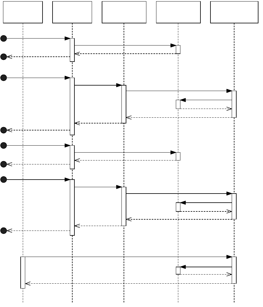
CHAPTER 3: Notification Observers 82
While every ISubject::ModelChange message sent to the subject is propagated to the observer via
IObserver::Update, only one IObserver::LazyUpdate call is made, regardless of the number of changes
made in a single transaction. For example, if multiple updates are made on an object, the update
messages being transmitted using a single protocol identifier, and the lazy update method is called only
once.
On undo or redo, only the LazyUpdate messages are rebroadcast.
Registering for both notifications allows an observer to have the rich context of the Update message and
have to rebuild their view of the model only on rarer undo/redo events.
Application Idle
Task
A Persistent
Interface
A Model Subject An ObserverA Command
Do
Set
DoNotify
ModelChange
Update
Get
Do
Set
DoNotify
ModelChange
Update
Get
LazyUpdate
Get

CHAPTER 3: Notification Observers 83
Lazy notification data
With regular notification, the observer (IObserver::Update) method is passed a context about what caused
the change (usually, the command that initiated the notification). With lazy notification
(IObserver::LazyUpdate), the observer gets notified only that something changed. The observer must be
capable (for instance, by examining the model) of deducing or otherwise rebuilding the set of information
it requires. In some cases, the time this takes causes performance issues; therefore, the API provides lazy
notification data as an optimization.
Lazy notification data objects are data-carrying (C++) objects created by the message originator. For
example, a command that deletes a document page object (kPageBoss) might create a lazy notification
data object and populate it with the UID of the deleted page. Generally, this lazy notification data object is
passed to observers via IObserver::LazyUpdate. There are situations where the lazy notification data
objects associated with a change are purged (for example, in low memory condition), and the observer is
called with a nil-pointer; therefore it is important that observers be designed to deal with this.
The lazy notification data objects used within the application are not documented in the public API.
NOTE: Use of lazy notification data objects is not pervasive in the application. They exist only as an
optimization, and the types of data they consist of varies. We recommend you avoid using them if possible
and refresh the observer’s state entirely when IObserver::LazyUpdate is called.
Observers and undo
Only observers registered for lazy notification are signalled when an object they are associated with is
modified through an undo or redo action. For each undo or redo, the observer receives one call (per
message protocol), regardless of the number of changes made to the subject object.
If the observer performs model modifications using commands (see “Model modifications” on page 85),
on undo or redo these are automatically undone or redone as required. For observers watching the model
to update some aspect of the user interface, lazy notification should give the required update. If there are
more exotic requirements for notification on undo and redo, two other patterns exist: see the Snapshot
interface and Inval Handler extension patterns in Chapter 2, “Commands.”
Relating observers to subjects
This section discusses how observers are attached to particular subjects.
Determining the subject
Before being able to attach and detach observers, an understanding of both the subject to attach to and
the protocol to listen along is required. The sample code provided as part of the SDK has examples for
many key events of interest. Similarly, Adobe InDesign SDK Solutions has advice on detecting when events
occur for domains like layout, text, XML, and so on.
If neither of these resources provide the answer, the debug version of the application can be used. In the
Test menu is the Spy command. It can be configured to log all executing commands, along with the
subjects that are notified, the protocol used for notification, and the change that occurs. Perform the
action of interest, and Spy provides the information required to observe the action.

CHAPTER 3: Notification Observers 84
Attaching and detaching subjects
In most situations, an observer understands the subjects in which it is interested and how to attach to
them. Such an observer attaches to the subjects in the IObserver::AutoAttach call and detaches in
IObserver::AutoDetach. For example, an observer on a panel can discover the widgets it contains (see the
IPanelControlData interface) and attach to their subject interface.
THE IOBSERVER::AUTOATTACH AND IOBSERVER::AUTODETACH METHODS STILL NEED TO BE CALLED BY ANOTHER
OBJECT. There are other situations where the observer does not know the subject(s) with which it should
be associated. Given a subject and an observer, a client object can directly attach or detach the observer
using ISubject::AttachObserver and ISubject::DetachObserver calls.
Using a responder to attach and detach an observer
Sometimes, an observer is required based on an action within the application. Responders (see
“Responders” on page 86) are called on different application events and can be used to manage the
association between an observer and a subject. For example, a responder can be called when documents
are created, opened, or closed. On create or open, the responder can attach an observer to the document.
On close, the responder can detach the observer.
Using an observer to attach and detach another observer
Sometimes, an observer attaches and detaches a second observer based on notification received by the
first observer. This pattern commonly is seen in user interface objects that view objects in the front most
document. The active context (see kActiveContextBoss, the IActiveContext interface, and the
IID_IACTIVECONTEXT protocol) is the subject that is updated when the user chooses the document on
which to work. The user interface object has a first observer that watches the active context. This observer
attaches and detaches a second observer to the subjects of interest in the front-most document.
Observing a subject that can be deleted
Sometimes, a client object needs to observe a subject created as part of an undoable action. To do this, a
pattern involving two observers and an inval handler can be used (inval handlers are described in
Chapter 2, “Commands”). The first observer watches for create events for the subject and attaches the
second observer to the newly created subject. To ensure this second observer gets detached if the create
action is undone, the first observer also must set up an inval handler. The inval handler provides a
mechanism to detach the observer on undo and reattach it on redo.
Observing a subject that can be deleted as part of an undoable action is similar. On undo, the observer
must be reattached; on redo, it must be detached. Again, this requires the use of an inval handler.
Document notification
The application supports a large object model. Any object is a candidate for becoming a subject (and
thousands of subjects exist). Management of observers interested in the set of messages broadcast from a
subject can be difficult, if many instances of a subject can exist. For example, consider objects in the page
item hierarchy (which can be deleted and recreated, undone and redone, as a consequence of user
actions). It is difficult and undesirable to maintain an observer on each page item. To solve this problem, as
well as the actual subject object broadcasting the change message, the document’s subject also
broadcasts the change. This means any observer associated with the ISubject interface on the document
CHAPTER 3: Notification Observers 85
(kDocBoss) subject is notified, without the overhead of managing the association with finer-grained
objects within the document.
Notification of changes to page items are broadcast on the document subject using
IPageItemUtils::NotifyDocumentObservers. Some other types of object use the ISubject interface of the
document (see kDocBoss) directly to notify of a change.
Observers and the model
This section details some considerations around the use of model observers within the application.
Observers “watch” model data for two primary reasons:
1. To update a user interface element to reflect the state of the model. (This type of observer is distinct
from user interface observers, which watch for changes in user interface elements like checkboxes.)
2. To provide a point where existing functionality can be extended. For example, an observer can be used
to set custom data in a story object (kTextStoryBoss), on story creation. There are side effects for both
the error state and model modifications that should be considered when using observers to extend
the model.
Error state
Model observers that extend functionality can set the global error state either directly (using
ErrorUtils::PMSetGlobalErrorCode) or indirectly (through processing of commands). Generally, observers
are notified during the processing of a command or sequence of commands. If the application tries to
process a command when the global error state indicates anything but success (kSuccess), a protective
shutdown is invoked to protect the integrity of open documents.
An observer setting the global error state either aborts the current change (that is, the current change is
undone) or causes the shutdown of the application. The behavior is determined on a per-use basis and can
be complicated by the use of commands in different scenarios. For example, the creation of a text story
object (kTextStoryBoss) can occur through the type text tool or from an import and place operation. The
type text tool is straightforward, and an observer setting global error state causes the change to be
undone. For import and place, however, the story creation occurs as part of a longer sequence of
commands. A similar observer setting global error state causes an application shutdown as further
commands are processed.
Unless it is explicitly suggested that it is appropriate to set error state in an observer of a particular subject
change, an observer should not set error state. Also, an observer that uses objects that potentially set error
state (such as commands) should test for and consume any errors, taking appropriate remedial action.
Model modifications
A common pattern involves calling commands within an observer to make further modifications to the
model. This can lead to problems. If the observer is notified as part of a sequence of commands, and the
commands that are due to be processed after the current notification phase ends make any assumptions
about the state of the model, instability and document corruption can result.
For example, consider a sequence of two commands. The first inserts text into a text story object
(kTextStoryBoss). The second changes the color of the newly inserted text to blue. Pseudo-code for this
sequence is in the following example.

CHAPTER 3: Notification Responders 86
void MyTextUtils::AddNote(string str, ITextModel* story, TextIndex position)
{
int32 stringLen = str.Length();
BeginSequence("AddNote");
MyTextUtils::AddToStory(story,position,str,stringLen);
MyTextUtils::SetTextColor(story,position,stringLen,BLUE);
EndSequence("AddNote");
}
At some point, a third party decides to extend the text functionality by writing a macro expander, the
purpose of which is to expand known acronyms as text is entered into stories. The third party uses an
observer that is notified when text is added to a story. If the observer modifies the model, specifically
changing the number of characters entered into the story, it breaks the sequence in the example. The
stringLen value is no longer valid.
If there is no risk of side effects from the model change within an observer (for example, the observer
modifies custom data, not the core application data on the object), it is safe to proceed with the change. If
there is a need to perform further modifications on the core application data, consider factoring the
change to execute as a separate task (possibly on application idle).
In the preceding example, the observer might mark some custom, persistent data in the story, indicating it
needs to be processed, and schedule a custom command. The custom command examines the story,
determines whether the macro expansion operation is still valid, and updates the story if required. No
assumptions can be made about what might occur between marking the story in the observer and the
follow-on processing (for example, the document could close, further updates could occur, or the
application could terminate).
Commands that delete objects generally prenotify, so subject observers get an opportunity to tidy up
associated objects before the object is deleted. Observers called in this context should ensure the
command state is CommandState::kNotDone.
Responders
This section describes the implementation of the responder pattern (see “Responder pattern” on page 74)
within the application. The responder pattern provides notification that a specific event has occurred. For
example, a responder can be called when a document is created, opened, or closed. The following figure
shows the general structure.
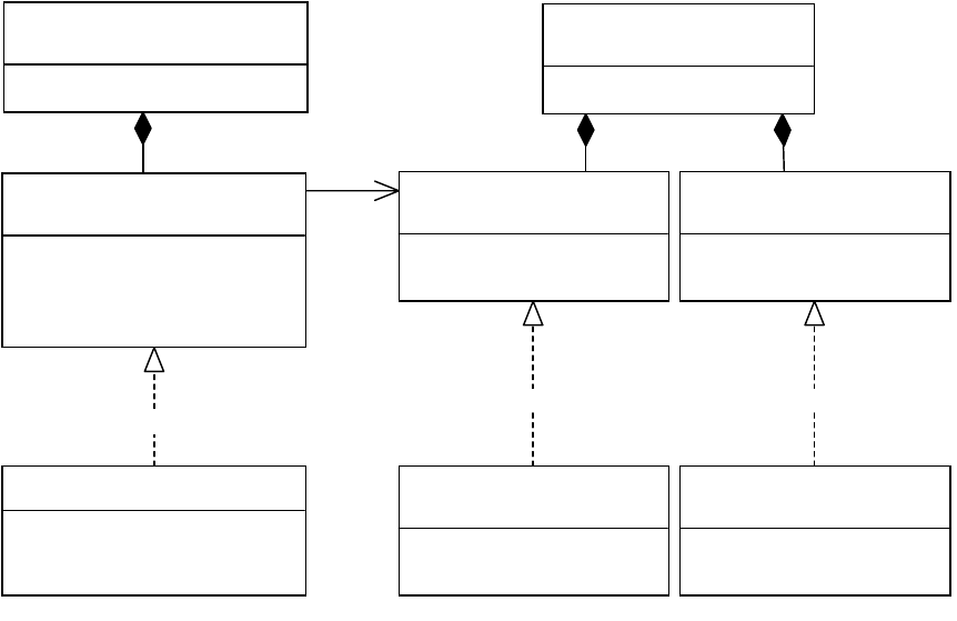
CHAPTER 3: Notification Responders 87
The components to the responder pattern shown in this figure are as follows:
Signal manager (signature interface ISignalMgr) — The entity responsible for notifying responders of
an event.
Service provider (interface IK2ServiceProvider) — The entity that identifies the object as a responder
and indicates the events of interest.
Responder (signature interface IResponder) — The entity invoked as a result of some event.
Signal manager
A signal manager is an object that controls the calling of responders. A boss class that has an ISignalMgr
interface is a signal manager. A signal manager is called by some other object that wants responders to be
notified when an event of interest has occurred. The object that calls a signal manager is often a command
(see interface ICommand). For example, the command that opens a document calls the signal manager to
notify responders which have registered an interest in this event.
Responders are service providers. Each event for which a responder can be notified has a corresponding
ServiceID. The application predefines a set of events and corresponding ServiceIDs in which responders
can register interest. For example, the open document event has a ServiceID of
kOpenDocSignalResponderService. See the “Notification” chapter of Adobe InDesign SDK Solutions.
When a particular event occurs the signal manager is called to signal all responders that have registered
interest. The signal manager uses the service registry (not shown in the preceding figure) to find the
responders that need to be called for the event.
If a responder sets the global error state, the signal manager is responsible for calling previously signalled
responders indicating there was an error condition (allowing the responder to take whatever action might
be necessary) and the action is aborted.
«interface»
ISignalMgr
CountResponders() : int32
Init(ServiceID) : void
SignalNextResponder() : ErrorCode
Terminate() : void
SignalMgr
ServiceID: = kARespServiceID
«interface»
IResponder
Respond(ISignalMgr*) : void
SignalFailed(ISignalMgr*) : void
CResponder
AResponder
Respond(ISignalMgr*) : void
«interface»
IK2ServiceProvider
GetServiceID() : ServiceID
CServiceProvider
AResponderServiceProvider
ServiceID: = kARespServiceID
«boss»
kAResponderBoss
«boss»
kASignalMgrBoss
«realize»
10..*
«realize» «realize»
CHAPTER 3: Notification Responders 88
Responder
A responder is a boss class that supports two specific interfaces, the service provider interface
(IK2ServiceProvider) that identifies the events the responder is interested in, and the responder interface
(signature interface IResponder) that is called for a particular event.
Responder registration
Each event for which a responder can be called has a corresponding ServiceID. A responder registers for
one or more of these events by returning the ServiceIDs for the events of interest via its IK2ServiceProvider
implementation. See the “Notification” chapter of Adobe InDesign SDK Solutions for details on the
predefined events the application makes available. For sample code, see the DocWchServiceProvider class
in the DocWatch plug-in.
Responder implementation
The responder is called via IResponder::Respond on an event of interest. The Respond method performs
whatever functionality is required and returns.
If the global error state is set (ErrorUtils::PMSetGlobalErrorCode) by a responder, any previously signalled
responders have their IRespond::SignalFailed method called to indicate failure. The SignalFailed method
performs the function needed to recover. For example, if the Respond method attached an observer to an
object, the SignalFailed method detaches that observer.
Both methods receive a pointer to a signal manager interface, so they can find out information about the
event. Typically, the Respond and SignalFailed methods query the signal manager interface for other
contextual interfaces. For example, the document signal manager (see kDocumentSignalMgrBoss)
provides context in the IDocumentSignalData data interface. Responders that register for document
signals like kAfterOpenDocSignalResponderService use this data interface to access the document being
opened.
The Respond and SignalFailed methods often call the service manager using the ISignalMgr::GetServiceID
method, to verify the ID of the service that occurred. This allows one responder implementation to be
handle more than one type of event
For sample code, see the DocWchResponder class in the DocWatch plug-in.
Responders and the model
Responder implementations can perform follow-on modifications to the model. For example, a responder
called as the result of a command modifying the model can make further changes to the model by calling
other commands.
Take care that these modifications do not interfere with the model data on which the signal is based. For
example, if a responder signalled on a create story signal (kNewStorySignalResponderService) deletes or
otherwise modifies the created story, commands, observers, and responders that might follow the errant
responder could make assumptions about the state of the story. Avoid direct modifications that interfere
with the data on which a responder is based. If such a change is required, consider using the responder to
set an associated, independent state that can be used by an idle task (or similar) to perform the actual
modification on the model. This technique guarantees the model is in a consistent state before
modifications are made.

CHAPTER 3: Notification Key client APIs 89
NOTE: A responder should check the global error state is kSuccess (ErrorUtils::PMGetGlobalErrorCode),
before modifying the model.
Responders and global error state
Responders are designed to accommodate error; however, in practice, how a particular signal service deals
with error state is implementation dependent.
NOTE: If you set global error state in the IResponder::Respond method, thoroughly test all areas in the
domain in which you are working.
If a responder sets global error state, the signal manager calls all previously signalled responders via
IResponder::SignalFailed and aborts the action. The ability to clean up a failed action is implementation
and context dependent. For example, the creation of a text story object (kTextStoryBoss) can occur as a
result of using the type text tool or importing a file. In the case of importing a file, the responder is called
from a much deeper stack than in the case of using the type text tool. The implementation in the latter
case does not handle aborting the import from a responder.
Another implication of the IResponder::SignalFailed method being called on error is the method must be
able to consume and take remedial action for any errors caused within the method. There is nothing the
application core can do if an IResponder::SignalFailed method itself fails; the condition is indeterminate.
Ordering of responders
No guarantees can be made about the order in which responders are called to react to an event. If a client
requires a particular responder to be called before another, the implementation of the second responder
should call ISignalMgr::SignalResponder (identifying the first responder) at the start of its respond
method. Even though the signal manager’s iteration of the responders has been short-circuited by calling
one of the responders directly, no responder is called more than once.
Responders and undo
Responders for the predefined events made available by the application are not called at undo or redo of
an operation.
If a responder processes commands to make follow-on changes to the model, these changes are undone
automatically as part of an undo operation; the client code need to manage this. The same is true for redo
of an operation.
If a responder is being used to attach an observer to a newly created model object, that observer must be
detached on undo and reattached on redo. Similarly, if a responder is being used to detach an observer
from a model object about to be deleted, that observer must be reattached on undo and detached on
redo. To achieve this, the undo or redo actions need to be tracked using an inval handler. See Chapter 2,
“Commands,” for a description of the inval handler extension pattern.
If the responder is being used for a nonmodel based activity (for example, keeping a log of specific
operations), and the undo or redo actions need to be tracked, an inval handler again is required.
Key client APIs
The following table shows key client APIs for observers and responders.

CHAPTER 3: Notification Extension patterns 90
Extension patterns
This section describes the mechanisms a plug-in can use to receive notification.
User-interface widget observer
Description
This observer is attached to the subject object for a user interface artifact and called on a user interface
event, such as selection of a checkbox or activation of a button.
Architecture
To implement a user-interface observer:
1. Subclass the widget type you are creating (for example, kDialogBoss for dialogs), as described in the
“User Interfaces” chapter of Adobe InDesign SDK Solutions.
1. Provide an implementation for IObserver. The AutoAttach and AutoDetach methods should attach the
observer to any sub-widgets (for example, all buttons on a dialog). Partial implementations exist; for
example CDialogObserver for dialogs and CWidgetObserver for widgets.
2. User interface widget observers register for regular notification. Implement the IObserver::Update
method to react to the user interface state change.
See also
Chapter 11, “User-Interface Fundamentals.”
The “User Interfaces” chapter of Adobe InDesign SDK Solutions.
For sample code: PictureIcon/PicIcoRollOverButtonObserver and
WListBoxComposite/WLBCmpListBoxObserver.
API Note
Observers IObserver Client code mainly calls AutoAttach and AutoDetach to have an observer
attach or detach automatically to or from the subject(s) of interest.
ISubject Client code mainly calls AttachObserver and DetachObserver methods
to attach or detach an observer.
Responders ISignalManager If you are extending the application and need to signal new types of
events to responders you will call the signal manager to perform the
notification. Often this notification is performed by a custom command
that you provide. Signal managers in the application use the default
implementation, kSignalMgrImpl, provided by the API. This default
implementation provides all functionality for the signal manager, it is
unlikely that a third party developer would need to further specialize it.

CHAPTER 3: Notification Extension patterns 91
Model observer
Description
A model observer provides an extension point for when a persistent object supported by an application
database supporting undo is updated.
Architecture
To implement a model observer:
1. Determine the subject that is to be observed, the protocol to listen on, and the change of interest. See
the “Notification” chapter of Adobe InDesign SDK Solutions.
2. Determine which boss class in the object model will aggregate the observer. Commonly, the boss class
that represents the object being observed is a good candidate (for example, aggregating the observer
on the document if you are interested in changes to the document). If the observer relates to multiple
subjects (for example, attaching to all open documents), place the observer somewhere accessible
from client code.
3. Provide the implementation of IObserver, deriving from the CObserver partial implementation.
4. Determine whether it is appropriate to implement the AutoAttach and AutoDetach methods.
Generally, these methods can be used if the subject object to be observed is known within the scope
of the observer (for example, if the subject is on the same boss object as the observer). If the
AutoAttach and AutoDetach methods are implemented, client code still needs to call them to create
the dependency between subject and observer. If these methods are not provided, client code needs
to manage the dependency between subject and observer directly (through the
ISubject::AttachObserver and ISubject::DetachObserver calls).
5. Determine whether the subject object is maintained in a database that supports undo. If so, lazy
notification is available.
6. If lazy notification is available, determine the type of notification required. If the subject object
represents a UID-based object from a database that supports undo/redo, lazy notification is available.
If the observer does not need to track every change to an object within a sequence of changes (for
example, the observer is used to keep information in a user interface panel up to date, and the panel
needs to be updated just once, after all changes are applied), lazy notification can be used. If the
observer needs to be aware of all changes to the object as they occur, use regular notification. When
attaching the observer to the subject (either in the AutoAttach/AutoDetach methods or through
client code), specify the notification type.
7. If lazy notification is not available, register for regular notification.
8. Provide implementations of the IObserver::Update and/or IObserver::LazyUpdate methods, as
required.
See also
“Relating observers to subjects” on page 83
“Determining the subject” on page 83

CHAPTER 3: Notification Extension patterns 92
“Regular and lazy notification” on page 78
For sample code showing a model observer using lazy notification: CustomDataLink /
CusDtLnkUITreeObserver, LinkWatcher / LnkWtchActiveContextObserver, PanelTreeView /
PnlTrvTreeObserver.
For sample code showing a model observer using regular notification: CustomDataLink/
CusDtLnkDocObserver, GoToLastTextEdit/GTTxtEdtNewDeleteStoryObserver,
LinkWatcher/LnkWtchCacheManager, and PersistentList/PstLstDocObserver.
Selection observer
Description
Selection observers provide an opportunity for client code to be called when there is a change in the
active selection.
See also
For details: “Selection Observers” section in Chapter 4, “Selection.”
For sample code: TableAttributes/TblAttSelectionObserver,
StrokeWeightMutator/StrMutSelectionObserver, BasicPersistInterface/BPISelectionObserver, and
Persistent List/PstLstUISelectionObserver.
Document observer
Description
As well as notifying a change on a subject, often the notification is repeated on the document for a
subject. This allows observers to watch for a change of interest on a document (rather than attach/detach
from every object within the document). For example, an observer interested in page items being moved
around the layout does not need to attach to each page item (and detach if the page item is deleted,
reattaching if it is undeleted, and so on), but attaches to the document instead.
A document observer is a special example of a model observer, using the document object (kDocBoss) as
the subject.
See also
“Model observer” on page 91
For sample code: CustomDataLink/CusDtLnkDocObserver, LinkWatcher LnkWtchCacheManager, and
PersistentList/PstLstDocObserver.

CHAPTER 3: Notification Extension patterns 93
Active context observer
Description
A context observer is an observer that watches the active context.
Architecture
The active context object (kActiveContextBoss) is session wide and available from the session object
(kSessionBoss) through the ISession::GetActiveContext call. An active context observer is an observer
attached to the subject interface on the active context object. Active context notifications always are
broadcast on the IID_IACTIVECONTEXT protocol. Only regular notification is available. The change context
provided is another IID, indicating the type of contextual change that occurred. The common contextual
changes of interest are shown in the following table.
To implement a context observer:
1. Aggregate an observer on a boss class accessible from client code.
2. Provide implementations of IObserver::AutoAttach and IObserver::AutoDetach (attaching to the
ISubject interface on the kActiveContextBoss accessible from the
GetExecutionContextSession()->GetActiveContext() call).
3. Provide an implementation of the IObserver::Update method. The protocol ID is IID_IACTIVECONTEXT.
The following example shows how to detect when the active document has changed.
void MyObs::Update(const ClassID& theChange, ISubject* iSubj, const PMMID&
protocol, void* changedBy)
{
if (protocol == IID_IACTIVECONTEXT){
InterfacePtr<IActiveContext> context(iSubj, UseDefaultIID());
IActiveContext::ContextInfo* info=
(IActiveContext::ContextInfo*)changedBy;
if(info->Key() == IID_IDOCUMENT){
HandleDocumentChange(context);
}
}
}
See also
For sample code: LinkWatcher/LnkWtchActiveContextObserver.
changedBy Note
IID_IDOCUMENT The active document changed.
IID_ICONTROLVIEW The active layout view changed (for example, when the document has
multiple layout views open).
IID_ISPREAD The current spread changed.
IID_ISELECTIONMANAGER The type of selection changed.
CHAPTER 3: Notification Extension patterns 94
Subject
Description
If there is a need for a boss class to be observable, it needs to be a subject.
Architecture
To turn a boss class into a subject:
1. Aggregate the ISubject interface onto the boss class.
2. Provide the implementation for the interface. Generally, reusing the API-supplied implementation
(kCSubjectImpl) is sufficient, and there should be no need for further specialization of this interface.
See also
For sample code: PersistentList/kPstLstDataBoss.
Responder
Description
A responder provides notification of an event, such as document open.
Architecture
To implement a responder:
1. Determine the event of interest (as described in the “Notification” chapter of Adobe InDesign SDK
Solutions).
2. Aggregate the service provider interface (IK2ServiceProvider) on a boss class. Either reuse an existing
implementation (see the “Notification” chapter of Adobe InDesign SDK Solutions), or provide an
implementation that defines the set of ServiceIDs for the events of interest.
3. Aggregate the responder (IResponder) on the same boss class.
4. Provide an implementation for the responder, derived from the CResponder partial implementation.
See also
The “Notification” chapter of Adobe InDesign SDK Solutions
For sample code: DocWatch/DocWchResponder, CustomDataLink/CusDtLnkDocResponder, and
BasicPersistInterface/BPIDefaultResponder.

95
4Selection
This chapter describes the InDesign/InCopy selection architecture. The selection architecture is based on
the concept of suites—abstract interfaces that allow client code to interact with an abstract selection. A
suite remains neutral to the underlying format of the objects that are selected.
Concepts
Selection
A selection is whatever is chosen or picked out. For instance, when a user selects a range of text with the
Text tool, the user chooses a range of characters. In this case, the selection is a choice of characters from
the text model. Highlighting in the user interface is incidental feedback that helps the user make the
intended selection. Usually, making a choice using selection is a precursor to modifying the properties of
the model underlying the selection. Selection primarily is about targeting objects on which to perform
some action, and the selection subsystem exists to mediate changes to those objects.
Selection format and target
It is necessary to distinguish between the format of a selection and its content, the selection target. A
selection format describes the model format of a selectable object, like the layout (frames), text, table cells,
or XML structure. Each of these has a distinct arrangement of objects that represents its model. A selection
target specifies a set of selected objects of a given selection format, like particular frames or a specific
range of text.
The principal goal of the selection subsystem is to hide all details about formats and targets from client
code. Client code needs ask only, “Can this client code do this operation to the selection?” If yes, the client
code can try to change the properties of the selection target. This encapsulation is achieved by means of
the facade pattern discussed in “Design patterns” on page 96.
InDesign 2.0 included support for a handful of selection formats, including layout objects (frames), text,
table cells, and XML-structure items. InCopy CS added support for other selection formats, like notes.
The following table shows selection formats and their targets:
Chapter Update Status
CS6 Unchanged
Selection format When obtained Selection target
Application defaults No documents are open. Global preferences
Document defaults Document is open with nothing selected. Document preferences
Galley text Insertion position is in text, or text range is
chosen in Galley view.
Range of characters in a text
model (ITextTarget)

CHAPTER 4: Selection Selection architecture 96
Design patterns
A key task for a plug-in developer is writing model code that extends some aspect of the document model.
For instance, if your principal requirement is adding private data to the layout model (see the
BasicPersistInterface sample plug-in), the data added extends the layout model and persists with
document contents. The command pattern, used in the application API to support undo and preserve
document integrity, requires you to write further code to change your model. The API already uses the
facade pattern, like ITableCommands and IXMLElementCommands, to hide the complexity of
parameterizing and processing low-level commands.
The selection architecture is an instance of the facade pattern, in that it makes client code easier to write
by defining a high-level interface on top of the selection subsystem. The selection architecture shields
client code from requiring detailed knowledge of what was selected in the selection subsystem. A facade
also makes software maintenance easier, because a facade weakens the coupling between a subsystem
and its clients. This weak coupling allows the subsystem components to be varied without necessarily
affecting its clients.
Selection architecture
The most important objective of the selection architecture is to ensure that new selection formats can be
added easily.
To support new selection formats without rewriting large parts of the application, client code must be
decoupled from the selection format. Client code must not need to know the selection’s subject identifier,
meaning client code must not need to know which objects are selected or any boss object associations in
the underlying model (for example, the architecture of a text frame). Client code also must not need to
know any commands that manipulate the objects.
To achieve this goal, the selection architecture makes extensive use of suites that are neutral to selection
format. A suite provides a high-level, model-independent API that encapsulates the details of the boss
classes, interfaces, and commands in the underlying model. Clients interact with suites instead of directly
with the selected objects. In programming terms, a suite is a layer of abstraction that sits on top of the
selection and provides a narrow API through which client code communicates its intent with respect to
the portion of the model selected. In design-pattern terms, a suite represents a facade that makes it easier
Layout One or more page items are chosen in a layout
view.
Layout objects (see
ILayoutTarget)
Note Insertion position or text range is chosen in a
note view.
Range of characters in note text
(ITextTarget)
Story editor text Insertion position is in text, or text range is
chosen in a story-editor view.
Range of characters in a text
model (ITextTarget)
Table (table cells) One or more table cells are chosen in a layout
view.
Table cells in a table model
(ITableTarget)
Text Insertion position is in text, or text range is
chosen in a layout view.
Range of characters in a text
model (ITextTarget)
XML structure One or more nodes are chosen in an
XML-structure view.
Elements/attributes in the XML
structure (IXMLNodeTarget)
Selection format When obtained Selection target
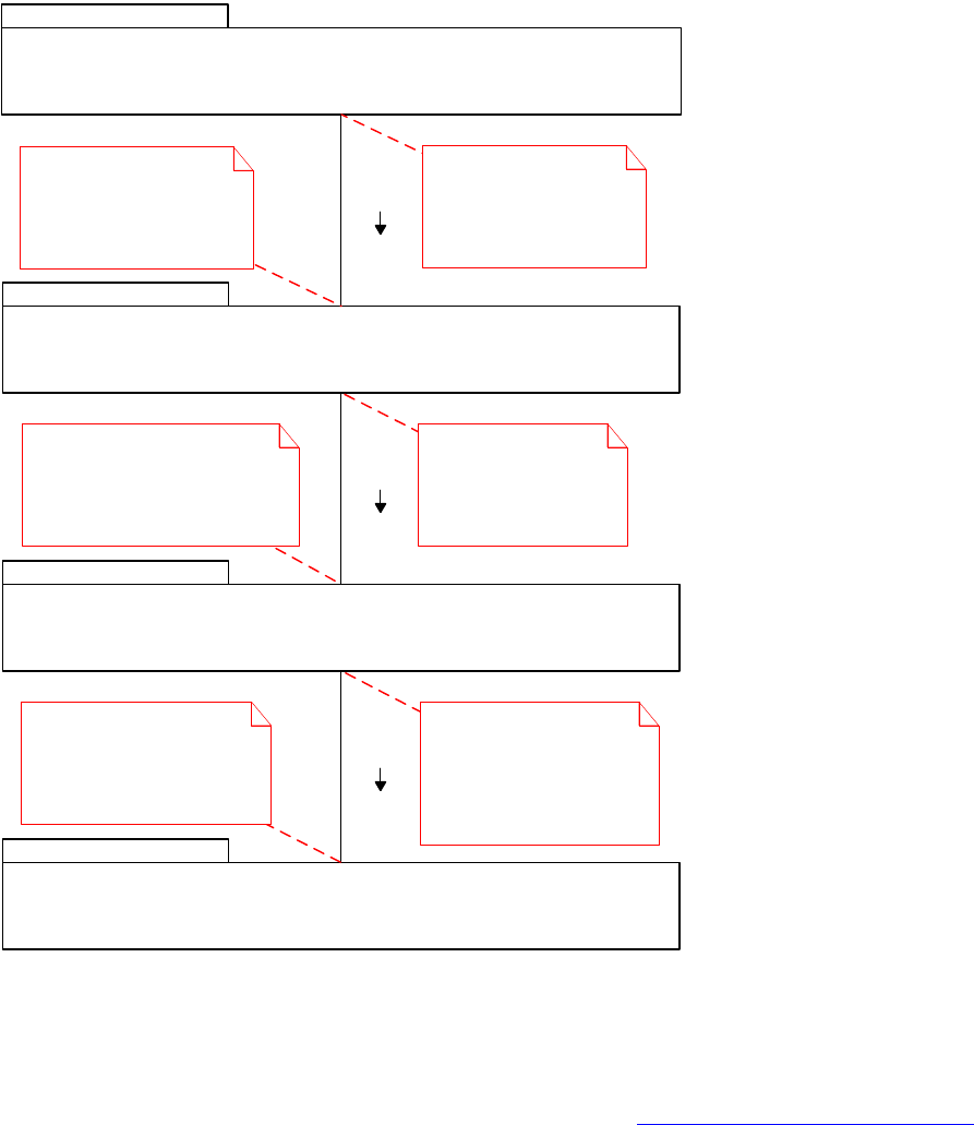
CHAPTER 4: Selection Selection architecture 97
to write client code. Writing code that sits on the model-manipulation side requires an understanding of
the selection architecture and the model.
The following figure shows the layers of encapsulation in the selection architecture. Client code
communicates through suites on an abstract selection boss (ASB) class. In turn, these suites communicate
with concrete selection boss (CSB) suites on one or more CSB classes. The CSB suites deal with the selection
format of only their CSB, and they know how to access and change objects only in the part of the model
the CSB manipulates.
A window can have one or more views that can support selection. Each view that uses selection
instantiates a selection subsystem. In general, client code can remain unaware of what selection
subsystem is in operation. While software developers need to be concerned about selection formats if
they are writing code that manipulates the model, there is less need to be concerned about selection
subsystems. For more information about selection subsystems, see “Selection architecture” on page 96.
Selection subsystem::
Abstract selection
Selection subsystem::
Concrete selection
Client
Model
Client code uses the selection
manager (ISelectionManager)
to acquire a suite, and then calls
one of its methods.
Integrator suite
forwards the method
call to the corresponding
CSB suite method on
enabled CSBs.
CSB suite accesses interfaces
on boss objects in the model
or processes commands to
change the model to do what
this suite method does.
Concrete selection
comprises one or more CSBs,
each of which target the part
of the model that underlies its
selection format.
Abstract selection:
Client code is decoupled
from the model by accessing
attributes of the selection
through an ASB.
Model stores attributes in
interfaces on boss objects. The
attributes targeted by selection
are selection attributes.

CHAPTER 4: Selection Selection architecture 98
To write code that uses selection to choose attributes of the model to be displayed or changed, it is
important to understand the structure that owns the selection format. To illustrate this, a schematic
diagram of the selection subsystem used by the layout view (kLayoutWidgetBoss) to edit design
documents is shown in the following figure. It presents the static structure and highlights important boss
classes and interfaces.
The ASB provides the suites called by client code. In this figure, interface IXxxxSuite illustrates such a
capability. The suite implementation on the ASB is an integrator suite; its responsibilities are described in
detail in “Integrator suites” on page 108. For now, think of these suites as forwarding any calls they receive
to corresponding suites on the CSBs. Further implementations of IXxxxSuite are provided on each CSB that
supports the capability. These implementations are CSB suites; their role is discussed further in “CSB
suites” on page 109
In the figure, you can see that IXxxxSuite is implemented on the layout CSB and the text CSB. This means
layout and text selections have its capability. Also, when nothing is selected, client code still has the
capability represented by IXxxxSuite, because the ASB then targets defaults and finds an implementation
of the suite on kDocumentDefaultSuiteBoss. For more information on how to use suites to manage
preferences, see “Selection architecture” on page 96. Table selections do not have the capability
represented by IXxxxSuite, because there is no implementation of the suite on the table CSB.
ISelectionManager is the signature interface that identifies a boss class as an ASB. To obtain a suite, client
code queries an ISelectionManager interface for the suite of interest. If the suite is available, its interface is
returned; otherwise, nil is returned. The ASB is not a normal boss class; all suite interfaces are aggregated
on the ASB, but an interface pointer is returned to client code only when an active CSB (or the default CSB)
kNewLayoutSelectionBoss
kLayoutSuiteBoss
ILayoutTarget
IConcreteSelection
kTextSuiteBoss
kTextSelectionBoss
ITextTarget
kTableSuiteBoss
kTableSelectionBoss
ITableTarget
IConcreteSelection IConcreteSelection
IXxxxSuite IXxxSuite
kDocumentDefaultSuiteBoss
kDocWorkspaceBoss
IXxxxSuite
Defaults:
Defaults are targeted
when nothing is selected
.
Suite:
interface that provides clients with a capability to access or change
attributes of the selection. More generically, a suite acts on or
reports information about the target. In the future, there may be
subclasses of kIntegratorSuiteBoss that are not selection related.
CSBs:
concrete selection boss classes that join this selection subsystem. Each CSB targets
its selection format(layout, text, or tables).
ASB:
abstract selection
Layout CSB DefaultsTable CSBText CSB
ILayoutSelectionSuite
ITextSelectionSuite
ITableSelectionSuite
IXxxxSuite
ISelectionManager
IIntegratorTarget
kIntegratorSuiteBoss
kAbstractSelectionBoss
kAbstractLayoutDocumentSelectionBoss
ASB
Selection manager:
Manages a selection subsystem.

CHAPTER 4: Selection Abstract selection bosses and suites 99
that supports the suite exists. The ASB uses a special implementation of IPMUnknown to control whether a
query for an interface returns the interface or nil.
Suite implementations get added to suite boss classes. The following suite boss classes are in the
preceding figure:
kDocumentDefaultSuiteBoss for defaults
kIntegratorSuiteBoss for the ASB
kLayoutSuiteBoss for the layout CSB
kTableSuiteBoss for the table CSB
kTextSuiteBoss for the text CSB
A suite boss class has a target (like IIntegratorTarget or ILayoutTarget) and a collection of suite
implementations. The figure shows how the selection extends the suite boss classes. Other boss classes
extend the suite boss classes in different ways. For example, scripting uses the suite boss kTextSuiteBoss to
manipulate text content.
Each box in the figure is a self-contained, portable unit. This is one reason why the selection architecture is
not coupled to a view, and CSBs do not have pointers to their ASB. This design allows reuse of suite boss
classes by other features in the future. A catalogue of suite boss classes is provided in the table in “Custom
suites” on page 111.
Each selection format has a CSB that extends its suite boss class. IConcreteSelection is the signature
interface that identifies a boss class as a CSB. Only those CSBs that join the selection subsystem used by
the layout view are shown in the the preceding figure. Other CSBs exist and are used by other subsystems.
For a complete list of all CSBs, refer to the API Reference for IConcreteSelection. To understand more about
the responsibilities of a CSB, see “Concrete selection bosses” on page 100.
Also, the ASB supports a set of interfaces that allows the selection content to be set programmatically.
ISelectionManager provides the ability to select/deselect all objects. Each selection format provides an
interface to allow the selection target to be varied. In the preceding figure, for example,
ILayoutSelectionSuite allows page items to be selected, and ITextSelectionSuite allows text to be selected.
Abstract selection bosses and suites
The selection architecture isolates client code from model code by means of an ASB. The ASB provides
suite interfaces, which are collections of capabilities, as well as other interfaces needed for managing the
selection. The main point to understand about the ASB is that it implements the facade for the selection
subsystem. Client code interacts with the facade (a suite on the ASB). Writing client code to take
advantage of the selection architecture is straightforward; you need to understand only the facade. To
write model code and code to change your model or the existing document model, however, it is
important to understand how to interact fully within the selection subsystem, and this is less
straightforward.
The client code in the following example uses a parameter to determine which selection manager
(ISelectionManager) to use by calling IActiveContext::GetContextSelection. The client code then queries
for the suite of interest, IFooSuite. If the suite is available, the client checks to see if the capability it wants is
enabled by calling IFooSuite::CanDoSomething. If so, the client uses the capability on the selection by
calling IFooSuite::DoSomething. If someone were to create a new selection format and add support for
IFooSuite, this client code would work. It does not need to know any details of how IFooSuite is
implemented on any specific selection format.

CHAPTER 4: Selection Concrete selection bosses 100
void FooActionComponent::DoAction(IActiveContext* ac, ActionID actionID...)
{
...
InterfacePtr<IFooSuite> iFooSuite(ac->GetContextSelection(),
UseDefaultIID());
if (iFooSuite != nil && iFooSuite->CanDoSomething()) {
iFooSuite->DoSomething();
}
...
}
In most cases, either client code is passed a parameter that identifies the selection manager to query for a
suite, or the selection manager is implied by the kind of code being written.
Concrete selection bosses
A CDB is a boss class that encapsulates a selection format. It supports the manipulation and observation of
the selected objects in the part of the model where the objects are located.
This section describes the available selection formats and their associated CSB. The key properties of each
CSB are tabulated. The following table describes the label for each field.
Layout selection
Layout selections—made with the Selection tool or programmatically—are represented by the layout CSB.
For examples of the suites available, see IGeometrySuite, ITransformSuite, and IGraphicAttributeSuite. For
a complete list of available suites, refer to the API Reference for kLayoutSuiteBoss. Also see the following
figure and table.
This figure shows a layout selection containing a page item:
Label Specifies
CSB The boss class that represents this concrete selection.
CSB name The name of the CSB that represents this concrete selection.
Description A general description of this concrete selection.
Selection
attribute
extensibility
Indicates whether this concrete selection can be extended to notify of changes to
new selection attributes introduced by third-party software developers. Each CSB is
responsible for defining the mechanism used to call selection extensions when
selection attributes change. Some CSBs allow the mechanism to be extended. See
“Selection extensions” on page 112 and “Selection observers” on page 113.
Selection format The format of the objects this concrete selection makes selectable.
Selection suite The interface that can specify the set of objects selected for this concrete selection.
Suite boss class The boss class to which suites get added that extend the attributes that can be
manipulated by this concrete selection. A list of all suites supported by the CSB is in
the documentation for this boss class. Custom suites get added to the suite boss
class.
Target The interface that identifies the set of objects selected for this concrete selection.

CHAPTER 4: Selection Concrete selection bosses 101
The following table shows the layout-selection CSB:
Table selection
Table selections—made with the Type tool or programmatically—are represented by the table CSB. For an
example of a suite, see ITableSuite. For a complete list of available suites, refer to the API Reference for
kTableSuiteBoss. Also see the following figure and table.
This figure shows a table selection containing table cells:
This table shows the table-selection CSB:
CSB Name Layout CSB
Selection format Layout objects like frames and other kinds of page items.
CSB kNewLayoutSelectionBoss.
Suite boss class kLayoutSuiteBoss.
Target ILayoutTarget.
Selection suite ILayoutSelectionSuite.
Selection
attribute
extensibility
Extensible. The CSB has a shared observer attached to the document’s subject
(kDocBoss). Selection extensions define CreateObserverProtocolCollection to extend
the protocols that are attached. Selection extensions define
SelectionAttributeChanged to handle change broadcasts.
CSB Name Table CSB
Selection format Table cells.
CSB kTableSelectionBoss.

CHAPTER 4: Selection Concrete selection bosses 102
Text selection
Text selections in the Layout view—made with the Type tool or programmatically—are represented by the
text CSB. Text selection take one of two principal forms, a selected range of characters in a story
(TextRange) or an insertion point within a story (represented by a TextRange with zero span). Although it
may not seem intuitive that an insertion point is considered a text selection, it is considered a selection
from the viewpoint of selection management.
NOTE: Other views use other CSBs to represent text selection.
For examples of the suites available, see ITextEditSuite and ITextAttributeSuite. For a complete list of
available suites, refer to the API Reference for kTextSuiteBoss. Also see the following figures and table.
This figure shows a text selection containing a range of characters:
This figure shows a text selection containing an insertion point:
This table shows the text-selection CSB:
Suite boss class kTableSuiteBoss.
Target ITableTarget.
Selection suite ITableSelectionSuite.
Selection attribute
extensibility
Extensible. The CSB has a cell focus (ICellFocus) that monitors table-attribute
changes in the selection. Changes to custom table attributes also are detected by
this CSB. Also, the CSB has a shared observer attached to the document’s subject
(kDocBoss). Selection extensions define CreateObserverProtocolCollection to
extend the protocols that are attached. Selection extensions define
SelectionAttributeChanged to handle change broadcasts.
CSB name Text CSB.
Selection format Text.
CSB kTextSelectionBoss.
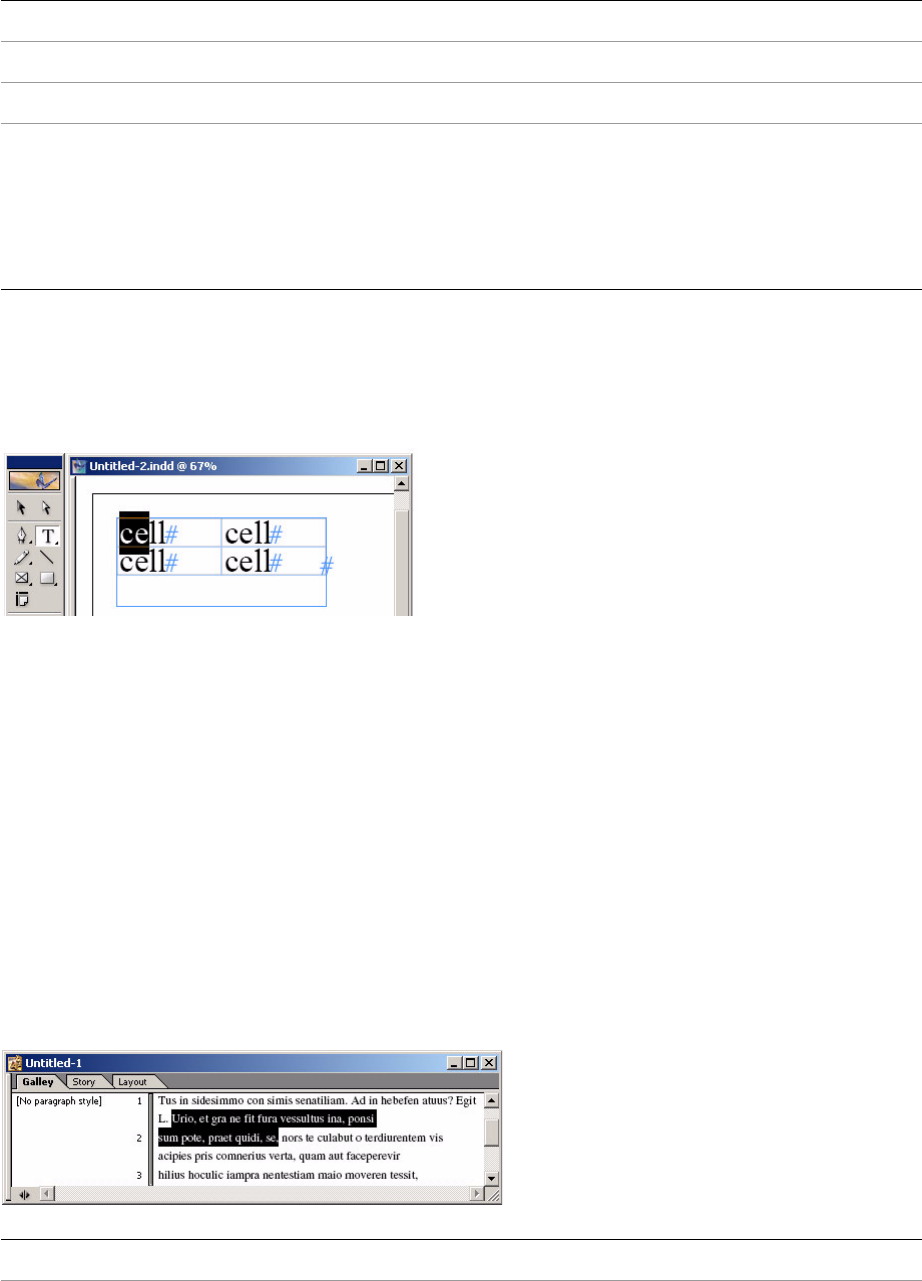
CHAPTER 4: Selection Concrete selection bosses 103
The following figure shows a text selection in a table cell. Although the selection is inside a table, this is a
text selection and not a table selection. The selected text is indicated by the ITextTarget target interface.
The table implied by this selection is indicated by ITableTarget, a secondary targeting interface provided
by text selection.
Galley text selection
Text selections in the galley view—made with the Type tool or programmatically—are represented by the
galley-text CSB. The galley-text CSB represents text selection made in a galley view window.
Text selection uses many subsystems. For the most part, client code can remain unaware of what
subsystem is in operation, but suite developers need to know, because the CSB that supports text
selection in the galley view is different than the one that supports it in the layout view. If you do not add
your suite to the appropriate suite boss class, your suite might not be available when you want it. In most
cases, the same suite implementation can be reused. For an example of a suite that is available, see
ITextEditSuite. For a complete list of available suites, refer to the API Reference for kGalleyTextSuiteBoss.
Also see the following figure and table.
This figure shows a galley text selection containing a range of characters:
Suite boss class kTextSuiteBoss.
Target ITextTarget.
Selection suite ITextSelectionSuite.
Selection
attribute
extensibility
Extensible. The CSB has a text focus (ITextFocus) on kTextSelectionFocusBoss that
monitors text-attribute changes; this picks up changes to custom text attributes.
Also, the CSB has a shared observer attached to the document’s subject (kDocBoss).
Selection extensions define CreateObserverProtocolCollection to extend the
protocols that are attached. Selection extensions define SelectionAttributeChanged
to handle change broadcasts.
CSB name Galley text CSB.
Selection format Galley text.

CHAPTER 4: Selection Concrete selection bosses 104
Story-editor text selection
The story editor is available in InDesign and InCopy.
Text selections by the story editor are similar to galley text selection. The story-editor CSB extends the
galley-text CSB, and both share the same suite boss class, kGalleyTextSuiteBoss. For an example of a suite
that is available, see ITextEditSuite. For a complete list of available suites, refer to the API Reference for
kGalleyTextSuiteBoss. Also see the following figures and table.
This figure shows a story-editor text selection in InCopy:
This figure shows a story-editor text selection in InDesign:
This table shows the story-editor text-selection CSB:
CSB kGalleyTextSelectionBoss.
Suite boss class kGalleyTextSuiteBoss.
Target ITextTarget.
Selection suite ITextSelectionSuite.
Selection
attribute
extensibility
Limited extensibility. The CSB has a text focus (ITextFocus) on
kTextSelectionFocusBoss, which monitors text-attribute changes. Changes to
custom text attributes are picked up by this.
CSB name Story-editor text CSB.
Selection format Story editor text.
CSB kStoryEditorSelectionBoss.
Suite boss class kGalleyTextSuiteBoss.
Target ITextTarget.
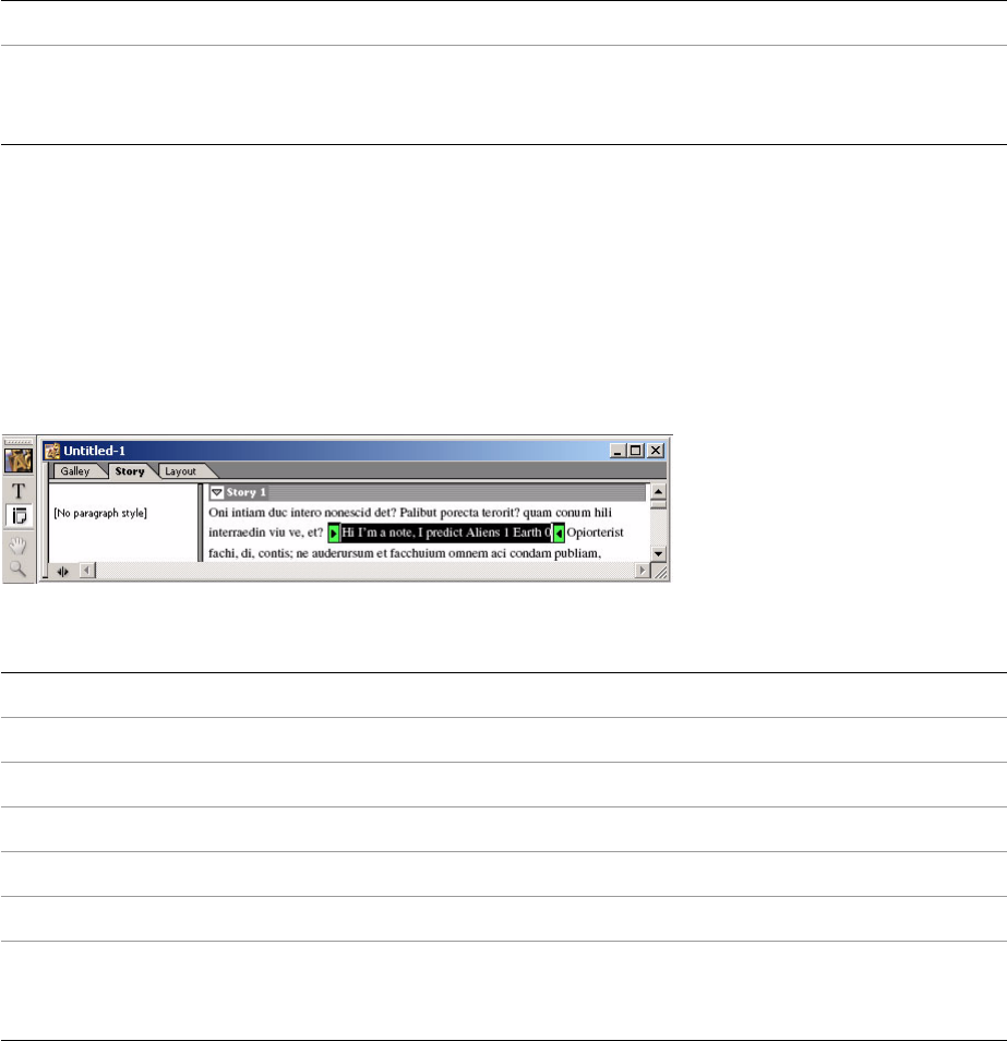
CHAPTER 4: Selection Concrete selection bosses 105
Note text selection
When text is selected in a note, the CSB involved is not the same as the one used for normal text selection.
The note-text CSB represents text selection made in a note. For an example of a suite that is available, see
INoteSuite. For the complete list of available suites, refer to the API Reference for kNoteTextSuiteBoss. Also
see the following figure and table.
This figure shows a note selection:
This table shows the note text-selection CSB:
XML selection
XML selections in the structure view (the left panel of the following figure)—made with the Selection tool
or programmatically—are represented by the XML CSB. There is a selection subsystem associated with the
XML structure view that is distinct from the selection subsystem associated with the layout view, even
though both views are displayed in the same window. Do not confuse XML selection with the XML tags
shown in the layout view (the right panel of the following figure). For examples of suites that are available,
see IXMLStructureSuite and IXMLTagSuite. For a complete list of available suites, see the documentation
for kXMLStructureSuiteBoss. Also see the following figure and table.
This figure shows XML node selections in an XML-structure view:
Selection suite ITextSelectionSuite.
Selection
attribute
extensibility
Limited extensibility. The CSB has a text focus (ITextFocus) on
kTextSelectionFocusBoss, which monitors text attribute changes. Changes to custom
text attributes are also picked up by this.
CSB name Note text CSB.
Selection format Note text.
CSB kNoteTextSelectionBoss.
Suite boss class kNoteTextSuiteBoss.
Target ITextTarget.
Selection suite ITextSelectionSuite.
Selection
attribute
extensibility
Limited extensibility. The CSB has a text focus (ITextFocus) on
kTextSelectionFocusBoss, which monitors text attribute changes. Changes to custom
text attributes are also picked up by this.
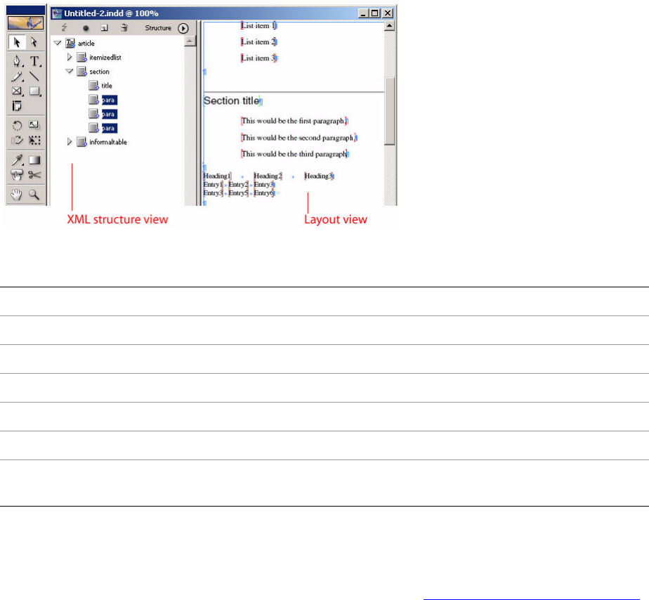
CHAPTER 4: Selection Concrete selection bosses 106
This table shows XML-selection CSB:
Document defaults
When a document is open but nothing is selected, the document workspace (kDocWorkspaceBoss)
becomes the selection subsystem’s target. For more information, see “Selection architecture” on page 96.
Also see the following figure and table.
This figure shows document defaults: An open document with no selection:
CSB name XML CSB
Selection format XML node (element, attribute, or both)
CSB kXMLStructureSelectionBoss
Suite boss class kXMLStructureSuiteBoss
Target IXMLNodeTarget
Selection suite IXMLNodeSelectionSuite
Selection attribute
extensibility
Not extensible.
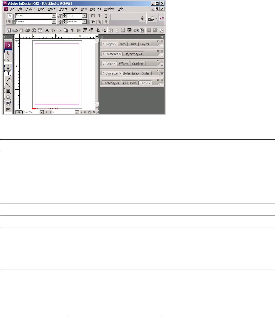
CHAPTER 4: Selection Concrete selection bosses 107
This table shows document-defaults CSB:
Application defaults
When no document is open, a special selection subsystem (the workspace selection,
kAbstractWorkspaceSelectionBoss) is activated. It targets application-wide defaults on kWorkspaceBoss.
For more information, see “Selection architecture” on page 96. Also see the following figure and table.
This figure shows application defaults: No document open:
CSB name Defaults.
Selection format Preferences maintained as data interfaces on kDocWorkspaceBoss.
CSB kDocWorkspaceBoss. (Strictly speaking, this is not a CSB, because it does not
aggregate IConcreteSelection; however, kDocWorkspaceBoss often is referred to as
the defaults CSB.)
Suite boss class kDocumentDefaultSuiteBoss.
Target NA
Selection suite NA
Selection
attribute
extensibility
Extensible. The CSB has a shared observer attached to the document workspace’s
subject (kDocWorkspaceBoss). Selection extensions define
CreateObserverProtocolCollection to extend the protocols that are attached.
Selection extensions define SelectionAttributeChanged to handle change
broadcasts.
CHAPTER 4: Selection Integrator suites 108
This table shows application-defaults CSB:
Integrator suites
An integrator suite is an implementation of a suite that was added to kIntegratorSuiteBoss, which is part of
an ASB. Consequently, an integrator suite sometimes is known as an ASB suite. All communication
between client code and the selection is performed using the integrator suite. A properly designed suite
API is neutral to selection format, meaning there are no references to a specific selection format. This is
essential to avoid tight coupling between the client code and the model.
The purpose of an integrator suite is to iterate over the concrete-selection formats supported by the suite
or, more formally, to integrate over the integrator target (represented by IIntegratorTarget). Although it
may seem that “iterator” may be a more appropriate name, “integrator” is correct in this context, because
it means “to join together.” In the mathematical sense, “integrate” also can refer to summation, and the
integrator suite performs a summation over the capabilities of individual selection-format-specific suites.
CSB name Defaults.
Selection format Preferences maintained as data interfaces on kWorkspaceBoss.
CSB kWorkspaceBoss. (Strictly speaking, kWorkspaceBoss is not a CSB, because it does not
aggregate IConcreteSelection; however, kWorkspaceBoss often is referred to as the
defaults CSB.)
Suite boss class kApplicationDefaultSuiteBoss.
Target NA
Selection suite NA
Selection
attribute
extensibility
Extensible. The CSB has a shared observer attached to the session workspace’s subject
(kWorkspaceBoss). Selection extensions define CreateObserverProtocolCollection to
extend the protocols that are attached. Selection extensions define
SelectionAttributeChanged to handle change broadcasts.
CHAPTER 4: Selection CSB suites 109
The implementation of an integrator suite is very stereotypical; it delegates any call to CSB suites on CSBs
that are active (that is, on CSBs that have a selection). Integrator-suite implementations should be based
on templates provided by the SDK. The templates reduce the amount of code you need to write.
An example of an integrator suite is the kTableSuiteIntegratorImpl implementation of ITableSuite on
kIntegratorSuiteBoss. Both text (kTextSuiteBoss) and table selections (kTableSuiteBoss) provide support for
ITableSuite. The client code is shielded from the selection format that is providing the implementation.
Integrator suite calls are forwarded to the selection-format–specific implementations on the CSB suites.
CSB suites
A CSB suite is a suite implementation on a CSB. CSB suites receive calls forwarded from integrator suites
when they are called by client code.
CSB suites exist to do model-specific work, like navigating relationships between objects in the model and
processing of commands. When you manipulate the model from within a CSB suite, you interact with
objects in a specific selection format (for example, by means of target interfaces like ITextTarget or
ILayoutTarget). There are several CSBs that extend suite-boss classes; for example, kTextSelectionBoss
subclasses kTextSuiteBoss. For a complete list of CSBs, refer to the API Reference for the IConcreteSelection
interface, from which you can examine the documentation page for each CSB to see which suite boss it
extends.
Encapsulation
A key concept in the selection architecture is that client code should be insulated from code that accesses
and modifies the model (both the document and associated data). Code that works in terms of UID,
UIDRef, or UIDList values that relate to stories (kTextStoryBoss objects) or layout objects (for example,
something that exposes an IGraphicFrameData interface) interacts with a portion of the document model.
A selection of objects that is represented, for example, as a UIDList (as would have been the case in the old
selection architecture) is tightly coupled to the model. Such tight coupling makes it very difficult to add
new selection formats, because client code already has detailed knowledge about what is in a selection.
Also, with such tight coupling, you cannot change the way in which the model is represented without
breaking client code, because the client code has detailed model knowledge.
To add new selection formats, the client code needs to be decoupled from the selection formats. This
means client code should be neutral with respect to selection format when dealing with the selection. The
client code communicates by means of ASB suites. These suites, in turn, communicate with CSB suites. The
CSB suites deal only with the model format of their CSB; they do not even know about the ASB. This is
necessary because an alternative use for suites is scripting, which most likely does not have an analog to
the ASB.
Suites and the user interface: an example
In the StrokeWeightMutator sample plug-in, the stroke-weight drop-down widget is enabled when the
stroke weight of whatever is selected can be changed. These steps are followed:
1. The widget looks for the API’s stroke attribute suite (IStrokeAttributeSuite).
2. If the suite is available, a CSB (the one with something selected or the defaults, if nothing is selected)
has an implementation of the suite.

CHAPTER 4: Selection Responsibilities 110
3. The widget asks the integrator suite on the ASB whether the stroke-weight attribute is available, by
calling IStrokeAttributeSuite::GetStrokeWeightCount.
4. The integrator-suite implementation on the ASB forwards the call to the CSB-suite implementations.
5. The CSB implementation accesses the model for the selection format it supports and returns the
answer.
6. The widget then calls IStrokeAttributeSuite::GetStrokeWeight to retrieve the value if applicable.
When the widget handles a user click to change the stroke weight, the widget calls
IStrokeAttributeSuite::ApplyStrokeWeight on the integrator suite to dispatch to the CSB suites, which
change the value stored in the model. The widget synchronizes what it displays with any changes to the
selection using a selection observer. It is sent a message when the stroke weights displayed in the widget
need to be refreshed. (See “Selection observers” on page 113.)
Responsibilities
Basic client-code responsibilities
If you are writing client code that modifies the properties of an abstract selection and can use a preexisting
suite, your responsibilities are minor. Query the selection manager (ISelectionManager) that represents
the abstract selection for the suite you want (like ITextAttributeSuite to change properties of text in a
selection) and, if you get the suite, use it. Look for a code fragment showing these responsibilities for the
ITextMiscellanySuite suite.
You must understand how to query the abstract selection for a particular capability. To understand what
suites are provided by the API, refer to the API Reference and examine the boss classes that aggregate
ITextMiscellanySuite, to see the selection formats that support this particular capability.
Selection-observer responsibilities
If you are writing code that needs to update when the selection changes, implement a selection observer
(see “Selection observers” on page 113). If there is a preexisting suite that informs your client code of the
changes you are interested in, your selection observer looks for messages from this suite. For example,
ITextAttributeSuite notifies clients when a text-attribute change happens to the selection. Otherwise,
implement a custom suite to inform client code about the changes of interest (see “Custom suites” on
page 111).
Custom-suite responsibilities
If you have any client code that depends on the state of the selection, write a custom suite to access that
state. For example, the BasicMenu sample implements a custom suite because it has menu items that need
to know whether a page item is selected. A suite is required because the client code needs to access a
selection target interface to determine whether a page item is selected.
If you are writing code that changes the existing document model (for example, you are implementing or
processing commands that change this model), and you want to use selection to target the objects, you
must create a suite.

CHAPTER 4: Selection Custom suites 111
If you are writing code that extends the document model (for example, you are adding a custom data
interface to the layout model, like BasicPersistInterface), and you want to use selection to target the
manipulation of this data, you must create a suite.
The model also extends to default preferences; changes to the application’s default preferences and the
document default preferences can be mediated by the selection subsystem.
Custom suites
When writing a custom suite that you want to make available to client code in one or more selection
formats, provide two implementations, one relating to abstract selections and another to concrete
selections. The former (see “Integrator suites” on page 108) is added to the kIntegratorSuiteBoss suite boss
class, and the latter (see “CSB suites” on page 109) is added to the selection-format-specific suite boss
classes. For details about the selection formats that can be of interest to client code, see “Concrete
selection bosses” on page 100. The following table lists suite boss classes.
Suite boss class Selection format Rationale
kApplicationDefaultSuiteBoss Application defaults If you want your suite to be available to
client code when no documents are
open, add the suite to this boss class.
kDocumentDefaultSuiteBoss Document defaults If you want your suite to be available to
client code when a document is open but
nothing is selected, add the suite to this
boss class.
kGalleyTextSuiteBoss Text in InCopy Galley
or Story Editor views
(ITextTarget)
If you want your suite to be available to
client code during galley- or
story-editor-view text selections, add the
suite to this boss class.
kIntegratorSuiteBoss Abstract
(IIntegratorTarget)
Required for any custom suite.
kLayoutSuiteBoss Layout
(ILayoutTarget)
If you want your suite to be available to
client code during layout selections, add
the suite to this boss class.
kNoteTextSuiteBoss Text in InCopy Note
(ITextTarget)
If you want your suite to be available to
client code during note selections, add
the suite to this boss class.
kSelectionInterfaceAlwaysActiveBoss If you want your suite to be available to
client code regardless of the kind of
concrete selection that exists, add the
suite to this boss class.
kStoryEditorSuiteBoss Text in Story Editor
view (ITextTarget)
(Not supported.) If you want the story
editor suite to be different from that for
InCopy Galley view, add the suite to this
boss class.

CHAPTER 4: Selection Selection extensions 112
Selection extensions
A selection extension (ISelectionExtension) is a bridge between a suite implementation with an unknown
interface and the selection architecture. A suite that requires advanced function registers a selection
extension with the selection subsystem. The selection subsystem then communicates with the extension,
which in turn forwards a message to the suite implementation. If your suite requires one or more of the
services described in this section, you must implement a selection extension.
Caches
A suite may need to cache data to improve performance. You can add caches to suite implementations. In
general, caches are added to CSB suite implementations. Cache validation should be delayed as long as
possible. Rather than updating the cache every time a model change occurs, declare a Boolean cacheValid
flag. When the model changes, set the flag to kFalse. Before accessing the cache, rebuild it if it is invalid.
Thus, if your suite provides data to a user-interface panel and that panel is not visible, your suite does not
needlessly consume CPU cycles recalculating cache values the user does not need.
Furthermore, caches should be enabled only on CSB boss classes, not suite boss classes. Because the
scripting architecture extends suite boss classes, no caching should be done on them. If you are
implementing a custom suite that needs a cache, add your cache interface only to the CSB.
IConcreteSelection is the signature interface that identifies a boss class as a CSB. Your custom suite
implementation can then perform a run-time check to see if your cache interface is available. If not, it can
handle this situation gracefully and carry on without using the cache.
Selection change notification
The design of some suites requires notification of selection changes. A selection extension allows your
suite to be called by a CSB whenever the selection changes. A selection extension allows you to control
whether clients of your suite—in the form of selection observers—get notified. (See “Selection observers”
on page 113.)
There are two kinds of selection change events:
An object is added to or removed from the selection (that is, the selection changes); for example, a
user Shift-clicks to add a frame to the selection.
An attribute of an object in the selection changes (that is, a selection attribute changes); for example,
the stroke color of selected frames changes.
kTableSuiteBoss Tables (ITableTarget) If you want your suite to be available to
client code during table selections, add
the suite to this boss class.
kTextSuiteBoss Text (ITextTarget) If you want your suite to be available to
client code during text selections, add the
suite to this boss class.
kXMLStructureSuiteBoss XML structure,
(IXMLNodeTarget)
If you want your suite to be available to
client code during XML selections, add
the suite to this boss class.
Suite boss class Selection format Rationale

CHAPTER 4: Selection Selection observers 113
A suite that has a cache must mark its cache as invalid when notified the selection has changed. A suite
needs to invalidate its cache when notified that a selection attribute changed only if the specific
selection-attribute change affects this suite's cache. Many selection-attribute changes may not affect a
particular cache.
NOTE: Selection-attribute change notification is not supported on all CSBs. For information on each CSB,
see “Concrete selection bosses” on page 100.
Initialization
Some suites need to perform an action on start-up or shut-down of a selection subsystem. Any such
initialization is done by implementing a selection extension. Do not confuse this kind of start-up and
shut-down with application services, like IStartupShutdownService, which are called for the application
session. Selection subsystems get created and destroyed as the views that own them open and close.
Communication with Integrator suite
Rarely, a CSB implementation needs to communicate with its integrator. Because there is no pointer on the
CSB back to the integrator, a messaging system was created:
IConcreteSelection::BroadcastToIntegratorSuite.
Selection observers
As described in “Selection change notification” on page 112, there are two kinds of selection change
event: selection-changed event and selection-attribute-changed event. A selection observer
(ActiveSelectionObserver) is the abstraction that allows client code to be called when a selection-changed
event occurs. For more information, see the SelectionObserver.h header file.
Suites that need to communicate extra data to selection observers during the selection-changed event
implement a selection extension. Suites that need to include information about a
selection-attribute–changed event also implement a selection extension. (See “Selection extensions” on
page 112.)
When a selection-changed event occurs, a selection observer’s
ActiveSelectionObserver::HandleSelectionChanged member method is called. On receiving this call, an
observer can take action. For example, the observer can update some data displayed in a user-interface
widget. Optionally, before taking action, the observer can examine the message parameter
(ISelectionMessage) and look for extra data placed there by a suite.
When a selection-attribute–changed event occurs, a selection observer’s
ActiveSelectionObserver::HandleSelectionAttributeChanged member method is called. On receiving this
call, an observer must call ISelectionMessage::WasSuiteAffected before taking action. There are many
kinds of selection attributes, and they can be given meaning only by the CSB suite. It examines the
broadcast from the selection format that changed (originating from a command notification that the
model was updated), then passes a model-independent message about the change to selection
observers. A selection observer may be called when any attribute of the selected objects changes, so a
selection observer can receive messages that do not affect it. The selection observer must filter these calls,
so it does not needlessly take action and waste CPU cycles. For sample code, see BasicPersistInterface.
CHAPTER 4: Selection Selection-utility interface (ISelectionUtils) 114
Selection-utility interface (ISelectionUtils)
A utility interface for selection (ISelectionUtils) is provided on kUtilsBoss. For detailed information on the
member methods, refer to the API Reference for ISelectionUtils.
Some member methods provided by ISelectionUtils allow you to access the active selection. Most client
code does not need to depend on the active selection, because client code normally is given access to the
selection manager to use. If you want the active selection, ISelectionUtils::GetActiveSelection returns the
selection manager from the active context. There also are other member methods, like
QueryActiveLayoutSelectionSuite and QueryActiveTextSelectionSuite, that depend on the active selection
manager; these should be used only by client code that needs to work with the active selection.

115
5Model and UI Separation
You must separate your model operations from your user-interface (UI) operations by placing them into
different plug-ins. This chapter discusses this required separation.
Introduction
InDesign requires that model and UI components be in separate plug-ins. Plug-ins must declare whether
they support model or UI operations, and model plug-ins must not depend on UI plug-ins or libraries.
This is required in InDesign Server, InDesign, and InCopy to support multithreading.
NOTE: Therefore, in this chapter, InDesign refers to InDesign, InCopy, and InDesign Server unless otherwise
noted.
This chapter covers:
“Separating model and UI components” on page 115
“Detecting plug-ins that mix model and UI components” on page 117
“Conversion issues” on page 119
Separating model and UI components
You must separate model and user interface (UI) components into different plug-ins.
Benefits of separation
This required separation offers several benefits:
Plugs-in can safely work in background threads.
Classes and implementations from model plug-ins are available to multithreaded operations such as
IDML export. UI plug-ins are not.
The user interface for a set of features can be refactored easily at any time.
Users can be given a model plug-in, so they can open and print documents with customized
persistent data without gaining access to the ability to manipulate such features.
Chapter Update Status
CS6 Edited Only the following changed:
• Removed obsolete text about CS4 from Introduction.

CHAPTER 5: Model and UI Separation Separating model and UI components 116
Declaring a plug-in as either UI or model
A plug-in must identify itself as either model or UI; it cannot be both. Refer to Chapter 6, “Multithreading,”
for additional information. The plug-in type is identified in the plug-in’s PluginVersion resource in its .fr file.
If you do not specify either model or UI, you will get an error in the PluginVersion resource when ODFRC
tries to compile your resource file.
To specify this, #include PlugInModel_UIAttributes.h in your .fr file and add a line (before the version and
after the feature set) that contains kUIPlugIn or kModelPlugIn. For example, in the framelabel sample
application, in FrmLbl.fr, this declares the plug-in to be a model plug-in (kModelPlugIn):
resource PluginVersion (kSDKDefPluginVersionResourceID)
{
kTargetVersion,
kFrmLblPluginID,
kSDKDefPlugInMajorVersionNumber, kSDKDefPlugInMinorVersionNumber,
kSDKDefHostMajorVersionNumber, kSDKDefHostMinorVersionNumber,
kFrmLblLastMajorFormatChange, kFrmLblLastMinorFormatChange,
{ kInDesignProduct, kInCopyProduct, kInDesignServerProduct},
{ kWildFS },
kModelPlugIn,
kFrmLblVersion
};
Model component content
The following are model components:
Core model data (including persistent data) and preferences (on either kWorkspaceBoss or
kDocWorkspaceBoss).
Commands that modify such data.
Façades that call core model commands and do not make calls to UI components.
Selection Suites (ASB/CSBs) that operate on the model and do not make calls to UI components. See
“Note about selection suites” on page 117.
Observers that are used for keeping other model components up to date.
Service providers that participate in model changes, including startup/shutdown service providers
and import/export providers. (NOTE: Methods in import/export providers use the UIFlag. Make sure
that the kSuppressUI mode is supported and that UI components are in other plug-ins.)
Any other code, such as utility classes (also called as façades or helper classes), that do not directly
make calls to UI components.
UI component content
The following are UI components:
Typical user-interface components, such as menus (action components), dialogs, dock bars, kits,
panels, and rulers. This also includes observers that are attached to widgets on user-interface
components, and event handlers that supplement the widget behavior.
Observers that are used for keeping user interfaces up to date, such as ActiveSelectionObservers.

CHAPTER 5: Model and UI Separation Detecting plug-ins that mix model and UI components 117
Service providers that participate in user-interface changes.
Commands that present a dialog.
Note about selection suites
The following selection suite bosses are part of the model:
kIntegratorSuiteBoss
kTextSuiteBoss
kLayoutSuiteBoss
kApplicationDefaultSuiteBoss
kDocumentDefaultSuiteBoss
AddIns that add model suites to these bosses belong in the model. Most suites are model suites, but there
are some view (UI) suites. These would be suites that operate on the user interface; for example,
IDragDropSourceSuite and IEyeDropperSuite. The AddIns for such UI suites belong in the user interface.
When identifying whether a suite is model or UI, be careful when you see “selection” in a method name.
For example, the ITextMiscellanySuite suite has a GetFirstSelectedWord method. This method probably
should be named GetFirstWord or GetFirstTargetedWord. Just because a method name contains
“selection” does not necessarily mean that the suite is a UI suite. As noted above, often a better word to use
in the method is “target,” as suites operate on targeted data. One kind of target is the selection, but
scripting also can target data and use suites to operate on that data. The kind of target is abstracted out of
the suite.
Other user-interface-specific bosses to which plug-ins often add interfaces are
kSelectionInterfaceAlwaysActiveBoss and kAbstractLayoutDocumentSelectionBoss.
kSelectionInterfaceAlwaysActiveBoss is a special class used only by the selection subsystem to determine
which interfaces to always “leave on.” The kAbstractLayoutDocumentSelectionBoss and the others that
sub-boss from kAbstractSelectionBoss also are only user interface.
Detecting plug-ins that mix model and UI components
It is possible that your plug-in violates the requirement for separating model and UI operations, whether
you are aware of the violation or not. There are three ways to detect plug-ins that mix model and UI
components:
“Using a script” on page 117.
“Examining your plug-in project for invalid links” on page 118.
“Using Dumpbin(Windows)” on page 119.
Using a script
The debug build of InDesign Server includes an extra script provider to help determine whether any
plug-ins mix model and UI components. Specifically, the script provider iterates through the object model
and reports bosses that aggregate interface implementations with well-known user-interface-related IIDs,
which include the following:
CHAPTER 5: Model and UI Separation Detecting plug-ins that mix model and UI components 118
IID_IACTIONCOMPONENT
IID_ICONTROLVIEW
IID_IDIALOGCONTROLLER
IID_IDIALOGCREATOR
IID_IDRAGDROPSOURCE
IID_IDRAGDROPTARGET
IID_ILAYOUTACTION
IID_ISELECTIONFILTER
IID_ISNAPTOSERVICE
IID_ISPRITE
IID_ITIP
IID_ITOOL
IID_ITOOLREGISTER
IID_ITRACKER
IID_ITRACKERFACTORY
IID_ITRACKERREGISTER
IID_IWIDGETCREATOR
This script provider adds the following read-only properties to the Application script object, exclusively in
the debug build:
modelpluginswithui
pluginswithui
uipluginswithmodel
For more information on scripting objects that you can use for testing, and for sample scripts, see
“Scripting objects you can use for testing” in Getting Started With Adobe InDesign Plug-in Development.
Examining your plug-in project for invalid links
Check your model plug-in project for the following links, remove them if they exist, and rebuild the plug-in
project:
On Windows, do not link to WidgetBin.lib.
On Mac OS®, do not link to InDesignModelAndUI; instead, you can use InDesignModel.
If you get linker errors, modify your code to remove dependencies on these user-interface-related
components.
CHAPTER 5: Model and UI Separation Conversion issues 119
Using Dumpbin(Windows)
If you are developing a plug-in for Windows, you can use Dumpbin to see whether your plug-in (.pln file)
imports any symbols from WidgetBin.dll. DUMPBIN is installed with Microsoft® Visual Studio 9 in the
following location:
<Microsoft Visual Studio 9>\VC\bin\dumpbin.exe
For more information, open a Command Prompt window, change directory to the <Microsoft Visual Studio
9>\VC\bin folder, and type “dumpbin /?” You may need to run <Microsoft Visual Studio
9>\Common7\Tools\vsvars32.bat to register environment variables before running Dumpbin. This is likely
if you have other versions of Visual Studio installed.
Problems when mixing model and UI
When InDesign Server launches, it will not load any model plug-in that links against InDesignModelAndUI
or WidgetBin. However, InDesign Server cannot detect the following situations and will therefore load
them; this causes severe runtime problems, including crashes or corrupt documents:
Model plug-ins that instantiate or inherit from bosses provided by UI plug-ins.
Model plug-ins that attempt to reuse UI implementations
When InDesign Server tries to load a plug-in with UI components, you might see warning messages on the
console window or log at startup, or asserts might be raised when you try to instantiate it or use it. For
example, if a boss named kCHDMPanelWidgetBoss in your plug-in inherits from kPalettePanelWidgetBoss
in the WidgetBin plug-in:
Could not find parent class WidgetPrefix + 23 (0x617) to get inherited interfaces!
Error in Class 0x47f04 (294660), kCHDMPanelWidgetBoss, the class’s Parent with Class ID 0x617 (1559)
doesn’t Exist
Because the WidgetBin plug-in is not available in the InDesign Server object mode or background threads,
the object model cannot set up this boss properly and you might get asserts or other problems.
Conversion issues
If you are converting existing plug-ins that mix model and UI components, follow the instructions in the
preceding sections and then review this section.
Note about moving ActionIDs
If you have model and UI components in the same plug-in, the easiest way to separate the components
into different plug-ins is to leave the model components in the existing plug-in and move the UI
components to a new plug-in.
If you move your UI components to a new plug-in (with a new plug-in prefix ID), the ActionIDs should
move with the components. This means that the value of ActionIDs changes. Some ActionIDs are
hard-coded in keyboard shortcut files (if you ship them), so when you change the value of an ActionID,
each keyboard shortcut file that maps that ID to a shortcut needs to be fixed. You can do this on an
action-by-action basis, using the InDesign keyboard shortcut editor.
CHAPTER 5: Model and UI Separation Conversion issues 120
Moving persistent data from UI plug-ins to model plug-ins
This section provides general guidelines for data conversion. For details on data conversion, see the
“Versioning Persistent Data” chapter of Adobe InDesign SDK Solutions.
If you are moving UI operations out of a model plug-in into a new UI plug-in--which is the recommended
strategy--you most likely will not need to do any data conversion. If, however, you have model data in a UI
plug-in that you want to move out, here’s the process for doing so.
Moving persistent data from a UI plug-in to a model plug-in is fairly straightforward, as long as all previous
conversions were handled by schemas. Even if the UI plug-in contains code conversions, this is not difficult
after you understand the steps. The following steps apply only if code converters need to be moved from a
UI plug-in to a model plug-in.
Mainly, the conversion manager needs to be notified of the conversion change to both the UI plug-in and
the model plug-in. To convert the data:
1. Preserve the original IDs of the persistent data in the UI plug-in’s *ID.h file, by appending _Obsolete to
the name.
2. Move the IDs for the persistent data from the UI plug-in to the model plug-in and renumber to match
the IDs in the destination plug-in.
3. In the UI plug-in’s *ID.h file, increment the conversion version number so that the PluginVersion
resource is changed. If this is the first conversion required for InDesign, it would look something like
this:
#define kMoveClippingPathSettingsToModel kFiredrakeInitialMinorFormatNumber
#define kClippingDlgLastFiredrakeFormatChange kMoveClippingPathSettingsToModel
// These things control the plug-in's conversion schemas
#define kClippingDlgLastMajorFormatChange kFiredrakeMajorFormatNumber
#define kClippingDlgLastMinorFormatChange kClippingDlgLastFiredrakeFormatChange
4. Increment the conversion number of the model plug-in in the same manner, using a similar but
unique identifier. We suggest appending “ToModel” to the ID in the UI conversion *ID.h file and
“FromUI” to the ID in the model conversion *ID.h file. In this example, it would be
“kMovePreferencesFromUI” in the model conversion *ID.h file. This matters in cases when the UI and
model plug-ins have different numbers of minor conversions. These two identifiers are used in the rest
of this procedure in different places. It is important to use the correct one in each place.
5. If the UI plug-in contains code converters, move them to the model plug-in. These converters are just
service providers, which are nonpersistent. You can move the class and implementation definitions as
well as the IDs, just like you would any other nonpersistent boss.
6. For the code converters that you moved in the previous step, modify the code converters (the C++
classes that derive from CConversionProvider) by renaming the object-model IDs that you obsoleted
in step 1 to the obsoleted version. You will need to include the UI conversion ID header file to get
access to these. Typically, these IDs are used in the ConvertTag and ShouldConvertImplementation
methods. An example follows. Note the use of kClipSettingsImpl_Obsolete instead of
kClipSettingsImpl.
CHAPTER 5: Model and UI Separation Conversion issues 121
ImplementationID Clip_ConversionProvider::ConvertTag(ImplementationID tag,
ClassID forClass, int32 conversionIndex, int32 inLength, IPMStream* inStream,
IPMStream* outStream, IterationStatus whichIteration)
{
if (conversionIndex == kSaveClipTypeChgIndex)
{
switch (tag.Get())
{
case kClipSettingsImpl_Obsolete:
if (inLength > 0)
ConvertClipSettings(inStream, outStream);
break;
}
}
return (tag);
}
7. In the model plug-in’s other schema resource, add a null conversion. Most plug-ins will not have an
OtherSchemaFormatNumber resource; you will need to create one. This resource lets you add a null
conversion for a plug-in other than the one containing the resource. This is required here rather than
in the UI plug-in, because the UI plug-in will not exist in the server product. The null conversion is
needed because we incremented the version number of the UI plug-in. An example follows. Note the
use of the minor version ID defined in the UI plug-in’s conversion ID header file.
// SchemaFormatNumber - Define null conversions
resource OtherSchemaFormatNumber(2)
{
{
kClippingDlgPluginID,
{ kFiredrakeMajorFormatNumber, kMoveClippingPathSettingsToModel },
}
};
8. Note that the plug-in ID used here, kClippingDlgPluginID, should be the plug-in ID of the UI plug-in. It
is the ID of the plug-in for which we are defining the null conversion.
9. For each code converter moved in step 5 that contains a code-null-converter, define a null converter in
the OtherSchemaFormatNumber created in the previous step 8. A code-null-converter is a code
converter that defines a conversion by returning a version number y from its GetNthConversion
method, but then returns IConversionProvider::kNothingToConvert from all of the ShouldConvert
methods for version number y. The version number used in the OtherSchemaFormatNumber should
be the one used in the code converter. For example, in the following GetNthConversion method
implementation, two code conversions are defined. The later one is a null conversion.
void Clip_ConversionProvider::GetNthConversion(int32 n,
VersionID* fromVersion, VersionID* toVersion) const
{
switch (n)
{
// Added eyedropper target to definition
case kSaveClipTypeChgIndex:
*fromVersion = VersionID(kClippingDlgPluginID, kK2MajorFormatNumber,
kLastK2MinorVersionNumber);
*toVersion = VersionID (kClippingDlgPluginID,
kSherpaMajorFormatNumber, kSherpaClippingChanged);
break;
// ID 1.0J changed our version number (no changes to be made)
case kHotakaRenumberChgIndex:
*fromVersion = VersionID(kClippingDlgPluginID,
CHAPTER 5: Model and UI Separation Conversion issues 122
kSherpaMajorFormatNumber,kSherpaClippingChanged);
*toVersion = VersionID(kClippingDlgPluginID,
kHotakaMajorFormatNumber,kHotakaInitialMinorFormatNumber);
break;
}
}
IConversionProvider::ConversionStatus
Clip_ConversionProvider::ShouldConvertImplementation(
ImplementationID implID, ClassID context,
int32 conversionIndex /* Which converter is being evaluated */) const
{
IConversionProvider::ConversionStatus conversionStatus =
IConversionProvider::kNothingToConvert;
if (conversionIndex == kSaveClipTypeChgIndex)
{
switch (implID.Get())
{
case kClipSettingsImpl_Obsolete:
// Always convert because these are containers
conversionStatus = IConversionProvider::kMustConvert;
break;
}
}
return (conversionStatus);
}
10. Now that we identified that the conversion from kSherpaMajorFormatNumber,
kSherpaClippingChanged to kHotakaMajorFormatNumber, kHotakaInitialMinorFormatNumber) is a
null conversion, we add the “to” version number to the OtherSchemaFormatNumber resource:
resource OtherSchemaFormatNumber(2)
{
{
kClippingDlgPluginID,
{ kHotakaMajorFormatNumber, kHotakaInitialMinorFormatNumber },
kClippingDlgPluginID,
kFiredrakeMajorFormatNumber, kMoveClippingPathSettingsToModel },
}
};
11. In the model plug-in’s schema resource, for each implementation moved, add a MoveImplementation
conversion. This describes where the data came from and what its new ID is. This is why we need to
preserve the original ID with the _Obsolete appendix. An example follows:
{
MoveImplementation
{
kClipSettingsImpl_Obsolete,
kClippingDlgPluginID,
{ kHotakaMajorFormatNumber, kHotakaInitialMinorFormatNumber },
kClipSettingsImpl,
{ kFiredrakeMajorFormatNumber, kMoveClippingPathSettingsFromUI }
}
},
12. Because the UI plug-in now contains no data as far as the conversion manager is concerned, and
because on the server the UI plug-in will not exist, we need to tell the conversion manager that the UI
plug-in was removed, as far as persistent data is concerned. To do this, add a RemovePlugin directive
to the model plug-in, as shown below:
CHAPTER 5: Model and UI Separation Conversion issues 123
{
RemovePlugin
{
{ kFiredrakeMajorFormatNumber, kMoveClippingPathSettingsFromUI },
kClippingDlgPluginID,
{ }
{ }
}
}
13. The version number in the remove plug-in directive is the version number of the plug-in that the
directive is in when the plug-in being removed was removed. Here, we use the model plug-in version
number we created in step 4 and the plug-in ID of the plug-in being removed. Both the classes and
implementations removed section are empty. We did not remove them; we moved them.

124
6Multithreading
This chapter describes how InDesign and InCopy use multithreading and explains how to ensure that your
plug-ins are thread safe.
This chapter covers the following:
The purpose of multithreading
What multithreading is
Model-based multithreading in InDesign
Which InDesign features use multithreading
Coding and testing your plug-in to ensure thread safety
Concepts
This section defines multithreading and explains its purpose
Background
Not long ago, application developers could count on improvements in performance because radically
faster CPUs regularly became available. For decades, processors (CPUs) increased in speed exponentially,
doubling roughly every two years. Presently, CPU makers are facing limitations that make it difficult or
impossible to continue to improve CPU speeds at this rate. The complexity of applications and the need to
continue to sell CPUs call for improved performance.
CPU makers are now attempting to improve performance by adding multiple cores. A multicore machine
has multiple processing units, meaning that it is essentially a multiprocessor machine. Machines with two,
four, or eight cores are now commonly seen. It is reasonable to expect to see machines with many more
cores. These machines may be referred to as many-core machines, and they very well might ship with
hundreds of cores.
While the old processor improvements helped any application to run faster, improving performance by
adding processors is highly dependent on whether software is written to take advantage of the separate
processors. Most applications, including prior versions of InDesign, have not been designed to do this. The
challenge for application developers now is to take advantage of multiple processors within a single
application. In some sense, it is similar to the change that takes place when a company grows from a
one-man operation to one with numerous employees.
Chapter Update Status
CS6 Edited Only the following changed:
• Removed obsolete text about CS4 from Features That Use Multithreading.

CHAPTER 6: Multithreading Multithreading in InDesign 125
What is multithreading?
Multithreading is a way of simultaneously executing multiple software operations within the same
program. Each such operation is said to occur in a separate thread. Threads can operate on data that is
global (shared with other threads) or local (specific to the thread).
Computers with multiple processors can simultaneously execute multiple threads. In most cases, there will
be more threads of execution than processors. Where fewer processors exist than threads of execution, the
operating system suspends and revives threads as necessary. More available processors ultimately equals
more available processing time.
Why multithreading?
Multithreading allows InDesign to take advantage of multiple processors. This provides opportunities to
improve performance and responsiveness.
Terminology
NOTE: InDesign means the InDesign and InCopy desktop applications. These applications make use of
multithreading; InDesign Server does not.
In general:
Synchronous processing means that operations take place in a specific sequence; if separate processes
occur, one must wait for another to complete before it can do anything.
Asynchronous processing means that multiple operations can occur simultaneously, and some
operations might be able to continue without waiting for other operations to complete. This implies
multithreaded execution with one or more tasks running on a background thread.
A model is a collection of objects that are backed by a database for persistent storage. InDesign
includes several models, including document models, session models, book models, and several
others; for more informaiton, see the discussion on models in the “Concepts” section of Chapter 2,
“Commands.”
Model operations are operations that affect the content of a model.
Multithreading in InDesign
This section describes the InDesign approach to multithreading.
Overview of model-based multithreading
Multithreading for InDesign focuses on model operations because this yields the greatest impact on
performance. This approach leans heavily on the InDesign database and requires model/user interface (UI)
separation, a practice previously required only by InDesign Server.
To support model-based threading, InDesign has a means for multiple threads to operate on a single
InDesign database. This mechanism is called database and merging. It allows the document database to be
cloned at a particular point, operated on by a background thread, and, if necessary, merged back into the
actual database. While this capability is not publicly exposed in the InDesign CS6 SDK, it is important to

CHAPTER 6: Multithreading Multithreading in InDesign 126
understand because all model code can be called by background threads. It is your responsibility when
developing plug-ins to ensure that your code is thread safe.
Most InDesign execution occurs on the main thread. This includes all user interactions and launching the
product. It is in the main thread that InDesign responds to typing and mouse events. It is also in the main
thread that changes to a document become visible. Both model and UI operations can be carried out in
the main thread.
Any additional thread is referred to as a background thread. Background threads have no access to
object-model constructs that come from UI plug-ins. They are limited to model operations and thus
resemble instances of InDesign Server. Model operations are equivalent whether run on the main thread
or a background thread; they must produce the same results in either case.
Features that use multithreading
InDesign applies multithreading to only the following features:
Updating the status of links in a document. This is carried out asynchronously. Link status is always
updated when a document is opened. If the “Check Links Before Opening Document” preference is off,
the update occurs asynchronously; the document becomes available to the user immediately without
waiting for links to be updated. If the preference is on, the updates are made synchronously; any
outstanding updates are completed before the document becomes available to the user. In both
cases, additional link updates continue asynchronously as long as the document remains open. This is
described as lightweight because such background threads merely gather information. No changes
are made to the document on background threads.
PDF (print) export. All InCopy PDF exports take place on the main thread. InDesign exports can be
carried out synchronously (on the main thread) or asynchronously (each on its own background
thread). By default, the InDesign Export UI exports PDF asynchronously. When exporting PDF from
InDesign via scripting or the C++ API, you can control whether export occurs synchronously or
asynchronously. See “Asynchronous exports”.
IDML export. This can be carried out synchronously or asynchronously. The Export UI exports IDML
asynchronously. When exporting IDML via scripting or the C++ API, you can control whether export
occurs synchronously or asynchronously. See “Asynchronous exports”
InCopy Save All. This uses multiple background threads when more than one InCopy story needs to be
saved. Multiple stories are distributed among several threads, but each story is processed in a single
thread (not split among threads). The entire operation is synchronous in that it waits until all threads
are complete before control returns to the user.
InCopy Save. This occurs on a background thread.
While this list isn’t large, keep the following in mind:
Model plug-ins are called by background threads during export. Export exercises nearly every model
plug-in, including yours.
Expect Adobe to add additional asynchronous operations in the future.
Effect on InDesign’s behavior
Multithreading has several effects on InDesign's behavior:

CHAPTER 6: Multithreading Ensuring thread safety in your plug-in 127
InDesign must postpone certain user actions until all background threads complete. In particular,
quitting, closing, and reverting are postponed until all background operations are complete. As an
alternative, the user can cancel the foreground action.
InDesign’s capacity to run background threads is based on the number of processors present and the
available memory. InDesign may queue requests if the required resources are unavailable or are
insufficient for optimal performance.
Background threads cannot directly report to the user on progress, success, or errors. These are
presented in the Background Tasks panel. Also, an animation appears in the application bar when
background tasks are in progress, and a Background Task Alert might appear when a background task
needs to convey a message to the user.
Activity on background threads can have a negative impact on the performance of the main thread.
This depends on the number of background thread operations, processor availability, physical
memory, and storage.
Ensuring thread safety in your plug-in
Ensuring thread safety is the process of following the rules that make plug-in code safe to run in the
InDesign multiple-threaded environment. As a plug-in developer, this is where you will spend your time
supporting multithreading. All model code must be made thread safe. (UI operations always run on the
main thread. They do not have to be made thread safe.)
This section provides an overview and detailed steps on how to make your plug-in thread safe.
Rules for thread safety
InDesign’s multithreading environment provides a separate execution context (a cloned copy of the
database) for each thread. Making a plug-in thread safe amounts to making all components safe to be
instantiated and operated on by multiple threads simultaneously.
NOTE: You must ensure that your plug-ins are thread safe. If you don’t, InDesign will behave inconsistently
and may randomly crash.
Threads do not share object-model instances. They do share globals and statics, so a big part of your effort
is removing or synchronizing such variables.
The following rules summarize what plug-in developers must do to support multithreading:
Separation of model and UI operations is now mandatory. A plug-in must declare whether it provides
model support or user-interface (UI) support. Object-model constructs (bosses and implementations)
provided by model plug-ins can be instantiated by background threads. Constructs from UI plug-ins
cannot be instantiated on background threads; if you try to do so, the system behaves as if the plug-in
were missing and returns a nil pointer. It is critical that you write model code that expects to be able to
receive nil pointers if it queries bosses that are provided by a UI plug-in. For information on declaring
model or UI support, see “Separating model and UI components” in Chapter 5, “Model and UI
Separation.”
All model plug-ins must be made thread safe. This amounts to eliminating or synchronizing global and
external resources as described later in this chapter. (Because UI plug-ins are called only from the main
thread, thread safety is not an issue.)

CHAPTER 6: Multithreading Ensuring thread safety in your plug-in 128
Third-party code using its own background threads must not operate on InDesign object-model
constructs from those threads. Object-model operations are thread safe only when using the internal
database cloning and merging mechanism discussed earlier in “Overview of model-based
multithreading”. This mechanism is internal and is not directly exposed to third-party developers.
Bypassing this mechanism results in crashes, document corruption, and/or unpredictable behavior
because multiple threads would be sharing the same execution context. InDesign’s model requires
each thread to have its own execution context (and cloned database).
Service providers must now declare whether they are available on background threads. This is done
using the IK2ServiceProvider::GetThreadingPolicy() method. You must call and implement service
providers with this in mind. For details, see “Threading and service providers”.
Startup/shutdown services can now be called on application and/or thread start-up. This is specified
using a ServiceID. For details, see “Threading and startup/shutdown services”. Make sure that your
service is using the appropriate ID.
All libraries that are used by plug-in code must be thread safe. For example, InDesign uses the
thread-safe versions of all Boost libraries.
Thread safety porting and development procedures
We recommend the following steps for porting plug-ins from prior versions of InDesign or developing new
plug-ins to support multithreading:
1. Read about “Thread-safe coding constructs”.
2. If you have not already done so, enforce complete model/UI separation on all your plug-ins as
described in “Separating model and UI components” in Chapter 5, “Model and UI Separation.” Us e t h e
original prefix ID in the model plug-in, and acquire a new prefix ID for the UI components.
3. Update your PlugInVersion resource as described in “Separating model and UI components” in
Chapter 5, “Model and UI Separation.”
4. Do enough nonmultithreading porting to get your plug-ins compiling.
5. Review “Threading and service providers” and make sure that your code follows those rules. Note:
Ensure that your service providers are available on background threads if necessary.
Most significant service providers are available on background threads, but some service
providers reside in a UI plug-in, hence are not available on background threads. Ensure that your
model code does not rely on any UI service providers, or ensure that these service providers are
moved to model plug-ins.
6. Review “Threading and startup/shutdown services” and make sure that your code meets the
requirements. Note:
Decide whether your startup/shutdown services need to be called on application and/or thread
startup and shutdown. Use the appropriate service-provider implementation. In most cases, your
code will be application specific, so you will most often use kCAppStartupShutdownProviderImpl.
7. Run the Statics Reporter tool on your plug-ins. This tool detects and reports the use of any global or
static variables in your plug-in. Running the tool requires some configuration. You also should be
aware that the tool makes use of some naming conventions to filter results. See
<SDK>/devtools/statics_reporter/ReadMe.txt for details about setting up and executing the Statics
Reporter tool.

CHAPTER 6: Multithreading Ensuring thread safety in your plug-in 129
8. Remove any globals and statics that you can. Some variables are acceptable: statically initialized const
variables are fundamentally safe, but other global variables that change state are not safe. Such
variables can be used to optimize performance, but they often are used just for convenience; often,
such code can be efficiently rewritten without a global variable. Regardless, the fact that such code
can run on multiple threads fundamentally changes the execution scenario.
9. Remove any function-local static variables. Substitute globals in an anonymous namespace with
appropriate synchronization, or use nonstatic const objects.
10. Certain globals will be difficult or impossible to remove, so some synchronization will be required.
Study the threading APIs and libraries, and use the appropriate constructs to make your code
thread-safe. For your convenience, we include several thread safety recipes; see “Thread-safety
recipes”.
11. If necessary, apply the same synchronization techniques to your use of external resources, such as
files. For example, if your plug-in writes to an external text file, use the described synchronization
strategies to ensure that only one thread writes to it at a time.
12. Launch the debug version of InDesign with your plug-in present. Fix any asserts or error messages
related to multithreading. In particular, fix violations of object-model rules reported on startup, as
described in “Object-Model Rules”.
13. Follow the guidance in “Testing for thread safety”.
Object-Model Rules
Refer to the rules in this section while developing plug-ins to ensure that your plug-in is thread safe.
A model boss cannot derive from a UI boss
For example:
// In model plugin Foo, foo.fr file
Class
{
kMyModelFooBoss,
kSomeUIBoss, // defined in MyUIPlugin
{
// interfaces
}
}
This code generates the following assert on startup:
Class kMyModelFooBoss is defined in a model plugin (Foo.apln) but derives from class
kSomeUIBoss which is defined in a UI plugin (MyUIPlugin.apln)! This is not allowed
because the main thread and worker threads will behave differently!
Model plug-ins cannot refer to classes or implementations in UI plug-ins
Model plug-ins must not depend on UI classes or implementations. For example:
CHAPTER 6: Multithreading Ensuring thread safety in your plug-in 130
// In model plugin Foo, foo.fr file
Class
{
kMyModelFooBoss,
kInvalidClass,
{
IID_IMYUIINTERFACE, kMyUIInterfaceImpl // defined in MyUIPlugin
}
}
// OR:
AddIn
{
kMyModelFooBoss,
{
IID_IMYUIINTERFACE, kMyUIInterfaceImpl // defined in MyUIPlugin
}
}
These two scenarios generate the following assert on startup:
Model plugin Foo.apln is attempting to use UI interface implementation kSomeUIImpl
provided by plugin kMyUIPlugin in class kMyModelFooBoss. A UI interface implementation
can be added to a model boss only via the AddIn directive in a UI plugin resource, and
that implementation will not be present in the boss when running in a background task.
UI classes derived from a model class cannot override model
implementations in the base class
Allowing such an override would result in different boss definitions in the main and background threads.
For example:
// in GenericClass.fr (model plugin):
Class
{
kDrawablePageItemBoss, // subclasses page item
kPageItemBoss,
{
... // a bunch of interfaces
IID_IPLACEBEHAVIOR, kCGraphicPlaceBehaviorImpl,
}
}
// in epsclass.fr (model plugin):
Class
{
kInDesignPageItemBoss, // subclasses drawable page item
CHAPTER 6: Multithreading Ensuring thread safety in your plug-in 131
kDrawablePageItemBoss,
{
... // a bunch of interfaces
}
}
// in ImportExportUIClass.fr (UI plugin):
AddIn
{
kInDesignPageItemBoss, // overrides base class interface implementation
kInvalidClass
{
IID_IPLACEBEHAVIOR, kInDesignDocPlaceBehaviorImpl,
}
}
This situation is detected at startup and you get the following error message in a dialog box:
Add-in class kInDesignPageItemBoss defined in UI plugin IMPORT EXPORT UI.RPLN overrides
model implementation kCGraphicPlaceBehaviorImpl in parent class kDrawablePageItemBoss
from model plugin GENERIC PAGE ITEM.RPLN! This is not allowed because the class will
have a different behavior on main thread than on the other threads! The override will be
ignored.
Threading and service providers
There are some thread-safety concerns when calling and implementing service providers. Some service
providers are available on both the main and background threads, while others are available only on the
main thread. To facilitate this, IK2ServiceProvider now contains a method called GetThreadingPolicy().
Implementations of IK2ServiceProvider::GetThreadingPolicy() can return either
kMainThreadOnly, indicating that the service is limited to the main thread.
kMultipleThreads, indicating that the service provider is available on both the main and background
threads.
Like all boss objects, service providers that are implemented in UI plug-ins are not available on
background threads. Such implementations should return kMainThreadOnly; they should never return
kMultipleThreads. Violating this causes an assert in the debug build.
The SDK includes CServiceProvider, a default implementation of IK2ServiceProvider. CServiceProvider is
the standard base class for service providers. It provides a default implementation of GetThreadingPolicy
that returns a threading policy based on the plug-in in which the service provider boss resides. If the boss
comes from a UI plug-in, it returns kMainThreadOnly. If the service is in a model plug-in, it returns
kMultipleThreads. A service from a model plug-in can override IK2ServiceProvider::GetThreadingPolicy
and return kMainThreadOnly to restrict itself to the main thread.
Typically, service providers are used to identify some other extension pattern, such as a responder or
startup/shutdown service. Most implementations, like kResponderServiceProviderImpl, inherit their
behavior from CServiceProvider, although any subclass can override GetThreadingPolicy.
Threading and startup/shutdown services
Startup/shutdown services are a type of service provider. Each startup/shutdown service must provide
implementations for both of the following:

CHAPTER 6: Multithreading Ensuring thread safety in your plug-in 132
IK2ServiceProvider, which identifies the startup/shutdown service and its threading policy.
IStartupShutdownService, which provides the actual code to be run on startup and shutdown.
The implementation of IK2ServiceProvider identifies itself as a startup/shutdown service by returning
kStartupShutdownService in GetServiceID() or GetServiceIDs(). As described above, it identifies a
threading policy by what it returns in GetThreadingPolicy(). Returning IPlugIn::kMainThreadOnly restricts
the service to startup and shutdown of the main thread. Returning IPlugIn::kMultipleThreads means the
service will be called on both the main thread and background thread startup and shutdown.
NOTE: Starupt/shutdown services that are intended to work on IPlugIn::kMultipleThreads must be
implemented in the model plug-ins.
However, it is unlikely that you will need to provide a custom implementation of IK2ServiceProvider,
because the SDK includes service-provider implementations for application startup, thread startup, and a
combination:
kCMainThreadStartupShutdownProviderImpl is for startup/shutdown services that are called only on
the main thread.
kCMTStartupShutdownProviderImpl is for startup/shutdown services that are called on the main and
background thread startup and shutdown. Such startup services must reside in a model plug-in.
kCStartupShutdownProviderImpl derives its implementation of GetThreadingPolicy from
CServiceProvider. If the startup/shutdown service boss resides in a model plug-in, the service will be
called on both main and background thread startup and shutdown. If the boss resides in a UI plug-in,
the service will be called only on main thread startup and shutdown.
Thread-safe coding constructs
InDesign uses several APIs and libraries to support making code thread safe. This amounts to a mixture of
the Boost.Threads Library and some Adobe-authored implementations.
Boost.Threads
Before you start using the recipes and code, it is best to develop some background on writing thread-safe
code outside of InDesign. The following article is a good introduction to threading with Boost. The “Thread
Creation” section is of limited value in porting InDesign plug-ins, but the sections explaining mutexes,
conditional variables, thread-local storage, and once routines are directly relevant.
“The Boost.Threads Library” (May 1, 2002), http://www.drdobbs.com/cpp/184401518
(There is an update to the article that is of less value to making InDesign plug-ins thread-safe, as it deals
more with managing threads.)
If you use Boost.Threads in your code, you must link against the correct library files in the various
configurations of your project files. On Windows, use the BoostThreadLib macro that is defined in the
platform-specific vsprops files (for example, DebugWin32.vsprops and Debugx64.xvsprops). The correct
path is already defined for each platform; you simply have to add “$(BoostThreadLib)” to each of the
Additional Dependencies (AdditionalDependencies in the XML) settings for the linker.
Mac OS projects that use the included xcconfig files are also configured to link against the correct
frameworks:
CHAPTER 6: Multithreading Thread-safety recipes 133
<SDK>/build/mac/debug|release/packagefolder/contents/Frameworks/boost_threads.framewo
rk
IDThreading and IDThreadingPrimitives
A handful of threading constructs are provided in Adobe-authored headers. Two files in particular provide
some useful tidbits:
IDThreading.h declares the IDThreading namespace and provides an InDesign-specific version of
thread-local storage. Thread-local storage provides thread-specific static and global variables.
InDesign’s version works much like the thread-local storage in Boost.Threads, but with some
advantages. InDesign’s thread-local storage implementation provides a virtually unlimited number of
thread locals. It also provides several “managed” thread-local storage types, which offer advanced
capabilities that are not in Boost. In Boost, thread-local storage is limited to four or eight bytes, but
IDThreading’s ThreadLocalManagedObject and ThreadLocalManagedArray allow you to store
variable-sized objects.
IDThreadingPrimitives.h provides a method that allows you to determine whether you are executing
on the main thread (or a background thread). It also provides several template functions that support
atomic operations (AtomicIncrement, AtomicDecrement, and CompareAndSwap). Atomic operations
allow you to perform as a single operation any operations that require multiple processor instructions.
This may not be obvious, but incrementing and decrementing require more than one instruction. It’s
possible for two threads to attempt to increment a variable at the same time. If the later thread checks
the memory before the earlier thread is done incrementing, it may increment the old value and save it
in memory after the earlier thread completes. This negates the earlier increment. Atomic operations
prevent this from happening.
Thread-safety recipes
This section describes additional situations that Adobe encountered when making InDesign and SDK
samples thread safe. You may encounter these situations when developing or porting plug-in code.
Synchronizing an operation
Synchronizing an operation amounts to preventing other threads from executing the same code. If you
need to synchronize an operation, you can do so with boost::mutex. Mutex is short for mutual exclusion. It
is a construct that allows you to ensure that only one thread can execute a particular piece of code at a
time.
The basic steps are as follows:
1. Add a boost::mutex variable to your .cpp file.
2. Enclose your operation in a single scope or method call.
3. Lock the mutex using a boost::mutex::scoped_lock. (The mutex will be unlocked when the variable
goes out of scope.)
See SDKODBCCache::Rebuild() for an example of using a mutex to provide exclusive access to a method
that rebuilds a cache. This particular code prevents other threads from building the cache while it’s under
construction.
CHAPTER 6: Multithreading Asynchronous exports 134
Constructing a singleton
If your plug-in code includes a singleton object, you must ensure that it is created in a thread-safe manner,
that is, to prevent more than one thread trying to simultaneously create such an object. Such an attempt
could result in more than one copy of the singleton, because there is an opportunity for a second thread to
create the object between the original creation of the object and when it’s marked as created. This
eventually results in invalid results and unpredictable behavior in your plug-in.
To ensure that only one thread can create a singleton, use boost::call_once to initialize the single object.
This construct guarantees that a particular function can be called only once by an application, even if
multiple threads reach the call_once statement simultaneously. To construct the initial singleton instance:
1. Add a boost::once_flag variable to your .cpp file.
2. Create a private static method that actually initializes the private singleton data.
3. Use boost::call_once to call the initialize from the method that creates and returns an instance. This
takes a pointer to the static method and the boost::once_flag.
For sample code, see SDKODBCCache::Instance().
Preventing reentrancy
It is not uncommon for a global variable to be used as a flag to prevent reentrancy into a particular
function. There are two ways to deal with this situation; which is appropriate depends on the code that
calls the method:
If you need to prevent reentrancy on a particular object, you can move the flag into the class.
If you need to prevent reentrancy on any instance, a member variable will not suffice. In this case, it is
best to use thread-local storage.
For an example of using thread-local storage to prevent reentrancy, see
TranFxMatteFactory::GetPaintedBBoxWithoutMatte().
Asynchronous exports
You can optionally code an InDesign plug-in or script to asynchronously export IDML and PDF. If you do
this, be aware that the main thread continues to execute your code while the export continues on a
background thread, so control returns to your code before the export operation is complete. Therefore,
immediately after starting the export thread, your code can't do operations such as checking the results of
the export or copying the exported file, because the operation might not have completed.
NOTE: InDesign allows asynchronous exports only to files, not to streams. This is due to limitations that
prevent transferring streams between threads.
Asynchronous export with C++
Asynchronous export from C++ is straightforward. IExportProvider contains methods that facilitate
asynchronous file export:
CanExportToFileAsynchronously() returns whether the export provider can export asynchronously.
The only such providers are IDML and PDF export. A third-party plug-in developer cannot write an
CHAPTER 6: Multithreading Testing for thread safety 135
asynchronous export because that requires database cloning, which is not available to third-party
developers in CS6.
AsynchronousExportToFile() can be called on export providers that support asynchronous export.
Export calling code typically looks something like the following:
exportProvider->ExportToFile(file,...);
if(ErrorUtils::GetPMGlobalErrorCode() == kSuccess)
doSomething(file);
This continues to work for ExportToFile(), but a similar pattern when calling AsynchronousExportToFile() is
incorrect. That is because the export will still be in progress on a background thread. It will not have set the
global error code, so the following code is incorrect:
TaskInfo TI = exportProvider->AsynchronousExportToFile(file);
// PMGlobalErrorCode is unchanged because the export is still in progress
if(ErrorUtils::GetPMGlobalErrorCode() == kSuccess)
doSomething(file); // file may not be valid yet!!
Instead, a plug-in that needs to check the status of an export must provide an export responder. (If the
event is started from a script, you could use attachable events for a similar effect.) Such a responder
receives notifications before export, after export, and upon export failures. Such a responder boss will
include an IK2ServiceProvider implementation that specifies one or more of the following services in
GetServiceID() or GetServiceIDs():
kBeforeExportSignalResponderService - Called before export.
kAfterExportSignalResponderService - Called after export.
kFailedExportSignalResponderService - Called on export failure and export cancellation.
The responder would then respond to these conditions in its IResponder::Respond() implementation,
which is called with an ISignalMgr pointer. This object is an ISignalMgr on the
kExportProviderSignalMgrBoss. It can be queried for an instance of IExportProviderSignalData.
InterfacePtr<IExportProviderSignalData> signalData(signalMgr,UseDefaultIID());
This interface can be used to determine useful information about the file, such as the source document or
the destination file.
Checking and Canceling Tasks
InDesign creates a background task for each asynchronous export. Use ITaskMonitorFacade to monitor
background tasks. This facade provides methods to get a TaskInfo (a class that provides information about
the background task) instance for one or all background tasks. TaskInfo::WaitForTask() causes the caller to
wait for a background task to complete. TaskInfo::Cancel() cancels the background task. Cancels occur
asynchronously, so code should call the appropriate wait method before continuing. ITaskMonitorFacade
includes utility methods that can be used to wait for or cancel all background tasks.
Testing for thread safety
Testing your plug-ins for thread safety takes some creativity. Your testing must cover more than simply
whether your feature behaves in the UI or with scripting. You should attempt to verify that your model
plug-in behaves appropriately when exercised simultaneously on the main thread and on a large number
of background threads. Consider the following recommendations when testing for thread safety:
CHAPTER 6: Multithreading Testing for thread safety 136
1. Test with the debug build. It contains numerous thread-safety asserts. Pay attention to these asserts
and fix them immediately.
2. Write a script that starts multiple IDML and/or PDF exports of large files. This should allow you to
create a large queue of exports on background threads.
3. While the exports are running in the background, have the script make a change to the data model on
the main thread and export, then repeat the change and export steps on the main thread repeatedly
while the background threads are running.
4. Verify that all exports produce the same results and that there are no inconsistent results or crashes.
Concentrate on your plug-in data.
5. Further enhance your test to include scripting changes to your feature on the main thread while many
other exports are queued and running.
6. Verify that changes made in the main thread did not affect exports on background threads.
7. Verify that the changes made in the main thread exported as expected.
137
7Layout Fundamentals
This chapter describes the features and supporting architecture of the layout subsystem, as well as how a
client can use these features and the layout-related extension patterns in the InDesign API.
For use cases related to layout, see the “Layout” chapter of Adobe InDesign SDK Solutions.
Terminology
See the “Glossary” for definitions of terms. The following table lists terms used in this chapter and sections
that relate to them.
Chapter Update Status
CS6 Unchanged
Term See ...
Bounding box “Bounding box and IGeometry” on page 171
Child “Parent and child objects and IHierarchy” on page 142
Content page item “Page items” on page 156
Current spread “Current spread and active layer” on page 177
Document “Documents and the layout hierarchy” on page 140 and “Spreads and
pages” on page 144
Document layer “Layers” on page 147
Frame “Frames and paths” on page 156
Front document “The layout presentation and view” on page 174
Front view “The layout presentation and view” on page 174
Geometric page item “Coordinate systems” on page 164
Graphic frame “Frames and paths” on page 156
Graphic page item “Graphic page items” on page 159
Group “Groups” on page 160
Guide “Guides and grids” on page 162
Layer “Documents and the layout hierarchy” on page 140 and “Layers” on
page 147
Layout hierarchy “Spreads and pages” on page 144
Layout view “Layout view” on page 176
CHAPTER 7: Layout Fundamentals Concepts 138
Concepts
The following figure shows a facing-pages publication with three pages arranged over two spreads. The
document is presented for edit in the layout presentation. The Pages panel is used to edit the spreads and
pages, including the master spreads and master pages. The Layers panel is used to edit the layers and to
list objects in the active spread.
Layout presentation “The layout presentation and view” on page 174
Master page, Master spread “Documents and the layout hierarchy” on page 140 and “Master spreads
and master pages” on page 152
Page “Documents and the layout hierarchy” on page 140 and “Master spreads
and master pages” on page 152
Page item “Documents and the layout hierarchy” on page 140 and “Page items” on
page 156
Pages layer “Spreads and pages” on page 144
Parent “Parent and child objects and IHierarchy” on page 142
Path “Frames and paths” on page 156
Publication “Spreads and pages” on page 144
Spread “Documents and the layout hierarchy” on page 140 and “Spreads and
pages” on page 144
Spread layer “Layers” on page 147
Text frame “Frames and paths” on page 156
Text page item “Text page items” on page 160
Transformation matrix “Transformation matrices” on page 164
Term See ...
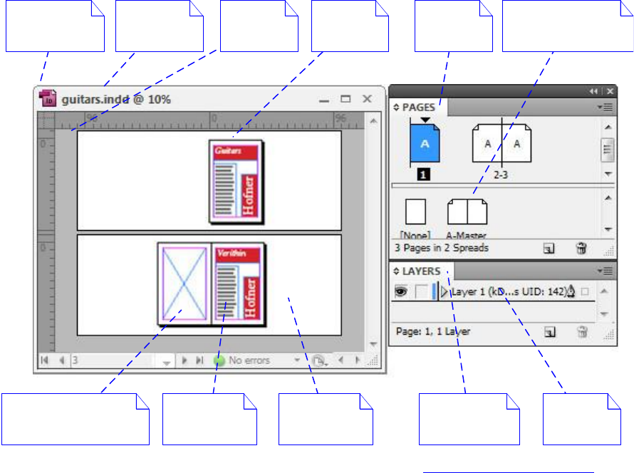
CHAPTER 7: Layout Fundamentals Concepts 139
Some basic terms are given below. A full layout-related glossary is in “Terminology” on page 137.
Document — An InDesign document, unless otherwise stated.
Layer — The abstraction that controls whether objects in a document are displayed and printed and
whether they can be edited. A layer can be shown or hidden, locked or unlocked, arranged in
front-to-back drawing order, and so on. A page item is assigned to a layer. If a layer is shown, its
associated page items are drawn; if a layer is hidden, its associated page items are not drawn. Layers
affect an entire document: if you alter a layer, the change applies across all spreads.
Layers panel —The user interface for creating, deleting, and arranging layers and for listing objects in
the active spread.
Layout presentation — The user-interface window in which the layout of a document is presented for
viewing and editing. The layout presentation contains the layout view and other widgets that control
the presentation of the document within the view.
Master page — A page that provides background content for another page. When a page is based on a
master page, the page items that lie on the master page also appear on the page. A master page
eliminates the need for repetitive page formatting and typically contains page numbers, headers and
footers, and background pictures.
Master spread — A special kind of spread that contains a set of master pages.
Page — The object in a spread on which page items are arranged.
Page item — Represents content the user creates and edits on a spread, like a path, a group, or a frame
and its content.
Document Spread Page
Pasteboard
Pages
panel
Layer
Page item
(text frame)
Page item
(empty graphic frame) Layers panel
Layout
presentation
Master spread and
master pages
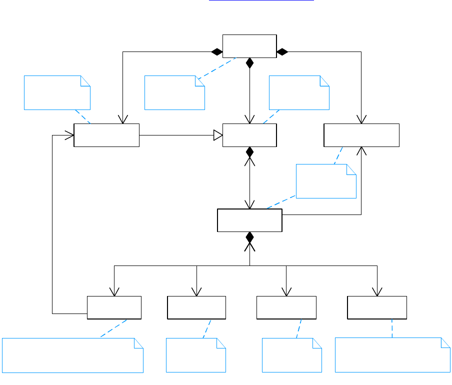
CHAPTER 7: Layout Fundamentals Documents and the layout hierarchy 140
Pages panel — The user interface for creating, deleting, and arranging pages and masters.
Spread — The primary container for layout data. A spread contains a set of pages on which page items
that represent pictures, text, and other content are arranged. The pages can be kept together to form
an island spread, a layout that spans more than one page.
Documents and the layout hierarchy
This section introduces the data model on which the layout subsystem is based. The boss classes and
interfaces that represent spreads, pages, and page items in a document are described in general.
Architecture
This section shows how the items introduced in “Concepts” on page 138 are represented by boss classes
and interfaces in a document. The following figure shows the overall arrangement.
A document (kDocBoss) comprises one or more spreads (kSpreadBoss) and master spreads
(kMasterPagesBoss). The ISpreadList interface lists the spreads. The IMasterSpreadList interface lists the
master spreads.
Each spread contains one or more pages (kPageBoss), ruler guides (kGuideItemBoss), frames
(kSplineItemBoss), paths (kSplineItemBoss), or groups (kGroupItemBoss). These objects are arranged in a
spread in a tree represented by the interface IHierarchy.
«boss»
kSpreadLayerBoss
«boss»
kDocBoss
«boss»
kSpreadBoss
1
IHierarchy4..*
1
1..*
ISpreadList
«boss»
kSplineItemBoss
0..*
IHierarchy
«boss»
kGroupItemBoss
0..*
«boss»
kGuideItemBoss
0..*
«boss»
kPageBoss
1..10
IHierarchy
«boss»
kDocumentLayerBoss
2
1
ISpreadLayer
1
2..*
ILayerList
«boss»
kMasterPagesBoss
1
1..*
IMasterSpreadList
<<extends>>
1
0..1
IMasterPage
Represents a
master spread.
Represents a
document.
Represents a
spread.
Represents a page or master page. Note:
A page doesn't own the content that lies
upon it; the spread owns the content.
Represents a
layer.
Represents a
ruler guide.
Represents a
group.
Represents a frame or path.
Graphics or text page items can
be nested inside a frame.

CHAPTER 7: Layout Fundamentals Documents and the layout hierarchy 141
Frames and groups have additional page items nested within them.
The objects in a layout are layered, and this layering is reflected within each spread. A layer is represented
by a document layer (kDocumentLayerBoss) that has two corresponding spread layers (kSpreadLayerBoss)
in each spread. The document layers are listed by the ILayerList interface; the spread layers are the
immediate children of a spread on the IHierarchy interface.
A spread (kSpreadBoss) contains 2n spread layers as children, where n is the number of document layers.
All the immediate children of a spread must be spread layers (kSpreadLayerBoss).
The preceding figure shows a document that has at least two layers:
The pages layer — Pages (kPageBoss) always are associated with the pages layer. The pages layer is
represented by the document layer (kDocumentLayerBoss) found at index 0 in the ILayerList interface.
It has two corresponding spread layers (kSpreadLayerBoss) in each spread. The spread layer that owns
the spread’s pages (kPageBoss) is found at child index 0 in the spread’s hierarchy (IHierarchy); the other
spread layer, which is always empty, is found at child index 1.
A layer for content.
The remaining layers—and there always is at least one other layer in the ILayerList interface—are the
layers to which guides (kGuideItemBoss), frames (kSplineItemBoss), paths (kSplineItemBoss), and groups
(kGroupItemBoss) can be assigned. Each of these layers is represented by a document layer that has two
corresponding spread layers. When a page item is assigned to belong to a particular layer, the object
becomes owned by the corresponding spread layer through IHierarchy. Changes to document layers are
document-wide, meaning changes to document layers affect all spreads in the document, including
master spreads. For more information about layers, see “Spreads and pages” on page 144 and “Layers” on
page 147.
The preceding figure also shows that master spreads (kMasterPagesBoss) have the same organization as
spreads. A master spread (kMasterPagesBoss) contains master pages (kPageBoss), which provide
background content for other pages. Master spreads form their own hierarchy, and each page connects to
its master by the interface IMasterPage. For more information, see “Master spreads and master pages” on
page 152.
The key interfaces involved in the layout data model are summarized in the following table. For more
information, refer to the API Reference for these interfaces.
Interface Note
IDocumentLayer Signature interface for a document layer (kDocumentLayerBoss). Stores a
document layer’s properties. Has an associated content-spread layer and
guide-spread layer.
IHierarchy Connects boss objects in a tree that represents a layout hierarchy. Provides a
mechanism to find parent and child objects and interfaces. See “Parent and child
objects and IHierarchy” on page 142.
ILayerList List of document layers (kDocumentLayerBoss) in a document. A layer is
represented by a kDocumentLayerBoss object that has two associated
kSpreadLayerBoss objects in each spread.
IMasterPage Stores the master spread (kMasterPagesBoss) associated with a page (kPageBoss)
and the index of the master page within the master spread on which this page is
based.
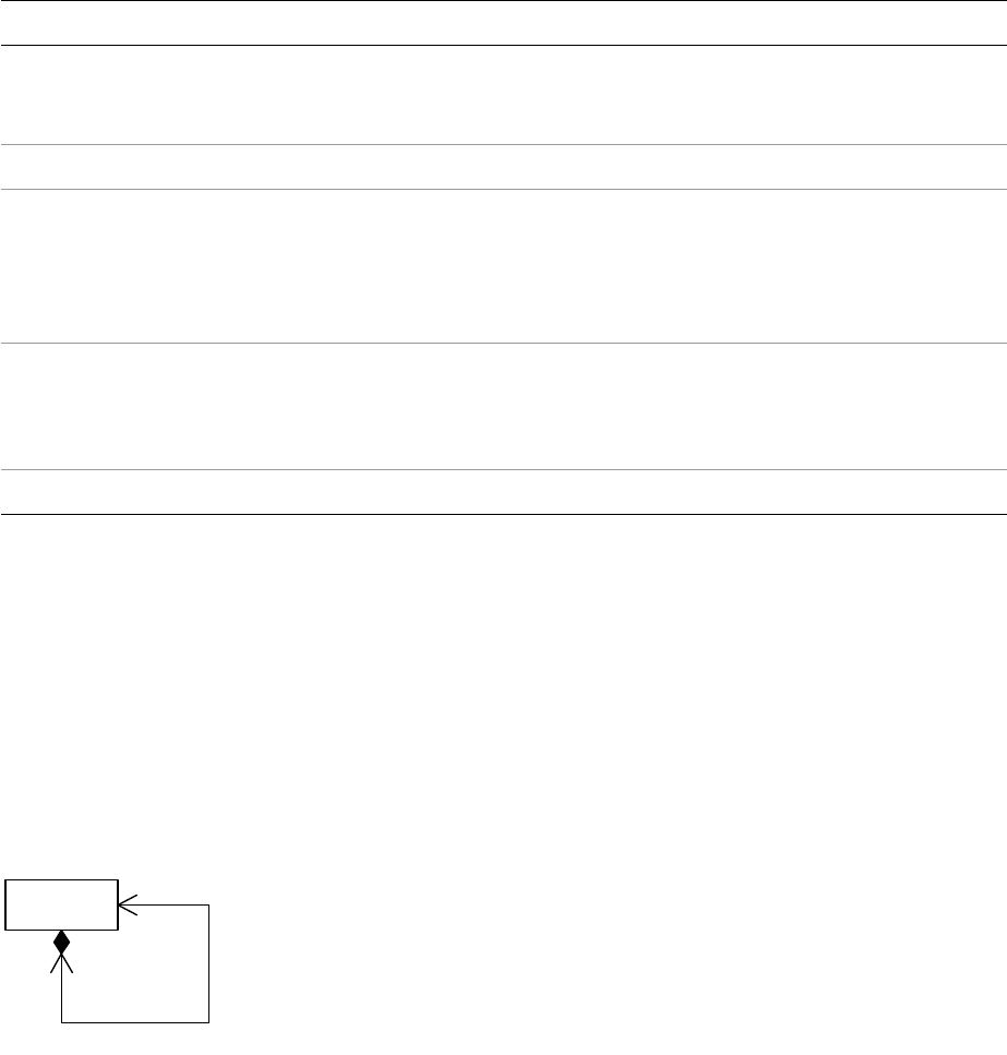
CHAPTER 7: Layout Fundamentals Documents and the layout hierarchy 142
The SnpInspectLayoutModel code snippet can inspect the layout hierarchy. Run the snippet in
SnippetRunner to create a textual report for a document. See SnpInspectLayoutModel for sample code
that examines the layout hierarchy in various ways.
Parent and child objects and IHierarchy
A page item can contain other page items. The containing object is the parent; the contained objects are
the children. Child index order defines z-order, the order in which objects draw; the child with index 0
draws first (behind), and the child with index n-1 draws last (in front). This association between page items
is implemented by the IHierarchy interface, as shown in the following figure.
kPageItemBoss is the abstract base class for objects that participate in the layout hierarchy. IHierarchy is a
required interface. Subclasses of kPageItemBoss include spreads (kSpreadBoss), spread layers
(kSpreadLayerBoss), and frames (kSplineItemBoss). To see all subclasses, refer to the API Reference for
kPageItemBoss. Each subclass of kPageItemBoss may have different constraints on the number and type
(boss class) of children it can contain.
The child objects contained within the parent are said to be nested. The following figure shows an
example. The object diagram is an example of how the internal representation changes when a circle is
nested inside a square using cut and paste. The parent-child association between boss objects in a layout
is realized by the IHierarchy interface. When the circle is cut, the association with its initial parent, the
spread layer, is broken. When the circle is pasted, it is associated with its new parent, the square. The
square becomes a frame, because it now contains the circle. The drawing of the circle is then clipped to its
frame.
IMasterSpread Signature interface for a master spread (kMasterPagesBoss). Stores the name of a
master spread and contains the incremental information that defines a master
spread. This information is beyond what is contained in a spread.
IMasterSpreadList List of the master spreads (kMasterPagesBoss) in a document.
ISpread Signature interface for a spread (kSpreadBoss). Contains useful methods for
discovering the page items that lie on a page or spread and for navigating between
document layers (kDocumentLayerBoss) and spread layers (kSpreadLayerBoss). A
document is laid out as a set of spreads in which each spread contains one or more
pages and other page items.
ISpreadLayer Signature interface for a spread layer (kSpreadLayerBoss). A spread layer is the
container for the page items in a layer through the IHierarchy interface on the
kSpreadLayerBoss. The ISpreadLayer interface maintains a relationship back to the
corresponding document layer boss (kDocumentLayerBoss).
ISpreadList List of the spreads (kSpreadBoss) in a document.
Interface Note
«boss»
kPageItemBoss
parent1
children
0..*
IHierarchy
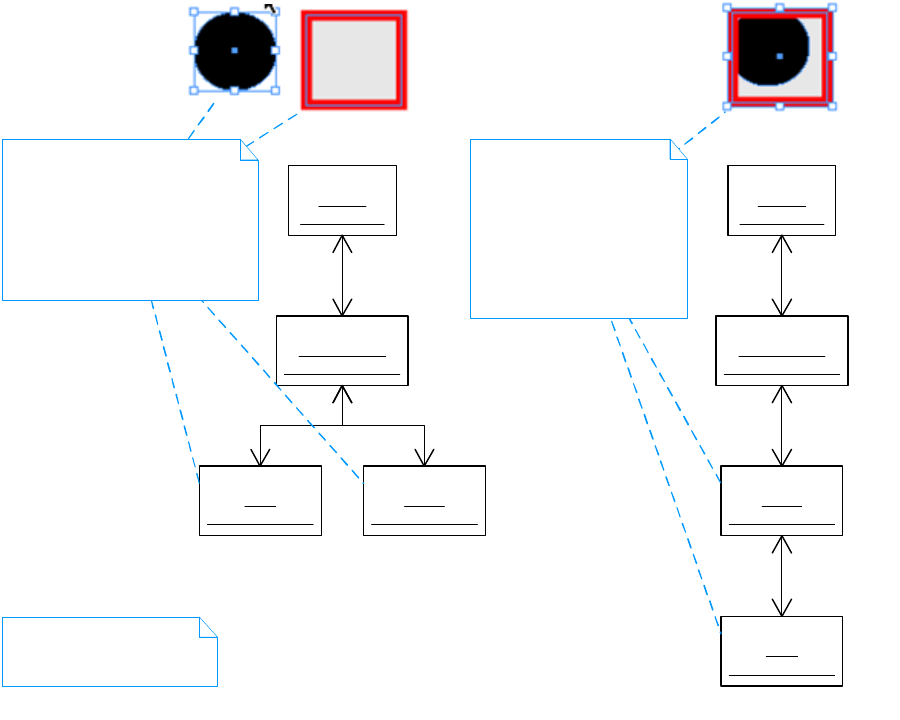
CHAPTER 7: Layout Fundamentals Documents and the layout hierarchy 143
The low-level commands used to edit the hierarchy programmatically are kAddToHierarchyCmdBoss and
kRemoveFromHierarchyCmdBoss. A utility interface, IHierarchyUtils, provides a facade that processes
these commands. For more information, refer to the API Reference.
The boss objects in the hierarchy illustrated above can be visited using a recursive function, as shown in
the following example, which visits each child boss object in a hierarchy:
void VisitChildren(IHierarchy* parent)
{
int32 childCount = parent->GetChildCount();
for (int32 childIndex = 0; childIndex < childCount; childIndex++)
{
InterfacePtr<IHierarchy> child(parent->QueryChild(childIndex));
#ifdef DEBUG
// Trace the boss class name of the child.
DebugClassUtilsBuffer className;
DebugClassUtils::GetIDName(&className, ::GetClass(child));
TRACEFLOW("LayoutFundamentals", "%s\n", className);
#endif
// Add code to examine other interfaces on the boss object.
VisitChildren(child);
}
}
«boss»
spread1
: kSpreadBoss
«boss»
layer1-content
: kSpreadLayerBoss
«boss»
circle
: kSplineItemBoss
«boss»
square
: kSplineItemBoss
parent
child
parent
child child
«boss»
spread1
: kSpreadBoss
«boss»
layer1-content
: kSpreadLayerBoss
«boss»
square
: kSplineItemBoss
«boss»
circle
: kSplineItemBoss
parent
child
parent
child
parent
child
Above:
The original circle and square paths.
Below:
The parent-child relationships
between the boss objects that
represent these paths on a
spread.
Above:
The circle cut and pasted into
the square.
Below:
The changed parent-child
relationships. The square is
the parent of the circle.
The parent-child associations
are represented by the
IHierarchy interface.
CHAPTER 7: Layout Fundamentals Spreads and pages 144
Spreads and pages
A spread is the primary container for layout data. A spread contains a set of pages on which the page items
that represent pictures, text, or content of another format are arranged. A spread owns all the objects it
contains, including its pages, ruler guides, frames, paths, groups, and any nested content. The objects in a
spread are organized into layers, so the user can control whether the objects assigned to a layer should be
displayed or editable. See the following figure for the user’s perspective. The publication shown is a
facing-pages document with one spread, one page, and one layer.
The following is an object diagram showing the layout-related boss objects that exist in a publication
containing a ruler guide and graphic frame on a page. The sample document (kDocBoss) contains a spread
(kSpreadBoss), page (kPageBoss), graphic frame (kSplineItemBoss), and ruler guide (kGuideItemBoss). The
content of the spread is layered on spread layers (kSpreadLayerBoss) that map onto corresponding
document layers (kDocumentLayerBoss). There are two document layers (kDocumentLayerBoss), the
pages layer and layer 1. The page, graphic frame, and ruler guide are arranged on spread layers
(kSpreadLayerBoss) under the spread’s IHierarchy interface.
Spread Page Layer
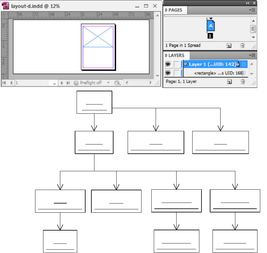
CHAPTER 7: Layout Fundamentals Spreads and pages 145
A layer is represented by a kDocumentLayerBoss object with two corresponding kSpreadLayerBoss
objects in each spread.
The pages layer is the layer to which pages (kPageBoss) are assigned. In the figure, the pages layer is
represented by the kDocumentLayerBoss object named “pages” and the kSpreadLayerBoss objects named
“pages” and “private.” The pages document layer (kDocumentLayerBoss) always is at index 0 in the layer
list (ILayerList). The first child on the spread’s hierarchy always is the associated page’s spread layer and
contains the spread’s pages (kPageBoss). The second child of the spread is a private spread layer that
always is empty. Pages are drawn behind all other objects, because they always are stored on the spread’s
hierarchy at child index 0. Note that the pages layer is not shown in the Layers panel.
In the preceding figure, Layer 1 is represented by the kDocumentLayerBoss object layer1. It has two
corresponding spread layers (kSpreadLayerBoss) on the spread’s hierarchy:
One for content: layer1-content, which stores the graphic frame (kSplineItemBoss).
One for ruler guides: layer1-guides, which stores the ruler guide.
«boss»
layout-d
: kDocBoss
«boss»
spread1
: kSpreadBoss
«boss»
pages
: kSpreadLayerBoss
«boss»
private
: kSpreadLayerBoss
«boss»
layer1-content
: kSpreadLayerBoss
«boss»
layer1-guides
: kSpreadLayerBoss
ISpreadList::GetNthSpreadUID(0)
IHierarchy::QueryChild(0) IHierarchy::QueryChild(1) IHierarchy::QueryChild(2) IHierarchy::QueryChild(3)
«boss»
graphic-frame
: kSplineItemBoss
IHierarchy::QueryChild(0)
«boss»
ruler-guide
: kGuideItemBoss
«boss»
page1
: kPageBoss
IHierarchy::QueryChild(0)
IHierarchy::QueryChild(0)
«boss»
pages
: kDocumentLayerBoss
«boss»
layer1
: kDocumentLayerBoss
ILayerList::QueryLayer(0) ILayerList::QueryLayer(1)

CHAPTER 7: Layout Fundamentals Spreads and pages 146
The order of these spread layers can vary, depending on whether guides are being drawn behind or in
front of content. The preceding figure illustrates the order when guides are drawn in front of content.
NOTE: Child index order in IHierarchy defines z-order, the order in which objects on those spread layers
(kSpreadLayerBoss) draw. The child with index 0 draws first (behind); the child with index n-1 draws last (in
front).
The code in the following example visits each child boss object of the spread shown in the preceding
figure. (For the implementation of VisitChildren, see the example in “Parent and child objects and
IHierarchy” on page 142.) All boss objects on the spread’s hierarchy are visited by the code in the following
example, including the spread layer and page boss objects.
void VisitSpreadChildren(UIDRef& documentUIDRef)
{
InterfacePtr<IDocument> document(documentUIDRef, UseDefaultIID());
InterfacePtr<ISpreadList> spreadList(document, UseDefaultIID());
IDataBase* database = documentUIDRef.GetDataBase();
int32 spreadCount = spreadList->GetSpreadCount();
for ( int32 spreadIndex = 0; spreadIndex < spreadCount; spreadIndex++ )
{
UIDRef spreadUIDRef(database, spreadList->GetNthSpreadUID(spreadIndex));
InterfacePtr<IHierarchy> spreadHierarchy(spreadUIDRef, UseDefaultIID());
VisitChildren(spreadHierarchy);
}
}
In contrast, the code shown in the following example filters the objects by the pages on which they lie. The
method ISpread::GetItemsOnPage calculates which items lie on a page. Because pages do not own the
items that lie on them (spreads own the items), the calculation of which items lie on a page is geometrical,
comparing the intersection of the bounding box of each item with the bounding box of the page. (For
details, see ISpread::GetItemsOnPage.) If this code is run on the spread shown in the preceding figure, the
only object that appears in the list itemsOnPage is the graphic frame. The ruler guide is not returned as an
item, because it is a pasteboard-ruler guide; if the ruler guide were a page-ruler guide, the code in the
following example would list it.
void FilterItemsByPage(UIDRef& documentUIDRef)
{
InterfacePtr<IDocument> document(documentUIDRef, UseDefaultIID());
InterfacePtr<ISpreadList> spreadList(document, UseDefaultIID());
IDataBase* database = documentUIDRef.GetDataBase();
int32 spreadCount = spreadList->GetSpreadCount();
for ( int32 spreadIndex = 0; spreadIndex < spreadCount; spreadIndex++ )
{
UIDRef spreadUIDRef(database, spreadList->GetNthSpreadUID(spreadIndex));
InterfacePtr<ISpread> spread(spreadUIDRef, UseDefaultIID());
for (int32 pageIndex = 0; pageIndex < spread->GetNumPages(); pageIndex++)
{
UIDList itemsOnPage(database);
const bool16 bIncludePage = kFalse;
const bool16 bIncludePasteboard = kFalse;
spread->GetItemsOnPage(pageIndex, &itemsOnPage, bIncludePage,
bIncludePasteboard);
// Add code to manipulate itemsOnPage.
}
}
}

CHAPTER 7: Layout Fundamentals Layers 147
The SnpInspectLayoutModel code snippet can inspect the spreads in a document and their associated
hierarchy. Run the snippet in SnippetRunner to create a textual report. For sample code, see
SnpInspectLayoutModel::ReportDocumentByHierarchy.
Layers
Layers are presented to the user and edited with the Layers panel. Layers can be shown or hidden, locked
or unlocked. By rearranging the order of layers, the user can control the front-to-back order in which page
items assigned to those layers draw. The user also can change the layer to which a selected page item is
assigned, by dragging and dropping in the Layers panel.
The following figure shows the user’s perspective of a layer. The document shown is a facing-pages
document with one spread, one page, and one layer.
Layers in a basic document
The following figure is an object diagram showing the layout hierarchy that results when a new layer is
added to the document in the frame-and-ruler diagram in “Spreads and pages” on page 144. The diagram
shows a document (kDocBoss) containing one spread (kSpreadBoss), one page (kPageBoss), and three
layers. Each layer is represented by one kDocumentLayerBoss object that has two corresponding
kSpreadLayerBoss objects in each spread. The pages layer that stores the page (kPageBoss) is represented
by the kDocumentLayerBoss object named “pages” and the kSpreadLayerBoss objects named “pages” and
“private.” Layer 1 is represented by the objects layer1, layer1-content, and layer1-guides. Layer 2 is
represented by the objects layer2, layer2-content, and layer2-guides. A graphic frame (kSplineItemBoss)
and a ruler guide (kGuideItemBoss) are assigned to Layer 1. Layer 2 is empty.
Spread Page Layer
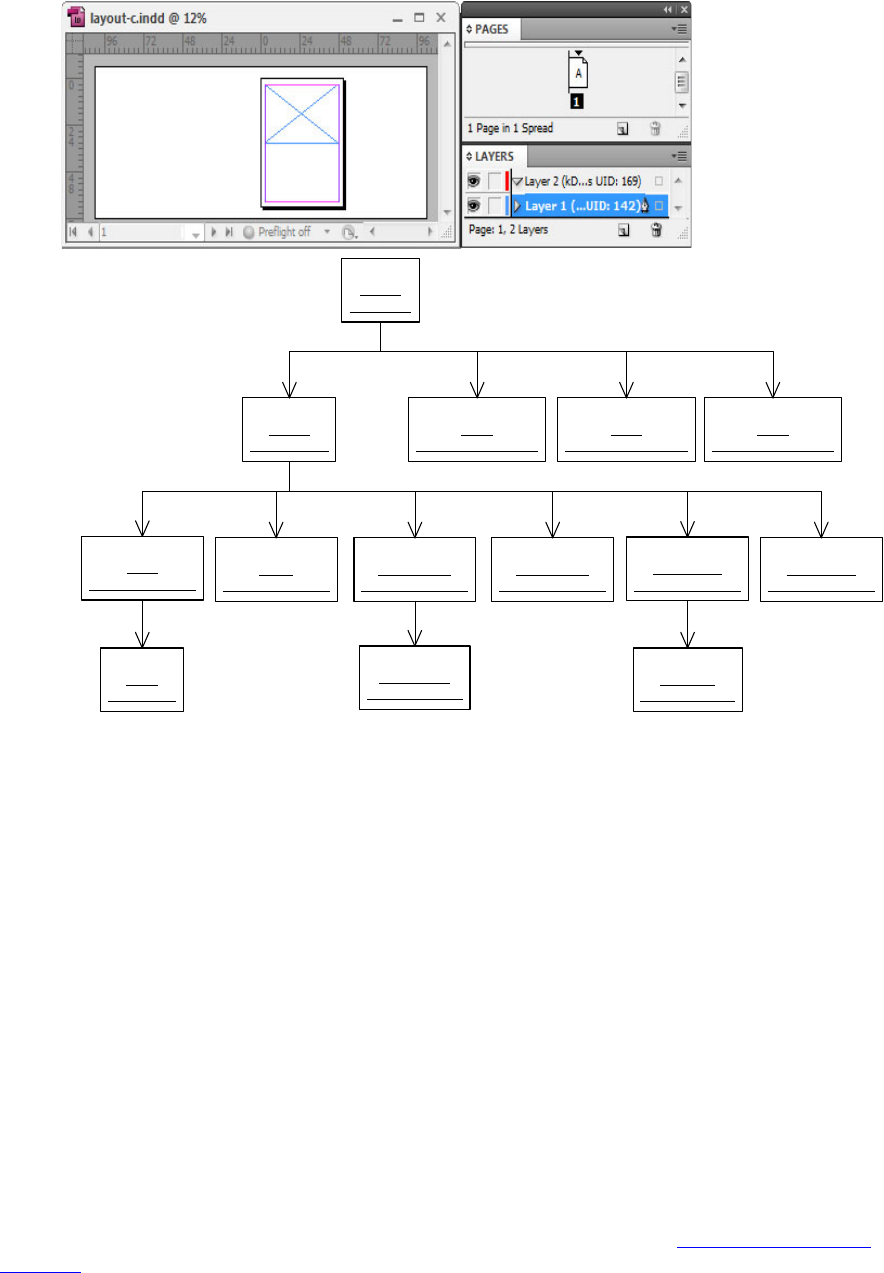
CHAPTER 7: Layout Fundamentals Layers 148
When a new layer is added, three new objects are created:
A new document layer is added to the layer list (ILayerList). This is the kDocumentLayerBoss object
layer2.
Two corresponding spread layers are added to the spread. One new spread layer is added to contain
paths, frames, or groups; the other new spread layer is added to contain ruler guides. These are the
kSpreadLayerBoss objects layer2-content and layer2-guides.
This figure shows that, when a document layer is created, two corresponding spread layers are added to
each spread. When a document layer is deleted, its corresponding spread layers are removed from each
spread. Document-layer edits are document-wide; that is, they affect all spreads in a document.
Content-spread layers are stored contiguously in the spread’s hierarchy (IHierarchy). Guide-spread layers
also are stored contiguously. For example, the layer1-content and layer2-content objects in this figureare
contiguous content-spread layers, and layer1-guides and layer2-guides are contiguous guide-spread
layers.
The order of content-spread layers and guide-spread layers as child objects of the spread’s hierarchy
(IHierarchy) varies, depending on whether guides are being drawn in front or in back of content. Ruler
guides are kept in a distinct spread layer, to allow them to be drawn in front of or behind other content, or
even to turn them off completely, as determined by a preference setting. (See “Guides and grids” on
page 162.) This figure shows the order when guides are drawn in front of content. The corresponding
index order is as follows:
«boss»
layout-c
: kDocBoss
«boss»
spread1
: kSpreadBoss
«boss»
pages
: kSpreadLayerBoss
«boss»
private
: kSpreadLayerBoss
«boss»
layer1-content
: kSpreadLayerBoss
«boss»
layer2-content
: kSpreadLayerBoss
ISpreadList::GetNthSpreadUID(0)
IHierarchy::QueryChild(0) IHierarchy::QueryChild(1) IHierarchy::QueryChild(2) IHierarchy::QueryChild(3)
«boss»
page1
: kPageBoss
IHierarchy::QueryChild(0)
«boss»
pages
: kDocumentLayerBoss
«boss»
layer1
: kDocumentLayerBoss
«boss»
layer2
: kDocumentLayerBoss
«boss»
layer1-guides
: kSpreadLayerBoss
«boss»
layer2-guides
: kSpreadLayerBoss
IHierarchy::QueryChild(4) IHierarchy::QueryChild(5)
ILayerList::QueryLayer(0) ILayerList::QueryLayer(1) ILayerList::QueryLayer(2)
«boss»
graphic-frame
: kSplineItemBoss
«boss»
ruler-guide
: kGuideItemBoss
IHierarchy::QueryChild(0) IHierarchy::QueryChild(0)

CHAPTER 7: Layout Fundamentals Layers 149
index[0] pages spread layer
index[1] private spread layer
index[2] layer1-content spread layer
index[3] layer2-content spread layer
index[4] layer1-guides spread layer
index[5] layer2-guides spread layer
If guides are drawn behind other content, the index order of spread layers in the spread’s hierarchy
(IHierarchy) is as follows:
index[0] pages spread layer
index[1] private spread layer
index[2] layer1-guides spread layer
index[3] layer2-guides spread layer
index[4] layer1-content spread layer
index[5] layer2-content spread layer
NOTE: Child-index order in IHierarchy defines z-order, the order in which objects on those spread layers
(kSpreadLayerBoss) draw. The child with index 0 draws first (behind); the child wth index n-1, last (in front).
The spread’s ISpread interface has methods that return the spread layer associated with a given document
layer. (See “Navigating spread content using ISpread” on page 151.) The associations are calculated using
the following algorithm.
The indices of the pages-spread layer and private-spread layer are fixed:
Pages-spread layer IHierarchy child index = 0.
Private-spread layer IHierarchy child index = 1.
Variable definitions:
i = index of document layer (kDocumentLayerBoss) in ILayerList whose associated spread layer
(kSpreadlayerBoss) is wanted.
c = number of document layers in ILayerList.
If guides are displayed in front of content, the following calculations are used:
Content-spread layer IHierarchy child index = i + 1.
Guide-spread layer IHierarchy child index = i + c.
If guides are displayed behind content, the following calculations are used:
Content-spread layer IHierarchy child index = i +c.
Guide-spread layer IHierarchy child index = i + 1.
Layer options
There are layer options that can be controlled via the Layers Options dialog. User can double click on a
layer name in the Layers panel to bring up the Layer Options dialog, as shown in the following figure.

CHAPTER 7: Layout Fundamentals Layers 150
The attributes in the Layer Options dialog are managed by the IDocumentLayer interface, which is
aggregated on the kDocumentLayerBoss. The following table lists some of the commands that can be
used to modify layer options.
Use the commands in this table whenever possible to modify layer options.
The SnpPrintDocument.cpp SDK snippet allows the user to select which layer to print. It uses
kPrintLayerCmdBoss to set the printability for each layer. For more information, see the snippet source
code.
NOTE: A similar set of attributes also exists in the ISpreadLayer. “Layers in a basic document” on page 147
explains the relationship between IDocumentLayer and ISpreadLayer in a document. The ISpreadLayer
interface primarily provides “getter” methods that forward the request for information to the
corresponding IDocumentLayer interface
Command Note
kChangeLayerNameCmdBoss Changes the name of the layer.
kIgnoreHiddenTextWrapCmdBoss Sets text-wrap options for a document layer.
kLockGuideLayerCmdBoss Locks or unlocks a guide layer. When the guide layer is locked,
nothing in that layer (that is, guides) can be selected.
kLockLayerCmdBoss Locks or unlocks a layer. A “locked” layer means that nothing in that
layer can be selected. Layers are unlocked by default.
kPrintLayerCmdBoss Sets the printability of the layer. A nonprintable layer does not print
or export.
kSetLayerColorCmdBoss Changes the layer color.
kShowGuideLayerCmdBoss Sets the visibility of the guide layer. An “invisible” layer is not
displayed on the screen.
kShowLayerCmdBoss Sets the visibility of the layer. An “invisible” layer is not displayed on
the screen.
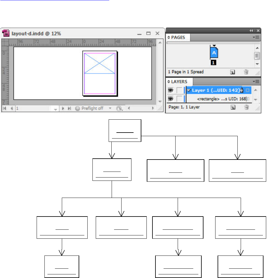
CHAPTER 7: Layout Fundamentals Layers 151
Navigating spread content using ISpread
“Layers in a basic document” on page 147 shows the content of a spread is stored on its IHierarchy
interface. Locating content using IHierarchy can be laborious. Alternately, the ISpread interface makes it
easy to examine the content of a spread, as shown in the object diagram in the following figure.
This figure shows that you can use the ISpread interface on a spread (kSpreadBoss) to find the guide or
content spread layer associated with a document layer. (For more information, see ISpread::QueryLayer.)
You also can discover which page items lie on a given page. (For more information, see
ISpread::GetItemsOnPage.)
Using ISpread to discover the content of a spread is much easier than using IHierarchy.
When run on the document shown in this figure, the code in the following example visits the content of
spread layer layer1-content if parameter wantGuideLayer is kFalse. The code visits the content of spread
layer layer1-guides if parameter wantGuideLayer is kTrue.
«boss»
layout-d
: kDocBoss
«boss»
spread1
: kSpreadBoss
«boss»
layer1-content
: kSpreadLayerBoss
«boss»
layer1-guides
: kSpreadLayerBoss
«boss»
private
: kSpreadLayerBoss
«boss»
pages
: kSpreadLayerBoss
ISpreadList::GetNthSpreadUID(0)
ISpread::QueryLayer ISpread::QueryLayer
ISpread::QueryPagesLayer
«boss»
page1
: kPageBoss
IHierarchy::QueryChild(0)
«boss»
ruler-guide
: kGuideItemBoss
«boss»
graphic-frame
: kSplineItemBoss
IHierarchy::QueryChild(0)
IHierarchy::QueryChild(0)
«boss»
layer1
: kDocumentLayerBoss
«boss»
pages
: kDocumentLayerBoss
ILayerList::QueryLayer(1)
ILayerList::QueryLayer(0)

CHAPTER 7: Layout Fundamentals Master spreads and master pages 152
This code iterates over spreads in a document, then iterates over document layers to visit items on the
spread layer associated with each document layer:
void FilterItemsByLayer(UIDRef& documentUIDRef, bool16 wantGuideLayer)
{
InterfacePtr<IDocument> document(documentUIDRef, UseDefaultIID());
InterfacePtr<ISpreadList> spreadList(document, UseDefaultIID());
InterfacePtr<ILayerList> layerList(document, UseDefaultIID());
IDataBase* database = documentUIDRef.GetDataBase();
int32 spreadCount = spreadList->GetSpreadCount();
for ( int32 spreadIndex = 0; spreadIndex < spreadCount; spreadIndex++ )
{
UIDRef spreadUIDRef(database, spreadList->GetNthSpreadUID(spreadIndex));
InterfacePtr<ISpread> spread(spreadUIDRef, UseDefaultIID());
int32 layerCount = layerList->GetCount();
// Skip the pages layer (layer 0).
for (int32 layerIndex = 1; layerIndex < layerCount; layerIndex++)
{
IDocumentLayer* documentLayer = layerList->QueryLayer(layerIndex);
int32 pPos;
// Visit the content spread layer associated with the document layer
// if wantGuideLayer is kFalse, the guide spread layer otherwise.
InterfacePtr<ISpreadLayer> contentSpreadLayer
(
spread->QueryLayer(documentLayer, &pPos, wantGuideLayer)
);
InterfacePtr<IHierarchy> hierarchy(contentSpreadLayer, UseDefaultIID());
VisitChildren(hierarchy);
}
}
}
NOTE: For an implementation of VisitChildren, see the example in “Parent and child objects and IHierarchy”
on page 142.
Master spreads and master pages
A master spread is a special kind of spread that contains master pages. A master page is a page that
contains background content for another page. When a page is based on a master page, the page items
that lie on the master page also appear on the page. A master page eliminates the need for repetitive page
formatting and typically contains page numbers, headers and footers, and background pictures. The
layout presentation is used to edit the content of master spreads. The Pages panel is used to arrange the
pages in a master spread and to assign a master page to a page.
The following figure shows the user’s perspective on master spreads and master pages. The publication
shown is a facing-pages document with a master spread containing two master pages.

CHAPTER 7: Layout Fundamentals Master spreads and master pages 153
Master spreads and master pages in a basic document
A master spread (kMasterPagesBoss) is a special kind of spread; it extends the spread boss class
(kSpreadBoss). The content of a master spread is organized the same way as a spread: each has a hierarchy
(IHierarchy) with spread layers acting as parent objects for content. Compare the spread shown in the
frame-and-ruler figure in “Spreads and pages” on page 144 to the master spread shown in the following
figure. The document (kDocBoss) shown contains a master spread (kMasterPagesBoss) with two pages
(kPageBoss), and two paths (kSplineItemBoss) in the form of a square and a circle.
NOTE: Pages (kPageBoss) that are part of a master spread are master pages. This name clashes with the
name of the master-spread boss class, kMasterPagesBoss, so the distinction between the two is worth
repeating: a master page is a page (kPageBoss) owned by a master spread (kMasterPagesBoss).
Master spread Master page Master page
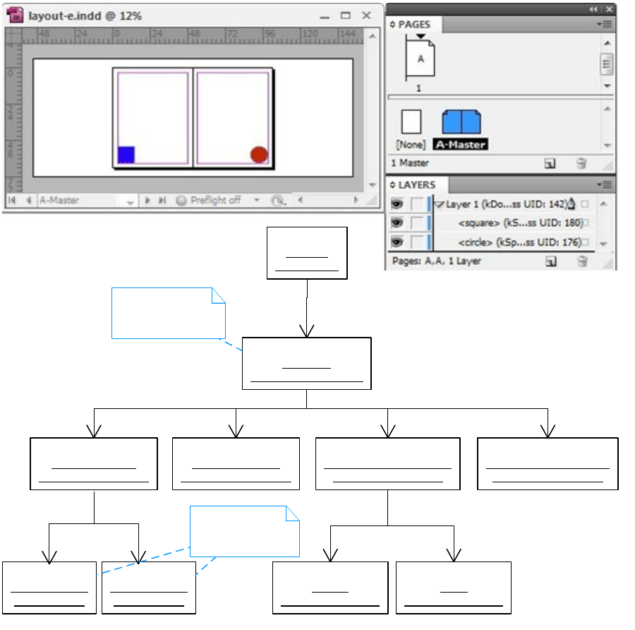
CHAPTER 7: Layout Fundamentals Master spreads and master pages 154
When a page is based on a master page, the page items that lie on the master page also appear on the
page. When the master spread in this figure is applied to page 1 of the facing-pages document in the
frame-and-ruler figure, page items from the master page appear on page 1. The circle in the screenshot of
page 1 in the following figure is an object from the master spread.
The following figure is an object diagram showing a one-page document that has a master (A-Master)
applied. The circle drawn on page 1 is an object inherited from the associated master page. The boss
objects that represent the spread and the master spread it is based on are shown. The association between
a page (kPageBoss) and its master page is implemented by the IMasterPage interface. The screenshot
shows that filtering of the objects on the master spread is being performed. Objects that intersect the
bounding box of the master page associated with the page are drawn; other objects on the master spread
are filtered out. The circle is the only object from the master spread to draw, because it is the only object
that intersects the bounding box of the master page associated with page 1.
This figure shows a spread based on a master spread:
«boss»
A-Master
: kMasterPagesBoss
«boss»
A-Master-layer1-content
: kSpreadLayerBoss
«boss»
A-Master-layer1-guides
: kSpreadLayerBoss
«boss»
A-Master-private
: kSpreadLayerBoss
«boss»
A-Master-pages
: kSpreadLayerBoss
«boss»
master-page-2
: kPageBoss
«boss»
circle
: kSplineItemBoss
«boss»
square
: kSplineItemBoss
IMasterSpreadList
IHierarchy
«boss»
master-page-1
: kPageBoss
IHierarchy IHierarchy
«boss»
layout-e
: kDocBoss
Master spread
Master pages
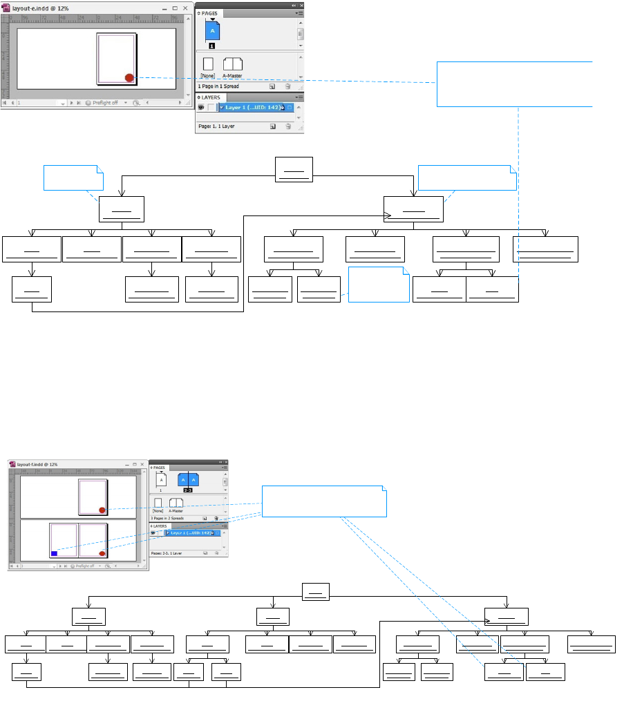
CHAPTER 7: Layout Fundamentals Master spreads and master pages 155
When two new pages based on the master shown in the first figure in this subsection are added to the
document, the layout hierarchy is as shown in the following figure. The object diagram shows the boss
objects that represent three pages in a facing-pages document based on the same master spread. The
circle and square objects drawn on pages 1, 2, and 3 come from the master.
The following figure show stwo spreads based on a facing-pages master spread:
The master spread (kMasterPagesBoss) associated with a page (kPageBoss) is found by calling
IMasterPage::GetMasterSpreadUID. The associated master page (kPageBoss) within that master spread is
calculated by calling update to IMasterPage::GetMasterSpreadPageIndex. The calculation depends on the
index position (0, 1, 2, ...) of the page within its spread and the document set-up. Given the result returned
by IMasterPage::GetMasterSpreadPageIndex, ISpread::GetNthPageUID can be called to get a reference to
the master page (kPageBoss), or ISpread::GetItemsOnPage can be called to calculate the objects on the
master spread that intersect the bounding box of the master page.
To base a page or set of pages on a master spread, process the kApplyMasterSpreadCmdBoss command.
«boss»
A-Master
: kMasterPagesBoss
«boss»
A-Master-layer1-content
: kSpreadLayerBoss
«boss»
A-Master-layer1-guides
: kSpreadLayerBoss
«boss»
A-Master-private
: kSpreadLayerBoss
«boss»
A-Master-pages
: kSpreadLayerBoss
«boss»
master-page-2
: kPageBoss
«boss»
circle
: kSplineItemBoss
«boss»
square
: kSplineItemBoss
IMasterSpreadList
«boss»
master-page-1
: kPageBoss
«boss»
spread1
: kSpreadBoss
«boss»
pages
: kSpreadLayerBoss
«boss»
private
: kSpreadLayerBoss
«boss»
layer1-content
: kSpreadLayerBoss
«boss»
layer1-guides
: kSpreadLayerBoss
«boss»
graphic-frame
: kSplineItemBoss
«boss»
ruler-guide
: kGuideItemBoss
«boss»
page1
: kPageBoss
ISpreadList
IMasterPage
«boss»
layout-e
: kDocBoss
Spread Master spread
Master
page
Page item inherited
from master.
«boss»
A-Master
: kMasterPagesBoss
«boss»
A-Master-layer1-content
: kSpreadLayerBoss
«boss»
A-Master-layer1-guides
: kSpreadLayerBoss
«boss»
A-Master-private
: kSpreadLayerBoss
«boss»
A-Master-pages
: kSpreadLayerBoss
«boss»
master-page-2
: kPageBoss
«boss»
circle
: kSplineItemBoss
«boss»
square
: kSplineItemBoss
IMasterSpreadList
«boss»
master-page-1
: kPageBoss
«boss»
spread1
: kSpreadBoss
«boss»
pages
: kSpreadLayerBoss
«boss»
private
: kSpreadLayerBoss
«boss»
layer1-content
: kSpreadLayerBoss
«boss»
layer1-guides
: kSpreadLayerBoss
«boss»
graphic-frame
: kSplineItemBoss
«boss»
ruler-guide
: kGuideItemBoss
«boss»
page1
: kPageBoss
«boss»
spread2
: kSpreadBoss
«boss»
pages
: kSpreadLayerBoss
«boss»
private
: kSpreadLayerBoss
«boss»
layer1-content
: kSpreadLayerBoss
«boss»
layer1-guides
: kSpreadLayerBoss
«boss»
page2
: kPageBoss
«boss»
page3
: kPageBoss
ISpreadList
IMasterPage
«boss»
layout-f
: kDocBoss
Page items inherited
from master

CHAPTER 7: Layout Fundamentals Page items 156
Master-page item overrides
Page items from a master spread can be overridden. For example, to change the fill color of the circle on
page 1 in the preceding figure, a master page item override is created. A record of the override is kept by
the page (kPageBoss) in the IMasterOverrideList interface.
Overrides to master-page items are applied programmatically with kOverrideMasterPageItemCmdBoss.
Even when a master-page item is overridden, changes made to its counterpart on the master still can
effect page items. An overridden page item continues to inherit all properties of its master counterpart
that are not overridden. For example, if the only property that was overridden on page 1 is the fill color of
the circle, modifying the position of the circle in the master causes the position of the circle to be updated
on the pages based on that master (pages 1 and 3). The application of the initial fill-color override creates a
copy of the circle (kSplineItemBoss) object on spread 1; a record of the override is kept in
IMasterOverrideList on page 1. The circle on spread 1 is a controlled page item; the circle on the master
spread is the controlling page item. Master page items maintain a list of controlled page items in the
IControlledPageItems interface, which represents the page items for which overrides were made. An
overridden master-page item on a spread maintains a reference to its controlling master-page item, in the
IControllingPageItem interface.
Basing one master page on another
A master page can be based on another master page. The association is maintained by the IMasterPage
interface as it is for a normal page (kPageBoss) owned by a spread (kSpreadBoss). For example, consider
two masters, A and B, with different sets of page items. When you drag master A onto master B in the
Pages panel, master B becomes based on master A. Master page items on master A appear on master B;
however, the page items on master B inherited from master A remain owned by master A. If you alter the
page items on master A, the change is inherited by master B. Master B can override page items from
master A for individual properties, just as the master-page items on a spread can be overridden.
Page items
A page item is a path, frame, group, picture, text frame, or page-item type that represents content the user
creates and edits on a spread. For general information about the organization of page items in a spread,
see “Spreads and pages” on page 144.
Frames and paths
A path represents a straight line, curved line, or closed shape like a rectangle, ellipse, or polygon. A path
comprises one or more segments, each of which may be straight or curved. Each path is open (the default)
or closed. Graphic attributes are properties that control how the path is formatted when drawn, like stroke
weight and color. For more information about paths, see the “Paths” section of Chapter 8, “Graphics
Fundamentals.” A frame is simply a path that contains—or is designated to contain—other objects, like a
graphic page item, text page item, or page item that represents another type of content.
Frames and paths are represented by the same boss class, kSplineItemBoss.
A path can become a frame, and a frame can become a path. The difference between a path and a frame is
the state of the interfaces on kSplineItemBoss. A path is a kSplineItemBoss object that contains no children
in its IHierarchy interface. A graphic frame is a kSplineItemBoss object that contains a graphic page item in
its IHierarchy interface. (For more information about graphic page items, see the “Graphic Page Items”
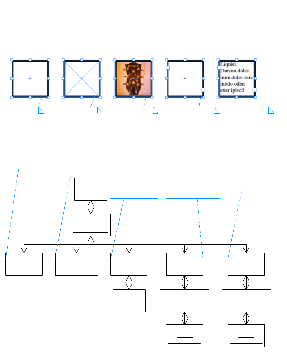
CHAPTER 7: Layout Fundamentals Page items 157
section of Chapter 8, “Graphics Fundamentals.”) A text frame is a kSplineItemBoss object that contains a
text page item (kMultiColumnItemBoss). (For more information on text page items, see Chapter 9, “Text
Fundamentals.”)
The following figure shows a square path, an empty graphic frame, a graphic frame displaying a picture, an
empty text frame, and a text frame containing text. The object diagram shows a square being used as a
path and as a frame.
The toolbox palette provides the user with several path-drawing tools. The Rectangle, Ellipse, Polygon, and
Line tools create basic shapes. The Rectangle Frame, Ellipse Frame, and Polygon Frame tools create basic
graphic-frame shapes. The Pen and Pencil tools create free-form shapes. When one of these tools is used to
draw a path, a spline item (kSplineItemBoss) is created to represent the path. The IPathGeometry interface
on kSplineItemBoss describes the points in the path. Other interfaces on kSplineItemBoss provide
«boss»
spread1
: kSpreadBoss
«boss»
layer1-content
: kSpreadLayerBoss
«boss»
square
: kSplineItemBoss
«boss»
empty-graphic-frame
: kSplineItemBoss
«boss»
graphic-frame
: kSplineItemBoss
«boss»
empty-text-frame
: kSplineItemBoss
«boss»
text-frame
: kSplineItemBoss
«boss»
jpeg-picture
: kImageItem
«boss»
column-controller
: kMultiColumnItemBoss
«boss»
column1
: kFrameItemBoss
«boss»
column-controller
: kMultiColumnItemBoss
«boss»
column1
: kFrameItemBoss
IHierarchy
Above:
Square.
Below:
Representation
as a spline,
a path-based
object. Any
spline can be
used as a frame.
Above:
Empty graphic frame.
Below:
Representation
as a spline
designated for
graphics content.
IGraphicFrameData::
IsGraphicFrame
returns kTrue.
Above:
Graphic frame
displaying JPEG
picture.
Below:
Representation
as a spline
containing an
image in its
IHierarchy
interface. The
content of the
frame is clipped
by the frame's path.
Above:
Empty text frame.
Below:
Representation
as a spline
containing a
column controller
in its IHierarchy
interface that in
turn contains a
column. The
story (not shown)
associated with
these objects is empty.
Above:
Text frame
displaying text.
Below:
Representation
is the same as
the empty text
frame. The
difference is
that the associated
story (not shown)
contains text.

CHAPTER 7: Layout Fundamentals Page items 158
properties like stroke weight and stroke color that control how the path is drawn. When a path is used as a
frame, the content is clipped by the frame’s path.
IGraphicFrameData is a frame’s signature interface. IGraphicFrameData stores data that distinguishes
whether the boss object represents a frame or a path. IFrameType is an alternative signature interface. It
provides an easy-to-use interface that indicates whether the object represents a path or a frame. Major
interfaces on kSplineItemBoss, the boss class representing paths and frames, are shown in the class
diagram in the following figure and summarized in the following table. For more information on the
interfaces noted and details of the other interfaces on kSplineItemBoss, refer to the API Reference.
The following table lists Key kSplineItemBoss interfaces:
Interface Note
IFrameType Indicates whether the boss object is a path or frame.
IGeometry Stores the bounding box of the boss object in inner coordinates. See
“Bounding box and IGeometry” on page 171.
IGraphicFrameData Stores whether the boss object is a graphic frame and provides other helper
methods to determine the content of a frame.
IHandleShape Draws selection handles on the boss object’s bounding box. These selection
handles are used to move and resize the object.
IHandleShape
(IID_IPATHHANDLESHAPE)
Draws selection handles on the points in the boss object’s path. These
selection handles are used to edit the path points.
IHierarchy Connects the boss object into a tree that represents a layout hierarchy.
Provides mechanism to find parent and child objects and interfaces. The
objects the boss object contains are the children of the IHierarchy interface.
The object in which the boss object is contained is its parent. The
child-index order in IHierarchy defines the z-order of child objects. See
“Parent and child objects and IHierarchy” on page 142.
IPageItemAdornmentList A list of adornments that the page item object may have. For details, see
Chapter 8, “Graphics Fundamentals.”
IPathGeometry Stores the points in the boss object’s path in inner coordinates. The
interface can describe multiple paths.
IGraphicFrameData
IHierarchy
IPathGeometry
IGeometry
ITransform
IShape
«boss»
kSplineItemBoss
IFrameType

CHAPTER 7: Layout Fundamentals Page items 159
A frame can contain at most one child in its hierarchy (IHierarchy). The child boss object is the content of
the frame. The child may be one of the following boss classes: kSplineItemBoss, kGroupItemBoss, a
graphics page item (for example, kImageItem, kSVGItem, kPlacedPDFItemBoss, and kEPSItem), a text page
item (kMultiColumnItemBoss), or another content page item.
NOTE: The child object can be a group (kGroupItemBoss). To put several objects in a frame, first group
them.
A frame can be owned by one parent using its hierarchy (IHierarchy) interface. Typically, a frame on a
spread is owned by a spread layer (kSpreadLayerBoss), but a frame also can be owned by other boss
objects. For example, a frame that is part of a group is owned by the kGroupItemBoss, a frame nested
inside a frame is owned by a kSplineItemBoss, and an inline frame is owned by a kInlineBoss.
Paths and frames are created programmatically using IPathUtils. For sample code, see
SDKLayoutHelper::CreateRectangleGraphic, SDKLayoutHelper::CreateSplineGraphic,
SDKLayoutHelper::CreateRectangleFrame, and SDKLayoutHelper::CreateTextFrame. The frame for a page
item can be created when a file is placed.
For sample code that can be used to examine the content of a frame, see the example in “Parent and child
objects and IHierarchy” on page 142. For sample code that can be used to discover frames in a document,
see the examples in “Spreads and pages” on page 144.
The SnpInspectLayoutModel code snippet can inspect the spreads in a document and their associated
hierarchy, including their frames. To create a textual report, run the snippet in SnippetRunner. For sample
code, see SnpInspectLayoutModel::ReportDocumentByHierarchy.
Graphic page items
A graphic page item represents a picture. The following table shows the boss classes that represent
graphics-format files that are imported and placed in a document. Graphic page items are contained in
frames (kSplineItemBoss) when placed on a spread. For more information, see “Graphic Page Items” in
Chapter 8, “Graphics Fundamentals.”
IScrapItem Creates commands that can copy and paste the boss object. Different types
of page items need to transfer different kinds of data. For example, a path
transfers a description of its shape, and a text frame transfers text as well as
a description of the frame.
IShape Draws the boss object.
ITransform Represents any transformation applied to the boss object (for example,
translation, rotation, scaling) in a transformation matrix (PMMatrix). See
“Transformation and ITransform” on page 171.
Interface Note
Boss class Represented graphics format
kDCSItemBoss DCS
kEPSItem EPS
kImageItem Raster image formats (for example, TIFF, JPEG, PNG, GIF)

CHAPTER 7: Layout Fundamentals Page items 160
Text page items
A text page item represents a visual container that displays text. The following table shows the boss
classes that participate in the display of text. Text page items are contained in frames (kSplineItemBoss)
when placed on a spread. For more information, see Chapter 9, “Text Fundamentals.”
Interactive page items
An interactive page item represents an item in a multimedia format. The following table shows the boss
classes that represent interactive page items. Interactive page items are contained in frames
(kSplineItemBoss) when placed on a spread.
Groups
Grouping is a way to combine two or more objects so they can be worked with as a single object. The
objects in a group move, transform, copy, and paste as a unit. Grouping boss objects results in the creation
of a kGroupItemBoss to represent the group. The grouped objects become the children of the group in its
IHierarchy interface. Unlike a frame, a group does not have a path that clips its content when drawn. The
geometry and shape of the group is defined by the objects in the group.
The object diagram in the following figure shows an example of how the internal representation changes
when two objects are grouped.
This figure shows the grouping of two kSplineItemBoss path objects:
kPICTItem PICT
kPlacedPDFItemBoss PDF
kSVGItem SVG
kWMFItem WMF
Boss class Represented graphics format
Boss class Represents
kFrameItemBoss Column
kMultiColumnItemBoss Column controller
Boss class Represents
kMoviePageItemBoss Movie
kMultiStateObjectItemBoss MultiStateObject
kPushButtonItemBoss Button
kSoundPageItemBoss Audio
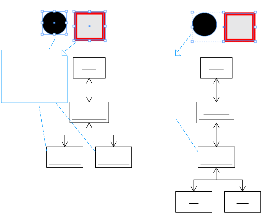
CHAPTER 7: Layout Fundamentals Page items 161
A group must contain at least two children in its IHierarchy. The only boss classes that can be part of a
group are kSplineItemBoss and kGroupItemBoss. In other words, only frames, paths, and groups can be
grouped. To put a graphic page item—such as an image (kImageItem)—into a group, that item must be
contained in a frame (kSplineItemBoss).
There is no signature interface on kGroupItemBoss that identifies a boss object uniquely as a group. To test
for a group, call IPageItemTypeUtils::IsGroup.
Objects are grouped using the kGroupCmdBoss command and ungrouped using the kUngroupCmdBoss
command. Selected objects can be grouped and ungrouped using IGroupItemSuite.
Abstract page items and kPageItemBoss
The kPageItemBoss boss class is the abstract base class for page items. The kDrawablePageItemBoss boss
class is the abstract base class for page items that can be selected and edited on a spread. These abstract
classes are subclassed and implemented by the set of page items that can be created and edited on a
spread, such as kSplineItemBoss, kGroupItemBoss, and kImageItem.
In general terms, a page item is any object that can participate in a hierarchy (IHierarchy). This perspective
is valid and includes spreads (kSpreadBoss) and pages (kPageBoss) as page items. There is an alternative,
more advanced definition of page item. To see all subclasses of kPageItemBoss, refer to the API Reference
for kPageItemBoss.
«boss»
spread1
: kSpreadBoss
«boss»
layer1-content
: kSpreadLayerBoss
«boss»
group1
: kGroupItemBoss
«boss»
circle
: kSplineItemBoss
IHierarchy
Above:
The circle and square
combined in a group.
Below:
The new group boss
object, kGroupItemBoss,
and the changed
IHierarchy associations.
The circle and square
become children of the
group.
«boss»
square
: kSplineItemBoss
«boss»
spread1
: kSpreadBoss
«boss»
layer1-content
: kSpreadLayerBoss
«boss»
circle
: kSplineItemBoss
«boss»
square
: kSplineItemBoss
IHierarchy
Above:
The original circle and
square paths.
Below:
The IHierarchy associations
between the boss objects that
represent these paths on a
spread.
Before grouping After grouping

CHAPTER 7: Layout Fundamentals Guides and grids 162
Guides and grids
Guides and grids are used to align and position objects. Some, like ruler guides, can be dynamically
created and changed. Others, like the margins of a page, are static properties of an object.
Ruler guides
A ruler guide is a horizontal or vertical guide line used to align and position objects on a spread. Ruler
guides are represented by the kGuideItemBoss boss class and are a type of page item. Ruler guides are
represented as page items, because ruler guides share many behaviors of page items. Ruler guides can be
associated with a layer, moved around on a spread, and copied and pasted. The signature interface that
identifies a boss object as a ruler guide is IGuideData, which stores the properties of the guide. There are
two kinds of ruler guides: page guides span a specific page, and pasteboard guides span the pasteboard of
a spread.
Ruler guides are kept in their own spread layer (kSpreadLayerBoss) in the spread hierarchy (IHierarchy), so
ruler guides can be drawn in front or back of other content or completely hidden. For a description of this
organization, see “Layers” on page 147.
Ruler guides are created by the kNewGuideCmdBoss command. They can be changed by the
kMoveGuideRelativeCmdBoss, kMoveGuideAbsoluteCmdBoss, kSetGuideViewThresholdCmdBoss,
kChangeGuideColorCmdBoss, kSetGuidesBackCmdBoss, kSetGuideOrientationCmdBoss, and
kSetGuideFitToPageCmdBoss commands.
Guide preferences are stored in the IGuidePrefs interface on the document workspace
(kDocWorkspaceBoss). A distinct set of preferences that are inherited by new documents is maintained on
the session workspace (kWorkspaceBoss). The kSetGuidePrefsCmdBoss command is used to manipulate
these preferences.
Margin and column guides
Margin guides represent the margins of a page. Column guides represent columns on a page. Each page
(kPageBoss) has its own margin and column settings stored in IMargins and IColumns interfaces,
respectively.
The margins for a page can be changed using kSetPageMarginsCmdBoss. The columns for a page can be
changed using kSetPageColumnsCmdBoss and kSetColumnGutterCmdBoss.
Document grid
The document grid is a grid (like graph paper) across a spread, on which page items can be aligned.
Grid preferences are stored in the IGridPrefs interface on the document workspace (kDocWorkspaceBoss).
A distinct set of preferences that are inherited by new documents is maintained on the session workspace
(kWorkspaceBoss). The kSetGridPrefsCmdBoss command is used to manipulate these preferences.
Baseline grid
The baseline grid is used to align the baseline of text across multiple columns on a spread.

CHAPTER 7: Layout Fundamentals Layout-related preferences 163
Baseline-grid preferences are stored in the IBaselineGridPrefs interface on a story (kTextStoryBoss), the
document workspace (kDocWorkspaceBoss), and the session workspace (kWorkspaceBoss). When a new
story is created, the preferences in the document workspace are inherited by the story. New documents
inherit preferences from the session workspace. The kSetBaselineGridPrefsCmdBoss command is used to
manipulate these preferences. Each story can override its baseline-grid preference settings.
Snap
If snapping is on, when the user drags an object within a certain distance of a guide or grid, the object’s
position is snapped to the guide or grid. If snapping is off, an object can be moved freely. Snapping is
implemented by interaction between three main objects:
The object on which other objects are being moved around; for example, a spread (kSpreadBoss). This
object supports snapping by instantiating the ISnapTo interface.
An object that can be snapped onto, like a guide or grid. The snapping is performed by a snap-to
service. The signature interface is ISnapToService, and the ServiceID is kSnapToService.
The object handling the user interaction. Normally, this is a tracker created by a tool of some sort. Refer
to the API Reference for the ITracker interface.
Snap preferences are stored in the ISnapToPrefs interface on the document workspace
(kDocWorkspaceBoss). A distinct set of preferences that are inherited by new documents is maintained on
the session workspace (kWorkspaceBoss). The kSetSnapToPrefsCmdBoss command is used to manipulate
these preferences.
Layout-related preferences
The interfaces that store the major preference settings related to layout are summarized in the following
table. Unless noted otherwise, each interface is present on the session workspace (kWorkspaceBoss) and
document workspace (kDocWorkspaceBoss). kWorkspaceBoss contains the settings inherited when a new
document is created. kDocWorkspaceBoss contains the settings for the document. For more information
about the interfaces and commands listed, refer to the API Reference.
Interface Note Mutator
IAutoTextFramePrefs kSetAutoTextFramePrefsCmdBoss
IBaselineGridPrefs kSetBaselineGridPrefsCmdBoss
IColumnPrefs kSetColumnPrefsCmdBoss
IDocStyleListMgr Stores a list of InDesign document presets
(kDocStyleBoss). The Save Preset button
in the New Document dialog box saves
entries into this list. Present only on the
session workspace (kWorkspaceBoss).
kDocAddStyleCmdBoss,
kDocDeleteStyleCmdBoss,
kDocEditStyleCmdBoss,
kDocSetStyleNameCmdBoss,
kSaveDocumentStyleDataCmdBoss,
kDocSetDefaultStyleNameCmdBoss
IFrameEdgePrefs kSetFrameEdgePrefsCmdBoss
IGridPrefs kSetGridPrefsCmdBoss
IGuidePrefs kSetGuidePrefsCmdBoss

CHAPTER 7: Layout Fundamentals Coordinate systems 164
Coordinate systems
This section describes the coordinate spaces used by layout, and the arrangement of the layout-related
interfaces that store geometric data.
Coordinate systems define the geometrical location of objects in a document and the canvas on which
drawing occurs. Coordinate systems determine the position, orientation, and size of the text, graphics, and
images that appear on a page.
InDesign uses two-dimensional graphics. Position is defined in terms of coordinates on a two-dimensional
surface (a Cartesian plane). A coordinate is a pair of real numbers, x and y, that locate a point horizontally
and vertically within a two-dimensional coordinate space. A coordinate space is determined by the
location of the origin, the orientation of the x and y axes, and the lengths of the units along each axis.
InDesign defines several coordinate spaces in which the coordinates that specify objects are interpreted.
The following sections describe these spaces and the relationships among them. Transformations among
coordinate spaces are defined by transformation matrices, which can specify any linear mapping of
two-dimensional coordinates, including translation, scaling, rotation, reflection, and skewing. Matrices are
used to move from one coordinate space to another.
The approach used by InDesign aligns with PostScript and Adobe PDF. for more information, refer to the
Adobe PDF Reference (http://www.adobe.com/devnet/pdf/pdf_reference.html). Computer Graphics
Principles and Practice (Foley, James D., et al., Addison-Wesley, 1990) also provides useful theory on
two-dimensional geometrical transformation.
Transformation matrices
A transformation matrix specifies the relationship between two coordinate spaces as a linear mapping of
one coordinate space to another. By modifying a transformation matrix, objects can be scaled, rotated,
translated, or transformed in other ways.
In InDesign, a transformation matrix is specified by six numbers in the form of a PMMatrix. In its most
general form, this PMMatrix is denoted [a b c d e f ]; it can represent any linear transformation from one
coordinate system to another.
ILayerPrefs kSetLayerPrefsCmdBoss
IMarginPrefs kSetMarginPrefsCmdBoss
IPageLayoutPrefs Stores the default shuffling behavior
preferences for pages (between spreads)
when pages are added, deleted, or
moved.
kSetPageLayoutPrefsCmdBoss
IPageSetupPrefs Stores the default set-up of an InDesign
document (number of pages, page size,
orientation, etc.).
kSetPageSetupPrefsCmdBoss
IPasteboardPrefs kSetPasteboardPrefsCmdBoss
ISnapToPrefs kSetSnapToPrefsCmdBoss
IZeroPointPrefs kSetZeroPointPrefCmdBoss
Interface Note Mutator
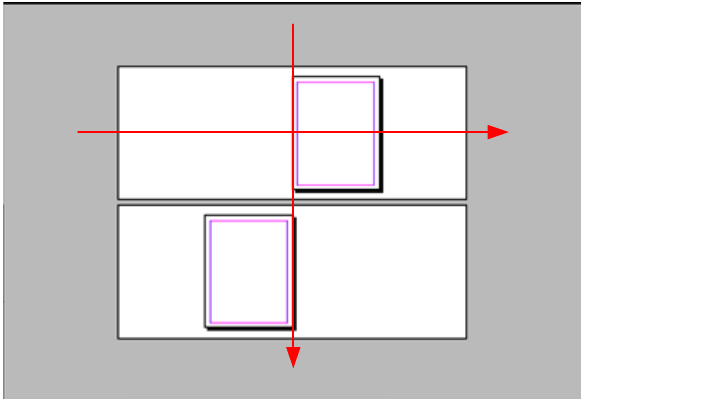
CHAPTER 7: Layout Fundamentals Coordinate systems 165
The PMMatrix patterns that specify the most common transformations are as follows:
Translation is specified by [1 0 0 1 Tx Ty], where Tx and Ty are the distances to translate the origin of the
coordinate system in the horizontal and vertical dimensions, respectively.
Scaling is specified by [Sx 0 0 Sy 0 0]. This scales the coordinates so one unit in the horizontal and
vertical dimensions of the new coordinate system is the same size as Sx and Sy units, respectively, in
the previous coordinate system.
Rotation is specified by [cos(A) sin(A) -sin(A) cos(A) 0 0], which has the effect of rotating the coordinate
system axes by an angle A counterclockwise.
Skew is specified by [1 tan(A) tan(B) 1 0 0], which skews the x axis by angle A and the y axis by angle B.
Pasteboard coordinate space
The pasteboard coordinate space is the global coordinate system that encloses all objects in a document,
as shown in the following figure.
All objects in a layout can have their coordinates expressed in pasteboard coordinates. The origin is the
center of the first spread. The x axis increases from left to right; the y axis decreases from up to down. The
length along each axis is measured in the PostScript unit of points. For example, the following figure
shows the pasteboard coordinates of the bounding boxes for the spreads and pages in a basic document.
The figure shows the pasteboard coordinates of the bounding box of each spread and page in a
facing-page document with letter-sized pages of width 612 points and height 792 points. All values shown
are in PostScript points.
Xpasteboard
Ypasteboard
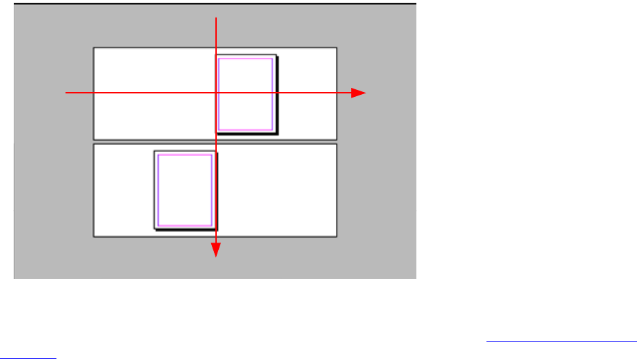
CHAPTER 7: Layout Fundamentals Coordinate systems 166
The unit in which all measurements are stored in a document is the PostScript point. The unit in which
measurements are shown in the user interface is controlled by a preference (see “Measurement units” on
page 172).
Inner coordinate space and parent coordinate space
Each page item has its own coordinate system, known as its inner coordinate space. Each page item has an
associated parent coordinate space. The inner coordinate space and its relationship with its parent
coordinate space are defined by three interfaces:
IHierarchy defines the parent association. The parent coordinate space is the first ancestor boss object
on IHierarchy that has an IGeometry interface. This may not be the boss object’s immediate parent. For
example, many objects are owned by a spread layer (kSpreadLayerBoss). Spread layers are not
geometrical objects; they do not have an IGeometry interface; therefore, the parent coordinate space
for a boss object owned by a spread layer is the spread (kSpreadBoss).
IGeometry defines the bounding box, which implies the origin and orientation of the x and y axes.
ITransform defines the transformation matrix that maps from the inner coordinate space to the parent
coordinate space.
The following figure shows a square containing a rectangular child page item as an example of a parent
page item. The inner coordinate system of the parent as defined by its IGeometry interface is shown.
-1224,-468
1224,468
-1224,504
1224,1440
Xpasteboard
Ypasteboard
1224,-468
-1224,468
1224,504
-1224,1440
0,-396
612,396
612,-396
0,396
-612,576
0,1368
0,576
-612,1368
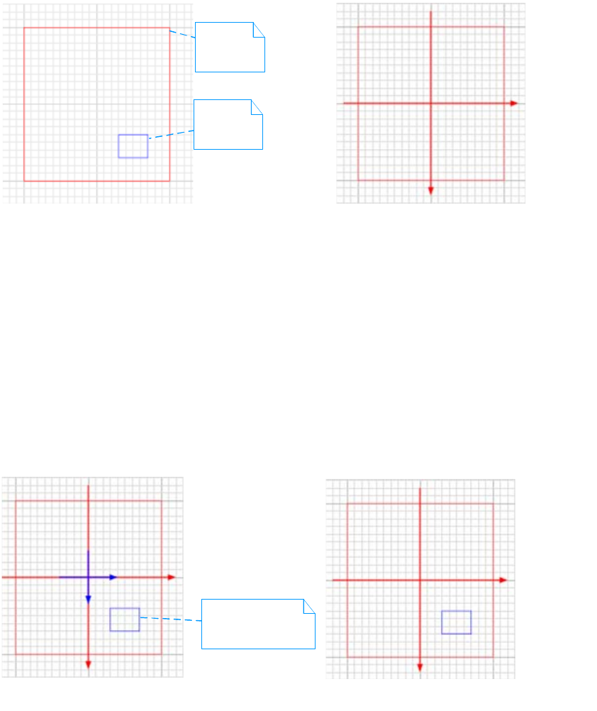
CHAPTER 7: Layout Fundamentals Coordinate systems 167
In the A part of this figure, the parent is a square (kSplineItemBoss), 200 points wide. The child is a
rectangle (kSplineItemBoss), 40 points wide and 30 points high. The square is used as a frame for the
rectangle; this association is defined by the IHierarchy interface. The objects are shown on a document
grid with a grid line every 100 points and subdivisions every 10 points.
In the B part of this figure, the bounding box stored by the square’s IGeometry interface defines the origin
of the object’s inner coordinate space and the orientation of its x and y axes. The coordinates of the
bounding box of the square in its inner coordinate space are shown, together with the x and y axes these
coordinates imply. For a parent object, this is known as the parent coordinate space.
The IGeometry and ITransform interfaces on the child object express the coordinate system relationship to
the parent. There is more than one way to arrange this data. In the following figure, the child’s coordinate
system (the rectangle) is coincident with the parent’s coordinate system (the square).
In the C part of this figure, the rectangle has its own inner coordinate space. The bounding box stored by
the rectangle’s IGeometry interface is shown. This bounding box defines the origin of the object’s inner
coordinate space and the orientation of its x and y axes, labeled xchild and ychild. The transformation
matrix defined by the rectangle’s ITransform interface maps the rectangle’s inner coordinate space (the
child coordinate space) into the square’s coordinate space (the parent coordinate space). In the
arrangement shown, the parent and child coordinate systems are coincident; therefore, the
transformation matrix in ITransform is the identity matrix.
In the D part of this figure, when the bounding box of the child (the rectangle) is transformed using the
child’s transformation matrix to the parent coordinate space (the square), the coordinates are expressed in
the parent coordinate space as shown.
A. Parent and child page items B. Inner coordinates of parent
xparent
yparent
-100,-100 100,-100
-100,100 100,100
Parent
Child
C. Inner coordinates of child
xparent
yparent
30,40 70,40
30,70 70,70
xchild
ychild
D. After transformation of C to parent
xparent
yparent
30,40 70,40
30,70 70,70
Transformation matrix
[1 0 0 1 0 0]
(the identity matrix)
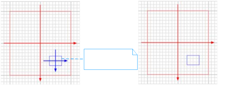
CHAPTER 7: Layout Fundamentals Coordinate systems 168
In the arrangement shown in the following figure, the child coordinate space is not coincident with its
parent coordinate space. Instead, the origin of the rectangle’s coordinate space is located at the rectangle’s
center.
In the E part of this figure, the origin of the rectangle’s inner coordinate space is located at its center. The
coordinates of the bounding box defined by the rectangle’s IGeometry interface, are shown together with
the x and y axes these coordinates imply, labeled xchild and ychild. The transformation matrix defined by
the child’s ITransform interface specifies the translation required to map to the parent coordinate space.
In the F part of this figure, when the bounding box of the child (the rectangle) is transformed using the
child’s transformation matrix to the parent coordinate space (the square), the coordinates are expressed in
the parent coordinate space as shown.
A comparison of this figure and the one that precedes it shows that, after transformation, the bounding
box of the rectangle in its parent’s coordinate space is the same.
NOTE: To transform any point from inner coordinate space to any other coordinate space, the page item’s
transformation matrix (ITransform) must be applied. For utilities to help with the calculations, see
TransformUtils.
Tools like the Rectangle tool use a tracker (CPathCreationTracker) to create a path (kSplineItemBoss) whose
coordinate system is coincident with their parent coordinate system as shown in the preceding figure with
parts C and D. Facades like IPathUtils often are used to create a path (kSplineItemBoss) arranged as shown
in the preceding figure with parts E and F.
Spread coordinate space
Spread coordinate space is the coordinate system of a spread (kSpreadBoss). Each spread has its own
coordinate space, also known as the inner coordinate space for a spread. The origin of the spread
coordinate space is the center of the spread. The parent coordinate space is pasteboard coordinate space.
Unlike other page items, the parent of a spread is not defined by IHierarchy; the parent of a spread is fixed
as the document (kDocBoss). See the following figure.
E. Inner coordinates of child
xparent
yparent
-20,-15 20,-15
-20,15 20,15
xchild
ychild
F. After transformation of E to parent
xparent
yparent
30,40 70,40
30,70 70,70
Transformation matrix
[1 0 0 1 50 55]
(translation Tx=50, Ty=55)
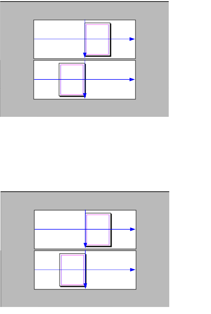
CHAPTER 7: Layout Fundamentals Coordinate systems 169
In spread coordinates, the bounding box of each spread is identical. It is returned by
IGeometry::GetStrokeBoundingBox. The spread’s (kSpreadBoss) implementation of IGeometry determines
the bounding box using the IPasteboard interface. The spread’s ITransform interface stores a
transformation matrix that translates the spread coordinate space to pasteboard coordinate space. This
matrix is a translation matrix [1 0 0 1 0 Ty], where Ty specifies the spread’s offset in the vertical dimension.
The following figure shows the spread coordinates of the bounding box of each spread and page in a basic
facing-page document with letter-sized pages 612 points wide and 792 points high.
Page coordinate space
Each page has its own coordinate space, also known as the inner coordinate space for a page (kPageBoss).
The parent coordinate space for page coordinate space is spread coordinate space. The origin of page
coordinate space is the top-left corner of the page. See the following figure.
Xspread1
Yspread1
Xspread2
Yspread2
-1224,-468
1224,468
-1224,-468
1224,468
Xspread1
Yspread1
1224,-468
-1224,468
1224,-468
-1224,468
Xspread2
Yspread2
0,-396
612,396
612,-396
0,396
-612,-396
0,396
0,-396
-612,396

CHAPTER 7: Layout Fundamentals Coordinate systems 170
In page coordinates, the bounding boxes of each page(kPageBoss) in a document can be different. They
are returned by IGeometry::GetStrokeBoundingBox. The page’s ITransform interface stores a
transformation matrix that translates the page coordinate space to spread coordinate space.
The following figure shows the page coordinates of the bounding box of each page in a facing-page
document with letter-sized pages 612 points wide and 792 points high.
Page-item coordinate space
Each page item has its own coordinate space, known as its inner coordinate space. The page item’s
bounding box is stored in interface IGeometry. The geometrical data stored in IGeometry and other data
interfaces specific to the page item type are in the inner coordinate space of the page item. For example,
the points that describe a path in interface IPathGeometry are stored in the inner coordinate space. A
transformation matrix that transforms from inner coordinate space to parent coordinate space is stored in
the ITransform interface. The parent coordinate system is defined by the IHierarchy interface.
For more information, see “Inner coordinate space and parent coordinate space” on page 166.
Xpage1
Ypage1
Xpage2
Ypage2
0,0
612,792
Xpage1
Ypage1
612,0
0,792
Xpage2
Ypage2
0,0
612,792
612,0
0,792

CHAPTER 7: Layout Fundamentals Coordinate systems 171
Bounding box and IGeometry
The bounding box (IGeometry::GetStrokeBoundingBox) is the smallest rectangle (PMRect) that encloses a
geometric page item:
The bounding box of an image (kImageItem) encloses the pixels that define its raster data.
The bounding box of a group (kGroupItemBoss) is the union of the bounding boxes of the objects in
the group.
The bounding box of a path (kSplineItemBoss) encloses all points in the path (IPathGeometry) and
includes the effect of the properties that control how the path is stroked, such as stroke weight and
corner style.
The bounding box of a page (kPageBoss) or spread (kSpreadBoss) encloses the objects that lie on it.
For illustrations, see “Spread coordinate space” on page 168 and “Page coordinate space” on page 169.
A page item stores the data that describes its geometry in its inner coordinate space. For example, the
bounding box in IGeometry and the points that describe a path in interface IPathGeometry are stored in
inner coordinate space (see “Inner coordinate space and parent coordinate space” on page 166). This
stored data is independent of any transformation that may be in effect. Transformation (for example,
scaling and rotation) is described by the page item’s ITransform interface.
The IGeometry::GetPathBoundingBox method gives the path bounding box, the bounding box of a path
excluding the effects of adornments.
NOTE: Paths (kSplineItemBoss) have path bounding boxes; page items of other types may not.
The IShape::GetPaintedBBox method gives the painted bounding box, the bounding box of the page item
including the effect of adornments.
The following table lists some useful geometry-related APIs.
Transformation and ITransform
A page item has its own coordinate space, its inner coordinate space. (See “Inner coordinate space and
parent coordinate space” on page 166.) The coordinates of the points that describe the page item are
stored in this inner coordinate space. A transformation matrix (PMMatrix) that maps from inner coordinate
space to the parent coordinate space is stored in the ITransform interface. Scaling, rotation, and other
transformations that may be in effect are represented in this matrix. Points in inner coordinate space are
mapped to the parent coordinate space using the matrix obtained from
ITransform::GetInnerToParentMatrix. There are useful functions in TransformUtils.h that help to get the
transform matrix (InnerToParentMatrix) and perform transform calculations. For details, refer to the API
Reference.
API Note
IGeometry Stores the bounding box of a page item.
IGeometryFacade Positions and resizes page items.
IGeometrySuite Positions and resizes objects currently selected.

CHAPTER 7: Layout Fundamentals Coordinate systems 172
For example, to calculate the bounding box of a page item in its parent coordinate space, get the
bounding box from the page item (IGeometry::GetStrokeBoundingBox), and apply its transformation
matrix (ITransform::GetInnerToParentMatrix). The calculated bounding box takes into account all scaling,
rotation, and other transformations that are applied. The parent could be a group (kGroupItemBoss),
frame (kSplineItemBoss), spread (kSpreadBoss), or other kind of page item.
A transformation matrix can be inverted (PMMatrix::Invert) to create a matrix that performs the inverse
transformation. For example, if you have a matrix that transforms from inner coordinate space to parent
coordinate space (InnerToParentMatrix), the inverse matrix can be used to transform points from parent
coordinate space to inner coordinate space.
The matrix that transforms from inner coordinate space to pasteboard coordinate space is returned by
ITransform::GetInnerToRootMatrix. To access it, we recommend you use a helper function,
InnerToPasteboardMatrix. This code walks up the hierarchy (IHierarchy) and concatenates the
transformation matrix (ITransform::GetInnerToParentMatrix) of each page item. The end result is a matrix
that maps from the inner coordinates of the page item it started from into pasteboard coordinates.
To compare the coordinates of two or more page items, the coordinates first should be transformed to a
common coordinate space. The pasteboard coordinate space often is used for this purpose.
When creating a path (kSplineItemBoss), it often is useful to specify its position in pasteboard coordinates.
You often position new page items relative to an existing boss object, like a spread, page, or frame. For
example, to determine a position relative to a page, you first need the IGeometry interface of the page
(kPageBoss); then you can call InnerToPasteboard to transform points on that page into pasteboard
coordinates. When you have the points described in pasteboard coordinates, you can use IPathUtils to
create the path. Alternately, you can describe the points in the parent coordinate space as shown by the
sample code in SnpCreateFrame and SDKLayoutHelper.
The following table lists some useful transformation-related APIs.
Measurement units
The internal unit of measurement used by the application is PostScript points. All measurements in a
document are stored in the internal measurement unit as PMReal values. The user can choose to work in
other measurement units, like centimeters, inches, picas, or ciceros. The user’s preferred measurement unit
is converted to and from the standard internal unit (PostScript points) at the boundary between the user
interface and the document model.
Unit-of-measure service
The conversion from a specific measurement unit to the internal measurement unit is performed by a
unit-of-measure service.
API Note
ITransform Stores the page item’s transformation matrix.
TransformUtils Utility functions for transform calculations. See methods like InnerToPasteboard
and PasteboardToInner in TransformUtils.h.
ITransformFacade Scale, rotate, skew, or move page items.
ITransformSuite Scale, rotate, skew, or move objects currently selected.
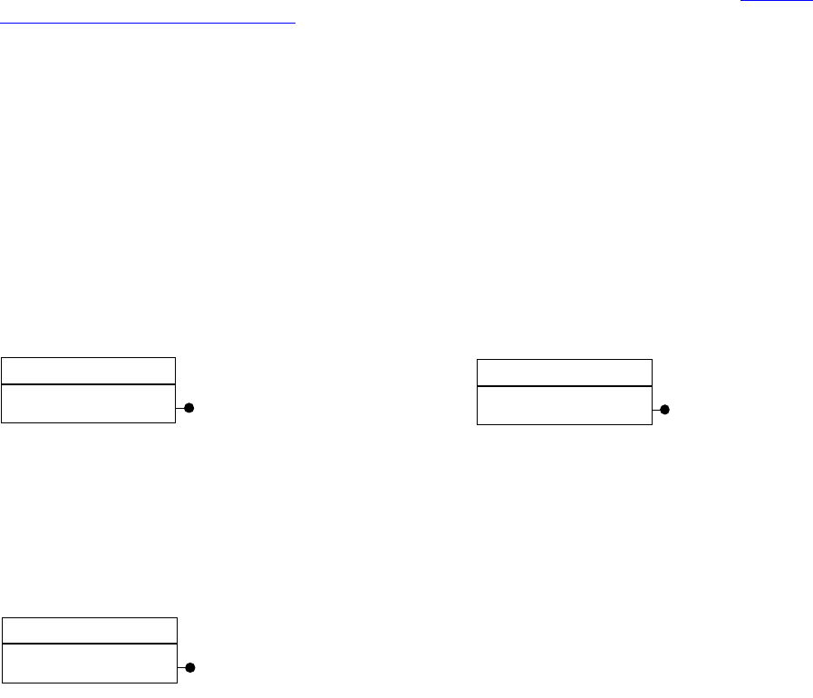
CHAPTER 7: Layout Fundamentals Coordinate systems 173
A unit-of-measure service is a boss class that aggregates the IUnitOfMeasure and IK2ServiceProvider
interfaces. IUnitOfMeasure is the interface responsible for converting between the unit of measure and the
internal unit of measure. IUnitOfMeasure also has methods for producing a formatted string
representation from units and tokenizing a string to produce a formatted number from the string. The
measurement units supported by the application can be extended. For more information, see “Custom
unit-of-measure service” on page 182.
Common unit-of-measure services include kPointsBoss, kInchesBoss, kInchesDecimalBoss,
kMillimetersBoss, kPicasBoss, kCicerosBoss, and kCentimetersBoss.
Measurement-unit preferences
The user’s preferred measurement unit is stored in the IUnitOfMeasureSettings interface. The session
workspace (kWorkspaceBoss) stores the measurement-unit preferences inherited by new documents. The
document workspace (kDocWorkspaceBoss) stores the document’s preferences. The user changes these
preferences by choosing Edit > Preferences > Units & Increments and using the resulting dialog box. To
change these preferences programmatically, use the kSetMeasureUnitsCmdBoss command.
The following is a class diagram of IUnitOfMeasureSettings.
The measurement system, IMeasurementSystem, is an interface aggregated on kSessionBoss that is used
to help locate and use a unit-of-measure service. Unit-of-measure services can be referred to by either
their ClassID or an index the measurement system assigns. The index assigned by the measurement
system is used while referring to a unit of measure in memory, but this index should be converted to a
ClassID when writing or reading from a stream. The following figure is a class diagram of
IMeasurementSystem.
Geometrical data types
The core geometrical data types are as follows:
PMPoint — (x, y) coordinates expressed as real (PMReal) numbers.
PMRect — Rectangle represented by points that designate the top-left and bottom-right corners.
PMMatrix — Two-dimensional transformation matrix that maps from one coordinate space to another.
The core geometrical-collection data types are as follows:
PMPointList
PMRectCollection
PMMatrixCollection
kWorkspaceBoss
IUnitOfMeasureSettings
kDocWorkspaceBoss
IUnitOfMeasureSettings
kSessionBoss
IMeasurementSystem
CHAPTER 7: Layout Fundamentals The layout presentation and view 174
The layout presentation and view
This section describes the objects that present the layout to the user and allow the content to be edited
interactively.
Layout presentation
The layout of a document is presented within a layout presentation. A document has a layout presentation
(kLayoutPresentationBoss) for each view of the publication’s layout. A layout presentation is implemented
by kLayoutPresentationBoss and its associated widgets. The pages and spreads are presented by the
layout view (kLayoutWidgetBoss). The general arrangement is shown in the class diagram in the following
figure.
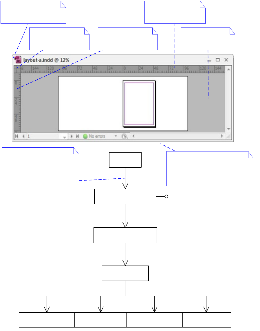
CHAPTER 7: Layout Fundamentals The layout presentation and view 175
The application may have several layout presentations open at once, each displaying different documents
or different views of the same document, as shown in the class diagram in the following figure. The figure
shows a screenshot of the application with three layout presentations open. The boss classes and
interfaces that are required to discover the open documents under the current session also are also shown.
Each document knows the windows that are open on it by means of the IPresentationList interface on
kDocBoss.
«boss»
kDocBoss
«boss»
kLayoutPresentationBoss
«boss»
kLayoutPanelBoss
«boss»
kLayoutGenericPanelBoss
«boss»
kLayoutWidgetBoss
«boss»
kVertRulerWidgetBoss
«boss»
kHorzRulerWidgetBoss
«boss»
kZeroPointWidgetBoss
1IPresentationList0..*
1
IPanelControlData1
1IPanelControlData1
0..* 0..1
1
0..1
1
IPanelControlData1
IDocumentPresentation
Layout presentation
kLayoutPresentationBoss
Zero point
kZeroPointWidgetBoss
Vertical ruler
kVertRulerWidgetBoss
Horizontal ruler
kHorzRulerWidgetBoss
Layout view
kLayoutWidgetBoss
The other widgets provided by the
layout presentation have not been
modelled; e.g., the widgets that
control the magnification of the
view, page navigation, and scrolling.
A document can be presented
in one or more presentation
views. Layout presentations
present pages and spreads.
Note: Presentations returned
by IPresentationList are not
always layout presentations.
Other types of presentation
may be open on a document;
e.g., story windows.
CHAPTER 7: Layout Fundamentals The layout presentation and view 176
A document does not need to have a presentation view. Documents that do not have a presentation view
can be edited programmatically. Sometimes this called editing a headless document.
Layout view
The layout view presents the layout of a document and is represented by the kLayoutWidgetBoss boss
class. Documents can contain a variety of objects, like spreads, pages, frames, text, and graphics. The
document stores these objects; the layout view displays them and allows them to be edited interactively.
The layout view is part of a layout presentation (see the layout presentation class diagram in “Layout
presentation” on page 174).
Only the visible part of a document is presented in layout view. The layout presentation controls which
part of a document is visible using magnification and page navigation widgets, etc. Other panels, like the
Pages and Navigation panels, also may adjust the view.
The layout view sometimes is known as the layout widget.
The layout view causes the visible objects to draw by discovering the spreads that are visible and calling
each spread to draw. The general arrangement is shown in the class diagram in the following figure.
«boss»
kSessionBoss
«boss»
kAppBoss
«boss»
kDocumentListBoss
«boss»
kDocBoss
1
ISession::QueryApplication1
1
IApplication::QueryDocumentList1
1
IDocumentList::GetNthDoc0..*
Layout presentations
showing different views
of the same document.
Layout
presentation
of a second
document
To discover the layout presentations
that are open, iterate the
IPresentationList interface on
each document. Documents
opened by the current session
can be discovered as shown.
IPresentationList
IDocument
CHAPTER 7: Layout Fundamentals The layout presentation and view 177
The layout view uses its ILayoutControlData interface to get to its associated document. The ISpreadList
interface on the document provides access to any particular spread. The IHierarchy interface can be used
to access children of the spread. For reasons of efficiency, navigation of the layout hierarchy during a
window draw is somewhat more selective than shown in the figure in “Layout view” on page 176. Portions
of spreads that are not visible in a window are not called to draw. The layout view also discriminates
between redrawing an entire window and drawing only the region that changed. These two strategies
mean page items are not guaranteed to be called to draw during every window draw.
Current spread and active layer
The current spread is the spread (kSpreadBoss) targeted for edit operations. Normally, new page items
created by the tools that handle user actions in the layout view are created in the current spread. Each
view (kLayoutWidgetBoss) stores a reference to its current spread in ILayoutControlData::GetSpreadRef.
The current spread is set in the user interface by clicking on a spread in the layout view. The tool that
handles the click processes the kSetSpreadCmdBoss command. A reference to the current spread of the
view that most recently edited the document (kDocBoss) is stored in the IPersistUIDData interface with
PMIID IID_ICURRENTSPREAD.
The active layer is the layer targeted for edit operations. New page items created by the tools that handle
user actions in the layout view are assigned to the active layer. Each view (kLayoutWidgetBoss) has a
reference to its active layer (kDocumentLayerBoss) given by ILayoutControlData::GetActiveDocLayerUID.
The active layer is set in the user interface by clicking on a layer in the Layers panel, which then processes
the kSetActiveLayerCmdBoss command. A reference to the active layer of the view that most recently
edited the document can be found by calling ILayerUtils::QueryDocumentActiveLayer.
When creating a page item programmatically, choose its parent boss object. Normally, this is a spread layer
(kSpreadLayerBoss). If you have access to a layout view, ILayoutControlData::QueryActiveLayer returns the
hierarchy of the spread layer to use.
«boss»
kLayoutWidgetBoss
«boss»
kDocBoss
«boss»
kSpreadBoss
1
ISpreadList1..*
1
ILayoutControlData1
The layout widget draws the area
within the red highlight. Interface
ILayoutControlData provides access
to the document being presented.
Additionally ILayoutControlData provides
access to the spread, page,
and layer being edited.
spread floor
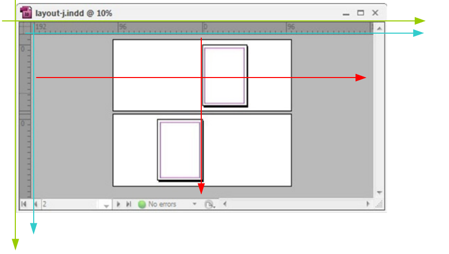
CHAPTER 7: Layout Fundamentals Key client APIs 178
NOTE: The current page is not stored anywhere in a document (in contrast, the current spread and active
layer are stored as described above). ILayoutControlData::GetPage returns the visible page. This is
calculated by means of ILayoutUIUtils::GetVisiblePageUID, by finding the page whose center point is
closest to the center of the layout view.
Layout-presentation and layout-view coordinate spaces
The relationship between layout-presentation coordinates and layout-view coordinates is relatively static
and is described by the respective IControlView implementations. When the user hides the rulers, the
layout-view coordinate space is coincident with the layout-presentation coordinate space. The
relationship between pasteboard coordinates and layout-view coordinates is stored in the layout view’s
IControlView interface. The layout view’s IControlView::GetContentToWindowTransform method returns
the transform that maps from pasteboard coordinates to layout-view coordinates. See the following figure.
As the user zooms and scrolls the view, the relationship between layout-view coordinates and pasteboard
coordinates changes. The layout view (kLayoutWidgetBoss) has an IPanorama interface to track the scroll
and zoom changes. The relationship between the pasteboard and layout-view coordinate systems is
stored in the layout view’s IControlView interface. The layout view’s
IControlView::GetContentToWindowTransform method returns the transform that maps from pasteboard
coordinates to window coordinates. By using the known coordinate relationships in the layout hierarchy, a
region described in a page item’s inner coordinate space can be mapped to the window coordinates.
Global-screen coordinates can be converted to pasteboard coordinates using
ILayoutUIUtils::ComputePasteboardPoint. Event handlers often return mouse locations in global-screen
coordinates.
Key client APIs
This section summarizes the APIs provided to manipulate layout-related objects. For more information,
refer to the API Reference.
Y layout-presentation
X layout-
presentation
Y layout-widget
X layout-
widget
Xpasteboard
Ypasteboard

CHAPTER 7: Layout Fundamentals Key client APIs 179
The layout view (kLayoutWidgetBoss) displays a document for editing and provides some important data
interfaces, summarized in the following table. The layout view can be obtained in several ways, one of
which is calling ILayoutUIUtils::QueryFrontLayoutData.
This table summarizes the suite interfaces that manipulate layout-related objects that are selected. To
obtain a suite, client code can query a selection manager interface (ISelectionManager) for the suite of
interest. If the suite is available, its interface is returned; otherwise, a nil pointer is returned. For details of
how to obtain the selection manager, see Chapter 4, “Selection.” Given a selection manager, you can call
suite methods using code that follows this pattern:
InterfacePtr<IGeometrySuite> suite(selectionManager,UseDefaultIID()
if (suite) suite->MethodName();
There are many command boss classes related to layout, as summarized in “Commands that manipulate
page items” on page 183. When possible, try to avoid to avoid processing low-level commands when
possible; instead, look for a facade or utility, to see if there is a method that serves your purpose on one of
API Note
ILayoutControlData Data interface that refers to the document being viewed and the spread,
page, and layer currently selected
ILayoutControlViewHelper Helper routines for performing page item hit-testing
API Description
IAlignAndDistributeSuite Aligns and distributes objects that are selected.
IArrangeSuite Brings forward, sends backward, or performs other z-order-related
operations on objects that are selected.
IFrameContentSuite Content-fitting operations and frame conversion operations on objects that
are selected.
IGeometrySuite Positions and resizes objects that are selected.
IGroupItemSuite Groups and ungroups objects that are selected.
IGuideDataSuite Manipulates the properties of guides that are selected.
ILayerSuite Manipulates document layers.
ILayoutHitTestSuite Hit-tests objects that are selected.
ILayoutSelectionSuite Sets the page items that are selected.
IMasterPageSuite Manipulates master page item overrides.
IPageItemLockSuite Locks or unlocks objects that are selected.
IPathOperationSuite Performs path operations of selected page items.
IPathSelectionSuite Performs path selections.
IReferencePointSuite Manipulates reference point.
ITransformSuite Scales, rotates, skews, or moves objects that are currently selected.

CHAPTER 7: Layout Fundamentals Key client APIs 180
these interfaces. Facades encapsulate parameterizing and processing the low-level commands. For
example, to add an item to a page-item hierarchy, you could process kAddToHierarchyCmdBoss, but
instead you should use IHierarchyUtils::AddToHierarchy, which provides a ready-made facade.
The facades and utilities related to layout are listed in the following tables. These interfaces are aggregated
on kUtilsBoss. The Utils smart pointer class makes it straightforward to acquire and call methods on these
interfaces. You can call their methods by writing code that follows this pattern:
Utils<IPathUtils>()->MethodName(...)
This table lists layout facades and utilities:
This table lists layout helper classes:
API Description
IGeometryFacade Positions and resizes page items.
ITransformFacade Scales, rotates, skews, or moves page items.
IPageItemNameFacade Gets and sets page item names.
IPageItemVisibilityFacade Shows and hides page items.
IPathUtils Creates and works with paths (kSplineItemBoss).
IFrameContentUtils Helps work with text or graphic-frame content.
IHierarchyUtils Adds and removes page items from a hierarchy (IHierarchy).
IImageUtils Helper functions to get image information.
ILayoutUIUtils Helper functions related to the layout user interface. Most of these are
related to the active or front document.
ILayoutUtils Helper functions related to layout. Most of these are related to pages or the
page-item hierarchy.
IMasterSpreadUtils Helper functions for master spreads and master page items.
IPageItemUtils Page-item helper functions, like cache and change notifications.
IPageItemTypeUtils Helps determine the type of a page item (for example, path, frame, and
image).
IPasteboardUtils Helps determine the spread by location or gets the location of page items.
IPathInfoUtils Helps get path information.
IPathPointUtils Stores path points during path-point transformation.
IPathUtils Creates and manipulates path page items.
IRefPointUtils Utility interface for functions that compute reference points.
ITransformUpdateUtils Helps determine values relative to the zero point.
IValidateGeometryUtils Validates transformation data.

CHAPTER 7: Layout Fundamentals Extension patterns 181
Extension patterns
This section summarizes the mechanisms a plug-in can use to extend the layout subsystem.
New-page-item responder
A new-page-item responder lets a plug-in receive notification when a new page item (for example, frame,
path, group, or image) is created by kNewPageItemCmdBoss. For the complete list of page item types, see
“Page items” on page 156.
A new-page-item responder often is used to detect the creation of a specific type of page item. For
example, to detect the creation of a graphic frame, implement a new-page-item responder that gets a
reference to the new page item (INewPISignalData::GetPageItem) and then checks whether it is a graphic
frame (IPageItemTypeUtils::IsGraphicFrame).
Another common use of a new-page-item responder is initializing a custom data interface on a page item
from defaults.
Consider the case where you defined a custom data interface and added this data interface to the
document workspace (kDocWorkspaceBoss) to store default data. You also added this data interface to
kDrawablePageItemBoss to store the settings per page item, and you want the default data to be inherited
when new page items are created. In this case, you can implement a new-page-item responder that copies
the data from defaults into the new page item. For an implementation of this pattern, see
BasicPersistInterface.
A new-page-item responder is a service provider characterized by the following:
The responder interface IResponder — The implementation can expect to be able to acquire an
INewPISignalData interface from the signal manager (ISignalMgr) that it is passed.
The signature interface IK2ServiceProvider — The ServiceID must be of type
kNewPISignalResponderService. You can reuse the API implementation kNewPISignalRespServiceImpl
for this.
Sample code
BasicPersistInterface copies data from defaults into new page items.
Custom page item
A custom page item lets a plug-in extend the set of objects that can be laid out on a page. A custom page
item gives the plug-in control of how the object is drawn and how it behaves when selected and
manipulated by the user. A common use of a custom page item is adding support for a graphics format for
API Note
Arranger Brings to front, sends to back, and performs other z-order-related operations.
See ArrangeUtils.h.
TransformUtils Utility functions for transform calculations. See methods in TransformUtils.h,
such as such as InnerToPasteboard and PasteboardToInner.
CHAPTER 7: Layout Fundamentals Extension patterns 182
which the application provides no native support. In this case, the custom page item also requires a
custom import provider (IImportProvider), to allow files of that graphics format to be placed. Some custom
page items also may require custom tools to be implemented to create and manipulate the custom page
items.
Implementing a custom page item can be complex. Before beginning development of a custom page
item, evaluate whether another type of extension pattern—like a page-item adornment or draw-event
handler—might meet your needs. If you do need to implement a custom page item, study the subclasses
of kPageItemBoss to see if there is an existing page item that is a close match to what you need. (Refer to
kPageItemBoss in the API Reference.) If an existing page item comes close to meeting your needs, use this
boss class as the base class for your implementation. The examples provided in the SDK show only the
basics of what is involved.
Sample code
BasicShape specializes kSplineItemBoss and shows how to implement the interfaces involved in
drawing a page item.
CandleChart specializes kSplineItemBoss to show how to draw some data as a chart.
Custom unit-of-measure service
Plug-ins can extend the set of measurement units supported by the application by defining a
unit-of-measure service. The following steps outline what a plug-in needs to do to make a custom unit of
measure appear in the Edit > Preferences > Units & Increments dialog box:
1. Define a unit-of-measure service boss class.
2. Implement the C++ code for IUnitOfMeasure, using CUnitOfMeasure as a base.
3. Implement IK2ServiceProvider using the default kUnitOfMeasureService provided by the API, which
registers the custom unit with the application-measurement system.
4. Include a ruler-resource description of the ODFRez type RulerDataType for your custom unit of
measure in the .fr resource file.
Rulers
Rulers are displayed by the ruler widgets (kHorzRulerWidgetBoss and kVertRulerWidgetBoss). The
presentation of the ruler is described by the data defined in the ODFRez resource type, RulerDataType. This
type describes the font, associated unit-of-measure service ClassID, and tick-mark layout. For more details,
see RulerType.fh.
Typically, a ruler is associated with a particular unit-of-measure service. The resource description for the
ruler is in the same plug-in as the unit-of-measure service. The unit-of-measure service returns the
resource ID of its ruler description in its implementation of IUnitOfMeasure::GetRulerSpecRsrcSpec.
When a new view is created on a document, the preferred measurement unit is determined. Then, the
associated unit-of-measure service is queried for the resource ID of its ruler description. If one exists, that
description is used to create a new ruler as part of the new view of the document.

CHAPTER 7: Layout Fundamentals Commands that manipulate page items 183
Sample code
CustomUnits creates a custom unit. In addition, it provides a resource description of how the ruler tick
markers are specified for the custom units. CstUniRuler.fr from the sample shows a sample ruler resource.
Commands that manipulate page items
Page-item creation commands
This table lists commands that create page items
Command Description
kCreateMultiColumnItemCmdBoss Creates a new text frame.
kImportAndLoadPlaceGunCmdBoss Combination of kImportPIFromFileCmdBoss and
kLoadPlaceGunCmdBoss.
kImportAndPlaceCmdBoss Combination of kImportPIFromFileCmdBoss and
kPlacePICmdBoss.
kImportPIFromFileCmdBoss First, this command imports a file. If what is imported is a story, a
multicolumn item is created. If what is imported is not in a
graphic frame, a new graphic frame is created and the imported
file is put into the frame. The UID of the new item is returned on
the command’s item list.
kLoadPlaceGunCmdBoss Loads the item specified on the command’s item list into the
place gun. Only one item can be loaded by this command.
kNewPageItemCmdBoss Used to create a new page item. You will need to use this
command only if you are creating a custom page item. Do not
use this command to create a page-item type supplied by the
API, a kSplineItemBoss, kImageItem, or kMultiColumnItemBoss.
Each page-item type provides a command to create it. The newly
created page item can be any simple page item that supports the
IGeometry interface. All attributes for the new page item are
stored in the INewPageItemCmdData interface. The UID of the
new page item is returned in the command’s item list. If the
parent is supplied, the new page item is added to the hierarchy.
kPlaceGraphicFrameCmdBoss Creates a graphic frame and places an image item into it. The
item to be placed can be passed through the command’s item list
or placed from the place gun. To use the place gun, set the
usePlaceGunContents parameter on the IPlacePIData interface to
kTrue, and do not set the command's item list. When passing the
UID of the placed item using the command's item list, set the
usePlaceGunContents parameter to kFalse.
kPlaceItemInGraphicFrameCmdBoss Places a page item into an existing graphic frame. The page item
can be passed into the command’s item list, or it can be placed
from the place gun. The UID of the graphic frame is returned on
the command’s item list.

CHAPTER 7: Layout Fundamentals Commands that manipulate page items 184
Page-item update commands
The following table lists commands that add/remove a page item to/from a hierarchy:
The following table lists commands that position page items:
The following table lists commands for content fitting:
kPlacePICmdBoss Places a page item. This command does not create a new page
item. It command takes an existing page item from the
command’s item list or the place gun, then places the page item
into the page item hierarchy.
kReplaceCmdBoss Replaces one page item with another. Both the old page item
and the new page item are specified in the IReplaceCmdData
interface.
Command Description
Command Description
kAddToHierarchyCmdBoss Adds the page item in the command’s item list to the parent
specified in the IHierarchyCmdData interface. The index position
for the page item also is specified on the IHierarchyCmdData
interface. For example, when a new page item is created, it calls this
command if the new item’s parent was supplied.
kRemoveFromHierarchyCmdBoss Removes a page item from its parent when deleting a page item or
detaching the imported content from the imported frame.
Command Description
kAlignCmdBoss Aligns the page items in the command’s item list to the alignment
type specified in the IIntData interface. The command itself is a
compound command made up of a set of move-relative commands.
Since the move commands are undoable, the align command also is
undoable.
kCenterItemsInViewCmdBoss Moves a set of page items so they appear centered in the current
view. This command is not undoable.
kFitPageItemInWindowCmdBoss Used to make the current selected page items fit in a window. This
command is not undoable.
kMoveToLayerCmdBoss Moves the page items specified on the command’s item list to the
document layer specified on the IUIDData interface. The page items
appear in the same z-order relative to each other as before in front of
the new layer. This command does not move the items that are
children of a group or a graphic frame, nor does it move standoffs.
kMoveToSpreadCmdBoss Like kMoveToLayerCmdBoss, except kMoveToSpreadCmdBoss moves
the page items from one spread to another.

CHAPTER 7: Layout Fundamentals Commands that manipulate page items 185
NOTE: Sometimes, after replace or paste operations, the graphic frame content (for example, the placed
image, PDF, or EPS item) does not fit into the frame or is not at the position you want inside the frame.
Unfortunately, there is no graphic attribute or helper function that can determine the fitting mode for a
page item. You can compare the bounding boxes for the content (for example, the image item) and the
parent (the frame), to decide whether the content should be positioned in the center, fit into the frame, or
aligned to the corner of the frame using a content-fitting command. Because these commands are
one-time actions and not attributes, however, these commands must be executed again if the page items
are resized.
The following table lists commands that designate the type of a frame:
The following table lists commands that copy and paste page items:
Command Description
kAlignContentInFrameCmdBoss Aligns the contents in the command’s item list to the specified
corners of their respective frames. The corner, which is the same for
all items, is specified on the IAlignContentInFrameCmdData
interface. This command ignores frames without content. The
command’s item list holds the UIDs of the contents, not the UIDs of
the frames that contain the contents. This command sends out a
notification that the content’s subject has changed.
kCenterContentInFrameCmdBoss Positions the contents at the centers of their respective frames. The
content UIDs are stored in the command’s item list.
kFitContentPropCmdBoss Takes a list of frame content and modifies the content size and
transformation to fit the frames and maintain the content’s
proportions.
kFitFrameToContentCmdBoss Resizes each frame in the command’s item list to fit its content’s path
bounding box. This command takes a list of page items, filters out
the empty frame and nongraphical frame, and transforms the
frame's path geometry. The text frames are still in the command’s
item list, even though they are not affected by this and other
commands.
Command Description
kConvertFrameToItemCmdBoss Takes a list of graphic frames and text frames with no content and
converts them to graphic items (unassigned), which are neither text
frames nor graphic frames. This command sets the graphic-frame
attribute of the specified page items to kFalse.
kConvertItemToFrameCmdBoss The opposite of kConvertFrameToItemCmdBoss.
kConvertItemToFrameCmdBoss sets the graphic-frame attribute of
the specified page items to kTrue and converts unassigned graphic
items to graphic frames. It command also converts empty text frames
to empty graphic frames.
kConvertItemToTextCmdBoss Converts unassigned page items and empty graphic frames to empty
text frames.

CHAPTER 7: Layout Fundamentals Commands that manipulate page items 186
The following table lists commands that transform page items:
NOTE: We strongly recommend using ITransformFacade and ITransformSuite for your transformation
needs.
NOTE: Although other transform commands are still available, they may be removed in the future, so we
strongly recommend you use only the two commands in the preceding table.
The following table lists commands that group page items:
Command Description
kCopyCmdBoss A generic command for copying page items from one document to
another. This command applies to any page item that supports the
IScrapItem interface.
kCopyImageItemCmdBoss Copies the specified image item to the specified target. Both the image
item and the target are specified in the ICopyCmdData interface.
kCopyPageItemCmdBoss Copies one or more page items to the specified parent object, if any. A
UIDList of the page items created is returned in the command’s item list.
kDuplicateCmdBoss Duplicates the items specified in the command’s item list. The page items
in the command's item list are duplicated if the command is prepared
successfully.
kPasteCmdBoss Pastes one or more page items to the specified database in the
command’s ICopyCmdData interface. The UIDList of the items to paste
are passed to the command in the ICopyCmdData interface.
kPasteGraphicItemCmdBoss Used for pasting EPS, image, and PDF items into the destination
database. The difference between kPasteGraphicItemCmdBoss and
kCopyPageItemCmdBoss is that if the specified parent is a graphic frame,
the graphic item (EPS, image, PDF) is created as a child of the frame. If no
frame is specified as the parent, kPasteGraphicItemCmdBoss creates a
new rectangular frame as its parent and applies all its transformation
values to the frame, so it appears in the correct location.
kPasteInsideCmdBoss Pastes the specified content into a frame and, if necessary, deletes
previous content. The pasted content is aligned to the top left.
Command Description
kTransformPageItemsCmdBoss Performs various page-item transformations, such as move, rotate,
scale, and skew. The caller needs to pass in appropriate data.
kTransformPathPointsCmdBoss Transforms path points of page items. The transformation could be
move, rotate, scale, skew, etc. The caller needs to pass in appropriate
data.

CHAPTER 7: Layout Fundamentals Commands that manipulate page items 187
The following table lists commands that lock page items:
Page-item deletion commands
The following table lists commands that delete page items:
Command Description
kGroupCmdBoss Groups selected items in the list and creates a new page item consisting of the
group. The parent for the group is the same as the parent of the last item in the
sorted selected-item list. The UID of the new group page item is returned in the
command’s item list. This command requires that the items to be grouped have
valid parents, because only items at the same level in the hierarchy can form a
group. For example, it is invalid to try to group an image with the spline item that
contains it (or any other splines not at the same level as the image of the
document hierarchy).
kUngroupCmdBoss Ungroups the items specified in the command’s item list. The parent of the group
becomes the parent of all ungrouped items.
Command Description
kSetLockPositionCmdBoss Used to lock/unlock the page items. (See the ILockPosition interface.)
Command Description
kDeleteCmdBoss Deletes the page items specified in the command’s item list. Any groups
left empty by the deletions also are deleted.
kDeleteFrameCmdBoss Deletes both the frame and its contents. In general, you should avoid
directly calling this command. Instead, use the GetDeleteCmd method of
the IScrapItem interface to delete the frame.
kDeletePageItemCmdBoss Deletes the page items specified in the command’s item list and removes
the items from the hierarchy. In general, you should avoid directly calling
this command. Instead, use the GetDeleteCmd method of the IScrapItem
interface to delete the page item.
kDeleteImageItemCmdBoss kDeleteImageItemCmdBoss is a subclass of kDeletePageItemCmdBoss.
The purpose of kDeleteImageItemCmdBoss is to release an image object
when the page item is deleted. This command deletes the image items on
the command’s item list. If the ClassID of any item is not kImageItem, that
item is not deleted.
kDeleteLayerCmdBoss Deletes the layer specified on the command’s item list. The layers in the
item list must be in the same document. After this operation, all page
items on the layer list also are deleted.

CHAPTER 7: Layout Fundamentals Commands that manipulate page items 188
kDeletePageCmdBoss Deletes the pages specified on the command’s item list. Page items on the
pages also are deleted. If the spread is left without pages by this
command, the spread also is deleted. If page reshuffling is specified on the
IBoolData interface, the remaining pages in the affected spread and pages
in the spreads that follow are reallocated so each spread has the number
of pages specified in the page set-up preferences for the document.
kDeleteSpreadCmdBoss Deletes one or more spreads and all their pages and page items. If the
deletion would leave the document without spreads, the command is
aborted and nothing is deleted. The list of spreads to delete is specified in
the command’s item list.
kDeleteUIDsCmdBoss Deletes the UIDs specified on the command’s item list.
kRemoveInternalCmdBoss Used when you delete a page item with embedded data. This command
removes the embedded data from the publication.
Command Description

189
8Graphics Fundamentals
This chapter explains how the appearance of page items is specified, how page items are drawn, and how
you can customize how page items are drawn.
The objectives of this chapter are as follows:
Show how paths are defined and manipulated.
Illustrate graphic page-item structure and how to import and export graphics files.
Examine how colors and related properties of graphics are represented.
Introduce graphic attributes.
Describe stroke-related effects, like custom path strokers.
Introduce transparency and transparency effects.
Outline how spreads and page items are drawn to the screen and printed.
Describe extension patterns to let you customize how page items are drawn.
For definitions of terms, see the “Glossary.”
Paths
This section shows how a path is defined and drawn according to its control points.
Path concepts
Paths
Paths can be created using various tools in InDesign. Shape tools and Frame tools create closed paths, the
Pencil tool creates continuous smooth paths with lots of anchor points, and the Pen tool allows you create
paths with great precision.
A path page item may have one or more paths. For example, a line, a rectangle, or an oval consists of one
path; a compound path, two or more paths.
Path points
A path is defined by its path points. A path may have one or more path points. Path points are represented
by PMPathPoint objects. There are three types of path points:
Chapter Update Status
CS6 Unchanged
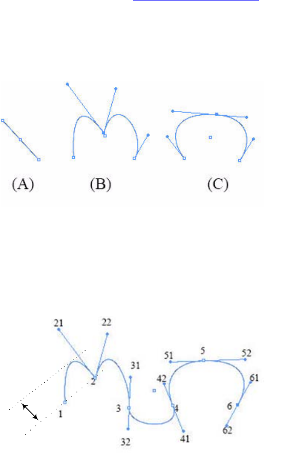
CHAPTER 8: Graphics Fundamentals Paths 190
kL, line point — Used to form a straight line. These (and kCK path points) are called corner points.
kCS, continuous smooth point — Used to form a continuous smooth curve. These are called smooth
points.
kCK, continuous unsmooth point — The point’s left and right tangents are not on the same line. These
(and kL path points) are called corner points.
A PMPathPoint object stores three PMPoint objects, represented as pairs of (x,y) coordinates. These
PMPoint objects represent the anchor point, the left-direction point, and the right-direction point,
respectively (see the figure in “Path drawing” on page 190). For a kL path point, the left- and
right-direction points are the same as the anchor point.
The following figure shows examples of path points. In part A, the line consists of two kL points. In part B,
the middle kCK point has two direction points that are not on a line with the anchor point. In part, the
middle kCS point’s anchor point and two direction points form a line.
Path drawing
A path is controlled by its path points. InDesign draws Bezier curves based on the path points.
The following figure shows an open path with six path points.
In the figure, note the following:
Every anchor point (1, 2, 3, 4, 5, and 6) is on the path.
Points 21, 31, 41, 51, and 61 are left-direction points. Points 22, 32, 42, 52, and 62 are right-direction
points.
Depth
of
curve

CHAPTER 8: Graphics Fundamentals Paths 191
Direction lines (from anchor point to direction point) always are tangent to (perpendicular to the
radius of) the curve at the anchor points.
The angle of each direction line determines the slope of the curve, and the length of each direction
line determines the height, or depth, of the curve.
A path is drawn segment by segment. The shape of each segment is determined by its two end anchor
points and their direction points. For example, curve (1,2) is determined by anchor points 1 and 2 and
left-direction point 21; curve (2,3) is determined by anchor points 2 and 3, right-direction point 22, and
left-direction point 31.
If a path is closed, the last segment is controlled by the last and first path points.
For more details, see PMBezierCurve.h.
Winding rule
The winding rule determines whether a given point is inside or outside the area defined by a path.
InDesign supports both even-odd and nonzero winding rules:
Even-odd winding rule — If a ray drawn from a point in any direction crosses the path an odd number
of times, the point is inside; otherwise, the point is outside.
Nonzero winding rule — The crossing count for a ray is the total number of times the ray crosses a
left-to-right portion of the path minus the total number of times the ray crosses a right-to-left portion
of the path. If a ray drawn from a point in any direction has a crossing count of zero, the point is
outside; otherwise, the point is inside.
For details, refer to the book PostScript Language Reference, available on the Adobe Web site.
The winding rule of an object is stored as a graphic attribute of the kGraphicStyleEvenOddAttrBoss page
item; therefore, you can get or set the winding rules through IGraphicsAttributeUtils the same way as
other graphic attributes. For more information, see “Graphic attributes” on page 229.
Paths data model
Path page-item structure
Paths can exist on any page item that defines an IPathGeometry interface. The following figure show the
relationship among page item, path, path point, and point. A path can be viewed as connected path
segments or connected path points.
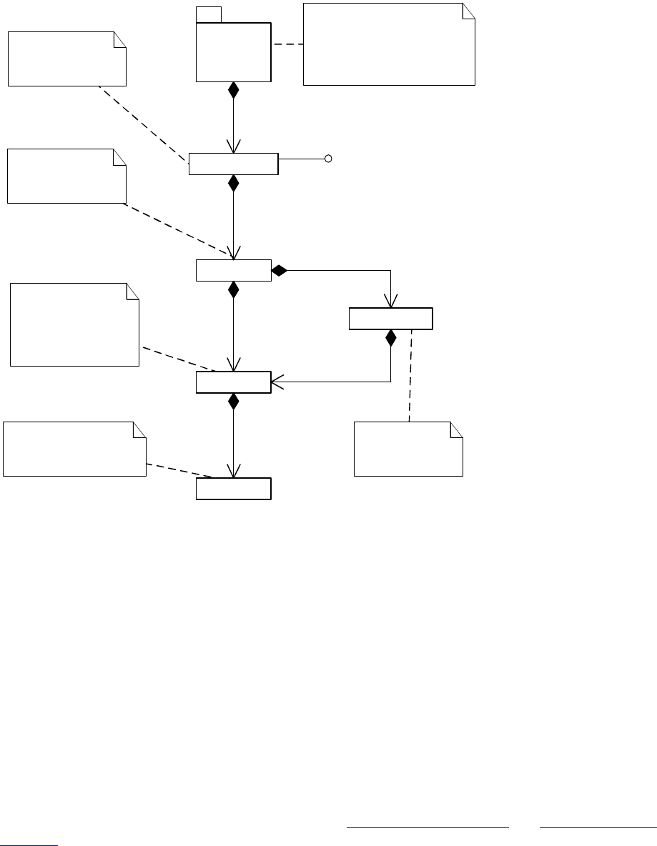
CHAPTER 8: Graphics Fundamentals Paths 192
Path geometry
There is no object in the InDesign object model that maps to a single path directly; instead, all path points
of all paths of a page item are stored using the interface defined by the IPathGeometry class.
IPathGeometry is the signature interface of a path page item. It has methods to access path information of
a page item, like the number of paths the page item has and whether a path is open or closed.
Paths are differentiated using a path index. Methods for accessing path points normally require a path
index parameter.
The PMPathPointList type is defined as K2Vector<PMPathPoint>. An item of this type stores a list of path
points; for example, all path points of a path. Unlike with IPathGeometry, path points stored in an item of
type PMPathPointList are not divided into paths by path index.
The most common path page item is the spline item, represented by kSplineItemBoss. Spline items
include paths (lines, curves, frames) like those shown in “Path points” on page 189 and “Path drawing” on
page 190. There are several other kinds of paths, including image-clipping paths, text-wrap paths, and text
outlines. All paths use IPathGeometry to store paths.
Path page item
Path
Path point
Point
1
1..*
owns
1
1..*
owns
A page item has
at least one path
associated with it.
A path consists of
straight or curved
line segments.
A point mathematically
defines coordinates of
a position.
A path point defines
an anchor point and
the directions of the
path at the anchor
point.
1
3
owns
Path segment
1
2defined by
10..*
owns
A path segment
connects two
path points.
Document
hierarchy
This package includes all
ancestors of a page item.
See details in "Layout
fundamentals" for information
on navigating to page items.
1
1..*
owns
IPathGeometry
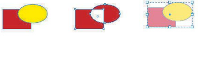
CHAPTER 8: Graphics Fundamentals Paths 193
Path operations
You can access paths of a page item through the interface defined by the IPathGeometry class. InDesign
also encapsulates some complex manipulations into several high-level path operations, which are
provided as commands and selection suites.
Compound paths
You can combine two or more paths, compound paths, grouped page items, text outlines, text frames, or
other shapes that interact with and intercept one another to create a new compound path. The advantage
of a compound path over individual paths is that a compound path is a single object, so you can apply
attributes to the compound path as a whole.
Use kMakeCompoundPathCmdBoss to create a new compound path and kReleasePathsCmdBoss to split a
compound path into individual paths.
NOTE: A compound path does not connect or join any two points of existing paths; it only puts two paths
together in one page item.
Comparing compound paths and groups
Both compound paths and groups involve combining multiple page items as a whole. The main difference
between compound paths and groups is that making compound paths combines all items together into
one page item (all other original page items are deleted), whereas grouping does not delete the original
page items; they are just moved into the new group item. See the following figure. The steps in the figure
are explained below.
In this figure:
1. The original page items are a red rectangle and a yellow oval, represented by kSplineItemBoss object
A and kSplineItemBoss object B, respectively.
2. To make a compound path out of these two objects, to take the path points from kSplineItemBoss
object B and add them to kSplineItemBoss object A through the IPathGeometry interface, then delete
kSplineItemBoss object B. The result is only one kSplineItemBoss object, A, with new path points. The
new item retains the first item’s graphic attributes, including fill color. All path operations use the
even-odd winding rule, resulting in the hole in the compound path.
3. To group the two page items instead, InDesign first creates a kGroupItemBoss object, then removes
both kSplineItemBoss object A and kSplineItemBoss object B from their current hierarchical parents
and adds them as hierarchical children to kGroupItemBoss. The result is three different boss objects.
The graphic attributes of the original items are retained. You can apply graphic attributes to a group
page item or its children independently.
(1) original red
rectangle and
yellow oval
(2) result of
compound path
(3) result of
group with 50%
opacity applied

CHAPTER 8: Graphics Fundamentals Paths 194
Path-finder operations
Path-finder operations, also referred to as compound-shape operations, combine shapes enclosed by the
paths. InDesign supports adding, subtracting, intersecting, excluding-overlap, and minus-back operations.
The following figure illustrates the results of these path finder operations.
You can use kMergePathCmdBoss or IPathOperationSuite to achieve the effect.
Path-finder operations require exactly two input objects. The attributes of the front object are retained by
the result object, except in the case of the subtract operation.
Shape conversion
Shape conversion changes the current shape to a new shape. InDesign can convert to various shapes,
including lines, triangles, rectangles with corner effects, ovals, and polygons. The following figure shows
the result of converting a rectangle and an oval to inverse-rounded rectangles.
The command to achieve this effect is kConvertShapeCmdBoss. It gets the bounding box of the current
shape, then inserts or changes path points in the IPathGeometry object to represent the desired shape, so
the resulting page item maintains the same bounding box as the original shape.
IConvertShapeSuite takes shape type, corner effects, and several other parameters. You can use this
method to convert a shape to a new shape with a new combination of attributes, like shape type, corner
effects, and number of polygon sides.
(1) original red
rectangle and
yellow oval
(2) result of path
fi nder add operation
(3) result of path
fi nder intersect
(4) result of path
fi nder subtract
(5) result of path
fi nder exclude
overlap operation
(6) result of path
fi nder minus back
operation
operation
operation
(1) original red
rectangle and
yellow oval
(2) result of converting
shape to inverse-
rounded rectangle

CHAPTER 8: Graphics Fundamentals Graphic page items 195
NOTE: If you convert a page item from shape A to shape B, then convert from shape B back to shape A
again, the number of path points and their coordinates may be different than for your original shape A.
Graphic page items
This section discusses the concepts and data model for graphic page items, as well as graphic page-item
special operations, like setting clipping paths and text-wrap contours. This section also covers importing
and exporting graphics files.
Graphic page-item types
Computer graphics fall into two main categories, vector graphics and raster images.
InDesign can import raster images, vector graphics, or a combination of both, depending on the
graphics-file format.
Raster images
Raster images, or bitmap images, are the most common electronic medium for such continuous-tone
images as photographs or images created in painting programs like Adobe Photoshop®. Raster images are
resolution dependent.
InDesign supports almost all popular raster-image formats, including PSD, JPEG, TIFF, GIF, PNG, BMP, and
Scitex, all of which are represented by kImageItem boss, which is discussed in more detail in “Graphic
page-item boss-class inheritances” on page 200.
An alpha channel is an invisible channel that defines transparent areas of a graphic. The alpha channel is
stored in a graphic with the RGB or CMYK channels. A user can create alpha channels using
background-removal features in Photoshop.
Vector graphics
Vector graphics use geometrical formulas to represent images. Paths created using the drawing tools in
the InDesign Toolbox are examples of vector graphics.
Vector graphics are more flexible than bitmaps, because vector graphics can be resized without losing
resolution. Another advantage of vector graphics is that their representations often require less memory
than representations of bitmap images.
NOTE: Since most output devices are raster devices, vector objects must be translated into bitmaps before
being printed or displayed. For example, PostScript printers have a raster image processor (RIP) that
performs the translation within the printer.
Vector-graphic formats can differ dramatically. InDesign supports import and export of most common
vector graphics (see the following table).

CHAPTER 8: Graphics Fundamentals Graphic page items 196
For more information on importing vector graphics, see “Graphics import” on page 212. For more
information on exporting vector graphics, see “Export to graphics file format” on page 216.
Graphic page-item settings
Content fitting
Sometimes the size of the graphic page item is not the same as the size of the parent graphics frame,
causing the graphic to be displayed incorrectly. Usually, end users can move, resize, or rotate the graphic
page item or the graphics frame in the same way as any other page item.
Taking advantage of the relationship between the graphic page item and the graphics frame, InDesign has
several content-fitting options:
Fit content to frame— Resizes the graphic page item to the same size as the graphics frame.
Fit frame to content — Resizes the graphics frame to the same size as the graphic page item.
Center content in frame — Moves the graphic page item to the center of the graphics frame. No
resizing is involved.
Fit content proportionally— Resizes the graphic page item to barely fit the frame (that is, the graphic
page-item edge touches the frame vertically or horizontally), while maintaining the aspect ratio of the
graphic page item.
Fill frame proportionally — Resizes the graphic page item while maintaining its aspect ratio until all
white space in the frame is filled.
If there is a selection, we recommend you use IFrameContentSuite or IFrameContentFacade where
possible to perform these operations, though individual commands for these operations do exist.
NOTE: These transformations of graphic page items and frames change only the IGeometry or ITransform
objects. These transformations do not alter the structure of the graphic page item and frame objects.
Clipping paths
A clipping path crops part of the image so only part image appears through the shape you create. The
clipping path is stored separately from its graphics frame, so you can freely modify one without affecting
File
format Import Export Related page-item boss
DCS Yes No kEPSItem
EPS Yes Yes kEPSItem
PDF Yes Yes kPlacedPDFItemBoss
PICT Yes No kPICTItem
SVG No Yes N/A. You can export various content or documents to SVG file format,
but there is no page item for SVG format.
WMF Yes No kWMFItem

CHAPTER 8: Graphics Fundamentals Graphic page items 197
the other. The clipping path does not change the image; the clipping path affects only how the image is
drawn.
Clipping paths can be created in the following ways:
Use existing paths or alpha channels. You can add paths and alpha channels in Photoshop files.
Let InDesign generate a clipping path with Detect Edges.
Draw a path in the shape you want, and paste the graphic into the path.
When you set or generate a clipping path, the clipping path is attached to the image, resulting in an image
that is drawn clipped by the path and cropped by the frame.
IPathGeometry aggregated on the graphic page-item bosses stores the clipping path. For more
information on how a path is defined, see “Path geometry” on page 192.
The IClipSettings interface is aggregated on kWorkspaceBoss, kDocWorkspaceBoss, and each graphic
page-item boss, to define preferences or individual graphic page items’ clipping-path settings. For more
details on IClipSettings, refer to the API Reference.
Not all settings in IClipSettings are required to determine a clipping path. For example, if you choose the
kClipEmbeddedPath type, you need to know only the embedded path index. Settings like threshold,
tolerance, and inset are required only to detect edges. We highly recommend you use the
IClippingPathSuite selection-suite interface.
Text wrap
You can wrap text around the frame of any page-item object.
The text-wrap data model is discussed in detail in the “Chapter 9, “Text Fundamentals.” The path the text
wraps around is defined by a separate page item, kStandOffPageItemBoss, which is accessible through
IStandOffData, aggregated both on the graphic-frame boss (kSplineItemBoss) and graphic page-item boss
(See the figure in “Graphic page-item class hierarchy” on page 200). Whenever the text-wrap object
changes, the path is copied to the IID_ITEXTWRAPPATH interface (same implementation as
IPathGeometry) of the graphic page-item boss; this improves the performance of text composition and
screen redrawing.
What makes the graphic page item special in text wrapping is that you can specify the contour options
when the text-wrap mode is set to Wrap Around Object Shape. In addition to setting the text-wrap
contour to the stroke bounding box of the graphics frame that owns a graphic page item, you also can
specify that text wrap around any of the following:
The rectangle formed by the graphic's height and width (the stroke bounding box of the graphic page
item).
Paths generated by edge detection. You can adjust edge detection manually, using a clipping path
(“Clipping paths” on page 196).
The image’s alpha channel.
The image’s embedded Photoshop path.
The image’s clipping path.
CHAPTER 8: Graphics Fundamentals Graphic page items 198
As with the clipping path setting, contour options for text wraps are specified by
IStandOffContourWrapSettings aggregated on kWorkspaceBoss, kDocWorkspaceBoss, and individual
graphic page-item bosses. We highly recommend you use ITextWrapFacade to manipulate text wraps,
including setting contour options.
Display performance
Display performance is used to set the balance between graphic display speed and quality. You can specify
the quality of how raster images, vector graphics, and transparencies are drawn to the screen. A display
performance group is a set of values for these categories.
NOTE: Graphics display performance options do not affect output resolution when exporting or printing
images in an InDesign document. When printing to a PostScript device, packaging for GoLive, or exporting
to EPS or PDF, the final image resolution depends on the output options you choose when you print or
export the file.
The following display performance groups are available:
Fast — The highest display speed but the lowest display quality. In the standard setting for this group,
InDesign draws a raster image or vector graphic as a gray box.
Typical — The default option for graphic page items. In the standard setting for this group, InDesign
draws a low-resolution proxy image appropriate for identifying and positioning a graphic.
High Quality — The highest quality but the lowest display speed. In the standard setting for this group,
InDesign draws a raster image or vector graphic at high resolution (that is, uses the file provided by the
graphic page item’s link).
NOTE: Standard settings of display performance groups can be modified through the Display Performance
area of the Preferences dialog box or programmatically. See the “Graphics” chapter of Adobe InDesign SDK
Solutions.
These display performance groups are session preferences, represented by IDrawOptions, aggregated on
kWorkspaceBoss (see the following figure). The interface stores an array of DrawOptionsSet (also defined
in IDrawOptions.h), corresponding to the fast, typical, and high-quality groups, respectively. Each group
itself, represented by a DrawOptionsSet, has a set identifier and defines the qualities for each category,
including vector, raster, and transparency. (For details, refer to the API Reference.) The array of
DrawOptionsSet defines a two-dimensional map that indicates whether the graphic page item should be
displayed as a gray box, proxy image, or a high-resolution graphic, given a display group (such as fast) and
a category (such as raster). You can contain the current active group by calling
IDrawOptions::GetActiveSetID, and can set groups through the Edit > Preferences > Display Performance
menu.
Display-performance settings are not document-level preferences; instead, they are set as view
preferences. IDrawOptionsSetID, aggregated on kLayoutWidgetBoss (see the following figure), allows each
layout presentation to have different default settings, even if they are of the same document.
IDrawOptionsSetID stores a DrawOptionsSet as default settings when importing graphic page items.
These settings can be set through the View > Display Performance menu.
Individual graphic page items can have their own display-performance overrides. IDrawOptionOverrides,
aggregated on kDrawablePageItemBoss—which is inherited by all graphic page item bosses (see the
following figure)—stores a display-performance group (DrawOptionsSet) for each graphic page item.
Display performance overrides can be set through the Object > Display Performance menu. The
IDisplayPerformanceSuite selection-suite interface facilitates the manipulation of display-performance
settings.
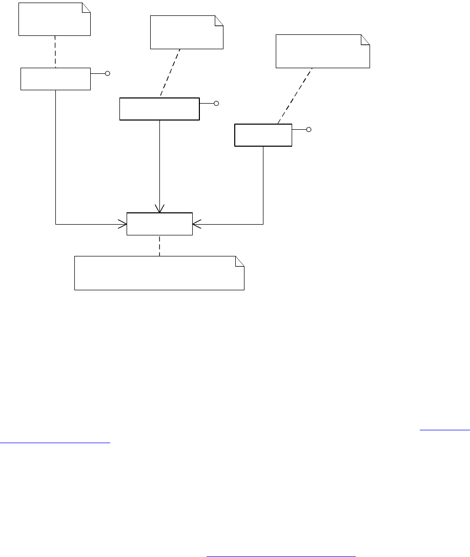
CHAPTER 8: Graphics Fundamentals Graphic page items 199
NOTE: To let page item overrides take effect, the IDrawOptions::GetIgnoreOverrides preferences flag must
be kFalse. You can set this flag through the View > Display Performance menu.
The display-performance object model is summarized in the class diagram in the following figure.
Drawing a graphic page item
Changing display performance from typical to fast does not replace a proxy image with a gray box directly.
In fact, changing display performance does not change the instance of the graphic page item at all. The
effect is achieved by invalidating the layout and letting the page-item drawing process take care of
displaying.
Drawing a layout containing graphic page items follows a generic drawing process detailed in “Dynamics
of drawing” on page 249. A graphic page item is drawn in the following steps:
1. Set the crop rectangle. This involves calculating the graphic page item’s bounding box, cropped by the
frame bounding box and view bounding box.
2. Clip the graphics with their clipping paths.
3. Determine drawing options and draw the graphics.
You can participate in the graphic page-item drawing process by implementing the custom, drawing
event-handler extension pattern, described in “Extension patterns” on page 259.
«boss»
kLayoutWidgetBoss
«boss»
kWorkspaceBoss
1
1..*
IDrawOptionsSetID::GetID
The individual graphic
page item
The application
preferences
1
1..*
IDrawOptionOverrides::GetDrawOptions
«struct»
DrawOptionsSet
Represents a display performance group,
which stores settings for raster images, vector
graphics, transparency, etc.
1
1..*
IDrawOptions::GetActiveSetID
The layout view
«boss»
kImageItem/...
IDrawOptions
IDrawOptionsSetID
IDrawOptionOverrides

CHAPTER 8: Graphics Fundamentals Graphic page items 200
Graphic page-item data model
This section illustrates the data model and common interfaces for graphic page items.
Graphic page-item boss-class inheritances
Although graphic page items are represented by various boss classes (kImageBoss and bosses for vector
graphics in the table in “Vector graphics” on page 195), they share similar interfaces and demonstrate
similar properties.
kImageItem (the boss representing raster images), kPlacedPDFItemBoss, kEPSItem, kPICTItem, and
kWMFItem directly or indirectly inherit from kDrawablePageItemBoss, which aggregates interfaces
necessary for page-item drawing. For the complete inheritance graph for the bosses, refer to the API
Reference; search for kDrawablePageItemBoss.
Graphic page-item class hierarchy
Graphic page-item boss classes have the following characteristics:
Are wrapped in a spline item (kSplineItemBoss).
Have text wrap around their contour or frame (represented as kStandOffPageItemBoss).
Store low-resolution proxy images as kImageInDB.
Store a link object (ILinkObject) which keeps the UIDRef(s) of link boss(es). A link boss, like
kImportLinkBoss, links the link object (page item) and external graphic files.
May embed link resources internally as kPMPersistDataBlobBoss.
The following figure is a simplified view of the graphic page items in the class hierarchy of an InDesign
document. ILinkObject provides access to the link object, which can be used to access the linked graphic
resource. If the link is embedded, IStoreInternal provides access to kPMPersistDataBlobBoss, which stores
the bitmap of the image. IImageDataAccess provides access to the proxy image, and the bitmap of the
images also are stored as kPMPersistDataBlobBoss, which is accessible through IPersistUIDData on
kImageInDB. Navigation from the document root to the kSplineItemBoss is wrapped into a package, which
is discussed in Chapter 7, “Layout Fundamentals.”
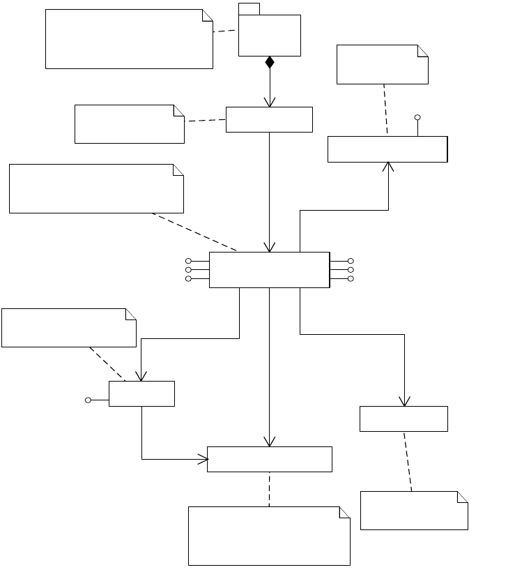
CHAPTER 8: Graphics Fundamentals Graphic page items 201
Graphic page-item interfaces
Several common interfaces are aggregated on graphic page-item bosses to provide features specific to
graphic page items. These interfaces are either aggregated directly on the boss (for example,
kPlacedPDFItemBoss), or aggregated by way of their parent bosses (for example, kImageBaseItem, the
parent of kImageItem, or kDisplayListPageItemBoss, the parent of all other vector graphic page item
bosses). The following table summarizes these important interfaces and their uses.
«boss»
kSplineItemBoss
«boss»
Any
graphic page item boss
«boss»
kImageInDB
«boss»
kImportLinkBoss
1
1
IHierarchy::QueryChild(0)
1
0..1
IStoreInternal::GetStoredUID()
The graphic frame
wrapping the image
page item.
The graphic page items such as
kImageItem, kPlacedPDFItemBoss,
kEPSItem, kPICTItem, kWMFItem,
or other graphic page item bosses.
Stores the link of
an external graphic
file.
kImageInDB stores a low-
resolution image (of a
high-resolution image)
1
0..*
ILinkObject::GetLinks
«boss»
kPMPersistDataBlobBoss
1
0..1
IImageDataAccess::
GetLowResImageUID()
Stores whole image internally
as a blob. Could be either proxy
image (from IPersistUIDData)
or embedded image (from
IStoreInternal).
1
0..1
IPersistUIDData::GetUID()
«boss»
kStandOffPageItemBoss
Stores the path
geometry of
text wrap.
1
0..1
IStandOffData::GetStandOffUID()
Document
hierarchy
This package includes all
ancestors of a spline page item.
See details in the "Layout
Fundamentals" section about how
to navigate to the page item.
1
0..*
owns
IGraphicItem
IImageItem(kImageItem only)IPathGeometry
IGeometry
IImageAttributes(kImageItem only)IID_ITEXTWRAPPATH(IPathGeometry)
IPathGeometry
IImageAttributes

CHAPTER 8: Graphics Fundamentals Graphic page items 202
t
Proxy images
When a graphic is placed, the contents of the original file are not actually copied into the document.
Instead, InDesign creates a link to the original file on the disk and adds a screen-resolution bitmap image
(the proxy image) to the layout, so you can view and move the graphic. When you export or print, InDesign
uses the link to retrieve the original graphic, creating the final, desired, full-resolution output. Although
end users can set preferences to tell InDesign to show high-resolution images (see “Display performance”
on page 198), by default InDesign shows a low-resolution proxy image for performance reasons; the proxy
image is created by processing kCreateLowResImageCmdBoss during the import process.
A proxy image is represented by the boss kImageInDB, which is accessible from the graphic page item
through IImageDataAccess::GetLowResImageUID. The connection is established during the image-import
process. For the data model of the proxy image in relation to the graphic page items, see “Graphic
page-item class hierarchy” on page 200 and “Graphic page-item examples” on page 203.
One of the most important interfaces on kImageInDB is IPersistUIDData, which holds a UID pointing to an
instance of kPMPersistDataBlobBoss, which stores the bitmap of the proxy image.
The proxy image is not always created by asking the image-import filter for the data. For raster images, if
image auto-embedding is allowed in the image-import preferences, and the image is smaller than a
predefined amount (defaults to 48KB, accessible through ILinkState::GetEmbedSize), the original
high-resolution image is embedded directly.
Interface ID Interface Description
IID_IGRAPHICITEM IIntData This is the signature interface for all graphic types (raster,
EPS, etc.). The integer data is never used.
IID_IIMAGEITEM IImageItem Aggregated onto kImageBaseItem, this interface provides
access to the embedded color profile of the image. More
importantly, testing the presence of this interface verifies
that a page item boss is a raster image.
IID_IGEOMETRY IGeometry This interface defines the geometry (position, size, etc.) of a
graphic page item. It is used for calculating cropping
during the graphic page-item drawing process.
IID_IPATHGEOMETRY IPathGeometry This interface stores the clipping path of a graphic page
item (see “Clipping paths” on page 196).
IID_ITEXTWRAPPATH IPathGeometry This interface stores the text-wrap path; however, this path
is only a cache (or mirror) of the text-wrap path. The real
path is stored at IPathGeometry on
kStandOffPageItemBoss. Every time the real text-wrap path
is changed, this path is updated. (See “Text wrap” on
page 197.)
IID_IIMAGEATTRIBUTES IImageAttributes This interface stores a set of tags to describe the attributes
of a raster image. Predefined tags are defined as
enumerators, each of which describes the type, length, and
data of a raster image. These tags are crucial in defining
image item properties, such as alpha channel, clipping
path, and color profile.

CHAPTER 8: Graphics Fundamentals Graphic page items 203
Creating a proxy image is aided by the IImageStreamManager interface, which provides a mechanism to
convert the source-image format to a destination-image format according to the image attributes.
Graphic page items and links
Every graphic page item that was placed from a file has an associated link. End users can choose the
Embed Link menu in the Links panel’s menu to embed the link manually. The file remains in the Links
panel, marked with an embedded link icon.
NOTE: This behavior differs from link for a text file. You can create a link when placing a text file; however,
since text is inheritently part of the InDesign document, you cannot really “embed” the link. If you create a
link when placing a text file, you can choose to unlink the file from the Links panel. Once it is unlinked, the
link is removed from the Links panel.
As a software developer, you also can use ILinkFacade::EmbedLinks to embed the image link (ILinkFacade
is aggregated on kUtilsBoss). kStoreInternalCmdBoss, processed internally, reads the original
high-resolution file and stores the image data as a data blob, referenced by the IStoreInternal interface on
the graphic page item.
Embedding a link is not the same as embedding the small image to create a proxy image, discussed in
“Proxy images” on page 202:
The image data is stored in a different place. Embedding a link stores a data blob referenced by
IStoreInternal on the graphic page item. Embedding an image as a proxy stores the data blob
referenced by IPersistUIDData on kImageInDB boss.
Embedding a link does not cause a check for the size of the image.Embedding an image as a proxy
requires the image file to be smaller than a predefined size.
Graphic page-item examples
New graphics can be placed into a layout with or without an existing graphics frame. This section
illustrates how instances of graphics objects evolve as you place a PDF file, replace it with an image, move
the image around, embed a link, and set clipping-path and text-wrap contour options.
Begin with an empty graphics frame
We start exploring the graphics object model by examining an empty graphics frame. The following figure
shows a screenshot and the object model when only an empty graphics frame is created. The graphics
frame is represented by kSplineItemBoss, and it does not have any hierarchical children.
CHAPTER 8: Graphics Fundamentals Graphic page items 204
Place a PDF item in a graphics frame
Next, we place a PDF file into the graphics frame. During import, InDesign creates a kPlacedPDFItemBoss
object to represent the PDF item and adds it as a child of the graphics frame. The following figure shows
the object model of the graphics frame with a PDF item. A few other objects are created to represent
information of the PDF item. New objects are marked in yellow.
Comparing this figure to the figure in “Graphic page-item examples” on page 203, notice that the Links
panel shows a link to the external PDF file. The link is represented by kImportLinkBoss through
ILinkObject, aggregated on kPlacedPDFItemBoss.
A proxy image is created for the PDF item as kImageInDB boss (UID 0xcd), and the proxy image bitmap is
represented by kPMPersistDataBlobBoss (UID 0xce).
By default, a graphic page item is put into the graphics frame with an offset of (0,0) in inner coordinate
space, so the PDF item has the same PMRect::LeftTop position (obtained from
IGeometry::GetPathBoundingBox) on the pasteboard as the graphics frame. Although the PDF item is
slightly wider than the frame (PMRect::RightBottom member), InDesign does not draw that part, because
it is cropped by the frame.
Above:
Empty links panel.
Right:
Empty graphic frame.
Below:
A graphic frame
represented as
kSplineItemBoss.
No child object.
LeftTop = (36, -360)
RightBottom = (276, 0)
«boss»
graphic-frame
: kSplineItemBoss
The graphic frame. Its
pasteboard coordinates
are shown.
Document
hierarchy
CHAPTER 8: Graphics Fundamentals Graphic page items 205
Replace a PDF item with an image
Next, we import an image file to replace the PDF item and examine the changes to the object model. The
following figure shows the screenshot and object model after the change. Again, new objects are marked
in yellow. Note the following:
The Links panel shows a link to the new image file (PalmTreeCMYK.tif).
UID = 0xcf
«boss»
link : kImportLinkBoss
UID = 0xcd
«boss»
proxy image
: kImageInDB
UID = 0xcb
LeftTop = (36, -360)
RightBottom = (298, -200)
«boss»
PDF
: kPlacedPDFItemBoss
Above:
A PDF file appears
in the Links panel.
Right:
PDF item placed in
the graphic frame.
Below:
The graphic frame
now has a PDF item
represented by
kPlacedPDFItemBoss.
LeftTop = (36, -360)
RightBottom = (276, 0)
«boss»
graphic-frame
: kSplineItemBoss
UID = 0xce
«boss»
image blob
: kPMPersistDataBlobBoss
The graphic frame
is not changed.
The PDF item is the only child
of the graphic frame. It is
wider than, but shorter than
the graphic frame.
A proxy image is
created for the
PDF file.
Link maintains a
connection to
external PDF file.
A proxy image is
stored as a data
blob.
Document
hierarchy
Area not
cropped
by frame

CHAPTER 8: Graphics Fundamentals Graphic page items 206
The overall structure of the object model did not change, but a new boss object kImageItem replaced
kPlacedPDFItemBoss.
The UID of the link, proxy image, and proxy image data blob also changed. These objects were created
during the import process—and the old objects were deleted.
UID = 0xb4
«boss»
proxy image
: kImageInDB
UID = 0xb5
«boss»
image blob
: kPMPersistDataBlobBoss
Above:
New image appears
in the Links panel.
Right:
Image replaced PDF item
in the graphic frame.
Below:
The graphic frame
now has an image
represented by
kImageItem.
The graphic frame
is not changed.
The image is the only child
of the graphic frame. It is
larger than the graphic frame,
thus only a portion is shown.
A proxy image is
created for the
the image file.
Link maintains a
connection to
external image file.
A proxy image is
stored as a data
blob.
LeftTop = (36, -360)
RightBottom = (276, 0)
«boss»
graphic-frame
: kSplineItemBoss
UID = 0xb7
«boss»
link : kImportLinkBoss
Document
hierarchy
UID = 0xb3
LeftTop = (36, -360)
RightBottom = (418, 302)
«boss»
image
: kImageItem
CHAPTER 8: Graphics Fundamentals Graphic page items 207
Move an image within a frame
You may have noticed the palm tree image is large, and we can only see a small part of the tree. Now we
move the image a little bit within the graphics frame, using the Direct Selection tool. The following figure
shows the resulting object model. Everything is the same, except the pasteboard coordinates of the image
item. The changed object is marked by a red circle; changed values are marked in yellow. The coordinates
represent the bounding box of the image item.
Right:
The image is moved to
a new location within
the graphic frame.
The graphic frame
is not changed.
After the move, the image has
new pasteboard coordinates.
A proxy image is
created for the
the image file.
Link maintains a
connection to
external image file.
A proxy image is
stored as a data
blob.
LeftTop = (36, -360)
RightBottom = (276, 0)
«boss»
graphic-frame
: kSplineItemBoss
UID = 0xb3
LeftTop = (-84, -528)
RightBottom = (298, 134)
«boss»
image
: kImageItem
UID = 0xb7
«boss»
link : kImportLinkBoss
UID = 0xb4
«boss»
proxy image
: kImageInDB
UID = 0xb5
«boss»
image blob
: kPMPersistDataBlobBoss
Document
hierarchy
CHAPTER 8: Graphics Fundamentals Graphic page items 208
Embed an image’s datalink
Next, we manually embed the image into the document by choosing Embed Link on the Links panel
menu. The following figure shows the changed object model after the image is embedded. The new
object is within the red circle, marked in yellow. A new kPMPersistDataBlobBoss is created to store the
embedded image information. Other bosses—including the link object (kImportLinkBoss)—do not
change.
There are two kPMPersistDataBlobBoss objects in the object model, but they represent different things.
The one accessible through IPersistUIDData on the proxy image:kImageInDB boss represents the proxy
image; the other—accessible through IStoreInternal on the image:kImageItem boss—represents the
embedded image data.
CHAPTER 8: Graphics Fundamentals Graphic page items 209
Setting clipping path and text wrap
Let’s use a different image to set clipping-path and text-wrap options. In this section, we place a linked
image, overlap it on top of a text frame, and examine how the image and text frame change when you set
clipping-path and text-wrap options.
The following figure shows examples of clipping-path options. In the left screenshot, no clipping path was
set, so the image overlaps the background text. The center screenshot shows the result of the
The image is embedded
into the InDesign file. The
look and feel of the image
does not change.
The graphic frame
is not changed.
Embedding the image does not
change pasteboard coordinates.
A proxy image is
created for the
the image file.
Link maintains
a connection to
external image file.
A proxy image is
stored as a data
blob.
UID = 0xb3
LeftTop = (-84, -528)
RightBottom = (298, 134)
«boss»
image
: kImageItem
UID = 0xb7
«boss»
link : kImportLinkBoss
UID = 0xb4
«boss»
proxy image
: kImageInDB
UID = 0xb5
«boss»
image blob
: kPMPersistDataBlobBoss
LeftTop = (36, -360)
RightBottom = (276, 0)
«boss»
graphic-frame
: kSplineItemBoss
UID = 0xd8
«boss»
embedded image blob
: kPMPersistDataBlobBoss
Embedded image blob (orignal
graphic file data), accessible
through IStoreInternal.
Document
hierarchy
1
1
IPersistUIDData::GetUID() 1
1
IStoreInternal::GetStoredUID()

CHAPTER 8: Graphics Fundamentals Graphic page items 210
clipping-path Detect Edges option (with the Threshold parameter set to 150). Although Detect Edges can
detect most of the contours of the bottle, the result looks even better if you use the existing Photoshop
paths, as shown in the right screenshot.
Reminder: The clipping path is stored with the IPathGeometry interface of the graphic page item, so no
extra object is created. For the graphic page item’s class diagram, see the figure in “Graphic page-item
class hierarchy” on page 200; for descriptions, see “Clipping paths” on page 196.
Now we set the text wrap of the image item, shown in the following figure. All three screenshots were
taken with the text wrap set to wrap around the graphic page item’s object shape. The left screenshot
shows the result when the text-wrap contour option is set to Same As Clipping, with clipping-path type set
to Detect Edges. The top-right corner of the bottle frame does not have text, because a small part of the
image is there. You can set the contour option to use existing Photoshop paths independent of the
clipping path, shown in the center screenshot. You also can set both the clipping path and text-wrap
contour options to use the Photoshop path, which produces the best result, as shown in the right
screenshot.
Object model changes after setting the text-wrap options are shown in the lower part of the figure. A new
kStandOffPageItemBoss object—within the red circle, marked in yellow—is created to hold the text-wrap
path. For information on how this affects text composition, see the Chapter 9, “Text Fundamentals.”
Image clipping
path set to None
Clipping path is generated
by detecting edges.
Clipping path set to
existing Photoshop
path.

CHAPTER 8: Graphics Fundamentals Graphic page items 211
Clipping path is set to
detect edges, and
text wrap is set to
Same As Clipping
Clipping path is generated
by detecting edges.
Text wrap is set to use
Photoshop path
Both clipping path and
text wrap are set to
use existing Photoshop
path.
The graphic frame
The image item
A proxy image is
created for the
the image file.
Link maintains
a connection to
external image file.
A proxy image is
stored as a data
blob.
LeftTop = (156, 123)
RightBottom = (288, 336)
«boss»
graphic-frame
: kSplineItemBoss
UID = 0xd1
LeftTop = (156, 123)
RightBottom = (308,350)
«boss»
image
: kImageItem
UID = 0xd4
«boss»
link : kImportLinkBoss
UID = 0xd2
«boss»
proxy image
: kImageInDB
UID = 0xd3
«boss»
image blob
: kPMPersistDataBlobBoss
UID = 0xd7
«boss»
text wrap
: kStandOffPageItemBoss
The standoff object, which
stores the path geometry of
the text wrap.

CHAPTER 8: Graphics Fundamentals Graphic page items 212
Graphics import
Overview of the import process
When a user chooses to place a graphic into a document, InDesign performs a sequence of steps to import
the graphics file as a graphic page item. The following figure shows the steps involved in importing PDF,
EPS, and image files.
You also can import another InDesign document to a document. The import process works like PDF
import. The only difference is that importing an InDesign document also imports swatches, inks, fonts,
links, and so on and creates secondary links if the document being imported also contains links. You can
set InDesign document-import options like other graphic file types; see “InDesign document-import
preferences” on page 215.
You can also import multimedia files such as movie clips and sounds. See Chapter 5, “Rich Interactive
Documents.”
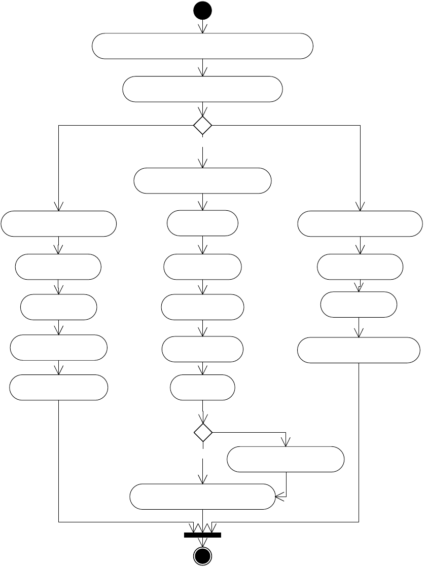
CHAPTER 8: Graphics Fundamentals Graphic page items 213
At a high level, the process involves the following steps:
1. Create a kImportLinkBoss that connects the link resource and the page item.
2. Query for an import provider that provides kImportProviderService for the graphic. This service also is
used for importing other types of files, like plain-text files. For graphics files, one of four providers is
called: kPDFPlaceProviderBoss, kImagePlaceProviderBoss, kEPSPlaceProviderBoss or
Create a link that connects the page item and link resource
Choose import provider based on file type
Create kPlacedPDFItemBoss
Choose image read format provider
Create EPS, DICT or WMF item
New kImageItem
Set image IO prefs
Set Image attributes
Sample high-resolution image
Read and set proxy image's data blob
Create kImageInDB
Set PDF import prefs
Set PDF attributes
Generate raster preview
Stream into kImageInDB
Set EPS import prefs
Set EPS attributes
Create TIFF proxy kImageInDB
[Raster Images]
[PDF] [Vectors (except PDF)]
[no]
[yes]
Embed image?

CHAPTER 8: Graphics Fundamentals Graphic page items 214
kNativeImportServiceBoss. See The following table shows details on file formats supported by these
providers.
3. Create the appropriate new page item according to the type of the graphics file as shown in the table.
4. Import the file and set new page-item attributes, like IPDFAttributes, IEPSAttributes, and
IImageAttributes. This may involve searching for an appropriate image import filter (“Image-import
filters” on page 216) and setting import options (“Import options” on page 214).
5. Create and set a low-resolution proxy image for the new page item, which is accessible through
IImageAccess on the new page item.
Import options
To control how the file should be imported, end users can choose Show Import Options in the Place dialog
box, which allows the user to set import options through an Import Options dialog box. The specific
options depend on the file type and graphics data in the file.
PDF-import preferences
The IPDFPlacePrefs (IID_IPDFPLACEPREFS) interface allows you to set various PDF import options, like how
to crop the graphic and which pages to import. If the PDF file contains layers, you can set up layer
information on the dialog using IGraphicLayerInfo.
Both interfaces are aggregated on kWorkspaceBoss. IGraphicLayerInfo can be initialized by the imported
file before bringing up the Import Options dialog. The following table lists some default settings of
IPDFPlacePrefs.
For details, see Chapter 4, “Import and Export.”
Import provider Filename extension Page-item boss
kEPSPlaceProviderBoss AI, EPS, DCS kEPSItem
kEPSPlaceProviderBoss PCT, PIC kPICTItem
kEPSPlaceProviderBoss WMF, EMF kWMFItem
kImagePlaceProviderBoss TIF, TIFF, SCT, PSD, PNG, PCX, JPEG, JPG, GIF,
DIB
kImageItem
kPDFPlaceProviderBoss PDF kPlacedPDFItemBoss
kNativeImportServiceBoss INDD kInDesignPageItemBoss
Preference Default value
Crop kCropToContent
Page number 1
Proxy resolution 72
Show preview kTrue
Transparent background kTrue

CHAPTER 8: Graphics Fundamentals Graphic page items 215
EPS-import preferences
IEPSPreferences (IID_IEPSPREFERENCES) also is aggregated on kWorkspaceBoss. Some settings are set
programmatically; for example, importing an EPS graphic from a file (not from the clipboard) automatically
sets the import mode to “import whole” (kImportWhole). The following table lists some default settings of
IEPSPreferences.
NOTE: “Create frame” corresponds to the Apply Photoshop Clipping Path checkbox, and kAlwaysCreate
corresponds to the Rasterize The PostScript radio button in the EPS Import Options dialog box.
Image-import preferences
The Raster Image Import Options dialog box uses separate panels to set raster image-specific import
options, like color profile and clipping path. Usually, InDesign uses session preferences
(IImageIOPreferences on kWorkspaceBoss) to import an image file. The following table lists some of the
default settings.
When auto-embedding is allowed and the image size is small, InDesign automatically embeds the
high-resolution image as the proxy image, so the data and the interfaces of kImageInDB reflect the
high-resolution image rather than a new, low-resolution image.
InDesign document-import preferences
Placing InDesign document directly into an InDesign document has advantages in the publishing
workflow, including automatically maintained links, fonts, swatches, links and so on. The
IImportDocOptions (IID_IIMPORTDOCOPTIONS) interface allows you to set various InDesign
document-import options, like how to crop the pages, which pages to import, and where to display
previews. IGraphicLayerInfo let you set up layer information on the dialog to choose which layer to import.
Both IImportDocOptions and IGraphicLayerInfo are session preferences aggregated on kWorkspaceBoss.
They also store information to pass to kImportDocCmdBoss, if you want to use the command directly to
place InDesign files. The following table lists some default settings of IImportDocOptions.
Preference Default value
Import mode kImportWhole
Display resolution 72
Read OPI comments kDontReadOPIComments
Create frame kDontCreateFrameFromClipPath
Create proxy kCreateIfNeeded
Preference Default value
Allow auto-embedding kTrue
Create clip frame kTrue
Preview resolution 72

CHAPTER 8: Graphics Fundamentals Graphic page items 216
Image-import filters
You may have noticed in the table in “Overview of the import process” on page 212 that the same
kImagePlaceProviderBoss is used for importing various kinds of raster images. These raster images have
different file formats and, therefore, they need different ways to read data. InDesign provides another level
of abstraction: the image-import provider queries for service providers that support
kImageReadFormatService. This mechanism also serves as another extension pattern software developers
may implement to support new raster-image formats.
InDesign implements a set of providers to read various image formats, to import TIF (TIFF), SCT, PSD, PNG,
PCX, JPEG (JPG), GIF, and DIB files. These providers serve as the image-import filters. When InDesign is
instructed to place an image, it iterates over all the providers until it finds one that can import the image.
See the following table for a list of these providers.
Export to graphics file format
InDesign supports exporting all or part of a document to PDF, EPS, SVG, and JPEG formats.
All the export processes are alike at a high level: exports are implemented using the IExportProvider
service-provider mechanism. Each type of export destination format provides export services. The
following table lists export providers that export to a graphics file format.
Preference Default value
Crop kCropToPage
Page number 1
Show preview kTrue
File type Image read-format provider
TIF kTIFFImageReadFormatBoss
SCT kSCTImageReadFormatBoss
PSD kPSImageReadFormatBoss
PNG kPNGImageReadFormatBoss
PCX kPCXImageReadFormatBoss
JPEG kJPEGImageReadFormatBoss
GIF kGIFImageReadFormatBoss
DIB kDIBImageReadFormatBoss
Export destination Export provider
PDF kPDFExportBoss
EPS kEPSExportBoss

CHAPTER 8: Graphics Fundamentals Graphic page items 217
For examples of export provider implementations, see SDK samples like CHMLFilter, TextExportFilter, and
XDocBookWorkflow.
Each export provider has a corresponding command that exports content to a desired file format in the
following two stages:
1. Drawing — Drawing page items to an intermediate entity, such as a viewport.
2. Streaming — Writing the content to the provided file stream.
Export to PDF and EPS are discussed in detail in the “Exporting to EPS and PDF” section of Chapter 3,
“Printing.” PDF import and export also are discussed in Chapter 4, “Import and Export.”
Only SVG and JPEG export are discussed in this section. The following figure shows high-level activities of
SVG and JPEG export.
SVG kSVGExportProviderBoss
JPEG kJPEGExportProviderBoss
Export destination Export provider

CHAPTER 8: Graphics Fundamentals Graphic page items 218
SVG export
SVG export preferences
Settings for SVG export are stored with the ISVGExportPreferences interface on kWorkspaceBoss. For
details, refer to the API Reference.
End users can modify the preferences through the SVG Export Options dialog box. You also can change
the preferences programmatically, with the kSVGExportSetPrefsCommandBoss command. The following
table lists some of the default SVG-export preferences.
Get export file format
Choose export provider
Set SVG export prefs Set JPEG export prefs
Export to JPEG stream
Create kSVGExportViewPortBoss and set attributes
Install draw event handler
Set up SVGWriter
Draw page items
Create SnapshotUtilsEx
Draw page items on SnapshotUtilsEx
Create output stream
[SVG] [JPEG]

CHAPTER 8: Graphics Fundamentals Graphic page items 219
Exporting to SVG format
InDesign exports to SVG format by drawing page items and documents to a special viewport,
kSVGExportViewPortBoss. For more information about viewports, see “Data model for drawing” on
page 248. kSVGExportCommandBoss aggregates ISVGExportController, which controls the drawing
process and hides much of the complexity involved in SVG export. kSVGExportViewPortBoss aggregates
ISVGWriterAccess, which helps in writing contents to an SVG file stream.
JPEG export
JPEG export preferences
Settings for JPEG export are stored with the IJPEGExportPreferences interface on kWorkspaceBoss. For
details, refer to the API Reference.
End users can modify the preferences through the JPEG Export Options dialog box. You also can change
the preferences programmatically, with the kJPEGExportSetPrefsCommandBoss command. The following
table lists some of the default JPEG-export preferences.
Exporting to JPEG format
kJPEGExportCommandBoss creates a SnapshotUtilsEx object and draws document contents on it.
kJPEGExportCommandBoss then calls SnapshotUtilsEx::ExportImageToJPEG to write to the file stream.
SnapshotUtilsEx also has methods to export to TIFF and GIF formats, so you can export to TIFF and GIF if
you write your own export command, though you may need to provide your own image-write format
boss. In the case of JPEG, the write-format boss provided is kJPEGImageWriteFormatBoss. For more
Preference Description Default value
Embed fonts Whether to embed fonts in the
SVG file
kTrue
Embed image Whether the image should be
embedded in the SVG file
kTrue
Export bitmap sampling Sampling quality kHiResSampling
Image format Image format kDefaultImageFormat, which is set to
the same as kPNGImageFormat
JPEG quality Image quality kJPEGQualityMed
Page item export Whether to export the selected
page item only
kFalse
Range format The range of pages to export kAllPages
Preference Description Default value
Export bitmap sampling Sampling quality kHiResSampling
JPEG quality Image quality kJPEGQualityMed
Range format The range of pages to export kAllPages

CHAPTER 8: Graphics Fundamentals Colors and swatches 220
information on SnapshotUtilsEx, see “Snapshots” on page 255. For use of SnapshotUtils (the older version
of SnapshotUtilsEx, see the Snapshot SDK sample plug-in).
NOTE: Multiple JPEG files are created for documents with multiple pages.
Colors and swatches
This section examines the data model for swatches, colors, and gradients.
Architecture
This section covers the representation of color, a fundamental graphic property, in the InDesign API. When
we talk about color in the context of InDesign, we refer to the following:
A color system refers to how colors and gradients are represented and printed and how to achieve
consistent color throughout different applications and different devices. See “Color management” on
page 226.
A rendering attribute of a page item refers to how a color or gradient can be used to render a page
item’s graphic attributes, like stroke and fill. See “Graphic attributes” on page 229.
The following figure shows some key color-related concepts and how they appear in the user interface.
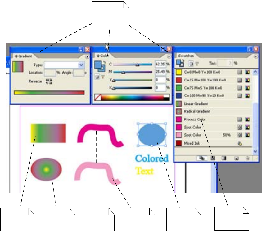
CHAPTER 8: Graphics Fundamentals Colors and swatches 221
The following figure shows some of the key color-related concepts and the relationships among them.
Linear
gradient
Radial
gradient Color Tint Swatches
Color-related
panels
Color
applied
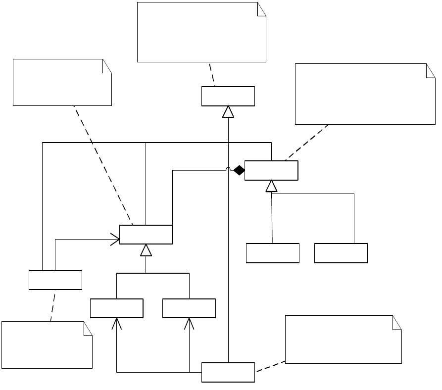
CHAPTER 8: Graphics Fundamentals Colors and swatches 222
The following figure is a UML class diagram involving color-related boss classes. It shows the relationship
among color and swatch–related boss classes. The relationships also apply if you replace
kDocWorkspaceBoss with kWorkspaceBoss.
swatch
gradient
11
based on
A swatch is a rendering object
that can render document
objects. It can be normal color,
tint, mixed ink, or gradient.
Gradients are continuous, smooth
color transitions along a vector
from one color to another. It could
be linear or radial type.
A mixed ink consists of at
least one process color ink
and at least one spot color.
«subtype»
color
process
mixed ink
tint
radial linear
spot
«subtype»
«subtype»
1
1..*
based on 1
1..*
based on
«subtype»
«subtype»
«subtype»«subtype»
1
-Composite1..*
Tint is a percentage
of a color.
Color could be of type
process or spot.

CHAPTER 8: Graphics Fundamentals Colors and swatches 223
Comparing this figure to the to the conceptual diagrams, note the following:
The kDocWorkspaceBoss is used here to show where these boss classes belong. These interfaces also
exist on kWorkspaceBoss.
The boss objects of type kPMColorBoss and kGradientRenderingObjectBoss and other classes
represent swatches directly. IRenderingObject is the signature interface.
kPMColorBoss implements solid color, tint, mixed ink, process color, and spot color.
When swatches are created, modified, or deleted, the state of the swatch list changes. For a detailed
discussion of these changes, see “Swatch-list state” on page 265.
Swatches
A swatch is an abstraction that can represent a color, gradient, tint or mixed ink.
A rendering object implements the IRenderingObject interface. IRenderingObject represents information
about a color or gradient and exposes capabilities to render this information to a device. The following are
some of the boss classes that expose the IRenderingObject interface:
«bos s»
kDocWorkspaceBoss
«bos s»
kPMColorBoss
«bos s»
kPMInkDataBoss
1
*IGradientFill::GetNthGradientColorUID()
1
0..*
IID_IUICOLORLIST,
IID_ISWATCHLIST
1
*
IID_IINKLIST
«bos s»
kGradientRenderingObjectBoss
«bos s»
kAGMBlackBoxRenderingObjectBoss
«bos s»
kGraphicStateNoneRenderingObjectBoss
1
0..*
1
0..*
IID_ISWATCHLIST
1
0..*
1
*
1
*
1
*
1
*IInkResources::GetUsedInks().
The document workspace
IID_ISWATCHLIST and IID_IUICOLORLI ST share
the same interface ISwatchList, but have different
implementat ions (kSwatchListImpl and
kUIColorListImpl respectively).
kPMColorBoss from IID_ISWATCHLIST is a swatch,
kPMColorBoss from IID_IUICOLORLIST is a UI color.
These four bosses
represent swatches.

CHAPTER 8: Graphics Fundamentals Colors and swatches 224
kPMColorBoss represents colors (including tint and mixed ink)
kGradientRenderingObjectBoss represents gradient.
kGraphicStateNoneRenderingObjectBoss represents the absence of rendering information; for
example, this boss can represent no-fill or no-stroke attributes. This boss is used internally.
kAGMBlackBoxRenderingObjectBoss is used for special page items created from Adobe Illustrator®
clipboard format. It is only for internal use.
Some methods of IRenderingObject take an IGraphicsPort item as an argument. IGraphicsPort is an
interface with methods that parallel PostScript operators like setcolorspace. The key responsibility of the
rendering object implementation is to set up the color space, tint, and color components to draw to the
graphics port. IRenderingObjectApplyAction is another required interface on rendering objects. For more
details on IRenderingObject, IRenderingObjectApplyAction, IGraphicsPort, and the other interfaces on
rendering object boss classes, refer to the API Reference.
Solid colors
Color is represented by the kPMColorBoss class, responsible for representing solid colors, including tints
and mixed inks. In addition to the signature interface for a rendering object, IRenderingObject,
kPMColorBoss aggregates several other interfaces, including the following:
IColorOverrides — Stores tint and color remarks so the kPMColorBoss also can represent tint and
special color types (for example, reserved color). For details, refer to the API Reference.
IInkData— Stores the ink information used by the color. InkType represents color type (process or
spot).
IColorData — Represents color coordinates in a ColorArray vector and a color space.
There are three color spaces of interest:
CMYK defines a color with four components: cyan, magenta, yellow, and black. Typically, these
components are represented by percentages.
RGB represents colors with three components: red, green, and blue. Typically, these components are
represented by values between 0 and 255.
LAB (more precisely, L*a*b*) is a device-independent color space
See “Color management” on page 226.
Gradients
Gradients are represented by the kGradientRenderingObjectBoss boss class, which aggregates
IRenderingObject as well as IGradientFill, representing gradient-specific properties. For details, refer to the
API Reference.
Gradients can be linear or radial; see the enum declaration of GradientType in GraphicTypes.h. A gradient
consists of one or more ranges of color, which are smooth interpolations between gradient stop positions.
The color is defined only at the gradient stop positions, with calculated color values at intermediate
positions. For more detail on working with gradients, see “Gradients” in InDesign Help.

CHAPTER 8: Graphics Fundamentals Colors and swatches 225
Swatch lists
Rendering objects (IRenderingObject) are referenced in a swatch list (ISwatchList). The swatch list
(ISwatchList) is exposed on workspaces (IWorkspace). For examples of the swatch list (and ink list) when an
end user creates and applies swatches to page items in a document, see “Swatch-list state” on page 265.
If you create a color through the Color panel, or create a new gradient through the Gradient panel and
then apply the gradient to a page item without creating a swatch beforehand, an unnamed (or local)
swatch is created in the swatch list. The unnamed swatches do not appear in the Swatches panel, but they
can be used for the strokes and fills of document objects by client code.
User-interface color list
Colors and color names that appear in the application user interface in places like the Layers panel and
Tags panel are not the same ones used in representing color in the document. User-interface colors also
are stored in an ISwatchList interface on workspaces (IWorkspace), but with the interface identifier
IID_IUICOLORLIST.
User-interface colors are normally RGB only. A key utility interface for working with user-interface colors is
IUIColorUtils. User-interface colors are represented by kUIColorDataBoss rather than a rendering-object
boss class.
Inks
Colors are ultimately printed by means of inks; for example, CMYK color separation is performed before
printing to a four-color press. Inks are represented by the kPMInkDataBoss boss class.
The rendering object classes like kPMColorBoss or kGradientRenderingObjectBoss aggregate the
IInkResources interface, with which you can refer to the inks used in a color (or other page item) by using
the IInkResources::GetUsedInks method, then querying for IPMInkDataBoss.
IInkData::GetInkUIDList returns an empty list when the color type is process. IInkData is an interface on
kPMColorBoss.
There is an IInkList interface on the workspace boss classes that specifies the inks needed for all swatches
in the document and application. The ink list contains process inks and zero or more spot inks.
The relation between inks and the swatch list is fairly direct: adding a new spot color to the swatch list and
applying it to a document object results in a new entry in the ink list. However, creating another swatch
that is a process color and applying it does not necessarily change the entries in the ink list, if the process
inks needed to print this new color already are in the ink list.
The ink-manager feature (Ink Manager in the Swatches panel menu) shows the inks associated with the
contents of the swatch list. For example, if the swatches in the document were defined in terms of four
process colors and two spot colors, the ink-manager user interface is similar to that shown in the following
figure. For information on how to work with the ink manager and iterate through the ink list, see the
“Graphics” chapter of Adobe InDesign SDK Solutions.
CHAPTER 8: Graphics Fundamentals Color management 226
It is necessary to preflight documents to ensure they print correctly when submitted to the press. As far as
color is concerned, it is necessary to identify the inks that must be loaded in the press for a job to print
correctly.
Color management
The purpose of color management is to get accurate color on all kinds of devices. Color-management
modules provide color-conversion calculations from one device’s color space to another, based on ICC
device profiles. For detailed descriptions of the color spaces used by InDesign, see “Color spaces” on
page 269.
ICC profiles
An ICC profile is a record of the unique color characteristics of a color input or output device. An ICC profile
contains data for the translation of device-dependent color to L*a*b* color. The following illustrates the
concept of translation from the L*a*b* color space to RGB and CMYK color spaces using ICC profiles:
L*a*b* = RGB + ICC profile
L*a*b* = CMYK + ICC profile
With an ICC profile, color-management systems can do the following:
Translate a user-defined, device-specific color to a device-independent, L*a*b* color. For example, if
the user creates an RGB color for a specific computer monitor, that color could be translated to L*a*b*.
Translate a L*a*b* color to a device-specific color. For example, when printing to a printer, the L*a*b*
color is translated to a CMYK color.
Color-management workflow
Color management within InDesign is relatively complex because of the following:
InDesign supports multiple color spaces per document. For example, a user could assign text in one
paragraph an RGB color, another paragraph a CMYK color, and so on.
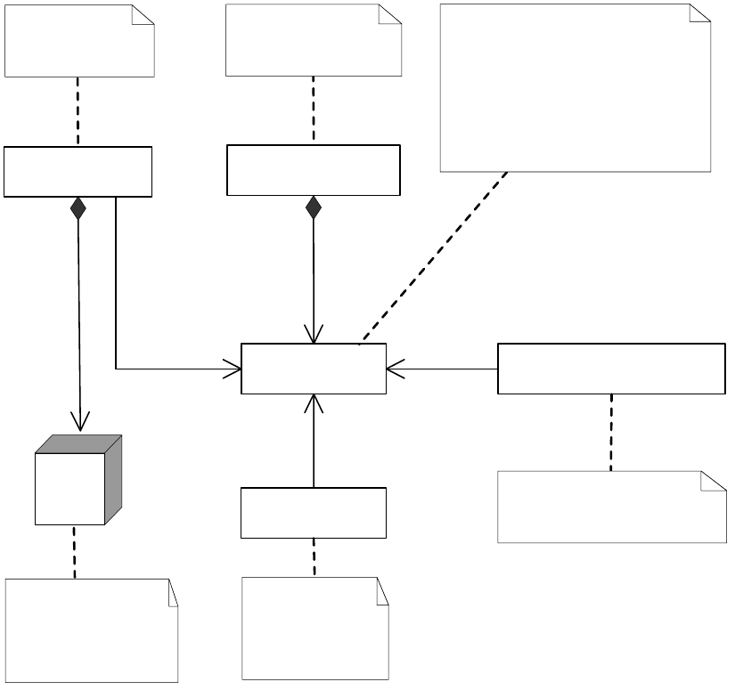
CHAPTER 8: Graphics Fundamentals Color management 227
InDesign supports external links (by means of ILink) to assets that can have different color settings
than those used in the document.
There are three levels of ICC profile sets involved in InDesign:
Image ICC profile— This is embedded in the image file when the image is created.
Document ICC profile — This is associated with a particular InDesign document.
Application ICC profile preference — This is the default profile of the application. The default profile is
assigned to any new document.
InDesign features relating to color management are described comprehensively in “Color Management” in
InDesign Help.
Data model for color management
The implementation of color management is somewhat complex. The class diagram in the following figure
illustrates some color management-related boss class relationships in InDesign.
Color
preset
files
<<boss>>
kWorkspaceBoss
<<boss>>
kDocWorkspaceBoss
<<boss>>
kCMSProfileBoss
<<boss>>
kDocumentPresentationBoss
<<boss>>
kImageBaseBoss
Application
preferences
Color preset files are
installed during
InDesign installation
and shared with other
Adobe applications.
Images may
each have their
own color
profile.
The document
workspace
Document window for
proofing
ICMSProfileList
11
1..*
1
1..*
ICMSProfileUID
1..* 1
1
0..*
IColorPresetManager
IColorPresetSettings ICMSProofing
The color profile. Note: although
both application-preference and
document-side bosses
(kDocumentPresentationBoss and
kImageBaseItem) can refer to a
profile by UIDRef, they are pointing
to different objects, because they
are at different databases.
CHAPTER 8: Graphics Fundamentals Color management 228
Color presets
Outside the application, predefined Adobe color-management settings are stored in color preset files,
which are saved at the following location:
Windows:
Program Files\Common Files\Adobe\Color\Settings\
Mac OS:
Library/Application Support/Adobe/Color/Settings
These presets are shared among all Adobe Creative Suite® applications, to make it easier to achieve
consistent color across the suite. The kWorkspaceBoss boss class aggregates the IColorPresetsManager
interface, which is responsible for managing the presets, like loading color preset files and saving
customized presets. The settings of the current preset are populated into the IColorPresetsSettings
interface on kWorkspaceBoss.
The IColorPresetsSettings interface stores the working color-management settings of the application, like
RGB and CMYK, the ICC profile, and color-management policies. In the user interface, the
color-management settings are accessed through the Color Settings dialog box.
Color profile
The kCMSProfileBoss boss class represents a color profile. The ICMSProfile interface on kCMSProfileBoss
stores information about the type and category of the profile. This interface has a method for getting and
setting profile data by accessing the IACESpecificProfileData interface on the same boss.
The ICMSProfileList interface, exposed on workspaces (IWorkspace), indicates which profiles are used, as
either document profiles or image profiles, and which are assigned to specific document categories (for
example, document CMYK and document RGB). A profile can be assigned to each category of a document
through Edit > Assign Profiles.
Image settings
Any imported image can have either an embedded profile or a profile already assigned to it. (See Object >
Image Color Settings.) The ICMSItemProfileSource interface aggregated on the kImageBaseItem boss class
stores the basic profile-assignment type (see the enumeration ICMSItemProfileSource::ProfileSourceType)
and the name of the image's embedded profile, if any.
If an image uses an external profile or an embedded profile, an interface IPersistUIDData (with interface
identifier IID_ICMSPROFILEUID) stores the UID of an instance of kCMSProfileBoss, so you will be able to
instantiate an interface on kCMSProfileBoss from this UID and get the profile data needed.
There is no link from a specific profile to the images that use that profile. To find the images that use a
specific profile in the profile list, you need to iterate through all images using the links manager
(ILinksManager).
Rendering intent
The ICMSSettings interface is aggregated on docworkspace (kDocWorkspaceBoss) and the
kImageBaseItem boss class, a superclass for image boss classes, which stores rendering-intent information
CHAPTER 8: Graphics Fundamentals Graphic attributes 229
for document and image page item. Please use the ICMSUtils interface to set rendering intent, rather than
manipulating the ICMSSettings interface directly.
For application defaults, rendering intent are determined by IColorPresetsSettings interface aggregated
on kWorkspaceBoss. You can use GetIntent and SetIntent methods to manipulate rendering intent.
Proofing
The ICMSProofing interface is aggregated on kWorkspaceBoss, kDocumentPresentationBoss, and several
user-interface panels. The implementation on kWorkspaceBoss is a proofing preference, and the
implementation on kDocumentPresentationBoss is responsible for setting up drawing when users choose
to proof their design using the Proof Setup dialog box. This ICMSProofing interface stores the proofing
settings as well as a proofing profile.
Graphic attributes
A graphic attribute describes an aspect of how a page item should be drawn. There are many kinds of
graphic attribute for properties like stroke color, fill color, stroke type, and stroke weight. This section
introduces the concepts involved and describes specific sets of graphic attributes for features like
page-item rendering.
Graphic-attribute data model
The following figure is a conceptual model of the graphic attributes associated with a page item.
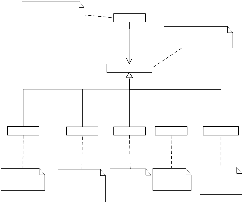
CHAPTER 8: Graphics Fundamentals Graphic attributes 230
A page item owns a collection of graphic attributes, specifying properties that control how the page item
is drawn, like stroke color, stroke style, and transparency. Each attribute is responsible for a single aspect of
how the page item is drawn. A list of graphic attributes is represented by IGraphicStyleAttributeBossList.
The following figure shows the graphic-attribute UML class model of a drawable page item.
Graphic attributes
Page item
A graphic attribute controls
one aspect of the drawing of
an object.
A page item that carries
a various number of
graphic attributes
Other various
attributes
Stroke style ...
Stroke color Gradient fill Transparency
«subtype»
«subtype»
«subtype»
«subtype»
Stroke color
controls the
color of stroke.
Stroke style
attribute controls
the style of
stroke (dotted
line, etc.).
1
0..*
owns
Gradient fill
controlls fill
of the object.
Transparency
controls the
transparecy
effect.
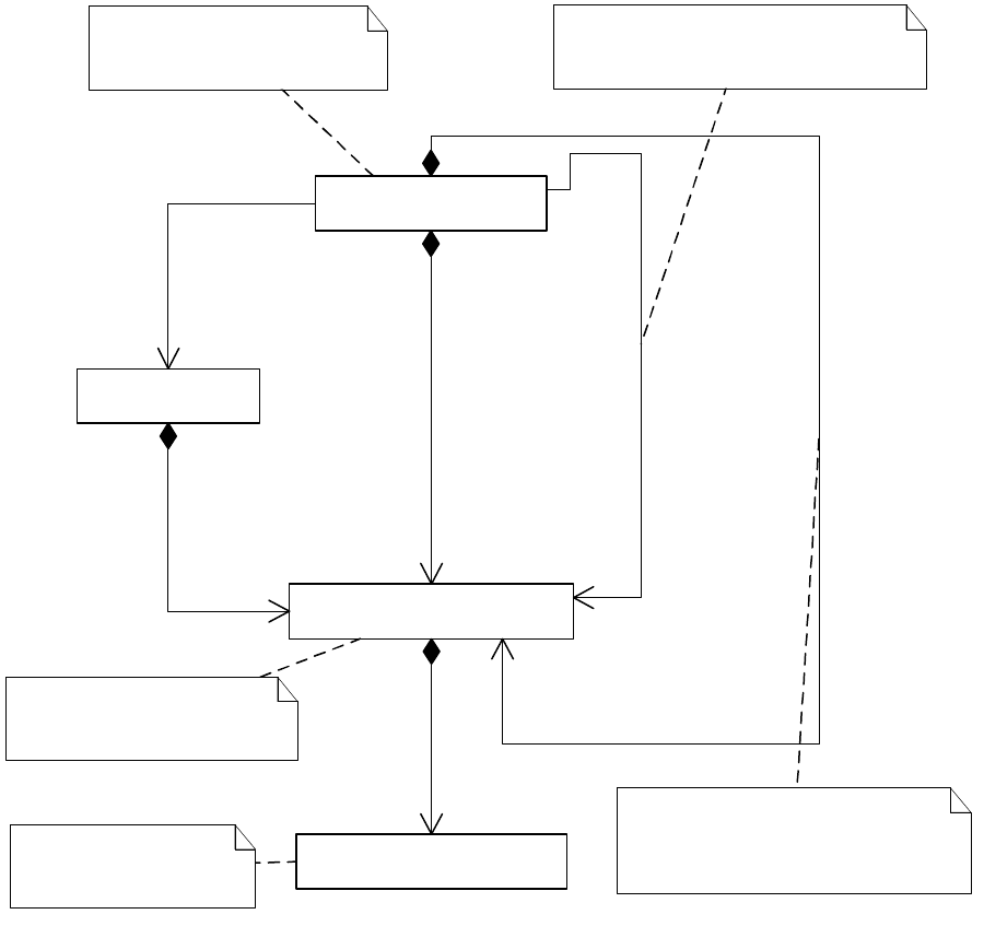
CHAPTER 8: Graphics Fundamentals Graphic attributes 231
There are several important interfaces on a page item responsible for managing graphic attributes:
IGraphicStateIsApplicable.
IGraphicStyleAttributeBossList (IID_IGRAPHICSTYLE_OVERRIDES), which stores a list of graphic
attributes that override those stored in a graphic style.
IGraphicStyleAttributeBossList.
IGraphicStyleDescriptor.
IGraphicStyleReference.
For details on each interface’s responsibilities, refer to the API Reference.
«boss»
kDrawablePageItemBoss
«boss»
kGraphicStyleBoss
«partial-implementation»
IGraphicStyleAttributeBossList
1
1
IID_IGRAPHICSTYLE_DESCRIPTOR
IGraphicStyleDescriptor
1
1
IID_IGRAPHICSTYLE_OVERRIDES
IGraphicStyleAttributeBossList
1
1
IID_IGRAPHICSTYLE_DEFINITION
IGraphicStyleAttributeBossList
1
1
IID_IGRAPHICSTYLE_REFERENCE
IGraphicStyleReference
1
1
IID_IGRAPHICSTYLE_IS_APPLICABLE
IGraphicStateIsApplicable
IGraphicStyleAttributeBossList
is a list of individual graphic
attribute boss objects.
«boss»
Individual kGraphicsAttrBoss
1
0..*
Iterating method
Drawable page items such as
Spline, Group, and Image have
graphic attributes applied.
IID_IGRAPHICSTYLE_IS_APPLICABLE
can answer whether an attribute is
applicable to the page item.
IID_IGRAPHICSTYLE_DESCRIPTOR
can be used to query an attribute
or return a list of attributes applied
to the page item.
Every individual attribute
class inherits from
kGraphicsAttrBoss.

CHAPTER 8: Graphics Fundamentals Graphic attributes 232
Representation of graphic attributes
Graphic attributes are represented by boss classes with the signature interface IGraphicAttributeInfo. The
graphic attributes in the application appear in the API Reference for IGraphicAttributeInfo. Typically, they
derive from the kGraphicsAttrBoss boss class.
The IGraphicAttributeInfo interface stores the name and type of the attribute. Some graphic attributes
have corresponding text and table attributes. See “Mapping graphic attributes between domains” on
page 233.
Graphic attributes have additional data interfaces that specify their values. Because there are many
graphic attributes, sometimes it is a challenge to determine which attribute boss corresponds to which
attribute. For a description of attributes, see “Catalog of graphic attributes” on page 270.
Most of the attributes represent a single value, like a Boolean, int16, int32, PMPoint, or PMReal. These
simple attributes generally are backed by interfaces like IGraphicAttrBoolean, IGraphicAttrInt16,
IGraphicAttrInt32, IGraphicAttrPoint, and IGraphicAttrRealNumber. For example,
kGraphicStyleEvenOddAttrBoss (IGraphicAttrBoolean) corresponds to the even-odd fill rule when you
have a compound path; set it to kTrue to use the even-odd rule or to kFalse to use the default InDesign fill
rule (nonzero winding fill rule).
Some other attributes have UID values. For example, attributes related to object rendering refer to a
rendering object through the IPersistUIDData interface. For more information, see “Rendering attributes”
on page 235.
Some other attributes have ClassID values, which are all stored with IGraphicAttrClassID. These attributes
are used to specify stroke effects of a page item. See “Stroke effects” on page 236.
Graphic styles
A graphic style (kGraphicStyleBoss, UID-based) is a collection of graphic attributes. The
IGraphicStyleNameTable interface exposed on workspaces (IWorkspace) stores the names and UIDs of
graphic styles.
There are two key interfaces on kGraphicStyleBoss:
IGraphicStyleInfo stores the name and UID for the style on which this style is based (the style from
which this style inherits).
IGraphicStyleAttributeBossList (IID_IGRAPHICSTYLE_DEFINITION) stores the list of graphic attributes
this graphic style owns.
Only [No Style] is used in InDesign and InCopy. kGraphicStyleNoneBoss implements the default [No Style],
which is set up during application start-up (for the session workspace) and document creation (for
document workspace). This style stores default settings of various graphic attributes, like stroke weight as
1.0 and stroke type as solid line.
Although there still is a public API to work with user-named graphic styles, these are deprecated since the
introduction of object styles. Adobe applications do not define user-named styles using graphic styles as
the container. We recommend you avoid using graphic styles for this purpose in your plug-ins.
User-named styles are supported by the object styles feature.
An object style is a style that defines the appearance of a page-item object. An object style contains
settings of a set of attributes, including graphic attributes and text attributes. An object style is a superset
of graphic style.
CHAPTER 8: Graphics Fundamentals Graphic attributes 233
Graphic state
Graphic state is the representation of the current state of things related to the graphic attributes. Usually
this is a collection of graphic attributes for the current selection or, if there is no selection, the current
defaults. The graphic state is represented by kGraphicStateBoss.
An active graphic state refers to the graphic state at the current context. Active graphic state can be
accessed through IGraphicStateAccessor, aggregated on kDocWorkspaceBoss or kWorkspaceBoss. A
reference to an interface of the active graphic state also can be acquired through
IGraphicStateUtils::QueryActiveGraphicState, aggregated on kUtilsBoss.
The kGraphicStateBoss boss class aggregates interfaces like IGraphicStateRenderObjects and
IGraphicStateData.
IGraphicStateRenderObjects
This interface is key to the graphic state. It can be acquired from the IGraphicStateUtils utility interface by
querying active graphic state or the graphic state of a specific database. For sample code that shows how
to acquire the interface, see the “Graphics” chapter of Adobe InDesign SDK Solutions.
Given this interface, you can query the current IRenderingObject interface for the specified rendering class
or the active rendering class in the graphic state. The active rendering could be fill or stroke.
Changing the graphic state
Changing any graphic attributes changes the graphic state. Virtually every user-interface action—like
selecting a new swatch, picking a color in the Color Picker panel, switching fill and stroke, selecting a
different stroke style, changing selection, or changing the front document—causes a change to current
active graphic state. You can use methods on IGraphicAttributeUtils or IGraphicStateUtils to acquire
appropriate commands.
kGraphicStateBoss also aggregates an ISubject interface. Changes to the graphic state can be observed by
listening along the IID_IGRAPHICSTATE_RENDEROBJECTS and IID_IGRAPHICSTATE_DATA protocols.
Creating new page items using default attributes
When a new page item is created, default attributes in the graphic-state boss objects are copied and
applied to new page items when you specify INewPageitemCmdData::kDefaultGraphicAttributes as
attrType parameter on spline creation methods on IPathUtils.
Mapping graphic attributes between domains
Some graphic attributes also can be applied to text or tables. For example, the following figure shows
stroke and fill colors and gradients applied to text, table cells, and a spline item. Although the intent is the
same in each case, the attributes differ in each case. Text and tables have some attributes corresponding to
the graphic attributes.
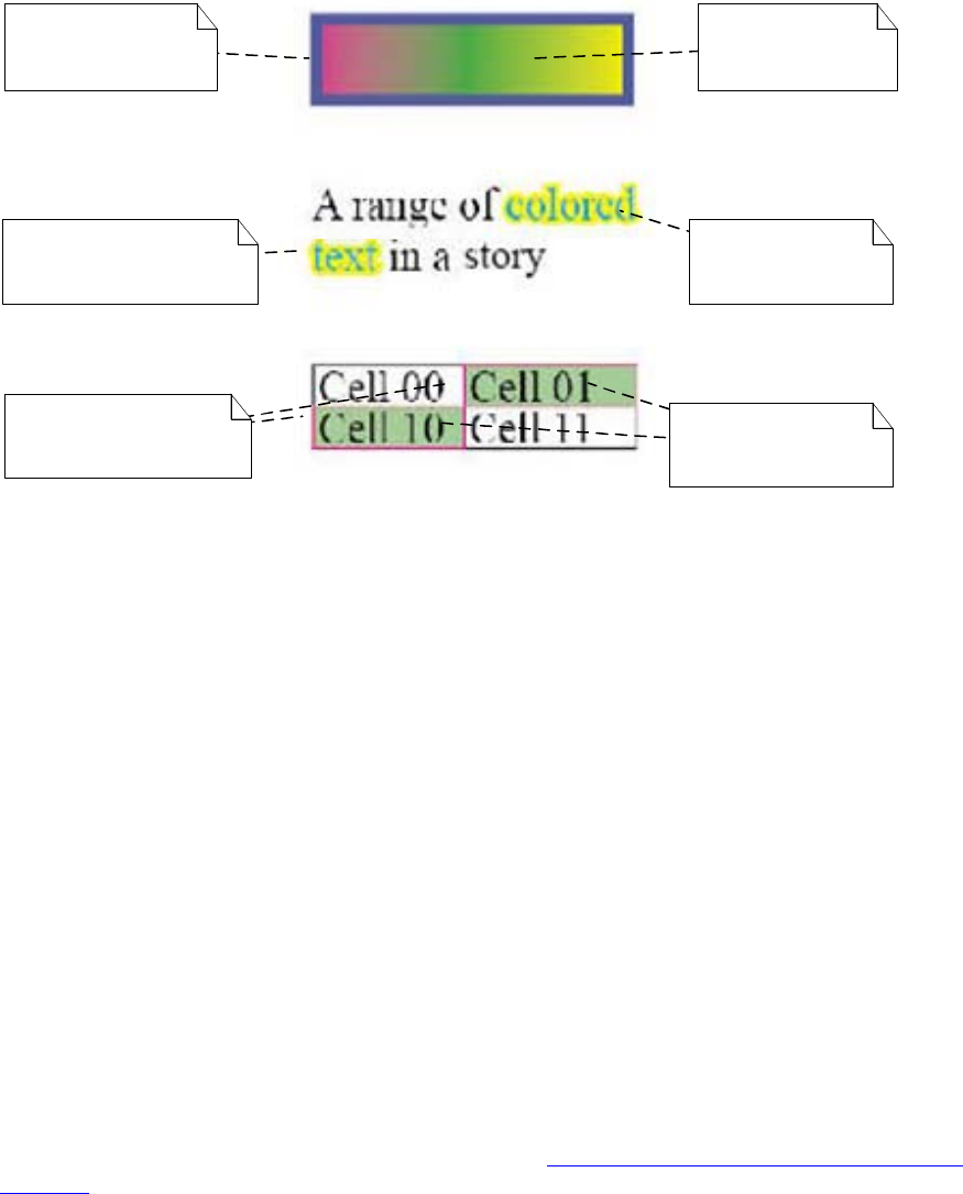
CHAPTER 8: Graphics Fundamentals Graphic attributes 234
There are independent attributes for each of these domains. For example, an attribute represented by
kGraphicStyleFillRenderingAttrBoss on a spline page item is represented by the kCellAttrFillColorBoss type
when the attribute is applied to a table cell, and it is represented by the kTextAttrColorBoss type when the
attribute is applied to a text run.
When a graphic attribute is applied to a text run, there is a conversion process in which a new text
attribute is applied as an override to the run. The same applies when trying to apply a graphic attribute to
a table; the graphic attribute can be converted to a corresponding table attribute.
Not all graphic attributes apply to text or tables. The IGraphicAttributeInfo::IsTextAttribute and
IGraphicAttributeInfo::IsTableAttribute methods return kTrue if the corresponding attribute in the
respective domain exists. IGraphicAttributeInfo::CreateTextAttribute returns a text attribute that maps
onto the equivalent graphic attribute. Similarly, IGraphicAttributeInfo::CreateTableAttribute returns a table
attribute that maps onto the equivalent graphic attribute. Each of these methods is expected to return a
nonzero value if the Is<XXX>Attribute method returns kTrue.
The selection suites (for example, IGraphicAttributeSuite and IGradientAttributeSuite) make it
straightforward for client code to change the properties of a selection; the client code needs to work with
only the graphic attributes. There is no need to worry about whether the selection is text, choosing the
specific text attribute, and whether the selection is text, table, or layout.
The mapping between different domains is hard-coded. New graphic attributes added by third-party
software developers may provide their own mapping by overriding the default implementations of
IGraphicAttributeInfo. The mappings between graphic attributes and text attributes, and between graphic
attributes and table attributes, are shown in the tables in “Mappings between attribute domains” on
page 274. Note that the mapping between graphic attributes and table attributes is many-to-one rather
than one-to-one because; for example, the kCellStrokeAttrDataBoss boss class can represent information
about multiple stroke parameters, whereas each of the corresponding graphic attributes refers to one
parameter.
kGraphicStyleFill
RenderingAttrBoss
(Gradient)
kTextAttrColorBoss
(Cyan)
kCellAttrFillColorBoss
(green)
kGraphicStyleStroke
RenderingAttrBoss
(blue)
kTextAttrStrokeColorBoss
(yellow)
kCellStrokeAttrDataBoss
(red)

CHAPTER 8: Graphics Fundamentals Rendering attributes 235
Rendering attributes
A rendering attribute refers to a swatch to be used when drawing an aspect of a page item. Rendering
attributes are a special kind of graphic attribute that refer to their associated swatch by UID. The swatch
can be a color, gradient, tint, etc.
Color-rendering attributes
A page item’s stroke, fill, or gap can be rendered independently. The following table lists color-rendering
attributes.
Gradient attributes
Page items also can be rendered using gradients; however, multiple graphic attributes are needed to
represent a gradient. For example, you need to specify gradient fill angle, center, and length. There is no
characteristic signature for a gradient attribute other than the boss class name; for the canonical graphic
attributes, the boss-class name is of the following form:
kGraphicStyleGradient<graphic_attribute>AttrBoss.
A list of these boss classes is in the master attributes list in “Catalog of graphic attributes” on page 270.
You can use the same color-rendering attributes class name to apply gradient attributes to page items.
IRenderingObjectApplyAction::PreGraphicApply automatically forwards the attributes to appropriate
gradient attributes. For example, if you are supplying kGraphicStyleFillRenderingAttrBoss, the method
adds attributes including the following:
kGraphicStyleGradientFillAngleAttrBoss
kGraphicStyleGradientFillGradCenterAttrBoss
kGraphicStyleGradientFillHiliteAngleAttrBoss
kGraphicStyleGradientFillHiliteLengthAttrBoss
kGraphicStyleGradientFillLengthAttrBoss
kGraphicStyleGradientFillRadiusAttrBoss
The situation gets more complicated by the possibility of applying gradients to table cells; when a
gradient is applied to a table cell, additional cell-specific attributes are involved. For example,
Rendering-attribute class Description
kGraphicStyleFillRenderingAttrBoss Fill rendering object
kGraphicStyleFillTintAttrBoss Fill tint
kGraphicStyleGapRenderingAttrBoss Gap rendering object
kGraphicStyleGapTintAttrBoss Gap tint
kGraphicStyleStrokeRenderingAttrBoss Stroke rendering object
kGraphicStyleStrokeTintAttrBoss Stroke tint

CHAPTER 8: Graphics Fundamentals Stroke effects 236
kCellAttrGradientFillBoss and kCellAttrGradientStrokeBoss are table-cell attributes representing properties
of gradients.
Stroke effects
There are several graphic attributes that define the look and feel of the stroke of a page item. Some of
these attributes are straightforward, like kGraphicStyleStrokeWeightAttrBoss, which defines stroke weight.
Path stroker
A path stroker is responsible for the basic drawing of a path. To find existing path-stroker boss classes, refer
to the API Reference for IPathStroker. For information on how to add custom path strokers, see “Custom
path-stroker effects” on page 259.
IPathStrokerList allows you to access the list of available path strokers. IPathStrokerUtils provides utility
methods to do the same thing.
The kGraphicStyleStrokeLineImplAttrBoss boss class specifies the class ID of a path stroker that applies to a
particular path.
Path corners
A path-corner effect draws the corners of a stroked path. For a list of path-corner-effect boss classes, refer
to the API Reference for IPathCorner. For information on how to add custom path corners, see “Custom
corner effects” on page 259.
The kGraphicStyleCornerImplAttrBoss boss class specifies the class ID of the corner effect.
Path-end strokers
A path-end stroker (IPathEndStroker) draws the start and end of a stroked path. To find path-end strokers,
refer to the API Reference for IPathEndStroker. For information on how to add custom path ends, see
“Custom path-end effects” on page 260.
The kGraphicStyleLineEndStartAttrBoss boss class specifies the class ID of the line-end (for example,
arrow) style at the starting side of a line. The kGraphicStyleLineEndEndAttrBoss boss class specifies the
class ID of the line-end style at the terminating side of a line.
Transparency effects
Concepts
Transparency effects are a set of graphic attributes that define color blending for overlapped page items
and backgrounds. Common transparency effects include basic transparency, drop shadow, and feather.
The following figure shows examples of transparency effects supported in InDesign.

CHAPTER 8: Graphics Fundamentals Transparency effects 237
These transparency effects can be divided into two classes:
Outer effects include drop shadow, outer glow, and outer bevel, and emboss. In this class of effects, a
copy of the artwork is converted to raster; the raster has the effects applied and is then drawn first, the
artwork is then drawn on top of the effect. (The exception is emboss, in which artwork is dean first
then the effect is drawn on top)
No effect
Outer glow
Satin
Gradient feather
Drop shadow
Inner glow
Basic feather
Inner shadow
Bevel & emboss
Directional feather
CHAPTER 8: Graphics Fundamentals Transparency effects 238
Inner (clipped) effects include inner shadow, inner glow, inner bevel, satin, and feathers. The artwork fill
and shape is combined with the effect parameters, and the result is a new fill for the artwork. Because
the fill is clipped to the artwork shape, this class of effect is highly dependent on the type of artwork
involved.
Common controlling parameters
Different transparency effects are controlled by different sets of parameters, Some of these parameters are
used commonly in defining different transparency effects.
Opacity
Opacity is the converse of transparency. It represented by the following formula:
opacity = (1.0 - transparency)
Opacity is expressed as a percentage, where 0% is completely clear and 100% is completely opaque. Page
items can have individual opacities assigned to them. Items can be grouped and have a group opacity
assigned, which is combined with the individual opacities to calculate the resultant color on the backdrop.
Blending mode
Blending mode defines how the background (backdrop) and foreground (source) colors interact. In the
physical world, transparency is the result of light passing through translucent materials. Blending modes
are somewhat different: they do not try to model the complex physics of transparency; rather, they are
analytic expressions that produce interesting visual effects. The following blending modes are
encountered often: normal, multiply, and screen. There also are blending modes related to color spaces,
like hue, saturation, and color-blending modes.
Blending modes are vector functions that take as input the object source color and backdrop color and
produce a resulting color that is the new color of the backdrop. This is not pixel-based blending; rather, this
is in terms of points with no dimension. The colors that are the input for a blending function need to be
specified in a common blending-color space (document CMYK or RGB). This is specified document-wide
through the Edit menu.
A blending mode is described by an analytic expression that specifies how to calculate the resultant
backdrop color given the mode, current backdrop color, foreground color, and opacities of the
background and foreground. Ordinarily, a blending function is a vector function:
C_r = F(Mode, C_b, C_f, O_b, O_f)
where C_r is the resultant backdrop color, Mode is the blending mode, C_b is the current backdrop color,
O_b is the opacity of the backdrop, and O_f is the opacity of the foreground (source object).
In general, the blending function gives the resulting color at a point. The two-dimensional coordinates in
the backdrop plane also can be specified in the expression above, to give an exhaustive expression for a
blending function.
Normal blending mode is a trivial blending mode, which specifies that the resulting blend is the value of
the source color. The result of a normal blend is given by the following formula:
B(C_b, C_s) = C_s
where B is the blending function, C_b is the backdrop color, and C_s the source-object color.
CHAPTER 8: Graphics Fundamentals Transparency effects 239
Multiply-blending mode is the scalar product of the backdrop color and the source object color. For an
additive color space like RGB, the multiply-blending mode is calculated by taking the component-wise
product of the two vectors. The multiply blending mode is given by the following formula:
B(C_b,C_s) = C_b•C_s
With an additive color space, the resulting blend color is darker than either of the two inputs, so the
multiply-blending mode also is referred to as shadow mode.
For a subtractive color space like CMYK, it is necessary to take the reciprocal of the colors. The expression
for the blending mode is identical to the above, but with the substitution of (1-c) for the color.
Screen-blending mode often is referred to as highlight mode. The analytic expression for screen blending
mode is given by the following formula:
B(C_b, C_s) = 1 - (1-C_s)•(1-C_b)
This can be thought of as the reciprocal of multiply mode, in the sense that it is multiplying the reciprocal
input colors and using the reciprocal of the result. The resulting components are larger than the
corresponding input components, so the net effect is a highlight of the two colors.
Position
Position determines the location of a transparency effect. It could be specified as an X offset-Y offset pair or
a distance-angle pair. They can be used to calculate each other. InDesign also have a concept of global
light, which is the angle of the light and is maintained the same for every object of a document.
Size
Size refers to the size of a transparency effect. It is specified in number of points. For example, a drop
shadow with size of 0p5 mains the shadow width is 5 points.
Spread
Adding spread outsets the object's outline before blurring, so the effect seems bolder. Spread is expressed
as a percentage of the blur width. Typically, spread is for outer effects, Spread is the percentage of the size
or blur width that is simply outset rather than tapered off. For example, for a drop shadow with a blur
width of 10 points and a spread of 0%, you get 10 points of blur. If the spread is 50%, however, you get 5
points of outset and 5 points of blur. If the spread is 100% you get 10 points of outset and no blur.
Noise
Random noise can be added to the transparency effect, to give it a rougher appearance.
Choke
Choke is conceptually the same as spread, but for effects that go “inward,” like inner glow. For example, an
inner glow with size 10 points and spread 50%, you get 5 points of inset and 5 points of blur.
Feather width
Feather width is conceptually the same as size, simply the total amount of inset applied. For example, if
you have 10 points of width, the feather extends from the edge of the object to 10 points inside the object.
For directional feather, you can specify width in four directions.
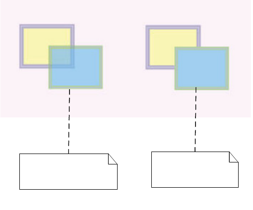
CHAPTER 8: Graphics Fundamentals Transparency effects 240
Basic transparency
Basic transparency is an effect that lets the viewer see through an object. The Transparency panel in the
user interface allows end users to specify the transparency attributes of selected page items, including
blending mode, opacity, whether these should be isolated, and whether knockout is required.
Transparency in group items
A group item is a collection of one or more page items. Transparency can be applied to a page item or a
group item. Transparency groups are constructs to work around real-world problems involving grouped
transparent objects. The application allows the assignment of opacity, knockout, and isolation properties
to transparency groups (that is, collections of page items). These group properties determine how a group
of page items interact transparently with the backdrop. It also is possible to specify knockout and isolation
properties for one page item.
Group attributes combine with those of the objects in the group. For example, if objects have 50% opacity
and the group has 50% opacity, the resulting opacity of the composited objects is equivalent to an object
with 25% opacity.
These group properties are independent of, and in addition to, the opacities and blending modes of the
individual objects. The objects interact with each other and the backdrop using their individual opacity
and blending modes. The group opacity and group-blending mode do not affect the interaction of the
individual objects with each other, but they do affect the interaction of these objects with the backdrop.
Knockout groups
A knockout group is a group whose individual elements do not interact with each other but do
interact with the backdrop. The objects within the group paint opaquely over each other, but
compositing occurs with the initial backdrop data. An example in which this is useful is a group that
consists of the fill and the stroke of a path. If the group is not a knockout group, there is an interaction
of the fill and stroke in the region they have in common, which often is undesirable. Instead, the
desired effect is to have the stroke opaquely cover the fill in the common overlap, and to have each
interact with the backdrop with respect to their individual opacities and blending modes. The
following figure shows a comparison of transparency effects with and without knockout groups.
Isolated groups
Transparency without
knockout group
Transparency with
knockout group
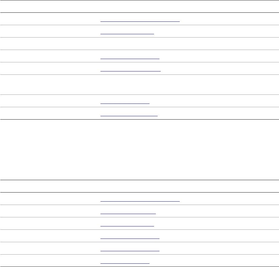
CHAPTER 8: Graphics Fundamentals Transparency effects 241
An isolated group is a group whose individual elements do not blend with the backdrop
independently but do blend with the backdrop as a group. An isolated group can be represented by
its group object of color and opacity values. By definition, an isolated group can be represented by
color and opacity values that are independent of the backdrop into which it is to be composited.
Drop shadow
In the real world, drop shadow is generated when light is blocked by an object. As represented in graphics,
drop shadow is a blurred representation of the shape of an object, offset by a user-specified distance and
drawn below the object.
The parameters that control a drop shadow include the ones listed in the following table.
Inner shadow
Inner shadow is very similar to drop shadow. It adds a shadow that falls just inside the edges of the object,
giving the object a recessed appearance. The parameters that control an inner shadow effect are like those
of drop shadows., as shown in the following table.
Parameter Description
Blending mode See “Blending mode” on page 238.
Noise See “Noise” on page 239.
Object-knockout shadow Object does not interact with shadow.
Opacity See “Opacity” on page 238.
Position See “Position” on page 239.
Shadow honors other effects Shadow can be the result when combined with other transparency
effects.
Size See “Size” on page 239.
Spread See “Spread” on page 239.
Parameter Description
Blending mode See “Blending mode” on page 238.
Choke See “Choke” on page 239.
Noise See “Noise” on page 239.
Opacity See “Opacity” on page 238.
Position See “Opacity” on page 238.
Size See “Size” on page 239.
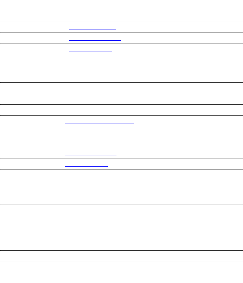
CHAPTER 8: Graphics Fundamentals Transparency effects 242
Outer and inner glow
Glow is a graphic effect that makes an object appear to shine as if with intense heat. Outer glow refers to
the glow effect applied to the outside edges of the object; inner glow refers to the glow effect applied to
the inside edges. The parameters that control outer glow are listed in the following table.
The parameters that control inner glow are listed in the following table.
Bevel and emboss
The bevel and emboss effect is a kind of simulation of how an object would look if it were “puffed up” into
the third dimension. The parameters that control bevel and emboss are listed in the following table.
Parameter Description
Blending mode See “Blending mode” on page 238.
Noise See “Noise” on page 239.
Opacity See “Opacity” on page 238.
Size See “Size” on page 239.
Spread See “Spread” on page 239.
Technique The method to produce angled corners. You can get a smooth/rounded effect
(softer) or a mitered effect (precise).
Parameter Description
Blending mode See “Blending mode” on page 238.
Choke See “Choke” on page 239.
Noise See “Noise” on page 239.
Opacity See “Opacity” on page 238.
Size See “Size” on page 239.
Source Indicates the “polarity” of the glow. “Center” means the center of the object
glows and the edges do not. “Edge” means the opposite.
Technique The method to produce angled corners. You can get a smooth/rounded effect
(softer) or a mitered effect (precise).
Parameter Description
Style A choice of inner bevel, outer bevel, emboss and pillow emboss.
Direction Indicates whether the object appears to be “sunken” or “raised.”
Technique Simulate effect made with smooth, chisel hard and chisel soft.

CHAPTER 8: Graphics Fundamentals Transparency effects 243
Satin
Satin applies interior shading that creates a satiny finish. The following table lists its controlling
parameters.
Feather effects
Feather is a graphic effect that allows designers to create a smooth edge around a frame. InDesign support
three types of feathers: basic, directional, and gradient. The parameters that control a basic feather effect
are listed in the following table.
Soften The amount of blurring, more or less, that is applied to the beveled result. This
softens the effect so your bevel is not so harsh.
Size Width of the effect. See “Size” on page 239.
Depth Determines the intensity or sharpness of the bevel.
Angle The direction in the page-plane of the light source.
Altitude The angular distance above the page plane.
Highlight-blending
mode
See “Blending mode” on page 238.
Highlight opacity See “Opacity” on page 238.
Shadow-blending
mode
See “Blending mode” on page 238.
Shadow opacity See “Opacity” on page 238.
Parameter Description
Blending mode See “Blending mode” on page 238.
Opacity See “Opacity” on page 238.
Angle The direction of the light to create effect.
Distance The distance of the light to satin effect.
Size See “Size” on page 239.
Parameter Description
Feather width See “Feather width” on page 239.
Corners Diffused, sharp, or rounded.
Parameter Description
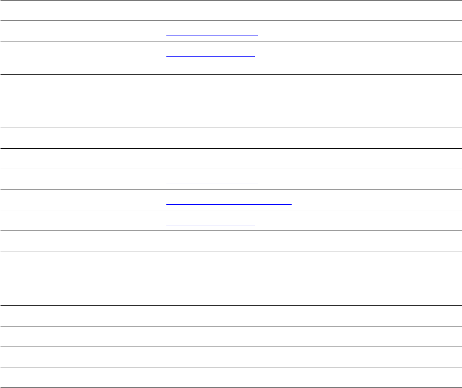
CHAPTER 8: Graphics Fundamentals Transparency effects 244
Directional-feather effect feathers only on selected sides of an object and takes additional parameters,
listed in the following table.
Gradient effect creates a linear or radial gradient of opacity around an object and allows parameters to
define a gradient, like gradient stops, gradient type and angle; see the following table.
Flattening
PostScript and PDF 1.3 have no representation of transparency information. To print or export spreads
with transparent information, it is necessary to generate nontransparent representations of the effects of
transparency; this is known as flattening. In some cases, the interactions may be among areas of solid
color, in which case they can be replaced by a solid color in each region of interaction. If images are
involved, a composite image must be calculated that reflects the contributions of the objects being
composited, including any solid-color areas.
Dealing with text and gradients requires the application of additional rules. If a section of the page is
particularly complex, it can be faster to rasterize the area than to try to calculate all the interactions; the
flattener user interface supports this feature.
The flattener is an Adobe core technology. Its implementation comes from the Adobe Graphics Manager
(AGM) library, and it is used in other Adobe applications that support transparency within vector graphics,
such as Illustrator.
The end user has a degree of control over how the flattener is used. The Print dialog box has an option to
parameterize the flattener. The user may choose flattener presets and specify, for example, that high
quality is preferred over high speed. There is a trade-off between precision of results and resources used.
The lower the resolution, the quicker and less memory-intensive the calculation.
Choke See “Choke” on page 239.
Noise See “Noise” on page 239. Feather noise is added only to the feather
region.
Parameter Description
Angle The direction of the feather.
Choke See “Choke” on page 239
Feather widths See “Feather width” on page 239.
Noise See “Noise” on page 239.
Shape First edge only, leading edges, or all edges.
Parameter Description
Gradient stops Defines the gradient
Gradient type Linear or radial gradient
Angle The direction of the gradient
Parameter Description

CHAPTER 8: Graphics Fundamentals Transparency effects 245
Flattening is a complex and potentially resource-expensive process. Various optimizations are required to
implement transparency effectively, such as caching high-resolution images to file, to ensure that the
memory requirements are minimized. There also are complexities introduced by OPI image substitution,
because printing with transparency requires that embedded files write graphic primitives into the output
stream.
Transparency data model
Transparency features are complicated, but the principles of their implementation are not. Basically,
transparency implementation involves the following related aspects:
Graphic attributes used to specify states and parameters of transparency effects
Page-item adornments used to draw transparency effects
Service providers and drawing-event handler to participate in the printing process that flattens the
transparency before printing
The boss classes responsible for transparency behavior are delivered mainly by the Transparency plug-in.
The user interface to the effects is supplied by the TransparencyUI plug-in.
Transparency information is represented by graphic attributes, and transparency is rendered to a device
through page-item adornments.
Defining transparency: graphic-attribute bosses
Transparency effects are defined programmatically as a set of graphic attributes. These attribute boss
classes derive from kGraphicsAttrBoss and aggregate a collection of interfaces that set and get a variety of
graphic-attribute data types. For general information about graphic attributes, see “Graphic attributes” on
page 229. For a summary of the transparency-attribute boss structure, see “Transparency-attribute boss
structure” on page 246.
Transparency-attribute targets
Transparency effects can be applied to the object, stroke, fill, or content. They are called transparency
targets. Accordingly, transparency attributes can be categorized into different targets. Attribute targets are
defined as enums in IXPAttributeSuite::AttributeTarget.
Transparency-attribute groups
Each transparency effect has a set of attributes to represent the parameters that control the effect.
Accordingly, transparency attributes can also be categorized into groups. Each group corresponds to each
transparency effect. Transparency-attribute groups are defined as enums in
IXPAttributeSuite::AttributeGroup.
Transparency-attribute data types and values
Different transparency attributes hold different types of data. The IXPAttributeSuite::AttributeDataType
enum defines all possible data types a transparency attribute can have.
IXPAttributeSuite::AttributeValue is a class that can hold values for any of the attributes. It serves as a
generic container for get and set functions.

CHAPTER 8: Graphics Fundamentals Transparency effects 246
Transparency-attribute boss structure
Transparency-attribute bosses are organized as a three-level inheritance. The most generic level is the
kGraphicsAttrBoss. This implies transparency attributes work and can be manipulated the same way as any
other graphic attributes.
The next level is attribute groups. These attribute group bosses inherit from kGraphicsAttrBoss and
aggregate the IID_IOBJECTSTYLEATTRINFO interface with the kXPAttrInfoImpl implementation. These
groups correspond to the transparency effects; see the following table.
The bottom level has the real transparency attributes that define every transparency. For example,
kXPBasicOpacityAttrBoss, kXPStrokeBlendingOpacityAttrBoss, kXPFillBlendingOpacityAttrBoss, and
kXPContentBlendingOpacityAttrBoss inherit from kXPAttrBoss and aggregate the
IID_IGRAPHICATTR_REALNUMBER interface. They define the opacity attribute of basic transparency for
object, stroke, fill, and content targets, respectively.
Transparency-attribute types
There are about 400 transparency attributes. You may still access them in the general graphic-attribute
way; however, the InDesign API also provides utility functions in IXPAttributeUtils to manipulate
transparency attributes more effectively. Part of that is the concept of transparency-attribute types.
Transparency-attribute types are defined as enums in IXPAttributeSuite::AttributeType. These enums are
divided into segments according to transparency targets and transparency groups. The
BASE_XP_ATTR(t,x) macro generates the base index of the segment. For example, if you want to know the
enum value of the first transparency attribute for controlling inner shadow on the stroke of an object, use
kStrokeInnerShadowBaseID + 1. kStrokeInnerShadowBaseID is calculated as
BASE_XP_ATTR(kTargetStroke, kGroupInnerShadow).
A transparency-attribute type has a one-to-one mapping to transparency-attribute boss. You can translate
between AttributeTypes and attribute-boss ClassIDs using the GetAttributeClassID and
GetAttributeFromClassID methods on IXPAttributeUtils.
Group-attribute boss Transparency effect
kDropShadowAttrBoss Drop shadow
kVignetteAttrBoss Basic feather
kXPAttrBoss Basic transparency
kXPBevelEmbossAttrBoss Bevel and emboss
kXPDirectionalFeatherAttrBoss Directional feather
kXPGradientFeatherAttrBoss Gradient feather
kXPInnerGlowAttrBoss Inner glow
kXPInnerShadowAttrBoss Inner shadow
kXPOuterGlowAttrBoss Outer glow
kXPSatinAttrBoss Satin

CHAPTER 8: Graphics Fundamentals Transparency effects 247
Drawing transparency: adornment bosses
To create a transparent rendering for an object, add an IAdornmentShape implementation to the
adornment boss class that provides the behavior for the object. The kBeforeShape and kAfterShape flags
specify when to draw in response to the IAdornmentShape::GetDrawOrderBits method. The
IAdornmentShape::GetPaintedAdornmentBounds method specifies the adornment bounding box. Bound
of the outer effects are larger than the object’s bounds.
The following table lists the adornment bosses responsible for drawing transparency effects. One
adornment boss can draw multiple effects. The primary reason we do not have one adornment for every
effect is to limit the total number of adornments of a page item, for performance reasons.
Printing transparency: flattening
Before transparency is printed, transparency effects must be flattened. You can choose different flattener
presets to represent transparency using nontransparency representation, then print the result as normal
page items.
Managing flattener presets
Flattener presets are represented by kXPFlattenerStyleBoss. The key interface is IFlattenerSettings, which
defines settings of presets, directly corresponding to the Flattener Preset Options dialog box.
The flattener preset is an application-wide preference. The IFlattenerStyleListMgr interface is aggregated
on kWorkspaceBoss and is responsible for managing all flattener presets. As with other general presets,
like print presets, the IFlattenerStyleListMgr implementation hooks flattener presets into the generic
presets dialog and provides an entry point for adding, deleting, and editing flattener presets with
respective commands.
The kSpreadBoss also aggregates IFlattenerSettings, which allows the spread to override the flattener
settings for a specific spread.
Printing-related bosses
Transparency participates in the printing process by iterating spreads for pages containing transparency
effects that require flattening. With these bosses, the print command can examine transparency use,
setting up viewport attributes and so on. Together with drawing in the spread and page item, InDesign
can achieve results that appear as if there are transparency interactions, even though these are
accomplished through flattened, opaque, drawing instructions. See the following table.
Boss-class name Description
kXPDropShadowAdornmentBoss Draws knockout drop shadows and outer glow.
kXPPageitemAdornmentBoss Draws blending and nonknockout drop shadows.
kXPVignetteAdornmentBoss Draws basic feather, directional feather, and gradient feather.
kXPInnerEffectsAdornmentBoss Draws inner effects, like inner shadow, inner glow, bevel and
emboss, and satin.

CHAPTER 8: Graphics Fundamentals Data model for drawing 248
Data model for drawing
Presentation views
Drawing documents to the screen really means drawing to an application-layout presentation, which is a
platform-independent construct containing layout widgets that display the contents of the document.
Layout presentation is represented by kLayoutPresentationBoss, with the key interface
IDocumentPresentation. Note that kLayoutPresentationBoss is inherited from kWindowBoss; however, it is
very important not to use the IWindow interface for any layout-presentation operation. Instead, always use
IDocumentPresentation for operations like minimizing the view. The IWindow on a
kLayoutPresentationBoss is only for internal use. There may be several layout presentations open at the
same time; these can be hosted in one operating-system window as tabbed document presentation views,
or each layout presentation can be hosted inside its own operating-system window.
In addition to the layout presentation, there are other windows/view containers in InDesign. Dialog boxes
and pop-up tips are application windows and are represented by the platform-independent kWindowBoss
object. The panel container, often referred to as palette, is represented by a PaletteRef. For more detail on
these interfaces and their responsibilities, refer to the API Reference.
To summarize, the application manages two main categories of views:
Document presentations have a document associated with them and display the content of the
document. They also are referred to as layout presentations. A document presentation may not always
correspond to a standalone operating-system window, because an operating-system window can
have many document presentations in it. Note, however, that “window” is still being referred to
throughout this document, because that is still a commonly accepted term for the view to a
document.
User-interface windows/palettes are used for dialog boxes, panels, and other types of windows that do
not have documents associated with them.
Most of the detail in the remainder of this section concerns drawing a layout.
Graphics context
Drawing requires a graphics context. When page items are called to draw, they are provided with a
GraphicsData object, which contains a pointer to an InDesign graphics context. Using the application’s
graphics context, page items can perform platform-independent drawing to several of device contexts:
screen, print, or PDF.
Boss-class name Description
kXPGatherProviderBoss A document iterator provider that gathers document-wide use of
transparency.
kXPPrintSetupServiceBoss Implements print services to set up global color profiles.
kXPDrwEvtHandlerBoss Transparency start-up and shut-down. Hooks transparency into the draw
manager.

CHAPTER 8: Graphics Fundamentals Dynamics of drawing 249
The graphics context for application drawing is described by an object derived from IGraphicsContext, an
abstract-data container interface. This interface is not aggregated on boss classes, nor is it derived from
IPMUnknown. Instead, implementations of IGraphicsContext are specialized for different drawing devices.
A graphics context is instantiated based on a viewport boss object (see “Viewport” on page 249),
IControlView interface pointer, and update region. Several important pieces of information are stored in
the graphics context object, including the following:
The current rectangular clip region for the drawing port.
The transform for mapping content to drawing device coordinates.
The transform describes the relationship of the content coordinates to the drawing-device coordinates.
For screen drawing, the drawing device is a window. The transform is based on the IControlView
implementation supplied at the time of the graphics-context instantiation. During a normal
screen-drawing sequence, this is the IControlView implementation on the kLayoutWidgetBoss that
instantiates the graphics context, so the transform is initialized to be pasteboard to the
application-window coordinates. During the drawing sequence, this transform is modified to represent
parent-window coordinates. For a description of coordinate systems related to drawing, see Chapter 7,
“Layout Fundamentals.”
Screen draws do not paint the entire document and then copy only a portion of it to the window. Instead,
only the region of the window marked invalid is redrawn. The clip region stored in the graphics context is
applied like a mask, discarding any drawing outside the clip bounds. During a drawing sequence, the clip
represents the update region in the window and is stored in window coordinates.
For drawing to the screen, AGM is used to provide the graphics context. An offscreen context is used for
drawing, to facilitate a smooth, flicker-free screen update. The drawing code renders off-screen, and the
result of the completed drawing is subsequently copied to the screen. For more details, see “Offscreen
drawing” on page 254. The use of off-screen contexts is transparent to page items when they draw. The
graphics context provided to the page item hides these implementation details.
Viewport
The application’s platform-independent API for drawing is provided by the viewport. Page items use the
IGraphicsPort interface on the viewport boss object for drawing. The viewport boss object does not draw
directly to the platform window; instead, the viewport boss object draws through the AGM, which is
specialized for the type of drawing device (for example, PostScript printing or the screen). The
specialization is transparent to clients of the graphics context and the viewport boss object.
A viewport boss object operates as a wrapper between the drawing client (often a page item) and the
underlying AGM code that defines the graphics context for the output device. There are several different
types of viewport boss classes, each tailored to a particular type of drawing output. For a list of relevant
boss classes and the responsibilities of the interfaces on the boss classes, refer to the API Reference for
IViewPort. For example, kWindowViewPortBoss is used for drawing to application windows.
Dynamics of drawing
Drawing the layout
Layout drawing is the process of drawing page items to the layout presentation. Layout is described in
depth in Chapter 7, “Layout Fundamentals.” For more detail on how individual page items are drawn, see
“Drawing page items” on page 252.
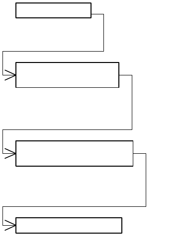
CHAPTER 8: Graphics Fundamentals Dynamics of drawing 250
Invalidating a view
InDesign drawing occurs in response to invalidation of a view, or region. Although InDesign provides
platform-independent APIs for invalidating a view, the APIs simply forward the invalidation to the
operating system. The invalidation state is maintained by the operating system, which generates update
events to the application.
Invalidation can be caused by changes to the model (persistent data in a document) or direct invalidation.
Both use the same mechanism to invalidate a view.
Changes to the model are broadcast to interested observers with regular or lazy notification. For example,
the application uses an observer on the layout widget to monitor changes to page items in the layout.
When the observer receives notification of a change, it asks the subject of the change to invalidate a
region based on its bounding box.
Views can be directly invalidated by using the ILayoutUtils::InvalidateViews method. The collaboration of
boss objects is shown in the following figure.
The ILayoutUtils::InvalidateViews method uses a document pointer to locate the views for a document. For
each view, the method gets the ILayoutController interface on the kLayoutWidgetBoss and calls
ILayoutController::InvalidateContent, which creates an invalidation region equal to the view’s window. The
invalidation region is passed to the IWindowPort::InvalRgn method on the IWindowPort interface of the
kWindowViewPortBoss corresponding to the window. This method then passes the invalidation region to
the operating system.
The invalidation region is then accumulated by the operating system, which generates a paint message.
The operating system sends an update message (event) to the InDesign event dispatcher, where the
message is wrapped in a platform-independent class and routed to the event handler on the appropriate
window.
The window’s event handler calls indirectly the IControlView::Draw method. At that point, the drawing
sequence begins following the pattern for drawing a widget hierarchy; Draw uses the IPanelControlData
interface to locate each of its children and call Draw on the child’s IControlView interface. This means the
«boss»
kWindowViewportBoss
ILayoutUIUtils
«boss»
kLayoutWidgetBoss
Platform invalidation
*
InvalidateViews
*
ILayoutController::InvalidateContent
*
IWindowPort::InvalRgn

CHAPTER 8: Graphics Fundamentals Dynamics of drawing 251
kLayoutPanelBoss is called to draw, and it iterates each of its child widgets (scroll bars, the layout widget,
rulers, etc.).
The drawing sequence concludes with validating the contents of the window. This completes the update
cycle, from invalidation to redraw.
Layout drawing order
Layout presentations are updated in several steps that allow better performance and the opportunity to
interrupt the drawing. Good performance is achieved by specializing the drawing operations according to
the view’s z-order, whether the invalidation is due to a selection change or because all objects changed.
At the level of the kLayoutWidgetBoss, several decisions are made behind the scenes for the sake of
drawing performance. The IControlView implementation on the kLayoutWidgetBoss chooses what to
draw based on the window’s z-order, the selection, and the update region.
Foreground and background drawing
If the window is the front view, two views may be drawn: a background view containing all objects and a
foreground view containing only the decorations for the selection. Offscreen graphics contexts are created
and cached for both views (see “Offscreen drawing” on page 254). If the update region overlaps the
window or the current front view was not the last view to have been drawn, the background view is
redrawn. If the selection is not empty, the foreground view also is redrawn.
Based on the above rules, the kLayoutWidgetBoss IControlView filters the visible spreads and calls their
IShape::ProcessDrawShape methods through the InDesign draw manager. This filtering means page items
are not guaranteed to be called for a screen draw. The background draw then propagates through the
layout hierarchy, as described in “Spread-drawing sequence” on page 275.
After the background draw is complete, if the selection is empty, the background image is copied to the
window and the draw is complete. If the selection is not empty, the foreground draw starts by copying the
background image to the foreground offscreen context. The selection is drawn to the foreground, then the
foreground image is copied to the window.
The use of foreground and background draws means a page item could be called twice during a redraw:
the first call to IShape::ProcessDrawShape in the order of the layout hierarchy for the background draw,
and the second call to HandleShape::DrawHandleShape in the order of the selection list for the foreground
draw.
If the window is not the front view, a more abbreviated drawing sequence takes place. Both the document
items and the selection are drawn to a foreground offscreen context, and it is copied to the screen.
Z-order
Z-order is the order (depth) of page item objects in the direction perpendicular to the screen. Z-order
determines which object or part of an object is visible to the user. InDesign handles three levels of z-order:
1. Window z-order — InDesign windows may overlap.
2. Layer order — InDesign documents are layered. InDesign draws page layers first, then other document
layers. For more information, see the “Layers” section of Chapter 7, “Layout Fundamentals.”
3. Page item z-order — On the same layer, page items are ordered according to their positions in the
parent object’s hierarchy. The child with index 0 is drawn first; the child with the greatest index is
drawn last. For more information, see the “Documents and the Layout Hierarchy” section of Chapter 7,
“Layout Fundamentals.”

CHAPTER 8: Graphics Fundamentals Dynamics of drawing 252
NOTE: Do not confuse z-order with foreground and background drawing. Z-order controls what is visible to
the viewer, whereas foreground and background are just bitmaps for speeding up rendering.
Draw manager
Conceptually, kLayoutWidgetBoss calls each spread to draw. In reality, kLayoutWidgetBoss calls through
the InDesign draw manager. The draw manager is an interface that exists on each viewport and is used to
set clipping areas and initiate the drawing of any page element and its children to that viewport. The draw
manager can be used for drawing to the screen, PDF, and print. Drawing in InDesign occurs on a
spread-by-spread basis and is hierarchical. Without a service like the draw manager, it would be hard to
change the behavior of drawing in a subhierarchy. Optionally, you can create a kDrawMgrBoss and use the
IterateDrawOrder method, which allows clients to iterate the document in the same manner as drawing,
calling a client-provided callback routine for every page item in the hierarchy, but without a graphics
context.
Funneling all drawing activity through the draw manager provides three important features for changing
the behavior of drawing operations:
Clipping of areas to be drawn.
Filtering of items to be drawn.
Interrupting a drawing sequence.
Clipping and filtering provide a means to select items for the draw based on regions. The draw manager
maintains the current values for the clip and filter regions. Interruption of the drawing sequence relies on
the broader mechanism of drawing events. As items draw, they broadcast standard messages that
announce the beginning and end of discrete drawing operations. Drawing events are received by special
handlers that register interest in particular types of messages, and each drawing-event handler has the
opportunity to abort the draw at that point. Clients of the draw manager (like the layout widget) install a
default drawing-event handler.
The draw manager provides services for hit testing, iterating the drawing order, and drawing. Detail about
how spreads are drawn is described in “Spread-drawing sequence” on page 275.
Drawing page items
When page items are called to draw, they are passed information about their drawing context, including a
GraphicsData object and IShape drawing flags (for example, kPatientUser). For more information, refer to
the API Reference for these types. Page items use this information to perform their drawing operations.
The IGraphicsPort interface is the InDesign interface for drawing and is aggregated on all viewport boss
classes. The IGraphicsPort interface is used by all drawing interfaces on a page item, regardless of the
output device.
The viewport settings can be modified using IGraphicsPort methods. The IGraphicsPort::gsave and
IGraphicsPort::grestore methods effectively push the current port settings onto a stack and pop the old
settings when desired. These methods are used to save the current port settings when setting the port’s
transform to a new space. For example, when a page item is called to draw, it should save the port settings,
set the port to its inner coordinate space, draw, and restore the port before returning.
The IGraphicsPort implementations provide methods very similar to PostScript graphics operators. These
methods support drawing primitives, port-transformation manipulation, and changing port-clip settings.
For a complete list of the methods, refer to the API Reference for IGraphicsPort.h. Line-drawing methods

CHAPTER 8: Graphics Fundamentals Dynamics of drawing 253
like IGraphicsPort::lineto, IGraphicsPort::moveto, IGraphicsPort::curveto, IGraphicsPort::closepath,
IGraphicsPort::fill, and IGraphicsPort::stroke are available. If a path is defined in the port, it can be discarded
using the IGraphicsPort::newpath method. These methods are demonstrated in the “Graphics” chapter of
Adobe InDesign SDK Solutions. Control over the color space, color values, gradient, and blending modes
also is available through IGraphicsPort methods.
See the following table for a list of interfaces for drawing page items.
IShape, IPathPageItem, and IHandleShape are directly involved in drawing a page item. IShape is the main
interface for drawing the page item and is called when the entire page item needs to be rendered.
Path-based items like spline bosses also have the IPathPageItem interface to handle the details of drawing
their paths. IHandleShape is called when a page item is in the selected state and is used for drawing the
decorations that denote selection. PathHandleShape is responsible for drawing path-selection handles.
IGraphicStyleDescriptor maintains the graphic attributes for the page item. The drawing process sets
graphics port settings based on various graphic attributes.
IPageItemAdornmentList maintains a list of adornments for the page item. Adornments are drawn with
the page item. This interface provides a means to enhance or decorate a page item’s appearance. For more
detail, see “Spread-drawing sequence” on page 275.
IShape is responsible for providing the drawing, hit testing, drawing-order iteration, and invalidation
functions for page items. This interface is responsible for rendering a page item and is used during
background draws to create the path, fill, and stroke of an object. For details, refer to the API Reference.
There are partial implementation classes like CShape and CGraphicFrameShape in the public API. For
details, refer to the API Reference.
For details on the drawing sequence for a page item, see “Drawing sequence for a page item” on page 277.
The IHandleShape interface
The IHandleShape interface is responsible for drawing and hit testing for a page item’s selection handles.
This interface is defined in the abstract base class in IHandleShape.h.
As with the IShape class, the IHandleShape drawing sequence includes extensibility points in the form of
adornment calls. For more detail, see “Extension patterns” on page 259. For more detail on its
responsibilities, refer to the API Reference on IHandleShape.
Most page items (such as kSplineItemBoss) that aggregate IHandleShape (with the ID IID_IHandleShape
interface) also have another implementation of IHandleShape which is based on PathHandleShape (with
the ID IID_IPATHHANDLESHAPE interface). The implementation based on PathHandleShape inherits from
the same superclass as IHandleShape; therefore, it has exactly the same public interface. The purpose of
Interface Function
IGraphicStyleDescriptor Renders graphic attributes.
IHandleShape Renders selection handles. Called during foreground drawing.
IPageItemAdornmentList Lists adornments for a page item.
IPathPageItem Renders low-level draws for path, fill, and stroke.
IShape Renders path, fill, and stroke. Called during background drawing.
CHAPTER 8: Graphics Fundamentals Dynamics of drawing 254
this interface is to draw path-selection handles. Observe the difference in the user interface by switching
between the Selection and Direct Selection tools.
The IPathPageItem interface
The IPathPageItem interface encapsulates the specialized drawing functions for path-based page items.
This class provides methods for operations like stroke, fill, clip, and copying a path to the graphics port. The
CGraphicFrameShape class delegates these specific draw operations to the IPathPageItem class.
In this class, graphic attributes are used to control the appearance. The IPathPageItem::Stroke method first
calls IPathPageItem::Setup, which initializes a set of default stroke properties and then tries to get the
stroke graphic attributes, like stroke weight and a ClassID for a path stroker. The path stroker is a service
provider that delivers the kPathStrokerService. The IPathPageitem::Stroke method then uses the stroke
graphic attributes and path stroker to actually create the stroke.
Drawing in user-interface widget windows
A user-interface widget is any descendant of kBaseWidgetBoss. Drawing in a user-interface widget
window—such as a palette, dialog box, or panel—is like drawing to the layout presentation. Instead of
calling the draw method of the layout-control view, palette drawing calls IControlView::Draw methods of
various IControlView implementations.
The first stage in creating an owner-drawn panel is constructing an AGMGraphicsContext object from the
IControlView::Draw parameters and obtaining an IGraphicsPort from the graphic context.
Next, set colors and draw the items. This can be done through the IInterfaceColors interface, aggregated
on kSessionBoss. There are a few standard interface colors common to drawing items in user-interface
windows. User-interface colors are defined in InterfaceColorDefines.h. Next, set the color of the graphics
port and draw items.
Each each widget actually is a window, so the PMRect value from IControlView::GetFrame represents the
coordinates of the widget in its parent widget. An IControlView::MoveTo(0,0) call is convenient for
transforming the coordinates.
You can draw lines, boxes, and so on as you normally draw in the layout presentation, using the methods
of IGraphicsPort. For drawing PMString, InDesign provides utility methods on the StringUtils class
(DrawStringUtils.h) that let you measure a PMString and draw strings directly. For more details, refer to the
API Reference.
For an example of an owner-drawn panel, with a custom IControlView::Draw implementation, see the SDK
sample PanelTreeView in <SDK>/source/sdksamples/paneltreeview, and inspect PnlTrvCustomView.cpp.
Offscreen drawing
Purpose of offscreen drawing
An offscreen drawing is simply a bitmap. The technique of offscreen drawing has been used for years by
various applications to reduce screen flicker and improve performance when drawing to the screen. Mac
OS X actually creates a separate offscreen buffer for each window, such that when an application tries to
draw to a window, it actually is drawing to the offscreen buffer. The operating system then periodically
transfers its offscreen buffer to the actual screen. This process is done at the operating-system level and
decreases the number of cases in which InDesign needs to draw offscreen on Mac OS X.

CHAPTER 8: Graphics Fundamentals Dynamics of drawing 255
Drawing layout offscreen
Offscreen drawing is used just about any time the layout presentation needs to update. InDesign
maintains an offscreen representation of the layout presentation with everything except the current
selection highlighting. Hence, when the selection changes, InDesign can very quickly redraw the screen
from the offscreen buffer, followed by drawing the new selection.
The biggest area where offscreen drawing is used is the layout-control view. Drawing background and
foreground in layout-control view is discussed in “Layout drawing order” on page 251. What must be
emphasized here is that drawing the layout does not really draw to the screen directly; instead, drawing
the layout actually draws offscreen.
Corresponding to background and foreground drawing, there are background offscreen buffers and
foreground offscreen buffers. The background offscreen representation in InDesign is the offscreen buffer
maintained by each layout view, containing everything except current selection highlighting. Each layout
view has its own offscreen buffer. The background offscreen buffer is invalidated by querying for the
ILayoutController of the IControlView interface for the layout and calling
ILayoutController::InvalidateContent.
InDesign can be told to update a layout without dirtying the background offscreen buffer, by querying for
the ILayoutController of the IControlView interface for the layout and calling
ILayoutController::InvalidateSelection.
Palettes and dialog boxes are responsible for their own offscreen representations. In general, most panels
do not use offscreen drawing; however, a few user-interface windows, like the Navigator panel, maintain
their own offscreen representations. As mentioned above, Mac OS X provides offscreen buffers for all
windows, so offscreen drawing on Mac OS X is not necessary if the goal is simply to avoid flicker.
Offscreen data
Drawing offscreen is drawing to the kOffscreenViewPortBoss. Besides other interfaces that are involved in
drawing, one of the most important interfaces on kOffscreenViewPortBoss is IOffscreenPortData. This is
the interface that stores a reference to the offscreen bitmap and distinguishes kOffscreenViewPortBoss
from other viewports.
An offscreen bitmap is wrapped in the platform-independent IPlatformOffscreen. You can get and set
bitmaps with IOffscreenPortData; however, you are not allowed to create bitmaps directly. Instead, you
may want to aggregate an IOffscreenViewPortCache interface on the control-view boss class, so you can
query background and foreground viewport data.
For more information, refer to the API Reference for IPlatformOffscreen, IOffscreenPortData, and
IOffscreenViewPortCache.
Snapshots
A snapshot is a record of a part of the document view at a specific instant. SnapshotUtilsEx draws items
into a memory-based graphics context, creating a bitmap (snapshot) that can be exported to a stream in
several formats, like JPEG, TIFF, or GIF.
SnapshotUtilsEx also creates its own offscreen bitmap and uses an IDrawMgr to walk the IHierarchy and
draw specific page items to the offscreen buffer; however, the internal implementation is different. Like
layout offscreen, the viewport SnapshotUtilsEx interacts with is kAGMImageViewportBoss, the bitmap it
draws to is of type AGMImageRecord defined in GraphicsExternal.h, and it uses IAGMImageViewPort to

CHAPTER 8: Graphics Fundamentals Client APIs 256
manipulate the bitmap. SnapshotUtilsEx does not interact with the layout's offscreen representation in
any way.
SnapshotUtilsEx is very useful for creating proxy images of documents, since it uses the same draw
manager to draw page items in memory, a much faster way. Sample code in the Snapshot sample plug-in
and in SnpCreateInddPreview.cpp demonstrates the use.
The sample code in the SDK still uses SnapshotUtils. We recommend using the more recent
SnapshotUtilsEx.
Client APIs
Path-related client APIs
High-level APIs provided to manipulate paths are summarized in the following table. For details about
them, refer to the API Reference.
Graphic page-item client APIs
APIs provided to manipulate graphics are summarized in the following table. For details about them, refer
to the API Reference.
API Description
IPathPointScriptUtils Utility methods related to path point scripting (called by script providers).
IPageItemTypeUtils Utilities to get the type of a page item.
IPathUtils Path manipulations.
ISplineUtils Utilities for spline-item manipulations.
IPathInfoUtils Analyzes whether a list of PathInfo object forms a point or straight line.
IPathPointUtils Utility methods related to path point transformations.
IPathOperationSuite Manipulates paths on selected page items, including compound paths. Includes
path-finder operations.
IConvertShapeSuite Converts selected page items to a new shape.
API Description
IFrameContentSuite Selection suite interface for content fitting and frame-content conversion.
IFrameContentFacade Facade for content fitting and frame-content conversion.
IFrameContentUtils Utility interface for determining various aspects of frame contents.
IClippingPathSuite Gets and sets clipping path for selected graphics items.
ITextWrapFacade Facade for manipulating text wrap.
IDisplayPerformanceSuite Changes display performance settings for selection.

CHAPTER 8: Graphics Fundamentals Client APIs 257
Key color-related client APIs
Interfaces provided to manipulate color, swatch, ink, and color management objects are summarized in
the following table. For details about them, refer to the API Reference.
Since color-related objects like colors, swatches, inks, and color profiles are stored in the document or
application database, you will need commands to manipulate them. The utility interfaces described above
IImageObjectSuite Accesses image layers.
IImageFacade Facade for getting image information.
IJPEGExportSuite Exports selection to JPEG file format.
ISVGExportSuite Exports selection to SVG file format.
API Description
API Description
IGradientAttributeSuite A selection suite interface. Provides gradient attribute–related operations that
apply to the application defaults, document defaults, text, layout, and tables.
ISwatchUtils Utility interface to manipulate swatches. For example, this interface can be
used to acquire the active swatch list, retrieve or instantiate new, persistent,
rendering boss objects, and modify the properties of the swatch list.
IUIColorUtils Utility interface for dealing with user-interface colors.
IInkMgrUtils Utility interface for managing inks. For example, this interface can be used to
acquire the active ink list and retrieve information about name, type, ink alias,
and corresponding swatches of a spot ink.
IInkMgrUIUtils Utility interface, mainly for calling the ink-manager dialog box.
IColorSystemUtils Utility interface for color-rendering objects. For example, this interface can be
used to get color space and color components of a given color swatch.
ICMSAttributeSuite A selection suite interface. Provides color-management functionality for the
selected image page item, like getting or applying color profile or rendering
intent.
ICMSUtils Utility interface for the color-management system. For example, this interface
can be used to obtain CMSSettings and ProfileList. Provides wrappers for
color-management commands.
ICMSManager A manager interface that provides a generic wrapper around a
color-management system (CMS). Access to the CMS typically is done by
coordinating between this interface and a data interface for the specific CMS
implementation.
IColorPresetsManager A manager interface that manages a set of color preset files. For example, load
or save a color preset, and get or set working RGB/CMYK profile and CMS
policy.

CHAPTER 8: Graphics Fundamentals Client APIs 258
provide a higher-level abstraction that wrap the required commands. For a list of commands, refer to the
API Reference.
Graphic-attribute client APIs
APIs provided to manipulate graphic attributes are summarized in the following table. For details about
them, refer to the API Reference.
There are command boss classes used to manipulate graphic attributes, graphic style, and graphic state.
The utility interfaces described in the table in “Graphic-attribute client APIs” on page 258 provide a
higher-level abstraction that wraps the common commands. For a complete list of provided commands,
refer to the API Reference.
API Description
IGraphicAttributeUtils Exposes methods that can be used to create lists of attribute overrides and
create commands to apply attribute overrides. It also exposes methods to
read the graphic attributes of document objects.
IGraphicStateUtils Exposes methods to create or process commands to apply overrides, swap
stroke and fill, and so on. It also exposes a key method to acquire a reference
to the active graphic state, which is discussed in detail in the “Graphics”
chapter of Adobe InDesign SDK Solutions.
IGraphicAttributeSuite Selection suite that can be queried for through an abstract selection
(kAbstractSelectionBoss). It is aggregated on the concrete selection boss
classes connected with application defaults, document defaults, layout,
tables, and text.
IGraphicAttrProxySuite Selection suite that switches graphic attributes between layout objects and
text.
IStrokeAttributeSuite High-level attribute suite interface specifically to get and set various stroke
attributes. It uses IGraphicAttributeSuite to get and set appropriate data.
IXPAttributeSuite Accesses or changes transparency attributes on the selected page items or
group items. This header file also defines all transparency-attribute-related
enums such as attribute types.
IXPAttributeUtils Transparency-attribute-related utility functions
IXPAttributeFacade High-level transparency-attribute facade. Defines methods to get and set all
transparency attributes.
IXPUtils Transparency utility functions. Mainly for flattening.
IXPManager Transparency helper functions.

CHAPTER 8: Graphics Fundamentals Extension patterns 259
Extension patterns
Custom graphic attributes
You can provide custom graphic attributes that extend InDesign function for end users. As explained in
“Representation of graphic attributes” on page 232, graphic attributes are applied to page items by
adding to a list of attribute boss objects associated with the page item.
To define a customized graphic attribute:
1. Create a new boss class for the attribute. The boss class should inherit from kGraphicsAttrBoss.
2. Provide an implementation of the IGraphicAttributeInfo interface.
3. If the graphic attribute value could be stored in an existing data interface, like IGraphicAttrBoolean or
IGraphicAttrClassID, add it to the attribute class; otherwise, implement an interface of your own.
4. Provide your own code to initialize and set your attribute data when the attribute is applied to a page
item. Code to apply the attribute to a page item also is required.
If you implemented a custom graphic attribute, you are likely to use a page-item adornment to decorate
the page item based on your graphic-attribute value. For an example, see the TransparencyEffect and
TransparencyEffectUI sample SDK plug-ins.
Custom path-stroker effects
You can provide custom path strokers with your own stroke implementation through a
kPathStrokerService. The service provider should provide an implementation of IPathStroker, with
IStrokeParameters used for storing parameters for the stroke. See “Path stroker” on page 236. To
implement a custom path stroker:
1. Create a new boss class for the service provider (for example k<XXX>PathStrokerBoss). Add a service
provider to the boss class (the application-provided kPathStrokerServiceProviderImpl can be reused),
and define your implementation of IPathStroker.
2. Create your implementation of IPathStroker. The interface basically provides methods on how to draw
the path on the specific graphic port and hit testing (stroke bounding box, etc.).
3. If the implementation of the stroker is complicated, you may aggregate additional interfaces on the
boss. InDesign/InCopy provides a common stroke-parameter implementation of the
IStrokeParameters interface. The interface stores information like where a path segment starts and the
length of the segment. For details, refer to the API Reference.
To change only the dash and gap of a stroke, you do not need a custom stroke implementation. Instead,
just apply the appropriate kDashedAttributeValuesBoss attribute.
Custom corner effects
You can provide a custom corner path with your own corner path implementation through a
kPathCornerService. The service provider should provide an implementation of IPathCorner. See “Path
corners” on page 236. To implement a custom corner effect:

CHAPTER 8: Graphics Fundamentals Extension patterns 260
1. Create a new boss class for the service provider (for example k<XXX>CornerBoss). Add a service
provider to the boss class (the application-provided kPathCornerServiceProviderImpl can be reused),
and define your own implementation of IPathCorner.
2. Create your implementation of IPathCorner. The interface basically provides drawing methods from
three points on the corner. For detailed definitions of the pointers, refer to the API Reference of the
interface. The three points are calculated by a private method not included in the SDK from the stroke
path and corner size. You need to provide only the method for creating the corner effect using these
points.
3. Determine the size of the corner, and apply kGraphicStyleCornerRadiusAttrBoss to the path page item.
The corner-size attribute is decoupled from the corner-path implementation, so you could set and
change corner size independently and use this setting with other corner implementations.
Custom path-end effects
You can provide a custom path-end effect with your own path-end implementation through a
kPathEndStrokerService. The service provider should provide an implementation of IPathEndStroker. See
“Path-end strokers” on page 236. To implement a custom path-end effect:
1. Create a new boss class for the service provider (for example k<XXX>ArrowHeadBoss). Add a service
provider to the boss class (the application-provided kPathEndStrokerServiceProviderImpl can be
reused), and define your own implementation of IPathEndStroker.
2. Create your implementation of IPathEndStroker. The interface basically provides drawing and hit
testing methods for a stroke end. A page item’s stroke bounding box includes both the stroke and
stroke-end bounding box returned from the method on this interface.
3. Set the implementation ID to the appropriate line-end attribute, and apply the attribute to the page
item.
Custom page-item adornments
Page-item adornments customize the appearance of a page item, giving a plug-in the chance to add
drawing when the page item is rendered. For example, if you want to add a drop shadow or label for a
specific page item, a page-item adornment is one way to add these extra drawings.
Examples of page-item adornments in InDesign are the transparency drop shadow and feather effects, the
graphics-frame outline path, and the empty-graphics frame indicator (the X inside the frame).
You can participate in page-item drawing by creating a custom page-item adornment. For example, you
could provide an adornment to show in magenta type the width and height of each selected page item, as
shown in the following figure.

CHAPTER 8: Graphics Fundamentals Extension patterns 261
Architecture
Page-item adornments are represented by boss objects. There are two main types of page-item
adornments:
IAdornmentShape implementations, drawn during execution of IShape::ProcessDrawShape.
IAdornmentHandleShape implementations, drawn during execution of
HandleShape::DrawHandleShape.
The Draw methods on their implementations determine the appearance of the adornment. Page-item
adornments are connected to page items through the IPageItemAdornmentList interface aggregated on
the kPageItemBoss boss class. The following figure illustrates the basic data model for adornments. A page
item aggregates the IPageItemAdornmentList interface, which stores a list of adornments the page item
has.
IPageItemAdornmentList
The IPageItemAdornmentList interface manages a list of the adornments for a page item. Each adornment
in the list is drawn in an order determined by the value of its AdornmentDrawOrder. For page-item
adornments, there are several opportunities within the drawing cycle to draw.
Each adornment can be drawn at one or more phases within the drawing cycle if you AND together the
flags defined in the AdornmentDrawOrder enumeration (defined in IAdornmentShape.h and
IAdornmentHandleShape). These values indicate when the adornment is to be drawn. Upon calling the
command kAddPageitemAdornmentCmdBoss, the adornment is inserted into the list based on drawing
order.
Before adding adornments After adding adornments
«boss»
kYourAdornmentBoss
«boss»
kPageItemBoss
1
*
IPageItemAdornmentList
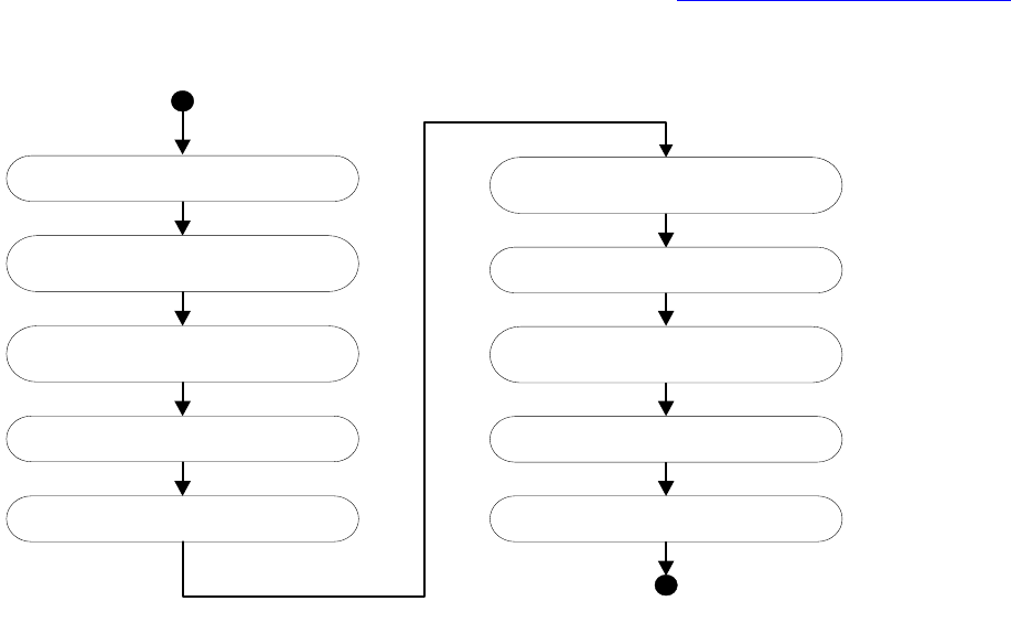
CHAPTER 8: Graphics Fundamentals Extension patterns 262
When adding an adornment to a page item, define the adornment as a new boss class that aggregates the
IAdornmentShape or IAdornmentHandleShape interface. In a more complex case, you can use more than
one adornment for a single page item.
IAdornmentShape
When implementing IAdornmentShape, you can choose to provide hit testing and invalidation of the
view, if needed. At a minimum, your implementation must draw the adornment.
When a page item is drawn, each attached adornment is called to draw through the IAdornmentShape
interface. A page-item shape tells the drawing manager at which of the following times it should be
drawn:
After the frame shape (kAfterShape).
Before the text foreground (kBeforeTextForeground).
At one of the other events defined in the adornment objects.
The drawing order controls when the adornment is called to draw. The following figure shows the drawing
sequences for one rectangle spline item. When the adornments’ drawing methods get called depends on
the drawing order. For detailed information on page item drawing, see “Drawing page items” on page 252.
IAdornmentHandleShape
Implementing IAdornmentHandleShape lets you decorate the selection handles associated with a page
item. This decoration can be drawn with IAdornmentHandleShape::kBeforeShape or
IAdornmentHandleShape::kAfterShape; that is, before or after IHandleShape calls
DrawHandlesImmediate.
Draw children by calling
IShape::ProcessDrawShape for each child.
DrawMgr
Continue other drawings.
Draw kBeforeShape adornments.
Set fill path by calling
IPathPageItem::CopyPath.
Fill shape by calling
IPathPageItem::Fill.
Set port’s clip to fill path.
Draw kAfterFill adornments.
Draw kBeforeStroke adornments.
Stroke by calling
IPathPageItem::Stroke.
Draw kAfterShape adornments.
Draw kAfterStroke adornments.

CHAPTER 8: Graphics Fundamentals Extension patterns 263
Implementation hints
To implement a custom page-item adornment, you need to do at least the following:
1. Define an adornment boss class. Depending on the nature of your adornment, you need to implement
IAdornmentShape or IAdornmentHandleShape. This determines how and when your adornment is
drawn. In providing the implementation aggregated on the adornment boss class, you specify how
the adornment is drawn and how the painted bounding box is calculated.
2. Determine when you will connect your adornment to the page-item adornment list, most likely by
processing a low-level command.
For a sample showing how to implement a custom page-item adornment, see FrameLabel in the SDK; also
see other samples that provide an implementation of IAdornmentShape, such as TransparencyEffect and
CustomDataLink.
Custom drawing-event handler
You can use a custom drawing-event handler to take control when a page item is being drawn at some
point in the drawing cycle, to modify how the item draws or cancel it being drawn.
Architecture
Drawing events are messages that are broadcast at specific points in the drawing order. Each drawing
event signals the beginning or end of a phase of drawing. Drawing events provide extensibility points in
that drawing operations can be modified or cancelled in response to the event.
Drawing-event types are defined in DocumentContextID.h. Some of the generic drawing event types
associated with shape drawing are shown in the following table.
In addition, there are other, more specific event types that signal the beginning and end of spread, layer,
and page drawing. Drawing events are generated for each Draw method in the hierarchy:
kBegin<XXX>Message, kEnd<XXX>Message, and kDraw<XXX>Message.
kBegin<XXX>Message is generated just before a call to the next level of the hierarchy (after any
transformation is applied to the object). kEnd<XXX>Message is generated just after execution returns from
a lower level of the hierarchy.
Registering and unregistering
There are two ways a plug-in can register or unregister for drawing events: as a service provider or using
direct registration through the IDrwEvtDispatcher interface.
Drawing event Use
kAbortCheckMessage Opportunity to abort drawing of an entire item.
kBeginShapeMessage Start of shape drawing.
kDrawShapeMessage Shape drawing is about to begin.
kEndShapeMessage End of shape drawing.
kFilterCheckMessage Opportunity to filter drawing based on object type.

CHAPTER 8: Graphics Fundamentals Extension patterns 264
Drawing-event handlers can be a type of service provider. If so, they are automatically registered at
start-up. A boss can register as a service provider using the IK2ServiceProvider interface and the
kDrawEventService service ID. The boss must provide an implementation of the IDrwEvtHandler
interface. When the application starts, the Register method in the drawing-event handler registers for
the drawing events it wants to receive.
A second method of registering for events is to instantiate the IDrwEvtDispatcher interface and call
IDrwEvtDispatcher::RegisterHandler directly. This requires parameters including the event being
registered for, a pointer to the event handler, and the priority of the event handler.
In the PrintSelection SDK sample, the kPrnSelDrawServicesBoss boss class does not provide an
implementation for IK2ServiceProvider. This is because this particular sample uses the direct registration
method; see the AfterPrintUI method in PrnSelPrintSetupProvider.cpp.
Unregistering is similar to registering, except the call to UnRegisterHandler is on the IDrwEvtDispatcher
interface.
Drawing event-handling priorities
Drawing event handlers register their prioritized interest in particular types of drawing events. Priorities
are defined in IDrwEvtDispatcher.h. When a handler registers for an event, it must pass a priority to
RegisterHandler. The priorities include the following:
kDEHPostProcess
kDEHLowestPriority
kDEHLowPriority
kDEHMediumPriority
kDEHHighPriority
kDEHInitialization
As each event is processed, handlers are called in order, from the kDEHInitialization priority down to
kDEHPostProcess. If two handlers have the same priority for the same event, the handler registered first is
called first. The return code for handlers registered using the kDEHInitialization priority is ignored. For
additional information about return codes for the other priorities, see “Handling drawing events” on
page 264.
Handling drawing events
The drawing-event handler’s HandleEvent method takes two parameters: a ClassID that is the eventID (see
DocumentContextID.h) and a void pointer to a class containing the event data. For drawing events, this
pointer must be cast to the DrawEventData class (see IDrwEvtHandler.h) to access the data.
In the HandleEvent method of the drawing-event handler, if the method returns kTrue, it is assumed the
event was properly handled and no other event handlers are called for the event; therefore, the drawing at
that step ceases. If the method returns kFalse, the drawing event is considered not handled, and the
drawing step proceeds. A drawing-event handler that modifies or decorates the drawing of an object but
does not replace it returns kFalse. Also, kEnd<XXX>Message does not look at the return code from the
event handler, because the draw operation already completed.

CHAPTER 8: Graphics Fundamentals Swatch-list state 265
Implementation
A custom drawing-event handler is an extension pattern to let third-party code participate in drawing or
printing or interrupt the drawing or printing of a page item. The following steps summarize how to
implement a custom drawing-event handler. The signature interface of the pattern is IDrwEvtHandler.
1. Define your own drawing-event handler boss class.
2. Depending on how you want to register and unregister your event handler, you also may need to
implement the IK2ServiceProvider interface, returning a ServiceID of kDrawEventService.
3. Provide an implementation of IDrwEvtHandler.
4. In your IDrwEvtHandler::HandleEvent implementation, you will get an event ID and a void pointer to a
class containing the event data. You should cast to the DrawEventData and obtain the GraphicsData
pointer; then you can do your custom drawing in the same context of page-item drawing.
For sample code, see BasicDrwEvtHandler and other samples that implement IDrwEvtHandler in the SDK.
Swatch-list state
Initial state of swatch list and ink list
When the application starts, it initializes a swatch list by creating several default swatches (rendering
objects). There are reserved swatches: None, Paper, Black, and Registration. The following table lists the
initial state of swatch list. Notice there are several invisible, unnamed swatches that are created but do not
show up in the Swatches panel.
Index UID Rendering object Swatch name
Color or gradient
information
0 11 kPMColorBoss Black (reserved) kPMCsCalCMYK(0,0,0,1)
1 18 kPMColorBoss C=0 M=0 Y=100 K=0 kPMCsCalCMYK(0,0,1,0)
2 19 kPMColorBoss C=0 M=100 Y=0 K=0 kPMCsCalCMYK(0,1,0,0)
3 20 kPMColorBoss C=100 M=0 Y=0 K=0 kPMCsCalCMYK(1,0,0,0)
4 21 kPMColorBoss C=100 M=90 Y=10 K=0 kPMCsCalCMYK(1,0.9,0.1,0)
5 22 kPMColorBoss C=15 M=100 Y=100 K=0 kPMCsCalCMYK(0.15,1,1,0)
6 23 kPMColorBoss C=75 M=5 Y=100 K=0 kPMCsCalCMYK(0.75,0.05,1,0)
7 12 kPMColorBoss Cyan kPMCsCalCMYK(1,0,0,0)
8 13 kPMColorBoss Magenta kPMCsCalCMYK(0,1,0,0)
9 14 kGraphicStateNoneRendering
ObjectBoss
None (reserved) N/A
10 15 kPMColorBoss Paper (reserved) kPMCsCalCMYK(0,0,0,0)
11 16 kPMColorBoss Registration (reserved) kPMCsCalCMYK(1,1,1,1)

CHAPTER 8: Graphics Fundamentals Swatch-list state 266
The following table illustrates initial ink list. (UIDs are not necessarily the same for different workspaces.)
State of swatch list and ink list after adding a custom stop color
Adding a custom color swatch, PANTONE 368 C, causes an additional swatch-list entry to be created. For
information on how to add a color swatch, see the “Graphics” chapter of Adobe InDesign SDK Solutions.
Note the following:
The swatch is sorted by swatch name. Since the new swatch’s name is between index 9 and 10, the
new color is inserted into position 10. The following row is added: 10, 167, kPMColorBoss, PANTONE
368 C, kPMCsCalCMYK (0.57,0,1,0), Spot.
The swatch list is reordered, so entries 10 and after are shifted down. The UIDs of the existing swatches
do not change.
A new spot ink is added to the ink list.
The following table illustrates the new state of the swatch list, and the second table illustrates the new
state of the ink list.
12 17 kPMColorBoss Yellow kPMCsCalCMYK(0,0,1,0)
13 97 kPMColorBoss (invisible) kPMCsCalCMYK(0,0,0,1)
14 99 kPMColorBoss (invisible) kPMCsCalCMYK(0,0,0,0)
15 98 kGradientRenderingObjectBos
s
(invisible) Stop 0 UID=99, Stop 1
UID=11
16 100 kAGMBlackBoxRenderingObjec
tBoss
(invisible) N/A
Index UID Name Type
0 7 Process Cyan Process
1 8 Process Magenta Process
2 9 Process Yellow Process
310 Process Black Process
Index UID Rendering object Swatch name
Color or gradient
information
Index UID Rendering object Swatch name Color or gradient information
0 11 kPMColorBoss Black (reserved) kPMCsCalCMYK(0,0,0,1)
1 18 kPMColorBoss C=0 M=0 Y=100 K=0 kPMCsCalCMYK(0,0,1,0)
2 19 kPMColorBoss C=0 M=100 Y=0 K=0 kPMCsCalCMYK(0,1,0,0)
3 20 kPMColorBoss C=100 M=0 Y=0 K=0 kPMCsCalCMYK(1,0,0,0)
4 21 kPMColorBoss C=100 M=90 Y=10 K=0 kPMCsCalCMYK(1,0.9,0.1,0)

CHAPTER 8: Graphics Fundamentals Swatch-list state 267
Ink list after a stop color is added to swatch:
Swatch list and ink list after adding a gradient swatch
The user also may add a custom gradient. Adding a gradient may add additional colors for a gradient stop.
Similar to what occurs when adding a custom color swatch, new entries are created for these added colors
and gradients. For information on adding a gradient swatch, see the “Graphics” chapter of Adobe InDesign
SDK Solutions. The following table lists only the new entries for the swatch list, and the second table
illustrates the updated ink list.
This table shows new entries in the swatch list after adding a custom gradient:
5 22 kPMColorBoss C=15 M=100 Y=100 K=0 kPMCsCalCMYK(0.15,1,1,0)
6 23 kPMColorBoss C=75 M=5 Y=100 K=0 kPMCsCalCMYK(0.75,0.05,1,0)
7 12 kPMColorBoss Cyan kPMCsCalCMYK(1,0,0,0)
8 13 kPMColorBoss Magenta kPMCsCalCMYK(0,1,0,0)
9 14 kGraphicStateNoneRenderin
gObjectBoss
None (reserved) N/A
10 167 kPMColorBoss PANTONE 368 C kPMCsCalCMYK(0.57,0,1,0), Spot
11 15 kPMColorBoss Paper (reserved) kPMCsCalCMYK(0,0,0,0)
12 16 kPMColorBoss Registration (reserved) kPMCsCalCMYK(1,1,1,1)
13 17 kPMColorBoss Yellow kPMCsCalCMYK(0,0,1,0)
14 97 kPMColorBoss (invisible) kPMCsCalCMYK(0,0,0,1)
15 99 kPMColorBoss (invisible) kPMCsCalCMYK(0,0,0,0)
16 98 kGradientRenderingObjectB
oss
(invisible) Stop 0 UID=99, Stop 1UID=11
17 100 kAGMBlackBoxRenderingOb
jectBoss
(invisible) N/A
Index UID Name Type
0 7 Process Cyan Process
1 8 Process Magenta Process
2 9 Process Yellow Process
310 Process Black Process
4 166 PANTONE 368 C Spot
Index UID Rendering object Swatch name Color or gradient information

CHAPTER 8: Graphics Fundamentals Swatch-list state 268
The new gradient, Tie-dye, has three stops, so these three color swatches (Stop 1, Stop 2, and Stop 3) also
are inserted into the swatch list.
For the existing swatches we did not list here, the swatch data did not change, but their indices were
changed to make room for new swatches. The new swatches are inserted continuously, because these
new swatch names happened to be in continuous position with existing names.
This table show the ink list after a gradient with three-stop colors is added to a swatch:
Since the gradient stop colors are spot colors, they also are added to the ink list.
Swatch list and ink list after applying an unnamed color to an object
When an instance of a color is chosen with the Color Picker panel and applied to a page item, a new,
unnamed swatch entry is added to the end of the swatch list. See the following table.
Unnamed swatches are not sorted, so a new unnamed swatch is appended at the end. After the previous
step (adding a gradient), there were 22 swatches total in the list, so this step adds the swatch at index 22.
Index UID Rendering object
Swatch
name Color or gradient information
13 169 kPMColorBoss Stop 1 kPMCsCalCMYK(0.2,1,0.5,0)
14 171 kPMColorBoss Stop 2 kPMCsCalRGB(0,1,0.5)
15 173 kPMColorBoss Stop 3 kPMCsCalCMYK(0,0.3,0.9,0)
16 174 kGradientRenderingObjectBoss Tie-dye Stop 0 UID=169, Stop 1UID=171, Stop 2 UID
=173
Index UID Name Type
0 7 Process Cyan Process
1 8 Process Magenta Process
2 9 Process Yellow Process
310 Process Black Process
4 166 PANTONE 368 C Spot
5168 Stop 1 Spot
6170 Stop 2 Spot
7172 Stop 3 Spot
Index UID
Rendering
object Swatch name Color or gradient information
22 177 kPMColorBoss (invisible) kPMCsCalCMYK(0.4715,0,0.75,0)

CHAPTER 8: Graphics Fundamentals Swatch-list state 269
Unnamed swatches do not appear in the Swatches panel, but they can be used for the strokes and fills of
document objects by client code. When a color is chosen through the Color panel, the active graphic state
changes, and a new swatch may be created. A new swatch is created in the swatch list only if the new color
is applied to a document object; that is, if there is an active selection when the color is created or the color
is applied to an object like a spline page item.
Because the added unnamed color is a process color, the inks this color uses to print (that is, Process Cyan,
Process Magenta, Process Yellow, and Process Black) already are in the ink list, so the ink list does not
change. Applying a new gradient to a page-item object through the Gradient panel results in a similar
state.
Color spaces
There are three common color spaces: RGB, CMYK, and L*a*b*.
RGB color spaces
RGB is a device-dependent color model. It is the native color model of monitors, scanners and digital
cameras.
The kPMCsCalRGB space denotes calibrated RGB. Although the space is device-dependent, coordinates
within this space are not arbitrary. There are several, slightly different color spaces that use the RGB color
model:
Adobe RGB (1998) — Previously referred to as SMPTE-240M.
Apple® RGB — The default color space for Photoshop 3 and 4.
ColorMatch RGB— Based on the Radius PressView display. This has a smaller gamut than Adobe RGB
(1998) and other color spaces for print production jobs.
sRGB (IEC61966-2.1) — The default color space for Photoshop 5. This reflects the color properties of
the average computer monitor. It was proposed in 1996 by Hewlett-Packard and Microsoft® for
representing color on the Internet, as described at http://www.w3.org/Graphics/Color/sRGB.html.
sRGB also is the color space used to represent color in SVG documents. For more information about
SVG, go to http://www.w3.org/TR/SVG.
CMYK
Like RGB, CMYK is a device-dependent color model. It is the native color model of most printers. Many
color spaces use the CMYK color model. For example, the InDesign color-management user interface lets
the end user specify any of the following:
Euroscale Coated v2
Euroscale Uncoated v2
Japan Standard v2
U.S. Sheetfed Coated v2
U.S. Sheetfed Uncoated v2
U.S. Web Coated (SWOP) v2
CHAPTER 8: Graphics Fundamentals Catalog of graphic attributes 270
U.S. Web Uncoated v2
The choice of color space is governed by expectations about the properties of the press on which the job
will be printed.
LAB
L*a*b* (1976 CIE L*a*b* Space) is device-independent and is the basic color model in PostScript. L*a*b* is
used for color management as the device-independent model of the ICC device profiles.
L*a*b* was standardized in 1976 to provide a space that is perceptually uniform. L*a*b* has its basis in the
CIE standard observer, derived by analysis of the physiology of the retina and the early visual pathways.
The terms L*, a*, and b* refer to coordinate axes within the space. L is a function of luminance, the physical
correlate of brightness. The other coordinates are less easily understood in physical terms and better
regarded as mathematical abstractions.
Catalog of graphic attributes
There are many graphic attributes in the application. Sometimes several attributes collaborate to
implement a feature, like transparency; sometimes the values of some attributes are important, like color
and stroke-line implementations.
The following figure is a master list of graphic attributes. The attribute boss class, name, and interface that
store the attribute value are listed. Other information is provided in the boolean matrix on the right of the
table.
The list can be obtained from the API Reference in two ways:
Look for IGraphicAttributeInfo and see which boss classes aggregate this interface.
Look at the kGraphicsAttrBoss boss class and examine the list of subclasses of this class.
NOTE: This list is not a complete list of graphic attributes and is not updated for each release.

CHAPTER 8: Graphics Fundamentals Catalog of graphic attributes 271
className
attributeName
value interfaces
affectsPageItemGeometry?
isRequiredGraphicAttribute?
isTableAttribute?
isTextAttribute?
isObservedByGraphicState?
isObservedByTransparencyAttrSuite?
isFormFieldAttribute?
kCheckDefaultCheckedAttrBoss Default Is Checked IGraphicAttrBoolean no no no no yes no yes
kCheckExportValueAttrBoss Export Value IStringAttr no no no no yes no yes
kChoiceAllowMultiSelAttrBoss Allow Multiple Selection IGraphicAttrBoolean no no no no yes no yes
kChoiceEditableAttrBoss Editable IGraphicAttrBoolean no no no no yes no yes
kChoiceListAttrBoss Choice List IChoiceListAttr (private) no no no no yes no yes
kChoiceSortAttrBoss Sort Items IGraphicAttrBoolean no no no no yes no yes
kDashedAttributeValuesBoss Dash settings IDashedAttributeValues no yes no no yes no no
kFormDefaultValueAttrBoss Form Field Default Value IStringAttr no no no no yes no yes
kFormDescriptionAttrBoss Form Field Description IStringAttr no no no no yes no yes
kFormExportAttrBoss Form Field Export IGraphicAttrBoolean no no no no yes no yes
kFormExportMappingAttrBoss Form Field Export Mapping Name IStringAttr no no no no yes no yes
kFormExportRequiredAttrBoss Form Field Required For Export IGraphicAttrBoolean no no no no yes no yes
kFormFontColorAttrBoss Form Field Font Color ITextAttrUID no no no no yes no yes
kFormFontOverprintAttrBoss Form Field Font Color Overprint IGraphicAttrBoolean no no no no yes no yes
kFormFontSizeAttrBoss Form Field Font Size IGraphicAttrRealNumber no no no no yes no yes
kFormFontStrokeColorAttrBoss Form Field Font Stroke Color ITextAttrUID no no no no yes no yes
kFormFontStrokeOverprintAttrBoss Form Field Font Stroke Color Overprint IGraphicAttrBoolean no no no no yes no yes
kFormFontStrokeTintAttrBoss Form Field Font Stroke Tint IGraphicAttrRealNumber no no no no yes no yes
kFormFontStrokeWeightAttrBoss Form Field Font Stroke Weight IGraphicAttrRealNumber no no no no yes no yes
kFormFontStyleAttrBoss Form Field Font Style ITextAttrFont no no no no yes no yes
kFormFontTintAttrBoss Form Field Font Tint IGraphicAttrRealNumber no no no no yes no yes
kFormFontUIDAttrBoss Form Field Font Family ITextAttrUID no no no no yes no yes
kFormNameAttrBoss Form Field Name IStringAttr yes no no no yes no yes
kFormPrintVisibleAttrBoss Form Field Visible When Printed IGraphicAttrBoolean no no no no yes no yes
kFormReadOnlyAttrBoss Form Field Read Only IGraphicAttrBoolean no no no no yes no yes
kFormScreenVisibleAttrBoss Form Field Visible On Screen IGraphicAttrBoolean no no no no yes no yes
kFormSpellCheckAttrBoss Spell Check IGraphicAttrBoolean no no no no yes no yes
kFormStyleAttrBoss Form Field Style IStringAttr yes no no no yes no yes
kFormTypeAttrBoss Form Field Type IGraphicAttrInt32 yes no no no yes no yes
kFormValueAttrBoss Form Field Value IStringAttr no no no no yes no yes
kGraphicStyleCornerImplAttrBoss Effect IGraphicAttrClassID yes yes no no yes no no
kGraphicStyleCornerRadiusAttrBoss Size IGraphicAttrRealNumber yes yes no no yes no no
kGraphicStyleEvenOddAttrBoss Even-Odd IGraphicAttrBoolean no yes no no yes no no
kGraphicStyleFillRenderingAttrBoss Color IPersistUIDData no yes yes yes yes no no

CHAPTER 8: Graphics Fundamentals Catalog of graphic attributes 272
className
attributeName
value interfaces
affectsPageItemGeometry?
isRequiredGraphicAttribute?
isTableAttribute?
isTextAttribute?
isObservedByGraphicState?
isObservedByTransparencyAttrSuite?
isFormFieldAttribute?
kGraphicStyleFillTintAttrBoss Tint IGraphicAttrRealNumber no no yes yes yes no no
kGraphicStyleGapRenderingAttrBoss Gap color IPersistUIDData no no yes no yes no no
kGraphicStyleGapTintAttrBoss Gap tint IGraphicAttrRealNumber no no yes no yes no no
kGraphicStyleGradientFillAngleAttrBoss Gradient fill angle IGraphicAttrRealNumber no no no yes no no no
kGraphicStyleGradientFillGradCenterAttrBoss Gradient fill center IGraphicAttrPoint no no no yes no no no
kGraphicStyleGradientFillHiliteAngleAttrBoss Gradient fill hilight angle IGraphicAttrRealNumber no no no no no no no
kGraphicStyleGradientFillHiliteLengthAttrBoss Gradient fill hilight length IGraphicAttrRealNumber no no no no no no no
kGraphicStyleGradientFillLengthAttrBoss Gradient fill length IGraphicAttrRealNumber no no no yes no no no
kGraphicStyleGradientFillRadiusAttrBoss Gradient fill radius IGraphicAttrRealNumber no no no no no no no
kGraphicStyleGradientStrokeAngleAttrBoss Gradient angle IGraphicAttrRealNumber no no no yes no no no
kGraphicStyleGradientStrokeGradCenterAttrBos
s
Gradient stroke center IGraphicAttrPoint no no no yes no no no
kGraphicStyleGradientStrokeHiliteAngleAttrBoss Gradient stroke hilight angle IGraphicAttrRealNumber no no no no no no no
kGraphicStyleGradientStrokeHiliteLengthAttrBos
s
Gradient stroke hilight length IGraphicAttrRealNumber no no no no no no no
kGraphicStyleGradientStrokeLengthAttrBoss Gradient stroke length IGraphicAttrRealNumber no no no yes no no no
kGraphicStyleGradientStrokeRadiusAttrBoss Gradient stroke radius IGraphicAttrRealNumber no no no no no no no
kGraphicStyleJoinTypeAttrBoss Join IGraphicAttrInt32 yes yes no no yes no no
kGraphicStyleLineCapAttrBoss End cap IGraphicAttrInt32 yes yes no no yes no no
kGraphicStyleLineEndEndAttrBoss Line end IGraphicAttrClassID yes yes no no yes no no
kGraphicStyleLineEndStartAttrBoss Line start IGraphicAttrClassID yes yes no no yes no no
kGraphicStyleMiterLimitAttrBoss Miter limit IGraphicAttrRealNumber yes yes no no yes no no
kGraphicStyleNonPrintAttrBoss Non print IGraphicAttrBoolean no yes no yes yes no no
kGraphicStyleOverprintFillAttrBoss Overprint fill IGraphicAttrBoolean no yes yes yes yes no no
kGraphicStyleOverprintGapAttrBoss Overprint gap IGraphicAttrBoolean no no no no yes no no
kGraphicStyleOverprintStrokeAttrBoss Overprint stroke IGraphicAttrBoolean no yes yes yes yes no no
kGraphicStyleStrokeAlignmentAttrBoss Stroke alignment IGraphicAttrInt32 yes no no no yes no no
kGraphicStyleStrokeLineImplAttrBoss Stroke type IPersistUIDData IGraphicAttrClassI
D
yes yes yes no yes no no
kGraphicStyleStrokeRenderingAttrBoss Color IPersistUIDData no yes yes yes yes no no
kGraphicStyleStrokeTintAttrBoss Tint IGraphicAttrRealNumber no no yes yes yes no no
kGraphicStyleStrokeWeightAttrBoss Stroke weight IGraphicAttrRealNumber yes yes yes yes yes no no
kStrokeParametersBoss Stroke parameters IStrokeParameters no no no no yes no no
kTextAlignmentAttrBoss TextAlignment (form field) IGraphicAttrInt32 no no no no yes no yes
kTextHasMaxLengthAttrBoss Has Maximum Field Length IGraphicAttrBoolean no no no no yes no yes
kTextMaxLengthAttrBoss Maximum Field Length IGraphicAttrInt32 no no no no yes no yes
kTextMultilineAttrBoss Multiline IGraphicAttrBoolean no no no no yes no yes
CHAPTER 8: Graphics Fundamentals Catalog of graphic attributes 273
Some boss classes inherit from kGraphicsAttrBoss and implement IGraphicAttributeInfo. They are the base
classes for graphic attributes, but they do not represent standalone attributes. These bosses are excluded
from the master attributes list and are listed in the following table for reference.
Boss ID Description
kVignetteAttrBoss Parent attribute boss for all basic feather attributes.
kDropShadowAttrBoss Parent attribute boss for all drop-shadow attributes.
kXPAttrBoss Parent attribute boss for all basic-transparency attributes.
kXPInnerShadowAttrBoss Parent attribute boss for all inner-shadow attributes.
kXPOuterGlowAttrBoss Parent attribute boss for all outer-glow attributes.
kXPInnerGlowAttrBoss Parent attribute boss for all inner-glow attributes.
kXPBevelEmbossAttrBoss Parent attribute boss for all bevel and emboss attributes.
kXPSatinAttrBoss Parent attribute boss for all satin attributes.
kXPDirectionalFeatherAttrBoss Parent attribute boss for all directional-feather attributes.
kXPGradientFeatherAttrBoss Parent attribute boss for all gradient-feather attributes.
className
attributeName
value interfaces
affectsPageItemGeometry?
isRequiredGraphicAttribute?
isTableAttribute?
isTextAttribute?
isObservedByGraphicState?
isObservedByTransparencyAttrSuite?
isFormFieldAttribute?
kTextPasswordAttrBoss Password IGraphicAttrBoolean no no no no yes no yes
kTextScrollAttrBoss Scroll IGraphicAttrBoolean no no no no yes no yes
kTextUseForFileSelAttrBoss Used For File Selection IGraphicAttrBoolean no no no no yes no yes
kXPBasicBlendModeAttrBoss Mode IGraphicAttrInt32 no yes no no no yes no
kXPBasicIsolationGroupAttrBoss Isolate blending IGraphicAttrBoolean no no no no no yes no
kXPBasicKnockoutGroupAttrBoss Knockout group IGraphicAttrBoolean no no no no no yes no
kXPBasicOpacityAttrBoss Opacity IGraphicAttrRealNumber no yes no no no yes no
kXPDropShadowBlendModeAttrBoss Mode IGraphicAttrInt32 no no no no no yes no
kXPDropShadowBlurRadiusAttrBoss Blur radius IGraphicAttrRealNumber no no no no no yes no
kXPDropShadowColorAttrBoss Color IPersistUIDData no no no no no yes no
kXPDropShadowModeAttrBoss Drop shadow IGraphicAttrInt32 no no no no no yes no
kXPDropShadowNoiseAttrBoss Noise IGraphicAttrRealNumber no no no no no yes no
kXPDropShadowOffsetXAttrBoss X offset IGraphicAttrRealNumber no no no no no yes no
kXPDropShadowOffsetYAttrBoss Y offset IGraphicAttrRealNumber no no no no no yes no
kXPDropShadowOpacityAttrBoss Opacity IGraphicAttrRealNumber no no no no no yes no
kXPDropShadowSpreadAttrBoss Spread IGraphicAttrRealNumber no no bo no no yes no
kXPVignetteCornersAttrBoss Corners IGraphicAttrInt32 no no no no no yes no
kXPVignetteInnerOpacityAttrBoss Inner opacity IGraphicAttrRealNumber no no no no no yes no
kXPVignetteModeAttrBoss Feather IGraphicAttrInt32 no no no no no yes no
kXPVignetteNoiseAttrBoss Noise IGraphicAttrRealNumber no no no no no yes no
kXPVignetteOuterOpacityAttrBoss Outer opacity IGraphicAttrRealNumber no no no no no yes no
kXPVignetteWidthAttrBoss Feather width IGraphicAttrRealNumber no no no no no yes no

CHAPTER 8: Graphics Fundamentals Mappings between attribute domains 274
Mappings between attribute domains
The following table lists graphic-attribute-to-text-attribute mappings:
The following table lists graphic-attribute-to-table-attribute mapping:
kDefaultGraphicsAttrBoss Parent of kGraphicStyleNonPrintAttrBoss.
kStrokeEffectGraphicsAttrBoss Parent of all stroke-effect attributes (line cap, join type, etc.).
kCornerEffectGraphicsAttrBoss Parent of all corner-effect attributes (corner implementation, size).
kFillGraphicsAttrBoss Parent of all fill attributes (gradient fill, gradient fill angle, fill color,
overprint, etc.).
kStrokeGraphicsAttrBoss Parent of all stroke attributes (gradient stroke, gradient-stroke angle,
stroke color, stroke weight, etc.).
kGradientStrokeGraphicsAttrBoss Gradient stroke itself is parent of all gradient-stroke attributes
(length, gradient center, radius, etc.).
kGradientFillGraphicsAttrBoss Gradient fill stroke itself is parent of all gradient fill attributes (length,
gradient center, radius, etc.)
Boss ID Description
Graphic-attribute class Text-attribute class
kGraphicStyleFillRenderingAttrBoss kTextAttrColorBoss
kGraphicStyleFillTintAttrBoss kTextAttrStrokeTintBoss
kGraphicStyleGradientFillAngleAttrBoss kTextAttrGradLengthBoss
kGraphicStyleGradientFillGradCenterAttrBoss kTextAttrGradCenterBoss
kGraphicStyleGradientStrokeAngleAttrBoss kTextAttrStrokeGradAngleBoss
kGraphicStyleGradientStrokeGradCenterAttrBoss kTextAttrStrokeGradCenterBoss
kGraphicStyleGradientStrokeLengthAttrBoss kTextAttrStrokeGradLengthBoss
kGraphicStyleOverprintFillAttrBoss kTextAttrOverprintBoss
kGraphicStyleOverprintStrokeAttrBoss kTextAttrStrokeOverprintBoss
kGraphicStyleStrokeRenderingAttrBoss kTextAttrStrokeColorBoss
kGraphicStyleStrokeWeightAttrBoss kTextAttrOutlineBoss
Graphic-attribute class Table-attribute class
kGraphicStyleFillRenderingAttrBoss kCellAttrFillColorBoss
kGraphicStyleFillTintAttrBoss kCellAttrFillTintBoss
kGraphicStyleOverprintFillAttrBoss kCellAttrFillOverprintBoss

CHAPTER 8: Graphics Fundamentals Spread-drawing sequence 275
Spread-drawing sequence
Once the kLayoutWidgetBoss IControlView implementation obtains a list of the visible spreads, it has to
ask each spread to draw through the InDesign draw manager. This section describes the overall sequence
for drawing the layout hierarchy.
The collaboration for drawing the layout hierarchy is shown in the following figure. The IControlView
implementation on the kLayoutWidgetBoss calls the draw manager once for each visible spread in the
window’s view. The draw manager is responsible for creating a GraphicsData object that describes the
graphics context for the spread’s drawing. Specifically, it sets the transformation matrix in the graphics
port to support drawing in the spread’s parent coordinate system, which is the pasteboard. The draw
manager then calls the spread’s IShape::ProcessDrawShape method to initiate the sequence of drawing
that spread.
kGraphicStyleOverprintStrokeAttrBoss kCellStrokeAttrDataBoss
kGraphicStyleStrokeLineImplAttrBoss kCellStrokeAttrDataBoss
kGraphicStyleStrokeRenderingAttrBoss kCellStrokeAttrDataBoss
kGraphicStyleStrokeWeightAttrBoss kCellStrokeAttrDataBoss
Graphic-attribute class Table-attribute class
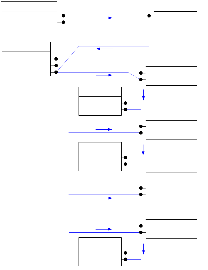
CHAPTER 8: Graphics Fundamentals Spread-drawing sequence 276
When an item’s IShape::ProcessDrawShape method is called, it must draw itself, then its children. This
action is analogous to the mechanism used for the IControlView interface on widgets. The IShape
implementation provides methods for drawing an object and iterating over the object’s children, asking
each of them to draw. Before drawing, the IShape implementation sets the transformation matrix in the
graphics port to the item’s inner coordinates. This establishes the following conventions:
Each drawing object expects to receive the graphics port set to its parent’s coordinate system.
Each drawing object sets the graphics port to its inner coordinates before drawing itself or calling its
children to draw.
Each drawing object reverts the graphics port to its parent’s coordinate system before returning to the
caller.
1. : DrawWithTimedUpdate() kViewPortBoss
IDrawMgr
kSpreadBoss
IGeometry
IHierarchy
IShape
kLayoutWidgetBoss
IControlView
ILayoutControlData
2 : ProcessDrawShape()
2.1 : Draw()
kPageBoss
IHierarchy
IShape
kSpreadLayerBoss
IHierarchy
IShape
kSplineItemBoss
IHierarchy
IShape
kSpreadLayerBoss
IHierarchy
IShape
kSpreadLayerBoss
IHierarchy
IShape
kGuideItemBoss
IHierarchy
IShape
kSpreadLayerBoss
IHierarchy
IShape
2.1.1 : ProcessDrawShape()
2.2.1 : ProcessDrawShape()
2.4.1 : ProcessDrawShape()
2.4 : ProcessDrawShape()
2.3 : ProcessDrawShape()
2.2 : ProcessDrawShape()

CHAPTER 8: Graphics Fundamentals Controlling the settings in a graphics port 277
Iterating over the object’s children is accomplished by using the IHierarchy interface on each page item.
This interface provides methods for iterating over the layout hierarchy. For more information about the
IHierarchy interface, see Chapter 7, “Layout Fundamentals.”
After being called by the draw manager, spread drawing always follows the layout hierarchy. Users can
control whether the guides appear in front of the content or behind it, and this affects the hierarchy.
Assuming guides are behind the content, page layers are drawn first, followed by the content layers, then
the guide layers. If the guide layers appear in front of the content, the guides draw before the content. All
content on a given layer is drawn before proceeding to the next layer. Embedded children of a page item
are called to draw before that item completes its drawing. For example, when the kSplineItemBoss is called
to draw in step 2.2.1 of the preceding figure, if it had children, they would be called to draw as step 2.2.1.1
and 2.2.1.2. before returning to the kSpreadLayerBoss.
Controlling the settings in a graphics port
The port’s transform can be modified by translations, scale factors, and rotations, and a new transform can
be concatenated to the existing port. Concatenation is most often used when page items draw; it is how a
page item sets the port to draw to its inner coordinates. The following example shows sample code
demonstrating this operation. For more information on the application coordinate systems, see Chapter 7,
“Layout Fundamentals.”
// Get the graphics port from gd, a GraphicsData*.
IGraphicsPort* gPort = gd->GetGraphicsPort();
if (gPort == nil) return;
// Save the current port settings.
gPort->gsave();
// Get this page item's ITransform interface.
InterfacePtr<ITransform> xform(this, IID_ITRANSFORM);
// Concatenate the inner to parent matrix to the port.
gPort->concat(xform->CurrentMatrix());
// Draw a rectangle around the item.
InterfacePtr<IGeometry> geo (this, IID_IGEOMETRY);
const PMRect r = geo->GetStrokeBoundingBox();
gPort->rectpath(r);
gPort->stroke();
// Restore the previous port settings.
gPort->grestore();
Drawing sequence for a page item
The drawing sequence for a page item that implements IShape involves more than just the drawing
instructions. Extensibility points are built into the sequence, in the form of drawing events and
adornments. Extensibility points are described in “Extension patterns” on page 259.
Although each IShape implementation may have its own specific drawing sequence, all implementations
follow these steps as guidelines:
1. When a page item begins drawing, three drawing events are broadcast (kAbortCheckMessage,
kFilterCheckMessage, and kDrawShapeMessage). No IShape drawing activities occur between the
broadcasts.
CHAPTER 8: Graphics Fundamentals Drawing sequence for a page item 278
2. Save the graphics port state by calling IGraphicsPort::gsave. The graphics port is set to draw in the
page item’s inner coordinate system.
3. A kBeginShapeMessage drawing event is broadcast. If any drawing-event handler returns kTrue, the
drawing activity ends.
4. Draw kBeforeShape page item adornments.
5. Draw the page item’s own shape by calling the protected method CShape::DrawShape. This method
varies depending on the nature of the page item. The following is a list of common tasks the
DrawShape method may accomplish:
Define the item’s path.
Fill the path.
Set the port to clip to the path.
Draw the item’s children.
Stroke the path.
6. Draw kAfterShape page-item adornments.
There are types of page-item adornments other than kBeforeShape and kAfterShape. These may be called
to draw at other points in the sequence. The use of graphics-port save and restore operations allows the
adornments and child drawing routines to modify the port as needed and return it to a known state for the
next drawing step.
For details of the code responsible for drawing, see the CShape.cpp and CGraphicFrameShape.cpp source
code in the SDK, under <SDK>/source/public/pageitems/basicinterfaces. For examples of how to create
your own shapes, also see the BasicShape and CandleChart sample plug-ins.

279
9Text Fundamentals
This chapter provides background on the fundamental concepts and subsystems that implement text
features. It has the following objectives:
Describe the model for text content—how raw text and formatting information is managed.
Describe how the presentation of text (that is, the actual rendered text) is modeled within the
application, including both the glyphs that represent the text and the objects that manage the
placement of glyphs on a spread.
Describe text composition, the process of taking the content model and incomplete presentation
model to generate the final appearance of text in the presentation model.
Describe fonts and how they relate to the InDesign text subsystem.
The following table lists resources for more information on relevant topics.
Concepts
This section introduces the subsystems that implement the text architecture. The core text architecture
can be divided into the following core subsystems: text content, text presentation, and text composition.
Subsystems that extend the core include import and export, text styles, editors, and text search/replace.
The text-content subsystem manages the content of a story. It stores the characters and attributes that
control the styled appearance of text.
The text-presentation subsystem deals with where the text glyphs appear on the page. Text is composed
into frames that display a story. A frame is a visual container for text. Visually, a story is displayed through a
linked set of one or more frames. The frames have properties—such as the number of columns, column
width, and text inset—that control where text flows. Text-wrap settings on overlapping frames may affect
For ... Go to ...
More information on digital typography
topics
http://www.adobe.com/type/topics/index.html
A glossary of typographic terms http://www.adobe.com/type/topics/glossary.html
An overview of Adobe type technology http://partners.adobe.com/asn/developer/type/main.html
The PostScript language FAQ list http://www.postscript.org/FAQs/language/FAQ.html
Chapter Update Status
CS6 Unchanged
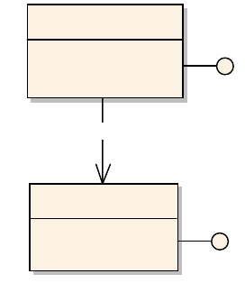
CHAPTER 9: Text Fundamentals Text content 280
this flow. After text is composed, it has a visual appearance and exhibits many of the same geometry traits
as other page items.
The text-composition subsystem manages the process that flows text into a set of specified containers.
Fonts provide the text-composition subsystem with the glyph dimensions it needs to arrange glyphs into
lines of a given width.
Text content
This section describes how the raw character and formatting information for a story is maintained within
the application. Text content represents the information required to render a set of characters. This
information includes the Unicode character values, along with any formatting information that defines the
appearance of text, contents of footnotes and tables, inline graphics, and styles that can be applied to text.
Stories
Text content within a document is represented by a story (signature interface ITextModel). A single, related
set of text is maintained within a single story. The document can contain multiple stories. All stories within
the document can be accessed through the IStoryList interface on the kDocBoss class. The following figure
shows this relationship.
A document can contain private, feature-dependent stories, which are defined not to be user-accessible.
Other features (like find/replace and spelling) ignore these stories. Programmatically, they can be accessed
through the IStoryList interface, as with any other story.
Generally, stories are not directly created or deleted. The life-cycle of a story is controlled as a side effect of
another operation. For example, creating a text frame using the Type tool causes a text story to be created,
whereas linking two text frames together causes a story to be deleted. It is possible to control the lifetime
of a story directly, though the story is still subject to the side effects of manipulating an associated text
frame.
A story has a length, which can be accessed using ITextModel::TotalLength. A story has a minimum length
of one character: a terminating kTextChar_CR, which is inserted into the story when the story is created.
This character should not be deleted.
The textual content of a story is maintained independently from the visual containers in which it is
contained; that is, its layout on the page. The text content from a story can be contained within one frame,
flow between columns within a frame, or even flow between multiple frames. For example, the following
figure shows three stories, each flowing through different sets of containers. The model used in
kDocBoss
IStoryList
kTextStoryBoss
ITextModel
1
IStoryList::GetNthUserAccessibleStoryUID
1..*
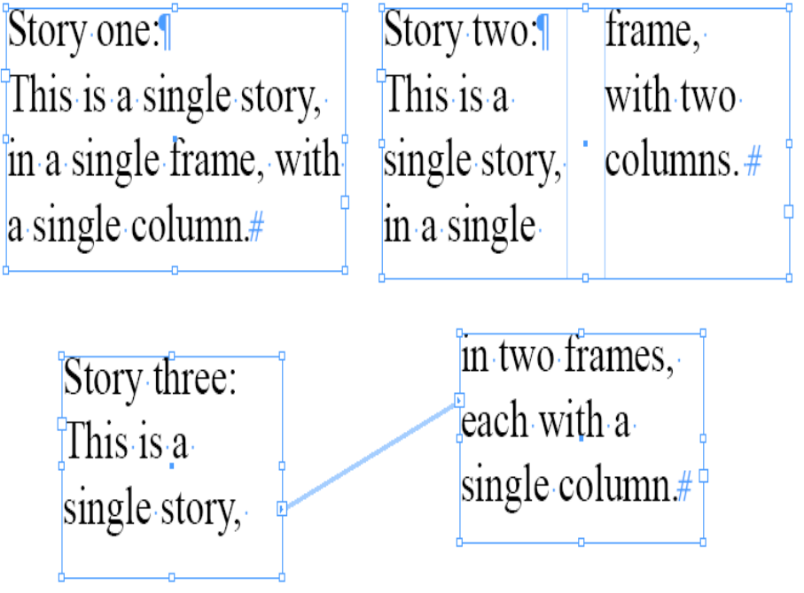
CHAPTER 9: Text Fundamentals Text content 281
maintaining the text content for each is the same. Determining where a particular glyph is rendered is the
responsibility of the composer.
Information related to the text in a story is maintained by a set of strands. Strands represent parallel sets of
information, each of which holds a component of the story. The strands intertwine to give a complete
description of the story. Strands are identified using the IStrand signature interface. Some common
strands are shown in the following figure, where the text story aggregates the strands representing the
content:
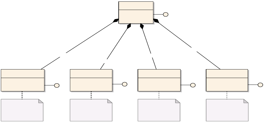
CHAPTER 9: Text Fundamentals Text content 282
Strands
Strands (signature interface IStrand) model the linear behavior of text. Each strand represents a different
aspect of textual information. A story can be thought of as the composition of the set of strands that
contain information for a particular aspect of the story. The preceding figure shows a story with associated
text, paragraph-attribute, and character-attribute strands. It also shows the owned item strand used to
maintain objects within the text, like inline graphics.
Each strand has the same virtual length, equal to the value returned by ITextModel::TotalLength. Each
position within a strand refers to the same logical position within the other strands and the story as a
whole. For example, position 10 on the kTextDataStrandBoss relates to a particular character—the
character at position 10 within the kCharAttrStrandBoss refers to formatting information applicable to this
character. Any modification of the text length is reflected in each strand.
The following figure shows some text and how it might be represented on two strands. While the actual
storage mechanism for the strands is of little interest, both strands have the same virtual length. A story
(kTextStoryBoss) comprises a set of strands, each with the same length. The figure shows only the data
(kTextDataStrandBoss) and paragraph-attribute (kParaAttrStrandBoss) strands.
kCharAttrStrandBoss
IStrand
kParaAttrStrandBoss
IStrand
kTextDataStrandBoss
IStrand
kTextStoryBoss
ITextModel
kOwnedItemStrandBoss
IStrand
Holds Unicode character
code data for the text in the
story.
Maintains formatting
information applicable to
paragraphs.
Maintains formatting
information applicable to a
range of characters.
Maintains a link to objects
anchored into the text,
such as inline images, table
frames, and footnotes.
1
ITextModel::QueryStrand(kOwnedItemStrandBoss,...)
1
1
ITextModel::QueryStrand(kCharAttrStrandBoss,...)
1
1
ITextModel::QueryStrand(kParaAttrStrandBoss,...)
1
1
ITextModel::QueryStrand(kTextDataStrandBoss,...)
1
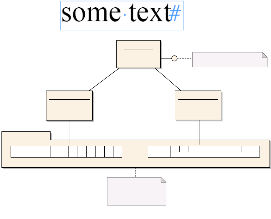
CHAPTER 9: Text Fundamentals Text content 283
Formatting is defined in “Text formatting” on page 288.
Runs
Strands are further divided into runs. A run represents something about the content of a particular strand.
For the kTextDataStrandBoss, a run is a manageable-sized chunk of text data. For the kParaAttrStrandBoss,
a run exists for each paragraph in the story. For the kCharAttrStrandBoss, a run represents a sequence of
characters that share the same formatting information. The semantics of a run is defined by its strand.
Owned items
Owned items (signature interface IOwnedItem) exist to allow some object to be associated with a
particular TextIndex position in the text strand. Generally, features anchor the owned item into the text by
placing a special character into the kTextDataStrandBoss; however, there is no requirement for associating
an owned item with a special character in the data strand. The following figure shows an instance diagram
associated with a story that contains an inline image. The story has the character “a” followed by an inline
image, then the character “b.” The owned item strand (kOwnedItemStrandBoss) maintains the UID of the
inline object (kInlineBoss). The actual image (kImageItem—note the nonstandard name) is associated
through the hierarchy (IHierarchy).
:kTextStoryBoss
ITextModel
:kTextDataStrandBoss :kParaAttrStrandBoss
Strands abstract over the raw
data. Developers should not need
to interact directly with the
storage model below strands.
ITextModel::TotalLength() == 10
Text storage subsystem
Index 012345678
Data s o m e t e x t
9
#
Data strand
Index 0 1 2 3 4 5 6 7 8 9
Data Format t i ng def i n ed by r oot st yl e
Paragraph attribute strand
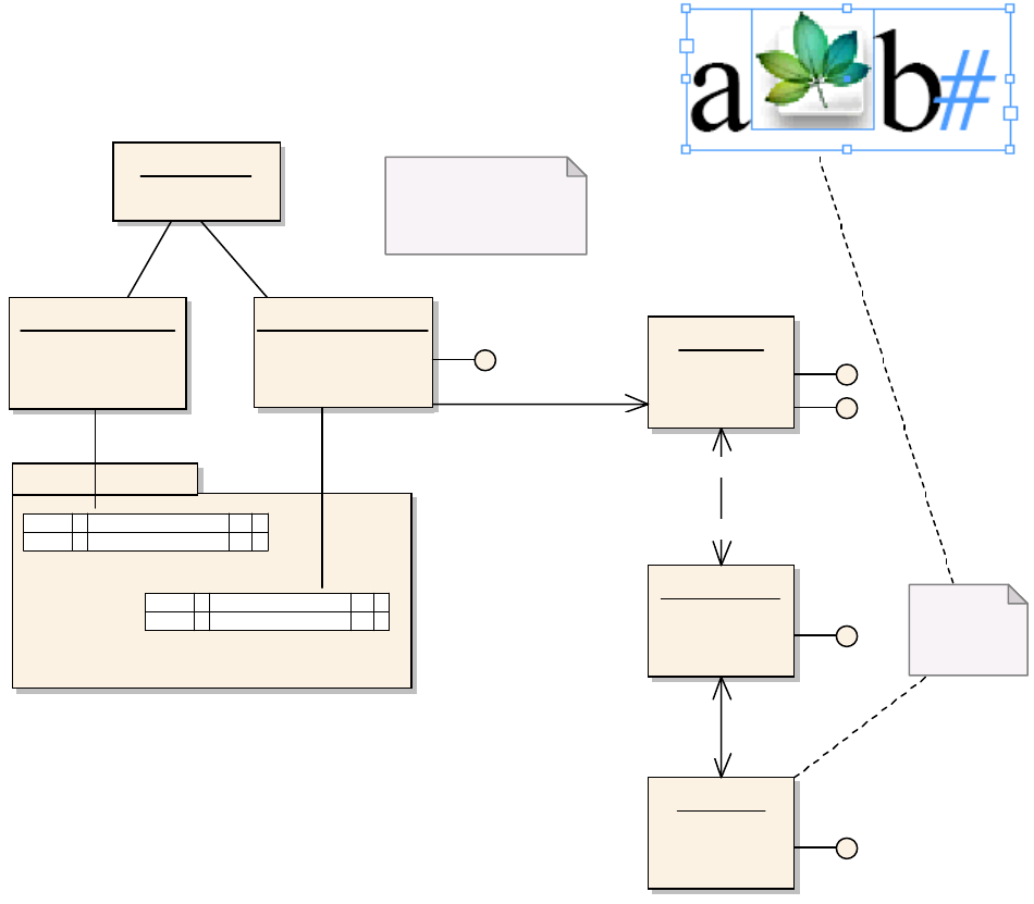
CHAPTER 9: Text Fundamentals Text content 284
Anchored-item positioning
The positioning of an inline object relative to its anchor position in the text is controlled through the
IAnchoredObjectData interface. The default behavior is defined by the IAnchoredObjectData on the
session and document-workspace boss classes. Object styles also can define how an inline object is
positioned (IAnchoredObjectData on kObjectStyleBoss). Specific inline objects can be modified
(IAnchoredObjectData on kInlineBoss).
The placement of inline objects can be specified as any of the following:
Within the text flow (with variable offset on the y axis).
Above the line, aligned to the center, right, or left of the text or spline. A variable amount of space
before and after the inline object can be specified.
A custom position on the page, relative to the anchor point, text frame, page, or spline.
As the content that contains the anchor is manipulated (by either adding text that causes the anchor to
flow out of the initial frame or manipulating the frames in which the text is contained), the position of the
inline object is updated automatically.
:kTextStoryBoss
:kTextDataStrandBoss :kOwnedItemStrandBoss
IItemStrand
:kInlineBoss
IHierarchy
IOwnedItem
:kSplineItemBoss
IHierarchy
:kImageItem
IHierarchy
IItemStrand::GetOwnedUID
for TextIndex 0, 2, and 3
would return kInvalidUID.
Text storage subsystem
I ndex 0 1 2 3
Dat a akTextChar_Inline b #
Data Strand
I ndex 0 1 2 3
Dat a UI D f or k I nl i neBoss #
Owned item strand
Inline graphic
represented by
kImageItem
1
IItemStrand::GetOwnedUID(1)
1
1
+IHiearchy::QueryChild
0..*
+IHierarchy::QueryParent
1
+IHierarchy::QueryChild
0..*
+IHierarchy::QueryParent

CHAPTER 9: Text Fundamentals Text content 285
Story threads
Strands model the linear nature of text; however, not all text within a story is linear. For example, an
embedded table can have cells with textual content that flows independently from the main text in the
story. Story threads (signature interface ITextStoryThread) represent these distinct flows of text.
Each story has at least one story thread, the primary story thread, which represents the main text of the
story. Other text elements (like footnotes) contained within a story are anchored off the primary story
thread using owned items, as described in “Owned items” on page 283.
The interface that models story threads (ITextStoryThread) is maintained on the boss class related to the
text it represents. For the primary story thread, the interface is found on the kTextStoryBoss. For footnotes,
the interface is on kFootnoteReferenceBoss. The story thread maintains text indices that identify the range
of text within the story that relates to the particular strands.
The following figure shows a story with only text within the primary story thread (that is, the story uses no
features requiring other story threads). The story instance (kTextStoryBoss) has four associated strands.
There is one story thread (ITextStoryThread) in this story.
:kTextStoryBoss
ITextStoryThread
ITextModel
:kTextDataStrandBoss
IStrand
:kParaAttrStrandBoss
IStrand
:kCharAttrStrandBoss
IStrand
:kOwnedItemStrandBoss
IStrand
ITextStoryThread::GetTextStart() == 0
ITextStoryThread::GetTextEnd() == 9
ITextModel::TotalLength() == 10
Text storage subsystem
Index 0 1 2 3 4 5 6 7 8
Data s o m e t e x t
9
#
Data strand
Index 0 1 2 3 4 5 6 7 8 9
Data Format t i ng def i n ed by root st yl e
Paragraph attribute strand
Index 0 1 2 3 4 5 6 7 8 9
Data No formatting defined
Character attribute strand
Index 0 1 2 3 4 5 6 7 8 9
Data No inline objects in stream
Owned item strand
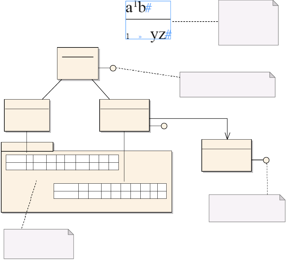
CHAPTER 9: Text Fundamentals Text content 286
The primary story thread always begins at TextIndex 0. Other features, like footnotes and tables, use story
threads to maintain the feature text as a distinct entity. The following figure shows an instance diagram of
a story with a footnote. In the figure, a text-story thread (ITextStoryThread) maintains a relationship with
some part of the text in a story. In this example, the primary story thread (on kTextStoryBoss) ranges
between TextIndex 0 and 3, and the footnote (kFootnoteReferenceBoss) ranges between TextIndex 4 and
8.
Story-thread dictionaries and hierarchies
Each distinct instance of a text feature within a story has a distinct text-story thread (ITextStoryThread),
including the main story text (the primary story thread). Text-story threads are associated with a particular
TextIndex, known as the anchor, obtainable with ITextStoryThreadDict::GetAnchorTextRange. This does
not apply to the primary story thread, which is the only thread that always returns an anchor position of
zero. An anchor for a footnote appears to the users in the user interface as the footnote-reference
character. The anchor for a table appears as the table itself.
Text storage subsystem
:kTextStoryBoss
ITextStoryThread
:kTextDataStrandBoss :kOwnedItemStrandBoss
IItemStrand
:kFootnoteReferenceBoss
ITextStoryThread
I ndex 0 1 2 3 4 5 6 7
Data a0x4 b # 0x4 0x9 y z
8
#
Data strand
Index 0 1 2 3 4 5 6 7
Data UI D
8
Owned item strand
0x4 == kTextChar_FootnoteMarker
0x09 == kTextChar_Tab
See TextChar.h.
ITextStoryThread::GetTextStart() returns 0
ITextStoryThread::GetTextEnd() returns 3
ITextStoryThread::GetTextSpan() returns 4
ITextStoryThread::GetTextStart() returns 4
ITextStoryThread::GetTextEnd() returns 8
ITextStoryThread::GetTextSpan() returns 5
The footnote number and tab
are inserted into the footnote
automatically. The data strand
indicates where the number
should be placed using
kTextChar_FootnoteMarker.
IItemStrand::GetOwnedUID(1)
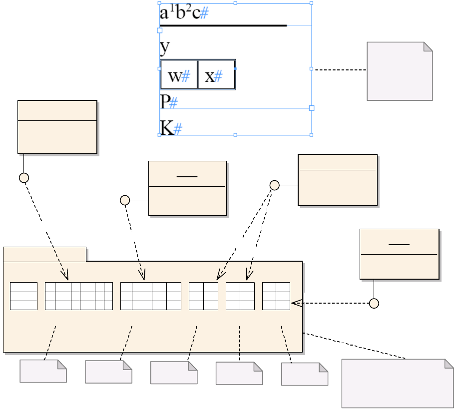
CHAPTER 9: Text Fundamentals Text content 287
A text-story thread can contain anchors for other text story threads, subject to some restrictions; for
example, footnotes can contain tables but not other footnotes. A feature does not need to associate the
story thread with a particular TextIndex, in which case it is associated with the end of story marker for the
primary text-story thread (these are unanchored threads).
A thread block is a contiguous text range (TextRange) that contains the contents for one text-story thread.
If a text-story thread contains a set of anchors, the thread blocks associated with these anchors directly
follow the thread block for this story thread. This is depicted in the following figure, which shows a story
with two footnotes, one containing a two-cell table. Note how the thread blocks for the table directly
follows the thread block for the footnote into which it is anchored. In the figure, ITextStoryThreadDict
manages the story threads for a particular use of a feature. There is one story thread for the primary story,
one for each footnote, and two for the embedded table.
The text-story thread dictionary (ITextStoryThreadDict) maintains the set of story threads associated with a
particular use of a feature. In the figure, each feature has one associated story thread, apart from the table.
Each cell in the table has a distinct story thread. ITextStoryThreadDict is responsible for managing the set
of threads in the table.
Text storage subsystem
Index
Data
Inlines
1 2 3 4
0x4 b0x4 c
UID1 UI D2
0
a
5
#
Primary story thread
6 7 8 9
y0x16 P #
UID3
Footnote 1 thread
10
w
11
#
Table
thread 1
14
K
15
#
Footnote
2
thread
UID1 :
kFootnoteReferenceBoss
ITextStoryThreadDict
UID2 :
kFootnoteReferenceBoss
ITextStoryThreadDict
UID3 :kTableModelBoss
ITextStoryThreadDict
kTextStoryBoss
ITextStoryThreadDict
On data strand:
0x4 == kTextChar_FootnoteMarker
0x16 == kTextChar_Table
See TextChar.h.
Thread block 0 Thread block 1 Thread block 2 Thread block 4
12
x
13
#
Table
thread 2
Thread block 3
The auto-numbering
characters have been
edited out of the
footnotes.
QueryStoryThread
QueryStoryThread QueryStoryThread
QueryStoryThread
QueryStoryThread
CHAPTER 9: Text Fundamentals Text content 288
Text story threads have a hierarchical relationship (the root being the primary story thread). Individual
features are responsible for managing a set of one or more story threads using the story-thread dictionary
(ITextStoryThreadDict). In the figure, kFootnoteReferenceBoss (UID1) manages one text-story thread, while
kTableModelBoss (UID3) manages two story threads, one for each cell. The story maintains a dictionary
hierarchy (ITextStoryThreadDictHier), which provides the ability to iterate across all objects that contain a
dictionary associated with the story.
Text formatting
This section describes how the style information that controls the look of text is maintained within the
application.
Text attributes
The fundamental component for formatting text is the text attribute (signature interface IAttrReport). This
is a lightweight, nonpersistent set of boss objects, each of which describes one text property; for example,
the color or point size of text. Attributes are interpreted by the text-composition subsystem, to define how
the text appears when composed.
Attributes target either arbitrary ranges of characters (like the color or point size of a set of characters) or a
paragraph (like applying a drop cap or setting paragraph alignment).
Attributes are managed in an AttributeBossList list, a persistent container class. Consider an
AttributeBossList list to be a hash table of attributes, the key being the ClassID. One implication of this is
there can be only one instance of any particular attribute within an AttributeBossList list (for example, no
conflicting text-color attribute within an AttributeBossList).
Attributes can be applied directly (within an AttributeBossList list) to the appropriate paragraph or
character-attribute strand, or they can be applied to a text style. An example of applying the attribute
directly to the strand would be italicizing text directly using the text editor. Such changes are local to the
text being formatted and known as local overrides to the current style.
An attribute boss class that supports the IAttrImportExport interface can participate in the import and
export of InDesign tagged text files.
Default attributes
The application provides a set of default attributes. These attributes are maintained within an
AttributeBossList on both the session and document workspace. Default attributes define a set of
overrides that are applied to any new stories created. These AttributeBossList lists reflect the state of the
Character and Paragraph panels when no documents are open (session workspace) or new stories are
created (document workspace). When a new document is created, the document workspace inherits the
value of the default attributes from the session. The default attributes can be updated directly through the
Paragraph and Character panels or by selecting styles in the styles panels; the defaults are updated to
match the style.
Text styles
A text style (signature interface IStyleInfo) provides a mechanism to name and persist a particular set of
text attributes with particular values. The application supports two kinds of styles for text, paragraph
styles and character styles. Each style has an AttributeBossList list that maintains the set of attributes that
apply to that style. Access to the attributes in a style is achieved through the ITextAttributes wrapper
CHAPTER 9: Text Fundamentals Text content 289
interface. Character styles are associated with character attributes; however, paragraph styles can be
associated with both paragraph and character attributes. Paragraph styles are applied to whole
paragraphs; character styles can be applied to arbitrary ranges of text.
All text must be associated with both a paragraph style and character style. To support this, the application
defines two default styles: the root character style and the root paragraph style (known in the application
user interface as [No Paragraph Style]). The root paragraph style contains a complete set of
paragraph-based and character-based attributes. This defines the default look of text with no further
formatting applied. The root character style is empty; it exists purely to provide a root for character styles.
Styles form a hierarchy rooted at the root style. Each style (except the root style) is based on another style,
which becomes its parent. The AttributeBossList list for a particular style records only the differences from
the style on which it is based; that is, the set of attributes that the particular style overrides. This is shown in
the following figure. In the figure, the kStyleBoss for the root paragraph style defines all attributes with a
default value. The kStyleBoss for the new style (Yellow Text) contains only the attributes that differ from
the root style. The root character style contains no attributes; it exists to provide a root to the
character-style hierarchy.
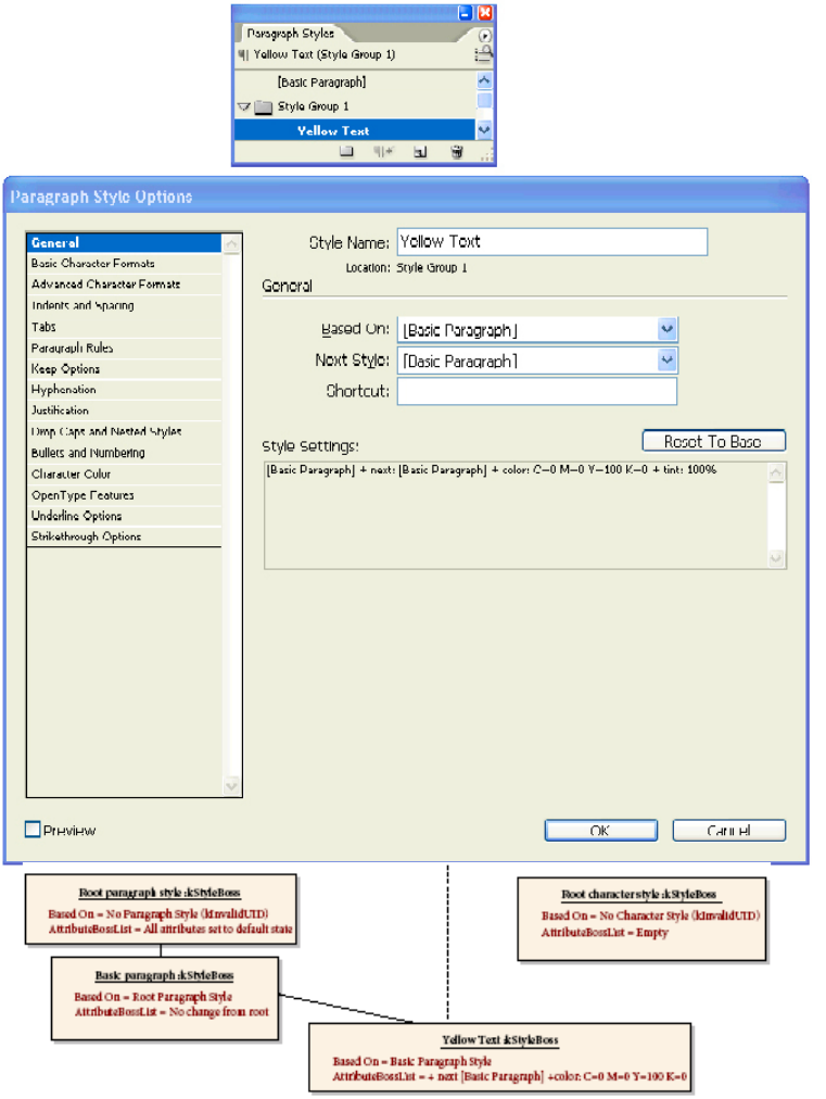
CHAPTER 9: Text Fundamentals Text content 290
The application provides two basic styles, one for character attributes and one for paragraph attributes.
These are the default styles applied to new stories (assuming no other style is selected in a styles panel).
The basic styles cannot be deleted, but you can modify them with plug-ins. Initially, the basic styles are
based on the root styles; however, a style’s parent can be replaced with a different style.
Users can create, edit, and delete folders, called Groups, in the Character, Paragraph, and Object Styles
palettes. A style group is a collection of styles or groups. The user also can nest groups inside groups and
drag styles within the palette to edit the contents of a group. Styles do not need to be inside a group and
can exist at the root level of the palette. The group concept also is available in the object style palette.
CHAPTER 9: Text Fundamentals Text content 291
Character and paragraph styles are not required to have unique names across groups; however, sibling
styles and groups—those at the same level in the hierarchy with the same parent—must have unique
names. Style names are case-sensitive, so the user could have both “heading” and “Heading” in the same
folder. A group and a style cannot have the same name. Because style names are not unique, they are
displayed in the user interface as full paths.
The alphabetical sort is an action applied to the entire list of styles. Users can rearrange the styles and
groups arbitrarily at any time; to view the list alphabetically, they can resort the list with the Sort By Name
command. Styles are intermixed with groups for sorting. Sorting is undo-able. The sorting is language
specific, based on the user-interface language. Reserved styles such as [Basic Paragraph] or [Basic Graphics
Frame] are not reordered by this command.
Styles are accessible through the style group manager (signature interface IStyleGroupManager) on the
document (kDocWorkspaceBoss) and session (kWorkspaceBoss) workspace boss classes. When a
document is created, its style group manager inherits the existing set of styles from the session workspace.
There are multiple style group managers supported by the workspaces, each identified by a distinct
interface identifier; for example, IID_IPARASTYLEGROUPMANAGER and IID_ICHARSTYLEGROUPMANAGER.
IStyleGroupManager has one automatically created object of type IStyleGroupHierarchy called “Root
Hierarchy,” represented by the kStyleGroupHierarchyBoss. IStyleGroupManager provides access to
kStyleGroupHierarchyBoss through its GetRootHierarchy() method.
This Root Hierarchy is created on the first call to the GetRootHierarchy method. The
kStyleGroupHierarchyBoss holds all the styles (kStyleBoss) and style groups (kStyleGroupBoss) at root
level. The key interface on the kStyleGroupHierarchyBoss is IStyleGroupHierarchy, which stores the
persistent UID-based style tree hierarchy so you can query information like parent/child node information.
All children of this root hierarchy must support the IStyleGroupHierarchy interface; therefore,
IStyleGroupHierarchy also is aggregated on the kStyleBoss and kStyleGroupBoss, so access to the style
hierarchy also is available if you have access to the UID of any style or style group in the hierarchy. With
IStyleGroupHierarchy, you gain access to the style-tree hierarchy the user sees in the style panel.
IStyleGroupHierarchy has a method to traverse the style hierarchy, which should be used to iterate
through all styles. IStyleGroupManager also provides two overloaded FindByName() methods that return
the UID of a style or style group.
The following figure shows how to navigate the styles, given a particular workspace. The style group
manager (IStyleGroupManager on document and session workspaces) provides access to all paragraph
and character styles (kStyleBoss) through the GetRootHierarchy() method, which returns an
IStyleGroupHierarchy on the kStyleGroupHierarchyBoss. kStyleGroupHierarchyBoss holds all the styles
(kStyleBoss) and style groups (kStyleGroupBoss) at root level. Styles can be iterated over using
IStyleGroupHierarchy::GetDescendents or accessed by name using IStyleGroupManager::FindByName.
Given a particular style, the style it is based on can be accessed using IStyleInfo::GetBasedOn.
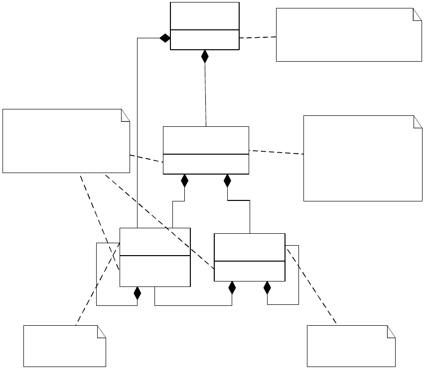
CHAPTER 9: Text Fundamentals Text content 292
Sorting the style hierarchy is done through the IStyleGroupHierarchy::Sort() method, when it is invoked, it
sorts its children and calls its children’s Sort method. The call to Sort() on the root hierarchy recursively
sorts all styles. This methods takes a flag to indicate whether to sort in descending/ascending order, all
child or immediate child, etc.
Text formatting and stories
All text has an associated character- and paragraph-attribute style. This style is either the root style (which
defines a default value for the complete set of attributes used in composition) or a style that records
differences from the root style. Styles form a hierarchy in which the values of attributes in child nodes
override those in parent nodes. As well as having the character and paragraph styles defined on the
attribute strands, local overrides can be applied. This occurs when a formatting change is made without
modifying a style; for example, selecting a word and making it bold.
Attributes describe one of the text’s appearance and are used by the composition engine when rendering
the associated glyphs. IComposeScanner (on the kTextStoryBoss) provides APIs that allow the value of any
attribute to be deduced for any TextIndex. The following figure shows an example of how styles and local
attribute overrides combine to describe the exact look of text. The paragraph-attribute strand specifies the
text will use the custom style pStyle and two local overrides. The overrides specify the body and last line of
the paragraph are to be centered. The character-attribute strand specifies the root style for the word
“Aliens,” a local +bold override for the word “and,” and the word “Earth” to use the custom style cStyle.
+IStyleGroupManager
«boss»
kDocWorkspaceBoss
+IStyleGroupHierarchy
«boss»
kStyleGroupBoss
+IStyleGroupHierarchy
«boss»
kStyleGroupHierarchyBoss
1
1
1
0..*
1
0..*
1
0..*
1
0..*
+IStyleGroupHierarchy
+IStyleInfo
«boss»
kStyleBoss
Holds all the styles (kStyleBoss)
and style groups (kStyleGroupBoss)
at root level.
IStyleGroupHierarchy can be
used to access its styles and
groups.
IStyleGroupHierarchy is aggregated
on kStyleGroupHierarchyBoss,
kStyleBoss, and kStyleGroupBoss, it is
used to access kStyleBoss/kStyleGroupBoss
current object may have.
1
0..1
IStyleInfo::GetBasedOn
IStyleGroupHierarchy::QueryChild
IStyleGroupHierarchy::QueryChild
IStyleGroupHierarchy::QueryChild
IStyleGroupHierarchy::QueryChild
1
1
IStyleGroupManager::GetRootStyleUID
IStyleGroupManager::GetRootHierarchy
Represents a text style Represents a style group
The IStyleGroupManager is the access point
for style set management. It gives access
to the root IStyleGroupHierarchy from where
you can get the full style set hierarchy
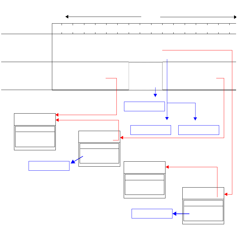
CHAPTER 9: Text Fundamentals Text content 293
Class associations
The following figure shows the major classes and associations for text content.
kTextAttrPointSizeBoss
+size: 24 pt
01234567891011121314
kTextDataStrandBoss
kParaAttrStrandBoss
kCharAttrStrandBoss
Start: 10
End: 16
UID: cStyle
Overrides: None
Start: 0
End: 6
UID: root
Overrides: None
Start: 7
End: 9
UID: root
Overrides: +bold
length = 17
Story
15 16
Al i ans nd Ear th#e
Start: 0
End: 16
UID: pStyle
Overrides: + last: centered + body: centered
name: root
based on: none
AttributeBossList
all attributes
described here
kStyleBoss
name:
pStyle
based on: root
AttributeBossList
kStyleBoss
kTextAttrFontStyleBoss
+bold
kTextAttrUnderlineBoss
+underline
name:
cStyle
based on: root
AttributeBossList
kStyleBoss
name: root
based on: none
AttributeBossList
kStyleBoss
always empty
kTextAttrAlignBodyBoss kTextAttrAlignLastBoss
+ body: centered + last: centered
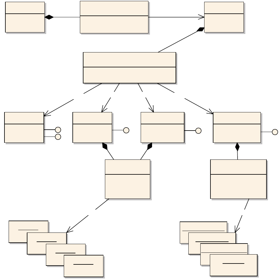
CHAPTER 9: Text Fundamentals Text presentation 294
Text presentation
This section describes the presentation model responsible for managing the final look of text. The layout
factors (such as the types of containers with which text can be associated) are described before the
representation of the rendered text (the wax) is presented.
The text-presentation model represents both the information required to place a set of glyphs on a spread
and the management of those glyphs within the application. This includes both the text layout and the
wax components. Text layout is concerned with the containers for text and the attributes of a container
that can affect how text is placed in respect to that container. The wax models the actual glyphs rendered
into the layout.
Other owned item boss
kDocBoss «interface»
IStoryList
+ GetNthTextModelUID() : UIDRef
kTextStoryBoss
«interface»
ITextModel
+ QueryStrand(PMIID, ClassID) : IPMUnknown *
kTextDataStrandBoss
IStrand
ITextStrand
kParaAttrStrandBoss
IStrand
kCharAttrStrandBoss
IStrand
«interface»
IAttributeStrand
+ GetStyleUID() : UID
«interface»
IItemStrand
+ GetNthOwnedUID() : UID
kTableFrameBoss
kFootnoteReferenceBoss
kInlineBoss
kOwnedItemStrandBoss
IStrand
kStyleBoss
kStyleBoss
kStyleBoss
kStyleBoss
GetNthTextModelUID
QueryStrand QueryStrand QueryStrand QueryStrand
GetNthOwnedUIDGetStyleUID

CHAPTER 9: Text Fundamentals Text presentation 295
Text layout
Text layout defines the shape and form of the visual containers in which text is composed and displayed.
The textual content is maintained in the text model of the story associated with the layout. This content is
divided into one or more story threads, each representing an independent flow of text. See “Story threads”
on page 285.
In text composition, text flows from the story thread into its associated visual containers to create wax that
fits the layout. Text layout, in turn, displays the wax. When the layout is updated, text is recomposed to
reflect the change.
Text frame
The text frame is the fundamental container used to place and display text. Text frames have properties,
like the number of columns, column width, gutter width, and text inset, that control where text flows. A
text frame is represented by several associated boss classes.
The following figure shows a text frame containing two columns, with one line of text displayed in each
column. The figure after it shows how this instance of a text frame is represented internally.
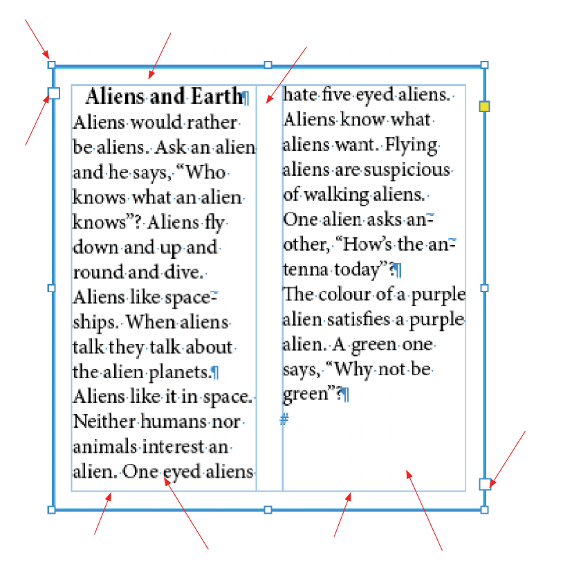
CHAPTER 9: Text Fundamentals Text presentation 296
Text frame 10-point inset 15-point gutter
Inport
Column 1 Column 2
Frame item 1 Frame item 2
Outport
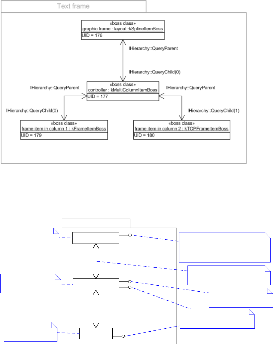
CHAPTER 9: Text Fundamentals Text presentation 297
As shown in the following figure, a text frame consists of a graphic frame (kSplineItemBoss) containing one
multicolumn item (kMultiColumnItemBoss). The multicolumn item (kMultiColumnItemBoss) is the
controller for the text frame and contains one or more frame items (kFrameItemBoss). The
ITextColumnSizer interface stores the major properties of the text frame, such as the number of columns.
IMultiColumnTextFrame provides access to the associated story, frame list, and the range of text displayed.
The relationship between the graphic frame (kSplineItemBoss) and its content is maintained by the
IHierarchy interface. Use IHierarchy::QueryChild to navigate from the graphic frame to its associated
multicolumn item, then onto individual columns. Conversely, use IHierarchy::QueryParent to navigate up
from a column to the multicolumn item and on up to the graphic frame.
Text frame
«boss class»
kMultiColumnItemBoss
«boss class»
kFrameItemBoss
IGraphicFrameData
IHierarchy::QueryParent1
IHierarchy::QueryChild
1..*
IMultiColumnTextFrame
ITextColumnSizer
ITextFrameColumn
IGraphicFrameData::GetTextContentUID
is a helper method that returns the UID
of the associated kMultiColumnItemBoss
or kInvalidUID if the frame does not have
textual content.
Stores the major properties
of a text frame, such as the
number of columns
«boss class»
layout::
kSplineItemBoss
1
1
IHierarchy::QueryParent1
IHierarchy::QueryChild1
Represents the graphic
frame
Represents a column
within the text frame
Represents the controller
for the text frame
Provides access to the associated
story, frame list, and the range of
text displayed
The relationship between the graphic
frame and its content is maintained
by the IHierarchy interface.
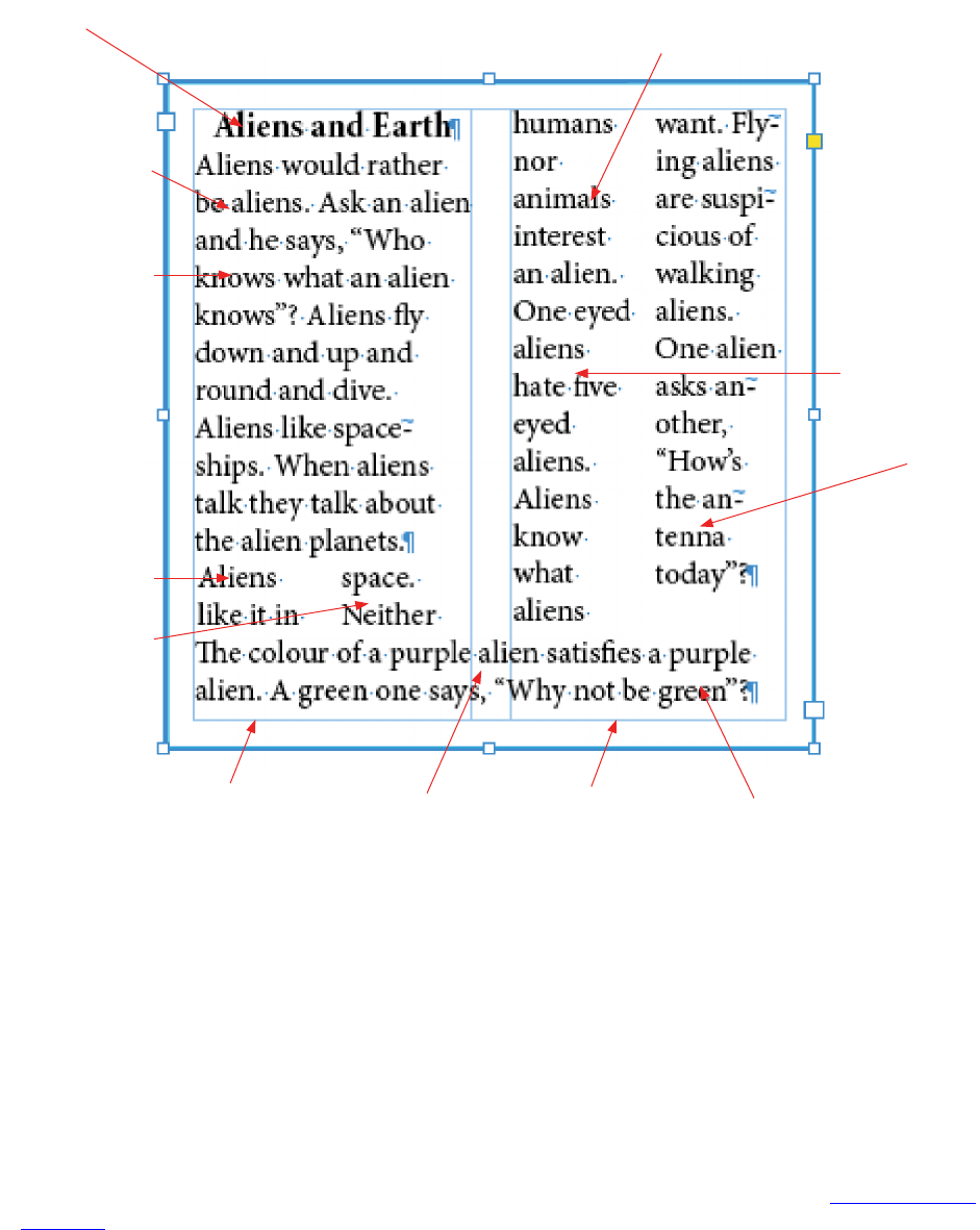
CHAPTER 9: Text Fundamentals Text presentation 298
The following figure shows a text frame with more frame items than columns
The number of columns is not always equal to the number of frame items (kFrameItemBoss). When a
paragraph has Span Columns or Split Column style, the number of frame items is greater than the number
of columns. For example, the text frame shown in Figure13 has two columns and two frame items. If
paragraph 3 is set to use Split Column style, and paragraph 4 to use Span Columns style, as shown in
Figure16, there are now six frame items within the two columns in the text frame. You can use
IHierarchy::GetChildCount or IParcelContainer::GetParcelCount to get the number of frame items.
Frame list
A story (kTextStoryBoss) associates the text frames that display its content through the frame list
(kFrameListBoss). Conversely, a text frame associates the story whose text it displays through the frame list.
The following figures show the story and frame list objects for the example introduced in “Text frame” on
page 295.
Frame item 1
Paragraph 3
Split Column
Paragraph 1
Column 1 Column 2
Frame item 6
Frame item 2
Frame item 3
Paragraph 4
Span Columns
Paragraph 2
Frame item 4
Frame item 5
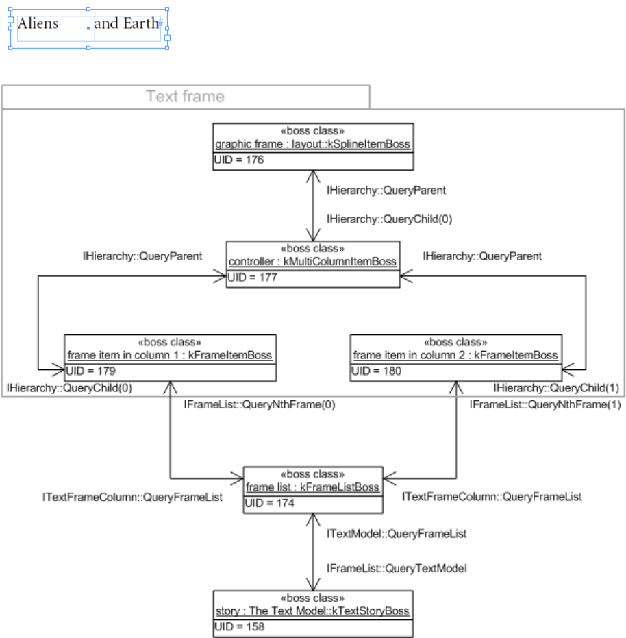
CHAPTER 9: Text Fundamentals Text presentation 299
The following figure shows the general structure of the frame list (IFrameList) for a story.

CHAPTER 9: Text Fundamentals Text presentation 300
Threading and text frames
The text in a frame can be independent of other frames, or it can flow between threaded frames.
Threading of text is the process of connecting the flow of text between frames. Do not confuse threading
text between frames with text-story threads. The connections can be visualized by selecting a text frame
and choosing View > Extras > Show Text Threads, as shown in the threaded text frames figure on page 302.
Threaded frames share a common underlying story (kTextStoryBoss) and can be on the same spread or
different spreads in the same document.
The following figure shows two unthreaded text frames.
«boss class»
layout::
kSplineItemBoss
«boss class»
kMultiColumnItemBoss
1
1
IHierarchy
«boss class»
kFrameItemBoss
1
1..*
IHierarchy
«boss class»
kFrameListBoss
«boss class»
The Text Model::
kTextStoryBoss
IFrameList::QueryNthFrame1..*
ITextFrameColumn::QueryFrameList1
ITextModel::QueryFrameList1
IFrameList::QueryTextModel1
IMultiColumnTextFrame::QueryFrameList
IMultiColumnTextFrame::QueryTextModel
ITextFrameColumn::QueryTextModel
IFrameList
ITextFrameColumn
IMultiColumnTextFrame
ITextModel
Text frame
IGraphicFrameData
Associates the story and the
frames that display its text
Represents text content
Provides access to the
story's text content
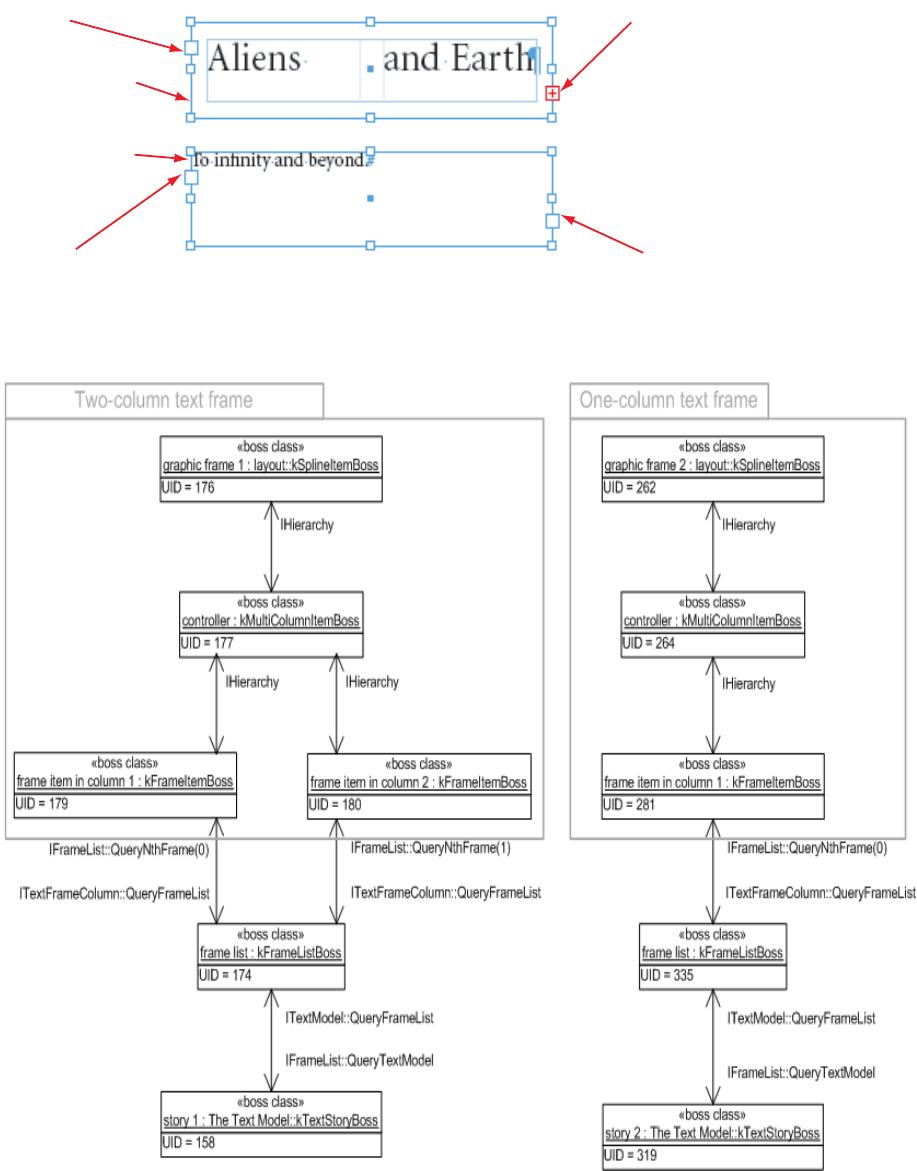
CHAPTER 9: Text Fundamentals Text presentation 301
Because each text frame is associated with a distinct story, editing the text in one of the frames does not
affect the text in the other frame (see the following figure).
When the text frames that display a story cannot display all the text, the unseen text is called “overset text.”
A red plus sign (+) on the outport of the two-column frame indicates the story has overset text.
OUTPORTINDICATINGOVERSETTEXTINPORTATBEGINNINGOFSTORY
4WO-COLUMNFRAME
/NE-COLUMNFRAME
INPORTATBEGINNINGOFSTORY OUTPORTATENDOFSTORY

CHAPTER 9: Text Fundamentals Text presentation 302
If the user clicks the outport of the two-column frame with the Selection tool and then clicks the inport of
the one-column frame, the frames become threaded. In the following figure, the text from the
two-column frame that was overset now flows through the one-column frame. During this process, the
text from the story underlying the one-column frame is appended to the story underlying the two-column
frame. The frame list (kFrameListBoss) and story (kTextStoryBoss) underlying the one-column frame are
deleted.
This figure shows threaded text frames:
Once threaded, the two frames share the same underlying story (see the following figure, an instance
diagram of threaded text frames).
OUTPORTINDICATINGOVERSETTEXT
INPORTATBEGINNINGOFSTORY OUTPORTINDICATINGLINKTONEXTFRAME
INPORTINDICATINGLINKFROMPREVIOUSFRAME
4WO-COLUMNFRAME
/NE-COLUMNFRAME
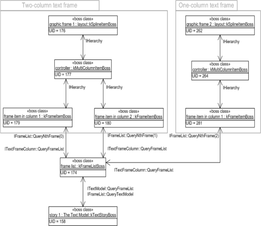
CHAPTER 9: Text Fundamentals Text presentation 303
Parcels
A flow of text content within a story is a story thread, is represented by a boss class with an
ITextStoryThread interface. A parcel is a visual container into which the text of a story thread is flowed for
layout and display. A parcel is represented by a boss class with an IParcel interface.
The text of a story thread (ITextStoryThread) can be composed into a list of parcels (IParcel) in a parcel list
(IParcelList).
Examples of application-provided parcels are as follows:
Text frame item (kFrameItemBoss)
Table cell parcel (kTextCellParcelBoss)
Footnote parcel (kFootnoteParcelBoss)
The following figure shows how text frames support story threads and parcels. The text in the primary
story thread is displayed through parcels given by the parcel list on the frame list. These parcels are the
frame items of the text frames that display the story.
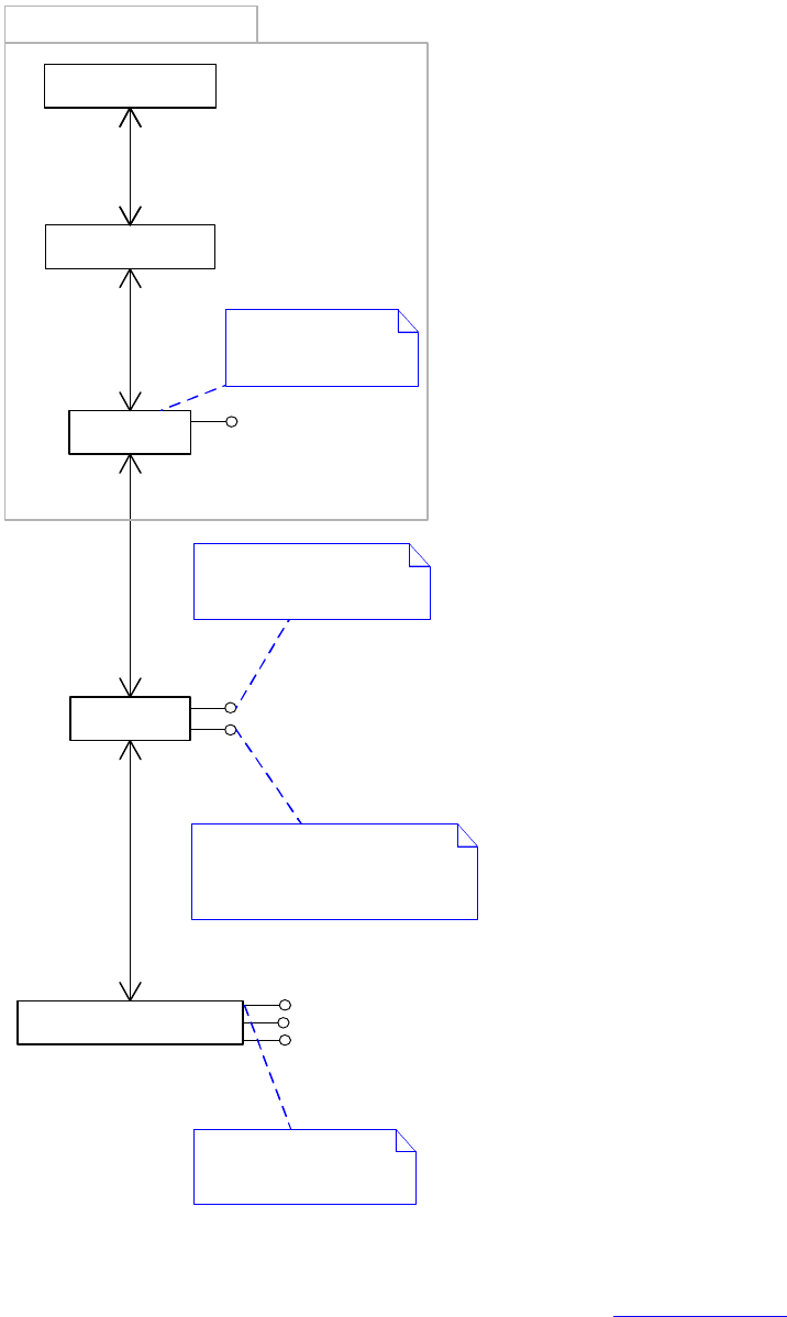
CHAPTER 9: Text Fundamentals Text presentation 304
This figure shows the structure of the parcel implementation for text frames:
The following figure shows how tables support story threads and parcels. The text for the story thread of a
table cell (kTextCellContentBoss) is displayed through the parcels given by its parcel list. These parcels are
text cell parcels (kTextCellParcelBoss). For more information, see Chapter 1, “Tables.”
This figure shows the structure of the parcel implementation for tables:
«boss class»
The Text Model::
kTextStoryBoss
ITextStoryThread
«boss class»
kFrameListBoss
IParcelList
ITextParcelList
«boss class»
kFrameItemBoss
IParcel
IParcelList::QueryParcel1..*
IParcel::QueryParcelList1
ITextStoryThread::QueryParcelList1
ITextParcelList::QueryStoryThread1
«boss class»
kMultiColumnItemBoss
«boss class»
layout::
kSplineItemBoss
1
1
1
1..*
Displays a range of
text from the
primary story thread
Text in the primary story thread
flows into parcels in this parcel list.
Effectively, this flows the content
through the text frames.
ITextStoryThreadDict
The range of text displayed
in the parcels can be found
in ITextParcelList.
Text frame
ITextModel
The primary story thread
CHAPTER 9: Text Fundamentals Text presentation 305
Span
Each object that displays text is associated with a story thread. After composition, the object stores into
the text model both the index (TextIndex) of the first character that it displays and the total number of
characters that it shows. This text range is the span. The span is available on several interfaces (see the
following tables). Note:
«boss class»
The Text Model::
kTextStoryBoss
ITextStoryThread
«boss class»
kFrameListBoss
IParcelList
ITextParcelList
«boss class»
kFrameItemBoss
IParcel
IParcelList::QueryParcel1..*
IParcel::QueryParcelList1
ITextStoryThread::QueryParcelList1
ITextParcelList::QueryStoryThread1«boss class»
table::
kTableModelBoss
«boss class»
table::
kTextCellContentBoss
ITextStoryThread
IParcelList
ITextParcelList
«boss class»
table::
kTextCellParcelBoss
IParcel
ITextStoryThreadDict
ITableTextContainer
ITableModel
ITableTextContainer::QueryTextModel1
lTableModelList::QueryNthModel 0..*
ITextStoryThreadDict::QueryThread1..*
ITextStoryThread::GetDictUID1
IParcelList::QueryParcel1..*
IParcel::QueryParcelList1
«boss class»
kMultiColumnItemBoss
«boss class»
layout::
kSplineItemBoss
1
1
1
1..*
Each cell has a story thread
whose text flows into parcels
in the cell's parcel list.
Displays a range of
text from the cell's
story thread
ITextStoryThreadDict
«boss class»
table::
kTableFrameBoss
ITableFrame
IOwnedItem
IWaxAnchorPt
IParcel::GetFrameUID
Text frame
ITextModel
A table frame (kTableFrameBoss) represents the rows
of a table that lie in a frame item (kFrameItemBoss).
The rows of a table can flow across one or more frame items
(kFrameItemBoss).
A table model exists for
each table embedded in
the story.
Each text cell in a table knows the
frame item (kFrameItemBoss)
in which it lies; unless it is overset, in
which case the cell is not displayed.
The range of text displayed
in the parcels can be found
in ITextParcelList.
ITableLayout::frame_iterator::QueryFrame
0..*
ITableFrame::QueryModel
1
1
ITableFrame::const_parcel_iterator1..*
1
ITableFrame::QueryFrame1

CHAPTER 9: Text Fundamentals Text presentation 306
The ranges returned from these APIs are accurate only if the text in the object is fully composed. Before
relying on these methods, you must check whether there is damage (see “Damage” on page 328) and
whether the object needs to be recomposed.
This table lists the APIs that indicate the range of text displayed:
This table lists the APIs that find the parcel or frame displaying a specific TextIndex.
The following figure shows a story displayed in a two-column frame. The range of text displayed in both
columns is available in the IMultiColumnTextFrame interface on the multicolumn item
(kMultiColumnItemBoss). The range of text available in each frame item (kFrameItemBoss) is available in
both ITextFrameColumn and ITextParcelList.
This figure shows finding the range of text displayed in a frame or parcel:
API Description
IFrameList Gives the range of text displayed by each frame item (kFrameItemBoss).
ITextFrameColumn Gives the range of text displayed by the frame item (kFrameItemBoss).
IMultiColumnTextFrame Gives the range of text displayed by the multicolumn item
(kMultiColumnItemBoss).
ITextParcelList Gives the range of text displayed by a parcel. All objects that display
composed text are a kind of parcel (IParcel).
API Description
IFrameList::QueryFrameContaining Use this method to find the frame item (kFrameItemBoss) that
displays the character at a specific index (TextIndex) in the text
model.
ITextModel::QueryTextParcelList Call this to find the text parcel list associated with a given
TextIndex. After you have the ITextParcelList, use
ITextParcelList::GetParcelContaining, then IParcelList::QueryParcel.
All objects that display composed text are a kind of parcel (IParcel).
As a result, this approach finds parcels for text frames, table cells, or
other new kinds of parcels. Note, however, that some text
embedded in the text model may not be composed or displayed in
a parcel.
IWaxIterator After you know which text model (ITextModel) and what range of
text you want, use this class to get the wax data.
TextIterator After you know which text model (ITextModel) and what range of
text you want, use this class to get the character data.

CHAPTER 9: Text Fundamentals Text presentation 307
Conversely, you can discover the parcel (IParcel) displaying the character at a specific index (TextIndex) in
the text model. It is possible the TextIndex of interest is overset text that is not displayed. The kind of parcel
returned depends on the kind of story thread (ITextStoryThread) that owns the range of text in which the
TextIndex lies.
For example, if the TextIndex lies in the primary story thread, it is in the range 0 to
(ITextModel::GetPrimaryStoryThreadSpan - 1). The primary story thread is displayed by the text frames
associated with the story. In this case, the frame item (kFrameItemBoss) that displays the desired TextIndex
is determined. Alternately, the desired TextIndex can be in the range
ITextModel::GetPrimaryStoryThreadSpan to (ITextModel::TotalLength - 1). Text in this range is associated
with a table or other feature that embeds text in stories, like notes, footnotes, or tracked changes. If the
feature displays composed text, the parcel displaying a specific TextIndex can be determined.
Text frames and the wax
After text is composed, each line is represented by a wax line (kWaxLineBoss). The wax for a story is owned
by the wax strand. A text frame is associated with its wax lines by the range of text displayed, which is
obtained from ITextFrameColumn or ITextParcelList. The range of text displayed by the frame is
maintained when text is recomposed. Wax lines are accessed using a wax iterator, IWaxIterator, which is a
C++ helper class created by calling IWaxStrand::NewWaxIterator.
Consider the wax for a text frame with two columns, each displaying one line of text. See the following
figure. Here, the wax line (kWaxLineBoss) objects do not have UIDs. They are managed by the wax strand
(IWaxStrand on kFrameListBoss) that persists some wax data and regenerates the rest by recomposing the
text when required.
This figure shows the structure of the wax for a text frame:
K-ULTI#OLUMN)TEM"OSS
3TART3PAN
K&RAME)TEM"OSS
3TART3PAN
K&RAME)TEM"OSS
3TART3PAN
K4EXT3TORY"OSS
)4EXT-ODEL
4EXT)NDEX
#HARACTER!LIENSAND%ARTHr
4HETEXTCONTENTISSTOREDin THEASSOCIATED
STORYgSTEXTMODEL$ETERMINETHERANGE
YOUWANT, andTHENUSETHE4EXT)TERATOR
class TOACCESSTHECHARACTERDATA
CHAPTER 9: Text Fundamentals Text presentation 308
Text-frame options
You manipulate text-frame options from the dialog box invoked by choosing Object > Text Frame Options.
Default text-frame options store the properties inherited when a new text frame is created. The text-frame
options are stored in the ITextOptions interface on the document workspace. A distinct set of defaults are
maintained on the session workspace and are inherited. The following figures show the boss classes and
interfaces involved.
This figure shows interfaces storing text-frame options on a text frame:
«boss class»
The Text Model::
kTextStoryBoss
«boss class»
kFrameListBoss
«boss class»
kFrameItemBoss
«boss class»
kMultiColumnItemBoss
«boss class»
layout::
kSplineItemBoss
IWaxStrand
«boss class»
The Wax::
kWaxLineBoss
ITextFrameColumn
IWaxLine::GetParcelKey
0..1
IWaxIterator::GetFirstWaxLine0..*
IWaxLine::QueryWaxStrand
1
IWaxIterator::GetFirstWaxLine 0..*
IWaxLine
IHierarchy::QueryParent1
IHierarchy::QueryChild1
IHierarchy::QueryParent1
IHierarchy::QueryChild1..*
IFrameList::QueryNthFrame1..*
ITextFrameColumn::QueryFrameList1
ITextModel::QueryFrameList1
IFrameList::QueryTextModel1
IFrameList
Text frame
The wax associated with a text frame can be discovered
by using a wax iterator (IWaxIterator) to find the wax lines
(IWaxLine) for the the range of text displayed by the frame
(see ITextFrameColumn).
IWaxStrand::NewWaxIterator is called to create an
IWaxIterator.
IWaxIterator is a helper class that can access the wax lines
associated with a given TextIndex.
IWaxIterator is not a descendant of IPMUnknown.
It should not be used in conjunction with InterfacePtr.
The wax lines associated with a story
can be found by using a wax iterator
(IWaxIterator) for the range of text
of interest.
A wax line for text in the range
0..(ITextModel::GetPrimaryStoryThreadSpan-1)
will be associated with a frame item
(kFrameItemBoss), unless the wax line
represents overset text (in which case it
is not displayed).
A wax line for text in the range
ITextModel::GetPrimaryStoryThreadSpan..
(ITextModel::TotalLength-1) may be associated
with other kinds of parcel, such as table
text cells (kTextCellParcelBoss). This is not
shown on the diagram.
Manages the wax for a story
CHAPTER 9: Text Fundamentals Text presentation 309
This figure shows interfaces storing default text-frame options:
Text-frame geometry
In the following figure, the bounds of the page items that make up the text frame are tabulated in the
inner coordinates of the spline. In the following table, the geometries of the multicolumn and column
items are expressed in the coordinate space of their parent, the spline. Effectively, they share a common
coordinate space.
This figure shows text-frame geometry:
Text Inset
Text inset, a property of a text frame, is an area between the edge of the frame and the area where text
flows. If the text frame is regular in shape, you can specify the inset independently for each side (see the
following figure).
yPosition Baseline
-15
-5
Tile for line 1
«boss class»
kDocWorkspaceBoss
«boss class»
kWorkspaceBoss
ITextOptionsITextOptions
Session-specific defaults that are
inherited by new documents
Document-specific defaults that are
inherited by new text frames
IWorkspace IWorkspace
Item Left Top Right Bottom
kFrameItemBoss (left column) -100.00 -15.00 -5.00 15.00
kFrameItemBoss (right column) 5.00 -15.00 100.00 15.00
kMultiColumnItemBoss -100.00 -15.00 100.00 15.00
kSplineItemBoss -100.00 -15.00 100.00 15.00
-100,-15
100,15
0,0
CHAPTER 9: Text Fundamentals Text presentation 310
With irregularly shaped frames, the inset follows the contour of the text frame, and there is only one inset
value (see the following figure).
The following figure shows the structure of a text inset. The properties of the text inset are found in the
ITextInset interface on the text frame’s kSplineItemBoss. Even when there is no text inset in effect (all insets
have a value of 0 points), a kTextInsetPageItemBoss is associated with the text frame and describes the
contour of the text inset.
Text wrap
Text in a text frame is affected by other page items that have text wrap applied. Text wrap is represented
by a standoff abstraction. A standoff describes whether there should be text wrap and, if so, the contour
around which the text should be wrapped.
TOPINSET POINTS
BOTTOMINSET POINTS
LEFTINSET POINTS
RIGHTINSET POINTS
INSET POINTS
«boss class»
kFrameItemBoss
«boss class»
kMultiColumnItemBoss
«boss class»
layout::
kSplineItemBoss
«boss class»
kTextInsetPageItemBoss
IPathGeometry
1
1
ITextInset::QueryInsetGeometry
11 IStandOffItemData::QueryPageItem
Represents the contour
of the inset associated
with the text frame
Text frame
«boss class»
kStandOffPolygonBoss
Text inset is a special
kind of standoff, which
is the abstraction that
represents text wrap.
ITextInset IStandOffItemData

CHAPTER 9: Text Fundamentals Text presentation 311
The following figure shows an empty graphic frame with text wrap set at a 4-point offset around the
frame’s path. The figure after it shows that if there is no intersection between the boundary of the standoff
and the boundary of the text frame, then the text in the text frame is not affected.
The following figure shows what happens when the empty graphic frame overlaps the text frame. The text
within that frame is forced to wrap around the empty frame, which is said to repel the text. By inverting the
text wrap, a page item can indicate it is to be used to attract text within its boundary rather than repel it.
This figure shows how this causes text to flow within the set boundaries.
The objects representing the text wrap for the sample are shown in the following figure.
MODE Form
MARGIN
EMPTYGRAPHICFRAME
K3PLINE)TEM"OSS
STANDOFF
K3TAND/FF0AGE)TEM"OSS
4HEMODEMARGIN,ANDFORMPROPERTIES
ARESTOREDININTERFACE)3TAND/FF$ATA.
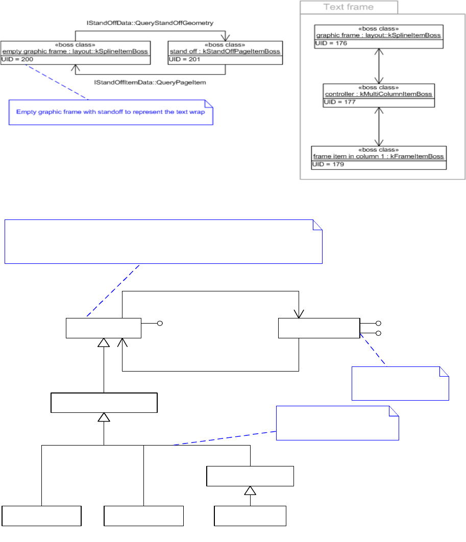
CHAPTER 9: Text Fundamentals Text presentation 312
The general structure of text wrap is shown in the following figure.
Properties of a standoff are found in IStandOffData on the page item with the standoff. Use
IStandOffData::GetMode to obtain the kind of text wrap and IStandOffData::GetMargin to get the offsets.
Each page item has distinct standoff applied, so the page item can be a graphic frame (kSplineItemBoss), a
group (kGroupItemBoss), or another type.
When a text wrap is applied, a standoff boss class kStandOffPageItemBoss is associated with the owning
page item. The standoff boss class is not part of the page item instance hierarchy; you do not navigate to it
using IHierarchy. Instead, use IStandOffData::QueryStandOffGeometry to access the standoff boss class.
The kStandOffPageItemBoss boss class has a path geometry that represents the contour of the standoff,
and text in a text frame wraps to this contour.
«boss class»
kStandOffPageItemBoss
IPathGeometry
1
0..1
IStandOffData::QueryStandOffGeometry
11 IStandOffItemData::QueryPageItem
«boss class»
layout::
kPageItemBoss
Text wrap is represented by a standoff. A standoff can be associated with various
kinds of page items such as graphic frames (kSplineItemBoss), pictures (kImageItemBoss,
etc.), and groups (kGroupItemBoss). They can each have distinct standoff
properties.
Represents the contour
of the text wrap
«boss class»
layout::
kSplineItemBoss
«boss class»
layout::
kDrawablePageItemBoss
«boss class»
layout::
kGroupItemBoss
«boss class»
graphics::
kImageBaseItem
«boss class»
graphics::
kImageItem
Other kinds of page items not
shown on this diagram can also
have a standoff.
IStandOffData IStandOffItemData
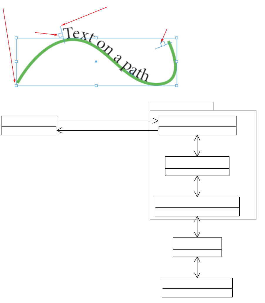
CHAPTER 9: Text Fundamentals Text presentation 313
Text on a path
Text on a path allows text to flow along the contour of a spline (kSplineItemBoss). Text on a path frame has
an inport and an outport. As a result, you can thread text in other frames to and from it. The following
figures show the objects involved in text on a path.
The following figure shows the structure of text on a path frame
kSplineItemBoss kTOPSplineItemBoss
kMultiColumnItemBoss
kTOPFrameItemBoss
Inport Outport
UID = 184
«boss class»
text on a path spline : kTOPSplineItemBoss
UID = 185
«boss class»
controller : kMultiColumnItemBoss
UID = 186
«boss class»
text on path frame item : kTOPFrameItemBoss
IHierarchy::QueryParent
IHierarchy::QueryChild(0)
IHierarchy::QueryParent
IHierarchy::QueryChild(0)
UID = 182
«boss class»
frame list : kFrameListBoss
UID = 166
«boss class»
story : The Text Model::kTextStoryBoss
IFrameList::QueryNthFrame(0)
ITextFrameColumn::QueryFrameList
ITextModel::QueryFrameList
IFrameList::QueryTextModel
UID = 144
«boss class»
path : layout::kSplineItemBoss
IMainItemTOPData::GetTOPSplineItemUID
ITOPSplineData::GetMainSplineItemUID
Text on a path frame
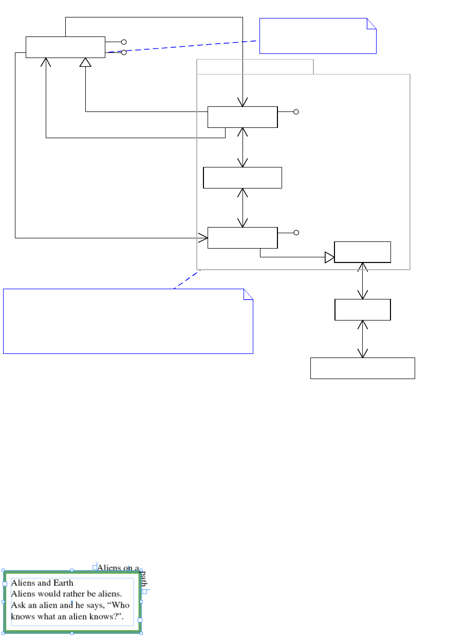
CHAPTER 9: Text Fundamentals Text presentation 314
Text on a path can be associated with any spline (kSplineItemBoss). The structure of text on a path frame
parallels that of a normal text frame. It is represented by three associated boss classes:
kTOPSplineItemBoss, kMultiColumnItemBoss, and kTOPFrameItemBoss. You can navigate from a spline
(kSplineItemBoss) to any associated text on a path (kTOPSplineItemBoss) using the IMainItemTOPData
interface. You can navigate back using the ITOPSplineData interface. After you have an interface on the
kTOPSplineItemBoss, you can navigate up and down the text on a path frame using IHierarchy.
The following figures show a text frame that also has text on a path running along its contour. In this
example, the text displayed inside the frame and the text that runs its contour have distinct underlying
stories. If they were threaded, they would be associated with the same story.
Text frame with text on a path:
Instance diagram for text frame with text on a path:
«boss class»
kTOPSplineItemBoss
«boss class»
kMultiColumnItemBoss
«boss class»
kTOPFrameItemBoss
«boss class»
layout::
kSplineItemBoss
«boss class»
kFrameItemBoss
IHierarchy::QueryParent1
IHierarchy::QueryChild
1
IHierarchy::QueryParent1
IHierarchy::QueryChild1
IMainItemTOPData
ITOPSplineData
1
owns text on path0..1
IMainItemTOPData::GetTOPSplineItemUID
1
1
ITOPSplineData::GetMainSplineItemUID
1
-IMainItemTOPData::GetTOPTextContentUID
1
Text on a path frame is a special kind of text frame. It is represented
by three associated boss classes: kTOPSplineItemBoss,
kMultiColumnItemBoss, and kTOPFrameItemBoss.
Note that you will not find these boss classes on the hierarchy
(IHierarchy) that owns the kSplineItemBoss. Instead, they
can be accessed by interface IMainItemTOPData on the owning spline.
Represents the contour along
which the text flows
«boss class»
kFrameListBoss
IFrameList::QueryNthFrame 1..* ITextFrameColumn::QueryFrame1
«boss class»
The Text Model::
kTextStoryBoss
ITextModel::QueryFrameList1
IFrameList::QueryTextModel1
Text on a path frame
IPathGeometry
ITOPFrameData
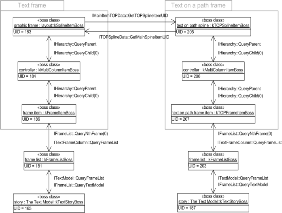
CHAPTER 9: Text Fundamentals Text presentation 315
The wax
The output of text composition is called the wax. The wax is responsible for drawing and hit testing the
text of a story.
The term “wax” comes from the manual paste-up process conventionally used to create magazine and
newspaper pages before the advent of interactive pagination software. In the old process, typeset
columns of text (galleys) were received from the typesetter. The galleys were run through a waxer, cut into
sections, and positioned on an art board. Wax was used as an adhesive to stick the sections on the art
board.
The art board in InDesign is a spread, and you can think of the galleys as text frames. The typeset columns
of text are the wax generated by text composition. The wax adheres—fixes—the position of a line of text
within a frame.
Wax strand, wax line, and wax run
The frame list (kFrameListBoss) manages the wax for a story by means of the wax strand (IWaxStrand
interface). The wax strand owns a collection of wax lines that contain wax runs, as shown in the following
class diagram.

CHAPTER 9: Text Fundamentals Text presentation 316
The wax is organized as a hierarchy of collections and leaf runs. The most common case is a series of wax
lines, each with a collection of wax runs. A wax line is created for each line of text in a frame. A wax run is
created each time the appearance of the text changes within the line. Examples of this include changes in
point size, changes in font, and the interruption of the flow of text in a line because text wrap causes text
to flow around another frame.
The IWaxStrand interface on kFrameListBoss owns all wax lines for a story and is the root of the wax tree.
The IWaxIterator and IWaxRunIterator iterator classes provide access to wax lines and wax runs.
kWaxLineBoss typically represents the wax for one line of text. (Warichuu is an exception to this, where the
Warichuu set contains multiple lines; all lines in the Warichuu set relate to one kWaxLineBoss object.) Each
line owns its wax runs, collections of wax runs, or combination of runs and collections of runs.
kWaxLineBoss provides access to its children through the IWaxCollection interface.
Any boss that supports the IWaxCollection interface is a parent in the wax hierarchy to boss objects that
support the IWaxRun interface. A boss can support both the IWaxCollection and IWaxRun interfaces,
creating levels in the hierarchy.
kWaxTextRunBoss is the object that represents the wax for ordinary text. This object stores the information
needed to render the glyphs and provides the interfaces that draw, hit test, and select the text.
kWaxILGRunBoss represents the wax for inline frames. Inline frames allow frames to be embedded in the
text flow. An inline frame behaves as if it were one character of text and moves along with the text flow
when the text is recomposed. kWaxILGRunBoss provides the drawing, hit testing, and selection behavior
for inline frames.
For a complete list of wax-run boss classes, refer to the API Reference for IWaxRun.
1
0..m
1
0..m
1
0..m
kTextStoryBoss
kFrameListBoss
kWaxTextRunBoss Collection
(TCY, WarichuuSet, etc.)
Collection (kWaxLineBoss)
kFrameItemBoss
1
0..1
1
0..m
The wax
IWaxStrand
0..m
kWaxILGRunBoss
1
CHAPTER 9: Text Fundamentals Text presentation 317
Examples of the wax
This section describes the wax generated for some sample text frames. To recreate these examples, use the
Text tool to create the frames. If you use another tool, like the place gun or a graphic frame tool, the inner
coordinate spaces for the frames will be different from those illustrated. For simplicity, use a sample page
size 200 points wide and 100 points deep, and format text using 8-point type, the Times Regular font, and
10-point leading. All text is composed by the Adobe Paragraph Composer in a horizontal text frame.
Single line with no format changes
The wax generated for a single line of text with no format changes is shown in the following figure. This
example has a frame 200 points wide and 30 points deep, containing one line of 8-point Times Regular
text with 10-point leading. The first baseline offset setting for the frame is set to leading. This forces the
baseline of the first line of text in the frame to be offset from the top of the frame by a distance equal to the
leading value for the text (10 points).
Wax for single line with no format changes:
Each node in the wax tree records its position, its width, and a reference to the characters in the text model
it describes. The origin records the index into the text model to the first character in the node. The span
records the number of characters in the node.
Wax lines record their position in the inner coordinate space of the frame in which they are displayed. Wax
runs record their position as an offset relative to the position of the wax line. Additional information is
stored specific to the type of node—wax line or wax run.
The following figure exposes some additional data in the wax. A wax line stores the leading for the line. A
wax run stores font name, a font-transformation matrix, glyph information, and other data necessary to
describe how the text is to be drawn. A glyph is an element of a font.
WaxLine
X=-100
Y=-5
Width=55.76
Origin=0
Span=17
WaxRun
X=0
Y=0
Width=55.76
Origin=0
Span=17
left=-100, top=-15
right=100, bottom= 15
-5
Leading
Width
CHAPTER 9: Text Fundamentals Text presentation 318
When a character is composed, its character code is mapped to its corresponding GlyphID from the font
being used to display the character. The font provides the initial width of a glyph at a particular point size.
This width may be adjusted by composition to account for letter spacing, word spacing, and kerning. The
GlyphID values and their widths after composition are stored in the wax run, as shown in the preceding
figure.
Generation of wax runs
Wax runs are generated for each set of format changes or line breaks that occur in the rendered text. The
following figure illustrates the effect of applying text attributes that change text format.
This shows the wax for single line with format changes:
WaxLine
X=-100
Y=-5
Width=55.76
Origin=0
Span=17
Leading=10
WaxRun
X=0
Y=0
Width=55.76
Origin=0
Span=17
FontName=Times-Roman
FontMatrix=[8 0 0 8 0 0]
GlyphIDs=[0x24 0x4f 0x4c 0x48 0x51 0x56 0x3 0x44 0x51 0x47 0x3 0x28 0x44 0x55 0x57 0x4b 0xffffffff]
GlyphWidths=[5.78 2.22 2.22 3.55 4.00 3.11 2.00 3.55 4.00 4.00 2.00 4.89 3.55 2.66 2.22 4.00 2.00]
-100,-15
100,15
Transformation matrix
for 8-point text

CHAPTER 9: Text Fundamentals Text presentation 319
This figure shows how a wax run is created each time the text attributes specify the appearance of the text
is to change. The arrows show the correspondence between the text drawn in the frame and the wax run
that describes its appearance and location. A distinct wax run would be required for the following:
Each time the appearance of the text changes within the line.
Each line of text that appears in the parcel list for a story.
Each side of a line that is interrupted, either by using an irregular-shaped frame or by overlapping a
page item with wrap turned on within the frame.
Text adornments
Text adornments provide a way for plug-ins to adorn the wax (composed text). Text adornments give
plug-ins the opportunity to do additional drawing when the wax in a frame is drawn. The wax draws the
text and calls the text adornments it is aware of to draw. For this to occur, the adornment must be attached
to the wax.
Text adornments are boss objects attached by ClassID to an individual wax run. When the run is drawn,
text adornments are given control using the ITextAdornment interface.
Calls to the ITextAdornment::Draw method are ordered by the priority value returned by the
ITextAdornment::GetDrawPriority method. Higher-priority adornments (smaller numbers) are called
before lower-priority adornments (larger numbers).
Text adornments cannot influence how text is composed; for example, they cannot influence how
characters are built into wax lines and wax runs by the text-composition subsystem. Instead, text
adornments augment the appearance of the text. A text adornment controls whether the adornment is
drawn in front of or behind the text.
WaxLine
X=-100
Y=-5
Width=60.33
Origin=0
Span=17
-100,-15
100,15
WaxRun
X=0
Y=0
Width=22.89
Origin=0
Span=7
FontName=Times-Roman
FontMatrix=[8 0 0 8 0 0]
WaxRun
X=22.89
Y=0
Width=16.12
Origin=7
Span=3
FontName=Times-Bold
FontMatrix=[10 0 0 10 0 0]
WaxRun
X=39.01
Y=0
Width=21.32
Origin=10
Span=7
FontName=Times-Roman
FontMatrix=[8 0 0 8 0 0]
UnderlineMode=kUnderlineSingle

CHAPTER 9: Text Fundamentals Text presentation 320
There are two types of text adornments: local and global.
Local text adornments
A local text adornment is controlled by one or more text attributes. A local text adornment provides visual
feedback of the text the text attributes control. For example, an adornment can highlight the background
on which the text is drawn or strike out text by drawing a line in the foreground.
The text attribute controls the process by interacting with text composition and associating the
adornment with a drawing style (see IDrawingStyle and kComposeStyleBoss). This causes the text
composer to attach the adornment to a wax run (see IWaxRenderData in “The wax” on page 315).
The following table shows the main text adornments used by the application and the text attributes that
control them.
To add a local text adornment, first add a new text attribute. In more complex situations, use multiple text
attributes to control one text adornment. For example, kTAKentenSizeBoss, kTAKentenRelatedSizeBoss,
kTAKentenFontFamilyBoss, and kTAKentenFontStyleBoss collectively control the kenten adornment
implemented by the kTextAdornmentKentenBoss.
Local text adornments are attached to a drawing style and subsequently to an individual wax run. These
adornments always are called to draw, although they can choose not to draw anything.
The following figure shows the sequence of calls that result in an adornment being associated with a
particular wax run.
Adornment classID Attribute classID Description
kTextAdornmentIndexMarkBoss kTAIndexMarkBoss Index mark
kTextAdornmentKentenBoss kTAKentenSizeBoss, etc. Adorns text for emphasis
kTextAdornmentRubyBoss kTARubyPointSizeBoss, etc. Annotates base text
kTextAdornmentStrikethruBoss kTextAttrStrikethruBoss Strikes through text
kTextAdornmentUnderlineBoss kTextAttrUnderlineBoss Underlines text
kTextHyperlinkAdornmentBoss kHyperlinkAttributeBoss Hyperlink mark
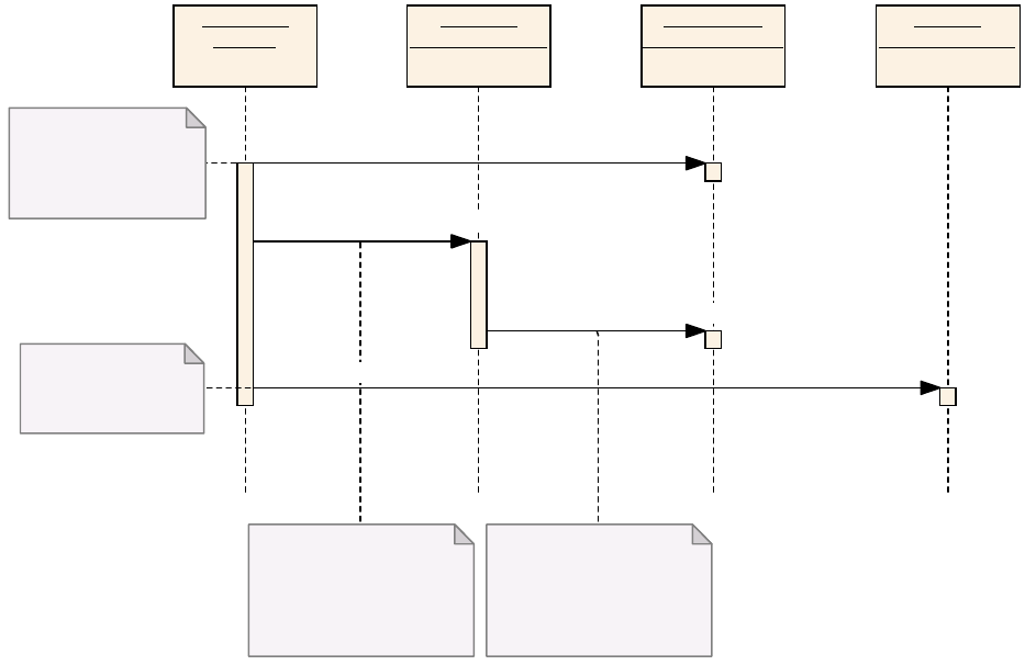
CHAPTER 9: Text Fundamentals Text presentation 321
The composition subsystem calls the IAttrReport::TellComposition method of each attribute that applies
to a particular range of text. This gives the attribute a chance to interact with the composition subsystem.
This interaction includes the registering of adornments that are to be associated with the wax and called
when the wax is drawn (IDrawingStyle::AddTextAdornment). The adornments are attached to the wax as
ClassIDs (IWaxRun::AddAdornment); that is, the adornments are not instantiated at this point.
The following figure shows how adornments associated with a wax run are instantiated and called to draw.
Composition
(abstract)
IAttrReport
(kSomeTextAttrBoss)
IDrawingStyle
(kComposeStyleBoss)
Creates kComposeStyleBoss
to hold the exact value of all
attributes as they apply to an
individual run of text
The composition subsystem
invokes each attribute active for
the run of text, allowing the
attribute to p articipate in the
composition process.
e attribute can specify
adornments to be added to the
drawing style. These adornments
will be given the opportunity to
participate in the drawing process.
IWaxRun
(kWaxTextRunBoss)
Adornment ClassID added
to the wax run
create
TellComposition(ICompositionStyle* style, IDrawingStyle* draw)
AddTextAdornment(ClassID attrID, ClassID adornmentID)
AddAdornment(ClassID id)
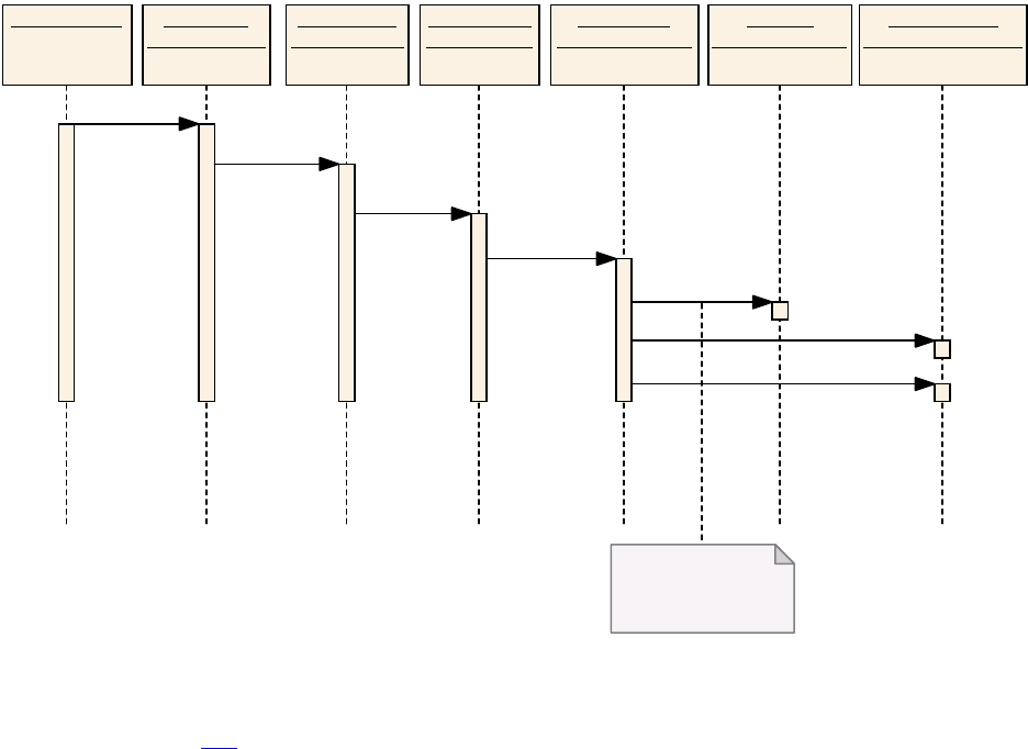
CHAPTER 9: Text Fundamentals Text presentation 322
The Draw signal propagates to the wax run (IWaxRunText on kWaxTextRunBoss). The wax run (IWaxRun on
kWaxTextRunBoss) is interrogated for the set of adornments registered through composition, as shown in
the figure on page 321. Each adornment (ITextAdornment) is created on whichever boss class it is
represented on, and the Draw method is called.
It is possible to associate a data interface (ITextAdornmentData) during registration
(IAttrReport::TellComposition). This interface allows control over whether the adornment is associated
with wax runs.
Global text adornments
Global text adornments are attached to all wax runs, though they never have run-specific adornment data.
Global text adornments provide the ability to draw something without requiring the text to be
recomposed. Unlike local text adornments, global text adornments do not need to be attached to
individual wax runs to draw; however, global text adornments are asked if they are active before they are
called to draw.
For example, the Show Hidden Characters feature is implemented using a global text adornment,
kTextAdornmentShowInvisiblesBoss. The adornment behaves as if it is attached to all runs, but is called
only when the adornment requests draw.
The following table lists global text adornments.
Draw Subsystem ITextParcelList
(kFrameListBoss)
IWaxLineShape
(kWaxLineBoss)
IWaxRunText
(kWaxTextRunBoss)
ITextAdornment
(kSomeAdornmentBoss)
IParcelShape
(kFrameItemBoss)
IWaxRun
(kWaxTextRunBoss)
Gets the list of adornments
(classID) held by the wax
run
Draw
Draw
Draw
Draw
GetAdornments
create
Draw

CHAPTER 9: Text Fundamentals Text presentation 323
Global text adornments are service providers. The ServiceID is kGlobalTextAdornmentService. Global text
adornments aggregate the IK2ServiceProvider interface and use the default implementation
kGlobalTextAdornmentServiceImpl.
Global adornments have the opportunity to participate in drawing if they are enabled. The following
figure shows the sequence of events that cause IGlobalTextAdornment::Draw to be called. For brevity, the
calls to the adornment to determine whether it is enabled (IGlobalTextAdorbment::GetIsActive) and to
access the ink bounds of the adornment (IGlobalTextAdornment::GetInkBounds) are not shown.
Adornment boss Description
kTextAdornmentHJKeepsVBoss Highlights keeps violations.
kTextAdornmentMissingFontBoss Highlights missing fonts.
kTextAdornmentMissingGlyphsBoss Highlights missing glyphs.
kDynamicSpellCheckAdornmentBoss Squiggle line to mark spell checks.
kTextAdornmentShowInvisiblesBoss Shows hidden characters.
kPositionMarkerLayoutAdornmentBoss Draws position marker.
kTextAdornmentShowKinsokuBoss Shows Japanese character line break.
kTextAdornmentShowCustomCharWidthsBoss Marks character width as a filled rectangle.
kXMLMarkerAdornmentBoss XML marker.
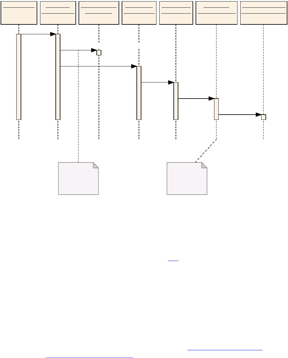
CHAPTER 9: Text Fundamentals Text composition 324
When a frame (IParcelShape on kFrameItemBoss) is instructed to draw, it queries the service registry
(IK2ServiceRegistry on kSessionBoss) for the set of global text adornments that are enabled
(IGlobalTextAdornment::GetIsActive). The frame calls Draw on the parcel list (ITextParcelList on
kFrameListBoss), which causes the wax line (IWaxLineShape on kWaxLineBoss) and wax run (IWaxRunText
on kWaxTextRunBoss) Draw methods to be called. During the drawing of the wax run, the global
adornments built up previously (Draw from IParcelShape on kFrameItemBoss) have their Draw method
called. Compare the preceding figure with the figure on page 322. The set of global adornments are global
to the document (maintained by the service registry), whereas local adornments are local to a specific wax
run.
Text composition
This section describes the process of creating the final rendered text. It includes information for software
developers who want to develop custom composition engines.
Text composition is the process of converting text content into its composed representation, the wax. The
text-composition subsystem flows text content from a story thread maintained by a story into a layout
represented by parcels in a parcel list. Story threads are described in “Story threads” on page 285; parcels
and the wax, in “Text presentation” on page 294. The following figure is an overview of text composition.
Draw Subsystem ITextParcelList
(kFrameListBoss)
IWaxLineShape
(kWaxLineBoss)
IWaxRunText
(kWaxTextRunBoss)
IGlobalTextAdornment
(kSomeAdornmentBoss)
IParcelShape
(kFrameItemBoss)
IK2ServiceReg istry
(kSessionBoss)
Builds a list of global
adornments
requesting to be
drawn
Invokes Draw on all
adornments on the
list previously
constructed
Draw
GetNthServiceProviderID(kGlobalTextAdornmentServiceID)
Draw
Draw
Draw
Draw

CHAPTER 9: Text Fundamentals Text composition 325
The following figure shows a sample text frame with no format changes. The figure shows the objects
representing the story, the frame, and the composed text; it does not show the details of how the text
actually gets composed.
The wax
The text model
Text layout
Text composition
Story thread
characters and text attributes
Frames/
parcels
Wax lines
Fonts
Glyphs
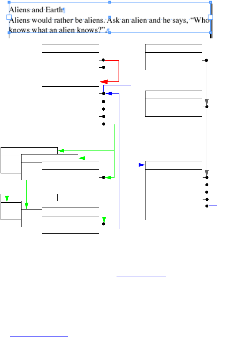
CHAPTER 9: Text Fundamentals Text composition 326
Text composition creates the wax lines (kWaxLineBoss) and their associated wax runs (kWaxTextRunBoss)
using the primary story thread’s content and layout as input.
Wax lines are added to the wax strand (IWaxStrand). Text composition also maintains the range of
characters displayed in each parcel/frame (see “Span” on page 305).
Phases of text composition
There are two distinct phases of text composition:
Damage refers to changes that invalidate the wax for a range of composed text. Inserting text and
modifying frame size are examples of changes that cause damage. This is described further in
“Damage” on page 328.
Recomposition is the process that repairs the damage and updates the wax to reflect the change. This
is described further in “Recomposition” on page 329.
Text composition toggles the wax between the states shown in the following figure.
kWaxTextRunBoss
kWaxLineBoss
IWaxLine
kWaxLineBoss
IWaxLine kFrameItemBoss
IHierarchy
IParcel
ITextTiler
ITextGrid
ITextFrameColumn
kSplineItemBoss
IHierarchy
kMultiColumnItemBoss
IHierarchy
kFrameListBoss
IFrameList
IParcelList
ITextParcelList
ITextParcelListData
IWaxStrand
kWaxLineBoss
IWaxLine
kTextStoryBoss
ITextModel
ITextStoryThread
kWaxTextRunBoss
IWaxRun
kWaxTextRunBoss
IWaxRun
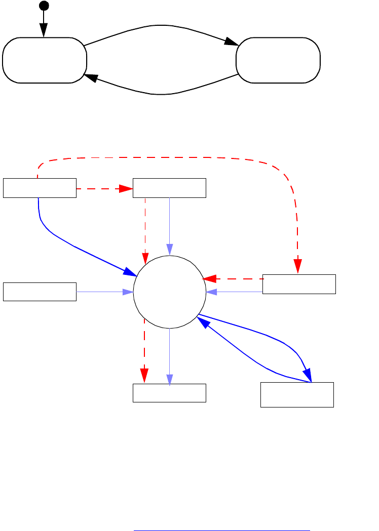
CHAPTER 9: Text Fundamentals Text composition 327
The flow of damage and recomposition is shown in the following figure.
This figure shows that a plug-in can update the text model or text layout, causing the wax (the composed
representation of the text) to be damaged.
The text-composition subsystem exposes interfaces that mark the damaged story, frame parcels, and wax.
The damage-recording flow is represented by dotted lines in the figure. The text-composition subsystem
also exposes interfaces that allow text to be recomposed. In the figure, the recomposition flow is
represented by solid lines.
Background composition (see “Background composition” on page 331) is a separate process that drives
text composition. Background composition runs as an idle task when the application has no
higher-priority tasks.
Consider the example in which the plug-in shown in the figure is the text editor. In response to typing, the
plug-in processes a command to insert the typed characters into the text model. This command calls
text-composition interfaces that record the damage caused. Background composition detects the damage
and recomposes the affected text.
Damaged.
Do recomposition.
The text model or text layout is updated.
Recomposition is completed.
Not damaged.
Start
The text model
The wax
Text
composition
Characters
+
text attributes
Parcels/
frames
Wax lines
Fonts
Glyphs
Plug-in
Background
composition
Update
MarkDamage Update
Recompose
Recompose
DetectDamage
MarkDamage
MarkDamage
Text layout

CHAPTER 9: Text Fundamentals Text composition 328
Damage
Damage refers to changes that invalidate the wax for a range of composed text. Damage is recorded by
marking the affected stories, parcels, frames, and wax. The damage indicates where recomposition is
required and the type of damage that has to be repaired.
The change counter on the frame list is incremented whenever something happens that causes damage.
No notification is broadcast when the change counter is incremented, so the change cannot be caught
immediately; however IFrameList::GetChangeCounter returns a counter that is incremented each time any
parcel in any frame in the frame list goes from undamaged to damaged, indicating some text in the frame
list was damaged and must be recomposed.
Damage drives and optimizes the recomposition process. For example, recomposition can shuffle existing
wax lines between frames to repair damage and avoid recomposing the text from scratch. Damage can be
in the following categories:
Insert damage occurs when text is inserted.
Delete damage occurs when a range of text is deleted.
Change damage occurs when a range of text is replaced or the text attributes that apply to a range of
text are modified.
Resize damage occurs when a frame is resized.
Rect damage occurs when text wrap or text inset is applied.
Move damage occurs when a frame is moved.
Destroyed damage occurs when some combination of the preceding types of damage occurs. When
this happens, the existing wax for the affected range must be recomposed.
Keeps damage occurs when a line must be pushed to the start of a new frame to eliminate orphans and
widows. Orphans and widows are words or single lines of text that become separated from the other
lines in a paragraph (see the following figure). An orphan occurs when the first line of a paragraph
becomes separated from the rest of the paragraph body. A widow occurs when the last line of a
paragraph becomes separated from the rest of the paragraph body.
This figure shows an orphan (left) and a widow (right):
Check for damage before relying on the information stored in the wax or the frame spans (see “Span” on
page 305). If your plug-in detects damage, it can either stop with a suitable error or recompose the text.

CHAPTER 9: Text Fundamentals Text composition 329
Damage API
To detect damage, use the interface methods shown in the following table.
Recomposition
Recomposition is the process of converting text from a sequence of characters and attributes into the wax
(fully formatted paragraphs ready for display). The components of recomposition are as follows:
Interfaces that control text composition.
The wax strand that manages the wax for the story.
Paragraph composers that create the wax for a line or paragraph.
Recomposition API
To request recomposition, use the interface methods shown in the following table.
Interface Method
IStoryList CountDamagedStories, GetLastDamagedStory,
GetNthDamagedTextModelUID
IFrameList GetFirstDamagedFrameIndex
IWaxLine IsContentDamaged, IsDamaged, IsDestroyed, IsGeometryDamaged,
IsKeepsDamaged
ITextParcelListData GetFirstDamagedParcel, GetParcelIsDamaged
ITextParcelList GetFirstDamagedParcel, GetIsDamaged
Interface Method Description
IFrameList QueryFrameContaining Helper method that causes recomposition.
IFrameListComposer RecomposeUntil,
RecomposeThruTextIndex
Controls recomposition of frames in the
frame list (kFrameListBoss). The methods
delegate to the parcel list composer
(ITextParcelListComposer).
ITextParcelListComposer RecomposeThru,
RecomposeThruTextIndex
Controls recomposition of parcels in a
parcel list. This interface drives the
recomposition for the parcel list.
IGlobalRecompose RecomposeAllStories,
SelectiveRecompose,
ForceRecompositionToComplete
Provides methods that can be used to
force all stories to recompose. This
interface marks damage that forces
recomposition to recompose the
damaged element, even though they were
not actually changed.
CHAPTER 9: Text Fundamentals Text composition 330
The interfaces and methods in the following table are not normally called by third-party plug-ins but play
a central role in the control of recomposition.
Wax strand
The wax strand (IWaxStrand) manages the wax for a story and is responsible for updating the wax to reflect
changes in the text model or text layout. The wax strand controls the existing wax and determines where a
paragraph composer needs to be used to create new wax. The wax strand also manages the overall
damage-recording process.
The lifecycle of the wax is as follows:
1. The wax strand is informed that a range in the text model was changed. In response, the wax strand
locates the wax lines that represent this range and marks them as damaged.
2. On the next recomposition pass, the wax strand finds the first damaged wax line in the story and asks
a paragraph composer to recompose it.
3. The paragraph composer creates new wax lines and applies them to the wax strand
(RecomposeHelper::ApplyComposedLine). RecomposeHelper is a helper class within
IParagraphComposer, so any existing wax lines that represent the same range in the text model are
destroyed.
4. Repeat this process until there are no more damaged wax lines or the end of the frame is reached.
Paragraph composers
A paragraph composer (IParagraphComposer) takes no more than a paragraph of text and arranges it into
lines to fit a layout. The paragraph composer creates the wax that represents the composed text. Plug-ins
can introduce new paragraph composers. For more information, see “Implementation notes for paragraph
composers” on page 332.
The text-composition architecture is designed for paragraph-based composition. The most significant
implication of this design is that any change to text or attributes causes at least one paragraph’s
composition information to be reevaluated. For example, inserting one character into a paragraph
potentially can result in changes to any or all of the line breaks in the paragraph, including those
preceding the inserted character.
Shuffling
Avoiding recomposition of text and simply moving existing wax lines up or down is called shuffling. The
performance improvement gained by shuffling is significant.
The wax strand can determine whether a wax line was damaged because of something that occurred
around the wax line and not because the range of text it represents changed, in which case the wax strand
knows that the result of recomposing the text is simply to move the wax line up or down. In this case, the
content of the wax line after recomposition is identical to its content before recomposition.
Interface Method See
IRecomposedFrames BroadcastRecompositionComplete “Recomposition notification” on page 332
IParagraphComposer Recompose, RebuildLineToFit “Paragraph composers” on page 330
CHAPTER 9: Text Fundamentals Text composition 331
For example, if you select and delete an entire paragraph of text, the next paragraph has not changed and
does not need to be recomposed. By pulling the following paragraph up to the position occupied by the
deleted paragraph, the wax strand avoids the cost of recomposition.
When shuffling, the wax strand implements some of the behaviors of a paragraph composer, such as
dealing with the Space Before and Space After paragraph attributes.
Iterative composition
In general, InDesign composes paragraphs relative to previous paragraphs so that text flows down and out
of the layout geometry. After a paragraph is composed in a Parcel, it is never changed again unless its
attributes or its geometry changes. But text composition cannot arrange wax lines well in one pass for
some features, such as balance columns, vertical justification, and span columns. The composition for such
features requires first making a valid composition outcome without any adjustments and then iteratively
recomposing, changing some aspect of the geometry each time to achieve the desired balanced outcome.
This is called iterative composition.
Vertical justification
The text frame justifies wax lines within it from the top, center, or bottom, or to fill the available area,
according to the setting for vertical justification. Shuffling can be performed for vertical justification if the
text container is rectangular. But for nonrectangular text frames, iterative composition is used because the
container is not equal in width everywhere. ITextFrameOptionsData provides access to the vertical
justification attribute.
Balanced columns
Column balancing is performed in a paragraph if the Balance Columns option of the text frame is turned
on or if the Paragraph Layout attribute of the paragraph below it is set to Span Columns.
This action requires iterative composition to first determine the length of the wax lines and then to adjust
and recompose. ITextFrameOptionsData provides access to the Balance Columns attribute.
Span columns
Within a multicolumn text frame, a paragraph with the Span Columns option stretches across multiple
columns; this is called straddling or spanning. This style requires that text must be balanced in the columns
preceding the spanning paragraph to determine the vertical position in those columns where the straddle
must begin. InDesign dynamically establishes the Parcels to hold the spanning text in the
IMultiColumnTextFrame. ICompositionStyle provides access to attributes such as span columns.
Background composition
Background composition looks for damage, then fixes it by calling for recomposition. Background
composition runs in the background as an idle task (IID_ICOMPOSITIONTHREAD on kSessionBoss) and
recomposes text. Each time that InDesign calls background composition, it performs the following actions
in priority order:
1. Recomposes visible frames of damaged stories in the frontmost document.
2. Recomposes other damaged stories in the frontmost document.
CHAPTER 9: Text Fundamentals Text composition 332
3. Recomposes damaged stories in other open documents.
The actions are performed until the time slice allocated for background text composition expires.
Background composition requests recomposition by calling the RecomposeUntil method on
IFrameListComposer.
Recomposition transactional model
Plug-ins use commands to update the input data that drives text composition (the text model and text
layout). The commands cause damage to occur. Recomposition subsequently recomposes the text and
generates the wax to reflect the changes. Recomposition does not execute within the scope of a
command; instead, the wax strand begins and ends a database transaction around the recomposition
process. This means that recomposition cannot directly be undone; however, the commands used to
update the input data are undoable. Undo causes damage, and recomposition repairs it to ensure that the
wax (the text displayed) reflects the state of the text model and text layout.
Recomposition notification
The IRecomposedFrames interface on the frame list (kFrameListBoss) keeps track of which frames are
recomposed, so text frame observers can be notified when recomposition completes. When InDesign calls
the BroadcastRecompositionComplete method, each affected column (kFrameItemBoss) receives
notification that it was recomposed. Observers attach to the kFrameItemBoss in which they are interested
and then watch for the Update method to be called with theChange == kRecomposeBoss and
protocol==IID_IFRAMECOMPOSER.
Implementation notes for paragraph composers
This section provides more in-depth background for software developers developing a custom paragraph
composer for the application.
Paragraph composers
A paragraph composer (IParagraphComposer) takes up to a paragraph of text, arranges it into lines to fit a
layout, and creates the wax that represents the text it composed. Plug-ins can introduce new paragraph
composers.
The user selects the composer to be used for a paragraph from the menu on the Paragraph panel (see the
following figure) or by using the Paragraph Styles palette. Selecting a paragraph composer sets the
kTextAttrComposerBoss paragraph attribute to indicate which paragraph composer to use.
CHAPTER 9: Text Fundamentals Text composition 333
Hyphenation and justification (HnJ)
The term “hyphenation and justification” (‘HnJ’) often is used in computer systems to refer to breaking of
text into lines and spacing of text so it aligns with the margins. This term is not used in this application’s
API or documentation; however, the role performed by an HnJ system is similar to the role of a paragraph
composer. Hyphenation is intimately associated with line breaking. In this application, the role is split out
and implemented by a hyphenation service (IHyphenationService). A paragraph composer that needs to
hyphenate a word uses a hyphenation service.
A paragraph composer’s environment
Paragraph composers are called by the text-composition subsystem. When text is to be recomposed, the
wax strand examines the paragraph attribute kTextAttrComposerBoss that specifies the paragraph
composer to be used, locates it through the service registry, and calls the
IParagraphComposer::Recompose method. This call gives the paragraph composer a context stored in the
helper class in which to work.
virtual bool16 Recompose(RecomposeHelper* helper)
The RecomposeHelper class is a wrapper of the story being recomposed. It stores information like the
story’s compose scanner, tiler, starting index, text span, and position. The RecomposeHelper class
definition is in IParagraphComposer.h.
The following figure shows an example of a paragraph composer called to compose text.
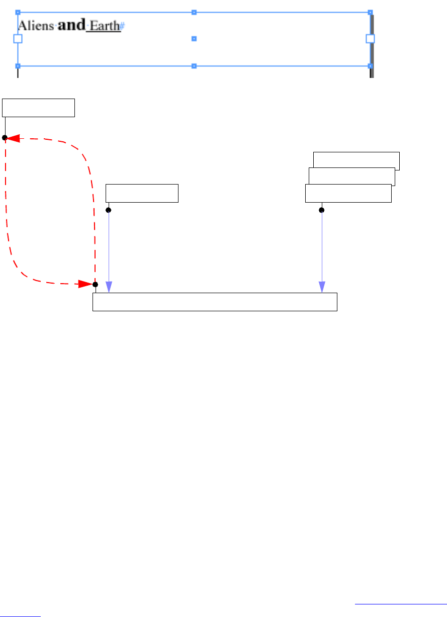
CHAPTER 9: Text Fundamentals Text composition 334
The following steps occur:
1. The paragraph composer composes the text and creates at least one wax line in the helper.
2. The paragraph composer accesses the character-code and text-attribute data for the story, using the
IComposeScanner interface acquired from helper->GetComposeScanner.
3. The paragraph composer determines the areas in a line where glyphs can flow, using
IParagraphComposer::Tiler.
4. The wax lines are applied to the IWaxStrand interface by calling helper->ApplyComposedLine.
NOTE: Both yPosition and tiles are specified in the inner bounds (coordinate system) in RecomposeHelper.
The scanner and drawing style
The scanner (IComposeScanner) provides access to both character and formatting (text attributes)
information from the text model, as shown in the following figure. The drawing style (interface
IDrawingStyle) represents the effective value of text attributes at a given index in the text model. The
drawing style cached by interfaces on kComposeStyleBoss considerably simplifies accessing text-attribute
values. These interfaces remove the need to resolve text-attribute values from their representation in the
text model and the text styles it references. A drawing style applies to at least one character. The range of
characters it applies to is a run. For more information on styles and overrides, see “Text formatting” on
page 288.
Other parcel list boss
kTextCellContentBoss
kTextStoryBoss
Paragraph composer boss class
kFrameListBoss
helper->GetComposeScanner
IParagraphComposer
IWaxStrand
Characters and effective attribute values
characters=”Aliens “
fontName=Times-Roman,
pointSize=8 point,
leading= 10 points
Tiles
firstBaselineOffset=leading
tile [0] = [-100, -15, 100, -5]
Wax lines and runs
Recompose
helper->ApplyComposedLine
kFrameListBoss
-100,-15
100,15
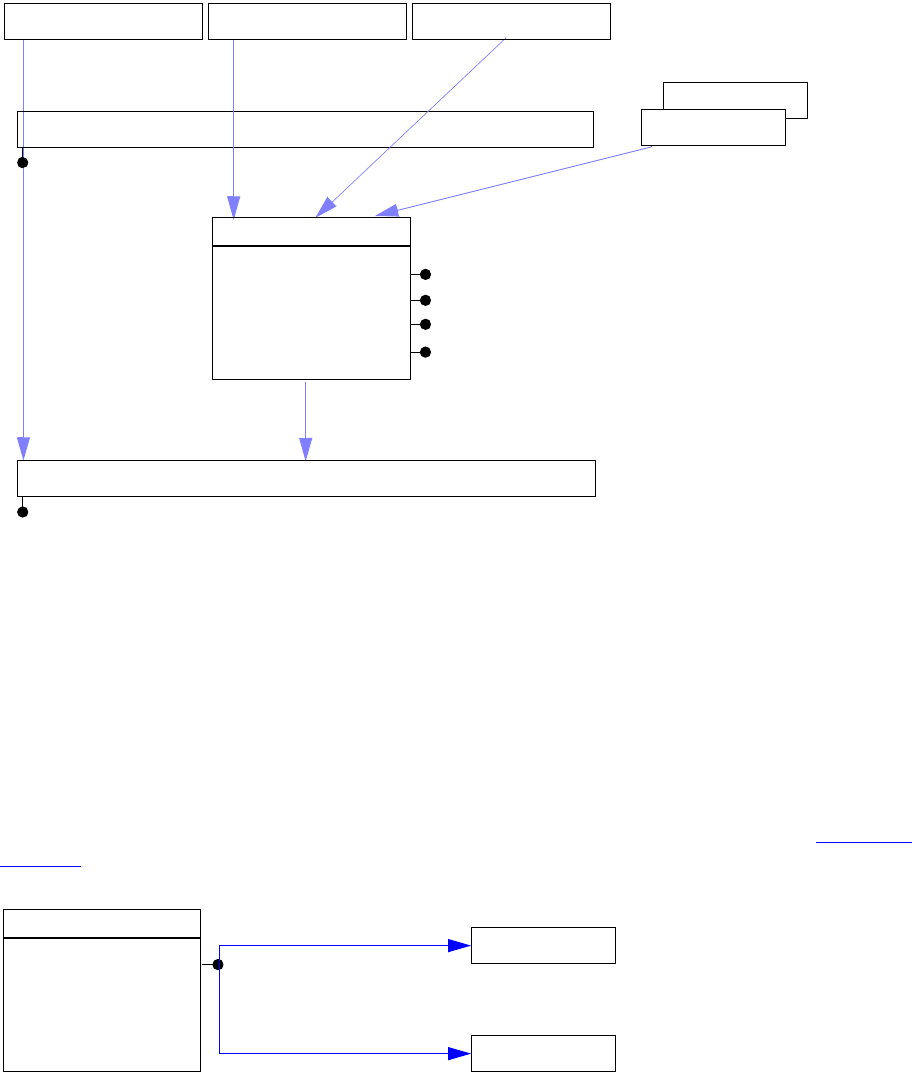
CHAPTER 9: Text Fundamentals Text composition 335
Fonts and glyphs
Fonts contain the glyphs that display characters for a typeface at a particular size. Paragraph composers
use the drawing style (IDrawingStyle) to find the font to be used. The font APIs provide the metrics
required to compose the text into lines composed of a run of glyphs for each stylistic run of text.
A font represents a typeface with a given size and style. A typeface, like Times, is the letters, numbers, and
symbols that make up a design of type. A glyph is a shape in a font that is used to represent a character
code on screen or paper. The most common example of a glyph is a letter, but the symbols and shapes in a
font like ITC Zapf Dingbats also are glyphs. For more information, see the following figure and “Fonts” on
page 347.
Tiles
Tiles (IParagraphComposer::Tiler) represent the areas on a line into which text can flow. Normally, there is
only one tile on a line; however, text wrap may cause intrusions that break up the places in the line where
text can go. The tiler takes care of this, as well as accounting for the effect of irregularly shaped text
containers.
kStyleBoss
kStyleBoss
kTextDataStrandBoss
kTextStoryBoss
Paragraph composer boss class
IComposeScanner
IParagraphComposer
Characters Drawing style (effective attribute values)
Text attributes
kComposeStyleBoss
IDrawingStyle
ICompositionStyle
IHyphenationStyle
IJustificationStyle
kParaAttrStrandBoss kCharAttrStrandBoss
kComposeStyleBoss
IDrawingStyle
IPMFont
IFontInstance
QueryFont
QueryFontInstance

CHAPTER 9: Text Fundamentals Text composition 336
Intrusions are the counterparts of tiles. Intrusions are not the inverse of tiles: they do not specify the areas
in the line where text cannot be flowed. From the perspective of ITextTiler, an intrusion is a horizontal band
within a frame, in which text flow within the bounding box of the frame may be interrupted. Intrusions can
be used to optimize recomposition. An intrusion is a flag that indicates that text cannot be flowed into the
entire width of a line. Intrusions are caused by text wrap and nonrectangular frames.
The tiles returned for a line depend on the y position where they are requested, their depth, and their
minimum width. The intrusions and tiles for some sample text frames are shown in the following figures.
Text frame with no intrusions:
Effect of image frame with text wrap:
Effect of two images with text wrap:
Effect of text inset:
Effect of nonrectangular frame:
Frame Intrusions(none) Tiles
Frame Intrusions Tiles
Frame Intrusions Tiles
Frame Intrusions Tiles
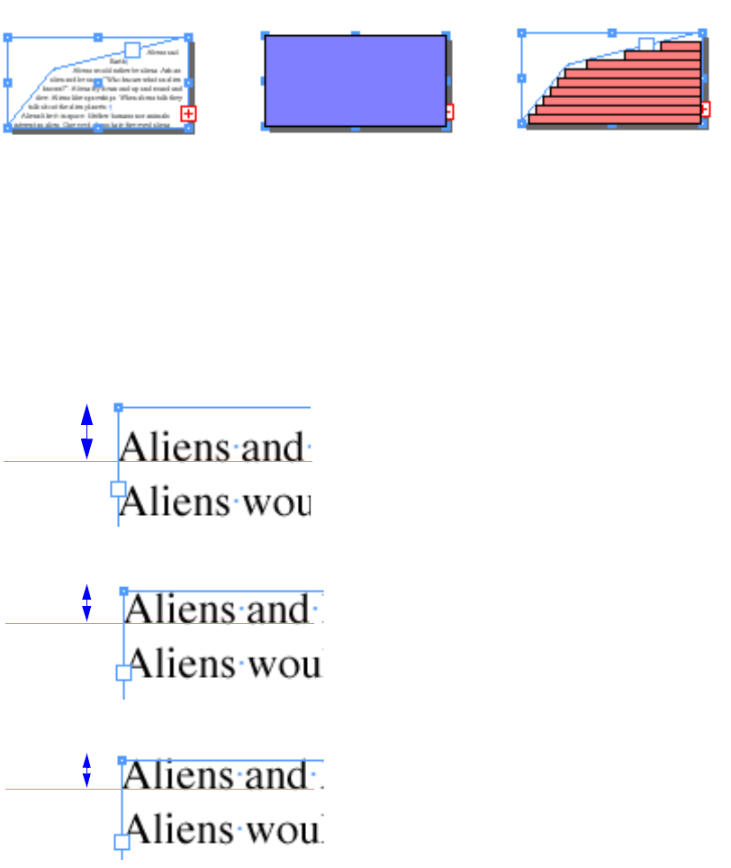
CHAPTER 9: Text Fundamentals Text composition 337
First-baseline offset
The first-baseline offset setting controls the distance between the top of a parcel or frame and the baseline
of the first line of text it displays. Some sample settings are shown in the following figure.
Control characters
A paragraph composer can apply an appropriate behavior to correctly implement the semantic intent of
many control characters. For a complete list of control-character codes, see TextChar.h in the API Reference.
Inline frames
Inline frames (kInlineBoss) allow frames to be embedded in the text flow. An inline frame behaves as if it
were one text character and moves along with the text flow when the text is recomposed. The
kTextChar_ObjectReplacementCharacter or kTextChar_Inline character is inserted into the text data strand
to mark the position of the inline frame in the text. The inline frames are owned by the owned item strand
Frame Intrusions Tiles
Leading
Ascent
Cap height
Use the largest leading on the line.
Use the largest ascent on the line. This
makes the top of the tallest glyph fall
below the top inset of the frame.
The setting controls the distance between
the top inset of the frame and the baseline
of the first line.
Use the largest Cap Height on the line. This
makes the top of upper case letters touch
the top inset of the frame.

CHAPTER 9: Text Fundamentals Text composition 338
(kOwnedItemStrandBoss) in the text model. Paragraph composers obtain the geometry of the frame
associated with the kInlineBoss by using ITextModel to access this strand directly. Inline frames are
represented in the wax by their own type of wax run, kWaxILGRunBoss.
Table frames
Table frames (kTableFrameBoss) are owned items anchored on a kTextChar_Table character embedded in
the text flow. Paragraph composers can and do compose text displayed in table cells.; however, they never
compose (create wax for) the character codes related to tables (kTextChar_Table and
kTextChar_TableContinued). When a paragraph composer encounters either of these characters, it should
create wax for any buffered text and return control to its caller.
Creating the wax
During the process of building lines, a paragraph composer normally uses an intermediate representation
of the glyphs, so it can evaluate potential line-break points and adjust glyph widths. The specific
arrangement used depends on the overall feature set of the paragraph composer and is beyond the scope
of this document. Once the line-break decisions are made, the paragraph composer must create wax lines
and runs.
For details of the mechanics of the creation of wax lines and runs, see “The wax” on page 315. Once
created by a call to RecomposeHelper::QueryNewWaxLine, new wax lines are added to the wax strand for a
story with the following call:
RecomposeHelper::ApplyComposedLine(IWaxLine* newLine, int32 newTextSpan)
The following figure shows an example of the wax generated by a paragraph composer.
Wax for a single line with format changes:
CHAPTER 9: Text Fundamentals Text composition 339
Adobe paragraph composers
Paragraph composers are implemented as service providers (IK2ServiceProvider) and can be located using
the service registry. The ServiceID used to identify paragraph composers is kTextEngineService.
The following figure shows the paragraph composers provided by the application under the Roman
feature set.
The following figure shows the paragraph composers provided under the Japanese feature set.
WaxLine
X=-100
Y=-5
Width=60.33
Origin=0
Span=17
-100,-15
100,15
WaxRun
X=0
Y=0
Width=22.89
Origin=0
Span=7
FontName=Times-Roman
FontMatrix=[8 0 0 8 0 0]
WaxRun
X=22.89
Y=0
Width=16.12
Origin=7
Span=3
FontName=Times-Bold
FontMatrix=[10 0 0 10 0 0]
WaxRun
X=39.01
Y=0
Width=21.32
Origin=10
Span=7
FontName=Times-Roman
FontMatrix=[8 0 0 8 0 0]
UnderlineMode=kUnderlineSingle
kParagraphComposerBoss
IParagraphComposer
IK2ServiceProvider
GetServiceID=kTextEngineService
GetName="HL Composer"
kSingleLineComposerBoss
IParagraphComposer
IK2ServiceProvider
GetServiceID=kTextEngineService
GetName="HL Single"
CHAPTER 9: Text Fundamentals Text composition 340
The following figure shows the world-ready composers that provide Middle Eastern support under the
Middle Eastern version of InDesign and InDesign Server. Roman paragraph composers
Key APIs
Class diagram
Paragraph composers are boss classes that implement IParagraphComposer, the interface called by the
application to compose text. To be recognized as a text composer, the boss class also must implement a
text-engine service (IK2ServiceProvider) with a ServiceID of kTextEngineService. The service also must
provide a name (a translatable string) for the paragraph composer, which is displayed in the user interface.
As output, composers generate wax lines (IWaxLine) and associated wax runs (IWaxRun) for up to one
paragraph of text at a time. The following figure shows the class diagram of a custom paragraph composer.
IParagraphComposer
There are two distinct phases to text composition, and IParagraphComposer reflects these roles:
Positioning the line and, if necessary, deciding where text in the line should break. This information is
represented persistently in the wax line. Features that affect line-break decisions belong here. This is
the role of the Recompose method.
Positioning glyphs that represent the characters in the line and, if necessary, adjusting their widths.
This information is represented by a set of wax runs associated with the wax line. Wax runs are not
kJParagraphComposerBoss
IParagraphComposer
IK2ServiceProvider
GetServiceID=kTextEngineService
GetName="HL Composer J"
kJSingleComposerBoss
IParagraphComposer
IK2ServiceProvider
GetServiceID=kTextEngineService
GetName="HL Single J"
kJParagraphComposerBoss
IParagraphComposer
IK2ServiceProvider
GetServiceID=kTextEngineService
GetName="HL Composer J"
kJSingleComposerBoss
IParagraphComposer
IK2ServiceProvider
GetServiceID=kTextEngineService
GetName="HL Single J"
kOptycaParagraphComposerBoss kOptycaSingleComposerBoss
HL Single Optyca”HL Composer Optyca”
kYourParagraphComposerBoss
IParagraphComposer
IK2ServiceProvider
GetServiceID=kTextEngineService
GetName=”Your Composer"
CHAPTER 9: Text Fundamentals Text composition 341
persistent and must be rebuilt for display when a wax line is read from disk. Features that affect glyph
position (paragraph alignment, justification, letter spacing, word spacing, and kerning) belong here.
This is the role of the RebuildLineToFit method, which regenerates composed text data from the
minimal data stored on disk.
Recompose is called when text needs to be fully recomposed. Each time this method is called, it should
compose at least one line and at most one paragraph of text into the passed-in helper. RecomposeHelper
actually does all the work, by creating wax starting from the character in the story indicated by
RecomposeHelper::GetStartingTextIndex. The top of the area text flows into is given by
RecomposeHelper::GetStartingYPosition, and composition is done using the supplied scanner and tiler.
The wax lines generated as a result are applied to the given wax strand.
NOTE: The paragraph composer is expected to create at least one wax line each time Recompose is called,
even when overset text is what is being composed.
RebuildLineToFit is called to regenerate the wax runs for a wax line from the minimal data stored on the
disk. No line breaking or line positioning needs to be done here.
IComposeScanner
IComposeScanner is an interface aggregated on kTextStoryBoss. It provides methods that help access
character and text-attribute information from the text model. It is the primary iterator for reading a story.
The following example shows QueryDataAt, which gets a chunk of data from the text model starting from
a given TextIndex. QueryDataAt is a primary method text composition uses to iterate through the text
model. QueryDataAt returns a TextIterator, which has its own reference count on the chunk of data in the
model, and thus makes the TextModel lifecycle independent of the compose scanner cache. Optionally,
QueryDataAt returns the drawing style and number of characters in the returned iterator. We recommend
you always ask for the returned number of characters.
virtual TextIterator QueryDataAt(TextIndex position, IDrawingStyle** newstyle, int32*
numChars) = 0;
You also can acquire the drawing style by one of the methods listed in the following example. For more
information on the methods in IComposeScanner, refer to the API Reference.
Acquiring IDrawingStyle from IComposeScanner:
virtual IDrawingStyle* GetCompleteStyleAt
(TextIndex position, int32* lenleft = nil) = 0;
virtual IDrawingStyle* GetParagraphStyleAt
(TextIndex position, int32* lenleft = nil, TextIndex* paragraphStart = nil) = 0;
QueryAttributeAt allows callers to query the effective value of one or more particular text attributes at a
given position. For more details, refer to the API Reference.
IDrawingStyle, ICompositionStyle, IHyphenationStyle, and IJustificationStyle
IDrawingStyle provides access to text-attribute values like font, point size, and leading. If the text property
you want is not in IDrawingStyle, you will find it in one of the other style interfaces on kComposeStyleBoss.
For details, refer to the API Reference for kComposeStyleBoss, IDrawingStyle, ICompositionStyle,
IHyphenationStyle, and IJustificationStyle.

CHAPTER 9: Text Fundamentals Text composition 342
IPMFont and IFontInstance
IPMFont encapsulates the CoolType font API. It represents a typeface and can generate instances
(IFontInstance) of it at various point sizes. IPMFont is not based on IPMUnknown, but IPMFont is reference
counted and can be used with InterfacePtr. For details, refer to the API Reference.
IFontInstance encapsulates the CoolType font-instance API. IFontInstance represents an instance of a
typeface at a given size. IFontInstance is not based on IPMUnknown, but IFontInstance is reference
counted and can be used with InterfacePtr.
IFontInstance controls the mapping from a character code (UTF32TextChar) into the identifier of its
corresponding glyph (GlyphID). For details, refer to the API Reference.
IParagraphComposer::Tiler
IParagraphComposer::Tiler manages the tiles for a parcel list and is used by paragraph composers to
determine the areas on a line into which text can flow (see “Tiles” on page 335). It controls the content area
bounds of each line.
The GetTiles method is used to get the tiles. If GetTiles cannot find large enough tiles in the current parcel
that meet all the requirements, it returns kFalse and should be called again to see if the next parcel in the
list can meet the request. If no parcel can meet the request, the tiler returns tiles into which overset text
can flow.
GetTiles is a complex call to set up. To fully understand how to use it, refer to the API Reference and the
text-composer samples (SingleLineComposer) provided in the SDK. The “TOP” abbreviation used in many
of the parameter names is short for “top of parcel,” because when a line falls at the top of a parcel, special
rules apply that govern its height (see “First-baseline offset” on page 337).
For Roman composers, a tile must be wide enough to receive one glyph plus any left and right line indents
that are active. A heuristic often is used that approximates the minimum glyph width to be the same as the
leading. The minimum tile height depends on the metric being used to compose the line. Normally this is
leading, but the first line in a parcel is a special case in which the metric used may vary depending on the
first-baseline offset (ascent, cap height, and leading) associated with the parcel. The pYOffset value
indicates the top of the area for text to flow into. The pYOffset value actually is a position rather than an
offset from the top of the parcel. The pYOffset value initially is the yPosition stored in RecomposeHelper
when the IParagraphComposer::Recompose method is called. For more details, refer to the API Reference.
Scenarios
This section illustrates how text gets recomposed. The scenarios presented here demonstrate basic
situations you may come across in developing a paragraph composer. To reduce complexity for these
examples, assume the paragraph composer being called generates only one line for each call (a single-line
composer).
Simple text composition
The following figure shows a simple composed text frame 200 points wide and 30 points deep, with its
baseline grid shown. The text is 8-point Times Regular with 10-point leading, and the first-baseline offset
for the frame is set to leading.
CHAPTER 9: Text Fundamentals Text composition 343
When text of the same appearance is flowed into the frame, the distance between the baselines of
succeeding lines of text is set to the leading.
The wax strand examines the paragraph attribute that specifies which paragraph composer to use and
locates it through the service registry. The paragraph composer is then asked to recompose the story from
the beginning, causing text to flow into the frame starting from the top by calling
IParagraphComposer::Recompose(helper).
The yPosition stored in the helper indicates the top of the area into which glyphs can flow. This is the
baseline of the preceding line or the top of the parcel.
The composer examines the drawing style and its associated font and calculates the depth and width of
the tiles it needs. The example uses 8-point text with 10-point leading and no line indents, so the
minimum height and width is 10 points. The tiler is then requested for tiles of the required depth and
minimum width at the given yPosition, and it returns the tile shown in the following figure.
Tiles for the first line:
The following sequence of actions then occurs:
1. The paragraph composer scans the text using IComposeScanner. Text flows into the tile until the tile is
full or an end-of-line character is encountered.
2. The composer chooses where the line is to be broken and creates a wax line for the range of text the
line will display.
3. The wax line is applied to the IWaxStrand and, as a side effect, the composer’s
IParagraphComposer::RebuildLineToFit method is called to generate wax runs for the line.
4. The IParagraphComposer::Recompose method is finished with its work and returns control to its caller.
5. The wax strand successively asks the paragraph composer to recompose the second and third lines
with yPositions of -5 and 5, respectively, until the text is fully composed.
The result is shown in the following figure. For more details, see the SDK sample code SingleLineCompose.
-5
5
15
Baseline
left = -100, top = -15
right = 100, bottom = 15
yPosition Baseline
-15
-5
Tile for line 1
CHAPTER 9: Text Fundamentals Text composition 344
Tiles for the second and third lines:
Change in text height on line
As a line is composed, attributes that control the height of the line, like point size and leading, may change.
The baseline of the text must be set to reflect the largest value of the metric, such as leading or ascent, that
is being used to compose the text. To achieve this, the composer asks the tiler for tiles deep enough to
take text of a given height. If an increase in text height is encountered as composition proceeds along a
line, the tiler needs to be asked for deeper tiles to accommodate the text. It is the composer’s responsibility
to ensure the parcel can receive the deeper text.
For example, if the point size for the word “Ask” is changed to 16 points and its leading to 20 points, the
text suffers change damage. The resulting sequence of recomposition is shown in the following figure.
Changing point size and leading of selected text:
yPosition Baseline
-5
5
5
15
Tile for line 2
Tile for line 3
-15
-5
5
15
-5
5
15
Composed frame with baseline grid displayed

CHAPTER 9: Text Fundamentals Text composition 345
Initially, the composer encounters 8-point text on 10-point leading, and it requests tiles of an appropriate
depth. When the composer hits the style change to 16-point text and 20-point leading, it goes back to the
tiler and gets a deeper tile. When the style changes back to the smaller point size, the composer already
has a tile deep enough to take this text, so it fills the tile with glyphs and breaks the line. Note how the
baseline is set to reflect the largest leading value encountered in the line.
Text wrap
Depending on the yPosition and depth of the tiles needed, the text-wrap settings on other page items or a
change to the shape of the frame may become significant during recomposition. To illustrate this, in the
following figure, a graphic with text wrap is added to the simple text-frame arrangement.
yPosition Baseline
-5
5
-5
15
Initial tile for line 2
Leading increased. Get deeper tile.
-15
-5
5
15
-5
5
15
Recomposed frame
The text suffers change damage and the paragraph composer is called.

CHAPTER 9: Text Fundamentals Text composition 346
The preceding figure shows the text frame and the tiles the 8-point text flows into with 10-point leading.
Note that the third line in the frame is affected by the text wrap and flows around the bounding box of the
graphic.
The following sequence illustrates what happens when the point size for “Ask” is changed to 12 points and
its leading is changed to 14 points. The initial case is shown in the following figure.
Changing the selection to 12-point text, 14-point leading:
The wax strand picks up the change damage and asks the paragraph composer to recompose the first line
of the second paragraph. The baseline of the first line of text in the frame, -5 points, is at the yPosition
stored in the RecomposeHelper.
The paragraph composer gets tiles deep enough to take the initial leading value (10 points) it encounters
on the line, as shown in the following figure.
Composer begins to recompose:
The paragraph composer then encounters the run of text with the changed point size and leading.
Because the text is deeper than the tiles the paragraph composer obtained, the composer goes back to
the tiler and asks for a new set of tiles to receive the deeper text. This is shown in the following figure.
Composer asks for deeper tiles:
Add graphic frame with text wrap set to wrap tightly around bounding box.
Text frame with 8-point Times regular text, 10-point leading
Frame Tiles
yPosition Baseline
-5
5
CHAPTER 9: Text Fundamentals Fonts 347
Because of the request for deeper tiles and the text-wrap setting on the graphic, the tiler returns the two
tiles shown in the following figure, causing text to tightly wrap to the bounding box of the graphic.
The paragraph composer flows glyphs into the deeper tiles, generating a wax line with four wax runs: one
for the tile to the left of the graphic and three in the tile to the right of the graphic. After this change, all
text for the story cannot be displayed in the frame, so the story is overset, as shown in the following figure.
Fully recomposed frame:
It is important to note that the tiles returned by the tiler depend on the yPosition within the frame for
which they are requested and the depth asked for by the caller.
Frame too narrow or not deep enough
IParagraphComposer::Recompose must return a wax line each time it is called; however, it is possible that
a frame is too narrow to accommodate text, when either the indent settings for a paragraph are large or
the text has a large point size. The result is overset text. Call the tiler (IParagraphComposer::Tiler’s
GetTiles()) repeatedly until it returns kTrue. The tiler iterates over all parcels; if none can accommodate the
text, the tiler returns a tile into which overset text can flow.
Fonts
This section explains how fonts fit into the InDesign text architecture. Fonts provide the basic information
required to render glyphs. A font is identified by a font name (for example, “Minion Pro”) and a face or style
name (for example, “Bold” or “Heavy”). A rendered font also has a size; for example, this text is 11 points. A
font of a specific point size is an instance of the font.
All rendered text in the application has an associated font.
yPosition Baseline
-5
9
yPosition Baseline
-5
9
yPosition Baseline
-5
9
-5
9
CHAPTER 9: Text Fundamentals Fonts 348
Fonts have rights, which determine what can be done with a particular font. For example, a font can
indicate that it should not be embedded in a PDF document or it should not be printed. The font
subsystem provides access to these rights and implements the policies required to adhere to these rights.
Available fonts
Several factors affect which fonts are available within a document.
Font sources
Fonts become available for use in InDesign from the following managed locations monitored by CoolType:
Fonts provided by the operating system.
The common Adobe fonts folder.
The application fonts folder.
Fonts also can become available from the following document-specific location:
The document-installed fonts folder.
The font manager provides these fonts to the user while the document is being edited.
System-wide fonts
When InDesign starts, it loads the system-wide fonts from the locations defined by the operating system.
These fonts are located:
On Macintosh OS X, in /System/Library/Fonts (install and uninstall are prohibited) and /Library/Fonts
(user installable).
On Windows, in WINDOWS\Fonts.
Adobe fonts
In prior releases, Adobe installed its own fonts in a common location for use in Adobe applications.
Although Adobe now installs its fonts into the user-modifiable system-wide font folders, InDesign still
loads fonts from these locations when it starts:
On Macintosh OS X, in /Library/Application Support/Adobe/Fonts.
On Windows, in Program Files\Common Files\Adobe\Fonts.
Application fonts
In prior releases, when InDesign started, it loaded any fonts in the folder named “Fonts” located in the
same folder as the InDesign executable binary. Use of this folder is deprecated and might not be
supported in future releases; however, InDesign currently still loads these fonts when it starts.
Document-installed fonts
When a document is opened, InDesign loads up to 100 fonts from the folder named “Document fonts”
within the same folder as the document. These document-installed fonts are associated with that specific
document, are available only to that document, and become unavailable when the document is closed.
CHAPTER 9: Text Fundamentals Fonts 349
Changes to font folders
For document-installed fonts, InDesign installs an internal copy of the fonts; after that, the
document-installed font folder becomes irrelevant while the document remains open. InDesign then
manages these fonts internally and will not be aware of any changes to the content of that folder until the
document is closed and reopened.
This is different from the other three managed font locations. In those locations, Adobe’s internal libraries
watch the managed folders and communicate changes to InDesign. InDesign then dynamically changes
its list of available fonts.
Missing fonts
There are times when the font manager gets a request for a font that is not available; for example, the font
was removed from the system or the document was produced on a system with a different set of available
fonts. The font manager resolves this situation by replacing the font with one that is available. The font
manager warns the user when such a replacement occurs.
Duplicate fonts
It is possible for the same font to occur in more than one of the locations to which InDesign and the
document have access. Identical fonts are fonts whose PostScript names and technology (OpenType,
Type1, and so on) are identical. If one of the duplicate fonts occurs in the document-installed fonts folder,
InDesign uses that font. If the duplicates occur elsewhere, InDesign resolves the situation by choosing one
of the fonts to make available.
Font-subsystem architecture
Font management within InDesign relies on a core piece of Adobe technology, CoolType. CoolType wraps
the operating-system font services to provide a cross-platform abstraction and provides further services to
clients.
The application wraps the CoolType representation of fonts, font groups, and font instances with
application-specific types. This is shown in the following figure.
Accessing CoolType fonts in the application:
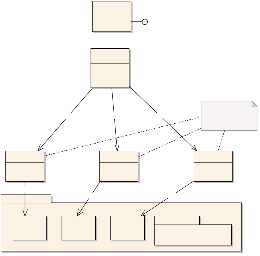
CHAPTER 9: Text Fundamentals Fonts 350
Session font manager
The session font manager, IFontMgr on kSessionBoss, provides access to the CoolType font wrappers.
IPMFont is the representation of a font, IFontGroup represents a group of fonts that are in the same font
family, and IFontInstance represents a particular font at a particular point size.
The session font manager provides access to all fonts and font groups that are available to the application
and to all open documents in the InDesign session. Each font group also allows you to access each font in
the group. The IFontMgr interface is aggregated on kSessionBoss.
CoolType
CoolType is the core technology through which InDesign accesses fonts.
CoolType font sybsystem
OS font subsystem
IPMFont IFontGroupIFontInstance
InDesign wrappers for core
CoolType types. Interfaces do
not inherit from IPMUnknown.
CTFontDict CTFontGroupCTFontInstance
kSessionBoss
IFontMgr
«interface»
IFontMgr
GetCTFontDict
GetCTFontGroup GetCTFontInst
1
QueryFont
*
1
QueryFontGroup
*
1
QueryFontInstance
*
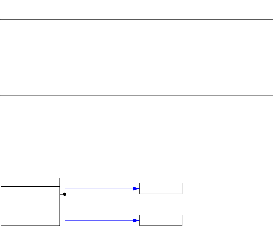
CHAPTER 9: Text Fundamentals Fonts 351
NOTE: CoolType font-abstraction technology is not related to Adobe’s subpixel font-rendering technology
with the same name.
The API provides the IFontGroup, IPMFont, and IFontInstance interfaces as shells through which InDesign
calls CoolType. These are not standard interfaces; that is, they do not derive from IPMUnknown. You
cannot create them using CreateObject or query them for other interfaces; however, these interfaces are
reference counted, and you can manage their lifetime using InterfacePtr. See the following table and
figure.
Interfaces that use CoolType:
Accessing a font:
Fonts are used when composing text, because fonts define the characteristics of individual glyphs.
kComposeStyleBoss is used by the composition engine. The IDrawingStyle interface provides access to the
font (IPMFont) and the particular font instance (IFontInstance) being used.
Local font manager
Each open document has its own local font manager, ILocalFontManager, which inherits from IFontMgr. To
ask the IDocument for its IFontMgr, make a request similar to the following:
InterfacePtr<IFontMgr> fontMgr(document, UseDefaultIID());
Interface Description How to get the interface
Code snippet with
example of use
IFontGroup Represents all font groups
available to the application
IFontMgr::QueryFontGroup,
FontGroupIteratorCallBack
SnpPerformFontGroupIter
ator
IPMFont Provides extensive data
related to a particular font.
IPMFont provides
font-name mapping calls
and access to font metrics
at a given point size.
IFontMgr::QueryFont,
IFontMgr::QueryFontPlatform
, IFontFamily, text attributes
kTextAttrFontUIDBoss and
kTextAttrFontStyleBoss,
IStoryService,
IWaxRenderData
SnpInspectFontMgr
IFontInstance Represents an instance of a
font of a given point size.
Of interest if you need to
write a paragraph
composer or map
character codes to
GlyphIDs.
IFontMgr, IDrawingStyle,
IStoryService
SnpInsertGlyph
kComposeStyleBoss
IDrawingStyle
IPMFont
IFontInstance
QueryFont
QueryFontInstance
CHAPTER 9: Text Fundamentals Fonts 352
You can cast the IFontMgr for a document to an ILocalFontManager. Getting the interface looks like this:
ILocalFontManager* lFontMgr = static_cast<ILocalFontManager*> (fontMgr.get());
If there are document-installed fonts, the local font manager ensures that those fonts are used before any
session managed fonts. If there are no document-installed fonts, ILocalFontManager provides essentially
the same services as the document’s IFontMgr. You can query whether a font was installed specifically for
the document using IsDocumentInstalledFont.
Code snippet SnpInspectFontMgr.cpp has an example of how to use ILocalFontManager.
Fonts within the document
Within a document, fonts are represented by the font name (plus information on font style and point size).
When the actual font is required, the font manager resolves the name-to-font (IPMFont or IFontInstance)
mapping.
The document-font manager
The document-font manager (IDocFontMgr) provides access to all fonts that persist in a session or
document workspace. The fonts that exist in a document include a set of default fonts, fonts used in visible
stories, and fonts used for features that are modeled using the application text subsystem but not
intended to be viewed or printed as part of a story (for example, text that exists in notes).
Fonts in the persistent document
Fonts are represented in the object model by kFontGroupBoss (signature interface IFontFamily). Each font
used in a story results in an instance of this boss object. A font family along with a font style identifies a
particular font in the font subsystem. The font family represents the name of the font (more correctly, the
set of names that identify each font within a particular group). This decoupling between font and name in
the document allows the font manager to resolve the font when required and take appropriate measures if
the font is not available to the application. The relationship between font manager and fonts is shown in
the following figure
How fonts persist in a document:
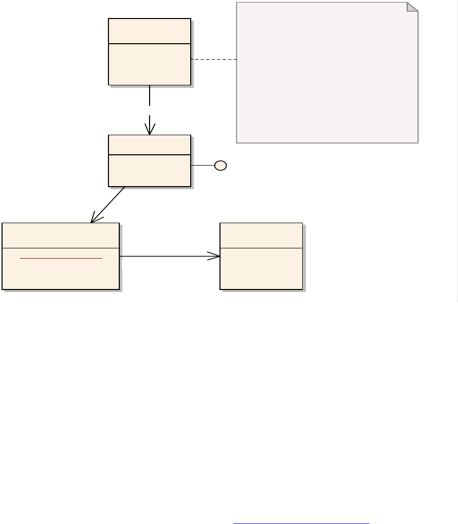
CHAPTER 9: Text Fundamentals Fonts 353
A font persists as a name, contained within a persistent implementation of IFontFamily. Access to these
persistent objects is provided through the (session or document) workspace. IFontFamily::QueryFace
requests the font from the font manager. If the returned IPMFont is non-nil, IPMFont::FontStatus can be
used to determine the validity of the font.
A set of text within a story is associated with a particular font using standard text attributes.
The text attributes that refer to the font in which text appears are as follows:
kTextAttrFontUIDBoss — ITextAttrUID gives the UID of the font family.
kTextAttrFontStyleBoss— ITextAttrFont gives the name of the stylistic variant.
kTextAttrPointSizeBoss— ITextAttrRealNumber gives the point size used.
The font family, along with the style of the font, identifies a particular font (IPMFont). The point size of the
text is used to provide an instance of the font (IFontInstance).
Text attributes are introduced and described fully in “Text formatting” on page 288.
The used-font list
The used-font list (IUsedFontList) on a document (kDocBoss) details the fonts associated with story text.
The used-font list does not include the fonts used in features that are not intended to be viewed or printed
as part of a story (for example, text that exists in notes).
«interface»
IDocFontMgr
kFontGroupBoss
IFontFamily
«interface»
IFontFamily
+ FontName: PMString
«interface»
IPMFont
IDocFontMgr exists on the session or document
workspace. e set of default fonts inherited by
new documents is maintained in IDocFontMgr
on the session workspace. e set of fonts used
by a document is maintained on the document
workspace.
Note that the fonts used by visible text in all
stories are identied by IDocFontMgr. Fonts
used in placed assets (EPS or PDF) and fonts used
in non-visible text in stories (such as with notes)
are not maintained on IDocFontMgr.
1
GetNthFontGroupUID
m..*
1
QueryFace
1..*
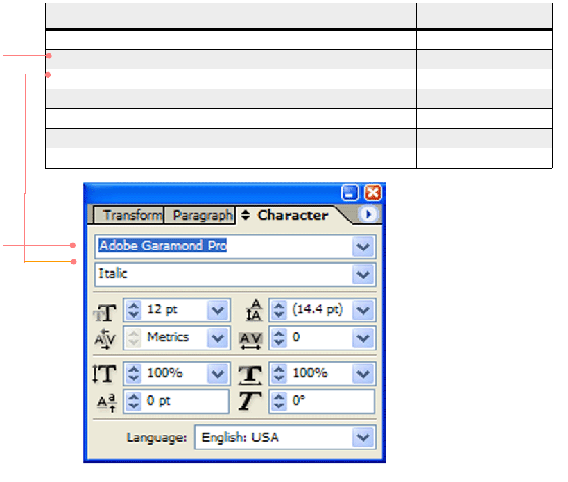
CHAPTER 9: Text Fundamentals Fonts 354
Fonts in placed assets
Placed (EPS or PDF) assets support the IFontNames interface. This interface reports the fonts used for the
particular asset, including whether the asset depends on the presence of fonts on the system. Placed
assets are maintained in the native asset’s format (PDF or EPS), with the IFontNames interface providing
access to information within the asset.
Document font use
A utility interface (IDocumentFontUsage) on the document (kDocBoss) provides a facade over the two
interfaces introduced above (IUsedFontList and IFontNames).
Font naming
Internally, application code uses PostScript font names. For example, IPMFont::AppendFontName returns
the PostScript font name. If you know the PostScript name of the font you want, you can get the associated
IPMFont using IFontMgr::QueryFont. Several other names are available on IPMFont and IFontFamily. For
example, if you use IFontMgr::QueryFont to instantiate the PostScript font AGaramond-Italic, IPMFont
gives you the names shown in the table in the following figure.
Notice the typeface name Adobe Garamond Pro in the panel in the preceding figure does not match the
family name in the table. This is because ITextUtils::GetDisplayFontNames supplies the platform-specific
name in the Character panel. If you do not have the PostScript font name but know the name of the
fd hh f b k h fh
Name Method Example
PostScript font name IPMFont::AppendFontName AGaramond-Italic
Family name IPMFont::AppendFamilyName Adobe Garamond
Style name IPMFont::AppendStyleName Italic
IPMFont::AppendFullName Adobe Garamond Italic
IPMFont::AppendFamilyNameNative Adobe Garamond
IPMFont::AppendStyleNameNative Italic
IPMFont::AppendFullNameNative Adobe Garamond Italic
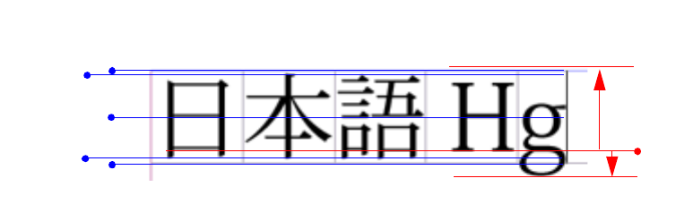
CHAPTER 9: Text Fundamentals Fonts 355
typeface on a given platform (the typeface name in Windows or the family name in Mac OS),
IFontMgr::QueryFontPlatform returns the corresponding IPMFont.
Font warnings
The IDocumentFontUsage interface (on kDocBoss) manages used-font and missing-font information for
text in stories of a document. The IDocumentFontUsage interface does not detail fonts used by features
that rely on the application text model but are not rendered as part of the document (for example, notes).
The IMissingFontSignalData interface provides data sent with the missing-font signal (of which responders
of type kMissingFontSignalResponderService are notified).
The IFontUseWarningManager interface can be called to check a particular font and possibly warn the user
about restrictions. Examples are restrictions based on user preferences or because a font is a bitmap.
Composite fonts and international-font issues
Some languages too many glyphs to be contained in a font; for example, Japanese contains about 50,000.
To accommodate this, font developers create fonts with subsets of glyphs. Also, there is a desire within
typography to replace some glyphs with others to achieve a certain visual effect. And users might want to
shift the position of Roman glyphs relative to the baseline or enlarge or reduce the size of glyphs. See the
following figure.
Japanese and Roman typography metrics:
The ICompositeFont interface creates a new font composed of base fonts and provides for size and
positioning adjustments. Font switching is based on Unicode values. The base font must be a Chinese,
Japanese, or Korean font. For examples of using ICompositeFont, see the SnpPerformCompFont code
snippet. An application can get this interface using any of the following:
IStyleNameTable (from the active workspace or document workspace)
InterfacePtr<IStyleNameTable> compFontList(workspace, IID_ICOMPOSITEFONTLIST)
InterfacePtr<ICompositeFont>rootTable(docDatabase, compFontList-> GetRootStyleUID(),
IID_ICOMPOSITEFONT)
Use the ICompositeFontMgr interface to manage composite fonts. For examples of its use, see the SDK
code snippet SnpPerformCompFont.
The IFontMetricsTable interface obtains the correct tsume values (similar to side bearings on glyphs)
around either the top and bottom or left and right of glyphs from the document originator and caches
them. Later users (who might have only bitmaps of the fonts used to create the document) can use the
tsume metrics saved in the document through this interface.
Em-box top
Em-box center
Em-box bottom
Ascent
Descent
Baseline
Japanese Roman
ICF box top
ICF box bottom

356
10 Scriptable Plug-in Fundamentals
This chapter describes how to extend your plug-in so that its features can be automated by a script, can be
accessed in InDesign Server, and can participate in technologies based on IDML.
You can add scripting support to a plug-in for InDesign, InCopy, or InDesign Server. This chapter is the C++
programming counterpart to Adobe InDesign Scripting Guide and Adobe InCopy Scripting Guide, which
document how to write scripts that automate InDesign and InCopy. Both the scripting guides and this
chapter are recommended reading if you are adding scripting support to your plug-in. This chapter also
describes the relationship between scripting and the InDesign Markup Language (IDML) file format.
Terminology
This following list contains terms used throughout this chapter. For other terms used in this chapter that
are not in the following list, see the “Glossary”.
Apple Event Terminology extension (AETE) — A resource that defines Apple Events and objects which
your application understands, both for scripts and for applications that send you events. Developed
by Apple.
Apple Events — High-level, semantic messages designed to allow for collaboration between programs.
Boss DOM — The model of a document as a set of boss objects; that is, the boss objects found under
kDocBoss, like kDocWorkspaceBoss, kSpreadBoss, kPageBoss, and kSplineItemBoss. See “Scripting
plug-in” on page 362.
Component Object Model (COM) — An object-oriented system developed by Microsoft for creating
binary software components that can interact with each other. See Scripting DOM below.
Dictionary — A set of definitions for words that are understood by a particular application under
AppleScript. A dictionary tells you which objects are available in a particular application and which
AppleScript commands you can use to control it. See Scripting DOM below.
Element — Script element.
Enum — Enumerates the list of potential values a property or parameter can have. See “Scripting
DOM” on page 360 and “Enum element” on page 391.
ICML — InCopy Markup Language. An ICML file is a snippet file containing an InCopy story.
IDML — InDesign Markup Language. IDML is based on serializing objects defined in a scripting DOM
tree to an XML-based format.
Chapter Update Status
CS6 Minor edits Only the following changed:
• Removed obsolete text about CS3 from chapter introduction.
•In “Versioning the scripting DOM” on page 361, clarified that it is Adobe that maintains the scripting DOM.
• Removed obsolete text about CS2 from “VersionedScriptElementInfo resource” on page 382

CHAPTER 10: Scriptable Plug-in Fundamentals Terminology 357
Method — A method call on a script object; for example, open or close. See “Method element” on
page 384.
Non-UID-based script object — A script object that represents a scriptable boss with no UID. See
“Scriptable boss classes” on page 366 and “Script-object inheritance” on page 407.
Plural form — A script object that can exist in a collection is said to have a plural form. For example, the
plural form of document is documents, a collection of document script objects. See “Scripting DOM”
on page 360 and “Object element” on page 383.
Preferences script object — A script object that represents preferences. See “Script providers” on
page 365 and “Script-object inheritance” on page 407.
Property — An attribute of a script object; for example, color or width. See “Scripting DOM” on
page 360 and “Property element” on page 387.
Provider — Associates a script provider with the script object(s), method(s), or property(ies) it handles.
See “Scripting DOM” on page 360 and “Provider element” on page 394.
Script element — A script object, property, method, or enum. The elements from which the scripting
DOM is made. See “Scripting DOM” on page 360 and “Scripting resources” on page 381.
Script language — The language in which you write your scripts. AppleScript, Visual Basic, and
JavaScript are supported in InDesign scripting.
Script manager — Manages a scripting DOM for a particular client of the scripting architecture. For
example, each scripting language has a script manager, kAppleScriptMgrBoss for AppleScript,
kOLEAutomationMgrBoss for Visual Basic, and kJavaScriptMgrBoss for JavaScript. See “Script
managers” on page 365.
Script object — An object in the scripting DOM. See “Scripting DOM” on page 360 and “Object
element” on page 383.
Script provider — A boss class that provides an implementation of IScriptProvider. This manipulates a
scriptable boss in response to requests made on a script object in the scripting DOM. See “Script
providers” on page 365.
Scriptable boss — A boss class exposed in the scripting DOM. Scriptable boss classes have the
signature interface IScript. Each scriptable boss has a corresponding script object. See “Scriptable boss
classes” on page 366.
ScriptElementID — An identifier defined in kScriptInfoIDSpace; for example,
kDocumentObjectScriptElement. This is akin to kClassIDSpace, where a boss ClassID is defined. See
“ScriptElementIDs” on page 398.
ScriptID — A four-character identifier for a script element; for example, “docu.” See “ScriptIDs” on
page 398.
Scripting DOM — A model of a document as a set of script objects with properties and methods that
represent the end user’s view. This is a high-level abstraction of the boss DOM. See “Scripting DOM” on
page 360 and “Scripting plug-in” on page 362.
Singleton — A script object that cannot exist in a collection. See plural form above, “Scripting DOM” on
page 360, and “Script-object inheritance” on page 407. The term “singleton” does not imply that there
is only one instance of the object (the common understanding of singleton in C++ programming and
design patterns). It is common to find several instances of a singleton in the scripting DOM; for
example, the singleton kTextFramePreferencesObjectScriptElement can have many instances, default

CHAPTER 10: Scriptable Plug-in Fundamentals Overview 358
text frame preference on the application, default text frame preferences on the document, and text
frame preferences on each text frame.
Surrogate — A concept that distinguishes an ownership relationship from a referential relationship. A
surrogate is a referential relationship between parent and child; no ownership is implied. See
“Surrogate” on page 397.
Type library — Binary files (.tlb files) that include information about types and objects exposed by a
COM application.
UID-based script object — A script object that represents a scriptable boss with a UID. See “Scriptable
boss classes” on page 366 and “Script-object inheritance” on page 407.
Overview
Scripting
Scripting allows users to exert virtually the same control of the application from a script as is available from
the user interface. This functionality can be used for purposes as simple as automating repetitive tasks, or
as involved as controlling the application from a database. Scripts can be written in AppleScript, Visual
Basic, or JavaScript. For instructions on writing and running scripts, see Adobe InDesign Scripting Guide.
The extensibility of this scripting architecture allows you to provide scripting support for functions added
by your own plug-in. The architecture provides a platform-independent and
scripting-language-independent foundation on which you can build. It abstracts and provides
implementations for the common elements of scripting. Your task is adding implementations for the
functionality you are exposing.
Benefits of making a plug-in scriptable
For the plug-in developer, making a plug-in scriptable has several benefits:
InDesign/InCopy users can automate the features added by your plug-in, by writing and executing
scripts. The potential for new solutions using automation means added productivity for you and your
customers.
Clients of InDesign Server can use your plug-in’s features. A plug-in must be scriptable to interact with
InDesign Server. See Getting Started With Adobe InDesign Server Plug-in Development.
Persistent data added to a document by your plug-in via boss objects and add-in interfaces is
expressed in the IDML file format and its derivative file formats and technologies.
Scripting and IDML
IDML is an XML-based format used to serialize and deserialize a scripting DOM. For an overview of IDML
and guidance on working with it, see IDML File Format Specification and Adobe InDesign Markup Language
Cookbook.
By exposing functionality through scripting, plug-ins can participate in technologies like Save Backwards.
You should make your plug-in scriptable if your plug-in adds persistent data to a document or to the
session workspace (kWorkspaceBoss) and your plug-in uses features that depend on IDML, such as the
following:

CHAPTER 10: Scriptable Plug-in Fundamentals Overview 359
Save backwards.
Asset libraries.
Assignments.
InCopy stories.
Application preference import/export. Preferences on the session workspace can be round-tripped as
INDML. To participate, a plug-in’s preferences must be exposed on the application script object
(kApplicationObjectScriptElement). For guidance, see Chapter 10, “Shared Application Resources.”
Also see “Adding a new script object to make preferences scriptable” on page 368,
ISnippetExport::ExportAppPrefs, and ISnippetImport::ImportFromStream.
Making a plug-in scriptable
These are the principal tasks involved in adding scripting support to your plug-in:
Design and implement script objects, properties, and methods. The features of your plug-in dictate the
script objects, methods, and properties that you need to add to the scripting DOM. Use “How to make
your plug-in scriptable” on page 366 as a guide.
Refactor your code to fit into the scripting architecture. This chapter does not make suggestions about
how to refactor your own plug-in code; however, a common refactoring task is decoupling the user
interface and model-related source code in your plug-ins. Your user interface is a client of your
plug-in’s model; the scripting architecture also is a client. The time required for refactoring depends on
the complexity of your plug-in and how well separated your user interface is from your model.
Document scriptability. Users writing scripts need documentation on the objects, properties, and
methods that your plug-in makes available. The Adobe InDesign Scripting Guide documents the
scripting supported by the application for AppleScript, Visual Basic, and JavaScript. You need to
document the additions provided by your plug-in.
Test. There are three categories of testing:
1. Testing scriptability — This involves writing scripts in AppleScript (Mac OS), Visual Basic (Windows),
and/or JavaScript (cross-platform). For instructions on writing scripts, see Adobe InDesign Scripting
Guide. To learn how to verify that your plug-in exposes the script objects you intend, see “Reviewing
scripting resources” on page 374.
2. Testing scriptability for backwards compatibility — The application supports the ability to execute
scripts written for earlier versions of the product. For example, suppose you released a scriptable
plug-in for InDesign CS5 and you are releasing a new version for InDesign CS6. You should test that
scripts written for InDesign CS5 run successfully under inDesign CS6 when targeted correctly. See
“Running versioned scripts” on page 376.
3. Testing IDML support in the IDML-based technologies that your plug-in requires — Basic IDML support
can be tested by exporting and importing documents containing your plug-in’s data as an IDML file.
Tools for making a plug-in scriptable
To make your plug-in scriptable, you need the following tools:
The current SDK plug-in development environment. For details, see Adobe InDesign Porting Guide.

CHAPTER 10: Scriptable Plug-in Fundamentals Scripting architecture 360
For AppleScript, you need the AppleScript Script Editor (Mac OS) or another tool used to write and run
AppleScript scripts.
For Visual Basic, you need Microsoft Visual Basic or Windows Script Host (Windows), the tools used to
write and run Visual Basic scripts. Alternatively, you can use any COM development environment,
including Microsoft Visual C++ and C#.
For JavaScript, you need a text editor. JavaScript can be run using the Scripts panel in InDesign and
InCopy. To debug JavaScript you must install the ExtendScript Toolkit (included in the InDesign
installer).
For more information on writing and debugging scripts, see Adobe InDesign Scripting Guide.
Scripting architecture
This section provides an architectural description of the framework that supports scripting. Instructions on
making your plug-in scriptable are in “How to make your plug-in scriptable” on page 366).
Scripting DOM
The scripting DOM is the end-user representation of an application and document as a set of script
objects. Each script object has properties and/or methods. The closest analogies for these concepts in an
object-oriented programming language are class (script object), attribute (property), and method
(method).
The scripting DOM describes a document as a tree structure of script objects, rooted at a document script
object. For example, a document may have several children that are color script objects, several that are
spreads, and so on. Besides having children, each script object can have a set of properties and methods. A
color has properties that describe its name, color model, and color value, among other things. At this level
of abstraction, we have the objects that are part of the end-user’s experience of an InDesign document
(spreads, pages, frames, stories, and so on), but the representation is less closely tied to the boss objects
you manipulate with the C++ API.
NOTE: For a description of the script objects provided by the application, see “Scripting DOM reference” on
page 426. C++ programmers add new script objects, properties, and methods to expose their plug-in’s
functionality.
The following figure shows a portion of the scripting DOM for an application that has a document
containing a page with a text frame. The scripting DOM is a hierarchy of script objects with methods and
properties. Four script objects are shown in the figure: Application, Document, Page, and TextFrame. The
script property that stores the bounds of a text frame object is shown.

CHAPTER 10: Scriptable Plug-in Fundamentals Scripting architecture 361
Scripts get or set properties and execute methods. To do this, a script must find the right object and then
perform an operation. The following example shows a script written in JavaScript that creates an instance
of the scripting DOM shown in the preceding figure and sets a property of the text frame.
app.documents.add(); // method creates a document
app.documents[0].pages[0].textFrames.add(); //method creates text frame
app.documents[0].pages[0].textFrames[0].geometricBounds = ["0p0", "0p0", "36p0",
"36p0"]; // sets a property
A script object is said to be a child of the script object on which it is exposed. The script object that exposes
another script object is said to be that object’s parent. For example, in the figure, the document script
object is a child of the application, and the application script object is the parent of the document.
A script object that can exist in a collection is said to have a plural form. The document, page, and text
frame script objects in the figure have a plural form. A script object that has a plural form must support the
special script methods used to manage collections (see “Special methods” on page 386).
A script objects that does not have a plural form often is called a singleton. Examples are the application
script object in the figure and script objects that expose preferences.
Each script object, method, and property has a name, description, ScriptID, and ScriptElementID defined,
as described in “Scripting resources” on page 381. The script objects provided by InDesign are identified in
the table in “Scripting DOM reference” on page 426, later in this chapter.
Each script object, method, and property has an associated script provider (see “Script providers” on
page 365) that handles it.
Versioning the scripting DOM
The scripting DOM covers the entire boss DOM. As the boss DOM changes, the scripting DOM evolves in
response. The scripting DOM is versioned to maintain compatibility with past and future versions.
Adobe maintains at least one version of backward compatibility of the scripting DOM. This ensures that
clients of the scripting DOM (for example, scripts, IDML, and INX) work seamlessly in new versions of the
product.
«script-object»
Application
«script-object»
Document
«script-object»
Page
+geometric bounds
«script-object»
TextFrame
collection
collection
collection

CHAPTER 10: Scriptable Plug-in Fundamentals Scripting architecture 362
Clients of the scripting DOM can specify which version of the scripting DOM should be used by the
application to interpret requests (see RequestContext in the API documentation). Requests involving
scripting elements (script objects, properties, and methods) that are added in a particular product version
(for example, InDesign CS6) work only if the client specifies that version (or later) of the scripting DOM.
Similarly, objects, properties, and methods removed from the scripting DOM in InDesign CS6 will not work
if the client specifies the InDesign CS6 version of the scripting DOM; however, they must still work if the
client specifies the InDesign CS5 version of the scripting DOM.
Compatibility is maintained not just for the elements in the scripting DOM, but for the functionality they
expose. This means that any underlying function that changes in InDesign CS6 is still exposed as it was in
InDesign CS5 for clients of the scripting DOM. In some cases, this requirement may constrain the ability to
significantly rearchitect the code. How to handle exceptions to this requirement, such as for functionality
that no longer exists, is determined on a case-by-case basis. At the very least, script providers must
degrade gracefully by implementing support as a no-op. For details of working with versioning, see
“Versioning of scripting resources” on page 408.
Special considerations and rules regarding versioning and IDML are in “Maintaining IDML forward and
backward compatibility” on page 380.
Scripting plug-in
The core architecture is implemented in the scripting plug-in, which manages the scripting DOM. The
scripting DOM is described by plug-ins using ODFRC resources (see “Scripting resources” on page 381).
These resources define script objects, their properties, methods, and the script provider (IScriptProvider)
that handles them. The architecture is extensible. Plug-ins can add new script objects or add new
properties and methods to existing script objects by defining ODFRC resources and implementing a script
provider.
See the following figure, showing scripting architecture. The scripting DOM represents a document as a
set of script objects with properties and methods. The boss DOM represents a document as a set of boss
objects and interfaces. Plug-ins expose their boss DOM data as objects and properties in the scripting
DOM, by defining ODFRez resources. Plug-ins expose other functionality as scripting methods in a similar
way. Plug-ins implement a script provider to manipulate data in the boss DOM when their script objects,
properties, and methods are used. The scripting plug-in manages the scripting DOM. When script
managers access the scripting DOM, the scripting plug-in maps script object properties and methods to
their associated script provider.
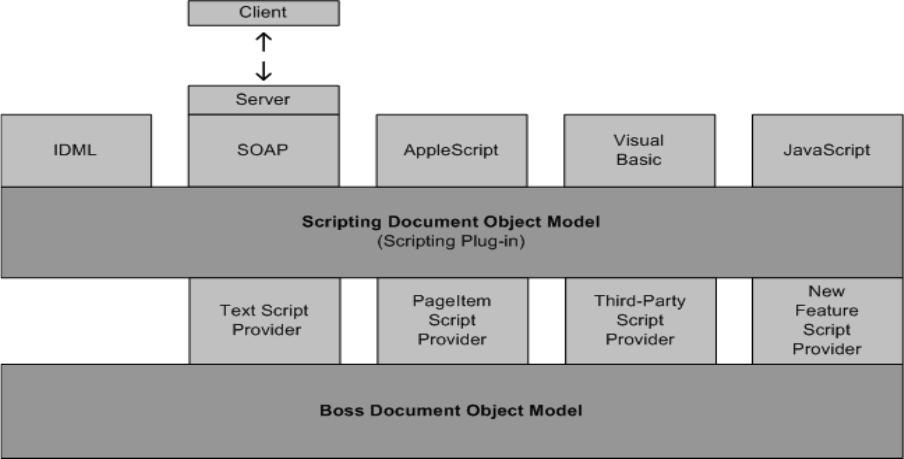
CHAPTER 10: Scriptable Plug-in Fundamentals Scripting architecture 363
Clients of the Scripting DOM are called script managers (see the IScriptManager interface in the API
documentation). Scripting language support for AppleScript, Visual Basic, and JavaScript is provided by
optional plug-ins that implement a script manager. The scripting DOM was conceived to make the
scripting architecture easier to use and more extensible; in addition, it has enabled other technologies to
be built. The IDML file format is founded on the scripting DOM.
Script interaction with the scripting DOM
Scripts interact with their associated script manager, which interacts with the scripting DOM, which
interacts with the application’s C++ API. The interaction varies somewhat depending on the scripting
language, as shown in the following figure. AppleScript and Visual Basic communicate with the
application through their respective interapplication communication processes, AppleEvents and
COM/OLE automation.
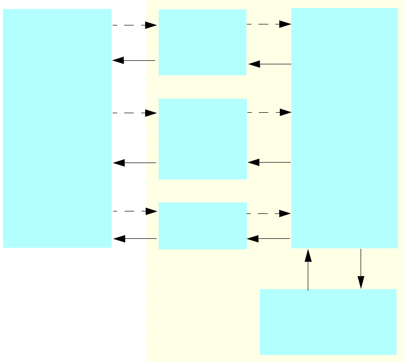
CHAPTER 10: Scriptable Plug-in Fundamentals Scripting architecture 364
Scripting process overview
1. After the application launches, scripting system architecture support is available to the user through
scripts; however, nothing is activated until a scripting request is received.
2. When a scripting request is received, the script manager determines what to do with it. After doing
set-up, checks, and so on, the script manager populates the IScriptRequestData interface with the data
that was passed in.
3. The script manager invokes the IScriptRequestHandler, which invokes the appropriate script provider
(IScriptProvider).
If a property comes in, the script provider gets or sets the property, based on the parameters
passed in through the IScriptRequestData interface. For a get operation, the script provider simply
returns the requested data from the model. For a set operation, the script provider extracts the
input and either executes its code successfully (modifying the model) or returns an error.
Methods work similarly. Some methods do not require any data, but most methods take a set of
parameters. The script provider uses the IScriptRequestData interface to get that input, executes
any necessary model modification via commands, and returns data or an error code.
RD0ARTY
3CRIPTS
!PPLE3CRIPT
$ICTIONARY
/3!
%XTEND3CRIPT
)NTERPRETER
*AVA3CRIPT
$ICTIONARY
6ISUAL"ASIC
#/-4,"
3CRIPTING
$/-
#!0)
K!PPLE3CRIPT-GR"OSS
K*AVA3CRIPT-GR"OSS
K/,%!UTOMATION-GR"OSS

CHAPTER 10: Scriptable Plug-in Fundamentals Scripting architecture 365
4. Control returns to the script manager, which does clean-up and conversion. The script manager takes
the data in the IScriptRequestData interface and converts it back to something the scripting language
understands.
5. The script manager returns, and control is passed back to the script.
Script managers
The application supplies script managers that handle the interaction between the scripting client and your
plug-in. The following tables lists major script manager boss casses
Scriptable plug-ins
This section describes the parts that enable a plug-in to receive a scripting request from a script manager
and report data back to the script manager. As with other client interfaces that you would give a plug-in,
scripting is intended to query and change the boss DOM. To accomplish this, we must be able to identify
objects in the boss DOM via IScript and get and/or set values.
For instructions on making your plug-in scriptable, see “How to make your plug-in scriptable” on
page 366.
Scripting resources
Every scriptable plug-in needs to supply a VersionedScriptElementInfo ODFRez resource that specifies the
plug-in’s additions to the scripting DOM in the form of script objects, properties, methods, and the
providers that handle these additions. In this resource, you identify details about the script objects and
their relationships with other script objects, and give them IDs so that your additions to the scripting DOM
can be identified.
See “Scripting resources” on page 381.
Script providers
IScriptProvider is the signature interface of a script-provider boss class. This interface allows the script
manager to access a script object, get and set its properties, and execute its methods. Script providers
Script Manager ClassID Used with
kAppleScriptMgrBoss AppleScript
kINXScriptManagerBoss Base class for INX and IDML script -manager bosses
kJavaScriptMgrBoss JavaScript
kOLEAutomationMgrBoss Visual Basic
kINXTraditionalImportScriptManagerBoss INX
kINXTraditionalExportScriptManagerBoss INX
kINXExpandedImportScriptManagerBoss IDML
kINXExpandedExportScriptManagerBoss IDML

CHAPTER 10: Scriptable Plug-in Fundamentals How to make your plug-in scriptable 366
know how to handle script objects, properties, and methods in an abstract sense. They map a request from
the scripting DOM onto the boss DOM. For example, in response to being called to get a property, a script
provider might call an accessor method on an interface on a scriptable boss. To set a property, it might
process a command that changes a scriptable boss.
When you implement a script provider boss, you normally extend kBaseScriptProviderBoss. To see its
interfaces, refer to the API documentation.
Partial implementations are as follows:
CScriptProvider — Subclass this to add properties or methods to existing objects in the Scripting
DOM.
PrefsScriptProvider — Subclass this to add a singleton script object and its properties to the scripting
DOM
RepresentScriptProvider— Subclass this to expose a new script object to the scripting DOM.
Scriptable boss classes
IScript is the signature interface of a scriptable boss; that is, a boss class exposed in the scripting DOM. A
scriptable boss object is the ultimate target of a method or property request made on a script object. The
need to implement an IScript interface depends on whether you want to add a function to an existing
script object or are implementing a new script object of your own. To add a function to an existing script
object, such as the document, you do not implement the IScript interface. To create a new script object,
you must define a boss class that implements the IScript interface, which maps your scriptable boss to its
associated script object.
Partial implementations are as follows:
CScript — Subclass this to expose a UID-based script object.
CProxyScript— Subclass this to expose a non-UID based script object.
NOTE: If you are adding a property or method to an object that already exists in the scripting DOM, you do
not need to implement IScript.
How to make your plug-in scriptable
Prerequisites
1. Examine the scripting samples provided by the SDK.
2. Determine how to represent your plug-in’s features in the scripting DOM:
Examine the scripting DOM and choose the objects on which your plug-in’s features should be
exposed. See the scripting references in <SDK>/docs/references, or create your own reference file
as explained in “Scripting DOM reference” on page 426.
Decide how to expose your plug-in’s data and functionality in the form of objects, properties, and
methods. Data is exposed by adding new script objects (see “Object element” on page 383) that
encapsulate properties or adding properties to existing script objects (see “Property element” on
page 387). Function is exposed by adding methods to new or existing script objects (see “Method
element” on page 384).

CHAPTER 10: Scriptable Plug-in Fundamentals How to make your plug-in scriptable 367
3. Refactor your code so it is easy to call from a script provider:
Your plug-in will have its own model implemented by some combination of data interfaces and
boss objects, together with commands that change this model.
We recommend that you encapsulate the model manipulation code in a helper class, so this code
can be easily shared between your user interface and script provider.
A facade interface added into kUtilsBoss is a good implementation solution. Another possibility is
a regular C++ class.
If you already refactored your plug-in for the selection architecture, you may be able to use your
selection suite interface from your script provider and your user interface code. The
recommended approach, however, is to factor code so your CSB suite and script provider delegate
to a facade that contains the shared code.
4. Examine the procedures in this section, and identify those that are relevant to your needs. Making
your plug-in scriptable always includes the following steps, at a minimum:
Add VersionedScriptElementInfo statement to your plug-in’s .fr file, to add script objects,
properties, methods, and providers to the scripting DOM. See “Scripting resources” on page 381.
Add a script provider (IScriptProvider) to handle your plug-in's scripting elements.
Add an error string service (see CErrorStringService), so your script provider can return meaningful
ErrorCode values.
Additional required steps depend on your plug-in’s features.
Defining IDs
You must define IDs that identify your plug-in’s additions to the Scripting DOM. See “ScriptElementIDs,
ScriptIDs, names, descriptions, and GUIDs” on page 398.
Adding a new property to an existing script object
1. Define a ScriptID/Name pair and a ScriptElementID for the new property.
2. Create VersionedScriptElementInfo resource statement and do the following:
Add a Property statement that defines the property.
Add a Provider statement to identify the existing script object(s) on which the property should be
exposed and define the script provider that will handle the property.
3. Create a script-provider boss that subclasses kBaseScriptProviderBoss.
4. Implement IScriptProvider by subclassing and completing CScriptProvider.
Related sample code:

CHAPTER 10: Scriptable Plug-in Fundamentals How to make your plug-in scriptable 368
Adding a new method to an existing script object
1. Define a ScriptID/Name pair and a ScriptElementID for the new method.
2. Create VersionedScriptElementInfo resource statement and do the following:
Add a Method statement to define the method.
Add a Provider statement to identify the existing script object(s) on which the method should be
exposed and define the script provider that will handle the method.
3. Create a script-provider boss that subclasses kBaseScriptProviderBoss.
4. Implement IScriptProvider by subclassing and completing CScriptProvider.
Related sample code:
Adding a new script object to make preferences scriptable
A preference object contains preference settings and exists in the scripting DOM as a singleton property.
Normally, preferences reside in the kApplicationObjectScriptElement and
kDocumentObjectScriptElement objects in the scripting DOM. In the boss DOM, these generally
correspond to preference data interfaces on kWorkspaceBoss and kDocWorkspaceBoss, respectively.
To add a new script object to make preferences scriptable:
1. Define a ScriptID/Name pair and a ScriptElementID for the preferences script object. Define a
ScriptID/Name pair and a ScriptElementID for the property, that will allow the new preference object
to be accessed on its parent.
2. Create a VersionedScriptElementInfo resource and define the preferences script object, as follows:
Sample Scripting DOM Notes
BasicPersistInterface Adds a string property to script objects
kPageItemObjectScriptElement and
kGraphicObjectScriptElement in the scripting DOM.
Exposes data stored in an
add-in data interface on
kDrawablePageItemBoss.
BasicTextAdornment Adds a boolean property to script objects
kTextStyleRangeObjectScriptElement and
kTextObjectScriptElement in the scripting DOM.
Exposes data stored in a
custom text attribute.
Sample Scripting DOM Notes
CandleChart Adds methods to script object
kDocumentObjectScriptElement in the scripting
DOM.
Exposes processes that manage
this sample’s function.
SnippetRunner
Adds methods and properties to script object
kApplicationObjectScriptElement in the scripting
DOM.
Exposes methods and
properties that manage code
snippets and the framework
that hosts them.

CHAPTER 10: Scriptable Plug-in Fundamentals How to make your plug-in scriptable 369
Add an Object statement to encapsulate the preferences in a script object. Normally, the script
object you add is based on kPreferencesObjectScriptElement.
Add a Property statement for each exposed preference in the script object.
Add a Property statement to allow the Object to be accessed on its parent.
Add a Provider statement to define the script provider that handles these preferences, the parent
object(s) in the scripting DOM (kApplicationObjectScriptElement for preferences on
kWorkspaceBoss, and kDocumentObjectScriptElement for preferences on kDocWorkspaceBoss),
the object itself, and its properties.
3. You do not have to define a new boss or provide an IScript implementation to make your preferences
scriptable. Normally, you can reuse kBasePrefsScriptObjectBoss.
4. Create a script provider boss that subclasses kBaseScriptProviderBoss, as follows:
Class
{
kYourPrefsScriptProviderBoss,
kBaseScriptProviderBoss,
{
IID_ISCRIPTPROVIDER, kYourPrefsScriptProviderImpl,
}
}
5. Implement IScriptProvider by subclassing and completing PrefsScriptProvider. In the constructor, call
PrefsScriptProvider::DefinePreference (for details, see the API documentation). This connects your
preferences script object to the scriptable boss that handles preferences.
Preference-related sample code:
Sample Scripting DOM Notes
BasicPersistInterface Adds script object
kBPIPrefObjectScriptElement to
kApplicationObjectScriptElement and
kDocumentObjectScriptElement in the
scripting DOM.
Exposes preferences stored in an
add-in interface on
kWorkspaceBoss and
kDocWorkspaceBoss.
PrintSelection Adds script object
kPrintSelectionObjectScriptElement to
kDocumentObjectScriptElement in the
scripting DOM.
Exposes data stored in an add-in
interface on kDocBoss.
SnippetRunner Adds script object
kSnipRunObjectScriptElement to
kApplicationObjectScriptElement in the
scripting DOM.
Exposes the Snippet Runner object
as a singleton object under
kApplicationObjectScriptElement,
which does not have any
counterpart interface on any
workspace boss.

CHAPTER 10: Scriptable Plug-in Fundamentals How to make your plug-in scriptable 370
Adding a new singleton script object
If the object you are exposing is a singleton, follow the procedure for preferences (see “Adding a new
script object to make preferences scriptable” on page 368 and the example in “Object element” on
page 383).
Adding a new script object to make a boss with a UID scriptable
1. Define the required ScriptID/Name pairs and ScriptElementIDs.
2. Create VersionedScriptElementInfo resources for the script object, methods, properties, and provider
(see “Scripting resources” on page 381). Normally, the script objects you add are based on
kUniqueIDBasedObjectScriptElement and must be accessible from another script object in the
scripting DOM.
3. Add an IScript implementation to the object’s boss, as shown here:
Class
{
kYourBoss,
kInvalidClass,
{
... //Other interfaces on your boss
IID_ISCRIPT, kYourScriptImpl,
}
}
4. Implement IScript by subclassing and completing CScript.
5. Create a script-provider boss that subclasses kBaseScriptProviderBoss, as shown here:
Class
{
kYourScriptProviderBoss,
kBaseScriptProviderBoss,
{
IID_ISCRIPTPROVIDER, kYourScriptProviderImpl,
}
}
6. Implement IScriptProvider by subclassing and completing RepresentScriptProvider.
Related sample code:
Adding a new script object to make a boss with no UID scriptable
1. Define the required ScriptID/Name pairs and ScriptElementIDs.
Sample Scripting DOM Notes
PersistentList Adds script object kPstLstDataObjectScriptElement to
kGraphicObjectScriptElement,
kPageItemObjectScriptElement and other page item related
objects in the scripting DOM. (For the complete list, see the
Provider statement in PstLst.fr).
Exposes the UID-based
object kPstLstDataBoss.

CHAPTER 10: Scriptable Plug-in Fundamentals How to make your plug-in scriptable 371
2. Create VersionedScriptElementInfo resources for the object, methods, properties, and provider.
Normally, the script objects you add are based on kNonUniqueIDBasedObjectScriptElement and must
be accessible from another script object in the scripting DOM.
3. Make your scriptable boss a subclass of kBaseProxyScriptObjectBoss, as shown here. (If you cannot do
this, proceed as in “Adding a new script object to make a C++ object with no boss scriptable” on
page 371.)
Class
{
kYourBoss,
kBaseProxyScriptObjectBoss,
{
... //Other interfaces on your boss
IID_ISCRIPT, kYourScriptImpl,
}
}
4. Implement IScript by subclassing and completing CProxyScript.
5. Create a script-provider boss that subclasses kBaseScriptProviderBoss, as shown here:
Class
{
kYourScriptProviderBoss,
kBaseScriptProviderBoss,
{
IID_ISCRIPTPROVIDER, kYourScriptProviderImpl,
}
}
6. Implement IScriptProvider by subclassing and completing RepresentScriptProvider.
7. By default, proxy objects are specified by index. To specify by another property (for example, name),
override CProxyScript::GetScriptObject and substitute code to build your custom script object.
For sample code, see the SnippetRunner sample. For related APIs, see IScript, IScriptProvider, and
CProxyScript.
Adding a new script object to make a C++ object with no boss
scriptable
1. Define the required ScriptID/Name pairs and ScriptElementIDs.
2. Create VersionedScriptElementInfo resources for the object, methods, properties, and provider.
Normally, the script objects you add are based on kNonIDBasedObjectScriptElement and must be
accessible from another script object in the Scripting DOM
3. Create a script object boss that subclasses kBaseProxyScriptObjectBoss, as shown here:
Class
{
kYourScriptObjectBoss,
kBaseProxyScriptObjectBoss,
{
IID_ISCRIPT, kYourScriptImpl,
}
}

CHAPTER 10: Scriptable Plug-in Fundamentals How to make your plug-in scriptable 372
4. Implement IScript by subclassing and completing CProxyScript.
5. Create a script-provider boss that subclasses kBaseScriptProviderBoss, as shown here:
Class
{
kYourScriptProviderBoss,
kBaseScriptProviderBoss,
{
IID_ISCRIPTPROVIDER, kYourScriptProviderImpl,
}
}
6. Implement IScriptProvider by subclassing and completing RepresentScriptProvider.
7. In your implementation of RepresentScriptProvider::AppendNthObject, call
IScriptUtils::CreateProxyScriptObject to create your scriptable boss, kYourScriptObjectBoss.
8. By default, proxy objects are specified by index. To specify by another property (for example, name):
Aggregate an appropriate data interface to your proxy script object’s boss (for example,
IID_ISTRINGDATA).
In your implementation of RepresentScriptProvider, set the specifier data after the call to
IScriptUtils::CreateProxyScriptObject.
In your implementation of IScript, override IScript::GetScriptObject and substitute code to build
your custom script object.
Related sample code:
Adding a new script object to make a panel scriptable
1. Define the required ScriptID/Name pairs and ScriptElementIDs.
2. Create VersionedScriptElementInfo resources for the object, methods, properties, and provider.
Normally, the script objects that you add are based on kNonIDBasedObjectScriptElement and must be
accessible from another script object in the scripting DOM.
3. In the KitList resource for the panel, use the panel object’s own ScriptID rather than the default ID.
4. If your panel is created via an API call to IPanelMgr::RegisterPanel, pass the panel object’s own ScriptID
to that method (instead of the default value for the parameter).
5. Specific panels are singleton objects (even if there can be multiple instances of a particular panel
type), so follow the procedure in “Adding a new singleton script object” on page 370 for defining
script elements. Unlike other singleton objects, do not expose a ParentProperty for access; access is by
name via the application’s Panels collection.
Sample Scripting DOM Notes
SnippetRunner
Adds script object kSnpRunnableObjectScriptElement to
represent a code snippet that can be run by SnippetRunner.
Code snippets are C++
objects that have no
associated boss.
CHAPTER 10: Scriptable Plug-in Fundamentals How to make your plug-in scriptable 373
6. Create a script-provider boss that subclasses kBaseScriptProviderBoss. Implement support for the new
panel object in a script provider that subclasses PrefsScriptProvider. Override QueryPrefScript to call
IPalettePanelScriptUtils::CreatePanelScriptObject, and pass the ScriptID of the new panel object. See
the following example.
Class
{
kYourScriptProviderBoss,
kBaseScriptProviderBoss,
{
IID_ISCRIPTPROVIDER, kYourScriptProviderImpl,
}
}
For related APIs, see IPalettePanelScriptUtils, IPanelMgr, and IScriptProvider.
Adding an error-string service
Your plug-in’s script provider (IScriptProvider) should return a meaningful ErrorCode. If it returns kFailure,
you will get an assert. To provide error information that is useful to clients, you must add an error-string
service to your plug-in. To do so:
1. Define a ClassID and ImplementationID in your plug-in’s ID.h file for your error-string service.
2. Define an error-string service boss in your plug-in’s .fr file.
3. Define a UserErrorTable resource in your plug-in’s .fr file.
4. Define string keys and translations in your plug-in’s StringTable resources.
5. Implement IErrorStringService by subclassing and completing CErrorStringService. See
BasicPersistInterface for sample code and IErrorStringService for related APIs.
Handling multiple concurrent requests
The scripting architecture can handle multiple requests concurrently in two ways: across multiple target
objects and across multiple properties.
Handling multiple objects concurrently
Many methods of IScriptRequestHandler, like DoHandleMethod, DoHandleCollectionMethod,
DoSetProperty, and DoGetProperty, can take either one IScript* or a const ScriptList&. The request handler
segregates the target objects according to which script provider handles them, then hands each script
provider its own list of targets (by calling IScriptProvider::HandleMethodOnObjects or
IScriptProvider::AccessPropertyOnObjects).
The default implementations of these methods (in CScriptProvider) simply iterate through the individual
objects and call HandleMethod or AccessProperty for each one separately. A script provider, however, may
override the overloaded version of CScriptProvider::HandleMethodOnObjects or
CScriptProvider::AccessPropertyOnObjects that takes a const ScriptList&, to handle the request on all
objects at once (for example, by executing a single command on all targets).
This approach is most useful for script providers that handle methods for which there is a command that
takes (or may take) multiple objects.
CHAPTER 10: Scriptable Plug-in Fundamentals How to make your plug-in scriptable 374
Handling multiple properties concurrently
Use IScriptRequestHandler::SetProperties and IScriptRequestHandler::GetProperties to set and get
multiple properties at a time. The request handler segregates the properties according to which script
provider handles them, then hands each script provider its own list of properties (by calling
IScriptProvider::AccessProperties).
The default implementation of AccessProperties (in CScriptProvider) simply iterates through the individual
properties and calls AccessProperty to set each one separately. If you have a property-heavy script
provider, however, you can override this behavior as follows:
1. Override CScriptProvider::PreAccessProperty, to create a command (or other cache) on set or acquire
access to all the properties on get.
2. In the implementation of AccessProperty, cache the property information.
3. Override CScriptProvider::PostAccessProperty to execute the command (that is, set all the properties
at once), or release access to the cache.
The prerequisite for the preceding approach is a script provider that uses the same command to set all or
most of the properties it supports, since the time to execute the command repeatedly is most expensive.
Preferences script providers are a good candidate, because a variety of preferences often are grouped
together in one command.
For related APIs, see IScriptRequestHandler and IScriptProvider.
Reviewing scripting resources
Windows: COM Type library location
The COM type library is stored under the user’s defaults folder for the application on Windows; for
example:
C:\Documents and Settings\<username>\Local Settings\Application Data\Adobe\ <InDesign
or InCopy or InDesign Server>\Version 8.0\en_US\Caches\ ScriptingSupport\8.0\
See the “Resources for Visual Basic.tlb” file.
This folder also contains a “Scripting SavedData” file that holds a list of scriptable plug-ins, together with
information that allows the application to detect changes that require the COM type library to be updated.
When the application launches, it creates the COM type library (Windows only) if the files mentioned
above do not exist or the “Scripting SavedData” file indicates these files need to be regenerated.
Another copy of the COM type library is stored under the “All Users” defaults folder on Windows; for
example:
C:\Documents and Settings\All Users\Application Data\Adobe\<InDesign or InCopy or
InDesign Server>\Version 8.0\Scripting Support\8.0\
See the “Resources for Visual Basic.tlb” file. This is set up by the product installer and regenerated only if
the application launches and finds the file does not exist. It is not regenerated when the set of scriptable
plug-ins changes.

CHAPTER 10: Scriptable Plug-in Fundamentals How to make your plug-in scriptable 375
Mac OS: AppleScript dictionary location
The AppleScript dictionary is stored under the user’s defaults folder for the application on the Mac; for
example:
/Users/<username>/Library/Caches/Adobe <InDesign or InCopy or InDesign Server>/Version
8.0/en_US/Scripting Support/8.0/
See the “Resources for AppleScript.aete” file.
This folder also contains a “Scripting SavedData” file that holds a list of scriptable plug-ins, together with
information that allows the application to detect changes that require the dictionary to be updated. When
the application launches, it creates the AppleScript dictionary (Mac OS only), if the files mentioned above
do not exist or the “Scripting SavedData” file indicates that these files need to be regenerated.
Reviewing the scripting DOM
To verify that your new script elements were incorporated into the scripting DOM:
1. Create a dump of the scripting DOM, as described in “Dumping the scripting DOM” on page 427.
2. Open the dump in a text editor, and search for your script elements by either ScriptID or
ScriptElementID.
3. Verify that each of your properties, methods, and enums is in the dump, and that they were added to
the script objects you expected.
Reviewing the AppleScript dictionary
To verify that your new script objects were incorporated into the AppleScript dictionary:
1. Launch the AppleScript Script Editor on your system.
2. Choose File > Open Dictionary. . .
3. Select the application you want (for example, Adobe InDesign CS6), and browse the dictionary.
Reviewing the COM type library
To verify that your new script objects were incorporated into the COM type library, choose one of the
following approaches:
Using Microsoft Visual Studio:
1. Launch Visual C++.
2. Select Tools > OLE/COM Object Viewer.
3. Select File > View TypeLib...
4. Open “Resources for Visual Basic.tlb” (see “Windows: COM Type library location” on page 374) and
browse the type library.
Using Microsoft Visual Basic:
CHAPTER 10: Scriptable Plug-in Fundamentals How to make your plug-in scriptable 376
1. Launch Visual Basic and create a new project.
2. Select Project > References…
3. From the Available References list, check “Adobe InDesign CS6 Type Library” or “Adobe InCopy CS6
Type Library” and click OK. If it does not appear in the list, click Browse… and find “Resources for Visual
Basic.tlb” (see “Windows: COM Type library location” on page 374). Click OK on the References dialog.
4. Select View > Object Browser (or hit the F2 key). Pick “InDesign” or “InCopy” from the first drop-down
list to view the type library:
Using Microsoft Word or Excel’s Macro Editor:
1. Launch Microsoft Word or Excel.
2. Select Tools > Macro > Visual Basic Editor.
3. Select Tools > References.
4. From the Available References list, check “Adobe InDesign CS6 Type Library” or “Adobe InCopy CS6
Type Library” and click OK. If it does not appear in the list, click Browse and find “Resources for Visual
Basic.tlb” (see “Windows: COM Type library location” on page 374).
5. Select View > Object Browser (or hit the F2 key). Pick “InDesign” or “InCopy” from the first drop-down
list to view the type library.
Running versioned scripts
Three steps must be properly versioned to run an older script in a newer version of the product:
CHAPTER 10: Scriptable Plug-in Fundamentals How to make your plug-in scriptable 377
1. Targeting— Scripts must be targeted to the version application in which they are being run (that is,
the current version). The mechanics of targeting are language specific.
2. Compilation — This involves mapping the names in the script to the underlying identifiers, which are
what the application understands. The mechanics of compilation are language specific.
3. Interpretation— This involves matching the identifiers to the appropriate request handler within the
application. The current version of the application correctly interprets a script written to an earlier
version of the scripting DOM, if you run it from a folder in the Scripts panel named, for example,
“Version 6.0 Scripts,” or explicitly set the application’s script preferences to the old DOM within the
script.
Targeting
Targeting for AppleScript applications
Targeting for AppleScript applications is done using the “tell” statement. You do not need a tell statement
if you run the script from the Scripts panel, because there is an implicit tell statement for the application
launching the script.
tell application "Adobe InDesign CS6" --target CS6
Targeting for Visual Basic applications
Targeting for Visual Basic applications and VBScripts is done using the “CreateObject” method:
Set myApp = CreateObject("InDesign.Application.CS6") 'Target CS6
Set myApp = CreateObject("InDesign.Application") 'Target the last version of InDesign
that was launched
Targeting for JavaScript applications
Targeting for JavaScripts is implicit when launched using the Scripts panel. If launched from elsewhere,
use the “target” directive:
#target "InDesign-8.0" //target CS6
#target "InDesign" //target the latest version of InDesign
Compilation
Compilation of AppleScript applications
Typically, AppleScripts are compiled using the targeted application’s dictionary. You can override this
behavior with the “using terms from” statement, which substitutes another application’s dictionary for
compilation purposes.
tell application "Adobe InDesign CS6" --target CS6
using terms from application "Adobe InDesign CS5" --compile using CS5
...
end using terms from
end tell
To generate a CS5 version of the AppleScript dictionary, use the publish terminology method, which is
exposed on the application object (see below). The dictionary is published into a folder (named with the
version of the DOM) under the “Scripting Support” folder. For example:
/Users/<username>/Library/Caches/Adobe <InDesign or InCopy or InDesign Server>/Version
8.0/en_US/Scripting Support/7.0.
CHAPTER 10: Scriptable Plug-in Fundamentals How to make your plug-in scriptable 378
tell application "Adobe InDesign CS6"
--publish the Adobe InDesign CS5 dictionary (version 7.0 DOM)
publish terminology version 7.0
end tell
Compilation of Visual Basic applications
Compilation of Visual Basic applications may be versioned by referencing the type library. To generate a
CS4 version of the type library, use the PublishTerminology method, which is exposed on the Application
object. The type library is published into a folder (named with the version of the DOM) that is under the
“Scripting Support” folder in your application's preferences folder, which is located:
Windows XP:
C:\Documents and Settings\<username>\Local Settings\Application Data\Adobe\<InDesign
or InCopy or InDesign Server>\Version 8.0\en_US\Caches\Scripting Support\7.0\.
Windows Vista:
C:\Users\<username>\AppData\Local\Adobe\InDesign\Version 8.0\en_US\Caches\Scripting
Support\7.0\.
For example:
Set myApp = CreateObject("InDesign.Application.CS6")
'publish the InDesign CS5 type library (version 7.0 DOM)
myApp.PublishTerminology(7.0)
VBScripts are not precompiled. The application generates and references the appropriate type library
automatically, based on the version of the DOM set for interpretation.
Compilation of JavaScript applications
JavaScripts are not precompiled. For compilation, the application uses the same version of the DOM that is
set for interpretation.
Interpretation
The Application object contains a Script Preferences object, which allows a script to get/set the version of
the scripting DOM to use for interpreting requests. The version will remain as set until explicitly changed
again, even across scripts. The version defaults to the current version of the application and persists. See
the following examples.
AppleScript interpretation
set version of script preferences to 7.0 --Set to 7.00 DOM
Visual Basic interpretation
Set myApp = CreateObject("InDesign.Application.CS6")
myApp.ScriptPreferences.Version = 7.0 'Set to 7.0 DOM
JavaScript interpretation
app.scriptPreferences.version = 7.0 ; //Set to 7.0 DOM
CHAPTER 10: Scriptable Plug-in Fundamentals How to make your plug-in scriptable 379
Supporting IDML
For the most part, you support the IDML file format simply by exposing your persistent data in the
scripting DOM.
If you are making a custom page item scriptable, make sure you do not rely on “with properties”
(parameters) during the create method (e_Create). This is because the application component that
generates the IDML file format may not have all the data to create the IDML tag attributes on your custom
objects. Also, it may not set properties on your custom object in any specific order. So, in your script
provider where you support the create method (e_Create), you should be able to support instantiation
without properties while using reasonable defaults, and tolerate setting properties in random order.
If you have read-only properties that are set automatically by the application or your plug-in (for example,
file modification date/time), you may need a separate read/write version of the property for use by the
kINXScriptManagerBoss, so the IDML subsystem can update it while writing. For example,
kPageCountPropertyScriptElement is a read-only element that needs the following:
Page count, a read-only property to which IDML requires write access
{
//Contexts
{
kInitialScriptVersion, kINXScriptManagerBoss, kWildFS, k_Wild,
}
//Elements
{
Provider
{
kSpreadScriptProviderBoss,
{
Object{ kMasterSpreadObjectScriptElement },
Property{ kPageCountPropertyScriptElement, kReadWrite },
}
}
}
} ;
IDML writes object and property data to XML using their long name identifiers. To allow long names to be
written within a list of values, define your property using a StructType containing StructFields that define
key/value pairs for each value in the list. For example, here is a definition of key/value pairs to define list
elements:
Property {
kBNRestartPolicyPropertyScriptElement,
"numbering restart policies",
"Numbering restart policies.",
StructType {
StructField("restart policy", EnumType( kBNRestartPolicyEnumScriptElement )),
StructField("lower level", Int32Type ),
StructField("upper level", Int32Type ) }
{PermitTypeChange}
kBNRestartPolicyBoss,
}
CHAPTER 10: Scriptable Plug-in Fundamentals How to make your plug-in scriptable 380
Maintaining IDML forward and backward compatibility
This section describes the versioning goals and rules for InDesign and the IDML file format. The same
versioning goals and rules apply to InCopy and its ICML file format.
Consider three InDesign versions, A, B and C, with A being the oldest. The scripting DOM version is
changed at the beginning of each product development cycle, so we also can speak of scripting DOM
versions A, B and C. Each product version has its own IDML file format version, IDML-A, IDML-B, IDML-C,
based on its associated scripting DOM.
Users do not want to specify which flavor of IDML they want to export or open. As a result, Adobe and
third-party developers must preserve the illusion that there is one version of IDML.
Goals
1. Each version of InDesign writes IDML in its own format. InDesign-C uses scripting DOM version C to
produce IDML-C, and similarly for earlier product versions.
2. Each version of InDesign can read its own IDML version and all previous versions. This is a natural
consequence of having a versioned scripting DOM. InDesign simply sets the scripting DOM to the
correct version when the file is opened. Everything else falls into place. InDesign-C can read IDML-A,
IDML-B, and IDML-C, because it knows about all three versions of the scripting DOM. Likewise,
InDesign-A knows about only its own scripting DOM version.
3. Each version of InDesign can read IDML versions newer than itself. A given InDesign version should
ignore information it does not understand and provide reasonable defaults for missing information.
This means InDesign-A should make a best effort to read files written in IDML-B and IDML-C.
Whether goal 3 is met depends on how carefully people write script providers. For most script objects,
which are simple, just a small set of rules need to be followed.
Rules
Adding script objects or properties
If you add new script objects or add new properties to existing objects, there is no problem; older versions
of InDesign simply ignore the information.
Removing script objects and properties
If you remove an object or property, there is no problem. Suppose a property called weasel is no longer
needed in InDesign-B. Mark the weasel property Obsolete as of scripting DOM version B. Leave support for
the property intact, since it will be needed when version A of the scripting DOM is active.
Changing the type of a property
We do not recommend changing the type of a property, and experience has shown that changes to a
property’s type should be rare. Choose carefully when adding a new property and specifying its type.
Verifying that your plug-in’s data is round-tripped through IDML
To make sure your new script objects are exported in IDML:
1. Start the application with your scriptable plug-in present.
CHAPTER 10: Scriptable Plug-in Fundamentals Scripting resources 381
2. Create a new document, and create objects that have your plug-in’s data applied.
3. Choose File > Export, and select the “InDesign Markup (IDML)” format. Save your file with an .idml
extension.
4. The IDML file is an archive package that contains XML files and other related files. To open the IDML
package, first extract it using WinZip or a similar tool. Search in the appropriate XML files for your
scripting object's name, specified in your plug-in's .fr file. For details about the contents of the IDML
package, see IDML File Format Specification.
5. Open the .idml file in InDesign, and verify there is no assert or data loss.
For example, the Watermark sample plug-in adds a preference object to the document. Follow the
instructions above, and use the Plug-ins > SDK > Watermark menu to define a watermark for the
document. Export an IDML file, uncompress it, open designmap.xml, and search for
“WatermarkPreference.”
Tips for debugging the scripting architecture
To help debug your scriptable plug-in, use the following debug-build-only menu items:
To trace BridgeTalk messages, turn on Test > TRACE > Script > BridgeTalk.
To trace the loading of scripts into the scripts panel, turn on Test > TRACE > Script > ScriptPanelFile.
To trace requests and see which script providers are invoked, turn on Test > TRACE > Script >
ScriptRequestHandler.
To trace the instantiation of scripting DOMs, turn on Test > TRACE > Script > ScriptTimer.
To trace the loading of script information resources, turn on Test > TRACE> Script > ScriptInfoManager
> Registration.
To enable asserts when a dependent resource is missing, turn on Test > TRACE> Script >
ScriptInfoManager > Resource Dependencies.
To trace the specification and resolution of objects used by a JavaScript, turn on Test > TRACE > Script
> CoreObjectSpecifier.
To trace Apple events processed, turn on Test > TRACE > AppleScript > EventHandlers.
To trace operations on InDesign COM objects used by a Visual Basic script, turn on Test > TRACE >
GenericCOMObject.
From the Test > Scripting menu, you can dump the contents of the ScriptInfoManager for various
clients to a text file in the QA Logs folder. This makes it easy to diff changes you are making or between
builds.
Scripting resources
The scripting DOM is made up of script objects, properties, methods, and providers that are defined by
plug-ins using the ODFRez resource statements described in this section.

CHAPTER 10: Scriptable Plug-in Fundamentals Scripting resources 382
NOTE: The scripting DOM provided by the application is described in “Scripting DOM reference” on
page 426. The script objects to which C++ programmers can add script objects, methods, and properties
are identified there.
The scripting resources in a plug-in:
Describe the objects, properties, and methods exposed through the scripting DOM.
Determine how objects are related to each other in the scripting DOM object hierarchy.
Specify which script providers can handle which properties and methods on which objects.
Are stored in the plug-in’s .fr file and are compiled like all ODFRC resources.
Are loaded and validated on first launch, then persisted in the application’s SavedData.
Are used to generate reference documentation required by specific clients (for example, AppleScript
Dictionary, Visual Basic TypeLibrary, and IDML DTD).
Are versioned to maintain backward and forward compatibility between releases of the product (see
“Versioning of scripting resources” on page 408).
The scripting plug-in manages the scripting DOM via the IScriptInfoManager interface.
IScriptInfoManager:
Caches data from the resources and makes it available programmatically.
Matches requests to handle methods and properties on particular objects with the appropriate script
provider.
NOTE: See <SDK>/source/public/includes/ScriptInfoTypes.fh for the script element type definitions for
Object, Method, Property, and so on.
VersionedScriptElementInfo resource
A VersionedScriptElementInfo statement adds script objects, properties, methods, and providers to the
scripting DOM. Example:
resource VersionedScriptElementInfo(1) // See Note 1
{
//Contexts
{
kCS6ScriptVersion, // See Note 2
kCoreScriptManagerBoss, // See Note 3
kWildFS, // See Note 4
k_Wild, // See Note 5
// See Note 6
}
//Elements
{
// See Note 7
}
}
Notes:

CHAPTER 10: Scriptable Plug-in Fundamentals Scripting resources 383
1. There may be more than one VersionedScriptElementInfo resource in a plug-in’s .fr file. Each must have
its own distinct resource identifier. The statement shown has a resource identifier of 1.
2. This is the version of the product the statement targets; kCS6ScriptVersion for CS6. See
ScriptInfoTypes.fh for other versions. See “Versioning of scripting resources” on page 408.
3. Use kCoreScriptManagerBoss if the statement contains resources that should be in all scripting DOMs.
If the statement applies only to a specific client, use its ClassID here. For example, if the statement is
specific to AppleScript, use kAppleScriptMgrBoss. See “Client-specific scripting resources” on
page 419.
4. This is the feature set identifier. kWildFS indicates this statement applies to all products and feature
sets.
5. This is the locale identifier. k_Wild indicates that this statement applies to all user interface locales.))
6. If the statement targets other contexts, repeat 1 through 4 to define the additional contexts.
7. Object, method, property, enum, and provider elements go here.
See “Versioning of scripting resources” on page 408.
Object element
An object element defines a new script object that can be added to the scripting DOM using a Provider
statement (see “Provider element” on page 394). The following is an example of a statement for a script
object with a plural form:
Object // See Note 1
{
kSpreadObjectScriptElement, // See Note 2
c_Spread, // See Note 3
"spread", // See Note 4
"A spread", // See Note 5
kSpread_CLSID, // See Note 6
c_Spreads, // See Note 7
"spreads", // See Note 8
"Every spread", // See Note 9
kSpreads_CLSID, // See Note 10
kUniqueIDBasedObjectScriptElement, // See Note 11
kLayoutSuiteScriptElement // See Note 12
}
Notes:
1. The object is defined within a VersionedScriptElementInfo resource (see “VersionedScriptElementInfo
resource” on page 382).
2. Objects’ ScriptElementID (see “ScriptElementIDs” on page 398).
3. Objects’ ScriptID (see “ScriptIDs” on page 398).
4. Objects’ name (see “Names” on page 398).
5. Objects’ description (see “Descriptions” on page 399).
6. Objects’ GUID (see “GUIDs” on page 399).

CHAPTER 10: Scriptable Plug-in Fundamentals Scripting resources 384
7. ScriptID of the object’s plural form (see “ScriptIDs” on page 398).
8. Name of the object’s plural form (see “Names” on page 398)
9. Description of the object’s plural form (see “Descriptions” on page 399)
10. GUID of the object’s plural form (see “GUIDs” on page 399).
11. Script object on which this object is based (see “Script-object inheritance” on page 407 and “Scripting
DOM reference” on page 426.
12. AppleScript suite to which the object belongs (see “Suite element” on page 397).
The following is an example of a statement for a singleton script object (for example, preferences):
Object
{
kMarginPrefsObjectScriptElement,
c_MarginPref,
"margin preference",
"Margin preferences",
kMarginPref_CLSID,
NoPluralInfo, // A preferences object has no plural form
kPreferencesObjectScriptElement, // Preferences are based on this script object.
kPreferencesSuiteScriptElement,
}
We recommend that any singleton script object be implemented using the pattern for preferences, for
backward compatibility. A singleton is based on kPreferencesObjectScriptElement, as shown in the
example, and it follows the implementation pattern outlined in “Adding a new script object to make
preferences scriptable” on page 368.
Earlier product versions (Creative Suite 1) required this, so the scripting DOM for JavaScript is set up
correctly. If you add script elements to the scripting DOM for Creative Suite 1, make your singleton a
preference script object).
Follow the preceding approach for any singleton, even if it exposes data to scripting that is not stored in
the normal locations for preference data (that is, kDocWorkspaceBoss and kWorkspaceBoss). For sample
code, see SnippetRunner’s kSnipRunObjectScriptElement object and SnipRunScriptProvider.
Method element
A method element defines a new method that can be added to the scripting DOM using a Provider
statement (see “Provider element” on page 394). Example:

CHAPTER 10: Scriptable Plug-in Fundamentals Scripting resources 385
Method // See Note 1
{
kQuitMethodScriptElement, // See Note 2
e_Quit, // See Note 3
"quit", // See Note 4
"Quit the application", // See Note 5
VoidType, // See Note 6
{ // See Note 7
en_SaveOptions, // See Note 8
"saving", // See Note 9
"Whether to save changes before closing open documents", // See Note 10
EnumDefaultType( kSaveOptionsEnumScriptElement, en_No ), // See Note 11
kOptional, // See Note 12
// See Note 13
}
}
Notes:
1. The method is defined within a VersionedScriptElementInfo resource (see
“VersionedScriptElementInfo resource” on page 382).
2. Method’s ScriptElementID (see “ScriptElementIDs” on page 398).
3. Method’s ScriptID (see “ScriptElementIDs, ScriptIDs, names, descriptions, and GUIDs” on page 398).
4. Method’s name (see “Names” on page 398).
5. Method’s description (see “Descriptions” on page 399).
6. Data type of the method’s return value (see “Scripting data types” on page 403).
7. A list of method parameters (Notes 8-12)
8. Parameter’s ScriptID (see “ScriptIDs” on page 398).
9. Parameter’s name (see “Names” on page 398).
10. Parameter’s description (see “Descriptions” on page 399).
11. Parameter’s type, including a default value for optional parameters (see “Scripting data types” on
page 403).
12. kOptional or kRequired.
13. The definition of other parameters goes here.
Default parameter values
You may specify a default value for optional parameters, using a default type (see “Scripting data types” on
page 403). There are no default declarations for date, file, object, record, or array types. (See the
ScriptInfoTypes.fh file.)
NOTE: A default value is not available for parameters of these types: Date, File, Object, Record, or Array. For
some of these types, you can use one of the permitted default value types. For example, a Unit typically
can be specified as a real or a string; and a variable type that includes object and string types could be
specified using a string. However, there is no supported way to specify an array of default values for an

CHAPTER 10: Scriptable Plug-in Fundamentals Scripting resources 386
array type. You can try the following workaround, but there is no guarantee it will be compatible in the
future.
//Specify as the default a list of two unit values equal to 0.0 points
kScriptInfoUnitType, 2, NoValue, NoValue, {s_list{{ UnitValue(0.0), UnitValue(0.0)
}}}, {}
Special methods
Create
The create method instantiates a script object.
Most script objects can reuse the predefined method kCreateMethodScriptElement, unless they have
required parameters for the create method, which is strongly discouraged. To define your own create
method, use e_Create as the ScriptID and “add” as the name in your Method statement.
The create method is expected to use the WITHPROPERTIESPARAM macro to add a “with properties”
parameter for AppleScript and JavaScript.
The create method is added to the scripting DOM using a CollectionMethod field within a Provider
statement; for example: CollectionMethod{ kCreateMethodScriptElement }. See “Provider element” on
page 394. This associates the method with the collection object (or container of, in AppleScript).
Count
The count method indicates how many script objects are instantiated. It is considered a property in Visual
Basic and appears on collections (the plural form of an object; for example “Books”) in the type library.
Most script objects can reuse the predefined method kCountMethodScriptElement.
The count method is added to the scripting DOM using a CollectionMethod field within a Provider
statement; for example: CollectionMethod{ kCountMethodScriptElement }. See “Provider element” on
page 394.
Predefined methods
The following table lists common predefined methods. They are useful if you are adding a new script
object that has a plural form to the scripting DOM.
ScriptElementID ScriptID Name Notes
kCreateMethodScriptElement e_Create add Instantiate a script object (“make” in Apple
Script, “Add” in Visual Basic, and “add” in
JavaScript).
kCountMethodScriptElement e_Count count Count how many script objects are
instantiated.
kDeleteMethodScriptElement e_Delete delete Delete a script object. (“delete” in Apple
Script, “Delete” in Visual Basic, and
“remove” in JavaScript).
kDuplicateMethodScriptElement e_Duplicate duplicate Duplicate a script object.
kMoveMethodScriptElement e_Move move Move a script object.

CHAPTER 10: Scriptable Plug-in Fundamentals Scripting resources 387
Property element
A property element defines a new property that can be added to the scripting DOM using a Provider
statement (see “Provider element” on page 394). Example:
Property //See Note 1
{
kNamePropertyScriptElement, // See Note 2
p_Name, // See Note 3
"name", // See Note 4
"The name of the ^Object", // See Note 5
StringType, // See Note 6
{} // See Note 7
kNoAttributeClass, // See Note 8
}
Notes:
1. The property is defined within a VersionedScriptElementInfo resource (see
“VersionedScriptElementInfo resource” on page 382).
2. Property’s ScriptElementID (see “ScriptElementIDs” on page 398).
3. Property’s ScriptID (see “ScriptIDs” on page 398).
4. Property’s name (see “Names” on page 398).
5. Property’s description (see “Descriptions” on page 399).
6. Property’s data type (see “Scripting data types” on page 403).
7. A list of additional data types acceptable to use when setting the value of the property (in this case,
none).
8. ClassID of the text, graphic, or table attribute boss class associated with this property. Use
kNoAttributeClass if the property is not associated with an attribute.
Other examples of Property statements are in the following example:
CHAPTER 10: Scriptable Plug-in Fundamentals Scripting resources 388
// Property that can be set using the name of a swatch or a swatch object.
Property
{
kPrefsFillColorPropertyScriptElement,
p_FillColor,
"fill color",
"The fill color",
StringType,
{ ObjectType( kSwatchObjectScriptElement ) }
kNoAttributeClass,
}
// Accessor property for a new script object.
// Added to parent object in Scripting DOM using a
// ParentProperty field in a Provider statement.
Property
{
kMarginPrefsPropertyScriptElement,
p_MarginPref,
"margin preferences",
"Margin preferences",
// This property refers to another object by ScriptElementID
ObjectType( kMarginPrefsObjectScriptElement ),
{}
kNoAttributeClass,
}
TypeDefType
A TypeDef resource defines a synonym for another type. You can use a TypeDef type wherever a type is
required, by using a TypeDefType declaration; see “TypeDef element” on page 44.
Settable types
If a property takes a particular type on “set” but will never return that type on “get,” that type should be in
the list of additional settable types, rather than in a variable type.
For a property with settable types, instead of using this:
Property
{
kActiveLayerPropertyScriptElement,
p_ActiveLayer,
"active layer",
"The active layer",
VariableType{ ObjectType( kLayerObjectScriptElement ), StringType },
{}
kNoAttributeClass,
}
Use this:

CHAPTER 10: Scriptable Plug-in Fundamentals Scripting resources 389
Property
{
kActiveLayerPropertyScriptElement,
p_ActiveLayer,
"active layer",
"The active layer",
ObjectType( kLayerObjectScriptElement ),
{ StringType },
kNoAttributeClass,
}
Special properties
Special properties added via inheritance
The special properties in the following table are added when appropriate via inheritance and do not need
to be added to any Provider statement. For documentation on the inheritance of properties from base
script objects, see “Script-object inheritance” on page 407.
Name
This must be added into the Provider statement that supports the Name property; for example: Property{
kNamePropertyScriptElement, kReadWrite }.
Predefined properties
The properties in the following table are predefined by the application and can be added to script objects
via a Provider statement:
ScriptElementID Name Description Note
kClassPropertyScriptElement class Class descriptor
type
Provided under AppleScript by
kAnyObjectScriptElement
kIDPropertyScriptElement id The object’s
identifier
Provided by
kUniqueIDBasedObjectScriptElement and
kNonUniqueIDBasedObjectScriptElement
kIndexPropertyScriptElement index Index of the object
within its parent
Provided by kAnyObjectScriptElement
kLabelPropertyScriptElement label A label that can be
set to any string
Provided by
kUniqueIDBasedObjectScriptElement and
kNonUniqueIDBasedObjectScriptElement
kObjectReferencePropertyScriptElement object
reference
An object
reference for this
object
Provided under AppleScript by
kAnyObjectScriptElement
kParentPropertyScriptElement parent The object’s parent Provided by kAnyObjectScriptElement
kPropertiesPropertyScriptElement properties Property that
allows setting of
several properties
at the same time
Provided by kAnyObjectScriptElement

CHAPTER 10: Scriptable Plug-in Fundamentals Scripting resources 390
Struct element
The StructType allows you to assign long scripting names to data within a group in your resource. This is
especially useful for data that will be written to IDML.
TypeDef {
kEmployeeTypeDefScriptElement,
t_EmployeeType,
"An Adobe employee",
"Information about our most valuable asset.",
StructType {
StructField( "name", StringType ),
StructField( "id", Int32Type )
}
}
TypeDef element
A TypeDef resource defines a synonym for another type. A TypeDef type may be used wherever a type is
required, by using a TypeDefType declaration; for example, the storage type of a property resource or the
return type or parameter types of a method resource.
ScriptElementID ScriptID Name Description Data type
kBottomPropertyScriptElement p_Bottom bottom Bottom edge of the object. UnitType
kBoundsPropertyScriptElement p_Bounds bounds Bounds of the object, in the
format (top, left, bottom,
right).
UnitArrayType(4)
kDatePropertyScriptElement p_Date date Date and time. DateType
kDescriptionPropertyScriptElement p_Description description Description. StringType
kFullNamePropertyScriptElement p_FullName full name Full path including the name. FileType
kHeightPropertyScriptElement p_Height height Height of the object. UnitType
kLeftPropertyScriptElement p_Left left Left edge of the object. UnitType
kLockedPropertyScriptElement p_Locked locked Whether the object is locked. BoolType
kNamePropertyScriptElement p_Name name Name of the object. StringType
kPathPropertyScriptElement p_Path file path File path. FileType
kPropertiesPropertyScriptElement p_Properties properties Property that allows setting
of several properties at the
same time.
RecordType(
kContainerObjec
tScriptElement )
kRightPropertyScriptElement p_Right right Right edge of the object. UnitType
kTopPropertyScriptElement p_Top top Top edge of the object. UnitType
kVisiblePropertyScriptElement p_Visible visible Whether the object is visible. BoolType
kWidthPropertyScriptElement p_Width width Width of the object. UnitType
CHAPTER 10: Scriptable Plug-in Fundamentals Scripting resources 391
Two TypeDefs in the core DOM corresponding to user-interface colors in InDesign and InCopy were
reimplemented using this technique. The new TypeDefs are shown here:
TypeDef
{
kInDesignUIcolortypeDefScriptElement,
t_IDUIColorType,
"InDesign UI color type",
"Properties or parameters using the InDesign UI Colors enumeration use this to
specify the type as either one of the enumerated UI colors or a list of
RGB values for a custom color.",
VariableType
{
RealMinMaxArrayType(3, 0, 255),
EnumType( kUIColorsEnumScriptElement )
}
}
TypeDef
{
kInCopyUIColorTypeDefScriptElement,
t_ICUIColorType,
"InCopy UI color type",
"Properties or parameters using the InCopy UI Colors enumeration use this to
specify the type as either one of the enumerated UI colors or a list of
RGB values for a custom color."
VariableType
{
RealMinMaxArrayType(3, 0, 255),
EnumType( kInCopyUIColorsEnumScriptElement )
}
}
To use a TypeDef in a property definition, use TypeDefType to specify which TypeDef to use:
Property
{
kWatermarkFontColorPropertyScriptElement,
p_WatermarkFontColor,
"watermark font color",
"Watermark font color for a document",
TypeDefType(kInDesignUIColorTypeDefScriptElement),
{},
kNoAttributeClass,
}
Enum element
An enum element defines the list of enumerated values that a property or parameter can take. Example:

CHAPTER 10: Scriptable Plug-in Fundamentals Scripting resources 392
Enum // See Note 1
{
kSaveOptionsEnumScriptElement, // See Note 2
en_SaveOptions, // See Note 3
"save options", // See Note 4
"Options for saving before closing a document", // See Note 5
{ // See Note 6
en_No, // See Note 7
"no", // See Note 8
"Don't save changes", // See Note 9
en_AskUserSaveFile, // See Note 10
"ask",
"Ask user whether to save changes",
en_Yes,
"yes",
"Save changes",
}
}
Notes:
1. The enum is defined within a VersionedScriptElementInfo resource (see “VersionedScriptElementInfo
resource” on page 382).
2. Enum’s ScriptElementID (see “ScriptElementIDs” on page 398).
3. Enum’s ScriptID (see “ScriptIDs” on page 398).
4. Enum’s name (see “Names” on page 398).
5. Enum’s description (see “Descriptions” on page 399).
6. A list of possible enum values (see Notes 7-9).
7. ScriptID of the first enum value (see “ScriptIDs” on page 398).
8. Name of the first enum value (see “Names” on page 398).
9. Description of the first enum value (see “Descriptions” on page 399).
10. ScriptIDs, names, and descriptions of other possible enum values would go here.
An enum is referred to by a ScriptElementID from a Property statement or from parameters within a
Method statement. See the example in “Method element” on page 384 for an example of a Method
statement that uses kSaveOptionsEnumScriptElement as a parameter.
Enumerator element
An enumerator element adds additional enumerators to an existing enum (see “Enum element” on
page 391). This is handy when adding a new value for an existing enumerated property. It also can be used
when the available values of an enum are different in the Roman and Japanese feature sets. Example:

CHAPTER 10: Scriptable Plug-in Fundamentals Scripting resources 393
Enumerator // See Note 1
{
kExportFormatEnumScriptElement, // See Note 2
{ // See Note 3
en_InCopyInterchange, "InCopy interchange", "InCopy Interchange"
en_InDesignInterchange, "InDesign interchange", "InDesign Interchange",
en_Snippet, "InDesign snippet", "InDesign Snippet",
}
}
Notes:
1. The enumerator is defined within a VersionedScriptElementInfo resource (see
“VersionedScriptElementInfo resource” on page 382).
2. This is the ScriptElementID of the enum being added to (see “ScriptElementIDs” on page 398).
3. This is a list of additional enum values. See “Enum element” on page 391 for the syntax of an
enumerator value.
NOTE: To alter the existing enumerators of an enum or remove enumerators from an Enum, you must
obsolete the existing enum and define a new one (see “Versioning of scripting resources” on page 408).
Metadata element
The metadata element allows you to add metadata to one or more existing Suite, Object, Method,
Property, Enum, and TypeDef elements. The target elements are listed by ScriptElementID; the metadata
takes the form of a ScriptID/ScriptData key/value pair. Metadata on an element can be accessed at run
time via the ScriptElement base class’s GetMetadata() and HasMetadata() methods. The CustomDataLink
sample in the SDK provides an example of metadata element, which is shown in this example:
Metadata
{
kTranFxSettingsINXPoliciesMetadataScriptElement, // see note 1
{
// see note 2
// Elements
kTranFxSettingsObjectScriptElement,
}
{
// see note 3
m_NoDefaultsCache, NoValue,
// How to handle these elements during import.
m_INXSnippetAttrImportState, Int32Value(e_SetElementAttributes),
}
}
Notes:
1. The ScriptElementID makes it possible to version the metadata resources included in a DOM based on
the client.
2. The first group of braces identifies the target element onto which the metadata is to be added.
Multiple elements can be added, and they can be different kind of element mixes, such as suite,
object, and method.
3. The second group of braces is where you put the key/values pair for the data.

CHAPTER 10: Scriptable Plug-in Fundamentals Scripting resources 394
Value types
The following metadata value types are supported:
EnumValue( enumerator )
BoolValue( kTrue or kFalse )
Int16Value( short int )
Int32Value( long int )
NoValue()
RealValue( real )
StringValue( “string” )
UnitValue( real ) //value in points
Provider element
A provider element adds the script objects, methods, and properties you defined into the scripting DOM. It
can be defined (used) in multiple places to represent different parent-child hierarchy client types. See
“Object element” on page 383, “Method element” on page 384, and “Property element” on page 387 for a
description of how objects, methods, and properties are defined. The provider statement:
Indicates which methods and properties are available on which objects.
Defines the script object hierarchy.
Specifies the script provider boss that handles the referenced object(s), method(s), and property(s).
The following is an example of a Provider statement that adds a property and a method to an existing
object in the scripting DOM, kPageItemObjectScriptElement:
Provider // See Note 1
{
kYourScriptProviderBoss, // See Note 2
{
Object{ kPageItemObjectScriptElement }, // See Note 3
Method{ kYourMethodScriptElement }, // See Note 4
Property{ kYourPropertyScriptElement, kReadOnly }, // See Note 5
// See Note 6
}
}
Notes:
1. The provider is defined within a VersionedScriptElementInfo resource (see
“VersionedScriptElementInfo resource” on page 382).
2. This is the ClassID of the script provider boss that handles the referenced method(s) and property(s).
3. The script object referenced by this field is the object in the scripting DOM to which properties and
methods referenced by subsequent fields are added. See “Scripting DOM reference” on page 426 for
documentation on the script objects provided by the application.

CHAPTER 10: Scriptable Plug-in Fundamentals Scripting resources 395
4. The method referenced by this field is added to the script object referenced by the preceding Object
field. See “Method element” on page 384.
5. The property referenced by this field is added to the script object referenced by the preceding Object
field. See “Property element” on page 387. This also indicates whether the property is read-write or
read-only.
6. References to other methods and/or properties handled by this script provider go here.
The following is an example of a Provider statement that adds a new script object into the scripting DOM:
Provider // See Note 1
{
kDocumentScriptProviderBoss, // See Note 2
{
Parent{ kApplicationObjectScriptElement }, // See Note 3
RepresentObject{ kDocumentObjectScriptElement }, // See Note 4
CollectionMethod{ kCountMethodScriptElement }, // See Note 5
CollectionMethod{ kCreateDocumentMethodScriptElement }, // See Note 6
Method{ kCloseDocumentMethodScriptElement }, // See Note 7
Property{ kNamePropertyScriptElement, kReadOnly }, // See Note 8
// See Note 9
}
}
Notes:
1. The provider is defined within a VersionedScriptElementInfo resource (see
“VersionedScriptElementInfo resource” on page 382).
2. This is the ClassID of the script provider boss that handles the referenced script object(s), method(s),
and property(s).
3. The script object referenced by this field is the parent in the scripting DOM for the new script object
referred to by the subsequent RepresentObject field. For documentation on the script objects
provided by the application, see “Scripting DOM reference” on page 426.
4. The script object referenced by this field is added to the scripting DOM. Its parent object is defined by
a preceding Parent field.
5. The count method referenced by this field is added to the script object referenced by the preceding
RepresentObject field. See “Special methods” on page 386.
6. The create method referenced by this field is added to the script object referenced by the proceeding
RepresentObject field. See “Special methods” on page 386.
7. The method referenced by this field is added to the script object referenced by the preceding
RepresentObject field.
8. The property referenced by this field is added to the script object referenced by the preceding
RepresentObject field. This also indicates whether the property is read-write or read-only.
9. Other references to parents, objects, methods, and/or properties handled by this script provider go
here.

CHAPTER 10: Scriptable Plug-in Fundamentals Scripting resources 396
Fields in a provider statement
The types of field that can appear in a Provider statement are listed in the following table. Each field refers
to an associated script element (a script object, method, property, or enum) using its ScriptElementID.
Field type Purpose Use
Object The script object referenced by this field is
the object in the scripting DOM to which
properties and methods referenced by
subsequent fields are added.
Add new properties and methods to
an existing script object.
Method The script method referenced by this field is
added to the script object referenced by the
preceding Object or RepresentObject field.
Add method to a new or existing
script object.
Property The script property referenced by this field is
added to the script object referenced by the
preceding Object or RepresentObject field.
This identifies access rights as kReadOnly,
kReadWrite, or
kReadOnlyButReadWriteForINX.
Add property to a new or existing
script object.
Parent The script object referenced by this field is a
parent in the scripting DOM for the new
script object referred to by a subsequent
RepresentObject field.
Add a new script object to the
scripting DOM.
RepresentObject The script object referenced by this field is
added to the scripting DOM. Its parent
object is defined by a presiding Parent field.
Add a new script object to the
scripting DOM.
ParentProperty The script property referenced by this field is
added to the script object referred to by a
preceding Parent field.
Provide an accessor in the scripting
DOM for a singleton script object.

CHAPTER 10: Scriptable Plug-in Fundamentals Scripting resources 397
Surrogate
A surrogate is a concept that helps INX identify a parent object that does not have an ownership
relationship with a child object.
In the native InDesign model, a document is stored as a tree of boss objects, each of which is bound to and
stored persistently in a database. Each boss object (except the root object) has one boss object (a parent
boss object) that refers to it and “owns” it and zero or more boss objects that simply reference it without
any ownership.
In the scripting DOM, a surrogate indicates a parent-child relationship that does not have an ownership
relationship with the underlying boss object. A surrogate simply refers to a child object. If you ask a child in
the scripting DOM for its parent, the object you get back is the parent that has the ownership relationship;
you do not get a surrogate. For example, a Page object has both a primary parent (a Spread object) and a
surrogate parent (the Document object). You can access all pages in a document via the surrogate
Document/Page relationship, but if you ask a Page which object is its parent, you always get back a Spread
object.
Suite element
A suite element adds a suite script element, which is used by AppleScript to group related script objects
together. Each Object statement refers to its associated suite (see “Object element” on page 383).
Example:
CollectionMethod A Create script method referenced by this
field creates an instance of a script object in
a collection. A Count script method
referenced by this field counts how many
instances exist in the collection. See “Special
methods” on page 386.
Provide access in the scripting DOM
for a collection of script objects.
Script objects that can exist in a
collection are said to have a plural
form. For example, the plural form of
spread is spreads.
SurrogateParent See“Surrogate” on page 397. Deprecated. SurrogateParent is an
old mechanism used to avoid INX
getting confused about ownership
relationships. The preferred
approach is to create an INX-specific
scripting resource (see
“Client-specific scripting resources”
on page 419) with a Provider
statement that uses the
kNotSupported script provider.
Parent fields added to this Provider
statement indicate the parent-child
relationship that simply reference an
object without any ownership. These
parents are ignored by INX, and
confusion about owner versus
reference relationships is avoided.
Field type Purpose Use

CHAPTER 10: Scriptable Plug-in Fundamentals Scripting resources 398
Suite // See Note 1
{
kBasicSuiteScriptElement, // See Note 2
s_InDesignBasicSuite, // See Note 3
"InDesign basics", // See Note 4
"Terms applicable to many InDesign operations", // See Note 5
}
1. The suite is defined within a VersionedScriptElementInfo resource (see “VersionedScriptElementInfo
resource” on page 382).
2. Suite’s ScriptElementID (see “ScriptElementIDs” on page 398).
3. Suite’s ScriptID (see “ScriptIDs” on page 398).
4. Suite’s name (see “Names” on page 398).
5. Suite’s description (see “Descriptions” on page 399).
The ScriptElementIDs for common suites are defined in ScriptingID.h (for example, see
kBasicSuiteScriptElement).
ScriptElementIDs, ScriptIDs, names, descriptions, and GUIDs
The scripting DOM is made up of script elements. A script element is a script object, script method, script
property, script enum, or script suite. Each script element has two identifiers, a ScriptElementID and a
ScriptID, together with a name and a description. Script objects also require one or more GUIDs.
ScriptElementIDs
A ScriptElementID is a kScriptInfoIDSpace ID, an object model identifier based on a plug-in prefix in the
same way as the IDs for boss classes, interfaces, and implementations. These IDs are defined in the ID.h file
of the plug-in that adds the script element to the scripting DOM. For example,
kSpreadObjectScriptElement, the ID for the spread script object, is defined in SpreadID.h.
ScriptIDs
A ScriptID is a four-character identifier for a script element. For example, “sprd” is the ScriptID for a spread.
Most ScriptIDs in the scripting DOM supplied by the application are defined in the
<SDK>/source/public/includes/ScriptingDefs.h header file.
NOTE: New ScriptIDs introduced by your plug-in must be registered with Adobe to prevent clashes with
other plugins. See “ScriptID/name registration” on page 400.
Names
The name field(s) in an Object, Method, Property, or Enum statement should contain a lowercase string,
using a space to delimit the parts of the name (for example, “graphic layer” or “text frame”). Optionally, you
can force uppercase for an acronym (for example, “URL”) or product name (for example, “InDesign basics”).
NOTE: New names introduced by your plug-in must be registered with Adobe to prevent clashes with
other plugins. See “ScriptID/name registration” on page 400.

CHAPTER 10: Scriptable Plug-in Fundamentals Scripting resources 399
Descriptions
The string in the description field(s) of an Object, Method, Property, or Enum statement should be
sentence case (that is, initial word capitalized), with no closing punctuation, unless the description is more
than one sentence long, in which case all sentences except the last should have closing punctuation.
Object-sensitive descriptions
This option is particularly useful for methods and properties that appear on multiple script objects.
Often, it makes sense for the description field(s) of a method or property element to contain the name of
the script object on which the method or property is exposed. For example, consider an object named
“swatch”:
Description of the name property: “The name of the swatch”.
Description of the count method: “The number of swatches”.
Description of the return value for the create method: “The new swatch”.
By using ^Object for the singular form and ^Objects for the plural form, the name of the relevant object is
substituted at run time. For example:
Description of the name property: “The name of the ^Object”.
Description of the count method: “The number of ^Objects”.
Description of the return value for the create method: “The new ^Object”.
GUIDs
A GUID is a Windows ID that allows COM to interact with the script manager. GUIDs are generated on
Windows using the Microsoft GUID generator GUIDGEN.EXE.
Adding a singleton script object to the scripting DOM requires a GUID. Adding a script object that has a
plural form requires two GUIDs (see “Object element” on page 383).
NOTE: If your plug-in is scriptable only on Mac OS, you can opt to use kInvalid_CLSID (see header Guid.h);
however, we recommend that you generate GUIDs for your script objects.
NOTE: For more information about UUID, see http://en.wikipedia.org/wiki/Universally_unique_identifier.
The following is a sample GUID declaration:
#define kDocument_CLSID { 0x1a5e8db4, 0x3443, 0x11d1, { 0x80, 0x3c, 0x0, 0x60, 0xb0,
0x3c, 0x2, 0xe4 } }
If you need to access the GUID from C++ code in your plug-in, you must declare the GUID, as shown in the
following example. Normally this is not necessary in the course of making a plug-in scriptable.
DECLARE_GUID( Document_CLSID, kDocument_CLSID );
Scripting ID naming idioms
The following table lists the ScriptID and ScriptElementID naming idioms:

CHAPTER 10: Scriptable Plug-in Fundamentals Scripting resources 400
Source-file organization
The current SDK sample organization of source files for scripting IDs is as follows. For the referenced
sample files, see <SDK>/source/sdksamples/basicpersistinterface:
Define ScriptElementIDs for your script elements in your plug-in’s ID.h file (for example,
kBPIPrefObjectScriptElement in BPIID.h). The recommended style is to group identifiers by element
type (objects, methods, properties, and so on). See the following example for a template that you can
use in your ID.h file.
Define ScriptIDs in your plug-in’s ScriptingDefs.h file (for example, BPIScriptingDefs.h).
If you are adding new objects to the scripting DOM, define Windows GUIDs in your plug-in’s
ScriptingDefs.h file (for example, kBPIPref_CLSID in BPIScriptingDefs.h). See “GUIDs” on page 399.
NOTE: In a future SDK release, it is likely that ScriptIDs and GUIDs will be consolidated in the plug-in’s ID.h
file.
//Script Element IDs
//Suites
DECLARE_PMID(kScriptInfoIDSpace, k???SuiteScriptElement, k???Prefix + 1)
//Objects
DECLARE_PMID(kScriptInfoIDSpace, k???ObjectScriptElement, k???Prefix + 40)
//Methods
DECLARE_PMID(kScriptInfoIDSpace, k???MethodScriptElement, k???Prefix + 80)
//Properties
DECLARE_PMID(kScriptInfoIDSpace, k???PropertyScriptElement,k???Prefix + 140)
//Enums
DECLARE_PMID(kScriptInfoIDSpace, k???EnumScriptElement, k???Prefix + 220)
ScriptID/name registration
This section discusses the scenarios in which plug-in developers need to extend the scripting DOM, and
how ScriptIDs and names, referred to as ScriptID/name pairs, are managed.
When you add a new script element (script object, method, property, or enum) to the scripting DOM, the
element has a ScriptID and a name (see “ScriptIDs” on page 398) and “Names” on page 398). The ScriptID
Script element
ScriptID
prefix ScriptElementID Examples
Object c_ kXxxObjectScriptElement c_Spread, kSpreadObjectScriptElement
Method e_ kXxxMethodScriptElement e_Open, kOpenMethodScriptElement
Method parameter p_ not required p_ShowInWindow
Property p_ kXxxPropertyScriptElement p_LineWeight,
kStrokeWeightPropertyScriptElement
Enum en_ kXxxEnumScriptElement en_FitContentOptions,
kFitContentOptionEnumScriptElement
Suite s_ kXxxSuiteScriptElement s_TableSuite, kTableSuiteScriptElement

CHAPTER 10: Scriptable Plug-in Fundamentals Scripting resources 401
and name are treated as a pair and must be used together. When you need a new ScriptID/name pair, you
must register them with Adobe via an online registration process, to avoid conflicts with other plug-ins.
If you are unsure whether you need to register a ScriptID/name pair for the elements you want to add to
the scripting DOM, always do the safe thing. Register a new unique ScriptID/name pair.
After you register ScriptID/name pairs, use them consistently in your code:
If you allocate a pair to identify a script object (for example, ‘myob’/”my object”), always use this pair to
identify this type of script object.
If you allocate a pair to identify a method (for example, ‘myme’/”my method”), always use this pair to
identify this method.
If you allocate a pair to identify a property (for example, ‘mypr’/”my property”), always use this pair to
identify this type of property.
Follow this consistency rule with the ScriptID/name pairs that you register for other kinds of script
elements.
ScriptID/name registration Web page
The ScriptID/name registration database is accessed via the following Web page:
http://www.adobe.com/devnet/indesign/
All plug-in developers—third party and Adobe engineers—register new ScriptID/name pairs via this Web
page when needed.
The following scenarios indicate situations in which a new ScriptID/name pair is needed. Do not use an
arbitrarily chosen ScriptID/name pair as a new ScriptID/name pair. If the ScriptID/name pair you want is
already registered, you must choose and register an alternative. Follow the procedures outlined in the
following scenarios.
All plug-in developers must check for ScriptID/name pair conflicts with Adobe plug-ins, by loading their
plug-in under the debug build of the application, having deleted the application’s SavedData file before
launching. If conflicts are detected, asserts are raised on start-up. Developers must change their scripting
resources to fix any conflicts and be able to start the application without asserts.
Reserved words in each scripting language (that do not yet have any corresponding IDs) are prepopulated
in the ASN ScriptID/name pair database with arbitrarily chosen IDs.
NOTE: Adobe-registered ScriptID/name pairs for InDesign CS6 are documented in “Scripting DOM
reference” on page 426.
Adding a new script object
1. Choose the ScriptID/Name pairs for your script object. If your object has a collection, you need two
pairs; the second pair is for the collection. If your object is a singleton, you need only one pair for the
object; however, you need a second pair for a new property, to expose your new object on its parent
or parents.
2. Make your plug-in scriptable, then test against the debug application build and resolve any conflicts
with Adobe-registered ScriptID/name pairs.

CHAPTER 10: Scriptable Plug-in Fundamentals Scripting resources 402
3. Register the new, unique ScriptID/name pairs (see “ScriptID/name registration Web page” on
page 401). Conflicts with any other third-party developers' objects are mitigated by this registration.
Adding a new property or method to an Adobe script object
You can add a new property or method to the application or document script object
(kApplicationObjectScriptElement or kDocumentObjectScriptElement). To do so:
1. Choose the ScriptID/Name pair for your property or method.
2. Make your plug-in scriptable, then test against the debug application build and resolve any conflicts
with Adobe-registered ScriptID/name pairs.
3. Register the new, unique ScriptID/name pairs (see “ScriptID/name registration Web page” on
page 401). Conflicts with any other third-party developers' properties/methods are mitigated by this
registration.
Adding a new suite or enum
Choose the ScriptID/Name pairs for your suite or enum.
Make your plug-in scriptable, then test against the debug application build and resolve any conflicts
with Adobe-registered ScriptID/Name pairs.
Register the new, unique ScriptID/Name pairs (see “ScriptID/name registration Web page” on
page 401). Conflicts with any other third party developers' suites/enums are avoided by this
registration.
Adding a new property or method to an Adobe script object using an Adobe
ScriptID/name pair
Suppose you want to add Adobe’s name property (kNamePropertyScriptElement) to the page-item script
object (kPageItemObjectScriptElement). In this example, the ScriptID/name pair is ‘pnam’/”name” and is
registered by Adobe.
NOTE: Do not under any circumstances do this. If you do this, you are creating a potential conflict should
the same ScriptID/name pair be added by another developer.
Never use Adobe-registered ScriptID/name pairs to add elements to Adobe script objects. Instead, register your
own ScriptID/name pair for any new element you add to an Adobe script object. See “Adding a new
property or method to an Adobe script object” on page 402.
NOTE: If you ignore this guideline, you risk conflict with other parties, and someone will have to give in.
Adobe will not mediate such disputes.
You can reuse an Adobe-registered ScriptID/name pair in your own script object. This is required if you are
overriding a method or property in any base script object provided by Adobe. When adding your new
object, follow the guidelines in “Adding a new script object” on page 401.
If you already registered the ScriptID/name pair for your element, this scenario does not apply to you: you
are not reusing an Adobe ScriptID/name pair). In this situation, the only party you can clash with is
yourself, so the resolution is under your control.

CHAPTER 10: Scriptable Plug-in Fundamentals Scripting resources 403
Scripting data types
The data types that can appear in Property and Method statements are listed in the following table. These
types are defined as ODFRC macros in <SDK>/source/public/Includes/ScriptInfoTypes.fh. A table key
follows:
default — A value-type macro of the desired type
enum_id — The ScriptElementID of an enum.
length— The number of items in the array. If it varies, use kVariableLength.
min, max, default — A value of the relevant type
object_id — The ScriptElementID of an object.
struct_type_list — A list of two or more StructField's separated by commas. A StructField consists of a
field name (string) and (non-Void) type.
typedef_id — A valid ScriptElementID of a typedef.
variable_type_list — A list of one or more basic types separated by commas.
ODFRC type Description ODL type AETE type
VoidType Void void typeNull
Int16Type Short integer short typeShortInteger
Int16DefaultType (default) Default short Integer short typeShortInteger
Int16MinMaxType (min, max) Short integer range short typeShortInteger
Int16MinMaxDefaultType (min, max,
default)
Default short integer
range
short typeShortInteger
Int32Type Long integer long typeLongInteger
Int32DefaultType (default) Default long Integer long typeLongInteger
Int32MinMaxType (min, max) Long integer range long typeLongInteger
Int32MinMaxDefaultType (min, max,
default)
Default long integer
range
long typeLongInteger
BoolType Boolean VARIANT_BOOL typeBoolean
BoolDefaultType (default) Default Boolean VARIANT_BOOL typeBoolean
StringType String BSTR typeChar
StringDefaultType (default)Default string BSTR typeChar
UnitType Measurement unit VARIANT cFixed
UnitDefaultType (default) Default measurement
unit
VARIANT cFixed
UnitMinMaxType (min, max) Measurement unit range VARIANT cFixed

CHAPTER 10: Scriptable Plug-in Fundamentals Scripting resources 404
UnitMinMaxDefaultType (min, max,
default)
Default measurement
unit range
VARIANT cFixed
RealType Real number double cFixed
RealDefaultType (default) Default real number double cFixed
RealMinMaxType (min, max) Real number range double cFixed
RealMinMaxDefaultType (min, max,
default)
Default real number
range
double cFixed
DateType Date or Time DATE typeLongDateTime
FileType File name or path BSTR or
VARIANT
typeAlias
KeyStringDefaultType (default) Key string (untranslated
version of a translatable
string)
BSTR typeChar
EnumType (enum_id) Enum enum's name enum's ScriptID
EnumDefaultType (enum_id, default) Default enum enum's name enum's ScriptID
ObjectType (object_id) Object IDispatch* cObjectSpecifier
Int16ArrayType (length) Array of short integers VARIANT typeShortInteger
(listOfItems)
Int16MinMaxArrayType (length, min,
max)
Array of short integer
ranges
VARIANT typeShortInteger
(listOfItems)
Int32ArrayType (length) Array of long integers VARIANT typeLongInteger
(listOfItems)
Int32MinMaxArrayType (length, min,
max)
Array of long integer
ranges
VARIANT typeLongInteger
(listOfItems)
BoolArrayType (length) Array of Booleans VARIANT typeBoolean
(listOfItems)
StringArrayType (length) Array of strings VARIANT typeChar
(listOfItems)
UnitArrayType (length)Array of measurement
units
VARIANT cFixed (listOfItems)
UnitMinMaxArrayType (length, min,
max)
Array of measurement
unit ranges
VARIANT cFixed (listOfItems)
RealArrayType (length) Array of real numbers VARIANT cFixed (listOfItems)
RealMinMaxArrayType (length, min,
max)
Array of real number
ranges
VARIANT cFixed (listOfItems)
DateArrayType (length) Array of dates/times VARIANT typeLongDateTime
(listOfItems)
ODFRC type Description ODL type AETE type

CHAPTER 10: Scriptable Plug-in Fundamentals Scripting resources 405
VariableType examples
FileArrayType (length) Array of file
names/paths
VARIANT typeAlias
(listOfItems)
EnumArrayType (enum_id), length) Array of enum values VARIANT enum's ScriptID
(listOfItems)
ObjectArrayType (object_id, length) Array of objects IDispatch* cObjectSpecifier
(listOfItems)
RecordType List of key/value pairs VARIANT typeAERecord
StructType {struct_type_list} Structure VARIANT typeWildCard
StructArrayType (length)
{struct_type_list}
Array of structures VARIANT typeWildCard
TypeDefType(typedef_id) Type definition (defined type is
substituted)
(defined type is
substituted)
TypeDefArrayType(typedef_id,
length)
Array of type definitions (defined type is
substituted)
(defined type is
substituted)
VariableType {variable_type_list} Variable VARIANT typeWildCard
VariableDefaultType default,
{variable_type_list}
Variable with default VARIANT typeWildCard
VariableArrayType (length)
{variable_type_list}
Array of variable
contents
VARIANT typeWildCard
(listOfItems)
Example Description
VariableType{ FileType, FileArrayType( kVariableLength ) } A single file or an array of files.
VariableType{ ObjectType( kPageItemObjectScriptElement ),
ObjectArrayType( kPageItemObjectScriptElement, kVariableLength ) }
A single page item or an array of
page items.
VariableType{ StringType, EnumType( kNothingEnumScriptElement ) } A string or the enumeration
“none.”
VariableType{ EnumType( kAnchorPointEnumScriptElement ),
UnitArrayType(2) }
An anchor point enumeration
or an array of two unit values
(that is, a measurement point).
VariableType{ ObjectType( kSwatchObjectScriptElement ), StringType } A swatch object or a string (that
is, the name of the swatch).
ODFRC type Description ODL type AETE type

CHAPTER 10: Scriptable Plug-in Fundamentals Scripting resources 406
Object-sensitive types
Object-sensitive types are useful for methods and properties that appear on multiple script objects. In
such cases, it makes sense for the type of a property or the return type of a method to be the type of the
script object on which the method or property is exposed. A field containing ObjectType(
kContainerObjectScriptElement ) is used to indicate this. For example, the create method that can be
reused by new script objects uses it as shown in the following example:
Using objecttype( kContainerObjectScriptElement ) to define a method that returns the type of the script
object on which it is exposed:
Method
{
kCreateMethodScriptElement,
e_Create,
"add",
"Create a new ^Object",
ObjectType( kContainerObjectScriptElement ),
"The new ^Object",
{
WITHPROPERTIESPARAM,
}
}
The ObjectType( kContainerObjectScriptElement ) is commonly used by:
The type of the AppleScript object reference property.
The type of the object returned by a create or duplicate method.
The type of a parameter to the move method.
Less often, a property or method parameter may have the type of the parent script object. For these cases,
use ObjectType( kContainerParentScriptElement ) as the type. Example:
Property
{
kParentPropertyScriptElement,
p_Parent,
"parent",
"The ^Object's parent",
ObjectType(kContainerParentScriptElement),
{}
kNoAttributeClass,
}
The ObjectType(kContainerParentScriptElement) is used by:
VariableDefaultType StringValue( “None” ), { StringType, FileType } A string or file (defaults to the
string “None”).
VariableArrayType( kVariableLength ) { ObjectType(
kPageItemObjectScriptElement ),ObjectType(
kImageObjectScriptElement ), ObjectType( kEPSObjectScriptElement
), ObjectType( kPDFObjectScriptElement ) }
An array of one or more page
items, images, EPS files, and/or
PDF files.
Example Description

CHAPTER 10: Scriptable Plug-in Fundamentals Scripting resources 407
The type of the parent property.
The type of the reference parameter to a move, duplicate, or create method.
Record type
A “record” is a list of key/value pairs, where the key is the ScriptID of a property and the value is any
appropriate one for that property. A RecordType declaration takes an object_id, which is the
ScriptElementID of the object to which the properties in the record apply. For example:
RecordType( kDocumentMethodScriptElement ) indicates that the keys in the record correspond to
properties of the document object.
Furthermore, you can use an object-sensitive type like RecordType(kContainerObjectScriptElement).
In a property resource, this indicates that the keys correspond to properties on the object that
contains the property; in a method's parameter resource, this indicates that they correspond to
properties on the object that contains the method.
Script-object inheritance
Script-object inheritance is what you use to construct specialized script objects from existing ones. If one
script object is based on another, it inherits the base object’s methods and properties. It does not inherit
its parents, children/collections, or collection methods. The root of the script-object inheritance hierarchy
is kAnyObjectScriptElement.
A script object is based on another by specifying the base object in its Object statement (see “Object
element” on page 383). Normally, a new script object is based on one of the base script objects shown in
the following table:
A new script object also can be based on an existing script object. The script object that represents page
items is kPageItemObjectScriptElement, as shown in the following example.
ScriptElementID Description Based on
kNonIDBasedObjectScriptElement A non-ID-based script object. A
proxy object in scripting. The
text script objects that
represent character, word, and
line, for example.
kAnyObjectScriptElement
kNonUniqueIDBasedObjectScriptElement A nonunique-ID-based script
object. A script object that
exposes a scriptable boss that
has an ID of some sort but not a
UID for example, table cells.
kAnyObjectScriptElement
kPreferencesObjectScriptElement A script object that exposes
preferences.
kNonIDBasedObjectScript
Element
kUniqueIDBasedObjectScriptElement A unique-ID-based script
object. A script object that
exposes a scriptable boss that
has a UID.
kAnyObjectScriptElement

CHAPTER 10: Scriptable Plug-in Fundamentals Scripting resources 408
Object
{
kPageItemObjectScriptElement,
c_PageItem,
"page item",
"An item on a page, including rectangles, ellipses...",
kPageItem_CLSID,
c_PageItems,
"The page items collection ...",
"All page items",
kPageItems_CLSID,
kUniqueIDBasedObjectScriptElement,
kLayoutSuiteScriptElement,
}
An oval is a kind of page item, so it is based on kPageItemObjectScriptElement, as shown in the following
example:
Object
{
kOvalObjectScriptElement,
c_Oval,
"oval",
"An ellipse",
kOval_CLSID,
c_Ovals,
"ovals",
"A collection of ellipses",
kOvals_CLSID,
kPageItemObjectScriptElement, // Script object inheritance
kLayoutSuiteScriptElement,
}
NOTE: Basing a script object on another implies that a collection of the base objects (for example, a
spread’s collection of page items) automatically includes any existing subclass objects (for example, the
spread’s ovals). This is a requirement for the IDML file format and programmatically depends on the
implementation of the IScriptProvider::GetObject methods for the base object's collection.
Overloading an existing method or property
Two script objects can have the same property or method, but with a slightly different definition. For
example, the descriptions, types of the property, or parameters of the method may differ. In this case, you
must define a unique ScriptElementID for each resource. The name and ScriptID must be identical in both
resources. Other information (description, type, parameters, etc.) may be identical or different.
Versioning of scripting resources
The following sections describe how to work with versioning in the scripting DOM (see “Versioning the
scripting DOM” on page 361).
Versioned resources
Scripting resources include data for the first and last version of each script element. This data may be
altered on an element-by-element basis.
CHAPTER 10: Scriptable Plug-in Fundamentals Scripting resources 409
Adding a new resource
New script elements (objects, properties, methods, etc.) are added to the scripting DOM using a
VersionedScriptElementInfo statement. For the version information, specify the first version of InDesign for
which the contained elements are applicable. The version information is called the context for the
elements. Example:
resource VersionedScriptElementInfo( 4010 )
{
//Contexts
{
//The contained elements are exposed beginning in InDesign CS2
kCS2ScriptVersion, kCoreScriptManagerBoss, kWildFS, k_Wild,
}
//Elements
{
// Object, Method, Property, Enum and Provider statements go here
}
} ;
VersionedScriptElementInfo resources can accommodate multiple contexts. Example:
resource VersionedScriptElementInfo( 4010 )
{
//Contexts
{
//The contained elements are only relevant to the Roman feature set in
//InDesign
kCS6ScriptVersion, kCoreScriptManagerBoss, kInDesignRomanFS,
k_Wild,
//but are exposed for all feature sets in the InDesign Server product
kCS6ScriptVersion, kCoreScriptManagerBoss,
kInDesignServerAllLanguagesFS, k_Wild,
}
//Elements
{
...
}
} ;
Specifying an obsolete element
To designate an existing resource as obsolete (that is, no longer part of the scripting DOM as of the current
version), add “Obsolete” to the beginning of the keyword for the type of element (for example,
ObsoleteSuite, ObsoleteObject, ObsoleteProperty, etc.) in the existing resource. Also, add version
information to specify the first version of InDesign for which the element is no longer applicable. If you are
removing a resource (rather than revising it), do not forget to also obsolete the relevant Provider resource.
Removing a script element from the scripting DOM:
CHAPTER 10: Scriptable Plug-in Fundamentals Scripting resources 410
resource VersionedScriptElementInfo( 20 ) //An existing resource
{
//Contexts
{
//The contained elements were exposed by InDesign CS1
kCS1ScriptVersion, kCoreScriptManagerBoss, kWildFS, k_Wild,
}
//Elements
{
ObsoleteProperty
{
kCS6ScriptVersion, //This element is no longer exposed as of CS6
kOldInfoPropertyScriptElement,
p_OldInfo,
"some old info",
"Information no longer relevant after Cobalt",
StringType,
{}
kNoAttributeClass,
}
ObsoleteProvider
{
kCS6ScriptVersion, //This element is not exposed as of CS6
kApplicationScriptProviderBoss,
{
Object{ kApplicationObjectScriptElement },
Property{ kOldInfoPropertyScriptElement, kReadWrite },
}
}
... //Other, unaffected elements may remain in this resource
}
} ;
Splitting a provider resource
If the property is only one of many on an object that is being obsoleted, you must pull it out into a new
ObsoleteProvider resource, rather than obsoleting the entire provider. For example, this code shows an
existing resource with two properties, Foo and Bar.
Provider
{
kApplicationScriptProviderBoss,
{
Object{ kApplicationObjectScriptElement },
Property{ kFooPropertyScriptElement, kReadWrite },
Property{ kBarPropertyScriptElement, kReadWrite },
}
}
The following example shows what the resources would look like after making the Foo property obsolete:
CHAPTER 10: Scriptable Plug-in Fundamentals Scripting resources 411
Provider
{
kApplicationScriptProviderBoss,
{
Object{ kApplicationObjectScriptElement },
Property{ kBarPropertyScriptElement, kReadWrite }, //This property is NOT
obsolete
}
}
ObsoleteProvider
{
kCS6ScriptVersion, //This element is not exposed as of CS6
kApplicationScriptProviderBoss,
{
Object{ kApplicationObjectScriptElement },
Property{ kFooPropertyScriptElement, kReadWrite }, //This property is obsolete
}
}
Changing an existing property
To change an existing property:
1. Indicate that the existing definition is obsolete.
2. Create a revised definition in a new VersionedScriptElementInfo statement.
The following example shows the existing resource before any changes:
resource VersionedScriptElementInfo( 10 )
{
//Contexts
{
kInitialScriptVersion, kCoreScriptManagerBoss, kWildFS, k_Wild,
}
//Elements
{
Property
{
kTolerancePropertyScriptElement,
p_Tolerance,
"tolerance",
"Tolerance",
Int32Type,
{}
kNoAttributeClass,
}
... //Other elements
}
} ;
The following example shows the existing resource after making it obsolete (in the existing .fr file):
CHAPTER 10: Scriptable Plug-in Fundamentals Scripting resources 412
resource VersionedScriptElementInfo( 10 )
{
//Contexts
{
kInitialScriptVersion, kCoreScriptManagerBoss, kWildFS, k_Wild,
}
//Elements
{
ObsoleteProperty //Change type to RealType for CS2
{
kCS2ScriptVersion,
kTolerancePropertyScriptElement,
p_Tolerance,
"tolerance",
"Tolerance",
Int32Type,
{}
kNoAttributeClass,
}
... //Other, unchanged elements that remain exposed "as is" in CS2
}
} ;
The following example shows the new, corrected resource (in a new _40.fr file):
resource VersionedScriptElementInfo( 4010 )
{
//Contexts
{
kCS2ScriptVersion, kCoreScriptManagerBoss, kWildFS, k_Wild,
}
//Elements
{
Property //Change type to RealType for CS2
{
kTolerancePropertyScriptElement,
p_Tolerance,
"tolerance",
"Tolerance",
RealType,
{}
kNoAttributeClass,
}
}
} ;
Changing an existing method
To change an existing method:
1. Indicate that the existing definition is obsolete.
2. Create a revised definition in a new VersionedScriptElementInfo statement.
The following example shows the statement that defines the method before any changes:

CHAPTER 10: Scriptable Plug-in Fundamentals Scripting resources 413
resource VersionedScriptElementInfo( 200 )
{
//Contexts
{
kInitialScriptVersion, kCoreScriptManagerBoss, kWildFS, k_Wild,
}
{
Method
{
kDeleteSwatchMethodScriptElement,
e_Delete,
"delete",
"Delete swatch",
VoidType,
{
p_Replace, "replacing with",
"The swatch to apply in place of this one",
ObjectType( kSwatchObjectScriptElement ), kRequired,
}
}
... //Other elements
}
} ;
The statement is edited in the existing .fr file, to indicate that the existing definition is obsolete (see
“Specifying an obsolete element” on page 409). Example:
resource VersionedScriptElementInfo( 200 )
{
//Contexts
{
kInitialScriptVersion, kCoreScriptManagerBoss, kWildFS, k_Wild,
}
//Elements
{
ObsoleteMethod
{
kCS2ScriptVersion,
kDeleteSwatchMethodScriptElement,
e_Delete,
"delete",
"Delete swatch",
VoidType,
{
p_Replace, "replacing with", "The swatch to apply in place of this
one", ObjectType( kSwatchObjectScriptElement ), kRequired,
}
}
... //Other, unchanged elements that remain exposed "as is" in InDesign CS6
}
} ;
A new VersionedScriptElementInfo statement (in a new _40.fr file) is used to define the change. Example:
CHAPTER 10: Scriptable Plug-in Fundamentals Scripting resources 414
resource VersionedScriptElementInfo( 40200 )
{
//Contexts
{
kCS2ScriptVersion, kCoreScriptManagerBoss, kWildFS, k_Wild,
}
//Elements
{
Method //Parameter is required in InDesign CS1,
// but optional in InDesign CS6
{
kDeleteSwatchMethodScriptElement,
e_Delete,
"delete",
"Delete swatch",
VoidType,
{
p_Replace, "replacing with", "The swatch to apply in place of this
one", ObjectType( kSwatchObjectScriptElement ), kOptional,
}
}
}
} ;
Changing an existing enum
New enumerators can be added and removed using Enumerator and ObsoleteEnumerator elements. To
add an additional enumerator, however, instead of obsoleting the entire enum, you can use an
enumerator resource. For example, suppose you want to add a new enumerator to the enum shown in this
example:
resource VersionedScriptElementInfo( 110 )
{
{ kInitialScriptVersion, kCoreScriptManagerBoss, kAllProductsJapaneseFS, k_Wild, }
{
Enum
{
kKinsokuTypeEnumScriptElement,
en_KinsokuType,
"kinsoku type",
"Kinsoku type",
{
en_KinsokuPushInFirst, "kinsoku push in first",
"Kinsoku push in first",
en_KinsokuPushOutFirst, "kinsoku push out first",
"Kinsoku push out first",
en_KinsokuPushOutOnly, "kinsoku push out only",
"Kinsoku push out only",
}
}
... //Other elements
}} ;
Using an enumerator resource, as shown in the following example, you can add an additional enumerator
to the existing enum without obsoleting the existing one:
CHAPTER 10: Scriptable Plug-in Fundamentals Scripting resources 415
resource VersionedScriptElementInfo( 40110 )
{
//Contexts
{
kCS2ScriptVersion, kCoreScriptManagerBoss, kAllProductsJapaneseFS, k_Wild,
}
//Elements
{
Enumerator
{
kKinsokuTypeEnumScriptElement,
{
en_KinsokuPushInAlways, "kinsoku push in always",
"Kinsoku push in always", //new enumerator
}
}
}
} ;
You also can use this approach for obsoleting one (or more) enumerators without obsoleting the entire
enum.
This example shows the existing resource:
Enum
{
kTextImportCharacterSetEnumScriptElement,
en_TextImportCharacterSet,
"text import character set",
"Character set options for importing text files.",
{
en_ANSI, "ansi", "The ANSI character set.",
en_ASCII, "ASCII", "ASCII",
en_DOSLatin2, "DOS latin 2", "DOS Latin 2",
en_CSUnicode, "unicode", "The Unicode character set.",
en_ShiftJIS83pv, "RecommendShiftJIS83pv", "The Recommend:Shift_JIS 83pv
character set.",
... //Other enumerators
}
}
Move the obsolete enumerator(s) into a separate, obsolete enumerator resource:

CHAPTER 10: Scriptable Plug-in Fundamentals Scripting resources 416
Enum
{
kTextImportCharacterSetEnumScriptElement,
en_TextImportCharacterSet,
"text import character set",
"Character set options for importing text files.",
{
en_ANSI, "ansi", "The ANSI character set.",
en_CSUnicode, "unicode", "The Unicode character set.",
en_ShiftJIS83pv, "RecommendShiftJIS83pv", "The Recommend:Shift_JIS 83pv
character set.",
...
}
}
ObsoleteEnumerator
{
kCS6ScriptVersion,
kTextImportCharacterSetEnumScriptElement,
{
en_ASCII, "ASCII", "ASCII",
n_DOSLatin2, "DOS latin 2", "DOS Latin 2",
}
}
Client access to the version
The scripting architecture requires that all requests specify which version of the scripting DOM to use.
Via the object model from IScriptProvider implementations
Script providers also can check which version of the scripting DOM to use when handling a request:
// IScriptProvider methods have an "IScriptRequestData* data" parameter
if ( data->GetRequestContext().GetVersion() >= kCS2ScriptVersion )
...
Major changes to function across versions should be implemented in a separate script provider (see
“Process for making changes” on page 417) and directed to the correct script provider via a versioned
resource.
Via the Object Model from IScriptManager Implementations
This is implemented via the IScriptPreferences interface, which is aggregated by every script manager boss
(that is, those with IScriptManager).
The code is as you would expect:
//Where "this" is a subclass of IScriptManager*
InterfacePtr<IScriptPreferences> scriptPrefs( this, UseDefaultIID() ) ;
if ( scriptPrefs->GetVersion() >= kCS2ScriptVersion )
...
IScriptManager::GetRequestContext() returns a request context based on the current settings (version and
locale) of the aggregated IScriptPreferences interface. The default implementation of
IScriptManager::CreateScriptRequestData() calls GetRequestContext(). This means you must make sure the
version information is set correctly before generating the IScriptRequestData for a client's request.

CHAPTER 10: Scriptable Plug-in Fundamentals Scripting resources 417
Via the scripting DOM
For information on accessing and setting the DOM version through scripting, see “Running versioned
scripts” on page 376.
For testing purposes
The Test > Scripting > Set Current DOM version menu contains items to set current DOM version to a
variety of versions. These reset all active script managers to the selected version.
Process for making changes
Most changes to the scripting DOM require creating a new VersionedScriptElementInfo statement (usually
in a new .fr file) and, possibly, a new script provider .cpp file.
Changes that may be made in the existing resource
You can make nonfunctional/superficial changes; for example, correcting an element’s description.
Changes that may be made in the existing script provider
You can fix bugs in the function of the script provider; for example:
Returns kSuccess but actually fails (no return value).
Returns error when it is expected to succeed.
Does something different than promised/expected.
Changes that must be made by versioning the resource and/or script provider
1. Semantic changes to the function of an element:
Script-provider code change.
Underlying model code change.
2. Changes to the Context of a Script Resource
Script manager boss ID.
Feature set ID.
Locale ID.
3. Changes to an element’s script resource:
Identity: Name, ScriptID, ScriptElementID.
Object: Modify GUID, change inheritance, change suite membership.
Property: Modify type.
Method: Modify type of return value, add/remove return value, add/remove method parameters.
Method parameter: Modify type, modify whether optional or required, modify default value.
Enum: Add/remove enumerators.
CHAPTER 10: Scriptable Plug-in Fundamentals Scripting resources 418
4. Changes to a provider’s script resource:
Changes to the implementation of a script-provider boss ClassID.
Parent: Add/remove, make surrogate or not.
Method: Add/remove.
Object: Add/remove, make represent or not
Property: Add/remove, change read-only access to/from read-write.
5. Delete/add elements and functions:
Suite
Object
Method
Property
Enum
Provider
Protocol for changes
New elements
Resources— Define new elements in a new VersionedScriptElementInfo statement in a new .fr file. We
recommend, for example, that the name of the new file be of the form MyScriptInfo80.fr, to indicate
that it was added in Basil and contains version 8.0 resources.
Code — Implement support for the new elements in a new script provider .cpp file. We recommend
that the name of the file be in the form “MyScriptProvider80.cpp,” to indicate that it was added in
InDesign CS6 and implements version 8.0 support.
Obsolete elements
Resources — Edit the existing element definition to designate it as obsolete in the existing script info
.fr file.
Code — This should require no changes to script provider .cpp files.
Altered elements
Resources — Edit the existing element definition to designate it as obsolete. Define the revised
elements in a new VersionedScriptElementInfo statement (in a new .fr file).
Code — If the function is changing, implement support for the changed function in a new script
provider .cpp file. The new script provider needs to contain the code for only the elements that are
changing; unchanged elements (properties and methods) can still be handled by the existing script
provider.
CHAPTER 10: Scriptable Plug-in Fundamentals Scripting resources 419
Bug fixes
Resources — Fixes to resources must be treated as a change to the scripting DOM (see “Altered
Elements” above).
Code — If the functionality is changing radically, implement support for the changed functionality in a
new script provider .cpp file. Changes to the semantics of an existing element must be treated as a
change to the DOM (see “Altered Elements” above).
Client-specific scripting resources
Certain script elements are applicable to only one client of the scripting DOM. These script elements are
declared in VersionedScriptElementInfo statements, but using the ClassID of the client’s script manager
boss instead of kCoreScriptManagerBoss. These script elements are managed automatically by the same
IScriptManagerInfo interface and are visible (or not) depending on the client that requested the
information.
On first launch, all script elements are loaded into a single “database” managed by the scripting plug-in
and stored in SavedData. Each element includes a member datum of the ElementContext class (defined in
ScriptInfo.h), which specifies the element’s client (core or specific), feature set, locale, and version (first and
last).
When a client wants access to the script information database, it must specify a RequestContext (defined
in ScriptInfo.h), which indicates the client, feature set, locale, and version in which the client is interested.
The client calls IScriptUtils::QueryScriptInfoManager or IScriptUtils::QueryScriptRequestHandler. If this is
the first request using a particular RequestContext, the scripting plug-in creates a new ScriptInfoManager
boss containing only the relevant elements. If this RequestContext was received previously, the scripting
plug-in returns the appropriate interface on the existing boss.
The elements contained in a ScriptInfoManager boss for a particular RequestContext include all core script
elements plus all elements specific to the specified client (if any). Script elements are included in the DOM
for client X if they are exposed for client X or any parent bosses of X in its boss inheritance hierarchy.
For example, suppose the boss inheritance hierarchy looks like this:
kCoreScriptManagerBoss > kINXScriptManagerBoss > kINXExpandedExportScriptManagerBoss
Every DOM includes all core elements exposed to the base script manager kCoreScriptManagerBoss.
kINXScriptManagerBoss gets all core elements plus any elements specifically exposed for it.
kINXExpandedExportScriptManagerBoss gets everything in the kINXScriptManagerBoss’s DOM, plus any
INX Expanded (IDML)-specific elements.
If any element is exposed at more than one level, the element exposed to the most derived boss is
retained. For example, if an element with the same ScriptElementID is exposed to
kCoreScriptManagerBoss and kINXScriptManagerBoss, the one for kINXScriptManagerBoss is used. If
another element with that ScriptElementID is exposed to kINXExpandedExportScriptManagerBoss, it
would be used for the INX-ALT DOM.
Elements visible to only one client
All VersionedScriptElementInfo resources specify a client, the ClassID of a script manager boss. For core
script elements, this is kCoreScriptManagerBoss. For client-specific script elements, this is the ClassID of
the client’s script manager boss. Example:

CHAPTER 10: Scriptable Plug-in Fundamentals Scripting resources 420
resource VersionedScriptElementInfo(10)
{
kInitialScriptVersion,
kMyScriptManagerBoss, // See Note 1
kWildFS, k_Wild,
{
// See Note 2
}
};
Notes:
1. This is the ClassID of the script manager for the client for which these resources are exposed; for
example, kAppleScriptMgrBoss. See the table in “Script managers” on page 365.
2. Client-specific suite, object, method, property, and provider resources go here.
Elements defined differently by different clients
Attributes of a script element that are intrinsic to its definition (that is, that appear in fields of the script
element’s resource) can be changed on a per-client basis. For example, a property might have a different
type, or a method might have different parameters.
One way to do this is to define a new script element with its own ScriptElementID, name, and ScriptID. In
this case, both versions of the element are available. Alternatively, you can use the same ScriptElementID,
but change some or all of the other attributes. In this case, only the client-specific version of the element is
available for that client. In either case, the alternative script element could be handled by the same or a
different script provider as the original one, since that is determined by the provider resource.
For example, in the following example, the delete method for the swatch object has one parameter by
default but no parameters for my client (which also uses a different script provider to handle the method):
resource VersionedScriptElementInfo( 20 )
{
{
kInitialScriptVersion, kCoreScriptManagerBoss, kWildFS, k_Wild,
}
{
Method
{
kDeleteSwatchMethodScriptElement,
e_Delete,
"delete",
"Delete swatch",
VoidType,
{
p_Replace, "replacing with", "The swatch to apply in place of this one",
VariableType{ ObjectType( kSwatchObjectScriptElement ), StringType },
kRequired,
}
}
Provider
{
kCoreSwatchScriptProviderBoss,
{
Object{ kSwatchObjectScriptElement },
Property{ kDeleteSwatchMethodScriptElement },
CHAPTER 10: Scriptable Plug-in Fundamentals Scripting resources 421
}
}
}
} ;
resource VersionedScriptElementInfo( 21 )
{
{
kInitialScriptVersion, kMyScriptManagerBoss, kWildFS, k_Wild,
}
{
Method
{
kDeleteSwatchMethodScriptElement,
e_Delete,
"delete",
"Delete swatch",
VoidType,
{
}
}
Provider
{
kMySwatchScriptProviderBoss,
{
Object{ kSwatchObjectScriptElement },
Method{ kDeleteSwatchMethodScriptElement},
}
}
}
};
Relationships between elements that are different for different clients
In some cases, attributes of a script element that are related to its behavior for a specific object are set in
the provider resources; for example, whether an object has a particular parent or whether a property is
read-only or read-write. For a particular client to obtain behavior that is different from the core attributes
set in the core resources, define a separate provider resource in a context-sensitive
VersionedScriptElementInfo resource for that client.
In the following example, the name property of the hyphenation exception object is read-only by default
but read-write for my client (and still handled by the same script provider implementation):
CHAPTER 10: Scriptable Plug-in Fundamentals Scripting resources 422
resource VersionedScriptElementInfo( 30 )
{
{
kInitialScriptVersion, kCoreScriptManagerBoss, kWildFS, k_Wild,
}
{
Provider
{
kHyphExceptionScriptProviderBoss,
{
Object{ kHyphenationExceptionObjectScriptElement },
Property{ kNamePropertyScriptElement, kReadOnly },
}
}
}
} ;
resource VersionedScriptElementInfo( 31 )
{
{
kInitialScriptVersion, kMyScriptManagerBoss, kWildFS, k_Wild,
}
{
Provider
{
kHyphExceptionScriptProviderBoss,
{
Object{ kHyphenationExceptionObjectScriptElement },
Property{ kNamePropertyScriptElement, kReadWrite },
}
}
}
} ;
Relationships between elements that are not applicable to a particular client
By default, elements specified in a core resource are available in all clients, although sometimes these
elements have an alternative, client-specific definition (see above). In most cases, however, whether these
elements actually are accessible to a user of the client is determined by whether they appear in a provider
resource. That is because the provider resources determine the parent/child relationships of the DOM
hierarchy, as well as which methods and properties are supported by which objects. This makes it possible
for a client to hide a particular element by hiding relationships between elements. (This is not true of core
suite or enum elements, which, therefore, cannot be hidden.)
To remove a relationship, define a provider resource that uses kNotSupported as the identifier of the script
provider. Doing so means any relationships in that provider resource specifically is not supported for the
client in question.
In the following example, a client-specific provider resource is used to add additional parents for the link
object and to remove a property that these parents use to access links in the default case:
CHAPTER 10: Scriptable Plug-in Fundamentals Scripting resources 423
Relationships between elements that are not applicable to a particular client
resource VersionedScriptElementInfo( 40 )
{
{
kInitialScriptVersion, kCoreScriptManagerBoss, kInDesignAllLanguagesFS,
k_Wild,
}
{
//For core clients, only the Document has a links collection
Provider
{
kLinkScriptProviderBoss,
{
SurrogateParent{ kDocumentObjectScriptElement },
RepresentObject{ kLinkObjectScriptElement },
CollectionMethod{ kCountMethodScriptElement },
}
}
Property
{
kItemLinkPropertyScriptElement,
p_Link,
"item link",
"Link to a placed file",
ObjectType( kLinkObjectScriptElement ),
{}
kNoAttributeClass,
}
//For core clients, there is a item link property on linkable objects
Provider
{
kLinkScriptProviderBoss,
{
Object{ kStoryObjectScriptElement },
Object{ kGraphicObjectScriptElement },
Property{ kItemLinkPropertyScriptElement, kReadOnly },
}
}
}
} ;
resource VersionedScriptElementInfo( 41 )
{
{
kInitialScriptVersion, kMyScriptManagerBoss, kInDesignAllLanguagesFS, k_Wild,
}
{
//For my client, there is a links collection on linkable objects
Provider
{
kLinkScriptProviderBoss,
{
Parent{ kStoryObjectScriptElement },
Parent{ kImageObjectScriptElement },
Parent{ kEPSObjectScriptElement },
Parent{ kWMFObjectScriptElement },
Parent{ kPICTObjectScriptElement },
CHAPTER 10: Scriptable Plug-in Fundamentals Key scripting APIs 424
Parent{ kPDFObjectScriptElement },
RepresentObject{ kLinkObjectScriptElement },
CollectionMethod{ kCountMethodScriptElement },
}
}
//For my client, there is no item link property on linkable objects
Provider
{
kNotSupported,
{
Object{ kStoryObjectScriptElement },
Object{ kGraphicObjectScriptElement },
Property{ kItemLinkPropertyScriptElement, kReadOnly },
}
}
}
} ;
Elements that are not applicable to a particular object
It also is possible to use kNotSupported to remove elements from an object. Typically, this is used for a
subclass object that does not want to inherit elements from its parent object type. We discourage this
approach, because by definition a subclasses should support the entire DOM of its parent class.
In the following example, the name property and delete method are removed from the foo object.
resource VersionedScriptElementInfo( 40 )
{
{
kInitialScriptVersion, kCoreScriptManagerBoss, kWildFS, k_Wild,
}
{
Provider
{
kNotSupported,
{
Object{ kFooObjectScriptElement },
Property{ kNamePropertyScriptElement, kReadOnly },
Method{ kDeleteMethodScriptElement }
}
}
}
} ;
Key scripting APIs
This section contains lists of commonly used scripting-related APIs. For reference documentation, either
search in <SDK>/docs/references/index.chm for the specified class by name or, if you uncompressed the
HTML-based API documentation (sdkdocs.tar.gz), view <SDK>/docs/references/api/class{ClassName}.html
with your HTML browser.
The following tables list common scripting-related interfaces, common partial implementation classes,
and other headers. For more information, see the API documentation.
Common scripting-related interfaces:

CHAPTER 10: Scriptable Plug-in Fundamentals Key scripting APIs 425
Common partial implementation classes:
Interface Location / description
IExportProviderSignalData Data interface for export providers to use when signaling responders.
This is not scripting specific.
IScript <SDK>/public/interfaces/architecture/IScript.h
IScriptArgs For passing arguments into scripts.
IScriptCoreFunctor Represent a function object in scripting.
IScriptError Contains error state information for a scripting request.
IScriptErrorUtils Sets method data for common errors.
IScriptEvent The interface for an attachable event in scripting.
IScriptEventTarget Any object that can be the target of attachable events in scripting should
aggregate this interface to the same boss as its IID_ISCRIPT.
IScriptInfoManager Manages information about elements in the scripting DOM.
IScriptLabel Script label.
IScriptManager Provides basic information about support for a particular scripting client
(including IDML).
IScriptObjectMgr Manages nonpersistent (that is, proxy) script objects.
IScriptObjectParent Allows script objects (usually proxy script objects) to refer to the parent
object in the scripting DOM.
IScriptPreferences Preferences for the application environment when executing a script.
IScriptProvider <SDK>/public/interfaces/architecture/IScriptProvider.h
IScriptRequestData <SDK>/public/interfaces/architecture/IScriptRequestData.h
IScriptRequestHandler <SDK>/public/interfaces/architecture/IScriptRequestHandler.h
IScriptRequestHandler Matches requests from clients to the appropriate script provider.
IScriptRunner Runs a script from within the application.
IScriptUtils <SDK>/public/interfaces/architecture/IScriptUtils.h
ITextObjectParent This interface must be implemented for any scripting object that wants to
act as a parent of text objects in the scripting DOM.
Class Location
CProxyScript <SDK>/public/includes/CProxyScript.h
CScript <SDK>/public/includes/CScript.h
CScriptRequestData <SDK>/public/includes/ CScriptRequestData.h

CHAPTER 10: Scriptable Plug-in Fundamentals Scripting DOM reference 426
Other headers:
Scripting DOM reference
The scripting DOM made available for developers to extend is documented by the references listed in the
following table . New script objects, properties, and methods are added to the script objects defined in
these references. Most of the scripting DOM is common to all client scripting managers; however, separate
references for IDML, INX, AppleScript, JavaScript, and Visual Basic are provided for completeness, so you
can see the differences. These mainly show how base script objects adapt to meet the needs of each script
manager. If you need information on the scripting DOM for another product (for example, InCopy), version
(for example, CS5), or feature-set locale (for example, Japanese), you can create your own dump
containing the desired information (see “Dumping the scripting DOM” on page 427.)
NOTE: Most of the ScriptIDs in the reference are defined as symbols in the header file ScriptingDefs.h.
Scripting DOM references for C++ programmers:
CScriptProvider <SDK>/public/includes/CScriptProvider.h
PrefsScriptProvider <SDK>/public/includes/PrefsScriptProvider.h
RepresentScriptProvider <SDK>/public/includes/CScriptProvider.h
Header file Location
ScriptData.h <SDK>/public/includes/ScriptData.h
ScriptInfo.h <SDK>/public/includes/ScriptInfo.h
ScriptInfoTypes.(f)h <SDK>/public/includes/ScriptInfoTypes.(f)h
ScriptingDefs.h <SDK>/public/includes/ScriptingDefs.h
ScriptingID.h <SDK>/public/interfaces/architecture/ScriptingID.h. This header is needed in
.fr files for base boss class ID declarations.
Class Location
Scripting DOM reference Location
Adobe InDesign CS6 IDML Scripting DOM Reference for
C++ Programmers
<SDK>/docs/references/scripting-dom-idml-idr80.html
Adobe InDesign CS6 INX Scripting DOM Reference for
C++ Programmers
<SDK>/docs/references/scripting-dom-inx-idr80.html
Adobe InDesign CS6 AppleScript Scripting DOM
Reference for C++ Programmers
<SDK>/docs/references/scripting-dom-applescript-idr80.html
Adobe InDesign CS6 JavaScript Scripting DOM
Reference for C++ Programmers
<SDK>/docs/references/scripting-dom-javascript-idr80.html
Adobe InDesign CS6 Visual Basic Scripting DOM
Reference for C++ Programmers
<SDK>/docs/references/scripting-dom-visualbasic-idr80.html

CHAPTER 10: Scriptable Plug-in Fundamentals Scripting DOM reference 427
Scripting DOM versioning
The scripting DOM is versioned by product, version, feature-set locale, and scripting client. This means that
each product (InDesign, InCopy, and InDesign Server) has several distinct scripting DOMs. For more
information, see RequestContext in the API documentation. For example, each row in the following table
represents an instance of a scripting DOM in InDesign CS6. The scripting DOM varies by scripting client,
but most of the DOM is core. There can be considerable variation by feature-set locale (Roman or
Japanese) and product version (for example, 3.0, 4.0, 5.0, 6.0, 7.0, or 8.0). Similar tables could be created for
InCopy and InDesign Server.
Dumping the scripting DOM
Via the diagnostics plug-in
The Adobe InDesign CS6 Scripting DOM Reference documents listed in the table in “Scripting DOM
reference” on page 426 are created via the diagnostics plug-in and an XSLT stylesheet. See Chapter 16,
“Diagnostics,” for information on dumping the scripting DOM in XML and transforming it to HTML using
XSLT.
Via Test > Scripting > Dump All Script Resources
The scripting DOM can be dumped to a text file using the debug build. To find the script objects provided
by a product and the methods and properties they expose:
1. Choose Test > Scripting > Dump All Script Resources and wait while the application dumps a text file
containing the scripting DOM for each client. Dump files are created in the qa/Logs folder, in the folder
that contains the application executable.
2. Choose the dump for the scripting client in which you are interested. See “Script managers” on
page 365 for a list of scripting clients. For example, under InDesign CS6, the dump file named
kJavaScriptMgrBossIDR8.0.txt contains the scripting DOM for JavaScript under InDesign CS6.
The dump contains separate sections that describe the available suites, enums, methods, properties, and
script objects.
Product Version Locale Script manager
InDesign 8.0 Roman kAppleScriptMgrBoss
InDesign 8.0 Roman kJavaScriptMgrBoss
InDesign 8.0 Roman kOLEAutomationMgrBoss
InDesign 8.0 Roman kINXTraditionalImportScriptManagerBoss
InDesign 8.0 Roman kINXTraditionalExportScriptManagerBoss
InDesign 8.0 Roman kINXExpandedImportScriptManagerBoss
InDesign 8.0 Roman kINXExpandedExportScriptManagerBoss

428
11 Custom Script Events
Script events allow scripting-based solutions to respond when something changes in InDesign. This is
essentially an observer mechanism for scripting. InDesign contains support for a fixed set of events. This
chapter discusses developing plug-ins that dispatch additional custom events.
Concepts
Users can execute scripts from the Scripts palette or externally. The ability to attach event listeners
provides a away to call scritpts or script methods whenever the user (or a script) triggers certain events or
changes in the object model or UI. For example, events are triggered every time a document is opened or
closed. You can attach an event listener of your own design to each event for which you need a particular
action to occur.
Event support has been enabled by default for all objects in the scripting DOM by exposing the Event and
EventListener objects as children. Using events in scripting is explained in the “Events” chapter of the
Adobe InDesign Scripting Guide.
Combining C++ and scripting
If your solution requires the ability to watch for an event that isn’t provided by InDesign, you can write a
plug-in that dispatches the event. This is called a hybrid solution because it requries both C++ and
scripting.
Event types
Event information, including target objects, is defined in scripting resources (.fr file) like all other parts of
the scripting DOM. Information about which objects support which events is exposed programmaticallyin
C++ via IScriptInfoManager.
ExtendScript client
For the ExtendScript client, you can add the event types as static class properties of their target objects, for
example:
app.eventListeners.add( Application.AFTER_ACTIVATE, myHandler ) ;
as an alternative to this:
app.eventListeners.add( "afterActivate", myHandler ) ;
You can look up these class static properties in the OMV (under an object’s class rather than instance
properties) to see which events an object supports.
Chapter Update Status
CS6 Unchanged
CHAPTER 11: Custom Script Events Scripting resources 429
Note that event types are also exposed as static class properties of the Event object that is used to dispatch
the event. For example:
app.eventListeners.add( Event.AFTER_ACTIVATE, myHandler ) ;
app.eventListeners.add( DocumentEvent.BEFORE_NEW, myHandler ) ;
VBScript client
For the VBScript client, event types are exposed as constants in a separate module of their target objects
(named as <object>Events, eg: ApplicationEvents). For example:
app.AddEventListener( ApplicationEvents.idBeforeNew, myHandler ) ;
app.AddEventListener( EventEvents.idAfterActivate, myHandler ) ;
app.AddEventListener( "beforeNew", myHandler ) ;
A handler can be specified as a file or a function.
For VBScript, file is provided as a string:
"<filename>"
and function is provided as:
GetRef("<function name>")
NOTE: Event handler should take in one argument of event type.
Example:
Function eventHandler(ev)
MsgBox "Event Handler: " + ev.EventType
End Function
AppleScript client
For the AppleScript client, each class lists the event types as static properties. For example:
make event listener with properties { event type : before new, handler: myHandler}
make event listener with properties { event type : "beforeNew", handler: myHandler}
Here, myHandler is a function defined in the same script. An argument, evt, of type event is implicitly
passed to the myHandler function, and the user needs to explicitly define it. So, the handler might look like
this:
on myHandler()
-- do something with evt
end myHandler
Scripting resources
Like all other elements in the scripting DOM, attachable events are defined using ODFRC resources in a
ScriptInfo.fr file. A sample resource looks like this:

CHAPTER 11: Custom Script Events C++ Interfaces 430
resource VersionedScriptElementInfo( 70300 )
{
//Contexts
{
kCS5CS6ScriptVersion, kCoreScriptManagerBoss, kWildFS, k_Wild,
}
//Elements
{
Event
{
kBeforeQuitEventScriptElement, //ScriptElementID
e_BeforeQuit, //ScriptID
"before quit", //Name
"Dispatched before the ^Object is quit. Allows the quit to be canceled.",
//Description
kTrue, //Bubbles
kTrue, //Cancelable
kBaseScriptEventBoss, //ClassID of the Event object
c_Event //ScriptID of the Event object
}
Event
{
kAfterQuitEventScriptElement, //ScriptElementID
e_AfterQuit, //ScriptID
"after quit", //Name
"Dispatched when the ^Object is quitting. Since the quit has been
committed, it can not be canceled.", //Description
kTrue, //Bubbles
kFalse, //Cancelable
kBaseScriptEventBoss, //ClassID of the Event object
c_Event //ScriptID of the Event object
}
Provider
{
kBaseObjectScriptProviderBoss, //ClassID of any valid script provider
{
Object{ kApplicationObjectScriptElement }, //Target object
Event{ kBeforeQuitEventScriptElement },
Event{ kAfterQuitEventScriptElement },
}
}
}
} ;
C++ Interfaces
There are three key interfaces related to attachability:
IScriptEventTarget exists on every scriptable object boss. It stores any registered event listeners (bosses
that implement IScriptEventListener) and is called to dispatch an event.
IScriptEventListener is a script event listener boss that represents the code that’s listening. In other
words, this is the code that needs to be notified.
IScriptEvent is a script event boss that represents the actual event. This is what isdispatched through
IScriptEventTarget to IScriptEventListener.
CHAPTER 11: Custom Script Events C++ Interfaces 431
IScriptEvent
IScriptEvent is the primary interface for an attachable event. It contains methods for initializing the event,
getters and setters for the event’s properties, and utility methods used internally during propagation of
the event. When an event is dispatched, it is pushed onto the target’s list of events using the
IScriptEventTarget interface (see below).
IID_ISCRIPTEVENT is aggregated to proxy script objects that represent an event in the scripting DOM. Most
events use the the generic kBaseScriptEventBoss, but events that have additional properties may subclass
this.
/** Represents an attachable script event */
Class
{
kBaseScriptEventBoss,
kBaseProxyScriptObjectBoss,
{
/** Implements an attachable script event */
IID_ISCRIPTEVENT, kScriptEventImpl,
/** Identifies this boss as an object in the scripting DOM */
IID_ISCRIPT, kScriptEventScriptImpl,
}
}
/** Represents an attachable script event for a scriptable idle task */
Class
{
kIdleTaskScriptEventBoss,
kBaseScriptEventBoss,
{
/** Provides data specific to idle task script events */
IID_IINTDATA, kIntDataImpl,
}
}
IScriptEventListener
IScriptEventListener is the primary interface for the boss that represents attached event handlers. It
contains methods for initializing the event listener, getters and setters for the event listener’s properties,
and utility methods used internally during propagation of an event. When an event listener is created, it is
pushed onto the target’s list of event listeners using the IScriptEventTarget interface (see below).
IID_ISCRIPTEVENTLISTENER is aggregated to the proxy script object that represents an event listener in the
scripting DOM.
Class
{
kScriptEventListenerBoss,
kBaseProxyScriptObjectBoss,
{
/** Implements a script event listener */
IID_ISCRIPTEVENTLISTENER, kScriptEventListenerImpl,
/** Identifies this boss as an object in the scripting DOM */
IID_ISCRIPT, kScriptEventListenerScriptImpl,
} }
CHAPTER 11: Custom Script Events C++ Interfaces 432
IScriptEventTarget
IScriptEventTarget is the interface for objects that may be the target of attachable events--which is to say,
all objects in the scripting DOM. For that reason, IID_ISCRIPTEVENTTARGET is automatically aggregated to
every boss in the object model that has an IID_ISCRIPT interface. This interface includes methods to access
events being dispatched on the object and event listeners attached to the object, along with utility
methods used internally during propagation of an event.
Most clients of this interface will use only the DispatchScriptEvent method.
typedef enum { kPreDispatch, kPostDispatch } InitCallbackType ;
typedef void (*InitEventCallback)( IScriptEvent* e, InitCallbackType t,
void* privateData ) ;
/**
Dispatch an attachable event
@param eventID - ID of the event
@param initCallback - function to call before and after the event is dispatched
@param privateData - private data to pass to the InitEventCallback function
@return - none, but if default action is canceled by an event handler,
sets the global error code to kCancel
*/
virtual void DispatchScriptEvent( ScriptElementID eventID, InitEventCallback
initCallback = nil, void* privateData = nil ) = 0 ;
As its name suggests, this method is responsible for:
Capturing the event’s propagation chain, which consists of the target object and, for events that
bubble, its ancestors in the scripting DOM.
Creating the event’s proxy script object.
Dispatching the event to all event handlers that are registered for the event on each object in the
propagation chain.
For cancelable events, detecting whether an event handler canceled the default behavior of the
object model action that triggered the event
For performance reasons, the process is aborted after the first step if there are no event listeners that will
be triggered by the event.
Valid Targets
At the time an event is dispatched, the target object must be a valid scripting object, which is to say that it
must be accessible via the scripting DOM. This point is particularly relevant when an event is related to the
creation or deletion of an object. Before create and after delete events are discouraged because the target
does not yet or no longer exists and it's confusing to dispatch the event on the parent.
Custom Event Properties
Some events have additional properties that either must be initialized prior to dispatch or are used to
update the object model after the event finishes propagation. In this case, you may pass an
InitEventCallback function to DispatchScriptEvent. The IScriptEvent interface on the initialized event is
passed to this function before and after propagation.

CHAPTER 11: Custom Script Events Notes 433
A good example of this is a mutation event. Its callback function is defined as a static method in
IScriptMutationData:
void InitMutationEventCallback( IScriptEvent* e,
IScriptEventTarget::InitCallbackType t, void* privateData )
{
const ScriptID* propID = (ScriptID*) privateData ;
ASSERT( propID ) ;
InterfacePtr<IScriptMutationData> mutationData( e, UseDefaultIID() ) ;
ASSERT( mutationData ) ;
if ( t == IScriptEventTarget::kPreDispatch )
{
mutationData->SetAttribute( *propID ) ;
}
else if ( t == IScriptEventTarget::kPostDispatch )
{
//intentionally left empty (no read-write properties on the MutationEvent
object)
}
}
The code to dispatch the mutation event for a change in the name of an object might look
like this:
ScriptID propID = p_Name ;
InterfacePtr<IScriptEventTarget> target( iScript, UseDefaultIID() ) ;
target->DispatchScriptEvent( kAfterAttributeChangedEventScriptElement,
&IScriptMutationData::InitMutationEventCallback, &propID ) ;
Notes
Multithreading
Some tasks in CS5 execute against a cloned document database on a thread with its own execution
context. However, no supported background tasks trigger attachable events. Events related to document
open, import or export, and so on are dispatched against the main execution context.
INX/IDML
Event listeners are attached via a scripting method, so you have to run a script to attach a script to be
executed when an event occurs. Currently, the INX file format does not include a mechanism to execute a
script, so you cannot use an INX file alone to attach a script.
INX/IDML import does trigger the dispatch of any events for which scripts have already been attached (by
running a script). Export will not trigger any events because it doesn’t change the model or view.
Example
The sample plug-in CustomScriptEvents shows how to create a custom script event. It allows scripts to
listen for an event that is dispatched on InDesign when the current paragraph style list changes.

434
Glossary
Text in [brackets] is the chapter where the term is
primarily used.
A
Absolute command
A command that modifies the model, specified as
an absolute new value that the model is to take.
Abstract selection
The layer that allows client code to access and
change attributes of selected objects. The abstract
selection decouples client code from the need to
know where or how these attributes are stored in
the underlying model.
Abstract-selection boss (ASB)
A class that represents the abstract selection and
lets client code use suites to access or change
selection attributes. If you add an interface to the
abstract-selection boss class (through an add-in to
kIntegratorSuiteBoss class), user-interface code
can query for this interface on the active selection
and call methods to manipulate the selection
target; for example, to change the attributes of a
table or filter or sort its data.
ACE
[“Graphics Fundamentals”] Adobe Color Engine.
Responsibilities include conversion between
different color spaces.
Acquirer; acquirer filter
[“XML Fundamentals”] Responsible for translating
an XML source into an XML stream.
Action
A piece of functionality that can be called through
a menu component or keyboard shortcut. Plug-ins
can implement actions that execute in response to
an IActionComponent::DoAction message from
the application framework.
Active context
The context the user has chosen to work with.
There can be several views open, each with its own
selection subsystem; however, only one view is
active at a time. The active context is represented
by the IActiveContext interface and gives access to
the key constructs, like the document, view,
workspace, and selection manager.
Active layer
[“Layout Fundamentals”] The layer targeted for
edit operations. New objects are assigned to the
active layer.
Add-in
An ODFRez type expression with keyword AddIn
that defines one or more interfaces (and their
implementations) to be added to an existing boss
class. An add-in lets you add functionality to an
existing class; it allows you to extend the type
system without defining a new class. Add-ins and
boss classes are the two primary mechanisms for
an extender of the application. Normally,
implementing building blocks requires defining
new add-ins and/or boss classes.
Aggregated interfaces; exposed interfaces
The set of interface/implementation pairs that
compose a distinct boss class. A boss class
aggregates (exposes) a set of interfaces; the exact
behavior depends on the implementations of
these interfaces. The API Reference shows the
complete set of interfaces each boss class exposes.
Some (or all) of the exposed interfaces on a boss
class can come from add-ins, whereas others can
be declared in the boss-class definition. A boss
class aggregates an interface if it provides an
implementation of that interface; it exposes an
interface of a specific type. InDesign/InCopy
interfaces are descendants of the IPMUnknown
type. There are some abstract classes in the API
that do not descend from IPMUnknown, like
IEvent, and these cannot be reference-counted.
Chapter Update Status
CS6 Unchanged

Glossary 435
AGM
[“Graphics Fundamentals”] Adobe Graphics
Manager. This is the core API used to draw vector
graphics, perform rasterization, work with
device-independent descriptions of graphics, and
so on. AGM should be used for drawing anything
that is to be printed or exported to a format that
may later be printed, like PDF.
Anchor
The top-left element of a cell. An anchor is a
location in the underlying grid and, therefore, it is
represented by a GridAddress.
API
Application programming interface. Sometimes
used as a shorthand for InDesign API.
Application
Executable program that loads plug-ins; a plug-in
host. The program could be a product in the
InDesign family: InDesign, InCopy or InDesign
Server.
Application core
Software that performs functions like inviting
plug-in panels to register, sending
IObserver::Update messages to registered
observers, and sending
IActionComponent::DoAction messages when a
particular action component is activated by a
shortcut or menu item.
Application database, database
Where InDesign documents are stored. This is a
fundamental provider of persistence to the
application. It is a lightweight, object-oriented
database that stores a tree of persistent boss
objects. Each object in the database (except the
root object) has another object (a parent object)
that refers to it by UID and “owns” it, and has zero
or more objects that simply reference it without
any ownership. Refer to IDataBase in the API
Reference.
Application object model
Responsible (among other things) for loading and
unloading plug-ins and managing the lifetimes of
boss objects.
Applications
Executable programs that support the InDesign
API.
ASB
See Abstract-selection boss (ASB).
Automatic undo and redo
The part of the InDesign architecture that takes
over responsibility reverting and restoring the
state of objects in the model at undo and redo.
B
Backdrop
[“Graphics Fundamentals”] One of the inputs used
to calculate resultant colors for transparent
objects. The object being blended with the
backdrop conventionally is referred to as the
source object. By convention, the backdrop is
100% white and 100% opaque.
Backing store
[“XML Fundamentals”] Storage for unpolished
content and other key objects like the document
element and root element. It can contain a DTD
element, objects representing processing
instructions and comments that are peers of the
root element, and unplaced elements.
Binary plug-in
The result of compiling and linking the source for a
plug-in; a shared library (DLL/framework) that
supports a protocol allowing it to be loaded by the
application.
Bitmap image
[“Graphics Fundamentals”] An image composed of
small squares (pixels) on a grid. Each pixel defines
its own color and is independent. Paint programs
manipulate bitmap images. Same as Raster image.
Blend
[“Graphics Fundamentals”] A mixing of colors to
produce interesting visual effects. Although
blending can produce results similar to physical
transparency, blending is not an attempt to model
translucent materials directly.
Blending mode
[“Graphics Fundamentals”] Specifies how a
transparent source object combines with other
objects and the backdrop. For example, the normal
blend specifies that the resultant backdrop color is
simply the color of the corresponding point in the
source object.

Glossary 436
Blending space
[“Graphics Fundamentals”] The color space
(user-specified) in which the colors are blended.
Document RGB and document CMYK are the
available choices.
Boss class
A class in the InDesign type system. Boss classes
are the fundamental building blocks of the
application object model. A boss class is a
compound ODFRez type expression consisting of a
set of interfaces and their implementations, some
or all of which can come from add-ins. Boss classes
support inheritance of implementation from a
single superclass. Boss classes represent objects in
the application domain and provide their
behavior; for example, a spread (kSpreadBoss) or
page (kPageBoss). The term “boss” was coined for
an entity that manages, or bosses, a collection of
interfaces.
Boss-class definition
An ODFRez type expression with the keyword
Class. There may be a superclass (or kInvalidClass if
none) and a list of interface/implementation
(PMIID/ImplementationID) pairs. Some or all of the
interface/implementation pairs that compose a
boss can come from add-ins. The boss-class
definition is a single place where the core
interfaces that compose a boss are declared,
without considering add-ins.
Boss class factory, class factory
A method used by the application core to
construct an instance of a boss class.
CREATE_PMINTERFACE is where these methods are
defined.
Boss DOM
Document object model specified in terms of boss
classes and associations between them. The boss
DOM contrasts with the scripting DOM, which is a
somewhat more abstract model of the document.
Boss leak
The state in which a boss object’s reference count
is nonzero when the application quits. A boss leak
usually is caused by mismatched
AddRef-with-Release calls and/or unmatched
QueryInterface/ Instantiate/
CreateObject-with-Release calls. A boss leak results
in a memory leak. See also UID leak.
Boss-leak tracking
A debugging aid built into the applications to help
find boss leaks.
Boss object
An instance of a boss class. At its lowest level, an
InDesign document is structured as a graph of
persistent boss objects, with relationships
between them; for example, spreads (kSpreadBoss)
and pages (kPageBoss). There also are boss objects
that exist only in memory. For more information on
how boss objects represent documents, see
Chapter 7, “Layout Fundamentals.”
Boss-object hierarchy; hierarchy
A tree-structured organization of boss objects in
parent-child relationships with one another. The
API has several different types of hierarchy; each
with its own characteristic interface to allow it to
be traversed. The hierarchies commonly
encountered the spread hierarchy traversed by
IHierarchy, the XML-element hierarchy traversed
by IIDXMLElement, and the scripting-DOM
hierarchy traversed by IDOMElement.
Bounding box
[“Layout Fundamentals”] The smallest rectangle
(PMRect) that encloses a geometric page item.
C
Cell
Visual containers for content that appear to end
users as the components of a table. A cell consists
of one or more elements; each cell has an anchor. A
cell corresponds to a <TD> (table data) item in the
HTML 4 table model.
Cell attribute
A boss class that represents an aspect specific to
one or more cells.
Character-attributes strand
A strand that maintains formatting information for
ranges of characters.
Child
[“Layout Fundamentals”] A page item contained
within a parent. For example, a graphic page item
is contained in a frame and is said to be a child of
the frame.

Glossary 437
CIE
[“Graphics Fundamentals”
Commission Internationale de l'Eclairage
(International Commission on Illumination). CIE
has a technical committee, Vision and Color, which
plays a leading role in colorimetry and defining
color standards.
Class factory
See Boss class factory, class factory.
Client
Any code that interacts with the selection;
typically, user-interface code. This includes
widgets in palettes, menu items, actions, and tools.
The interaction can include reflecting the value of
a selection attribute, changing the attribute, or
both.
Client code
Code written by a third-party plug-in developer
that uses the InDesign/InCopy API to use the
services of the application. Client code typically
drives suites, processing commands or wrapper
interfaces that in turn process commands, like
ITableCommands and IXMLElementCommands.
Code-based converter
A conversion provider that converts persistent
data from one format to another, based on specific
coded instructions. Generally, this is implemented
as a subclass of CConversionProvider, which
inherits from IConversionProvider and provides
several housekeeping methods.
Color component
[“Graphics Fundamentals”] A coordinate in a given
color space. A ColorArray item is used to represent
the color components in the implementations of
IColorData interface. Colors defined in different
color spaces may have different number of
components; for example, four components in
CMYK and three components in RGB.
Color model
[“Graphics Fundamentals”] The dimensional
coordinate system used to numerically describe
colors. Some models are RGB (red, green, blue),
CMYK (cyan, magenta, yellow, black), HLS (hue,
lightness, saturation), and L*a*b* (lightness, a, b).
Color space also can refer to the range of colors in a
particular color model. Also known as gamut.
Color space
[“Graphics Fundamentals”] Same as Color model.
Command
Transactions that change the data model must be
implemented as commands. A command in the
API is a boss class with an ICommand
implementation and optional data interfaces. A
custom command is an extension pattern you can
implement to change aspects of the data model
you may have contributed yourself. For example, if
you add your own persistent interfaces
somewhere in the boss document object model,
you would implement custom commands to
change these.
Comment, XML
[“XML Fundamentals”] A comment valid within an
XML document (kXMLCommentBoss).
Composite font
An extension of the basic PostScript font
mechanism that enables the encoding of very
large character sets and handles nonhorizontal
writing modes. You can create a composite font
that contains any number of base fonts.
Compound path
[“Graphics Fundamentals”] Two or more simple
paths that interact with or intercept each other.
Compound shape
[“Graphics Fundamentals”] Two or more paths,
compound paths, groups, blends, text outlines,
text frames, or other shapes that interact with and
intercept one another to create new, editable
shapes.
Concrete selection
The layer underlying abstract selection that knows
which objects are selected and how to access and
change their attributes in the underlying model.
Comprises one or more CSBs. See also CSB
(concrete selection boss).
Container (structural) element
[“XML Fundamentals”] An XML element that does
not itself have an associated content item but is
intended to be an ancestor for other content items.
Container-managed persistent-boss object
An object stored in an application database, whose
storage is managed by another UID-based

Glossary 438
persistent boss object. Examples are text
attributes, graphic attributes, XML elements. None
of these is associated with UIDs.
Content handler
[“XML Fundamentals”] Responsible for reading
XML content from an input stream.
Content item
[“XML Fundamentals”] An object in a document
that can be tagged. An object in the native
document model that can be associated with an
element in the logical structure. A content item is
represented by boss classes with
IXMLReferenceData. Examples include placeholder
items (kPlaceHolderItemBoss), images
(kImageItem), and stories (kTextStoryBoss). A text
range within a story (kTextStoryBoss) also is a
content item, since it can be tagged.
Content page item
[“Layout Fundamentals”] A frame, path, group, or
page item that represents another type of content
that can be placed on a spread.
Content manager
The component that manages plug-ins that add
content to documents (that is, any plug-in with
persistent data that is saved to a document). The
content manager (identified by the IContentMgr
interface) works with the conversion manager to
determine whether data conversion is needed.
Control-data model
An aspect of a widget boss class that represents
the data associated with a widget's state. The
control-data model typically can be changed by an
end user or through the API. The control-data
model is associated with an interface named
I<data-type>ControlData. For example, there is an
ITextControlData interface associated with
text-edit boxes, the internal state of which is
represented by a PMString.
Control view
An aspect of a widget boss class that represents
the appearance of a widget. It is associated with
the IControlView interface, which also can be used
to change the visual representation of a given
widget. For example, use this interface to vary the
resources used in representing the states of an
iconic button or to show/hide a widget.
Conversion manager
The component that manages persistent-data
conversions between different versions of plug-ins.
By comparing format numbers both in the
persistent data and the currently loaded plug-in,
the conversion manager finds the appropriate
conversion provider, which determines whether
conversion is needed and, if necessary, converts
the data. This component is identified by the
IConversionMgr interface.
Conversion provider
A service provider that determines whether a data
conversion needs to be performed and performs
the appropriate conversions. This component is
identified by the IConversionProvider interface.
There are two types of conversion providers:
schema-based and code-based.
CSB (concrete selection boss)
A class that encapsulates a selection format and
supports access, change, and observation of the
selected objects in its underlying model.
CSB suite
The suite implementation for a selection format
that understands how to access and change some
attributes of the selected objects in the underlying
model.
Current spread
[“Layout Fundamentals”] The spread targeted for
edit operations. New objects created by the user
interface are contained in the current spread.
D
Data conversion
The process of converting persistent data in a
database from one format to another.
Data flavor
Describes the data involved in data exchange, like
cut-and-paste and drag-and-drop operations.
Internal types are represented by PMFlavor;
external types, ExternalPMFlavor. For a list of
built-in types, see
source/public/includes/PMFlavorTypes.h.
Database
See Application database, database.

Glossary 439
Detail control
The process of varying the resolution of a user
interface by varying the composition of the widget
set or the size of elements in the interface. This
capability is represented by IPanelDetailController.
Developer prefix; plug-in prefix
Identifier defining the range of 256 values in which
you can define the unique identifiers in any ID
space (for example, kClassIDSpace,
kInterfaceIDSpace, and kImplementationIDSpace)
required for your contributions to the object
model. The prefix must be obtained from Adobe
Developer Support before you can release your
product, to ensure your plug-ins do not conflict
with other plug-ins.
Dialog protocol
Message sequencing for dialog boss objects
(kDialogBoss and descendants). This protocol
consists of messages delivered in this sequence:
IDialogController::InitializeDialogFields,
ValidateDialogFields, and ApplyDialogFields. A
ResetDialogFields also may be sent, but only if the
dialog is enabled to do so.
Direct model change
A call to a mutator method on a persistent
interface.
DLL (dynamic-link library)
A library linked in at run time or load time, not at
build time. Normally this is associated with the
Windows operating system.
Document
[“Layout Fundamentals”] An InDesign document,
unless otherwise stated. A publication that stores
layout data. The content is organized in a set of
spreads. Each spread has one or more pages on
which page items are arranged. Page items are
assigned to layers, which control whether the
content is displayed or editable.
Document element
[“XML Fundamentals”] Element in the logical
structure associated with the document
(kDocBoss), represented by kXMLDocumentBoss. A
singleton instance of this class is present in the
document’s backing store. Be aware this is defined
differently than “document element” in the XML
1.0 specification (http://www.w3.org/TR/REC-xml),
which is equivalent to “root element in the
InDesign XML API.
Document layer
[“Layout Fundamentals”] The objects shown in the
Layers panel that, together with their
corresponding spread layers in each spread,
represent the layers in a document.
Document object model (DOM)
A specification for how objects in a document are
presented. For example, the InDesign scripting
DOM refers to sets of objects and properties that
make up an InDesign document, including page
items in the document hierarchy and various
document preferences.
Document Type Declaration (DTD)
[“XML Fundamentals”] Defines the grammar for a
class of documents. This is represented by
kXMLDTDBoss.
DollyXs
A plug-in developer productivity tool, written
entirely in Java™, which uses XSL templates to
generate fundamental plug-in projects. Details on
its use can be found in
<SDK>/devtools/sdktools/dollyxs/Readme.txt.
DOM
See Document object model (DOM).
DTD
See Document Type Declaration (DTD).
E
Element
A unit item on the underlying grid of a table. An
element may or may not have an anchor. Elements
always have the unit (trivial) GridSpan(1,1). There is
no corresponding entity in the HTML 4 table
model.
Entity
[“XML Fundamentals”] Container for content in an
XML document.
Event handler
Handler responsible for processing events and
changing the data model of a widget. An event
handler is equivalent to a controller. Unlike other
APIs, in which you must extend an event handler to

Glossary 440
receive notification about control changes, there
are very few circumstances in the InDesign/InCopy
API in which overriding a widget event handler is
required. Notifications about changes in control
state are sent as IObserver::Update messages,
because InDesign/InCopy update for every
keystroke for edit boxes, if they are configured
correctly in the ODFRez data statements.
Exposed interfaces
See Aggregated interfaces; exposed interfaces.
Extending
Subclassing. Boss classes and ODFRez types can be
extended (subclassed).
Extension pattern
A software pattern that fits into an extension point
for the application. It is associated with a
well-defined purpose; for instance, to signal that a
document was opened. Every plug-in should
implement one or more extension patterns to do
something useful. A common extension pattern is
the service provider.
Extension point
A hook in the application for a plug-in developer,
where you can plug an extension pattern so your
implementation code gets called. For example, if
you implement a specific extension pattern
(Open-doc Responder), you can be called when
documents are opened. The extension point in this
example is in the code that opens documents.
Extension points know about the extension
patterns that plug into them.
F
Facing pages
[“Layout Fundamentals”] Used for publications like
magazines, books, and newspapers that have both
left-hand (verso) and right-hand (recto) pages.
Family name
The name of a font family; for example, Times,
Courier, or Times New Roman. The group name
and the family name always are the same.
Feather (vignette)
[“Graphics Fundamentals”] A transparency effect
that ships with InDesign, that allows designers to
create smooth, diffuse edges on frames.
Fill
[“Graphics Fundamentals”] Color or gradient
applied to area inside a path.
Flatten
[“Graphics Fundamentals”] To remove the
transparency information from the representation
of what is to be drawn, leaving only a
representation of the resulting color information at
each point once blending is computed. Typically
this is implemented by factoring the area to be
printed into a set of atomic regions that can be
printed with opaque inks.
Font
A collection of glyphs designed together and
intended to be used together. See the IPMFont
interface.
Font family
A font group used within a document. See the
IFontFamily interface.
Font group
A collection of fonts designed together and
intended to be used together. Font groups
describe all fonts available to the application.
Within a group, there might be several different
stylistic variants. See the IFontGroup interface.
Font group name
The name of a font group; for example, Times,
Courier, or Times New Roman.
Format number
A tuple, defined in the PluginVersion ODFRez
resource, that identifies the version of a persistent
data format for a particular plug-in. The format
number is different from the application version or
a plug-in version number. Format numbers are
incremented when changes to persistent data
formats occur.
Frame
[“Layout Fundamentals” and “Graphics
Fundamentals”] The page item (kSplineItemBoss)
that acts as a container or placeholder for a graphic
page item, text page item, or page item that
represents content of another format. This is
defined by one or more paths.

Glossary 441
Frame content
[“Graphics Fundamentals”] Text or graphic object
inside a frame. Fill is not frame content.
Frame list
Lists the text frames that are displayed.
Framework
See Resources; framework.
Front document
[“Layout Fundamentals”] The document displayed
in the layout presentation the user is using to edit
and view a publication.
Front view
[“Layout Fundamentals”] The layout view the user
is using to edit and view a publication.
G
Generic identifier
[“XML Fundamentals”] Name of an element in an
XML document, which corresponds to the tag
name.
Geometric page item
[“Layout Fundamentals”] A page item with
IGeometry and ITransform interfaces that define its
coordinate space.
Glyph
A shape used to represent a character code on
screen or in print.
Gradient
[“Graphics Fundamentals”] Continuous, smooth,
color transitions along a vector from one color (a
gradient stop) to another (another gradient stop).
The colors are defined only at the stops and
interpolated elsewhere. A gradient may have two
or more gradient stops.
Gradient stop
[“Graphics Fundamentals”] One of the points of a
range over which a gradient is defined.
Graphic frame
[“Layout Fundamentals” and “Graphics
Fundamentals”]— A frame that contains or is
designated to contain a graphic page item. A
placeholder for graphic content. The spline item
wrapping a graphic or image. In the API, boss
classes (for example, kSplineItemBoss) that
represent the behavior of graphic frames have the
signature interface IGraphicFrameData.
Graphic page item
[“Layout Fundamentals” and “Graphics
Fundamentals”] A page item that represents a
picture of one format or another (for example,
kImageItem). A page item that contains graphics. A
graphic page item is the content of a graphics
frame.
Group
[“Layout Fundamentals” and “Graphics
Fundamentals”] A collection of two or more page
items, which can be manipulated as a single entity.
A transparency group is a group with at least one
transparency-related attribute.
Group blending mode
[“Graphics Fundamentals”] The blending mode
applied to blend a group of objects. This is
independent of the blending modes of the group
members.
Group opacity
[“Graphics Fundamentals”] An opacity attribute
applied to a group of transparent objects.
Grouping is performed with the rule that an object
can belong to only one immediate group,
although groups can contain other groups. The
group opacity is independent of individual object
opacities.
Guide
[“Layout Fundamentals”] An object used to help
align and position other objects.
H
Headless document
[“Layout Fundamentals”] A document (kDocBoss)
that has no layout presentation. Headless
documents can be edited programmatically.
Heap corruption; memory trampling
When code illegally accesses memory. InDesign
gives you some help in detecting this. All new
memory in debug mode allocated with global new
is cleared to 0xFBFB. If you see this as a value of a
memory block (instance variable, etc.), this is a sign
it was not initialized properly. All deallocated
memory in debug mode is cleared to 0xEAEA. If

Glossary 442
you see this value in a memory block, you are
using it after it was deleted. When a boss object is
destroyed in debug mode, the application object
model deletes each interface and sets the pointer
to the interface to have the value 0xDEADBEEF. If
you see 0xDEADBEEF as the value of a pointer, you
have queried for an interface on a boss object that
was in the process of being destroyed. When
allocating memory with global new in debug
mode, the actual memory allocated is bracketed
by an extra head and a tail. Look at the ASCII value
of memory, and search for “Chck” and “Blck” to see
the block header and trailer.
Helper class
Partial implementation class; a C++ class in the API
that provides most or all of the code required to
implement a particular interface, like IObserver. A
helper class may leave key method
implementations to be filled in by the plug-in
developer. For example, CObserver provides a
basic implementation of IObserver.
CActiveSelectionObserver provides a richer
implementation for client code to observe
changes in the active context.
Hierarchy
See Boss-object hierarchy; hierarchy.
Host
Application in which a client plug-in is loaded.
Plug-ins can choose the hosts that should load
them. For example, a plug-in may specify that it
should load within both InDesign and InCopy.
Hybrid selection
The ability to select objects of differing selection
formats simultaneously. An example of hybrid
selection is selecting a frame containing a picture
(a layout selection), adding a range of text (a text
selection) to that selection, and then changing the
color of both the frame and the text with one
action. Hybrid selection is not yet supported. but
the new selection architecture was implemented
to accommodate it in the future by means of
integrator suites.
I
ICC
[“Graphics Fundamentals”] International Color
Consortium. Most notable for their
characterization of the properties of hardware
represented in ICC device profiles. For the
specification of the ICC file format, see their Web
site at http://www.color.org.
ID space
A set of numeric values in which an identifier (for
example, ClassID or ImplementationID) is defined.
For example, kClassIDSpace identifies the set of
numbers in which a ClassID can be defined; the
values that can be used run from 0x0 to 0xFFFF.
Likewise, an ImplementationID is defined in
kImplementationIDSpace. The ID spaces are
disjoint, so you can have the same number in two
or more different spaces without a clash. You do
need to ensure that identifiers you define are
unique within the given ID space; obtain a
developer prefix to achieve this.
IDE (integrated development environment)
An application or set of applications used to
develop other computer applications. At the
minimum, IDEs include a text editor, a compiler, a
linker, and a debugger.
Idle task
One way to perform a background task within the
application. An idle task is a function point that can
called when the application is waiting to receive
user events. Idle tasks are used to spread the load
of CPU-bound tasks. For example, text
composition is performed by an idle task, allowing
the application to remain responsive to the user as
text is being composed. See the IIdleTask interface.
Implementation
A C++ class that implements an interface. An
implementation can either extend a partial
implementation class or be based on
CPMUnknown.
IDML
InDesign Markup Language file format. Based on
serializing objects defined in a scripting DOM tree
to an XML-based format.
Implementation identifier
An identifier for a C++ implementation.
INCX
InCopy Interchange file format. An INCX file is a
snippet file containing an InCopy story.

Glossary 443
InDesign API
API for the InDesign platform, consisting of
InDesign and related products.
Ink
[“Graphics Fundamentals”] Foundation colors that
can make a color; for example, cyan, magenta,
yellow, black, and spot inks.
Integrator suite
Suite implementation on an ASB called by client
code to access or change attributes of the
selection. An integrator suite forwards any
member function call to its corresponding CSB
suite on one or more CSBs.
Interface
An abstract C++ class in the API that extends
IPMUnknown. Interfaces are aggregated by boss
classes and represent the capability or services a
boss class provides to client code. (Exception:
There are a handful of abstract C++ classes named
IXXX that do not derive from IPMUnknown;
IDataBase is a frequently encountered example.)
Invariant data
A data format that does not vary based on what is
contained within. For example, if a data structure
contains a field that identifies whether the next
field is a string or an integer, that data structure is
variant; otherwise, it is invariant.
INX
InDesign Interchange file format. Based on
serializing objects defined in a scripting DOM tree
to an XML-based format.
Isolated blending
[“Graphics Fundamentals”] A Boolean property of a
group. An isolated group does not blend with the
backdrop as individual elements, but rather blends
as a group object. This is independent of knockout;
a group can have both knockout and
isolation-group properties.
K
Knockout group
[“Graphics Fundamentals”] A Boolean property of a
group. Objects in a knockout group of transparent
objects do not interact transparently with each
other in calculating the blend color, but they do
interact transparently with the backdrop. This is
used in creating effects where the group as a
whole is composited onto the background rather
than mistakenly compositing elements onto each
other.
L
Layer
[“Layout Fundamentals”] Either document
(user-interface) layer or spread (content) layer. This
is the abstraction that controls whether objects in
a document are displayed and printed and
whether they can be edited. A layer can be shown
or hidden, locked or unlocked, arranged in
front-to-back drawing order, etc. A page item is
assigned to a layer. If a layer is shown, its associated
page items are drawn; if a layer is hidden, its
associated page items are not drawn. Layers affect
an entire document: if you alter a layer, the change
applies across all spreads. See IDocumentLayer
and ISpreadLayer in the API Reference.
Layers panel
[“Layout Fundamentals”] The user interface for
creating, deleting, and arranging layers.
Layout
[“Layout Fundamentals”] The spreads in a
document that store the page items in a
publication.
Layout hierarchy
[“Layout Fundamentals”] The hierarchy under each
spread in a document, which controls how page
items are stored and displayed.
Layout item; layout object
Page item.
Layout view
[“Layout Fundamentals”] The part of the layout
presentation that presents the layout of a
document. (This also is known as the layout
widget.)
Layout presentation
[“Layout Fundamentals”] The user-interface
window in which the layout of a document is
presented for viewing and editing. The layout
presentation contains the layout view and other
widgets that control the presentation of the
document within the view.

Glossary 444
Lazy notification
A new notification mechanism. An observer can
opt to observe a subject in the model lazily and get
notified once per step. The notification is lazy in
the sense that the observer gets notified after all
commands in the step are processed. See
IObserver::LazyUpdate.
Link
An explicit relationship between a document
object or part thereof and another entity (for
example, external content, like an image or a
hyperlink destination that is a text frame in
another document). Links (represented by the type
ILink) can represent the path to a placed image;
they also are used by the hyperlink subsystem and
the book subsystem.
Logical structure
[“XML Fundamentals”] A tree of elements that
represents the logical relationships between
content items. The elements are represented by
boss classes with the IIDXMLElement interface,
which maintains the logical structure and allows it
to be traversed. The logical structure also can
contain a DTD element, processing instructions,
and comments.
Low-level API
The API at the level of boss classes, interfaces, and
partial-implementation classes.
Low-level event
Something like a window system occurrence or
low-level input, like one keystroke.
M
Mask
[“Graphics Fundamentals”] A raster version of the
outline of an object.
Master page
[“Layout Fundamentals”] A page that provides
background content for another page. When a
page is based on a master page, the page items
that lie on the master page also appear on the
page. A master page eliminates the need for
repetitive page formatting and typically contains
page numbers, headers and footers, and
background pictures.
Master spread
[“Layout Fundamentals”] A special kind of spread
that contains a set of master pages.
Matrix
See Transformation matrix; matrix.
Memory trampling
See Heap corruption; memory trampling.
Message protocol
The IID sent with the IObserver::Update message.
An observer listens along a particular protocol; it is
merely a way of establishing a filter on the
semantic events about which an observer might
be informed.
Messaging architecture
How client code can be written to receive
notifications from the application core when
widget data models change. The main architecture
of interest uses the observer pattern.
Mixed ink
[“Graphics Fundamentals”] An ink defined as a
mixture of process-color inks and spot-color inks.
Model
Persistent boss objects and persistent interfaces
that represent a feature and are stored in a
database that supports undo. Also, from the
perspective of selection, the commands that
mutate this data are part of the model. There may
be several distinct yet related models in a
document. For example, the layout model
represents layout and stories, their text models
represent text and tables, and their table model
represents tables and so on. A selection format sits
atop each distinct model that contains selectable
objects.
Model notification
Indicates to observers that one or more objects in
the model have changed.
N
Native document model
Specifies how end-user documents are
represented within the InDesign API. It consists of
a hierarchy of persistent boss objects, with a root
node of class kDocBoss.

Glossary 445
Nesting
The containing of one object within another
object. Three kinds of nesting are common: paths
inside frames, frames inside frames, and groups
inside groups. You can also use combinations of
paths, frames, and groups to build hierarchies of
nested objects.
O
Object model
Model responsible for (among other things)
loading and unloading plug-ins and managing the
lifetimes of boss objects.
Observer
An abstraction (represented by the IObserver
interface) that listens for changes in a subject.
Typically, implementations use CObserver or one
of its subclasses to implement an IObserver
interface, which can listen for changes in the
control-data model of a subject (ISubject) and
respond appropriately. The observer pattern is
central to the messaging architecture.
ODF
OpenDoc Framework, a cross-platform software
effort initiated by Apple and IBM that defined an
object-oriented extension of the Apple Rez
language to specify user-interface resources.
ODFRC
OpenDoc Framework Resource Compiler, the
SDK-supplied compiler for framework resource (.fr)
files.
ODFRez
OpenDoc Framework Resource Language, which
allows cross-platform resources to be defined for
plug-ins. Boss classes and add-ins must be defined
in ODFRez, along with data statements defining
scripting entities, menu elements, user-interface
widgets, and so on. The SDK tool DollyXs can
generate ODFRez.
ODFRez custom-resource type
The type defined in the top-level framework
resource file and typically populated in data
statements in the localized framework resource
files.
ODFRez data statement
An expression in ODFRez other than a type
expression. It can define the properties of a given
widget or a key/value pair in a string table.
Opacity
[“Graphics Fundamentals”] Defined as
(1-transparency), in a continuous range [0,1], with
0 being entirely opaque and 1 entirely transparent.
Owned-item strand
A strand that maintains information on objects
inserted into the text flow, like inline frames.
Ownership relation
Parent-child relationship between two classes. For
example, spreads (kSpreadBoss) own spread layers
(kSpreadLayerBoss).
P
Page
[“Layout Fundamentals”] The object in a spread on
which page items are arranged.
Page item
[“Layout Fundamentals”] An object that can
participate in a layout; for example, a graphic
frame or text frame. This represents content the
user creates and edits on a spread, like a path, a
group, or a frame and its content.
Pages layer
[“Layout Fundamentals”] The layer to which pages
(kPageBoss) are assigned.
Pages panel
[“Layout Fundamentals”] The user interface for
creating, deleting, and arranging pages and
masters.
Palette
A floating window that is a container for one or
more panels. A palette can be dragged around,
and its children can be reordered.
Panel
A container for widgets. The Layers panel is an
example. Panels can reside in tabbed palettes.
Paragraph-attributes strand
A strand that stores paragraph boundaries and
formatting information for ranges of paragraphs.

Glossary 446
Parcel
A lightweight container associated with at most
one text frame, into which text can be flowed for
layout purposes. A parcel can be considered a
lightweight text frame; however, a parcel has
geometry information, so it is not a page item, nor
is it UID-based.
Parcel list
A list of the parcels associated with a story thread.
Parent
[“Layout Fundamentals”] A page item that
contains other page items. For example, a frame
that contains a graphic page item is the parent of
that graphic page item.
Parent widget
A container widget; a widget that contains another
widget. The parent widget can determine when
the children draw and which of the children
receive events.
Pasteboard
[“Layout Fundamentals”] The area that surrounds
the pages of a spread. Page items can be
positioned on the pasteboard for temporary
storage.
Path
[“Layout Fundamentals” and “Graphics
Fundamentals”] A set of straight and/or curved
segments. These segments can connect to one
another at anchor points (to form closed shapes
like rectangles, ellipses, or polygons) or be
disconnected. A path comprises one or more
segments, each of which may be straight or
curved. A path can be open or closed.
Path page item
[“Graphics Fundamentals”] A page item that
defines its paths. The most common path page
item is the spline item, which represents such path
types as lines, curves, and polygons.
Persistence
This is defined by Wiktionary as: “Property of some
data to continue existing after the execution of the
program.” See Database.
Persistent boss object
A boss object that saves its state between sessions.
Persistent boss objects store their state to an
application database through persistent interfaces.
Persistent data
Data stored in a database and retained between
sessions. InDesign publication files are referred to
as databases. Types of persistent data include
preferences, page item, and text data, as well as
user-interface states.
Persistent interface
A boss class aggregates interfaces, some of which
may be persistent. An interface is persistent to the
application object model when
CREATE_PERSIST_PMINTERFACE is used in the
implementation code when defining it. It must call
PreDirty before it changes a persistent member,
and it must implement a ReadWrite() method to
deserialize and serialize an instance of the class.
For example, the IControlView interface on widget
boss objects always is persistent. This is why every
widget has at least one CControlView field in the
ODFRez data—to set up its initial state, such as
widget ID, whether it is enabled, or whether it is
visible (properties common to all widgets).
Placed element; placed content
[“XML Fundamentals”] An element associated with
document content; that is, with a content item in
the layout. There is a small visual indicator in the
Structure view that indicates whether an element
is associated with a placed-content item. In terms
of the model, this means the
IIDXMLElement::GetContentItem returns
something other than kInvalidUID. This is
contrasted with unplaced element.
Placeholder
[“XML Fundamentals”] A target for XML import. It
can be a graphic frame that has a tag applied to
identify it as a target for content from an XML
import. If a text container is marked up, the
placeholder is the story (kTextStoryBoss) rather
than the containing frame.
Plug-in
A library that extends or changes the behavior of
the application and follows the rules for extending
the application. On Windows, a plug-in is a DLL; on
Mac OS, a framework. Plug-ins are loaded and
managed by the application object model.

Glossary 447
Plug-in prefix
See Developer prefix; plug-in prefix.
PostScript points
[“Layout Fundamentals”] The standard internal
measurement unit, equal to 1/72 inch. All
measurements stored in databases are stored
using PostScript points as the unit.
Predirty
Indicates to the application object model that
persistent data is about to change. As of Creative
Suite 3, a mutator method on a persistent interface
just call PreDirty() before changing any persistent
data.
Primary-story thread
The main flow of text that is not for table cells or
other features that store text in the story.
Process color
[“Graphics Fundamentals”] (i) A scheme used to
print full-color images, typically with four passes
through the printing press, one for each ink color.
(ii) A single color within the CMYK system; for
example, cyan. The term is used within the user
interface as a shorthand for a color intended to be
printed with process color as in definition (i).
Processing instruction (PI)
[“XML Fundamentals”] Instruction for an
application. PIs take the form <?application-name
... ?>.
Proxy image
[“Graphics Fundamentals”] A screen-resolution
bitmap image with which the end user can view
designs on the screen faster than with the original
image.
Pseudo-buttons
Items that have a button-like facility, like being
responsive to mouse clicks, but that are intended
as image-based buttons rather than text-labeled
buttons.
Publication
[“Layout Fundamentals”] A document that stores
layout data. The page items are organized in a set
of spreads. Each spread has one or more pages on
which content is arranged. Page items are assigned
to layers that control whether the content is
displayed or editable.
R
Raster image
[“Graphics Fundamentals”] See Bitmap image.
Regular notification
Notification broadcast immediately after the
model is modified by a command. After the
command’s Do() method returns, its DoNotify()
method is called. This method initiates the
broadcast and observers are called. See
IObserver::Update().
Relative command
A command that modifies data in the model by
some delta; for example, a command that
increased the point size of text by 1.
Rendering intent
[“Graphics Fundamentals”] Methods or rules for
converting from one color space to another.
Examples of rendering intent include perceptual,
saturation, relative colorimetric, and absolute
colorimetric.
Repeating element
[“XML Fundamentals”] An element with the same
tag name as its previous sibling.
Resources; framework
Initializes widgets, and are held in files written in
ODFRez. These files also contains locale-specific
information that allows user interfaces to be
localized. Platform-specific resources (defined in
an .rc, .r, or .rsrc file) play a very small role in
InDesign plug-ins and typically are used only for
icons or images in image-based widgets.
Revision history
Records the state required for undo and redo of
changes made to objects in a database that
supports undo. Includes snapshots of the
persistent interfaces modified by commands
during a step. The database and its revision history
are associated but distinct states
Root element
[“XML Fundamentals”] Top-level XML element in
the logical structure of a document. This is a child
of the document element.

Glossary 448
Ruler guide
[“Layout Fundamentals”] A horizontal or vertical
guide line used to align or position objects on a
spread.
Run
Strands are subdivided into runs. Run lengths
differ depending on the strand. For example, a
text-data strand uses runs to split character data
into manageable chunks, and a character-attribute
strand uses runs to indicate formatting changes.
S
SBOS (small boss object store)
[“XML Fundamentals”] Where the objects
representing XML elements are held. It is an
example of container-managed persistence.
Schema
An ODFRez resource that contains metadata about
a persistent data format. There are various kinds of
resources.
Schema-based converter
A conversion provider that converts
persistent-data formats from one format to
another based on format numbers in a document
and plug-ins, along with instructions given in
schema resources.
Script ID value
A concise identifier for an element from the DOM.
This is a four-character value (32-bit integer), like
“docu” or “colr.”
Script ID name
A verbose identifier for an element from the DOM.
This is the full name of the element, like
“document” or “color.”
Scripting DOM
View of the document-object model seen through
the scripting subsystem (IDOMElement).
Scripting DOM tree
An instance of a document, described from the
scripting subsystem’s perspective. At its root is the
document object (kDocBoss, with the
IDOMElement interface), which has element name
“docu” in the scripting DOM.
SDK
The combined software development kit for
InDesign and related products. When stated as
<SDK> in a path, it refers to the InDesign SDK
installation location.
Section
[“Layout Fundamentals”] A range of pages with a
defined set of properties that control how the
pages within that section are numbered. For
example, a section can have its own starting page
number and numbering style such as Roman or
Arabic.
Segment
[“Graphics Fundamentals”] A curve or line
connecting two path points.
Selection attribute
A property of a selectable object, like stroke color,
height, or opacity.
Selection extension
An extension that can be made to a suite
implementation when advanced features are
needed.
Selection format
The model format of a selectable object. Examples
of selection formats are layout (page items), text,
table cells, and XML structure.
Selection manager
The abstraction ISelectionManager that manages a
selection subsystem.
Selection notification
Indicates that either the set of objects selected by
the user changed (for example, a frame was
selected or deselected) or a property of these
objects changed (for example the stroke color of
selected frames changed). See
ActiveSelectionObserver().
Selection observer
The abstraction ActiveSelectionObserver that
allows client code to be notified when the
selection changes.
Selection subsystem
The abstraction responsible for managing
selection in a particular view.

Glossary 449
Selection target
The means by which a selection format identifies
the set of objects that are selected.
Semantic event
Directly corresponds to high-level user interactions
with a user-interface component. Clicking a button
is an example of a semantic event. These events
are communicated to client code through
IObserver::Update messages with various
protocols, like IID_IBOOLEANCONTROLDATA for a
button click, and other message parameters.
Service provider
A class that provides a service identified by a
specific ServiceID. It aggregates an
implementation of the IK2ServiceProvider
interface and a second provided interface. For
example, an export-provider service provides the
IExportProvider interface.
Session
Depending on context, this can mean the period of
use of the application between starting up and
shutting down or the session boss object (instance
of kSessionBoss), referred to through global
variable gSession of type ISession*.
Smart pointer
A construct that automatically manages the
lifetime of the object it encapsulates. At a
minimum, it should provide an implementation of
the -> operator that can be used as a pointer. It
also can provide an implementation of the *
(dereference) operator. In the context of the
InDesign API, smart pointers, like InterfacePtr<T>,
implement the necessary reference-counting
behavior to avoid memory leaks and controlled
access to memory. There also are other smart
pointers in the InDesign API, like TreeNodePtr and
K2::scoped_ptr.
Snapshot
A copy of the state of an interface at a particular
time. Snapshots of interfaces are kept in the
revision history for the database, to support undo
and redo.
Snippet, XML snippet
XML-based file containing a definition of one or
more objects in an InDesign document. Snippet
files are standalone assets that can range from
defining a spot-color swatch to a group of page
items or an InCopy story (ICML) file. For more
information, see Chapter 9, “Snippet
Fundamentals.”
Spot color
[“Graphics Fundamentals”] A color intended to be
printed with its own individual ink.
Spread
[“Layout Fundamentals”] The primary container for
layout data; a collection of pages that belong
together in a document. A spread contains a set of
pages on which page items that represent
pictures, text, and other content are arranged. The
pages can be kept together to form an island
spread, a layout that spans multiple pages.
Spread layer
[“Layout Fundamentals”] The object
(kSpreadLayerBoss) in a spread used to realize
layers.
Standard buttons
Buttons that descend from kButtonWidgetBoss.
Story
A piece of textual content.
Story thread
A range of text in the text model that represents a
flow of text content. There can be multiple flows of
text content stored in the text model—the main
flow and one flow per table cell for the tables
embedded in the story.
Story-thread strand
A strand that stores the content boundaries of
story threads within a story.
Strand
Parallel sets of information that, when combined,
provided a complete description of the text
content in a story.
String table
A collection consisting of key/value pairs for a
specific locale, which contain the strings that may
be displayed in the user interface by the plug-in
and are candidates for localization. A string table is
represented in a plug-in by an instance of the
ODFRez custom-resource type StringTable.

Glossary 450
Stroke
[“Graphics Fundamentals”] The outline of a path,
with characteristics like color, weight, and stroke
type, that affect the visual presentation of the
path.
Style
A collection of text attributes. There are paragraph
styles and character styles. Styles are defined in a
hierarchy. The root style contains a value for all
attributes. Leaf styles define differences from their
parent.
Style name
The name of a stylistic variant. Typically, the
Roman—also called Plain or Regular—member of
a font group is the base font; the name varies from
group to group. The group might include variants
like Bold, Semibold, Italic, and Bold Italic.
Stylistic variant
A difference in the appearance—other than
size—of a font in a font group.
Subject
An abstraction that is the target for the attention of
observers. In the user-interface API, widget boss
objects are the typical subjects.
Subject identifier
A means of uniquely identifying the selected
objects for a selection format. For example, layout
page items have a subject identifier similar to a
UIDList, and text uses a story UID and a text range.
All boss classes, interfaces, and relationships that
contribute to the functioning of a selectable object
also are part of that selectable object's selection
format. This also includes commands and
observers.
Suite
A suite interface is an interface that lets you
manipulate the properties of an abstract selection.
See the interfaces aggregated on
kIntegratorSuiteBoss. Suite interfaces represent a
level of abstraction between the low-level API and
the high-level (scripting DOM–based) API.
Implement a custom suite if you need to interact
with the model behind a selection.
Suite boss class
Boss classes to which suite interfaces get added.
These extend the set of attributes of selected
objects that can be accessed and changed.
Swatch
[“Graphics Fundamentals”] A representation of
color-related objects that end users manipulate. A
swatch can represent a process color, spot color,
gradient, tint, or mixed ink.
Table attribute
A boss class that represents an attribute for an
entire table.
Table frame
A composed piece of the table that exists in a
parcel or text column. In general, header and
footer rows repeat in all table frames with at least
one body row.
Table iterator
An abstraction that allows sequential access to the
cells in a table. Table iterators return references to
GridAddress objects for anchor cells. There are
forward and reverse variants that can be used to
traverse a table from beginning to end or from end
to beginning, both using the same increment
operator (++ ). These are STL-like iterators.
Table layout
Represents the composed state of the table. The
composer creates layout rows as rows are
composed. One model row can map to one or
more layout rows.
Tag
[“XML Fundamentals”] Stores tag names of
elements and the color in which they appear in the
user interface (see kXMLTagBoss).
Tag collection; tag list
[“XML Fundamentals”] The set of tags that can
participate in the logical structure of a document.
Represented in the API by IXMLTagList, stored in a
workspace (for example, kDocWorkspaceBoss).
Tagged content item
[“XML Fundamentals”] An instance of a content
item that has been subject to tagging. In terms of
the model, this means
IXMLReferenceData::GetReference would return a
valid XMLReference.

Glossary 451
Tagging
[“XML Fundamentals”] The process of applying
mark-up to content items. This has no connection
with tagged text, a format not based on XML that
the applications use to import and export styled
text. Content items that can be tagged aggregate
the IXMLReferenceData interface.
Text attribute
A property of text, like point size, font, color, or left
indent. Identified by a ClassID, such as
kTextAttrPointSizeBoss.
Text composition
Flows textual content in story threads into a layout,
which is represented by parcels in a parcel list,
creating the wax as output.
Text-data strand
A strand that stores characters in Unicode
encoding.
Text frame
[“Layout Fundamentals”] A frame that displays or is
designated to display text.
Text page item
[“Layout Fundamentals”] The page item that
represents a visual container that displays text.
Text model
Holds the textual content of a story (character
codes, their formatting, and other associated data)
as separate but related strands.
Tint
[“Graphics Fundamentals”] A percentage of a color.
Tint also can be defined over an already-tinted
color.
Tool
Abstraction an end user experiences in the toolbox
window of the user interface; represented in the
API by ITool For example, the Text tool can be used
to create text frames. You can add custom tools to
extend the applications that have a user interface.
For more information, see Chapter 17, “Tools.”
Top-level FR file
The file that is included in the compilation as a
custom build element. In SDK samples, these are
called <plug-in-short-name>.fr; for example,
BscMnu.fr.
Transform
For a page item, the ITransform interface stores
mapping between inner coordinates of the page
item and its parent in the spread hierarchy. See
Chapter 7, “Layout Fundamentals.” See also
ITransform and PMMatrix.
Transformation matrix; matrix
[“Layout Fundamentals”] A matrix that specifies
the relationship between two coordinate spaces,
giving a linear mapping of one coordinate space to
another coordinate space (PMMatrix).
Type binding
An association between a widget boss class and an
ODFRez custom-resource type. Alternately,
interfaces can be bound to ODFRez
custom-resource types (by the identifier
IID_<whatever>) that compose more complex
types. This type binding occurs in the context of an
ODFRez type expression. For example, the type
expression defining the ODFRez type
ButtonWidget binds it to kButtonWidgetBoss (see
the API header file Widgets.fh for many examples
of this). The ODFRez type delineates how the data
is laid out in a binary resource for the widget boss
class to deserialize itself. That is, the ButtonWidget
type specifies the layout for data that allows an
instance of kButtonWidgetBoss to read its initial
state from the binary resource. When an interface
is bound to an ODFRez custom-resource type, it is
expected that the implementation in the boss class
reads its initial state from the fields defined in the
ODFRez custom-resource type. When the plug-in
resource is being parsed for the first time, the type
information represented in the binary resource
provides sufficient information for the application
core to make an instance of the correct type of
widget and give it the intended widget ID. By
reading the data in the resource, that is effectively
a serialized form of the widget boss object.
UID
Unique identifier; an identifier for a persistent boss
object that is unique within a given InDesign
document, equivalent to a record number within
the document’s database. Not all persistent boss
objects have a UID—only those that expose
IPMPersist. Other persistent boss objects may be
managed by a UID-based object; for example, XML
elements (see IIDXMLElement).

Glossary 452
UID leak
The state in which a boss object has been
orphaned from the boss object that owns it, which
may have been deleted. A UID leak is a potentially
serious condition, because it means the underlying
document in which the object is stored can
become corrupt. See also Boss leak.
UIDRef
Reference to a persistent boss object, composed of
a referenceto an application database (IDataBase)
and UID. See the API reference documentation for
UIDRef. A UIDRef works only for UID-based
persistent boss objects; how you refer to
container-managed persistent boss objects
depends on the container.
Underlying grid
The coarsest grid that can contain all cell edges for
a given table, with the constraint that each cell in
the underlying grid has trivial GridSpan(1,1).
Unplaced element; unplaced content
[“XML Fundamentals”] An element in the logical
structure with no associated content item. These
are associated with text or reference images but
are not in the document layout and are not linked
to items in the native document model.
Utils boss
The kUtilsBoss boss class, which exposes utility
interfaces that span the application domain. There
is a smart pointer class, Utils, that makes it easier to
access interfaces on this boss class. Along with the
suite interfaces, you should look first at the utility
interfaces when looking for a particular capability.
Value-name look-up table
A table that takes the Script ID value as input and
returns the Script ID name. Specifically, this refers
to ScriptingDefs.h or Scripting Reference and the
INX-specific script ID names and values.
Vector graphics
[“Graphics Fundamentals”] Graphic objects made
up of lines and curves defined mathematically.
These objects are not converted to pixels until they
are displayed or printed. Drawing programs enable
you to create and manipulate vector graphics.
Vignette
[“Graphics Fundamentals”] See Feather (vignette).
Wax
The output of text composition that draws text.
Wax strand
A strand that stores the composed representation
of text that can be drawn and selected. The wax
strand is the result of composition.
Widget
This term is particularly prone to confusion and is
qualified in this document to make its meaning
clear. For example, “static text widget” is highly
ambiguous and could refer to one of at least four
things: the boss class that provides the behavior
(kStaticTextWidgetBoss), an instance of this boss
class, the ODFRez custom-resource type
StaticTextWidget, or an instance of this ODFRez
type used to specify initial state and properties of a
kStaticTextWidgetBoss object.
Widget boss class
Boss classes that derive from the kBaseWidgetBoss.
They are typically, but not invariably, named
k<Widgetname>WidgetBoss. The only difference
between a widget boss class and a normal boss
class is that a widget boss class can be associated
with an ODFRez custom-resource type through an
associating or type binding. The ODFRez type is
concerned with the layout of plug-in resource
data, so a widget boss object can be correctly
instantiated and initialized by the application
framework. The ODFRez type defines the data
required to correctly deserialize a particular widget
boss object from the plug-in resource.
Widget boss object
An instantiated widget boss class. Because it is
aggregated on any widget boss object that has a
visual representation, the most common way to
manipulate widget boss objects from client code is
through an IControlView pointer.
Widget notification
Indicates that a user-interface object, like a button
or check box, has changed state.
Window-paning
X-join of stripes where the stripes do not overlap in
the intersection; that is, the middle stripes meet in
an X, and the outer stripes meet the adjoining
outer stripes, so no stripes draw over each other.

Glossary 453
Workflow user model
Web-based Distributed Authoring and Versioning
(WebDAV), which is a set of extensions to the HTTP
protocol that allows users to collaboratively edit
and manage files on remote web servers.
XML (Extensible Markup Language)
[“XML Fundamentals”] A metalanguage for
defining mark-up languages. The specification for
current version is defined as the W3C
Recommendation (see
http://www.w3.org/TR/REC-xml).
XML data
[“XML Fundamentals”] Content defined in an
XML-based language
XML element
[“XML Fundamentals”] A node in the logical
structure of a document. XML elements are
represented by boss classes with the signature
interface IIDXMLElement.
XML element, existing
[“XML Fundamentals”] An element in an XML
template (an InDesign document), which may
receive content as a result of import or be deleted
subject to import options.
XML element, incoming
[“XML Fundamentals”] An element in the input
XML, which may replace content of an existing
element in the XML template or be deleted subject
to import options.
XML snippet
[“XML Fundamentals”] See Snippet, XML snippet.
XML template
[“XML Fundamentals”] An InDesign document
with tagged placeholders into which XML data can
be flowed. Using XML templates avoids end users
having to manually place content or mark up
content manually once it is imported.
XMP SDK
Extensible Metadata Platform software
development kit, a facility for software developers
to create and store their own metadata.
XP
[“Graphics Fundamentals”] Refers to transparency
boss classes and interface names. This not be
confused with other potential meanings, such as
cross-platform or Windows XP.
XSLT (Extensible Stylesheet Language
Transformations)
[“XML Fundamentals”] The specification for the
current version is defined as the W3C
Recommendation (see
http://www.w3.org/TR/xslt).
Z-order
[“Layout Fundamentals”] The order in which
objects are drawn, which determines which object
is in the foreground when objects are stacked.
