Adobe InDesign CS6 Products Programming Guide Volume 2: Advanced Topics Plugin Vol2
plugin-programming-guide-vol2
User Manual:
Open the PDF directly: View PDF ![]() .
.
Page Count: 362 [warning: Documents this large are best viewed by clicking the View PDF Link!]
- Adobe® InDesign® CS6 Plug-In Programming Guide Volume 2: Advanced Topics
- Introduction
- Tables
- Track Changes
- Concepts
- Data model for Track Changes
- Key client APIs
- Useful commands and associated notification protocols
- kSetRedlineTrackingCmdBoss
- kSetTrackChangesPrefsCmdBoss
- kActivateRedlineCmdBoss
- kDeactivateRedlineCmdBoss
- kRejectAllRedlineCmdBoss
- kRejectRangeRedlineCmdBoss
- kRejectRedlineCmdBoss
- kAcceptAllRedlineCmdBoss
- kAcceptRangeRedlineCmdBoss
- kAcceptRedlineCmdBoss
- kMoveRedlineChangeCmdBoss
- kRedlinePreserveDeletionCmdBoss
- Working with Track Changes
- Navigating tracked changes
- Accepting and rejecting tracked changes
- Understanding multiple change records in one location
- Avoid insignificant tracked changes
- Undoing accepted deleted text
- Determining whether a location in a story is in deleted text
- Determining whether a primary story-thread location is at a deleted-text anchor
- Getting kDeletedTextBoss, given a text index having deleted text
- Removing deleted text
- Moving a change record from one story to another
- Maintaining kRedlineStrandBoss text-run information
- Printing
- Concepts
- Printing data model
- Utility APIs
- The print action sequence
- Print user interface
- Printing extension patterns
- Printing solutions
- Getting started
- Working with print-preset styles
- Getting information about print-preset styles
- Adding a print-preset style
- Duplicating a print-preset style
- Modifying the name of a print-preset style
- Modifying the settings of a print-preset style
- Deleting a print-preset style
- Exporting a set of print-preset styles to a file
- Importing a set of print-preset styles from a file
- Getting notified when a print-preset style is imported to/exported from a file
- Working with trap styles
- Getting information about trap styles
- Adding a trap style
- Duplicating a trap style
- Modifying a trap style
- Deleting a trap style
- Exporting a set of trap styles to another trap-style list
- Importing a set of trap styles from another trap-style list
- Determining which trap style is associated with a page on a document
- Associating a trap style with a page on a document
- Participating in the print process
- Participating in the stages of the print-action sequence
- Specifying which page items should be printed
- Specifying which layer(s) of a document should be printed
- Adding a custom watermark during the printing process
- Injecting PostScript comments or extra data into the print stream during the print action sequence
- Adding custom print settings so they are managed like other print settings
- Adding your own panel to the Print and Print Presets dialog boxes
- Specifying which parts of the Print and Print Presets dialog boxes are relevant or locked
- Writing printing data to a custom stream
- Bosses that aggregate IPrintData
- Print-action and supporting commands
- Japanese page-mark files
- Exporting to EPS and PDF
- Import and Export
- PDF import and export
- PDF import
- PDF export
- PDF Export Performance
- PDF style import and export
- Frequently asked PDF questions
- How does the PDF export provider determine whether it should start the viewer after the export?
- How do I set the PDF clipboard setting as seen in the File Handling preferences?
- How do I control which layer of a document should be exported?
- How do I make the two-page spreads in my document export as two separate PDF pages?
- Why does kPDFExportCmdBoss give me an assert after the command is processed (ASSERT 'db != nil' in PDFExportController.cpp)?
- How do I set up line ranges for output in InCopy Galley or Story mode?
- Is it possible to export only selected text from an InDesign document?
- EPub export
- Articles
- PDF import and export
- Rich Interactive Documents
- Links
- Implementing Preflight Rules
- XML Fundamentals
- Introduction
- Terminology
- XML features at a glance
- The user interface for XML
- XML model
- Importing XML
- Import architecture
- Importing a minimal XML file
- Unplaced content versus placed content
- XML template
- Matching against an XML template
- Importing repeating elements
- Throwing away unmatched existing elements on import (delete unmatched right)
- Throwing away unmatched incoming elements on XML import
- Attribute-style mapping
- Creating links on XML import
- Sparse import
- Importing a CALS table as an InDesign table
- Support table and cell styles when importing an InDesign table
- Exporting XML
- Tags
- Elements and content
- XML-related preferences
- Key client API
- Extension patterns
- Commands and notification
- Entities supported
- Assets from XSLT example
- Limitations of the InDesign XML architecture
- Snippet Fundamentals
- Conceptual overview
- User interface for snippets
- Snippet model
- Snippet examples
- Client API
- Extension patterns
- Frequently asked questions
- What is a snippet, and how do I create one?
- What happens if I export a snippet of a placed image?
- What features are based on snippets?
- How accurately is data round-tripped through snippets?
- When do I have to care about snippets?
- Can I export spreads or pages as snippets?
- Should we generate snippet files from scratch?
- Can I import a snippet directly into a library?
- Can I import a snippet into the scrap database?
- Can we add our own new snippet types?
- Shared Application Resources
- Introduction
- Terminology
- Architecture
- Working with snippet APIs: frequently asked questions
- How do I create streams for reading and writing snippets?
- How do I limit my export to those items in the preference panel?
- How do I export all text styles, object styles, XML tags, or swatches in the application workspace?
- How do I import a snippet into the application?
- How do I control whether existing objects like paragraph styles are replaced or deleted on import.
- How do I determine the correct ScriptID to use for a preference I’m trying to include or exclude?
- How do I know which list element types will be exported by default?
- User-Interface Fundamentals
- Suppressed User Interface
- Using Adobe File Library
- Introduction
- Terminology
- Adobe File Library architecture
- Frequently asked questions
- Why should I use Adobe file library?
- Does Adobe file library support cross-platform path conversion?
- Should I still use the ICoreFileName interface?
- How do I navigate between IDFile and IDPath?
- What are the differences between a file and a directory?
- What are the relationships between IDPath and IDFile?
- Why should IDFile not be treated as PMString?
- How do an invalid path and a nonexistent path differ?
- Can I construct an AString from PMString?
- How can I convert a relative path to an absolute path?
- Performance Tuning
- Performance Metrics API
- Diagnostics
- Introduction
- Using the diagnostics plug-in
- Diagnostics menu
- Diagnostics > Command menu
- Diagnostics > Document Structure menu
- Diagnostics > INX DTD menu
- Diagnostics > Object Model menu
- Diagnostics > Scripting DOM menu
- Running the Diagnostics plug-in in indesign/incopy with a script
- Running the Diagnostics plug-in in InDesign Server on Windows with a script
- Running the Diagnostics plug-in in InDesign Server on Mac OS with a script
- Frequently asked questions
- Tools
- Key concepts
- Custom tools
- Working with tools
- Catching a mouse click or mouse drag on a document
- Implementing a custom tool
- Displaying a Tool Options dialog box
- Finding the spread nearest the mouse position
- Changing spreads
- Performing a page-item hit test
- Setting or getting the active tool
- Observing when the active tool changes
- Changing the toolbox appearance from normal to skinny
- Using default implementations for trackers
- Suppressing the application's default tracker for a custom toolbox
- Tool-category information
- Default implementations of tool-related interfaces
- Tracker listings
- InCopy: Getting Started
- InCopy: Notes
- Concepts
- Capabilities
- Data model for notes
- Essential APIs
- Useful commands and associated notification protocols
- Working with notes
- Adding a note at the current insertion-point position
- Inserting text into a note
- Converting text to a new note
- Converting note content to text
- Navigating among notes
- Splitting a note
- Expanding and collapsing notes
- Selecting a note
- Getting kNoteDataBoss, given a text index whose position is anchored to note
- Deleting notes
- Changing notes-palette content to reflect particular note data
- Checking note spelling
- Observing a note that is being modified
- Using notes in InDesign
- InCopy: Assignments

ADOBE® INDESIGN® CS6
ADOBE INDESIGN CS6
PLUG-IN PROGRAMMING GUIDE
VOLUME 2: ADVANCED TOPICS

2012 Adobe Systems Incorporated. All rights reserved.
Adobe® InDesign® CS6 Plug-In Programming Guide Volume 2: Advanced Topics
If this guide is distributed with software that includes an end user agreement, this guide, as well as the software
described in it, is furnished under license and may be used or copied only in accordance with the terms of such license.
Except as permitted by any such license, no part of this guide may be reproduced, stored in a retrieval system, or
transmitted, in any form or by any means, electronic, mechanical, recording, or otherwise, without the prior written
permission of Adobe Systems Incorporated. Please note that the content in this guide is protected under copyright law
even if it is not distributed with software that includes an end user license agreement.
The content of this guide is furnished for informational use only, is subject to change without notice, and should not be
construed as a commitment by Adobe Systems Incorporated. Adobe Systems Incorporated assumes no responsibility or
liability for any errors or inaccuracies that may appear in the informational content contained in this guide.
Please remember that existing artwork or images that you may want to include in your project may be protected under
copyright law. The unauthorized incorporation of such material into your new work could be a violation of the rights of
the copyright owner. Please be sure to obtain any permission required from the copyright owner.
Any references to company names in sample templates are for demonstration purposes only and are not intended to
refer to any actual organization.
Adobe, the Adobe logo, InCopy, and InDesign are either registered trademarks or trademarks of Adobe Systems
Incorporated in the United States and/or other countries. Windows s either a registered trademark or a trademark of
Microsoft Corporation in the United States and/or other countries. Mac OS is a trademark of Apple Computer,
Incorporated, registered in the United States and other countries. All other trademarks are the property of their
respective owners.
Adobe Systems Incorporated, 345 Park Avenue, San Jose, California 95110, USA. Notice to U.S. Government End Users.
The Software and Documentation are “Commercial Items,” as that term is defined at 48 C.F.R. §2.101, consisting of
“Commercial Computer Software” and “Commercial Computer Software Documentation,” as such terms are used in 48
C.F.R. §12.212 or 48 C.F.R. §227.7202, as applicable. Consistent with 48 C.F.R. §12.212 or 48 C.F.R. §§227.7202-1 through
227.7202-4, as applicable, the Commercial Computer Software and Commercial Computer Software Documentation are
being licensed to U.S. Government end users (a) only as Commercial Items and (b) with only those rights as are granted
to all other end users pursuant to the terms and conditions herein. Unpublished-rights reserved under the copyright
laws of the United States. Adobe Systems Incorporated, 345 Park Avenue, San Jose, CA 95110-2704, USA. For U.S.
Government End Users, Adobe agrees to comply with all applicable equal opportunity laws including, if appropriate, the
provisions of Executive Order 11246, as amended, Section 402 of the Vietnam Era Veterans Readjustment Assistance Act
of 1974 (38 USC 4212), and Section 503 of the Rehabilitation Act of 1973, as amended, and the regulations at 41 CFR
Parts 60-1 through 60-60, 60-250, and 60-741. The affirmative action clause and regulations contained in the preceding
sentence shall be incorporated by reference.
Document Update Status
CS6 Version edits Throughout, C5 changed to C6 and 7.0 to 8.0. Refer to chapter headers for other changes.
3
Contents
Introduction . . . . . . . . . . . . . . . . . . . . . . . . . . . . . . . . . . . . . . . . . . . . . . . . . . . . . . . . . . . . . . 8
About this guide . . . . . . . . . . . . . . . . . . . . . . . . . . . . . . . . . . . . . . . . . . . . . . . . . . . . . . . . . . . . . . . . . . . . . . . . . . . . . 8
Where to start . . . . . . . . . . . . . . . . . . . . . . . . . . . . . . . . . . . . . . . . . . . . . . . . . . . . . . . . . . . . . . . . . . . . . . . . . . . . . . . 10
. . . . . . . . . . . . . . . . . . . . . . . . . . . . . . . . . . . . . . . . . . . . . . . . . . . . . . . . . . . . . . . . . . . . . . . . . . . . . . . . . . . . . . . . . . . . . 10
1 Tables . . . . . . . . . . . . . . . . . . . . . . . . . . . . . . . . . . . . . . . . . . . . . . . . . . . . . . . . . . . . . . . . . . . 11
Concepts . . . . . . . . . . . . . . . . . . . . . . . . . . . . . . . . . . . . . . . . . . . . . . . . . . . . . . . . . . . . . . . . . . . . . . . . . . . . . . . . . . . 11
Design and architecture . . . . . . . . . . . . . . . . . . . . . . . . . . . . . . . . . . . . . . . . . . . . . . . . . . . . . . . . . . . . . . . . . . . . . 16
Essential APIs . . . . . . . . . . . . . . . . . . . . . . . . . . . . . . . . . . . . . . . . . . . . . . . . . . . . . . . . . . . . . . . . . . . . . . . . . . . . . . . 27
2 Track Changes . . . . . . . . . . . . . . . . . . . . . . . . . . . . . . . . . . . . . . . . . . . . . . . . . . . . . . . . . . . 29
Concepts . . . . . . . . . . . . . . . . . . . . . . . . . . . . . . . . . . . . . . . . . . . . . . . . . . . . . . . . . . . . . . . . . . . . . . . . . . . . . . . . . . . 29
Data model for Track Changes . . . . . . . . . . . . . . . . . . . . . . . . . . . . . . . . . . . . . . . . . . . . . . . . . . . . . . . . . . . . . . . 31
Key client APIs . . . . . . . . . . . . . . . . . . . . . . . . . . . . . . . . . . . . . . . . . . . . . . . . . . . . . . . . . . . . . . . . . . . . . . . . . . . . . . 45
Useful commands and associated notification protocols . . . . . . . . . . . . . . . . . . . . . . . . . . . . . . . . . . . . . . 49
Working with Track Changes . . . . . . . . . . . . . . . . . . . . . . . . . . . . . . . . . . . . . . . . . . . . . . . . . . . . . . . . . . . . . . . . 57
3 Printing . . . . . . . . . . . . . . . . . . . . . . . . . . . . . . . . . . . . . . . . . . . . . . . . . . . . . . . . . . . . . . . . . 60
Concepts . . . . . . . . . . . . . . . . . . . . . . . . . . . . . . . . . . . . . . . . . . . . . . . . . . . . . . . . . . . . . . . . . . . . . . . . . . . . . . . . . . . 60
Printing data model . . . . . . . . . . . . . . . . . . . . . . . . . . . . . . . . . . . . . . . . . . . . . . . . . . . . . . . . . . . . . . . . . . . . . . . . . 62
Utility APIs . . . . . . . . . . . . . . . . . . . . . . . . . . . . . . . . . . . . . . . . . . . . . . . . . . . . . . . . . . . . . . . . . . . . . . . . . . . . . . . . . . 63
The print action sequence . . . . . . . . . . . . . . . . . . . . . . . . . . . . . . . . . . . . . . . . . . . . . . . . . . . . . . . . . . . . . . . . . . . 63
Print user interface . . . . . . . . . . . . . . . . . . . . . . . . . . . . . . . . . . . . . . . . . . . . . . . . . . . . . . . . . . . . . . . . . . . . . . . . . . 65
Printing extension patterns . . . . . . . . . . . . . . . . . . . . . . . . . . . . . . . . . . . . . . . . . . . . . . . . . . . . . . . . . . . . . . . . . . 76
Printing solutions . . . . . . . . . . . . . . . . . . . . . . . . . . . . . . . . . . . . . . . . . . . . . . . . . . . . . . . . . . . . . . . . . . . . . . . . . . . 78
Bosses that aggregate IPrintData . . . . . . . . . . . . . . . . . . . . . . . . . . . . . . . . . . . . . . . . . . . . . . . . . . . . . . . . . . . . 87
Print-action and supporting commands . . . . . . . . . . . . . . . . . . . . . . . . . . . . . . . . . . . . . . . . . . . . . . . . . . . . . . 87
Japanese page-mark files . . . . . . . . . . . . . . . . . . . . . . . . . . . . . . . . . . . . . . . . . . . . . . . . . . . . . . . . . . . . . . . . . . . . 88
Exporting to EPS and PDF . . . . . . . . . . . . . . . . . . . . . . . . . . . . . . . . . . . . . . . . . . . . . . . . . . . . . . . . . . . . . . . . . . . 88
4 Import and Export . . . . . . . . . . . . . . . . . . . . . . . . . . . . . . . . . . . . . . . . . . . . . . . . . . . . . . . 92
PDF import and export . . . . . . . . . . . . . . . . . . . . . . . . . . . . . . . . . . . . . . . . . . . . . . . . . . . . . . . . . . . . . . . . . . . . . . 92
EPub export . . . . . . . . . . . . . . . . . . . . . . . . . . . . . . . . . . . . . . . . . . . . . . . . . . . . . . . . . . . . . . . . . . . . . . . . . . . . . . . . 111
Articles . . . . . . . . . . . . . . . . . . . . . . . . . . . . . . . . . . . . . . . . . . . . . . . . . . . . . . . . . . . . . . . . . . . . . . . . . . . . . . . . . . . . 113
4
5 Rich Interactive Documents . . . . . . . . . . . . . . . . . . . . . . . . . . . . . . . . . . . . . . . . . . . . . . 114
Terminology . . . . . . . . . . . . . . . . . . . . . . . . . . . . . . . . . . . . . . . . . . . . . . . . . . . . . . . . . . . . . . . . . . . . . . . . . . . . . . . 114
Interactive documents . . . . . . . . . . . . . . . . . . . . . . . . . . . . . . . . . . . . . . . . . . . . . . . . . . . . . . . . . . . . . . . . . . . . . 114
Animations . . . . . . . . . . . . . . . . . . . . . . . . . . . . . . . . . . . . . . . . . . . . . . . . . . . . . . . . . . . . . . . . . . . . . . . . . . . . . . . . 115
Multistate objects . . . . . . . . . . . . . . . . . . . . . . . . . . . . . . . . . . . . . . . . . . . . . . . . . . . . . . . . . . . . . . . . . . . . . . . . . . 116
Timings . . . . . . . . . . . . . . . . . . . . . . . . . . . . . . . . . . . . . . . . . . . . . . . . . . . . . . . . . . . . . . . . . . . . . . . . . . . . . . . . . . . . 117
Media . . . . . . . . . . . . . . . . . . . . . . . . . . . . . . . . . . . . . . . . . . . . . . . . . . . . . . . . . . . . . . . . . . . . . . . . . . . . . . . . . . . . . . 118
Buttons . . . . . . . . . . . . . . . . . . . . . . . . . . . . . . . . . . . . . . . . . . . . . . . . . . . . . . . . . . . . . . . . . . . . . . . . . . . . . . . . . . . . 119
Exporting rich interactive documents to files . . . . . . . . . . . . . . . . . . . . . . . . . . . . . . . . . . . . . . . . . . . . . . . . 119
6 Links . . . . . . . . . . . . . . . . . . . . . . . . . . . . . . . . . . . . . . . . . . . . . . . . . . . . . . . . . . . . . . . . . . . 121
Introduction . . . . . . . . . . . . . . . . . . . . . . . . . . . . . . . . . . . . . . . . . . . . . . . . . . . . . . . . . . . . . . . . . . . . . . . . . . . . . . . 121
Architecture . . . . . . . . . . . . . . . . . . . . . . . . . . . . . . . . . . . . . . . . . . . . . . . . . . . . . . . . . . . . . . . . . . . . . . . . . . . . . . . 121
File-based Links . . . . . . . . . . . . . . . . . . . . . . . . . . . . . . . . . . . . . . . . . . . . . . . . . . . . . . . . . . . . . . . . . . . . . . . . . . . . 128
Linked Stories . . . . . . . . . . . . . . . . . . . . . . . . . . . . . . . . . . . . . . . . . . . . . . . . . . . . . . . . . . . . . . . . . . . . . . . . . . . . . . 130
Support Your Own Links . . . . . . . . . . . . . . . . . . . . . . . . . . . . . . . . . . . . . . . . . . . . . . . . . . . . . . . . . . . . . . . . . . . . 130
7 Implementing Preflight Rules . . . . . . . . . . . . . . . . . . . . . . . . . . . . . . . . . . . . . . . . . . . . 132
Introduction . . . . . . . . . . . . . . . . . . . . . . . . . . . . . . . . . . . . . . . . . . . . . . . . . . . . . . . . . . . . . . . . . . . . . . . . . . . . . . . 132
About preflight . . . . . . . . . . . . . . . . . . . . . . . . . . . . . . . . . . . . . . . . . . . . . . . . . . . . . . . . . . . . . . . . . . . . . . . . . . . . 132
About rules . . . . . . . . . . . . . . . . . . . . . . . . . . . . . . . . . . . . . . . . . . . . . . . . . . . . . . . . . . . . . . . . . . . . . . . . . . . . . . . . 132
Rule IDs . . . . . . . . . . . . . . . . . . . . . . . . . . . . . . . . . . . . . . . . . . . . . . . . . . . . . . . . . . . . . . . . . . . . . . . . . . . . . . . . . . . . 133
Rule service . . . . . . . . . . . . . . . . . . . . . . . . . . . . . . . . . . . . . . . . . . . . . . . . . . . . . . . . . . . . . . . . . . . . . . . . . . . . . . . . 133
Rule bosses . . . . . . . . . . . . . . . . . . . . . . . . . . . . . . . . . . . . . . . . . . . . . . . . . . . . . . . . . . . . . . . . . . . . . . . . . . . . . . . . 135
IPreflightRuleVisitor method examples . . . . . . . . . . . . . . . . . . . . . . . . . . . . . . . . . . . . . . . . . . . . . . . . . . . . . . 136
More on specific objects . . . . . . . . . . . . . . . . . . . . . . . . . . . . . . . . . . . . . . . . . . . . . . . . . . . . . . . . . . . . . . . . . . . . 146
8 XML Fundamentals . . . . . . . . . . . . . . . . . . . . . . . . . . . . . . . . . . . . . . . . . . . . . . . . . . . . . 152
Introduction . . . . . . . . . . . . . . . . . . . . . . . . . . . . . . . . . . . . . . . . . . . . . . . . . . . . . . . . . . . . . . . . . . . . . . . . . . . . . . . 152
Terminology . . . . . . . . . . . . . . . . . . . . . . . . . . . . . . . . . . . . . . . . . . . . . . . . . . . . . . . . . . . . . . . . . . . . . . . . . . . . . . . 153
XML features at a glance . . . . . . . . . . . . . . . . . . . . . . . . . . . . . . . . . . . . . . . . . . . . . . . . . . . . . . . . . . . . . . . . . . . 154
The user interface for XML . . . . . . . . . . . . . . . . . . . . . . . . . . . . . . . . . . . . . . . . . . . . . . . . . . . . . . . . . . . . . . . . . . 155
XML model . . . . . . . . . . . . . . . . . . . . . . . . . . . . . . . . . . . . . . . . . . . . . . . . . . . . . . . . . . . . . . . . . . . . . . . . . . . . . . . . 159
Importing XML . . . . . . . . . . . . . . . . . . . . . . . . . . . . . . . . . . . . . . . . . . . . . . . . . . . . . . . . . . . . . . . . . . . . . . . . . . . . . 164
Exporting XML . . . . . . . . . . . . . . . . . . . . . . . . . . . . . . . . . . . . . . . . . . . . . . . . . . . . . . . . . . . . . . . . . . . . . . . . . . . . . 175
Tags . . . . . . . . . . . . . . . . . . . . . . . . . . . . . . . . . . . . . . . . . . . . . . . . . . . . . . . . . . . . . . . . . . . . . . . . . . . . . . . . . . . . . . . 178
Elements and content . . . . . . . . . . . . . . . . . . . . . . . . . . . . . . . . . . . . . . . . . . . . . . . . . . . . . . . . . . . . . . . . . . . . . . 182
XML-related preferences . . . . . . . . . . . . . . . . . . . . . . . . . . . . . . . . . . . . . . . . . . . . . . . . . . . . . . . . . . . . . . . . . . . 196
Key client API . . . . . . . . . . . . . . . . . . . . . . . . . . . . . . . . . . . . . . . . . . . . . . . . . . . . . . . . . . . . . . . . . . . . . . . . . . . . . . 199
5
Extension patterns . . . . . . . . . . . . . . . . . . . . . . . . . . . . . . . . . . . . . . . . . . . . . . . . . . . . . . . . . . . . . . . . . . . . . . . . . 200
Commands and notification . . . . . . . . . . . . . . . . . . . . . . . . . . . . . . . . . . . . . . . . . . . . . . . . . . . . . . . . . . . . . . . . 204
Entities supported . . . . . . . . . . . . . . . . . . . . . . . . . . . . . . . . . . . . . . . . . . . . . . . . . . . . . . . . . . . . . . . . . . . . . . . . . 205
Assets from XSLT example . . . . . . . . . . . . . . . . . . . . . . . . . . . . . . . . . . . . . . . . . . . . . . . . . . . . . . . . . . . . . . . . . . 206
Limitations of the InDesign XML architecture . . . . . . . . . . . . . . . . . . . . . . . . . . . . . . . . . . . . . . . . . . . . . . . 207
9 Snippet Fundamentals . . . . . . . . . . . . . . . . . . . . . . . . . . . . . . . . . . . . . . . . . . . . . . . . . . 208
Conceptual overview . . . . . . . . . . . . . . . . . . . . . . . . . . . . . . . . . . . . . . . . . . . . . . . . . . . . . . . . . . . . . . . . . . . . . . . 208
User interface for snippets . . . . . . . . . . . . . . . . . . . . . . . . . . . . . . . . . . . . . . . . . . . . . . . . . . . . . . . . . . . . . . . . . . 209
Snippet model . . . . . . . . . . . . . . . . . . . . . . . . . . . . . . . . . . . . . . . . . . . . . . . . . . . . . . . . . . . . . . . . . . . . . . . . . . . . . 210
Snippet examples . . . . . . . . . . . . . . . . . . . . . . . . . . . . . . . . . . . . . . . . . . . . . . . . . . . . . . . . . . . . . . . . . . . . . . . . . . 216
Client API . . . . . . . . . . . . . . . . . . . . . . . . . . . . . . . . . . . . . . . . . . . . . . . . . . . . . . . . . . . . . . . . . . . . . . . . . . . . . . . . . . 225
Extension patterns . . . . . . . . . . . . . . . . . . . . . . . . . . . . . . . . . . . . . . . . . . . . . . . . . . . . . . . . . . . . . . . . . . . . . . . . . 226
Frequently asked questions . . . . . . . . . . . . . . . . . . . . . . . . . . . . . . . . . . . . . . . . . . . . . . . . . . . . . . . . . . . . . . . . 227
10 Shared Application Resources . . . . . . . . . . . . . . . . . . . . . . . . . . . . . . . . . . . . . . . . . . . 229
Introduction . . . . . . . . . . . . . . . . . . . . . . . . . . . . . . . . . . . . . . . . . . . . . . . . . . . . . . . . . . . . . . . . . . . . . . . . . . . . . . . 229
Terminology . . . . . . . . . . . . . . . . . . . . . . . . . . . . . . . . . . . . . . . . . . . . . . . . . . . . . . . . . . . . . . . . . . . . . . . . . . . . . . . 229
Architecture . . . . . . . . . . . . . . . . . . . . . . . . . . . . . . . . . . . . . . . . . . . . . . . . . . . . . . . . . . . . . . . . . . . . . . . . . . . . . . . 229
Working with snippet APIs: frequently asked questions . . . . . . . . . . . . . . . . . . . . . . . . . . . . . . . . . . . . . . 232
11 User-Interface Fundamentals . . . . . . . . . . . . . . . . . . . . . . . . . . . . . . . . . . . . . . . . . . . . 234
Introduction . . . . . . . . . . . . . . . . . . . . . . . . . . . . . . . . . . . . . . . . . . . . . . . . . . . . . . . . . . . . . . . . . . . . . . . . . . . . . . . 234
Key concepts . . . . . . . . . . . . . . . . . . . . . . . . . . . . . . . . . . . . . . . . . . . . . . . . . . . . . . . . . . . . . . . . . . . . . . . . . . . . . . . 235
Sample user interface . . . . . . . . . . . . . . . . . . . . . . . . . . . . . . . . . . . . . . . . . . . . . . . . . . . . . . . . . . . . . . . . . . . . . . 239
Factorization of the user-interface model . . . . . . . . . . . . . . . . . . . . . . . . . . . . . . . . . . . . . . . . . . . . . . . . . . . 243
Relevant design patterns . . . . . . . . . . . . . . . . . . . . . . . . . . . . . . . . . . . . . . . . . . . . . . . . . . . . . . . . . . . . . . . . . . . 245
Persistence and widgets . . . . . . . . . . . . . . . . . . . . . . . . . . . . . . . . . . . . . . . . . . . . . . . . . . . . . . . . . . . . . . . . . . . . 250
Resource roadmap . . . . . . . . . . . . . . . . . . . . . . . . . . . . . . . . . . . . . . . . . . . . . . . . . . . . . . . . . . . . . . . . . . . . . . . . . 251
Customizing a widget . . . . . . . . . . . . . . . . . . . . . . . . . . . . . . . . . . . . . . . . . . . . . . . . . . . . . . . . . . . . . . . . . . . . . . 254
Advanced event handling . . . . . . . . . . . . . . . . . . . . . . . . . . . . . . . . . . . . . . . . . . . . . . . . . . . . . . . . . . . . . . . . . . 254
Key abstractions in the API . . . . . . . . . . . . . . . . . . . . . . . . . . . . . . . . . . . . . . . . . . . . . . . . . . . . . . . . . . . . . . . . . 255
12 Suppressed User Interface . . . . . . . . . . . . . . . . . . . . . . . . . . . . . . . . . . . . . . . . . . . . . . . 257
Introduction . . . . . . . . . . . . . . . . . . . . . . . . . . . . . . . . . . . . . . . . . . . . . . . . . . . . . . . . . . . . . . . . . . . . . . . . . . . . . . . 257
Architecture . . . . . . . . . . . . . . . . . . . . . . . . . . . . . . . . . . . . . . . . . . . . . . . . . . . . . . . . . . . . . . . . . . . . . . . . . . . . . . . 257
XML-based implementation . . . . . . . . . . . . . . . . . . . . . . . . . . . . . . . . . . . . . . . . . . . . . . . . . . . . . . . . . . . . . . . . 258
XML file format . . . . . . . . . . . . . . . . . . . . . . . . . . . . . . . . . . . . . . . . . . . . . . . . . . . . . . . . . . . . . . . . . . . . . . . . . . . . . 258
SuppressedUI tool . . . . . . . . . . . . . . . . . . . . . . . . . . . . . . . . . . . . . . . . . . . . . . . . . . . . . . . . . . . . . . . . . . . . . . . . . . 261
6
Working with the ISuppressedUI API . . . . . . . . . . . . . . . . . . . . . . . . . . . . . . . . . . . . . . . . . . . . . . . . . . . . . . . . 263
Other user-interface “suppression” mechanisms . . . . . . . . . . . . . . . . . . . . . . . . . . . . . . . . . . . . . . . . . . . . . 263
13 Using Adobe File Library . . . . . . . . . . . . . . . . . . . . . . . . . . . . . . . . . . . . . . . . . . . . . . . . 265
Introduction . . . . . . . . . . . . . . . . . . . . . . . . . . . . . . . . . . . . . . . . . . . . . . . . . . . . . . . . . . . . . . . . . . . . . . . . . . . . . . . 265
Terminology . . . . . . . . . . . . . . . . . . . . . . . . . . . . . . . . . . . . . . . . . . . . . . . . . . . . . . . . . . . . . . . . . . . . . . . . . . . . . . . 265
Adobe File Library architecture . . . . . . . . . . . . . . . . . . . . . . . . . . . . . . . . . . . . . . . . . . . . . . . . . . . . . . . . . . . . . 266
Frequently asked questions . . . . . . . . . . . . . . . . . . . . . . . . . . . . . . . . . . . . . . . . . . . . . . . . . . . . . . . . . . . . . . . . 270
14 Performance Tuning . . . . . . . . . . . . . . . . . . . . . . . . . . . . . . . . . . . . . . . . . . . . . . . . . . . . 273
Use profiling tools . . . . . . . . . . . . . . . . . . . . . . . . . . . . . . . . . . . . . . . . . . . . . . . . . . . . . . . . . . . . . . . . . . . . . . . . . . 273
Commands . . . . . . . . . . . . . . . . . . . . . . . . . . . . . . . . . . . . . . . . . . . . . . . . . . . . . . . . . . . . . . . . . . . . . . . . . . . . . . . . 274
Observers . . . . . . . . . . . . . . . . . . . . . . . . . . . . . . . . . . . . . . . . . . . . . . . . . . . . . . . . . . . . . . . . . . . . . . . . . . . . . . . . . . 274
File input/output . . . . . . . . . . . . . . . . . . . . . . . . . . . . . . . . . . . . . . . . . . . . . . . . . . . . . . . . . . . . . . . . . . . . . . . . . . . 275
Memory . . . . . . . . . . . . . . . . . . . . . . . . . . . . . . . . . . . . . . . . . . . . . . . . . . . . . . . . . . . . . . . . . . . . . . . . . . . . . . . . . . . 276
Idle tasks . . . . . . . . . . . . . . . . . . . . . . . . . . . . . . . . . . . . . . . . . . . . . . . . . . . . . . . . . . . . . . . . . . . . . . . . . . . . . . . . . . . 276
15 Performance Metrics API . . . . . . . . . . . . . . . . . . . . . . . . . . . . . . . . . . . . . . . . . . . . . . . . 278
InDesign metrics . . . . . . . . . . . . . . . . . . . . . . . . . . . . . . . . . . . . . . . . . . . . . . . . . . . . . . . . . . . . . . . . . . . . . . . . . . . 278
Adding a metric . . . . . . . . . . . . . . . . . . . . . . . . . . . . . . . . . . . . . . . . . . . . . . . . . . . . . . . . . . . . . . . . . . . . . . . . . . . . 278
Accessing metrics from scripting . . . . . . . . . . . . . . . . . . . . . . . . . . . . . . . . . . . . . . . . . . . . . . . . . . . . . . . . . . . 283
Accessing metrics in perfmon . . . . . . . . . . . . . . . . . . . . . . . . . . . . . . . . . . . . . . . . . . . . . . . . . . . . . . . . . . . . . . 284
Accessing metrics in DTrace . . . . . . . . . . . . . . . . . . . . . . . . . . . . . . . . . . . . . . . . . . . . . . . . . . . . . . . . . . . . . . . . 286
Accessing metrics in Instruments . . . . . . . . . . . . . . . . . . . . . . . . . . . . . . . . . . . . . . . . . . . . . . . . . . . . . . . . . . . 287
16 Diagnostics . . . . . . . . . . . . . . . . . . . . . . . . . . . . . . . . . . . . . . . . . . . . . . . . . . . . . . . . . . . . . 291
Introduction . . . . . . . . . . . . . . . . . . . . . . . . . . . . . . . . . . . . . . . . . . . . . . . . . . . . . . . . . . . . . . . . . . . . . . . . . . . . . . . 291
Using the diagnostics plug-in . . . . . . . . . . . . . . . . . . . . . . . . . . . . . . . . . . . . . . . . . . . . . . . . . . . . . . . . . . . . . . . 291
Frequently asked questions . . . . . . . . . . . . . . . . . . . . . . . . . . . . . . . . . . . . . . . . . . . . . . . . . . . . . . . . . . . . . . . . 297
17 Tools . . . . . . . . . . . . . . . . . . . . . . . . . . . . . . . . . . . . . . . . . . . . . . . . . . . . . . . . . . . . . . . . . . . 299
Key concepts . . . . . . . . . . . . . . . . . . . . . . . . . . . . . . . . . . . . . . . . . . . . . . . . . . . . . . . . . . . . . . . . . . . . . . . . . . . . . . . 299
Custom tools . . . . . . . . . . . . . . . . . . . . . . . . . . . . . . . . . . . . . . . . . . . . . . . . . . . . . . . . . . . . . . . . . . . . . . . . . . . . . . . 306
Working with tools . . . . . . . . . . . . . . . . . . . . . . . . . . . . . . . . . . . . . . . . . . . . . . . . . . . . . . . . . . . . . . . . . . . . . . . . . 310
Tool-category information . . . . . . . . . . . . . . . . . . . . . . . . . . . . . . . . . . . . . . . . . . . . . . . . . . . . . . . . . . . . . . . . . . 312
Default implementations of tool-related interfaces . . . . . . . . . . . . . . . . . . . . . . . . . . . . . . . . . . . . . . . . . . 314
Tracker listings . . . . . . . . . . . . . . . . . . . . . . . . . . . . . . . . . . . . . . . . . . . . . . . . . . . . . . . . . . . . . . . . . . . . . . . . . . . . . 315
18 InCopy: Getting Started . . . . . . . . . . . . . . . . . . . . . . . . . . . . . . . . . . . . . . . . . . . . . . . . . 320
About InCopy . . . . . . . . . . . . . . . . . . . . . . . . . . . . . . . . . . . . . . . . . . . . . . . . . . . . . . . . . . . . . . . . . . . . . . . . . . . . . . 320
7
Using the combined InDesign/InCopy SDK . . . . . . . . . . . . . . . . . . . . . . . . . . . . . . . . . . . . . . . . . . . . . . . . . . 320
Synchronization of design and architecture . . . . . . . . . . . . . . . . . . . . . . . . . . . . . . . . . . . . . . . . . . . . . . . . . 321
File relationships . . . . . . . . . . . . . . . . . . . . . . . . . . . . . . . . . . . . . . . . . . . . . . . . . . . . . . . . . . . . . . . . . . . . . . . . . . . 322
Workflow . . . . . . . . . . . . . . . . . . . . . . . . . . . . . . . . . . . . . . . . . . . . . . . . . . . . . . . . . . . . . . . . . . . . . . . . . . . . . . . . . . 324
InCopyBridge plug-in . . . . . . . . . . . . . . . . . . . . . . . . . . . . . . . . . . . . . . . . . . . . . . . . . . . . . . . . . . . . . . . . . . . . . . 326
19 InCopy: Notes . . . . . . . . . . . . . . . . . . . . . . . . . . . . . . . . . . . . . . . . . . . . . . . . . . . . . . . . . . . 328
Concepts . . . . . . . . . . . . . . . . . . . . . . . . . . . . . . . . . . . . . . . . . . . . . . . . . . . . . . . . . . . . . . . . . . . . . . . . . . . . . . . . . . 328
Capabilities . . . . . . . . . . . . . . . . . . . . . . . . . . . . . . . . . . . . . . . . . . . . . . . . . . . . . . . . . . . . . . . . . . . . . . . . . . . . . . . . 328
Data model for notes . . . . . . . . . . . . . . . . . . . . . . . . . . . . . . . . . . . . . . . . . . . . . . . . . . . . . . . . . . . . . . . . . . . . . . . 330
Essential APIs . . . . . . . . . . . . . . . . . . . . . . . . . . . . . . . . . . . . . . . . . . . . . . . . . . . . . . . . . . . . . . . . . . . . . . . . . . . . . . 338
Useful commands and associated notification protocols . . . . . . . . . . . . . . . . . . . . . . . . . . . . . . . . . . . . . 341
Working with notes . . . . . . . . . . . . . . . . . . . . . . . . . . . . . . . . . . . . . . . . . . . . . . . . . . . . . . . . . . . . . . . . . . . . . . . . 345
20 InCopy: Assignments . . . . . . . . . . . . . . . . . . . . . . . . . . . . . . . . . . . . . . . . . . . . . . . . . . . . 350
Concepts . . . . . . . . . . . . . . . . . . . . . . . . . . . . . . . . . . . . . . . . . . . . . . . . . . . . . . . . . . . . . . . . . . . . . . . . . . . . . . . . . . 350
Assignment workflow . . . . . . . . . . . . . . . . . . . . . . . . . . . . . . . . . . . . . . . . . . . . . . . . . . . . . . . . . . . . . . . . . . . . . . 351
Assignment-export options . . . . . . . . . . . . . . . . . . . . . . . . . . . . . . . . . . . . . . . . . . . . . . . . . . . . . . . . . . . . . . . . 351
Assignment . . . . . . . . . . . . . . . . . . . . . . . . . . . . . . . . . . . . . . . . . . . . . . . . . . . . . . . . . . . . . . . . . . . . . . . . . . . . . . . . 352
Assignment data model . . . . . . . . . . . . . . . . . . . . . . . . . . . . . . . . . . . . . . . . . . . . . . . . . . . . . . . . . . . . . . . . . . . . 354
Assignment files . . . . . . . . . . . . . . . . . . . . . . . . . . . . . . . . . . . . . . . . . . . . . . . . . . . . . . . . . . . . . . . . . . . . . . . . . . . 358
The assignment API . . . . . . . . . . . . . . . . . . . . . . . . . . . . . . . . . . . . . . . . . . . . . . . . . . . . . . . . . . . . . . . . . . . . . . . . 360
8
Introduction
This guide provide detailed information on the Adobe® InDesign® plug-in architecture. This C++-based
SDK can be used for creating plug-ins compatible with the CS6 versions of InDesign, InDesign Server, and
Adobe InCopy®.
The two volumes of this guide contain the most detailed information about plug-in development for
InDesign products. It is not designed to be a starting point. They pick up where Getting Started With Adobe
InDesign Plug-in Development leaves off, and this guide is more commonly used to understand particular
subjects deeply.
This Introduction contains:
“About this guide”
“Where to start”
About this guide
Using the guide
As usual, you can click cross-reference links to go to any chapter in the combined Programming Guide. This
has been confirmed in Acrobat and Acrobat Reader 8 and 9.
In Adobe Acrobat, you can go back to the page you were previously viewing by typing ALT-left arrow in
Windows or command-left arrow in Mac OS.
NOTE: This guide consists of two files. If either file is renamed, or if a file is moved to a different folder from
the other file, links between files will no longer work. The files are:
plugin-programming-guide-vol1.pdf (Volume 1: Plug-In Fundamentals)
plugin-programming-guide-vol2.pdf (Volume 2: Advanced Topics)
Guide content
This guide has two parts.
Volume 1: Fundamentals
Volume 1 covers topics that are most likely to be used in plug-in development or that provide the
foundation for additional features, including how persistent data is managed; how to use commands and
notifications; selection operations; fundamentals of text, layout, and graphics; and basics of scriptable
plug-ins and customized script events. This document also includes a glossary.
Chapter Update Status
CS6 Unchanged
Introduction About this guide 9
This “Introduction”
Chapter 1, “Persistent Data and Data Conversion
Chapter 2, “Commands
Chapter 3, “Notification
Chapter 4, “Selection
Chapter 5, “Model and UI Separation
Chapter 6, “Multithreading
Chapter 7, “Layout Fundamentals
Chapter 8, “Graphics Fundamentals
Chapter 9, “Text Fundamentals
Chapter 10, “Scriptable Plug-in Fundamentals
Chapter 11, “Custom Script Events
“Glossary”
Volume 2: Advanced topics
Volume 2 covers topics that are more specialized, including the design and architecture of tables; working
with change tracking; importing and exporting to PDF; making documents interactive; how links work;
implementing preflight rules; fundamentals of XML, snippets, and user interface; using the file library;
performance tuning, diagnostics, and specialized tools; and some operations specific to InCopy (notes and
assignments).
This “Introduction”
Chapter 1, “Tables
Chapter 2, “Track Changes
Chapter 3, “Printing
Chapter 4, “Import and Export
Chapter 5, “Rich Interactive Documents
Chapter 6, “Links
Chapter 7, “Implementing Preflight Rules
Chapter 8, “XML Fundamentals
Chapter 9, “Snippet Fundamentals
Chapter 10, “Shared Application Resources
Chapter 11, “User-Interface Fundamentals
Chapter 12, “Suppressed User Interface

Introduction Where to start 10
Chapter 13, “Using Adobe File Library
Chapter 14, “Performance Tuning
Chapter 15, “Performance Metrics API
Chapter 16, “Diagnostics
Chapter 17, “Tools
Chapter 18, “InCopy: Getting Started
Chapter 19, “InCopy: Notes
Chapter 20, “InCopy: Assignments
Where to start
For experienced InDesign developers
If you are an experienced InDesign plug-in developer, we recommend starting with Adobe InDesign Porting
Guide.
For new InDesign developers
If you are new to InDesign development, we recommend approaching the documentation as follows:
1. Getting Started With Adobe InDesign Plug-In Development provides an overview of the SDK, as well as a
tutorial that takes you through the tools and steps to build your first plug-in. It also introduces the
most common programming constructs for InDesign development. This includes an introduction to
the InDesign object model and basic information on user-interface options, scripting, localization, and
best practices for structuring your plug-in.
2. The SDK itself includes several sample projects. All samples are described in the “Samples” section of
the API Reference. This is a great opportunity to find sample code that does something similar to what
you want to do, and study it.
3. Adobe InDesign SDK Solutions provides step-by-step instructions (or “recipes”) for accomplishing
various tasks. If your particular task is covered by the Solutions guide, reading it can save you a lot of
time.
4. This SDK Programming Guide provides the most complete, in-depth information on plug-in
development for InDesign products.
11
1Tables
This chapter describes concepts and architecture related to the table feature of InDesign.
Table attributes are boss classes with ITableAttrReport implementation; they are discussed in “Table
attributes” on page 20. Table and cell styles define a collection of table attributes that are appropriate for
tables or cells. They can be applied to individual tables and cells. See “Table and cell styles” on page 23.
For information on how to work with table models and APIs, see the “Tables” chapter of Adobe InDesign
SDK Solutions.
Concepts
Table structure
Tables in InDesign publications consist of rows, columns, and cells. Cells can span multiple rows or
columns, as in the HTML 4 table model, which evolved from the CALS SGML table model.
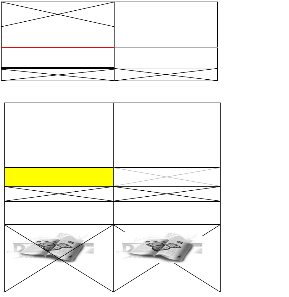
There are helper classes in the InDesign API that are used to specify location, dimension of cells, and areas
within tables. The abstractions used to specify these are shown in the following figure. For this example,
the resolution of the underlying grid is 4 (rows) by 3 (columns). Cells can consist of merged elements on
this underlying grid.
Table-structure example:
Anchor cells versus grid elements
The top-left of a cell is its anchor.
Chapter Update Status
CS6 Unchanged
GridAddress(0,0) GridSpan(1,3)
GridAddress(1,0) GridSpan(1,3)
GridAddress(2,0) GridSpan (1,2) GridAddress(2,2)
GridSpan(1,1)
GridAddress (3,0)
GridSpan(1,1)
GridAddress(3,1)
GridSpan(1,1)
GridAddress(3,2)
GridSpan(1,1)
Whole table:
GridArea(0,0,4,3)
CHAPTER 1: Tables Concepts 12
A grid element is a unit on the underlying grid. Grid elements may or may not be anchor cells.
A cell can comprise multiple elements on the underlying grid, but there is at most one anchor point per
cell.
To access the text content of a cell, some API methods require a GridAddress that refers to an anchor,
whereas other methods can work with a grid element that is not necessarily an anchor.
GridAddress
The API helper class GridAddress identifies the location of cells within tables. GridAddress and the other
GridXXX classes are defined in TableTypes.h. In InDesign, GridCoord is an alias for the primitive type int32.
The nondefault constructor for GridAddress is as follows:
GridAddress(GridCoord row, GridCoord column)
where row and column are the row and column, respectively, in which the top-left of the cell is located.
Another key concept is the underlying grid on which measurements are made, consisting of grid
elements.
For example, if a cell is split by a vertical line, this increases the resolution of the grid in the horizontal
direction. The resolution of the grid in a given direction is determined by projecting all cell boundaries
onto an axis in that direction. Adding another vertical line means an additional projection onto the
horizontal axis; that is, an increase in horizontal grid resolution.
The grid lines are not uniformly distributed. The grid is rectilinear.
Determining what row a particular cell is in can become quite complex in a table with many split and
merged cells; that is, tables with many nontrivial GridSpan values. The algorithm to determine the
GridAddress for a particular cell is straightforward:
1. Determine the resolution of the underlying grid. For the horizontal direction, this can be calculated by
projecting all vertical edges to the x-axis (top of the table). Similarly, for the vertical direction, project
all horizontal edges to the y-axis (left of the table).
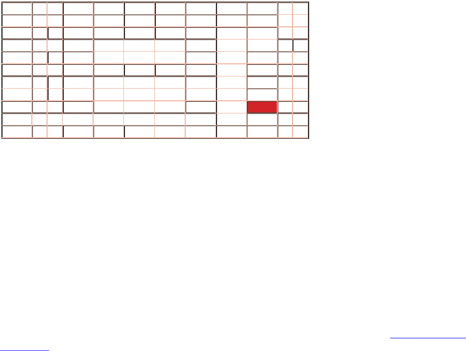
2. Calculate the coordinates on this grid. The process is shown in the following figure. The underlying
grid is just fine enough so there are no cell edges that do not lie on an edge in this underlying grid. In
the figure, the GridAddress of the red cell is (8, 9). The table has an underlying grid 12 rows wide and
11 columns high.
Complex table and underlying grid:
CHAPTER 1: Tables Concepts 13
The GridAddress of a cell can change even if its physical location does not change.
GridSpan
GridSpan is a class that represents the dimension of an area within a table, expressed as coverage of
elements in the notional underlying grid. GridSpan has a constructor with two arguments:
GridSpan(int32 height, int32 width)
where height and columns are the numbers of rows and columns spanned, respectively (on the underlying
grid).
When a table is created (for example, using the Insert Table menu command), each cell in the table has the
trivial GridSpan(1,1). The concept of GridSpan is illustrated in the table-structure figure in “Table structure”
on page 11, which shows the GridSpan for several cell configurations
The GridSpan of a given cell can change as more cells are added to a table—for example, by a cell being
split vertically in a column that this cell spans—even if the physical dimension of the cell of interest does
not vary. GridSpan for a cell is affected by changes in the columns spanned by a cell and the rows spanned
by a cell.
Merging a pair of cells with trivial GridSpan(1,1) gives one cell with a GridSpan(2,1) if the cells are merged
vertically and GridSpan(1,2) if the cells are merged horizontally.
Cells may be unmerged by selecting any merged cells—even the whole table—and choosing Unmerge
Cells.
Splitting a cell with GridSpan(2,1) in the vertical direction gives two cells with trivial GridSpan(1,1).
Splitting the cell horizontally leads to the GridSpan of other cells in the table being recalculated.
GridArea
The GridArea class is used to specify a region within a table. Like GridSpan and GridAddress, GridArea is
calculated on the underlying grid. GridArea has a constructor with four arguments:
GridArea(GridCoord topRow, GridCoord leftColumn, GridCoord bottomRow, GridCoord
rightColumn)
where:
0
1
2
3
4
5
6
7
0123456788,9

CHAPTER 1: Tables Concepts 14
topRow is the row coordinate for the top-left of area.
leftColumn is the column coordinate for the top-left of area.
bottomRow is one greater than the lowest row contained in the area; that is, the row immediately
below the given area and outside it.
rightColumn is one greater than the rightmost column contained in this area; that is, the column
immediately to the right of the given area and outside it.
The choice of using one greater than the last row or column allows for specifying an empty area in a simple
way. That is, an empty GridArea can be specified by writing GridArea(0,0,0,0), for example.
Alternately, given the definition of GridArea, it is equivalent to the following:
GridArea(top, left, row-span, column-span)
Table and cell selection
You can select a whole table or cells within a table, allowing the selected cells to be deleted or their
properties to be altered as a block. Alternately, you can select text within a table cell, allowing the text
properties to be specified for this text run. This is shown in the following figures.
Table cells selected:
Table text selected:

CHAPTER 1: Tables Concepts 15
The selection manager hides the detail of the particular selection type involved from client code. The
intent is that client code interact with the table model only indirectly, through the integrator suite
interfaces, which present a uniform facade to client code. When the cursor is within a table cell, InDesign
can perform operations for any of the three selection types: text selection, cell selection, and table
selection.
Some operations are possible only with table cells selected; for example, the Merge Cells command is
enabled only when multiple table cells are selected.
Table composition
Typically, a table is associated with a text frame. One text frame can contain multiple tables.
The table composer flows the row content of tables between table frames. Once a table becomes too deep
for the containing text frame, rows from the table may be flowed to another text frame, if there is one
linked to the current table’s text frame. Only whole rows are flowed by the table composer.
Text composition within a table cell uses the same text-composition engines that operates over normal
text (that is, text outside tables). For more information on text composition, see Chapter 9, “Text
Fundamentals.”
A text frame that contains one or more table rows that are too deep to display is marked as overset. The
overset rows can be flowed to another text frame by linking the frames, exactly as for overset text. The
visual indicator for table cell overset is drawn as a text adornment.
Tables can be wider than the containing text frame; table rows, on the other hand, flow between linked
cells, or the frame is marked as overset.

CHAPTER 1: Tables Design and architecture 16
Table region
A table can be viewed as composed of regions: header rows, footer rows, left column, right column, and
body rows. When inserting a table, headers and footers can be specified in the Insert Table dialog box. A
table style can set different cell styles for each region.
Design and architecture
Table model versus text model
Text-model extensions for tables
The basic text model API is extended to accommodate tables. kTextStoryBoss aggregates interfaces to
support the abstraction of text-story threads, which are spans of characters that represent the text content
of one cell. The text-story thread interface (ITextStoryThread) is aggregated on the kTextStoryBoss class,
which is used to represent the main text flow within a story designated as the primary story thread.
Many higher-level APIs make it possible to manipulate the content of text cells without having to
manipulate the underlying text model directly. The essential API for this is the ITableTextContent interface,
which is aggregated on the kTableModelBoss class. This provides a mechanism to get and set table text in
chunks.
How tables are connected to text
The kTextStoryBoss boss class is the fundamental class that represents the textual content of stories. For
more information, see Chapter 9, “Text Fundamentals.”
A story can contain zero or more tables. Tables can be nested within tables to an arbitrary depth. The
text-model interface (ITextModel) is the fundamental API to interact with stories; for every table, there is an
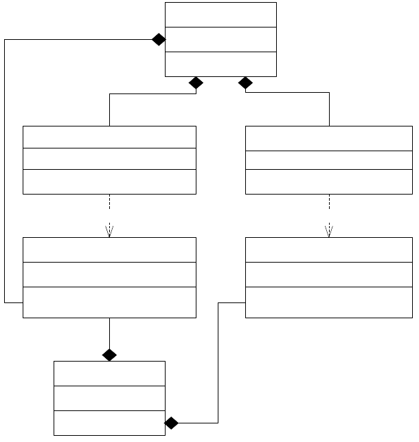
embedding story. An ITextModel interface can be used to obtain the text-cell contents. The UML diagram
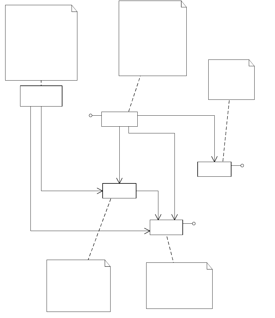
in the following figure is a graphical representation of the relationship between the story and table
models. It shows other key abstractions, such as the table-model list and the TextStoryThreadDictHier.
CHAPTER 1: Tables Design and architecture 17
Text and tables are connected in two ways:
Through the table-model list (ITableModelList, aggregated on kTextStoryBoss). This is relatively
straightforward to understand, but it may be deprecated in future versions of the API.
Through ITextStoryThreadDictHier. This is more complex to understand, but it represents the new
architecture and will be a more dependable API moving forward.
Obtaining a reference to ITableModel through the table model list meant making a series of API calls by
client code to navigate the table architecture. The alternative scheme to obtain a reference to an
ITableModel has a starting point of an ITextModel interface on a kTextStoryBoss object. The difference is
that there is no dependence on ITableModelList.
Another API that allows connections between tables and text to be explored is ITableTextContainer. Given
a table, ITableTextContainer allows client code to determine the embedding text model. This interface is
aggregated on kTableModelBoss.
Table data model
A key abstraction in the table model is the kTableModelBoss boss class. Among other things, this class
encapsulates the data model for a table, allows iteration over the cells in a table, allows access and
modification of the attributes of a table, and provides access to the text chunks (or other content) in a
table. It provides APIs that enable copy, paste, and deletion of content and access to the geometry of the
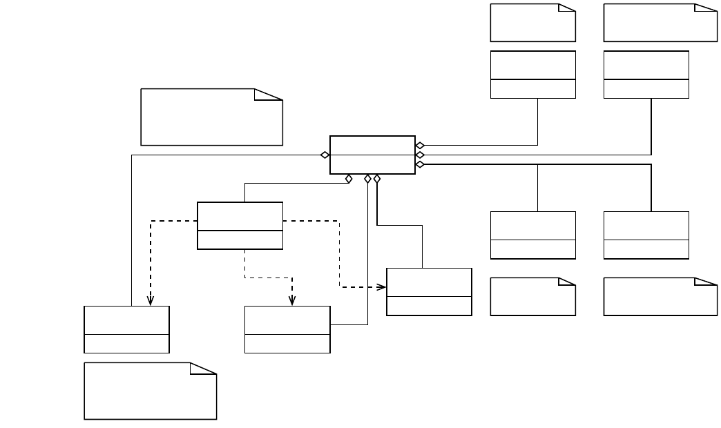
table. For some of the key interfaces aggregated on the boss class, see the following figure.
KTextStoryBoss
text::ITextStoryThreadDictHier table::ITableModelList
table::ITableModeltext::ITextStoryThreadDict
kTableModelBoss
Manages collection Manages collection
1
1
1
1
11
11
1
CHAPTER 1: Tables Design and architecture 18
NOTE: Plug-in (client) code that uses the API exposed through interfaces aggregated on the
kTableModelBoss class should be written to use the selection suites and facades.
The kTableModelBoss boss class aggregates interfaces like ITableModel. This interface has methods to
obtain table iterators; these can be used to navigate a table or iterate through a specific GridArea within a
table. These are STL-like iterators, supporting both forward and reverse iteration.
The ITableAttrAccessor and ITableAttrModifier interfaces also are aggregated on kTableModelBoss. These
provide detailed queries over the set of table attributes and allow applying overrides to table and cell
attributes. In practice, most of the capability required for client code to query attributes and apply
overrides is provided by the more convenient suite interface, ITableSuite. ITableAttrModifier is not likely to
be used directly by client code; all the capabilities exposed by this interface are available through methods
on ITableCommands, which wrap changes to the document object model in a command sequence in a
clean and convenient way for client code to use. Client code should use ITableCommands (rather than
ITableAttrModifier). Refer to the API Reference for details of the interfaces aggregated on kTableModelBoss.
The ITableTextContent interface is aggregated on kTableModelBoss; this allows the text contained within
cells to be accessed. Do not confuse this interface with ITableTextContainer, which is a fundamental API
that represents the connection between a table and the story (kTextStoryBoss) within which it is
embedded.
The kTableModelBoss class represents the data model for an entire table. A table is composed into a set of
table frames (kTableFrameBoss) by the table composer.
<SDK>/source/sdksamples/tablebasics indicates how to acquire a reference to a table model. This code is
in the context of a suite implementation that was added to a concrete-selection boss class.
Access to text in cells Information about text flow in
which table is anchored
Read-only access to
the geometry
Core of the table model subsystem;
table structure, copy/paste, content
boss, and text content manager
access
ITableCommands encapsulates change
to the model in a command sequence
and provides undo/redo services to
client code.
kTableModelBoss
<<interface>>
ITableAttrAccessor
<<interface>>
ITableCommands
<<interface>>
ITableModel
<<interface>>
ITableAttrModifier
<<interface>>
ITableGeometry
<<interface>>
ITableLayout
<<interface>>
ITableTextContent
<<interface>>
ITableTextContainer
ITableLayout is responsible for
mapping the model to the
composed state.
<<use> <<use>
<<use>

CHAPTER 1: Tables Design and architecture 19
Table layout
ITableLayout on kTableModelBoss provides detailed information about the layout of the table.
ITableLayout centralizes the persistent data into one implementation and contains several subclasses
responsible for maintaining table layout information, like Row (representing the composed state of
table-model rows), Frame (mapped to one persistent kTableFrameBoss object), and Parcel (holding
information about IParcel). ITableLayout also provides iterators to access these layout elements. For
example, ITableFrame can be obtained from ITableLayout using the following snippet:
// Assume that iTableModel is a valid table model interface ptr.
InterfacePtr<ITableLayout> tableLayout(iTableModel , UseDefaultIID());
ITableLayout::frame_iterator frameIter = tableLayout->begin_frame_iterator();
ITableLayout::frame_iterator endFrameIter = tableLayout->end_frame_iterator();
while(frameIter != endFrameIter)
{
InterfacePtr<ITableFrame> tableFrame(frameIter->QueryFrame());
...
}
The ITableLayout::Row subclass represents the partial mapping of a model row to a table frame
(represented by the kTableFrameBoss). For each model row, there is one or more corresponding table
layout rows. Each row contains information for each parcel owned by a table cell, like the GridCoord of the
model row it maps and the UID of the table frame with which it is associated. Each layout row is associated
with one table frame.
ITableLayout is responsible for the lifetime management of table frames. Besides containing the layout
rows, the table frame also is responsible for maintaining the link back to the containing Parcel and
associated ParcelList.
Table frames
The rows in a table may not all fit in one text frame. The table composer groups as many rows as will fit into
the first text frame, the second text frame, and so on. A table with many rows may be spread across
multiple, linked, text frames.
These groups of rows are table frames. Each row is part of one and only one table frame.
A table is divided into one or more table frames, spread across one or more text frames. A table frame
(represented by the kTableFrameBoss boss class) is a collection of rows within a text frame. There can be
multiple table frames within a text frame (if the text frame contains multiple tables), so there are at least as
many table frames as text frames.
An occurrence of a table frame leads to its UID for the corresponding kTableFrameBoss object appearing in
the owned item strand.
Tables can have an arbitrary number of table frames, split between linked text frames. If rows cannot be
displayed within the last linked frame in the series, the frame is marked as overset. For each text frame,
there is a corresponding table frame that represents the collection of rows being displayed within the
given text frame.
For each row of a table, there is an occurrence of the kTextChar_Table or kTextChar_TableContinued
character in the text data strand. For more information, see Chapter 9, “Text Fundamentals.”
CHAPTER 1: Tables Design and architecture 20
Cell data model
Cell-content managers
The table architecture supports having different cell-content managers. In practice, InDesign has only text
cell-content manager (with behavior provided by kTextCellContentMgrBoss) and a dummy cell-content
manager. (Future versions of InDesign may add canonical cell-content managers for content types like
images.) You may add your own types of cell-content managers. The main responsibility of a cell-content
manager is to implement the ICellContentMgr interface.
A cell-content manager is created during table creation. You can get the cell-content manager from the
table via ITableModel::QueryContentMgr().
Cell contents
Text cells (the only kind in InDesign) have behavior provided by the kTextCellContentBoss boss class.
Instances of this boss class do not store the content directly but provide a convenient API on top of the
table text model to allow its manipulation. It also is possible to quickly and conveniently manipulate the
text content of a cell through the text model. In this case, API classes like TextIterator can be used to access
a range within the text model.
To set cell text, the ITableCommands::SetCellText API method makes it straightforward to change the cell
text at a given GridAddress. The ITableCommands interface is aggregated on kTableModelBoss.
Code snippets like SnpAccessTableContent.cpp show how to work with the APIs to access cell contents.
See also the TableBasics plug-in and the SnpSortTable.cpp code snippet for examples of accessing and
manipulating table text content.
Cell strands
The kCellStrandBoss cell strand provides storage for cell attributes and aggregates an ITableStrand
interface. This abstraction is likely to be hidden from client code and should be treated as an
implementation feature. Higher-level APIs, like ITableAttrAccessor and ITableCommands, provide methods
to access and modify attributes without having to work at the lower level of representation of the table
strand.
Table attributes
The table architecture supports extensible attributes with inheritance. Attributes can be applied to an
entire table or one or more cells within a table, and there also are a small set of row-specific and
column-specific attributes. As with the text subsystem, attributes are represented by boss classes.
Table-attribute boss classes have names that follow the pattern k<target-entity>Attr<property>Boss,
where <target-entity> is one of Table, Cell, Row, or Column. Some text-cell-specific attributes have TextCell
in the attribute name.
The ITableAttrReport::AppendDescription method reports whether an attribute is a cell-specific,
row-specific, column-specific, or table-specific attribute. To obtain information about the default value of
each attribute, refer to the API Reference.
CHAPTER 1: Tables Design and architecture 21
Table-specific attributes
A table attribute describes one property of an entire table. A table attribute is applied to the table itself;
the attributes collectively define aspects of how the table should appear.
A table attribute is represented by a table attribute boss with a name that conforms to the pattern
kTableAttr<property>Boss.
Row attributes
There are only a few row-specific attributes, which apply to a row or collection of rows within the table.
Row attributes are represented by boss classes. For details, refer to kRowAttrBaseBoss in the API Reference.
These are named to follow the pattern kRowAttr<property>Boss.
Column attributes
There are very few column-specific attributes. For details, see kColAttrBaseBoss in the API Reference. These
are represented by boss classes, which are named to follow the pattern kColAttr<property>Boss.
Cell-specific attributes
There are a wide range of cell-specific attributes that can be overridden. These can be divided into those
that apply to an entire cell and those that are specific to one border (bottom, left, right, top) of the cell. See
the following figure.
Examples of cell-specific attributes:
CHAPTER 1: Tables Design and architecture 22
Text-cell-specific attributes
Some cell attributes apply only to text cells. Text cells are the only supported kind of cell in InDesign, but
future versions may support other cell-content types, so text cells are not generic-cell attributes.
Text-cell attributes are represented by boss classes named to follow the pattern
kTextCellAttr<property>Boss.
This cell has an override (2p) for the bottom
text inset kCellAttrBottomInsetBoss
This cell has an override for the bottom stroke
color kCellAttrBottomStrokeColorBoss
This cell has an override for the bottom tint
kCellAttrBottomStrokeTintBoss
This cell has an override (4 pt) for the bottom stroke
weight kCellAttrBottomStrokeWeightBoss
This cell has no overrides.
This cell has an override
for the rotation (90 deg.)
kCellAttrRotationBoss
This cell has an override
for the rotation (270 deg.)
kCellAttrRotationBoss
This cell has an override for the cell fi ll color
kCellAttrFillColorBoss
This cell has an override for a diagonal tint
kCellAttrDiagnolTintBoss
This is a cell that has had its fi rst line
offset set to be fi xed and with contents
clipped to cell kCellAttrClipBoss
This is a cell that has had its fi rst line off-
set set to be fi xed but without contents
clipped to cell kCellAttrClipBoss
This cell has an inline graphic and some
text that fl ows around it. It has a diagonal
in front of the cell contents
kCellAttrDiagnolsOnTopBoss
This cell has an inline graphic and some
text that fl ows around it. It has a diagonal
behind the cell contents
kCellAttrDiagnolsOnTopBoss
.

CHAPTER 1: Tables Design and architecture 23
Default table attributes
The ITableAttributes interface is aggregated on the workspace (kWorkspaceBoss class) and the document
workspace (kDocWorkspaceBoss class), with interface identifier IID_IDEFAULTTABLEATTRIBUTES.
When a new document is created, this root set of table attributes is applied to the document. This attribute
list is further enhanced when the swatch list is available for the new document, since some of the
attributes reference a swatch (black or none) by UID.
When a new table is created (by kNewTableCmdBoss class, an instance of which is created and executed
through the ITableCommands interface on kTableModelBoss), the root table style is applied to the table.
Table and cell styles
A style can be considered a collection of attributes. Table and cell styles provide a mechanism to name and
persist a particular set of table attributes.
Table style and cell style are analogous to paragraph style and character style in the text. Each style has an
AttributeBossList list that maintains the set of attributes that apply to that style. Access to the attributes in
a style is achieved through the ITableAttributes interface. Cell styles are associated with cell-specific
attributes; however, table styles can be associated with both table attributes and cell-specific and other
attributes.
Styles form a hierarchy rooted at the root style. Each style (except the root style) is based on a style. The
AttributeBossList list for a particular style records only the differences from the style on which it is based;
that is, the set of attributes the particular style overrides.
As with other types of styles, table and cell styles support the Style Group concept. Users can create, edit
and delete folders (called Groups), in the table styles and cell styles palettes. Style group is a collection of
styles or groups. The user also can nest groups inside groups and drag styles within the palette to edit the
contents of a group. Styles do not need to be inside a group and can exist at the root level of the palette.
Table styles
A table style is represented by a kTableStyleBoss. Its IStyleInfo stores general, style-related information like
style name and parent style. Its ITableAttributes interface stores a list of table attributes that are different
from its parent.
The root table style (known in the application user interface as [No Table Style]) contains a complete set of
default table attributes. This defines the default look of the table with no further formatting applied.
The application also defines a basic table style called [Basic Table]. The basic style cannot be deleted, but
you can change it. Initially, the basic style is based on the root style; however, its parent style can be
changed.
Table styles are accessible through the table-style group manager (signature interface
IStyleGroupManager with interface identifier IID_ITABLESTYLEGROUPMANAGER) on the document
(kDocWorkspaceBoss) and session (kWorkspaceBoss) workspace boss classes. When a document is
created, its style group manager inherits the existing set of styles from the session workspace.
THe IStyleGroupManager of the table styles works exactly the same way as that of paragraph and
character styles. For details, see Chapter 9, “Text Fundamentals.”
CHAPTER 1: Tables Design and architecture 24
Cell styles
A cell style is represented by a kCellStyleBoss. Its IStyleInfo store general, style-related information like
style name and parent style. Its ITableAttributes interface (with implementation
kCellStyleCellAttributeListImpl) stores a list of cell-specific attributes that are different from its parent cell
style.
The root cell style (known in the application user interface as [None]) is really nothing; in fact, it defines
nothing. It is synonymous with the root character style. The root cell style cannot be deleted.
Cell styles are accessible through the cell-style group manager (signature interface IStyleGroupManager
with interface identifier IID_ICELLSTYLEGROUPMANAGER) on the document (kDocWorkspaceBoss) and
session (kWorkspaceBoss) workspace boss classes. When a document is created, its style group manager
inherits the existing set of styles from the session workspace.
As with table styles, the IStyleGroupManager of the cell styles works the same way as that of paragraph
and character styles. For details, see Chapter 9, “Text Fundamentals.”
Regional cell styles
Each table style can assign different cell styles for different regions: headers rows, footers rows, first
column, last column, and body rows. When a table style is applied to a table, these regional cell styles are
applied to the appropriate regions.
Regional cell styles are considered as table attributes of a table style. Except for body rows, the values of
two related attributes, “cell style” and “use body,” determine a regional style. See the following table.
Regions and their controlling attributes:
To set a regional cell style, you need to create and apply an appropriate “cell style” attribute as well as
create and apply an appropriate “use body” attribute (except for body rows). To get a regional cell style,
you need to look for these attributes at the complete list of attributes. For more information, see the
“Tables” chapter of Adobe InDesign SDK Solutions.
Table and cell style in the data model
The following figure illustrates a simplified class diagram of table styles, cell styles, and their relationships
to application/document workspaces and the table model. The descriptions of the boss classes give hints
to navigate through these related classes.
Region Cell-style attribute boss Use body attribute boss
Body rows kTableAttrBodyCellStyleBoss kInvalidClass
Header rows kTableAttrHeaderCellStyleBoss kTableAttrHeaderUseBodyCellStyleBoss
Footer rows kTableAttrFooterCellStyleBoss kTableAttrFooterUseBodyCellStyleBoss
Left column kTableAttrLeftColCellStyleBoss kTableAttrLeftColUseBodyCellStyleBoss
Right column kTableAttrRightColCellStyleBoss kTableAttrRightColUseBodyCellStyleBoss
CHAPTER 1: Tables Design and architecture 25
Formatting tables, cells, and table text
Formatting a table
Tables are formatted according to table-specific attributes. Every table is assigned a table style.
ITableAttributes, aggregated on kTableModelBoss, provides coarse-grained access to the locally
overridden attribute list for a particular table. For a given attribute (such as table stroke), InDesign follows
these steps to format a table:
«boss»
kTableModelBoss
«boss»
kWorkspaceBoss
kDocWorkspaceBoss
1
1
ITableAttrModifier::GetTableStyle()
Represents
individual cell.
Its ITableStrand
stores cell attribute
overrides.
The application or document
preferences.
The workspace stores table
styles and cell styles. They
are accessible through
IStyleGroupManager interface
using interface identifier
IID_ITABLESTYLEGROUPMANAGER
and
IID_ITABLESTYLEGROUPMANAGER
respectviely.
1
1..*
ITableModelStorage::QueryNthStrand()
«struct»
kTableStyleBoss
The table style.
It can define different cell
style for different region.
They are defined as attributes
of the table style, thus need
to query appropriate Boss
class to get the regional style.
1
1..*
IStyleGroupManager::FindByName()
The table.
Table's own ITableAttributes
stores local overrides of table
attribute.
It's ITableAttrModifier interface
has access to the table style
applied.
Its ITableAttrAccess encapsulate
the access to applied cell style
for individual cell.
«boss»
kCellStrandBoss
«struct»
kCellStyleBoss
1
1..*
ITableAttrAccessor::GetCellStyle
1
1..*
ITableAttributes::QueryByClassID()
1
1..*
IStyleGroupManager::FindByName()
ITableAttributes
ITableStrand
ITableAttributes
The cell style.
Its ITableAttribute interface
stores the cell specific attribute
of the cell style, includes the
default paragraph style.
CHAPTER 1: Tables Design and architecture 26
1. If there is a local override, format the table according to the override.
2. Otherwise, check the attributes in the table style of the table. If the attribute is among those attributes
defined in ITableAttributes of kTableStyleBoss, format the table according to the value of the attribute
defined in the table style.
3. Otherwise, check the table style’s parent style, until either the attribute is found or the root table style
(which defines all default attributes) is reached. Format the table according the value of the attribute.
Formatting a cell
Cells are formatted according to cell-specific attributes, similar to tables. For a given cell attribute, InDesign
follows these steps to format a cell:
1. If there is a local override, format the cell according to the override (which is defined in ITableStrand on
kCellStrandBoss).
2. Otherwise, check the attribute against the attribute list of the cell style applied to the cell. To
determine the cell style, check if a cell-style override is applied. If so, use the cell style; otherwise, use
the regional cell style defined in the table style of the table.
3. As with table styles, if the attribute is among the attributes defined in ITableAttributes of
kCellStyleBoss, format the cell according to the value of the attribute defined in the cell style.
Otherwise, check the cell style’s parent style, until either the attribute is found or the root cell style
(where nothing is defined) is reached. Format the cell according to the value of the attribute or leave it
as the default format.
Formatting text in a cell
It is helpful to view table attributes as equivalent to paragraph-level attributes for normal text, and cell
attributes as equivalent to character-level attributes. The analogy holds insofar as the effective attributes
are calculated by applying the following in the order listed below:
Table-style attributes
Table-level overrides
Row or column cell style
Cell overrides
The paragraph style defined by the cell
Paragraph override
Character style
Character overrides
To format a character in a table cell, InDesign looks at the reverse of the order above. An override always
takes priority than a style; a smaller range style always takes priority over a coarse one.
Text-formatting priorities:
CHAPTER 1: Tables Essential APIs 27
A cell style can have a paragraph style used in the paragraphs of a cell to which the cell style is applied. If a
cell style does not have a paragraph style defined, any cell that has that cell style applied to it will have all
paragraph-style formatting removed.
Essential APIs
Table commands
ITableCommands is an interface that is aggregated by kTableModelBoss and provides methods to create
and execute table-related commands, instead of having to manipulate the table model at a lower level.
You can use ITableCommands to affect the table model on any specific table area. Some functions in
ITableCommands also are provided by ITableSuite, which instead operates on the currently selected area
of the table. For more details, refer to ITableCommands in the API Reference.
ITableSuite
ITableSuite is a key API for manipulating tables in client code. It provides much of the required capability
for plug-ins, with the exception of insertion and retrieval of cell content.
The ITableSuite interface is aggregated on the integrator suite boss class (kIntegratorSuiteBoss), which
makes it available through the abstract selection. Implementations of this interface are provided on
various concrete-selection boss classes, which are hidden from client code through the facade of the
abstract selection. To obtain ITableSuite, client code should query the selection manager
(ISelectionManager) for the interface.
The integrator suites expose methods that determine whether a capability is present on the current
selection; this always should be tested before trying to exercise a capability. For more detail on the
integrator suites, see Chapter 4, “Selection.”
Suite interfaces typically use this pattern of checking for a service (capability) and, if the abstract selection
supports the capability, calling the method called. For details, refer to ITableSuite in the API Reference.
Use is illustrated in the following code:
bool16 canDeleteTable = iTableSuite->CanDeleteTable();
if(canDeleteTable)
{
iTableSuite->DeleteTable();
}
Overrides Styles
Character overrides Character styles
Paragraph overrides Paragraph styles
Cell overrides Cell style
Table overrides Table style
CHAPTER 1: Tables Essential APIs 28
ITableStyleSuite and ITableStylesFacade
ITableStyleSuite is the selection suite used to manipulate table styles, such as creating and editing table
styles of a selected table; applying a table style to the current selection; and getting and setting local
overrides of table attributes. As with other selection suites, the interface can be acquired through
ISelectionManager.
Aggregated on kUtilsBoss, ITablesStylesFacade is used to manipulate table styles on a table or table style
directly. It is the counterpart of ITableStyleSuite.
The ITableAttrAccessor and ITableAttrModifier interfaces aggregated on the kTableModelBoss provide
access to and mutation of table attributes; however, we recommend you use suites and facades whenever
possible.
ICellStyleSuite and ICellStylesFacade
ICellStyleSuite is the selection suite used to manipulate cell styles, like creating and editing the cell styles
of selected cells; applying a cell style to the current cell selection; and getting and setting local overrides of
cell attributes.
The facade counterpart of ICellStyleSuite is ICellStylesFacade, aggregated on kUtilsBoss.
By using suites and facade, implementation details of cell strands and cell styles storage are encapsulated.
We recommend you use only suites and facades.
29
2Track Changes
This chapter describes the change-tracking features of InDesign and InCopy for software developers.
The chapter has the following objectives:
Explain how change tracking fits into the application architecture.
Show the relationship between a story and the tracked changes it contains.
Describe important APIs for tracking changes.
List common commands and the notification protocols associated with them.
For use cases, see “Working with Track Changes” on page 57.
Concepts
User interface for Track Changes feature
Editors and writers need the ability to selectively track, show, hide, accept, and reject changes as a
document moves through the writing and editing process. The Track Changes features of InDesign and
InCopy address these needs.
Changes are tracked in both InDesign and InCopy, and the API is available in both applications. In galley
view or story view, the user can choose to see changes; tracked changes are not visible in layout view.
The following figure shows the Track Changes panel, which provides most of the relevant user interface.
Chapter Update Status
CS6 Unchanged
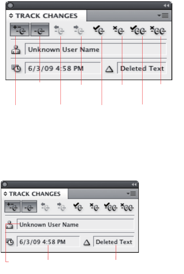
CHAPTER 2: Track Changes Concepts 30
When Track Changes is turned on, changes to text are tracked. When changes are shown, tracked changes
in text are highlighted with the color assigned to the user who made the change. An optional change bar
may appear to the left of the body of the text, to indicate which lines contain tracked changes. The Track
Changes panel displays information about the change at the insertion point, as shown in the following
figure. See InDesign/InCopy Help for more information about the user interface.
There are three types of tracked changes, each indicated in a manner chosen in the Track Changes
Preferences panel:
Added text — Text typed in directly; text copied (not cut) and then pasted within the same document;
and text pasted from another document.
Deleted text — Text that is deleted or cut. Deleted text appears in its original position when tracked
changes are shown.
Moved text — Text cut (not copied) and then pasted within the same document. Moved text is shown
highlighted and boxed, to differentiate it from added text.
Showing and hiding changes
You can show or hide changes in story view or galley view.
CHAPTER 2: Track Changes Data model for Track Changes 31
Navigating tracked changes
If the story contains a record of tracked changes, the user can navigate sequentially through tracked
changes. Navigating to a change selects the change.
Accepting and rejecting tracked changes
The user can accept and reject changes—added, deleted, or moved text—made by any user. For more
information, see InDesign/InCopy Help.
Partially accepting or rejecting tracked changes often results in replacing one tracked change with
multiple tracked changes, and vice versa. When an operation results in multiple tracked changes in
contiguous text, any adjacent tracked changes are concatenated into one contiguous tracked change.
Conversely, accepting or rejecting part of a tracked change may result in multiple, discontiguous tracked
changes with nontracked (normal) text between them.
Copy, cut, and paste behavior
When copying, cutting, or pasting text that includes tracked changes, it is the text itself that is copied, cut,
or pasted—not the tracked change that was applied to the text in its previous location. In other words,
when you copy something out of a tracked change, you copy the text content, not the type of tracked
change. Copying or cutting text from a tracked deletion does not affect the tracked deletion; pasting this
text is treated the same way as adding new text.
Track Changes preferences
The Track Changes panel in the Preferences dialog box contains user settings for tracking changes, like
which types of changes to show and the color of the highlight that indicates a change.
Data model for Track Changes
Redline strand
Tracked changes are recorded in a story (kTextStoryBoss) on the redline strand (kRedlineStrandBoss). They
are accessed through an iterator, RedlineIterator.
The following figure illustrates the relationship between a story and its tracked changes:

CHAPTER 2: Track Changes Data model for Track Changes 32
Track Changes implements kRedlineNewStoryResponderBoss. When a new story is created—for example,
using kNewStoryCmdBoss—the Track Changes plug-in is notified to create and initialize a new text strand,
kRedlineStrandBoss, which is responsible for maintaining the Track Changes information. During the
initialization of the kRedlineStrandBoss, the story's Track Changes state (ITrackChangeStorySettings from
kTextStoryBoss) is set to the state from the session (ITrackChangeAppSettings) using the
kSetRedlineTrackingCmdBoss.
During a normal text operation performed by a text command—like Insert or Delete—each strand
(including kRedlineStrandBoss) on the text story gets a chance to react to the operation. This results in the
IRedlineStrand methods—like Insert or Cut—being called to manage the corresponding change record
before the text is inserted into or cut from the text model.
kRedlineStrandBoss uses a virtual object store (VOS) to store and manage the Track Changes records. Each
change record is represented by the VOSRedlineChange class. In the redline strand, one or more
VOS_RedlineObject objects manage the VOSRedlineChange. We strongly discourage direct access to the
VOS object; instead, the IRedlineDataStrand interface in kRedlineStrandBoss provides RedlineIterator to
access the strand and let you examine and manipulate the change record. You should view RedlineIterator
as the primary access to tracked changes.
kTextStoryBoss
ITextModel
ITextStoryThreadDictHier
...
kOwnedItemStrandBoss
IItemStrand
IStrand
...
kDeletedTextBoss is
connected to kTextStoryBoss
through the owned item
strand, but the deleted text
content is maintained as a
separate story thread in the
story.
kDeletedTextBoss
IDeletedTextData
IOwnedItem
...
ITextStoryThreadDict
ITextStoryThread
...
kRedlineStrandBoss
IRedlineDataStrand
IStrand
...
IItemStrand::
GetNthOwnedUID()
ITextModel::
QueryStrand()
IRedlineDataStrand::
NewRedlineIterator()
VOS_RedlineObject manages
VOSRedlineChange.
VOS_RedlineObject
RedlineIterator is provided to
access track changes.
RedlineIterator
MoveToPosition
ProcessAccept
Increment
GetCurrentChangeRecord
QueryCurrentObject
...
VOSRedlineChange represents a change
record. It indicates the type of the tracked
change as added, deleted, or moved text.
There could be multiple change record at
the same text position because you can
delete text in front of added text.
VOSRedlineChange
1
1..*
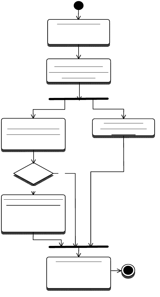
CHAPTER 2: Track Changes Data model for Track Changes 33
Relationship between a story and the tracked changes it contains
Tracking text insertion and deletion
When text is inserted, IStrand::Insert from kRedlineStrandBoss places a change record
(VOSRedlineChange) on a VOS redline object (VOS_RedlineObject); length is the number of characters
inserted. When a new story is created, a carriage-return character is inserted at the end of the story. This
means IStrand::Insert from kRedlineStrandBoss is called during the execution of kNewStoryCmdBoss. The
following figure shows the activities in kRedlineStrandBoss when text is inserted into a story.
start
Text model notifies
each strand boss about
the insertion.
User inserts text.
kUserTypeTextCmdBoss is
processed.
Is Track
Changes
on?
Create a change record
at the insertion point.
VOS_RedlineObject is
inserted with a new change
record (VOSRedlineChange).
kRedlineStrandBoss
handles the insertion
IStrand::Insert() is called.
All other strand
bosses handle the
insertion.
Insertion finished.
In Galley view, the tracked
change will be shown if the
user chooses to show tracked
changes.
end
Yes
No
CHAPTER 2: Track Changes Data model for Track Changes 34
When text is deleted, a change record (VOSRedlineChange) is placed on a VOS redline object
(VOS_RedlineObject), on the character following the deleted text. Also, the text is copied to a story thread,
so the deleted text can be retrieved and displayed in story view or galley view.
To preserve the deleted text before it is deleted, Track Changes implements a kRedlinePreprocessorBoss
service provider, which enables Track Changes to participate in a preprocessing text event, like deletion, so
it can preserve the soon-to-be-deleted text. During deletion, if Track Changes is turned on, and (private)
IRedlineUtils>()->ShouldStoreDelete returns true, RedlinePreProcessor::StoreDeletedText gets called. The
deleted text is represented by an owned item accessed through the kOwnedItemStrandBoss on the text
story, with an owned-item boss (kDeletedTextBoss) anchored in the deleted position. A new story thread is
created to hold the deleted text content, and the owned item’s class ID is set to the kDeletedTextBoss.
The following figure shows the activities in kRedlineStrandBoss when text is deleted from a story.
kRedlineStrandBoss Activity on text deletion:
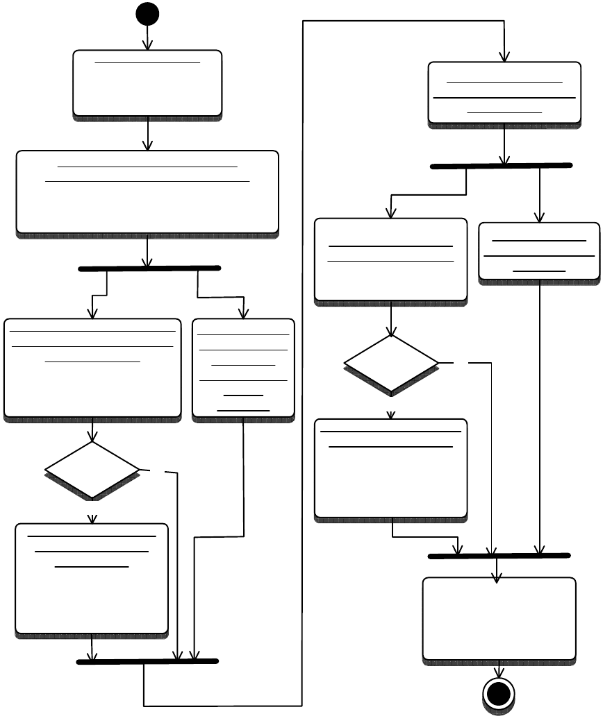
CHAPTER 2: Track Changes Data model for Track Changes 35
In some situations, there can be multiple VOSRedlineChanges for one text position. The most likely
scenario is one in which the character following the deleted text is an insertion change; then the insertion
change is nested. In this case, it is possible to iterate through changes and have the current text position
be the same, even though the iterator was incremented or decremented (through
RedlineIterator::Increment or RedlineIterator::Decrement). Calling the accessor methods returns the
appropriate change-record information given the state of an internal flag, or the useUI flag if passed when
the iterator was constructed with NewRedlineIterator. Accepting a nested insertion does not affect the
deletion; however, rejecting a nested insertion rejects the deletion.
start
Text model pre-notifies delete
preprocessors about the deletion.
delete preprocessor is a service provider
with service ID kEditCmdPreProcessService
User deletes text.
kUserTypeTextCmdBoss is
processed.
Is Track
Changes
on?
Create a change record
at the deletion point.
VOS_RedlineObject is
inserted with a new change
record (VOSRedlineChange).
kRedlineStrandBoss
handles the deletion.
IStrand::Cut() is called.
All other strand
bosses handle the
deletion.
Deletion finished.
In Galley view, the tracked
text will be shown if user
chooses to show tracked
deletions.
end
Yes
No
Should
preserve
deleted text?
A new story thread is
created to hold the
deleted text.
kDeletedTextBoss (an owned
item boss) is created, it
provides access to the new
story thread.
kRedlinePreprocessorBoss
handles the preprocessing
for the deletion.
ITextCommandPreProcess::
DeletePreProcess() is called.
Text model notifies
each strand boss about
the deletion.
All other delete
preprocessors
handle the
preprocessing
for the
deletion.
Yes
No
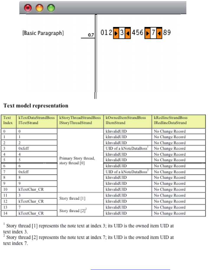
CHAPTER 2: Track Changes Data model for Track Changes 36
Example: Track Changes in action
Consider the example of the story “0123456789,” with “3” and “7” converted to notes, as shown in the
InCopy story view in the following figure. This story, with embedded owned items—the
notes—demonstrates what happens in a text story when deletion and insertion are performed while Track
Changes is turned on. Below the story view in the figure is a table showing the fundamental text model
data, with which you can understand the basics of change tracking.
Track Changes action 1: Before Track Changes is turned on:
NOTE: The complete text data model is more complex than that depicted in this table. For more
information on the text model, see Chapter 9, “Text Fundamentals.”
In the table, the columns are interpreted as follows:
The first column represents the text index in the text model.
CHAPTER 2: Track Changes Data model for Track Changes 37
The second column represents the text data stored in the kTextDataStrandBoss object. The visual story
representation you see in the InDesign or InCopy document window does not necessarily represent
the sequence in which the data is stored in the text model. For example, although the note with
content “3” is located between characters “2” and “4,” the real note-text content is stored in a different
story thread in text index 11. Between characters “2” and “4,” the text data is inserted with a note
anchor.
The third column from the left shows the text-story threads. The InDesign text engine uses an owned
item strand (kOwnedItemStrandBoss) to figure out where to find the corresponding text when the
engine comes to compose the text.
The fourth column shows the owned-item strand data.
The fifth column shows tracked-change data; the information is obtained from RedlineIterator.
Looking at the text model representation in the preceding figure, see in the kTextDataStrandBoss that
each note is anchored at the note’s visual location (text index 3 and text index 7) with a special anchor
character, 0xfeff. At the same position, the UID of the note’s kNoteDataBoss is stored through the
IItemStrand interface on the kOwnedItemStrandBoss. The kNoteDataBoss also aggregates the interfaces
to access the story threads that store the note contents. To find the text content of a note, you can go
through the kOwnedItemStrandBoss to find its corresponding story thread. Because the story was entered
with Track Changes off, the kRedlineStrandBoss does not contain any tracked-change information at this
point.
Using the SnippetRunner SnpInspectTextModel snippet, you can inspect the text model while Track
Changes is turned on. Some methods in SnpInspectTextModel were used to produce the results you see in
the preceding figure. The SnpInspectTextModel::InspectTrackChange method uses the RedlineIterator to
examine the change record under each text index in the story. The
SnpInspectTextModel::InspectStoryThreads and SnpInspectTextModel::CountStoryOwnedItems methods
were used to examine the story threads, owned item, and text data.
Next, turn on Track Changes, select the text “234,” and delete the selected text. The result is shown in the
following figure.

CHAPTER 2: Track Changes Data model for Track Changes 38
Track Changes action 2: Delete one block of text:
Unlike the note—which uses a kTextChar_ZeroSpaceNoBreak character to anchor the note—Track
Changes does not insert anchor characters for deleted text in text position 2 in the kTextDataStrandBoss;
that position is occupied by the character “5” after the deletion. The text model uses kRedlineStrandBoss
to maintain tracked-change information. In text index 2 of the kRedlineStrandBoss, there is a change
record with the type kDelete stored in that location, which tells the text model that at least one character
was deleted at that location. Similar to the inline note, the tracked change stores the deleted text in an
owned-item boss, kDeletedTextBoss. In text index 2, where the text was deleted, the
kOwnedItemStrandBoss stores the UID of the kDeletedTextBoss. The kDeletedTextBoss aggregates
ITextStoryThread and ITextStoryThreadDict, as shown in the first figure in “Redline strand” on page 31,
which points back to the text-story thread, represented by the kStoryThreadStrandBoss of the text model.
The result of SnpInspectTextModel.cpp can show you the UID stored in the kOwnedItemStrandBoss and
the UID of the associated story thread, so you can make the connection. For simplicity, the UIDs are
omitted from the table in the preceding figure.
! !
" # $
!
% &
' $$$ $
%
# (
& )
* +
,-
./
( "
) $$$ $
"
! '
!! +
.!/
!
!" %
!% +
."/
"
!' *
!# +
.%/
%
!.!/0"1
"2 3)- 04
2
"."/0.!/1
)2
%.%/0'1
'2
CHAPTER 2: Track Changes Data model for Track Changes 39
Notice how embedded content is being stored in the event, such as deletion, and how it is tracked. The
deleted text includes a note. The UID of the kDeletedTextBoss in position 2 leads to story thread [1] in the
preceding figure. By examining this thread’s corresponding kTextdataStrandBoss and
kOwnedItemStrandBoss, you can see that all attributes in the predeletion indices 2–4 are preserved in
indices 8–9, including the deleted note’s information. The kRedlineStrandBoss does not keep any change
record in the position under the deleted text-story thread, though. In the
SnpInspectTextModel::InspectTrackChange, when in the deleted text thread, the text index is not used to
create a RedlineIterator. Instead, the corresponding deleted text position is found, and that position is
used in the primary story thread to check its corresponding change record. To find the deleted note’s text
content, go to the story thread [1], which represents the deleted text. From there, find the UID of the
deleted note’s kNoteDataBoss, which leads to the thread [2]. Note that the text content of the inline note in
text index 7 is now the text thread [3], because a new story thread was created and inserted to hold the
deleted text.
Next, select and delete the text “67.” The result is shown in the following figure. Since both notes are
deleted, you will not see any UIDs of kNoteDataBoss if you examine the kOwnedItemStrandBoss in the
primary story-thread range; they are all preserved in the deleted text’s threads, which can be reached
through the UIDs of the kDeletedTextBoss at indices 2 and 3. Also, the kRedlineStrandBoss data shows
there are kDelete items at both index 2 and index 3, which is consistent with what you see in story view, in
which the deleted text is displayed immediately before the character “5” (at index 2) and immediately
before the character “8” (at index 3).
Track Changes action 3: Delete two blocks of text:
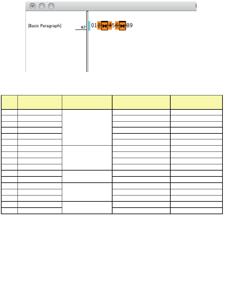
CHAPTER 2: Track Changes Data model for Track Changes 40
Next, select and delete all text. The result is shown in the following figure. The deleted text contains all
original text and notes. Only one kDeletedTextBoss is needed to maintain the deleted text.
Track Changes action 4: Delete all text:
! !
" # $
!
% ( $
%
' )
# +
,-
./
& "
* $$$
$
"
( '
) +
.!/
!
! %
!! + ."/
"
!" &
!% $$$
$
'
!' +
.%/
%
!# *
!&
+ .'/
'
!.!/0"1
"2 3*- 04
2
"."/0.!/1
*2
%.%/0%1
%2 3!%- 04
2
'.'/0.%/1
!%2
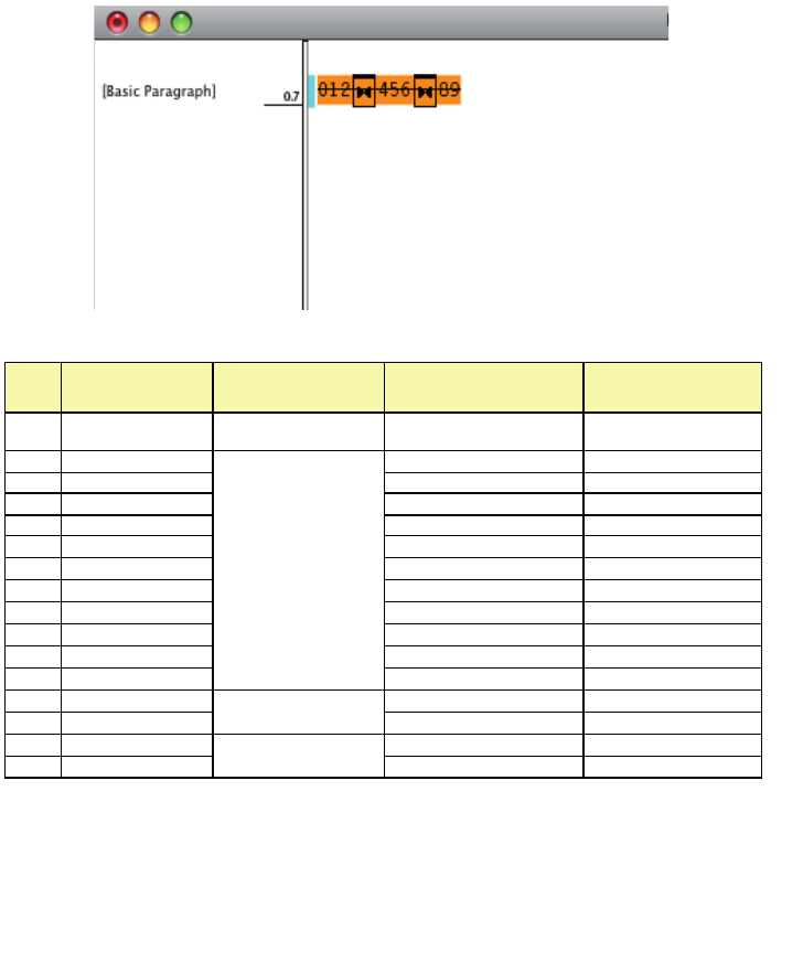
CHAPTER 2: Track Changes Data model for Track Changes 41
Next, select “01234” and accept the change, then select “678” and reject the change. The result is shown in
the following figure. When you accept the deletion, the tracked change no longer tracks that portion of
deleted text; therefore, the tracked text “01234” is removed from the story view, and the corresponding
kDeletedTextBoss is purged. The only way to get the deleted text back is through the undo operation.
Because you rejected the change partially (“6[7]8” out of the tracked “56[7]89,” where “[7]” is a note), the
tracked text is not in a contiguous block; therefore, two separate kDeletedTextBoss objects are needed,
one to track “5” and one to track “9.”
Track Changes action 5: Partially accept and partially reject a change:
+ ,-
./
$
!
!
" !
% "
' $$$ $
"
# '
& #
* &
( $$$ $
%
) (
! )
!! +
.!/
!
!" %
!% + ."/
"
!' *
!# + .%/
%
!.!/01
2 3"'(-
042
"."/0'
.!/1'2
%.%/0(
.!/1(2
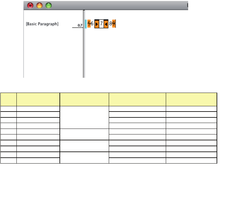
CHAPTER 2: Track Changes Data model for Track Changes 42
Next, insert “1234” before the deleted “5.” Because Track Changes is still turned on, the new insertion is
tracked, as shown in the following figure. In this case, the inserted text is simply added into the text model
as normal: the data is added into kTextDataStrandBoss at a normal text index, and no owned item boss
needs to be created. The corresponding position in the kRedlineStrandBoss is marked as kInsert. With this
one flag, the text model can hide, show, accept, or reject a tracked change when user chooses to do so.
Track Changes action 6: Insert a block of text:
&
!
!
"
" (
% +
,-
./
%
' #
# + .!/
!
& *
* + ."/
"
( )
) + .%/
%
!
.!/1
2
"
."/!./1
!2
%
.%/%1
%2
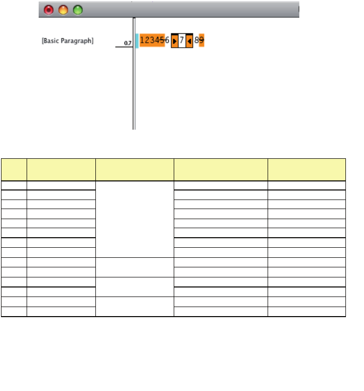
CHAPTER 2: Track Changes Data model for Track Changes 43
Next, select the text “3” and convert it to a note. The result is shown in the following figure. The note is
created in text index 2 and tracked as inserted text in that position. The tracked text’s change information
in the kRedlineStrandBoss will not change until the user accepts or rejects the change or the text is cut. So,
if you highlight the note in index 2 and accept the change, you will see the kRedlineStrandBoss change the
change data from kInsert to none.
Track Changes action 7: Convert tracked text to a note:
!
! "
" %
% '
' & !
!
#
"
& (
* +
,-
./
!
%
( #
) + .!/
!
! *
!! + ."/
"
!" )
!%
+ .%/
%
!
.!/'1
'2
"
."/#./1
#2
%
.%/*1
*2

CHAPTER 2: Track Changes Data model for Track Changes 44
Track Changes preferences
An ITrackChangeAppSettings interface is added to the kWorkspaceBoss. This interface is responsible for
maintaining the Track Changes settings in the Preferences panel. To access this interface, you can do the
following:
!
! "
" !#
% '
' & "
#
%
& (
* +
,-
./
'
( %
) + .!/!
! #
!! + ."/"
!" *
!%
+ .%/%
!' )
!# + .'/'
!
.!/"./1
"2
"
."/'
./1'2
%
.%/#./1
#2
'
.'/*
./1*2
#
-
2-
2

CHAPTER 2: Track Changes Key client APIs 45
InterfacePtr<IWorkspace> workSpace(GetExecutionContextSession()->QueryWorkspace());
InterfacePtr<ITrackChangeAppSettings> tcAppSettings(
(ITrackChangeAppSettings*)workSpace->
QueryInterface(IID_ITRACKCHANGEAPPSETTINGS));
if (tcAppSettings != nil)
{
// Do something with the preference.
}
The ITrackChangeStorySettings interface (IID_ITRACKCHANGESTORYSETTINGS) is added to the
kTextStoryBoss. This interface’s responsibility is to maintain story-level settings, like whether Track
Changes is turned on for the story. To access this interface, you can do the following:
// Assume textModel is a valid ITextModel interface pointer.
InterfacePtr<ITrackChangeStorySettings>
trackSetting(textModel, IID_ITRACKCHANGESTORYSETTINGS);
if (trackSetting && trackSetting->GetIsTracking())
{
// Track Changes is on for this story. Do something.
{
Key client APIs
Track Changes utilities
ITrackChangeUtils, added to the kUtilsBoss, provides convenient methods for a client to access some Track
Changes features. For more information, see ITrackChangeUtils.h.
Suite interfaces
Much of the capability required for client code to work with Track Changes is provided in a high-level suite
interface, ITrackChangeSuite, which is available through a reference to a selection. To obtain the interface,
query a selection manager (ISelectionManager) for the ITrackChangeSuite interface. For information on
obtaining a reference to the selection manager, see Chapter 4, “Selection.” ITrackChangeSuite
encapsulates the details of interacting with the Track Changes model and hides details about the selection
format that is active, providing a capability-driven API that can be used to accept and reject tracked
change. Other suites for accessing Track Changes are discussed in this section.
ITrackChangeSuite
ITrackChangeSuite is a key API for manipulating Track Changes in client code; most Track Changes
user-interface functions are provided through this interface. It provides much of the required capability for
plug-ins.
The ITrackChangeSuite interface is aggregated on the integrator-suite boss class (kIntegratorSuiteBoss),
which makes it available through the abstract selection. Implementations of this interface are provided on
concrete-selection boss classes kGalleyTextSuiteBoss and kTextSuiteBoss, which are hidden from client
code through the facade of the abstract selection. To obtain ITrackChangeSuite, client code should query
the selection manager (ISelectionManager) for the interface, as shown below:
CHAPTER 2: Track Changes Key client APIs 46
InterfacePtr<ITrackChangeSuite> iTCSuite
(ac->GetContextSelection(), IID_ITRACKCHANGESUITE);
if (iTCSuite)
// Do something with Track Changes through the suite.
Generally, ITrackChangeSuite is active when the text cursor is active in story view or galley view. Suite
interfaces typically use this pattern of checking for a service or capability, and if the abstract selection
supports this capability, the method can be called; however, ITrackChangeSuite does not follow this
pattern. The ITrackChangeSuite::CanAccept and ITrackChangeSuite::CanReject methods check only
whether the workspace preference ITrackChangeAppSettings::GetUserCanAcceptRejectChanges method
returns true. If true—and the story is not locked—the CanAccept and CanReject methods always return
true.
IChangesReviewSuite
Because ITrackChangeSuite does not provide meaningful CanDo-types of methods (see
ITrackChangeSuite), another suite interface, IChangesReviewSuite, is provided for determining whether a
tracked change is available in the current text position. The application uses this suite to decide whether
the user interface related to Track Changes—like the menu and the Track Changes toolbar
buttons—should be enabled or disabled when the text selection changes. For example, to determine
whether the current cursor position has a change record the user can accept, call
IChangesReviewSuite::IsAcceptChangeEnabled.
ITrackChangeSettingsSuite
IChangesReviewSuite is mainly responsible for getting and setting a story’s change-tracking state. You also
can apply the state to multiple stories at the same time with one call.
IChangeInfoSuite
IChangeInfoSuite provides one method to get the current tracked-change information, based on the
current text selection. IChangeInfoSuite returns the information in a public ChangeInfo class, which stores
three pieces of information: story user, date of change, and change type. This suite is used by the
application for the Change Info panel.
RedlineIterator
RedlineIterator is the primary access to the tracked change object; it also provides for processing
acceptance and rejection of tracked changes. Create a new iterator using
IRedlineDataStrand::NewRedlineIterator as shown below; the caller is responsible for destroying the
iterator.
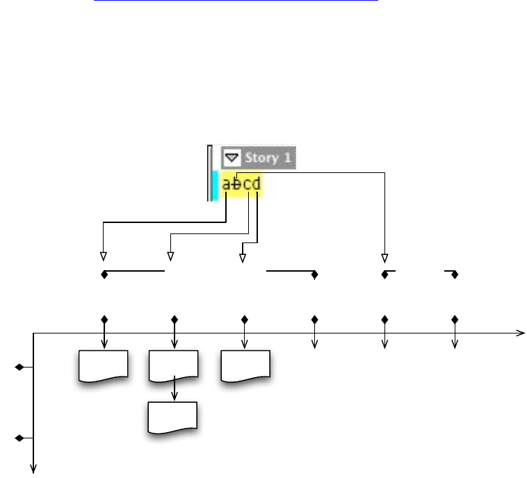
CHAPTER 2: Track Changes Key client APIs 47
// Assume textModel is a valid ITextModel interface pointer.
InterfacePtr<IRedlineDataStrand> redline((IRedlineDataStrand*)textModel
->QueryStrand(kRedlineStrandBoss, IRedlineDataStrand::kDefaultIID));
if (redline)
{
RedlineIterator *redIterator = redline->NewRedlineIterator(0L);
if (redIterator)
{
// Use the iterator to access the Track Changes.
// When done with the iterator, delete it!
delete redIterator;
}
}
As discussed in “Example: Track Changes in action” on page 36, there may be more than one change
record under each text index. Currently, the only situation that results in multiple change records under
one text index is the deletion of text that results in a deleted text record in front of added text, which
causes a deletion record and an insertion record at the same text position. The records are managed so the
deletion always is at change position 0. The underlying change record can be viewed as being laid out in a
two-dimensional map, as shown in the following figure.
Conceptual change record structure map:
The RedlineIterator::MoveToPosition method provides the means to move in this two-dimensional space:
virtual bool16 MoveToPosition(TextIndex t, int32 c = -1) = 0;
The first parameter lets you go horizontally (i.e., navigate by the text), and the second parameter lets you
go vertically (i.e., navigate among change records at the same text index).
You also can use RedlineIterator::Increment or RedlineIterator::Decrement to access the change record.
When you use Increment, it first goes down to the next change record on the same text index, then moves
to the next text index that has a change record, and then goes downward from the first record in that
index before moving to the next index again. SnpInspectTextModel::InspectTrackChange uses this
method to iterate through all change records in a story.
Text Index
Change record position
kDelete
0
1
012 34 5
ac bcr cr
primary story thread [0] thread [1]
kInsert
kInsert kInsert
d
CHAPTER 2: Track Changes Key client APIs 48
kDeletedTextBoss
kDeletedTextBoss is anchored as an owned item in the text story. The following code snippet shows one
way to get to the kDeletedTextBoss from the story. After you gain access to the owned item, you have
access to the whole kDeletedTextBoss, and you can use it to find the primary story thread index where the
owned item is anchored.
// Find deleted text owned item in current storyRef.
InterfacePtr<ITextModel> textModel(storyRef, UseDefaultIID());
InterfacePtr<IItemStrand> itemStrand((IItemStrand*)textModel
->QueryStrand(kOwnedItemStrandBoss, IItemStrand::kDefaultIID));
int32 mainStoryLength = textModel->GetPrimaryStoryThreadSpan() - 1;
// Collect owned item from the story.
Text::CollectOwnedItems(textModel, 0, mainStoryLength, &ownedItemList);
if (ownedItemList.Length() > 0)
{
// Remove non-deleted text items.
for (i = ownedItemList.Length()-1; i>=0; i--)
{
if (ownedItemList[i].fClassID != kDeletedTextBoss)
ownedItemList.Remove(i);
}
}
See the following figure for an illustration of kDeletedTextBoss and its key interfaces.
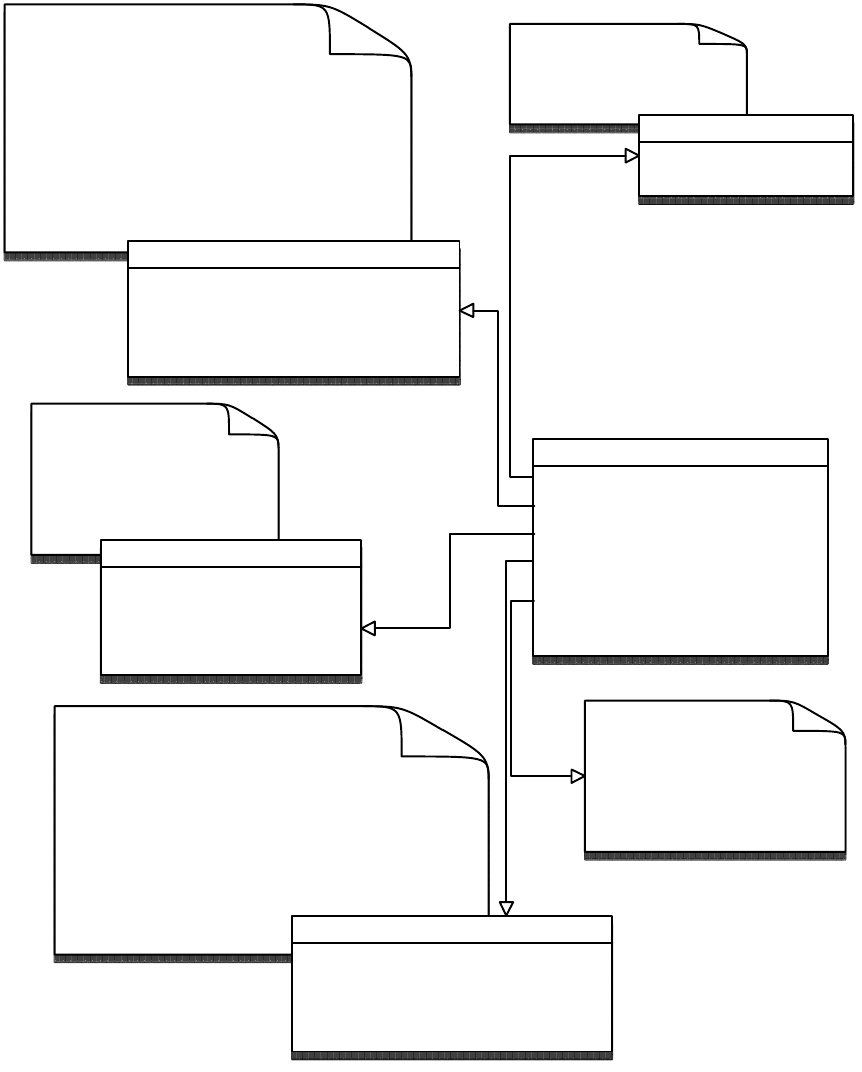
CHAPTER 2: Track Changes Useful commands and associated notification protocols 49
Useful commands and associated notification protocols
This section summarizes some of the most common commands related to Track Changes. Critical data
interfaces that users of the command must supply are explained, and the notification protocol associated
with the command is listed.
Implements the story
thread (ITextStoryThread)
that represents the
deleted text content.
kDeletedTextBoss
IDeletedTextData
IOwnedItem
ITextStoryThread
ITextStoryThreadDict
IParcelList
ITextParcelList
...
storage for the deleted
text story UID.
The IOwnedItem and ITextModelMemento
(on a separate boss,
kDeletedTextModelMementoImpl)
implementations are the hooks that allow the
deleted text to be managed when it is
affected by text model operations. However,
when Track Changes is turned on, text
deletion is handled by a pre-processor.
IOwnedItem
CollectStoryRanges
GetNumSpecialAnchorChars
...
IDeletedTextData
GetStoryUID
SetStoryUID
ITextStoryThread
GetDictUID
GetTextStart
QueryTextModel
...
Deleted text's (kDeletedTextBoss)
ITextStoryThreadDict implementation manages
only one story thread.
Many instances of kDeletedDataBoss can be
embedded in a story, but each has its own
deleted text data (kDeletedTextBoss) with its
own dictionary (ITextStoryThreadDict) and story
thread(ITextStoryThread). ITextStoryThreadDict
QueryThread
GetAnchorTextRange
GetThreadBlockTextRange
...
Because deleted text does
not support display of
composed text, all of the
parcel-related interface are
implemented as stubs.

CHAPTER 2: Track Changes Useful commands and associated notification protocols 50
kSetRedlineTrackingCmdBoss
Description
Sets the tracking flag for the story or workspace (whichever is specified in the command’s item list) to the
specified boolean setting. Changes remain tracked, but no new changes are tracked.
Item list
UIDList that contains either the workspace pointer (from
GetExecutionContextSession()->QueryWorspace()) or UIDs of the text stories for the setting change.
Data interface
IBoolData, to turn Track Changes on or off for the target.
kSetTrackChangesPrefsCmdBoss
Description
Sets the session preference ITrackChangeAppSettings to the settings specified in the data interface.
Item list
UIDList that contains the workspace pointer (from GetExecutionContextSession()->QueryWorspace()).
Data interface
ITrackChangesPrefsCmdData can be changed to the user’s preference. The following table shows the
default values in ITrackChangesPrefsCmdData. A Set method changes all preference data, and individual
Get or Set methods modify individual attributes.
Attribute Default value
Added Text Background Color Choice ITrackChangeAppSettings::kUseUserColorBG
Added Text Background Color Index 2 (InCopyUIColors => yellow)
Added Text Color Choice ITrackChangeAppSettings::kUseGalleyColor
Added Text Color Index 1 (InCopyUIColors => black)
Added Text Marking 0 (ITrackChangeAppSettings::kNone)
Change Bar Color Index 18 (InCopyUIColors => cyan)
Change Bar Location 0 (ITrackChangeAppSettings::kLeftMargin)
Deleted Text Background Color Choice ITrackChangeAppSettings::kUseUserColorBG
CHAPTER 2: Track Changes Useful commands and associated notification protocols 51
Notification
Notify kSessionBoss with kSetTrackChangesPrefsCmdBoss message along with the
IID_ITRACKCHANGEAPPSETTINGS protocol.
kActivateRedlineCmdBoss
Description
Create the kRedlineStrandBoss, and attach it to the story. It synchronizes the redline strand to the story to
which it is attached. Usually, the kRedlineStrandBoss is created when a new story is created. If the redline
strand cannot be found, this command can be processed to get the strand back. The following is one way
to check whether a redline strand is available in a story:
InterfacePtr<IRedlineDataStrand> redlineStrand
((IRedlineDataStrand*)textModel->QueryStrand(
kRedlineStrandBoss,
IRedlineDataStrand::kDefaultIID));
If QueryStrand returns a valid IRedlineDataStrand interface pointer, a redline strand is connected to the
story.
Item List
UIDList that contains the UID of the text story to which the redline is supposed to be connected.
Deleted Text Background Color Index 2 (InCopyUIColors => yellow)
Deleted Text Color Index 1 (InCopyUIColors => black)
Deleted Text Marking 1 (ITrackChangeAppSettings::kStrikethrough)
Deleted TextColor Choice ITrackChangeAppSettings::kUseGalleyColor
Moved Text Background Color Choice ITrackChangeAppSettings::kUseUserColorBG
Moved Text Background Color Index 2 (InCopyUIColors => yellow)
Moved Text Color Choice ITrackChangeAppSettings::kUseGalleyColor
Moved Text Color Index 1 (InCopyUIColors => black)
Moved Text Marking 3 (ITrackChangeAppSettings::kOutline)
Show Added Text kTrue
Show Change Bar kTrue
Show Deleted Text kTrue
Show Moved Text kTrue
Spellcheck Deleted Text kTrue
Attribute Default value
CHAPTER 2: Track Changes Useful commands and associated notification protocols 52
kDeactivateRedlineCmdBoss
Description
This is the reverse of kActivateRedlineCmdBoss. To delete the kRedlineStrandBoss associated with a story,
this command purges the strand from the associated VOS disk page, deregisters the redline strand from
the text model, and removes the UID of the kRedlineStrandBoss from the database. This command accepts
all changes before it deletes the strand.
Item list
UIDList that contains the UID of the text story from which the redline is supposed to be disconnected.
kRejectAllRedlineCmdBoss
Description
Rejects all tracked change (redline) data in a story.
Item list
UIDList that contains the UID of the text story for which the redline data is supposed to be rejected.
Data interface
IBoolData with interface ID IID_IRESTORESELECTIONDATA. This interface defaults to false. Set to true to
restore the selection.
Notification
Notify kTextStoryBoss with the kRejectAllRedlineCmdBoss message and IID_ITEXTMODEL protocol. Notify
kDocBoss with the kRejectAllRedlineCmdBoss message and IID_REJECTALLREDLINE_DOCUMENT
protocol.
kRejectRangeRedlineCmdBoss
Description
Rejects changes in the specified range. If the range’s start index or end index corresponds to a deletion,
this deletion is not rejected; such deletions should be detected and rejected individually if desired.
Item list
UIDList containing UID of the text story for which the redline data is supposed to be rejected.
CHAPTER 2: Track Changes Useful commands and associated notification protocols 53
Data interface
IRedlineChangeData — Not needed. The command finds the change record based on the text index
on which it is working. This interface is a placeholder for original change data, so it can be preserved.
IRangeData with IID_IRANGEDATA — The range of text for which you want to reject the change
records.
IBoolData with IID_IBOOLDATA — Not needed.
IBoolData with IID_IRESTORESELECTIONDATA — The default is false; true restores the selection.
Notification
Notify kTextStoryBoss with the kRejectRangeRedlineCmdBoss message and IID_ITEXTMODEL
protocol.
Notify kDocBoss with the kRejectRangeRedlineCmdBoss message and
IID_REJECTRANGEREDLINE_DOCUMENT protocol.
kRejectRedlineCmdBoss
Description
Rejects the change record at the text index specified by the user.
Item list
UIDList containing the UID of the text story for which the redline data is to be rejected.
Data interface
IRedlineChangeData with IID_IREDLINECHANGEDATA — Set this data interface to a
VOSRedlineChange pointer returned from the RedlineIterator::GetCurrentChangeRecord. The
GetCurrentChangeRecord takes a TextIndex and returns the current track change record for that
index.
IRangeData with IID_IRANGEDATA — The text index of the change record to be rejected should be
used as the range start and range end.
IBoolData with IID_IBOOLDATA — Set to false to prevent notification if rejection is within reject-all
context.
IBoolData with IID_IRESTORESELECTIONDATA — This interface defaults to false. Set to true to restore
selection.
Notification
The command notifies only when the IBoolData (with IID_IBOOLDATA) is set to false.
Notify kTextStoryBoss with the kRejectRedlineCmdBoss message and IID_ITEXTMODEL protocol.
CHAPTER 2: Track Changes Useful commands and associated notification protocols 54
Notify kDocBoss with the kRejectRedlineCmdBoss message and IID_REJECTREDLINE_DOCUMENT
protocol.
kAcceptAllRedlineCmdBoss
Description
Accepts all tracked change (redline records) in a story.
Item list
UIDList containing the UID of the text story for which the changes are to be accepted.
Data interface
IBoolData with IID_IRESTORESELECTIONDATA — The default is false. True restores selection.
Notification
Notify kTextStoryBoss with the kAcceptAllRedlineCmdBoss message and IID_ITEXTMODEL protocol.
Notify kDocBoss with the kAcceptAllRedlineCmdBoss message and IID_ACCEPTREDLINE_DOCUMENT
protocol.
kAcceptRangeRedlineCmdBoss
Description
Accepts changes in the specified range. If the range start index or end index corresponds to a deletion, it is
not accepted. Such deletions should be detected and accepted individually if desired.
Item list
UIDList containing the UID of the text story for which the changes are to be accepted.
Data interface
IRedlineChangeData — Not needed. The command finds the change record based on the text index
on which it is working. This interface is a placeholder for the original change data, so it can be
preserved.
IRangeData with IID_IRANGEDATA — This is the range of text for which you want to accept the change
record.
IBoolData with IID_IBOOLDATA — Not needed.
IBoolData with IID_IRESTORESELECTIONDATA — The default is false; true restores selection.
CHAPTER 2: Track Changes Useful commands and associated notification protocols 55
Notification
Notify kTextStoryBoss with the kAcceptRangeRedlineCmdBoss message and IID_ITEXTMODEL
protocol.
Notify kDocBoss with the kAcceptRangeRedlineCmdBoss message and
IID_ACCEPTRANGEREDLINE_DOCUMENT protocol.
kAcceptRedlineCmdBoss
Description
Accepts the change record at the text index specified by the user
Item list
UIDList containing the UID of the text story for which the change is to be accepted.
Data interface
IRedlineChangeData IID_IREDLINECHANGEDATA — Set this data interface to a VOSRedlineChange
pointer returned from RedlineIterator::GetCurrentChangeRecord, which takes a TextIndex and returns
the current track change record for that index.
IRangeData with IID_IRANGEDATA — The text index of the change record to be accepted should be
used to as the range start and range end.
IBoolData with IID_IBOOLDATA — Set to false to prevent notification if acceptance is within accept-all
context.
IBoolData with IID_IRESTORESELECTIONDATA — The default is false; true restores the selection.
Notification
The command notifies only when the IBoolData (with IID_IBOOLDATA) is set to false.
Notify kTextStoryBoss with the kAcceptRedlineCmdBoss message and IID_ITEXTMODEL protocol.
kMoveRedlineChangeCmdBoss
Description
Moves a tracked-change (redline) record from one (source) location to another (destination) location
within the same story.
Item list
UIDList containing the UID of the text story for which a change is to be moved.
CHAPTER 2: Track Changes Useful commands and associated notification protocols 56
Data interface
IRedlineChangeData with IID_IREDLINECHANGEDATA — Set this data interface to a
VOSRedlineChange pointer returned from RedlineIterator::GetCurrentChangeRecord. The
RedlineIterator should be based on the source location.
IRangeData with IID_IRANGEDATA — The text index of the source change record should be used to as
the range start, and the text index of the destination change record should be used to as the range
end.
IBoolData with IID_IRESTORESELECTIONDATA — The default is false; true restores selection.
Notification
The command notifies only when the IBoolData (with IID_IRESTORESELECTIONDATA) is set to true.
Notify kTextStoryBoss with the kMoveRedlineChangeCmdBoss message and IID_ITEXTMODEL protocol.
kRedlinePreserveDeletionCmdBoss
Description
Copies a deletion record from one location to another. This works across stories.
Item list
When copying within the same story: a UIDList that contains the UID of the text story for which the
deletion record is supposed to be copied.
When copying across stories: a UIDList with the first item (index 0 in the list) the UID of the source text
story from which the deletion record is supposed to be copied, and the second item (index 1 in the list) the
destination text story to which the deletion record is supposed to be copied.
Data interface
IIntData with IID_ISRCDELDATA — Set this data interface to the source text index where the deletion
record is anchored.
IIntData with IID_IDESTDELDATA — Set this data interface to the destination text index where the
deletion record is to be anchored.
Commands that should not be called directly
DeletedTextEditCmds methods provide the function to split deleted text into two deletions, to allow text
to be inserted into the main story while the selection is in deleted text. Use these methods. Do not use
kDeletedTextDeleteCmdBoss, kDeletedTextTypeCmdBoss, kDeletedTextPasteCmdBoss, or
kDeletedTextInsertCmdBoss directly.
CHAPTER 2: Track Changes Working with Track Changes 57
Working with Track Changes
Navigating tracked changes
Whenever possible, use ITrackChangeSuite::GotoNextChange and
ITrackChangeSuite::GotoPreviousChange. ITrackChangeSuite should be available as long as Track Changes
is turned on. Alternately, you can access each change record using RedlineIterator.
Accepting and rejecting tracked changes
Use the ITrackChangeSuite::Accept and ITrackChangeSuite::Reject methods whenever possible.
Alternately, use RedlineIterator::ProcessAccept and RedlineIterator::ProcessReject. In general, low-level
commands should be used only when the problem cannot be solved by RedlineIterator or the suite.
Understanding multiple change records in one location
When multiple change records in one location occur, the Track Changes subsystem manages them so the
deletion record is at index 0 and the insertion record is at index 1. Use this information to get to the desired
change record, as illustrated in the InspectTrackChange method in
<SDK>/source/sdksamples/codesnippets/SnpInspectTextModel.cpp. This sample shows how to reach the
insertion record when there are multiple change records in one location.
Avoid insignificant tracked changes
Use the redline phase, documented in the IRedlineDataStrand.h, to modify the redline strand decision of
whether to track an edit. For example, there probably is no need to track the insertion and deletion of
carriage returns during paste operations, or the removal and insertion of XML tag characters.
Undoing accepted deleted text
Redlining can use the auto-undo architecture implemented for InDesign. Since accept and reject actions
cause model changes, and the redline strand is on the model, accept and reject actions can be converted
to auto-undo commands.
Basically, a snapshot is taken of the model during Do, which is restored during Undo. Accepting a deletion
removes the change record; but since the redline strand is on the model, it also is part of the snapshot
restored on Undo. This is what brings back the change record.
Determining whether a location in a story is in deleted text
Use IRedlineUtils::DetectDeletedText to determine whether a location is in deleted text.
Alternately, see the InspectTrackChange method in
<SDK>/source/sdksamples/codesnippets/SnpInspectTextModel.cpp, which provides a way to achieve the
same result.

CHAPTER 2: Track Changes Working with Track Changes 58
Determining whether a primary story-thread location is at a
deleted-text anchor
Use the following:
InterfacePtr<IItemStrand> itemStrand((IItemStrand*)textModel->
QueryStrand(kOwnedItemStrandBoss, IID_IITEMSTRAND));
UID ownedUID = itemStrand->GetOwnedUID(withinPrimaryIndex, kDeletedTextBoss);
if (ownedUID != kInvalidUID)
{
// if you find a kDeletedTextBoss owned item in this index,
// it is a deleted text anchor
}
Alternatively, you can use ITrackChangeUtils::PrimaryIndexToDeletedText, which returns true if deleted
text is anchored at a specified primary index. This method also returns the deleted thread start and thread
span.
Getting kDeletedTextBoss, given a text index having deleted text
The following snippet shows one way to get kDeletedTextBoss if you know the position has deleted text:
InterfacePtr<IItemStrand> itemStrand((IItemStrand*)model
->QueryStrand(kOwnedItemStrandBoss, IID_IITEMSTRAND));
if (itemStrand)
{
UID deletedTextUID = itemStrand->GetOwnedUID(position, kDeletedTextBoss);
// deletedTextUID is the UID of the kDeletedTextBoss
}
Even better, use ITrackChangeUtils::GetDeletedText to get the same UID plus the deleted text stored in a
WideString or PMString of your choice.
Removing deleted text
Accepting a deletion removes the associated kDeletedTextBoss from the text model and makes the
deletion permanent (unless you undo the accept operation). There are many ways to accept a deletion, as
described in “Accepting and rejecting tracked changes” on page 31. If you know the UID of the
kDeletedTextBoss, you can use IRedlineUtils::RemoveDeletion, which calls RedlineIterator::ProcessAccept
to remove the deleted-text owned item.
Moving a change record from one story to another
Moving a change record from one story to another is not always straightforward; it depends on what kind
of change record you want to move. kRedlinePreserveDeletionCmdBoss is a command for preserving
deletions that works across stories. There are methods on the IRedlineDataStrand to remove and apply
insertions that could be used across stories similar to kMoveRedlineChangeCmdBoss, which does not
work across stories.
CHAPTER 2: Track Changes Working with Track Changes 59
Maintaining kRedlineStrandBoss text-run information
Text-run information cannot be maintained. The redline strand has a similar concept to text run, but its
objects are divided on change boundaries rather than attributes, and they are not really considered runs
but, rather, objects that may or may not have a change record. Use the RedlineIterator to find the tracked
changes.

60
3Printing
This chapter provides information about the concepts surrounding the process of printing a publication,
including the printing data model and commands, the printing user interface, key interfaces, and how
plug-ins can participate in the printing process.
Concepts
Printing is simply drawing to the printer
The implementation and user interface for printing from InDesign and InCopy are similar to those for
printing from other Adobe applications, like Photoshop and Illustrator. All these applications use a
common component, the Adobe Graphics Manager (AGM), to handle the core printing tasks. Printing from
the application entails drawing part or all of a document to a printer rather than to the screen. Adobe
applications use Display PostScript, supplied by AGM, to draw graphics primitives to both the screen and
the printer.
For more information on how document content is drawn to an output device, see Chapter 8, “Graphics
Fundamentals.”
Control can be shared
The tasks of printing from InDesign can be shared among the following:
AGM, which is responsible for PostScript generation.
The InDesign Print plug-in, which is responsible for the user interface, initialization of print settings,
and drawing pages. (See “The print action sequence” on page 63.)
Plug-ins that implement various print-related extension patterns, which provide the ability to
participate in the printing process carried out by the Print plug-in
A plug-in can use printing commands, interfaces, structures, and event-handling mechanisms to print with
the C++ API. By understanding the flow of operations in the application’s Print plug-in, you can design a
plug-in to participate in the print process and the print user interface by hooking onto the various
extensibility points.
Third-party plug-in developers do not have direct access to the AGM API. Instead, the application provides
the user interface, commands, interfaces, and data structures necessary to drive and participate in the
printing process. For details, see “Printing data model” on page 62.
Chapter Update Status
CS6 Unchanged

CHAPTER 3: Printing Concepts 61
Inks and colors
When printing a document to any output device, the colors used in a printable item on each page need to
be rendered. Depending on the output device and print settings, each color can be separated into
multiple inks. This is done so a system like a four-color (CMYK) printing press can render each printable
item. In some cases, printable items can contain spot colors, which generally correspond to a specific ink.
Colors, gradients, and spot colors generally are referred to as swatches. A swatch is identified by the
IRenderingObject interface. Inks are identified by the IPMInkBossData interface.
For more details on inks and colors, see Chapter 8, “Graphics Fundamentals.”
Overprinting
You can specify the way in which inks are printed on top of one another. Depending on how you set up
overprinting, the colors of overlapping items of different colors may appear differently. For more details on
overprinting, see InDesign Help.
Trapping
Trapping allows an output device to compensate for printing problems due to paper misregistration.
When the print medium (for example, paper) is not registered exactly in a multi-color press system, the
output can show unintended gaps between inks. An example of a case in which this is especially
important is when a printable item has a thin, dark border around a lighter-colored shape. By specifying
how trapping is set up, you can compensate for media-registration errors.
Color management and proofing
What you see on the screen may not always be what you see printed on print media. This is due to
variances in how each device used in the design and print process renders colors. For example, your
computer monitor may show a bright red apple, but when that is printed on paper using a specific set of
inks on a specific output device, the apple may appear to be a different color or brightness. Colors also
may shift in the input device, such as digital scanners and cameras. It can be hard to make sure the colors
appear as you want on the print media. InDesign and InCopy offer features to manage color throughout
the design process.
For more details on color management and proofing, see “Color Management” in InDesign Help and
Chapter 8, “Graphics Fundamentals.”
Preflight and packaging
Preflight is a way to verify before you send a publication to the output device that you have all associated
files, fonts, assets (for example, placed images and PDF files), printer settings, trapping styles, and so on.
For example, if you placed an image as a low-resolution proxy but do not have the high-resolution original
image accessible on your hard disk (or workgroup server), that may result in an error during the printing
process. Preflight checks for this sort of problem.
For details, see Chapter 7, “Implementing Preflight Rules”.

CHAPTER 3: Printing Printing data model 62
Exporting to EPS and PDF
Although the user interface for exporting a publication to the EPS and PDF file formats is different from
that for printing, the output processes incorporate the same types of drawing components (AGM, inks and
color swatches, color management, etc.). Some publishing workflows may incorporate exporting to EPS or
PDF as part of the proofing and output steps. Though this document does not go into the details of
extending the EPS and PDF export capabilities of the application, you can refer to “Exporting to EPS and
PDF” on page 88 for some highlights of how to drive the EPS and PDF export features.
Printing data model
This section describes the printing data model, commands, interfaces, and structures available in the SDK.
InDesign and InCopy can print documents and books to a registered output device. The registered output
device can be a printer, PostScript file, or external file format like EPS or PDF.
For more information on the PostScript language, see the PostScript Language Reference at
http://www.adobe.com/devnet/postscript/pdfs/PLRM.pdf.
Print settings
This section describes the data interfaces that make up the print-settings data model. For information on
bosses that aggregate these interfaces, refer to the API Reference. The print settings generally are set by the
user in either the Print or Print Presets dialog box. (For more information on the Print user interface, see
“Print user interface” on page 65.)
IPrintData
IPrintData is the main data interface that keeps most print-settings data. It also is the interface passed
among the print commands during a print operation or in the Print or Print Presets dialog box.
Other interfaces that store print settings
IPrintDeviceInfo stores data about printing devices.
IPrintJobData stores data specific to a print job.
IPrintContentPrefs specifies which content (for example, text, page items, Japanese layout grids, or
frame grids) should be printed or omitted from printing.
IOutputPages stores data about pages or spreads to print.
ITrapStyle stores a set of trap settings with a specified name.
IPrintGlyphThresholdPref specifies whether all glyphs of a font are to be downloaded to the output
device completely or subsetted.
Print preset styles
A print preset style is a group of print settings with a specified name. Of the print-settings data model
interfaces, the IPrintData and IPrintDeviceInfo data interfaces are stored as part of a print-preset style. A
print-preset style is represented by kPrStStyleBoss, and a list of defined print-preset-style boss instances is
CHAPTER 3: Printing Utility APIs 63
managed in the kWorkspaceBoss using the IPrStStyleListMgr interface. kPrStStyleBoss also aggregates
IGenStyleLockInfo, which specifies whether the style is locked or can be deleted.
When a list of print-preset settings is exported to a file (database), the root of that database is an instance
of kPrStExportRootBoss, which also aggregates IPrStStyleListMgr. Using this IPrStStyleListMgr interface,
you can iterate through the print-preset styles that are stored in the exported file.
Trap styles
A trap style is a set of trap settings with a specified name. A trap style is represented by kTrapStyleBoss and
aggregates the ITrapStyle interface. kTrapStyleBoss also aggregates IGenStyleLockInfo, which specifies
whether the style is locked or can be deleted. A trap style is associated with an individual page in a
document.
A list of trap styles is accessible from ITrapStyleListMgr on kDocWorkspaceBoss (the trap styles used on a
document), kWorkspaceBoss (the workspace default trap styles), and kBookBoss (the trap styles used in a
book).
NOTE: ITrapStyleListMgr does not inherit from IGenStlEdtListMgr like IPrStStyleListMgr does; therefore, the
behavior of some ITrapStyleListMgr methods differs from that of any interfaces derived from
IGenStlEdtListMgr, and the general style-editing family of APIs (commands like
kGenStlEdtExportStylesCmdBoss and interfaces like IGenericSettings) do not apply to trap styles managed
in ITrapStyleListMgr.
Utility APIs
The following utility interfaces are available to facilitate the management and manipulation of print data
settings:
IPrintUtils (kUtilsBoss) contains various methods for checking settings on IPrintData. IPrintUtils also
has InitializeOutputPages, a method that fills a list of pages to output, given IPrintData and a
document.
ITrapStyleUtils (kUtilsBoss) contains methods to facilitate manipulation of trap styles.
For details, refer to the API Reference.
The print action sequence
When you print a document or book in InDesign or InCopy, the application processes a hierarchy of
commands. This is the core feature provided by the Print plug-in. This section discusses the sequence of
events that take place during the print process and explains the various extensibility points for third-party
plug-ins.
The primary actions taken by the Print plug-in are as follows:
1. Client code (usually in the form of a menu action or script event) receives two pieces of information:
IDocument for the document to be printed and a user-interface options flag indicating which parts of
the print user interface should be displayed. The client code creates and executes a specific
print-action command, which is one of the following:
kPrintActionCmdBoss — for printing a document in InDesign.

CHAPTER 3: Printing The print action sequence 64
kBookPrintActionCmdBoss — for printing a book in InDesign.
kInCopyPrintActionCmdBoss — for printing a document in InCopy.
NOTE: For brief descriptions of these commands, see “Print-action and supporting commands” on page 87.
2. From within the print-action command, a series of supporting print commands is processed. All
subsequent steps originate from inside this print-action command.
3. A print-command data interface (IPrintCmdData) used by all print commands gets the IDocument
supplied by the client code, along with the UIDRef for the print style (if any), the document’s ink list,
and trap-style manager.
4. The print-action command polls print-setup providers (service providers of kPrintSetupService) to
determine whether any plug-in wants to participate in the print process by calling
IPrintSetupProvider::StartPrintPub (for document printing) or IPrintSetupProvider::StartPrintBook (for
book printing). A print-setup provider can either take over the process at this point (including
aborting the printing process by means of a flag passed in the parameter list) or perform an action and
return control to the Print plug-in.
5. If control returns to the Print plug-in, a nonpersistent instance of a print-settings data boss (generally
kPrintDataBoss) is created. This is passed around during the rest of the printing process in each
supporting print command.
6. The print-action command polls print-setup providers and calls IPrintSetupProvider::BeforePrintUI. A
print-setup provider can determine whether to display the print user interface before returning
control. After all print-setup providers are polled, the user-interface options flag is examined. If the
print user interface is to be shown, the kPrintDialogCmdBoss is created and processed. If the dialog
box is opened, the user can modify the settings for this particular print operation. The settings are
stored back in the instance of the print-settings data boss created in the previous step.
7. The print-action command polls print-setup providers and calls IPrintSetupProvider::AfterPrintUI. A
print-setup provider can either take over the process at this point or perform an action (for example,
set the flag indicating whether to show the Save dialog box) and return control to the Print plug-in. If
the Save dialog box is to be shown, the kSaveFileDialogBoss is processed.
8. If control returns to the Print plug-in, the print settings data (IPrintData) is saved to the document by
means of processing kPrintSavePrintDataCmdBoss (for documents) or kBookSavePrintDataCmdBoss
(for books).
9. Data is gathered for the print job. kPrintGatherDataCmdBoss is created but not yet processed. An
instance of IOutputPages is created.
10. The print-action command polls print-setup providers and calls
IPrintSetupProvider::BeforePrintGatherCmd. A print-setup provider can determine whether to allow
processing of the kPrintGatherDataCmdBoss created earlier and whether to return control.
11. If control returns, the print-action command polls print-setup providers and calls
IPrintSetupProvider::AfterPrintGatherCmd. A print-setup provider can determine whether to quit here
or return control to the Print plug-in.
12. If control returns, a core print command (kNewPrintCmdBoss if running in InDesign or
kInCopyNewPrintCmdBoss if running in InCopy) is created and processed. This is where the document
or book data actually is sent to the output device.
13. If an error occurs during the core print command, it polls print-setup providers and calls
IPrintSetupProvider::PrintErrorEvent. A print-setup provider can handle the print event and determine

CHAPTER 3: Printing Print user interface 65
whether the error message should be displayed to the user. The global error code is set, and the core
print command is aborted.
14. If no errors occurred in the core print command, the print-action command saves the print data again
(in case it changed during printing).
15. The print process ends. The print-action command polls print-setup providers and calls
IPrintSetupProvider::EndPrint. This is the final opportunity for print-setup providers to participate in
the print process.
Common print interfaces
The following are the data interfaces used during the print-action sequence and supporting commands:
IPrintCmdData stores most print settings. IPrintCmdData is used commonly among the print
commands.
IPrintData stores most print settings data. (See “IPrintData” on page 62.)
IOutputPages stores data about pages or spreads to print.
IBookPrintData stores book-printing options for the kBookSavePrintDataCmdBoss.
IPrintJobData stores data specific to a print job.
IPrintDialogCmdData stores data for the kPrintDialogCmdBoss.
IPrintContentPrefs specifies which content (for example, text, page items, Japanese layout grids, and
frame grids) should be printed or omitted from printing.
IInCopyGalleySettingData stores settings used to construct the Galley panel and contains information
about the constructed Galley panel for printing and PDF export in InCopy.
Print user interface
The print user interface lets an end user change print settings during a print process or in print preset
styles. This section describes the design of the Print and Print Presets dialog boxes and how they are
invoked, and it presents an overview of how to extend these dialog boxes.
Print dialog box
The Print dialog box shows the current print settings for the frontmost document. This dialog box opens
when the user chooses File > Print in InDesign or chooses one of the print preset styles from the File > Print
Presets menu. The Print dialog box also opens when the user chooses Print from the Book panel. This
dialog box is invoked programmatically in InDesign by processing the kPrintDialogCmdBoss command.
NOTE: An InCopy version of the Print dialog box is invoked by processessing the
kInCopyPrintDialogCmdBoss box. This section focuses on the InDesign version of the Print dialog box.
The Print dialog box is a selectable dialog box, which contains a list of panels that are selectable by a list
(located on the left-hand side of the dialog box). The Print dialog box contains the following panels:
General
Setup
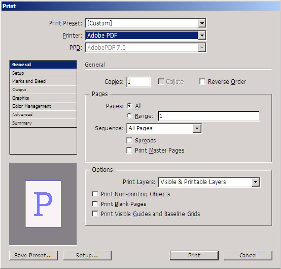
CHAPTER 3: Printing Print user interface 66
Marks And Bleed
Output
Graphics
Color Management
Advanced
Summary
The panels are shown in order in the following sections. Below a screen shot of each panel is a list of
methods on the print data-model interfaces (for example, IPrintData) corresponding to each user-interface
element on the panel.
For details on these settings, see InDesign Help.
Print dialog box: General panel
The three user-interface elements above the selectable panel region of the dialog box are common in all
Print dialog box screenshots and are mapped to the following API methods:
Style Name — IPrintData::SetStyleName
Printer — IPrintDeviceInfo::UpdatePrinterInfo (which calls IPrintData::SetPrinter internally. Get with
IPrintData::GetPrinter.)
PPD — IPrintDeviceInfo::UpdatePrinterInfo (which calls IPrintData::SetPPDFile and
IPrintData::SetPPDName internally. Get with IPrintData::GetPPDFile and IPrintData::GetPPDName.)
NOTE: Generally, there is a corresponding Get method for each Set method.
CHAPTER 3: Printing Print user interface 67
The user-interface elements on the General panel are mapped to the API methods listed in the following
table .
User-interface element API method
Copies IPrintData::SetCopies
Collate IPrintData::SetCollate
Reverse Order IPrintData::SetReverseOrder
Pages: All IPrintData::SetWhichPages(IPrintData::kAllPages)
Pages: Range IPrintData::SetWhichPages(IPrintData::kPageRange) (Range text edit
box): IPrintData::SetPageRange
Sequence IPrintData::SetPrintOption, using IPrintData::kBothPages (for All Pages),
IPrintData::kEvenPagesOnly, or IPrintData::kOddPagesOnly
Spreads IPrintData::SetSpreads
Print Master Pages IPrintData::SetScope, using IPrintData::kScopeMaster or
IPrintData::kScopeDocument
Print Non-printing Objects IPrintData::SetPrintNonPrintingObjects
Print Blank Pages IPrintData::SetPrintBlankPages
Print Visible Guides and
Baseline Grids
IPrintData::SetPrintWYSIWYGGridsGuides
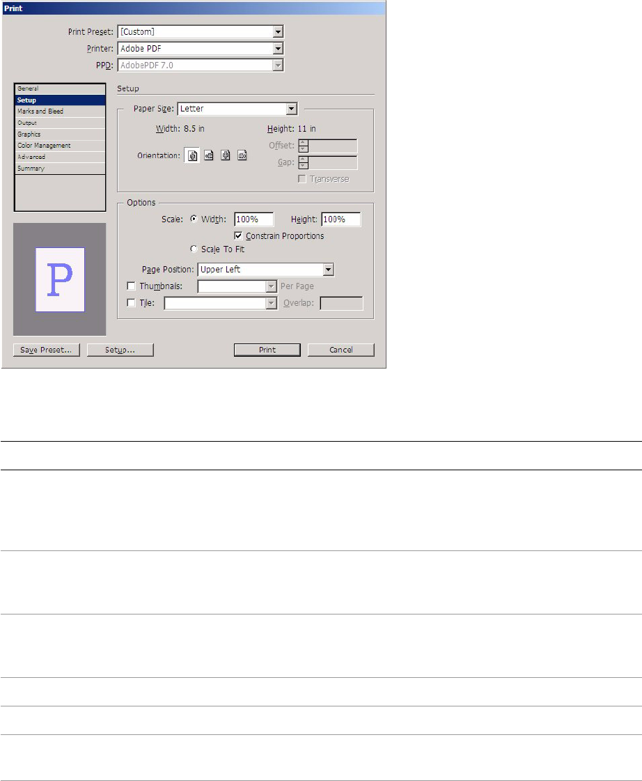
CHAPTER 3: Printing Print user interface 68
Print dialog box: Setup panel
The user-interface elements on the Setup selectable panel are mapped to the API methods listed in the
following table.
\
User-interface element API method
Paper Size IPrintData::SetPaperSizeSelection if defined by the user
(IPrintData::kPaperSizeDefinedByUser), printer driver
(IPrintData::kPaperSizeDefinedByDriver), or
IPrintData::SetPaperSizeName
Paper Size: Width IPrintData::SetCustomPaperWidth only if Paper Size is defined by the user;
otherwise (if defined by driver or paper-size name),
IPrintData::SetCustomPaperWidth(IPrintData::kCustomPaperSizeAuto)
Paper Size: Height IPrintData::SetCustomPaperHeight only if Paper Size is defined by user;
otherwise (if defined by driver or paper-size name),
IPrintData::SetCustomPaperHeight(IPrintData::kCustomPaperSizeAuto)
Offset IPrintData::SetCustomPaperOffset only if Paper Size is defined by the user
Gap IPrintData::SetCustomPaperGap only if Paper Size is defined by the user
Transverse IPrintData::SetPaperOrientation, using IPrintData::kTransverse or
IPrintData::kNormal
Orientation IPrintData::SetPageOrientation, using IPrintData::kPortrait,
IPrintData::kLandscape, IPrintData::kReversePortrait, or
IPrintData::kReverseLandscape
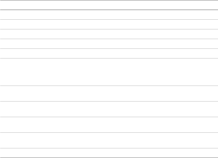
CHAPTER 3: Printing Print user interface 69
Scale (radio button) IPrintData::SetScaleMode using IPrintData::kScaleXAndY
Scale: Width IPrintData::SetXScale
Scale: Height IPrintData::SetYScale
Scale: Constrain Proportions IPrintData::SetProportional
Scale to Fit (radio button) IPrintData::SetScaleMode using IPrintData::kScaleToFit
Page Position IPrintData::SetPagePosition, using IPrintData::kPagePositionUpperLeft,
IPrintData::kPagePositionCenterHorizontally,
IPrintData::kPagePositionCenterVertically, or
IPrintData::kPagePositionCentered
Print Layers IPrintData::SetPrintLayers using kPrintAllLayers, kPrintVisibleLayers, or
kPrintVisiblePrintableLayers.
Thumbnails IPrintData::SetTileThumbMode, using IPrintData::kThumbnails or
IPrintData::kTileThumbOff
Per Page IPrintData::SetNumberOfThumbsPerPage. Calculate the number of
thumbnails on the page (for example, 4x4 = 16).
Tile IPrintData::SetTileThumbMode, using IPrintData::kTiling or
IPrintData::kTileThumbOff
Overlap IPrintData::SetTilingOverlap
User-interface element API method
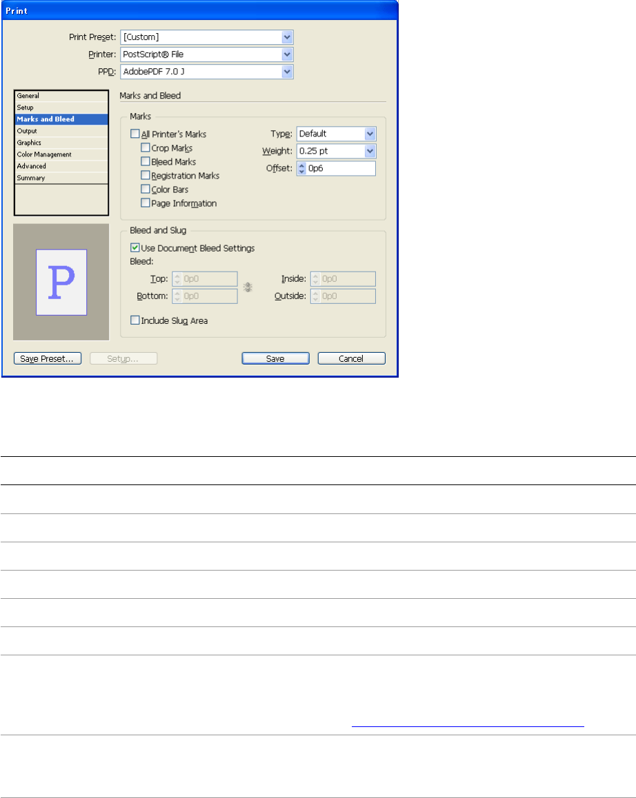
CHAPTER 3: Printing Print user interface 70
Print dialog box: Marks and Bleed panel
(Roman feature set)
The user-interface elements on the Marks And Bleed selectable panel are mapped to the API methods
listed in the following table.
User-interface element API method
All Printer’s Marks Checking this sets the state of the five check boxes below it.
Crop Marks IPrintData::SetCropMarks
Bleed Marks IPrintData::SetBleedMarks
Registration Marks PrintData::SetRegistrationMarks
Color Bars IPrintData::SetColorBars
Page Information PrintData::SetPageInformation
Type IPrintData::SetPageMarkFile. For the Roman and Japanese feature sets,
you get the Default setting; in this case, the PMString passed into
SetPageMarkFile is blank. There are extra details when using the
Japanese feature set; see “Japanese page-mark files” on page 88.
Weight IPrintData::SetMarkLineWeight, using the enumerations ranging from
IPrintData::kMarkLineWeight125pt to
IPrintData::kMarkLineWeight30mm (see IPrintData.h.)
Offset IPrintData::SetPageMarkOffset
CHAPTER 3: Printing Print user interface 71
Print dialog box: Output panel
The user-interface elements on the Output selectable panel are mapped to the API methods listed in the
following table.
Use Document Bleed Settings IPrintData::SetUseDocumentBleed
Bleed (chain button) IPrintData::SetBleedChain
Bleed: Top IPrintData::SetBleedTop
Bleed: Bottom IPrintData::SetBleedBottom
Bleed: Inside IPrintData::SetBleedInside
Bleed: Outside IPrintData::SetBleedOutside
Include Slug Area IPrintData::SetIncludeSlug
User-interface
element API method
Color IPrintData::SetOutputMode, using IPrintData::kCompositeLeaveUnchanged,
IPrintData::kCompositeGray, IPrintData::kCompositeRGB,
IPrintData::kCompositeCMYK, IPrintData::kSeparationBuiltIn, or
IPrintData::kSeparationInRIP
Text as Black IPrintData::SetPrintColorsInBlack
User-interface element API method
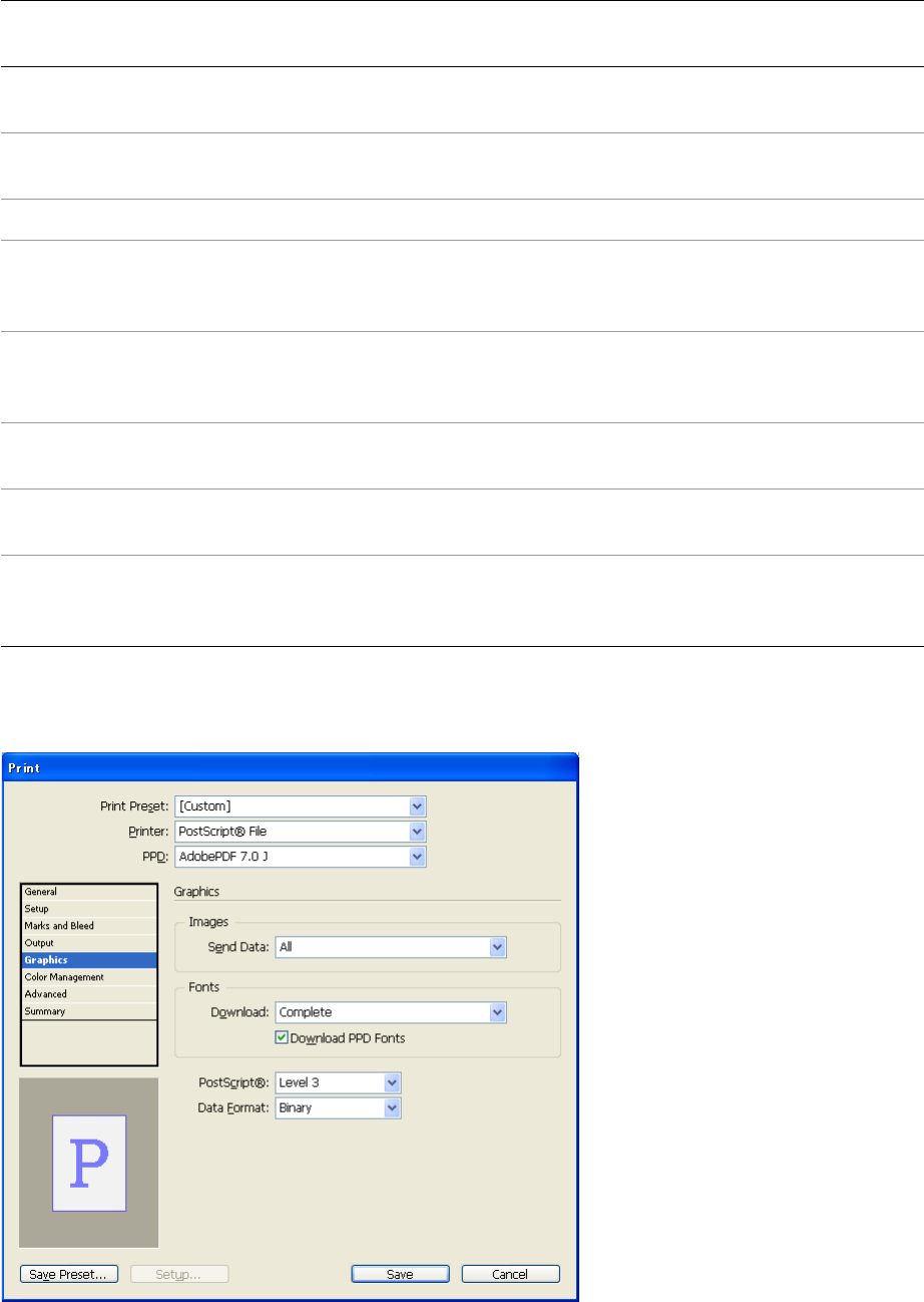
CHAPTER 3: Printing Print user interface 72
Print dialog box: Graphics panel
Trapping IPrintData::SetTrappingMode, using IPrintData::kTrappingNone,
IPrintData::kTrappingBuiltIn, or IPrintData::kTrappingInRIP
Flip IPrintData::SetFlipMode, using IPrintData::kFlipOff, IPrintData::kFlipHorizontal,
IPrintData::kFlipVertical, or IPrintData::kFlipBoth
Negative IPrintData::SetNegative
Screening When the IPrintData::GetOutputMode is a separation mode,
IPrintData::SetSeparationScreenText; when the IPrintData::GetOutputMode is a
composite mode, IPrintData::SetCompositeScreenText.
Frequency If output mode is kCompositeGray and the composite-screen mode is string key
“kCustom” (translates differently in each locale),
IPrintData::SetCompositeFrequency.
Angle If output mode is kCompositeGray and the composite-screen mode is string key
“kCustom” (translates differently in each locale), IPrintData::SetCompositeAngle.
Simulate Overprint IPrintData::SetSpotOverPrint, using IPrintData::kSimulatePress (if the radio
button is checked) or IPrintData::kLegacy (if the radio button is not checked).
Inks Stored temporarily in IPrintDialogData::SetNthInkScreening. When the user
clicks the OK button in the Ind Manager dialog box, the kChangeInkCmdBoss
command is processed for each ink listed.
User-interface
element API method
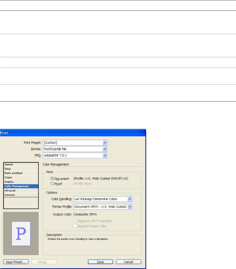
CHAPTER 3: Printing Print user interface 73
The user-interface elements on the Graphics selectable panel are mapped to the API methods listed in the
following table.
Print dialog box: Color Management panel
The user-interface elements on the Color Management selectable panel are mapped to the API methods
listed in the following table.
User-interface element API method
Images: Send Data IPrintData::SetImageData, using IPrintData::kImageDataAll,
IPrintData::kImageDataOptimized, IPrintData::kImageDataLoRez, or
IPrintData::kImageDataProofPrint
Fonts: Download IPrintData::SetFontDownload, usingIPrintData::kFontDownloadNone,
IPrintData::kFontDownloadComplete, IPrintData::kFontDownloadSubset,
or IPrintData::kFontDownloadSubsetLrg
Download PPD Fonts IPrintData::SetDownloadPPDFonts
PostScript IPrintData::SetPSLangLevel, using IPrintData::kPSLangLevel_2 or
IPrintData::kPSLangLevel_3
Data Form at IPrintData::SetImageDataFormat, using IPrintData::kImageDataBinary or
IPrintData::kImageDataASCII
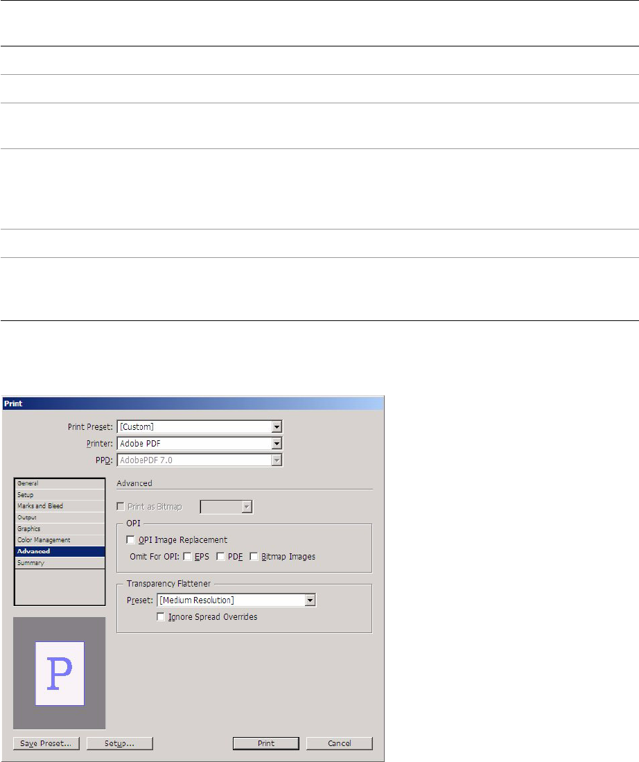
CHAPTER 3: Printing Print user interface 74
Print dialog box: Advanced panel
The user-interface elements on the Advanced selectable panel are mapped to the API methods listed in
the following table.
User-interface
element API method
Print: Document IPrintData::SetSourceSpace(IPrintData::kDocumentSourceSpace)
Print: Proof IPrintData::SetSourceSpace(IPrintData::kProofSourceSpace)
Color Handling IPrintData::SetProfileType, using IPrintData::kUseDocumentProfile,
IPrintData::kUsePostScriptCMS, or IPrintData::kUseNoCMS
Printer Profile IPrintData::SetProfileType, using IPrintData::kUseDocumentProfile or
IPrintData::kUseWorkingProfile. If this is not one of the predefined profiles, use
IPrintData::kUseSpecificProfile and then call IPrintData::SetProfileName,
specifying the name of the profile as displayed in the drop-down list.
Preserve CMYK Colors IPrintData::SetPreserveColorNumbers
Simulate Paper Color IPrintData::SetIntent, using IPrintData::kRelativeColorimetric (if the radio button
is unselected) or IPrintData::kAbsoluteColorimetric (if the radio button is
selected).
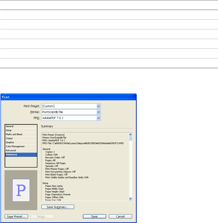
CHAPTER 3: Printing Print user interface 75
Print dialog box: Summary panel
When you click the Save Summary button, the Save File dialog box opens, asking for the path of a text file
to which to save the summary. If you call IPrStStyleListMgr::GetNthStyleDescription for a selected printer
style, you get the same text as shown in the Summary multi-line text widget.
Print Presets dialog box
The main Print Presets dialog box is opened when the user chooses File > Print Presets > Define.
In the main Print Presets dialog box, the user can see the currently defined print presets and a text
summary of the currently selected preset. The main dialog box also has buttons for creating a new print
preset (New), editing an existing print preset (Edit), deleting the selected print preset (Delete), loading
from a print presets file (Load), and saving the print presets to a file (Save).
User-interface element API method
OPI Image Replacement IPrintData::SetOPIReplacement
Omit for OPI: EPS IPrintData::SetOmitEPS
Omit for OPI: PDF IPrintData::SetOmitPDF
Omit for OPI: Images IPrintData::SetOmitImages
Transparency Flattener: Preset IPrintData::SetFlattenerStyleName
Transparency Flattener: Ignore Spread Overrides IPrintData::SetIgnoreSpreadOverrides
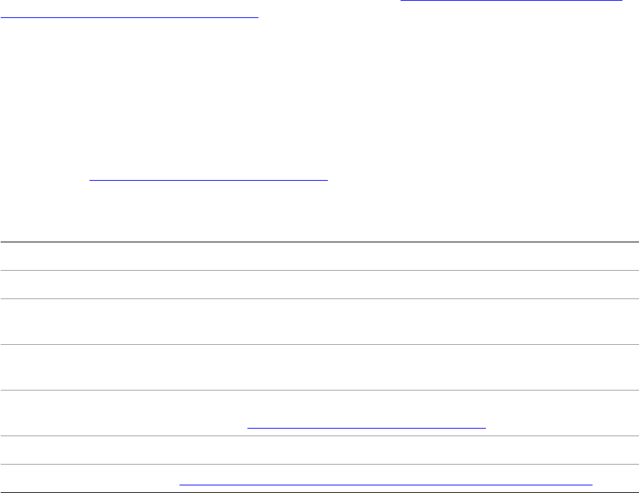
CHAPTER 3: Printing Printing extension patterns 76
When the user clicks the New or Edit button, a selectable dialog box similar to the Print dialog box opens.
The design of the Print Presets selectable dialog box is mostly the same as the Print dialog box, with a few
minor differences:
The title of the dialog box differs based on what the end user is doing.
The thumbnail image on the bottom-left corner of the dialog box is shown only in the Print dialog box
and is disabled in the Print Presets dialog box.
The Print dialog box has a Save Preset button, which allows the user to save the current print settings
as a print-preset style in the workspace. The Print Presets dialog box does not have that button, since
the Print Presets dialog box is where you edit the print-preset style.
Extending the Print dialog box or the Print Presets selectable dialog
box
The Print dialog box and the Print Presets selectable dialog boxes are extensible by third-party plug-ins by
means of custom, selectable, dialog panel. By implementing one selectable dialog panel, you can add your
own panel into both the Print dialog box and the Print Presets selectable dialog box. For a discussion on
SDK sample plug-ins that implement selectable dialog panels, see “Adding your own panel to the Print
and Print Presets dialog boxes” on page 85.
Printing extension patterns
Print-setup provider
A plug-in can register a print-setup service boss by providing an IK2ServiceProvider implementation that
supports the kPrintSetupService service ID. The service is called at various points during the print-action
sequence (see “The print action sequence” on page 63). The implementation for IPrintSetupProvider
provides methods to set up or change print parameters before and during the printing process. See the
following table for implementation details.
Purpose Participate in various phases in the print process.
ServiceID kPrintSetupService
Required companion
interface
IPrintSetupProvider
Boss class IID_IK2SERVICEPROVIDER with implementation ID kPrintSetupServiceImpl
(see PrintID.h) and IID_IPRINTSETUPPROVIDER with your implementation ID
When called Methods of IPrintSetupProvider are called at various phases of the print action
command. See “The print action sequence” on page 63.
How called All providers of this ServiceID get called.
Sample code See “Participating in the stages of the print-action sequence” on page 83.
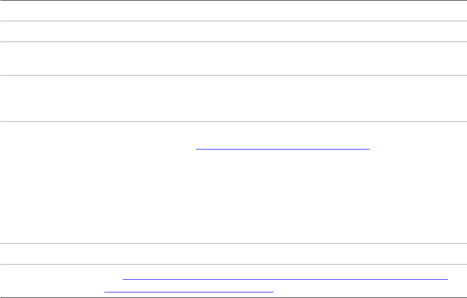
CHAPTER 3: Printing Printing extension patterns 77
Print-insert-PostScript proc provider
A plug-in can inject PostScript statements into the print-output stream by registering an
IK2ServiceProvider implementation supporting the kPrintInsertPSProcService serviceID and providing an
implementation for IPrintInsertPSProcProvider. See the following table for implementation details.
Implementation recipe for a print-insert-PostScript proc provider:
Print-data helper-strategy provider
A plug-in can control whether to override the current locked state and relevant state of print data items in
the Print dialog box by registering an implementation of IK2ServiceProvider supporting the
kPrintDataHelperStrategyService serviceID. The IPrintDataHelperStrategy interface provides two methods:
IsLocked and IsRelevant.
IsLocked allows a plug-in to lock the Print and Print Presets dialog-box user-interface elements. Although
an item's locked state can be partially controlled using this method, the application print components are
still free to change an item's value as necessary to maintain the print data in a consistent and valid context.
IsRelevant allows a plug-in to disable specific Print and Print Presets dialog-box user-interface elements.
Although an item's relevant state can be partially controlled using this interface, the application print
components are still free to change an item's value as necessary to maintain the print data in a consistent
and valid context.
The most restrictive interface takes precedence. After an ID is set to be locked (the most restrictive setting),
other implementations are not called. After an ID’s relevance is set to kFalse (the most restrictive setting),
other implementations are not called.
Purpose Inject PostScript comments at predetermined phases of the printing process.
ServiceID kPrintInsertPSProcService
Required companion
interface
IPrintInsertPSProcProvider
Boss class IID_IK2SERVICEPROVIDER with implementation ID kInsertPSProcServiceImpl
(see PrintID.h) and IID_IPRINTINSERTPSPROCPROVIDER with your
implementation ID
When called Methods of IPrintInsertPSProcProvider are called at various phases of the core
print command. See “The print action sequence” on page 63. The Setup method
is called first, to give the provider a chance to store print settings. Then the
GetInsertPSProcName method is called, so the provider can return a name. (The
following steps occur only if your GetInsertPSProcName implementation returns
a nonempty string.) The GetClientData method gets called to obtain the
provider’s custom client data (if any), then the PrintInsertPSProc method is called
at various phases of the printing process. (For a list of phases, see the enum
IPrintInsertPSProcProvider::DocumentSection.)
How called All providers of this ServiceID get called.
Sample code See “Injecting PostScript comments or extra data into the print stream during
the print action sequence” on page 84.
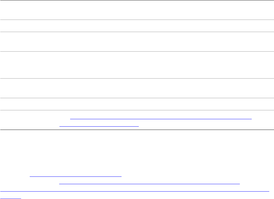
CHAPTER 3: Printing Printing solutions 78
See the following table for implementation details.
Implementation recipe for a print-data helper-strategy provider:
Draw-event handlers
A plug-in can register a draw-event handler (IDrwEvtHandler) to participate in various draw events that
happen during the printing process. For more details on draw-event handlers, including implementation
details, see Chapter 8, “Graphics Fundamentals.” For samples that implement this extension pattern for
printing purposes, see “Adding a custom watermark during the printing process” on page 84 and
“Injecting PostScript comments or extra data into the print stream during the print action sequence” on
page 84.
Printing solutions
Getting started
Printing a document
Execute (not process) one of the following commands:
kPrintActionCmdBoss, to print a document in InDesign
kInCopyPrintActionCmdBoss, to print a document in InCopy
The minimal settings required to print a document with kPrintActionCmdBoss in InDesign are as follows:
The document you want to print.
The range of pages in the document you want to print.
Print user-interface options.
Purpose Influence the Print and Print Presets dialog boxes through the ability to suppress
and lock print user-interface elements.
ServiceID kPrintDataHelperStrategyService
Required
companion interface
IPrintDataHelperStrategy
Boss class IID_IK2SERVICEPROVIDER with implementation ID
kDataHelperStrategyServiceImpl(see PrintID.h) and
IID_IPRINTDATAHELPERSTRATEGY with your implementation ID
When called Whenever IPrintData::IsLocked or IPrintData::IsRelevant is called. Generally this
happens when the Print or Print Presets dialog box is being prepared for display.
How called All providers of this ServiceID get called.
Related sample code See “Specifying which parts of the Print and Print Presets dialog boxes are
relevant or locked” on page 86.
CHAPTER 3: Printing Printing solutions 79
The print-action command is executed (not processed), because there is no undo capability provided. For
a sample that uses either kPrintActionCmdBoss or kInCopyPrintActionCmdBoss, see the
SnpPrintDocument.cpp sample code snippet, in particular SnpPrintDocument::DoPrintDocument.
Printing a Book
Execute the kBookPrintActionCmdBoss command.
Working with print-preset styles
Getting information about print-preset styles
Query for IPrStStyleListMgr on kWorkspaceBoss, then call the Get methods to get information about the
print-preset styles that are registered. IPrStStyleListMgr::GetNumStyles reports the number of print-preset
styles registered. IPrStStyleListMgr::GetNthStyleName reports the name of the print-preset style at index n.
IPrStStyleListMgr::GetNthStyleRef returns the UIDRef of the print-preset style at index n. Using this UIDRef,
you can query IPrintData, and get further information about the print-preset style. There are other useful
methods on IPrStStyleListMgr.
NOTE: IPrStStyleListMgr.h does not declare any methods; however, it inherits IGenStlEdtListMgr. See
IGenStlEdtListMgr.h for details.
For more details, see the SnpManipulatePrintStyles.cpp code snippet, in particular
SnpManipulatePrintStyles::InspectPrintStyle.
Adding a print-preset style
Query for IPrStStyleListMgr on kWorkspaceBoss, then call IPrStStyleListMgr::AddStyle. When the new style
is created, it is appended to the end of the list of print-preset styles.
For details, see the SnpManipulatePrintStyles.cpp code snippet, in particular
SnpManipulatePrintStyles::AddPrintStyle.
Duplicating a print-preset style
Query for IPrStStyleListMgr on kWorkspaceBoss, then call IPrStStyleListMgr::CopyNthStyle. When the new
style is created, it is appended to the end of the list of print-preset styles.
Modifying the name of a print-preset style
First, query for IPrStStyleListMgr on kWorkspaceBoss.
Then, call IPrStStyleListMgr::SetNthStyleName. When you do this, however, the name of the print-preset
style stored in IPrintData is not updated, so you must query for IPrintData and call
IPrintData::SetStyleName, using the same name. For details, see the SnpManipulatePrintStyles.cpp code
snippet, in particular SnpManipulatePrintStyles::ModifyPrintStyleName.
CHAPTER 3: Printing Printing solutions 80
Modifying the settings of a print-preset style
First, query for IPrStStyleListMgr on kWorkspaceBoss.
Then, call IPrStStyleListMgr::EditNthStyle, which invokes the Print Presets selectable dialog box. This
procedure requires a user to use the dialog box to change settings. For details, see the
SnpManipulatePrintStyles.cpp code snippet, in particular SnpManipulatePrintStyles::ModifyPrintStyle.
Deleting a print-preset style
Query for IPrStStyleListMgr on kWorkspaceBoss, then call IPrStStyleListMgr::DeleteNthStyle. For details,
see the SnpManipulatePrintStyles.cpp code snippet, in particular
SnpManipulatePrintStyles::DeletePrintStyle.
Exporting a set of print-preset styles to a file
Process the kGenStlEdtExportStylesCmdBoss command. In the IGenStlEdtCmdData data interface, call
SetListMgrIID to set the type of style list to be the print style list, by specifying the
IPrStStyleListMgr::kDefaultIID (IID_IPRSTSTYLELISTMGR), then call SetTargetFile to specify the full path of
the file to save. Optionally, specify a set of style indices you want to export from IPrStStyleListMgr on
kWorkspaceBoss. If you do not specify a set of style indices, all styles stored in IPrStStyleListMgr are
exported.
Importing a set of print-preset styles from a file
Process the kGenStlEdtImportStylesCmdBoss command. In the IGenStlEdtCmdData data interface, call
SetListMgrIID to set the type of style list to be the print style list, by specifying the
IPrStStyleListMgr::kDefaultIID (IID_IPRSTSTYLELISTMGR), then call SetTargetFile to specify the full path of
the file to import.
Getting notified when a print-preset style is imported to/exported from a file
Implement a signal-responder extension pattern that responds one or more of the following signals:
kBeforeExportStyleSignalResponderService
kAfterExportStyleSignalResponderService
kBeforeImportStyleSignalResponderService
kAfterImportStyleSignalResponderService
These IDs are defined in GenericSettingsID.h. In your implementation of IResponder::Respond, you can
query for the IStyleSignalData interface using ISignalMgr::QueryInterface (or InterfacePtr).
IStyleSignalData gives you a reference to the file that is the target of the export or import operation.
Any preset style that is managed by the generic-settings framework and can be exported or
imported—such as PDF-export styles and document-preset styles—can be monitored in the same way.
CHAPTER 3: Printing Printing solutions 81
Working with trap styles
Getting information about trap styles
First, query for ITrapStyleListMgr on one of the following bosses:
kWorkspaceBoss, for trap styles registered in the workspace (also used as document defaults when a
new document is created)
kDocWorkspaceBoss, for trap styles registered in a document
kBookBoss, for trap styles registered in a book
The utility interface ITrapStyleUtils (on kUtilsBoss) has a QueryTrapStyleListMgr method to simplify this
process. There are two overloaded methods:
The one that takes IDocument* returns the ITrapStyleListMgr on kDocWorkspaceBoss (that is, the
workspace related to the document).
The one that takes a UIDRef returns the ITrapStyleListMgr on the same boss as the UIDRef, or the
ITrapStyleListMgr on kWorkspaceBoss if the UID in the UIDRef is kInvalidUID.
Next, call the Get methods to get various information about the trap styles that are registered.
ITrapStyleListMgr::GetNumStyles reports the number of trap styles registered.
ITrapStyleListMgr::GetNthStyleName reports the name of the trap style at index n.
ITrapStyleListMgr::GetNthStyleRef returns the UIDRef of the trap style at index n. Using this UIDRef, you
can query ITrapStyle and get further information about this trap style. There are other useful methods on
ITrapStyleListMgr.
ITRAPSTYLELISTMGR DOES NOT INHERIT FROM IGENSTLEDTLISTMGR THE WAY IPRSTSTYLELISTMGR DOES. For
details, see the SnpManipulateTrapStyles.cpp code snippet, in particular
SnpManipulateTrapStyles::InspectTrapStyle.
Adding a trap style
Query for ITrapStyleListMgr, then call ITrapStyleListMgr::AddStyle. When the new style is created, it is
appended to the end of the list of trap styles.
For details, see the SnpManipulateTrapStyles.cpp code snippet, in particular
SnpManipulateTrapStyles::AddTrapStyle.
Duplicating a trap style
Query for ITrapStyleListMgr, then call ITrapStyleListMgr::CopyNthStyle. When the new style is created, it i
appended to the end of the list of trap styles.
Modifying a trap style
Query for ITrapStyleListMgr, then call ITrapStyleListMgr::EditNthStyle. You are required to pass in the
trap-style data via the parameter list as ITrapStyle. You can create a nonpersistent instance of
kTrapStyleBoss to store the settings.
CHAPTER 3: Printing Printing solutions 82
For details, see the SnpManipulateTrapStyles.cpp code snippet, in particular
SnpManipulateTrapStyles::ModifyTrapStyle.
Deleting a trap style
Query for ITrapStyleListMgr, then call ITrapStyleListMgr::DeleteNthStyle.
For details, see the SnpManipulateTrapStyles.cpp code snippet, in particular
SnpManipulateTrapStyles::DeleteTrapStyle.
Exporting a set of trap styles to another trap-style list
First, create a command sequence, as the following procedure processes multiple commands. Next, query
for ITrapStyleListMgr, then call ITrapStyleListMgr::ExportStyles. The first parameter is a UIDRef for the
destination trap style list (note the source trap style list is identified by this particular instance of
ITrapStyleListMgr), and that UIDRef must refer to a boss that aggregates ITrapStyleListMgr. If you want to
export the trap styles to a file, you can create a new database using DBUtils::CreateDataBase and
IDataBase::New, then put a new root UID by calling IDataBase::NewUID. The class for the new root should
be kTrapStyleExportRootBoss. Create a UIDRef for this new root, and pass it into
ITrapStyleListMgr::ExportStyles. Once that completes, save the database by calling IDataBase::SaveAs, and
close the database by deleting the IDataBase pointer.
Importing a set of trap styles from another trap-style list
First, create a command sequence, as the following procedure processes multiple commands. Next, query
for ITrapStyleListMgr, then call ITrapStyleListMgr::ImportStyles. The first parameter is a UIDRef for the
source trap style list (note the destination trap style list is identified by this particular instance of
ITrapStyleListMgr), and that UIDRef must refer to a boss that aggregates ITrapStyleListMgr. If you want to
import the trap styles from a file, you can open a database using DBUtils::CreateDataBase and
IDataBase::Open, then get the root UID by calling IDataBase::GetRootUID. The class for the new root should
be kTrapStyleExportRootBoss. Create a UIDRef for this root, and pass it into
ITrapStyleListMgr::ImportStyles. Once that completes, close the database by deleting the IDataBase
pointer.
Determining which trap style is associated with a page on a document
Given a specific page (kPageBoss) on a document (which you can query using IPageList on kDocBoss),
query for IPersistUIDData with the specific IID of IID_ITRAPSTYLEUIDDATA. Get the UID from
IPersistUIDData. That UID refers to the trap style registered in ITrapStyleListMgr on the document
workspace (kDocWorkspaceBoss). To find out the name of this trap style, first call
ITrapStyleListMgr::GetStyleIndexByUID and then call ITrapStyleListMgr::GetNthStyleName.
Alternately, you can collect a list of pages that use a specific trap style. Call
ITrapStyleUtils::GetDocumentTrapStylePageList. For details, see the SnpManipulateTrapStyles.cpp code
snippet, specifically SnpManipulateTrapStyles::InspectTrapStyle.
Associating a trap style with a page on a document
Create a UIDList of pages (kPageBoss) to which you want to associate a trap style, and the UIDRef of the
trap style. Then call ITrapStyleUtils::AssignStyleToPageList. For details, see the

CHAPTER 3: Printing Printing solutions 83
SnpManipulateTrapStyles.cpp code snippet, specifically
SnpManipulateTrapStyles::AssignTrapStyleToPages.
Participating in the print process
Participating in the stages of the print-action sequence
There are various ways to participate in the print-action sequence. The main way is to implement a
print-setup provider (see “Print-setup provider” on page 76). By implementing IPrintSetupProvider, your
plug-in can be notified at the stages of the print-action sequence described in “The print action sequence”
on page 63.
Other ways to participate in the print-action sequence are noted in the following list. Some of these
require extra hook-ups from within a print setup-provider implementation.
Implement a print-insert PostScript proc provider to inject PostScript statements into the print-output
stream. (See “Print-insert-PostScript proc provider” on page 77 and “Injecting PostScript comments or
extra data into the print stream during the print action sequence” on page 84.)
Implement a print-data-helper strategy provider to influence the display of the Print and Print Presets
dialog boxes. (See “Print-data helper-strategy provider” on page 77 and “Specifying which parts of the
Print and Print Presets dialog boxes are relevant or locked” on page 86.)
Implement a draw-event handler that handles print-related drawing events. (See “Draw-event
handlers” on page 78, “Adding a custom watermark during the printing process” on page 84,
“Specifying which page items should be printed” on page 83, and “Injecting PostScript comments or
extra data into the print stream during the print action sequence” on page 84).
Implement a custom write stream so the print-action sequence writes to it. The custom stream must
be specified from one of the methods in your print-setup provider. (See “Writing printing data to a
custom stream” on page 86.)
The following sample plug-ins contain an implementation of a print-setup provider:
PrintMemoryStream prints document content to a custom memory stream.
PrintSelection adds a flag to the document to print only selected page items.
For details, refer to the API Reference for each sample plug-in.
Specifying which page items should be printed
You can implement a print-setup provider (see “Participating in the stages of the print-action sequence”
on page 83) and a custom draw-event handler to specify which pages items should be printed. From the
print-setup provider (in any method that gets called before the core print command is executed, the last
chance being AfterPrintGatherCmd), you register the custom draw-event handler that handles the print
event only when it encounters document content you want to print. When the printing is done, you
de-register the custom draw-event handler in your print-setup provider’s EndPrint implementation.
The PrintSelection sample plug-in shows how this is done. Here are the highlights of what the
PrintSelection plug-in does:
In PrnSelPrintSetupProvider::AfterPrintUI, the currently selected page items are gathered and the
custom draw-event handler is registered for the draw event message kDrawShapeMessage.

CHAPTER 3: Printing Printing solutions 84
In PrnSelPrintSetupProvider::BeforePrintGatherCmd, the set of pages to output is modified based on
which pages contain the selected page items.
The PrnSelDrawHandler::HandleEvent determines whether the current printable item should be
printed. This draw event handler does not do any drawing; the actual drawing of the printable item is
delegated to other draw-event handlers.
In PrnSelPrintSetupProvider::EndPrint, the custom draw-event handler is unregistered.
For details, refer to the API Reference for the PrintSelection plug-in.
Specifying which layer(s) of a document should be printed
In the Setup panel of the Print dialog box, there is a setting called “Print Layers,” which is a drop-down list
that allows the user to choose printing with visible and printable layers, visible layers, or all layers. This
option can be get/set through the IPrintData::GetPrintLayers/SetPrintLayers methods. Each layer’s visibility
and printability, however, are managed by layer options as described in the “Layer Options” section of
Chapter 7, “Layout Fundamentals.” To set the visibility of a layer, use the kShowLayerCmdBoss command.
To set the printability of a layer, use the kPrintLayerCmdBoss command. The SnpPrintDocument.cpp SDK
snippet shows how to use a kPrintLayerCmdBoss. Before processing a kPrintLayerCmdBoss, make sure the
printability of the layer is different from the new state you are going to set. If the new printability state is
the same as the old one, kPrintLayerCmdBoss asserts, although the assert is benign.
Adding a custom watermark during the printing process
You can implement a custom draw-event handler that draws the watermark on a page or a page item. This
is done in the BasicDrwEvtHandler sample plug-in, a canonical example of a draw-event handler. For
details, refer to the API Reference for the BasicDrwEvtHandler plug-in.
Another way to add custom watermarks to page items is to implement a page-item adornment that draws
when the draw flag has the IShape::kPrinting bit set. While the FrameLabel sample plug-in does not
support printing (that is, if flags contains IShape::kPrinting, the Draw method breaks out), you can use the
FrameLabel sample as a basis for implementing custom watermarks and extra persistent data on page
items. For details, refer to the API Reference for the FrameLabel plug-in.
Injecting PostScript comments or extra data into the print stream during the
print action sequence
You can implement a print-insert PostScript proc provider (see “Print-insert-PostScript proc provider” on
page 77) to inject PostScript comments during predetermined phases of the print-output process as
driven by the core print command. The PrintMemoryStream sample plug-in contains an implementation
of a print-insert PostScript proc provider. The print-insert PostScript proc provider implementation in this
sample is a canonical example that demonstrates when each method in IPrintInsertPSProcProvider gets
called by writing a trace message. This plug-in also demonstrates how to manage custom print settings
throughout the print-action sequence.
There are other ways to inject PostScript comments into the print stream during the print action sequence:
Implement a custom draw-event handler that calls the IGraphicsPort::AddComment method. For a
sample of a draw-event handler that responds to the kDrawShapeMessage for printing, see
PrnSelDrawHandler::HandleEvent in the PrintSelection sample plug-in. To obtain IGraphicsPort, you

CHAPTER 3: Printing Printing solutions 85
can first get a pointer to the GraphicsData from DrawEventData::gd, then call
GraphicsData::GetGraphicsPort.
Add custom registration marks on each page, if you are using the Japanese feature set of InDesign or
InCopy. See “Japanese page-mark files” on page 88.
Adding custom print settings so they are managed like other printsettings
Any plug-in that registers for kPrintCopyCustomDataService gets a chance to manage its own print data
during the print process. Note the service provider is called after the application’s CopyData is done. You
should provide the implementation for IPrintCopyCustomDataProvider and aggregate it on the
service-provider boss that registered as kPrintCopyCustomDataService. Then your
IPrintCopyCustomDataProvider will be called whenever IPrintData::CopyData is called.
Adding your own panel to the Print and Print Presets dialog boxes
You can implement a panel that adds itself to the dialog box identified by kPrintSelectableDialogService.
The panel should be 400 pixels wide and 345 pixels high. The ODFRez widget type should inherit from
PrimaryResourcePanelWidget, and the boss class that contains the necessary implementations (see below)
should inherit from kPrimaryResourcePanelWidgetBoss. The required implementations in this boss class
are as follows:
IK2ServiceProvider (IID_IK2SERVICEPROVIDER), to register the ServiceID values specified in the
IPanelCreator::GetServiceIDs method. You do not need to implement this yourself; you can use the
implementation ID provided by the application: kDialogPanelServiceImpl (defined in WidgetID.h).
IPanelCreator (IID_IPANELCREATOR), to specify the resource IDs in your ODFRez resource file (.fr) that
declares the selectable dialog ServiceID and the panel resource IDs provided by the plug-in. Using this
implementation, the IK2ServiceProvider in this boss (kDialogPanelServiceImpl) can get the necessary
data to register the panel into the appropriate selectable dialog box. The implementation of this
interface must inherit from CPanelCreator.
IDialogController (IID_IDIALOGCONTROLLER), to initialize the panel, validate the settings on the panel
when the OK button is clicked, apply the settings on the panel when the OK button is clicked, and
perform any clean-up if the user cancels the dialog. The implementation of this interface may inherit
from CDialogController.
IObserver (IID_IOBSERVER), to handle user-interface actions for widgets on the panel, as well as
widgets on the parent selectable dialog. (To get the widget IDs of the widgets on the parent selectable
dialog box, choose QA > Panel Edit Mode in the debug build of the application.) The implementation
of this interface must inherit from AbstractDialogObserver (as opposed to CSelectableDialogObserver,
which is used in the BasicSelectableDialog sample plug-in). Refer to the API Reference for
AbstractDialogObserver.
In addition to the panel user-interface definition and the supporting boss class, you must include the
following resources:
IDList — Specifies the selectable-dialog service ID, which in this case is kPrintSelectableDialogService.
IDListPair — Specifies the selectable-dialog service ID (again, kPrintSelectableDialogService), the
resource ID of the panel you want to add to the selectable dialog box, and the PluginID that owns the
panel. You can specify multiple panels in this resource.

CHAPTER 3: Printing Printing solutions 86
Both these resources should have the resource ID you specified in your IPanelCreator::GetPanelRsrcID
implementation. For example, if the resource ID you specify in IPanelCreator::GetPanelRsrcID is
kSDKDefIDListPairResourceID, the resource ID of the panel is kSDKDefPanelResourceID, and the ID of the
plug-in that provides this panel is kPrtHokUIPluginID, the resources would be written like the following
example.
An IDList and IDListPair to support the kPrintSelectableDialogService:
resource IDList (kSDKDefIDListPairResourceID)
{
{
kPrintSelectableDialogService,
},
};
resource IDListPair (kSDKDefIDListPairResourceID)
{
{
kPrintSelectableDialogService, kSDKDefPanelResourceID, kPrtHokUIPluginID,
},
};
To find out whether the panel is being opened from the Print or Print Presets dialog box, you can query the
IPrintDialogData interface from the parent selectable dialog (by using the help of IWidgetParent), and call
IPrintDialogData::GetFlags. See the following example.
Getting IPrintDialogData flags from a print-dialog selectable-panel implementation:
// 'this' maybe a dialog controller or observer
InterfacePtr<IWidgetParent> widgetParent(this, UseDefaultIID());
InterfacePtr<IPrintDialogData> printDialogData
((IPrintDialogData*)widgetParent->QueryParentFor(IID_IPRINTDIALOGDATA));
printFlags = printDialogData->GetFlags();
If the returned value has the IPrintDialogData::kWorkingOnStyle bit set (test by doing a logical AND on the
value with IPrintDialogData::kWorkingOnStyle), the panel is in the Print Presets dialog box.
A canonical implementation of a selectable dialog box (along with children panels) is provided in the
BasicSelectableDialog sample plug-in. You can use BasicSelectableDialog to understand the interactions
between the parent selectable dialog box and its child panels. For more details, refer to the API Reference
associated with the BasicSelectableDialog sample plug-in.
Specifying which parts of the Print and Print Presets dialog boxes are relevant
or locked
You can implement a print-data helper strategy provider (see “Print-data helper-strategy provider” on
page 77). Print-data helper strategy provider also are called when the Print or Print Presets dialog box gets
its summary text. (That is, if a setting is not relevant, it is not included in the summary text.) For a sample
implementation of IPrintDataHelperStrategy, see the PrintMemoryStream sample plug-in.
Writing printing data to a custom stream
You can write a class that implements IPMStream (and inherits CStreamWrite), along with a class that
inherits IXferBytes, to copy the data to whatever your stream targets. Your stream may target things like a
file, a memory buffer, or even a database. This custom stream must be reported to the print-action
sequence by calling IOutputPages::SetOutputStream. You can do this from one of the methods in your

CHAPTER 3: Printing Bosses that aggregate IPrintData 87
print-setup provider (see “Print-setup provider” on page 76 and “Participating in the stages of the
print-action sequence” on page 83), like IPrintSetupProvider::BeforePrintGatherCmd. For a sample
implementation, see the PrintMemoryStream sample plug-in.
Bosses that aggregate IPrintData
kBookBoss stores the Custom print settings for a book.
kBookPrintDataBoss stores the print settings when printing a book with the print commands.
kDocWorkspaceBoss stores the Custom print settings for a document.
kInCopyTempPrintDataBoss stores the print settings for temporary use only (InCopy only).
kPrintDataBoss stores the print settings when printing a document with the print commands. This is
the most common boss class for storing print settings during the print process.
kPrintDataOnlyBoss stores the print settings for temporary use only.
kPrStStyleBoss stores the print settings for a particular style in the list of defined print preset styles.
(See “Print preset styles” on page 62.)
kStylePrintDataBoss stores the print settings for temporary use when generating the human-readable
text summary of a print-preset style. This text is displayed in the Print Presets dialog box.
For details on these bosses, such as other aggregated interfaces or boss hierarchy, refer to the API
Reference.
Print-action and supporting commands
The following table lists the main command bosses used in the print process.
Command boss Description
kBookPrintActionCmdBoss Top-level print-action command for printing a book. For most clients,
this is the command to execute to print a book in InDesign. It
processes the following supporting commands:
kPrintDialogCmdBoss, kBookSavePrintDataCmdBoss,
kPrintGatherDataCmdBoss, and kNewPrintCmdBoss.
kBookSavePrintDataCmdBoss Saves the print data into a book.
kCreatePrintGalleyViewCmdBoss Creates a galley window view to print.
kInCopyNewPrintCmdBoss Performs the actual output of a document in InCopy.
kInCopyPrintActionCmdBoss Top-level print-action command for printing in InCopy. For most
clients, this is the command to execute to print a document in
InCopy. It processes the following supporting commands:
kCreatePrintGalleyViewCmdBoss, kInCopyPrintDialogCmdBoss,
kInCopyNewPrintCmdBoss, and kPrintGatherDataCmdBoss.
kInCopyPrintDialogCmdBoss Displays the print dialog box in InCopy.

CHAPTER 3: Printing Japanese page-mark files 88
Japanese page-mark files
The Japanese feature set provides two extra Type options in the Marks And Bleed panel in the Print dialog
box and Print Presets selectable dialog box:
Maru-tsuki Sentaa-tombo — The untranslated string key “kJMarksWithCircle” is passed into
IPrintData::SetPageMarkFile.
Maru-nashi Sentaa-tombo — The untranslated string key “kJMarksWithoutCircle” is passed into
IPrintData::SetPageMarkFile.
In addition (with either the Roman or Japanese feature set), you can specify a filename (without path or
extension) of a file that contains a custom page mark written using PostScript. The contents of this
PostScript file are injected during printing. The actual file should have an .mrk extension and be in one of
the following locations:
(Windows) C:\Program Files\Common Files\Adobe\PrintSpt
(Mac OS) /Library/Application Support/Adobe/PrintSpt
Exporting to EPS and PDF
The process of exporting to EPS and PDF file formats is somewhat similar to the process of printing, in that
similar components of the application are employed. The way you drive the export process and the data
model behind the EPS and PDF export features are somewhat different. This section provides highlights of
how to drive the EPS and PDF export features in the application.
Exporting to EPS
EPS export preferences
Settings for EPS export are stored in the IEPSExportPreferences interface on kWorkspaceBoss. For details,
refer to the API Reference.
To get the preferences, query for IEPSExportPreferences on kWorkspaceBoss and call its Get methods.
kNewPrintCmdBoss Performs the actual output of a document or a book to the output
device in InDesign.
kPrintActionCmdBoss Top-level print-action command for printing a document. For most
clients, this is the command to execute to print a document in
InDesign. It processes the following supporting commands:
kPrintDialogCmdBoss, kPrintSavePrintDataCmdBoss,
kPrintGatherDataCmdBoss, and kNewPrintCmdBoss.
kPrintDialogCmdBoss Displays the print dialog box in InDesign.
kPrintGatherDataCmdBoss Gathers print data.
kPrintSavePrintDataCmdBoss Saves the print data into a document.
Command boss Description
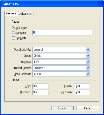
CHAPTER 3: Printing Exporting to EPS and PDF 89
To modify the preferences, process the kSetEPSExportPrefsCmdBoss command. This command has a data
interface, IEPSExportPrefsCmdData, with which you specify the new values of the EPS preferences. Before
you call any Set methods, you can call IEPSExportPrefsCmdData::CopyPrefs to copy the current preference
settings in IEPSExportPreferences.
User interface
When you choose File > Export and specify the file to export and the export format to be EPS, you will see
a selectable dialog box with two panels, General and Advanced. The user-interface elements on these
panels are mapped to the methods on IEPSExportPreferences, as described below.
Export EPS dialog box: General panel
All Pages — IEPSExportPreferences::SetEPSExPageOption using
IEPSExportPreferences::kExportAllPages
Ranges (radio button) — IEPSExportPreferences::SetEPSExPageOption using
IEPSExportPreferences::kExportRanges
Ranges (text-edit box) — IEPSExportPreferences::SetEPSExPageRange
Spreads — IEPSExportPreferences::SetEPSExReaderSpread using
IEPSExportPreferences::kExportReaderSpreadOFF or IEPSExportPreferences::kExportReaderSpreadON
PostScript — IEPSExportPreferences::SetEPSExPSLevel using IEPSExportPreferences::kExportPSLevel2
or IEPSExportPreferences::kExportPSLevel3
Color — IEPSExportPreferences::SetEPSExColorSpace, using
IEPSExportPreferences::kExportPSColorSpaceLeaveUnchanged,
IEPSExportPreferences::kExportPSColorSpaceDIC, IEPSExportPreferences::kExportPSColorSpaceCMYK,
IEPSExportPreferences::kExportPSColorSpaceGray, or
IEPSExportPreferences::kExportPSColorSpaceRGB
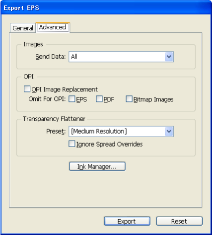
CHAPTER 3: Printing Exporting to EPS and PDF 90
Preview — IEPSExportPreferences::SetEPSExPreview using
IEPSExportPreferences::kExportPreviewNone, IEPSExportPreferences::kExportPreviewTIFF, or
IEPSExportPreferences::kExportPreviewPICT (Mac OS only)
Embed Fonts — IEPSExportPreferences::SetEPSExIncludeFonts using
IEPSExportPreferences::kExportIncludeFontsNone,
IEPSExportPreferences::kExportIncludeFontsWhole,
IEPSExportPreferences::kExportIncludeFontsSubset, or
IEPSExportPreferences::kExportIncludeFontsSubsetLarge
Data Format — IEPSExportPreferences::SetEPSExDataFormat, using
IEPSExportPreferences::kExportASCIIData or IEPSExportPreferences::kExportBinaryData
Bleed: Top — IEPSExportPreferences::SetEPSExBleedTop
Bleed: Bottom — IEPSExportPreferences::SetEPSExBleedBottom
Bleed: Inside — IEPSExportPreferences::SetEPSExBleedInside
Bleed: Outside — IEPSExportPreferences::SetEPSExBleedOutside
If any Bleed settings are over 0 — IEPSExportPreferences::SetEPSExBleedOnOff using either
IEPSExportPreferences::kExportBleedON, or IEPSExportPreferences::kExportBleedOFF
Export EPS dialog box: Advanced panel
Send Data — IEPSExportPreferences::SetEPSExBitmapSampling, using
IEPSExportPreferences::kExportBMSampleNormal or kExportBMSampleLowRes
OPI Image Replacement — IEPSExportPreferences::SetEPSExOPIReplace, using
IEPSExportPreferences::kExportOPIReplaceON or IEPSExportPreferences::kExportOPIReplaceOFF
Omit for OPI: EPS — IEPSExportPreferences::SetEPSExOmitEPS, using
IEPSExportPreferences::kExportOmitEPSON or IEPSExportPreferences::kExportOmitEPSOFF

CHAPTER 3: Printing Exporting to EPS and PDF 91
Omit for OPI: PDF — IEPSExportPreferences::SetEPSExOmitPDF, using
IEPSExportPreferences::kExportOmitPDFON or IEPSExportPreferences::kExportOmitPDFOFF
Omit for OPI: BitMap Images — IEPSExportPreferences::SetEPSExOmitBitmapImages, using
IEPSExportPreferences::kExportOmitBitmapImagesON or
IEPSExportPreferences::kExportOmitBitmapImagesOFF
Preset — IEPSExportPreferences::SetEPSExFlattenerStyle, using a UID of a kXPFlattenerStyleBoss object
(use IFlattenerStyleListMgr to find one)
Ignore Spread Overrides — IEPSExportPreferences::SetEPSExIgnoreFlattenerSpreadOverrides, using
IEPSExportPreferences::kExportIgnoreSpreadOverridesON or
IEPSExportPreferences::kExportIgnoreSpreadOverridesOFF
Exporting
Using IK2ServiceRegistry, query for service providers supporting kExportProviderService. Find an export
provider that can support the format name “EPS,” by iterating over all export providers and calling
IExportProvider::CountFormats and IExportProvider::GetNthFormatName, or
IExportProvider::CanExportThisFormat. Once you find the export provider for EPS, do the following:
Call IExportProvider::CanExportToFile to check whether the document and current selection target
can be exported.
Optionally, query for IBoolData, set it to kTrue to set IPrintContentPrefs, and query for
IPrintContentPrefs and call its Set methods.
Call IExportProvider::CanExportToFile or IExportProvider::ExportToStream to do the export.
Exporting to PDF
The structure of the PDF-export architecture is very similar to that of EPS export; however, you can specify
a greater level of detail when exporting a document to PDF. For details of exporting to PDF, see Chapter 4,
“Import and Export.”
92
4Import and Export
This chapter discusses various ways of importing into and exporting from InDesign documents using the
API:
“PDF import and export” on page 92
“EPub export” on page 111
“Articles” on page 113
PDF import and export
PDF import
This section focuses on how to control PDF import preferences during the PDF import process.
Importing a file into InDesign requires a series of commands to be processed in a certain sequence. Before
a PDF file can be imported, a page item needs to be created to hold the PDF content. Also, a proper
datalink needs to be set up, so the association between the page item and the external file can be
established.
The following figure is a high-level illustration of the import process in InDesign for a standalone desktop
PDF file (not a workgroup file) to be loaded into the place gun. The details of a complete import process is
beyond the scope of this document. We recommend you always try to import (or place) a file using the
method illustrated in the SnpPlaceFile.cpp snippet sample, which uses kImportAndPlaceCmdBoss to place
the file on the active spread. You also can use kImportAndLoadPlaceGunCmdBoss to load the file into the
place gun. Both commands check with all the import providers and pick the appropriate provider for the
type of file to import. The PDF import provider (kPDFPlaceProviderBoss) is the default InDesign import
provider for PDF files. kPDFPlaceProviderBoss processes kPDFPlaceCmdBoss, which is the central
command that does the real work of importing a PDF file.
Chapter Update Status
CS6 Unchanged
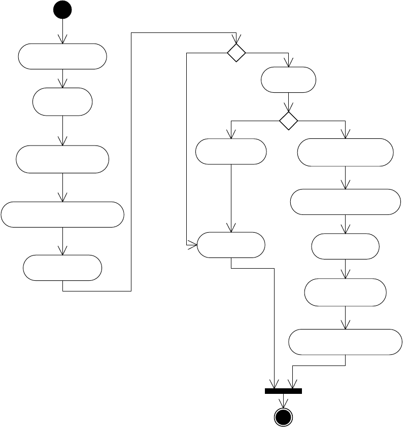
CHAPTER 4: Import and Export PDF import and export 93
When you import a PDF file through the InDesign Place dialog box, if you choose Show Import Options,
the Place PDF dialog opens:
Receive an IDFile to import
Create a data link
from the IDFile
Open an IPMStream
from the data link for import
Display PDF import option if necessary
Create a new page item
Import PDF
Delete the page item Update user's PDF import pref
based on the pref just used
Add the data link to the page item
Make sure the page item
is in a graphic frame
Load the new item in the place gun
Release the datalink Release the datalink
fail succeed
fail succeed
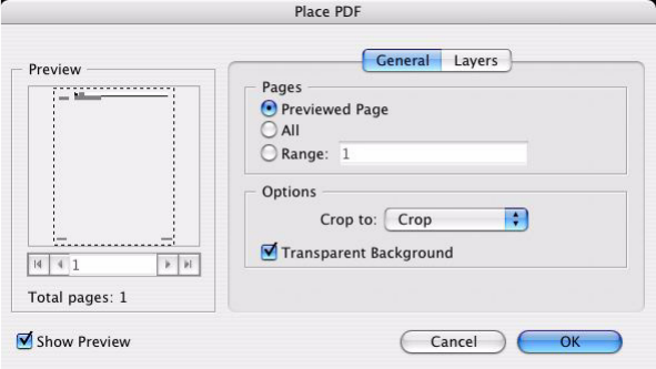
CHAPTER 4: Import and Export PDF import and export 94
The following options offer flexible PDF import:
Placing multipage PDF pages (General tab) — You can place a range of PDF pages from a multipage
PDF file. Under Pages, select All or enter a value for Range. The place gun is loaded as before, but the
pointer changes to show that multiple pages exist. Each time you click, a PDF page is placed on the
page. If you hold down the Alt/Option keys, the pointer changes to the cascade-place pointer, and
clicking places all remaining pages on the page, cascading down from the click point.
Optional content groups (OCG) layers support (Layers tab) — OCG groups content for selective
viewing and printing, supports complex mapping of objects to groups, and allows special use cases
like language and zoom factors. By recognizing OCG constructs in placed PDF files, InDesign offers
users the ability to selectively include those pieces of content.
General PDF import options are stored in the IPDFPlacePrefs interface, and layers options are stored in
IGraphicLayerInfo; both interfaces are added to the kWorkspaceBoss workspace. Normally, these options
are used unless the PDF import is performed through a link update; in that case, the IGraphicLayerInfo on
the page item (kPlacedPDFItemBoss) is used instead, and some attributes from the IPDFAttributes
aggregated on the kPlacedPDFItemBoss are used. The following attributes override the defaults under the
condition of a link update:
IPDFAttributes::SetPage — Overrides PDF page number of the placed page.
IPDFAttributes::SetTransparentBackground — Overrides Transparency background.
IPDFAttributes::SetPreserveScreens — Overrides Preserve Halftone Screens.
IPDFAttributes::SetUserPassword — Overrides Set User Password.
IPDFAttributes::SetCropTo — Overrides Set Crop To.
The following figure shows how kPDFPlaceProviderBoss sets up the data interfaces for kPDFPlaceCmdBoss
in different cases. If the import is done with the full user interface, the user can change settings through
the Place PDF dialog (see the preceding figure). InDesign uses kPDFPlaceProviderBoss to do its PDF
import, so by changing import options you control InDesign’s PDF import behavior.
The following figure has a “Minimal UI” decision point. If the user deselects Show Import Options when
importing a file, a minimal user interface is used: the user sees only a progress bar, not the Place PDF
dialog.
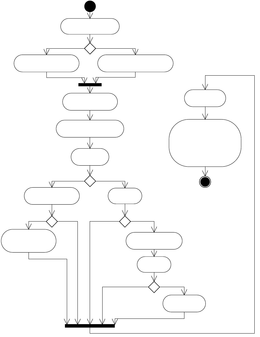
CHAPTER 4: Import and Export PDF import and export 95
The figure also has an “Is the PDF import for link update?” decision point. Link update is performed when
the user selects Relink or Update from the Links panel. Doing this triggers a PDF import if the link is a PDF
item.
The main interfaces to control the PDF import options are IPDFPlacePrefs, IGraphicLayerInfo, and
IPDFAttributes. To modify the data stored in these interfaces, use the commands shown in the following
table. Note there is no command to modify the IPDFPlacePrefs for clipboard import
(IID_IPDFCLIPBOARDPLACEPREFS). If you process your own kPDFPlaceCmdBoss, use the IPDFPlacePrefs
Get the session preference:
IGraphicLayerInfo
Is the PDF import
for link update?
Does the linked page
item have IPDFAttributes
Is the import from clipboard?
Get session prefs: IPDFPlacePrefs
from IID_IPDFPLACEPREFS
Get session prefs: IPDFPlacePrefs
from IID_IPDFCLIPBOARDPLACEPREFS
Suppress UI?
Minimal UI?
Copy session preference data to
kPDFPlaceCmdBoss data interface
Override some session data
with linked page item's
IPDFAttributes
Override the PDF password
setting from the source PDF
Bring up PDF Import
Dialog if available
Process
kPDFPlaceCmdBoss
If the import was successful,
and we are NOT importing from
clipboard, and we are NOT in
active INX context, then update
the user’s PDF place preferences
based on what they just chose using
kSetPDFPlacePrefsCmdBoss
Yes
Yes
Yes
Yes
Yes
No
No
No
No
No

CHAPTER 4: Import and Export PDF import and export 96
aggregated on the command boss to set up the import option. The IGraphicLayerInfo on the page item
passed to the kPDFPlaceCmdBoss is used for layer options.
Commands to Change PDF Import Options:
PDF export
InDesign/InCopy document export
The easiest way to export an InDesign or InCopy document is to use the PDF export service provider. The
following example is a snippet showing how to get the PDF export provider and call the export method.
PMString PDFFormat("Adobe PDF");
PDFFormat.SetTranslatable(kFalse);
InterfacePtr<ISelectionManager> selection(SelectionUtils::QueryActiveSelection());
IDocument *frontDoc = ::GetFrontDocument();
InterfacePtr<IK2ServiceRegistry> k2ServiceRegistry(gSession, UseDefaultIID());
// Look for all service providers with kExportProviderService.
int32 exportProviderCount =
k2ServiceRegistry->GetServiceProviderCount(kExportProviderService);
// Iterate through them.
bool found = kFalse;
for (int32 exportProviderIndex = 0 ; exportProviderIndex < exportProviderCount ;
exportProviderIndex++)
{
// get the service provider boss class
InterfacePtr<IK2ServiceProvider> k2ServiceProvider
(k2ServiceRegistry->QueryNthServiceProvider(kExportProviderService,
exportProviderIndex));
// Get the export provider implementation itself.
InterfacePtr<IExportProvider> exportProvider(k2ServiceProvider,
To change... Use
IPDFPlacePrefs on the workspace kSetPDFPlacePrefsCmdBoss
IGraphicLayerInfo on the workspace kSetPDFPlacePrefsCmdBoss
IPDFAttributes on the page item kSetPDFAttributesCmdBoss
IGraphicLayerInfo on the page item kSetGraphicLayerInfoCmdBoss

CHAPTER 4: Import and Export PDF import and export 97
IID_IEXPORTPROVIDER);
// Check to see if the current selection specifier can be exported
// by this provider.
bool16 canExportByTarget =
exportProvider->CanExportThisFormat(frontDoc, selection, PDFFormat);
if (canExportByTarget)
{
found = kTrue;
// assume idFile is a valid IDFile to hold the soon to be created PDF
exportProvider->ExportToFile(idFile, frontDoc, selection, PDFFormat,
kFullUI);
}
if (found)
break;
}
In the example:
The format name used to get the PDF export provider is Adobe PDF, defined in the beginning of the
example.
The example tells the PDF export provider to use the full user interface during the export, meaning the
PDF export settings dialog is brought up for the user to set export options. The settings dialog box is
provided by kPDFExportDialogBoss in InDesign and by kInCopyPDFExptDialogBoss in InCopy. They
are selectable dialog service providers you can retrieve through the
IK2ServiceRegistry::GetServiceProviderIndex method, although it is most practical to specify kFullUI
and let the export provider do the work. If kSuppressUI is used instead, no user interface is presented,
and you can change the preference as described below.
The example omits the steps that produce a valid IDFile to be passed into the
IExportProvider::ExportToFile method. Normally, the IDFile is obtained through a standard Save File
dialog box. You also can construct an IDFile from scratch. For more information on IDFile, see
Chapter 13, “Using Adobe File Library.”
The example is for exporting an InDesign/InCopy document. To export an InDesign book, see
“InDesign book export” on page 106.
The PDF export provider for InDesign/InCopy documents is represented by kPDFExportBoss. There is an
IBoolData in kPDFExportBoss, which indicates whether print content preferences (IPrintContentPrefs)
should be considered. When you export from the InDesign menu, the default value for the IBoolData is set
to false, so no print content preference are used during the default PDF export. Also, the PDF export
provider allows you to use an export style (kPDFExportStyleBoss) instead of dealing with the settings one
by one. This is achieved by passing the style UID in the IUIDData aggregated on the kPDFExportBoss.
The kPDFExportBoss processes kPDFExportCmdBoss. Before the command is processed,
kExportValidationCmdBoss is used to verify that the attributes set for the command will produce a valid
output. The following table summarizes the command interfaces kPDFExportBoss needs to set up before it
processes kPDFExportCmdBoss.
Critical data interfaces for kPDFExportCmdBoss:
CHAPTER 4: Import and Export PDF import and export 98
Interactive PDF
The IInteractivePDFExportPrefs interface is used to configure the parameters for an export to the PDF
format specifically targeted at Acrobat 9 and later. To export InDesign content to an interactive PDF, an
instance of the interactive PDF export command kInteractivePDFExportCmdBoss will typically need to be
created.
You can then use the IInteractivePDFExportPrefs aggregated on the command boss to set up various
parameters for the export. The IPDFSecurityPrefs interface off of the command boss can be used to set the
security settings for the exported PDF. The IInteractivePDFExportPrefs interface is also aggregated on the
application workspace, where it is used to ensure that default export settings are preserved from export to
export. Consider using this instance as the base for export settings. Also consider using
kSetInteractivePDFExportPrefsCmdBoss to update the default export settings for subsequent exports. The
IInteractivePDFExportFacade facade can assist in retrieving the application workspace settings.
From InDesign layout view
If a style is passed to the export provider, the IPDFExportPrefs on the kPDFExportStyleBoss is copied to the
IPDFExportPrefs on the kPDFExportCmdBos; otherwise, the IPDFExportPrefs on the kWorkspaceBoss is
used. You can query the session’s PDF export preference as follows:
InterfacePtr<IPDFExportPrefs>
appExportPrefs((IPDFExportPrefs*)::QuerySessionPreferences(IID_IPDFEXPORTPREFS));
Interface Purpose
IPDFExportPrefs Holds most of the PDF export settings as seen in
the PDF export options dialog.
IPDFSecurityPrefs Holds the PDF security preference.
ISysFileData Holds the destination IDFile for the PDF
document.
IBoolData Indicates whether the IPrintContentPrefs should
be used.
IPrintContentPrefs Allows certain contents to be removed from the
output.
IBoolData (IID_IBOOKEXPORT) Indicates whether the command is used to
export an InDesign book.
IUIFlagData Tells the command to use kFullUI, kMinimalUI, or
kSuppressUI.
IOutputPages Holds the UIDs of the pages to output in layout
mode.
IInCopyGalleySettingData Holds the data for galley export.
IBoolData (IID_IINCOPYPDFNOTEANNOTATIONDATA) Layout export note annotation flag.
IInteractivePDFExportPrefs Contains settings for exporting PDF files with
interactive content such as multistate objects
and media files. The PDF files created are
targeted for Acrobat 9.0 and later.

CHAPTER 4: Import and Export PDF import and export 99
To change the preferences, process kSetPDFExportPrefsCmdBoss and use the Set*** methods of
IPDFExportPrefs on the command boss to change the settings.
IPDFSecurityPrefs is set up using the preferences saved in the session (that is, IPDFSecurityPrefs on the
kWorkspaceBoss). You can query the preferences as follows:
InterfacePtr<IPDFSecurityPrefs>
appSecurityPrefs((IPDFSecurityPrefs*)::QuerySessionPreferences(IID_IPDFSECURITYPREFS)
);
To change the security preferences, process kSetPDFSecurityPrefsCmdBoss and use the Set*** methods of
IPDFSecurityPrefs on the command boss to change the settings.
Another critical interface in kPDFExportCmdBoss that needs to be set up is IOutputPages. It holds the UIDs
of the pages from the document for export. The PDF export provider uses IPageRange on the
kWorkspaceBoss to initialize the IOutputPages on kPDFExportCmdBoss. kPDFExportDialogBoss uses the
same data to initialize the export settings dialog user interface, and it updates the session data when the
user changes it from the dialog box. The following example shows how to set up IOutputPages from
IPageRange on kWorkspaceBoss.
InterfacePtr<IPageRange>
myPageRange((IPageRange*)::QuerySessionPreferences(IID_IPAGERANGE));
IPageRange::RangeFormat pageRangeFormat = myPageRange->GetPageRangeFormat();
// Assume theDoc is a valid IDocument* for export.
UIDList pageUIDs = UIDList(::GetDataBase(theDoc));
InterfacePtr<IPageList> iPageList((IPMUnknown*)theDoc, IID_IPAGELIST);
if (pageRangeFormat != IPageRange::kAllPages)
{
PMString pageRange;
pageRange = myPageRange->GetPageRange();
pageRange.SetTranslatable(kFalse);
iPageList->PageRangeStringToUIDList(pageRange, &pageUIDs);
}
else
{
int32 cPages = iPageList->GetPageCount();
for (int32 iPage = 0; iPage < cPages; iPage++ )
{
UID uidPage = iPageList->GetNthPageUID(iPage);
pageUIDs.Append( uidPage );
}
}
// Assume pdfExportCmd is the valid ICommand* from kPDFExportCmdBoss.
InterfacePtr<IOutputPages> iExportPages(pdfExportCmd, IID_IOUTPUTPAGES);
// Assume exportPrefs is the previously set IPDFExportPrefs from kPDFExportCmdBoss.
iExportPages->InitializeFrom(pageUIDs, (exportPrefs->GetPDFExReaderSpreads() ==
IPDFExportPrefs::kExportReaderSpreadsON));
PMString name;
theDoc->GetName(name);
iExportPages->SetName(name);
From InCopy layout view
There is an IInCopyPDFExptLayoutData interface on kWorkspaceBoss, which is used to store some InCopy
layout export settings. During an InCopy layout export, IPDFExportPrefs is set up as described in “From
InDesign layout view” on page 98. Then the IInCopyPDFExptLayoutData on the kWorkspaceBoss is used to
override some of the data on the command’s IPDFExportPrefs. The following table summarizes the
overrides. To change the IInCopyPDFExptLayoutData on the kWorkspaceBoss, use
kSaveInCopyPDFExptLayoutDataCmdBoss.

CHAPTER 4: Import and Export PDF import and export 100
InCopy Layout-specific export settings:
IOutputPages for kPDFExportCmdBoss is set up like kPDFExportCmdBoss IOutputPages from IPageRange,
except IInCopyPDFExptLayoutData::GetPDFExPageRangeFormat is used to check the range format and
IInCopyPDFExptLayoutData::GetPDFExPageRange is used to get the range if the range format is not
IInCopyPDFExptLayoutData::kAllPages.
kPDFExportCmdBoss also aggregates an interface, IInCopyGalleySettingData. During InCopy layout
export, IInCopyGalleySettingData::SetGalleySetting(kFalse) is called, so no IInCopyGalleySettingData is
used.
The IBoolData (IID_IINCOPYPDFNOTEANNOTATIONDATA) on the kPDFFxportCmdBoss is set to the value
from IInCopyPDFExptLayoutData::GetPDFExAnnotationNotes.
From InCopy story view or galley view
Export from galley view is different than export from layout view, because the galley and story view
on-screen may not be the export (print) view. Galley export allows the user to output the galley story with
multiple columns and a selected range of story lines. When the user selects export, a final view to the
Attributes Override
Launch Adobe
Acrobat
Changed by SetPDFExLaunchAcrobat. If
IInCopyPDFExptLayoutData::GetPDFExLaunchAcrobat is equal to kTrue, this is set to
kExportLaunchAcrobatON; otherwise, kExportLaunchAcrobatOFF.
Compatibility
Level
Changed by SetPDFExAcrobatCompatibilityLevel. Set to the value returned by
IInCopyPDFExptLayoutData::GetPDFExAcrobatCompatibilityLevel.
Compression
Type
Changed by SetCompressionType. If
IInCopyPDFExptLayoutData::GetPDFExAcrobatCompatibilityLevel >= kPDFVersion15,
this is set to kCompressObjects; otherwise, kCompressNone.
Embed Page
Thumbnails
Changed by SetPDFExThumbnails. If
IInCopyPDFExptLayoutData::GetPDFExThumbnails is equal to kTrue, this is set to
kExportThumbnailsON; otherwise, kExportThumbnailsOFF.
Optimize for Fast
Web View
Changed by SetPDFExLinearized. If IInCopyPDFExptLayoutData::GetPDFExLinearized
is equal to kTrue, this is set to kExportLinearizedON; otherwise, kExportLinearizedOFF.
Include Page
Information
Changed by SetPDFExPageInfo. If IInCopyPDFExptLayoutData::GetPDFExPageInfo is
equal to kTrue, this is set to kExportPageInfoON; otherwise, kExportPageInfoOFF.
Subset Fonts
Threshold
Changed by SetPDFExSubsetFontsThreshold. Set to the value returned by
IInCopyPDFExptLayoutData::GetPDFExSubsetFontsThreshold.
Export Reader
Spreads
Changed by SetPDFExReaderSpreads. If
IInCopyPDFExptLayoutData::GetPDFExReaderSpreads is equal to kTrue, this is set to
kExportReaderSpreadsON; otherwise, kExportReaderSpreadsOFF.
Interactive
Elements
Changed by SetPDFExAddInteractiveElements. Set to the value returned by
IInCopyPDFExptLayoutData::GetPDFExAddInteractiveElements.
Multimedia
Content to
Embed
Changed by SetContentToEmbed. Set to the value returned by
IInCopyPDFExptLayoutData::GetContentToEmbed.

CHAPTER 4: Import and Export PDF import and export 101
document is not yet available. The PDF export provider internally executes
kCreatePrintGalleyViewCmdBoss to generate an invisible galley view for PDF port printing based on the
user’s preferences.
IInCopyPDFExptGalleyData on the kWorkspaceBoss is the default galley-specific setting data used during
PDF export. It is used to set up some of the data in IPDFExportPrefs and IInCopyGalleySettingData; both
are aggregated on kPDFExportCmdBoss. The PDF export provider does not take the data from
IInCopyPDFExptGalleyData on the kWorkspaceBoss as is: if the galley document contains any story and
the session’s IInCopyPDFExptGalleyData is default (checked through
IInCopyPDFExptGalleyData::GetIsDefaultValues), the data shown in the following table is overridden.
IInCopyPDFExptGalleyData overrides when it is the default:
NOTE: ITextLine and IGalleySettingsOverwrite should be from the galley view (kWritingModeWidgetBoss)
of the exported document.
Attributes Override
Font Leading Changed by SetPDFExFontLeading. Set to the string value returned from
IGalleySettingsOverwrite::GetDisplayFontLeading.
Font Name Changed by SetPDFExFont. Set to the value returned by
Utils<IGalleyUtils>()->GetFontFamilyAndStyle.
Font Size Changed by SetPDFExFontSize. Set to the string value returned from
IGalleySettingsOverwrite::GetDisplayFontSize.
Font Type Changed by SetPDFExFontType. Set to the value returned by
Utils<IGalleyUtils>()->GetFontFamilyAndStyle.
Include Accurate Line
Endings
Changed by SetPDFExALE. If ITextLine::GetLinesType is equal to
ITextLines::kLayoutLineEnds, set to kTrue; otherwise, kFalse.
Include Inline Notes Changed by SetPDFExInlineNotes. If there is at least one note anchor in the
document, set to kTrue; otherwise, kFalse.
Include Line Numbers Changed by SetPDFExLineNumber. Set to the value returned by
Utils<IGalleyUtils>()->InGalley().
Include Paragraph
Styles
Changed by SetPDFExStyle. Set to the value returned from
IGalleySettingsOverwrite::GetShowParagraphStyleNames.
Include Track Changes Changed by SetPDFExTrackChanges. Set to the value returned from
IGalleySettingsOverwrite::GetShowTrackChanges.
Notes Type Changed by SetPDFExNotesType. Set to kVisible.
Show Notes
Backgrounds in Color
Changed by SetPDFExNotesBackground. Set to kFalse.
Show Track Changes
Backgrounds in Color
Changed by SetPDFExTrackChangesBackground. Set to kFalse.
Track Changes Type Changed by SetPDFExTrackChangesType. Set to kVisible.
CHAPTER 4: Import and Export PDF import and export 102
In galley view mode, the PDF export provider initializes IPDFExportPrefs and IPDFExportPrefs in much the
same way as described in “From InCopy layout view” on page 99, but the attributes from IPDFExportPrefs
shown in the following table are overridden by IInCopyPDFExptGalleyData, as described above.
Galley-specific settings for IPDFExportPrefs:
As described in “From InCopy layout view” on page 99, IOutputPages is a critical interface that holds the
UIDs of pages to be exported for kPDFExportCmdBoss in layout mode. For InCopy galley and story mode,
however, IOutputPages cannot provide enough data for kPDFExportCmdBoss to draw a range of lines
from galley view or rearrange the number of columns in the output PDF that are allowed in the galley
export options dialog box. Therefore, the interface IInCopyGalleySettingData is aggregated on
kPDFExportCmdBoss to hold the data used to create a galley window for PDF export.
In addition to settings specific to galley mode, IInCopyGalleySettingData also holds the views
(IControlView* of the galley writing widgets, paragraph information panel, etc.) that represent the real
output pages based on the user’s galley export settings. kPDFExportCmdBoss passes these views to the
PDF drawing port for output instead of using IOutputPages. The user of kPDFExportCmdBoss is
responsible for setting up IInCopyGalleySettingData properly before the command is processed.
The PDF export provider executes kCreatePrintGalleyViewCmdBoss to get an invisible output view based
on the data from the current galley document and IInCopyPDFExptGalleyData. It then uses the view and
IInCopyPDFExptGalleyData to set up IInCopyGalleySettingData for kPDFExportCmdBoss. The PDF export
provider sets up IOutputPages of kPDFExportCmdBoss with IOutputPages returned from
kCreatePrintGalleyViewCmdBoss, which has the values shown in the following table.
IOutput pages from kCreatePrintGalleyViewCmdBoss:
The following steps summarize how the PDF export provider sets up IInCopyGalleySettingData for
kPDFExportCmdBoss.
1. A new kInCopyGalleySettingDataBoss is created, with default value.
Attributes Values
Acrobat Compatibility
Level
Set by SetPDFExAcrobatCompatibilityLevel. Set to the value returned from
IInCopyPDFExptGalleyData::GetPDFExAcrobatCompatibilityLevel.
Include Page
Information
Set by SetPDFExPageInfo. If IInCopyPDFExptGalleyData::GetPDFExPageInfo is
equal to kTrue, this is set to IPDFExportPrefs::kExportPageInfoON; otherwise,
IPDFExportPrefs::kExportPageInfoOFF.
Subset Fonts
Threshold
Set by SetPDFExSubsetFontsThreshold. Set to the value returned from
IInCopyPDFExptGalleyData::GetPDFExSubsetFontsThreshold.
Attributes Values
ContiguousPages kTrue
Name Name of the galley document
IsSpreads kFalse
MasterDataBase Database for the window created by the kCreatePrintGalleyViewCmdBoss
UIDs Placeholder. UIDs number from 0 to total pages-1. UIDs contained in IOutputPages
are not used by kPDFExportCmdBoss in InCopy galley and story mode.

CHAPTER 4: Import and Export PDF import and export 103
2. IInCopyPDFExptGalleyData is used to override the IInCopyGalleySettingData of the new
kInCopyGalleySettingDataBoss.
3. IInCopyGalleySettingData is used to execute the kCreatePrintGalleyViewCmdBoss command.
4. A copy of IInCopyGalleySettingData returned from kCreatePrintGalleyViewCmdBoss in Step 3 is used
to set up kPDFExportCmdBoss.
The following table shows how attributes from IInCopyGalleySettingData get their values in different
stages. In the table, “PEGD” stands for IInCopyPDFExptGalleyData from Step 2 above.
Setting up IInCopyGalleySettingData for kPDFExportCmdBoss:
Attribute and description Default value Overridden value
Final value after
kCreatePrintGalleyViewC
mdBoss
Galley/story control view nil nil Calculated by
kCreatePrintGalleyViewCmd
Boss
Paragraph panel control view
(GetInfoColumnView)
nil nil Calculated by
kCreatePrintGalleyViewCmd
Boss
Line number panel control
view (GetLineNumberView)
N/A, not used N/A, not used N/A, not used
Splitter control view
(GetInfoSplitterView)
nil nil Calculated by
kCreatePrintGalleyViewCmd
Boss
Total content height of the
galley (GetTotalHeight)
00 Calculated by
kCreatePrintGalleyViewCmd
Boss
Start Line Number
(GetStartLineNumber)
N/A, not used N/A, not used N/A, not used
End Line Number
(GetEndLineNumber)
N/A, not used N/A, not used N/A, not used
Column width
(GetColumnWidth)
0 Calculated based on
PEGD and current unit
settings
Calculated by
kCreatePrintGalleyViewCmd
Boss
GalleySetting kTrue kTrue kTrue
Document UIDRef
(GetDocUIDRef )
N/A UIDRef of galley
document
UIDRef of galley document
To print with paragraph style
info (GetParaStyle)
kFalse from PEGD from PEGD
To print with line number
(GetLineNumber)
kFalse from PEGD from PEGD

CHAPTER 4: Import and Export PDF import and export 104
To print with accurate line
ending (GetALE)
kFalse from PEGD from PEGD
To print with notes displayed
(GetNotes)
kFalse from PEGD from PEGD
To print with tracked changes
displayed (GetTrackChange)
kFalse from PEGD from PEGD
Notes displayed type
(GetNotesType)
kVisible from PEGD from PEGD
Track change displayed type
(GetTrackChangesType)
kVisible from PEGD from PEGD
Font name (GetFontName) “” from PEGD from PEGD
Font type (GetFontType) “” from PEGD from PEGD
Font size (GetFontSize) “” from PEGD from PEGD
Font leading
(GetFontLeading)
“” from PEGD from PEGD
To print with line range scope
(GetWhich)
IIncopyGalleyP
rintData::kAll
If PEGD’s
GetPDFExlineRangeFor
mat is
IInCopyPDFExptGalleyD
ata::kAllLine, set to
kAllLines; otherwise,
kUseRange
If PEGD’s
GetPDFExlineRangeFormat
is
IInCopyPDFExptGalleyData::
kAllLine, set to kAllLines;
otherwise kUseRange.
To print the line range
(GetRange)
“” from PEGD from PEGD
Galley frame size
(GetFrameSize)
Rect(0, 0, 0, 0) Set frame to the page
bounds from the first
page of the galley
document.
Set frame to the page
bounds from the first page
of the galley document.
To print with content filled
with the page (GetFill)
kFalse If GetALE returns true,
then set to the return
value from PEGD’s
GetPDFExFill; otherwise,
kFalse.
If GetALE returns true, then
set to the return value from
PEGD’s GetPDFExFill;
otherwise, kFalse.
Story range (GetScope) IInCopyGalley
PrintData::kAll
from PEGD from PEGD
To print with story
information (GetStoryInfo)
kFalse from PEGD from PEGD
Attribute and description Default value Overridden value
Final value after
kCreatePrintGalleyViewC
mdBoss

CHAPTER 4: Import and Export PDF import and export 105
PDF/VT
PDF/VT (V: variable, T: transactional) enables variable data publishing in a variety of environments, from
desktop printing to digital production press, and to accommodate linkages for content, such as
TransPromo applications, which combine color promotional content with transaction information.
PDF/VT has three levels; InDesign provides API support for creating only PDF/VT-1:
PDF/VT-1 is for a complete single file exchange. PDF/VT-1 requires all resources necessary for proper
interpretation of the PDF data to be included within the conforming PDF file.
PDF/VT-2 is for multiple file exchange, allowing additional content to come from external files.
PDF/VT-2s is for streamed delivery, which is a MIME package that contains a sequence of one or more
PDF/VT files and supporting resources.
With InDesign, the third-party plug-in has the responsibility for setting up the PDF export preferences
properly to achieve PDF/X-4 standards compliance (required for PDF/VT-1).
The solution for generating a PDF/VT document is built upon the PDFExportSetupService service provider.
To create a PDF/VT document, implement this service (IID_IPDFEXPORTSETUPPROVIDER) to start receiving
the PDF export events (class PDFExportEvent).
The PDF export events are generated by InDesign’s PDF export process and are dispatched to all the
PDFExportSetupService providers. A PDF export event contains the following information:
Event ID — The identifier for the event, which conveys what stage the PDF export process is in, for
example, begin export, draw page, draw spread, or end export.
Target port — The PDF doc port to which InDesign is exporting.
Database — The database for the page/spread to draw. It may change from one event to another for a
single PDF export if multiple InDesign documents are being exported in the same session.
UID — The UID for the page/spread to draw.
To print with notes
background in color
(GetNotesBackgroundInColor)
kTrue from PEGD from PEGD
To print with track changes
background in color
(GetTrackChangesBackgroun
dInColor)
kTrue from PEGD from PEGD
To print with page
information (GetPagesInfo)
kFalse kFalse kFalse
(kPDFExportCmdBoss takes
this info from
IPDFExportPrefs)
To print with number of
columns (GetColumns)
11 Calculated by
kCreatePrintGalleyViewCmd
Boss
Attribute and description Default value Overridden value
Final value after
kCreatePrintGalleyViewC
mdBoss

CHAPTER 4: Import and Export PDF import and export 106
To create a PDF/VT file, the plug-in must provide the PDF/VT DPart hierarchy and metadata information
that it will generate to the PDF export process. This information could either be provided page by page (in
the draw page/spread event), record by record (in the draw page/spread event but at record boundaries)
for a multipage document template, or all at one time (in the end export event).
The interface IPDFDPartHierarchy is aggregated on the kPDFViewPortBoss. The plug-in code can get this
interface from the PDF doc port as follows:
InterfacePtr<IPDFDPartHierarchy> iHier(pdfExportEvent->targetPort, UseDefaultIID());
The IPDFDPartHierarchy interface provides APIs to create the DPart hierarchy for the PDF/VT. These APIs
allow the plug-in to set the PDF/VT node name list, set the record level, and create the DPart node tree,
starting from the root DPart node. It also provides APIs to create child DPart nodes, add pages to DPart
nodes, and set metadata for DPart nodes.
Plug-ins create the DPart metadata using the services of another interface, IPDFDPartMetadataUtils, which
is again aggregated on the kPDFViewPortBoss. This interface allows plug-ins to create rich DPart metadata.
The metadata dictionary created using this interface can then be attached to the DPart node by the
plug-ins.
For a sample showing how to export PDF/VT file, see PDFVT in the SDK.
InDesign book export
You can use the high-level kBookExportActionCmdBoss to easily export a book. For details, see
SnpExportBookAsPDF.cpp.
kBookExportActionCmdBoss uses kPDFExportBookBoss (with service ID kExportBookService), which uses
the same PDF export service provider (kPDFExportProviderImpl) as the kPDFExportBoss; however,
kPDFExportBookBoss aggregates an IOutputPages interface that lists document pages in the book to
export. The regular document kPDFExportBoss does not aggregate IOutputPages; it sets up IOutputPages
for the kPDFExportCmdBoss based on the IPageRange, as shown in the example in “From InDesign layout
view” on page 98.
Selected page-items export
There is no direct user interface to allow export of selected page items in InDesign; however, you can copy
selected page items to the pasteboard in PDF format. Then, when you paste into an external application
that supports PDF import, the pasted object is in PDF format. This is done through
kPDFExportItemsCmdBoss. The snippet in the following example shows how to process the command.
CHAPTER 4: Import and Export PDF import and export 107
// Assume stream is the destination PDF file write stream.
// Assume realPageItems contains no guide item, which can
// cause trouble in PDF export.
InterfacePtr<ICommand> command(CmdUtils::CreateCommand(kPDFExportItemsCmdBoss));
if (command)
{
command->SetItemList(realPageItems);
// Initialize the command data from the session.
InterfacePtr<IPDFExportPrefs> appExportPrefs((IPDFExportPrefs *)
::QuerySessionPreferences(IID_IPDFCLIPBOARDEXPORTPREFS));
InterfacePtr<IPDFExportPrefs> exportPrefs(command, IID_IPDFEXPORTPREFS);
InterfacePtr<IPDFSecurityPrefs> appSecurityPrefs((IPDFSecurityPrefs *)
::QuerySessionPreferences(IID_IPDFSECURITYPREFS));
InterfacePtr<IPDFSecurityPrefs>
exportSecurityPrefs(command,IID_IPDFSECURITYPREFS);
exportPrefs->CopyPrefs(appExportPrefs);
exportSecurityPrefs->CopyPrefs(appSecurityPrefs);
// no progress bar
InterfacePtr<IBoolData> useProgressBar(command, IID_IUSEPROGRESSINDICATOR);
useProgressBar->Set(kFalse);
InterfacePtr<IUIFlagData> uiFlagData(command, IID_IUIFLAGDATA);
uiFlagData->Set(kSuppressUI);
// Assume no destination color profile (i.e., ignore IUIDData).
// (IID_IPDFDESTCMSPROFILE)
// Put the stream pointer in the IIntData.
InterfacePtr<IIntData> exportCmdStreamData(command, IID_IINTDATA);
exportCmdStreamData->Set((long) stream);
// process the command
CmdUtils::ProcessCommand(command);
success = ErrorUtils::PMGetGlobalErrorCode();
}
PDF Export Performance
Consider two exports:
A 1000-page InDesign document exported to a single PDF file
A one-page InDesign document exported to 1000 PDF files
The first is much faster because it has a single port to which the 1000 pages are exported, whereas the
second has 1000 such ports. Each port has its own cache. For the first case, the cache is initialized only
once. For the second, the caches are initialized 1000 times, once in each port.
For example, suppose that you have a one-page InDesign document containing variable content as a
template and you have a database containing thousands of records for the variable content. You want to
merge the template document with each record in the database and export the resulting files to PDF.
A bad approach would be to
1. Replace the variable data in the template document with each record.
2. Export each merged document to PDF.
CHAPTER 4: Import and Export PDF import and export 108
This is same as the second case, which has bad performance.
A good approach would be
1. Trigger the PDF export command on the template document with page range=(1,1,1...,1), where the
quantity of 1s is equal to the quantity of records to merge.
InterfacePtr<ICommand> cmd(CmdUtils::CreateCommand(kPDFExportCmdBoss));
InterfacePtr<IPageList> pageList(theDoc, IID_IPAGELIST);
UIDRef uidRef = ::GetUIDRef(theDoc);
UIDList pageUIDs = UIDList(uidRef.GetDataBase());
// Number of records to merge
int32 N = 1000;
// Assume the template document has 1 page
UID uidPage = pageList->GetNthPageUID(0);
// Append the uid of page 0 N times
for (int32 i = 0; i < N; i++)
{
pageUIDs.Append(uidPage);
}
cmd->SetItemList(pageUIDs);
InterfacePtr<IOutputPages> exportPages(cmd, IID_IOUTPUTPAGES);
exportPages->InitializeFrom(pageUIDs, kFalse);
PMString name;
theDoc->GetName(name);
exportPages->SetName(name);
2. Provide a PDFExportSetupService service provider.
During the PDF export process, the PDF export events are generated by InDesign’s PDF export process
and are dispatched to this service provider’s PDFProcessEvent callback for each page. In this callback,
merge the record data into the template document.
This approach allows all records to be exported into a single PDF file, eliminating the creation of numerous
PDF ports.
PDF style import and export
When the PDF export provider brings up the Export Adobe PDF options dialog box, the dialog box is
initialized according to the following rules:
1. A preset style UID may be passed in. When it is available, use it.
2. Otherwise, if the last preset used is named “[Custom]” or the style name ends with “(modified),” use
the application preferences of the workspace.
3. Otherwise, if the last preset used is not empty and is valid, use it.
4. Otherwise, use the default preferences. This is the first time the export dialog is run after deleting Save
Data.
CHAPTER 4: Import and Export PDF import and export 109
PDF export style is represented by kPDFExportStyleBoss, which aggregates an IPDFExportPrefs interface
that stores the settings. Usually, the IPDFExportPrefs -> CopyPrefs method is used to copy the setting out
of the style boss to another IPDFExportPrefs you are using. The last preset style’s name is saved in the
IPDFExportStyleLastUsed on the kWorkspace. You can use the snippet in the following example to get the
name in PMString:
InterfacePtr<IPDFExportStyleLastUsed>
iStyleLast((IPDFExportStyleLastUsed*)::QuerySessionPreferences
(IID_IPDFEXPORTSTYLELASTUSED));
PMString lastPreset;
if (iStyleLast)
lastPreset = iStyleLast->GetString();
lastPreset.SetTranslatable(false);
Given a style name, you can use IPDFExptStyleListMgr (aggregated on kWorkspace) to obtain the UID style
object, Continuing from the preceding example, the following example shows how to get to a last used
style object from its name:
InterfacePtr<IPDFExptStyleListMgr>
styleMgr((IPDFExptStyleListMgr*)::QuerySessionPreferences(IID_IPDFEXPORTSTYLELISTMGR)
);
int32 nStyle = styleMgr->GetStyleIndexByName(lastPreset);
if (nStyle != -1)
{
UIDRef styleRef = styleMgr->GetNthStyleRef(nStyle);
InterfacePtr<IPDFExportPrefs> pStylePrefs(styleRef, UseDefaultIID());
if( pStylePrefs )
{
// assume myExportPrefs is an IPDFExportPrefs I am trying to set up
myExportPrefs->CopyPrefs(pStylePrefs);
};
}
Adding, deleting, and editing styles
To add a style, use kPDFExportAddStyleCmdBoss. The following example shows how to process the
command:
InterfacePtr<ICommand> addCmd(CmdUtils::CreateCommand(kPDFExportAddStyleCmdBoss));
InterfacePtr<IExportStyleCmdData> cmdData(addCmd, IID_IEXPORTSTYLECMDDATA);
InterfacePtr<IWorkspace> workspace(gSession->QueryWorkspace());
UIDRef workspaceUIDRef = ::GetUIDRef(workspace);
cmdData->SetSrcList(workspaceUIDRef);
cmdData->SetDstList(workspaceUIDRef);
// Assume presetName is a PMString containing the new style name.
cmdData->SetNewName(presetName);
cmdData->SetStyleIndex(-2); // -2 means get the PDF preferences from the command.
InterfacePtr<IPDFExportPrefs> commandPrefs(cmdData, UseDefaultIID());
// Assume pSrcPref is my source IPDFExportPrefs to be made into the new style.
commandPrefs->CopyPrefs(pSrcPrefs);
commandPrefs->SetUIName(presetName);
ErrorCode rc = CmdUtils::ProcessCommand(addCmd);
The command boss aggregates an IExportStyleCmdData that has a method, SetStyleIndex, that sets up a
style index for the command. The style index tells the command where the source style comes from,
according to the following rules:
CHAPTER 4: Import and Export PDF import and export 110
1. If there is valid index (index >= 0), that style's PDF preferences (queried from an IPDFExptStyleListMgr
returned by IExportStyleCmdData::GetSrcList) are used.
2. If the index is -2, the PDF preferences come from the command.
3. If the index is -3, the PDF preferences come from the command, but the data is not written to disk.
4. Otherwise, the PDF preferences come from the current application preferences.
5. In all cases except -3, the data is written to disk.
To delete a style, use kPDFExportDeleteStyleCmdBoss. The following example shows how to delete a style
stored in the application’s workspace:
InterfacePtr<IWorkspace> workspace(gSession->QueryWorkspace());
UIDRef workspaceUIDRef = ::GetUIDRef(workspace);
InterfacePtr<ICommand>
deleteCmd(CmdUtils::CreateCommand(kPDFExportDeleteStyleCmdBoss));
InterfacePtr<IExportStyleCmdData> commandData(deleteCmd, IID_IEXPORTSTYLECMDDATA);
// Assume i is the (to-be-deleted) style index in the style list.
commandData->SetStyleIndex(i);
commandData->SetDstList(workspaceUIDRef);
CmdUtils::ProcessCommand(deleteCmd);
To edit a style, use kPDFEditStyleCmdBoss. The following example shows how to edit a style stored in the
application’s workspace:
InterfacePtr<ICommand> editStyleCmd(CmdUtils::CreateCommand(kPDFEditStyleCmdBoss));
InterfacePtr<IIntData> data(editStyleCmd, IID_IINTDATA);
// Assume index is the index of the style to be edited.
data->Set(index);
InterfacePtr<IPDFExportPrefs> newPrefs(editStyleCmd, IID_IPDFEXPORTPREFS );
// Assume myPrefs is the edited copy of IPDFExportPrefs.
newPrefs->CopyPrefs(myPrefs);
CmdUtils::ProcessCommand(editStyleCmd);
Frequently asked PDF questions
How does the PDF export provider determine whether it should start the
viewer after the export?
In InDesign, IPDFPostProcessPrefs is used to maintain persistent PDF preference data not part of the
standard IPDFExportPrefs. IPDFPostProcessPrefs is aggregated on kWorkspaceBoss and can be queried
through QuerySessionPreferences. Use IPDFPostProcessPrefs::GetViewAfterExport to determine whether
the viewer should be launched.
In InCopy, IInCopyPDFExptGalleyData::GetPDFExLaunchAcrobat (for galley) and
IInCopyPDFExptLayoutData::GetPDFExLaunchAcrobat (for layout) are used to determine whether the
viewer should be started.
How do I set the PDF clipboard setting as seen in the File Handling
preferences?
Those settings (for example, Prefer PDF when Pasting) are kept in the IPDFClipboardPrefs aggregated on
the kWorkspaceBoss. To modify the settings, use kSetPDFCBPrefsCmdBoss.

CHAPTER 4: Import and Export EPub export 111
How do I control which layer of a document should be exported?
IPDFExportPrefs::SetExportLayers can be used to control the function of layers for visibility and printability.
Use the enums kExportAllLayers, kExportVisibleLayers, and kExportVisiblePrintableLayers to set the export
layer’s preference. Each layer’s visibility and printability are controlled by each layer’s option, managed by
IDocumentLayer. For more information about how to set each layer’s visibility and printability, see the
“Layer Options” section of Chapter 7, “Layout Fundamentals.”
How do I make the two-page spreads in my document export as two separate
PDF pages?
Set the Boolean control for reader spreads in the IPDFExportPrefs to false. The IOutputPages on the
kPDFExportCmdBoss usually is initialized as follows:
InterfacePtr<IOutputPages> iExportPages(cmd, IID_IOUTPUTPAGES);
iExportPages->InitializeFrom(pageUIDs, (exportPrefs->GetPDFExReaderSpreads() ==
IPDFExportPrefs::kExportReaderSpreadsON));
If the preference for the reader spreads is set to false and you set up IOutputPages as above, the two pages
spreads are exported as separated pages in the PDF. See the example in “From InDesign layout view” on
page 98.
Why does kPDFExportCmdBoss give me an assert after the command is
processed (ASSERT 'db != nil' in PDFExportController.cpp)?
Make sure you put the UIDRef of the pages in the IOutputPage interface. Also, set the item list with the
pages’ UIDRef values (in a UIDList). kPDFExportCmdBoss is used for exporting both books (multiple .indd
files) and multiple pages from a document. kPDFExportCmdBoss first checks to see whether it has a valid
IOutputPages and uses the database from the first UIDRef of the output pages. If the command cannot
find a valid database from IOutputPages, it looks for it from the command item list.
How do I set up line ranges for output in InCopy Galley or Story mode?
Use IInCopyPDFExptGalleyData::SetPDFExLineRange. Pass in a PMString with a format like “3-10” (that is,
the beginning page number, followed by a dash, followed by the ending page number).
IInCopyPDFExptGalleyData is aggregated on the kWorkspaceBoss.
Is it possible to export only selected text from an InDesign document?
No. When printing or exporting to PDF, the decision to draw or not draw is made at the page-item level.
This is evidenced by the “Nonprinting” attribute, which can be applied to a text frame but not the text
itself. Similarly, draw event handlers work on the page-item level, such as the text frame.
EPub export
EPub (electronic publication) is a free and open e-book standard by the International Digital Publishing
Forum. EPub files have the extension .epub. EPub is designed for reflowable content, meaning that the
text display can be optimized for the particular display device used by the reader of the EPub-formatted
book.

CHAPTER 4: Import and Export EPub export 112
The easiest way to export an InDesign document as an EPub file is to use the EPub export service provider.
The following snippet shows how to get the EPub export provider and call the export method:
PMString EPubFormat("EPUB");
EPubFormat.SetTranslatable(kFalse);
InterfacePtr<ISelectionManager>
selection(Utils<ISelectionUtils>()->QueryActiveSelection());
IDocument* frontDoc = Utils<ILayoutUIUtils>()->GetFrontDocument();
InterfacePtr<IK2ServiceRegistry> k2ServiceRegistry(GetExecutionContextSession(),
UseDefaultIID());
// Look for all service providers with kExportProviderService.
int32 exportProviderCount =
k2ServiceRegistry->GetServiceProviderCount(kExportProviderService);
// Iterate through them.
bool found = kFalse;
for (int32 exportProviderIndex = 0;
exportProviderIndex < exportProviderCount; exportProviderIndex++)
{
// get the service provider boss class
InterfacePtr<IK2ServiceProvider> k2ServiceProvider
(k2ServiceRegistry->QueryNthServiceProvider(kExportProviderService,
exportProviderIndex));
// Get the export provider implementation itself.
InterfacePtr<IExportProvider> exportProvider(k2ServiceProvider,
IID_IEXPORTPROVIDER);
// Check to see if the current selection specifier can be exported by this provider.
bool16 canExportByTarget =
exportProvider->CanExportThisFormat(frontDoc, selection, EPubFormat);
if (canExportByTarget)
{
// assume epubFileName is a valid IDFile to hold the soon to be created EPUB file
exportProvider->ExportToFile(epubfile, frontDoc, selection, EPubFormat,
kFullUI);
break;
}
In this example:
The format name used to get the EPUB export provider is EPUB, defined at the beginning.
The code tells the EPUB export provider to use the full user interface during the export, meaning that
the EPUB export settings dialog is opened for the user to set export options.
The example omits the steps that produce a valid IDFile to be passed into the
IExportProvider::ExportToFile method. Normally, the IDFile is obtained through a standard Save File
dialog box. You also can construct an IDFile from scratch. For more information on IDFile, see
Chapter 13, “Using Adobe File Library.”
The EPUB export provider for InDesign documents is represented by kEBookExportProviderBoss.
For details, see SnpExportEPub.cpp.
CHAPTER 4: Import and Export Articles 113
Articles
Articles provide designers and production artists with an easy way to create relationships among page
items. These relationships can be used to define which content to export to ePub, HTML, or Accessible
PDFs and to define the order of the content. You can create articles from a combination of existing page
items within a layout, including images, graphics, or text. After an article has been created, you can add,
remove, or reorder page items.
To operate on articles, use IArticleFacade. This facade provides methods to create and delete articles and
to add articles to a document at the specified position. It also provides several useful utility methods for
changing an article’s name, adding page items to an article, removing page items from an article, and
reordering page items in an article.
The IArticleList interface on the document provides access to any particular article:
InterfacePtr<IArticleList> articleList(document, UseDefaultIID());
Through this interface, you can retrieve article counts, access any particular article in the document’s
article list, add an existing article at the specified position in the document’s article list, or remove an
article from the document’s article list. For a complete list of APIs, refer to the API Reference for IArticleList.
Given the UID of an article, you can use IArticleMemberList aggregated on kArticleBoss to access any
member of the article:
InterfacePtr<IArticleMemberList> memberList(db, articleUID, IID_IARTICLEMEMBERLIST);
Through this interface, you can retrieve the number of members in the article, add a new member at the
specified position in the article, or remove a member from the article. For a complete list of APIs, refer to
the API Reference for IArticleMemberList.
Group items can be added to the article as well. To reorder the group children inside an article
independent of their layout hierarchy, use interface IArticleChildList aggregated on kGroupItemBoss. With
this interface, you can retrieve the number of direct children of the group, add a child at the specified
position in the group, or remove a child from the group. All the APIs in this interface affect only the order of
children inside an article; their layout hierarchy will not be affected. For a complete list of APIs, refer to the
API Reference for IArticleChildList.
The sample code in SnpManipulateArticles.cpp demonstrates the use of article APIs.

114
5Rich Interactive Documents
InDesign provides users with tools for developing interactive content, that is, content that users can
interact with as well as view. Interactive content includes animated page items, media files, and other
objects whose state changes as a result of a document event such as a button click or page load.
Interactive content is intended to be exported to interactive file formats such as PDF, SWF, or XFL.
The interactive features can be organized into the following categories: animations, timings, buttons,
hyperlinks, multistate objects, and media. Each of these features is represented by a separate panel in
InDesign. The combinations of these features allow complex and capable interactive documents to be
created.
This chapter describes these capabilities and how to take advantage of these features with C++ plug-ins.
This chapter assumes that you have some familiarity with the interactive features found in the Window >
Interactive menu in InDesign.
Terminology
Dynamic event — Event triggers such as button click or page load that cause a single page item or a
group of page items to perform a behavior.
Behavior — Any interactive change to the document resulting from a dynamic event.
Action — Behavior changes made as a result of a button event.
Dynamic target — The page item whose behavior is triggered as a result of a dynamic event.
Preset — A predefined animation.
Interactive documents
InDesign provides a feature that allows users to specify whether a document is intended to be a print
document or web document when the document is created. Documents are not required to have an
interactive intent to use the interactive features. The purpose of specifying the document intent is to
change document defaults. Documents intended for interactive use will have their default measurement
units set to pixels and their default color space set to RGB.
By default, the intent of a new document is for printing. This can be changed when the document is
created with the INewDocCmdData interface by calling the SetIntent function and passing the kWebIntent
enum value. The kWebIntent is included in the IPageSetupPrefs header file.
Chapter Update Status
CS6 Unchanged

CHAPTER 5: Rich Interactive Documents Animations 115
InterfacePtr<ICommand>
newDocCmd(Utils<IDocumentCommands>()->CreateNewCommand(uiflags));
if (newDocCmd == nil) {
break;
}
// Set the command's parameterized data.
InterfacePtr<INewDocCmdData> newDocCmdData(newDocCmd, UseDefaultIID());
if (newDocCmdData == nil) {
break;
}
newDocCmdData->SetIntent(kWebIntent);
Animations
Page items can have a single animation applied to them, which can be triggered by a variety of events
such as page load or button click. (See “Timings” on page 117.) Users may apply preset animations
supplied in InDesign or create custom animations. InDesign includes many preset animations. These
include options such as fading in page items, rotating page items, or moving page items. The preset
animations may be configured with additional options such as duration or loops. If animation presets
provided by default are too limited, custom animations can be imported from XML files. There is a
one-to-one relationship between page items and animation settings, which means that page items can
have only one animation applied to them. While the same page item animation behavior may be triggered
by multiple trigger events, it is not possible to apply multiple animations to a page item that are
conditionally triggered based on the trigger event.
IAnimationAttributeData
This interface has been added to the kDrawablePageItemBoss to give drawable page items animation
settings.
IAnimationFacade
This facade provides services for obtaining and modifying the animation setting for the page items, as
shown in the following code excerpt from the create animated multistate object snippet:
PMString presetName = "twirl";
//Get the animation preset index
InterfacePtr<IMotionPresetMgr> iPresetMgr
(Utils<IMotionPresetUtils>()->QueryMotionPresetManager (nil));
int32 presetIndex = iPresetMgr->FindPreset (presetName, false /*case sensitive*/);
//Get a UIDRef for the Preset
UID presetUID = iPresetMgr->GetNthPresetUID (presetIndex);
UIDRef presetRef = UIDRef (::GetDataBase (iPresetMgr), presetUID);
//Set the pageitem animation preset
Utils<Facade::IAnimationFacade > iAnimationFacade;
result = iAnimationFacade->SetPageItemMotionPreset(pageItemRef, presetRef);

CHAPTER 5: Rich Interactive Documents Multistate objects 116
IMotionFacade
This façade provides services for adding, modifying, or removing preset animations. Use this facade to
import custom animations defined in an XML file or to export existing animations to an XML file. The name
of the preset in the preset list of the animation panel is determined by the name of the XML file. To have
the custom animation preview in the animation panel, a separate SWF file must be created with the same
name as the XML file defining the animation and placed in the presets/motion presets folder.
The following code excerpt from the create custom animation snippet shows importing from and
exporting to XML files:
//Import Animation Preset from XML file
std::vector<IDFile> files;
files.push_back(file);
UID newPresetUID = kInvalidUID;
ErrorCode err = Utils<Facade::IMotionFacade>()->LoadPresetFromFile (files,
newPresetUID, false);
//Export Animation Preset To XML File
Utils<Facade::IMotionFacade > iMotionFacade;
ErrorCode err = iMotionFacade->SavePresetToFile(presetRef, file);
Multistate objects
Multistate objects provide any easy-to-use tool for toggling the visibility of multiple page items with a
single button click. Multistate objects exist on the page hierarchy and act as containers for the groups
within them. Both groups and individual page items can be added to them. If an individual page item is
added, the multistate object places that page item inside a group. With multistate objects, groups are
treated as unique states. There is not a separate state object used for storing page items. Multistate objects
are not viewable. Only the page items within the object can be viewed. With multistate objects, only one
state is viewable at a time. It helps to think of states as layers where only one layer is visible at one time.
The multistate object provides controls for toggling states. States in a multistate object can be toggled
only with a button click event. Page clicks and other events do not change the current state. Button click
events can be used to go to the next state, the previous state, or a specific state identified by a name or
index.
Multistate objects require a minimum of two states. When created programmatically with fewer than two
states, an empty state is added. Take this into consideration when adding states. Otherwise, these
additional empty states may appear unexpectedly.
IAppearanceItemFacade
This façade is used to create multistate objects and buttons (see “Buttons” on page 119). The façade also
provides functions for adding, removing, moving, and altering states contained within a multistate object.
Finally, it provides functions for changing the active state. Here is a code excerpt from the
CreateAnimatedMultiStateObject snippet:
CHAPTER 5: Rich Interactive Documents Timings 117
//Creates a new Multi-State object and add the states to it.
//Note: the stateList is a UIDList of page item UIDRefs
UIDList outItems(msoRef);
Utils<Facade::IAppearanceItemFacade> iFacade;
result = iFacade->CreateAppearanceItem(stateList, kMultiStateObjectItemBoss,
&outItems);
msoRef = outItems.GetRef(0);
Timings
Timings are used determine when interactive behaviors assigned to page items are triggered. They can
match behaviors such as animations with dynamic events. They can also organize and chain animation
dependencies to each other. The following timing settings can be configured:
Order – When multiple page items are assigned animations, the order in which animations are
triggered can be adjusted. The order is a list of dependencies. Before the next behavior starts, the
previous behavior must finish.
Groupings – These allow page items to be grouped so their animations are triggered simultaneously.
Delays – A period of time may be added as a delay between the trigger event execution and the
animation execution.
Dynamic Events - Event triggers that cause a single page item or a group of page items to perform a
dynamic behavior.
Dynamic events
The following dynamic events are available for the associated boss objects. When an event fires, it triggers
interactive behaviors assigned to these objects or to active objects within these objects. Buttons are an
exception to this rule. Buttons can trigger behaviors on outside target objects such as a multistate object
or a page item.
Spread:
kOnPageLoad (added by default when animations are added to a page item)
kOnPageClick
Multistate object:
kOnPageLoad (the same as on state load)
Page items with animations applied:
kOnSelfClick
kOnSelfRollover
Buttons:
kOnClick
kOnRelease
kOnRollover
CHAPTER 5: Rich Interactive Documents Media 118
kOnRolloff
IDynamicEventTimingMgr
This interface has been added to the following boss classes:
kSpreadBoss
kMultiStateObjectItemBoss
kGroupItemBoss
kDrawablePageItemBoss
kFormFieldItemBoss
IDynamicTargetsFacade
This façade provides services for accessing information regarding page items in dynamic documents. Here
is a code excerpt from the CreateAnimatedMultiStateObject snippet:
//Remove default page load events from the spread
Utils<Facade::IDynamicEventTimingFacade > iDynEvtTimingFacade;
InterfacePtr<IDynamicEventTimingMgr> iDynEvtTimingMgr (spreadRef, UseDefaultIID ());
uint32 numTriggers = iDynEvtTimingMgr->GetNumDynamicEvents ();
for( int32 i = 0; i < numTriggers; i++)
{
EventTriggerType trigger = iDynEvtTimingFacade->GetNthDynamicEvent (spreadRef, i);
bool successful = iDynEvtTimingFacade->RemoveDynamicEvent(spreadRef, trigger);
if (!successful)
return kFailure;
}
//Add the Page_Load Event for each state.
IAnimationUtils* animationUtils = Utils<IAnimationUtils>();
UID parentTimingUID = animationUtils->GetTimingParentUID(msoRef);
InterfacePtr<IDynamicEventTimingMgr> iMsoTimingMgr (msoRef.GetDataBase(),
parentTimingUID, UseDefaultIID());
IDynamicEventTimingMgr::DynamicTargetPtr dynamicTarget =
iDynEvtTimingFacade->CreateDynamicTarget(msoRef, kOnPageLoad,
kTimingTargetVerbPlay);
bool successful = iMsoTimingMgr->AddTargetInNthGroup(kOnPageLoad, dynamicTarget, -1);
if (!successful)
return kFailure;
Media
InDesign can place audio and video files within an interactive document. The following audio and video
file formats are supported: MP3, AU, WAV, AIFF, SWF, MP4, F4V, FLV, and H.264-encoded MOV. In addition to
playing these formats, InDesign provides the ability to modify poster images, set navigation points to
specific times in the video, and customize controller skins.

CHAPTER 5: Rich Interactive Documents Buttons 119
IMediaUtils
This utility provides tools for changing the poster image, determining whether a media file is encoded in a
supported format, working with controller skins, and placing media files.
IMediaSuite
This suite contains tools for setting navigation points, changing poster images, placing media files, and
setting controller skins.
IImportExportFacade
This façade is not media specific. It is used to create a link to a media file and place it in a document (see
the “Architecture” section in Chapter 6, “Links”). While doing so, the IMediaUtils functions are called to
place media-specific files on the document.
Here is a code excerpt from the AddMediaFile snippet:
//This façade will create a link to the
Utils<Facade::IImportExportFacade> iFacade;
ErrorCode err = iFacade->ImportAndLoadPlaceGun(documentUIDRef.GetDataBase(), uri,
kSuppressUI, kTrue /*retainFormat*/, kTrue /*convertQuotes*/,
kTrue /*applyCJKGrid*/, kTrue /*useClippingFrame*/, IPlaceGun::kAddToBack
/*location*/);
UIDList replaceList;
IDataBase * db = documentUIDRef.GetDataBase();
InterfacePtr<IPlaceGun> placeGun(documentUIDRef.GetDataBase(),
documentUIDRef.GetDataBase()->GetRootUID(), UseDefaultIID());
err = iFacade->ReplacePageItem(db , pageItemUIDRef.GetUID(),
placeGun->GetFirstPlaceGunItemUID(), kFalse, replaceList ) ;
Buttons
Buttons in InDesign are one way to trigger interactive events. Buttons are the only objects that can trigger
behaviors on other page items. Behaviors triggered by button events include page transitions, state
transitions, playing animations and more. Button events can have multiple actions assigned to them,
allowing a single button event to trigger multiple behaviors. Buttons in InDesign do not have a required
preset appearance. They are created by converting existing page items to buttons. See Chapter 4, “Import
and Export,” for more information about exporting interactive PDF files.
Here is a code excerpt from the ExportDynamicDocuments snippet:
//Convert spline item into a button.
UIDList buttonUIDs(splineItemUIDs.GetDataBase());
Utils<Facade::IAppearanceItemFacade> iFacade;
ErrorCode result = iFacade->CreateAppearanceItem(splineItemUIDs, kPushButtonItemBoss,
&buttonUIDs);
Exporting rich interactive documents to files
InDesign documents can store interactive behaviors but they are not intended for displaying these
behaviors. Interactive documents can be exported to file formats, such as XFL, SWF, and interactive PDF,
CHAPTER 5: Rich Interactive Documents Exporting rich interactive documents to files 120
that fully utilize these features. The supported export formats each have a unique export preferences
interface such as ISWFExportPreferences or IXFLExportPreferences.
An export is shown in the following code excerpt from the export dynamic documents snippet:
// Create the SWF export action command
InterfacePtr<ICommand> swfExportCmd(CmdUtils::CreateCommand(kSWFExportCommandBoss));
if (swfExportCmd == nil)
{
return kFailure;
}
// Set cmd data
InterfacePtr<IDynamicDocumentsExportCommandData> dynamicDocsCmdData(swfExportCmd,
UseDefaultIID());
dynamicDocsCmdData->SetStream(outStream);
dynamicDocsCmdData->SetUIFlags(kSuppressUI);
InterfacePtr<ISWFExportPreferences> swfCmdData(swfExportCmd, UseDefaultIID());
InterfacePtr<IWorkspace> iAppWS(GetExecutionContextSession()->QueryWorkspace());
InterfacePtr<ISWFExportPreferences> iSWFExportPrefs(iAppWS, UseDefaultIID());
swfCmdData->Copy(iSWFExportPrefs);
// process the command
return CmdUtils::ProcessCommand(swfExportCmd);

121
6Links
This chapter describes the InDesign link architecture.
Introduction
A link establishes a relationship between a link object, such as a page item, and a link resource, such as an
external graphic file. When you place an image in an InDesign document, a link is created between the
image file and the page item that contains the image. The link acts as a bridge between a source (the
resource) and a destination InDesign object (the object). A link object is not limited to a page item; it can
be an XML element, swatch, style set, chunk of text, and so on.
Architecture
Types of links
InDesign supports three types of links:
Import-only link — Represented by kImportLinkBoss, this maintains an import association between an
object and a linked resource. If the linked resource changes, the object can be updated through an
import operation.
Export-only link — Represented by kExportLinkBoss, this maintains an export association between an
object and a linked resource. If the object changes, the linked resource asset can be updated through
an export operation.
Bi-directional link — Represented by kBidirectionalLinkBoss, this maintains a bi-directional association
between an object and a linked resource. A bi-directional link requires conflict-resolution when both
the object and the linked asset change.
NOTE: One more type, a child link, is represented by kChildLinkBoss. This allows an InDesign publication
that contains links to be placed in another document. In this case, the links in the placed document
become child links. You cannot update a child link directly; you must open the original document to
update the links it contains.
A link is created and maintained by ILinkManager. The ILinkManager::CreateLink methods create a link
between a given link object and linked resource.
The ILink interface
All three link boss classes aggregate a key interface, ILink, which establishes a relationship between a link
resource and a link object.
Chapter Update Status
CS6 Unchanged
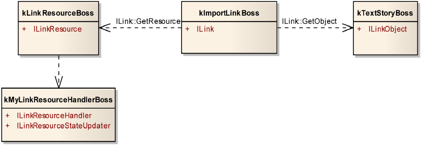
CHAPTER 6: Links Architecture 122
A link resource is represented by kLinkResourceBoss, which aggregates the ILinkResource interface.
ILinkResource methods access and maintain a linked resource.
A link object can be any boss object that aggregates the ILinkObject interface.
There is an ILinkManager that manages linked resources and links
The following figure shows the relationship between a linked resource and linked object.
The ILink interface defines Get/SetResource to access the associated link resource and
GetObject/SetObject are used to access the associated link object. In these functions, a UID is used to
identify the link resource or link object.
ILink defines import and export policies.
The ImportPolicy enumeration denotes the policy that specifies when to automatically update the link
object via an import when the resource is marked as modified:
kNoAutoImport — Never automatically update the object.
kImportOnModify — Update the object via an import when the resource is marked as modified.
Use Get/SetImportPolicy to access the import policy.
The ResourceModificationState enumeration denotes the modification state of the linked resource, and
Get/SetResourceModificationState are used to access the state.
The ExportPolicy enumeration denotes the policy used to specify when to automatically update the link
resource via an export, when the object is marked as modified:
kNoAutoExport — Never automatically export to the resource.
kExportOnModify — Update the resource via an export when the object is marked as modified.
kExportOnClose — Update the resource via an export on close.
kExportOnSave — Update the resource via an export on save.
Use Get/SetExportPolicy to access the export policy.
The ObjectModificationState enumeration denotes the modification state of the linked object, and
Get/SetResourceModificationState are used to access the state.

CHAPTER 6: Links Architecture 123
ILink has many other settings to customize the link, such as Get/SetCanEmbed, Get/SetCanPackage, and
Get/SetShowInUI.
Linked resource and ILinkResourceHandler
The most common link resources are desktop files. However, InDesign link architecture supports
generalized, abstract links: it allows data to come from a file, URL, database record, or any external or
internal source that can be read or written via a stream.
A linked resource is referenced by a URI. According to the URI specification, a URI consists of a hierarchical
sequence of five components, referred to as the scheme, authority, path, query, and fragment. For URI
format syntax, see the specification (http://labs.apache.org/webarch/uri/rfc/rfc3986.html#components).
There is an InDesign class, URI, which can be used to construct and parse a well formed URI. The link
architecture classifies link resources based on the link resource’s scheme from its URI. All link resources of
the same type must share the same scheme in their URIs. There should be a link-resource handler
(represented by ILinkResourceHandler) for each type of scheme available in InDesign. For example, most
traditional InDesign datalinks are file-based links; that is, the link is between a page item and an external
file established though a “Place” action. The link resources for these type of links are the external file, and
all their URIs have the scheme of “file”; that is, their URIs all look like “file://path_to_file”. During import
(through Place), a resource handler that knows how to handle URIs with a “file” scheme is used to create a
resource read stream, and the stream is given to an import provider that knows how to handle the
particular file format to import the resource.
What makes up a resource handler? A resource handler aggregates the ILinkResourceHandler interface
and is implemented by a generic InDesign boss class. The convention to invoke a resource handler is
through a service-provider boss that supports the kLinkResourceService service ID. In this service-provider
boss, an ILinkResourceFactory should be aggregated. The ILinkResourceFactory indicates what kind of URI
scheme the resource handler can handle through its GetSchemes method, and
ILinkResourceFactory::QueryHandler returns an instance of the handler upon request, based on a URI. For
example, the CustomDataLink SDK sample allows you to place assets specified in a CSV file. Since only
CustomDataLink knows how data is stored in the CSV file, it must implement a resource handler for assets
from the CSV. CustomDataLink defines its own URI that can uniquely identify any asset in the CSV.
CustomDataLink’s resource handler knows how to retrieve data from the CSV based on the URI. The URI
defined in CustomDataLink has its own scheme, CSVLink, and its URI looks something like this:
CSVLink://csv_fullpath?recordID
The resource handler in CustomDataLink declares it knows how to handle resources whose URI scheme is
CSVLink. When CustomDataLink’s client asks to place a resource from the CSV, CustomDataLink processes
a kImportAndLoadPlaceGunCmdBoss by giving the command a IImportResourceCmdData that consists of
an URI to the resource client specified. kImportAndLoadPlaceGunCmdBoss does all the ground work for an
import action; when it comes time to import the real resource, it sends the URI to the link manager. The
link manager queries all the service providers that support kLinkResourceService, to see if anyone can
handle a URI scheme of CSVLink. Since CustomDataLink implements one, it is chosen to import the data
from the URI. The CustomDataLink’s implementation of ILinkResourceHandler defines methods like
CreateResourceReadStream(), which returns an IPMStream to the resource to which the selected CSV
record points. Since CustomDataLink knows how to access the CSV, given its own URI, it knows exactly
what record its client is requesting and handles the request.
The following table lists the URI schemes handled by a default InDesign resource handler.

CHAPTER 6: Links Architecture 124
If you provide you own resource handler, you should implement your own Place dialog and add it under
your own Place menu.
The ILinkResourceFactory Interface
This factory class is used to provide a list of schemes supported by a link resource handler, and to create
instances of a link resource handler. Include this interface on the link resource provider boss that is
registered with the service registry as a kLinkResourceService.
ILinkResourceFactory::GetSchemes returns the list of URI schemes supported by the handler.
ILinkResourceFactory::QueryHandler returns the link resource handler that will be used by a link resource
object to act on an resource whose URI scheme matches one of the supported schemes.
ILinkResourceFactory::QueryStateUpdater returns the link resource state updater that will be used to
obtain and update the state of a link resource whose URI scheme matches one of the supported schemes.
Both Custom Data Link and Extended Link SDK samples show usage of ILinkResourceFactory.
Link object
A link object is any boss that aggregates the ILinkObject interface. ILinkObject is a proxy used to represent
the item in an InDesign publication being linked to; for example, a page item, XML element, or range of
text. Depending on the type of link associated with the item, ILinkObject specifies how the item is
imported, exported, or resolved. A link (ILink) stores the UID of the link object with which it is associated,
and the link object can be retrieved from the ILink::GetObject() method. Normally, if your link object is a
regular page item, it has an ILinkObject with kPageItemLinkObjectImpl as its default implementation.
kPageItemLinkObjectImpl specifies kPageItemUpdateLinkServiceProviderBoss as its import provider.
When the link needs an update, kPageItemUpdateLinkServiceProviderBoss is used to update the link.
Internally, kPageItemUpdateLinkServiceProviderBoss’s IUpdateLinkService implementation
(kPageItemUpdateLinkServiceImpl) processes a kReimportCmdBoss to update the link. Eventually,
kReimportCmdBoss uses the link resource’s resource handler to provide a data stream to the resource, just
like the initial Place.
The following table lists the InDesign bosses that aggregates an ILinkObject by default.
Scheme Purpose
file Used when InDesign Place... is used to import file
adobevc For handling assets from Version Cue.
ADBEapli Used in assignment link
Boss name Note
kDocBoss kPageItemLinkObjectImpl
kTextStoryBoss kPageItemLinkObjectImpl
kSplineItemBoss kPageItemLinkObjectImpl
kMediaPageItemBoss kPageItemLinkObjectImpl
kGroupItemBoss kPageItemLinkObjectImpl

CHAPTER 6: Links Architecture 125
NOTE: kJBXLinkObjectBoss also has kJBXLinkObjectImpl.
If you are trying to create a link on an object not listed in the table, make sure you aggregate ILinkObject to
the object’s boss. The SDK sample ExtendedLink illustrates this situation, where a link object is derived
from kXMLLinkObjectReferenceBoss.
Link manager
There is a link manager, represented by ILinkManager, in every InDesign document (kDocBoss).
ILinkManager is used to create and delete links and link resources. ILinkManager also provides many ways
to query links and link resources.
There should be one, and only one, ILinkManager per InDesign database. However, different flavors of links
can be differentiated by the LinkClientID. For example, InDesign placed links all have a client identifier of
kIDLinkClientID, and hyperlinks have a client id of kHyperlinkLinkClientID. Both flavors of links are
managed by the same manager, but the manager prevents links and resources with different client ids
from interacting with each other. Therefore, a link with a client id of kIDLinkClientID cannot link a resource
with a client id of kHyperlinkLinkClientID. The client ids can also be utilized to control where and how the
links and resources are displayed to the user. For example, the Links Panel only shows links and resources
with a client id of kIDLinkClientID; hyperlinks have their own UI.
Most operations provided by the manager, with the exception of queries, should be initiated from the
ILinkFacade.
To query links through ILinkManager, first you should construct a LinkQuery object. LinkQuery is a class
that allows you to easily specify what you want the ILinkManager to search for and pass the LinkQuery
object to the ILinkManager::QueryLinks method. ILinkManager returns the query result in a
ILinkManager::QueryResult, which is a std::vector that contains the UID of the links. Once you have the UID
of a link, you can query its ILink interface.
ILinkManager also uses the link client ID as a filter when it returns the LinkQuery result. If you specify a
client ID, ILinkManager::QueryLinks returns the link with the same client ID. This is convenient if you used a
unique client ID to identify your link and link resource: you can easily query all your links with an empty
LinkQuery and your client ID.
To query a link resource through ILinkManager, construct a LinkResourceQuery object. LinkResourceQuery
is similar to LinkQuery, in that it allows you to specify the criteria (such as resource URI scheme) to look for
when ILinkManager searches for a link resource in a document. Once you construct a LinkResourceQuery,
you then pass it to ILinkManager::QueryResources for the query. ILinkManager also returns the query
result in a ILinkManager::QueryResult.
kDisplayListPageItemBoss kPageItemLinkObjectImpl
kImageItem kPageItemLinkObjectImpl
kPlacedPDFItemBoss kPageItemLinkObjectImpl
kXMLLinkObjectReferenceBoss kXMLElementLinkObjectImpl
kTestSplineItemBoss kPageItemLinkObjectImpl
kSPPlaceHolderPageItemBoss kPageItemLinkObjectImpl
kBookContentBoss kBookLinkObjectImpl
Boss name Note

CHAPTER 6: Links Architecture 126
For example, to get links from a page item, Use ILinkManager::QueryLinksByObjectUID to get to ILink. It
returns the result in an ILinkManager::QueryResult, which is a UID vector that holds the ILink UID.
InterfacePtr<IHierarchy> childHierarchy(frameHierarchy->QueryChild(0));
// If we're on a placed image we should have a data link to source item
InterfacePtr<ILinkObject> iLinkObject(childHierarchy,UseDefaultIID());
// get the link for this object
IDataBase* iDataBase = ::GetDataBase(childHierarchy);
InterfacePtr<ILinkManager>
iLinkManager(iDataBase,iDataBase->GetRootUID(),UseDefaultIID());
ILinkManager::QueryResult linkQueryResult;
if (iLinkManager->QueryLinksByObjectUID(::GetUID(childHierarchy), linkQueryResult))
{
ASSERT_MSG(linkQueryResult.size()==1,
"Only expecting single link with this object");
ILinkManager::QueryResult::const_iterator iter = linkQueryResult.begin();
InterfacePtr<ILink> iLink (iDataBase, *iter,UseDefaultIID());
if (iLink!=nil)
{
InterfacePtr<ILinkResource>
iLinkResource(iLinkManager->QueryResourceByUID(iLink->GetResource()));
ASSERT_MSG(iLinkResource,"CHMLFiltHelper::addGraphicFrameDescription - Link
with no associated asset?");
if(iLinkResource!=nil)
PMString datalinkPath = iLinkResource->GetLongName();
}
}
Link status
For every link resource handler made available in the link architecture through the kLinkResourceService
service provider, you should provide an implementation of ILinkResourceStateUpdater, which provides
the link manager with link-resource status information. There are times when link manager will ask each
link resource to provide a status update; for example, when the application resumes from background to
foreground. ILinkManager calls ILinkResourceStateUpdater::UpdateResourceStateAsync.
ILinkResourceStateUpdater should be aggregated on the boss where ILinkResourceHandler is aggregated.
In “Linked resource and ILinkResourceHandler” on page 123, we discuss how ILinkResourceHandler
normally is instantiated through the ILinkResourceFactory. ILinkResourceFactory has a method called
QueryStateUpdater, which is used to instantiate a status updater for the URI scheme supported by the
same ILinkResourceFactory.
ILinkManager may call for a link-resource status report synchronously or asynchronously, depending on
the situation; therefore ILinkResourceStateUpdater declares two update methods:
UpdateResourceStateSync and UpdateResourceStateAsync. In UpdateResourceStateSync, the status
update should be completed on the return of the function. In UpdateResourceStateAsync, it is expected
that status update is done in the background or during idle time.
Both ILinkResourceStateUpdater::UpdateResourceStateSync and
ILinkResourceStateUpdater::UpdateResourceStateAsync are passed in an UIDRef of a link resource
(kLinkResourceBoss). ILinkResource stores resource-status information like resource state
(ILinkResource::ResourceState), modification time, and size.
Also, there is a “stamp” (of type ResourceStamp, which is essentially a WideString) stored in ILinkResource.
You can use the ResourceStamp to construct any custom stamp you need for status-update purposes.
ILinkResource has declared get/set methods for maintaining these resource attributes.
CHAPTER 6: Links Architecture 127
In UpdateResourceStateSync/UpdateResourceStateAsync, a comparison should be made between the
link-resource object passed in and the external link resource (available from the URI, which can be queried
through the link-resource object). If you decide the link is out of date, a
kLinkResourceStateUpdateCmdBoss should be processed. This causes the link resource to be updated
with the new status data. The corresponding link (ILink) also maintains a linked-resource modification
state, which is set to ILink::kResourceModified, indicating the link resource was modified since the last
update. If the link is displayed in the Links UI panel, the status shows it is out of date, and the Update Link
option becomes available; this allows the user to manually update the link on demand.
NOTE: Each ILinkResourceStateUpdater implementation may have its own policy to decide what should be
regarded as a status change. For example, InDesign’s ILinkResourceStateUpdater for URI scheme “file” uses
the file’s modification date and file size as its criteria.
There are several approaches you can take to accomplish link-state updates. For example, Version Cue links
are updating via a push approach. Version Cue notifies InDesign whenever the state of a Version Cue link
changes. File links use a pull approach to update link states, by getting current information from the file
system. The SDK ExtLink sample uses an idle-task-based solution. It is important to consider the case
where there are many links in a document. When the link architecture asks for a link-status update, it asks
all links to provide updates; therefore, the performance issue is critical and deserves a good
implementation strategy.
Link update
When a link status is outdated, a link-update action becomes available. If the link information is available
on the Links UI panel, a contextual-menu item, Update Link, is enabled when a link is selected in the panel.
When the Update Link menu action is selected on an import link, kLinkUpdateCmdBoss is processed; this
queries the ILink on the kImportLinkBoss and calls its ILink::Update() method. Inside the ILink::Update(), it
queries its associated link object (ILinkObject) to see if there is an import provider available for the link
object through the ILinkObject::GetImportProvider(). If there is one, that import provider is used to
reimport the link resource; otherwise, ILinkObject::Import() is called. In ILinkObject::GetImportProvider(),
you can specify a update-link service-provider boss that implements IUpdateLinkService or kInvalidClass.
In the later case, you should then implement ILinkObject::Import. For example, if the link object is a
kPageItemLinkObjectImpl, it defines an kPageItemUpdateLinkServiceProviderBoss in its
GetImportProvider, which is used to update the link. kPageItemUpdateLinkServiceProviderBoss processes
a kReimportCmdBoss, which asks the link-resource handler to create a read stream from the resource for
import purposes.
What if your link object is not a page-item type, or you do not want to (or cannot) use kReimportCmdBoss
to update your link? In these cases, you must implement your own link object that will use your own
IUpdateLinkService or ILinkObject::Import.
Link Notification
When a link or link resource is added, deleted, or changed, a lazy notification is sent on the protocol of
IID_ILINK or IID_ILINKRESOURCE (depending on what was changed). The UID of the link or link resource is
sent in the notification via the notification cookie, LazyNotificationData. Using
ListLazyNotificationData::BreakoutChanges, you can determine which items (UIDs) were added, deleted,
or changed.
There is another lazy notification sent via the IID_ILINKDATA_CHANGED protocol. This occurs not only
when a link or link resource is added, deleted, or changed, but also when a link’s link resource is changed.
The notification cookie is passed in a type called ILinkManager::ChangeData, a wrapper of UID, which tells
you what kind of UID is referenced.
CHAPTER 6: Links File-based Links 128
You need not send any links-related notification from your plug-in—the links manager takes care of that.
The ILinkFacade Interface
ILinkFacade is a high-level API for dealing with links, link resources, and link objects. It has methods to
create, delete, update, and relink a link. Also, it has methods to create link resources and update resource
state. Use ILinkFacade whenever possible.
For example, to update links, use ILinkFacade::UpdateLinks, which processes (or schedules) a
kLinkUpdateCmdBoss. You need to pass in the UID of a kImportLinkBoss.
Links panel extensibility
You can add your own column into the Links panel (through a service-provider boss with
kLinkInfoServiceImpl as IK2ServiceProvider) and provide your own ILinkInfoProvider implementation. The
column will be available in the Links panel’s option dialog for the user to turn on or off. Providing an
ILinkInfoProvider implementation can be as easy as providing static information, or you can indicate that
the information needs to be updated dynamically based on certain protocol’s notification. You can elect to
listen to any command-notification protocol in ILinkInfoProvider and update your information when the
command notifies your subscribed protocol. For a simple ILinkInfoProvider implementation, see the
CustomDataLink sample in the SDK.
File-based Links
When you place a graphic file in an InDesign publication, InDesign does not include the graphic file in the
publication. Instead, it creates a page item to host the graphic object and establishes a link between the
page item and the graphic file. What you see on screen is a low-resolution proxy image of the graphic. A
link helps InDesign avoid redundantly storing large amounts of data in the publication, and it enables us
to automatically update page items when the external file is modified.
To see the link information associated with the page item, you need to display the Links UI panel. If the
current selected page item has an associated link, its link information is highlighted in the Links UI panel.
The link information includes where the linked file comes from and the link’s status.
When a user uses the default InDesign menu item File > Place, the InDesign File Chooser dialog appears,
and when the user selects a file from the InDesign Place dialog, kImportAndLoadPlaceGunCmdBoss is
processed. kImportAndLoadPlaceGunCmdBoss requires its client to set up a command data-interface
IImportResourceCmdData. IImportResourceCmdData can store the UID of a link resource or a URI (Uniform
Resource Identifier) that is a reference to the link resource. The URI is used in a kImportResourceCmdBoss
to create a link resource from an URI. Internally, kImportResourceCmdBoss calls
ILinkFacade::CreateResource to create the link resource from an URI, which in turn uses
kLinkResourceCreateCmdBoss. Finally, ILinkManager::CreateResource() is used to create the resource
(kLinkResourceBoss) using the InDesign link client ID.
NOTE: A link client ID identifies a link client, You should use the same link client ID when creating the link
resource and the link. If you use kIDLinkClientID, the link shows up in the Links UI panel. If you do not want
to have your links in the Links UI panel, use an ID other than kIDLinkClientID when you create the link and
link resource.
The ILinkManager will query a resource handler based on the URI’s scheme. The first resource handler that
knows how to handle (import, export, and resolve) the particular URI scheme is used to import the
resource. The resource handler is asked to supply a resource’s read stream, and it is given to an import
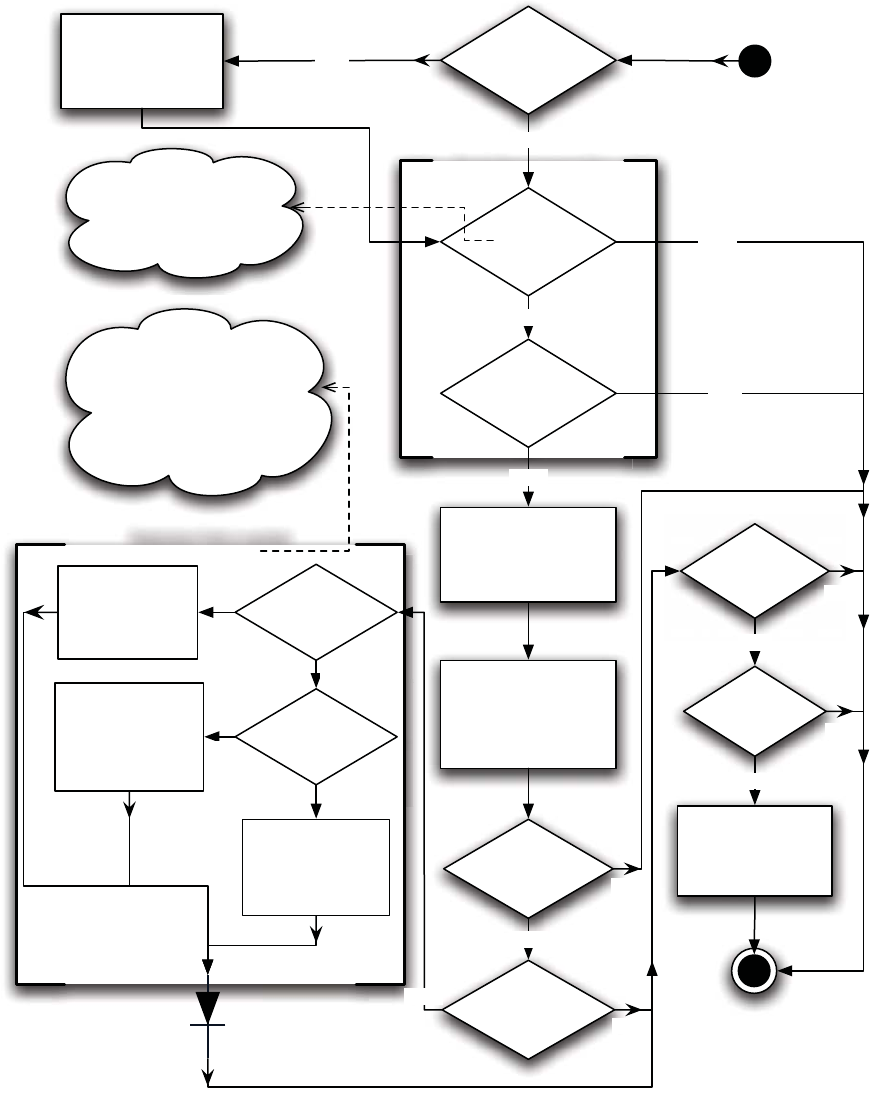
CHAPTER 6: Links File-based Links 129
provider that knows how to import the particular file format. Once the file is imported, a series of checks is
performed to determine if a link is wanted before a link is created. For example, by default, a text file
always is embedded, not linked, unless it is an Adobe InCopy file. The following figure illustrate the
sequence of how the link and link resource are created during the processing of a
kImportAndLoadPlaceGunCmdBoss.
Determine if link is wanted
for the text file
Yes
Yes
Check link resource state
Does link
resource
(kLinkResourceB
oss) exist?
Create link resource
using
ILinkFacade::CreateR
esource with the URI
Resource
missing?
Resource
available & a
valid read stream
is available
Link Resource queries
an IPMStream for read
from an
ILinkResourceHandler
Identify an import
provider that knows
how to handle the file
format, and give it the
stream for import.
Import
successful?
Is the import file
a text file?
Import to an
existing page
item?
Is it InCopy
import?
Set link is wanted
flag to the P.I's old
state
Set link is wanted
flag to
ITextOptions::GetLi
nkTextFiles on
doc's workspace
Is link
wanted?
Create link using
ILinkFacade::Create
Link
Yes
No
Yes
Yes
link state is managed by
ILinkState on the link object
boss such as kTextStoryBoss.
If a link is wanted,
ILinkState::SetIsLinkWanted is
used to set the status.
Set link is wanted
flag to true
end
Yes
Yes
No
No
Yes
Yes
No
Check using
ILinkResource::GetState()
against
ILinkResource::kMissing
start
No
No
No
If the link
already
exists?
No
Yes

CHAPTER 6: Links Linked Stories 130
Linked Stories
Linked stories make it easier to manage multiple versions of the same story or text content in the same
document; it makes it easier to support emerging digital publishing workflows, where, for example, you
need to design for both vertical and horizontal layouts. Linked stories behave similarly to traditional links.
You can designate a story as a parent and then place the same story at other places in the document as
child stories. Whenever the parent story is updated, the child stories are flagged in the Links panel and can
can be updated to synchronize with the parent story.
To create link for shared stories, use facade ISharedContentFacade.
Utils<Facade::ISharedContentFacade>()->CreateSharedContentLink(UIDList(sourceTextFram
eRef), sourceTextFrameRef.GetDataBase(), kSuppressUI);
ISharedContentFacade provides other functions to operate on shared content links including:
Checking whether the given link is a shared content link.
Checking whether the given link resouce is a shared content link resource.
Checking whether the given link object is a shared content link object.
Retrieving the ILink UIDRef for the given link object.
Retrieving the link object and link resource for the given ILink UIDRef.
For the complete APIs, refer to the API Reference for ISharedContentFacade.
An ASB class ISharedContentSuite is also provided for creating shared stories for the selected text frames.
Support Your Own Links
To provide your own type of links support, you should implement a resource-handler boss that aggregates
an ILinkResourceHandler and ILinkResourceStateUpdater, and provide a ILinkResourceFactory to
instantiate the handler on demand, as described in the following procedure.
1. Define how your resource can be represented by a URI. You will need your own URI scheme to identify
the type of resource for which you will provide support. Here are two examples of URIs; “CSVLink” and
“odbc” are schemas of each URI:
CSVLink://fullpath_to_alias-database-1.csv?recordID
odbc://MySQL/?table%3Dinventory%26sku%3D%27AB-223%27#description
2. Implement a link-resource handler that knows how to import the type of resource you defined in your
URI. Link-resource handlers are identified by the URI scheme. Here is a typical link-resource- handler
boss:
Class {
kMyLinkResourceHandlerBoss,
kInvalidClass, {
IID_ILINKRESOURCEHANDLER, kMyLinkResourceHandlerImpl,
IID_ILINKRESOURCESTATEUPDATER, kMyLinkResourceStateUpdaterImpl,
}
}
3. Provide a link-resource state-updater service provider that reports back to the link manager the
current state of a link resource.
CHAPTER 6: Links Support Your Own Links 131
4. Register the link-resource handler. This requires a service provider.
Class {
kMyResourceProviderBoss,
kInvalidClass, {
IID_IK2SERVICEPROVIDER,kLinkResourceServiceImpl,
IID_ILINKRESOURCEFACTORY,kMyLinkResourceFactoryImpl,
}
}
Schemes are registered with ILinkResourceFactory::GetSchemes():
void MyLinkResourceFactory::GetSchemes( K2Vector<WideString>& schemes ) const
{
static const WideString myScheme1(“myscheme1”);
static const WideString myScheme2(“myscheme2”);
schemes.clear();
schemes.push_back(myScheme1);
schemes.push_back(myScheme2);
}
The link-resource handler and state-updater are returned by ILinkResourceFactory::QueryHandler and
ILinkResourceFactory::QueryStateUpdater, respectively.
Both the Custom Data Link and Extended Link SDK samples show the above procedure.
If you want to programmatically define conditional links, here is an suggestion. Suppose you have an
image with both low-resolution and high-resolution versions. You want to have the ability to define a link
to alternate images, depending on whether the high-resolution image is available. The easiest way to
achieve this workflow is to define a custom URI that has paths to both images. The URI is opaque, the links
subsystem cares about only the scheme part of the URI, and each scheme is tied to a link-resource handler.
In your link resource, you must parse the URI to get the paths to both versions of the image (link
resources). Then, you also will build the logic for determining when to use each image in the link resource
(and the link-resource state updater). For example, you might have a flag in the database for each
high-resolution image, to indicate if it is ready to publish. In your link-resource handler, you would check
that flag, to see if you should import the low- or high-resolution image.

132
7Implementing Preflight Rules
Introduction
This chapter provides high-level information for developers who want to build their own rules or set of
rules. It complements the low-level information found in the SDK.
About preflight
InDesign includes a fully rule-driven, parameterized, continuous preflight that can run in the background
as you work.
The preflight model comprises several major areas, most of which are fully extensible by external
developers. Very little preflight code is written using private interfaces.
The preflight object model is a parallel view of the InDesign document and things that do not appear in
the document. It has references to both standard InDesign objects like page items and documents
and to nonpersistent entities like marking operations. The object model is fully extensible to support
new objects.
Preflight rule services are where objects are checked for compliance with a set of parameters. A rule
provides discovery, visitation, and reporting functions to the preflight engine.
Preflight processes are idle-task-driven in-memory objects which coordinate all interactions between
the object model and the rule services. Processes also can be driven synchronously if desired, but
normally they run in the background. The processes are not extensible, but developers have full access
to their status and database.
This chapter is concerned only with the rule services, which are the most common type of extension.
About rules
In the preflight model, rules are the entities that check conditions in the document and generate errors. An
example of a rule is “Missing and Modified Graphics,” which looks for graphics that are missing or
outdated.
To write a rule, you need two things:
The rule boss encapsulates both the intelligence and data for a rule.
The rule service tells InDesign that your rule exists and lets it create a boss for a rule. A rule service can
“host” as many rules as desired; the native InDesign rule service hosts dozens of rules.
Chapter Update Status
CS6 Unchanged

CHAPTER 7: Implementing Preflight Rules Rule IDs 133
Rule IDs
Each unique rule (for example, missing fonts or image resolution) is identified by a rule ID. A rule ID is
simply a WideString that is never exposed in the user interface but serves to distinguish it from every other
rule out there. For each rule you implement, you need to devise a unique rule ID. For example, you could
prefix your rule ID with your company name or use a GUID converted to a string. Rule IDs are exposed to
scripting.
Rule service
A rule service is implemented as a standard InDesign service with the service ID kPreflightRuleService. On
the service boss, you need the IID_IK2SERVICEPROVIDER (you can use kPreflightRuleSPImpl for the
implementation) and an IPreflightRuleService. The latter interface has two methods, shown in the
following table.
In other words, this interface provides a map and boss factory for rule bosses. Most of the complexity is in
the rule bosses themselves.
CreateRule can be called on when InDesign is creating new preflight profiles or, in some cases, for purely
temporary purposes. For example, it might create a rule just to get some information about it, then destroy
it. It takes a database pointer to indicate whether it wants the boss to be created in a document (or
preferences) or in memory for temporary purposes.
IPreflightRuleService example
To illustrate a typical rule-service implementation, here are some sample method implementations. In this
example, there are two rules, Maximum Text Size and Maximum Rectangle Size.
IPreflightRuleService::GetAllRules
The first step is to create rule IDs for these rules; typically, we’ll also need rule bosses. If XYZCo company is
developing the rules, we might use the mapping shown in the following table.
The GetAllRules method must return a vector of rule IDs. This is not complicated:
Method Purpose
GetAllRules Returns a vector of rule IDs that your services hosts.
CreateRule Given a rule ID that you host, creates a rule boss and returns it.
Rule Rule ID Boss
Maximum text size XYZCo_MaxTextSize kMaxTextSizeRuleBoss
Maximum rectangle size XYZCo_MaxRectSize kMaxRectSizeRuleBoss
CHAPTER 7: Implementing Preflight Rules Rule service 134
const PreflightRuleID kMaxTextSizeRuleID("XYZCo_MaxTextSize");
const PreflightRuleID kMaxRectSizeRuleID("XYZCo_MaxRectSize");
virtual PreflightRuleIDVector GetAllRules() const
{
PreflightRuleIDVector rules;
rules.push_back(kMaxTextSizeRuleID);
rules.push_back(kMaxRectSizeRuleID);
return rules;
}
This method usually will be called only once per session, by the rule manager, which then holds onto the
information in its internal maps.
IPreflightRuleService::CreateRule
This method creates the appropriate boss from a passed-in rule ID and fills in defaults. In our example, we
would do something like the following. (For ease of reading, most error handling is omitted.)
virtual IPreflightRuleInfo* CreateRule
(
// Rule to create
PreflightRuleID ruleID,
// Database in which to create it (nil = in memory)
IDataBase* db
) const
{
ClassID bossID = 0;
PMString desc;
if (ruleID == kMaxTextSizeRuleID)
{
bossID = kMaxTextSizeRuleBoss;
desc = PMString("Maximum text size");
}
else if (ruleID == kMaxTextSizeRuleID)
{
bossID = kMaxRectSizeRuleBoss;
desc = PMString("Maximum rectangle size");
}
else return nil;
IPreflightRuleInfo* iRule = (IPreflightRuleInfo*)CreateObject
(db, bossID, IID_IPREFLIGHTRULEINFO);
iRule->SetRuleID(ruleID);
iRule->SetRuleDescription(desc);
iRule->SetPluginDescription("XYZCo Rules Plugin");
// Set up default parameter values.
InterfacePtr<IPreflightRuleUtilities> iUtils(iRule, UseDefaultIID());
iUtils->UpdateRuleData();
return iRule;
}
It is up to you what strategy to use for initialization, mapping rule IDs to bosses and descriptions, and so
on. If you have only a few rules, the method above should suffice.

CHAPTER 7: Implementing Preflight Rules Rule bosses 135
Rule bosses
A rule boss is where all the heavy lifting goes on in the preflight world. A rule boss corresponds to a
particular rule and encapsulates all the behaviors of that rule, including the following:
Parameter data — For example, if your rule looks for things larger than X, and the user can specify X, X
is a rule parameter.
User interface — This is the interface used to modify your rule parameters.
Evaluation — Your rule is a visitor. The preflight engine “carries it around” to objects it wants to visit,
and the rule must determine if the object is alright or has an error.
Aggregation — Once your rule finishes gathering errors, it must determine how to present the errors
to the user.
Utilities — If your rule has any special requirements when copied or deleted, it needs to provide those
implementations.
As shown in the previous example, each rule your plug-in supports typically has its own boss. Each rule
boss must have the interfaces shown in the following table. You can add whatever other interfaces you
want on your rule bosses.
These interfaces are documented in the headers and doc++ comments, but the IPreflightRuleVisitor
interface is critical, so we expand on it below.
IPreflightRuleVisitor interface
The IPreflightRuleVisitor interface has three methods related to rule evaluation, shown in the following
table.
Interface Purpose
IPreflightRuleData Stores the rule parameter data as a dictionary (key-value pairs). Use
kPreflightRuleDataImpl unless you have a really good reason not to do so.
IPreflightRuleVisitor Provides all the evaluation and aggregation functions. This interface tells
InDesign what kinds of objects the rule wants to visit (page items, styles,
artwork, etc.), is called back when it is time to visit one of those objects, and is
called back when it is time to aggregate (create final report of findings). Also, it
provides some parameter initialization and validation methods.
IPreflightRuleUtilities Provides rule-specific utilities for your rule, including copying the rule, any
special deletion requirements, and determining equality with other rules. In
most cases, you can use the default kPreflightRuleUtilitiesImpl implementation.

CHAPTER 7: Implementing Preflight Rules IPreflightRuleVisitor method examples 136
The IPreflightRuleVisitor interface also has two methods related to rule-parameter initialization and
validation, shown in the following table. (These could be on another interface but since every rule needs
to implement them, there is less overhead to include them on this interface, since every rule needs its own
IPreflightRuleVisitor.)
IPreflightRuleVisitor method examples
The methods in this interface concentrate on the discovery, visitation, and aggregation phases of the
preflight process. This is the trickiest interface to write.
IPreflightRuleVisitor::GetClassesToVisit
This method simply tells InDesign what object classes your rule wants to visit. For example the
missing-fonts rule looks at text runs (to see directly which fonts are used and where), as well as placed
content that has required-font data, namely placed EPS, EPS, and INDD files. Its implementation looks like
the following:
Method Description
GetClassesToVisit Preflight calls this method, generally on start-up, when it builds its maps relating
rules to objects. It must return a vector of preflight object class IDs that your rule
wants to visit. For example, if you want to visit all images, you would return a vector
containing kPreflightOM_Image.
Visit Preflight calls this method when it is time to evaluate a given object, either because
it was not visited before or something was changed such that the result might be
different. This method is passed an abstract utility class that your method uses to
obtain information and report its findings.
AggregateResults Preflight calls this method after the first pass (visitation) is complete and the Visit
method found something it might want to report. This method takes the “raw”
results found during visitation into final presentation, in the form of nodes in the
results tree. This method typically consolidates multiple errors into a single node,
builds strings, and so on.
Method Description
UpdateRuleData Preflight calls this method at start-up (for application profiles) and document open
time (for document embedded profiles), to give the rule an opportunity to initialize
and/or update the rule parameters.
ValidateRuleData Preflight calls this method when a parameter is set via scripting, to ensure it is a
legitimate value.

CHAPTER 7: Implementing Preflight Rules IPreflightRuleVisitor method examples 137
virtual PreflightObjectClassIDVector GetClassesToVisit() const
{
PreflightObjectClassIDVector classes;
classes.push_back(kPreflightOM_WaxRun);
classes.push_back(kPreflightOM_EPS);
classes.push_back(kPreflightOM_PDF);
classes.push_back(kPreflightOM_INDD);
return classes;
}
Do not declare classes in which you are not actually interested. The preflight engine expands only those
portions of the model required to satisfy the rules in the profile, If you ask for artwork, for instance, you will
take a big hit in processing cycles; do this only if it is needed.
IPreflightRuleVisitor::Visit
This is the method in which your rule inspects objects it asked to visit. Typically, this method consists of
comparing attributes of the object against rule parameters.
The argument for this method is a IPreflightVisitInfo interface, which provides all the information you
should need about the object being visited. It also provides the mechanism for reporting the errors. The
following table lists the methods in this interface.
Here is an example of a Visit implementation, the page-count rule. (To enhance readability, most error
checking, like nil interfaces, is omitted.)
Method Purpose
QueryOptions Gets the IPreflightOptions interface for the current process. Not typically used,
but sometimes rules want to know the options.
GetObjectID Gets the PreflightObjectID of the thing being visited. Typically, this is used to get
the ClassID of that object, if your rule looks at multiple object types.
QueryObject Obtains the IPreflightObject interface for the object being visited. This is used in
nearly every rule, because it lets you ask questions about the object.
CreateResultRecord Creates a result record; that is, records a problem (or potential problem) with this
node. Usually, this is an error indication, but not necessarily; you might use this to
count instances of something and have an error only if it finds more than a
certain number.
CHAPTER 7: Implementing Preflight Rules IPreflightRuleVisitor method examples 138
virtual void Visit(IPreflightVisitInfo* iVisit) override
{
InterfacePtr<IPreflightObject> iObj(iVisit->QueryObject());
InterfacePtr<IDocument> iDoc(iObj->GetModelRef(), UseDefaultIID());
InterfacePtr<IPageList> iDocPages(iDoc, UseDefaultIID());
int32 count = iDocPages->GetPageCount();
PreflightRuleDataHelper dh(this);
ComparisonType comp = (ComparisonType)dh.GetIntParam
(kParamCountComparisonType);
int32 value = dh.GetIntParam(kParamCountComparisonValue);
int32 value2 = dh.GetIntParam(kParamCountComparisonValue2);
bool32 fails = kFalse;
switch(comp)
{
case kComparison_EqualTo:
fails = (count != value);
break;
case kComparison_Minimum:
fails = (count < value);
break;
case kComparison_Maximum:
fails = (count > value);
break;
case kComparison_MultipleOf:
fails = value > 1 && (count % value != 0);
break;
case kComparison_Between:
fails = (count < value ││ count > value2);
break;
}
if (fails)
{
InterfacePtr<IPreflightResultRecord> iRec
(iVisit->CreateResultRecord());
iRec->SetCriteria(kPreflightRC_Default);
iRec->AddValue(count);
}
}
In this case, the rule is looking only at the document object, so it does not need to check for the class ID of
the object that is passed in. The first thing it does is as follows:
InterfacePtr<IPreflightObject> iObj(iVisit->QueryObject());
InterfacePtr<IDocument> iDoc(iObj->GetModelRef(), UseDefaultIID());
Since the object in question is the document, it has a model mapping, so iObj->GetModelRef() produces
the UIDRef of the document. Not all objects have a model mapping. You need to do things that are unique
to the kind of object you are looking at, even if in general those things fall into general categories.
The rest of the implementation simply compares the number of pages against the rule parameter, using
the rule’s comparison type (also a rule parameter). If it fails, then it does the following:
InterfacePtr<IPreflightResultRecord> iRec
(iVisit->CreateResultRecord());
iRec->SetCriteria(kPreflightRC_Default);
iRec->AddValue(count);

CHAPTER 7: Implementing Preflight Rules IPreflightRuleVisitor method examples 139
This code creates a result record, which is simply a small data structure that records what the rule tells it to,
and attaches it in the process database (a nonpersistent database) to the node representing the object (in
this case, the document). This record can be produced later (along with all other records the rule created as
it inspected objects), in the results-aggregation method. In this example, there is only one object, the
document, but in a case where you are inspecting page items or marking operations, there could be
dozens or hundreds.
After the result record is created, the rule sets the criteria to kPreflightRC_Default. This is the value used by
rules that do not need to break down errors into different categories (or at least not at the time it is finding
the errors).
Finally, consider the case where the rule is adding a value to the record. The meaning of this value and the
use of the value vector are completely up to the rule; however, when the rule is inspecting the object, it
may make complex decisions or get calculated values that are inconvenient to repeat when results are
aggregated. For example, a marking operation that looks at stroke width will record the stroke width it
found, because it does not want to have to look it up again later. More examples of this are later in this
section.
The following table shows the contents of a results record.
IPreflightRuleVisitor::AggregateResults
This method is where your rule takes the results (specifically, the result records) found in the Visit phase
and produces nodes in the aggregated results tree. In other words, the input is the array of result records;
for example:
Stroke on object X is 0.1 pt
Field Uses
Object ID The PreflightObjectID of the entity to which the record refers. This always is the object to
which the record was attached.
Subparts A vector of subpart IDs. Normally, this is set up by one of the aggregation utilities during
the aggregation phase, but a rule also may specify a subpart, if that is useful.
Values A vector of PMReals. Normally, this is a width, height, or other quantity you want to record
for this instance. For example, you can record the width of a stroke you found. The
aggregation utilities also use this information when combining multiple records together.
Criteria This can be used to differentiate different kinds of failure. This field also is used by the
aggregation utilities to simplify the process of generating results. An example is the
image-resolution rule, which has different criteria for each image type and min/max
failure. This means that the aggregation method does not have to determine what the
image type was again.
Aux String This is just string data that the rule can use as it wishes. For example, the font-type rule
records the font name here. This allows it to build results easily, because the aggregation
utilities can sort by this value.
Process
Node
If this record was created by IPreflightVisitInfo::CreateResultRecord, it has the process
node ID recorded here. This is useful if you want to look at the result relative to other
objects in the tree. The aggregation utilities use this to determine the relationship
between artwork and containing objects.
CHAPTER 7: Implementing Preflight Rules IPreflightRuleVisitor method examples 140
Stroke on object Y is 0.1 pt
The output is a hierarchy of preflight aggregated result nodes; for example:
Strokes are too small
Object X
Object Y
This example is simple. In the general case, especially with artwork, the raw results can be numerous, with
many grouped under the same object (for example, the same PDF).
The tree contains several different kinds of nodes:
Category nodes are added by the preflight engine and represent the rule categories; for example,
Document, Links, and Text. These nodes are created automatically by preflight, based on the
categories the rule services declare and place the rules in.
Criteria nodes are used to group failing objects together under the common failure type. For example,
“Strokes are too small” is a criteria, under which you would put the violations of that rule (Object X and
Object Y, in the above example).
Violation nodes are individual failures of a rule. In the example above, “Object X” and “Object Y” are
violation nodes.
Criteria/violation nodes are nodes that are both criteria and violation, because there is only a single
object or single failure for that rule. Typically, this means it is a document-level error, like number of
pages.
Each node has a short string that appears in the tree-view widget in the preflight panel and long-form
strings that appear in the Info section. In both cases, these strings also appear in the preflight report.
Mapping the raw preflight result records to the tree hierarchy can be complex, because each rule usually
has its own strategy for reducing the complexity of the results presentation. The preflight API allows the
rules to do this any way they like, but it supports those mechanisms with utilities that reduce the line
count. All these utilities are in IPreflightAggregatedResultsUtils.
The recommended sequence of events in the AggregateResults method is as follows. The code assumes a
declaration with the following arguments:
virtual void AggregateResults
(
const IPreflightProcess* iProcess,
const IPreflightProcess::NodeIDVector& resultNodes,
IPreflightAggregatedResults* iResults,
IPreflightAggregatedResults::NodeID parentID
) const
The first two parameters can be thought of as the inputs to the aggregation process; that is, the nodes in
the process database corresponding to the raw results found during the Visit. The last two parameters can
be thought of as the outputs: iResults is the artwork-tree interface you would use to add nodes, and
parentID is the node in that tree under which you should add your nodes as children.
All utilities in the IPreflightAggregatedResultsUtils work on preflight result records, collecting them in
tables (IPreflightResultRecordTable) for most operations. A IPreflightResultRecordTable is simply a vector
of ref-counted record pointers, so dividing a table into subtables is a fairly quick operation; therefore, most
CHAPTER 7: Implementing Preflight Rules IPreflightRuleVisitor method examples 141
of the utilities transform one table of results into another, at which point those results are copied into the
aggregated results tree.
Typical steps in aggregation are as follows:
1. Get the raw table of results — All the rule’s result records are extracted from the process database, to
get an initial, raw, unprocessed table.
2. Apply standard aggregations — Records are combined in the table using standard combination
techniques, such as localizing artwork to the page items that contain it and combining contiguous
text runs. Improves the usability of the results and can dramatically reduce the size of the results.
3. Combine records into buckets — Once the record list is reduced by standard aggregations, there are
various ways of grouping results together. In some cases, multiple records map to one result node; in
others, result nodes are grouped together.
4. Generate result nodes — To make a result node, all required strings are generated and added to the
result node; then, the result node is inserted into the tree.
Get the raw table of results
The first step in aggregation is getting the initial table of results by collecting them from the
process-database result nodes. Unless you have a good reason otherwise, use
IPreflightAggregatedResultsUtils::CreateTableFromNodes for this step:
Utils<IPreflightAggregatedResultsUtils> iUtils;
InterfacePtr<const IPreflightResultRecordTable> iRawTable(
iUtils->CreateTableFromNodes(iProcess, resultNodes));
The raw table now contains all the results added by your iVisit->CreateResultRecord() calls.
Apply standard aggregations
The usual next step is aggregating all results together using “standard” aggregations, using
IPreflightAggregatedResultsUtils::ApplyAllStandardAggregations:
InterfacePtr<const IPreflightResultRecordTable> iTable(
iUtils->ApplyAllStandardAggregations(iProcess, iRawTable));
The standard aggregations utilities aggregate the following:
All records corresponding to marking operations. These are aggregated into the containing object
(shape, text run, table cell, etc.) that contains them. The subpart is determined automatically. Only
those records with the same subpart and criteria are aggregated together. Thus, you are left with “high
level” objects that can be selected, rather than artwork, which cannot.
Text runs that share the same criteria, subpart, and value. These are aggregated into a larger text
range.
Records that share the same criteria and values, but different subparts. These are aggregated together.
This is done last.
You do not need to call ApplyAllStandardAggregations. You do not need to make this call if your rule looks
at only one object or does not look at objects that would ever be aggregated, or you simply do not want to
do any standard aggregation. You also can use any of the “lesser” aggregation utilities, which do only one
kind of aggregation, not all of them.

CHAPTER 7: Implementing Preflight Rules IPreflightRuleVisitor method examples 142
Combine records into buckets
After standard aggregation, the nodes are more or less ready to go into the tree; however, depending on
your rule’s desired presentation, you may want to put them in buckets. The native InDesign rules put
records into buckets in two ways
Single node represents multiple violation records. For example, the image-resolution rule can fail in
multiple ways on the same object; in particular, when the images come from a PDF, EPS, or INDD file.
Rather than creating a node for each failure, there is a single node for the PDF/EPS/INDD, and all
failures are enumerated within that node’s information text.
Nodes grouped under a rule or criteria — If you just add violation nodes under parentID, typically they
appear as children of a category, which usually is not desirable. (The exception is nodes that can
involve only one object, like the document object; these should share both the criteria and violation in
a single node.) Rather, you want a criteria node, which describes the error, with the individual
violations of that error added as children of the criteria.
Several methods in IPreflightAggregatedResultsUtils are useful for putting nodes into buckets. Some of
these are shown in the following.
You can use several of these together. For example, you could create tables by criteria, then for each of
those tables, create tables by object. Remember, tables are lightweight and ref counted, so there is no
record copying when creating subtables. Thus, you can use these utilities to your advantage, without
worrying too much about overhead.
As an example, the colorspace rule’s aggregation method looks like this:
Method Purpose/use
CreateSubTable Use this when you have manually determined how to divide entries
and want to create a new table containing just those entries (for
example, for passing to your shared node-building subroutine).
CreateSubTableByCriteria Use this to put all records under a common criteria node. This method
creates a table with only the matching criteria, so you know all entries
share that criteria.
CreateTablesByCriteriaCreateTa
blesByAuxString
Use this to group entries under the same criteria or aux strings, and
might have quite a few different criteria (or in the case of strings, you
probably don’t know ahead of time how many strings to expect). This
method gives you a vector of tables, each sharing entries of the same
criteria or string. You can then iterate over the vector and pass each to
a common formatting utility.
CreateTablesByObject Use this to ensure that an object appears in only one node. If there are
multiple criteria/subparts under that object, you just want to add
more information strings. For example, this how the stroke-width rule
works.
CHAPTER 7: Implementing Preflight Rules IPreflightRuleVisitor method examples 143
// We only want one entry per object, so divide the table into multiple tables,
// one per common object.
IPreflightAggregatedResultsUtils::VectorOfTables byObject;
iUtils->CreateTablesByObject(iTable, byObject);
int32 i, n;
for(i = 0; i < byObject.size(); i++)
{
// Create a violation node for this object; then for each record just
// add strings corresponding to that record.
IPreflightResultRecordTable* iObjTable = byObject[i];
InterfacePtr<const IPreflightResultRecord> iRec(
iObjTable->QueryNthRecord(0));
InterfacePtr<IPreflightResultNodeInfo> iNode(
iUtils->CreateViolationNode(iRec->GetObjectID()));
InterfacePtr<IPreflightResultNodeData> iData(iNode, UseDefaultIID());
iData->AddInfoString(IPreflightResultNodeData::kFieldRequired, sRequirement);
// For each subpart create its own Problem line.
for(n = 0; n < iObjTable->GetRecordCount(); n++)
{
InterfacePtr<const IPreflightResultRecord> iRec(
ObjTable->QueryNthRecord(n));
Data->AddInfoString(IPreflightResultNodeData::kFieldProblem,
MyMakeProblemString(iRec));
}
}
In the above example, some of the details are omitted. The point of the example is to show how the
original, raw table, having been reduced through standard aggregation, is divided and conquered via
CreateTablesByObject.
Generating result nodes
The final step is generating the nodes that appear in the results tree. There are three substeps:
Create the node — You can create four kinds of nodes through the existing utilities: Generic, Criteria,
Violation, and Criteria/Violation.
Fill in the node’s short-form string (that is, the one that appears in the tree view panel) — Violation
nodes are self-describing through the object model, but the others require you to specify the string
you want to appear. These strings also appear in the reports.
Fill in the node’s Info strings — These are label-value pairs, like “Required:” and “Text must be either
blue or green.” These strings appear in the Info pane below the tree view. They also appear in the
reports.
To create the nodes, the IPreflightAggregatedResultsUtils methods in the following table are handy.

CHAPTER 7: Implementing Preflight Rules IPreflightRuleVisitor method examples 144
In most cases, you take the result of these methods and start adding info strings. Unless you are going to
build your own implementation of IPreflightResultNodeInfo, you do this via code like the following:
InterfacePtr<IPreflightResultNodeInfo> iNode(
iUtils->CreateViolationNode(iRec->GetObjectID()));
InterfacePtr<IPreflightResultNodeData> iData(iNode, UseDefaultIID());
iData->AddInfoString(IPreflightResultNodeData::kFieldProblem,
"The object has the wrong color.");
iData->AddInfoString(IPreflightResultNodeData::kFieldFix,
"Set the color to something else.")
How you fill in the strings is up to you, but there are some utility methods that help with the task. Some of
them are explained in the following table. Normally, these are used along with
StringUtils::ReplaceStringParameters() to handle localization properly.
IPreflightAggregatedResultsUtils methods that help with formatting:
Method Purpose
CreateGenericNode Creates a generic node. Typically, this is a child of a criteria node and
is used to group together like items by something other than a
criteria. The native rules use this when they want to group by font
name, for example.
AddCriteriaNode Creates a criteria node and immediately adds it to the tree. You
specify the name at the time of creation. Criteria nodes typically have
no info text, which is why this does both operations.
CreateViolationNode Creates a violation node; this is a node that describes a particular
problem with a particular object. Thus, the name is generated
automatically from the passed-in object ID, and all other behaviors
are inherited automatically (page number reporting, selection, etc).
CreateCriteriaAndViolationNode Creates a combination criteria and violation node. Typically, this is
used for rules that check only the document or other singleton.
There is not much point in having a criteria node with a violation
child; that is unnecessary hierarchy.
Method Purpose/application
IsPlacedContent Determines whether a given record corresponds to a placed element or a
subpart of a placed element. In many cases, the recommended fix string
depends on the distinction.
FormatXMeasure
FormatYMeasure
FormatLineMeasure
FormatTextSizeMeasure
FormatResolution
FormatAsInteger
Return pretranslated strings ready for substitution via
StringUtils::ReplaceStringParameters(). These take PMReals and return
PMStrings. See below for an example.
GetSubpartsDescription Returns a description of the subpart (or subparts) for a record. For example, if
the subparts are kPreflightOM_NativeStroke and kPreflightOSP_NativeFill,
this returns the string “Stroke, Fill”. This leverages the object model.
CHAPTER 7: Implementing Preflight Rules IPreflightRuleVisitor method examples 145
Here is an example of how you might use the preceding:
// Set up requirement string
PreflightRuleDataHelper dh(this);
PMString sRequired("Min size is ^1", PMString::kTranslateDuringCall);
StringUtils::ReplaceStringParameters(&sRequired,
iUtils->FormatXMeasure(dh.GetRealParam("min_size")));
iData->AddInfoString(IPreflightResultNodeData::kFieldRequired, sRequired);
// Set up problem string
PMString sProblem("Actual size is ^1", PMString::kTranslateDuringCall);
StringUtils::ReplaceStringParameters(&sProblem,
iUtils->FormatXMeasure(iRec->GetMinValue()));
if (!iRec->HasCommonValue()) sProblem += PMString(
" (smallest)", PMString::kTranslateDuringCall);
iData->AddInfoString(IPreflightResultNodeData::kFieldProblem, sProblem);
// Set up fix string
if (iUtils->IsPlacedContent(iRec))
{
iData->AddInfoString(IPreflightResultNodeData::kFieldFix,
"Fix it in the original file.");
}
else
{
iData->AddInfoString(IPreflightResultNodeData::kFieldFix ,
"Use Object > Size to change the size.");
}
This example is almost literally the code found in the InDesign native rules. It takes a number of lines of
code to write the string generation, but this is unavoidable; the presentation depends entirely on the
nature of your rule and how verbose you want the results to be. You do not need to be this fancy, but users
expect more in-depth information to be presented where possible.
IPreflightRuleVisitor::UpdateRuleData
This method is called when a document is opened, at start-up, or when a new rule is created. It examines
the rule parameters, establishes defaults, and removes any parameters that are no longer needed. This is
analogous to the class constructor and converters used for stream-based data in other interface
implementations.
Typically, this method leverages the utilities in PreflightRuleDataHelper, which makes it easier to set
defaults.
The following example is from the colorspace rule:
virtual void UpdateRuleData() override
{
PreflightRuleDataHelper dh(this);
dh.SetBoolParamDefault(kParamNoRGB, kFalse);
dh.SetBoolParamDefault(kParamNoCMYK, kFalse);
dh.SetBoolParamDefault(kParamNoGray, kFalse);
dh.SetBoolParamDefault(kParamNoLAB, kFalse);
dh.SetBoolParamDefault(kParamNoSpot, kFalse);}
By using SetBoolParamDefault, there will be no change if the parameter was already initialized, so this
implementation works for both updating and initializing.
CHAPTER 7: Implementing Preflight Rules More on specific objects 146
IPreflightRuleVisitor::ValidateRuleData
Preflight calls this method whenever a script sets a parameter on a rule. Since there is no range metadata
in the rule data, the rule must perform any required checking. If the rule exposes no parameters with range
restrictions, it can simply return kSuccess.
The following example is from the bleed/trim hazard rule:
virtual ErrorCode ValidateRuleData
(
const IPreflightRuleData::Key& key,
const ScriptData& proposedValue
) const
{
PreflightRuleDataHelper dh(this);
if (!dh.DataExists (key.GetPlatformString ().c_str ()))
return kInvalidParameterError;
PMReal value = -1;
if (key == kParamLiveAreaL ││ key == kParamLiveAreaR ││
key == kParamLiveAreaT ││ key == kParamLiveAreaB)
{
if (proposedValue.GetType () == ScriptData::s_double)
{
proposedValue.GetPMReal (&value);
if (value < 0 ││ value > kMaxValue)
return kOutOfRangeError;
}
else
return kInvalidParameterError;
}
return kSuccess;
}
More on specific objects
This section describes how to work with particular objects in the model in your Visitor.
Native, UID-based objects
These are the simplest to work with because their preflight object boss does not have any additional
interfaces. You simply use IPreflightObject::GetModelRef to get an interface on a native (persistent)
InDesign boss in the document database. There is no point in preflight providing additional interfaces on
the preflight object in this case, because you can get this information from the UID and all existing
InDesign model interfaces.
For example, the Scaled Graphics rule always looks at graphic page items, so its Visit code looks like the
following:
virtual void Visit(IPreflightVisitInfo* iVisit) override
{
InterfacePtr<IPreflightObject> iObj(iVisit->QueryObject());
InterfacePtr<IShape> iShape(iObj->GetModelRef(), UseDefaultIID());
InterfacePtr<ITransform> iTransform(iShape, UseDefaultIID());
// etc

CHAPTER 7: Implementing Preflight Rules More on specific objects 147
This version has error checking removed, for readability. Initially, you may want to put in several asserts in
your rules, to satisfy yourself that the visitor is looking at the object it thinks it is.
Artwork
A rule can ask to look at marking operations. This is a powerful capability because you can look at exactly
what marking is done for a particular page item or graphic element, regardless of whether you “own” the
implementation of that object. Preflight renders the spread into a port, then builds a tree data structure
based on what it finds. That tree consists of the marking operations, any logical artwork groups (for
example, transparency groups), and groups corresponding to native InDesign elements like wax runs and
page items.
Unlike page items, artwork objects are not UID based, so all the information exists on the preflight object
boss in interfaces that you query.
The following table shows the artwork preflight object types and their related interfaces.
Preflight object class ID Description
kPreflightOM_ArtworkMark The most commonly inspected object type for artwork rules. The boss
that the service creates for this object type has the following interfaces:
IPreflightArtworkMarkInfo — Provides information about the
marking operation, such as the geometry, colorspace, opacity, and
text versus path.
IPreflightArtworkContext — Relates the marking operation to any
context objects of which it is a child. This is useful when you need to
know whether the mark is, say, drawn as part of rendering a text run
or graphic.

CHAPTER 7: Implementing Preflight Rules More on specific objects 148
Regarding artwork-based rules: if a rule wants to see any of these classes (or any other class that lists these
classes as parents), preflight forces artwork expansion, which is fairly expensive compared to looking at
the attributes of native objects. This is one reason why the out-of-the-box default profile (Basic) does not
have any artwork rules. This is not to say you should not have such rules; many native rules (like colorspace
and CMY marking) are artwork rules. If you can get the information you need by inspecting attributes
instead of looking at artwork, however, you probably should use attributes, which has much lower
overhead.
An artwork-rule visitor usually looks something like that shown below. This is actual code from the
colorspace rule.
kPreflightOM_ArtworkGroup Placeholder for future implementation.
kPreflightOM_ArtworkContext “Metadata” contexts that enclose artwork. In other words, the marking
operation tells you that a stroke of a specified width and color exists;
the context tells you what that stroke is associated with.Preflight
supports the following contexts:
Shape — The IShape-supporting page item containing the artwork.
This also records the “subpart” of the shape: stroke, fill, adornments,
and so on. Shape information is obtained via
IPreflightArtworkShapeContext.
Text — The text with which the artwork is associated, if any. This is
defined by the text model, index, and range. Text information is
obtained via IPreflightArtworkTextContext.
Table — The associated table and cells, if any. This information is
available from IPreflightArtworkTableContext.
OPI — If the artwork is being drawn as part of an OPI reference, this
context is present. It has no data and only indicates that there is an
OPI context.
To determine what contexts an artwork mark is associated with, you
start with the IPreflightArtworkContext interface on the mark boss; that
interface allows you to search for the nearest, or any, context of a given
type. You also can walk the context tree manually.You can ask to visit
these context types directly, although this would be uncommon. For
example, the OPI rule looks at OPI contexts, because it cares about only
their existence.
Preflight object class ID Description
CHAPTER 7: Implementing Preflight Rules More on specific objects 149
virtual void Visit(IPreflightVisitInfo* iVisit) override
{
InterfacePtr<IPreflightObject> iObj(iVisit->QueryObject());
InterfacePtr<IPreflightArtworkContext> iContext(iObj, UseDefaultIID());
if (iContext && iContext->GetShapeContextDepth(
kPreflightOSP_GraphicProxy) > 0)
{
// Artwork is part of a graphic proxy (missing graphic); ignore
}
else
{
InterfacePtr<IPreflightArtworkMarkInfo> iMark
(iObj, UseDefaultIID());
InterfacePtr<IPreflightArtworkPaintInfo> iColor
(iMark->QueryColorPaintInfo());
if (!iColor) return;
InterfacePtr<IPreflightArtworkCSInfo> iCS
(iColor->QueryColorSpace());
// etc
Note the use of IPreflightArtworkContext, which looks for an enclosing shape context with a subpart of
kPreflightOSP_GraphicProxy. This identifies the marking operation as proxy-related. Your rule may or may
not want to exclude proxy artwork in this way.
Once the rule determines that the artwork is not part of a proxy, it gathers the marking data, including the
paint characteristics. All these secondary interfaces (for example, IPreflightArtworkPaintInfo) are obtained
via methods in IPreflightArtworkMarkInfo. In the case of the colorspace rule, it simply calls various
IPreflightArtworkCSInfo methods to determine whether the marking operation violates its rule
parameters.
Text runs and ranges
Text runs are not persistent objects, so IPreflightObject::GetModelRef will not give you a UID for one of
these. Thus, a text run or range object has all its data on the preflight object boss itself.
To obtain information about text objects, query for the following interfaces:
IPreflightTextRangeInfo — This interface is available on all text-range objects
(kPreflightOM_TextRange, kPreflightOM_TextCharacter, kPreflightOM_WaxRun, and
kPreflightOM_TextParcel). It provides the text model, thread, parcel, index, and span information for
the text object. To obtain further information, you use the InDesign text model.
IPreflightWaxInfo — This interface is available only on a kPreflightOM_WaxRun object, not the other
text types, since they do not necessarily correspond to a wax-run boundary. This provides the number
of glyphs in the run, as well as a method that provides an IWaxRun.
An example of the use of text interfaces follows (from the missing-fonts rule):
CHAPTER 7: Implementing Preflight Rules More on specific objects 150
virtual void Visit(IPreflightVisitInfo* iVisit) override
{
const PreflightObjectID& objID = iVisit->GetObjectID();
InterfacePtr<IPreflightObject> iObj(iVisit->QueryObject());
if (objID.GetClassID() == kPreflightOM_WaxRun)
{
InterfacePtr<IPreflightWaxInfo> iWax(iObj, UseDefaultIID());
if (!iWax) return;
InterfacePtr<const IWaxRun> iRun(iWax->QueryRun());
if (!iRun) return;
InterfacePtr<const IWaxRenderData> iRender(iRun, UseDefaultIID());
if (!iRender) return;
if (iRender->FontFaceMissing())
{
InterfacePtr<IPreflightResultRecord> iRec(
iVisit->CreateResultRecord());
iRec->SetCriteria(kPreflightRC_Default);
PMString fontName = iRender->GetFontName();
fontName.SetTranslatable(kFalse);
iRec->SetAuxString(fontName);
}
}
// etc
Tables, rows, columns, and cells
Many table elements in a document are composed of elements and may or may not have an associated
UID. Thus, some of the table objects are UID based (for example, use GetModelRef ) and some are not.
Those that are not have additional data on the preflight object boss.
For non-UID based elements, the IPreflightTableCellInfo interface on the preflight object boss provides the
necessary data, from which you can navigate to the InDesign model. The objects that support this
interface are kPreflightOM_TableCell, kPreflightOM_TableArea, kPreflightOM_TableFrameCell, and
kPreflightOM_TableFrameArea.
The following is an abbreviated example from the overprint rule, which looks for any overprint attributes
that are set. In this case, the rule is interested in page items, text, and tables, all of which have overprint
attributes.
CHAPTER 7: Implementing Preflight Rules More on specific objects 151
virtual void Visit(IPreflightVisitInfo* iVisit) override
{
PreflightObjectID objID = iVisit->GetObjectID();
InterfacePtr<IPreflightObject> iObj(iVisit->QueryObject());
if (objID.GetClassID() == kPreflightOM_PageItem)
{
InterfacePtr<IGraphicStyleDescriptor> iStyle(iObj->GetModelRef(),
UseDefaultIID());
// Check graphic attributes..
}
else if (objID.GetClassID() == kPreflightOM_WaxRun)
{
InterfacePtr<IPreflightTextRangeInfo> iRange(iObj, UseDefaultIID());
if (!iRange) return;
// Check text attributes via the text model...
}
else if (objID.GetClassID() == kPreflightOM_TableFrame)
{
InterfacePtr<ITableFrame> iFrame(iObj->GetModelRef(), UseDefaultIID());
if (!iFrame) return;
// Check the table attributes...
}
else if (objID.GetClassID() == kPreflightOM_TableFrameCell)
{
InterfacePtr<IPreflightTableCellInfo> iCellInfo(iObj, UseDefaultIID());
if (!iCellInfo) return;
// Check the cell attributes..
}
}
Note how the rule must use a different strategy for each object type. For page items and tables there is a
UID to work with, so it queries the model directly. For text and cells, which are composed entities, the rule
uses the interfaces hosted on the preflight object directly: IPreflightTextRangeInfo for text and
IPreflightTableCellInfo for table cells.
For example, the first thing it does when looking for cell attributes is to look up the table attribute’s
accessor interface from the table model, using IPreflightTableCellInfo::GetTableModelRef:
InterfacePtr<ITableAttrAccessor> iTableAttrs(
iCellInfo->GetTableModelRef(), UseDefaultIID());
if (!iTableAttrs) return;
152
8XML Fundamentals
This chapter describes features of the InDesign XML subsystem relevant to plug-in developers, and the
architecture that supports them. It explains how client code can use these features and take advantage of
the XML-related extension patterns in the InDesign API.
For use cases, see the “XML” chapter of Adobe InDesign SDK Solutions.
Introduction
XML-based workflow
There are several benefits of using an XML workflow in publishing:
Separation of concerns; for example, maintaining content and presentation information
independently.
Working with standards that are open, relatively stable, and defined by experts in a domain. This
avoids being locked into proprietary, unpublished file formats and helps reduce implementation
effort. For example, having standards available such as NITF
(http://www.iptc.org/cms/site/index.html?channel=CH0107) and NewsML
(http://www.iptc.org/cms/site/single.html?channel=CH0087&document=CMS1206527546450)
prevents you from having to reinvent a language to store articles, transmit news feeds, and support a
newspaper workflow.
Relatively easy processing, because you have a textual representation of XML documents.
Relatively easy repurposing of content for other media, like HTML and Mobile SVG, in addition to print
publishing and PDF delivery. The main advantage is that the content can be single-sourced but
published to multiple media with relatively little effort.
Relatively easy manipulation of XML documents, thanks to the availability of many XML-aware tools,
software developer toolkits, and standardized APIs.
Existence of many databases that can produce and consume XML data, some natively.
Disadvantages to an XML workflow can include the following:
Journalists and graphic designers are unlikely to want to learn about XML. A system designed around
XML may need to shield end users from having to create mark-up manually. For example, templates
can be pretagged.
Some XML technologies are not straightforward to use and may require some effort to understand (for
example, XSLT/XPath), even for capable software developers.
Chapter Update Status
CS6 Unchanged
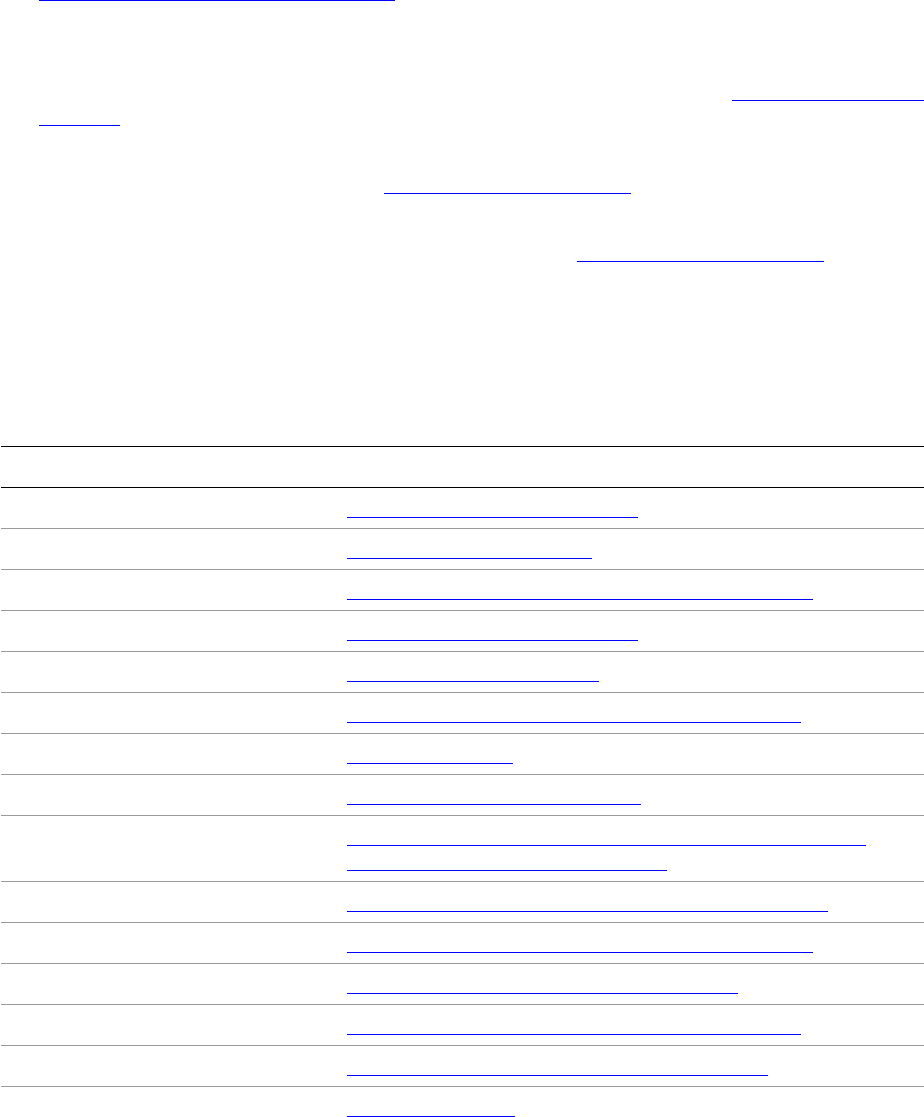
CHAPTER 8: XML Fundamentals Terminology 153
Using XML with InDesign
Using XML-based data and XML templates in InDesign has some benefits to a programmer, which include
the following:
There are mature XML toolkits and technologies to manipulate XML data (see
http://xml.coverpages.org/software.html), which make it relatively straightforward to manipulate XML
data before import or after export. For example, using XSLT to manipulate XML data is particularly
convenient in the context of the InDesign import architecture. You can develop and debug your XSL
stylesheets independently of InDesign, using existing XSLT-aware tools, but deploy them as part of a
workflow involving InDesign if you use its features like the XML transformer. See “XML transformer” on
page 201.
Importing graphics into tagged placeholders is a convenient way to import and place graphics
without writing much (if any) code. See Tagged graphic placeholder.
The XML API of InDesign is well documented. The command facades and suite interfaces in the XML
API make it relatively straightforward to write client code. See “Key client API” on page 199.
Terminology
See the “Glossary” for definitions of terms. The following table lists terms used in this chapter and sections
that relate to them.
Term See ...
Acquirer; acquirer filter “Extension patterns” on page 200
Backing store “Backing store” on page 162
Comment, XML “Processing instructions and comments” on page 194
Content handler “Extension patterns” on page 200
Content item “Content items” on page 160
Document element “Document element and root element” on page 161
Document Type Declaration (DTD) “DTD” on page 192
Entity “SAX-entity resolver” on page 204
Logical structure “Native document model and logical structure” on page 159 and
“Elements and content” on page 182
Placed element; placed content “Unplaced content versus placed content” on page 169
Processing instruction (PI) “Processing instructions and comments” on page 194
Repeating element “Importing repeating elements” on page 154
Root element “Document element and root element” on page 161
SBOS (small boss object store) “Persistence and the backing store” on page 163
Tag “Tags” on page 178

CHAPTER 8: XML Fundamentals XML features at a glance 154
XML features at a glance
XML extension patterns
Several XML extension patterns depend on the refactored XML import architecture. You can implement
these extension patterns to customize how XML data is imported and exported and other XML-related
features. See “Extension patterns” on page 200.
Tagging in tables and inline graphics
InDesign supports tagging of tables and table cells. See “Tagged tables” on page 190. Inline graphics can
be tagged, and placeholders for inline graphics can be created in XML templates. See “Tagged inline
graphics” on page 188.
Throw away unmatched existing (right)
It may be desirable to filter out elements in your XML template that are not matched by elements in the
incoming XML data. When enabled, this features discards unmatched existing elements in an XML
template. See “Throwing away unmatched existing elements on import (delete unmatched right)” on
page 171. The feature is implemented by an import-matchmaker service, an extension pattern described
in “XMl-import matchmaker” on page 201.
Throw away unmatched incoming (left)
It may be desirable to filter out incoming XML elements that have no corresponding match in your XML
template. When enabled, this feature discards inbound elements in the XML-based data being imported
that have no match in the XML template into which the data is being imported. In API terms, the feature is
called “throw away unmatched left.” See “Throwing away unmatched incoming elements on XML import”
on page 172. The feature is implemented by an import-matchmaker service, described in “XMl-import
matchmaker” on page 201.
Importing repeating elements
This feature allows text styling from elements in an XML template to be preserved (within one story) when
repeated elements are imported. It is described in “Importing repeating elements” on page 154.
Importing CALS table
This feature allows CALS table to be imported as InDesign table. It is described in “Importing a CALS table
as an InDesign table” on page 174.
Unplaced element; unplaced content “Unplaced content versus placed content” on page 169
XML element “Elements and content” on page 182
Term See ...

CHAPTER 8: XML Fundamentals The user interface for XML 155
Support for DOM core level 2
This specification is implemented by the features related to matching and transforming on import. Import
matchmakers and XML transformers that operate on the DOM (Document Object Model) are described in
“Extension patterns” on page 200. For the DOM Level 2 Core specification, see
http://www.w3c.org/TR/2000/REC-DOM-Level-2-Core-20001113.
Support table- and cell-styles import
This feature allows table and cell styles to be applied to InDesign table when is imported. It is described in
“Support table and cell styles when importing an InDesign table” on page 174.
Support XML-rules processing
The scripting-based XML-rules feature allows an XML DOM to be altered after an XML file is imported. XML
rules also can be triggered by application events, such as open, place, and close. The feature is described in
the “XML Rules” chapter of Adobe InDesign Scripting Guide.
Snippets
The snippet architecture is described in Chapter 9, “Snippet Fundamentals.” The snippet architecture
depends on the XML subsystem, as well as on INX (InDesign Interchange) or IDML (InDesign Markup
Language) import and export. Snippets are XML-based representations of parts of a document in INX or
IDML file format.
The user interface for XML
Structure view
The following figure shows the structure view, a representation of the logical structure of a document that
lets you view and interact with its logical structure. You can make selections in this view and create new
elements as children of the selection, delete elements, create or delete attributes, and so on. The figure
shows the structure view with text snippets visible, which provides context to see what content items in
the document are associated with the elements in the logical structure.
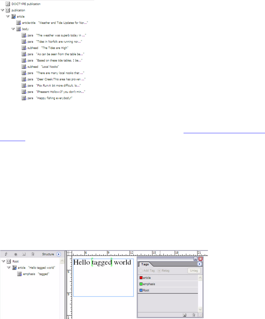
CHAPTER 8: XML Fundamentals The user interface for XML 156
Depending on your workflow, it may be desirable to control the visibility and other properties of the
Structure pane. These properties are controlled by preferences. See “XML-related preferences” on
page 196.
When you tag a graphic frame as a placeholder, the structure view draws a cross through the icon
representing the element to indicate its placeholder status. There are also other icons that represent
whether an element is associated with text content or image-based content.
Tags in layout view and story view
The following figure shows content that has been tagged, rendered in the layout view of the application.
In layout view, tags are shown as brackets with a width of zero; that is, they are intended to have no effect
on text composition. Start tags are indicated by brackets pointing right ([), and end tags by brackets
pointing left (]). The tag name associated with the tag markers is encoded by color, corresponding to the
color displayed in the Tags panel. Multiple tags can exist at the same position in layout view.
Story view makes it somewhat easier to understand the logical structure of a story and edit its structured
content. The following figure shows structured content rendered in story view. In this view, the names of
tags are shown explicitly.
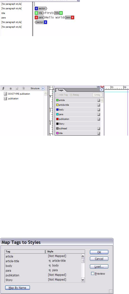
CHAPTER 8: XML Fundamentals The user interface for XML 157
Tags panel
The following figure shows part of the Tags panel, which has a list of tags that can be applied to document
content. Each tag has a name and associated color. In this example, some tags were created when a DTD
was imported, shown with icons at the right-hand end of the list elements.
To open the Tags panel, choose Window > Tags. By default, the list of tags shown is sorted alphabetically
by tag name; the list has no inherent logical structure. The complete set of tags in an imported DTD or
imported tag list is shown, regardless of what is selected in the structure view. To populate the tag list, end
users can load a set of tags with the Load Tags menu command in the Tags-panel menu.
You can create a new tag through the Tags panel; this adds an entry to the tag list. Creating a new tag
means it is available to mark up content or tag placeholder graphic frames for content. You can delete a
tag through the Tags panel. You can export the tag with the Save Tags menu command in the Tags-panel
menu.
Mapping between tags and styles
You can choose to apply a mapping between element names and styles (character and paragraph styles).
Once the mapping is applied to a document, any marked-up text is styled as specified by the style on the
right-hand side of this mapping. See the following figure.
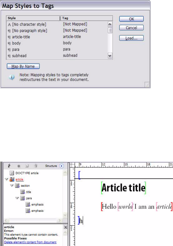
CHAPTER 8: XML Fundamentals The user interface for XML 158
An important use case for mapping tags to styles is preparing a document for XML import. Assuming
XML-based content does not carry style information, the tag-to-style map is a simple mechanism to apply
styling to inbound XML-based content; more complex mechanisms include styling based on XSLT or a
proprietary mechanism like an Adobe FrameMaker Element Definition Document (EDD). The FrameMaker
EDD effectively is a style sheet containing rules specifying how to map tags to styles, but in a
context-dependent way.
You can apply structure to an unstructured InDesign document by choosing to map styles to tags. The
effect of this is to mark up the text ranges that have the styles on the left-hand side of the style-to-tag
mapping. See the following figure, which shows the user interface for mapping styles to tags:
Validation window
The XML-validation-errors pane appears below the Structure pane; see the following figure. The
XML-validation-errors pane contains hyperlinks. If the end user clicks on the hyperlinks, InDesign tries to
fix the validation errors. This may not always have the desired effect; for example, it may delete content
that was tagged incorrectly.
Other
Other components of the user interface for XML—like context-sensitive menus for tagging the
selection—are beyond the scope of this chapter.

CHAPTER 8: XML Fundamentals XML model 159
XML model
Native document model and logical structure
The InDesign native document model specifies how end-user documents are represented by InDesign.
The InDesign native document model consists of both the description of the document in terms of boss
classes and the scripting DOM. End users directly manipulate spreads, pages, and the items they contain;
these abstractions are represented by boss classes in the native document model or objects in the
scripting DOM.
For example, a spread is represented by kSpreadBoss in the low-level model or boss DOM. Spread contents
are organized into a hierarchy (IHierarchy). In the scripting DOM, a spread is represented by a Spread
object, with properties like Pages or PageItems to represent the object hierarchy at a higher level of
abstraction.
The logical structure of an InDesign document is specified by the user; for example, by tagging content
items in the layout or importing their XML data. An XML template, consisting of tagged placeholders for
text and graphics, provides the user with a way to define how user-domain data is mapped into the native
model.
The logical structure of an InDesign document is organized into a hierarchy of XML elements (see
IIDXMLElement) representing logical relationships between content. The IIDXMLElement interface plays
the same role in the logical structure that IHierarchy plays in the spread hierarchy. The key operation that
modifies logical structure is tagging document objects, like graphic frames, stories, and text ranges.
Tagging establishes associations between objects in the native document model and the logical structure.
See “Elements and content” on page 182.
Importing XML-based data into an InDesign document creates new elements in the logical structure (see
“Importing XML” on page 164). If there are tagged placeholders, content can be flowed into these
placeholders. The logical structure of an InDesign document also can be exported as an XML file (see
“Exporting XML” on page 175). You also can create new elements by mapping styles to tags (see “Tags” on
page 178).
Elements and attributes
Elements represent user-defined logical relationships between content items in a document. Elements are
created by InDesign when XML data is imported or content is tagged. The implementation of elements in
InDesign is closely related to the XML specification (http://www.w3.org/TR/REC-xml), which defines an
element as follows:
“Each XML document contains one or more elements, the boundaries of which are either delimited by
start-tags and end-tags, or, for empty elements, by an empty-element tag. Each element has a type,
identified by name, sometimes called its “generic identifier” (GI), and may have a set of attribute
specifications. Each attribute specification has a name and a value.”
You can create a new element in the logical structure with the New Element command in the
Structure-pane menu. The behavior of this feature depends on whether the element in the structure view
already is placed and, if placed, what is the associated content item. You can choose a tag for the element
or create a new one. The tag stores the element’s name and color in the user interface.
The following figure shows what happens when the root element is selected in the structure view and the
user chooses the New Element menu command. The application adds a child element to the logical
structure’s root element. By default, the child element is added at the end of the collection of child
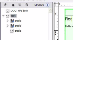
CHAPTER 8: XML Fundamentals XML model 160
elements of the root element. In this example, the root element <book> is selected and a new element
<article> is added. The new element is inserted into the logical structure as the last child of the root
element and is shown as unplaced content, since the top-level element was not placed; only its child
elements are placed content.
You can add an element to the logical structure in the structure view, in which case the element is not
directly associated with document content. You can indirectly add one or more elements in another view,
like layout view, by tagging (for example, tagging a text range or graphic placeholder frame).
Attributes are properties of elements. Attributes can be added by end users through the structure view,
when a node is selected that supports added attributes. Some elements, like comments, processing
instructions, and the DTD element, do not support the addition of attributes.
Elements are modeled by boss classes that have the IIDXMLElement interface. Tags are modelled by the
kXMLTagBoss boss class. See “Tags” on page 178. Attributes are modeled as properties of elements
(IIDXMLElement). There are facades that make it relatively easy to change the properties of elements, tags,
and attributes (IXMLElementCommands, IXMLTagCommands, and IXMLAttributeCommands).
Content items
Elements (IIDXMLElement) are created when content items are tagged. Elements also may be created on
import of XML data. New content items can be created when XML content is flowed into an XML template.
The main point is that elements are defined in the user domain and represent logical relationships
between content items—or between elements, in the case of structural elements.
Content items are objects in the layout or text domain that can be tagged to create an association with an
element in the logical structure of an InDesign document. Many content items can be tagged:
Placeholders for graphics (kPlaceHolderItemBoss)
Placeholders for inline graphics (kILPlaceHolderPageItemBoss)
Images (kImageItem, any other descendants of kImageBaseItem)
Stories (kTextStoryBoss)
Text ranges
Tables (kTableModelBoss) and cells within them
Text within table cells
There is no easy way to identify a content item. Many but not all the objects that can be tagged have the
IXMLReferenceData interface. If you refer to the API Reference for IXMLReferenceData and see the boss
classes in the native document model that aggregate this interface, you get some indication of the variety
of document objects that can be tagged.
CHAPTER 8: XML Fundamentals XML model 161
References to elements and content items
All elements in the logical structure of an InDesign document expose the IIDXMLElement interface;
therefore, one type of reference to an element is an interface pointer of type IIDXMLElement. A more
convenient type for programmers to work with is XMLReference, an instance of which can be obtained
from IIDXMLElement::GetXMLReference. This XMLReference is just another way to refer to the same
element.
Conversely, given an XMLReference, you can obtain an IIDXMLElement interface pointer by using
XMLReference::Instantiate. XMLReference is the XML subsystem’s equivalent of UIDRef; note that UIDRef
applies only to UID-based objects, and elements in the logical structure are not UID-based.
XMLContentReference refers to a chunk of content rather than an element. Do not mistake the
XMLContentReference type for XMLReference: XMLContentReference is a reference to a content item,
which might be a UID-based like a graphic frame or a non-UID-based object like a table cell. An instance of
XMLContentReference can be obtained from IIDXMLElement::GetContentReference. This generalizes and
replaces IIDXMLElement::GetContentItem, which is deprecated.
An instance of XMLContentReference can tell you the type of object with which it is associated, through
XMLContentReference::GetContentType. For example, kContentType_Normal is used for elements
associated with a UID-based object in the layout; this could be something like a tagged graphic
placeholder.
For more information on methods and use of these key types, refer to the API Reference for XMLReference
and XMLContentReference. The main difference between XMLReference and XMLContentReference is that
XMLReference refers to an element (IIDXMLElement), whereas XMLContentReference refers to a content
item.
Document element and root element
The IXMLReferenceData interface on kDocBoss stores a reference to the document element (instance of
kXMLDocumentBoss). There also is an interface on the document (kDocBoss), with a different PMIID
referring to the DTD element (kXMLDTDBoss), if one is associated with the document. The document
element associates with the root element both through IXMLReferenceData (as shown in the following
figure ) and through IIDXMLElement::GetNthChild, because the document element is the parent of the
root element. The class diagram in this figure shows associations involving the document element
(kXMLDocumentBoss) and other classes.
Document element, root element, and DTD:
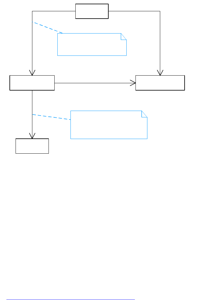
CHAPTER 8: XML Fundamentals XML model 162
The document element is responsible for managing document-level information (like the DTD) and
comments and processing instructions that are peers of the root element.
The root element (kTextXMLElementBoss) appears as the root of the element hierarchy in the structure
view, although the root element is a child of the document element, which is not shown in the structure
view. By default, the root element for a new InDesign document has the tag Root; you can change this to
whatever the content model for your XML vocabulary requires.
The document element and root element—along with the DTD element and any top-level comments
(kXMLCommentBoss) and processing instructions (kXMLPIBoss)—are held in the backing store.
Backing store
Each InDesign document contains one backing store, which stores XML elements that are unplaced and
elements that are siblings of the root element, like the document element, root element, DTD element,
comments, and processing instructions. The backing store is a story (kTextStoryBoss) that is not accessible
to the user and is present in every InDesign document. The architecture of the backing store is described
in “Persistence and the backing store” on page 163.
The object diagram in the following figure shows the relationship between the document, backing store,
and elements stored in the backing store.
«boss»
kDocBoss
«boss»
kXMLDTDBoss
«boss»
kXMLDocumentBoss
«boss»
kTextXMLElementBoss
1
1
IXMLReferenceData::GetReference 1
1
IXMLUtils::QueryRootElement
11
IXMLReferenceData::GetReference
1
0..1
IXMLReferenceData::GetReference
Interface with PMIID of
IID_IXMLDTDXMLREFERENCEDATA
on kXMLDocumentBoss refers to
the DTD object, if one exists.
IXMLUtils::QueryDocElement is
another way to navigate this
association.

CHAPTER 8: XML Fundamentals XML model 163
The backing store is opaque to client code. Use facade methods like IXMLUtils::QueryDocElement and
IXMLUtils::QueryRootElement to acquire objects like the document element (kXMLDocumentBoss) or the
root element (shown as the article object in the figure). To acquire a reference to the backing store when
you need it (for example, for notification), use IXMLUtils::GetBackingStore.
For more information, see “Backing store and notification of changes in logical structure” on page 204.
Persistence and the backing store
The main persistence mechanism for the native document model is UID-based; that is, each instance of the
classes shown in the model, like kSpreadBoss, has a record number or UID (unique identifier) associated
with it in the document’s database. The UID is unique only within the context of a particular database, not
globally.
UID-based objects also can store persistent boss objects without a UID; for example, this model is used for
attributes and widely within the table and XML subsystems. This as an example of container-managed
persistence, to distinguish it from the conventional, UID-based persistence mechanism. The
implementation of container-managed persistence in InDesign is very efficient compared to UID-based
persistence, which played a large part in the decision to use it for both tables and XML. For more
information, see Chapter 1, “Persistent Data and Data Conversion.”
This object diagram in the following figure is an elaborated version of the figure in “Backing store” on
page 162. The BaseUID shown for each object is the UID of the kTextStoryBoss implementing the backing
store. The LSID (logical structure ID) starts at 1 for the document element (kXMLDocumentBoss). Refer to
the API Reference for XMLReference. The root element, with LSID of 2 in this diagram, is an instance of
kTextXMLElementBoss; it has a reference to a tag (TagUID=126, name= “Root”) but not to a content item.
«boss»
document : kDocBoss
Backing store (opaque)
«boss»
doc-elem : kXMLDocumentBoss
«boss»
article : kTextXMLElementBoss
«boss»
title : kTextXMLElementBoss
There is exactly one backing store for
a document, an instance of a story
(kTextStoryBoss) that is not user-accessible.
It stores XML elements that are not on the page
and other elements, such as the
document element.
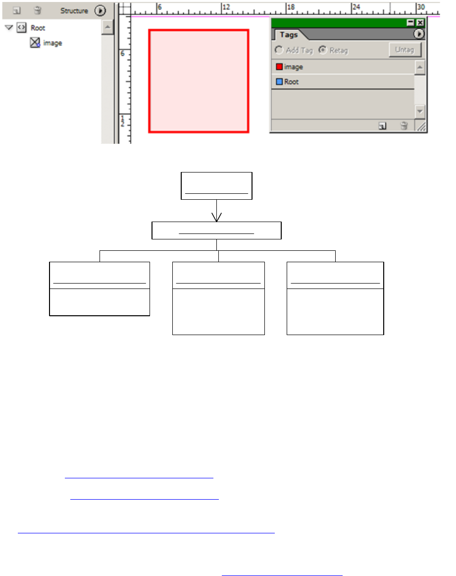
CHAPTER 8: XML Fundamentals Importing XML 164
The image element has a reference to a tag (TagUID=159, name= “image”) and to a content item
(UID=161, an instance of kPlaceHolderItemBoss).
The backing store is an instance of a small-boss object store (SBOS), a storage container for small boss
objects. The container has a UID, but the objects it stores do not have UIDs. The objects managed by the
store have logical IDs (LSIDs) as keys. Refer to the API Reference for XMLReference::GetLogicalID and related
methods.
Importing XML
The application supports import of XML data encoded as any of the following:
UTF-8 (see http://www.ietf.org/rfc/rfc2279.txt)
UTF-16 (see http://www.ietf.org/rfc/rfc2781.txt)
Shift-JIS, a two-byte format for Japanese (see
http://www.w3.org/TR/2000/NOTE-japanese-xml-20000414)
There are two main workflows for importing XML data:
Importing XML data into the backing store (see “Backing store” on page 162), then manually placing it
onto the layout to set up the associations between elements in the logical structure and document
object.
BaseUID = 111
LSID = 3
ContentItemUID = 161
TagUID = 159
«boss»
image : kTextXMLElementBoss
BaseUID = 111
LSID = 1
«boss»
doc-elem : kXMLDocumentBoss
BaseUID = 111
LSID = 2
ContentItemUID = 0
TagUID = 126
«boss»
Root : kTextXMLElementBoss
«boss»
document : kDocBoss
Backing store (opaque)
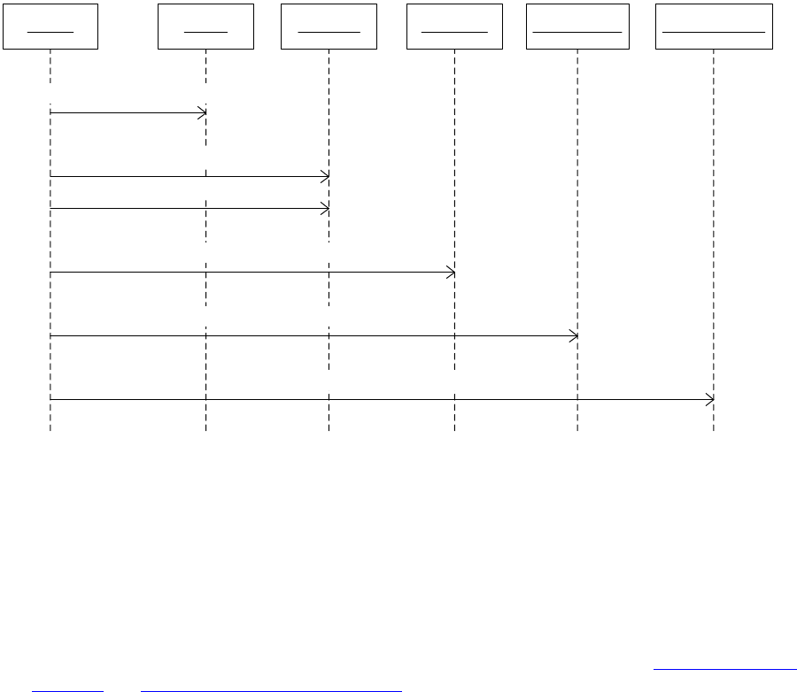
CHAPTER 8: XML Fundamentals Importing XML 165
Creating an InDesign document as an XML template that contains placeholders, which are tagged
with names of the elements in the XML data to import. When the XML data is imported, the contents
of the XML file are flowed into the placeholders. The order in which the elements appear in the logical
structure determines how the content is flowed into the tagged placeholders.
Import architecture
The import process is controlled by the XML importer (kXMLImporterBoss), which is the main delegate for
the low-level command that performs the import (kImportXMLFileCmdBoss). Unlike other forms of
import—like EPS (import provider kEPSPlaceProviderBoss) and PDF (import provider
kPDFPlaceProviderBoss) import—importing XML data does not use the standard import provider
(IImportProvider) architecture. The importer controls the import process by dispatching messages to
extension patterns responsible for different parts of the import sequence, as shown in the following figure.
The sequence diagram shows some of the messages sent during XML import. The importer object shown
consists of the low-level import XML command (kImportXMLFileCmdBoss) and its delegate
(kXMLImporterBoss). The main points to note are the order in which the different extension patterns are
sent messages and, for the transformer (IXMLTransformer), how the stream transform precedes the DOM
transform message.
A low-level command (kImportXMLFileCmdBoss) is processed to import an XML file. Much of the work is
done by this command’s delegate, an instance of the kXMLImporterBoss boss class, in its implementation
of IXMLImporter::DoImport. The following operations are performed while importing an XML file:
1. The import parameters are specified through an instance of kImportXMLDataBoss. In particular, see
IImportXMLData. This specifies either an IDFile (based on a path, which may be a file path or an
arbitrary URL-like string).
2. An acquirer service (IXMLAcquirerFilter) is located, which knows how to turn the import specification
(in IImportXMLData) into an XML stream, perhaps with a SAX entity resolver. See “XML acquirer” on
page 200 and “SAX-entity resolver” on page 204.
Importer Acquirer
IXMLAcquirerFilter::CreateStreamAndResolver
Transformer
IXMLTransformer::TransformStream
IXMLTransformer::TransformDOM
Matchmaker
IXMLImportMatchMaker::MatchDocument
Serializer handler
ISAXDOMSerializerHandler::StartDocument
Post-import iterator
IXMLPostImportIteration::BeforeIteration
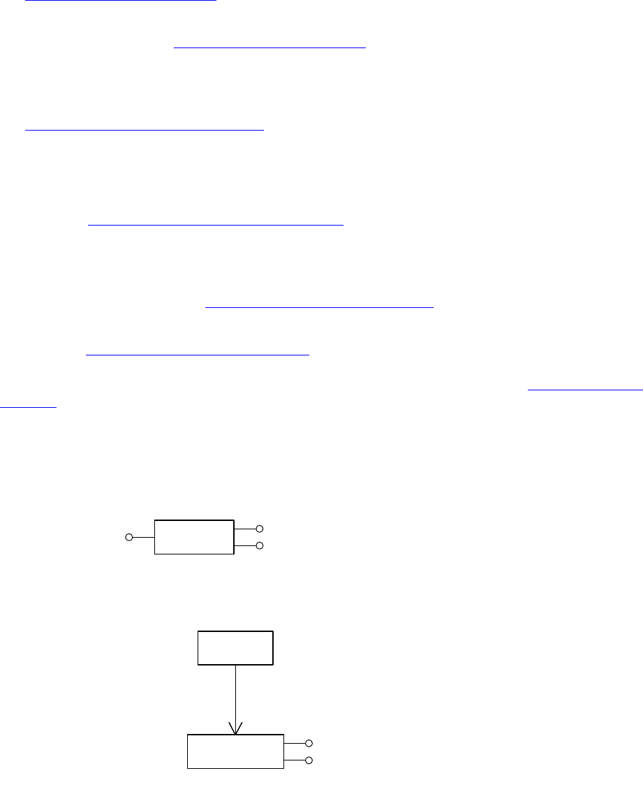
CHAPTER 8: XML Fundamentals Importing XML 166
3. The SAX parser service (kXMLParserServiceBoss, ISAXServices) parses the inbound XML from the
stream.
4. XML transformer services (kXMLImporterTransformerService) are called to transform the stream. See
“XML transformer” on page 201.
5. At this point, the stream has been turned into an XML DOM. XML transformer services are called to
transform the DOM. See “XML transformer” on page 201.
6. The XML-import match driver calls XML-import matchmaker services
(kXMLImportMatchMakerSignalService) to participate in matching the input XML data against the
XML template (the logical structure of the document into which content is being imported). See
“XMl-import matchmaker” on page 201.
7. Matches are registered by the XML match recorder (IXMLImportMatchRecorder) of the importer
(kXMLImporterBoss).
8. SAX DOM serializer handlers (ISAXDOMSerializerHandler) are called to create content based on the
DOM. See “SAX DOM serializer handler” on page 203. The parsing of the final input XML data is
controlled by a top-level SAX DOM serializer handler (kSAXDocumentHandlerBoss). Dependent SAX
DOM serializer handlers turn parts of the DOM into InDesign content.
9. Post-import responders are called to iterate the DOM and take appropriate action. See
IXMLPostImportIteration and “Post-import responder” on page 201.
When XML data is imported, the XML subsystem creates elements (IIDXMLElement) in the logical
structure. See “Elements and content” on page 182. Import of XML data results in content items
(IXMLReferenceData) being populated with the imported content, if the content items are tagged before
import. After import, unplaced elements are held in the document’s backing store. See “Backing store” on
page 162.
The UML diagrams in the following figure show some interfaces involved in storing options for import and
export of XML data at the session level (kWorkspaceBoss) or document level (kDocWorkspaceBoss). There
are other interfaces specific to individual components in the XML import architecture (for example,
IXMLImportPreferences, which can be found on service boss classes), which are not shown here.
«boss»
kDocWorkspaceBoss
«boss»
kWorkspaceBoss
IXMLExportSessionOptions
IXMLImportOptions
IXMLImportOptions
«boss»
kDocBoss
IDocument
IXMLExportOptions
IXMLExportOptions
CHAPTER 8: XML Fundamentals Importing XML 167
Importing a minimal XML file
A new, empty document has a logical structure consisting of one Root element. To construct a slightly less
trivial example, you can create a new document and import a minimal XML file into the backing store. The
content is as shown in the following example.
Minimal XML data to be imported:
<article><title>Hello World</title>
</article>
To perform the import:
1. Save the XML data above to a text file, hello-world.xml.
2. Create a new InDesign document.
3. Show the structure view. Rename the Root tag to be “article.”
4. Create a new tag named “title.”
5. Import the XML data from the hello-world.xml file. The structure view should look like the following
figure.
The objects created and instances of associations between them are shown in the following figure. The
UML object diagram shows the objects involved in representing the logical structure when minimal XML
content is imported into the backing store of a new InDesign document. The logical structure of the
InDesign document represents the tree structure of the original XML document, which has one title
element as a child of the root-article element. Instances of the associations with the objects that represent
tags are shown (kXMLTagBoss).
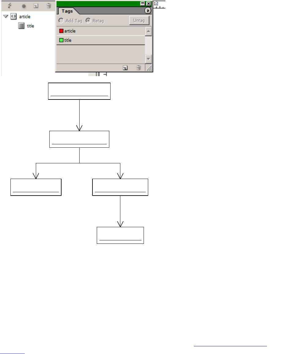
CHAPTER 8: XML Fundamentals Importing XML 168
Given a reference to the document (IDocument) or a document database (IDataBase), you can acquire a
reference to the document element or root element in the logical structure, using the IXMLUtils facade.
The document element has no tag, but the root element always has a tag; in this example, it is named
“article.” The IIDXMLElement::GetTagString method discovers the tag name of an element.
The root element is one starting point for traversing the logical structure. For the minimal example, you
can start from the root element and look at its children.
XML elements have the signature interface IIDXMLElement. Given an IIDXMLElement interface, you can
obtain an XMLReference, another way to refer to an XML element. See IIDXMLElement::GetXMLReference.
Conversely, given an XMLReference, you can get an IIDXMLElement interface through
XMLReference::Instantiate. XML elements are described in more detail in “Elements and content” on
page 182.
The UML object diagram in the following figure shows instances of associations between a document
(kDocBoss), document workspace (kDocWorkspaceBoss), and objects representing tags (kXMLTagBoss)
and their colors within the Tags panel (kUIColorDataBoss).
Objects representing tags and colors:
«boss»
article : kTextXMLElementBoss
«boss»
article-tag : kXMLTagBoss
IXMLTag
«boss»
title : kTextXMLElementBoss
IIDXMLElement
«boss»
title-tag : kXMLTagBoss
IXMLTag
«boss»
doc-elem : kXMLDocumentBoss
IIDXMLElement
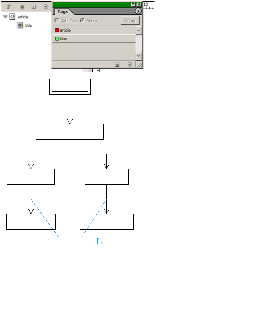
CHAPTER 8: XML Fundamentals Importing XML 169
Unplaced content versus placed content
When XML content is imported with default options and there are no tagged placeholders for the
incoming content, the content is held in the backing store. See “Backing store” on page 162.
XML template
An XML template is an InDesign document with tagged placeholders. These can be any of the following:
Stories
«boss»
document : kDocBoss
«boss»
doc-workspace : kDocWorkspaceBoss
IDocument
«boss»
article-tag : kXMLTagBoss
«boss»
title-tag : kXMLTagBoss
IXMLTagList IXMLTagList
«boss»
red-col : kUIColorDataBoss
IPersistUIDData
«boss»
green-col : kUIColorDataBoss
IPersistUIDData
Interface IPersistUIDData that
stores UID of color object has
the identifer (PMIID) of
IID_ICOLORPERSISTUIDDATA
on kXMLTagBoss.

CHAPTER 8: XML Fundamentals Importing XML 170
Text ranges
Graphic frames
Tables and table cells
In addition, for the template to be useful, it is likely to already have some styles established and a mapping
from tags to styles. See “Tag-to-style mapping” on page 180.
Matching against an XML template
When XML data is imported into an XML template that matches elements in the imported XML data, some
or all of the content becomes placed. Determining what constitutes a match is not a straightforward
process.
Architecture
Matching against an XML template is performed by XML-import matchmaker services
(IXMLImportMatchMaker), which implement the matching logic. For a description of this extension
pattern, see “XMl-import matchmaker” on page 201. There are several existing import matchmaker
services that support the import features; for example, for importing structured tables or repeating
elements. For a more complete listing, refer to the API Reference for IXMLImportMatchMaker and the boss
classes that aggregate this interface.
If you implement your own import matchmaker, you can customize how the matching against the
template is done. For example, you might want to add new pages to the document when you encounter
certain repeating elements in the incoming XML data or perform some other operation not provided by
the application. For details, see “XMl-import matchmaker” on page 201.
Importing repeating elements
Suppose you have XML-based content that consists of many very similar elements, like classified
advertisements for used automobiles. You want an XML template that can handle repeating elements in
the incoming XML data, rather than having to specify up front how many advertisements could be flowed
into the template. In designing an XML template, it often is desirable to design only one instance of a
repeating substructure and, during import, have all incoming instances of the substructure pick up the
design of that instance.
Often, the number of instances in the incoming XML data is either unknown or variable, so having the
ability to handle repeating elements adds flexibility. During XML import, InDesign examines the incoming
XML data's structure, compares it to the existing structure in the XML template, and makes duplicates of
the existing template element as necessary when it detects the incoming elements are repetitions of the
existing template element.
Suppose you are going to import this hypothetical XML data related to classified advertisements for motor
vehicles. The fields in the XML template tagged with the names of the different elements may be styled
differently. The number of items in the incoming XML data is unknown. You may set up a template
structure like that in the following example.

CHAPTER 8: XML Fundamentals Importing XML 171
<classifieds>
<advert>
<vehicle>
<year></year>
<make></make>
<model></model>
<mileage></mileage>
<price></price>
...
</vehicle>
<contact>
<name></name>
<phone></phone>
</contact>
</advert>
</classifieds>
In this case, the “advert” element is the repeating element. You would set up styling for the fields in each
advert element. During XML import, InDesign duplicates the repeatable advert element as many times as
there are elements in the incoming XML.
When the data is imported into the XML template, the fields under advert retain the original styling
throughout the duplication process, so the final outcome is that there are as many advert elements as
there advert elements in the incoming XML.
Architecture
The feature is implemented by an import matchmaker service (IXMLImportMatchMaker) whose ClassID is
kXMLRepeatTextElementsMatchMakerServiceBoss, which is responsible for duplicating elements in the
XML template to accommodate the incoming XML elements.
The feature is turned on or off by an XML import preference (IXMLImportPreferences); see “Service-level
XML preferences” on page 198.
Throwing away unmatched existing elements on import (delete
unmatched right)
You can choose to throw away (delete) unmatched existing elements on import, to filter out XML template
elements that do not have a match in the incoming XML data. This might occur if, for example, your XML
template contains placeholders for all possible elements in the incoming XML, including optional
elements, and the incoming XML does not contain some of the optional elements. If an element (like a
byline element) in your XML template is not matched in the actual content, you would not want to leave
this unnecessary element in the logical structure of the document. This feature removes any unmatched
optional elements (and their content) in the document after XML import. The user sets this import option
in the XML Import Options dialog box.
Suppose you have an XML template with the logical structure and existing mark-up shown in the
following figure. If the feature to throw away unmatched existing elements is enabled before importing
XML, and the inbound XML does not have elements that match a copyright element in the template, the
copyright element in the template is deleted on import.
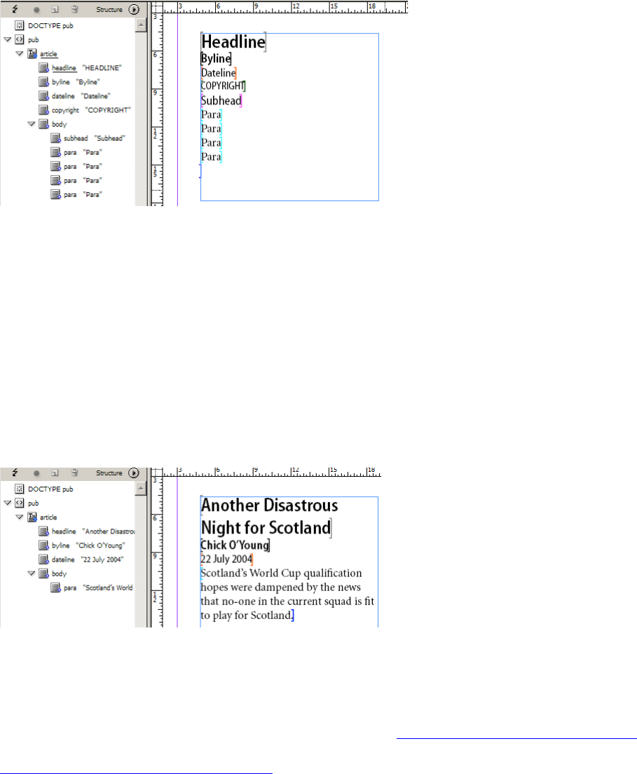
CHAPTER 8: XML Fundamentals Importing XML 172
For example, suppose the incoming XML contains only the elements shown in the following example,
rather than the full set of elements in the XML template document in the preceding figure.
<article><headline>Another Disastrous Night for Scotland</headline>
<byline>Chick O'Young</byline>
<dateline>22 July 2004</dateline>
<body><para>Scotland's World Cup qualification hopes were dampened by the news
that no-one in the current squad is fit to play for Scotland.</para></body>
</article>
The net result of importing the sample XML with the option to throw away unmatched existing elements
is that only the elements in the incoming XML data explicitly matched in the template are retained, and
the template elements and associated content are deleted from the document on import. The result for
this sample XML is shown in the following figure.
Architecture
This feature is implemented by a matchmaking service
(kXMLThrowAwayUnmatchedRightMatchMakerServiceBoss); see “XMl-import matchmaker” on page 201.
The feature is turned on or off by a service-specific import preference (IXMLImportPreferences); see
“Service-level XML preferences” on page 198. For more information on controlling the feature, see the
“XML” chapter of Adobe InDesign SDK Solutions.
Throwing away unmatched incoming elements on XML import
You can choose to throw away (delete) unmatched incoming elements, to filter out elements in the
incoming XML data that do not have a match in the XML template into which they are being imported.

CHAPTER 8: XML Fundamentals Importing XML 173
You can use this feature when you know there are optional elements in the incoming XML that you do not
want to display, and you do not want to use XSLT to explicitly filter them out.
Architecture
This feature is implemented by a matchmaking service
(kXMLThrowAwayUnmatchedRightMatchMakerServiceBoss); see “XMl-import matchmaker” on page 201.
This feature is turned on or off by a service-specific import preference (IXMLImportPreferences); see
“Service-level XML preferences” on page 198. For more information on controlling the feature, see the
“XML” chapter of Adobe InDesign SDK Solutions.
Attribute-style mapping
Suppose you want to import XML that has (or is transformed to have) attributes that specify the character
or paragraph style to apply to text content in the inbound XML. You can use the attribute-style mapping
feature, which looks for attributes pstyle and cstyle in the inbound XML, then tries to match these to
paragraph and character styles in the document.
Architecture
This feature is implemented by a post-import responder (kXMLImporterPostImportMappingBoss); see
“Post-import responder” on page 201. This responder also implements tag-to-style mapping on import;
see “Tag-to-style mapping” on page 180. For information on how this feature is turned on or off, see
“Service-level XML preferences” on page 198.
Creating links on XML import
When XML is imported into an XML template, the default behavior is not to create a link to the imported
XML file; however, it is possible to turn on a feature that supports creating a link to the imported XML file.
XML linking is a feature that enables InDesign to keep track of imported XML files. Each imported XML file
has a corresponding link, which is shown in the Links panel along with status. Operations that can be
performed on XML links include the following:
Create — When an XML file is imported, a link (kXMLImportLinkBoss) is created and associated with
the root element of the imported content. Only one link can be associated with one element.
Importing into an element that already has a link replaces the old link with the new one.
Delete — Deleting an element deletes its associated link, if it has one.
Copy, paste, duplicate — When an XML element associated with a link is copied, pasted, or duplicated,
a copy of the link is created and associated with the new element.
Place — Placing an element into the layout or unplacing it does not affect its XML link. Both placed
and unplaced elements can be associated with XML links.
Check status — An XML link’s status (for example, up-to-date, modified, or missing) is shown as an icon
in the Links panel.

CHAPTER 8: XML Fundamentals Importing XML 174
Architecture
This feature is controlled by an XML-related preference. For details on how this feature is turned on or off,
see “Service-level XML preferences” on page 198.
Sparse import
If this feature is turned on during XML import, incoming elements that have no content (or only
whitespace for content) do not replace content in the matching existing XML element in the XML
template. By default, this feature is turned off.
Architecture
The feature is controlled by an XML-related preference (kXMLSparseImportOptionsServiceBoss). The
top-level SAX handler (kSAXDocumentHandlerBoss) acts on this preference, rather than the service
(kXMLSparseImportOptionsServiceBoss) being responsible for providing the behavior. This explains why
kXMLSparseImportOptionsServiceBoss has no service interface: it is not implementing a particular
extension pattern other than for XML import preferences. For details on how to turn sparse import on and
off, see “Service-level XML preferences” on page 198.
Importing a CALS table as an InDesign table
You can choose whether to import a CALS table as an InDesign table. You can use this feature when you
have a table specified in CALS table format and you want to manipulate it the same way as InDesign native
tables.
Architecture
This feature is implemented by a matchmaking service (kXMLTableMatchMakerServiceBoss) and DOM
serializer handler service; see “XMl-import matchmaker” on page 201 and “SAX DOM serializer handler” on
page 203. During the matchmaker phase, a special attribute, kTableFormatAttr (“tformat”), with value
kAttrValueCALS (“CALS”), is inserted into the table element. During the DOM serializer phase, contents in
the CALS table are altered to fit the InDesign table format. This feature can be turned on or off by a
service-specific import preference (IXMLImportPreferences); see “Service-level XML preferences” on
page 198. For more information on controlling the feature, see the “XML” chapter of Adobe InDesign SDK
Solutions.
Support table and cell styles when importing an InDesign table
You can specify table and cell styles when importing an InDesign table. A table-style attribute applies only
to a table element. Cell-style attributes apply to either a table element or a cell element; they are ignored
for other types of elements. If the style name specified in the attribute value does not exist, a new style
with that name is created and then applied to the table or cell.
Architecture
This feature is implemented by a post-import responder (kXMLImporterPostImportMappingBoss), the
same way as character style and paragraph style; see “Attribute-style mapping” on page 173. The only
difference is that the attribute names are tablestyle and cellstyle.
CHAPTER 8: XML Fundamentals Exporting XML 175
Exporting XML
Exporting XML data from InDesign is considerably more straightforward than importing XML data into
InDesign. The downside to this is that there are fewer opportunities for your plug-in to customize the
export side.
You can export the logical structure of an InDesign document as an XML document. The export takes place
in document order, meaning the logical structures of the InDesign document and exported XML data are
the same.
An XML file can be exported from any element in the logical structure. For example, if exported from the
root element, the exported XML data represents the logical structure of the entire document. If another
element—for example, E—is chosen, the exported XML data represents the logical structure of the
subtree with E at its root.
Even an empty InDesign document has some (albeit trivial) logical structure: it has one root element with
no dependents. If exported as XML data, one element (<Root></Root>) is written to the output file. The
following figure shows the logical structure of a new, empty document and the XML data exported from
InDesign with the default settings. Note the default encoding (UTF-8).
There are two points to note about the relationship between XML data exported from InDesign and the
logical structure:
XML content can be exported from a document even if it is not associated with placed content in the
document. Exported XML data is based on the logical structure, irrespective of whether the elements
are associated with content in the document.
The order in which the elements appear in the XML output is based on the logical structure and has no
direct relation with the hierarchy of the native document model. The exception to this is a story with
mark-up, in which case the order of the elements in the logical structure within the subtree
corresponding to the story corresponds to the story-reading order.
Export architecture
An XML generator (IXMLGenerator) is an abstraction responsible for generating the XML content during
export. The IXMLGenerator interface is aggregated by classes representing XML elements
(IIDXMLElement) in the logical structure.
The mechanism that supports XML export is a standard export provider (kXMLExportProviderBoss,
IExportProvider). This delegates to an instance of kXMLExportHandlerBoss to perform the actual export.
The implementation of IXMLHandler iterates elements in the logical structure, calling methods through
the IXMLGenerator interface of the elements.
<?xml version="1.0" encoding="UTF-8" standalone="yes" ?>
<Root></Root>
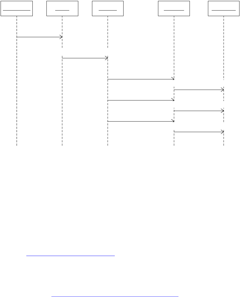
CHAPTER 8: XML Fundamentals Exporting XML 176
This sequence diagram in the following figure shows some of the messages sent during a typical XML
export.
The export provider (kXMLExportProviderBoss), shown as export-provider in this figure, starts the export.
The parser service (kXMLParserServiceBoss) has an IXMLAccess interface, shown as the xmlAccess object.
An instance of kXMLExportHandlerBoss, shown as xmlHandler, with signature interface IXMLHandler,
iterates elements in the logical structure. The implementation of the IXMLGenerator interface on these
elements generates XML content to the output stream. There are several implementations of this
interface, generating different content types on export.
Contributions to XML export come from instances of boss classes that expose the IXMLGenerator
interface. These classes represent elements in the logical structure; for example, kTextXMLElementBoss
(tagged stories, tagged text ranges, and tagged graphics) and kXMLCommentBoss (XML comments).
You can participate in the export process by providing a custom kXMLExportHandlerSignalService. The
providers are called when the XML handler iterates elements. For more information, see the extension
pattern in “XML-export handler” on page 204.
Document order
The logical structure of an InDesign document is exported as XML in document order, as defined in the
XPath specification (http://www.w3.org/TR/xpath#dt-document-order). For convenience, part of the
definition is repeated here:
“There is an ordering, document order, defined on all the nodes in the document corresponding to the
order in which the first character of the XML representation of each node occurs in the XML representation
of the document after expansion of general entities. Thus, the root node will be the first node. Element
nodes occur before their children. Thus, document order orders element nodes in order of the occurrence
of their start-tag in the XML (after expansion of entities). The attribute nodes and namespace nodes of an
element occur before the children of the element. ... Reverse document order is the reverse of document
order.”
export-provider xmlHandlerxmlUtils
IXMLUtils::ExportElement
xmlAccess
IXMLAccess::VisitAllElements
IXMLHandler::HandleElementBefore
IXMLHandler::HandleAfterNthChild
IXMLHandler::HandleElementAfter
xmlGenerator
IXMLGenerator::GenerateBeginTag
IXMLGenerator::GenerateContent
IXMLGenerator::GenerateEndTag
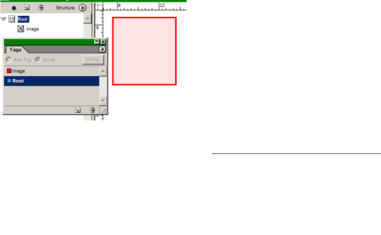
CHAPTER 8: XML Fundamentals Exporting XML 177
Document order has no direct relationship with the order in which a document would be read or other
ordering schemes you might devise (for example, based on page numbering).
Tagged graphic placeholder, exported
Consider the case, shown in the following figure , of a simple but nontrivial logical structure in which a
tagged placeholder is intended as the destination for an image.
Exporting the logical structure with default export options results in the XML data shown in the following
figure. To vary the options, like the encoding, see “XML-related preferences” on page 196.
The abstraction responsible for generating the XML data related to the tagged graphic is the element
(IIDXMLElement) that represents the graphic. It exposes the IXMLGenerator interface, which is used during
the export process.
Tagged text range, exported
Consider the example in which you create a text frame, tag the story running through it with a tag named
“story,” then tag a range within that story with a different tag named “emphasis.” The XML story element
represents the instance of the tagged story. The XML emphasis element represents the tagged content
item with value “Hello.” This is shown in the following figure. The screenshot shows logical structure, tags,
and layout view for a document with one text frame, with a tagged text range. The story is tagged “story”
and represented by the story element in the logical structure. The text range is tagged “emphasis” and
represented by the emphasis element.
<?xml version="1.0" encoding="UTF-8" standalone="yes" ?>
-<Root>
<image />
</Root>
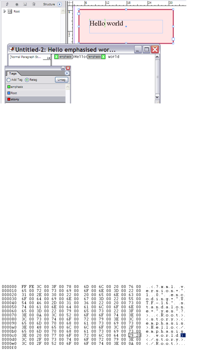
CHAPTER 8: XML Fundamentals Tags 178
If you export the logical structure as XML data from the root element, you get the XML data shown in the
following figure. This time, the export option to export with UTF-16 encoding is set, to make it easier to
inspect the Unicode character that represents the hard carriage return in the story. This XML data was
exported by InDesign from the document shown in the preceding figure.
The XML content of the exported story requires some study. The intent of the InDesign function is that
stories should be represented in exported XML data as closely as possible to how InDesign represents
them internally. The end-of-line character corresponding to the hard carriage return after the word
“world” is represented by the Unicode character 0x2029. If you open the XML file in a binary editor on
Windows—which is little-endian—the Unicode character 0x2029 is represented as the octet 29 and then
the octet 20. Soft carriage returns are represented by 0x2028. See IXMLOutStream. This is shown in the
following figure; the 0x2029 (hard carriage return) is highlighted.
Tags
Tags can be loaded from several different sources, including the following:
An InDesign tag file, an XML document containing only tag-specific information.
<?xml version="1.0" encoding="UTF-16" standalone="yes" ?>
-<Root>
-<story>
<emphasis>Hello</emphasis>
world
</story>
</Root>

CHAPTER 8: XML Fundamentals Tags 179
Any XML document that is an instance of the document type being worked with.
By associating a DTD with the document. Doing this means the DTD is parsed for element tag names,
and tags are created correspondingly. Elements defined within entities are ignored.
The following example is a sample tag list.
<?xml version="1.0" encoding="UTF-16" standalone="yes"?>
<article colorindex="4">
<articleinfo colorindex="6"/>
... (other elements omitted)
<ulink colorindex="19"/>
</article>
It also is possible to specify the color of the tag using RGB coordinates, which are used for any tags defined
with a custom color. The coordinates are hex-encoded; for example, one tag with a custom color (0,0,255)
in decimal RGB coordinates appears below:
<link rgb="0 0,0 0,3ff00000 0"/>
In addition, the custom-tag service-extension pattern lets you customize what tags are created when an
XML document is being parsed. See “Custom-tag service” on page 203.
Architecture
The kXMLTagBoss boss class represents an individual entry in a tag list. The signature interface of this boss
class is IXMLTag; this stores properties like the name and color in the user interface. The tag list is
represented by IXMLTagList.
IXMLTagList is aggregated on the session workspace (kWorkspaceBoss), representing a default set of tags
for any new document.
IXMLTagList is aggregated on the document workspace (kDocWorkspaceBoss), representing tags in a
given document.
The session workspace (kWorkspaceBoss) stores zero or more tags. A document workspace
(kDocWorkspaceBoss) stores one or more tags; the minimal tag set for a new document consists of the
Root tag.
Tagging relationships are represented by associations between classes representing elements in the
logical structure and those representing tags. For example, if a graphic frame is tagged for use as a
placeholder, an association is created between the placeholder boss object (an instance of the
kPlaceHolderItemBoss class) and an instance of the kTextXMLElementBoss class. An association is created
between an element in the logical structure (IIDXMLElement) and an instance of kXMLTagBoss, to
represent the tagging.
Tags (kXMLTagBoss) that can be used to mark up content items in the native document model are held in
the tag list (IXMLTagList) of a workspace (kDocWorkspaceBoss, kWorkspaceBoss). Tags are rendered in the
Tags panel (see “Tags panel” on page 157) and shown in views like layout view or story view (see “Tags in
layout view and story view” on page 156). XML elements that have tag names are associated with tags
(kXMLTagBoss) that store the tag names.
Given a reference to an XML element, you can find the tag string through a method on IIDXMLElement.
You also can use IIDXMLElement::GetTagUID to acquire a reference to an instance of kXMLTagBoss
representing the tag.
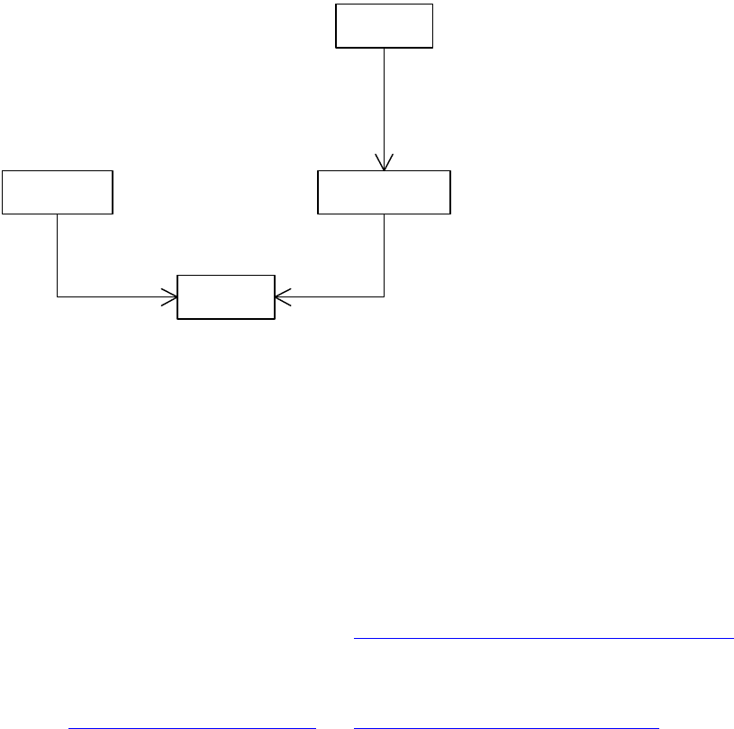
CHAPTER 8: XML Fundamentals Tags 180
You can acquire a reference to a tag (kXMLTagBoss) in a document through the tag list (IXMLTagList) on the
document workspace (kDocWorkspaceBoss). The tagUIDRef variable refers to an instance of kXMLTagBoss.
The class diagram in the following figure shows associations between tags and workspaces and the
document (kDocBoss).
Tag-to-style mapping
Suppose you have XML content with a headline tag and a p-head-1 paragraph style in your XML template.
You can create an association between tags and styles in the document, to enable incoming XML to be
styled automatically.
When a tag-to-style mapping is applied during the XML import, inbound XML content has the styles
applied when elements with tag names matching the tags in the tag-to-style map are encountered. For
example, if you create a mapping from the headline tag to the p-head-1 paragraph style, textual content in
a headline element has the p-head-1 style applied.
The user interface for this feature is shown in “Mapping between tags and styles” on page 157. This
establishes a one-to-one mapping from tag names to character or paragraph styles, which is sufficient
when context-sensitive styling is not required. If context-sensitive styling for incoming XML is required,
you can use a combination of a stream-based XML transformer and attribute-style mapping to achieve
this. See “XML transformer” on page 201 and “Attribute-style mapping” on page 173.
Architecture
The following figure is a class diagram for tag-to-style mappings (IXMLTagToStyleMap). The session
workspace (kWorkspaceBoss) stores the default mapping inherited by new documents. The document
workspace (kDocWorkspaceBoss) stores the mapping applied to a particular document (kDocBoss).
«boss»
kWorkspaceBoss
«boss»
kDocWorkspaceBoss
«boss»
kXMLTagBoss
1
1..* IXMLTagList::GetTag
1
0..*
IXMLTagList::GetTag
«boss»
kDocBoss
1
1
IDocument::GetDocWorkspace
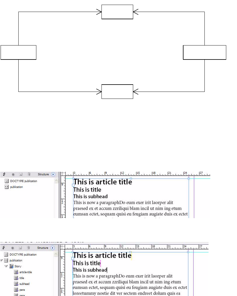
CHAPTER 8: XML Fundamentals Tags 181
Style-to-tag mapping
The following figure is a screenshot of an unstructured but systematically styled document, which as an
associated DTD.
Before mapping styles to tags:
The following figure shows the result of applying a style-to-tag mapping.
Once a style-to-tag mapping is defined and applied, ranges of styled text with the styles mapped to given
tags end up tagged, creating new elements in the logical structure. There are some default commitments
in terms of the tags applied; for example, the Story tag is used for a story, even if it is not in the tag list of
the document when the style-to-tag mapping is applied.
Architecture
The class diagram in the following figure shows the associations between workspaces (IWorkspace), tags
(kXMLTagBoss), and styles (kStyleBoss), mediated by the style-to-tag map (IXMLStyleToTagMap). The
«boss»
kXMLTagBoss
«boss»
kWorkspaceBoss
«boss»
kDocWorkspaceBoss
1
0..*
IXMLTagToStyleMap::GetTagAt
1
0..* IXMLTagToStyleMap::GetTagAt
«boss»
kStyleBoss
1
0..*
IXMLTagToStyleMap::GetStyleMappedToTag
1
0..*IXMLTagToStyleMap::GetStyleMappedToTag
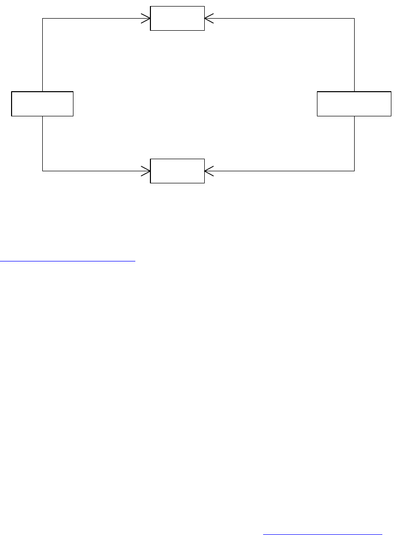
CHAPTER 8: XML Fundamentals Elements and content 182
session workspace (kWorkspaceBoss) stores the default style-to-tag map for new documents. The
document workspace (kDocWorkspaceBoss) stores the style-to-tag map for a given document (kDocBoss).
Text styles are represented by kStyleBoss. Collections of styles are held in the style-name table
(IStyleNameTable) and stored in a workspace (IWorkspace). The session workspace (kWorkspaceBoss)
stores text styles that are defaults for new documents. The document workspace (kDocWorkspaceBoss)
stores text styles that can be used in the associated document. For more information on text styles, see
Chapter 9, “Text Fundamentals,” a n d re fe r t o th e API Reference for kStyleBoss.
The workspace (IWorkspace) maintains an associative map between text styles (kStyleBoss) and tags
(kXMLTagBoss). This map is stored in the persistent interface IXMLStyleToTagMap. The workspace style list
(IStyleNameTable) may contain styles that are not referenced in the style-to-tag map. Similarly, there may
be tags in the tag list (IXMLTagList) of the workspace that are not involved in the style-to-tag map.
Elements and content
Tagged graphic placeholder
Suppose you are building an XML template and you want to create placeholders into which images will be
placed when an XML data file is imported. To create a placeholder graphic for an image:
1. Create a new document.
1. Create a tag named “image” through the Tags panel (Window > Tags).
2. Create a rectangle page item with the Rectangle tool.
3. Leave the page item selected, and click on the image tag in the Tags panel.
4. Show the structure view. It should look like the figure in “Architecture” on page 182.
Architecture
The UML object diagram in the following figure shows the boss objects representing a tagged graphic
placeholder and some of the relationships between them. The placeholder object (kPlaceHolderItemBoss)
is a child of a graphic frame (kSplineItemBoss); the latter is omitted from this diagram, in the interest of
«boss»
kDocWorkspaceBoss
«boss»
kWorkspaceBoss
«boss»
kStyleBoss
«boss»
kXMLTagBoss
1
0..*
IXMLStyleToTagMap::GetStyleAt
1
0..* IXMLStyleToTagMap::GetStyleAt
1
0..*
IXMLStyleToTagMap::GetTagMappedToStyle
1
0..* IXMLStyleToTagMap::GetTagMappedToStyle
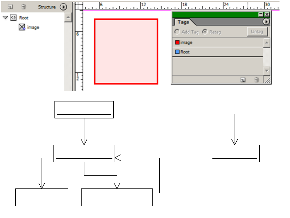
CHAPTER 8: XML Fundamentals Elements and content 183
simplicity. Content items like kPlaceHolderItemBoss have an IXMLReferenceData interface, which lets
them refer to an element in the logical structure.
When document content is tagged, XML elements (IIDXMLElement) are created within the logical
structure. Tagging content creates associations between content items (see IXMLReferenceData) and
elements in the logical structure. Tagging also creates associations between elements and tags
(kXMLTagBoss).
The following figure shows a class diagram for some of the classes representing a tagged placeholder
graphic. A graphic frame (kSplineItemBoss) acquires a placeholder item child (kPlaceHolderItemBoss),
when the frame is tagged to use as a placeholder. If a graphic frame is not tagged, it has no dependent
placeholder (kPlaceHolderItemBoss).
«boss»
Root : kTextXMLElementBoss
«boss»
image : kTextXMLElementBoss
«boss»
image-tag : kXMLTagBoss
IXMLTag
IIDXMLElement
«boss»
Root-tag : kXMLTagBoss
IXMLTag
«boss»
placeholder : kPlaceHolderItemBoss
IIDXMLElement::GetContentItem
IXMLReferenceData
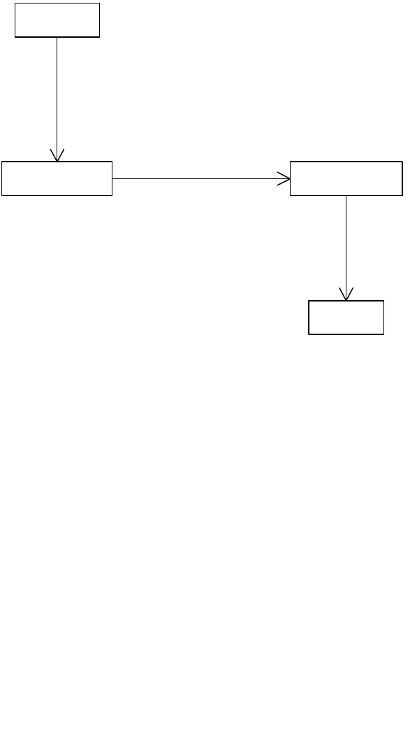
CHAPTER 8: XML Fundamentals Elements and content 184
There are several key associations related to tagging of content items shown in the two preceding figures:
Content items in the native document model associate with elements in the logical structure. The
association is maintained by the IXMLReferenceData interface and the XMLReference helper class.
Elements in the logical structure associate with content items in the native document model. The
association is maintained by the IIDXMLElement interface. See GetContentItem and
GetContentReference.
Elements in the logical structure associate with tags. The association is maintained by the
IIDXMLElement interface. See GetTagUID and GetTagString.
Tagged images
The following figure is an example of a minimal XML file that can be used to place an image. The path
shown is a relative one; the image would have to be in the same folder as the XML file that referenced it.
See the “XML” chapter of Adobe InDesign SDK Solutions for an example of XML for importing an image by
reference. On importing the XML file, if we do not have a preexisting placeholder graphic frame tagged
with the Image tag, the image is not placed.
The following figure shows the result of importing the minimal XML file.
«boss»
kSplineItemBoss
«boss»
kPlaceHolderItemBoss
«boss»
kTextXMLElementBoss
«boss»
kXMLTagBoss
1
0..1
IHierarchy
1 0..1
IXMLReferenceData::GetReference
1
1
IIDXMLElement::GetTagUID
<?xml version="1.0" encoding="UTF-8" ?>
<Root>
<Image href="file://testfile.tif" />
</Root>
CHAPTER 8: XML Fundamentals Elements and content 185
If there is a preexisting graphic frame tagged with the Image tag, the image is placed on import. One
constraint is that if you intend an image to be placed in the graphic frame, the Image element (for this
example) must support the href attribute that on import should specify the system path with which to
locate the image to be placed, or you will have to place the image yourself.
Architecture
Elements can be associated with a tagged placeholder (kPlaceHolderItemBoss) or a tagged graphic
content item, such as an image (kImageItem, kPlacedPDFItemBoss, kEPSItem, etc.).
When an XML tag is applied to a graphic frame with placeholder content (for example, kSplineItemBoss
containing a kPlaceHolderItemBoss), a new instance of the kTextXMLElementBoss class is created, and a
link is created between this object and the boss object representing the placeholder item
(kPlaceHolderItemBoss).
Tagged stories
Architecture
Elements (IIDXMLElement) can be associated with a content item that is either a story or a range of text
within a story. The story (kTextStoryBoss) in which the text range is contained must be tagged before a
range of text can be tagged. Tagging a story is useful when you want to create a tagged placeholder for
incoming, text-based content. The end-user action to tag a story is to tag the text frame through which the
story flows; this creates an association between the story (kTextStoryBoss) and an XML element
(IIDXMLElement).
The following figure shows associations for some of the classes representing a tagged story
(kTextStoryBoss). If a story is tagged, the IXMLReferenceData of the story boss object (kTextStoryBoss)
refers to a valid instance of an element (kTextXMLElementBoss).
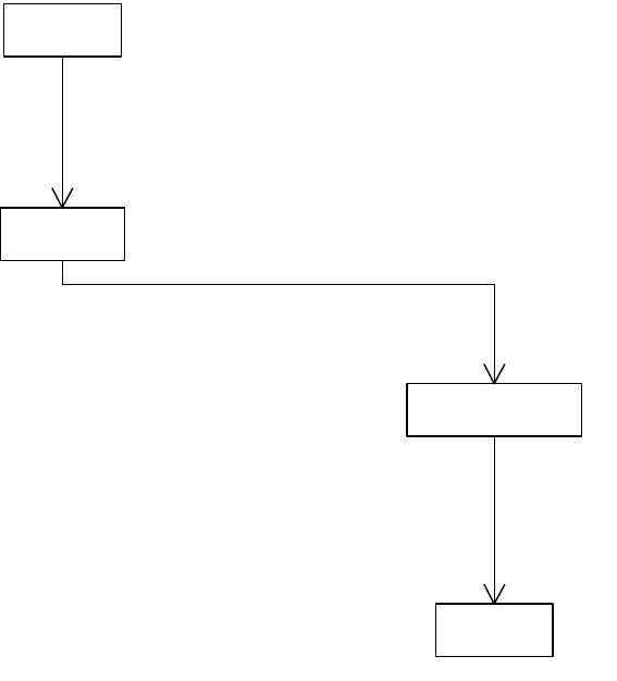
CHAPTER 8: XML Fundamentals Elements and content 186
You can iterate over the children of the element tagging the story, using XMLContentIterator, to find out
text ranges marked up by the child elements. For an example, see the section on “Finding Text associated
with Tagged Text Ranges” in the “XML” chapter of Adobe InDesign SDK Solutions.
Tagged text ranges
A tag is applied to a text range by making a text selection and either clicking a particular tag in the Tags
panel or selecting an item from a context-sensitive menu containing tag names. Once the range is tagged,
tag markers are placed before and after the tagged range. The “[” and “]” adornment characters are
nonprinting, zero-width spaces inserted into the text; these characters can be shown or hidden.
Text ranges within a tagged story can themselves be tagged. Text within table cells also can be tagged.
There are some constraints on what text can be tagged. The following text ranges cannot be tagged:
Some owned items, including notes (kNoteDataBoss), tracked changes, and hyperlinks.
Ruby text annotations in Japanese.
Text in locked stories (see IItemLockData).
The following figure shows a tagged range of text. In this example, the article tag is applied to the story,
and the emphasis tag is applied to the text range containing the characters “tagged.”
«boss»
kDocBoss
«boss»
kTextStoryBoss
1
1..*
IStoryList
«boss»
kTextXMLElementBoss
1
0..1
IXMLReferenceData::GetReference
«boss»
kXMLTagBoss
1
1
IIDXMLElement::GetTagUID
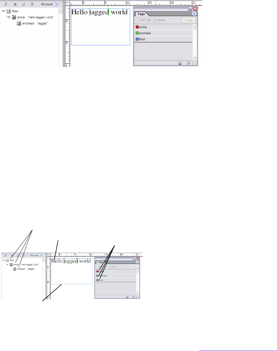
CHAPTER 8: XML Fundamentals Elements and content 187
Architecture
When tagging a text range in an untagged story, the following steps take place:
1. The story (kTextStoryBoss) in which the text range lies is tagged, and an element (IIDXMLElement) is
created in the logical structure.
2. An element (IIDXMLElement) is created to represent the tagged-text range. This element refers to a
tag (kXMLTagBoss) with a tag name (“emphasis” in the example in the preceding figure).
3. Characters are inserted into the text model to represent the start and end of the tagged-text range
(kTextChar_ZeroSpaceNoBreak).
4. Optionally, adornments (IGlobalTextAdornment, kXMLMarkerAdornmentBoss) are drawn in layout
view, as shown in the preceding figure, if the preference to show tag markers is enabled (see
IXMLPreferences).
The following figure shows the classes involved in this minimal example of tagging a text range.
Consider the example of one tagged text range, as shown in the following figure, which shows objects
involved in representing a tagged text range. The result of tagging this text range is to create a new
element that is a child of the element associated with the tagged story. See “Tagged stories” on page 185.
In the following figure, an emphasis element is created on tagging the text range. This is a child of an
article element for this example. The information about the range of text is encapsulated in the
kTextXMLElementBoss, but it can be accessed through using XMLContentIterator.
K4EXT8-,%LEMENT"OSS
K4EXT3TORY"OSS
K3PLINE)TEM"OSS
K-ULTI#OLUMN)TEM"OSS
K&RAME)TEM"OSS
K8-,4AG"OSS
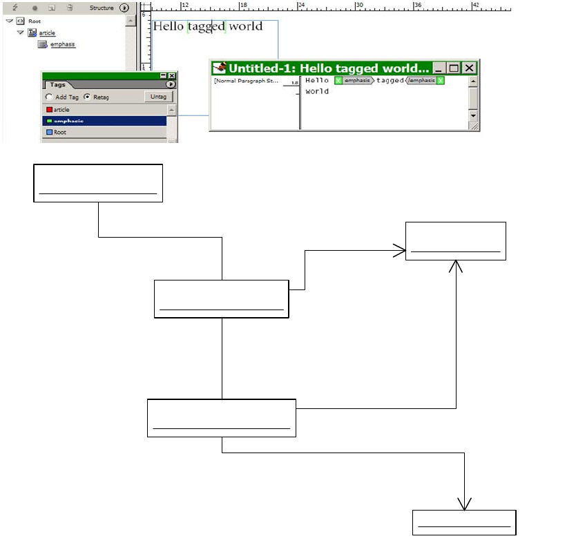
CHAPTER 8: XML Fundamentals Elements and content 188
Tagged inline graphics
You can create a tagged inline graphic by either selecting an existing inline graphic and tagging it or
placing an image into a tagged inline placeholder.
The following figure shows a tagged story, with two tagged paragraphs and a tagged inline graphic.
«boss»
article : kTextXMLElementBoss
«boss»
emphasis : kTextXMLElementBoss
«boss»
Root : kTextXMLElementBoss
IIDXMLElement
IIDXMLElement
«boss»
Story : kTextStoryBoss
IIDXMLElement::GetContentReference
IIDXMLElement::GetContentReference
text-range : TextRange
XMLContentIterator
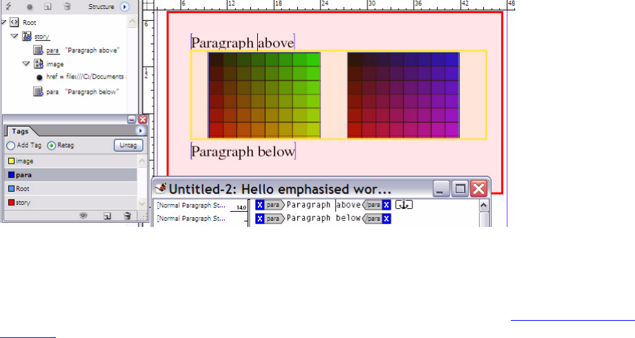
CHAPTER 8: XML Fundamentals Elements and content 189
Architecture
From an XML perspective, tagged inline graphics are like tagged images, described in “Tagged images” on
page 184. The main differences are on the native-document-model side; the image (for example,
kImageItem) is owned by a frame that itself is owned by an inline object (kInlineBoss). The object diagram
in the preceding figure shows some objects that model a tagged inline graphic.
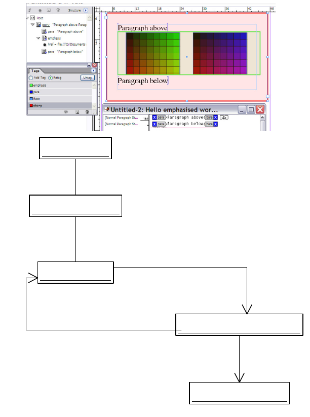
CHAPTER 8: XML Fundamentals Elements and content 190
Tagged tables
You can tag a table and cells within a table. A table that is not explicitly tagged will not get exported
during XML export. If a table is tagged, all its cells must be tagged. In other words, a tagged table cannot
contain untagged cells, and a tagged table cell cannot be inside an untagged table.
Tagged tables and table cells also can be untagged; that is, the mark-up associated with them can be
removed. Untagging a table or its cells untags the entire table, including the cells.
The model for tagging tables is restricted: you can tag either at the whole-table level or the cell level, but
you cannot tag rows or create other container elements within the logical structure of a table.
Architecture
If you refer to the API Reference for IXMLReferenceData and see the boss classes that aggregate this
interface, you will notice table-related classes like kTableModelBoss and kTextCellContentBoss. The
operation of tagging a table (kTableModelBoss) has the following constraints:
«boss»
inline : kInlineBoss
«boss»
image : kImageItem
«boss»
frame : kSplineItemBoss
«boss»
<image> : kTextXMLElementBoss
IHierarchy
IHierarchy
IXMLReferenceData::GetReference
«boss»
image-tag : kXMLTagBoss
IIDXMLElement::GetTagUID
IIDXMLElement::GetContentReference

CHAPTER 8: XML Fundamentals Elements and content 191
A tagged table must reside in a tagged story (kTextStoryBoss), so the act of tagging a table also tags
the story in which it resides, if the story is not already tagged. The story is auto-tagged with the Story
tag, if no other tag is specified.
The cells within the table also must be tagged when the table itself is tagged. The cells are
auto-tagged with the Cell tag, if no other tag is specified.
It also is possible to tag text within a table cell, which is not much different than the situation described in
“Tagged text ranges” on page 186. For example, if you create an element that is a child of a Cell element,
the new element becomes a placeholder for tagged text within a table cell.
For more details on implementing tagging of tables, see the section on “Tagging a Table” in the “XML”
chapter of Adobe InDesign SDK Solutions.
The object diagram in the following figure shows some of the objects that represent a tagged table. Note
how the table (kTableModelBoss) associates with an XML table element. The key to understanding the
model is the XMLContentReference type, an instance of which can be obtained from
IIDXMLElement::GetContentReference. In the case of XML elements associated with table cells, the
properties of the cells can be discovered through XMLContentReference.
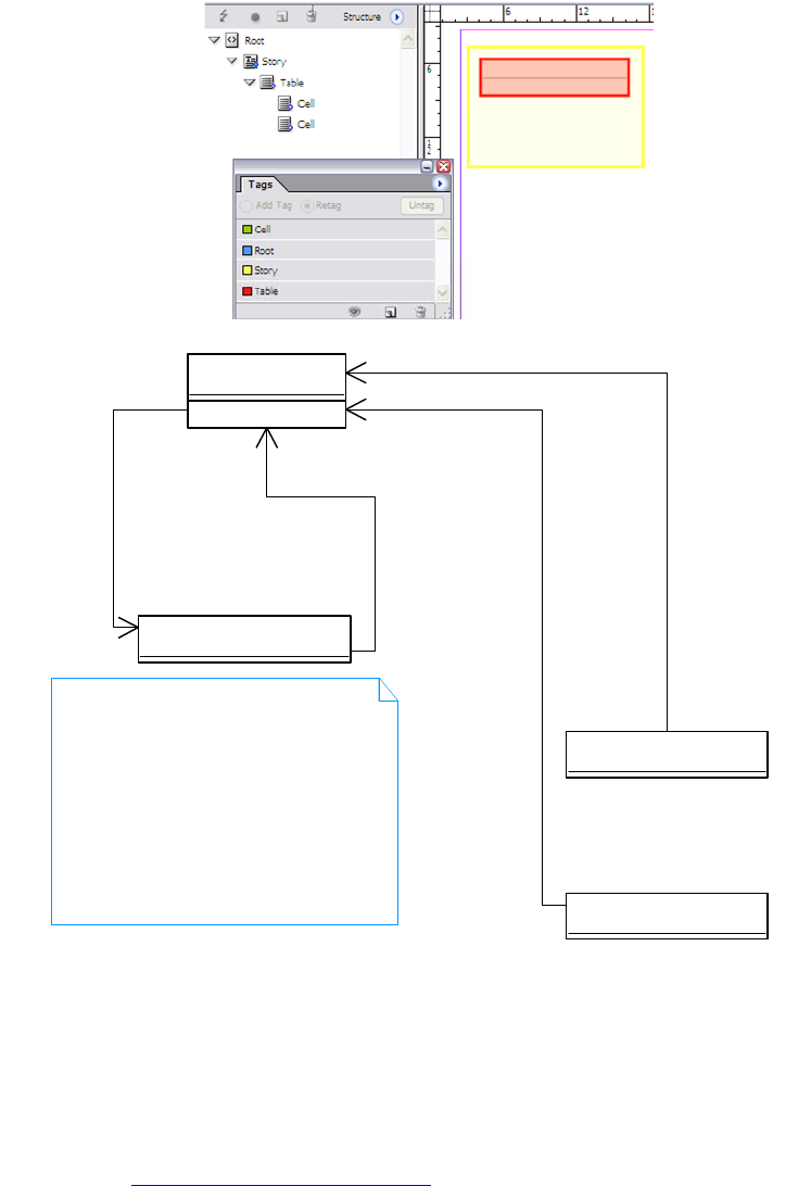
CHAPTER 8: XML Fundamentals Elements and content 192
DTD
A document type declaration (DTD) is a grammar defined in an extended Backus-Naur format that can be
read by XML processors. The main point of associating a DTD with an InDesign document is to allow the
logical structure of the InDesign document to be checked or validated against the grammar. The XML 1.0
specification (http://www.w3.org/TR/REC-xml) defines a DTD as follows:
“The XML document type declaration contains or points to markup declarations that provide a grammar
for a class of documents. This grammar is known as a document type definition, or DTD. The document
type declaration can point to an external subset (a special kind of external entity) containing markup
declarations, or can contain the markup declarations directly in an internal subset, or can do both. The
DTD for a document consists of both subsets taken together.”
You can import a DTD to create an association between the DTD and the document’s logical structure,
using the Load DTD menu command in the Structure pane. This associates the DTD with the logical
«boss»
table : kTableModelBoss
«boss»
<Table> : kTextXMLElementBoss
«boss»
<Cell> : kTextXMLElementBoss
1
0..1
IXMLReferenceData::GetReference
1
0..1
XMLContentReference::GetUID
1
0..1
XMLContentReference::GetUID
«boss»
<Cell> : kTextXMLElementBoss
1
0..1
XMLContentReference::GetUID
An XMLContentReference is obtained from
IIDXMLElement::GetContentReference.
You can use XMLContentReference::Instantiate
to get an IXMLReferenceData pointer, which refers
to the table in the case of a Cell element.
Other methods on XMLContentReference let
you find where the cell is when you have the
table (ITableModel, kTableModelBoss).

CHAPTER 8: XML Fundamentals Elements and content 193
structure of the document. New tags are created (see “Tags” on page 178) from an element type
declaration, if they are not already in the tag list.
After associating a DTD with the document, you can validate the logical structure of a document against
the DTD. The user interface for this is shown in the figure in “Validation window” on page 158.
Once you load a DTD, you can validate the logical structure against the DTD, to determine the extent to
which the document’s structure violates the constraints expressed in the grammar represented by the
DTD. See Section “5.1 Validating and Non-Validating Processors” in the XML 1.0 specification.
The API does not support validating the logical structure of an InDesign document against an XML schema
(http://www.w3.org/TR/xmlschema-0).
If you import a DTD, a new element is created in the logical structure, and new tags are created as needed.
A sample DTD is shown in the following example. This was associated with the logical structure of a
document after importing the minimal XML from “Importing a minimal XML file” on page 167.
<!ELEMENT article (title, body?)>
<!ELEMENT body (subhead │ para)+>
<!ELEMENT title (#PCDATA)>
<!ELEMENT subhead (#PCDATA)>
<!ELEMENT para (#PCDATA)>
Architecture
The DTD associated with the logical structure of an InDesign document is represented by an instance of
kXMLDTDBoss. When present, this instance is a child of the document element (kXMLDocumentBoss) and
a peer of the root element. See the following figure for an object diagram showing relationships between
objects representing the logical structure of a minimal InDesign document. The UML diagram in the
following figure shows objects representing the logical structure when a DTD is imported into the
document. kXMLDTDBoss, as a participant in the logical structure, has the IIDXMLElement interface;
however, it does not have children and has no associated tag.
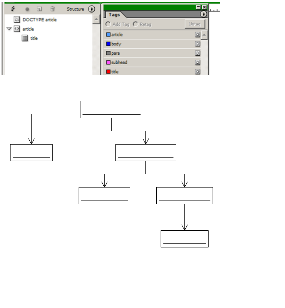
CHAPTER 8: XML Fundamentals Elements and content 194
Processing instructions and comments
An XML comment stores text that is not considered part of the document content, but that may be
relevant when authoring. XML comments are defined in the XML 1.0 specification
(http://www.w3.org/TR/REC-xml) as follows:
“Comments may appear anywhere in a document outside other markup; in addition, they may appear
within the document type declaration at places allowed by the grammar. They are not part of the
document's character data ....”
XML comments can occur anywhere in the logical structure that is legal within the XML specification. An
XML comment appears in the XML data like this:
<!-- This is a comment -->
Processing instructions (PIs) also store text that is not considered part of the document content, but the
content may be relevant to an XML processor. Processing instructions are defined in the XML specification
as follows:
«boss»
article : kTextXMLElementBoss
«boss»
article-tag : kXMLTagBoss
IXMLTag
«boss»
title : kTextXMLElementBoss
IIDXMLElement
«boss»
title-tag : kXMLTagBoss
IXMLTag
«boss»
doc-elem : kXMLDocumentBoss
IIDXMLElement
«boss»
DTD : kXMLDTDBoss
IID_IXMLDTDXMLREFERENCEDATA
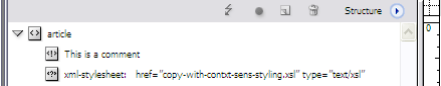
CHAPTER 8: XML Fundamentals Elements and content 195
“PIs are not part of the document's character data, but must be passed through to the application. The PI
begins with a target (PITarget) used to identify the application to which the instruction is directed.”
Processing instructions allow XML-based documents to contain instructions for applications that know
how to process them. It is possible to create new processing instructions anywhere in the logical structure.
A processing instruction appears in the XML data like this:
<?xml-stylesheet href="copy-with-contxt-sens-styling.xsl" type="text/xsl"?>
This processing instruction directs an XML application to choose a particular XSL stylesheet if applying an
XSL transform to the XML content.
The following figure shows how an XML comment and processing instruction are rendered in the structure
view.
Architecture
An XML comment is associated with one string. Comments are represented by kXMLCommentBoss, with
the text stored by an implementation of IStringData. On the other hand, a processing instruction appears
to the user as a pair of strings, one specifying the target for the processing instruction and the other
specifying the data. Processing instructions are represented by kXMLPIBoss; there are two IStringData
interfaces implemented by this class, (IID_IXMLPITARGET, IID_IXMLPIDATA) storing strings representing
the key (target) and value (data).
The kXMLCommentBoss and kXMLPIBoss boss classes have implementations of the IIDXMLElement
interface (through inheritance) and are part of the logical-structure tree. Comment and
processing-instruction elements support some but not all properties of other XML elements. For example,
you cannot add attributes to a comment or processing instruction, and there is neither a valid
content-item reference nor a valid tag reference for a comment or processing instruction.
Structural (container) elements
You can add new elements to the logical structure of a document using the structure view and its
associated menu. Elements created in this way are not immediately associated with content items and are,
therefore, unplaced.
Unplaced elements can be placed from the logical structure onto the layout manually or
programmatically, but sometimes it is useful to retain unplaced elements as structural or container
elements.
For example, suppose a publication is a collection of sections (for example, “Arts” and “Motoring”), each
comprising one or more articles. You could model this with a Section element that consists of a set of
Article elements; the Section element might never itself have any content but instead be used to structure
the collection of Article elements. The Section element is a logical element of the publication, rather than a
content-related element.
CHAPTER 8: XML Fundamentals XML-related preferences 196
The XML template for this publication might be set up as shown in the following figure. The Article
elements appear as placed content, because we tagged some stories with Article tags; these stories are
placeholders into which the XML-based data would be imported.
Architecture
Structural elements differ from elements representing placed content only insofar as structural elements
do not have a valid content-item reference (IIDXMLElement::GetContentReference). However, structural
elements should have a valid tag reference (IIDXMLElement::GetTagUID).
XML-related preferences
The XML subsystem is relatively complex, and there are several interfaces that store XML preferences.
These can be grouped into workspace-level preferences and service-level preferences.
Workspace-level XML preferences
There are some XML-related preferences (options) interfaces stored in workspaces (kWorkspaceBoss and
kDocWorkspaceBoss). These are shown in the following table, along with low-level commands that enable
them to be changed.

CHAPTER 8: XML Fundamentals XML-related preferences 197
In most cases, the command required to change a data interface is specified in the API Reference or can be
deduced when inspecting the boss classes that aggregate a given interface.
The UML diagrams in the following figure show some of the interfaces involved in storing options for
import and export of XML at the session level (kWorkspaceBoss) or document level (kDocWorkspaceBoss).
Interface Responsibility
Command to process to change
preference
IDocStructurePrefs Stores preferences like whether
structure view is visible when the
document is opened.
kChangeDocStructurePrefsCmdBoss
to change the data, but you need to
execute an action to change the
structure-view state.
IGeneralXMLPreferences Stores tagging preferences in the
session workspace, like default
tag name for story, table, and cell.
kSetGeneralXMLPreferencesCmdBoss
IStructureViewPrefs Stores information related to the
appearance of the structure view,
like whether comments are
visible.
kChangeStructureViewPrefsCmdBoss
IXMLExportOptions Stores XML export options in the
workspace that control what gets
written to the XML data.
kChangeXMLExportOptionsCmdBoss
IXMLExportSessionOptions Stores XML export options in the
session workspace related to
viewing XML data after export.
kChangeXMLExportSOptionsCmdBoss
IXMLImportOptions Stores XML import options in the
workspace.
kChangeXMLImportOptionsCmdBoss
IXMLPreferences Stores user-interface preferences
related to XML.
kShowTaggedFramesCmdBoss,
kShowTagMarkersCmdBoss, and
kShowTagOptionsCmdBoss
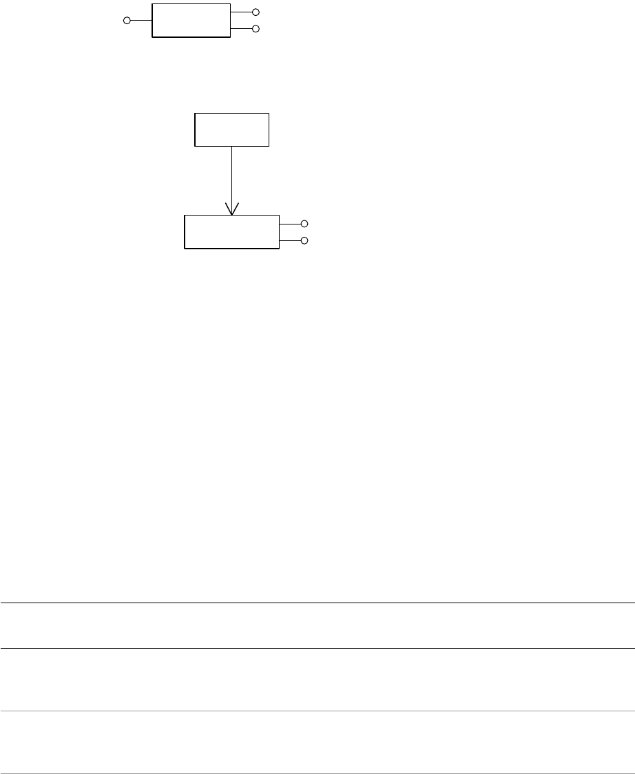
CHAPTER 8: XML Fundamentals XML-related preferences 198
Preferences related to structure view and other user-interface components
The IDocStructurePrefs interface controls some properties of the structure view. IDocStructurePrefs is
present on the session workspace (kWorkspaceBoss) and document workspace (kDocWorkspaceBoss).
IDocStructurePrefs stores preferences related to whether to show the structure pane and how wide it
should be.
The IStructureViewPrefs interface (only on kWorkspaceBoss) stores other properties of the structure view,
like whether text snippets are to be shown. The IXMLPreferences interface on the session workspace
(kWorkspaceBoss) stores the visibility of tag markers, etc.
Service-level XML preferences
Some services that aggregate the IXMLImportPreferences interface are shown in the following table.
Object-specific preference interfaces related to XML:
«boss»
kDocWorkspaceBoss
«boss»
kWorkspaceBoss
IXMLExportSessionOptions
IXMLImportOptions
IXMLImportOptions
«boss»
kDocBoss
IDocument
IXMLExportOptions
IXMLExportOptions
Service and its responsibility
Semantics of its IXMLImportPreferences
interface
kXMLRepeatTextElementsMatchMakerServiceBoss,
responsible for preserving story text styling when
handling repeating elements.
0th preference is bool16, whether to turn on,
kTrue by default.
kXMLThrowAwayUnmatchedRightMatchMakerService
Boss, responsible for discarding unmatched elements
in the XML template.
0th preference is bool16, whether to turn on
feature, kFalse by default.
kXMLThrowAwayUnmatchedLeftMatchMakerServiceB
oss, responsible for discarding incoming elements that
have no match in the XML template.
0th preference is bool16, whether to turn on
feature, kFalse by default.
CHAPTER 8: XML Fundamentals Key client API 199
Key client API
XML suites
Some suite interfaces that represent a fairly high level of abstraction over the XML subsystem can be used
to program the XML features. We recommend you use these suites when possible when programming
using the XML features:
IXMLNodeSelectionSuite can be used to make a programmatic selection in the Structure pane. See
also the extension pattern described in “Custom suite for the structure view” on page 202.
IXMLStructureSuite can be used when there is a selection in the Structure pane. IXMLStructureSuite
lets you change the logical structure of a document at the node selected in the structure-view tree. If
you are writing client code that involves the end user making active selections, this is one mechanism
to modify the logical-structure tree. The methods on this suite interface delegate to the command
facades (for example, IXMLElementCommands and IXMLAttributeCommands).
IXMLTagSuite can be used to apply tags to a selection, like a text range or graphic frames.
IXMLTagSuite also can be used for other purposes, like adding a processing comment to the
document’s logical structure. See “Elements and content” on page 182 and “Processing instructions
and comments” on page 194.
You can extend the application by writing a custom suite that is available when there is a selection in the
Structure pane. See “Extension patterns” on page 200.
Command facades and utilities
There are many command-related boss classes named kXML<whatever>CmdBoss, but in most cases, you
do not need to process these low-level commands, as there are command facades in the XML API that
encapsulate parameterizing and processing these commands.
Interfaces like IXMLUtils, IXMLElementCommands, IXMLMappingCommands, IXMLTagCommands, and
IXMLAttributeCommands are examples of command facades. These encapsulate processing of almost all
the commands required by plug-in code. These interfaces are aggregated on kUtilsBoss; the smart pointer
class Utils makes it straightforward to acquire and call methods on these interface. You can call their
methods by writing code that follows this pattern:
Utils<IXMLElementCommands>()->MethodName(...)
kXMLImporterPostImportMappingBoss, responsible
for attribute-style mapping.
0th preference, bool16, kTrue by default.
Specifies whether to delete namespace
attribute (aid: for example) and the namespace
attribute (xmlns:).
kXMLSparseImportOptionsServiceBoss, just stores a
preference relating to sparse import.
0th preference, bool16, whether to use sparse
import, kFalse by default.
kXMLLinkingPostImportResponderBoss, responsible
for creating a link (kXMLImportLinkBoss) to imported
XML files.
0th preference, bool16, whether to create link,
kFalse by default.
Service and its responsibility
Semantics of its IXMLImportPreferences
interface

CHAPTER 8: XML Fundamentals Extension patterns 200
When writing code that does not involve selection, always look first at the IXMLUtils or
IXML<whatever>Commands interfaces, to see if there is a method that serves your purpose on one of
these interfaces. By doing so, you can avoid the increased chance of confusion and error that comes with
processing low-level commands. Of course, your use case may require you to process some low-level
commands, if the facades do not provide all the functionality you require.
Extension patterns
XML acquirer
Suppose you want to customize how InDesign obtains the XML data to be read by the standard
import-XML file operation. For example, you might query your database to get XML-based data, and you
want to allow InDesign to parse the XML data directly from a stream you open.
Architecture
An XML acquirer (IXMLAcquirerFilter) lets you take control to create a stream (IPMStream) from which
InDesign reads XML data, and optionally provide an entity resolver (ISAXEntityResolver) for InDesign to
use when importing the XML data in your stream. An XML acquirer allows you to take control early in the
XML-import sequence, to determine where the XML data comes from. An XML acquirer is a service
provider, characterized by the IXMLAcquirerFilter service interface. The ServiceID must be of type
kAcquireXMLService; you can reuse the API implementation kXMLFilterServiceProviderImpl
(IK2ServiceProvider) for this.
XML import begins with a URL-style string that describes the XML source. This stage of the import process
(see “Import architecture” on page 165) has the task of converting the XML source description into a
stream (IPMStream). In the simplest case, the URL-style string is a path to a local file. In more complex
cases, it could be an XQuery, any kind of URL, or a comma-separated values (CSV) file.
These different identifiers for the XML source are handled uniformly by the XML importer
(kXMLImporterBoss). The XML importer takes the source string and sends it to each of the XML acquirer
filters (IXMLAcquirerFilter) in turn, until it finds one that can handle the string. Each filter examines the
string and determines whether it can return a stream given the string.
The order in which the filters are called is undefined. The XML import mechanism of InDesign includes a
file-based, XML-acquirer filter (kXMLAcquirerTextFilterServiceProviderBoss), and other filters can be added
by third parties.
In theory, it should be possible to write a database connectivity acquirer to get XML data directly out of a
database (or content-management system) into InDesign. The URL string has to be something that can be
recognized by the target acquirer (and, hopefully, no one else). The URL can even be an instruction that
points to another file with more instructions (for example, a binding file). The only thing the acquirer must
do is return an XML stream in the end; the acquirer can process instructions, get some XML data, process it
further, and finally return manipulated XML data if desired by the acquirer.
The import source is specified through data stored in the IImportXMLData of the data object
(kImportXMLDataBoss), which encapsulates an IDFile. To implement a custom acquirer, you can construct
an IDFile with an arbitrary path, then you can implement the IXMLAcquirerFilter to interpret the path
specified by the IDFile to take whatever action you want. For example, you might plan to make a query on
a server-based repository of some kind, then open a stream to a local file that you copied onto the
machine from the server. The query could be specified or parameterized by information in the string you
CHAPTER 8: XML Fundamentals Extension patterns 201
got back from IDFile::GetString, once you get inside your acquirer code (see
IImportXMLData::GetImportSource).
XML transformer
Suppose you want to transform the incoming XML data using something like the InDesign built-in XSLT
engine or a transformation engine of your own. The XML transformer is an extension pattern you can
implement if you want to transform the XML data being imported. You have the choice of transforming
the data when it is still a stream or when it has been turned into a DOM.
Architecture
The XML transformer (IXMLTransformer) is an extension pattern for manipulating the incoming XML DOM.
It is an opportunity for a third-party software developer to add elements, throw away others, and change
the rest before the incoming XML data is matched against the existing XML template. An import
transformer is a service provider characterized by the service interface IXMLTransformer and signature
interface IK2ServiceProvider. The ServiceID must be of type kXMLImporterTransformerService; you can
reuse the API implementation kXMLImportTransformerSignalServiceImpl (IK2ServiceProvider) for this.
You can transform the inbound XML data in one or both of two phases:
The first phase is while there is a stream (IPMStream); you can apply an XSLT transform to the inbound
stream (IPMStream) of XML-based data and turn it into another stream (IPMStream). See
IXMLTransformer::TransformStream.
The second phase occurs immediately after the DOM is created. During this phase, you can manually
manipulate the DOM by inserting, removing, and changing elements. See
IXMLTransformer::TransformDOM and IIDXMLDOMDocument.
XMl-import matchmaker
Suppose you want to customize how the XML template is matched against the incoming XML data.
Architecture
This is a service that participates in XML import, to determine how the incoming XML is matched against
the XML template (document) into which the XML is imported. An import matchmaker is a service
provider characterized by the service interface IXMLImportMatchMaker and signature interface
IK2ServiceProvider. The ServiceID must be of type kXMLImportMatchMakerSignalService; you can reuse
the API implementation kXMLImportMatchMakerSignalServiceImpl (IK2ServiceProvider) for this.
An XML-import matchmaker service (IXMLImportMatchMaker) is responsible for determining the behavior
of InDesign when importing XML-based data into an XML template that has structure which provides a
partial match for the inbound XML data. For example, the features to throw away unmatched existing or
inbound are implemented by matchmaker services. In theory, you can implement a custom XML-import
matchmaker to specialize how matching against an XML template is performed.
Post-import responder
Suppose you want to perform an operation just after the XML data is imported and the logical structure
created, like placing images based on information in the logical structure. Rather than having to write your
CHAPTER 8: XML Fundamentals Extension patterns 202
own code to traverse the logical structure after import, there is an extension pattern that lets you be called
when the logical structure of the document is being traversed, just after the DOM is completed.
Architecture
A post-import iterator (IXMLPostImportIteration) is a type of responder (IResponder) that is signalled
during XML import. An post-import iterator is a service provider; specifically, it is a responder service,
characterized by the service interface IXMLPostImportIteration and signature interface IK2ServiceProvider.
The ServiceID must be of type kXMLPostImportIterationService; you can reuse the API implementation
kXMLPostImportIterationServiceProviderImpl (IK2ServiceProvider) for this.
A lot of post-processing tasks are of the form “go through the logical structure. and if you see
<something>, do <whatever>.” The iterator allows you to do this without writing the iteration itself, while
taking as little penalty in performance as possible. Essentially, InDesign iterates over the structure one
time and calls all the clients when every node is visited. If your task is simple and localized, this is a good
choice, because all you would write is your specialized code. If you require, you can still write a full
post-import processor of your own design and iterate over the whole structure yourself.
Features of the application like tag-to-style mapping are implemented using a post-import iterator.
Custom suite for the structure view
Suppose you want to allow some operations to be performed whenever there is a selection of one or more
nodes in the logical structure. For example, suppose you want to let an end user verify the image
references in the nodes selected in the structure view, perhaps through a context-sensitive menu item that
is present or enabled only when nodes are selected.
Architecture
A custom suite for the structure view lets your code be called only when there is a node-selection target
(IXMLNodeTarget) in the structure view. You can follow the pattern of IXMLStructureSuite (refer to the API
Reference for that interface). To implement a custom suite for the structure view:
1. Add an appropriate implementation of your custom suite to kIntegratorSuiteBoss (ASB,
abstract-selection boss class).
2. Add an appropriate implementation of your custom suite in to kXMLStructureSuiteBoss (CSB,
concrete-selection boss class).
When you implement a custom suite, it gives you access to the nodes selected in the structure view
through IXMLNodeTarget, through your add-in to the concrete-selection boss class
kXMLStructureSuiteBoss.
SAX-content handler
Suppose you want to load a configuration from an XML file that contains information relevant only to your
plug-ins and does not specify document content.

CHAPTER 8: XML Fundamentals Extension patterns 203
Architecture
A custom SAX-content handler (ISAXContentHandler) lets you take control when XML is being parsed by
the XML-parser service early in the XML-import service. This extension pattern can be used to read
configuration data from an XML file, for example.
A SAX-content handler is not (any longer) a service. Your main requirement is to register with the SAX
services (ISAXServices) of the SAX parser (kXMLParserServiceBoss).
There are several instances of SAX-content handlers (for example, parsing the tag list, itself an XML file).
Refer to ISAXContentHandler in the API Reference and note the boss classes that expose this interface.
See http://sax.sourceforge.net for information about the Simple API for XML (SAX).
SAX DOM serializer handler
Suppose you want to take control when XML is being imported and the XML DOM is being serialized into
the document, and you want to handle the parsing of XML content for some custom elements, to let you
create some document content.
Architecture
A custom, SAX DOM serializer handler lets you take control when the XML DOM is imported and is being
serialized (written) into the document. If you implement this extension pattern, you can choose how
particular elements in the DOM are written into the document; for example, you can create custom
content. This is done for tables and Ruby annotations.
A SAX DOM serializer handler is a service provider characterized by the service interface
ISAXDOMSerializerHandler and signature interface IK2ServiceProvider. The ServiceID must be of type
kXMLContentHandlerService; you can reuse the API implementation kXMLContentServiceProviderImpl
(implementation of IK2ServiceProvider) to do this.
Custom-tag service
Suppose you have custom content in the XML file that is created programmatically on export, and you do
not want end users to be able to apply the tags based on the element names in your custom content.
Architecture
A tag service is given the opportunity to handle elements in an XML stream that has been opened for
reading element names to be used as tags.
A tag service is a service provider that is closely related to the SAX-content-handler service. A tag service is
characterized by the service interface ISAXContentHandler and interface IK2ServiceProvider, which should
yield a ServiceID of kXMLTagHandlerService. You can reuse the API implementation
kXMLTagServiceProviderImpl to achieve this.
For example, you may be using a tag service to filter out names of custom elements you do not want to
appear in the tag list. In this case, you would provide a minimal implementation of ISAXContentHandler
that registers your handler for the elements you want to filter out and claims to handle a subtree. You then

CHAPTER 8: XML Fundamentals Commands and notification 204
do not need to do anything when sent the other ISAXContentHandler messages for elements for which
you do not want tags to be created.
SAX-entity resolver
Suppose you want to customize how external entities are resolved by the InDesign SAX parser. An external
entity needs to have an associated PUBLIC or SYSTEM identifier, which can be translated to something like
a URI, which should point at the input source where the entity is defined:
“Attempts to retrieve the resource identified by a URI MAY be redirected at the parser level (for example, in
an entity resolver)”
See the XML specification (http://www.w3.org/TR/REC-xml, section 4.2.2) for a definition of “external
entity.”
Architecture
If you implement a custom entity resolver for external entities, it is your responsibility to create a stream
(IPMStream) to the input source where the entity is defined, when passed a PUBLIC or SYSTEM identifier
for the entity. An entity resolver is characterized by the ISAXEntityResolver interface.
You create an instance of the boss class you defined with your own implementation of ISAXEntityResolver
when needed; for example, when implementing an XML acquirer
(IXMLAcquirerFilter::CreateStreamAndResolver or CreateResolver).
XML-export handler
Suppose you want to control the output of some XML elements when they are being exported; for
example, you want to alter the structure of XML file for some custom elements, to better fit your needs.
Architecture
A custom, XML-export handler lets you control the output. If you implement this extension pattern, you
can choose how particular elements in the document are written into the XML file.
An XML-export handler is a service provider characterized by the service interface IXMLExportHandler and
signature interface IK2ServiceProvider. The ServiceID must be of type kXMLExportHandlerSignalService;
you can reuse the API implementation kXMLExportServiceImpl (implementation of IK2ServiceProvider).
To customize the output of an element or elements, override the CanHandleElement method to return
true for the element, and override other methods to write custom content to the output.
Commands and notification
Backing store and notification of changes in logical structure
When the logical structure of a document changes, the commands that change the logical structure send
notification about changes in the backing store. The subject for notifications about change in the logical
structure is a UID-based object (instance of kTextStoryBoss).
CHAPTER 8: XML Fundamentals Entities supported 205
You can acquire the backing store with IXMLUtils::GetBackingStore and query for its ISubject interface.
Once you have the ISubject interface, you can attach an observer and listen for changes of interest in the
usual pattern.
Command output can be stored in the item list of a command boss object on output, which is sent as the
changedBy parameter in the IObserver::Update message. When implementing an observer, you can cast
the changedBy parameter of the Update method to an interface pointer of type ICommand*, as shown
below:
ICommand* iCommand = (ICommand*)changedBy;
const UIDList itemList = iCommand->GetItemListReference();
When the command output shows the output is stored in an interface on the command (for example as an
XMLReference), you might write code like this:
InterfacePtr<IXMLReferenceData> cmdData(iCommand, UseDefaultIID());
if(cmdData) {
XMLReference xmlRef = cmdData->GetReference();
...
}
Entities supported
Standard entities supported by default by the XML subsystem are shown in the following table. If you
need to support a wider set—like the entire ISO-LATIN 1 set of character entities (for example, &174; for ™,
the trademark symbol)—you can use them with the applications if they are defined in the DTD. For
example, Simplified DocBook (http://www.oasis-open.org/docbook/xml/simple/sdocbook) contains
additional entity definitions within its DTD to support ISO-LATIN 1.
Entity Meaning Description
& & Ampersand
< < Less than
> > Greater than
' ' Apostrophe
" " Quote

 CR Character replacement entity for carriage return

 LF Character replacement entity for line feed
CHAPTER 8: XML Fundamentals Assets from XSLT example 206
Assets from XSLT example
Basic grammar for article-based publications
<?xml version="1.0" encoding="UTF-8"?>
<!ELEMENT publication (article)+>
<!ELEMENT article (article-title, body)>
<!ELEMENT body (title │ subhead │ para)+>
<!ELEMENT article-title (#PCDATA)>
<!ELEMENT title (#PCDATA)>
<!ELEMENT subhead (#PCDATA)>
<!ELEMENT emphasis (#PCDATA)>
<!ENTITY % pub.content "#PCDATA">
<!ELEMENT para (%pub.content; │ emphasis)*>
Fragment of XSL Stylesheet to Convert NITF to Basic Pub
<?xml version="1.0" encoding="UTF-8"?>
<xsl:stylesheet version="1.0" xmlns:xsl="http://www.w3.org/1999/XSL/Transform">
<xsl:strip-space elements="*"></xsl:strip-space>
<xsl:output method="xml" omit-xml-declaration="yes"/>
<xsl:template match="text()"><xsl:value-of select="normalize-space(.)"/>
</xsl:template>
<xsl:template match="/">
<xsl:apply-templates></xsl:apply-templates>
</xsl:template>
<!-- include content from these elements -->
<xsl:template match="nitf│block│body.head│ul">
<xsl:apply-templates></xsl:apply-templates>
</xsl:template>
<!-- exclude content we are not interested in with this empty template -->
<xsl:template match="*"/>
<xsl:template match="body">
<article><xsl:apply-templates></xsl:apply-templates></article>
</xsl:template>
<xsl:template match="body.content">
<body><xsl:apply-templates></xsl:apply-templates></body>
</xsl:template>
<xsl:template match="p">
<para><xsl:apply-templates></xsl:apply-templates></para>
<xsl:text>
</xsl:text></xsl:template>
<xsl:template match="hedline">
<article-title><xsl:value-of select="hl1"/></article-title><xsl:text>
</xsl:text>
</xsl:template>
<xsl:template match="hl1">
<title><xsl:value-of select="."/></title><xsl:text>
</xsl:text>
</xsl:template>
<xsl:template match="nitf-table">
<para><emphasis>Table omitted on import</emphasis></para><xsl:text>
</xsl:text>
</xsl:template>
<xsl:template match="hl2">
<subhead><xsl:apply-templates></xsl:apply-templates></subhead><xsl:text>
CHAPTER 8: XML Fundamentals Limitations of the InDesign XML architecture 207
</xsl:text>
</xsl:template>
<xsl:template match="em">
<emphasis><xsl:apply-templates></xsl:apply-templates></emphasis>
<xsl:text> </xsl:text>
</xsl:template>
<xsl:template match="org">
<xsl:text> </xsl:text>
<emphasis><xsl:apply-templates></xsl:apply-templates></emphasis>
</xsl:template>
<xsl:template match="li">
<para><xsl:apply-templates></xsl:apply-templates></para>
<xsl:text>
</xsl:text></xsl:template>
</xsl:stylesheet>
Limitations of the InDesign XML architecture
The architecture is detailed and has a broad client API and many extension patterns, but there are known
limitations you should be aware of, which could make implementing particular XML-based workflows
tricky or impossible.
Specifically, XML elements associated with graphics cannot have dependents. The model for representing
logical structure does not allow you to have a subtree of elements that depend on the element linked to a
graphic item.

208
9Snippet Fundamentals
A snippet is a logically complete fragment of an InDesign document, expressed in one of two XML formats,
INX (.inds or .incx file extensions) or IDML (.idms or .icml file extensions). INX-based snippets were
introduced in InDesign CS, but because of the complexity of the format, we did not recommend using
them to generate and manipulate content outside of InDesign. IDML- and IDML-based snippets were
designed for these purposes. This chapter describes the snippet architecture and the organization of
snippets for different asset types, and it relates this to the low-level (boss) document object model (DOM).
The snippet architecture is the basis for the asset library in InDesign, which is a collection of snippets in a
binary container. The chapter discusses implications of the change to this snippet architecture if you store
your own persistent data in documents.
In addition to explaining what snippets are, the chapter describes the organization of some snippets,
identifies use cases involving snippet, and provides implementation hints.
Conceptual overview
Snippets as self-contained assets
Snippets are a feature added to InDesign to support factoring a document into components that become
self-contained assets. One special application of this is an InCopy story. A snippet is a logically complete
fragment of an InDesign document, saved in either InDesign Interchange format (INX) or InDesign Markup
Language (IDML). Both are XML-based formats. INX-based snippet files have the extension .inds (or .incx
for InCopy stories). IDML-based snippet files have the extension .idms, (or .icml for InCopy stories).
The snippet architecture allows a subset of the objects in a document (and their dependencies) to be
imported into a snippet file, which can be exported to another document. Features like assignments
depend on snippets to factor document content into XML documents, each of which represents a subset
of the information in the original InDesign document.
The asset-library subsystem takes advantage of the snippet architecture, reinforcing the notion of a
snippet as an asset. An InDesign library is a collection of snippets in a binary container. If you store
persistent data in InDesign documents (for example, through adding your own persistent interfaces to
page items), you must make sure this content roundtrips through snippets, by adding scripting support to
your plug-in. See Chapter 10, “Scriptable Plug-in Fundamentals.”
Snippets can contain page items, swatches, styles, XML tags, XML elements, and application preferences. If
you understand how to export and import snippets, you can assemble most of the contents in an InDesign
document from snippets. To make the process more straightforward, see the procedures in the “Snippets”
chapter of Adobe InDesign SDK Solutions.
Chapter Update Status
CS6 Unchanged

CHAPTER 9: Snippet Fundamentals User interface for snippets 209
Snippet types
Snippets can—in one format—represent information previously exported from InDesign in several quite
different (and often opaque binary) formats. The object types that can be exported from InDesign include
the following:
Page items, like text frames, group items, and placed images
XML elements
Preferences
InCopy stories
These reduces to a handful of basic snippet types, described in “Snippet types and policies” on page 212.
Features that depend on snippets
Several subsystems and features depend on the snippet architecture:
Assets are stored as snippets in a library database file (.indl file). The database is a binary file; however,
within a database, assets are snippets.
Assignments depend on the ability to factor out document content into distinct assets as snippet files.
InCopy Interchange (INCX) and InCopy Document (ICML) files are both snippet files.
Object styles are stored in a snippet file. Load Object Styles reads in styles defined in a snippet file.
User interface for snippets
The snippet architecture is more a foundation technology than a feature, so there is relatively little user
interface to let you interact directly with snippets; however, there are a few places where snippets show up
in the user interface, directly or indirectly.
Drag and drop
You can drag a snippet file onto the InDesign layout view, and the application takes appropriate action. For
example, if the snippet file contains a text style, a new text style may be created if one matching the
specification does not already exist. If you drag a snippet file defining a group item with many page-item
dependents, a new group item with dependents is created in the InDesign document.
An end user can create a new snippet file on the desktop, by dragging a layout object from an InDesign
document onto the desktop. An end user also can drag an XML element from the structure view to the
desktop, to create a snippet on the desktop.
The snippet format is the primary representation for chunks of InDesign content for data exchange. The
user interface now strictly uses IDML-based (IDMS) snippets. You can still generate INX-based (INDS)
snippets using the API.

CHAPTER 9: Snippet Fundamentals Snippet model 210
Asset library
The asset library depends on page items being represented as snippets. An InDesign library (INDL) file is a
binary file containing a collection of snippets, and the Library panel can be considered a view onto the
snippets it contains.
When an asset is dragged from the library onto a document, the snippet is imported into the document,
and the new content is created. When an asset is dragged from a document into a library or added
through a menu item in the Library panel menu, the content is written to the library file in a block of XML
contained within the (binary) library.
Export snippet from selection
You can export snippets under certain selection conditions, including the existence of a layout selection
(page items) or structure-view selection (XML elements). You can export an InCopy story (ICML or INCX)
when there is a text selection. The snippet-export provider is responsible for serializing page items to
snippet files after drag and drop. This export provider depends on the suite ISnippetExportSuite. (See
“Client API” on page 225.) For more information about the selection architecture, see Chapter 4,
“Selection.”
Snippet model
Snippets contain collections of XML fragments that represent document content. What makes snippet files
interesting is that they are standalone representations of document assets (for example, a styled page
item) that can be imported into another document. The precise collection of XML fragments that compose
a snippet depends on the objects you want to export into the snippet and the objects on which it
depends.
The objects represented in the snippet file are instances of classes in the scripting-level DOM. Deciding
what goes into a snippet file and understanding what is represented there requires knowledge of the
low-level boss DOM. Understanding what happens when a snippet file is imported requires knowledge of
the low-level boss DOM.
INX, IDML, and snippets
INX and IDML are XML-based formats that represent InDesign content at a higher level of abstraction than
the low-level binary InDesign document (INDD) files. These higher level files contain a collection of XML
elements that represent an entire InDesign document, created by serializing the scripting DOM for a
document instance.
A major benefit of this representation is that the scripting DOM is stable relative to the low-level (boss)
document model. A price to be paid for this higher level of abstraction (and XML-based format) is that it
takes longer to read and write an INX- or IDML-based file than a binary InDesign (INDD) document.
InDesign binary documents load data on demand, whereas the entire INX file must be loaded before it can
be used.
A snippet file represents one or more root objects and their dependents in the document from which they
came. A root object in this context does not mean the root of the entire document, but the root of a
subtree within the scripting-DOM tree.
A root object must expose the IDOMElement interface. Parent-child relationships in a snippet come from
ownership relations in the scripting DOM; however, as we will see in the examples, the elements in a

CHAPTER 9: Snippet Fundamentals Snippet model 211
snippet file have information that comes from the boss DOM (about UIDs, for example), and the
relationship between the boss DOM and scripting DOM is predictable.
Although INCX, the INX-based InCopy story format, is still supported, the default file format for InCopy is
ICML. The main difference between an INX or IDML file and a snippet file is that INX and IDML files
represent complete InDesign documents, whereas a snippet file represents only a subset of the
information in an InDesign document.
There are two things you need to know to work with snippets:
How to acquire references to the objects you want to export as a snippet. Minimally, you need an
IDOMElement interface on each root object you want to export in a given snippet and an export
policy. For information on acquiring references to objects in the layout, see Chapter 7, “Layout
Fundamentals.”
Where to target the snippet import; that is, what DOM element (IDOMElement) you should use as the
parent for the objects in the snippet to import. To understand how to do this, you need to understand
the connection between the scripting DOM and the boss DOM, because you target a node in the
scripting DOM on import.
Generating a snippet from scratch is not easy. Snippets for even simple content page items are complex,
owing to the need to serialize the graph of dependencies. We do not recommend generating INX-based
snippets. If you need to generate snippets outside of InDesign, create IDML-based snippets. You still will
have to be concerned with fulfilling all dependencies.
Boss DOM overview
The InDesign DOM is relatively complex on the surface, but it is fundamentally simple. An InDesign
(binary) document consists of the following:
A set of persistent boss objects.
Relationships between the boss objects.
References to external content (images, fonts, etc.).
You can consider an InDesign (binary) document as a serialized graph of boss objects. The boss DOM
specifies InDesign documents at the level of boss classes and relationships between them. Sometimes the
relationships are hard to express purely in terms of classes, and we visualize them in object diagrams to
understand them better. See Chapter 7, “Layout Fundamentals.”
A boss object can represent a spread (kSpreadBoss), guide (kGuideItemBoss), frame (kSplineItemBoss),
story (kTextStoryBoss), etc. The binary document stores the persistent state of these boss objects,
consisting of a hierarchy of objects on each spread (kSpreadBoss) and a set of relationships between the
boss objects.
One kind of relationship that can exist between boss objects is ownership, which is the same as the
concept of composition in object-oriented literature: coincident lifetime of part and whole, composite
object responsible for creation and destruction of parts. Boss objects can either own other objects (and
manage their lifetimes) or refer to them.
Boss objects expose interfaces which provide their behavior, and if they have persistent implementations,
store their state across instantiations of InDesign. The persistent interfaces determine exactly what data a
given boss object stores in the document; for example, it may store references to other objects it depends
on in some way or references to objects it owns.
CHAPTER 9: Snippet Fundamentals Snippet model 212
Persistent implementations of interfaces on each boss class that participates in the boss DOM read and
write the data in an InDesign binary document. The interfaces themselves are part of the low-level API for
InDesign, which is fine-grained and extensive. This means an InDesign (binary) document is very tightly
coupled to the low-level API.
Scripting DOM overview
Compared to the boss DOM, there is a more abstract way to represent an InDesign document, based on
the notion of scriptable objects (IScript). This level of abstraction is the scripting-DOM view of an InDesign
document. This level of abstraction still involves the objects that are part of the end user’s experience of an
InDesign document (spreads, pages, frames, stories, etc.), but the representation is less closely tied to the
boss objects you manipulate with the low-level API. There are several advantages of working at this level
of abstraction:
The classes in the scripting DOM have names with meaning within the application domain, rather
than being associated with the implementation domain.
The weak coupling to the low-level API means you are somewhat shielded from changes in the
low-level API. This made it easier to stabilize the format and insulate it from changes in the low-level
API. Versioning also was built into the scripting DOM from its inception.
There are fewer entities in the scripting DOM than in the boss DOM.
The concepts of ownership relationships between classes versus referential associations also exists in the
scripting DOM and, therefore in snippets. These two types of associations are important when it comes to
understanding what is in a snippet file.
From boss DOM to scripting DOM
The low-level boss DOM is the ultimate truth as far as inDesign document is concerned, and the scripting
DOM is an abstraction over that very fine-grained, low-level model. When you inspect snippet files, you
will find information that comes directly from the boss DOM, like UIDs.
Information can appear in a snippet file only if some boss object with an IDOMElement interface generates
it. As a C++ programmer, you inevitably work at the level of how scripting was implemented within the
InDesign API, rather than at the consumer level. This means scripting appears as an additional complexity,
but it provides a stable abstraction over the low-level boss document model.
Each script class has an identifier (ScriptElementID) defined in kScriptInfoIDSpace; this space is parallel
with kClassIDSpace, where a boss ClassID is defined. If you consider the scripting DOM and boss DOM as
distinct graphs, they have points of contact, where a node in the boss DOM also participates in the
scripting DOM (for example, kSpreadBoss), and there are points of difference (sometimes there is a proxy
boss class, sometimes no boss class at all).
The IScript and IDOMElement interfaces are exposed by any boss class that participates in the scripting
DOM. The signature interface of a scriptable object, IScript, provides the low-level API programmer with a
bridge into the scripting object world. IDOMElement can be used to traverse the scripting DOM for a given
document instance.
Snippet types and policies
The supported snippet types are listed in the following table.

CHAPTER 9: Snippet Fundamentals Snippet model 213
Export
Application-preferences export
Exporting application preferences means serializing the state of preference objects that are dependents of
the application-script object (kApplicationObjectScriptElement). See IScriptUtils::QueryApplicationScript
and IINXInfo::IsPreferenceObject. In terms of where these preferences are stored in the boss DOM, these
are preferences stored in the session workspace (kWorkspaceBoss) as persistent interfaces.
The export policy for application preferences (kAppPrefsExportBoss) would be specified explicitly only if
you were trying to export a subset of application preferences, which is beyond the scope of this
document. If you use methods like ISnippetExport::ExportAppPrefs, the policy is implicit. The exact
behavior of the policy is beyond the scope of this document.
Application-preference export supports only INX-based snippets.
Document-element export
Exporting a document element means exporting something that is a fairly direct dependent of the
document (IDocument). For example, swatches are stored in the document workspace
(kDocWorkspaceBoss), and these are exported as DocumentElement snippets.
Page-item export
Exporting a page-item snippet means exporting one or more root objects and dependents. For example, if
you placed images or text frames containing content, exporting a page item gives you a self-contained
representation of the page item that you can import into another document.
The page-item export policy contains rules including the following:
If all frames of a story are chosen for export, the entire story is exported as a story element. The text
contents for the entire story—including notes, tables, and tracked changes—is exported as children of
the story element.
If some frames of a story are not chosen for export, a story element is not exported. The text contents
for the frames chosen—including editorial notes, table, and tracked changes—that lie within the span
of the text frames are exported as children of the text-frame elements.
Hyperlink sources are exported if the source exists in/on an exported page item. Hyperlink
destinations are exported if the destination exists in/on an exported page item. Hyperlink page
Snippet type Boss DOM source
ApplicationPreferences Session workspace (kWorkspaceBoss) preferences.
InCopyInterchange From story (kTextStoryBoss). InCopy default story format.
PageItem A page item in the spread hierarchy (kSpreadBoss/ISpread).
XMLElement XML elements (see IIDXMLElement) and associated content, if elements
are placed.

CHAPTER 9: Snippet Fundamentals Snippet model 214
destinations are not exported. Hyperlinks are exported if the associated hyperlink source is exported,
and destination references are set to nil if the destination is not exported.
Bookmarks are exported if the associated hyperlink destination is exported.
A page-item snippet is exported from a layout selection (see ISnippetExportSuite), or you can choose one
or more page items by UID and export them using ISnippetExport.
InCopy stories
Exporting in InCopy stories can be done either through the export provider for this format or by exporting
a snippet with type InCopyInterchange and export policy kInCopyInterchangeExportBoss.
The export policy is very much the same as for a page item, with respect to how story content is handled,
as described in “Page-item export” on page 213.
There is a high-level suite responsible for exporting snippets (ISnippetExportSuite). It exports an
InCopyInterchange snippet if there is a text selection on export. If you used a lower-level API like
ISnippetExport, in which you must choose the document object from which to export, you would export
from a story (rather than text frame); you would export a story by calling
ISnippetExport::ExportInCopyInterchange().
XML-element export
The high-level suite responsible for exporting snippets (ISnippetExportSuite) can export XML elements
selected in the structure view. If you use a lower-level API like ISnippetExport to perform the export, you
need to explicitly identify the objects to export by XMLReference. For more information on acquiring
references to objects in the logical structure, see Chapter 8, “XML Fundamentals.” Use the XML-element
export policy (kXMLElementExportBoss) when exporting XML elements.
Import
Snippets are imported mostly as if they were standard INX or IDML files. Snippet-import policies are
applied when importing a snippet, depending on the type of content in the snippet file. As a programmer,
you need to decide what object in the boss DOM should parent the objects you are importing from the
snippet. For example, if you import a page-item snippet and want the page items in it to be top-level items
on a spread, you specify a particular spread (kSpreadBoss) to parent the content. For most other snippet
types, the document (kDocBoss) is sufficient.
The snippet type is carried by processing instructions at the start of a snippet file. These are of the form
<?aid ... ?>. See the table in “Snippet types and policies” on page 212 for list of types that can occur. For
example, if the snippet is a page item, the following processing instruction occurs:
<?aid SnippetType="PageItem"?>
Importing snippets can be tricky for some snippet types, like XML elements, because you must decide the
node in the scripting DOM that will parent the incoming content, and sometimes this is nontrivial to
discover. When you import a snippet, you must choose a boss object to parent the snippet content that
has IDOMElement and IScript interfaces that characterize participants in the scripting DOM. Some snippet
types are easy, and the choice is the document (kDocBoss) or session workspace (kWorkspaceBoss). Others
require more work and a detailed understanding of how the scripting DOM works in terms of boss classes.
CHAPTER 9: Snippet Fundamentals Snippet model 215
Application-preferences import
When you import application preferences, you need to identify an object that can parent the import. This
is the session workspace (kWorkspaceBoss). Suppose you opened a stream onto a snippet file containing
“ApplicationPreferences.” You might import it by writing code like the following:
InterfacePtr<IScript> appScript(Utils<IScriptUtils>()->QueryApplicationScript());
InterfacePtr<IDOMElement> rootElement(
appScript, UseDefaultIID());
Utils<ISnippetImport>()->ImportFromStream(stream, rootElement);
The IScriptUtils::QueryApplicationScript method returns a reference to the session workspace
(kWorkspaceBoss) in the boss DOM through its IScript interface. The session workspace associates with the
application script object (kApplicationObjectScriptElement) in the scripting DOM.
The import policy is complicated and beyond the scope of this document.
Page-item import
When importing a page item—like a placed image or text frame—you can target a Spread element in the
scripting DOM. This supposes you want the page item to be a top-level page item.
In boss terms, this means targeting a spread (kSpreadBoss) rather than the spread-layer boss
(kSpreadLayerBoss), the parent of top-level page items in the boss DOM.
A boolean interface, IID_ISNIPPETIMPORTUSESORIGINALLOCATIONPREF, was aggregated on both
kWorkspaceBoss and kDocBoss to determine whether the coordinates of the page item imported should
be same as where it was exported from or a new location. The behavior also can be altered temporarily
based on modifier key ALT/Option when the page item is imported via the user interface, such as via
drag-and-drop and use-place-gun.
NOTE: If the snippet contains guides, all page items, together with the guides, are placed at the same
location when they are exported.
The import policy does very little, because most of the work is done by the page-item export policy during
export.
InCopy-story import
When importing a story from an InCopy story snippet, you can go through the import provider, rather than
trying to import the snippet directly. Importing InCopy stories directly using the low-level snippet API
(ISnippetImport) is not supported.
XML-element import
Deciding where in the scripting DOM an XML-element snippet should be parented is not straightforward.
This is because XML elements are represented by proxy objects in the scripting DOM. That is, boss classes
like kTextXMLElementBoss that represent XML elements in the boss DOM do not have IScript and
IDOMElement interfaces. There are proxy boss classes that participate in the scripting DOM, and you need
to specify one of these as the parent for incoming XML-element snippet content.
CHAPTER 9: Snippet Fundamentals Snippet examples 216
If you want to import an XML element into a specified location within the logical structure of an InDesign
document, you must construct a proxy boss object (kXMLItemProxyScriptObjectBoss), configure it
correctly, and set this as the target for ISnippetImport::ImportFromStream.
When you import a snippet containing XML elements, what happens depends on whether the exported
XML elements were placed or all unplaced content. If the XML elements in the snippet were exported from
placed elements, layout content is created on import.
The behavior of the import policy is beyond the scope of this document.
Snippet examples
Filled-rectangle snippet
In this scenario, a new document was created, a document layer (red-layer) added, and a single page item
created (with the Rectangle tool) on this layer. The rectangle had a swatch applied (C=15, M=100, Y=0,
K=0). For information on exporting a page item programmatically, see the “Snippets” chapter of Adobe
InDesign SDK Solutions. Through the InDesign user interface, you can drag a page item to the desktop to
create a PageItem snippet.
Boss-level model
We consider the key boss objects that represent this page item, then examine the organization of the
snippet that results from exporting the asset. The objects referred to by a page item depend on what the
page item is and what relationships it has with other objects in the document at the time of its export.
The object diagram in the following figure shows some of the objects that represent a rectangle page
item. The page item is a top-level item that is a child of a spread layer (kSpreadLayerBoss, with signature
ISpreadLayer). The spread layer is a child of a spread (kSpreadBoss). The spread layer class associates with a
document layer (kDocumentLayerBoss, with signature IDocumentLayer). The document (kDocBoss,
signature IDocument) manages the spreads via ISpreadList and manages the document layers via
ILayerList. The UID of the document layer and spline-item boss objects are shown, as these will appear in
the snippet as object references.
Boss-object diagram for a rectangle page item:
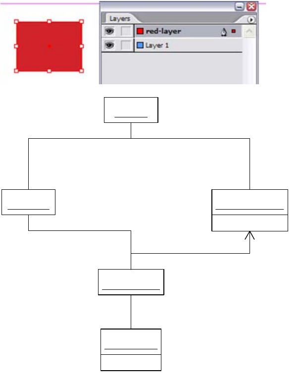
CHAPTER 9: Snippet Fundamentals Snippet examples 217
The UML object diagram in the following figure shows relationships between objects that represent the fill
color and object style (Basic Graphic Frame) of a rectangle page item.
Boss-object diagram for page-item style:
«boss»
: kDocBoss
«boss»
: kSpreadBoss
IHierarchy
«boss»
: kSpreadLayerBoss
UID = 0xa5
«boss»
: kDocumentLayerBoss
ILayerList
IHierarchy
ISpreadLayer::GetDocLayerUID
UID = 0xaa
«boss»
: kSplineItemBoss
IHierarchy
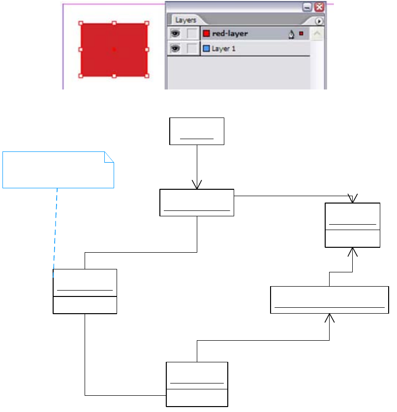
CHAPTER 9: Snippet Fundamentals Snippet examples 218
Snippet organization
When the filled-rectangle page item is exported as a snippet, a somewhat large XML file is generated. The
contents depend on whether it is an IDML or INX snippet. Though this may seem to be a lot of data to
specify a red rectangle, consider that the intent of a snippet is to provide a complete, standalone
description of a collection of objects that can be imported into any other InDesign document. The first few
and last few characters are shown in the following examples. This small percentage of the text shows some
differences between the two formats. The IDML-based snippet has a document element called Document,
while the INX-based example has a document element of SnippetRoot.
Example 1: IDML-based (IDMS) extraction:
«boss»
: kDocBoss
UID = 0xaa
«boss»
: kSplineItemBoss
«boss»
: kDocWorkspaceBoss
IDocument::GetDocWorkspace
UID = 0x67
«boss»
: kObjectStyleBoss
IStyleNameTable (IID_IOBJECTSTYLENAMETABLE)
IPersistUIDData (IID_IPERSISTOBJECTSTYLEDATA)
UID = 0x16
«boss»
: kPMColorBoss
IPersistUIDData
«boss»
: kGraphicStyleFillRenderingAttrBoss
IGraphicStyleAttributeBossList (IID_IGRAPHICSTYLE_OVERRIDES)
ISwatchList::GetNthSwatch
Basic Graphic Frame, default
object style for newly created
graphic frame

CHAPTER 9: Snippet Fundamentals Snippet examples 219
<?xml version="1.0" encoding="UTF-8" standalone="yes"?>
<?aid style="50" type="snippet"...?>
<?aid SnippetType="PageItem"?>
<Document DOMVersion="8.0" Self="d">
<Color ...
</Document>
Example 2: Snippet-file extract:
<?xml version="1.0" encoding="UTF-8" standalone="yes"?>
<?aid style="33" type="snippet"... ?>
<?aid SnippetType="PageItem"?>
<SnippetRoot>
<colr ... (other x,000 characters omitted)
</SnippetRoot>
Inspecting the raw XML data contained in an INX snippet file is not immediately illuminating (see the XML
in the following figure, for example), so some XSLT transformations have been applied to render the data
in a form that is easier to understand. The snippet file creating by exporting a rectangle page item was
transformed with XSLT, using information from the ScriptingDefs.h file in the SDK as a translation table, to
turn short names like “crec” into long names (Rectangle). The amount of information was reduced by
filtering out all but the names of elements and some key attributes. The relationships between elements
were represented as a graph of nodes (the elements) and edges (the links between them).
Subset of XML from filled-rectangle snippet:
The newer, IDML-based format is more readable. The example in the following figure is a similar subset, in
actual IDML.
-<Rectangle AnchoredObjectSettings="ro_uaacAOs1" TextWrap="ro_uaactxw1"
ItemGeometry="x_19_l_1_l_4_l_2_D_-231.5_D_-311.5_l_2_D_-231.5_D_-240.5_l_2_D_-
144.5_D_-240.5_l_2_D_-144.5_D_-311.5_b_f_D_-231.5_D_-311.5_D_-144.5_D_-
240.5_D_1_D_0_D_0_D_1_D_293_D_-22" ContentType="e_unas"
AssociatedXMLElement="ro_n" XPBlendMode="e_norm" XPOpacity="D_100"
XPKnockoutGroup="b_f" XPIsolateBlending="b_f" XPDSMode="e_none"
XPDSBlendMode="e_xpMb" XPDSOffsetX="U_7" XPDSOffsetY="U_7" XPDSBlurRadius="U_5"
XPDSColor="o_ub" XPDSOpacity="D_75" XPVGMode="e_none" XPVGWidth="U_9"
XPVGCornerType="e_xpCc" XPDSSpread="D_0" XPDSNoise="D_0" XPVGNoise="D_0"
StoryOffset="ro_n" FillColor="o_u16" FillTint="D_-1" Overprint="b_f" LineWeight="U_1"
MiterLimit="D_4" EndCap="e_bcap" EndJoin="e_mjon" StrokeType="o_di5a29"
LeftLineEnd="e_none" RightLineEnd="e_none" LineColor="o_ub" LineTint="D_-1"
CornerEffect="e_none" CornerRadius="D_12" GradientFillStart="x_2_U_0_U_0"
GradientFillLength="U_0" GradientFillAngle="D_0" GradientStrokeStart="x_2_U_0_U_0"
GradientStrokeLength="U_0" GradientStrokeAngle="D_0" StrokeOverprint="b_f" GapColor="o_ue"
GapTint="D_-1" StrokeAlignment="e_stAC" NonPrinting="b_f" ItemLayer="o_ua5" Locked="b_f"
LocalDisplaySetting="e_Dflt" AppliedObjectStyle="o_u67" Tag="c_" Self="rc_uaa"
SnippetParent="root">
<AnchoredObjectSettings Self="rc_uaacAOs1" />
-<TextWrap TextWrapType="e_none" TextWrapInset="e_none" TextWrapInverse="b_f"
ItemGeometry="x_5_l_0_D_0_D_0_D_0_D_0" ContourOptions="ro_uaactxw1ccos1"
Self="rc_uaactxw1">
<ContourOptions PSPathNames="rx_0" ACPathNames="rx_0" Self="rc_uaactxw1ccos1" />
</TextWrap>
</Rectangle>

CHAPTER 9: Snippet Fundamentals Snippet examples 220
If we visualize the XML from the preceding figures as a graph showing a subset of the elements, we arrive
at the following figure. The Rectangle object (kRectangleObjectScriptElement) from the scripting DOM
corresponds to kSplineItemBoss in the boss DOM. The Color object (kColorObjectScriptElement)
corresponds to kPMColorBoss in the boss DOM. The Layer object (kLayerObjectScriptElement)
corresponds to kDocumentLayerBoss (IDocumentLayer) in the boss DOM.
The following figure shows a subset of the elements in the snippet file exported from this document asset.
The long names for the elements are shown. The Self attribute (shown as, for example, 0xaa rather than
rc_uaa or u_123) corresponds to the UIDs for the boss objects shown in “Filled-rectangle snippet” on
page 216. The snippet (scripting DOM) model is simplified relative to the boss model; there is no
graphics-attribute object interposed between the page item and the object representing its color.
Relationships between elements in snippet representing a rectangle:
<?xml version="1.0" encoding="UTF-8"?>
<Rectangle Self="ud8" StoryTitle="$ID/" ContentType="Unassigned"
FillColor="Color/C=15 M=100 Y=100 K=0" GradientFillStart="0 0" GradientFillLength="0"
GradientFillAngle="0" GradientStrokeStart="0 0" GradientStrokeLength="0"
GradientStrokeAngle="0"
ItemLayer="ud3" Locked="false" LocalDisplaySetting="Default" GradientFillHiliteLength="0"
GradientFillHiliteAngle="0" GradientStrokeHiliteLength="0" GradientStrokeHiliteAngle="0"
AppliedObjectStyle="ObjectStyle/$ID/[Normal Graphics Frame]" ItemTransform="1 0 0 1 0 0"
FramelabelString="" FramelabelSize="12" FramelabelVisibility="false"
FramelabelPosition="FramelabelBottom" BpiData=" ">
<Properties>
<PathGeometry>
<GeometryPathType PathOpen="false">
<PathPointArray>
<PathPointType Anchor="89.75 -294.35714285714283"
LeftDirection="89.75 -294.35714285714283"
RightDirection="89.75 -294.35714285714283"/>
<PathPointType Anchor="89.75 -189.07142857142856"
LeftDirection="89.75 -189.07142857142856"
RightDirection="89.75 -189.07142857142856"/>
<PathPointType Anchor="188.07142857142858 -189.07142857142856"
LeftDirection="188.07142857142858 -189.07142857142856"
RightDirection="188.07142857142858 -189.07142857142856"/>
<PathPointType Anchor="188.07142857142858 -294.35714285714283"
LeftDirection="188.07142857142858 -294.35714285714283"
RightDirection="188.07142857142858 -294.35714285714283"/>
</PathPointArray>
</GeometryPathType>
</PathGeometry>
<FramelabelFontColor type="enumeration">Pink</FramelabelFontColor>
</Properties>
<TextWrapPreference Inverse="false" ApplyToMasterPageOnly="false" TextWrapSide="BothSides"
TextWrapMode="None">
<Properties>
<TextWrapOffset Top="0" Left="0" Bottom="0" Right="0"/>
</Properties>
</TextWrapPreference>
<InCopyExportOption IncludeGraphicProxies="true" IncludeAllResources="false"/>
<FrameFittingOption LeftCrop="0" TopCrop="0" RightCrop="0" BottomCrop="0"
FittingOnEmptyFrame="None" FittingAlignment="TopLeftAnchor"/>
<Transparencyeffectsettings Transparencyeffectmode="false"
Transparencyeffectoffsetxdirection="0" Transparencyeffectoffsetydirection="0"
Transparencyeffectuseblackasopaque="false" Transparencyeffectusealpha="false"
Transparencyeffectuseblur="false"/>
</Rectangle>
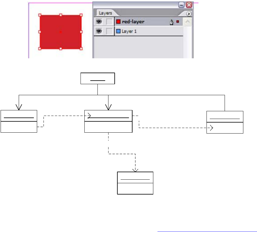
CHAPTER 9: Snippet Fundamentals Snippet examples 221
NOTE: In this figure, “Root” can be either Document (for IDML) or SnippetRoot (for INX).
Two different views are shown of the elements and associations in a snippet file. This figure shows the key
objects that were explicitly identified by UID in the figures in “Filled-rectangle snippet” on page 216.
Image-item snippet
A new document was created, and an image was placed in it. A page-item snippet was exported, based on
the graphic frame containing the image. We examine both the low-level boss model for this and the
organization of the snippet file. To create this through the InDesign user interface, you can select the frame
containing the image and just drag the page item from the layout to the desktop. To do this
programmatically, see the “Snippets” chapter of Adobe InDesign SDK Solutions.
Boss-level model
The following figure contains an object diagram showing key boss objects that represent a placed (TIFF)
image (kImageItem) in a graphic frame (kSplineItemBoss), and links between them (instances of
associations between the boss classes). A low-resolution embedded proxy (kImageInDB) is stored in the
document. The actual high-resolution image is referenced from a link (kImportLinkBoss). In the interest of
clarity, associations with objects of class kSpreadLayerBoss (which would own the kSplineItemBoss if it
were a top-level page item) and so on are omitted.
: Root
Self = 0xaa
: Rectangle (crec)
Self = 0x16
: Color (colr)
FillColor (flcl)
Self = 0xa5
: Layer (layr)
Self = 0x67
: ObjectStyle
ItemLayer (pilr)
AppliedObjectStyle (aobs)

CHAPTER 9: Snippet Fundamentals Snippet examples 222
A placed image is represented by the boss class (kImageItem), which can be found as a child of a graphic
frame (kSplineItemBoss). The image item (kImageItem) refers to both a link (through ILinkObject) and an
object that may store a proxy (through IImageDataAccess or IStoreInternal).
The original high-resolution image placed is referenced by a link (kImportLinkBoss), and the
low-resolution image proxy may be stored by a boss object (kImageInDB). The embedded proxy is
referenced either through IStoreInternal interface of the kImageItem object (for example, for PDF, EPS, and
PICT) or by IImageDataAccess (as in the TIFF example here and for other formats like JPEG).
Snippet organization
The complete snippet is quite complicated, but we can make sense of the picture by focusing on the
objects in the scripting model and considering the relationships to the boss objects we saw in the
preceding figure.
The frame is represented in the scripting DOM by a Rectangle object (kRectangleObjectScriptElement),
and the image placed by an Image object (kImageObjectScriptElement). The scripting classes associate to
kSplineItemBoss and kImageItem in the boss DOM. Consequently, when we inspect the snippet, we see a
Rectangle, with child element Image. The link to a high-resolution image external to the InDesign file is
UID = 0xa9
«boss»
: kSplineItemBoss
UID = 0xa5
«boss»
: kImageItem
IHierarchy
UML = 0xa8
«boss»
: kImportLinkBoss
ILink::GetObject
«boss»
: kImageInDB
IImageDataAccess / IStoreInternal
Embedded, low-resolution
image proxy
Refers to high-resolution,
external image
ILinkObject::GetLinks
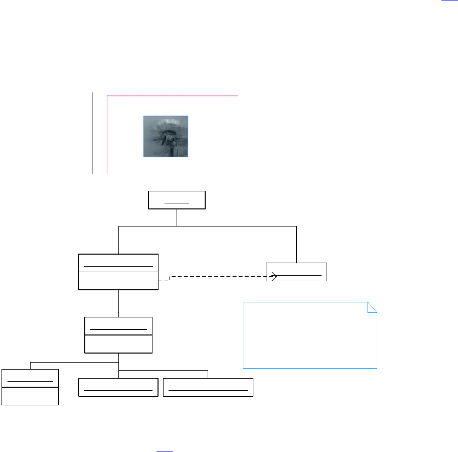
CHAPTER 9: Snippet Fundamentals Snippet examples 223
maintained in the scripting DOM by a Link object (kLinkObjectScriptElement), which associates with
kImportLinkBoss (in the case of a placed image file).
The object diagram in the following figure represents elements in the snippet file for a placed image. The
Rectangle element has a Self attribute matching the UID of the kSplineItemBoss in the figure on page 221.
The Image element has a Self attribute equal to the UID of the kImageItemBoss object in that figure. The
Link object has a Self attribute corresponding to the UID of the link boss object (kImportLinkBoss) in that
figure. The ClippingPath and TextWrap elements correspond (approximately) to the IClipSettings and
IStandOffData interfaces on kImageItem, respectively.
Relationships between elements in snippet for a placed image:
NOTE: In the preceding figure, “Root” can be either Document (for IDML) or SnippetRoot (for INX).
The Image element shown on page 222 has a dependent Link element, which maintains a link to the
high-resolution image that was placed. This Link element stores approximately the data stored in or
obtainable from a link boss object (kImportLinkBoss); it stores a path to the file and other information, like
link-import stamp and link-stored state. The snippet also maintains a low-resolution thumbnail of the
image, but in the xap:Thumbnail metadata element, intended for consumers of the XMP format.
XML element snippet, tagged placeholder
Consider the scenario of creating one element in the logical structure as a tagged placeholder for an
image to be placed later. We can examine the organization of a snippet obtained by exporting a placed
element from the logical structure.
Self = 0xa9
: Rectangle (crec)
Self = 0xa5
: Image (imag)
Self = 0xa8
: Link (clnk)
: Root
: Layer (layr)
ItemLayer
The low-resolution image
proxy that was embedded
in the document is stored
in the snippet as part of
its XAP metadata. Inspect
the xap:Thumbnails element.
: TextWrap (ctxw) : ClippingPath (cpth)
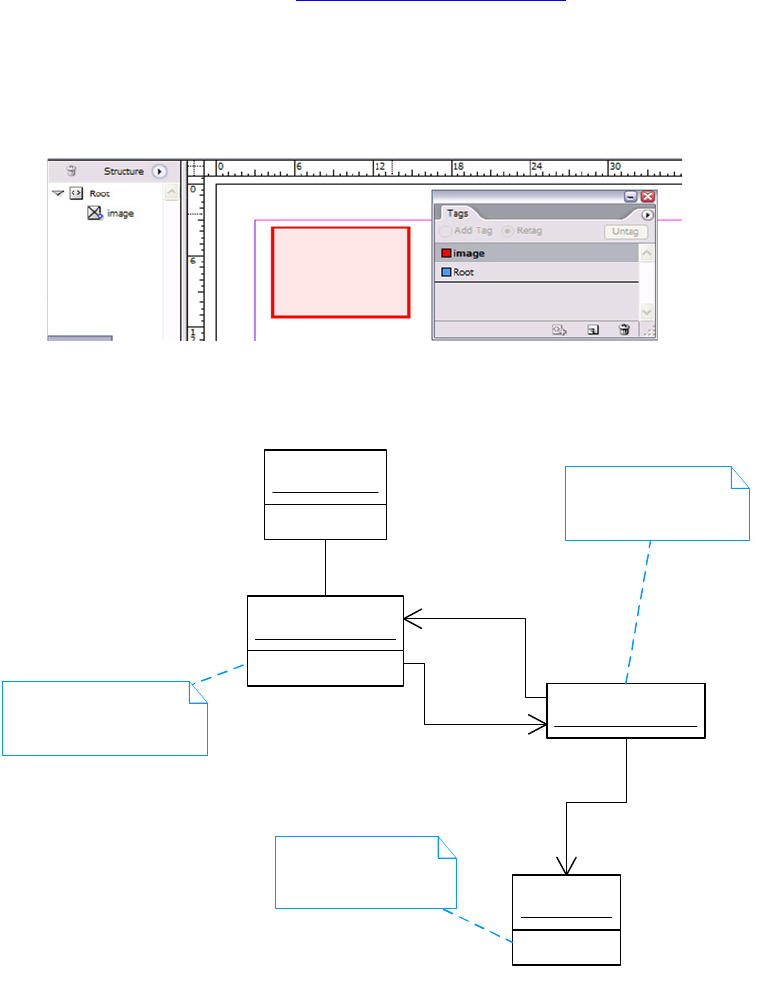
CHAPTER 9: Snippet Fundamentals Snippet examples 224
Boss-level model
This is described in some detail in Chapter 8, “XML Fundamentals”. Briefly, a tagged graphic placeholder is
represented by a kSplineItemBoss, with a kPlaceHolderItemBoss child. Associations with XML elements
(IIDXMLElement) are maintained by the IXMLReferenceData on the placeholder (kPlaceHolderItemBoss).
See the following figure.
Boss-object diagram for XML-tagged placeholder:
Snippet organization
An XML-element snippet is the serialized form of an XML element, its tree of elements (IIDXMLElement) it
owns, and any placed content that it or any of its dependents refer to, along with dependencies. Because
we only one tagged object, there is only one element (XMLElement) in the snippet. Only the tags required
for the exported XML elements are contained in the snippet; in this case, we have only one XMLTag
element in the snippet. The UIDs of the frame (kSplineItemBoss) and tag (kXMLTagBoss) propagated to the
UID = 0xa1
«boss»
: kSplineItemBoss
UID = 0xa7
«boss»
: kPlaceHolderItemBoss
IHierarchy
«boss»
: kTextXMLElementBoss
IXMLReferenceData
IIDXMLElement
UID = 0xa6
«boss»
: kXMLTagBoss
IIDXMLElement
Represents the element
<image> in the logical
structure
Object representing
the tag named "image"
Placeholder, to be replaced
by e.g. kImageItem, when
image is placed
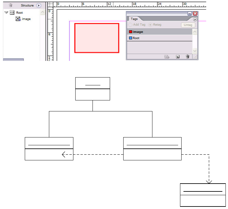
CHAPTER 9: Snippet Fundamentals Client API 225
snippet. XML elements are not UID-based, and the Self attributes for the XMLElement elements in the
snippet are less easy to relate to the original InDesign document. See the following figure.
Key elements in a snippet for a tagged placeholder:
NOTE: In this figure, “Root” can be either Document (for IDML) or SnippetRoot (for INX).
Client API
Suites
To create a snippet based on the current selection, use ISnippetExportSuite. ISnippetExportSuite lets you
export the layout selection or a selection in the structure view as a snippet, and a text selection as an
InCopyInterchange snippet (INCX or ICML). For more details, see the “Snippets” chapter of Adobe InDesign
SDK Solutions.
Utilities
The following utilities are available:
ISnippetExport — A utility interface on kUtilsBoss that exposes the snippet types that can be exported
by the application. There are several snippet types you can export with this interface, including text
styles, XML tags, swatches, preferences, and InCopy stories. You also can export a collection of objects
with IDOMElement interfaces and specify the export policy. Several methods take an INXOptions
: XMLElement (cXML)
UID = 0xa6
: XMLTag (tagX)
: Root
Self = 0xa1
: Rectangle (crec) XMLContent XMLTag

CHAPTER 9: Snippet Fundamentals Extension patterns 226
argument, allowing you to specify whether you want to export INX- or IDML-based snippets. For more
detail, refer to the API Reference.
ISnippetImport — A utility interface on kUtilsBoss, with a simpler API than the export equivalent. The
only requirement on import is that you know where you want to import in the scripting DOM tree. You
need an IDOMElement interface on a scriptable object. For more detail, refer to the API Reference.
The ISnippetExportSuite suite can be used if you create a selection programmatically and are not worried
about trampling the user selection. For example, the ITextSelectionSuite, IXMLNodeSelectionSuite
(structure view), and ILayoutSelectionSuite interfaces each create selections that can be exported as
snippets through ISnippetExportSuite. For more information on creating selections programmatically, see
Chapter 4, “Selection.”
If you have a nonselectable object you want to export as a snippet, you can use one of two methods on
the ISnippetExport interface (on the kUtilsBoss). ISnippetExport::ExportAppPrefs can be used to export
various application preferences; for examples, see the SnpShareAppResources code snippet. You also can
use ISnippetExport::ExportDocumentResource to export resources of the document; for examples, see the
SnpImportExportSnippet code snippet.
For more information, see the “Snippets” chapter of Adobe InDesign SDK Solutions.
Importing
On import, the main thing the client must specify is where on the scripting DOM tree the incoming
snippet will go. The incoming snippet will have one or more root objects (for example, page items), and
the client needs to specify where on the DOM tree they will go. For page items, this typically means
specifying the spread. For XML elements, it means specifying an element on the structure tree that will be
the parent of the imported element. For many other snippet types (styles, swatches, etc.) the document is
the parent. For more information, see the “Snippets” chapter of Adobe InDesign SDK Solutions.
Extension patterns
There are no specific extension patterns you can implement relating to snippets; however, if you add
persistent data to the low-level document model (for example, through add-ins of interfaces that have
persistent implementations), your plug-in must expose this data to scripting.
Adding persistent data to snippet files
If you add persistent data to the boss DOM—for example, through an add-in to one of the page-item boss
classes—then for this data to be round-tripped through snippets, you need to expose your data as
properties in the scripting DOM. This also may require you to define new object (classes) in the scripting
DOM. For more information, see Chapter 10, “Scriptable Plug-in Fundamentals.”
For example, if your custom data on page items needs to be round-tripped through asset libraries (which
depend on the snippet architecture), you need to ensure your persistent data is scriptable. See, for
example, the SDK sample CandleChart, which was updated to support round-tripping persistent data
through snippets by exposing the persistent data as properties added to the scripting DOM.

CHAPTER 9: Snippet Fundamentals Frequently asked questions 227
Frequently asked questions
What is a snippet, and how do I create one?
A snippet is a logically complete fragment of an InDesign document, saved in the XML-based InDesign
Markup (IDMS) or InDesign Interchange (INX) formats. A snippet is created by acquiring references to
document objects you want to export (for example, by UID or XMLReference), then using one of the client
APIs like ISnippetExport. Alternately, there is a ISnippetExportSuite suite interface that lets you export
based on a selection in the layout or structure view (XML elements) or a text selection, as InCopy
Interchange format.
What happens if I export a snippet of a placed image?
See “Image-item snippet” on page 221. A snippet for a placed image maintains a link to the asset within
the XML representation. When the snippet is imported into a new document, a link appears in the Links
panel as if you had placed the image.
What features are based on snippets?
See “Features that depend on snippets” on page 209.
How accurately is data round-tripped through snippets?
Maintaining a high-fidelity representation of a document asset was one of the design goals for snippets.
However, some limitations were designed in. For example, snippets do not carry document-level
preferences with them. If they did, they would create overrides of the existing document-level preferences
when imported into a new document, which is desirable.
When importing a new asset, it is reasonable for it to bring new document objects, like swatches on which
it depends, but it could have unintended global effects on the target document if it starts to redefine
document-level preferences that control typography, for example. Importing a snippet should not alter
the properties of other document objects in the document into which you import the snippet.
When do I have to care about snippets?
If you are adding custom data to the document—for example, to page items in some way—and you want
this data to be round-tripped through asset libraries, you must be sure you can get your persistent data
into snippet files. This is because asset libraries store their assets as snippets internally, meaning your
persistent data must be exported into a snippet. See “Adding persistent data to snippet files” on page 226
for more discussion, and Chapter 10, “Scriptable Plug-in Fundamentals,” for information on how to do this.
Can I export spreads or pages as snippets?
Suppose you have a multipage document, and you want to decompose it into independent pages by
exporting each page as individual snippets containing all objects on each page and dependencies.
Alternately, you may want to export each spread as a snippet.
This is not possible, as pages are not recreated on snippet import, so you cannot factor a document into
individual spreads or pages using the snippet architecture alone.

CHAPTER 9: Snippet Fundamentals Frequently asked questions 228
Should we generate snippet files from scratch?
No. The INX-based snippet format should be regarded as a read-only format. We do not recommend using
it to generate snippets from scratch.
We designed IDML-based snippets to facilitate programmatic assembly and disassembly of snippets. You
can validate your snippets using a RELAX NG-based schema. The SDK also includes a sample plug-in that
logs errors on import and export. Both schema validation and the error-logging plug-in are covered in
Adobe InDesign Markup Language (IDML) Cookbook.
Can I import a snippet directly into a library?
Although asset libraries (kSnippetBasedCatalogBoss) depend heavily on snippets for their representation
of assets, there is no public API to let you import a snippet directly into a library. You must import the
snippet into a document, then use the library APIs to add the item to an existing library. See the “Snippets”
chapter of Adobe InDesign SDK Solutions.
Can I import a snippet into the scrap database?
The scrap database (kScrapDocBoss) does not support importing snippets; there is no DOM element
hierarchy (IDOMElement) on the scrap, which is required to import snippets.
Can we add our own new snippet types?
You cannot add new snippet types or policies; you are restricted to those identified in the table in “Snippet
types and policies” on page 212. The existing snippet types, however, cover the range of document
content it makes sense to export as self-contained assets. Since you can export an arbitrary collection of
root objects (those with IDOMElement interfaces) to a snippet file, you can select what goes into a snippet,
at least in terms of root objects. What you cannot do is decide what dependents of those objects to
include or leave out when export is taking place. You might have to do some additional work before
export, to ensure those dependents were exported as if they were root objects in determining what goes
on in the snippet.

229
10 Shared Application Resources
Introduction
With InDesign and a small amount of your own code, you can manage application resources like
preferences, text styles, XML tags, and swatches. This chapter describes how to read and write these
resources to or from a stream, using InDesign Interchange (INX) snippets.
This chapter does not require a full understanding of XML, INX, snippets, or scripting, nor does it try to
teach you those technologies. For background, see the “Scriptable Plug-in Fundamentals” and “Snippet
Fundamentals” chapters. Also see Adobe InDesign Scripting Guide and Adobe InCopy Scripting Guide.
NOTE: The shared-application-resources APIs support only INX snippets. IDML-based snippets are not
supported.
Terminology
Application preferences are the preferences in the InDesign or InCopy preference panel with no
documents open. These are the preferences used when InDesign creates a new document.
INX (InDesign Interchange) is an XML-based format InDesign uses to serialize and deserialize native
content. It is based on InDesign’s robust scripting support. An INX file is a script expressed in XML that
allows for the recreation of InDesign content and properties.
Shared application resources amounts to saving and refreshing resources like application preferences,
defaults, text styles, swatches, and XML tags, while the application is running.
An INX snippet is a logically complete INX fragment that represents pieces of an InDesign document or
other native application content such as application preferences. This chapter focuses on using
snippets to write out application resources like preferences and styles.
Architecture
InDesign and InCopy provide robust scripting support. It is very simple to change an application
preference via scripting. One approach to managing application preferences is to write a script that sets
these properties to some predefined state. Due to the large number of preferences in InDesign and
InCopy, however, this would be fairly involved.
You could continue along this path, and manage character and paragraph styles, object styles, swatches,
and XML tags. This would become very involved, with a great deal of code to maintain. Fortunately, you do
not have to write these scripts. Snippets achieve the same result, and most of the work is done for you. You
must write only the code that exports and imports the snippet.
Chapter Update Status
CS6 Unchanged

CHAPTER 10: Shared Application Resources Architecture 230
How it works
INX is an XML-based equivalent to a script, which recreates native InDesign content. Snippets are INX
fragments, which are complete enough to recreate part of an InDesign document or workspace. For
example, a snippet may recreate a page item and all the resources on which it depends. This probably is
the most common use of snippets to date. Chapter 9, “Snippet Fundamentals,” provides details about
exporting document content. Although beyond the scope of what is covered in that chapter, snippets can
be used to recreate most of the items saved in the application workspace.
Instead of building elaborate scripts that set and reset your application workspace, you can use the
application’s user interface to set your application preferences and styles as required, then export all or
part of the workspace using INX snippets. The snippet then contains all the data needed to recreate all or
part of your application workspace via the scripting model.
From an API standpoint, special support was added to the snippet architecture for exporting and
importing application preferences and resources. The one caveat to using snippets is that you cannot
control which individual properties are exported. The API does not provide this level of granularity;
instead, it is based on classes of scriptable objects (for example c_GeneralPrefs). All such objects that are
marked as preference objects in the scripting model and are children of the Application object can be
exported. By default, several other classes also are exported. These classes amount to elements of some
style list. For instance, for Paragraph Styles, the c_ParaStyle list element is exported. For your reference and
use in code, the scripting IDs for these types are in AppPrefsListElementTypes.h.
A brief description of all relevant interfaces follows.
ISnippetExport
ISnippetExport is the interface used to write snippets to a stream. Most the methods have a specific
application (like ExportInCopyInterchange, ExportXMLTags, and ExportTextStyles). There also are generic
Export methods. It is important to note that these methods can be called only with a predefined snippet
export policy. You cannot create your own snippet export policy using the publicly available SDK. Certain
interfaces intentionally were left out; calling these items with an invalid policy (kInvalidClass) exports
invalid XML.
The method used to export application resources is ExportAppPrefs(). By default, this method exports all
application preference types and all other types specified in AppPrefsListElementTypes.h. For the exact
content, see the method. It contains a collection of list element types, such as text and object styles.
ExportAppPrefs also takes three optional arguments, which allow you to control exactly what is exported:
An operation — You can specify one of two values (kInclude or kExclude) from the
ISnippetExport::PreferenceOperation enumeration. Passing in kExclude causes everything to be
exported except the items listed in the K2Vector. Passing in kInclude causes only what is in the vector
to be exported.
A reference to a K2Vector<ScriptID>.
A pointer to an instance of IAppPrefsExportDelegate, described in the following section.
IAppPrefsExportDelegate
While you cannot create your own INX export policy, IAppPrefsExportDelegate allows for finer control of
the application preference export process. It gives the caller final say on exactly what is exported and in
CHAPTER 10: Shared Application Resources Architecture 231
what order. This may be important if your plug-in adds scripting support to an object you want to be
exported by ExportAppPrefs(). You may need a way to reorder the export, putting your item after objects
on which it depends.
To add an IAppPresExportDelegate, create your own instance and pass in a pointer when you call
ExportAppPrefs().
ISnippetImport
ISnippetImport is the interface used to import snippets from a stream. You can access an instance through
Utils<> helper.
The methods in this interface are generic. They are not specific to importing application resources, but
rather any type of snippets. The difference in the two ImportFromStream methods is that one allows you
to import a snippet containing multiple root objects. For our purposes, we use the ImportFromStream
method that specifies a single root object (the application).
Like the generic export methods, ImportFromStream also takes an INX import policy. Again, you cannot
create this on your own. The argument itself is optional and defaults to kInvalidClass. The correct policy to
use is kAppPrefsImportBoss; if you leave it as kInvalidClass (the default value), the method will figure this
out from the snippet.
IAppPrefsImportOptions
Two options must be defined when importing. These options are provided by an instance of
IAppPrefsImportOptions on the application workspace. To set these options, query for that instance of
IAppPrefsImportOptions and call the appropriate set method. That implementation in turn creates and
processes a command to change its own state.
The first option is what to do when list items already in the application match those being imported. For
example, suppose you import Paragraph Styles A, B, and C into an application workspace that already has
Paragraph Style A. Should the import keep or replace Paragraph Style A? To set the option for this, call
SetHandleListItemsWithMatchingNames with either IAppPrefsImportOptions::kUseExistingListItems or
IAppPrefsImportOptions::kReplaceListItems. The default value is kReplaceListItems.
The second option is what to do with list items that are not being imported. You can either delete
everything not in the imported list or leave existing items alone. For example, suppose you import
Paragraph Styles A, B, and C into an application workspace that contains Paragraph Style D. Should the
import keep or delete Paragraph Style D? To set this option, call SetDeleteNonImportedListItems with
kTrue or kFalse. When called with kTrue, items not in the imported list are deleted, which is the default
behavior. To retain existing items, return kFalse.
To completely restore lists like paragraph styles to exported snippets, set the above two properties to
kReplaceListItems and kTrue, respectively. This replaces any existing list items and deletes list items not in
the import. This is the default behavior, but it is up to you to know whether IAppPrefsImportOptions was
changed.
IAppPrefsImportDelegate
While you cannot create your own INX import policy, IAppPrefsImportDelegate allows for finer control of
the application preference import process. It gives the plug-in developer final say on exactly what is
imported, what is kept and/or deleted, and which property is used to compare list elements. You may
never need to use a delegate; however, if you need finer control over the import, you need to provide an
CHAPTER 10: Shared Application Resources Working with snippet APIs: frequently asked questions 232
instance of IAppPrefsImportDelegate. To do this, add your IAppPrefsImportDelegate instance to
kAppPrefsImportBoss. This delegate is a way to influence the import policy even though you cannot create
your own policies.
Working with snippet APIs: frequently asked questions
See the “Share App Resources” snippet in
<sdk>/source/sdksamples/codesnippets/SnpShareAppResources.cpp. This contains the sample code that
demonstrates everything covered above except the use of delegates (IAppPrefsImportDelegate and
IAppPrefsExportDelegate).
How do I create streams for reading and writing snippets?
SnpShareAppResources::CreateStream() shows how to create file streams. It uses StreamUtils, which has
other useful methods for reading and writing different kind of streams.
How do I limit my export to those items in the preference panel?
You cannot be that precise, but you can come close. SnpShareAppResources::ExportPrefsPanel contains all
ScriptIDs for the objects that control the preference panels. Some of these objects control other settings,
like items in the View menu.
How do I export all text styles, object styles, XML tags, or swatches in
the application workspace?
Specify the correct list of ScriptIDs to include. See ExportTextStyles(), ExportObjectStyles(),
ExportXMLTagsAndPrefs(), and ExportSwatches() in SnpShareAppResources.cpp.
How do I import a snippet into the application?
Call ISnippetImport::ImportFromStream() with a pointer to the appropriate root object (IDOMElement)
instance. SnpShareAppResources::ImportToApp() shows how to query for the application root and call
ImportFromStream().
How do I control whether existing objects like paragraph styles are
replaced or deleted on import.
SnpShareAppResources::ImportToAppWithOptions() shows how to set the application workspace’s
IAppPrefsImportOptions before importing.
How do I determine the correct ScriptID to use for a preference I’m
trying to include or exclude?
This may involve trial and error. While all the native IDs are available in ScriptingDefs.h, sometimes it is
difficult to find the ID corresponding to a particular user interface feature. Most of the ScriptIDs have
meaningful names that map to the user interface or how they appear in the scripting object model. To
CHAPTER 10: Shared Application Resources Working with snippet APIs: frequently asked questions 233
start, look at ScriptingDefs. If you cannot figure it out, an understanding of the scripting object model will
help. If you cannot identify the right ID, open a developer support case.
How do I know which list element types will be exported by default?
The list of all such types is in AppPrefsListElementTypes.h. In ScriptingDefs.h, most list element types have
both a singular and plural ID; for example, c_ObjectStyle and c_ObjectStyles. AppPrefsListElementTypes.h
uses all singular IDs. In all cases, use the singular ID. The internal snippet code considers these elements on
a case-by-case basis. It does not export all object styles if you pass in c_ObjectStyles.

234
11 User-Interface Fundamentals
This chapter introduces the key concepts in the user-interface architecture, such as type bindings between
widget boss classes or interfaces and ODFRez custom resource types. This chapter also describes how the
user-interface model is factored, discusses relevant design patterns like the Observer pattern, and
provides an overview of common plug-in resources.
The chapter has the following objectives:
Explain user-interface programming for InDesign.
Help you create responsive user interfaces for InDesign plug-ins.
Illustrate key concepts with a concrete example of a user interface.
Describe the factoring of the user-interface model.
Discuss design patterns relevant to user-interface programming.
Describe the role played by persistence in the user-interface model.
Outline how resources are used in defining user interfaces.
Introduction
Plug-in developers often need to implement a user interface early in their plug-in programming
experience. To program user interfaces, a plug-in developer needs to understand concepts like boss
classes and interface aggregation, as much of the user interface is specified in resources.
The initial state and properties of a plug-in user interface are specified in a cross-platform resource
language, ODFRez (OpenDoc Framework Resource language). Developing responsive user interfaces for
InDesign plug-ins requires understanding type binding between boss classes (and persistent API
interfaces) and types defined in ODFRez, and how persistent interfaces on widget boss classes read their
initial state from the plug-in resources.
One benefit of the ODFRez data format is that it is a cross-platform resource definition language. The initial
geometry of widgets can be defined in ODFRez data, as well as other data needed to define the initial state
of widgets, like the labels on buttons. It is rare that a platform-specific resource is required; in the SDK
samples, this occurs only for image-based buttons.
“Sample user interface” on page 239 introduces a concrete example of a user interface to explain abstract
topics like type binding. “Factorization of the user-interface model” on page 243 describes the
user-interface programming model.
Chapter Update Status
CS6 Unchanged
CHAPTER 11: User-Interface Fundamentals Key concepts 235
Key concepts
Design objectives for user-interface API
The following are some of the design objectives for the user-interface programming model:
Enable cross-platform user-interface development.
Create reusable user-interface components with rich behaviors.
Provide a well factored design that separates data and presentation.
To meet these objectives, the design supports reuse, with the possibility of customizing widget behavior
and appearance, and it encapsulates of platform dependencies. Support for reuse is established through
the use of widget boss classes. Platform independence is achieved by using a cross-platform resource
format; widgets are defined in the ODFRez language.
The following are the key responsibilities of a plug-in developer:
Identify and use existing widgets where possible.
Define new boss classes, typically subclasses of existing widget boss classes.
Define ODFRez custom resource types. If widget boss classes are subclassed, the associated ODFRez
types also must be subclassed. These also go in the top-level framework resource file.
Define ODFRez data statements, to specify the geometry and properties of the widgets, as well as for
localization.
Client code also may be responsible for the following:
Navigation between boss objects. An example is finding the panel to which a pop-up menu is
attached, then locating a widget belonging to the panel.
Processing actions when menu items are executed or keyboard shortcuts are executed.
Handling notifications about changes in widget state sent to interested observers. InDesign client
code rarely requires writing event-handling code. Instead, observers process update messages that
specify how the state of the subject has changed.
Idioms and naming conventions
This section describes some programming idioms and naming conventions that are strongly
recommended when writing plug-in user-interface code. There are two types of conventions:
Conventions used within the public API.
Naming conventions used to minimize confusion and uncertainty about code intent.
Control-data interfaces on widget boss classes are predictably named. When working with controls, there
are many interfaces named I<Data-type>ControlData. Notifications of changes in the data model of a
control are performed by the implementations of these interfaces.
It is helpful to be disciplined in defining symbolic constants for identifiers. We strongly recommend you
observe the following conventions:
CHAPTER 11: User-Interface Fundamentals Key concepts 236
Ensure constants like boss, implementation, and widget IDs begin with “k.”
Ensure new interface identifier names begin with “IID_,” are in all uppercase, and are declared in the
interface ID namespace.
Use “k<Name>Boss” to define a new ID in the boss namespace, where ideally <Name> is related to the
boss-class intent; for example, kMyCustomButtonWidgetBoss.
Use “k<Name>Impl” to define a new ID in the implementation ID namespace.
Use “k<Name>WidgetID” to define a new ID in the widget ID namespace.
Use “k<Name>Key” to define a new string key in the global string table.
Strive for regular relationships between implementation class names and identifiers. For example,
kMyPluginObserverImpl is associated with a C++ class MyPluginObserver.
Make ODFRez custom-resource type names indicative of the boss class they bind to, in as regular a
fashion as possible. For example, kMyCustomButtonWidgetBoss is bound to the ODFRez type
MyCustomButtonWidget.
Along with following the appropriate naming conventions for the domain, it is essential to define symbolic
constants in the correct namespace and make sure there are no constants defined that clash numerically.
In addition to the boss class IDs and implementation IDs used throughout the API, there are widget
identifiers and string tables consisting of key/value pairs for each locale of interest.
In some cases, the namespaces are global; each plug-in must ensure any identifiers and strings it creates
are unique within the application. This applies to string keys; for example. However, widget identifiers
need be unique only within the list of descendants of a given widget, so in some circumstances you can
reuse a widget identifier (for example, across different dialog boxes or panels you own), as long as you
observe this constraint.
Abstractions and reuse
This section highlights the major abstractions in the InDesign API and the main strategy for code reuse
within the user-interface API: extending widget boss classes. This section also reviews some of the
fundamental material required for InDesign programming.
There is a very high degree of code reuse within the user-interface domain, and the boss class hierarchies
are particularly deep in this area compared to other application domains. Reuse within the widget API
typically takes the form of reuse of boss classes by inheritance. In some circumstances, implementations
from the API of particular interfaces can be reused.
In general, it is not possible to predict whether an implementation of an interface on an existing boss class
can be safely reused. There might be implementation dependencies, like expecting the container-widget
boss object to expose an IBoolData interface. In general, it is not safe to try to reuse just one
implementation from a given widget boss class. The recommended reuse policy is to extend an existing
widget boss class and override an interface, if required, by extending the implementation present on the
parent boss class.
Widget boss classes and the user-interface API can be confusing, because there are widgets defined in
ODFRez and widgets in the boss-class space with very similar names. For example, kButtonWidgetBoss is a
boss class that provides implementations responsible for the behavior of a given widget, and
ButtonWidget is an ODFRez custom-resource type that specifies data for the initial state and properties of
a control.
CHAPTER 11: User-Interface Fundamentals Key concepts 237
Another source of confusion is that occasionally there are C++ helper classes and ODFRez
custom-resource types with identical names (like CControlView) but different responsibilities. To avoid
confusing these types, it always is necessary to consider whether entities are from the code domain (C++)
or data domain (ODFRez).
Widgets versus platform controls
This section describes the relationship between InDesign widget classes and platform controls. Widget
boss classes provide a layer of abstraction over platform-specific controls and provide additional capability
beyond what is delivered by the platform controls. The user-interface model extends widgets to the
platform-specific control set, providing controls like measure-edit boxes specialized for the domain of
print publishing.
A widget boss class potentially encapsulates a platform control and provides additional capabilities like
entry validation—a cross-platform API to query and set data values and change notification. This is the
principal benefit of the user-interface model: the same code can be written to develop a plug-in user
interface for Mac OS and Windows, with little or no attention to platform differences.
A widget boss class can be associated with a platform control, as in the case of an edit box. Some classes,
however, have no direct platform equivalent or platform peers; for example, the iconic push buttons are
not bound to a platform control. When writing client code, typically it is not necessary to be aware of
whether there is a platform peer control for an API widget, and we recommend you manipulate the state
of InDesign widgets through the InDesign API and not through platform-specific APIs. In addition, use
InDesign API-specific patterns to receive notification about changes in control state (subject/observer).
Widget boss classes provide more capability than platform controls. For example, there is a mechanism for
controls to persist their state across instances of the application; this is not default behavior for platform
controls. The integer edit-box widget (kIntEditBoxWidgetBoss) provides additional validation capability
not typically provided by platform controls. Another key point about widget boss classes is that they
expose a cross-platform API and a uniform programming model on both Mac OS and Windows. This
provides true cross-platform development of user interfaces, although at the cost of some complexity in
the architecture.
Commands, model plug-ins, and user-interface plug-ins
This section introduces a common factoring in the InDesign plug-ins, which are decomposed into model
plug-ins and user-interface plug-ins. The core capabilities of the InDesign API are delivered by required
plug-ins, most of which are model plug-ins. A model plug-in delivers required pieces of architecture every
client plug-in needs, or it implements the document-object model at the core of InDesign. Much of the
application user interface is delivered by plug-ins that named <whatever>UI.apln, indicating they are
user-interface–specific and not required plug-ins, which end in .rpln.
A plug-in’s user interface can be thought of as a means of parameterizing command sequences that
perform functions benefitting an end user, like changing the document object model to be consistent
with user intent. For example, the XML required plug-in provides the core cross-media API (for example,
IXMLElementCommands, a key wrapper interface), and the XMedia user-interface plug-in creates the user
interface and drives the commands delivered through the XML required plug-in. Behind most plug-in user
interfaces, a command or command sequence is executed when a widget receives the appropriate
end-user event.
Commands provide a means to encapsulate change, provide support for undoing commands, and
support notification of changes. The command pattern is a well-known design pattern, described in depth

CHAPTER 11: User-Interface Fundamentals Key concepts 238
in Gamma, Helm, Johnson, and Vlissides, Design Patterns: Elements of Reusable Object-Oriented Software,
Addison-Wesley, 1995.
Commands also use the messaging framework, which allows observers (IObserver) to attach to subjects
and receive notification of change to the underlying model. Frequently, notifications about commands are
received by observers associated with plug-in user-interface components. For example, the Layers panel
receives notifications about documents being opened and closed through the command architecture and
updates its views accordingly. It is particularly convenient that the same design pattern (subject/observer)
is used within the user-interface programming model, since all widget boss classes expose an ISubject
interface that can be observed by another boss object that implements IObserver.
Previewable dialogs are closely connected with commands. Commands used in previewable dialogs
should be absolute; that is, do not try to increase or decrease the value of data. With preview off, the dialog
is operating in collect mode, queuing up the set of commands that will execute. If preview is turned on,
these commands are executed, and further updates are executed immediately. If the user cancels the
action or turns preview back off, the database rolls back to the original state. Providing preview capability
is an essential requirement in some client code.
Suites and the user interface
Selection suites are a convenient way to package model-manipulation code that makes it almost trivial to
write a user interface to drive the code. As described above, you should factor the code such that the suite
is delivered by one plug-in, and the client code for your user interface that exercises the methods on the
suite is in another plug-in. For a more detailed discussion of suites, see Chapter 4, “Selection.”
Suites are particularly appropriate to writing user-interface code because they simplify the process.
Whenever an end user is required to manipulate document objects by making active selections, make
maximum use of suites.
Finding widgets in the API
There are two main ways to inspect the widget set delivered by the API:
Look at the boss classes delivered by the Widgets plug-in (refer to the API Reference for
WidgetBinClass).
Look at the ODFRez counterparts for many of these boss classes, which can be found in the API header
file Widgets.fh.
For information on why there are widget boss classes and ODFRez types with similar names, see “Type
binding” on page 240.
Each widget in the API is best understood in terms of the boss class that provides its behavior. Although
there is an ODFRez type ButtonWidget, it really is the boss class kButtonWidgetBoss that provides all the
significant behavior. For simple widgets, however, you can use just the ODFRez type without worrying
about the boss class behind it; a static text widget is an example of this.
For example, a button in the InDesign API can be understood mainly by the interfaces aggregated on the
button-widget boss classes and the semantics of those interfaces. For example, kButtonWidgetBoss
exposes the following key interfaces, among others:
ITextControlData represents the label on the button.
IControlView is responsible for the button appearance.
CHAPTER 11: User-Interface Fundamentals Sample user interface 239
IBooleanControlData stores its state, pressed in or not.
ISubject lets client code attach an observer (IObserver) to receive notification about changes in the
button state.
Observers (IObserver) are notified of changes to an abstract subject (ISubject). When a button is pressed
by an end user, the button-widget boss object (kButtonWidgetBoss) notifies any attached observers about
the state change, by sending them a message along IID_IBOOLEANCONTROLDATA protocol. The message
contains additional information to say whether the button is being pressed in.
Notifications about control events or changes
A change in control state can be caused by many events, such as a button click, a keystroke entered in an
edit box, or a selection in a list box. Within the InDesign API, you get notification of changes by providing
your own implementation of an observer (IObserver) that listens for changes in the state of a subject
(ISubject). Since all widget boss classes extend kBaseWidgetBoss, which aggregates ISubject, all widgets
are observable by default. The simplest way to get notification about changes in state is to add an
IObserver interface to the widget boss class in which you are interested, and subclass the corresponding
ODFRez type. While this pattern has the advantage of simplicity, if you have any elaboration in your user
interface, we recommend you have one observer listen for changes in multiple widgets and be
aggregated on the parent of all widgets in whose state changes you are interested.
If you are accustomed to programming other user-interface APIs, you may expect to need to extend the
event-handler interface. Usually, however, this is not required for the InDesign API, where typically writing
an observer (IObserver) implementation is sufficient to be notified about the semantic events associated
(for example, check-box state changed) with the widgets, rather than about the low-level events
(left-mouse-button-click) transmitted through the event handler (IEventHandler).
If you use model-view observers to update the user interface, and they update data that does not always
need to be synchronized with the model state, you can use lazy notification to improve performance. For
more information, see Chapter 3, “Notification.”
Sample user interface
The Stroke panel has an assembly of widgets to let an end user vary the miter limit associated with a line
(the following figure). There is a text-edit box (kIntEditBoxWidgetBoss), a pair of labels
(kStaticTextWidgetBoss), and a nudge-control widget (kNudgeControlWidgetBoss), which increments or
decrements values in the edit control by a specified amount.
The edit-box widget (kIntEditBoxWidgetBoss) shown in this figure is specialized for the input of integers;
for example, a warning message is generated for any input that is not a valid integer. A widget boss object
of type kIntEditBoxWidgetBoss encapsulates a standard platform native edit box and adds behavior, like
validation logic when accepting updates; for example, when the end user presses Enter with focus in the
edit box.
kIntEditBoxWidgetBoss
kStaticTextWidgetBoss
kNudgeControlWidgetBoss
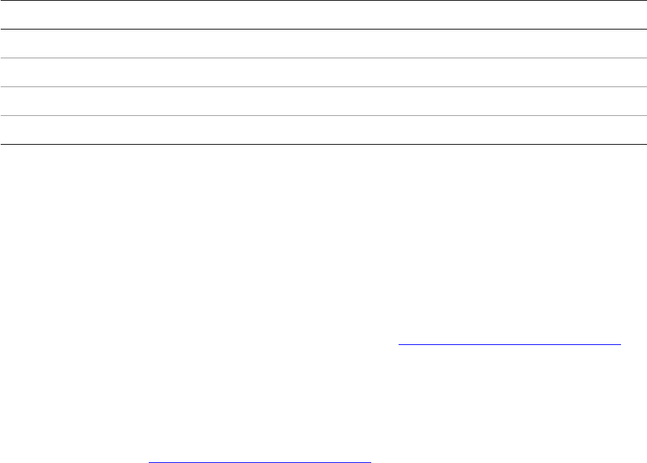
CHAPTER 11: User-Interface Fundamentals Sample user interface 240
The nudge-control widget (kNudgeControlWidgetBoss) collaborates with the integer edit box, allowing
increments or decrements of the value in the edit box. A nudge-control widget boss object
(kNudgeControlWidgetBoss) is not based on any specific platform control. Instead, it consists of two API
iconic button-like widgets, although this detail is hidden from developers of client code. This is an instance
of the facade design pattern.
The initial state of widget boss objects must be specified through resources, and for each widget boss
class, there is an associated ODFRez custom-resource type used to specify initial state for the widget. The
following table shows the widget boss classes for the example in the preceding figure and associated
ODFRez resource types.
The key behavior of each control comes from the boss classes shown in the first column. The nudge
control and edit box interact in a different way; the nudge control is coupled to the edit box in ODFRez
data statements, and you do not need to write any additional C++ code to have an edit box with nudge
capability. The code behind the nudge control is delivered by the application’s required Widgets plug-in,
and it can be safely reused through the user-interface architecture.
Type binding
This section describes the type bindings that exist between widget boss classes or interfaces and ODFRez
custom-resource types, using the example shown in the figure in “Sample user interface” on page 239. A
key aspect of working with plug-in user interfaces is being able to interpret the binding between a widget
boss class and an ODFRez custom-resource type or the significance of the binding between an API
interface and an ODFRez custom-resource type.
Widget boss classes provide the behavior behind widgets, including the capability to draw and manage
internal state and mediate interactions with the end user. Boss classes implement sets of interfaces. The
example in the figure in “Sample user interface” on page 239 uses an integer edit box
(kIntEditBoxWidgetBoss), which is a control specialized for the input of integers. The implementation of
the IControlView interface on the kIntEditBoxWidgetBoss boss class is responsible for drawing the edit
box. The implementation of the ITextDataValidation interface on this boss class validates that the input is
an integer.
ODFRez custom-resource types define data to initialize widgets and other elements needed for the
interface. For example, the CControlView field in the example later in this section specifies the initial
location and dimensions of each widget, along with other properties like its widget ID and visibility.
When a panel is shown for the first time, a set of widget boss objects is created by the application
framework, and the lifetime of these boss objects is managed by the framework. Each widget boss object
is invited to draw itself to the display. A widget boss class provides the capability behind the user-interface
element drawn to the screen and implements the user-interface model.
For example, the kStaticTextWidgetBoss boss class is bound to the ODFRez custom-resource type
StaticTextWidget. The ODFRez data defines the initial state of a widget the first time it instantiates;
API Widget boss class ODFRez custom-resource type Displaying
kIntEditBoxWidgetBoss IntEditBoxWidget 4
kNudgeControlWidgetBoss NudgeControlWidget (Nothing)
kStaticTextWidgetBoss StaticTextWidget Miter limit
kStaticTextWidgetBoss StaticTextWidget x
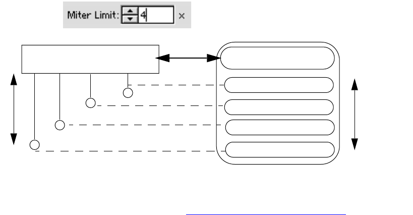
CHAPTER 11: User-Interface Fundamentals Sample user interface 241
thereafter, the state of the widget is restored from a saved data database. This enables widgets to persist
their state across instances of the application, which is how end users can save the state of their working
areas in terms of the visible panels, their geometries, etc.
A frequently encountered type expression is an ODFRez custom-resource type definition that refers to an
interface ID or boss class IDs. An ODFRez expression like ClassID = xxx (or IID = xxx) establishes a binding
between a widget boss class (or interface in the API) and an ODFRez custom-resource type.
For the following example, some of the type bindings are illustrated in the following figure, which shows
one of the widget boss classes involved, the kIntEditBoxWidgetBoss class which provides an API to an
integer-specific edit control. Note how the ODFRez is made up of fields, like CControlView, that map onto
interfaces on the widget boss class. There also are other interfaces on the widget boss class that do not
map to fields in ODFRez, like IEventHandler. The ODFRez fields specify the appearance of the control; they
do not address its behavior, which is done by the widget boss class.
The following figure shows the type binding between the kIntEditBoxWidgetBoss boss class and the
associated ODFRez custom-resource type IntEditBoxWidget. It also shows the type bindings for each
interface with persistent data exposed by kIntEditBoxWidgetBoss. Each persistent interface is bound to an
ODFRez custom-resource type that is used to define the initial state stored in the interface by a widget
boss object.
The ODFRez fields in IntEditBoxWidget define the initial state for the integer edit-box widget, whose
behavior is provided by kIntEditBoxWidgetBoss. The following example shows the ODFRez data
statements for the widgets in the figure in “Sample user interface” on page 239.
// Miter Limit
StaticTextWidget
(
// CControlView fields below
kMiterStaticTextWidgetId, kPMRsrcID_None, // WidgetId, RsrcId
kBindNone, // Frame binding
Frame(0,30,58,47) // Frame
kTrue, kTrue, // Visible, Enabled,
// StaticTextAttributes fields below
kAlignRight, // Alignment
kDontEllipsize, // Ellipsize style
// CTextControlData field below
"Miter Limit:",
// AssociatedWidgetAttributes field below
kMiterTextWidgetId
),
kIntEditBoxWidgetBoss
IntEditBoxWidget
ODFRez custom resource type
IControlView
IEditBoxAttributes
ITextDataValidation
ITextControlData
CControlView
CEditBoxAttributes
TextDataValidation
CTextControlData
ODFRez
fields
Interfaces
CHAPTER 11: User-Interface Fundamentals Sample user interface 242
IntEditBoxWidget
(
// CControlView fields below
kMiterTextWidgetId, // WidgetId,
kSysEditBoxRsrcId, kStrokePanelPluginID, // RsrcId
kBindNone, // Frame binding
Frame(73,30,111,47) // Frame
kTrue, kTrue, // Visible, Enabled
// CEditBoxAttributes fields below
kMiterNudgeWidgetId, // widget id of nudge button
1, 10, // small/large nudge amount
3, // max num chars( 0 = no limit)
kFalse, // is read only
kFalse, // should notify each key stroke
// TextDataValidation fields below
kTrue, // range checking enabled
kFalse, // blank entry allowed
500, 1, // upper/lower bounds
"4" // initial value
),
NudgeControlWidget
(
kMiterNudgeWidgetId, kPMRsrcID_None, // WidgetId, RsrcId
kBindNone, // Frame binding
Frame(59,30,73,47) // Frame
kTrue, kTrue, // Visible, Enabled
),
StaticTextWidget
(
kXTextWidgetId, kPMRsrcID_None, // WidgetId, RsrcId
kBindNone, // Frame binding
Frame(115,30,125,47) // Frame
kTrue, kTrue, kAlignLeft, // Visible, Enabled, Alignment
kDontEllipsize, // Ellipsize style
"x",
kMiterTextWidgetId
),
NOTE: Although there are strings like “Miter Limit:” in the ODFRez data, these always are translated for
display in the user interface. The strings should be regarded as keys rather than values to be displayed. The
SDK string keys are defined with particular care, using a scheme to avoid string-key clashes between
plug-ins from different third-party software developers. The approach taken within the application is less
structured and not recommended for third-party development.
The main point to note about the ODFRez data statements is that each comprises fields of simpler types.
For example, CTextControlData has one field, containing a string key. The contents of this
CTextControlData field are used to initialize the contents of the ITextControlData when the widget boss
object is created.
Widget boss objects read their initial state from the compiled version of the ODFRez data. They persist
their state to a saved-data database and read it back from this if the application starts up with saved data.
CHAPTER 11: User-Interface Fundamentals Factorization of the user-interface model 243
Factorization of the user-interface model
Architecture
Often it is tedious and difficult to write a responsive user interface. Also, there are well known differences
in the user-interface APIs on Mac OS and Windows. A key design objective for the InDesign user-interface
architecture was to provide a cross-platform API and interface-definition format. The result is that the
architecture is relatively elaborate; however, it is based on simple and familiar concepts. The user-interface
architecture consists of views, data models, event handlers, and observers on the models. There also are
attributes associated with the widget boss classes. See the following table.
The event handlers have code that changes the data models. When the widget data models change, the
change manager is notified through the default ISubject implementation. It is the change manager that
notifies observers of changes to the data model of interest. This abstraction is described elsewhere, in
connection with commands and the notification framework.
Views are connected with the visual appearance of a widget. They can be manipulated to change the
visual representation of widgets, like the dimension of the bounding box or the visibility. They also
encapsulate the process of rendering a view of the data model.
The only occurrence of an explicit controller abstraction is in the context of dialog boxes. Widget boss
classes have no externally visible controller abstraction; code with an equivalent responsibility is
encapsulated in the widget event handlers. The MVC pattern is not a complete description of the
user-interface architecture.
There also can be other interfaces aggregated on boss classes, often related to details about an
implementation of a particular widget.
At its simplest, a widget consists of at least a control view (IControlView). If a widget has a state that can be
changed, it also has a control data model, like IBooleanControlData, ITriStateControlData, or
ITextControlData. If the widget is responsive to end-user events, it aggregates an event handler
(IEventHandler). It also may have other property-related interfaces.
Depending on the widget type, there can be additional interfaces to manipulate the control or perform
operations on data. For example, the combo-box widget boss class kIntComboBoxWidgetBoss has
Aspect Description
Attributes Represent properties (rather than user data), like the point size a text widget uses to
displays its label. These are properties that can be defined in ODFRez data statements,
although typically they also can be set through interfaces aggregated on the widget
boss class providing the widget behavior. See “Attributes” on page 245.
Control data
models
Encapsulate the widget state. Typically, the control-data-model implementation notifies
when it changes, so observers on its state can get notified about the changes. See
“Control data models” on page 244.
Control views Specify the presentation of a widget, like whether it is visible, its widget ID, or whether it
is enabled. The particular implementation on a widget boss class determines how the
control draws. See “Control views” on page 244.
Event
handlers
Convert events into changes to the data model. See “Event handlers” on page 244.

CHAPTER 11: User-Interface Fundamentals Factorization of the user-interface model 244
additional interfaces, like IDropDownListController (to manipulate the list component of the combo box)
and ITextDataValidation (for performing validation on data entered in the edit-box component of the
combo box).
Control views
Control views are responsible for creating the visual representation of a widget boss class. For example,
the control-view implementation associated with a palette-panel widget draws a drop shadow. The
interface that allows control views to be manipulated is IControlView. This interface, for example, can be
used to show or hide a widget or to vary other visual properties.
The key method for widget drawing is IControlView::Draw. A widget boss class implements this method to
provide its default visual appearance. This method is called in response to system paint events or explicit
requests to redraw. Any owner draw widgets should override this method to provide a specialized
appearance.
Views also can control their own size in response to end-user events. Overriding the ConstrainDimensions
method on the IControlView interface allows a panel to resize to its container palette. For more
information, see the API documentation for this interface and the table in “Key abstractions in the API” on
page 255.
Control data models
A control data model represents the state of a widget and is responsible for notifying the application core
of changes in its state. For example, an edit box has a data model represented by a PMString. Changes in
this state are likely to be of interest to client code in a plug-in.
The widget boss classes that control the behavior of radio buttons (kRadioButtonWidgetBoss) and check
boxes (kCheckBoxWidgetBoss) aggregate an ITriStateControlData interface. This interface queries and
modifies the state of the check box. The possible states are checked, unchecked, or indeterminate (mixed).
The event handler interacts with the control data to set the state. Client code also may have to set and
query the control-data-model state and register for notification about changes to the state of the control
data model. Typically, observers associated with widgets request notification about changes along a
protocol, IID_I<name>CONTROLDATA. This is the standard mechanism for client code to receive messages
about changes in the state of a control.
Other APIs require that explicit event handlers be written to process messages from controls. Coding event
handlers are used relatively infrequently when programming with the user interface API; the requirement
to implement observers is far more common.
Event handlers
The main pattern for processing end-user events is the observer pattern; events are transformed into
semantic events by the widget boss class’s event-handler code. These semantic events are then
transmitted to the observer, as IObserver::Update messages with informative parameters. An end user
clicking the left mouse button when the pointer is over a button is a low-level event; it becomes a
semantic event when interpreted as a button press that takes the control into a button-down state. The
semantic event is of more interest to client code than the low-level event, because it provides a useful level
of abstraction over the details of how the end user manipulates the state of different types of controls.
Event handlers are responsible for transforming end-user events into changes in the data model. The
event handler, therefore, mediates between the end user and the control’s internal state.

CHAPTER 11: User-Interface Fundamentals Relevant design patterns 245
It is important to be clear about the difference between an event handler and an observer. Event handlers
generally are of little interest to client code, except in highly specialized circumstances, when the standard
behavior of the control needs to be overridden. There is no need to code an event handler to be notified of
events within a widget, like mouse clicks on a button, if the semantic event of interest is the button press.
When an end user clicks in a widget, events are transformed by the application core into cross-platform
messages. For example, if an end user clicks on a button, the button-event handler receives an
IEvent::LButtonDn message. The responsibility of the event handler is to map these events into changes to
the state of the control, which it does through interaction with the control’s data model. For example, if a
check box is selected, the state is represented by the control data interface ITriStateControlData. The event
handler determines this state and calls ITriStateControlData::Deselect when the check box is clicked in the
selected state. For more information, see the API documentation for IEventHandler and the table in “Key
abstractions in the API” on page 255.
Attributes
An attribute is a property of a control that is not an aspect of the data model but can be used in defining its
visual representation, as well as other nonvisual properties. For example, the following are some of the
attributes of a multiline text widget:
The font ID used in rendering text.
The widget ID of the associated scrollbar.
Leading between the lines, expressed in pixels.
An instance of a PMPoint, specifying the inset of the text from its frame.
These attributes are defined in ODFRez data statements. The dimensions of a widget (for example) also
can be defined in data statements, but this is a property directly associated with the view. The data model
represents the widget state likely to be varied by an end user, like the contents of an edit box.
Relevant design patterns
Design patterns are “simple and elegant solutions to specific problems in object-oriented software design”
(Gamma, et al.). The objective of such patterns is to write code with the following characteristics:
Flexible — The code can be reused from many different contexts.
Well factored — Responsibilities of classes are not confused or confounded.
Easily comprehensible — There is a low barrier to understanding by new software developers.
Easy to extend and maintain.
To understand design patterns, you must be aware of how objects in the pattern interact and how
responsibilities are distributed between the classes involved. This section introduces some of the design
patterns in the API related to the user interface.
These patterns are introduced here to provide a clear outline of the design commitments made in the API.
Some of the abstractions may be unfamiliar, but they will be encountered repeatedly in developing
plug-ins, so it is important to understand these patterns. Some patterns of relevance and their applicable
domain are as follows:

CHAPTER 11: User-Interface Fundamentals Relevant design patterns 246
Observer — Event-notification framework. For example, observers are notified of changes in the
control data model (the subject). See “Observer pattern” on page 246.
Chain of responsibility — Applicable to the event-handling architecture. The application event handler
maintains a stack of event handlers, which are invited in turn to process the current event. If one does
not handle the event, the next one down on the stack is invited to handle the event. This is not
identical with the pattern described in Gamma et al., but the intent is the same. See “Chain of
responsibility” on page 248.
Command pattern — Command processing by the application core is an elaborated implementation
of this pattern.
Observer pattern
The observer pattern also is referred to with the term “publish-subscribe.” This pattern is fundamental to
the user-interface model. Every widget boss class aggregates an ISubject interface and, therefore, it can be
observed.
The observer pattern is appropriate in the following situations:
When the situation being modeled has two aspects—one dependent on the other—and you want to
represent these in separate, lightly-coupled abstractions.
When change to one object requires change to another, but it is not known beforehand how many
other objects need to be changed.
When one object needs to broadcast a state change to other objects registering an interest.
The abstractions in the pattern are the observer and the subject. The subject abstraction encapsulates state
of potential interest to client code, like the state of a check-box widget.
The observer is interested in changes to the subject. The observing abstraction determines when to
register with a particular subject and when to deregister.
The observer registers an interest in being informed when the subject changes. For completeness, the
pattern also specifies the ability of the observer to send a message to the subject to state it is no longer
interested in being told about changes in the subject.
The observer pattern defines simple abstractions and a straightforward protocol for communication
between the subject and observer. The sequence is as follows:
1. The observer sends an attach message to the subject (similar to registering for a mailing list by
sending one’s e-mail address).
2. A client or owner of the subject sends it a notify message to indicate that any registered observers
should be informed of a change.
3. When a change occurs, the subject sends an update message to the observer.
4. The observer queries the subject for details of the subject state in which it is interested.
Changes in the state (data model) of widgets are observed by objects derived from a helper C++ class
(CObserver). This allows creation of a listener object that is notified when the data model associated with a
widget changes.
Observers are discussed in more detail in Chapter 3, “Notification.”
CHAPTER 11: User-Interface Fundamentals Relevant design patterns 247
How event handlers implement controllers
Events do not lead directly to observer notifications; there is an intermediate step in the user-interface
model. IEvent types, for example, do not convey the appropriate semantics to allow a listener to determine
the meaning of an event; a mouse click on a radio button does not tell a listener enough about the action
(selection or deselection). The listener would be aware only that a particular mouse event occurred. The
missing data is the state of the widget.
The correct process is to attach to the data model of the widget and register for notification on changes in
the data model. Rather than each individual observer having to maintain information about the state of
the widget, this state is held in the control's data model, and many observers can listen for changes in this
model.
For example, if a radio button is selected or deselected, the widget boss object’s event handler changes
the control data model. This, in turn, generates a call to the Update method in the observer. At this point,
the implementation-specific code determines what operation to perform, based on the current state and
the type of event. The parameters of the Update message specify to an observer the new state of the
control.
Model-view controller (MVC) is a well-known mutation of the observer pattern. The model plays the role of
subject in the observer pattern. The view is equivalent to the observer. The only new abstraction is the
controller, which is implicit in the observer pattern; it is the entity that mediates between the end user (an
event source) and the data model. The controller causes views to update after the data model is changed.
The responsibilities of the elements of the MVC pattern are as follows:
The controller receives end-user input events, queries or updates the model, and forces the views to
refresh with new data.
The model is a data container. It is protected from the end user by the controller and encapsulates the
state of interest to the end user.
The view consists of renderings of data supplied to it by the controller. Typically, the view cannot
actively query the model but passively renders data.
The controller separates the responsibility of dealing with user interaction from the entities responsible for
displaying a view of the model or maintaining model state. It becomes particularly useful when not all end
users have equal rights to change or query the model, and it mediates between the users and the data
(state).
This pattern is especially useful when an application is involved in creating multiple renderings of the
same data and keeping these synchronized across updates of the data.
The role of MVC in the user-interface model
Strictly speaking, the application does not implement the pattern from the SmallTalk MVC. There are few
explicitly named abstractions in the codebase named <name>Controller; for example, the
IDialogController interface. In SmallTalk, there are classes in the class library named Model, View, and
Controller, that are subclassed to build a user interface. There is no direct equivalent in the InDesign API.
MVC is an approximation to the architecture and is a reasonable conceptual (high-level) description of the
architecture; however, it is not accurate at a more detailed level.
Event handlers are related to controllers, because they act upon and change a model (the widget data
model). The code that implements the widget data model in turn sends out notifications via the change
manager, when the model is changed.
CHAPTER 11: User-Interface Fundamentals Relevant design patterns 248
A widget’s event handler changes the data model of a widget boss object directly, without using
commands. A command sequence always is needed to change the native document model, which does
not involve user-interface widget boss objects. The event handler is in the same role as the controller
abstraction in the MVC pattern, because it sits between the data model and the end user, mediates
changes in the model initiated by the end user, and indirectly triggers notifications about changes in the
data model. In other words, within the InDesign user-interface architecture, the data model actively
notifies the change manager about its change in state, rather than being a passive abstraction.
The data model of a widget boss object sends a change message to the change manager through the
default ISubject implementation, and attached listeners receive an IObserver::Update message.
This pattern is encountered in the context of creating dialog interfaces by subclassing the partial
implementation classes CDialogController and CDialogObserver. In the behavior of most widget boss
classes, the notion of an explicit controller is not encountered directly, and you can largely forget about
MVC when it comes to writing user-interface plug-ins. Think in terms of the observer pattern, and consider
that changes to the control data model (subject, represented by ISubject) of a widget result in change
notifications being sent to any registered observers (IObserver) on the abstract subject.
Chain of responsibility
The chain-of-responsibility pattern also is referred to with the term “responder” (see IResponder in the API)
or “event handler” (see IEventHandler in the API). Use it in the following situations:
When multiple objects might be able to handle a single request or event.
When it is not known beforehand which event handler will be used for a specific event.
The key intent of this pattern is to give multiple objects a chance to handle a request or event. This pattern
is useful when writing event handlers for plug-ins, as event handlers are stacked by the application core,
and events are chained between the event handlers. If one handler does not signify that an event was
handled, the next event handler receives notification of the event. The chaining stops if one handler claims
responsibility for having handled the event and no further event propagation would occur.
The user-interface model does not implement the pattern exactly as specified in Gamma et al. In the API,
there is an event dispatcher that takes responsibility for propagating the events instead of having each
event handler explicitly be aware of the next handler in the chain.
Facade
The intent of the facade pattern (Gamma et al.) is to provide a simplified interface to a complex subsystem.
The abstractions in a facade pattern are the facade itself and subsystem classes. The facade knows the
subsystem classes to which particular requests should be delegated. The suite architecture uses the facade
pattern; suites provide a simplified API for potentially complicated selection format-specific code that has
detailed knowledge of model structure.
Within the context of the InDesign selection architecture, the facade is the abstract interface of the suite
itself (for example, ITableSuite), and the subsystem classes are those such as <name>ASB and <name>CSB,
which add implementations of the suite interface to the abstraction and concrete-selection boss classes,
respectively.
In the facade pattern, a client sends requests to the facade, which forwards them to the appropriate object
in the subsystem. In the case of suites and the selection architecture, the client is the client code that
handled (for example) a menu item. The integrator suite is responsible for choosing the correct
implementation given the selection format and delegating the request to the correct implementation.
CHAPTER 11: User-Interface Fundamentals Relevant design patterns 249
There are other examples of the facade pattern in the API, like the nudge-control widget
(kNudgeControlWidgetBoss) and combo-box widgets (kComboBoxWidgetBoss). These are relatively
complex widgets that expose a more restricted API to client code, to allow it to manipulate their state and
properties.
Command
The intent of the command pattern (Gamma et al.) is to encapsulate a request as an object, allowing clients
to parameterize requests, enabling requests to be queued and executed at different times, and supporting
an undo protocol. A major benefit of this pattern is that it decouples the object that calls an operation
from the object that knows how to perform it.
The key abstraction in the command pattern is the client, which creates a command, a specification of a
parameterized operation. The caller executes the command subject to its scheduling preferences. A
receiver abstraction knows how to perform the command; for example, an abstraction that can perform a
copy on a document page item. The receiver is referenced from the command, to allow the caller to
indirectly execute the required operations.
Within the application, client code (often user-interface code) takes on the role of the client; the caller is
the command-execution framework of the application core. Client code also may provide the receiver (or
delegate to another abstraction within the API). At its most basic, the command abstraction should
support an execute method; ideally, it also should support an undo protocol.
Widget-observer pattern
The widget-observer pattern is a specialization of the observer pattern that applies in the following
circumstances:
You have many controls on a panel, and you want to get notifications about changes in their state.
You do not want to subclass every widget boss class involved, just to aggregate an IObserver on each.
Rather than having to subclass all the controls you use on a panel, use one widget observer aggregated on
the parent panel boss class. Use the observer implementation to attach to and detach from the ISubject
interface on the widgets of interest, when this widget observer is sent IObserver::AutoAttach and
IObserver::AutoDetach messages.
There is an extension of this pattern that you can use when you also want to observe changes in the active
context. Observing changes in the active context is very common when writing panels that may be
constantly present and provide some form of read-out about the application state. This extended pattern
for receiving notification about changes in control state on a panel and notification about changes in the
active context can be called the “active-selection and widget-observer pattern”; it requires you to
aggregate a standard API implementation of IControlViewObservers on the panel-widget boss class. The
corresponding ODFRez data statements are sufficient to create all wiring for the observer
implementations to be auto-attached and detached. In the old InDesign 1.x architecture, there was no way
to do this, and it would have been necessary to create a dummy observer that simply called AutoAttach on
other observers on a given boss object.
IControlViewObserver
Adding a widget observer and active-selection observers to a single-panel boss class and using the
IControlViewObservers mechanism to wire these in ODFRez data is a very common pattern in the InDesign
CHAPTER 11: User-Interface Fundamentals Persistence and widgets 250
application codebase. For example, panels—like the Character panel—observe changes in the active
context and update states of the widgets, while simultaneously monitoring for changes in the state of
many combo-box widgets and so on, using a widget observer and an active-selection observer that are
hooked up by IControlViewObservers.
For an example of adding a widget observer, an active-context observer, and control-view observers, see
the boss-class definition for kTblAttPanelWidgetBoss in
<SDK>/source/sdksamples/tableattributes/TblAttr.fr.
See the TblAttPanelWidget type definition, which adds the field to the type statement for the ODFRez
panel widget.
Persistence and widgets
Widget boss classes descend from kBaseWidgetBoss, which exposes the IPMPersist interface. This means a
widget boss object can read its initial or stored state for any persistent interfaces exposed by the widget
boss class. An interface is persistent if and only if its implementation is declared with the
CREATE_PERSIST_PMINTERFACE macro, in which case it must implement a ReadWrite method.
The initial state of a widget is created by reading data from the plug-in resource in the very first instance.
The persistent interfaces on a widget boss class, like IControlView, read their initial state from the plug-in
resource.
There is a simple rule for understanding which interfaces should be persistent in a widget boss class: at
least the interfaces that are bound to ODFRez types should be persistent. If not, there is no way for them to
read their initial state from the binary data in the plug-in resource.
Consider the example with the integer edit box and nudge control shown in the figure in “Sample user
interface” on page 239. There are four interfaces bound to ODFRez types (see the figure in “Type binding”
on page 240), and other interfaces on this boss class that are not bound to ODFRez types. The following
table shows some of the interfaces on the boss class, whether they are persistent, and whether they are
bound to an ODFRez type.
Interfaces, with persistence and binding information:
NOTE: ITextValue is specified as persistent in the implementation code but is not bound to any specific
ODFRez type. This interface provides an API to read and write formatted values, and it cannot be initialized
by ODFRez data statements.
Interface Implementation ID Persistent? Bound to ODFREz type?
IControlView kNudgeEditBoxViewImpl Yes Yes
IEditBoxAttributes kEditBoxAttributesImpl Yes Yes
IEventHandler kEditBoxEventHandlerImpl No No
IObserver kCNudgeObserverImpl No No
ITextControlData kEditBoxTextControlDataImpl Yes Yes
ITextDataValidation kIntTextValidationImpl Yes Yes
ITextValue kIntTextValueImpl Yes * (see note
below table)
No
CHAPTER 11: User-Interface Fundamentals Resource roadmap 251
In theory, a third-party software developer can create an entirely new widget boss class, deriving from
kBaseWidgetBoss and providing the implementation of required interfaces like IControlView and
IEventHandler. Extreme care must be taken to ensure that the specification of the fields in the xxx.fh file
matches the order in which the data is read or written in the ReadWrite method of any persistent
interfaces on the new widget boss class. The key point to remember is that a binding between an ODFRez
type and an interface ID means the (implementation of) the interface must be persistent.
All widgets have an initial state defined by ODFRez data statements. The ReadWrite method of the
persistent interface implementation is called during the initialization of widget boss objects, when an
object is created by reading its initial state from a plug-in resource or saved-data database. If there is no
saved data, the widget boss object is initialized from the plug-in resource. If there is saved data, any
persistent data associated with the widget is read back from the saved data, including parameters like
position and size (for resizable elements such as resizable panels).
Resource roadmap
Architecture
A typical plug-in comprises the following:
Top-level framework resource files (.fr) that contain boss-class definitions, new ODFRez
custom-resource type definitions, and other resources, like view definitions and nontranslated string
tables.
Localized framework resource files (the names of which end in something like “_enUS.fr”) that contain
the ODFRez data statements required to define the plug-in user interface on a per-locale basis.
C++ code that implements the interfaces in the boss-class definitions.
The framework resources are compiled using the ODF resource compiler (ODFRC). The C++ code is
compiled by the appropriate compiler for the platform. The boss-class definitions are the starting point to
understand a new code base; they specify the subclasses for the new boss classes that the plug-in adds to
the API, and promise implementations of interfaces.
OpenDoc framework (ODF) resources
The ODF resource language (ODFRez) is a cross-platform solution for defining user-interface resources.
ODFRez is based on Rez, the Apple resource utility available with Apple MPW. ODFRez differs from Rez in
minor respects; it is intended as an object-oriented, cross-platform, resource-definition format, and it is
case-sensitive.
The ODF resource compiler, ODFRC, compiles files written in the ODFRez language. The ODFRez language
has a very simple grammar and provides a comprehensive way to define resources, not write programs.
There is support for code in other languages that can be embedded, but this capability is limited; only
constant C expressions can be embedded in ODFRez files.
ODFRez files contain both type statements (defining new types, or the equivalent of resource classes) and
resource-data statements (instances of types). The following example shows a separator widget type
being defined; that is, definition of the ODFRez custom-resource type SeparatorWidget, which extends the
ODFRez custom-resource type, Widget. A ClassID field is initialized to the value of kSeparatorWidgetBoss,
specifying the class that provides the behavior behind this widget.
CHAPTER 11: User-Interface Fundamentals Resource roadmap 252
// The ODFRez type expression defining that the SeparatorWidget extends the
// base type, Widget, and has a field of type CControlView.
type SeparatorWidget (kViewRsrcType) :
// note that this is a view-resource type Widget
// superclass for this type - the base ODFRez Widget
(ClassID = kSeparatorWidgetBoss)
// ClassID is a field of Widget, bound here to a boss class kSeparatorWidgetBoss
{
CControlView; // field belonging to the SeparatorWidget type
};
ODF resources are created in one or more ODF resource-definition files. These files are text files with .fr
extensions. There also may be platform-specific resources associated with a plug-in, like icons, PICT, or
Windows bitmap resources, though plug-ins should be using PNG-based resources wherever possible,
because it is a cross-platform format.
Top-level framework resources
PanelList resource
Panels are containers for widgets housed in palettes. They enable panels to be ordered, dragged around,
shown, and hidden. An example of a panel contained in a palette is the Stroke panel.
The root panel for a plug-in is defined in a PanelList resource. The ODFRez custom-resource type PanelList
specifies what plug-in ID the panels are associated with, a resource ID to use in loading the panels, and
how each panel interacts with the menu subsystem.
To understand the PanelList, it is important to be able to distinguish between the ODFRez PanelList type
(the template, just like a C++ class declaration) and an ODFRez data statement defining an instance of a
PanelList:
The template for PanelList is prefaced by type; for example: “type PanelList (kPanelListRsrcType).”
An instance of a PanelList is prefaced by resource; for example: “resource PanelList
(kSDKDefPanelResourceID).”
Nontranslated StringTable resource
There is a StringTable resource where the plug-in developer can place strings that are not to be translated.
To minimize the amount of unnecessary duplication of strings across the locale-specific string tables, pay
careful attention to localization. For examples of localization, refer to the SDK sample plug-ins.
Localizing framework resources
Strings displayed in the user-interface elements, except the layout widget (the document view), are likely
to require localization. From a programming perspective, consider the following entities when localizing:
View resources — The geometry of a panel may change in a language like German, in which, on
average, strings are longer than in English.
Strings — The display of strings may change on dialog boxes and panels (as labels), and on menus as
the names for menu items.

CHAPTER 11: User-Interface Fundamentals Resource roadmap 253
For each of these entities, there should be an ODFRez LocaleIndex custom resource, which provides the
offsets the application framework needs to switch to the localized data for a particular locale. There also
should be an appropriate ODFRez StringTable or view resource in the localized framework resource files, to
match those promised in the ODFRez LocaleIndex statements.
For most purposes, the recommended string class to use in the API is PMString. The application
architecture tries to translate all PMStrings for display in the user interface, unless they are explicitly
marked as nontranslatable, either by being included in the nontranslate string table (which, in general,
should be very small) or by calling a SetTranslatable(kFalse) on a PMString before it is used. You should
provide a translation for every string likely to be displayed in the user interface, in locale-specific string
tables.
Localization and LocaleIndex resources
The mechanism of localization is extremely straightforward using the application architecture. The key is
to manipulate string keys (keys into the StringTable for a locale) rather than thinking in terms of strings as
values.
The LocaleIndex resource is a look-up table that specifies how to locate a particular resource given the
locale. A LocaleIndex resource should be declared for each of the following:
Each view that is to be localized.
The localized string table.
The nontranslated string table.
When adding new resource statements for views, a common mistake is to forget the LocaleIndex
associated with the view. The type expressions and the data statements for the view may be perfectly
formed, but without the LocaleIndex resource telling the localization subsystem which view to choose for
which locale, the widgets corresponding to the view resource do not appear. The LocaleIndex type is
defined in the SDK header file LocaleIndex.h. The ODFRez LocaleIndex type is a template for defining
resources that enables the application core to choose the correct views and strings, given the current
locale setting.
Resource compilers
It is important to understand how the files that make up a plug-in project are compiled. The following
table lists the tools used for compiling resources.
Platform Tool Description
Mac OS ODFRC Plug-in for Metrowerks CodeWarrior.
Mac OS Rez Platform-native compiler which compiles any platform-specific resources, like
icons or .rsrs or .r files.
Windows ODFRC.exe Windows executable version of the ODF resource compiler that produces
Windows binary resources.
Windows RC.exe Platform-native resource compiler which compiles the RC file present in a
plug-in and any other platform-specific resources, like icon definitions.

CHAPTER 11: User-Interface Fundamentals Customizing a widget 254
The same (header) file may be compiled with the C++ compiler, ODFRC compiler, and platform-native
resource compiler; this is achieved by using macros. Some of the key macros can be found in
CrossPlatformTypes.h, with core data types defined in CoreResTypes.h.
Customizing a widget
A common reason to add a new interface to an existing widget boss class is to create a new widget boss
class that exposes an IObserver interface. This is the pattern for obtaining notification about changes to
the data model of a particular widget boss object. If you have many widgets on a panel, use the pattern
described in “Widget-observer pattern” on page 249. Otherwise, you risk the unnecessary proliferation of
entities that may lead to problems later.
For example, suppose a software developer wrote a new type of panel with a single list box on it. When an
end user makes a new selection in the list box, client code receives an update message on the IObserver
interface. The parameters of the update message specify the type of change that occurred. In this instance,
the software developer would subclass the kWidgetListBoxWidgetNewBoss boss class and extend the
ODFRez custom-resource type WidgetListBoxWidgetN, binding it to the new boss type.
For controls on dialog boxes, generally there is no need to subclass a widget boss class for each of the
controls to get notification about events. There can be one observer for all controls on the dialog box,
which can choose to attach to particular controls on the dialog box if notifications about changes in data
are required before the dialog box is closed. The helper class CDialogObserver (partial implementation of
IObserver) provides an API that is extremely useful for attaching to and detaching from controls on a
dialog box. It also should be used as the basis for an override of the IObserver interface on the kDialogBoss
class. If you use DollyXs to generate the boilerplate for a dialog box, by default you already have an
implementation of an observer that gets notification about all controls. This actually is an implementation
of the widget-observer pattern, which merely generalizes the notion to an arbitrary parent-widget type.
Advanced event handling
Writing a proxy event handler
The way in which the observer design pattern is implemented in the user-interface model means client
code can be notified about widget events without an event handler having to be implemented in your
plug-in. In general, this is sufficient for client code to be responsive to end-user events. This pattern
simplifies client code and avoids client code having to turn low-level events (like a mouse move or button
press) into semantic events (like a check-box widget becoming checked). Even notification of single
keystrokes can be sent to an observer of a text widget, so the granularity of notification is potentially quite
fine.
The event-handler implementations in the InDesign/InCopy user interface can have an inheritance
hierarchy several levels deep. In most cases, it is not possible to subclass the implementation by
straightforward C++ techniques, because most event-handler implementation headers are not exposed to
plug-in developers.
There are specialized cases in which some knowledge of the event-handling model is useful and the ability
to override the default event handling for a control is essential. An example is when there is a requirement
to specialize the event-handling behavior of a particular control, such as to perform a special function in
response to a double click. The challenge is that most of the event-handler implementation classes are not
exposed to plug-in developers, because these may involve deep hierarchies of implementation classes
that also are not public. It breaks the encapsulation in the user-interface API if client code comes to

CHAPTER 11: User-Interface Fundamentals Key abstractions in the API 255
depend on this code. Fortunately, there is a convenient workaround for this, by using a proxy or delegate
pattern.
Watching events
The concept of overriding the default event handler for a control using the proxy technique, which is often
all that is appropriate, implies handling many messages. Often, only a few messages are of interest, and
you want a technique with more precision. The event-watcher (IEventWatcher) abstraction can target
specific events, and a particularly useful partial implementation class (CIdleMouseWatcher) can provide a
convenient source of information about MouseMove events, without the need to register every
MouseMove event associated with a control.
For example, the JPEG Export dialog box has a feature that allows a description of the widget over which
the mouse pointer is hovering, based on the CIdleMouseWatcher partial implementation. This
implementation class can be used to create a mouse event watcher without having to use a proxy
event-handler pattern.
Key abstractions in the API
The following table shows some of the key interfaces and summarizes their responsibilities. The
kBaseWidgetBoss boss class is the ancestor for all API widget boss classes. Some of these are found on
kBaseWidgetBoss. For a complete list of interfaces on kBaseWidgetBoss, refer to the API Reference.
Name Key responsibilities
IControlView Implements the widget view (the visual representation of a widget) and stores
properties like its dimensions or visibility. Every widget boss class provides an
implementation of the IControlView interface, and the IControlView::Draw method
determines how it renders its appearance. For more detail on owner-draw controls,
refer to the API Reference for IControlView and the CustomDataLink and
PanelTreeView SDK samples.
ISubject Makes a widget observable by observers. Exposed by kBaseWidgetBoss, so every
widget also is a subject.
IObserver Provides notification when widgets change. Implements the observer component
of the observer design pattern. You add an implementation of IObserver in to a
widget boss class to let your code be called when a widget or one of its dependents
is changed.
IPanelControlData Used to traverse the widget tree in the direction of the leaves. Found on container
widget boss classes (like panels or dialog boxes).
IWidgetParent Allows the widget tree to be traversed in the direction of the root. At the root of a
typical widget hierarchy (associated with a panel or dialog box) is a window boss
object. Given an interface pointer referring to one widget boss object, it is possible
to walk up the widget hierarchy, querying for a particular interface, until reaching
the root.
IEventHandler An event-handling API. The event dispatcher in the application core dispatches
events to a widget’s event handler, according to its own logic. Your client code
typically uses the observer pattern only to receive notification about changes in
control state and does not need to implement event handlers.
CHAPTER 11: User-Interface Fundamentals Key abstractions in the API 256
ITip Allows a tip to be defined in ODFRez data statements.
IPMPersist Allows the widget to read its state from the plug-in resource’s saved data and to
write its state back to saved data.
Name Key responsibilities

257
12 Suppressed User Interface
Introduction
This chapter describes the suppressed user interface feature and how plug-in developers can use it to hide
or disable pieces of the InDesign or InCopy user interfaces.
Sometimes it is valuable to remove or disable some functions. For example, system integrators may want
to disable particular features or controls. The easiest way to do this is to remove nonrequired
user-interface plug-ins that provide access to the undesirable features. While this works in the simplest of
cases, it does not provide the granularity necessary in most cases. Most often, it is desirable to disable
parts of a plug-in. Suppressed user interface allows plug-in developers to disable or hide menus, actions,
and widgets; and disable drop operations for specific widgets.
In this chapter, suppress means hide or disable.
Architecture
The suppressed user-interface architecture is straightforward. An implementation of ISuppressedUI was
added to kSessionBoss. The menu, action, widget and drag-and-drop code calls methods on this interface
to determine whether a user-interface element is suppressed. The implementation of ISuppressedUI does
not track suppressed widgets; instead, it forwards the method calls to the ISuppressedUI implementations
on kSuppressedUIService service provider bosses. These service provider bosses are the extension point
for third-party developers.
The minimum requirement for a plug-in to become part of the decision-making process is to provide a
service provider like the following:
Class
{
kMySuppressedUIServiceBoss,
kInvalidClass,
{
IID_IK2SERVICEPROVIDER, kSuppressedUIServiceProviderImpl,
IID_ISUPPRESSEDUI, kMySuppressedUIImpl
}
}
In the above, kSuppressedUIServiceProviderImpl is provided by InDesign. It is a premade implementation
of IK2ServiceProvider that identifies this service provider as type kSuppressedUIService. The other
implementation, kMySuppressedUIImpl, is where the interesting work would occur.
For an illustration of how the method calls are forwarded to service providers, consider what happens
when an otherwise enabled widget is added to a panel. The widget code calls IsWidgetDisabled() on the
ISuppressedUI implementation aggregated on kSessionBoss. This implementation forwards the call to the
Chapter Update Status
CS6 Unchanged
CHAPTER 12: Suppressed User Interface XML-based implementation 258
service providers, by looping through calling IsWidgetDisabled () on the ISuppressedUI implementation. If
one service provider returns kTrue, it breaks out of the loop by immediately returning kTrue. If all service
providers return kFalse, the forwarding method also returns kFalse. The widget is then enabled or disabled,
based on the results of this call.
NOTE: Supresssed user interface is architected for static solutions; that is, the user-interface configuration
does not change during an application instantiation. To show the new state, the user interface that is
supressed needs to be redrawn. If a suppressed control is on a panel, the control’s new state is not drawn
until the next update event on the control, which does not happen until events occur like the panel being
closed and reopened. The SDK sample “suppui” uses some of the user interfaces that always are redrawn
before they are displayed, such as menu items; this may lead to confusion about dynamic support for
supressed user interface.
XML-based implementation
Depending on your requirements, you may not need to write your own ISuppressedUI implementation.
InDesign provides an ISuppressedUI implementation (kSuppressedUIWithXMLFileImpl) that suppresses
user-interface items (menus, actions, widgets, and drop targets) based on the content of a specified XML
file. To use this implementation in your service provider boss, use kSuppressedUIWithXMLFileImpl as the
ISuppressedUI implementation. You also will need to provide an ISysFileData implementation, which is
used to specify the XML file. Your boss will look something like the following:
Class
{
kMySuppressedWithXMLUIServiceBoss,
kInvalidClass,
{
IID_IK2SERVICEPROVIDER, kSuppressedUIServiceProviderImpl,
IID_ISUPPRESSEDUI, kSuppressedUIWithXMLFileImpl,
IID_ISYSFILEDATA, kMySuppressedUISysFileImpl,
}
}
When providing an ISysFile Implementation, you may provide your own ISysFileData implementation, as
shown above. Alternately, you can reuse kSysFileDataImpl which is provided by InDesign. The difference
lies in how the data is initialized. If you provide your own implementation, you can initialize your class to
point to a file of your liking. If you reuse kSysFileDataImpl, you must set its data before it is used. One way
to do that is to provide a start-up service (IStartupShutdownService) that sets the SysFileData at start-up.
Then, at any other time, you could set ISysFileData and call ISuppressedUI::Reset() to force the
kSuppressedUIWithXMLFileImpl to read the XML file. To get to the ISysFileData interface from your service
boss, you can call
IK2ServiceRegistry::QueryServiceProviderByClassID(kSuppressedUIService,kMySuppressedUIWithXMLUIS
erviceBoss). For an example of how to add your own XML based service, see the SuppUI sample project.
XML file format
The XML file should be well formed, with a single root element of type SuppressedUI; for example:

CHAPTER 12: Suppressed User Interface XML file format 259
<?xml version="1.0" encoding="UTF-16" standalone="yes"?>
<SuppressedUI>
<SuppressedWidget widgetID="8457" ancestorWidgetID="0"
restrictionType="disable"></SuppressedWidget>
<SuppressedWidget widgetID="1538" ancestorWidgetID="23506"
restrictionType="disable"></SuppressedWidget>
<SuppressedAction actionID="263" restrictionType="disable"></SuppressedAction>
<SuppressedMenu menuName="Main:&Type:&Font"
restrictionType="hide"></SuppressedMenu>
<SuppressedDragDrop widgetID="8455" ancestorWidgetID="0"></SuppressedDragDrop>
<SuppressedPlatformDialogControl
PlatformDialogControlIdentifier="AllOpenDocDialogCustomControls">
</SuppressedPlatfrmDialogControl >
<SuppressedPlatformDialogControl
PlatformDialogControlIdentifier="PlaceFileImportOptionsCheckbox">
</SuppressedPlatfrmDialogControl ></SuppressedUI>
Any of the following five elements and their attributes can be used:
SuppressedWidget
SuppressedAction
SuppressedMenu
SuppressedDragDrop
SuppressPlatformDialogControl
They are all described below.
SuppressedWidget
The SuppressedWidget element is used to suppress widgets. It should contain the attributes shown in the
following table.
SuppressedAction
The SuppressedAction element is used to suppress actions. It should contain the attributes shown in the
following table.
Attribute name Type Summary
widgetID CDATA This specifies which widget is being disabled or hidden. Provide a
WidgetID in decimal format.
ancestorWidgetID CDATA In some cases, you may need to qualify a widgetID. For example,
suppose you want to disable the OK button in the Style Options dialog.
The Widget ID (kOKButtonWidgetID) is shared by many dialogs. Without
qualifying it with an ancestorWidgetID, the OK button would be
suppressed on all dialogs. To prevent this, you need to specify (in
decimal format) the WidgetID of the Style Options dialog, using the
ancestorWidgetID attribute. A value of “0” means no ancestor.
restrictionType CDATA This specifies how the widget is suppressed. The choices are disable or
hide.
CHAPTER 12: Suppressed User Interface XML file format 260
SuppressedMenu
The SuppressedMenu element is used to suppress menus. It should contain the attributes shown in the
following table.
SuppressedDragDrop
Description
The SuppressedDragDrop element is used to disable drag and drop operations for particular widgets. It
should contain the attributes shown in the following table.
SuppressPlatformDialogControl
Description
Platform dialogs like Place, Open, and Save are provided by the operating system. InDesign uses such
dialogs but adds its own custom controls. This element is used to suppress these custom controls on
platform dialogs. It should contain the attributes shown in the following table.
Attribute
name Type Summary
actionID CDATA This specifies which action is being disabled or hidden. Provide a ActionID in
decimal format.
restrictionType CDATA This specifies how the action is suppressed. The choices are disable or hide.
Attribute
name Type Summary
menuName CDATA This specifies a menu name; for example, “Main:&Type:&Font.”
restrictionType CDATA This specifies how the action is suppressed. The choices are disable or hide.
Attribute name Type Summary
widgetID CDATA This specifies a widget. Provide a WidgetID in decimal format.
ancestorWidgetID CDATA In some cases, you may need to qualify a widgetID. For example, suppose
you want to disable the OK button in the Style Options dialog. The
Widget ID (kOKButtonWidgetID) is shared by many dialogs. Without
qualifying it with an ancestorWidgetID, the OK button would be
suppressed on all dialogs. To prevent this, you must specify (in decimal
format) the WidgetID of the Style Options dialog, using the
ancestorWidgetID attribute. A value of “0” means no ancestor.
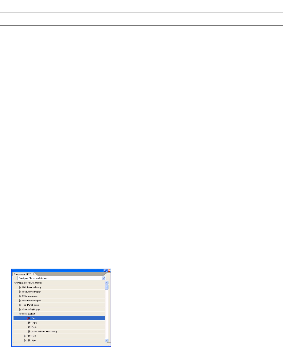
CHAPTER 12: Suppressed User Interface SuppressedUI tool 261
SuppressedUI tool
The SuppressedUIPanel plug-in (also known as the SuppressedUI tool) can be used in conjunction with the
debug build to discover widget IDs and generate XML files as described above. It is included with the
debug builds of InDesign and InCopy (in the “tools” folder), but due to start-up costs and potential
confusion, it is not loaded by default. To load the plug-in, you need to manually copy it to the “plug-ins”
folder in your debug build. When installed, it is available under the SuppressedUI Tool menu item in the
Windows menu.
Although the SuppressedUI Tool can be very useful, it has several significant limitations. Before using the
tool, be sure to read and understand “SuppressedUI tool limitations” on page 262.
The SuppressedUIPanel plug-in provides a kSuppressedUIService service provider boss that uses the
XML-based implementation (kSuppressedUIWithXMLFileImpl). This means when the plug-in is loaded, the
specified widgets are suppressed. This is only for debug purposes. When your plug-in is deployed, you
need to provide your own such service provider.
When the SuppressedUIPanel is loaded, it looks for the SuppressedUI.xml file in the user's application
preferences folder. If the XML file is present, it is parsed, and its data is used to suppress the user interface.
If no file is present, it is created with no elements.
The SuppressedUIPanel contains two subpanels.
“Configure Menus & Actions” can be used to suppress menu items and actions. It contains a Tree
control that has a hierarchical list of menus and actions not contained in menus. An icon button on
each element toggles the state of the menu/action among three values: unsuppressed, disabled, and
hidden. A black eyeball icon indicates the is unsuppressed; a grey eyeball, is disabled; and an eyeball
with a red X, hidden. Top-level menus, like File, Edit, and Object, cannot be suppressed. Palette menus
(shown under Popups) may have strange names; because these names normally are not displayed in
the user interface, they use names from the code.
“Configure Widgets and DragDrop” can be used to suppress widgets and disable them from accepting
drop operations. You start by targeting the widget on which you want to operate. In this pane, there is
a button with a target icon. To target a widget, click and drag from the button to the widget you want
targeted. When you release the mouse, the first drop-down list, “WidgetID to suppress,” contains the
ID name of the targeted widget. Next, suppress the item by clicking one of three buttons, Hide,
Disable, or Disable Drop. The widget should then appear in the list at the bottom of the panel, which
Attribute name Type Summary
PlatformDialogControlIdentifier CDATA This specifies which custom controls to suppress.
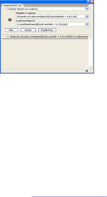
CHAPTER 12: Suppressed User Interface SuppressedUI tool 262
shows suppressed widgets. To unsuppress a widget, select it from the list and click the trash button at
the bottom of the panel.
If you open the “WidgetID to suppress” drop-down, you will see the targeted widget at the top of the list.
For your convenience, all its ancestors also are added to the list. This is important because it is easy to
target the wrong widget. For example, if you try to target the stroke styles drop-down, it may target the
widget inside the drop-down that draws the line. This widget contains sub-widgets, which can be
targeted. If you disable the sub-widget instead of the drop-down, the drop-down will still function.
Instead, you need to select the appropriate ancestor, in this case the kStrokTypePopupWidgetId.
There is another drop-down, “Qualifying WidgetID.” Its purpose is to provide more context when
WidgetIDs are shared. For example, many dialogs share the kOKButtonWidgetID. To disable the OK button
in a specific dialog, you must specify the button's parent WidgetID in the “Qualifying WidgetID”
drop-down. Doing so prevents the OK button from being disabled in all dialogs that share the
kOKButtonWidgetID. To do this using the tool, you target a widget, then select the ancestor widget you
want as your qualifier from the “Qualifying WidgetID” drop-down. Click one of the buttons to add this
widget/qualifier combination to the suppressed list.
This tool does not handle platform dialog controls; these must be put in the XML file by hand. For more
information, see “XML file format” on page 258.
SuppressedUI tool limitations
Using the SuppressedUI tool on modal dialogs requires special care. For the SuppressedUI tool to work on
modal dialogs, it must already be open when the dialog is opened. Furthermore, it must be opened before
the dialog is opened for the first time. If you open the dialog before the SuppressedUI tool, you need to
quit and delete the SavedData file in your preferences folder, to reset the dialog and allow you to use the
tool for that dialog.
On Windows, if you have a modal dialog open, you can target a widget with the tool, but you will not be
able to click the Hide, Disable, or Disable Drop buttons. Instead, target the widget and then dismiss the
dialog. Once the dialog is dismissed, you can click the Hide (or other) button to suppress the widget.
Do not disable the top level widget in a dialog. If you disable the dialog widget, when you dismiss the
dialog, the menus remain disabled as they were when the dialog was open.
When browsing the available actions in the SuppressedUI tool, you may see strange actions like “dynamic”
or “doesn’t matter.” These actions are present because the tool makes no effort to filter out special-case
actions; it simply lists all actions defined. These particular actions exist but are not useful to the user;
ignore them.
CHAPTER 12: Suppressed User Interface Working with the ISuppressedUI API 263
Working with the ISuppressedUI API
The ISuppressedUI interface is documented in the SDK API documentation. For a sample implementation,
see the SuppUI sample project. The interface itself is not complex, but it is challenging to determine the
appropriate IDs and menu paths. The best way to get around this is to use the SuppressedUI tool to
discover IDs and menu paths, even if ultimately you will not use the XML-based implementation.
Before implementing this interface yourself, read and understand the following additional points:
The methods of your implementation will be called very often. Performance is an important
consideration. Poor implementations can slow down the entire application.
You can use the Reset() method to improve performance. For instance, if your implementation reads
data from a file, you should build a cache when Reset() is called. Then, anytime the data file changes,
you will need to query for ISuppressedUI on your service provider, and call Reset() to rebuild the cache.
Calling Reset() on the gSession ISuppressedUI implementation forwards the Reset() call to all
kSuppressedUIService service providers. In most cases, this probably is not what you want to do. If you
just want to call your service providers ISuppressedUI::Reset(), query for it yourself using
IK2ServiceRegistry::QueryServiceProviderByClassID().
IsWidgetDisabled and IsWidgetHidden take an IControlView*. See the SuppUI sample for an example
of how to extract a WidgetID or a parent WidgetID from the IControlView*.
When suppressing widgets, the hardest part may be determining the widget’s WidgetID. You can learn
a lot by opening the ID.h file for the feature you care about. This assumes you can identify the ID.h file
in which the widget is defined. You may run into cases that are not obvious. It is easiest to use the
SuppressedUI tool to discover WidgetIDs.
IsDragDropDisabled() is called with a lot of context. IDragDropTarget* and IDragDropSource* allow
you to extract information on the target and source. DataObjectIterator* lets you peak at the flavors
on the clipboard.
To suppress menu items with a corresponding action, implement IsActionDisabled() or
IsActionHidden(). The IsSubMenuDisabled() and IsSubMenuHidden() methods are used to disable
submenus. These are strictly menus and not items with a corresponding action. For example, to
disable the entire Edit menu, you could use IsSubMenuDisabled().
Determining a menu path may involve thought or investigation. The path needs to be specified as an
untranslated string. Furthermore, each menu has a name, and you may not know the name of the
menu you are disabling. It is easiest to use the SuppressedUI tool.
Determining the names of platform dialog custom controls is more straightforward. The available
dialogs and controls are listed in SuppressedUIXMLDefs.h. For example,
IsPlatformDialogControlSuppressed specifies all custom controls on the Place dialog.
Other user-interface “suppression” mechanisms
The application API supports other mechanisms that allow for customization and suppression of the user
interface behavior:
See IMenuFilter in the API documentation. This abstraction allows for configuration of menu items as
they are added.
CHAPTER 12: Suppressed User Interface Other user-interface “suppression” mechanisms 264
See IActionFilter in the API documentation (and the CustomActionFilter SDK sample),. This abstraction
allows for configuration of actions as they are added.
See the section on “Working with the Quick Apply Dialog” in the “User Interfaces” chapter of Adobe
InDesign SDK Solutions for examples of using the IQuickApplyService and IQuickApplyFilterService
extension patterns to control the function available through the quick apply dialog.
265
13 Using Adobe File Library
Introduction
This chapter describes the Adobe File Library (AFL) as it applies to developers of plug-ins for InDesign. This
library provides utilities for manipulating files, paths, and directories on Windows and Mac OS. The chapter
defines terms and explains key concepts related to the Adobe file library, provides detailed descriptions of
the design and class hierarchy of the Adobe file library, and answers common questions.
The Adobe file library was designed with two goals in mind:
Provide a unified collection of classes and utilities that can be used to perform all file and directory
manipulation.
Provide a core architecture that can be used by other Adobe applications.
To this end, the design includes a core set of classes and utilities that are independent of InDesign (that is,
they do not rely on the InDesign model). In addition to the core architecture, there are classes and utilities
that provide functions specific to InDesign, as well as model-dependent features.
Plug-in developers should use the IDFile. IDFile is an InDesign API class used to manipulate a file or
directory specified by a path. IDFile has a rich cross-platform method set including, for example,
persistence of file and directory paths.
Terminology
The following terms are used throughout this chapter. They are illustrated in the following figure.
Adobe file library (AFL) — A file library with APIs for file and directory manipulation.
Base name — The portion of a filename or directory name before the last period.
Directory — A construct provided by the operating system, which contains the names of files, other
directories, or both. Directories are identified by directory paths.
Directory name — The last path component of a directory path.
Directory path — A path whose last component is a directory name.
Filename — The last path component of a file path.
File path — A path whose last component is a filename.
Extension — The portion of a filename or directory name after the last period.
Chapter Update Status
CS6 Minor edit Only the following has changed:
• In several places, removed obsolete text that referred to CS2.
CHAPTER 13: Using Adobe File Library Adobe File Library architecture 266
Hierarchical File System (HFS) — The Mac OS standard file system format. It is used to represent a
collection of files as a hierarchy of directories (folders), each of which may contain files or folders
themselves.
Path — A sequence of path components. Each element except the last names a directory that contains
the next element. The last element may name a directory or a file. The first element is closest to the
root of the directory tree; the last element, farthest from the root.
Path component — A name of a volume, directory, or file that is an element of a path, separated by a
path separator character (such as \, /, or :).
Adobe File Library architecture
Adobe File Library is a dynamic library. It is in the Windows SDK at
<SDK>\external\afl\libs\win\<release_debug>\AFL.lib. On Windows, if you have a plug-in project that uses
Adobe file library, you need to explicitly link to AFL.lib. On Mac OS, AdobeAFL.framework is included in
InDesignModel.framework), a universal binary that can be used on both PPC and i386 systems.
Adobe file library is not based on the InDesign object model and does not use concepts specific to
InDesign, like bosses and interface IDs.
Adobe File Library classes and utilities
The following figure provides an overview of file library classes and utilities provided by Adobe File Library.
C:\mydir\second_level\filelibrary.pdf
Macintosh HD:macDir:fun:sunphoto.jpg
/user/john/unixpath/sampledocs/files
Path
File path
Directory
path
Path
components
File name
(filelibrary.pdf,
sunphoto.jpg)
Directory name
(files)
Base name
(filelibrary,
sunphoto)
Extension
(pdf, jpg)
Path
components
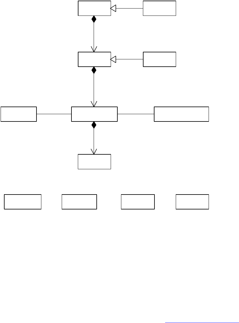
CHAPTER 13: Using Adobe File Library Adobe File Library architecture 267
AFile, APath, APathComponent, and AString form a composition chain. An AFile object represents a file or
directory; it holds an APath object pointing to the full path of the file or directory. An APath object consists
of one or more APathComponent objects; a sequence of path components forms a path. An
APathComponent object consists of two AString objects, representing base and extension parts,
respectively.
AFile and APath are not pure virtual classes: they have their own implementations that may be used by
other Adobe products. IDFile is the InDesign implementation of AFile. IDPath is the InDesign
implementation of APath. They extend their parent classes by providing additional methods specific to
InDesign and InCopy.
CorePathUtils and CoreFileUtils provide core utilities that apply to both Windows and Mac OS. WinFileUtils
provides utilities specific to Windows. MacFileUtils provides utilities specific to Mac OS. FileUtils provides
file-manipulation utilities specific to InDesign and InCopy. See “FileUtils class” on page 269.
Common file API
The common file API comprises classes and utilities that can be used in InDesign and InCopy, as well as
other Adobe products. For detailed methods and definitions, refer to the API Reference.
«type»
AString
«type»
APathComponent
«type»
APath
«delegate»
APathIterator
«delegate»
APathReverseIterator
«type»
AFile
«utility»
CorePathUtils
«utility»
CoreFileUtils
«utility»
MacFileUtils
«type»
IDPath
«type»
IDFile
«utility»
WinFileUtils
1
1
1
1..*
1
1..*
-Iterator
11..* -Iterator
11..*
CHAPTER 13: Using Adobe File Library Adobe File Library architecture 268
AString class
AString is a class used to hold and manipulate a UTF-16 string. AString has general string-manipulation
methods, such as Append, Insert, and Length. AString has methods for converting to and from other string
types. The common file implementation does not know InDesign types, so AString cannot be constructed
from PMString directly.
APathComponent class
APathComponent is a container class used to hold the name of a single component of a path. A path
component can be a volume name, directory name, or filename. APathComponent has methods for
getting and setting the base, extension, or full name of an APathComponent object as an AString.
APath class
APath is a container class used to hold an absolute or relative path. The individual path elements are
stored in a vector of APathComponent objects. Storing the path in a vector allows for quick retrieval,
manipulation, and iteration of the path components. APath does not require that the contained path exist
on the file system. It has methods for getting path information, setting and changing the path, and
begin(), end(), rbegin(), and rend() methods for use with its iterator class APathIterator and
APathReverseIterator.
APathIterator class
The APathIterator random access iterator class provides the ability to iterate over the path components
contained in an APath object. The class mimics the function provided by STL random access iterators.
APathReverseIterator class
The APathReverseIterator random access reverse iterator class provides the ability to iterate over the path
components contained in an APath object in reverse order. The class mimics the function provided by STL
random access reverse iterators.
AFile class
The AFile class is used to create and delete files and directories, and to get and set file and directory status
and access properties. A file or directory referred to by the class does not need to exist. Methods that
require the existence of a file or directory are ignored and fail appropriately when the file does not exist.
CorePathUtils class
CorePathUtils is a utility class that provides additional path function beyond the scope of
APathComponent and APath. CorePathUtils includes methods for converting UTF-8 to and from an
APathComponent object, getting and setting current working directory, and checking the path type of an
APath object.

CHAPTER 13: Using Adobe File Library Adobe File Library architecture 269
CoreFileUtils class
CoreFileUtils is a utility class that provides additional file and file system function. CoreFileUtils includes
methods for creating temporary files, copying and moving a file, renaming a file, and testing whether a file
is on a server.
MacFileUtils class
MacFileUtils is a utility class that provides additional file and file system functions specific to Mac OS.
Methods are included for getting and setting VolumeRefNum, getting and setting the creator and type of
a file, converting AFile to and from FSRef, SpecInfo, FSSpec, and CFURLRef.
WinFileUtils class
WinFileUtils is a utility class that provides additional file and file system functions specific to Windows.
Methods are included for getting UNC path, local path, and POSIX path.
File API specific to InDesign
IDPath class
IDPath is an InDesign class used to manipulate a file or directory specified by a path. IDPath is a child of
APath; therefore, it inherits all APath methods. IDPath can be constructed from an APathComponent, an
AString, or an InDesign WideString object.
IDFile class
IDFile is an InDesign class used to manipulate a file or directory. IDFile is a child of AFile; therefore, it
inherits all AFile methods. Like IDPath, IDFile can be constructed from an APath, AString, or InDesign
WideString. In addition, IDFile defines several methods specific to Windows and Mac OS.
FileUtils class
The FileUtils class has been in existence since InDesign CS. The following table briefly describes some
methods.
Method Description
static FILE* OpenFile(const IDFile& file, const char* mode) Opens the file. This method uses
FSpfopen,
FSRefParentAndFilenamefopen, or
FSReffopen to open the file, depending
upon the current state of the file.
static OSErr FSSpecToIDFile(const FSSpec& fsSpec, IDFile&
file)
Converts an FSSpec to an IDFile object.
static OSErr SpecInfoToIDFile(FSVolumeRefNum vRefNum,
uint32 parId, const PMString& name, IDFile& file)
Converts Mac OS file system specification
information to an IDFile object.

CHAPTER 13: Using Adobe File Library Frequently asked questions 270
SDKFileHelper
SDKFileHelper is not part of Adobe file library. This class is listed here because it is used as a utility class in
SDK sample code and, presumably, it is used commonly in code written by third-party plug-in developers.
Debugging IDFile
To help you debug your code containing IDFile objects, the IDFile class has a debug-only data member,
fDebugPath, that always contains the current path. The path contained by fDebugPath matches the path
contained by the AFile implementation class, but it is much easier to get from the debugger.
On Windows, fDebugPath is defined as a wchar_t string that contains a UTF-16 UNC or mapped drive path.
On Mac OS, fDebugPath is defined as a character string that contains a UTF-8 POSIX path. On both
platforms, if the current path is empty, fDebugPath is null.
WARNING: On Windows, do not use the fTmpPathStr data member contained by IDFile objects to obtain
the current path. The fTmpPathStr member is a temporary path string used as a buffer to return the path as
a PMString, CString, ConstCString, TCHAR buffer, WString, or UTF16TextChar. The path contained by
fTmpPathStr is neither guaranteed nor expected to always match the IDFile object’s current path.
Frequently asked questions
Why should I use Adobe file library?
Adobe file library provides unified file-manipulation methods, so you do not need to write
platform-specific code for Windows and Mac OS, or even UNIX.
Adobe file library provides classes and utilities that meet most file-manipulation needs, so your code will
be shorter, more robust, and easier to maintain.
Adobe file library will evolve with the operating systems, so your code will be easier to port.
Most importantly, InDesign code uses Adobe file library. Future interfaces will continue to be based on
Adobe file library.
We highly recommend using Adobe file library classes.
static OSErr IDFileToFSSpec(const IDFile& file, FSSpec&
fsSpec, PMString* unicodeName = nil, bool16 bCreateLong
= kFalse)
Converts an IDFile object to an FSSpec.
static OSErr UnicodeNameToHFSName(const PMString&
unicodeName, PMString& hfsName, TextEncoding
textEncodingHint = kTextEncodingUnknown);
Converts a Unicode name to an HFS Pascal
name.
static OSErr HFSNameToUnicodeName(const PMString&
hfsName, PMString& unicodeName, TextEncoding
textEncodingHint = kTextEncodingUnknown)
Converts an HFS Pascal name to a Unicode
name.
Method Description
CHAPTER 13: Using Adobe File Library Frequently asked questions 271
Does Adobe file library support cross-platform path conversion?
No.
However, Adobe file library directly supports POSIX paths on Mac OS. You can use
FileUtils::PMStringToSysFile to create an IDFile object from an HFS path (like Macintosh
HD:macfolder:myfile) or Windows file path (like C:\Program Files\Adobe\InDesign)
Should I still use the ICoreFileName interface?
Adobe file library does not replace ICoreFileName; however, we do not recommend using ICoreFileName
unless you absolutely have to (for example, when dealing with data links). On Mac OS, the class still
depends heavily on FSSpec and is not very efficient. Most of the function is provided more efficiently in
Adobe file library classes like CoreFileUtils, CorePathUtils, MacFileUtils, WinFileUtils, AFile, and FileUtils.
How do I navigate between IDFile and IDPath?
You can round-trip between IDFile and IDPath as shown in the following sample code:
IDFile idFile (existingFile); //assume existingFile already initialized
IDPath idPath = idFile.GetPath();
IDFile newFile(idPath);
What are the differences between a file and a directory?
There is no difference between a file and a directory in terms of how they are represented as IDFile objects.
The differences are at the operating-system level: A directory has other files or directories as its children,
and a file does not.
What are the relationships between IDPath and IDFile?
IDPath and IDFile objects can point to the same file or directory. They differ mainly in concepts: IDPath has
methods that apply to a file path, and IDFile has methods that apply to file operations.
Why should IDFile not be treated as PMString?
They are different conceptually. PMString represents a string, used primarily in the user interface. IDFile
deals primarily with file manipulation.
Also, not all IDFile objects are represented by a PMString, so treating an IDFile as a string makes your code
prone to errors. Mac OS has several ways to represent a file. Windows, UNIX, and file URLs also have
different formats.
IDFile does not allow an invalid path, so you may encounter runtime errors or asserts if you assign a
PMString to an IDFile with an invalid path. PMString does not validate paths at run time.
CHAPTER 13: Using Adobe File Library Frequently asked questions 272
How do an invalid path and a nonexistent path differ?
An invalid path is a path with one or more invalid path components in its respective platform. For example,
the wildcard *.* does not refer to a file, so any path containing *.* is an invalid path.
A nonexistent path is a path that points to a file that does not exist. IDFile and IDPath fully support
nonexistent paths. You can create or delete a file using IDFile methods.
Can I construct an AString from PMString?
Yes and no.
You cannot construct an AString from a PMString, because Adobe file library is not aware of the InDesign
type PMString. Since they both use UTF-16, however, you can construct an AString with the following
code:
String aString(pmString.GrabUTF16Buffer(nil));
How can I convert a relative path to an absolute path?
Use APath::MakeAbsolute.
Make sure you are converting paths on the same platform. You cannot convert a Windows relative path on
Mac OS, or vice versa. Instead, you must manipulate the relative path as a PMString, convert it to the
platform-specific format, and then convert to an absolute path.

273
14 Performance Tuning
The InDesign plug-in architecture and object model make it possible for software developers to add
powerful features to InDesign; however, the architecture also allows developers to accidentally create very
inefficient code.
This chapter describes how to optimize InDesign plug-ins for peak performance.
Use profiling tools
Often, software developers believe they know the cause of a performance problem in their code, only to
be surprised by the results of a profile of that code. There are several very good tools for identifying
performance problems, and you always should use them before trying to optimize your code manually.
This section describe some of these tools.
Windows
There are several tools that can be used to profile your code and identify performance problems on
Windows. For example, the InDesign engineering team has had success with GlowCode. GlowCode is a set
of analysis tools to profile code and identify memory use problems. GlowCode instruments a user-selected
list of plug-ins, allows the user to define a trigger function, and provides accurate timings and function call
counts. For more information about GlowCode, including a trial version, see http://www.glowcode.com.
Mac OS
Sampler
Sampler is an Apple profiling tool that is part of the Xcode tools package, which comes with Mac OS X.
Sampler periodically samples an application to build profile data. Because Sampler is a sampling profiler, it
cannot provide accurate function-call counts; however, it provides very good timing data, is very easy to
use, and does not require any changes to your code. For Sampler to provide timing information at the
function level, you must turn on tracebacks in your project. For more information, see the Apple Web site.
Shark
Shark is an Apple profiling tool that is part of the Xcode tools package, which comes with Mac OS X. Like
Sampler, Shark is very easy to use. Shark, however, can be used only with Mach-O applications; therefore, it
cannot be used with InDesign CS and earlier. For more information, see the Apple Web site.
Chapter Update Status
CS6 Unchanged
CHAPTER 14: Performance Tuning Commands 274
Quartz Debug
Quartz Debug is an Apple tool that helps you to identify redundant drawing to the screen.
Commands
Commands are responsible for encapsulating compound modifications to the object model, supporting
the undo/redo protocol, and indicating to the object model when it should notify its state to observers. If
not used properly, commands can seriously reduce performance.
Commands should operate on lists of inputs
You can improve performance by reducing the number of commands processed, partly because undo
information for each command must be stored on the command history, and partly because each
command sends out a notification on completion. One good way to reduce the number of commands
processed is to write commands such that each accepts a list of inputs.
For example, a MovePageItem command should either call GetItemList to obtain the command’s list of
inputs or include a separate data interface in the command’s boss. This makes it possible to execute one
command for an entire list of page items, instead of executing a separate command for each page item.
Notify on the document subject instead of the page item object
Notifications can decrease performance because observers tend to do some work each time they are
notified; therefore, it is desirable to find ways to reduce the total number of notifications. One way, as
mentioned above, is to reduce the number of commands executed. Another, is to send one notification on
the document subject instead of a separate notification for each page item. This approach requires
observers to attach at the document level instead of at the page item level. See the following code:
void MyCommand::DoNotify()
{
const UIDList* itemList = GetItemList();
InterfacePtr<IDataBase> iDatabase(itemList->GetDataBase(), UseDefaultIID());
Utils<PageItemUtils>() -> NotifyDocumentObservers(iDatabase, kMyCmdBoss,
IID_MYIID_IDOCUMENT, this);
}
Mark commands that do not require undo support
Some commands do not require undo support. For example, a command to print a document is not
undoable. In such cases, the constructor of the command should call SetUndoability(kUndoNotRequired).
Observers
Observers can be attached to and detached from any subject, but be careful to attach observers only to
subjects in which you are interested, since each attachment impairs performance. Performance is affected
by the level of the subject to which the observer is attached.
CHAPTER 14: Performance Tuning File input/output 275
Attach to documents, not page items
It is inefficient for an observer to attach and observe at the page-item level. Instead, observers should
attach and observe at the document level.
Do work only when the command is done
Many commands notify several times. For example, when a page item moves, a prenotify and post-notify
must occur, so the old and new locations can be invalidated on the screen. Often, an observer can ignore
all but the last notification, as follows:
void MyObserver::Update(const ClassID& theChange, ISubject* theSubject, const PMIID&
protocol, void* changeBy)
{
if (protocol == IID_MYIID)
{ if (theChange == kMyCmdBoss)
{ ICommand* cmd = (ICommand*) changeBy;
ICommand::CommandState cmdState = cmd->GetCommandState();
if(cmdState == ICommand::kDone)
{ const UIDList* contentList = cmd->GetItemList();
// do some work here
}
}
}
}
Do not update the user interface from an observer
Many panels display information about the current selection, like graphic attributes, character attributes,
or information about the selection’s geometry. These panels must have an observer, and it is tempting to
update the panel from the Update method of the observer; however, in general, updating a panel from an
observer is a bad idea. Instead, it is much better to mark the data in the panel as dirty or invalid, generate a
screen invalidation for the panel, then update the user interface in the Draw code for the panel.
Watch for lazy notification whenever possible
The application supports two types of notification, regular and lazy. If an observer needs to be called as
soon as a subject broadcasts the change message, it should request regular notification. If the observer
can afford to wait until idle time before being notified of a change of interest, it can register for lazy
notification.
Lazy notification is used when observers do not need to be in tight synchronization with changes being
made to the subject objects they observe. Rather than participating in each change that occurs on a
subject object, observers using lazy notification are notified after all updates are made and the application
is idle.
File input/output
Each operation to access a local disk or server can greatly reduce performance. For this reason, it is very
important to reduce the number of disk access operations as much as possible. For example, if you need to
parse a file using many very small read operations, consider reading a large block into a memory buffer
CHAPTER 14: Performance Tuning Memory 276
using one read operation, then operating on the buffer. This kind of optimization is very important when
working over a network.
Memory
Use memory caches for items accessed often
If a profile shows that your code is spending a lot of time recomputing the same value or repeatedly
searching a list for the same element, consider caching the result or element. It is very important to use
profiling tools to identify where caches are needed. Unnecessary caches can decrease performance, by
forcing the software to keep the cache up to date even when it is not needed.
Avoid allocating too much memory
Allocating memory beyond what is physically available causes InDesign to try to purge its caches and may
cause a page fault in the operating system. Purging memory and page faults are very slow; avoid them
when possible.
Idle tasks
The InDesign object model is not thread-safe, so it does not use true threads; however, you can use
cooperative threads, in the form of idle tasks (IIdleTask). Idle tasks are given a chance to execute when
there are no events in the EventQueue for the application to process. Idle tasks are a great way to defer
expensive operations and allow the user to continue using the application.
The remainder of this section presents guidelines that should be followed when implementing an idle
task.
Honor the RunTask flags
Each idle task has a RunTask method, which is passed a set of flags. These flags can be very important to
the application’s performance. For example, normally you will not want an idle task to execute when the
user is dragging a page item around the layout, and you may not want the idle task to execute when a
dialog box is open, because it slows the application’s responsiveness. So, a typical idle task starts with the
following lines of code:
if (flags & IIdleTaskMgr::kMouseTracking ││ flags & IIdleTaskMgr::kModelDialogUp)
return (kOnFlagChange);
Do a small amount of work during each RunTask call
Idle tasks allow the software to perform computationally expensive operations when the user is idle. The
goal is to make the application as responsive as possible, so the user does not have to wait for an
expensive operation to complete. For this reason, you do not want one call to RunTask to take a long time.
It is better for each call to RunTask to perform some work, then ask for RunTask to be called again. For
example, your RunTask method may look like the following:
CHAPTER 14: Performance Tuning Idle tasks 277
uint32 MyIdleTask::RunTask(uint32 schedulerFlags, uint32 (*timeCheck)())
{
if (InappropriateState(schedulerFlags))
return kOnFlagChange;
DoPeriodicThing();
return 1000; // Call this task again in 1 second.
}

278
15 Performance Metrics API
A performance metric allows you to quantify the performance of your software. Adobe® InDesign®
contains a scriptable performance-metrics API. This API allows you to add performance counters to your
components, giving you the ability to monitor aspects of your code or of InDesign code.
Performance metrics are implemented as counters. These counters can track any numerical value
associated with your software; for example, time spent in an algorithm, memory usage, and number of
objects created.
Several metrics already are implemented within the InDesign architecture, and the API allows you to add
metrics to your own plug-in. An important aspect of the performance-metrics API is that it exposes the
counters to PerfMon on Windows® and DTrace on Mac OS®, allowing you to track your counters over time.
InDesign metrics
The performance-metrics API contains many built-in counters. These counters track information about
CPU time, number of threads, memory size, handle count, memory-purge count, PDF allocations, image
cache, database file, drop shadow, snapshot, composition, draw manager, and so on.
These counters are available through scripting; therefore, you can find a complete list of the built-in
counters by using the Object Model Viewer in the ExtendScript Toolkit, as described in “Accessing metrics
from scripting” on page 283.
The performance-metrics architecture is an application startup/shutdown service
(IStartupShutdownService) consisting of a metrics service provider, script provider, idle task, and
performance-counters implementation.
Adding a metric
First, determine what performance data to expose for your plug-in. Then, find where that data is updated;
this is, where you will update your performance counter. Your counter can represent any numeric data, as
long as it fits in a uint64.
Performance-metric service provider
Start with implementing a performance-metric service provider. Edit your Class resource to define your
service provider, as in this example from the hyphenator sample:
Chapter Update Status
CS6 Unchanged
CHAPTER 15: Performance Metrics API Adding a metric 279
Class
{
kHypServiceProviderBoss,
kInvalidClass,
{
IID_IK2SERVICEPROVIDER, kPerformanceMetricProviderImpl,
IID_IPERFORMANCEMETRIC, kHypPerformanceMetricImpl,
}
},
Next, create IDs for your counters in your ID.h file:
DECLARE_PMID(kPerformanceMetricIDSpace, kHypMetricMaxID, kHypPrefix + 1)
DECLARE_PMID(kPerformanceMetricIDSpace, kHypMetricTotalID, kHypPrefix + 2)
Then, implement your performance metric (IPerformanceMetric). The first step is to define your counters.
To keep the new counters independent of the object model, add a C++ class HypPerformanceData and
define static data members in it:
class HypPerformanceData
{
...
private:
static boost::mutex fMutex;
static uint64 fHypMax;
static uint64 fHypTotal;
};
fHypMax and fHypTotal are for keeping the performance counters; fMutex is for synchronization.
In GetMetricInfo(), add your metrics to the global list of metrics by appending your metric IDs to the
PerformanceMetricIDList argument:
void HypPerformanceMetric::GetMetricInfo(PerformanceMetricIDList &metricIDs)
{
metricIDs.push_back(kHypMetricMaxID);
metricIDs.push_back(kHypMetricTotalID);
}
Return your metric’s short name in GetMetricShortName(). The string you return defines the accessor for
your metric in both PerfMon and DTrace.
PMString HypPerformanceMetric::GetMetricShortName(PerformanceMetricID metricID)
{
PMString returnValue("");
switch (metricID.Get()) {
case kHypMetricMaxID:
returnValue = PMString("Hyphenation Max");
break;
case kHypMetricTotalID:
returnValue = PMString("Hyphenation Total");
break;
}
return returnValue;
}
Return your metric’s description in GetMetricLongName().
CHAPTER 15: Performance Metrics API Adding a metric 280
PMString HypPerformanceMetric::GetMetricLongName(PerformanceMetricID metricID)
{
PMString returnValue("");
switch (metricID.Get()) {
case kHypMetricMaxID:
returnValue = PMString("The maximum number of hyphenations
in any word");
break;
case kHypMetricTotalID:
returnValue = PMString("The total number of hyphenation calls");
break;
}
return returnValue;
}
If you are allocating memory or have other clean-up to do, add that code in DeRegisterMetric().
In GetMetricValue(), return the value of your global counter. The return value must be a uint64 value. If the
data you are tracking is a floating or real value (PMReal), you need to convert the value accordingly.
uint64 HypPerformanceMetric::GetMetricValue(PerformanceMetricID metricID)
{
uint64 returnValue = 0;
switch (metricID.Get()) {
case kHypMetricMaxID:
returnValue = HypPerformanceData::GetHypMax();;
break;
case kHypMetricTotalID:
returnValue = HypPerformanceData::GetHypTotal();
break;
}
return returnValue;
}
Reset your global counters back to their initial values in ResetMetric():
void HypPerformanceMetric::ResetMetric(PerformanceMetricID metricID)
{
switch (metricID.Get()) {
case kHypMetricMaxID:
HypPerformanceData::SetHypMax(0);
break;
case kHypMetricTotalID:
HypPerformanceData::SetHypTotal(0);
break;
}
}
Performance-metric script provider
Performance metrics are accessed in scripting by their registered metric ID. You register these IDs in your
service provider’s GetMetricInfo() method. To make this ID accessible from scripting, you need to
implement a simple script provider.
First, edit your Class resource in your .fr file:
CHAPTER 15: Performance Metrics API Adding a metric 281
Class
{
kHypScriptProviderBoss,
kBaseScriptProviderBoss,
{
IID_ISCRIPTPROVIDER, kHypScriptProviderImpl,
}
},
Also, define one scripting property for each counter, and a provider element:
resource VersionedScriptElementInfo (1)
{
//Contexts
{
kBasilScriptVersion, kCoreScriptManagerBoss, kWildFS, k_Wild,
}
//Elements
{
Property
{
kHypMaxPropertyScriptElement,
p_HypMax,
"hyphenation max",
"The maximum number of hyphenations in any word",
Int32Type,
{}
kNoAttributeClass,
}
Property
{
kHypTotalPropertyScriptElement,
p_HypTotal,
"hyphenation total",
"The total number of hyphenation calls",
Int32Type,
{}
kNoAttributeClass,
}
Provider
{
kHypScriptProviderBoss
{
Object{ kApplicationObjectScriptElement },
Property{ kHypMaxPropertyScriptElement, kReadOnly },
Property{ kHypTotalPropertyScriptElement, kReadOnly },
}
}
}
}
Next, define your scripting identifiers in your ID.h file:
CHAPTER 15: Performance Metrics API Adding a metric 282
DECLARE_PMID(kScriptInfoIDSpace, kHypMaxPropertyScriptElement, kHypPrefix + 1)
DECLARE_PMID(kScriptInfoIDSpace, kHypTotalPropertyScriptElement, kHypPrefix + 2)
// scripting defs
enum HypScriptIDs
{
p_HypMax = 'hpmx',
p_HypTotal = 'hptt',
};
Then, implement your scripting provider:
ErrorCode HypScriptProvider::HandleEvent(ScriptID eventID,
IScriptEventData* data, IScript* parent)
{
return CScriptProvider::HandleEvent(eventID, data, parent);
}
ErrorCode HypScriptProvider::AccessProperty(ScriptID propID,
IScriptEventData* data, IScript* parent)
{
ErrorCode status = kFailure;
switch (propID.Get())
{
case p_HypMax:
case p_HypTotal:
status = GetHyphPerformanceConstant(propID, data, parent);
break;
default:
status = CScriptProvider::AccessProperty(propID, data, parent);
break;
}
return status;
}
ErrorCode HypScriptProvider::GetHyphPerformanceConstant(ScriptID propID,
IScriptEventData* data, IScript* parent)
{
ErrorCode result = kSuccess;
if (data && data->IsPropertyGet()) {
ScriptData scriptData;
switch (propID.Get())
{
case p_HypMax:
scriptData.SetInt32(kHypMetricMaxID);
break;
case p_HypTotal:
scriptData.SetInt32(kHypMetricTotalID);
break;
}
data->AppendReturnData( parent, propID, scriptData );
}
return result;
}
CHAPTER 15: Performance Metrics API Accessing metrics from scripting 283
Accessing metrics from scripting
The InDesign scripting DOM contains several accessors for the built-in performance metrics. You can learn
more about the metrics implemented in the DOM by using the Object Model viewer in ExtendScript
Toolkit.
1. Run ExtendScript Toolkit.
2. Choose Help > Object Model Viewer.
3. From the Browser menu, choose Adobe InDesign Server Object Model.
4. From the Classes menu, choose PerformanceMetric.
5. To view the implemented metrics types and descriptions, choose items in the Properties and Methods
drop-down list.
InDesign built-in metrics
You can use InDesign’s built-in metrics to track what is going on in InDesign. Here is an example that
calculates the CPU time required to create and close 50 documents:
var startTime = app.performanceMetric(PerformanceMetricOptions.CPU_TIME);
for (var i = 0; i < 50; i++){
var myDoc = app.documents.add();
myDoc.close();
}
var endTime = app.performanceMetric(PerformanceMetricOptions.CPU_TIME);
var message = "CPU time: " + (endTime - startTime);
if(app.name == "Adobe InDesign Server")
app.consoleout(message);
else
alert(message);
User-defined metrics
If you created a performance script provider for your plug-in, you can access your counter from scripting
using the appropriate property:
var hypMax = app.performanceMetric(app.hyphenationMax);
var hypMaxShortName = app.performanceMetricShortName(app.hyphenationTotal);
var hypMaxLongName = app.performanceMetricLongName(app.hyphenationTotal);
If you did not create a script provider, you can still access your counter by running through the entire list of
counters and locating yours. The following code compares to the short name value, but you also could
compare to the ID or long name. The name values are defined by your service provider’s GetShortName
and GetLongName methods:
CHAPTER 15: Performance Metrics API Accessing metrics in perfmon 284
var metricList = app.performanceMetrics;
var nMetrics = metricList.length;
for (var i = 0; i < nMetrics; i++) {
var myMetricID = metricList[i];
var myMetricShortName = app.performanceMetricShortName(myMetricID);
if (myMetricShortName == "Hyphenation Max") {
var myMetricValue = app.performanceMetric(myMetricID);
var myMetricLongName = app.performanceMetricLongName(myMetricID);
}
}
Memory tracker
If you have access to the Debug install of InDesign or InDesign Server, you will have installed a special
memory-tracker version of PMRuntime. This version of PMRuntime contains memory-tracking metrics not
available to the regular installed version. Look in your debug installation’s MemoryTracker folder for the
DLL file (dylib).
Memory-growth example
By using the memory tracker PMRuntime, you can determine where memory is being allocated by using
the performanceMetric scripting calls. Here is a sample script you could use to find InDesign
memory-growth problems:
//... execute a test a few dozen times ...
gStartMarker = app.performanceMetric(PerformanceMetricOptions.currentMemoryMark);
//... execute the test a few dozen more times ...
gEndMarker = app.performanceMetric(PerformanceMetricOptions.currentMemoryMark);
//... execute the test a few dozen more times ...
app.dumpBetweenMemoryMarks(gStartMarker, gEndMarker);
The purpose of the first set of test executions is to build up caches and allow the system to load any code
that needs to be loaded. The third set allows any delayed memory deallocation to occur. The
dumpBetweenMemoryMarks call creates a file named Memory Usage Dump.txt that is similar to a leaks
file, with any allocations made between the currentMemoryMark calls that are still active.
Usually, a real memory-growth problem shows up in the output file as a repeated call stack (for example, if
you run the test 20 times, there are 20 identical call stacks). Stack crawls that appear only once or twice
generally are not a real problem but are caches being built up. Obviously, this list contains only those
memory allocations that go through InDesign’s memory allocator.
Accessing metrics in perfmon
All counters with the performance-monitoring code are made available to the Windows perfmon system
tool through a helper application named PerformanceMonitor.exe. This application is run when InDesign
Server is started up. It adds the InDesign performance counters to perfmon. To see the InDesign counters
from within PerfMon:
1. Shut down InDesign Server.
2. From your InDesign Server folder (C:\Program Files\Adobe\Adobe InDesign CS6 Server), copy
PerformanceMonitor.exe from the performancemonitor subfolder to the InDesign Server folder.
3. Start InDesign Server.
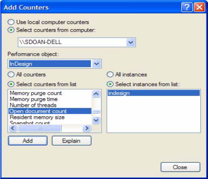
CHAPTER 15: Performance Metrics API Accessing metrics in perfmon 285
4. Start perfmon: choose Start > Run, enter perfmon.exe, and click OK.
5. Right-click in the graph area and choose “Add Counters.”
6. In the dialog that appears, select InDesign from the Performance Object menu.
7. In the counters list, choose the counters that are of interest and click Add, or choose “All counters.” You
must have InDesign Server running, or the Add button is disabled.
8. Choose a specific instance of InDesign Server (listed as “indesign”) or “All Instances.” The dialog should
look like this:
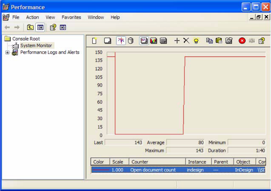
CHAPTER 15: Performance Metrics API Accessing metrics in DTrace 286
After you chose counters and dismiss the Add Counters dialog, the graph updates with InDesign’s data:
Accessing metrics in DTrace
On OS X 10.5, InDesign’s performance counters can be accessed from DTrace. DTrace is a command-line
tool with its own scripting language, D. To examine an InDesign performance metric in DTrace, you first
write a D script, then run that script using DTrace.
This sample script echoes all InDesign performance counters to the console:
indesign$1:DTraceSupport.dylib:UpdatePerformanceCounter:
{
printf("counter: %s", stringof(copyinstr(arg0)));
printf("\tvalue(hi):%d", arg1);
printf("\tvalue(low)%d", arg2);
}
If this script is saved to a file named test.d, it can be invoked using the following command line. Replace
15534 with the correct process ID for your running instance of InDesign or InDesign Server. (You can use
Activity Monitor to find the process ID.)
sudo dtrace -p 15534 -s test.d 15534
We use the required sudo command to run DTrace as superuser. This command line executes the test.d
script, which outputs information for every InDesign performance counter. The script runs continuously,
ouputting the data every time the InDesign performance counters are updated (currently once per
second).

CHAPTER 15: Performance Metrics API Accessing metrics in Instruments 287
If you are interested in a particular counter, for example, “DB new UID count,” you can narrow the scope of
the probe with a conditional:
indesign$1:DTraceSupport.dylib:UpdatePerformanceCounter:
/copyinstr(arg0) == "DB new UID count"/
{
printf("counter: %s", stringof(copyinstr(arg0)));
printf("\tvalue(hi):%d", arg1);
printf("\tvalue(low)%d", arg2);
}
This script executes the printf code only if arg0 (the name of the counter) matches the specified constant
string. This script writes out one line for the “DB new UID count” once per second. If you have added your
own metric to InDesign, you can use your metric’s short name to compare to arg0.
For more information on DTrace, read its manual page using the command “man dtrace”, or go to
http://hub.opensolaris.org/bin/view/Community+Group+dtrace/.
Accessing metrics in Instruments
On OS X 10.5, Apple’s Developer tool, Instruments (formerly Xray), supports DTrace. You can view InDesign
metrics using instruments, giving you an experience like that of PerfMon on Windows.
To set up a custom instrument to track all InDesign metrics:
1. Start InDesign or InDesign Server, then note the process ID by finding the instance in Activity Monitor
(/Applications/Utilities).
2. Open Instruments (/Developer/Applications).
3. In the Choose template dialog, choose Blank for Mac OS X, and click Choose.
4. From the Instrument menu, choose Build new instrument.
5. Enter a name and description for your instrument. Leave Category as “Custom Instruments.”
6. Enter a name for your probe.
7. Set the probe type to custom.
8. Set Provider to indesignXXXXX, replacing XXXXX with your process ID.
9. Set Module to DTraceSupport.dylib.
10. Set Function to UpdatePerformanceCounter.
11. Leave Name empty.
12. Set up the values that you want to track in the “Record the following data” section:
Choose “arg0” (represents the metric’s name) from the drop-down list, enter a label for the output,
and choose String for the data type.
Choose “arg1” (represents the metric’s high 32-bits of its value) from the drop-down list, enter a
label for the output, and choose Integer for the data type.
Choose “arg2” (represents the metric’s low 32-bits of its value) from the drop-down list, enter a
label for the output, and choose Integer for the data type.
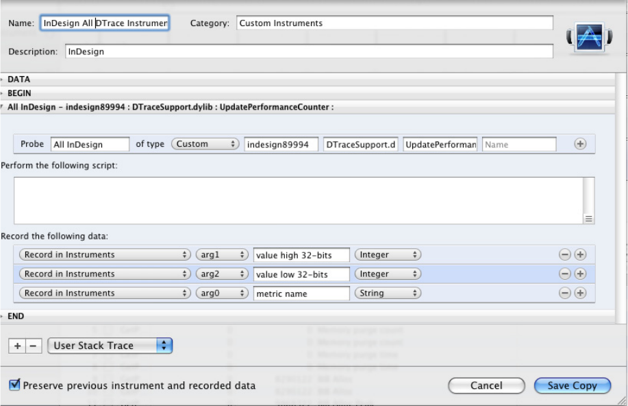
CHAPTER 15: Performance Metrics API Accessing metrics in Instruments 288
13. Click Save Copy.
To create a custom instrument that tracks individual InDesign metrics, perform the steps above, except
also create a predicate to narrow the probe. First, open the Instrument you created above by
double-clicking it. Then, to add a predicate:
1. Click the + sign to the right of your probe.
2. Choose Custom from the leftmost menu.
3. Set Expression to copyinstr(arg0).
4. Choose the == comparison.
5. Set Value to the short name of the metric you want to monitor.
6. To add multiple expressions, click the + sign to the right of your expression and choose the
appropriate boolean expression.
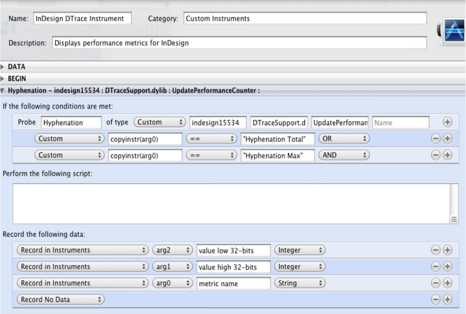
CHAPTER 15: Performance Metrics API Accessing metrics in Instruments 289
After you have set up your Instrument, you can begin a Record session and watch live data output to the
Instruments user interface. Start by choosing Attach to Process > (PID) InDesign from the Launch
Executable menu. Make sure to choose the instance that has the same PID that you used in your
instrument. Next, click Record, and you should see output like the following:
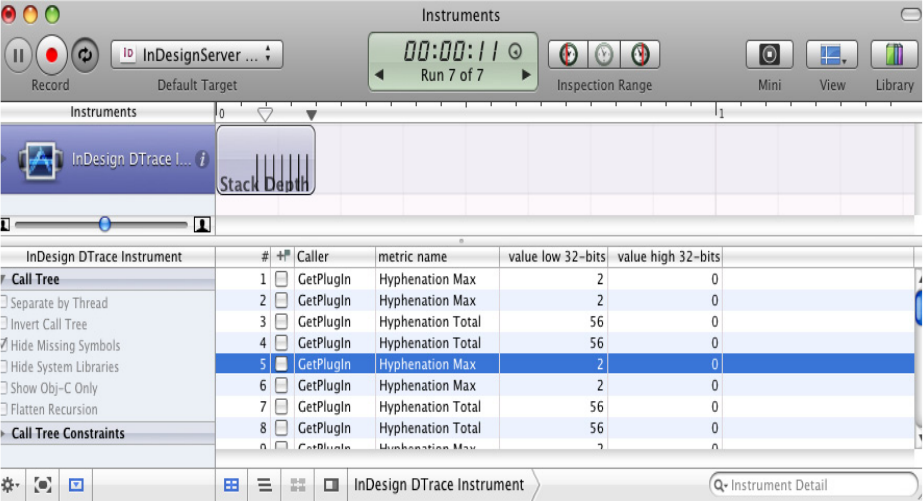
CHAPTER 15: Performance Metrics API Accessing metrics in Instruments 290

291
16 Diagnostics
Introduction
This chapter describes how you can use the diagnostics plug-in when developing plug-ins for InDesign,
InCopy, and InDesign Server. The Diagnostics plug-in provides a detailed look at the internal operations of
command processing; the organization of document content inside spreads, layers and page items; INX
DTD generation; and object model IDs and UIDs. Note, the newer IDML file format supports schema
generation and validation. For information on IDML and RelaxNG schema validation see Adobe InDesign
Markup Language (IDML) Cookbook.
The diagnostics plug-in can help you find answers to questions like the following:
Which commands is the application using to manipulate content?
What is exposed in the scripting Document Object Model (DOM)?
What types of page items are used to store content?
How are page items organized inside spreads and layers?
What is the symbolic name (for example, kSessionBoss) that corresponds to a numeric object model ID
(for example, 0x101)?
What type of boss class does a given UID refer to?
Using the diagnostics plug-in
The diagnostics plug-ins (Diagnostics.apln and DiagnosticsUI.apln) are found on:
Windows in <SDK>\build\win\debug\testing
Mac OS in <SDK>/build/mac/debug/packagefolder/contents/macos/testing
This chapter describes the use of the Diagnostics plug-in through the application user interface and
scripting.
To use the plug-in with the debug build of InDesign or InCopy, select one of the Test > Diagnostics menu
items. To use the plug-in with the release build of InDesign or InCopy or with InDesign Server, you must
use a script. See “Diagnostics > Scripting DOM menu” on page 295.
You can use the diagnostics plug-in to generate traces, which provide an equivalent of printf debug
messages to a log. You can filter messages by category. To see the trace, use the Test > TRACE menu to
enable the logs you want use. If you do not see any traces when you use the plug-in’s menus, make sure
the Diagnostics category is checked on the Test > TRACE menu. Unchecking these categories filters the
Chapter Update Status
CS6 Edited Expanded “What is trace?” on page 297. Other content not guaranteed to be current.
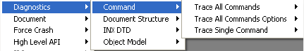
CHAPTER 16: Diagnostics Using the diagnostics plug-in 292
trace produced by the plug-in. If you do not see a Test > TRACE > Diagnostics menu, select Test >
Diagnostics > ObjectModel > TraceID. Some trace output must be written before the Test > TRACE menu
shows the category.
Diagnostics menu
Plug-in options are not persistent; that is, settings you make to control the level of reporting must be
applied for each session.
Diagnostics > Command menu
This menu contains items to trace one or more commands:
The three commands in the menu are described below.
Trace All Commands — This traces all commands being processed by the application. Use this to
discover the command being used to manipulate content in response to a user action. For example,
this trace is created in response to grouping a set of page items:
kMoveReferencePointCmdBoss Diagnostics::ProcessCommand()
kSetDefaultRefPointPositionCmdBoss Diagnostics::ProcessCommand()
kSetAttributeTargetCommandBoss Diagnostics::ProcessCommand()
kGroupCmdBoss Diagnostics::ProcessCommand()
kNewPageItemCmdBoss Diagnostics::ProcessCommand()
kApplyObjectStyleCmdBoss Diagnostics::ProcessCommand()
kBPISetDataCmdBoss Diagnostics::ProcessCommand()
kMoveReferencePointCmdBoss Diagnostics::ProcessCommand()
kSetDefaultRefPointPositionCmdBoss Diagnostics::ProcessCommand()
kSetAttributeTargetCommandBoss Diagnostics::ProcessCommand()
kCheckExportSettingsCmdBoss Diagnostics::ScheduleCommand()
kCheckColorSettingsCmdBoss Diagnostics::ScheduleCommand()
kCheckExportSettingsCmdBoss Diagnostics::ProcessCommand()
kCheckColorSettingsCmdBoss Diagnostics::ProcessCommand()
Trace All Commands Options — Several options are available to control the detail of the information
reported by Trace All Commands:
Data Interfaces — Turn this on to trace the data interfaces (for example, IID_BOOLDATA)
aggregated by each command for parameter passing.
ItemList UIDs — Turn this on to trace the UIDs of objects in each command’s item list.
ItemList ClassIDs — Turn this on to trace the ClassID values of objects in each command’s item list.
Use this to find the type of object (for example, kSplineItemBoss) a command manipulates.
Dynamic Commands — Turn this on to trace dynamic command processing (for example, the
commands processed by a tracker when a page item is moved using the mouse).
Trace Single Command — Once you know the command of interest (for example, kGroupCmdBoss),
you can use Trace Single Command to examine its processing in more detail. Use this when you know
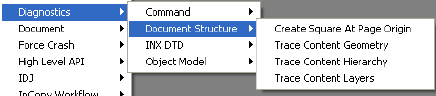
CHAPTER 16: Diagnostics Using the diagnostics plug-in 293
the ClassID of the command about which you want to know more. The trace is indented to show the
commands used by the command of interest. For example:
Begin cmd no. 0 'kGroupCmdBoss' (class id 0x405)
Begin cmd no. 1 'kNewPageItemCmdBoss' (class id 0x2c01)
## Begin Sequence
Begin cmd no. 2 'kGfxApplyMultAttributesCmdBoss'
## Begin Sequence
## End Sequence
End cmd 'kGfxApplyMultAttributesCmdBoss' (class id 0x6e4d)
## End Sequence
End cmd 'kNewPageItemCmdBoss' (class id 0x2c01)
>> Direct Change: SetDirty (id: 125)
>> Direct Change: SetDirty (id: 136)
>> Direct Change: SetDirty (id: 136)
>> Direct Change: SetDirty (id: 140)
>> Direct Change: SetDirty (id: 136)
>> Direct Change: SetDirty (id: 136)
>> Direct Change: SetDirty (id: 125)
>> Direct Change: SetDirty (id: 137)
>> Direct Change: SetDirty (id: 137)
>> Direct Change: SetDirty (id: 140)
>> Direct Change: SetDirty (id: 137)
>> Direct Change: SetDirty (id: 137)
>> Direct Change: SetDirty (id: 125)
>> Direct Change: SetDirty (id: 140)
>> Direct Change: SetDirty (id: 140)
>> Direct Change: SetDirty (id: 137)
>> Direct Change: SetDirty (id: 136)
// Direct Changes are Done
// Root Command is Done
End cmd 'kGroupCmdBoss' (class id 0x405)
Diagnostics > Document Structure menu
The menu contains items to report information on the spreads, pages, and page items in the front
document:
The four commands in the menu are described below.
Create Square At Page Origin— This creates a 100pt-by-100pt square spline at the origin of the current
page in the front-most document and traces the geometry of the object and its parent spread as it
does so.
Trace Content Geometry — This traces the geometry of spreads and page items in their inner
coordinates, relative to their parent object and the pasteboard.
Trace Content Hierarchy — This traces the content of each spread, by the spread layer by which the
content is owned. For example:
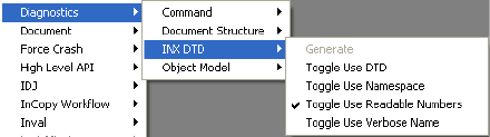
CHAPTER 16: Diagnostics Using the diagnostics plug-in 294
TraceContentHierarchy() ********Begin
kDocBoss, uid 0x1
Untitled-2
kSpreadBoss, uid 0x7a
Spread 1 content by hierarchy...
kSpreadLayerBoss, uid 0x7b
kPageBoss, uid 0x7f
kSpreadLayerBoss, uid 0x7c
kSpreadLayerBoss, uid 0x7d
kSplineItemBoss, uid 0x8c
kImageItem, uid 0x88
kSpreadLayerBoss, uid 0x7e
kMasterPagesBoss, uid 0x81
A-Master master spread content by hierarchy...
kSpreadLayerBoss, uid 0x82
kPageBoss, uid 0x86
kPageBoss, uid 0x87
kSpreadLayerBoss, uid 0x83
kSpreadLayerBoss, uid 0x84
kSpreadLayerBoss, uid 0x85
TraceContentHierarchy() ********End
Trace Content Layers — This traces the content of each spread, by the document layer on which the
content is displayed.
Diagnostics > INX DTD menu
This menu contains items related to INX DTD generation. InDesign Interchange (INX) format is an
XML-based format used to serialize and deserialize the InDesign scripting DOM. The API supports several
options for export to INX file format, and this menu item demonstrates generating DTDs that correspond
to these options.
NOTE: The application itself does not provide these options during export.
The five commands in the menu are described below.
Generate — This generates a DTD according to the current scripting model at run time. This means if
your newly developed plug-in supports scripting, the generated DTD covers that. The menu
command is disabled if no document is open. The generated DTD is saved to the same directory as
InDesign recovery and named INXFile.DTD.
Toggle Use DTD — This toggles use of the DTD. The default setting for INX export is false.
Toggle Use Namespace — This toggles use of the namespace. The default setting for INX export is false.
Toggle Use Readable Numbers — This toggles use of readable numbers. The default setting for INX
export is true. When true, the real number in exported INX is represented as human-readable text;
otherwise, binary.
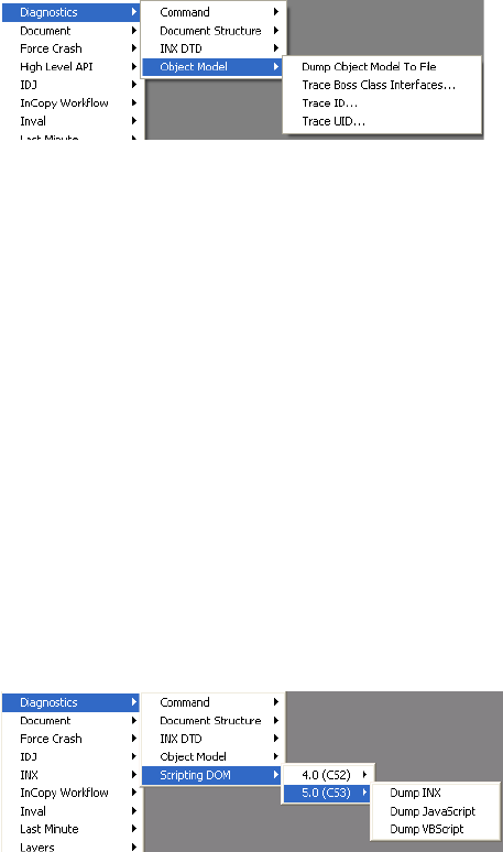
CHAPTER 16: Diagnostics Using the diagnostics plug-in 295
Toggle Use Verbose Name — This toggles use of verbose names. The default setting for INX export is
false. When true, the verbose name is used to represent element and attribute name instead of the
four-character value (for example, “document” instead of “docu”).
NOTE: InDesign supports RelaxNG schema validation of IDML. It does not, and will not, support DTD
validation of INX files. We recommend IDML to assemble and disassemble content outside of InDesign. For
details about schema validation with IDML, see Adobe InDesign Markup Language (IDML) Cookbook.
Diagnostics > Object Model menu
The four commands in the menu are described below.
Dump Object Model To File — This exports the object model to a tab-separated file in the folder where
the application is installed. A record is produced for each interface on each boss class. The output file is
IObjectModel_RomanFS.txt if the application is running with the Roman feature set and
IObjectModel_JapaneseFS.txt if the application is running with the Japanese feature set. These
reports are suitable for import into a spreadsheet or database application. You can then do filtered
searches to get answers to question like “Which boss classes aggregate IID_IATTRREPORT?”
Trace Boss Class Interfaces — This traces the interfaces aggregated by a given boss class.
Trace ID — This traces the symbolic name of a given numeric ID in each ID space.
Trace UID — This traces the ClassID of a given UID, by instantiating an object of that UID in the front
document and examining its associated boss class. If no documents are open, the InDesign Defaults
database is used.
Diagnostics > Scripting DOM menu
The Scripting DOM menu can be used to dump a language-specific scripting DOM to an XML file. It
contains submenus that allow you to specify the product version, followed by the language to dump.
IDML, INX, and JavaScript DOMs are available on both Windows and Mac OS. Also, Visual Basic is available
on Windows, and AppleScript is available on Mac OS.
These XML files can be transformed into two useful HTML representations, using an XSLT processor and
the style sheets included at <sdk>/docs/references/. The scripting-dom-to-html.xsl file produces an HTML
representation of the entire DOM. The scripting-dom-idname-table.xsl file produces a simple table that
maps scriptIDs to names. See the comments at the top of the style sheets for detailed use instructions.
CHAPTER 16: Diagnostics Using the diagnostics plug-in 296
Running the Diagnostics plug-in in indesign/incopy with a script
You may run the Diagnostics plug-in with a script. The following examples demonstrate how to do so
using JavaScript.
The following Windows example dumps the object model to c:\dump.txt:
var myDiagnostics = app.diagnostics;
myDiagnostics.dumpObjectModel("c:\\dump.txt");
// Note: the path separator is \\ and not a single \.
The following Windows example produces c:\vbDOM-5.xml, a Visual Basic DOM for InDesign 5.0 or InCopy
5.0:
var myDiagnostics = app.diagnostics;
myDiagnostics.dumpScriptingDOM(ScriptingDOMLanguage.visualBasic, "5.0",
"c:\\vbDOM-5.xml");
The following Mac OS example dumps the object model to dump.txt on the disk gokkyo:
var myDiagnostics = app.diagnostics;
myDiagnostics.dumpObjectModel("gokkyu:dump.txt");
// Note: posix paths are not supported, use old style for now.
The following Mac OS example produces appleScriptDOM-5.xml, an AppleScript DOM for InDesign 5.0 or
InCopy 5.0:
var myDiagnostics = app.diagnostics;
myDiagnostics.dumpScriptingDOM(ScriptingDOMLanguage.applescriptLanguage, "5.0",
"gokkyu:appleScriptDOM-5.xml");
Once you save a script on your hard drive, you can run it using the Scripts panel. To open the Scripts panel,
select Window > Automation > Scripts. Open the scripts folder, add a shortcut to your script, and run the
script.
Running the Diagnostics plug-in in InDesign Server on Windows with a
script
To run the above scripts with InDesign Server on Windows, open a command window, locate InDesign
Server through Windows Explorer, drag it to the command prompt, and append the port on which you
want it to listen. For example:
<path>\InDesignServer.com -port 12345
Open another command window. Locate sampleclient through Windows Explorer, drag it to the command
prompt, and append the host to which you want it to send. For example:
<path>\sampleclient.exe <path>\MyScript.js -host localhost:12345
Before running InDesign Server, make sure the TCP/IP port (from which InDesign Server is listening for
SOAP messages) is open (especially if you have a firewall set up).
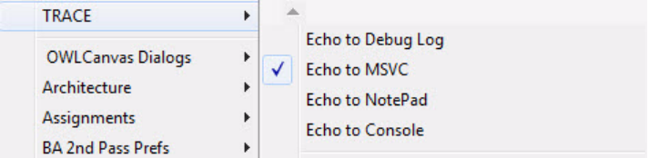
CHAPTER 16: Diagnostics Frequently asked questions 297
Running the Diagnostics plug-in in InDesign Server on Mac OS with a
script
To run the above scripts with InDesign Server on Mac OS, open a terminal window, locate InDesign Server
through the Finder, drag it to the terminal window, and append the port on which you want it to listen. For
example:
<path>/InDesignServer -port 12345
Open another terminal window. Locate sampleclient using the Finder and drag it to the terminal window.
Append the host to which you want it to send. For example:
<path>/sampleclient <path>/MyScript.js -host localhost:12345
Before running InDesign Server, make sure the TCP/IP port (from which InDesign Server is listening for
SOAP messages) is open (especially if you have a firewall set up).
Frequently asked questions
Where is the Diagnostics panel?
The user interface for the features provided by the Diagnostics plug-in is in the Test > Diagnostics menu.
The panel used by previous versions of this plug-in is no longer needed.
What is trace?
The easiest way to gather debug information is to use the debug facility’s trace command, which is
available in InDesign Build. A trace provides a printf style of debug log. Traces are available only with the
debug build of InDesign Build; trace output under the release build is not supported.
When a trace statement is executed, the output goes to one or more trace logs. Use the Test > TRACE
menu to enable the logs that you want use. The choices are:
Windows:
Debug Log file: The Trace output is exported into a text file named like Debug Logxxxx.txt.
MSVC’s debug window: If you are running InDesign Debug with the plug-in under Visual Studio,
trace outputs are exported to Visual Studio’s output window.
Notepad: The Notepad application is launched and the trace output is exported into a Notepad
file.
Console: cmd.exe is launched and trace output is displayed on the Console.
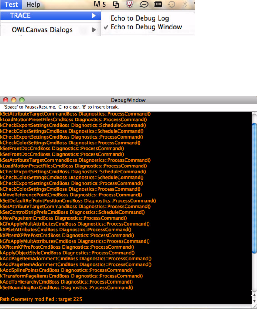
CHAPTER 16: Diagnostics Frequently asked questions 298
Macintosh:
Debug Log file: The Trace output is exported into a text file named like Debug Logxxxx.txt.
DebugWindow: This is a Macintosh-only utility for viewing Trace output. To use it, manually
launch the utility, which resides in the <SDK>/devtools/bin folder, before starting InDesign
Debug. The Trace output is exported to the DebugWindow as if it were a console window. The
following is a screen shot of DebugWindow.
Why don’t I get trace messages?
Make sure you checked one of the available logs presented on the Test > TRACE menu and Test > TRACE >
Diagnostics is selected. If you do not see a Test > TRACE > Diagnostics menu, use Test > Diagnostics >
ObjectModel > TraceID first. (Some trace output must be written to the category before the Test > TRACE
menu shows it.)
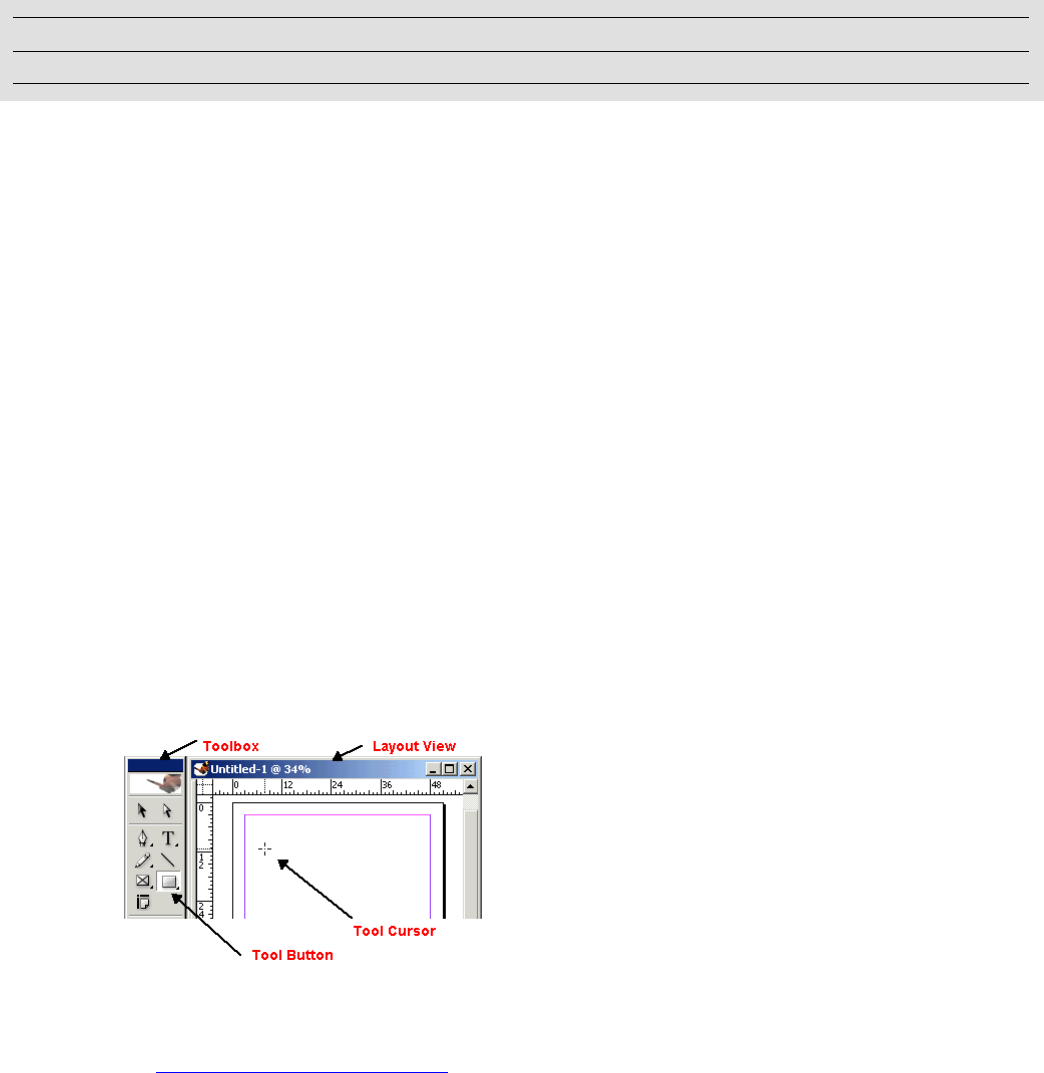
299
17 Tools
This chapter describes how tools work and how to implement your own custom tools and add them to the
toolbox.
The chapter has the following objectives:
Define terms related to tools, trackers, and the toolbox.
Introduce the layout view.
Explain how tools work.
Explain how to track the user’s mouse actions.
Explain how to implement a custom tool.
Describe the extension patterns provided by the API that relate to tools.
Key concepts
The toolbox and the layout view
Tools are presented using the toolbox palette. Document content is presented in the layout view. Tools
create and manipulate document objects using keyboard and mouse events in the layout view. This is
illustrated in the following figure.
The layout view is a widget in which a document is presented and edited by the user. The layout view is the
IControlView interface on the kLayoutWidgetBoss boss object. For more information on the layout widget,
see Chapter 7, “Layout Fundamentals.”
Tools commonly use interfaces on kLayoutWidgetBoss to discover the context in which they are working.
For example, the spread being manipulated is found using ILayoutControlData, and hit testing can be
Chapter Update Status
CS6 Unchanged
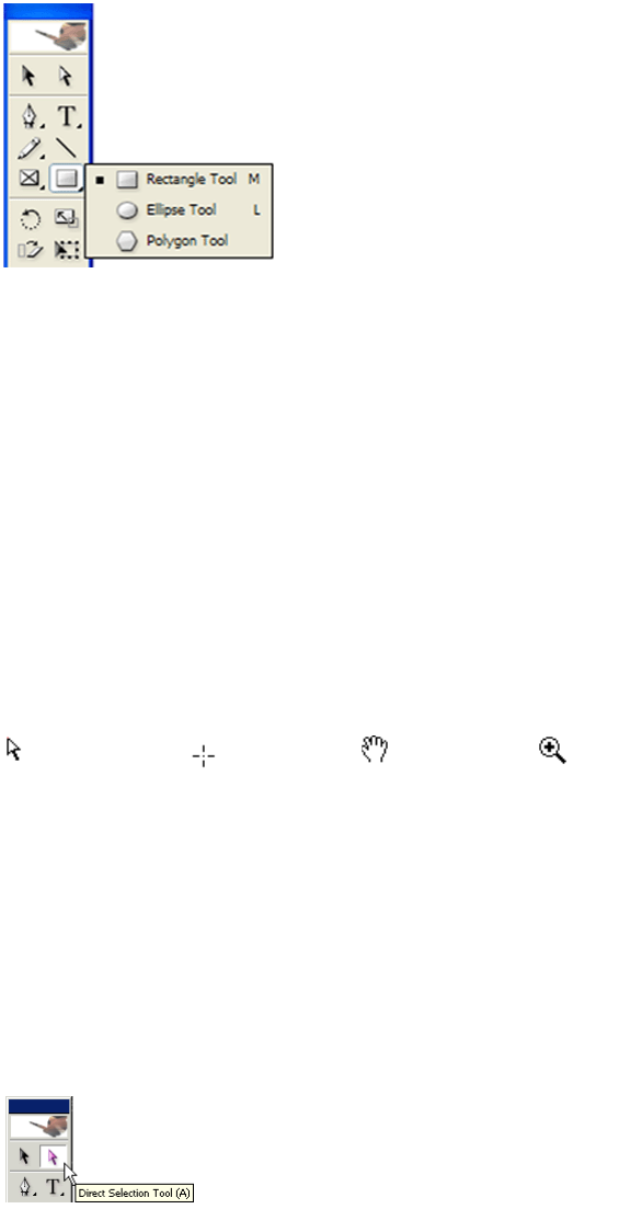
CHAPTER 17: Tools Key concepts 300
done using ILayoutControlViewHelper. The toolbox contains a tool button icon for each tool and,
optionally, a hidden-tools panel containing other tools (see the following figure).
Tools
A tool (ITool interface) has a button icon in the toolbox and, optionally, a keyboard shortcut. A tool also
may provide a cursor (pointer) as a visual cue to the user of the active tool and a tool tip to help the user
understand the purpose of the tool. To track mouse actions when the tool is being used, the tool provides
a tracker (ITracker interface).
Cursors
A cursor (ICursorProvider interface) provides a visual cue to the user of the active tool. Tools that provide
their own cursors must implement cursor providers. Cursor providers set the mouse cursor and provide
context-sensitive cursors for different areas of the screen. See the following figure.
Tool tips
A tool tip (ITip interface) displays a string with the name of the tool and its keyboard shortcut, when the
pointer is positioned over the tool icon in the toolbox. See the following figure. The strings displayed are
declared as ODFRez string resources in the plug-in’s .fr file. The application automatically handles display
of tool tips.
Direct Select Path Creation Grabber Hand Zoom In
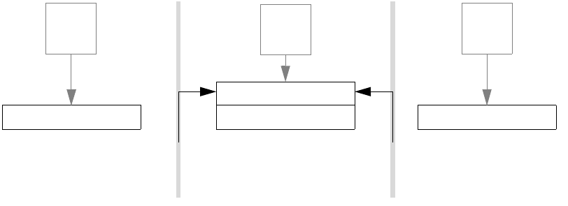
CHAPTER 17: Tools Key concepts 301
Trackers
Trackers (ITracker interface) monitor mouse movement while an object is being manipulated by a tool.
Trackers can provide visual feedback to the user. Trackers make changes to the objects being manipulated
using commands. A tool may have one or more trackers, though only one tracker is active at a time.
Tracker factory, tracking, and event handling
The tracker factory (ITrackerFactory interface) allows you to introduce new trackers by manufacturing the
tracker required for a particular context. The ITrackerFactory interface is aggregated on the kSessionBoss
boss class. The tracker factory maintains a table associating a tracker with a given widget and tool by
ClassID. When the tool is used in the context of the widget, the associated tracker is created and receives
control. Trackers for tools that appear in the toolbox register themselves as being associated with the
layout widget, kLayoutWidgetBoss. The code in the following example adds an entry to the tracker factory.
void LineTrackerRegister::Register(ITrackerFactory *factory)
{
factory->InstallTracker(kLayoutWidgetBoss, kLineToolBoss, kLineTrackerBoss);
}
The framework maintains an event-handler stack that it uses to dispatch events (mouse, keyboard, and
system events). Many event handlers (IEventHandler interface) are associated with a widget. The widget
that has the user-interface focus is on top of the stack and receives and processes events.
When a mouse-down event occurs in layout view and the active tool is kLineToolBoss, the layout view’s
event handler asks the tracker factory to manufacture the tracker for this context. It does this by making
the following call to create kLineTrackerBoss and return its ITracker interface:
ITrackerFactory::QueryTracker(kLayoutWidgetBoss, kLineToolBoss)
The tracker is then focused on the layout view and begins tracking.
To follow mouse movement, a tracker must handle events for the duration of the tracking process. To do
this, the tracker pushes its event-handler interface onto the stack when tracking begins and pops it off the
stack when tracking ends. For example, when the Line tool is used to drag the end points of a line, its
tracker pushes and pops its event handler as shown in the following figure.
All tracker boss classes that want to follow the mouse as it is dragged aggregate an IEventHandler
interface. When the LayoutEventHandler receives a mouse-down event, it calls the tracker’s
ITracker::BeginTracking method, which normally is implemented by CTracker::BeginTracking. If the mouse
is to be tracked, this method calls CTracker::EnableTracking, which calls CTracker::PushEventHandler to
LineTrackerEventHandler
LayoutEventHandler LayoutEventHandler
Event Event
LayoutEventHandler
Event
Event handler stack
before tracking
Event handler stack
during tracking
Event handler stack
after tracking
Push Pop

CHAPTER 17: Tools Key concepts 302
push the tracker’s event handler (interface IEventHandler) onto the event-handler stack using
IEventDispatcher::Push. For more implementation details, see CTracker.cpp in the SDK.
Beyond the toolbox
Tools do not have to appear in the toolbox. For example, the Place tool is activated after selecting a file
using the File > Place menu command. Trackers also are used extensively in mouse-dragging features, like
setting the layout zero point and dragging guides from rulers.
Drawing and sprites
To provide visual feedback while an object is undergoing manipulation, a tracker can draw to the screen.
Page items can be hard to draw when they are being changed dynamically. To ensure objects are drawn on
the screen smoothly and efficiently without flickering, the application provides a sprite API. A sprite
(ISprite interface) is a graphic object that can be moved around on screen without causing any disturbance
to the background.
Documents, page items, and commands
Tools allow the manipulation of documents and page items by the user. For more information on how
documents are organized and page items are arranged, see Chapter 7, “Layout Fundamentals.” Tools use
commands to make changes to a document.
Line-tool use scenario
The following scenario describing the Line tool shows how the objects in a tool collaborate.
The scenario is divided into three sections:
Control is concerned with the registration of the tool with the application and the mechanism
allowing the user to select the tool
Dispatch is concerned with how the application begins active use of the tool.
Behavior is concerned with what the tool does to create a line.
The following figure shows how the Line tool registers with the application and is used to create a line
between two points in a document. The table following the figure defines the abbreviations used in the
figure.
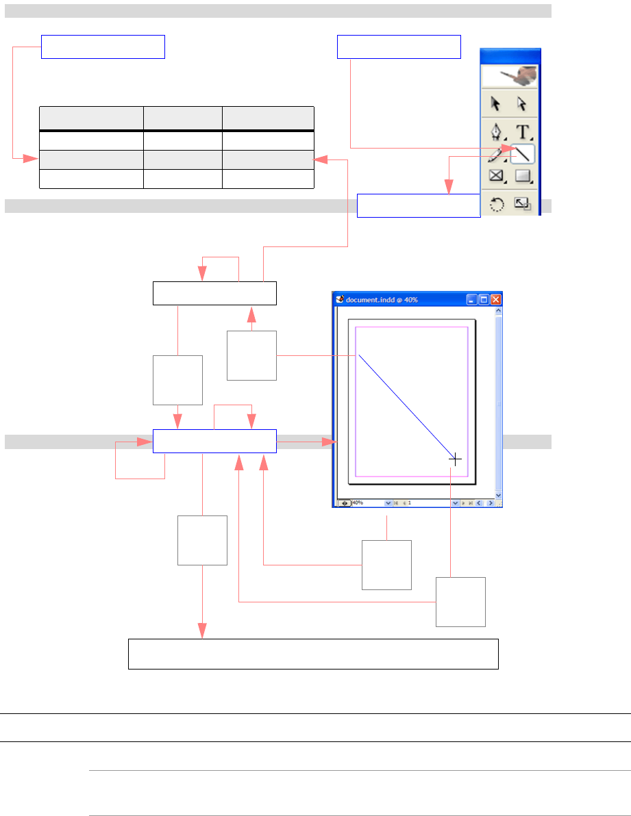
CHAPTER 17: Tools Key concepts 303
Figure area Abbreviation Description
Control C1 The tool’s tracker is registered with the application’s tracker factory.
C2 The tool is registered with the application, and its tool-button icon in the
toolbox is initialized.
C3 The user clicks the tool’s button icon (kLineToolBoss becomes the active
tool).
Drag &
other
events
Behavior
LayoutEventHandler
LineTracker
LayoutWidget/LayoutView
LineTool
LineTrackerRegister LineToolRegister
Control
Dispatch
Mouse-
down
event
Mouse-
up
event
Cmd
Document
Mouse-
down
event
Tracker factory
Widget To o l Tr a c k er
... ... ...
kLayoutWidgetBoss k LineToolBoss kLineTrackerBoss
... ... ...
Toolbox
C1 C2
C3
D1
D3
D4
B1
B2 B4
B5
B3
D2
B6
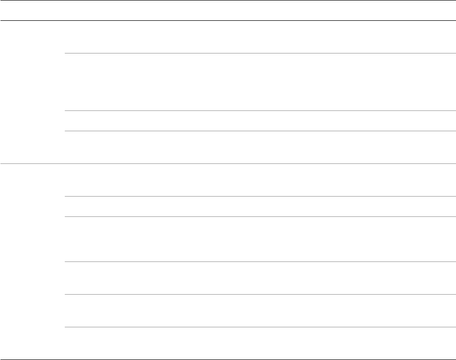
CHAPTER 17: Tools Key concepts 304
The scenario shown in the figure is typical of a tool that creates items. The item itself is created by the
tracker, using a command after the user releases the mouse button; however, other categories of tools
may execute commands dynamically, while tracking the mouse. For example, the Selection tool
dynamically executes commands when moving or resizing items.
Trackers with multiple behaviors
If a tracker needs to exhibit multiple behaviors, it can create another tracker that depends on the context.
For example, the Selection tool exhibits multiple behaviors. When it is active and a mouse-down event
occurs in a layout view, the pointer tracker (kPointerTrackerBoss) is created. The pointer tracker considers
the context of the click, then creates and dispatches control to another tracker. Once the pointer tracker
examines the context and creates an appropriate tracker, its job is done. The trackers used by
kPointerTrackerBoss to move and resize page items are shown in the following figure.
Pointer tracker move and resize behavior:
Dispatch D1 The user clicks in the layout view (a mouse-down event is passed to the
LayoutEventHandler).
D2 The LayoutEventHandler looks at the active tool (kLineToolBoss) and the
context of the event (mouse-down over an empty page area). The
association identifies the tracker that should be created for the context
(kLineTrackerBoss).
D3 The appropriate tracker is manufactured by the tracker factory.
D4 The tracker is asked to begin tracking the mouse from the original
mouse-down event.
Behavior B1 The tracker pushes its own event handler onto the application’s event
handler stack, so it can receive events and track the mouse.
B2 The user drags the mouse (events are passed into the tracker).
B3 The tracker provides appropriate dynamic visual feedback to the user of
the tool behavior: a line is drawn between the location of the original
mouse-down event and the current mouse position.
B4 The user releases the mouse (a mouse-up event is passed into the
tracker).
B5 The tracker implements an appropriate action (creation of a page item
describing the line between start and end points), using a command.
B6 The tracker pops its event handler from the application’s event-handler
stack, and tracking is complete.
Figure area Abbreviation Description
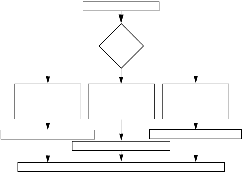
CHAPTER 17: Tools Key concepts 305
This figure does not show all kPointerTrackerBoss behaviors. For example, the following are not shown in
the figure:
The threading of text frames via in and out port handles by kPrePlaceTrackerBoss.
The tracking of when the layer on which the item lies is locked (kLockTrackerBoss).
The tracking of text on a path-handle manipulation (kTOPResizeTrackerBoss and
kTOPMoveTrackerBoss).
Each page item can register its own resize tracker, although they all use the same one for resizing.
Tool manager
Tools are managed by the tool manager, kToolManagerBoss. You can navigate to the IToolManager
interface as shown in the following code:
InterfacePtr<IApplication> app(GetExecutionContextSession()->QueryApplication());
InterfacePtr<IToolManager> toolMgr(app->QueryToolManager());
Toolbox utilities
The IToolBoxUtils interface provides a facade that should, in most situations, save you from having to
program to the IToolManager interface. IToolBoxUtils is a utility interface on kUtilsBoss, accessed in the
standard way. For example, the following code queries the active tool of type kPointerToolBoss. The tool
type in this context identifies a group of tools, of which only one can be active:
Create resize tracker to
resize the page item as the
user drags. Each page item
registers its own resize
tracker.
PointerTracker::BeginTracking()
Mouse-down on
Page item bounding box
Empty area
Page item resize handle
MoveTracker::BeginTracking()
LayoutSelectionTracker::BeginTracking()
CRectResizeTracker::BeginTracking()
PointerTracker complete
Create layout selection
tracker to draw a marquee
selection as the user drags
and set the selection on
mouse-up.
Create move tracker to
move the page item as the
user drags.

CHAPTER 17: Tools Custom tools 306
const ClassID toolType = kPointerToolBoss;
InterfacePtr<ITool> currentTool(
Utils<IToolBoxUtils>()->QueryActiveTool(toolType));
Tool type
Tools are categorized as belonging to one or more of the categories given by ITool::ToolType. This
identifies what the tool does and how the selection in the layout view reacts when that tool becomes
active (IToolChangeSuite interface). Tools identify this type in their CTool constructor by the toolInfo
parameter.
ITool::ToolType easily can be confused with the ClassID parameter toolType defined by the tool’s ToolDef
statement (see “ToolDef ODFRez type” on page 308) and used by ITool::GetToolType and other APIs. This
ClassID is used to identify a group of mutually exclusive tools—tools for which only one tool of a given tool
type can be selected in the toolbox at any time.
The table in “Tool-category information” on page 312 illustrates the distinction between these two
different tool types and their values.
Custom tools
Architecture
This section describes the boss classes, interfaces, and resources you must implement to add a new tool.
The section also describes the APIs you use to build and catalogue custom tools.
Plug-ins that implement tools typically provide the following:
A tool-register boss class.
A tracker-register boss class.
A tool boss class per tool.
A tracker boss class per tracker.
Resources controlling how the tool is displayed.
Class diagram
The classes typically found in a custom tool are shown in the following figure.
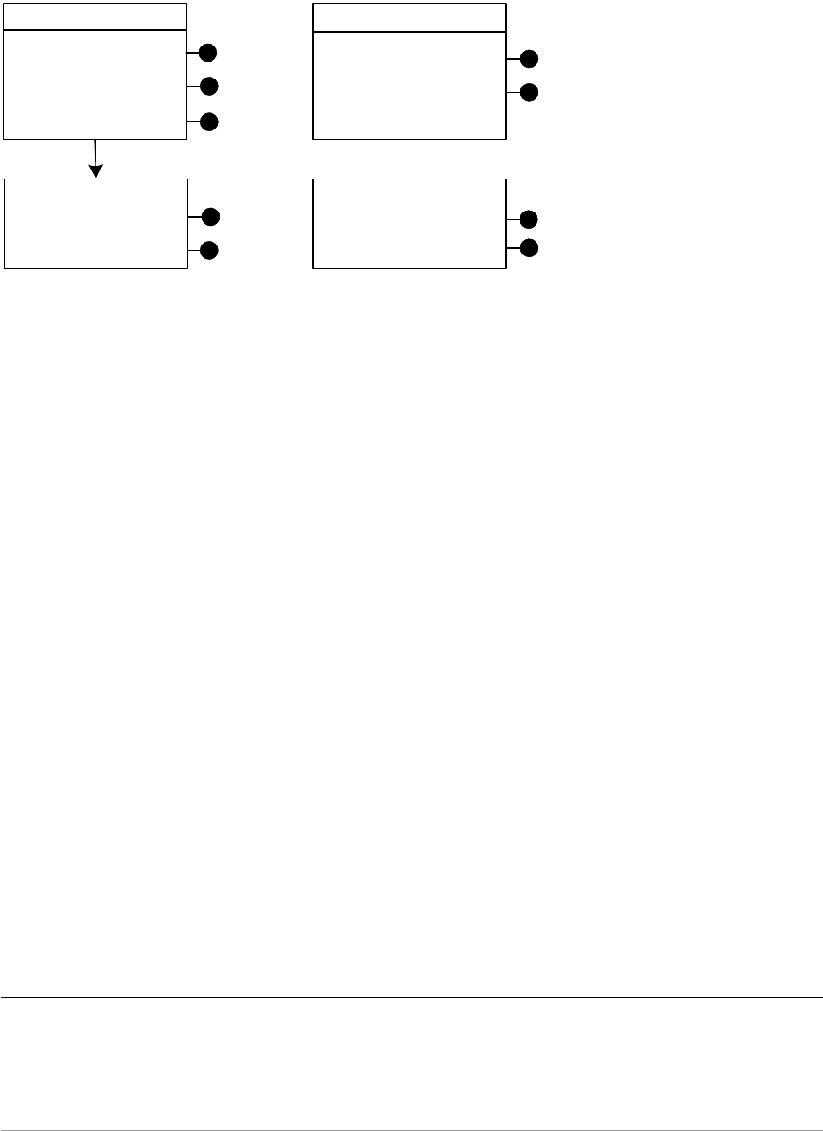
CHAPTER 17: Tools Custom tools 307
kYourTrackerRegisterBoss registers the plug-in’s trackers with the tracker factory using the ITrackerRegister
interface.
kYourToolBoss allows the tool manager to control the tool using the ITool interface. kYourToolBoss
specifies information about the tool and gets called when the tool is selected or deselected by the user
and when a tool options dialog box should be displayed. ICursorProvider allows the tool to customize the
cursor when the tool is active. IPMPersist allows information like the tool’s name and icon to be saved
persistently.
kGenericToolBoss is the parent boss class for toolbox tools. The control view it provides displays the tool's
buttons, and its event handler handles clicks on the tool’s buttons in the toolbox.
kYourTrackerBoss responds to mouse actions in the layout view when your tool is being used. There is at
least one tracker boss for each tool in your plug-in. The interfaces on a tracker boss class collaborate to
provide the active behavior of the tool. Control is passed to the ITracker interface, so the mouse can be
tracked. This interface manages and controls the other interfaces on the boss object.
The tracker pushes its event handler to the top of the event handler stack when tracking begins. During
tracking, IEventHandler forwards events into the ITracker interface. When tracking ends, the event handler
is popped from the stack, and the tracker is finished. Standard tracker event-handler implementations are
provided by the API. It is common for tracker boss classes to have other interfaces particular to their needs.
For example, trackers that create splines aggregate ISprite and IPathGeometry. If a tracker needs to handle
only one mouse click, however, it does not require an IEventHandler.
Partial implementation classes
The API provides helper classes that partially implement interfaces relevant to building tools. Some
relevant classes are shown in the following table. For more information, refer to the API Reference for each
class.
kGenericToolBoss
IControlView
kYourToolBoss
ITool
ICursorProvider
IPMPersist
kYourTrackerRegisterBoss
ITrackerRegister
IK2ServiceProvider
kYourTrackerBoss
ITracker
IEventHandler IEventHandler
Interface Class
ICursorProvider CToolCursorProvider
IEventHandler CTrackerEventHandler (the C++ source code for this implementation is provided on
the SDK)
ITool CTool
ITracker CTracker (the C++ source code for this implementation is provided on the SDK)
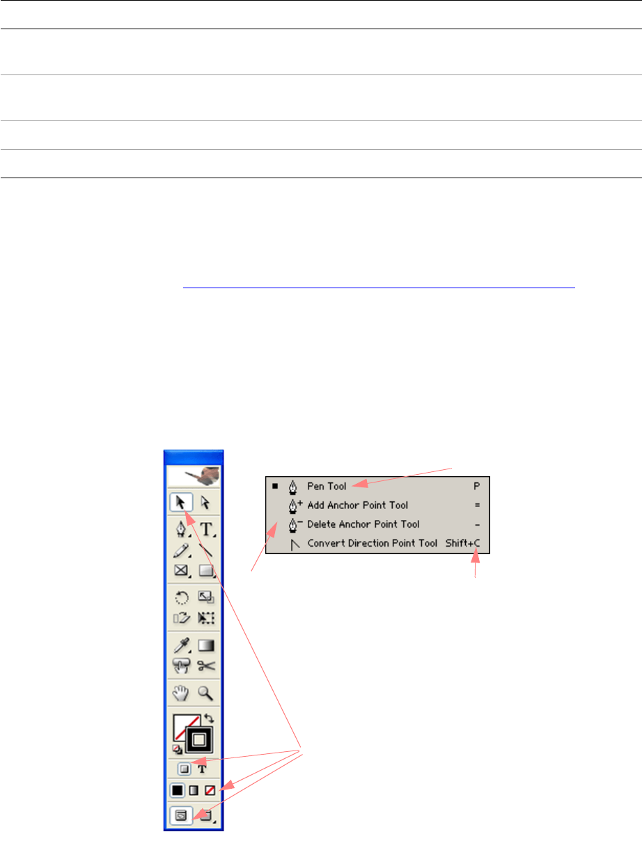
CHAPTER 17: Tools Custom tools 308
Default implementations
The API provides default implementations that completely implement some of the interfaces involved in
building tools. If these meet your needs, you can reuse them in your boss class definition and avoid writing
the C++ code. See the table in “Default implementations of tool-related interfaces” on page 314 for a list of
reusable implementations in the API.
ToolDef ODFRez type
ODFRez provides a type, ToolDef, that controls how a tool is displayed within the toolbox. This type
controls the order in which tools are displayed, the way in which they are grouped, and other properties,
as shown in the following figure.
ToolDef resources are localizable, so you can define different resources for different locales and have a tool
show up in a different place or with a different icon. For example, for a currency stamp tool, a tool icon
could be provided for each locale (for example, dollar and yen) and the icon for the current locale would
ITracker CPathCreationTracker (the C++ source code for this implementation is provided on
the SDK)
ITracker CLayoutTracker (the C++ source code for this implementation is provided on the
SDK)
ITracker CSliderTracker
ITrackerRegister None
Interface Class
Hidden tools panel
Subtools
Group numbers Parent tool
kFirstAdobeToolsGroup
kSecondAdobeToolsGroup
kThirdAdobeToolsGroup
kFourthAdobeToolsGroup
kFifthAdobeToolsGroup
kNinthAdobeToolsGroup
kTenthAdobeToolsGroup
kSeventhAdobeToolsGroup
Shortcut
Selected tools
Only one tool of a given tool type
can be selected at any one time in
the toolbox. Since four tools are
shown as selected, this toolbox has
four distinct tool types.

CHAPTER 17: Tools Custom tools 309
be shown in the toolbox. To localize your ToolDef resources, add a locale index to your plug-in’s .fr file and
define a ToolDef resource in the .fr file for each locale.
Icons and cursors
Icons and cursors can be created in their native-platform resource form. InDesign also supports PNG
platform-independent files for icons, which is the preferred resource type to use in icon-based widgets. All
the application tools’ icons use PNG files, so they all have rollover effect.
To create a PNG-based icon:
1. In your .fr file, where you have the ToolDef, declare the PNG resources. There should be two states for
each each icon, normal and rollover. For example, the SDK Info button seen in several SDK dialog uses
the following PNG resources
resource PNGA(kSDKDefIconInfoResourceID) "SDKInfoButton.png"
resource PNGR(kSDKDefIconInfoRolloverResourceID) "SDKInfoButtonRollover.png"
2. Two PNG resources are defined in Step 1. The normal state, PNGA, has an ID of
kSDKDefIconInfoResourceID and uses the SDKInfoButton.png file. The rollover state, PNGR, has an ID
of kSDKDefIconInfoRolloverResourceID and uses the SDKInfoButtonRollover.png file. Both IDs should
be defined as the same number; in this case, both are defined as 180 in the SDKDef.h file.
3. Use the normal-state resource ID in your ToolDef definition, where you specify the icon ID for the tool.
Mac OS icons need resources of type icl4, icl8, and ICN#. Cursors need resources of type CURS.
Windows icons need an icon bitmap .ico file and an ICON resource declaration in your plug-in project’s .rc
file. Cursors need a cursor bitmap .cur file and a CURSOR resource declaration in your plug-in project’s .rc
file.
Tool-button icons come in two sizes: standard and mini. Normally, you use the standard size,
kStandardToolRect. CTool specifies the widget rects involved. In your CTool::Init implementing, you control
the size to be used by calling CTool::InitWidget and passing in the tool rects.
InDesign trackers
The API provides many trackers, and you may want to dispatch control to one of them. Generally, these can
be divided into trackers used by tools to manipulate document content (see “Tool-related trackers” on
page 315) and trackers used by user-interface widgets to manipulate controls (see User-interface
widget-related trackers). The ClassID needed by ITrackerFactory to make one of these trackers are listed in
these tables.
Since no iterator generates all registered trackers the application supports at run time, two distinct tables
are shown: one for tool-related trackers (“Tool-related trackers” on page 315) and another for
user-interface widget–related trackers (User-interface widget-related trackers).
Often, the application’s existing trackers can be reused for your custom tools. For example, suppose you
implemented a custom tracker, and the application already provides another tracker to which, under
certain circumstances, you want to pass control. Suppose you want to pass control to the pointer tracker,
kPointerTrackerBoss. You look up the tracker ClassID in the Tracker ClassID column of the following tables
and find the relevant widget ClassID and tool ClassID. You then pass these into
ITrackerFactory::QueryTracker.

CHAPTER 17: Tools Working with tools 310
If desired, you can suppress or replace one of the application’s trackers. See “Tool-related trackers” on
page 315 for a list of tool-related trackers.
Working with tools
Catching a mouse click or mouse drag on a document
If you want users to recognize that your tool will handle the event, you want a custom cursor. In this case,
you need to implement a custom tool, set your tool as the active tool, and handle the mouse event in your
tracker (see “The toolbox and the layout view” on page 299).
If you do not want users to recognize that your tool will handle the event, you probably want to handle the
event without the user receiving any visual cue. In this case, use another stimulus, like a change in
selection, to push an event handler onto the event-handler stack. If you are in doubt about what stimulus
to choose, use a tool and tracker. This is the recommended way to catch mouse events in a layout view on
a document.
Implementing a custom tool
See “Custom tools” on page 306, or refer to one of the sample tool plug-ins and adapt it to your needs.
Displaying a Tool Options dialog box
Specialize the DisplayOptions and/or DisplayAltOptions methods in your ITool implementation. For an
example, see SnapTool::displayOptions in the Snapshot sample.
Finding the spread nearest the mouse position
When implementing a tracker, you need to handle the fact that the user can click on any spread in a layout
view. Your tracker must identify the spread on which the user has clicked. To do this, transform the position
from the system-coordinate system to the pasteboard-coordinate system, then use one of the methods in
IPasteboardUtils.
Changing spreads
When implementing a tracker, you need to handle the fact that the user can click on any spread in a layout
view. A layout view caches the current spread in the ILayoutControlData interface. Your tracker may need
to change this if the spread that was clicked on is different. Process kSetSpreadCmdBoss to change to
another spread.
Performing a page-item hit test
ILayoutControlViewHelper provides page-item hit-testing methods that can be used. For an example of
using ILayoutControlViewHelper, see <SDK>/source/sdksamples/codesnippets/SnpHitTestFrame.cpp.

CHAPTER 17: Tools Working with tools 311
Setting or getting the active tool
IToolBoxUtils provides methods you can use to set or get the active tool. For an example of activating the
Text tool, see <SDK>/source/sdksamples/codesnippets/SnpManipulateTextFrame.
Observing when the active tool changes
Attach an observer (IObserver interface) to kToolManagerBoss. In your Update method, detect the
IID_ITOOLMANAGER protocol for the change kSetToolCmdBoss.
Changing the toolbox appearance from normal to skinny
Use kSetUserInterfacePrefsToolboxCmdBoss or IUserInterfacePreferencesFacade to change the
IUserInterfacePreferences.
Using default implementations for trackers
Your tracker can create and dispatch control to a tracker supplied by the application. For example, to
perform a marquee selection, you can create and dispatch control to a kLayoutSelectionTrackerBoss. For a
complete list of all trackers provided by the API, see Tool-related trackers.
Suppressing the application's default tracker for a custom toolbox
Suppose you implemented a special text tool on your custom toolbox that is to replace the Adobe
standard toolbox. You do not want your text tool to create a text frame and only allow editing of text.
In this case, the frame creation you want to suppress is registered in the tracker factory under
kIBeamToolBoss and kFrameToolBoss. The tracker ClassID installed is kFrameTrackerBoss. When your
custom toolbox is activated, you could save this registered tracker and replace it with your own, using the
code in the following example.
InterfacePtr<ITrackerFactory> factory(GetExecutionContextSession(), UseDefaultIID());
if (factory)
{
InterfacePtr<ITracker> registeredTracker(factory->QueryTracker(kIBeamToolBoss,
kFrameToolBoss));
ClassID savedClassID = ::GetClassID(registeredTracker);
if (registeredTracker)
{
factory->RemoveTracker(kIBeamToolBoss, kFrameToolBoss);
factory->InstallTracker(kIBeamToolBoss, kFrameToolBoss, kYourTrackerBoss);
}
}
In this case, when the text-tool tracker tries to drag out a new frame, your tracker receives the control. If
your CTracker::DoBeginTracking method returns kFalse, you suppress the frame-creation behavior. When
your custom toolbox is deactivated, restore the previously registered tracker.
There is one drawback to this mechanism. If more than one third-party plug-in tries to replace the same
tracker, there is the potential for a collision. If you use the activation or deactivation of your toolbox or tool
to replace or restore the registered tracker, such collisions can be avoided.

CHAPTER 17: Tools Tool-category information 312
Tool-category information
Tool Tool boss ITool::ToolType ClassID toolType
Add Anchor Point kSplineAddPointToolBoss kLayoutManipulationTool,
kPathManipulationTool
kPointerToolBoss
Apply color kBoss_ApplyCurrentColorTool kNone kBoss_ClearFillStrokeTool
Apply gradient kBoss_ApplyCurrentGradientTool kNone kBoss_ClearFillStrokeTool
Apply none kBoss_ClearFillStrokeTool kNone kBoss_ClearFillStrokeTool
Bleed mode kBleedModeToolBoss kNone kNormalViewModeToolBoss
Convert Direction kSplineDirectionToolBoss kLayoutManipulationTool,
kPathManipulationTool
kPointerToolBoss
Delete Anchor kSplineRemovePointToolBoss kLayoutManipulationTool,
kPathManipulationTool
kPointerToolBoss
Direct Selection kDirectSelectToolBoss kLayoutSelectionTool,
kPathManipulationTool
kPointerToolBoss
Erase kEraseToolBoss kLayoutCreationTool,
kLayoutManipulationTool,
kPathManipulationTool
kPointerToolBoss
Eyedropper private kLayoutManipulationTool,
kTextManipulationTool,
kTableManipulationTool
kPointerToolBoss
Fill stroke kStrokeFillProxyToolBoss kNone
Free transform tool kFreeTransformToolBoss kLayoutManipulationTool kPointerToolBoss
Gradient kGradientToolBoss kLayoutManipulationTool,
kTextManipulationTool,
kTableManipulationTool
kPointerToolBoss
Hand kGrabberHandToolBoss kViewModificationTool kPointerToolBoss
Horizontal frame grid
(Japanese feature set)
private kLayoutCreationTool kPointerToolBoss
Horizontal text on a
path
kTOPHorzToolBoss kTextSelectionTool,
kTableSelectionTool,
kTextManipulationTool,
kTableManipulationTool,
kTextCreationTool,
kTableCreationTool
kPointerToolBoss
Line kLineToolBoss kLayoutCreationTool kPointerToolBoss
Normal view mode kNormalViewModeToolBoss kNone kNormalViewModeToolBoss

CHAPTER 17: Tools Tool-category information 313
Oval kOvalToolBoss kLayoutCreationTool kPointerToolBoss
Oval Frame kOvalFrameToolBoss kLayoutCreationTool kPointerToolBoss
Pen kSplinePenToolBoss kLayoutCreationTool,
kLayoutManipulationTool,
kPathManipulationTool
kPointerToolBoss
Pencil kPencilToolBoss kLayoutCreationTool,
kLayoutManipulationTool,
kPathManipulationTool
kPointerToolBoss
Place kPlaceToolBoss kNone (The place tool
creates page items and is
in theory a layout
-creation tool, but
because it does not
appear in the toolbox, it
has no category as such.)
not applicable
Preview mode kPreviewModeToolBoss kNone kNormalViewModeToolBoss
Rectangle kRectToolBoss kLayoutCreationTool kPointerToolBoss
Rectangle Frame kRectFrameToolBoss kLayoutCreationTool kPointerToolBoss
Regular Polygon kRegPolyToolBoss kLayoutCreationTool kPointerToolBoss
Regular Polygon Frame kRegPolyFrameToolBoss kLayoutCreationTool kPointerToolBoss
Rotate kRotateToolBoss kLayoutSelectionTool,
kLayoutManipulationTool
kPointerToolBoss
Scale kScaleToolBoss kLayoutSelectionTool,
kLayoutManipulationTool
kPointerToolBoss
Scissors kScissorsToolBoss kLayoutManipulationTool,
kPathManipulationTool
kPointerToolBoss
Selection kPointerToolBoss kLayoutSelectionTool kPointerToolBoss
Shear kShearToolBoss kLayoutSelectionTool,
kLayoutManipulationTool
kPointerToolBoss
Slug mode kSlugModeToolBoss kNone kNormalViewModeToolBoss
Smooth kSmoothToolBoss kLayoutCreationTool,
kLayoutManipulationTool,
kPathManipulationTool
kPointerToolBoss
Type kIBeamToolBoss kTextSelectionTool,
kTableSelectionTool,
kTextManipulationTool,
kTableManipulationTool,
kTextCreationTool,
kTableCreationTool
kPointerToolBoss
Tool Tool boss ITool::ToolType ClassID toolType

CHAPTER 17: Tools Default implementations of tool-related interfaces 314
Default implementations of tool-related interfaces
Vertical frame grid
(Japanese feature set)
private kLayoutCreationTool kPointerToolBoss
Vertical text on a path
(Japanese feature set)
kTOPVertToolBoss kTextSelectionTool,
kTableSelectionTool,
kTextManipulationTool,
kTableManipulationTool,
kTextCreationTool,
kTableCreationTool
kPointerToolBoss
Zoom kZoomToolBoss kViewModificationTool kPointerToolBoss
Tool Tool boss ITool::ToolType ClassID toolType
Interface ImplementationID
IK2ServiceProvider kCToolRegisterProviderImpl
IK2ServiceProvider kCTrackerRegisterProviderImpl
IEventHandler kCTrackerEventHandlerImpl
ICursorProvider kCreationCursorProviderImpl,
kDirectSelectCursorProviderImpl, kRotateCursorProviderImpl,
kGrabberHandCursorProviderImpl, kScaleCursorProviderImpl,
kShearCursorProviderImpl, kCreationCursorProviderImpl,
kSplineAddCursorProviderImpl,
kSplineRemoveCursorProviderImpl,
kSplineDirectionCursorProviderImpl,
kScissorsCursorProviderImpl,
kHorizontalIBeamCrsrProviderImpl,
kVerticalIBeamCrsrProviderImpl,
kZoomToolCursorProviderImpl, kSelectCursorProviderImpl,
kPlaceGunCursorProviderImpl,
kSplineCreationCursorProviderImpl,
kPencilCursorProviderImpl, kSmoothCursorProviderImpl,
kEraseCursorProviderImpl, kTOPHorzToolCursorProviderImpl,
kTOPVertToolCursorProviderImpl
ISprite kNoHandleSpriteImpl,
kGradientToolSpritekFreeTransformSpriteImpl, kCSpriteImpl,
kNoHandleAndCrossSpriteImpl, kLayoutSpriteImpl,
kPencilSpriteImpl, kStandOffSpriteImpl,
kTableResizeSpriteImpl, kTextOffscreenSpriteImpl
IPathGeometry kPathGeometryImpl

CHAPTER 17: Tools Tracker listings 315
Tracker listings
Tool-related trackers
Widget classID Tool classID Tracker classID
kDCSItemBoss kPathResizeToolBoss kSplinePathResizeTrackerBoss
kDCSItemBoss kResizeToolBoss kBBoxResizeTrackerBoss
kDCSItemBoss kScissorsToolBoss kSplineScissorsTrackerBoss
kDCSItemBoss kSplineAddPointToolBoss kSplineAddPointTrackerBoss
kDCSItemBoss kSplineDirectionToolBoss kSplineDirectionTrackerBoss
kDCSItemBoss kSplineRemovePointToolBoss kSplineRemovePointTrackerBoss
kEPSItem kPathResizeToolBoss kSplinePathResizeTrackerBoss
kEPSItem kResizeToolBoss kBBoxResizeTrackerBoss
kEPSItem kScissorsToolBoss kSplineScissorsTrackerBoss
kEPSItem kSplineAddPointToolBoss kSplineAddPointTrackerBoss
kEPSItem kSplineDirectionToolBoss kSplineDirectionTrackerBoss
kEPSItem kSplineRemovePointToolBoss kSplineRemovePointTrackerBoss
kEPSTextItemBoss kResizeToolBoss kBBoxResizeTrackerBoss
kFrameItemBoss kILGMoveToolImpl kILGMoveTrackerBoss
kFrameItemBoss kILGRotateToolImpl kILGRotateTrackerBoss
kFrameItemBoss kTextFrameILGMoveTrackerImpl kTextFrameILGMoveTrackerBoss
kGenericToolBoss kPrePlaceToolBoss kPrePlaceTrackerBoss
kGroupItemBoss kResizeToolBoss kTextBBoxResizeTrackerBoss
kGuideItemBoss kMoveToolBoss kGuideMoveTrackerBoss
kIBeamToolBoss kFrameToolBoss kFrameTrackerBoss
kIBeamToolBoss kTextSelectionToolBoss kTextSelectionTrackerBoss
kIBeamToolBoss kVerticalTextToolBoss kVerticalFrameTrackerBoss
kImageItem kPathResizeToolBoss kSplinePathResizeTrackerBoss
kImageItem kResizeToolBoss kBBoxResizeTrackerBoss
kImageItem kScissorsToolBoss kSplineScissorsTrackerBoss
kImageItem kSplineAddPointToolBoss kSplineAddPointTrackerBoss
kImageItem kSplineDirectionToolBoss kSplineDirectionTrackerBoss

CHAPTER 17: Tools Tracker listings 316
kImageItem kSplineRemovePointToolBoss kSplineRemovePointTrackerBoss
kLayoutWidgetBoss kDirectSelectToolBoss kDirectSelectTrackerBoss
kLayoutWidgetBoss kEraseToolBoss kEraseTrackerBoss
kLayoutWidgetBoss kFreeTransformMoveToolBoss kFreeTransformMoveTrackerBoss
kLayoutWidgetBoss kFreeTransformRotateToolBoss kFreeTransformRotateTrackerBoss
kLayoutWidgetBoss kFreeTransformScaleToolBoss kFreeTransformScaleTrackerBoss
kLayoutWidgetBoss kFreeTransformToolBoss kFreeTransformTrackerBoss
kLayoutWidgetBoss kGrabberHandToolBoss kGrabberHandTrackerBoss
kLayoutWidgetBoss kGradientToolBoss kGradientToolTrackerBoss
kLayoutWidgetBoss kGroupSelectToolImpl kGroupSelectTrackerBoss
kLayoutWidgetBoss kIBeamToolBoss kIBeamTrackerBoss
kLayoutWidgetBoss kLayoutLockToolImpl kLockTrackerBoss
kLayoutWidgetBoss kLayoutSelectionToolImpl kLayoutSelectionTrackerBoss
kLayoutWidgetBoss kLineToolBoss kLineTrackerBoss
kLayoutWidgetBoss kOvalFrameToolBoss kOvalFrameTrackerBoss
kLayoutWidgetBoss kOvalToolBoss kOvalTrackerBoss
kLayoutWidgetBoss kPencilToolBoss kPencilCreationTrackerBoss
kLayoutWidgetBoss kPlaceToolBoss kPlaceTrackerBoss
kLayoutWidgetBoss kPointerToolBoss kPointerTrackerBoss
kLayoutWidgetBoss kRectFrameToolBoss kRectangleFrameTrackerBoss
kLayoutWidgetBoss kRectToolBoss kRectangleTrackerBoss
kLayoutWidgetBoss kReferencePointToolImpl kReferencePointTrackerBoss
kLayoutWidgetBoss kRegPolyFrameToolBoss kRegPolyFrameTrackerBoss
kLayoutWidgetBoss kRegPolyToolBoss kRegPolyTrackerBoss
kLayoutWidgetBoss kRotateToolBoss kRotateTrackerBoss
kLayoutWidgetBoss kScaleToolBoss kScaleTrackerBoss
kLayoutWidgetBoss kScissorsToolBoss kScissorsTrackerBoss
kLayoutWidgetBoss kShearToolBoss kShearTrackerBoss
kLayoutWidgetBoss kSmoothToolBoss kSmoothTrackerBoss
kLayoutWidgetBoss kSplineAddPointToolBoss kAddPointTrackerBoss
kLayoutWidgetBoss kSplineDirectionToolBoss kConvertDirectionTrackerBoss
Widget classID Tool classID Tracker classID

CHAPTER 17: Tools Tracker listings 317
kLayoutWidgetBoss kSplinePenToolBoss kSplineCreationTrackerBoss
kLayoutWidgetBoss kSplineRemovePointToolBoss kRemovePointTrackerBoss
kLayoutWidgetBoss kTOPHorzToolBoss kTOPHorzToolTrackerBoss
kLayoutWidgetBoss kTOPVertToolBoss kTOPVertToolTrackerBoss
kLayoutWidgetBoss kVerticalTextToolBoss kVerticalTextTrackerBoss
kLayoutWidgetBoss kZoomToolBoss kZoomToolTrackerBoss
kMultiColumnItemBoss kPlaceToolBoss kPlacePITrackerBoss
kPageBoss kMoveToolBoss kColumnGuideTrackerBoss
kPageItemBoss kMoveToolBoss kMoveTrackerBoss
kPageItemBoss kPlaceToolBoss kPlacePITrackerBoss
kPICTItem kPathResizeToolBoss kSplinePathResizeTrackerBoss
kPICTItem kResizeToolBoss kBBoxResizeTrackerBoss
kPICTItem kScissorsToolBoss kSplineScissorsTrackerBoss
kPICTItem kSplineAddPointToolBoss kSplineAddPointTrackerBoss
kPICTItem kSplineDirectionToolBoss kSplineDirectionTrackerBoss
kPICTItem kSplineRemovePointToolBoss kSplineRemovePointTrackerBoss
kPlacedPDFItemBoss kPathResizeToolBoss kSplinePathResizeTrackerBoss
kPlacedPDFItemBoss kResizeToolBoss kBBoxResizeTrackerBoss
kPlacedPDFItemBoss kScissorsToolBoss kSplineScissorsTrackerBoss
kPlacedPDFItemBoss kSplineAddPointToolBoss kSplineAddPointTrackerBoss
kPlacedPDFItemBoss kSplineDirectionToolBoss kSplineDirectionTrackerBoss
kPlacedPDFItemBoss kSplineRemovePointToolBoss kSplineRemovePointTrackerBoss
kSplineItemBoss kPathResizeToolBoss kSplinePathResizeTrackerBoss
kSplineItemBoss kResizeToolBoss kTextBBoxResizeTrackerBoss
kSplineItemBoss kScissorsToolBoss kSplineScissorsTrackerBoss
kSplineItemBoss kSplineAddPointToolBoss kSplineAddPointTrackerBoss
kSplineItemBoss kSplineDirectionToolBoss kSplineDirectionTrackerBoss
kSplineItemBoss kSplineRemovePointToolBoss kSplineRemovePointTrackerBoss
kSplitterWidgetBoss kSplitterWidgetBoss kSplitterTrackerBossMessage
kStandOffPageItemBoss kMoveToolBoss kStandOffMoveTrackerBoss
kStandOffPageItemBoss kPathResizeToolBoss kStandOffResizeTrackerBoss
Widget classID Tool classID Tracker classID

CHAPTER 17: Tools Tracker listings 318
User-interface widget-related trackers
kStandOffPageItemBoss kResizeToolBoss kStandOffResizeTrackerBoss
kStandOffPageItemBoss kSplineAddPointToolBoss kStandOffAddPointTrackerBoss
kStandOffPageItemBoss kSplineDirectionToolBoss kStandOffDirectionTrackerBoss
kStandOffPageItemBoss kSplineRemovePointToolBoss kStandOffRemovePointTrackerBoss
kTOPSplineItemBoss kTOPMoveToolBoss kTOPMoveTrackerBoss
kTOPSplineItemBoss kTOPResizeToolBoss kTOPResizeTrackerBoss
kWMFItem kPathResizeToolBoss kSplinePathResizeTrackerBoss
kWMFItem kResizeToolBoss kBBoxResizeTrackerBoss
kWMFItem kScissorsToolBoss kSplineScissorsTrackerBoss
kWMFItem kSplineAddPointToolBoss kSplineAddPointTrackerBoss
kWMFItem kSplineDirectionToolBoss kSplineDirectionTrackerBoss
kWMFItem kSplineRemovePointToolBoss kSplineRemovePointTrackerBoss
Widget classID Tool classID Tracker classID
Widget classID Tool classID Tracker classID
kCmykColorSliderWidgetBoss kCmykColorSliderWidgetBoss kCmykColorSliderTrackerBoss
kColorSliderWidgetBoss kColorSliderWidgetBoss kColorSliderTrackerBoss
kGradientSliderWidgetBoss kGradientSliderWidgetBoss kGradientSliderTrackerBoss
kGroupItemBoss kResizeToolBoss kTextBBoxResizeTrackerBoss
kGuideItemBoss kMoveToolBoss kGuideMoveTrackerBoss
kHorzRulerWidgetBoss kGuideToolImpl kGuideCreationTrackerBoss
kHorzTabRulerBoss kTabCreationToolImpl kTabCreationTrackerBoss
kHorzTabRulerBoss kTabMoveToolImpl kTabMoveTrackerBoss
kHorzTextDocRulerBoss kTabCreationToolImpl kDocRulerTrackerBoss
kLabColorSliderWidgetBoss kLabColorSliderWidgetBoss kLabColorSliderTrackerBoss
kPencilFidelitySliderWidgetBoss kPencilFidelitySliderWidgetBoss kPencilSliderTrackerBoss
kPencilSmoothnessSliderWidgetBoss kPencilSmoothnessSliderWidgetBoss kPencilSliderTrackerBoss
kPencilWithinSliderWidgetBoss kPencilWithinSliderWidgetBoss kPencilSliderTrackerBoss
kRasterSliderCntrlViewBoss kRasterSliderCntrlViewBoss kRasterSliderTrackerBoss
kRgbColorSliderWidgetBoss kRgbColorSliderWidgetBoss kColorSliderTrackerBoss

CHAPTER 17: Tools Tracker listings 319
kSpectrumWidgetBoss kSpectrumWidgetBoss kSpectrumTrackerBoss
kSplitterWidgetBoss kSplitterWidgetBoss kSplitterTrackerBossMessage
kStructureSplitterWidgetBoss kStructureSplitterWidgetBoss kXorSplitterTrackerBoss
kThresholdSliderWidgetBoss kThresholdSliderWidgetBoss kThresholdSliderTrackerBoss
kTintSliderWidgetBoss kTintSliderWidgetBoss kColorSliderTrackerBoss
kToleranceSliderWidgetBoss kToleranceSliderWidgetBoss kThresholdSliderTrackerBoss
kTransparencySliderCntrlViewBoss kTransparencySliderCntrlViewBoss kXPSliderTrackerBoss
kVectorSliderCntrlViewBoss kVectorSliderCntrlViewBoss kVectorSliderTrackerBoss
kVertRulerWidgetBoss kGuideToolImpl kGuideCreationTrackerBoss
kVertTabRulerBoss kTabCreationToolImpl kTabCreationTrackerBoss
kVertTabRulerBoss kTabMoveToolImpl kTabMoveTrackerBoss
kVertTextDocRulerBoss kTabCreationToolImpl kDocRulerTrackerBoss
kZeroPointWidgetBoss kGuideToolImpl kGuideCreationTrackerBoss
kZeroPointWidgetBoss kZeroPointToolImpl kZeroPointTrackerBoss
Widget classID Tool classID Tracker classID

320
18 InCopy: Getting Started
This chapter introduces InCopy as a programming platform. Because the SDK is unified for InDesign and
InCopy, information specific to InCopy is a relatively small portion of this document.
This chapter has the following objectives:
Acquaint you with elements of the programming environment specific to InCopy.
Direct you to documentation that expands on topics mentioned briefly here.
About InCopy
InCopy is a collaborative, text-editing application developed for integrated use with InDesign. InCopy
enables you to track changes, add editorial notes, and fit copy tightly into the space designed for it. InCopy
uses the same text-composition engine as InDesign, so InCopy fits copy within a layout with identical
composition.
InCopy is for the editorial environment; it allows editorial workflow participants to collaborate on
magazines, newspapers, and corporate publishing, enabling concurrent text and layout editing. Its users
are editors, writers, proofreaders, copy editors, and copy processors.
InCopy shares many panels and palettes with InDesign but also provides its own user-interface items.
Developing for InCopy
Previous releases of InCopy focused on large installations and were available for purchase only through
system integrators, so system integrators were the primary group developing for InCopy. Several software
developers also wrote plug-ins targeted for magazine and newspaper use.
With the current release, smaller developers have additional opportunities to write plug-ins targeted at
magazines, newspapers, corporate publishing, and other collaborative users.
Using the combined InDesign/InCopy SDK
This section looks at the SDK from an InCopy perspective. InDesign and InCopy share an SDK.
In the great majority of cases, when you write code in the InDesign source base, you also are writing code
for InCopy. Statistically speaking, the programs are nearly identical; nevertheless, you will need to keep
InCopy in mind when working with files, links, text and page items, as there are behaviors that can be
broken easily.
InDesign, InDesign Server, and InCopy all run the same code. This means any specific behaviors must be
implemented at run time, not at compile time. The only uniquely built portions of the program are the
Chapter Update Status
CS6 Unchanged

CHAPTER 18: InCopy: Getting Started Synchronization of design and architecture 321
application shells for each version. All other plug-ins can be loaded into any of the applications, although a
plug-in also has a resource in its class file that lists which variants should load it.
The InCopy API
Since InCopy does not support the entire InDesign API, it is important to know which APIs are available for
use with InCopy. To determine whether a particular API is appropriate for InCopy, refer to the API Reference
for boss classes; for each interface exposed by a given boss class, you can see in which application(s) the
interface can be found.
Compiler settings
Compiler settings do not differ between InDesign and InCopy plug-ins. For details on plug-in
development environments, see the “Development Environment” section of Adobe InDesign Porting Guide.
Resources
InCopy and InDesign plug-ins are compiled from the same code base; therefore, the information on
whether a plug-in is intended for InDesign or InCopy is built into the PluginVersion resource found in a
plug-in's.fr file, using the kInDesignProduct and kInCopyProduct identifiers. When both identifiers are
used in the resource definition, the plug-in is intended for use in both InDesign and InCopy.
Additional feature-set IDs exist that may be applicable to your InCopy plug-in. For information on
additional feature-set IDs, see FeatureSets.h.
Synchronization of design and architecture
Important areas of integration between InDesign and InCopy are described below:
Extended InCopy file format — The InCopy file format supports persistent features from InDesign, like
table headers and footers, as well as Japanese-specific features.
Assignment files — Users can group related document constituents (like headline, byline, copy,
graphics, and captions) into meaningful elements that can be worked on as a group. InDesign and
InCopy support the creation of such groupings. For details, see Chapter 20, “InCopy: Assignments.”
Auto undo/redo — The Auto undo/redo architecture in the core code makes implementing and
maintaining commands much easier. This change affects change-tracking, notes and the story editor.
Scripting architecture — InCopy plug-ins use the scripting architecture.
Document actions — File actions between the two applications are consistent.
Symbol glyph-font resolution — The story editor uses a default display font to show text. Where a glyph
is used that is not native to the default display font, another font capable of correctly displaying the
glyph is searched for and used instead.
Unified text navigation — Text-navigation behavior within layout, story, and galley views is identical.

CHAPTER 18: InCopy: Getting Started File relationships 322
File relationships
This section describes relationships between InDesign and InCopy files. These relationships are important
because of the division of labor in a publication workflow that occurs when much of the same material is
opened and modified in both applications.
There are two common scenarios for exporting from InCopy:
You can export an (IDML-based) ICML file.
You can export an (INX-based) INCX file.
There are two common scenarios for exporting from InDesign that involve InCopy in some way:
Stories exported from InDesign as InCopy files are XML files or streams; the InCopyExport and
InCopyWorkflow plug-ins loaded into InDesign provide this function. Some of the practical
implications of this approach for InCopy files are that they are much smaller, they are faster over the
network, they do not contain any page geometry, and data within the XML file or stream is available
outside InDesign/InCopy (for search engines, database tools, etc.).
Groupings within an article (like a headline, byline, copy, graphics, and captions) also can be exported.
InDesign and Incopy support the creation of groupings with assignment files, which handle file
management by adding an additional file that tracks the other files. In essence, an assignment is a set
of files whose contents are assigned to one person for some work to be done (for example, copy edit,
layout, and/or writing). Any stories in an assignment are exported as InCopy files. Geometry
information and the relationship of the files are held in the assignment file. InDesign allows the user to
export a given set of stories by exporting into an assignment. InCopy opens all stories that are in an
assignment together (as one unit). For details, see Chapter 20, “InCopy: Assignments.”
Stories
Each InCopy file represents one story. An InDesign document containing several stories can be
modularized to the same number of InCopy documents, through export. Those exported InDesign stories
contain a link, which may be viewed in the Links panel (InDesign) or the Story List palette as assignment
files (InCopy).
InCopy does not maintain a link to the InDesign document it is associated with (if one exists). InDesign
maintains any links with InCopy files as bi-directional links (kBidirectionalLinkBoss).
Stories can be structured in XML. This means XML data can be contained within XML data. This feature can
be used to design a data structure in which the raw text of a story is contained within an outer structure
that contains data specific to InCopy (like styles).
Within InCopy, content can be saved in an ICML/INCX format or, if there is structure in the story, the logical
structure can be exported in XML.
An ICML or INCX file can contain both InCopy data and marked-up text. If the file is exported as XML data,
the data specific to InCopy is stripped out, leaving the marked-up content minus the information about
how it is to be styled.
Page geometry
InCopy files do not contain page geometry. When geometry is needed, it must be obtained from the
InDesign document. InCopy can open InDesign documents and extract design information and links to
CHAPTER 18: InCopy: Getting Started File relationships 323
the exported stories where needed. When page geometry is desired from within InCopy, assignment files
can be supplied with it.
Metadata
The Adobe Extensible Metadata Platform (XMP) provides a practical method for creating, interchanging,
and managing metadata. InCopy files support XMP.
Just as InDesign provides the File > File Info menu command to view XMP data, InCopy provides the File >
Story Info menu command. The ability for that data to be retained or stripped out during export is
provided to systems integrators.
Metadata added to stories by third-party software developers is preserved when incorporated into
InDesign documents. Added metadata can be viewed within InDesign from the File Info dialog box,
available from the Links panel menu, as well as viewed within InCopy. Further, third-party software
developers can add function to InDesign to view that metadata in a custom user interface.
An extensibility point exists for service providers to add metadata content to InCopy files. For further
information on the metadata API, see MetaDataID.h. Also, the XMP SDK provides documentation, tools,
and sample code to help you build support for XMP metadata.
The document model
InDesign documents are the basis for all content in InDesign. InCopy also uses InDesign documents, but
they are not the default document type. Symbolic constants are used to identify document types:
InDesign documents are identified with kInDesignFileTypeInfoID, whereas InCopy documents are
identified with kInCopyFileTypeInfoID. There also is a constant that means “this program's document,”
kPublicationFileTypeInfoID. There also is a corresponding template ID, kTemplateFileTypeInfoID.
In both InDesign and InCopy, the basic document always is a database based on IDocument; in InCopy,
however, this document may be an incomplete document. In InDesign, the main document typically is an
opened InDesign file, but it also can be an opened INX or IDML file, which typically appears to be an
unsaved InDesign document.
InCopy has a few other permutations. There is the basic InDesign file, as well as a new document with an
InCopy story (or plain or RTF text) imported into it; this is known as a standalone document and can be
identified by the IStandAloneDoc interface on the kDocBoss. Also, there are IDML- and INX-based
assignment files, which has some part of an InDesign file stored in an XML file. The InDesign/InCopy
document model corresponds to the base required model plug-in set, versioned against changes over
time. It is important that all IDML/INX scripting work in both InDesign and InCopy, so documents can be
moved with high fidelity between the applications.
User-interface differences
InDesign and InCopy share most of their panels, but InCopy has a smaller set and several additional
toolbars along the top, left, and bottom screen borders. Most InCopy panels also can be docked on these
bars, providing a smaller but always-visible view of the panel. Modifications made to these panels in
InDesign also may need to modify their alternate view in InCopy. InCopy support for alternate panel
layouts (kits) involves KitList resources.
InCopy also has a custom window layout with multiple views, in a main window with three tabs: Galley
view, Story view, and Layout view. Layout view is the InDesign window view. Galley and story views are
simply the story-editor view, with and without accurate line endings, respectively.

CHAPTER 18: InCopy: Getting Started Workflow 324
Checking the feature set
The most popular practice is checking for the proper feature set with the LocaleID utility. The most
important thing to remember about this is that there are three products: InDesign, InDesign Server, and
InCopy. As a result, you should almost never check for the InDesign feature set. Instead, check for InCopy
or InDesignServer as needed:
bool16 isInCopy = LocaleSetting::GetLocale().IsProductFS(kInCopyProductFS);
bool16 isServer = LocaleSetting::GetLocale().IsProductFS(kInDesignServerProductFS);
To check a language feature set, for example, Japanese:
bool16 isJapanese = LocaleSetting::GetLocale().IsLanguageFS(kJapaneseLanguageFS);
Workflow
The InCopy workflow interface is an extensibility layer available to all third-party software developers and
system integrators. The major pieces of this workflow are the following:
An internal interface (IInCopyWorkflow) that provides core functions and guarantees compatibility.
A set of three general action categories—Import, Export, and FileActions—that are supplied as
plug-ins in source code form. These plug-ins are intended to be modified by software developers and
system integrators to meet their own unique workflow needs.
InDesign (with InCopyBridge) and InCopy inline, editorial-notes features let you add comments,
annotations, or notes directly to the text without affecting the flow of the story. The notes features are
designed to be used in a workgroup environment, so the notes can be color-coded and turned on or
off based on certain criteria. For more information, see Chapter 19, “InCopy: Notes.”
The InCopy Track Changes features give editors and writers the ability to track edits as a document
moves through the writing and editing system. They need to be able to selectively track, show, hide,
accept, and reject changes. For more information, see Chapter 2, “Track Changes.”
InCopyBridge plug-ins (InCopyBridge and InCopyBridgeUI) are supplied as out-of-the-box workflow
solutions.
Design and architecture
Story/file relationship
ICML is an IDML-based representation of an InCopy story. It represents the future direction of
InDesign/InCopy and is an especially good choice if you need to edit a file outside of InDesign.
ICML format
Each InCopy file or stream is in XML. One of the advantages of this is that InCopy files can be parsed easily
and opened by any text editor.
CHAPTER 18: InCopy: Getting Started Workflow 325
INCX format
INCX is an INX-based representation of an InCopy story. This format is not as readable as ICML, but it is still
available to support INCX-based workflows.
Document operations
InCopy provides default implementations of document operations (file actions) like New, Save, Save As,
Save A Copy, Open, Close, Revert, and Update Design. All these InCopy file actions are in one plug-in
(InCopyFileActions) in source-code form that software developers or system integrators are expected to
replace with their own implementations, to customize the interaction for their workflow system.
Using service providers for document interchange
InCopy uses the service-provider architecture for import and export. The InCopy Import and Export
provider plug-ins function in both InDesign and InCopy applications. It is expected that system integrators
will replace these default service providers with their own, to customize the interaction for their workflow
system.
From InDesign, InCopy import provider — With the appropriate InCopy plug-ins installed into InDesign,
the user can place an InCopy document into the InDesign document. The Place mechanism is the
same as for any other kind of text file.
From InDesign, InCopy export provider — With the appropriate InCopy plug-ins installed into InDesign,
the user can export a story to an InCopy document by choosing the Export menu item and selecting
the InCopy file format. Behind the scenes, this export process creates a link pointing to the resulting
InCopy file and associates the link with the story. The InCopy document does not have any geometry
information associated with it.
From InCopy, InCopy import provider — The Place mechanism is the same as for any other kind of text
file.
From InCopy, InCopy export provider — The user can export a story to PDF or one of several text
documents, by choosing the Export menu item and selecting the desired file format.
Using XMP metadata
The user can enter and edit metadata by choosing File > Story Info. Panels are supplied for General,
Keywords, and Summary data. This metadata is saved in the InCopy file. Software developers and system
integrators can create and store their own metadata using the XMP SDK.
Locked page items
One of the most common problems is making changes to locked page items. All page items have an
IItemLockData interface on them, and this interface controls whether the page item is locked. Stories and
images that are managed (i.e., exported to InCopy) get locked, so unintended changes cannot be made.
All tools in InDesign need to check and respect this interface, as there is no magical bottleneck that can
prevent changes from occurring. Always check this interface before making changes to page items.
CHAPTER 18: InCopy: Getting Started InCopyBridge plug-in 326
There are two properties of IItemLockData, InsertLock and AttributeLock. Only InsertLock is used, for both
content and attribute changes. The rule is simple: if InsertLock is set, you cannot make any changes to the
contents of the frame.
Plug-in availability
InCopy has all InDesign model plug-ins but a substantially different set of user-interface plug-ins. It is
essential that you check for nil on any interfaces that may not be present in one or more products. The
most notorious interfaces that go missing in these cases are utility interfaces provided by plug-ins that are
not required. It is almost never safe to assume an interface will be available, although plug-in
dependencies can be specified that prevent your plug-in from loading if a requisite plug-in is unavailable.
Because interfaces can move between plug-ins between versions, however, it is best to always check for
nil.
InCopyBridge plug-in
The InCopyBridge plug-in is intended for small publishing workgroups—like corporate publishing, a
newspaper, or a magazine—with an editorial and production staff of 2–10 people.
The InCopyBridge plug-in enables the user to manage InCopy files through a regular file system. This is
done by writing out lock files. When a lock file exists for an InCopy file, the InCopy file is locked, so no other
user can check it out. When the user submits changes, the lock file goes away, and the InCopy file is
available for someone else to check out. The lock file holds the name of the user currently using the file, as
well as the application; this way, when people users try to edit a locked file, they are told who has it
checked out. This works for both InDesign and InCopy.
The InCopyBridge plug-ins provide a ready-to-use alternative to the InCopyFileActions plug-in, which is
supplied as source code in the SDK. These two plug-ins (InCopyBridge and InCopyBridgeUI) are supplied
as out-of-the-box workflow solutions. The older InCopyFileActions plug-in continues to be supplied as a
foundation for third-party solutions.
The InCopyBridge plug-ins provide a file-based system for preventing simultaneous editing of InCopy
stories by multiple InCopy and InDesign users that is based on a shared file-system (file-server) workflow.
InCopyBridge is designed for explicitly checking in and out InCopy stories. This user model restricts access
to InCopy stories that are being edited by other users.
NOTE: This user model is different from the workflow user model, which offers implicit check-out and
explicit check-in and in which the user is warned of conflicts during check-out. The user can make
changes, and changes are resolved on synchronize or save operations.
InCopyBridge
This plug-in provides the core function but no user interface. This plug-in can run in an environment
without any user interface, such as an InDesign server process. This plug-in also provides code for scripting
and testing InCopyBridge core function.
InCopyBridgeUI
This plug-in provides the user interface for InCopyBridge. InCopyBridgeUI implements warning dialog
boxes for handling check-in and check-out conflicts. InCopy adds Bridge menu items to its File menu and
Story list, whereas InDesign adds them to its Edit menu and the Links panel. While the InCopyBridge
CHAPTER 18: InCopy: Getting Started InCopyBridge plug-in 327
plug-in has implications for many menu items, the menu items most involved with the InCopyBridge
plug-in are the following:
Edit Story In InDesign — Checks out a linked InCopy story, locking it for use by the current InDesign
user. If the InCopy story changed since the InDesign version was updated, an alert appears, prompting
the user for action.
Submit Story — Saves the latest changes in the current story to its storage location on disk and makes
them available for others to check out and edit. Releases editing control of the checked-out story.
Submit All Stories — Saves the latest changes to all checked-out stories to their respective locations on
disk and makes them available for others to check out and edit. Releases editing control of all
checked-out stories.
Revert Story Changes — Discards changes made since the last time the user used the Save Story or
Save command, and restores the content from the storage location on disk.
User — Displays the User dialog box for entering a name by which InCopyBridge processes identify
who has control of a document at a given time. Invoking an InCopyBridge-related action without
having entered a user name brings up a prompt asking for this information.
328
19 InCopy: Notes
This chapter describes the inline, editorial notes features of InDesign and InCopy for software developers.
The chapter has the following objectives:
Describe the notes environment.
Describe the capabilities of notes.
Show the data model for notes.
Describe the essential API for notes.
Provide use cases in Working with notes.
Concepts
With the InDesign and InCopy inline, editorial notes features, you can add comments and annotations as
notes directly to text without affecting the flow of a story. Notes features are designed to be used in a
workgroup environment, so the notes can be color coded or turned on or off based on certain criteria.
Capabilities
Adding a note
You can add notes to a story using the Note tool in the toolbox, the Notes > New Note command, or the
New Note icon on the Notes palette. You also can create a note from an existing story, by converting or
copying the text into a new note. In galley or story view, type your note between the note bookends. In
layout view, type your note in the Notes palette.
Converting text to a note
The Convert To Note command converts the selected text to a note; a new note is created, and selected
text is removed and copied into the new note. In galley and story views, the container of the new note is
expanded, and the text focus is at the beginning of the new note. The note contents appear in the Notes
palette. The note anchor is located where the end of the text selection range was before the Convert To
Note operation.
Converting a note to text
The Convert To Text command converts the selected note or selected text in a note container into regular
text. Depending on the selection of the note, this command removes the selected text from the note and
Chapter Update Status
CS6 Unchanged
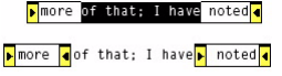
CHAPTER 19: InCopy: Notes Capabilities 329
pastes the text into the document text in the location where the insertion point was before the Convert To
Text operation. If the entire note is selected or the insertion point is inside the note container with no text
selected, the entire note contents are converted to text. If only part of the content of a note is selected,
only the selection is converted, while the remaining content stays in the note—or in two notes, if the
selection does not include the beginning or end of the note content. The following figure shows the case
in which the selection is in the middle of the note content, resulting in two notes after conversion.
Navigating among notes
The Next Note and Previous Note commands enable navigation among notes. These commands select the
next or previous note anchor in the text flow. If the current note is the final or first note in the text, the first
or last note is selected, respectively.
Splitting a note
The Split Note command breaks a note into two notes at the insertion point. After a note is split, the
insertion point moves to the story text, between the two notes produced by the split.
Deleting a note
The Delete Note command deletes the selected note. The command is available if a note anchor is
selected, the current insertion point is within an inline note, or the current insertion point is within the text
editing area of the Notes palette. The Remove Notes From Story command deletes all notes from the
current story, whereas the Remove All Notes command deletes all notes from the document.
Expanding and collapsing notes
The Expand Note or Collapse Note command expands or collapses the selected note. Only one of these
commands is visible at a time, depending on the state of the selected note. Alternately, in story or galley
view, click on a note’s bookend icon to expand or collapse the note. You can expand all collapsed inline
notes in the current document with the Expand All Notes command. You can collapse all inline notes in the
current document with the Collapse All Notes command.
The View > Hide Notes and View > Show Notes commands hide and show notes. Which of these
commands is available depends on the current state of the notes.
Setting notes preferences
You can customize the appearance and behavior of notes using the Preferences settings, by choosing Edit
> Preferences > Notes (Windows) or InCopy > Preferences > Notes (Mac OS).

CHAPTER 19: InCopy: Notes Data model for notes 330
Data model for notes
How notes are connected to text
When a note is added, through either the menu or the Notes palette, INoteSuite::DoAddNote is called. You
can add a note only when the text tool is active but no text is selected; that is, when there is a blinking
insertion point somewhere in the story. If a range of text is selected, you can convert the text to a note. The
DoAddNote method first checks the INoteSettings on the kWorkspaceBoss, to determine the note’s global
visibility state. If the note is hidden, the kSetHideNoteStateCmdBoss is used to turn on the note’s visibility.
Next, INoteDataUtils::NewNote is used to make the new note by processing a kCreateNoteCmdBoss
command.
Although the note seems to be embedded in the text, it actually is maintained in the text system as an
owned item. A special anchor character (kTextChar_ZeroSpaceNoBreak) is inserted in the primary story
thread of the text model, at the position where the note is to be placed. Then, an instance of
kNoteDataBoss is instantiated to hold the note data; this object is anchored in the text model by
associating the owned-item strand of the text model with the kNoteDataBoss object. This is done by the
kCreateNoteCmdBoss, which sets the class of the owned-item strand at the offset to kNoteDataBoss with
the UID of the kNoteDataBoss object. In the primary story thread, the note is represented by the special
character kTextChar_ZeroSpaceNoBreak. The real note text is stored in a separate story thread.
kNoteDataBoss implements ITextStoryThreadDict and ITextStoryThread, to maintain its story thread. For
more information on the story thread dictionaries, see Chapter 9, “Text Fundamentals.” Th e
kNoteDataBoss object’s INoteData holds information like note author and note creation time. It is
important to understand that INoteData does not contain the note’s text content; the note content is held
by a separate story thread, accessible through the kNoteDataBoss object’s ITextStoryThreadDict interface.
Relationship between a note and its parent story:
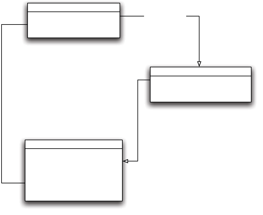
CHAPTER 19: InCopy: Notes Data model for notes 331
Using the SnippetRunner InspectTextModel snippet, we can inspect how the story threads are changed
when a note is being added. Assume you have a text story with the text “abc.” There are three characters,
plus the carriage return at the end, so the primary story thread’s character count is four, as shown in the
following figure.
Text story containing only regular text:
kTextStoryBoss
ITextModel
ITextStoryThreadDictHier
...
kOwnedItemStrandBoss
IItemStrand
IStrand
...
kNoteDataBoss
INoteData
IOwnedItem
...
ITextStoryThreadDict
ITextStoryThread
...
ITextModel::Q
ueryStrand()
IItemStrand::SetOwnedUID()
kNoteDataBoss is connected to kTextStoryBoss
through the owned item strand, but the note's text
content is maintained as a separate story thread
in the story, which is managed by both
ITextStoryThreadDictHier and ITextStoryThreadDict.
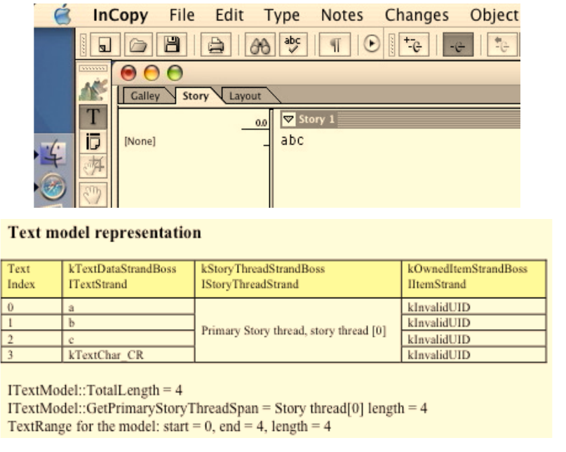
CHAPTER 19: InCopy: Notes Data model for notes 332
If you insert an empty note at the beginning, InDesign adds an owned-item strand to the text model, and
this strand is represented by kTextChar_ZeroSpaceNoBreak (0xfeff). Also, a story thread is created to
represent the note’s content. When there is no initial text in the note, the thread is initialized to
kTextChar_CR, which makes the note’s story thread length 1. Thus, the text model’s length is increased to 6
from the original 4, because of the added kTextChar_ZeroSpaceNoBreak for the owned item and
kTextChar_CR for the note’s initial data. In the output of InspectTextModel, the carriage return is not
reported; but if you read ITextStoryThread[0], its length is reported as 5, which is equal to the
PrimaryStoryThreadSpan. TextIndex 4 is for the carriage return. The following figure illustrates the text
model when an empty note is inserted into a story.
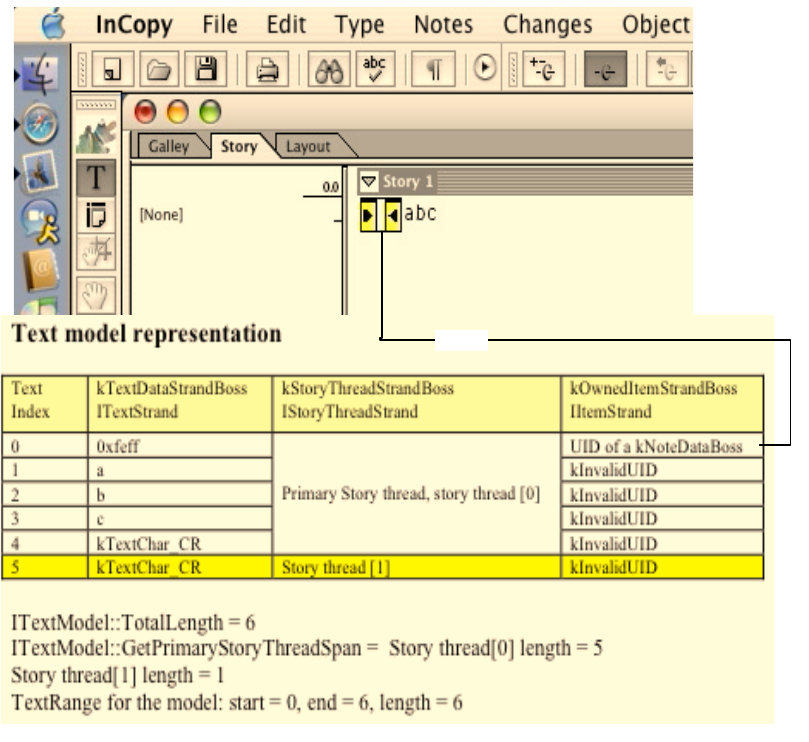
CHAPTER 19: InCopy: Notes Data model for notes 333
If you type something into the note—for example, type “d” in the note, so you see “<d> abc”—you can see
the text model has seven characters, which is one character more than the version with empty note. Note,
however, that the primary story thread looks the same as before. The new text is added into the thread
that represents the note’s text, which now has a length of 2 (for the “d” character plus the default
carriage-return character). See the following figure.
Text story with a one-character note:
Note
Note
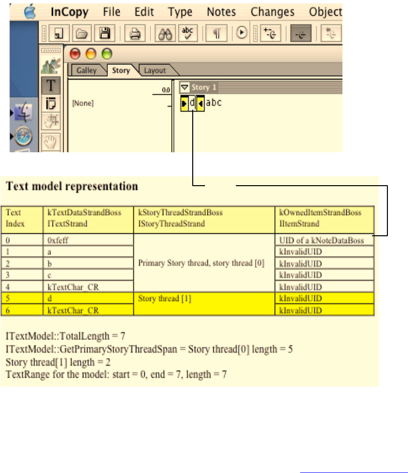
CHAPTER 19: InCopy: Notes Data model for notes 334
Notes suite and utilities
Much of the capability required for client code to work with notes is provided in a high-level suite
interface, INoteSuite (with the ID IID_INOTESUITE interface), which is available through a reference to a
selection (kIntegratorSuiteBoss). This interface is described in detail in “INoteSuite” on page 338.
This interface encapsulates the details of interacting with the note model and hides details about the
selection format that is active, providing a capability-driven API that can be used to do things like add,
delete, and convert notes.
Most of the note suite methods do not interact directly with model; instead, a few utility classes were
added to kUtilsBoss. These utilities are used in most of the suite implementations. We highly recommend
you use the suite functions when possible. If the suite does not meet your needs, look into the utilities
before using a command directly.
See the following figure for an overview of notes utility classes.
Note

CHAPTER 19: InCopy: Notes Data model for notes 335
Notes preferences
An INotePref interface (with the ID IID_INOTEPREFERENCE interface) is added to the kWorkspaceBoss. This
interface is responsible for maintaining note settings in the Preferences panel, like note color. To access
this interface, do the following:
kUtilsBoss
...
INotePaletteUtils
INoteDrawUtils
INoteDataUtils
INoteUIUtils
INoteUtils
...
Mainly for internal use
to draw the user
feedback in the note.
INoteDrawUtils
DrawHitTestBox
DrawNoteCaret
...
Mainly used to interact with the
InCopy Notes palette. For example,
if you create a note from your plug-
in and you want the Notes palette to
show the content, you can use
SetNoteToPalette to do that. The
INoteSuite provides a similar
function on a higher level.
INotePaletteUtils
SetNoteToPalette
ResetNotePalette
...
Mainly a collection of
methods that help in
interacting with the document
hierarchy and the text model.
It also contains an often used
method, QueryNoteData,
which returns an INoteData*
given a text index.
INoteUtils
QueryNoteData
NoteInCurrentSpread
...
Mainly deals with note
selections (e.g., go to
and select a note) and
visibility (expand/
collapse) note.
INoteUIUtils
GoToNextNote
ExpandAllNotes
...
Mainly responsible for providing the
NewNote method that is used in the
note suite and various commands.
It also provides some supporting
functions used by NewNote.
INoteDataUtils
NewNote
SetupOwnedItemInfo
...
CHAPTER 19: InCopy: Notes Data model for notes 336
InterfacePtr<INotePref> notePref
((INotePref*)::QuerySessionPreferences(IID_INOTEPREFERENCES));
if (notePref != nil)
{
// Do something with the preference.
}
There also is an INoteSettings interface (with the ID IID_INOTESETTINGS interface) added to
kWorkspaceBoss. This interface’s sole responsibility is to maintain the visibility state of the note. Users
typically show and hide notes with the View > Show Notes and View > Hide Notes menu commands. To
access this interface, do the following:
InterfacePtr<IWorkspace>
sessionWorkSpace(GetExecutionContextSession()->QueryWorkspace());
InterfacePtr<INoteSettings> noteSettings(sessionWorkSpace, UseDefaultIID());
End-user requirements
Unlike in Acrobat or Photoshop—in which sticky notes float on top of document content— each
InDesign/InCopy note is anchored to a specific location in the text. This is necessary because notes are
intended to be used as annotations to text, rather than to a layout element or the document as a whole.
Notes can be created using the Note tool in the toolbox, the Notes > New Note command, or the New
Note icon on the Notes palette.
The following figure shows most of the user interface related to notes. The notes features are
context-sensitive; an action is available to the end user only when the context is appropriate for that
action. Some of the menu items in the figure are disabled, because their function does not apply at the
current location of the text-insertion point.

CHAPTER 19: InCopy: Notes Data model for notes 337
Note anchors
Each notes is associated with a specific location in the text, indicated by a note-anchor icon. The preceding
figure shows examples of note anchors in different states. Content is visible only within a note container:
In layout view, the container for note content is the Notes palette.
In story and galley views, the container for note content is an inline note container within the
document text, between the two bookend icons that make up the note-anchor icon. In story and
galley views, note content also can be seen in the Notes palette.
The content of a note is the same, regardless of the note container or view used. Anchors can be placed
anywhere within text in layout or galley view, including the beginning or end of a word, within a word, and
between a word and a punctuation mark; however, only one note anchor can occupy a single location
within text. Users can create notes only in the text flow. If the user moves the Note tool pointer over an
area that does not contain an open story, the pointer changes to the No Drop pointer, and clicking does
not create a new note.
Note anchors perform multiple functions:
Note anchors indicate the location of the note. When the text reflows, the anchor moves as part of the
text.
Note
tool
Begin note
bookend
(anchor)
icon
End note
bookend
(anchor)
icon
Collapsed
bookend
(anchor) icon
Default
anchor
icon
Note that is
selected
Notes palette menu
Note info
area
Editing
area
Button
area
User
color
icon
Go To
Note
Anchor
Previous
Note
Next
Note
New
Note
Delete
Note
Notes menu:
functions similar
to that of Notes
palette menu
CHAPTER 19: InCopy: Notes Essential APIs 338
Note anchors offer a clickable screen element, so the user can open, move, edit, or delete the note or
its contents.
In galley or story view, each inline note icon has an anchor icon consisting of a start-note bookend icon
and an end-note bookend icon. When the note is expanded, the content of the note appears between
these bookends. New inline notes have a thin, empty, inline note container, with an insertion point ready
for note-text entry. When the user begins typing the note text, the bookend icons move apart to
accommodate the added text.
Editing text containing note anchors
The note anchor is an access point for opening and editing notes. Selected note anchors can be cut,
copied, deleted, and moved by dragging. Selecting text also selects all note anchors within that text.
Cutting, copying, or pasting text cuts, copies, or pastes all note anchors in the selected text, with the
following exceptions:
No note anchors can be created or placed within other notes.
If text containing note anchors is pasted into a note, only the selected surrounding text is copied to
the note, not the anchors or note contents.
When text containing a note anchor is deleted, cut, copied, or pasted, whatever happens to the enclosing
text happens to the note whose anchor is contained within. This includes notes that are hidden.
Although note content always is drawn in plain text (that is, with no styles, color, size, or other
text-formatting attributes shown), any text copied or pasted to a note retains all formatting information it
had, even though that formatting is not shown when the text is part of a note. Text with formatting may be
copied and pasted to a note, and at a later time that text may be copied and pasted to note text; when the
text is placed as regular (nonnote) text, any formatting information it contains is rendered (shown) once
again.
Essential APIs
INoteSuite
The INoteSuite suite interface is a key API for manipulating notes in client code. Most of a note’s
user-interface functions are provided through this interface. This interface provides much of the required
capability for plug-ins.
The INoteSuite interface is aggregated on the integrator-suite boss class (kIntegratorSuiteBoss), which
makes this interface available through the abstract selection. Implementations of this interface are
provided on various concrete-selection boss classes, like kGalleyTextSuiteBoss and kNoteTextSuiteBoss,
which are hidden from client code through the facade of the abstract selection. To obtain INoteSuite,
client code should query the selection manager (ISelectionManager) for the interface, as shown below:
// Many functions are passed in an IActiveContext as a parameter.
// It should be used whenever possible.
InterfacePtr<IActiveContext>
activeContext(GetExecutionContextSession()->GetActiveContext(), UseDefaultIID());
if (!activeContext)
return;
ISelectionManager *selectionManager = activeContext->GetContextSelection();
InterfacePtr<INoteSuite> noteSuite(selectionManager, UseDefaultIID());

CHAPTER 19: InCopy: Notes Essential APIs 339
Generally speaking, the INoteSuite interface is active when the text-insertion point is active in the layout,
story, galley, or Notes palette editing area. The suite interfaces typically use this pattern of checking for a
service or capability and, if the abstract selection supports this capability, the method can be called. For
example, the INoteSuite interface exposes a method that allows you to delete a selected note. To use this
method, do the following:
bool16 canDeleteNote = iNoteSuite->CanDeleteNote(ac->GetContextView(), docView);
if(canDeleteNote )
{
iNoteSuite->DeleteNote(ac->GetContextView(), docView);
}
The following table lists INoteSuite methods.
kNoteDataBoss
kNoteDataBoss is anchored as an owned item in the text story. The following code snippet shows one way
to get the kNoteDataBoss from the story:
CanDoSomething method DoSomething method
CanAddNote DoAddNote
CanConvertToNote DoConvertToNote
CanOpenNote DoOpenNote
CanDeleteNote DoDeleteNote
CanConvertToText DoConvertToText
CanScrollToNote DoScrollToNote
CanNavigateNote DoNavigateNote
CanRemoveAllNotes DoRemoveAllNotes
CanRemoveStoryNotes DoRemoveStoryNotes
CanSplitNote DoSplitNote
CanShowHideNote DoShowHideNote
CanExpandAllNotes DoExpandAllNotes
CanCollapseAllNotes DoCollapseAllNotes
CHAPTER 19: InCopy: Notes Essential APIs 340
// Find notes in current storyRef.
InterfacePtr<ITextModel> textModel(storyRef, UseDefaultIID());
InterfacePtr<IItemStrand> itemStrand((IItemStrand*)textModel
->QueryStrand(kOwnedItemStrandBoss, IID_IITEMSTRAND));
int32 mainStoryLength =
textModel->GetPrimaryStoryThreadSpan() - 1;
// Collect owned item from the story.
Text::CollectOwnedItems(textModel, 0, mainStoryLength, &ownedItemList);
if (ownedItemList.Length() > 0)
{
// Remove non-note items.
for (i = ownedItemList.Length()-1; i>=0; i--)
{
if (!Utils<INoteDataUtils>()->IsNoteOwnedItem(ownedItemList[i].fClassID))
ownedItemList.Remove(i);
}
}
See the following figure for the key interfaces of kNoteDataBoss.
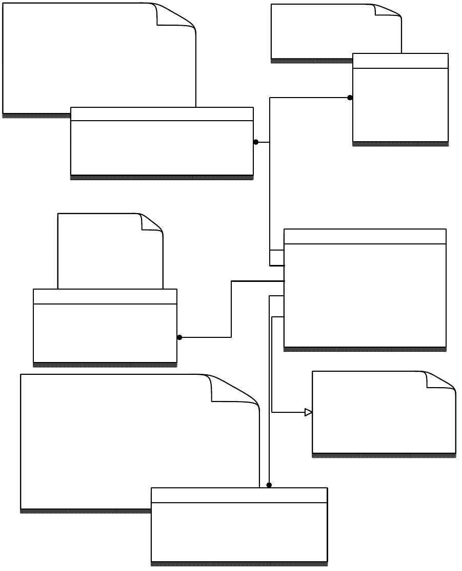
CHAPTER 19: InCopy: Notes Useful commands and associated notification protocols 341
Useful commands and associated notification protocols
This section summarizes some of the most common commands related to notes, the critical data
interfaces that users of the commands must supply, and the notification protocols associated with the
commands so an observer who wants to observe certain commands can know what protocols to listen to.
Implements the
story thread
(ITextStoryThread)
that represents the
note content.
kNoteDataBoss
INoteData
IOwnedItem
ITextStoryThread
ITextStoryThreadDict
IParcelList
ITextParcelList
...
Storage for the note
information such as
author and creation date
The IOwnedItem and
ITextModelMemento (on a separate
boss,
kNoteDataTextModelMementoBoss)
implementations are the hooks that
allow the note to be managed when it
is affected by text model operations.
IOwnedItem
CollectStoryRanges
GetNumSpecialAnchorChars
...
INoteData
GetAuthor
SetAuthor
GetCollapse
SetCollapse
...
ITextStoryThread
GetDictUID
GetTextStart
QueryTextModel
...
Note's ITextStoryThreadDict implementation
manages only one
story thread.
Many instances of notes can be embedded in a
story, but each has its own note data
(kNoteDataBoss) with its own dictionary
(ITextStoryThreadDict) and story
thread(ITextStoryThread).
ITextStoryThreadDict
QueryThread
GetAnchorTextRange
GetThreadBlockTextRange
...
Because Note does not
support display of
composed text, all of the
parcel-related interface are
implemented as stubs.
CHAPTER 19: InCopy: Notes Useful commands and associated notification protocols 342
kCollapseStateCmdBoss
Description
Sets the INoteData collapsed state according to the command’s IBoolData. Used to expand (open) or
collapse (close) a note.
Item list
The UID of the text story that contains the note to be expanded or collapsed.
Data interface
IBoolData — Whether the note should be collapsed (true for collapsed, false for expanded).
IIntData — The TextIndex at which the note of interest is anchored in the text story.
Notification
Notify kTextStoryBoss with the IID_INOTEDATA protocol.
Notify kDocBoss with the IID_COLLAPSESTATE_DOCUMENT protocol.
kCreateNoteCmdBoss
Description
Creates a new note in a text story at the location specified by a text index.
Item list
The UID of the text story that contains the note to be created.
Data interface
IIntData — The TextIndex where the new note is to be created. A note is not allowed in another note,
so make sure the index is not in an existing note’s story range.
ICreateNoteCmdData — This data interface is optional. You can set note class using SetNoteClass to
kNoteDataBoss. Set the note content’s range using SetNoteContentRange(createAt, createAt), if the
note is to be initialized to an empty note; createAt is the TextIndex where the new note anchor will be.
You also should use the Set method to set the author and collapsed state. You do not need to set the
marker range, because it is for an unsupported feature.
Notification
Notify kTextStoryBoss with the IID_INOTEDATA protocol.
CHAPTER 19: InCopy: Notes Useful commands and associated notification protocols 343
Notify kDocBoss with the IID_INOTEDATA protocol.
kConvertToNoteCmdBoss
Description
Converts a range of text into a note.
Item list
The UID of the text story that contains the text to be converted.
Data interface
Data should be set up as for kCreateNoteCmdBoss:
IIntData — The start text index of the text range to be converted.
ICreateNoteCmdData — The note’s content range should be set from the start index to the end index
of the text to be converted, using the SetNoteContentRange method.
Notification
Notify kTextStoryBoss with the IID_INOTEDATA protocol. When the notification is broadcast, the
command boss’s IIntData is set to the note’s content-range start index.
Notify kDocBoss with the IID_INOTEDATA protocol.
kConvertNoteToTextCmdBoss
Description
Converts a whole note or part of the note content into regular text. When the note content to be
converted is between another note text in the same note, the portion of the note that is not converted is
split into two notes, one on each side of the converted text.
Item list
The command needs two items: the UID of the story that contains the note to be converted, and the UID of
the kNoteDataBoss of the note to be converted. When the text focus is in the note-content area,
ITextModel::QueryStoryThread can be used to find out the note’s story thread, from which you can get to
the corresponding kNoteDataBoss. When the text focus is on the anchor, use INoteUtils::QueryNoteData to
get to the INoteData, from which you can reach the kNoteDataBoss.

CHAPTER 19: InCopy: Notes Useful commands and associated notification protocols 344
Data interface
IIntData with interface ID IID_ISTARTFOCUSINTDATA — The start-text index of the range of note content
to be converted to text. This range should be in the note’s story thread. If the range is in the note’s
anchor range, you should find out the text range that covers the note content.
IIntData with interface ID IID_IENDFOCUSINTDATA — The end-text index of the range of note content
to be converted to text. This range should be in the note’s story thread. If the range is in the note’s
anchor range, you should find out the text range that covers the real note content.
IBoolData — Was used to restore text focus in an undo operation prior to CS4. With automatic undo,
this has no effect.
IConvertNoteToTextCmdData — Required to suspend galley drawing while converting to text. Pass in
the UIDRef of the IControlView* returned by INoteSuiteUtils::GetDocControlView.
Notification
Generally, the broadcast is based on how the note is converted.
If the entire note is converted:
Notify the kDocBoss with the kNoteRemovedMsg message along with the
IID_ICONVERTNOTETOTEXTCMD protocol.
If the note is spit into two notes after the conversion:
Notify the kDocBoss with the kConvertNoteToTextMsg message along with the
IID_ICONVERTNOTETOTEXTCMD protocol.
Notify the kTextStoryBoss with the kConvertNoteToTextMsg message along with the
IID_ICONVERTNOTETOTEXTCMD protocol.
If the converted text is to the left or right of the original note:
Notify the kDocBoss with the kMoveNoteToTextMsg message along with the
IID_ICONVERTNOTETOTEXTCMD protocol.
Notify the kTextStoryBoss with the kMoveNoteToTextMsg message along with the
IID_ICONVERTNOTETOTEXTCMD protocol.
kSplitNoteCmdBoss
Description
Splits a note into two notes at the text-index location specified by the data interface.
Item list
The command needs two items: the UID of the story that contains the note to be split, and the UID of the
kNoteDataBoss of the note to be split. This is similar to the kConvertNoteToTextCmdBoss. For more details
on how to get to the kNoteDataBoss from a text location, see “kNoteDataBoss” on page 339.
CHAPTER 19: InCopy: Notes Working with notes 345
Data interface
IIntData with interface ID IID_ISTARTFOCUSINTDATA —The text index of the location where you want to
split the note. The index should be in the note’s story thread.
IConvertNoteToTextCmdData — Required to suspend galley drawing while converting to text. Pass in
the UIDRef of the IControlView* returned by INoteSuiteUtils::GetDocControlView.
Notification
Notify the kTextStoryBoss with the kSplitNoteMsg message along with the IID_ISPLITNOTECMD
protocol.
Notify the kDocBoss with the kSplitNoteMsg message along with the IID_ISPLITNOTECMD protocol.
kNotePrefCmdBoss
Description
Modifies the notes preference as seen in the application’s Notes Preferences panel.
Item list
The item needed is the application’s workspace UID.
Data interface
INotePrefCmdData— Use its Set method to set the preference.
Notification
Notify the kWorkspaceBoss with the IID_INOTEPREFERENCES protocol.
Working with notes
Adding a note at the current insertion-point position
When proper context is available, use INoteSuite::DoAddNote to add a new note. For an example, see the
SnpPerformNoteFunction snippet.
When the INoteSuite interface is not available, first process a kSetHideNoteStateCmdBoss command, to
make sure the note’s visibility is on. Next, use kCreateNoteCmdBoss to create the note. A note is not
allowed inside another note, but a note is allowed in deleted text (you can use
ITrackChangeUtils::DeletedTextToPrimaryIndex to check if it is in deleted text), so you should make sure
the text index for the note anchor is in either the primary story thread span or deleted text but not in an
existing note’s story thread range.
CHAPTER 19: InCopy: Notes Working with notes 346
Inserting text into a note
Use ITextModelCmds::InsertCmd to insert text into note. This is just like a regular text insertion operation.
For an example, see the SnpPerformNoteFunction snippet.
Converting text to a new note
When proper context is available, use INoteSuite::DoConvertToNote to convert selected text to a note. For
an example, see the SnpPerformNoteFunction snippet.
When the INoteSuite interface is not available, check whether the text for conversion contains any XML
tags. Normally, if there is a tag in the text range, you should abort the operation. Use
INoteSuiteUtils::CheckRemoveXML to check for XML tags. If a tag is found in the selected text, this method
causes an alert to pop up, asking whether the user wants to remove the XML tag. Proceed with the
conversion only when the function returns a true value; then use the kSetHideNoteStateCmdBoss
command to make sure the note’s visibility is turned on. Use kConvertToNoteCmdBoss to convert the text.
Converting note content to text
When proper context is available, use INoteSuite::DoConvertToText to convert selected note content to
text. For an example, see the SnpPerformNoteFunction snippet.
When the INoteSuite interface is not available, use kConvertNoteToTextCmdBoss to convert note content
to regular text. If text focus is in the note content area and no text is selected, or if the note anchor is
selected, the whole note is converted. If only part of the note content is selected, only that portion is
converted to regular text.
Pay special attention to the text range to be converted. Consider the sample story “<Convert Me> Please,”
where “<Convert Me>” is a note and “<” and “>” are the bookends. If the whole note is selected, the
current selection range is [0, 1], because the selection is on the anchor character. If the selection is in the
note content area—for example, the whole ‘Convert Me’— the selection range is [9, 19], because the
selection is in the note’s story thread, not in the primary story thread. The command’s focus-start and
focus-end data (IIntData with the interface IDs IID_ISTARTFOCUSINTDATA and IID_IENDFOCUSINTDATA)
need to be the indices in the note’s story thread. So, if the selection is the note anchor (where the selection
range is [0,1]), find out where that note’s story thread is, and pass in the corresponding text index to the
data interface. Use INoteUIUtils::TextFocusInNote to check whether the focus is in the note’s content area.
Also, the following snippet shows how to find the whole note’s range; after indexStart and indexEnd are
found, they can be passed into the command’s data interface:
//Note anchor is selected.
InterfacePtr<INoteData> noteData(Utils<INoteUtils>()->QueryNoteData(textModel,
indexStart));
if (!noteDataOnLeft)
return; // no note
noteDataRef = ::GetUIDRef(noteDataOnLeft);
if(textModel->FindStoryThread(noteDataRef.GetUID(), 0, &threadStart, &threadLength))
{
// Range is a whole note.
indexStart = threadStart;
indexEnd = threadStart+threadLength-1;//no carriage return
}
CHAPTER 19: InCopy: Notes Working with notes 347
The item list in this command needs both the UID of the kTextStoryBoss that contains the note and the
kNoteDataBoss of the note.
Navigating among notes
When proper context is available, use INoteSuite::DoNavigateNote to go to the next or previous note. For
an example, see the SnpPerformNoteFunction snippet.
Navigating the notes without INoteSuite is very difficult, because there are so many factors to consider.
You must collect all the notes by yourself, and you must consider the situation in which the insertion point
is in a different context (for example, table or deleted text), and there is no command to do it. The closest
thing is the INoteSuiteUtils::NavigateNote, which also involves the selection subsystem. Therefore, we
highly recommend you do the navigation through the INoteSuite interface. In general, if you have a text
story in the document, with a visible note anchored somewhere in the story, the
INoteSuite::CanNavigateNote returns true, and you can navigate the notes with much greater ease.
Splitting a note
When proper context is available, use INoteSuite::DoSplitNote to split a note. For an example, see the
SnpPerformNoteFunction snippet.
When the INoteSuite interface is not available, use kSplitNoteCmdBoss to split the note at the position
indicated by the text-index argument. As with kConvertNoteToTextCmdBoss, you must make sure the text
index where you want to split is inside the note’s content area; that is, the text index needs to be in the
note’s story-thread range. By default, notes are not splittable in layout view.
Expanding and collapsing notes
When proper context is available, use INoteSuite::DoOpenNote to expand or collapse one note, use
INoteSuite::DoExpandAllNotes to expand all notes in the document, and use
INoteSuite::DoCollapseAllNotes to collapse all notes in the document.
If the INoteSuite interface is not available, use kCollapseStateCmdBoss, supplying a valid TextIndex that
points to a note anchor. Given a text-index location, use INoteUIUtils::TextFocusInNote to check whether
that location is in the note contents area. If it is not, also check whether the location is on the note anchor.
Both situations should be allowed to expand/collapse a note. After the command is processed, a text
selection may need to be set to have a text focus in a desired location. INoteData in the kNoteDataBoss
stores the current collapsed state data on the note. Normally, you toggle between the two states when
processing the kCollapseStateCmdBoss.
Normally, if there are notes in the story and they are not already all expanded or all collapsed,
INoteSuite::CanCollapseAllNotes or INoteSuite::CanExpandAllNotes returns true, so you should be able to
use these suite methods when you need to expand or collapse all notes.
By default, layout view does not support the expand note and collapse note features.
Selecting a note
Whenever possible, use INoteSuite::DoNavigateNote, as shown in the SDK snippet
SnpPerformNoteFunction::NavigateNote. When you do not have a proper selection context to work with,
however, you can use the following low level-method.

CHAPTER 19: InCopy: Notes Working with notes 348
Assuming you know the UID of the note’s kNoteDataBoss and the UID of the kTextStoryBoss that contains
the note, do the following to select that note in galley view:
// Assume storyRef is the story and noteDataRef is the note.
InterfacePtr<ITextModel> textModel(storyRef, UseDefaultIID());
InterfacePtr<IItemStrand> itemStrand(
(IItemStrand*)textModel->QueryStrand(kOwnedItemStrandBoss, IID_IITEMSTRAND));
InterfacePtr<IOwnedItem> ownedItem(noteDataRef, UseDefaultIID());
TextIndex noteDataPos = itemStrand->GetOwnedItemIndex(ownedItem);
ASSERT(noteDataPos != kInvalidTextIndex);
InterfacePtr<ISelectionManager> viewSelMgr (docView, UseDefaultIID());
Utils<ISelectUtils>()->GoToTextWithMarker( storyRef, noteDataPos, 1);
In layout view, instead of using ISelectUtils::GoToTextWithMarker, use the following to select the note
anchor:
// docView is the document window's IControlView*
Utils<ISelectUtils>()->ProcessSelectText( ::GetUIDRef(textModel),
RangeData(noteDataPos, RangeData::kLeanForward),
Selection::kScrollIntoView,nil,viewSelMgr, docView);
Getting kNoteDataBoss, given a text index whose position is anchored
to note
Use INoteUtils::QueryNoteData to get to the kNoteDataBoss. For an example, see “Converting note
content to text” on page 346.
Deleting notes
When proper context is available, use INoteSuite::DoDeleteNote to delete a note, use
INoteSuite::DoRemoveStoryNotes to delete all notes from a story, and use INoteSuite::DoRemoveAllNotes
to delete all notes from a document.
When the INoteSuite interface is not available, delete the note by simply removing the note-anchor
character, which subsequently asks the note owned item to handle the rest of the data removal:
// Assume textModelCmds is the ITextModelCmds from the kTextStoryBoss.
// Assume noteAnchorPos is the note anchor position.
InterfacePtr<ICommand> typeCmd(textModelCmds->
TypeTextCmd(noteAnchorPos, noteAnchorPos + 1, WideString::kNil_shared_ptr));
PMString newName = "Delete Note";
typeCmd->SetName(newName);
CmdUtils::ProcessCommand(typeCmd);
To remove all stories when the INoteSuite interface is not available, use INoteUtils::ClearAllNotes.
Changing notes-palette content to reflect particular note data
Use INotePaletteUtils>()->SetNoteToPalette to bring up the note data in the Notes palette.
Checking note spelling
INotePref::SetSpellCheckContent lets you turn on spell checking in the note content, but you cannot
change the behavior of how the note interacts with the text’s spell-checking engine.
CHAPTER 19: InCopy: Notes Working with notes 349
Observing a note that is being modified
Many note commands notify with the IID_INOTEDATA protocol along with its command ID, so attach an
observer and listen to that protocol on an appropriate subject. The following code attaches an observer
for IID_INOTEDATA broadcast to a document subject:
InterfacePtr<IDocument> document(Utils<ILayoutUIUtils>()->GetFrontDocument(),
IID_IDOCUMENT);
InterfacePtr<ISubject> docSubject(document, IID_ISUBJECT);
if (docSubject && !docSubject->IsAttached(this, IID_INOTEDATA))
docSubject->AttachObserver(this, IID_INOTEDATA);
Using notes in InDesign
InCopy Workflow plug-ins install the InCopy Notes and Track Changes features in InDesign for use in the
InCopyBridge workflow. These features use InCopyBridge user names to identify the author of a note.
When you add editorial notes to a managed story in InDesign, these notes become available to others in
the workflow.

350
20 InCopy: Assignments
This chapter provides information about InCopy assignment files. To understand this chapter, you should
have a basic understanding of XML and have a basic knowledge of the InDesign/InCopy workflow.
This chapter has the following objectives:
Provide key concepts of assignments and assignment files.
Give a detailed illustration of the assignment data model and assignment file structure.
Describe how to work with the assignment API.
For common use cases, see the “InCopy: Assignments” chapter of Adobe InDesign SDK Solutions.
Concepts
Assignment-file features address the following user needs:
An InCopy user might want to export a few related stories (headline, byline, copy), and therefore
needs convenient export options for many common workflows.
An InCopy user might want to open several exported stories as one file. Having to open separate files
(for example, heading, story, caption) is counterintuitive for many customers who may see these files
as a logical whole.
An InCopy user might want to see how stories fit into an InDesign layout without opening the entire
InDesign document. (Opening a large InDesign document can be very time-consuming, especially if it
is located on another computer across a network.)
Users want to be able to group related document constituents—not just stories, but graphics as
well—into meaningful elements that can be worked on as a group. For example, users might want to
group a headline, byline, copy, graphics, and captions into a group; if a company has dedicated headline
writers or editors, they may want to group all headlines into a meaningful unit.
InDesign and InCopy support the creation of such groupings with assignment files. Assignment files solve
the file-management issue by adding an additional file that tracks the other files. In essence, an
assignment is a set of files, the contents of which are assigned to one person for some work to be done (for
example, copy-editing, layout, and writing). Stories in an assignment are exported as InCopy files.
Geometry information and the relationships between the files are held in the assignment file. InDesign
allows the user to export a given set of stories by exporting into an assignment. InCopy open all the stories
in an assignment together, as a single unit.
Assignment files have the following attributes:
Users can create and name assignments, including any set of elements of one document.
Chapter Update Status
CS6 Edited Only the following has changed:
• In several places, removed obsolete text that referred to CS2.

CHAPTER 20: InCopy: Assignments Assignment workflow 351
When exporting a group of items from InDesign, an additional file—the assignment file—is created. It
contains links or pointers to the grouped page elements and any transforms on those elements. This
lets the user open one file in InCopy and have editorial access to multiple stories. Assignment files also
include page geometry, so InCopy users can see the layout of the frame for the content they are
editing, without the slowdown of opening the entire InDesign file. Optionally, users can see the
context of their editing (other items on the same page) by exporting entire spreads on which one or
more assigned frames lie. For details, see “Assignment-export options” on page 351.
Users can see the contents of an assignment in two ways: a list of contents (in the Assignments
palette) and by special highlighting or color coding of frames in a single assignment (in the document
window). Even after the assignment grouping is created, users can add items to and remove items
from the group.
Assignments are saved in one of two file formats, IDML-based IMCA files or INX-based INCA files.
Assignment files group content into chunks smaller than a complete publication that InDesign
understands and manages. Assignment files provide the basis for asset control on a scale smaller than an
entire publication.
Assignment workflow
Here is a common workflow for users collaborating by means of assignment files:
A layout designer designs the framework of a document layout and assigns contents (that is, stories
and images) to different users, by creating an assignment file for each user.
Content contributors or editors check out the assigned stories and images, do their editing, and check
in finished content.
The layout designer receives notification by an indicator in the Assignments palette that a document
is out of synchronization. The layout designer can then update the document.
For more information on the use of assignment files, see InCopy Help or InDesign Help.
Assignment-export options
To give users control over how much geometry information an assignment file contains, InDesign allows
users to choose assignment-export options. These options determine what content the user can see in
InCopy when opening the assignment file. InDesign provides three such options:
Placeholder frames — Lets the InCopy user see the text and frames in the assignment, as well as boxes
or other shapes representing all other frames on the InDesign pages that contain frames in the
assignment. All frames and placeholders accurately reflect the size, shape, and location of the
InDesign originals. Note, however, that placeholders are empty shapes and do not show any of the
content in the InDesign file. These shapes, which are visible in InCopy layout view, are gray, so the user
can distinguish them from empty frames that may be part of the assignment. This option provides the
minimum information to the InCopy user; anything less would remove possible text wraps that affect
copy fitting.
Assigned spreads — Lets the InCopy user see everything described in the Placeholder Frames option,
as well as showing the entire contents of any spreads that happen to intersect with the assignment
(that is, spreads that contain at least one frame in the assignment). This noneditable content is visible
in InCopy layout view.
CHAPTER 20: InCopy: Assignments Assignment 352
All spreads — Shows the entire InDesign file of which the assignment is a part. The difference between
using this option and opening an actual InDesign file is that a user who opens an assignment file with
this option can see the design and layout of every page but can edit (after checking out) only those
frames in the current assignment.
Assignment
The primary tool for working with assignments is the Assignment palette. Through the palette’s interface,
users can create, delete, add, and remove content of any assignment, as well as check out and check in
InCopy stories and change assignment options.
The content of a document could be any of the following:
Assigned content — Content belonging to an assignment.
Unassigned InCopy content — Content exported as InCopy stories, but not belonging to any
assignment.
Unassigned content — Content that was never exported as stories or page items.
An assignment may become out of date when there is a change to the InDesign document after the
assignment is exported. Saving an InDesign document does not clear the state; the user must choose
Update Selected Assignment or Update All Assignments to reexport the assignment.
In the screenshot in the following figure, two text frames in the lower-right part of the page are
unassigned contents. The remaining content is part of Assignment 1 (magenta border) or Assignment 2
(gold border).
In the figure, there are several ways to distinguish an assignment: the assignment name (assignment_1,
assignment_2), the user to whom it is assigned (user_1, user_2), and the color of the assignment
(magenta, gold). The image on the lower-left part of the page is colored gold because it belongs to
assignment_2. The magenta frames belong to assignment_1.
Contents of an assignment are listed in the Assignments palette as children of the assignment. The palette
shows the assigned story name as well as the status of the story file; for example, whether it is checked out
by another InCopy user.
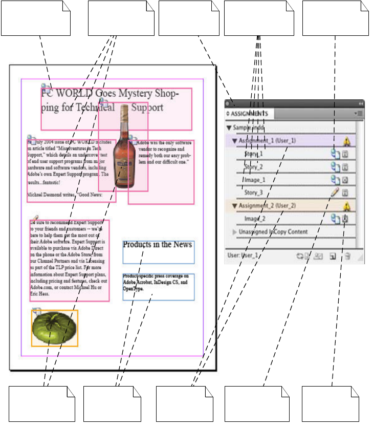
CHAPTER 20: InCopy: Assignments Assignment 353
In the following figure, an assignment belongs to a publication (document) and is made up of several
assigned stories. An assigned story holds text or an image. An assigned story holding an image is an
assigned image.
Assigned story
(image)
Unassigned
content
Assignment
out of date
Story checked
out (editing)
Assignments
palette
Assigned to
(assignee)
InCopy stories
of assignment 1
Assignment
color (magenta)
Assigned story
(text)
Story available
for check-out
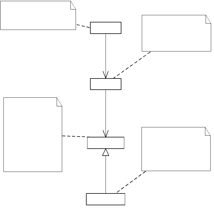
CHAPTER 20: InCopy: Assignments Assignment data model 354
Assignment data model
Assignment hierarchy
In the terms of the document object model (DOM), an assignment is a child of the document.
Assignment-related boss class objects form a hierarchical tree.
In the following figure, IAssignedDocument stores a list of assignments for a document, each described by
a kAssignmentBoss. An assignment consists of a number of assigned stories, each either a text story
(kAssignedStoryBoss) or an image story (kAssignedImageBoss). Assigned stories have references back to
the assignment.
document
assignment
assigned story
assigned image
1
0..*
owns
1
0..*
owns
A publication (InDesign/InCopy
document) with assignment
capability. An assignment refers to a
group of stories and images
that are assigned to a
particular user.
An assigned image is a
special case of an assigned
story. The only difference
is that the story it holds is
an image.
An assigned story
holds story information
in an assignment.
It stores InCopy story
file location and
reference to an actual
story in the document.
It could be a text story
or an image story

CHAPTER 20: InCopy: Assignments Assignment data model 355
Object structure of an assignment
The object structure of an assignment is constructed dynamically, as a user creates assignments and adds
contents to assignments.
The sample document in the following figure contains two assignments (kAssignmentBoss):
Assignment_1 has three assigned stories, two of which are text stories (kAssignedStoryBoss), and one
of which is an image story (kAssignedImageBoss). The stories are Story_1, Story_2, and Image_1,
respectively.
Assignment_2 has two assigned stories, one of which is a text story (Story_3) and one of which is an
image story (Image_2).
«boss»
kDocBoss
«boss»
kAssignmentBoss
«boss»
kAssignedImageBoss
«boss»
kAssignedStoryBoss
1
0..*
IAssignedDocument
1
0..*
IAssignment
1
0..*
IAssignment
1
1
IAssignedStory
1
1
IAssignedStory
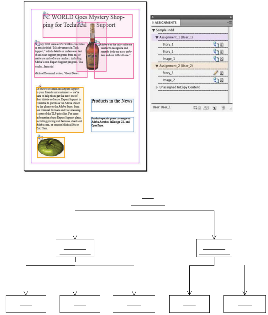
CHAPTER 20: InCopy: Assignments Assignment data model 356
Moving assignment content
Text frames and images in an InDesign document can never have been assigned, or they can have been
assigned or exported and, therefore, can be moved among different assignments and unassigned InCopy
content. When adding content to an assignment, the following is true:
If the selected text or text frame is within a story with multiple text frames, the story becomes an
assigned story, and all text frames of the story are assigned.
«boss»
sample
: kDocBoss
«boss»
Assignment_1
: kAssignmentBoss
«boss»
Assignment_2
: kAssignmentBoss
«boss»
Story_1
: kAssignedStoryBoss
«boss»
Story_3
: kAssignedStoryBoss
«boss»
Story_2
: kAssignedStoryBoss
«boss»
Image_1
: kAssignedImageBoss
«boss»
Image_2
: kAssignedImageBoss
IAssignedDocument::GetAssignments()[0] IAssignedDocument::GetAssignments()[1]
IAssignment
::GetStories()[0] IAssignment
::GetStories()[1]
IAssignment
::GetStories()[2] IAssignment
::GetStories()[0]
IAssignment
::GetStories()[1]
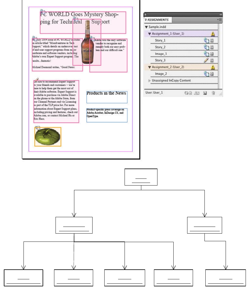
CHAPTER 20: InCopy: Assignments Assignment data model 357
If the selected content already belongs to another assignment, the content is removed automatically
from that assignment.
The following figure shows the new screenshot and object diagram of the document shown in the
preceding figure, after reassigning the lower-left text frame from Assignment_2 to Assignment_1.
Assignment_1 has four assigned stories (three text stories and one image story). Assignment_2 has only
one assigned story (an image story).
After the reassignment operation, the following is true:
In the object model, Story_3 is removed from Assignment_2 and added to Assignment_1.
«boss»
sample
: kDocBoss
«boss»
Assignment_1
: kAssignmentBoss
«boss»
Assignment_2
: kAssignmentBoss
«boss»
Story_1
: kAssignedStoryBoss
«boss»
Story_3
: kAssignedStoryBoss
«boss»
Story_2
: kAssignedStoryBoss
«boss»
Image_1
: kAssignedImageBoss
«boss»
Image_2
: kAssignedImageBoss
IAssignedDocument::GetAssignments()[0] IAssignedDocument::GetAssignments()[1]
IAssignment
:GetStories()[0] IAssignment
::GetStories()[1]
IAssignment
::GetStories()[2]
IAssignment
::GetStories()[3] IAssignment
::GetStories()[0]
CHAPTER 20: InCopy: Assignments Assignment files 358
In the document window, the color of the text frame changes from gold (the color of Assignment_2)
to magenta (the color of Assignment_1).
In the Assignments palette, Story_3.incx becomes part of Assignment_1.
Assignment files and links
The assignment feature relies on links to track the status of assignments and stories. Assignment files do
not appear in the Links palette, but they work the same way as links:
If the assignment file is moved to another location, the application reports a missing file and prompts
the user to find the file.
The user can find the missing file during document opening or relink the assignment file later from
Assignments palette.
When the files are changed outside the application, the application prompts for an update.
Assignment files
Assignment files are stored as separate entities using the designated storage medium (for example, hard
disk or network resource). Assignment files use the .icma filename extension.
Assignment files store the following information:
Reference to the InDesign document (file path, in case the user wants to open the document with the
stories).
Assignee, the user responsible for the content in the assignment.
A list of references or links to the stories and graphics in the assignment.
Character and paragraph styles and swatch information used in the document. The assignment file
contains the style and swatch information for the entire document, whereas each story contains only
the style and swatch information applicable to that story.
XML tags maintaining the assignment file structure.
Frame geometry; that is, coordinates and dimensions of each frame in the assignment, along with its
page location and any transforms users have done to the frames.
Comparing assignment files to InDesign and InCopy files
The assignment-files feature requires collaborative work with InDesign and InCopy files. Only InDesign
writes to assignment files; InCopy cannot create an assignment. InCopy can only open an assignment file
and work on its contained stories. The following sections summarize how assignment-related information
is stored in the InCopy file and the InDesign file.
InCopy file (*.icml)
An InCopy file holds InCopy story contents—frame information and all relevant transform information for
graphics; style, swatch, and tag definitions used in the story; user names associated with the story (for
example, in notes, tracked changes); and story XMP data.
CHAPTER 20: InCopy: Assignments Assignment files 359
InDesign file (*.indd)
An InDesign file contains a list of references to the assignment files that contain elements from the
document. InDesign needs to locate these files when moving the document from one machine to another.
InDesign needs to open and potentially update these assignment files when the InDesign document is
saved.
Assignment-file format
InDesign and InCopy support an IDML-based format; it uses the .icma file extension. The following is an
example of an ICMA (IDML-based) assigment file.
<?xml version="1.0" encoding="UTF-8" standalone="yes"?>
<?aid style="50" type="assignment" readerVersion="6.0" featureSet="257"
product="8.0(297)" ?>
<Document DOMVersion="8.0" Self="d" ZeroPoint="0 0" CMYKProfile="U.S. Web Coated (SWOP)
v2"
RGBProfile="sRGB IEC61966-2.1" SolidColorIntent="UseColorSettings"
AfterBlendingIntent="UseColorSettings"
DefaultImageIntent="UseColorSettings"
RGBPolicy="PreserveEmbeddedProfiles"
CMYKPolicy="CombinationOfPreserveAndSafeCmyk"
AccurateLABSpots="false">
<Language Self="Language/$ID/English%3a USA" Name="$ID/English: USA"
SingleQuotes="''"
DoubleQuotes="""" PrimaryLanguageName="$ID/English"
SublanguageName="$ID/USA" Id="269"
HyphenationVendor="Proximity" SpellingVendor="Proximity"/>
<Color Self="Color/Black" Model="Process" Space="CMYK"
ColorValue="0 0 0 100"
ColorOverride="Specialblack" AlternateSpace="NoAlternateColor"
AlternateColorValue=""
Name="Black" ColorEditable="false" ColorRemovable="false"
Visible="true" SwatchCreatorID="7937"/>
<!--... Omitted Content ...!-->
<Assignment Self="u102" Name="Assignment 1" UserName="hlynn"
ExportOptions="AssignedSpreads"
IncludeLinksWhenPackage="true"
FilePath="C:\Examples\Assignments\Assignment 1.icma">
<Properties>
<FrameColor type="enumeration">LightBlue</FrameColor>
</Properties>
<AssignedStory Self="u107" Name="myDoc.icml" StoryReference="uea"
FilePath="C:\Examples\Assignments\content\myDoc.icml"/>
<AssignedStory Self="u10d" Name="story-1.icml" StoryReference="ud3"
FilePath="C:\Examples\Assignments\content\story-1.icml"
/>
</Assignment>
</Document>
Notes:
ICMA- (or IDML-based) assignments also use the “assignment” type in a Processing Instruction on line
2 of the file.
<Document> is the outermost element (or document element) of an ICMA assignment file.

CHAPTER 20: InCopy: Assignments The assignment API 360
ICMA uses robust (descriptive) scripting names similar to JavaScript; for example, an assignment is
contained in the Assignment element. Assignment-related elements exist in both IDML (if
assignments are created) and ICMA files.
An assignment file has only one Assignment element referring to itself, whereas an IDML file contains
an Assignment element for each assignment in the document.
There are some elements and attributes that assignment files do not include.
Not all spreads of the document are included in the assignment file, depending on the export option
chosen for assignment. For details, see “Assignment-export options” on page 351.
An assignment file usually is smaller than an IDML file.
Assignment files can be validated with the single file format of the RelaxNG schema. For information
on schema validation, see Adobe InDesign Markup Language (IDML) Cookbook.
The assignment API
IAssignmentMgr
IAssignmentMgr is aggregated into kSessionBoss. IAssignmentMgr serves as a manager for assignment file
function, so it has the broadest scope, serving all assignments in all documents. IAssignmentMgr also has
the broadest range of methods, including manipulation methods like open, save, export, and import
assignment; create, add, and remove content of an assignment; and general management methods like
finding out whether a page item is assigned and checking whether an assigned story is a text story.
IAssignedDocument
Aggregated into kDocBoss, IAssignedDocument serves all assignments in one document, so its methods
are designed to work for managing assignments in a document. IAssignedDocument has methods for
adding assignments, removing assignments, and getting the list of all assignments for a document.
IAssignment
IAssignment represents an individual assignment; therefore, it is a typical entry point for accessing an
assignment. IAssignment has get and set methods to access assignment information, like assignment
name, location of the assignment file, and export options for the assignment. IAssignment also has
methods to access its assigned content and add, remove, and delete assigned stories.
IAssignedStory
IAssignedStory represents an assigned story. IAssignedStory has two different implementations:
kAssignedStoryImpl and kAssignedImageImpl, representing text story and image story, respectively.
Despite the difference in implementation, text story and image story share the same interface.
IAssignedStory has access methods to get and set assigned story name, file location of the story, UIDRef of
the story in the InDesign document to which it refers, and the assignment to which it belongs.

CHAPTER 20: InCopy: Assignments The assignment API 361
IAssignmentSelectionSuite
IAssignmentSelectionSuite is a typical selection-suite interface that has CanAssign and Assign methods to
add the current selection to an assignment.
IAssignmentUtils
IAssignmentUtils is aggregated into kUtilsBoss. IAssignmentUtils has useful methods for assignment
scripting.
IAssignmentUIUtils
IAssignmentUIUtils is aggregated into kUtilsBoss. IAssignmentUIUtils has very useful utility functions for
assignment user-interface control. IAssignmentUIUtils has methods that check front document, current
layout selection, and Assignments palette selection, to determine what type of operation might apply and
execute it, such as create, delete an assignment, add content to an assignment, remove content from an
assignment, update, relink assignment, check out, submit changes, and revert changes to the assignment.
IAssignmentPreferences
IAssignmentPreferences controls how assignment contents are drawn in the document window. If Show
Assigned Frame is set, InDesign draws a colored frame for the assigned story; otherwise, InDesign draws a
normal frame.
Common commands
Commands are the only recommended way to change the model. The following table lists commands
used to manipulate assignments and their contents.
Command name Command data Description
kAssignDocCmdBoss IID_IASSIGNSETPRO
PSCMDDATA
Creates a new assignment. The UIDRef of
the document is passed as the command’s
ItemList. Other information (assignment
name, assignment file path, assignee, color,
assignment export options, etc.) is passed as
command-data interface
IID_IASSIGNSETPROPSCMDDATA. After
execution, the new assignment is stored in
the command’s ItemList.
kAssignSetPropsCmdBoss IID_IASSIGNSETPRO
PSCMDDATA
Sets assignment properties. The ItemList of
the command is the assignment UIDRef, and
the command shares the same command
data as kAssignDocCmdBoss.

CHAPTER 20: InCopy: Assignments The assignment API 362
kUnassignDocCmdBoss IID_ISTRINGDATA Deletes an assignment. The command’s
ItemList is the UIDRef of the assigned
document, and the command data
IID_ISTRINGDATA passes in the assignment’s
file path.
kAddToAssignmentCmdBoss None Adds content to an existing assignment. The
content to be added and the assignment are
passed as the first and second items of the
command’s ItemList, respectively.
kAssignStorySetPropsCmdBoss IID_IASSIGNSTORYS
ETPROPSCMDDATA
Sets assigned story properties. The ItemList
of the command is the UIDRef of the
assigned story. Its command data
IID_IASSIGNSTORYSETPROPSCMDDATA
stores UIDRef of the story that the assigned
story points to, the filename of the story in
the disk, and the assigned story name.
kAssignmentSetColorCmdBoss IID_IUIDDATA Sets assignment color. The command’s
ItemList stores the UIDRef of stories. Its
command data IID_IUIDDATA stores the UID
of the color the client wants to set.
kRemoveAssignedStoryCmdBoss None Removes the assigned story from any
assignment. The UIDRef of the assigned
story to be removed is passed to the
command as ItemList.
kRemoveAssignedFrameCmdBoss None Keeps assignment up to date when a frame
is deleted in the document. Removes the
assigned story from an assignment if the
deleted frame is the only frame an assigned
story has. UIDRef of the deleted frame is
passed to the command as ItemList.
kMoveAssignedStoryCmdBoss None Moves an assigned story within an
assignment. Moves the assigned story
referenced by the first item of ItemList
before the assigned story referenced by the
second item of ItemList.
kShowAssignedFramesCmdBoss IID_IBOOLDATA Sets show or hide assigned frame
preference of IAssignmentPreferences.
Command name Command data Description
