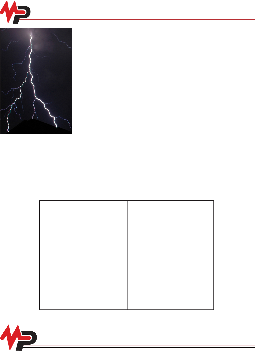
Power Line Surge Arrestor DF
User Manual: power-line-surge-arrestor-DF
Open the PDF directly: View PDF ![]() .
.
Page Count: 35
Please note that because MacLean Power Systems follows a policy of continuous product improvement, we reserve the right to change
specications and drawings at any time without notice.
Table of Contents
MacLean Power Systems
MacLean Power Systems
Surge Arresters Catalog
Surge Arresters Catalog
MacLean Power Systems offers a full range of polymer housed surge arresters meeting the
needs for transmission, substation, distribution and secondary surge protection. With over 75
years of arrester design and manufacturing under the Joslyn brand, combined with MacLean
Power Systems’ polymer manufacturing expertise, the MPS arrester product offering provides
maximum surge protection for the long term.
All of our arresters are designed for the growing demands of power quality and reliability with
safety of workers and the public as a rst priority. Each design maximizes protection for each
application to extend the life of operating lines and equipment.
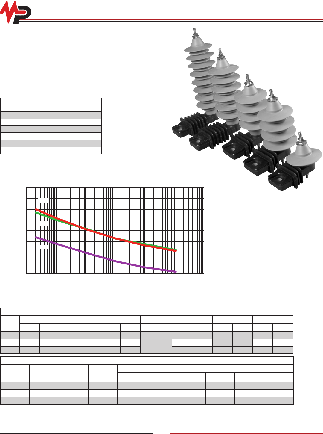
Distribution
• Zforce™ direct ‘mold-on’ polymer housing design provides the best protection for overhead
distribution circuits and the best protection against moisture ingress for the most reliable
service life
• ZE elbow arresters for distribution underground open point protection
Substation
• ZSP polymer housed station class arresters are lightweight and easy to install
• ZIP polymer housed intermediate class arresters designed for lower energy demands
• ZJP polymer housed, light fault duty, intermediate class arresters for low fault current system
applications
Transmission Lines
• ZQPT heavy duty, polymer housed transmission line arresters are designed for line protection to signicantly reduce lightning outages
and extend recloser life
• ZXLA Insulator-Arrester combination assembles designed with MPS transmission insulators to provide an easy to install combination
for maximum insulation and over-voltage protection
Secondary Voltage
• SurgeTec - 175, 480 and 650 volt secondary arresters with a patented fault withstand safety design. Provide protection for meters and
facility service entrance
Arresters General Information AR-1 Station Class Arresters AR-20
Arrester Ratings for Various System
Voltages AR-5 ZSP Electrical Characteristics AR-21
Zforce™ Distribution Arresters AR-6 ZSP Physical Characteristics and
Clearances AR-22
Zforce ZNP™ and ZHP™ Distribution
Arresters AR-8 ZSP Ordering information AR-24
Zforce ZRP™ Distribution Arresters AR-9 Station and Intermediate Class
Arresters Accessories AR-25
Zforce™ EZ Ordering Information AR-10 Transmission Line Arresters AR-27
Zforce™ Accessories AR-11 Surge Tec® Secondary Arresters AR-31
ZE Elbow Distribution Arresters AR-12 Surge Tec® Physical and Electrical
Characteristics AR-32
ZIP and ZJP Intermediate Class
Surge Arresters AR-14 Surge Tec® Typical Wiring
Connections AR-33
ZIP Intermediate Class Arresters AR-15 Surge Tec® Catalog Number Selection
Guide AR-34
ZJP Intermediate Class Arresters AR-17 Numerical Index AR-35
ZIP/ZJP Ordering Information AR-19
http://waterheatertimer.org/Names-of-parts-on-electric-pole.html
© Copyright 2010 MacLean Power Systems
Issued: May 2010
Supercedes: n/a
11411 Addison Avenue, Franklin Park, IL 60131
T: 847.455.0014 F: 847.455.0029
www.macleanpower.com
AR-3
Arresters General Information
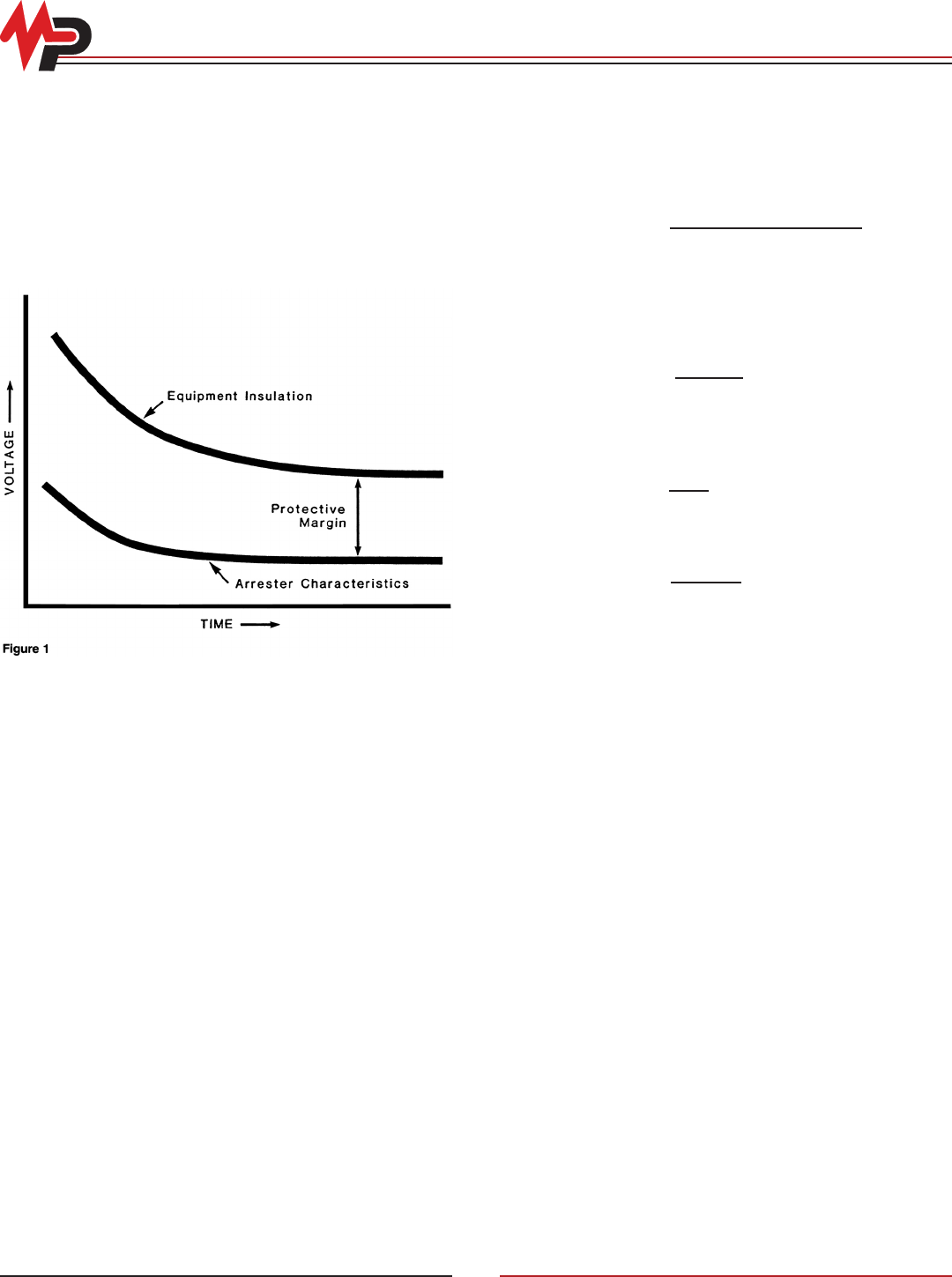
Insulation Coordination
Arresters are used to limit voltage surges on an electrical system
to a known and controlled level. The concept of insulation
coordination means that properly installed arresters limit the
incoming voltage surges to levels within the withstand capability
of the insulating system. Arresters prevent insulation, such as
air, porcelain, oil, cable or wire insulation, etc. from breaking
down, therefore, significantly improving the reliability of the
electrical system. Figure 1 demonstrates this basic concept. The
difference between the two curves is the protective margin.
The process of correlating the insulation withstand levels of
the protected equipment and the protective characteristics of
surge arresters is known as insulation coordination. Without
sparkgaps, the insulation coordination between the metal oxide
arrester and the insulation being protected is defined by the
discharge voltage of the arrester from very short times in the
impulse region to longer times in the switching surge region. The
equivalent front-of-wave of the arrester is used to coordinate with
the chopped wave withstand value, generally defined as 1.15 x
BIL of the transformer. For station class arresters, the equivalent
front-of-wave (EFOW) of the arrester is obtained by discharging
a 10kA (5kA for intermediate arresters) impulse current wave
which produces a voltage wave cresting in 0.5 microseconds.
Discharge voltage, at a specific current level, is used to coordinate
with the equipment Basic Insulation Level (BIL). The discharge
voltage is the crest voltage that results from an 8/20 microsecond
current surge. The coordinating current selected will depend
on the shielding of the substation and other system conditions.
A typically recommended value for the coordinating current is
10kA.
The switching surge protective level is determined by
comparing the switching surge response of the arrester,
with the switching surge withstand level of the transformer,
generally defined as .83 x BIL of the transformer. The voltage of
the arrester is a function of the current. A current of 500 amperes
is used for the intermediate arresters and station class arresters
from 3-96kV. A 1000 ampere surge is used for station arresters
rated 108kV to 198kV. All current impulses have a 45/90
microsecond wave shape.
Application
Proper application of metal oxide arresters is needed to receive
appropriate performance and adequate protection. Arrester
selection depends on the application and should be based on the
level of protection needed, durability of the arrester and quality
assurance of the manufacturer.
Level of protection is the first and most important factor in
applying arresters. The purpose of an arrester is to protect system
equipment against damaging surges. The level of protection
is a function of the discharge voltage characteristics of the
arrester. The lower the discharge voltage, the greater the level
of protection provided. The discharge voltage characteristics
of distribution arresters provide excellent margins of protection
needed for even the most severe applications.
Protective margins are not the only criteria in arrester selection.
Proper performance is based on selecting the appropriate ratings
to withstand system conditions. The maximum continuous line-
to-ground voltage of the system should not exceed the MCOV
rating of the arrester. The MPS arrester ratings are in accordance
with the ANSI/IEEEC62.11-2005 Standard for Metal Oxide Surge
Arresters for AC Power Circuits. Temporary overvoltages (TOV)
can have damaging effects on metal oxide arresters. The
excellent TOV characteristics of the MOV arresters will exceed
the potential system overvoltages when properly selected.
To determine the margin of protection, the following equation is
used:
Percent Margin = Transformer Withstand Level - 1 x 100
Arrester Protective Level
A Type ZSP arrester rated 108 kV protecting a transformer with
a 450 kV BIL has the following margins of protection:
Chopped Wave Withstand - Equivalent Front of Wave
Percent Margin = 1.15 x 450 - 1 x 100 = 82 %
273.7
Full Wave Withstand - Discharge Voltage for a 10kA
Impulse Current
Percent Margin = 450 - 1 x 100 = 74%
249.2
Switching Surge Withstand - Switching Surge Voltage
Percent Margin = 0.83 x 450 - 1 x 100 = 73%
195.2
All margins are well above the minimum 20% margin recom-
mendation of the ANSI application guide C62.22.
[(
[(
[( )
) ]
]
]
[( ) ]
)

© Copyright 2010 MacLean Power Systems
Issued: May 2010
Supercedes: n/a
11411 Addison Avenue, Franklin Park, IL 60131
T: 847.455.0014 F: 847.455.0029
www.macleanpower.com
AR-4
Arresters General Information
There are four basic types of arresters defined by industry
standards. The arrester type selected for the application depends
on the equipment being protected and what level of protection is
required.
Secondary—Available in ratings up to 650 volts, secondary
arresters are used to protect equipment at the utilization voltage
level.
Distribution—Typically used for the protection of equipment on
power distribution circuits. They are available in ratings up to
36kV. This type of arrester is further defined by Normal Duty and
Heavy Duty and includes special application arresters such as
riser pole or dead front elbow type.
Intermediate—Available in ratings up to 144kV, intermediate type
arresters offer improved protective characteristics and durability.
They are generally used for protection of smaller substations, or
medium class power equipment.
Station—Available in ratings up to 216kV, station class arresters
offer the best performance among the four different types. They
are typically used to protect substation equipment, rotating
machines or other applications where premium protection is
required.
Fault Current Data
Fault current testing, also known as short circuit testing,
demonstrates an arrester failure based on the most probable
failure modes over a range of fault currents. Two failure modes
are tested: 1) a fuse wire runs along the side of the internal valve
elements to simulate an internal flashover (moisture or collar
failure), 2) overvoltage the arrester until the resistive elements
fail to simulate a system overvoltage exceeding the unit’s TOV
capability.
ANSI/IEEE C62.11 2005, specifies the test procedures and
acceptance criteria for fault current tests on surge arresters.
Temporary Overvoltage
Temporary power frequency overvoltages (TOV) can occur due
to the voltage rise on unfaulted phases during a line-to-ground
fault, the loss of the neutral ground of an effectively grounded
system, sudden loss of load, generator over speed and other
conditions. Overvoltages exceeding an arrester’s MCOV (Uc)
rating cause an increase in current, resulting in increased power
loss and temperature, thereby, affecting the arrester’s stability.
Quality Assurance
ISO 9001:2000 Certified
MacLean Power Systems metal oxide facility is ISO 9001:2000
certified. Years of extensive quality control processes easily
met the requirements of ISO certification, and has been proven
with unsurpassed field performance of arresters. MPS employs
an extensive quality system from raw materials through final
assembly.
Each block is selected for final assembly based on discharge
voltage, to assure the discharge voltage of the arrester will not
exceed published values. After final assembly, the complete
arrester once again receives a series of electrical tests including
watts loss, reference voltage and radio influence voltage. Only
units accepted by the computerized tester continue on for final
packaging and shipping.
Research and Development
Research and development is an on-going process at MPS.
Our engineers are continually striving for new materials or
processes that will lead to improved arrester performance in
the field. Specifically designed test equipment provides the
capability to properly evaluate new developments. Research
and Development is an important part of our business and
commitment to the future.
© Copyright 2010 MacLean Power Systems
Issued: May 2010
Supercedes: n/a
11411 Addison Avenue, Franklin Park, IL 60131
T: 847.455.0014 F: 847.455.0029
www.macleanpower.com
AR-5
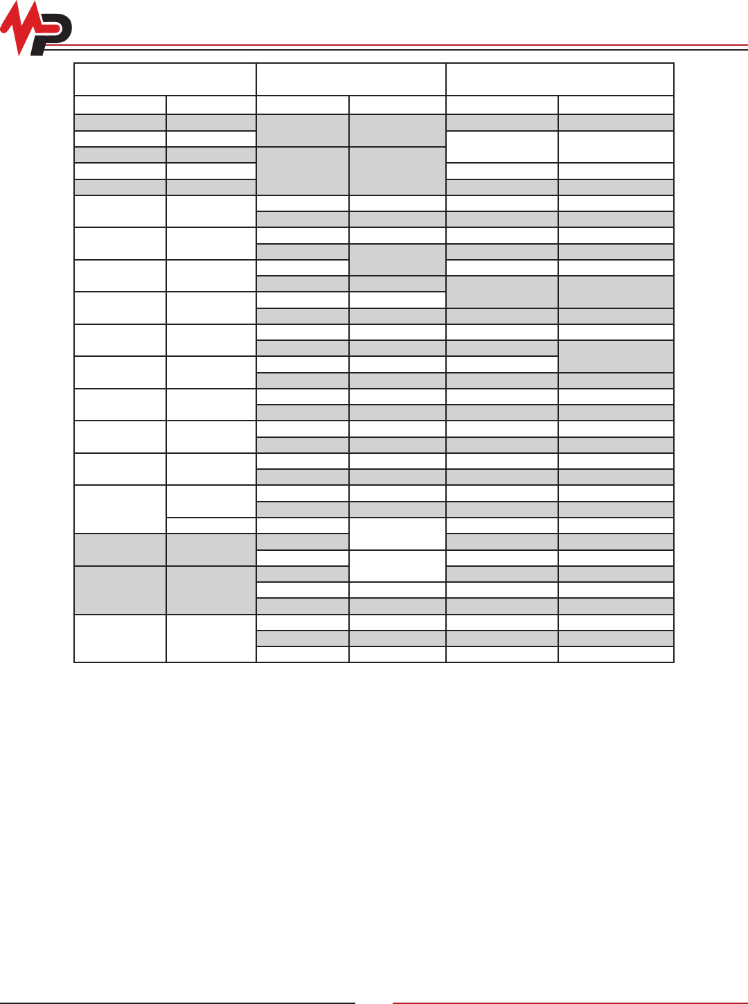
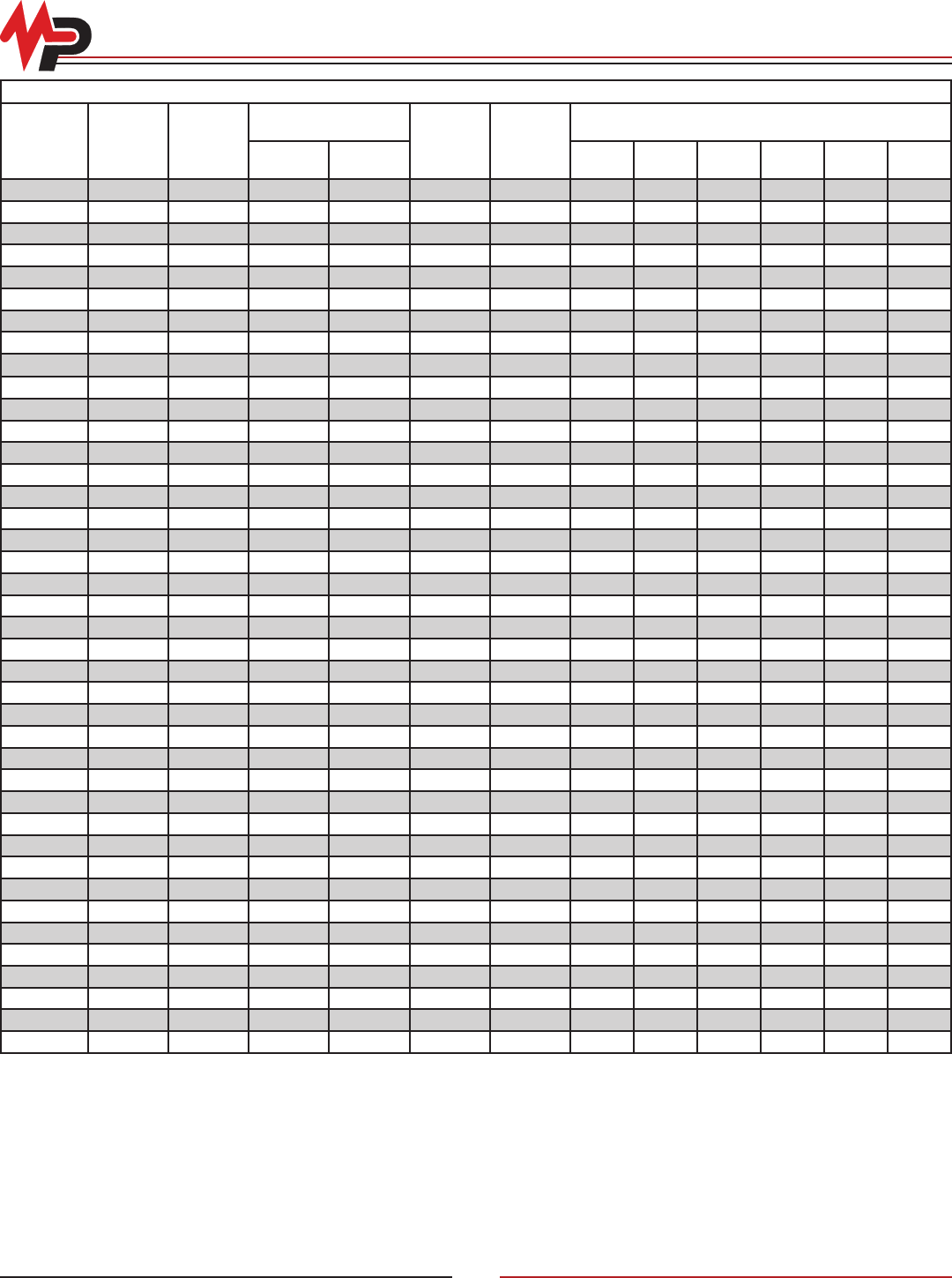
Arrester Ratings for Various System Voltages
System L-L Voltage (kV) Grounded Neutral Circuits
Ungrounded, Temporarily Ungrounded
Impedance Grounded Circuits
Nominal Maximum Rating MCOV Rating MCOV
2.40 2.52 3* 2.55 3* 2.55
4.16 4.37 6* 5.10
4.80 5.04
6* 5.106.90 7.25 9* 7.65
8.32 8.74 10* 8.40
12.00 12.70 9* 7.65 15 12.70
10 8.40 18 15.30
12.47 13.20 9* 7.65 15* 12.70
10 8.40 18 15.30
13.20 13.90 10* 15 12.70
12 10.20 18* 15.30
13.80 14.50 10* 8.40
12 10.20 - -
23.00 24.20 18* 15.30 27* 22.00
21 17.00 30 24.40
24.90 26.10 18* 15.30 30*
21 17.00 36 29.00
34.50 36.20 27* 22.00 39* 31.50
30 24.40 45 36.50
46.00 48.30 36* 29.00 48* 39.00
39 31.50 54 42.00
69.00 72.50 54* 42.00 66* 54.00
60 48.00 72 57.00
115.00 121.00 90* 70.00 - -
96 76.00 108* 84.00
121.00 108 84.00 120 98.00
138.00 145.00 108* 132* 106.00
120 98.00 144 115.00
161.00 169.00
120* - -
132 106.00 144* 115.00
144 115.00 168 131.00
230.00 242.00
172* 140.00 - -
180 144.00
192 152.00
*Nominal recommended ratings are highlighted. Use higher rating for severe duty.
© Copyright 2010 MacLean Power Systems
Issued: May 2010
Supercedes: n/a
11411 Addison Avenue, Franklin Park, IL 60131
T: 847.455.0014 F: 847.455.0029
www.macleanpower.com
AR-6
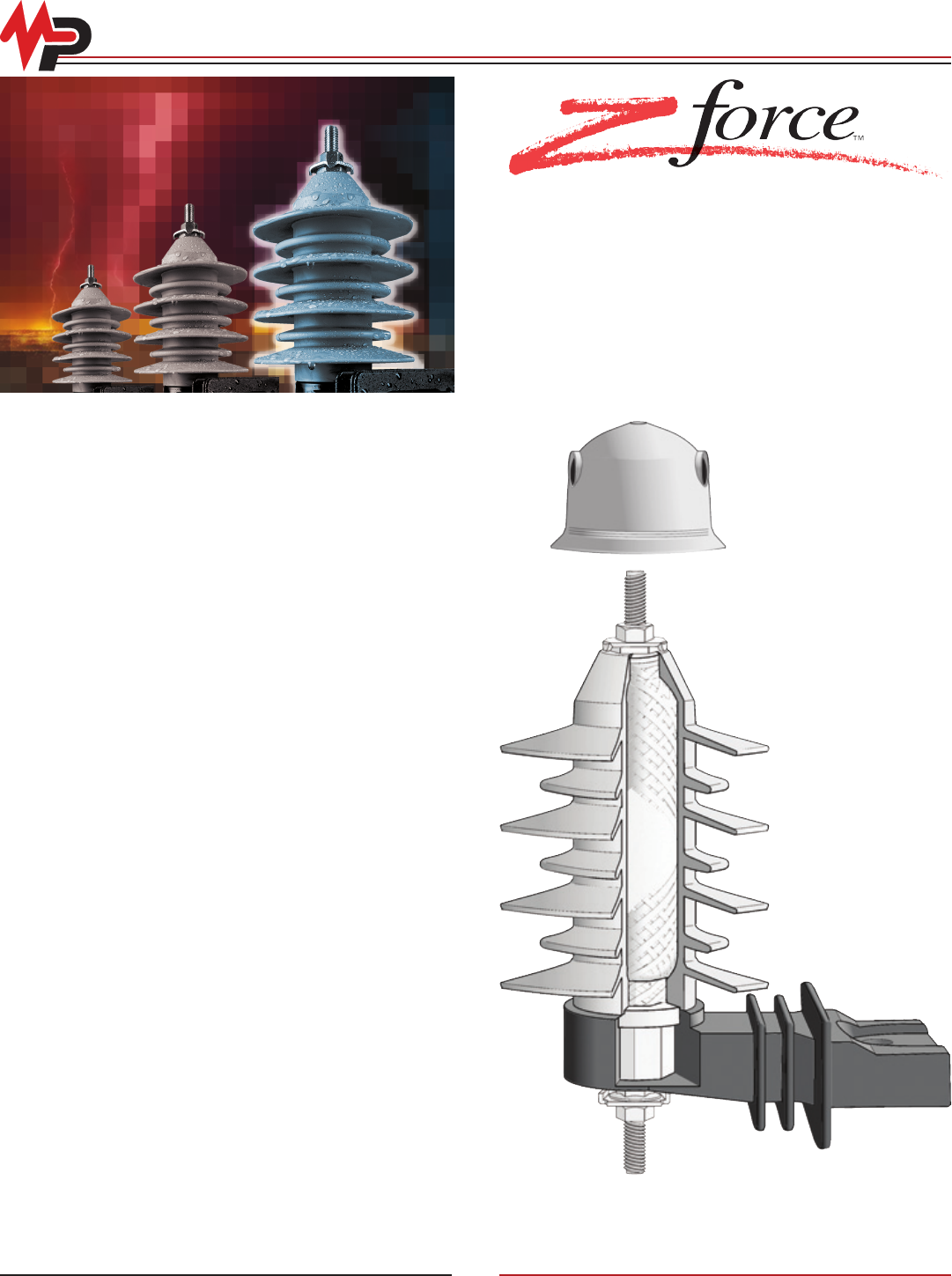
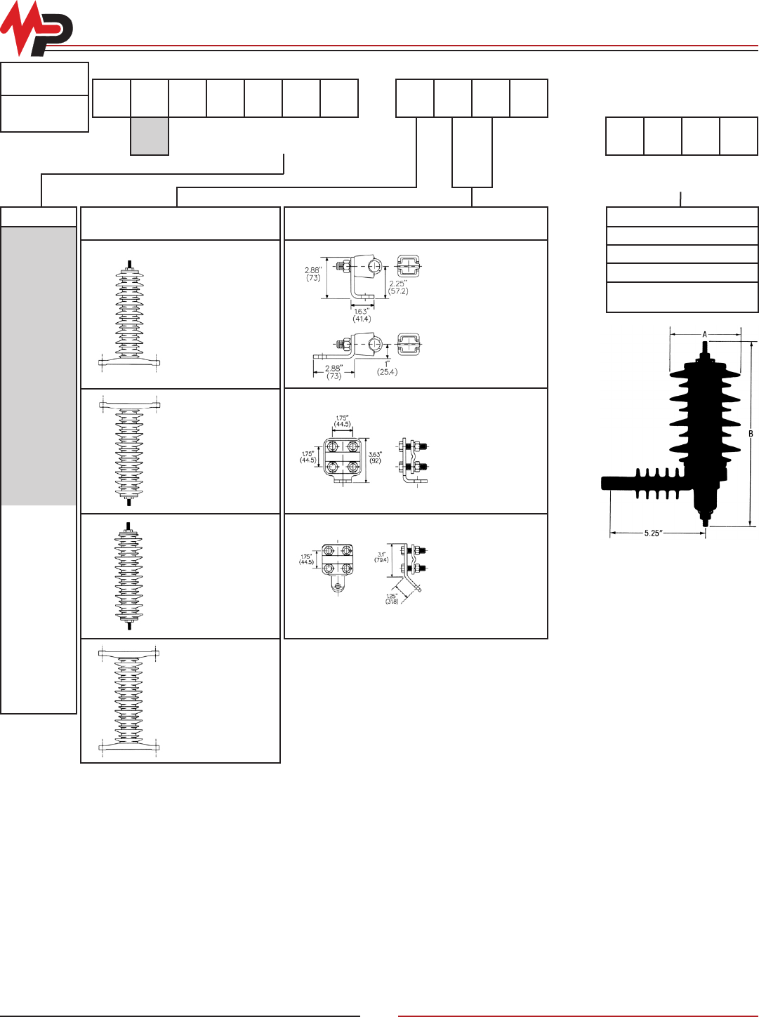
Zforce™ Distribution Arresters
Features
• Zforce™ mold-on polymer housing for the ultimate seal against
moisture ingress
• High strength berglass wrap for high fault-withstand design
• Integrated Ground Lead Disconnect for fast, reliable operation.
Operates in less than 2 seconds at 1 amp and less than 2 cycles at
1,000 amps
Zforce™ ZNP (5kA Normal Duty Polymer)
Zforce™ ZHP (10kA Heavy Duty Polymer)
Zforce™ ZRP (10kA Riser Pole Polymer)
Durability
Heavy Duty and Riser Pole Distribution Class arresters have been
called upon to serve in the most demanding of applications. Typically
unshielded, overhead lines can produce some of the most severe
lightning surges on the power system. MPS distribution arresters
are designed to meet the demands of protecting underground and
overhead equipment, respectively. Tested in accordance with the
latest industry standard, ANSI/IEEE C62.11-2005 for metal oxide
arresters, Zforce™ distribution arresters withstand the following
minimum design tests:
Zforce Design Performance:
• High Current Short Duration
• ZNP - 65kA
• ZHP & ZRP - 100kA
• Low Current Long Duration
• ZNP - 150A
• ZHP & ZRP - 250A
• Duty Cycle per ANSI
• ZNP - 5kA
• ZHP & ZRP - 10kA
• Nominal Discharge Class per IEC:
•ZNP - 5kA
•ZHP & ZRP - 10kA, Class 1
• Minimum Switching Energy Capability (2 Surges)
•ZNP - 2.2kJ/kV MCOV
•ZHP - 2.7kJ/kV MCOV
•ZRP - 2.2kJ/kV MCOV
• Lightning Energy Capability (1 Surge)
•ZNP - 2.3kJ/kV MCOV
•ZHP - 3.4kJ/kV MCOV
•ZRP - 2.7kJ/kV MCOV
• Fault Withstand Capability
• ZNP - 10kA
• ZHP & ZRP - 20kA
• RUS Listed
© Copyright 2010 MacLean Power Systems
Issued: May 2010
Supercedes: n/a
11411 Addison Avenue, Franklin Park, IL 60131
T: 847.455.0014 F: 847.455.0029
www.macleanpower.com
AR-7
Zforce™ Distribution Arresters
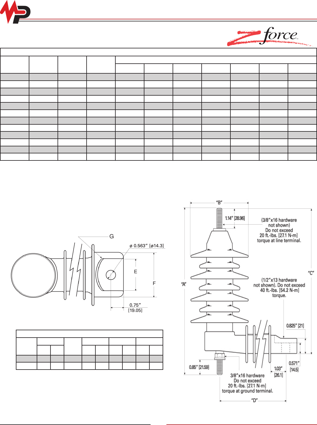
Terminal Connection
Distribution arrester line terminals utilize a stainless steel four
corner “Star Clamp” for maximum conductor range and speed
of installation. The ground terminals utilize a stainless steel “U
clamp”. Both connectors securely clamp aluminum or copper
conductors from No. 10 solid through 2/0 stranded. MPS species
that no more than 20 ft/lbs of torque be applied to the line and
ground terminals.
Duration (sec)
Voltage P.U. of MCOV (Uc)
ZNP ZHP ZRP
0.02 1.77 1.80 1.54
0.10 1.70 1.73 1.48
1.00 1.61 1.63 1.40
10 1.52 1.54 1.31
100 1.47 1.47 1.26
1000 1.42 1.43 1.22
Physical Characteristics
kV
Creepage1Strike A B C D Weight2
In Mm In Mm In Mm In Mm In Mm In Mm Lb Kg
915.04 382 7.69 195 8.83 224
4.00 102
7.71 195
3.93 100
2.90 1.32
10 17.41 442 8.00 203 9.14 232 8.02 204 3.00 1.36
18 26.59 675 11.23 285 12.23 311 11.16 283 5.43 138 4.80 2.18
Electrical Characteristics
Voltage
Rating (Ur)
(kV-rms)
MCOV
(Uc)3
(kV-rms)
Max Equiv
FOW4
(kV-Crest)
Max Switch
Surge6
(kV-Crest)
Maximum Discharge Voltage (kV-Crest) Using an 8/20 ms Current Impulse
1.5 kA 2.5 kA 3.0 kA 5.0 kA 10 kA 20 kA
97.65 29.9 23.7 25.4 26.2 26.6 28.2 30.5 33.8
10 8.4 32.9 26.3 28.1 29.2 29.6 31.3 33.9 37.4
18 15.3 59.7 47.4 50.7 52.3 53.1 56.4 61.0 67.5
Zforce ZNP™ (5kA Normal Duty Polymer)
Time (Seconds)
1.2
1.3
1.4
1.5
1.6
1.7
1.8
1.9
2.0
0.01 0.1 1 10 100 1000 10000
ZHPZHP
ZNPZNP
ZRPZRP
TOV Graph and Capability 3kV to 36kV
Overvoltage per Unit of Arrester
MCOV (Uc)
© Copyright 2010 MacLean Power Systems
Issued: May 2010
Supercedes: n/a
11411 Addison Avenue, Franklin Park, IL 60131
T: 847.455.0014 F: 847.455.0029
www.macleanpower.com
AR-8
Zforce ZNP™ and ZHP™ Distribution Arresters
Physical Characteristics
kV
Creepage1Strike A B C D Weight2
In Mm In Mm In Mm In Mm In Mm In Mm Lb Kg
37.96 202 5.47 139 6.52 166
4.30 109
5.40 137
3.93 100
2.30 1.05
611.94 303 6.02 153 7.66 195 6.54 166 3.00 1.37
915.92 404 7.76 197 8.80 224 7.68 195 3.60 1.64
10 18.28 464 8.21 209 9.14 232 8.02 204 3.70 1.68
12 19.90 506 8.91 226 9.94 253 8.82 224 4.20 1.91
15 23.84 606 10.01 254 11.09 282 10.02 254 4.90 2.23
18 27.87 708 11.40 290 12.23 311 11.16 283
5.43 138
5.90 2.68
21 31.85 809 12.54 319 13.37 340 12.30 312 6.50 2.96
24 35.83 910 13.69 348 14.51 369 13.44 341 7.10 3.23
27 39.92 1014 14.52 369 15.66 398 14.59 371 7.80 3.52
30 43.90 1115 15.51 394 16.78 426 15.71 399 8.40 3.80
36 51.95 1320 17.79 452 19.13 486 18.06 459 9.60 4.38
Zforce ZRP™ (10kA Riser Pole Polymer)
Physical Characteristics
kV
Creepage1Strike A B C D Weight2
In Mm In Mm In Mm In Mm In Mm In Mm Lb Kg
37.96 202 5.47 139 6.52 166
4.30 109
5.40 137
3.93 100
2.30 1.05
611.94 303 6.02 153 7.66 195 6.54 166 3.00 1.37
915.92 404 7.76 197 8.80 224 7.68 195 3.60 1.64
10 18.28 464 8.21 209 9.14 232 8.02 204 3.70 1.68
12 19.90 506 8.91 226 9.94 253 8.82 224 4.20 1.91
15 23.84 606 10.01 254 11.09 282 10.02 254 4.90 2.23
18 27.87 708 11.40 290 12.23 311 11.16 283
5.43 138
5.90 2.68
21 31.85 809 12.54 319 13.37 340 12.30 312 6.50 2.96
24 35.83 910 13.69 348 14.51 369 13.44 341 7.10 3.23
27 39.92 1014 14.52 369 15.66 398 14.59 371 7.80 3.52
30 43.90 1115 15.51 394 16.78 426 15.71 399 8.40 3.80
36 51.95 1320 17.79 452 19.13 486 18.06 459 9.60 4.38
Electrical Characteristics
Voltage
Rating (Ur)
(kV-rms)
MCOV
(Uc)3
(kV-rms)
Max Equiv
FOW5
(kV-Crest)
Max Switch
Surge6
(kV-Crest)
Maximum Discharge Voltage (kV-Crest) Using an 8/20 ms Current Impulse
1.5 kA 2.5 kA 3.0 kA 5.0 kA 10 kA 20 kA
32.55 10.4 7.8 8.5 8.8 8.9 9.3 9.9 10.9
65.10 20.7 15.5 16.9 17.5 17.7 18.6 19.8 21.8
97.65 31.0 23.3 25.4 26.2 26.6 27.9 29.7 32.7
10 8.40 34.5 25.9 28.2 29.1 29.5 31.0 33.0 36.3
12 10.20 41.3 311.0 33.8 34.9 35.4 37.2 39.6 43.5
15 12.70 51.7 38.8 42.2 43.6 44.2 46.5 49.5 54.4
18 15.30 62.0 46.5 50.7 52.3 53.1 55.8 59.4 65.3
21 17.00 72.3 54.3 59.1 61.0 61.9 65.1 69.3 76.2
24 19.50 82.6 62.1 67.6 69.7 70.7 74.4 79.2 87.0
27 22.00 92.9 69.9 76.0 78.4 79.6 83.7 89.1 98.9
30 24.40 103.3 77.6 84.4 87.1 88.4 93.0 99.0 108.8
36 29.00 124.0 93.1 101.3 104.5 106.1 111.5 118.8 130.5
Zforce ZHP™ (10kA Heavy Duty Polymer)
© Copyright 2010 MacLean Power Systems
Issued: May 2010
Supercedes: n/a
11411 Addison Avenue, Franklin Park, IL 60131
T: 847.455.0014 F: 847.455.0029
www.macleanpower.com
AR-9
Zforce ZRP™ Distribution Arresters
Electrical Characteristics
Voltage
Rating (Ur)
(kV-rms)
MCOV
(Uc)3
(kV-rms)
Max Equiv
FOW5
(kV-Crest)
Max Switch
Surge6
(kV-Crest)
Maximum Discharge Voltage (kV-Crest) Using an 8/20 ms Current Impulse
1.5 kA 2.5 kA 3.0 kA 5.0 kA 10 kA 20 kA 40 kA
32.55 8.6 6.2 6.8 7.1 7.2 7.5 8.2 9.0 10.3
65.10 17.1 12.4 13.6 14.1 14.3 15.1 16.3 18.1 20.6
97.65 25.7 18.6 20.3 21.2 21.5 22.6 24.5 27.1 30.9
10 8.40 28.5 20.7 22.6 23.5 23.9 25.1 27.2 30.1 34.3
12 10.20 34.2 24.8 27.1 28.2 28.7 30.1 32.6 36.1 41.2
15 12.70 42.8 31.1 33.9 35.3 35.9 37.7 40.8 45.2 51.5
18 15.30 51.3 37.3 40.7 42.3 43.0 45.2 49.0 54.2 61.7
21 17.00 59.9 43.5 47.5 49.4 50.2 52.7 57.1 63.2 72.0
24 19.50 68.4 49.7 54.2 56.4 57.4 60.2 65.3 72.2 82.3
27 22.00 77.0 55.9 61.0 63.5 64.5 67.8 73.4 81.3 92.6
30 24.40 85.5 62.1 67.8 70.5 71.7 75.3 81.6 90.3 102.9
36 29.00 102.6 74.5 81.4 84.6 86.0 90.4 97.9 108.4 123.5
Notes:
1) Reduce creepage by 1.45 inches (36.8 mm) when ordering without insulating bracket
2) Does not include metal mounting bracket hardware
3) MCOV = Maximum Continuous Operating Voltage that may be applied coninuously between the terminals of the arrester
4) The equivalent Front-of-Wave is the maximum discharge voltage for a 5kA impulse current wave which produces a voltage wave cresting in 0.5 ms
5) The equivalent Front-of-Wave is the maximum discharge voltage for a 10kA impulse current wave which produces a voltage wave cresting in 0.5 ms
6) Based on a switching surge current impulse of 45x90 ms, 500 amperes
* Single pack modier required for 30 kV and 36 kV ratings
Insulated Bracket Data
Arrester
Rating
(kV)
Creepage
Skirts
E F G (Radius)
In Mm In Mm In Mm In Mm
3 - 15 4.60 117 3 1.875 47.62 2.70 66.58 1.312 33.34
18 - 36 9.12 232 6 2.130 54.10 2.95 74.93 1.656 42.06
© Copyright 2010 MacLean Power Systems
Issued: May 2010
Supercedes: n/a
11411 Addison Avenue, Franklin Park, IL 60131
T: 847.455.0014 F: 847.455.0029
www.macleanpower.com
AR-10
Zforce™ Distribution Arrester EZ Ordering Information
Z_P P0 kV -P1 P2 P3 P4 P5 P6 P7
Z_P Pole Type P2 -Additional Bracket Options P5 Bottom Terminal Options*
ZNP
ZHP
ZRP
-
-
-
Zinc Oxide Normal Duty 5 kA Polymer
Arrester
Zinc Oxide Heavy Duty 10 kA Polymer
Arrester
Zinc Oxide Riser Pole 10 kA Polymer
Arrester
0
A
C
N
W
-
-
-
-
-
No NEMA Brackets
Transformer Type “A” Bracket
Crossarm Bracket (top mounting with
backstrap assembly)
Transformer Type “N” Bracket
Transformer Type “W” Bracket
00
02
12
-
-
-
Standard - “U” clamp and nut
Two four corner SSTL clamps (up/down)
12.0” Copper Strap
P0 General Options P3 Top Terminal Options* P6 Bagging Options
0- 3/8” x 16 SSTL Studs (line and ground
terminals)
00
02
12
-
-
-
Standard - Four corner SSTL clamp
and nut
Two four corner SSTL clamps
18” Insulated Wire Lead with two ring
terminals/at washer/lock washer
B- Boss Mounting Hardware
kV(Ur)Duty-Cycle Rating of Arrester P7 Packaging Options
03, 06, 09, 10, 12, 15, 18, 21, 24, 27,
30, 36
#S
#K
-
-
Single pack modier required only for
30kV and 36kV ratings
Bulk packing
P1 Insulating Bracket Options
0
1
2
3
-
-
-
-
Standard Insulating Bracket, with GLD
Standard Insulating Bracket, no GLD
No Insulating Bracket, with GLD (line
arrester)
No Insulating Bracket, no GLD
(switchgear application)
P4 Universal Insulating Cap
(Birdguard) * Top/Bottom Terminal: Fits wire ranges for aluminum or copper
conductors from #10 solid (3.0mm diameter) through 2/0
stranded (11.0mm diameter)
0
1
2
-
-
-
Without Cap
With Cap
Fuse Kit
ZHP 0 10 -0 N 02 0 12 B
Heavy Duty
3/8” x 16 SSTL Stud
9 kV Duty Cycle Rating
Two four Corner SSTL Clamps
No Insulating Cap (Birdguard)
12.0” Copper Strap
Boss Mounting Hardware
in up/down conguration
Standard Insulating Bracket w/ GLD
Transformer Type N Mounting
Bracket
Catalog Order Number Example
Optional Birdguard
© Copyright 2010 MacLean Power Systems
Issued: May 2010
Supercedes: n/a
11411 Addison Avenue, Franklin Park, IL 60131
T: 847.455.0014 F: 847.455.0029
www.macleanpower.com
AR-11
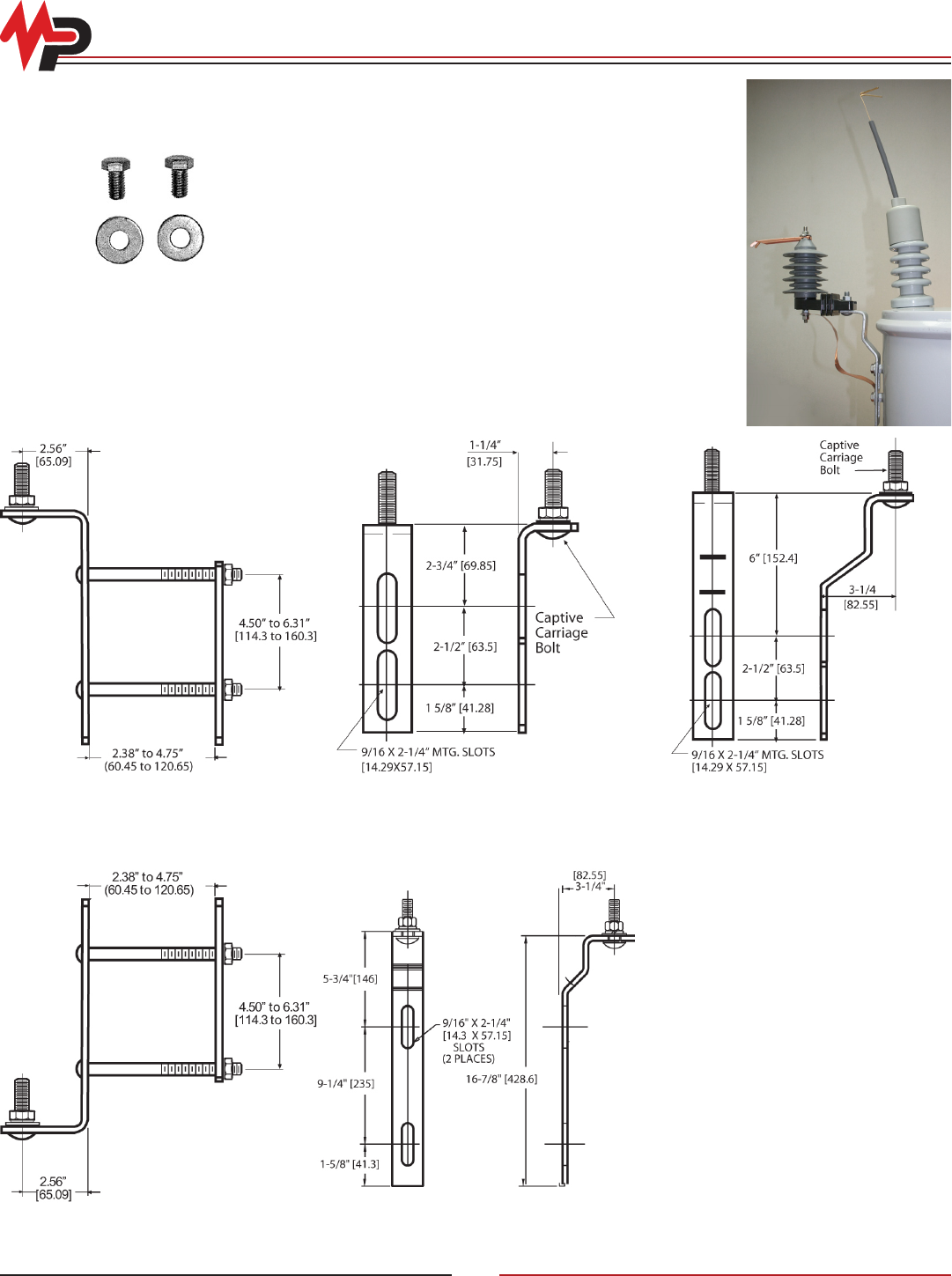
Zforce™ Distribution Arrester Accessories
Mounting Brackets
Type “C”
Catalog No. 7106A0025
Type “A”
Catalog No. 7106A0013
Type “N”
Catalog No. 7106A0015
Boss Mounting
Hardware
Cat No. AD1137-B
Type “E”
Catalog No. J24515
Type “W”
Catalog No. 7106A0047
Flipper Fuse Kit
The AD524-Z fuse kit includes a stationary
terminal for mounting on the transformer
bushing. Its spring arm subjects the
fuselink to moderate tension during steady-
state operation and provides a positive whip
action to quickly separate the link during
fault conditions. An insulating cap for the
transformer busing and an insulating sleeve
for the spring arm are included for wildlife
protection.
Optional Bagging Accessories
Transformer mounting hardware is available
upon request. To specify, add sufx “-B” for boss
mounting hardware to catalog number.
© Copyright 2010 MacLean Power Systems
Issued: May 2010
Supercedes: n/a
11411 Addison Avenue, Franklin Park, IL 60131
T: 847.455.0014 F: 847.455.0029
www.macleanpower.com
AR-12
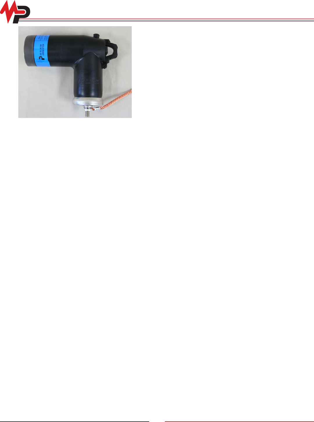
ZE Elbow Distribution Arresters
The type “ZE” arrester incorporates surge protection in a one-
piece, shielded elbow housing. It permits arrester installation on
standard separable connector bushings, maintaining the dead
front concept.
Performance
The “ZE” elbow arrester consistently withstands the following
minimum design tests:
• High Current-Short Duration: 2 current surges of 40kA
magnitude
• Low Current-Long Duration: 20 current surges of 75 amperes
magnitude and 2000 microsecond duration
• Duty Cycle: 22 discharges with a current surge of 5kA magnitude
and 8/20 microsecond wave shape
• Following each of these tests, the “ZE” arrester remains
thermally stable and the discharge voltage increase at rated
current is less than 10%
Design
The type “ZE” arrester was developed specically for protection of
underground distribution systems. It is installed at the open point
of the underground system to prevent voltage wave doubling.
When also installed at an intermediate point, voltage reections
from the open point arrester are harmlessly discharged. The
housing, made of peroxide cured EPDM rubber, is totally shielded
with a molded conductive EPDM jacket to maintain the dead front
concept. The one-piece construction requires no eld assembly.
The “ZE” dead front elbow arrester is RUS listed.
Reliability
Rigid control standards insure that all material conforms to
exacting engineering specications. Each nished arrester is
subjected to electrical tests to determine reference voltage, total
leakage current and corona levels.
Application
The type “ZE” arrester rated voltage designates the 60Hz voltage
applied across the arrester terminals during the duty cycle test. In
addition, the type “ZE” arrester Maximum Continuous Operating
Voltage (MCOV) designates the maximum power frequency
voltage that may be continuously applied across the arrester in
service. Selection of the appropriate type “ZE” rating is made on
the basis that the maximum continuous line-to-ground voltage on
the system does not exceed the MCOV of the arrester.
The 10kV, 18kV and 27kV rated arresters are designed for
application on nominal 15kV, 25kV and 35kV URD systems,
respectively. The three ratings include standard ANSI/IEEE 386
separable connector interface designs that are compatible with
major interface suppliers at each voltage level.
© Copyright 2010 MacLean Power Systems
Issued: May 2010
Supercedes: n/a
11411 Addison Avenue, Franklin Park, IL 60131
T: 847.455.0014 F: 847.455.0029
www.macleanpower.com
AR-13
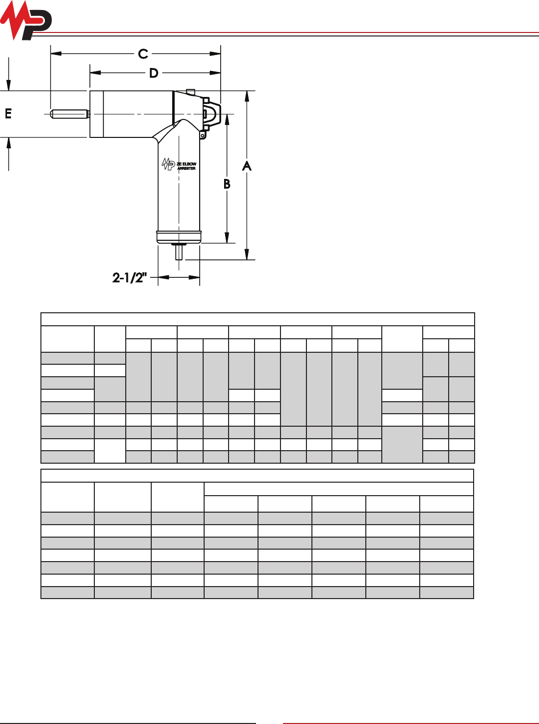
ZE Elbow Distribution Arresters
Physical Characteristics
Catalog
Number
kV
Rating
A B C D E Elbow
Interface*
Weight
In Mm In Mm In Mm In Mm In Mm Lb Kg
8132B0003J001 3
7.0 177.8 4.6 116.8
8.1 205.7
7.7 195.6 2.9 73.7
15kV
3.0 1.4
8132B0006J001 6
8132B0010J001
10 3.5 1.6
8132B1010J001 10.1 256.5 25kV
8132B0012J001 12 8.3 210.8 5.9 149.9 8.1 205.7 15kV 4.0 1.8
8132B0018J001 18 10.0 254.0 7.6 193.0 10.1 256.5 25kV 4.7 2.1
8132B2024J001 24 13.3 337.8 10.3 261.6 12.6 320.0 10.1 256.5 4.0 101.6
35kV2
5.2 2.4
8132B1027J001
27
13.4 340.4 11.0 279.4 10.1 256.5 7.7 195.6 2.9 73.7 6.4 2.9
8132B2027J001 14.5 368.3 11.5 292.1 12.6 320.0 10.1 256.5 4.0 101.6 8.5 3.9
Electrical Characteristics
Voltage
Rating (Ur)
(kV-rms)
MCOV
(kV-rms)
Max Equiv
FOW*
(kV-Crest)
Maximum Discharge Voltage (kV-Crest) Using an 8/20 ms Current Impulse
1.5 kA 3.0 kA 5.0 kA 10 kA 20 kA
32.55 10.0 8.5 8.8 9.3 10.2 12.9
65.10 20.1 17.0 17.6 18.6 20.4 25.8
10 8.40 30.5 28.0 29.0 30.7 33.7 42.6
12 10.20 40.2 34.0 35.2 37.2 40.8 51.6
18 15.30 60.3 51.0 52.8 55.8 61.2 77.4
24 19.50 80.4 68.0 70.4 74.4 81.6 103.2
27 22.00 90.5 76.5 79.2 83.7 91.8 116.1
Notes:
* Compatible with standard ANSI/IEEE 386, 1995
1) Small 35kV Interface, 21.1/36kV Figure 7 of ANSI/IEEE 386, 1995
2) Large 35kV Interface, 21.1/36.6kV Figure 8 of ANSI/1EEE 386, 1995
A
B
C
D
E
2-1/2"
Probe
Standard load break probe is shipped assembled with each unit
Ground Cable
Size: #5 stranded copper wire- 37” length
Lubricant
Each arrester is shipped with a packet of silicone grease, wiping cloth
and instruction sheet
© Copyright 2010 MacLean Power Systems
Issued: May 2010
Supercedes: n/a
11411 Addison Avenue, Franklin Park, IL 60131
T: 847.455.0014 F: 847.455.0029
www.macleanpower.com
AR-14
ZIP and ZJP Intermediate Class Surge Arresters
The type “ZIP”/“ZJP” intermediate class arresters offer the
benefits of polymer housings for system voltages up to 161kV.
The arresters are approximately 1/5 the weight of the porcelain
equivalent. Handling and installation become much easier tasks.
Also, the risk of damage to the housing is reduced compared to
porcelain.
Performance
ZIP:
3 kV through 144 kV duty cycle rating, 2.55 kV through 115 kV
MCOV, 2.4 kV through 161 kV system line-line voltage
ZJP:
3 kV through 45 kV duty cycle rating, 2.55 kV through 36.5
MCOV, 2.4 kV through 46 kV system line-line voltage
The arrester designs are tested in accordance with the latest
industry strandards for metal oxide arresters. The “ZIP”/“ZJP”
arresters consistently withstand the following minimum design
tests:
• High Current-Short Duration: 100 kA crest
• Duty Cycle per ANSI: 10 kA
• Nominal Discharge Current per IEC: 10 kA
• Line Discharge Class per IEC: Class 2
• Minimum Energy Capability: 5.0 kJ/kV MCOV
• Fault Withstand Capability:
• ZIP—50 kA rms
• ZJP—20 kA rms
• Working Cantilever Strength:
• ZIP—5000 in.-lbs.
• ZJP—720 in.-lbs.
• ZIP RUS listed
Design
The design consists of a number of metal oxide valve elements
contained within a fiberglass winding and then inserted into
the polymer housing. Type “ZIP”/“ZJP” arresters are shipped
as single units for all ratings. There is no need to combine
sections, even for the 144kV duty cycle rating. The metal oxide
valve elements combine excellent protective characteristics with
steady state per formance to maximize protec tion over many
years of service.
Fault Current Withstand
The severity of a failure depends on the duration and magnitude
of the available fault current conducting through the arrester at
the time of failure. This type of arrester, with its polymer housing,
eliminates the potential danger of porcelain fragmentation. The
design uses a fiberglass epoxy wrap to relieve the pressure that
is present during a fault.
Benefits
The use of polymer housings for our arresters provides many
benefits over porcelain designs.
• LIGHTWEIGHT—The lightweight design provides much easier
handling and installation. The polymer arresters are less than
1/5 the weight of the porcelain equivalents. The burden on
mounting structures and personnel is greatly reduced.
• REDUCED CLEARANCES—The smaller physical size of the
polymer housing and the line side of the arrester allow the
clearances to be reduced. This provides added flexibility with
design and layout since they can be used in tighter areas.
• SINGLE UNIT DESIGN—The single unit design simplifies
installation by reducing handling that was previously required
for multi-section porcelain designs. This also provides improved
contamination performance over multi-unit arresters.
• DAMAGE RESISTANT—The polymer housings resist damage
from handling where porcelain units are most vulnerable to
chipping and breakage.
• SAFETY—The “ZIP”/“ZJP” arresters minimize safety hazards
to personnel and nearby equipment that exists with porcelain
housings.
Reliability
Each completed “ZIP”/“ZJP” arrester unit must pass the following
electrical tests: reference voltage, power loss, and RIV.
© Copyright 2010 MacLean Power Systems
Issued: May 2010
Supercedes: n/a
11411 Addison Avenue, Franklin Park, IL 60131
T: 847.455.0014 F: 847.455.0029
www.macleanpower.com
AR-15
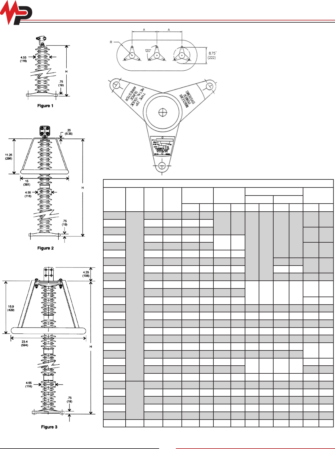
ZIP Intermediate Class Surge Arresters
Physical Characteristics and Clearances
Catalog
Number Figure
kV
Rating
MCOV
kV
Total Height Creepage
Minimum Clearances1
WeightA R
In Mm In Mm In Mm In Mm Lb Kg
ZIP0003
1
3 2.55 6.80 173
15.70 400
9.5 241
5.5 140
8.0 3.6
ZIP0006 6 5.10 6.80 173
ZIP0009 9 7.65 6.82 173
9.0 4.1
ZIP0010 10 8.40 6.87 175
15.80 401
ZIP0012 12 10.20 6.85 174
11.0 5.0
ZIP0015 15 12.70 8.31 211 20.20 512
ZIP0018 18 15.30 9.22 234 22.00 559 5.8 147
12.0 5.4
ZIP0021 21 17.00 10.70 272 26.40 671 6.8 173
ZIP0024 24 19.50 12.10 308 30.70 781 7.8 198 14.0 6.4
ZIP0027 27 22.00 13.10 333 33.70 856
10.5 267 8.8 224
15.0 6.8
ZIP0030 30 24.40 14.60 370 38.10 967
ZIP0033 33 26.70 15.90 403 40.30 1024 16.0 7.3
ZIP0036 36 29.00 16.80 428 44.20 1122 12.5 318 10.8 274 17.0 7.8
ZIP0039 39 31.50 18.30 466 48.60 1234 13.5 343 11.8 300 18.0 8.2
ZIP0042 42 34.00 19.20 489 51.40 1307 14.5 369 12.8 326 19.0 8.7
ZIP0045 45 36.50 21.30 542 54.50 1385 15.5 394 13.8 351 20.0 9.1
ZIP0048 48 39.00 23.00 583 61.70 1567 16.5 419 14.8 376 24.0 10.9
ZIP0054 54 42.00 24.90 634 67.60 1718 18.5 470 16.8 427
25.0 11.3
ZIP0060 60 48.00 27.90 708 76.40 1940 20.5 521 18.8 478
ZIP0066 66 54.00 30.50 774 80.80 2054
23.5 597 21.8 554
27.0 12.3
ZIP0072 72 57.00 32.40 823 88.60 2251 29.0 13.2
ZIP0084 84 68.00 37.20 945 103.00 2620 25 635 23.30 592 32.40 14.70
ZIP0090
2
90 70.00 41.40 1051 109.00 2775 40.0 1016 33.0 838 41.0 18.6
ZIP0096 96 76.00 43.80 1112 119.00 3027 42.0 1067 35.0 889 43.0 19.6
ZIP0108 108 84.00 48.00 1218 133.00 3379 46.0 1168 39.0 991 47.0 21.4
ZIP0120 120 98.00 53.30 1355 149.00 3788 49.0 1245 42.0 1067 51.0 23.1
ZIP0132 132 106.00 59.30 1507 161.00 4088 51.0 1296 44.0 1118 55.0 25.0
ZIP0144 3 144 115.00 63.50 1613 177.00 4507 67.0 1702 55 1397 73.0 33.2
Notes:
1) These minimum clearances are determined by the protective capabilities of the arresters and they are secondary to any other
clearance requirement that may exist for specic applications.
Three Phase Installation Layout
The holes for mounting are .56” (42 mm) for
1/2” bolts. Mounting bolts and washers are not
furnished with arrester.
Nameplates
In addition to the information that is included on
the tripod base, a nameplate is attached to the
casting to provide all of the required arrester
details. The catalog number, the rated voltage,
the maximum continuous operating voltage, and
the pressure relief current rating are shown. The
serial number includes information about the time
of manufacture.
© Copyright 2010 MacLean Power Systems
Issued: May 2010
Supercedes: n/a
11411 Addison Avenue, Franklin Park, IL 60131
T: 847.455.0014 F: 847.455.0029
www.macleanpower.com
AR-16
ZIP Intermediate Class Surge Arresters
Electrical Characteristics
Catalog
Number
Voltage
Rating
(kV-rms)
MCOV
(kV-rms)
TOV1
Max Equiv
FOW2
(kV-Crest)
Max
Switch
Surge3
(kV-Crest)
Maximum Discharge Voltage (kV-Crest)
Using an 8/20 ms Current Impulse
1 s
(kV-rms)
10 s
(kV-rms) 1.5 kA 3.0 kA 5.0 kA 10 kA 20 kA 40 kA
ZIP0003 3 2.55 3.7 3.5 8.55 6.34 6.79 7.17 7.50 8.09 8.96 10.1
ZIP0006 6 5.10 7.41 7.04 17.1 12.7 13.6 14.3 15 16.2 17.9 20.2
ZIP0009 9 7.65 11.10 10.6 25.9 19.2 20.5 21.7 22.7 24.5 27.1 30.5
ZIP0010 10 8.40 12.20 11.6 28.3 21 22.5 23.7 24.8 26.8 29.6 33.4
ZIP0012 12 10.20 14.80 14.1 34.2 25.4 27.2 28.7 30 32.4 35.8 40.4
ZIP0015 15 12.70 18.40 17.5 43.1 32 34.2 36.1 37.8 40.8 45.1 50.8
ZIP0018 18 15.30 22.20 21.1 51.3 38.1 40.8 43 45 48.6 53.8 60.6
ZIP0021 21 17.00 24.70 23.5 56.6 42 44.9 47.5 49.6 53.6 59.3 66.8
ZIP0024 24 19.50 28.30 26.9 68.5 50.8 54.3 57.4 60 64.8 71.7 80.7
ZIP0027 27 22.00 31.90 30.4 77.3 57.4 61.4 64.8 67.8 73.2 81 91.2
ZIP0030 30 24.40 35.40 33.7 83.5 61.9 66.2 70 73.2 79 87.4 98.4
ZIP0033 33 26.70 38.80 36.9 91.9 68.2 72.9 77 80.6 86.9 96.3 108
ZIP0036 36 29.00 42.10 40 98.9 73.4 78.5 82.9 86.7 93.5 104 117
ZIP0039 39 31.50 45.70 43.5 109 80.5 86.1 90.9 95.1 103 114 128
ZIP0042 42 34.00 49.40 47 117 86.7 92.7 97.9 102 111 122 138
ZIP0045 45 36.50 53.00 50.4 125 92.9 99.4 105 110 119 131 148
ZIP0048 48 39.00 56.60 53.9 137 102 109 115 120 130 143 161
ZIP0054 54 42.00 61.00 58 155 115 123 130 136 146 162 182
ZIP0060 60 48.00 69.70 66.3 167 124 132 140 146 158 175 197
ZIP0066 66 54.00 78.40 74.6 184 136 146 154 161 174 193 217
ZIP0072 72 57.00 82.80 78.7 198 147 157 166 173 187 207 233
ZIP0084 84 68.00 98.70 93.9 234 173 185 196 205 221 245 276
ZIP0090 90 70.00 102.00 96.7 251 186 199 210 220 237 262 296
ZIP0096 96 76.00 110.00 105 267 198 212 224 234 253 280 315
ZIP0108 108 84.00 122.00 116 297 220 235 249 260 281 311 350
ZIP0120 120 98.00 142.00 135 334 248 265 280 293 316 350 394
ZIP0132 132 106.00 154.00 146 367 273 292 308 322 348 385 433
ZIP0144 144 115.00 167.00 159 396 293 314 332 347 374 414 467
Notes:
1) Temporary Overvoltage without any Prior Duty
2) The equivalent Front-of-Wave is the maximum discharge voltage for a 10kA impulse current wave which produces a voltage wave cresting in a 0.5 ms
3) Based on a switching surge current of 500 amperes
© Copyright 2010 MacLean Power Systems
Issued: May 2010
Supercedes: n/a
11411 Addison Avenue, Franklin Park, IL 60131
T: 847.455.0014 F: 847.455.0029
www.macleanpower.com
AR-17
ZJP Intermediate Class Surge Arresters
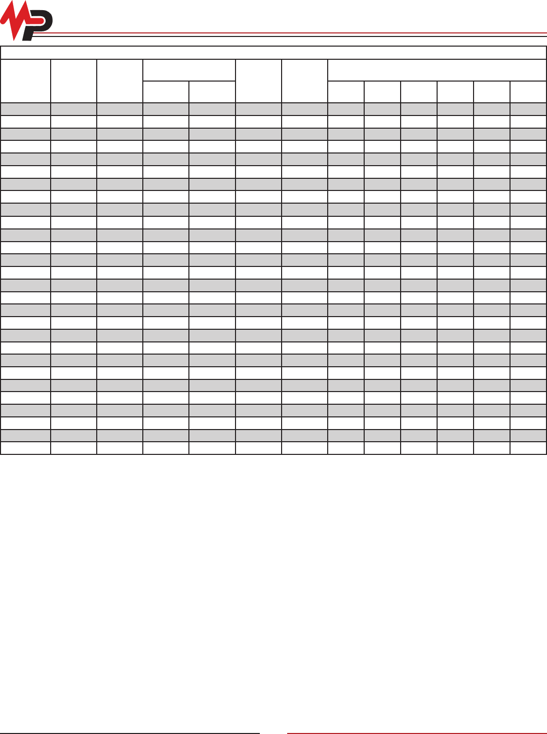
Physical Characteristics and Clearances
Catalog
Number Figure
kV
Rating
MCOV
kV
Total
Height Creepage
Minimum Clearances1
WeightA R
In Mm In Mm In Mm In Mm Lb Kg
ZJP0003-1211
1
3 2.55
6.8
173 15.7
400 9.5 241 5.5 140 7.7 3.5
ZJP0006-1211 6 5.10 400 9.5 241 5.5 140 8.1 3.7
ZJP0009-1211 9 7.65 6.82 400 9.5 241 5.5 140 8.4 3.8
ZJP0010-1211 10 8.40 6.87 175
15.8
401 9.5 241 5.5 140 8.6 3.9
ZJP0012-1211 12 10.20 6.85 174 401 9.5 241 5.5 140 10.7 4.9
ZJP0015-1211 15 12.70 8.31 211 20.2 512 9.5 241 5.5 140 11 5
ZJP0018-1211 18 15.30 9.22 234 22 559 9.5 241 5.8 147 11.4 5.2
ZJP0021-1211 21 17.00 10.7 272 26.4 671 9.5 241 6.8 173 11.9 5.4
ZJP0024-1211 24 19.50 12.1 308 30.7 781 9.5 241 7.8 198 14 6.4
ZJP0027-1211 27 22.00 13.1 333 33.7 856 10.5 267 8.8 224 14.7 6.7
ZJP0030-1211 30 24.40 14.6 370 38.1 967 10.5 267 8.8 224 14.7 6.7
ZJP0033-1211 33 26.70 15.9 403 40.3 1024 10.5 267 8.8 224 15.7 7.1
ZJP0036-1211 36 29.00 16.8 428 44.2 1122 12.5 318 10.8 274 16.6 7.5
ZJP0039-1211 39 31.50 18.3 466 48.6 1234 13.5 343 11.8 300 17.5 8
ZJP0042-1211 42 34.00 19.2 489 51.4 1307 14.5 369 12.8 326 18.4 8.4
ZJP0045-1211 45 36.50 21.3 542 54.5 1385 15.5 394 13.8 351 19.3 8.8
Notes:
1) These minimum clearances are determined by the protective capabilities of the arresters and they are secondary to any other
clearance requirement that may exist for specic applications.
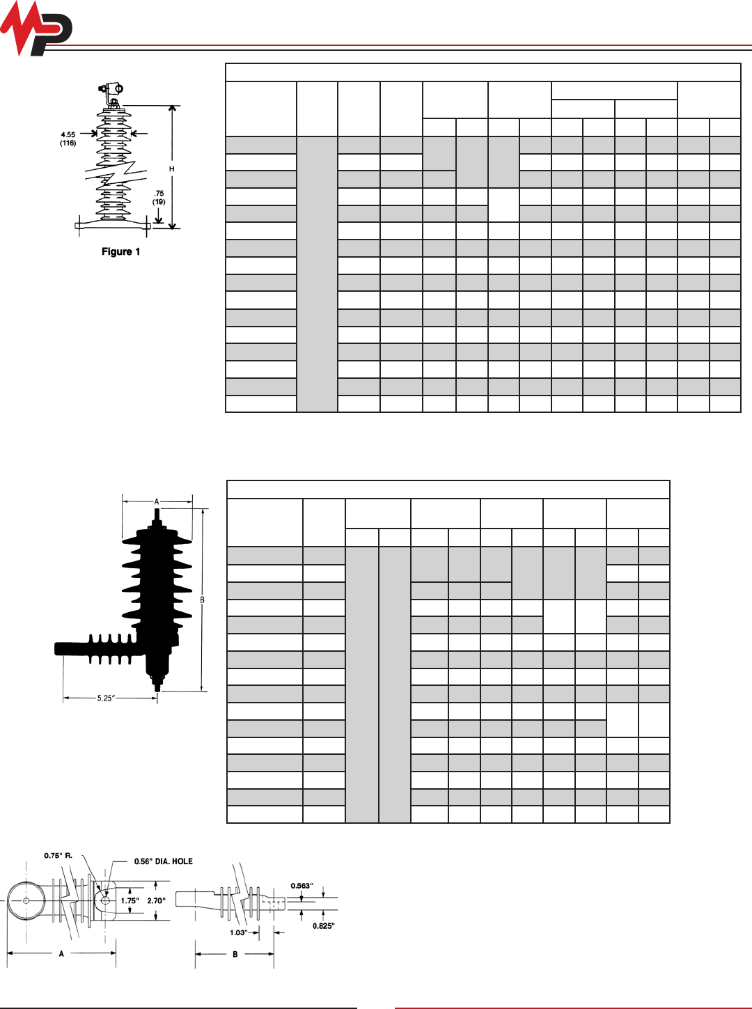
Physical Characteristics and Clearances
Catalog
Number
kV
Rating
Width A Length B
Nominal
Strike
Nominal
Creepage Weight
In Mm In Mm In Mm In Mm Lb Kg
ZJP0003-D005 3
4.6 116
11.1 282 6.8
173 15.7 400
4.8 2.2
ZJP0006-D005 6 5.2 2.3
ZJP0009-D005 9 11.12 283 6.82 5.6 2.5
ZJP0010-D005 10 11.17 284 6.87 175
15.8 401
5.7 2.6
ZJP0012-D005 12 11.15 283 6.85 174 7.8 3.5
ZJP0015-D005 15 12.61 320 8.31 211 20.2 512 8.2 3.7
ZJP0018-D005 18 13.52 343 9.22 234 22 559 8.5 3.9
ZJP0021-D005 21 15 381 10.7 272 26.4 671 9 4.1
ZJP0024-D005 24 16.42 417 12.1 308 30.7 781 11.1 5
ZJP0027-D005 27 17.41 442 13.1 333 33.7 856
11.8 5.4
ZJP0030-D005 30 18.88 480 14.6 370 38.1 967
ZJP0033-D005 33 20.18 513 15.9 403 40.3 1024 12.8 5.8
ZJP0036-D005 36 21.14 537 16.8 428 44.2 1122 13.7 6.2
ZJP0039-D005 39 22.64 575 18.3 466 48.6 1234 14.6 6.6
ZJP0042-D005 42 23.54 598 19.2 489 51.4 1307 15.5 7
ZJP0045-D005 45 25.64 651 21.3 542 54.5 1385 16.4 7.5
ZJP D Series Intermediate Class Arresters
© Copyright 2010 MacLean Power Systems
Issued: May 2010
Supercedes: n/a
11411 Addison Avenue, Franklin Park, IL 60131
T: 847.455.0014 F: 847.455.0029
www.macleanpower.com
AR-18
ZJP Intermediate Class Surge Arresters
Electrical Characteristics
Catalog
Number
Voltage
Rating
(kV-rms)
MCOV
(kV-rms)
TOV1
Max Equiv
FOW2
(kV-Crest)
Max
Switch
Surge3
(kV-Crest)
Maximum Discharge Voltage (kV-Crest)
Using an 8/20 ms Current Impulse
1 s
(kV-rms)
10 s
(kV-rms) 1.5 kA 3.0 kA 5.0 kA 10 kA 20 kA 40 kA
ZJP0003 3 2.55 3.7 3.5 8.55 6.34 6.79 7.17 7.5 8.09 8.96 10.1
ZJP0006 6 5.10 7.41 7.04 17.1 12.7 13.6 14.3 15 16.2 17.9 20.2
ZJP0009 9 7.65 11.1 10.6 25.9 19.2 20.5 21.7 22.7 24.5 27.1 30.5
ZJP0010 10 8.40 12.2 11.6 28.3 21 22.5 23.7 24.8 26.8 29.6 33.4
ZJP0012 12 10.20 14.8 14.1 34.2 25.4 27.2 28.7 30 32.4 35.8 40.4
ZJP0015 15 12.70 18.4 17.5 43.1 32 34.2 36.1 37.8 40.8 45.1 50.8
ZJP0018 18 15.30 22.2 21.1 51.3 38.1 40.8 43 45 48.6 53.8 60.6
ZJP0021 21 17.00 24.7 23.5 56.6 42 44.9 47.5 49.6 53.6 59.3 66.8
ZJP0024 24 19.50 28.3 26.9 68.5 50.8 54.3 57.4 60 64.8 71.7 80.7
ZJP0027 27 22.00 31.9 30.4 77.3 57.4 61.4 64.8 67.8 73.2 81 91.2
ZJP0030 30 24.40 35.4 33.7 83.5 61.9 66.2 70 73.2 79 87.4 98.4
ZJP0033 33 26.70 38.8 36.9 91.9 68.2 72.9 77 80.6 86.9 96.3 108
ZJP0036 36 29.00 42.1 40.0 98.9 73.4 78.5 82.9 86.7 93.5 104 117
ZJP0039 39 31.50 45.7 43.5 109 80.5 86.1 90.9 95.1 103 114 128
ZJP0042 42 34.00 49.4 47 117 86.7 92.7 97.9 102 111 122 138
ZJP0045 45 36.50 53 50.4 125 92.9 99.4 105 110 119 131 148.3
Notes:
1) Temporary Overvoltage without any Prior Duty
2) The equivalent Front-of-Wave is the maximum discharge voltage for a 10kA impulse current wave which produces a voltage wave cresting in a 0.5 ms
3) Based on a switching surge current of 500 amperes
© Copyright 2010 MacLean Power Systems
Issued: May 2010
Supercedes: n/a
11411 Addison Avenue, Franklin Park, IL 60131
T: 847.455.0014 F: 847.455.0029
www.macleanpower.com
AR-19
ZIP/ZJP Intermediate Class Arrester Ordering Information
Z I P X X X X - X X X 1
J -or- D X X X
{
kV Rating
0003 = 3
0006 = 6
0009 = 9
0010 = 10
0012 = 12
0015 = 15
0018 = 18
0021 = 21
0024 = 24
0027 = 27
0030 = 30
0033 = 33
0036 = 36
0039 = 39
0042 = 42
0045 = 45
0048 = 48
0054 = 54
0060 = 60
0066 = 66
0072 = 72
0084 = 84
0090 = 90
0096 = 96
0108 = 108
0120 = 120
0132 = 132
0144 = 144
Fault
Withstand
ZIP = 50kA
ZJP = 20kA
Conguration
(not available on “D” Series)
1 - Stainless steel
top cover with
tripod base
2 - Tripod on top
with stainless
steel bottom
cover (Inverted
Mounting)
3 - Stainless steel
covers on both
ends
4 - Tripod on both
ends
Top & Bottom Connectors
(not available on “D” Series)
1 - Eyebolt with a
90° angle bracket
Conductor Range:
0.25” - 0.75”
(6.35 - 19.05 mm)
2 - Four hole NEMA
pad with a 90°
angle
Conductor Range:
0.25” - 1.25”
(6.35 - 31.75 mm)
3 - Four hole NEMA
pad with a 45°
angle
Conductor Range:
0.25” - 1.25”
(6.35 - 31.75 mm)
“D” Series ZJP only
D001 = Crossarm Bracket
D005 = Standard Unit
D106 = with Birdguard
D109 =Birdguard and
Crossarm Bracket
{
© Copyright 2010 MacLean Power Systems
Issued: May 2010
Supercedes: n/a
11411 Addison Avenue, Franklin Park, IL 60131
T: 847.455.0014 F: 847.455.0029
www.macleanpower.com
AR-20
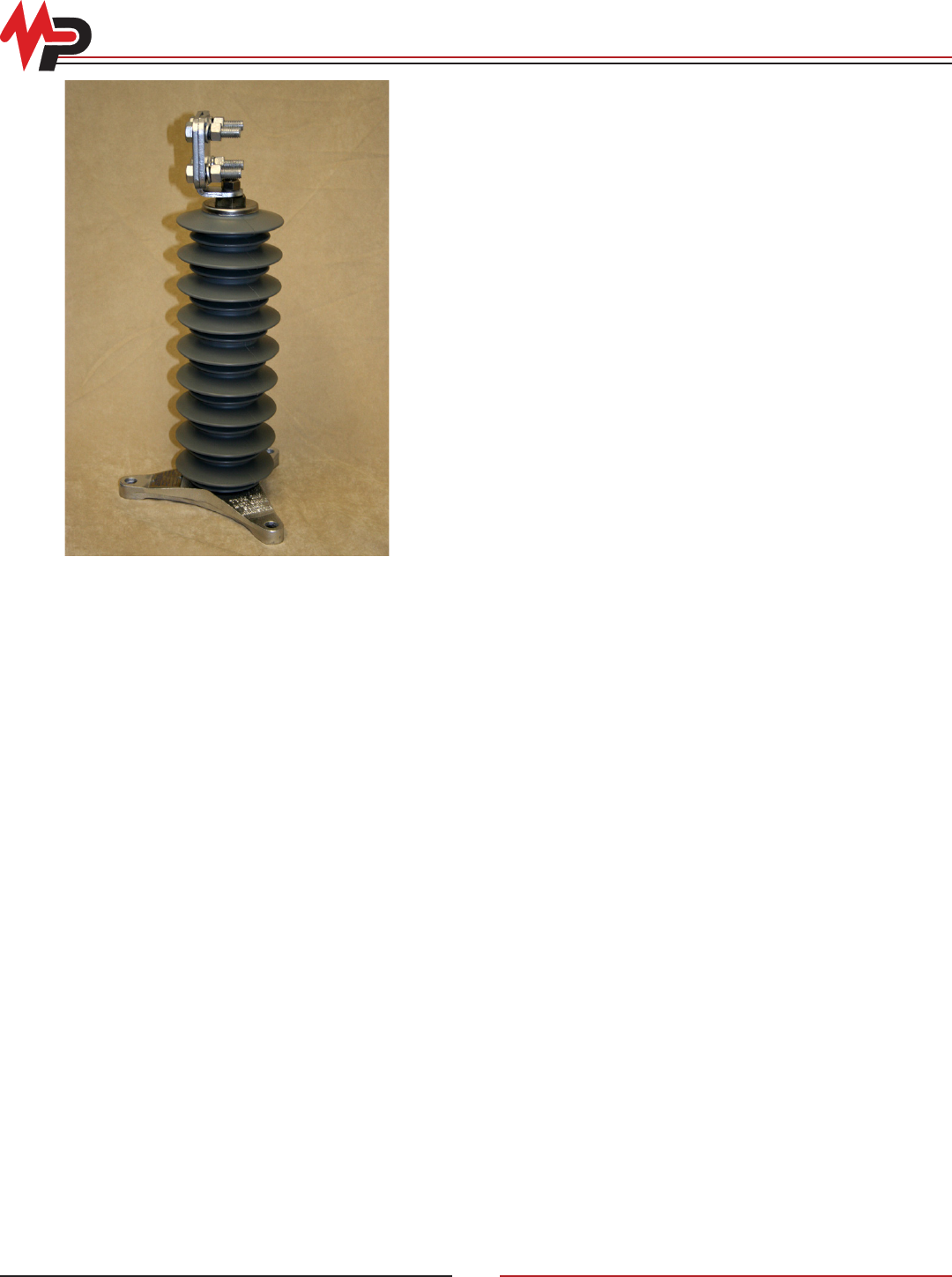
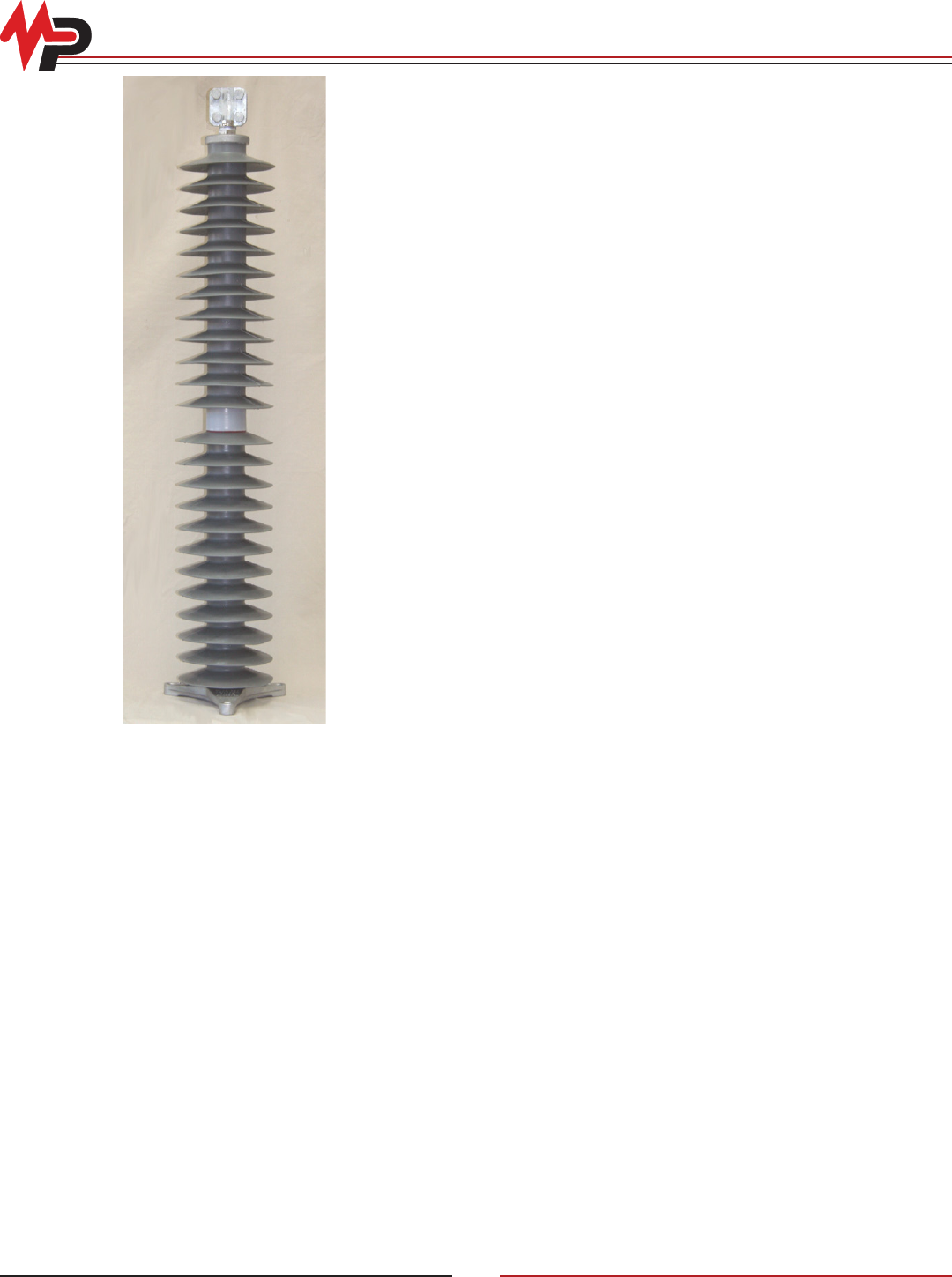
Station Class Arresters
The type “ZSP” station class arresters offer the benefits of
polymer housings for system voltages up to 230kV. The arresters
are approximately 25% the weight of the porcelain equivalent.
Handling and installation become much easier tasks. Also, the
risk of damage to the housing is reduced compared to porcelain.
Performance
“ZSP” arresters are available in duty cycle ratings from 3kV
through 216kV (2.55kV through 174kV MCOV) and are designed
for system line-line voltages of 2.4kV through 230kV. The
“ZSP” arrester design is tested in accordance with the latest
industry standards for metal oxide arresters. The “ZSP” arresters
consistently withstand the following minimum design tests:
• High Current-Short Duration: 100kA crest
• Duty Cycle per ANSI: 10kA
• Nominal Discharge Current per IEC: 10kA
• Line Discharge Class per IEC: Class 2 or 3
• Minimum Energy Capability: 6.1 kJ/kV MCOV
• Fault Withstand Capability: 80kA rms
• Working Cantilever Strength: 10,000 in.-lbs.
• RUS Listed
Design
The design consists of a number of metal oxide valve ele ments
contained within a fiberglass winding and then inserted into the
polymer housing. Type “ZSP” arresters are shipped as single
units for all ratings. There is no need to combine sections, even
for the 216kV duty cycle rating. The metal oxide valve elements
combine excellent protective characteristics with steady state
performance to maximize protection over many years of service.
Fault Current Withstand
The severity of a failure depends on the duration and magnitude
of the available fault current conducting through the arrester at the
time of failure. The “ZSP” type arrester with its polymer housing
eliminates the potential danger of porcelain fragmentation. The
“ZSP” design uses a high strength fiberglass epoxy wrap to
relieve the pressure that is present during a fault. The arresters
achieved a fault withstand capability of 80kA.
Benefits
The use of polymer housings for our arresters provides many
benefits over porcelain designs.
• LIGHTWEIGHT—The lightweight design provides much easier
handling and installation. The polymer arresters are less than
1/5 the weight of the porcelain equivalents. The burden on
mounting structures and personnel is greatly reduced.
• REDUCED CLEARANCES—The smaller physical size of the
polymer housing and the line side of the arrester allow the
clearances to be reduced. This provides added flexibility with
design and layout since they can be used in tighter areas.
• SINGLE UNIT DESIGN—The single unit design simplifies
installation by reducing handling that was previously required
for multi-section porcelain designs. This also provides improved
contamination performance over multi-unit arresters.
• DAMAGE RESISTANT—The polymer housings resist damage
from handling where porcelain units are most vulnerable to
chipping and breakage.
• SAFETY—The ZSP arresters minimize safety hazards to
personnel and nearby equipment that exists with porcelain
housings.
Reliability
Each completed “ZSP” arrester unit must pass the following
electrical tests: reference voltage, power loss, and RIV.
© Copyright 2010 MacLean Power Systems
Issued: May 2010
Supercedes: n/a
11411 Addison Avenue, Franklin Park, IL 60131
T: 847.455.0014 F: 847.455.0029
www.macleanpower.com
AR-21
ZSP Electrical Characteristics
Electrical Characteristics
Catalog
Number
Voltage
Rating
(kV-rms)
MCOV
(kV-rms)
TOV1
Max Equiv
FOW2
(kV-Crest)
Max
Switch
Surge3
(kV-Crest)
Maximum Discharge Voltage (kV-Crest)
Using an 8/20 ms Current Impulse
1 s
(kV-rms)
10 s
(kV-rms) 1.5 kA 3.0 kA 5.0 kA 10 kA 20 kA 40 kA
ZSP0003 3 2.55 3.74 3.53 8.23 5.87 6.32 6.65 6.96 7.49 8.27 9.38
ZSP0006 6 5.10 7.47 7.06 16.5 11.7 12.6 13.3 13.9 15 16.5 18.8
ZSP0009 9 7.65 11.2 10.6 24.7 17.6 19 20 20.9 22.5 24.8 28.2
ZSP0010 10 8.40 12.3 11.6 27.8 19.8 21.4 22.5 23.5 25.3 28 31.7
ZSP0012 12 10.20 14.9 14.1 33 23.6 25.4 26.7 27.9 30.1 33.2 37.7
ZSP0015 15 12.70 18.6 17.6 41.3 29.4 31.7 33.4 34.9 37.6 41.5 47.1
ZSP0018 18 15.30 22.4 21.2 49.8 35.5 38.2 40.2 42.1 45.3 50 56.8
ZSP0021 21 17.00 24.9 23.5 55.2 39.4 42.4 44.6 46.7 50.3 55.5 63
ZSP0024 24 19.50 28.6 27 65 46.4 49.9 52.6 55 59.2 65.4 74.2
ZSP0027 27 22.00 32.2 30.5 72.9 52 56 59 61.7 66.4 73.3 83.2
ZSP0030 30 24.40 35.7 33.8 79.9 57 61.4 64.6 67.6 72.7 80.3 91.1
ZSP0033 33 26.70 39.1 37 88 62.7 67.6 71.1 74.4 80.1 88.4 100.4
ZSP0036 36 29 42.5 40.2 96.2 68.6 73.9 77.8 81.5 87.6 96.8 109.8
ZSP0039 39 31.50 46.1 43.6 103 73.5 79.1 83.3 87.2 93.8 103.6 117.5
ZSP0042 42 34 49.8 47.1 113.5 81 87.2 91.8 96.1 103.4 114.2 129.5
ZSP0045 45 36.5 53.5 50.6 120.3 85.8 92.4 97.3 101.8 109.5 120.9 137.2
ZSP0048 48 39 57.1 54 128.6 91.7 98.7 104 108.8 117.1 129.3 146.7
ZSP0054 54 42 61.5 58.2 143.6 102.4 110.3 116.1 121.5 130.8 144.4 163.8
ZSP0060 60 48 70.3 66.5 163.1 116.4 125.3 131.9 138.1 148.5 164 186.1
ZSP0063 63 50.25 73.6 69.6 170.3 121.4 130.8 137.7 144.1 155 171.2 194.3
ZSP0066 66 52.50 76.9 72.7 177.5 126.6 136.3 143.5 150.2 161.6 178.4 202.4
ZSP0072 72 57 83.5 78.9 192.3 137.1 147.7 155.5 162.7 175.1 193.3 219.3
ZSP0072-58* 72 58 85 80.3 192.3 137.1 147.7 155.5 162.7 175.1 193.3 219.3
ZSP0090 90 70 102.6 97 227.1 161.9 174.4 183.6 192.2 206.7 228.3 259
ZSP0090-74* 90 74 108.4 102.5 240.6 171.6 184.8 194.6 203.6 219 241.9 274.5
ZSP0096 96 76 111.3 105.3 257.1 183.4 197.5 207.9 217.6 234.1 258.5 293.3
ZSP0108 108 84 123.1 116.3 273.7 195.2 210.2 221.3 231.6 249.2 275.2 312
ZSP0108-88* 108 88 128.9 121.9 287.2 204.8 220.6 232.3 243.1 261.5 288.8 328
ZSP0120 120 98 143.6 135.7 326 239.7 250.6 263.9 276.1 297.1 328 372
ZSP0120-102* 120 102 149.4 141.3 331 243 254 267.5 279.9 301 333 377
ZSP0132 132 106 155.3 146.8 347 255 266.7 280.8 293.8 316 349 396
ZSP0144 144 115 168.5 159.3 385 282.4 295.3 311 325 350 387 439
ZSP0150 150 121 177.3 167.6 411 302 315 332 347 374 413 468
ZSP0168 168 131 191.9 181.4 450 331 346 364 381 410 453 514
ZSP0172 172 140 205.1 193.9 460 338 354 372 390 419 463 525
ZSP0180 180 144 211 199.4 481 354 370 389 407 438 484 549
ZSP0192 192 152 222.7 210.5 511 375 392 413 432 465 514 583
ZSP0198 198 160 234.4 221.6 532 391 409 431 451 485 535 607
ZSP0210 210 170 249.1 235.5 562 413 432 454 476 512 565 641
ZSP0216 216 174 254.9 241 577 424 443 466 488 525 580 658
Notes:
1) Temporary Overvoltage without any Prior Duty
2) The equivalent Front-of-Wave is the maximum discharge voltage for a 10kA impulse current wave which produces a voltage wave cresting in a 0.5 ms
3) Based on a switching surge current of 500 amperes for arresters rated 2.55kV MCOV to 84kV MCOV and 1000 amperes for arresters from 88kV MCOV to 174kV MCOV
* The catalog number for special MCOV levels would use the following format = ZSP0090-1231-74 and ZSP 0108-1231-88
© Copyright 2010 MacLean Power Systems
Issued: May 2010
Supercedes: n/a
11411 Addison Avenue, Franklin Park, IL 60131
T: 847.455.0014 F: 847.455.0029
www.macleanpower.com
AR-22
ZSP Physical Characteristics and Clearances
Physical Characteristics and Clearances
Catalog
Number Figure
kV
Rating
MCOV
kV
Total Height Creepage
Minimum Clearances1
WeightA R
In Mm In Mm In Mm In Mm Lb Kg
ZSP0003
1
3 2.55
7.6 192 18.1 461
12 305
6 152
18 8.2ZSP0006 6 5.10
ZSP0009 9 7.65
ZSP0010 10 8.40
9.2 234 24.1 612 21 9.5ZSP0012 12 10.20
7 178
ZSP0015 15 12.70 13 330
ZSP0018 18 15.30
11 279 30.1 765
14 356
8 203
25 11.3ZSP0021 21 17.00 9 229
ZSP0024 24 19.50 15 381
10 254
ZSP0027 27 22.00
12.8 325 36.2 920
16 406
29 13.2
ZSP0030 30 24.40
17 432
11 279
ZSP0033 33 26.70 13.6 344 41.3 1048 12 305 31 14.1
ZSP0036 36 29.00 14.5 367 42.2 1071 18 457
13 330
33 15
ZSP0039 39 31.50 16 406 48 1218 19 483 36 16.3
ZSP0042 42 34.00
18.1 461 54.4 1382
20 508
14 356
41 18.6ZSP0045 45 36.50 15 381
ZSP0048 48 39.00 21 533 16 406
ZSP0054 54 42.00 19.6 498 60.2 1528 23 584 17 432 44 20
ZSP0060 60 48.00
23.3 591 72.4 1838
25 635
19 483
52 23.6ZSP0063 63 51.00
20 508
ZSP0066 66 54.00 26 660
ZSP0072 72 57.00
23.9 607 73 1855 27 686 22 559 53 24
ZSP0072-58* 72 58.00
ZSP0090 90 70.00
34.7
882 109.6 2783
31 787 25 635
77 34.9ZSP0090-74* 90 74.00 32 813 26 660
ZSP0096 96 76.00 34 864 28 711
ZSP0108 108 84.00
957 121 3075
35 889 30 762
84 38.1
ZSP0108-88* 108 88.00 36 914 31 787
ZSP0120 120 98.00
44.9 1140 145.4 3694
40 1016
35 889 99 44.9
ZSP0120-102* 120 102.00 41 1041
ZSP132 132 106.00 45 1144 145.6 3697 42 1067 37 940 100 45.4
ZSP0144 144 115.00 46.3 1175 146.8 3728 46 1168 40 1016 102 46.3
ZSP0150 150 121 55.8 1418 182.1 4624 48 1219 43 1092 139 63
ZSP0168
2
168 131.00 59.8 1519 194.1 4931 64 1626 53 1346 146 66.2
ZSP0172 172 140.00 63.5 1613 206.4 5243 65 1651 54 1372 154 69.8
ZSP0180 180 144.00
67.2 1706 218.6 5553
67 1702 56 1422 162 73.5
ZSP0192 192 152.00 70 1778 58 1473 163 73.9
ZSP0198 198 157.00 72 1829 61 1549 162 73.5
ZSP0210 210 170 68.4 1739 219.9 5586 75 1905 63 1600 165 74.8
ZSP0216 216 174 69.1 1755 220.5 5602 76 1930 65 1651 167 75.7
Notes:
1) These minimum clearances are determined by the protective capabilities of the arresters and they are secondary to any other clearance
requirement that may exist for specic applications.
* The catalog number for special MCOV levels would use the following format = ZSP0090-1231-74 and ZSP 0108-1231-88
© Copyright 2010 MacLean Power Systems
Issued: May 2010
Supercedes: n/a
11411 Addison Avenue, Franklin Park, IL 60131
T: 847.455.0014 F: 847.455.0029
www.macleanpower.com
AR-23
ZSP Physical Characteristics and Clearances
Three Phase Installation Layout
The holes for mounting are .56” (42 mm) for
1/2” bolts. Mounting bolts and washers are not
furnished with arrester.
Nameplate
In addition to the information that is included on
the tripod base, a nameplate is attached to the
casting to provide all of the required arrester
details. The catalog number, the rated voltage,
the maximum continuous operating voltage, and
the pressure relief current rating are shown. The
serial number includes information about the time
of manufacture.
© Copyright 2010 MacLean Power Systems
Issued: May 2010
Supercedes: n/a
11411 Addison Avenue, Franklin Park, IL 60131
T: 847.455.0014 F: 847.455.0029
www.macleanpower.com
AR-24
ZSP Station Class Arrester Ordering Information
Z S P X X X X - X X X 1
{
kV Rating
0003 = 3
0006 = 6
0009 = 9
0010 = 10
0012 = 12
0015 = 15
0018 = 18
0021 = 21
0024 = 24
0027 = 27
0030 = 30
0033 = 33
0036 = 36
0039 = 39
0042 = 42
0045 = 45
0048 = 48
0054 = 54
0060 = 60
0063 = 63
0066 = 66
0072 = 72
0090 = 90
0096 = 96
0108 = 108
0120 = 120
0134 = 132
0144 = 144
0168 = 168
0172 = 172
0180 = 180
0192 = 192
0198 = 198
0210 = 210
0216 = 216
Conguration
1 - Stainless steel
top cover with
tripod base
2 - Tripod on top
with stainless
steel bottom
cover (Inverted
Mounting)
3 - Stainless steel
covers on both
ends
4 - Tripod on both
ends
Top & Bottom Connectors
1 - Eyebolt with a
90° angle bracket
Conductor Range:
0.25” - 0.75”
(6.35 - 19.05 mm)
2 - Four hole NEMA
pad with a 90°
angle
Conductor Range:
0.25” - 1.25”
(6.35 - 31.75 mm)
3 - Four hole NEMA
pad with a 45°
angle
Conductor Range:
0.25” - 1.25”
(6.35 - 31.75 mm)
Example
108kV rated arrester with:
Small top cover & tripod base
Top - eyebolt with a 90° angle
bracket
Bottom - Four hole NEMA
pad with a 45° angle
Catalog Number - ZSP0108-1131
Special Needs
For special arrester characteristics other than
those shown in this catalog, contact your MPS
representative
© Copyright 2010 MacLean Power Systems
Issued: May 2010
Supercedes: n/a
11411 Addison Avenue, Franklin Park, IL 60131
T: 847.455.0014 F: 847.455.0029
www.macleanpower.com
AR-25
Station and Intermediate Class Arresters Accessories
Discharge Counter
Catalog No. 7120B0004H0001
The optional discharge counter records the number
of current discharges through the ground lead of
the arrester. A ve-digit cyclometer records each
current discharge. The counter registers impulse
discharges of an amplitude of 200 amperes or
more. No external power source is required. The
discharge counter must be used in conjunction
with insulating sub-bases.
A milliammeter comes with the discharge counter
to provide continuous reading of the total current
through the metal oxide valve elements and the
leakage current across the external polymer
insulation. A 0-30 milliampere scale is used.
Heavy external contaminants on the polymer
housing will increase the level of current registered
and may serve as an indication the polymer
housing needs washing. Steadily increasing
readings with a clean housing may be an indication
of potential problems with the arrester metal oxide
valve elements.
Single Crossarm Mounting Bracket
Catalog No. 7106C0001
Maximum Arrester Sizes:
ZIP-96kV; ZSP-108kV
Includes 2 backstraps, 1/2” bolt size hardware and pipe spacers for
inverted mounting.
Mounting Brackets
Hot Dip Galvanized
© Copyright 2010 MacLean Power Systems
Issued: May 2010
Supercedes: n/a
11411 Addison Avenue, Franklin Park, IL 60131
T: 847.455.0014 F: 847.455.0029
www.macleanpower.com
AR-26
Station Class Arresters Accessories
Pole Mounting Bracket
One Arrester, Horizontal Mounting
Catalog No. 7102C0003
Maximum Arrester Sizes:
ZIP-60kV; ZSP-72kV
No hardware included.
Pole Mounting Bracket
Three Arrester, Horizontal Mounting
Catalog No. 7102D0002
Maximum Arrester Sizes:
ZIP-60kV; ZSP-72kV
No hardware included.
© Copyright 2010 MacLean Power Systems
Issued: May 2010
Supercedes: n/a
11411 Addison Avenue, Franklin Park, IL 60131
T: 847.455.0014 F: 847.455.0029
www.macleanpower.com
AR-27
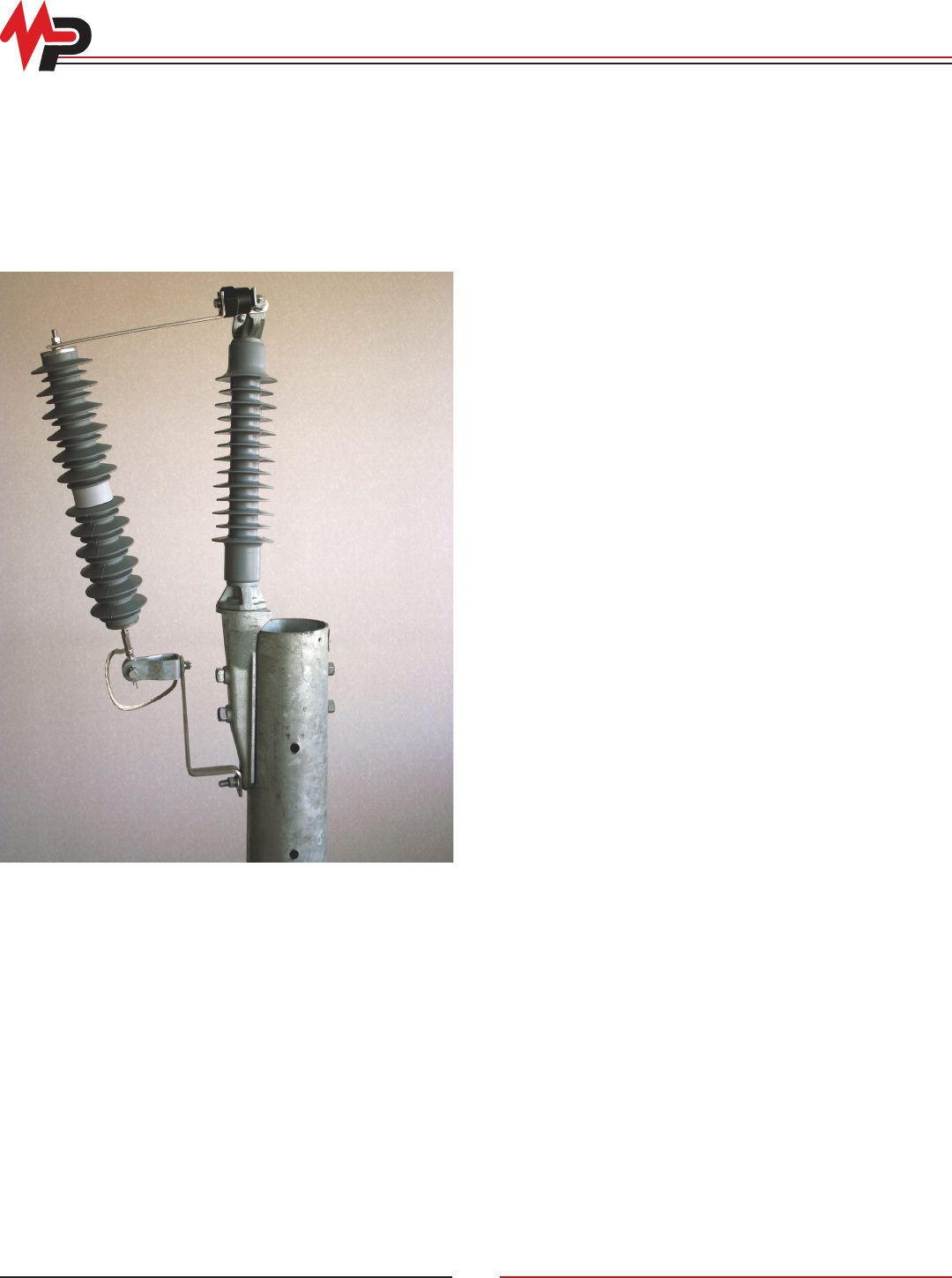
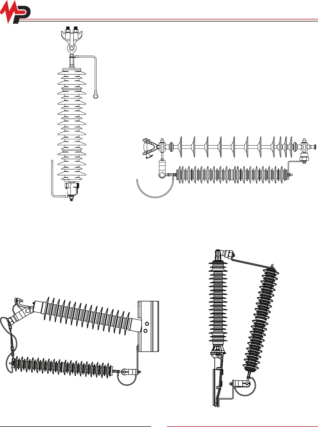
Transmission Line Arrester and Assemblies
Type “ZQPT”/“ZXLA”
Available for System Voltages Up to 161kV
Users of electricity have become more and more demanding over
recent years. The quality of the power they receive is critical to
their operations. Sensitive electronic equipment cannot tolerate
voltage uctuations and many problems are directed to the utility.
The heightened awareness of power quality has brought the
issue to all levels of operations, including transmission.
In the area of transmission line power quality, MPS offers the
“ZQPT”/“ZXLA” transmission line arrester and arrester insulator
assembly. The lightweight construction makes it possible to easily
mount arresters on transmission line structures. The arresters
provide a preferred path between line and ground, guarding
against insulator ashover.
Transmission line surge protection is a solution to troublesome
outages and customer dissatisfaction. State-of-the-art protection
of transmission lines using polymer MOV arresters provides
higher power quality which will improve customer satisfaction.
“ZQPT”/“ZXLA” transmission line arresters and assemblies are
available for system voltages up to 161kV. The metal oxide
blocks are specially selected and wrapped under compression
with a strong berglass wrap.
Application
“ZQPT”/“ZXLA” transmission line arresters and assemblies are
applied to:
• Improve power quality and overall line performance
• Supplement shield wire protection
• Provide protection for lines without a shield wire
• Create more space on structures by eliminating the shield
wires
• Protect both new construction and retrot
The factors that impact transmission line lightning performance
include the following: The amount of lightning activity in a given
area per year, the stroke magnitude and the wave shape of the
lightning, the tower height and the amount of nearby natural
shielding from trees or buildings, the tower footing resistance,
the presence of an overhead shield wire and the shield angle,
and the existing line insulation.
When selecting transmission line arresters for specic application,
there are several things to keep in mind. The application is usually
different for a line with an overhead shield wire than without.
The arrester rating should be coordinated with the arresters in
the substation. The transmission line arresters should be the
same rating or larger so that they do not end up protecting the
substation arresters.
The transmission line arresters should be sized by evaluating the
line voltage and the line insulation. By using a high MCOV arrester
the temporary overvoltage (TOV) capability will be increased
and the energy capability will also be greater. With the added
lightning exposure that may be expected on a transmission line,
it is helpful to have higher capabilities in these categories. Also,
higher rated arresters will not experience as much duty because
the reference voltage is higher and will not turn on as soon as
lower rated units.
Benets
Lightning is one of the major causes of power interruption.
Currently, shield wires serve as lightning protection for
transmission lines.
“ZQPT”/“ZXLA” transmission line arresters and assemblies
provide these advantages over the use of shield wire alone:
• Minimize the requirement to lower ground resistance
• Protect against backash
• Safeguard from induced surges caused by nearby lightning
• Limit effects of switching surges
• Install easily and economically
• Allow for reduction of structure BIL
• Reduce system breaker operations
• Provide protection for isolated problem areas
• Improve overall line performance
• Enhance customer relations
© Copyright 2010 MacLean Power Systems
Issued: May 2010
Supercedes: n/a
11411 Addison Avenue, Franklin Park, IL 60131
T: 847.455.0014 F: 847.455.0029
www.macleanpower.com
AR-28
ZQPT Transmission Line Arresters
Physical Characteristics
Catalog
Number
kV
Rating
Width A Length B Nominal Strike Nominal Creepage Weight
In Mm In Mm In Mm In Mm Lb Kg
8155CS036T**** 36
4.2 107
19.6 498 20.1 511 55 1397 12 5.5
8155CS039T**** 39
8155CS045T**** 45 23.4 595 24.0 610 65 1651 14 6.4
8155CS054T**** 54
27.2 691 27.9 709 76 1931 16 7.3
8155CS060T**** 60
8155CS072T**** 72 40.7 1034 41.9 1065
114 2896
24 10.9
8155CS090T**** 90
4.5 115
41.5 1055 41.2 1047 26 11.8
8155CS096T**** 96 47.5 1207 47.3 1202 131 3328 29 13.2
8155CS108T**** 108 51.2 1301 51.2 1301 141 3582 31 14.1
8155CS120T**** 120 55.0 1397 58.1 1476 152 3861 33 15.0
Notes:
* The astericks identify the mounting hardware
Electrical Characteristics
Catalog
Number
Voltage
Rating
(kV-rms)
MCOV
(kV-rms)
Max Equiv
FOW1
(kV-Crest)
Max
Switch
Surge2
(kV-Crest)
Maximum Discharge Voltage (kV-Crest)
Using an 8/20 ms Current Impulse
1.5 kA 3.0 kA 5.0 kA 10 kA 20 kA 40 kA
8155CS036T**** 36 29.0 130.2 84.9 95.1 98.5 104.1 115.5 131.3 155.1
8155CS039T**** 39 31.5 134.7 87.8 98.4 101.9 107.8 119.5 135.9 160.5
8155CS045T**** 45 36.5 156.8 102.2 114.5 118.6 125.4 139 158.1 186.8
8155CS054T**** 54 42 195.8 127.7 143 148.1 156.7 173.7 197.5 233.3
8155CS060T**** 60 48 217.3 141.7 158.7 164.4 173.9 192.8 219.2 258.9
8155CS072T**** 72 57 261.5 170.5 191 197.8 209.2 231.9 263.7 311.5
8155CS090T**** 90 70 326 212.6 238.1 246.6 260.8 289.1 328.8 388.3
8155CS096T**** 96 76 347.5 226.6 253.8 262.9 278 308.2 350.5 414
8155CS108T**** 108 88 391.1 255 285.6 295.9 312.9 346.9 394.5 465
8155CS120T**** 120 98 434.6 283.5 317.5 328.8 347.7 385.5 438.4 517
Notes:
1) The equivalent Front-of-Wave is the maximum discharge voltage for a 10kA impulse current wave which produces a voltage wave cresting in a 0.5 ms
2) Based on a switching surge current of 500 amperes for arresters rated 3kV to 90kV and 1000 amperes for arresters from 108kV to 144kV
© Copyright 2010 MacLean Power Systems
Issued: May 2010
Supercedes: n/a
11411 Addison Avenue, Franklin Park, IL 60131
T: 847.455.0014 F: 847.455.0029
www.macleanpower.com
AR-29
ZXLA Transmission Line Arrester and Insulator Assembly
Line
Voltage ZXLA Catalog No.
Arrester Duty
Voltage Rating Arrester Catalog No.
MCOV
Insulator Catalog No.
Insulator
Section Length
Assembly
Leakage
Assembly
Weight
kV kV kV in (mm) in (mm) lbs (kg)
46
ZH4PKG13-036 36 8155CS036T**** 29.0 NPKG20XG13S0
OLPK-13-SIL-GB-12
25.2
(640)
42.3
(1074)
38.0
(17.2)
ZH4PKG13-039 39 8155CS039T**** 31.5
69
ZH4PKG17-054 54 8155CS054T**** 42.0 NPKG20XG17S0
OLPK-17-SIL-GB-12
29.2
(742)
54.0
(1372)
45.0
(20.4)
ZH4PKG17-060 60 8155CS060T**** 48.0
69
ZH4PKG21-054 54 8155CS054T**** 42.0 NPKG20XGM21S0
MLPK-21-SIL-GB-12
29.2
(742)
59.4
(1509)
46.0
(20.9)
ZH4PKG21-060 60 8155CS060T**** 48.0
69 ZH4PKG25-060 60 8155CS060T**** 48.0 NPKG20XGM25S0
MLPK-25-SIL-GB-12
31.2
(792)
71.1
(1806)
48.0
(21.8)
* Consult factory for system voltages greater than 69kV
Line
Voltage ZXLA Catalog No.
Arrester Duty
Voltage Rating Arrester Catalog No.
MCOV
Insulator Catalog No.
Insulator
Section Length
Assembly
Leakage
Assembly
Weight
kV kV kV in (mm) in (mm) lbs (kg)
46
ZV4PKG13-036 36 8155CS036T**** 29.0 NPKV20XG13S0
OLPK-13-SIL-VB-12
23.4
(594)
42.3
(1074)
38.0
(17.2)
ZV4PKG13-039 39 8155CS039T**** 31.5
69
ZV4PKG17-054 54 8155CS054T**** 42.0 NPKV20XG17S0
OLPK-17-SIL-VB-12
27.4
(696)
54.0
(1372)
45.0
(20.4)
ZV4PKG17-060 60 8155CS060T**** 48.0
69
ZV4PKG21-054 54 8155CS054T**** 42.0 NPKV20XGM21S0
MLPK-21-SIL-VB-12
27.4
(696)
59.4
(1509)
46.0
(20.9)
ZV4PKG21-060 60 8155CS060T**** 48.0
69 ZV4PKG25-060 60 8155CS060T**** 48.0 NPKV20XGM25S0
MLPK-25-SIL-VB-12
31.4
(798)
71.1
(1806)
48.0
(21.8)
* Consult factory for system voltages greater than 69kV
Horizontal Transmission Assembly
Vertical Transmission Assembly
Line
Voltage ZXLA Catalog No.
Arrester Duty
Voltage Rating Arrester Catalog No.
MCOV
Insulator Catalog No.
Insulator
Section Length
Assembly
Leakage
Total Weight
(Est)
kV kV kV in (mm) in (mm) lbs (kg)
46 ZD148035MX01-039 39 8155CS039T**** 31.5 S148035MX01 35.4
[899]
60.8
[1544]
27.3
[12.4]
69
ZD148035MX01-054 54 8155CS054T**** 42.0
S148035MX01 35.4
[899]
60.8
[1544]
39.3
[17.8]
ZD148035MX01-060 60 8155CS060T**** 48.0
ZD148035MX01-072 72 8155CS072T**** 57.0
115 ZD148035MX01-090 90 8155CS090T**** 70.0 S148054MX01 54.3
[1379]
109.2
[2774]
45.6
[20.7]
138
ZD148035MX01-108 108 8155CS0108T**** 48.0
S148065MX01 65.3
[1659]
137.4
[3490]
57.1
[25.9]
ZD148035MX01-132 132 8155CS0132T**** 106.0
* Consult factory for system voltages greater than 138 kV
Deadend Transmission Assembly
© Copyright 2010 MacLean Power Systems
Issued: May 2010
Supercedes: n/a
11411 Addison Avenue, Franklin Park, IL 60131
T: 847.455.0014 F: 847.455.0029
www.macleanpower.com
AR-30
Transmission Line Protection Congurations
Horizontal Conguration Vertical Conguration
Deadend Conguration
Suspension Conguration
© Copyright 2010 MacLean Power Systems
Issued: May 2010
Supercedes: n/a
11411 Addison Avenue, Franklin Park, IL 60131
T: 847.455.0014 F: 847.455.0029
www.macleanpower.com
AR-31
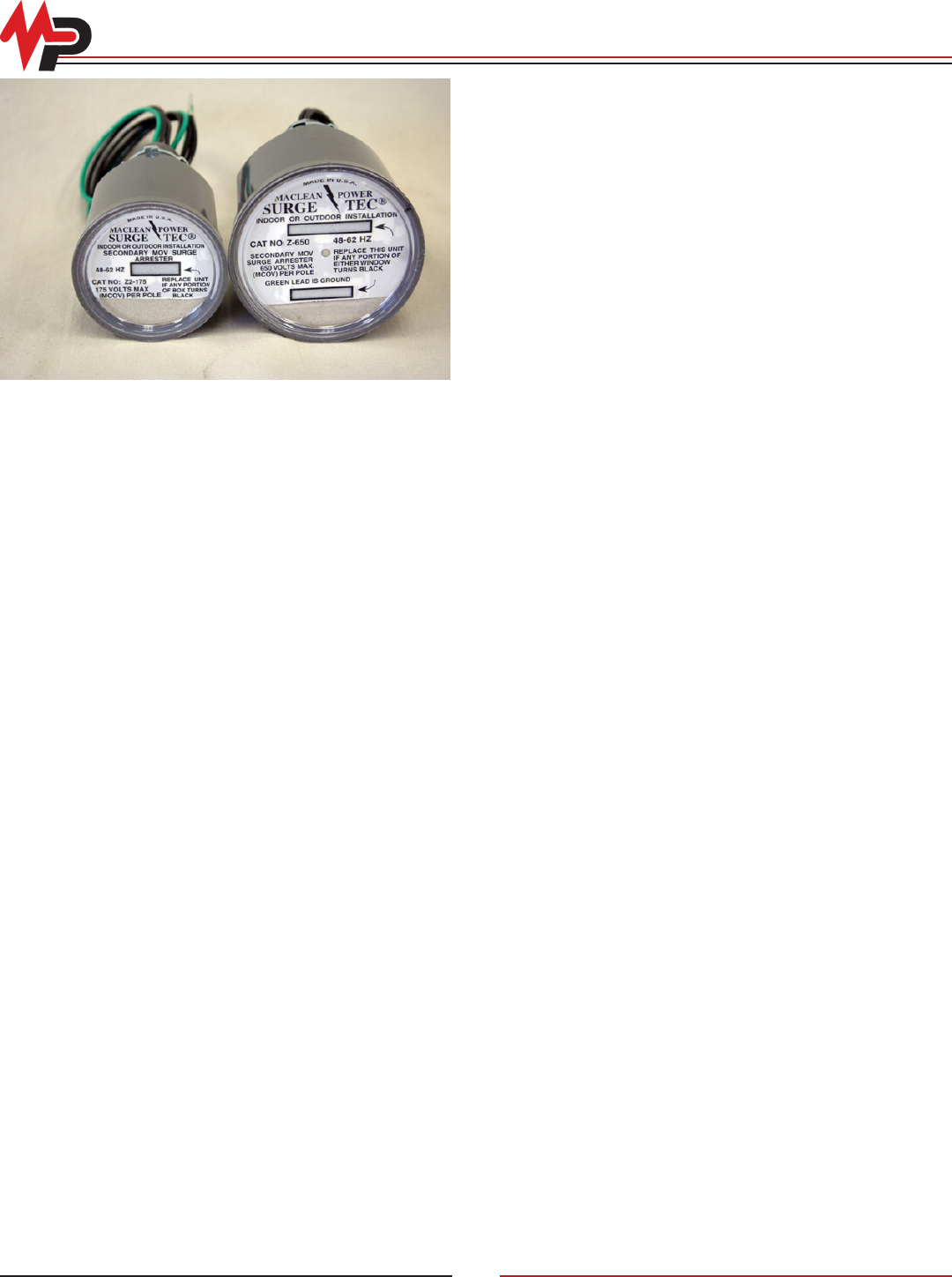
Surge Tec® Secondary Arresters
Electricity users, from the homeowner to big business, are
more interested today in the quality of the power they receive
than in the past, and with good reason. Advances in technology
have introduced new electronic equipment and appliances that
are more susceptible to damage by power surges. Replacing
or repairing damaged equipment is inconvenient and can be
costly.
Lightning or an interruption in the power line can generate a
power surge. These high energy surges can enter a home
or building through the electric service entrance. Once the
surge enters the building, there is a possibility that high voltages
resulting from the surge current will damage electrical wiring
or equipment. Surge Tec® arresters are designed to limit surge
voltages by discharging (bypassing) surge current to ground.
Individuals should assess their risk by evaluating the potential
impact that a power surge may have on their property. In many
cases, the cost of protection is relatively inexpensive compared
to the possible loss. The Surge Tec® arrester is designed to
provide brute force protection against surges at the service
entrance, where protection is needed the most. The family of
Surge Tec® arresters provides an excellent first line of defense
for any critical electrical service, whether it is in a home, business
or industrial applications.
Surge Arrester Application
MPS’ Surge Tec® arresters are designed for service entrance
installations. The arresters are designed for repeated operation
and continuous protection.
Surge arresters provide the path of least resistance to ground for
surges on a system. THE ARRESTERS SHOULD BE INSTALLED
BY A LICENSED ELECTRICIAN. To provide the best protection,
the lead wires should be kept as short as possible. When installed
properly, they will divert lightning surges to ground very quickly.
Surge Tec® arresters offer the first line of defense for the entire
electrical service and protect wiring, major appliances, pumps,
and heating/air conditioning equipment. For added protection to
computers, MPS recommends plug-in-strip type of device with
lower clamping voltages as a second line of defense. This type
of coordination provides excellent surge protection for the entire
electric service.
Features
Surge Tec® arresters incorporate special features that make them
stand above other Secondary Arresters and Transient Voltage
Surge Suppressors (TVSS). These arresters use a patented
(#5,502,612) fault withstand design along with replacement
indication. The arresters are available in 175 volt, 480 volt and 650
volt AC ratings for application on system voltages below 650 volts
phase to ground and operate at frequencies between 48 and 62 Hz.
The units come with 18 inch, #14 AWG solid copper wire leads and
are designed to be mounted outdoors or indoors.
• METAL OXIDE VARISTORS—Surge Tec® arresters use metal
oxide varistors (MOV). This takes advantage of our experience
with metal oxide production for the utility industry. The arresters
meet ANSI/IEEE C62.11-1993 for secondary arresters. In
addition, they have passed a 5kA Duty Cycle test. They
provide high speed response and excellent energy capability
for today’s critical electric loads.
• REPLACEMENT INDICATION—A visual indication on the front
label permits routine checks of the arrester’s operational
status. Indication windows on the label turn black if the arrester
has faulted. The arrester should be replaced when any area of
any window turns black.
• FAULT WITHSTAND CAPABILITY—The Surge Tec® secondary
arresters have a patented fault withstand design. This unique
design has been tested at high current failure modes to verify
its ability to withstand a failure without a violent fracture of the
housing. Fault current is the full available system current that the
device conducts in the event it is short circuited by conducting
a surge beyond the designed capability. This provides signifi-
cant advantages in the area of secondary voltage protection.
There currently is not a standard requirement or test specification
for fault withstand capability of secondary arresters. The Surge
Tec® arresters were tested by failing them with an overvoltage
and then applying fault currents of 4kA and 10kA. The arresters
achieved the fault withstand capability of 10kA rms without the
use of, or the requirement for, any external fusing.
• COST EFFECTIVE—The Surge Tec® arresters are very
inexpensive compared to potential equipment damage.
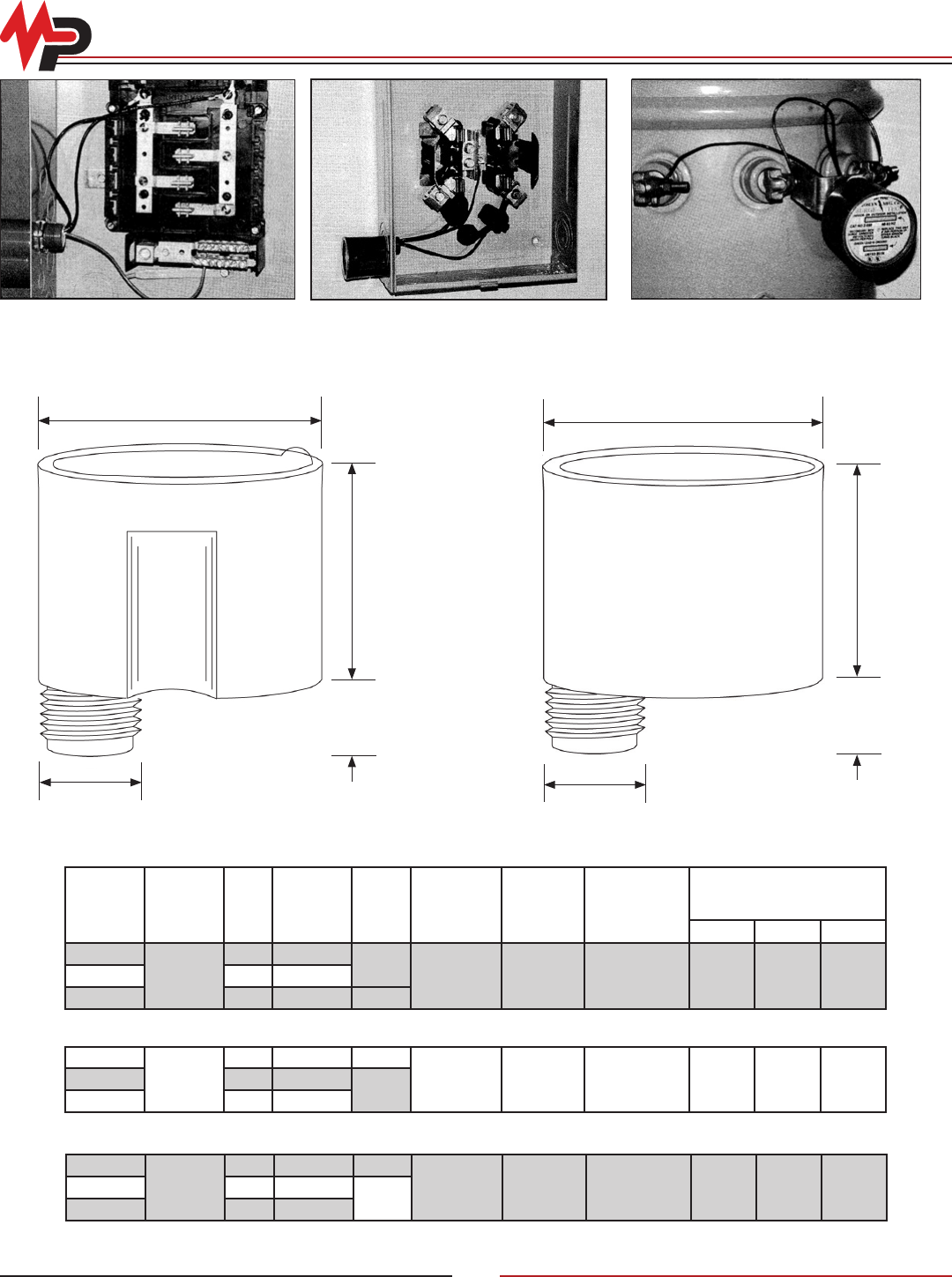
© Copyright 2010 MacLean Power Systems
Issued: May 2010
Supercedes: n/a
11411 Addison Avenue, Franklin Park, IL 60131
T: 847.455.0014 F: 847.455.0029
www.macleanpower.com
AR-32
Surge Tec® Physical and Electrical Characteristics
Knockout Mounting
Z2-175-0
Meterbase Mounting
with insulating piercing connector
Transformer Mounting
Z2-480-4C
Z2-650-4C
(for 3/8” hardware)
2.48”
1.125”
2.33”
.875”
1.125”
.875”
2.46”
3.11”
Catalog
No.
Voltage
Rating
MCOV Poles
Weight
Oz (Gram) Figure
Energy
Capability
(Joules/
Phase)
Response
Time (nsec)
Front-of-Wave
Protection
Level
(kV-Crest)
Max. Discharge Voltage
Clamping Using an 8/20 msec
Current Wave (units-kV)
1.5kA 5.0kA 10kA
Z1-175-0
175
1 14 (435)
1
427 <5 1.21 0.75 0.95 1.27Z2-175-0 2 15 (466)
Z3-175-0 3 18 (560) 2
*Add an “A” sufx to obtain the mounting bracket (e.g. Z1-175-0A)
Z1-480-0
480
1 15 (466) 1
742 <5 1.90 1.42 1.76 2.16Z2-480-0 2 19 (590)
2
Z3-480-0 3 20 (622)
*Add an “A” sufx to obtain the mounting bracket (e.g. Z1-480-0A)
Z1-650-0
650
1 19 (590) 1
919 <5 2.48 2.01 2.44 2.55Z2-650-0 2 20 (622)
2
Z3-650-0 3 21 (653)
*Add an “A” sufx to obtain the mounting bracket (e.g. Z1-650-0A)
Physical and Electrical Characteristics
Fig. 1
Fig. 2
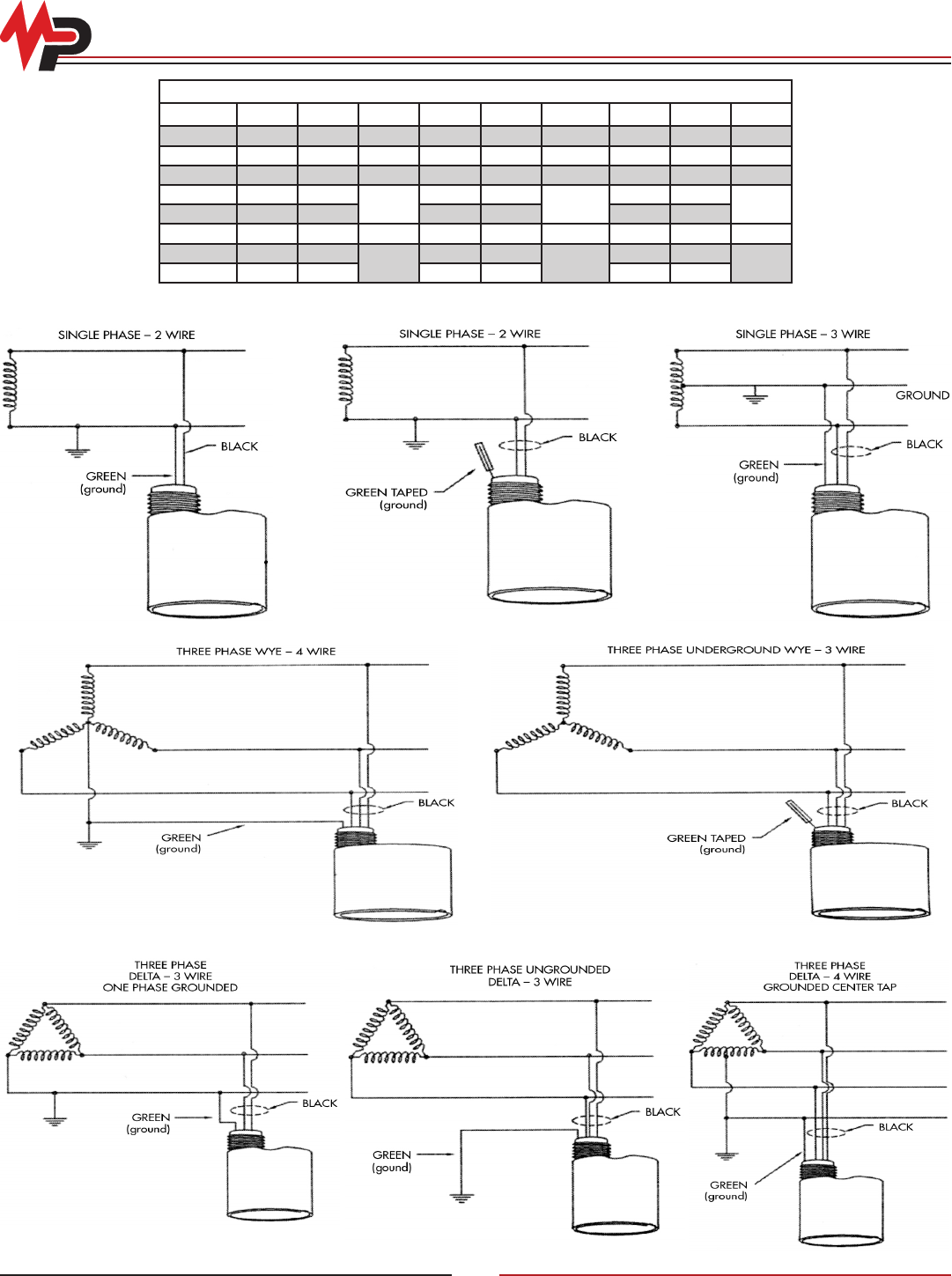
© Copyright 2010 MacLean Power Systems
Issued: May 2010
Supercedes: n/a
11411 Addison Avenue, Franklin Park, IL 60131
T: 847.455.0014 F: 847.455.0029
www.macleanpower.com
AR-33
Surge Tec® Typical Wiring Connections
Maximum Phase-Phase/Phase-Ground Voltages
Figure No. Z1-175 Z2-175 Z3-175 Z1-480 Z2-480 Z3-480 Z1-650 Z2-650 Z3-650
3 175/NA 480/NA 650/NA
4 350/NA 960/NA 1300/NA
5 350/175 960/480 1300/650
6 303/175 831/480 1125/650
7
8 175 480 650
9 175/101 480/277 650/375
10
For severe duty applications, select arrester with next highest voltage rating.
Figure 3 Figure 4 Figure 5
Figure 6 Figure 7
Figure 8 Figure 9 Figure 10
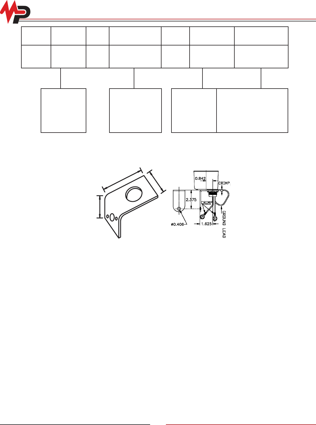
© Copyright 2010 MacLean Power Systems
Issued: May 2010
Supercedes: n/a
11411 Addison Avenue, Franklin Park, IL 60131
T: 847.455.0014 F: 847.455.0029
www.macleanpower.com
AR-34
Surge Tec® Catalog Numbering System
1.53"
1.75"
2.625"
‘A’ Bracket
Part No. 8340903
Option ‘C’
Z 2 - 175 - 0 A
Number of
Poles
Max. Voltage per
Pole (MCOV)
Lead Wire
Length (in/mm)
Mounting
Bracket/Hardware
Options
1 - One pole
2 - Two poles
3 - Three poles
175 - 175 volt
480 - 480 volt
650 - 650 volt
0 - 18”/457
1 - 24”/610
2 - 36”/914
A - Aluminum ‘A’ Bracket
C - Aluminum ‘C’ Bracket
1” Ring Terminals -
Ground 3/8” Ring
Terminals - Line
Connections

© Copyright 2010 MacLean Power Systems
Issued: May 2010
Supercedes: n/a
11411 Addison Avenue, Franklin Park, IL 60131
T: 847.455.0014 F: 847.455.0029
www.macleanpower.com
AR-35
Index
Catalog Number Description Page
7102C0003 Pole Mounting Bracket; One Arrester,
Horizontal Mounting
AR-26
7102D0002 Pole Mounting Bracket; Three Arrester,
Horizontal Mounting
AR-26
7106C0001 Single Crossarm Mounting Bracket AR-25
712B0004H0001 Discharge Counter AR-25
Z1-175 Surge Tec® AR-31 - 34
Z1-480 Surge Tec® AR-31 - 34
Z1-650 Surge Tec® AR-31 - 34
Z2-175 Surge Tec® AR-31 - 34
Z2-480 Surge Tec® AR-31 - 34
Z2-650 Surge Tec® AR-31 - 34
Z3-175 Surge Tec® AR-31 - 34
Z3-480 Surge Tec® AR-31 - 34
Z3-650 Surge Tec® AR-31 - 34
ZE Series ZE Elbow Distribution Arresters AR-12 - 13
ZHP Series Zforce ZHP™ (10kA Heavy Duty Polymer) AR-8
ZIP Series ZIP Intermediate Class Surge Arresters AR-14 - 19
ZJP Series ZJP Intermediate Class Surge Arresters AR-14 - 19
ZNP Series Zforce™ ZNP (5kA Normal Duty Polymer) AR-8
ZQPT Series ZQPT Transmission Line Arresters AR-27 - 28
ZRP Series ZRP™ (10kA Riser Pole Polymer) AR-9
ZSP Series Station Class Arresters AR-20 - 24
ZXLA Series ZXLA Transmission Line Arrester and
Insulator Assembly
AR-27 - 29
