Service Manual, C956i, C966i (Gen 06) Treadmill Product Support\precor\Service Manuals\Commercial Treadmill\C954i (120 VAC)(serial Code AEXE, ADEY)
User Manual: C966i
Open the PDF directly: View PDF ![]() .
.
Page Count: 55
- Section One - Things you Should Know
- Procedure 2.1 - Accessing the Diagnostic Software
- Procedure 2.2 - Displaying Information
- Procedure 2.3 - Setting Club Parameters
- Procedure 2.4 - Documenting Software Problems
- Section Three - Checking Treadmill Operation
- Procedure 4.1 - Calibrating the Incline Motor
- Procedure 4.2 - Adjusting Drive Belt Tension
- Procedure 5.1 - Troubleshooting the Keypad and Upper PCA
- Procedure 5.2 - Troubleshooting the Incline System
- Procedure 5.3 - Troubleshooting Hand Held Heart Rate
- Procedure 5.4 - Troubleshooting the External A.C. Power Source
- Procedure 5.5 - Troubleshooting the 3 Phase AC Drive Motor System
- Procedure 6.1 - Replacing the Incline Motor
- Procedure 6.2 - Replacing the Incline Platform
- Procedure 6.3 - Replacing the Power Control Module
- Procedure 6.4 - Replacing Drive Motor
- Procedure 6.5 - Replacing the Circuit Breaker
- Procedure 6.6 - Replacing the Line Filter
- Procedure 6.7 - Replacing the Line Cord
- Procedure 6.8 - Replacing the Input Module
- Procedure 6.9 - Replacing the End Cap or Belt Guard
- Procedure 6.10 - Replacing the Upper PCA
- Procedure 6.11 - Replacing the Metrics PCA
- Procedure 6.12 - Replacing the D-Pad Assembly
- Procedure 6.13 - Replacing the HR PCA
- Procedure 6.14 - Replacing the Display Face
- Wiring Diagram 7.1 - C956i, C966i 120 Vac
- Block Diagram 7.2 - C956i, C966i 120 Vac
- Wiring Diagram 7.3 - C956i, C966i 240 Vac
- Block Diagram 7.4 - C956i, C966i 240 Vac

C956i, C966i (Gen 06) Treadmill
Page 1
C956i, C966i Treadmill
Warning: This service manual is for use by Precor trained service providers only.
If you are not a Precor Trained Servicer, you must not attempt to service any Precor Product;
Call your dealer for service.
This document contains information required to perform the majority of troubleshooting, and
replacement procedures required to repair and maintain this product.
This document contains general product information, software diagnostic procedures (when
available), preventative maintenance procedures, inspection and adjustment procedures,
troubleshooting procedures, replacement procedures and electrical block and wiring diagrams.
To move directly to a procedure, click the appropriate procedure in the bookmark section to the
left of this page. You may “drag” the separator bar between this page and the bookmark section
to change the size of the page being viewed.
© 2006 Precor Incorporated
Unauthorized Reproduction and Distribution Prohibited By Law
20077-111
C956i, C966i (Gen 06) Treadmill
Page 1-2 Page 2
Section One - Things you Should Know
About This Appendix
The C956i, C966i (Gen 06) incorporate new drive motor system and display systems. The drive
motor is a three phase AC motor. The drive motor controller converts a single phase AC input
into three phase motor control.
Section One, Things You Should Know. This section includes technical specifications. Read
this section, as well as the C956i, C966i Treadmill Owners Manual, before you perform the
maintenance procedures in this manual.
Section Two, Software Features. Precor’s C956i, C966i Treadmills are programmed with
several diagnostic and setup features. This section contains the procedures you need to access
the diagnostic features on this treadmill.
Section Three, Checking Treadmill Operation. This section provides you with a quick way of
checking treadmill operation. Check treadmill operation at the end of a maintenance procedure
and when it is necessary to ensure that the treadmill is operating properly.
Section Four, Inspection and Adjustment Procedures. Perform inspection procedures when
a trouble symptom points to a particular problem and after removing and replacing major
components. Many maintenance problems can be fixed by adjusting various treadmill
components. This section also provides you with the step-by-step procedures required to make
these adjustments.
Section Five, Troubleshooting Procedures. The diagnostic and troubleshooting procedures
contained in this section should be performed when it is necessary to isolate a problem to a
particular component.
Section Six, Replacement Procedures. When a treadmill component must be replaced, go to
this section and follow the step-by-step procedures required to remove and replace the
component.
Section Seven, Technical Diagrams and Parts Lists. This section includes wiring diagrams,
and block diagrams for the C956i, C966i Treadmills.
C956i, C966i (Gen 06) Treadmill
Page 3
Safety guidelines you should know and follow include:
• Read the owner’s manual and follow all operating instructions.
• Operate the treadmill on a solid, level surface.Visually check the treadmill before beginning
service or maintenance operations. If it is not completely assembled or is damaged in any
way, exercise extreme caution while operating and checking the treadmill.
• When operating the treadmill, do not wear loose clothing. Do not wear shoes with heels or
leather soles. Check the soles of your shoes and remove any embedded stones. Tie long
hair back.
• Do not rock the unit. Do not stand or climb on the handlebars, display enclosure, or cover.
• Do not set anything on the handlebars, display enclosure, or cover. Never place liquids on
any part of the treadmill, while performing service.
• To prevent electrical shock, keep all electrical components away from water and other
liquids.
• Do not use accessory attachments that are not recommended by the manufacturer-such
attachments might cause injuries.
•
• Removing the hood exposes high voltage components and potentially dangerous
machinery. Exercise extreme caution when you perform maintenance procedures with the
hood removed.
C956i, C966i (Gen 06) Treadmill
Page 1-4 Page 4
General Information
For the latest exploded view diagram, part number and part pricing information, visit the Precor
dealer website at “www.precor.com/connection.
C956i, C966i (Gen 06) Treadmill
Page 5
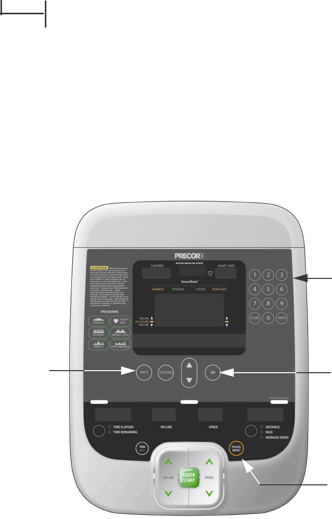
Procedure 2.1 - Accessing the Diagnostic Software
The treadmill's diagnostic software consists of the following modes:
• Display Test
• Keyboard Test
• Heart Rate Test
• Machine Test
Belt Speed
Incline
Procedure
1. Plug the power cord into the wall outlet, then turn on the treadmill with the circuit breaker.
2. Using the RESET key and the numeric keypad, press keys RESET,5,1,7,6,5,7,6,1,
sequentially.
3. Hardware Validation will scroll across the display followed by DISPLAY TEST.
Diagram 2.1 - C956i, C966i Treadmill Display
Numeric Keypad
Reset Key
OK Key
Back Key
C956i, C966i (Gen 06) Treadmill
Page 1-6 Page 6
4. Press the OK key, the upper most group of LED’s will illuminate on the display. Check the
display to ensure that all LED segments are illuminated.
5. Press the OK key four more times to display the remaining LED groups. Check each display
group to ensure that all LED segments are illuminated.
6. Press the BACK key then the key, KEYBOARD TEST will scroll across the display.
7. Press the OK key, a representation of all of the keys on the console will be displayed.
Pressing a key on the console will cause the representation of that key to go off. Press all of
the keys on the console to ensure that all of the keys are functioning.
8. Press and hold the BACK key then the key, HEART RATE will be displayed.
9. Grasp both of the heart rate grips on the handlebar, after a couple of seconds the heart rate
will be displayed in the heart rate and smart rate displays.
10. Use chest strap transmitter or a test transmitter to test the wireless heart rate function, after
a couple of seconds the heart rate will be displayed in the heart rate and smart rate displays.
11. Press the BACK key then the key, MACHINE TEST will scroll across the display.
12. You may now proceed to either the belt speed test or the incline test. Press the key once
to access the belt speed test or twice to access the incline test.
13. BELT SPEED test. Press the OK key, the console will display the power bits (PWRB), Press
the SPEED key to start the treadmill running belt, the display will indicate the power bits,
the elapsed time and the actual speed (in either miles per hour or kilometers per hour
depending on the club parameters setting, see Procedure 2.3).
14. Press the key, the console will display the motor current (AMPS), the elapsed time and
the actual speed.
15. Press the BACK key to exit the belt speed test.
16. INCLINE test. The console will display the analog to digital (A/D) incline position number
and the incline position in percent of incline. Press the inline , keys to operate the incline
through out its range.
17. Press the BACK key to exit the incline test.
18. Press the RESET key to exit the hardware validation test.
C956i, C966i (Gen 06) Treadmill
Page 7
Procedure 2.2 - Displaying Information
The information display will access the following data;
• Odometer
• Hour Meter
• U-Boot Software
• U-Base Software
• Lower Software
• Serial Number
• Usage log
• Error Log
Procedure
1. Plug the power cord into the wall outlet, then turn on the treadmill with the circuit breaker.
2. With the PRECOR banner scrolling, press the keys RESET,6,5, sequentially.
3. DIAGS-INFORMATION DISPLAY will scroll across the display.
4. Use the , keys to move to the desired display shown in the list above.
5. ODOMETER display. Press the OK key.
6. The odometer will be displayed as 1234567 MILES or 1234567 KM depending on club
parameter settings (See Procedure 2.3). The odometer is also used to provide the “distance
stamp” for the error code log
Note: The odometer data is stored in non-volatile memory on the upper PCA. If the upper PCA
is replaced the odometer data will be lost.
7. Press the BACK key to exit the odometer display.
8. HOUR METER display. Press the OK key.
9. The operating time of the unit will be displayed as 12345 HOURS. The operating time is
defined as total amount of time that the unit has operated in program modes with the drive
motor running. The hour meter is also used to provide the “time stamp” for the error code
log.
10. Press the BACK key to exit the hour meter display.
11. U-BOOT SW display. This display the installed version of upper boot software. The boot
software is used to upload new software into the upper display PCA.
12. Press the OK key. The software part number will be displayed as XXXXX-XXX.
C956i, C966i (Gen 06) Treadmill
Page 1-8 Page 8
13. Press the BACK key to exit the U-Boot SW display.
14. U-BASE SW display. This display the installed version of upper PCA software.
15. Press the OK key. The software part number will be displayed as XXXXX-XXX.
16. Press the BACK key to exit the U-Base SW display.
17. LOWER SW display. This display the installed version of lower PCA software.
18. Press the OK key. The software part number will be displayed as XXXXX-XXX.
19. Press the BACK key to exit the lower SW display.
20. SER. NUMBER display. Press the OK key.
21. The treadmill’s serial number will be displayed. The serial number may be incorrect or not
displayed if the upper PCA has been replaced.
22. Press the BACK key to exit the serial number display.
23. USAGE LOG display. Press the OK key.
24. Use the , keys to move through the list of programs. A message will scroll describing the
program, the number of times and the number of minutes the program was used.
25. Press the BACK key to exit the usage log display.
26. ERROR LOG display. Press the OK key, the quantity of errors in the log will be displayed.
27. Press the OK key, the most recent error will be displayed first.
28. Use the , keys to move through the list of errors. The error messages will list the error
name, the odometer reading when the error occurred, the hour meter when the error
occurred and the drive motor current reading when the error occurred.
29. If you wish to clear the error log, press and hold the QUICK START key. The message
HOLD TO CLEAR ERRORS will be displayed. The error log will be cleared when the
message NO ERRORS is displayed.
30. Press the RESET key to exit the information display.
31. Please note that the ERROR LOG may also be accessed at any time by pressing and
holding the RESET key for four seconds. If the error log does not contain any errors, the
message STUCK KEY will be displayed.
C956i, C966i (Gen 06) Treadmill
Page 9
Procedure 2.3 - Setting Club Parameters
This procedure allows you to change the following club settings:
• Safety Code
• Select Language
• Select Units
• Set Max Workout Time
• Set Max Pause Time
• Set Cool Down Time
• Set Speed Limit
• Set Incline Limit
• Hidden Programs
• Remote Speed Control
• Set Custom Program 1
• Set Custom Program 2
Procedure
1. Plug the power cord into the wall outlet, then turn on the treadmill with the circuit breaker.
2. With the banner scrolling, press keys RESET,5,6,5,1,5,6,5, sequentially.
3. Use the , keys to move to the desired display shown in the list above.
4. DIAGS-SET CLUB PARAMETERS will scroll across the display.
5. SAFETY CODE display. The safety code, when enabled, makes the user enter a password
in order to start the treadmill. Press the OK key.
6. Use the , keys to toggle between ENABLED and DISABLED.
7. Press the BACK key to exit the safety code display.
8. SELECT LANGUAGE display. Press the OK key.
9. Use the , keys to toggle between the available languages.
10. Press the BACK key to exit the select language display.
11. SELECT UNITS display. Press the OK key.
12. Use the , keys to toggle between U.S (miles per hour) and METRIC (kilometers per
hour).
13. Press the BACK key to exit the set units display.
C956i, C966i (Gen 06) Treadmill
Page 1-10 Page 10
14. SET MAX WORKOUT TIME display. Press the OK key.
15. Use the , keys to select the maximum time a user can remain in a program.
16. Press the BACK key to exit the set max. workout time display.
17. SET MAX PAUSE TIME display. Press the OK key.
18. Use the , keys to select the maximum time a program will remain in the pause mode.
19. Press the BACK key to exit the set max. pause time display.
20. SET COOL DOWN TIME display. Press the OK key.
21. Use the , keys to select the cool down time.
22. Press the BACK key to exit the set cool down time display.
23. SET SPEED LIMIT display. Press the OK key.
24. Use the , keys to select the maximum allowable treadmill speed.
25. Press the BACK key to exit the set speed limit time display.
26. SET INCLINE LIMIT display. Press the OK key.
27. Use the , keys to select the maximum allowable incline setting.
28. Press the BACK key to exit the set incline limit time display.
29. HIDDEN PROGRAMS display. Press the OK key.
30. Use the , keys to toggle between HIDE PROGRAMS and SHOW PROGRAMS.
31. Press the BACK key to exit the hidden programs display.
32. REMOTE SPEED CONTROL display. Remote speed control allows the treadmill speed to
be controlled by an external source such as InSite. Press the OK key.
33. Use the , keys to toggle between ENABLED and DISABLED.
34. Press the BACK key to exit the remote speed control display.
35. SET CUSTOM PROGRAM 1 display. Allows programing of the custom program 1. Follow
the instructions scrolling on the display to program the custom course. Use the ENTER key
to save changes and exit or the BACK to exit without saving changes.
C956i, C966i (Gen 06) Treadmill
Page 11
36. SET CUSTOM PROGRAM 2 display. Allows programing of the custom program 2. Follow
the instructions scrolling on the display to program the custom course. Use the ENTER key
to save changes and exit or the BACK to exit without saving changes.
C956i, C966i (Gen 06) Treadmill
Page 1-12 Page 12
Procedure 2.4 - Documenting Software Problems
When a problem is found with the software in the upper or lower PCA, record the information
listed below.
When a problem occurs, record the following information:
• Model and serial number
• Software version number
• Program number running when the problem occurred
• A description of:
•a. What happened or failed to happen.
b. The action taken by the user just before the problem occurred.
c. Problem-related information (such as how far into the program the problem occurred,
the work level being used when the problem occurred, error code displayed, etc.).
• The frequency of occurrence.
C956i, C966i (Gen 06) Treadmill
Page 13
Section Three - Checking Treadmill Operation
This section provides you with a quick method of checking treadmill operation. Check treadmill
operation at the end of a maintenance procedure and when it is necessary to ensure that the
treadmill is operating properly.
Procedure
1. Plug the power cord into the wall outlet, then turn on the treadmill with the circuit breaker.
2. Operate the treadmill in the Manual program. Adjust the speed of the running belt to 2–3
m.p.h. Operate the treadmill for at least 5 minutes.
a. Concentrate on the feel of the running belt and the sound of the drive motor and rollers.
Be on the alert for unusual noises, smells, or vibrations.
b. Observe the LED’s on the electronic console. Make sure that each LED lights as the in-
formation corresponding to that LED is displayed on the electronic console.
c. Enter the diagnostics program (see Procedure 2.1) and log the power bits under loaded
and unloaded conditions.
3. Press the STOP key. When the treadmill comes to a stop, view the electronic console as the
treadmill scans time, speed, distance and percent of incline.
4. Press the INCLINE ▲ key while viewing the electronic console. Confirm that the running
bed inclines and the incline display increments to 15% as the INCLINE ▲ key is pressed.
5. Press the INCLINE ▼ key while viewing the electronic console. Confirm that the running bed
returns to a level position and the incline display decrements to 0% as the INCLINE ▼ key is
pressed.
6. Turn off the treadmill with the circuit breaker, then unplug the treadmill from the wall outlet.
C956i, C966i (Gen 06) Treadmill
Page 1-14 Page 14
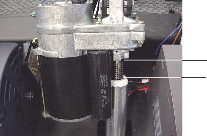
Procedure 4.1 - Calibrating the Incline Motor
1. Set the treadmill circuit breaker in the “off” position and unplug the line cord from the wall
outlet.
2. Remove the hood.
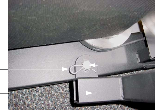
3. Place the treadmill on its right side. Remove hitch and clevis pins that secure the incline
tube to the incline platform. See Diagram 4.1.
Diagram 4.1 - incline Motor Mounting
4. Plug the power cord into the wall outlet, set the treadmill circuit breaker in the “on” position.
If the lift was not set at 0% incline the lift motor will immediately start to operate. The lift
motor will continue to operate until the system is at 0% incline.
5. With the system at 0% incline, rotate the incline tube until the distance from the top of the
incline tube to the incline motor is 1-1/4 inch. See Diagram 4.1. While rotating the incline
tube, be sure the incline motor drive screw does not rotate. If the drive screw is rotated,
return to step 4 and repeat steps 4 and 5.
6. Set the treadmill circuit breaker in the “off” position and remove the line cord from the wall
outlet.
7. Replace the clevis and hitch pins removed in step 3. Return the treadmill to an upright
position.
8. Plug the line cord into the wall outlet, set the treadmill circuit breaker in the “on” position.
1-1/4”
C956i, C966i (Gen 06) Treadmill
Page 15
9. Check the calibration of the incline system by performing the following steps:
a Press the INCLINE key until maximum incline is obtained, 15%.
b Press the INCLINE key to minimum incline is obtained, 0% on C956i treadmills or
-3% on C966i treadmills.
12. Re-install the hood.
C956i, C966i (Gen 06) Treadmill
Page 1-16 Page 16
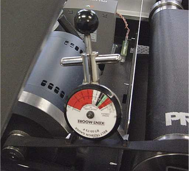
Procedure 4.2 - Adjusting Drive Belt Tension
1. Set the treadmill circuit breaker in the “off” position and unplug the line cord from the wall
outlet.
2. Remove the hood.
3. Place the drive belt tension gauge on the drive belt as shown in Diagram 4.2.
Diagram 4.2 - Drive Belt Tension Gauge
4. The gauge should read approximately 80 inch/pounds. The drive belt tension is acceptable
if it is in the range of 70 to 90 inch-pounds.
5. If the drive belt tension is less than 70 or greater than 90 inch/pounds, slightly loosen the
four drive motor mounting bolts. The drive motor mounts on slotted holes allowing the drive
motor to be move forward or rearward. Move the drive motor forward or rearwards, as
required, until the belt gauge reads approximately 80 inch/pounds and tighten the four drive
motor mounting bolts. See Diagram 4.3. Momentarily remove the drive belt tension gauge
from the drive belt. Replace the drive belt tension gauge on the drive belt and re-adjust the
drive belt tension, if necessary. Torque the four drive motor mounting bolts to 204 inch
pounds (17 foot pounds).
C956i, C966i (Gen 06) Treadmill
Page 17
Diagram 4.3 - Drive Belt Adjustment
6. Re-install the hood.
7. Plug the line cord into the wall outlet and set the treadmill circuit breaker in the “on” position.
8. Check treadmill operation per Section 3.
C956i, C966i (Gen 06) Treadmill
Page 1-18 Page 18
Procedure 5.1 - Troubleshooting the Keypad and Upper PCA
Procedure
Note The red wire on the cables shown in Diagram 5.1 denotes pin 1. When these cables are
inserted into their connectors, the red wire must align with the pin 1 designation on the PCA.
1. Set the treadmill’s on/off switch in the “off” position. Remove the display back plate and
display face per Procedure 6.10.
2. If the message STUCK KEY is displayed when the treadmill is turned on, skip to step 23.
3. If a key does not function, skip to step 18.
4. If the display does not illuminate, continue with step 5.
Diagram 5.1 - Display Face, Rear View
5. If the upper PCA is not illuminating, skip to step 12.
6. If the metrics PCA is not illuminating, continue with step 7.
7. Un-clip the metrics PCA from the display face and rotate it so that the front of the PCA is
visible. Set the treadmill’s on/off switch in the “on” position.
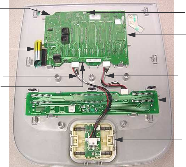
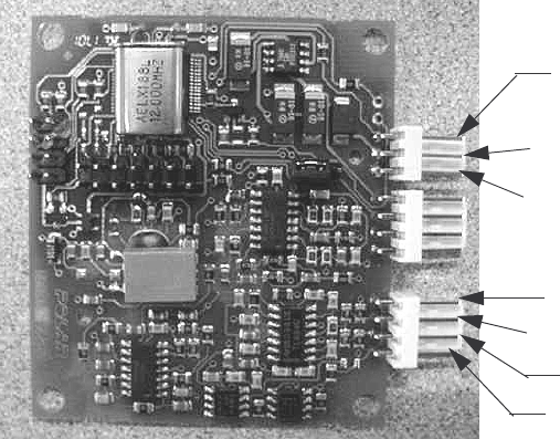
Upper PCA
Metrics PCA
D-Pad Assembly
Keypad Cable
Stop Switch
Connector
ISP Connector
J4
Entertainment
Connector J1
D-Pad Cable Metrics Cable
C956i, C966i (Gen 06) Treadmill
Page 19
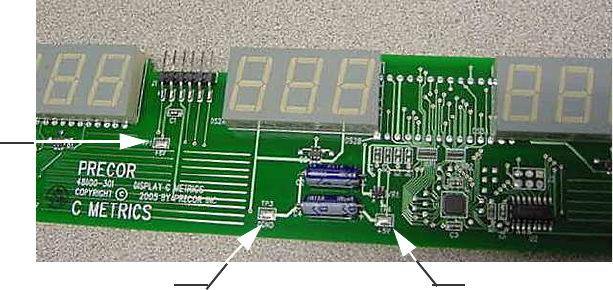
8. With a DC voltmeter, measure between TP1 (+8V) and TP3 (DGND) for 8 Vdc and between
TP4 (+5V) and TP3 (DGND) for 5Vdc. See Diagram 5.2.
Diagram 5.2 - Metrics PCA, Front View
9. If 5 Vdc is not present on TP4 and 8 Vdc is present on TP1, replace the metrics PCA.
10. If 8 Vdc is not present on TP1 and the upper PCA is illuminating normally, replace the cable
between the upper PCA and the metrics PCA.
11. If you have performed steps 7 - 10 and the metrics PCA still does not illuminate, contact
Precor customer support for assistance.
12. Set the treadmill’s on/off switch in the “on” position.
13. With a DC voltmeter, measure between pins 2 and 6 of J1 (ISP) for 5 Vdc and between pins
4 and 5 of J4 (entertainment) for 8 Vdc.
14. If 5 Vdc is not present on J1 and 8 Vdc is present on J4, replace the upper PCA.
15. If 8 Vdc is not present on J4, temporarily replace the upper PCA to power control module
with a known good cable.
16. If the upper PCA illuminates normally, replace the upper PCA to power control module cable
permanently. If the upper PCA still does not illuminate, replace the power control module.
17. If you have performed steps 12 - 16 and the upper PCA still does not illuminate, contact
Precor customer support for assistance.
18. Set the treadmill’s on/off switch in the “on” position.
19. If none of the keys on the display are functioning, check the stop switch cable connection to
the upper PCA. If the stop switch is not connected or the stop switch is not functioning, none
of the display keys will operate. This feature insures that the treadmill has a functioning stop
switch when it is in use.
20. If a particular key is not functioning, perform the keyboard test in Procedure 2.1. If the test
verifies that the key is not functioning, replace the display face.
TP1 (+8V)
TP3 (DGND) TP4 (+5V)
C956i, C966i (Gen 06) Treadmill
Page 1-20 Page 20
21. If the display face has been replaced and the same key is still not functioning, replace the
upper PCA.
22. If you have performed steps 18 - 22 and the same key is still not functioning, contact Precor
customer support for assistance.
23. Remove the keypad cable from the upper PCA. See Diagram 5.1.
24. Set the treadmill’s on/off switch in the “on” position.
25. If the STUCK KEY message is no longer displayed, replace the display face.
26. If the STUCK KEY is still being displayed with the keyboard cable disconnected, replace the
upper PCA.
27. If you have performed steps 23 - 26 and the STUCK KEY message is still being displayed,
contact Precor customer support for assistance.
C956i, C966i (Gen 06) Treadmill
Page 21
Procedure 5.2 - Troubleshooting the Incline System
Incline System Description:
The incline system on these units consists of an AC line voltage driven incline motor (120 Vac or
240 Vac), and an internal 1 KΩ potentiometer for incline position identification. The incline motor
contains two motor windings, one to operate the motor in an “upward” direction and the other to
operate the motor in a “downward” direction. As the incline motor is operated, the motor also
rotates the potentiometer via an internal gear system. Therefore, the position of the incline
system can be determined by monitoring the value of the internal potentiometer. The incline
motor is initially set at a known starting position (calibration, See Procedure 4.1), subsequent
motor movement is tracked via the potentiometer resistance reading.
Note:
All resistance measurements must be performed with power removed from the treadmill.
Performing resistance measurements with voltage applied may damage your ohmmeter.
Procedure
1. If the incline motor operates but creates a incline error (error 40 or 42) go to step 14. If the
incline motor will not move continue with step 2.
2. Set the treadmill’s on/off switch in the “on” position.
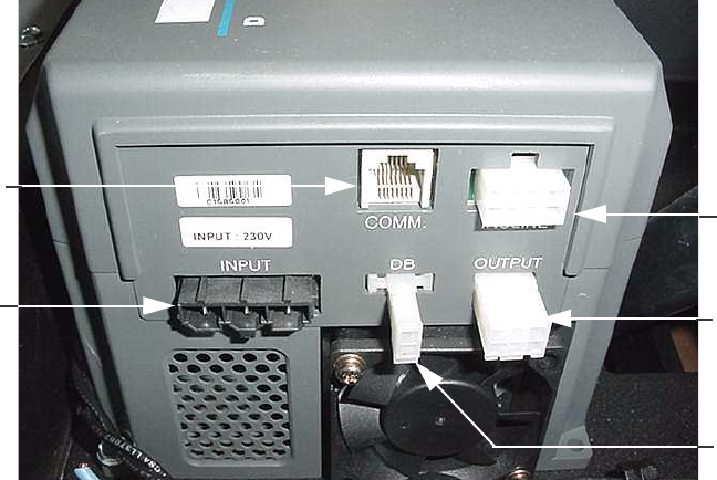
Diagram 5.3 - Power Control Module
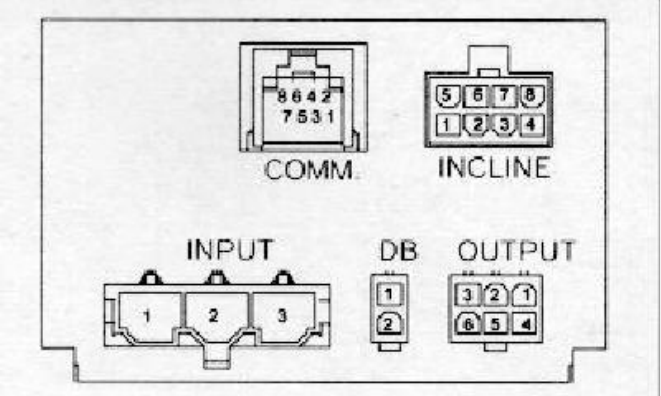
3. With the incline below 15%, connect an AC voltmeter between terminals 1 & 6 of the
INCLINE connector. See Diagrams 5.3 and 5.4. Set the treadmill in the manual program and
press the INCLINE key. The AC voltmeter should read AC line voltage (either 120 Vac or
240 Vac). Note that the AC line voltage reading will only be present before an error condition
is displayed.
Incline
Connector
Motor
Connector
Dynamic
Connector
Connector
AC Input
Connector
Data Cable
Braking
C956i, C966i (Gen 06) Treadmill
Page 1-22 Page 22
Diagram 5.4 - Power Control Module Connector Numbering
4. If the incline moves normally skip to step 7.
5. If the display indicates that the incline should be moving and the incline motor does not
move and AC line voltage is present, skip to step 12.
6. If the display indicates that the incline should be moving and the incline motor does not
move and AC line voltage is not present, replace the power control module.
7. With the incline above 0%, connect an AC voltmeter between terminals 1 & 5 of the
INCLINE connector. See Diagrams 5.3 and 5.4. Set the treadmill in the manual program and
press the INCLINE key. The AC voltmeter should read AC line voltage (either 120 Vac or
240 Vac). Note that the AC line voltage reading will only be present before an error condition
is displayed.
8. If the incline moves normally skip to step 11.
9. If the display indicates that the incline should be moving and the incline motor does not
move and AC line voltage is present, skip to step 12.
10. If the display indicates that the incline should be moving and the incline motor does not
move and AC line voltage is not present, replace the power control module.
11. The incline is moving normally in both directions, there is either is not an incline problem or
the problem is intermittent. Intermittent problems are often caused by poor connections or
wiring problems.
C956i, C966i (Gen 06) Treadmill
Page 23
12. Set the treadmill’s on/off switch in the “off” position. Visually inspect the incline motor’s
wiring and connector for any broken or improperly crimped connections. With an ohmmeter,
measure between terminals 1 & 5 and 1 & 6 of the INCLINE connector. Both readings
should be approximately 12Ω. If either reading is significantly high or open replace the
incline motor.
13. If you have performed all of the procedures above and have been unable to correct the
problem, call Precor customer service.
14. Set the treadmill’s on/off switch in the “off” position. Remove the incline motor’s connector
from the INCLINE connector on the power control module. Visually inspect the incline
motor’s wiring and connector for any broken or improperly crimped connections. With an
ohmmeter, read between terminals 3 & 4, 4 & 8 and 3 & 8 of the INCLINE connector.
Terminals 3 & 4 should read approximately 1KΩ. The sum of the readings between
terminals 4 & 8 and 3 & 8 should total approximately 1KΩ. If either reading is significantly
high or open, replace the incline motor.
15. If you have performed all of the procedures above and have been unable to correct the
problem, call Precor customer service.
C956i, C966i (Gen 06) Treadmill
Page 1-24 Page 24
Procedure 5.3 - Troubleshooting Hand Held Heart Rate
Circuit Description
The hand held heart rate system is actually a dual system, that is, it can accept a heart rate
signal from either the hand held heart rate contacts on the handlebar or from a Polar heart rate
chest strap transmitter. The system is set for hand held heart rate priority, that is if both a chest
strap and hand heart rate signal is being received, the system will accept the hand held signal
and ignore the chest strap signal.
Diagram 5.5 - Hand held/chest strap heart rate PCA
Normal hand held reading - No chest strap reading
1. Set the on/off switch in the “on” position and access the diagnostic program (Procedure 2.1).
Advance to the heart rate display portion of the diagnostic program. Verify that a chest strap
signal is not being accepted with either a Polar heart rate test transmitter or a known good
chest strap transmitter. If this reading is good, skip to step 3.
2. Using a Polar heart rate test receiver, verify the operation of the chest strap transmitter. If
the Polar heart rate test receiver does not receive a signal, replace the chest strap
transmitter.
3. Set the on/off switch in the “off” position and remove the display housing.
4. Verify that a ferrite bead is installed on the heart rate PCA to upper PCA cable.
5. If the above procedures did not correct the problem, replace the heart rate PCA.
5 Vdc
Gnd
Lower Right
Upper Right
Upper Left
Lower Left
HR Output
C956i, C966i (Gen 06) Treadmill
Page 25
No hand held reading - Normal chest strap reading
6. Set the on/off switch in the “on” position and access the diagnostic program (Procedure 2.1).
Advance to the heart rate display portion of the diagnostic program. Verify that a hand held
signal is not being accepted by firmly grasping both the right and left hand held contacts.
Cover as much of the contact surface area with your hands as possible, you should receive
a heart rate reading within ten seconds. If a hand held signal is still not being accepted,
continue with step 7. If a hand held signal is now being received, they user may not have
been making good contact with the grips. There may be nothing wrong. Retest both hand
held and chest strap readings, if normal there is no heart rate problem.
7. Grasp both the right and left hand held contacts with the opposite hands, right hand on the
left handlebar contacts and left hand on the right handlebar contacts. Cover as much of the
contact surface area with your hands as possible, you should receive a heart rate reading
within ten seconds. If a hand held signal is still not being accepted, skip to step 9.
8. If a hand held signal was accepted in step 7, the hand held contact wiring is reversed. The
end of the wire harness that connects to the hand held contacts in the handlebar is
segregated into two groups. One group has blue shrink wrap around it and the other group
has black shrink wrap around it. The “blue” group must go to the right hand contacts and the
“black” group must go to the left hand contacts. In both groups the black wire must go to the
lower contact and the red wire must go to the upper contact. If necessary, rewire the hand
held contacts as described above and test as described in step 7.
9. Set the on/off switch in the “off” position. Refer to Diagram 5.5 for the following
measurements. With an ohmmeter measure between the “lower right contact” pin on the J1
connector and the lower right hand held heart rate contact on the handlebar. The reading
should be 1 Ω or less. Measure between the “upper right contact” pin on the J1 connector
and the upper right hand held heart rate contact on the handlebar. The reading should be 1
Ω or less. Measure between the “upper left contact” pin on the J1 connector and the upper
left hand held heart rate contact on the handlebar. The reading should be 1 Ω or less.
Measure between the “lower left contact” pin on the J1 connector and the lower left hand
held heart rate contact on the handlebar. The reading should be 1 Ω or less. If any of the
above readings are greater than 1 Ω, replace the heart rate PCA to handlebar wire harness.
No hand held reading - No chest strap reading
10. Set the on/off switch in the “on” position and access the diagnostic program (Procedure 2.1).
Advance to the heart rate display portion of the diagnostic program. Verify that neither a
chest strap signal or a hand held signal is being accepted with either a heart rate test
transmitter or a chest strap transmitter.
11. Check the plug/connector connections on both the heart rate PCA, and upper PCA.
12. If neither a chest strap signal or a hand held signal is being accepted, measure between the
“ground” and “5 Vdc” pins on J4 for 5 Vdc. If 5 Vdc is present, replace the heart rate PCA.
C956i, C966i (Gen 06) Treadmill
Page 1-26 Page 26
13. If 5 Vdc is not present, remove the connector from J4 of the heart rate PCA. Measure
between the “ground” and “5 Vdc” pins of the connector (just removed from the heart rate
PCA) for 5 Vdc. If 5 Vdc is present, replace the heart rate PCA. If the 5 Vdc is not present,
measure between the corresponding pins of J17 on the upper PCA (red and black wires). If
5 Vdc is not present replace the upper PCA. If 5 Vdc is present, replace the upper PCA to
heart rate PCA cable.
Constant or intermittent readings when neither the hand held or chest strap is in use
14. Constant or intermittent heart rate readings when neither heart rate system is in use is
caused by something in the near vicinity radiating RF energy that is being received by the
chest strap portion of the heart rate PCA.
15. If the hand held signal is now being accepted, something in the near vicinity is radiating RF
energy that is being received by the chest strap portion of the heart rate PCA. Disabling the
chest strap signal proves that it is radiated energy that is causing the problem.
16. The source of the radiated energy must be determined and relocated so that it no longer
affects the heart rate PCA. Televisions, cell phones, Cardio-theatre receivers, etc. are
possible sources of radiated energy.

C956i, C966i (Gen 06) Treadmill
Page 27
Procedure 5.4 - Troubleshooting the External A.C. Power
Source
It is extremely important that any Precor treadmill be connected to and operated on a dedicated
20 amp A.C. circuit. A 20 amp dedicated circuit is defined as: a circuit fed by a 20 amp circuit
breaker that feeds a single load. A treadmill operating from a non-dedicated circuit or a circuit
breaker of less than 20 amps capacity will not have the necessary power available to operate
normally under higher load conditions. The lack of available power can cause any number of
symptoms ranging from numerous intermittent (seemingly inexplicable) error conditions, poor
speed control, or tripping the house circuit breaker.
If any of the above symptoms exist the external A.C. circuit must be checked and confirmed to be
a 20 amp dedicated circuit before troubleshooting the treadmill.
In addition the A.C. voltage must be checked. Nominal A.C. operating voltage on 120 Vac circuits
is 105 Vac to 120 Vac. Nominal A.C. operating voltage on 240 Vac circuits is 208 Vac to 240 Vac.
For operator safety considerations and to minimize electrostatic discharge conditions the A.C.
frame ground continuity must also be verified to be a low resistance connection to the A.C.
distribution ground bar.
Important
If the A.C. circuit feeding a treadmill is found to be a non-dedicated circuit or a circuit equipped
with a circuit breaker with a capacity of less than 20 amps, the A.C. circuit must be corrected to
be a 20 amp dedicated circuit before any reliable troubleshooting can be performed on the
treadmill. More importantly, a non-dedicated circuit may constitute a safety hazard to the
treadmill operator.
120 Vac Systems
120 Vac distribution systems utilize a single pole circuit breaker (hot lead) and a neutral lead
connected to a common neutral (ground) bar. The A.C. safety ground (green wire) is connected
to a separate ground bar in the distribution system.
The most common problems found are (1) the circuit is fed by a circuit breaker of less than 20
amp capacity, (2) the circuit breaker correctly feeds a single A.C. outlet but the neutral is common
between several A.C. outlets and (3) both the hot and neutral leads feed several A.C. outlets.
The appropriate correction action or actions (see below) must be followed if any of the above
conditions exist. Corrective actions should only be undertaken by a licensed electrician.
1. The circuit breaker feeding the treadmill is not a 20 amp circuit breaker.
If the circuit breaker is greater than 20 amps, the circuit breaker should be replaced with a
20 amp circuit breaker. If the circuit breaker is less than 20 amps the circuit breaker must be
replaced with a 20 amp circuit breaker and the wiring from the A.C. distribution must be
capable of safely handing 20 amps. If the A.C. wiring is under sized, it must be replaced
with wire capable of safely handling 20 amps. Please, refer to local electrical codes when
determining the appropriate wire size for a 20 amp circuit.
C956i, C966i (Gen 06) Treadmill
Page 1-28 Page 28
2. The circuit breaker correctly feeds a single A.C. outlet but the neutral is common
between several A.C. outlets.
The common neutral lead must be removed from treadmill’s A.C. outlet and a new neutral
lead from the treadmill’s A.C. outlet to the A.C. neutral distribution bar must be added.
3. Both the hot and neutral leads feed several A.C. outlets.
Both the common neutral and hot leads must be removed from treadmill’s A.C. outlet and a
new neutral lead and hot lead from the treadmill’s A.C. outlet to the A.C. neutral distribution
bar and circuit breaker must be added.
240 Vac Systems
240 Vac distribution systems utilize a double pole circuit breaker (two hot leads) The A.C. safety
ground (green wire) is connected to a ground bar in the distribution system.
The most common problems found are (1) the circuit is fed by a circuit breaker of less than 20
amp capacity and (2) both the hot leads feed several A.C. outlets. The appropriate correction
action or actions (see below) must be followed if any of the above conditions exist. Corrective
actions should only be undertaken by a licensed electrician.
1. The circuit breaker feeding the treadmill is not a 20 amp circuit breaker.
If the circuit breaker is greater than 20 amps, the circuit breaker should be replaced with a
20 amp circuit breaker. If the circuit breaker is less than 20 amps the circuit breaker must be
replaced with a 20 amp circuit breaker and the wiring from the A.C. distribution must be
capable of safely handing 20 amps. If the A.C. wiring is under sized, it must be replaced
with wire capable of safely handling 20 amps. Please, refer to local electrical codes when
determining the appropriate wire size for a 20 amp circuit.
2. Both the hot leads feed several A.C. outlets.
Both hot leads must be removed from treadmill’s A.C. outlet and two new hot leads from the
treadmill’s A.C. outlet to the circuit breaker must be added.
A licensed electrician may use the followings hints to determine if an A.C. service is dedicated.
1. If, on a 120 Vac system, the A.C. distribution panel contains more circuit breakers than
neutral leads, the system has shared neutral leads and is not dedicated.
2. If an A.C. outlet (120 or 240 Vac) has multiple hot and/or neutral leads, it is not a dedicated.
If either of the above conditions exist, the system is not dedicated. However, absence of the
above conditions does not necessarily mean that the system is dedicated. If any doubt exists
about A.C. systems dedication, point to point tracing of the A.C. wiring may be the only way to
prove system dedication.
C956i, C966i (Gen 06) Treadmill
Page 29
Procedure 5.5 - Troubleshooting the 3 Phase AC Drive Motor
System
Circuit Description
The power control module converts single phase 120Vac or 240Vac into three phase variable
frequency current for the AC drive motor. The motor speed is controlled by controlling the
frequency of the drive motor current.
1. When taking voltage readings of the AC drive motor current, the readings will not be
accurate because of the frequencies being used, however, they are indicative of the
presence of drive motor voltage and relative frequency changes.
2. If the symptoms are the drive motor starts when you force the running belt to move and once
running the drive motor runs “rough”, skip to step 10. If the drive motor will not start continue
with step 3.
3. If the drive motor does not start, the power control module will only apply voltage for a
couple of seconds before it shuts down. Therefore the voltage readings in the following step
must be taken within the first couple of seconds after the treadmill is instructed to start the
running belt.
4. Connect an AC voltmeter between terminals 4 & 5 of the OUTPUT connector on the power
control module. See Diagrams 5.3 and 5.4. Set the treadmill’s on/off switch in the “on”
position. Press the QUICK START key. If the power control module is supplying output, you
will momentarily read approximately 55 Vac. Set the treadmill’s on/off switch in the “off”
position.
5. Repeat the procedure in step 4 between terminals 4 & 6 of the OUTPUT connector on the
power control module.
6. Repeat the procedure in step 4 between terminals 5 & 6 of the OUTPUT connector on the
power control module.
7. If one or more of voltage readings in steps 4 through 6 are not present, replace the power
control module. If the voltage readings in steps 4 through 6 are present, continue with step
8.
8. Set the treadmill’s on/off switch in the “off” position. Disconnect the drive motor connector
from the OUTPUT connector on the power control module. With an ohmmeter, measure
between terminals 4 & 5, 4 & 6 and 5 & 6 of the drive motor connector. Each reading should
be approximately 2.5Ω. If any of the readings are significantly high or open, replacement the
drive motor.
9. If you have performed all of the procedures above and have been unable to correct the
problem, call Precor customer service.
C956i, C966i (Gen 06) Treadmill
Page 1-30 Page 30
10. Connect an AC voltmeter between terminals 4 & 5 of the OUTPUT connector on the power
control module. See Diagrams 5.3 and 5.4. Set the treadmill’s on/off switch in the “on”
position. Press the QUICK START key. If the power control module is supplying output, you
will momentarily read approximately 55 Vac.
11. Repeat the procedure in step 4 between terminals 4 & 6 of the OUTPUT connector on the
power control module.
12. Repeat the procedure in step 4 between terminals 5 & 6 of the OUTPUT connector on the
power control module.
13. If one or more of voltage readings in steps 4 through 6 are not present, replace the power
control module. If the voltage readings in steps 10 through 12 are present, skip to step 8
C956i, C966i (Gen 06) Treadmill
Page 31
Procedure 6.1 - Replacing the Incline Motor
Note:
The replacement incline motor must be calibrated prior to installation (See Procedure 4.1).
1. Set the treadmill’s circuit breaker in the “off” position and remove the AC line cord from the
AC outlet.
2. Disconnect the incline motor connector from the INCLINE connector on the power control
module. See Diagrams 5.3 and 5.4. Lay the replacement incline motor on the floor in front of
the treadmill and insert its connector in the INCLINE connector on the power control
module.
3. Calibrate the incline motor per Procedure 4.1.
4. Either lay the treadmill on its side or securely block the front of the treadmill so that the
treadmill’s weight is off of the incline platform.
5. Remove the defective incline motor as follows: remove the screw that fastens the frame
ground wire (green with yellow stripe) to the treadmill frame. Remove the hitch and clevis
pins from the top and bottom of the incline motor. Remove the incline motor from the
treadmill.
6. Set the calibrated incline motor in its mounting position. Replace the upper clevis and hitch
pins.
7. Replace the lower clevis and hitch pins. It may be necessary to slightly rotate the incline
tube to align it so that the clevis pin may be inserted. To align the hole in the incline tube
rotate it in the direction that will cause the least amount of rotation to make alignment
possible.
8. Connect the frame ground wire to the treadmill frame with the screw removed in step 5.
Route both incline motor cables as noted in the incline motor removal procedure.
9. Insert the incline motor connector in the INCLINE connector on the power control module.
10. Check treadmill operation per Procedure 3.
C956i, C966i (Gen 06) Treadmill
Page 1-32 Page 32
Procedure 6.2 - Replacing the Incline Platform
1. Set the treadmill circuit breaker in the “off” position. Remove the AC line cord from the AC
outlet.
2. Carefully, lay the treadmill on its side.
3. Remove the hitch pin and clevis pin that fastens the incline motor tube to the incline
platform. While the incline tube is not fastened to the incline platform, care must be taken to
not allow the incline tube to rotate. If the incline tube rotates, the incline motor must be re-
calibrated per Procedure 4.1.
4. Remove the two large hitch pins (one each side) from the incline platform to frame
mounting. See Diagram 6.1. Remove the incline platform mounting pins and remove the
incline platform from the treadmill.
Diagram 6.1 - Incline Platform Mounting
5. Remove the wheels from the old incline platform and remount them on the replacement
incline platform.
6. Set the replacement incline platform in it mounting position. Align the key the incline
mounting pin with the keyway in the frame and slide the incline mounting pins into place.
See Diagram 6.2. Fasten the incline mounting pins with the hitch pins removed in step 4.
7. If the incline tube or the incline motor’s drive screw have been moved, re-calibrate the
incline motor per Procedure 4.1, at this time.
Mounting Pin
Hitch Pin
Incline
Platform

C956i, C966i (Gen 06) Treadmill
Page 33
Diagram 6.2 - Incline Mounting Pin
8. Fasten the incline tube to the incline platform with the clevis pin and hitch pin removed in
step 3.
9. Set the treadmill in its upright position and thoroughly check it per Section 3.
Key
C956i, C966i (Gen 06) Treadmill
Page 1-34 Page 34
Procedure 6.3 - Replacing the Power Control Module
1. Set the treadmill’s on/off switch in the “off” position and remove the AC line cord from the AC
outlet.
2. Remove the treadmill’s hood.
3. Disconnect the COMM, INCLINE, INPUT, DB and OUTPUT connectors from the power
control module. See Diagram 5.3 and 5.4.
4. Remove the four screws that mount the power control module. See Diagram 6.3.
Diagram 6.3 - Power Control Module Mounting
5. Set the replacement power control module in its mounting position.
6. Fasten the power control module with the four screws removed in step 4.
7. Reconnect the COMM, INCLINE, INPUT, DB and OUTPUT connectors removed in step 3.
The mating connectors on the power control module are polarized, therefore they can not be
reconnected incorrectly.
8. Replace the treadmill’s hood.
9. Thoroughly check the treadmill per Section 3.
Mounting
Screw
Power
Control
Module
C956i, C966i (Gen 06) Treadmill
Page 35
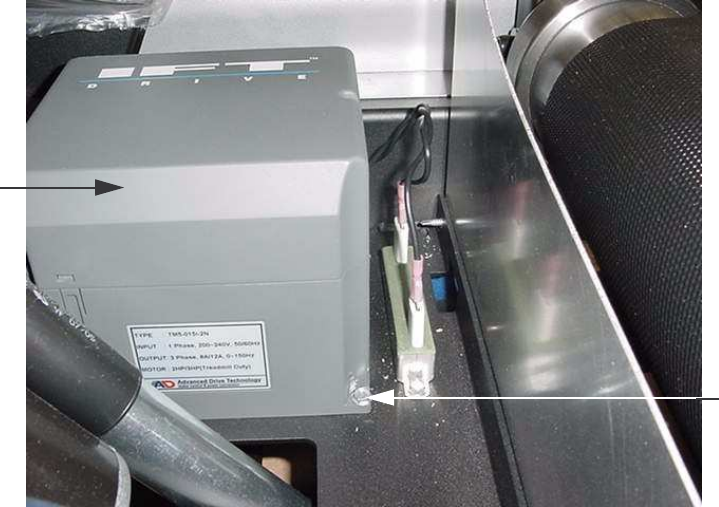
Procedure 6.4 - Replacing Drive Motor
1. Set the treadmill’s on/off switch in the “off” position and unplug the treadmill’s line cord from
the AC outlet.
1. Remove the hood.
2. Disconnect the drive motor connector from the OUTPUT connector on the power control
module.
3. Remove the four bolts that fasten the drive motor to the frame. Remove the drive belt from
the drive motor.
4. Set the replacement drive motor in its mounting position. Place the drive belt on the drive
roller pulley and on the drive motor pulley.
5. Adjust the drive belt tension and complete the motor installation per Procedure 4.2.
6. Thoroughly check the treadmill per Section 3.
C956i, C966i (Gen 06) Treadmill
Page 1-36 Page 36
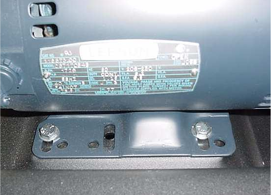
Procedure 6.5 - Replacing the Circuit Breaker
1. Set the treadmill circuit breaker in the “off” position and unplug the treadmill’s line cord from
the AC outlet.
2. Remove the treadmill’s hood.
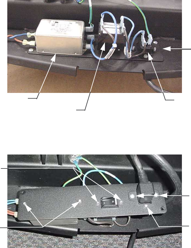
3. Remove the two screws that fastens the AC input panel to the frame,. See Diagram 6.4.
4. Disconnect the wiring from the circuit breaker (2 blue wires on 120 Vac treadmills or 2 blue
and 2 brown wires on 240 Vac treadmills).
Diagram 6.4 - AC Input Panel
5. Lift the AC input panel from the frame and rotate it to expose the circuit breaker mounting
screws. See Diagram 6.5.
Diagram 6.5 - AC Input Panel
AC Input
Panel
Input Module
Circuit Breaker
AC Line Filter
Clamp
Hardware
Input Module
Hardware
Circuit Breaker
Hardware
AC Line Filter
Hardware
C956i, C966i (Gen 06) Treadmill
Page 37
6. Remove the two screws retaining the circuit breaker and remove the circuit breaker.
7. Reference the label on the replacement circuit breaker and set the circuit breaker in its
mounting position with the “LINE” side of the breaker facing the input module and the
“LOAD” side of the circuit breaker facing the AC line filter. Fasten the circuit breaker with the
hardware removed in step 6.
8. On 120 Vac treadmills connect the blue wire from the input module to the “LINE” terminal on
the circuit breaker and the blue wire from the AC line filter to the “LOAD” terminal on the
circuit breaker.
9. On 240 Vac treadmills connect the blue wire from the input module to the upper “LINE”
terminal on the circuit breaker and the blue wire from the AC line filter to the upper “LOAD”
terminal on the circuit breaker. Connect the brown wire from the input module to the lower
“LINE” terminal on the circuit breaker and the brown wire from the AC line filter to the lower
“LOAD” terminal on the circuit breaker.
10. Set the input panel in its mounting position and fasten it with the hardware removed in step
3.
11. Thoroughly check the treadmill per Section 3.
C956i, C966i (Gen 06) Treadmill
Page 1-38 Page 38
Procedure 6.6 - Replacing the Line Filter
1. Set the treadmill circuit breaker in the “off” position and unplug the treadmill’s line cord from
the AC outlet.
2. Remove the treadmill’s hood.
3. Remove the two screws that fastens the AC input panel to the frame,. See Diagram 6.4.
4. Disconnect the wiring from the AC line filter (2 blue wires, 2 brown wires and a green/yellow
wire.
5. Lift the AC input panel from the frame and rotate it to expose the AC line filter mounting
screws. See Diagram 6.5.
6. Remove the screws that retain the AC line filter. Remove the AC line filter.
7. Set the replacement AC line filter in its mounting position with the side with three terminal
facing the circuit breaker.
8. On 120 Vac and 240 Vac treadmills, connect the blue wire from the power control module to
the L1 terminal on the “LOAD” side of the AC line filter and the brown wire from the power
control module to the L2 terminal on the “LOAD” side of the AC line filter.
9. On 120 Vac treadmills, connect the blue wire from the input module to the L1 terminal on the
“LINE” side of the AC line filter, the brown wire from the circuit breaker to the L2 terminal on
the “LINE” side of the AC line filter and the green/yellow wire to the (annunciated) terminal
mounted directly on the line filter case.
10. On 240 Vac treadmills, connect the blue wire from the circuit breaker to the L1 terminal on
the “LINE” side of the AC line filter, the brown wire from the circuit breaker to the L2 terminal
on the “LINE” side of the AC line filter and the green/yellow wire to the (annunciated)
terminal mounted directly on the line filter case.
11. Set the input panel in its mounting position and fasten it with the hardware removed in step
3.
12. Thoroughly check the treadmill per Section 3.
C956i, C966i (Gen 06) Treadmill
Page 39
Procedure 6.7 - Replacing the Line Cord
1. Set the treadmill circuit breaker in the “off” position and unplug the treadmill’s line cord from
the AC outlet.
2. Remove the treadmill’s hood.
1. Remove the two screws that fastens the AC input panel to the frame,. See Diagram 6.4.
2. Lift the AC input panel from the frame and rotate it to expose the AC line cord clamp screws.
See Diagram 6.5.
3. Remove the hardware that retains the AC line cord clamp and remove the clamp.
4. Disconnect the AC line cord from the input module.
5. Feed the end of the replacement AC line cord that mates with the input module through its
hole in the frame and firmly insert it into the input module.
6. Set the AC line cord clamp in its mounting position and fasten it with the hardware removed
in step 3.
7. Set the input panel in its mounting position and fasten it with the hardware removed in step
3.
8. Check treadmill operation per Section 3.

C956i, C966i (Gen 06) Treadmill
Page 1-40 Page 40
Procedure 6.8 - Replacing the Input Module
1. Set the treadmill circuit breaker in the “off” position and unplug the treadmill’s line cord from
the AC outlet.
2. Remove the treadmill’s hood.
3. Remove the two screws that fastens the AC input panel to the frame,. See Diagram 6.4.
4. Lift the AC input panel from the frame and rotate it to expose the AC line cord clamp screws
and input module screws. See Diagram 6.5.
5. Remove the hardware that retains the AC line cord clamp and remove the clamp.
6. Disconnect the AC line cord from the input module.
7. Disconnect the wiring from the input module (1 blue wire, 1 brown wire and 1 green/yellow
wire).
8. Remove the hardware that retains the input module and remove the input module.
9. Set the input module in its mounting position with the side with two terminals facing the
circuit breaker.
10. Connect the blue wire removed in step 5 to terminal “N”, the brown wire to terminal “L” and
the green/yellow wire to terminal “E” of the input module. See Diagram 6.6.
Diagram 6.6 - Input Module Wiring
11. Insert the AC line cord firmly into the input module. Set the AC line cord clamp in its
mounting position and fasten it with the hardware removed in step 5.
12. Set the input panel in its mounting position and fasten it with the hardware removed in step
3.
13. Check treadmill operation per Section 3
Green/Yellow
E
L
N
Brown
Blue
C956i, C966i (Gen 06) Treadmill
Page 41
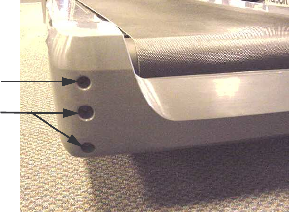
Procedure 6.9 - Replacing the End Cap or Belt Guard
1. Set the treadmill circuit breaker in the “off” position and unplug the treadmill’s line cord from
the AC outlet.
2. Remove the four screws (2 lower screws, each side) that retain the end cap. Do Not loosen
or move the take up roller mounting/adjustment bolts. Doing so will change the running
belt’s tension and alignment. See Diagram 6.7.
Diagram 6.7 - End Cap Mounting
3. Slide the end cap off of the treadmill.
4. If you are not replacing the belt guard skip to step 8.
5. The tabs on the belt guard (1 each side) snap into the take up roller mounts See Diagram
6.8.
6. Press inwards on the belt guard to remove the belt guard’s tabs from the take up roller
mounts. Slide the belt guard off of the treadmill.
7. Slide the replacement belt guard into place so that the tabs on the belt guard engage in both
take up roller mounts.
8. Slide the end cap into place so that the tabs on the end cap engage in the notches in the
running belt trim strips. See Diagram 6.8.
9. Fasten the end cap with the hardware removed in step 2.
Take up Roller
Mtg/Adj Bolt
End Cap
Bolts

C956i, C966i (Gen 06) Treadmill
Page 1-42 Page 42
Diagram 6.8 - Belt Guard Mounting
Belt Guard
Tab
Notch
C956i, C966i (Gen 06) Treadmill
Page 43
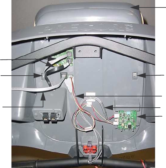
Procedure 6.10 - Replacing the Upper PCA
1. Set the treadmill circuit breaker in the “off” position and unplug the treadmill’s line cord from
the AC outlet.
2. The PCA’s in the display are static sensitive. They can be damaged if proper static
prevention equipment is not used. Attach an anti-static wrist strap to your arm, then connect
the ground lead of the wrist strap to the treadmill’s frame ground.
3. Remove the eight screws that fasten the display back cover and remove the display back
cover.
4. Disconnect the data cable, 2 CSAFE cables and the heart rate cable from the upper PCA.
See Diagram 6.9.
Diagram 6.9 - Upper PCA and Heart Rate PCA Mounting
5. The display cap snaps onto the display with two tabs. Reach into the upper portion of the
display and locate the two display cap tabs. Press the tabs outwards to disengage the tabs
and remove the display cap.
6. The display face snaps onto the display with six tabs. One of the tabs is behind the HR PCA.
The HR PCA snaps into its mounting. Press its tabs downward and remove the HR PCA
from its mounting.
Display Cap
Upper PCA Tab
Upper PCA Tab
CSAFE Cable
Data Cable
HR Cable
HR PCA
Handlebar Cable
C956i, C966i (Gen 06) Treadmill
Page 1-44 Page 44
7. Press the four display face tabs outwards and disengage the display face from the display.
Disconnect the stop switch cable from the upper PCA and remove the display face from the
display.
8. Disconnect the Metrics cable, D-pad cable and the keypad cable from the upper PCA. See
Diagram 5.1.
9. The upper PCA snaps into the display face. Press the upper PCA tabs outward and remove
the upper PCA from the display face.
10. Snap the replacement upper PCA into its mounting on the display face.
11. The red wire in the Metrics and D-pad cables indicate pin 1. Align the red wire in the Metrics
and D-pad cables with the pin 1 markings on the upper PCA. Connect the Metrics, D-pad
and keypad cables to the upper PCA.
12. Connect the stop switch cable to upper PCA and snap the display face into place on the
display.
13. Reconnect the data cable, two CSAFE cables and the HR cable to the upper PCA as shown
in Diagram 6.9.
14. Snap the HR PCA into its mounting. See Diagram 6.9.
15. Snap the display cap into place on the display.
16. Replace the display back cover with the hardware removed in step 3.
17. Check treadmill operation per Section 3.
C956i, C966i (Gen 06) Treadmill
Page 45
Procedure 6.11 - Replacing the Metrics PCA
1. Set the treadmill circuit breaker in the “off” position and unplug the treadmill’s line cord from
the AC outlet.
2. The PCA’s in the display are static sensitive. They can be damaged if proper static
prevention equipment is not used. Attach an anti-static wrist strap to your arm, then connect
the ground lead of the wrist strap to the treadmill’s frame ground.
3. Remove the eight screws that fasten the display back cover and remove the display back
cover.
4. Disconnect the data cable, 2 CSAFE cables and the heart rate cable from the upper PCA.
See Diagram 6.9.
5. The display cap snaps onto the display with two tabs. Reach into the upper portion of the
display and locate the two display cap tabs. Press the tabs outwards to disengage the tabs
and remove the display cap.
6. The display face snaps onto the display with six tabs. One of the tabs is behind the HR PCA.
The HR PCA snaps into its mounting. Press its tabs downward and remove the HR PCA
from its mounting.
7. Press the four display face tabs outwards and disengage the display face from the display.
Disconnect the stop switch cable from the upper PCA and remove the display face from the
display.
8. Disconnect the Metrics cable from the Metrics PCA. See Diagram 5.1.
9. The Metrics PCA snaps into the display face. Press the Metrics PCA tabs outward and
remove the Metrics PCA from the display face.
10. Snap the replacement Metrics PCA into its mounting on the display face.
11. The red wire in the Metrics cable indicates pin 1. Align the red wire in the Metrics cable with
the pin 1 markings on the Metrics PCA. Connect the Metrics cable to the Metrics PCA.
12. Connect the stop switch cable to upper PCA and snap the display face into place on the
display.
13. Reconnect the data cable, two CSAFE cables and the HR cable to the upper PCA as shown
in Diagram 6.9.
14. Snap the HR PCA into its mounting. See Diagram 6.9.
15. Snap the display cap into place on the display.
C956i, C966i (Gen 06) Treadmill
Page 1-46 Page 46
16. Replace the display back cover with the hardware removed in step 3.
17. Check treadmill operation per Section 3.
C956i, C966i (Gen 06) Treadmill
Page 47
Procedure 6.12 - Replacing the D-Pad Assembly
1. Set the treadmill circuit breaker in the “off” position and unplug the treadmill’s line cord from
the AC outlet.
2. The PCA’s in the display are static sensitive. They can be damaged if proper static
prevention equipment is not used. Attach an anti-static wrist strap to your arm, then connect
the ground lead of the wrist strap to the treadmill’s frame ground.
3. Remove the eight screws that fasten the display back cover and remove the display back
cover.
4. Disconnect the data cable, 2 CSAFE cables and the heart rate cable from the upper PCA.
See Diagram 6.9.
5. The display cap snaps onto the display with two tabs. Reach into the upper portion of the
display and locate the two display cap tabs. Press the tabs outwards to disengage the tabs
and remove the display cap.
6. The display face snaps onto the display with six tabs. One of the tabs is behind the HR PCA.
The HR PCA snaps into its mounting. Press its tabs downward and remove the HR PCA
from its mounting.
7. Press the four display face tabs outwards and disengage the display face from the display.
Disconnect the stop switch cable from the upper PCA and remove the display face from the
display.
8. Disconnect the D-pad cable from the D-pad assembly. See Diagram 5.1.
9. The D-pad assembly snaps into the display face. Release the D-pad assembly’s tabs and
push the D-pad assembly out of the front of the display face.
10. With the replacement D-pad assembly oriented so that the incline and speed switches are
correctly aligned, slide the D-pad assembly into the display face until it snaps into place.
11. The red wire in the D-pad cable indicates pin 1. Align the red wire in the D-pad cable with
the pin 1 markings on the D-pad PCA. Connect the D-pad cable to the D-pad PCA.
12. Connect the stop switch cable to upper PCA and snap the display face into place on the
display.
13. Reconnect the data cable, two CSAFE cables and the HR cable to the upper PCA as shown
in Diagram 6.9.
14. Snap the HR PCA into its mounting. See Diagram 6.9.
15. Snap the display cap into place on the display.
C956i, C966i (Gen 06) Treadmill
Page 1-48 Page 48
16. Replace the display back cover with the hardware removed in step 3.
17. Check treadmill operation per Section 3
C956i, C966i (Gen 06) Treadmill
Page 49
Procedure 6.13 - Replacing the HR PCA
1. Set the treadmill circuit breaker in the “off” position and unplug the treadmill’s line cord from
the AC outlet.
2. The PCA’s in the display are static sensitive. They can be damaged if proper static
prevention equipment is not used. Attach an anti-static wrist strap to your arm, then connect
the ground lead of the wrist strap to the treadmill’s frame ground.
3. Remove the eight screws that fasten the display back cover and remove the display back
cover.
4. Disconnect the HR cable and handlebar cable from the HR PCA. See Diagram 6.9.
5. The HR PCA snaps into its mounting. Press its tabs downward and remove the HR PCA
from its mounting.
6. Orient the replacement HR PCA so that the side with three connectors is facing to the left
and snap the HR PCA into its mounting.
7. Connect the handlebar cable to the upper connector on the HR PCA and the HR cable to
the lower connector on the HR PCA. See Diagram 6.9.
8. Replace the display back cover with the hardware removed in step 3.
9. Check treadmill operation per Section 3
C956i, C966i (Gen 06) Treadmill
Page 1-50 Page 50
Procedure 6.14 - Replacing the Display Face
1. Set the treadmill circuit breaker in the “off” position and unplug the treadmill’s line cord from
the AC outlet.
2. The PCA’s in the display are static sensitive. They can be damaged if proper static
prevention equipment is not used. Attach an anti-static wrist strap to your arm, then connect
the ground lead of the wrist strap to the treadmill’s frame ground.
3. Remove the eight screws that fasten the display back cover and remove the display back
cover.
4. Disconnect the data cable, 2 CSAFE cables and the heart rate cable from the upper PCA.
See Diagram 6.9.
5. The display cap snaps onto the display with two tabs. Reach into the upper portion of the
display and locate the two display cap tabs. Press the tabs outwards to disengage the tabs
and remove the display cap.
6. The display face snaps onto the display with six tabs. One of the tabs is behind the HR PCA.
The HR PCA snaps into its mounting. Press its tabs downward and remove the HR PCA
from its mounting.
7. Press the four display face tabs outwards and disengage the display face from the display.
Disconnect the stop switch cable from the upper PCA and remove the display face from the
display.
8. Disconnect the Metrics cable, D-pad cable and the keypad cable from the upper PCA. See
Diagram 5.1.
9. The upper PCA snaps into the display face. Press the upper PCA tabs outward and remove
the upper PCA from the display face.
10. Disconnect the Metrics cable from the Metrics PCA. See Diagram 5.1.
11. The Metrics PCA snaps into the display face. Press the Metrics PCA tabs outward and
remove the Metrics PCA from the display face.
12. Disconnect the D-pad cable from the D-pad assembly. See Diagram 5.1.
13. The D-pad assembly snaps into the display face. Release the D-pad assembly’s tabs and
push the D-pad assembly out of the front of the display face.
14. Snap the upper PCA into its mounting on the replacement display face.
C956i, C966i (Gen 06) Treadmill
Page 51
15. The red wire in the Metrics and D-pad cables indicate pin 1. Align the red wire in the Metrics
and D-pad cables with the pin 1 markings on the upper PCA. Connect the Metrics, D-pad
and keypad cables to the upper PCA.
16. Snap the Metrics PCA into its mounting on the replacement display face.
17. The red wire in the Metrics cable indicates pin 1. Align the red wire in the Metrics cable with
the pin 1 markings on the Metrics PCA. Connect the Metrics cable to the Metrics PCA.
18. With the D-pad assembly oriented so that the incline and speed switches are correctly
aligned, slide the D-pad assembly into the replacement display face until it snap into place.
19. The red wire in the D-pad cable indicates pin 1. Align the red wire in the D-pad cable with
the pin 1 markings on the D-pad PCA. Connect the D-pad cable to the D-pad PCA.
20. Connect the stop switch cable to upper PCA and snap the display face into place on the
display.
21. Reconnect the data cable, two CSAFE cables and the HR cable to the upper PCA as shown
in Diagram 6.9.
22. Snap the HR PCA into its mounting. See Diagram 6.9.
23. Snap the display cap into place on the display.
24. Replace the display back cover with the hardware removed in step 3.
25. Check treadmill operation per Section 3
C956i, C966i (Gen 06) Treadmill
Page 1-52 Page 52
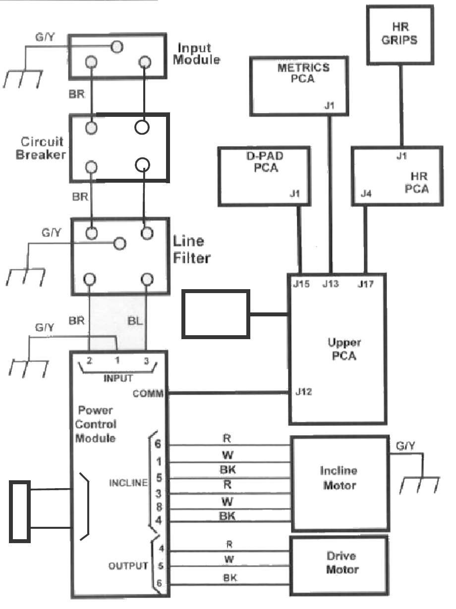
Wiring Diagram 7.1 - C956i, C966i 120 Vac
GRIPS
HR
PCA
HR
J1
J4
PCA
METRICS
J1
D-PAD
PCA
J1
J17
J13
J15
J14
Switch
Stop
PCA
Upper
J12
Incline
Motor
Motor
Drive
G/Y
BK
W
R
BK
W
R
BK
W
R
6
5
4
4
8
3
5
1
6
OUTPUT
INCLINE
COMM
BR
BR
50W
100Ω
2
1
DB
Control
Module
Power
3
1
2
INPUT
G/Y
BR BL
Filter
Line
G/Y
BR
Breaker
Circuit BL
Module
Input
BR
G/Y
C956i, C966i (Gen 06) Treadmill
Page 53
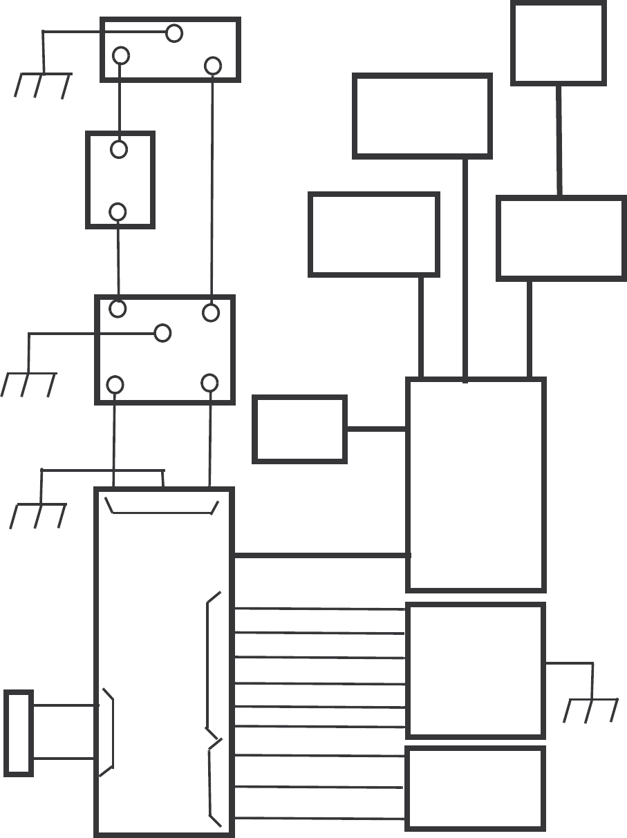
Block Diagram 7.2 - C956i, C966i 120 Vac
C956i, C966i (Gen 06) Treadmill
Page 1-54 Page 54
Wiring Diagram 7.3 - C956i, C966i 240 Vac
BL
BL
Stop
Switch
J14
1
2
BR
BR
DB
50W
100
Ω
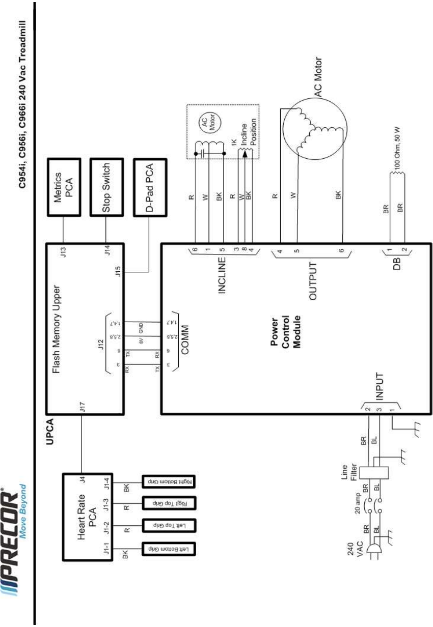
C956i, C966i (Gen 06) Treadmill
Page 55
Block Diagram 7.4 - C956i, C966i 240 Vac
VAC
240
