Service Manual, C960, C962, C964 Treadmills C964i Product Support\precor\Service Manuals\Commercial Treadmill\C962i (120 VAC) (serial Code 3A, 5M)
User Manual: C964i
Open the PDF directly: View PDF ![]() .
.
Page Count: 89
- Section One - Things you Should Know
- Procedure 2.1 - Running the Diagnostic Program (SCR & PWM Units)
- Procedure 2.2 - Running the Diagnostic Program (i Units)
- Procedure 2.3 - Selecting Club Settings
- Procedure 2.4 - Displaying the Odometer
- Procedure 2.5 - Determining Software Version Numbers
- Procedure 2.6 - Documenting Software Problems
- Section Three - Checking Treadmill Operation
- Procedure 4.1 - Calibrating the Lift Assembly on C962 & C964 SCR & PWM Units
- Procedure 4.2 - Calibrating the Lift Assembly on C962i & C964i Treadmills
- Procedure 4.3 - Inspecting and Adjusting Safety Switch Alignment
- Procedure 5.1 - Troubleshooting the Keypad and Upper PCA
- Procedure 5.2 - Troubleshooting the Lift System (SCR & PWM Units)
- Procedure 5.3 - Troubleshooting the Lift System (i Units)
- Procedure 5.4 - Troubleshooting the Speed Sensor
- Procedure 5.5 - Troubleshooting Hand Held Heart Rate
- Procedure 5.6 - Troubleshooting the External A.C. Power Source
- Procedure 6.1 - Replacing the Lift Motor, Rotation Sensor or Magnet Hub
- Procedure 6.2 - Replacing the Limit Switches, Actuator Shaft or Switch Bracket
- Procedure 6.3 - Replacing the Lift Motor Capacitor
- Procedure 6.4 - Replacing the Lift Platform
- Procedure 6.5 - Replacing the Drive Belt
- Procedure 6.6 - Replacing the Drive Roller or Drive Roller Bearings
- Procedure 6.7 - Replacing the Take-Up Roller or Take-Up Roller Bearings
- Procedure 6.8 - Replacing the Safety Switch Assembly
- Procedure 6.9 - Replacing the PROM
- Wiring Diagram 7.1 - C960 SCR 240 Vac
- Block Diagram 7.2 - C960 SCR 240 Vac
- Wiring Diagram 7.3 - C962, C964 SCR 120 Vac
- Block Diagram 7.4 - C962, C964 SCR 120 Vac
- Wiring Diagram 7.5 - C962, C964 SCR 240 Vac
- Block Diagram 7.6 - C962, C964 SCR 240 Vac
- Wiring Diagram 7.7 - C960 PWM 240 Vac
- Block Diagram 7.8 - C960 PWM 240 Vac
- Wiring Diagram 7.9 - C962, C964 PWM 120 Vac
- Block Diagram 7.10 - C962, C964 PWM 120 Vac
- Wiring Diagram 7.11 - C962, C964 PWM 240 Vac
- Block Diagram 7.12 - C962, C964 PWM 240 Vac
- Wiring Diagram 7.13 - C962i, C964i 120 Vac
- Block Diagram 7.14 - C962i, C964i 120 Vac
- Wiring Diagram 7.15 - C962i, C964i 240 Vac
- Block Diagram 7.16 - C962i, C964i 240 Vac
C960 Series Commercial Treadmill
Page 1
C960, C962, C964 Treadmill
Warning: This service manual is for use by Precor trained service providers only.
If you are not a Precor Trained Servicer, you must not attempt to service any Precor Product;
Call your dealer for service.
This document contains information required to perform the majority of troubleshooting, and
replacement procedures required to repair and maintain this product.
This document contains general product information, software diagnostic procedures (when
available), preventative maintenance procedures, inspection and adjustment procedures,
troubleshooting procedures, replacement procedures and electrical block and wiring diagrams.
To move directly to a procedure, click the appropriate procedure in the bookmark section to the
left of this page. You may “drag” the separator bar between this page and the bookmark section
to change the size of the page being viewed.
© 2003 Precor Incorporated
Unauthorized Reproduction and Distribution Prohibited By Law
C960 Series Commercial Treadmill
Page 2
Section One - Things you Should Know
About This Appendix
Section One, Things You Should Know. This section includes technical specifications and a
procedure matrix. Read this section, as well as the owner's manuals shipped with the C960,
C962 and C964 Treadmills, before you perform the procedures in this manual.
Section Two, Software Features. Precors C960 Series Treadmills are programmed with
several diagnostic and setup features. This section contains the procedures you need to access
the diagnostic features on this treadmill.
Section Three, Checking Treadmill Operation. This section provides you with a quick way of
checking treadmill operation. Check treadmill operation at the end of a maintenance procedure
and when it is necessary to ensure that the treadmill is operating properly.
Section Four, Inspection and Adjustment Procedures. Perform inspection procedures when
a trouble symptom points to a problem and after replacing major components. Many
maintenance problems can be fixed by adjusting various treadmill components. This section also
provides the step-by-step procedures required to make these adjustments.
Section Five, Troubleshooting Procedures. Diagnostic and troubleshooting procedures are
performed when it is necessary to isolate a problem to a particular component.
Section Six, Replacement Procedures. When a component must be replaced, follow the step-
by-step procedures included in this section.
Section Seven, Technical Diagrams and Parts Lists. This section includes wiring diagrams
and block diagrams for the C960, C962 and C964 Treadmills.
General Information
For the latest exploded view, part number and part pricing information, visit the Precor dealer
website at “www.precor.com/Dealer.
C960 Series Commercial Treadmill
Page 3
Technical Specifications
Length: 80.5 inches (205 cm.)
Width: Handrails 32 inches (81 cm.)
Height: 45 inches (114 cm.)
Running surface: 61 inches by 20 inches (155 cm. by 51 cm.)
Speed: 240 Volts: 0.5 to 15 m.p.h. (0.8 to 24 k.p.h.)
120 Volts: 0.5 to 10 m.p.h. (0.8 to 16 k.p.h.)
(SCR) 120 Volts: 0.5 to 15 m.p.h. (0.8 to 24 k.p.h.),
(PWM)
Incline: -3% to +15% grade (C962 and C964 only)
0% Fixed grade (C960)
Power: 50/60 Hz 120 Vac or 240 Vac
Shipping Weight: 502 lbs (226 kg.)
C960 Series Commercial Treadmill
Page 4
Serial Number Sequencing
Table 1 identifies the serial number sequences for C960 Series SCR and PWM treadmills.
Table 1. C960 Series Treadmill Serial Number Sequences
SCR Units
If the Model is... And the Voltage The Serial Number
Rating is... Starts With...
C960 120 83
C960 240 84
C962 120 80
C962 240 82
C964 120 81
C964 240 85
PWM Units
If the Model is... And the Voltage The Serial Number
Rating is... Starts With...
C960 240 1N
C962 120 1Y
C962 240 1P
C964 120 1Q
C964 240 1R
i Units
If the Model is... And the Voltage The Serial Number
Rating is... Starts With...
C962i 120 3A
C962i 240 3B
C964i 120 3E
C964i 240 3F
C960 Series Commercial Treadmill
Page 5
SCR and PWM Upper PCAs
Note:
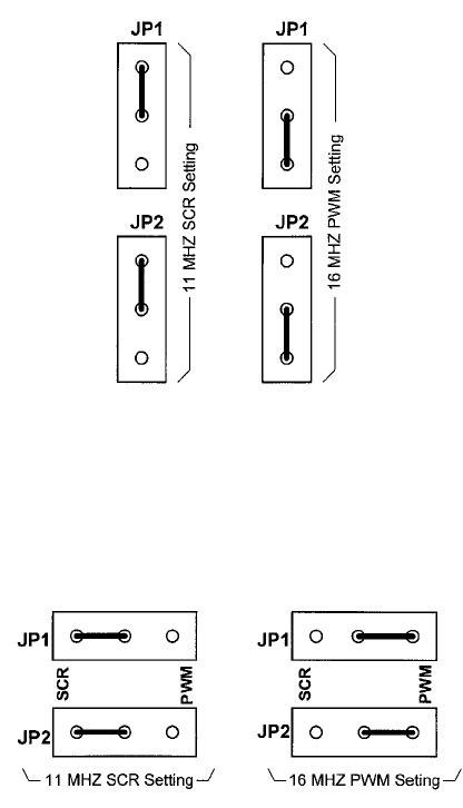
Upper PCA part number 33663-10X is used on C960s & C962s. Upper PCA part number 33662-
10X is used on C964s. There are currently three versions of the upper PCA that may be
encountered in the field. Versions -101 through 105 were only used on SCR treadmills and have
a fixed 11 MHZ clock frequency. Treadmills manufactured starting October 10, 1995 used the
version -106. Theses boards could be used on either SCR or PWM treadmills and could be set
for either 11 MHZ (SCR) or 16 MHZ (PWM) operation (see diagram 1.1). On August 6, 1997 on
version -108 the jumper selection was changed to indicate SCR or PWM (see diagram 1.2).
Diagram 1.1 - UPCA jumpers versions -106 & -107
Diagram 1.2 - UPCA jumpers versions -108 and higher
C960 Series Commercial Treadmill
Page 6
Procedure 2.1 - Running the Diagnostic Program (SCR &
PWM Units)
Placing the C962 or C964 Treadmill in diagnostic mode causes the software to perform the
following operations:
a Test the LEDs mounted on the upper PCA;
b Provide the option of adjusting the lift system;
c Provide the option of adjusting the limit switches;
d Display the odometer setting in either miles or kilometers;
e Display the software version number;
f Display the drive motor power bits;
g For SCR units (PROM Version 2.08 and earlier), display a prompt allowing you to select
between 110- and 220-volts; and
h Provide a method of checking the operation of the keys on the electronic console.
Procedure
1. Plug the power cord into the wall outlet, then position the safety switch at the green dot.
Turn on the treadmill by using the circuit breaker.
2. At the PRESS ENTER FOR PROGRAMS prompt, press and hold the SPEED T, SPEED S,
and INCLINE S keys simultaneously or keys RESET,5,1,7,6,5,7,6,1 sequentially on units
with standard access codes. The LED display test is initiated on the electronic console. (The
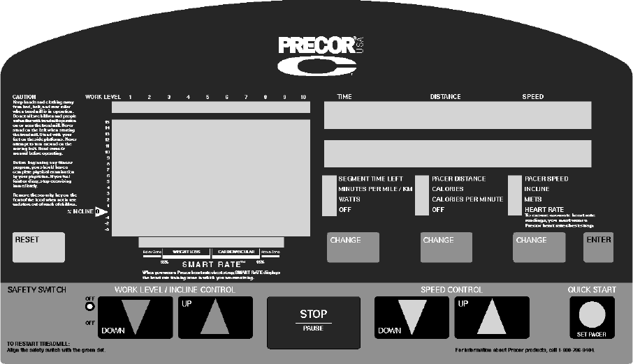
C964 electronic console is shown in Diagram 2.1. Diagram 2.2 is the C962 electronic
console. The C960 electronic console is shown in Diagram 2.3).
3. Watch the electronic console as the display test progresses. This test is programmed to
display the following LED illumination sequence:
a A horizontal series of dashes appear on the left and right display windows; and
b The LEDs to the left of the first column of functions illuminate, followed by the LEDs to
the second and third column.
4. The ADJUST LIFT [YES/DN NO/UP] prompt is displayed. If you wish to adjust the lift...
C960 Series Commercial Treadmill
Page 7
THEN... OTHERWISE...
Press any T key, then continue Press any S key, then skip to Step 6.
with the next step.
Diagram 2.1 - C964 Electronic Display
5. With the message PRESS ENTER WHEN FINISHED displayed on the electronic console,
press the INCLINE S and INCLINE T keys to adjust the slant of the running bed. Press
ENTER when you are finished.
6. The LIMIT SWITCH [YES/DN NO/UP] prompt is displayed. If you wish to check the limit
switches...
THEN... OTHERWISE...
Press any T key, then continue Press any S key, then skip to Step 9.
with the next step.
7. Watch the electronic console. If the three limit switches are adjusted correctly, the following
series of messages is displayed on the electronic console:
GOING TO FIFTEEN PERCENT
AT FIFTEEN PERCENT
GOING TO UPPER LIMIT
GOING TO NEG THREE PERCENT
AT NEGATIVE THREE PERCENT
GOING TO LOWER LIMIT
GOING TO ZERO
C960 Series Commercial Treadmill
Page 8
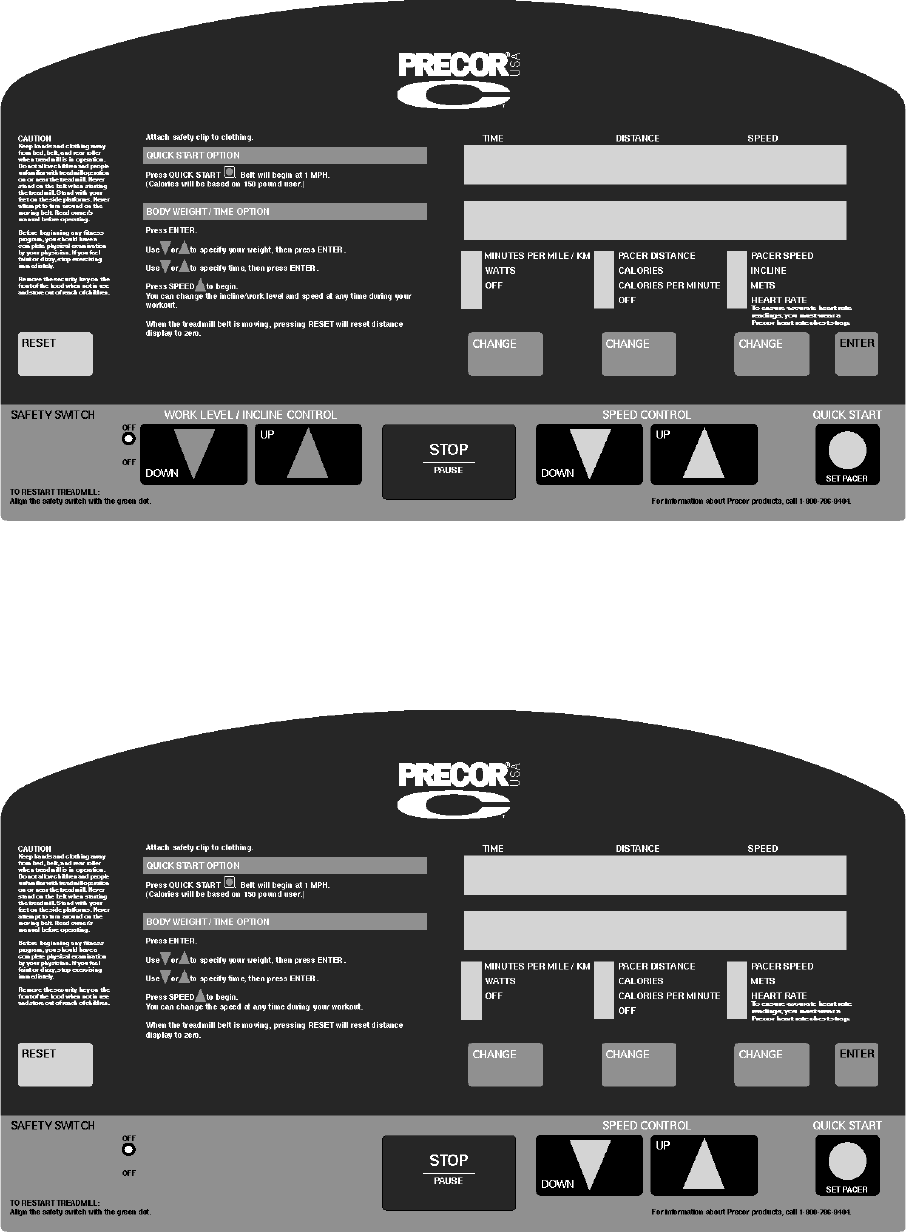
Diagram 2.2 - C962 Electronic Display
Diagram 2.3 - C960 Electronic Display
C960 Series Commercial Treadmill
Page 9
8. If all of the messages listed in Step 7 are displayed on the electronic console...
THEN... OTHERWISE...
The treadmill lift switches are Press RESET to return to the PRESS
calibrated correctly, press ENTER ENTER FOR PROGRAMS prompt,
to continue. then calibrate the lift systems
described in Procedure 4.1.
Note:
Some newer versions of software display the odometer as a separate function. Refer to
procedure 2.4 for these units.
9. The electronic console displays the odometer reading. With the MILE NNNNN or
KILOMETER NNNNN message displayed, press ENTER.
Note:
NNNNN represents the number of miles (or kilometers) travelled on the running belt. The
mileage is recorded on the upper PCA. If a new upper PCA is installed in the treadmill, the
odometer reading will be zero.
10. The electronic console displays the version number of the PROM. With the VERSION N.N
message displayed, press ENTER.
Note:
N.N represents the version number of the PROM currently installed on the upper PCA.
11. The electronic console displays the drive motor power bits. With the POWER BITS NNN
message displayed, press ENTER.
IMPORTANT
Step 12 applies only to SCR units (PROM Version 2.08 and earlier).
12. Press ENTER to display the CHOOSE MOTOR [220/DN 110/UP] prompt. If you are
servicing a 110-volt treadmill, press any S key, then continue with the next step. If you are
servicing a 240-volt unit, press any T key.
13. The electronic console displays the NO KEYS message. Press each of the keys listed in the
left column of Table 2.1. Verify that the message across from each function key name is
displayed on the electronic console as the key is pressed.
Note:
The messages displayed in the right column are displayed as the keys are pressed. The
message NO KEYS is displayed after each key is pressed.
14. When the NO KEYS message is displayed after you test the QUICK START/SET PACER
key, press RESET to return to the PRESS ENTER FOR PROGRAMS prompt.
15. Turn off the treadmill with the circuit breaker, then unplug the power cord from the wall
C960 Series Commercial Treadmill
Page 10
outlet.
C960 Series Commercial Treadmill
Page 11
Table 2.1 - Electronic Console Key Test
KEY TO BE PRESSED MESSAGE TO BE VERIFIED
Left CHANGE Key CHANGE 1
Middle CHANGE Key CHANGE 2
Right CHANGE Key CHANGE 3
ENTER ENTER
INCLINE t INCLINE DOWN
INCLINEs INCLINE UP
STOP/PAUSE STOP
SPEED t SPEED DOWN
SPEED s SPEED UP
QUICK START/SET PACER SET PACER
C960 Series Commercial Treadmill
Page 12
Procedure 2.2 - Running the Diagnostic Program (i Units)
Placing the C962i or C964i Treadmill in diagnostic mode causes the software to perform the
following operations:
a Test the LEDs mounted on the upper PCA;
b Provide the option of calibrating the lift system;
c Display the drive motor power bits;
d Display and test the heart rate function;
e Display the error code log;
f Provide a method of checking the operation of the keys on the electronic console;
g Test the circuit breaker trip function.
Procedure
1. Plug the power cord into the wall outlet, then position the safety switch at the green dot.
Turn on the treadmill by using the circuit breaker.
2. At the PRESS ENTER FOR PROGRAMS prompt, press keys RESET,5,1,7,6,5,7,6,1
sequentially. The LED display test is initiated prompt on the electronic console. (The C964i
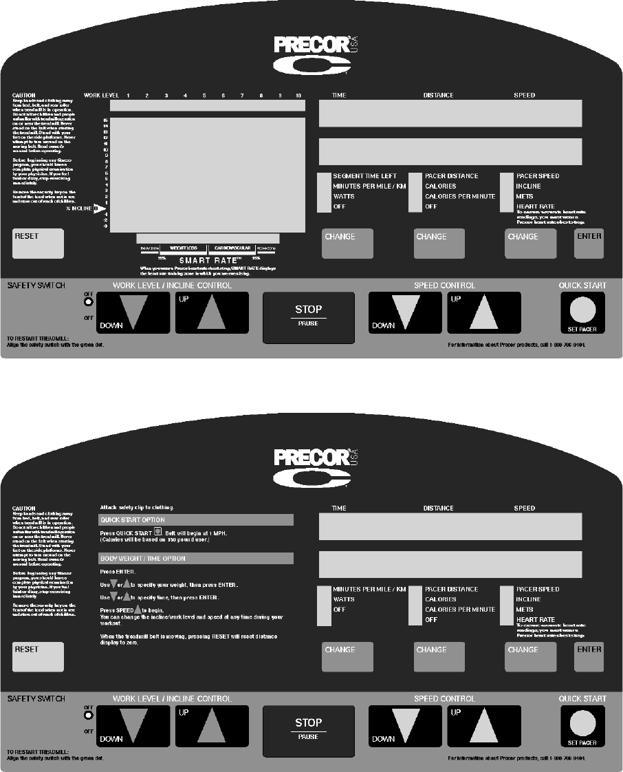
electronic console is shown in Diagram 2.4. The C962i electronic console is shown in
Diagram 2.5).
3. Watch the electronic console as the display test progresses. This test is programmed to
illuminate every LED on the display. It is necessary to watch the test as it proceeds to
determine if an LED does not illuminate. Press the ENTER key to proceed to the next test.
4. The lift calibration setup will be available if required. If you need to calibrate the lift proceed
with step 5, otherwise, press the ENTER key, go to step 6 and choose RECALIBRATE NO.
5. Using the INCLINE S and INCLINE T keys set the treadmill so that the distance from the
bottom front corner of the treadmill frame is 4.3 inches ± .05 inch. When the position is set
press the ENTER key. In step 6 of this procedure, choose RECALIBRATE YES.
6. You will be offered the to choice to either recalibrate the lift or to proceed without
recalibrating the lift. Press one of the S keys to recalibrate the lift or one of the T keys to
proceed without recalibrating the lift.
C960 Series Commercial Treadmill
Page 13
Diagram 2.4 - C964i Electronic Display
Diagram 2.5 - C962i Electronic Display
C960 Series Commercial Treadmill
Page 14
7. The power bits will be displayed. The power bits indicate how much power is being applied
to the drive motor. The power bit reading is a combination of the speed selected and the
load applied to the treadmill. The power bit reading can be used to help determine bed and
belt wear. To display power bits, press the SPEED S key. Observe that the power bit
reading will increase when the speed is increased and/or the load is increased. Press the
ENTER to continue to the next test.
8. Heart rate will be displayed. Either a heart rate test transmitter or chest strap transmitter
may be used. The heart rate will be displayed. Press the ENTER key to proceed to the next
test.
9. The error code log will be displayed. Use the st keys to scroll through the log. Position 1 will
contain the most recent error logged and error 5 will contain the oldest error logged. If more
than five errors have been logged, the most recent error will be entered into position 1, and
all of the existing errors will be pushed down one position. The error that was in position 5
will be lost. If you wish to clear the error code log, press the QUICK START key. Press the
ENTER key to proceed to the next test.
10. The keypad test will be displayed. Press each of the keys on the display panel, the display
will indicate which key was pressed. This test will also check safety switch operation.
11. The next test is the circuit breaker trip test. While the keypad test is still displayed, press and
hold the STOP key. After a few seconds the circuit breaker will trip.
12. The diagnostics program is now complete.
C960 Series Commercial Treadmill
Page 15
Procedure 2.3 - Selecting Club Settings
Selecting United States standard units causes information to be displayed in feet and pounds.
Information is displayed in meters and kilograms if metric units are selected.
Procedure
1. Plug the power cord into the wall outlet, then position the safety switch at the green dot.
Turn on the treadmill by using the circuit breaker.
2. At the PRESS ENTER FOR PROGRAMS prompt, press and hold all three CHANGE keys
simultaneously or keys RESET,5,6,5,1,5,6,5 sequentially on units with standard access
codes until the CHOOSE UNITS [YES/DN NO/UP] prompt is displayed.
3. Use any S or T key to select either the U. S. Standard or Metric measurement system.
4. With the MAX SPEED prompt displayed, use the S or T keys to designate a workout speed
limit. Press ENTER when the desired speed appears.
Note:
For 110-volt treadmills, the maximum workout speed limit is between either 1 and 10 MPH or 1
and 16 KPH. Maximum workout speed limits for 220-volt treadmills range between 1 and 12
MPH or 1 and 20 KPH.
5. With the MAX WORKOUT prompt displayed, use the S or T keys to designate a workout
time limit between 10 and 240 minutes. Press ENTER when the desired time appears.
IMPORTANT
On PWM C960 Series Treadmills, you may choose either English, Spanish, German or French
language options.
6. The MODIFY CUSTOM prompt is displayed. If you plan to customize the program...
THEN... OTHERWISE...
Press any T key, then press Press any S key, then press ENTER
ENTER to return to the PRESS tto return to the PRESS ENTER FOR
ENTER FOR PROGRAMS prompt. PROGRAMS prompt.
Note:
Instructions for designing custom courses are provided in the C964 Owner's Manual.
C960 Series Commercial Treadmill
Page 16
Procedure 2.4 - Displaying the Odometer
Note:
Some older versions of software display the odometer as part of the diagnostics program. Refer
to procedure 2.1 for these units.
1. To access the odometer press the RESET key to return to the start up point, if necessary.
Press keys Speed S and Incline S, simultaneously or keys RESET,6,5 sequentially. The
odometer will displayed in either miles or kilometers depending on club setting selection.
Refer to procedure 2.3.
2. Press the Enter key. The hours in use will be displayed.
3. Press the Enter key. The software version will be displayed.
4. Press the Enter key to exit.
C960 Series Commercial Treadmill
Page 17
Procedure 2.5 - Determining Software Version Numbers
Software version numbers are invaluable for tracking and identifying problems and staying aware
of changes to the operation and features of the product. Software version numbers will usually
appear as two digits separated by a decimal.
Procedure
1. Plug the power cord into the wall outlet, then position the safety switch at the green dot.
Turn on the treadmill by using the circuit breaker.
2. On older software versions access the diagnostics as in procedure 2.1. On newer software
versions enter the odometer program as in procedure 2.4
C960 Series Commercial Treadmill
Page 18
Procedure 2.6 - Documenting Software Problems
When a problem is found with either the software or upper or lower PCAs, record the information
listed below. If you isolated the problem to either the PROM, upper PCA, or lower PCA, include
the information you recorded with the malfunctioning PROM or PCA when you ship it to Precor.
When a problem occurs, record the following information:
• Model and serial number
• Software version number
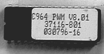
Determine the version number of the PROM mounted on the upper PCA as described in
Procedure 2.5 or by looking at the label on the PROM. See Diagram 2.6
• Program number running when the problem occurred
• A description of:
a What happened or failed to happen.
b The action taken by the user just before the problem occurred.
c Problem-related information (such as how far into the program the problem occurred,
the work level being used when the problem occurred, etc.).
• The frequency of occurrence.
Diagram 2.6 - Prom
C960 Series Commercial Treadmill
Page 19
Section Three - Checking Treadmill Operation
This section provides you with a quick method of checking treadmill operation. Check treadmill
operation at the end of a maintenance procedure and when it is necessary to ensure that the
treadmill is operating properly.
Procedure
1. Plug the power cord into the wall outlet, then turn on the treadmill with the circuit breaker.
2. Place the treadmill in Manual Mode. Adjust the speed of the running belt to 2–3 m.p.h.
Operate the treadmill for at least 5 minutes.
a Concentrate on the feel of the running belt and the sound of the drive motor and rollers.
Be on the alert for unusual noises, smells, or vibrations.
b. On SCR units, measure and log the AC input current under loaded and unloaded con-
ditions. On PWM units, log the power bits under loaded and unloaded conditions.
c Observe the Leds on the electronic console. Make sure that each LED lights as the
information corresponding to that LED is displayed on the electronic console.
3. Press the STOP key. When the treadmill comes to a stop, view the electronic console as the
treadmill scans time, speed, distance and percent.
Note:
If you are servicing a C960 Treadmill, skip Steps 4 and 5.
4. Press the INCLINE S key while viewing the electronic console. Confirm that the treadmill
inclines and the incline display increments to twelve percent as the INCLINE S key is
pressed.
5. Press the INCLINE T key while viewing the electronic console. Confirm that the running bed
returns to a level position and the incline display decrements to minus three percent as the
INCLINE T key is pressed.
6. Return the treadmill to 0% incline and turn off the treadmill with the circuit breaker, then
unplug the treadmill from the wall outlet.
C960 Series Commercial Treadmill
Page 20
Procedure 4.1 - Calibrating the Lift Assembly on C962 &
C964 SCR & PWM Units
WARNING
Always turn off the circuit breaker and unplug the treadmill before you remove the treadmill hood.
1. If the treadmill is not already at zero percent incline, press any key when the CALIBRATE
LIFT PRESS ANY KEY prompt is displayed.
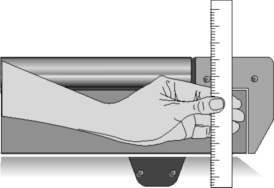
2. Using the ruler, measure the distance between the floor and the top of the front and back
ends of the side rail (see Diagram 4.1).
Note:
The distance between the floor and the top of the front end of the side rail should be 11 inches.
Diagram 4.1 - Measuring the Ends of the Side Rail
C960 Series Commercial Treadmill
Page 21
3. If the distances recorded in the previous step are equal to within 1/4 inch...
THEN... OTHERWISE...
Skip to Step 17. Continue with the next step.
4. At the PRESS ENTER FOR PROGRAMS prompt, press and hold the ENTER key.
5. Press ENTER when the display test starts.
6. With the ADJUST LIFT [YES/DN NO/UP] prompt displayed, press any T key. The
message PRESS ENTER WHEN FINISHED is displayed on the electronic console.
7. If the distance measured at the front of the side rail is larger than the distance measured at
the back of the side rail...
THEN... OTHERWISE...
Press the INCLINE T key until Press the INCLINE S key until the
the front and back treadmill front and back treadmill measurements
measurements are equal; then are equal; then press RESET.
press RESET.
8. Turn off the treadmill with the circuit breaker, then unplug the power cord from the wall
outlet.
WARNING
Before continuing with this procedure, review the Warning and Caution statements listed in
Section One of the Commercial Treadmill Service Manual.
9. Remove the hood.
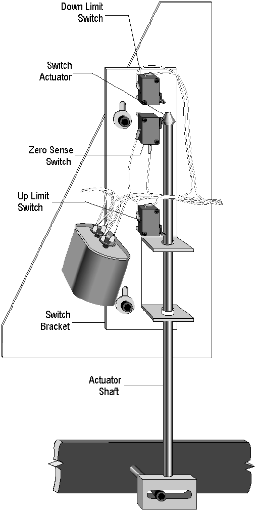
10. Check the position of the zero sense switch in relation to the switch actuator (see Diagram
4.2).
11. If the widest point of the switch actuator is lined up with the center of the wheel on the zero
sense switch...
THEN... OTHERWISE...
The zero sense switch is calibrated The switch bracket must be adjusted;
correctly; skip to Step 16. continue with the next step.
C960 Series Commercial Treadmill
Page 22
Diagram 4.2 - Limit Switch Bracket Assembly
WARNING
When power is applied to the treadmill, the wires connected to the upper and lower limit switches
carry 110 volts (or 220 volts if you are servicing a 220-volt treadmill). Turn off the treadmill and
unplug the power cord from the wall outlet before you perform the following steps.
C960 Series Commercial Treadmill
Page 23
12. Loosen the socket head bolts and washers that secure the switch bracket to the lift platform
(see Diagram 4.2).
Note:
The zero sense switch can be actuated if the center of the wheel is slightly above or slightly
below the widest point of the switch actuator. However, for best results, adjust the position of the
zero sense switch as described in the following step.
13. If the center of the wheel on the zero sense switch is above the widest point of the switch
actuator...
THEN... OTHERWISE...
Move the switch bracket down until Move the switch bracket up until the
the widest part of the actuator is widest part of the actuator is centered
centered on the wheel on the zero on the wheel on the zero sense switch;
sense switch; then continue with then continue with the next step.
the next step.
14. Tighten the socket head bolts and washers that secure the switch bracket to the lift platform.
15. Replace the hood
16. Check the operation of the treadmill as described in Section 3 of this appendix.
IMPORTANT
If the electronic console displays the diagnostic message LIFT ERROR PRESS STOP when you
incline or decline the running bed to its maximum limits, repeat this procedure.
C960 Series Commercial Treadmill
Page 24
Procedure 4.2 - Calibrating the Lift Assembly on C962i &
C964i Treadmills
Note:
On April 20, 2000 the C962i and C964i treadmills were equipped with a lift utilizing an internal lift
potentiometer. Use the calibration procedure in steps 1-4 for units manufactured prior to April 20,
2000. For units manufactured after March 26, 2000, skip to step 5.
1. Enter the diagnostics program by pressing keys RESET,5,1,7,6,5,7,6,1, sequentially.
Proceed to the lift calibration portion of the diagnostics routine.
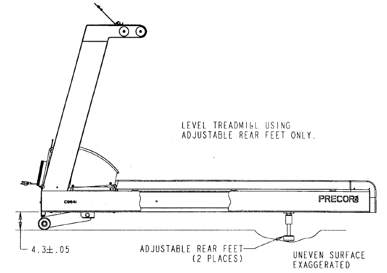
2. Use the INCLINE S and INCLINE T keys to set the distance between the front, bottom
corner of the frame to the floor at 4.3 inches ± 0.05 inch. See diagram 4.3. After the 4.3 inch
distance has been set, press the ENTER key. At the message PRESS UP TO
RECALIBRATE / PRESS DOWN FOR NO RECALIBRATION, press one of the S keys.
3. Exit the diagnostics program.
4. Check the rear bottom corners of the frame. If the rear corners of the frame do not measure
4.3 inches to the floor, adjust the rear feet accordingly. If the rear feet need to be adjusted
more than 1 inch, the treadmill should be relocated to a more level location.
Note:
It is important that the lift is calibrated first (steps 1 & 2) before the rear height is adjusted.
Diagram 4.3 - Lift Calibration Dimensions
C960 Series Commercial Treadmill
Page 25
5. Set the on/off switch in the off position. Lay the treadmill on its left side.
6. Remove the bolt that fastens the lower end of the lift motor to the lift platform.
7. Set the on/off switch in the on position. Enter the diagnostics program by pressing keys
RESET,5,1,7,6,5,7,6,1, sequentially. Proceed to the lift calibration portion of the diagnostics
routine.
8. Using the INCLINE S and INCLINE T keys, set the lift calibration number to 78.
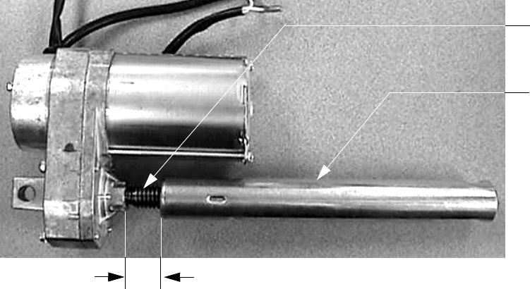
9. Exit the diagnostics program and set the on/off switch in the off position. Taking care not to
rotate the lift motor drive screw, rotate the lift motor tube until the measurement between the
lift motor frame and the top of the lift tube is 1-7/8 inches. See Diagram 4.4.
Diagram 4.4 - Lift Motor Calibration
10. Fasten the lift motor tube to the lift platform with the bolt removed in step 6. Do not rotate the
lift tube any more than is necessary to align the lift tube mounting hole with the lift platform
mounting hole.
11. Set the treadmill in an upright position. The distance from the front of the treadmill to the
floor should be 4.3 inches. See Diagram 4.3.
12. Check the rear bottom corners of the frame. If the rear corners of the frame do not measure
4.3 inches to the floor, adjust the rear feet accordingly. If the rear feet need to be adjusted
more than 1 inch, the treadmill should be relocated to a more level location.
1-7/8
Lift Motor
Drive Screw
Lift Motor Tube
C960 Series Commercial Treadmill
Page 26
Procedure 4.3 - Inspecting and Adjusting Safety Switch
Alignment
WARNING
Always turn off the circuit breaker and unplug the treadmill before you remove the treadmill hood.
Inspecting the Alignment of the Safety Switch
1. Turn off the treadmill with the circuit breaker, then unplug the power cord from the wall
outlet.
2. Attach the safety clip to your clothing at waist level, then watch the safety switch as you step
backwards.
Note:
Do not attach the safety clip too securely.
3. If the safety switch tripped before the safety clip came off your clothing...
THEN... OTHERWISE...
The safety switch is adjusted Continue with the next step.
correctly; skip to Step 15
Adjusting the Alignment of the Safety Switch
4. Remove the screws that secure the display housing to the display housing mounting plate.
5. Place your right hand on the two right upper display housing mounting tabs. Place your left
hand on the left tabs.
6. Push the right tabs towards the right targa upright and the left tabs towards the left targa
upright, while lifting the display housing from the mounting plate. Support the display
housing on the front handrails.
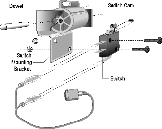
7. Loosen the screws and nuts that secure the safety limit switch to the switch mounting
bracket (see Diagram 4.5).
8. Slide the safety switch away from the cam.
9. Tighten the screws and nuts that secure the safety limit switch to the switch mounting
bracket.
C960 Series Commercial Treadmill
Page 27
Diagram 4.5 - Safety Switch Assembly
10. Line up the tabs on the display housing with the holes on the display housing mounting
plate.
11. Gently press the display housing onto the mounting plate until the tabs are pushed into the
holes.
12. Attach the safety clip to your clothing at waist level, then watch the safety switch as you step
backwards.
13. If the safety switch tripped before the safety clip came off your clothing...
THEN... OTHERWISE...
The safety switch is adjusted correctly; Return to Step 5.
continue with the next step.
14. Replace the three screws that secure the upper display housing to the display housing
mounting plate.
C960 Series Commercial Treadmill
Page 28
Procedure 5.1 - Troubleshooting the Keypad and Upper PCA
If the function keys on the electronic console are unresponsive, the problem may be either the
upper PCA or keypad. This troubleshooting procedure gives you the information you need to
determine which of these components is malfunctioning.
Procedure
1. Set the circuit breaker in the “off” position.
WARNING
Before continuing with this procedure, review the Warning and Caution statements listed in
Section One of the Residential Treadmill Service Manual.
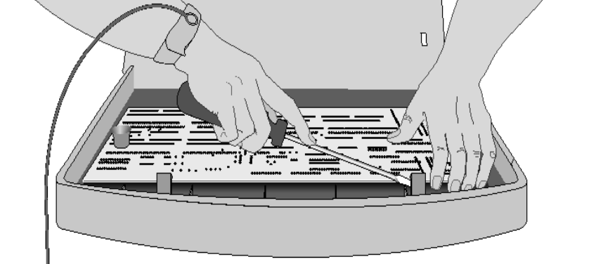
2. Remove the screws that secure the upper display assembly to the upper handrail. Carefully,
pull some excess interconnect cable out from the targa upright. Rotate the display housing,
so that the rear of the upper PCA is facing upward, and set the display housing on the upper
handrail.
3. Attach the wrist strap to your arm, then connect the ground lead of the wrist strap to the
treadmill frame.
Diagram 5.1 - Removing the Upper PCA
4. Set the voltmeter to a range that will conveniently read +6 Vdc.
5. Set the circuit breaker in the “on” position.
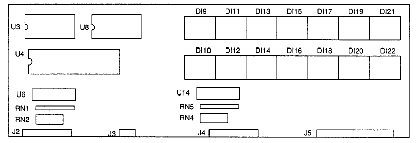
6. Use a DVM, set for DC volts, and read between pin 5 of J4 and the each of the pins in Table
5.1 (no keys pressed) and Table 5.2 (with the appropriate key pressed)...
C960 Series Commercial Treadmill
Page 29
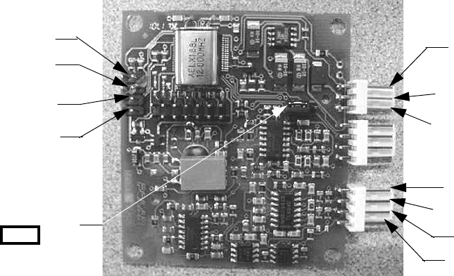
Diagram 5.2 - Upper PCA Component Layout
Table 5.1 - Voltage Test Points (Function Keys Not Pressed)
PLACE THE POSITIVE LEAD OF THE THE VOLTMETER SHOULD
VOLTMETER ON... READ...
Pin 1 of J4 5 Vdc ± 500 mVdc
Pin 2 of J4 5 Vdc ± 500 mVdc
Pin 3 of J4 5 Vdc ± 500 mVdc
Pin 4 of J4 5 Vdc ± 500 mVdc
Pin 6 of J4 5 Vdc ± 500 mVdc
Pin 7 of J4 5 Vdc ± 500 mVdc
Pin 8 of J4 5 Vdc ± 500 mVdc
Pin 9 of J4 5 Vdc ± 500 mVdc
Pin 4 of J2 5 Vdc ± 500 mVdc
Pin 5 of J2 5 Vdc ± 500 mVdc
Pin 6 of J2 5 Vdc ± 500 mVdc
Table 5.2 - Voltage Test Points (Function Keys Pressed)
Place the positive lead At the electronic The voltmeter
of the voltmeter on... console, press... should read between...
Pin 1 of J4 Left CHANGE key 0 Vdc and 350 mVdc
Pin 2 of J4 STOP key 0 Vdc and 350 mVdc
Pin 3 of J4 SPEED T key 0 Vdc and 350 mVdc
Pin 4 of J4 SPEED S key 0 Vdc and 350 mVdc
Pin 6 of J4 QUICK START key 0 Vdc and 350 mVdc
Pin 7 of J4 ENTER key 0 Vdc and 350 mVdc
Pin 8 of J4 Right CHANGE key 0 Vdc and 350 mVdc
Pin 9 of J4 Center CHANGE key 0 Vdc and 350 mVdc
Pin 4 of J2 RESET key 0 Vdc and 350 mVdc
Pin 6 of J2 INCLINE T key 0 Vdc and 350 mVdc
Pin 7 of J2 INCLINE S Tkey 0 Vdc and 350 mVdc
C960 Series Commercial Treadmill
Page 30
7. If the voltage readings match those listed in Tables 5.1 and 5.2 and one or more keys do not
function, replace the upper PCA.
8. If the voltage readings in Table 5.1 are incorrect, disconnect the keypad cable from the key
pad connector and repeat the voltage measurements in 5.1. If the voltage readings are now
correct, replace the display housing (keypad). If the voltage readings are still incorrect,
replace the upper PCA.
9. If the voltage readings in Table 5.1 are correct and one or more voltage readings in Table
5.2 are incorrect, replace the display housing (keypad).
10. Set the circuit breaker in the “off” position.
11. If necessary, carefully re-connect the keypad cable to the keypad connector.
12. Remove the ground lead of the wrist strap from the treadmill frame, then remove the wrist
strap from your arm.
13. Position the display enclosure on the display plate. Install the screws that secure the display
enclosure to the display plate.
14. Check the operation of the treadmill as described in Section Three of this appendix.
C960 Series Commercial Treadmill
Page 31
Procedure 5.2 - Troubleshooting the Lift System
(SCR & PWM Units)
Lift System Description:
The lift system on these units consists of an AC line voltage driven lift motor (120 Vac or 240
Vac), a hall effect rotation sensor and three position location switches. The lift system orients
itself by locating the zero sense switch when the treadmill is powered up. When the zero sense
switch is activated the system recognizes that physical position as 0% incline. If the zero sense
switch is activated when the treadmill is powered up, the system proceeds directly into the
normal program mode. If the zero sense switch is not activated when the treadmill is powered up,
the system performs a self calibration procedure. The purpose of the self calibration procedure is
to locate the zero sense switch (0% incline). The user will be prompted to press any key to
commence the lift calibration. The treadmill will go up 4%, because the lowest the treadmill could
have been at power up is -3%. If the treadmill does not locate the zero sense switch by going up
4%, it will stop and then go down until it activates the zero sense switch. The system will then
proceed to the normal program mode. Once the 0% lift position has been located, the system
tracks any subsequent lift operations by counting motor revolutions. A hall effect sensor is
mounted on a bracket that is next to a hub that is attached to the lift motor shaft. As the lift motors
operates, a magnet mounted in the hub, passes the hall effect sensor once per motor revolution.
The hall effect sensor send one pulse to the lift control system per revolution. The system knows
how far the lift travels per revolution and by counting revolutions (hall effect sensor pulses),
knows the current lift position. The other two position switches (upper and lower limit) do not
come into play during normal operation. If either switch is activated it means that the lift has
moved beyond its normal range of motion. When either limit switch is activated, power is
removed from the lift motor. Removing power from the lift motor, protects the lift system from
physical damage.
Note:
All resistance measurements must be performed with power removed from the treadmill.
Performing resistance measurements with voltage applied may damage your ohmmeter.
Procedure
1. If the lift motor operates but creates a lift error (error 40, 41 or 43) go to step 8. If the lift
motor will not move continue with step 2.
2. Put the treadmill in a condition in which the lift motor is ready to be operated (for example,
quick start into the manual program). Using an AC voltmeter, monitor the voltage across the
lift capacitor and press one of the incline keys. Approximately 1.4 times the AC input voltage
should appear on the lift capacitor when an incline key is pressed. Approximately 170 Vac
on a 120 Vac unit or approximately 340 Vac on a 240 Vac unit. The actual lift capacitor
voltage will vary with the AC input voltage. If AC line voltage or 1.4 times line voltage is on
the lift capacitor go to step 6. If no AC voltage is on the lift capacitor, continue with step 3.
C960 Series Commercial Treadmill
Page 32
3. Set the treadmill circuit breaker in the “off” position. Remove the 2 amp lift fuse (F2) from the
lower PCA. Using an ohmmeter, measure the fuse resistance. The fuse should measure
approximately 1W or less. If the fuse is open or significantly higher than 1W, replace the
fuse. If the fuse was bad, perform the test in step 4 before applying power to the lift. If the
fuse was good continue with step 5.
4. Using an ohmmeter, measure the resistance across the lift capacitor terminals. The Lower
PCA resistance should be extremely high (megohms), the capacitor resistance should be
extremely high (megohms) and the lift motor winding should read approximately 34W (120
Vac units) or 122W (240 Vac units). Therefore, if the measurement is significantly lower
than 34W or 122W, disconnect both red leads from the lift capacitor. Measure the resistance
between the black leads on the lift capacitor and red lead to the lower PCA. If it measures
significantly low, replace the lower PCA. Measure the resistance between the black leads on
the lift capacitor and red lead to the lift motor. If it measures significantly low, replace the lift
motor. Measure the resistance between the black leads on the lift capacitor and other
terminal of the lift capacitor. If it measures significantly low, replace the lift capacitor.
5. At this point the lift fuse is good, but there is no AC voltage on the lift capacitor when the lift
is actuated. There are three potential causes for this condition. They are lower PCA, ribbon
cable or upper PCA. There are no good means of troubleshooting these components other
than substituting known good components. Replace only one component at a time. If the
component that you replaced does not correct the problem, replace the original component.
Try substituting the lower PCA first, the ribbon cable second and the upper PCA third. If you
have performed all of the above procedures and have been unable to correct the problem,
call Precor Customer Support.
6. Using an ohmmeter, measure the resistance across the lift capacitor terminals. The lower
PCA resistance should be extremely high (megohms), the capacitor resistance should be
extremely high (megohms) and the lift motor winding should read approximately 34W or
122W. If it measures significantly high or open (•), replace the lift motor.
7. If the resistance measurement in step 6 was approximately 34W (120 VAC units) or 122W
(240 VAC units), replace the lift capacitor. If you have performed all of the above procedures
and have been unable to correct the problem, call Precor Customer Support.
8. Typically, when the lift is able to physically move but causes a lift error, the problem is in the
lift position identification system (rotation sensor and zero sense switch).
9. Connect a DC voltmeter between the white wire (term. 2 of J3) and the red wire (term. 4 of
J3) on the lower PCA. Set the treadmill circuit breaker in the “on” position and slowly rotate
the hub at the bottom of the lift motor by hand. The DC voltmeter should read approximately
0 Vdc when the magnet in the hub is not near the hall effect sensor and approximately 5
VDC when the magnet is near the hall effect sensor. If the voltage switches between 0 and
5 Vdc as the magnet passes the hall effect sensor continue with step 11.
C960 Series Commercial Treadmill
Page 33
10. Measure the voltage between the red wire (term. 4 of J3) and the black wire (term 1 of J3).
The voltage should read a constant 5 Vdc. If the voltage is 0 or significantly lower than 5
Vdc, disconnect the rotation sensor connector from the lower PCA. Measure the voltage
between the red wire (term. 4 of J3) and the black wire (term 1 of J3) on the lower PCA. If
the voltage is still 0 Vdc or significantly low, replace the lower PCA. If the voltage is now
correct, replace the hall effect sensor.
Note:
If possible set the lift in a position that does not operate the zero sense switch. The zero sense
switch may be operated by hand to perform the tests in step 11.
11. At this point the hall effect sensor is functioning normally, but lift errors occur. With a DC
voltmeter measure the voltage across the zero sense (center) switch. It should measure
approximately 0 Vdc when the switch is not operated and approximately 5 Vdc when the
switch is operated. If the operated voltage is 0 Vdc or significantly low, remove both blue
wires from the zero sense switch. Measure the voltage between the two blue wires. If the
voltage is now correct replace the zero sense switch. If the voltage is still O Vdc or
significantly low, replace the lower PCA.
12. At this point the hall effect sensor and the zero sense switch are functioning normally, but lift
errors occur. There are three potential causes for this condition. They are lower PCA, ribbon
cable or upper PCA. There are no good means of troubleshooting these components other
than substituting known good components. Replace only one component at a time. If the
component that you replaced does not correct the problem, replace the original component.
Try substituting the lower PCA first, the ribbon cable second and the upper PCA third. If you
have performed all of the above procedures and have been unable to correct the problem,
call Precor Customer Support.
C960 Series Commercial Treadmill
Page 34
Procedure 5.3 - Troubleshooting the Lift System (i Units)
Lift System Description:
The C962i and C964i treadmills were manufactured with two types of lift systems. Units built prior
to April 20, 2000 consisted of an AC line voltage driven lift motor (120 Vac or 240 Vac) and an
external 10 KW potentiometer. The 10KW potentiometer rotates as the lift operates and indicates
the current lift position. The lift system is factory calibrated, but will require re-calibration
whenever the upper PCA is replaced (refer to procedure 4.2). Units built after April 19, 2000,
utilized a lift motor with an internal 1 KW potentiometer. Use the procedure in steps 1-14 for
trpubleshooting units manufactured prior to April 20, 2000. Start with step 15 for units
manufactured after April 19, 2000.
Note:
All resistance measurements must be performed with power removed from the treadmill.
Performing resistances measurements with voltage applied may damage your ohmmeter.
Whenever the upper PCA is replaced on a C962i or C964i manufactured prior April 20, 2000, the
lift system must be re-calibrated.
1. If the lift motor operates but creates a lift error (error 40, 41 or 42) go to step 8. If the lift
motor will not move continue with step 2.
2. Put the treadmill in a condition in which the lift motor is ready to be operated (for example,
quick start into the manual program). Using an AC voltmeter, monitor the voltage across the
lift capacitor and press one of the incline keys. Approximately 1.4 times the AC input voltage
should appear on the lift capacitor when a incline key is pressed. Approximately 170 Vac on
a 120 Vac unit or approximately 340 Vac on a 240 Vac unit. The actual lift capacitor voltage
will vary with the AC input voltage. If AC line voltage or 1.4 times line voltage is on the lift
capacitor go to step 6. If no AC voltage is on the lift capacitor, continue with step 3.
3. Set the treadmill circuit breaker in the “off” position. Remove the 2 amp lift fuse (F2) from the
lower PCA. Using an ohmmeter, measure the fuse resistance. The fuse should measure
approximately 1W or less. If the fuse is open (•) or significantly higher than 1W, replace the
fuse. If the fuse was bad, perform the test in step 4 before applying power to the lift. If the
fuse was good continue with step 5.
4. Using an ohmmeter, measure the resistance across the lift capacitor terminals. The lower
PCA resistance should be extremely high (megohms), the capacitor resistance should be
extremely high (megohms) and the lift motor winding should read approximately 34W (120
Vac units) or 122W (240 Vac units). Therefore, if the measurement is significantly lower
than 34W or 122W, disconnect both red leads from the lift capacitor. Measure the resistance
between the black leads on the lift capacitor and red lead to the lower PCA. If it measures
significantly low, replace the lower logic/lift PCA. Measure the resistance between the black
leads on the lift capacitor and red lead to the lift motor. If it measures significantly low,
replace the lift motor. Measure the resistance between the black leads on the lift capacitor
and other terminal of the lift capacitor. If it measures significantly low, replace the lift
capacitor.
C960 Series Commercial Treadmill
Page 35
5. At this point the lift fuse is good, but there is no AC voltage on the lift capacitor when the lift
is actuated. There are three potential causes for this condition. They are lower logic/lift PCA,
ribbon cable or upper PCA. There are no good means of troubleshooting these components
other than substituting known good components. Replace only one component at a time. If
the component that you replaced does not correct the problem, replace the original
component. Try substituting the lower PCA first, the ribbon cable second and the upper PCA
third.
6. If you have performed all of the above procedures and have been unable to correct the
problem, call Precor Customer Support.
7. Using an ohmmeter, measure the resistance across the lift capacitor terminals. The lower
logic/lift PCA resistance should be extremely high (megohms), the capacitor resistance
should be extremely high (megohms) and the lift motor winding should read approximately
34W or 122W. If it measures significantly high or open (•), replace the lift motor.
8. If the resistance measurement in step 6 was approximately 34W (120 VAC units) or 122W
(240 VAC units), replace the lift capacitor. If you have performed all of the above procedures
and have been unable to correct the problem, call Precor Customer Support.
9. Typically, when the lift is able to physically move but causes a lift error, the problem is in the
lift position identification system (lift potentiometer or lift calibration).
10. Measure the voltage between the red wire (term. 1 of J1) and the black wire (term 3 of J1)
on the lower PCA. The voltage should measure approximately 5 Vdc. If the voltage is 0 Vdc
or significantly low, continue with step 11. If the voltage is correct go to step 12.
11. Disconnect the J1 connector from the lower logic/lift PCA. Measure the voltage between
term.1 of J1 and term 3 of J1on the lower PCA. If the voltage is still 0 Vdc or significantly low
replace the lower logic/lift PCA. If the voltage is correct with the J1 connector disconnected,
replace the potentiometer assembly.
12. Disconnect the J1 connector from the lower logic/lift PCA. With an ohmmeter, measure the
resistance between the red wire (term. 1 of J1) and the black wire (term 3 of J1). The
measurement should be approximately 10KW. With an ohmmeter, measure the resistance
between the red wire (term. 1 of J1) and the white wire (term 2 of J1)and measure the
resistance between the white wire (term. 2 of J1) and the black wire (term 3 of J1). The sum
of the last two measurements should total approximately 10 KW.
13. If either of the two 10 KW measurements are open (•) or significantly low or high, replace the
potentiometer assembly.
14. If you have performed all of the above procedures and have been unable to correct the
problem, call Precor Customer Support.
15. If the lift motor operates but creates a lift error (error 40, 41 or 42) go to step 22. If the lift
motor will not move continue with step 2.
C960 Series Commercial Treadmill
Page 36
16. Put the treadmill in a condition in which the lift motor is ready to be operated (for example,
quick start into the manual program). Using an AC voltmeter, monitor the voltage across the
lift capacitor and press one of the incline keys. Approximately 1.4 times the AC input voltage
should appear on the lift capacitor when a incline key is pressed. Approximately 170 Vac on
a 120 Vac unit or approximately 340 Vac on a 240 Vac unit. The actual lift capacitor voltage
will vary with the AC input voltage. If AC line voltage or 1.4 times line voltage is on the lift
capacitor go to step 20. If no AC voltage is on the lift capacitor, continue with step 17.
17. Set the treadmill circuit breaker in the “off” position. Remove the 2 amp lift fuse (F2) from the
lower PCA. Using an ohmmeter, measure the fuse resistance. The fuse should measure
approximately 1W or less. If the fuse is open (•) or significantly higher than 1W, replace the
fuse. If the fuse was bad, perform the test in step 18 before applying power to the lift. If the
fuse was good continue with step 19.
18. Using an ohmmeter, measure the resistance across the lift capacitor terminals. The lower
PCA resistance should be extremely high (megohms), the capacitor resistance should be
extremely high (megohms) and the lift motor winding should read approximately 32W (120
Vac units) or 115W (240 Vac units). Therefore, if the measurement is significantly lower
than 32W or 115W, disconnect both red leads from the lift capacitor. Measure the resistance
between the black leads on the lift capacitor and red lead to the lower PCA. If it measures
significantly low, replace the lower logic/lift PCA. Measure the resistance between the black
leads on the lift capacitor and red lead to the lift motor. If it measures significantly low,
replace the lift motor. Measure the resistance between the black leads on the lift capacitor
and other terminal of the lift capacitor. If it measures significantly low, replace the lift
capacitor.
19. At this point the lift fuse is good, but there is no AC voltage on the lift capacitor when the lift
is actuated. There are three potential causes for this condition. They are lower logic/lift PCA,
ribbon cable or upper PCA. There are no good means of troubleshooting these components
other than substituting known good components. Replace only one component at a time. If
the component that you replaced does not correct the problem, replace the original
component. Try substituting the lower PCA first, the ribbon cable second and the upper PCA
third.
20. If you have performed all of the above procedures and have been unable to correct the
problem, call Precor Customer Support.
21. Using an ohmmeter, measure the resistance across the lift capacitor terminals. The lower
logic/lift PCA resistance should be extremely high (megohms), the capacitor resistance
should be extremely high (megohms) and the lift motor winding should read approximately
32W or 115W. If it measures significantly high or open (•), replace the lift motor.
22. If the resistance measurement in step 6 was approximately 32W (120 VAC units) or 115W
(240 VAC units), replace the lift capacitor. If you have performed all of the above procedures
and have been unable to correct the problem, call Precor Customer Support.
23. Typically, when the lift is able to physically move but causes a lift error, the problem is in the
lift position identification system (lift potentiometer or lift calibration).
C960 Series Commercial Treadmill
Page 37
24. Measure the voltage between the red wire (term. 1 of J1) and the black wire (term 3 of J1)
on the lower PCA. The voltage should measure approximately 5 Vdc. If the voltage is 0 Vdc
or significantly low, continue with step 11. If the voltage is correct go to step 12.
25. Disconnect the J1 connector from the lower logic/lift PCA. Measure the voltage between
term.1 of J1 and term 3 of J1on the lower PCA. If the voltage is still 0 Vdc or significantly low
replace the lower logic/lift PCA. If the voltage is correct with the J1 connector disconnected,
replace the potentiometer assembly.
26. Disconnect the J1 connector from the lower logic/lift PCA. With an ohmmeter, measure the
resistance between the red wire (term. 1 of J1) and the black wire (term 3 of J1). The
measurement should be approximately 1KW. With an ohmmeter, measure the resistance
between the red wire (term. 1 of J1) and the white wire (term 2 of J1)and measure the
resistance between the white wire (term. 2 of J1) and the black wire (term 3 of J1). The sum
of the last two measurements should total approximately 1 KW.
27. If either of the two 1 KW measurements are open (•) or significantly low or high, replace the
lift motor assembly.
28. If you have performed all of the above procedures and have been unable to correct the
problem, call Precor Customer Support.
C960 Series Commercial Treadmill
Page 38
Procedure 5.4 - Troubleshooting the Speed Sensor
Note:
The speed sensor is a hall effect sensor that emits a pulse when a flywheel lobe passes it. The
speed control circuit processes the pulse train emitted by the speed sensor. The speed sensor
signal is a real time representation of the operating speed of the treadmill. The speed control
circuit compares the real time speed (speed sensor output) with the speed that it expects the
treadmill to be operating at and acts accordingly to control treadmill speed or initiate an error
code sequence, if necessary. Typically, if a problem exists with the speed sensor the drive motor
will operate (perhaps only briefly) before a speed related error occurs (errors 20-26).
Note:
Some speed sensor have red, black and white wires and some have red, black and green wires.
The following procedures will assume red, black and white wires. If the speed sensor on the unit
under test has red black and green wires, perform your test procedures using the green wire
instead of the white wire. The white and green wires serve the same function.
1. Set the treadmill circuit breaker in the “on” position. Using a DC voltmeter, measure the
voltage between terminal 1 of J5 (red wire) and terminal 3 of J5 (white wire) on the lower
PCA. Slowly, rotate the drive motor flywheel. The voltage should read approximately 5 Vdc
as a flywheel lobe passes the speed sensor and approximately 0 Vdc when a flywheel lobe
is not in front of the speed sensor.
2. If the voltage in step 1 is correct, go to step 5. If the voltage in step 1 is 0 Vdc or significantly
low when a flywheel lobe passes the speed sensor, continue with step 3.
3. Measure the voltage between terminal 1 of J5 (red wire) and terminal 4 of J5 (black wire) on
the lower PCA. The voltage should read approximately 5 Vdc.
4. If the voltage is missing or significantly low, disconnect the speed sensor plug from the lower
PCA. Measure the voltage between pins 1 & 4 of the J5 plug on the lower PCA. If the
voltage is approximately 5 Vdc, replace the speed sensor. If the voltage is missing or
significantly low, replace the lower PCA.
5. At this point the speed sensor output is good, but speed error occur. There are three
potential causes for this condition. They are ribbon cable, upper PCA or lower PCA. There
are no good means of troubleshooting these components other than substituting known
good components. Replace only one component at a time. If the component that you
replaced does not correct the problem, replace the original component. Try substituting the
ribbon cable first, the upper PCA second and the lower PCA third.
6. If you have performed all of the above procedures and have been unable to correct the
problem, call Precor Customer Support.
C960 Series Commercial Treadmill
Page 39
Procedure 5.5 - Troubleshooting Hand Held Heart Rate
Circuit Description
The hand held heart rate system is actually a dual system, that is, it can accept a heart rate
signal from either the hand held heart rate contacts on the units handlebar or from a Polar heart
rate chest strap transmitter. Refer to Diagram 5.3 and verify that no jumpers are equipped on
J13, J14, J15 or J16. Also, verify that there is a jumper equipped on the internal chest strap
setting. The internal chest strap setting is the two left hand pins on the three pin connector as
shown below in Diagram 5.3. These settings allow the heart rate system to operate on the
internal chest strap receiver with the chest strap heart rate priority. That is, if both a chest strap
and hand heart rate signal is being received, the system will accept the chest strap signal and
ignore the hand held signal. If a chest strap signal is not being received, the system will accept
the hand held signal.
Note:
There are four typical failure modes for the hand held/chest strap heart rate system. They are:
1 - hand held is normal - no chest strap reading; 2 - no hand held reading - chest strap normal;
3 - no hand held or chest strap reading; 4 - constant or intermittent readings when neither hand
held or chest strap are in use.
Diagram 5.3 - Hand held/chest strap heart rate PCA
Normal hand held reading - No chest strap reading
1. Set the on/off switch in the “on” position and access the diagnostic program (Procedure 2.1
or 2.2). Advance to the heart rate display portion of the diagnostic program. Verify that a
chest strap signal is not being accepted with either a Polar heart rate test transmitter or a
known good chest strap transmitter. If this reading is good, skip to step 3.
2. Using a Polar heart rate test receiver, verify the operation of the chest strap transmitter
furnished with the unit. If the Polar heart rate test receiver does not receive a signal, replace
the chest strap transmitter.
J13
J14
J15
J16
5 Vdc
Gnd
Lower Right
Upper Right
Upper Left
Lower Left
HR Output
o o o
Internal Chest
Strap Setting
C960 Series Commercial Treadmill
Page 40
3. Set the on/off switch in the “off” position and remove the display housing.
4. Verify the internal chest strap setting is set as shown in Diagram 5.3. Verify that a ferrite
bead is installed on the heart rate PCA to upper PCA cable.
5. If the above procedures did not correct the problem, replace the heart rate PCA.
No hand held reading - Normal chest strap reading
6. Set the on/off switch in the “on” position and access the diagnostic program (Procedure 2.1
or 2.2). Advance to the heart rate display portion of the diagnostic program. Verify that a
hand held signal is not being accepted by firmly grasping both the right and left hand held
contacts on the handlebars. Cover as much of the contact surface area with your hands as
possible (without moving your hands), you should receive a heart rate reading within ten
seconds.
7. If a hand held signal is not being accepted, set the on/off switch in the off position.
8. Temporarily, install a spare jumper on J14 of the heart rate PCA (hand held priority). Set the
on/off switch in the “on” position and repeat the procedure in step 6.
9. If the hand held signal is now being accept, something in the near vicinity is radiating RF
(radio frequency) energy that is being received by the chest strap portion of the heart rate
PCA. Disabling the chest strap signal proves that it is radiated energy that is causing the
problem.
10. If a hand held signal still not being accepted, skip to step 13.
11. The source of the radiated energy must be determined and relocated so that it no longer
affects the heart rate PCA. Televisions, cell phones, Cardio-theatre receivers, etc. are
possible sources of radiated energy.
12. Set the on/off switch in the “off” position, and remove the temporary jumper from J14 of the
heart rate PCA. Re-locate all potential sources of radiation. Set the on/off switch in the “on”
position and repeat the procedure in step 6.
13. Set the on/off switch in the “on” position and access the diagnostic program (Procedure 2.1
or 2.2). Advance to the heart rate display portion of the diagnostic program. Verify that a
hand held signal is not being accepted by firmly grasping both the right and left hand held
contacts with the opposite hands, right hand on the left handlebar contacts and left hand on
the right handlebar contacts. Cover as much of the contact surface area with your hands as
possible, you should receive a heart rate reading within ten seconds. If a hand held signal is
still not being accepted, skip to step 15.
C960 Series Commercial Treadmill
Page 41
14. If a hand held signal was accepted in step 13, the hand held contact wiring is reversed. The
end of the wire harness that connects to the hand held contacts in the handlebar is
segregated into two groups. One group has blue shrink wrap around it and the other group
has black shrink wrap around it. The “blue” group must go to the right hand contacts and the
“black” group must go to the left hand contacts. In both groups the black wire must go to the
lower contact and the red wire must go to the upper contact. If necessary, rewire the hand
held contacts as described above and test as described in step 6.
15. Set the on/off switch in the “off” position. Refer to Diagram 5.3 for the following
measurements. With an ohmmeter measure between the “lower right contact” pin on the J1
connector and the lower right hand held heart rate contact on the handlebar. The reading
should be 1 W or less. Measure between the “upper right contact” pin on the J1 connector
and the upper right hand held heart rate contact on the handlebar. The reading should be 1
W or less. Measure between the “upper left contact” pin on the J1 connector and the upper
left hand held heart rate contact on the handlebar. The reading should be 1 W or less.
Measure between the “lower left contact” pin on the J1 connector and the lower left hand
held heart rate contact on the handlebar. The reading should be 1 W or less. If any of the
above readings are greater than 1 W, replace the heart rate PCA to handlebar wire harness.
No hand held reading - No chest strap reading
16. Set the on/off switch in the “on” position and access the diagnostic program (Procedure 2.1
or 2.2). Advance to the heart rate display portion of the diagnostic program. Verify that
neither a chest strap signal or a hand held signal is being accepted with either a heart rate
test transmitter or a chest strap transmitter.
17. Check the plug/connector connections on both the heart rate PCA (J4), and upper PCA (J1).
18. If neither a chest strap signal or a hand held signal is being accepted, measure between the
“ground” and “5 Vdc” pins on J4 for 5 Vdc. If 5 Vdc is present, replace the heart rate PCA.
19. If 5 Vdc is not present, remove the connector from J4 of the heart rate PCA. Measure
between the “ground” and “5 Vdc” pins of the connector (just removed from the heart rate
PCA) for 5 Vdc. If 5 Vdc is present, replace the heart rate PCA. If the 5 Vdc is not present,
measure between the corresponding pins of J1 on the upper PCA (red and black wires). If 5
Vdc is not present replace the upper PCA. If 5 Vdc is present, replace the upper PCA to
heart rate PCA cable.
Constant or intermittent readings when neither the hand held or chest strap is in use
20. Verify that a ferrite core is clamped around the heart rate PCA to upper PCA cable.
21. Constant or intermittent heart rate readings when neither heart rate system is in use is
caused by something in the near vicinity radiating RF energy that is being received by the
chest strap portion of the heart rate PCA.
22. Temporarily, install a spare jumper on J14 of the heart rate PCA (hand held priority). Set the
on/off switch in the “on” position and repeat the procedure in step 6.
C960 Series Commercial Treadmill
Page 42
23. If the hand held signal is now being accept, something in the near vicinity is radiating RF
energy that is being received by the chest strap portion of the heart rate PCA. Disabling the
chest strap signal proves that it is radiated energy that is causing the problem.
24. The source of the radiated energy must be determined and relocated so that it no longer
affects the heart rate PCA. Televisions, cell phones, Cardio-theatre receivers, etc. are
possible sources of radiated energy.
25. Set the on/off switch in the “off” position, and remove the spare jumper from J14 of the heart
rate PCA. Re-locate all potential sources of radiation. Set the on/off switch in the “on”
position and repeat the procedure in step 6.

C960 Series Commercial Treadmill
Page 43
Procedure 5.6 - Troubleshooting the External A.C. Power
Source
It is extremely important that any Precor treadmill be connected to and operated on a dedicated
20 amp A.C. circuit. A 20 amp dedicated circuit is defined as: a circuit fed by a 20 amp circuit
breaker that feeds a single load. A treadmill operating from a non-dedicated circuit or a circuit
breaker of less than 20 amps capacity will not have the necessary power available to operate
normally under higher load conditions. The lack of available power can cause any number of
symptoms ranging from numerous intermittent (seemingly inexplicable) error conditions, poor
speed control, or tripping the house circuit breaker.
If any of the above symptoms exist the external A.C. circuit must be checked and confirmed to be
a 20 amp dedicated circuit before troubleshooting the treadmill.
In addition the A.C. voltage must be checked. Nominal A.C. operating voltage on 120 Vac circuits
is 105 Vac to 120 Vac. Nominal A.C. operating voltage on 240 Vac circuits is 208 Vac to 240
Vac.
For operator safety considerations and to minimize electrostatic discharge conditions the A.C.
frame ground continuity must also be verified to be a low resistance connection to the A.C.
distribution ground bar.
Important
If the A.C. circuit feeding a treadmill is found to be a non-dedicated circuit or a circuit equipped
with a circuit breaker with a capacity of less than 20 amps, the A.C. circuit must be corrected to
be a 20 amp dedicated circuit before any reliable troubleshooting can be performed on the
treadmill. More importantly, a non-dedicated circuit may constitute a safety hazard to the
treadmill operator.
120 Vac Systems
120 Vac distribution systems utilize a single pole circuit breaker (hot lead) and a neutral lead
connected to a common neutral (ground) bar. The A.C. safety ground (green wire) is connected
to a separate ground bar in the distribution system.
The most common problems found are (1) the circuit is fed by a circuit breaker of less than 20
amp capacity, (2) the circuit breaker correctly feeds a single A.C. outlet but the neutral is
common between several A.C. outlets and (3) both the hot and neutral leads feed several A.C.
outlets. The appropriate correction action or actions (see below) must be followed if any of the
above conditions exist. Corrective actions should only be undertaken by a licensed
electrician.
1. The circuit breaker feeding the treadmill is not a 20 amp circuit breaker.
If the circuit breaker is greater than 20 amps, the circuit breaker should be replaced with a
20 amp circuit breaker. If the circuit breaker is less than 20 amps the circuit breaker must be
replaced with a 20 amp circuit breaker and the wiring from the A.C. distribution must be
capable of safely handing 20 amps. If the A.C. wiring is under sized, it must be replaced
with wire capable of safely handling 20 amps. Please, refer to local electrical codes when
determining the appropriate wire size for a 20 amp circuit.
C960 Series Commercial Treadmill
Page 44
2. The circuit breaker correctly feeds a single A.C. outlet but the neutral is common
between several A.C. outlets.
The common neutral lead must be removed from treadmills A.C. outlet and a new neutral
lead from the treadmills A.C. outlet to the A.C. neutral distribution bar must be added.
3. Both the hot and neutral leads feed several A.C. outlets.
Both the common neutral and hot leads must be removed from treadmills A.C. outlet and a
new neutral lead and hot lead from the treadmills A.C. outlet to the A.C. neutral distribution
bar and circuit breaker must be added.
240 Vac Systems
240 Vac distribution systems utilize a double pole circuit breaker (two hot leads) The A.C. safety
ground (green wire) is connected to a ground bar in the distribution system.
The most common problems found are (1) the circuit is fed by a circuit breaker of less than 20
amp capacity and (2) both the hot leads feed several A.C. outlets. The appropriate correction
action or actions (see below) must be followed if any of the above conditions exist. Corrective
actions should only be undertaken by a licensed electrician.
1. The circuit breaker feeding the treadmill is not a 20 amp circuit breaker.
If the circuit breaker is greater than 20 amps, the circuit breaker should be replaced with a
20 amp circuit breaker. If the circuit breaker is less than 20 amps the circuit breaker must be
replaced with a 20 amp circuit breaker and the wiring from the A.C. distribution must be
capable of safely handing 20 amps. If the A.C. wiring is under sized, it must be replaced
with wire capable of safely handling 20 amps. Please, refer to local electrical codes when
determining the appropriate wire size for a 20 amp circuit.
2. Both the hot leads feed several A.C. outlets.
Both hot leads must be removed from treadmills A.C. outlet and two new hot leads from the
treadmills A.C. outlet to the circuit breaker must be added.
A licensed electrician may use the followings hints to determine if an A.C. service is dedicated.
1. If, on a 120 Vac system, the A.C. distribution panel contains more circuit breakers than
neutral leads, the system has shared neutral leads and is not dedicated.
2. If an A.C. outlet (120 or 240 Vac) has multiple hot and/or neutral leads, it is not a dedicated.
3. If either of the above conditions exist, the system is not dedicated. However, absence of the
above conditions does not necessarily mean that the system is dedicated. If any doubt
exists about A.C. systems dedication, point to point tracing of the A.C. wiring may be the
only way to prove system dedication.
C960 Series Commercial Treadmill
Page 45
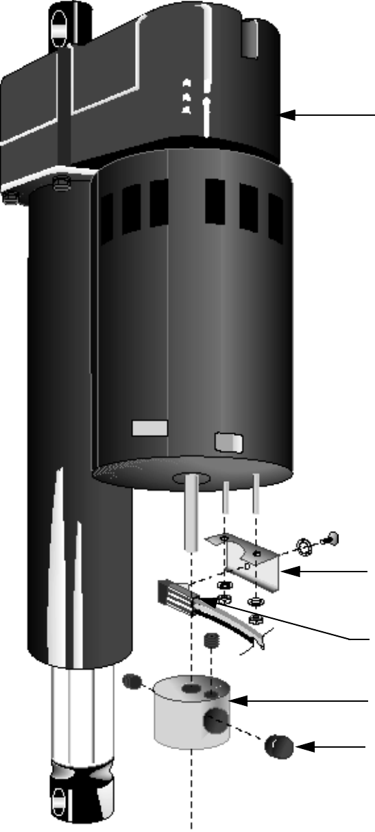
Procedure 6.1 - Replacing the Lift Motor, Rotation Sensor or
Magnet Hub
Note:
If you need to replace a lift motor that utilizes a hall effect rotation sensor, remove the magnet
hub and rotation sensor bracket from the defective lift motor and mount them on the new lift
motor. Unless the magnet and rotation sensor are defective, do not remove them from their
mounting positions on the magnet hub and sensor bracket. Replacement lift motors are not
furnished with the hall effect rotation sensor.
WARNING
Always turn off the circuit breaker and unplug the treadmill before you remove the treadmill hood.
Removing the Lift Motor
1. Remove the hood.
2. Remove the red lift motor lead from the lift motor capacitor, but leave the remaining red wire
connected to the capacitor terminal.
3. Remove the black lift motor lead from the lift motor capacitor, but leave the remaining black
wire connected to the capacitor terminal.
4. Disconnect the connector on the white lift motor lead.
5. If the treadmill does not have a rotation sensor (C962i or C964i), go to step 8.
6. Remove the revolution sensor plug from the J2 connector jack on the lower PCA.
Note:
When the revolution sensor wire assembly is disconnected from the lower PCA, the zero sense
switch must be disconnected as well.
7. Disconnect the two blue wires on the rotation sensor wire assembly from the zero sense
switch terminals.
8. Place the treadmill on its left side.
9. Remove the two shoulder screws and nuts that secure the lift motor to the treadmill frame
and lift platform (see Diagram 6.1). Remove the lift motor and set it aside.
10. If the treadmill does not have a rotation sensor (C962i or C964i), go to step 25.
11. Remove the set screw that secures the magnet hub to the lift motor. Set aside the magnet
hub.
C960 Series Commercial Treadmill
Page 46
Diagram 6.1 - Exploded view of the Lift Motor (with Rotation Sensor)
Lift Motor
Rotation Sensor
Mounting Bracket
Rotation Sensor
Magnet Hub
Magnet
C960 Series Commercial Treadmill
Page 47
Replacing the Magnet
12. Remove the set screw that secures the magnet to the magnet hub. Discard the magnet.
Note:
When you position the magnet in the magnet hub, place the north pole towards the center of the
magnet hub. The north pole of the magnet should be marked with a spot of white paint. If the
magnet on the treadmill you are servicing is not marked, use either a compass or another
magnet to determine the north pole.
13. Position a new magnet in the magnet hub.
14. Tighten the set screw that secures the magnet to the magnet hub.
15. If you are replacing the revolution sensor...
THEN... OTHERWISE...
Continue with the next step. Skip to Step 19.
16. Remove the screw and washer that secure the rotation sensor to the sensor bracket (see
Diagram 6.1).
17. Position the revolution sensor at its mounting location.
18. Position the screw and washer that secure the rotation sensor to the sensor bracket. Torque
the screw to 8 in-lbs.
19. If you are replacing the lift motor you removed earlier in this procedure...
THEN... OTHERWISE...
Continue with the next step. Skip to Step 25.
Removing and Replacing the Rotation Sensor Bracket
20. Remove the two nuts that secure the sensor bracket to the lift motor.
21. Position the sensor bracket removed in the previous step on the lift motor.
22. Replace the two nuts that secure the sensor bracket to the lift motor.
23. Position the magnet hub on the lift motor so that it is flush with the speed sensor bracket.
24. Replace the set screw that secures the magnet hub to the lift motor.
Replacing the Lift Motor
25. Extend the lift motor actuator 1/2”.
C960 Series Commercial Treadmill
Page 48
Note:
To extend the lift motor actuator faster, place a screwdriver shaft in the lower mounting hole of
the lift motor and rotate the lift motor tube.
26. Position the lift motor at its mounting location.
Note:
When you perform Step 27, replace the lower screw and nut first.
27. Replace the two shoulder screws and nuts that secure the lift motor to the treadmill frame.
Note:
The original nuts used to mount the lift motor are Kep nuts, which do not require a separate
washer. If you do not use Kep nuts to mount the lift motor, use washers when you mount the lift
motor to the treadmill frame.
28. Return the treadmill to an upright position.
29. Connect the black lift motor lead to the terminal of the lift motor capacitor that already has a
black wire.
30. Connect the red lift motor lead to the terminal of the lift motor capacitor that already has a
red wire.
31. Connect the connector on the white lift motor lead that connects the lift motor to pin 4 of
lower PCA connector J3.
32. Connect the molex connector on the revolution sensor wire assembly to connector J2 on the
lower PCA.
33. If the treadmill does not have a rotation sensor (C962i or C964i), go to step 36.
34. Connect the two blue wires on the revolution sensor wire assembly to the terminals on the
zero sense switch terminals.
35. Calibrate the treadmill lift assembly as described in Procedure 4.1 of this appendix.
36. Check the operation of the treadmill as described in Section Three of this appendix, then
replace the hood as described in Procedure 5.1 of the Commercial Treadmill Service
Manual.
C960 Series Commercial Treadmill
Page 49
Procedure 6.2 - Replacing the Limit Switches, Actuator Shaft
or Switch Bracket
Note:
The limit switches and the actuator shaft are mounted on the switch bracket (see Diagram 5.1).
WARNING
Always turn off the circuit breaker and unplug the treadmill before you remove the treadmill hood.
Procedure
1. Remove the hood.
2. If you are removing the actuator shaft or switch...
THEN... OTHERWISE...
Skip to Step 12 (to remove the upper Continue with the next step.
limit bracket switch), Step 6 (to remove
the down limit switch) or Step 9 (to
remove the zero sense switch.
Removing the Upper Limit Switch
WARNING
When power is applied to the treadmill, the wires connected to the upper and lower limit switches
carry high voltage. Turn off the treadmill and unplug the power cord from the wall outlet before
you perform the following steps.
3. Carefully remove the red wires from the upper limit switch.
Note:
See Diagram 6.2 for limit switch wiring.
4. Remove the screws and washers that secure the limit switch to the switch bracket.
5. If you are removing more than one limit switch...
THEN... OTHERWISE...
Continue with the next step to Skip to Step 11.
remove the down limit switch or
Step 9 to remove the zero sense
switch
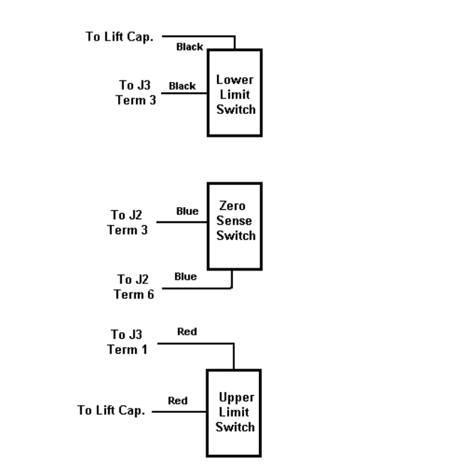
C960 Series Commercial Treadmill
Page 50
Removing the Down Limit Switch
6. Carefully remove the black wires from the down limit switch.
7. Remove the screws and washers that secure the limit switch to the switch bracket (see
Diagram 5.1).
8. If you are removing the zero sense switch...
THEN... OTHERWISE...
Continue with the next step. Skip to Step 11.
Removing the Zero Sense Switch
9. Carefully remove the blue wires from the zero sense switch.
10. Remove the two screws and washers that secure the limit switch to the switch bracket (see
Diagram 5.1).
Diagram 6.2 - Limit Switch Wiring Diagram
C960 Series Commercial Treadmill
Page 51
11. If you are removing the actuator shaft or switch bracket...
THEN... OTHERWISE...
Continue with the next step. Skip to Step 26.
Removing the Actuator Shaft and Switch Actuator
12. Remove the screw that secures the switch actuator to the actuator shaft. Set aside the
screw and switch actuator.
13. Remove the shoulder screw that connects the actuator shaft and actuator block to the lift
platform.
Note:
If necessary, hold the actuator shaft with the pliers and support the actuator block firmly with your
hand when you perform Step 14.
14. Unscrew the actuator shaft from the actuator block. Set aside the actuator block.
15. Slide the actuator shaft from the switch bracket.
16. If you are removing the switch bracket...
THEN... OTHERWISE...
Continue with the next step. Skip to Step 20.
Removing and Replacing the Switch Bracket
17. Remove the socket head screws and washers that secure the switch bracket to the lift motor
platform. Set aside the switch bracket.
18. Position the switch bracket at its mounting location.
19. Replace the socket head screws and washers that secure the switch bracket to the lift motor
platform.
Replacing the Actuator Shaft and Switch Actuator
20. Slide the actuator shaft through the switch bracket until it is positioned at its mounting
location.
21. Thread the actuator block onto the lower end of the actuator shaft.
Note:
If necessary, use the pliers to secure the actuator block to the actuator shaft.
C960 Series Commercial Treadmill
Page 52
22. Position the shoulder screw removed in Step 13 through the actuator block and into the
base of the lift platform.
23. Tighten the shoulder screw that connects the actuator shaft and actuator block to the lift
platform.
24. Position the switch actuator on the top of the actuator shaft.
25. Replace the screw that secures the switch actuator to the actuator shaft.
26. If you must replace one or more of the limit switches...
THEN... OTHERWISE...
Continue with the next step to Skip to Step 38.
replace the upper limit switch, skip
to step 31 to replace the down
limit switch or skip to Step 35 to
replace the zero sense switch.
Replacing the Upper Lift Limit Switch
27. Position the limit switch at its mounting location.
28. Replace the screws and washers that secure the limit switch to the switch bracket.
29. Connect the red wires disconnected in Step 3 to the limit switch terminals.
30. If you are replacing more than one limit switch...
THEN... OTHERWISE...
Continue with the next step (to Skip to Step 38.
to replace the down limit switch) or
skip to Step 35 (to replace the zero
sense switch.
Replacing the Down Lift Limit Switch
31. Position the limit switch at its mounting location.
32. Replace the screws and washers that secure the limit switch to the switch bracket.
33. Connect the black wires disconnected in Step 6 to the limit switch terminals.
34. If you are replacing the zero sense switch...
C960 Series Commercial Treadmill
Page 53
THEN... OTHERWISE...
Continue with the next step. Skip to Step 38.
Replacing the Zero Sense Switch
35. Position the limit switch at its mounting location.
36. Replace the screws and washers that secure the limit switch to the switch bracket.
37. Connect the blue wires disconnected in Step 9 to the switch terminals.
38. Calibrate the lift assembly as described in Procedure 4.1 of this appendix.
39. Check the operation of the treadmill as described in Section Three of this appendix.
C960 Series Commercial Treadmill
Page 54
Procedure 6.3 - Replacing the Lift Motor Capacitor
WARNING
Always turn off the circuit breaker and unplug the treadmill before you remove the treadmill hood.
Removing the Lift Motor Capacitor
1. Remove the hood
2. Remove the black and red wires from the lift motor capacitor terminals.
3. Loosen the screw and nut on the capacitor mounting bracket.
Note:
If you are servicing a 240-volt 960 series treadmill, use a phillips screwdriver to loosen and
tighten the screw on the capacitor mounting bracket.
4. Remove the capacitor from the mounting bracket.
Replacing the Lift Motor Capacitor
5. Position the lift motor capacitor in the capacitor mounting bracket.
Note:
Wire length and wire assembly configuration may limit the mounting orientations of the lift motor
capacitor. Make sure that the wires you removed from the capacitor will reach the capacitor
terminals before you perform the next step.
6. Tighten the screw and nut on the capacitor mounting bracket.
7. Connect the wires removed in Step 2 to the capacitor terminals.
Note:
Because the lift motor capacitor is not polarized, you can connect wires to either terminal.
However, you cannot mix wire colors on any one terminal.
8. Check the operation of the treadmill as described in Section Three of this appendix.

C960 Series Commercial Treadmill
Page 55
Procedure 6.4 - Replacing the Lift Platform
WARNING
Always turn off the circuit breaker and unplug the treadmill before you remove the treadmill hood.
Removing the Lift Platform
1. Turn off the treadmill with the circuit breaker, then unplug the power cord from the wall
outlet.
2. Place the treadmill on its right side.
Note:
To avoid scratching or marring the treadmill, put a drop cloth underneath the treadmill when you
perform Step 2.
3. Remove the lower bolt and nut that secures the lift motor to the lift platform. It is not
necessary to remove the lift motor when you remove the lift platform.
4. Skip this step on C962i and C964i treadmills. Remove the bolt that connects the actuator
block to the lift platform. (See Diagram 6.3B)
5. Perform this step on C962i and C964i treadmills, only. Remove the nut that retains the lift
potentiometer and remove the lift potentiometer. Remove the coupler that connects the lift
potentiometer to lift platform shaft. Note the orientation of the flat side of the lift platform
shaft. When it is replaced, later in this procedure, it must be remounted in the same
orientation. If the lift shaft is incorrectly oriented the lift system calibration will be incorrect.
Remove the retaining ring from the lift shaft. Use a thin drift punch or similar tool to carefully
drive the pin out of the lift shaft on the left hand (lift potentiometer) side of the lift platform.
Remove the lift shaft. (See Diagram 6.3A)
6. Remove the bolt(s) and nut(s) that secure the lift platform to the treadmill frame. Remove
the lift platform.
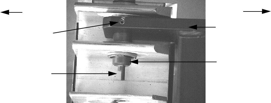
C960 Series Commercial Treadmill
Page 56
Diagram 6.3A - Lift Shaft Orientation
FRONT
REAR
Flat Side
Pin Lift Platform
Lift Shaft
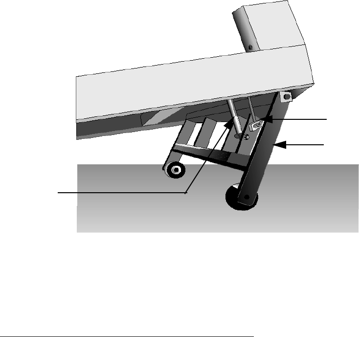
C960 Series Commercial Treadmill
Page 57
Diagram 6.3B - Lift Platform
Replacing the Lift Platform
7. With the treadmill still on its right side, position the lift platform at its mounting position.
8. Replace the bolt(s) and nut(s) that secure the lift platform to the treadmill frame.
9. Perform this step on C962i and C964i treadmills, only. Replace the lift shaft. Replace the
retaining ring. Orient the lift shaft into the position it was in when removed in step 5. With the
lift platform rotated to the front of the treadmill, the flat side of the lift shaft will face to the
rear of the treadmill when correctly oriented. See Diagram 6.3A. Align the hole in the lift
platform with the hole in the lift shaft and replace the pin. Carefully tap the pin into place with
a mallet or hammer. Slide the coupler onto the the lift shaft and replace the lift
potentiometer. Align the flat side of the lift potentiometer shaft with the flat side of the lift
shaft and and position the lift potentiometer so that the locator tab on the lift potentiometer
fits into the locator hole in the lift potentiometer bracket. See Diagram 6.3C. Carefully tighten
the lift potentiometer nut. Do not overtighten the lift potentiometer nut. If the coupler has set
screws, align the coupler over the junction of the lift potentiometer shaft and the lift shaft and
tighten the coupler set screws.
Actuator Block
Lift Platform
Lift Motor
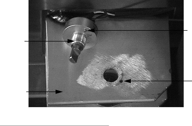
C960 Series Commercial Treadmill
Page 58
Diagram 6.3C - Lift Potentiometer Mounting
10. Skip this step on C962i and C964i treadmills. Replace the bolt that connects the actuator
block to the lift platform.
11. Replace the lower bolt and nut that secures the lift motor to the lift platform.
12. Check the operation of the treadmill as described in Section Three of this appendix.
Potentiometer
Potentiometer
Bracket
Locator
Tab
Locator
Hole
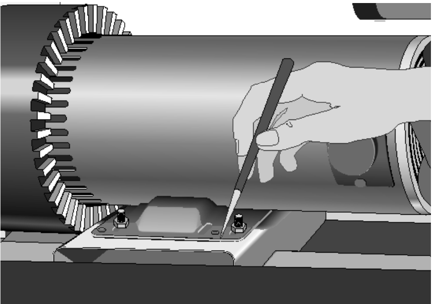
C960 Series Commercial Treadmill
Page 59
Procedure 6.5 - Replacing the Drive Belt
WARNING
Always turn off the circuit breaker and unplug the treadmill before you remove the treadmill hood.
Removing the Drive Belt
1. Remove the hood.
2. Score a line on the drive motor mounting plate that runs the length of the motor pedestal
(see Diagram 6.4).
Note:
The line scored on the mounting plate allows you to correctly position the drive motor.
3. If the treadmill is an SCR treadmill, remove the inductor.
4. Loosen the four lock nuts that secure the drive motor pedestal to the drive motor mounting
plate.
Diagram 6.4 - Scoring the Drive Motor Pedestal
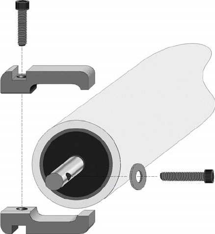
C960 Series Commercial Treadmill
Page 60
5. Carefully push the drive motor toward the drive roller.
6. Loosen the bolts threaded through both ends of the drive roller shaft.
7. Remove the socket head screws that secure the top drive roller mounts (see Diagram 6.5).
8. Remove the top roller mounts, then remove the drive belt from the drive roller pulley.
9. Lift the drive roller from the lower roller mounts and slide it from the running belt.
10. Slip the drive belt off the drive motor pulley.
Replacing the Drive Belt
11. Push the drive roller through the running belt. Place the drive belt on the drive roller pulley
and place the drive roller on the lower drive roller mounts.
12. Place the top roller mounts on the lower roller mounts.
Note:
When you place the top roller mounts over the ends of the roller shaft, the bolt heads and
washers must be outside of the clamp formed by the upper and lower roller mounts.
13. Thread the socket head screws through the top roller mounts and into the lower roller
mounts.
Diagram 6.5 - Roller Mount Assembly
C960 Series Commercial Treadmill
Page 61
14. Tighten the socket head screws.
15. Push and hold the left side of the drive roller toward the drive motor.
Note:
Right, left, front, and back are from the perspective of a user standing on the treadmill and facing
the electronic console.
CAUTION
Do not crush the washer on the bolt when you perform the next step.
16. Turn the bolt in the left end of the drive roller shaft all the way clockwise and tighten
securely.
17. Adjust the right hand bolt until the drive roller is square to the frame.
18. Position the new drive belt on the drive motor pulley.
19. Position the drive motor pedestal parallel to the line scored on the drive motor mounting
plate.
20. Tighten the bolts that mount the pedestal to the drive motor mounting plate.
21. Replace the inductor.
22. Inspect and adjust the tension of the drive belt as described in the Commercial Treadmill
Service Manual.
Note:
The drive belt will track along either the right or left edge of the pulley grooves. It will not center
itself between the pulley flanges.
23. Check the operation of the treadmill, then replace the hood.
C960 Series Commercial Treadmill
Page 62
Procedure 6.6 - Replacing the Drive Roller or Drive Roller
Bearings
WARNING
Always turn off the circuit breaker and unplug the treadmill before you remove the treadmill hood.
Note:
If the drive roller bearings require replacement, you may replace either the bearings or the entire
drive roller. Replacing the bearings uses parts that are less expensive but requires more time to
perform the replacement.
Removing the Drive Roller
1. Remove the hood.
2. Remove the running belt tension by turning the drive roller adjustment bolts
counterclockwise.
3. Remove the drive motor as described in Procedure 6.5.
4. Remove the socket head screws that secure the top drive roller mounts.
5. Remove the top roller mounts, then remove the drive belt from the drive pulley.
6. Lift the drive roller from the lower roller mounts and slide it out of the running belt.
7. Slip the drive belt off the drive motor pulley, then set aside the drive belt until you are ready
to install the drive roller.
8. If you are replacing the bearings or the bearings and shaft in drive roller...
THEN... OTHERWISE...
Continue with the next step. Remove the bolts threaded through the
drive roller shaft; then skip to Step 21.
Removing the Roller Bearings and Shaft
Always remove and replace the bearings and washers as a set. It is not necessary to replace the
shaft if you are replacing the bearings. However, if you are replacing the shaft, you must also
replace the bearings and washers.
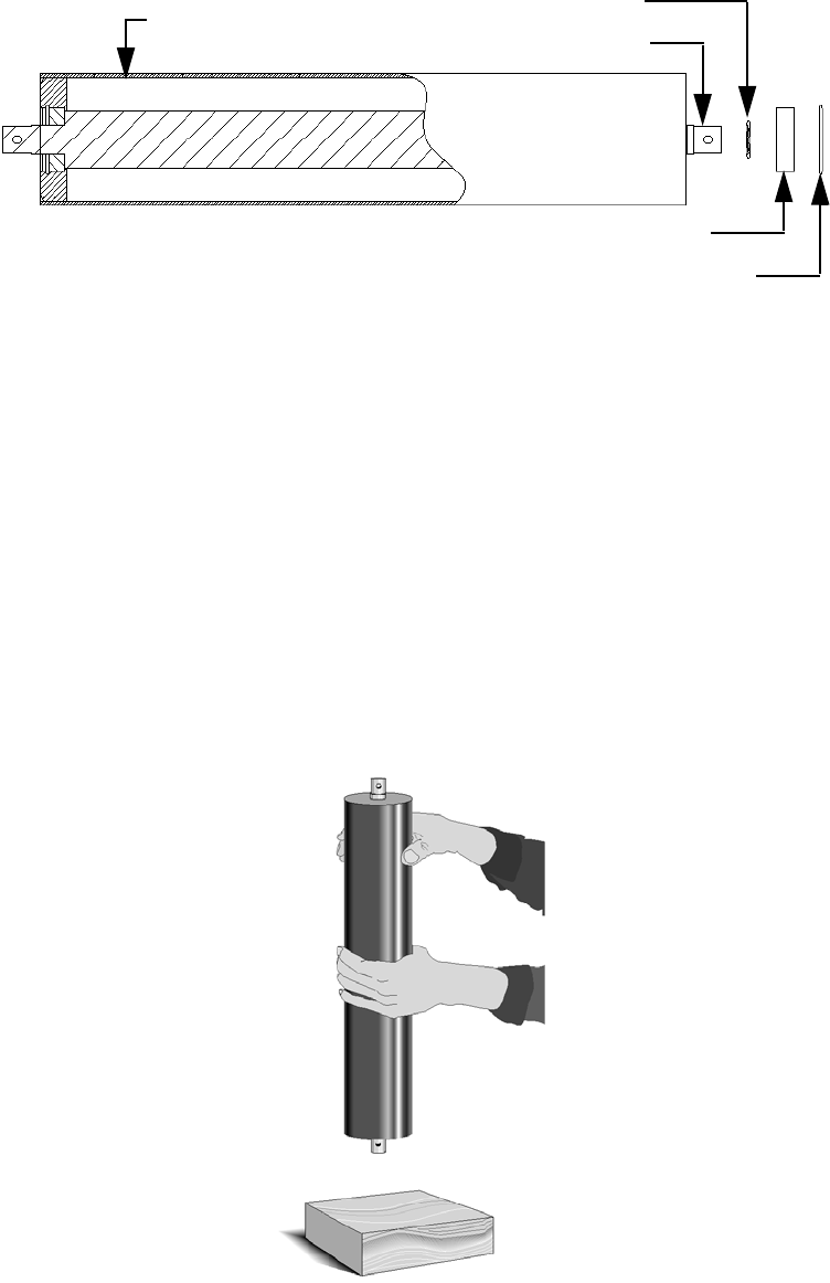
C960 Series Commercial Treadmill
Page 63
Diagram 6.6 - Exploded View of a Roller
9. Remove the snap ring from both ends of the roller (see Diagram 6.6).
10. Hold the roller in a vertical position 3–4 inches above a block of wood. The block of wood
must be on a hard solid surface such as a floor. (see Diagram 6.7
11. Hold the roller with the end of the roller upward, and drop the roller onto the block of wood.
The roller may need to be dropped several times to drive the bearing out of the roller.
12. Remove the bearing from the opposite end of the roller in the same manner. Care must be
taken to keep the roller shaft in the bearing because the shaft is no longer being retained on
the lower end of the roller as it is dropped onto the block of wood.
13. Remove the shaft from the roller.
Diagram 6.7 - Removing a Bearing
Roller Tube Wave Washer
Roller Shaft
Bearing
Snap Ring
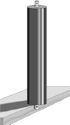
C960 Series Commercial Treadmill
Page 64
Replacing the Roller Bearings and Shaft
You will need an assistant to perform the following steps.
14. Have an assistant support the roller against a work surface. One end of the roller must be
flush with the work surface.
15. Place a bearing on the roller, then position the bearing replacement tube against the outer
race of the bearing
Note:
A ten inch length of 2 inch O.D. pipe with a cap threaded onto one end, will serve as a bearing
replacement tool. The open end will be placed against the bearing and the end with the capped
end will be struck with the hammer.
.
CAUTION
The bearing must go squarely into the roller tube. If the bearing is not square in the roller tube,
you will be unable to insert the bearing.
16. Set the roller tube on a solid work surface. Place a new bearing in the bearing pocket on one
end of the roller tube. Using the bearing replacement tool and a hammer or mallet, gently
tap the bearing into the tube. The bearing will be below flush and the snap ring groove will
be exposed when the bearing is properly set into the roller tube.
17. Using the snap ring pliers, install the snap ring.
18. Place a wave washer onto roller shaft. Slide the roller tube down over the shaft until the end
of the shaft protrudes through the bearing. Invert the roller tube while holding the shaft in
place. Set the roller tube on a block of wood as shown in Diagram 6.8.
Diagram 6.8 - Replacing the Roller Bearing
C960 Series Commercial Treadmill
Page 65
19. While an assistant supports the roller tube, place a wave washer on to the shaft. Slide the
new bearing onto the upper end of the shaft. Using the bearing replacement tool and a
hammer or mallet, gently tap the bearing into the tube. The bearing will be below flush and
the snap ring groove will be exposed when the bearing is properly set in the roller tube.
20. Using the snap ring pliers, install a retaining ring next to the bearing just mounted in the
roller.
Replacing the Drive Roller
21. Thread the drive roller adjustment bolts into the drive roller shaft.
22. Visually inspect the drive belt for wear, cracks, or other damage. Replace the drive belt if
required.
23. Slide the drive roller through the running belt. Place the drive belt on the drive roller pulley
and place the drive roller on the lower drive roller mounts.
24. Place the top roller mounts on the lower roller mounts.
Note:
When you place the top roller mounts over the ends of the roller shaft, the bolt heads and
washers must be outside of the clamp formed by the upper and lower roller mounts.
25. Thread the socket head screws through the top roller mounts and into the lower roller
mounts and tighten.
26. Push and hold the left side of the drive roller toward the drive motor.
Note:
Right, left, front, and back are from the perspective of a user standing on the treadmill and facing
the electronic console.
27. Securely tighten the left hand drive roller adjustment bolt. It is important that the bolt pulls
drive roller shaft all the way forward in the roller mount.
28. While applying rearward pressure to the drive roller, adjust the right hand drive roller
adjustment bolt until the drive roller is square relative to the treadmill frame.
29. Position the drive belt on the drive motor pulley.
30. Position the drive motor parallel to the line scored on the motor mounting pedestal.
31. Tighten the four bolts that mount the pedestal to the drive motor mounting plate.
32. Inspect and adjust the tension of the drive belt as described in Procedure 3.2 of the
Commercial Treadmill Service Manual.
C960 Series Commercial Treadmill
Page 66
33. Inspect and adjust the tension, tracking, and alignment of the running belt as described in
Procedure 3.1 of the Commercial Treadmill Service Manual.
34. Check the operation of the treadmill as described in Section Three of this appendix, then
replace the hood.
C960 Series Commercial Treadmill
Page 67
Procedure 6.7 - Replacing the Take-Up Roller or Take-Up
Roller Bearings
Removing the Take-Up Roller
1. Remove the screws that secure the right and left end caps to the treadmill frame. Set the
end caps and end cap mounting hardware aside.
2. Place a running belt gauge on each side of the running belt and set the gauges a mid range.
3. Remove the running belt tension by turning the take up roller tension adjustment bolts
counterclockwise.
4. Turn the running belt tracking bolt counterclockwise 2–3 turns.
5. Remove the socket head bolts that secure the top take-up roller mounts.
6. Remove the top roller mounts, then lift the take-up roller from the lower roller mounts.
7. If you are replacing the bearings or the bearings and shaft in the take-up roller...
THEN... OTHERWISE...
Continue with the next step. Remove the tension limiting bolt and
you perform the following steps. running belt tracking bolt from the
take-up roller shaft. Skip to Step 19.
Removing the Roller Bearings and Shaft
Always remove and replace the bearings and washers as a set. It is not necessary to replace the
shaft if you are replacing the bearings. However, if you are replacing the shaft, you must also
replace the bearings and washers.
8. Remove the snap ring from one end of the roller (see Diagram 6.6).
9. Hold the roller in a vertical position 3–4 inches above a block of wood. The block of wood
must be on a hard solid surface such as a floor. (see Diagram 6.7).
10. Hold the roller with the end of the roller that has had the snap ring removed upward, and
drop the roller onto the block of wood. The roller may need to be dropped several times to
drive the bearing out of the roller.
11. Remove the bearing from the opposite end of the roller in right same manner. Care must be
taken to keep the roller shaft in the bearing because the shaft is no longer being retained on
the lower end of the roller as it is dropped onto the block of wood.
12. Remove the shaft from the roller.
C960 Series Commercial Treadmill
Page 68
Replacing the Roller Bearings and Shaft
You will need an assistant to perform the following steps.
13. Have an assistant support the roller against a work surface. One end of the roller must be
flush with the work surface.
14. Place a bearing on the roller, then position the bearing replacement tube against the outer
race of the bearing
Note:
A ten inch length of 2 inch O.D. pipe with a cap threaded onto one end, will serve as a bearing
replacement tool. The open end will be placed against the bearing and the end with the capped
end will struck with the hammer.
.CAUTION
The bearing must go squarely into the roller tube. If the bearing is not square in the roller tube,
you will be unable to insert the bearing.
15. Set the roller tube on a solid work surface. Place a new bearing in the bearing pocket on one
end of the roller tube. Using the bearing replacement tool and a hammer or mallet, gently
tap the bearing into the tube. The bearing will be below flush and the snap ring groove will
be exposed when the bearing is properly set into the roller tube.
16. Using the snap ring pliers, install the snap ring.
17. Place a wave washer onto roller shaft. Slide the roller tube down over the shaft until the end
of the shaft protrudes through the bearing. Invert the roller tube while holding the shaft in
place. Set the roller tube on a block of wood as shown in Diagram 6.8.
18. While an assistant supports the roller tube, place a wave washer on to the shaft. Slide the
new bearing onto the upper end of the shaft. Using the bearing replacement tool and a
hammer or mallet, gently tap the bearing into the tube. The bearing will be below flush and
the snap ring groove will be exposed when the bearing is properly set in the roller tube.
19. Using the snap ring pliers, install a retaining ring next to the bearing just mounted in the
roller.
Replacing the Take-Up Roller
20. Slide the take-up roller through the running belt, then place the take-up roller on the lower
roller mounts.
21. If the treadmill uses a tension limiting bolt assembly, thread it into the right end of the take-
up roller shaft.
22. Thread the running belt tracking bolt through the left end of the take-up roller shaft.
C960 Series Commercial Treadmill
Page 69
Note:
When you replace the bolts in the take-up roller, the tension limiting bolt must be on the right side
of the treadmill when the take-up roller is installed on the treadmill. The belt tracking bolt must be
on the left side of the treadmill.
23. Place the top roller mounts on the lower roller mounts.
Note:
When you place the top roller mounts over the ends of the roller shaft, the bolt heads and
washers must be outside of the clamp formed by the upper and lower roller mounts.
24. Thread the socket head bolts through the top roller mount and into the lower roller mount.
25. Tighten the socket head bolts that secure the top and lower roller mounts.
26. Replace the screws that secure the right and left end caps to the treadmill frame.
27. Tension the running belt until both gauges are again at mid range.
28. Inspect and adjust the tension, tracking, and alignment of the running belt as described in
Procedure 3.1 of the Commercial Treadmill Service Manual.
29. Check the operation of the treadmill as described in Section Three of this appendix.
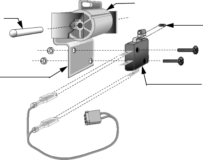
C960 Series Commercial Treadmill
Page 70
Procedure 6.8 - Replacing the Safety Switch Assembly
The exploded view of the safety switch assembly is shown in Diagram 6.9.
Removing the Safety Switch Cam
1. Remove the three screws that secure the upper display housing to the display housing
mounting plate.
2. Place your right hand on the two right upper display housing mounting tabs. Place your left
hand on the left tabs. Push the right tabs towards the right targa upright and the left tabs
towards the left targa upright as you lift the display housing from the mounting plate.
Support the display housing on the front handrails.
3. If you are removing the safety switch cam as well as the safety limit switch...
THEN... OTHERWISE...
Continue with the next step. Skip to Step 6.
Diagram 6.9 - Safety Switch Assembly
Switch Cam
O-ring
Safety
Switch
Dowel
Switch
Bracket
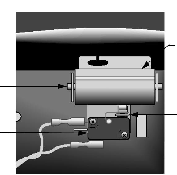
C960 Series Commercial Treadmill
Page 71
4. Disconnect the safety cord from the switch cam (see Diagram 6.10).
5. Remove the dowel that secures the switch cam to the switch mounting bracket (see
Diagram 6.10). Set aside the safety switch cam.
Removing the Safety Limit Switch
6. Disconnect the safety switch wiring.
7. Remove the screws and nuts that secure the safety switch to the switch mounting bracket.
8. Remove the small rubber ring positioned between the safety switch actuator and the switch
cam.
Replacing the Safety Switch
9. Position the small rubber ring removed in the previous step between the safety switch
actuator and the switch cam.
10. Position the safety limit switch at its mounting location.
Diagram 6.10 - Safety Switch Cam and Safety Cord Bracket
Switch Cam
O-ring
Dowel
Safety
Switch
C960 Series Commercial Treadmill
Page 72
11. Replace the screws and nuts that secure the safety limit switch to the switch mounting
bracket.
12. Connect the safety switch wire assembly to the upper PCA.
Replacing the Safety Switch Cam
13. If the safety switch cam operates too freely, the switch may operate unintentionally. If
desired a friction pad (Precor part # 38628-101) may be inserted between the safety switch
cam and switch mounting bracket.
14. Position the safety switch cam at its mounting location.
15. Replace the dowel that secures the switch cam to the switch mounting bracket.
Note:
One end of the dowel will go into the switch cam easier than the other end.
16. Line up the tabs on the display housing with the holes on the display housing mounting
plate.
17. Gently press the display housing onto the mounting plate until the tabs are pushed into the
holes.
18. Connect the safety cord on the switch cam.
19. Replace the screws that secure the upper display housing to the display housing mounting
plate.
20. Check the operation of the treadmill as described in Section Three of this appendix.
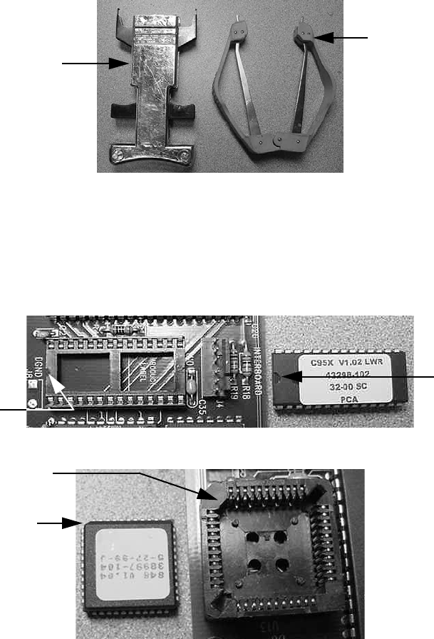
C960 Series Commercial Treadmill
Page 73
Procedure 6.9 - Replacing the PROM
Anti-static kits (part number 20024-101) can be ordered from Precor.
1. The PROM and the associated printed circuit assembly (PCA) are static sensitive. Anti-
static devices must be used and all anti-static precautions must be followed during this
procedure.
2. Remove the printed circuit assembly per its associated procedure.
3. Currently we are using two styles of IC software packages. they are a 28 pin dual in line
package (DIP28) and a forty-four pin square package (PLCC44). Each of these packages
should be removed with a proper IC removal tool (see the illustrations below)
4. The ICs may inserted into their socket by hand by carefully aligning the notch on the IC with
the notch on the IC socket and carefully pressing the IC into its socket. See the illustrations
below for the alignment notches. Care must be taken that the IC legs on a DIP28 are all
aligned in the socket to prevent the legs from bending when inserted. The PLCC44 IC must
be carefully aligned squarely in its socket or it will not insert. Do not force the IC into its,
socket. If it does not insert easily, remove the it and re-align it in its socket.
DIP28 removal tool
PLCC44 removal tool
Notch
Notch
DIP28
Notch
N
o
t
c
h
PLCC44
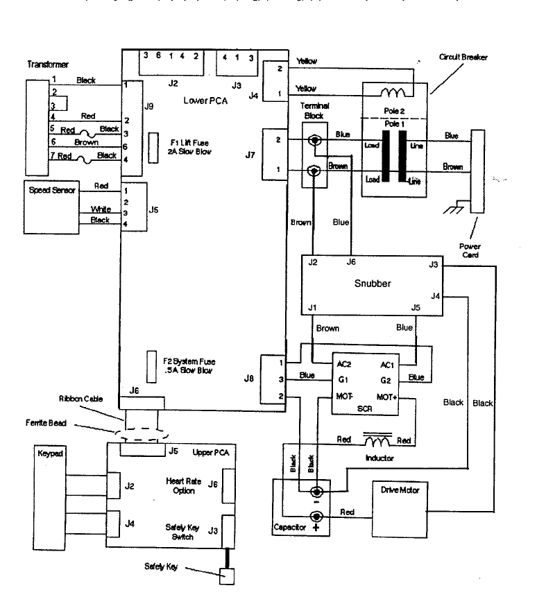
C960 Series Commercial Treadmill
Page 74
Wiring Diagram 7.1 - C960 SCR 240 Vac
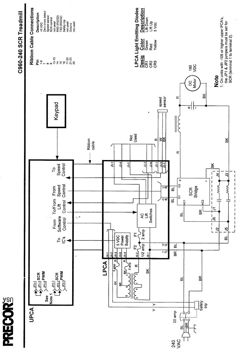
C960 Series Commercial Treadmill
Page 75
Block Diagram 7.2 - C960 SCR 240 Vac
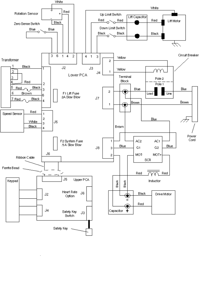
C960 Series Commercial Treadmill
Page 76
Wiring Diagram 7.3 - C962, C964 SCR 120 Vac
J9
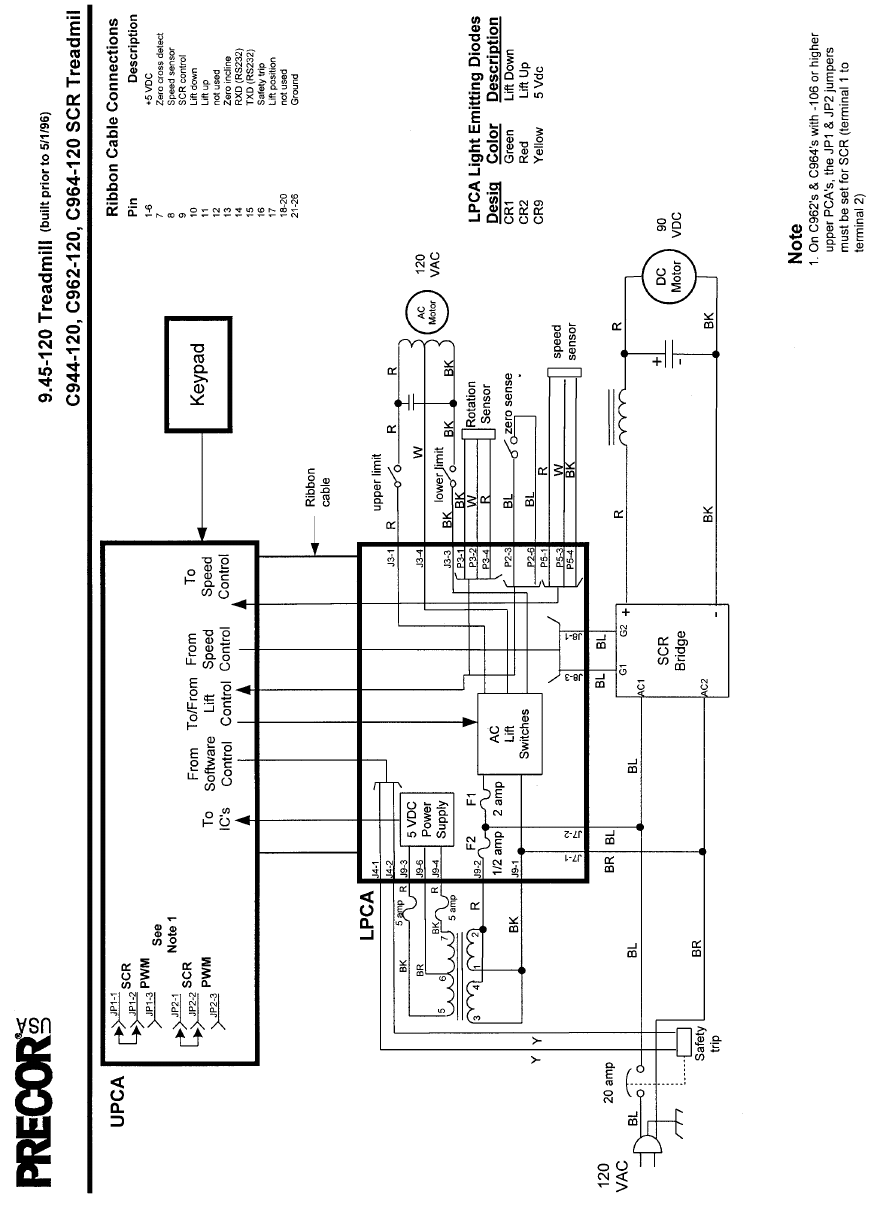
C960 Series Commercial Treadmill
Page 77
Block Diagram 7.4 - C962, C964 SCR 120 Vac
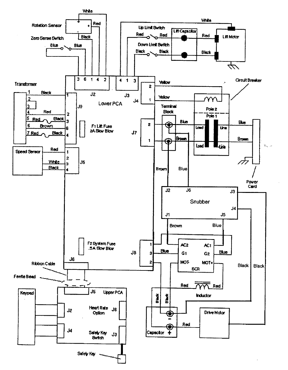
C960 Series Commercial Treadmill
Page 78
Wiring Diagram 7.5 - C962, C964 SCR 240 Vac
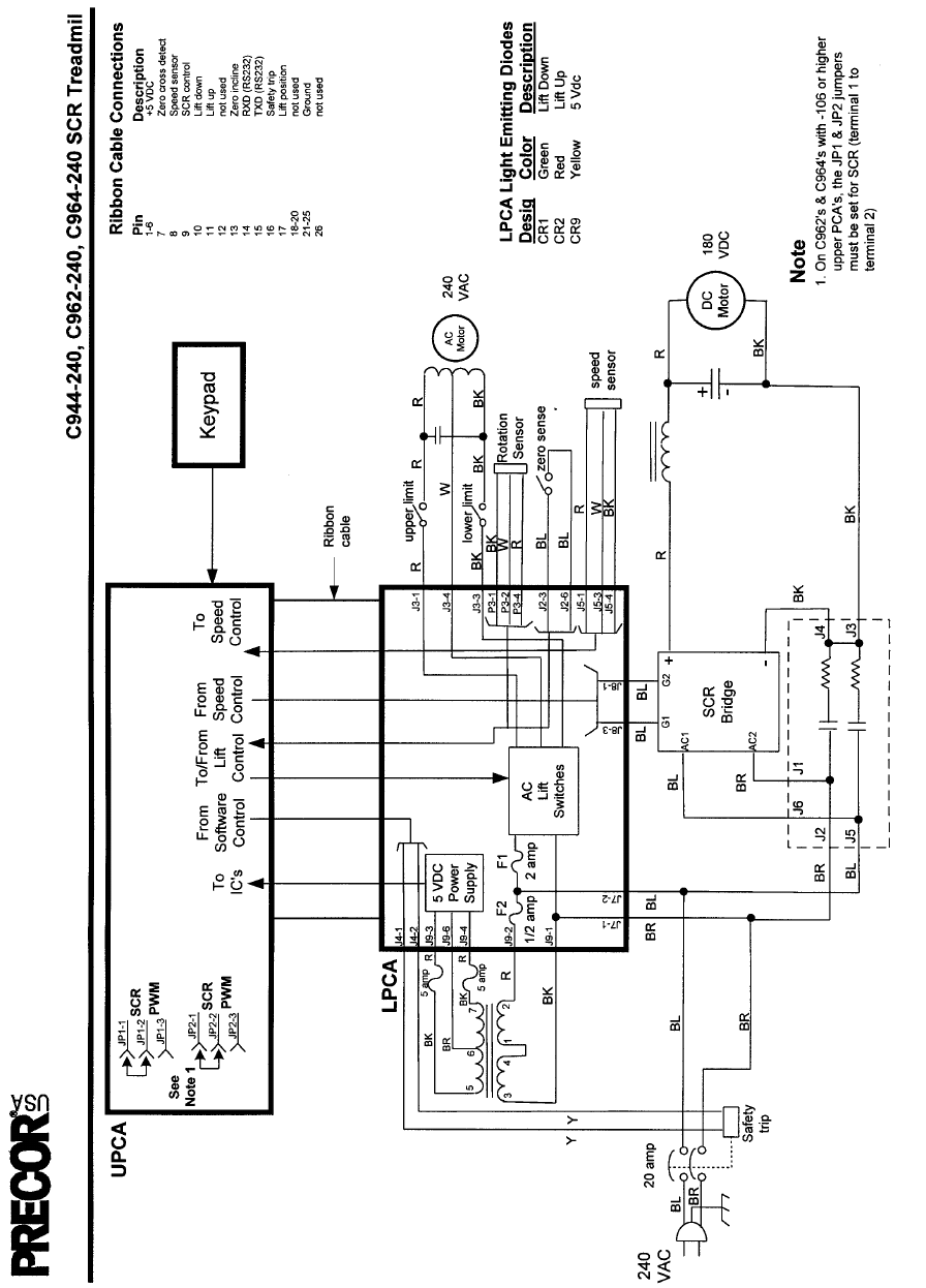
C960 Series Commercial Treadmill
Page 79
Block Diagram 7.6 - C962, C964 SCR 240 Vac
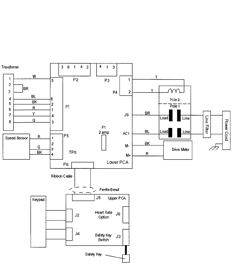
C960 Series Commercial Treadmill
Page 80
Wiring Diagram 7.7 - C960 PWM 240 Vac
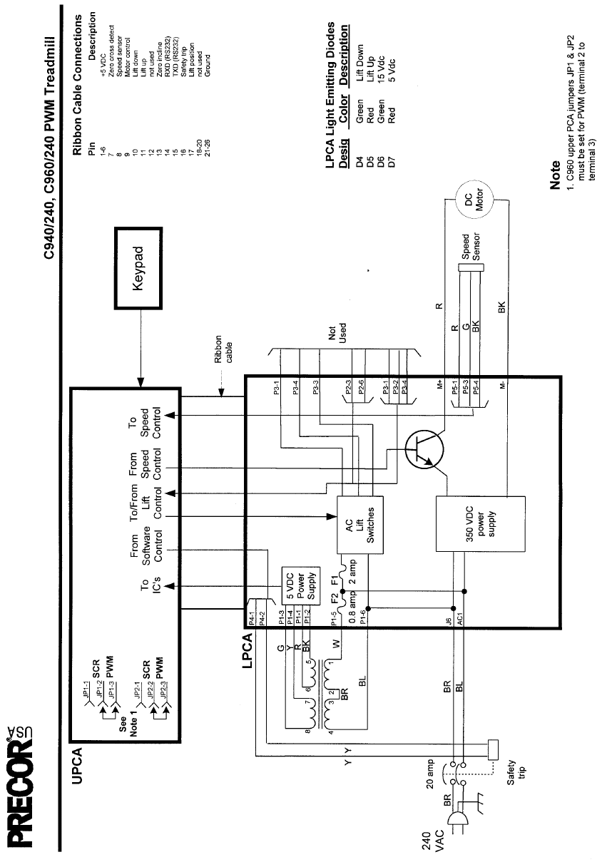
C960 Series Commercial Treadmill
Page 81
Block Diagram 7.8 - C960 PWM 240 Vac
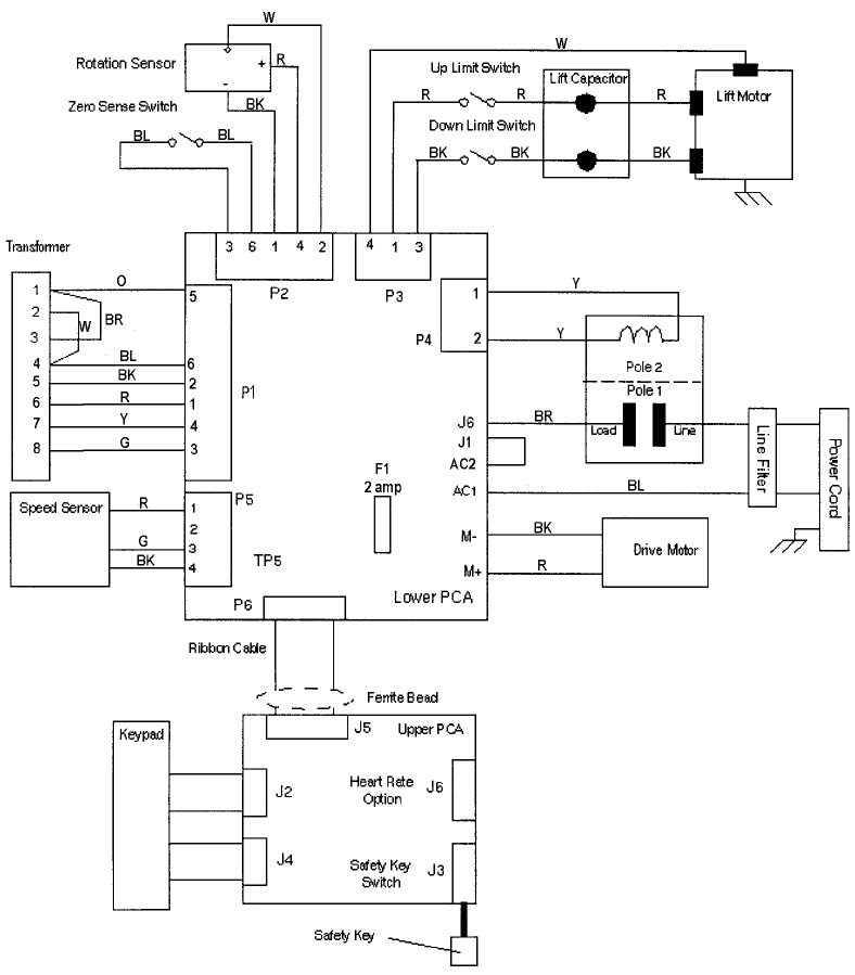
C960 Series Commercial Treadmill
Page 82
Wiring Diagram 7.9 - C962, C964 PWM 120 Vac
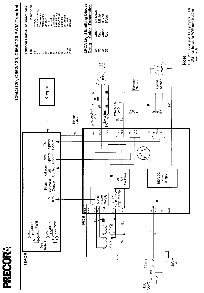
C960 Series Commercial Treadmill
Page 83
Block Diagram 7.10 - C962, C964 PWM 120 Vac
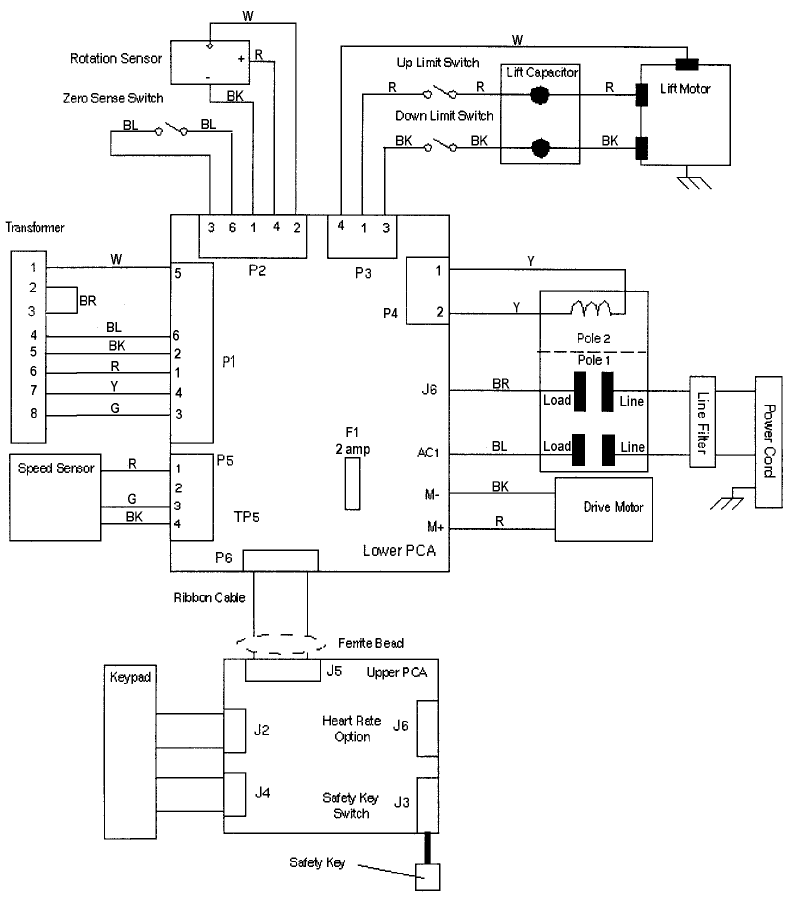
C960 Series Commercial Treadmill
Page 84
Wiring Diagram 7.11 - C962, C964 PWM 240 Vac
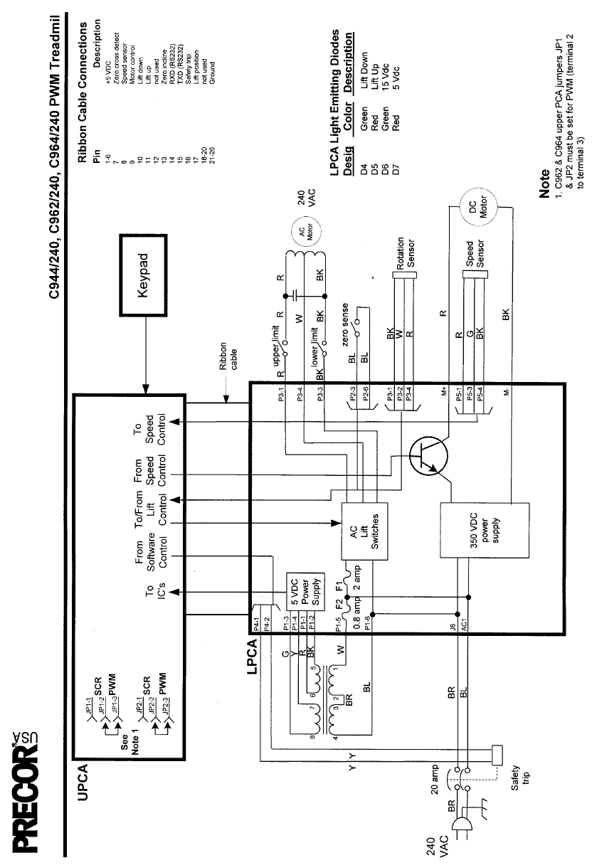
C960 Series Commercial Treadmill
Page 85
Block Diagram 7.12 - C962, C964 PWM 240 Vac
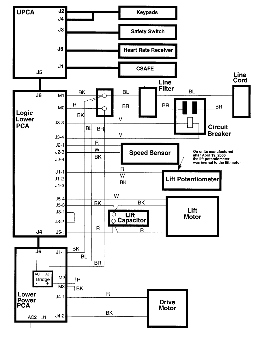
C960 Series Commercial Treadmill
Page 86
Wiring Diagram 7.13 - C962i, C964i 120 Vac
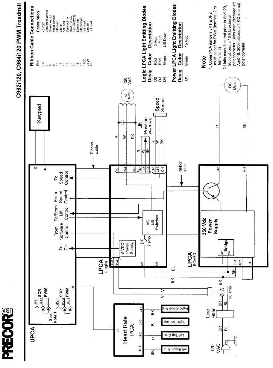
C960 Series Commercial Treadmill
Page 87
Block Diagram 7.14 - C962i, C964i 120 Vac
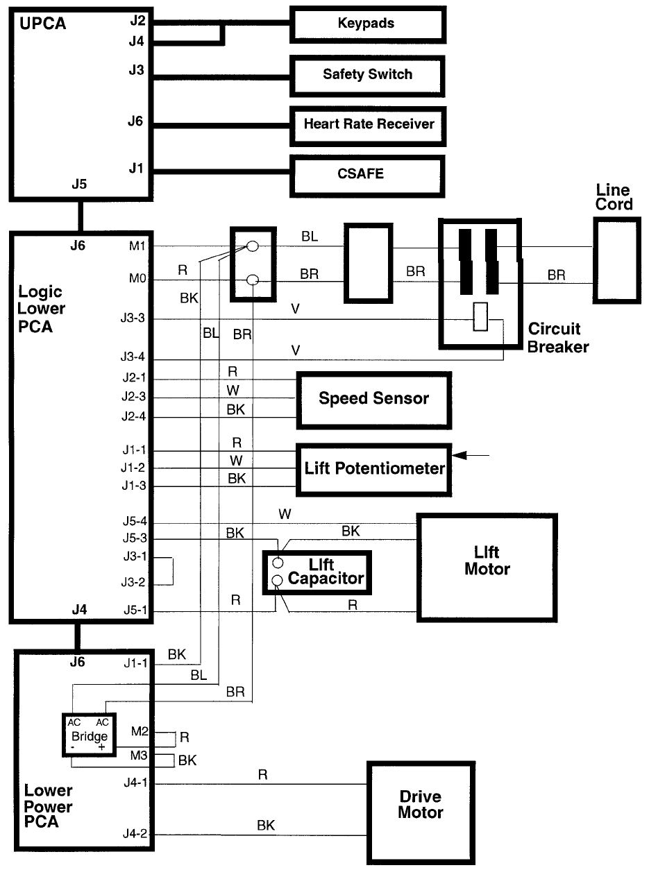
C960 Series Commercial Treadmill
Page 88
Wiring Diagram 7.15 - C962i, C964i 240 Vac
BL
BL
Line Filter
On units manufactured
after April 19, 2000
the lift potentiometer
was internal to the lift motor
BK
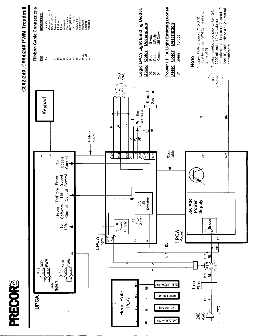
C960 Series Commercial Treadmill
Page 89
Block Diagram 7.16 - C962i, C964i 240 Vac
