Programmer's Guide Prog Master
User Manual:
Open the PDF directly: View PDF ![]() .
.
Page Count: 407 [warning: Documents this large are best viewed by clicking the View PDF Link!]
- Introduction
- Overview
- Environment Abstraction Layer
- Service Cores
- Ring Library
- Mempool Library
- Mbuf Library
- Poll Mode Driver
- Generic flow API (rte_flow)
- Switch Representation within DPDK Applications
- Traffic Metering and Policing API
- Traffic Management API
- Wireless Baseband Device Library
- Cryptography Device Library
- Compression Device Library
- Security Library
- Rawdevice Library
- Link Bonding Poll Mode Driver Library
- Timer Library
- Hash Library
- Elastic Flow Distributor Library
- Membership Library
- LPM Library
- LPM6 Library
- Flow Classification Library
- Packet Distributor Library
- Reorder Library
- IP Fragmentation and Reassembly Library
- Generic Receive Offload Library
- Generic Segmentation Offload Library
- The librte_pdump Library
- Multi-process Support
- Kernel NIC Interface
- Thread Safety of DPDK Functions
- Event Device Library
- Event Ethernet Rx Adapter Library
- Event Ethernet Tx Adapter Library
- Event Timer Adapter Library
- Event Crypto Adapter Library
- Quality of Service (QoS) Framework
- Power Management
- Packet Classification and Access Control
- Packet Framework
- Vhost Library
- Metrics Library
- Berkeley Packet Filter Library
- Source Organization
- Development Kit Build System
- Development Kit Root Makefile Help
- Extending the DPDK
- Building Your Own Application
- External Application/Library Makefile help
- Performance Optimization Guidelines
- Writing Efficient Code
- Profile Your Application
- Glossary

Programmer’s Guide
Release 18.11.0-rc5
November 25, 2018

CONTENTS
1 Introduction 1
1.1 Documentation Roadmap ............................... 1
1.2 Related Publications .................................. 2
2 Overview 3
2.1 Development Environment .............................. 3
2.2 Environment Abstraction Layer ............................ 4
2.3 Core Components ................................... 4
2.4 Ethernet* Poll Mode Driver Architecture ....................... 6
2.5 Packet Forwarding Algorithm Support ........................ 6
2.6 librte_net ........................................ 6
3 Environment Abstraction Layer 7
3.1 EAL in a Linux-userland Execution Environment .................. 7
3.2 Memory Segments and Memory Zones (memzone) ................ 14
3.3 Multiple pthread .................................... 14
3.4 Malloc .......................................... 17
4 Service Cores 22
4.1 Service Core Initialization ............................... 22
4.2 Enabling Services on Cores ............................. 22
4.3 Service Core Statistics ................................ 23
5 Ring Library 24
5.1 References for Ring Implementation in FreeBSD* ................. 25
5.2 Lockless Ring Buffer in Linux* ............................ 25
5.3 Additional Features .................................. 25
5.4 Use Cases ....................................... 25
5.5 Anatomy of a Ring Buffer ............................... 25
5.6 References ....................................... 34
6 Mempool Library 36
6.1 Cookies ......................................... 36
6.2 Stats .......................................... 36
6.3 Memory Alignment Constraints ............................ 36
6.4 Local Cache ...................................... 37
6.5 Mempool Handlers .................................. 38
6.6 Use Cases ....................................... 39
7 Mbuf Library 40
i

7.1 Design of Packet Buffers ............................... 40
7.2 Buffers Stored in Memory Pools ........................... 42
7.3 Constructors ...................................... 42
7.4 Allocating and Freeing mbufs ............................. 42
7.5 Manipulating mbufs .................................. 42
7.6 Meta Information .................................... 42
7.7 Direct and Indirect Buffers .............................. 44
7.8 Debug ......................................... 45
7.9 Use Cases ....................................... 45
8 Poll Mode Driver 46
8.1 Requirements and Assumptions ........................... 46
8.2 Design Principles ................................... 47
8.3 Logical Cores, Memory and NIC Queues Relationships .............. 48
8.4 Device Identification, Ownership and Configuration ................ 48
8.5 Poll Mode Driver API ................................. 52
9 Generic flow API (rte_flow) 58
9.1 Overview ........................................ 58
9.2 Flow rule ........................................ 58
9.3 Rules management .................................. 92
9.4 Isolated mode ..................................... 95
9.5 Verbose error reporting ................................ 96
9.6 Helpers ......................................... 97
9.7 Caveats ......................................... 97
9.8 PMD interface ..................................... 98
9.9 Device compatibility .................................. 98
9.10 Future evolutions ...................................100
10 Switch Representation within DPDK Applications 102
10.1 Introduction .......................................102
10.2 Port Representors ...................................103
10.3 Basic SR-IOV .....................................104
10.4 Controlled SR-IOV ...................................105
10.5 Flow API (rte_flow) ..................................108
10.6 Switching Examples ..................................113
11 Traffic Metering and Policing API 116
11.1 Overview ........................................116
11.2 Configuration steps ..................................116
11.3 Run-time processing .................................116
12 Traffic Management API 118
12.1 Overview ........................................118
12.2 Capability API .....................................118
12.3 Scheduling Algorithms ................................119
12.4 Traffic Shaping .....................................119
12.5 Congestion Management ...............................119
12.6 Packet Marking ....................................120
12.7 Steps to Setup the Hierarchy .............................120
13 Wireless Baseband Device Library 122
ii

13.1 Design Principles ...................................122
13.2 Device Management .................................122
13.3 Device Operation Capabilities ............................124
13.4 Operation Processing .................................126
13.5 Sample code ......................................133
14 Cryptography Device Library 135
14.1 Design Principles ...................................135
14.2 Device Management .................................135
14.3 Device Features and Capabilities ..........................137
14.4 Operation Processing .................................139
14.5 Symmetric Cryptography Support ..........................141
14.6 Sample code ......................................145
14.7 Asymmetric Cryptography ..............................148
14.8 Asymmetric crypto Sample code ...........................149
15 Compression Device Library 153
15.1 Device Management .................................153
15.2 Device Features and Capabilities ..........................154
15.3 Compression Operation ................................155
15.4 Transforms .......................................157
15.5 Compression API Hash support ...........................157
15.6 Compression API Stateless operation ........................157
15.7 Compression API Stateful operation .........................160
15.8 Burst in compression API ...............................163
15.9 Sample code ......................................164
16 Security Library 165
16.1 Design Principles ...................................165
16.2 Device Features and Capabilities ..........................169
17 Rawdevice Library 175
17.1 Introduction .......................................175
17.2 Design .........................................175
18 Link Bonding Poll Mode Driver Library 177
18.1 Link Bonding Modes Overview ............................177
18.2 Implementation Details ................................178
18.3 Using Link Bonding Devices .............................186
19 Timer Library 189
19.1 Implementation Details ................................189
19.2 Use Cases .......................................190
19.3 References .......................................190
20 Hash Library 191
20.1 Hash API Overview ..................................191
20.2 Multi-process support .................................192
20.3 Multi-thread support ..................................192
20.4 Extendable Bucket Functionality support ......................193
20.5 Implementation Details (non Extendable Bucket Case) ..............193
20.6 Implementation Details (with Extendable Bucket) ..................194
20.7 Entry distribution in hash table ............................195
iii

20.8 Use Case: Flow Classification ............................196
20.9 References .......................................196
21 Elastic Flow Distributor Library 197
21.1 Introduction .......................................197
21.2 Flow Based Distribution ................................197
21.3 Example of EFD Library Usage ...........................201
21.4 Library API Overview .................................202
21.5 Library Internals ....................................203
21.6 References .......................................206
22 Membership Library 207
22.1 Introduction .......................................207
22.2 Vector of Bloom Filters ................................208
22.3 Hash-Table based Set-Summaries ..........................211
22.4 Library API Overview .................................213
22.5 References .......................................215
23 LPM Library 216
23.1 LPM API Overview ..................................216
23.2 Implementation Details ................................216
24 LPM6 Library 220
24.1 LPM6 API Overview ..................................220
24.2 Use Case: IPv6 Forwarding .............................224
25 Flow Classification Library 225
25.1 Overview ........................................225
26 Packet Distributor Library 232
26.1 Distributor Core Operation ..............................233
26.2 Worker Operation ...................................234
27 Reorder Library 235
27.1 Operation ........................................235
27.2 Implementation Details ................................235
27.3 Use Case: Packet Distributor .............................236
28 IP Fragmentation and Reassembly Library 237
28.1 Packet fragmentation .................................237
28.2 Packet reassembly ...................................237
29 Generic Receive Offload Library 240
29.1 Overview ........................................240
29.2 Two Sets of API ....................................240
29.3 Reassembly Algorithm ................................241
29.4 TCP/IPv4 GRO ....................................242
29.5 VxLAN GRO ......................................242
30 Generic Segmentation Offload Library 244
30.1 Overview ........................................244
30.2 Limitations .......................................244
30.3 Packet Segmentation .................................245
iv

30.4 Supported GSO Packet Types ............................246
30.5 How to Segment a Packet ..............................247
31 The librte_pdump Library 249
31.1 Operation ........................................249
31.2 Implementation Details ................................250
31.3 Use Case: Packet Capturing .............................250
32 Multi-process Support 251
32.1 Memory Sharing ....................................251
32.2 Deployment Models ..................................253
32.3 Multi-process Limitations ...............................254
32.4 Communication between multiple processes ....................255
33 Kernel NIC Interface 258
33.1 The DPDK KNI Kernel Module ............................258
33.2 KNI Creation and Deletion ..............................261
33.3 DPDK mbuf Flow ...................................262
33.4 Use Case: Ingress ...................................262
33.5 Use Case: Egress ...................................263
33.6 Ethtool .........................................263
34 Thread Safety of DPDK Functions 264
34.1 Fast-Path APIs .....................................264
34.2 Performance Insensitive API .............................265
34.3 Library Initialization ..................................265
34.4 Interrupt Thread ....................................265
35 Event Device Library 266
35.1 Event struct ......................................266
35.2 API Walk-through ...................................268
35.3 Summary ........................................272
36 Event Ethernet Rx Adapter Library 273
36.1 API Walk-through ...................................273
37 Event Ethernet Tx Adapter Library 277
37.1 API Walk-through ...................................277
38 Event Timer Adapter Library 280
38.1 Event Timer struct ...................................280
38.2 API Overview .....................................281
38.3 Processing Timer Expiry Events ...........................284
38.4 Summary ........................................284
39 Event Crypto Adapter Library 285
39.1 Adapter Mode .....................................285
39.2 API Overview .....................................286
40 Quality of Service (QoS) Framework 291
40.1 Packet Pipeline with QoS Support ..........................291
40.2 Hierarchical Scheduler ................................292
40.3 Dropper .........................................315
v

40.4 Traffic Metering ....................................324
41 Power Management 326
41.1 CPU Frequency Scaling ................................326
41.2 Core-load Throttling through C-States ........................327
41.3 Per-core Turbo Boost .................................327
41.4 Use of Power Library in a Hyper-Threaded Environment ..............327
41.5 API Overview of the Power Library ..........................327
41.6 User Cases .......................................328
41.7 Empty Poll API .....................................328
41.8 User Cases .......................................329
41.9 References .......................................329
42 Packet Classification and Access Control 330
42.1 Overview ........................................330
42.2 Application Programming Interface (API) Usage ..................336
43 Packet Framework 339
43.1 Design Objectives ...................................339
43.2 Overview ........................................339
43.3 Port Library Design ..................................340
43.4 Table Library Design ..................................341
43.5 Pipeline Library Design ................................355
43.6 Multicore Scaling ...................................357
43.7 Interfacing with Accelerators .............................358
44 Vhost Library 359
44.1 Vhost API Overview ..................................359
44.2 Vhost-user Implementations .............................362
44.3 Guest memory requirement ..............................363
44.4 Vhost supported vSwitch reference .........................363
44.5 Vhost data path acceleration (vDPA) .........................363
45 Metrics Library 365
45.1 Initialising the library ..................................365
45.2 Registering metrics ..................................365
45.3 Updating metric values ................................366
45.4 Querying metrics ...................................366
45.5 Bit-rate statistics library ................................367
45.6 Latency statistics library ................................368
46 Berkeley Packet Filter Library 370
46.1 Not currently supported eBPF features .......................370
47 Source Organization 371
47.1 Makefiles and Config .................................371
47.2 Libraries ........................................371
47.3 Drivers .........................................372
47.4 Applications ......................................372
48 Development Kit Build System 374
48.1 Building the Development Kit Binary .........................374
48.2 Building External Applications ............................375
vi

48.3 Makefile Description ..................................376
49 Development Kit Root Makefile Help 381
49.1 Configuration Targets .................................381
49.2 Build Targets ......................................381
49.3 Install Targets .....................................382
49.4 Test Targets ......................................382
49.5 Documentation Targets ................................382
49.6 Misc Targets ......................................383
49.7 Other Useful Command-line Variables ........................383
49.8 Make in a Build Directory ...............................383
49.9 Compiling for Debug ..................................383
50 Extending the DPDK 384
50.1 Example: Adding a New Library libfoo ........................384
51 Building Your Own Application 386
51.1 Compiling a Sample Application in the Development Kit Directory ........386
51.2 Build Your Own Application Outside the Development Kit .............386
51.3 Customizing Makefiles ................................386
52 External Application/Library Makefile help 388
52.1 Prerequisites ......................................388
52.2 Build Targets ......................................388
52.3 Help Targets ......................................388
52.4 Other Useful Command-line Variables ........................389
52.5 Make from Another Directory .............................389
53 Performance Optimization Guidelines 390
53.1 Introduction .......................................390
54 Writing Efficient Code 391
54.1 Memory .........................................391
54.2 Communication Between lcores ...........................392
54.3 PMD Driver .......................................393
54.4 Locks and Atomic Operations ............................394
54.5 Coding Considerations ................................394
54.6 Setting the Target CPU Type .............................394
55 Profile Your Application 395
55.1 Profiling on x86 ....................................395
55.2 Profiling on ARM64 ..................................395
56 Glossary 397
vii

CHAPTER
ONE
INTRODUCTION
This document provides software architecture information, development environment informa-
tion and optimization guidelines.
For programming examples and for instructions on compiling and running each sample appli-
cation, see the DPDK Sample Applications User Guide for details.
For general information on compiling and running applications, see the DPDK Getting Started
Guide.
1.1 Documentation Roadmap
The following is a list of DPDK documents in the suggested reading order:
•Release Notes : Provides release-specific information, including supported features,
limitations, fixed issues, known issues and so on. Also, provides the answers to frequently
asked questions in FAQ format.
•Getting Started Guide : Describes how to install and configure the DPDK software;
designed to get users up and running quickly with the software.
•FreeBSD* Getting Started Guide : A document describing the use of the DPDK with
FreeBSD* has been added in DPDK Release 1.6.0. Refer to this guide for installation
and configuration instructions to get started using the DPDK with FreeBSD*.
•Programmer’s Guide (this document): Describes:
–The software architecture and how to use it (through examples), specifically in a
Linux* application (linuxapp) environment
–The content of the DPDK, the build system (including the commands that can be
used in the root DPDK Makefile to build the development kit and an application) and
guidelines for porting an application
–Optimizations used in the software and those that should be considered for new
development
A glossary of terms is also provided.
•API Reference : Provides detailed information about DPDK functions, data structures
and other programming constructs.
•Sample Applications User Guide: Describes a set of sample applications. Each chap-
ter describes a sample application that showcases specific functionality and provides
instructions on how to compile, run and use the sample application.
1

Programmer’s Guide, Release 18.11.0-rc5
1.2 Related Publications
The following documents provide information that is relevant to the development of applications
using the DPDK:
• Intel® 64 and IA-32 Architectures Software Developer’s Manual Volume 3A: System Pro-
gramming Guide
Part 1: Architecture Overview
1.2. Related Publications 2

CHAPTER
TWO
OVERVIEW
This section gives a global overview of the architecture of Data Plane Development Kit (DPDK).
The main goal of the DPDK is to provide a simple, complete framework for fast packet process-
ing in data plane applications. Users may use the code to understand some of the techniques
employed, to build upon for prototyping or to add their own protocol stacks. Alternative ecosys-
tem options that use the DPDK are available.
The framework creates a set of libraries for specific environments through the creation of an
Environment Abstraction Layer (EAL), which may be specific to a mode of the Intel® architec-
ture (32-bit or 64-bit), Linux* user space compilers or a specific platform. These environments
are created through the use of make files and configuration files. Once the EAL library is cre-
ated, the user may link with the library to create their own applications. Other libraries, outside
of EAL, including the Hash, Longest Prefix Match (LPM) and rings libraries are also provided.
Sample applications are provided to help show the user how to use various features of the
DPDK.
The DPDK implements a run to completion model for packet processing, where all resources
must be allocated prior to calling Data Plane applications, running as execution units on logical
processing cores. The model does not support a scheduler and all devices are accessed by
polling. The primary reason for not using interrupts is the performance overhead imposed by
interrupt processing.
In addition to the run-to-completion model, a pipeline model may also be used by passing
packets or messages between cores via the rings. This allows work to be performed in stages
and may allow more efficient use of code on cores.
2.1 Development Environment
The DPDK project installation requires Linux and the associated toolchain, such as one or more
compilers, assembler, make utility, editor and various libraries to create the DPDK components
and libraries.
Once these libraries are created for the specific environment and architecture, they may then
be used to create the user’s data plane application.
When creating applications for the Linux user space, the glibc library is used. For DPDK
applications, two environmental variables (RTE_SDK and RTE_TARGET) must be configured
before compiling the applications. The following are examples of how the variables can be set:
export RTE_SDK=/home/user/DPDK
export RTE_TARGET=x86_64-native-linuxapp-gcc
3

Programmer’s Guide, Release 18.11.0-rc5
See the DPDK Getting Started Guide for information on setting up the development environ-
ment.
2.2 Environment Abstraction Layer
The Environment Abstraction Layer (EAL) provides a generic interface that hides the environ-
ment specifics from the applications and libraries. The services provided by the EAL are:
• DPDK loading and launching
• Support for multi-process and multi-thread execution types
• Core affinity/assignment procedures
• System memory allocation/de-allocation
• Atomic/lock operations
• Time reference
• PCI bus access
• Trace and debug functions
• CPU feature identification
• Interrupt handling
• Alarm operations
• Memory management (malloc)
The EAL is fully described in Environment Abstraction Layer.
2.3 Core Components
The core components are a set of libraries that provide all the elements needed for high-
performance packet processing applications.
2.3.1 Ring Manager (librte_ring)
The ring structure provides a lockless multi-producer, multi-consumer FIFO API in a finite size
table. It has some advantages over lockless queues; easier to implement, adapted to bulk
operations and faster. A ring is used by the Memory Pool Manager (librte_mempool) and
may be used as a general communication mechanism between cores and/or execution blocks
connected together on a logical core.
This ring buffer and its usage are fully described in Ring Library .
2.3.2 Memory Pool Manager (librte_mempool)
The Memory Pool Manager is responsible for allocating pools of objects in memory. A pool
is identified by name and uses a ring to store free objects. It provides some other optional
2.2. Environment Abstraction Layer 4
Programmer’s Guide, Release 18.11.0-rc5
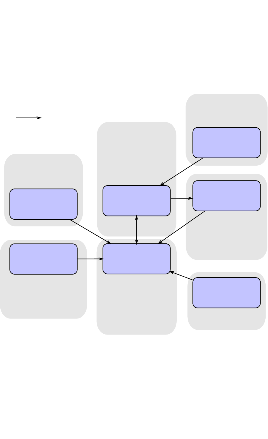
rte_malloc rte_eal + libc
rte_ring
rte_mempool
rte_mbuf
rte_timer
X uses Y
Allocation of named
memory zones using
libc's malloc()
Environment abstraction
layer: RTE loading, memory
allocation, time reference,
PCI access, logging
Timer facilities. Based
on HPET interface that
is provided by EAL.
Handle a pool of objects
using a ring to store
them. Allow bulk
enqueue/dequeue and
per-CPU cache.
Fixed-size lockless
FIFO for storing objects
in a table.
Manipulation of packet
buffers carrying network
data.
rte_debug
Provides debug helpers
XY
Fig. 2.1: Core Components Architecture
2.3. Core Components 5

Programmer’s Guide, Release 18.11.0-rc5
services, such as a per-core object cache and an alignment helper to ensure that objects are
padded to spread them equally on all RAM channels.
This memory pool allocator is described in Mempool Library.
2.3.3 Network Packet Buffer Management (librte_mbuf)
The mbuf library provides the facility to create and destroy buffers that may be used by the
DPDK application to store message buffers. The message buffers are created at startup time
and stored in a mempool, using the DPDK mempool library.
This library provides an API to allocate/free mbufs, manipulate packet buffers which are used
to carry network packets.
Network Packet Buffer Management is described in Mbuf Library .
2.3.4 Timer Manager (librte_timer)
This library provides a timer service to DPDK execution units, providing the ability to execute
a function asynchronously. It can be periodic function calls, or just a one-shot call. It uses
the timer interface provided by the Environment Abstraction Layer (EAL) to get a precise time
reference and can be initiated on a per-core basis as required.
The library documentation is available in Timer Library .
2.4 Ethernet* Poll Mode Driver Architecture
The DPDK includes Poll Mode Drivers (PMDs) for 1 GbE, 10 GbE and 40GbE, and para virtu-
alized virtio Ethernet controllers which are designed to work without asynchronous, interrupt-
based signaling mechanisms.
See Poll Mode Driver.
2.5 Packet Forwarding Algorithm Support
The DPDK includes Hash (librte_hash) and Longest Prefix Match (LPM,librte_lpm) libraries to
support the corresponding packet forwarding algorithms.
See Hash Library and LPM Library for more information.
2.6 librte_net
The librte_net library is a collection of IP protocol definitions and convenience macros. It is
based on code from the FreeBSD* IP stack and contains protocol numbers (for use in IP
headers), IP-related macros, IPv4/IPv6 header structures and TCP, UDP and SCTP header
structures.
2.4. Ethernet* Poll Mode Driver Architecture 6

CHAPTER
THREE
ENVIRONMENT ABSTRACTION LAYER
The Environment Abstraction Layer (EAL) is responsible for gaining access to low-level re-
sources such as hardware and memory space. It provides a generic interface that hides the
environment specifics from the applications and libraries. It is the responsibility of the initializa-
tion routine to decide how to allocate these resources (that is, memory space, devices, timers,
consoles, and so on).
Typical services expected from the EAL are:
• DPDK Loading and Launching: The DPDK and its application are linked as a single
application and must be loaded by some means.
• Core Affinity/Assignment Procedures: The EAL provides mechanisms for assigning exe-
cution units to specific cores as well as creating execution instances.
• System Memory Reservation: The EAL facilitates the reservation of different memory
zones, for example, physical memory areas for device interactions.
• Trace and Debug Functions: Logs, dump_stack, panic and so on.
• Utility Functions: Spinlocks and atomic counters that are not provided in libc.
• CPU Feature Identification: Determine at runtime if a particular feature, for example,
Intel® AVX is supported. Determine if the current CPU supports the feature set that the
binary was compiled for.
• Interrupt Handling: Interfaces to register/unregister callbacks to specific interrupt
sources.
• Alarm Functions: Interfaces to set/remove callbacks to be run at a specific time.
3.1 EAL in a Linux-userland Execution Environment
In a Linux user space environment, the DPDK application runs as a user-space application
using the pthread library.
The EAL performs physical memory allocation using mmap() in hugetlbfs (using huge page
sizes to increase performance). This memory is exposed to DPDK service layers such as the
Mempool Library .
At this point, the DPDK services layer will be initialized, then through pthread setaffinity calls,
each execution unit will be assigned to a specific logical core to run as a user-level thread.
The time reference is provided by the CPU Time-Stamp Counter (TSC) or by the HPET kernel
API through a mmap() call.
7

Programmer’s Guide, Release 18.11.0-rc5
3.1.1 Initialization and Core Launching
Part of the initialization is done by the start function of glibc. A check is also performed at
initialization time to ensure that the micro architecture type chosen in the config file is supported
by the CPU. Then, the main() function is called. The core initialization and launch is done
in rte_eal_init() (see the API documentation). It consist of calls to the pthread library (more
specifically, pthread_self(), pthread_create(), and pthread_setaffinity_np()).
Note: Initialization of objects, such as memory zones, rings, memory pools, lpm tables and
hash tables, should be done as part of the overall application initialization on the master lcore.
The creation and initialization functions for these objects are not multi-thread safe. However,
once initialized, the objects themselves can safely be used in multiple threads simultaneously.
3.1.2 Shutdown and Cleanup
During the initialization of EAL resources such as hugepage backed memory can be allocated
by core components. The memory allocated during rte_eal_init() can be released by
calling the rte_eal_cleanup() function. Refer to the API documentation for details.
3.1.3 Multi-process Support
The Linuxapp EAL allows a multi-process as well as a multi-threaded (pthread) deployment
model. See chapter Multi-process Support for more details.
3.1.4 Memory Mapping Discovery and Memory Reservation
The allocation of large contiguous physical memory is done using the hugetlbfs kernel filesys-
tem. The EAL provides an API to reserve named memory zones in this contiguous memory.
The physical address of the reserved memory for that memory zone is also returned to the
user by the memory zone reservation API.
There are two modes in which DPDK memory subsystem can operate: dynamic mode, and
legacy mode. Both modes are explained below.
Note: Memory reservations done using the APIs provided by rte_malloc are also backed by
pages from the hugetlbfs filesystem.
• Dynamic memory mode
Currently, this mode is only supported on Linux.
In this mode, usage of hugepages by DPDK application will grow and shrink based on applica-
tion’s requests. Any memory allocation through rte_malloc(),rte_memzone_reserve()
or other methods, can potentially result in more hugepages being reserved from the system.
Similarly, any memory deallocation can potentially result in hugepages being released back to
the system.
Memory allocated in this mode is not guaranteed to be IOVA-contiguous. If large chunks of
IOVA-contiguous are required (with “large” defined as “more than one page”), it is recom-
mended to either use VFIO driver for all physical devices (so that IOVA and VA addresses can
be the same, thereby bypassing physical addresses entirely), or use legacy memory mode.
3.1. EAL in a Linux-userland Execution Environment 8
Programmer’s Guide, Release 18.11.0-rc5
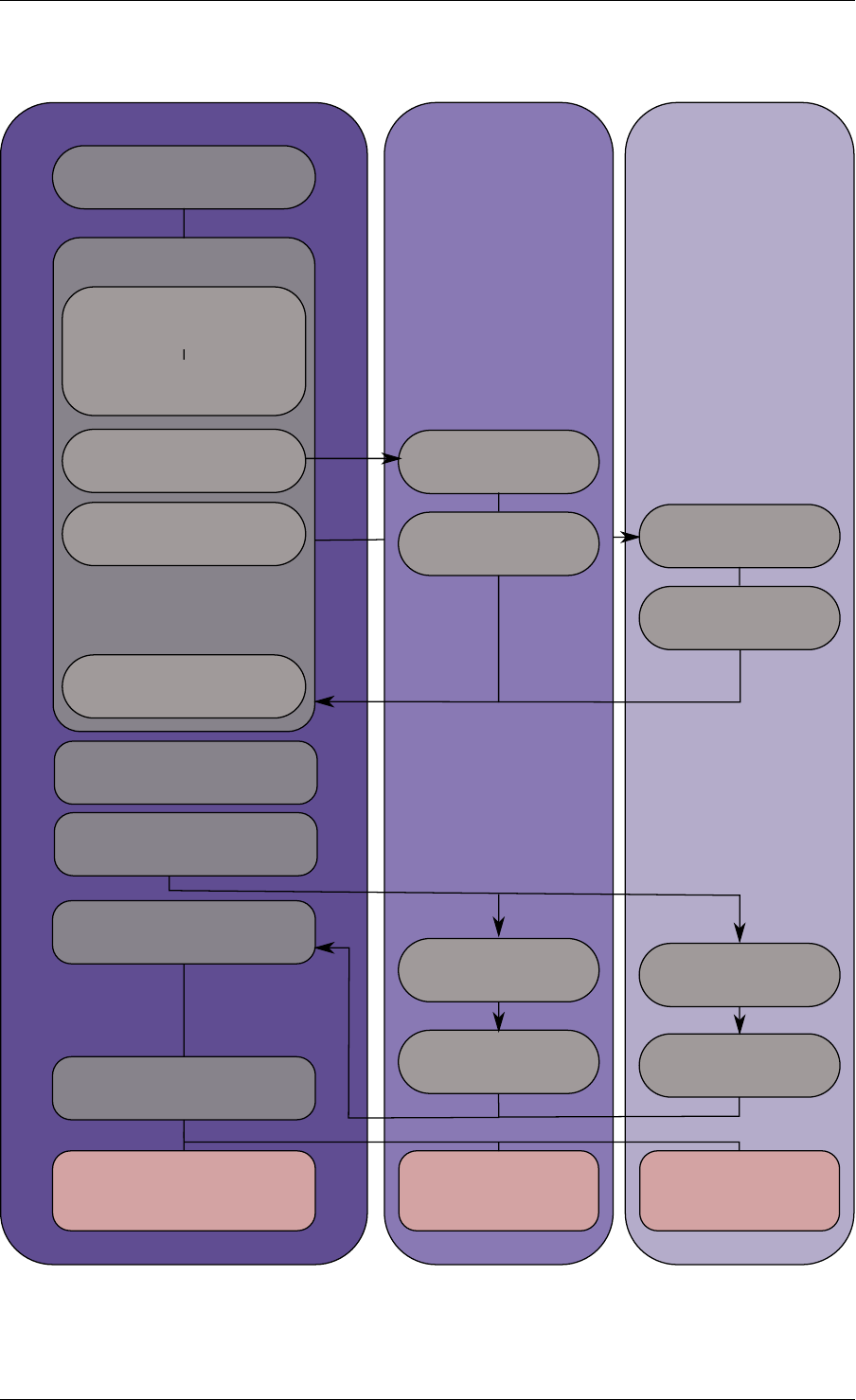
Master lcore lcore 1 lcore 2
main()
rte_eal_init()
rte_eal_memory_init()
rte_eal_logs_init()
rte_eal_pci_init()
...
pthread_create(1)
pthread_create(2)
per-thread init
wait per-thread init
wait
wait all threads
per_lcore_
app_init()
per_lcore_
app_init()
rte_eal_mp_wait_lcore()
application
...
wait wait
application
...
application
...
rte_eal_remote_lauch(app)
rte_eal_remote_lauch(
per_lcore_app_init)
other inits (libs, drivers)
Fig. 3.1: EAL Initialization in a Linux Application Environment
3.1. EAL in a Linux-userland Execution Environment 9

Programmer’s Guide, Release 18.11.0-rc5
For chunks of memory which must be IOVA-contiguous, it is recommended to use
rte_memzone_reserve() function with RTE_MEMZONE_IOVA_CONTIG flag specified. This
way, memory allocator will ensure that, whatever memory mode is in use, either reserved
memory will satisfy the requirements, or the allocation will fail.
There is no need to preallocate any memory at startup using -m or --socket-mem command-
line parameters, however it is still possible to do so, in which case preallocate memory will be
“pinned” (i.e. will never be released by the application back to the system). It will be possible
to allocate more hugepages, and deallocate those, but any preallocated pages will not be
freed. If neither -m nor --socket-mem were specified, no memory will be preallocated, and
all memory will be allocated at runtime, as needed.
Another available option to use in dynamic memory mode is --single-file-segments
command-line option. This option will put pages in single files (per memseg list), as opposed
to creating a file per page. This is normally not needed, but can be useful for use cases like
userspace vhost, where there is limited number of page file descriptors that can be passed to
VirtIO.
If the application (or DPDK-internal code, such as device drivers) wishes to receive notifica-
tions about newly allocated memory, it is possible to register for memory event callbacks via
rte_mem_event_callback_register() function. This will call a callback function any
time DPDK’s memory map has changed.
If the application (or DPDK-internal code, such as device drivers) wishes to
be notified about memory allocations above specified threshold (and have a
chance to deny them), allocation validator callbacks are also available via
rte_mem_alloc_validator_callback_register() function.
A default validator callback is provided by EAL, which can be enabled with a --socket-limit
command-line option, for a simple way to limit maximum amount of memory that can be used
by DPDK application.
Note: In multiprocess scenario, all related processes (i.e. primary process, and secondary
processes running with the same prefix) must be in the same memory modes. That is, if
primary process is run in dynamic memory mode, all of its secondary processes must be run
in the same mode. The same is applicable to --single-file-segments command-line
option - both primary and secondary processes must shared this mode.
• Legacy memory mode
This mode is enabled by specifying --legacy-mem command-line switch to the EAL. This
switch will have no effect on FreeBSD as FreeBSD only supports legacy mode anyway.
This mode mimics historical behavior of EAL. That is, EAL will reserve all memory at startup,
sort all memory into large IOVA-contiguous chunks, and will not allow acquiring or releasing
hugepages from the system at runtime.
If neither -m nor --socket-mem were specified, the entire available hugepage memory will
be preallocated.
• 32-bit support
Additional restrictions are present when running in 32-bit mode. In dynamic memory mode, by
default maximum of 2 gigabytes of VA space will be preallocated, and all of it will be on master
lcore NUMA node unless --socket-mem flag is used.
3.1. EAL in a Linux-userland Execution Environment 10

Programmer’s Guide, Release 18.11.0-rc5
In legacy mode, VA space will only be preallocated for segments that were requested (plus
padding, to keep IOVA-contiguousness).
• Maximum amount of memory
All possible virtual memory space that can ever be used for hugepage mapping in a DPDK
process is preallocated at startup, thereby placing an upper limit on how much memory a
DPDK application can have. DPDK memory is stored in segment lists, each segment is strictly
one physical page. It is possible to change the amount of virtual memory being preallocated at
startup by editing the following config variables:
•CONFIG_RTE_MAX_MEMSEG_LISTS controls how many segment lists can DPDK have
•CONFIG_RTE_MAX_MEM_MB_PER_LIST controls how much megabytes of memory each
segment list can address
•CONFIG_RTE_MAX_MEMSEG_PER_LIST controls how many segments each segment
can have
•CONFIG_RTE_MAX_MEMSEG_PER_TYPE controls how many segments each memory
type can have (where “type” is defined as “page size + NUMA node” combination)
•CONFIG_RTE_MAX_MEM_MB_PER_TYPE controls how much megabytes of memory each
memory type can address
•CONFIG_RTE_MAX_MEM_MB places a global maximum on the amount of memory DPDK
can reserve
Normally, these options do not need to be changed.
Note: Preallocated virtual memory is not to be confused with preallocated hugepage memory!
All DPDK processes preallocate virtual memory at startup. Hugepages can later be mapped
into that preallocated VA space (if dynamic memory mode is enabled), and can optionally be
mapped into it at startup.
3.1.5 Support for Externally Allocated Memory
It is possible to use externally allocated memory in DPDK, using a set of malloc heap API’s.
Support for externally allocated memory is implemented through overloading the socket ID -
externally allocated heaps will have socket ID’s that would be considered invalid under normal
circumstances. Requesting an allocation to take place from a specified externally allocated
memory is a matter of supplying the correct socket ID to DPDK allocator, either directly (e.g.
through a call to rte_malloc) or indirectly (through data structure-specific allocation API’s
such as rte_ring_create).
Since there is no way DPDK can verify whether memory are is available or valid, this re-
sponsibility falls on the shoulders of the user. All multiprocess synchronization is also user’s
responsibility, as well as ensuring that all calls to add/attach/detach/remove memory are done
in the correct order. It is not required to attach to a memory area in all processes - only attach
to memory areas as needed.
The expected workflow is as follows:
• Get a pointer to memory area
• Create a named heap
3.1. EAL in a Linux-userland Execution Environment 11

Programmer’s Guide, Release 18.11.0-rc5
•Add memory area(s) to the heap
–If IOVA table is not specified, IOVA addresses will be assumed to be unavailable,
and DMA mappings will not be performed
–Other processes must attach to the memory area before they can use it
• Get socket ID used for the heap
• Use normal DPDK allocation procedures, using supplied socket ID
•If memory area is no longer needed, it can be removed from the heap
–Other processes must detach from this memory area before it can be removed
•If heap is no longer needed, remove it
–Socket ID will become invalid and will not be reused
For more information, please refer to rte_malloc API documentation, specifically the
rte_malloc_heap_*family of function calls.
3.1.6 Per-lcore and Shared Variables
Note: lcore refers to a logical execution unit of the processor, sometimes called a hardware
thread.
Shared variables are the default behavior. Per-lcore variables are implemented using Thread
Local Storage (TLS) to provide per-thread local storage.
3.1.7 Logs
A logging API is provided by EAL. By default, in a Linux application, logs are sent to syslog and
also to the console. However, the log function can be overridden by the user to use a different
logging mechanism.
Trace and Debug Functions
There are some debug functions to dump the stack in glibc. The rte_panic() function can
voluntarily provoke a SIG_ABORT, which can trigger the generation of a core file, readable by
gdb.
3.1.8 CPU Feature Identification
The EAL can query the CPU at runtime (using the rte_cpu_get_features() function) to deter-
mine which CPU features are available.
3.1.9 User Space Interrupt Event
• User Space Interrupt and Alarm Handling in Host Thread
3.1. EAL in a Linux-userland Execution Environment 12

Programmer’s Guide, Release 18.11.0-rc5
The EAL creates a host thread to poll the UIO device file descriptors to detect the interrupts.
Callbacks can be registered or unregistered by the EAL functions for a specific interrupt event
and are called in the host thread asynchronously. The EAL also allows timed callbacks to be
used in the same way as for NIC interrupts.
Note: In DPDK PMD, the only interrupts handled by the dedicated host thread are those for
link status change (link up and link down notification) and for sudden device removal.
• RX Interrupt Event
The receive and transmit routines provided by each PMD don’t limit themselves to execute in
polling thread mode. To ease the idle polling with tiny throughput, it’s useful to pause the polling
and wait until the wake-up event happens. The RX interrupt is the first choice to be such kind
of wake-up event, but probably won’t be the only one.
EAL provides the event APIs for this event-driven thread mode. Taking linuxapp as an example,
the implementation relies on epoll. Each thread can monitor an epoll instance in which all the
wake-up events’ file descriptors are added. The event file descriptors are created and mapped
to the interrupt vectors according to the UIO/VFIO spec. From bsdapp’s perspective, kqueue
is the alternative way, but not implemented yet.
EAL initializes the mapping between event file descriptors and interrupt vectors, while each
device initializes the mapping between interrupt vectors and queues. In this way, EAL actually
is unaware of the interrupt cause on the specific vector. The eth_dev driver takes responsibility
to program the latter mapping.
Note: Per queue RX interrupt event is only allowed in VFIO which supports multiple MSI-
X vector. In UIO, the RX interrupt together with other interrupt causes shares the same
vector. In this case, when RX interrupt and LSC(link status change) interrupt are both en-
abled(intr_conf.lsc == 1 && intr_conf.rxq == 1), only the former is capable.
The RX interrupt are controlled/enabled/disabled by ethdev APIs - ‘rte_eth_dev_rx_intr_*’.
They return failure if the PMD hasn’t support them yet. The intr_conf.rxq flag is used to turn on
the capability of RX interrupt per device.
• Device Removal Event
This event is triggered by a device being removed at a bus level. Its underlying resources may
have been made unavailable (i.e. PCI mappings unmapped). The PMD must make sure that
on such occurrence, the application can still safely use its callbacks.
This event can be subscribed to in the same way one would subscribe to a link status change
event. The execution context is thus the same, i.e. it is the dedicated interrupt host thread.
Considering this, it is likely that an application would want to close a device having emitted
a Device Removal Event. In such case, calling rte_eth_dev_close() can trigger it to
unregister its own Device Removal Event callback. Care must be taken not to close the device
from the interrupt handler context. It is necessary to reschedule such closing operation.
3.1.10 Blacklisting
The EAL PCI device blacklist functionality can be used to mark certain NIC ports as blacklisted,
so they are ignored by the DPDK. The ports to be blacklisted are identified using the PCIe*
description (Domain:Bus:Device.Function).
3.1. EAL in a Linux-userland Execution Environment 13

Programmer’s Guide, Release 18.11.0-rc5
3.1.11 Misc Functions
Locks and atomic operations are per-architecture (i686 and x86_64).
3.1.12 IOVA Mode Configuration
Auto detection of the IOVA mode, based on probing the bus and IOMMU configuration, may
not report the desired addressing mode when virtual devices that are not directly attached to
the bus are present. To facilitate forcing the IOVA mode to a specific value the EAL command
line option --iova-mode can be used to select either physical addressing(‘pa’) or virtual ad-
dressing(‘va’).
3.2 Memory Segments and Memory Zones (memzone)
The mapping of physical memory is provided by this feature in the EAL. As physical memory
can have gaps, the memory is described in a table of descriptors, and each descriptor (called
rte_memseg ) describes a physical page.
On top of this, the memzone allocator’s role is to reserve contiguous portions of physical mem-
ory. These zones are identified by a unique name when the memory is reserved.
The rte_memzone descriptors are also located in the configuration structure. This structure is
accessed using rte_eal_get_configuration(). The lookup (by name) of a memory zone returns
a descriptor containing the physical address of the memory zone.
Memory zones can be reserved with specific start address alignment by supplying the align
parameter (by default, they are aligned to cache line size). The alignment value should be a
power of two and not less than the cache line size (64 bytes). Memory zones can also be
reserved from either 2 MB or 1 GB hugepages, provided that both are available on the system.
Both memsegs and memzones are stored using rte_fbarray structures. Please refer to
DPDK API Reference for more information.
3.3 Multiple pthread
DPDK usually pins one pthread per core to avoid the overhead of task switching. This allows
for significant performance gains, but lacks flexibility and is not always efficient.
Power management helps to improve the CPU efficiency by limiting the CPU runtime frequency.
However, alternately it is possible to utilize the idle cycles available to take advantage of the
full capability of the CPU.
By taking advantage of cgroup, the CPU utilization quota can be simply assigned. This gives
another way to improve the CPU efficiency, however, there is a prerequisite; DPDK must handle
the context switching between multiple pthreads per core.
For further flexibility, it is useful to set pthread affinity not only to a CPU but to a CPU set.
3.2. Memory Segments and Memory Zones (memzone) 14

Programmer’s Guide, Release 18.11.0-rc5
3.3.1 EAL pthread and lcore Affinity
The term “lcore” refers to an EAL thread, which is really a Linux/FreeBSD pthread. “EAL
pthreads” are created and managed by EAL and execute the tasks issued by remote_launch.
In each EAL pthread, there is a TLS (Thread Local Storage) called _lcore_id for unique identi-
fication. As EAL pthreads usually bind 1:1 to the physical CPU, the _lcore_id is typically equal
to the CPU ID.
When using multiple pthreads, however, the binding is no longer always 1:1 between an EAL
pthread and a specified physical CPU. The EAL pthread may have affinity to a CPU set, and
as such the _lcore_id will not be the same as the CPU ID. For this reason, there is an EAL
long option ‘–lcores’ defined to assign the CPU affinity of lcores. For a specified lcore ID or ID
group, the option allows setting the CPU set for that EAL pthread.
The format pattern: –lcores=’<lcore_set>[@cpu_set][,<lcore_set>[@cpu_set],...]’
‘lcore_set’ and ‘cpu_set’ can be a single number, range or a group.
A number is a “digit([0-9]+)”; a range is “<number>-<number>”; a group is “(<num-
ber|range>[,<number|range>,...])”.
If a ‘@cpu_set’ value is not supplied, the value of ‘cpu_set’ will default to the value of ‘lcore_set’.
For example, "--lcores='1,2@(5-7),(3-5)@(0,2),(0,6),7-8'" which means start 9 EAL thread;
lcore 0 runs on cpuset 0x41 (cpu 0,6);
lcore 1 runs on cpuset 0x2 (cpu 1);
lcore 2 runs on cpuset 0xe0 (cpu 5,6,7);
lcore 3,4,5 runs on cpuset 0x5 (cpu 0,2);
lcore 6 runs on cpuset 0x41 (cpu 0,6);
lcore 7 runs on cpuset 0x80 (cpu 7);
lcore 8 runs on cpuset 0x100 (cpu 8).
Using this option, for each given lcore ID, the associated CPUs can be assigned. It’s also
compatible with the pattern of corelist(‘-l’) option.
3.3.2 non-EAL pthread support
It is possible to use the DPDK execution context with any user pthread (aka. Non-EAL
pthreads). In a non-EAL pthread, the _lcore_id is always LCORE_ID_ANY which identifies
that it is not an EAL thread with a valid, unique, _lcore_id. Some libraries will use an alter-
native unique ID (e.g. TID), some will not be impacted at all, and some will work but with
limitations (e.g. timer and mempool libraries).
All these impacts are mentioned in Known Issues section.
3.3.3 Public Thread API
There are two public APIs rte_thread_set_affinity() and
rte_thread_get_affinity() introduced for threads. When they’re used in any pthread
context, the Thread Local Storage(TLS) will be set/get.
Those TLS include _cpuset and _socket_id:
•_cpuset stores the CPUs bitmap to which the pthread is affinitized.
•_socket_id stores the NUMA node of the CPU set. If the CPUs in CPU set belong to
different NUMA node, the _socket_id will be set to SOCKET_ID_ANY.
3.3. Multiple pthread 15

Programmer’s Guide, Release 18.11.0-rc5
3.3.4 Known Issues
• rte_mempool
The rte_mempool uses a per-lcore cache inside the mempool. For non-EAL pthreads,
rte_lcore_id() will not return a valid number. So for now, when rte_mempool is used
with non-EAL pthreads, the put/get operations will bypass the default mempool cache and
there is a performance penalty because of this bypass. Only user-owned external caches
can be used in a non-EAL context in conjunction with rte_mempool_generic_put()
and rte_mempool_generic_get() that accept an explicit cache parameter.
• rte_ring
rte_ring supports multi-producer enqueue and multi-consumer dequeue. However, it is
non-preemptive, this has a knock on effect of making rte_mempool non-preemptable.
Note: The “non-preemptive” constraint means:
–a pthread doing multi-producers enqueues on a given ring must not be preempted
by another pthread doing a multi-producer enqueue on the same ring.
–a pthread doing multi-consumers dequeues on a given ring must not be preempted
by another pthread doing a multi-consumer dequeue on the same ring.
Bypassing this constraint may cause the 2nd pthread to spin until the 1st one is scheduled
again. Moreover, if the 1st pthread is preempted by a context that has an higher priority,
it may even cause a dead lock.
This means, use cases involving preemptible pthreads should consider using rte_ring
carefully.
1. It CAN be used for preemptible single-producer and single-consumer use case.
2. It CAN be used for non-preemptible multi-producer and preemptible single-
consumer use case.
3. It CAN be used for preemptible single-producer and non-preemptible multi-
consumer use case.
4. It MAY be used by preemptible multi-producer and/or preemptible multi-consumer
pthreads whose scheduling policy are all SCHED_OTHER(cfs), SCHED_IDLE or
SCHED_BATCH. User SHOULD be aware of the performance penalty before using
it.
5. It MUST not be used by multi-producer/consumer pthreads, whose scheduling poli-
cies are SCHED_FIFO or SCHED_RR.
• rte_timer
Running rte_timer_manage() on a non-EAL pthread is not allowed. However, reset-
ting/stopping the timer from a non-EAL pthread is allowed.
• rte_log
In non-EAL pthreads, there is no per thread loglevel and logtype, global loglevels are
used.
• misc
3.3. Multiple pthread 16

Programmer’s Guide, Release 18.11.0-rc5
The debug statistics of rte_ring, rte_mempool and rte_timer are not supported in a non-
EAL pthread.
3.3.5 cgroup control
The following is a simple example of cgroup control usage, there are two pthreads(t0 and t1)
doing packet I/O on the same core ($CPU). We expect only 50% of CPU spend on packet IO.
mkdir /sys/fs/cgroup/cpu/pkt_io
mkdir /sys/fs/cgroup/cpuset/pkt_io
echo $cpu > /sys/fs/cgroup/cpuset/cpuset.cpus
echo $t0 > /sys/fs/cgroup/cpu/pkt_io/tasks
echo $t0 > /sys/fs/cgroup/cpuset/pkt_io/tasks
echo $t1 > /sys/fs/cgroup/cpu/pkt_io/tasks
echo $t1 > /sys/fs/cgroup/cpuset/pkt_io/tasks
cd /sys/fs/cgroup/cpu/pkt_io
echo 100000 > pkt_io/cpu.cfs_period_us
echo 50000 > pkt_io/cpu.cfs_quota_us
3.4 Malloc
The EAL provides a malloc API to allocate any-sized memory.
The objective of this API is to provide malloc-like functions to allow allocation from hugepage
memory and to facilitate application porting. The DPDK API Reference manual describes the
available functions.
Typically, these kinds of allocations should not be done in data plane processing because they
are slower than pool-based allocation and make use of locks within the allocation and free
paths. However, they can be used in configuration code.
Refer to the rte_malloc() function description in the DPDK API Reference manual for more
information.
3.4.1 Cookies
When CONFIG_RTE_MALLOC_DEBUG is enabled, the allocated memory contains overwrite
protection fields to help identify buffer overflows.
3.4.2 Alignment and NUMA Constraints
The rte_malloc() takes an align argument that can be used to request a memory area that is
aligned on a multiple of this value (which must be a power of two).
On systems with NUMA support, a call to the rte_malloc() function will return memory that has
been allocated on the NUMA socket of the core which made the call. A set of APIs is also
provided, to allow memory to be explicitly allocated on a NUMA socket directly, or by allocated
on the NUMA socket where another core is located, in the case where the memory is to be
used by a logical core other than on the one doing the memory allocation.
3.4. Malloc 17

Programmer’s Guide, Release 18.11.0-rc5
3.4.3 Use Cases
This API is meant to be used by an application that requires malloc-like functions at initialization
time.
For allocating/freeing data at runtime, in the fast-path of an application, the memory pool library
should be used instead.
3.4.4 Internal Implementation
Data Structures
There are two data structure types used internally in the malloc library:
• struct malloc_heap - used to track free space on a per-socket basis
• struct malloc_elem - the basic element of allocation and free-space tracking inside the
library.
Structure: malloc_heap
The malloc_heap structure is used to manage free space on a per-socket basis. Internally,
there is one heap structure per NUMA node, which allows us to allocate memory to a thread
based on the NUMA node on which this thread runs. While this does not guarantee that the
memory will be used on that NUMA node, it is no worse than a scheme where the memory is
always allocated on a fixed or random node.
The key fields of the heap structure and their function are described below (see also diagram
above):
• lock - the lock field is needed to synchronize access to the heap. Given that the free
space in the heap is tracked using a linked list, we need a lock to prevent two threads
manipulating the list at the same time.
• free_head - this points to the first element in the list of free nodes for this malloc heap.
• first - this points to the first element in the heap.
• last - this points to the last element in the heap.
Structure: malloc_elem
The malloc_elem structure is used as a generic header structure for various blocks of memory.
It is used in two different ways - all shown in the diagram above:
1. As a header on a block of free or allocated memory - normal case
2. As a padding header inside a block of memory
The most important fields in the structure and how they are used are described below.
Malloc heap is a doubly-linked list, where each element keeps track of its previous and next
elements. Due to the fact that hugepage memory can come and go, neighbouring malloc
elements may not necessarily be adjacent in memory. Also, since a malloc element may
3.4. Malloc 18
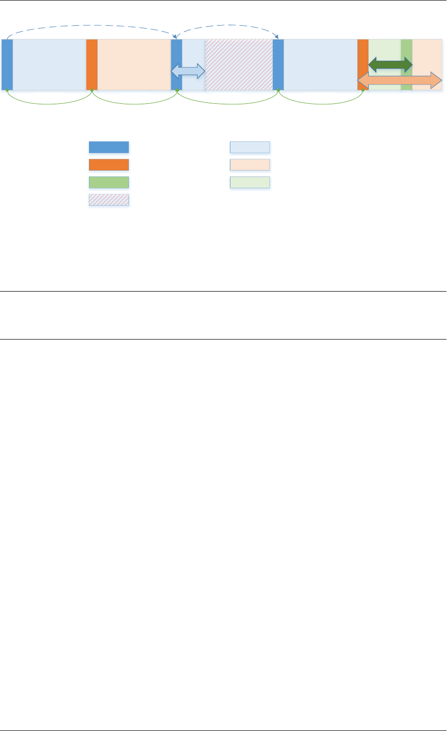
Programmer’s Guide, Release 18.11.0-rc5
Free element header
Used element header
Free space
Allocated data
Pad element header Padding
Unavailable space
size
pad
prev/next prev/next
size
next free next free
prev/next prev/next
Fig. 3.2: Example of a malloc heap and malloc elements within the malloc library
span multiple pages, its contents may not necessarily be IOVA-contiguous either - each malloc
element is only guaranteed to be virtually contiguous.
Note: If the usage of a particular field in one of the above three usages is not described, the
field can be assumed to have an undefined value in that situation, for example, for padding
headers only the “state” and “pad” fields have valid values.
• heap - this pointer is a reference back to the heap structure from which this block was
allocated. It is used for normal memory blocks when they are being freed, to add the
newly-freed block to the heap’s free-list.
• prev - this pointer points to previous header element/block in memory. When freeing a
block, this pointer is used to reference the previous block to check if that block is also
free. If so, and the two blocks are immediately adjacent to each other, then the two free
blocks are merged to form a single larger block.
• next - this pointer points to next header element/block in memory. When freeing a block,
this pointer is used to reference the next block to check if that block is also free. If so,
and the two blocks are immediately adjacent to each other, then the two free blocks are
merged to form a single larger block.
• free_list - this is a structure pointing to previous and next elements in this heap’s free list.
It is only used in normal memory blocks; on malloc() to find a suitable free block to
allocate and on free() to add the newly freed element to the free-list.
• state - This field can have one of three values: FREE,BUSY or PAD. The former two are
to indicate the allocation state of a normal memory block and the latter is to indicate that
the element structure is a dummy structure at the end of the start-of-block padding, i.e.
where the start of the data within a block is not at the start of the block itself, due to
alignment constraints. In that case, the pad header is used to locate the actual malloc
element header for the block.
• pad - this holds the length of the padding present at the start of the block. In the case
of a normal block header, it is added to the address of the end of the header to give the
address of the start of the data area, i.e. the value passed back to the application on
a malloc. Within a dummy header inside the padding, this same value is stored, and is
subtracted from the address of the dummy header to yield the address of the actual block
3.4. Malloc 19

Programmer’s Guide, Release 18.11.0-rc5
header.
• size - the size of the data block, including the header itself.
Memory Allocation
On EAL initialization, all preallocated memory segments are setup as part of the malloc heap.
This setup involves placing an element header with FREE at the start of each virtually contigu-
ous segment of memory. The FREE element is then added to the free_list for the malloc
heap.
This setup also happens whenever memory is allocated at runtime (if supported), in which case
newly allocated pages are also added to the heap, merging with any adjacent free segments if
there are any.
When an application makes a call to a malloc-like function, the malloc function will first index the
lcore_config structure for the calling thread, and determine the NUMA node of that thread.
The NUMA node is used to index the array of malloc_heap structures which is passed as a
parameter to the heap_alloc() function, along with the requested size, type, alignment and
boundary parameters.
The heap_alloc() function will scan the free_list of the heap, and attempt to find a free block
suitable for storing data of the requested size, with the requested alignment and boundary
constraints.
When a suitable free element has been identified, the pointer to be returned to the user is
calculated. The cache-line of memory immediately preceding this pointer is filled with a struct
malloc_elem header. Because of alignment and boundary constraints, there could be free
space at the start and/or end of the element, resulting in the following behavior:
1. Check for trailing space. If the trailing space is big enough, i.e. > 128 bytes, then the free
element is split. If it is not, then we just ignore it (wasted space).
2. Check for space at the start of the element. If the space at the start is small, i.e. <=128
bytes, then a pad header is used, and the remaining space is wasted. If, however, the
remaining space is greater, then the free element is split.
The advantage of allocating the memory from the end of the existing element is that no adjust-
ment of the free list needs to take place - the existing element on the free list just has its size
value adjusted, and the next/previous elements have their “prev”/”next” pointers redirected to
the newly created element.
In case when there is not enough memory in the heap to satisfy allocation request, EAL will
attempt to allocate more memory from the system (if supported) and, following successful
allocation, will retry reserving the memory again. In a multiprocessing scenario, all primary
and secondary processes will synchronize their memory maps to ensure that any valid pointer
to DPDK memory is guaranteed to be valid at all times in all currently running processes.
Failure to synchronize memory maps in one of the processes will cause allocation to fail, even
though some of the processes may have allocated the memory successfully. The memory is
not added to the malloc heap unless primary process has ensured that all other processes
have mapped this memory successfully.
Any successful allocation event will trigger a callback, for which user applications and other
DPDK subsystems can register. Additionally, validation callbacks will be triggered before allo-
3.4. Malloc 20

Programmer’s Guide, Release 18.11.0-rc5
cation if the newly allocated memory will exceed threshold set by the user, giving a chance to
allow or deny allocation.
Note: Any allocation of new pages has to go through primary process. If the primary process
is not active, no memory will be allocated even if it was theoretically possible to do so. This is
because primary’s process map acts as an authority on what should or should not be mapped,
while each secondary process has its own, local memory map. Secondary processes do not
update the shared memory map, they only copy its contents to their local memory map.
Freeing Memory
To free an area of memory, the pointer to the start of the data area is passed to the free
function. The size of the malloc_elem structure is subtracted from this pointer to get the
element header for the block. If this header is of type PAD then the pad length is further
subtracted from the pointer to get the proper element header for the entire block.
From this element header, we get pointers to the heap from which the block was allocated and
to where it must be freed, as well as the pointer to the previous and next elements. These
next and previous elements are then checked to see if they are also FREE and are immediately
adjacent to the current one, and if so, they are merged with the current element. This means
that we can never have two FREE memory blocks adjacent to one another, as they are always
merged into a single block.
If deallocating pages at runtime is supported, and the free element encloses one or more
pages, those pages can be deallocated and be removed from the heap. If DPDK was started
with command-line parameters for preallocating memory (-m or --socket-mem), then those
pages that were allocated at startup will not be deallocated.
Any successful deallocation event will trigger a callback, for which user applications and other
DPDK subsystems can register.
3.4. Malloc 21

CHAPTER
FOUR
SERVICE CORES
DPDK has a concept known as service cores, which enables a dynamic way of performing
work on DPDK lcores. Service core support is built into the EAL, and an API is provided to
optionally allow applications to control how the service cores are used at runtime.
The service cores concept is built up out of services (components of DPDK that require CPU
cycles to operate) and service cores (DPDK lcores, tasked with running services). The power
of the service core concept is that the mapping between service cores and services can be
configured to abstract away the difference between platforms and environments.
For example, the Eventdev has hardware and software PMDs. Of these the software PMD
requires an lcore to perform the scheduling operations, while the hardware PMD does not.
With service cores, the application would not directly notice that the scheduling is done in
software.
For detailed information about the service core API, please refer to the docs.
4.1 Service Core Initialization
There are two methods to having service cores in a DPDK application, either by using the
service coremask, or by dynamically adding cores using the API. The simpler of the two is to
pass the -s coremask argument to EAL, which will take any cores available in the main DPDK
coremask, and if the bits are also set in the service coremask the cores become service-cores
instead of DPDK application lcores.
4.2 Enabling Services on Cores
Each registered service can be individually mapped to a service core, or set of service cores.
Enabling a service on a particular core means that the lcore in question will run the service.
Disabling that core on the service stops the lcore in question from running the service.
Using this method, it is possible to assign specific workloads to each service core, and map N
workloads to M number of service cores. Each service lcore loops over the services that are
enabled for that core, and invokes the function to run the service.
22

Programmer’s Guide, Release 18.11.0-rc5
4.3 Service Core Statistics
The service core library is capable of collecting runtime statistics like number of calls to a
specific service, and number of cycles used by the service. The cycle count collection is
dynamically configurable, allowing any application to profile the services running on the system
at any time.
4.3. Service Core Statistics 23

CHAPTER
FIVE
RING LIBRARY
The ring allows the management of queues. Instead of having a linked list of infinite size, the
rte_ring has the following properties:
• FIFO
• Maximum size is fixed, the pointers are stored in a table
• Lockless implementation
• Multi-consumer or single-consumer dequeue
• Multi-producer or single-producer enqueue
• Bulk dequeue - Dequeues the specified count of objects if successful; otherwise fails
• Bulk enqueue - Enqueues the specified count of objects if successful; otherwise fails
• Burst dequeue - Dequeue the maximum available objects if the specified count cannot
be fulfilled
• Burst enqueue - Enqueue the maximum available objects if the specified count cannot
be fulfilled
The advantages of this data structure over a linked list queue are as follows:
• Faster; only requires a single Compare-And-Swap instruction of sizeof(void *) instead of
several double-Compare-And-Swap instructions.
• Simpler than a full lockless queue.
• Adapted to bulk enqueue/dequeue operations. As pointers are stored in a table, a de-
queue of several objects will not produce as many cache misses as in a linked queue.
Also, a bulk dequeue of many objects does not cost more than a dequeue of a simple
object.
The disadvantages:
• Size is fixed
• Having many rings costs more in terms of memory than a linked list queue. An empty
ring contains at least N pointers.
A simplified representation of a Ring is shown in with consumer and producer head and tail
pointers to objects stored in the data structure.
24

Programmer’s Guide, Release 18.11.0-rc5
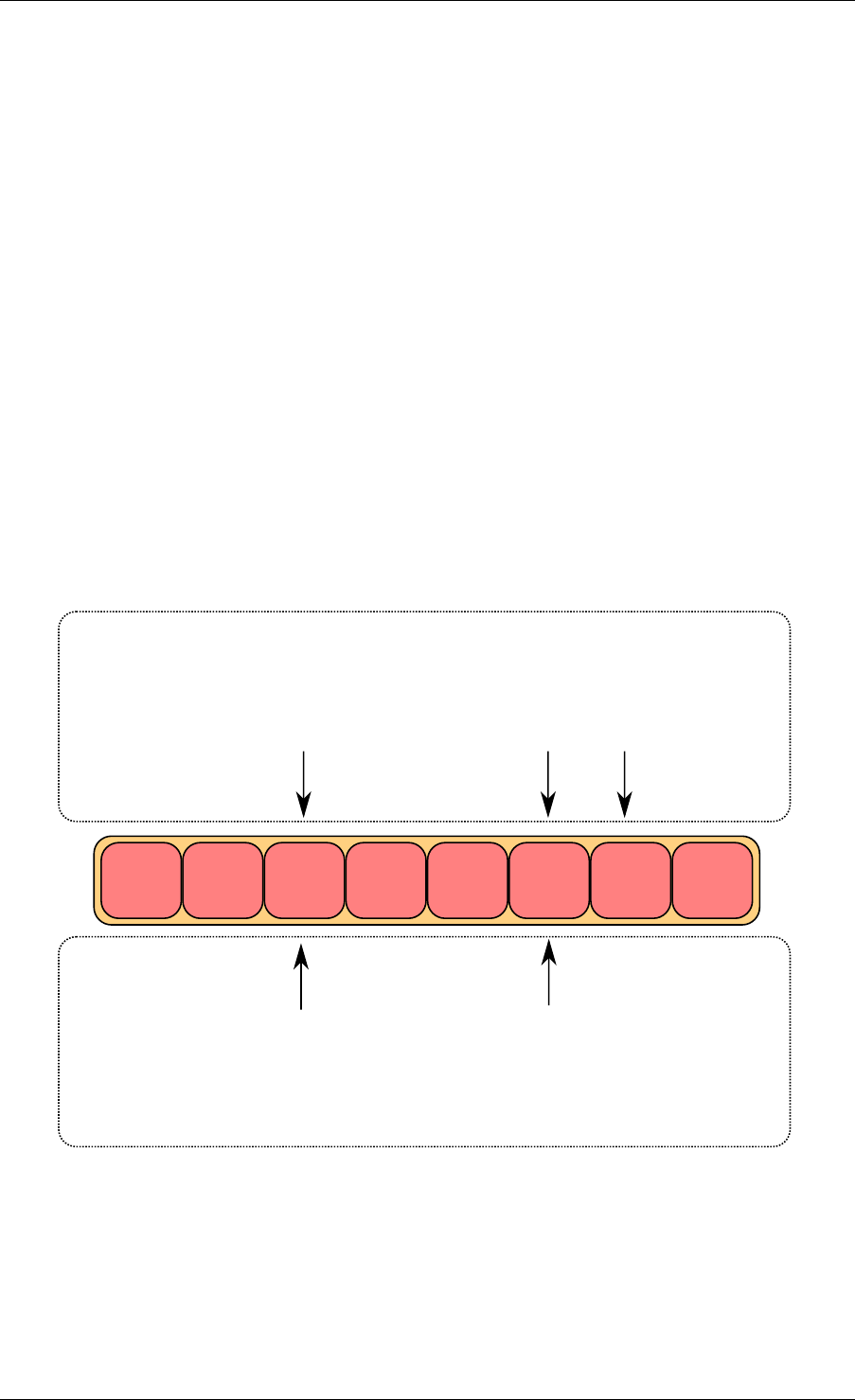
obj1 obj2 obj3
cons_head
cons_tail
prod_head
prod_tail
Fig. 5.1: Ring Structure
5.1 References for Ring Implementation in FreeBSD*
The following code was added in FreeBSD 8.0, and is used in some network device drivers (at
least in Intel drivers):
•bufring.h in FreeBSD
•bufring.c in FreeBSD
5.2 Lockless Ring Buffer in Linux*
The following is a link describing the Linux Lockless Ring Buffer Design.
5.3 Additional Features
5.3.1 Name
A ring is identified by a unique name. It is not possible to create two rings with the same name
(rte_ring_create() returns NULL if this is attempted).
5.4 Use Cases
Use cases for the Ring library include:
• Communication between applications in the DPDK
• Used by memory pool allocator
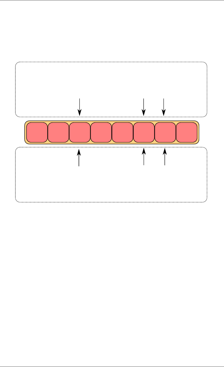
5.5 Anatomy of a Ring Buffer
This section explains how a ring buffer operates. The ring structure is composed of two head
and tail couples; one is used by producers and one is used by the consumers. The figures of
the following sections refer to them as prod_head, prod_tail, cons_head and cons_tail.
5.1. References for Ring Implementation in FreeBSD* 25
Programmer’s Guide, Release 18.11.0-rc5
Each figure represents a simplified state of the ring, which is a circular buffer. The content
of the function local variables is represented on the top of the figure, and the content of ring
structure is represented on the bottom of the figure.
5.5.1 Single Producer Enqueue
This section explains what occurs when a producer adds an object to the ring. In this example,
only the producer head and tail (prod_head and prod_tail) are modified, and there is only one
producer.
The initial state is to have a prod_head and prod_tail pointing at the same location.
Enqueue First Step
First, ring->prod_head and ring->cons_tail are copied in local variables. The prod_next lo-
cal variable points to the next element of the table, or several elements after in case of bulk
enqueue.
If there is not enough room in the ring (this is detected by checking cons_tail), it returns an
error.
obj1 obj2 obj3
cons_head
cons_tail
prod_head
prod_tail
local variables
structure state
cons_tail prod_head prod_next
Fig. 5.2: Enqueue first step
5.5. Anatomy of a Ring Buffer 26
Programmer’s Guide, Release 18.11.0-rc5
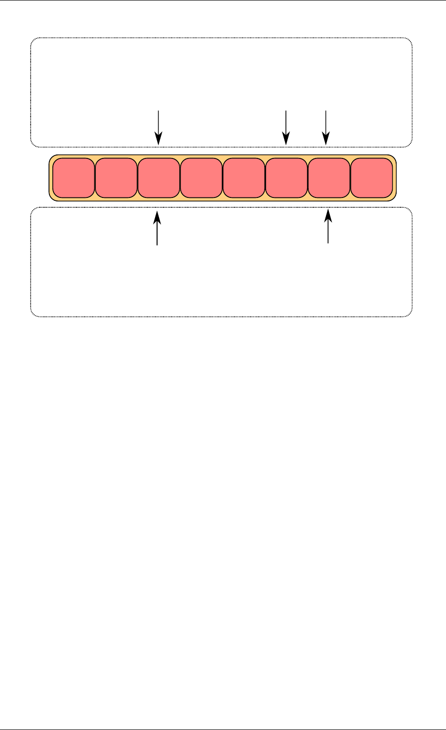
Enqueue Second Step
The second step is to modify ring->prod_head in ring structure to point to the same location
as prod_next.
A pointer to the added object is copied in the ring (obj4).
obj1 obj2 obj3
cons_head
cons_tail
prod_head
prod_tail
local variables
structure state
cons_tail prod_head prod_next
obj4
Fig. 5.3: Enqueue second step
Enqueue Last Step
Once the object is added in the ring, ring->prod_tail in the ring structure is modified to point to
the same location as ring->prod_head. The enqueue operation is finished.
5.5.2 Single Consumer Dequeue
This section explains what occurs when a consumer dequeues an object from the ring. In this
example, only the consumer head and tail (cons_head and cons_tail) are modified and there
is only one consumer.
The initial state is to have a cons_head and cons_tail pointing at the same location.
Dequeue First Step
First, ring->cons_head and ring->prod_tail are copied in local variables. The cons_next local
variable points to the next element of the table, or several elements after in the case of bulk
5.5. Anatomy of a Ring Buffer 27
Programmer’s Guide, Release 18.11.0-rc5
obj1 obj2 obj3
cons_head
cons_tail prod_head
prod_tail
local variables
structure state
cons_tail prod_head prod_next
obj4
Fig. 5.4: Enqueue last step
dequeue.
If there are not enough objects in the ring (this is detected by checking prod_tail), it returns an
error.
Dequeue Second Step
The second step is to modify ring->cons_head in the ring structure to point to the same location
as cons_next.
The pointer to the dequeued object (obj1) is copied in the pointer given by the user.
Dequeue Last Step
Finally, ring->cons_tail in the ring structure is modified to point to the same location as ring-
>cons_head. The dequeue operation is finished.
5.5.3 Multiple Producers Enqueue
This section explains what occurs when two producers concurrently add an object to the ring.
In this example, only the producer head and tail (prod_head and prod_tail) are modified.
The initial state is to have a prod_head and prod_tail pointing at the same location.
5.5. Anatomy of a Ring Buffer 28
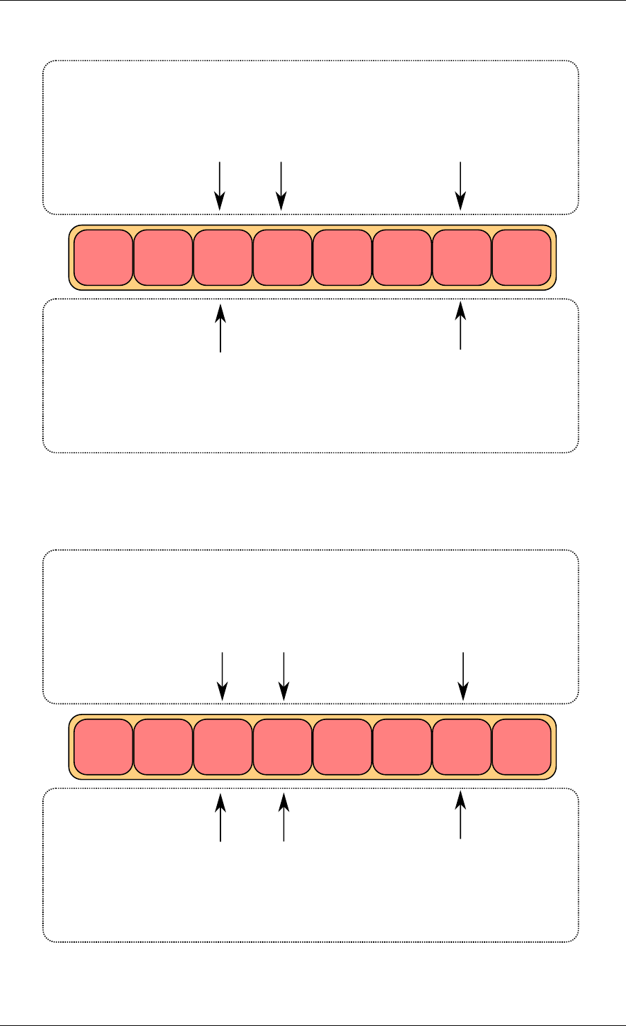
Programmer’s Guide, Release 18.11.0-rc5
obj1 obj2 obj3
cons_head
cons_tail prod_head
prod_tail
local variables
structure state
obj4
cons_head prod_tailcons_next
Fig. 5.5: Dequeue last step
obj2 obj3
cons_head
cons_tail
prod_head
prod_tail
local variables
structure state
cons_head prod_tailcons_next
obj4
Fig. 5.6: Dequeue second step
5.5. Anatomy of a Ring Buffer 29
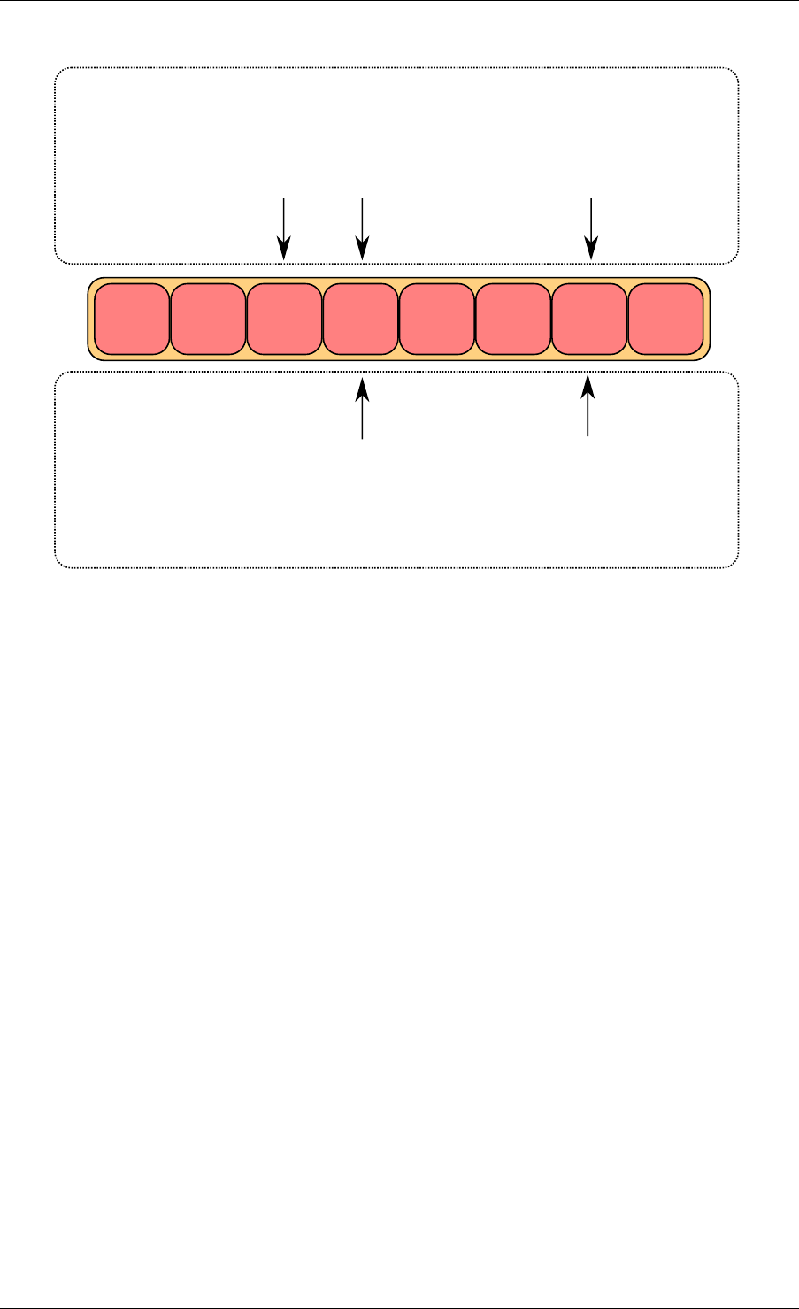
Programmer’s Guide, Release 18.11.0-rc5
obj2 obj3
cons_head
cons_tail prod_head
prod_tail
local variables
structure state
cons_head prod_tailcons_next
obj4
Fig. 5.7: Dequeue last step
Multiple Producers Enqueue First Step
On both cores, ring->prod_head and ring->cons_tail are copied in local variables. The
prod_next local variable points to the next element of the table, or several elements after in
the case of bulk enqueue.
If there is not enough room in the ring (this is detected by checking cons_tail), it returns an
error.
Multiple Producers Enqueue Second Step
The second step is to modify ring->prod_head in the ring structure to point to the same location
as prod_next. This operation is done using a Compare And Swap (CAS) instruction, which
does the following operations atomically:
• If ring->prod_head is different to local variable prod_head, the CAS operation fails, and
the code restarts at first step.
• Otherwise, ring->prod_head is set to local prod_next, the CAS operation is successful,
and processing continues.
In the figure, the operation succeeded on core 1, and step one restarted on core 2.
Multiple Producers Enqueue Third Step
The CAS operation is retried on core 2 with success.
5.5. Anatomy of a Ring Buffer 30
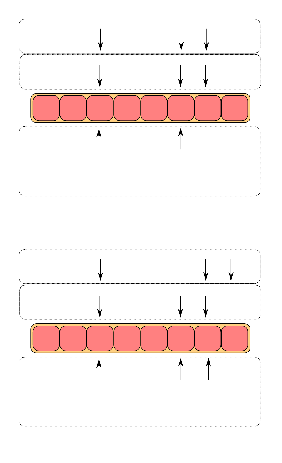
Programmer’s Guide, Release 18.11.0-rc5
obj1 obj2 obj3
cons_head
cons_tail
prod_head
prod_tail
local variables
core 2
structure state
cons_tail prod_head prod_next
local variables
core 1
cons_tail prod_head prod_next
Fig. 5.8: Multiple producer enqueue first step
obj1 obj2 obj3
cons_head
cons_tail
prod_head
prod_tail
local variables
core 2
structure state
cons_tail prod_head prod_next
local variables
core 1
cons_tail prod_head prod_next
compare and swap succeeds
on core 1 and fails on core 2
Fig. 5.9: Multiple producer enqueue second step
5.5. Anatomy of a Ring Buffer 31
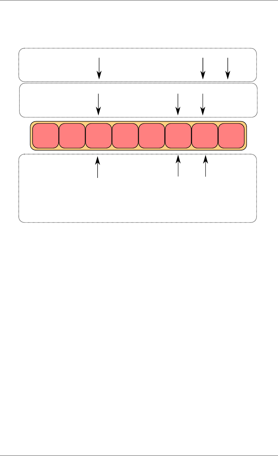
Programmer’s Guide, Release 18.11.0-rc5
The core 1 updates one element of the ring(obj4), and the core 2 updates another one (obj5).
obj1 obj2 obj3
cons_head
cons_tail
prod_head
prod_tail
local variables
core 2
structure state
cons_tail prod_head prod_next
local variables
core 1
cons_tail prod_head prod_next
compare and swap succeeds
on core 2
obj4 obj5
Fig. 5.10: Multiple producer enqueue third step
Multiple Producers Enqueue Fourth Step
Each core now wants to update ring->prod_tail. A core can only update it if ring->prod_tail is
equal to the prod_head local variable. This is only true on core 1. The operation is finished on
core 1.
Multiple Producers Enqueue Last Step
Once ring->prod_tail is updated by core 1, core 2 is allowed to update it too. The operation is
also finished on core 2.
5.5.4 Modulo 32-bit Indexes
In the preceding figures, the prod_head, prod_tail, cons_head and cons_tail indexes are repre-
sented by arrows. In the actual implementation, these values are not between 0 and size(ring)-
1 as would be assumed. The indexes are between 0 and 2^32 -1, and we mask their value
when we access the pointer table (the ring itself). 32-bit modulo also implies that operations
on indexes (such as, add/subtract) will automatically do 2^32 modulo if the result overflows the
32-bit number range.
The following are two examples that help to explain how indexes are used in a ring.
5.5. Anatomy of a Ring Buffer 32
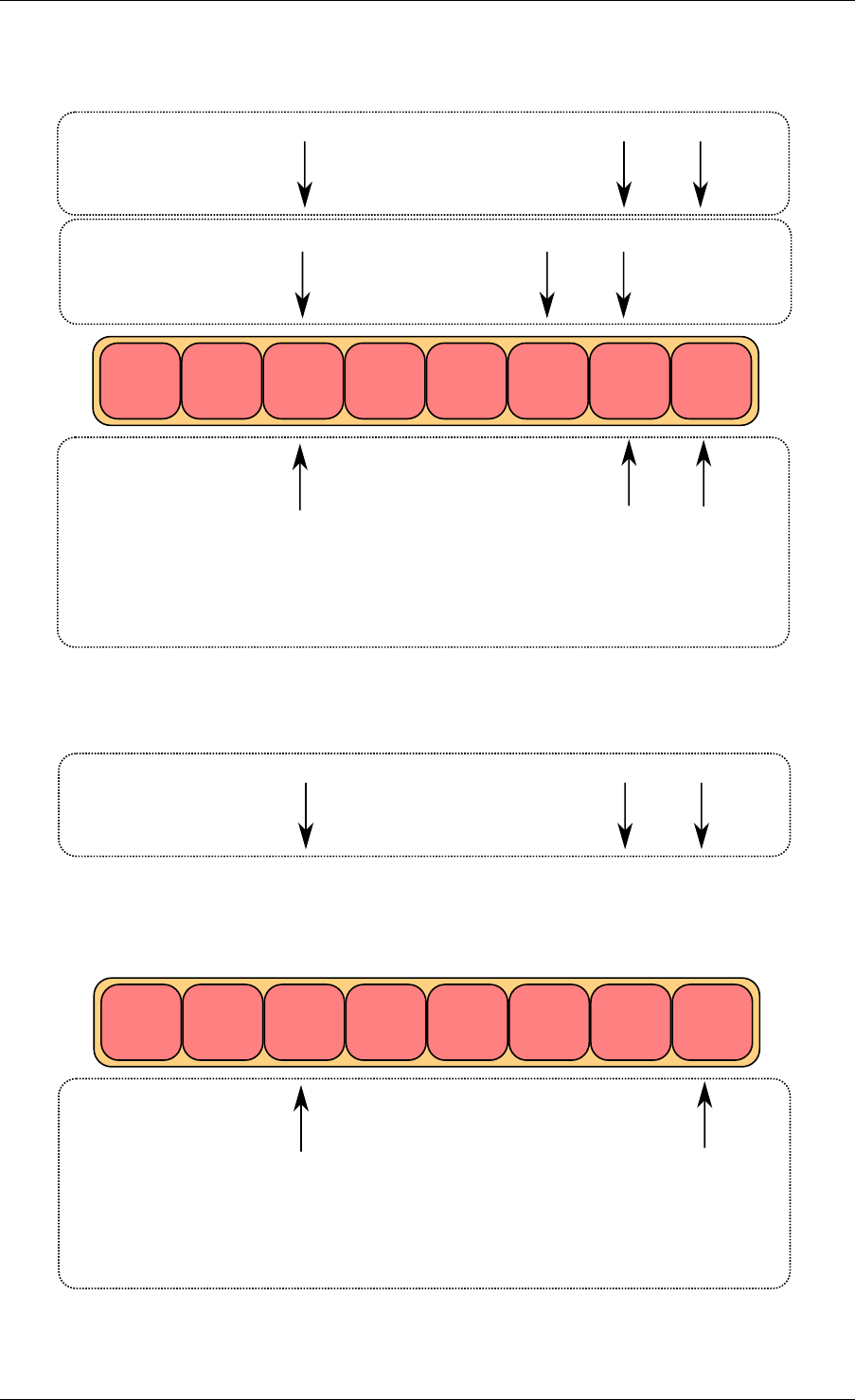
Programmer’s Guide, Release 18.11.0-rc5
obj1 obj2 obj3
cons_head
cons_tail
prod_head
prod_tail
local variables
core 2
structure state
cons_tail prod_head prod_next
local variables
core 1
cons_tail prod_head prod_next
core 2 is waiting for
r->prod_tail == prod_head
obj4 obj5
Fig. 5.11: Multiple producer enqueue fourth step
obj1 obj2 obj3
cons_head
cons_tail
prod_head
prod_tail
local variables
core 2
structure state
cons_tail prod_head prod_next
obj4 obj5
Fig. 5.12: Multiple producer enqueue last step
5.5. Anatomy of a Ring Buffer 33
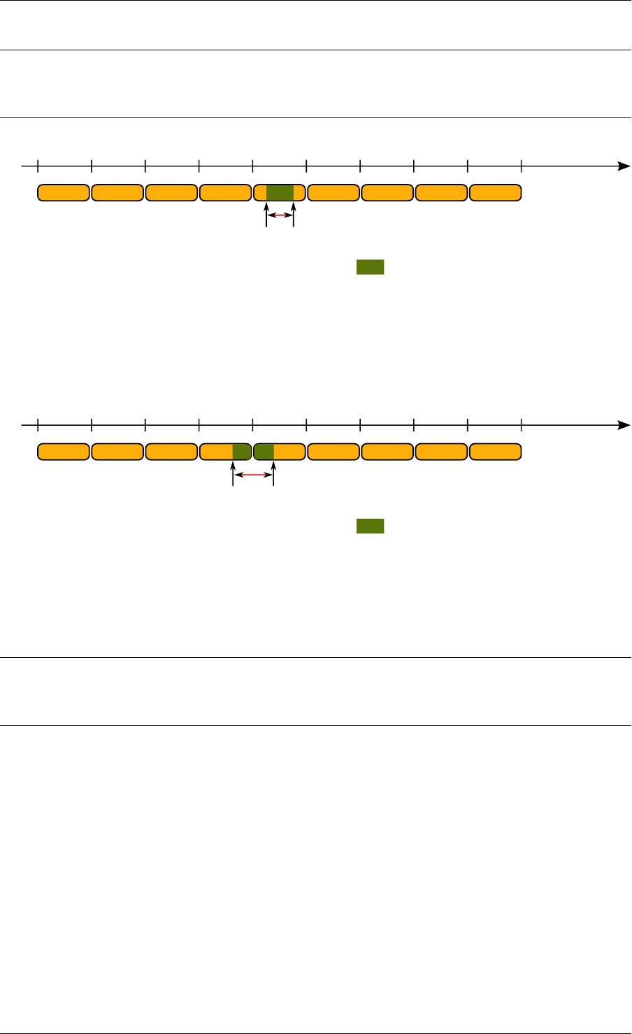
Programmer’s Guide, Release 18.11.0-rc5
Note: To simplify the explanation, operations with modulo 16-bit are used instead of modulo
32-bit. In addition, the four indexes are defined as unsigned 16-bit integers, as opposed to
unsigned 32-bit integers in the more realistic case.
0 16384 32768 49152 65536
0 0
16384 1638432768 49152 65536
ring
ch
ct
ph
pt
value for
indexes
(prod_head,
prod_tail, ...)
used entries in ring
size = 16384
mask = 16383
ph = pt = 14000
ct = ch = 3000
used_entries = (pt - ch) % 65536 = 11000
free_entries = (mask + ct - ph) % 65536 = 5383
used_entries
Fig. 5.13: Modulo 32-bit indexes - Example 1
This ring contains 11000 entries.
0 16384 32768 49152 65536
0 0
16384 1638432768 49152 65536
ring
ch
ct
ph
pt
value for
indexes
(prod_head,
prod_tail, ...)
used entries in ring
size = 16384
mask = 16383
ph = pt = 6000
ct = ch = 59000
used_entries = (pt - ch) % 65536 = 12536
free_entries = (mask + ct - ph) % 65536 = 3847
used_entries
Fig. 5.14: Modulo 32-bit indexes - Example 2
This ring contains 12536 entries.
Note: For ease of understanding, we use modulo 65536 operations in the above examples.
In real execution cases, this is redundant for low efficiency, but is done automatically when the
result overflows.
The code always maintains a distance between producer and consumer between 0 and
size(ring)-1. Thanks to this property, we can do subtractions between 2 index values in a
modulo-32bit base: that’s why the overflow of the indexes is not a problem.
At any time, entries and free_entries are between 0 and size(ring)-1, even if only the first term
of subtraction has overflowed:
uint32_t entries =(prod_tail -cons_head);
uint32_t free_entries =(mask +cons_tail -prod_head);
5.6 References
•bufring.h in FreeBSD (version 8)
•bufring.c in FreeBSD (version 8)
5.6. References 34


CHAPTER
SIX
MEMPOOL LIBRARY
A memory pool is an allocator of a fixed-sized object. In the DPDK, it is identified by name and
uses a mempool handler to store free objects. The default mempool handler is ring based. It
provides some other optional services such as a per-core object cache and an alignment helper
to ensure that objects are padded to spread them equally on all DRAM or DDR3 channels.
This library is used by the Mbuf Library .
6.1 Cookies
In debug mode (CONFIG_RTE_LIBRTE_MEMPOOL_DEBUG is enabled), cookies are added
at the beginning and end of allocated blocks. The allocated objects then contain overwrite
protection fields to help debugging buffer overflows.
6.2 Stats
In debug mode (CONFIG_RTE_LIBRTE_MEMPOOL_DEBUG is enabled), statistics about get
from/put in the pool are stored in the mempool structure. Statistics are per-lcore to avoid
concurrent access to statistics counters.
6.3 Memory Alignment Constraints
Depending on hardware memory configuration, performance can be greatly improved by
adding a specific padding between objects. The objective is to ensure that the beginning of
each object starts on a different channel and rank in memory so that all channels are equally
loaded.
This is particularly true for packet buffers when doing L3 forwarding or flow classification. Only
the first 64 bytes are accessed, so performance can be increased by spreading the start ad-
dresses of objects among the different channels.
The number of ranks on any DIMM is the number of independent sets of DRAMs that can be
accessed for the full data bit-width of the DIMM. The ranks cannot be accessed simultaneously
since they share the same data path. The physical layout of the DRAM chips on the DIMM itself
does not necessarily relate to the number of ranks.
When running an application, the EAL command line options provide the ability to add the
number of memory channels and ranks.
36
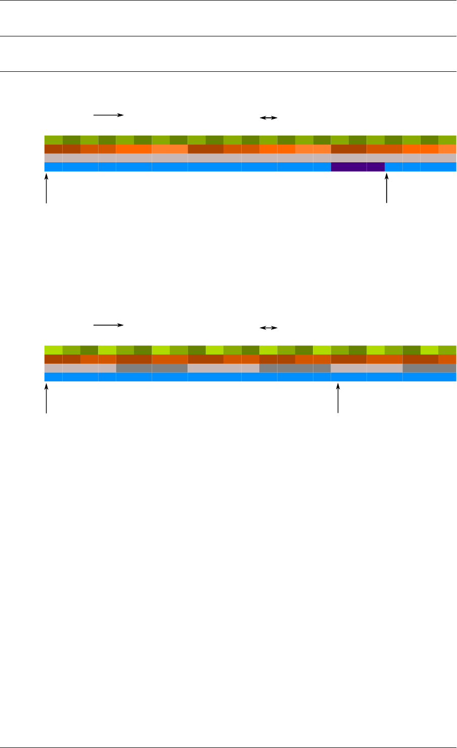
Programmer’s Guide, Release 18.11.0-rc5
Note: The command line must always have the number of memory channels specified for the
processor.
Examples of alignment for different DIMM architectures are shown in Fig. 6.1 and Fig. 6.2.
Channel
Rank
packet 1 packet 2padding
0 1 0 0 0
1 1 1
1 1 1
0 0 0
2 2 2
3 3
memory addresses
pkt1 starts at
channel 0, rank 0 pkt2 starts at
channel 1, rank 1
64 bytes wide
0 1 23 4 56 7 8 9 A B C D E F 10 11 12 13 14 15 ...
Block num
0 1 23 4 56 7 8 9 A B C D E F 0 1 23
Fig. 6.1: Two Channels and Quad-ranked DIMM Example
In this case, the assumption is that a packet is 16 blocks of 64 bytes, which is not true.
The Intel® 5520 chipset has three channels, so in most cases, no padding is required between
objects (except for objects whose size are n x 3 x 64 bytes blocks).
Channel
Rank
packet 1 packet 2
0 1 0 1 1
1 1 1
0 0 0
0 0 0
1 1
memory addresses
pkt0 starts at
channel 0, rank 1 pkt2 starts at
channel 1, rank 0
(no padding needed)
64 bytes wide
0 1 23 4 56 7 8 9 A B C D E F 10 11 12 13 14 15 ...
Block num
0 1 23 4 56 7 8 9 A B C D E F 0 1 23
21 0
2
DIMM 0 0 01
1 1
Fig. 6.2: Three Channels and Two Dual-ranked DIMM Example
When creating a new pool, the user can specify to use this feature or not.
6.4 Local Cache
In terms of CPU usage, the cost of multiple cores accessing a memory pool’s ring of free
buffers may be high since each access requires a compare-and-set (CAS) operation. To avoid
having too many access requests to the memory pool’s ring, the memory pool allocator can
maintain a per-core cache and do bulk requests to the memory pool’s ring, via the cache with
many fewer locks on the actual memory pool structure. In this way, each core has full access
to its own cache (with locks) of free objects and only when the cache fills does the core need to
shuffle some of the free objects back to the pools ring or obtain more objects when the cache
is empty.
While this may mean a number of buffers may sit idle on some core’s cache, the speed at
which a core can access its own cache for a specific memory pool without locks provides
performance gains.
6.4. Local Cache 37
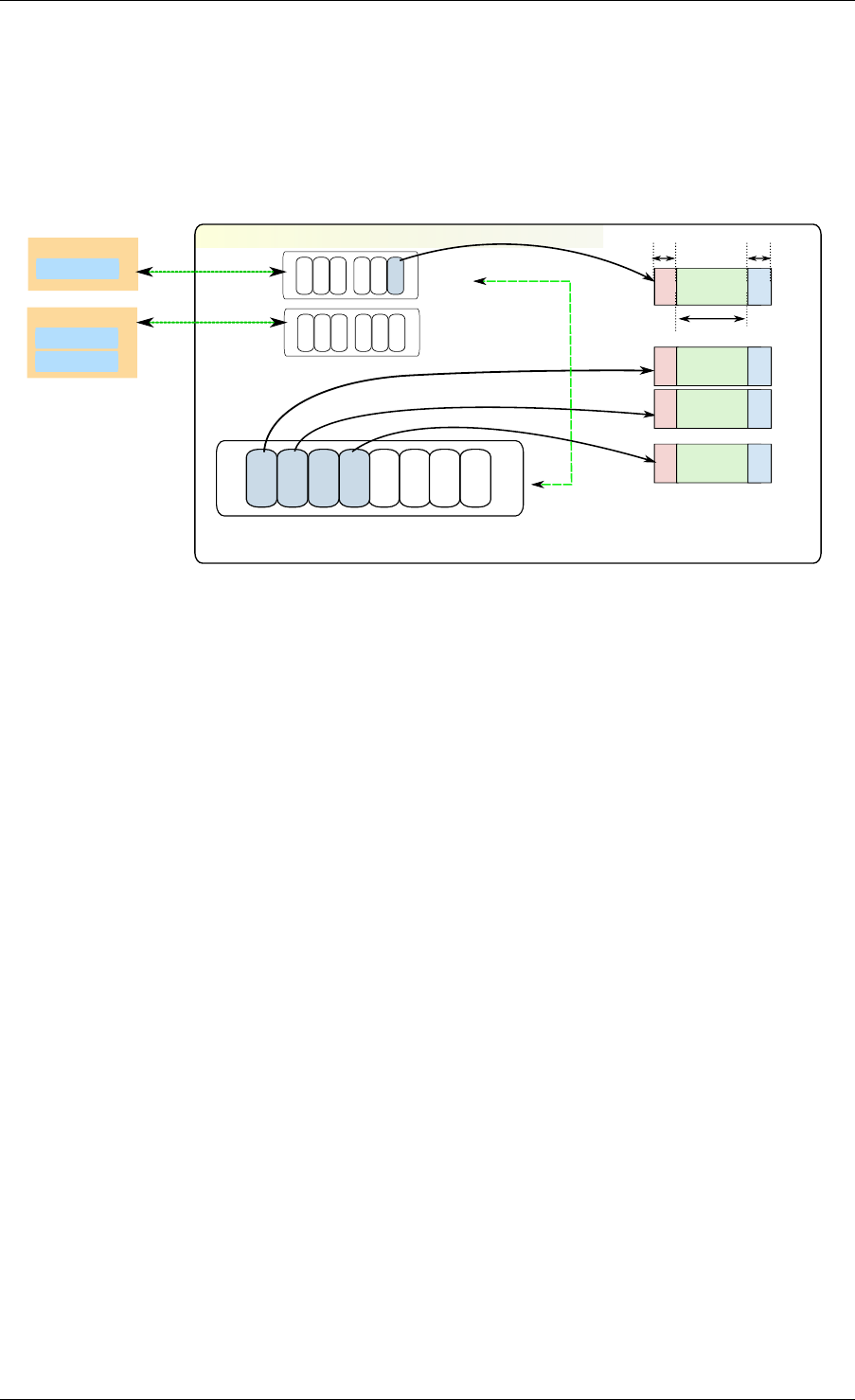
Programmer’s Guide, Release 18.11.0-rc5
The cache is composed of a small, per-core table of pointers and its length (used as a stack).
This internal cache can be enabled or disabled at creation of the pool.
The maximum size of the cache is static and is defined at compilation time (CON-
FIG_RTE_MEMPOOL_CACHE_MAX_SIZE).
Fig. 6.3 shows a cache in operation.
mempool
rte_ring: stores memory pool's free objects
Object caches for
obj n
obj 0
header trailer
elt_size
obj 2
obj 1
core 0
core 1
Core 0
App A - ring
Core 1
App B - ring
App C - ring
If cache empty get from ring
if cache full move to ring
Fig. 6.3: A mempool in Memory with its Associated Ring
Alternatively to the internal default per-lcore local cache, an application can cre-
ate and manage external caches through the rte_mempool_cache_create(),
rte_mempool_cache_free() and rte_mempool_cache_flush() calls. These
user-owned caches can be explicitly passed to rte_mempool_generic_put() and
rte_mempool_generic_get(). The rte_mempool_default_cache() call returns the
default internal cache if any. In contrast to the default caches, user-owned caches can be
used by non-EAL threads too.
6.5 Mempool Handlers
This allows external memory subsystems, such as external hardware memory management
systems and software based memory allocators, to be used with DPDK.
There are two aspects to a mempool handler.
• Adding the code for your new mempool operations (ops). This is achieved by adding a
new mempool ops code, and using the MEMPOOL_REGISTER_OPS macro.
• Using the new API to call rte_mempool_create_empty() and
rte_mempool_set_ops_byname() to create a new mempool and specifying
which ops to use.
Several different mempool handlers may be used in the same application. A new mem-
pool can be created by using the rte_mempool_create_empty() function, then using
rte_mempool_set_ops_byname() to point the mempool to the relevant mempool handler
callback (ops) structure.
Legacy applications may continue to use the old rte_mempool_create() API call, which
uses a ring based mempool handler by default. These applications will need to be modified to
6.5. Mempool Handlers 38

Programmer’s Guide, Release 18.11.0-rc5
use a new mempool handler.
For applications that use rte_pktmbuf_create(), there is a config setting
(RTE_MBUF_DEFAULT_MEMPOOL_OPS) that allows the application to make use of an
alternative mempool handler.
6.6 Use Cases
All allocations that require a high level of performance should use a pool-based memory allo-
cator. Below are some examples:
•Mbuf Library
•Environment Abstraction Layer , for logging service
• Any application that needs to allocate fixed-sized objects in the data plane and that will
be continuously utilized by the system.
6.6. Use Cases 39

CHAPTER
SEVEN
MBUF LIBRARY
The mbuf library provides the ability to allocate and free buffers (mbufs) that may be used by
the DPDK application to store message buffers. The message buffers are stored in a mempool,
using the Mempool Library .
A rte_mbuf struct generally carries network packet buffers, but it can actually be any data
(control data, events, ...). The rte_mbuf header structure is kept as small as possible and
currently uses just two cache lines, with the most frequently used fields being on the first of the
two cache lines.
7.1 Design of Packet Buffers
For the storage of the packet data (including protocol headers), two approaches were consid-
ered:
1. Embed metadata within a single memory buffer the structure followed by a fixed size area
for the packet data.
2. Use separate memory buffers for the metadata structure and for the packet data.
The advantage of the first method is that it only needs one operation to allocate/free the whole
memory representation of a packet. On the other hand, the second method is more flexible
and allows the complete separation of the allocation of metadata structures from the allocation
of packet data buffers.
The first method was chosen for the DPDK. The metadata contains control information such as
message type, length, offset to the start of the data and a pointer for additional mbuf structures
allowing buffer chaining.
Message buffers that are used to carry network packets can handle buffer chaining where
multiple buffers are required to hold the complete packet. This is the case for jumbo frames
that are composed of many mbufs linked together through their next field.
For a newly allocated mbuf, the area at which the data begins in the message buffer is
RTE_PKTMBUF_HEADROOM bytes after the beginning of the buffer, which is cache aligned.
Message buffers may be used to carry control information, packets, events, and so on between
different entities in the system. Message buffers may also use their buffer pointers to point to
other message buffer data sections or other structures.
Fig. 7.1 and Fig. 7.2 show some of these scenarios.
The Buffer Manager implements a fairly standard set of buffer access functions to manipulate
network packets.
40
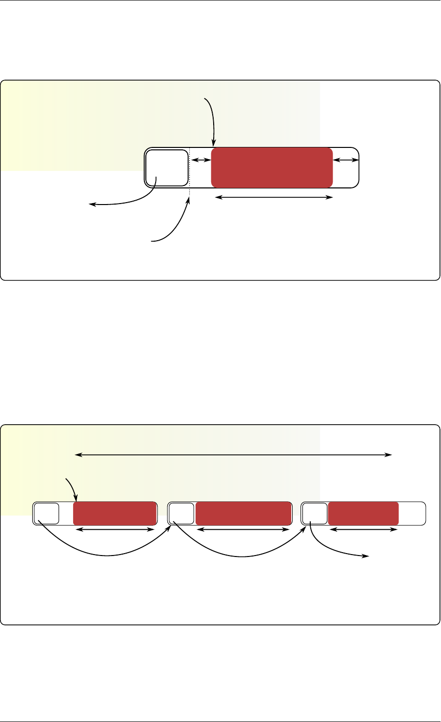
Programmer’s Guide, Release 18.11.0-rc5
struct rte_mbuf
m->buf_addr
(m->buf_iova is the
corresponding physical address)
rte_pktmbuf_mtod(m)
mbuf
struct
m->pkt.next = NULL rte_pktmbuf_pktlen(m)
or rte_pktmbuf_datalen(m)
headroom tailroom
Fig. 7.1: An mbuf with One Segment
multi-segmented rte_mbuf
m->pkt.next = NULLm->pkt.next = mseg3m->pkt.next = mseg2
mmseg2 mseg3
rte_pktmbuf_mtod(m)
rte_pktmbuf_pktlen(m) = rte_pktmbuf_datalen(m) +
rte_pktmbuf_datalen(mseg2) + rte_pktmbuf_datalen(mseg3)
rte_pktmbuf_datalen(m) rte_pktmbuf_datalen(m) rte_pktmbuf_datalen(m)
Fig. 7.2: An mbuf with Three Segments
7.1. Design of Packet Buffers 41

Programmer’s Guide, Release 18.11.0-rc5
7.2 Buffers Stored in Memory Pools
The Buffer Manager uses the Mempool Library to allocate buffers. Therefore, it ensures
that the packet header is interleaved optimally across the channels and ranks for L3 pro-
cessing. An mbuf contains a field indicating the pool that it originated from. When calling
rte_pktmbuf_free(m), the mbuf returns to its original pool.
7.3 Constructors
Packet mbuf constructors are provided by the API. The rte_pktmbuf_init() function initializes
some fields in the mbuf structure that are not modified by the user once created (mbuf type,
origin pool, buffer start address, and so on). This function is given as a callback function to the
rte_mempool_create() function at pool creation time.
7.4 Allocating and Freeing mbufs
Allocating a new mbuf requires the user to specify the mempool from which the mbuf
should be taken. For any newly-allocated mbuf, it contains one segment, with a length
of 0. The offset to data is initialized to have some bytes of headroom in the buffer
(RTE_PKTMBUF_HEADROOM).
Freeing a mbuf means returning it into its original mempool. The content of an mbuf is not
modified when it is stored in a pool (as a free mbuf). Fields initialized by the constructor do not
need to be re-initialized at mbuf allocation.
When freeing a packet mbuf that contains several segments, all of them are freed and returned
to their original mempool.
7.5 Manipulating mbufs
This library provides some functions for manipulating the data in a packet mbuf. For instance:
• Get data length
• Get a pointer to the start of data
• Prepend data before data
• Append data after data
• Remove data at the beginning of the buffer (rte_pktmbuf_adj())
• Remove data at the end of the buffer (rte_pktmbuf_trim()) Refer to the DPDK API Refer-
ence for details.
7.6 Meta Information
Some information is retrieved by the network driver and stored in an mbuf to make process-
ing easier. For instance, the VLAN, the RSS hash result (see Poll Mode Driver) and a flag
indicating that the checksum was computed by hardware.
7.2. Buffers Stored in Memory Pools 42

Programmer’s Guide, Release 18.11.0-rc5
An mbuf also contains the input port (where it comes from), and the number of segment mbufs
in the chain.
For chained buffers, only the first mbuf of the chain stores this meta information.
For instance, this is the case on RX side for the IEEE1588 packet timestamp mechanism, the
VLAN tagging and the IP checksum computation.
On TX side, it is also possible for an application to delegate some processing to the hardware
if it supports it. For instance, the PKT_TX_IP_CKSUM flag allows to offload the computation
of the IPv4 checksum.
The following examples explain how to configure different TX offloads on a vxlan-encapsulated
tcp packet: out_eth/out_ip/out_udp/vxlan/in_eth/in_ip/in_tcp/payload
• calculate checksum of out_ip:
mb->l2_len = len(out_eth)
mb->l3_len = len(out_ip)
mb->ol_flags |= PKT_TX_IPV4 | PKT_TX_IP_CSUM
set out_ip checksum to 0 in the packet
This is supported on hardware advertising DEV_TX_OFFLOAD_IPV4_CKSUM.
• calculate checksum of out_ip and out_udp:
mb->l2_len = len(out_eth)
mb->l3_len = len(out_ip)
mb->ol_flags |= PKT_TX_IPV4 | PKT_TX_IP_CSUM | PKT_TX_UDP_CKSUM
set out_ip checksum to 0 in the packet
set out_udp checksum to pseudo header using rte_ipv4_phdr_cksum()
This is supported on hardware advertising DEV_TX_OFFLOAD_IPV4_CKSUM and
DEV_TX_OFFLOAD_UDP_CKSUM.
• calculate checksum of in_ip:
mb->l2_len = len(out_eth + out_ip + out_udp + vxlan + in_eth)
mb->l3_len = len(in_ip)
mb->ol_flags |= PKT_TX_IPV4 | PKT_TX_IP_CSUM
set in_ip checksum to 0 in the packet
This is similar to case 1), but l2_len is different. It is supported on hardware advertising
DEV_TX_OFFLOAD_IPV4_CKSUM. Note that it can only work if outer L4 checksum is
0.
• calculate checksum of in_ip and in_tcp:
mb->l2_len = len(out_eth + out_ip + out_udp + vxlan + in_eth)
mb->l3_len = len(in_ip)
mb->ol_flags |= PKT_TX_IPV4 | PKT_TX_IP_CSUM | PKT_TX_TCP_CKSUM
set in_ip checksum to 0 in the packet
set in_tcp checksum to pseudo header using rte_ipv4_phdr_cksum()
This is similar to case 2), but l2_len is different. It is supported on hardware advertising
DEV_TX_OFFLOAD_IPV4_CKSUM and DEV_TX_OFFLOAD_TCP_CKSUM. Note that
it can only work if outer L4 checksum is 0.
• segment inner TCP:
mb->l2_len = len(out_eth + out_ip + out_udp + vxlan + in_eth)
mb->l3_len = len(in_ip)
mb->l4_len = len(in_tcp)
mb->ol_flags |= PKT_TX_IPV4 | PKT_TX_IP_CKSUM | PKT_TX_TCP_CKSUM |
PKT_TX_TCP_SEG;
7.6. Meta Information 43

Programmer’s Guide, Release 18.11.0-rc5
set in_ip checksum to 0 in the packet
set in_tcp checksum to pseudo header without including the IP
payload length using rte_ipv4_phdr_cksum()
This is supported on hardware advertising DEV_TX_OFFLOAD_TCP_TSO. Note that it
can only work if outer L4 checksum is 0.
• calculate checksum of out_ip, in_ip, in_tcp:
mb->outer_l2_len = len(out_eth)
mb->outer_l3_len = len(out_ip)
mb->l2_len = len(out_udp + vxlan + in_eth)
mb->l3_len = len(in_ip)
mb->ol_flags |= PKT_TX_OUTER_IPV4 | PKT_TX_OUTER_IP_CKSUM | \
PKT_TX_IP_CKSUM | PKT_TX_TCP_CKSUM;
set out_ip checksum to 0 in the packet
set in_ip checksum to 0 in the packet
set in_tcp checksum to pseudo header using rte_ipv4_phdr_cksum()
This is supported on hardware advertising DEV_TX_OFFLOAD_IPV4_CKSUM,
DEV_TX_OFFLOAD_UDP_CKSUM and DEV_TX_OFFLOAD_OUTER_IPV4_CKSUM.
The list of flags and their precise meaning is described in the mbuf API documentation
(rte_mbuf.h). Also refer to the testpmd source code (specifically the csumonly.c file) for de-
tails.
7.7 Direct and Indirect Buffers
A direct buffer is a buffer that is completely separate and self-contained. An indirect buffer
behaves like a direct buffer but for the fact that the buffer pointer and data offset in it refer to
data in another direct buffer. This is useful in situations where packets need to be duplicated
or fragmented, since indirect buffers provide the means to reuse the same packet data across
multiple buffers.
A buffer becomes indirect when it is “attached” to a direct buffer using the rte_pktmbuf_attach()
function. Each buffer has a reference counter field and whenever an indirect buffer is attached
to the direct buffer, the reference counter on the direct buffer is incremented. Similarly, when-
ever the indirect buffer is detached, the reference counter on the direct buffer is decremented.
If the resulting reference counter is equal to 0, the direct buffer is freed since it is no longer in
use.
There are a few things to remember when dealing with indirect buffers. First of all, an indirect
buffer is never attached to another indirect buffer. Attempting to attach buffer A to indirect buffer
B that is attached to C, makes rte_pktmbuf_attach() automatically attach A to C, effectively
cloning B. Secondly, for a buffer to become indirect, its reference counter must be equal to 1,
that is, it must not be already referenced by another indirect buffer. Finally, it is not possible to
reattach an indirect buffer to the direct buffer (unless it is detached first).
While the attach/detach operations can be invoked directly using the recommended
rte_pktmbuf_attach() and rte_pktmbuf_detach() functions, it is suggested to use the higher-
level rte_pktmbuf_clone() function, which takes care of the correct initialization of an indirect
buffer and can clone buffers with multiple segments.
Since indirect buffers are not supposed to actually hold any data, the memory pool for indirect
buffers should be configured to indicate the reduced memory consumption. Examples of the
initialization of a memory pool for indirect buffers (as well as use case examples for indirect
7.7. Direct and Indirect Buffers 44

Programmer’s Guide, Release 18.11.0-rc5
buffers) can be found in several of the sample applications, for example, the IPv4 Multicast
sample application.
7.8 Debug
In debug mode (CONFIG_RTE_MBUF_DEBUG is enabled), the functions of the mbuf library
perform sanity checks before any operation (such as, buffer corruption, bad type, and so on).
7.9 Use Cases
All networking application should use mbufs to transport network packets.
7.8. Debug 45

CHAPTER
EIGHT
POLL MODE DRIVER
The DPDK includes 1 Gigabit, 10 Gigabit and 40 Gigabit and para virtualized virtio Poll Mode
Drivers.
A Poll Mode Driver (PMD) consists of APIs, provided through the BSD driver running in user
space, to configure the devices and their respective queues. In addition, a PMD accesses the
RX and TX descriptors directly without any interrupts (with the exception of Link Status Change
interrupts) to quickly receive, process and deliver packets in the user’s application. This section
describes the requirements of the PMDs, their global design principles and proposes a high-
level architecture and a generic external API for the Ethernet PMDs.
8.1 Requirements and Assumptions
The DPDK environment for packet processing applications allows for two models, run-to-
completion and pipe-line:
• In the run-to-completion model, a specific port’s RX descriptor ring is polled for packets
through an API. Packets are then processed on the same core and placed on a port’s TX
descriptor ring through an API for transmission.
• In the pipe-line model, one core polls one or more port’s RX descriptor ring through
an API. Packets are received and passed to another core via a ring. The other core
continues to process the packet which then may be placed on a port’s TX descriptor ring
through an API for transmission.
In a synchronous run-to-completion model, each logical core assigned to the DPDK executes
a packet processing loop that includes the following steps:
• Retrieve input packets through the PMD receive API
• Process each received packet one at a time, up to its forwarding
• Send pending output packets through the PMD transmit API
Conversely, in an asynchronous pipe-line model, some logical cores may be dedicated to the
retrieval of received packets and other logical cores to the processing of previously received
packets. Received packets are exchanged between logical cores through rings. The loop for
packet retrieval includes the following steps:
• Retrieve input packets through the PMD receive API
• Provide received packets to processing lcores through packet queues
The loop for packet processing includes the following steps:
46

Programmer’s Guide, Release 18.11.0-rc5
• Retrieve the received packet from the packet queue
• Process the received packet, up to its retransmission if forwarded
To avoid any unnecessary interrupt processing overhead, the execution environment must not
use any asynchronous notification mechanisms. Whenever needed and appropriate, asyn-
chronous communication should be introduced as much as possible through the use of rings.
Avoiding lock contention is a key issue in a multi-core environment. To address this issue,
PMDs are designed to work with per-core private resources as much as possible. For ex-
ample, a PMD maintains a separate transmit queue per-core, per-port, if the PMD is not
DEV_TX_OFFLOAD_MT_LOCKFREE capable. In the same way, every receive queue of a port is
assigned to and polled by a single logical core (lcore).
To comply with Non-Uniform Memory Access (NUMA), memory management is designed to
assign to each logical core a private buffer pool in local memory to minimize remote memory
access. The configuration of packet buffer pools should take into account the underlying physi-
cal memory architecture in terms of DIMMS, channels and ranks. The application must ensure
that appropriate parameters are given at memory pool creation time. See Mempool Library.
8.2 Design Principles
The API and architecture of the Ethernet* PMDs are designed with the following guidelines in
mind.
PMDs must help global policy-oriented decisions to be enforced at the upper application level.
Conversely, NIC PMD functions should not impede the benefits expected by upper-level global
policies, or worse prevent such policies from being applied.
For instance, both the receive and transmit functions of a PMD have a maximum number of
packets/descriptors to poll. This allows a run-to-completion processing stack to statically fix or
to dynamically adapt its overall behavior through different global loop policies, such as:
• Receive, process immediately and transmit packets one at a time in a piecemeal fashion.
• Receive as many packets as possible, then process all received packets, transmitting
them immediately.
• Receive a given maximum number of packets, process the received packets, accumulate
them and finally send all accumulated packets to transmit.
To achieve optimal performance, overall software design choices and pure software optimiza-
tion techniques must be considered and balanced against available low-level hardware-based
optimization features (CPU cache properties, bus speed, NIC PCI bandwidth, and so on). The
case of packet transmission is an example of this software/hardware tradeoff issue when opti-
mizing burst-oriented network packet processing engines. In the initial case, the PMD could ex-
port only an rte_eth_tx_one function to transmit one packet at a time on a given queue. On top
of that, one can easily build an rte_eth_tx_burst function that loops invoking the rte_eth_tx_one
function to transmit several packets at a time. However, an rte_eth_tx_burst function is effec-
tively implemented by the PMD to minimize the driver-level transmit cost per packet through
the following optimizations:
• Share among multiple packets the un-amortized cost of invoking the rte_eth_tx_one func-
tion.
8.2. Design Principles 47

Programmer’s Guide, Release 18.11.0-rc5
• Enable the rte_eth_tx_burst function to take advantage of burst-oriented hardware fea-
tures (prefetch data in cache, use of NIC head/tail registers) to minimize the number of
CPU cycles per packet, for example by avoiding unnecessary read memory accesses
to ring transmit descriptors, or by systematically using arrays of pointers that exactly fit
cache line boundaries and sizes.
• Apply burst-oriented software optimization techniques to remove operations that would
otherwise be unavoidable, such as ring index wrap back management.
Burst-oriented functions are also introduced via the API for services that are intensively used
by the PMD. This applies in particular to buffer allocators used to populate NIC rings, which
provide functions to allocate/free several buffers at a time. For example, an mbuf_multiple_alloc
function returning an array of pointers to rte_mbuf buffers which speeds up the receive poll
function of the PMD when replenishing multiple descriptors of the receive ring.
8.3 Logical Cores, Memory and NIC Queues Relationships
The DPDK supports NUMA allowing for better performance when a processor’s logical cores
and interfaces utilize its local memory. Therefore, mbuf allocation associated with local PCIe*
interfaces should be allocated from memory pools created in the local memory. The buffers
should, if possible, remain on the local processor to obtain the best performance results and RX
and TX buffer descriptors should be populated with mbufs allocated from a mempool allocated
from local memory.
The run-to-completion model also performs better if packet or data manipulation is in local
memory instead of a remote processors memory. This is also true for the pipe-line model
provided all logical cores used are located on the same processor.
Multiple logical cores should never share receive or transmit queues for interfaces since this
would require global locks and hinder performance.
If the PMD is DEV_TX_OFFLOAD_MT_LOCKFREE capable, multiple threads can invoke
rte_eth_tx_burst() concurrently on the same tx queue without SW lock. This PMD fea-
ture found in some NICs and useful in the following use cases:
• Remove explicit spinlock in some applications where lcores are not mapped to Tx queues
with 1:1 relation.
• In the eventdev use case, avoid dedicating a separate TX core for transmitting and thus
enables more scaling as all workers can send the packets.
See Hardware Offload for DEV_TX_OFFLOAD_MT_LOCKFREE capability probing details.
8.4 Device Identification, Ownership and Configuration
8.4.1 Device Identification
Each NIC port is uniquely designated by its (bus/bridge, device, function) PCI identifiers as-
signed by the PCI probing/enumeration function executed at DPDK initialization. Based on
their PCI identifier, NIC ports are assigned two other identifiers:
• A port index used to designate the NIC port in all functions exported by the PMD API.
8.3. Logical Cores, Memory and NIC Queues Relationships 48

Programmer’s Guide, Release 18.11.0-rc5
• A port name used to designate the port in console messages, for administration or de-
bugging purposes. For ease of use, the port name includes the port index.
8.4.2 Port Ownership
The Ethernet devices ports can be owned by a single DPDK entity (application, library,
PMD, process, etc). The ownership mechanism is controlled by ethdev APIs and allows to
set/remove/get a port owner by DPDK entities. Allowing this should prevent any multiple man-
agement of Ethernet port by different entities.
Note: It is the DPDK entity responsibility to set the port owner before using it and to manage
the port usage synchronization between different threads or processes.
8.4.3 Device Configuration
The configuration of each NIC port includes the following operations:
• Allocate PCI resources
• Reset the hardware (issue a Global Reset) to a well-known default state
• Set up the PHY and the link
• Initialize statistics counters
The PMD API must also export functions to start/stop the all-multicast feature of a port and
functions to set/unset the port in promiscuous mode.
Some hardware offload features must be individually configured at port initialization through
specific configuration parameters. This is the case for the Receive Side Scaling (RSS) and
Data Center Bridging (DCB) features for example.
8.4.4 On-the-Fly Configuration
All device features that can be started or stopped “on the fly” (that is, without stopping the
device) do not require the PMD API to export dedicated functions for this purpose.
All that is required is the mapping address of the device PCI registers to implement the config-
uration of these features in specific functions outside of the drivers.
For this purpose, the PMD API exports a function that provides all the information associated
with a device that can be used to set up a given device feature outside of the driver. This
includes the PCI vendor identifier, the PCI device identifier, the mapping address of the PCI
device registers, and the name of the driver.
The main advantage of this approach is that it gives complete freedom on the choice of the
API used to configure, to start, and to stop such features.
As an example, refer to the configuration of the IEEE1588 feature for the Intel® 82576 Giga-
bit Ethernet Controller and the Intel® 82599 10 Gigabit Ethernet Controller controllers in the
testpmd application.
Other features such as the L3/L4 5-Tuple packet filtering feature of a port can be configured in
the same way. Ethernet* flow control (pause frame) can be configured on the individual port.
8.4. Device Identification, Ownership and Configuration 49

Programmer’s Guide, Release 18.11.0-rc5
Refer to the testpmd source code for details. Also, L4 (UDP/TCP/ SCTP) checksum offload by
the NIC can be enabled for an individual packet as long as the packet mbuf is set up correctly.
See Hardware Offload for details.
8.4.5 Configuration of Transmit Queues
Each transmit queue is independently configured with the following information:
• The number of descriptors of the transmit ring
• The socket identifier used to identify the appropriate DMA memory zone from which to
allocate the transmit ring in NUMA architectures
• The values of the Prefetch, Host and Write-Back threshold registers of the transmit queue
• The minimum transmit packets to free threshold (tx_free_thresh). When the number of
descriptors used to transmit packets exceeds this threshold, the network adaptor should
be checked to see if it has written back descriptors. A value of 0 can be passed during
the TX queue configuration to indicate the default value should be used. The default
value for tx_free_thresh is 32. This ensures that the PMD does not search for completed
descriptors until at least 32 have been processed by the NIC for this queue.
• The minimum RS bit threshold. The minimum number of transmit descriptors to use be-
fore setting the Report Status (RS) bit in the transmit descriptor. Note that this parameter
may only be valid for Intel 10 GbE network adapters. The RS bit is set on the last de-
scriptor used to transmit a packet if the number of descriptors used since the last RS bit
setting, up to the first descriptor used to transmit the packet, exceeds the transmit RS
bit threshold (tx_rs_thresh). In short, this parameter controls which transmit descriptors
are written back to host memory by the network adapter. A value of 0 can be passed
during the TX queue configuration to indicate that the default value should be used. The
default value for tx_rs_thresh is 32. This ensures that at least 32 descriptors are used
before the network adapter writes back the most recently used descriptor. This saves
upstream PCIe* bandwidth resulting from TX descriptor write-backs. It is important to
note that the TX Write-back threshold (TX wthresh) should be set to 0 when tx_rs_thresh
is greater than 1. Refer to the Intel® 82599 10 Gigabit Ethernet Controller Datasheet for
more details.
The following constraints must be satisfied for tx_free_thresh and tx_rs_thresh:
• tx_rs_thresh must be greater than 0.
• tx_rs_thresh must be less than the size of the ring minus 2.
• tx_rs_thresh must be less than or equal to tx_free_thresh.
• tx_free_thresh must be greater than 0.
• tx_free_thresh must be less than the size of the ring minus 3.
• For optimal performance, TX wthresh should be set to 0 when tx_rs_thresh is greater
than 1.
One descriptor in the TX ring is used as a sentinel to avoid a hardware race condition, hence
the maximum threshold constraints.
Note: When configuring for DCB operation, at port initialization, both the number of transmit
queues and the number of receive queues must be set to 128.
8.4. Device Identification, Ownership and Configuration 50

Programmer’s Guide, Release 18.11.0-rc5
8.4.6 Free Tx mbuf on Demand
Many of the drivers do not release the mbuf back to the mempool, or local cache, immediately
after the packet has been transmitted. Instead, they leave the mbuf in their Tx ring and either
perform a bulk release when the tx_rs_thresh has been crossed or free the mbuf when a
slot in the Tx ring is needed.
An application can request the driver to release used mbufs with the
rte_eth_tx_done_cleanup() API. This API requests the driver to release mbufs that are
no longer in use, independent of whether or not the tx_rs_thresh has been crossed. There
are two scenarios when an application may want the mbuf released immediately:
• When a given packet needs to be sent to multiple destination interfaces (either for Layer 2
flooding or Layer 3 multi-cast). One option is to make a copy of the packet or a copy of the
header portion that needs to be manipulated. A second option is to transmit the packet
and then poll the rte_eth_tx_done_cleanup() API until the reference count on the
packet is decremented. Then the same packet can be transmitted to the next destination
interface. The application is still responsible for managing any packet manipulations
needed between the different destination interfaces, but a packet copy can be avoided.
This API is independent of whether the packet was transmitted or dropped, only that the
mbuf is no longer in use by the interface.
• Some applications are designed to make multiple runs, like a packet generator. For
performance reasons and consistency between runs, the application may want to reset
back to an initial state between each run, where all mbufs are returned to the mempool.
In this case, it can call the rte_eth_tx_done_cleanup() API for each destination
interface it has been using to request it to release of all its used mbufs.
To determine if a driver supports this API, check for the Free Tx mbuf on demand feature in
the Network Interface Controller Drivers document.
8.4.7 Hardware Offload
Depending on driver capabilities advertised by rte_eth_dev_info_get(), the PMD may
support hardware offloading feature like checksumming, TCP segmentation, VLAN insertion
or lockfree multithreaded TX burst on the same TX queue.
The support of these offload features implies the addition of dedicated status bit(s) and value
field(s) into the rte_mbuf data structure, along with their appropriate handling by the re-
ceive/transmit functions exported by each PMD. The list of flags and their precise meaning
is described in the mbuf API documentation and in the in Mbuf Library, section “Meta Informa-
tion”.
Per-Port and Per-Queue Offloads
In the DPDK offload API, offloads are divided into per-port and per-queue offloads as follows:
• A per-queue offloading can be enabled on a queue and disabled on another queue at the
same time.
• A pure per-port offload is the one supported by device but not per-queue type.
8.4. Device Identification, Ownership and Configuration 51

Programmer’s Guide, Release 18.11.0-rc5
• A pure per-port offloading can’t be enabled on a queue and disabled on another queue
at the same time.
• A pure per-port offloading must be enabled or disabled on all queues at the same time.
• Any offloading is per-queue or pure per-port type, but can’t be both types at same de-
vices.
• Port capabilities = per-queue capabilities + pure per-port capabilities.
• Any supported offloading can be enabled on all queues.
The different offloads capabilities can be queried using rte_eth_dev_info_get(). The
dev_info->[rt]x_queue_offload_capa returned from rte_eth_dev_info_get() in-
cludes all per-queue offloading capabilities. The dev_info->[rt]x_offload_capa re-
turned from rte_eth_dev_info_get() includes all pure per-port and per-queue offloading
capabilities. Supported offloads can be either per-port or per-queue.
Offloads are enabled using the existing DEV_TX_OFFLOAD_*or DEV_RX_OFFLOAD_*
flags. Any requested offloading by an application must be within the device ca-
pabilities. Any offloading is disabled by default if it is not set in the param-
eter dev_conf->[rt]xmode.offloads to rte_eth_dev_configure() and
[rt]x_conf->offloads to rte_eth_[rt]x_queue_setup().
If any offloading is enabled in rte_eth_dev_configure() by an application, it is enabled
on all queues no matter whether it is per-queue or per-port type and no matter whether it is set
or cleared in [rt]x_conf->offloads to rte_eth_[rt]x_queue_setup().
If a per-queue offloading hasn’t been enabled in rte_eth_dev_configure(), it can be
enabled or disabled in rte_eth_[rt]x_queue_setup() for individual queue. A newly
added offloads in [rt]x_conf->offloads to rte_eth_[rt]x_queue_setup() input by
application is the one which hasn’t been enabled in rte_eth_dev_configure() and is re-
quested to be enabled in rte_eth_[rt]x_queue_setup(). It must be per-queue type,
otherwise trigger an error log.
8.5 Poll Mode Driver API
8.5.1 Generalities
By default, all functions exported by a PMD are lock-free functions that are assumed not to be
invoked in parallel on different logical cores to work on the same target object. For instance,
a PMD receive function cannot be invoked in parallel on two logical cores to poll the same RX
queue of the same port. Of course, this function can be invoked in parallel by different logical
cores on different RX queues. It is the responsibility of the upper-level application to enforce
this rule.
If needed, parallel accesses by multiple logical cores to shared queues can be explicitly pro-
tected by dedicated inline lock-aware functions built on top of their corresponding lock-free
functions of the PMD API.
8.5.2 Generic Packet Representation
A packet is represented by an rte_mbuf structure, which is a generic metadata structure con-
taining all necessary housekeeping information. This includes fields and status bits corre-
8.5. Poll Mode Driver API 52

Programmer’s Guide, Release 18.11.0-rc5
sponding to offload hardware features, such as checksum computation of IP headers or VLAN
tags.
The rte_mbuf data structure includes specific fields to represent, in a generic way, the offload
features provided by network controllers. For an input packet, most fields of the rte_mbuf
structure are filled in by the PMD receive function with the information contained in the receive
descriptor. Conversely, for output packets, most fields of rte_mbuf structures are used by the
PMD transmit function to initialize transmit descriptors.
The mbuf structure is fully described in the Mbuf Library chapter.
8.5.3 Ethernet Device API
The Ethernet device API exported by the Ethernet PMDs is described in the DPDK API Refer-
ence.
8.5.4 Ethernet Device Standard Device Arguments
Standard Ethernet device arguments allow for a set of commonly used arguments/ parameters
which are applicable to all Ethernet devices to be available to for specification of specific device
and for passing common configuration parameters to those ports.
•representor for a device which supports the creation of representor ports this argu-
ment allows user to specify which switch ports to enable port representors for.:
-w BDBF,representor=0
-w BDBF,representor=[0,4,6,9]
-w BDBF,representor=[0-31]
Note: PMDs are not required to support the standard device arguments and users should
consult the relevant PMD documentation to see support devargs.
8.5.5 Extended Statistics API
The extended statistics API allows a PMD to expose all statistics that are available to it, includ-
ing statistics that are unique to the device. Each statistic has three properties name,id and
value:
•name: A human readable string formatted by the scheme detailed below.
•id: An integer that represents only that statistic.
•value: A unsigned 64-bit integer that is the value of the statistic.
Note that extended statistic identifiers are driver-specific, and hence might not be the same for
different ports. The API consists of various rte_eth_xstats_*() functions, and allows an
application to be flexible in how it retrieves statistics.
Scheme for Human Readable Names
A naming scheme exists for the strings exposed to clients of the API. This is to allow scraping of
the API for statistics of interest. The naming scheme uses strings split by a single underscore
_. The scheme is as follows:
8.5. Poll Mode Driver API 53

Programmer’s Guide, Release 18.11.0-rc5
• direction
• detail 1
• detail 2
• detail n
• unit
Examples of common statistics xstats strings, formatted to comply to the scheme proposed
above:
•rx_bytes
•rx_crc_errors
•tx_multicast_packets
The scheme, although quite simple, allows flexibility in presenting and reading information
from the statistic strings. The following example illustrates the naming scheme:rx_packets.
In this example, the string is split into two components. The first component rx indicates that
the statistic is associated with the receive side of the NIC. The second component packets
indicates that the unit of measure is packets.
A more complicated example: tx_size_128_to_255_packets. In this example, tx indi-
cates transmission, size is the first detail, 128 etc are more details, and packets indicates
that this is a packet counter.
Some additions in the metadata scheme are as follows:
• If the first part does not match rx or tx, the statistic does not have an affinity with either
receive of transmit.
• If the first letter of the second part is qand this qis followed by a number, this statistic is
part of a specific queue.
An example where queue numbers are used is as follows: tx_q7_bytes which indicates this
statistic applies to queue number 7, and represents the number of transmitted bytes on that
queue.
API Design
The xstats API uses the name,id, and value to allow performant lookup of specific statistics.
Performant lookup means two things;
• No string comparisons with the name of the statistic in fast-path
• Allow requesting of only the statistics of interest
The API ensures these requirements are met by mapping the name of the statistic to a unique
id, which is used as a key for lookup in the fast-path. The API allows applications to request an
array of id values, so that the PMD only performs the required calculations. Expected usage
is that the application scans the name of each statistic, and caches the id if it has an interest
in that statistic. On the fast-path, the integer can be used to retrieve the actual value of the
statistic that the id represents.
8.5. Poll Mode Driver API 54

Programmer’s Guide, Release 18.11.0-rc5
API Functions
The API is built out of a small number of functions, which can be used to retrieve the number
of statistics and the names, IDs and values of those statistics.
•rte_eth_xstats_get_names_by_id(): returns the names of the statistics. When
given a NULL parameter the function returns the number of statistics that are available.
•rte_eth_xstats_get_id_by_name(): Searches for the statistic ID that matches
xstat_name. If found, the id integer is set.
•rte_eth_xstats_get_by_id(): Fills in an array of uint64_t values with matching
the provided ids array. If the ids array is NULL, it returns all statistics that are available.
Application Usage
Imagine an application that wants to view the dropped packet count. If no packets are dropped,
the application does not read any other metrics for performance reasons. If packets are
dropped, the application has a particular set of statistics that it requests. This “set” of statistics
allows the app to decide what next steps to perform. The following code-snippets show how
the xstats API can be used to achieve this goal.
First step is to get all statistics names and list them:
struct rte_eth_xstat_name *xstats_names;
uint64_t *values;
int len, i;
/*Get number of stats */
len =rte_eth_xstats_get_names_by_id(port_id, NULL,NULL,0);
if (len <0) {
printf("Cannot get xstats count\n");
goto err;
}
xstats_names =malloc(sizeof(struct rte_eth_xstat_name) *len);
if (xstats_names == NULL) {
printf("Cannot allocate memory for xstat names\n");
goto err;
}
/*Retrieve xstats names, passing NULL for IDs to return all statistics */
if (len != rte_eth_xstats_get_names_by_id(port_id, xstats_names, NULL, len)) {
printf("Cannot get xstat names\n");
goto err;
}
values =malloc(sizeof(values) *len);
if (values == NULL) {
printf("Cannot allocate memory for xstats\n");
goto err;
}
/*Getting xstats values */
if (len != rte_eth_xstats_get_by_id(port_id, NULL, values, len)) {
printf("Cannot get xstat values\n");
goto err;
}
/*Print all xstats names and values */
8.5. Poll Mode Driver API 55

Programmer’s Guide, Release 18.11.0-rc5
for (i =0;i<len; i++) {
printf("%s: %"PRIu64"\n", xstats_names[i].name, values[i]);
}
The application has access to the names of all of the statistics that the PMD exposes. The ap-
plication can decide which statistics are of interest, cache the ids of those statistics by looking
up the name as follows:
uint64_t id;
uint64_t value;
const char *xstat_name ="rx_errors";
if(!rte_eth_xstats_get_id_by_name(port_id, xstat_name, &id)) {
rte_eth_xstats_get_by_id(port_id, &id, &value, 1);
printf("%s: %"PRIu64"\n", xstat_name, value);
}
else {
printf("Cannot find xstats with a given name\n");
goto err;
}
The API provides flexibility to the application so that it can look up multiple statistics using an
array containing multiple id numbers. This reduces the function call overhead of retrieving
statistics, and makes lookup of multiple statistics simpler for the application.
#define APP_NUM_STATS 4
/*application cached these ids previously; see above */
uint64_t ids_array[APP_NUM_STATS] ={3,4,7,21};
uint64_t value_array[APP_NUM_STATS];
/*Getting multiple xstats values from array of IDs */
rte_eth_xstats_get_by_id(port_id, ids_array, value_array, APP_NUM_STATS);
uint32_t i;
for(i =0;i<APP_NUM_STATS; i++) {
printf("%d: %"PRIu64"\n", ids_array[i], value_array[i]);
}
This array lookup API for xstats allows the application create multiple “groups” of statistics, and
look up the values of those IDs using a single API call. As an end result, the application is able
to achieve its goal of monitoring a single statistic (“rx_errors” in this case), and if that shows
packets being dropped, it can easily retrieve a “set” of statistics using the IDs array parameter
to rte_eth_xstats_get_by_id function.
8.5.6 NIC Reset API
int rte_eth_dev_reset(uint16_t port_id);
Sometimes a port has to be reset passively. For example when a PF is reset, all its VFs should
also be reset by the application to make them consistent with the PF. A DPDK application also
can call this function to trigger a port reset. Normally, a DPDK application would invokes this
function when an RTE_ETH_EVENT_INTR_RESET event is detected.
It is the duty of the PMD to trigger RTE_ETH_EVENT_INTR_RESET events and the appli-
cation should register a callback function to handle these events. When a PMD needs to
trigger a reset, it can trigger an RTE_ETH_EVENT_INTR_RESET event. On receiving an
RTE_ETH_EVENT_INTR_RESET event, applications can handle it as follows: Stop working
queues, stop calling Rx and Tx functions, and then call rte_eth_dev_reset(). For thread safety
all these operations should be called from the same thread.
8.5. Poll Mode Driver API 56

Programmer’s Guide, Release 18.11.0-rc5
For example when PF is reset, the PF sends a message to notify VFs of this event and also
trigger an interrupt to VFs. Then in the interrupt service routine the VFs detects this notification
message and calls _rte_eth_dev_callback_process(dev, RTE_ETH_EVENT_INTR_RESET,
NULL). This means that a PF reset triggers an RTE_ETH_EVENT_INTR_RESET event within
VFs. The function _rte_eth_dev_callback_process() will call the registered callback function.
The callback function can trigger the application to handle all operations the VF reset requires
including stopping Rx/Tx queues and calling rte_eth_dev_reset().
The rte_eth_dev_reset() itself is a generic function which only does some hardware reset op-
erations through calling dev_unint() and dev_init(), and itself does not handle synchronization,
which is handled by application.
The PMD itself should not call rte_eth_dev_reset(). The PMD can trigger the application
to handle reset event. It is duty of application to handle all synchronization before it calls
rte_eth_dev_reset().
8.5. Poll Mode Driver API 57

CHAPTER
NINE
GENERIC FLOW API (RTE_FLOW)
9.1 Overview
This API provides a generic means to configure hardware to match specific ingress or egress
traffic, alter its fate and query related counters according to any number of user-defined rules.
It is named rte_flow after the prefix used for all its symbols, and is defined in rte_flow.h.
• Matching can be performed on packet data (protocol headers, payload) and properties
(e.g. associated physical port, virtual device function ID).
• Possible operations include dropping traffic, diverting it to specific queues, to vir-
tual/physical device functions or ports, performing tunnel offloads, adding marks and
so on.
It is slightly higher-level than the legacy filtering framework which it encompasses and super-
sedes (including all functions and filter types) in order to expose a single interface with an
unambiguous behavior that is common to all poll-mode drivers (PMDs).
9.2 Flow rule
9.2.1 Description
A flow rule is the combination of attributes with a matching pattern and a list of actions. Flow
rules form the basis of this API.
Flow rules can have several distinct actions (such as counting, encapsulating, decapsulating
before redirecting packets to a particular queue, etc.), instead of relying on several rules to
achieve this and having applications deal with hardware implementation details regarding their
order.
Support for different priority levels on a rule basis is provided, for example in order to force a
more specific rule to come before a more generic one for packets matched by both. However
hardware support for more than a single priority level cannot be guaranteed. When supported,
the number of available priority levels is usually low, which is why they can also be implemented
in software by PMDs (e.g. missing priority levels may be emulated by reordering rules).
In order to remain as hardware-agnostic as possible, by default all rules are considered to
have the same priority, which means that the order between overlapping rules (when a packet
is matched by several filters) is undefined.
58

Programmer’s Guide, Release 18.11.0-rc5
PMDs may refuse to create overlapping rules at a given priority level when they can be detected
(e.g. if a pattern matches an existing filter).
Thus predictable results for a given priority level can only be achieved with non-overlapping
rules, using perfect matching on all protocol layers.
Flow rules can also be grouped, the flow rule priority is specific to the group they belong to.
All flow rules in a given group are thus processed within the context of that group. Groups
are not linked by default, so the logical hierarchy of groups must be explicitly defined by flow
rules themselves in each group using the JUMP action to define the next group to redirect too.
Only flow rules defined in the default group 0 are guarantee to be matched against, this makes
group 0 the origin of any group hierarchy defined by an application.
Support for multiple actions per rule may be implemented internally on top of non-default hard-
ware priorities, as a result both features may not be simultaneously available to applications.
Considering that allowed pattern/actions combinations cannot be known in advance and would
result in an impractically large number of capabilities to expose, a method is provided to vali-
date a given rule from the current device configuration state.
This enables applications to check if the rule types they need is supported at initialization time,
before starting their data path. This method can be used anytime, its only requirement being
that the resources needed by a rule should exist (e.g. a target RX queue should be configured
first).
Each defined rule is associated with an opaque handle managed by the PMD, applications are
responsible for keeping it. These can be used for queries and rules management, such as
retrieving counters or other data and destroying them.
To avoid resource leaks on the PMD side, handles must be explicitly destroyed by the applica-
tion before releasing associated resources such as queues and ports.
The following sections cover:
•Attributes (represented by struct rte_flow_attr): properties of a flow rule such
as its direction (ingress or egress) and priority.
•Pattern item (represented by struct rte_flow_item): part of a matching pattern
that either matches specific packet data or traffic properties. It can also describe proper-
ties of the pattern itself, such as inverted matching.
•Matching pattern: traffic properties to look for, a combination of any number of items.
•Actions (represented by struct rte_flow_action): operations to perform when-
ever a packet is matched by a pattern.
9.2.2 Attributes
Attribute: Group
Flow rules can be grouped by assigning them a common group number. Groups allow a logical
hierarchy of flow rule groups (tables) to be defined. These groups can be supported virtually
in the PMD or in the physical device. Group 0 is the default group and this is the only group
which flows are guarantee to matched against, all subsequent groups can only be reached by
way of the JUMP action from a matched flow rule.
9.2. Flow rule 59

Programmer’s Guide, Release 18.11.0-rc5
Although optional, applications are encouraged to group similar rules as much as possible
to fully take advantage of hardware capabilities (e.g. optimized matching) and work around
limitations (e.g. a single pattern type possibly allowed in a given group), while being aware that
the groups hierarchies must be programmed explicitly.
Note that support for more than a single group is not guaranteed.
Attribute: Priority
A priority level can be assigned to a flow rule, lower values denote higher priority, with 0 as the
maximum.
Priority levels are arbitrary and up to the application, they do not need to be contiguous nor
start from 0, however the maximum number varies between devices and may be affected by
existing flow rules.
A flow which matches multiple rules in the same group will always matched by the rule with the
highest priority in that group.
If a packet is matched by several rules of a given group for a given priority level, the outcome
is undefined. It can take any path, may be duplicated or even cause unrecoverable errors.
Note that support for more than a single priority level is not guaranteed.
Attribute: Traffic direction
Flow rule patterns apply to inbound and/or outbound traffic.
In the context of this API, ingress and egress respectively stand for inbound and outbound
based on the standpoint of the application creating a flow rule.
There are no exceptions to this definition.
Several pattern items and actions are valid and can be used in both directions. At least one
direction must be specified.
Specifying both directions at once for a given rule is not recommended but may be valid in a
few cases (e.g. shared counters).
Attribute: Transfer
Instead of simply matching the properties of traffic as it would appear on a given DPDK port ID,
enabling this attribute transfers a flow rule to the lowest possible level of any device endpoints
found in the pattern.
When supported, this effectively enables an application to reroute traffic not necessarily in-
tended for it (e.g. coming from or addressed to different physical ports, VFs or applications) at
the device level.
It complements the behavior of some pattern items such as Item: PHY_PORT and is mean-
ingless without them.
When transferring flow rules, ingress and egress attributes (Attribute: Traffic direction) keep
their original meaning, as if processing traffic emitted or received by the application.
9.2. Flow rule 60

Programmer’s Guide, Release 18.11.0-rc5
9.2.3 Pattern item
Pattern items fall in two categories:
• Matching protocol headers and packet data, usually associated with a specification struc-
ture. These must be stacked in the same order as the protocol layers to match inside
packets, starting from the lowest.
• Matching meta-data or affecting pattern processing, often without a specification struc-
ture. Since they do not match packet contents, their position in the list is usually not
relevant.
Item specification structures are used to match specific values among protocol fields (or item
properties). Documentation describes for each item whether they are associated with one and
their type name if so.
Up to three structures of the same type can be set for a given item:
•spec: values to match (e.g. a given IPv4 address).
•last: upper bound for an inclusive range with corresponding fields in spec.
•mask: bit-mask applied to both spec and last whose purpose is to distinguish the
values to take into account and/or partially mask them out (e.g. in order to match an IPv4
address prefix).
Usage restrictions and expected behavior:
• Setting either mask or last without spec is an error.
• Field values in last which are either 0 or equal to the corresponding values in spec are
ignored; they do not generate a range. Nonzero values lower than those in spec are not
supported.
• Setting spec and optionally last without mask causes the PMD to use the default mask
defined for that item (defined as rte_flow_item_{name}_mask constants).
• Not setting any of them (assuming item type allows it) is equivalent to providing an empty
(zeroed) mask for broad (nonspecific) matching.
•mask is a simple bit-mask applied before interpreting the contents of spec and last,
which may yield unexpected results if not used carefully. For example, if for an IPv4
address field, spec provides 10.1.2.3,last provides 10.3.4.5 and mask provides
255.255.0.0, the effective range becomes 10.1.0.0 to 10.3.255.255.
Example of an item specification matching an Ethernet header:
Table 9.1: Ethernet item
Field Subfield Value
spec
src 00:01:02:03:04
dst 00:2a:66:00:01
type 0x22aa
last unspecified
mask
src 00:ff:ff:ff:00
dst 00:00:00:00:ff
type 0x0000
9.2. Flow rule 61

Programmer’s Guide, Release 18.11.0-rc5
Non-masked bits stand for any value (shown as ?below), Ethernet headers with the following
properties are thus matched:
•src:??:01:02:03:??
•dst:??:??:??:??:01
•type:0x????
9.2.4 Matching pattern
A pattern is formed by stacking items starting from the lowest protocol layer to match. This
stacking restriction does not apply to meta items which can be placed anywhere in the stack
without affecting the meaning of the resulting pattern.
Patterns are terminated by END items.
Examples:
Table 9.2: TCPv4
as L4
Index Item
0 Ethernet
1 IPv4
2 TCP
3 END
Table 9.3: TCPv6 in
VXLAN
Index Item
0 Ethernet
1 IPv4
2 UDP
3 VXLAN
4 Ethernet
5 IPv6
6 TCP
7 END
9.2. Flow rule 62

Programmer’s Guide, Release 18.11.0-rc5
Table 9.4: TCPv4
as L4 with meta
items
Index Item
0 VOID
1 Ethernet
2 VOID
3 IPv4
4 TCP
5 VOID
6 VOID
7 END
The above example shows how meta items do not affect packet data matching items, as long
as those remain stacked properly. The resulting matching pattern is identical to “TCPv4 as L4”.
Table 9.5:
UDPv6 any-
where
Index Item
0 IPv6
1 UDP
2 END
If supported by the PMD, omitting one or several protocol layers at the bottom of the stack
as in the above example (missing an Ethernet specification) enables looking up anywhere in
packets.
It is unspecified whether the payload of supported encapsulations (e.g. VXLAN payload) is
matched by such a pattern, which may apply to inner, outer or both packets.
Table 9.6: Invalid,
missing L3
Index Item
0 Ethernet
1 UDP
2 END
The above pattern is invalid due to a missing L3 specification between L2 (Ethernet) and L4
(UDP). Doing so is only allowed at the bottom and at the top of the stack.
9.2.5 Meta item types
They match meta-data or affect pattern processing instead of matching packet data directly,
most of them do not need a specification structure. This particularity allows them to be speci-
fied anywhere in the stack without causing any side effect.
Item: END
End marker for item lists. Prevents further processing of items, thereby ending the pattern.
9.2. Flow rule 63

Programmer’s Guide, Release 18.11.0-rc5
• Its numeric value is 0 for convenience.
• PMD support is mandatory.
•spec,last and mask are ignored.
Table 9.7: END
Field Value
spec ignored
last ignored
mask ignored
Item: VOID
Used as a placeholder for convenience. It is ignored and simply discarded by PMDs.
• PMD support is mandatory.
•spec,last and mask are ignored.
Table 9.8: VOID
Field Value
spec ignored
last ignored
mask ignored
One usage example for this type is generating rules that share a common prefix quickly without
reallocating memory, only by updating item types:
Table 9.9: TCP, UDP or ICMP as
L4
Index Item
0 Ethernet
1 IPv4
2 UDP VOID VOID
3 VOID TCP VOID
4 VOID VOID ICMP
5 END
Item: INVERT
Inverted matching, i.e. process packets that do not match the pattern.
•spec,last and mask are ignored.
Table 9.10:
INVERT
Field Value
spec ignored
last ignored
mask ignored
9.2. Flow rule 64

Programmer’s Guide, Release 18.11.0-rc5
Usage example, matching non-TCPv4 packets only:
Table 9.11:
Anything but TCPv4
Index Item
0 INVERT
1 Ethernet
2 IPv4
3 TCP
4 END
Item: PF
Matches traffic originating from (ingress) or going to (egress) the physical function of the current
device.
If supported, should work even if the physical function is not managed by the application and
thus not associated with a DPDK port ID.
• Can be combined with any number of Item: VF to match both PF and VF traffic.
•spec,last and mask must not be set.
Table 9.12: PF
Field Value
spec unset
last unset
mask unset
Item: VF
Matches traffic originating from (ingress) or going to (egress) a given virtual function of the
current device.
If supported, should work even if the virtual function is not managed by the application and
thus not associated with a DPDK port ID.
Note this pattern item does not match VF representors traffic which, as separate entities,
should be addressed through their own DPDK port IDs.
• Can be specified multiple times to match traffic addressed to several VF IDs.
• Can be combined with a PF item to match both PF and VF traffic.
• Default mask matches any VF ID.
Table 9.13: VF
Field Subfield Value
spec id destination VF ID
last id upper range value
mask id zeroed to match any VF ID
9.2. Flow rule 65

Programmer’s Guide, Release 18.11.0-rc5
Item: PHY_PORT
Matches traffic originating from (ingress) or going to (egress) a physical port of the underlying
device.
The first PHY_PORT item overrides the physical port normally associated with the specified
DPDK input port (port_id). This item can be provided several times to match additional physical
ports.
Note that physical ports are not necessarily tied to DPDK input ports (port_id) when those are
not under DPDK control. Possible values are specific to each device, they are not necessarily
indexed from zero and may not be contiguous.
As a device property, the list of allowed values as well as the value associated with a port_id
should be retrieved by other means.
• Default mask matches any port index.
Table 9.14: PHY_PORT
Field Subfield Value
spec index physical port index
last index upper range value
mask index zeroed to match any port index
Item: PORT_ID
Matches traffic originating from (ingress) or going to (egress) a given DPDK port ID.
Normally only supported if the port ID in question is known by the underlying PMD and related
to the device the flow rule is created against.
This must not be confused with Item: PHY_PORT which refers to the physical port of a device,
whereas Item: PORT_ID refers to a struct rte_eth_dev object on the application side
(also known as “port representor” depending on the kind of underlying device).
• Default mask matches the specified DPDK port ID.
Table 9.15: PORT_ID
Field Subfield Value
spec id DPDK port ID
last id upper range value
mask id zeroed to match any port ID
Item: MARK
Matches an arbitrary integer value which was set using the MARK action in a previously matched
rule.
This item can only specified once as a match criteria as the MARK action can only be specified
once in a flow action.
Note the value of MARK field is arbitrary and application defined.
9.2. Flow rule 66
Programmer’s Guide, Release 18.11.0-rc5
Depending on the underlying implementation the MARK item may be supported on the physical
device, with virtual groups in the PMD or not at all.
• Default mask matches any integer value.
Table 9.16: MARK
Field Subfield Value
spec id | integer value
last id | upper range value
mask id zeroed to match any value
9.2.6 Data matching item types
Most of these are basically protocol header definitions with associated bit-masks. They must
be specified (stacked) from lowest to highest protocol layer to form a matching pattern.
The following list is not exhaustive, new protocols will be added in the future.
Item: ANY
Matches any protocol in place of the current layer, a single ANY may also stand for several
protocol layers.
This is usually specified as the first pattern item when looking for a protocol anywhere in a
packet.
• Default mask stands for any number of layers.
Table 9.17: ANY
Field Subfield Value
spec num number of layers covered
last num upper range value
mask num zeroed to cover any number of layers
Example for VXLAN TCP payload matching regardless of outer L3 (IPv4 or IPv6) and L4 (UDP)
both matched by the first ANY specification, and inner L3 (IPv4 or IPv6) matched by the second
ANY specification:
Table 9.18: TCP in VXLAN with wildcards
Index Item Field Subfield Value
0 Ethernet
1 ANY spec num 2
2 VXLAN
3 Ethernet
4 ANY spec num 1
5 TCP
6 END
9.2. Flow rule 67

Programmer’s Guide, Release 18.11.0-rc5
Item: RAW
Matches a byte string of a given length at a given offset.
Offset is either absolute (using the start of the packet) or relative to the end of the previous
matched item in the stack, in which case negative values are allowed.
If search is enabled, offset is used as the starting point. The search area can be delimited by
setting limit to a nonzero value, which is the maximum number of bytes after offset where the
pattern may start.
Matching a zero-length pattern is allowed, doing so resets the relative offset for subsequent
items.
• This type does not support ranges (last field).
• Default mask matches all fields exactly.
Table 9.19: RAW
Field Subfield Value
spec
relative look for pattern after the previous item
search search pattern from offset (see also limit)
reserved reserved, must be set to zero
offset absolute or relative offset for pattern
limit search area limit for start of pattern
length pattern length
pattern byte string to look for
last if specified, either all 0 or with the same values as spec
mask bit-mask applied to spec values with usual behavior
Example pattern looking for several strings at various offsets of a UDP payload, using com-
bined RAW items:
9.2. Flow rule 68

Programmer’s Guide, Release 18.11.0-rc5
Table 9.20: UDP payload matching
Index Item Field Subfield Value
0 Ethernet
1 IPv4
2 UDP
3 RAW spec
relative 1
search 1
offset 10
limit 0
length 3
pattern “foo”
4 RAW spec
relative 1
search 0
offset 20
limit 0
length 3
pattern “bar”
5 RAW spec
relative 1
search 0
offset -29
limit 0
length 3
pattern “baz”
6 END
This translates to:
• Locate “foo” at least 10 bytes deep inside UDP payload.
• Locate “bar” after “foo” plus 20 bytes.
• Locate “baz” after “bar” minus 29 bytes.
Such a packet may be represented as follows (not to scale):
0 >= 10 B == 20 B
| |<--------->| |<--------->|
| | | | |
|-----|------|-----|-----|-----|-----|-----------|-----|------|
| ETH | IPv4 | UDP | ... | baz | foo | ......... | bar | .... |
|-----|------|-----|-----|-----|-----|-----------|-----|------|
| |
|<--------------------------->|
== 29 B
Note that matching subsequent pattern items would resume after “baz”, not “bar” since match-
ing is always performed after the previous item of the stack.
Item: ETH
Matches an Ethernet header.
The type field either stands for “EtherType” or “TPID” when followed by so-called layer 2.5
pattern items such as RTE_FLOW_ITEM_TYPE_VLAN. In the latter case, type refers to that of
9.2. Flow rule 69

Programmer’s Guide, Release 18.11.0-rc5
the outer header, with the inner EtherType/TPID provided by the subsequent pattern item. This
is the same order as on the wire.
•dst: destination MAC.
•src: source MAC.
•type: EtherType or TPID.
• Default mask matches destination and source addresses only.
Item: VLAN
Matches an 802.1Q/ad VLAN tag.
The corresponding standard outer EtherType (TPID) values are ETHER_TYPE_VLAN or
ETHER_TYPE_QINQ. It can be overridden by the preceding pattern item.
•tci: tag control information.
•inner_type: inner EtherType or TPID.
• Default mask matches the VID part of TCI only (lower 12 bits).
Item: IPV4
Matches an IPv4 header.
Note: IPv4 options are handled by dedicated pattern items.
•hdr: IPv4 header definition (rte_ip.h).
• Default mask matches source and destination addresses only.
Item: IPV6
Matches an IPv6 header.
Note: IPv6 options are handled by dedicated pattern items, see Item: IPV6_EXT .
•hdr: IPv6 header definition (rte_ip.h).
• Default mask matches source and destination addresses only.
Item: ICMP
Matches an ICMP header.
•hdr: ICMP header definition (rte_icmp.h).
• Default mask matches ICMP type and code only.
9.2. Flow rule 70

Programmer’s Guide, Release 18.11.0-rc5
Item: UDP
Matches a UDP header.
•hdr: UDP header definition (rte_udp.h).
• Default mask matches source and destination ports only.
Item: TCP
Matches a TCP header.
•hdr: TCP header definition (rte_tcp.h).
• Default mask matches source and destination ports only.
Item: SCTP
Matches a SCTP header.
•hdr: SCTP header definition (rte_sctp.h).
• Default mask matches source and destination ports only.
Item: VXLAN
Matches a VXLAN header (RFC 7348).
•flags: normally 0x08 (I flag).
•rsvd0: reserved, normally 0x000000.
•vni: VXLAN network identifier.
•rsvd1: reserved, normally 0x00.
• Default mask matches VNI only.
Item: E_TAG
Matches an IEEE 802.1BR E-Tag header.
The corresponding standard outer EtherType (TPID) value is ETHER_TYPE_ETAG. It can be
overridden by the preceding pattern item.
•epcp_edei_in_ecid_b: E-Tag control information (E-TCI), E-PCP (3b), E-DEI (1b),
ingress E-CID base (12b).
•rsvd_grp_ecid_b: reserved (2b), GRP (2b), E-CID base (12b).
•in_ecid_e: ingress E-CID ext.
•ecid_e: E-CID ext.
•inner_type: inner EtherType or TPID.
• Default mask simultaneously matches GRP and E-CID base.
9.2. Flow rule 71

Programmer’s Guide, Release 18.11.0-rc5
Item: NVGRE
Matches a NVGRE header (RFC 7637).
•c_k_s_rsvd0_ver: checksum (1b), undefined (1b), key bit (1b), sequence number
(1b), reserved 0 (9b), version (3b). This field must have value 0x2000 according to RFC
7637.
•protocol: protocol type (0x6558).
•tni: virtual subnet ID.
•flow_id: flow ID.
• Default mask matches TNI only.
Item: MPLS
Matches a MPLS header.
•label_tc_s_ttl: label, TC, Bottom of Stack and TTL.
• Default mask matches label only.
Item: GRE
Matches a GRE header.
•c_rsvd0_ver: checksum, reserved 0 and version.
•protocol: protocol type.
• Default mask matches protocol only.
Item: FUZZY
Fuzzy pattern match, expect faster than default.
This is for device that support fuzzy match option. Usually a fuzzy match is fast but the cost is
accuracy. i.e. Signature Match only match pattern’s hash value, but it is possible two different
patterns have the same hash value.
Matching accuracy level can be configured by threshold. Driver can divide the range of thresh-
old and map to different accuracy levels that device support.
Threshold 0 means perfect match (no fuzziness), while threshold 0xffffffff means fuzziest
match.
Table 9.21: FUZZY
Field Subfield Value
spec threshold 0 as perfect match, 0xffffffff as fuzziest match
last threshold upper range value
mask threshold bit-mask apply to “spec” and “last”
Usage example, fuzzy match a TCPv4 packets:
9.2. Flow rule 72

Programmer’s Guide, Release 18.11.0-rc5
Table 9.22: Fuzzy
matching
Index Item
0 FUZZY
1 Ethernet
2 IPv4
3 TCP
4 END
Item: GTP,GTPC,GTPU
Matches a GTPv1 header.
Note: GTP, GTPC and GTPU use the same structure. GTPC and GTPU item are defined for a
user-friendly API when creating GTP-C and GTP-U flow rules.
•v_pt_rsv_flags: version (3b), protocol type (1b), reserved (1b), extension header flag
(1b), sequence number flag (1b), N-PDU number flag (1b).
•msg_type: message type.
•msg_len: message length.
•teid: tunnel endpoint identifier.
• Default mask matches teid only.
Item: ESP
Matches an ESP header.
•hdr: ESP header definition (rte_esp.h).
• Default mask matches SPI only.
Item: GENEVE
Matches a GENEVE header.
•ver_opt_len_o_c_rsvd0: version (2b), length of the options fields (6b), OAM packet
(1b), critical options present (1b), reserved 0 (6b).
•protocol: protocol type.
•vni: virtual network identifier.
•rsvd1: reserved, normally 0x00.
• Default mask matches VNI only.
Item: VXLAN-GPE
Matches a VXLAN-GPE header (draft-ietf-nvo3-vxlan-gpe-05).
9.2. Flow rule 73

Programmer’s Guide, Release 18.11.0-rc5
•flags: normally 0x0C (I and P flags).
•rsvd0: reserved, normally 0x0000.
•protocol: protocol type.
•vni: VXLAN network identifier.
•rsvd1: reserved, normally 0x00.
• Default mask matches VNI only.
Item: ARP_ETH_IPV4
Matches an ARP header for Ethernet/IPv4.
•hdr: hardware type, normally 1.
•pro: protocol type, normally 0x0800.
•hln: hardware address length, normally 6.
•pln: protocol address length, normally 4.
•op: opcode (1 for request, 2 for reply).
•sha: sender hardware address.
•spa: sender IPv4 address.
•tha: target hardware address.
•tpa: target IPv4 address.
• Default mask matches SHA, SPA, THA and TPA.
Item: IPV6_EXT
Matches the presence of any IPv6 extension header.
•next_hdr: next header.
• Default mask matches next_hdr.
Normally preceded by any of:
•Item: IPV6
•Item: IPV6_EXT
Item: ICMP6
Matches any ICMPv6 header.
•type: ICMPv6 type.
•code: ICMPv6 code.
•checksum: ICMPv6 checksum.
• Default mask matches type and code.
9.2. Flow rule 74

Programmer’s Guide, Release 18.11.0-rc5
Item: ICMP6_ND_NS
Matches an ICMPv6 neighbor discovery solicitation.
•type: ICMPv6 type, normally 135.
•code: ICMPv6 code, normally 0.
•checksum: ICMPv6 checksum.
•reserved: reserved, normally 0.
•target_addr: target address.
• Default mask matches target address only.
Item: ICMP6_ND_NA
Matches an ICMPv6 neighbor discovery advertisement.
•type: ICMPv6 type, normally 136.
•code: ICMPv6 code, normally 0.
•checksum: ICMPv6 checksum.
•rso_reserved: route flag (1b), solicited flag (1b), override flag (1b), reserved (29b).
•target_addr: target address.
• Default mask matches target address only.
Item: ICMP6_ND_OPT
Matches the presence of any ICMPv6 neighbor discovery option.
•type: ND option type.
•length: ND option length.
• Default mask matches type only.
Normally preceded by any of:
•Item: ICMP6_ND_NA
•Item: ICMP6_ND_NS
•Item: ICMP6_ND_OPT
Item: ICMP6_ND_OPT_SLA_ETH
Matches an ICMPv6 neighbor discovery source Ethernet link-layer address option.
•type: ND option type, normally 1.
•length: ND option length, normally 1.
•sla: source Ethernet LLA.
• Default mask matches source link-layer address only.
9.2. Flow rule 75

Programmer’s Guide, Release 18.11.0-rc5
Normally preceded by any of:
•Item: ICMP6_ND_NA
•Item: ICMP6_ND_OPT
Item: ICMP6_ND_OPT_TLA_ETH
Matches an ICMPv6 neighbor discovery target Ethernet link-layer address option.
•type: ND option type, normally 2.
•length: ND option length, normally 1.
•tla: target Ethernet LLA.
• Default mask matches target link-layer address only.
Normally preceded by any of:
•Item: ICMP6_ND_NS
•Item: ICMP6_ND_OPT
Item: META
Matches an application specific 32 bit metadata item.
• Default mask matches the specified metadata value.
Table 9.23: META
Field Subfield Value
spec data | 32 bit metadata value
last data | upper range value
mask data bit-mask applies to “spec” and “last”
9.2.7 Actions
Each possible action is represented by a type. Some have associated configuration structures.
Several actions combined in a list can be assigned to a flow rule and are performed in order.
They fall in three categories:
• Actions that modify the fate of matching traffic, for instance by dropping or assigning it a
specific destination.
• Actions that modify matching traffic contents or its properties. This includes
adding/removing encapsulation, encryption, compression and marks.
• Actions related to the flow rule itself, such as updating counters or making it non-
terminating.
Flow rules being terminating by default, not specifying any action of the fate kind results in
undefined behavior. This applies to both ingress and egress.
PASSTHRU, when supported, makes a flow rule non-terminating.
9.2. Flow rule 76

Programmer’s Guide, Release 18.11.0-rc5
Like matching patterns, action lists are terminated by END items.
Example of action that redirects packets to queue index 10:
Table 9.24:
Queue action
Field Value
index 10
Actions are performed in list order:
Table 9.25: Count
then drop
Index Action
0 COUNT
1 DROP
2 END
Table 9.26: Mark, count then redirect
Index Action Field Value
0 MARK mark 0x2a
1 COUNT shared 0
id 0
2 QUEUE queue 10
3 END
Table 9.27: Redirect to queue 5
Index Action Field Value
0 DROP
1 QUEUE queue 5
2 END
In the above example, while DROP and QUEUE must be performed in order, both have to
happen before reaching END. Only QUEUE has a visible effect.
Note that such a list may be thought as ambiguous and rejected on that basis.
9.2. Flow rule 77

Programmer’s Guide, Release 18.11.0-rc5
Table 9.28: Redirect to queues 5 and
3
Index Action Field Value
0 QUEUE queue 5
1 VOID
2 QUEUE queue 3
3 END
As previously described, all actions must be taken into account. This effectively duplicates
traffic to both queues. The above example also shows that VOID is ignored.
9.2.8 Action types
Common action types are described in this section. Like pattern item types, this list is not
exhaustive as new actions will be added in the future.
Action: END
End marker for action lists. Prevents further processing of actions, thereby ending the list.
• Its numeric value is 0 for convenience.
• PMD support is mandatory.
• No configurable properties.
Table 9.29:
END
Field
no properties
Action: VOID
Used as a placeholder for convenience. It is ignored and simply discarded by PMDs.
• PMD support is mandatory.
• No configurable properties.
Table 9.30:
VOID
Field
no properties
Action: PASSTHRU
Leaves traffic up for additional processing by subsequent flow rules; makes a flow rule non-
terminating.
• No configurable properties.
9.2. Flow rule 78

Programmer’s Guide, Release 18.11.0-rc5
Table 9.31:
PASSTHRU
Field
no properties
Example to copy a packet to a queue and continue processing by subsequent flow rules:
Table 9.32: Copy to queue 8
Index Action Field Value
0 PASSTHRU
1 QUEUE queue 8
2 END
Action: JUMP
Redirects packets to a group on the current device.
In a hierarchy of groups, which can be used to represent physical or logical flow group/tables
on the device, this action redirects the matched flow to the specified group on that device.
If a matched flow is redirected to a table which doesn’t contain a matching rule for that flow
then the behavior is undefined and the resulting behavior is up to the specific device. Best
practice when using groups would be define a default flow rule for each group which a defines
the default actions in that group so a consistent behavior is defined.
Defining an action for matched flow in a group to jump to a group which is higher in the group
hierarchy may not be supported by physical devices, depending on how groups are mapped
to the physical devices. In the definitions of jump actions, applications should be aware that it
may be possible to define flow rules which trigger an undefined behavior causing flows to loop
between groups.
Table 9.33: JUMP
Field Value
group Group to redirect packets to
Action: MARK
Attaches an integer value to packets and sets PKT_RX_FDIR and PKT_RX_FDIR_ID mbuf
flags.
This value is arbitrary and application-defined. Maximum allowed value depends on the under-
lying implementation. It is returned in the hash.fdir.hi mbuf field.
Table 9.34: MARK
Field Value
id integer value to return with packets
9.2. Flow rule 79

Programmer’s Guide, Release 18.11.0-rc5
Action: FLAG
Flags packets. Similar to Action: MARK without a specific value; only sets the PKT_RX_FDIR
mbuf flag.
• No configurable properties.
Table 9.35:
FLAG
Field
no properties
Action: QUEUE
Assigns packets to a given queue index.
Table 9.36: QUEUE
Field Value
index queue index to use
Action: DROP
Drop packets.
• No configurable properties.
Table 9.37:
DROP
Field
no properties
Action: COUNT
Adds a counter action to a matched flow.
If more than one count action is specified in a single flow rule, then each action must specify a
unique id.
Counters can be retrieved and reset through rte_flow_query(), see struct
rte_flow_query_count.
The shared flag indicates whether the counter is unique to the flow rule the action is specified
with, or whether it is a shared counter.
For a count action with the shared flag set, then then a global device namespace is assumed
for the counter id, so that any matched flow rules using a count action with the same counter
id on the same port will contribute to that counter.
For ports within the same switch domain then the counter id namespace extends to all ports
within that switch domain.
9.2. Flow rule 80

Programmer’s Guide, Release 18.11.0-rc5
Table 9.38: COUNT
Field Value
shared shared counter flag
id counter id
Query structure to retrieve and reset flow rule counters:
Table 9.39: COUNT query
Field I/O Value
reset in reset counter after query
hits_set out hits field is set
bytes_set out bytes field is set
hits out number of hits for this rule
bytes out number of bytes through this rule
Action: RSS
Similar to QUEUE, except RSS is additionally performed on packets to spread them among
several queues according to the provided parameters.
Unlike global RSS settings used by other DPDK APIs, unsetting the types field does not
disable RSS in a flow rule. Doing so instead requests safe unspecified “best-effort” settings
from the underlying PMD, which depending on the flow rule, may result in anything ranging
from empty (single queue) to all-inclusive RSS.
Note: RSS hash result is stored in the hash.rss mbuf field which overlaps hash.fdir.lo.
Since Action: MARK sets the hash.fdir.hi field only, both can be requested simultane-
ously.
Also, regarding packet encapsulation level:
•0requests the default behavior. Depending on the packet type, it can mean outermost,
innermost, anything in between or even no RSS.
It basically stands for the innermost encapsulation level RSS can be performed on ac-
cording to PMD and device capabilities.
•1requests RSS to be performed on the outermost packet encapsulation level.
•2and subsequent values request RSS to be performed on the specified inner
packet encapsulation level, from outermost to innermost (lower to higher values).
Values other than 0are not necessarily supported.
Requesting a specific RSS level on unrecognized traffic results in undefined behavior. For
predictable results, it is recommended to make the flow rule pattern match packet headers up
to the requested encapsulation level so that only matching traffic goes through.
9.2. Flow rule 81

Programmer’s Guide, Release 18.11.0-rc5
Table 9.40: RSS
Field Value
func RSS hash function to apply
level encapsulation level for types
types specific RSS hash types (see ETH_RSS_*)
key_len hash key length in bytes
queue_num number of entries in queue
key hash key
queue queue indices to use
Action: PF
Directs matching traffic to the physical function (PF) of the current device.
See Item: PF .
• No configurable properties.
Table 9.41: PF
Field
no properties
Action: VF
Directs matching traffic to a given virtual function of the current device.
Packets matched by a VF pattern item can be redirected to their original VF ID instead of the
specified one. This parameter may not be available and is not guaranteed to work properly if
the VF part is matched by a prior flow rule or if packets are not addressed to a VF in the first
place.
See Item: VF .
Table 9.42: VF
Field Value
original use original VF ID if possible
id VF ID
Action: PHY_PORT
Directs matching traffic to a given physical port index of the underlying device.
See Item: PHY_PORT .
Table 9.43: PHY_PORT
Field Value
original use original port index if possible
index physical port index
9.2. Flow rule 82

Programmer’s Guide, Release 18.11.0-rc5
Action: PORT_ID
Directs matching traffic to a given DPDK port ID.
See Item: PORT_ID.
Table 9.44: PORT_ID
Field Value
original use original DPDK port ID if possible
id DPDK port ID
Action: METER
Applies a stage of metering and policing.
The metering and policing (MTR) object has to be first created using the rte_mtr_create() API
function. The ID of the MTR object is specified as action parameter. More than one flow can
use the same MTR object through the meter action. The MTR object can be further updated
or queried using the rte_mtr* API.
Table 9.45: METER
Field Value
mtr_id MTR object ID
Action: SECURITY
Perform the security action on flows matched by the pattern items according to the configura-
tion of the security session.
This action modifies the payload of matched flows. For INLINE_CRYPTO, the security protocol
headers and IV are fully provided by the application as specified in the flow pattern. The
payload of matching packets is encrypted on egress, and decrypted and authenticated on
ingress. For INLINE_PROTOCOL, the security protocol is fully offloaded to HW, providing full
encapsulation and decapsulation of packets in security protocols. The flow pattern specifies
both the outer security header fields and the inner packet fields. The security session specified
in the action must match the pattern parameters.
The security session specified in the action must be created on the same port as the flow
action that is being specified.
The ingress/egress flow attribute should match that specified in the security session if the
security session supports the definition of the direction.
Multiple flows can be configured to use the same security session.
Table 9.46: SECURITY
Field Value
security_session security session to apply
The following is an example of configuring IPsec inline using the INLINE_CRYPTO security
session:
9.2. Flow rule 83

Programmer’s Guide, Release 18.11.0-rc5
The encryption algorithm, keys and salt are part of the opaque rte_security_session.
The SA is identified according to the IP and ESP fields in the pattern items.
Table 9.47: IPsec
inline crypto flow
pattern items.
Index Item
0 Ethernet
1 IPv4
2 ESP
3 END
Table 9.48: IPsec in-
line flow actions.
Index Action
0 SECURITY
1 END
Action: OF_SET_MPLS_TTL
Implements OFPAT_SET_MPLS_TTL (“MPLS TTL”) as defined by the OpenFlow Switch Spec-
ification.
Table 9.49:
OF_SET_MPLS_TTL
Field Value
mpls_ttl MPLS TTL
Action: OF_DEC_MPLS_TTL
Implements OFPAT_DEC_MPLS_TTL (“decrement MPLS TTL”) as defined by the OpenFlow
Switch Specification.
Table 9.50:
OF_DEC_MPLS_TTL
Field
no properties
Action: OF_SET_NW_TTL
Implements OFPAT_SET_NW_TTL (“IP TTL”) as defined by the OpenFlow Switch Specification.
Table 9.51:
OF_SET_NW_TTL
Field Value
nw_ttl IP TTL
9.2. Flow rule 84

Programmer’s Guide, Release 18.11.0-rc5
Action: OF_DEC_NW_TTL
Implements OFPAT_DEC_NW_TTL (“decrement IP TTL”) as defined by the OpenFlow Switch
Specification.
Table 9.52:
OF_DEC_NW_TTL
Field
no properties
Action: OF_COPY_TTL_OUT
Implements OFPAT_COPY_TTL_OUT (“copy TTL “outwards” – from next-to-outermost to outer-
most”) as defined by the OpenFlow Switch Specification.
Table 9.53:
OF_COPY_TTL_OUT
Field
no properties
Action: OF_COPY_TTL_IN
Implements OFPAT_COPY_TTL_IN (“copy TTL “inwards” – from outermost to next-to-
outermost”) as defined by the OpenFlow Switch Specification.
Table 9.54:
OF_COPY_TTL_IN
Field
no properties
Action: OF_POP_VLAN
Implements OFPAT_POP_VLAN (“pop the outer VLAN tag”) as defined by the OpenFlow Switch
Specification.
Table 9.55:
OF_POP_VLAN
Field
no properties
Action: OF_PUSH_VLAN
Implements OFPAT_PUSH_VLAN (“push a new VLAN tag”) as defined by the OpenFlow Switch
Specification.
9.2. Flow rule 85

Programmer’s Guide, Release 18.11.0-rc5
Table 9.56:
OF_PUSH_VLAN
Field Value
ethertype EtherType
Action: OF_SET_VLAN_VID
Implements OFPAT_SET_VLAN_VID (“set the 802.1q VLAN id”) as defined by the OpenFlow
Switch Specification.
Table 9.57:
OF_SET_VLAN_VID
Field Value
vlan_vid VLAN id
Action: OF_SET_VLAN_PCP
Implements OFPAT_SET_LAN_PCP (“set the 802.1q priority”) as defined by the OpenFlow
Switch Specification.
Table 9.58:
OF_SET_VLAN_PCP
Field Value
vlan_pcp VLAN priority
Action: OF_POP_MPLS
Implements OFPAT_POP_MPLS (“pop the outer MPLS tag”) as defined by the OpenFlow Switch
Specification.
Table 9.59:
OF_POP_MPLS
Field Value
ethertype EtherType
Action: OF_PUSH_MPLS
Implements OFPAT_PUSH_MPLS (“push a new MPLS tag”) as defined by the OpenFlow Switch
Specification.
Table 9.60:
OF_PUSH_MPLS
Field Value
ethertype EtherType
9.2. Flow rule 86

Programmer’s Guide, Release 18.11.0-rc5
Action: VXLAN_ENCAP
Performs a VXLAN encapsulation action by encapsulating the matched flow in the VXLAN
tunnel as defined in the‘‘rte_flow_action_vxlan_encap‘‘ flow items definition.
This action modifies the payload of matched flows. The flow definition specified in the
rte_flow_action_tunnel_encap action structure must define a valid VLXAN network
overlay which conforms with RFC 7348 (Virtual eXtensible Local Area Network (VXLAN): A
Framework for Overlaying Virtualized Layer 2 Networks over Layer 3 Networks). The pattern
must be terminated with the RTE_FLOW_ITEM_TYPE_END item type.
Table 9.61: VXLAN_ENCAP
Field Value
definition Tunnel end-point overlay definition
Table 9.62: IPv4
VxLAN flow pattern
example.
Index Item
0 Ethernet
1 IPv4
2 UDP
3 VXLAN
4 END
Action: VXLAN_DECAP
Performs a decapsulation action by stripping all headers of the VXLAN tunnel network overlay
from the matched flow.
The flow items pattern defined for the flow rule with which a VXLAN_DECAP action is specified,
must define a valid VXLAN tunnel as per RFC7348. If the flow pattern does not specify a valid
VXLAN tunnel then a RTE_FLOW_ERROR_TYPE_ACTION error should be returned.
This action modifies the payload of matched flows.
Action: NVGRE_ENCAP
Performs a NVGRE encapsulation action by encapsulating the matched flow in the NVGRE
tunnel as defined in the‘‘rte_flow_action_tunnel_encap‘‘ flow item definition.
This action modifies the payload of matched flows. The flow definition specified in the
rte_flow_action_tunnel_encap action structure must defined a valid NVGRE network
overlay which conforms with RFC 7637 (NVGRE: Network Virtualization Using Generic Rout-
ing Encapsulation). The pattern must be terminated with the RTE_FLOW_ITEM_TYPE_END
item type.
Table 9.63: NVGRE_ENCAP
Field Value
definition NVGRE end-point overlay definition
9.2. Flow rule 87

Programmer’s Guide, Release 18.11.0-rc5
Table 9.64: IPv4
NVGRE flow pat-
tern example.
Index Item
0 Ethernet
1 IPv4
2 NVGRE
3 END
Action: NVGRE_DECAP
Performs a decapsulation action by stripping all headers of the NVGRE tunnel network overlay
from the matched flow.
The flow items pattern defined for the flow rule with which a NVGRE_DECAP action is specified,
must define a valid NVGRE tunnel as per RFC7637. If the flow pattern does not specify a valid
NVGRE tunnel then a RTE_FLOW_ERROR_TYPE_ACTION error should be returned.
This action modifies the payload of matched flows.
Action: RAW_ENCAP
Adds outer header whose template is provided in its data buffer, as defined in the
rte_flow_action_raw_encap definition.
This action modifies the payload of matched flows. The data supplied must be a valid header,
either holding layer 2 data in case of adding layer 2 after decap layer 3 tunnel (for example
MPLSoGRE) or complete tunnel definition starting from layer 2 and moving to the tunnel item
itself. When applied to the original packet the resulting packet must be a valid packet.
Table 9.65: RAW_ENCAP
Field Value
data Encapsulation data
preserve Bit-mask of data to preserve on output
size Size of data and preserve
Action: RAW_DECAP
Remove outer header whose template is provided in its data buffer, as defined in the
rte_flow_action_raw_decap
This action modifies the payload of matched flows. The data supplied must be a valid header,
either holding layer 2 data in case of removing layer 2 before eincapsulation of layer 3 tunnel
(for example MPLSoGRE) or complete tunnel definition starting from layer 2 and moving to
the tunnel item itself. When applied to the original packet the resulting packet must be a valid
packet.
9.2. Flow rule 88

Programmer’s Guide, Release 18.11.0-rc5
Table 9.66: RAW_DECAP
Field Value
data Decapsulation data
size Size of data
Action: SET_IPV4_SRC
Set a new IPv4 source address in the outermost IPv4 header.
It must be used with a valid RTE_FLOW_ITEM_TYPE_IPV4 flow pattern item. Otherwise,
RTE_FLOW_ERROR_TYPE_ACTION error will be returned.
Table 9.67: SET_IPV4_SRC
Field | Value
ipv4_addr new IPv4 source address
Action: SET_IPV4_DST
Set a new IPv4 destination address in the outermost IPv4 header.
It must be used with a valid RTE_FLOW_ITEM_TYPE_IPV4 flow pattern item. Otherwise,
RTE_FLOW_ERROR_TYPE_ACTION error will be returned.
Table 9.68: SET_IPV4_DST
Field Value
ipv4_addr new IPv4 destination address
Action: SET_IPV6_SRC
Set a new IPv6 source address in the outermost IPv6 header.
It must be used with a valid RTE_FLOW_ITEM_TYPE_IPV6 flow pattern item. Otherwise,
RTE_FLOW_ERROR_TYPE_ACTION error will be returned.
Table 9.69: SET_IPV6_SRC
Field Value
ipv6_addr new IPv6 source address
Action: SET_IPV6_DST
Set a new IPv6 destination address in the outermost IPv6 header.
It must be used with a valid RTE_FLOW_ITEM_TYPE_IPV6 flow pattern item. Otherwise,
RTE_FLOW_ERROR_TYPE_ACTION error will be returned.
9.2. Flow rule 89

Programmer’s Guide, Release 18.11.0-rc5
Table 9.70: SET_IPV6_DST
Field Value
ipv6_addr new IPv6 destination address
Action: SET_TP_SRC
Set a new source port number in the outermost TCP/UDP header.
It must be used with a valid RTE_FLOW_ITEM_TYPE_TCP or
RTE_FLOW_ITEM_TYPE_UDP flow pattern item. Otherwise,
RTE_FLOW_ERROR_TYPE_ACTION error will be returned.
Table 9.71: SET_TP_SRC
Field Value
port | new TCP/UDP source port
Action: SET_TP_DST
Set a new destination port number in the outermost TCP/UDP header.
It must be used with a valid RTE_FLOW_ITEM_TYPE_TCP or
RTE_FLOW_ITEM_TYPE_UDP flow pattern item. Otherwise,
RTE_FLOW_ERROR_TYPE_ACTION error will be returned.
Table 9.72: SET_TP_DST
Field Value
port | new TCP/UDP destination port
Action: MAC_SWAP
Swap the source and destination MAC addresses in the outermost Ethernet header.
It must be used with a valid RTE_FLOW_ITEM_TYPE_ETH flow pattern item. Otherwise,
RTE_FLOW_ERROR_TYPE_ACTION error will be returned.
Table 9.73:
MAC_SWAP
Field
no properties
Action: DEC_TTL
Decrease TTL value.
If there is no valid RTE_FLOW_ITEM_TYPE_IPV4 or RTE_FLOW_ITEM_TYPE_IPV6 in pat-
tern, Some PMDs will reject rule because behaviour will be undefined.
9.2. Flow rule 90

Programmer’s Guide, Release 18.11.0-rc5
Table 9.74:
DEC_TTL
Field
no properties
Action: SET_TTL
Assigns a new TTL value.
If there is no valid RTE_FLOW_ITEM_TYPE_IPV4 or RTE_FLOW_ITEM_TYPE_IPV6 in pat-
tern, Some PMDs will reject rule because behaviour will be undefined.
Table 9.75: SET_TTL
Field Value
ttl_value new TTL value
Action: SET_MAC_SRC
Set source MAC address
Table 9.76: SET_MAC_SRC
Field Value
mac_addr MAC address
Action: SET_MAC_DST
Set source MAC address
Table 9.77: SET_MAC_DST
Field Value
mac_addr MAC address
9.2.9 Negative types
All specified pattern items (enum rte_flow_item_type) and actions (enum
rte_flow_action_type) use positive identifiers.
The negative space is reserved for dynamic types generated by PMDs during run-time. PMDs
may encounter them as a result but must not accept negative identifiers they are not aware of.
A method to generate them remains to be defined.
9.2.10 Planned types
Pattern item types will be added as new protocols are implemented.
9.2. Flow rule 91

Programmer’s Guide, Release 18.11.0-rc5
Variable headers support through dedicated pattern items, for example in order to match spe-
cific IPv4 options and IPv6 extension headers would be stacked after IPv4/IPv6 items.
Other action types are planned but are not defined yet. These include the ability to alter packet
data in several ways, such as performing encapsulation/decapsulation of tunnel headers.
9.3 Rules management
A rather simple API with few functions is provided to fully manage flow rules.
Each created flow rule is associated with an opaque, PMD-specific handle pointer. The appli-
cation is responsible for keeping it until the rule is destroyed.
Flows rules are represented by struct rte_flow objects.
9.3.1 Validation
Given that expressing a definite set of device capabilities is not practical, a dedicated function
is provided to check if a flow rule is supported and can be created.
int
rte_flow_validate(uint16_t port_id,
const struct rte_flow_attr *attr,
const struct rte_flow_item pattern[],
const struct rte_flow_action actions[],
struct rte_flow_error *error);
The flow rule is validated for correctness and whether it could be accepted by the device
given sufficient resources. The rule is checked against the current device mode and queue
configuration. The flow rule may also optionally be validated against existing flow rules and
device resources. This function has no effect on the target device.
The returned value is guaranteed to remain valid only as long as no successful calls to
rte_flow_create() or rte_flow_destroy() are made in the meantime and no device
parameter affecting flow rules in any way are modified, due to possible collisions or resource
limitations (although in such cases EINVAL should not be returned).
Arguments:
•port_id: port identifier of Ethernet device.
•attr: flow rule attributes.
•pattern: pattern specification (list terminated by the END pattern item).
•actions: associated actions (list terminated by the END action).
•error: perform verbose error reporting if not NULL. PMDs initialize this structure in case
of error only.
Return values:
• 0 if flow rule is valid and can be created. A negative errno value otherwise (rte_errno
is also set), the following errors are defined.
•-ENOSYS: underlying device does not support this functionality.
•-EINVAL: unknown or invalid rule specification.
9.3. Rules management 92

Programmer’s Guide, Release 18.11.0-rc5
•-ENOTSUP: valid but unsupported rule specification (e.g. partial bit-masks are unsup-
ported).
•EEXIST: collision with an existing rule. Only returned if device supports flow rule colli-
sion checking and there was a flow rule collision. Not receiving this return code is no
guarantee that creating the rule will not fail due to a collision.
•ENOMEM: not enough memory to execute the function, or if the device supports resource
validation, resource limitation on the device.
•-EBUSY: action cannot be performed due to busy device resources, may suc-
ceed if the affected queues or even the entire port are in a stopped state (see
rte_eth_dev_rx_queue_stop() and rte_eth_dev_stop()).
9.3.2 Creation
Creating a flow rule is similar to validating one, except the rule is actually created and a handle
returned.
struct rte_flow *
rte_flow_create(uint16_t port_id,
const struct rte_flow_attr *attr,
const struct rte_flow_item pattern[],
const struct rte_flow_action *actions[],
struct rte_flow_error *error);
Arguments:
•port_id: port identifier of Ethernet device.
•attr: flow rule attributes.
•pattern: pattern specification (list terminated by the END pattern item).
•actions: associated actions (list terminated by the END action).
•error: perform verbose error reporting if not NULL. PMDs initialize this structure in case
of error only.
Return values:
A valid handle in case of success, NULL otherwise and rte_errno is set to the positive
version of one of the error codes defined for rte_flow_validate().
9.3.3 Destruction
Flow rules destruction is not automatic, and a queue or a port should not be released if any
are still attached to them. Applications must take care of performing this step before releasing
resources.
int
rte_flow_destroy(uint16_t port_id,
struct rte_flow *flow,
struct rte_flow_error *error);
Failure to destroy a flow rule handle may occur when other flow rules depend on it, and de-
stroying it would result in an inconsistent state.
9.3. Rules management 93

Programmer’s Guide, Release 18.11.0-rc5
This function is only guaranteed to succeed if handles are destroyed in reverse order of their
creation.
Arguments:
•port_id: port identifier of Ethernet device.
•flow: flow rule handle to destroy.
•error: perform verbose error reporting if not NULL. PMDs initialize this structure in case
of error only.
Return values:
• 0 on success, a negative errno value otherwise and rte_errno is set.
9.3.4 Flush
Convenience function to destroy all flow rule handles associated with a port. They are released
as with successive calls to rte_flow_destroy().
int
rte_flow_flush(uint16_t port_id,
struct rte_flow_error *error);
In the unlikely event of failure, handles are still considered destroyed and no longer valid but
the port must be assumed to be in an inconsistent state.
Arguments:
•port_id: port identifier of Ethernet device.
•error: perform verbose error reporting if not NULL. PMDs initialize this structure in case
of error only.
Return values:
• 0 on success, a negative errno value otherwise and rte_errno is set.
9.3.5 Query
Query an existing flow rule.
This function allows retrieving flow-specific data such as counters. Data is gathered by special
actions which must be present in the flow rule definition.
int
rte_flow_query(uint16_t port_id,
struct rte_flow *flow,
const struct rte_flow_action *action,
void *data,
struct rte_flow_error *error);
Arguments:
•port_id: port identifier of Ethernet device.
•flow: flow rule handle to query.
•action: action to query, this must match prototype from flow rule.
•data: pointer to storage for the associated query data type.
9.3. Rules management 94

Programmer’s Guide, Release 18.11.0-rc5
•error: perform verbose error reporting if not NULL. PMDs initialize this structure in case
of error only.
Return values:
• 0 on success, a negative errno value otherwise and rte_errno is set.
9.4 Isolated mode
The general expectation for ingress traffic is that flow rules process it first; the remaining un-
matched or pass-through traffic usually ends up in a queue (with or without RSS, locally or in
some sub-device instance) depending on the global configuration settings of a port.
While fine from a compatibility standpoint, this approach makes drivers more complex as they
have to check for possible side effects outside of this API when creating or destroying flow
rules. It results in a more limited set of available rule types due to the way device resources
are assigned (e.g. no support for the RSS action even on capable hardware).
Given that nonspecific traffic can be handled by flow rules as well, isolated mode is a means
for applications to tell a driver that ingress on the underlying port must be injected from the
defined flow rules only; that no default traffic is expected outside those rules.
This has the following benefits:
• Applications get finer-grained control over the kind of traffic they want to receive (no traffic
by default).
• More importantly they control at what point nonspecific traffic is handled relative to other
flow rules, by adjusting priority levels.
• Drivers can assign more hardware resources to flow rules and expand the set of sup-
ported rule types.
Because toggling isolated mode may cause profound changes to the ingress processing path
of a driver, it may not be possible to leave it once entered. Likewise, existing flow rules or global
configuration settings may prevent a driver from entering isolated mode.
Applications relying on this mode are therefore encouraged to toggle it as soon as possible
after device initialization, ideally before the first call to rte_eth_dev_configure() to avoid
possible failures due to conflicting settings.
Once effective, the following functionality has no effect on the underlying port and may return
errors such as ENOTSUP (“not supported”):
• Toggling promiscuous mode.
• Toggling allmulticast mode.
• Configuring MAC addresses.
• Configuring multicast addresses.
• Configuring VLAN filters.
• Configuring Rx filters through the legacy API (e.g. FDIR).
• Configuring global RSS settings.
int
rte_flow_isolate(uint16_t port_id, int set, struct rte_flow_error *error);
9.4. Isolated mode 95

Programmer’s Guide, Release 18.11.0-rc5
Arguments:
•port_id: port identifier of Ethernet device.
•set: nonzero to enter isolated mode, attempt to leave it otherwise.
•error: perform verbose error reporting if not NULL. PMDs initialize this structure in case
of error only.
Return values:
• 0 on success, a negative errno value otherwise and rte_errno is set.
9.5 Verbose error reporting
The defined errno values may not be accurate enough for users or application developers
who want to investigate issues related to flow rules management. A dedicated error object is
defined for this purpose:
enum rte_flow_error_type {
RTE_FLOW_ERROR_TYPE_NONE, /**< No error. */
RTE_FLOW_ERROR_TYPE_UNSPECIFIED, /**< Cause unspecified. */
RTE_FLOW_ERROR_TYPE_HANDLE, /**< Flow rule (handle). */
RTE_FLOW_ERROR_TYPE_ATTR_GROUP, /**< Group field. */
RTE_FLOW_ERROR_TYPE_ATTR_PRIORITY, /**< Priority field. */
RTE_FLOW_ERROR_TYPE_ATTR_INGRESS, /**< Ingress field. */
RTE_FLOW_ERROR_TYPE_ATTR_EGRESS, /**< Egress field. */
RTE_FLOW_ERROR_TYPE_ATTR, /**< Attributes structure. */
RTE_FLOW_ERROR_TYPE_ITEM_NUM, /**< Pattern length. */
RTE_FLOW_ERROR_TYPE_ITEM, /**< Specific pattern item. */
RTE_FLOW_ERROR_TYPE_ACTION_NUM, /**< Number of actions. */
RTE_FLOW_ERROR_TYPE_ACTION, /**< Specific action. */
};
struct rte_flow_error {
enum rte_flow_error_type type; /**< Cause field and error types. */
const void *cause; /**< Object responsible for the error. */
const char *message; /**< Human-readable error message. */
};
Error type RTE_FLOW_ERROR_TYPE_NONE stands for no error, in which case remaining fields
can be ignored. Other error types describe the type of the object pointed by cause.
If non-NULL, cause points to the object responsible for the error. For a flow rule, this may be
a pattern item or an individual action.
If non-NULL, message provides a human-readable error message.
This object is normally allocated by applications and set by PMDs in case of error, the message
points to a constant string which does not need to be freed by the application, however its
pointer can be considered valid only as long as its associated DPDK port remains configured.
Closing the underlying device or unloading the PMD invalidates it.
9.5. Verbose error reporting 96

Programmer’s Guide, Release 18.11.0-rc5
9.6 Helpers
9.6.1 Error initializer
static inline int
rte_flow_error_set(struct rte_flow_error *error,
int code,
enum rte_flow_error_type type,
const void *cause,
const char *message);
This function initializes error (if non-NULL) with the provided parameters and sets
rte_errno to code. A negative error code is then returned.
9.6.2 Object conversion
int
rte_flow_conv(enum rte_flow_conv_op op,
void *dst,
size_t size,
const void *src,
struct rte_flow_error *error);
Convert src to dst according to operation op. Possible operations include:
• Attributes, pattern item or action duplication.
• Duplication of an entire pattern or list of actions.
• Duplication of a complete flow rule description.
• Pattern item or action name retrieval.
9.7 Caveats
• DPDK does not keep track of flow rules definitions or flow rule objects automatically.
Applications may keep track of the former and must keep track of the latter. PMDs may
also do it for internal needs, however this must not be relied on by applications.
• Flow rules are not maintained between successive port initializations. An application
exiting without releasing them and restarting must re-create them from scratch.
• API operations are synchronous and blocking (EAGAIN cannot be returned).
• There is no provision for reentrancy/multi-thread safety, although nothing should prevent
different devices from being configured at the same time. PMDs may protect their control
path functions accordingly.
• Stopping the data path (TX/RX) should not be necessary when managing flow rules. If
this cannot be achieved naturally or with workarounds (such as temporarily replacing the
burst function pointers), an appropriate error code must be returned (EBUSY).
• PMDs, not applications, are responsible for maintaining flow rules configuration when
stopping and restarting a port or performing other actions which may affect them. They
can only be destroyed explicitly by applications.
For devices exposing multiple ports sharing global settings affected by flow rules:
9.6. Helpers 97

Programmer’s Guide, Release 18.11.0-rc5
• All ports under DPDK control must behave consistently, PMDs are responsible for making
sure that existing flow rules on a port are not affected by other ports.
• Ports not under DPDK control (unaffected or handled by other applications) are user’s
responsibility. They may affect existing flow rules and cause undefined behavior. PMDs
aware of this may prevent flow rules creation altogether in such cases.
9.8 PMD interface
The PMD interface is defined in rte_flow_driver.h. It is not subject to API/ABI versioning
constraints as it is not exposed to applications and may evolve independently.
It is currently implemented on top of the legacy filtering framework through filter type
RTE_ETH_FILTER_GENERIC that accepts the single operation RTE_ETH_FILTER_GET to
return PMD-specific rte_flow callbacks wrapped inside struct rte_flow_ops.
This overhead is temporarily necessary in order to keep compatibility with the legacy filtering
framework, which should eventually disappear.
• PMD callbacks implement exactly the interface described in Rules management, except
for the port ID argument which has already been converted to a pointer to the underlying
struct rte_eth_dev.
• Public API functions do not process flow rules definitions at all before calling PMD func-
tions (no basic error checking, no validation whatsoever). They only make sure these
callbacks are non-NULL or return the ENOSYS (function not supported) error.
This interface additionally defines the following helper function:
•rte_flow_ops_get(): get generic flow operations structure from a port.
More will be added over time.
9.9 Device compatibility
No known implementation supports all the described features.
Unsupported features or combinations are not expected to be fully emulated in software by
PMDs for performance reasons. Partially supported features may be completed in software as
long as hardware performs most of the work (such as queue redirection and packet recogni-
tion).
However PMDs are expected to do their best to satisfy application requests by working around
hardware limitations as long as doing so does not affect the behavior of existing flow rules.
The following sections provide a few examples of such cases and describe how PMDs should
handle them, they are based on limitations built into the previous APIs.
9.9.1 Global bit-masks
Each flow rule comes with its own, per-layer bit-masks, while hardware may support only a
single, device-wide bit-mask for a given layer type, so that two IPv4 rules cannot use different
bit-masks.
9.8. PMD interface 98

Programmer’s Guide, Release 18.11.0-rc5
The expected behavior in this case is that PMDs automatically configure global bit-masks ac-
cording to the needs of the first flow rule created.
Subsequent rules are allowed only if their bit-masks match those, the EEXIST error code
should be returned otherwise.
9.9.2 Unsupported layer types
Many protocols can be simulated by crafting patterns with the Item: RAW type.
PMDs can rely on this capability to simulate support for protocols with headers not directly
recognized by hardware.
9.9.3 ANY pattern item
This pattern item stands for anything, which can be difficult to translate to something hardware
would understand, particularly if followed by more specific types.
Consider the following pattern:
Table 9.78: Pattern with
ANY as L3
Index Item
0 ETHER
1 ANY num 1
2 TCP
3 END
Knowing that TCP does not make sense with something other than IPv4 and IPv6 as L3, such
a pattern may be translated to two flow rules instead:
Table 9.79: ANY replaced with
IPV4
Index Item
0 ETHER
1 IPV4 (zeroed mask)
2 TCP
3 END
Table 9.80: ANY replaced with
IPV6
Index Item
0 ETHER
1 IPV6 (zeroed mask)
2 TCP
3 END
9.9. Device compatibility 99

Programmer’s Guide, Release 18.11.0-rc5
Note that as soon as a ANY rule covers several layers, this approach may yield a large number
of hidden flow rules. It is thus suggested to only support the most common scenarios (anything
as L2 and/or L3).
9.9.4 Unsupported actions
• When combined with Action: QUEUE, packet counting (Action: COUNT ) and tagging
(Action: MARK or Action: FLAG) may be implemented in software as long as the target
queue is used by a single rule.
• When a single target queue is provided, Action: RSS can also be implemented through
Action: QUEUE.
9.9.5 Flow rules priority
While it would naturally make sense, flow rules cannot be assumed to be processed by hard-
ware in the same order as their creation for several reasons:
• They may be managed internally as a tree or a hash table instead of a list.
• Removing a flow rule before adding another one can either put the new rule at the end of
the list or reuse a freed entry.
• Duplication may occur when packets are matched by several rules.
For overlapping rules (particularly in order to use Action: PASSTHRU) predictable behavior is
only guaranteed by using different priority levels.
Priority levels are not necessarily implemented in hardware, or may be severely limited (e.g. a
single priority bit).
For these reasons, priority levels may be implemented purely in software by PMDs.
• For devices expecting flow rules to be added in the correct order, PMDs may destroy and
re-create existing rules after adding a new one with a higher priority.
• A configurable number of dummy or empty rules can be created at initialization time to
save high priority slots for later.
• In order to save priority levels, PMDs may evaluate whether rules are likely to collide and
adjust their priority accordingly.
9.10 Future evolutions
• A device profile selection function which could be used to force a permanent profile in-
stead of relying on its automatic configuration based on existing flow rules.
• A method to optimize rte_flow rules with specific pattern items and action types gener-
ated on the fly by PMDs. DPDK should assign negative numbers to these in order to not
collide with the existing types. See Negative types.
• Adding specific egress pattern items and actions as described in Attribute: Traffic direc-
tion.
9.10. Future evolutions 100

Programmer’s Guide, Release 18.11.0-rc5
• Optional software fallback when PMDs are unable to handle requested flow rules so
applications do not have to implement their own.
9.10. Future evolutions 101

CHAPTER
TEN
SWITCH REPRESENTATION WITHIN DPDK APPLICATIONS
•Introduction
•Port Representors
•Basic SR-IOV
•Controlled SR-IOV
–Initialization
–VF Representors
–Traffic Steering
•Flow API (rte_flow)
–Extensions
–Traffic Direction
–Transferring Traffic
*Without Port Representors
*With Port Representors
–Pattern Items And Actions
*PORT Pattern Item
*PORT Action
*PORT_ID Pattern Item
*PORT_ID Action
*PF Pattern Item
*PF Action
*VF Pattern Item
*VF Action
**_ENCAP actions
**_DECAP actions
–Actions Order and Repetition
•Switching Examples
–Associating VF 1 with Physical Port 0
–Sharing Broadcasts
–Encapsulating VF 2 Traffic in VXLAN
10.1 Introduction
Network adapters with multiple physical ports and/or SR-IOV capabilities usually support the
offload of traffic steering rules between their virtual functions (VFs), physical functions (PFs)
and ports.
102

Programmer’s Guide, Release 18.11.0-rc5
Like for standard Ethernet switches, this involves a combination of automatic MAC learning
and manual configuration. For most purposes it is managed by the host system and fully
transparent to users and applications.
On the other hand, applications typically found on hypervisors that process layer 2 (L2) traffic
(such as OVS) need to steer traffic themselves according on their own criteria.
Without a standard software interface to manage traffic steering rules between VFs, PFs and
the various physical ports of a given device, applications cannot take advantage of these of-
floads; software processing is mandatory even for traffic which ends up re-injected into the
device it originates from.
This document describes how such steering rules can be configured through the DPDK flow
API (rte_flow), with emphasis on the SR-IOV use case (PF/VF steering) using a single physical
port for clarity, however the same logic applies to any number of ports without necessarily
involving SR-IOV.
10.2 Port Representors
In many cases, traffic steering rules cannot be determined in advance; applications usually
have to process a bit of traffic in software before thinking about offloading specific flows to
hardware.
Applications therefore need the ability to receive and inject traffic to various device endpoints
(other VFs, PFs or physical ports) before connecting them together. Device drivers must pro-
vide means to hook the “other end” of these endpoints and to refer them when configuring flow
rules.
This role is left to so-called “port representors” (also known as “VF representors” in the specific
context of VFs), which are to DPDK what the Ethernet switch device driver model (switchdev)
1is to Linux, and which can be thought as a software “patch panel” front-end for applications.
• DPDK port representors are implemented as additional virtual Ethernet device (ethdev)
instances, spawned on an as needed basis through configuration parameters passed to
the driver of the underlying device using devargs.
-w pci:dbdf,representor=0
-w pci:dbdf,representor=[0-3]
-w pci:dbdf,representor=[0,5-11]
• As virtual devices, they may be more limited than their physical counterparts, for instance
by exposing only a subset of device configuration callbacks and/or by not necessarily
having Rx/Tx capability.
• Among other things, they can be used to assign MAC addresses to the resource they
represent.
• Applications can tell port representors apart from other physical of virtual port
by checking the dev_flags field within their device information structure for the
RTE_ETH_DEV_REPRESENTOR bit-field.
struct rte_eth_dev_info {
...
uint32_t dev_flags; /**< Device flags */
...
};
1Ethernet switch device driver model (switchdev)
10.2. Port Representors 103

Programmer’s Guide, Release 18.11.0-rc5
• The device or group relationship of ports can be discovered using the switch domain_id
field within the devices switch information structure. By default the switch domain_id
of a port will be RTE_ETH_DEV_SWITCH_DOMAIN_ID_INVALID to indicate that the port
doesn’t support the concept of a switch domain, but ports which do support the concept
will be allocated a unique switch domain_id, ports within the same switch domain will
share the same domain_id. The switch port_id is used to specify the port_id in terms
of the switch, so in the case of SR-IOV devices the switch port_id would represent the
virtual function identifier of the port.
/**
*Ethernet device associated switch information
*/
struct rte_eth_switch_info {
const char *name; /**< switch name */
uint16_t domain_id; /**< switch domain id */
uint16_t port_id; /**< switch port id */
};
10.3 Basic SR-IOV
“Basic” in the sense that it is not managed by applications, which nonetheless expect traffic to
flow between the various endpoints and the outside as if everything was linked by an Ethernet
hub.
The following diagram pictures a setup involving a device with one PF, two VFs and one shared
physical port
.-------------. .-------------. .-------------.
| hypervisor | | VM 1 | | VM 2 |
| application | | application | | application |
`--+----------' `----------+--' `--+----------'
| | |
.-----+-----. | |
| port_id 3 | | |
`-----+-----' | |
| | |
.-+--. .---+--. .--+---.
|PF| |VF1||VF2|
`-+--' `---+--' `--+---'
| | |
`---------. .-----------------------' |
| | .-------------------------'
|||
.--+-----+-----+--.
| interconnection |
`--------+--------'
|
.----+-----.
| physical |
| port 0 |
`----------'
• A DPDK application running on the hypervisor owns the PF device, which is arbitrarily
assigned port index 3.
• Both VFs are assigned to VMs and used by unknown applications; they may be DPDK-
based or anything else.
• Interconnection is not necessarily done through a true Ethernet switch and may not even
10.3. Basic SR-IOV 104

Programmer’s Guide, Release 18.11.0-rc5
exist as a separate entity. The role of this block is to show that something brings PF, VFs
and physical ports together and enables communication between them, with a number
of built-in restrictions.
Subsequent sections in this document describe means for DPDK applications running on the
hypervisor to freely assign specific flows between PF, VFs and physical ports based on traffic
properties, by managing this interconnection.
10.4 Controlled SR-IOV
10.4.1 Initialization
When a DPDK application gets assigned a PF device and is deliberately not started in basic
SR-IOV mode, any traffic coming from physical ports is received by PF according to default
rules, while VFs remain isolated.
.-------------. .-------------. .-------------.
| hypervisor | | VM 1 | | VM 2 |
| application | | application | | application |
`--+----------' `----------+--' `--+----------'
| | |
.-----+-----. | |
| port_id 3 | | |
`-----+-----' | |
| | |
.-+--. .---+--. .--+---.
|PF| |VF1||VF2|
`-+--' `------' `------'
|
`-----.
|
.--+----------------------.
| managed interconnection |
`------------+------------'
|
.----+-----.
| physical |
| port 0 |
`----------'
In this mode, interconnection must be configured by the application to enable VF communica-
tion, for instance by explicitly directing traffic with a given destination MAC address to VF 1 and
allowing that with the same source MAC address to come out of it.
For this to work, hypervisor applications need a way to refer to either VF 1 or VF 2 in addition
to the PF. This is addressed by VF representors.
10.4.2 VF Representors
VF representors are virtual but standard DPDK network devices (albeit with limited capabilities)
created by PMDs when managing a PF device.
Since they represent VF instances used by other applications, configuring them (e.g. as-
signing a MAC address or setting up promiscuous mode) affects interconnection accordingly.
If supported, they may also be used as two-way communication ports with VFs (assuming
switchdev topology)
10.4. Controlled SR-IOV 105

Programmer’s Guide, Release 18.11.0-rc5
.-------------. .-------------. .-------------.
| hypervisor | | VM 1 | | VM 2 |
| application | | application | | application |
`--+---+---+--' `----------+--' `--+----------'
| | | | |
| | `-------------------. | |
| `---------. | | |
| | | | |
.-----+-----. .-----+-----. .-----+-----. | |
| port_id 3 | | port_id 4 | | port_id 5 | | |
`-----+-----' `-----+-----' `-----+-----' | |
| | | | |
.-+--. .-----+-----. .-----+-----. .---+--. .--+---.
|PF| |VF1rep.||VF2rep.||VF1||VF2|
`-+--' `-----+-----' `-----+-----' `---+--' `--+---'
| | | | |
| | .---------' | |
`-----. | | .-----------------' |
| | | | .---------------------'
| ||||
.--+-------+---+---+---+--.
| managed interconnection |
`------------+------------'
|
.----+-----.
| physical |
| port 0 |
`----------'
• VF representors are assigned arbitrary port indices 4 and 5 in the hypervisor application
and are respectively associated with VF 1 and VF 2.
• They can’t be dissociated; even if VF 1 and VF 2 were not connected, representors could
still be used for configuration.
• In this context, port index 3 can be thought as a representor for physical port 0.
As previously described, the “interconnection” block represents a logical concept. Interconnec-
tion occurs when hardware configuration enables traffic flows from one place to another (e.g.
physical port 0 to VF 1) according to some criteria.
This is discussed in more detail in traffic steering.
10.4.3 Traffic Steering
In the following diagram, each meaningful traffic origin or endpoint as seen by the hypervisor
application is tagged with a unique letter from A to F.
.-------------. .-------------. .-------------.
| hypervisor | | VM 1 | | VM 2 |
| application | | application | | application |
`--+---+---+--' `----------+--' `--+----------'
| | | | |
| | `-------------------. | |
| `---------. | | |
| | | | |
.----(A)----. .----(B)----. .----(C)----. | |
| port_id 3 | | port_id 4 | | port_id 5 | | |
`-----+-----' `-----+-----' `-----+-----' | |
| | | | |
.-+--. .-----+-----. .-----+-----. .---+--. .--+---.
10.4. Controlled SR-IOV 106

Programmer’s Guide, Release 18.11.0-rc5
|PF| |VF1rep.||VF2rep.||VF1||VF2|
`-+--' `-----+-----' `-----+-----' `--(D)-' `-(E)--'
| | | | |
| | .---------' | |
`-----. | | .-----------------' |
| | | | .---------------------'
| ||||
.--+-------+---+---+---+--.
| managed interconnection |
`------------+------------'
|
.---(F)----.
| physical |
| port 0 |
`----------'
•A: PF device.
•B: port representor for VF 1.
•C: port representor for VF 2.
•D: VF 1 proper.
•E: VF 2 proper.
•F: physical port.
Although uncommon, some devices do not enforce a one to one mapping between PF and
physical ports. For instance, by default all ports of mlx4 adapters are available to all their
PF/VF instances, in which case additional ports appear next to Fin the above diagram.
Assuming no interconnection is provided by default in this mode, setting up a basic SR-IOV
configuration involving physical port 0 could be broken down as:
PF:
•A to F: let everything through.
•F to A: PF MAC as destination.
VF 1:
•A to D,E to D and F to D: VF 1 MAC as destination.
•D to A: VF 1 MAC as source and PF MAC as destination.
•D to E: VF 1 MAC as source and VF 2 MAC as destination.
•D to F: VF 1 MAC as source.
VF 2:
•A to E,D to E and F to E: VF 2 MAC as destination.
•E to A: VF 2 MAC as source and PF MAC as destination.
•E to D: VF 2 MAC as source and VF 1 MAC as destination.
•E to F: VF 2 MAC as source.
Devices may additionally support advanced matching criteria such as IPv4/IPv6 addresses or
TCP/UDP ports.
10.4. Controlled SR-IOV 107

Programmer’s Guide, Release 18.11.0-rc5
The combination of matching criteria with target endpoints fits well with rte_flow 6, which
expresses flow rules as combinations of patterns and actions.
Enhancing rte_flow with the ability to make flow rules match and target these endpoints pro-
vides a standard interface to manage their interconnection without introducing new concepts
and whole new API to implement them. This is described in flow API (rte_flow).
10.5 Flow API (rte_flow)
10.5.1 Extensions
Compared to creating a brand new dedicated interface, rte_flow was deemed flexible enough
to manage representor traffic only with minor extensions:
• Using physical ports, PF, VF or port representors as targets.
• Affecting traffic that is not necessarily addressed to the DPDK port ID a flow rule is
associated with (e.g. forcing VF traffic redirection to PF).
For advanced uses:
• Rule-based packet counters.
• The ability to combine several identical actions for traffic duplication (e.g. VF representor
in addition to a physical port).
• Dedicated actions for traffic encapsulation / decapsulation before reaching an endpoint.
10.5.2 Traffic Direction
From an application standpoint, “ingress” and “egress” flow rule attributes apply to the DPDK
port ID they are associated with. They select a traffic direction for matching patterns, but have
no impact on actions.
When matching traffic coming from or going to a different place than the immediate port ID a
flow rule is associated with, these attributes keep their meaning while applying to the chosen
origin, as highlighted by the following diagram
.-------------. .-------------. .-------------.
| hypervisor | | VM 1 | | VM 2 |
| application | | application | | application |
`--+---+---+--' `----------+--' `--+----------'
| | | | |
| | `-------------------. | |
| `---------. | | |
| ^ | ^ | ^ | |
| | ingress | | ingress | | ingress | |
| | egress | | egress | | egress | |
| v | v | v | |
.----(A)----. .----(B)----. .----(C)----. | |
| port_id 3 | | port_id 4 | | port_id 5 | | |
`-----+-----' `-----+-----' `-----+-----' | |
| | | | |
.-+--. .-----+-----. .-----+-----. .---+--. .--+---.
|PF| |VF1rep.||VF2rep.||VF1||VF2|
6Generic flow API (rte_flow)
10.5. Flow API (rte_flow) 108

Programmer’s Guide, Release 18.11.0-rc5
`-+--' `-----+-----' `-----+-----' `--(D)-' `-(E)--'
| | | ^ | | ^
| | | egress | | | | egress
| | | ingress | | | | ingress
| | .---------' v | | v
`-----. | | .-----------------' |
| | | | .---------------------'
| ||||
.--+-------+---+---+---+--.
| managed interconnection |
`------------+------------'
^ |
ingress | |
egress | |
v |
.---(F)----.
| physical |
| port 0 |
`----------'
Ingress and egress are defined as relative to the application creating the flow rule.
For instance, matching traffic sent by VM 2 would be done through an ingress flow rule on VF 2
(E). Likewise for incoming traffic on physical port (F). This also applies to Cand Arespectively.
10.5.3 Transferring Traffic
Without Port Representors
Traffic direction describes how an application could match traffic coming from or going to a
specific place reachable from a DPDK port ID. This makes sense when the traffic in question
is normally seen (i.e. sent or received) by the application creating the flow rule (e.g. as in
“redirect all traffic coming from VF 1 to local queue 6”).
However this does not force such traffic to take a specific route. Creating a flow rule on A
matching traffic coming from Dis only meaningful if it can be received by Ain the first place,
otherwise doing so simply has no effect.
A new flow rule attribute named “transfer” is necessary for that. Combining it with “ingress” or
“egress” and a specific origin requests a flow rule to be applied at the lowest level
ingress only : ingress + transfer
:
.-------------. .-------------. : .-------------. .-------------.
| hypervisor | | VM 1 | : | hypervisor | | VM 1 |
| application | | application | : | application | | application |
`------+------' `--+----------' : `------+------' `--+----------'
| | | traffic : | | | traffic
.----(A)----. | v : .----(A)----. | v
| port_id 3 | | : | port_id 3 | |
`-----+-----' | : `-----+-----' |
| | : | ^ |
| | : | | traffic |
.-+--. .---+--. : .-+--. .---+--.
|PF| |VF1| : |PF| |VF1|
`-+--' `--(D)-' : `-+--' `--(D)-'
| | | traffic : | ^ | | traffic
| | v : | | traffic | v
.--+-----------+--. : .--+-----------+--.
| interconnection | : | interconnection |
10.5. Flow API (rte_flow) 109

Programmer’s Guide, Release 18.11.0-rc5
`--------+--------' : `--------+--------'
| | traffic : |
| v : |
.---(F)----. : .---(F)----.
| physical | : | physical |
| port 0 | : | port 0 |
`----------' : `----------'
With “ingress” only, traffic is matched on Athus still goes to physical port Fby default
testpmd> flow create 3 ingress pattern vf id is 1 / end
actions queue index 6 / end
With “ingress + transfer”, traffic is matched on Dand is therefore successfully assigned to
queue 6 on A
testpmd> flow create 3 ingress transfer pattern vf id is 1 / end
actions queue index 6 / end
With Port Representors
When port representors exist, implicit flow rules with the “transfer” attribute (described in with-
out port representors) are be assumed to exist between them and their represented resources.
These may be immutable.
In this case, traffic is received by default through the representor and neither the “transfer”
attribute nor traffic origin in flow rule patterns are necessary. They simply have to be created
on the representor port directly and may target a different representor as described in PORT_ID
action.
Implicit traffic flow with port representor
.-------------. .-------------.
| hypervisor | | VM 1 |
| application | | application |
`--+-------+--' `----------+--'
| | ^ | | traffic
| | | traffic | v
| `-----. |
| | |
.----(A)----. .----(B)----. |
| port_id 3 | | port_id 4 | |
`-----+-----' `-----+-----' |
| | |
.-+--. .-----+-----. .---+--.
|PF| |VF1rep.||VF1|
`-+--' `-----+-----' `--(D)-'
| | |
.--|-------------|-----------|--.
| | | | |
| | `-----------' |
| | <-- traffic |
`--|----------------------------'
|
.---(F)----.
| physical |
| port 0 |
`----------'
10.5. Flow API (rte_flow) 110

Programmer’s Guide, Release 18.11.0-rc5
10.5.4 Pattern Items And Actions
PORT Pattern Item
Matches traffic originating from (ingress) or going to (egress) a physical port of the underlying
device.
Using this pattern item without specifying a port index matches the physical port associated
with the current DPDK port ID by default. As described in traffic steering, specifying it should
be rarely needed.
• Matches Fin traffic steering.
PORT Action
Directs matching traffic to a given physical port index.
• Targets Fin traffic steering.
PORT_ID Pattern Item
Matches traffic originating from (ingress) or going to (egress) a given DPDK port ID.
Normally only supported if the port ID in question is known by the underlying PMD and related
to the device the flow rule is created against.
This must not be confused with the PORT pattern item which refers to the physical port of
a device. PORT_ID refers to a struct rte_eth_dev object on the application side (also
known as “port representor” depending on the kind of underlying device).
• Matches A,Bor Cin traffic steering.
PORT_ID Action
Directs matching traffic to a given DPDK port ID.
Same restrictions as PORT_ID pattern item.
• Targets A,Bor Cin traffic steering.
PF Pattern Item
Matches traffic originating from (ingress) or going to (egress) the physical function of the current
device.
If supported, should work even if the physical function is not managed by the application and
thus not associated with a DPDK port ID. Its behavior is otherwise similar to PORT_ID pattern
item using PF port ID.
• Matches Ain traffic steering.
10.5. Flow API (rte_flow) 111

Programmer’s Guide, Release 18.11.0-rc5
PF Action
Directs matching traffic to the physical function of the current device.
Same restrictions as PF pattern item.
• Targets Ain traffic steering.
VF Pattern Item
Matches traffic originating from (ingress) or going to (egress) a given virtual function of the
current device.
If supported, should work even if the virtual function is not managed by the application and
thus not associated with a DPDK port ID. Its behavior is otherwise similar to PORT_ID pattern
item using VF port ID.
Note this pattern item does not match VF representors traffic which, as separate entities,
should be addressed through their own port IDs.
• Matches Dor Ein traffic steering.
VF Action
Directs matching traffic to a given virtual function of the current device.
Same restrictions as VF pattern item.
• Targets Dor Ein traffic steering.
*_ENCAP actions
These actions are named according to the protocol they encapsulate traffic with (e.g.
VXLAN_ENCAP) and using specific parameters (e.g. VNI for VXLAN).
While they modify traffic and can be used multiple times (order matters), unlike PORT_ID action
and friends, they have no impact on steering.
As described in actions order and repetition this means they are useless if used alone in an
action list, the resulting traffic gets dropped unless combined with either PASSTHRU or other
endpoint-targeting actions.
*_DECAP actions
They perform the reverse of *_ENCAP actions by popping protocol headers from traffic instead
of pushing them. They can be used multiple times as well.
Note that using these actions on non-matching traffic results in undefined behavior. It is rec-
ommended to match the protocol headers to decapsulate on the pattern side of a flow rule in
order to use these actions or otherwise make sure only matching traffic goes through.
10.5. Flow API (rte_flow) 112

Programmer’s Guide, Release 18.11.0-rc5
10.5.5 Actions Order and Repetition
Flow rules are currently restricted to at most a single action of each supported type, performed
in an unpredictable order (or all at once). To repeat actions in a predictable fashion, applications
have to make rules pass-through and use priority levels.
It’s now clear that PMD support for chaining multiple non-terminating flow rules of varying pri-
ority levels is prohibitively difficult to implement compared to simply allowing multiple identical
actions performed in a defined order by a single flow rule.
• This change is required to support protocol encapsulation offloads and the ability to per-
form them multiple times (e.g. VLAN then VXLAN).
• It makes the DUP action redundant since multiple QUEUE actions can be combined for
duplication.
• The (non-)terminating property of actions must be discarded. Instead, flow rules them-
selves must be considered terminating by default (i.e. dropping traffic if there is no spe-
cific target) unless a PASSTHRU action is also specified.
10.6 Switching Examples
This section provides practical examples based on the established testpmd flow command
syntax 2, in the context described in traffic steering
.-------------. .-------------. .-------------.
| hypervisor | | VM 1 | | VM 2 |
| application | | application | | application |
`--+---+---+--' `----------+--' `--+----------'
| | | | |
| | `-------------------. | |
| `---------. | | |
| | | | |
.----(A)----. .----(B)----. .----(C)----. | |
| port_id 3 | | port_id 4 | | port_id 5 | | |
`-----+-----' `-----+-----' `-----+-----' | |
| | | | |
.-+--. .-----+-----. .-----+-----. .---+--. .--+---.
|PF| |VF1rep.||VF2rep.||VF1||VF2|
`-+--' `-----+-----' `-----+-----' `--(D)-' `-(E)--'
| | | | |
| | .---------' | |
`-----. | | .-----------------' |
| | | | .---------------------'
| ||||
.--|-------|---|---|---|--.
| | | `---|---' |
| | `-------' |
| `---------. |
`------------|------------'
|
.---(F)----.
| physical |
| port 0 |
`----------'
2Flow syntax
10.6. Switching Examples 113

Programmer’s Guide, Release 18.11.0-rc5
By default, PF (A) can communicate with the physical port it is associated with (F), while VF
1 (D) and VF 2 (E) are isolated and restricted to communicate with the hypervisor application
through their respective representors (Band C) if supported.
Examples in subsequent sections apply to hypervisor applications only and are based on port
representors A,Band C.
10.6.1 Associating VF 1 with Physical Port 0
Assign all port traffic (F)toVF1(D) indiscriminately through their representors
flow create 3 ingress pattern / end actions port_id id 4 / end
flow create 4 ingress pattern / end actions port_id id 3 / end
More practical example with MAC address restrictions
flow create 3 ingress
pattern eth dst is {VF 1 MAC} / end
actions port_id id 4 / end
flow create 4 ingress
pattern eth src is {VF 1 MAC} / end
actions port_id id 3 / end
10.6.2 Sharing Broadcasts
From outside to PF and VFs
flow create 3 ingress
pattern eth dst is ff:ff:ff:ff:ff:ff / end
actions port_id id 3 / port_id id 4 / port_id id 5 / end
Note port_id id 3 is necessary otherwise only VFs would receive matching traffic.
From PF to outside and VFs
flow create 3 egress
pattern eth dst is ff:ff:ff:ff:ff:ff / end
actions port / port_id id 4 / port_id id 5 / end
From VFs to outside and PF
flow create 4 ingress
pattern eth dst is ff:ff:ff:ff:ff:ff src is {VF 1 MAC} / end
actions port_id id 3 / port_id id 5 / end
flow create 5 ingress
pattern eth dst is ff:ff:ff:ff:ff:ff src is {VF 2 MAC} / end
actions port_id id 4 / port_id id 4 / end
Similar 33:33:*rules based on known MAC addresses should be added for IPv6 traffic.
10.6.3 Encapsulating VF 2 Traffic in VXLAN
Assuming pass-through flow rules are supported
flow create 5 ingress
pattern eth / end
actions vxlan_encap vni 42 / passthru / end
10.6. Switching Examples 114

Programmer’s Guide, Release 18.11.0-rc5
flow create 5 egress
pattern vxlan vni is 42 / end
actions vxlan_decap / passthru / end
Here passthru is needed since as described in actions order and repetition, flow rules are
otherwise terminating; if supported, a rule without a target endpoint will drop traffic.
Without pass-through support, ingress encapsulation on the destination endpoint might not be
supported and action list must provide one
flow create 5 ingress
pattern eth src is {VF 2 MAC} / end
actions vxlan_encap vni 42 / port_id id 3 / end
flow create 3 ingress
pattern vxlan vni is 42 / end
actions vxlan_decap / port_id id 5 / end
10.6. Switching Examples 115

CHAPTER
ELEVEN
TRAFFIC METERING AND POLICING API
11.1 Overview
This is the generic API for the Quality of Service (QoS) Traffic Metering and Policing (MTR) of
Ethernet devices. This API is agnostic of the underlying HW, SW or mixed HW-SW implemen-
tation.
The main features are:
• Part of DPDK rte_ethdev API
• Capability query API
• Metering algorithms: RFC 2697 Single Rate Three Color Marker (srTCM), RFC 2698 and
RFC 4115 Two Rate Three Color Marker (trTCM)
• Policer actions (per meter output color): recolor, drop
• Statistics (per policer output color)
11.2 Configuration steps
The metering and policing stage typically sits on top of flow classification, which is why the
MTR objects are enabled through a special “meter” action.
The MTR objects are created and updated in their own name space (rte_mtr) within the
librte_ethdev library. Whether an MTR object is private to a flow or potentially shared by
several flows has to be specified at its creation time.
Once successfully created, an MTR object is hooked into the RX processing path of the Ether-
net device by linking it to one or several flows through the dedicated “meter” flow action. One
or several “meter” actions can be registered for the same flow. An MTR object can only be
destroyed if there are no flows using it.
11.3 Run-time processing
Traffic metering determines the color for the current packet (green, yellow, red) based on the
previous history for this flow as maintained by the MTR object. The policer can do nothing,
override the color the packet or drop the packet. Statistics counters are maintained for MTR
object, as configured.
The processing done for each input packet hitting an MTR object is:
116

Programmer’s Guide, Release 18.11.0-rc5
• Traffic metering: The packet is assigned a color (the meter output color) based on the
previous traffic history reflected in the current state of the MTR object, according to the
specific traffic metering algorithm. The traffic metering algorithm can typically work in
color aware mode, in which case the input packet already has an initial color (the input
color), or in color blind mode, which is equivalent to considering all input packets initially
colored as green.
• Policing: There is a separate policer action configured for each meter output color, which
can:
–Drop the packet.
–Keep the same packet color: the policer output color matches the meter output color
(essentially a no-op action).
–Recolor the packet: the policer output color is set to a different color than the meter
output color. The policer output color is the output color of the packet, which is set
in the packet meta-data (i.e. struct rte_mbuf::sched::color).
• Statistics: The set of counters maintained for each MTR object is configurable and sub-
ject to the implementation support. This set includes the number of packets and bytes
dropped or passed for each output color.
11.3. Run-time processing 117

CHAPTER
TWELVE
TRAFFIC MANAGEMENT API
12.1 Overview
This is the generic API for the Quality of Service (QoS) Traffic Management of Ethernet devices,
which includes the following main features: hierarchical scheduling, traffic shaping, congestion
management, packet marking. This API is agnostic of the underlying HW, SW or mixed HW-
SW implementation.
Main features:
• Part of DPDK rte_ethdev API
• Capability query API per port, per hierarchy level and per hierarchy node
• Scheduling algorithms: Strict Priority (SP), Weighed Fair Queuing (WFQ)
• Traffic shaping: single/dual rate, private (per node) and shared (by multiple nodes)
shapers
• Congestion management for hierarchy leaf nodes: algorithms of tail drop, head drop,
WRED, private (per node) and shared (by multiple nodes) WRED contexts
• Packet marking: IEEE 802.1q (VLAN DEI), IETF RFC 3168 (IPv4/IPv6 ECN for TCP and
SCTP), IETF RFC 2597 (IPv4 / IPv6 DSCP)
12.2 Capability API
The aim of these APIs is to advertise the capability information (i.e critical parameter values)
that the TM implementation (HW/SW) is able to support for the application. The APIs supports
the information disclosure at the TM level, at any hierarchical level of the TM and at any node
level of the specific hierarchical level. Such information helps towards rapid understanding of
whether a specific implementation does meet the needs to the user application.
At the TM level, users can get high level idea with the help of various parameters such as
maximum number of nodes, maximum number of hierarchical levels, maximum number of
shapers, maximum number of private shapers, type of scheduling algorithm (Strict Priority,
Weighted Fair Queueing , etc.), etc., supported by the implementation.
Likewise, users can query the capability of the TM at the hierarchical level to have more gran-
ular knowledge about the specific level. The various parameters such as maximum number of
nodes at the level, maximum number of leaf/non-leaf nodes at the level, type of the shaper(dual
rate, single rate) supported at the level if node is non-leaf type etc., are exposed as a result of
hierarchical level capability query.
118

Programmer’s Guide, Release 18.11.0-rc5
Finally, the node level capability API offers knowledge about the capability supported by the
node at any specific level. The information whether the support is available for private shaper,
dual rate shaper, maximum and minimum shaper rate, etc. is exposed by node level capability
API.
12.3 Scheduling Algorithms
The fundamental scheduling algorithms that are supported are Strict Priority (SP) and
Weighted Fair Queuing (WFQ). The SP and WFQ algorithms are supported at the level of
each node of the scheduling hierarchy, regardless of the node level/position in the tree. The
SP algorithm is used to schedule between sibling nodes with different priority, while WFQ is
used to schedule between groups of siblings that have the same priority.
Algorithms such as Weighed Round Robin (WRR), byte-level WRR, Deficit WRR (DWRR),
etc are considered approximations of the ideal WFQ and are therefore assimilated to WFQ,
although an associated implementation-dependent accuracy, performance and resource usage
trade-off might exist.
12.4 Traffic Shaping
The TM API provides support for single rate and dual rate shapers (rate limiters) for the hierar-
chy nodes, subject to the specific implementation support being available.
Each hierarchy node has zero or one private shaper (only one node using it) and/or zero, one
or several shared shapers (multiple nodes use the same shaper instance). A private shaper
is used to perform traffic shaping for a single node, while a shared shaper is used to perform
traffic shaping for a group of nodes.
The configuration of private and shared shapers is done through the definition of shaper pro-
files. Any shaper profile (single rate or dual rate shaper) can be used by one or several shaper
instances (either private or shared).
Single rate shapers use a single token bucket. Therefore, single rate shaper is configured by
setting the rate of the committed bucket to zero, which effectively disables this bucket. The
peak bucket is used to limit the rate and the burst size for the single rate shaper. Dual rate
shapers use both the committed and the peak token buckets. The rate of the peak bucket has
to be bigger than zero, as well as greater than or equal to the rate of the committed bucket.
12.5 Congestion Management
Congestion management is used to control the admission of packets into a packet queue
or group of packet queues on congestion. The congestion management algorithms that are
supported are: Tail Drop, Head Drop and Weighted Random Early Detection (WRED). They
are made available for every leaf node in the hierarchy, subject to the specific implementation
supporting them. On request of writing a new packet into the current queue while the queue
is full, the Tail Drop algorithm drops the new packet while leaving the queue unmodified, as
opposed to the Head Drop* algorithm, which drops the packet at the head of the queue (the
oldest packet waiting in the queue) and admits the new packet at the tail of the queue.
12.3. Scheduling Algorithms 119

Programmer’s Guide, Release 18.11.0-rc5
The Random Early Detection (RED) algorithm works by proactively dropping more and more
input packets as the queue occupancy builds up. When the queue is full or almost full, RED
effectively works as Tail Drop. The Weighted RED (WRED) algorithm uses a separate set of
RED thresholds for each packet color and uses separate set of RED thresholds for each packet
color.
Each hierarchy leaf node with WRED enabled as its congestion management mode has zero
or one private WRED context (only one leaf node using it) and/or zero, one or several shared
WRED contexts (multiple leaf nodes use the same WRED context). A private WRED context is
used to perform congestion management for a single leaf node, while a shared WRED context
is used to perform congestion management for a group of leaf nodes.
The configuration of WRED private and shared contexts is done through the definition of WRED
profiles. Any WRED profile can be used by one or several WRED contexts (either private or
shared).
12.6 Packet Marking
The TM APIs have been provided to support various types of packet marking such as VLAN
DEI packet marking (IEEE 802.1Q), IPv4/IPv6 ECN marking of TCP and SCTP packets (IETF
RFC 3168) and IPv4/IPv6 DSCP packet marking (IETF RFC 2597). All VLAN frames of a given
color get their DEI bit set if marking is enabled for this color. In case, when marking for a given
color is not enabled, the DEI bit is left as is (either set or not).
All IPv4/IPv6 packets of a given color with ECN set to 2’b01 or 2’b10 carrying TCP or SCTP
have their ECN set to 2’b11 if the marking feature is enabled for the current color, otherwise
the ECN field is left as is.
All IPv4/IPv6 packets have their color marked into DSCP bits 3 and 4 as follows: green mapped
to Low Drop Precedence (2’b01), yellow to Medium (2’b10) and red to High (2’b11). Marking
needs to be explicitly enabled for each color; when not enabled for a given color, the DSCP
field of all packets with that color is left as is.
12.7 Steps to Setup the Hierarchy
The TM hierarchical tree consists of leaf nodes and non-leaf nodes. Each leaf node sits on top
of a scheduling queue of the current Ethernet port. Therefore, the leaf nodes have predefined
IDs in the range of 0... (N-1), where N is the number of scheduling queues of the current
Ethernet port. The non-leaf nodes have their IDs generated by the application outside of the
above range, which is reserved for leaf nodes.
Each non-leaf node has multiple inputs (its children nodes) and single output (which is input
to its parent node). It arbitrates its inputs using Strict Priority (SP) and Weighted Fair Queuing
(WFQ) algorithms to schedule input packets to its output while observing its shaping (rate
limiting) constraints.
The children nodes with different priorities are scheduled using the SP algorithm based on their
priority, with 0 as the highest priority. Children with the same priority are scheduled using the
WFQ algorithm according to their weights. The WFQ weight of a given child node is relative
to the sum of the weights of all its sibling nodes that have the same priority, with 1 as the
lowest weight. For each SP priority, the WFQ weight mode can be set as either byte-based or
packet-based.
12.6. Packet Marking 120

Programmer’s Guide, Release 18.11.0-rc5
12.7.1 Initial Hierarchy Specification
The hierarchy is specified by incrementally adding nodes to build up the scheduling tree. The
first node that is added to the hierarchy becomes the root node and all the nodes that are
subsequently added have to be added as descendants of the root node. The parent of the root
node has to be specified as RTE_TM_NODE_ID_NULL and there can only be one node with
this parent ID (i.e. the root node). The unique ID that is assigned to each node when the node
is created is further used to update the node configuration or to connect children nodes to it.
During this phase, some limited checks on the hierarchy specification can be conducted, usu-
ally limited in scope to the current node, its parent node and its sibling nodes. At this time, since
the hierarchy is not fully defined, there is typically no real action performed by the underlying
implementation.
12.7.2 Hierarchy Commit
The hierarchy commit API is called during the port initialization phase (before the Ethernet port
is started) to freeze the start-up hierarchy. This function typically performs the following steps:
• It validates the start-up hierarchy that was previously defined for the current port through
successive node add API invocations.
• Assuming successful validation, it performs all the necessary implementation specific
operations to install the specified hierarchy on the current port, with immediate effect
once the port is started.
This function fails when the currently configured hierarchy is not supported by the Ethernet port,
in which case the user can abort or try out another hierarchy configuration (e.g. a hierarchy
with less leaf nodes), which can be built from scratch or by modifying the existing hierarchy
configuration. Note that this function can still fail due to other causes (e.g. not enough memory
available in the system, etc.), even though the specified hierarchy is supported in principle by
the current port.
12.7.3 Run-Time Hierarchy Updates
The TM API provides support for on-the-fly changes to the scheduling hierarchy, thus op-
erations such as node add/delete, node suspend/resume, parent node update, etc., can be
invoked after the Ethernet port has been started, subject to the specific implementation sup-
porting them. The set of dynamic updates supported by the implementation is advertised
through the port capability set.
12.7. Steps to Setup the Hierarchy 121

CHAPTER
THIRTEEN
WIRELESS BASEBAND DEVICE LIBRARY
The Wireless Baseband library provides a common programming framework that abstracts HW
accelerators based on FPGA and/or Fixed Function Accelerators that assist with 3GPP Phys-
ical Layer processing. Furthermore, it decouples the application from the compute-intensive
wireless functions by abstracting their optimized libraries to appear as virtual bbdev devices.
The functional scope of the BBDEV library are those functions in relation to the 3GPP Layer 1
signal processing (channel coding, modulation, ...).
The framework currently only supports Turbo Code FEC function.
13.1 Design Principles
The Wireless Baseband library follows the same ideology of DPDK’s Ethernet Device and
Crypto Device frameworks. Wireless Baseband provides a generic acceleration abstraction
framework which supports both physical (hardware) and virtual (software) wireless acceleration
functions.
13.2 Device Management
13.2.1 Device Creation
Physical bbdev devices are discovered during the PCI probe/enumeration of the EAL function
which is executed at DPDK initialization, based on their PCI device identifier, each unique PCI
BDF (bus/bridge, device, function).
Virtual devices can be created by two mechanisms, either using the EAL command line options
or from within the application using an EAL API directly.
From the command line using the –vdev EAL option
--vdev 'baseband_turbo_sw,max_nb_queues=8,socket_id=0'
Our using the rte_vdev_init API within the application code.
rte_vdev_init("baseband_turbo_sw","max_nb_queues=2,socket_id=0")
All virtual bbdev devices support the following initialization parameters:
•max_nb_queues - maximum number of queues supported by the device.
•socket_id - socket on which to allocate the device resources on.
122

Programmer’s Guide, Release 18.11.0-rc5
13.2.2 Device Identification
Each device, whether virtual or physical is uniquely designated by two identifiers:
• A unique device index used to designate the bbdev device in all functions exported by
the bbdev API.
• A device name used to designate the bbdev device in console messages, for administra-
tion or debugging purposes. For ease of use, the port name includes the port index.
13.2.3 Device Configuration
From the application point of view, each instance of a bbdev device consists of one or more
queues identified by queue IDs. While different devices may have different capabilities (e.g.
support different operation types), all queues on a device support identical configuration possi-
bilities. A queue is configured for only one type of operation and is configured at initializations
time. When an operation is enqueued to a specific queue ID, the result is dequeued from the
same queue ID.
Configuration of a device has two different levels: configuration that applies to the whole device,
and configuration that applies to a single queue.
Device configuration is applied with rte_bbdev_setup_queues(dev_id,num_queues,socket_id)
and queue configuration is applied with rte_bbdev_queue_configure(dev_id,queue_id,conf).
Note that, although all queues on a device support same capabilities, they can be configured
differently and will then behave differently. Devices supporting interrupts can enable them by
using rte_bbdev_intr_enable(dev_id).
The configuration of each bbdev device includes the following operations:
• Allocation of resources, including hardware resources if a physical device.
• Resetting the device into a well-known default state.
• Initialization of statistics counters.
The rte_bbdev_setup_queues API is used to setup queues for a bbdev device.
int rte_bbdev_setup_queues(uint16_t dev_id, uint16_t num_queues,
int socket_id);
•num_queues argument identifies the total number of queues to setup for this device.
•socket_id specifies which socket will be used to allocate the memory.
The rte_bbdev_intr_enable API is used to enable interrupts for a bbdev device, if sup-
ported by the driver. Should be called before starting the device.
int rte_bbdev_intr_enable(uint16_t dev_id);
13.2.4 Queues Configuration
Each bbdev devices queue is individually configured through the
rte_bbdev_queue_configure() API. Each queue resources may be allocated on a
specified socket.
13.2. Device Management 123

Programmer’s Guide, Release 18.11.0-rc5
struct rte_bbdev_queue_conf {
int socket;
uint32_t queue_size;
uint8_t priority;
bool deferred_start;
enum rte_bbdev_op_type op_type;
};
13.2.5 Device & Queues Management
After initialization, devices are in a stopped state, so must be started by the application. If
an application is finished using a device it can close the device. Once closed, it cannot be
restarted.
int rte_bbdev_start(uint16_t dev_id)
int rte_bbdev_stop(uint16_t dev_id)
int rte_bbdev_close(uint16_t dev_id)
int rte_bbdev_queue_start(uint16_t dev_id, uint16_t queue_id)
int rte_bbdev_queue_stop(uint16_t dev_id, uint16_t queue_id)
By default, all queues are started when the device is started, but they can be stopped individ-
ually.
int rte_bbdev_queue_start(uint16_t dev_id, uint16_t queue_id)
int rte_bbdev_queue_stop(uint16_t dev_id, uint16_t queue_id)
13.2.6 Logical Cores, Memory and Queues Relationships
The bbdev device Library as the Poll Mode Driver library support NUMA for when a processor’s
logical cores and interfaces utilize its local memory. Therefore baseband operations, the mbuf
being operated on should be allocated from memory pools created in the local memory. The
buffers should, if possible, remain on the local processor to obtain the best performance results
and buffer descriptors should be populated with mbufs allocated from a mempool allocated
from local memory.
The run-to-completion model also performs better, especially in the case of virtual bbdev de-
vices, if the baseband operation and data buffers are in local memory instead of a remote
processor’s memory. This is also true for the pipe-line model provided all logical cores used
are located on the same processor.
Multiple logical cores should never share the same queue for enqueuing operations or de-
queuing operations on the same bbdev device since this would require global locks and hinder
performance. It is however possible to use a different logical core to dequeue an operation on
a queue pair from the logical core which it was enqueued on. This means that a baseband
burst enqueue/dequeue APIs are a logical place to transition from one logical core to another
in a packet processing pipeline.
13.3 Device Operation Capabilities
Capabilities (in terms of operations supported, max number of queues, etc.) identify what a
bbdev is capable of performing that differs from one device to another. For the full scope of the
bbdev capability see the definition of the structure in the DPDK API Reference.
struct rte_bbdev_op_cap;
13.3. Device Operation Capabilities 124

Programmer’s Guide, Release 18.11.0-rc5
A device reports its capabilities when registering itself in the bbdev framework. With the aid
of this capabilities mechanism, an application can query devices to discover which operations
within the 3GPP physical layer they are capable of performing. Below is an example of the
capabilities for a PMD it supports in relation to Turbo Encoding and Decoding operations.
static const struct rte_bbdev_op_cap bbdev_capabilities[] ={
{
.type =RTE_BBDEV_OP_TURBO_DEC,
.cap.turbo_dec ={
.capability_flags =
RTE_BBDEV_TURBO_SUBBLOCK_DEINTERLEAVE |
RTE_BBDEV_TURBO_POS_LLR_1_BIT_IN |
RTE_BBDEV_TURBO_NEG_LLR_1_BIT_IN |
RTE_BBDEV_TURBO_CRC_TYPE_24B |
RTE_BBDEV_TURBO_DEC_TB_CRC_24B_KEEP |
RTE_BBDEV_TURBO_EARLY_TERMINATION,
.max_llr_modulus =16,
.num_buffers_src =RTE_BBDEV_MAX_CODE_BLOCKS,
.num_buffers_hard_out =
RTE_BBDEV_MAX_CODE_BLOCKS,
.num_buffers_soft_out =0,
}
},
{
.type =RTE_BBDEV_OP_TURBO_ENC,
.cap.turbo_enc ={
.capability_flags =
RTE_BBDEV_TURBO_CRC_24B_ATTACH |
RTE_BBDEV_TURBO_CRC_24A_ATTACH |
RTE_BBDEV_TURBO_RATE_MATCH |
RTE_BBDEV_TURBO_RV_INDEX_BYPASS,
.num_buffers_src =RTE_BBDEV_MAX_CODE_BLOCKS,
.num_buffers_dst =RTE_BBDEV_MAX_CODE_BLOCKS,
}
},
RTE_BBDEV_END_OF_CAPABILITIES_LIST()
};
13.3.1 Capabilities Discovery
Discovering the features and capabilities of a bbdev device poll mode driver is achieved through
the rte_bbdev_info_get() function.
int rte_bbdev_info_get(uint16_t dev_id, struct rte_bbdev_info *dev_info)
This allows the user to query a specific bbdev PMD and get all the device capabilities. The
rte_bbdev_info structure provides two levels of information:
• Device relevant information, like: name and related rte_bus.
• Driver specific information, as defined by the struct rte_bbdev_driver_info
structure, this is where capabilities reside along with other specifics like: maximum queue
sizes and priority level.
struct rte_bbdev_info {
int socket_id;
const char *dev_name;
const struct rte_bus *bus;
uint16_t num_queues;
bool started;
13.3. Device Operation Capabilities 125

Programmer’s Guide, Release 18.11.0-rc5
struct rte_bbdev_driver_info drv;
};
13.4 Operation Processing
Scheduling of baseband operations on DPDK’s application data path is performed using a
burst oriented asynchronous API set. A queue on a bbdev device accepts a burst of baseband
operations using enqueue burst API. On physical bbdev devices the enqueue burst API will
place the operations to be processed on the device’s hardware input queue, for virtual devices
the processing of the baseband operations is usually completed during the enqueue call to the
bbdev device. The dequeue burst API will retrieve any processed operations available from
the queue on the bbdev device, from physical devices this is usually directly from the device’s
processed queue, and for virtual device’s from a rte_ring where processed operations are
place after being processed on the enqueue call.
13.4.1 Enqueue / Dequeue Burst APIs
The burst enqueue API uses a bbdev device identifier and a queue identifier to specify the
bbdev device queue to schedule the processing on. The num_ops parameter is the number
of operations to process which are supplied in the ops array of rte_bbdev_*_op structures.
The enqueue function returns the number of operations it actually enqueued for processing, a
return value equal to num_ops means that all packets have been enqueued.
uint16_t rte_bbdev_enqueue_enc_ops(uint16_t dev_id, uint16_t queue_id,
struct rte_bbdev_enc_op **ops, uint16_t num_ops)
uint16_t rte_bbdev_enqueue_dec_ops(uint16_t dev_id, uint16_t queue_id,
struct rte_bbdev_dec_op **ops, uint16_t num_ops)
The dequeue API uses the same format as the enqueue API of processed but the num_ops
and ops parameters are now used to specify the max processed operations the user wishes
to retrieve and the location in which to store them. The API call returns the actual number of
processed operations returned, this can never be larger than num_ops.
uint16_t rte_bbdev_dequeue_enc_ops(uint16_t dev_id, uint16_t queue_id,
struct rte_bbdev_enc_op **ops, uint16_t num_ops)
uint16_t rte_bbdev_dequeue_dec_ops(uint16_t dev_id, uint16_t queue_id,
struct rte_bbdev_dec_op **ops, uint16_t num_ops)
13.4.2 Operation Representation
An encode bbdev operation is represented by rte_bbdev_enc_op structure, and by
rte_bbdev_dec_op for decode. These structures act as metadata containers for all nec-
essary information required for the bbdev operation to be processed on a particular bbdev
device poll mode driver.
struct rte_bbdev_enc_op {
int status;
struct rte_mempool *mempool;
void *opaque_data;
struct rte_bbdev_op_turbo_enc turbo_enc;
};
13.4. Operation Processing 126

Programmer’s Guide, Release 18.11.0-rc5
struct rte_bbdev_dec_op {
int status;
struct rte_mempool *mempool;
void *opaque_data;
struct rte_bbdev_op_turbo_dec turbo_dec;
};
The operation structure by itself defines the operation type. It includes an operation status,
a reference to the operation specific data, which can vary in size and content depending on
the operation being provisioned. It also contains the source mempool for the operation, if it is
allocated from a mempool.
If bbdev operations are allocated from a bbdev operation mempool, see next section, there is
also the ability to allocate private memory with the operation for applications purposes.
Application software is responsible for specifying all the operation specific fields in the
rte_bbdev_*_op structure which are then used by the bbdev PMD to process the requested
operation.
13.4.3 Operation Management and Allocation
The bbdev library provides an API set for managing bbdev operations which utilize the Mem-
pool Library to allocate operation buffers. Therefore, it ensures that the bbdev operation is
interleaved optimally across the channels and ranks for optimal processing.
struct rte_mempool *
rte_bbdev_op_pool_create(const char *name, enum rte_bbdev_op_type type,
unsigned int num_elements, unsigned int cache_size,
int socket_id)
rte_bbdev_*_op_alloc_bulk() and rte_bbdev_*_op_free_bulk() are used to allo-
cate bbdev operations of a specific type from a given bbdev operation mempool.
int rte_bbdev_enc_op_alloc_bulk(struct rte_mempool *mempool,
struct rte_bbdev_enc_op **ops, uint16_t num_ops)
int rte_bbdev_dec_op_alloc_bulk(struct rte_mempool *mempool,
struct rte_bbdev_dec_op **ops, uint16_t num_ops)
rte_bbdev_*_op_free_bulk() is called by the application to return an operation to its
allocating pool.
void rte_bbdev_dec_op_free_bulk(struct rte_bbdev_dec_op **ops,
unsigned int num_ops)
void rte_bbdev_enc_op_free_bulk(struct rte_bbdev_enc_op **ops,
unsigned int num_ops)
13.4.4 BBDEV Inbound/Outbound Memory
The bbdev operation structure contains all the mutable data relating to performing Turbo coding
on a referenced mbuf data buffer. It is used for either encode or decode operations.
Turbo Encode operation accepts one input and one output. Turbo Decode operation accepts
one input and two outputs, called hard-decision and soft-decision outputs. Soft-decision output
is optional.
It is expected that the application provides input and output mbuf pointers allocated and ready
to use. The baseband framework supports turbo coding on Code Blocks (CB) and Transport
13.4. Operation Processing 127

Programmer’s Guide, Release 18.11.0-rc5
Blocks (TB).
For the output buffer(s), the application is required to provide an allocated and free mbuf, so
that bbdev write back the resulting output.
The support of split “scattered” buffers is a driver-specific feature, so it is reported individually
by the supporting driver as a capability.
Input and output data buffers are identified by rte_bbdev_op_data structure, as follows:
struct rte_bbdev_op_data {
struct rte_mbuf *data;
uint32_t offset;
uint32_t length;
};
This structure has three elements:
•data: This is the mbuf data structure representing the data for BBDEV operation.
This mbuf pointer can point to one Code Block (CB) data buffer or multiple CBs contigu-
ously located next to each other. A Transport Block (TB) represents a whole piece of data
that is divided into one or more CBs. Maximum number of CBs can be contained in one
TB is defined by RTE_BBDEV_MAX_CODE_BLOCKS.
An mbuf data structure cannot represent more than one TB. The smallest piece of data
that can be contained in one mbuf is one CB. An mbuf can include one contiguous CB,
subset of contiguous CBs that are belonging to one TB, or all contiguous CBs that are
belonging to one TB.
If a BBDEV PMD supports the extended capability “Scatter-Gather”, then it is capable
of collecting (gathering) non-contiguous (scattered) data from multiple locations in the
memory. This capability is reported by the capability flags:
–RTE_BBDEV_TURBO_ENC_SCATTER_GATHER, and
–RTE_BBDEV_TURBO_DEC_SCATTER_GATHER.
Only if a BBDEV PMD supports this feature, chained mbuf data structures are accepted.
A chained mbuf can represent one non-contiguous CB or multiple non-contiguous CBs.
The first mbuf segment in the given chained mbuf represents the first piece of the CB.
Offset is only applicable to the first segment. length is the total length of the CB.
BBDEV driver is responsible for identifying where the split is and enqueue the split data
to its internal queues.
If BBDEV PMD does not support this feature, it will assume inbound mbuf data contains
one segment.
The output mbuf data though is always one segment, even if the input was a chained
mbuf.
•offset: This is the starting point of the BBDEV (encode/decode) operation, in bytes.
BBDEV starts to read data past this offset. In case of chained mbuf, this offset applies
only to the first mbuf segment.
•length: This is the total data length to be processed in one operation, in bytes.
In case the mbuf data is representing one CB, this is the length of the CB undergoing
the operation. If it is for multiple CBs, this is the total length of those CBs undergoing the
operation. If it is for one TB, this is the total length of the TB under operation. In case
13.4. Operation Processing 128

Programmer’s Guide, Release 18.11.0-rc5
of chained mbuf, this data length includes the lengths of the “scattered” data segments
undergoing the operation.
13.4.5 BBDEV Turbo Encode Operation
struct rte_bbdev_op_turbo_enc {
struct rte_bbdev_op_data input;
struct rte_bbdev_op_data output;
uint32_t op_flags;
uint8_t rv_index;
uint8_t code_block_mode;
union {
struct rte_bbdev_op_enc_cb_params cb_params;
struct rte_bbdev_op_enc_tb_params tb_params;
};
};
The Turbo encode structure is composed of the input and output mbuf data pointers. The
provided mbuf pointer of input needs to be big enough to stretch for extra CRC trailers.
op_flags parameter holds all operation related flags, like whether CRC24A is included by the
application or not.
code_block_mode flag identifies the mode in which bbdev is operating in.
The encode interface works on both the code block (CB) and the transport block (TB). An
operation executes in “CB-mode” when the CB is standalone. While “TB-mode” executes when
an operation performs on one or multiple CBs that belong to a TB. Therefore, a given data can
be standalone CB, full-size TB or partial TB. Partial TB means that only a subset of CBs
belonging to a bigger TB are being enqueued.
NOTE: It is assumed that all enqueued ops in one
rte_bbdev_enqueue_enc_ops() call belong to one mode, either CB-mode or
TB-mode.
In case that the CB is smaller than Z (6144 bits), then effectively the TB = CB. CRC24A is
appended to the tail of the CB. The application is responsible for calculating and appending
CRC24A before calling BBDEV in case that the underlying driver does not support CRC24A
generation.
In CB-mode, CRC24A/B is an optional operation. The input kis the size of the CB (this maps
to K as described in 3GPP TS 36.212 section 5.1.2), this size is inclusive of CRC24A/B. The
length is inclusive of CRC24A/B and equals to kin this case.
Not all BBDEV PMDs are capable of CRC24A/B calculation. Flags
RTE_BBDEV_TURBO_CRC_24A_ATTACH and RTE_BBDEV_TURBO_CRC_24B_ATTACH in-
forms the application with relevant capability. These flags can be set in the op_flags
parameter to indicate BBDEV to calculate and append CRC24A to CB before going forward
with Turbo encoding.
Output format of the CB encode will have the encoded CB in esize output (this maps to E
described in 3GPP TS 36.212 section 5.1.4.1.2). The output mbuf buffer size needs to be big
enough to hold the encoded buffer of size e.
In TB-mode, CRC24A is assumed to be pre-calculated and appended to the inbound TB mbuf
data buffer. The output mbuf data structure is expected to be allocated by the application with
enough room for the output data.
13.4. Operation Processing 129
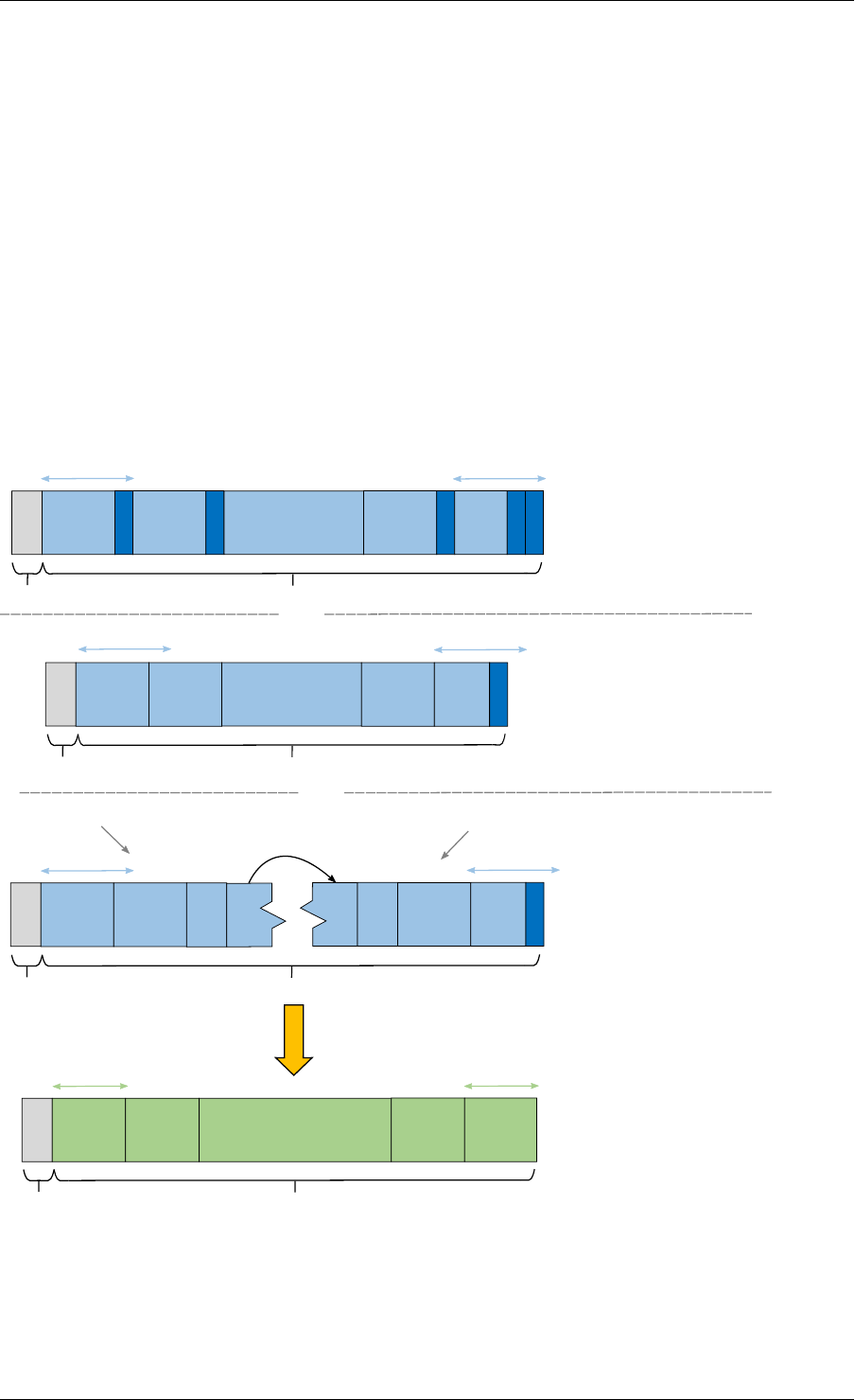
Programmer’s Guide, Release 18.11.0-rc5
The difference between the partial and full-size TB is that we need to know the index of the
first CB in this group and the number of CBs contained within. The first CB index is given by
rbut the number of the remaining CBs is calculated automatically by BBDEV before passing
down to the driver.
The number of remaining CBs should not be confused with c.cis the total number of CBs that
composes the whole TB (this maps to C as described in 3GPP TS 36.212 section 5.1.2).
The length is total size of the CBs inclusive of any CRC24A and CRC24B in case they were
appended by the application.
The case when one CB belongs to TB and is being enqueued individually to BBDEV, this case
is considered as a special case of partial TB where its number of CBs is 1. Therefore, it
requires to get processed in TB-mode.
The figure below visualizes the encoding of CBs using BBDEV interface in TB-mode. CB-mode
is a reduced version, where only one CB exists:
offset
length
offset
or
CB1
CRC24B
CB2
CRC24B
... CBc-1
CRC24B
CBc
CRC24A
CRC24B
k_neg k_pos
- CRC24B & CRC24A were pre-calculated
by the application
- The raw TB is given as a contiguous
buffer
- Only CRC24A was pre-calculated by the
application, therefore
RTE_BBDEV_TURBO_CRC_24B_ATTACH
is set in op_flags
- The raw TB is given as a contiguous
buffer
offset length
or
k_neg
CB1CB2... CBc-1 CBc
CRC24A
k_pos
k_neg k_pos
mbuf seg 1 mbuf seg 2
offset length
CB1CB2... CBNCBN... CBc-1
CRC24A
CBc
- CRC24A was pre-calculated and
RTE_BBDEV_TURBO_CRC_24B_ATTACH
is set in op_flags
- The raw TB is given as a "scattered"
buffer through a chained mbuf
encode
length
CB1
ea
... CBc-1 CBc
eb
CB2
Result is encoded back into the given
output mbuf as one contiguous buffer
Fig. 13.1: Turbo encoding of Code Blocks in mbuf structure
13.4. Operation Processing 130

Programmer’s Guide, Release 18.11.0-rc5
13.4.6 BBDEV Turbo Decode Operation
struct rte_bbdev_op_turbo_dec {
struct rte_bbdev_op_data input;
struct rte_bbdev_op_data hard_output;
struct rte_bbdev_op_data soft_output;
uint32_t op_flags;
uint8_t rv_index;
uint8_t iter_min:4;
uint8_t iter_max:4;
uint8_t iter_count;
uint8_t ext_scale;
uint8_t num_maps;
uint8_t code_block_mode;
union {
struct rte_bbdev_op_dec_cb_params cb_params;
struct rte_bbdev_op_dec_tb_params tb_params;
};
};
The Turbo decode structure is composed of the input and output mbuf data pointers.
op_flags parameter holds all operation related flags, like whether CRC24B is retained or not.
code_block_mode flag identifies the mode in which bbdev is operating in.
Similarly, the decode interface works on both the code block (CB) and the transport block (TB).
An operation executes in “CB-mode” when the CB is standalone. While “TB-mode” executes
when an operation performs on one or multiple CBs that belong to a TB. Therefore, a given
data can be standalone CB, full-size TB or partial TB. Partial TB means that only a subset of
CBs belonging to a bigger TB are being enqueued.
NOTE: It is assumed that all enqueued ops in one
rte_bbdev_enqueue_dec_ops() call belong to one mode, either CB-mode or
TB-mode.
The input kis the size of the decoded CB (this maps to K as described in 3GPP TS 36.212
section 5.1.2), this size is inclusive of CRC24A/B. The length is inclusive of CRC24A/B and
equals to kin this case.
The input encoded CB data is the Virtual Circular Buffer data stream, wk, with the null padding
included as described in 3GPP TS 36.212 section 5.1.4.1.2 and shown in 3GPP TS 36.212
section 5.1.4.1 Figure 5.1.4-1. The size of the virtual circular buffer is 3*Kpi, where Kpi is the
32 byte aligned value of K, as specified in 3GPP TS 36.212 section 5.1.4.1.1.
Each byte in the input circular buffer is the LLR value of each bit of the original CB.
hard_output is a mandatory capability that all BBDEV PMDs support. This is the decoded
CBs of K sizes (CRC24A/B is the last 24-bit in each decoded CB). Soft output is an optional
capability for BBDEV PMDs. Setting flag RTE_BBDEV_TURBO_DEC_TB_CRC_24B_KEEP in
op_flags directs BBDEV to retain CRC24B at the end of each CB. This might be useful for
the application in debug mode. An LLR rate matched output is computed in the soft_output
buffer structure for the given esize (this maps to E described in 3GPP TS 36.212 section
5.1.4.1.2). The output mbuf buffer size needs to be big enough to hold the encoded buffer of
size e.
The first CB Virtual Circular Buffer (VCB) index is given by rbut the number of the remaining
CB VCBs is calculated automatically by BBDEV before passing down to the driver.
13.4. Operation Processing 131
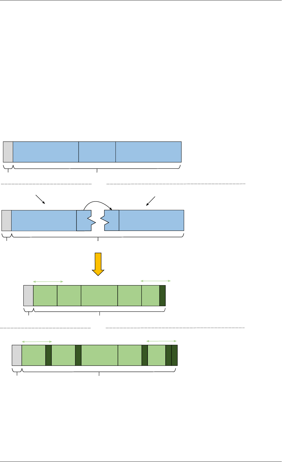
Programmer’s Guide, Release 18.11.0-rc5
The number of remaining CB VCBs should not be confused with c.cis the total number of
CBs that composes the whole TB (this maps to C as described in 3GPP TS 36.212 section
5.1.2).
The length is total size of the CBs inclusive of any CRC24A and CRC24B in case they were
appended by the application.
The case when one CB belongs to TB and is being enqueued individually to BBDEV, this case
is considered as a special case of partial TB where its number of CBs is 1. Therefore, it
requires to get processed in TB-mode.
The output mbuf data structure is expected to be allocated by the application with enough room
for the output data.
The figure below visualizes the decoding of CBs using BBDEV interface in TB-mode. CB-mode
is a reduced version, where only one CB exists:
wk LLR circular buffer ... wk LLR circular buffer
length
offset
The encoded TB is given as a
contiguous buffer
or
or
offset
wk LLR circular buffer
wk LLR circular buffer
length
.. ..
The encoded TB is given as a
"scattered" buffer through a
chained mbuf
Result is decoded back into the given output
mbuf as one contiguous buffer with no
CRC24B retaining
decode
Result is decoded back into the given output
mbuf as one contiguous buffer with CRC24B
retained in place when
RTE_BBDEV_TURBO_DEC_TB_CRC_24B_KEEP
is set in op_flags
offset length
CB1
hard
CB2
hard
k_neg
... CBc-1
hard
CBc
hard
CRC24A
k_pos
offset
k_neg
length
k_pos
CB1
hard
CRC24B
CB2
hard
CRC24B
... CBc-1
hard
CRC24B
CBc
hard
CRC24A
CRC24B
mbuf seg 1 mbuf seg 2
Fig. 13.2: Turbo decoding of Code Blocks in mbuf structure
13.4. Operation Processing 132

Programmer’s Guide, Release 18.11.0-rc5
13.5 Sample code
The baseband device sample application gives an introduction on how to use the bbdev frame-
work, by giving a sample code performing a loop-back operation with a baseband processor
capable of transceiving data packets.
The following sample C-like pseudo-code shows the basic steps to encode several buffers
using (sw_trubo) bbdev PMD.
/*EAL Init */
ret =rte_eal_init(argc, argv);
if (ret <0)
rte_exit(EXIT_FAILURE, "Invalid EAL arguments\n");
/*Get number of available bbdev devices */
nb_bbdevs =rte_bbdev_count();
if (nb_bbdevs == 0)
rte_exit(EXIT_FAILURE, "No bbdevs detected!\n");
/*Create bbdev op pools */
bbdev_op_pool[RTE_BBDEV_OP_TURBO_ENC] =
rte_bbdev_op_pool_create("bbdev_op_pool_enc",
RTE_BBDEV_OP_TURBO_ENC, NB_MBUF, 128, rte_socket_id());
/*Get information for this device */
rte_bbdev_info_get(dev_id, &info);
/*Setup BBDEV device queues */
ret =rte_bbdev_setup_queues(dev_id, qs_nb, info.socket_id);
if (ret <0)
rte_exit(EXIT_FAILURE,
"ERROR(%d): BBDEV %u not configured properly\n",
ret, dev_id);
/*setup device queues */
qconf.socket =info.socket_id;
qconf.queue_size =info.drv.queue_size_lim;
qconf.op_type =RTE_BBDEV_OP_TURBO_ENC;
for (q_id =0; q_id <qs_nb; q_id++) {
/*Configure all queues belonging to this bbdev device */
ret =rte_bbdev_queue_configure(dev_id, q_id, &qconf);
if (ret <0)
rte_exit(EXIT_FAILURE,
"ERROR(%d): BBDEV %u queue %u not configured properly\n",
ret, dev_id, q_id);
}
/*Start bbdev device */
ret =rte_bbdev_start(dev_id);
/*Create the mbuf mempool for pkts */
mbuf_pool =rte_pktmbuf_pool_create("bbdev_mbuf_pool",
NB_MBUF, MEMPOOL_CACHE_SIZE, 0,
RTE_MBUF_DEFAULT_BUF_SIZE, rte_socket_id());
if (mbuf_pool == NULL)
rte_exit(EXIT_FAILURE,
"Unable to create '%s' pool\n", pool_name);
while (!global_exit_flag) {
/*Allocate burst of op structures in preparation for enqueue */
13.5. Sample code 133

Programmer’s Guide, Release 18.11.0-rc5
if (rte_bbdev_enc_op_alloc_bulk(bbdev_op_pool[RTE_BBDEV_OP_TURBO_ENC],
ops_burst, op_num) != 0)
continue;
/*Allocate input mbuf pkts */
ret =rte_pktmbuf_alloc_bulk(mbuf_pool, input_pkts_burst, MAX_PKT_BURST);
if (ret <0)
continue;
/*Allocate output mbuf pkts */
ret =rte_pktmbuf_alloc_bulk(mbuf_pool, output_pkts_burst, MAX_PKT_BURST);
if (ret <0)
continue;
for (j =0;j<op_num; j++) {
/*Append the size of the ethernet header */
rte_pktmbuf_append(input_pkts_burst[j],
sizeof(struct ether_hdr));
/*set op */
ops_burst[j]->turbo_enc.input.offset =
sizeof(struct ether_hdr);
ops_burst[j]->turbo_enc->input.length =
rte_pktmbuf_pkt_len(bbdev_pkts[j]);
ops_burst[j]->turbo_enc->input.data =
input_pkts_burst[j];
ops_burst[j]->turbo_enc->output.offset =
sizeof(struct ether_hdr);
ops_burst[j]->turbo_enc->output.data =
output_pkts_burst[j];
}
/*Enqueue packets on BBDEV device */
op_num =rte_bbdev_enqueue_enc_ops(qconf->bbdev_id,
qconf->bbdev_qs[q], ops_burst,
MAX_PKT_BURST);
/*Dequeue packets from BBDEV device*/
op_num =rte_bbdev_dequeue_enc_ops(qconf->bbdev_id,
qconf->bbdev_qs[q], ops_burst,
MAX_PKT_BURST);
}
13.5.1 BBDEV Device API
The bbdev Library API is described in the DPDK API Reference document.
13.5. Sample code 134

CHAPTER
FOURTEEN
CRYPTOGRAPHY DEVICE LIBRARY
The cryptodev library provides a Crypto device framework for management and provisioning
of hardware and software Crypto poll mode drivers, defining generic APIs which support a
number of different Crypto operations. The framework currently only supports cipher, authenti-
cation, chained cipher/authentication and AEAD symmetric and asymmetric Crypto operations.
14.1 Design Principles
The cryptodev library follows the same basic principles as those used in DPDKs Ethernet
Device framework. The Crypto framework provides a generic Crypto device framework which
supports both physical (hardware) and virtual (software) Crypto devices as well as a generic
Crypto API which allows Crypto devices to be managed and configured and supports Crypto
operations to be provisioned on Crypto poll mode driver.
14.2 Device Management
14.2.1 Device Creation
Physical Crypto devices are discovered during the PCI probe/enumeration of the EAL function
which is executed at DPDK initialization, based on their PCI device identifier, each unique
PCI BDF (bus/bridge, device, function). Specific physical Crypto devices, like other physical
devices in DPDK can be white-listed or black-listed using the EAL command line options.
Virtual devices can be created by two mechanisms, either using the EAL command line options
or from within the application using an EAL API directly.
From the command line using the –vdev EAL option
--vdev 'crypto_aesni_mb0,max_nb_queue_pairs=2,socket_id=0'
Note:
• If DPDK application requires multiple software crypto PMD devices then required number
of --vdev with appropriate libraries are to be added.
• An Application with crypto PMD instaces sharing the same library requires unique ID.
Example: --vdev ’crypto_aesni_mb0’ --vdev ’crypto_aesni_mb1’
Our using the rte_vdev_init API within the application code.
135

Programmer’s Guide, Release 18.11.0-rc5
rte_vdev_init("crypto_aesni_mb",
"max_nb_queue_pairs=2,socket_id=0")
All virtual Crypto devices support the following initialization parameters:
•max_nb_queue_pairs - maximum number of queue pairs supported by the device.
•socket_id - socket on which to allocate the device resources on.
14.2.2 Device Identification
Each device, whether virtual or physical is uniquely designated by two identifiers:
• A unique device index used to designate the Crypto device in all functions exported by
the cryptodev API.
• A device name used to designate the Crypto device in console messages, for adminis-
tration or debugging purposes. For ease of use, the port name includes the port index.
14.2.3 Device Configuration
The configuration of each Crypto device includes the following operations:
• Allocation of resources, including hardware resources if a physical device.
• Resetting the device into a well-known default state.
• Initialization of statistics counters.
The rte_cryptodev_configure API is used to configure a Crypto device.
int rte_cryptodev_configure(uint8_t dev_id,
struct rte_cryptodev_config *config)
The rte_cryptodev_config structure is used to pass the configuration parameters for
socket selection and number of queue pairs.
struct rte_cryptodev_config {
int socket_id;
/**< Socket to allocate resources on */
uint16_t nb_queue_pairs;
/**< Number of queue pairs to configure on device */
};
14.2.4 Configuration of Queue Pairs
Each Crypto devices queue pair is individually configured through the
rte_cryptodev_queue_pair_setup API. Each queue pairs resources may be allo-
cated on a specified socket.
int rte_cryptodev_queue_pair_setup(uint8_t dev_id, uint16_t queue_pair_id,
const struct rte_cryptodev_qp_conf *qp_conf,
int socket_id)
struct rte_cryptodev_qp_conf {
uint32_t nb_descriptors; /**< Number of descriptors per queue pair */
};
14.2. Device Management 136

Programmer’s Guide, Release 18.11.0-rc5
14.2.5 Logical Cores, Memory and Queues Pair Relationships
The Crypto device Library as the Poll Mode Driver library support NUMA for when a processor’s
logical cores and interfaces utilize its local memory. Therefore Crypto operations, and in the
case of symmetric Crypto operations, the session and the mbuf being operated on, should
be allocated from memory pools created in the local memory. The buffers should, if possible,
remain on the local processor to obtain the best performance results and buffer descriptors
should be populated with mbufs allocated from a mempool allocated from local memory.
The run-to-completion model also performs better, especially in the case of virtual Crypto de-
vices, if the Crypto operation and session and data buffer is in local memory instead of a
remote processor’s memory. This is also true for the pipe-line model provided all logical cores
used are located on the same processor.
Multiple logical cores should never share the same queue pair for enqueuing operations or de-
queuing operations on the same Crypto device since this would require global locks and hinder
performance. It is however possible to use a different logical core to dequeue an operation on
a queue pair from the logical core which it was enqueued on. This means that a crypto burst
enqueue/dequeue APIs are a logical place to transition from one logical core to another in a
packet processing pipeline.
14.3 Device Features and Capabilities
Crypto devices define their functionality through two mechanisms, global device features and
algorithm capabilities. Global devices features identify device wide level features which are
applicable to the whole device such as the device having hardware acceleration or supporting
symmetric and/or asymmetric Crypto operations.
The capabilities mechanism defines the individual algorithms/functions which the device sup-
ports, such as a specific symmetric Crypto cipher, authentication operation or Authenticated
Encryption with Associated Data (AEAD) operation.
14.3.1 Device Features
Currently the following Crypto device features are defined:
• Symmetric Crypto operations
• Asymmetric Crypto operations
• Chaining of symmetric Crypto operations
• SSE accelerated SIMD vector operations
• AVX accelerated SIMD vector operations
• AVX2 accelerated SIMD vector operations
• AESNI accelerated instructions
• Hardware off-load processing
14.3. Device Features and Capabilities 137

Programmer’s Guide, Release 18.11.0-rc5
14.3.2 Device Operation Capabilities
Crypto capabilities which identify particular algorithm which the Crypto PMD supports are de-
fined by the operation type, the operation transform, the transform identifier and then the par-
ticulars of the transform. For the full scope of the Crypto capability see the definition of the
structure in the DPDK API Reference.
struct rte_cryptodev_capabilities;
Each Crypto poll mode driver defines its own private array of capabilities for the operations it
supports. Below is an example of the capabilities for a PMD which supports the authentication
algorithm SHA1_HMAC and the cipher algorithm AES_CBC.
static const struct rte_cryptodev_capabilities pmd_capabilities[] ={
{/*SHA1 HMAC */
.op =RTE_CRYPTO_OP_TYPE_SYMMETRIC,
.sym ={
.xform_type =RTE_CRYPTO_SYM_XFORM_AUTH,
.auth ={
.algo =RTE_CRYPTO_AUTH_SHA1_HMAC,
.block_size =64,
.key_size ={
.min =64,
.max =64,
.increment =0
},
.digest_size ={
.min =12,
.max =12,
.increment =0
},
.aad_size ={0},
.iv_size ={0}
}
}
},
{/*AES CBC */
.op =RTE_CRYPTO_OP_TYPE_SYMMETRIC,
.sym ={
.xform_type =RTE_CRYPTO_SYM_XFORM_CIPHER,
.cipher ={
.algo =RTE_CRYPTO_CIPHER_AES_CBC,
.block_size =16,
.key_size ={
.min =16,
.max =32,
.increment =8
},
.iv_size ={
.min =16,
.max =16,
.increment =0
}
}
}
}
}
14.3. Device Features and Capabilities 138

Programmer’s Guide, Release 18.11.0-rc5
14.3.3 Capabilities Discovery
Discovering the features and capabilities of a Crypto device poll mode driver is achieved
through the rte_cryptodev_info_get function.
void rte_cryptodev_info_get(uint8_t dev_id,
struct rte_cryptodev_info *dev_info);
This allows the user to query a specific Crypto PMD and get all the device features and ca-
pabilities. The rte_cryptodev_info structure contains all the relevant information for the
device.
struct rte_cryptodev_info {
const char *driver_name;
uint8_t driver_id;
struct rte_device *device;
uint64_t feature_flags;
const struct rte_cryptodev_capabilities *capabilities;
unsigned max_nb_queue_pairs;
struct {
unsigned max_nb_sessions;
} sym;
};
14.4 Operation Processing
Scheduling of Crypto operations on DPDK’s application data path is performed using a burst
oriented asynchronous API set. A queue pair on a Crypto device accepts a burst of Crypto
operations using enqueue burst API. On physical Crypto devices the enqueue burst API will
place the operations to be processed on the devices hardware input queue, for virtual devices
the processing of the Crypto operations is usually completed during the enqueue call to the
Crypto device. The dequeue burst API will retrieve any processed operations available from the
queue pair on the Crypto device, from physical devices this is usually directly from the devices
processed queue, and for virtual device’s from a rte_ring where processed operations are
place after being processed on the enqueue call.
14.4.1 Private data
For session-based operations, the set and get API provides a mechanism for an application to
store and retrieve the private user data information stored along with the crypto session.
For example, suppose an application is submitting a crypto operation with a session associ-
ated and wants to indicate private user data information which is required to be used after
completion of the crypto operation. In this case, the application can use the set API to set the
user data and retrieve it using get API.
int rte_cryptodev_sym_session_set_user_data(
struct rte_cryptodev_sym_session *sess, void *data, uint16_t size);
void *rte_cryptodev_sym_session_get_user_data(
struct rte_cryptodev_sym_session *sess);
14.4. Operation Processing 139

Programmer’s Guide, Release 18.11.0-rc5
For session-less mode, the private user data information can be placed along with the struct
rte_crypto_op. The rte_crypto_op::private_data_offset indicates the start of
private data information. The offset is counted from the start of the rte_crypto_op including
other crypto information such as the IVs (since there can be an IV also for authentication).
14.4.2 Enqueue / Dequeue Burst APIs
The burst enqueue API uses a Crypto device identifier and a queue pair identifier to specify the
Crypto device queue pair to schedule the processing on. The nb_ops parameter is the number
of operations to process which are supplied in the ops array of rte_crypto_op structures.
The enqueue function returns the number of operations it actually enqueued for processing, a
return value equal to nb_ops means that all packets have been enqueued.
uint16_t rte_cryptodev_enqueue_burst(uint8_t dev_id, uint16_t qp_id,
struct rte_crypto_op **ops, uint16_t nb_ops)
The dequeue API uses the same format as the enqueue API of processed but the nb_ops
and ops parameters are now used to specify the max processed operations the user wishes
to retrieve and the location in which to store them. The API call returns the actual number of
processed operations returned, this can never be larger than nb_ops.
uint16_t rte_cryptodev_dequeue_burst(uint8_t dev_id, uint16_t qp_id,
struct rte_crypto_op **ops, uint16_t nb_ops)
14.4.3 Operation Representation
An Crypto operation is represented by an rte_crypto_op structure, which is a generic metadata
container for all necessary information required for the Crypto operation to be processed on a
particular Crypto device poll mode driver.
Crypto Operation
Operation Specific Data (struct rte_crypto_sym_op)
private data
General Operation Data (struct rte_crypto_op)
The operation structure includes the operation type, the operation status and the session type
(session-based/less), a reference to the operation specific data, which can vary in size and
content depending on the operation being provisioned. It also contains the source mempool
for the operation, if it allocated from a mempool.
If Crypto operations are allocated from a Crypto operation mempool, see next section, there is
also the ability to allocate private memory with the operation for applications purposes.
14.4. Operation Processing 140

Programmer’s Guide, Release 18.11.0-rc5
Application software is responsible for specifying all the operation specific fields in the
rte_crypto_op structure which are then used by the Crypto PMD to process the requested
operation.
14.4.4 Operation Management and Allocation
The cryptodev library provides an API set for managing Crypto operations which utilize the
Mempool Library to allocate operation buffers. Therefore, it ensures that the crytpo op-
eration is interleaved optimally across the channels and ranks for optimal processing. A
rte_crypto_op contains a field indicating the pool that it originated from. When calling
rte_crypto_op_free(op), the operation returns to its original pool.
extern struct rte_mempool *
rte_crypto_op_pool_create(const char *name, enum rte_crypto_op_type type,
unsigned nb_elts, unsigned cache_size, uint16_t priv_size,
int socket_id);
During pool creation rte_crypto_op_init() is called as a constructor to initialize each
Crypto operation which subsequently calls __rte_crypto_op_reset() to configure any
operation type specific fields based on the type parameter.
rte_crypto_op_alloc() and rte_crypto_op_bulk_alloc() are used to allo-
cate Crypto operations of a specific type from a given Crypto operation mempool.
__rte_crypto_op_reset() is called on each operation before being returned to allocate
to a user so the operation is always in a good known state before use by the application.
struct rte_crypto_op *rte_crypto_op_alloc(struct rte_mempool *mempool,
enum rte_crypto_op_type type)
unsigned rte_crypto_op_bulk_alloc(struct rte_mempool *mempool,
enum rte_crypto_op_type type,
struct rte_crypto_op **ops, uint16_t nb_ops)
rte_crypto_op_free() is called by the application to return an operation to its allocating
pool.
void rte_crypto_op_free(struct rte_crypto_op *op)
14.5 Symmetric Cryptography Support
The cryptodev library currently provides support for the following symmetric Crypto operations;
cipher, authentication, including chaining of these operations, as well as also supporting AEAD
operations.
14.5.1 Session and Session Management
Sessions are used in symmetric cryptographic processing to store the immutable data defined
in a cryptographic transform which is used in the operation processing of a packet flow. Ses-
sions are used to manage information such as expand cipher keys and HMAC IPADs and
OPADs, which need to be calculated for a particular Crypto operation, but are immutable on a
packet to packet basis for a flow. Crypto sessions cache this immutable data in a optimal way
for the underlying PMD and this allows further acceleration of the offload of Crypto workloads.
14.5. Symmetric Cryptography Support 141
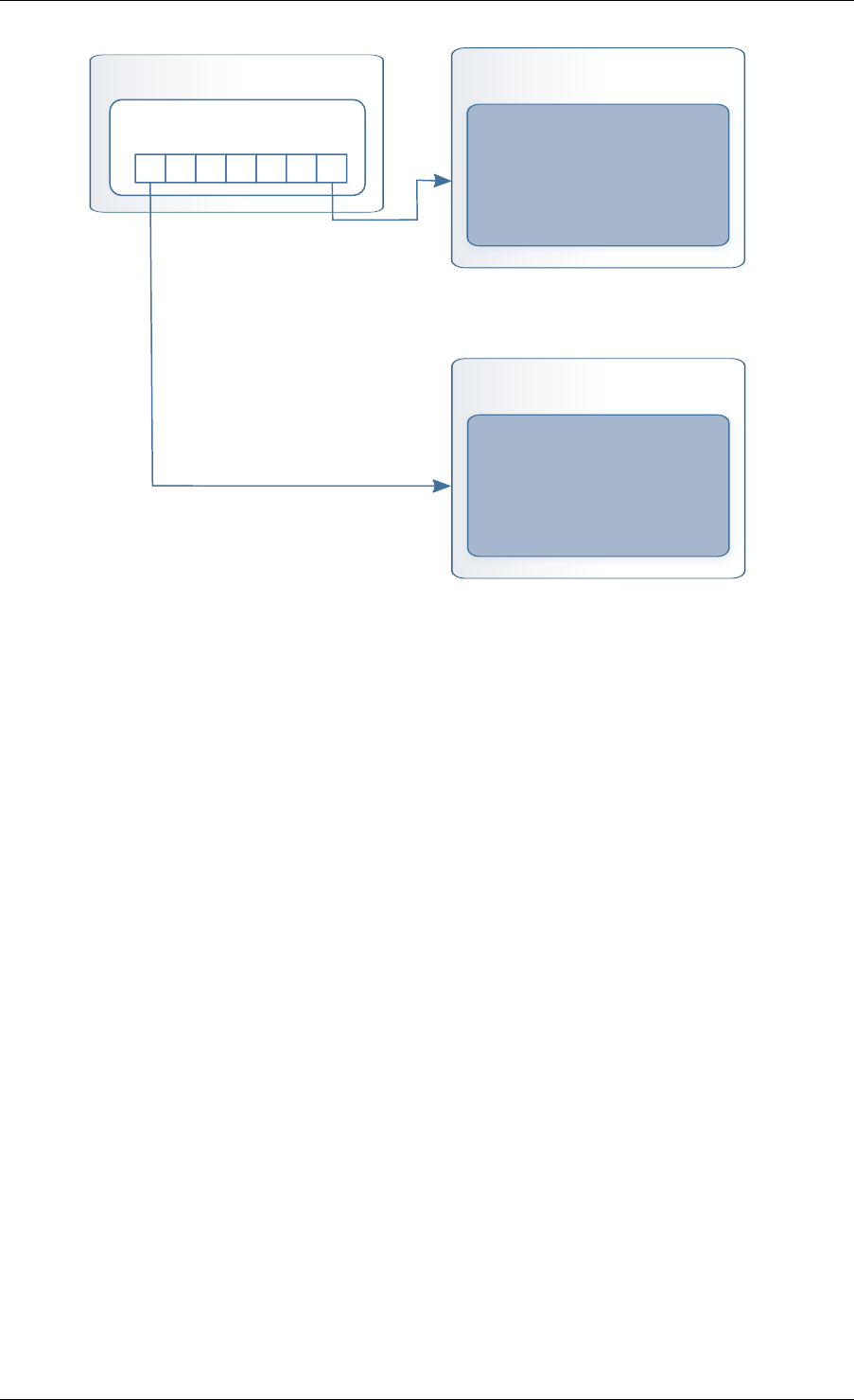
Programmer’s Guide, Release 18.11.0-rc5
Crypto Symmetric Session
void *sess_private_data[]
Crypto Driver Private Session
Private Session Data
Crypto Driver Private Session
Private Session Data
...
The Crypto device framework provides APIs to allocate and initialize sessions for crypto de-
vices, where sessions are mempool objects. It is the application’s responsibility to create and
manage the session mempools. This approach allows for different scenarios such as having a
single session mempool for all crypto devices (where the mempool object size is big enough
to hold the private session of any crypto device), as well as having multiple session mempools
of different sizes for better memory usage.
An application can use rte_cryptodev_sym_get_private_session_size() to get the
private session size of given crypto device. This function would allow an application to calcu-
late the max device session size of all crypto devices to create a single session mempool. If
instead an application creates multiple session mempools, the Crypto device framework also
provides rte_cryptodev_sym_get_header_session_size to get the size of an uninitial-
ized session.
Once the session mempools have been created, rte_cryptodev_sym_session_create()
is used to allocate an uninitialized session from the given mempool. The session then must
be initialized using rte_cryptodev_sym_session_init() for each of the required crypto
devices. A symmetric transform chain is used to specify the operation and its parameters. See
the section below for details on transforms.
When a session is no longer used, user must call rte_cryptodev_sym_session_clear()
for each of the crypto devices that are using the session, to free all driver private session data.
Once this is done, session should be freed using rte_cryptodev_sym_session_free
which returns them to their mempool.
14.5.2 Transforms and Transform Chaining
Symmetric Crypto transforms (rte_crypto_sym_xform) are the mechanism used to spec-
ify the details of the Crypto operation. For chaining of symmetric operations such as cipher
encrypt and authentication generate, the next pointer allows transform to be chained together.
14.5. Symmetric Cryptography Support 142
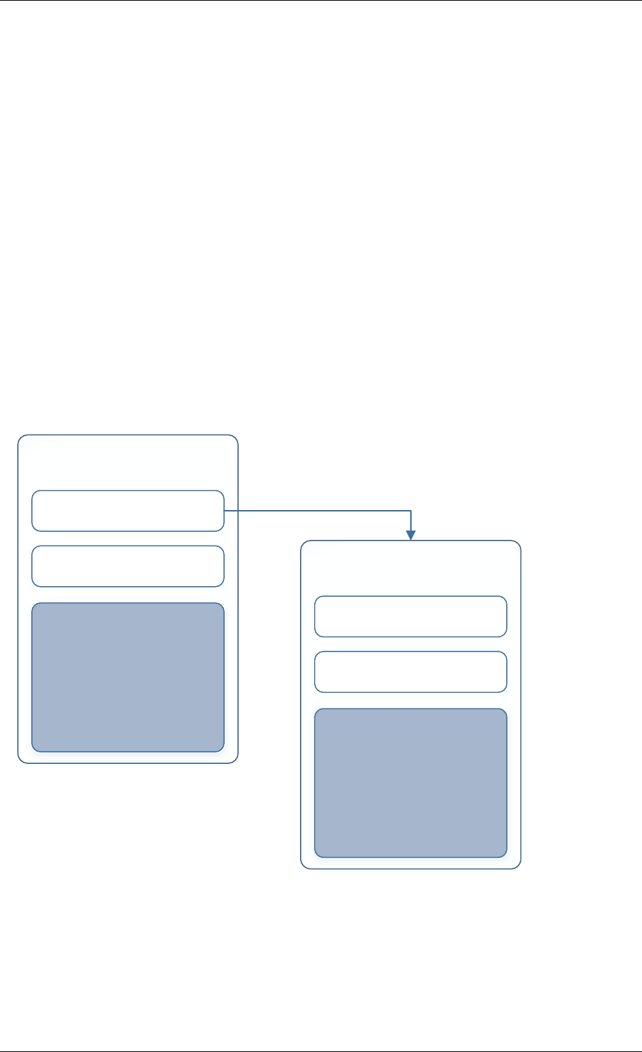
Programmer’s Guide, Release 18.11.0-rc5
Crypto devices which support chaining must publish the chaining of symmetric Crypto opera-
tions feature flag.
Currently there are three transforms types cipher, authentication and AEAD. Also it is important
to note that the order in which the transforms are passed indicates the order of the chaining.
struct rte_crypto_sym_xform {
struct rte_crypto_sym_xform *next;
/**< next xform in chain */
enum rte_crypto_sym_xform_type type;
/**< xform type */
union {
struct rte_crypto_auth_xform auth;
/**< Authentication / hash xform */
struct rte_crypto_cipher_xform cipher;
/**< Cipher xform */
struct rte_crypto_aead_xform aead;
/**< AEAD xform */
};
};
The API does not place a limit on the number of transforms that can be chained together but
this will be limited by the underlying Crypto device poll mode driver which is processing the
operation.
Symmetric Transform (struct rte_crypto_sym_xform)
Transform Parameters struct rte_crypto_auth_xform struct rte_crypto_cipher_xformstruct rte_crypto_aead_xform
next transform (struct rte_crypto_sym_xform *)
transform type (enum rte_crypto_sym_xform_type)
Symmetric Transform (struct rte_crypto_sym_xform)
Transform Parameters struct rte_crypto_auth_xform struct rte_crypto_cipher_xformstruct rte_crypto_aead_xform
next transform (struct rte_crypto_sym_xform *)
transform type (enum rte_crypto_sym_xform_type)
14.5.3 Symmetric Operations
The symmetric Crypto operation structure contains all the mutable data relating to performing
symmetric cryptographic processing on a referenced mbuf data buffer. It is used for either
cipher, authentication, AEAD and chained operations.
14.5. Symmetric Cryptography Support 143

Programmer’s Guide, Release 18.11.0-rc5
As a minimum the symmetric operation must have a source data buffer (m_src), a valid session
(or transform chain if in session-less mode) and the minimum authentication/ cipher/ AEAD pa-
rameters required depending on the type of operation specified in the session or the transform
chain.
struct rte_crypto_sym_op {
struct rte_mbuf *m_src;
struct rte_mbuf *m_dst;
union {
struct rte_cryptodev_sym_session *session;
/**< Handle for the initialised session context */
struct rte_crypto_sym_xform *xform;
/**< Session-less API Crypto operation parameters */
};
union {
struct {
struct {
uint32_t offset;
uint32_t length;
} data; /**< Data offsets and length for AEAD */
struct {
uint8_t *data;
rte_iova_t phys_addr;
} digest; /**< Digest parameters */
struct {
uint8_t *data;
rte_iova_t phys_addr;
} aad;
/**< Additional authentication parameters */
} aead;
struct {
struct {
struct {
uint32_t offset;
uint32_t length;
} data; /**< Data offsets and length for ciphering */
} cipher;
struct {
struct {
uint32_t offset;
uint32_t length;
} data;
/**< Data offsets and length for authentication */
struct {
uint8_t *data;
rte_iova_t phys_addr;
} digest; /**< Digest parameters */
} auth;
};
};
};
14.5. Symmetric Cryptography Support 144

Programmer’s Guide, Release 18.11.0-rc5
14.6 Sample code
There are various sample applications that show how to use the cryptodev library, such as the
L2fwd with Crypto sample application (L2fwd-crypto) and the IPSec Security Gateway applica-
tion (ipsec-secgw).
While these applications demonstrate how an application can be created to perform generic
crypto operation, the required complexity hides the basic steps of how to use the cryptodev
APIs.
The following sample code shows the basic steps to encrypt several buffers with AES-CBC
(although performing other crypto operations is similar), using one of the crypto PMDs available
in DPDK.
/*
*Simple example to encrypt several buffers with AES-CBC using
*the Cryptodev APIs.
*/
#define MAX_SESSIONS 1024
#define NUM_MBUFS 1024
#define POOL_CACHE_SIZE 128
#define BURST_SIZE 32
#define BUFFER_SIZE 1024
#define AES_CBC_IV_LENGTH 16
#define AES_CBC_KEY_LENGTH 16
#define IV_OFFSET (sizeof(struct rte_crypto_op) + \
sizeof(struct rte_crypto_sym_op))
struct rte_mempool *mbuf_pool, *crypto_op_pool, *session_pool;
unsigned int session_size;
int ret;
/*Initialize EAL. */
ret =rte_eal_init(argc, argv);
if (ret <0)
rte_exit(EXIT_FAILURE, "Invalid EAL arguments\n");
uint8_t socket_id =rte_socket_id();
/*Create the mbuf pool. */
mbuf_pool =rte_pktmbuf_pool_create("mbuf_pool",
NUM_MBUFS,
POOL_CACHE_SIZE,
0,
RTE_MBUF_DEFAULT_BUF_SIZE,
socket_id);
if (mbuf_pool == NULL)
rte_exit(EXIT_FAILURE, "Cannot create mbuf pool\n");
/*
*The IV is always placed after the crypto operation,
*so some private data is required to be reserved.
*/
unsigned int crypto_op_private_data =AES_CBC_IV_LENGTH;
/*Create crypto operation pool. */
crypto_op_pool =rte_crypto_op_pool_create("crypto_op_pool",
RTE_CRYPTO_OP_TYPE_SYMMETRIC,
NUM_MBUFS,
POOL_CACHE_SIZE,
14.6. Sample code 145

Programmer’s Guide, Release 18.11.0-rc5
crypto_op_private_data,
socket_id);
if (crypto_op_pool == NULL)
rte_exit(EXIT_FAILURE, "Cannot create crypto op pool\n");
/*Create the virtual crypto device. */
char args[128];
const char *crypto_name ="crypto_aesni_mb0";
snprintf(args, sizeof(args), "socket_id=%d", socket_id);
ret =rte_vdev_init(crypto_name, args);
if (ret != 0)
rte_exit(EXIT_FAILURE, "Cannot create virtual device");
uint8_t cdev_id =rte_cryptodev_get_dev_id(crypto_name);
/*Get private session data size. */
session_size =rte_cryptodev_sym_get_private_session_size(cdev_id);
/*
*Create session mempool, with two objects per session,
*one for the session header and another one for the
*private session data for the crypto device.
*/
session_pool =rte_mempool_create("session_pool",
MAX_SESSIONS *2,
session_size,
POOL_CACHE_SIZE,
0,NULL,NULL,NULL,
NULL, socket_id,
0);
/*Configure the crypto device. */
struct rte_cryptodev_config conf ={
.nb_queue_pairs =1,
.socket_id =socket_id
};
struct rte_cryptodev_qp_conf qp_conf ={
.nb_descriptors =2048
};
if (rte_cryptodev_configure(cdev_id, &conf) <0)
rte_exit(EXIT_FAILURE, "Failed to configure cryptodev %u", cdev_id);
if (rte_cryptodev_queue_pair_setup(cdev_id, 0,&qp_conf,
socket_id, session_pool) <0)
rte_exit(EXIT_FAILURE, "Failed to setup queue pair\n");
if (rte_cryptodev_start(cdev_id) <0)
rte_exit(EXIT_FAILURE, "Failed to start device\n");
/*Create the crypto transform. */
uint8_t cipher_key[16]={0};
struct rte_crypto_sym_xform cipher_xform ={
.next =NULL,
.type =RTE_CRYPTO_SYM_XFORM_CIPHER,
.cipher ={
.op =RTE_CRYPTO_CIPHER_OP_ENCRYPT,
.algo =RTE_CRYPTO_CIPHER_AES_CBC,
.key ={
.data =cipher_key,
.length =AES_CBC_KEY_LENGTH
},
.iv ={
14.6. Sample code 146

Programmer’s Guide, Release 18.11.0-rc5
.offset =IV_OFFSET,
.length =AES_CBC_IV_LENGTH
}
}
};
/*Create crypto session and initialize it for the crypto device. */
struct rte_cryptodev_sym_session *session;
session =rte_cryptodev_sym_session_create(session_pool);
if (session == NULL)
rte_exit(EXIT_FAILURE, "Session could not be created\n");
if (rte_cryptodev_sym_session_init(cdev_id, session,
&cipher_xform, session_pool) <0)
rte_exit(EXIT_FAILURE, "Session could not be initialized "
"for the crypto device\n");
/*Get a burst of crypto operations. */
struct rte_crypto_op *crypto_ops[BURST_SIZE];
if (rte_crypto_op_bulk_alloc(crypto_op_pool,
RTE_CRYPTO_OP_TYPE_SYMMETRIC,
crypto_ops, BURST_SIZE) == 0)
rte_exit(EXIT_FAILURE, "Not enough crypto operations available\n");
/*Get a burst of mbufs. */
struct rte_mbuf *mbufs[BURST_SIZE];
if (rte_pktmbuf_alloc_bulk(mbuf_pool, mbufs, BURST_SIZE) <0)
rte_exit(EXIT_FAILURE, "Not enough mbufs available");
/*Initialize the mbufs and append them to the crypto operations. */
unsigned int i;
for (i =0;i<BURST_SIZE; i++) {
if (rte_pktmbuf_append(mbufs[i], BUFFER_SIZE) == NULL)
rte_exit(EXIT_FAILURE, "Not enough room in the mbuf\n");
crypto_ops[i]->sym->m_src =mbufs[i];
}
/*Set up the crypto operations. */
for (i =0;i<BURST_SIZE; i++) {
struct rte_crypto_op *op =crypto_ops[i];
/*Modify bytes of the IV at the end of the crypto operation */
uint8_t *iv_ptr =rte_crypto_op_ctod_offset(op, uint8_t *,
IV_OFFSET);
generate_random_bytes(iv_ptr, AES_CBC_IV_LENGTH);
op->sym->cipher.data.offset =0;
op->sym->cipher.data.length =BUFFER_SIZE;
/*Attach the crypto session to the operation */
rte_crypto_op_attach_sym_session(op, session);
}
/*Enqueue the crypto operations in the crypto device. */
uint16_t num_enqueued_ops =rte_cryptodev_enqueue_burst(cdev_id, 0,
crypto_ops, BURST_SIZE);
/*
*Dequeue the crypto operations until all the operations
*are proccessed in the crypto device.
*/
uint16_t num_dequeued_ops, total_num_dequeued_ops =0;
do {
14.6. Sample code 147

Programmer’s Guide, Release 18.11.0-rc5
struct rte_crypto_op *dequeued_ops[BURST_SIZE];
num_dequeued_ops =rte_cryptodev_dequeue_burst(cdev_id, 0,
dequeued_ops, BURST_SIZE);
total_num_dequeued_ops += num_dequeued_ops;
/*Check if operation was processed successfully */
for (i =0;i<num_dequeued_ops; i++) {
if (dequeued_ops[i]->status != RTE_CRYPTO_OP_STATUS_SUCCESS)
rte_exit(EXIT_FAILURE,
"Some operations were not processed correctly");
}
rte_mempool_put_bulk(crypto_op_pool, (void **)dequeued_ops,
num_dequeued_ops);
}while (total_num_dequeued_ops <num_enqueued_ops);
14.7 Asymmetric Cryptography
The cryptodev library currently provides support for the following asymmetric Crypto opera-
tions; RSA, Modular exponentiation and inversion, Diffie-Hellman public and/or private key
generation and shared secret compute, DSA Signature generation and verification.
14.7.1 Session and Session Management
Sessions are used in asymmetric cryptographic processing to store the immutable data de-
fined in asymmetric cryptographic transform which is further used in the operation processing.
Sessions typically stores information, such as, public and private key information or domain
params or prime modulus data i.e. immutable across data sets. Crypto sessions cache this
immutable data in a optimal way for the underlying PMD and this allows further acceleration of
the offload of Crypto workloads.
Like symmetric, the Crypto device framework provides APIs to allocate and initialize asymmet-
ric sessions for crypto devices, where sessions are mempool objects. It is the application’s
responsibility to create and manage the session mempools. Application using both symmetric
and asymmetric sessions should allocate and maintain different sessions pools for each type.
An application can use rte_cryptodev_get_asym_session_private_size() to get
the private size of asymmetric session on a given crypto device. This function
would allow an application to calculate the max device asymmetric session size of all
crypto devices to create a single session mempool. If instead an application cre-
ates multiple asymmetric session mempools, the Crypto device framework also provides
rte_cryptodev_asym_get_header_session_size() to get the size of an uninitialized
session.
Once the session mempools have been created, rte_cryptodev_asym_session_create()
is used to allocate an uninitialized asymmetric session from the given mempool. The session
then must be initialized using rte_cryptodev_asym_session_init() for each of the
required crypto devices. An asymmetric transform chain is used to specify the operation and
its parameters. See the section below for details on transforms.
When a session is no longer used, user must call rte_cryptodev_asym_session_clear()
for each of the crypto devices that are using the session, to free all driver pri-
vate asymmetric session data. Once this is done, session should be freed using
rte_cryptodev_asym_session_free() which returns them to their mempool.
14.7. Asymmetric Cryptography 148

Programmer’s Guide, Release 18.11.0-rc5
14.7.2 Asymmetric Sessionless Support
Currently asymmetric crypto framework does not support sessionless.
14.7.3 Transforms and Transform Chaining
Asymmetric Crypto transforms (rte_crypto_asym_xform) are the mechanism used to
specify the details of the asymmetric Crypto operation. Next pointer within xform allows trans-
form to be chained together. Also it is important to note that the order in which the transforms
are passed indicates the order of the chaining.
Not all asymmetric crypto xforms are supported for chaining. Currently supported asymmetric
crypto chaining is Diffie-Hellman private key generation followed by public generation. Also,
currently API does not support chaining of symmetric and asymmetric crypto xfroms.
Each xform defines specific asymmetric crypto algo. Currently supported are: * RSA * Modular
operations (Exponentiation and Inverse) * Diffie-Hellman * DSA * None - special case where
PMD may support a passthrough mode. More for diagnostic purpose
See DPDK API Reference for details on each rte_crypto_xxx_xform struct
14.7.4 Asymmetric Operations
The asymmetric Crypto operation structure contains all the mutable data relating to asymmetric
cryptographic processing on an input data buffer. It uses either RSA, Modular, Diffie-Hellman
or DSA operations depending upon session it is attached to.
Every operation must carry a valid session handle which further carries information on xform
or xform-chain to be performed on op. Every xform type defines its own set of operational
params in their respective rte_crypto_xxx_op_param struct. Depending on xform information
within session, PMD picks up and process respective op_param struct. Unlike symmetric,
asymmetric operations do not use mbufs for input/output. They operate on data buffer of type
rte_crypto_param.
See DPDK API Reference for details on each rte_crypto_xxx_op_param struct
14.8 Asymmetric crypto Sample code
There’s a unit test application test_cryptodev_asym.c inside unit test framework that show how
to setup and process asymmetric operations using cryptodev library.
The following sample code shows the basic steps to compute modular exponentiation using
1024-bit modulus length using openssl PMD available in DPDK (performing other crypto oper-
ations is similar except change to respective op and xform setup).
/*
*Simple example to compute modular exponentiation with 1024-bit key
*
*/
#define MAX_ASYM_SESSIONS 10
#define NUM_ASYM_BUFS 10
struct rte_mempool *crypto_op_pool, *asym_session_pool;
unsigned int asym_session_size;
14.8. Asymmetric crypto Sample code 149

Programmer’s Guide, Release 18.11.0-rc5
int ret;
/*Initialize EAL. */
ret =rte_eal_init(argc, argv);
if (ret <0)
rte_exit(EXIT_FAILURE, "Invalid EAL arguments\n");
uint8_t socket_id =rte_socket_id();
/*Create crypto operation pool. */
crypto_op_pool =rte_crypto_op_pool_create(
"crypto_op_pool",
RTE_CRYPTO_OP_TYPE_ASYMMETRIC,
NUM_ASYM_BUFS, 0,0,
socket_id);
if (crypto_op_pool == NULL)
rte_exit(EXIT_FAILURE, "Cannot create crypto op pool\n");
/*Create the virtual crypto device. */
char args[128];
const char *crypto_name ="crypto_openssl";
snprintf(args, sizeof(args), "socket_id=%d", socket_id);
ret =rte_vdev_init(crypto_name, args);
if (ret != 0)
rte_exit(EXIT_FAILURE, "Cannot create virtual device");
uint8_t cdev_id =rte_cryptodev_get_dev_id(crypto_name);
/*Get private asym session data size. */
asym_session_size =rte_cryptodev_get_asym_private_session_size(cdev_id);
/*
*Create session mempool, with two objects per session,
*one for the session header and another one for the
*private asym session data for the crypto device.
*/
asym_session_pool =rte_mempool_create("asym_session_pool",
MAX_ASYM_SESSIONS *2,
asym_session_size,
0,
0,NULL,NULL,NULL,
NULL, socket_id,
0);
/*Configure the crypto device. */
struct rte_cryptodev_config conf ={
.nb_queue_pairs =1,
.socket_id =socket_id
};
struct rte_cryptodev_qp_conf qp_conf ={
.nb_descriptors =2048
};
if (rte_cryptodev_configure(cdev_id, &conf) <0)
rte_exit(EXIT_FAILURE, "Failed to configure cryptodev %u", cdev_id);
if (rte_cryptodev_queue_pair_setup(cdev_id, 0,&qp_conf,
socket_id, asym_session_pool) <0)
rte_exit(EXIT_FAILURE, "Failed to setup queue pair\n");
if (rte_cryptodev_start(cdev_id) <0)
rte_exit(EXIT_FAILURE, "Failed to start device\n");
14.8. Asymmetric crypto Sample code 150

Programmer’s Guide, Release 18.11.0-rc5
/*Setup crypto xform to do modular exponentiation with 1024 bit
*length modulus
*/
struct rte_crypto_asym_xform modex_xform ={
.next =NULL,
.xform_type =RTE_CRYPTO_ASYM_XFORM_MODEX,
.modex ={
.modulus ={
.data =
(uint8_t *)
("\xb3\xa1\xaf\xb7\x13\x08\x00\x0a\x35\xdc\x2b\x20\x8d"
"\xa1\xb5\xce\x47\x8a\xc3\x80\xf4\x7d\x4a\xa2\x62\xfd\x61\x7f"
"\xb5\xa8\xde\x0a\x17\x97\xa0\xbf\xdf\x56\x5a\x3d\x51\x56\x4f"
"\x70\x70\x3f\x63\x6a\x44\x5b\xad\x84\x0d\x3f\x27\x6e\x3b\x34"
"\x91\x60\x14\xb9\xaa\x72\xfd\xa3\x64\xd2\x03\xa7\x53\x87\x9e"
"\x88\x0b\xc1\x14\x93\x1a\x62\xff\xb1\x5d\x74\xcd\x59\x63\x18"
"\x11\x3d\x4f\xba\x75\xd4\x33\x4e\x23\x6b\x7b\x57\x44\xe1\xd3"
"\x03\x13\xa6\xf0\x8b\x60\xb0\x9e\xee\x75\x08\x9d\x71\x63\x13"
"\xcb\xa6\x81\x92\x14\x03\x22\x2d\xde\x55"),
.length =128
},
.exponent ={
.data =(uint8_t *)("\x01\x00\x01"),
.length =3
}
}
};
/*Create asym crypto session and initialize it for the crypto device. */
struct rte_cryptodev_asym_session *asym_session;
asym_session =rte_cryptodev_asym_session_create(asym_session_pool);
if (asym_session == NULL)
rte_exit(EXIT_FAILURE, "Session could not be created\n");
if (rte_cryptodev_asym_session_init(cdev_id, asym_session,
&modex_xform, asym_session_pool) <0)
rte_exit(EXIT_FAILURE, "Session could not be initialized "
"for the crypto device\n");
/*Get a burst of crypto operations. */
struct rte_crypto_op *crypto_ops[1];
if (rte_crypto_op_bulk_alloc(crypto_op_pool,
RTE_CRYPTO_OP_TYPE_ASYMMETRIC,
crypto_ops, 1)== 0)
rte_exit(EXIT_FAILURE, "Not enough crypto operations available\n");
/*Set up the crypto operations. */
struct rte_crypto_asym_op *asym_op =crypto_ops[0]->asym;
/*calculate mod exp of value 0xf8 */
static unsigned char base[] ={0xF8};
asym_op->modex.base.data =base;
asym_op->modex.base.length =sizeof(base);
asym_op->modex.base.iova =base;
/*Attach the asym crypto session to the operation */
rte_crypto_op_attach_asym_session(op, asym_session);
/*Enqueue the crypto operations in the crypto device. */
uint16_t num_enqueued_ops =rte_cryptodev_enqueue_burst(cdev_id, 0,
crypto_ops, 1);
/*
*Dequeue the crypto operations until all the operations
14.8. Asymmetric crypto Sample code 151

Programmer’s Guide, Release 18.11.0-rc5
*are processed in the crypto device.
*/
uint16_t num_dequeued_ops, total_num_dequeued_ops =0;
do {
struct rte_crypto_op *dequeued_ops[1];
num_dequeued_ops =rte_cryptodev_dequeue_burst(cdev_id, 0,
dequeued_ops, 1);
total_num_dequeued_ops += num_dequeued_ops;
/*Check if operation was processed successfully */
if (dequeued_ops[0]->status != RTE_CRYPTO_OP_STATUS_SUCCESS)
rte_exit(EXIT_FAILURE,
"Some operations were not processed correctly");
}while (total_num_dequeued_ops <num_enqueued_ops);
14.8.1 Asymmetric Crypto Device API
The cryptodev Library API is described in the DPDK API Reference
14.8. Asymmetric crypto Sample code 152

CHAPTER
FIFTEEN
COMPRESSION DEVICE LIBRARY
The compression framework provides a generic set of APIs to perform compression ser-
vices as well as to query and configure compression devices both physical(hardware) and
virtual(software) to perform those services. The framework currently only supports lossless
compression schemes: Deflate and LZS.
15.1 Device Management
15.1.1 Device Creation
Physical compression devices are discovered during the bus probe of the EAL function which
is executed at DPDK initialization, based on their unique device identifier. For eg. PCI devices
can be identified using PCI BDF (bus/bridge, device, function). Specific physical compression
devices, like other physical devices in DPDK can be white-listed or black-listed using the EAL
command line options.
Virtual devices can be created by two mechanisms, either using the EAL command line options
or from within the application using an EAL API directly.
From the command line using the –vdev EAL option
--vdev '<pmd name>,socket_id=0'
Note:
• If DPDK application requires multiple software compression PMD devices then required
number of --vdev with appropriate libraries are to be added.
• An Application with multiple compression device instances exposed by the same PMD
must specify a unique name for each device.
Example: --vdev ’pmd0’ --vdev ’pmd1’
Or, by using the rte_vdev_init API within the application code.
rte_vdev_init("<pmd_name>","socket_id=0")
All virtual compression devices support the following initialization parameters:
•socket_id - socket on which to allocate the device resources on.
153

Programmer’s Guide, Release 18.11.0-rc5
15.1.2 Device Identification
Each device, whether virtual or physical is uniquely designated by two identifiers:
• A unique device index used to designate the compression device in all functions exported
by the compressdev API.
• A device name used to designate the compression device in console messages, for ad-
ministration or debugging purposes.
15.1.3 Device Configuration
The configuration of each compression device includes the following operations:
• Allocation of resources, including hardware resources if a physical device.
• Resetting the device into a well-known default state.
• Initialization of statistics counters.
The rte_compressdev_configure API is used to configure a compression device.
The rte_compressdev_config structure is used to pass the configuration parameters.
See DPDK API Reference for details.
15.1.4 Configuration of Queue Pairs
Each compression device queue pair is individually configured through the
rte_compressdev_queue_pair_setup API.
The max_inflight_ops is used to pass maximum number of rte_comp_op that could be
present in a queue at-a-time. PMD then can allocate resources accordingly on a specified
socket.
See DPDK API Reference for details.
15.1.5 Logical Cores, Memory and Queues Pair Relationships
Library supports NUMA similarly as described in Cryptodev library section.
A queue pair cannot be shared and should be exclusively used by a single processing context
for enqueuing operations or dequeuing operations on the same compression device since
sharing would require global locks and hinder performance. It is however possible to use a
different logical core to dequeue an operation on a queue pair from the logical core on which
it was enqueued. This means that a compression burst enqueue/dequeue APIs are a logical
place to transition from one logical core to another in a data processing pipeline.
15.2 Device Features and Capabilities
Compression devices define their functionality through two mechanisms, global device features
and algorithm features. Global devices features identify device wide level features which are
15.2. Device Features and Capabilities 154

Programmer’s Guide, Release 18.11.0-rc5
applicable to the whole device such as supported hardware acceleration and CPU features.
List of compression device features can be seen in the RTE_COMPDEV_FF_XXX macros.
The algorithm features lists individual algo feature which device supports per-algorithm, such
as a stateful compression/decompression, checksums operation etc. List of algorithm features
can be seen in the RTE_COMP_FF_XXX macros.
15.2.1 Capabilities
Each PMD has a list of capabilities, including algorithms listed in enum
rte_comp_algorithm and its associated feature flag and sliding window range in log
base 2 value. Sliding window tells the minimum and maximum size of lookup window that
algorithm uses to find duplicates.
See DPDK API Reference for details.
Each Compression poll mode driver defines its array of capabilities for each algorithm it sup-
ports. See PMD implementation for capability initialization.
15.2.2 Capabilities Discovery
PMD capability and features are discovered via rte_compressdev_info_get function.
The rte_compressdev_info structure contains all the relevant information for the device.
See DPDK API Reference for details.
15.3 Compression Operation
DPDK compression supports two types of compression methodologies:
• Stateless, data associated to a compression operation is compressed without any refer-
ence to another compression operation.
• Stateful, data in each compression operation is compressed with reference to previous
compression operations in the same data stream i.e. history of data is maintained be-
tween the operations.
For more explanation, please refer RFC https://www.ietf.org/rfc/rfc1951.txt
15.3.1 Operation Representation
Compression operation is described via struct rte_comp_op, which contains both input
and output data. The operation structure includes the operation type (stateless or stateful), the
operation status and the priv_xform/stream handle, source, destination and checksum buffer
pointers. It also contains the source mempool from which the operation is allocated. PMD
updates consumed field with amount of data read from source buffer and produced field with
amount of data of written into destination buffer along with status of operation. See section
Produced, Consumed And Operation Status for more details.
Compression operations mempool also has an ability to allocate private memory with the op-
eration for application’s purposes. Application software is responsible for specifying all the
15.3. Compression Operation 155

Programmer’s Guide, Release 18.11.0-rc5
operation specific fields in the rte_comp_op structure which are then used by the compres-
sion PMD to process the requested operation.
15.3.2 Operation Management and Allocation
The compressdev library provides an API set for managing compression operations which uti-
lize the Mempool Library to allocate operation buffers. Therefore, it ensures that the compres-
sion operation is interleaved optimally across the channels and ranks for optimal processing.
Arte_comp_op contains a field indicating the pool it originated from.
rte_comp_op_alloc() and rte_comp_op_bulk_alloc() are used to allocate compres-
sion operations from a given compression operation mempool. The operation gets reset before
being returned to a user so that operation is always in a good known state before use by the
application.
rte_comp_op_free() is called by the application to return an operation to its allocating pool.
See DPDK API Reference for details.
15.3.3 Passing source data as mbuf-chain
If input data is scattered across several different buffers, then Application can either parse
through all such buffers and make one mbuf-chain and enqueue it for processing or, alterna-
tively, it can make multiple sequential enqueue_burst() calls for each of them processing them
statefully. See Compression API Stateful Operation for stateful processing of ops.
15.3.4 Operation Status
Each operation carries a status information updated by PMD after it is processed. following
are currently supported status:
•RTE_COMP_OP_STATUS_SUCCESS, Operation is successfully completed
•RTE_COMP_OP_STATUS_NOT_PROCESSED, Operation has not yet been processed
by the device
•RTE_COMP_OP_STATUS_INVALID_ARGS, Operation failed due to invalid arguments
in request
•RTE_COMP_OP_STATUS_ERROR, Operation failed because of internal error
•RTE_COMP_OP_STATUS_INVALID_STATE, Operation is invoked in invalid state
•RTE_COMP_OP_STATUS_OUT_OF_SPACE_TERMINATED, Output buffer ran out of
space during processing. Error case, PMD cannot continue from here.
•RTE_COMP_OP_STATUS_OUT_OF_SPACE_RECOVERABLE, Output buffer ran out
of space before operation completed, but this is not an error case. Output data up
to op.produced can be used and next op in the stream should continue on from
op.consumed+1.
15.3. Compression Operation 156

Programmer’s Guide, Release 18.11.0-rc5
15.3.5 Produced, Consumed And Operation Status
•If status is RTE_COMP_OP_STATUS_SUCCESS, consumed = amount of data read
from input buffer, and produced = amount of data written in destination buffer
•If status is RTE_COMP_OP_STATUS_FAILURE, consumed = produced = 0 or unde-
fined
•If status is RTE_COMP_OP_STATUS_OUT_OF_SPACE_TERMINATED, consumed =
0 and produced = usually 0, but in decompression cases a PMD may return > 0 i.e.
amount of data successfully produced until out of space condition hit. Application
can consume output data in this case, if required.
•If status is RTE_COMP_OP_STATUS_OUT_OF_SPACE_RECOVERABLE,
consumed = amount of data read, and produced = amount of data success-
fully produced until out of space condition hit. PMD has ability to recover from here,
so application can submit next op from consumed+1 and a destination buffer with
available space.
15.4 Transforms
Compression transforms (rte_comp_xform) are the mechanism to specify the details of the
compression operation such as algorithm, window size and checksum.
15.5 Compression API Hash support
Compression API allows application to enable digest calculation alongside compression and
decompression of data. A PMD reflects its support for hash algorithms via capability algo
feature flags. If supported, PMD calculates digest always on plaintext i.e. before compression
and after decompression.
Currently supported list of hash algos are SHA-1 and SHA2 family SHA256.
See DPDK API Reference for details.
If required, application should set valid hash algo in compress or
decompress xforms during rte_compressdev_stream_create() or
rte_compressdev_private_xform_create() and pass a valid output buffer in
rte_comp_op hash field struct to store the resulting digest. Buffer passed should be
contiguous and large enough to store digest which is 20 bytes for SHA-1 and 32 bytes for
SHA2-256.
15.6 Compression API Stateless operation
An op is processed stateless if it has - op_type set to RTE_COMP_OP_STATELESS - flush
value set to RTE_FLUSH_FULL or RTE_FLUSH_FINAL (required only on compression side),
- All required input in source buffer
When all of the above conditions are met, PMD initiates stateless processing and releases
acquired resources after processing of current operation is complete. Application can enqueue
multiple stateless ops in a single burst and must attach priv_xform handle to such ops.
15.4. Transforms 157
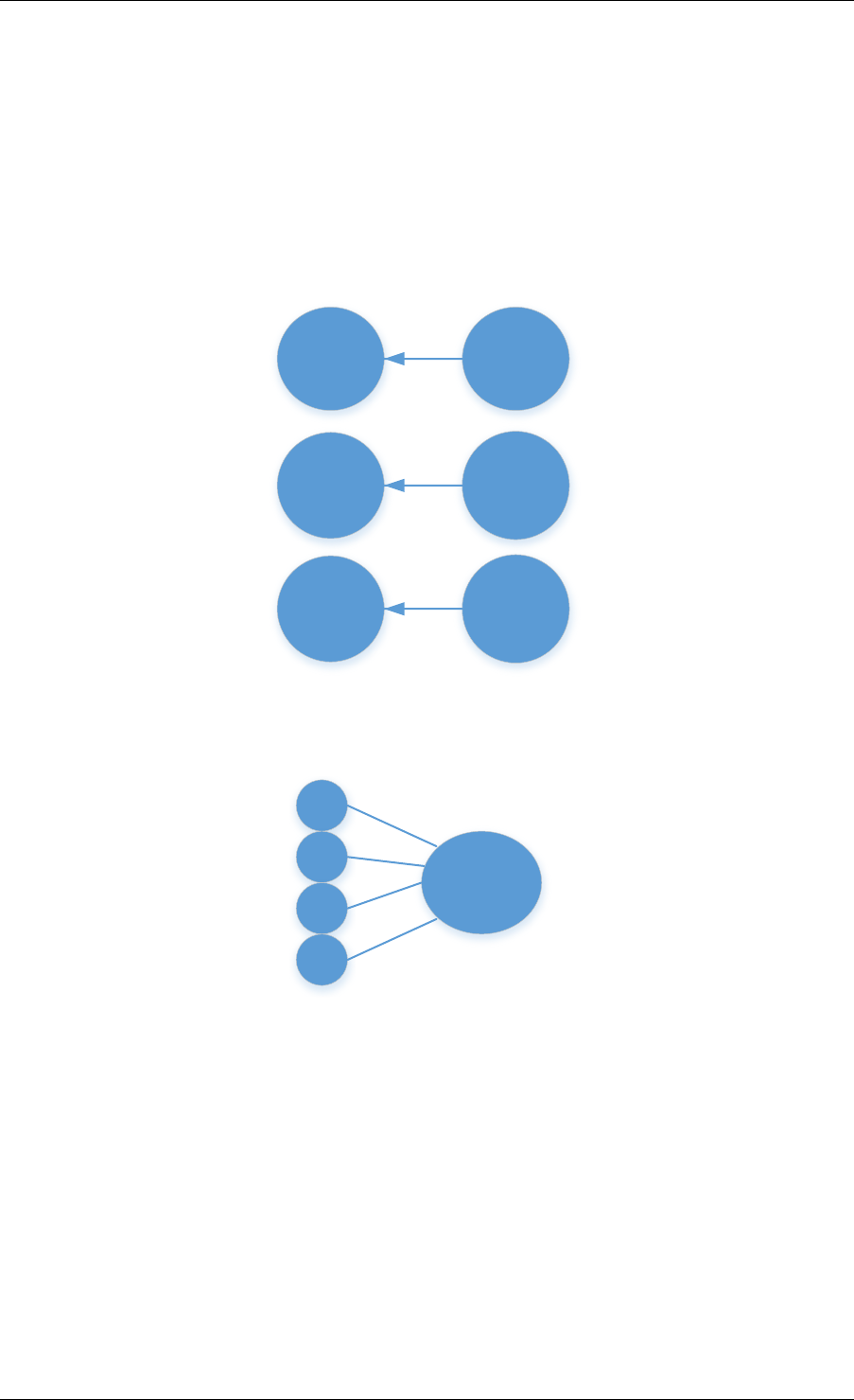
Programmer’s Guide, Release 18.11.0-rc5
15.6.1 priv_xform in Stateless operation
priv_xform is PMD internally managed private data that it maintains to do stateless processing.
priv_xforms are initialized provided a generic xform structure by an application via making call
to rte_comp_private_xform_create, at an output PMD returns an opaque priv_xform
reference. If PMD support SHAREABLE priv_xform indicated via algorithm feature flag, then
application can attach same priv_xform with many stateless ops at-a-time. If not, then applica-
tion needs to create as many priv_xforms as it expects to have stateless operations in-flight.
op
priv_xform
op
priv_xform
op
priv_xform
Fig. 15.1: Stateless Ops using Non-Shareable priv_xform
priv_xform
op
op
op
op
Fig. 15.2: Stateless Ops using Shareable priv_xform
Application should call rte_compressdev_private_xform_create() and
attach to stateless op before enqueuing them for processing and free via
rte_compressdev_private_xform_free() during termination.
An example pseudocode to setup and process NUM_OPS stateless ops with each of length
OP_LEN using priv_xform would look like:
/*
*pseudocode for stateless compression
*/
uint8_t cdev_id =rte_compdev_get_dev_id(<pmd name>);
15.6. Compression API Stateless operation 158

Programmer’s Guide, Release 18.11.0-rc5
/*configure the device. */
if (rte_compressdev_configure(cdev_id, &conf) <0)
rte_exit(EXIT_FAILURE, "Failed to configure compressdev %u", cdev_id);
if (rte_compressdev_queue_pair_setup(cdev_id, 0, NUM_MAX_INFLIGHT_OPS,
socket_id()) <0)
rte_exit(EXIT_FAILURE, "Failed to setup queue pair\n");
if (rte_compressdev_start(cdev_id) <0)
rte_exit(EXIT_FAILURE, "Failed to start device\n");
/*setup compress transform */
struct rte_compress_compress_xform compress_xform ={
.type =RTE_COMP_COMPRESS,
.compress ={
.algo =RTE_COMP_ALGO_DEFLATE,
.deflate ={
.huffman =RTE_COMP_HUFFMAN_DEFAULT
},
.level =RTE_COMP_LEVEL_PMD_DEFAULT,
.chksum =RTE_COMP_CHECKSUM_NONE,
.window_size =DEFAULT_WINDOW_SIZE,
.hash_algo =RTE_COMP_HASH_ALGO_NONE
}
};
/*create priv_xform and initialize it for the compression device. */
void *priv_xform =NULL;
rte_compressdev_info_get(cdev_id, &dev_info);
if(dev_info.capability->comps_feature_flag &RTE_COMP_FF_SHAREABLE_PRIV_XFORM) {
rte_comp_priv_xform_create(cdev_id, &compress_xform, &priv_xform);
}else {
shareable =0;
}
/*create operation pool via call to rte_comp_op_pool_create and alloc ops */
rte_comp_op_bulk_alloc(op_pool, comp_ops, NUM_OPS);
/*prepare ops for compression operations */
for (i =0;i<NUM_OPS; i++) {
struct rte_comp_op *op =comp_ops[i];
if (!shareable)
rte_priv_xform_create(cdev_id, &compress_xform, &op->priv_xform)
else
op->priv_xform =priv_xform;
op->type =RTE_COMP_OP_STATELESS;
op->flush =RTE_COMP_FLUSH_FINAL;
op->src.offset =0;
op->dst.offset =0;
op->src.length =OP_LEN;
op->input_chksum =0;
setup op->m_src and op->m_dst;
}
num_enqd =rte_compressdev_enqueue_burst(cdev_id, 0, comp_ops, NUM_OPS);
/*wait for this to complete before enqueing next*/
do {
num_deque =rte_compressdev_dequeue_burst(cdev_id, 0,&processed_ops, NUM_OPS);
}while (num_dqud <num_enqd);
15.6. Compression API Stateless operation 159

Programmer’s Guide, Release 18.11.0-rc5
15.6.2 Stateless and OUT_OF_SPACE
OUT_OF_SPACE is a condition when output buffer runs out of space and where PMD
still has more data to produce. If PMD runs into such condition, then PMD returns
RTE_COMP_OP_OUT_OF_SPACE_TERMINATED error. In such case, PMD resets itself
and can set consumed=0 and produced=amount of output it could produce before hitting
out_of_space. Application would need to resubmit the whole input with a larger output buffer,
if it wants the operation to be completed.
15.6.3 Hash in Stateless
If hash is enabled, digest buffer will contain valid data after op is successfully processed i.e.
dequeued with status = RTE_COMP_OP_STATUS_SUCCESS.
15.6.4 Checksum in Stateless
If checksum is enabled, checksum will only be available after op is successfully processed i.e.
dequeued with status = RTE_COMP_OP_STATUS_SUCCESS.
15.7 Compression API Stateful operation
Compression API provide RTE_COMP_FF_STATEFUL_COMPRESSION and
RTE_COMP_FF_STATEFUL_DECOMPRESSION feature flag for PMD to reflect its sup-
port for Stateful operations.
A Stateful operation in DPDK compression means application invokes enqueue burst() multiple
times to process related chunk of data because application broke data into several ops.
In such case - ops are setup with op_type RTE_COMP_OP_STATEFUL, - all ops ex-
cept last set to flush value = RTE_COMP_NO/SYNC_FLUSH and last set to flush value
RTE_COMP_FULL/FINAL_FLUSH.
In case of either one or all of the above conditions, PMD initiates stateful process-
ing and releases acquired resources after processing operation with flush value =
RTE_COMP_FLUSH_FULL/FINAL is complete. Unlike stateless, application can enqueue
only one stateful op from a particular stream at a time and must attach stream handle to each
op.
15.7.1 Stream in Stateful operation
stream in DPDK compression is a logical entity which identifies related set of ops, say, a
one large file broken into multiple chunks then file is represented by a stream and each
chunk of that file is represented by compression op rte_comp_op. Whenever application
wants a stateful processing of such data, then it must get a stream handle via making call to
rte_comp_stream_create() with xform, at an output the target PMD will return an opaque
stream handle to application which it must attach to all of the ops carrying data of that stream.
In stateful processing, every op requires previous op data for compression/decompression. A
PMD allocates and set up resources such as history, states, etc. within a stream, which are
maintained during the processing of the related ops.
15.7. Compression API Stateful operation 160

Programmer’s Guide, Release 18.11.0-rc5
Unlike priv_xforms, stream is always a NON_SHAREABLE entity. One stream handle must be
attached to only one set of related ops and cannot be reused until all of them are processed
with status Success or failure.
stream
op
op
op
op
Fig. 15.3: Stateful Ops
Application should call rte_comp_stream_create() and attach to op before enqueuing
them for processing and free via rte_comp_stream_free() during termination. All ops that
are to be processed statefully should carry same stream.
See DPDK API Reference document for details.
An example pseudocode to set up and process a stream having NUM_CHUNKS with each
chunk size of CHUNK_LEN would look like:
/*
*pseudocode for stateful compression
*/
uint8_t cdev_id =rte_compdev_get_dev_id(<pmd name>);
/*configure the device. */
if (rte_compressdev_configure(cdev_id, &conf) <0)
rte_exit(EXIT_FAILURE, "Failed to configure compressdev %u", cdev_id);
if (rte_compressdev_queue_pair_setup(cdev_id, 0, NUM_MAX_INFLIGHT_OPS,
socket_id()) <0)
rte_exit(EXIT_FAILURE, "Failed to setup queue pair\n");
if (rte_compressdev_start(cdev_id) <0)
rte_exit(EXIT_FAILURE, "Failed to start device\n");
/*setup compress transform. */
struct rte_compress_compress_xform compress_xform ={
.type =RTE_COMP_COMPRESS,
.compress ={
.algo =RTE_COMP_ALGO_DEFLATE,
.deflate ={
.huffman =RTE_COMP_HUFFMAN_DEFAULT
},
.level =RTE_COMP_LEVEL_PMD_DEFAULT,
.chksum =RTE_COMP_CHECKSUM_NONE,
.window_size =DEFAULT_WINDOW_SIZE,
.hash_algo =RTE_COMP_HASH_ALGO_NONE
}
};
/*create stream */
rte_comp_stream_create(cdev_id, &compress_xform, &stream);
/*create an op pool and allocate ops */
rte_comp_op_bulk_alloc(op_pool, comp_ops, NUM_CHUNKS);
15.7. Compression API Stateful operation 161

Programmer’s Guide, Release 18.11.0-rc5
/*Prepare source and destination mbufs for compression operations */
unsigned int i;
for (i =0;i<NUM_CHUNKS; i++) {
if (rte_pktmbuf_append(mbufs[i], CHUNK_LEN) == NULL)
rte_exit(EXIT_FAILURE, "Not enough room in the mbuf\n");
comp_ops[i]->m_src =mbufs[i];
if (rte_pktmbuf_append(dst_mbufs[i], CHUNK_LEN) == NULL)
rte_exit(EXIT_FAILURE, "Not enough room in the mbuf\n");
comp_ops[i]->m_dst =dst_mbufs[i];
}
/*Set up the compress operations. */
for (i =0;i<NUM_CHUNKS; i++) {
struct rte_comp_op *op =comp_ops[i];
op->stream =stream;
op->m_src =src_buf[i];
op->m_dst =dst_buf[i];
op->type =RTE_COMP_OP_STATEFUL;
if(i == NUM_CHUNKS-1) {
/*set to final, if last chunk*/
op->flush =RTE_COMP_FLUSH_FINAL;
}else {
/*set to NONE, for all intermediary ops */
op->flush =RTE_COMP_FLUSH_NONE;
}
op->src.offset =0;
op->dst.offset =0;
op->src.length =CHUNK_LEN;
op->input_chksum =0;
num_enqd =rte_compressdev_enqueue_burst(cdev_id, 0,&op[i], 1);
/*wait for this to complete before enqueing next*/
do {
num_deqd =rte_compressdev_dequeue_burst(cdev_id, 0,&processed_ops, 1);
}while (num_deqd <num_enqd);
/*push next op*/
}
15.7.2 Stateful and OUT_OF_SPACE
If PMD supports stateful operation, then OUT_OF_SPACE status is not
an actual error for the PMD. In such case, PMD returns with status
RTE_COMP_OP_STATUS_OUT_OF_SPACE_RECOVERABLE with consumed = num-
ber of input bytes read and produced = length of complete output buffer. Application should
enqueue next op with source starting at consumed+1 and an output buffer with available
space.
15.7.3 Hash in Stateful
If enabled, digest buffer will contain valid digest after last op in stream (having flush =
RTE_COMP_OP_FLUSH_FINAL) is successfully processed i.e. dequeued with status =
RTE_COMP_OP_STATUS_SUCCESS.
15.7. Compression API Stateful operation 162

Programmer’s Guide, Release 18.11.0-rc5
15.7.4 Checksum in Stateful
If enabled, checksum will only be available after last op in stream (having flush =
RTE_COMP_OP_FLUSH_FINAL) is successfully processed i.e. dequeued with status =
RTE_COMP_OP_STATUS_SUCCESS.
15.8 Burst in compression API
Scheduling of compression operations on DPDK’s application data path is performed using a
burst oriented asynchronous API set. A queue pair on a compression device accepts a burst
of compression operations using enqueue burst API. On physical devices the enqueue burst
API will place the operations to be processed on the device’s hardware input queue, for virtual
devices the processing of the operations is usually completed during the enqueue call to the
compression device. The dequeue burst API will retrieve any processed operations available
from the queue pair on the compression device, from physical devices this is usually directly
from the devices processed queue, and for virtual device’s from a rte_ring where processed
operations are place after being processed on the enqueue call.
A burst in DPDK compression can be a combination of stateless and stateful operations with
a condition that for stateful ops only one op at-a-time should be enqueued from a particular
stream i.e. no-two ops should belong to same stream in a single burst. However a burst may
contain multiple stateful ops as long as each op is attached to a different stream i.e. a burst
can look like:
en-
queue_burst
op1.no_flush op2.no_flush op3.flush_final op4.no_flush op5.no_flush
Where, op1 .. op5 all belong to different independent data units. op1, op2, op4, op5 must
be stateful as stateless ops can only use flush full or final and op3 can be of type stateless
or stateful. Every op with type set to RTE_COMP_OP_TYPE_STATELESS must be attached
to priv_xform and Every op with type set to RTE_COMP_OP_TYPE_STATEFUL must be at-
tached to stream.
Since each operation in a burst is independent and thus can be completed out-of-order, appli-
cations which need ordering, should setup per-op user data area with reordering information
so that it can determine enqueue order at dequeue.
Also if multiple threads calls enqueue_burst() on same queue pair then it’s application onus to
use proper locking mechanism to ensure exclusive enqueuing of operations.
15.8.1 Enqueue / Dequeue Burst APIs
The burst enqueue API uses a compression device identifier and a queue pair identifier to spec-
ify the compression device queue pair to schedule the processing on. The nb_ops parameter
is the number of operations to process which are supplied in the ops array of rte_comp_op
structures. The enqueue function returns the number of operations it actually enqueued for
processing, a return value equal to nb_ops means that all packets have been enqueued.
The dequeue API uses the same format as the enqueue API but the nb_ops and ops pa-
rameters are now used to specify the max processed operations the user wishes to retrieve
and the location in which to store them. The API call returns the actual number of processed
operations returned, this can never be larger than nb_ops.
15.8. Burst in compression API 163

Programmer’s Guide, Release 18.11.0-rc5
15.9 Sample code
There are unit test applications that show how to use the compressdev library inside
test/test/test_compressdev.c
15.9.1 Compression Device API
The compressdev Library API is described in the DPDK API Reference document.
15.9. Sample code 164

CHAPTER
SIXTEEN
SECURITY LIBRARY
The security library provides a framework for management and provisioning of security proto-
col operations offloaded to hardware based devices. The library defines generic APIs to create
and free security sessions which can support full protocol offload as well as inline crypto oper-
ation with NIC or crypto devices. The framework currently only supports the IPsec and PDCP
protocol and associated operations, other protocols will be added in future.
16.1 Design Principles
The security library provides an additional offload capability to an existing crypto device and/or
ethernet device.
+---------------+
| rte_security |
+---------------+
\ /
+-----------+ +--------------+
| NIC PMD | | CRYPTO PMD |
+-----------+ +--------------+
Note: Currently, the security library does not support the case of multi-process. It will be
updated in the future releases.
The supported offload types are explained in the sections below.
16.1.1 Inline Crypto
RTE_SECURITY_ACTION_TYPE_INLINE_CRYPTO: The crypto processing for security pro-
tocol (e.g. IPSec) is processed inline during receive and transmission on NIC port. The flow
based security action should be configured on the port.
Ingress Data path - The packet is decrypted in RX path and relevant crypto status is set in
Rx descriptors. After the successful inline crypto processing the packet is presented to host
as a regular Rx packet however all security protocol related headers are still attached to the
packet. e.g. In case of IPSec, the IPSec tunnel headers (if any), ESP/AH headers will remain
in the packet but the received packet contains the decrypted data where the encrypted data
was when the packet arrived. The driver Rx path check the descriptors and and based on the
crypto status sets additional flags in the rte_mbuf.ol_flags field.
Note: The underlying device may not support crypto processing for all ingress packet match-
ing to a particular flow (e.g. fragmented packets), such packets will be passed as encrypted
165

Programmer’s Guide, Release 18.11.0-rc5
packets. It is the responsibility of application to process such encrypted packets using other
crypto driver instance.
Egress Data path - The software prepares the egress packet by adding relevant security pro-
tocol headers. Only the data will not be encrypted by the software. The driver will accordingly
configure the tx descriptors. The hardware device will encrypt the data before sending the the
packet out.
Note: The underlying device may support post encryption TSO.
Egress Data Path
|
+--------|--------+
| egress IPsec |
|||
| +------V------+ |
| | SADB lookup | |
| +------|------+ |
| +------V------+ |
| | Tunnel | | <------ Add tunnel header to packet
| +------|------+ |
| +------V------+ |
| | ESP | | <------ Add ESP header without trailer to packet
| | | | <------ Mark packet to be offloaded, add trailer
| +------|------+ | meta-data to mbuf
+--------V--------+
|
+--------V--------+
| L2 Stack |
+--------|--------+
|
+--------V--------+
| |
| NIC PMD | <------ Set hw context for inline crypto offload
| |
+--------|--------+
|
+--------|--------+
| HW ACCELERATED | <------ Packet Encryption and
| NIC | Authentication happens inline
| |
+-----------------+
16.1.2 Inline protocol offload
RTE_SECURITY_ACTION_TYPE_INLINE_PROTOCOL: The crypto and protocol processing
for security protocol (e.g. IPSec) is processed inline during receive and transmission. The flow
based security action should be configured on the port.
Ingress Data path - The packet is decrypted in the RX path and relevant crypto status is set in
the Rx descriptors. After the successful inline crypto processing the packet is presented to the
host as a regular Rx packet but all security protocol related headers are optionally removed
from the packet. e.g. in the case of IPSec, the IPSec tunnel headers (if any), ESP/AH headers
will be removed from the packet and the received packet will contains the decrypted packet
only. The driver Rx path checks the descriptors and based on the crypto status sets additional
flags in rte_mbuf.ol_flags field. The driver would also set device-specific metadata in
16.1. Design Principles 166

Programmer’s Guide, Release 18.11.0-rc5
rte_mbuf.udata64 field. This will allow the application to identify the security processing
done on the packet.
Note: The underlying device in this case is stateful. It is expected that the device shall support
crypto processing for all kind of packets matching to a given flow, this includes fragmented
packets (post reassembly). E.g. in case of IPSec the device may internally manage anti-replay
etc. It will provide a configuration option for anti-replay behavior i.e. to drop the packets or
pass them to driver with error flags set in the descriptor.
Egress Data path - The software will send the plain packet without any security protocol head-
ers added to the packet. The driver will configure the security index and other requirement in
tx descriptors. The hardware device will do security processing on the packet that includes
adding the relevant protocol headers and encrypting the data before sending the packet out.
The software should make sure that the buffer has required head room and tail room for any
protocol header addition. The software may also do early fragmentation if the resultant packet
is expected to cross the MTU size.
Note: The underlying device will manage state information required for egress processing.
E.g. in case of IPSec, the seq number will be added to the packet, however the device shall
provide indication when the sequence number is about to overflow. The underlying device may
support post encryption TSO.
Egress Data Path
|
+--------|--------+
| egress IPsec |
|||
| +------V------+ |
| | SADB lookup | |
| +------|------+ |
| +------V------+ |
| | Desc | | <------ Mark packet to be offloaded
| +------|------+ |
+--------V--------+
|
+--------V--------+
| L2 Stack |
+--------|--------+
|
+--------V--------+
| |
| NIC PMD | <------ Set hw context for inline crypto offload
| |
+--------|--------+
|
+--------|--------+
| HW ACCELERATED | <------ Add tunnel, ESP header etc header to
| NIC | packet. Packet Encryption and
| | Authentication happens inline.
+-----------------+
16.1.3 Lookaside protocol offload
RTE_SECURITY_ACTION_TYPE_LOOKASIDE_PROTOCOL: This extends librte_cryptodev
to support the programming of IPsec Security Association (SA) as part of a crypto session
creation including the definition. In addition to standard crypto processing, as defined by the
16.1. Design Principles 167

Programmer’s Guide, Release 18.11.0-rc5
cryptodev, the security protocol processing is also offloaded to the crypto device.
Decryption: The packet is sent to the crypto device for security protocol processing. The device
will decrypt the packet and it will also optionally remove additional security headers from the
packet. E.g. in case of IPSec, IPSec tunnel headers (if any), ESP/AH headers will be removed
from the packet and the decrypted packet may contain plain data only.
Note: In case of IPSec the device may internally manage anti-replay etc. It will provide a
configuration option for anti-replay behavior i.e. to drop the packets or pass them to driver with
error flags set in descriptor.
Encryption: The software will submit the packet to cryptodev as usual for encryption, the hard-
ware device in this case will also add the relevant security protocol header along with encrypt-
ing the packet. The software should make sure that the buffer has required head room and tail
room for any protocol header addition.
Note: In the case of IPSec, the seq number will be added to the packet, It shall provide an
indication when the sequence number is about to overflow.
Egress Data Path
|
+--------|--------+
| egress IPsec |
|||
| +------V------+ |
| | SADB lookup | | <------ SA maps to cryptodev session
| +------|------+ |
| +------|------+ |
| | \--------------------\
| | Crypto | | | <- Crypto processing through
| | /----------------\ | inline crypto PMD
| +------|------+ | | |
+--------V--------+ | |
| | |
+--------V--------+ | | create <-- SA is added to hw
| L2 Stack | | | inline using existing create
+--------|--------+ | | session sym session APIs
| | | |
+--------V--------+ +---|---|----V---+
| | | \---/ | | <--- Add tunnel, ESP header etc
| NIC PMD | | INLINE | | header to packet.Packet
| | | CRYPTO PMD | | Encryption/Decryption and
+--------|--------+ +----------------+ Authentication happens
| inline.
+--------|--------+
| NIC |
+--------|--------+
V
16.1.4 PDCP Flow Diagram
Based on 3GPP TS 36.323 Evolved Universal Terrestrial Radio Access (E-UTRA); Packet Data
Convergence Protocol (PDCP) specification
Transmitting PDCP Entity Receiving PDCP Entity
| ^
| +-----------|-----------+
V|In order delivery and |
16.1. Design Principles 168

Programmer’s Guide, Release 18.11.0-rc5
+---------|----------+ | Duplicate detection |
|Sequence Numbering | | (Data Plane only) |
+---------|----------+ +-----------|-----------+
| |
+---------|----------+ +-----------|----------+
|Header Compression*| | Header Decompression*|
|(Data-Plane only) | | (Data Plane only) |
+---------|----------+ +-----------|----------+
| |
+---------|-----------+ +-----------|----------+
|Integrity Protection| |Integrity Verification|
|(Control Plane only)| | (Control Plane only) |
+---------|-----------+ +-----------|----------+
+---------|-----------+ +----------|----------+
|Ciphering | | Deciphering |
+---------|-----------+ +----------|----------+
+---------|-----------+ +----------|----------+
|Add PDCP header | | Remove PDCP Header |
+---------|-----------+ +----------|----------+
| |
+----------------->>----------------+
Note:
• Header Compression and decompression are not supported currently.
Just like IPsec, in case of PDCP also header addition/deletion, cipher/ de-cipher, integrity
protection/verification is done based on the action type chosen.
16.2 Device Features and Capabilities
16.2.1 Device Capabilities For Security Operations
The device (crypto or ethernet) capabilities which support security operations, are defined
by the security action type, security protocol, protocol capabilities and corresponding crypto
capabilities for security. For the full scope of the Security capability see definition of
rte_security_capability structure in the DPDK API Reference.
struct rte_security_capability;
Each driver (crypto or ethernet) defines its own private array of capabilities for the operations
it supports. Below is an example of the capabilities for a PMD which supports the IPsec and
PDCP protocol.
static const struct rte_security_capability pmd_security_capabilities[] ={
{/*IPsec Lookaside Protocol offload ESP Tunnel Egress */
.action =RTE_SECURITY_ACTION_TYPE_LOOKASIDE_PROTOCOL,
.protocol =RTE_SECURITY_PROTOCOL_IPSEC,
.ipsec ={
.proto =RTE_SECURITY_IPSEC_SA_PROTO_ESP,
.mode =RTE_SECURITY_IPSEC_SA_MODE_TUNNEL,
.direction =RTE_SECURITY_IPSEC_SA_DIR_EGRESS,
.options ={0}
},
.crypto_capabilities =pmd_capabilities
},
{/*IPsec Lookaside Protocol offload ESP Tunnel Ingress */
.action =RTE_SECURITY_ACTION_TYPE_LOOKASIDE_PROTOCOL,
16.2. Device Features and Capabilities 169

Programmer’s Guide, Release 18.11.0-rc5
.protocol =RTE_SECURITY_PROTOCOL_IPSEC,
.ipsec ={
.proto =RTE_SECURITY_IPSEC_SA_PROTO_ESP,
.mode =RTE_SECURITY_IPSEC_SA_MODE_TUNNEL,
.direction =RTE_SECURITY_IPSEC_SA_DIR_INGRESS,
.options ={0}
},
.crypto_capabilities =pmd_capabilities
},
{/*PDCP Lookaside Protocol offload Data Plane */
.action =RTE_SECURITY_ACTION_TYPE_LOOKASIDE_PROTOCOL,
.protocol =RTE_SECURITY_PROTOCOL_PDCP,
.pdcp ={
.domain =RTE_SECURITY_PDCP_MODE_DATA,
.capa_flags =0
},
.crypto_capabilities =pmd_capabilities
},
{/*PDCP Lookaside Protocol offload Control */
.action =RTE_SECURITY_ACTION_TYPE_LOOKASIDE_PROTOCOL,
.protocol =RTE_SECURITY_PROTOCOL_PDCP,
.pdcp ={
.domain =RTE_SECURITY_PDCP_MODE_CONTROL,
.capa_flags =0
},
.crypto_capabilities =pmd_capabilities
},
{
.action =RTE_SECURITY_ACTION_TYPE_NONE
}
};
static const struct rte_cryptodev_capabilities pmd_capabilities[] ={
{/*SHA1 HMAC */
.op =RTE_CRYPTO_OP_TYPE_SYMMETRIC,
.sym ={
.xform_type =RTE_CRYPTO_SYM_XFORM_AUTH,
.auth ={
.algo =RTE_CRYPTO_AUTH_SHA1_HMAC,
.block_size =64,
.key_size ={
.min =64,
.max =64,
.increment =0
},
.digest_size ={
.min =12,
.max =12,
.increment =0
},
.aad_size ={0},
.iv_size ={0}
}
}
},
{/*AES CBC */
.op =RTE_CRYPTO_OP_TYPE_SYMMETRIC,
.sym ={
.xform_type =RTE_CRYPTO_SYM_XFORM_CIPHER,
.cipher ={
.algo =RTE_CRYPTO_CIPHER_AES_CBC,
.block_size =16,
.key_size ={
.min =16,
16.2. Device Features and Capabilities 170

Programmer’s Guide, Release 18.11.0-rc5
.max =32,
.increment =8
},
.iv_size ={
.min =16,
.max =16,
.increment =0
}
}
}
}
}
16.2.2 Capabilities Discovery
Discovering the features and capabilities of a driver (crypto/ethernet) is achieved through the
rte_security_capabilities_get() function.
const struct rte_security_capability *rte_security_capabilities_get(uint16_t id);
This allows the user to query a specific driver and get all device security capabilities. It returns
an array of rte_security_capability structures which contains all the capabilities for that
device.
16.2.3 Security Session Create/Free
Security Sessions are created to store the immutable fields of a particular Security Association
for a particular protocol which is defined by a security session configuration structure which
is used in the operation processing of a packet flow. Sessions are used to manage protocol
specific information as well as crypto parameters. Security sessions cache this immutable data
in a optimal way for the underlying PMD and this allows further acceleration of the offload of
Crypto workloads.
The Security framework provides APIs to create and free sessions for crypto/ethernet devices,
where sessions are mempool objects. It is the application’s responsibility to create and manage
the session mempools. The mempool object size should be able to accommodate the driver’s
private data of security session.
Once the session mempools have been created, rte_security_session_create() is
used to allocate and initialize a session for the required crypto/ethernet device.
Session APIs need a parameter rte_security_ctx to identify the crypto/ethernet security
ops. This parameter can be retrieved using the APIs rte_cryptodev_get_sec_ctx() (for
crypto device) or rte_eth_dev_get_sec_ctx (for ethernet port).
Sessions already created can be updated with rte_security_session_update().
When a session is no longer used, the user must call rte_security_session_destroy()
to free the driver private session data and return the memory back to the mempool.
For look aside protocol offload to hardware crypto device, the rte_crypto_op
created by the application is attached to the security session by the API
rte_security_attach_session().
For Inline Crypto and Inline protocol offload, device specific defined meta-
data is updated in the mbuf using rte_security_set_pkt_metadata() if
DEV_TX_OFFLOAD_SEC_NEED_MDATA is set.
16.2. Device Features and Capabilities 171

Programmer’s Guide, Release 18.11.0-rc5
For inline protocol offloaded ingress traffic, the application can register a pointer, userdata
, in the security session. When the packet is received, rte_security_get_userdata()
would return the userdata registered for the security session which processed the packet.
Note: In case of inline processed packets, rte_mbuf.udata64 field would be used by the
driver to relay information on the security processing associated with the packet. In ingress,
the driver would set this in Rx path while in egress, rte_security_set_pkt_metadata()
would perform a similar operation. The application is expected not to modify the field when
it has relevant info. For ingress, this device-specific 64 bit value is required to derive other
information (like userdata), required for identifying the security processing done on the packet.
16.2.4 Security session configuration
Security Session configuration structure is defined as rte_security_session_conf
struct rte_security_session_conf {
enum rte_security_session_action_type action_type;
/**< Type of action to be performed on the session */
enum rte_security_session_protocol protocol;
/**< Security protocol to be configured */
union {
struct rte_security_ipsec_xform ipsec;
struct rte_security_macsec_xform macsec;
struct rte_security_pdcp_xform pdcp;
};
/**< Configuration parameters for security session */
struct rte_crypto_sym_xform *crypto_xform;
/**< Security Session Crypto Transformations */
void *userdata;
/**< Application specific userdata to be saved with session */
};
The configuration structure reuses the rte_crypto_sym_xform struct for crypto related con-
figuration. The rte_security_session_action_type struct is used to specify whether
the session is configured for Lookaside Protocol offload or Inline Crypto or Inline Protocol Of-
fload.
enum rte_security_session_action_type {
RTE_SECURITY_ACTION_TYPE_NONE,
/**< No security actions */
RTE_SECURITY_ACTION_TYPE_INLINE_CRYPTO,
/**< Crypto processing for security protocol is processed inline
*during transmission */
RTE_SECURITY_ACTION_TYPE_INLINE_PROTOCOL,
/**< All security protocol processing is performed inline during
*transmission */
RTE_SECURITY_ACTION_TYPE_LOOKASIDE_PROTOCOL
/**< All security protocol processing including crypto is performed
*on a lookaside accelerator */
};
The rte_security_session_protocol is defined as
enum rte_security_session_protocol {
RTE_SECURITY_PROTOCOL_IPSEC =1,
/**< IPsec Protocol */
RTE_SECURITY_PROTOCOL_MACSEC,
/**< MACSec Protocol */
RTE_SECURITY_PROTOCOL_PDCP,
16.2. Device Features and Capabilities 172

Programmer’s Guide, Release 18.11.0-rc5
/**< PDCP Protocol */
};
Currently the library defines configuration parameters for IPsec and PDCP only. For other pro-
tocols like MACSec, structures and enums are defined as place holders which will be updated
in the future.
IPsec related configuration parameters are defined in rte_security_ipsec_xform
struct rte_security_ipsec_xform {
uint32_t spi;
/**< SA security parameter index */
uint32_t salt;
/**< SA salt */
struct rte_security_ipsec_sa_options options;
/**< various SA options */
enum rte_security_ipsec_sa_direction direction;
/**< IPSec SA Direction - Egress/Ingress */
enum rte_security_ipsec_sa_protocol proto;
/**< IPsec SA Protocol - AH/ESP */
enum rte_security_ipsec_sa_mode mode;
/**< IPsec SA Mode - transport/tunnel */
struct rte_security_ipsec_tunnel_param tunnel;
/**< Tunnel parameters, NULL for transport mode */
};
PDCP related configuration parameters are defined in rte_security_pdcp_xform
struct rte_security_pdcp_xform {
int8_t bearer; /**< PDCP bearer ID */
/** Enable in order delivery, this field shall be set only if
*driver/HW is capable. See RTE_SECURITY_PDCP_ORDERING_CAP.
*/
uint8_t en_ordering;
/** Notify driver/HW to detect and remove duplicate packets.
*This field should be set only when driver/hw is capable.
*See RTE_SECURITY_PDCP_DUP_DETECT_CAP.
*/
uint8_t remove_duplicates;
/** PDCP mode of operation: Control or data */
enum rte_security_pdcp_domain domain;
/** PDCP Frame Direction 0:UL 1:DL */
enum rte_security_pdcp_direction pkt_dir;
/** Sequence number size, 5/7/12/15/18 */
enum rte_security_pdcp_sn_size sn_size;
/** Starting Hyper Frame Number to be used together with the SN
*from the PDCP frames
*/
uint32_t hfn;
/** HFN Threshold for key renegotiation */
uint32_t hfn_threshold;
};
16.2.5 Security API
The rte_security Library API is described in the DPDK API Reference document.
16.2. Device Features and Capabilities 173

Programmer’s Guide, Release 18.11.0-rc5
16.2.6 Flow based Security Session
In the case of NIC based offloads, the security session specified in the
‘rte_flow_action_security’ must be created on the same port as the flow action that is
being specified.
The ingress/egress flow attribute should match that specified in the security session if the
security session supports the definition of the direction.
Multiple flows can be configured to use the same security session. For example if the security
session specifies an egress IPsec SA, then multiple flows can be specified to that SA. In the
case of an ingress IPsec SA then it is only valid to have a single flow to map to that security
session.
Configuration Path
|
+--------|--------+
| Add/Remove |
| IPsec SA | <------ Build security flow action of
| | | ipsec transform
|--------|--------|
|
+--------V--------+
| Flow API |
+--------|--------+
|
+--------V--------+
| |
| NIC PMD | <------ Add/Remove SA to/from hw context
| |
+--------|--------+
|
+--------|--------+
| HW ACCELERATED |
| NIC |
| |
+--------|--------+
• Add/Delete SA flow: To add a new inline SA construct a rte_flow_item for Ether-
net + IP + ESP using the SA selectors and the rte_crypto_ipsec_xform as the
rte_flow_action. Note that any rte_flow_items may be empty, which means it is not
checked.
In its most basic form, IPsec flow specification is as follows:
+-------+ +----------+ +--------+ +-----+
| Eth | -> | IP4/6 | -> | ESP | -> | END |
+-------+ +----------+ +--------+ +-----+
However, the API can represent, IPsec crypto offload with any encapsulation:
+-------+ +--------+ +-----+
| Eth | -> ... -> | ESP | -> | END |
+-------+ +--------+ +-----+
16.2. Device Features and Capabilities 174

CHAPTER
SEVENTEEN
RAWDEVICE LIBRARY
17.1 Introduction
In terms of device flavor (type) support, DPDK currently has ethernet (lib_ether), cryptodev
(libcryptodev), eventdev (libeventdev) and vdev (virtual device) support.
For a new type of device, for example an accelerator, there are not many options except:
1. create another lib/librte_MySpecialDev, driver/MySpecialDrv and use it through Bus/PMD
model. 2. Or, create a vdev and implement necessary custom APIs which are directly exposed
from driver layer. However this may still require changes in bus code in DPDK.
The DPDK Rawdev library is an abstraction that provides the DPDK framework a way to man-
age such devices in a generic manner without expecting changes to library or EAL for each
device type. This library provides a generic set of operations and APIs for framework and
Applications to use, respectively, for interfacing with such type of devices.
17.2 Design
Key factors guiding design of the Rawdevice library:
1. Following are some generic operations which can be treated as applicable to a large
subset of device types. None of the operations are mandatory to be implemented by a
driver. Application should also be design for proper handling for unsupported APIs.
• Device Start/Stop - In some cases, ‘reset’ might also be required which has different
semantics than a start-stop-start cycle.
• Configuration - Device, Queue or any other sub-system configuration
• I/O - Sending a series of buffers which can enclose any arbitrary data
• Statistics - Fetch arbitrary device statistics
• Firmware Management - Firmware load/unload/status
2. Application API should be able to pass along arbitrary state information to/from device
driver. This can be achieved by maintaining context information through opaque data or
pointers.
Figure below outlines the layout of the rawdevice library and device vis-a-vis other well known
device types like eth and crypto:
+-----------------------------------------------------------+
| Application(s) |
175

Programmer’s Guide, Release 18.11.0-rc5
+------------------------------.----------------------------+
|
|
+------------------------------'----------------------------+
| DPDK Framework (APIs) |
+--------------|----|-----------------|---------------------+
/ \ \
(crypto ops) (eth ops) (rawdev ops) +----+
/ \ \ |DrvA|
+-----'---+ +----`----+ +---'-----+ +----+
| crypto | | ethdev | | raw |
+--/------+ +---/-----+ +----/----+ +----+
/\ __/\ / ..........|DrvB|
/ \ / \ / ../ \ +----+
+====+ +====+ +====+ +====+ +==/=+ ```Bus Probe
|DevA| |DevB| |DevC| |DevD| |DevF|
+====+ +====+ +====+ +====+ +====+
| | | | |
``|``````|````````|``````|`````````````````|````````Bus Scan
(PCI) | (PCI) (PCI) (PCI)
(BusA)
*It is assumed above that DrvB is a PCI type driver which registers itself
with PCI Bus
*Thereafter, when the PCI scan is done, during probe DrvB would match the
rawdev DevF ID and take control of device
*Applications can then continue using the device through rawdev API
interfaces
17.2.1 Device Identification
Physical rawdev devices are discovered during the Bus scan executed at DPDK initialization,
based on their identification and probing with corresponding driver. Thus, a generic device
needs to have an identifier and a driver capable of identifying it through this identifier.
Virtual devices can be created by two mechanisms, either using the EAL command line options
or from within the application using an EAL API directly.
From the command line using the –vdev EAL option
--vdev 'rawdev_dev1'
Our using the rte_vdev_init API within the application code.
rte_vdev_init("rawdev_dev1",NULL)
17.2. Design 176
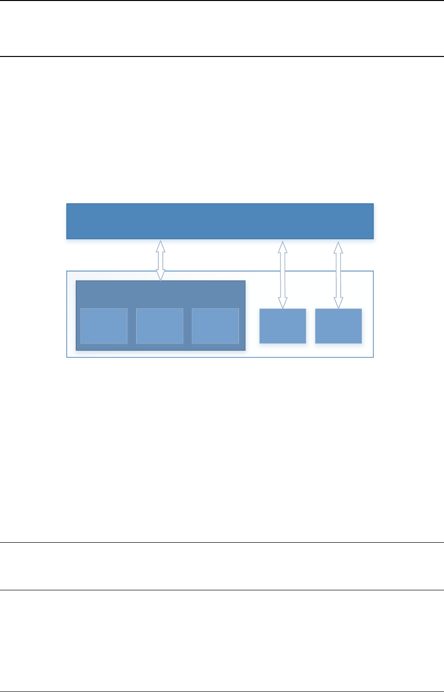
CHAPTER
EIGHTEEN
LINK BONDING POLL MODE DRIVER LIBRARY
In addition to Poll Mode Drivers (PMDs) for physical and virtual hardware, DPDK also includes
a pure-software library that allows physical PMDs to be bonded together to create a single
logical PMD.
DPDK
bonded ethdev
User Application
ethdev port
ethdev port
ethdev port
ethdev port
ethdev port
Fig. 18.1: Bonded PMDs
The Link Bonding PMD library(librte_pmd_bond) supports bonding of groups of rte_eth_dev
ports of the same speed and duplex to provide similar capabilities to that found in Linux bonding
driver to allow the aggregation of multiple (slave) NICs into a single logical interface between
a server and a switch. The new bonded PMD will then process these interfaces based on
the mode of operation specified to provide support for features such as redundant links, fault
tolerance and/or load balancing.
The librte_pmd_bond library exports a C API which provides an API for the creation of bonded
devices as well as the configuration and management of the bonded device and its slave
devices.
Note: The Link Bonding PMD Library is enabled by default in the build configuration files, the
library can be disabled by setting CONFIG_RTE_LIBRTE_PMD_BOND=n and recompiling the
DPDK.
18.1 Link Bonding Modes Overview
Currently the Link Bonding PMD library supports following modes of operation:
177
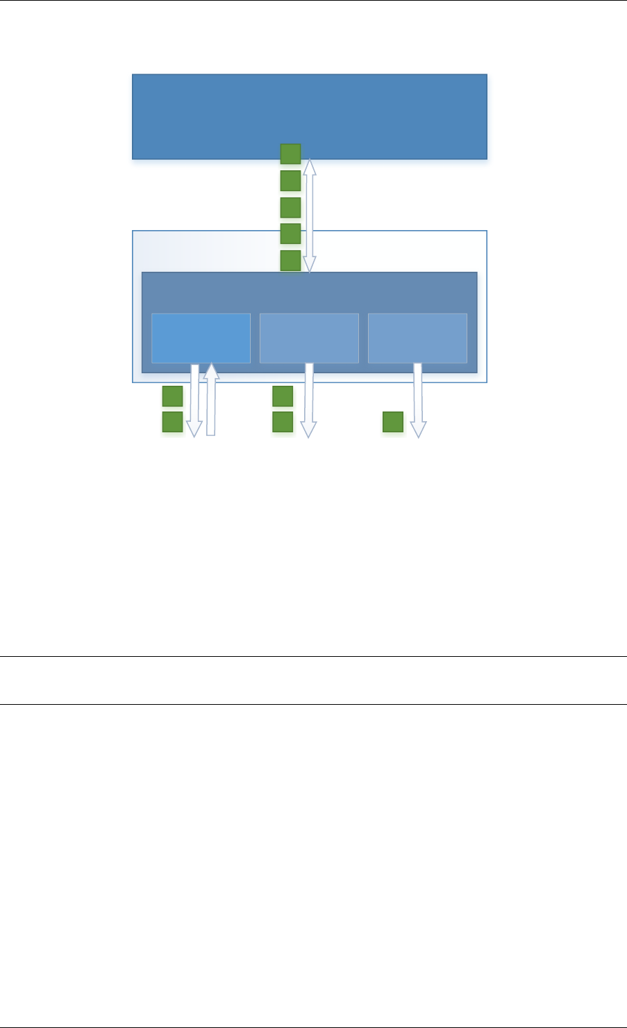
Programmer’s Guide, Release 18.11.0-rc5
•Round-Robin (Mode 0):
User Application
DPDK
bonded ethdev
ethdev port ethdev port ethdev port
1
2
3
4
5
1
2
3
4
5
Fig. 18.2: Round-Robin (Mode 0)
This mode provides load balancing and fault tolerance by transmission of packets in se-
quential order from the first available slave device through the last. Packets are bulk de-
queued from devices then serviced in a round-robin manner. This mode does not guaran-
tee in order reception of packets and down stream should be able to handle out of order
packets.
•Active Backup (Mode 1):
•Balance XOR (Mode 2):
Note: The coloring differences of the packets are used to identify different flow classification
calculated by the selected transmit policy
•Broadcast (Mode 3):
•Link Aggregation 802.3AD (Mode 4):
•Transmit Load Balancing (Mode 5):
18.2 Implementation Details
The librte_pmd_bond bonded device are compatible with the Ethernet device API exported by
the Ethernet PMDs described in the DPDK API Reference.
The Link Bonding Library supports the creation of bonded devices at application startup time
during EAL initialization using the --vdev option as well as programmatically via the C API
rte_eth_bond_create function.
18.2. Implementation Details 178

Programmer’s Guide, Release 18.11.0-rc5
User Application
DPDK
bonded ethdev
ethdev port ethdev port ethdev port
1
2
3
1
2
3
Fig. 18.3: Active Backup (Mode 1)
In this mode only one slave in the bond is active at any time, a different slave becomes
active if, and only if, the primary active slave fails, thereby providing fault tolerance to slave
failure. The single logical bonded interface’s MAC address is externally visible on only one
NIC (port) to avoid confusing the network switch.
Bonded devices support the dynamical addition and removal of slave devices using the
rte_eth_bond_slave_add /rte_eth_bond_slave_remove APIs.
After a slave device is added to a bonded device slave is stopped using rte_eth_dev_stop
and then reconfigured using rte_eth_dev_configure the RX and TX queues are also re-
configured using rte_eth_tx_queue_setup /rte_eth_rx_queue_setup with the pa-
rameters use to configure the bonding device. If RSS is enabled for bonding device, this mode
is also enabled on new slave and configured as well. Any flow which was configured to the
bond device also is configured to the added slave.
Setting up multi-queue mode for bonding device to RSS, makes it fully RSS-capable, so all
slaves are synchronized with its configuration. This mode is intended to provide RSS configu-
ration on slaves transparent for client application implementation.
Bonding device stores its own version of RSS settings i.e. RETA, RSS hash function and RSS
key, used to set up its slaves. That let to define the meaning of RSS configuration of bonding
device as desired configuration of whole bonding (as one unit), without pointing any of slave
inside. It is required to ensure consistency and made it more error-proof.
RSS hash function set for bonding device, is a maximal set of RSS hash functions supported
by all bonded slaves. RETA size is a GCD of all its RETA’s sizes, so it can be easily used as
a pattern providing expected behavior, even if slave RETAs’ sizes are different. If RSS Key is
not set for bonded device, it’s not changed on the slaves and default key for device is used.
As RSS configurations, there is flow consistency in the bonded slaves for the next rte flow
operations:
Validate:
18.2. Implementation Details 179
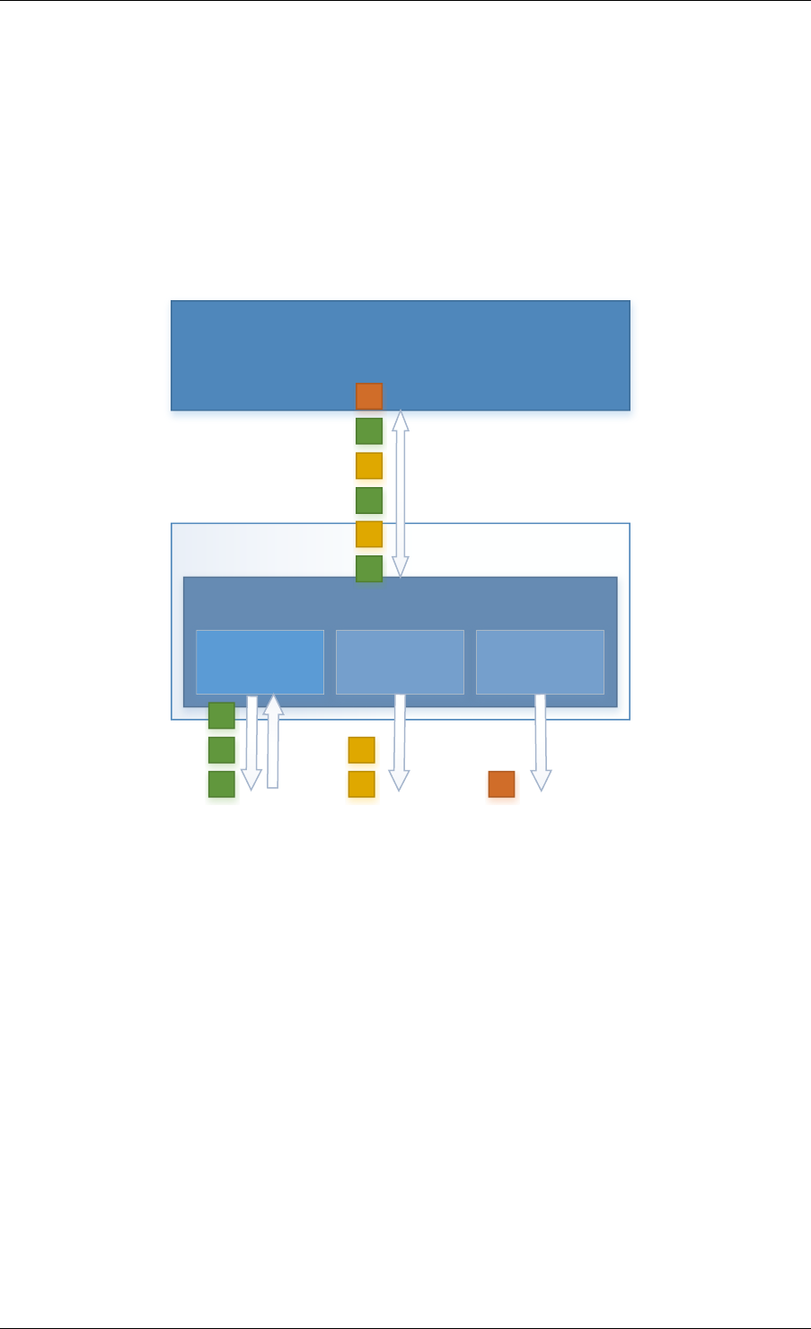
Programmer’s Guide, Release 18.11.0-rc5
User Application
DPDK
bonded ethdev
ethdev port ethdev port ethdev port
1
2
3
4
5
6
2
4
6
1
3
5
Fig. 18.4: Balance XOR (Mode 2)
This mode provides transmit load balancing (based on the selected transmission policy)
and fault tolerance. The default policy (layer2) uses a simple calculation based on the
packet flow source and destination MAC addresses as well as the number of active slaves
available to the bonded device to classify the packet to a specific slave to transmit on. Alter-
nate transmission policies supported are layer 2+3, this takes the IP source and destination
addresses into the calculation of the transmit slave port and the final supported policy is
layer 3+4, this uses IP source and destination addresses as well as the TCP/UDP source
and destination port.
18.2. Implementation Details 180

Programmer’s Guide, Release 18.11.0-rc5
User Application
DPDK
bonded ethdev
ethdev port ethdev port ethdev port
1
2
3
1
2
3
1
2
3
1
2
3
Fig. 18.5: Broadcast (Mode 3)
This mode provides fault tolerance by transmission of packets on all slave ports.
• Validate flow for each slave, failure at least for one slave causes to bond validation
failure.
Create:
• Create the flow in all slaves.
• Save all the slaves created flows objects in bonding internal flow structure.
• Failure in flow creation for existed slave rejects the flow.
• Failure in flow creation for new slaves in slave adding time rejects the slave.
Destroy:
• Destroy the flow in all slaves and release the bond internal flow memory.
Flush:
• Destroy all the bonding PMD flows in all the slaves.
Note: Don’t call slaves flush directly, It destroys all the slave flows which may include external
flows or the bond internal LACP flow.
Query:
• Summarize flow counters from all the slaves, relevant only for
RTE_FLOW_ACTION_TYPE_COUNT.
Isolate:
• Call to flow isolate for all slaves.
• Failure in flow isolation for existed slave rejects the isolate mode.
18.2. Implementation Details 181
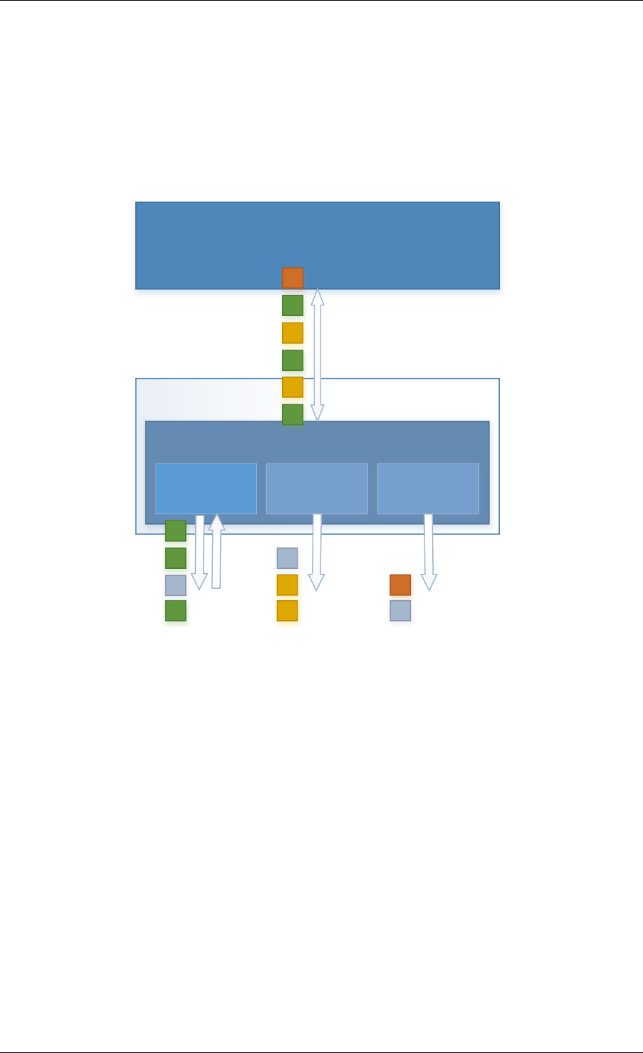
Programmer’s Guide, Release 18.11.0-rc5
User Application
DPDK
bonded ethdev
ethdev port ethdev port ethdev port
1
2
3
4
5
6
2
4
6
1
3
5
O
O
O
Fig. 18.6: Link Aggregation 802.3AD (Mode 4)
This mode provides dynamic link aggregation according to the 802.3ad specification. It
negotiates and monitors aggregation groups that share the same speed and duplex settings
using the selected balance transmit policy for balancing outgoing traffic.
DPDK implementation of this mode provide some additional requirements of the applica-
tion.
1. It needs to call rte_eth_tx_burst and rte_eth_rx_burst with intervals period
of less than 100ms.
2. Calls to rte_eth_tx_burst must have a buffer size of at least 2xN, where N is
the number of slaves. This is a space required for LACP frames. Additionally LACP
packets are included in the statistics, but they are not returned to the application.
18.2. Implementation Details 182
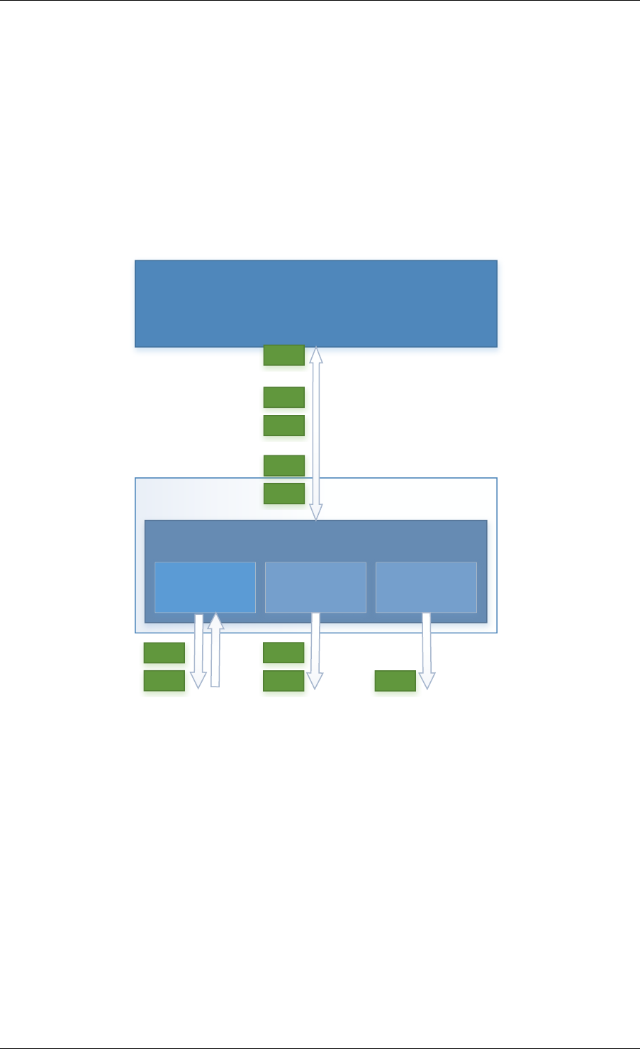
Programmer’s Guide, Release 18.11.0-rc5
User Application
DPDK
bonded ethdev
ethdev port ethdev port ethdev port
5006
5005
0001
0002
12003
0001
0002 5006
5005 12003
Fig. 18.7: Transmit Load Balancing (Mode 5)
This mode provides an adaptive transmit load balancing. It dynamically changes the trans-
mitting slave, according to the computed load. Statistics are collected in 100ms intervals
and scheduled every 10ms.
18.2. Implementation Details 183

Programmer’s Guide, Release 18.11.0-rc5
• Failure in flow isolation for new slaves in slave adding time rejects the slave.
All settings are managed through the bonding port API and always are propagated in one
direction (from bonding to slaves).
18.2.1 Link Status Change Interrupts / Polling
Link bonding devices support the registration of a link status change callback, using the
rte_eth_dev_callback_register API, this will be called when the status of the bond-
ing device changes. For example in the case of a bonding device which has 3 slaves, the link
status will change to up when one slave becomes active or change to down when all slaves
become inactive. There is no callback notification when a single slave changes state and the
previous conditions are not met. If a user wishes to monitor individual slaves then they must
register callbacks with that slave directly.
The link bonding library also supports devices which do not implement link status change
interrupts, this is achieved by polling the devices link status at a defined period which is
set using the rte_eth_bond_link_monitoring_set API, the default polling interval is
10ms. When a device is added as a slave to a bonding device it is determined using the
RTE_PCI_DRV_INTR_LSC flag whether the device supports interrupts or whether the link sta-
tus should be monitored by polling it.
18.2.2 Requirements / Limitations
The current implementation only supports devices that support the same speed and duplex to
be added as a slaves to the same bonded device. The bonded device inherits these attributes
from the first active slave added to the bonded device and then all further slaves added to the
bonded device must support these parameters.
A bonding device must have a minimum of one slave before the bonding device itself can be
started.
To use a bonding device dynamic RSS configuration feature effectively, it is also required, that
all slaves should be RSS-capable and support, at least one common hash function available
for each of them. Changing RSS key is only possible, when all slave devices support the same
key size.
To prevent inconsistency on how slaves process packets, once a device is added to a bonding
device, RSS and rte flow configurations should be managed through the bonding device API,
and not directly on the slave.
Like all other PMD, all functions exported by a PMD are lock-free functions that are assumed
not to be invoked in parallel on different logical cores to work on the same target object.
It should also be noted that the PMD receive function should not be invoked directly on a slave
devices after they have been to a bonded device since packets read directly from the slave
device will no longer be available to the bonded device to read.
18.2.3 Configuration
Link bonding devices are created using the rte_eth_bond_create API which requires a
unique device name, the bonding mode, and the socket Id to allocate the bonding device’s
resources on. The other configurable parameters for a bonded device are its slave devices, its
18.2. Implementation Details 184

Programmer’s Guide, Release 18.11.0-rc5
primary slave, a user defined MAC address and transmission policy to use if the device is in
balance XOR mode.
Slave Devices
Bonding devices support up to a maximum of RTE_MAX_ETHPORTS slave devices of the same
speed and duplex. Ethernet devices can be added as a slave to a maximum of one bonded
device. Slave devices are reconfigured with the configuration of the bonded device on being
added to a bonded device.
The bonded also guarantees to return the MAC address of the slave device to its original value
of removal of a slave from it.
Primary Slave
The primary slave is used to define the default port to use when a bonded device is in active
backup mode. A different port will only be used if, and only if, the current primary port goes
down. If the user does not specify a primary port it will default to being the first port added to
the bonded device.
MAC Address
The bonded device can be configured with a user specified MAC address, this address will be
inherited by the some/all slave devices depending on the operating mode. If the device is in
active backup mode then only the primary device will have the user specified MAC, all other
slaves will retain their original MAC address. In mode 0, 2, 3, 4 all slaves devices are configure
with the bonded devices MAC address.
If a user defined MAC address is not defined then the bonded device will default to using the
primary slaves MAC address.
Balance XOR Transmit Policies
There are 3 supported transmission policies for bonded device running in Balance XOR mode.
Layer 2, Layer 2+3, Layer 3+4.
•Layer 2: Ethernet MAC address based balancing is the default transmission policy for
Balance XOR bonding mode. It uses a simple XOR calculation on the source MAC
address and destination MAC address of the packet and then calculate the modulus of
this value to calculate the slave device to transmit the packet on.
•Layer 2 + 3: Ethernet MAC address & IP Address based balancing uses a combination of
source/destination MAC addresses and the source/destination IP addresses of the data
packet to decide which slave port the packet will be transmitted on.
•Layer 3 + 4: IP Address & UDP Port based balancing uses a combination of
source/destination IP Address and the source/destination UDP ports of the packet of
the data packet to decide which slave port the packet will be transmitted on.
All these policies support 802.1Q VLAN Ethernet packets, as well as IPv4, IPv6 and UDP
protocols for load balancing.
18.2. Implementation Details 185

Programmer’s Guide, Release 18.11.0-rc5
18.3 Using Link Bonding Devices
The librte_pmd_bond library supports two modes of device creation, the libraries export full C
API or using the EAL command line to statically configure link bonding devices at application
startup. Using the EAL option it is possible to use link bonding functionality transparently
without specific knowledge of the libraries API, this can be used, for example, to add bonding
functionality, such as active backup, to an existing application which has no knowledge of the
link bonding C API.
18.3.1 Using the Poll Mode Driver from an Application
Using the librte_pmd_bond libraries API it is possible to dynamically create and manage
link bonding device from within any application. Link bonding devices are created using the
rte_eth_bond_create API which requires a unique device name, the link bonding mode
to initial the device in and finally the socket Id which to allocate the devices resources onto.
After successful creation of a bonding device it must be configured using the generic Ethernet
device configure API rte_eth_dev_configure and then the RX and TX queues which will
be used must be setup using rte_eth_tx_queue_setup /rte_eth_rx_queue_setup.
Slave devices can be dynamically added and removed from a link bonding device us-
ing the rte_eth_bond_slave_add /rte_eth_bond_slave_remove APIs but at least
one slave device must be added to the link bonding device before it can be started using
rte_eth_dev_start.
The link status of a bonded device is dictated by that of its slaves, if all slave device link status
are down or if all slaves are removed from the link bonding device then the link status of the
bonding device will go down.
It is also possible to configure / query the configuration of the control param-
eters of a bonded device using the provided APIs rte_eth_bond_mode_set/
get,rte_eth_bond_primary_set/get,rte_eth_bond_mac_set/reset and
rte_eth_bond_xmit_policy_set/get.
18.3.2 Using Link Bonding Devices from the EAL Command Line
Link bonding devices can be created at application startup time using the --vdev EAL com-
mand line option. The device name must start with the net_bonding prefix followed by numbers
or letters. The name must be unique for each device. Each device can have multiple options
arranged in a comma separated list. Multiple devices definitions can be arranged by calling the
--vdev option multiple times.
Device names and bonding options must be separated by commas as shown below:
$RTE_TARGET/app/testpmd -l 0-3 -n 4--vdev 'net_bonding0,bond_opt0=..,bond opt1=..'--vdev 'net_bonding1,bond _opt0=..,bond_opt1=..'
Link Bonding EAL Options
There are multiple ways of definitions that can be assessed and combined as long as the
following two rules are respected:
18.3. Using Link Bonding Devices 186

Programmer’s Guide, Release 18.11.0-rc5
• A unique device name, in the format of net_bondingX is provided, where X can be any
combination of numbers and/or letters, and the name is no greater than 32 characters
long.
• A least one slave device is provided with for each bonded device definition.
• The operation mode of the bonded device being created is provided.
The different options are:
• mode: Integer value defining the bonding mode of the device. Currently supports modes
0,1,2,3,4,5 (round-robin, active backup, balance, broadcast, link aggregation, transmit
load balancing).
mode=2
• slave: Defines the PMD device which will be added as slave to the bonded de-
vice. This option can be selected multiple times, for each device to be added as a
slave. Physical devices should be specified using their PCI address, in the format do-
main:bus:devid.function
slave=0000:0a:00.0,slave=0000:0a:00.1
• primary: Optional parameter which defines the primary slave port, is used in active
backup mode to select the primary slave for data TX/RX if it is available. The primary
port also is used to select the MAC address to use when it is not defined by the user.
This defaults to the first slave added to the device if it is specified. The primary device
must be a slave of the bonded device.
primary=0000:0a:00.0
• socket_id: Optional parameter used to select which socket on a NUMA device the bonded
devices resources will be allocated on.
socket_id=0
• mac: Optional parameter to select a MAC address for link bonding device, this overrides
the value of the primary slave device.
mac=00:1e:67:1d:fd:1d
• xmit_policy: Optional parameter which defines the transmission policy when the bonded
device is in balance mode. If not user specified this defaults to l2 (layer 2) forwarding, the
other transmission policies available are l23 (layer 2+3) and l34 (layer 3+4)
xmit_policy=l23
• lsc_poll_period_ms: Optional parameter which defines the polling interval in milli-
seconds at which devices which don’t support lsc interrupts are checked for a change
in the devices link status
lsc_poll_period_ms=100
• up_delay: Optional parameter which adds a delay in milli-seconds to the propagation of
a devices link status changing to up, by default this parameter is zero.
up_delay=10
• down_delay: Optional parameter which adds a delay in milli-seconds to the propagation
of a devices link status changing to down, by default this parameter is zero.
down_delay=50
18.3. Using Link Bonding Devices 187

Programmer’s Guide, Release 18.11.0-rc5
Examples of Usage
Create a bonded device in round robin mode with two slaves specified by their PCI address:
$RTE_TARGET/app/testpmd -l 0-3 -n 4--vdev 'net_bonding0,mode=0, slave=0000:00a:00.01,slave=0000:004:00.00' -- --port-topology=chained
Create a bonded device in round robin mode with two slaves specified by their PCI address
and an overriding MAC address:
$RTE_TARGET/app/testpmd -l 0-3 -n 4--vdev 'net_bonding0,mode=0, slave=0000:00a:00.01,slave=0000:004:00.00,mac=00:1e:67:1d:fd:1d' -- --port-topology=chained
Create a bonded device in active backup mode with two slaves specified, and a primary slave
specified by their PCI addresses:
$RTE_TARGET/app/testpmd -l 0-3 -n 4--vdev 'net_bonding0,mode=1, slave=0000:00a:00.01,slave=0000:004:00.00,primary=0000:00a:00.01' -- --port-topology=chained
Create a bonded device in balance mode with two slaves specified by their PCI addresses,
and a transmission policy of layer 3 + 4 forwarding:
$RTE_TARGET/app/testpmd -l 0-3 -n 4--vdev 'net_bonding0,mode=2, slave=0000:00a:00.01,slave=0000:004:00.00,xmit_policy=l34' -- --port-topology=chained
18.3. Using Link Bonding Devices 188

CHAPTER
NINETEEN
TIMER LIBRARY
The Timer library provides a timer service to DPDK execution units to enable execution of
callback functions asynchronously. Features of the library are:
• Timers can be periodic (multi-shot) or single (one-shot).
• Timers can be loaded from one core and executed on another. It has to be specified in
the call to rte_timer_reset().
• Timers provide high precision (depends on the call frequency to rte_timer_manage() that
checks timer expiration for the local core).
• If not required in the application, timers can be disabled at compilation time by not calling
the rte_timer_manage() to increase performance.
The timer library uses the rte_get_timer_cycles() function that uses the High Precision Event
Timer (HPET) or the CPUs Time Stamp Counter (TSC) to provide a reliable time reference.
This library provides an interface to add, delete and restart a timer. The API is based on BSD
callout() with a few differences. Refer to the callout manual.
19.1 Implementation Details
Timers are tracked on a per-lcore basis, with all pending timers for a core being maintained
in order of timer expiry in a skiplist data structure. The skiplist used has ten levels and each
entry in the table appears in each level with probability ¼^level. This means that all entries are
present in level 0, 1 in every 4 entries is present at level 1, one in every 16 at level 2 and so on
up to level 9. This means that adding and removing entries from the timer list for a core can be
done in log(n) time, up to 4^10 entries, that is, approximately 1,000,000 timers per lcore.
A timer structure contains a special field called status, which is a union of a timer state
(stopped, pending, running, config) and an owner (lcore id). Depending on the timer state,
we know if a timer is present in a list or not:
• STOPPED: no owner, not in a list
• CONFIG: owned by a core, must not be modified by another core, maybe in a list or not,
depending on previous state
• PENDING: owned by a core, present in a list
• RUNNING: owned by a core, must not be modified by another core, present in a list
189

Programmer’s Guide, Release 18.11.0-rc5
Resetting or stopping a timer while it is in a CONFIG or RUNNING state is not allowed. When
modifying the state of a timer, a Compare And Swap instruction should be used to guarantee
that the status (state+owner) is modified atomically.
Inside the rte_timer_manage() function, the skiplist is used as a regular list by iterating along
the level 0 list, which contains all timer entries, until an entry which has not yet expired has
been encountered. To improve performance in the case where there are entries in the timer
list but none of those timers have yet expired, the expiry time of the first list entry is maintained
within the per-core timer list structure itself. On 64-bit platforms, this value can be checked
without the need to take a lock on the overall structure. (Since expiry times are maintained
as 64-bit values, a check on the value cannot be done on 32-bit platforms without using either
a compare-and-swap (CAS) instruction or using a lock, so this additional check is skipped in
favor of checking as normal once the lock has been taken.) On both 64-bit and 32-bit platforms,
a call to rte_timer_manage() returns without taking a lock in the case where the timer list for
the calling core is empty.
19.2 Use Cases
The timer library is used for periodic calls, such as garbage collectors, or some state machines
(ARP, bridging, and so on).
19.3 References
•callout manual - The callout facility that provides timers with a mechanism to execute a
function at a given time.
•HPET - Information about the High Precision Event Timer (HPET).
19.2. Use Cases 190

CHAPTER
TWENTY
HASH LIBRARY
The DPDK provides a Hash Library for creating hash table for fast lookup. The hash table is
a data structure optimized for searching through a set of entries that are each identified by a
unique key. For increased performance the DPDK Hash requires that all the keys have the
same number of bytes which is set at the hash creation time.
20.1 Hash API Overview
The main configuration parameters for the hash table are:
• Total number of hash entries in the table
• Size of the key in bytes
• An extra flag to describe additional settings, for example the multithreading mode of
operation and extendable bucket functionality (as will be described later)
The hash table also allows the configuration of some low-level implementation related param-
eters such as:
• Hash function to translate the key into a hash value
The main methods exported by the Hash Library are:
• Add entry with key: The key is provided as input. If the new entry is successfully added
to the hash table for the specified key, or there is already an entry in the hash table
for the specified key, then the position of the entry is returned. If the operation was not
successful, for example due to lack of free entries in the hash table, then a negative value
is returned.
• Delete entry with key: The key is provided as input. If an entry with the specified key is
found in the hash, then the entry is removed from the hash table and the position where
the entry was found in the hash table is returned. If no entry with the specified key exists
in the hash table, then a negative value is returned
• Lookup for entry with key: The key is provided as input. If an entry with the specified
key is found in the hash table (i.e., lookup hit), then the position of the entry is returned,
otherwise (i.e., lookup miss) a negative value is returned.
Apart from the basic methods explained above, the Hash Library API provides a few more
advanced methods to query and update the hash table:
• Add / lookup / delete entry with key and precomputed hash: Both the key and its pre-
computed hash are provided as input. This allows the user to perform these operations
faster, as the hash value is already computed.
191

Programmer’s Guide, Release 18.11.0-rc5
• Add / lookup entry with key and data: A data is provided as input for add. Add allows the
user to store not only the key, but also the data which may be either a 8-byte integer or a
pointer to external data (if data size is more than 8 bytes).
• Combination of the two options above: User can provide key, precomputed hash, and
data.
• Ability to not free the position of the entry in the hash table upon calling delete. This is
useful for multi-threaded scenarios where readers continue to use the position even after
the entry is deleted.
Also, the API contains a method to allow the user to look up entries in batches, achieving
higher performance than looking up individual entries, as the function prefetches next entries
at the time it is operating with the current ones, which reduces significantly the performance
overhead of the necessary memory accesses.
The actual data associated with each key can be either managed by the user using a separate
table that mirrors the hash in terms of number of entries and position of each entry, as shown
in the Flow Classification use case described in the following sections, or stored in the hash
table itself.
The example hash tables in the L2/L3 Forwarding sample applications define which port to
forward a packet to based on a packet flow identified by the five-tuple lookup. However, this
table could also be used for more sophisticated features and provide many other functions and
actions that could be performed on the packets and flows.
20.2 Multi-process support
The hash library can be used in a multi-process environment. The only function that can only
be used in single-process mode is rte_hash_set_cmp_func(), which sets up a custom compare
function, which is assigned to a function pointer (therefore, it is not supported in multi-process
mode).
20.3 Multi-thread support
The hash library supports multithreading, and the user specifies the needed mode of operation
at the creation time of the hash table by appropriately setting the flag. In all modes of operation
lookups are thread-safe meaning lookups can be called from multiple threads concurrently.
For concurrent writes, and concurrent reads and writes the following flag values define the
corresponding modes of operation:
• If the multi-writer flag (RTE_HASH_EXTRA_FLAGS_MULTI_WRITER_ADD) is set, mul-
tiple threads writing to the table is allowed. Key add, delete, and table reset are protected
from other writer threads. With only this flag set, readers are not protected from ongoing
writes.
• If the read/write concurrency (RTE_HASH_EXTRA_FLAGS_RW_CONCURRENCY) is
set, multithread read/write operation is safe (i.e., application does not need to stop the
readers from accessing the hash table until writers finish their updates. Readers and
writers can operate on the table concurrently). The library uses a reader-writer lock to
provide the concurrency.
20.2. Multi-process support 192

Programmer’s Guide, Release 18.11.0-rc5
• In addition to these two flag values, if the transactional memory flag
(RTE_HASH_EXTRA_FLAGS_TRANS_MEM_SUPPORT) is also set, the reader-
writer lock will use hardware transactional memory (e.g., Intel® TSX) if supported to
guarantee thread safety. If the platform supports Intel® TSX, it is advised to set the
transactional memory flag, as this will speed up concurrent table operations. Otherwise
concurrent operations will be slower because of the overhead associated with the
software locking mechanisms.
• If lock free read/write concurrency (RTE_HASH_EXTRA_FLAGS_RW_CONCURRENCY_LF)
is set, read/write concurrency is provided without using reader-writer lock. For platforms
(e.g., current ARM based platforms) that do not support transactional memory, it is
advised to set this flag to achieve greater scalability in performance. If this flag is set, the
(RTE_HASH_EXTRA_FLAGS_NO_FREE_ON_DEL) flag is set by default.
• If the ‘do not free on delete’ (RTE_HASH_EXTRA_FLAGS_NO_FREE_ON_DEL) flag is
set, the position of the entry in the hash table is not freed upon calling delete(). This flag
is enabled by default when the lock free read/write concurrency flag is set. The applica-
tion should free the position after all the readers have stopped referencing the position.
Where required, the application can make use of RCU mechanisms to determine when
the readers have stopped referencing the position.
20.4 Extendable Bucket Functionality support
An extra flag is used to enable this functionality (flag is not set by default). When the
(RTE_HASH_EXTRA_FLAGS_EXT_TABLE) is set and in the very unlikely case due to exces-
sive hash collisions that a key has failed to be inserted, the hash table bucket is extended with a
linked list to insert these failed keys. This feature is important for the workloads (e.g. telco work-
loads) that need to insert up to 100% of the hash table size and can’t tolerate any key insertion
failure (even if very few). Currently the extendable bucket is not supported with the lock-free
concurrency implementation (RTE_HASH_EXTRA_FLAGS_RW_CONCURRENCY_LF).
20.5 Implementation Details (non Extendable Bucket Case)
The hash table has two main tables:
• First table is an array of buckets each of which consists of multiple entries, Each entry
contains the signature of a given key (explained below), and an index to the second table.
• The second table is an array of all the keys stored in the hash table and its data associ-
ated to each key.
The hash library uses the Cuckoo Hash algorithm to resolve collisions. For any input key, there
are two possible buckets (primary and secondary/alternative location) to store that key in the
hash table, therefore only the entries within those two buckets need to be examined when the
key is looked up. The Hash Library uses a hash function (configurable) to translate the input
key into a 4-byte hash value. The bucket index and a 2-byte signature is derived from the hash
value using partial-key hashing [partial-key].
Once the buckets are identified, the scope of the key add, delete, and lookup operations is
reduced to the entries in those buckets (it is very likely that entries are in the primary bucket).
20.4. Extendable Bucket Functionality support 193

Programmer’s Guide, Release 18.11.0-rc5
To speed up the search logic within the bucket, each hash entry stores the 2-byte key signature
together with the full key for each hash table entry. For large key sizes, comparing the input
key against a key from the bucket can take significantly more time than comparing the 2-
byte signature of the input key against the signature of a key from the bucket. Therefore, the
signature comparison is done first and the full key comparison is done only when the signatures
matches. The full key comparison is still necessary, as two input keys from the same bucket
can still potentially have the same 2-byte signature, although this event is relatively rare for
hash functions providing good uniform distributions for the set of input keys.
Example of lookup:
First of all, the primary bucket is identified and entry is likely to be stored there. If signature
was stored there, we compare its key against the one provided and return the position where
it was stored and/or the data associated to that key if there is a match. If signature is not in
the primary bucket, the secondary bucket is looked up, where same procedure is carried out.
If there is no match there either, key is not in the table and a negative value will be returned.
Example of addition:
Like lookup, the primary and secondary buckets are identified. If there is an empty entry in
the primary bucket, a signature is stored in that entry, key and data (if any) are added to the
second table and the index in the second table is stored in the entry of the first table. If there
is no space in the primary bucket, one of the entries on that bucket is pushed to its alternative
location, and the key to be added is inserted in its position. To know where the alternative
bucket of the evicted entry is, a mechanism called partial-key hashing [partial-key] is used. If
there is room in the alternative bucket, the evicted entry is stored in it. If not, same process
is repeated (one of the entries gets pushed) until an empty entry is found. Notice that despite
all the entry movement in the first table, the second table is not touched, which would impact
greatly in performance.
In the very unlikely event that an empty entry cannot be found after certain number of displace-
ments, key is considered not able to be added (unless extendable bucket flag is set, and in
that case the bucket is extended to insert the key, as will be explained later). With random
keys, this method allows the user to get more than 90% table utilization, without having to drop
any stored entry (e.g. using a LRU replacement policy) or allocate more memory (extendable
buckets or rehashing).
Example of deletion:
Similar to lookup, the key is searched in its primary and secondary buckets. If the key is found,
the entry is marked as empty. If the hash table was configured with ‘no free on delete’ or ‘lock
free read/write concurrency’, the position of the key is not freed. It is the responsibility of the
user to free the position after readers are not referencing the position anymore.
20.6 Implementation Details (with Extendable Bucket)
When the RTE_HASH_EXTRA_FLAGS_EXT_TABLE flag is set, the hash table implementa-
tion still uses the same Cuckoo Hash algorithm to store the keys into the first and second
tables. However, in the very unlikely event that a key can’t be inserted after certain number
of the Cuckoo displacements is reached, the secondary bucket of this key is extended with a
linked list of extra buckets and the key is stored in this linked list.
In case of lookup for a certain key, as before, the primary bucket is searched for a match
and then the secondary bucket is looked up. If there is no match there either, the extendable
20.6. Implementation Details (with Extendable Bucket) 194

Programmer’s Guide, Release 18.11.0-rc5
buckets (linked list of extra buckets) are searched one by one for a possible match and if there
is no match the key is considered not to be in the table.
The deletion is the same as the case when the RTE_HASH_EXTRA_FLAGS_EXT_TABLE flag
is not set. With one exception, if a key is deleted from any bucket and an empty location is
created, the last entry from the extendable buckets associated with this bucket is displaced into
this empty location to possibly shorten the linked list.
20.7 Entry distribution in hash table
As mentioned above, Cuckoo hash implementation pushes elements out of their bucket, if there
is a new entry to be added which primary location coincides with their current bucket, being
pushed to their alternative location. Therefore, as user adds more entries to the hash table,
distribution of the hash values in the buckets will change, being most of them in their primary
location and a few in their secondary location, which the later will increase, as table gets busier.
This information is quite useful, as performance may be lower as more entries are evicted to
their secondary location.
See the tables below showing example entry distribution as table utilization increases.
Table 20.1: Entry distribution measured with an example table with
1024 random entries using jhash algorithm
% Table used % In Primary location % In Secondary location
25 100 0
50 96.1 3.9
75 88.2 11.8
80 86.3 13.7
85 83.1 16.9
90 77.3 22.7
95.8 64.5 35.5
Table 20.2: Entry distribution measured with an example table with 1
million random entries using jhash algorithm
% Table used % In Primary location % In Secondary location
50 96 4
75 86.9 13.1
80 83.9 16.1
85 80.1 19.9
90 74.8 25.2
94.5 67.4 32.6
Note: Last values on the tables above are the average maximum table utilization with random
keys and using Jenkins hash function.
20.7. Entry distribution in hash table 195

Programmer’s Guide, Release 18.11.0-rc5
20.8 Use Case: Flow Classification
Flow classification is used to map each input packet to the connection/flow it belongs to. This
operation is necessary as the processing of each input packet is usually done in the context
of their connection, so the same set of operations is applied to all the packets from the same
flow.
Applications using flow classification typically have a flow table to manage, with each separate
flow having an entry associated with it in this table. The size of the flow table entry is application
specific, with typical values of 4, 16, 32 or 64 bytes.
Each application using flow classification typically has a mechanism defined to uniquely iden-
tify a flow based on a number of fields read from the input packet that make up the flow key.
One example is to use the DiffServ 5-tuple made up of the following fields of the IP and trans-
port layer packet headers: Source IP Address, Destination IP Address, Protocol, Source Port,
Destination Port.
The DPDK hash provides a generic method to implement an application specific flow classifi-
cation mechanism. Given a flow table implemented as an array, the application should create
a hash object with the same number of entries as the flow table and with the hash key size set
to the number of bytes in the selected flow key.
The flow table operations on the application side are described below:
• Add flow: Add the flow key to hash. If the returned position is valid, use it to access the
flow entry in the flow table for adding a new flow or updating the information associated
with an existing flow. Otherwise, the flow addition failed, for example due to lack of free
entries for storing new flows.
• Delete flow: Delete the flow key from the hash. If the returned position is valid, use it to
access the flow entry in the flow table to invalidate the information associated with the
flow.
• Free flow: Free flow key position. If ‘no free on delete’ or ‘lock-free read/write concur-
rency’ flags are set, wait till the readers are not referencing the position returned during
add/delete flow and then free the position. RCU mechanisms can be used to find out
when the readers are not referencing the position anymore.
• Lookup flow: Lookup for the flow key in the hash. If the returned position is valid (flow
lookup hit), use the returned position to access the flow entry in the flow table. Otherwise
(flow lookup miss) there is no flow registered for the current packet.
20.9 References
• Donald E. Knuth, The Art of Computer Programming, Volume 3: Sorting and Searching
(2nd Edition), 1998, Addison-Wesley Professional
• [partial-key] Bin Fan, David G. Andersen, and Michael Kaminsky, MemC3: compact and
concurrent MemCache with dumber caching and smarter hashing, 2013, NSDI
20.8. Use Case: Flow Classification 196

CHAPTER
TWENTYONE
ELASTIC FLOW DISTRIBUTOR LIBRARY
21.1 Introduction
In Data Centers today, clustering and scheduling of distributed workloads is a very common
task. Many workloads require a deterministic partitioning of a flat key space among a cluster
of machines. When a packet enters the cluster, the ingress node will direct the packet to its
handling node. For example, data-centers with disaggregated storage use storage metadata
tables to forward I/O requests to the correct back end storage cluster, stateful packet inspection
will use match incoming flows to signatures in flow tables to send incoming packets to their
intended deep packet inspection (DPI) devices, and so on.
EFD is a distributor library that uses perfect hashing to determine a target/value for a given
incoming flow key. It has the following advantages: first, because it uses perfect hashing
it does not store the key itself and hence lookup performance is not dependent on the key
size. Second, the target/value can be any arbitrary value hence the system designer and/or
operator can better optimize service rates and inter-cluster network traffic locating. Third,
since the storage requirement is much smaller than a hash-based flow table (i.e. better fit for
CPU cache), EFD can scale to millions of flow keys. Finally, with the current optimized library
implementation, performance is fully scalable with any number of CPU cores.
21.2 Flow Based Distribution
21.2.1 Computation Based Schemes
Flow distribution and/or load balancing can be simply done using a stateless computation, for
instance using round-robin or a simple computation based on the flow key as an input. For
example, a hash function can be used to direct a certain flow to a target based on the flow key
(e.g. h(key) mod n) where h(key) is the hash value of the flow key and n is the number of
possible targets.
In this scheme (Fig. 21.1), the front end server/distributor/load balancer extracts the flow key
from the input packet and applies a computation to determine where this flow should be di-
rected. Intuitively, this scheme is very simple and requires no state to be kept at the front end
node, and hence, storage requirements are minimum.
A widely used flow distributor that belongs to the same category of computation-based
schemes is consistent hashing, shown in Fig. 21.2. Target destinations (shown in red)
are hashed into the same space as the flow keys (shown in blue), and keys are mapped to the
nearest target in a clockwise fashion. Dynamically adding and removing targets with consistent
hashing requires only K/n keys to be remapped on average, where K is the number of keys,
197
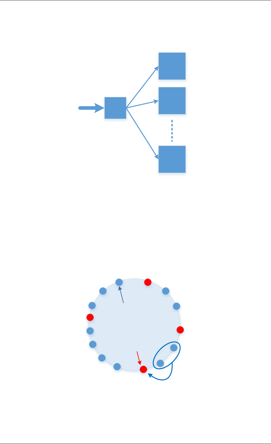
Programmer’s Guide, Release 18.11.0-rc5
LB
Target 1
Target 2
Target N
Fig. 21.1: Load Balancing Using Front End Node
Target Hashed Value
Keys
Fig. 21.2: Consistent Hashing
21.2. Flow Based Distribution 198
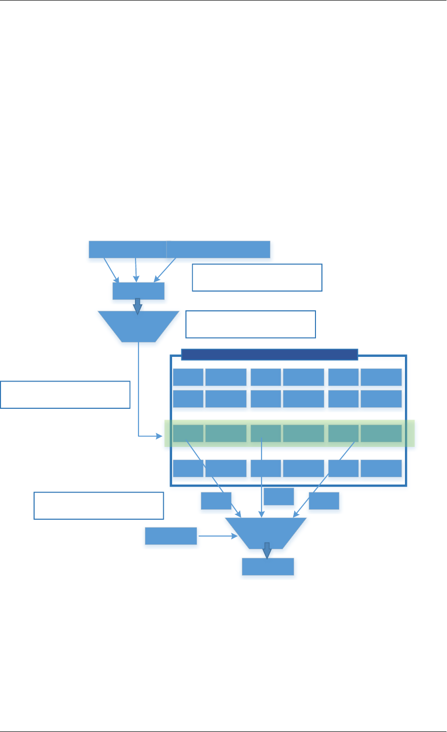
Programmer’s Guide, Release 18.11.0-rc5
and n is the number of targets. In contrast, in a traditional hash-based scheme, a change in
the number of targets causes nearly all keys to be remapped.
Although computation-based schemes are simple and need very little storage requirement,
they suffer from the drawback that the system designer/operator can’t fully control the target
to assign a specific key, as this is dictated by the hash function. Deterministically co-locating
of keys together (for example, to minimize inter-server traffic or to optimize for network traffic
conditions, target load, etc.) is simply not possible.
21.2.2 Flow-Table Based Schemes
When using a Flow-Table based scheme to handle flow distribution/load balancing, in contrast
with computation-based schemes, the system designer has the flexibility of assigning a given
flow to any given target. The flow table (e.g. DPDK RTE Hash Library) will simply store both
the flow key and the target value.
Packet Header
Payload
Flow Key
Fields of the packet are used to form a flow Key
H(..)
Hash function is used to create a flow table index
Key 1Action 1Key 2Action 2
Key xAction xKey yAction yKey z Action z
Key NAction N
Load Balancing Flow Table
Hash value used to index Flow table
Key x Key z
Match
Key y
Flow Key
Retrieved keys are matched with input key
Action
Fig. 21.3: Table Based Flow Distribution
As shown in Fig. 21.3, when doing a lookup, the flow-table is indexed with the hash of the flow
key and the keys (more than one is possible, because of hash collision) stored in this index
and corresponding values are retrieved. The retrieved key(s) is matched with the input flow key
and if there is a match the value (target id) is returned.
The drawback of using a hash table for flow distribution/load balancing is the storage require-
ment, since the flow table need to store keys, signatures and target values. This doesn’t allow
21.2. Flow Based Distribution 199
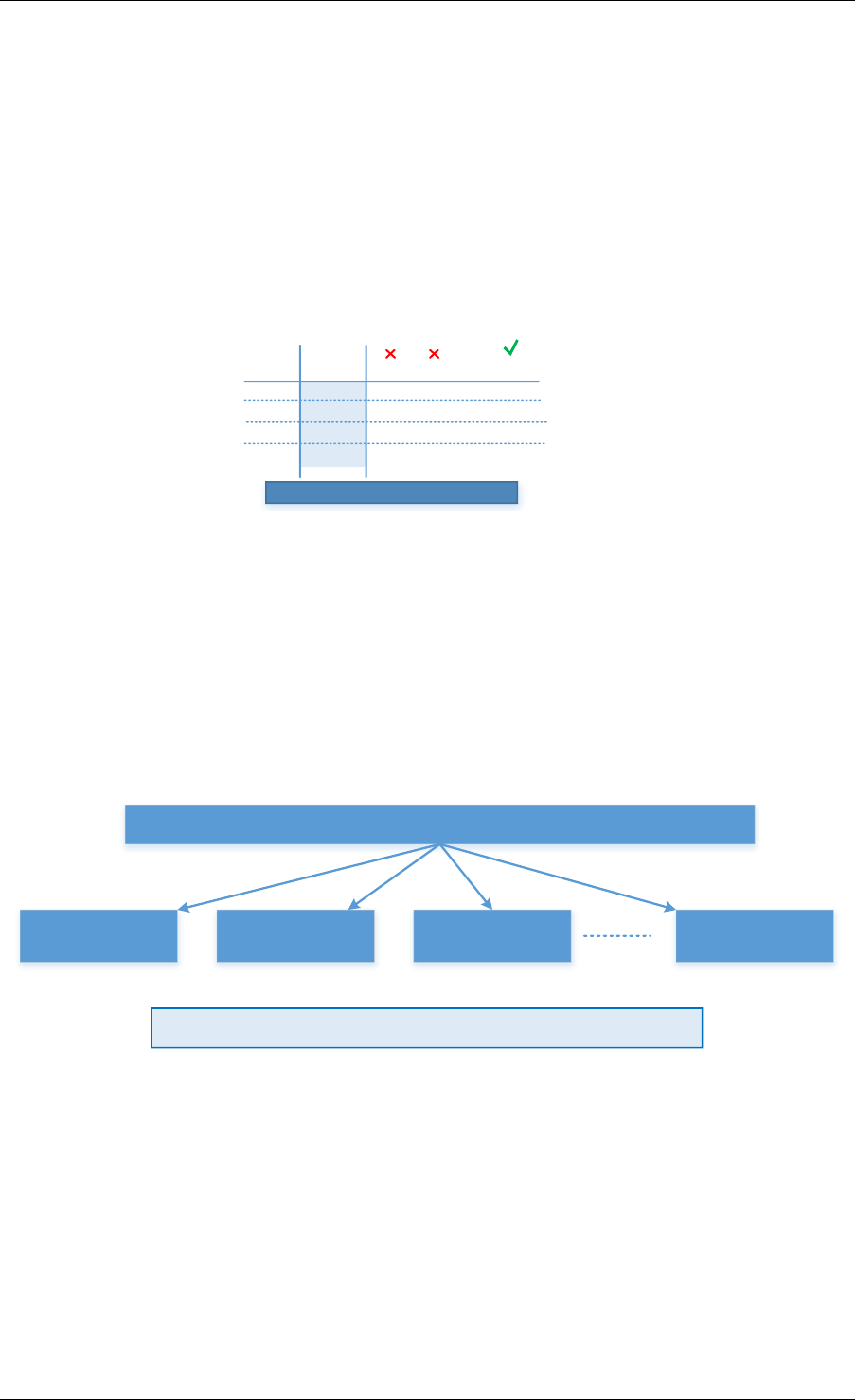
Programmer’s Guide, Release 18.11.0-rc5
this scheme to scale to millions of flow keys. Large tables will usually not fit in the CPU cache,
and hence, the lookup performance is degraded because of the latency to access the main
memory.
21.2.3 EFD Based Scheme
EFD combines the advantages of both flow-table based and computation-based schemes.
It doesn’t require the large storage necessary for flow-table based schemes (because EFD
doesn’t store the key as explained below), and it supports any arbitrary value for any given key.
Key 1Key 2...Key 28
Target Value
010 000
H1(x)
110
H2(x)
010
Hm(x)
…..
Store m for this group of keys
Fig. 21.4: Searching for Perfect Hash Function
The basic idea of EFD is when a given key is to be inserted, a family of hash functions is
searched until the correct hash function that maps the input key to the correct value is found, as
shown in Fig. 21.4. However, rather than explicitly storing all keys and their associated values,
EFD stores only indices of hash functions that map keys to values, and thereby consumes
much less space than conventional flow-based tables. The lookup operation is very simple,
similar to a computational-based scheme: given an input key the lookup operation is reduced
to hashing that key with the correct hash function.
All Keys
Group 1
Group 2
Group 3
Group X
H7H267 H46 H132
Store hash function index for each group of keys
Fig. 21.5: Divide and Conquer for Millions of Keys
Intuitively, finding a hash function that maps each of a large number (millions) of input keys
to the correct output value is effectively impossible, as a result EFD, as shown in Fig. 21.5,
breaks the problem into smaller pieces (divide and conquer). EFD divides the entire input key
set into many small groups. Each group consists of approximately 20-28 keys (a configurable
parameter for the library), then, for each small group, a brute force search to find a hash
function that produces the correct outputs for each key in the group.
It should be mentioned that, since the online lookup table for EFD doesn’t store the key itself,
the size of the EFD table is independent of the key size and hence EFD lookup performance
21.2. Flow Based Distribution 200
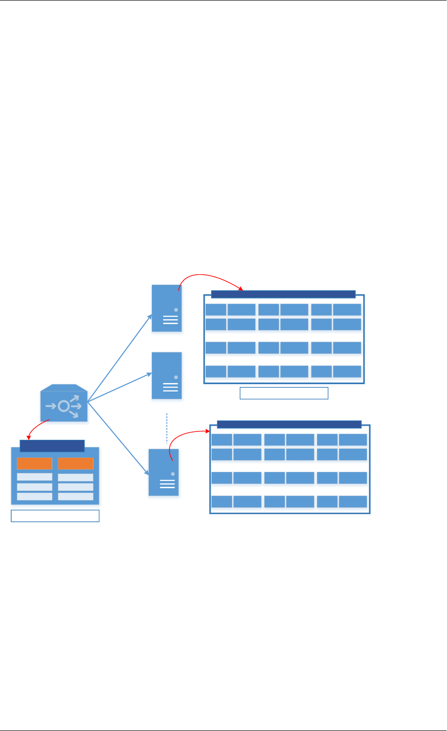
Programmer’s Guide, Release 18.11.0-rc5
which is almost constant irrespective of the length of the key which is a highly desirable feature
especially for longer keys.
In summary, EFD is a set separation data structure that supports millions of keys. It is used to
distribute a given key to an intended target. By itself EFD is not a FIB data structure with an
exact match the input flow key.
21.3 Example of EFD Library Usage
EFD can be used along the data path of many network functions and middleboxes. As previ-
ously mentioned, it can used as an index table for <key,value> pairs, meta-data for objects, a
flow-level load balancer, etc. Fig. 21.6 shows an example of using EFD as a flow-level load
balancer, where flows are received at a front end server before being forwarded to the target
back end server for processing. The system designer would deterministically co-locate flows
together in order to minimize cross-server interaction. (For example, flows requesting certain
webpage objects are co-located together, to minimize forwarding of common objects across
servers).
Key 1Action 1Key 2Action 2
Key xAction xKey yAction yKey z Action z
Key NAction N
Local Table for N Specific Flows Serviced at Node 1
EFD Table
Group_id
Hash index
Supports X*N Flows
Frontend Serveror Load Balancer
Backend Server 1
Backend Server 2
Backend Server X
Key 1Action 1Key 2Action 2
Key xAction xKey yAction yKey z Action z
Key NAction N
Local Table for N Specific Flows Serviced at Node X
Supports N Flows
Fig. 21.6: EFD as a Flow-Level Load Balancer
As shown in Fig. 21.6, the front end server will have an EFD table that stores for each group
what is the perfect hash index that satisfies the correct output. Because the table size is small
and fits in cache (since keys are not stored), it sustains a large number of flows (N*X, where N
is the maximum number of flows served by each back end server of the X possible targets).
With an input flow key, the group id is computed (for example, using last few bits of CRC hash)
and then the EFD table is indexed with the group id to retrieve the corresponding hash index to
use. Once the index is retrieved the key is hashed using this hash function and the result will
be the intended correct target where this flow is supposed to be processed.
It should be noted that as a result of EFD not matching the exact key but rather distributing
the flows to a target back end node based on the perfect hash index, a key that has not been
21.3. Example of EFD Library Usage 201

Programmer’s Guide, Release 18.11.0-rc5
inserted before will be distributed to a valid target. Hence, a local table which stores the flows
served at each node is used and is exact matched with the input key to rule out new never
seen before flows.
21.4 Library API Overview
The EFD library API is created with a very similar semantics of a hash-index or a flow table.
The application creates an EFD table for a given maximum number of flows, a function is called
to insert a flow key with a specific target value, and another function is used to retrieve target
values for a given individual flow key or a bulk of keys.
21.4.1 EFD Table Create
The function rte_efd_create() is used to create and return a pointer to an EFD table that
is sized to hold up to num_flows key. The online version of the EFD table (the one that does
not store the keys and is used for lookups) will be allocated and created in the last level cache
(LLC) of the socket defined by the online_socket_bitmask, while the offline EFD table (the
one that stores the keys and is used for key inserts and for computing the perfect hashing) is
allocated and created in the LLC of the socket defined by offline_socket_bitmask. It should
be noted, that for highest performance the socket id should match that where the thread is
running, i.e. the online EFD lookup table should be created on the same socket as where the
lookup thread is running.
21.4.2 EFD Insert and Update
The EFD function to insert a key or update a key to a new value is rte_efd_update().
This function will update an existing key to a new value (target) if the key has already been
inserted before, or will insert the <key,value> pair if this key has not been inserted before. It
will return 0 upon success. It will return EFD_UPDATE_WARN_GROUP_FULL (1) if the op-
eration is insert, and the last available space in the key’s group was just used. It will return
EFD_UPDATE_FAILED (2) when the insertion or update has failed (either it failed to find a
suitable perfect hash or the group was full). The function will return EFD_UPDATE_NO_CHANGE
(3) if there is no change to the EFD table (i.e, same value already exists).
Note: This function is not multi-thread safe and should only be called from one thread.
21.4.3 EFD Lookup
To lookup a certain key in an EFD table, the function rte_efd_lookup() is used to return the
value associated with single key. As previously mentioned, if the key has been inserted, the cor-
rect value inserted is returned, if the key has not been inserted before, a ‘random’ value (based
on hashing of the key) is returned. For better performance and to decrease the overhead of
function calls per key, it is always recommended to use a bulk lookup function (simultaneous
lookup of multiple keys) instead of a single key lookup function. rte_efd_lookup_bulk()
is the bulk lookup function, that looks up num_keys simultaneously stored in the key_list and
the corresponding return values will be returned in the value_list.
21.4. Library API Overview 202
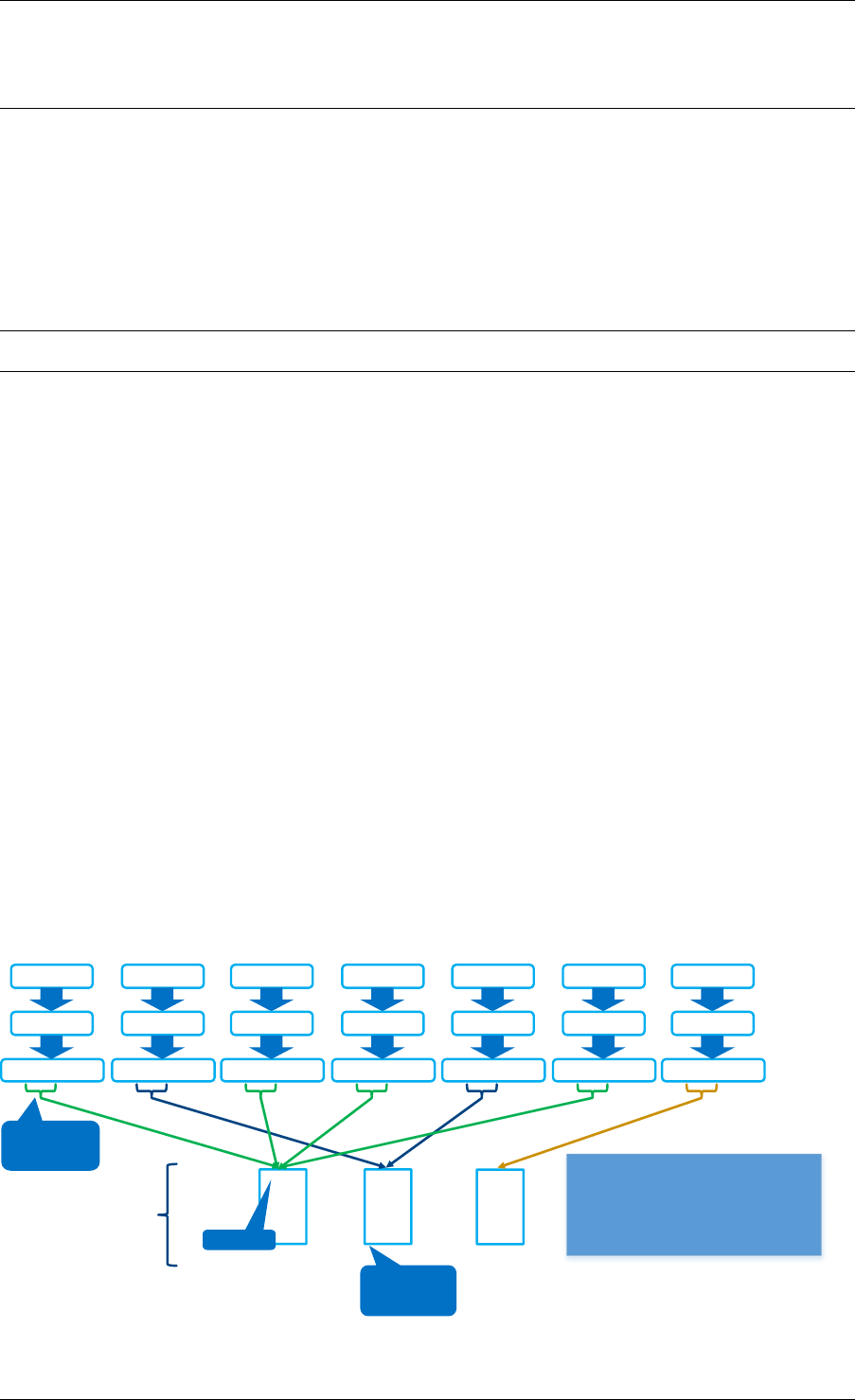
Programmer’s Guide, Release 18.11.0-rc5
Note: This function is multi-thread safe, but there should not be other threads writing in the
EFD table, unless locks are used.
21.4.4 EFD Delete
To delete a certain key in an EFD table, the function rte_efd_delete() can be used. The
function returns zero upon success when the key has been found and deleted. Socket_id is
the parameter to use to lookup the existing value, which is ideally the caller’s socket id. The
previous value associated with this key will be returned in the prev_value argument.
Note: This function is not multi-thread safe and should only be called from one thread.
21.5 Library Internals
This section provides the brief high-level idea and an overview of the library internals to accom-
pany the RFC. The intent of this section is to explain to readers the high-level implementation
of insert, lookup and group rebalancing in the EFD library.
21.5.1 Insert Function Internals
As previously mentioned the EFD divides the whole set of keys into groups of a manageable
size (e.g. 28 keys) and then searches for the perfect hash that satisfies the intended target
value for each key. EFD stores two version of the <key,value> table:
• Offline Version (in memory): Only used for the insertion/update operation, which is less
frequent than the lookup operation. In the offline version the exact keys for each group is
stored. When a new key is added, the hash function is updated that will satisfy the value
for the new key together with the all old keys already inserted in this group.
• Online Version (in cache): Used for the frequent lookup operation. In the online version,
as previously mentioned, the keys are not stored but rather only the hash index for each
group.
Key1
hash
0x0102ABCD
Key2
hash
0x0103CDAB
Key3
hash
0x0102BAAD
Key4
hash
0x0104BEEF
Key5
hash
0x0103DABD
Key6
hash
0x0102ADCB
Key7
hash
0x0104DBCA
0x0102
4
0x0103
2
0x0104
1
Groups
group id
- Keys separated into
groups based on
some bits from hash
- Groups contain a
small number of
keys (<28)
Group
Identifier
(simplified)
· Keys separated into groups based on some bits from hash.· Groups contain a small number of keys (<28)
Total # of keys in group so far
Fig. 21.7: Group Assignment
21.5. Library Internals 203
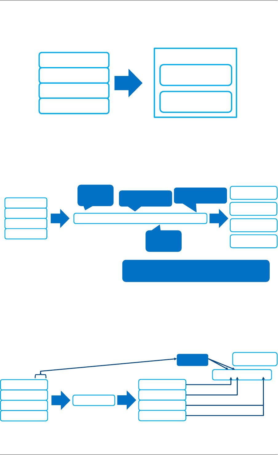
Programmer’s Guide, Release 18.11.0-rc5
Fig. 21.7 depicts the group assignment for 7 flow keys as an example. Given a flow key, a hash
function (in our implementation CRC hash) is used to get the group id. As shown in the figure,
the groups can be unbalanced. (We highlight group rebalancing further below).
hash_index
(integer, 16 bits)
lookup_table
(16 bits)
Group ID: 0x0102
Key1: Value = 0
Key3: Value = 1
Key4: Value = 0
Key7: Value = 1
Fig. 21.8: Perfect Hash Search - Assigned Keys & Target Value
Focusing on one group that has four keys, Fig. 21.8 depicts the search algorithm to find the
perfect hash function. Assuming that the target value bit for the keys is as shown in the figure,
then the online EFD table will store a 16 bit hash index and 16 bit lookup table per group per
value bit.
(hash(key, seed1) + hash_index *
hash(key
, seed2)) % 16
lookup_tablebit
index for key1
lookup_tablebit
index for key3
lookup_tablebit
index for key4
lookup_tablebit
index for key7
CRC32 (32
bit output) Goal: Find a valid
hash_index
Lookup Table has
16 bits
CRC32 (32
bit output)
Goal is to find a hash_index that produces
a lookup_table with no contradictions
Key1: Value = 0
Key3: Value = 1
Key4: Value = 0
Key7: Value = 1
Fig. 21.9: Perfect Hash Search - Satisfy Target Values
For a given keyX, a hash function (h(keyX, seed1) + index *h(keyX, seed2)) is
used to point to certain bit index in the 16bit lookup_table value, as shown in Fig. 21.9. The
insert function will brute force search for all possible values for the hash index until a non
conflicting lookup_table is found.
Key1: Value = 0
Key3: Value = 1
Key4: Value = 0
Key7: Value = 1
F(key,
hash_index = i)
Key1: Position 4
Key3: Position 6
Key4: Position 14
Key7: Position 14
0000 0010 0000 00?0
Values Lookup_table
(16 bits)
Fig. 21.10: Finding Hash Index for Conflict Free lookup_table
21.5. Library Internals 204
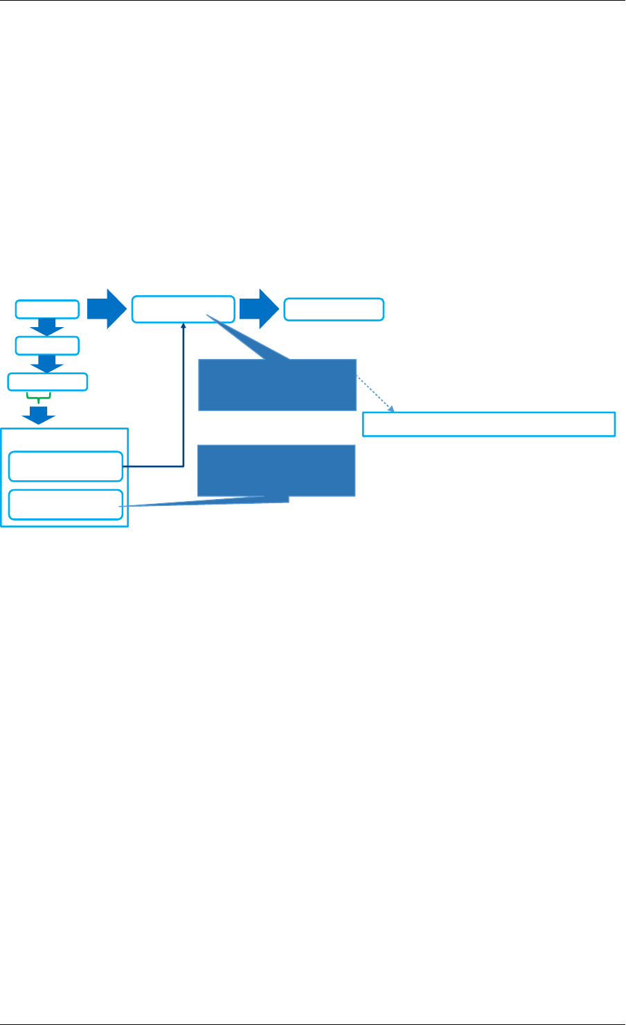
Programmer’s Guide, Release 18.11.0-rc5
For example, since both key3 and key7 have a target bit value of 1, it is okay if the hash function
of both keys point to the same bit in the lookup table. A conflict will occur if a hash index is
used that maps both Key4 and Key7 to the same index in the lookup_table, as shown in Fig.
21.10, since their target value bit are not the same. Once a hash index is found that produces
a lookup_table with no contradictions, this index is stored for this group. This procedure is
repeated for each bit of target value.
21.5.2 Lookup Function Internals
The design principle of EFD is that lookups are much more frequent than inserts, and hence,
EFD’s design optimizes for the lookups which are faster and much simpler than the slower
insert procedure (inserts are slow, because of perfect hash search as previously discussed).
Key
hash
0x0102ABCD
hash_index =
38123
lookup_table =
0110 1100 0101 1101
Group ID: 0x0102
Position = 6
Apply the equation
to retrieve the bit
position in the
lookup_table
Retrieve the value “0' from the specified location in the lookup table
F(Key, hash_index = 38123
Apply the equation to retrieve the bit position in the lookup_table
(Hash(key,seed1)+38123*hash(key,seed2))%16
Fig. 21.11: EFD Lookup Operation
Fig. 21.11 depicts the lookup operation for EFD. Given an input key, the group id is computed
(using CRC hash) and then the hash index for this group is retrieved from the EFD table. Using
the retrieved hash index, the hash function h(key, seed1) + index *h(key, seed2) is
used which will result in an index in the lookup_table, the bit corresponding to this index will be
the target value bit. This procedure is repeated for each bit of the target value.
21.5.3 Group Rebalancing Function Internals
When discussing EFD inserts and lookups, the discussion is simplified by assuming that a
group id is simply a result of hash function. However, since hashing in general is not perfect
and will not always produce a uniform output, this simplified assumption will lead to unbalanced
groups, i.e., some group will have more keys than other groups. Typically, and to minimize in-
sert time with an increasing number of keys, it is preferable that all groups will have a balanced
number of keys, so the brute force search for the perfect hash terminates with a valid hash
index. In order to achieve this target, groups are rebalanced during runtime inserts, and keys
are moved around from a busy group to a less crowded group as the more keys are inserted.
Fig. 21.12 depicts the high level idea of group rebalancing, given an input key the hash result
is split into two parts a chunk id and 8-bit bin id. A chunk contains 64 different groups and 256
bins (i.e. for any given bin it can map to 4 distinct groups). When a key is inserted, the bin id
is computed, for example in Fig. 21.12 bin_id=2, and since each bin can be mapped to one
of four different groups (2 bit storage), the four possible mappings are evaluated and the one
21.5. Library Internals 205
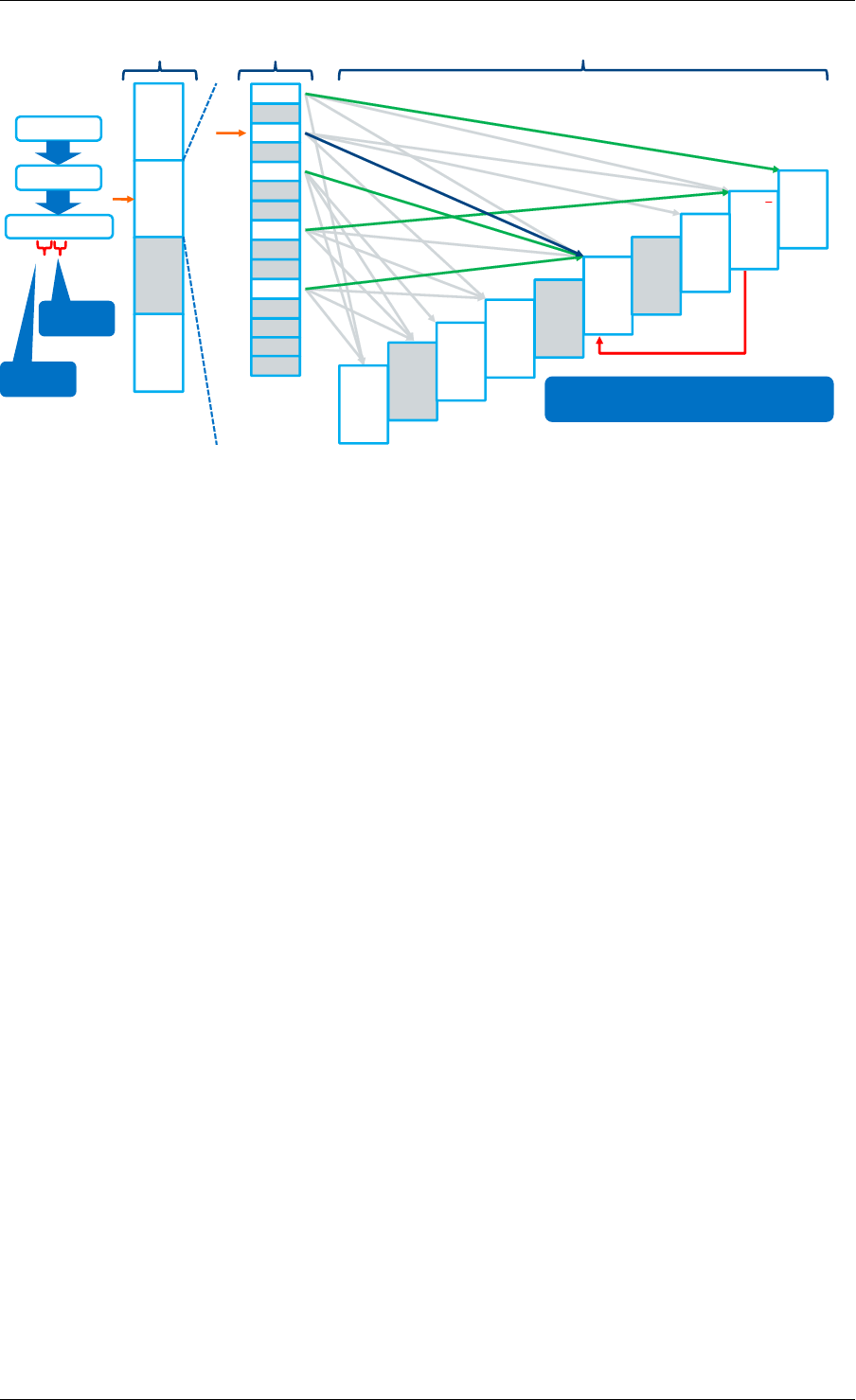
Programmer’s Guide, Release 18.11.0-rc5
Bins Groups
0
Chunks
1
…
variable
# of
chunks
(power
of 2)
04
1
23+1
3
40
5
6
72
8
9
10 1
11
12
…
255
…
5
42
4
10
1+4
3
12
7
5-3
00
4
64 96
7
698
5
299
9
797
6
Insert key
hash
0x0102ABCD
chunk id
bin id
Move bin from group 1 to 4
Fig. 21.12: Runtime Group Rebalancing
that will result in a balanced key distribution across these four is selected the mapping result is
stored in these two bits.
21.6 References
1- EFD is based on collaborative research work between Intel and Carnegie Mel-
lon University (CMU), interested readers can refer to the paper “Scaling Up Clus-
tered Network Appliances with ScaleBricks;” Dong Zhou et al. at SIGCOMM 2015
(http://conferences.sigcomm.org/sigcomm/2015/pdf/papers/p241.pdf ) for more information.
21.6. References 206

CHAPTER
TWENTYTWO
MEMBERSHIP LIBRARY
22.1 Introduction
The DPDK Membership Library provides an API for DPDK applications to insert a new member,
delete an existing member, or query the existence of a member in a given set, or a group of
sets. For the case of a group of sets, the library will return not only whether the element has
been inserted before in one of the sets but also which set it belongs to. The Membership Library
is an extension and generalization of a traditional filter structure (for example Bloom Filter
[Member-bloom]) that has multiple usages in a wide variety of workloads and applications. In
general, the Membership Library is a data structure that provides a “set-summary” on whether
a member belongs to a set, and as discussed in detail later, there are two advantages of using
such a set-summary rather than operating on a “full-blown” complete list of elements: first, it
has a much smaller storage requirement than storing the whole list of elements themselves,
and secondly checking an element membership (or other operations) in this set-summary is
much faster than checking it for the original full-blown complete list of elements.
We use the term “Set-Summary” in this guide to refer to the space-efficient, probabilistic mem-
bership data structure that is provided by the library. A membership test for an element will
return the set this element belongs to or that the element is “not-found” with very high prob-
ability of accuracy. Set-summary is a fundamental data aggregation component that can be
used in many network (and other) applications. It is a crucial structure to address performance
and scalability issues of diverse network applications including overlay networks, data-centric
networks, flow table summaries, network statistics and traffic monitoring. A set-summary is
useful for applications who need to include a list of elements while a complete list requires
too much space and/or too much processing cost. In these situations, the set-summary works
as a lossy hash-based representation of a set of members. It can dramatically reduce space
requirement and significantly improve the performance of set membership queries at the cost
of introducing a very small membership test error probability.
There are various usages for a Membership Library in a very large set of applications and
workloads. Interested readers can refer to [Member-survey] for a survey of possible networking
usages. The above figure provide a small set of examples of using the Membership Library:
• Sub-figure (a) depicts a distributed web cache architecture where a collection of proxies
attempt to share their web caches (cached from a set of back-end web servers) to pro-
vide faster responses to clients, and the proxies use the Membership Library to share
summaries of what web pages/objects they are caching. With the Membership Library,
a proxy receiving an http request will inquire the set-summary to find its location and
quickly determine whether to retrieve the requested web page from a nearby proxy or
from a back-end web server.
207
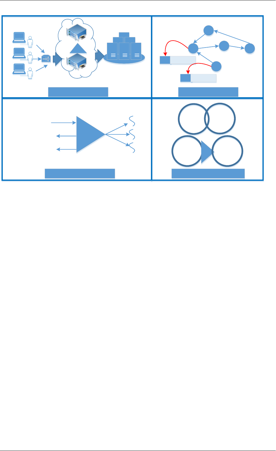
Programmer’s Guide, Release 18.11.0-rc5
List 1
matching Criteria
1
List 1 matching Criteria 1
List 2
List 2
List 1
matching Criteria
1
List 1 matching Criteria 1
setsum
List 2
matching Criteria
2
List 2 matching Criteria 2
Set Summary
Flow Key
New Flow => New Assignment
Old Flow => forward to specific thread
SUM Packet
SUM Packet
Encode ID
setsum
Clients Distributed Cache
Web Servers
(a) Distributed Web Cache (b) Detecting Routing Loops
(c) In-order Workload Scheduler (d) Database Semi-join Operations
Fig. 22.1: Example Usages of Membership Library
• Sub-figure (b) depicts another example for using the Membership Library to prevent rout-
ing loops which is typically done using slow TTL countdown and dropping packets when
TTL expires. As shown in Sub-figure (b), an embedded set-summary in the packet
header itself can be used to summarize the set of nodes a packet has gone through,
and each node upon receiving a packet can check whether its id is a member of the set
of visited nodes, and if it is, then a routing loop is detected.
• Sub-Figure (c) presents another usage of the Membership Library to load-balance flows
to worker threads with in-order guarantee where a set-summary is used to query if a
packet belongs to an existing flow or a new flow. Packets belonging to a new flow are
forwarded to the current least loaded worker thread, while those belonging to an existing
flow are forwarded to the pre-assigned thread to guarantee in-order processing.
• Sub-figure (d) highlights yet another usage example in the database domain where a set-
summary is used to determine joins between sets instead of creating a join by comparing
each element of a set against the other elements in a different set, a join is done on the
summaries since they can efficiently encode members of a given set.
Membership Library is a configurable library that is optimized to cover set membership function-
ality for both a single set and multi-set scenarios. Two set-summary schemes are presented
including (a) vector of Bloom Filters and (b) Hash-Table based set-summary schemes with
and without false negative probability. This guide first briefly describes these different types of
set-summaries, usage examples for each, and then it highlights the Membership Library API.
22.2 Vector of Bloom Filters
Bloom Filter (BF) [Member-bloom] is a well-known space-efficient probabilistic data structure
that answers set membership queries (test whether an element is a member of a set) with
22.2. Vector of Bloom Filters 208
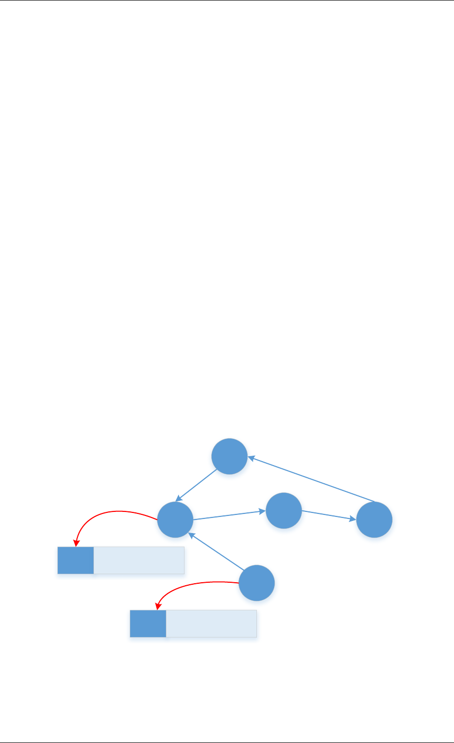
Programmer’s Guide, Release 18.11.0-rc5
some probability of false positives and zero false negatives; a query for an element returns
either it is “possibly in a set” (with very high probability) or “definitely not in a set”.
The BF is a method for representing a set of nelements (for example flow keys in network
applications domain) to support membership queries. The idea of BF is to allocate a bit-vector
vwith mbits, which are initially all set to 0. Then it chooses kindependent hash functions
h1,h2, ... hk with hash values range from 0to m-1 to perform hashing calculations on each
element to be inserted. Every time when an element Xbeing inserted into the set, the bits
at positions h1(X),h2(X), ... hk(X) in vare set to 1 (any particular bit might be set to 1
multiple times for multiple different inserted elements). Given a query for any element Y, the
bits at positions h1(Y),h2(Y), ... hk(Y) are checked. If any of them is 0, then Y is definitely
not in the set. Otherwise there is a high probability that Y is a member of the set with certain
false positive probability. As shown in the next equation, the false positive probability can be
made arbitrarily small by changing the number of hash functions (k) and the vector length (m).
False Positive Probability = (1-(1-1/m)kn)k ≃ (1-ekn/m)k
Fig. 22.2: Bloom Filter False Positive Probability
Without BF, an accurate membership testing could involve a costly hash table lookup and full
element comparison. The advantage of using a BF is to simplify the membership test into a
series of hash calculations and memory accesses for a small bit-vector, which can be easily
optimized. Hence the lookup throughput (set membership test) can be significantly faster than
a normal hash table lookup with element comparison.
BF of IDs
Packet
BF of IDs
Packet
Encode ID
Fig. 22.3: Detecting Routing Loops Using BF
BF is used for applications that need only one set, and the membership of elements is checked
against the BF. The example discussed in the above figure is one example of potential applica-
tions that uses only one set to capture the node IDs that have been visited so far by the packet.
22.2. Vector of Bloom Filters 209
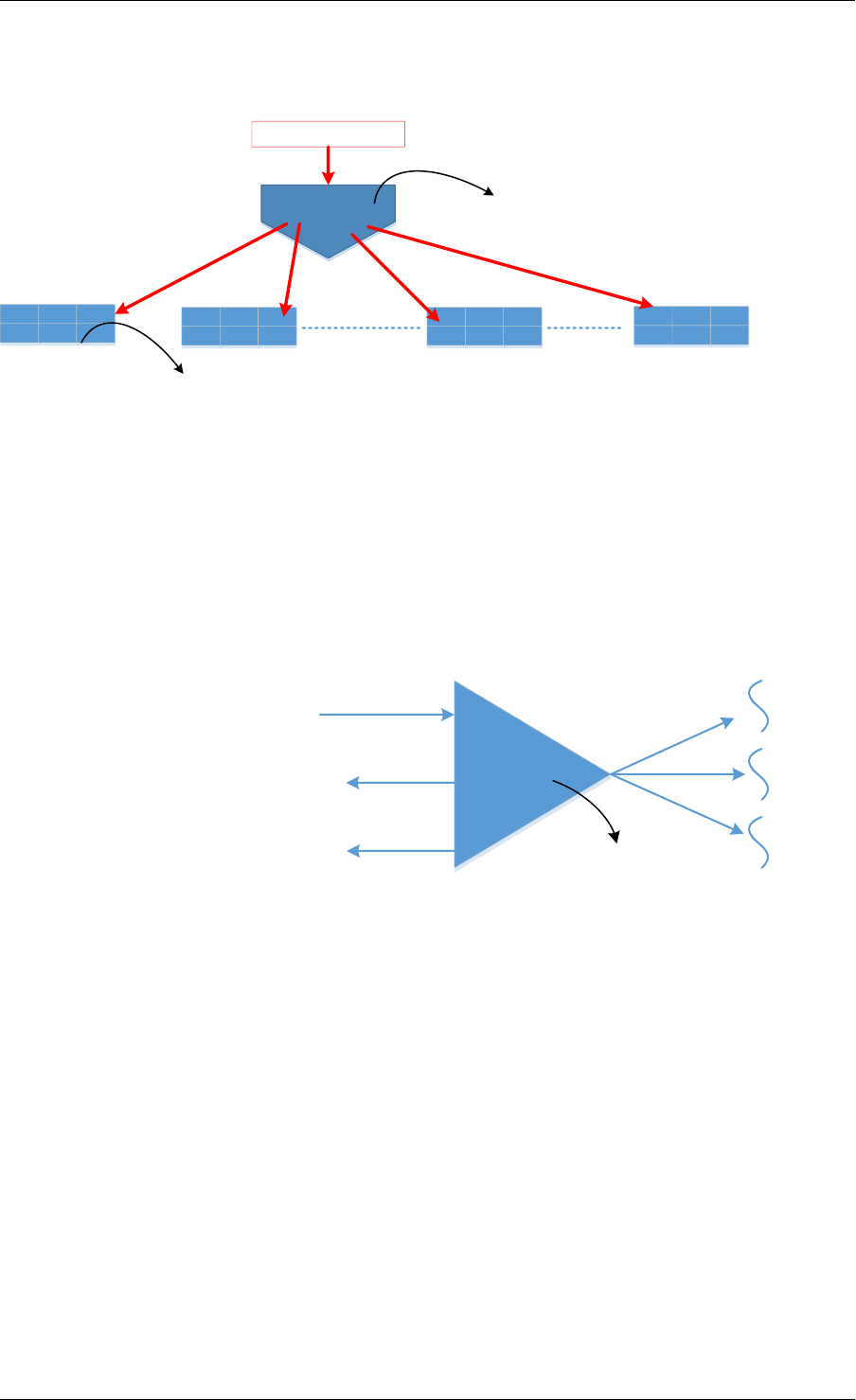
Programmer’s Guide, Release 18.11.0-rc5
Each node will then check this embedded BF in the packet header for its own id, and if the BF
indicates that the current node is definitely not in the set then a loop-free route is guaranteed.
Element
BF-1
h1, h2 .. hk
BF-2 BF-X BF-L
Hashing for lookup/Insertion into a vector of BFs happens once
Lookup/Insertion is done in the series of BFs, one by one or can be optimized to do in parallel.
Fig. 22.4: Vector Bloom Filter (vBF) Overview
To support membership test for both multiple sets and a single set, the library implements a
Vector Bloom Filter (vBF) scheme. vBF basically composes multiple bloom filters into a vector
of bloom filers. The membership test is conducted on all of the bloom filters concurrently to
determine which set(s) it belongs to or none of them. The basic idea of vBF is shown in the
above figure where an element is used to address multiple bloom filters concurrently and the
bloom filter index(es) with a hit is returned.
vBF
Flow Key
New Flow => New Assignment
Old Flow => forward to specific thread
A BF corresponding to each worker thread
Fig. 22.5: vBF for Flow Scheduling to Worker Thread
As previously mentioned, there are many usages of such structures. vBF is used for appli-
cations that need to check membership against multiple sets simultaneously. The example
shown in the above figure uses a set to capture all flows being assigned for processing at
a given worker thread. Upon receiving a packet the vBF is used to quickly figure out if this
packet belongs to a new flow so as to be forwarded to the current least loaded worker thread,
or otherwise it should be queued for an existing thread to guarantee in-order processing (i.e.
the property of vBF to indicate right away that a given flow is a new one or not is critical to
minimize response time latency).
It should be noted that vBF can be implemented using a set of single bloom filters with sequen-
tial lookup of each BF. However, being able to concurrently search all set-summaries is a big
throughput advantage. In the library, certain parallelism is realized by the implementation of
checking all bloom filters together.
22.2. Vector of Bloom Filters 210
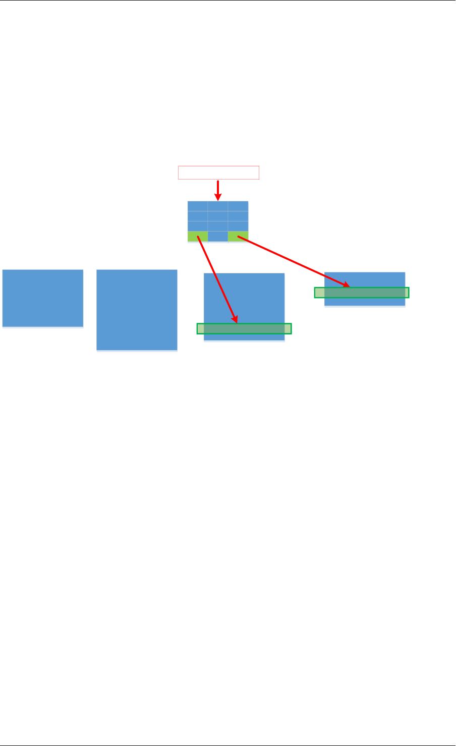
Programmer’s Guide, Release 18.11.0-rc5
22.3 Hash-Table based Set-Summaries
Hash-table based set-summary (HTSS) is another scheme in the membership library. Cuckoo
filter [Member-cfilter] is an example of HTSS. HTSS supports multi-set membership testing like
vBF does. However, while vBF is better for a small number of targets, HTSS is more suitable
and can easily outperform vBF when the number of sets is large, since HTSS uses a single
hash table for membership testing while vBF requires testing a series of Bloom Filters each
corresponding to one set. As a result, generally speaking vBF is more adequate for the case
of a small limited number of sets while HTSS should be used with a larger number of sets.
Signatures fortarget 1
Match 1
Packet Payload
Attack Signature Length 1
Signatures fortarget 2
Attack Signature Length 2 Attack Signature Length L
Match 2
Attack Signature Length X
HTSS
Fig. 22.6: Using HTSS for Attack Signature Matching
As shown in the above figure, attack signature matching where each set represents a certain
signature length (for correctness of this example, an attack signature should not be a subset
of another one) in the payload is a good example for using HTSS with 0% false negative (i.e.,
when an element returns not found, it has a 100% certainty that it is not a member of any set).
The packet inspection application benefits from knowing right away that the current payload
does not match any attack signatures in the database to establish its legitimacy, otherwise a
deep inspection of the packet is needed.
HTSS employs a similar but simpler data structure to a traditional hash table, and the major
difference is that HTSS stores only the signatures but not the full keys/elements which can
significantly reduce the footprint of the table. Along with the signature, HTSS also stores a
value to indicate the target set. When looking up an element, the element is hashed and the
HTSS is addressed to retrieve the signature stored. If the signature matches then the value is
retrieved corresponding to the index of the target set which the element belongs to. Because
signatures can collide, HTSS can still has false positive probability. Furthermore, if elements
are allowed to be overwritten or evicted when the hash table becomes full, it will also have a
false negative probability. We discuss this case in the next section.
22.3.1 Set-Summaries with False Negative Probability
As previously mentioned, traditional set-summaries (e.g. Bloom Filters) do not have a false
negative probability, i.e., it is 100% certain when an element returns “not to be present” for a
given set. However, the Membership Library also supports a set-summary probabilistic data
structure based on HTSS which allows for false negative probability.
22.3. Hash-Table based Set-Summaries 211
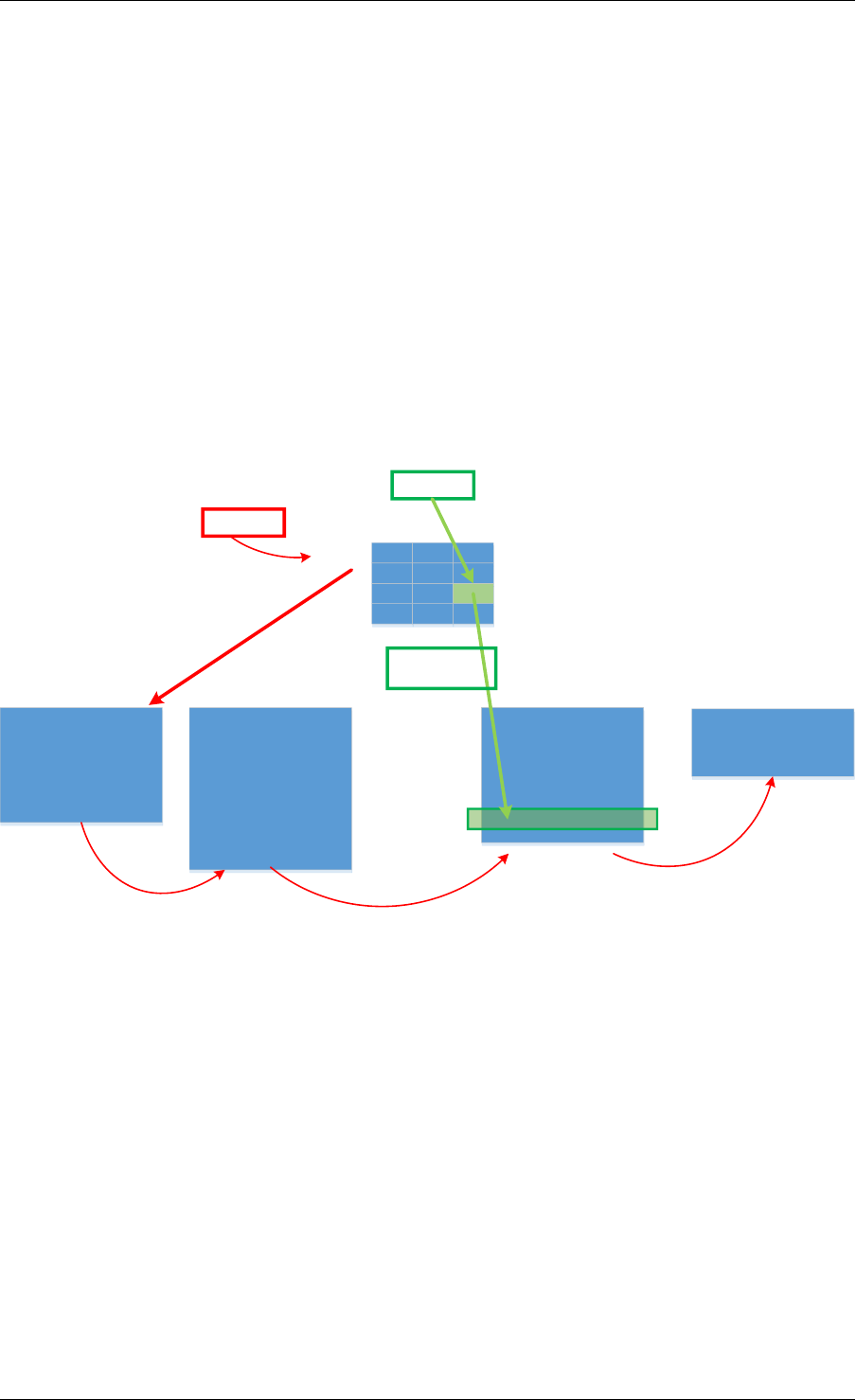
Programmer’s Guide, Release 18.11.0-rc5
In HTSS, when the hash table becomes full, keys/elements will fail to be added into the table
and the hash table has to be resized to accommodate for these new elements, which can be
expensive. However, if we allow new elements to overwrite or evict existing elements (as a
cache typically does), then the resulting set-summary will begin to have false negative proba-
bility. This is because the element that was evicted from the set-summary may still be present
in the target set. For subsequent inquiries the set-summary will falsely report the element not
being in the set, hence having a false negative probability.
The major usage of HTSS with false negative is to use it as a cache for distributing elements to
different target sets. By allowing HTSS to evict old elements, the set-summary can keep track
of the most recent elements (i.e. active) as a cache typically does. Old inactive elements (in-
frequently used elements) will automatically and eventually get evicted from the set-summary.
It is worth noting that the set-summary still has false positive probability, which means the ap-
plication either can tolerate certain false positive or it has fall-back path when false positive
happens.
Flow Keys Matching Mask 1
Match
Flow ID1
Flow Mask 1
Flow Keys Matching Mask 2
HTSS with False Negative (Cache)
Active
Target for Flow ID 1
Flow ID2
New/Inactive
Miss
Flow Mask 2 Flow Mask X Flow Mask L
Fig. 22.7: Using HTSS with False Negatives for Wild Card Classification
HTSS with false negative (i.e. a cache) also has its wide set of applications. For example wild
card flow classification (e.g. ACL rules) highlighted in the above figure is an example of such
application. In that case each target set represents a sub-table with rules defined by a certain
flow mask. The flow masks are non-overlapping, and for flows matching more than one rule
only the highest priority one is inserted in the corresponding sub-table (interested readers can
refer to the Open vSwitch (OvS) design of Mega Flow Cache (MFC) [Member-OvS] for further
details). Typically the rules will have a large number of distinct unique masks and hence, a
large number of target sets each corresponding to one mask. Because the active set of flows
varies widely based on the network traffic, HTSS with false negative will act as a cache for
<flowid, target ACL sub-table> pair for the current active set of flows. When a miss occurs (as
shown in red in the above figure) the sub-tables will be searched sequentially one by one for
a possible match, and when found the flow key and target sub-table will be inserted into the
set-summary (i.e. cache insertion) so subsequent packets from the same flow don’t incur the
overhead of the sequential search of sub-tables.
22.3. Hash-Table based Set-Summaries 212

Programmer’s Guide, Release 18.11.0-rc5
22.4 Library API Overview
The design goal of the Membership Library API is to be as generic as possible to support all
the different types of set-summaries we discussed in previous sections and beyond. Funda-
mentally, the APIs need to include creation, insertion, deletion, and lookup.
22.4.1 Set-summary Create
The rte_member_create() function is used to create a set-summary structure, the input
parameter is a struct to pass in parameters that needed to initialize the set-summary, while the
function returns the pointer to the created set-summary or NULL if the creation failed.
The general input arguments used when creating the set-summary should include name which
is the name of the created set-summary, type which is one of the types supported by the library
(e.g. RTE_MEMBER_TYPE_HT for HTSS or RTE_MEMBER_TYPE_VBF for vBF), and key_len
which is the length of the element/key. There are other parameters are only used for cer-
tain type of set-summary, or which have a slightly different meaning for different types of set-
summary. For example, num_keys parameter means the maximum number of entries for Hash
table based set-summary. However, for bloom filter, this value means the expected number of
keys that could be inserted into the bloom filter(s). The value is used to calculate the size of
each bloom filter.
We also pass two seeds: prim_hash_seed and sec_hash_seed for the primary and sec-
ondary hash functions to calculate two independent hash values. socket_id parameter is
the NUMA socket ID for the memory used to create the set-summary. For HTSS, another pa-
rameter is_cache is used to indicate if this set-summary is a cache (i.e. with false negative
probability) or not. For vBF, extra parameters are needed. For example, num_set is the num-
ber of sets needed to initialize the vector bloom filters. This number is equal to the number
of bloom filters will be created. false_pos_rate is the false positive rate. num_keys and
false_pos_rate will be used to determine the number of hash functions and the bloom filter
size.
22.4.2 Set-summary Element Insertion
The rte_member_add() function is used to insert an element/key into a set-summary struc-
ture. If it fails an error is returned. For success the returned value is dependent on the set-
summary mode to provide extra information for the users. For vBF mode, a return value of 0
means a successful insert. For HTSS mode without false negative, the insert could fail with
-ENOSPC if the table is full. With false negative (i.e. cache mode), for insert that does not
cause any eviction (i.e. no overwriting happens to an existing entry) the return value is 0. For
insertion that causes eviction, the return value is 1 to indicate such situation, but it is not an
error.
The input arguments for the function should include the key which is a pointer to the ele-
ment/key that needs to be added to the set-summary, and set_id which is the set id associ-
ated with the key that needs to be added.
22.4. Library API Overview 213

Programmer’s Guide, Release 18.11.0-rc5
22.4.3 Set-summary Element Lookup
The rte_member_lookup() function looks up a single key/element in the set-summary
structure. It returns as soon as the first match is found. The return value is 1 if a match is
found and 0 otherwise. The arguments for the function include key which is a pointer to the
element/key that needs to be looked up, and set_id which is used to return the first target set
id where the key has matched, if any.
The rte_member_lookup_bulk() function is used to look up a bulk of keys/elements in
the set-summary structure for their first match. Each key lookup returns as soon as the first
match is found. The return value is the number of keys that find a match. The arguments
of the function include keys which is a pointer to a bulk of keys that are to be looked up,
num_keys is the number of keys that will be looked up, and set_ids are the return target
set ids for the first match found for each of the input keys. set_ids is an array needs to be
sized according to the num_keys. If there is no match, the set id for that key will be set to
RTE_MEMBER_NO_MATCH.
The rte_member_lookup_multi() function looks up a single key/element in the set-
summary structure for multiple matches. It returns ALL the matches (possibly more than one)
found for this key when it is matched against all target sets (it is worth noting that for cache
mode HTSS, the current implementation matches at most one target set). The return value
is the number of matches that was found for this key (for cache mode HTSS the return value
should be at most 1). The arguments for the function include key which is a pointer to the
element/key that needs to be looked up, max_match_per_key which is to indicate the max-
imum number of matches the user expects to find for each key, and set_id which is used
to return all target set ids where the key has matched, if any. The set_id array should be
sized according to max_match_per_key. For vBF, the maximum number of matches per key
is equal to the number of sets. For HTSS, the maximum number of matches per key is equal
to two time entry count per bucket. max_match_per_key should be equal or smaller than the
maximum number of possible matches.
The rte_membership_lookup_multi_bulk() function looks up a bulk of keys/elements
in the set-summary structure for multiple matches, each key lookup returns ALL the matches
(possibly more than one) found for this key when it is matched against all target sets (cache
mode HTSS matches at most one target set). The return value is the number of keys that find
one or more matches in the set-summary structure. The arguments of the function include
keys which is a pointer to a bulk of keys that are to be looked up, num_keys is the number
of keys that will be looked up, max_match_per_key is the possible maximum number of
matches for each key, match_count which is the returned number of matches for each key,
and set_ids are the returned target set ids for all matches found for each keys. set_ids is
2-D array containing a 1-D array for each key (the size of 1-D array per key should be set by the
user according to max_match_per_key). max_match_per_key should be equal or smaller
than the maximum number of possible matches, similar to rte_member_lookup_multi.
22.4.4 Set-summary Element Delete
The rte_membership_delete() function deletes an element/key from a set-summary
structure, if it fails an error is returned. The input arguments should include key which is a
pointer to the element/key that needs to be deleted from the set-summary, and set_id which
is the set id associated with the key to delete. It is worth noting that current implementation of
22.4. Library API Overview 214

Programmer’s Guide, Release 18.11.0-rc5
vBF does not support deletion 1. An error code -EINVAL will be returned.
22.5 References
[Member-bloom] B H Bloom, “Space/Time Trade-offs in Hash Coding with Allowable Errors,”
Communications of the ACM, 1970.
[Member-survey] A Broder and M Mitzenmacher, “Network Applications of Bloom Filters: A
Survey,” in Internet Mathematics, 2005.
[Member-cfilter] B Fan, D G Andersen and M Kaminsky, “Cuckoo Filter: Practically Better Than
Bloom,” in Conference on emerging Networking Experiments and Technologies, 2014.
[Member-OvS] B Pfaff, “The Design and Implementation of Open vSwitch,” in NSDI, 2015.
1Traditional bloom filter does not support proactive deletion. Supporting proactive deletion require additional
implementation and performance overhead.
22.5. References 215

CHAPTER
TWENTYTHREE
LPM LIBRARY
The DPDK LPM library component implements the Longest Prefix Match (LPM) table search
method for 32-bit keys that is typically used to find the best route match in IP forwarding appli-
cations.
23.1 LPM API Overview
The main configuration parameter for LPM component instances is the maximum number of
rules to support. An LPM prefix is represented by a pair of parameters (32- bit key, depth), with
depth in the range of 1 to 32. An LPM rule is represented by an LPM prefix and some user
data associated with the prefix. The prefix serves as the unique identifier of the LPM rule. In
this implementation, the user data is 1-byte long and is called next hop, in correlation with its
main use of storing the ID of the next hop in a routing table entry.
The main methods exported by the LPM component are:
• Add LPM rule: The LPM rule is provided as input. If there is no rule with the same prefix
present in the table, then the new rule is added to the LPM table. If a rule with the same
prefix is already present in the table, the next hop of the rule is updated. An error is
returned when there is no available rule space left.
• Delete LPM rule: The prefix of the LPM rule is provided as input. If a rule with the
specified prefix is present in the LPM table, then it is removed.
• Lookup LPM key: The 32-bit key is provided as input. The algorithm selects the rule that
represents the best match for the given key and returns the next hop of that rule. In the
case that there are multiple rules present in the LPM table that have the same 32-bit key,
the algorithm picks the rule with the highest depth as the best match rule, which means
that the rule has the highest number of most significant bits matching between the input
key and the rule key.
23.2 Implementation Details
The current implementation uses a variation of the DIR-24-8 algorithm that trades memory
usage for improved LPM lookup speed. The algorithm allows the lookup operation to be per-
formed with typically a single memory read access. In the statistically rare case when the best
match rule is having a depth bigger than 24, the lookup operation requires two memory read
accesses. Therefore, the performance of the LPM lookup operation is greatly influenced by
whether the specific memory location is present in the processor cache or not.
216
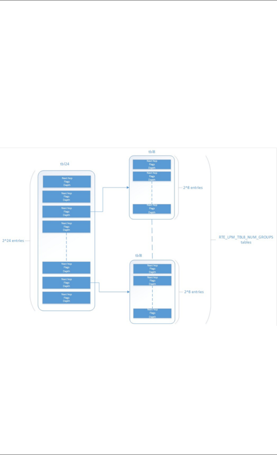
Programmer’s Guide, Release 18.11.0-rc5
The main data structure is built using the following elements:
• A table with 2^24 entries.
• A number of tables (RTE_LPM_TBL8_NUM_GROUPS) with 2^8 entries.
The first table, called tbl24, is indexed using the first 24 bits of the IP address to be looked up,
while the second table(s), called tbl8, is indexed using the last 8 bits of the IP address. This
means that depending on the outcome of trying to match the IP address of an incoming packet
to the rule stored in the tbl24 we might need to continue the lookup process in the second level.
Since every entry of the tbl24 can potentially point to a tbl8, ideally, we would have 2^24 tbl8s,
which would be the same as having a single table with 2^32 entries. This is not feasible due
to resource restrictions. Instead, this approach takes advantage of the fact that rules longer
than 24 bits are very rare. By splitting the process in two different tables/levels and limiting the
number of tbl8s, we can greatly reduce memory consumption while maintaining a very good
lookup speed (one memory access, most of the times).
Fig. 23.1: Table split into different levels
An entry in tbl24 contains the following fields:
• next hop / index to the tbl8
• valid flag
• external entry flag
• depth of the rule (length)
The first field can either contain a number indicating the tbl8 in which the lookup process should
continue or the next hop itself if the longest prefix match has already been found. The two flags
are used to determine whether the entry is valid or not and whether the search process have
23.2. Implementation Details 217

Programmer’s Guide, Release 18.11.0-rc5
finished or not respectively. The depth or length of the rule is the number of bits of the rule that
is stored in a specific entry.
An entry in a tbl8 contains the following fields:
• next hop
• valid
• valid group
• depth
Next hop and depth contain the same information as in the tbl24. The two flags show whether
the entry and the table are valid respectively.
The other main data structure is a table containing the main information about the rules (IP
and next hop). This is a higher level table, used for different things:
• Check whether a rule already exists or not, prior to addition or deletion, without having to
actually perform a lookup.
• When deleting, to check whether there is a rule containing the one that is to be deleted.
This is important, since the main data structure will have to be updated accordingly.
23.2.1 Addition
When adding a rule, there are different possibilities. If the rule’s depth is exactly 24 bits, then:
• Use the rule (IP address) as an index to the tbl24.
• If the entry is invalid (i.e. it doesn’t already contain a rule) then set its next hop to its value,
the valid flag to 1 (meaning this entry is in use), and the external entry flag to 0 (meaning
the lookup process ends at this point, since this is the longest prefix that matches).
If the rule’s depth is exactly 32 bits, then:
• Use the first 24 bits of the rule as an index to the tbl24.
• If the entry is invalid (i.e. it doesn’t already contain a rule) then look for a free tbl8, set
the index to the tbl8 to this value, the valid flag to 1 (meaning this entry is in use), and the
external entry flag to 1 (meaning the lookup process must continue since the rule hasn’t
been explored completely).
If the rule’s depth is any other value, prefix expansion must be performed. This means the rule
is copied to all the entries (as long as they are not in use) which would also cause a match.
As a simple example, let’s assume the depth is 20 bits. This means that there are 2^(24 -
20) = 16 different combinations of the first 24 bits of an IP address that would cause a match.
Hence, in this case, we copy the exact same entry to every position indexed by one of these
combinations.
By doing this we ensure that during the lookup process, if a rule matching the IP address exists,
it is found in either one or two memory accesses, depending on whether we need to move to
the next table or not. Prefix expansion is one of the keys of this algorithm, since it improves the
speed dramatically by adding redundancy.
23.2. Implementation Details 218

Programmer’s Guide, Release 18.11.0-rc5
23.2.2 Lookup
The lookup process is much simpler and quicker. In this case:
• Use the first 24 bits of the IP address as an index to the tbl24. If the entry is not in use,
then it means we don’t have a rule matching this IP. If it is valid and the external entry
flag is set to 0, then the next hop is returned.
• If it is valid and the external entry flag is set to 1, then we use the tbl8 index to find out
the tbl8 to be checked, and the last 8 bits of the IP address as an index to this table.
Similarly, if the entry is not in use, then we don’t have a rule matching this IP address. If
it is valid then the next hop is returned.
23.2.3 Limitations in the Number of Rules
There are different things that limit the number of rules that can be added. The first one is the
maximum number of rules, which is a parameter passed through the API. Once this number is
reached, it is not possible to add any more rules to the routing table unless one or more are
removed.
The second reason is an intrinsic limitation of the algorithm. As explained before, to avoid high
memory consumption, the number of tbl8s is limited in compilation time (this value is by default
256). If we exhaust tbl8s, we won’t be able to add any more rules. How many of them are
necessary for a specific routing table is hard to determine in advance.
A tbl8 is consumed whenever we have a new rule with depth bigger than 24, and the first 24
bits of this rule are not the same as the first 24 bits of a rule previously added. If they are, then
the new rule will share the same tbl8 than the previous one, since the only difference between
the two rules is within the last byte.
With the default value of 256, we can have up to 256 rules longer than 24 bits that differ on
their first three bytes. Since routes longer than 24 bits are unlikely, this shouldn’t be a problem
in most setups. Even if it is, however, the number of tbl8s can be modified.
23.2.4 Use Case: IPv4 Forwarding
The LPM algorithm is used to implement Classless Inter-Domain Routing (CIDR) strategy used
by routers implementing IPv4 forwarding.
23.2.5 References
• RFC1519 Classless Inter-Domain Routing (CIDR): an Address Assignment and Aggre-
gation Strategy, http://www.ietf.org/rfc/rfc1519
• Pankaj Gupta, Algorithms for Routing Lookups and Packet Classification, PhD Thesis,
Stanford University, 2000 (http://klamath.stanford.edu/~pankaj/thesis/ thesis_1sided.pdf
)
23.2. Implementation Details 219

CHAPTER
TWENTYFOUR
LPM6 LIBRARY
The LPM6 (LPM for IPv6) library component implements the Longest Prefix Match (LPM) ta-
ble search method for 128-bit keys that is typically used to find the best match route in IPv6
forwarding applications.
24.1 LPM6 API Overview
The main configuration parameters for the LPM6 library are:
• Maximum number of rules: This defines the size of the table that holds the rules, and
therefore the maximum number of rules that can be added.
• Number of tbl8s: A tbl8 is a node of the trie that the LPM6 algorithm is based on.
This parameter is related to the number of rules you can have, but there is no way to accurately
predict the number needed to hold a specific number of rules, since it strongly depends on the
depth and IP address of every rule. One tbl8 consumes 1 kb of memory. As a recommendation,
65536 tbl8s should be sufficient to store several thousand IPv6 rules, but the number can vary
depending on the case.
An LPM prefix is represented by a pair of parameters (128-bit key, depth), with depth in the
range of 1 to 128. An LPM rule is represented by an LPM prefix and some user data associated
with the prefix. The prefix serves as the unique identifier for the LPM rule. In this implementa-
tion, the user data is 21-bits long and is called “next hop”, which corresponds to its main use
of storing the ID of the next hop in a routing table entry.
The main methods exported for the LPM component are:
• Add LPM rule: The LPM rule is provided as input. If there is no rule with the same prefix
present in the table, then the new rule is added to the LPM table. If a rule with the same
prefix is already present in the table, the next hop of the rule is updated. An error is
returned when there is no available space left.
• Delete LPM rule: The prefix of the LPM rule is provided as input. If a rule with the
specified prefix is present in the LPM table, then it is removed.
• Lookup LPM key: The 128-bit key is provided as input. The algorithm selects the rule
that represents the best match for the given key and returns the next hop of that rule. In
the case that there are multiple rules present in the LPM table that have the same 128-bit
value, the algorithm picks the rule with the highest depth as the best match rule, which
means the rule has the highest number of most significant bits matching between the
input key and the rule key.
220

Programmer’s Guide, Release 18.11.0-rc5
24.1.1 Implementation Details
This is a modification of the algorithm used for IPv4 (see Implementation Details). In this case,
instead of using two levels, one with a tbl24 and a second with a tbl8, 14 levels are used.
The implementation can be seen as a multi-bit trie where the stride or number of bits inspected
on each level varies from level to level. Specifically, 24 bits are inspected on the root node, and
the remaining 104 bits are inspected in groups of 8 bits. This effectively means that the trie
has 14 levels at the most, depending on the rules that are added to the table.
The algorithm allows the lookup operation to be performed with a number of memory accesses
that directly depends on the length of the rule and whether there are other rules with bigger
depths and the same key in the data structure. It can vary from 1 to 14 memory accesses, with
5 being the average value for the lengths that are most commonly used in IPv6.
The main data structure is built using the following elements:
• A table with 224 entries
• A number of tables, configurable by the user through the API, with 28 entries
The first table, called tbl24, is indexed using the first 24 bits of the IP address be looked up,
while the rest of the tables, called tbl8s, are indexed using the rest of the bytes of the IP
address, in chunks of 8 bits. This means that depending on the outcome of trying to match
the IP address of an incoming packet to the rule stored in the tbl24 or the subsequent tbl8s we
might need to continue the lookup process in deeper levels of the tree.
Similar to the limitation presented in the algorithm for IPv4, to store every possible IPv6 rule,
we would need a table with 2^128 entries. This is not feasible due to resource restrictions.
By splitting the process in different tables/levels and limiting the number of tbl8s, we can greatly
reduce memory consumption while maintaining a very good lookup speed (one memory ac-
cess per level).
An entry in a table contains the following fields:
• next hop / index to the tbl8
• depth of the rule (length)
• valid flag
• valid group flag
• external entry flag
The first field can either contain a number indicating the tbl8 in which the lookup process should
continue or the next hop itself if the longest prefix match has already been found. The depth
or length of the rule is the number of bits of the rule that is stored in a specific entry. The flags
are used to determine whether the entry/table is valid or not and whether the search process
have finished or not respectively.
Both types of tables share the same structure.
The other main data structure is a table containing the main information about the rules (IP,
next hop and depth). This is a higher level table, used for different things:
• Check whether a rule already exists or not, prior to addition or deletion, without having to
actually perform a lookup.
24.1. LPM6 API Overview 221
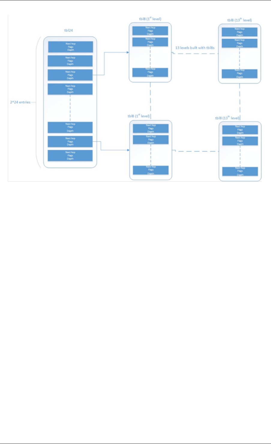
Programmer’s Guide, Release 18.11.0-rc5
Fig. 24.1: Table split into different levels
When deleting, to check whether there is a rule containing the one that is to be deleted. This
is important, since the main data structure will have to be updated accordingly.
24.1.2 Addition
When adding a rule, there are different possibilities. If the rule’s depth is exactly 24 bits, then:
• Use the rule (IP address) as an index to the tbl24.
• If the entry is invalid (i.e. it doesn’t already contain a rule) then set its next hop to its value,
the valid flag to 1 (meaning this entry is in use), and the external entry flag to 0 (meaning
the lookup process ends at this point, since this is the longest prefix that matches).
If the rule’s depth is bigger than 24 bits but a multiple of 8, then:
• Use the first 24 bits of the rule as an index to the tbl24.
• If the entry is invalid (i.e. it doesn’t already contain a rule) then look for a free tbl8, set
the index to the tbl8 to this value, the valid flag to 1 (meaning this entry is in use), and the
external entry flag to 1 (meaning the lookup process must continue since the rule hasn’t
been explored completely).
• Use the following 8 bits of the rule as an index to the next tbl8.
• Repeat the process until the tbl8 at the right level (depending on the depth) has been
reached and fill it with the next hop, setting the next entry flag to 0.
If the rule’s depth is any other value, prefix expansion must be performed. This means the rule
is copied to all the entries (as long as they are not in use) which would also cause a match.
24.1. LPM6 API Overview 222

Programmer’s Guide, Release 18.11.0-rc5
As a simple example, let’s assume the depth is 20 bits. This means that there are 2^(24-20)
= 16 different combinations of the first 24 bits of an IP address that would cause a match.
Hence, in this case, we copy the exact same entry to every position indexed by one of these
combinations.
By doing this we ensure that during the lookup process, if a rule matching the IP address exists,
it is found in, at the most, 14 memory accesses, depending on how many times we need to
move to the next table. Prefix expansion is one of the keys of this algorithm, since it improves
the speed dramatically by adding redundancy.
Prefix expansion can be performed at any level. So, for example, is the depth is 34 bits, it will
be performed in the third level (second tbl8-based level).
24.1.3 Lookup
The lookup process is much simpler and quicker. In this case:
• Use the first 24 bits of the IP address as an index to the tbl24. If the entry is not in use,
then it means we don’t have a rule matching this IP. If it is valid and the external entry
flag is set to 0, then the next hop is returned.
• If it is valid and the external entry flag is set to 1, then we use the tbl8 index to find out
the tbl8 to be checked, and the next 8 bits of the IP address as an index to this table.
Similarly, if the entry is not in use, then we don’t have a rule matching this IP address. If
it is valid then check the external entry flag for a new tbl8 to be inspected.
• Repeat the process until either we find an invalid entry (lookup miss) or a valid entry with
the external entry flag set to 0. Return the next hop in the latter case.
24.1.4 Limitations in the Number of Rules
There are different things that limit the number of rules that can be added. The first one is the
maximum number of rules, which is a parameter passed through the API. Once this number is
reached, it is not possible to add any more rules to the routing table unless one or more are
removed.
The second limitation is in the number of tbl8s available. If we exhaust tbl8s, we won’t be able
to add any more rules. How to know how many of them are necessary for a specific routing
table is hard to determine in advance.
In this algorithm, the maximum number of tbl8s a single rule can consume is 13, which is the
number of levels minus one, since the first three bytes are resolved in the tbl24. However:
• Typically, on IPv6, routes are not longer than 48 bits, which means rules usually take up
to 3 tbl8s.
As explained in the LPM for IPv4 algorithm, it is possible and very likely that several rules will
share one or more tbl8s, depending on what their first bytes are. If they share the same first 24
bits, for instance, the tbl8 at the second level will be shared. This might happen again in deeper
levels, so, effectively, two 48 bit-long rules may use the same three tbl8s if the only difference
is in their last byte.
The number of tbl8s is a parameter exposed to the user through the API in this version of the
algorithm, due to its impact in memory consumption and the number or rules that can be added
to the LPM table. One tbl8 consumes 1 kilobyte of memory.
24.1. LPM6 API Overview 223

Programmer’s Guide, Release 18.11.0-rc5
24.2 Use Case: IPv6 Forwarding
The LPM algorithm is used to implement the Classless Inter-Domain Routing (CIDR) strategy
used by routers implementing IP forwarding.
24.2. Use Case: IPv6 Forwarding 224

CHAPTER
TWENTYFIVE
FLOW CLASSIFICATION LIBRARY
DPDK provides a Flow Classification library that provides the ability to classify an input packet
by matching it against a set of Flow rules.
The initial implementation supports counting of IPv4 5-tuple packets which match a particular
Flow rule only.
Please refer to the Generic flow API (rte_flow) for more information.
The Flow Classification library uses the librte_table API for managing Flow rules and
matching packets against the Flow rules. The library is table agnostic and can use the following
tables: Access Control List,Hash and Longest Prefix Match(LPM). The Access
Control List table is used in the initial implementation.
Please refer to the Packet Framework for more information.on librte_table.
DPDK provides an Access Control List library that provides the ability to classify an input packet
based on a set of classification rules.
Please refer to the Packet Classification and Access Control library for more information on
librte_acl.
There is also a Flow Classify sample application which demonstrates the use of the Flow
Classification Library API’s.
Please refer to the ../sample_app_ug/flow_classify for more information on the
flow_classify sample application.
25.1 Overview
The library has the following API’s
/**
*Flow classifier create
*
*@param params
*Parameters for flow classifier creation
*@return
*Handle to flow classifier instance on success or NULL otherwise
*/
struct rte_flow_classifier *
rte_flow_classifier_create(struct rte_flow_classifier_params *params);
/**
*Flow classifier free
*
225

Programmer’s Guide, Release 18.11.0-rc5
*@param cls
*Handle to flow classifier instance
*@return
*0 on success, error code otherwise
*/
int
rte_flow_classifier_free(struct rte_flow_classifier *cls);
/**
*Flow classify table create
*
*@param cls
*Handle to flow classifier instance
*@param params
*Parameters for flow_classify table creation
*@return
*0 on success, error code otherwise
*/
int
rte_flow_classify_table_create(struct rte_flow_classifier *cls,
struct rte_flow_classify_table_params *params);
/**
*Validate the flow classify rule
*
*@param[in] cls
*Handle to flow classifier instance
*@param[in] attr
*Flow rule attributes
*@param[in] pattern
*Pattern specification (list terminated by the END pattern item).
*@param[in] actions
*Associated actions (list terminated by the END pattern item).
*@param[out] error
*Perform verbose error reporting if not NULL. Structure
*initialised in case of error only.
*@return
*0 on success, error code otherwise
*/
int
rte_flow_classify_validate(struct rte_flow_classifier *cls,
const struct rte_flow_attr *attr,
const struct rte_flow_item pattern[],
const struct rte_flow_action actions[],
struct rte_flow_error *error);
/**
*Add a flow classify rule to the flow_classifier table.
*
*@param[in] cls
*Flow classifier handle
*@param[in] attr
*Flow rule attributes
*@param[in] pattern
*Pattern specification (list terminated by the END pattern item).
*@param[in] actions
*Associated actions (list terminated by the END pattern item).
*@param[out] key_found
*returns 1 if rule present already, 0 otherwise.
*@param[out] error
*Perform verbose error reporting if not NULL. Structure
*initialised in case of error only.
*@return
25.1. Overview 226

Programmer’s Guide, Release 18.11.0-rc5
*A valid handle in case of success, NULL otherwise.
*/
struct rte_flow_classify_rule *
rte_flow_classify_table_entry_add(struct rte_flow_classifier *cls,
const struct rte_flow_attr *attr,
const struct rte_flow_item pattern[],
const struct rte_flow_action actions[],
int *key_found;
struct rte_flow_error *error);
/**
*Delete a flow classify rule from the flow_classifier table.
*
*@param[in] cls
*Flow classifier handle
*@param[in] rule
*Flow classify rule
*@return
*0 on success, error code otherwise.
*/
int
rte_flow_classify_table_entry_delete(struct rte_flow_classifier *cls,
struct rte_flow_classify_rule *rule);
/**
*Query flow classifier for given rule.
*
*@param[in] cls
*Flow classifier handle
*@param[in] pkts
*Pointer to packets to process
*@param[in] nb_pkts
*Number of packets to process
*@param[in] rule
*Flow classify rule
*@param[in] stats
*Flow classify stats
*
*@return
*0 on success, error code otherwise.
*/
int
rte_flow_classifier_query(struct rte_flow_classifier *cls,
struct rte_mbuf **pkts,
const uint16_t nb_pkts,
struct rte_flow_classify_rule *rule,
struct rte_flow_classify_stats *stats);
25.1.1 Classifier creation
The application creates the Classifier using the rte_flow_classifier_create API.
The rte_flow_classify_params structure must be initialised by the application before
calling the API.
struct rte_flow_classifier_params {
/** flow classifier name */
const char *name;
/** CPU socket ID where memory for the flow classifier and its */
/** elements (tables) should be allocated */
int socket_id;
25.1. Overview 227

Programmer’s Guide, Release 18.11.0-rc5
};
The Classifier has the following internal structures:
struct rte_cls_table {
/*Input parameters */
struct rte_table_ops ops;
uint32_t entry_size;
enum rte_flow_classify_table_type type;
/*Handle to the low-level table object */
void *h_table;
};
#define RTE_FLOW_CLASSIFIER_MAX_NAME_SZ 256
struct rte_flow_classifier {
/*Input parameters */
char name[RTE_FLOW_CLASSIFIER_MAX_NAME_SZ];
int socket_id;
/*Internal */
/*ntuple_filter */
struct rte_eth_ntuple_filter ntuple_filter;
/*classifier tables */
struct rte_cls_table tables[RTE_FLOW_CLASSIFY_TABLE_MAX];
uint32_t table_mask;
uint32_t num_tables;
uint16_t nb_pkts;
struct rte_flow_classify_table_entry
*entries[RTE_PORT_IN_BURST_SIZE_MAX];
} __rte_cache_aligned;
25.1.2 Adding a table to the Classifier
The application adds a table to the Classifier using the
rte_flow_classify_table_create API. The rte_flow_classify_table_params
structure must be initialised by the application before calling the API.
struct rte_flow_classify_table_params {
/** Table operations (specific to each table type) */
struct rte_table_ops *ops;
/** Opaque param to be passed to the table create operation */
void *arg_create;
/** Classifier table type */
enum rte_flow_classify_table_type type;
};
To create an ACL table the rte_table_acl_params structure must be initialised and as-
signed to arg_create in the rte_flow_classify_table_params structure.
struct rte_table_acl_params {
/** Name */
const char *name;
/** Maximum number of ACL rules in the table */
uint32_t n_rules;
25.1. Overview 228

Programmer’s Guide, Release 18.11.0-rc5
/** Number of fields in the ACL rule specification */
uint32_t n_rule_fields;
/** Format specification of the fields of the ACL rule */
struct rte_acl_field_def field_format[RTE_ACL_MAX_FIELDS];
};
The fields for the ACL rule must also be initialised by the application.
An ACL table can be added to the Classifier for each ACL rule, for example another table
could be added for the IPv6 5-tuple rule.
25.1.3 Flow Parsing
The library currently supports three IPv4 5-tuple flow patterns, for UDP, TCP and SCTP.
/*Pattern for IPv4 5-tuple UDP filter */
static enum rte_flow_item_type pattern_ntuple_1[] ={
RTE_FLOW_ITEM_TYPE_ETH,
RTE_FLOW_ITEM_TYPE_IPV4,
RTE_FLOW_ITEM_TYPE_UDP,
RTE_FLOW_ITEM_TYPE_END,
};
/*Pattern for IPv4 5-tuple TCP filter */
static enum rte_flow_item_type pattern_ntuple_2[] ={
RTE_FLOW_ITEM_TYPE_ETH,
RTE_FLOW_ITEM_TYPE_IPV4,
RTE_FLOW_ITEM_TYPE_TCP,
RTE_FLOW_ITEM_TYPE_END,
};
/*Pattern for IPv4 5-tuple SCTP filter */
static enum rte_flow_item_type pattern_ntuple_3[] ={
RTE_FLOW_ITEM_TYPE_ETH,
RTE_FLOW_ITEM_TYPE_IPV4,
RTE_FLOW_ITEM_TYPE_SCTP,
RTE_FLOW_ITEM_TYPE_END,
};
The API function rte_flow_classify_validate parses the IPv4 5-tuple pattern, attributes
and actions and returns the 5-tuple data in the rte_eth_ntuple_filter structure.
static int
rte_flow_classify_validate(struct rte_flow_classifier *cls,
const struct rte_flow_attr *attr,
const struct rte_flow_item pattern[],
const struct rte_flow_action actions[],
struct rte_flow_error *error)
25.1.4 Adding Flow Rules
The rte_flow_classify_table_entry_add API creates an rte_flow_classify ob-
ject which contains the flow_classify id and type, the action, a union of add and delete keys and
a union of rules. It uses the rte_flow_classify_validate API function for parsing the
flow parameters. The 5-tuple ACL key data is obtained from the rte_eth_ntuple_filter
structure populated by the classify_parse_ntuple_filter function which parses the
Flow rule.
25.1. Overview 229

Programmer’s Guide, Release 18.11.0-rc5
struct acl_keys {
struct rte_table_acl_rule_add_params key_add; /*add key */
struct rte_table_acl_rule_delete_params key_del; /*delete key */
};
struct classify_rules {
enum rte_flow_classify_rule_type type;
union {
struct rte_flow_classify_ipv4_5tuple ipv4_5tuple;
} u;
};
struct rte_flow_classify {
uint32_t id; /*unique ID of classify object */
enum rte_flow_classify_table_type tbl_type; /*rule table */
struct classify_rules rules; /*union of rules */
union {
struct acl_keys key;
} u;
int key_found; /*rule key found in table */
struct rte_flow_classify_table_entry entry; /*rule meta data */
void *entry_ptr; /*handle to the table entry for rule meta data */
};
It then calls the table.ops.f_add API to add the rule to the ACL table.
25.1.5 Deleting Flow Rules
The rte_flow_classify_table_entry_delete API calls the table.ops.f_delete
API to delete a rule from the ACL table.
25.1.6 Packet Matching
The rte_flow_classifier_query API is used to find packets which match a given flow
Flow rule in the table. This API calls the flow_classify_run internal function which calls the
table.ops.f_lookup API to see if any packets in a burst match any of the Flow rules in
the table. The meta data for the highest priority rule matched for each packet is returned in
the entries array in the rte_flow_classify object. The internal function action_apply
implements the Count action which is used to return data which matches a particular Flow
rule.
The rte_flow_classifier_query API uses the following structures to return data to the applica-
tion.
/** IPv4 5-tuple data */
struct rte_flow_classify_ipv4_5tuple {
uint32_t dst_ip; /**< Destination IP address in big endian. */
uint32_t dst_ip_mask; /**< Mask of destination IP address. */
uint32_t src_ip; /**< Source IP address in big endian. */
uint32_t src_ip_mask; /**< Mask of destination IP address. */
uint16_t dst_port; /**< Destination port in big endian. */
uint16_t dst_port_mask; /**< Mask of destination port. */
uint16_t src_port; /**< Source Port in big endian. */
uint16_t src_port_mask; /**< Mask of source port. */
uint8_t proto; /**< L4 protocol. */
uint8_t proto_mask; /**< Mask of L4 protocol. */
};
25.1. Overview 230

Programmer’s Guide, Release 18.11.0-rc5
/**
*Flow stats
*
*For the count action, stats can be returned by the query API.
*
*Storage for stats is provided by the application.
*
*
*/
struct rte_flow_classify_stats {
void *stats;
};
struct rte_flow_classify_5tuple_stats {
/** count of packets that match IPv4 5tuple pattern */
uint64_t counter1;
/** IPv4 5tuple data */
struct rte_flow_classify_ipv4_5tuple ipv4_5tuple;
};
25.1. Overview 231
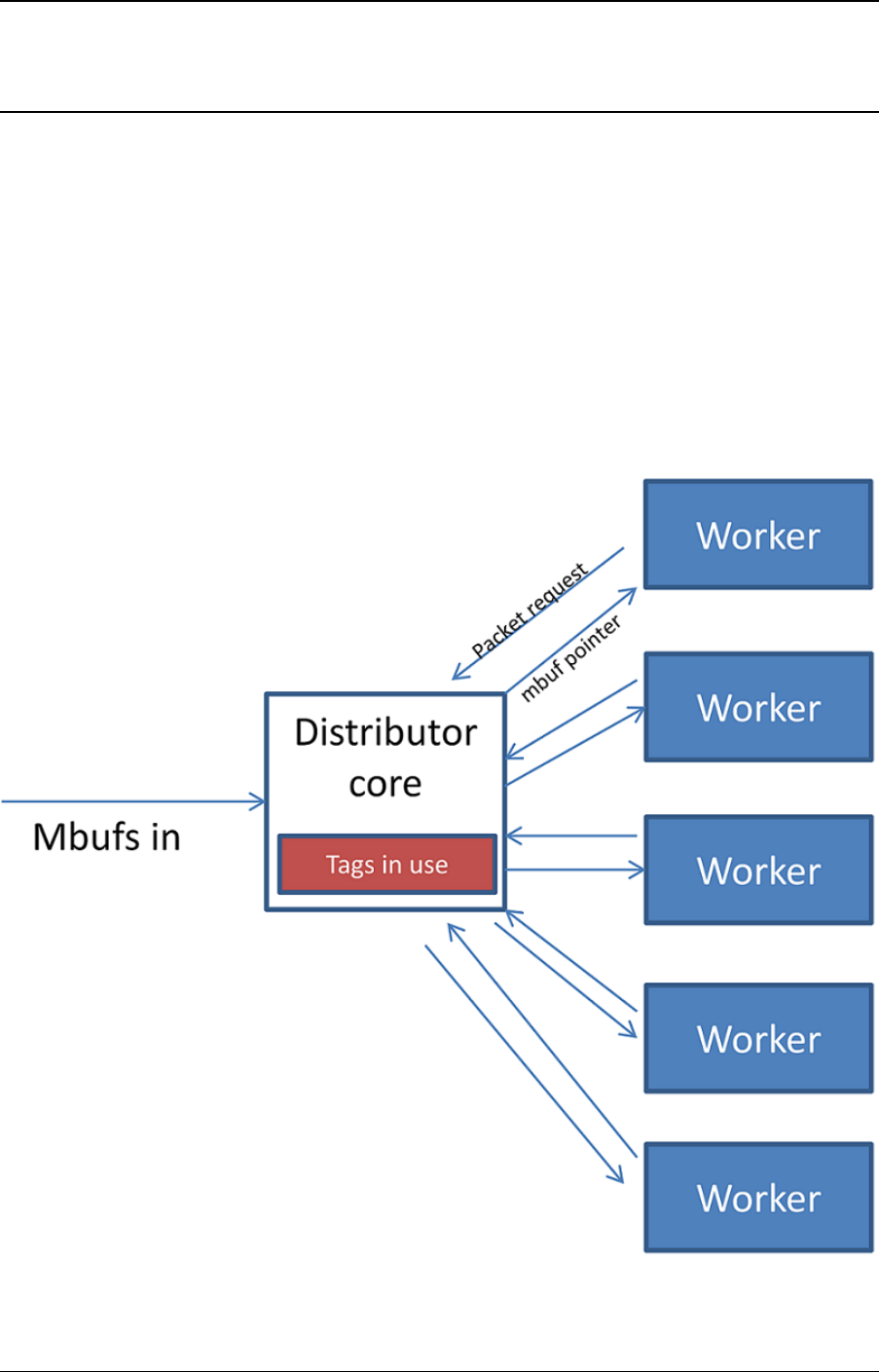
CHAPTER
TWENTYSIX
PACKET DISTRIBUTOR LIBRARY
The DPDK Packet Distributor library is a library designed to be used for dynamic load balancing
of traffic while supporting single packet at a time operation. When using this library, the logical
cores in use are to be considered in two roles: firstly a distributor lcore, which is responsible
for load balancing or distributing packets, and a set of worker lcores which are responsible for
receiving the packets from the distributor and operating on them. The model of operation is
shown in the diagram below.
Fig. 26.1: Packet Distributor mode of operation
232

Programmer’s Guide, Release 18.11.0-rc5
There are two modes of operation of the API in the distributor library, one which sends one
packet at a time to workers using 32-bits for flow_id, and an optimized mode which sends
bursts of up to 8 packets at a time to workers, using 15 bits of flow_id. The mode is selected
by the type field in the rte_distributor_create() function.
26.1 Distributor Core Operation
The distributor core does the majority of the processing for ensuring that packets are fairly
shared among workers. The operation of the distributor is as follows:
1. Packets are passed to the distributor component by having the distributor lcore thread
call the “rte_distributor_process()” API
2. The worker lcores all share a single cache line with the distributor core in order to pass
messages and packets to and from the worker. The process API call will poll all the
worker cache lines to see what workers are requesting packets.
3. As workers request packets, the distributor takes packets from the set of packets passed
in and distributes them to the workers. As it does so, it examines the “tag” – stored in the
RSS hash field in the mbuf – for each packet and records what tags are being processed
by each worker.
4. If the next packet in the input set has a tag which is already being processed by a worker,
then that packet will be queued up for processing by that worker and given to it in prefer-
ence to other packets when that work next makes a request for work. This ensures that
no two packets with the same tag are processed in parallel, and that all packets with the
same tag are processed in input order.
5. Once all input packets passed to the process API have either been distributed to workers
or been queued up for a worker which is processing a given tag, then the process API
returns to the caller.
Other functions which are available to the distributor lcore are:
• rte_distributor_returned_pkts()
• rte_distributor_flush()
• rte_distributor_clear_returns()
Of these the most important API call is “rte_distributor_returned_pkts()” which should only be
called on the lcore which also calls the process API. It returns to the caller all packets which
have finished processing by all worker cores. Within this set of returned packets, all packets
sharing the same tag will be returned in their original order.
NOTE: If worker lcores buffer up packets internally for transmission in bulk afterwards, the
packets sharing a tag will likely get out of order. Once a worker lcore requests a new packet,
the distributor assumes that it has completely finished with the previous packet and therefore
that additional packets with the same tag can safely be distributed to other workers – who may
then flush their buffered packets sooner and cause packets to get out of order.
NOTE: No packet ordering guarantees are made about packets which do not share a common
packet tag.
Using the process and returned_pkts API, the following application workflow can be used, while
allowing packet order within a packet flow – identified by a tag – to be maintained.
26.1. Distributor Core Operation 233
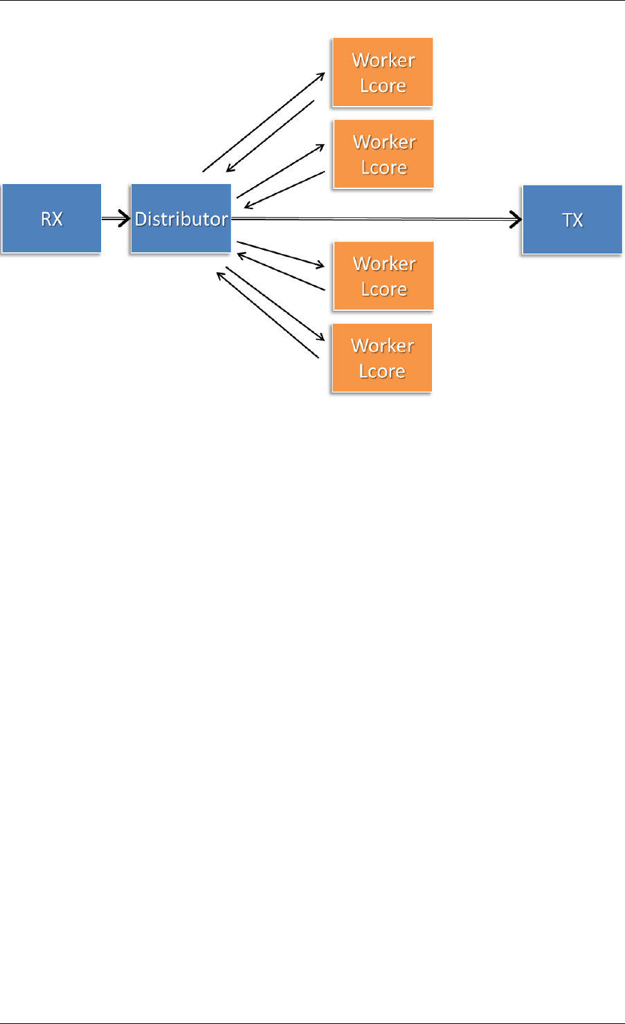
Programmer’s Guide, Release 18.11.0-rc5
Fig. 26.2: Application workflow
The flush and clear_returns API calls, mentioned previously, are likely of less use that the
process and returned_pkts APIS, and are principally provided to aid in unit testing of the li-
brary. Descriptions of these functions and their use can be found in the DPDK API Reference
document.
26.2 Worker Operation
Worker cores are the cores which do the actual manipulation of the packets distributed by the
packet distributor. Each worker calls “rte_distributor_get_pkt()” API to request a new packet
when it has finished processing the previous one. [The previous packet should be returned to
the distributor component by passing it as the final parameter to this API call.]
Since it may be desirable to vary the number of worker cores, depending on the traffic load i.e.
to save power at times of lighter load, it is possible to have a worker stop processing packets
by calling “rte_distributor_return_pkt()” to indicate that it has finished the current packet and
does not want a new one.
26.2. Worker Operation 234

CHAPTER
TWENTYSEVEN
REORDER LIBRARY
The Reorder Library provides a mechanism for reordering mbufs based on their sequence
number.
27.1 Operation
The reorder library is essentially a buffer that reorders mbufs. The user inserts out of order
mbufs into the reorder buffer and pulls in-order mbufs from it.
At a given time, the reorder buffer contains mbufs whose sequence number are inside the
sequence window. The sequence window is determined by the minimum sequence number
and the number of entries that the buffer was configured to hold. For example, given a reorder
buffer with 200 entries and a minimum sequence number of 350, the sequence window has
low and high limits of 350 and 550 respectively.
When inserting mbufs, the reorder library differentiates between valid, early and late mbufs
depending on the sequence number of the inserted mbuf:
• valid: the sequence number is inside the window.
• late: the sequence number is outside the window and less than the low limit.
• early: the sequence number is outside the window and greater than the high limit.
The reorder buffer directly returns late mbufs and tries to accommodate early mbufs.
27.2 Implementation Details
The reorder library is implemented as a pair of buffers, which referred to as the Order buffer
and the Ready buffer.
On an insert call, valid mbufs are inserted directly into the Order buffer and late mbufs are
returned to the user with an error.
In the case of early mbufs, the reorder buffer will try to move the window (incrementing the
minimum sequence number) so that the mbuf becomes a valid one. To that end, mbufs in the
Order buffer are moved into the Ready buffer. Any mbufs that have not arrived yet are ignored
and therefore will become late mbufs. This means that as long as there is room in the Ready
buffer, the window will be moved to accommodate early mbufs that would otherwise be outside
the reordering window.
235

Programmer’s Guide, Release 18.11.0-rc5
For example, assuming that we have a buffer of 200 entries with a 350 minimum sequence
number, and we need to insert an early mbuf with 565 sequence number. That means that we
would need to move the windows at least 15 positions to accommodate the mbuf. The reorder
buffer would try to move mbufs from at least the next 15 slots in the Order buffer to the Ready
buffer, as long as there is room in the Ready buffer. Any gaps in the Order buffer at that point
are skipped, and those packet will be reported as late packets when they arrive. The process
of moving packets to the Ready buffer continues beyond the minimum required until a gap, i.e.
missing mbuf, in the Order buffer is encountered.
When draining mbufs, the reorder buffer would return mbufs in the Ready buffer first and then
from the Order buffer until a gap is found (mbufs that have not arrived yet).
27.3 Use Case: Packet Distributor
An application using the DPDK packet distributor could make use of the reorder library to
transmit packets in the same order they were received.
A basic packet distributor use case would consist of a distributor with multiple workers cores.
The processing of packets by the workers is not guaranteed to be in order, hence a reorder
buffer can be used to order as many packets as possible.
In such a scenario, the distributor assigns a sequence number to mbufs before delivering them
to the workers. As the workers finish processing the packets, the distributor inserts those mbufs
into the reorder buffer and finally transmit drained mbufs.
NOTE: Currently the reorder buffer is not thread safe so the same thread is responsible for
inserting and draining mbufs.
27.3. Use Case: Packet Distributor 236

CHAPTER
TWENTYEIGHT
IP FRAGMENTATION AND REASSEMBLY LIBRARY
The IP Fragmentation and Reassembly Library implements IPv4 and IPv6 packet fragmenta-
tion and reassembly.
28.1 Packet fragmentation
Packet fragmentation routines divide input packet into number of fragments. Both
rte_ipv4_fragment_packet() and rte_ipv6_fragment_packet() functions assume that input mbuf
data points to the start of the IP header of the packet (i.e. L2 header is already stripped out).
To avoid copying of the actual packet’s data zero-copy technique is used (rte_pktmbuf_attach).
For each fragment two new mbufs are created:
• Direct mbuf – mbuf that will contain L3 header of the new fragment.
• Indirect mbuf – mbuf that is attached to the mbuf with the original packet. It’s data field
points to the start of the original packets data plus fragment offset.
Then L3 header is copied from the original mbuf into the ‘direct’ mbuf and updated to reflect
new fragmented status. Note that for IPv4, header checksum is not recalculated and is set to
zero.
Finally ‘direct’ and ‘indirect’ mbufs for each fragment are linked together via mbuf’s next filed to
compose a packet for the new fragment.
The caller has an ability to explicitly specify which mempools should be used to allocate ‘direct’
and ‘indirect’ mbufs from.
For more information about direct and indirect mbufs, refer to Direct and Indirect Buffers.
28.2 Packet reassembly
28.2.1 IP Fragment Table
Fragment table maintains information about already received fragments of the packet.
Each IP packet is uniquely identified by triple <Source IP address>, <Destination IP address>,
<ID>.
Note that all update/lookup operations on Fragment Table are not thread safe. So if different
execution contexts (threads/processes) will access the same table simultaneously, then some
external syncing mechanism have to be provided.
237

Programmer’s Guide, Release 18.11.0-rc5
Each table entry can hold information about packets consisting of up to
RTE_LIBRTE_IP_FRAG_MAX (by default: 4) fragments.
Code example, that demonstrates creation of a new Fragment table:
frag_cycles =(rte_get_tsc_hz() +MS_PER_S -1)/MS_PER_S *max_flow_ttl;
bucket_num =max_flow_num +max_flow_num /4;
frag_tbl =rte_ip_frag_table_create(max_flow_num, bucket_entries, max_flow_num, frag_cycles, socket_id);
Internally Fragment table is a simple hash table. The basic idea is to use two hash functions
and <bucket_entries> * associativity. This provides 2 * <bucket_entries> possible locations
in the hash table for each key. When the collision occurs and all 2 * <bucket_entries> are
occupied, instead of reinserting existing keys into alternative locations, ip_frag_tbl_add() just
returns a failure.
Also, entries that resides in the table longer then <max_cycles> are considered as invalid, and
could be removed/replaced by the new ones.
Note that reassembly demands a lot of mbuf’s to be allocated. At any given time up to (2 *
bucket_entries * RTE_LIBRTE_IP_FRAG_MAX * <maximum number of mbufs per packet>)
can be stored inside Fragment Table waiting for remaining fragments.
28.2.2 Packet Reassembly
Fragmented packets processing and reassembly is done by the
rte_ipv4_frag_reassemble_packet()/rte_ipv6_frag_reassemble_packet. Functions. They
either return a pointer to valid mbuf that contains reassembled packet, or NULL (if the packet
can’t be reassembled for some reason).
These functions are responsible for:
1. Search the Fragment Table for entry with packet’s <IPv4 Source Address, IPv4 Destina-
tion Address, Packet ID>.
2. If the entry is found, then check if that entry already timed-out. If yes, then free all
previously received fragments, and remove information about them from the entry.
3. If no entry with such key is found, then try to create a new one by one of two ways:
(a) Use as empty entry.
(b) Delete a timed-out entry, free mbufs associated with it mbufs and store a new entry
with specified key in it.
4. Update the entry with new fragment information and check if a packet can be reassem-
bled (the packet’s entry contains all fragments).
(a) If yes, then, reassemble the packet, mark table’s entry as empty and return the
reassembled mbuf to the caller.
(b) If no, then return a NULL to the caller.
If at any stage of packet processing an error is encountered (e.g: can’t insert new entry into the
Fragment Table, or invalid/timed-out fragment), then the function will free all associated with
the packet fragments, mark the table entry as invalid and return NULL to the caller.
28.2. Packet reassembly 238

Programmer’s Guide, Release 18.11.0-rc5
28.2.3 Debug logging and Statistics Collection
The RTE_LIBRTE_IP_FRAG_TBL_STAT config macro controls statistics collection for the
Fragment Table. This macro is not enabled by default.
The RTE_LIBRTE_IP_FRAG_DEBUG controls debug logging of IP fragments processing and
reassembling. This macro is disabled by default. Note that while logging contains a lot of
detailed information, it slows down packet processing and might cause the loss of a lot of
packets.
28.2. Packet reassembly 239

CHAPTER
TWENTYNINE
GENERIC RECEIVE OFFLOAD LIBRARY
Generic Receive Offload (GRO) is a widely used SW-based offloading technique to reduce per-
packet processing overheads. By reassembling small packets into larger ones, GRO enables
applications to process fewer large packets directly, thus reducing the number of packets to be
processed. To benefit DPDK-based applications, like Open vSwitch, DPDK also provides own
GRO implementation. In DPDK, GRO is implemented as a standalone library. Applications
explicitly use the GRO library to reassemble packets.
29.1 Overview
In the GRO library, there are many GRO types which are defined by packet types. One GRO
type is in charge of process one kind of packets. For example, TCP/IPv4 GRO processes
TCP/IPv4 packets.
Each GRO type has a reassembly function, which defines own algorithm and table structure to
reassemble packets. We assign input packets to the corresponding GRO functions by MBUF-
>packet_type.
The GRO library doesn’t check if input packets have correct checksums and doesn’t re-
calculate checksums for merged packets. The GRO library assumes the packets are complete
(i.e., MF==0 && frag_off==0), when IP fragmentation is possible (i.e., DF==0). Additionally, it
complies RFC 6864 to process the IPv4 ID field.
Currently, the GRO library provides GRO supports for TCP/IPv4 packets and VxLAN packets
which contain an outer IPv4 header and an inner TCP/IPv4 packet.
29.2 Two Sets of API
For different usage scenarios, the GRO library provides two sets of API. The one is called
the lightweight mode API, which enables applications to merge a small number of packets
rapidly; the other is called the heavyweight mode API, which provides fine-grained controls to
applications and supports to merge a large number of packets.
29.2.1 Lightweight Mode API
The lightweight mode only has one function rte_gro_reassemble_burst(), which pro-
cess N packets at a time. Using the lightweight mode API to merge packets is very simple.
Calling rte_gro_reassemble_burst() is enough. The GROed packets are returned to
applications as soon as it finishes.
240

Programmer’s Guide, Release 18.11.0-rc5
In rte_gro_reassemble_burst(), table structures of different GRO types are allocated in
the stack. This design simplifies applications’ operations. However, limited by the stack size,
the maximum number of packets that rte_gro_reassemble_burst() can process in an
invocation should be less than or equal to RTE_GRO_MAX_BURST_ITEM_NUM.
29.2.2 Heavyweight Mode API
Compared with the lightweight mode, using the heavyweight mode API is relatively com-
plex. Firstly, applications need to create a GRO context by rte_gro_ctx_create().
rte_gro_ctx_create() allocates tables structures in the heap and stores their pointers
in the GRO context. Secondly, applications use rte_gro_reassemble() to merge packets.
If input packets have invalid parameters, rte_gro_reassemble() returns them to applica-
tions. For example, packets of unsupported GRO types or TCP SYN packets are returned.
Otherwise, the input packets are either merged with the existed packets in the tables or in-
serted into the tables. Finally, applications use rte_gro_timeout_flush() to flush packets
from the tables, when they want to get the GROed packets.
Note that all update/lookup operations on the GRO context are not thread safe. So if different
processes or threads want to access the same context object simultaneously, some external
syncing mechanisms must be used.
29.3 Reassembly Algorithm
The reassembly algorithm is used for reassembling packets. In the GRO library, different GRO
types can use different algorithms. In this section, we will introduce an algorithm, which is used
by TCP/IPv4 GRO and VxLAN GRO.
29.3.1 Challenges
The reassembly algorithm determines the efficiency of GRO. There are two challenges in the
algorithm design:
• a high cost algorithm/implementation would cause packet dropping in a high speed net-
work.
• packet reordering makes it hard to merge packets. For example, Linux GRO fails to
merge packets when encounters packet reordering.
The above two challenges require our algorithm is:
• lightweight enough to scale fast networking speed
• capable of handling packet reordering
In DPDK GRO, we use a key-based algorithm to address the two challenges.
29.3.2 Key-based Reassembly Algorithm
Fig. 29.1 illustrates the procedure of the key-based algorithm. Packets are classified into
“flows” by some header fields (we call them as “key”). To process an input packet, the algorithm
searches for a matched “flow” (i.e., the same value of key) for the packet first, then checks all
29.3. Reassembly Algorithm 241
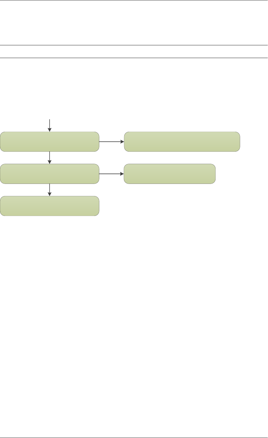
Programmer’s Guide, Release 18.11.0-rc5
packets in the “flow” and tries to find a “neighbor” for it. If find a “neighbor”, merge the two
packets together. If can’t find a “neighbor”, store the packet into its “flow”. If can’t find a
matched “flow”, insert a new “flow” and store the packet into the “flow”.
Note: Packets in the same “flow” that can’t merge are always caused by packet reordering.
The key-based algorithm has two characters:
• classifying packets into “flows” to accelerate packet aggregation is simple (address chal-
lenge 1).
• storing out-of-order packets makes it possible to merge later (address challenge 2).
Categorize into an existed “flow”
Search for a “neighbor”
Insert a new “flow” and store the packet
Store the packet
Merge the packet
packet
find a “flow”
find a “neighbor”
not find
not find
Fig. 29.1: Key-based Reassembly Algorithm
29.4 TCP/IPv4 GRO
The table structure used by TCP/IPv4 GRO contains two arrays: flow array and item array. The
flow array keeps flow information, and the item array keeps packet information.
Header fields used to define a TCP/IPv4 flow include:
• source and destination: Ethernet and IP address, TCP port
• TCP acknowledge number
TCP/IPv4 packets whose FIN, SYN, RST, URG, PSH, ECE or CWR bit is set won’t be pro-
cessed.
Header fields deciding if two packets are neighbors include:
• TCP sequence number
• IPv4 ID. The IPv4 ID fields of the packets, whose DF bit is 0, should be increased by 1.
29.5 VxLAN GRO
The table structure used by VxLAN GRO, which is in charge of processing VxLAN packets
with an outer IPv4 header and inner TCP/IPv4 packet, is similar with that of TCP/IPv4 GRO.
29.4. TCP/IPv4 GRO 242

Programmer’s Guide, Release 18.11.0-rc5
Differently, the header fields used to define a VxLAN flow include:
• outer source and destination: Ethernet and IP address, UDP port
• VxLAN header (VNI and flag)
• inner source and destination: Ethernet and IP address, TCP port
Header fields deciding if packets are neighbors include:
• outer IPv4 ID. The IPv4 ID fields of the packets, whose DF bit in the outer IPv4 header is
0, should be increased by 1.
• inner TCP sequence number
• inner IPv4 ID. The IPv4 ID fields of the packets, whose DF bit in the inner IPv4 header is
0, should be increased by 1.
Note: We comply RFC 6864 to process the IPv4 ID field. Specifically, we check IPv4 ID fields
for the packets whose DF bit is 0 and ignore IPv4 ID fields for the packets whose DF bit is 1.
Additionally, packets which have different value of DF bit can’t be merged.
29.5. VxLAN GRO 243

CHAPTER
THIRTY
GENERIC SEGMENTATION OFFLOAD LIBRARY
30.1 Overview
Generic Segmentation Offload (GSO) is a widely used software implementation of TCP Seg-
mentation Offload (TSO), which reduces per-packet processing overhead. Much like TSO,
GSO gains performance by enabling upper layer applications to process a smaller number of
large packets (e.g. MTU size of 64KB), instead of processing higher numbers of small packets
(e.g. MTU size of 1500B), thus reducing per-packet overhead.
For example, GSO allows guest kernel stacks to transmit over-sized TCP segments that far
exceed the kernel interface’s MTU; this eliminates the need to segment packets within the
guest, and improves the data-to-overhead ratio of both the guest-host link, and PCI bus. The
expectation of the guest network stack in this scenario is that segmentation of egress frames
will take place either in the NIC HW, or where that hardware capability is unavailable, either in
the host application, or network stack.
Bearing that in mind, the GSO library enables DPDK applications to segment packets in soft-
ware. Note however, that GSO is implemented as a standalone library, and not via a ‘fallback’
mechanism (i.e. for when TSO is unsupported in the underlying hardware); that is, applica-
tions must explicitly invoke the GSO library to segment packets. The size of GSO segments
(segsz) is configurable by the application.
30.2 Limitations
1. The GSO library doesn’t check if input packets have correct checksums.
2. In addition, the GSO library doesn’t re-calculate checksums for segmented packets (that
task is left to the application).
3. IP fragments are unsupported by the GSO library.
4. The egress interface’s driver must support multi-segment packets.
5. Currently, the GSO library supports the following IPv4 packet types:
• TCP
• UDP
• VxLAN
• GRE
See Supported GSO Packet Types for further details.
244
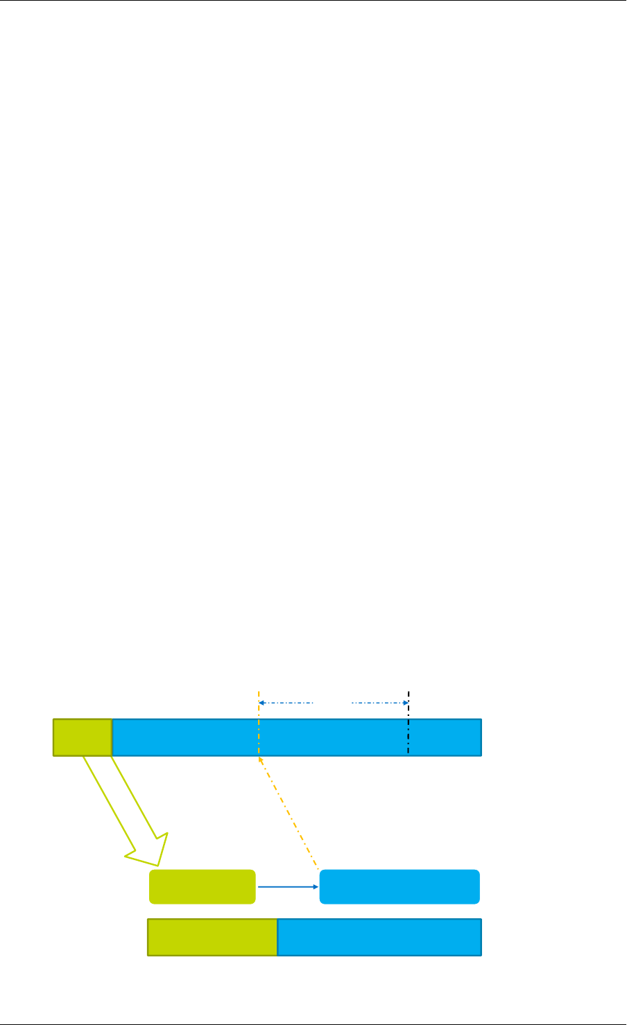
Programmer’s Guide, Release 18.11.0-rc5
30.3 Packet Segmentation
The rte_gso_segment() function is the GSO library’s primary segmentation API.
Before performing segmentation, an application must create a GSO context object (struct
rte_gso_ctx), which provides the library with some of the information required to under-
stand how the packet should be segmented. Refer to How to Segment a Packet for additional
details on same. Once the GSO context has been created, and populated, the application can
then use the rte_gso_segment() function to segment packets.
The GSO library typically stores each segment that it creates in two parts: the first part contains
a copy of the original packet’s headers, while the second part contains a pointer to an offset
within the original packet. This mechanism is explained in more detail in GSO Output Segment
Format.
The GSO library supports both single- and multi-segment input mbufs.
30.3.1 GSO Output Segment Format
To reduce the number of expensive memcpy operations required when segmenting a packet,
the GSO library typically stores each segment that it creates as a two-part mbuf (technically,
this is termed a ‘two-segment’ mbuf; however, since the elements produced by the API are
also called ‘segments’, for clarity the term ‘part’ is used here instead).
The first part of each output segment is a direct mbuf and contains a copy of the original
packet’s headers, which must be prepended to each output segment. These headers are
copied from the original packet into each output segment.
The second part of each output segment, represents a section of data from the original packet,
i.e. a data segment. Rather than copy the data directly from the original packet into the output
segment (which would impact performance considerably), the second part of each output seg-
ment is an indirect mbuf, which contains no actual data, but simply points to an offset within
the original packet.
The combination of the ‘header’ segment and the ‘data’ segment constitutes a single logical
output GSO segment of the original packet. This is illustrated in Fig. 30.1.
Payload 0 Payload 1 Payload 2
Header
Header Payload 1
Indirect mbuf
(pointer to data)
Memory copy No Memory Copy
Logical output segment
Two-part output segment
Direct mbuf
(copy of headers)
next
segsz
Input packet
Fig. 30.1: Two-part GSO output segment
30.3. Packet Segmentation 245
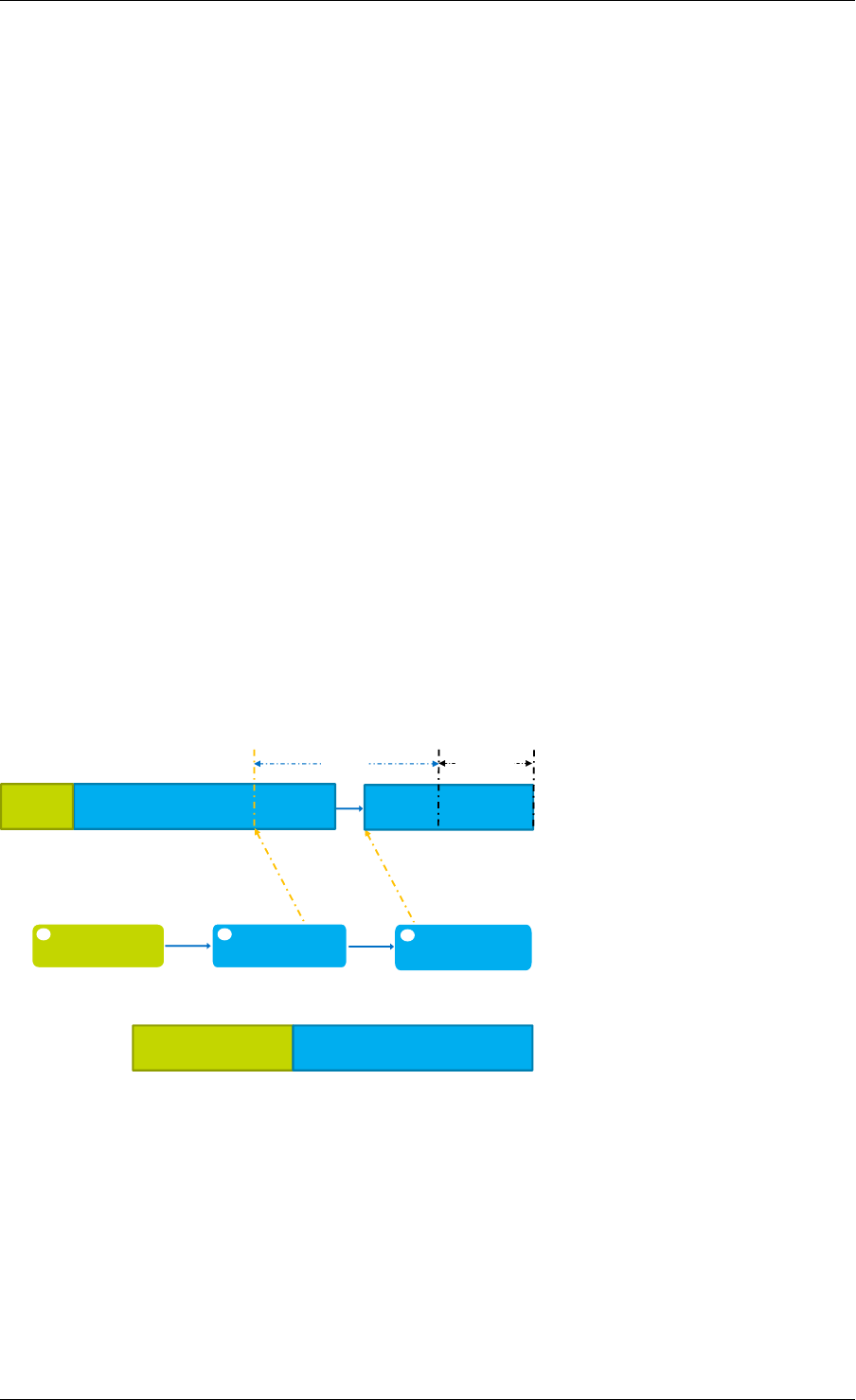
Programmer’s Guide, Release 18.11.0-rc5
In one situation, the output segment may contain additional ‘data’ segments. This only occurs
when:
• the input packet on which GSO is to be performed is represented by a multi-segment
mbuf.
• the output segment is required to contain data that spans the boundaries between seg-
ments of the input multi-segment mbuf.
The GSO library traverses each segment of the input packet, and produces numerous output
segments; for optimal performance, the number of output segments is kept to a minimum.
Consequently, the GSO library maximizes the amount of data contained within each output
segment; i.e. each output segment segsz bytes of data. The only exception to this is in the
case of the very final output segment; if pkt_len %segsz, then the final segment is smaller
than the rest.
In order for an output segment to meet its MSS, it may need to include data from multiple input
segments. Due to the nature of indirect mbufs (each indirect mbuf can point to only one direct
mbuf), the solution here is to add another indirect mbuf to the output segment; this additional
segment then points to the next input segment. If necessary, this chaining process is repeated,
until the sum of all of the data ‘contained’ in the output segment reaches segsz. This ensures
that the amount of data contained within each output segment is uniform, with the possible
exception of the last segment, as previously described.
Fig. 30.2 illustrates an example of a three-part output segment. In this example, the output
segment needs to include data from the end of one input segment, and the beginning of an-
other. To achieve this, an additional indirect mbuf is chained to the second part of the output
segment, and is attached to the next input segment (i.e. it points to the data in the next input
segment).
Payload 0 Payload 1
Header
Header Payload 1 Logical output segment
Direct mbuf
(copy of headers)
next
segsz
Payload 1 Payload 2 Multi-segment input packet
Indirect mbuf
(pointer to data)
next
pkt_len
% segsz
1 2 next
Indirect mbuf
(pointer to data)
3
(pointer to data)
Three-part output segment
Fig. 30.2: Three-part GSO output segment
30.4 Supported GSO Packet Types
30.4.1 TCP/IPv4 GSO
TCP/IPv4 GSO supports segmentation of suitably large TCP/IPv4 packets, which may also
contain an optional VLAN tag.
30.4. Supported GSO Packet Types 246

Programmer’s Guide, Release 18.11.0-rc5
30.4.2 UDP/IPv4 GSO
UDP/IPv4 GSO supports segmentation of suitably large UDP/IPv4 packets, which may also
contain an optional VLAN tag. UDP GSO is the same as IP fragmentation. Specifically, UDP
GSO treats the UDP header as a part of the payload and does not modify it during segmenta-
tion. Therefore, after UDP GSO, only the first output packet has the original UDP header, and
others just have l2 and l3 headers.
30.4.3 VxLAN GSO
VxLAN packets GSO supports segmentation of suitably large VxLAN packets, which contain
an outer IPv4 header, inner TCP/IPv4 headers, and optional inner and/or outer VLAN tag(s).
30.4.4 GRE GSO
GRE GSO supports segmentation of suitably large GRE packets, which contain an outer IPv4
header, inner TCP/IPv4 headers, and an optional VLAN tag.
30.5 How to Segment a Packet
To segment an outgoing packet, an application must:
1. First create a GSO context (struct rte_gso_ctx); this contains:
• a pointer to the mbuf pool for allocating the direct buffers, which are used to store
the GSO segments’ packet headers.
• a pointer to the mbuf pool for allocating indirect buffers, which are used to locate
GSO segments’ packet payloads.
Note: An application may use the same pool for both direct and indirect buffers.
However, since indirect mbufs simply store a pointer, the application may reduce
its memory consumption by creating a separate memory pool, containing smaller
elements, for the indirect pool.
• the size of each output segment, including packet headers and payload, measured
in bytes.
• the bit mask of required GSO types. The GSO library uses the
same macros as those that describe a physical device’s TX offloading
capabilities (i.e. DEV_TX_OFFLOAD_*_TSO) for gso_types. For exam-
ple, if an application wants to segment TCP/IPv4 packets, it should set
gso_types to DEV_TX_OFFLOAD_TCP_TSO. The only other supported values cur-
rently supported for gso_types are DEV_TX_OFFLOAD_VXLAN_TNL_TSO, and
DEV_TX_OFFLOAD_GRE_TNL_TSO; a combination of these macros is also allowed.
• a flag, that indicates whether the IPv4 headers of output segments should contain
fixed or incremental ID values.
2. Set the appropriate ol_flags in the mbuf.
30.5. How to Segment a Packet 247

Programmer’s Guide, Release 18.11.0-rc5
• The GSO library use the value of an mbuf’s ol_flags attribute to to determine how
a packet should be segmented. It is the application’s responsibility to ensure that
these flags are set.
• For example, in order to segment TCP/IPv4 packets, the application should add the
PKT_TX_IPV4 and PKT_TX_TCP_SEG flags to the mbuf’s ol_flags.
• If checksum calculation in hardware is required, the application should also add the
PKT_TX_TCP_CKSUM and PKT_TX_IP_CKSUM flags.
3. Check if the packet should be processed. Packets with one of the following properties
are not processed and are returned immediately:
• Packet length is less than segsz (i.e. GSO is not required).
• Packet type is not supported by GSO library (see Supported GSO Packet Types).
• Application has not enabled GSO support for the packet type.
• Packet’s ol_flags have been incorrectly set.
4. Allocate space in which to store the output GSO segments. If the amount of space
allocated by the application is insufficient, segmentation will fail.
5. Invoke the GSO segmentation API, rte_gso_segment().
6. If required, update the L3 and L4 checksums of the newly-created segments. For tun-
neled packets, the outer IPv4 headers’ checksums should also be updated. Alternatively,
the application may offload checksum calculation to HW.
30.5. How to Segment a Packet 248

CHAPTER
THIRTYONE
THE LIBRTE_PDUMP LIBRARY
The librte_pdump library provides a framework for packet capturing in DPDK. The library
does the complete copy of the Rx and Tx mbufs to a new mempool and hence it slows down
the performance of the applications, so it is recommended to use this library for debugging
purposes.
The library provides the following APIs to initialize the packet capture framework, to enable or
disable the packet capture, and to uninitialize it:
•rte_pdump_init(): This API initializes the packet capture framework.
•rte_pdump_enable(): This API enables the packet capture on a given port and queue.
Note: The filter option in the API is a place holder for future enhancements.
•rte_pdump_enable_by_deviceid(): This API enables the packet capture on a
given device id (vdev name or pci address) and queue. Note: The filter option
in the API is a place holder for future enhancements.
•rte_pdump_disable(): This API disables the packet capture on a given port and
queue.
•rte_pdump_disable_by_deviceid(): This API disables the packet capture on a
given device id (vdev name or pci address) and queue.
•rte_pdump_uninit(): This API uninitializes the packet capture framework.
•rte_pdump_set_socket_dir(): This API sets the server and client socket paths.
Note: This API is not thread-safe.
31.1 Operation
The librte_pdump library works on a client/server model. The server is responsible for
enabling or disabling the packet capture and the clients are responsible for requesting the
enabling or disabling of the packet capture.
The packet capture framework, as part of its initialization, creates the pthread and the server
socket in the pthread. The application that calls the framework initialization will have the server
socket created, either under the path that the application has passed or under the default path
i.e. either /var/run/.dpdk for root user or ~/.dpdk for non root user.
Applications that request enabling or disabling of the packet capture will have the client socket
created either under the path that the application has passed or under the default path i.e.
either /var/run/.dpdk for root user or ~/.dpdk for not root user to send the requests to
249

Programmer’s Guide, Release 18.11.0-rc5
the server. The server socket will listen for client requests for enabling or disabling the packet
capture.
31.2 Implementation Details
The library API rte_pdump_init(), initializes the packet capture framework by creating the
pthread and the server socket. The server socket in the pthread context will be listening to the
client requests to enable or disable the packet capture.
The library APIs rte_pdump_enable() and rte_pdump_enable_by_deviceid() en-
ables the packet capture. On each call to these APIs, the library creates a separate client
socket, creates the “pdump enable” request and sends the request to the server. The server
that is listening on the socket will take the request and enable the packet capture by registering
the Ethernet RX and TX callbacks for the given port or device_id and queue combinations.
Then the server will mirror the packets to the new mempool and enqueue them to the rte_ring
that clients have passed to these APIs. The server also sends the response back to the client
about the status of the request that was processed. After the response is received from the
server, the client socket is closed.
The library APIs rte_pdump_disable() and rte_pdump_disable_by_deviceid() dis-
ables the packet capture. On each call to these APIs, the library creates a separate client
socket, creates the “pdump disable” request and sends the request to the server. The server
that is listening on the socket will take the request and disable the packet capture by removing
the Ethernet RX and TX callbacks for the given port or device_id and queue combinations.
The server also sends the response back to the client about the status of the request that was
processed. After the response is received from the server, the client socket is closed.
The library API rte_pdump_uninit(), uninitializes the packet capture framework by closing
the pthread and the server socket.
The library API rte_pdump_set_socket_dir(), sets the given path as either server socket
path or client socket path based on the type argument of the API. If the given path is NULL,
default path will be selected, i.e. either /var/run/.dpdk for root user or ~/.dpdk for non
root user. Clients also need to call this API to set their server socket path if the server socket
path is different from default path.
31.3 Use Case: Packet Capturing
The DPDK app/pdump tool is developed based on this library to capture packets in DPDK.
Users can use this as an example to develop their own packet capturing tools.
31.2. Implementation Details 250

CHAPTER
THIRTYTWO
MULTI-PROCESS SUPPORT
In the DPDK, multi-process support is designed to allow a group of DPDK processes to work
together in a simple transparent manner to perform packet processing, or other workloads. To
support this functionality, a number of additions have been made to the core DPDK Environ-
ment Abstraction Layer (EAL).
The EAL has been modified to allow different types of DPDK processes to be spawned, each
with different permissions on the hugepage memory used by the applications. For now, there
are two types of process specified:
• primary processes, which can initialize and which have full permissions on shared mem-
ory
• secondary processes, which cannot initialize shared memory, but can attach to pre- ini-
tialized shared memory and create objects in it.
Standalone DPDK processes are primary processes, while secondary processes can only run
alongside a primary process or after a primary process has already configured the hugepage
shared memory for them.
Note: Secondary processes should run alongside primary process with same DPDK version.
Secondary processes which requires access to physical devices in Primary process, must be
passed with the same whitelist and blacklist options.
To support these two process types, and other multi-process setups described later, two addi-
tional command-line parameters are available to the EAL:
•--proc-type: for specifying a given process instance as the primary or secondary
DPDK instance
•--file-prefix: to allow processes that do not want to co-operate to have different
memory regions
A number of example applications are provided that demonstrate how multiple DPDK pro-
cesses can be used together. These are more fully documented in the “Multi- process Sample
Application” chapter in the DPDK Sample Application’s User Guide.
32.1 Memory Sharing
The key element in getting a multi-process application working using the DPDK is to ensure that
memory resources are properly shared among the processes making up the multi-process ap-
251
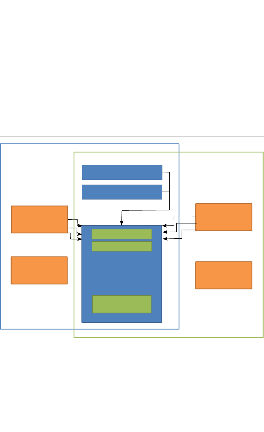
Programmer’s Guide, Release 18.11.0-rc5
plication. Once there are blocks of shared memory available that can be accessed by multiple
processes, then issues such as inter-process communication (IPC) becomes much simpler.
On application start-up in a primary or standalone process, the DPDK records to memory-
mapped files the details of the memory configuration it is using - hugepages in use, the virtual
addresses they are mapped at, the number of memory channels present, etc. When a sec-
ondary process is started, these files are read and the EAL recreates the same memory con-
figuration in the secondary process so that all memory zones are shared between processes
and all pointers to that memory are valid, and point to the same objects, in both processes.
Note: Refer to Multi-process Limitations for details of how Linux kernel Address-Space Layout
Randomization (ASLR) can affect memory sharing.
If the primary process was run with --legacy-mem or --single-file-segments switch,
secondary processes must be run with the same switch specified. Otherwise, memory corrup-
tion may occur.
Primary Process
Secondary Process
struct rte_config
struct hugepage[]
IPC Queue
IPC Queue
Hugepage
DPDK
Memory
Mbuf Pool
Local Pointers
Local Pointers
Local Data Local Data
Fig. 32.1: Memory Sharing in the DPDK Multi-process Sample Application
The EAL also supports an auto-detection mode (set by EAL --proc-type=auto flag ),
whereby an DPDK process is started as a secondary instance if a primary instance is already
running.
32.1. Memory Sharing 252

Programmer’s Guide, Release 18.11.0-rc5
32.2 Deployment Models
32.2.1 Symmetric/Peer Processes
DPDK multi-process support can be used to create a set of peer processes where each pro-
cess performs the same workload. This model is equivalent to having multiple threads each
running the same main-loop function, as is done in most of the supplied DPDK sample ap-
plications. In this model, the first of the processes spawned should be spawned using the
--proc-type=primary EAL flag, while all subsequent instances should be spawned using
the --proc-type=secondary flag.
The simple_mp and symmetric_mp sample applications demonstrate this usage model. They
are described in the “Multi-process Sample Application” chapter in the DPDK Sample Applica-
tion’s User Guide.
32.2.2 Asymmetric/Non-Peer Processes
An alternative deployment model that can be used for multi-process applications is to have
a single primary process instance that acts as a load-balancer or server distributing received
packets among worker or client threads, which are run as secondary processes. In this case,
extensive use of rte_ring objects is made, which are located in shared hugepage memory.
The client_server_mp sample application shows this usage model. It is described in the “Multi-
process Sample Application” chapter in the DPDK Sample Application’s User Guide.
32.2.3 Running Multiple Independent DPDK Applications
In addition to the above scenarios involving multiple DPDK processes working together, it is
possible to run multiple DPDK processes side-by-side, where those processes are all work-
ing independently. Support for this usage scenario is provided using the --file-prefix
parameter to the EAL.
By default, the EAL creates hugepage files on each hugetlbfs filesystem using the rtemap_X
filename, where X is in the range 0 to the maximum number of hugepages -1. Similarly, it cre-
ates shared configuration files, memory mapped in each process, using the /var/run/.rte_config
filename, when run as root (or $HOME/.rte_config when run as a non-root user; if filesystem
and device permissions are set up to allow this). The rte part of the filenames of each of the
above is configurable using the file-prefix parameter.
In addition to specifying the file-prefix parameter, any DPDK applications that are to be run
side-by-side must explicitly limit their memory use. This is less of a problem on Linux, as by
default, applications will not allocate more memory than they need. However if --legacy-mem
is used, DPDK will attempt to preallocate all memory it can get to, and memory use must be
explicitly limited. This is done by passing the -m flag to each process to specify how much
hugepage memory, in megabytes, each process can use (or passing --socket-mem to spec-
ify how much hugepage memory on each socket each process can use).
Note: Independent DPDK instances running side-by-side on a single machine cannot share
any network ports. Any network ports being used by one process should be blacklisted in every
other process.
32.2. Deployment Models 253

Programmer’s Guide, Release 18.11.0-rc5
32.2.4 Running Multiple Independent Groups of DPDK Applications
In the same way that it is possible to run independent DPDK applications side- by-side on a
single system, this can be trivially extended to multi-process groups of DPDK applications run-
ning side-by-side. In this case, the secondary processes must use the same --file-prefix
parameter as the primary process whose shared memory they are connecting to.
Note: All restrictions and issues with multiple independent DPDK processes running side-by-
side apply in this usage scenario also.
32.3 Multi-process Limitations
There are a number of limitations to what can be done when running DPDK multi-process
applications. Some of these are documented below:
• The multi-process feature requires that the exact same hugepage memory mappings be
present in all applications. This makes secondary process startup process generally un-
reliable. Disabling Linux security feature - Address-Space Layout Randomization (ASLR)
may help getting more consistent mappings, but not necessarily more reliable - if the
mappings are wrong, they will be consistently wrong!
Warning: Disabling Address-Space Layout Randomization (ASLR) may have security im-
plications, so it is recommended that it be disabled only when absolutely necessary, and
only when the implications of this change have been understood.
• All DPDK processes running as a single application and using shared memory must have
distinct coremask/corelist arguments. It is not possible to have a primary and secondary
instance, or two secondary instances, using any of the same logical cores. Attempting to
do so can cause corruption of memory pool caches, among other issues.
• The delivery of interrupts, such as Ethernet* device link status interrupts, do not work
in secondary processes. All interrupts are triggered inside the primary process only.
Any application needing interrupt notification in multiple processes should provide its
own mechanism to transfer the interrupt information from the primary process to any
secondary process that needs the information.
• The use of function pointers between multiple processes running based of different com-
piled binaries is not supported, since the location of a given function in one process may
be different to its location in a second. This prevents the librte_hash library from behav-
ing properly as in a multi-threaded instance, since it uses a pointer to the hash function
internally.
To work around this issue, it is recommended that multi-process applications perform the
hash calculations by directly calling the hashing function from the code and then using the
rte_hash_add_with_hash()/rte_hash_lookup_with_hash() functions instead of the functions
which do the hashing internally, such as rte_hash_add()/rte_hash_lookup().
• Depending upon the hardware in use, and the number of DPDK processes used, it may
not be possible to have HPET timers available in each DPDK instance. The minimum
number of HPET comparators available to Linux* userspace can be just a single com-
parator, which means that only the first, primary DPDK process instance can open and
mmap /dev/hpet. If the number of required DPDK processes exceeds that of the number
32.3. Multi-process Limitations 254

Programmer’s Guide, Release 18.11.0-rc5
of available HPET comparators, the TSC (which is the default timer in this release) must
be used as a time source across all processes instead of the HPET.
32.4 Communication between multiple processes
While there are multiple ways one can approach inter-process communication in DPDK, there
is also a native DPDK IPC API available. It is not intended to be performance-critical, but rather
is intended to be a convenient, general purpose API to exchange short messages between
primary and secondary processes.
DPDK IPC API supports the following communication modes:
• Unicast message from secondary to primary
• Broadcast message from primary to all secondaries
In other words, any IPC message sent in a primary process will be delivered to all secondaries,
while any IPC message sent in a secondary process will only be delivered to primary process.
Unicast from primary to secondary or from secondary to secondary is not supported.
There are three types of communications that are available within DPDK IPC API:
• Message
• Synchronous request
• Asynchronous request
A “message” type does not expect a response and is meant to be a best-effort notification
mechanism, while the two types of “requests” are meant to be a two way communication mech-
anism, with the requester expecting a response from the other side.
Both messages and requests will trigger a named callback on the receiver side. These call-
backs will be called from within a dedicated IPC or interrupt thread that are not part of EAL
lcore threads.
32.4.1 Registering for incoming messages
Before any messages can be received, a callback will need to be registered. This is accom-
plished by calling rte_mp_action_register() function. This function accepts a unique
callback name, and a function pointer to a callback that will be called when a message or a
request matching this callback name arrives.
If the application is no longer willing to receive messages intended for a specific callback func-
tion, rte_mp_action_unregister() function can be called to ensure that callback will not
be triggered again.
32.4.2 Sending messages
To send a message, a rte_mp_msg descriptor must be populated first. The list of fields to be
populated are as follows:
•name - message name. This name must match receivers’ callback name.
•param - message data (up to 256 bytes).
32.4. Communication between multiple processes 255

Programmer’s Guide, Release 18.11.0-rc5
•len_param - length of message data.
•fds - file descriptors to pass long with the data (up to 8 fd’s).
•num_fds - number of file descriptors to send.
Once the structure is populated, calling rte_mp_sendmsg() will send the descriptor either
to all secondary processes (if sent from primary process), or to primary process (if sent from
secondary process). The function will return a value indicating whether sending the message
succeeded or not.
32.4.3 Sending requests
Sending requests involves waiting for the other side to reply, so they can block for a relatively
long time.
To send a request, a message descriptor rte_mp_msg must be populated. Additionally, a
timespec value must be specified as a timeout, after which IPC will stop waiting and return.
For synchronous synchronous requests, the rte_mp_reply descriptor must also be created.
This is where the responses will be stored. The list of fields that will be populated by IPC are
as follows:
•nb_sent - number indicating how many requests were sent (i.e. how many peer pro-
cesses were active at the time of the request).
•nb_received - number indicating how many responses were received (i.e. of those
peer processes that were active at the time of request, how many have replied)
•msgs - pointer to where all of the responses are stored. The order in which responses
appear is undefined. Whendoing sycnrhonous requests, this memory must be freed by
the requestor after request completes!
For asynchronous requests, a function pointer to the callback function must be provided in-
stead. This callback will be called when the request either has timed out, or will have received
a response to all the messages that were sent.
Warning: When an asynchronous request times out, the callback will be called not by
a dedicated IPC thread, but rather from EAL interrupt thread. Because of this, it may not
be possible for DPDK to trigger another interrupt-based event (such as an alarm) while
handling asynchronous IPC callback.
When the callback is called, the original request descriptor will be provided (so that it would
be possible to determine for which sent message this is a callback to), along with a response
descriptor like the one described above. When doing asynchronous requests, there is no need
to free the resulting rte_mp_reply descriptor.
32.4.4 Receiving and responding to messages
To receive a message, a name callback must be registered using the
rte_mp_action_register() function. The name of the callback must match the
name field in sender’s rte_mp_msg message descriptor in order for this message to be
delivered and for the callback to be trigger.
32.4. Communication between multiple processes 256

Programmer’s Guide, Release 18.11.0-rc5
The callback’s definition is rte_mp_t, and consists of the incoming message pointer msg, and
an opaque pointer peer. Contents of msg will be identical to ones sent by the sender.
If a response is required, a new rte_mp_msg message descriptor must be constructed and
sent via rte_mp_reply() function, along with peer pointer. The resulting response will then
be delivered to the correct requestor.
32.4.5 Misc considerations
Due to the underlying IPC implementation being single-threaded, recursive requests (i.e. send-
ing a request while responding to another request) is not supported. However, since sending
messages (not requests) does not involve an IPC thread, sending messages while processing
another message or request is supported.
Asynchronous request callbacks may be triggered either from IPC thread or from interrupt
thread, depending on whether the request has timed out. It is therefore suggested to avoid
waiting for interrupt-based events (such as alarms) inside asynchronous IPC request callbacks.
This limitation does not apply to messages or synchronous requests.
If callbacks spend a long time processing the incoming requests, the requestor might time out,
so setting the right timeout value on the requestor side is imperative.
If some of the messages timed out, nb_sent and nb_received fields in the rte_mp_reply
descriptor will not have matching values. This is not treated as error by the IPC API, and it is
expected that the user will be responsible for deciding how to handle such cases.
If a callback has been registered, IPC will assume that it is safe to call it. This is important
when registering callbacks during DPDK initialization. During initialization, IPC will consider
the receiving side as non-existing if the callback has not been registered yet. However, once
the callback has been registered, it is expected that IPC should be safe to trigger it, even if the
rest of the DPDK initialization hasn’t finished yet.
32.4. Communication between multiple processes 257

CHAPTER
THIRTYTHREE
KERNEL NIC INTERFACE
The DPDK Kernel NIC Interface (KNI) allows userspace applications access to the Linux*
control plane.
The benefits of using the DPDK KNI are:
• Faster than existing Linux TUN/TAP interfaces (by eliminating system calls and
copy_to_user()/copy_from_user() operations.
• Allows management of DPDK ports using standard Linux net tools such as ethtool, ifcon-
fig and tcpdump.
• Allows an interface with the kernel network stack.
The components of an application using the DPDK Kernel NIC Interface are shown in Fig.
33.1.
33.1 The DPDK KNI Kernel Module
The KNI kernel loadable module rte_kni provides the kernel interface for DPDK applications.
When the rte_kni module is loaded, it will create a device /dev/kni that is used by the
DPDK KNI API functions to control and communicate with the kernel module.
The rte_kni kernel module contains several optional parameters which can be specified
when the module is loaded to control its behavior:
#modinfo rte_kni.ko
<snip>
parm: lo_mode: KNI loopback mode (default=lo_mode_none):
lo_mode_none Kernel loopback disabled
lo_mode_fifo Enable kernel loopback with fifo
lo_mode_fifo_skb Enable kernel loopback with fifo and skb buffer
(charp)
parm: kthread_mode: Kernel thread mode (default=single):
single Single kernel thread mode enabled.
multiple Multiple kernel thread mode enabled.
(charp)
parm: carrier: Default carrier state for KNI interface (default=off):
off Interfaces will be created with carrier state set to off.
on Interfaces will be created with carrier state set to on.
(charp)
Loading the rte_kni kernel module without any optional parameters is the typical way a
DPDK application gets packets into and out of the kernel network stack. Without any param-
258
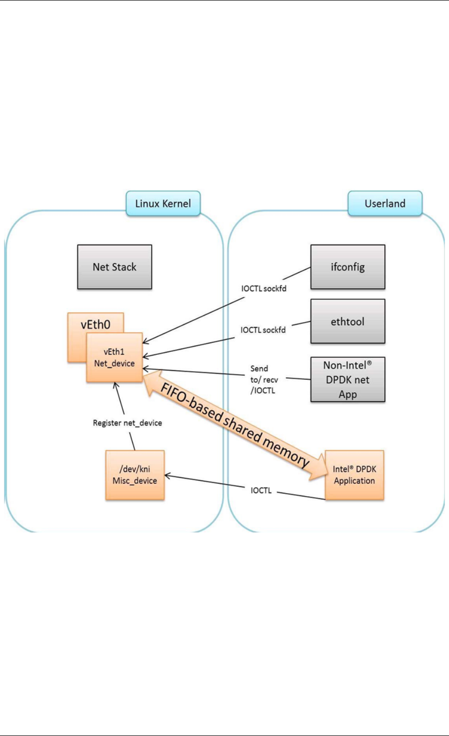
Programmer’s Guide, Release 18.11.0-rc5
Fig. 33.1: Components of a DPDK KNI Application
33.1. The DPDK KNI Kernel Module 259

Programmer’s Guide, Release 18.11.0-rc5
eters, only one kernel thread is created for all KNI devices for packet receiving in kernel side,
loopback mode is disabled, and the default carrier state of KNI interfaces is set to off.
#insmod kmod/rte_kni.ko
33.1.1 Loopback Mode
For testing, the rte_kni kernel module can be loaded in loopback mode by specifying the
lo_mode parameter:
#insmod kmod/rte_kni.ko lo_mode=lo_mode_fifo
The lo_mode_fifo loopback option will loop back ring enqueue/dequeue operations in kernel
space.
#insmod kmod/rte_kni.ko lo_mode=lo_mode_fifo_skb
The lo_mode_fifo_skb loopback option will loop back ring enqueue/dequeue operations
and sk buffer copies in kernel space.
If the lo_mode parameter is not specified, loopback mode is disabled.
33.1.2 Kernel Thread Mode
To provide flexibility of performance, the rte_kni KNI kernel module can be loaded with the
kthread_mode parameter. The rte_kni kernel module supports two options: “single kernel
thread” mode and “multiple kernel thread” mode.
Single kernel thread mode is enabled as follows:
#insmod kmod/rte_kni.ko kthread_mode=single
This mode will create only one kernel thread for all KNI interfaces to receive data on the kernel
side. By default, this kernel thread is not bound to any particular core, but the user can set
the core affinity for this kernel thread by setting the core_id and force_bind parameters in
struct rte_kni_conf when the first KNI interface is created:
For optimum performance, the kernel thread should be bound to a core in on the same socket
as the DPDK lcores used in the application.
The KNI kernel module can also be configured to start a separate kernel thread for each KNI
interface created by the DPDK application. Multiple kernel thread mode is enabled as follows:
#insmod kmod/rte_kni.ko kthread_mode=multiple
This mode will create a separate kernel thread for each KNI interface to receive data on the
kernel side. The core affinity of each kni_thread kernel thread can be specified by setting the
core_id and force_bind parameters in struct rte_kni_conf when each KNI interface
is created.
Multiple kernel thread mode can provide scalable higher performance if sufficient unused cores
are available on the host system.
If the kthread_mode parameter is not specified, the “single kernel thread” mode is used.
33.1. The DPDK KNI Kernel Module 260

Programmer’s Guide, Release 18.11.0-rc5
33.1.3 Default Carrier State
The default carrier state of KNI interfaces created by the rte_kni kernel module is controlled
via the carrier option when the module is loaded.
If carrier=off is specified, the kernel module will leave the carrier state of the interface
down when the interface is management enabled. The DPDK application can set the carrier
state of the KNI interface using the rte_kni_update_link() function. This is useful for
DPDK applications which require that the carrier state of the KNI interface reflect the actual
link state of the corresponding physical NIC port.
If carrier=on is specified, the kernel module will automatically set the carrier state of the
interface to up when the interface is management enabled. This is useful for DPDK appli-
cations which use the KNI interface as a purely virtual interface that does not correspond to
any physical hardware and do not wish to explicitly set the carrier state of the interface with
rte_kni_update_link(). It is also useful for testing in loopback mode where the NIC port
may not be physically connected to anything.
To set the default carrier state to on:
#insmod kmod/rte_kni.ko carrier=on
To set the default carrier state to off :
#insmod kmod/rte_kni.ko carrier=off
If the carrier parameter is not specified, the default carrier state of KNI interfaces will be set
to off.
33.2 KNI Creation and Deletion
Before any KNI interfaces can be created, the rte_kni kernel module must be loaded into
the kernel and configured withe rte_kni_init() function.
The KNI interfaces are created by a DPDK application dynamically via the rte_kni_alloc()
function.
The struct rte_kni_conf structure contains fields which allow the user to specify the
interface name, set the MTU size, set an explicit or random MAC address and control the
affinity of the kernel Rx thread(s) (both single and multi-threaded modes).
The struct rte_kni_ops structure contains pointers to functions to handle requests from
the rte_kni kernel module. These functions allow DPDK applications to perform actions
when the KNI interfaces are manipulated by control commands or functions external to the
application.
For example, the DPDK application may wish to enabled/disable a physical NIC port when a
user enabled/disables a KNI interface with ip link set [up|down] dev <ifaceX>. The
DPDK application can register a callback for config_network_if which will be called when
the interface management state changes.
There are currently four callbacks for which the user can register application functions:
config_network_if:
Called when the management state of the KNI interface changes. For example,
when the user runs ip link set [up|down] dev <ifaceX>.
33.2. KNI Creation and Deletion 261

Programmer’s Guide, Release 18.11.0-rc5
change_mtu:
Called when the user changes the MTU size of the KNI interface. For example,
when the user runs ip link set mtu <size> dev <ifaceX>.
config_mac_address:
Called when the user changes the MAC address of the KNI interface. For example,
when the user runs ip link set address <MAC> dev <ifaceX>. If the user
sets this callback function to NULL, but sets the port_id field to a value other than
-1, a default callback handler in the rte_kni library kni_config_mac_address()
will be called which calls rte_eth_dev_default_mac_addr_set() on the
specified port_id.
config_promiscusity:
Called when the user changes the promiscusity state of the KNI inter-
face. For example, when the user runs ip link set promisc [on|off]
dev <ifaceX>. If the user sets this callback function to NULL, but sets
the port_id field to a value other than -1, a default callback handler in
the rte_kni library kni_config_promiscusity() will be called which calls
rte_eth_promiscuous_<enable|disable>() on the specified port_id.
In order to run these callbacks, the application must periodically call the
rte_kni_handle_request() function. Any user callback function registered will be
called directly from rte_kni_handle_request() so care must be taken to prevent
deadlock and to not block any DPDK fastpath tasks. Typically DPDK applications which use
these callbacks will need to create a separate thread or secondary process to periodically call
rte_kni_handle_request().
The KNI interfaces can be deleted by a DPDK application with rte_kni_release(). All KNI
interfaces not explicitly deleted will be deleted when the the /dev/kni device is closed, either
explicitly with rte_kni_close() or when the DPDK application is closed.
33.3 DPDK mbuf Flow
To minimize the amount of DPDK code running in kernel space, the mbuf mempool is managed
in userspace only. The kernel module will be aware of mbufs, but all mbuf allocation and free
operations will be handled by the DPDK application only.
Fig. 33.2 shows a typical scenario with packets sent in both directions.
33.4 Use Case: Ingress
On the DPDK RX side, the mbuf is allocated by the PMD in the RX thread context. This thread
will enqueue the mbuf in the rx_q FIFO. The KNI thread will poll all KNI active devices for the
rx_q. If an mbuf is dequeued, it will be converted to a sk_buff and sent to the net stack via
netif_rx(). The dequeued mbuf must be freed, so the same pointer is sent back in the free_q
FIFO.
The RX thread, in the same main loop, polls this FIFO and frees the mbuf after dequeuing it.
33.3. DPDK mbuf Flow 262
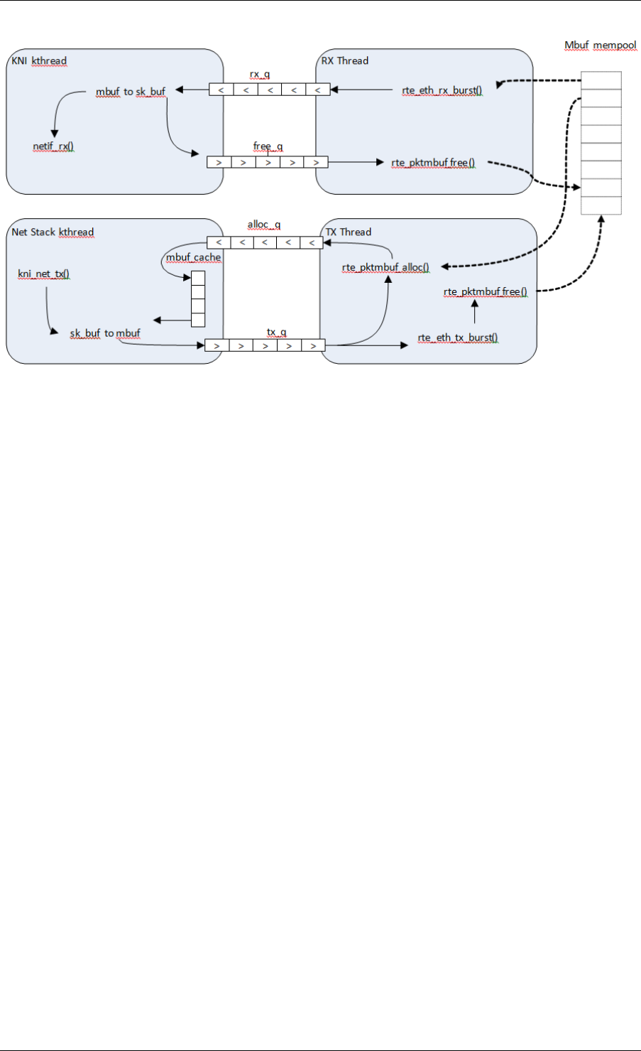
Programmer’s Guide, Release 18.11.0-rc5
Fig. 33.2: Packet Flow via mbufs in the DPDK KNI
33.5 Use Case: Egress
For packet egress the DPDK application must first enqueue several mbufs to create an mbuf
cache on the kernel side.
The packet is received from the Linux net stack, by calling the kni_net_tx() callback. The mbuf
is dequeued (without waiting due the cache) and filled with data from sk_buff. The sk_buff is
then freed and the mbuf sent in the tx_q FIFO.
The DPDK TX thread dequeues the mbuf and sends it to the PMD via rte_eth_tx_burst().
It then puts the mbuf back in the cache.
33.6 Ethtool
Ethtool is a Linux-specific tool with corresponding support in the kernel where each net device
must register its own callbacks for the supported operations. The current implementation uses
the igb/ixgbe modified Linux drivers for ethtool support. Ethtool is not supported in i40e and
VMs (VF or EM devices).
33.5. Use Case: Egress 263

CHAPTER
THIRTYFOUR
THREAD SAFETY OF DPDK FUNCTIONS
The DPDK is comprised of several libraries. Some of the functions in these libraries can be
safely called from multiple threads simultaneously, while others cannot. This section allows the
developer to take these issues into account when building their own application.
The run-time environment of the DPDK is typically a single thread per logical core. In some
cases, it is not only multi-threaded, but multi-process. Typically, it is best to avoid sharing data
structures between threads and/or processes where possible. Where this is not possible, then
the execution blocks must access the data in a thread- safe manner. Mechanisms such as
atomics or locking can be used that will allow execution blocks to operate serially. However,
this can have an effect on the performance of the application.
34.1 Fast-Path APIs
Applications operating in the data plane are performance sensitive but certain functions within
those libraries may not be safe to call from multiple threads simultaneously. The hash, LPM
and mempool libraries and RX/TX in the PMD are examples of this.
The hash and LPM libraries are, by design, thread unsafe in order to maintain performance.
However, if required the developer can add layers on top of these libraries to provide thread
safety. Locking is not needed in all situations, and in both the hash and LPM libraries, lookups
of values can be performed in parallel in multiple threads. Adding, removing or modifying
values, however, cannot be done in multiple threads without using locking when a single hash
or LPM table is accessed. Another alternative to locking would be to create multiple instances
of these tables allowing each thread its own copy.
The RX and TX of the PMD are the most critical aspects of a DPDK application and it is
recommended that no locking be used as it will impact performance. Note, however, that these
functions can safely be used from multiple threads when each thread is performing I/O on a
different NIC queue. If multiple threads are to use the same hardware queue on the same NIC
port, then locking, or some other form of mutual exclusion, is necessary.
The ring library is based on a lockless ring-buffer algorithm that maintains its original de-
sign for thread safety. Moreover, it provides high performance for either multi- or single-
consumer/producer enqueue/dequeue operations. The mempool library is based on the DPDK
lockless ring library and therefore is also multi-thread safe.
264

Programmer’s Guide, Release 18.11.0-rc5
34.2 Performance Insensitive API
Outside of the performance sensitive areas described in Section 25.1, the DPDK provides a
thread-safe API for most other libraries. For example, malloc and memzone functions are safe
for use in multi-threaded and multi-process environments.
The setup and configuration of the PMD is not performance sensitive, but is not thread safe
either. It is possible that the multiple read/writes during PMD setup and configuration could be
corrupted in a multi-thread environment. Since this is not performance sensitive, the developer
can choose to add their own layer to provide thread-safe setup and configuration. It is expected
that, in most applications, the initial configuration of the network ports would be done by a
single thread at startup.
34.3 Library Initialization
It is recommended that DPDK libraries are initialized in the main thread at application startup
rather than subsequently in the forwarding threads. However, the DPDK performs checks to
ensure that libraries are only initialized once. If initialization is attempted more than once, an
error is returned.
In the multi-process case, the configuration information of shared memory will only be initialized
by the master process. Thereafter, both master and secondary processes can allocate/release
any objects of memory that finally rely on rte_malloc or memzones.
34.4 Interrupt Thread
The DPDK works almost entirely in Linux user space in polling mode. For certain infrequent
operations, such as receiving a PMD link status change notification, callbacks may be called
in an additional thread outside the main DPDK processing threads. These function callbacks
should avoid manipulating DPDK objects that are also managed by the normal DPDK threads,
and if they need to do so, it is up to the application to provide the appropriate locking or mutual
exclusion restrictions around those objects.
34.2. Performance Insensitive API 265

CHAPTER
THIRTYFIVE
EVENT DEVICE LIBRARY
The DPDK Event device library is an abstraction that provides the application with features to
schedule events. This is achieved using the PMD architecture similar to the ethdev or cryptodev
APIs, which may already be familiar to the reader.
The eventdev framework introduces the event driven programming model. In a polling model,
lcores poll ethdev ports and associated Rx queues directly to look for a packet. By contrast
in an event driven model, lcores call the scheduler that selects packets for them based on
programmer-specified criteria. The Eventdev library adds support for an event driven program-
ming model, which offers applications automatic multicore scaling, dynamic load balancing,
pipelining, packet ingress order maintenance and synchronization services to simplify applica-
tion packet processing.
By introducing an event driven programming model, DPDK can support both polling and event
driven programming models for packet processing, and applications are free to choose what-
ever model (or combination of the two) best suits their needs.
Step-by-step instructions of the eventdev design is available in the API Walk-through section
later in this document.
35.1 Event struct
The eventdev API represents each event with a generic struct, which contains a payload and
metadata required for scheduling by an eventdev. The rte_event struct is a 16 byte C struc-
ture, defined in libs/librte_eventdev/rte_eventdev.h.
35.1.1 Event Metadata
The rte_event structure contains the following metadata fields, which the application fills in to
have the event scheduled as required:
•flow_id - The targeted flow identifier for the enq/deq operation.
•event_type - The source of this event, eg RTE_EVENT_TYPE_ETHDEV or CPU.
•sub_event_type - Distinguishes events inside the application, that have the same
event_type (see above)
•op - This field takes one of the RTE_EVENT_OP_* values, and tells the eventdev about
the status of the event - valid values are NEW, FORWARD or RELEASE.
266

Programmer’s Guide, Release 18.11.0-rc5
•sched_type - Represents the type of scheduling that should be performed on this event,
valid values are the RTE_SCHED_TYPE_ORDERED, ATOMIC and PARALLEL.
•queue_id - The identifier for the event queue that the event is sent to.
•priority - The priority of this event, see RTE_EVENT_DEV_PRIORITY.
35.1.2 Event Payload
The rte_event struct contains a union for payload, allowing flexibility in what the actual event
being scheduled is. The payload is a union of the following:
•uint64_t u64
•void *event_ptr
•struct rte_mbuf *mbuf
These three items in a union occupy the same 64 bits at the end of the rte_event structure.
The application can utilize the 64 bits directly by accessing the u64 variable, while the event_ptr
and mbuf are provided as convenience variables. For example the mbuf pointer in the union
can used to schedule a DPDK packet.
35.1.3 Queues
An event queue is a queue containing events that are scheduled by the event device. An event
queue contains events of different flows associated with scheduling types, such as atomic,
ordered, or parallel.
Queue All Types Capable
If RTE_EVENT_DEV_CAP_QUEUE_ALL_TYPES capability bit is set in the event device, then
events of any type may be sent to any queue. Otherwise, the queues only support events of
the type that it was created with.
Queue All Types Incapable
In this case, each stage has a specified scheduling type. The application configures each
queue for a specific type of scheduling, and just enqueues all events to the eventdev. An
example of a PMD of this type is the eventdev software PMD.
The Eventdev API supports the following scheduling types per queue:
• Atomic
• Ordered
• Parallel
Atomic, Ordered and Parallel are load-balanced scheduling types: the output of the queue can
be spread out over multiple CPU cores.
Atomic scheduling on a queue ensures that a single flow is not present on two different CPU
cores at the same time. Ordered allows sending all flows to any core, but the scheduler must
35.1. Event struct 267
Programmer’s Guide, Release 18.11.0-rc5
ensure that on egress the packets are returned to ingress order on downstream queue en-
queue. Parallel allows sending all flows to all CPU cores, without any re-ordering guarantees.
Single Link Flag
There is a SINGLE_LINK flag which allows an application to indicate that only one port will be
connected to a queue. Queues configured with the single-link flag follow a FIFO like structure,
maintaining ordering but it is only capable of being linked to a single port (see below for port
and queue linking details).
35.1.4 Ports
Ports are the points of contact between worker cores and the eventdev. The general use-case
will see one CPU core using one port to enqueue and dequeue events from an eventdev. Ports
are linked to queues in order to retrieve events from those queues (more details in Linking
Queues and Ports below).
35.2 API Walk-through
This section will introduce the reader to the eventdev API, showing how to create and configure
an eventdev and use it for a two-stage atomic pipeline with one core each for RX and TX. RX
and TX cores are shown here for illustration, refer to Eventdev Adapter documentation for
further details. The diagram below shows the final state of the application after this walk-
through:
In Intf
Out Intf
RXCore TXCore
Atomic Q 1 Atomic Q 2 Single Link
Stage 1 Stage 2
Worker4Core
Worker3Core
Worker2Core
Worker1Core
Worker4Core
Worker3Core
Worker2Core
Worker1Core
Fig. 35.1: Sample eventdev usage, with RX, two atomic stages and a single-link to TX.
A high level overview of the setup steps are:
• rte_event_dev_configure()
• rte_event_queue_setup()
• rte_event_port_setup()
• rte_event_port_link()
• rte_event_dev_start()
35.2. API Walk-through 268

Programmer’s Guide, Release 18.11.0-rc5
35.2.1 Init and Config
The eventdev library uses vdev options to add devices to the DPDK application. The --vdev
EAL option allows adding eventdev instances to your DPDK application, using the name of the
eventdev PMD as an argument.
For example, to create an instance of the software eventdev scheduler, the following vdev
arguments should be provided to the application EAL command line:
./dpdk_application --vdev="event_sw0"
In the following code, we configure eventdev instance with 3 queues and 6 ports as follows.
The 3 queues consist of 2 Atomic and 1 Single-Link, while the 6 ports consist of 4 workers, 1
RX and 1 TX.
const struct rte_event_dev_config config ={
.nb_event_queues =3,
.nb_event_ports =6,
.nb_events_limit =4096,
.nb_event_queue_flows =1024,
.nb_event_port_dequeue_depth =128,
.nb_event_port_enqueue_depth =128,
};
int err =rte_event_dev_configure(dev_id, &config);
The remainder of this walk-through assumes that dev_id is 0.
35.2.2 Setting up Queues
Once the eventdev itself is configured, the next step is to configure queues. This is done
by setting the appropriate values in a queue_conf structure, and calling the setup function.
Repeat this step for each queue, starting from 0 and ending at nb_event_queues - 1 from
the event_dev config above.
struct rte_event_queue_conf atomic_conf ={
.schedule_type =RTE_SCHED_TYPE_ATOMIC,
.priority =RTE_EVENT_DEV_PRIORITY_NORMAL,
.nb_atomic_flows =1024,
.nb_atomic_order_sequences =1024,
};
struct rte_event_queue_conf single_link_conf ={
.event_queue_cfg =RTE_EVENT_QUEUE_CFG_SINGLE_LINK,
};
int dev_id =0;
int atomic_q_1 =0;
int atomic_q_2 =1;
int single_link_q =2;
int err =rte_event_queue_setup(dev_id, atomic_q_1, &atomic_conf);
int err =rte_event_queue_setup(dev_id, atomic_q_2, &atomic_conf);
int err =rte_event_queue_setup(dev_id, single_link_q, &single_link_conf);
As shown above, queue IDs are as follows:
• id 0, atomic queue #1
• id 1, atomic queue #2
• id 2, single-link queue
These queues are used for the remainder of this walk-through.
35.2. API Walk-through 269

Programmer’s Guide, Release 18.11.0-rc5
35.2.3 Setting up Ports
Once queues are set up successfully, create the ports as required.
struct rte_event_port_conf rx_conf ={
.dequeue_depth =128,
.enqueue_depth =128,
.new_event_threshold =1024,
};
struct rte_event_port_conf worker_conf ={
.dequeue_depth =16,
.enqueue_depth =64,
.new_event_threshold =4096,
};
struct rte_event_port_conf tx_conf ={
.dequeue_depth =128,
.enqueue_depth =128,
.new_event_threshold =4096,
};
int dev_id =0;
int rx_port_id =0;
int err =rte_event_port_setup(dev_id, rx_port_id, &rx_conf);
for(int worker_port_id =1; worker_port_id <= 4; worker_port_id++) {
int err =rte_event_port_setup(dev_id, worker_port_id, &worker_conf);
}
int tx_port_id =5;
int err =rte_event_port_setup(dev_id, tx_port_id, &tx_conf);
As shown above:
• port 0: RX core
• ports 1,2,3,4: Workers
• port 5: TX core
These ports are used for the remainder of this walk-through.
35.2.4 Linking Queues and Ports
The final step is to “wire up” the ports to the queues. After this, the eventdev is capable of
scheduling events, and when cores request work to do, the correct events are provided to that
core. Note that the RX core takes input from eg: a NIC so it is not linked to any eventdev
queues.
Linking all workers to atomic queues, and the TX core to the single-link queue can be achieved
like this:
uint8_t rx_port_id =0;
uint8_t tx_port_id =5;
uint8_t atomic_qs[] ={0,1};
uint8_t single_link_q =2;
uin8t_t priority =RTE_EVENT_DEV_PRIORITY_NORMAL;
for(int worker_port_id =1; worker_port_id <= 4; worker_port_id++) {
int links_made =rte_event_port_link(dev_id, worker_port_id, atomic_qs, NULL,2);
}
int links_made =rte_event_port_link(dev_id, tx_port_id, &single_link_q, &priority, 1);
35.2. API Walk-through 270

Programmer’s Guide, Release 18.11.0-rc5
35.2.5 Starting the EventDev
A single function call tells the eventdev instance to start processing events. Note that all queues
must be linked to for the instance to start, as if any queue is not linked to, enqueuing to that
queue will cause the application to backpressure and eventually stall due to no space in the
eventdev.
int err =rte_event_dev_start(dev_id);
35.2.6 Ingress of New Events
Now that the eventdev is set up, and ready to receive events, the RX core must enqueue some
events into the system for it to schedule. The events to be scheduled are ordinary DPDK
packets, received from an eth_rx_burst() as normal. The following code shows how those
packets can be enqueued into the eventdev:
const uint16_t nb_rx =rte_eth_rx_burst(eth_port, 0, mbufs, BATCH_SIZE);
for (i =0;i<nb_rx; i++) {
ev[i].flow_id =mbufs[i]->hash.rss;
ev[i].op =RTE_EVENT_OP_NEW;
ev[i].sched_type =RTE_SCHED_TYPE_ATOMIC;
ev[i].queue_id =atomic_q_1;
ev[i].event_type =RTE_EVENT_TYPE_ETHDEV;
ev[i].sub_event_type =0;
ev[i].priority =RTE_EVENT_DEV_PRIORITY_NORMAL;
ev[i].mbuf =mbufs[i];
}
const int nb_tx =rte_event_enqueue_burst(dev_id, rx_port_id, ev, nb_rx);
if (nb_tx != nb_rx) {
for(i =nb_tx; i <nb_rx; i++)
rte_pktmbuf_free(mbufs[i]);
}
35.2.7 Forwarding of Events
Now that the RX core has injected events, there is work to be done by the workers. Note that
each worker will dequeue as many events as it can in a burst, process each one individually,
and then burst the packets back into the eventdev.
The worker can lookup the events source from event.queue_id, which should indicate to the
worker what workload needs to be performed on the event. Once done, the worker can update
the event.queue_id to a new value, to send the event to the next stage in the pipeline.
int timeout =0;
struct rte_event events[BATCH_SIZE];
uint16_t nb_rx =rte_event_dequeue_burst(dev_id, worker_port_id, events, BATCH_SIZE, timeout);
for (i =0;i<nb_rx; i++) {
/*process mbuf using events[i].queue_id as pipeline stage */
struct rte_mbuf *mbuf =events[i].mbuf;
/*Send event to next stage in pipeline */
events[i].queue_id++;
}
uint16_t nb_tx =rte_event_enqueue_burst(dev_id, worker_port_id, events, nb_rx);
35.2. API Walk-through 271

Programmer’s Guide, Release 18.11.0-rc5
35.2.8 Egress of Events
Finally, when the packet is ready for egress or needs to be dropped, we need to inform the
eventdev that the packet is no longer being handled by the application. This can be done by
calling dequeue() or dequeue_burst(), which indicates that the previous burst of packets is no
longer in use by the application.
An event driven worker thread has following typical workflow on fastpath:
while (1) {
rte_event_dequeue_burst(...);
(event processing)
rte_event_enqueue_burst(...);
}
35.3 Summary
The eventdev library allows an application to easily schedule events as it requires, either using
a run-to-completion or pipeline processing model. The queues and ports abstract the logical
functionality of an eventdev, providing the application with a generic method to schedule events.
With the flexible PMD infrastructure applications benefit of improvements in existing eventdevs
and additions of new ones without modification.
35.3. Summary 272

CHAPTER
THIRTYSIX
EVENT ETHERNET RX ADAPTER LIBRARY
The DPDK Eventdev API allows the application to use an event driven programming model
for packet processing. In this model, the application polls an event device port for receiving
events that reference packets instead of polling Rx queues of ethdev ports. Packet transfer
between ethdev and the event device can be supported in hardware or require a software
thread to receive packets from the ethdev port using ethdev poll mode APIs and enqueue
these as events to the event device using the eventdev API. Both transfer mechanisms may
be present on the same platform depending on the particular combination of the ethdev and
the event device. For SW based packet transfer, if the mbuf does not have a timestamp set,
the adapter adds a timestamp to the mbuf using rte_get_tsc_cycles(), this provides a more
accurate timestamp as compared to if the application were to set the timestamp since it avoids
event device schedule latency.
The Event Ethernet Rx Adapter library is intended for the application code to configure both
transfer mechanisms using a common API. A capability API allows the eventdev PMD to adver-
tise features supported for a given ethdev and allows the application to perform configuration
as per supported features.
36.1 API Walk-through
This section will introduce the reader to the adapter API. The application has to first instantiate
an adapter which is associated with a single eventdev, next the adapter instance is configured
with Rx queues that are either polled by a SW thread or linked using hardware support. Finally
the adapter is started.
For SW based packet transfers from ethdev to eventdev, the adapter uses a DPDK service
function and the application is also required to assign a core to the service function.
36.1.1 Creating an Adapter Instance
An adapter instance is created using rte_event_eth_rx_adapter_create(). This func-
tion is passed the event device to be associated with the adapter and port configuration for the
adapter to setup an event port if the adapter needs to use a service function.
int err;
uint8_t dev_id;
struct rte_event_dev_info dev_info;
struct rte_event_port_conf rx_p_conf;
err =rte_event_dev_info_get(id, &dev_info);
273

Programmer’s Guide, Release 18.11.0-rc5
rx_p_conf.new_event_threshold =dev_info.max_num_events;
rx_p_conf.dequeue_depth =dev_info.max_event_port_dequeue_depth;
rx_p_conf.enqueue_depth =dev_info.max_event_port_enqueue_depth;
err =rte_event_eth_rx_adapter_create(id, dev_id, &rx_p_conf);
If the application desires to have finer control of eventdev port allocation and
setup, it can use the rte_event_eth_rx_adapter_create_ext() function. The
rte_event_eth_rx_adapter_create_ext() function is passed a callback function.
The callback function is invoked if the adapter needs to use a service function and
needs to create an event port for it. The callback is expected to fill the struct
rte_event_eth_rx_adapter_conf structure passed to it.
36.1.2 Adding Rx Queues to the Adapter Instance
Ethdev Rx queues are added to the instance using the
rte_event_eth_rx_adapter_queue_add() function. Configuration for the Rx queue
is passed in using a struct rte_event_eth_rx_adapter_queue_conf parameter.
Event information for packets from this Rx queue is encoded in the ev field of struct
rte_event_eth_rx_adapter_queue_conf. The servicing_weight member of the struct
rte_event_eth_rx_adapter_queue_conf is the relative polling frequency of the Rx queue and is
applicable when the adapter uses a service core function.
ev.queue_id =0;
ev.sched_type =RTE_SCHED_TYPE_ATOMIC;
ev.priority =0;
queue_config.rx_queue_flags =0;
queue_config.ev =ev;
queue_config.servicing_weight =1;
err =rte_event_eth_rx_adapter_queue_add(id,
eth_dev_id,
0,&queue_config);
36.1.3 Querying Adapter Capabilities
The rte_event_eth_rx_adapter_caps_get() function allows the application to query
the adapter capabilities for an eventdev and ethdev combination. For e.g, if the
RTE_EVENT_ETH_RX_ADAPTER_CAP_OVERRIDE_FLOW_ID is set, the application can over-
ride the adapter generated flow ID in the event using rx_queue_flags field in struct
rte_event_eth_rx_adapter_queue_conf which is passed as a parameter to the
rte_event_eth_rx_adapter_queue_add() function.
err =rte_event_eth_rx_adapter_caps_get(dev_id, eth_dev_id, &cap);
queue_config.rx_queue_flags =0;
if (cap &RTE_EVENT_ETH_RX_ADAPTER_CAP_OVERRIDE_FLOW_ID) {
ev.flow_id =1;
queue_config.rx_queue_flags =
RTE_EVENT_ETH_RX_ADAPTER_QUEUE_FLOW_ID_VALID;
}
36.1. API Walk-through 274

Programmer’s Guide, Release 18.11.0-rc5
36.1.4 Configuring the Service Function
If the adapter uses a service function, the application is required to assign a service core to
the service function as show below.
uint32_t service_id;
if (rte_event_eth_rx_adapter_service_id_get(0,&service_id) == 0)
rte_service_map_lcore_set(service_id, RX_CORE_ID);
36.1.5 Starting the Adapter Instance
The application calls rte_event_eth_rx_adapter_start() to start the adapter. This
function calls the start callbacks of the eventdev PMDs for hardware based eventdev-ethdev
connections and rte_service_run_state_set() to enable the service function if one ex-
ists.
36.1.6 Getting Adapter Statistics
The rte_event_eth_rx_adapter_stats_get() function reports counters defined in
struct rte_event_eth_rx_adapter_stats. The received packet and enqueued event
counts are a sum of the counts from the eventdev PMD callbacks if the callback is supported,
and the counts maintained by the service function, if one exists. The service function also
maintains a count of cycles for which it was not able to enqueue to the event device.
36.1.7 Interrupt Based Rx Queues
The service core function is typically set up to poll ethernet Rx queues for packets. Certain
queues may have low packet rates and it would be more efficient to enable the Rx queue
interrupt and read packets after receiving the interrupt.
The servicing_weight member of struct rte_event_eth_rx_adapter_queue_conf is applicable
when the adapter uses a service core function. The application has to enable Rx queue inter-
rupts when configuring the ethernet device using the rte_eth_dev_configure() function
and then use a servicing_weight of zero when addding the Rx queue to the adapter.
The adapter creates a thread blocked on the interrupt, on an interrupt this thread enqueues the
port id and the queue id to a ring buffer. The adapter service function dequeues the port id and
queue id from the ring buffer, invokes the rte_eth_rx_burst() to receive packets on the
queue and converts the received packets to events in the same manner as packets received
on a polled Rx queue. The interrupt thread is affinitized to the same CPUs as the lcores of the
Rx adapter service function, if the Rx adapter service function has not been mapped to any
lcores, the interrupt thread is mapped to the master lcore.
36.1.8 Rx Callback for SW Rx Adapter
For SW based packet transfers, i.e., when the RTE_EVENT_ETH_RX_ADAPTER_CAP_INTERNAL_PORT
is not set in the adapter’s capabilities flags for a particular ethernet device, the service function
temporarily enqueues mbufs to an event buffer before batch enqueueing these to the event
device. If the buffer fills up, the service function stops dequeueing packets from the ethernet
device. The application may want to monitor the buffer fill level and instruct the service function
36.1. API Walk-through 275

Programmer’s Guide, Release 18.11.0-rc5
to selectively enqueue packets to the event device. The application may also use some other
criteria to decide which packets should enter the event device even when the event buffer
fill level is low. The rte_event_eth_rx_adapter_cb_register() function allow the
application to register a callback that selects which packets to enqueue to the event device.
36.1. API Walk-through 276

CHAPTER
THIRTYSEVEN
EVENT ETHERNET TX ADAPTER LIBRARY
The DPDK Eventdev API allows the application to use an event driven programming model for
packet processing in which the event device distributes events referencing packets to the appli-
cation cores in a dynamic load balanced fashion while handling atomicity and packet ordering.
Event adapters provide the interface between the ethernet, crypto and timer devices and the
event device. Event adapter APIs enable common application code by abstracting PMD spe-
cific capabilities. The Event ethernet Tx adapter provides configuration and data path APIs for
the transmit stage of the application allowing the same application code to use eventdev PMD
support or in its absence, a common implementation.
In the common implementation, the application enqueues mbufs to the adapter which runs as
a rte_service function. The service function dequeues events from its event port and transmits
the mbufs referenced by these events.
37.1 API Walk-through
This section will introduce the reader to the adapter API. The application has to first instantiate
an adapter which is associated with a single eventdev, next the adapter instance is configured
with Tx queues, finally the adapter is started and the application can start enqueuing mbufs to
it.
37.1.1 Creating an Adapter Instance
An adapter instance is created using rte_event_eth_tx_adapter_create(). This func-
tion is passed the event device to be associated with the adapter and port configuration for the
adapter to setup an event port if the adapter needs to use a service function.
If the application desires to have finer control of eventdev port configuration,
it can use the rte_event_eth_tx_adapter_create_ext() function. The
rte_event_eth_tx_adapter_create_ext() function is passed a callback func-
tion. The callback function is invoked if the adapter needs to use a service function
and needs to create an event port for it. The callback is expected to fill the struct
rte_event_eth_tx_adapter_conf structure passed to it.
struct rte_event_dev_info dev_info;
struct rte_event_port_conf tx_p_conf ={0};
err =rte_event_dev_info_get(id, &dev_info);
tx_p_conf.new_event_threshold =dev_info.max_num_events;
tx_p_conf.dequeue_depth =dev_info.max_event_port_dequeue_depth;
277

Programmer’s Guide, Release 18.11.0-rc5
tx_p_conf.enqueue_depth =dev_info.max_event_port_enqueue_depth;
err =rte_event_eth_tx_adapter_create(id, dev_id, &tx_p_conf);
37.1.2 Adding Tx Queues to the Adapter Instance
Ethdev Tx queues are added to the instance using the
rte_event_eth_tx_adapter_queue_add() function. A queue value of -1 is used
to indicate all queues within a device.
int err =rte_event_eth_tx_adapter_queue_add(id,
eth_dev_id,
q);
37.1.3 Querying Adapter Capabilities
The rte_event_eth_tx_adapter_caps_get() function allows the application to query
the adapter capabilities for an eventdev and ethdev combination. Currently, the only capability
flag defined is RTE_EVENT_ETH_TX_ADAPTER_CAP_INTERNAL_PORT, the application can
query this flag to determine if a service function is associated with the adapter and retrieve its
service identifier using the rte_event_eth_tx_adapter_service_id_get() API.
int err =rte_event_eth_tx_adapter_caps_get(dev_id, eth_dev_id, &cap);
if (!(cap &RTE_EVENT_ETH_TX_ADAPTER_CAP_INTERNAL_PORT))
err =rte_event_eth_tx_adapter_service_id_get(id, &service_id);
37.1.4 Linking a Queue to the Adapter’s Event Port
If the adapter uses a service function as described in the previous section, the application is
required to link a queue to the adapter’s event port. The adapter’s event port can be obtained
using the rte_event_eth_tx_adapter_event_port_get() function. The queue can be
configured with the RTE_EVENT_QUEUE_CFG_SINGLE_LINK since it is linked to a single event
port.
37.1.5 Configuring the Service Function
If the adapter uses a service function, the application can assign a service core to the service
function as shown below.
if (rte_event_eth_tx_adapter_service_id_get(id, &service_id) == 0)
rte_service_map_lcore_set(service_id, TX_CORE_ID);
37.1.6 Starting the Adapter Instance
The application calls rte_event_eth_tx_adapter_start() to start the adapter.
This function calls the start callback of the eventdev PMD if supported, and the
rte_service_run_state_set() to enable the service function if one exists.
37.1. API Walk-through 278

Programmer’s Guide, Release 18.11.0-rc5
37.1.7 Enqueuing Packets to the Adapter
The application needs to notify the adapter about the transmit port and queue used to send
the packet. The transmit port is set in the struct rte mbuf::port field and the transmit
queue is set using the rte_event_eth_tx_adapter_txq_set() function.
If the eventdev PMD supports the RTE_EVENT_ETH_TX_ADAPTER_CAP_INTERNAL_PORT
capability for a given ethernet device, the application should use the
rte_event_eth_tx_adapter_enqueue() function to enqueue packets to the adapter.
If the adapter uses a service function for the ethernet device then the application should use
the rte_event_enqueue_burst() function.
struct rte_event event;
if (cap &RTE_EVENT_ETH_TX_ADAPTER_CAP_INTERNAL_PORT) {
event.mbuf =m;
m->port =tx_port;
rte_event_eth_tx_adapter_txq_set(m, tx_queue_id);
rte_event_eth_tx_adapter_enqueue(dev_id, ev_port, &event, 1);
}else {
event.queue_id =qid; /*event queue linked to adapter port */
event.op =RTE_EVENT_OP_NEW;
event.event_type =RTE_EVENT_TYPE_CPU;
event.sched_type =RTE_SCHED_TYPE_ATOMIC;
event.mbuf =m;
m->port =tx_port;
rte_event_eth_tx_adapter_txq_set(m, tx_queue_id);
rte_event_enqueue_burst(dev_id, ev_port, &event, 1);
}
37.1.8 Getting Adapter Statistics
The rte_event_eth_tx_adapter_stats_get() function reports counters defined in
struct rte_event_eth_tx_adapter_stats. The counter values are the sum of the counts
from the eventdev PMD callback if the callback is supported, and the counts maintained by the
service function, if one exists.
37.1. API Walk-through 279

CHAPTER
THIRTYEIGHT
EVENT TIMER ADAPTER LIBRARY
The DPDK Event Device library introduces an event driven programming model which presents
applications with an alternative to the polling model traditionally used in DPDK applications.
Event devices can be coupled with arbitrary components to provide new event sources by
using event adapters. The Event Timer Adapter is one such adapter; it bridges event devices
and timer mechanisms.
The Event Timer Adapter library extends the event driven model by introducing a new type
of event that represents a timer expiration, and providing an API with which adapters can be
created or destroyed, and event timers can be armed and canceled.
The Event Timer Adapter library is designed to interface with hardware or software implemen-
tations of the timer mechanism; it will query an eventdev PMD to determine which implemen-
tation should be used. The default software implementation manages timers using the DPDK
Timer library.
Examples of using the API are presented in the API Overview and Processing Timer Expiry
Events sections. Code samples are abstracted and are based on the example of handling a
TCP retransmission.
38.1 Event Timer struct
Event timers are timers that enqueue a timer expiration event to an event device upon timer
expiration.
The Event Timer Adapter API represents each event timer with a generic struct, which
contains an event and user metadata. The rte_event_timer struct is defined in
lib/librte_event/librte_event_timer_adapter.h.
38.1.1 Timer Expiry Event
The event contained by an event timer is enqueued in the event device when the timer expires,
and the event device uses the attributes below when scheduling it:
•event_queue_id - Application should set this to specify an event queue to which the
timer expiry event should be enqueued
•event_priority - Application can set this to indicate the priority of the timer expiry
event in the event queue relative to other events
•sched_type - Application can set this to specify the scheduling type of the timer expiry
event
280

Programmer’s Guide, Release 18.11.0-rc5
•flow_id - Application can set this to indicate which flow this timer expiry event corre-
sponds to
•op - Will be set to RTE_EVENT_OP_NEW by the event timer adapter
•event_type - Will be set to RTE_EVENT_TYPE_TIMER by the event timer adapter
38.1.2 Timeout Ticks
The number of ticks from now in which the timer will expire. The ticks value has a resolution
(timer_tick_ns) that is specified in the event timer adapter configuration.
38.1.3 State
Before arming an event timer, the application should initialize its state to
RTE_EVENT_TIMER_NOT_ARMED. The event timer’s state will be updated when a
request to arm or cancel it takes effect.
If the application wishes to rearm the timer after it has expired, it should reset the state back to
RTE_EVENT_TIMER_NOT_ARMED before doing so.
38.1.4 User Metadata
Memory to store user specific metadata. The event timer adapter implementation will not
modify this area.
38.2 API Overview
This section will introduce the reader to the event timer adapter API, showing how to create
and configure an event timer adapter and use it to manage event timers.
From a high level, the setup steps are:
• rte_event_timer_adapter_create()
• rte_event_timer_adapter_start()
And to start and stop timers:
• rte_event_timer_arm_burst()
• rte_event_timer_cancel_burst()
38.2.1 Create and Configure an Adapter Instance
To create an event timer adapter instance, initialize an rte_event_timer_adapter_conf
struct with the desired values, and pass it to rte_event_timer_adapter_create().
#define NSECPERSEC 1E9 // No of ns in 1 sec
const struct rte_event_timer_adapter_conf adapter_config ={
.event_dev_id =event_dev_id,
.timer_adapter_id =0,
.clk_src =RTE_EVENT_TIMER_ADAPTER_CPU_CLK,
38.2. API Overview 281

Programmer’s Guide, Release 18.11.0-rc5
.timer_tick_ns =NSECPERSEC /10,// 100 milliseconds
.max_tmo_nsec =180 *NSECPERSEC // 2 minutes
.nb_timers =40000,
.timer_adapter_flags =0,
};
struct rte_event_timer_adapter *adapter =NULL;
adapter =rte_event_timer_adapter_create(&adapter_config);
if (adapter == NULL) { ... };
Before creating an instance of a timer adapter, the application should create and configure
an event device along with its event ports. Based on the event device capability, it might
require creating an additional event port to be used by the timer adapter. If required, the
rte_event_timer_adapter_create() function will use a default method to configure an
event port; it will examine the current event device configuration, determine the next available
port identifier number, and create a new event port with a default port configuration.
If the application desires to have finer control of event port allocation and setup, it can use the
rte_event_timer_adapter_create_ext() function. This function is passed a callback
function that will be invoked if the adapter needs to create an event port, giving the application
the opportunity to control how it is done.
38.2.2 Retrieve Event Timer Adapter Contextual Information
The event timer adapter implementation may have constraints on tick resolution or maximum
timer expiry timeout based on the given event timer adapter or system. In this case, the imple-
mentation may adjust the tick resolution or maximum timeout to the best possible configuration.
Upon successful event timer adapter creation, the application can get the configured resolution
and max timeout with rte_event_timer_adapter_get_info(). This function will return
an rte_event_timer_adapter_info struct, which contains the following members:
•min_resolution_ns - Minimum timer adapter tick resolution in ns.
•max_tmo_ns - Maximum timer timeout(expiry) in ns.
•adapter_conf - Configured event timer adapter attributes
38.2.3 Configuring the Service Component
If the adapter uses a service component, the application is required to map the service to a
service core before starting the adapter:
uint32_t service_id;
if (rte_event_timer_adapter_service_id_get(adapter, &service_id) == 0)
rte_service_map_lcore_set(service_id, EVTIM_CORE_ID);
An event timer adapter uses a service component if the event device PMD indicates that the
adapter should use a software implementation.
38.2.4 Starting the Adapter Instance
The application should call rte_event_timer_adapter_start() to start running the
event timer adapter. This function calls the start entry points defined by eventdev PMDs for
38.2. API Overview 282

Programmer’s Guide, Release 18.11.0-rc5
hardware implementations or puts a service component into the running state in the software
implementation.
38.2.5 Arming Event Timers
Once an event timer adapter has been started, an application can begin to manage event
timers with it.
The application should allocate struct rte_event_timer objects from a mempool or
huge-page backed application buffers of required size. Upon successful allocation, the ap-
plication should initialize the event timer, and then set any of the necessary event attributes de-
scribed in the Timer Expiry Event section. In the following example, assume conn represents
a TCP connection and that event_timer_pool is a mempool that was created previously:
rte_mempool_get(event_timer_pool, (void **)&conn->evtim);
if (conn->evtim == NULL) { ... }
/*Set up the event timer. */
conn->evtim->ev.op =RTE_EVENT_OP_NEW;
conn->evtim->ev.queue_id =event_queue_id;
conn->evtim->ev.sched_type =RTE_SCHED_TYPE_ATOMIC;
conn->evtim->ev.priority =RTE_EVENT_DEV_PRIORITY_NORMAL;
conn->evtim->ev.event_type =RTE_EVENT_TYPE_TIMER;
conn->evtim->ev.event_ptr =conn;
conn->evtim->state =RTE_EVENT_TIMER_NOT_ARMED;
conn->evtim->timeout_ticks =30;//3 sec Per RFC1122(TCP returns)
Note that it is necessary to initialize the event timer state to
RTE_EVENT_TIMER_NOT_ARMED. Also note that we have saved a pointer to the conn
object in the timer’s event payload. This will allow us to locate the connection object again
once we dequeue the timer expiry event from the event device later. As a convenience, the
application may specify no value for ev.event_ptr, and the adapter will by default set it to point
at the event timer itself.
Now we can arm the event timer with rte_event_timer_arm_burst():
ret =rte_event_timer_arm_burst(adapter, &conn->evtim, 1);
if (ret != 1) { ... }
Once an event timer expires, the application may free it or rearm it as necessary. If the appli-
cation will rearm the timer, the state should be reset to RTE_EVENT_TIMER_NOT_ARMED
by the application before rearming it.
Multiple Event Timers with Same Expiry Value
In the special case that there is a set of event timers that should all expire at the same time, the
application may call rte_event_timer_arm_tmo_tick_burst(), which allows the imple-
mentation to optimize the operation if possible.
38.2.6 Canceling Event Timers
An event timer that has been armed as described in Arming Event Timers can be canceled by
calling rte_event_timer_cancel_burst():
38.2. API Overview 283

Programmer’s Guide, Release 18.11.0-rc5
/*Ack for the previous tcp data packet has been received;
*cancel the retransmission timer
*/
rte_event_timer_cancel_burst(adapter, &conn->timer, 1);
38.3 Processing Timer Expiry Events
Once an event timer has successfully enqueued a timer expiry event in the event device, the
application will subsequently dequeue it from the event device. The application can use the
event payload to retrieve a pointer to the object associated with the event timer. It can then
re-arm the event timer or free the event timer object as desired:
void
event_processing_loop(...)
{
while (...) {
/*Receive events from the configured event port. */
rte_event_dequeue_burst(event_dev_id, event_port, &ev, 1,0);
...
switch(ev.event_type) {
...
case RTE_EVENT_TYPE_TIMER:
process_timer_event(ev);
...
break;
}
}
}
uint8_t
process_timer_event(...)
{
/*A retransmission timeout for the connection has been received. */
conn =ev.event_ptr;
/*Retransmit last packet (e.g. TCP segment). */
...
/*Re-arm timer using original values. */
rte_event_timer_arm_burst(adapter_id, &conn->timer, 1);
}
38.4 Summary
The Event Timer Adapter library extends the DPDK event-based programming model by rep-
resenting timer expirations as events in the system and allowing applications to use existing
event processing loops to arm and cancel event timers or handle timer expiry events.
38.3. Processing Timer Expiry Events 284

CHAPTER
THIRTYNINE
EVENT CRYPTO ADAPTER LIBRARY
The DPDK Eventdev library provides event driven programming model with features to sched-
ule events. The Cryptodev library provides an interface to the crypto poll mode drivers which
supports different crypto operations. The Event Crypto Adapter is one of the adapter which is
intended to bridge between the event device and the crypto device.
The packet flow from crypto device to the event device can be accomplished using SW and
HW based transfer mechanism. The Adapter queries an eventdev PMD to determine which
mechanism to be used. The adapter uses an EAL service core function for SW based packet
transfer and uses the eventdev PMD functions to configure HW based packet transfer between
the crypto device and the event device. The crypto adapter uses a new event type called
RTE_EVENT_TYPE_CRYPTODEV to indicate the event source.
The application can choose to submit a crypto operation directly to
crypto device or send it to the crypto adapter via eventdev based on
RTE_EVENT_CRYPTO_ADAPTER_CAP_INTERNAL_PORT_OP_FWD capability. The
first mode is known as the event new(RTE_EVENT_CRYPTO_ADAPTER_OP_NEW) mode
and the second as the event forward(RTE_EVENT_CRYPTO_ADAPTER_OP_FORWARD)
mode. The choice of mode can be specified while creating the adapter. In the former mode,
it is an application responsibility to enable ingress packet ordering. In the latter mode, it is the
adapter responsibility to enable the ingress packet ordering.
39.1 Adapter Mode
39.1.1 RTE_EVENT_CRYPTO_ADAPTER_OP_NEW mode
In the RTE_EVENT_CRYPTO_ADAPTER_OP_NEW mode, application submits crypto opera-
tions directly to crypto device. The adapter then dequeues crypto completions from crypto
device and enqueues them as events to the event device. This mode does not ensure
ingress ordering, if the application directly enqueues to the cryptodev without going through
crypto/atomic stage. In this mode, events dequeued from the adapter will be treated as new
events. The application needs to specify event information (response information) which is
needed to enqueue an event after the crypto operation is completed.
39.1.2 RTE_EVENT_CRYPTO_ADAPTER_OP_FORWARD mode
In the RTE_EVENT_CRYPTO_ADAPTER_OP_FORWARD mode, if HW supports
RTE_EVENT_CRYPTO_ADAPTER_CAP_INTERNAL_PORT_OP_FWD capability the
application can directly submit the crypto operations to the cryptodev. If not, application
285
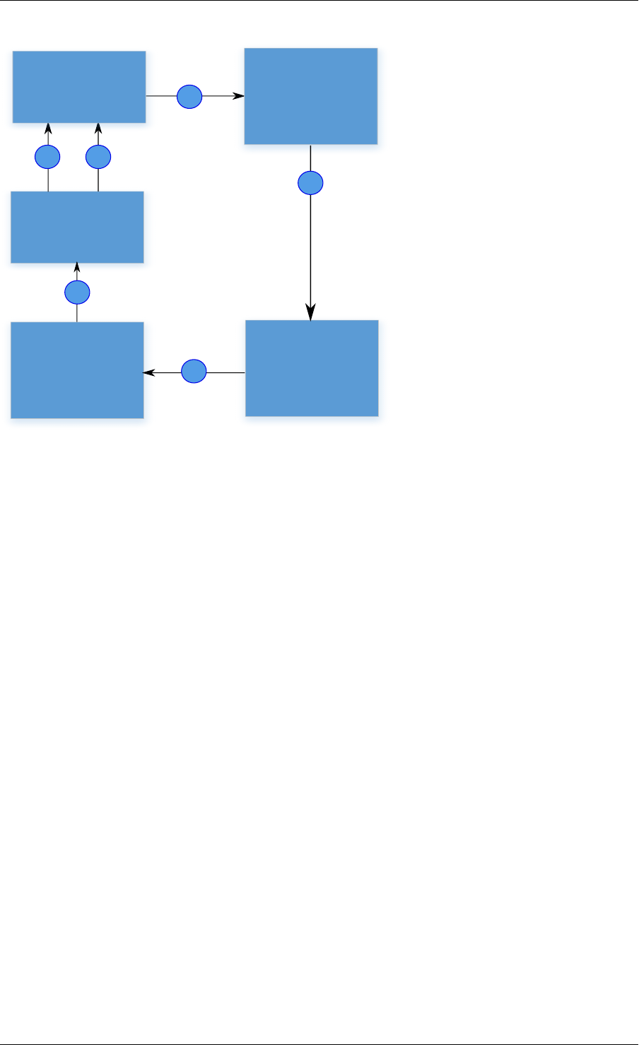
Programmer’s Guide, Release 18.11.0-rc5
1
2
3
4
6
Eventdev
Atomic stage
+
enqueue to
cryptodev
5
Cryptodev
Crypto
adapter
1. Application dequeues
events from the previous
stage
2. Application prepares the
crypto operations.
3. Crypto operations are
submitted to cryptodev
by application..
4. Crypto adapter dequeues
crypto completions from
cryptodev.
5. Crypto adapter enqueues
events to the eventdev.
6. Application dequeues from
eventdev and prepare for
further processing
Application
Fig. 39.1: Working model of RTE_EVENT_CRYPTO_ADAPTER_OP_NEW mode
retrieves crypto adapter’s event port using rte_event_crypto_adapter_event_port_get() API.
Then, links its event queue to this port and starts enqueuing crypto operations as events to
the eventdev. The adapter then dequeues the events and submits the crypto operations to
the cryptodev. After the crypto completions, the adapter enqueues events to the event device.
Application can use this mode, when ingress packet ordering is needed. In this mode, events
dequeued from the adapter will be treated as forwarded events. The application needs to
specify the cryptodev ID and queue pair ID (request information) needed to enqueue a crypto
operation in addition to the event information (response information) needed to enqueue an
event after the crypto operation has completed.
39.2 API Overview
This section has a brief introduction to the event crypto adapter APIs. The application is ex-
pected to create an adapter which is associated with a single eventdev, then add cryptodev
and queue pair to the adapter instance.
39.2.1 Create an adapter instance
An adapter instance is created using rte_event_crypto_adapter_create(). This func-
tion is called with event device to be associated with the adapter and port configuration for the
adapter to setup an event port(if the adapter needs to use a service function).
Adapter can be started in RTE_EVENT_CRYPTO_ADAPTER_OP_NEW or
RTE_EVENT_CRYPTO_ADAPTER_OP_FORWARD mode.
39.2. API Overview 286
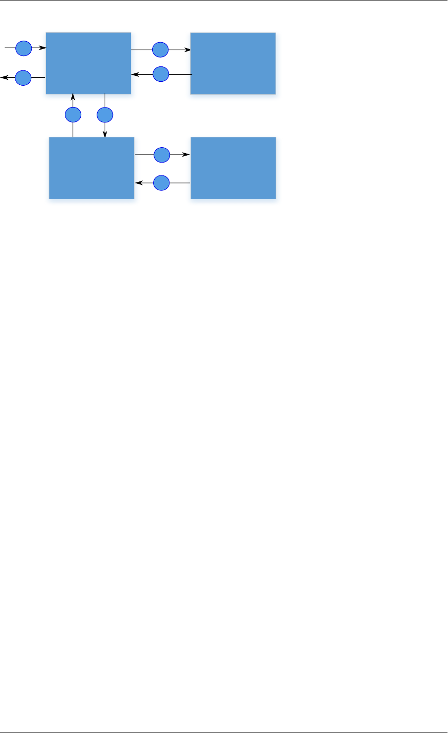
Programmer’s Guide, Release 18.11.0-rc5
12
8
7
3
4
5
6
Eventdev
Crypto
Adapter
Application
in ordered
stage
Cryptodev
1. Events from the previous stage.
2. Application in ordered stage
dequeues events from eventdev.
3. Application enqueues crypto
operations as events to eventdev.
4. Crypto adapter dequeues event
from eventdev.
5. Crypto adapter submits crypto
operations to cryptodev (Atomic
stage)
6. Crypto adapter dequeues crypto
completions from cryptodev
7. Crypto adapter enqueues events
to the eventdev
8. Events to the next stage
Fig. 39.2: Working model of RTE_EVENT_CRYPTO_ADAPTER_OP_FORWARD mode
int err;
uint8_t dev_id, id;
struct rte_event_dev_info dev_info;
struct rte_event_port_conf conf;
enum rte_event_crypto_adapter_mode mode;
err =rte_event_dev_info_get(id, &dev_info);
conf.new_event_threshold =dev_info.max_num_events;
conf.dequeue_depth =dev_info.max_event_port_dequeue_depth;
conf.enqueue_depth =dev_info.max_event_port_enqueue_depth;
mode =RTE_EVENT_CRYPTO_ADAPTER_OP_FORWARD;
err =rte_event_crypto_adapter_create(id, dev_id, &conf, mode);
If the application desires to have finer control of eventdev port allocation and
setup, it can use the rte_event_crypto_adapter_create_ext() function. The
rte_event_crypto_adapter_create_ext() function is passed as a callback func-
tion. The callback function is invoked if the adapter needs to use a service function
and needs to create an event port for it. The callback is expected to fill the struct
rte_event_crypto_adapter_conf structure passed to it.
For RTE_EVENT_CRYPTO_ADAPTER_OP_FORWARD mode, the event port created by
adapter can be retrieved using rte_event_crypto_adapter_event_port_get() API.
Application can use this event port to link with event queue on which it enqueues events to-
wards the crypto adapter.
uint8_t id, evdev, crypto_ev_port_id, app_qid;
struct rte_event ev;
int ret;
ret =rte_event_crypto_adapter_event_port_get(id, &crypto_ev_port_id);
ret =rte_event_queue_setup(evdev, app_qid, NULL);
ret =rte_event_port_link(evdev, crypto_ev_port_id, &app_qid, NULL,1);
// Fill in event info and update event_ptr with rte_crypto_op
39.2. API Overview 287

Programmer’s Guide, Release 18.11.0-rc5
memset(&ev, 0,sizeof(ev));
ev.queue_id =app_qid;
.
.
ev.event_ptr =op;
ret =rte_event_enqueue_burst(evdev, app_ev_port_id, ev, nb_events);
39.2.2 Querying adapter capabilities
The rte_event_crypto_adapter_caps_get() function allows the application to query
the adapter capabilities for an eventdev and cryptodev combination. This API provides whether
cryptodev and eventdev are connected using internal HW port or not.
rte_event_crypto_adapter_caps_get(dev_id, cdev_id, &cap);
39.2.3 Adding queue pair to the adapter instance
Cryptodev device id and queue pair are created using cryptodev APIs. For more information
see here.
struct rte_cryptodev_config conf;
struct rte_cryptodev_qp_conf qp_conf;
uint8_t cdev_id =0;
uint16_t qp_id =0;
rte_cryptodev_configure(cdev_id, &conf);
rte_cryptodev_queue_pair_setup(cdev_id, qp_id, &qp_conf);
These cryptodev id and queue pair are added to the instance using the
rte_event_crypto_adapter_queue_pair_add() API. The same is removed
using rte_event_crypto_adapter_queue_pair_del() API. If HW supports
RTE_EVENT_CRYPTO_ADAPTER_CAP_INTERNAL_PORT_QP_EV_BIND capability,
event information must be passed to the add API.
uint32_t cap;
int ret;
ret =rte_event_crypto_adapter_caps_get(id, evdev, &cap);
if (cap &RTE_EVENT_CRYPTO_ADAPTER_CAP_INTERNAL_PORT_QP_EV_BIND) {
struct rte_event event;
// Fill in event information & pass it to add API
rte_event_crypto_adapter_queue_pair_add(id, cdev_id, qp_id, &event);
}else
rte_event_crypto_adapter_queue_pair_add(id, cdev_id, qp_id, NULL);
39.2.4 Configure the service function
If the adapter uses a service function, the application is required to assign a service core to
the service function as show below.
uint32_t service_id;
if (rte_event_crypto_adapter_service_id_get(id, &service_id) == 0)
rte_service_map_lcore_set(service_id, CORE_ID);
39.2. API Overview 288

Programmer’s Guide, Release 18.11.0-rc5
39.2.5 Set event request/response information
In the RTE_EVENT_CRYPTO_ADAPTER_OP_FORWARD mode, the application needs to
specify the cryptodev ID and queue pair ID (request information) in addition to the event infor-
mation (response information) needed to enqueue an event after the crypto operation has com-
pleted. The request and response information are specified in the struct rte_crypto_op
private data or session’s private data.
In the RTE_EVENT_CRYPTO_ADAPTER_OP_NEW mode, the application is required to pro-
vide only the response information.
The SW adapter or HW PMD uses rte_crypto_op::sess_type to decide whether re-
quest/response data is located in the crypto session/ crypto security session or at an offset in
the struct rte_crypto_op. The rte_crypto_op::private_data_offset is used to
locate the request/ response in the rte_crypto_op.
For crypto session, rte_cryptodev_sym_session_set_user_data() API
will be used to set request/response data. The same data will be ob-
tained by rte_cryptodev_sym_session_get_user_data() API. The
RTE_EVENT_CRYPTO_ADAPTER_CAP_SESSION_PRIVATE_DATA capability indicates
whether HW or SW supports this feature.
For security session, rte_security_session_set_private_data() API will
be used to set request/response data. The same data will be obtained by
rte_security_session_get_private_data() API.
For session-less it is mandatory to place the request/response data with the rte_crypto_op.
union rte_event_crypto_metadata m_data;
struct rte_event ev;
struct rte_crypto_op *op;
/*Allocate & fill op structure */
op =rte_crypto_op_alloc();
memset(&m_data, 0,sizeof(m_data));
memset(&ev, 0,sizeof(ev));
/*Fill event information and update event_ptr to rte_crypto_op */
ev.event_ptr =op;
if (op->sess_type == RTE_CRYPTO_OP_WITH_SESSION) {
/*Copy response information */
rte_memcpy(&m_data.response_info, &ev, sizeof(ev));
/*Copy request information */
m_data.request_info.cdev_id =cdev_id;
m_data.request_info.queue_pair_id =qp_id;
/*Call set API to store private data information */
rte_cryptodev_sym_session_set_user_data(
op->sym->session,
&m_data,
sizeof(m_data));
}if (op->sess_type == RTE_CRYPTO_OP_SESSIONLESS) {
uint32_t len =IV_OFFSET +MAXIMUM_IV_LENGTH +
(sizeof(struct rte_crypto_sym_xform) *2);
op->private_data_offset =len;
/*Copy response information */
rte_memcpy(&m_data.response_info, &ev, sizeof(ev));
/*Copy request information */
m_data.request_info.cdev_id =cdev_id;
m_data.request_info.queue_pair_id =qp_id;
39.2. API Overview 289

Programmer’s Guide, Release 18.11.0-rc5
/*Store private data information along with rte_crypto_op */
rte_memcpy(op +len, &m_data, sizeof(m_data));
}
39.2.6 Start the adapter instance
The application calls rte_event_crypto_adapter_start() to start the adapter. This
function calls the start callbacks of the eventdev PMDs for hardware based eventdev-cryptodev
connections and rte_service_run_state_set() to enable the service function if one ex-
ists.
rte_event_crypto_adapter_start(id, mode);
39.2.7 Get adapter statistics
The rte_event_crypto_adapter_stats_get() function reports counters defined in
struct rte_event_crypto_adapter_stats. The received packet and enqueued event
counts are a sum of the counts from the eventdev PMD callbacks if the callback is supported,
and the counts maintained by the service function, if one exists.
39.2. API Overview 290
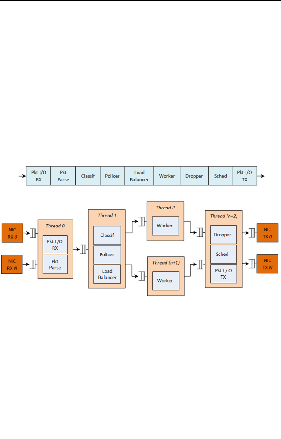
CHAPTER
FORTY
QUALITY OF SERVICE (QOS) FRAMEWORK
This chapter describes the DPDK Quality of Service (QoS) framework.
40.1 Packet Pipeline with QoS Support
An example of a complex packet processing pipeline with QoS support is shown in the following
figure.
Fig. 40.1: Complex Packet Processing Pipeline with QoS Support
This pipeline can be built using reusable DPDK software libraries. The main blocks implement-
ing QoS in this pipeline are: the policer, the dropper and the scheduler. A functional description
of each block is provided in the following table.
291

Programmer’s Guide, Release 18.11.0-rc5
Table 40.1: Packet Processing Pipeline Implementing QoS
# Block Functional Description
1 Packet I/O
RX & TX
Packet reception/ transmission from/to multiple NIC ports. Poll mode
drivers (PMDs) for Intel 1 GbE/10 GbE NICs.
2 Packet
parser
Identify the protocol stack of the input packet. Check the integrity of the
packet headers.
3 Flow clas-
sification
Map the input packet to one of the known traffic flows. Exact match table
lookup using configurable hash function (jhash, CRC and so on) and
bucket logic to handle collisions.
4 Policer Packet metering using srTCM (RFC 2697) or trTCM (RFC2698)
algorithms.
5 Load
Balancer
Distribute the input packets to the application workers. Provide uniform
load to each worker. Preserve the affinity of traffic flows to workers and
the packet order within each flow.
6 Worker
threads
Placeholders for the customer specific application workload (for
example, IP stack and so on).
7 Dropper Congestion management using the Random Early Detection (RED)
algorithm (specified by the Sally Floyd - Van Jacobson paper) or
Weighted RED (WRED). Drop packets based on the current scheduler
queue load level and packet priority. When congestion is experienced,
lower priority packets are dropped first.
8 Hierarchi-
cal
Scheduler
5-level hierarchical scheduler (levels are: output port, subport, pipe,
traffic class and queue) with thousands (typically 64K) leaf nodes
(queues). Implements traffic shaping (for subport and pipe levels), strict
priority (for traffic class level) and Weighted Round Robin (WRR) (for
queues within each pipe traffic class).
The infrastructure blocks used throughout the packet processing pipeline are listed in the fol-
lowing table.
Table 40.2: Infrastructure Blocks Used by the Packet Processing Pipeline
# Block Functional Description
1 Buffer manager Support for global buffer pools and private per-thread buffer caches.
2 Queue manager Support for message passing between pipeline blocks.
3 Power saving Support for power saving during low activity periods.
The mapping of pipeline blocks to CPU cores is configurable based on the performance level
required by each specific application and the set of features enabled for each block. Some
blocks might consume more than one CPU core (with each CPU core running a different
instance of the same block on different input packets), while several other blocks could be
mapped to the same CPU core.
40.2 Hierarchical Scheduler
The hierarchical scheduler block, when present, usually sits on the TX side just before the
transmission stage. Its purpose is to prioritize the transmission of packets from different users
and different traffic classes according to the policy specified by the Service Level Agreements
(SLAs) of each network node.
40.2. Hierarchical Scheduler 292
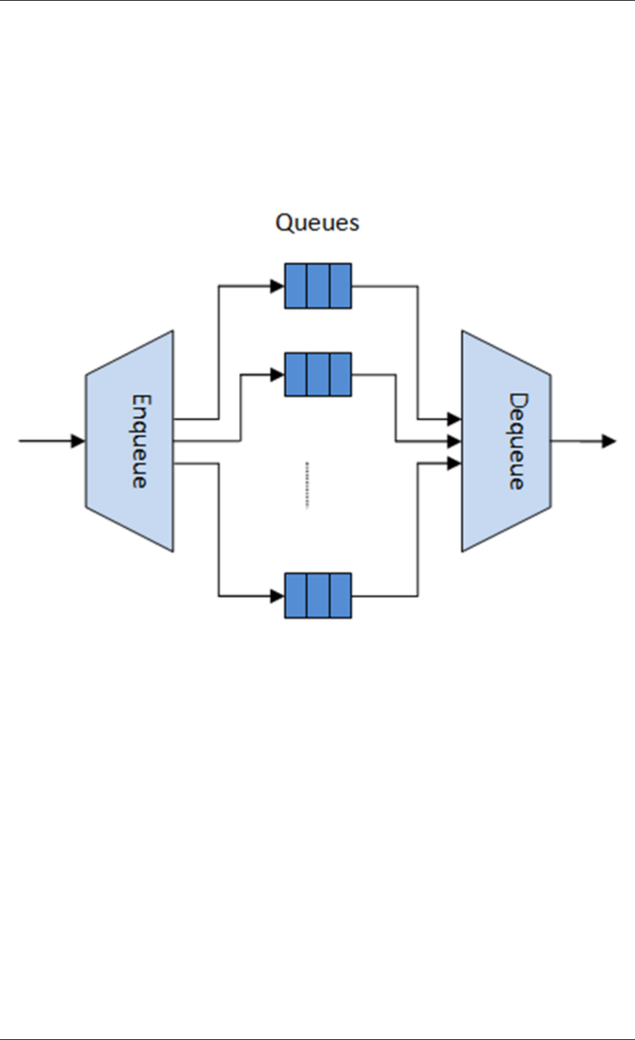
Programmer’s Guide, Release 18.11.0-rc5
40.2.1 Overview
The hierarchical scheduler block is similar to the traffic manager block used by network proces-
sors that typically implement per flow (or per group of flows) packet queuing and scheduling. It
typically acts like a buffer that is able to temporarily store a large number of packets just before
their transmission (enqueue operation); as the NIC TX is requesting more packets for trans-
mission, these packets are later on removed and handed over to the NIC TX with the packet
selection logic observing the predefined SLAs (dequeue operation).
Fig. 40.2: Hierarchical Scheduler Block Internal Diagram
The hierarchical scheduler is optimized for a large number of packet queues. When only a
small number of queues are needed, message passing queues should be used instead of this
block. See Worst Case Scenarios for Performance for a more detailed discussion.
40.2.2 Scheduling Hierarchy
The scheduling hierarchy is shown in Fig. 40.3. The first level of the hierarchy is the Ethernet
TX port 1/10/40 GbE, with subsequent hierarchy levels defined as subport, pipe, traffic class
and queue.
Typically, each subport represents a predefined group of users, while each pipe represents an
individual user/subscriber. Each traffic class is the representation of a different traffic type with
specific loss rate, delay and jitter requirements, such as voice, video or data transfers. Each
queue hosts packets from one or multiple connections of the same type belonging to the same
user.
The functionality of each hierarchical level is detailed in the following table.
40.2. Hierarchical Scheduler 293
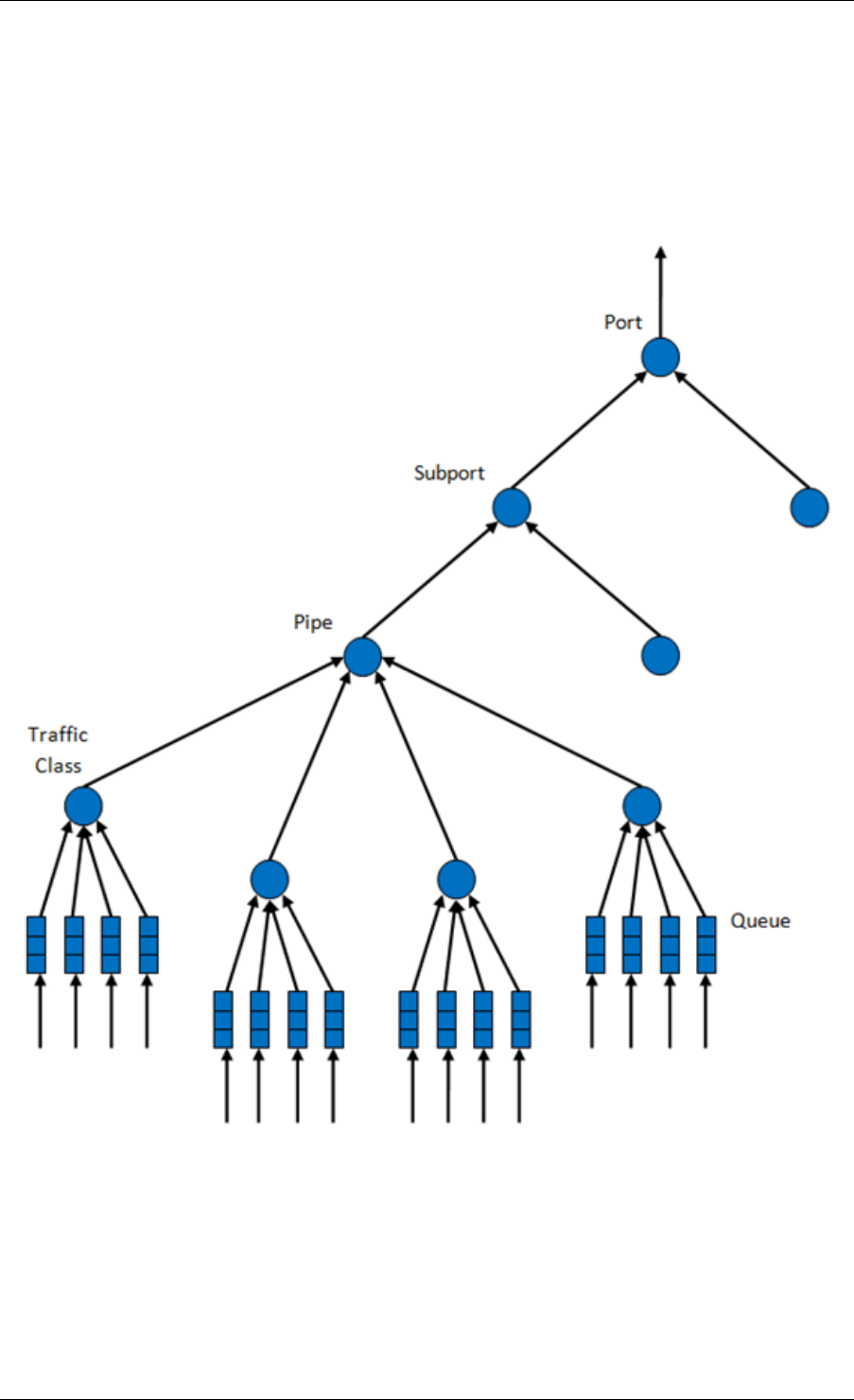
Programmer’s Guide, Release 18.11.0-rc5
Fig. 40.3: Scheduling Hierarchy per Port
40.2. Hierarchical Scheduler 294

Programmer’s Guide, Release 18.11.0-rc5
Table 40.3: Port Scheduling Hierarchy
# Level Siblings per Parent Functional Descrip-
tion
1 Port •1. Output Ethernet
port 1/10/40
GbE.
2. Multiple ports
are scheduled
in round robin
order with all
ports having
equal priority.
2 Subport Configurable (default:
8) 1. Traffic shaping
using token
bucket algo-
rithm (one token
bucket per
subport).
2. Upper limit en-
forced per Traf-
fic Class (TC)
at the subport
level.
3. Lower priority
TCs able to
reuse subport
bandwidth cur-
rently unused by
higher priority
TCs.
3 Pipe Configurable (default:
4K) 1. Traffic shaping
using the token
bucket algo-
rithm (one token
bucket per pipe.
4 Traffic Class (TC) 4 1. TCs of the same
pipe handled in
strict priority or-
der.
2. Upper limit en-
forced per TC at
the pipe level.
3. Lower prior-
ity TCs able
to reuse pipe
bandwidth cur-
rently unused by
higher priority
TCs.
4. When subport
TC is over-
subscribed
(configuration
time event), pipe
TC upper limit
is capped to
a dynamically
adjusted value
that is shared by
all the subport
pipes.
5 Queue 4 1. Queues of the
same TC are
serviced us-
ing Weighted
Round Robin
(WRR) ac-
cording to
predefined
weights.
40.2. Hierarchical Scheduler 295

Programmer’s Guide, Release 18.11.0-rc5
40.2.3 Application Programming Interface (API)
Port Scheduler Configuration API
The rte_sched.h file contains configuration functions for port, subport and pipe.
Port Scheduler Enqueue API
The port scheduler enqueue API is very similar to the API of the DPDK PMD TX function.
int rte_sched_port_enqueue(struct rte_sched_port *port, struct rte_mbuf **pkts, uint32_t n_pkts);
Port Scheduler Dequeue API
The port scheduler dequeue API is very similar to the API of the DPDK PMD RX function.
int rte_sched_port_dequeue(struct rte_sched_port *port, struct rte_mbuf **pkts, uint32_t n_pkts);
Usage Example
/*File "application.c" */
#define N_PKTS_RX 64
#define N_PKTS_TX 48
#define NIC_RX_PORT 0
#define NIC_RX_QUEUE 0
#define NIC_TX_PORT 1
#define NIC_TX_QUEUE 0
struct rte_sched_port *port =NULL;
struct rte_mbuf *pkts_rx[N_PKTS_RX], *pkts_tx[N_PKTS_TX];
uint32_t n_pkts_rx, n_pkts_tx;
/*Initialization */
<initialization code>
/*Runtime */
while (1) {
/*Read packets from NIC RX queue */
n_pkts_rx =rte_eth_rx_burst(NIC_RX_PORT, NIC_RX_QUEUE, pkts_rx, N_PKTS_RX);
/*Hierarchical scheduler enqueue */
rte_sched_port_enqueue(port, pkts_rx, n_pkts_rx);
/*Hierarchical scheduler dequeue */
n_pkts_tx =rte_sched_port_dequeue(port, pkts_tx, N_PKTS_TX);
/*Write packets to NIC TX queue */
rte_eth_tx_burst(NIC_TX_PORT, NIC_TX_QUEUE, pkts_tx, n_pkts_tx);
}
40.2. Hierarchical Scheduler 296

Programmer’s Guide, Release 18.11.0-rc5
40.2.4 Implementation
Internal Data Structures per Port
A schematic of the internal data structures in shown in with details in.
40.2. Hierarchical Scheduler 297
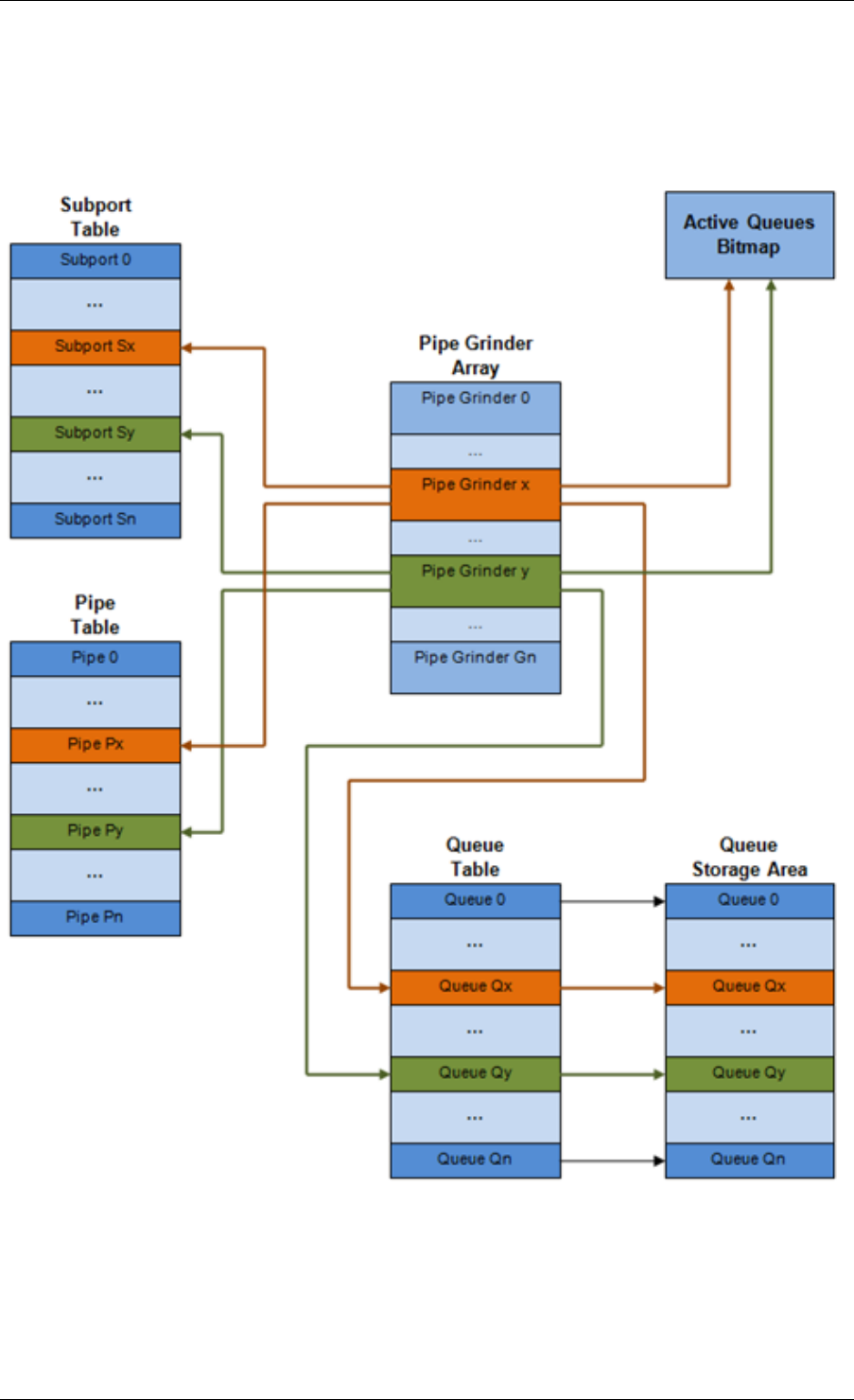
Programmer’s Guide, Release 18.11.0-rc5
Fig. 40.4: Internal Data Structures per Port
40.2. Hierarchical Scheduler 298

Programmer’s Guide, Release 18.11.0-rc5
Table 40.4: Scheduler Internal Data Structures per Port
# Data structure Size (bytes) # per port Access type Description
Enq Deq
1 Subport ta-
ble entry
64 # subports
per port •Rd, Wr Persistent
subport data
(credits,
etc).
2 Pipe table
entry
64 # pipes per
port •Rd, Wr Persistent
data for
pipe, its
TCs and
its queues
(credits, etc)
that is up-
dated during
run-time.
The pipe
configura-
tion param-
eters do not
change dur-
ing run-time.
The same
pipe con-
figuration
parameters
are shared
by multiple
pipes, there-
fore they are
not part of
pipe table
entry.
3 Queue table
entry
4 #queues per
port
Rd, Wr Rd, Wr Persistent
queue data
(read and
write point-
ers). The
queue size
is the same
per TC for
all queues,
allowing
the queue
base ad-
dress to be
computed
using a fast
formula, so
these two
parameters
are not part
of queue
table entry.
The queue
table entries
for any given
pipe are
stored in the
same cache
line.
4 Queue stor-
age area
Config (de-
fault: 64 x8)
# queues
per port
Wr Rd Array of el-
ements per
queue; each
element is
8 byte in
size (mbuf
pointer).
5 Active
queues
bitmap
1 bit per
queue
1 Wr (Set) Rd, Wr
(Clear)
The bitmap
maintains
one sta-
tus bit per
queue:
queue
not active
(queue is
empty) or
queue active
(queue is
not empty).
Queue bit is
set by the
scheduler
enqueue
and cleared
by the
scheduler
dequeue
when queue
becomes
empty.
Bitmap scan
operation
returns the
next non-
empty pipe
and its sta-
tus (16-bit
mask of
active queue
in the pipe).
6 Grinder ~128 Config (de-
fault: 8) •Rd, Wr Short list
of active
pipes cur-
rently under
processing.
The grinder
contains
temporary
data dur-
ing pipe
processing.
Once the
current pipe
exhausts
packets or
credits, it
is replaced
with another
active pipe
from the
bitmap.
40.2. Hierarchical Scheduler 299

Programmer’s Guide, Release 18.11.0-rc5
Multicore Scaling Strategy
The multicore scaling strategy is:
1. Running different physical ports on different threads. The enqueue and dequeue of the
same port are run by the same thread.
2. Splitting the same physical port to different threads by running different sets of subports
of the same physical port (virtual ports) on different threads. Similarly, a subport can
be split into multiple subports that are each run by a different thread. The enqueue
and dequeue of the same port are run by the same thread. This is only required if, for
performance reasons, it is not possible to handle a full port with a single core.
Enqueue and Dequeue for the Same Output Port
Running enqueue and dequeue operations for the same output port from different cores is likely
to cause significant impact on scheduler’s performance and it is therefore not recommended.
The port enqueue and dequeue operations share access to the following data structures:
1. Packet descriptors
2. Queue table
3. Queue storage area
4. Bitmap of active queues
The expected drop in performance is due to:
1. Need to make the queue and bitmap operations thread safe, which requires either using
locking primitives for access serialization (for example, spinlocks/ semaphores) or using
atomic primitives for lockless access (for example, Test and Set, Compare And Swap, an
so on). The impact is much higher in the former case.
2. Ping-pong of cache lines storing the shared data structures between the cache hierar-
chies of the two cores (done transparently by the MESI protocol cache coherency CPU
hardware).
Therefore, the scheduler enqueue and dequeue operations have to be run from the same
thread, which allows the queues and the bitmap operations to be non-thread safe and keeps
the scheduler data structures internal to the same core.
Performance Scaling
Scaling up the number of NIC ports simply requires a proportional increase in the number of
CPU cores to be used for traffic scheduling.
Enqueue Pipeline
The sequence of steps per packet:
1. Access the mbuf to read the data fields required to identify the destination queue for the
packet. These fields are: port, subport, traffic class and queue within traffic class, and
are typically set by the classification stage.
40.2. Hierarchical Scheduler 300
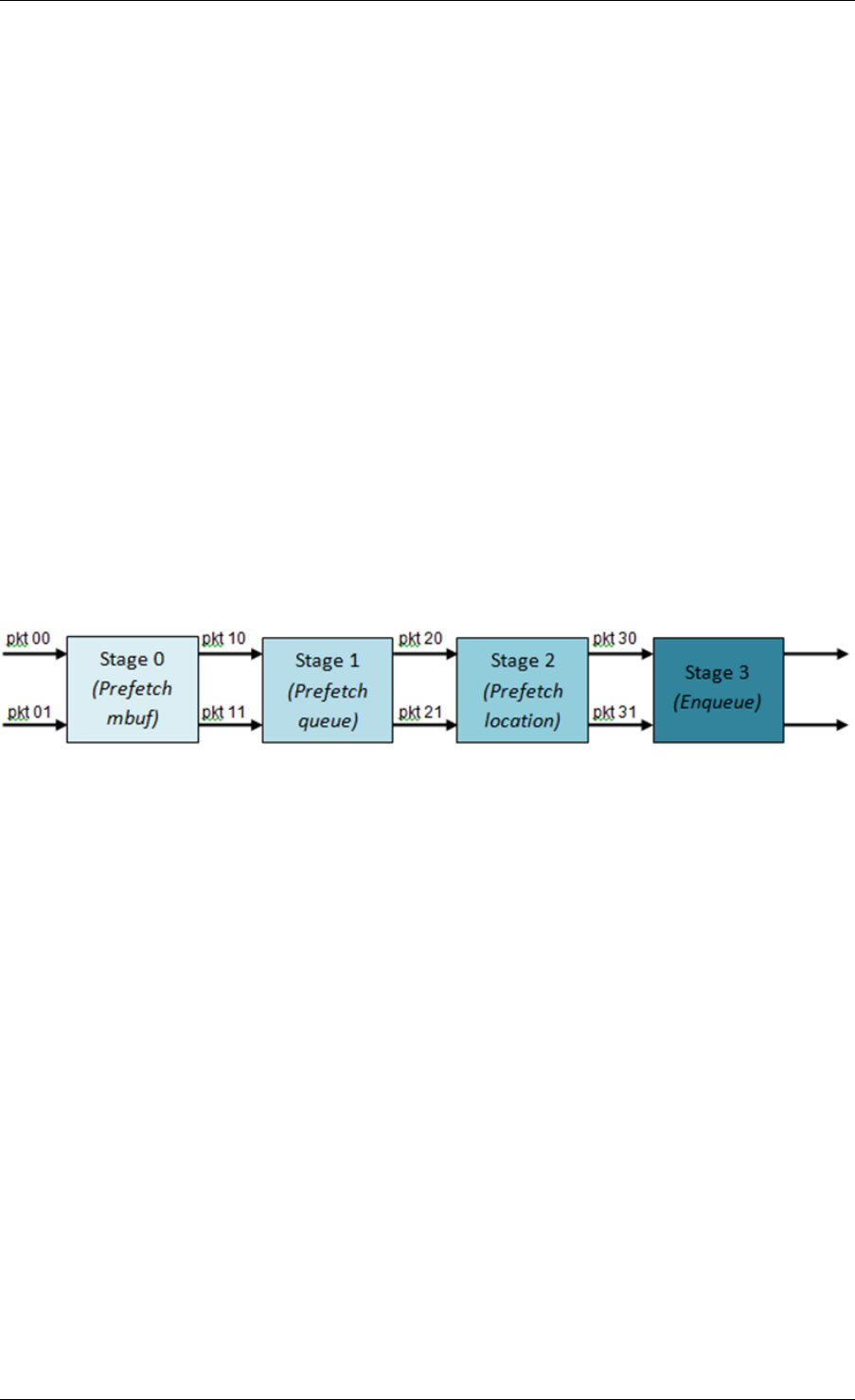
Programmer’s Guide, Release 18.11.0-rc5
2. Access the queue structure to identify the write location in the queue array. If the queue
is full, then the packet is discarded.
3. Access the queue array location to store the packet (i.e. write the mbuf pointer).
It should be noted the strong data dependency between these steps, as steps 2 and 3 cannot
start before the result from steps 1 and 2 becomes available, which prevents the processor out
of order execution engine to provide any significant performance optimizations.
Given the high rate of input packets and the large amount of queues, it is expected that the
data structures accessed to enqueue the current packet are not present in the L1 or L2 data
cache of the current core, thus the above 3 memory accesses would result (on average) in L1
and L2 data cache misses. A number of 3 L1/L2 cache misses per packet is not acceptable for
performance reasons.
The workaround is to prefetch the required data structures in advance. The prefetch operation
has an execution latency during which the processor should not attempt to access the data
structure currently under prefetch, so the processor should execute other work. The only other
work available is to execute different stages of the enqueue sequence of operations on other
input packets, thus resulting in a pipelined implementation for the enqueue operation.
Fig. 40.5 illustrates a pipelined implementation for the enqueue operation with 4 pipeline stages
and each stage executing 2 different input packets. No input packet can be part of more than
one pipeline stage at a given time.
Fig. 40.5: Prefetch Pipeline for the Hierarchical Scheduler Enqueue Operation
The congestion management scheme implemented by the enqueue pipeline described above
is very basic: packets are enqueued until a specific queue becomes full, then all the packets
destined to the same queue are dropped until packets are consumed (by the dequeue oper-
ation). This can be improved by enabling RED/WRED as part of the enqueue pipeline which
looks at the queue occupancy and packet priority in order to yield the enqueue/drop decision for
a specific packet (as opposed to enqueuing all packets / dropping all packets indiscriminately).
Dequeue State Machine
The sequence of steps to schedule the next packet from the current pipe is:
1. Identify the next active pipe using the bitmap scan operation, prefetch pipe.
2. Read pipe data structure. Update the credits for the current pipe and its subport. Identify
the first active traffic class within the current pipe, select the next queue using WRR,
prefetch queue pointers for all the 16 queues of the current pipe.
3. Read next element from the current WRR queue and prefetch its packet descriptor.
4. Read the packet length from the packet descriptor (mbuf structure). Based on the packet
length and the available credits (of current pipe, pipe traffic class, subport and subport
traffic class), take the go/no go scheduling decision for the current packet.
40.2. Hierarchical Scheduler 301
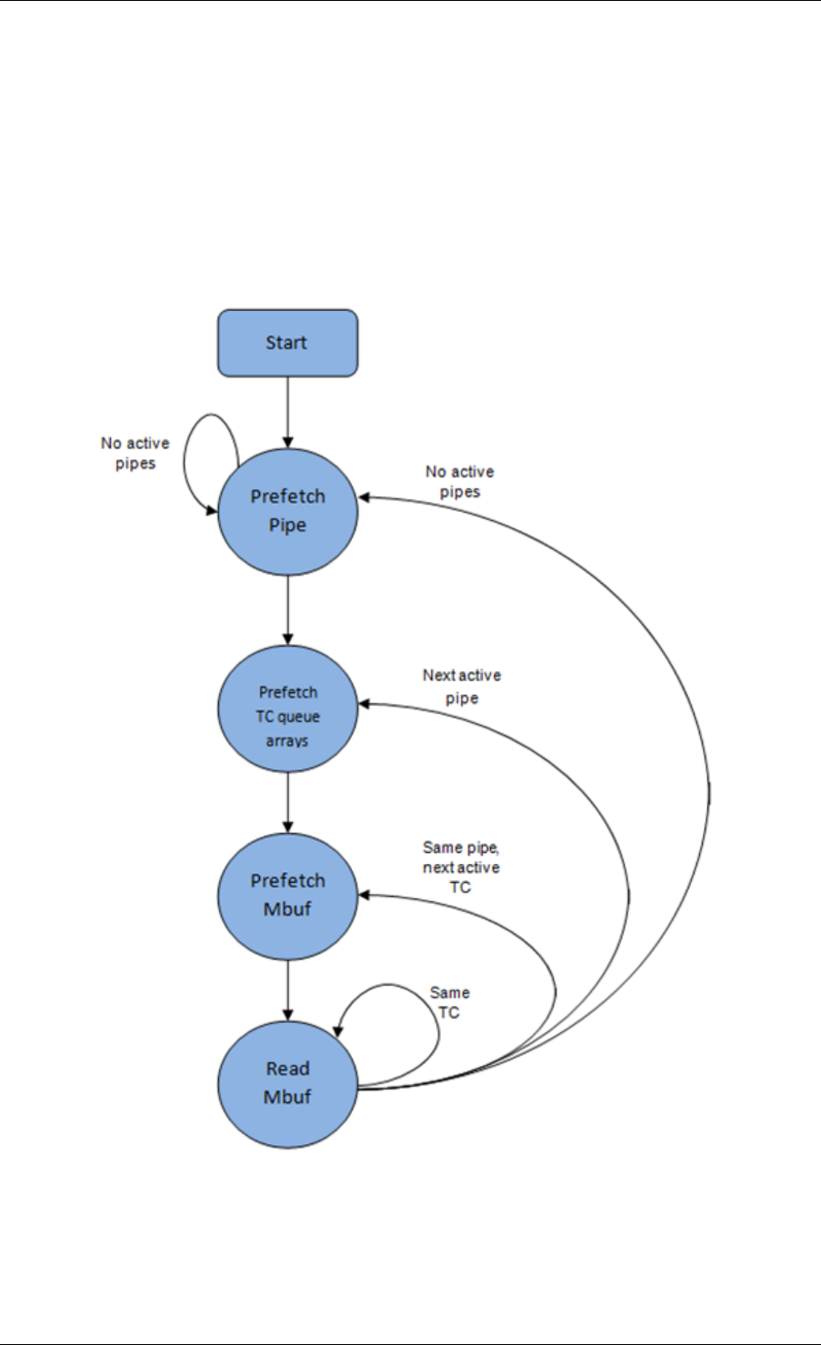
Programmer’s Guide, Release 18.11.0-rc5
To avoid the cache misses, the above data structures (pipe, queue, queue array, mbufs) are
prefetched in advance of being accessed. The strategy of hiding the latency of the prefetch
operations is to switch from the current pipe (in grinder A) to another pipe (in grinder B) imme-
diately after a prefetch is issued for the current pipe. This gives enough time to the prefetch
operation to complete before the execution switches back to this pipe (in grinder A).
The dequeue pipe state machine exploits the data presence into the processor cache, therefore
it tries to send as many packets from the same pipe TC and pipe as possible (up to the available
packets and credits) before moving to the next active TC from the same pipe (if any) or to
another active pipe.
Fig. 40.6: Pipe Prefetch State Machine for the Hierarchical Scheduler Dequeue Operation
40.2. Hierarchical Scheduler 302

Programmer’s Guide, Release 18.11.0-rc5
Timing and Synchronization
The output port is modeled as a conveyor belt of byte slots that need to be filled by the sched-
uler with data for transmission. For 10 GbE, there are 1.25 billion byte slots that need to be
filled by the port scheduler every second. If the scheduler is not fast enough to fill the slots, pro-
vided that enough packets and credits exist, then some slots will be left unused and bandwidth
will be wasted.
In principle, the hierarchical scheduler dequeue operation should be triggered by NIC TX.
Usually, once the occupancy of the NIC TX input queue drops below a predefined threshold,
the port scheduler is woken up (interrupt based or polling based, by continuously monitoring
the queue occupancy) to push more packets into the queue.
Internal Time Reference
The scheduler needs to keep track of time advancement for the credit logic, which requires
credit updates based on time (for example, subport and pipe traffic shaping, traffic class upper
limit enforcement, and so on).
Every time the scheduler decides to send a packet out to the NIC TX for transmission, the
scheduler will increment its internal time reference accordingly. Therefore, it is convenient
to keep the internal time reference in units of bytes, where a byte signifies the time duration
required by the physical interface to send out a byte on the transmission medium. This way,
as a packet is scheduled for transmission, the time is incremented with (n + h), where n is the
packet length in bytes and h is the number of framing overhead bytes per packet.
Internal Time Reference Re-synchronization
The scheduler needs to align its internal time reference to the pace of the port conveyor belt.
The reason is to make sure that the scheduler does not feed the NIC TX with more bytes than
the line rate of the physical medium in order to prevent packet drop (by the scheduler, due to
the NIC TX input queue being full, or later on, internally by the NIC TX).
The scheduler reads the current time on every dequeue invocation. The CPU time stamp can
be obtained by reading either the Time Stamp Counter (TSC) register or the High Precision
Event Timer (HPET) register. The current CPU time stamp is converted from number of CPU
clocks to number of bytes: time_bytes = time_cycles / cycles_per_byte, where cycles_per_byte
is the amount of CPU cycles that is equivalent to the transmission time for one byte on the wire
(e.g. for a CPU frequency of 2 GHz and a 10GbE port,*cycles_per_byte = 1.6*).
The scheduler maintains an internal time reference of the NIC time. Whenever a packet is
scheduled, the NIC time is incremented with the packet length (including framing overhead).
On every dequeue invocation, the scheduler checks its internal reference of the NIC time
against the current time:
1. If NIC time is in the future (NIC time >= current time), no adjustment of NIC time is
needed. This means that scheduler is able to schedule NIC packets before the NIC
actually needs those packets, so the NIC TX is well supplied with packets;
2. If NIC time is in the past (NIC time < current time), then NIC time should be adjusted by
setting it to the current time. This means that the scheduler is not able to keep up with
the speed of the NIC byte conveyor belt, so NIC bandwidth is wasted due to poor packet
supply to the NIC TX.
40.2. Hierarchical Scheduler 303

Programmer’s Guide, Release 18.11.0-rc5
Scheduler Accuracy and Granularity
The scheduler round trip delay (SRTD) is the time (number of CPU cycles) between two con-
secutive examinations of the same pipe by the scheduler.
To keep up with the output port (that is, avoid bandwidth loss), the scheduler should be able to
schedule n packets faster than the same n packets are transmitted by NIC TX.
The scheduler needs to keep up with the rate of each individual pipe, as configured for the pipe
token bucket, assuming that no port oversubscription is taking place. This means that the size
of the pipe token bucket should be set high enough to prevent it from overflowing due to big
SRTD, as this would result in credit loss (and therefore bandwidth loss) for the pipe.
Credit Logic
Scheduling Decision
The scheduling decision to send next packet from (subport S, pipe P, traffic class TC, queue
Q) is favorable (packet is sent) when all the conditions below are met:
• Pipe P of subport S is currently selected by one of the port grinders;
• Traffic class TC is the highest priority active traffic class of pipe P;
• Queue Q is the next queue selected by WRR within traffic class TC of pipe P;
• Subport S has enough credits to send the packet;
• Subport S has enough credits for traffic class TC to send the packet;
• Pipe P has enough credits to send the packet;
• Pipe P has enough credits for traffic class TC to send the packet.
If all the above conditions are met, then the packet is selected for transmission and the nec-
essary credits are subtracted from subport S, subport S traffic class TC, pipe P, pipe P traffic
class TC.
Framing Overhead
As the greatest common divisor for all packet lengths is one byte, the unit of credit is selected
as one byte. The number of credits required for the transmission of a packet of n bytes is equal
to (n+h), where h is equal to the number of framing overhead bytes per packet.
40.2. Hierarchical Scheduler 304

Programmer’s Guide, Release 18.11.0-rc5
Table 40.5: Ethernet Frame Overhead Fields
# Packet field Length
(bytes)
Comments
1 Preamble 7
2 Start of Frame
Delimiter (SFD)
1
3 Frame Check
Sequence (FCS)
4 Considered overhead only if not included in the
mbuf packet length field.
4 Inter Frame Gap
(IFG)
12
5 Total 24
Traffic Shaping
The traffic shaping for subport and pipe is implemented using a token bucket per subport/per
pipe. Each token bucket is implemented using one saturated counter that keeps track of the
number of available credits.
The token bucket generic parameters and operations are presented in Table 40.6 and Table
40.7.
Table 40.6: Token Bucket Generic Parameters
# Token Bucket
Parameter
Unit Description
1 bucket_rate Credits per
second
Rate of adding credits to the bucket.
2 bucket_size Credits Max number of credits that can be stored in
the bucket.
Table 40.7: Token Bucket Generic Operations
# Token
Bucket
Operation
Description
1 Initialization Bucket set to a predefined value, e.g. zero or half of the bucket size.
2 Credit
update
Credits are added to the bucket on top of existing ones, either
periodically or on demand, based on the bucket_rate. Credits cannot
exceed the upper limit defined by the bucket_size, so any credits to be
added to the bucket while the bucket is full are dropped.
3 Credit con-
sumption
As result of packet scheduling, the necessary number of credits is
removed from the bucket. The packet can only be sent if enough credits
are in the bucket to send the full packet (packet bytes and framing
overhead for the packet).
To implement the token bucket generic operations described above, the current design uses
the persistent data structure presented in Table 40.8, while the implementation of the token
bucket operations is described in Table 40.9.
40.2. Hierarchical Scheduler 305

Programmer’s Guide, Release 18.11.0-rc5
Table 40.8: Token Bucket Persistent Data Structure
# Token
bucket
field
Unit Description
1 tb_time BytesTime of the last credit update. Measured in bytes instead of seconds
or CPU cycles for ease of credit consumption operation (as the
current time is also maintained in bytes).
See Section 26.2.4.5.1 “Internal Time Reference” for an explanation
of why the time is maintained in byte units.
2 tb_period BytesTime period that should elapse since the last credit update in order
for the bucket to be awarded tb_credits_per_period worth or credits.
3 tb_credits_per_periodBytesCredit allowance per tb_period.
4 tb_size BytesBucket size, i.e. upper limit for the tb_credits.
5 tb_credits BytesNumber of credits currently in the bucket.
The bucket rate (in bytes per second) can be computed with the following formula:
bucket_rate = (tb_credits_per_period / tb_period) * r
where, r = port line rate (in bytes per second).
40.2. Hierarchical Scheduler 306

Programmer’s Guide, Release 18.11.0-rc5
Table 40.9: Token Bucket Operations
# Token bucket operation Description
1 Initialization tb_credits = 0; or tb_credits =
tb_size / 2;
2 Credit update Credit update options:
• Every time a packet is
sent for a port, update
the credits of all the the
subports and pipes of
that port. Not feasible.
• Every time a packet is
sent, update the cred-
its for the pipe and sub-
port. Very accurate, but
not needed (a lot of cal-
culations).
• Every time a pipe is se-
lected (that is, picked by
one of the grinders), up-
date the credits for the
pipe and its subport.
The current implementation
is using option 3. Accord-
ing to Section Dequeue State
Machine, the pipe and sub-
port credits are updated every
time a pipe is selected by the
dequeue process before the
pipe and subport credits are
actually used.
The implementation uses a
tradeoff between accuracy
and speed by updating the
bucket credits only when at
least a full tb_period has
elapsed since the last update.
• Full accuracy can
be achieved by se-
lecting the value for
tb_period for which
tb_credits_per_period =
1.
• When full accuracy is
not required, better per-
formance is achieved by
setting tb_credits to a
larger value.
Update operations:
• n_periods = (time -
tb_time) / tb_period;
• tb_credits += n_periods
* tb_credits_per_period;
• tb_credits =
min(tb_credits, tb_size);
• tb_time += n_periods *
tb_period;
3Credit consumption (on
packet scheduling)
As result of packet schedul-
ing, the necessary number
of credits is removed from
the bucket. The packet can
only be sent if enough cred-
its are in the bucket to send
the full packet (packet bytes
and framing overhead for the
packet).
Scheduling operations:
pkt_credits = pkt_len
+ frame_overhead;
if (tb_credits >=
pkt_credits){tb_credits -=
pkt_credits;}
40.2. Hierarchical Scheduler 307

Programmer’s Guide, Release 18.11.0-rc5
Traffic Classes
Implementation of Strict Priority Scheduling Strict priority scheduling of traffic classes
within the same pipe is implemented by the pipe dequeue state machine, which selects the
queues in ascending order. Therefore, queues 0..3 (associated with TC 0, highest priority TC)
are handled before queues 4..7 (TC 1, lower priority than TC 0), which are handled before
queues 8..11 (TC 2), which are handled before queues 12..15 (TC 3, lowest priority TC).
Upper Limit Enforcement The traffic classes at the pipe and subport levels are not traffic
shaped, so there is no token bucket maintained in this context. The upper limit for the traffic
classes at the subport and pipe levels is enforced by periodically refilling the subport / pipe
traffic class credit counter, out of which credits are consumed every time a packet is scheduled
for that subport / pipe, as described in Table 40.10 and Table 40.11.
Table 40.10: Subport/Pipe Traffic Class Upper Limit Enforcement Persistent Data Structure
# Subport
or pipe
field
Unit Description
1 tc_time BytesTime of the next update (upper limit refill) for the 4 TCs of the current
subport / pipe.
See Section Internal Time Reference for the explanation of why the
time is maintained in byte units.
2 tc_period BytesTime between two consecutive updates for the 4 TCs of the current
subport / pipe. This is expected to be many times bigger than the
typical value of the token bucket tb_period.
3 tc_credits_per_periodBytesUpper limit for the number of credits allowed to be consumed by the
current TC during each enforcement period tc_period.
4 tc_credits BytesCurrent upper limit for the number of credits that can be consumed
by the current traffic class for the remainder of the current
enforcement period.
Table 40.11: Subport/Pipe Traffic Class Upper Limit Enforcement Operations
# Traffic Class
Operation
Description
1 Initialization tc_credits = tc_credits_per_period;
tc_time = tc_period;
2 Credit update Update operations:
if (time >= tc_time) {
tc_credits = tc_credits_per_period;
tc_time = time + tc_period;
}
3 Credit
consumption (on
packet scheduling)
As result of packet scheduling, the TC limit is decreased with the
necessary number of credits. The packet can only be sent if
enough credits are currently available in the TC limit to send the
full packet (packet bytes and framing overhead for the packet).
Scheduling operations:
pkt_credits = pk_len + frame_overhead;
if (tc_credits >= pkt_credits) {tc_credits -= pkt_credits;}
40.2. Hierarchical Scheduler 308


Programmer’s Guide, Release 18.11.0-rc5
Table 40.12: Weighted Round Robin (WRR)
# All
Queues
Ac-
tive?
Equal
Weights for
All
Queues?
All
Pack-
ets
Equal?
Strategy
1 Yes Yes Yes Byte level round robin
Next queue queue #i, i = (i+1)%n
2 Yes Yes No Packet level round robin
Consuming one byte from queue #i requires
consuming exactly one token for queue #i.
T(i) = Accumulated number of tokens previously
consumed from queue #i. Every time a packet is
consumed from queue #i, T(i) is updated as: T(i) +=
pkt_len.
Next queue : queue with the smallest T.
3 Yes No No Packet level weighted round robin
This case can be reduced to the previous case by
introducing a cost per byte that is different for each
queue. Queues with lower weights have a higher
cost per byte. This way, it is still meaningful to
compare the consumption amongst different queues
in order to select the next queue.
w(i) = Weight of queue #i
t(i) = Tokens per byte for queue #i, defined as the
inverse weight of queue #i. For example, if w[0..3] =
[1:2:4:8], then t[0..3] = [8:4:2:1]; if w[0..3] =
[1:4:15:20], then t[0..3] = [60:15:4:3]. Consuming one
byte from queue #i requires consuming t(i) tokens for
queue #i.
T(i) = Accumulated number of tokens previously
consumed from queue #i. Every time a packet is
consumed from queue #i, T(i) is updated as: T(i) +=
pkt_len * t(i).Next queue : queue with the smallest T.
4 No No No Packet level weighted round robin with variable
queue status
Reduce this case to the previous case by setting the
consumption of inactive queues to a high number, so
that the inactive queues will never be selected by the
smallest T logic.
To prevent T from overflowing as result of successive
accumulations, T(i) is truncated after each packet
consumption for all queues. For example, T[0..3] =
[1000, 1100, 1200, 1300] is truncated to T[0..3] = [0,
100, 200, 300] by subtracting the min T from T(i), i =
0..n.
This requires having at least one active queue in the
set of input queues, which is guaranteed by the
dequeue state machine never selecting an inactive
traffic class.
mask(i) = Saturation mask for queue #i, defined as:
mask(i) = (queue #i is active)? 0 : 0xFFFFFFFF;
w(i) = Weight of queue #i
t(i) = Tokens per byte for queue #i, defined as the
inverse weight of queue #i.
T(i) = Accumulated numbers of tokens previously
consumed from queue #i.
Next queue : queue with smallest T.
Before packet consumption from queue #i:
T(i) |= mask(i)
After packet consumption from queue #i:
T(j) -= T(i), j != i
T(i) = pkt_len * t(i)
Note: T(j) uses the T(i) value before T(i) is updated.
40.2. Hierarchical Scheduler 310

Programmer’s Guide, Release 18.11.0-rc5
Subport Traffic Class Oversubscription
Problem Statement Oversubscription for subport traffic class X is a configuration-time event
that occurs when more bandwidth is allocated for traffic class X at the level of subport member
pipes than allocated for the same traffic class at the parent subport level.
The existence of the oversubscription for a specific subport and traffic class is solely the result
of pipe and subport-level configuration as opposed to being created due to dynamic evolution
of the traffic load at run-time (as congestion is).
When the overall demand for traffic class X for the current subport is low, the existence of
the oversubscription condition does not represent a problem, as demand for traffic class X is
completely satisfied for all member pipes. However, this can no longer be achieved when the
aggregated demand for traffic class X for all subport member pipes exceeds the limit configured
at the subport level.
Solution Space summarizes some of the possible approaches for handling this problem,
with the third approach selected for implementation.
Table 40.13: Subport Traffic Class Oversubscription
No. Approach Description
1 Don’t care First come, first served.
This approach is not fair amongst subport member pipes, as pipes that
are served first will use up as much bandwidth for TC X as they need,
while pipes that are served later will receive poor service due to
bandwidth for TC X at the subport level being scarce.
2 Scale down
all pipes
All pipes within the subport have their bandwidth limit for TC X scaled
down by the same factor.
This approach is not fair among subport member pipes, as the low end
pipes (that is, pipes configured with low bandwidth) can potentially
experience severe service degradation that might render their service
unusable (if available bandwidth for these pipes drops below the
minimum requirements for a workable service), while the service
degradation for high end pipes might not be noticeable at all.
3 Cap the high
demand
pipes
Each subport member pipe receives an equal share of the bandwidth
available at run-time for TC X at the subport level. Any bandwidth left
unused by the low-demand pipes is redistributed in equal portions to
the high-demand pipes. This way, the high-demand pipes are
truncated while the low-demand pipes are not impacted.
Typically, the subport TC oversubscription feature is enabled only for the lowest priority traffic
class (TC 3), which is typically used for best effort traffic, with the management plane prevent-
ing this condition from occurring for the other (higher priority) traffic classes.
To ease implementation, it is also assumed that the upper limit for subport TC 3 is set to 100%
of the subport rate, and that the upper limit for pipe TC 3 is set to 100% of pipe rate for all
subport member pipes.
Implementation Overview The algorithm computes a watermark, which is periodically up-
dated based on the current demand experienced by the subport member pipes, whose purpose
is to limit the amount of traffic that each pipe is allowed to send for TC 3. The watermark is
40.2. Hierarchical Scheduler 311

Programmer’s Guide, Release 18.11.0-rc5
computed at the subport level at the beginning of each traffic class upper limit enforcement
period and the same value is used by all the subport member pipes throughout the current
enforcement period. illustrates how the watermark computed as subport level at the beginning
of each period is propagated to all subport member pipes.
At the beginning of the current enforcement period (which coincides with the end of the pre-
vious enforcement period), the value of the watermark is adjusted based on the amount of
bandwidth allocated to TC 3 at the beginning of the previous period that was not left unused
by the subport member pipes at the end of the previous period.
If there was subport TC 3 bandwidth left unused, the value of the watermark for the current
period is increased to encourage the subport member pipes to consume more bandwidth. Oth-
erwise, the value of the watermark is decreased to enforce equality of bandwidth consumption
among subport member pipes for TC 3.
The increase or decrease in the watermark value is done in small increments, so several
enforcement periods might be required to reach the equilibrium state. This state can change
at any moment due to variations in the demand experienced by the subport member pipes for
TC 3, for example, as a result of demand increase (when the watermark needs to be lowered)
or demand decrease (when the watermark needs to be increased).
When demand is low, the watermark is set high to prevent it from impeding the subport member
pipes from consuming more bandwidth. The highest value for the watermark is picked as the
highest rate configured for a subport member pipe. Table 40.14 and Table 40.15 illustrates the
watermark operation.
40.2. Hierarchical Scheduler 312

Programmer’s Guide, Release 18.11.0-rc5
Table 40.14: Watermark Propagation from Subport Level to Member Pipes at the Beginning of
Each Traffic Class Upper Limit Enforcement Period
No. Subport Traffic Class Opera-
tion
Description
1 Initialization Subport level: sub-
port_period_id= 0
Pipe level: pipe_period_id =
0
2 Credit update Subport Level:
if (time>=subport_tc_time)
{subport_wm = wa-
ter_mark_update();
subport_tc_time = time
+ subport_tc_period;
subport_period_id++;
}
Pipelevel:
if(pipe_period_id != sub-
port_period_id)
{
pipe_ov_credits
= subport_wm *
pipe_weight;
pipe_period_id
= sub-
port_period_id;
}
3 Credit consumption (on
packet scheduling)
Pipe level:
pkt_credits = pk_len +
frame_overhead;
if(pipe_ov_credits >=
pkt_credits{
pipe_ov_credits -
= pkt_credits;
}
40.2. Hierarchical Scheduler 313

Programmer’s Guide, Release 18.11.0-rc5
Table 40.15: Watermark Calculation
No. Subport Traffic Class Opera-
tion
Description
1 Initialization Subport level:
wm = WM_MAX
2 Credit update Subport level (wa-
ter_mark_update):
tc0_cons = sub-
port_tc0_credits_per_period -
subport_tc0_credits;
tc1_cons = sub-
port_tc1_credits_per_period -
subport_tc1_credits;
tc2_cons = sub-
port_tc2_credits_per_period -
subport_tc2_credits;
tc3_cons = sub-
port_tc3_credits_per_period -
subport_tc3_credits;
tc3_cons_max = sub-
port_tc3_credits_per_period
- (tc0_cons + tc1_cons +
tc2_cons);
if(tc3_consumption >
(tc3_consumption_max -
MTU)){
wm -= wm >> 7;
if(wm < WM_MIN)
wm = WM_MIN;
} else {
wm += (wm >> 7)
+ 1;
if(wm >
WM_MAX) wm =
WM_MAX;
}
40.2.5 Worst Case Scenarios for Performance
Lots of Active Queues with Not Enough Credits
The more queues the scheduler has to examine for packets and credits in order to select one
packet, the lower the performance of the scheduler is.
The scheduler maintains the bitmap of active queues, which skips the non-active queues, but
in order to detect whether a specific pipe has enough credits, the pipe has to be drilled down
using the pipe dequeue state machine, which consumes cycles regardless of the scheduling
result (no packets are produced or at least one packet is produced).
This scenario stresses the importance of the policer for the scheduler performance: if the pipe
40.2. Hierarchical Scheduler 314
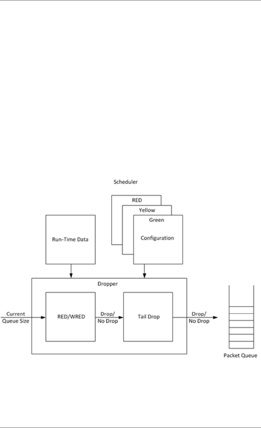
Programmer’s Guide, Release 18.11.0-rc5
does not have enough credits, its packets should be dropped as soon as possible (before they
reach the hierarchical scheduler), thus rendering the pipe queues as not active, which allows
the dequeue side to skip that pipe with no cycles being spent on investigating the pipe credits
that would result in a “not enough credits” status.
Single Queue with 100% Line Rate
The port scheduler performance is optimized for a large number of queues. If the number of
queues is small, then the performance of the port scheduler for the same level of active traffic
is expected to be worse than the performance of a small set of message passing queues.
40.3 Dropper
The purpose of the DPDK dropper is to drop packets arriving at a packet scheduler to avoid
congestion. The dropper supports the Random Early Detection (RED), Weighted Random
Early Detection (WRED) and tail drop algorithms. Fig. 40.7 illustrates how the dropper inte-
grates with the scheduler. The DPDK currently does not support congestion management so
the dropper provides the only method for congestion avoidance.
Fig. 40.7: High-level Block Diagram of the DPDK Dropper
The dropper uses the Random Early Detection (RED) congestion avoidance algorithm as doc-
umented in the reference publication. The purpose of the RED algorithm is to monitor a packet
queue, determine the current congestion level in the queue and decide whether an arriving
packet should be enqueued or dropped. The RED algorithm uses an Exponential Weighted
40.3. Dropper 315

Programmer’s Guide, Release 18.11.0-rc5
Moving Average (EWMA) filter to compute average queue size which gives an indication of the
current congestion level in the queue.
For each enqueue operation, the RED algorithm compares the average queue size to minimum
and maximum thresholds. Depending on whether the average queue size is below, above or in
between these thresholds, the RED algorithm calculates the probability that an arriving packet
should be dropped and makes a random decision based on this probability.
The dropper also supports Weighted Random Early Detection (WRED) by allowing the sched-
uler to select different RED configurations for the same packet queue at run-time. In the case
of severe congestion, the dropper resorts to tail drop. This occurs when a packet queue has
reached maximum capacity and cannot store any more packets. In this situation, all arriving
packets are dropped.
The flow through the dropper is illustrated in Fig. 40.8. The RED/WRED algorithm is exercised
first and tail drop second.
The use cases supported by the dropper are:
•–Initialize configuration data
•–Initialize run-time data
•–Enqueue (make a decision to enqueue or drop an arriving packet)
•–Mark empty (record the time at which a packet queue becomes empty)
The configuration use case is explained in Section2.23.3.1, the enqueue operation is explained
in Section 2.23.3.2 and the mark empty operation is explained in Section 2.23.3.3.
40.3.1 Configuration
A RED configuration contains the parameters given in Table 40.16.
Table 40.16: RED Configuration Parameters
Parameter Minimum Maximum Typical
Minimum Threshold 0 1022 1/4 x queue size
Maximum Threshold 1 1023 1/2 x queue size
Inverse Mark Probability 1 255 10
EWMA Filter Weight 1 12 9
The meaning of these parameters is explained in more detail in the following sections. The
format of these parameters as specified to the dropper module API corresponds to the format
used by Cisco* in their RED implementation. The minimum and maximum threshold parame-
ters are specified to the dropper module in terms of number of packets. The mark probability
parameter is specified as an inverse value, for example, an inverse mark probability parameter
value of 10 corresponds to a mark probability of 1/10 (that is, 1 in 10 packets will be dropped).
The EWMA filter weight parameter is specified as an inverse log value, for example, a filter
weight parameter value of 9 corresponds to a filter weight of 1/29.
40.3.2 Enqueue Operation
In the example shown in Fig. 40.9, q (actual queue size) is the input value, avg (average
queue size) and count (number of packets since the last drop) are run-time values, decision is
40.3. Dropper 316
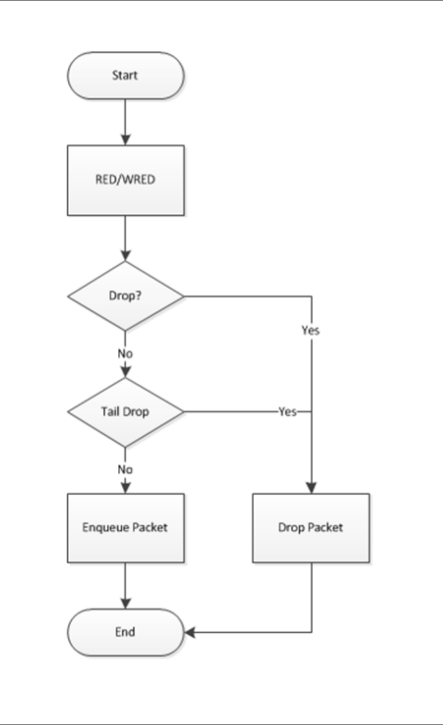
Programmer’s Guide, Release 18.11.0-rc5
Fig. 40.8: Flow Through the Dropper
40.3. Dropper 317
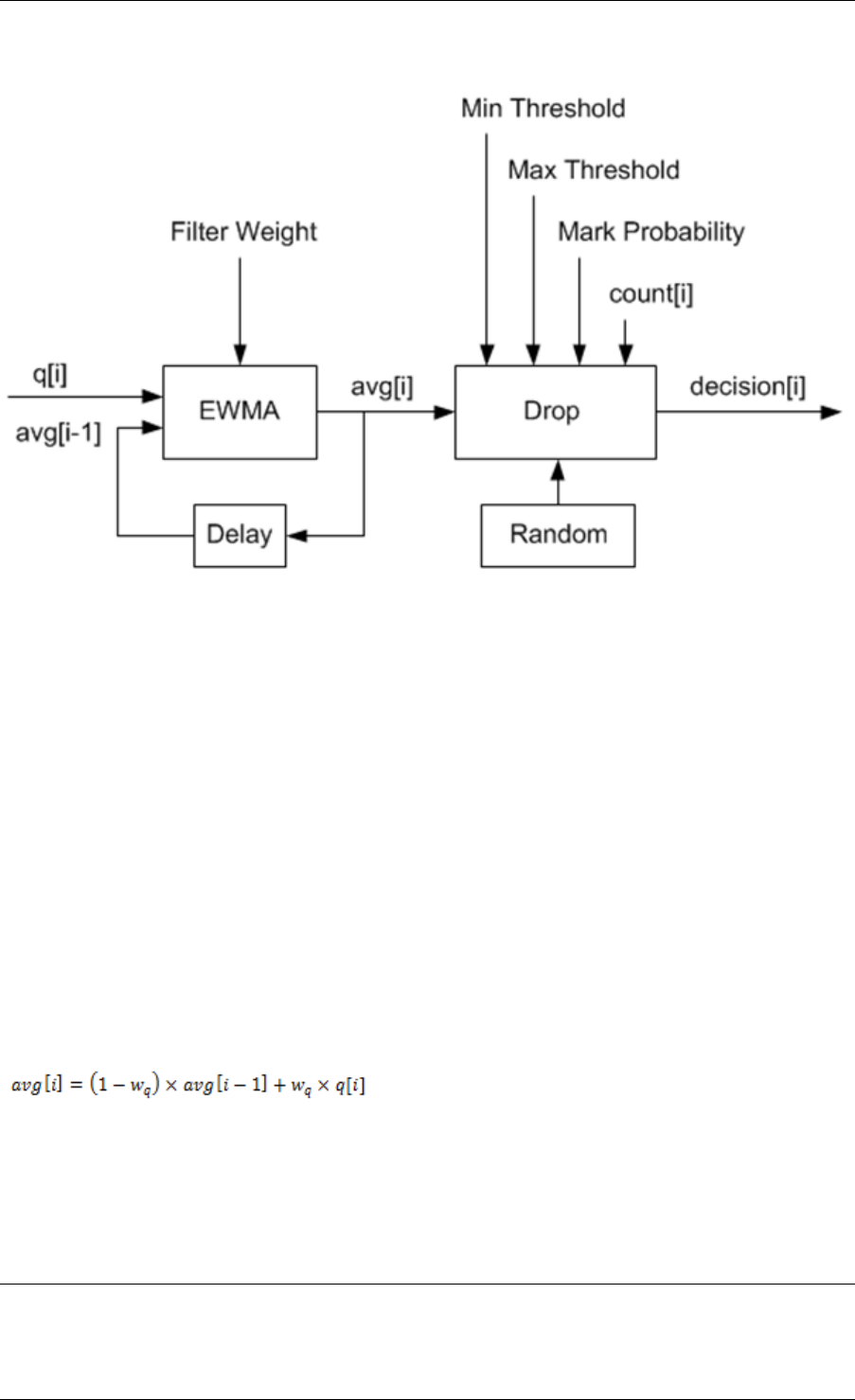
Programmer’s Guide, Release 18.11.0-rc5
the output value and the remaining values are configuration parameters.
Fig. 40.9: Example Data Flow Through Dropper
EWMA Filter Microblock
The purpose of the EWMA Filter microblock is to filter queue size values to smooth out transient
changes that result from “bursty” traffic. The output value is the average queue size which gives
a more stable view of the current congestion level in the queue.
The EWMA filter has one configuration parameter, filter weight, which determines how quickly
or slowly the average queue size output responds to changes in the actual queue size input.
Higher values of filter weight mean that the average queue size responds more quickly to
changes in actual queue size.
Average Queue Size Calculation when the Queue is not Empty
The definition of the EWMA filter is given in the following equation.
Where:
•avg = average queue size
•wq = filter weight
•q= actual queue size
Note:
The filter weight, wq = 1/2^n, where n is the filter weight parameter value passed to the dropper module
on configuration (see Section2.23.3.1 ).
40.3. Dropper 318
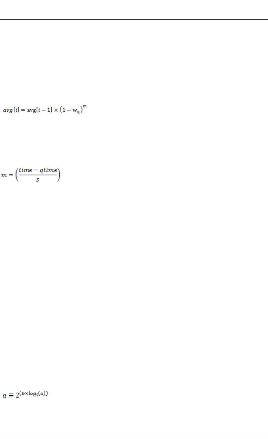
Programmer’s Guide, Release 18.11.0-rc5
Average Queue Size Calculation when the Queue is Empty
The EWMA filter does not read time stamps and instead assumes that enqueue operations
will happen quite regularly. Special handling is required when the queue becomes empty as
the queue could be empty for a short time or a long time. When the queue becomes empty,
average queue size should decay gradually to zero instead of dropping suddenly to zero or
remaining stagnant at the last computed value. When a packet is enqueued on an empty
queue, the average queue size is computed using the following formula:
Where:
•m= the number of enqueue operations that could have occurred on this queue while the
queue was empty
In the dropper module, mis defined as:
Where:
•time = current time
•qtime = time the queue became empty
•s= typical time between successive enqueue operations on this queue
The time reference is in units of bytes, where a byte signifies the time duration required by the
physical interface to send out a byte on the transmission medium (see Section Internal Time
Reference). The parameter s is defined in the dropper module as a constant with the value:
s=2^22. This corresponds to the time required by every leaf node in a hierarchy with 64K leaf
nodes to transmit one 64-byte packet onto the wire and represents the worst case scenario.
For much smaller scheduler hierarchies, it may be necessary to reduce the parameter s, which
is defined in the red header source file (rte_red.h) as:
#define RTE_RED_S
Since the time reference is in bytes, the port speed is implied in the expression: time-qtime.
The dropper does not have to be configured with the actual port speed. It adjusts automatically
to low speed and high speed links.
Implementation
A numerical method is used to compute the factor (1-wq)^m that appears in Equation 2.
This method is based on the following identity:
This allows us to express the following:
40.3. Dropper 319

Programmer’s Guide, Release 18.11.0-rc5
In the dropper module, a look-up table is used to compute log2(1-wq) for each value of wq
supported by the dropper module. The factor (1-wq)^m can then be obtained by multiplying
the table value by mand applying shift operations. To avoid overflow in the multiplication, the
value, m, and the look-up table values are limited to 16 bits. The total size of the look-up table
is 56 bytes. Once the factor (1-wq)^m is obtained using this method, the average queue size
can be calculated from Equation 2.
Alternative Approaches
Other methods for calculating the factor (1-wq)^m in the expression for computing average
queue size when the queue is empty (Equation 2) were considered. These approaches include:
• Floating-point evaluation
• Fixed-point evaluation using a small look-up table (512B) and up to 16 multiplications
(this is the approach used in the FreeBSD* ALTQ RED implementation)
• Fixed-point evaluation using a small look-up table (512B) and 16 SSE multiplications
(SSE optimized version of the approach used in the FreeBSD* ALTQ RED implementa-
tion)
• Large look-up table (76 KB)
The method that was finally selected (described above in Section 26.3.2.2.1) out performs all
of these approaches in terms of run-time performance and memory requirements and also
achieves accuracy comparable to floating-point evaluation. Table 40.17 lists the performance
of each of these alternative approaches relative to the method that is used in the dropper. As
can be seen, the floating-point implementation achieved the worst performance.
Table 40.17: Relative Performance of Alternative Approaches
Method Relative Performance
Current dropper method (see Section 23.3.2.1.3) 100%
Fixed-point method with small (512B) look-up table 148%
SSE method with small (512B) look-up table 114%
Large (76KB) look-up table 118%
Floating-point 595%
Note: In this case, since performance is expressed as time spent executing the operation in a specific condition, any relative performance value above 100% runs slower than the reference method.
Drop Decision Block
The Drop Decision block:
• Compares the average queue size with the minimum and maximum thresholds
• Calculates a packet drop probability
• Makes a random decision to enqueue or drop an arriving packet
The calculation of the drop probability occurs in two stages. An initial drop probability is calcu-
lated based on the average queue size, the minimum and maximum thresholds and the mark
probability. An actual drop probability is then computed from the initial drop probability. The
40.3. Dropper 320
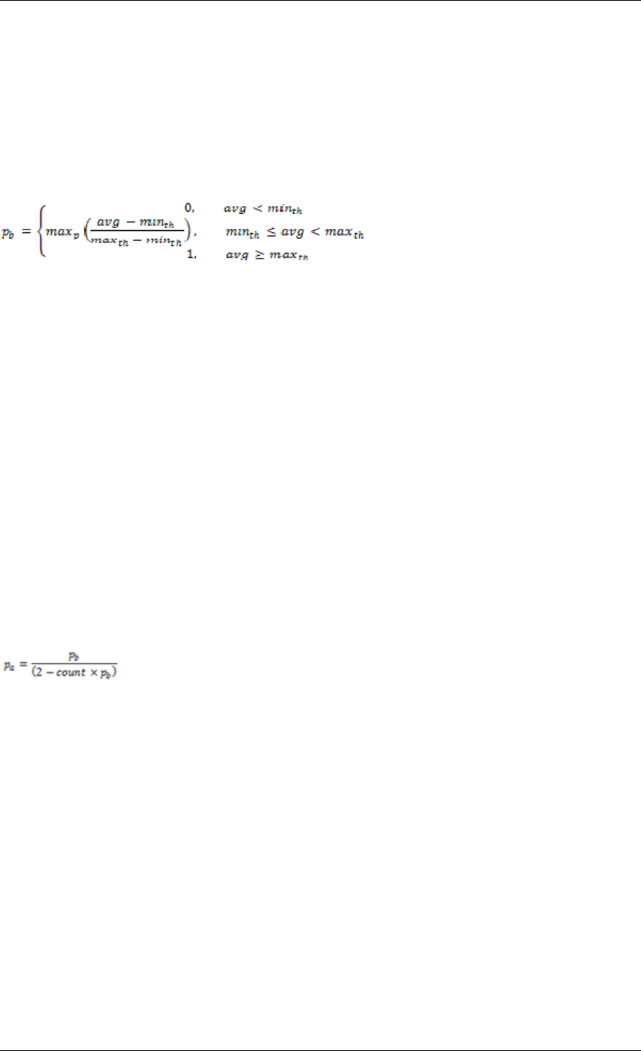
Programmer’s Guide, Release 18.11.0-rc5
actual drop probability takes the count run-time value into consideration so that the actual drop
probability increases as more packets arrive to the packet queue since the last packet was
dropped.
Initial Packet Drop Probability
The initial drop probability is calculated using the following equation.
Where:
•maxp = mark probability
•avg = average queue size
•minth = minimum threshold
•maxth = maximum threshold
The calculation of the packet drop probability using Equation 3 is illustrated in Fig. 40.10. If
the average queue size is below the minimum threshold, an arriving packet is enqueued. If the
average queue size is at or above the maximum threshold, an arriving packet is dropped. If
the average queue size is between the minimum and maximum thresholds, a drop probability
is calculated to determine if the packet should be enqueued or dropped.
Actual Drop Probability
If the average queue size is between the minimum and maximum thresholds, then the actual
drop probability is calculated from the following equation.
Where:
•Pb = initial drop probability (from Equation 3)
•count = number of packets that have arrived since the last drop
The constant 2, in Equation 4 is the only deviation from the drop probability formulae given in
the reference document where a value of 1 is used instead. It should be noted that the value pa
computed from can be negative or greater than 1. If this is the case, then a value of 1 should
be used instead.
The initial and actual drop probabilities are shown in Fig. 40.11. The actual drop probabil-
ity is shown for the case where the formula given in the reference document1 is used (blue
curve) and also for the case where the formula implemented in the dropper module, is used
(red curve). The formula in the reference document results in a significantly higher drop rate
compared to the mark probability configuration parameter specified by the user. The choice to
deviate from the reference document is simply a design decision and one that has been taken
by other RED implementations, for example, FreeBSD* ALTQ RED.
40.3. Dropper 321
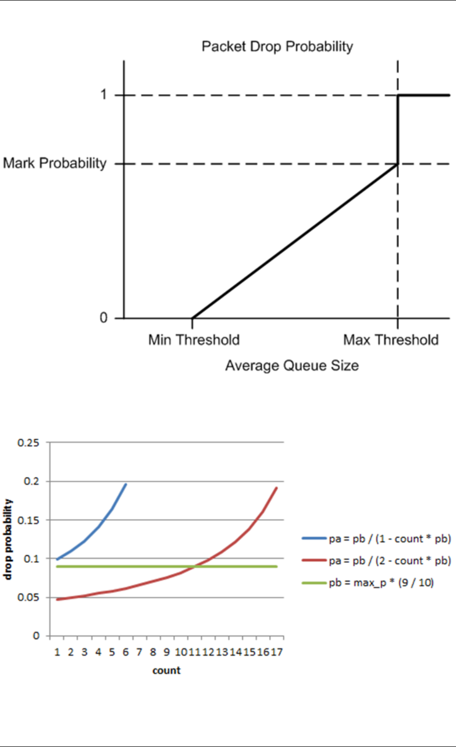
Programmer’s Guide, Release 18.11.0-rc5
Fig. 40.10: Packet Drop Probability for a Given RED Configuration
Fig. 40.11: Initial Drop Probability (pb), Actual Drop probability (pa) Computed Using a Factor
1 (Blue Curve) and a Factor 2 (Red Curve)
40.3. Dropper 322

Programmer’s Guide, Release 18.11.0-rc5
40.3.3 Queue Empty Operation
The time at which a packet queue becomes empty must be recorded and saved with the RED
run-time data so that the EWMA filter block can calculate the average queue size on the next
enqueue operation. It is the responsibility of the calling application to inform the dropper mod-
ule through the API that a queue has become empty.
40.3.4 Source Files Location
The source files for the DPDK dropper are located at:
• DPDK/lib/librte_sched/rte_red.h
• DPDK/lib/librte_sched/rte_red.c
40.3.5 Integration with the DPDK QoS Scheduler
RED functionality in the DPDK QoS scheduler is disabled by default. To enable it, use the
DPDK configuration parameter:
CONFIG_RTE_SCHED_RED=y
This parameter must be set to y. The parameter is found in the build configuration files in
the DPDK/config directory, for example, DPDK/config/common_linuxapp. RED configuration
parameters are specified in the rte_red_params structure within the rte_sched_port_params
structure that is passed to the scheduler on initialization. RED parameters are specified sep-
arately for four traffic classes and three packet colors (green, yellow and red) allowing the
scheduler to implement Weighted Random Early Detection (WRED).
40.3.6 Integration with the DPDK QoS Scheduler Sample Application
The DPDK QoS Scheduler Application reads a configuration file on start-up. The configura-
tion file includes a section containing RED parameters. The format of these parameters is
described in Section2.23.3.1. A sample RED configuration is shown below. In this example,
the queue size is 64 packets.
Note: For correct operation, the same EWMA filter weight parameter (wred weight) should be
used for each packet color (green, yellow, red) in the same traffic class (tc).
; RED params per traffic class and color (Green / Yellow / Red)
[red]
tc 0 wred min = 28 22 16
tc 0 wred max = 32 32 32
tc 0 wred inv prob = 10 10 10
tc 0 wred weight = 9 9 9
tc 1 wred min = 28 22 16
tc 1 wred max = 32 32 32
tc 1 wred inv prob = 10 10 10
tc 1 wred weight = 9 9 9
tc 2 wred min = 28 22 16
tc 2 wred max = 32 32 32
40.3. Dropper 323

Programmer’s Guide, Release 18.11.0-rc5
tc 2 wred inv prob = 10 10 10
tc 2 wred weight = 9 9 9
tc 3 wred min = 28 22 16
tc 3 wred max = 32 32 32
tc 3 wred inv prob = 10 10 10
tc 3 wred weight = 9 9 9
With this configuration file, the RED configuration that applies to green, yellow and red packets
in traffic class 0 is shown in Table 40.18.
Table 40.18: RED Configuration Corresponding to RED Configuration
File
RED Parameter Configuration Name Green Yellow Red
Minimum Threshold tc 0 wred min 28 22 16
Maximum Threshold tc 0 wred max 32 32 32
Mark Probability tc 0 wred inv prob 10 10 10
EWMA Filter Weight tc 0 wred weight 9 9 9
40.3.7 Application Programming Interface (API)
Enqueue API
The syntax of the enqueue API is as follows:
int rte_red_enqueue(const struct rte_red_config *red_cfg, struct rte_red *red, const unsigned q, const uint64_t time)
The arguments passed to the enqueue API are configuration data, run-time data, the current
size of the packet queue (in packets) and a value representing the current time. The time
reference is in units of bytes, where a byte signifies the time duration required by the physical
interface to send out a byte on the transmission medium (see Section 26.2.4.5.1 “Internal Time
Reference” ). The dropper reuses the scheduler time stamps for performance reasons.
Empty API
The syntax of the empty API is as follows:
void rte_red_mark_queue_empty(struct rte_red *red, const uint64_t time)
The arguments passed to the empty API are run-time data and the current time in bytes.
40.4 Traffic Metering
The traffic metering component implements the Single Rate Three Color Marker (srTCM) and
Two Rate Three Color Marker (trTCM) algorithms, as defined by IETF RFC 2697 and 2698
respectively. These algorithms meter the stream of incoming packets based on the allowance
defined in advance for each traffic flow. As result, each incoming packet is tagged as green,
yellow or red based on the monitored consumption of the flow the packet belongs to.
40.4. Traffic Metering 324

Programmer’s Guide, Release 18.11.0-rc5
40.4.1 Functional Overview
The srTCM algorithm defines two token buckets for each traffic flow, with the two buckets
sharing the same token update rate:
• Committed (C) bucket: fed with tokens at the rate defined by the Committed Information
Rate (CIR) parameter (measured in IP packet bytes per second). The size of the C bucket
is defined by the Committed Burst Size (CBS) parameter (measured in bytes);
• Excess (E) bucket: fed with tokens at the same rate as the C bucket. The size of the E
bucket is defined by the Excess Burst Size (EBS) parameter (measured in bytes).
The trTCM algorithm defines two token buckets for each traffic flow, with the two buckets being
updated with tokens at independent rates:
• Committed (C) bucket: fed with tokens at the rate defined by the Committed Information
Rate (CIR) parameter (measured in bytes of IP packet per second). The size of the C
bucket is defined by the Committed Burst Size (CBS) parameter (measured in bytes);
• Peak (P) bucket: fed with tokens at the rate defined by the Peak Information Rate (PIR)
parameter (measured in IP packet bytes per second). The size of the P bucket is defined
by the Peak Burst Size (PBS) parameter (measured in bytes).
Please refer to RFC 2697 (for srTCM) and RFC 2698 (for trTCM) for details on how tokens are
consumed from the buckets and how the packet color is determined.
Color Blind and Color Aware Modes
For both algorithms, the color blind mode is functionally equivalent to the color aware mode
with input color set as green. For color aware mode, a packet with red input color can only get
the red output color, while a packet with yellow input color can only get the yellow or red output
colors.
The reason why the color blind mode is still implemented distinctly than the color aware mode
is that color blind mode can be implemented with fewer operations than the color aware mode.
40.4.2 Implementation Overview
For each input packet, the steps for the srTCM / trTCM algorithms are:
• Update the C and E / P token buckets. This is done by reading the current time (from
the CPU timestamp counter), identifying the amount of time since the last bucket update
and computing the associated number of tokens (according to the pre-configured bucket
rate). The number of tokens in the bucket is limited by the pre-configured bucket size;
• Identify the output color for the current packet based on the size of the IP packet and the
amount of tokens currently available in the C and E / P buckets; for color aware mode
only, the input color of the packet is also considered. When the output color is not red, a
number of tokens equal to the length of the IP packet are subtracted from the C or E /P
or both buckets, depending on the algorithm and the output color of the packet.
40.4. Traffic Metering 325

CHAPTER
FORTYONE
POWER MANAGEMENT
The DPDK Power Management feature allows users space applications to save power by dy-
namically adjusting CPU frequency or entering into different C-States.
• Adjusting the CPU frequency dynamically according to the utilization of RX queue.
• Entering into different deeper C-States according to the adaptive algorithms to speculate
brief periods of time suspending the application if no packets are received.
The interfaces for adjusting the operating CPU frequency are in the power management library.
C-State control is implemented in applications according to the different use cases.
41.1 CPU Frequency Scaling
The Linux kernel provides a cpufreq module for CPU frequency scaling for each lcore. For
example, for cpuX, /sys/devices/system/cpu/cpuX/cpufreq/ has the following sys files for fre-
quency scaling:
• affected_cpus
• bios_limit
• cpuinfo_cur_freq
• cpuinfo_max_freq
• cpuinfo_min_freq
• cpuinfo_transition_latency
• related_cpus
• scaling_available_frequencies
• scaling_available_governors
• scaling_cur_freq
• scaling_driver
• scaling_governor
• scaling_max_freq
• scaling_min_freq
• scaling_setspeed
326

Programmer’s Guide, Release 18.11.0-rc5
In the DPDK, scaling_governor is configured in user space. Then, a user space application
can prompt the kernel by writing scaling_setspeed to adjust the CPU frequency according to
the strategies defined by the user space application.
41.2 Core-load Throttling through C-States
Core state can be altered by speculative sleeps whenever the specified lcore has nothing to
do. In the DPDK, if no packet is received after polling, speculative sleeps can be triggered
according the strategies defined by the user space application.
41.3 Per-core Turbo Boost
Individual cores can be allowed to enter a Turbo Boost state on a per-core basis. This is
achieved by enabling Turbo Boost Technology in the BIOS, then looping through the relevant
cores and enabling/disabling Turbo Boost on each core.
41.4 Use of Power Library in a Hyper-Threaded Environment
In the case where the power library is in use on a system with Hyper-Threading enabled, the
frequency on the physical core is set to the highest frequency of the Hyper-Thread siblings. So
even though an application may request a scale down, the core frequency will remain at the
highest frequency until all Hyper-Threads on that core request a scale down.
41.5 API Overview of the Power Library
The main methods exported by power library are for CPU frequency scaling and include the
following:
•Freq up: Prompt the kernel to scale up the frequency of the specific lcore.
•Freq down: Prompt the kernel to scale down the frequency of the specific lcore.
•Freq max: Prompt the kernel to scale up the frequency of the specific lcore to the maxi-
mum.
•Freq min: Prompt the kernel to scale down the frequency of the specific lcore to the
minimum.
•Get available freqs: Read the available frequencies of the specific lcore from the sys
file.
•Freq get: Get the current frequency of the specific lcore.
•Freq set: Prompt the kernel to set the frequency for the specific lcore.
•Enable turbo: Prompt the kernel to enable Turbo Boost for the specific lcore.
•Disable turbo: Prompt the kernel to disable Turbo Boost for the specific lcore.
41.2. Core-load Throttling through C-States 327

Programmer’s Guide, Release 18.11.0-rc5
41.6 User Cases
The power management mechanism is used to save power when performing L3 forwarding.
41.7 Empty Poll API
41.7.1 Abstract
For packet processing workloads such as DPDK polling is continuous. This means CPU cores
always show 100% busy independent of how much work those cores are doing. It is critical to
accurately determine how busy a core is hugely important for the following reasons:
• No indication of overload conditions
• User does not know how much real load is on a system, resulting in wasted energy as
no power management is utilized
Compared to the original l3fwd-power design, instead of going to sleep after detecting an empty
poll, the new mechanism just lowers the core frequency. As a result, the application does not
stop polling the device, which leads to improved handling of bursts of traffic.
When the system become busy, the empty poll mechanism can also increase the core fre-
quency (including turbo) to do best effort for intensive traffic. This gives us more flexible and
balanced traffic awareness over the standard l3fwd-power application.
41.7.2 Proposed Solution
The proposed solution focuses on how many times empty polls are executed. The less the
number of empty polls, means current core is busy with processing workload, therefore, the
higher frequency is needed. The high empty poll number indicates the current core not doing
any real work therefore, we can lower the frequency to safe power.
In the current implementation, each core has 1 empty-poll counter which assume 1 core is
dedicated to 1 queue. This will need to be expanded in the future to support multiple queues
per core.
Power state definition:
• LOW: Not currently used, reserved for future use.
• MED: the frequency is used to process modest traffic workload.
• HIGH: the frequency is used to process busy traffic workload.
There are two phases to establish the power management system:
• Training phase. This phase is used to measure the optimal frequency change thresholds
for a given system. The thresholds will differ from system to system due to differences
in processor micro-architecture, cache and device configurations. In this phase, the user
must ensure that no traffic can enter the system so that counts can be measured for
empty polls at low, medium and high frequencies. Each frequency is measured for two
41.6. User Cases 328

Programmer’s Guide, Release 18.11.0-rc5
seconds. Once the training phase is complete, the threshold numbers are displayed,
and normal mode resumes, and traffic can be allowed into the system. These threshold
number can be used on the command line when starting the application in normal mode
to avoid re-training every time.
• Normal phase. Every 10ms the run-time counters are compared to the supplied threshold
values, and the decision will be made whether to move to a different power state (by
adjusting the frequency).
41.7.3 API Overview for Empty Poll Power Management
•State Init: initialize the power management system.
•State Free: free the resource hold by power management system.
•Update Empty Poll Counter: update the empty poll counter.
•Update Valid Poll Counter: update the valid poll counter.
•Set the Fequence Index: update the power state/frequency mapping.
•Detect empty poll state change: empty poll state change detection algorithm then take
action.
41.8 User Cases
The mechanism can applied to any device which is based on polling. e.g. NIC, FPGA.
41.9 References
• l3fwd-power: The sample application in DPDK that performs L3 forwarding with power
management.
• The “L3 Forwarding with Power Management Sample Application” chapter in the DPDK
Sample Application’s User Guide.
41.8. User Cases 329

CHAPTER
FORTYTWO
PACKET CLASSIFICATION AND ACCESS CONTROL
The DPDK provides an Access Control library that gives the ability to classify an input packet
based on a set of classification rules.
The ACL library is used to perform an N-tuple search over a set of rules with multiple categories
and find the best match (highest priority) for each category. The library API provides the
following basic operations:
• Create a new Access Control (AC) context.
• Add rules into the context.
• For all rules in the context, build the runtime structures necessary to perform packet
classification.
• Perform input packet classifications.
• Destroy an AC context and its runtime structures and free the associated memory.
42.1 Overview
42.1.1 Rule definition
The current implementation allows the user for each AC context to specify its own rule (set of
fields) over which packet classification will be performed. Though there are few restrictions on
the rule fields layout:
• First field in the rule definition has to be one byte long.
• All subsequent fields has to be grouped into sets of 4 consecutive bytes.
This is done mainly for performance reasons - search function processes the first input byte as
part of the flow setup and then the inner loop of the search function is unrolled to process four
input bytes at a time.
To define each field inside an AC rule, the following structure is used:
struct rte_acl_field_def {
uint8_t type; /*< type - ACL_FIELD_TYPE. */
uint8_t size; /*< size of field 1,2,4, or 8. */
uint8_t field_index; /*< index of field inside the rule. */
uint8_t input_index; /*< 0-N input index. */
uint32_t offset; /*< offset to start of field. */
};
• type The field type is one of three choices:
330

Programmer’s Guide, Release 18.11.0-rc5
–_MASK - for fields such as IP addresses that have a value and a mask defining the
number of relevant bits.
–_RANGE - for fields such as ports that have a lower and upper value for the field.
–_BITMASK - for fields such as protocol identifiers that have a value and a bit mask.
• size The size parameter defines the length of the field in bytes. Allowable values are 1,
2, 4, or 8 bytes. Note that due to the grouping of input bytes, 1 or 2 byte fields must be
defined as consecutive fields that make up 4 consecutive input bytes. Also, it is best to
define fields of 8 or more bytes as 4 byte fields so that the build processes can eliminate
fields that are all wild.
• field_index A zero-based value that represents the position of the field inside the rule; 0
to N-1 for N fields.
• input_index As mentioned above, all input fields, except the very first one, must be in
groups of 4 consecutive bytes. The input index specifies to which input group that field
belongs to.
• offset The offset field defines the offset for the field. This is the offset from the beginning
of the buffer parameter for the search.
For example, to define classification for the following IPv4 5-tuple structure:
struct ipv4_5tuple {
uint8_t proto;
uint32_t ip_src;
uint32_t ip_dst;
uint16_t port_src;
uint16_t port_dst;
};
The following array of field definitions can be used:
struct rte_acl_field_def ipv4_defs[5]={
/*first input field - always one byte long. */
{
.type =RTE_ACL_FIELD_TYPE_BITMASK,
.size =sizeof (uint8_t),
.field_index =0,
.input_index =0,
.offset =offsetof (struct ipv4_5tuple, proto),
},
/*next input field (IPv4 source address) - 4 consecutive bytes. */
{
.type =RTE_ACL_FIELD_TYPE_MASK,
.size =sizeof (uint32_t),
.field_index =1,
.input_index =1,
.offset =offsetof (struct ipv4_5tuple, ip_src),
},
/*next input field (IPv4 destination address) - 4 consecutive bytes. */
{
.type =RTE_ACL_FIELD_TYPE_MASK,
.size =sizeof (uint32_t),
.field_index =2,
.input_index =2,
.offset =offsetof (struct ipv4_5tuple, ip_dst),
},
42.1. Overview 331

Programmer’s Guide, Release 18.11.0-rc5
/*
*Next 2 fields (src & dst ports) form 4 consecutive bytes.
*They share the same input index.
*/
{
.type =RTE_ACL_FIELD_TYPE_RANGE,
.size =sizeof (uint16_t),
.field_index =3,
.input_index =3,
.offset =offsetof (struct ipv4_5tuple, port_src),
},
{
.type =RTE_ACL_FIELD_TYPE_RANGE,
.size =sizeof (uint16_t),
.field_index =4,
.input_index =3,
.offset =offsetof (struct ipv4_5tuple, port_dst),
},
};
A typical example of such an IPv4 5-tuple rule is a follows:
source addr/mask destination addr/mask source ports dest ports protocol/mask
192.168.1.0/24 192.168.2.31/32 0:65535 1234:1234 17/0xff
Any IPv4 packets with protocol ID 17 (UDP), source address 192.168.1.[0-255], destination
address 192.168.2.31, source port [0-65535] and destination port 1234 matches the above
rule.
To define classification for the IPv6 2-tuple: <protocol, IPv6 source address> over the following
IPv6 header structure:
struct struct ipv6_hdr {
uint32_t vtc_flow; /*IP version, traffic class & flow label. */
uint16_t payload_len; /*IP packet length - includes sizeof(ip_header). */
uint8_t proto; /*Protocol, next header. */
uint8_t hop_limits; /*Hop limits. */
uint8_t src_addr[16]; /*IP address of source host. */
uint8_t dst_addr[16]; /*IP address of destination host(s). */
} __attribute__((__packed__));
The following array of field definitions can be used:
struct struct rte_acl_field_def ipv6_2tuple_defs[5]={
{
.type =RTE_ACL_FIELD_TYPE_BITMASK,
.size =sizeof (uint8_t),
.field_index =0,
.input_index =0,
.offset =offsetof (struct ipv6_hdr, proto),
},
{
.type =RTE_ACL_FIELD_TYPE_MASK,
.size =sizeof (uint32_t),
.field_index =1,
.input_index =1,
.offset =offsetof (struct ipv6_hdr, src_addr[0]),
},
{
.type =RTE_ACL_FIELD_TYPE_MASK,
.size =sizeof (uint32_t),
42.1. Overview 332

Programmer’s Guide, Release 18.11.0-rc5
.field_index =2,
.input_index =2,
.offset =offsetof (struct ipv6_hdr, src_addr[4]),
},
{
.type =RTE_ACL_FIELD_TYPE_MASK,
.size =sizeof (uint32_t),
.field_index =3,
.input_index =3,
.offset =offsetof (struct ipv6_hdr, src_addr[8]),
},
{
.type =RTE_ACL_FIELD_TYPE_MASK,
.size =sizeof (uint32_t),
.field_index =4,
.input_index =4,
.offset =offsetof (struct ipv6_hdr, src_addr[12]),
},
};
A typical example of such an IPv6 2-tuple rule is a follows:
source addr/mask protocol/mask
2001:db8:1234:0000:0000:0000:0000:0000/48 6/0xff
Any IPv6 packets with protocol ID 6 (TCP), and source address inside the range
[2001:db8:1234:0000:0000:0000:0000:0000 - 2001:db8:1234:ffff:ffff:ffff:ffff:ffff] matches the
above rule.
In the following example the last element of the search key is 8-bit long. So it is a case
where the 4 consecutive bytes of an input field are not fully occupied. The structure for the
classification is:
struct acl_key {
uint8_t ip_proto;
uint32_t ip_src;
uint32_t ip_dst;
uint8_t tos; /*< This is partially using a 32-bit input element */
};
The following array of field definitions can be used:
struct rte_acl_field_def ipv4_defs[4]={
/*first input field - always one byte long. */
{
.type =RTE_ACL_FIELD_TYPE_BITMASK,
.size =sizeof (uint8_t),
.field_index =0,
.input_index =0,
.offset =offsetof (struct acl_key, ip_proto),
},
/*next input field (IPv4 source address) - 4 consecutive bytes. */
{
.type =RTE_ACL_FIELD_TYPE_MASK,
.size =sizeof (uint32_t),
.field_index =1,
.input_index =1,
.offset =offsetof (struct acl_key, ip_src),
},
/*next input field (IPv4 destination address) - 4 consecutive bytes. */
42.1. Overview 333

Programmer’s Guide, Release 18.11.0-rc5
{
.type =RTE_ACL_FIELD_TYPE_MASK,
.size =sizeof (uint32_t),
.field_index =2,
.input_index =2,
.offset =offsetof (struct acl_key, ip_dst),
},
/*
*Next element of search key (Type of Service) is indeed 1 byte long.
*Anyway we need to allocate all the 4 consecutive bytes for it.
*/
{
.type =RTE_ACL_FIELD_TYPE_BITMASK,
.size =sizeof (uint32_t), /*All the 4 consecutive bytes are allocated */
.field_index =3,
.input_index =3,
.offset =offsetof (struct acl_key, tos),
},
};
A typical example of such an IPv4 4-tuple rule is as follows:
source addr/mask destination addr/mask tos/mask protocol/mask
192.168.1.0/24 192.168.2.31/32 1/0xff 6/0xff
Any IPv4 packets with protocol ID 6 (TCP), source address 192.168.1.[0-255], destination
address 192.168.2.31, ToS 1 matches the above rule.
When creating a set of rules, for each rule, additional information must be supplied also:
•priority: A weight to measure the priority of the rules (higher is better). If the input tuple
matches more than one rule, then the rule with the higher priority is returned. Note that
if the input tuple matches more than one rule and these rules have equal priority, it is
undefined which rule is returned as a match. It is recommended to assign a unique
priority for each rule.
•category_mask: Each rule uses a bit mask value to select the relevant category(s) for
the rule. When a lookup is performed, the result for each category is returned. This ef-
fectively provides a “parallel lookup” by enabling a single search to return multiple results
if, for example, there were four different sets of ACL rules, one for access control, one for
routing, and so on. Each set could be assigned its own category and by combining them
into a single database, one lookup returns a result for each of the four sets.
•userdata: A user-defined value. For each category, a successful match returns the
userdata field of the highest priority matched rule. When no rules match, returned value
is zero.
Note: When adding new rules into an ACL context, all fields must be in host byte order (LSB).
When the search is performed for an input tuple, all fields in that tuple must be in network byte
order (MSB).
42.1.2 RT memory size limit
Build phase (rte_acl_build()) creates for a given set of rules internal structure for further run-
time traversal. With current implementation it is a set of multi-bit tries (with stride == 8).
Depending on the rules set, that could consume significant amount of memory. In attempt
42.1. Overview 334

Programmer’s Guide, Release 18.11.0-rc5
to conserve some space ACL build process tries to split the given rule-set into several non-
intersecting subsets and construct a separate trie for each of them. Depending on the rule-set,
it might reduce RT memory requirements but might increase classification time. There is a
possibility at build-time to specify maximum memory limit for internal RT structures for given
AC context. It could be done via max_size field of the rte_acl_config structure. Setting it to
the value greater than zero, instructs rte_acl_build() to:
• attempt to minimize number of tries in the RT table, but
• make sure that size of RT table wouldn’t exceed given value.
Setting it to zero makes rte_acl_build() to use the default behavior: try to minimize size of the
RT structures, but doesn’t expose any hard limit on it.
That gives the user the ability to decisions about performance/space trade-off. For example:
struct rte_acl_ctx *acx;
struct rte_acl_config cfg;
int ret;
/*
*assuming that acx points to already created and
*populated with rules AC context and cfg filled properly.
*/
/*try to build AC context, with RT structures less then 8MB. */
cfg.max_size =0x800000;
ret =rte_acl_build(acx, &cfg);
/*
*RT structures can't fit into 8MB for given context.
*Try to build without exposing any hard limit.
*/
if (ret == -ERANGE) {
cfg.max_size =0;
ret =rte_acl_build(acx, &cfg);
}
42.1.3 Classification methods
After rte_acl_build() over given AC context has finished successfully, it can be used to perform
classification - search for a rule with highest priority over the input data. There are several
implementations of classify algorithm:
•RTE_ACL_CLASSIFY_SCALAR: generic implementation, doesn’t require any specific
HW support.
•RTE_ACL_CLASSIFY_SSE: vector implementation, can process up to 8 flows in paral-
lel. Requires SSE 4.1 support.
•RTE_ACL_CLASSIFY_AVX2: vector implementation, can process up to 16 flows in par-
allel. Requires AVX2 support.
It is purely a runtime decision which method to choose, there is no build-time difference. All
implementations operates over the same internal RT structures and use similar principles. The
main difference is that vector implementations can manually exploit IA SIMD instructions and
process several input data flows in parallel. At startup ACL library determines the highest
available classify method for the given platform and sets it as default one. Though the user has
an ability to override the default classifier function for a given ACL context or perform particular
42.1. Overview 335

Programmer’s Guide, Release 18.11.0-rc5
search using non-default classify method. In that case it is user responsibility to make sure
that given platform supports selected classify implementation.
42.2 Application Programming Interface (API) Usage
Note: For more details about the Access Control API, please refer to the DPDK API Refer-
ence.
The following example demonstrates IPv4, 5-tuple classification for rules defined above with
multiple categories in more detail.
42.2.1 Classify with Multiple Categories
struct rte_acl_ctx *acx;
struct rte_acl_config cfg;
int ret;
/*define a structure for the rule with up to 5 fields. */
RTE_ACL_RULE_DEF(acl_ipv4_rule, RTE_DIM(ipv4_defs));
/*AC context creation parameters. */
struct rte_acl_param prm ={
.name ="ACL_example",
.socket_id =SOCKET_ID_ANY,
.rule_size =RTE_ACL_RULE_SZ(RTE_DIM(ipv4_defs)),
/*number of fields per rule. */
.max_rule_num =8,/*maximum number of rules in the AC context. */
};
struct acl_ipv4_rule acl_rules[] ={
/*matches all packets traveling to 192.168.0.0/16, applies for categories: 0,1 */
{
.data ={.userdata =1, .category_mask =3, .priority =1},
/*destination IPv4 */
.field[2]={.value.u32 =IPv4(192,168,0,0),. mask_range.u32 =16,},
/*source port */
.field[3]={.value.u16 =0, .mask_range.u16 =0xffff,},
/*destination port */
.field[4]={.value.u16 =0, .mask_range.u16 =0xffff,},
},
/*matches all packets traveling to 192.168.1.0/24, applies for categories: 0 */
{
.data ={.userdata =2, .category_mask =1, .priority =2},
/*destination IPv4 */
.field[2]={.value.u32 =IPv4(192,168,1,0),. mask_range.u32 =24,},
/*source port */
42.2. Application Programming Interface (API) Usage 336

Programmer’s Guide, Release 18.11.0-rc5
.field[3]={.value.u16 =0, .mask_range.u16 =0xffff,},
/*destination port */
.field[4]={.value.u16 =0, .mask_range.u16 =0xffff,},
},
/*matches all packets traveling from 10.1.1.1, applies for categories: 1 */
{
.data ={.userdata =3, .category_mask =2, .priority =3},
/*source IPv4 */
.field[1]={.value.u32 =IPv4(10,1,1,1),. mask_range.u32 =32,},
/*source port */
.field[3]={.value.u16 =0, .mask_range.u16 =0xffff,},
/*destination port */
.field[4]={.value.u16 =0, .mask_range.u16 =0xffff,},
},
};
/*create an empty AC context */
if ((acx =rte_acl_create(&prm)) == NULL) {
/*handle context create failure. */
}
/*add rules to the context */
ret =rte_acl_add_rules(acx, acl_rules, RTE_DIM(acl_rules));
if (ret != 0) {
/*handle error at adding ACL rules. */
}
/*prepare AC build config. */
cfg.num_categories =2;
cfg.num_fields =RTE_DIM(ipv4_defs);
memcpy(cfg.defs, ipv4_defs, sizeof (ipv4_defs));
/*build the runtime structures for added rules, with 2 categories. */
ret =rte_acl_build(acx, &cfg);
if (ret != 0) {
/*handle error at build runtime structures for ACL context. */
}
For a tuple with source IP address: 10.1.1.1 and destination IP address: 192.168.1.15, once
the following lines are executed:
uint32_t results[4]; /*make classify for 4 categories. */
rte_acl_classify(acx, data, results, 1,4);
then the results[] array contains:
results[4]={2,3,0,0};
• For category 0, both rules 1 and 2 match, but rule 2 has higher priority, therefore results[0]
42.2. Application Programming Interface (API) Usage 337

Programmer’s Guide, Release 18.11.0-rc5
contains the userdata for rule 2.
• For category 1, both rules 1 and 3 match, but rule 3 has higher priority, therefore results[1]
contains the userdata for rule 3.
• For categories 2 and 3, there are no matches, so results[2] and results[3] contain zero,
which indicates that no matches were found for those categories.
For a tuple with source IP address: 192.168.1.1 and destination IP address: 192.168.2.11,
once the following lines are executed:
uint32_t results[4]; /*make classify by 4 categories. */
rte_acl_classify(acx, data, results, 1,4);
the results[] array contains:
results[4]={1,1,0,0};
• For categories 0 and 1, only rule 1 matches.
• For categories 2 and 3, there are no matches.
For a tuple with source IP address: 10.1.1.1 and destination IP address: 201.212.111.12, once
the following lines are executed:
uint32_t results[4]; /*make classify by 4 categories. */
rte_acl_classify(acx, data, results, 1,4);
the results[] array contains:
results[4]={0,3,0,0};
• For category 1, only rule 3 matches.
• For categories 0, 2 and 3, there are no matches.
42.2. Application Programming Interface (API) Usage 338

CHAPTER
FORTYTHREE
PACKET FRAMEWORK
43.1 Design Objectives
The main design objectives for the DPDK Packet Framework are:
• Provide standard methodology to build complex packet processing pipelines. Provide
reusable and extensible templates for the commonly used pipeline functional blocks;
• Provide capability to switch between pure software and hardware-accelerated implemen-
tations for the same pipeline functional block;
• Provide the best trade-off between flexibility and performance. Hardcoded pipelines usu-
ally provide the best performance, but are not flexible, while developing flexible frame-
works is never a problem, but performance is usually low;
• Provide a framework that is logically similar to Open Flow.
43.2 Overview
Packet processing applications are frequently structured as pipelines of multiple stages, with
the logic of each stage glued around a lookup table. For each incoming packet, the table
defines the set of actions to be applied to the packet, as well as the next stage to send the
packet to.
The DPDK Packet Framework minimizes the development effort required to build packet pro-
cessing pipelines by defining a standard methodology for pipeline development, as well as
providing libraries of reusable templates for the commonly used pipeline blocks.
The pipeline is constructed by connecting the set of input ports with the set of output ports
through the set of tables in a tree-like topology. As result of lookup operation for the current
packet in the current table, one of the table entries (on lookup hit) or the default table entry (on
lookup miss) provides the set of actions to be applied on the current packet, as well as the next
hop for the packet, which can be either another table, an output port or packet drop.
An example of packet processing pipeline is presented in Fig. 43.1:
339
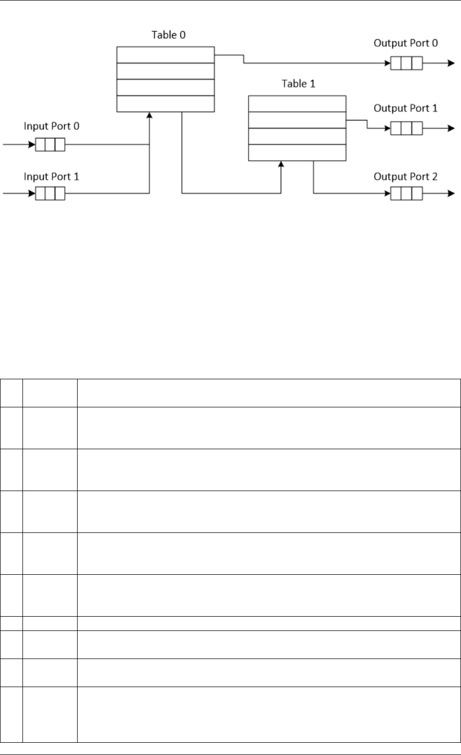
Programmer’s Guide, Release 18.11.0-rc5
Fig. 43.1: Example of Packet Processing Pipeline where Input Ports 0 and 1 are Connected
with Output Ports 0, 1 and 2 through Tables 0 and 1
43.3 Port Library Design
43.3.1 Port Types
Table 43.1 is a non-exhaustive list of ports that can be implemented with the Packet Framework.
Table 43.1: Port Types
# Port
type
Description
1 SW ring SW circular buffer used for message passing between the application
threads. Uses the DPDK rte_ring primitive. Expected to be the most
commonly used type of port.
2 HW ring Queue of buffer descriptors used to interact with NIC, switch or accelerator
ports. For NIC ports, it uses the DPDK rte_eth_rx_queue or
rte_eth_tx_queue primitives.
3 IP re-
assem-
bly
Input packets are either IP fragments or complete IP datagrams. Output
packets are complete IP datagrams.
4 IP frag-
menta-
tion
Input packets are jumbo (IP datagrams with length bigger than MTU) or
non-jumbo packets. Output packets are non-jumbo packets.
5 Traffic
man-
ager
Traffic manager attached to a specific NIC output port, performing
congestion management and hierarchical scheduling according to
pre-defined SLAs.
6 KNI Send/receive packets to/from Linux kernel space.
7 Source Input port used as packet generator. Similar to Linux kernel /dev/zero
character device.
8 Sink Output port used to drop all input packets. Similar to Linux kernel /dev/null
character device.
9 Sym_cryptoOutput port used to extract DPDK Cryptodev operations from a fixed offset
of the packet and then enqueue to the Cryptodev PMD. Input port used to
dequeue the Cryptodev operations from the Cryptodev PMD and then
retrieve the packets from them.
43.3. Port Library Design 340

Programmer’s Guide, Release 18.11.0-rc5
43.3.2 Port Interface
Each port is unidirectional, i.e. either input port or output port. Each input/output port is
required to implement an abstract interface that defines the initialization and run-time operation
of the port. The port abstract interface is described in.
Table 43.2: 20 Port Abstract Interface
# Port
Operation
Description
1 Create Create the low-level port object (e.g. queue). Can internally allocate
memory.
2 Free Free the resources (e.g. memory) used by the low-level port object.
3 RX Read a burst of input packets. Non-blocking operation. Only defined for
input ports.
4 TX Write a burst of input packets. Non-blocking operation. Only defined for
output ports.
5 Flush Flush the output buffer. Only defined for output ports.
43.4 Table Library Design
43.4.1 Table Types
Table 43.3 is a non-exhaustive list of types of tables that can be implemented with the Packet
Framework.
43.4. Table Library Design 341

Programmer’s Guide, Release 18.11.0-rc5
Table 43.3: Table Types
# Table Type Description
1 Hash table Lookup key is n-tuple based.
Typically, the lookup key is hashed to produce a signature that is used
to identify a bucket of entries where the lookup key is searched next.
The signature associated with the lookup key of each input packet is
either read from the packet descriptor (pre-computed signature) or
computed at table lookup time.
The table lookup, add entry and delete entry operations, as well as
any other pipeline block that pre-computes the signature all have to
use the same hashing algorithm to generate the signature.
Typically used to implement flow classification tables, ARP caches,
routing table for tunnelling protocols, etc.
2 Longest
Prefix Match
(LPM)
Lookup key is the IP address.
Each table entries has an associated IP prefix (IP and depth).
The table lookup operation selects the IP prefix that is matched by the
lookup key; in case of multiple matches, the entry with the longest
prefix depth wins.
Typically used to implement IP routing tables.
3 Access
Control List
(ACLs)
Lookup key is 7-tuple of two VLAN/MPLS labels, IP destination
address, IP source addresses, L4 protocol, L4 destination port, L4
source port.
Each table entry has an associated ACL and priority. The ACL
contains bit masks for the VLAN/MPLS labels, IP prefix for IP
destination address, IP prefix for IP source addresses, L4 protocol and
bitmask, L4 destination port and bit mask, L4 source port and bit
mask.
The table lookup operation selects the ACL that is matched by the
lookup key; in case of multiple matches, the entry with the highest
priority wins.
Typically used to implement rule databases for firewalls, etc.
4 Pattern
matching
search
Lookup key is the packet payload.
Table is a database of patterns, with each pattern having a priority
assigned.
The table lookup operation selects the patterns that is matched by the
input packet; in case of multiple matches, the matching pattern with
the highest priority wins.
5 Array Lookup key is the table entry index itself.
43.4.2 Table Interface
Each table is required to implement an abstract interface that defines the initialization and
run-time operation of the table. The table abstract interface is described in Table 43.4.
43.4. Table Library Design 342

Programmer’s Guide, Release 18.11.0-rc5
Table 43.4: Table Abstract Interface
# Table
opera-
tion
Description
1 Create Create the low-level data structures of the lookup table. Can internally
allocate memory.
2 Free Free up all the resources used by the lookup table.
3 Add
entry
Add new entry to the lookup table.
4 Delete
entry
Delete specific entry from the lookup table.
5 Lookup Look up a burst of input packets and return a bit mask specifying the result
of the lookup operation for each packet: a set bit signifies lookup hit for the
corresponding packet, while a cleared bit a lookup miss.
For each lookup hit packet, the lookup operation also returns a pointer to
the table entry that was hit, which contains the actions to be applied on the
packet and any associated metadata.
For each lookup miss packet, the actions to be applied on the packet and
any associated metadata are specified by the default table entry
preconfigured for lookup miss.
43.4.3 Hash Table Design
Hash Table Overview
Hash tables are important because the key lookup operation is optimized for speed: instead of
having to linearly search the lookup key through all the keys in the table, the search is limited
to only the keys stored in a single table bucket.
Associative Arrays
An associative array is a function that can be specified as a set of (key, value) pairs, with each
key from the possible set of input keys present at most once. For a given associative array, the
possible operations are:
1. add (key, value): When no value is currently associated with key, then the (key, value ) as-
sociation is created. When key is already associated value value0, then the association
(key,value0) is removed and association (key, value) is created;
2. delete key: When no value is currently associated with key, this operation has no effect.
When key is already associated value, then association (key, value) is removed;
3. lookup key: When no value is currently associated with key, then this operation returns
void value (lookup miss). When key is associated with value, then this operation returns
value. The (key, value) association is not changed.
The matching criterion used to compare the input key against the keys in the associative array
is exact match, as the key size (number of bytes) and the key value (array of bytes) have to
match exactly for the two keys under comparison.
Hash Function
43.4. Table Library Design 343
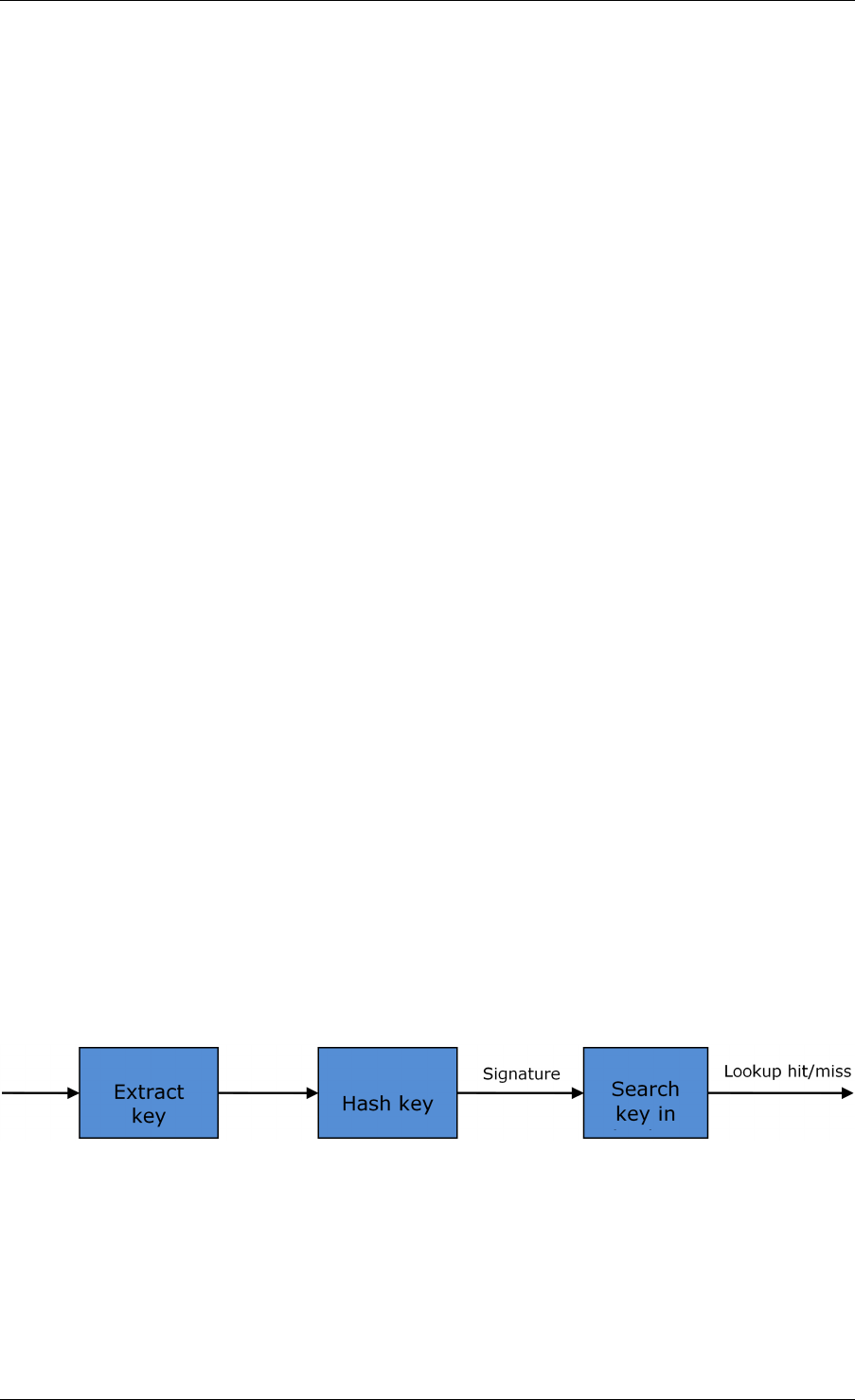
Programmer’s Guide, Release 18.11.0-rc5
A hash function deterministically maps data of variable length (key) to data of fixed size (hash
value or key signature). Typically, the size of the key is bigger than the size of the key signature.
The hash function basically compresses a long key into a short signature. Several keys can
share the same signature (collisions).
High quality hash functions have uniform distribution. For large number of keys, when dividing
the space of signature values into a fixed number of equal intervals (buckets), it is desirable
to have the key signatures evenly distributed across these intervals (uniform distribution), as
opposed to most of the signatures going into only a few of the intervals and the rest of the
intervals being largely unused (non-uniform distribution).
Hash Table
A hash table is an associative array that uses a hash function for its operation. The reason for
using a hash function is to optimize the performance of the lookup operation by minimizing the
number of table keys that have to be compared against the input key.
Instead of storing the (key, value) pairs in a single list, the hash table maintains multiple lists
(buckets). For any given key, there is a single bucket where that key might exist, and this bucket
is uniquely identified based on the key signature. Once the key signature is computed and the
hash table bucket identified, the key is either located in this bucket or it is not present in the
hash table at all, so the key search can be narrowed down from the full set of keys currently in
the table to just the set of keys currently in the identified table bucket.
The performance of the hash table lookup operation is greatly improved, provided that the table
keys are evenly distributed among the hash table buckets, which can be achieved by using a
hash function with uniform distribution. The rule to map a key to its bucket can simply be to
use the key signature (modulo the number of table buckets) as the table bucket ID:
bucket_id = f_hash(key) % n_buckets;
By selecting the number of buckets to be a power of two, the modulo operator can be replaced
by a bitwise AND logical operation:
bucket_id = f_hash(key) & (n_buckets - 1);
considering n_bits as the number of bits set in bucket_mask = n_buckets - 1, this means that
all the keys that end up in the same hash table bucket have the lower n_bits of their signature
identical. In order to reduce the number of keys in the same bucket (collisions), the number of
hash table buckets needs to be increased.
In packet processing context, the sequence of operations involved in hash table operations is
described in Fig. 43.2:
Fig. 43.2: Sequence of Steps for Hash Table Operations in a Packet Processing Context
Hash Table Use Cases
Flow Classification
43.4. Table Library Design 344

Programmer’s Guide, Release 18.11.0-rc5
Description: The flow classification is executed at least once for each input packet. This oper-
ation maps each incoming packet against one of the known traffic flows in the flow database
that typically contains millions of flows.
Hash table name: Flow classification table
Number of keys: Millions
Key format: n-tuple of packet fields that uniquely identify a traffic flow/connection. Example:
DiffServ 5-tuple of (Source IP address, Destination IP address, L4 protocol, L4 protocol source
port, L4 protocol destination port). For IPv4 protocol and L4 protocols like TCP, UDP or SCTP,
the size of the DiffServ 5-tuple is 13 bytes, while for IPv6 it is 37 bytes.
Key value (key data): actions and action meta-data describing what processing to be applied
for the packets of the current flow. The size of the data associated with each traffic flow can
vary from 8 bytes to kilobytes.
Address Resolution Protocol (ARP)
Description: Once a route has been identified for an IP packet (so the output interface and
the IP address of the next hop station are known), the MAC address of the next hop station is
needed in order to send this packet onto the next leg of the journey towards its destination (as
identified by its destination IP address). The MAC address of the next hop station becomes
the destination MAC address of the outgoing Ethernet frame.
Hash table name: ARP table
Number of keys: Thousands
Key format: The pair of (Output interface, Next Hop IP address), which is typically 5 bytes for
IPv4 and 17 bytes for IPv6.
Key value (key data): MAC address of the next hop station (6 bytes).
Hash Table Types
Table 43.5 lists the hash table configuration parameters shared by all different hash table types.
Table 43.5: Configuration Parameters Common for All Hash Table Types
# Parameter Details
1 Key size Measured as number of bytes. All keys have the same size.
2 Key value (key
data) size
Measured as number of bytes.
3 Number of
buckets
Needs to be a power of two.
4 Maximum number
of keys
Needs to be a power of two.
5 Hash function Examples: jhash, CRC hash, etc.
6 Hash function
seed
Parameter to be passed to the hash function.
7 Key offset Offset of the lookup key byte array within the packet meta-data
stored in the packet buffer.
43.4. Table Library Design 345

Programmer’s Guide, Release 18.11.0-rc5
Bucket Full Problem
On initialization, each hash table bucket is allocated space for exactly 4 keys. As keys are
added to the table, it can happen that a given bucket already has 4 keys when a new key has
to be added to this bucket. The possible options are:
1. Least Recently Used (LRU) Hash Table. One of the existing keys in the bucket is
deleted and the new key is added in its place. The number of keys in each bucket never
grows bigger than 4. The logic to pick the key to be dropped from the bucket is LRU. The
hash table lookup operation maintains the order in which the keys in the same bucket are
hit, so every time a key is hit, it becomes the new Most Recently Used (MRU) key, i.e.
the last candidate for drop. When a key is added to the bucket, it also becomes the new
MRU key. When a key needs to be picked and dropped, the first candidate for drop, i.e.
the current LRU key, is always picked. The LRU logic requires maintaining specific data
structures per each bucket.
2. Extendable Bucket Hash Table. The bucket is extended with space for 4 more keys.
This is done by allocating additional memory at table initialization time, which is used to
create a pool of free keys (the size of this pool is configurable and always a multiple of 4).
On key add operation, the allocation of a group of 4 keys only happens successfully within
the limit of free keys, otherwise the key add operation fails. On key delete operation, a
group of 4 keys is freed back to the pool of free keys when the key to be deleted is the
only key that was used within its group of 4 keys at that time. On key lookup operation,
if the current bucket is in extended state and a match is not found in the first group of 4
keys, the search continues beyond the first group of 4 keys, potentially until all keys in
this bucket are examined. The extendable bucket logic requires maintaining specific data
structures per table and per each bucket.
Table 43.6: Configuration Parameters Specific to Extendable Bucket Hash Table
# Parameter Details
1 Number of additional keys Needs to be a power of two, at least equal to 4.
Signature Computation
The possible options for key signature computation are:
1. Pre-computed key signature. The key lookup operation is split between two CPU cores.
The first CPU core (typically the CPU core that performs packet RX) extracts the key
from the input packet, computes the key signature and saves both the key and the key
signature in the packet buffer as packet meta-data. The second CPU core reads both
the key and the key signature from the packet meta-data and performs the bucket search
step of the key lookup operation.
2. Key signature computed on lookup (“do-sig” version). The same CPU core reads the
key from the packet meta-data, uses it to compute the key signature and also performs
the bucket search step of the key lookup operation.
Table 43.7: Configuration Parameters Specific to Pre-computed Key Signature Hash Table
# Parameter Details
1 Signature
offset
Offset of the pre-computed key signature within the packet
meta-data.
43.4. Table Library Design 346

Programmer’s Guide, Release 18.11.0-rc5
Key Size Optimized Hash Tables
For specific key sizes, the data structures and algorithm of key lookup operation can be spe-
cially handcrafted for further performance improvements, so following options are possible:
1. Implementation supporting configurable key size.
2. Implementation supporting a single key size. Typical key sizes are 8 bytes and 16
bytes.
Bucket Search Logic for Configurable Key Size Hash Tables
The performance of the bucket search logic is one of the main factors influencing the perfor-
mance of the key lookup operation. The data structures and algorithm are designed to make
the best use of Intel CPU architecture resources like: cache memory space, cache memory
bandwidth, external memory bandwidth, multiple execution units working in parallel, out of
order instruction execution, special CPU instructions, etc.
The bucket search logic handles multiple input packets in parallel. It is built as a pipeline of
several stages (3 or 4), with each pipeline stage handling two different packets from the burst
of input packets. On each pipeline iteration, the packets are pushed to the next pipeline stage:
for the 4-stage pipeline, two packets (that just completed stage 3) exit the pipeline, two packets
(that just completed stage 2) are now executing stage 3, two packets (that just completed stage
1) are now executing stage 2, two packets (that just completed stage 0) are now executing
stage 1 and two packets (next two packets to read from the burst of input packets) are entering
the pipeline to execute stage 0. The pipeline iterations continue until all packets from the burst
of input packets execute the last stage of the pipeline.
The bucket search logic is broken into pipeline stages at the boundary of the next memory
access. Each pipeline stage uses data structures that are stored (with high probability) into
the L1 or L2 cache memory of the current CPU core and breaks just before the next memory
access required by the algorithm. The current pipeline stage finalizes by prefetching the data
structures required by the next pipeline stage, so given enough time for the prefetch to com-
plete, when the next pipeline stage eventually gets executed for the same packets, it will read
the data structures it needs from L1 or L2 cache memory and thus avoid the significant penalty
incurred by L2 or L3 cache memory miss.
By prefetching the data structures required by the next pipeline stage in advance (before they
are used) and switching to executing another pipeline stage for different packets, the number of
L2 or L3 cache memory misses is greatly reduced, hence one of the main reasons for improved
performance. This is because the cost of L2/L3 cache memory miss on memory read accesses
is high, as usually due to data dependency between instructions, the CPU execution units have
to stall until the read operation is completed from L3 cache memory or external DRAM memory.
By using prefetch instructions, the latency of memory read accesses is hidden, provided that it
is preformed early enough before the respective data structure is actually used.
By splitting the processing into several stages that are executed on different packets (the pack-
ets from the input burst are interlaced), enough work is created to allow the prefetch instruc-
tions to complete successfully (before the prefetched data structures are actually accessed)
and also the data dependency between instructions is loosened. For example, for the 4-stage
pipeline, stage 0 is executed on packets 0 and 1 and then, before same packets 0 and 1 are
used (i.e. before stage 1 is executed on packets 0 and 1), different packets are used: packets
43.4. Table Library Design 347
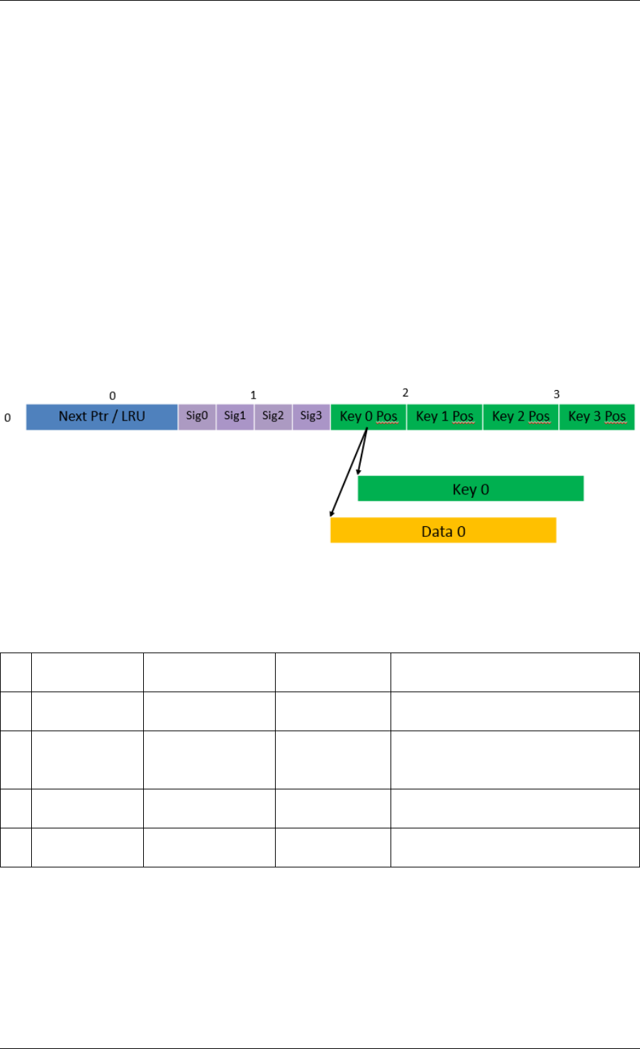
Programmer’s Guide, Release 18.11.0-rc5
2 and 3 (executing stage 1), packets 4 and 5 (executing stage 2) and packets 6 and 7 (exe-
cuting stage 3). By executing useful work while the data structures are brought into the L1 or
L2 cache memory, the latency of the read memory accesses is hidden. By increasing the gap
between two consecutive accesses to the same data structure, the data dependency between
instructions is loosened; this allows making the best use of the super-scalar and out-of-order
execution CPU architecture, as the number of CPU core execution units that are active (rather
than idle or stalled due to data dependency constraints between instructions) is maximized.
The bucket search logic is also implemented without using any branch instructions. This avoids
the important cost associated with flushing the CPU core execution pipeline on every instance
of branch misprediction.
Configurable Key Size Hash Table
Fig. 43.3,Table 43.8 and Table 43.9 detail the main data structures used to implement con-
figurable key size hash tables (either LRU or extendable bucket, either with pre-computed
signature or “do-sig”).
Fig. 43.3: Data Structures for Configurable Key Size Hash Tables
Table 43.8: Main Large Data Structures (Arrays) used for Configurable Key Size Hash Tables
# Array name Number of
entries
Entry size
(bytes)
Description
1 Bucket array n_buckets
(configurable)
32 Buckets of the hash table.
2 Bucket
extensions
array
n_buckets_ext
(configurable)
32 This array is only created for
extendable bucket tables.
3 Key array n_keys key_size
(configurable)
Keys added to the hash table.
4 Data array n_keys entry_size
(configurable)
Key values (key data) associated
with the hash table keys.
43.4. Table Library Design 348
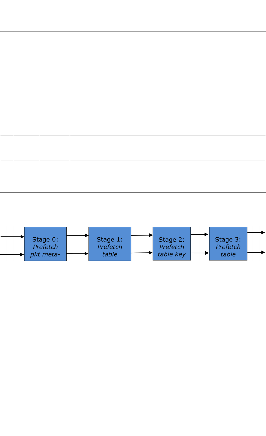
Programmer’s Guide, Release 18.11.0-rc5
Table 43.9: Field Description for Bucket Array Entry (Configurable Key Size Hash Tables)
# Field
name
Field
size
(bytes)
Description
1 Next
Ptr/LRU
8 For LRU tables, this fields represents the LRU list for the current
bucket stored as array of 4 entries of 2 bytes each. Entry 0 stores
the index (0 .. 3) of the MRU key, while entry 3 stores the index of
the LRU key.
For extendable bucket tables, this field represents the next pointer
(i.e. the pointer to the next group of 4 keys linked to the current
bucket). The next pointer is not NULL if the bucket is currently
extended or NULL otherwise. To help the branchless
implementation, bit 0 (least significant bit) of this field is set to 1 if
the next pointer is not NULL and to 0 otherwise.
2 Sig[0
.. 3]
4 x 2 If key X (X = 0 .. 3) is valid, then sig X bits 15 .. 1 store the most
significant 15 bits of key X signature and sig X bit 0 is set to 1.
If key X is not valid, then sig X is set to zero.
3 Key
Pos [0
.. 3]
4 x 4 If key X is valid (X = 0 .. 3), then Key Pos X represents the index
into the key array where key X is stored, as well as the index into
the data array where the value associated with key X is stored.
If key X is not valid, then the value of Key Pos X is undefined.
Fig. 43.4 and Table 43.10 detail the bucket search pipeline stages (either LRU or extendable
bucket, either with pre-computed signature or “do-sig”). For each pipeline stage, the described
operations are applied to each of the two packets handled by that stage.
Fig. 43.4: Bucket Search Pipeline for Key Lookup Operation (Configurable Key Size Hash
Tables)
43.4. Table Library Design 349

Programmer’s Guide, Release 18.11.0-rc5
Table 43.10: Description of the Bucket Search Pipeline Stages (Configurable Key Size Hash
Tables)
# Stage name Description
0 Prefetch
packet
meta-data
Select next two packets from the burst of input packets.
Prefetch packet meta-data containing the key and key signature.
1 Prefetch
table bucket
Read the key signature from the packet meta-data (for extendable
bucket hash tables) or read the key from the packet meta-data and
compute key signature (for LRU tables).
Identify the bucket ID using the key signature.
Set bit 0 of the signature to 1 (to match only signatures of valid keys
from the table).
Prefetch the bucket.
2 Prefetch
table key
Read the key signatures from the bucket.
Compare the signature of the input key against the 4 key signatures
from the packet. As result, the following is obtained:
match = equal to TRUE if there was at least one signature match and
to FALSE in the case of no signature match;
match_many = equal to TRUE is there were more than one signature
matches (can be up to 4 signature matches in the worst case scenario)
and to FALSE otherwise;
match_pos = the index of the first key that produced signature match
(only valid if match is true).
For extendable bucket hash tables only, set match_many to TRUE if
next pointer is valid.
Prefetch the bucket key indicated by match_pos (even if match_pos
does not point to valid key valid).
3 Prefetch
table data
Read the bucket key indicated by match_pos.
Compare the bucket key against the input key. As result, the following
is obtained: match_key = equal to TRUE if the two keys match and to
FALSE otherwise.
Report input key as lookup hit only when both match and match_key
are equal to TRUE and as lookup miss otherwise.
For LRU tables only, use branchless logic to update the bucket LRU list
(the current key becomes the new MRU) only on lookup hit.
Prefetch the key value (key data) associated with the current key (to
avoid branches, this is done on both lookup hit and miss).
Additional notes:
1. The pipelined version of the bucket search algorithm is executed only if there are at least
7 packets in the burst of input packets. If there are less than 7 packets in the burst of input
packets, a non-optimized implementation of the bucket search algorithm is executed.
2. Once the pipelined version of the bucket search algorithm has been executed for all the
packets in the burst of input packets, the non-optimized implementation of the bucket
search algorithm is also executed for any packets that did not produce a lookup hit, but
have the match_many flag set. As result of executing the non-optimized version, some
of these packets may produce a lookup hit or lookup miss. This does not impact the
performance of the key lookup operation, as the probability of matching more than one
signature in the same group of 4 keys or of having the bucket in extended state (for
extendable bucket hash tables only) is relatively small.
43.4. Table Library Design 350

Programmer’s Guide, Release 18.11.0-rc5
Key Signature Comparison Logic
The key signature comparison logic is described in Table 43.11.
Table 43.11: Lookup Tables for Match, Match_Many and Match_Pos
# mask match (1 bit) match_many (1 bit) match_pos (2 bits)
0 0000 0 0 00
1 0001 1 0 00
2 0010 1 0 01
3 0011 1 1 00
4 0100 1 0 10
5 0101 1 1 00
6 0110 1 1 01
7 0111 1 1 00
8 1000 1 0 11
9 1001 1 1 00
10 1010 1 1 01
11 1011 1 1 00
12 1100 1 1 10
13 1101 1 1 00
14 1110 1 1 01
15 1111 1 1 00
The input mask hash bit X (X = 0 .. 3) set to 1 if input signature is equal to bucket signature X
and set to 0 otherwise. The outputs match,match_many and match_pos are 1 bit, 1 bit and 2
bits in size respectively and their meaning has been explained above.
As displayed in Table 43.12, the lookup tables for match and match_many can be collapsed into
a single 32-bit value and the lookup table for match_pos can be collapsed into a 64-bit value.
Given the input mask, the values for match,match_many and match_pos can be obtained by
indexing their respective bit array to extract 1 bit, 1 bit and 2 bits respectively with branchless
logic.
Table 43.12: Collapsed Lookup Tables for Match, Match_Many and Match_Pos
Bit array Hexadecimal value
match 1111_1111_1111_1110 0xFFFELLU
match_many 1111_1110_1110_1000 0xFEE8LLU
match_pos 0001_0010_0001_0011__0001_0010_0001_0000 0x12131210LLU
The pseudo-code for match, match_many and match_pos is:
match = (0xFFFELLU >> mask) & 1;
match_many = (0xFEE8LLU >> mask) & 1;
match_pos = (0x12131210LLU >> (mask << 1)) & 3;
Single Key Size Hash Tables
Fig. 43.5,Fig. 43.6,Table 43.13 and Table 43.14 detail the main data structures used to
implement 8-byte and 16-byte key hash tables (either LRU or extendable bucket, either with
pre-computed signature or “do-sig”).
43.4. Table Library Design 351

Programmer’s Guide, Release 18.11.0-rc5
Fig. 43.5: Data Structures for 8-byte Key Hash Tables
Fig. 43.6: Data Structures for 16-byte Key Hash Tables
Table 43.13: Main Large Data Structures (Arrays) used for 8-byte and 16-byte Key Size Hash
Tables
# Array
name
Number of
entries
Entry size (bytes) Description
1 Bucket
array
n_buckets
(config-
urable)
8-byte key size:
64 + 4 x entry_size
16-byte key size:
128 + 4 x entry_size
Buckets of the hash
table.
2 Bucket
exten-
sions
array
n_buckets_ext
(config-
urable)
8-byte key size:
64 + 4 x entry_size
16-byte key size:
128 + 4 x entry_size
This array is only
created for extendable
bucket tables.
43.4. Table Library Design 352
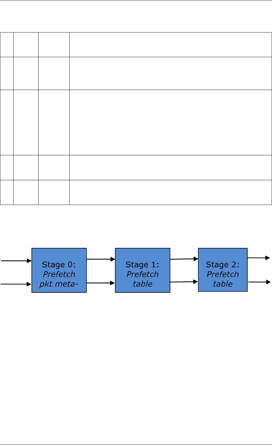
Programmer’s Guide, Release 18.11.0-rc5
Table 43.14: Field Description for Bucket Array Entry (8-byte and 16-byte Key Hash Tables)
# Field
name
Field
size
(bytes)
Description
1 Valid 8 Bit X (X = 0 .. 3) is set to 1 if key X is valid or to 0 otherwise.
Bit 4 is only used for extendable bucket tables to help with the
implementation of the branchless logic. In this case, bit 4 is set to 1
if next pointer is valid (not NULL) or to 0 otherwise.
2 Next
Ptr/LRU
8 For LRU tables, this fields represents the LRU list for the current
bucket stored as array of 4 entries of 2 bytes each. Entry 0 stores
the index (0 .. 3) of the MRU key, while entry 3 stores the index of
the LRU key.
For extendable bucket tables, this field represents the next pointer
(i.e. the pointer to the next group of 4 keys linked to the current
bucket). The next pointer is not NULL if the bucket is currently
extended or NULL otherwise.
3 Key
[0 ..
3]
4 x
key_size
Full keys.
4 Data
[0 ..
3]
4 x en-
try_size
Full key values (key data) associated with keys 0 .. 3.
and detail the bucket search pipeline used to implement 8-byte and 16-byte key hash tables
(either LRU or extendable bucket, either with pre-computed signature or “do-sig”). For each
pipeline stage, the described operations are applied to each of the two packets handled by that
stage.
Fig. 43.7: Bucket Search Pipeline for Key Lookup Operation (Single Key Size Hash Tables)
43.4. Table Library Design 353

Programmer’s Guide, Release 18.11.0-rc5
Table 43.15: Description of the Bucket Search Pipeline Stages (8-byte and 16-byte Key Hash
Tables)
# Stage name Description
0 Prefetch packet meta-data 1. Select next two packets
from the burst of input
packets.
2. Prefetch packet meta-
data containing the key
and key signature.
1 Prefetch table bucket 1. Read the key signa-
ture from the packet
meta-data (for extend-
able bucket hash tables)
or read the key from the
packet meta-data and
compute key signature
(for LRU tables).
2. Identify the bucket ID
using the key signature.
3. Prefetch the bucket.
2 Prefetch table data 1. Read the bucket.
2. Compare all 4 bucket
keys against the input
key.
3. Report input key as
lookup hit only when
a match is identified
(more than one key
match is not possible)
4. For LRU tables only, use
branchless logic to up-
date the bucket LRU
list (the current key be-
comes the new MRU)
only on lookup hit.
5. Prefetch the key value
(key data) associated
with the matched key (to
avoid branches, this is
done on both lookup hit
and miss).
Additional notes:
1. The pipelined version of the bucket search algorithm is executed only if there are at least
5 packets in the burst of input packets. If there are less than 5 packets in the burst of input
43.4. Table Library Design 354

Programmer’s Guide, Release 18.11.0-rc5
packets, a non-optimized implementation of the bucket search algorithm is executed.
2. For extendable bucket hash tables only, once the pipelined version of the bucket search
algorithm has been executed for all the packets in the burst of input packets, the non-
optimized implementation of the bucket search algorithm is also executed for any packets
that did not produce a lookup hit, but have the bucket in extended state. As result of
executing the non-optimized version, some of these packets may produce a lookup hit or
lookup miss. This does not impact the performance of the key lookup operation, as the
probability of having the bucket in extended state is relatively small.
43.5 Pipeline Library Design
A pipeline is defined by:
1. The set of input ports;
2. The set of output ports;
3. The set of tables;
4. The set of actions.
The input ports are connected with the output ports through tree-like topologies of intercon-
nected tables. The table entries contain the actions defining the operations to be executed on
the input packets and the packet flow within the pipeline.
43.5.1 Connectivity of Ports and Tables
To avoid any dependencies on the order in which pipeline elements are created, the connec-
tivity of pipeline elements is defined after all the pipeline input ports, output ports and tables
have been created.
General connectivity rules:
1. Each input port is connected to a single table. No input port should be left unconnected;
2. The table connectivity to other tables or to output ports is regulated by the next hop
actions of each table entry and the default table entry. The table connectivity is fluid, as
the table entries and the default table entry can be updated during run-time.
• A table can have multiple entries (including the default entry) connected to the same
output port. A table can have different entries connected to different output ports.
Different tables can have entries (including default table entry) connected to the
same output port.
• A table can have multiple entries (including the default entry) connected to another
table, in which case all these entries have to point to the same table. This constraint
is enforced by the API and prevents tree-like topologies from being created (allow-
ing table chaining only), with the purpose of simplifying the implementation of the
pipeline run-time execution engine.
43.5. Pipeline Library Design 355

Programmer’s Guide, Release 18.11.0-rc5
43.5.2 Port Actions
Port Action Handler
An action handler can be assigned to each input/output port to define actions to be executed
on each input packet that is received by the port. Defining the action handler for a specific
input/output port is optional (i.e. the action handler can be disabled).
For input ports, the action handler is executed after RX function. For output ports, the action
handler is executed before the TX function.
The action handler can decide to drop packets.
43.5.3 Table Actions
Table Action Handler
An action handler to be executed on each input packet can be assigned to each table. Defining
the action handler for a specific table is optional (i.e. the action handler can be disabled).
The action handler is executed after the table lookup operation is performed and the table
entry associated with each input packet is identified. The action handler can only handle the
user-defined actions, while the reserved actions (e.g. the next hop actions) are handled by the
Packet Framework. The action handler can decide to drop the input packet.
Reserved Actions
The reserved actions are handled directly by the Packet Framework without the user being able
to change their meaning through the table action handler configuration. A special category of
the reserved actions is represented by the next hop actions, which regulate the packet flow
between input ports, tables and output ports through the pipeline. Table 43.16 lists the next
hop actions.
Table 43.16: Next Hop Actions (Reserved)
# Next hop
action
Description
1 Drop Drop the current packet.
2 Send to
output port
Send the current packet to specified output port. The output port ID is
metadata stored in the same table entry.
3 Send to
table
Send the current packet to specified table. The table ID is metadata
stored in the same table entry.
User Actions
For each table, the meaning of user actions is defined through the configuration of the table
action handler. Different tables can be configured with different action handlers, therefore the
meaning of the user actions and their associated meta-data is private to each table. Within
the same table, all the table entries (including the table default entry) share the same definition
for the user actions and their associated meta-data, with each table entry having its own set
43.5. Pipeline Library Design 356

Programmer’s Guide, Release 18.11.0-rc5
of enabled user actions and its own copy of the action meta-data. Table 43.17 contains a
non-exhaustive list of user action examples.
Table 43.17: User Action Examples
# User action Description
1 Metering Per flow traffic metering using the srTCM and trTCM algorithms.
2 Statistics Update the statistics counters maintained per flow.
3 App ID Per flow state machine fed by variable length sequence of packets
at the flow initialization with the purpose of identifying the traffic
type and application.
4 Push/pop labels Push/pop VLAN/MPLS labels to/from the current packet.
5 Network
Address
Translation
(NAT)
Translate between the internal (LAN) and external (WAN) IP
destination/source address and/or L4 protocol destination/source
port.
6 TTL update Decrement IP TTL and, in case of IPv4 packets, update the IP
checksum.
7 Sym Crypto Generate Cryptodev session based on the user-specified algorithm
and key(s), and assemble the cryptodev operation based on the
predefined offsets.
43.6 Multicore Scaling
A complex application is typically split across multiple cores, with cores communicating through
SW queues. There is usually a performance limit on the number of table lookups and actions
that can be fitted on the same CPU core due to HW constraints like: available CPU cycles,
cache memory size, cache transfer BW, memory transfer BW, etc.
As the application is split across multiple CPU cores, the Packet Framework facilitates the
creation of several pipelines, the assignment of each such pipeline to a different CPU core
and the interconnection of all CPU core-level pipelines into a single application-level complex
pipeline. For example, if CPU core A is assigned to run pipeline P1 and CPU core B pipeline
P2, then the interconnection of P1 with P2 could be achieved by having the same set of SW
queues act like output ports for P1 and input ports for P2.
This approach enables the application development using the pipeline, run-to-completion (clus-
tered) or hybrid (mixed) models.
It is allowed for the same core to run several pipelines, but it is not allowed for several cores to
run the same pipeline.
43.6.1 Shared Data Structures
The threads performing table lookup are actually table writers rather than just readers. Even if
the specific table lookup algorithm is thread-safe for multiple readers (e. g. read-only access
of the search algorithm data structures is enough to conduct the lookup operation), once the
table entry for the current packet is identified, the thread is typically expected to update the
action meta-data stored in the table entry (e.g. increment the counter tracking the number of
packets that hit this table entry), and thus modify the table entry. During the time this thread
is accessing this table entry (either writing or reading; duration is application specific), for data
43.6. Multicore Scaling 357

Programmer’s Guide, Release 18.11.0-rc5
consistency reasons, no other threads (threads performing table lookup or entry add/delete
operations) are allowed to modify this table entry.
Mechanisms to share the same table between multiple threads:
1. Multiple writer threads. Threads need to use synchronization primitives like
semaphores (distinct semaphore per table entry) or atomic instructions. The cost of
semaphores is usually high, even when the semaphore is free. The cost of atomic in-
structions is normally higher than the cost of regular instructions.
2. Multiple writer threads, with single thread performing table lookup operations and
multiple threads performing table entry add/delete operations. The threads perform-
ing table entry add/delete operations send table update requests to the reader (typically
through message passing queues), which does the actual table updates and then sends
the response back to the request initiator.
3. Single writer thread performing table entry add/delete operations and multiple
reader threads that perform table lookup operations with read-only access to the
table entries. The reader threads use the main table copy while the writer is updating
the mirror copy. Once the writer update is done, the writer can signal to the readers and
busy wait until all readers swaps between the mirror copy (which now becomes the main
copy) and the mirror copy (which now becomes the main copy).
43.7 Interfacing with Accelerators
The presence of accelerators is usually detected during the initialization phase by inspecting
the HW devices that are part of the system (e.g. by PCI bus enumeration). Typical devices
with acceleration capabilities are:
• Inline accelerators: NICs, switches, FPGAs, etc;
• Look-aside accelerators: chipsets, FPGAs, Intel QuickAssist, etc.
Usually, to support a specific functional block, specific implementation of Packet Framework
tables and/or ports and/or actions has to be provided for each accelerator, with all the imple-
mentations sharing the same API: pure SW implementation (no acceleration), implementation
using accelerator A, implementation using accelerator B, etc. The selection between these
implementations could be done at build time or at run-time (recommended), based on which
accelerators are present in the system, with no application changes required.
43.7. Interfacing with Accelerators 358

CHAPTER
FORTYFOUR
VHOST LIBRARY
The vhost library implements a user space virtio net server allowing the user to manipulate the
virtio ring directly. In another words, it allows the user to fetch/put packets from/to the VM virtio
net device. To achieve this, a vhost library should be able to:
• Access the guest memory:
For QEMU, this is done by using the -object
memory-backend-file,share=on,... option. Which means QEMU will cre-
ate a file to serve as the guest RAM. The share=on option allows another process to
map that file, which means it can access the guest RAM.
• Know all the necessary information about the vring:
Information such as where the available ring is stored. Vhost defines some messages
(passed through a Unix domain socket file) to tell the backend all the information it needs
to know how to manipulate the vring.
44.1 Vhost API Overview
The following is an overview of some key Vhost API functions:
•rte_vhost_driver_register(path, flags)
This function registers a vhost driver into the system. path specifies the Unix domain
socket file path.
Currently supported flags are:
–RTE_VHOST_USER_CLIENT
DPDK vhost-user will act as the client when this flag is given. See below for an
explanation.
–RTE_VHOST_USER_NO_RECONNECT
When DPDK vhost-user acts as the client it will keep trying to reconnect to the
server (QEMU) until it succeeds. This is useful in two cases:
*When QEMU is not started yet.
*When QEMU restarts (for example due to a guest OS reboot).
This reconnect option is enabled by default. However, it can be turned off by setting
this flag.
359

Programmer’s Guide, Release 18.11.0-rc5
–RTE_VHOST_USER_DEQUEUE_ZERO_COPY
Dequeue zero copy will be enabled when this flag is set. It is disabled by default.
There are some truths (including limitations) you might want to know while setting
this flag:
*zero copy is not good for small packets (typically for packet size below 512).
*zero copy is really good for VM2VM case. For iperf between two VMs, the boost
could be above 70% (when TSO is enableld).
*For zero copy in VM2NIC case, guest Tx used vring may be starved if the PMD
driver consume the mbuf but not release them timely.
For example, i40e driver has an optimization to maximum NIC pipeline which
postpones returning transmitted mbuf until only tx_free_threshold free descs
left. The virtio TX used ring will be starved if the formula (num_i40e_tx_desc -
num_virtio_tx_desc > tx_free_threshold) is true, since i40e will not return back
mbuf.
A performance tip for tuning zero copy in VM2NIC case is to adjust the fre-
quency of mbuf free (i.e. adjust tx_free_threshold of i40e driver) to balance
consumer and producer.
*Guest memory should be backended with huge pages to achieve better perfor-
mance. Using 1G page size is the best.
When dequeue zero copy is enabled, the guest phys address and host phys
address mapping has to be established. Using non-huge pages means far more
page segments. To make it simple, DPDK vhost does a linear search of those
segments, thus the fewer the segments, the quicker we will get the mapping.
NOTE: we may speed it by using tree searching in future.
*zero copy can not work when using vfio-pci with iommu mode currently, this is
because we don’t setup iommu dma mapping for guest memory. If you have to
use vfio-pci driver, please insert vfio-pci kernel module in noiommu mode.
–RTE_VHOST_USER_IOMMU_SUPPORT
IOMMU support will be enabled when this flag is set. It is disabled by default.
Enabling this flag makes possible to use guest vIOMMU to protect vhost from ac-
cessing memory the virtio device isn’t allowed to, when the feature is negotiated and
an IOMMU device is declared.
However, this feature enables vhost-user’s reply-ack protocol feature, which imple-
mentation is buggy in Qemu v2.7.0-v2.9.0 when doing multiqueue. Enabling this
flag with these Qemu version results in Qemu being blocked when multiple queue
pairs are declared.
–RTE_VHOST_USER_POSTCOPY_SUPPORT
Postcopy live-migration support will be enabled when this flag is set. It is disabled
by default.
Enabling this flag should only be done when the calling application does not pre-fault
the guest shared memory, otherwise migration would fail.
44.1. Vhost API Overview 360

Programmer’s Guide, Release 18.11.0-rc5
•rte_vhost_driver_set_features(path, features)
This function sets the feature bits the vhost-user driver supports. The vhost-user driver
could be vhost-user net, yet it could be something else, say, vhost-user SCSI.
•rte_vhost_driver_callback_register(path, vhost_device_ops)
This function registers a set of callbacks, to let DPDK applications take the appropriate
action when some events happen. The following events are currently supported:
–new_device(int vid)
This callback is invoked when a virtio device becomes ready. vid is the vhost device
ID.
–destroy_device(int vid)
This callback is invoked when a virtio device is paused or shut down.
–vring_state_changed(int vid, uint16_t queue_id, int enable)
This callback is invoked when a specific queue’s state is changed, for example to
enabled or disabled.
–features_changed(int vid, uint64_t features)
This callback is invoked when the features is changed. For example,
VHOST_F_LOG_ALL will be set/cleared at the start/end of live migration, respec-
tively.
–new_connection(int vid)
This callback is invoked on new vhost-user socket connection. If DPDK acts as the
server the device should not be deleted before destroy_connection callback is
received.
–destroy_connection(int vid)
This callback is invoked when vhost-user socket connection is closed. It indicates
that device with id vid is no longer in use and can be safely deleted.
•rte_vhost_driver_disable/enable_features(path, features))
This function disables/enables some features. For example, it can be used to disable
mergeable buffers and TSO features, which both are enabled by default.
•rte_vhost_driver_start(path)
This function triggers the vhost-user negotiation. It should be invoked at the end of ini-
tializing a vhost-user driver.
•rte_vhost_enqueue_burst(vid, queue_id, pkts, count)
Transmits (enqueues) count packets from host to guest.
•rte_vhost_dequeue_burst(vid, queue_id, mbuf_pool, pkts, count)
Receives (dequeues) count packets from guest, and stored them at pkts.
•rte_vhost_crypto_create(vid, cryptodev_id, sess_mempool,
socket_id)
44.1. Vhost API Overview 361

Programmer’s Guide, Release 18.11.0-rc5
As an extension of new_device(), this function adds virtio-crypto workload acceleration
capability to the device. All crypto workload is processed by DPDK cryptodev with the
device ID of cryptodev_id.
•rte_vhost_crypto_free(vid)
Frees the memory and vhost-user message handlers created in
rte_vhost_crypto_create().
•rte_vhost_crypto_fetch_requests(vid, queue_id, ops, nb_ops)
Receives (dequeues) nb_ops virtio-crypto requests from guest, parses them to DPDK
Crypto Operations, and fills the ops with parsing results.
•rte_vhost_crypto_finalize_requests(queue_id, ops, nb_ops)
After the ops are dequeued from Cryptodev, finalizes the jobs and notifies the guest(s).
•rte_vhost_crypto_set_zero_copy(vid, option)
Enable or disable zero copy feature of the vhost crypto backend.
44.2 Vhost-user Implementations
Vhost-user uses Unix domain sockets for passing messages. This means the DPDK vhost-
user implementation has two options:
• DPDK vhost-user acts as the server.
DPDK will create a Unix domain socket server file and listen for connections from the
frontend.
Note, this is the default mode, and the only mode before DPDK v16.07.
• DPDK vhost-user acts as the client.
Unlike the server mode, this mode doesn’t create the socket file; it just tries to connect to
the server (which responses to create the file instead).
When the DPDK vhost-user application restarts, DPDK vhost-user will try to connect to
the server again. This is how the “reconnect” feature works.
Note:
–The “reconnect” feature requires QEMU v2.7 (or above).
–The vhost supported features must be exactly the same before and after the restart.
For example, if TSO is disabled and then enabled, nothing will work and issues
undefined might happen.
No matter which mode is used, once a connection is established, DPDK vhost-user will start
receiving and processing vhost messages from QEMU.
For messages with a file descriptor, the file descriptor can be used directly in the vhost process
as it is already installed by the Unix domain socket.
The supported vhost messages are:
•VHOST_SET_MEM_TABLE
44.2. Vhost-user Implementations 362

Programmer’s Guide, Release 18.11.0-rc5
•VHOST_SET_VRING_KICK
•VHOST_SET_VRING_CALL
•VHOST_SET_LOG_FD
•VHOST_SET_VRING_ERR
For VHOST_SET_MEM_TABLE message, QEMU will send information for each memory region
and its file descriptor in the ancillary data of the message. The file descriptor is used to map
that region.
VHOST_SET_VRING_KICK is used as the signal to put the vhost device into the data plane,
and VHOST_GET_VRING_BASE is used as the signal to remove the vhost device from the data
plane.
When the socket connection is closed, vhost will destroy the device.
44.3 Guest memory requirement
• Memory pre-allocation
For non-zerocopy, guest memory pre-allocation is not a must. This can help save of
memory. If users really want the guest memory to be pre-allocated (e.g., for performance
reason), we can add option -mem-prealloc when starting QEMU. Or, we can lock all
memory at vhost side which will force memory to be allocated when mmap at vhost side;
option –mlockall in ovs-dpdk is an example in hand.
For zerocopy, we force the VM memory to be pre-allocated at vhost lib when mapping the
guest memory; and also we need to lock the memory to prevent pages being swapped
out to disk.
• Memory sharing
Make sure share=on QEMU option is given. vhost-user will not work with a QEMU
version without shared memory mapping.
44.4 Vhost supported vSwitch reference
For more vhost details and how to support vhost in vSwitch, please refer to the vhost example
in the DPDK Sample Applications Guide.
44.5 Vhost data path acceleration (vDPA)
vDPA supports selective datapath in vhost-user lib by enabling virtio ring compatible devices
to serve virtio driver directly for datapath acceleration.
rte_vhost_driver_attach_vdpa_device is used to configure the vhost device with ac-
celerated backend.
Also vhost device capabilities are made configurable to adopt various devices. Such capabili-
ties include supported features, protocol features, queue number.
Finally, a set of device ops is defined for device specific operations:
44.3. Guest memory requirement 363

Programmer’s Guide, Release 18.11.0-rc5
•get_queue_num
Called to get supported queue number of the device.
•get_features
Called to get supported features of the device.
•get_protocol_features
Called to get supported protocol features of the device.
•dev_conf
Called to configure the actual device when the virtio device becomes ready.
•dev_close
Called to close the actual device when the virtio device is stopped.
•set_vring_state
Called to change the state of the vring in the actual device when vring state changes.
•set_features
Called to set the negotiated features to device.
•migration_done
Called to allow the device to response to RARP sending.
•get_vfio_group_fd
Called to get the VFIO group fd of the device.
•get_vfio_device_fd
Called to get the VFIO device fd of the device.
•get_notify_area
Called to get the notify area info of the queue.
44.5. Vhost data path acceleration (vDPA) 364

CHAPTER
FORTYFIVE
METRICS LIBRARY
The Metrics library implements a mechanism by which producers can publish numeric infor-
mation for later querying by consumers. In practice producers will typically be other libraries or
primary processes, whereas consumers will typically be applications.
Metrics themselves are statistics that are not generated by PMDs. Metric information is pop-
ulated using a push model, where producers update the values contained within the metric
library by calling an update function on the relevant metrics. Consumers receive metric infor-
mation by querying the central metric data, which is held in shared memory.
For each metric, a separate value is maintained for each port id, and when publishing metric
values the producers need to specify which port is being updated. In addition there is a special
id RTE_METRICS_GLOBAL that is intended for global statistics that are not associated with
any individual device. Since the metrics library is self-contained, the only restriction on port
numbers is that they are less than RTE_MAX_ETHPORTS - there is no requirement for the ports
to actually exist.
45.1 Initialising the library
Before the library can be used, it has to be initialized by calling rte_metrics_init() which
sets up the metric store in shared memory. This is where producers will publish metric infor-
mation to, and where consumers will query it from.
rte_metrics_init(rte_socket_id());
This function must be called from a primary process, but otherwise producers and consumers
can be in either primary or secondary processes.
45.2 Registering metrics
Metrics must first be registered, which is the way producers declare the names of the metrics
they will be publishing. Registration can either be done individually, or a set of metrics can be
registered as a group. Individual registration is done using rte_metrics_reg_name():
id_1 =rte_metrics_reg_name("mean_bits_in");
id_2 =rte_metrics_reg_name("mean_bits_out");
id_3 =rte_metrics_reg_name("peak_bits_in");
id_4 =rte_metrics_reg_name("peak_bits_out");
or alternatively, a set of metrics can be registered together using
rte_metrics_reg_names():
365

Programmer’s Guide, Release 18.11.0-rc5
const char *const names[] ={
"mean_bits_in","mean_bits_out",
"peak_bits_in","peak_bits_out",
};
id_set =rte_metrics_reg_names(&names[0], 4);
If the return value is negative, it means registration failed. Otherwise the return value is the key
for the metric, which is used when updating values. A table mapping together these key values
and the metrics’ names can be obtained using rte_metrics_get_names().
45.3 Updating metric values
Once registered, producers can update the metric for a given port using the
rte_metrics_update_value() function. This uses the metric key that is returned when
registering the metric, and can also be looked up using rte_metrics_get_names().
rte_metrics_update_value(port_id, id_1, values[0]);
rte_metrics_update_value(port_id, id_2, values[1]);
rte_metrics_update_value(port_id, id_3, values[2]);
rte_metrics_update_value(port_id, id_4, values[3]);
if metrics were registered as a single set, they can either be updated indi-
vidually using rte_metrics_update_value(), or updated together using the
rte_metrics_update_values() function:
rte_metrics_update_value(port_id, id_set, values[0]);
rte_metrics_update_value(port_id, id_set +1, values[1]);
rte_metrics_update_value(port_id, id_set +2, values[2]);
rte_metrics_update_value(port_id, id_set +3, values[3]);
rte_metrics_update_values(port_id, id_set, values, 4);
Note that rte_metrics_update_values() cannot be used to update metric values from
multiple sets, as there is no guarantee two sets registered one after the other have contiguous
id values.
45.4 Querying metrics
Consumers can obtain metric values by querying the metrics library using
the rte_metrics_get_values() function that return an array of struct
rte_metric_value. Each entry within this array contains a metric value and its asso-
ciated key. A key-name mapping can be obtained using the rte_metrics_get_names()
function that returns an array of struct rte_metric_name that is indexed by the key. The
following will print out all metrics for a given port:
void print_metrics() {
struct rte_metric_value *metrics;
struct rte_metric_name *names;
int len;
len =rte_metrics_get_names(NULL,0);
if (len <0) {
printf("Cannot get metrics count\n");
return;
}
if (len == 0) {
printf("No metrics to display (none have been registered)\n");
45.3. Updating metric values 366

Programmer’s Guide, Release 18.11.0-rc5
return;
}
metrics =malloc(sizeof(struct rte_metric_value) *len);
names =malloc(sizeof(struct rte_metric_name) *len);
if (metrics == NULL || names == NULL) {
printf("Cannot allocate memory\n");
free(metrics);
free(names);
return;
}
ret =rte_metrics_get_values(port_id, metrics, len);
if (ret <0|| ret >len) {
printf("Cannot get metrics values\n");
free(metrics);
free(names);
return;
}
printf("Metrics for port %i:\n", port_id);
for (i =0;i<len; i++)
printf(" %s: %"PRIu64"\n",
names[metrics[i].key].name, metrics[i].value);
free(metrics);
free(names);
}
45.5 Bit-rate statistics library
The bit-rate library calculates the exponentially-weighted moving average and peak bit-rates
for each active port (i.e. network device). These statistics are reported via the metrics library
using the following names:
•mean_bits_in: Average inbound bit-rate
•mean_bits_out: Average outbound bit-rate
•ewma_bits_in: Average inbound bit-rate (EWMA smoothed)
•ewma_bits_out: Average outbound bit-rate (EWMA smoothed)
•peak_bits_in: Peak inbound bit-rate
•peak_bits_out: Peak outbound bit-rate
Once initialised and clocked at the appropriate frequency, these statistics can be obtained by
querying the metrics library.
45.5.1 Initialization
Before the library can be used, it has to be initialised by calling
rte_stats_bitrate_create(), which will return a bit-rate calculation object. Since
the bit-rate library uses the metrics library to report the calculated statistics, the bit-rate library
then needs to register the calculated statistics with the metrics library. This is done using the
helper function rte_stats_bitrate_reg().
struct rte_stats_bitrates *bitrate_data;
bitrate_data =rte_stats_bitrate_create();
if (bitrate_data == NULL)
45.5. Bit-rate statistics library 367

Programmer’s Guide, Release 18.11.0-rc5
rte_exit(EXIT_FAILURE, "Could not allocate bit-rate data.\n");
rte_stats_bitrate_reg(bitrate_data);
45.5.2 Controlling the sampling rate
Since the library works by periodic sampling but does not use an internal thread, the application
has to periodically call rte_stats_bitrate_calc(). The frequency at which this function is
called should be the intended sampling rate required for the calculated statistics. For instance
if per-second statistics are desired, this function should be called once a second.
tics_datum =rte_rdtsc();
tics_per_1sec =rte_get_timer_hz();
while(1) {
/*... */
tics_current =rte_rdtsc();
if (tics_current -tics_datum >= tics_per_1sec) {
/*Periodic bitrate calculation */
for (idx_port =0; idx_port <cnt_ports; idx_port++)
rte_stats_bitrate_calc(bitrate_data, idx_port);
tics_datum =tics_current;
}
/*... */
}
45.6 Latency statistics library
The latency statistics library calculates the latency of packet processing by a DPDK application,
reporting the minimum, average, and maximum nano-seconds that packet processing takes,
as well as the jitter in processing delay. These statistics are then reported via the metrics
library using the following names:
•min_latency_ns: Minimum processing latency (nano-seconds)
•avg_latency_ns: Average processing latency (nano-seconds)
•mac_latency_ns: Maximum processing latency (nano-seconds)
•jitter_ns: Variance in processing latency (nano-seconds)
Once initialised and clocked at the appropriate frequency, these statistics can be obtained by
querying the metrics library.
45.6.1 Initialization
Before the library can be used, it has to be initialised by calling rte_latencystats_init().
lcoreid_t latencystats_lcore_id = -1;
int ret =rte_latencystats_init(1,NULL);
if (ret)
rte_exit(EXIT_FAILURE, "Could not allocate latency data.\n");
45.6. Latency statistics library 368

Programmer’s Guide, Release 18.11.0-rc5
45.6.2 Triggering statistic updates
The rte_latencystats_update() function needs to be called periodically so that latency
statistics can be updated.
if (latencystats_lcore_id == rte_lcore_id())
rte_latencystats_update();
45.6.3 Library shutdown
When finished, rte_latencystats_uninit() needs to be called to de-initialise the latency
library.
rte_latencystats_uninit();
45.6.4 Timestamp and latency calculation
The Latency stats library marks the time in the timestamp field of the mbuf for the ingress pack-
ets and sets the PKT_RX_TIMESTAMP flag of ol_flags for the mbuf to indicate the marked
time as a valid one. At the egress, the mbufs with the flag set are considered having valid
timestamp and are used for the latency calculation.
45.6. Latency statistics library 369

CHAPTER
FORTYSIX
BERKELEY PACKET FILTER LIBRARY
The DPDK provides an BPF library that gives the ability to load and execute Enhanced Berke-
ley Packet Filter (eBPF) bytecode within user-space dpdk application.
It supports basic set of features from eBPF spec. Please refer to the eBPF spec
<https://www.kernel.org/doc/Documentation/networking/filter.txt> for more information. Also it
introduces basic framework to load/unload BPF-based filters on eth devices (right now only via
SW RX/TX callbacks).
The library API provides the following basic operations:
• Create a new BPF execution context and load user provided eBPF code into it.
• Destroy an BPF execution context and its runtime structures and free the associated
memory.
• Execute eBPF bytecode associated with provided input parameter.
• Provide information about natively compiled code for given BPF context.
• Load BPF program from the ELF file and install callback to execute it on given ethdev
port/queue.
46.1 Not currently supported eBPF features
• JIT for non X86_64 platforms
• cBPF
• tail-pointer call
• eBPF MAP
• skb
• external function calls for 32-bit platforms
Part 2: Development Environment
370

CHAPTER
FORTYSEVEN
SOURCE ORGANIZATION
This section describes the organization of sources in the DPDK framework.
47.1 Makefiles and Config
Note: In the following descriptions, RTE_SDK is the environment variable that points to the
base directory into which the tarball was extracted. See Useful Variables Provided by the Build
System for descriptions of other variables.
Makefiles that are provided by the DPDK libraries and applications are located in
$(RTE_SDK)/mk.
Config templates are located in $(RTE_SDK)/config. The templates describe the options
that are enabled for each target. The config file also contains items that can be enabled and
disabled for many of the DPDK libraries, including debug options. The user should look at
the config file and become familiar with these options. The config file is also used to create a
header file, which will be located in the new build directory.
47.2 Libraries
Libraries are located in subdirectories of $(RTE_SDK)/lib. By convention a library refers to
any code that provides an API to an application. Typically, it generates an archive file (.a), but
a kernel module would also go in the same directory.
The lib directory contains:
lib
+-- librte_cmdline # Command line interface helper
+-- librte_distributor # Packet distributor
+-- librte_eal # Environment abstraction layer
+-- librte_ethdev # Generic interface to poll mode driver
+-- librte_hash # Hash library
+-- librte_ip_frag # IP fragmentation library
+-- librte_kni # Kernel NIC interface
+-- librte_kvargs # Argument parsing library
+-- librte_lpm # Longest prefix match library
+-- librte_mbuf # Packet buffer manipulation
+-- librte_mempool # Memory pool manager (fixed sized objects)
+-- librte_meter # QoS metering library
+-- librte_net # Various IP-related headers
+-- librte_power # Power management library
+-- librte_ring # Software rings (act as lockless FIFOs)
371

Programmer’s Guide, Release 18.11.0-rc5
+-- librte_sched # QoS scheduler and dropper library
+-- librte_timer # Timer library
47.3 Drivers
Drivers are special libraries which provide poll-mode driver implementations for devices: either
hardware devices or pseudo/virtual devices. They are contained in the drivers subdirectory,
classified by type, and each compiles to a library with the format librte_pmd_X.a where X
is the driver name.
The drivers directory has a net subdirectory which contains:
drivers/net
+-- af_packet # Poll mode driver based on Linux af_packet
+-- bonding # Bonding poll mode driver
+-- cxgbe # Chelsio Terminator 10GbE/40GbE poll mode driver
+-- e1000 # 1GbE poll mode drivers (igb and em)
+-- enic # Cisco VIC Ethernet NIC Poll-mode Driver
+-- fm10k # Host interface PMD driver for FM10000 Series
+-- i40e # 40GbE poll mode driver
+-- ixgbe # 10GbE poll mode driver
+-- mlx4 # Mellanox ConnectX-3 poll mode driver
+-- null # NULL poll mode driver for testing
+-- pcap # PCAP poll mode driver
+-- ring # Ring poll mode driver
+-- szedata2 # SZEDATA2 poll mode driver
+-- virtio # Virtio poll mode driver
+-- vmxnet3 # VMXNET3 poll mode driver
Note: Several of the driver/net directories contain a base sub-directory. The base direc-
tory generally contains code the shouldn’t be modified directly by the user. Any enhancements
should be done via the X_osdep.c and/or X_osdep.h files in that directory. Refer to the local
README in the base directories for driver specific instructions.
47.4 Applications
Applications are source files that contain a main() function. They are located in the
$(RTE_SDK)/app and $(RTE_SDK)/examples directories.
The app directory contains sample applications that are used to test DPDK (such as autotests)
or the Poll Mode Drivers (test-pmd):
app
+-- chkincs # Test program to check include dependencies
+-- cmdline_test # Test the commandline library
+-- test # Autotests to validate DPDK features
+-- test-acl # Test the ACL library
+-- test-pipeline # Test the IP Pipeline framework
+-- test-pmd # Test and benchmark poll mode drivers
The examples directory contains sample applications that show how libraries can be used:
examples
+-- cmdline # Example of using the cmdline library
+-- exception_path # Sending packets to and from Linux TAP device
+-- helloworld # Basic Hello World example
+-- ip_reassembly # Example showing IP reassembly
47.3. Drivers 372

Programmer’s Guide, Release 18.11.0-rc5
+-- ip_fragmentation # Example showing IPv4 fragmentation
+-- ipv4_multicast # Example showing IPv4 multicast
+-- kni # Kernel NIC Interface (KNI) example
+-- l2fwd # L2 forwarding with and without SR-IOV
+-- l3fwd # L3 forwarding example
+-- l3fwd-power # L3 forwarding example with power management
+-- l3fwd-vf # L3 forwarding example with SR-IOV
+-- link_status_interrupt # Link status change interrupt example
+-- load_balancer # Load balancing across multiple cores/sockets
+-- multi_process # Example apps using multiple DPDK processes
+-- qos_meter # QoS metering example
+-- qos_sched # QoS scheduler and dropper example
+-- timer # Example of using librte_timer library
+-- vmdq_dcb # Example of VMDQ and DCB receiving
+-- vmdq # Example of VMDQ receiving
+-- vhost # Example of userspace vhost and switch
Note: The actual examples directory may contain additional sample applications to those
shown above. Check the latest DPDK source files for details.
47.4. Applications 373

CHAPTER
FORTYEIGHT
DEVELOPMENT KIT BUILD SYSTEM
The DPDK requires a build system for compilation activities and so on. This section describes
the constraints and the mechanisms used in the DPDK framework.
There are two use-cases for the framework:
• Compilation of the DPDK libraries and sample applications; the framework generates
specific binary libraries, include files and sample applications
• Compilation of an external application or library, using an installed binary DPDK
48.1 Building the Development Kit Binary
The following provides details on how to build the DPDK binary.
48.1.1 Build Directory Concept
After installation, a build directory structure is created. Each build directory contains include
files, libraries, and applications.
A build directory is specific to a configuration that includes architecture + execution environ-
ment + toolchain. It is possible to have several build directories sharing the same sources with
different configurations.
For instance, to create a new build directory called my_sdk_build_dir using the default config-
uration template config/defconfig_x86_64-linuxapp, we use:
cd ${RTE_SDK}
make config T=x86_64-native-linuxapp-gcc O=my_sdk_build_dir
This creates a new my_sdk_build_dir directory. After that, we can compile by doing:
cd my_sdk_build_dir
make
which is equivalent to:
make O=my_sdk_build_dir
The content of the my_sdk_build_dir is then:
-- .config # used configuration
-- Makefile # wrapper that calls head Makefile
# with $PWD as build directory
374

Programmer’s Guide, Release 18.11.0-rc5
-- build #All temporary files used during build
+--app # process, including . o, .d, and .cmd files.
| +-- test # For libraries, we have the .a file.
| +-- test.o # For applications, we have the elf file.
| `-- ...
+-- lib
+-- librte_eal
| `-- ...
+-- librte_mempool
| +-- mempool-file1.o
| +-- .mempool-file1.o.cmd
| +-- .mempool-file1.o.d
| +-- mempool-file2.o
| +-- .mempool-file2.o.cmd
| +-- .mempool-file2.o.d
| `-- mempool.a
`-- ...
-- include # All include files installed by libraries
+-- librte_mempool.h # and applications are located in this
+-- rte_eal.h # directory. The installed files can depend
+-- rte_spinlock.h # on configuration if needed (environment,
+-- rte_atomic.h # architecture, ..)
`-- \*.h ...
-- lib # all compiled libraries are copied in this
+-- librte_eal.a # directory
+-- librte_mempool.a
`-- \*.a ...
-- app # All compiled applications are installed
+ --test # here. It includes the binary in elf format
Refer to Development Kit Root Makefile Help for details about make commands that can be
used from the root of DPDK.
48.2 Building External Applications
Since DPDK is in essence a development kit, the first objective of end users will be to create
an application using this SDK. To compile an application, the user must set the RTE_SDK and
RTE_TARGET environment variables.
export RTE_SDK=/opt/DPDK
export RTE_TARGET=x86_64-native-linuxapp-gcc
cd /path/to/my_app
For a new application, the user must create their own Makefile that includes some .mk files,
such as ${RTE_SDK}/mk/rte.vars.mk, and ${RTE_SDK}/mk/ rte.app.mk. This is described in
Building Your Own Application.
Depending on the chosen target (architecture, machine, executive environment, toolchain) de-
fined in the Makefile or as an environment variable, the applications and libraries will com-
pile using the appropriate .h files and will link with the appropriate .a files. These files are
located in ${RTE_SDK}/arch-machine-execenv-toolchain, which is referenced internally by
${RTE_BIN_SDK}.
To compile their application, the user just has to call make. The compilation result will be
located in /path/to/my_app/build directory.
48.2. Building External Applications 375

Programmer’s Guide, Release 18.11.0-rc5
Sample applications are provided in the examples directory.
48.3 Makefile Description
48.3.1 General Rules For DPDK Makefiles
In the DPDK, Makefiles always follow the same scheme:
1. Include $(RTE_SDK)/mk/rte.vars.mk at the beginning.
2. Define specific variables for RTE build system.
3. Include a specific $(RTE_SDK)/mk/rte.XYZ.mk, where XYZ can be app, lib, extapp, extlib,
obj, gnuconfigure, and so on, depending on what kind of object you want to build. See
Makefile Types below.
4. Include user-defined rules and variables.
The following is a very simple example of an external application Makefile:
include $(RTE_SDK)/mk/rte.vars.mk
# binary name
APP =helloworld
# all source are stored in SRCS-y
SRCS-y := main.c
CFLAGS += -O3
CFLAGS += $(WERROR_FLAGS)
include $(RTE_SDK)/mk/rte.extapp.mk
48.3.2 Makefile Types
Depending on the .mk file which is included at the end of the user Makefile, the Makefile will
have a different role. Note that it is not possible to build a library and an application in the
same Makefile. For that, the user must create two separate Makefiles, possibly in two different
directories.
In any case, the rte.vars.mk file must be included in the user Makefile as soon as possible.
Application
These Makefiles generate a binary application.
• rte.app.mk: Application in the development kit framework
• rte.extapp.mk: External application
• rte.hostapp.mk: prerequisite tool to build dpdk
48.3. Makefile Description 376

Programmer’s Guide, Release 18.11.0-rc5
Library
Generate a .a library.
• rte.lib.mk: Library in the development kit framework
• rte.extlib.mk: external library
• rte.hostlib.mk: host library in the development kit framework
Install
• rte.install.mk: Does not build anything, it is only used to create links or copy files to the
installation directory. This is useful for including files in the development kit framework.
Kernel Module
• rte.module.mk: Build a kernel module in the development kit framework.
Objects
• rte.obj.mk: Object aggregation (merge several .o in one) in the development kit frame-
work.
• rte.extobj.mk: Object aggregation (merge several .o in one) outside the development kit
framework.
Misc
• rte.doc.mk: Documentation in the development kit framework
• rte.gnuconfigure.mk: Build an application that is configure-based.
• rte.subdir.mk: Build several directories in the development kit framework.
48.3.3 Internally Generated Build Tools
app/dpdk-pmdinfogen
dpdk-pmdinfogen scans an object (.o) file for various well known symbol names. These well
known symbol names are defined by various macros and used to export important information
about hardware support and usage for pmd files. For instance the macro:
RTE_PMD_REGISTER_PCI(name, drv)
Creates the following symbol:
static char this_pmd_name0[] __attribute__((used)) ="<name>";
Which dpdk-pmdinfogen scans for. Using this information other relevant bits of data can
be exported from the object file and used to produce a hardware support description, that
dpdk-pmdinfogen then encodes into a json formatted string in the following format:
static char <name_pmd_string>="PMD_INFO_STRING=\"{'name' : '<name>', ...}\"";
48.3. Makefile Description 377

Programmer’s Guide, Release 18.11.0-rc5
These strings can then be searched for by external tools to determine the hardware support of
a given library or application.
48.3.4 Useful Variables Provided by the Build System
• RTE_SDK: The absolute path to the DPDK sources. When compiling the development
kit, this variable is automatically set by the framework. It has to be defined by the user as
an environment variable if compiling an external application.
• RTE_SRCDIR: The path to the root of the sources. When compiling the development kit,
RTE_SRCDIR = RTE_SDK. When compiling an external application, the variable points
to the root of external application sources.
• RTE_OUTPUT: The path to which output files are written. Typically, it is
$(RTE_SRCDIR)/build, but it can be overridden by the O= option in the make command
line.
• RTE_TARGET: A string identifying the target for which we are building. The format is
arch-machine-execenv-toolchain. When compiling the SDK, the target is deduced by the
build system from the configuration (.config). When building an external application, it
must be specified by the user in the Makefile or as an environment variable.
• RTE_SDK_BIN: References $(RTE_SDK)/$(RTE_TARGET).
• RTE_ARCH: Defines the architecture (i686, x86_64). It is the same value as CON-
FIG_RTE_ARCH but without the double-quotes around the string.
• RTE_MACHINE: Defines the machine. It is the same value as CONFIG_RTE_MACHINE
but without the double-quotes around the string.
• RTE_TOOLCHAIN: Defines the toolchain (gcc , icc). It is the same value as CON-
FIG_RTE_TOOLCHAIN but without the double-quotes around the string.
• RTE_EXEC_ENV: Defines the executive environment (linuxapp). It is the same value as
CONFIG_RTE_EXEC_ENV but without the double-quotes around the string.
• RTE_KERNELDIR: This variable contains the absolute path to the kernel sources that
will be used to compile the kernel modules. The kernel headers must be the same as the
ones that will be used on the target machine (the machine that will run the application).
By default, the variable is set to /lib/modules/$(shell uname -r)/build, which is correct
when the target machine is also the build machine.
• RTE_DEVEL_BUILD: Stricter options (stop on warning). It defaults to y in a git tree.
48.3.5 Variables that Can be Set/Overridden in a Makefile Only
• VPATH: The path list that the build system will search for sources. By default,
RTE_SRCDIR will be included in VPATH.
• CFLAGS: Flags to use for C compilation. The user should use += to append data in this
variable.
• LDFLAGS: Flags to use for linking. The user should use += to append data in this vari-
able.
48.3. Makefile Description 378

Programmer’s Guide, Release 18.11.0-rc5
• ASFLAGS: Flags to use for assembly. The user should use += to append data in this
variable.
• CPPFLAGS: Flags to use to give flags to C preprocessor (only useful when assembling
.S files). The user should use += to append data in this variable.
• LDLIBS: In an application, the list of libraries to link with (for example, -L /path/to/libfoo
-lfoo ). The user should use += to append data in this variable.
• SRC-y: A list of source files (.c, .S, or .o if the source is a binary) in case of application,
library or object Makefiles. The sources must be available from VPATH.
• INSTALL-y-$(INSTPATH): A list of files to be installed in $(INSTPATH). The files must be
available from VPATH and will be copied in $(RTE_OUTPUT)/$(INSTPATH). Can be used
in almost any RTE Makefile.
• SYMLINK-y-$(INSTPATH): A list of files to be installed in $(INSTPATH). The files must be
available from VPATH and will be linked (symbolically) in $(RTE_OUTPUT)/$(INSTPATH).
This variable can be used in almost any DPDK Makefile.
• PREBUILD: A list of prerequisite actions to be taken before building. The user should
use += to append data in this variable.
• POSTBUILD: A list of actions to be taken after the main build. The user should use += to
append data in this variable.
• PREINSTALL: A list of prerequisite actions to be taken before installing. The user should
use += to append data in this variable.
• POSTINSTALL: A list of actions to be taken after installing. The user should use += to
append data in this variable.
• PRECLEAN: A list of prerequisite actions to be taken before cleaning. The user should
use += to append data in this variable.
• POSTCLEAN: A list of actions to be taken after cleaning. The user should use += to
append data in this variable.
• DEPDIRS-$(DIR): Only used in the development kit framework to specify if the build of
the current directory depends on build of another one. This is needed to support parallel
builds correctly.
48.3.6 Variables that can be Set/Overridden by the User on the Command Line
Only
Some variables can be used to configure the build system behavior. They are documented in
Development Kit Root Makefile Help and External Application/Library Makefile Help
• WERROR_CFLAGS: By default, this is set to a specific value that depends on the com-
piler. Users are encouraged to use this variable as follows:
CFLAGS += $(WERROR_CFLAGS)
This avoids the use of different cases depending on the compiler (icc or gcc). Also, this variable
can be overridden from the command line, which allows bypassing of the flags for testing
purposes.
48.3. Makefile Description 379

Programmer’s Guide, Release 18.11.0-rc5
48.3.7 Variables that Can be Set/Overridden by the User in a Makefile or Com-
mand Line
• CFLAGS_my_file.o: Specific flags to add for C compilation of my_file.c.
• LDFLAGS_my_app: Specific flags to add when linking my_app.
• EXTRA_CFLAGS: The content of this variable is appended after CFLAGS when compil-
ing.
• EXTRA_LDFLAGS: The content of this variable is appended after LDFLAGS when link-
ing.
• EXTRA_LDLIBS: The content of this variable is appended after LDLIBS when linking.
• EXTRA_ASFLAGS: The content of this variable is appended after ASFLAGS when as-
sembling.
• EXTRA_CPPFLAGS: The content of this variable is appended after CPPFLAGS when
using a C preprocessor on assembly files.
48.3. Makefile Description 380

CHAPTER
FORTYNINE
DEVELOPMENT KIT ROOT MAKEFILE HELP
The DPDK provides a root level Makefile with targets for configuration, building, cleaning, test-
ing, installation and others. These targets are explained in the following sections.
49.1 Configuration Targets
The configuration target requires the name of the target, which is specified using T=mytarget
and it is mandatory. The list of available targets are in $(RTE_SDK)/config (remove the def-
config _ prefix).
Configuration targets also support the specification of the name of the output directory, using
O=mybuilddir. This is an optional parameter, the default output directory is build.
• Config
This will create a build directory, and generates a configuration from a template. A Make-
file is also created in the new build directory.
Example:
make config O=mybuild T=x86_64-native-linuxapp-gcc
49.2 Build Targets
Build targets support the optional specification of the name of the output directory, using
O=mybuilddir. The default output directory is build.
• all, build or just make
Build the DPDK in the output directory previously created by a make config.
Example:
make O=mybuild
• clean
Clean all objects created using make build.
Example:
make clean O=mybuild
381

Programmer’s Guide, Release 18.11.0-rc5
• %_sub
Build a subdirectory only, without managing dependencies on other directories.
Example:
make lib/librte_eal_sub O=mybuild
• %_clean
Clean a subdirectory only.
Example:
make lib/librte_eal_clean O=mybuild
49.3 Install Targets
• Install
The list of available targets are in $(RTE_SDK)/config (remove the defconfig_ prefix).
The GNU standards variables may be used: http://gnu.org/prep/standards/html_node/Directory-
Variables.html and http://gnu.org/prep/standards/html_node/DESTDIR.html
Example:
make install DESTDIR=myinstall prefix=/usr
49.4 Test Targets
• test
Launch automatic tests for a build directory specified using O=mybuilddir. It is optional,
the default output directory is build.
Example:
make test O=mybuild
49.5 Documentation Targets
• doc
Generate the documentation (API and guides).
• doc-api-html
Generate the Doxygen API documentation in html.
• doc-guides-html
Generate the guides documentation in html.
• doc-guides-pdf
Generate the guides documentation in pdf.
49.3. Install Targets 382

Programmer’s Guide, Release 18.11.0-rc5
49.6 Misc Targets
• help
Show a quick help.
49.7 Other Useful Command-line Variables
The following variables can be specified on the command line:
• V=
Enable verbose build (show full compilation command line, and some intermediate com-
mands).
• D=
Enable dependency debugging. This provides some useful information about why a tar-
get is built or not.
• EXTRA_CFLAGS=, EXTRA_LDFLAGS=, EXTRA_LDLIBS=, EXTRA_ASFLAGS=, EX-
TRA_CPPFLAGS=
Append specific compilation, link or asm flags.
• CROSS=
Specify a cross toolchain header that will prefix all gcc/binutils applications. This only
works when using gcc.
49.8 Make in a Build Directory
All targets described above are called from the SDK root $(RTE_SDK). It is possible to run the
same Makefile targets inside the build directory. For instance, the following command:
cd $(RTE_SDK)
make config O=mybuild T=x86_64-native-linuxapp-gcc
make O=mybuild
is equivalent to:
cd $(RTE_SDK)
make config O=mybuild T=x86_64-native-linuxapp-gcc
cd mybuild
#no need to specify O=now
make
49.9 Compiling for Debug
To compile the DPDK and sample applications with debugging information included and the
optimization level set to 0, the EXTRA_CFLAGS environment variable should be set before
compiling as follows:
export EXTRA_CFLAGS='-O0 -g'
49.6. Misc Targets 383

CHAPTER
FIFTY
EXTENDING THE DPDK
This chapter describes how a developer can extend the DPDK to provide a new library, a new
target, or support a new target.
50.1 Example: Adding a New Library libfoo
To add a new library to the DPDK, proceed as follows:
1. Add a new configuration option:
for f in config/\*;do \
echo CONFIG_RTE_LIBFOO=y>>$f;done
2. Create a new directory with sources:
mkdir ${RTE_SDK}/lib/libfoo
touch ${RTE_SDK}/lib/libfoo/foo.c
touch ${RTE_SDK}/lib/libfoo/foo.h
3. Add a foo() function in libfoo.
Definition is in foo.c:
void foo(void)
{
}
Declaration is in foo.h:
extern void foo(void);
4. Update lib/Makefile:
vi ${RTE_SDK}/lib/Makefile
#add:
#DIRS-$(CONFIG_RTE_LIBFOO)+=libfoo
5. Create a new Makefile for this library, for example, derived from mempool Makefile:
cp ${RTE_SDK}/lib/librte_mempool/Makefile ${RTE_SDK}/lib/libfoo/
vi ${RTE_SDK}/lib/libfoo/Makefile
#replace:
#librte_mempool -> libfoo
#rte_mempool -> foo
6. Update mk/DPDK.app.mk, and add -lfoo in LDLIBS variable when the option is enabled.
This will automatically add this flag when linking a DPDK application.
7. Build the DPDK with the new library (we only show a specific target here):
384

Programmer’s Guide, Release 18.11.0-rc5
cd ${RTE_SDK}
make config T=x86_64-native-linuxapp-gcc
make
8. Check that the library is installed:
ls build/lib
ls build/include
50.1.1 Example: Using libfoo in the Test Application
The test application is used to validate all functionality of the DPDK. Once you have added a
library, a new test case should be added in the test application.
• A new test_foo.c file should be added, that includes foo.h and calls the foo() function from
test_foo(). When the test passes, the test_foo() function should return 0.
• Makefile, test.h and commands.c must be updated also, to handle the new test case.
• Test report generation: autotest.py is a script that is used to generate the test re-
port that is available in the ${RTE_SDK}/doc/rst/test_report/autotests directory. This
script must be updated also. If libfoo is in a new test family, the links in
${RTE_SDK}/doc/rst/test_report/test_report.rst must be updated.
• Build the DPDK with the updated test application (we only show a specific target here):
cd ${RTE_SDK}
make config T=x86_64-native-linuxapp-gcc
make
50.1. Example: Adding a New Library libfoo 385

CHAPTER
FIFTYONE
BUILDING YOUR OWN APPLICATION
51.1 Compiling a Sample Application in the Development Kit Di-
rectory
When compiling a sample application (for example, hello world), the following variables must
be exported: RTE_SDK and RTE_TARGET.
~/DPDK$ cd examples/helloworld/
~/DPDK/examples/helloworld$ export RTE_SDK=/home/user/DPDK
~/DPDK/examples/helloworld$ export RTE_TARGET=x86_64-native-linuxapp-gcc
~/DPDK/examples/helloworld$ make
CC main.o
LD helloworld
INSTALL-APP helloworld
INSTALL-MAP helloworld.map
The binary is generated in the build directory by default:
~/DPDK/examples/helloworld$ ls build/app
helloworld helloworld.map
51.2 Build Your Own Application Outside the Development Kit
The sample application (Hello World) can be duplicated in a new directory as a starting point
for your development:
~$ cp -r DPDK/examples/helloworld my_rte_app
~$ cd my_rte_app/
~/my_rte_app$ export RTE_SDK=/home/user/DPDK
~/my_rte_app$ export RTE_TARGET=x86_64-native-linuxapp-gcc
~/my_rte_app$ make
CC main.o
LD helloworld
INSTALL-APP helloworld
INSTALL-MAP helloworld.map
51.3 Customizing Makefiles
51.3.1 Application Makefile
The default makefile provided with the Hello World sample application is a good starting point.
It includes:
386

Programmer’s Guide, Release 18.11.0-rc5
• $(RTE_SDK)/mk/rte.vars.mk at the beginning
• $(RTE_SDK)/mk/rte.extapp.mk at the end
The user must define several variables:
• APP: Contains the name of the application.
• SRCS-y: List of source files (*.c, *.S).
51.3.2 Library Makefile
It is also possible to build a library in the same way:
• Include $(RTE_SDK)/mk/rte.vars.mk at the beginning.
• Include $(RTE_SDK)/mk/rte.extlib.mk at the end.
The only difference is that APP should be replaced by LIB, which contains the name of the
library. For example, libfoo.a.
51.3.3 Customize Makefile Actions
Some variables can be defined to customize Makefile actions. The most common are listed
below. Refer to Makefile Description section in Development Kit Build System
chapter for details.
• VPATH: The path list where the build system will search for sources. By default,
RTE_SRCDIR will be included in VPATH.
• CFLAGS_my_file.o: The specific flags to add for C compilation of my_file.c.
• CFLAGS: The flags to use for C compilation.
• LDFLAGS: The flags to use for linking.
• CPPFLAGS: The flags to use to provide flags to the C preprocessor (only useful when
assembling .S files)
• LDLIBS: A list of libraries to link with (for example, -L /path/to/libfoo - lfoo)
51.3. Customizing Makefiles 387

CHAPTER
FIFTYTWO
EXTERNAL APPLICATION/LIBRARY MAKEFILE HELP
External applications or libraries should include specific Makefiles from RTE_SDK, located in
mk directory. These Makefiles are:
• ${RTE_SDK}/mk/rte.extapp.mk: Build an application
• ${RTE_SDK}/mk/rte.extlib.mk: Build a static library
• ${RTE_SDK}/mk/rte.extobj.mk: Build objects (.o)
52.1 Prerequisites
The following variables must be defined:
• ${RTE_SDK}: Points to the root directory of the DPDK.
• ${RTE_TARGET}: Reference the target to be used for compilation (for example, x86_64-
native-linuxapp-gcc).
52.2 Build Targets
Build targets support the specification of the name of the output directory, using O=mybuilddir.
This is optional; the default output directory is build.
• all, “nothing” (meaning just make)
Build the application or the library in the specified output directory.
Example:
make O=mybuild
• clean
Clean all objects created using make build.
Example:
make clean O=mybuild
52.3 Help Targets
• help
388

Programmer’s Guide, Release 18.11.0-rc5
Show this help.
52.4 Other Useful Command-line Variables
The following variables can be specified at the command line:
• S=
Specify the directory in which the sources are located. By default, it is the current direc-
tory.
• M=
Specify the Makefile to call once the output directory is created. By default, it uses
$(S)/Makefile.
• V=
Enable verbose build (show full compilation command line and some intermediate com-
mands).
• D=
Enable dependency debugging. This provides some useful information about why a tar-
get must be rebuilt or not.
• EXTRA_CFLAGS=, EXTRA_LDFLAGS=, EXTRA_ASFLAGS=, EXTRA_CPPFLAGS=
Append specific compilation, link or asm flags.
• CROSS=
Specify a cross-toolchain header that will prefix all gcc/binutils applications. This only
works when using gcc.
52.5 Make from Another Directory
It is possible to run the Makefile from another directory, by specifying the output and the source
dir. For example:
export RTE_SDK=/path/to/DPDK
export RTE_TARGET=x86_64-native-linuxapp-icc
make -f /path/to/my_app/Makefile S=/path/to/my_app O=/path/to/build_dir
Part 3: Performance Optimization
52.4. Other Useful Command-line Variables 389

CHAPTER
FIFTYTHREE
PERFORMANCE OPTIMIZATION GUIDELINES
53.1 Introduction
The following sections describe optimizations used in DPDK and optimizations that should be
considered for new applications.
They also highlight the performance-impacting coding techniques that should, and should not
be, used when developing an application using the DPDK.
And finally, they give an introduction to application profiling using a Performance Analyzer from
Intel to optimize the software.
390

CHAPTER
FIFTYFOUR
WRITING EFFICIENT CODE
This chapter provides some tips for developing efficient code using the DPDK. For additional
and more general information, please refer to the Intel® 64 and IA-32 Architectures Optimiza-
tion Reference Manual which is a valuable reference to writing efficient code.
54.1 Memory
This section describes some key memory considerations when developing applications in the
DPDK environment.
54.1.1 Memory Copy: Do not Use libc in the Data Plane
Many libc functions are available in the DPDK, via the Linux* application environment. This
can ease the porting of applications and the development of the configuration plane. However,
many of these functions are not designed for performance. Functions such as memcpy() or
strcpy() should not be used in the data plane. To copy small structures, the preference is for
a simpler technique that can be optimized by the compiler. Refer to the VTune™ Performance
Analyzer Essentials publication from Intel Press for recommendations.
For specific functions that are called often, it is also a good idea to provide a self-made opti-
mized function, which should be declared as static inline.
The DPDK API provides an optimized rte_memcpy() function.
54.1.2 Memory Allocation
Other functions of libc, such as malloc(), provide a flexible way to allocate and free memory. In
some cases, using dynamic allocation is necessary, but it is really not advised to use malloc-
like functions in the data plane because managing a fragmented heap can be costly and the
allocator may not be optimized for parallel allocation.
If you really need dynamic allocation in the data plane, it is better to use a memory pool of
fixed-size objects. This API is provided by librte_mempool. This data structure provides several
services that increase performance, such as memory alignment of objects, lockless access to
objects, NUMA awareness, bulk get/put and per-lcore cache. The rte_malloc () function uses
a similar concept to mempools.
391

Programmer’s Guide, Release 18.11.0-rc5
54.1.3 Concurrent Access to the Same Memory Area
Read-Write (RW) access operations by several lcores to the same memory area can generate
a lot of data cache misses, which are very costly. It is often possible to use per-lcore variables,
for example, in the case of statistics. There are at least two solutions for this:
• Use RTE_PER_LCORE variables. Note that in this case, data on lcore X is not available
to lcore Y.
• Use a table of structures (one per lcore). In this case, each structure must be cache-
aligned.
Read-mostly variables can be shared among lcores without performance losses if there are no
RW variables in the same cache line.
54.1.4 NUMA
On a NUMA system, it is preferable to access local memory since remote memory access
is slower. In the DPDK, the memzone, ring, rte_malloc and mempool APIs provide a way to
create a pool on a specific socket.
Sometimes, it can be a good idea to duplicate data to optimize speed. For read-mostly vari-
ables that are often accessed, it should not be a problem to keep them in one socket only,
since data will be present in cache.
54.1.5 Distribution Across Memory Channels
Modern memory controllers have several memory channels that can load or store data in par-
allel. Depending on the memory controller and its configuration, the number of channels and
the way the memory is distributed across the channels varies. Each channel has a bandwidth
limit, meaning that if all memory access operations are done on the first channel only, there is
a potential bottleneck.
By default, the Mempool Library spreads the addresses of objects among memory channels.
54.1.6 Locking memory pages
The underlying operating system is allowed to load/unload memory pages at its own discretion.
These page loads could impact the performance, as the process is on hold when the kernel
fetches them.
To avoid these you could pre-load, and lock them into memory with the mlockall() call.
if (mlockall(MCL_CURRENT |MCL_FUTURE)) {
RTE_LOG(NOTICE, USER1, "mlockall() failed with error \"%s\"\n",
strerror(errno));
}
54.2 Communication Between lcores
To provide a message-based communication between lcores, it is advised to use the DPDK
ring API, which provides a lockless ring implementation.
54.2. Communication Between lcores 392

Programmer’s Guide, Release 18.11.0-rc5
The ring supports bulk and burst access, meaning that it is possible to read several elements
from the ring with only one costly atomic operation (see Ring Library). Performance is greatly
improved when using bulk access operations.
The code algorithm that dequeues messages may be something similar to the following:
#define MAX_BULK 32
while (1) {
/*Process as many elements as can be dequeued. */
count =rte_ring_dequeue_burst(ring, obj_table, MAX_BULK, NULL);
if (unlikely(count == 0))
continue;
my_process_bulk(obj_table, count);
}
54.3 PMD Driver
The DPDK Poll Mode Driver (PMD) is also able to work in bulk/burst mode, allowing the factor-
ization of some code for each call in the send or receive function.
Avoid partial writes. When PCI devices write to system memory through DMA, it costs less if
the write operation is on a full cache line as opposed to part of it. In the PMD code, actions
have been taken to avoid partial writes as much as possible.
54.3.1 Lower Packet Latency
Traditionally, there is a trade-off between throughput and latency. An application can be tuned
to achieve a high throughput, but the end-to-end latency of an average packet will typically
increase as a result. Similarly, the application can be tuned to have, on average, a low end-to-
end latency, at the cost of lower throughput.
In order to achieve higher throughput, the DPDK attempts to aggregate the cost of processing
each packet individually by processing packets in bursts.
Using the testpmd application as an example, the burst size can be set on the command line
to a value of 16 (also the default value). This allows the application to request 16 packets at
a time from the PMD. The testpmd application then immediately attempts to transmit all the
packets that were received, in this case, all 16 packets.
The packets are not transmitted until the tail pointer is updated on the corresponding TX queue
of the network port. This behavior is desirable when tuning for high throughput because the
cost of tail pointer updates to both the RX and TX queues can be spread across 16 packets,
effectively hiding the relatively slow MMIO cost of writing to the PCIe* device. However, this
is not very desirable when tuning for low latency because the first packet that was received
must also wait for another 15 packets to be received. It cannot be transmitted until the other
15 packets have also been processed because the NIC will not know to transmit the packets
until the TX tail pointer has been updated, which is not done until all 16 packets have been
processed for transmission.
To consistently achieve low latency, even under heavy system load, the application developer
should avoid processing packets in bunches. The testpmd application can be configured from
the command line to use a burst value of 1. This will allow a single packet to be processed at
a time, providing lower latency, but with the added cost of lower throughput.
54.3. PMD Driver 393

Programmer’s Guide, Release 18.11.0-rc5
54.4 Locks and Atomic Operations
Atomic operations imply a lock prefix before the instruction, causing the processor’s LOCK#
signal to be asserted during execution of the following instruction. This has a big impact on
performance in a multicore environment.
Performance can be improved by avoiding lock mechanisms in the data plane. It can often be
replaced by other solutions like per-lcore variables. Also, some locking techniques are more
efficient than others. For instance, the Read-Copy-Update (RCU) algorithm can frequently
replace simple rwlocks.
54.5 Coding Considerations
54.5.1 Inline Functions
Small functions can be declared as static inline in the header file. This avoids the cost of a call
instruction (and the associated context saving). However, this technique is not always efficient;
it depends on many factors including the compiler.
54.5.2 Branch Prediction
The Intel® C/C++ Compiler (icc)/gcc built-in helper functions likely() and unlikely() allow the
developer to indicate if a code branch is likely to be taken or not. For instance:
if (likely(x >1))
do_stuff();
54.6 Setting the Target CPU Type
The DPDK supports CPU microarchitecture-specific optimizations by means of CON-
FIG_RTE_MACHINE option in the DPDK configuration file. The degree of optimization de-
pends on the compiler’s ability to optimize for a specific microarchitecture, therefore it is prefer-
able to use the latest compiler versions whenever possible.
If the compiler version does not support the specific feature set (for example, the Intel® AVX in-
struction set), the build process gracefully degrades to whatever latest feature set is supported
by the compiler.
Since the build and runtime targets may not be the same, the resulting binary also contains
a platform check that runs before the main() function and checks if the current machine is
suitable for running the binary.
Along with compiler optimizations, a set of preprocessor defines are automatically added to the
build process (regardless of the compiler version). These defines correspond to the instruc-
tion sets that the target CPU should be able to support. For example, a binary compiled for
any SSE4.2-capable processor will have RTE_MACHINE_CPUFLAG_SSE4_2 defined, thus
enabling compile-time code path selection for different platforms.
54.4. Locks and Atomic Operations 394

CHAPTER
FIFTYFIVE
PROFILE YOUR APPLICATION
The following sections describe methods of profiling DPDK applications on different architec-
tures.
55.1 Profiling on x86
Intel processors provide performance counters to monitor events. Some tools provided by Intel,
such as Intel® VTune™ Amplifier, can be used to profile and benchmark an application. See
the VTune Performance Analyzer Essentials publication from Intel Press for more information.
For a DPDK application, this can be done in a Linux* application environment only.
The main situations that should be monitored through event counters are:
• Cache misses
• Branch mis-predicts
• DTLB misses
• Long latency instructions and exceptions
Refer to the Intel Performance Analysis Guide for details about application profiling.
55.1.1 Profiling with VTune
To allow VTune attaching to the DPDK application, reconfigure and re-
compile the DPDK with CONFIG_RTE_ETHDEV_RXTX_CALLBACKS and
CONFIG_RTE_ETHDEV_PROFILE_WITH_VTUNE enabled.
55.2 Profiling on ARM64
55.2.1 Using Linux perf
The ARM64 architecture provide performance counters to monitor events. The Linux perf
tool can be used to profile and benchmark an application. In addition to the standard events,
perf can be used to profile arm64 specific PMU (Performance Monitor Unit) events through
raw events (-e -rXX).
For more derails refer to the ARM64 specific PMU events enumeration.
395

Programmer’s Guide, Release 18.11.0-rc5
55.2.2 High-resolution cycle counter
The default cntvct_el0 based rte_rdtsc() provides a portable means to get a wall clock
counter in user space. Typically it runs at <= 100MHz.
The alternative method to enable rte_rdtsc() for a high resolution wall clock counter is
through the armv8 PMU subsystem. The PMU cycle counter runs at CPU frequency. However,
access to the PMU cycle counter from user space is not enabled by default in the arm64 linux
kernel. It is possible to enable cycle counter for user space access by configuring the PMU
from the privileged mode (kernel space).
By default the rte_rdtsc() implementation uses a portable cntvct_el0
scheme. Application can choose the PMU based implementation with
CONFIG_RTE_ARM_EAL_RDTSC_USE_PMU.
The example below shows the steps to configure the PMU based cycle counter on an armv8
machine.
git clone https://github.com/jerinjacobk/armv8_pmu_cycle_counter_el0
cd armv8_pmu_cycle_counter_el0
make
sudo insmod pmu_el0_cycle_counter.ko
cd $DPDK_DIR
make config T=arm64-armv8a-linuxapp-gcc
echo "CONFIG_RTE_ARM_EAL_RDTSC_USE_PMU=y" >> build/.config
make
Warning: The PMU based scheme is useful for high accuracy performance profiling with
rte_rdtsc(). However, this method can not be used in conjunction with Linux userspace
profiling tools like perf as this scheme alters the PMU registers state.
55.2. Profiling on ARM64 396

CHAPTER
FIFTYSIX
GLOSSARY
ACL Access Control List
API Application Programming Interface
ASLR Linux* kernel Address-Space Layout Randomization
BSD Berkeley Software Distribution
Clr Clear
CIDR Classless Inter-Domain Routing
Control Plane The control plane is concerned with the routing of packets and with providing
a start or end point.
Core A core may include several lcores or threads if the processor supports hyperthreading.
Core Components A set of libraries provided by the DPDK, including eal, ring, mempool,
mbuf, timers, and so on.
CPU Central Processing Unit
CRC Cyclic Redundancy Check
Data Plane In contrast to the control plane, the data plane in a network architecture are the lay-
ers involved when forwarding packets. These layers must be highly optimized to achieve
good performance.
DIMM Dual In-line Memory Module
Doxygen A documentation generator used in the DPDK to generate the API reference.
DPDK Data Plane Development Kit
DRAM Dynamic Random Access Memory
EAL The Environment Abstraction Layer (EAL) provides a generic interface that hides the
environment specifics from the applications and libraries. The services expected from the
EAL are: development kit loading and launching, core affinity/ assignment procedures,
system memory allocation/description, PCI bus access, inter-partition communication.
FIFO First In First Out
FPGA Field Programmable Gate Array
GbE Gigabit Ethernet
HW Hardware
397

Programmer’s Guide, Release 18.11.0-rc5
HPET High Precision Event Timer; a hardware timer that provides a precise time reference on
x86 platforms.
ID Identifier
IOCTL Input/Output Control
I/O Input/Output
IP Internet Protocol
IPv4 Internet Protocol version 4
IPv6 Internet Protocol version 6
lcore A logical execution unit of the processor, sometimes called a hardware thread.
KNI Kernel Network Interface
L1 Layer 1
L2 Layer 2
L3 Layer 3
L4 Layer 4
LAN Local Area Network
LPM Longest Prefix Match
master lcore The execution unit that executes the main() function and that launches other
lcores.
mbuf An mbuf is a data structure used internally to carry messages (mainly network packets).
The name is derived from BSD stacks. To understand the concepts of packet buffers or
mbuf, refer to TCP/IP Illustrated, Volume 2: The Implementation.
MESI Modified Exclusive Shared Invalid (CPU cache coherency protocol)
MTU Maximum Transfer Unit
NIC Network Interface Card
OOO Out Of Order (execution of instructions within the CPU pipeline)
NUMA Non-uniform Memory Access
PCI Peripheral Connect Interface
PHY An abbreviation for the physical layer of the OSI model.
pktmbuf An mbuf carrying a network packet.
PMD Poll Mode Driver
QoS Quality of Service
RCU Read-Copy-Update algorithm, an alternative to simple rwlocks.
Rd Read
RED Random Early Detection
RSS Receive Side Scaling
398

Programmer’s Guide, Release 18.11.0-rc5
RTE Run Time Environment. Provides a fast and simple framework for fast packet processing,
in a lightweight environment as a Linux* application and using Poll Mode Drivers (PMDs)
to increase speed.
Rx Reception
Slave lcore Any lcore that is not the master lcore.
Socket A physical CPU, that includes several cores.
SLA Service Level Agreement
srTCM Single Rate Three Color Marking
SRTD Scheduler Round Trip Delay
SW Software
Target In the DPDK, the target is a combination of architecture, machine, executive environ-
ment and toolchain. For example: i686-native-linuxapp-gcc.
TCP Transmission Control Protocol
TC Traffic Class
TLB Translation Lookaside Buffer
TLS Thread Local Storage
trTCM Two Rate Three Color Marking
TSC Time Stamp Counter
Tx Transmission
TUN/TAP TUN and TAP are virtual network kernel devices.
VLAN Virtual Local Area Network
Wr Write
WRED Weighted Random Early Detection
WRR Weighted Round Robin
399
