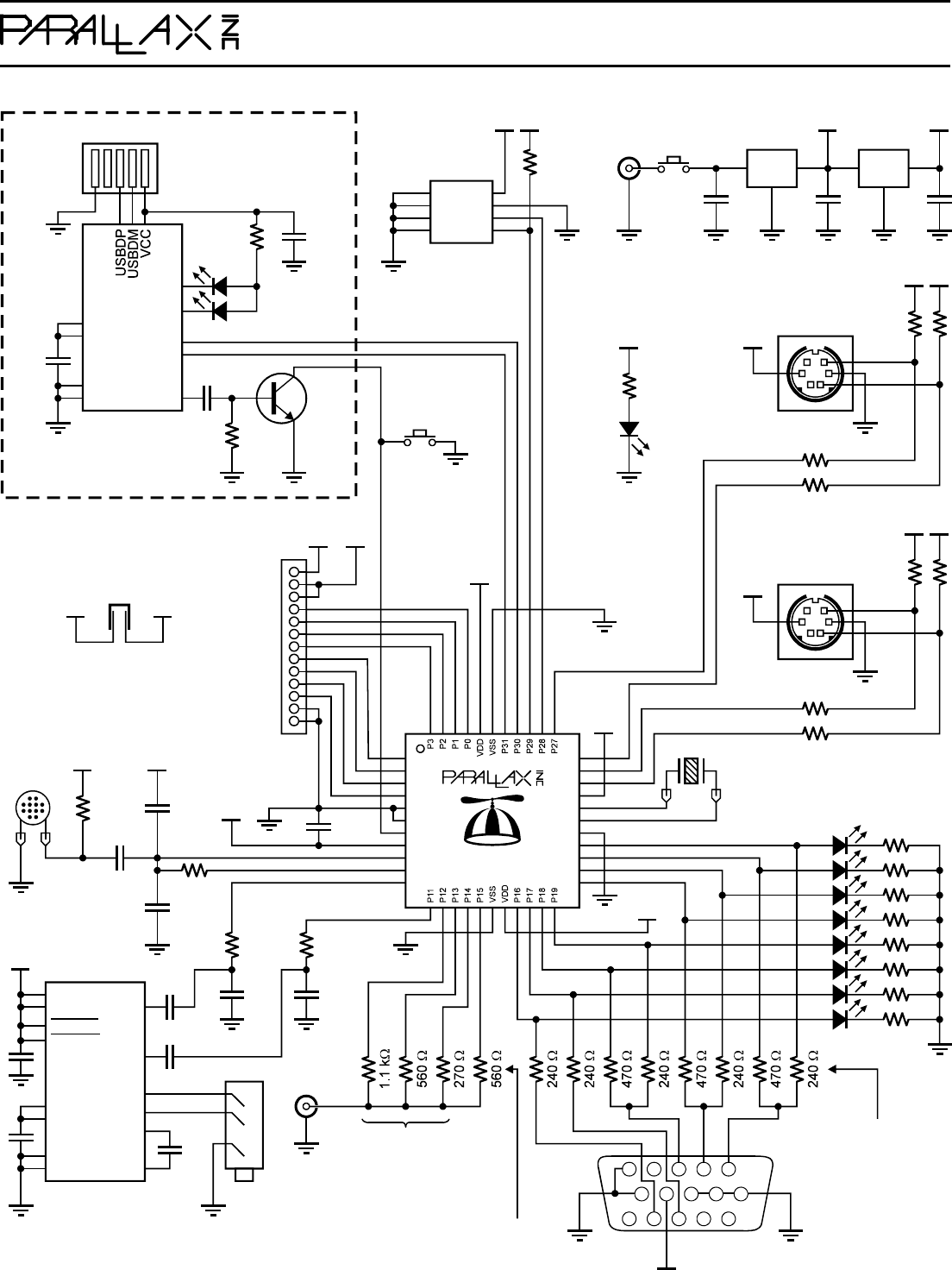
Propdemod Schematic
User Manual: parallax -
Open the PDF directly: View PDF ![]() .
.
Page Count: 1
P26
P25
P24
VDD
XO
XI
P21
P20
P22
P23
VSS
P4
P5
P6
P7
VSS
BOEn
P9
P10
P8
VDD
RESn
P8X32A-Q44
TV
15
78910
124 35
6
111214 13
VGA
V H B G R
10 kW10 kW
10 nF10 nF
1 µF
1 µF
Headphone
Amp
MAX4411ETP
INL
INR
OUTL
OUTR
Left
Right
1 µF
C1P
C1N
SVSS
PVSS
SGND
PVDD
SVDD
PGND
1 µF
1 µF
1 nF
100 kW
0.1 µF
10 kW
Vdd
Electret
Mic
Vdd
1 nF Vdd
1 µF
P0
Vdd
5V
P1
P2
P3
P4
P5
P7
P6
VSS
VSS
5V
Vdd
FT232RQ
RXLED
TXLED
RXD
TXD
DTR
VCCIO
3.3VOUT
GND
TEST
0.1 µF
Blue
Red
10 kW
NPN
5 MHz
5V
Vdd
100 W
100 W
Vdd
Vdd
Mouse
PS / 2 10 kW
5V
Vdd
100 W
100 W
Vdd
Keyboard
PS / 2
Clock
Data
10 kW
USB Mini B
10 nF
Reset
100 W4.7 µF
12345
240 W
Yellow
LED
Indicators
These three sets of two
resistors form 1-volt, 75-
ohm, 2-bit DACs that
are used to generate
red, green, and blue.
This resistor is only required for
aural subcarrier in broadcast mode.
These three resistors
form a 1-volt, 75-ohm,
3-bit DAC that is used
to generate baseband
and broadcast video.
Stereo
3.3V
IN OUT
GND IN OUT
GND
0.1 µF
5V
10 µF 10 µF
On/Off LM2937IMP-5.0 LM2937IMP-3.3
6-9
VDC
Removable
Crystal
3.3V
5V
Vdd
Vdd
A0
VSS
A2
A1
SDA
SCL
WP
VDD
32 KB
EEPROM 10 kW
24LC256-I/ST
Vdd
On-Board USB to Serial
Also available separately
as the Propeller Clip
or the Propeller Plug
Vdd
599 Menlo Drive
Rocklin, CA 95765, USA
Office: (916) 624-8333
Fax: (916) 624-8003
www.parallax.com info@parallax.com Tech Support: support@parallax.com Educational: www.stampsinclass.com
Propeller Demo Board Rev D/E/F Schematic (11-29-06)
3.3V Vdd
I
Jumper
VDD
Vdd
3.3V
240 W
Green
Clock
Data
SHDNL
SHDNR
