Spectral Audio Pro Tone Service Manual Protone
Spectral Audio ProTone Service Manual ProTone_Service_Manual Spectral Audio - ProTone - Service Manual
Spectral Audio ProTone Service Manual protone_service_manual Spectral Audio - ProTone - Service Manual
User Manual: Spectral Audio ProTone Service Manual Spectral Audio - ProTone - Service Manual
Open the PDF directly: View PDF ![]() .
.
Page Count: 20

Service Manual ProTone Page 1 of 20 © 1996-2001 Spectral Audio
ProTone
MIDI Analog Synthesizer
Service Manual
Copyright © 1996-2001 by Spectral Audio, Switzerland
CAUTION!
All instructions in this manual must be carried out by a professional who observes the valid safety
regulations. In operation, they have got dangerous voltages in the instrument. Spectral Audio
GmbH accepts no liability for personal injury or material damage.

Service Manual ProTone Page 2 of 20 © 1996-2001 Spectral Audio
1 Description of the Operating Elements 3
1.1 Sockets on the Rear of the Housing 3
1.2 Front Panel Controls 4
2 Functional Description 5
3 History of Series 7
4 Improvements and explanations 7
4.1 Sense of R174 and R175 7
4.2 Sense of C63 – C65 7
4.3 Sense of R174 and R175 8
4.4 Hum Problems 8
4.5 Increasing the Gate voltage to +12V 8
5 Adjustment of the ProTone 9
5.1 Digital PCB (MIDI to CV converter) 9
5.2 Analog PCB (VCO1 and VCO 2) 9
5.2.1 VCO1 9
5.2.2 VCO2 9
6 Digital PCB 11
6.1 Assembly plan 11
6.2 Part list 11
7 Analog PCB 13
7.1 Assembly plan 13
7.2 Part list 15
8 Mechanical part list 20
Service Manual ProTone Page 3 of 20 © 1996-2001 Spectral Audio
1 Description of the Operating Elements
Out
Left
Out
Right Extern
VCO
Input
Extern
LFO
Input
Gate CV MIDI
Thru MIDI
IN
0.7 Veff 0.7 Veff 0V:Off 1V/Oct
5V:On
230 V~
max. 500mAT
ProTone
Made in Switzerland
37 36 38 39 40 41 42 43 44
Warning : Shock Hazard - do not open!
Vorsicht : Lebensgefahr - nicht öffnen!
Avis : Risque de choc Electrique - ne pas ouvrir!
SPECTRAL AUDIO GmbH
Serial No.
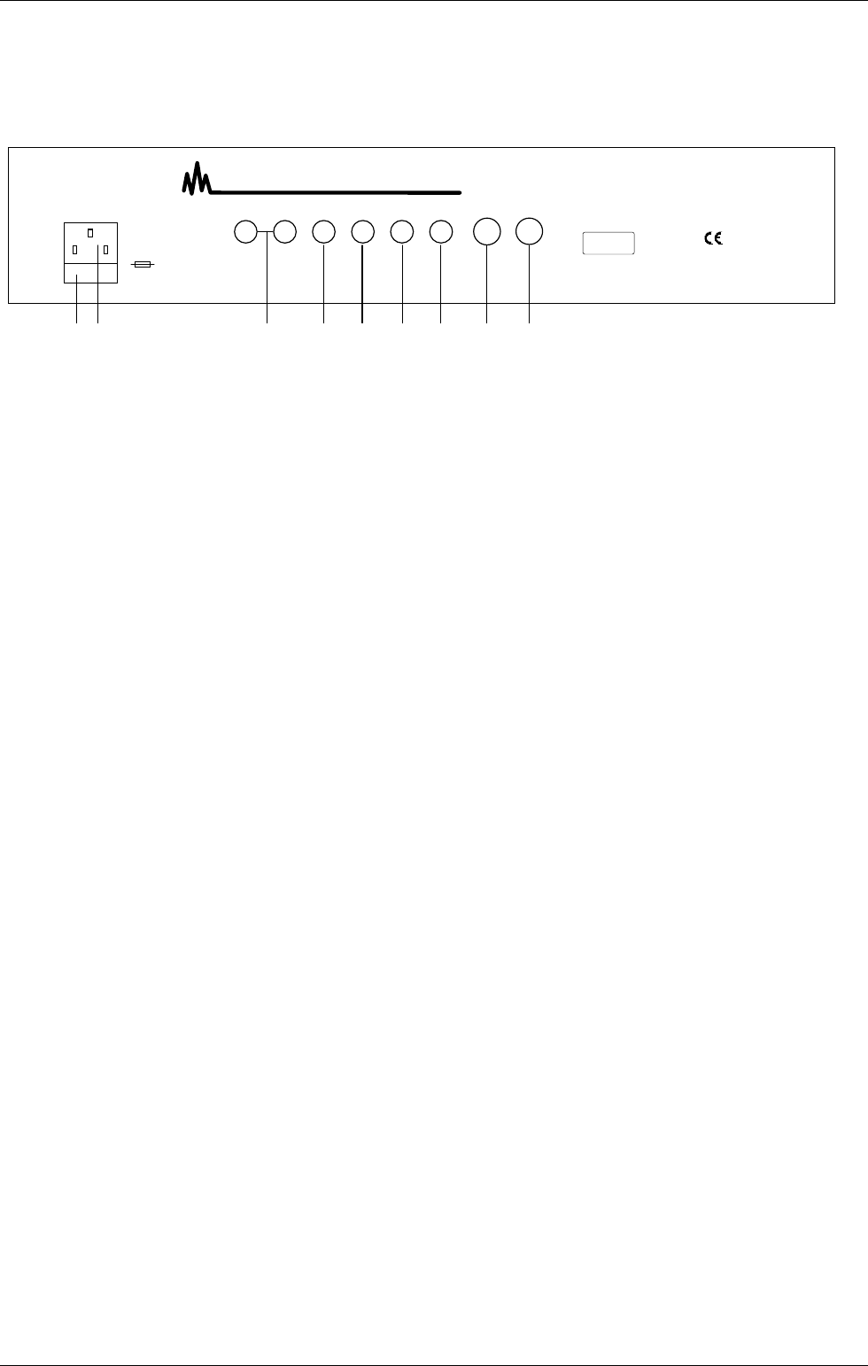
1.1 Sockets on the Rear of the Housing
36. Power socket
37. Fuse compartment, fuse max. 500 mA, 250V type
38. Audio outputs right / left
39. External VCO input, switched on with switch (7)
40. External modulation input, selected with selector switch (22)
41. Gate input/output (dependent on the jumper setting inside the unit, standard setting: output)
42. CV input / output (dependent on the jumper setting inside the unit, standard setting: output)
43. MIDI Thru socket
44. MIDI IN socket
Service Manual ProTone Page 4 of 20 © 1996-2001 Spectral Audio
TUNE PW
NOISE
TUNE
SLIDE
EXT
VCO 1
VCO 2
FILTER
KEY-
FOLLOW
LFO
FREQUENCY MODULATION
WAVE LFO ON ...
NOISE
EXT.
PW 1
VCO 1
VCO 2 PAN
RANDOM
RANGE
MIDDLE
LOW
HIGH
ProTone
GATE /
LEARN
POWER
GROUND-
LEVEL
LEARN
PAN
ENV MOD
CUTOFF RESONANZ
VOL VCO 2
RINGMOD
VOL VCO 1
DECAYATTACK SUSTAIN RELEASE
CUT
OFF
ACCENT 24 dB
HIGHPASS
LOWPASS
12 dB
SYNC ON
MIDI ANALOG SYNTHESIZER
-
6
5
4
2
112
3
0
789
10
11
6
5
4
2
112
3
0
789
10
11
6
5
4
2
112
3
0
789
10
11
6
5
4
2
112
3
0
789
10
11
6
5
4
2
112
3
0
789
10
11
6
5
4
2
112
3
0
789
10
11
6
5
4
2
112
3
0
789
10
11
6
5
4
2
112
3
0
789
10
11
6
5
4
2
112
3
0
789
10
11
6
5
4
2
112
3
0
789
10
11
6
5
4
2
112
3
0
789
10
11
6
5
4
2
112
3
0
789
10
11
6
5
4
2
112
3
0
789
10
11
6
5
4
2
112
3
0
789
10
11
6
5
4
2
112
3
0
789
10
11
6
5
4
2
112
3
0
789
10
11
C1
R
L5
4
3
2
5
1
4
32
01
6
65
4
3
2
5
1
4
3
2
-+
01
6
65
4
3
2
5
1
4
3
2
-+
1
0
12 3
4567
89 11
1410
12 13 18 19
15 16 17 25 26 27
20 21 22 23 24
28 29 31
30
32
33 34 35
SPECTRAL AUDIO
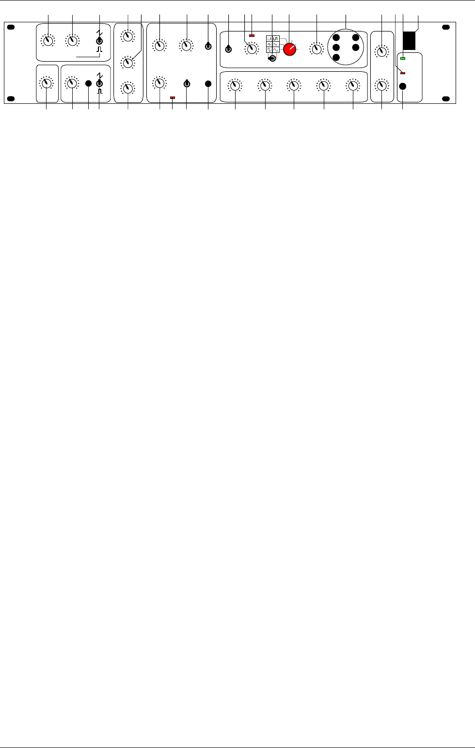
1.2 Front Panel Controls
VCO 1:
1. TUNE: Regulates the pitch of the VCO 1
2. PW: Pulse width of the rectangular pulse
3. Changeover between the signal types saw tooth, noise and rectangle
4. SLIDE: regulates the time balance of VCO 1 and VCO 2
VCO 2:
5. TUNE: Regulates the pitch of the VCO 2
6. SYNC: Synchronises VCO 2 with VCO 1
7. Changeover between the signal types saw tooth, external (input on rear of housing) and rectangle
Mixer:
8. VOL VCO 1: Volume of VCO 1
9. RINGMOD: Volume of the ring modulation of VCO1 and VCO2
10. VOL VCO 2: Volume of VCO 2
VCF:
11. CUTOFF: Cut-off frequency of the filter
12. RESONANCE: increases the harmonics at the cut-off point
13. Changeover between lowpass and highpass
14. ACCENT: Pulsed increase of the cut-off frequency and the volume
15. ACCENT ON Indicator: Lights when the accent function is switched on (MIDI Controller 65)
16. Determines the edge steepness of the filter: 12 or 24dB / octave
17. KEYFOLLOW: The cut-off frequency is influenced by the actual note
LFO:
18. RANGE: Changeover between three LFO frequency ranges
19. FREQUENCY: Setting the LFO frequency
20. LFO Indicator: Indicates each positive half wave of the LFO.
Note: The eye recognises frequencies larger than 60 Hz as being static.
21. Changeover between symmetrical and asymmetrical LFO waveforms
22. Selector switch for different LFO waveforms. By means of the matrix presentation, there are a total of 9
signal forms available: sinus, asymmetrical sinus, triangle, saw tooth, rectangle, pulse, random, noise and
external (input on the rear of the housing)
23. MODULATION: Determines the strength of the LFO influence
24. LFO ON..: LFO assignment possibilities: VCO 1, VCO 2, PW 1, cut-off, pan (any combination possible)
Envelope:
25. ATTACK: Rise time
26. DECAY: Decay time
27. SUSTAIN: Hold level
28. RELEASE: Release time
29. ENV MOD: Influences the cut-off frequency with the envelope
Stereo VCA:
30. GROUNDLEVEL: Ground level of the unit. This also includes the volume increase influenced by the
accent.
31. PAN: Regulates the relationship of the volume from the left and right-hand channel
Various:
32. LEARN Key; Switches the ProTone to the learn mode
33. GATE / LEARN indicator
34. Switch-on indicator
35. Main switch

Service Manual ProTone Page 5 of 20 © 1996-2001 Spectral Audio
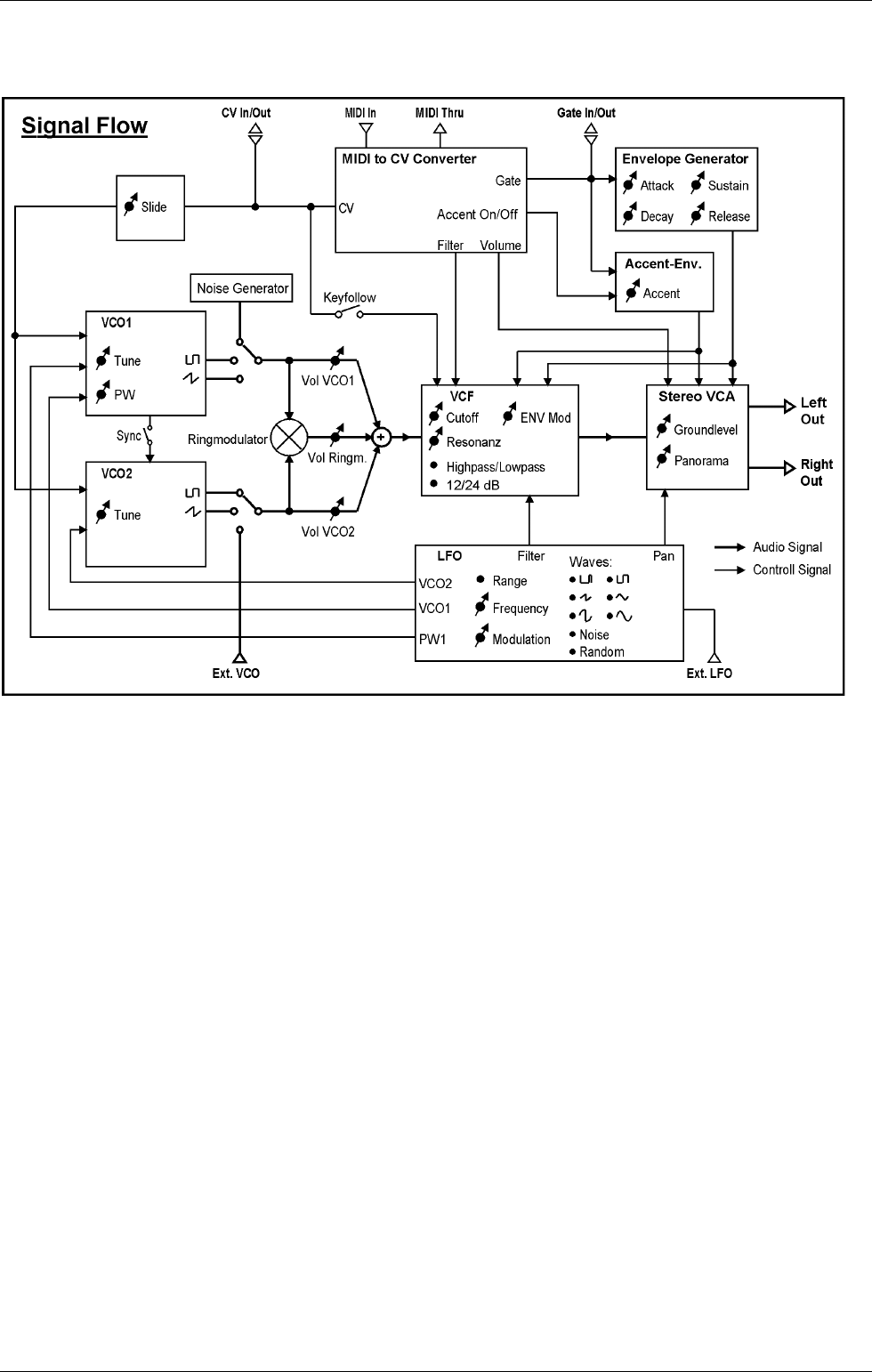
2 Functional Description
The basic principle of the ProTone corresponds to the tried and tested analog synthesizer principle with VCO,
VCF, VCA, envelope generator and LFO. This principle is called subtractive synthesis.
In order that the ProTone is suitable for MIDI, an additional MIDI to CV converter is necessary which converts
the MIDI signals into analog signals with which the VCOs, the filter, as well as the envelope generator are
controlled.
The raw material for the sound is offered by the VCOs (Voltage Controlled Oscillator) in the form of a sawtooth
or rectangular signal as well as the noise generator (for effects such as wind and thunder sounds). The width
of the rectangular signal from VCO1 can be changed with the PW regulator (2). The narrower the rectangular
signal (regulator turned to the right), the 'sharper' the sound. VCO2 is synchronised from VCO1 with the SYNC
switch (6). The tone will be interesting in this case when the TUNE regulator (5) of VCO2 is turned (or by
modulating with the LFO VCO 2), which results in a typical "Sync-Sound".
By means of the external VCO input, other sounds can also serve as raw material. The ring modulator
multiplies the signals of the two VCOs which markedly amplifies the beat (frequency difference).
Note: When the SYNC switch (6) is switched on, no beats are developed and the ring modulator has
therefore no effect.
The SLIDE regulator (4) determines the time balance from one note to another and is valid for both VCOs.
Afterwards, the signal flows through the voltage controlled filter (VCF=Voltage Controlled Filter), within which
certain frequency ranges are suppressed. The lowpass filter allows low frequencies to pass and suppresses
the high ones, the highpass filter lets high frequencies through and suppresses the low ones. The frequency
from which the signals are suppressed is called the limit or cut-off frequency. With the ProTone, this is formed
from various sources:
1. CUTOFF frequency regulator (11)
2. ENV MOD regulator (29) (influence of the envelope on the cut-off frequency)
3. LFO
4. ACCENT regulator (14)
5. KEYFOLLOW switch (17).
With the KEYFOLLOW switch (17), the cut-off frequency increases on higher notes so that audible frequency
bands always remain the same. The resonance forms a feedback of the output to the input of the filter and
causes an amplification of the frequencies around the cut-off frequency.
The ACCENT regulator (14) sets the share of the second envelope and affects the cut-off frequency as well as
the volume. It is only active when the ACCENT indicator (15) lights, i.e., when the accent function is switched
on via the MIDI controller 65. The accent function is always active when the unit is switched on. By means of
the MIDI controller 65, it is now possible, as with the TB 303, to give individual notes an accent (value 127) or
to take an accent away (value 0). For this purpose, the corresponding control value must be sent in the
sequencer, timed either before or with the note.
Before the signal leaves the ProTone, it arrives at the VCA (Voltage Controlled Amplifier) which is available in
the ProTone in stereo form. Here the input signal is multiplied with a control signal. In this way, the volume can
be influenced by a control signal which comes from the envelope generator and the MIDI converter. The
volume of the ProTone is controlled with the GROUND LEVEL regulator (30) as well as via the MIDI controller
EXT (7). Additional to this level is the short-term increase through the accent function. The panorama (volume
relationship of the left-hand to the right-hand signal) can be set with the PAN regulator (31).
The LFO is particularly developed with the ProTone. Using its signal, the pitch from VCO1 and VCO2, the
pulse width of the rectangular signal from VCO1, the cut-off frequency of the filter as well as the panorama can
be modulated with the LFO ON ... switches (24).
With switches (21) and (22) selection can be made between 9 different signal forms. By means of the external
LFO input on the rear of the housing, it is also possible to use any other signal for modulation. To do this,
switch (22) must be turned completely to the right. A microphone, etc, must be connected via a pre-amplifier
as this is a high level input. When the external inputs of the ProTone are used, the ProTone must
simultaneously receive a note command (the same MIDI channel) in order that something is audible.
The envelope generator determines the chronological sequence of the volume after receiving a note
command. The MIDI to CV converter then gives out a gate signal (+5V) with which the sequence of the
envelope generator begins. The gate signal remains at +5V until the 'note off' command comes, i.e., the key is
Service Manual ProTone Page 6 of 20 © 1996-2001 Spectral Audio
released. The parameters of the envelope can be set with regulators (25) to (28). How the envelope should be
imagined is described later on in the glossary.
Service Manual ProTone Page 7 of 20 © 1996-2001 Spectral Audio
3 History of Series
There where 3 different series made:
Serie # 1 : 960000 .. 960020 with golden front panel
Serie # 2 : 960021 .. 960161 with red front panel, C66 and C67 added
Serie # 3 : 960162 .. 960470 with red front panel, now with switch and trafo for 115V / 230V; R173,
R174, C63-C65 inbuilt; R174 and R175 (NTCs) added (by hand); GND Connection to case
This manual describe the last serie.
This manual contains no the hole schematics. Spectral Audio may send it to you for important
reasons, please write to info@spectralaudio.ch.
4 Improvements and explanations
4.1 Sense of R174 and R175
These two resistors helps to increase the lower limit of the cutoff frequency. Otherwise a ploop-
noise may occur when reaching 0 Hz cutoff frequency with a high resonance. You may reach the
0Hz using the LFO.
They are in serie connected from U20 pin 16 to GND.
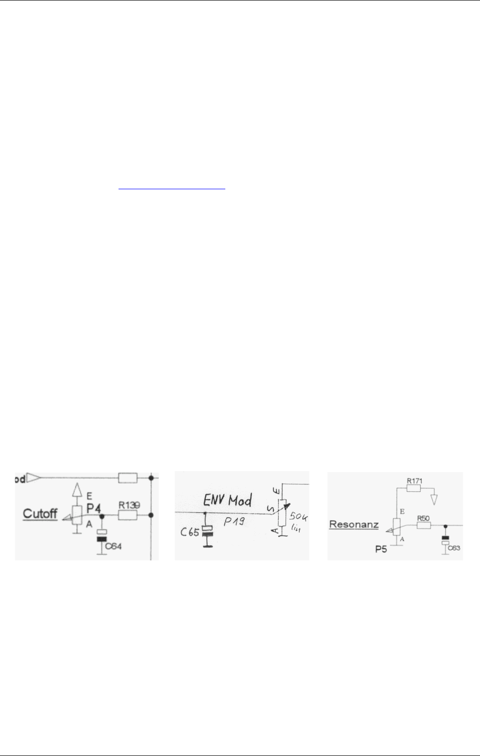
4.2 Sense of C63 – C65
With time, the pots may become noisy. You may hear this effect especially at the Cutoff pot. Using
the C63 – C65 solve this problem.
They are connected from the middle pin (+) of the pot to GND (-). Resonance has negative voltage,
so middle pin is (-) and GND is (+):
Service Manual ProTone Page 8 of 20 © 1996-2001 Spectral Audio
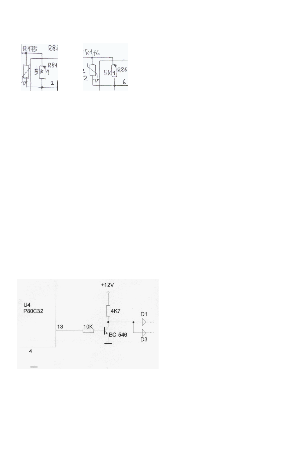
4.3 Sense of R174 and R175
These NTC resistors improves the temperature stability of the two VCOs a lot. It is important that, if
you add these NTCs, also change the resistors R81 and R86 to 5k1. Use hot glue to glue them
onto U16. Sold them parallel to R81 and R86:
After this change, a readjustment must be done.
4.4 Hum Problems
In some circumstances, the internal connection from GND to the metal case creates a hum noise
because of closed earth loops.
In this case it may help to cut this internal GND connection.
You will find it (on later Proton's series only) on the digital pcb, a pretty wide track to one screw. Cut
it with a sharp cutter.
4.5 Increasing the Gate voltage to +12V
To increase the Gate voltage from +5V to +12V, two additional resistors and one NPN transistor are
necessary.
Apart from this, port 1.3 (pin 4) of the microprocessor must be connected to GND that the gate
signal output from the microprocessor is inverted.
The circuit change appears as follows:

Service Manual ProTone Page 9 of 20 © 1996-2001 Spectral Audio
5 Adjustment of the ProTone
5.1 Digital PCB (MIDI to CV converter)
The slope of the control voltage CV is set with trimmer R10. Octave jumps which are initiated via
MIDI-IN, must result in a 1.00 V change.
For this purpose, an accurate voltmeter must be connected to the CV socket J3 and the reference
note (default: 36=C1) initiated and the voltage value noted (some mV). Now initiate the MIDI note
four octaves higher (C4) and adjust R10 so that the voltage is 4.00 V higher. Check the reference
note again and repeat the adjustment if necessary.
5.2 Analog PCB (VCO1 and VCO 2)
In order to tune the VCOs, the analog PCB must first be separated from the front panel (6 screws
with spacers). The analog PCB must then be reconnected to the digital PCB and started.
After disassembly, the Tune VCO1 and Tune VCO2 knobs must be replaced and positioned exactly
in the centre (Tune setting = 0).
Before adjustment, the unit should be in operation for approximately one hour. The adjustment
should be made at room temperature.
Before adjusting the VCO, check the CV slope (chapter above). The setting of R10 in the MIDI to
CV converter is valid for both VCO of course.
5.2.1 VCO1
The frequency of the oscillator can be taken from pin 8 of U11 or at the unit output, whereby the
filter must be open and set to Lowpass. Only VCO1 must be audible (set the mixer correctly). Make
sure that no LFO modulation take place.
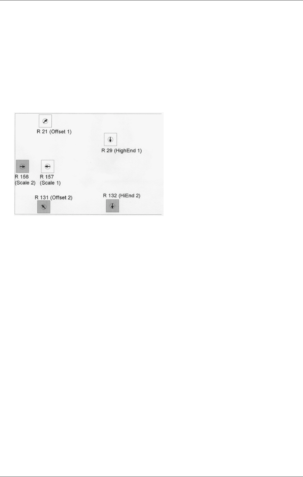
The offset for VCO1 is set with R21 and the slope with R157. Nonlinearity in the upper frequency
range is adjusted with R29.
Proceed as follows to make the adjustment:
1. Set trimmers R21, R157 and R29 to the base settings shown below.
2. Set the ProTone MIDI reference note to C1 by pressing the learn-key.
3. Press key A3 and set the VCO1 frequency with R21 to 220.00 Hz, measured with an exactly
frequency meter.
4. Press key A1 and set the frequency to 55.00 Hz with R157.
5. Repeat steps 3 and 4 until frequency values are stable.
6. Press the key A5 and set the frequency to 880.0 Hz with R29.
7. Repeat steps 3 to 6 and re-adjust if necessary.
5.2.2 VCO2
The offset for VCO2 is set with R131 and the slope with R156. Nonlinearity in the upper frequency
range is adjusted with R132.
Proceed as follows to make the adjustment:
8. Set trimmers R131, R156 and R132 to the base settings shown below.
9. Set the ProTone MIDI reference note to C1 by pressing the learn-key if not done yet.
Service Manual ProTone Page 10 of 20 © 1996-2001 Spectral Audio
10. Press key A3 and set the VCO2 frequency with R131 to 220.00 Hz, measured with an
exactly frequency meter.
11. Press key A1 and set the frequency to 55.00 Hz with R156.
12. Repeat steps 3 and 4 until frequency values are stable.
13. Press the key A5 and set the frequency to 880.0 Hz with R132. Check here if no beats are
audible with VCO1 open, too. If so, adjust R132 in that way that no beats are audible.
14. Repeat steps 3 to 6 and re-adjust if necessary.
15. done!
Service Manual ProTone Page 11 of 20 © 1996-2001 Spectral Audio
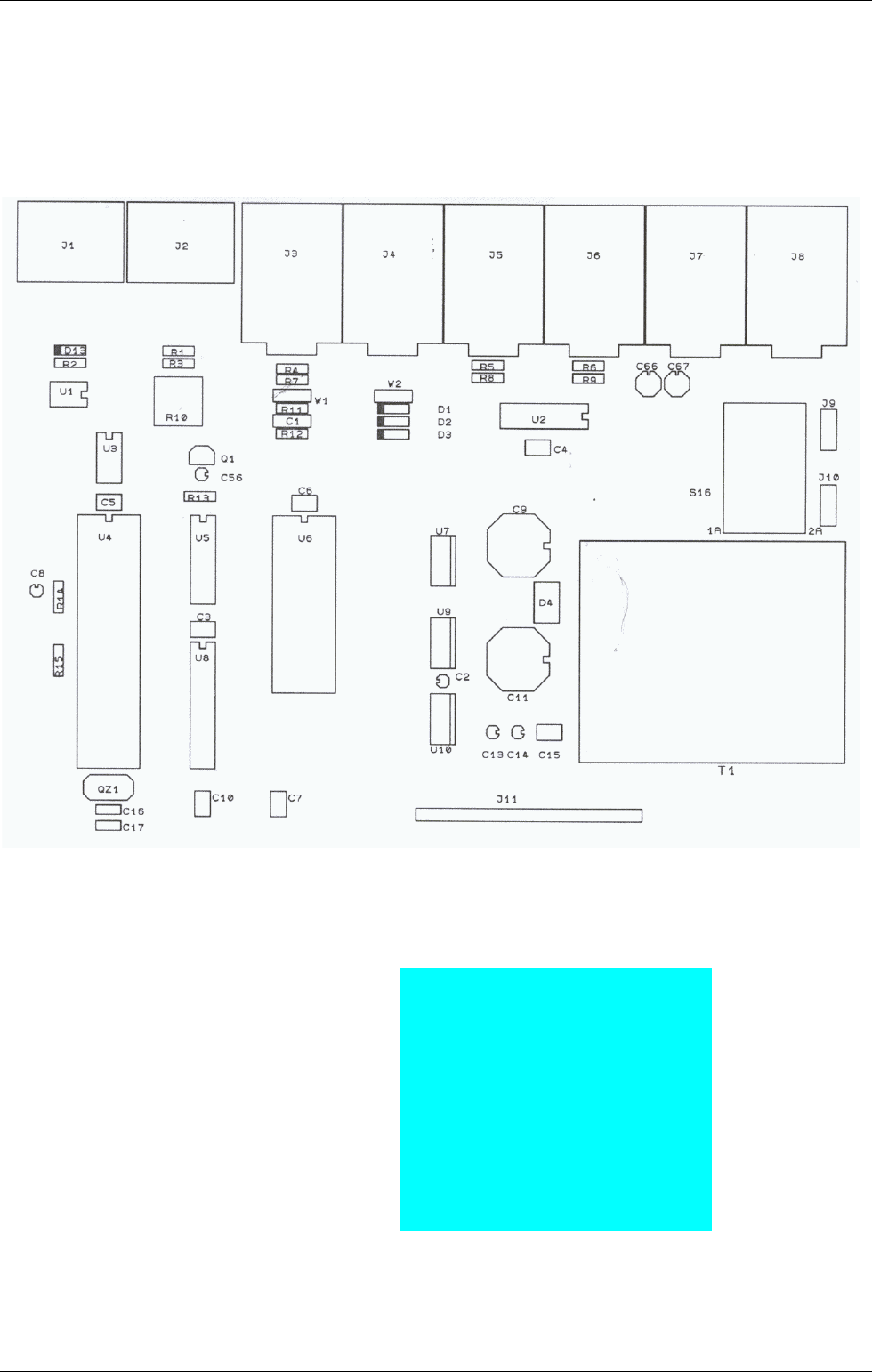
6 Digital PCB
6.1 Assembly plan
6.2 Part list
Resistors
Metal Film Resistor, 1%:
R1 220
R2 220 100R
R3 220 4k7
R4 1k 24k
R5 10k 30k
R6 10k 62k
R7 1k 91k
R8 47k 100k
R9 47k 300k
R10 2k Trimmer 1M
R11 10k
R12 10k
R13 220
R14 10k
R15 1K

Service Manual ProTone Page 12 of 20 © 1996-2001 Spectral Audio
Capacitors Kind Gird [mm] Dimensions [mm]
C1 100p Foil 5 2.5 x 7.2
C2 10u Elko 2 d=5
C3 100n Ker 2.54 3.2 x 5.1
C4 100n Ker 2.54 3.2 x 5.1
C5 100n Ker 2.54 3.2 x 5.1
C6 100n Ker 2.54 3.2 x 5.1
C7 100n Ker 2.54 3.2 x 5.1
C8 10u Elko 2 d=5
C9 1000u/25V Elko 5 d=12.5
C10 100n Ker 2.54 3.2 x 5.1
C11 1000u/25V Elko 5 d=12.5
C13 10u Elko 2 d=5
C14 10u Elko 2 d=5
C15 100n Ker 2.54 3.2 x 5.1
C16 22p Ker 2.54 2 x 5
C17 22p Ker 2.54 2 x 5
C56 10u Elko 2 d=5
C66 2.2u Elko 2 d=5
C67 2.2u Elko 2 d=5
Semiconductors
Q1 TL 431 CLP
D1 1N4148
D2 1N4148
D3 1N4148
D4 DF 02 M
D13 1N4148
U1 CNY17-3 / SFH 601-3
U2 TL 074 CN
U3 24C01/02 CB
U4 P80C32 / SAB-C501-LP
U5 MAX 512 CPD
U6 27C64 Q200
U7 LM 2940CT-12
U8 74HC573 N
U9 LM 7805
U10 LM 7912
Various
Socket for U6 28 pin assemble with EPROM "ProTone V1.04"
QZ1 12 MHz (HC 49)
T1 BV 030-7010.0 L Transformer
S16 V20212MS02Q C&K
J1 DIN 5pol Socket
J2 DIN 5pol Socket
J3 Jack Socket 6,3mm
J4 Jack Socket 6,3mm
J5 Jack Socket 6,3mm
J6 Jack Socket 6,3mm
J7 Jack Socket 6,3mm
J8 Jack Socket 6,3mm
J9 PCB-Plug 4.8 x 0.8 mm
J10 PCB-Plug 4.8 x 0.8 mm
J11 Plug Connector 18 pole angular

Service Manual ProTone Page 13 of 20 © 1996-2001 Spectral Audio
W1 Plug Ledge 3 pole
W2 Plug Ledge 3 pole
Jump1 Jumper 2.54 mm assemble on W1 "Out"
Jump2 Jumper 2.54 mm assemble on W2 "Out"
7 Analog PCB
7.1 Assembly plan
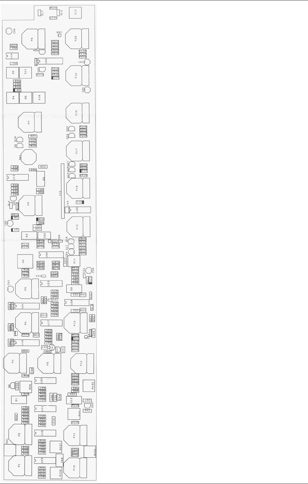
Service Manual ProTone Page 14 of 20 © 1996-2001 Spectral Audio

Service Manual ProTone Page 15 of 20 © 1996-2001 Spectral Audio
7.2 Part list
Resistors
R16 1M
R17 100K *
R18 270K *
R19 220K
R20 47K
R21 100K Trimmer
R22 100K
R23 100K
R24 100K
R25 100K
R26 10K
R27 15K
R28 1K
R29 10K Trimmer
R30 4K7
R31 10K
R32 1M
R33 1M
R34 300K
R35 2K2
R36 390
R37 2K2
R38 470
R39 220
R40 10K
R41 1K
R42 91K
R43 15K
R44 10K
R45 91K
R46 10K
R47 15K
R48 10K
R49 10K
R50 15K
R51 24K
R52 47K
R53 100K *
R54 10K
R55 100
R56 100
R57 4K7
R58 10K
R59 30K
R60 100
R61 24K
R62 2K2
R63 1K
R64 4K7
R65 10K

Service Manual ProTone Page 16 of 20 © 1996-2001 Spectral Audio
R66 22
R67 470K
R68 100K
R69 47K
R70 470K
R71 1M
R72 470K
R73 10K
R74 10K
R75 10K
R76 1K
R77 100K *
R78 100K *
R79 100K *
R80 220K
R81 5k1 *
R82 100 *
R83 1M *
R84 1M *
R85 100 *
R86 5k1 *
R87 10K
R88 10K
R89 100K *
R90 180K
R91 470K
R92 2M2
R93 470
R94 2M2
R95 220K
R96 220K
R97 24K
R98 300K
R99 62K
R100 24K
R101 300K
R102 470K
R103 100
R104 100
R105 4K7
R106 24K
R107 10K
R108 100
R109 2K2
R110 1K
R111 4K7
R112 10K
R113 220K
R114 47K
R115 100K
R116 4K7
R117 390
R118 390
R119 270K *
R120 1M
R121 1K

Service Manual ProTone Page 17 of 20 © 1996-2001 Spectral Audio
R122 4K7
R123 15K
R124 10K
R125 100K
R126 100K
R128 47K
R129 1K
R130 24K
R131 100K Trimmer
R132 10K Trimmer
R133 300K
R134 120K
R135 100K
R136 100K
R137 100K
R138 30K
R139 100K
R140 220
R141 180K
R142 10K
R143 470
R144 470
R146 15K
R147 1K
R148 1K
R149 4K7
R150 10K
R151 24K
R152 300K
R153 10K
R154 47K
R155 100
R156 1K Trimmer
R157 1K Trimmer
R158 30K
R159 1K
R160 470K
R162 470
R163 15K
R164 1K
R165 1K
R166 24K
R167 1K
R168 47K
R169 100K
R170 100K
R171 15K
R172 15K
R173 10M
R174 4M7
R175 NTC 68k mounted with hot glue on U16 parallel to R81
R176 NTC 68k mounted with hot glue on U16 parallel to R86
* must be a Metal Film Resistor, 1%
P1 47K LIN TUNE VCO1 Solder Temp. 235 Grad Celsius max,

Service Manual ProTone Page 18 of 20 © 1996-2001 Spectral Audio
P2 47K LIN PW VCO1 solder time max. 5 sec
P3 47K LIN VOL VCO1
P4 47K LIN CUTOFF
P5 47K LIN RESONANZ
P6 10K LOG F LFO
P7 47K LIN MOD LFO
P8 10K LOG LEVEL
P9 47K LIN VOL RING
P10 1M LOG SILDE
P11 47K LIN TUNE VCO2
P12 47K LIN VOL VCO2
P13 47K LIN ACCENT
P15 1M LOG ATTACK
P16 1M LOG DECAY
P17 47K LIN SUSTAIN
P18 1M LOG RELAISE
P19 47K LIN ENV MOD
P20 47K LIN PAN
Capacitors Kind Gird [mm] Dimensions [mm] Producer
C18 3.3n Foil 5 2.5 x 7.2 WIMA
C19 100p Foil 5 2.5 x 7.2 WIMA
C20 100p Foil 5 2.5 x 7.2 WIMA
C21 22p Ker 2.54 1.8 x 3.5 Phillips
C22 470p Foil 5 2.5 x 7.2 WIMA
C23 470p Foil 5 2.5 x 7.2 WIMA
C24 4p7 Ker 2.54 1.8 x 3.5 Philips
C25 1u Foil 5 6 x 10.5 EVOX
C26 47n Foil 5 2.5 x 7.2 EVOX
C27 470p Foil 5 2.5 x 7.2 WIMA
C28 470p Foil 5 2.5 x 7.2 WIMA
C29 47n Foil 5 2.5 x 7.2 EVOX
C30 100n Ker 2.54 3.2 x 5.1
C31 100n Ker 2.54 3.2 x 5.1
C32 100p Foil 5 2.5 x 7.2 WIMA
C33 100n Ker 2.54 3.2 x 5.1
C34 100n Ker 2.54 3.2 x 5.1
C35 22p Ker 2.54 1.8 x 3.5 Philips
C36 100n Ker 2.54 3.2 x 5.1
C37 470p Foil 5 2.5 x 7.2 WIMA
C38 470p Foil 5 2.5 x 7.2 WIMA
C39 4p7 Ker 2.54 1.8 x 3.5 Philips
C40 470n Foil 5 6 x 10.5 EVOX
C41 47u Elko 2 d=10
C42 1n Ker 2.54 1.8 x 3.5 Philips
C43 1u Elko 2 d=5
C44 47n Foil 5 2.5 x 7.2
C45 100n Ker 2.54 3.2 x 5.1
C46 470p Foil 5 2.5 x 7.2 WIMA
C47 3.3n Foil 5 2.5 x 7.2 WIMA
C48 2.2u Elko 2 d=5
C54 10u Elko 2 d=5
C55 100p Foil 5 2.5 x 7.2 WIMA
C57 100n Ker 2.54 3.2 x 5.1
C58 100n Ker 2.54 3.2 x 5.1
C59 100n Ker 2.54 3.2 x 5.1

Service Manual ProTone Page 19 of 20 © 1996-2001 Spectral Audio
C60 1u Elko 2 d=5
C61 1u Elko 2 d=5
C62 1u Elko 2 d=5
C63 1u Elko 2 d=5
C64 1u Elko 2 d=5
C65 1u Elko 2 d=5
Semiconductors
Q2 BC 556 B
Q3 BC 546 B
Q9 BC 546 B
Q10 BF 245 B
Q11 BC 546 B
Q17 BC 556 B
Q18 BC 556 B
Q19 BC 546 B
Q20 BC 556 B
Q21 BC 546 B
Q22 BC 546 B
Q23 BC 546 B
Q24 BC 556 B
Q25 BC 556 B
Q26 BC 556 B
D7 1N4148
D8 1N4148
D9 1N4148
D10 1N4148
D11 1N4148
D12 1N4148
D14 1N4148
D15 1N4148
D16 1N4148
DL1 2.5 x 5mm Green Assemble with 8 mm spacer (Total 17mm)
DL2 2.5 x 5mm Red Assemble with 8 mm spacer (Total 17mm)
DL3 2.5 x 5mm Red Assemble with 8 mm spacer (Total 17mm)
DL4 2.5 x 5mm Red Assemble with 8 mm spacer (Total 17mm)
U11 TL 074 CN
U13 TL 074 CN
U14 TL 072 CN
U15 TL 074 CN
U16 CA 3046
U17 TL 074 CN
U18 XR 2208 CP
U20 LM 13700 N
U21 LM13700 N
U22 TL 074 CN
U23 TL 074 CN
U24 LM13700 N
U25 LM13700 N
U26 CD 4001 BCN
Various

Service Manual ProTone Page 20 of 20 © 1996-2001 Spectral Audio
S1 E103-SD1CBE 1pole on-off-on Toggle Switch C&K
S2 E201-SD1CBE 2pole on-on Toggle Switch C&K
S3 E103-SD1CBE 1pole on-off-on Toggle Switch C&K
S4 PVA1-EE 1 pole on-off Push-Push Switch ITT
S5 PVA1-EE 1 pole on-off Push-Push Switch ITT
S6 PVA1-EE 1 pole on-off Push-Push Switch ITT
S8 E101-SD1CBE 1pole on-on Toggle Switch C&K
S9 E101-SD1CBE 1pole on-on Toggle Switch C&K
S10 PVA1-EE 1 pole on-off Push-Push Switch ITT
S11 PVA1-EE 1 pole on-off Push-Push Switch ITT
S12 PVA1-EE 1 pole on-off Push-Push Switch ITT
S13 E103-SD1CBE 1pole on-off-on Toggle Switch C&K
S14 PVA1-EE 1 pole on-off Push-Push Switch ITT
S15 PVA1-OA 1 pole on-off Momentary Switch ITT
SW1 56P36-01-1-06N 6 pole Rotary Switch Grayhill
J12 Connector 18 pole (Socket) mounted on Solder Side
8 Mechanical part list
Pcs. Part
1 Front Panel
1 Chassis
1 Backside
4 Screw M3 x 5mm with counter bore head black
5 Cylinder head screw M3 x 5mm black
1 Nut M3 for grounding
1 Washer for grounding
8 Sheet metal screw 2.9 x 6.5mm black
6 Sheet metal screw with counter bore head 2.9 x 22mm black
6 Spacer 14 mm
2 Spacer 25 mm metal with thread M3
1 Analog PCB assembled
1 Digital PCB assembled
6 Nuts for Phone Jack
19 Knobs 18 splines
1 Knob "D" Shape 1/8"
1 Inlet IEC Socket with Fuse Box
1 Fuse 250mA
1 Cable blue with thimbles 4.8mm
2 Cable brown with thimbles 4.8mm
1 Cable yellow-green with thimbles
1 Power switch 1 pole with 4.8mm terminals
