PS CMR 3003 Performance Plus 20.4V
User Manual: Performance Plus 20.4V
Open the PDF directly: View PDF ![]() .
.
Page Count: 24

PROCUREMENT SPECIFICATION NUMBER
PS-CMR-3003
Rev. C Date: 17 Nov 06 CR# 06-1057
PRINTED COPIES OF THIS DOCUMENT ARE CONSIDERED “REFERENCE” UNLESS OTHERWISE STAMPED IN RED INK.
Authorizing Signature is on FILE
APPROVED: ________________________________
DIRECTOR OF PRODUCT ENGINEERING
FORM NO. 1141-05-23, Rev F, Date: 1 AUG 2006, CR# 06-0669 Page 1 of 24
PROCUREMENT SPECIFICATION
CHERRYMAX® PLUS
RIVET, BLIND, ALUMINUM SLEEVE,
MECHANICALLY LOCKED SPINDLE, BULBED

PROCUREMENT SPECIFICATION NUMBER:
PS-CMR 3003
Rev. C Date: 17 Nov 06 CR# 06-1057
FORM NO.: 1141-05-23, Rev. F, Date: 1 AUG 2006, CR# 06-0669 Page 2 of 24
TABLE OF CONTENTS
PARAGRAPH CONTENTS PAGE
1.0 Scope 3
2.0 Applicable Documents 3
3.0 Requirements 4
4.0 Quality Assurance Provisions 6
5.0 Preparation for Delivery 9
6.0 Notes 9
TABLE
I Qualification Sampling and Test Procedure 11
II Qualification Rivet Selection 12
III Acceptance Tests (Summary) 12
IV Discontinuity Limits 13
V Tolerances on Eccentricity 13
VI Single Shear Strength 14
VII Tensile Strength 15
VIII Thin Sheet Pull Thru 15
IX Spindle Retention Load 15
X Spindle Retention Load 15
XI Sheet Take-Up 16
XII Fatigue Test Load 16
XIII Hole Sizes for Defined Tests 17
FIGURES
1 Locking Element and Spindle Flushness Limits 18
2 Tension Specimen 19
3 Thin Sheet Pull-Thru 20
4 Spindle Retention Test 21
5 Sheet Take-Up Specimen 22
6 Specimen for Installation Test 23
7 Shank Expansion Specimen 24

PROCUREMENT SPECIFICATION NUMBER:
PS-CMR 3003
Rev. C Date: 17 Nov 06 CR# 06-1057
FORM NO.: 1141-05-23, Rev. F, Date: 1 AUG 2006, CR# 06-0669 Page 3 of 24
1.0 SCOPE
1.1. Scope - The specification establishes the requirements for procurement of self-plugging blind rivets with
a visual mechanically locked spindle. These blind rivets are intended for use in aircraft structural or
similar applications in both thick and thin sheets. The bulbed blind head configuration makes these blind
rivets especially well suited for thin sheet or double dimple applications.
1.2. Styles, Classes and Codes - Rivets are furnished in the following styles, classes and codes.
Style 'A' Nominal Shank Diameter
Class 1 - Protruding Head Rivets (MS20470)
Code B - 5056 Aluminum Alloy Sleeve - Alloy Steel Stem
Code E - 5056 Aluminum Alloy Sleeve - CRES Stem
Class 2 - 100° Flush Head (MS20426)
Code B - 5056 Aluminum Alloy Sleeve - Alloy Steel Stem
Code E - 5056 Aluminum Alloy Sleeve - CRES Stem
Class 3 - 100° Flush Shear Head (NAS1097)
Code B - 5056 Aluminum Alloy Sleeve - Alloy Steel Stem
Code E - 5056 Aluminum Alloy Sleeve - CRES Stem
Style 'B' 1/64" Oversize Shank Diameter
Class 1 Protruding Head Rivets (MS20470)
Code B - 5056 Aluminum Alloy Sleeve - Alloy Steel Stem
Code E - 5056 Aluminum Alloy Sleeve - CRES Stem
Class 2 - 100° Flush Head (MS20426)
Code B - 5056 Aluminum Alloy Sleeve - Alloy Steel Stem
Code E - 5056 Aluminum Alloy Sleeve - CRES Stem
Class 4 Flanged Dome Head
Code B - 5056 Aluminum Alloy Sleeve - Alloy Steel Stem
Code E - 5056 Aluminum Alloy Sleeve - CRES Stem
2.0 APPLICABLE DOCUMENTS
2.1. Publications - The following publications of the issue in effect on date of invitation for bids shall form a
part of this specification to the extent specified herein.
2.1.1. Federal Specifications
QQ-P-416 Plating, Cadmium (Electro-Deposited)
(Copies of Federal Specifications and the Federal Specifications Index may be obtained upon
application, accompanied by money order, coupon or cash, to the Superintendent of Documents,
Government printing office, Washington, DC. 20402. The price of Federal Specifications may be
obtained from the Federal Specification Index of the Superintendent of Documents.)

PROCUREMENT SPECIFICATION NUMBER:
PS-CMR 3003
Rev. C Date: 17 Nov 06 CR# 06-1057
FORM NO.: 1141-05-23, Rev. F, Date: 1 AUG 2006, CR# 06-0669 Page 4 of 24
2.1.2. Military Specifications
AMS-H-6088 Heat treatment of aluminum alloys, process for
MIL-R-85188 Riveter, power, pneumatic-hydraulic
AMS-H-6875 Heat treatment of steels, process for
(Copies of Military Specifications may be obtained upon application to the Commander, Air
Materiel Command, Wright-Patterson Air Force Base, Dayton, Ohio; or to the Commanding
Officer, U.S. Naval Air Development Station, Johnsville, Pennsylvania. The price may be
obtained from the Index of Military Aeronautical (AN or MIL) Standards or upon applications to
either of the above agencies and payments shall be made by check or money order, payable to
the Superintendent of Documents or to the Treasurer of the United States.)
2.1.3. Standards
Federal
MS33522 Federal Test Method Standard # 151
Military
ANSI/ASQC Z1.4 Sampling Procedures and Tables for Inspection by Attributes
MIL-STD-129 Marking for Shipment and Storage
NASM1312 Fastener Test Methods
3.0 REQUIREMENTS
3.1. Qualification - The rivet furnished under this specification shall be a product, which has been tested and
has passed the qualification tests specified herein. The rivet manufacturer is responsible for conducting
the tests of this specification. Results of these tests shall be submitted upon application for qualification.
3.2. Materials - The materials used in the manufacture of the blind rivets shall be as specified on the
applicable product standards pages.
3.3. Design and construction
3.3.1. Construction - The blind rivet is of multiple piece construction, must be an integral assembly and
shall include a means, other than friction or the use of adhesives, of mechanically locking the
spindle to the blind rivet sleeve. The blind rivet assembly shall consist principally of a blind rivet
sleeve and spindle plus any other elements required with a visible metallic locking element to
lock the spindle to the blind rivet sleeve and a disposable driving anvil.
This metallic locking element must be visibly dimensionally inspectable for
flushness after installation (See 3.3.6). The 1/8, 5/32 and 3/16 diameter blind
rivets produced to this specification must be capable of being installed using
tooling manufactured to the requirements of MIL-R-85188.
3.3.2. Installation - Installation tests shall be conducted as specified in Paragraph 4.4.6. Installation is
to be accomplished with a tool conforming to MIL-R-85188. The installation tool shall be capable
of installing the blind rivet and mechanically locking the spindle to the blind rivet sleeve. The
excess portion of the blind rivet spindle shall be separated during the installation operation.

PROCUREMENT SPECIFICATION NUMBER:
PS-CMR 3003
Rev. C Date: 17 Nov 06 CR# 06-1057
FORM NO.: 1141-05-23, Rev. F, Date: 1 AUG 2006, CR# 06-0669 Page 5 of 24
3.3.3. Spindle retention - When tested as specified in Paragraph 4.4.7, the installed blind rivet spindle
shall withstand the axial pushout load values specified in Table IX. The spindle of an uninstalled
blind rivet shall be capable of withstanding the axial pushout loads specified in Table X.
3.3.4. Dimensions - Blind rivets shall conform dimensionally to the applicable product standards pages.
3.3.5. Eccentricity of heads - The periphery of the blind rivet manufactured head shall measure within
the limits specified in Table V when tested as specified in Paragraph 4.4.2.
3.3.6. Installed Flushness - The installed spindle and locking element shall be flush within the limits
shown in Figure 1. This means of visual inspection is provided to show that the rivet is properly
installed.
3.3.7. Finish - The blind rivet shall be finished in accordance with the applicable product standards
pages.
3.3.8. Heat Treatment - Heat treatment of 5056 aluminum components shall be as required to meet the
performance requirements of this specification. Heat treatment of 8740 alloy steel components
shall be per AMS-H-6875.
3.3.9. Shear strength - The single shear strength of the blind rivet shall be not less than the value
specified in Table VI when tested in accordance with Paragraph 4.4.3.
3.3.10. Tensile strength - The tensile strength of the driven blind rivet shall be not less than the value
listed in Table VII when tested in accordance with Paragraph 4.4.4.
3.3.11. Thin sheet pull-through - The blind rivet shall exhibit not less than the minimum pull-through
strength value specified in Table VIII when tested as specified in Paragraph 4.4.5
3.3.12. Sheet take-up - The blind rivet shall be capable of closing the respective gap indicated in Table
XI when the total stack of thickness (not including gap) is equal to the prescribed maximum grip
for the blind rivet tested. The force resisting closure of the gap shall not be less than that
specified in Table XI, when tested per Paragraph 4.4.8.
3.3.13. Lubrication - Lubrication as necessary to assure proper function of the blind rivet is permissible.
The lubricant used shall pass the lubricant tests as specified in Paragraph 4.4.9 (qualification
only). Cadmium shall not be used for a lubricant unless specified as a finish on the applicable
standards pages. Lubricants used shall be stable and not subject to deterioration under normal
handling and storage conditions not to exceed 150°F.
3.3.14. Workmanship - The blind rivet shall be of uniform quality and shall be finished in a workmanlike
manner in accordance with high-grade aircraft manufacturing practice. Discontinuities such as
seams and clinch or die marks are permitted within the limits specified in Table IV provided they
do not affect other requirements of this specification. Rivets shall be free from fins and other
defects, which could cause an injury to the operator.
3.3.15. Head marking - The rivet shall be marked in accordance with the applicable standards pages.
3.3.16. Shank Expansion. The rivet shall be capable of passing the expansion test specified in 4.4.10
3.3.17. Fatigue Strength. The rivet shall be capable of passing the fatigue test specified in 4.4.11.

PROCUREMENT SPECIFICATION NUMBER:
PS-CMR 3003
Rev. C Date: 17 Nov 06 CR# 06-1057
FORM NO.: 1141-05-23, Rev. F, Date: 1 AUG 2006, CR# 06-0669 Page 6 of 24
4.0 QUALITY ASSURANCE PROVISIONS
4.1. Classification of tests - The inspection and testing of blind rivets shall be classified as follows:
(A) Qualification Tests (See 4.2)
(B) Acceptance Tests (See 4.3)
4.2. Qualification tests - Qualification tests are those tests performed on samples submitted for qualification.
These samples must be manufactured on production equipment using the same methods as intended for
production. Qualification of any one head style constitutes qualification of the remaining head styles
except that shear and tension testing is required for all head styles.
4.2.1. Sampling instructions - Qualification test samples shall be selected in accordance with Table I
and Ia. Samples shall be packaged in accordance with the requirements of Section 5 and plainly
identified by securely attached labels or tags marked with the following information:
Rivet part number
Sample for qualification test
Rivets, blind, self-pligging, mechanically locked solid spindle, bulbed
Specification: PS-CMR-3003
Code: (Material)
Class: (Flush or protruding head)
Grip Length:
Diameter:
Manufactured by: (Name and symbol)
Submitted by: (Name)
4.2.2. Tests - The qualification tests of blind rivets shall consist of all the tests of this specification as
described under "Test Methods" (See 4.4) and as specified in Table I.
4.3. Acceptance tests - Acceptance tests consist of all tests specified in Table III that must be applied to all
lots by the manufacturer.
4.3.1. Sampling instructions - Acceptance tests shall consist of Sampling Plan A, Sampling Plan B,
Sampling Plan C and Sampling Plan D tests. Reduced Sampling Plan may be installed after ten
(10) consecutive lots of the same part number have passed the acceptance criteria in
accordance with ANSI/ASQC Z1.4.
4.3.2. Lot - A lot shall consist of finished blind rivets which are of the same code, class, grip and
diameter, fabricated by the same process, heat treated in the same manner and produced as
one continuous run or order, or part thereof. No one lot of assemblies shall be comprised of
more than one lot each of stems, sleeves, lockrings, driving anvils or shear rings.
4.3.2.1. A lot of component members of blind rivets (such as sleeves or spindles) shall consist
of those components which are of the same code, class, grip and diameter, fabricated
by the same processes, heat treated in the same manner and produced as one
continuous run, or order, from the same heat of raw material or part thereof.
Dimensional inspection already performed on component members need not be
repeated after assembly of finished blind rivets submitted as inspection lot. Lot control
is required for all components, excluding driving anvils.

PROCUREMENT SPECIFICATION NUMBER:
PS-CMR 3003
Rev. C Date: 17 Nov 06 CR# 06-1057
FORM NO.: 1141-05-23, Rev. F, Date: 1 AUG 2006, CR# 06-0669 Page 7 of 24
4.3.3. Sampling Plan A Tests - Samples shall be selected at random in accordance with ANSI/ASQC
Z1.4, Level S-3, and shall be subjected to the following tests described under "Test Methods"
(see 4.4):
(A) Visual and Dimensional Inspection (4.4.1)
(B) Eccentricity of Head (4.4.2) (AQL 6.5)
4.3.4. Sampling Plan B Tests - Samples shall be selected at random in accordance with ANSI/ASQC
Z1.4, Level S-3, and shall be subjected to the following tests described under "Test Methods"
(see 4.4):
(A) Shear Strength (4.4.3) (AQL=0)
(B) Tensile Strength (4.4.4) (AQL=0)
(C) Spindle Retention (4.4.7) (AQL=0)
The number of tests to be made shall be the smallest number shown under the multiple
sampling plan.
4.3.5. Sampling Plan C Tests - Samples shall be selected at random in accordance with ANSI/ASQC
Z1.4, Level S-3, and shall be subjected to the following test described under "Test Methods"
(see 4.4):
(A) Installation (4.4.6) (AQL 2.5)
4.3.6. Sampling Plan D Tests - One sample each shall be selected at random and shall be subjected to
the following test described under "Test Methods" (see 4.4):
(A) Thin Sheet Pull Thru (4.4.5)
(B) Sheet Take-up (4.4.8)
4.3.6.1. Retest - In the event of failure, test three more samples. All three samples in the retest
must pass in order for the lot to be accepted.
4.3.7. Resubmitted inspection lots - ANSI/ASQC Z1.4 shall apply.
4.4. Test Methods
4.4.1. Visual and Dimensional Examination
4.4.1.1. Sampling per 4.3.3.
4.4.1.2. Procedure - Dimensional examinations may be accomplished visually. Optical aids or
special gages may be used whenever appropriate to insure compliance with this
specification.
4.4.1.3. Classification of defects - All dimensional characteristics are considered defective
when out of tolerance.

PROCUREMENT SPECIFICATION NUMBER:
PS-CMR 3003
Rev. C Date: 17 Nov 06 CR# 06-1057
FORM NO.: 1141-05-23, Rev. F, Date: 1 AUG 2006, CR# 06-0669 Page 8 of 24
Major
101 Shank diameter 4.0 AQL
102 Identification 1.0 AQL
103 Gage Protrusion (Flush Heads) 4.0 AQL
104 Presence of lock ring 4.0 AQL
105 Presence of driving anvil 4.0 AQL
Minor
201 Land Thickness (Flush Head) 4.0 AQL
202 Head Angle (Flush Head) 4.0 AQL
203 Fillet Radius (Flush Head) 4.0 AQL
4.4.2. Eccentricity of Head
4.4.2.1. Eccentricity of heads shall be determined by observing the total variation of a dial
indicator testing the periphery of the head (both flush and protruding styles) as the
blind rivet is rotated with its shank as an axis. (See Table IV).
4.4.3. Shear strength - Blind rivets shall be tested at the maximum grip of the particular blind rivet
under test. The actual tests of the specimens shall be in accordance with the methods specified
in NASM1312-20 or equivalent. Test fixture holes shall be in accordance with Table XIII. The
tests need not be carried to destruction if the test specimens meet the rated strengths specified
in Table VI without failure. Failure is defined as the highest load obtained during the test. Load
deflection curves are not required.
4.4.4. Tensile strength - Tensile strength of blind riveted specimens shall be tested, in the rivet’s
maximum grip condition, in a fixture as shown in Figure 2. Blind rivet grip lengths that will not
accommodate the minimum sheet thickness specified in the Figure 2 table need not be tested.
Failure is defined as the highest load obtained during the test.
4.4.5. Thin sheet pull-thru - The resistance to pull-thru of the blind side head shall be determined using
the specimen shown in Figure 3. Test method procedure shall be per NASM1312-8. Tests shall
be conducted such that the blind head bears against the thin sheet. Blind rivets shall meet the
appropriate requirement in pounds of Table VIII. Hole sizes per Table XIII. Fasteners to be
tested in minimum grip only.
4.4.6. Installation - The blind rivet shall be installed in sheet specimens equivalent to minimum grip and
maximum grip for the particular blind rivet under test in accordance with Figure 6. The blind
rivets shall be installed in accordance with the manufacturer's instructions. Superficial surface
cracking in the rivet blind head as the result of installation is not cause for rejection. Splits,
failure to expand, improper locking element position or stem position as the result of driving are
considered defective. Superficial surface cracks are those cracks whose length is less than one
third of the height of the blind head after upset.

PROCUREMENT SPECIFICATION NUMBER:
PS-CMR 3003
Rev. C Date: 17 Nov 06 CR# 06-1057
FORM NO.: 1141-05-23, Rev. F, Date: 1 AUG 2006, CR# 06-0669 Page 9 of 24
4.4.7. Spindle retention - A full sample of the rivet test specimens shall be tested in a minimum
specified grip thickness (except that rivets with minimum grip thickness). The installed
specimens shall be completely and properly locked. An additional full sample shall be in the
uninstalled condition.
In determining the spindle retention loads, a test device similar to that shown in Figure 4 shall be
used. The load shall be applied at maximum rate of .05 inch per minute to the spindle from the
manufactured head or the rivet. The loads required to push out the spindles of the installed
rivets shall be equal to or greater than those in Table IX. Also, the loads required to push out the
spindles of the uninstalled rivets shall be equal to or greater than those in Table X. A means for
accurately determining the force applied to the rivet spindle shall be provided. The push out load
shall be applied directly in line with the axis of the rivet spindle.
4.4.8. Sheet take-up - The sheet material and hole sizes shall be as shown in Figure 5. One test shall
be made and the rivet shall remove the entire gap. Gap removal shall be measured with the use
of a 0.0015" thick gage. The gage shall not be able to penetrate the faying surface to touch the
rivet shank. The force resisting the closing of the gap and the gap to be closed shall not be less
than the value shown in Table XI.
4.4.9. Suitability of lubricant coatings - Lubricant coated and unlubricated "scratch specimens" made of
the same materials as the finished rivet sleeves and having the same protective or other surface
finish (if any) shall be scratched through to the basic metal. Specimens may be of any
convenient size and shape, but the total surface area of each should exceed 6 square inches.
These specimens shall be subjected to a 96-hour salt spray test in accordance with Method 811
of the Federal Test Method Standard #151. After exposure, no significant increase in corrosion
shall be found when a comparison is made between lubricated and unlubricated panels.
4.4.10. Shank Expansion (Qualification Only). The test rivet shall be installed in 7075-T6 (UNS A90705)
coupon and steel split plate fixture in total grips equal to the nominal diameter of the rivet being
tested. Headside coupon thickness and hole size, and split plate thickness and hole size shall
be as shown in Figure 7. Insert the rivet into the headside coupon. The shank diameter shall be
measured at the faying surface and recorded, Install the rivet as previously described. After
installation, the plates shall be separated from one another and from the rivet leaving the rivet
and headside coupon together. The shank diameter of the installed rivet shall be measured at
the faying surface of the split plate and the solid head side aluminum coupon.
The difference between the two recorded measurements shall be a minimum of .002 inch.
4.4.11. Fatigue Strength (Qualification Only). Fatigue strength shall be determined by the full load
transfer method per NASM1312-21. Minimum load shall be 10% of maximum load as indicated
in Table XII. Minimum life requirement at the loads listed in Table XII shall be 3X10⁶ cycles. If
no failure after 3X10⁶ cycles, test may be discontinued.
5.0 PREPARATION FOR DELIVERY
5.1. Packaging - To the requirements of MIL-STD-129 unless otherwise specified.
6.0 NOTES
6.1. Intended use - This specification is intended to establish and control the quality of blind rivets for use in
structural applications on items and components of military and commercial equipment.

PROCUREMENT SPECIFICATION NUMBER:
PS-CMR 3003
Rev. C Date: 17 Nov 06 CR# 06-1057
FORM NO.: 1141-05-23, Rev. F, Date: 1 AUG 2006, CR# 06-0669 Page 10 of 24
6.2. Design information - Design and construction requirements information concerning the use of rivets for
blind attachment is contained in Standard MS33522.
6.3. Installation tools - For government use only, procurement of blind rivets may be limited to those
acceptable rivets, which may be driven, by installation tools already in the service stock system and in
compliance with MIL-R-85188.
6.4. Ordering data - Procurement documents should specify the following:
(A) Type and class of rivets by part number. (See 1.2)
(B) Quantity
(C) Selection of applicable levels of packaging and packing. (See Section 5)
6.5. Cadmium plating - Plating, when required, shall be to the requirements of QQ-P-416 with the following
exceptions:
1. The restriction on "Steel Fasteners RC 43 or higher shall not be plated" is waived.
2. Alloy steel stems shall be baked at 375°F ± 25°F (191°C ± 14°C) for a minimum of four (4) hours within
(4) hours after plating.
3. Hydrogen Embrittlement relief testing will not be required.
4. The maximum plating thickness requirement is waived.

PROCUREMENT SPECIFICATION NUMBER:
PS-CMR 3003
Rev. C Date: 17 Nov 06 CR# 06-1057
FORM NO.: 1141-05-23, Rev. F, Date: 1 AUG 2006, CR# 06-0669 Page 11 of 24
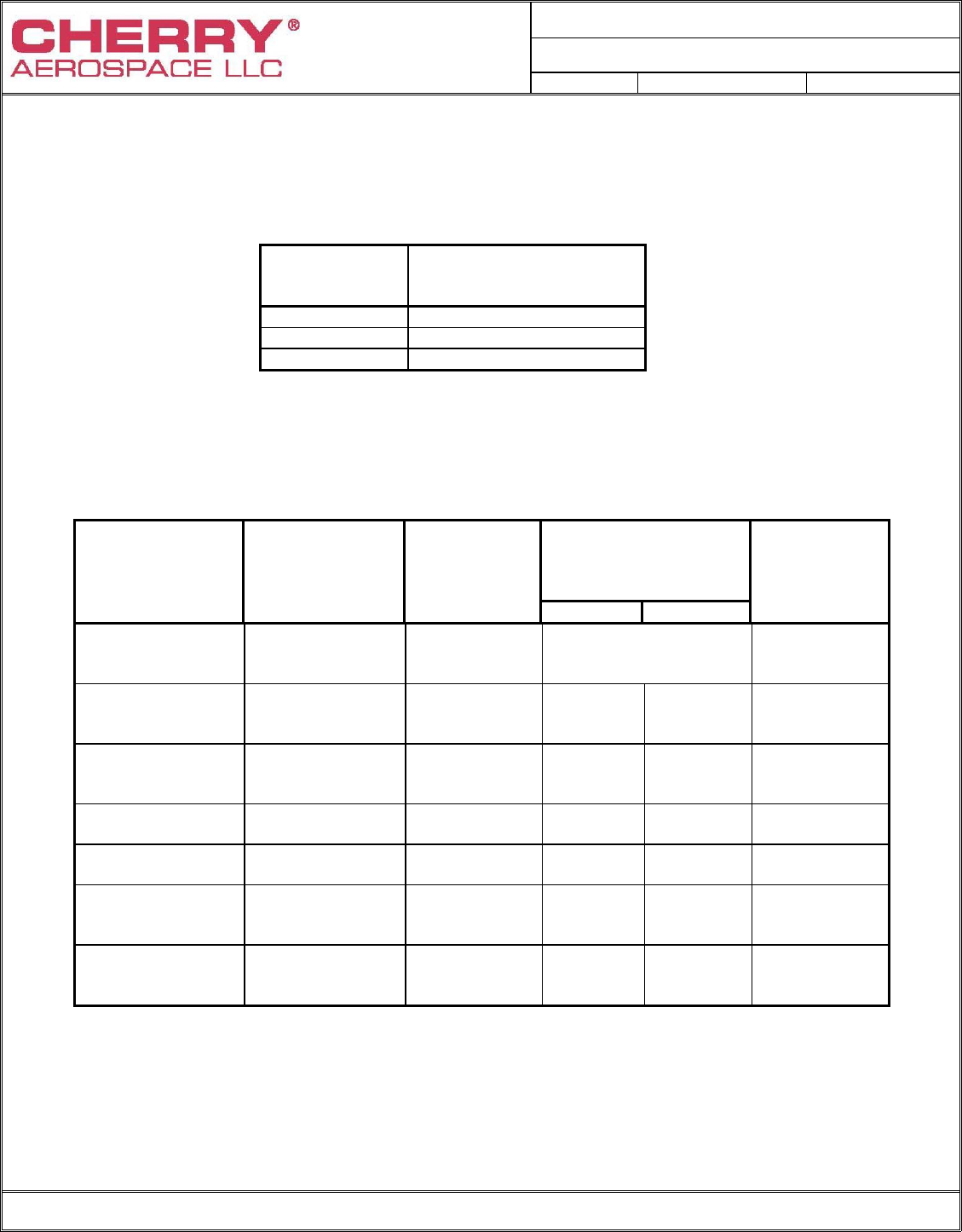
TABLE I
QUALIFICATION SAMPLING AND TEST PROCEDURE
Qualification
Tests Requirement
Paragraph Method
Paragraph
Table, and/or
Figure
Each Diameter
of Each Class
Style Code (1)
Acceptance
Limits
Examination 3.3.1
3.3.4
3.3.5
3.3.7
3.3.15
4.4.1, 4.4.2,
Tables III & IV For each test:
Test ten
fasteners for
each grip length
submitted
1 Defect per part
number submitted
Installation
Installed
Flushness (2)
3.3.2
3.3.6 4.4.6, Figure 6
Figure 1 For each test:
Test ten
fasteners for
each grip
length submitted.
1/20 Total over-
all defectives per
part number.
Shear strength
Tensile strength
Spindle retention
3.3.9
3.3.10
3.3.3
4.4.3, Table VI,
4.4.4, Table VII, Fig. 2
4.4.7, Table IX & X,
Figure 4
For each test:
Test three
fasteners for
each of the three
grip lengths
submitted.
0 Defective
Thin Sheet
Pull-Through
3.3.11
4.4.5, Table VIII
Figure 3
For each test:
Test three
fasteners for
each of the three
grip lengths.
0 Defective
Sheet take-up
3.3.12
4.4.8, Table XI,
Figure 5
Test three fasten-
ers of each grip
length submitted.
0 Defective
Shank Expansion
3.3.16
4.4.10
Figure 7
Test three fasten-
ers of the
appropriate grip
length
0 Defective
Fatigue Strength
3.3.17
4.4.11, Table XII Test three fasten-
ers of the
appropriate grip
length
0 Defective
(1) The grip lengths submitted for qualification shall be as specified by the qualifying activity and shall be selected
from Table II. Generally, 9 lots of hardware are required to qualify a given head style for a particular material
combination (-4, -5 and -6 diameters).
(2) Full sample shall be tested in both minimum and maximum grip conditions (total 20 fasteners)
PROCUREMENT SPECIFICATION NUMBER:
PS-CMR 3003
Rev. C Date: 17 Nov 06 CR# 06-1057
FORM NO.: 1141-05-23, Rev. F, Date: 1 AUG 2006, CR# 06-0669 Page 12 of 24
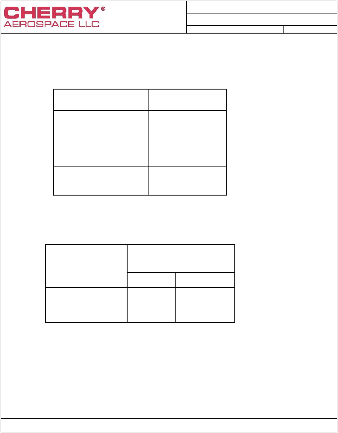
TABLE II
QUALIFICATION RIVET SELECTION
Rivet Diameter Range of Grip Lengths
for
Qualification
-4 -2 thru -8
-5 -3 thru -10
-6 -3 thru -10
TABLE III
ACCEPTANCE TESTS
(SUMMARY)
TEST
REQUIREMENT
PARAGRAPH
METHOD
PARAGRAPH
SAMPLE SIZE
(ANSI/ASQC Z1.4)
ACCEPTANCE
LIMITS
(% AQL)
NORMAL REDUCED
EXAMINATION 3.3.1, 3.3.4,
3.3.5, 3.3.7
3.3.15
4.4.1, 4.4.2
See Para.
4.4.1
INSTALLATION 3.3.2
3.3.6
4.4.6
S-3
N/A
4.0
SHEAR
STRENGTH
3.3.9
4.4.3
S-3
S-1
0 DEFECTIVE
TENSILE
STRENGTH
3.3.10
4.4.4
S-3
S-1
0 DEFECTIVE
SPINDLE
RETENTION
3.3.3
4.4.7
S-3
S-1
2.5
THIN SHEET
PULL THRU
3.3.11
4.4.5
1 *
PIECE
N/A *
0 DEFECTIVE
SHEET TAKE-UP
3.3.12
4.4.8 1 *
PIECE
N/A *
0 DEFECTIVE
* Sample size for retest = 3 pieces. Acceptance limits on retest = 0 Defective
PROCUREMENT SPECIFICATION NUMBER:
PS-CMR 3003
Rev. C Date: 17 Nov 06 CR# 06-1057
FORM NO.: 1141-05-23, Rev. F, Date: 1 AUG 2006, CR# 06-0669 Page 13 of 24
TABLE IV
DISCONTINUITY LIMITS
LOCATION
MAXIMUM DEPTH OF
DISCONTINUITY (INCH)
SHANKS OF SLEEVES
.005
PERIPHERY OF
MANUFACTURED HEADS OF
SLEEVES
.020
OTHER SURFACES ON
SLEEVE AND STEM
.010
TABLE V
TOLERANCES ON ECCENTRICITY OF HEAD
TOTAL VARIATION IN
INDICATOR READING
(INCH)
RIVET
DIAMETER CLASS
2,3,4 CLASS
1
-4 0.010 0.010
-5 0.010 0.015
-6 0.010 0.015
PROCUREMENT SPECIFICATION NUMBER:
PS-CMR 3003
Rev. C Date: 17 Nov 06 CR# 06-1057
FORM NO.: 1141-05-23, Rev. F, Date: 1 AUG 2006, CR# 06-0669 Page 14 of 24
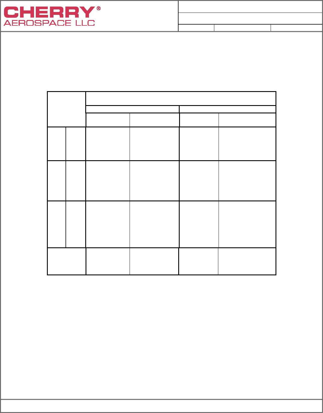
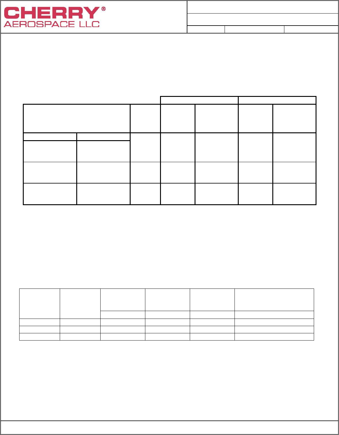
TABLE VI
SINGLE SHEAR STRENGTH
RIVET MINIMUM SHEAR STRENGTH
DIAMETER (POUNDS)
& GRIP (1) STYLE A STYLE B
DASH CLASS 1 CLASS 2, 3 CLASS 1,4 CLASS 2
NUMBER CODE B&E CODE B & E CODE B&E CODE B&E
-1 (2) (2) (2) (2)
-2 505 411 592 480
-3 584 531 692 614
-4 -4 655 651 771 741
-5 664 664 814 814
-2 699 (2) 805 (2)
-3 840 714 982 815
-5 -4 929 862 1080 977
-5 1020 1010 1175 1135
-6 1030 1030 1245 1245
-2 920 (2) 1015 (2)
-3 1130 918 1240 1005
-6 -4 1250 1095 1385 1200
-5 1355 1310 1505 1390
-6 1460 1455 1615 1580
-7 1480 1480 1685 1685
Reference
Shear
Strength
Level
50 KSI 50 KSI 50 KSI 50 KSI
Notes: (1) For rivet grips greater than listed use highest value shown for the
diameter, code, class and style.
(2) Parts too short to be tested.
PROCUREMENT SPECIFICATION NUMBER:
PS-CMR 3003
Rev. C Date: 17 Nov 06 CR# 06-1057
FORM NO.: 1141-05-23, Rev. F, Date: 1 AUG 2006, CR# 06-0669 Page 15 of 24
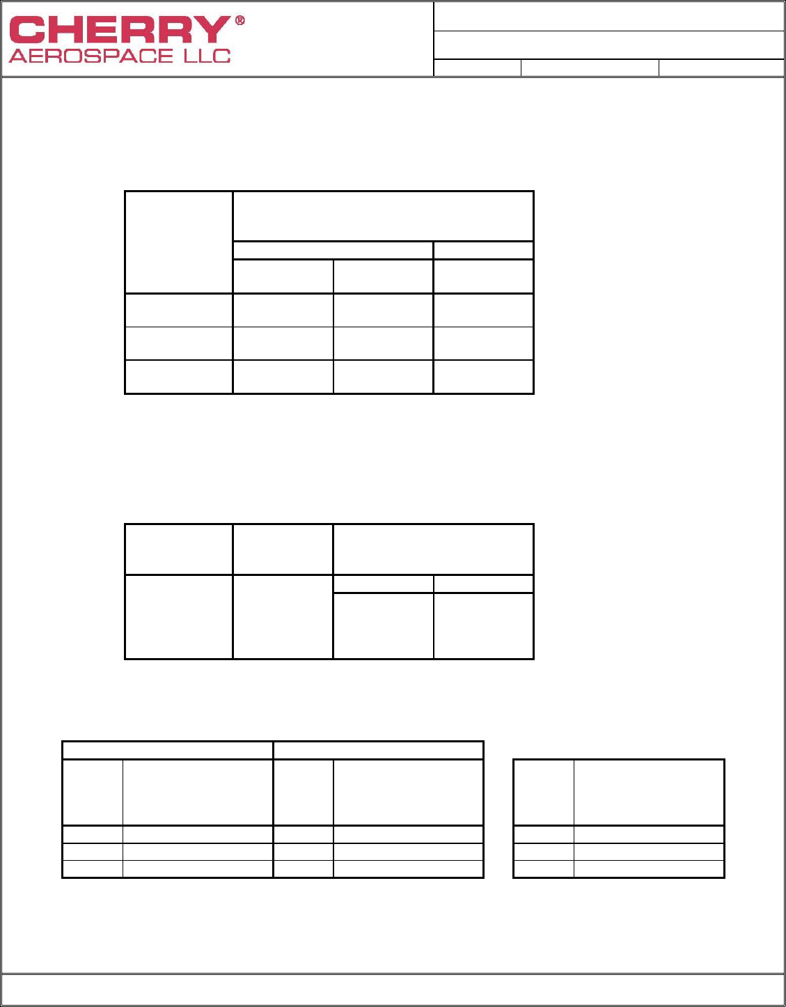
TABLE VII
TENSILE STRENGTH
RIVET
MINIMUM TENSILE
STRENGTH VALUES
(POUNDS)
DIAMETER STYLE A STYLE B
CLASS 1,2
CODE B&E CLASS 3
CODE B&E CLASS 1,2,4
CODE B&E
-4 285 250 345
-5 445 390 530
-6 635 560 710
Note: 4-1, 5-1, 5-2, 6-1 & 6-2 rivets are too short to be tested in tensile.
TABLE VIII
THIN SHEET PULL THRU
Rivet
Diameter Thin Sheet
Thickness
"T" ±.001
Minimum Thin Sheet
Pull-Thru Loads
(Pounds)
Style A Style B
-4 .025 160 180
-5 .032 220 260
-6 .040 315 375
TABLE IX TABLE X
SPINDLE RETENTION LOAD SPINDLE RETENTION LOAD
Style A Style B
RIVET
DIA
MINIMUM AXIAL
PUSH-OUT (LBS.)
INSTALLED
CONDITION
RIVET
DIA
MINIMUM AXIAL
PUSH-OUT (LBS.)
INSTALLED
CONDITION
RIVET
DIA
MINIMUM AXIAL
PUSH-OUT (LBS)
UNINSTALLED
CONDITION
-4 125 -4 150 -4 10
-5 200 -5 250 -5 10
-6 290 -6 450 -6 10
PROCUREMENT SPECIFICATION NUMBER:
PS-CMR 3003
Rev. C Date: 17 Nov 06 CR# 06-1057
FORM NO.: 1141-05-23, Rev. F, Date: 1 AUG 2006, CR# 06-0669 Page 16 of 24
TABLE XI
SHEET TAKE-UP
STYLE A STYLE B
GRIP LENGTHS FOR WHICH
THIS TEST IS APPLICABLE
RIVET
DIA. GAP
G (INCH) FORCE
RESISTING
CLOSURE
(POUNDS)
GAP
G (INCH) FORCE
RESISTING
CLOSURE
(POUNDS)
CLASS 1, 3 & 4 CLASS 2
-2 AND
LONGER
-2 AND
LONGER
-4
.031
10
.031
15
-2 AND
LONGER
-2 AND
LONGER
-5
.031
25
.031
30
-2 AND
LONGER
-2 AND
LONGER
-6
.031
40
.031
50
Note: The -2 & -3 grip parts may not consistently close the gap in the minimum grip condition because of
hole filling. The -4 grip and longer are expected to close the gap regardless of whether they are
installed in minimum or maximum grip condition. Acceptance testing is performed in maximum grip
only.
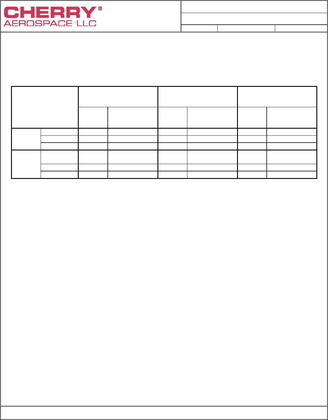
TABLE XII
FATIGUE TEST LEAD (lbs.)
Style A
Hole Size Style B
Hole Size Sheet
Thickness
“T” (Inches)
Maximum Load Per
Specimen
(lbs.)
Rivet
Diameter Rivet
Grip
Dash No. ±.0005 ±.0005 ±.002 B, & E
1/8 (-4) -2 .130 .144 .063 440
5/32 (-5) -3 .162 .178 .080 700
3/16 (-8) -3 .194 .207 .090 945
PROCUREMENT SPECIFICATION NUMBER:
PS-CMR 3003
Rev. C Date: 17 Nov 06 CR# 06-1057
FORM NO.: 1141-05-23, Rev. F, Date: 1 AUG 2006, CR# 06-0669 Page 17 of 24
TABLE XIII
HOLE SIZES FOR DEFINED TESTS
STYLE
AND CLASS
-4 DIAMETER
-5 DIAMETER
-6 DIAMETER
HOLE
DIA.
±.0005
COUNTERSINK
DIA.
±.003
HOLE
DIA.
±.0005
COUNTERSINK
DIA.
±.003
HOLE
DIA.
±.0005
COUNTERSINK
DIA.
±.003
STYLE CLASS 1 0.130 - - - 0.162 - - - 0.194 - - -
A CLASS 2 0.130 0.225 0.162 0.286 0.194 0.353
CLASS 3 0.130 0.192 0.162 0.243 0.194 0.299
STYLE
CLASS 1
0.144
- - -
0.178
- - -
0.207
- - -
B CLASS 2 0.144 0.225 0.178 0.286 0.207 0.353
CLASS 4 0.144 0.170 0.178 0.213 0.207 0.255
Notes: 1) Holes to be square with both faces within 1°.
2) Countersink and cylindrical holes to be concentric within .002 FIM.
3) Countersink diameters only apply to class 2,3 and 4 rivets, and the angle shall be 100°-101°.
4) Material: Alloy Steel Rc46 min.
5) All dimensions in inches.
6) Alternate coupon configurations (e.g. stepped to allow testing
of multiple grips) may be used.
PROCUREMENT SPECIFICATION NUMBER:
PS-CMR 3003
Rev. C Date: 17 Nov 06 CR# 06-1057
FORM NO.: 1141-05-23, Rev. F, Date: 1 AUG 2006, CR# 06-0669 Page 18 of 24
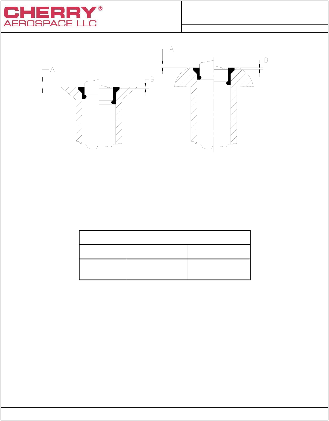
FIGURE 1 - INSTALLED RIVET
LOCKING ELEMENT AND SPINDLE FLUSHNESS LIMITS
SPINDLE FLUSHNESS LIMITS (INCH)
ALL TYPES AND STYLES
RIVET
DIAMETER A MAX.
(ABOVE) B MAX.
(BELOW)
-4 0.010 0.015
-5 0.010 0.020
-6 0.010 0.020
Note: 1) Locking element shall be flush with top surface of rivet head within
±.005. Slight element flash permissible .010 max. from top of rivet
head.
PROCUREMENT SPECIFICATION NUMBER:
PS-CMR 3003
Rev. C Date: 17 Nov 06 CR# 06-1057
FORM NO.: 1141-05-23, Rev. F, Date: 1 AUG 2006, CR# 06-0669 Page 19 of 24
FIGURE 2
TENSION SPECIMEN
RIVET
DIAMETER "T" DIMENSION
MINIMUM
-4 .063
-5 .094
-6 .094
Notes: 1) Material: Alloy steel Rc46 Min.
2) Hole preparation per Table XIII.
3) Spacer thickness as necessary to accommodate grip.
4) Dimension in inches.
5) Thickness of coupons may be adjusted to suit
manufacturers' fixtures
6) Alternate fixture geometries are permissible
provided it is demonstrated that comparable
results are achieved.
PROCUREMENT SPECIFICATION NUMBER:
PS-CMR 3003
Rev. C Date: 17 Nov 06 CR# 06-1057
FORM NO.: 1141-05-23, Rev. F, Date: 1 AUG 2006, CR# 06-0669 Page 20 of 24
FIGURE 3
THIN SHEET PULL-THRU SPECIMEN
NOTES: 1) Material: Thin Sheet = 2024-T3 Aluminum (bare)
Fixtures = Alloy Steel (Rc36 Minimum)
2) Hole Preparation - See Table XIII.
3) "T" Thickness (See Table VIII) Selected to produce
blind head "Pull Thru".
4) Dimensions in inches.
5) Alternate fixture geometries are permissible if it is demonstrated
that comparable results are achieved.
6) Grip lengths -1 and -2 are too short to test.
PROCUREMENT SPECIFICATION NUMBER:
PS-CMR 3003
Rev. C Date: 17 Nov 06 CR# 06-1057
FORM NO.: 1141-05-23, Rev. F, Date: 1 AUG 2006, CR# 06-0669 Page 21 of 24
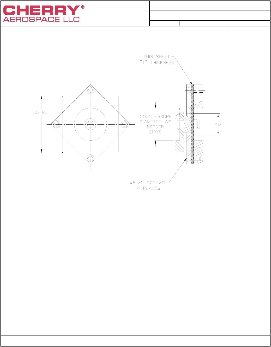
FIGURE 4
SPINDLE RETENTION TEST
Notes: 1) Countersunk dimensions to be same as Table XIII.
2) Material: 2024-T3 Aluminum
3) Except that rivets with a minimum grip length equal to or less than their
diameter shall be installed in a test plate representing maximum
grip condition and having a hole size equal to that required for the
minimum grip test plate of Figure 6.

PROCUREMENT SPECIFICATION NUMBER:
PS-CMR 3003
Rev. C Date: 17 Nov 06 CR# 06-1057
FORM NO.: 1141-05-23, Rev. F, Date: 1 AUG 2006, CR# 06-0669 Page 22 of 24
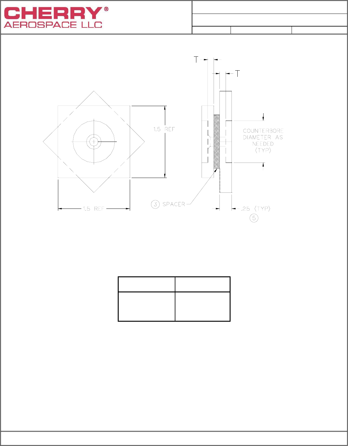
FIGURE 5
SHEET TAKE-UP SPECIMEN
Notes: 1) Sheet material: Shall be 2024-T3 aluminum alloy per QQ-A-250/4 or QQ-A-250/5 (referee)
2) Y dimension to be adjusted to produce closure-resisting force values shown in Table XI.
3) X dimension +.125 shall be equivalent to maximum and minimum grip of test rivet.
4) Fastener hole in specimen shall not be deburred by chamfering.
5) Fastener holes per Table XIII.
6) During calibration, use a .0015" thick feeler gage at hole. The load
required to bring the sheets into contact with the feeler gage is defined as the force resisting
closure of the gap. Calibrate with un-installed rivet in plate and apply load between the rivet
and 1/2” diameter blind side spacer.
7) Force shall not be measured after the sheets are closed.
8) Alternate fixture geometries are permitted if it is demonstrated that comparable results are
achieved.
PROCUREMENT SPECIFICATION NUMBER:
PS-CMR 3003
Rev. C Date: 17 Nov 06 CR# 06-1057
FORM NO.: 1141-05-23, Rev. F, Date: 1 AUG 2006, CR# 06-0669 Page 23 of 24
RIVET
DIAMETER HOLE DIAMETER
± .0005
MINIMUM GRIP
HOLE DIAMETER
± .0005
MAXIMUM GRIP
STYLE A STYLE B STYLE A STYLE B
-4 .132 .146 .129 .143
-5 .164 .180 .160 .176
-6 .196 .209 .192 .205
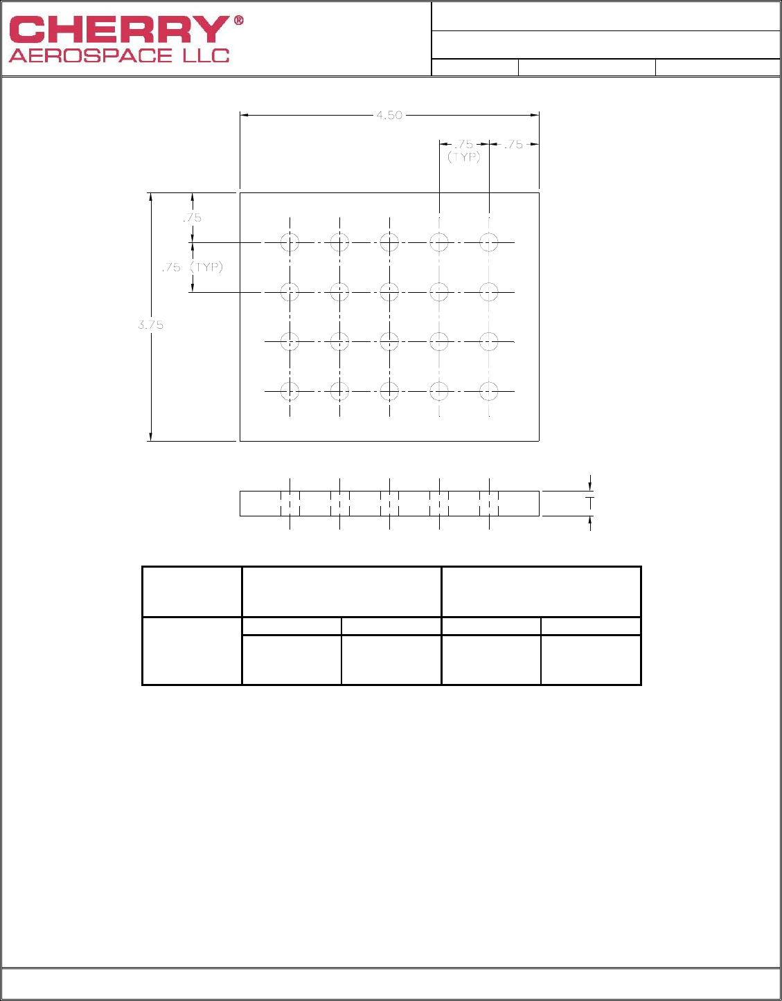
FIGURE 6
SPECIMEN FOR INSTALLATION
Notes: 1) "T" - Sheet thickness. For each specific grip length of appropriate size under evaluation,
installation tests shall be conducted at total grip (T) conforming to minimum and maximum
grip as indicated in applicable standard. One-half of required tests shall be in min. grip-max.
hole and one-half in max. grip-min. hole.
2) Material: Alloy steel or aluminum alloy at manufacturers’ option. (Referee material = 2024-T3).
3) Dimensions in inches.
4) See Table XIII for countersink dimensions.
5) This figure presents the recommended test specimen geometry. Specimens with different
lengths, widths and hole patterns may be used at the rivet manufacturer’s option.

PROCUREMENT SPECIFICATION NUMBER:
PS-CMR 3003
Rev. C Date: 17 Nov 06 CR# 06-1057
FORM NO.: 1141-05-23, Rev. F, Date: 1 AUG 2006, CR# 06-0669 Page 24 of 24
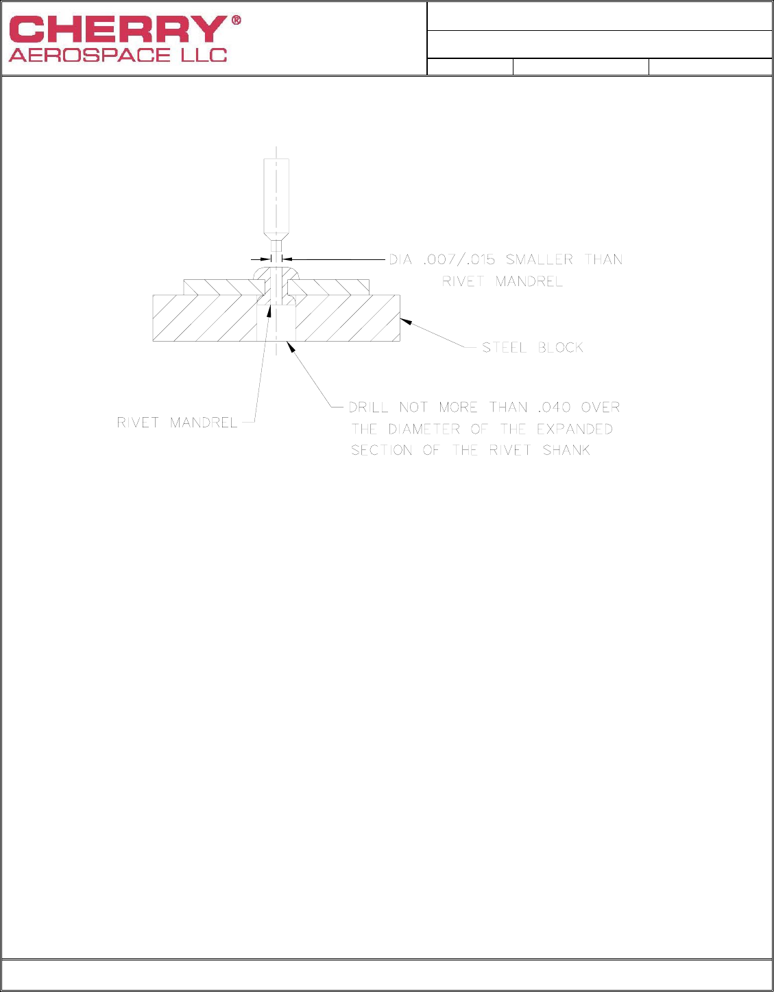
FIGURE 7
SHANK EXPANSION COUPON
Headside Coupon Split Plate
Hole Size
±.0005
Hole Size
±.001
Nominal
Rivet
Diameter
Rivet Grip
Dash No.
Thickness
±.002
Style A
Style B
Thickness
±.002
Style A
Style B
Total
Grip
1/8 (-4)
5/32 (-5)
3/16 (-6)
-3
-4
-4
.098
.127
.156
.1315
.1635
.1955
.1460
.1780
.2040
.062
.078
.094
.132
.164
.196
.146
.180
.209
.
.160
.205
.250
