Pst_psx Pst Psx
User Manual: pst_psx
Open the PDF directly: View PDF ![]() .
.
Page Count: 4
Copley Controls Corp., 20 Dan Road, Canton, MA 02021, USA Tel: 781-828-8090 Fax: 781-828-6547
Web: www.copleycontrols.com Page 1 of 4
PST Power Supplies
UNREGULATED DC POWER SUPPLIES
Model Vdc Adc W Vac
PST-040-13-DP 40 13 520 115/230
PST-070-08-DP 70 7.5 525 115/230
PST-140-04-DP 140 3. 490 115/230
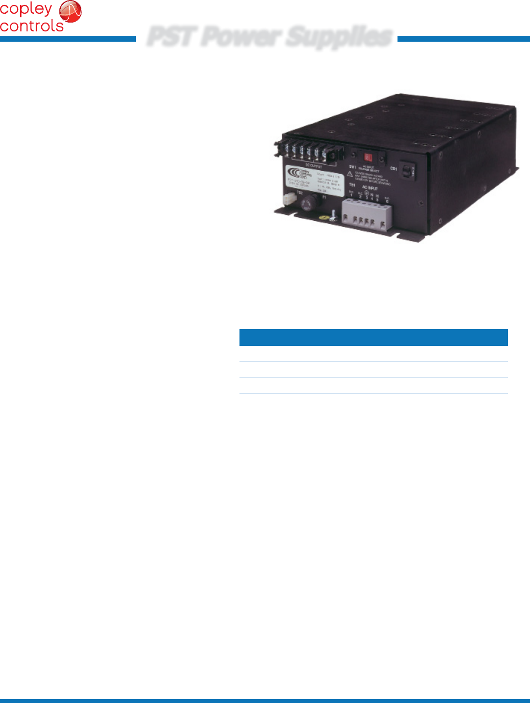
DESCRIPTION
PST models are linear, unregulated power supplies for Copley
Controls PWM servo ampliers.
The small footprint takes advantage of the fact that multiple-
amplier installations seldom operate at the maximum continuous
power rating of each individual amplier. Particularly in incremental
motion applications, machine design commonly prevents
simultaneous movement of all axes, and when motion occurs, it
requires less than the ampliers peak rating.
The power output rating of the PST models is sufcient to drive the
majority of applications, given the varying duty cycles and power
outputs of the mounted ampliers.
The PST-040-13-DP model is compatible with 24~55 Vdc drives.
The PST-070-08-DP is compatible with 24~90 Vdc drives.
The PST-140-04-DP is compatible with 24~180 Vdc drives.
All of the -DP models offer switch-selection of mains voltages:
115/230 Vac at 50/60 Hz.
• Linear, unregulated DC power for
PWM servo ampliers
• Internal toroidal transformer
• Thermal circuit breakers on AC power input
eliminate inrush tripping at power on,
permit fast reset in eld.
• Screw-terminal connections for
mains wiring and motor power connections.
• Small footprint (7” X 11.5”)
• Dual AC-voltage input for OEM
exibility when shipping to international markets.
IMPORTANT:
As of January 1, 2015, Copley Controls will no longer accept new orders for these power supplies.
Orders for these products can be placed until January 1, 2015 and scheduled with ship dates through July 1, 2015.

Copley Controls Corp., 20 Dan Road, Canton, MA 02021, USA Tel: 781-828-8090 Fax: 781-828-6547
Web: www.copleycontrols.com Page 2 of 4
PST Power Supplies
UNREGULATED DC POWER SUPPLIES
GENERAL SPECIFICATIONS
Test conditions: Ambient temperature = 25°C
OUTPUT POWER
MODELPST-040-13-DP PST-070-08-DP PST-140-04-DP
DC Volts, full load 40 70 140 Vdc, at rated Vac input
DC Volts, no load 45 79 159 Vdc, at rated Vac input
DC Amps, continuous 13 7.5 3.5 Vdc, at rated Vac input
DC Amps, peak 33 20 10 For 1 sec, 20% duty cycle
Watts, continuous 520 525 490 Full-load
Ripple voltage 2% 2% 2% Peak-peak % of DC Volts
INPUT POWER
AC Volts 115/230 115/230 115/230 Vac, single-phase
AC Frequency 47~63 47~63 47~63 Hz
Internal circuit breaker 15 15 15 A
OTHER
Internal capacitor 47,000 20,000 6,800 µF
Capacitor rated voltage 63 100 200 Vdc
Capacitor surge voltage 79 125 250 Vdc (Note 1)
Reverse energy absorption 56 51 69 Joules (Note 2)
Bleeder resistor 3.9 k 3.9 k 6.8 k Ohm
Isolation yes yes yes Transformer-isolated secondary
Breakdown voltage 4 kV 4 kV 4 kV Rating
ENVIRONMENTAL
Operating temperature 0 ºC (32F) to 50 ºC (122F)
Derating 0.86% / ºC from 50 C to 65 C
PROTECTIONS
Mains input overcurrent Thermal circuit-breaker, 15 A, time-delay
Fan power overcurrent Fuse receptacle for AC power to TB2 for a mains-powered fan (user supplied)
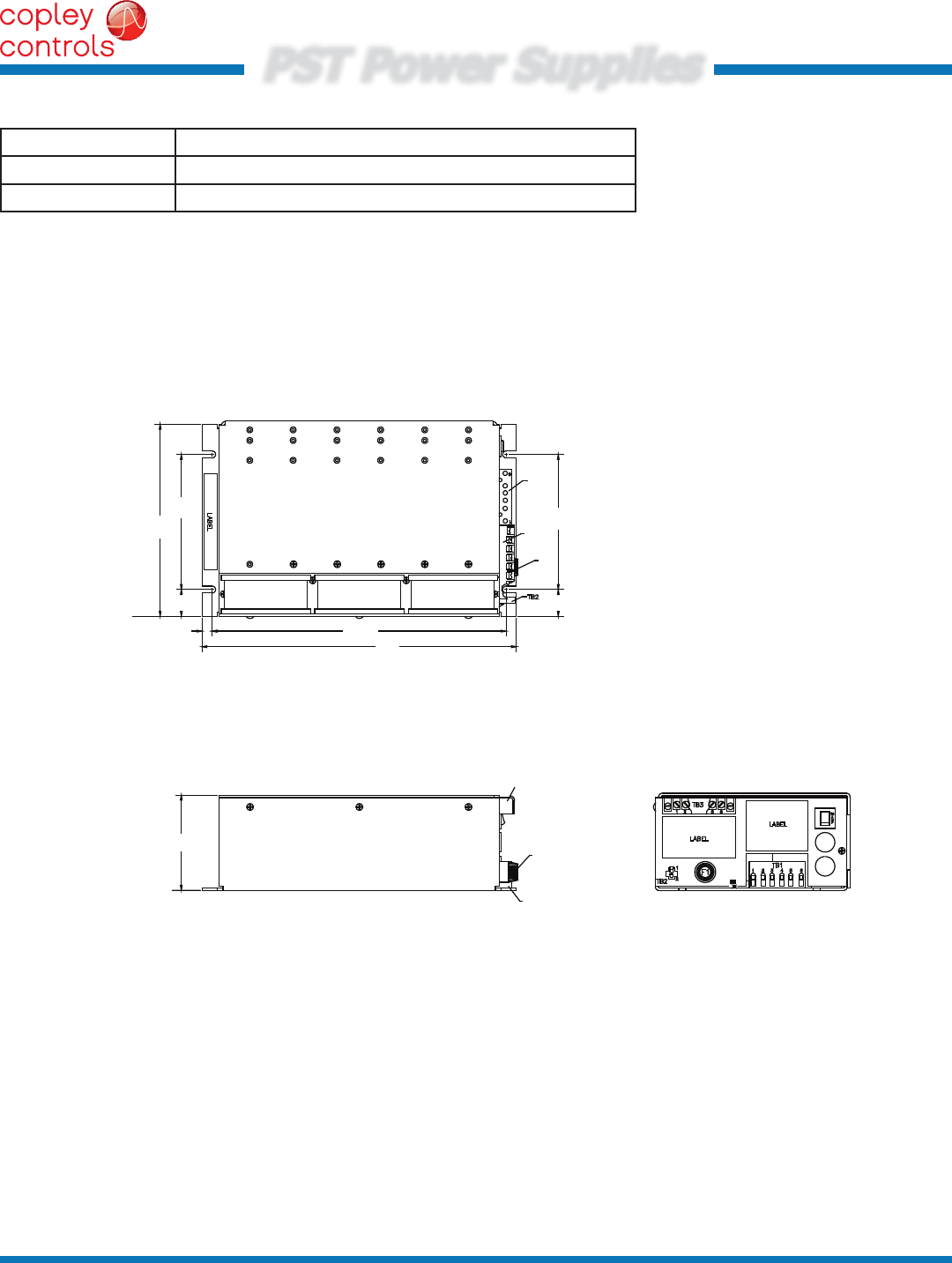
MECHANICAL & ENVIRONMENTAL
Size 11.5 x 7.0 x3.47 [292 x 177.8 x 88.1] in[mm]
Weight 18 [8.2] lb[kg]
Ambient temperature 0 to +50 C operating
Notes:
1) The surge voltage rating is the maximum over-voltage including DC, peak AC and transients to which the capacitor may be
subjected for short periods of time (not exceeding 30 seconds every 5 minutes).
2) Reverse energy absorption is the energy returned to the power supply when a servo drive decelerates an inertial load.
It is the energy that will raise the power supply voltage from its rated output voltage to the capacitors rated voltage.
Copley Controls Corp., 20 Dan Road, Canton, MA 02021, USA Tel: 781-828-8090 Fax: 781-828-6547
Web: www.copleycontrols.com Page 3 of 4
PST Power Supplies
UNREGULATED DC POWER SUPPLIES
TB1
6
4
3
2
1
5
FAN
+C
R
F1
CB1
15A
TB3
(3 FANS, OPTIONAL)
115/230VAC
50/60Hz
HOT
NEUT
GND
N.C.
N.C.
N.C.
+HV
GND
Chassis
T1
SW1
Voltage
Select
1
2
1 2 3 4 5 6
+HV PWR GND
VDC @ A
FANS
TB2
1 2 3 4 5 6
TB3
OUTPUT POWER
FAN FUSE
1.0 AMP
120 VAC
N H
1 2 3 4 5 6
N.C.
INPUT POWER
120 VAC
60 Hz.
10A
TB1
N.C. N.C.
115VAC
TB2
TB3
TB1
SW1
CB1
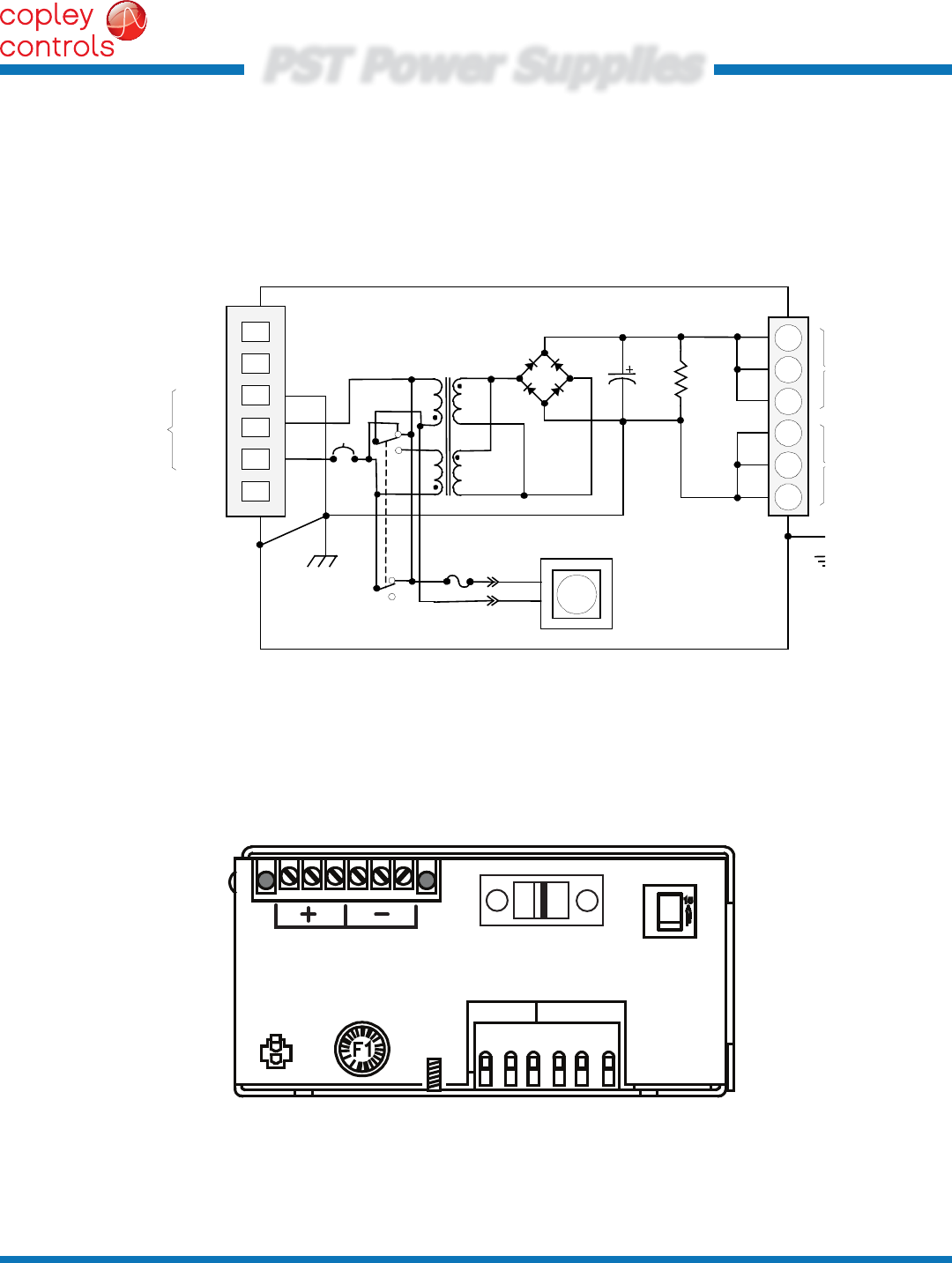
APPLICATION INFORMATION
CONSTRUCTION
An internal toroidal transformer provides isolation from the mains as well as voltage step-down. A thermal circuit-breaker in the
AC input will tolerate inrush current to charge the internal lter capacitor, as well as peak power outputs up to 2.5X the continuous
output power. Mains power is also connected to a receptacle (TB2) for powering a user supplied fan. This output is fuse-protected.
FUNCTIONAL DIAGRAM
CONNECTIONS
Copley Controls Corp., 20 Dan Road, Canton, MA 02021, USA Tel: 781-828-8090 Fax: 781-828-6547
Web: www.copleycontrols.com Page 4 of 4
PST Power Supplies
UNREGULATED DC POWER SUPPLIES
PST-040-13-DP
PST Power Supply, 40 Vdc @ 13 Adc, 120/240 Vac
PST-070-08-DP
PST Power Supply, 70 Vdc @ 8 Adc, 120/240 Vac
PST-140-04-DP
PST Power Supply, 140 Vdc @ 4 Adc, 120/240 Vac
3.47
(88.1) F1
TB1
TB3
(237.5)
7.00
(177.8)
4.92
(125.0)
0.98
(24.9)
0.38
(9.65) 10.75
(273) 11.5
(292)
0.98
(24.9)
4.92
(125)
TB1
TB3
F1
MASTER ORDERING GUIDE
Rev 201-fr 10/24/2014
Note: Specications subject to change without notice
DIMENSIONS
in [mm]
