699904342E Pts320
User Manual: pts320
Open the PDF directly: View PDF ![]() .
.
Page Count: 22
- TriScrollTM 320 Series Dry Scroll Vacuum Pump
- Declaration of Conformity
- Instructions for Use
- Technical Information
- Unpacking and Inspection
- Installation
- Safety
- Startup
- Electrical Connections
- Single Phase Motor Connection
- Mechanical Connections
- Pump Location
- Rotation of the Pump Inlet with Respect to the Motor Frame
- Pump Inlet
- Pump Exhaust
- Optional Isolation Valve
- Gas Ballast
- Bearing Purge
- Purge Kit
- Troubleshooting
- Maintenance
- General Information
- Related TriScroll Manuals
- Maintenance and Tooling Kits
- Factory Service Options
- Accessories
- Contacting Varian
- Request for Return Health and Safety Certification

INSTALLATION AND
OPERATION MANUAL
vacuum technologies
TriScrollTM 320 Series
Dry Scroll
Vacuum Pump
Manual No. 699904342
Revision E
April 2007
NOTICE: This document contains references to Varian.
Please note that Varian, Inc. is now part of Agilent
Technologies. For more information, go to
www.agilent.com/chem.
Copyright 2007
Varian, Inc.
TriScroll™ 320
Dry Scroll Vacuum Pump
TriScroll is a trademark of Varian, Inc.

i
TriScroll 320 Series Vacuum Pump
Contents
Declaration of Conformity
Instructions for Use . . . . . . . . . . . . . . . . . . . . . . . . . . . 1
General Information . . . . . . . . . . . . . . . . . . . . . . . . . 1
Storage . . . . . . . . . . . . . . . . . . . . . . . . . . . . . . . . . 1
Installation Requirements . . . . . . . . . . . . . . . . . . . . . 2
Operation. . . . . . . . . . . . . . . . . . . . . . . . . . . . . . . . . 2
Start up Procedure . . . . . . . . . . . . . . . . . . . . . . . . 2
Shutdown Procedure . . . . . . . . . . . . . . . . . . . . . . 2
Maintenance . . . . . . . . . . . . . . . . . . . . . . . . . . . . . . 2
Technical Information . . . . . . . . . . . . . . . . . . . . . . . . . 3
Unpacking and Inspection . . . . . . . . . . . . . . . . . . . . 5
Installation . . . . . . . . . . . . . . . . . . . . . . . . . . . . . . . . 6
Safety . . . . . . . . . . . . . . . . . . . . . . . . . . . . . . . . . . 6
Startup . . . . . . . . . . . . . . . . . . . . . . . . . . . . . . . . . 6
Electrical Connections . . . . . . . . . . . . . . . . . . . . . . . 7
Single Phase Motor Connection . . . . . . . . . . . . . . 7
Mechanical Connections . . . . . . . . . . . . . . . . . . . . . 8
Pump Location . . . . . . . . . . . . . . . . . . . . . . . . . . . 8
Rotation of the Pump Inlet
with Respect to the Motor Frame . . . . . . . . . . . . . 8
Pump Inlet . . . . . . . . . . . . . . . . . . . . . . . . . . . . . . 8
Pump Exhaust. . . . . . . . . . . . . . . . . . . . . . . . . . . . 8
Optional Isolation Valve. . . . . . . . . . . . . . . . . . . . . . 8
Gas Ballast . . . . . . . . . . . . . . . . . . . . . . . . . . . . . . . . 9
Bearing Purge. . . . . . . . . . . . . . . . . . . . . . . . . . . . . . 9
Purge Kit . . . . . . . . . . . . . . . . . . . . . . . . . . . . . . . . . 9
Troubleshooting . . . . . . . . . . . . . . . . . . . . . . . . . . . 10
Maintenance . . . . . . . . . . . . . . . . . . . . . . . . . . . . . 11
General Information . . . . . . . . . . . . . . . . . . . . . . 11
Related TriScroll Manuals. . . . . . . . . . . . . . . . . . 11
Maintenance and Tooling Kits . . . . . . . . . . . . . . 11
Factory Service Options . . . . . . . . . . . . . . . . . . . 12
Accessories. . . . . . . . . . . . . . . . . . . . . . . . . . . . . 12
Contacting Varian. . . . . . . . . . . . . . . . . . . . . . . . 12
Request for Return Health and Safety Certification
List of Figures
Figure Caption Page
1 Interface Drawing with Dimensions . . . . . . . .4
2 Pumping Speed Curves . . . . . . . . . . . . . . . . .4
3 TriScroll 320 Vacuum Pump . . . . . . . . . . . . . .5
4 Single Phase Motor Electrical Connections . . .7
5 Isolation Valve Location . . . . . . . . . . . . . . . . .8
List of Tables
Table Title Page
1 Specifications . . . . . . . . . . . . . . . . . . . . . . . . 3
2 Full Load Motor Currents . . . . . . . . . . . . . . . 7
3 VPI Valve Installation Data . . . . . . . . . . . . . . 9
4 Troubleshooting Chart . . . . . . . . . . . . . . . . 10
5 Other Related Manuals . . . . . . . . . . . . . . . . 11
6 Maintenance and Tooling Kits . . . . . . . . . . 11
7 Factory Service Options . . . . . . . . . . . . . . . 12
8 Accessories . . . . . . . . . . . . . . . . . . . . . . . . . 12

TriScroll 320 Series Vacuum Pump
This page intentionally left blank.

declare under our sole responsibility that the product,
erklären, in alleniniger Verantwortung, daß dieses Produkt,
déclarons sous notre seule responsabilité que le produit,
declaramos, bajo nuestra sola responsabilidad, que el producto,
verklaren onder onze verantwoordelijkheid, dat het product,
dichiariamo sotto nostra unica responsabilità, che il prodotto,
Declaration of Conformity
Konformitätserklärung
Déclaration de Conformité
Declaración de Conformidad
Verklaring de Overeenstemming
Dichiarazione di Conformità
to which this declaration relates is in conformity with the following standard(s) or other normative documents.
auf das sich diese Erklärung bezieht, mit der/den flogenden Norm(en) oder Richtlinie(n) übereinstimmt.
auquel se réfère cette déclaration est conforme à la (auz) norme(s) ou au(x) document(s) normatif(s).
al que se refiere esta declaración es conforme a la(s) norma(s) u otro(s) documento(s) normativo(s).
waamaar deze verklaring verwijst, aan de volende norm(en) of richtlijn(en) beantwoodt.
a cui se rifersce questa dichiarazione è conforme alla/e sequente/I norma/o documento/I normativo/i.
We
Wir
Nous
Nosotros
Wij
Noi
Varian, Inc.
Lexington, MA, 02421-3133 USA
121 Hartwell Avenue
Frederick C. Campbell
Operations Manager
March 2003
Lexington, Massachusetts, USA
Varian, Inc.
TriScroll Series Vacuum Pump
98/37/EEC, Machinery Directive
EN 1012-2:1996 Compressors and Vacuum pumps Safety Reqmts; Part 2 Vacuum Pumps
EN 1050:1996 Safety of machinery - principles for risk assessment
EN 60204-1 Electrical equipment of industrial machines; general requirements
73/023/EEC, Low Voltage Directive
EN 60034 part 1 Rotating electrical machines - Part 1: Rating and performance
89/336/EEC, Electromagnetic Compatibility Directive
EN 61000-4-2 Testing and Measurement Techniques - Electrostatic Discharge Immunity Test
Declaration of Conformity

TriScroll 320 Series Vacuum Pump
This page intentionally left blank.
1
TriScroll 320 Series Vacuum Pump
Instructions for Use
General Information
This equipment is designed for use by professionals. The
user should read this instruction manual and any other
additional information supplied by Varian before operating
the equipment. Varian will not be held responsible for any
events that occur due to non-compliance with these
instructions, improper use by untrained persons,
non-authorized interference with the equipment, or any
action contrary to that provided for by specific national
standards.
The TriScroll™ 320 is a dry, scroll vacuum pump
specifically optimized for helium leak detection
equipment. This pump is suitable for pumping air or inert
gases. The pump is not intended to pump toxic, corrosive,
explosive, or particulate-forming gases.
The following paragraphs contain all the information
necessary to guarantee the safety of the operator when
using the equipment. Detailed information is supplied in
“Technical Information” on page 3.
This manual uses the following standard safety protocol:
Storage
When transporting and storing the pump, the following
environmental requirements should not be exceeded:
Preparation for Installation
The pump is supplied in a special protective packing. If
this shows signs of damage, which may have occurred
during transport, contact your local sales office.
Total weight of the packing, including the pump, is
approximately 34.2 kg (75 lbs).
WARNING The warning messages are for attracting
the attention of the operator to a partic-
ular procedure or practice which, if not
followed correctly, could lead to serious
injury.
CAUTION The caution messages are displayed
before procedures, which if not fol-
lowed, could cause damage to the
equipment.
NOTE The notes contain important informa-
tion taken from the text.
Temperature: –20 °C to 60 °C (–4 °F to 140 °F)
Relative humidity: 0 to 95% (non-condensing)
WARNING When unpacking the pump, be sure not
to drop it, and avoid any kind of sudden
impact or shock vibration to it.
WARNING The TriScroll 320 weighs 26.4 kg
(58 lbs). To avoid injury, use proper lift-
ing techniques when moving the pump.
NOTE Normal exposure to the environment
cannot damage the pump. Neverthe-
less, it is advisable to keep the pump
inlet closed until the pump is installed
in the system.
TriScroll 320 Series Vacuum Pump
2
Installation Requirements
Do not install or use the pump in an environment
exposed to atmospheric agents (rain, snow, ice), dust,
aggressive gases, or in explosive environments or those
with a high fire risk.
During operation, the following environmental
conditions must be respected:
Operation
In order to reach ultimate vacuum, the pump must be left
running for about an hour with the inlet sealed.
Unlike conventional oil-sealed pumps, Varian’s dry scroll
pumps do not have fluid to cleanse them of accumulated
dust and debris. Run the pump periodically at atmosphere
for a minute or two to flush out the pump. Flush the pump
regularly and adjust this schedule according to your
specific conditions.
Start up Procedure
1. Ensure that the vacuum system isolation valve is
closed.
2. Turn on power to the pump.
3. Open the isolation valve.
Shutdown Procedure
1. Close the vacuum system isolation valve. This
prevents debris in pump from being transported into
the vacuum system.
2. Turn off pump.
Maintenance
Personnel responsible for pump operation and
maintenance must be well-trained and aware of the
accident prevention rules.
If a pump is to be discarded, it must be disposed of in
accordance with specific national and local standards.
Temperature: +5 °C to +40 °C (41 °F to 104 °F)
Relative humidity: 0 to 95% (non-condensing)
CAUTION As supplied from the factory, the pump
is configured for low voltage. Verify that
the configuration matches the supply
voltage.
If voltage changeover is required,
configure the voltage as described in
“Electrical Connections” on page 7.
WARNING During operation the outer surface of
the motor housing can become hot.
Avoid touching the motor housing dur-
ing pump operaion.
WARNING The pump is designed for operation
with neutral or noncorrosive fluids. It
is absolutely forbidden to use it with
potentially explosive, inflammable or
poisonous substances.
WARNING ❑Death may result from contact with
high voltages. Always take extreme care
and observe the accident prevention
regulations in force.
❑When the machine is powered up,
be careful of moving parts and high
voltages.
❑If you have to perform maintenance
on the pump after a considerable time
in operation, allow the pump to cool as
the temperature of the outer surface
may be in excess of 60 °C (140 °F).
❑Always disconnect your power
supply to the pump before beginning
maintenance work.
NOTE Before returning the pump to the factory
for repair, the “Health and Safety” sheet
attached to this instruction manual must
be completed and sent to the local sales
office. A copy of the sheet must be
inserted in the pump package before
shipping.

3
TriScroll 320 Series Vacuum Pump
Technical Information
Table 1 Specifications
Model TriScroll™ 320 Dry Scroll Vacuum Pump
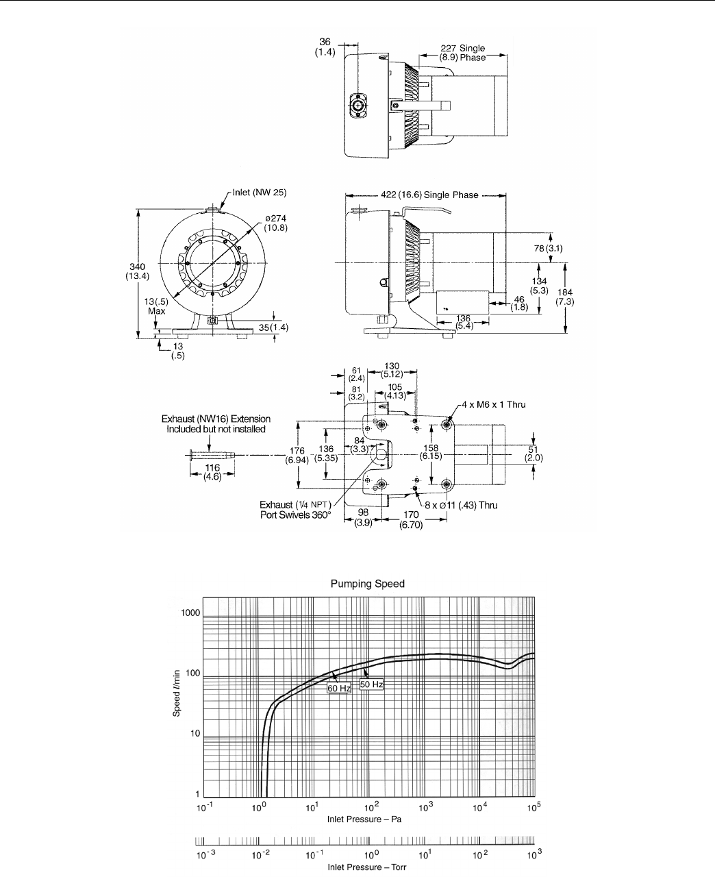
Interface dimensions See Figure 1
Peak pumping speed 50 Hz: 210 l/m, 12.6 m3/hr (7.4 cfm)
60 Hz: 250 l/m, 15 m3/hr (8.8 cfm)
Media Clean air. No toxic, corrosive, explosive or particulate forming gases
Ultimate pressure (Torr) 1.0 x 10⁻² Torr (1.3 x 10⁻² mbar)
Maximum inlet pressure 1.0 atmosphere (0 psig)
Maximum outlet pressure 1.1 atmosphere (1.5 psig)
Inlet connection NW25
Exhaust connection Female 1/4" National Pipe Thread (NW16 adapter provided)
Gas ballast Female 1/4" National Pipe Thread (40 Micron sintered filter provided)
Ambient operating temperature 5 °C to 40 °C (41 °F to 104 °F)
Storage temperature –20 °C to 60 °C (–4 °F to 140 °F)
Motor rating 0.75 HP (0.56 kW)
Operating voltages Single phase models:
❑50-60 Hz/100-115:200-230 VAC
Motor full load currents See Table 2 on page 7
Motor thermal protection Type U automatic
Operating speed 60 Hz: 1725 RPM, 50 Hz: 1425 RPM
Cooling system Air-cooled
Weight Pump only: 26.4 kg (58 lbs)
Shipping weight: 34.2 kg (75 lbs)
Noise level (per ISO 11201) 68 dB(A)
Vibration level at inlet (per ISO 10816-1) 6.3 mm/sec
TriScroll 320 Series Vacuum Pump
4
Figure 1 Interface Drawing with Dimensions
Figure 2 Pumping Speed Curves
5
TriScroll 320 Series Vacuum Pump
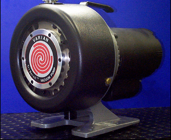
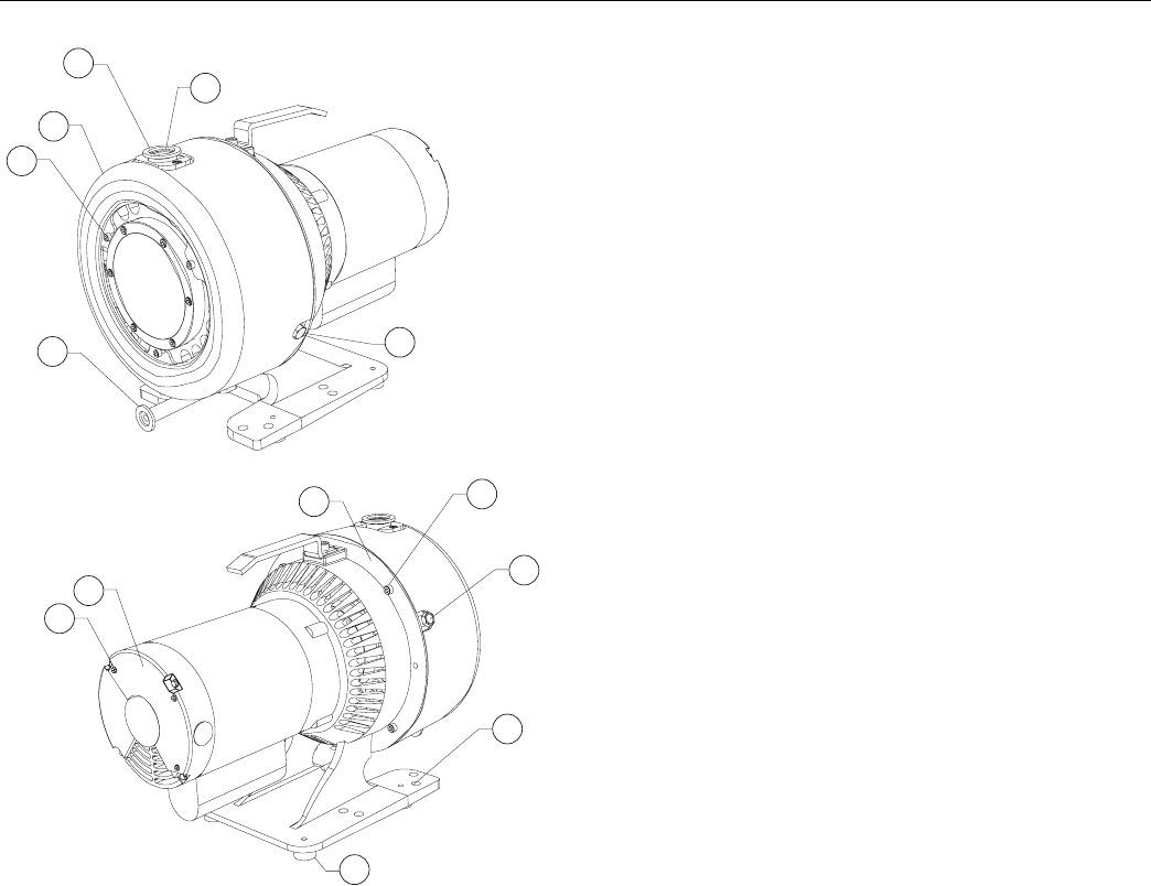
Figure 3 TriScroll 320 Vacuum Pump
1. Cowling Screws; M5 (3)
2. Cowling
3. Inlet (NW25)
4. Inlet Screen
5. NW16 Exhaust Adapter
6. Bearing Purge Port (1/4" National Pipe Thread)
7. Pump Frame
8. Frame Screws; M6 (4)
9. Gas Ballast Port (1/4" National Pipe Thread)
10. Mounting Holes; 11 mm diameter thru (8)
11. Rubber Feet (4)
12. Motor Cover Screws (3)
13. Motor Electrical Cover
Unpacking and Inspection
The shipping container is a double carton.
1. After opening the outer box, remove the foam
packing.
2. Slit open the inner box.
3. Lift the pump with the plywood base out of the inner
box.
4. Remove the four bolts securing the pump frame to the
plywood base.
5. Locate the NW16 exhaust fitting and set it aside.
6. Inspect the pump for damage. If there is shipping
damage, contact the freight carrier and your local
Varian sales office immediately.
7. Save the carton and packing materials.
6
3
2
1
5
4
8
9
7
10
13
12
11
TriScroll 320 Series Vacuum Pump
6
Installation
Safety
Do not remove or modify any safety or insulating
equipment from the pump. To do so may create a serious
safety hazard and may void the warranty.
Startup
1. Check that the inlet screen is installed before
beginning operation.
2. Operate the pump at an ambient temperature of 5° C
to 40° C (41° F to 104° F), otherwise damage to the
pump or shortened operating life may result.
3. Close the isolation valve between the vacuum pump
and the vacuum chamber before startup or shutdown;
debris may be sucked back into the vacuum
chamber.
An optional isolation valve can be installed for this
purpose. See “Optional Isolation Valve” on page 8.
WARNING ❑This pump is designed to pump air
and inert gases only; it is not designed
to pump explosive, flammable, toxic, or
corrosive gases. They can cause bodily
injury, explosion, or fire.
❑Install in an area that is not exposed
to rain, steam, or excessive humidity.
They can cause electric shock, short cir-
cuits, and severe bodily injury.
❑Before inspecting or servicing the
pump, be sure the electrical supply is
disconnected.
❑Protect against short circuits by
installing a circuit breaker of the proper
capacity.
CAUTION Although the pump can pump trace
particulates normally found in the
atmosphere, it is not designed for pro-
cess solids, chemicals, powders, sol-
vents, condensates, or other
particulates. They can damage the
equipment, degrade its performance, or
shorten its useful life.
Consult a qualified electrician when-
ever wiring the pump.
TriScroll series pumps operate in a
clockwise direction when viewed from
the motor end. (Note the arrow on the
pump frame.) Improper rotation can
cause permanent damage to the pump.
WARNING Do not insert a finger or any foreign
object in the path of the fan; serious
personal injury may result or the pump
may be damaged.
CAUTION Do not block the fan ducts because the
pump can become overheated. A pump
surface temperature in excess of 55 °C
(131 °F) is potentially damaging. If such
conditions are observed, turn pump off
and allow to cool. Disassemble, inspect
for damage, and repair if necessary.
7
TriScroll 320 Series Vacuum Pump
Electrical Connections
Wire the motor and electrical interlocks (if applicable) in accordance with local electrical codes and the relevant electrical
component manufacturer’s instructions. Table 2 lists the full load motor currents at various voltages.
Single Phase Motor Connection
The pump can be configured for low voltage, 100 VAC to 115 VAC, or for high voltage, 200 VAC to 230 VAC. As supplied
from the factory, the pump is configured for low voltage. Figure 4 shows the electrical connections for a single phase
motor.
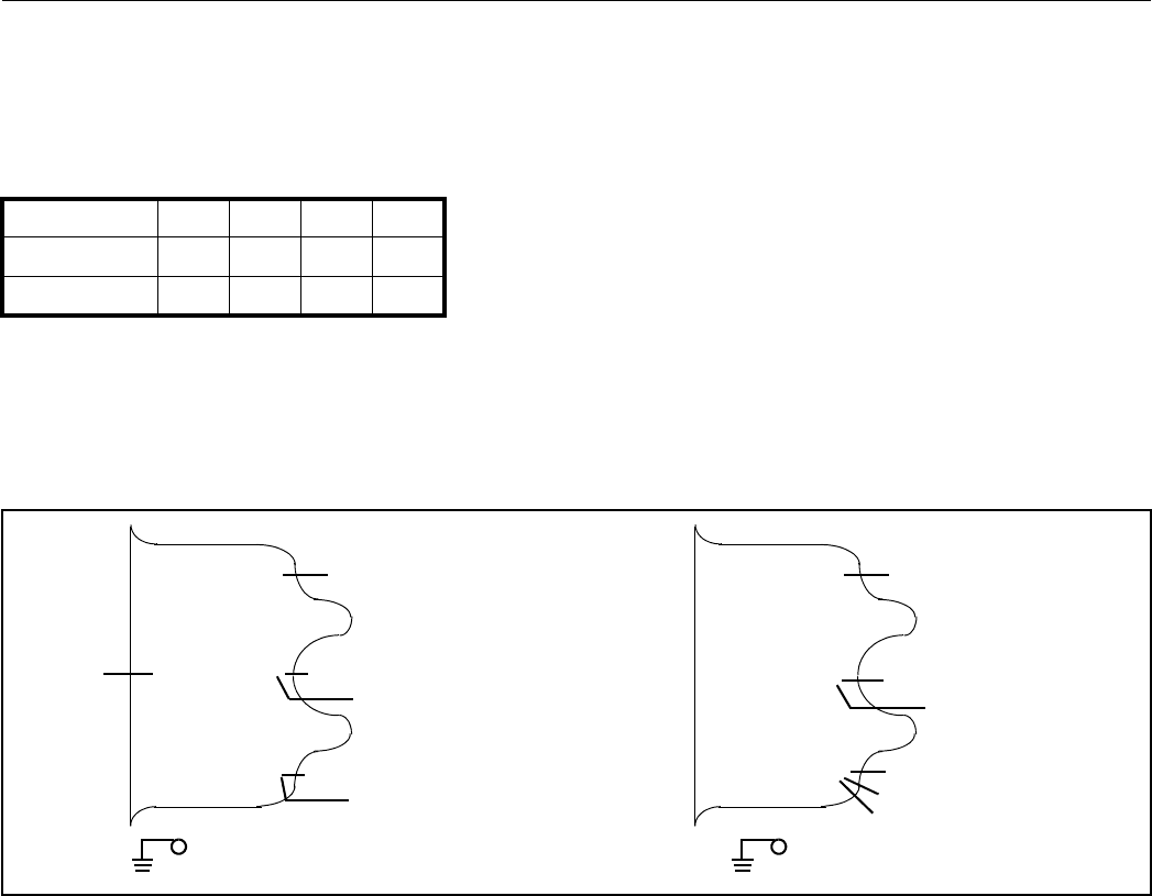
Figure 4 Single Phase Motor Electrical Connections
1. Verify the electrical supply voltage.
2. Remove the three screws (item 12 in Figure 3 on
page 5) that are holding the motor electrical cover
(item 13 in Figure 3).
3. Refer to Figure 4 to connect the motor to match your
supply voltage.
Two options are available to strain relieve the electrical
supply cable.
❑The cable can be mechanically held under the
electrical cover in the groove provided. The
groove is sized for a 14 gage cable.
❑A 1/2−14 NPSM hole is also provided next to the
motor cover.
4. Wire L1 and L2 per Figure 4 using right angle flag
connectors or ring connectors.
Ensure that no exposed wiring is close to the electri-
cal cover or to other terminals on the board.
5. Secure the ground wire under the ground screw using
a ring connector.
6. Replace the motor electrical cover and secure it with
three (3) screws removed in step 2.
Table 2 Full Load Motor Currents
1 phase motor 100 V 115 V 200 V 230 V
50 Hz 8.4 9 4.2 4.5
60 Hz 6.8 6.8 3.7 3.4
5
.4
.
1.
2.
High Voltage
..Low Voltage
5
.4.
1.
2.
L1 Power Cord L1 Power Cord
Black (Internal)
VPI Valve (Optional)
L2 Power Cord
VPI Valve (Optional)
Violet
(Internal)
Violet (Internal)
VPI Valve (Optional)
Black (Internal)
L2 Power Cord
VPI Valve (Optional)
TriScroll 320 Series Vacuum Pump
8
Mechanical Connections
Pump Location
Locate the pump on a firm, level surface.
Mounting holes provided in the frame can be used to
provide permanent attachment. The rubber mounts on
the frame can be removed if desired.
Rotation of the Pump Inlet
with Respect to the Motor Frame
The standard pump configuration is with the inlet fitting
positioned at the top of the pump as shown in Figure 1 on
page 4. The pump inlet has two alternate positions:
❑90 degrees clockwise
❑90 degrees counterclockwise
To rotate the inlet:
1. Remove three (3) M5 screws (item 1 on Figure 3 on
page 5) that secure the cowling (item 2 on Figure 3)
to the scroll module. Remove the cowling.
2. Tilt the pump back so that the rear end of the motor
touches the floor.
3. Remove the four (4) M6 screws (item 8 on Figure 3)
holding the frame (item 7 on Figure 3) and scroll
module together.
4. Axially separate the frame and scroll module.
5. Rotate the module 90 degrees in either direction and
realign the two (2) locating pins on the scroll module
with the mating frame holes. Ensure that the rubber
spider is still on the motor coupling and that the
coupling teeth are properly aligned.
6. Rejoin the scroll module with the frame and install
and tighten the four (4) M6 screws removed in step 3.
7. Reinstall the cowling using the three (3) M5 screws
removed in step 1.
Pump Inlet
Use NW25, or larger, clean vacuum hardware with as
short a length as practical between the pump and the
vacuum chamber.
Use a bellows to provide both vibration isolation and
strain relief between the pump and the vacuum chamber.
Pump Exhaust
A female 1/4" National Pipe Thread exhaust fitting is
located underneath the scroll module. This fitting swivels
360 degrees. Additionally, an NW16 male adapter with
1/4" National Pipe Thread is provided.
To avoid overheating the pump, do not restrict the
exhaust flow with long lengths of small diameter tubing.
Use as short as practical lengths of NW16 diameter, or
larger, hardware.
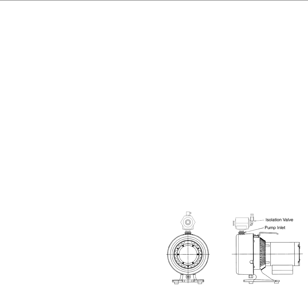
Optional Isolation Valve
Scroll pumps return to atmospheric pressure quickly
when shut off, thus the installation of a fast acting,
automatic, normally closed isolation valve is strongly
recommended to prevent pump debris from being
transported back into the vacuum chamber when the
pump is turned off.
❑The opening of this valve should occur
simultaneously with or after pump start up.
❑Valve closing should occur before,
simultaneously with, but no later than 250 ms
after pump shut off.
Use an NW25 valve or larger and mount it as close as
possible to the pump inlet. Mounting to the pump inlet is
ideal. (See Figure 5).
.
Figure 5 Isolation Valve Location
Varian offers a variety of manual, electromagnetic and
electropneumatic controlled vacuum valves for vacuum
applications. The Varian Vacuum Pump Isolation (VPI)
Valve is highly recommended for vacuum pump isolation
applications. The VPI valve application and installation
information for use with TriScroll vacuum pumps has
been included below.
9
TriScroll 320 Series Vacuum Pump
Overview
The status of the VPI Valve is controlled by the TriScroll
motor internal thermal switch and its electrical supply.
The VPI Valve opens when the pump is running and
closes when it is stopped. It will also close when the
TriScroll motor thermal overload protection switch shuts
down the pump.
Wiring
Using the data in Table 3, verify that the VPI Valve chosen
is compatible with the TriScroll supply voltage and
frequency. Then, locate the proper wiring diagram to use
(Figure 4 on page 7).
1. Remove the three screws (item 12 in Figure 3 on
page 5) that are holding the motor electrical cover
(item 13 in Figure 3).
2. Connect the VPI Valve solenoid wire leads to the
pump motor as shown in Figure 4.
3. Replace the motor electrical cover and secure it using
the three screws removed in step 1. Verify that the
valve is properly grounded before applying
electrical power.
* Solenoid operating voltages are lower than the TriScroll vacuum pump operating voltages in order to utilize the TriScroll motor’s inter-
nal thermal switch to actuate the VPI Valve.
Gas Ballast
The gas ballast port (item 9 on Figure 3 on page 5) is
sealed on the TriScroll 320.
For applications where a lot of water is being pumped,
dry nitrogen at a flow rate of ≈5 lpm can be bled into the
gas ballast port. See “Purge Kit” below.
Bearing Purge
The bearing purge port (item 6 on Figure 3 on page 5) is
sealed on the TriScroll 320 and must not be opened or
used.
Purge Kit
A purge kit (Varian part number PTSPURGEKIT) to
properly purge the gas ballast is available. This kit
contains a flow meter and all necessary valving and
tubing.
CAUTION To prevent damage to the VPI Valve, it
must be installed by a qualified electri-
cian and only as specified below.
Table 3 VPI Valve Installation Data
Motor TriScroll Vacuum Pump
Operating Voltage
VPI Valve Part #
NW25
VPI Valve Part #
NW40
Solenoid Operating
Voltage Range
Use the following
Wiring Diagram
1 Phase 100-120 V 50/60 Hz VPI251205060 VPI401205060 90-132 V Figure 4 low voltage
1 Phase 200-230 V 50/60 Hz VPI251205060 VPI401205060 90-132 V* Figure 4 high voltage
CAUTION The bearing purge port has been
disabled on the TriScroll 320 model.
Use of this port could cause internal
damage to the pump.

TriScroll 320 Series Vacuum Pump
10
Troubleshooting
Table 4 contains a list of possible problems, their probable causes, and corrective actions.
Table 4 Troubleshooting Chart
Problem Probable Cause Corrective Action
Pump won’t start Circuit breaker open Close breaker.
Identify cause of overload.
Motor thermal protector open Allow motor to cool.
Identify cause of overload.
Electrical short under the motor
electrical cover
Inspect and repair.
Wiring loose or cut Repair or replace.
Excessive voltage drop Check size and length of power supply
cable.
Defective motor Inspect. Contact Varian.
Poor ultimate pressure System leak Locate and repair leak.
Water in pump Flush pump with air or dry nitrogen.
Gas ballast plugged Replace breather vent. Contact Varian.
Solvent in pump Flush pump with air or dry nitrogen.
Install trap or filter.
Seals worn out Replace tip seals. (Table 6 and Table 7
on page 11 list maintenance kits and
service options.)
Poor conductance to pump Replumb with shorter and/or larger
diameter tubing.
Pump makes hammering noise Pump overheated Check ambient temperature.
Check ventilation to pump.
Debris in pump Check inlet screen.
Flush pump.
Disassemble pump and inspect.
(Table 6 and Table 7 on page 11 list
maintenance kits and service options.)
11
TriScroll 320 Series Vacuum Pump
Maintenance
General Information
Varian TriScroll 300 series pumps are designed to provide years of trouble-free service if maintenance procedures and
intervals are observed. Bearing grease replenishment and tip seal replacement is recommended when pump base pressure
has risen to an unacceptably high level for your application. Bearings, rotary seals and o-rings should also be replaced if
the pump exhibits humming or grinding noises from the bearings.
Maintenance should be performed in accordance with procedures, tooling and materials specified in the manuals listed
below.
Related TriScroll Manuals
Other manuals related to tip seal replacement, pump module replacement, and major maintenance of the TriScroll 300
series pumps are listed in Table 5.
Maintenance and Tooling Kits
Material and tooling required to perform maintenance on TriScroll pumps is provided in kit form. A description of each kit
and ordering information is provided in Table 6.
Table 5 Other Related Manuals
Title Applicable TriScroll Model Part Number
Tip Seal Replacement Manual All TriScroll 300 Series models 699904280
Pump Module Replacement Manual All TriScroll 300 Series models 699904285
Major Maintenance Manual All TriScroll 300 Series models 699904260
Table 6 Maintenance and Tooling Kits
Description Contents Applicable TriScroll Model Part Number
Major Maintenance Kit All bearings, bearing seals,
bearing lubricant, O-rings, and
tip seals required to rebuild
TriScroll 300 series pumps.
All TriScroll 300 Series models PTSS0300MK
Maintenance Tool Kit All fixtures and tools required to
perform any maintenance on
TriScroll 300 Series pumps.
All TriScroll 300 Series models PTSS0300TK
Replacement Tip Seal Set Replacement tip seals and static
O-rings for TriScroll 300 Series
pumps.
All TriScroll 300 Series models PTSS0300TS
NOTE: The Maintenance Tool Kit is also required for tip seal replacement.
TriScroll 320 Series Vacuum Pump
12
Factory Service Options
Table 7 lists the factory-rebuild service and advance exchange of complete TriScroll Pumps, as well as factory service
options that Varian offers.
Accessories
The accessories listed in Table 8 are available for use with the TriScroll 300 series pump. Contact your local Varian office
to place an order. A list of offices is included on the rear cover of this manual.
Contacting Varian
In the United States, you can contact Varian Customer Service at 1-800-8VARIAN. See the back cover of this manual for a
listing of our sales and service offices.
Internet users:
❑Send email to Customer Service & Technical Support at vpl.customer.support@varianinc.com
❑Visit our web site at www.varianinc.com/vacuum
❑Order on line at www.evarian.com
Table 7 Factory Service Options
Factory Service Options Part Number
Advance Exchange TriScroll 320 Single Phase EXPTS03201ULD
Advance Exchange TriScroll 320 Pump Module Only EXPTS0320SC
Service/Rebuild TriScroll 320 Pump PTS0320KMA
Table 8 Accessories
Purge Kit PTSPURGEKIT
Exhaust Extension S4707002
Exhaust Filter Kit PTS300EXFIL
Request for Return
Health and Safety Certification
1. Return authorization numbers (RA#) will not be issued for any product until this Certificate is completed and returned to a
Varian, Inc. Customer Service Representative.
2. Pack goods appropriately and drain all oil from rotary vane and diffusion pumps (for exchanges please use the packing
material from the replacement unit), making sure shipment documentation and package label clearly shows assigned
Return Authorization Number (RA#) VVT cannot accept any return without such reference.
3. Return product(s) to the nearest location:
4. If a product is received at Varian, Inc. in a contaminated condition, the customer is held responsible for all costs incurred to
ensure the safe handling of the product, and is liable for any harm or injury to Varian, Inc. employees occurring as a result of
exposure to toxic or hazardous materials present in the product.
PLEASE FILL IN THE FAILURE REPORT SECTION ON THE NEXT PAGE
North and South America Europe and Middle East Asia and ROW
Varian, Inc.
121 Hartwell Ave.
Lexington, MA 02421
Fax: (781) 860-9252
Varian S.p.A.
Via F.lli Varian, 54
10040 Leini (TO) – ITALY
Fax: (39) 011 997 9350
Varian Vacuum Technologies
Local Office
For a complete list of phone/fax numbers see www.varianinc.com/vacuum
Do not write below this line
Notification (RA) #: ................................... Customer ID #: ........................................ Equipment #: ............................................
CUSTOMER INFORMATION
Company name: ......................................................................................................................................................................
Contact person: Name: ...................................................................................... Tel:............................................................
Fax: .......................................................................................... E-mail: .....................................................
Ship method: Shipping Collect #: .................................. P.O.#: .......................................................
Europe only: VAT Reg Number: ........... USA only: ❒Taxable ❒Non-taxable
Customer ship to: .................................................................... Customer bill to: .................................................................
.................................................................... .................................................................
.................................................................... .................................................................
PRODUCT IDENTIFICATION
Product Description Varian, Inc. Part Number Varian, Inc. Serial Number
TYPE OF RETURN (check appropriate box)
❒ Paid Exchange ❒ Paid Repair ❒ Warranty Exchange ❒ Warranty Repair ❒ Loaner Return
❒ Credit ❒ Shipping Error ❒ Evaluation Return ❒ Calibration ❒ Other
HEALTH and SAFETY CERTIFICATION
VARIAN, INC. CANNOT ACCEPT ANY BIOLOGICAL HAZARDS, RADIOACTIVE MATERIAL, ORGANIC METALS, OR MERCURY AT ITS
FACILITY. CHECK ONE OF THE FOLLOWING:
❒I confirm that the above product(s) has (have) NOT pumped or been exposed to any toxic or dangerous materials in a
quantity harmful for human contact.
❒I declare that the above product(s) has (have) pumped or been exposed to the following toxic or dangerous materials in a
quantity harmful for human contact (Must be filled in):
Print Name................................................ Signature ................................................... Date ...............................
August 2003 — Page 1 of 2
ISO
REGISTERED
9001
Request
for
Return
Health
and
Safety
Certification
Request for Return
Health and Safety Certification
FAILURE REPORT
(Please describe in detail the nature of the malfunction to assist us in performing failure analysis):
TURBO PUMPS AND TURBOCONTROLLERS
ION PUMPS/CONTROLLERS VALVES/COMPONENTS
LEAK DETECTORS INSTRUMENTS
ALL OTHER VARIAN, INC. DIFFUSION PUMPS
Claimed Defect Position Parameters
❒ Does not start ❒ Noise ❒ Vertical Power: Rotational Speed:
❒ Does not spin freely ❒ Vibrations ❒ Horizontal Current: Inlet Pressure:
❒ Does not reach full speed ❒ Leak ❒ Upside-down Temp 1: Foreline Pressure:
❒ Mechanical Contact ❒ Overtemperature ❒ Other
................................
Temp 2: Purge flow:
❒ Cooling defective ❒ Clogging Operation Time:
Describe Failure:
Turbocontroller Error Message:
❒ Bad feedthrough ❒ Poor vacuum ❒ Main seal leak ❒ Bellows leak
❒ Vacuum leak ❒ High voltage problem ❒ Solenoid failure ❒ Damaged flange
❒ Error code on display ❒ Other .............................. ❒ Damaged sealing area ❒ Other ...............................
Describe failure: Describe failure:
Customer application: Customer application:
❒ Cannot calibrate ❒ No zero/high background ❒ Gauge tube not working ❒ Display problem
❒ Vacuum system unstable ❒ Cannot reach test mode ❒ Communication failure ❒ Degas not working
❒ Failed to start ❒ Other ............................... ❒ Error code on display ❒ Other ...............................
Describe failure: Describe failure:
Customer application: Customer application:
❒ Pump doesn’t start ❒ Noisy pump (describe) ❒ Heater failure ❒ Electrical problem
❒ Doesn’t reach vacuum ❒ Overtemperature ❒ Doesn’t reach vacuum ❒ Cooling coil damage
❒ Pump seized ❒ Other ............................... ❒ Vacuum leak ❒ Other ...............................
Describe failure: Describe failure:
Customer application: Customer application:
August 2003 — Page 2 of 2
ISO
REGISTERED
9001

Sales and Service Offices
12/04
Canada
Central coordination through:
Varian, Inc.
121 Hartwell Avenue
Lexington, MA 02421
USA
Tel: (781) 861 7200
Fax:(781) 860 5437
Toll Free: (800) 882 7426
China
Varian Technologies - Beijing
Room 1201, Jinyu Mansion
No. 129A, Xuanwumen Xidajie
Xicheng District
Beijing 1000031
P.R. China
Tel: (86) 10 6608 1031
Fax:(86) 10 6608 1541
France and Benelux
Varian s.a.
7 avenue des Tropiques
Z.A. de Courtaboeuf – B.P. 12
Les Ulis cedex (Orsay) 91941
France
Tel: (33) 1 69 86 38 13
Fax:(33) 1 69 28 23 08
Germany and Austria
Varian Deutschland GmbH
Alsfelder Strasse 6
Postfach 11 14 35
64289 Darmstadt
Germany
Tel: (49) 6151 703 353
Fax:(49) 6151 703 302
India
Varian India PVT LTD
101-108, 1st Floor
1010 Competent House
7, Nangal Raya Business Centre
New Delhi 110 046
India
Tel: (91) 11 5548444
Fax:(91) 11 5548445
Italy
Varian, Inc.
Via F.lli Varian, 54
10040 Leini, (Torino)
Italy
Tel (39) 011 997 9 111
Fax (39) 011 997 9 350
Japan
Varian, Inc.
Sumitomo Shibaura Building, 8th Floor
4-16-36 Shibaura
Minato-ku, Tokyo 108
Japan
Tel: (81) 3 5232 1253
Fax:(81) 3 5232 1263
Korea
Varian Technologies Korea, Ltd.
Shinsa 2nd Building 2F
966-5 Daechi-dong
Kangnam-gu, Seoul
Korea 135-280
Tel: (82) 2 3452 2452
Fax:(82) 2 3452 2451
Mexico
Varian S.A.
Concepcion Beistegui No 109
Col Del Valle
C.P. 03100
Mexico, D.F.
Tel: (52) 5 523 9465
Fax:(52) 5 523 9472
Russia
Central coordination through:
Varian, Inc.
via F.lli Varian 54
10040 Leini, (Torino)
Italy
Tel: (39) 011 997 9 252
Fax: (39) 011 997 9 316
Ta i w a n
Varian Technologies Asia Ltd.
18F-13 No.79, Hsin Tai Wu Road
Sec. 1, Hsi Chih, Taipei Hsien
Taiwan, R.O.C.
Tel: (886) 2 2698 9555
Fax:(886) 2 2698 9678
UK and Ireland
Varian Ltd.
28 Manor Road
Walton-On-Thames
Surrey KT 12 2QF
England
Tel: (44) 1932 89 8000
Fax:(44) 1932 22 8769
United States
Varian, Inc.
121 Hartwell Avenue
Lexington, MA 02421
USA
Tel: (781) 861 7200
Fax:(781) 860 5437
Other Countries
Varian, Inc.
Via F.lli Varian 54
10040 Leini, (Torino)
Italy
Tel: (39) 011 997 9 111
Fax:(39) 011 997 9 350
Customer Support and Service:
North America
Tel: 1 (800) 882-7426 (toll-free)
vtl.technical.support@varianinc.com
Europe
Tel: 00 (800) 234 234 00 (toll-free)
vtl.technical.support@varianinc.com
Japan
Tel: (81) 3 5232 1253 (dedicated line)
vtj.technical.support@varianinc.com
Korea
Tel (82) 2 3452 2452 (dedicated line)
vtk.technical.support@varianinc.com
Ta i w a n
Tel: 0 (800) 051 342 (toll-free)
vtw.technical.support@varianinc.com
Worldwide Web Site,
Catalog and On-line Orders:
www.varianinc.com
Representatives in most countries
Sales and Service Offices
