LSCAS Main Book File Qv3441 Student Guide
User Manual:
Open the PDF directly: View PDF ![]() .
.
Page Count: 234 [warning: Documents this large are best viewed by clicking the View PDF Link!]
- Front cover
- Contents
- Trademarks
- Course description
- Agenda
- Unit 1. Virtual I/O Server Configuration
- Unit 2. Virtual SCSI Configuration
- Unit 3. File-backed Storage Devices
- Unit 4. Virtual Fibre Channel Storage Devices
- Unit 5. Virtual Ethernet Adapter Configuration
- Unit 6. Shared Ethernet Adapter Configuration
- Unit 7. Virtual I/O Server Maintenance
- Appendix A. Checkpoint solutions

IBM PowerVM
Virtual I/O Server I:
Configuring Virtual Devices
(Course code QV344)
Student Notebook
ERC 1.0
V5.4.0.3
cover
UNIX Software Service Enablement
Front cover

Student Notebook
July 2012 edition
The information contained in this document has not been submitted to any formal IBM test and is distributed on an “as is” basis without
any warranty either express or implied. The use of this information or the implementation of any of these techniques is a customer
responsibility and depends on the customer’s ability to evaluate and integrate them into the customer’s operational environment. While
each item may have been reviewed by IBM for accuracy in a specific situation, there is no guarantee that the same or similar results will
result elsewhere. Customers attempting to adapt these techniques to their own environments do so at their own risk.
© Copyright International Business Machines Corporation 2012.
This document may not be reproduced in whole or in part without the prior written permission of IBM.
Note to U.S. Government Users — Documentation related to restricted rights — Use, duplication or disclosure is subject to restrictions
set forth in GSA ADP Schedule Contract with IBM Corp.
Trademarks
IBM® and the IBM logo are registered trademarks of International Business Machines
Corporation.
The following are trademarks of International Business Machines Corporation, registered in
many jurisdictions worldwide:
Linux is a registered trademark of Linus Torvalds in the United States, other countries, or
both.
UNIX is a registered trademark of The Open Group in the United States and other
countries.
Other product and service names might be trademarks of IBM or other companies.
Active Memory™ AIX 6™ AIX®
developerWorks® Express® POWER Hypervisor™
Power Systems™ Power® PowerHA®
PowerPC® PowerVM® POWER6®
POWER7® Redbooks® System p®
System Storage® Tivoli®

Student Notebook
V7.0
TOC
Course materials may not be reproduced in whole or in part
without the prior written permission of IBM.
© Copyright IBM Corp. 2012 Contents iii
Contents
Trademarks . . . . . . . . . . . . . . . . . . . . . . . . . . . . . . . . . . . . . . . . . . . . . . . . . . . . . . . . . . . ix
Course description . . . . . . . . . . . . . . . . . . . . . . . . . . . . . . . . . . . . . . . . . . . . . . . . . . . . . xi
Agenda . . . . . . . . . . . . . . . . . . . . . . . . . . . . . . . . . . . . . . . . . . . . . . . . . . . . . . . . . . . . . . xiii
Unit 1. Virtual I/O Server Configuration . . . . . . . . . . . . . . . . . . . . . . . . . . . . . . . . . . . 1-1
Unit objectives . . . . . . . . . . . . . . . . . . . . . . . . . . . . . . . . . . . . . . . . . . . . . . . . . . . . . 1-3
What is virtual I/O? . . . . . . . . . . . . . . . . . . . . . . . . . . . . . . . . . . . . . . . . . . . . . . . . . 1-4
Virtual devices and scalability . . . . . . . . . . . . . . . . . . . . . . . . . . . . . . . . . . . . . . . . . 1-5
Benefits and considerations . . . . . . . . . . . . . . . . . . . . . . . . . . . . . . . . . . . . . . . . . . 1-6
Virtual devices overview (1 of 2) . . . . . . . . . . . . . . . . . . . . . . . . . . . . . . . . . . . . . . . 1-7
Virtual devices overview (2 of 2) . . . . . . . . . . . . . . . . . . . . . . . . . . . . . . . . . . . . . . . 1-8
Virtual I/O Server overview . . . . . . . . . . . . . . . . . . . . . . . . . . . . . . . . . . . . . . . . . . . 1-9
Virtual I/O Server . . . . . . . . . . . . . . . . . . . . . . . . . . . . . . . . . . . . . . . . . . . . . . . . . . 1-10
Virtual I/O Server support portal . . . . . . . . . . . . . . . . . . . . . . . . . . . . . . . . . . . . . . 1-11
Creating a Virtual I/O Server partition . . . . . . . . . . . . . . . . . . . . . . . . . . . . . . . . . . 1-12
Installing the Virtual I/O Server . . . . . . . . . . . . . . . . . . . . . . . . . . . . . . . . . . . . . . . 1-13
Installing the Virtual I/O Server from media . . . . . . . . . . . . . . . . . . . . . . . . . . . . . . 1-14
Installing from the HMC . . . . . . . . . . . . . . . . . . . . . . . . . . . . . . . . . . . . . . . . . . . . . 1-15
Command Line Interface (CLI) (1 of 2) . . . . . . . . . . . . . . . . . . . . . . . . . . . . . . . . . 1-16
Command Line Interface (CLI) (2 of 2) . . . . . . . . . . . . . . . . . . . . . . . . . . . . . . . . . 1-17
Configuring the Virtual I/O Server (1 of 2) . . . . . . . . . . . . . . . . . . . . . . . . . . . . . . . 1-18
Configuring the Virtual I/O Server (2 of 2) . . . . . . . . . . . . . . . . . . . . . . . . . . . . . . . 1-19
Configure networking . . . . . . . . . . . . . . . . . . . . . . . . . . . . . . . . . . . . . . . . . . . . . . 1-20
Resource Monitoring and Control (RMC) . . . . . . . . . . . . . . . . . . . . . . . . . . . . . . . 1-21
RMC management . . . . . . . . . . . . . . . . . . . . . . . . . . . . . . . . . . . . . . . . . . . . . . . . 1-22
RMC reinitialization . . . . . . . . . . . . . . . . . . . . . . . . . . . . . . . . . . . . . . . . . . . . . . . . 1-23
Checkpoint (1 of 2) . . . . . . . . . . . . . . . . . . . . . . . . . . . . . . . . . . . . . . . . . . . . . . . . 1-24
Checkpoint (2 of 2) . . . . . . . . . . . . . . . . . . . . . . . . . . . . . . . . . . . . . . . . . . . . . . . . 1-25
Exercise 1 - VIOS configuration . . . . . . . . . . . . . . . . . . . . . . . . . . . . . . . . . . . . . . 1-26
Unit summary . . . . . . . . . . . . . . . . . . . . . . . . . . . . . . . . . . . . . . . . . . . . . . . . . . . . 1-27
Unit 2. Virtual SCSI Configuration . . . . . . . . . . . . . . . . . . . . . . . . . . . . . . . . . . . . . . . 2-1
Unit objectives . . . . . . . . . . . . . . . . . . . . . . . . . . . . . . . . . . . . . . . . . . . . . . . . . . . . . 2-3
Virtual SCSI overview (1 of 3) . . . . . . . . . . . . . . . . . . . . . . . . . . . . . . . . . . . . . . . . . 2-4
Virtual SCSI overview (2 of 3) . . . . . . . . . . . . . . . . . . . . . . . . . . . . . . . . . . . . . . . . . 2-5
Virtual SCSI overview (3 of 3) . . . . . . . . . . . . . . . . . . . . . . . . . . . . . . . . . . . . . . . . . 2-6
Creating virtual SCSI devices . . . . . . . . . . . . . . . . . . . . . . . . . . . . . . . . . . . . . . . . . 2-7
Step 1: Virtual SCSI server adapter (1 of 2) . . . . . . . . . . . . . . . . . . . . . . . . . . . . . . 2-8
Step 1: Virtual SCSI server adapter (2 of 2) . . . . . . . . . . . . . . . . . . . . . . . . . . . . . . 2-9
Step 2: Virtual SCSI client adapter (1 of 2) . . . . . . . . . . . . . . . . . . . . . . . . . . . . . . 2-10
Step 2: Virtual SCSI client adapter (2 of 2) . . . . . . . . . . . . . . . . . . . . . . . . . . . . . . 2-11
Step 3: Verify virtual SCSI server adapter . . . . . . . . . . . . . . . . . . . . . . . . . . . . . . . 2-12

Student Notebook
Course materials may not be reproduced in whole or in part
without the prior written permission of IBM.
iv VIOS © Copyright IBM Corp. 2012
Step 4a: Create storage resources with LVM . . . . . . . . . . . . . . . . . . . . . . . . . . . . .2-13
Step 4b: Create storage resources with storage pools (1 of 2) . . . . . . . . . . . . . . .2-14
Step 4b: Create storage resources with storage pools (2 of 2) . . . . . . . . . . . . . . .2-15
List storage resource configuration (1 of 2) . . . . . . . . . . . . . . . . . . . . . . . . . . . . . .2-16
List storage resource configuration (2 of 2) . . . . . . . . . . . . . . . . . . . . . . . . . . . . . .2-17
Step 5: Create the virtual target device . . . . . . . . . . . . . . . . . . . . . . . . . . . . . . . . .2-18
Verify the mapping of virtual targets . . . . . . . . . . . . . . . . . . . . . . . . . . . . . . . . . . . .2-19
Step 6: Virtual SCSI disks (client view) . . . . . . . . . . . . . . . . . . . . . . . . . . . . . . . . . .2-20
Manage Virtual devices with cfgassist . . . . . . . . . . . . . . . . . . . . . . . . . . . . . . . . .2-21
Check configuration from HMC (1 of 2) . . . . . . . . . . . . . . . . . . . . . . . . . . . . . . . . .2-22
Check configuration from HMC (2 of 2) . . . . . . . . . . . . . . . . . . . . . . . . . . . . . . . . .2-23
Discover backing storage example (1 of 2) . . . . . . . . . . . . . . . . . . . . . . . . . . . . . .2-24
Discover backing storage example (2 of 2) . . . . . . . . . . . . . . . . . . . . . . . . . . . . . .2-25
Removing virtual devices (1 of 2) . . . . . . . . . . . . . . . . . . . . . . . . . . . . . . . . . . . . . .2-26
Removing virtual devices (2 of 2) . . . . . . . . . . . . . . . . . . . . . . . . . . . . . . . . . . . . . .2-27
Managing devices from the HMC (1 of 2) . . . . . . . . . . . . . . . . . . . . . . . . . . . . . . . .2-28
Managing devices from the HMC (2 of 2) . . . . . . . . . . . . . . . . . . . . . . . . . . . . . . . .2-29
Create virtual disk example (1 of 2) . . . . . . . . . . . . . . . . . . . . . . . . . . . . . . . . . . . .2-30
Create virtual disk example (2 of 2) . . . . . . . . . . . . . . . . . . . . . . . . . . . . . . . . . . . .2-31
Modify assignment . . . . . . . . . . . . . . . . . . . . . . . . . . . . . . . . . . . . . . . . . . . . . . . . .2-32
Creating storage pools / volume groups . . . . . . . . . . . . . . . . . . . . . . . . . . . . . . . . .2-33
Physical volumes (1 of 2) . . . . . . . . . . . . . . . . . . . . . . . . . . . . . . . . . . . . . . . . . . . .2-34
Physical volumes (2 of 2) . . . . . . . . . . . . . . . . . . . . . . . . . . . . . . . . . . . . . . . . . . . .2-35
Optical devices . . . . . . . . . . . . . . . . . . . . . . . . . . . . . . . . . . . . . . . . . . . . . . . . . . . .2-36
Virtual SCSI storage and LVM . . . . . . . . . . . . . . . . . . . . . . . . . . . . . . . . . . . . . . . .2-37
Dynamically adding virtual SCSI storage (1 of 2) . . . . . . . . . . . . . . . . . . . . . . . . . .2-38
Dynamically adding virtual SCSI storage (2 of 2) . . . . . . . . . . . . . . . . . . . . . . . . . .2-39
VIOS storage groups (1 of 2) . . . . . . . . . . . . . . . . . . . . . . . . . . . . . . . . . . . . . . . . .2-40
VIOS storage groups (2 of 2) . . . . . . . . . . . . . . . . . . . . . . . . . . . . . . . . . . . . . . . . .2-41
Checkpoint (1 of 2) . . . . . . . . . . . . . . . . . . . . . . . . . . . . . . . . . . . . . . . . . . . . . . . . .2-42
Checkpoint (2 of 2) . . . . . . . . . . . . . . . . . . . . . . . . . . . . . . . . . . . . . . . . . . . . . . . . .2-43
Exercise 2 - Virtual SCSI configuration . . . . . . . . . . . . . . . . . . . . . . . . . . . . . . . . . .2-44
Unit summary . . . . . . . . . . . . . . . . . . . . . . . . . . . . . . . . . . . . . . . . . . . . . . . . . . . . .2-45
Unit 3. File-backed Storage Devices . . . . . . . . . . . . . . . . . . . . . . . . . . . . . . . . . . . . . .3-1
Unit objectives . . . . . . . . . . . . . . . . . . . . . . . . . . . . . . . . . . . . . . . . . . . . . . . . . . . . .3-3
File-backed virtual devices (1 of 2) . . . . . . . . . . . . . . . . . . . . . . . . . . . . . . . . . . . . . .3-4
File-backed virtual devices (2 of 2) . . . . . . . . . . . . . . . . . . . . . . . . . . . . . . . . . . . . . .3-5
Creating file-backed virtual disks . . . . . . . . . . . . . . . . . . . . . . . . . . . . . . . . . . . . . . .3-6
Create FB virtual disks example . . . . . . . . . . . . . . . . . . . . . . . . . . . . . . . . . . . . . . . .3-7
View mapping of file-backed virtual disk . . . . . . . . . . . . . . . . . . . . . . . . . . . . . . . . . .3-8
View storage pools and backing devices . . . . . . . . . . . . . . . . . . . . . . . . . . . . . . . . .3-9
FB virtual disks remove commands . . . . . . . . . . . . . . . . . . . . . . . . . . . . . . . . . . . .3-10
File-backed virtual optical devices . . . . . . . . . . . . . . . . . . . . . . . . . . . . . . . . . . . . .3-11
Create FB virtual optical device (1 of 2) . . . . . . . . . . . . . . . . . . . . . . . . . . . . . . . . .3-12
Create FB virtual optical device (2 of 2) . . . . . . . . . . . . . . . . . . . . . . . . . . . . . . . . .3-13
View repository information (1 of 2) . . . . . . . . . . . . . . . . . . . . . . . . . . . . . . . . . . . .3-14
View repository information (2 of 2) . . . . . . . . . . . . . . . . . . . . . . . . . . . . . . . . . . . .3-15

Student Notebook
V7.0
TOC
Course materials may not be reproduced in whole or in part
without the prior written permission of IBM.
© Copyright IBM Corp. 2012 Contents v
View virtual optical drive mapping . . . . . . . . . . . . . . . . . . . . . . . . . . . . . . . . . . . . . 3-16
Manage repository with cfgassist utility . . . . . . . . . . . . . . . . . . . . . . . . . . . . . . . 3-17
Viewing FB configuration from the HMC . . . . . . . . . . . . . . . . . . . . . . . . . . . . . . . . 3-18
Manage FB devices with the HMC (1 of 3) . . . . . . . . . . . . . . . . . . . . . . . . . . . . . . 3-19
Manage FB devices with the HMC (2 of 3) . . . . . . . . . . . . . . . . . . . . . . . . . . . . . . 3-20
Manage FB devices with the HMC (3 of 3) . . . . . . . . . . . . . . . . . . . . . . . . . . . . . . 3-21
Adding image file from HMC GUI . . . . . . . . . . . . . . . . . . . . . . . . . . . . . . . . . . . . . 3-22
Checkpoint . . . . . . . . . . . . . . . . . . . . . . . . . . . . . . . . . . . . . . . . . . . . . . . . . . . . . . 3-23
Exercise 3 - File-backed storage devices . . . . . . . . . . . . . . . . . . . . . . . . . . . . . . . 3-24
Unit summary . . . . . . . . . . . . . . . . . . . . . . . . . . . . . . . . . . . . . . . . . . . . . . . . . . . . 3-25
Unit 4. Virtual Fibre Channel Storage Devices . . . . . . . . . . . . . . . . . . . . . . . . . . . . . 4-1
Unit objectives . . . . . . . . . . . . . . . . . . . . . . . . . . . . . . . . . . . . . . . . . . . . . . . . . . . . . 4-3
Virtual Fibre Channel adapter (1 of 3) . . . . . . . . . . . . . . . . . . . . . . . . . . . . . . . . . . . 4-4
Virtual Fibre Channel adapter (2 of 3) . . . . . . . . . . . . . . . . . . . . . . . . . . . . . . . . . . . 4-5
Virtual Fibre Channel adapter (3 of 3) . . . . . . . . . . . . . . . . . . . . . . . . . . . . . . . . . . . 4-6
NPIV benefits . . . . . . . . . . . . . . . . . . . . . . . . . . . . . . . . . . . . . . . . . . . . . . . . . . . . . 4-7
NPIV considerations . . . . . . . . . . . . . . . . . . . . . . . . . . . . . . . . . . . . . . . . . . . . . . . . 4-8
NPIV overview . . . . . . . . . . . . . . . . . . . . . . . . . . . . . . . . . . . . . . . . . . . . . . . . . . . . . 4-9
Add virtual Fibre Channel adapters (1 of 2) . . . . . . . . . . . . . . . . . . . . . . . . . . . . . 4-10
Add virtual Fibre Channel adapters (2 of 2) . . . . . . . . . . . . . . . . . . . . . . . . . . . . . 4-11
View available N_Ports . . . . . . . . . . . . . . . . . . . . . . . . . . . . . . . . . . . . . . . . . . . . . 4-12
Map virtual Fibre Channel server adapter . . . . . . . . . . . . . . . . . . . . . . . . . . . . . . . 4-13
View Fibre Channel mapping . . . . . . . . . . . . . . . . . . . . . . . . . . . . . . . . . . . . . . . . 4-14
Zone LUNs on the SAN using client WWPNs . . . . . . . . . . . . . . . . . . . . . . . . . . . . 4-15
Virtual Fibre Channel DLPAR operations . . . . . . . . . . . . . . . . . . . . . . . . . . . . . . . 4-16
Activating all WWPNs to aid SAN mapping . . . . . . . . . . . . . . . . . . . . . . . . . . . . . . 4-17
Logging into N_Ports from the HMC CLI . . . . . . . . . . . . . . . . . . . . . . . . . . . . . . . . 4-18
Alternate procedure to activate WWPNs (1 of 2) . . . . . . . . . . . . . . . . . . . . . . . . . 4-19
Alternate procedure to activate WWPNs (2 of 2) . . . . . . . . . . . . . . . . . . . . . . . . . 4-20
Activating WWPNs from the HMC GUI (1 of 2) . . . . . . . . . . . . . . . . . . . . . . . . . . . 4-21
Activating WWPNs from the HMC GUI (2 of 2) . . . . . . . . . . . . . . . . . . . . . . . . . . . 4-22
Monitoring and tuning virtual Fibre Channel adapters (1 of 2) . . . . . . . . . . . . . . . 4-23
Monitoring and tuning virtual Fibre Channel adapters (2 of 2) . . . . . . . . . . . . . . . 4-24
Checkpoint (1 of 2) . . . . . . . . . . . . . . . . . . . . . . . . . . . . . . . . . . . . . . . . . . . . . . . . 4-25
Checkpoint (2 of 2) . . . . . . . . . . . . . . . . . . . . . . . . . . . . . . . . . . . . . . . . . . . . . . . . 4-26
Exercise 4 - Virtual Fibre Channel storage devices . . . . . . . . . . . . . . . . . . . . . . . 4-27
Unit summary . . . . . . . . . . . . . . . . . . . . . . . . . . . . . . . . . . . . . . . . . . . . . . . . . . . . 4-28
Unit 5. Virtual Ethernet Adapter Configuration . . . . . . . . . . . . . . . . . . . . . . . . . . . . . 5-1
Unit objectives . . . . . . . . . . . . . . . . . . . . . . . . . . . . . . . . . . . . . . . . . . . . . . . . . . . . . 5-3
Virtual Ethernet overview . . . . . . . . . . . . . . . . . . . . . . . . . . . . . . . . . . . . . . . . . . . . 5-4
POWER Hypervisor Ethernet switch . . . . . . . . . . . . . . . . . . . . . . . . . . . . . . . . . . . . 5-5
Virtual LAN (VLAN) overview . . . . . . . . . . . . . . . . . . . . . . . . . . . . . . . . . . . . . . . . . 5-6
IEEE 802.1Q VLAN . . . . . . . . . . . . . . . . . . . . . . . . . . . . . . . . . . . . . . . . . . . . . . . . . 5-7
Virtual Ethernet configuration example (1 of 2) . . . . . . . . . . . . . . . . . . . . . . . . . . . . 5-8
Virtual Ethernet configuration example (2 of 2) . . . . . . . . . . . . . . . . . . . . . . . . . . . . 5-9
Packets leaving virtual Ethernet hosts . . . . . . . . . . . . . . . . . . . . . . . . . . . . . . . . . 5-10

Student Notebook
Course materials may not be reproduced in whole or in part
without the prior written permission of IBM.
vi VIOS © Copyright IBM Corp. 2012
Packet delivered to virtual Ethernet hosts . . . . . . . . . . . . . . . . . . . . . . . . . . . . . . .5-11
Virtual Ethernet adapters . . . . . . . . . . . . . . . . . . . . . . . . . . . . . . . . . . . . . . . . . . . .5-12
Creating a virtual Ethernet adapter (1 of 6) . . . . . . . . . . . . . . . . . . . . . . . . . . . . . .5-13
Creating a virtual Ethernet adapter (2 of 6) . . . . . . . . . . . . . . . . . . . . . . . . . . . . . .5-14
Creating a virtual Ethernet adapter (3 of 6) . . . . . . . . . . . . . . . . . . . . . . . . . . . . . .5-15
Creating a virtual Ethernet adapter (4 of 6) . . . . . . . . . . . . . . . . . . . . . . . . . . . . . .5-16
Creating a virtual Ethernet adapter (5 of 6) . . . . . . . . . . . . . . . . . . . . . . . . . . . . . .5-17
Creating a virtual Ethernet adapter (6 of 6) . . . . . . . . . . . . . . . . . . . . . . . . . . . . . .5-18
View adapter and interfaces . . . . . . . . . . . . . . . . . . . . . . . . . . . . . . . . . . . . . . . . . .5-19
Adding VLAN access (1 of 3) . . . . . . . . . . . . . . . . . . . . . . . . . . . . . . . . . . . . . . . . .5-20
Adding VLAN access (2 of 3) . . . . . . . . . . . . . . . . . . . . . . . . . . . . . . . . . . . . . . . . .5-21
Adding VLAN access (3 of 3) . . . . . . . . . . . . . . . . . . . . . . . . . . . . . . . . . . . . . . . . .5-22
Virtual Ethernet switches . . . . . . . . . . . . . . . . . . . . . . . . . . . . . . . . . . . . . . . . . . . .5-23
Manage virtual switches (1 of 2) . . . . . . . . . . . . . . . . . . . . . . . . . . . . . . . . . . . . . . .5-24
Manage virtual switches (2 of 2) . . . . . . . . . . . . . . . . . . . . . . . . . . . . . . . . . . . . . . .5-25
View virtual LANs (1 of 2) . . . . . . . . . . . . . . . . . . . . . . . . . . . . . . . . . . . . . . . . . . . .5-26
View virtual LANs (2 of 2) . . . . . . . . . . . . . . . . . . . . . . . . . . . . . . . . . . . . . . . . . . . .5-27
Checkpoint (1 of 2) . . . . . . . . . . . . . . . . . . . . . . . . . . . . . . . . . . . . . . . . . . . . . . . . .5-28
Checkpoint (2 of 2) . . . . . . . . . . . . . . . . . . . . . . . . . . . . . . . . . . . . . . . . . . . . . . . . .5-29
Exercise 5 - Virtual Ethernet adapter configuration . . . . . . . . . . . . . . . . . . . . . . . .5-30
Unit summary . . . . . . . . . . . . . . . . . . . . . . . . . . . . . . . . . . . . . . . . . . . . . . . . . . . . .5-31
Unit 6. Shared Ethernet Adapter Configuration . . . . . . . . . . . . . . . . . . . . . . . . . . . . .6-1
Unit objectives . . . . . . . . . . . . . . . . . . . . . . . . . . . . . . . . . . . . . . . . . . . . . . . . . . . . .6-3
Shared Ethernet adapter overview (1 of 2) . . . . . . . . . . . . . . . . . . . . . . . . . . . . . . . .6-4
Shared Ethernet adapter overview (2 of 2) . . . . . . . . . . . . . . . . . . . . . . . . . . . . . . . .6-5
Configure virtual Ethernet adapter for SEA . . . . . . . . . . . . . . . . . . . . . . . . . . . . . . .6-6
Create Shared Ethernet adapter . . . . . . . . . . . . . . . . . . . . . . . . . . . . . . . . . . . . . . . .6-7
View SEA configuration . . . . . . . . . . . . . . . . . . . . . . . . . . . . . . . . . . . . . . . . . . . . . .6-8
SEA with multiple virtual adapters . . . . . . . . . . . . . . . . . . . . . . . . . . . . . . . . . . . . . .6-9
SEA with multiple physical adapters . . . . . . . . . . . . . . . . . . . . . . . . . . . . . . . . . . . .6-10
Create SEA with cfgassist tool . . . . . . . . . . . . . . . . . . . . . . . . . . . . . . . . . . . . . .6-11
Configuring the VIOS interface (1 of 2) . . . . . . . . . . . . . . . . . . . . . . . . . . . . . . . . . .6-12
Configuring the VIOS interface (2 of 2) . . . . . . . . . . . . . . . . . . . . . . . . . . . . . . . . . .6-13
Using HEA logical ports for SEA . . . . . . . . . . . . . . . . . . . . . . . . . . . . . . . . . . . . . . .6-14
Troubleshooting SEA "cfgsea"error . . . . . . . . . . . . . . . . . . . . . . . . . . . . . . . . . . . .6-15
Shared Ethernet adapter with VLANs . . . . . . . . . . . . . . . . . . . . . . . . . . . . . . . . . . .6-16
Configure SEA using the HMC (1 of 2) . . . . . . . . . . . . . . . . . . . . . . . . . . . . . . . . . .6-17
Configure SEA using the HMC (2 of 2) . . . . . . . . . . . . . . . . . . . . . . . . . . . . . . . . . .6-18
View SEA configuration from HMC . . . . . . . . . . . . . . . . . . . . . . . . . . . . . . . . . . . . .6-19
Removing the SEA using the HMC . . . . . . . . . . . . . . . . . . . . . . . . . . . . . . . . . . . . .6-20
Threading/non-threading (1 of 2) . . . . . . . . . . . . . . . . . . . . . . . . . . . . . . . . . . . . . .6-21
Threading/non-threading (2 of 2) . . . . . . . . . . . . . . . . . . . . . . . . . . . . . . . . . . . . . .6-22
Monitoring SEA traffic . . . . . . . . . . . . . . . . . . . . . . . . . . . . . . . . . . . . . . . . . . . . . . .6-23
Checkpoint . . . . . . . . . . . . . . . . . . . . . . . . . . . . . . . . . . . . . . . . . . . . . . . . . . . . . . .6-24
Exercise 6 - Shared Ethernet adapter . . . . . . . . . . . . . . . . . . . . . . . . . . . . . . . . . .6-25
Unit summary . . . . . . . . . . . . . . . . . . . . . . . . . . . . . . . . . . . . . . . . . . . . . . . . . . . . .6-26

Student Notebook
V7.0
TOC
Course materials may not be reproduced in whole or in part
without the prior written permission of IBM.
© Copyright IBM Corp. 2012 Contents vii
Unit 7. Virtual I/O Server Maintenance . . . . . . . . . . . . . . . . . . . . . . . . . . . . . . . . . . . . 7-1
Unit objectives . . . . . . . . . . . . . . . . . . . . . . . . . . . . . . . . . . . . . . . . . . . . . . . . . . . . . 7-2
Maintaining the Virtual I/O Server . . . . . . . . . . . . . . . . . . . . . . . . . . . . . . . . . . . . . . 7-3
VIOS backup options . . . . . . . . . . . . . . . . . . . . . . . . . . . . . . . . . . . . . . . . . . . . . . . . 7-4
Using backupios for backups . . . . . . . . . . . . . . . . . . . . . . . . . . . . . . . . . . . . . . . . . 7-5
Manual backup of VIOS device mappings . . . . . . . . . . . . . . . . . . . . . . . . . . . . . . . 7-6
VIOS manual backup examples . . . . . . . . . . . . . . . . . . . . . . . . . . . . . . . . . . . . . . . 7-7
Restore options with backupios . . . . . . . . . . . . . . . . . . . . . . . . . . . . . . . . . . . . . . . 7-8
Backup and restore with viosbr . . . . . . . . . . . . . . . . . . . . . . . . . . . . . . . . . . . . . . . 7-9
viosbr command examples . . . . . . . . . . . . . . . . . . . . . . . . . . . . . . . . . . . . . . . . . 7-10
Updating the Virtual I/O Server (1 of 2) . . . . . . . . . . . . . . . . . . . . . . . . . . . . . . . . . 7-11
Updating the Virtual I/O Server (2 of 2) . . . . . . . . . . . . . . . . . . . . . . . . . . . . . . . . . 7-12
View installed levels . . . . . . . . . . . . . . . . . . . . . . . . . . . . . . . . . . . . . . . . . . . . . . . 7-13
Sizing the Virtual I/O Server (1 of 2) . . . . . . . . . . . . . . . . . . . . . . . . . . . . . . . . . . . 7-14
Sizing the Virtual I/O Server (2 of 2) . . . . . . . . . . . . . . . . . . . . . . . . . . . . . . . . . . . 7-15
Monitoring Virtual I/O Server resources . . . . . . . . . . . . . . . . . . . . . . . . . . . . . . . . 7-16
Checkpoint . . . . . . . . . . . . . . . . . . . . . . . . . . . . . . . . . . . . . . . . . . . . . . . . . . . . . . 7-17
Exercise 7 - Virtual I/O Server Maintenance . . . . . . . . . . . . . . . . . . . . . . . . . . . . . 7-18
Unit Summary . . . . . . . . . . . . . . . . . . . . . . . . . . . . . . . . . . . . . . . . . . . . . . . . . . . . 7-19
Appendix A. Checkpoint solutions . . . . . . . . . . . . . . . . . . . . . . . . . . . . . . . . . . . . . . . A-1

Student Notebook
Course materials may not be reproduced in whole or in part
without the prior written permission of IBM.
viii VIOS © Copyright IBM Corp. 2012

Student Notebook
Course materials may not be reproduced in whole or in part
without the prior written permission of IBM.
© Copyright IBM Corp. 2012 Trademarks ix
V7.0
TMK Trademarks
The reader should recognize that the following terms, which appear in the content of this
training document, are official trademarks of IBM or other companies:
IBM® and the IBM logo are registered trademarks of International Business Machines
Corporation.
The following are trademarks of International Business Machines Corporation, registered in
many jurisdictions worldwide:
Linux is a registered trademark of Linus Torvalds in the United States, other countries, or
both.
UNIX is a registered trademark of The Open Group in the United States and other
countries.
Other product and service names might be trademarks of IBM or other companies.
Active Memory™ AIX 6™ AIX®
developerWorks® Express® POWER Hypervisor™
Power Systems™ Power® PowerHA®
PowerPC® PowerVM® POWER6®
POWER7® Redbooks® System p®
System Storage® Tivoli®

Student Notebook
Course materials may not be reproduced in whole or in part
without the prior written permission of IBM.
x VIOS © Copyright IBM Corp. 2012

Student Notebook
V7.0
TOC
Course materials may not be reproduced in whole or in part
without the prior written permission of IBM.
© Copyright IBM Corp. 2012 Course description xi
Course description
IBM PowerVM Virtual I/O Server I: Configuring Virtual Devices
Purpose
This course describes the concepts and implementation details of
virtual I/O devices on IBM Power Systems servers. The course details
the installation and configuration of the Virtual I/O Server and the
implementation of virtual SCSI devices, virtual Fibre Channel devices,
virtual Ethernet adapters, and Shared Ethernet adapters. The Virtual
I/O Server software is part of the PowerVM system feature. Students
will configure virtual SCSI disks using physical and logical volumes,
optical media devices, and files as backing storage. Students will learn
how to create and use the Optical Media Repository and configure
networking with virtual Ethernet adapters and shared Ethernet
adapters. In addition, students will configure virtual Fibre Channel
adapters, which support N_Port Identifier Virtualization (NPIV).
Students will use both the HMC and the Virtual I/O Server command
line interface to configure partitions to implement and manage virtual
devices.
Audience
The audiences for this training include System p and AIX/Linux
technical support individuals, AIX or Linux system administrators,
system architects and engineers, pre-sales technical support staff and
performance analysis individuals.
Prerequisites
Student must already know the basics of configuring and managing
logical partitions. This prerequisite can be met by attending the
following course:
• AHQV332 Managing Logical Partitions (LPARs) on Power Systems
with HMC V7
Objectives
After completing this course, you should be able to:
• Configure virtual SCSI devices that are backed by physical
volumes, logical volumes, optical media devices, and file-backed
devices

Student Notebook
Course materials may not be reproduced in whole or in part
without the prior written permission of IBM.
xii VIOS © Copyright IBM Corp. 2012
• Configure the Optical Media Repository, load a CD image, and use
it to install a new AIX partition
• Configure virtual Fibre channel devices using NPIV technology
• Configure virtual Ethernet adapters
• Configure a Shared Ethernet adapter
• Perform Virtual I/O Server maintenance operations

Student Notebook
V7.0
TOC
Course materials may not be reproduced in whole or in part
without the prior written permission of IBM.
© Copyright IBM Corp. 2012 Agenda xiii
Agenda
Welcome
Unit 1 - Virtual I/O Server Configuration
Exercise 1 - Virtual I/O Serve Configuration
Unit 2 - Virtual SCSI Configuration
Exercise 2 - Virtual SCSI Configuration
Unit 3 - File-backed Storage Devices
Exercise 3 - File-backed Storage Devices
Unit 4 - Virtual Fibre Channel Storage Devices
Exercise 4 - Virtual Fibre Channel Storage Devices
Unit 5 - Virtual Ethernet Adapter Configuration
Exercise 5 - Virtual Ethernet Adapter Configuration
Unit 6- Shared Ethernet Adapter
Exercise 6 - Shared Ethernet Adapter
Unit 7 - VIOS Maintenance
Exercise 7 - VIOS Maintenance
Wrap up / Evaluations

Student Notebook
Course materials may not be reproduced in whole or in part
without the prior written permission of IBM.
xiv VIOS © Copyright IBM Corp. 2012
Text highlighting
The following text highlighting conventions are used throughout this book:
Bold Identifies file names, file paths, directories, user names,
principals, menu paths and menu selections. Also identifies
graphical objects such as buttons, labels and icons that the
user selects.
Italics Identifies links to web sites, publication titles, is used where the
word or phrase is meant to stand out from the surrounding text,
and identifies parameters whose actual names or values are to
be supplied by the user.
Monospace Identifies attributes, variables, file listings, SMIT menus, code
examples and command output that you would see displayed
on a terminal, and messages from the system.
Monospace bold Identifies commands, subroutines, daemons, and text the user
would type.

Student Notebook
Course materials may not be reproduced in whole or in part
without the prior written permission of IBM.
© Copyright IBM Corp. 2012 Unit 1. Virtual I/O Server Configuration 1-1
V7.0
Uempty Unit 1. Virtual I/O Server Configuration
What this unit is about
This unit describes the concepts and features of the Virtual I/O Server
and virtual I/O devices. It explains why virtualized I/O is important for
scaling large server environments and details the installation and
configuration of a Virtual I/O Server partition in preparation for
configuring virtual devices.
What you should be able to do
After completing this unit, you should be able to:
• List the reasons for implementing virtual I/O
• Describe virtual I/O devices
• Describe the function of the Virtual I/O Server
• Describe the installation of the Virtual I/O Server product including
configuring the Virtual I/O Server software
How you will check your progress
Accountability:
• Checkpoint questions
• Machine exercises
References
IBM Power Systems Hardware Information Center:
http://publib.boulder.ibm.com/infocenter/powersys/v3r1m5/index.jsp
Virtual I/O Server product documentation from the IBM Power
Systems Hardware Information Center:
http://publib.boulder.ibm.com/infocenter/powersys/v3r1m5/index.jsp?t
opic=/p7hb1/iphb1kickoff.htm
IBM Support: Fix Central:
http://www.ibm.com/support/fixcentral/
IBM Support Portal:
http://www.ibm.com/support/entry/portal

Student Notebook
Course materials may not be reproduced in whole or in part
without the prior written permission of IBM.
1-2 VIOS © Copyright IBM Corp. 2012
IBM Support Portal: PowerVM Virtual I/O Server:
https://www.ibm.com/support/entry/myportal/Overview/Software/Other
_Software/PowerVM_Virtual_I~O_Server
The following IBM Redbooks documents can be found at:
http://www.redbooks.ibm.com
REDP4340 Integrated Virtual Ethernet Adapter Technical Overview
and Introduction
SG24-7940 IBM PowerVM Virtualization Introduction and
Configuration
SG24-7590 IBM PowerVM Virtualization Managing and Monitoring
SG24-6615 A Practical Guide for Resource Monitoring and Control
(RMC)
SG24-7825 PowerVM Migration from Physical to Virtual Storage
REDP4194 IBM System p Advanced POWER Virtualization
(PowerVM) Best Practices
This list of third party software products which are allowed to be
installed in the VIOS is available from IBM’s W3 site:
http://dbluedst.pok.ibm.com/DCF/isg/isgintra.nsf/all/T1010620
VIOS developerWorks link:
http://www.ibm.com/developerworks/wikis/display/virtualization/VIO
PowerHA support for NPIV link:
http://www-03.ibm.com/support/techdocs/atsmastr.nsf/WebIndex/FLA
SH10691

Student Notebook
Course materials may not be reproduced in whole or in part
without the prior written permission of IBM.
© Copyright IBM Corp. 2012 Unit 1. Virtual I/O Server Configuration 1-3
V7.0
Uempty
Figure 1-1. Unit objectives QV3441.0
Notes:
© Copyright IBM Corporation 2012
UNIX Software Service Enablement
Unit objectives
After completing this unit, you should be able to:
List the reasons for implementing virtual I/O
Describe virtual I/O devices
Describe the function of the Virtual I/O Server
Describe the installation of the Virtual I/O Server product
including configuring the Virtual I/O Server software

Student Notebook
Course materials may not be reproduced in whole or in part
without the prior written permission of IBM.
1-4 VIOS © Copyright IBM Corp. 2012
Figure 1-2. What is virtual I/O? QV3441.0
Notes:
Virtual I/O
Virtual I/O is the term used to describe the ability to share physical I/O resources
between partitions. When referring to the virtual devices available to clients from a
Virtual I/O Server, the physical resources being shared are adapter cards or devices
configured in the Virtual I/O Server partition.
AIX V5.3 and all the supported Linux versions (SLES 9, SLES 10, RHEL 3 Update 3,
and RHEL 4) and up support the ability to be a virtual client partition utilizing virtual I/O
from a Virtual I/O Server.
© Copyright IBM Corporation 2012
UNIX Software Service Enablement
What is virtual I/O?
Virtual I/O allows the sharing of physical resources (adapters and
devices) between partitions on the same server
Allows servers to scale to large numbers of partitions because of reduced
hardware requirements
Most virtual devices depend on a Virtual I/O Server partition to host the
physical adapters
Example 1: One disk can provide storage to one or more LPARs
Example 2: One physical Ethernet adapter can be shared by
multiple partitions to access the external network
Virtual I/O functionality is available on POWER5 and higher
processor-based systems
Virtual I/O Server client partitions must be running a minimum of:
AIX V5.3, Linux SLES 9 or RHEL 3, or IBM i 6.1

Student Notebook
Course materials may not be reproduced in whole or in part
without the prior written permission of IBM.
© Copyright IBM Corp. 2012 Unit 1. Virtual I/O Server Configuration 1-5
V7.0
Uempty
Figure 1-3. Virtual devices and scalability QV3441.0
Notes:
System limitation example
As an example, the IBM Power 750 server supports up to 32 POWER7 processors. If
configured with the PowerVM Standard Edition (or above) feature, this system is
capable of running up to 320 partitions concurrently. However the machine supports a
maximum of 52 PCI-X adapter slots, so with a two slots per partition minimum, the
maximum number of partitions that could be created without the use of virtual I/O would
be 26.
© Copyright IBM Corporation 2012
UNIX Software Service Enablement
Virtual devices and scalability
Virtual devices provide scalability
POWER5 and POWER6 architectures support up to 254 partitions
POWER7 architecture supports up to 1024 partitions
Hardware supports more partitions than there are PCI slots to support
them:
Slots can be the limiting factor
For example, each partition requires at minimum:
1 slot for accessing the boot disk (typically SCSI or Fibre Channel)
1 slot for Ethernet adapter
System example:
A fully configured IBM Power 750 server:
Supports up to 320 partitions
Supports up to 50 PCI-X slots Not enough for all 320 partitions without
using virtual devices

Student Notebook
Course materials may not be reproduced in whole or in part
without the prior written permission of IBM.
1-6 VIOS © Copyright IBM Corp. 2012
Figure 1-4. Benefits and considerations QV3441.0
Notes:
Benefits
When new partitions can be configured to use virtualized I/O resources, it allows them
to be configured in a timely manner, since no physical reconfiguration of the system
(that is, moving adapter cards and cables) is required. And when LPARs can share
adapters, this saves the customer money. The use of virtualized I/O facilitates server
consolidation because it permits multiple client partitions to reside on a single machine,
making efficient use of shared resources.
Considerations
Prevent single adapters or the Virtual I/O Server partition from becoming single points
of failure for multiple clients by using redundancy. More processing resources are
consumed for virtual devices. Configuring and managing virtual devices is more
complex than using native devices and the tools are different than those used in other
operating systems.
© Copyright IBM Corporation 2012
UNIX Software Service Enablement
Benefits and considerations
Benefits of virtualized I/O
Partitions can be created without requiring additional physical I/O resources
Economical I/O model:
Efficient utilization of resources through sharing
Facilitates server consolidation
Facilitates functions which require virtual I/O such as Live Partition Mobility
and Active Memory Sharing
Requires the IBM PowerVM Enterprise Edition
Allows client attachment to previously unsupported storage solutions
Example: A storage solution supported by AIX, but not Linux or
IBM i, could be made available as virtual SCSI disks
Considerations for virtualized I/O
Plan and design the configuration for availability
Assign adequate resources to the Virtual I/O Server
System support and administration staff must be trained

Student Notebook
Course materials may not be reproduced in whole or in part
without the prior written permission of IBM.
© Copyright IBM Corp. 2012 Unit 1. Virtual I/O Server Configuration 1-7
V7.0
Uempty
Figure 1-5. Virtual devices overview (1 of 2) QV3441.0
Notes:
Special-purpose virtual devices
LPARs have two pre-configured virtual serial adapters to support virtual console
access. Do not remove these and there is no need to create additional virtual serial
adapters. As of POWER6 server firmware release 320, every VIOS partition will have at
least one Virtual Asynchronous Services Interface (VASI) adapter. These devices can
be seen in the VIOS operating system only.
Virtual devices that do NOT require a Virtual I/O Server
The virtual Ethernet adapter is supported on POWER5 and higher processor-based
server partitions running AIX V5.3 or higher or Linux. No actual Ethernet hardware is
required to implement this feature. The Integrated Virtual Ethernet (IVE) adapter is
available on most POWER6 and POWER7 processor-based servers. This adapter is
also known as the Host Ethernet Adapter (HEA). IVE logical ports are supported in
partitions running AIX V5.2 and higher and Linux.
© Copyright IBM Corporation 2012
UNIX Software Service Enablement
Virtual devices overview (1 of 2)
Pre-configured special-purpose virtual devices:
Virtual serial adapter
On all partitions
For HMC to LPAR virtual console connection
VASI adapter
On VIOS type partitions
High level administrative access to VIOS
Currently used in Live Partition Mobility and Active Memory Sharing
configurations
Virtual devices that do NOT require a Virtual I/O Server:
Virtual Ethernet Adapter
Partitions on the same system communicate without using physical Ethernet
adapters
Integrated Virtual Ethernet Adapter (POWER6 and POWER7)
Ethernet virtualized in hardware (supports 16-32 LPARs)

Student Notebook
Course materials may not be reproduced in whole or in part
without the prior written permission of IBM.
1-8 VIOS © Copyright IBM Corp. 2012
Figure 1-6. Virtual devices overview (2 of 2) QV3441.0
Notes:
Virtual devices that DO require a Virtual I/O Server
Virtual SCSI devices are backed by physical devices on the Virtual I/O Server. Backing
storage is the term for these physical devices that will be used as virtual devices for
client partitions. Even though SCSI is the protocol used for the virtualization, the actual
backing storage devices do not need to be SCSI devices. See the Fix Central web site
for a list of current supported backing devices.
The Shared Ethernet adapter is a network bridge device that can connect the virtual
Ethernet traffic on a server to a physical Ethernet adapter and have this traffic bridge to
an external network. It operates at the layer 2 or data link layer of the OSI seven layer
network model.
The virtual Fibre Channel adapter capability allows client partitions to access storage
area network (SAN) devices using NPIV. NPIV is an industry standard technology used
in Fibre Channel networks. Each partition is identified by a unique World Wide Port
Name (WWPN) as if it had its own physical HBA.
© Copyright IBM Corporation 2012
UNIX Software Service Enablement
Virtual devices overview (2 of 2)
Virtual devices that DO require a Virtual I/O Server:
Virtual SCSI
Virtual I/O Server partition uses logical volumes, physical volumes, optical,
tape, or file devices to provide the backing storage for virtual SCSI devices
presented to client partitions
Shared Ethernet Adapter
Layer 2 bridge function to connect internal virtual Ethernet with external
physical network
Virtual Fibre Channel Adapter
Provides virtualization of Fibre Channel adapter ports (N_Ports) called N_Port
Identifier Virtualization (NPIV)
Student Notebook
Course materials may not be reproduced in whole or in part
without the prior written permission of IBM.
© Copyright IBM Corp. 2012 Unit 1. Virtual I/O Server Configuration 1-9
V7.0
Uempty
Figure 1-7. Virtual I/O Server overview QV3441.0
Notes:
Virtual I/O Server description
Virtual I/O Server partitions are not intended to run applications other than those which
directly support the VIOS functions. When configuring the VIOS partition, allocate all of
the physical adapters to it which will be used to provide virtual devices. Once installed
on disk, the VIOS image will only boot in a special type of partition that provides the
special Virtual I/O Server environment.
Client partitions may have a mix of physical adapters and virtual adapters, unless there
is some other requirement (such as Live Partition Mobility or Active Memory Sharing
configurations) which prohibits the use of native physical adapters in the client partition.
The graphic in the visual above shows different types of partitions some of which are
using the Virtual I/O Server to provide access to devices. All connections between the
Virtual I/O Server and its clients for access to devices is done through the Hypervisor.
© Copyright IBM Corporation 2012
UNIX Software Service Enablement
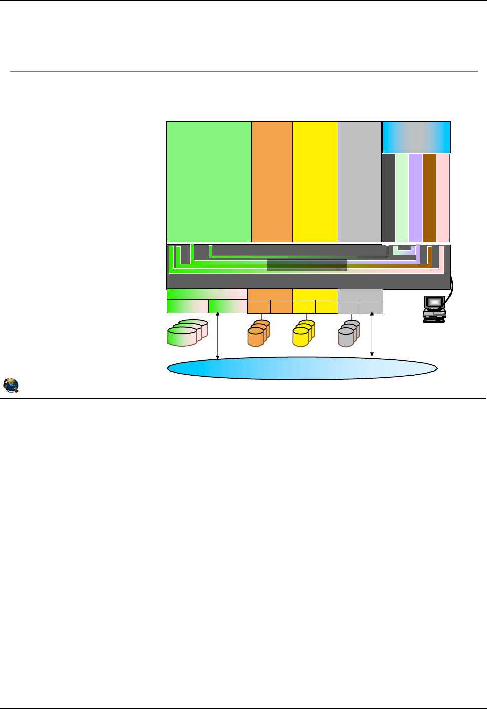
Virtual I/O Server overview
Virtual I/O Server partition is allocated the physical I/O
adapters used to access devices that will be virtualized
Client LPARs may
have a mix of
physical and
virtual devices
Hardware
Management
Console
(HMC)
POWER Hypervisor
Linux AIX6 AIX7
I/O
Storage Network
LAN, WAN, ...
I/O
Storage Network
AIX 5.3
I/O
Storage Network
I/O
Storage Network
AIX 5.3
Linux
AIX 6
Linux
AIX 7
Virtual I/O paths
Virtual I/O
Server
Partition

Student Notebook
Course materials may not be reproduced in whole or in part
without the prior written permission of IBM.
1-10 VIOS © Copyright IBM Corp. 2012
Figure 1-8. Virtual I/O Server QV3441.0
Notes:
VIOS software
The Virtual I/O Server product media is supplied when one of the PowerVM features is
purchased as part of a machine order or upgrade. The Virtual I/O Server is
implemented as a customized AIX mksysb image, however, the interface to the system
is abstracted using a secure shell-based Command Line Interface (CLI).
The Virtual I/O Server partition may be installed by activating the partition and booting
directly from the product media. The partition may also be installed from the HMC or
from a NIM server.
© Copyright IBM Corporation 2012
UNIX Software Service Enablement
Virtual I/O Server
Component of PowerVM Express, Standard, and Enterprise Edition
system features
Supplied as an AIX mksysb image on DVD media
Installed from the HMC, the managed system, or a NIM server
Installed as a customized AIX-based appliance
Special command line interface obscures the complexity and changes of
underlying operating system commands
Can only be run in Virtual I/O Server type partitions
Error displayed if you try to boot the Virtual I/O Server image in an
AIX/Linux partition
Contains Integrated Virtualization Manager (IVM) GUI functions for
non-HMC managed systems
Maximum number of Virtual I/O Server partitions
Configurations with more than 10 Virtual I/O Server partitions are not
supported
Student Notebook
Course materials may not be reproduced in whole or in part
without the prior written permission of IBM.
© Copyright IBM Corp. 2012 Unit 1. Virtual I/O Server Configuration 1-11
V7.0
Uempty
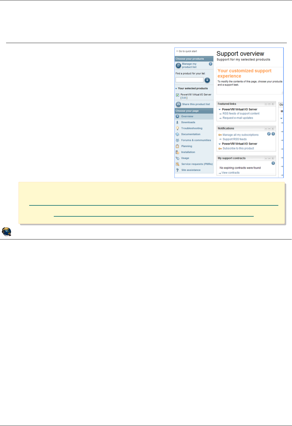
Figure 1-9. Virtual I/O Server support portal QV3441.0
Notes:
Support web site
The IBM Support Portal is a unified, customizable view of all technical support tools
and information for all IBM systems, software, and services. The IBM Support Portal is
located at: http://www.ibm.com/support
Select the products that you are interested in, such as PowerVM Virtual I/O Server and
search the technical areas of interest. This portal provides a variety of links including:
- Downloads (from the Fix Central web site)
- Documentation
- Troubleshooting tips
To go directly to the IBM Support Portal - PowerVM Virtual I/O Server page:
https://www.ibm.com/support/entry/myportal/Overview/Software/Other_Software/Power
VM_Virtual_I~O_Server
© Copyright IBM Corporation 2012
UNIX Software Service Enablement
Virtual I/O Server support portal
Links to the latest support information:
PowerVM Virtual I/O Server
Overview
Downloads (Fix Central)
Troubleshooting tips
Documentation
Forums
Planning
Installation
Location:
https://www.ibm.com/support/entry/myportal/Overview/Softwa
re/Other_Software/PowerVM_Virtual_I~O_Server
Location:
https://www.ibm.com/support/entry/myportal/Overview/Softwa
re/Other_Software/PowerVM_Virtual_I~O_Server
Student Notebook
Course materials may not be reproduced in whole or in part
without the prior written permission of IBM.
1-12 VIOS © Copyright IBM Corp. 2012
Figure 1-10. Creating a Virtual I/O Server partition QV3441.0
Notes:
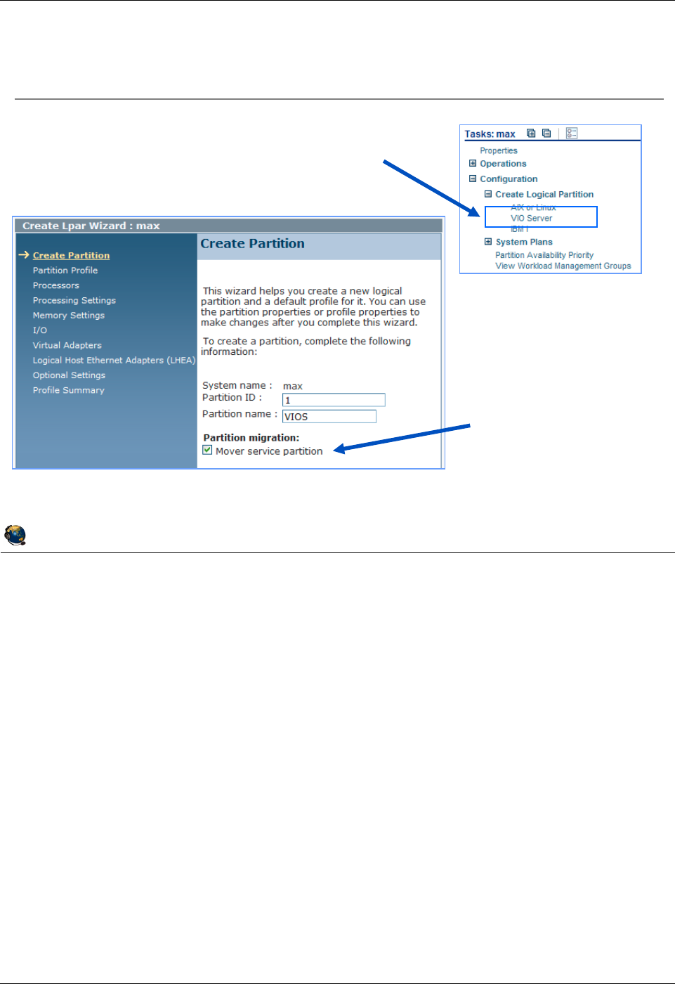
Creating the Virtual I/O Server partition
A partition that is to be used as a Virtual I/O Server must be configured as a VIO Server
type partition. This task will only be available if the PowerVM feature has been
authorized for the system. To verify this authorization, go to the Capabilities tab in the
managed system’s properties sheet. If Virtual I/O Server Capable is set to True, then
the system has been authorized for this feature.
A minimum of 30 GB of disk storage is required to install the Virtual I/O Server v2.2
product. The partition may use dedicated or shared processors and 768 MB to 1 GB of
memory is typically the minimum amount or memory needed. However, if using VIOS
Shared Storage Groups, the minimum memory requirement is 4 GB.
Once installed on disk, the Virtual I/O Server image will only boot in a partition
configured with the correct environment type. It will not boot in partitions suitable for
other operating systems. Additionally, other operating systems will not boot in a partition
that is configured with the Virtual I/O Server environment.
© Copyright IBM Corporation 2012
UNIX Software Service Enablement
Creating a Virtual I/O Server partition
Use the Create Logical Partition ->
VIO Server task to create a VIOS type
partition
Indicate if this
VIO Server will
be used for Live
Partition Mobility
Configure other resources as you would for any partition

Student Notebook
Course materials may not be reproduced in whole or in part
without the prior written permission of IBM.
© Copyright IBM Corp. 2012 Unit 1. Virtual I/O Server Configuration 1-13
V7.0
Uempty
Figure 1-11. Installing the Virtual I/O Server QV3441.0
Notes:
Virtual I/O Server installation
You must have purchased the PowerVM Express, Standard, or Enterprise Edition
feature to get the VIO Server media. Once you have the media, you can choose from
the different install methods, which are described further in the next couple of visuals.
All the resources required for the install are available on the base media.
•
•
© Copyright IBM Corporation 2012
UNIX Software Service Enablement
Installing the Virtual I/O Server
To install the Virtual I/O Server, you need the media, a Virtual I/O
Server partition, and an install method:
Install directly from media
Install from the HMC CLI (installios)
Install from an AIX NIM master
The mksysb install image and other install resources are on the
media
The VIOS installation media includes an expansion pack that delivers
additional VIO Server security functionality:
Kerberos (Network Authentication Service for users and Client and Server
Applications)
LDAP (Lightweight Directory Access Protocol client and server
functionality) and
SNMP V3 (Simple Network Management Protocol Version 3)
To migrate from VIOS V1.x to V2.x, use the migration DVD
Student Notebook
Course materials may not be reproduced in whole or in part
without the prior written permission of IBM.
1-14 VIOS © Copyright IBM Corp. 2012
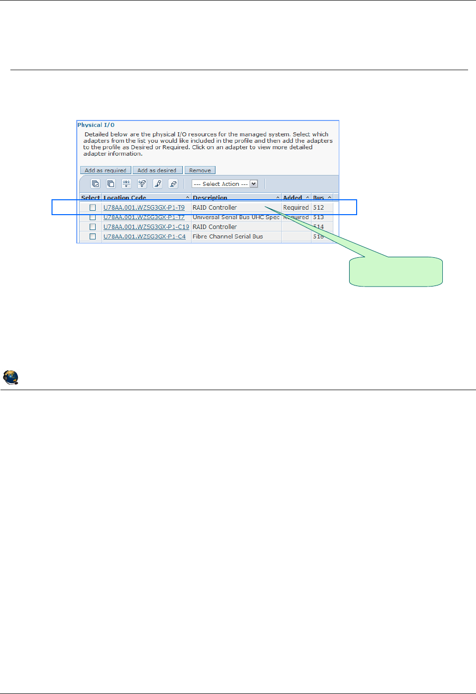
Figure 1-12. Installing the Virtual I/O Server from media QV3441.0
Notes:
Installation from media
The Virtual I/O Server may be installed directly from the supplied product media. In this
case, the partition being used should contain an adapter slot that has a connected DVD
device. Insert the product media into the DVD drive, and then activate the partition.
When starting the partition, select the checkbox to open a terminal window. Be sure to
click the Advanced button and override the default boot mode with a selection of
Diagnostic with default boot list. This will cause the partition to boot from the DVD
device.
When the terminal window appears, you will be prompted to enter a number to select
the terminal as the console for the newly activated partition and then to select a
language. Next, at the Start Install Now with Default Settings prompt, press Enter to
install the default PowerVM Express Edition. Select Change/Show Installation
Settings and Install to change the installation and system settings.
Once the installation is complete, the partition will reboot.
© Copyright IBM Corporation 2012
UNIX Software Service Enablement
Place Virtual I/O Server product media in system DVD drive
Ensure slot connected to DVD drive is in partition and available:
Activate the partition and select:
Boot mode = Diagnostic with default boot list
Open a terminal window
Interact with presented menu choices to complete the installation
Partition will reboot when installation is complete
Installing the Virtual I/O Server from media
IBM Power 720
example

Student Notebook
Course materials may not be reproduced in whole or in part
without the prior written permission of IBM.
© Copyright IBM Corp. 2012 Unit 1. Virtual I/O Server Configuration 1-15
V7.0
Uempty
Figure 1-13. Installing from the HMC QV3441.0
Notes:
Additional installation options
Place the VIOS product media into the optical media drive on the HMC. Login to the
HMC and invoke the installios command. Once the managed system and partition
have been selected, the command will prompt for profile (default) and image source
(/dev/cdrom) selections. It will then prompt for network information. Once the choices
have been made, the command will activate the partition and install the Virtual I/O
Server product.
Installing the VIOS software from a NIM Server is similar to installing the VIOS from the
HMC because it is also a network install using a NIM master. You have the option of
using installios from a NIM master just like from the HMC. In this case, the creation
of NIM objects to represent the install resources and client (the VIOS) is done
automatically. In a traditional NIM environment, you can simply create these objects and
perform mksysb bos_inst operations.
© Copyright IBM Corporation 2012
UNIX Software Service Enablement
Installing from the HMC
Place VIO Server product media in HMC DVD drive
Log in to HMC using SSH connection
Invoke installios and follow menu prompts
Will prompt you to select:
Managed system that contains the partition you want to install
Partition you wish to install
Partition profile name
Source of product images (/dev/cdrom)
Intended IP address, subnet mask and gateway
Ethernet media speed and duplex setting
If you want to configure the clients network after installation
Uses NIMOL (NIM on Linux) to install AIX mksysb image, and
therefore requires that the VIO Server partition has an interface
configured on the same LAN as the HMC
VIOS partition will reboot once installation is complete

Student Notebook
Course materials may not be reproduced in whole or in part
without the prior written permission of IBM.
1-16 VIOS © Copyright IBM Corp. 2012
Figure 1-14. Command Line Interface (CLI) (1 of 2) QV3441.0
Notes:
The VIOS CLI
Although the Virtual I/O Server is currently implemented as a customized AIX image,
the system administrator does not use regular AIX commands to configure and maintain
the partition. The administration of the Virtual I/O Server can be performed using a
Command Line Interface (CLI), that encapsulates the underlying native operating
system commands used to perform particular tasks. This abstracts the AIX command
interface for those who are unfamiliar with AIX administration. Many of the VIOS
management tasks can also be completed from the HMC GUI, or the cfgassist
command
The CLI is implemented using a secure Korn shell. This means the administrator is
limited to the commands defined in the CLI. Since a secure shell is used, there are
limitations on the types of input/output redirection that are allowed.
© Copyright IBM Corporation 2012
UNIX Software Service Enablement
Command Line Interface (CLI) (1 of 2)
Virtual I/O Server can be configured and administered using CLI:
Device management (physical, virtual, LVM)
Network configuration
Software installation and update
Security
User management
Installation of OEM software
Maintenance tasks
Alternatively, you can use cfgassist, or the HMC to configure the VIOS
and managed virtual devices
VIOS CLI uses a restricted Korn shell:
Limited set of commands available
Cannot change directory, or set SHELL, ENV or PATH
Cannot redirect output with >, >>, >| or <>
Use the help command to see list of available commands
Student Notebook
Course materials may not be reproduced in whole or in part
without the prior written permission of IBM.
© Copyright IBM Corp. 2012 Unit 1. Virtual I/O Server Configuration 1-17
V7.0
Uempty
Figure 1-15. Command Line Interface (CLI) (2 of 2) QV3441.0
Notes:
The VIOS CLI
The oem_setup_env command provides a root shell for use when installing and
configuring software for use with complex storage solutions, for example, for adding
device drivers for IBM System Storage products. Once in the root shell, you can use
AIX commands and SMIT. Procedures performed in the padmin environment are
supported, however if something is configured from the root environment, then the
configuration might not be tested for the VIOS or supported.
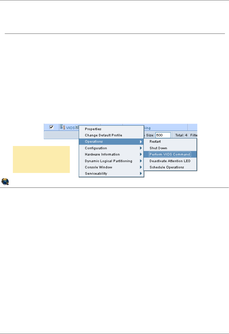
Virtual I/O Server commands can be run from the HMC GUI. The example graphic in
the visual above shows the Operations -> Perform VIOS Command task. If you run
this task, a popup window appears and you can type a VIOS command in the input box.
In addition, we’ll see later in this course that there is another way to manage virtual
devices from the HMC.
© Copyright IBM Corporation 2012
UNIX Software Service Enablement
Command Line Interface (CLI) (2 of 2)
Use oem_setup_env command to access AIX root shell
Use exit command to return to padmin shell
To run a VIOS CLI command while in the root shell, precede the
command with the /usr/ios/cli/ioscli command
Example: # /usr/ios/cli/ioscli ioslevel
When writing VIOS scripts to be run by padmin, precede each
command with the ioscli command
VIOS commands can be run from the HMC:
Example: viosvrcmd m MSname p VIOS1 c "ioslevel"
Or, use the HMC GUI:
Operations ->
Perform VIOS
Command
Student Notebook
Course materials may not be reproduced in whole or in part
without the prior written permission of IBM.
1-18 VIOS © Copyright IBM Corp. 2012
Figure 1-16. Configuring the Virtual I/O Server (1 of 2) QV3441.0
Notes:
Login and accept license
Since the CLI is used to configure the Virtual I/O Server, the root user login is not
typically used. Instead, you should login to the partition using the user padmin. This is
the login for the Prime Administrator of the VIOS partition. The first time the padmin
user logs in, you will be prompted to set the password. Once you have entered a new
password, you will have to type "a" to accept the software maintenance terms and
conditions and then you’ll be logged in using the restricted Korn shell. Even though you
accepted the software maintenance terms and conditions, you still must accept the
software usage licenses by running the license -accept command.
© Copyright IBM Corporation 2012
UNIX Software Service Enablement
Configuring the Virtual I/O Server (1 of 2)
Login to the VIOS as the user padmin, not root
Will be prompted to set the password
The first time you log in, you will be prompted to accept software
maintenance terms
Indicate by selecting the appropriate response below whether you
accept or decline the software maintenance terms and conditions.
Accept (a) | Decline (d) | View Terms (v) > a
Then, you must accept the license for the Virtual I/O Server product:
$ license -accept
Use cfgassist
command to configure
initial basic settings
Similar to SMIT
Set date/timezone
Configure networking
ato accept
C
onfig Assist for VIOS
M
ove cursor to desired item and press Enter.
S
et Date and TimeZone
C
hange Passwords
S
et System Security
V
IOS TCP/IP Configuration
I
nstall and Update Software
.
. .
S
hared Storage Pools
Electronic Service Agent

Student Notebook
Course materials may not be reproduced in whole or in part
without the prior written permission of IBM.
© Copyright IBM Corp. 2012 Unit 1. Virtual I/O Server Configuration 1-19
V7.0
Uempty
Figure 1-17. Configuring the Virtual I/O Server (2 of 2) QV3441.0
Notes:
Creating VIOS users
As of VIOS 2.2 you can create users with role-based access controls (RBAC). For
example, if the system administrator creates the role UserManagement with
authorization to access user management commands and assigns this role to a user,
that user can manage users on the system but has no further access rights. Reference:
http://pic.dhe.ibm.com/infocenter/powersys/v3r1m5/index.jsp?topic=/p7hb1/iphb1_vios
_using_rbac.htm
Set up redundancy for VIOS boot disk
After installing the VIOS and before setting up clients is the best time to mirror the
rootvg for the VIOS because you must reboot the VIOS as part of the procedure. The
-defer option to the mirrorios command can be used to avoid an auto boot when the
command completes. The VIOS will need to be rebooted before creating virtual
devices.
© Copyright IBM Corporation 2012
UNIX Software Service Enablement
Configuring the Virtual I/O Server (2 of 2)
Consider creating additional users with mkuser command
Other user management commands include lsuser, rmuser, passwd
The cfgassist utility can also be used to change passwords
Different user types are supported:
Prime administrator (can only be one of this type: padmin)
Service Representative (use -sr flag with mkuser)
Development Engineer (use -de flag with mkuser)
If boot disk mirroring is to be used, configure before supporting clients
Extend rootvg to a second disk: $ extendvg -f rootvg hisk1
Mirror rootvg: $ mirrorios hdisk1
VIOS will reboot on command completion, or use -defer to reboot later

Student Notebook
Course materials may not be reproduced in whole or in part
without the prior written permission of IBM.
1-20 VIOS © Copyright IBM Corp. 2012
Figure 1-18. Configure networking QV3441.0
Notes:
Configuring network access
If the partition was installed from the HMC or a NIM server, then the network interface
may still be configured (depending on the options you selected when running the
installios or NIM commands).
Use the cfgassist VIOS TCP/IP Configuration option or the mktcpip command to
configure the first Ethernet interface. Use lstcpip to check the configuration.
It is probably unlikely that a VIOS will need more than one interface. However, to
configure additional Ethernet interfaces after the first, you must use the chdev
command. The mktcpip command is used for the first interface because it sets the
hostname as well as the other TCP/IP parameters. Here is an example chdev
command for the Virtual I/O Server which configures the interface en1, has an IP
address of 10.0.0.5, and has a netmask of 255.0.0.0:
$ chdev -dev en1 -attr netaddr=10.0.0.5 netmask=255.0.0.0 state=up
© Copyright IBM Corporation 2012
UNIX Software Service Enablement
Configure networking
Use cfgassist or mktcpip command to configure first network
interface (if not configured during installation from HMC or NIM
server)
Syntax for mktcpip:
mktcpip -hostname HostName -inetaddr Address \
-interface Interface [-start] \
[-netmask SubnetMask] [-cabletype CableType]\
[-gateway Gateway] \
[-nsrvaddr NameServerAddress \
-nsrvdomain Domain] [-plen prefixLength]
Check network configuration with the lstcpip command
Useful flags: -interfaces, -state, -stored, -adapters,
-namesrv
The hostname command is also available

Student Notebook
Course materials may not be reproduced in whole or in part
without the prior written permission of IBM.
© Copyright IBM Corp. 2012 Unit 1. Virtual I/O Server Configuration 1-21
V7.0
Uempty
Figure 1-19. Resource Monitoring and Control (RMC) QV3441.0
Notes:
RMC resource managers
The RMC subsystem is used by clients to monitor the state of system resources and to
send commands to resource managers. The RMC subsystem acts as a broker between
the client processes that use it and the resource manager processes that control
resources. Resource managers may be active or may be inoperative until they are
needed. This is not a complete list, but a typical list you’ll see in AIX is as follows:
- CSMAgentRM - For CSM client resource agent (nodes) operations
- ServiceRM - For service event operations
- DRM - For DLPAR operations
- DMSRM - For tracking status of partitions
- ERRM - For taking action in response to a system event
- AuditRM - For audit log operations
- HostRM - For host monitoring operations related to load and OS status
- LPRM - The least privileged RM can run a root command or script, locally or
remotely, on behalf of an authorized user
© Copyright IBM Corporation 2012
UNIX Software Service Enablement
Resource Monitoring and Control (RMC)
RMC daemons
Exist on the HMC, VIOS, and client partitions
Used for communications for operations such as:
DLPAR, reporting service events, and HMC screens for shutting down
partitions and virtual device configuration
The daemons are Resource Managers which each manage a class of resources
List resource managers:
HMC: monhmc -s rmc
VIOS and AIX: lssrc -g rsct_rm
# lssrc -g rsct_rm
Subsystem Group PID Status
IBM.CSMAgentRM rsct_rm 7012576 active
IBM.ServiceRM rsct_rm 5177570 active
IBM.DRM rsct_rm 5636306 active
IBM.DMSRM rsct_rm 5701836 active
IBM.ERRM rsct_rm inoperative
IBM.AuditRM rsct_rm inoperative
IBM.HostRM rsct_rm inoperative
IBM.LPRM rsct_rm inoperative

Student Notebook
Course materials may not be reproduced in whole or in part
without the prior written permission of IBM.
1-22 VIOS © Copyright IBM Corp. 2012
Figure 1-20. RMC management QV3441.0
Notes:
Restarting RMC daemons
If you find that the following features do not work, try stopping and restarting the
daemons:
- DLPAR operations
- HMC GUI commands to shutdown partitions or to view virtual SCSI configurations
Reporting serviceable events to the HMC also relies on RMC connections, but the lack
of this function may not be immediately noticed by the administrator.
When starting the daemons you must first run the command with -A, then run it again
with -p. That is, you cannot run these flags at the same time.
© Copyright IBM Corporation 2012
UNIX Software Service Enablement
RMC management
Wait up to 5-7 minutes after partition or HMC has booted
The RMC daemons on the HMC will establish communications with the
daemons on the VIOS and client LPARs
If the /var file system is full when RMC daemons start, the RMC
configuration may be corrupted
To stop the daemons on an AIX LPAR:
# /usr/sbin/rsct/bin/rmcctrl z
To start the daemons on an AIX LPAR and enable remote client
(peer) communications:
# /usr/sbin/rsct/bin/rmcctrl A
# /usr/sbin/rsct/bin/rmcctrl p
Use oem_setup_env for the VIOS to run these commands
To restart daemons on HMC, reboot the HMC

Student Notebook
Course materials may not be reproduced in whole or in part
without the prior written permission of IBM.
© Copyright IBM Corp. 2012 Unit 1. Virtual I/O Server Configuration 1-23
V7.0
Uempty
Figure 1-21. RMC reinitialization QV3441.0
Notes:
RMC reinitialization
Sometimes restarting the daemons is not enough to fix an RMC problem, particularly on
a cloned system. Systems which are cloned from other systems may have the old
system’s authorization information. To clear this, reinitialize the RMC system with the
recfgct command.
© Copyright IBM Corporation 2012
UNIX Software Service Enablement
RMC reinitialization
If necessary, reinitialize RMC files with recfgct
Fix a broken RSCT configuration or reinitialize RSCT files after cloning an
LPAR's operating system
Use if the restart of the RMC daemons did not fix the problem and there
are no network issues
New files are copied from templates
Command path:
# /usr/sbin/rsct/install/bin/recfgct

Student Notebook
Course materials may not be reproduced in whole or in part
without the prior written permission of IBM.
1-24 VIOS © Copyright IBM Corp. 2012
Figure 1-22. Checkpoint (1 of 2) QV3441.0
Notes:
© Copyright IBM Corporation 2012
UNIX Software Service Enablement
Checkpoint (1 of 2)
1. Which one of the following types of virtual devices can be used without a Virtual I/O
Server?
A. Virtual Ethernet adapter
B. Virtual SCSI disks
C. Shared Ethernet adapter
D. Virtual Fibre Channel adapter
2. Which one of the following is NOT a function of virtual I/O?
A. Reduction or elimination of need for additional physical I/O adapters
B. Supports Live Partition Mobility operations
C. Enables partitions to take advantage of unused processing cycles
D. Allows clients to attach to storage that may be unsupported for Linux or IBM i
3. Which one of the following is NOT a valid way to install the Virtual I/O Server product:
A. Directly from product media
B. Install AIX first, then install the Virtual I/O Server filesets and updates
C. Install from the HMC with the installios command
D. Install from an AIX NIM master

Student Notebook
Course materials may not be reproduced in whole or in part
without the prior written permission of IBM.
© Copyright IBM Corp. 2012 Unit 1. Virtual I/O Server Configuration 1-25
V7.0
Uempty
Figure 1-23. Checkpoint (2 of 2) QV3441.0
Notes:
© Copyright IBM Corporation 2012
UNIX Software Service Enablement
Checkpoint (2 of 2)
4. True or False: When installing the Virtual I/O Server, it installs just like an
AIX mksysb image.
5. To use virtual SCSI devices, which system feature must be purchased?
A. Virtual I/O Server software
B. PowerVM Express, Standard, or Enterprise Edition
C. Live Partition Mobility
D. None of the above
6. What is the command in the Virtual I/O Server command line interface that will
show a list of all available Virtual I/O Server command line commands?
7. True or False: The Virtual I/O Server can be booted in any type of partition.
Student Notebook
Course materials may not be reproduced in whole or in part
without the prior written permission of IBM.
1-26 VIOS © Copyright IBM Corp. 2012
Figure 1-24. Exercise 1 - VIOS configuration QV3441.0
Notes:
© Copyright IBM Corporation 2012
UNIX Software Service Enablement
Exercise 1 - VIOS configuration
Activity:
Configure a new Virtual I/O Server installation and investigate the
VIOS command line interface (CLI)
Configuration
Domain
Nameserver IP
Address
Default Gateway
Netmask
VIOS IP
Address
VIOS Hostname
Fill in the network information for the VIOS partition:

Student Notebook
Course materials may not be reproduced in whole or in part
without the prior written permission of IBM.
© Copyright IBM Corp. 2012 Unit 1. Virtual I/O Server Configuration 1-27
V7.0
Uempty
Figure 1-25. Unit summary QV3441.0
Notes:
© Copyright IBM Corporation 2012
UNIX Software Service Enablement
Unit summary
Virtual I/O is a way to share hardware resources providing support for
more logical partitions
The Virtual I/O Server software:
Is installed in a Virtual I/O Server type partition
Is needed for the virtual SCSI, Shared Ethernet adapter, and virtual
Fibre Channel devices
The Virtual I/O Server can export physical volumes, logical volumes,
optical drives, tape drives, and files to client partitions
The Virtual I/O Server has a command line interface with many
commands for managing the VIOS and its devices

Student Notebook
Course materials may not be reproduced in whole or in part
without the prior written permission of IBM.
1-28 VIOS © Copyright IBM Corp. 2012

Student Notebook
Course materials may not be reproduced in whole or in part
without the prior written permission of IBM.
© Copyright IBM Corp. 2012 Unit 2. Virtual SCSI Configuration 2-1
V7.0
Uempty Unit 2. Virtual SCSI Configuration
What this unit is about
This unit details the configuration of virtual SCSI devices both from the
Virtual I/O Server command line and from the HMC Storage
Management graphical user interface. Creating virtual targets with
different types of backing storage is covered in detail.
What you should be able to do
After completing this unit, you should be able to:
• Create virtual SCSI target devices using different types of backing
storage:
- Physical volumes, logical volumes, and optical devices
• Configure storage pool devices
• Configure a client partition to use virtual SCSI devices
• Determine the details of an existing virtual SCSI configuration
How you will check your progress
Accountability:
• Checkpoint questions
• Machine exercises
References
IBM Power Systems Hardware Information Center:
http://publib.boulder.ibm.com/infocenter/powersys/v3r1m5/index.jsp
Virtual I/O Server product documentation from the IBM Power
Systems Hardware Information Center:
http://publib.boulder.ibm.com/infocenter/powersys/v3r1m5/index.jsp?t
opic=/p7hb1/iphb1kickoff.htm
IBM Redbooks documents can be found at:
http://www.redbooks.ibm.com
SG24-7940 IBM PowerVM Virtualization Introduction and
Configuration, an IBM Redbooks document

Student Notebook
Course materials may not be reproduced in whole or in part
without the prior written permission of IBM.
2-2 VIOS © Copyright IBM Corp. 2012
SG24-7590 IBM PowerVM Virtualization Managing and Monitoring, an
IBM Redbooks document
SG24-7825 PowerVM Migration from Physical to Virtual Storage, an
IBM Redbooks document
REDP4194 IBM System p Advanced POWER Virtualization
(PowerVM) Best Practices, an IBM Redbooks
document

Student Notebook
Course materials may not be reproduced in whole or in part
without the prior written permission of IBM.
© Copyright IBM Corp. 2012 Unit 2. Virtual SCSI Configuration 2-3
V7.0
Uempty
Figure 2-1. Unit objectives QV3441.0
Notes:
© Copyright IBM Corporation 2012
UNIX Software Service Enablement
Unit objectives
After completing this unit, you should be able to:
Create virtual SCSI target devices using different types of backing
storage:
Physical volumes, logical volumes, and optical devices
Configure storage pool devices
Configure a client partition to use virtual SCSI devices
Determine the details of an existing virtual SCSI configuration

Student Notebook
Course materials may not be reproduced in whole or in part
without the prior written permission of IBM.
2-4 VIOS © Copyright IBM Corp. 2012
Figure 2-2. Virtual SCSI overview (1 of 3) QV3441.0
Notes:
Virtual devices
The Virtual I/O Server supports virtual SCSI disks which are backed by various types of
physical devices. Regardless of how the virtual SCSI disk is implemented using various
types of backing storage, all standard SCSI conventional rules apply to the device; it will
behave as a standard SCSI compliant device. Once a virtual disk is assigned to a client
partition, the Virtual I/O Server must be available before the client partitions are able to
access it.
Regardless of the type of backing storage (physical volume, logical volume, file) being
used for a virtual SCSI disk, the client partition recognizes it as a generic SCSI disk
device. As such it can be used in the same way as a physical disk.
If you are using Virtual I/O Server V1.2 (or later) and have AIX V5.3 with maintenance
level 3 in the client partition (or later), then you can also configure virtual optical drives.
© Copyright IBM Corporation 2012
UNIX Software Service Enablement
Virtual SCSI overview (1 of 3)
Implemented as client/server relationship
Virtual I/O Server owns the physical resource
Client partition sees generic SCSI devices
Current virtual device types supported:
Disk backed by physical volume
Disk backed by logical volume
Disk backed by file (as of VIOS V1.5)
Optical media device backed by physical optical media device
(as of VIOS V1.2)
Optical media device backed by file (as of VIOS V1.5)
Tape backed by tape device (as of VIOS V2.1)
Inter-partition communication provided by Hypervisor
Client partition can boot from virtual SCSI devices
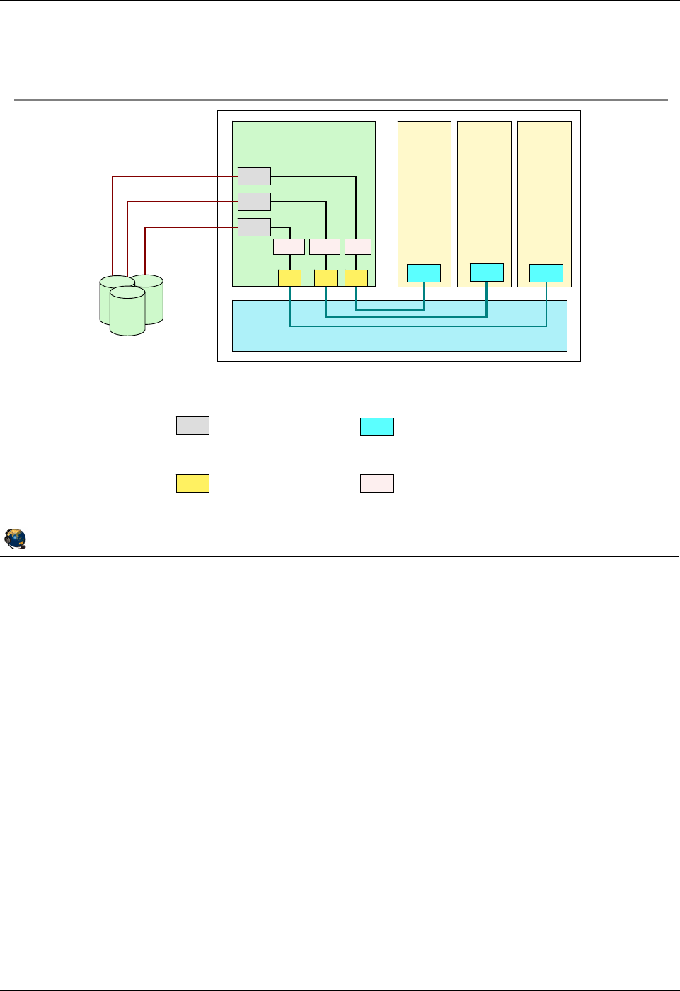
Student Notebook
Course materials may not be reproduced in whole or in part
without the prior written permission of IBM.
© Copyright IBM Corp. 2012 Unit 2. Virtual SCSI Configuration 2-5
V7.0
Uempty
Figure 2-3. Virtual SCSI overview (2 of 3) QV3441.0
Notes:
Overview
The visual above illustrates how the POWER Hypervisor provides the communications
channels that permit client virtual SCSI adapters to communicate with server virtual
SCSI adapters. Virtual target devices (VTDs) are used to allow backing storage that is
physically owned by the Virtual I/O Server to be presented as a target on a virtual SCSI
bus. A client partition using a virtual SCSI bus can detect and use all virtual targets on
that bus.
Virtual SCSI itself does not have any maximums in terms of number of supported
devices. The Virtual I/O Server supports a maximum of 1024 virtual I/O slots per Virtual
I/O Server. A maximum of 256 virtual I/O slots can be assigned to a single client
partition.
© Copyright IBM Corporation 2012
UNIX Software Service Enablement
Virtual SCSI overview (2 of 3)
S S S
PHYS
Virtual I/O Server
C
Client
C
Client
C
Client
PHYS
PHYS
PHYS Physical
Adapter
SVirtual SCSI
Server Adapter
CVirtual SCSI
Client Adapter
VTD Virtual Target
Device
VTDVTD VTD
Hypervisor
Physical
Storage
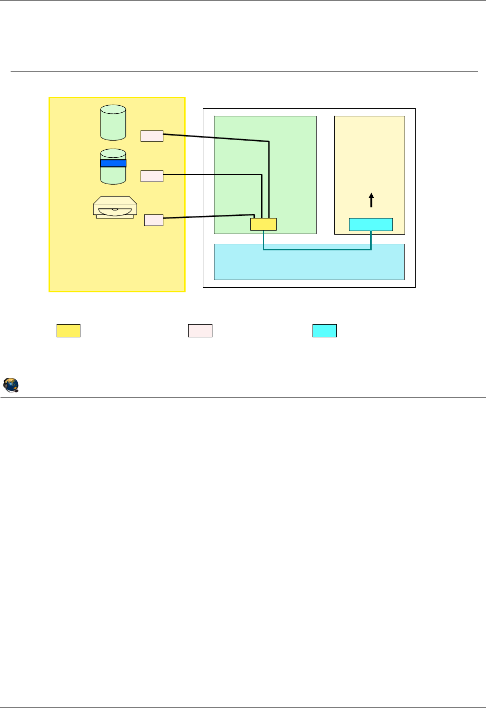
Student Notebook
Course materials may not be reproduced in whole or in part
without the prior written permission of IBM.
2-6 VIOS © Copyright IBM Corp. 2012
Figure 2-4. Virtual SCSI overview (3 of 3) QV3441.0
Notes:
Details
The visual above illustrates how multiple virtual target devices, and their associated
backing storage devices, can be presented on a single virtual SCSI bus. This can
simplify configurations by reducing the number of virtual adapters. Notice in the visual
above that the three backing storage devices map to the three virtual devices in the
client LPAR. The devices associate with the virtual SCSI server adapter (vhost#) can be
changed dynamically. The client partition just needs to run the cfgmgr command to see
new devices.
© Copyright IBM Corporation 2012
UNIX Software Service Enablement
Virtual SCSI overview (3 of 3)
SVirtual SCSI
Server Adapter CVirtual SCSI
Client Adapter
VTD Virtual Target
Device
Virtual I/O Server
C
Client
Hypervisor
Physical Storage
(physical volumes,
logical volumes, optical
media drive, tape, files)
hdisk5
lv_3
cd0
vtscsi0
vtscsi1
vtopt0
VTD
VTD
hdisk0
hdisk1
cd0
One virtual adapter can host multiple virtual target devices
vscsi0
vhost0
S
VTD
(Physical adapters are implied)

Student Notebook
Course materials may not be reproduced in whole or in part
without the prior written permission of IBM.
© Copyright IBM Corp. 2012 Unit 2. Virtual SCSI Configuration 2-7
V7.0
Uempty
Figure 2-5. Creating virtual SCSI devices QV3441.0
Notes:
Procedure
The visual shows the steps required to make virtual SCSI devices available to a client
partition. After the virtual SCSI server adapter is created, the backing storage is
associated with the adapter by creating one or more virtual target devices (backing
storage may have to be configured also). Finally, the client partition can be activated
with the new adapter configured in its profile, or a client adapter can be dynamically
configured from the HMC with a DLPAR operation. DLPAR operations are available if
there is network connectivity between the HMC and partitions.
After adding devices with DLPAR, use the cfgmgr command in AIX or the cfgdev
command in the Virtual I/O Server to have the operating system discover the new
devices. You do not need to run a command for this in Linux.
The next set of visuals show how to create virtual devices on the command line,
followed by visuals showing how to create virtual devices from the HMC. In addition,
devices may be created with the VIOS cfgassist utility.
© Copyright IBM Corporation 2012
UNIX Software Service Enablement
Creating virtual SCSI devices
1. Create virtual SCSI server adapter in Virtual I/O server
Allow any partition to connect or map to specific client and adapter ID
2. Create virtual SCSI client adapter in client partition
Specify connection to SCSI server partition and adapter ID
Modify server adapter to specify client if not done at creation
3. Activate Virtual I/O server partition and check adapter is available
Or, if added with DLPAR, discover new devices with the cfgdev
command
4. Create storage resources to export for virtual SCSI disk
5. Create virtual target device (VTD) by associating storage with virtual
SCSI server adapter
6. Activate the client partition*
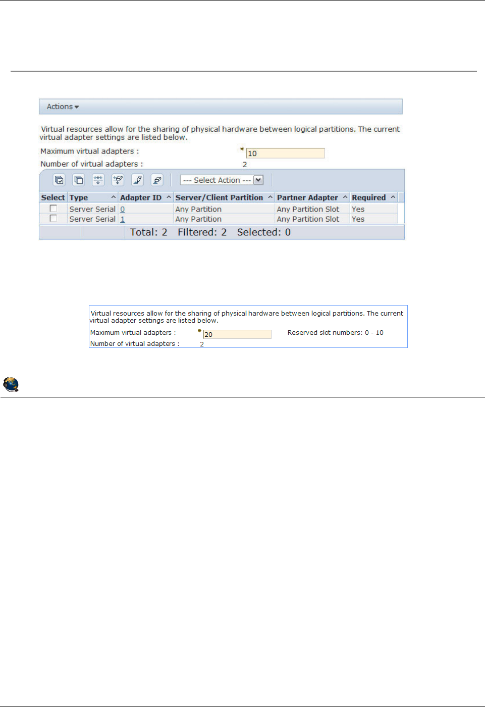
Student Notebook
Course materials may not be reproduced in whole or in part
without the prior written permission of IBM.
2-8 VIOS © Copyright IBM Corp. 2012
Figure 2-6. Step 1: Virtual SCSI server adapter (1 of 2) QV3441.0
Notes:
Virtual SCSI server adapter
The first step in the procedure to create virtual SCSI devices available to a client
partition is to use the HMC to add a virtual SCSI server adapter to the Virtual I/O Server
partition. Using the HMC interface, edit a profile for the Virtual I/O Server partition or
add the adapter dynamically (or both for a permanent configuration). On the Virtual
Adapters tab, click on Actions, then choose Create -> SCSI Adapter.
Maximum virtual adapters
On POWER6 processor-based servers, the default maximum number of virtual
adapters supported by default for a VIO Server partition is 20, instead of 10 as it is for
POWER5 and POWER7 servers. The first 11 virtual adapter IDs (0-10) are reserved on
a Virtual I/O Server partition on POWER6. On POWER5 and POWER7 servers, only
the first two adapter IDs (0-1) are reserved. For AIX/Linux type partitions, the default
maximum is still 10 virtual adapters and the first 2 virtual slots are reserved.
© Copyright IBM Corporation 2012
UNIX Software Service Enablement
Step 1: Virtual SCSI server adapter (1 of 2)
On Virtual Adapters tab, use Actions -> Create -> SCSI Adapter
Default maximum number of virtual adapters on the VIOS:
POWER7 servers have a default of 10 and slots 0-1 are reserved
POWER6 servers have a default of 20 and slots 0-10 are reserved
Cannot change maximum setting dynamically
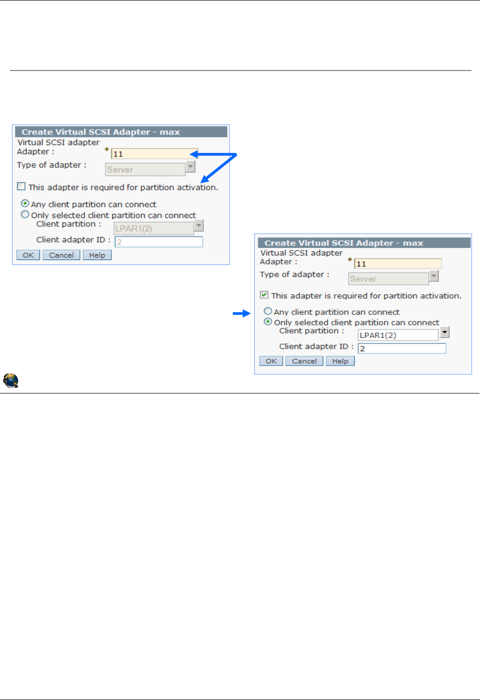
Student Notebook
Course materials may not be reproduced in whole or in part
without the prior written permission of IBM.
© Copyright IBM Corp. 2012 Unit 2. Virtual SCSI Configuration 2-9
V7.0
Uempty
Figure 2-7. Step 1: Virtual SCSI server adapter (2 of 2) QV3441.0
Notes:
Virtual SCSI server adapter properties
For adapters which support client partitions that may be relocated with Live Partition
Mobility, do not make the adapter required.
You can select the Any client partition can connect option when the client partition is
not yet created. If you do this, it is important to return to this panel again to change this
setting once you have created the client partition and the virtual SCSI client adapter.
Make a note of the adapter ID because it will be needed when you create the virtual
SCSI client adapter.
If the client partition exists, select Only selected client partition can connect and
provide the client partition name and its virtual adapter ID. The client adapter will not
exist yet, but choose the adapter ID that you plan to use on the client.
Once you have selected the correct options, click on the OK button to finish the dialog.
This will return you to the partition profile properties dialog.
© Copyright IBM Corporation 2012
UNIX Software Service Enablement
Step 1: Virtual SCSI server adapter (2 of 2)
Enter the adapter ID, whether the adapter is required, and the client
adapter that will connect
By default, Any client partition can
connect is specified, but it is better
to specify a particular client partition
and ID to be sure only that client can
use the devices
Note (or change) the adapter ID and
indicate if the adapter is required
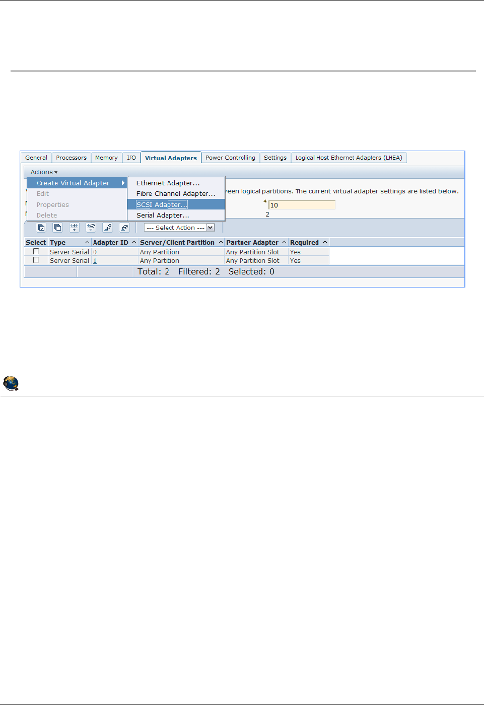
Student Notebook
Course materials may not be reproduced in whole or in part
without the prior written permission of IBM.
2-10 VIOS © Copyright IBM Corp. 2012
Figure 2-8. Step 2: Virtual SCSI client adapter (1 of 2) QV3441.0
Notes:
Virtual SCSI client adapter
The second step in the procedure to make virtual SCSI devices available to a client
partition is to use the HMC to add a virtual SCSI client adapter to the client partition.
Using the HMC interface, navigate to the Virtual Adapters tab on the desired profile for
the client, just as you did for the Virtual I/O Server. Or, use a DLPAR operation to add
the adapter. Use the Actions menu to create a new virtual SCSI adapter.
Maximum virtual adapters
Note that the default maximum number of virtual adapters on an AIX/Linux LPAR is 10.
This default maximum value is the same on all Power Systems. On all AIX/Linux and
VIOS partitions, the first two virtual slots are reserved for virtual serial adapters which
are used for the virtual console communications.
© Copyright IBM Corporation 2012
UNIX Software Service Enablement
Step 2: Virtual SCSI client adapter (1 of 2)
Create client adapter after you create the server adapter
Default maximum for AIX/Linux partitions is 10
Adapters IDs 0 and 1 are reserved
Student Notebook
Course materials may not be reproduced in whole or in part
without the prior written permission of IBM.
© Copyright IBM Corp. 2012 Unit 2. Virtual SCSI Configuration 2-11
V7.0
Uempty
Figure 2-9. Step 2: Virtual SCSI client adapter (2 of 2) QV3441.0
Notes:
Create virtual SCSI client adapter dialog
The visual above shows the Create Virtual SCSI Adapter Properties dialog for a client
partition. Just as for the server adapter, you must specify a virtual adapter ID. This
should match the adapter ID you specified for the client when you created the server
adapter (if it was specified at that time). If this is a required device, for example, a boot
device, then check the This adapter is required for partition activation checkbox.
Next, select the Virtual I/O Server partition name from the drop-down list available for
the Server partition field, and enter the adapter ID being used for the virtual SCSI
server adapter. The server ID listed on this dialog must match the one you used when
creating the virtual server SCSI adapter!
© Copyright IBM Corporation 2012
UNIX Software Service Enablement
Configure the adapter in the Properties window
Use the System VIOS Info button to view and choose a virtual SCSI
server adapter configured on the VIOS
Step 2: Virtual SCSI client adapter (2 of 2)
Specify the client
adapter ID
Is this adapter
required?
Select the VIOS
partition and enter the
server adapter ID

Student Notebook
Course materials may not be reproduced in whole or in part
without the prior written permission of IBM.
2-12 VIOS © Copyright IBM Corp. 2012
Figure 2-10. Step 3: Verify virtual SCSI server adapter QV3441.0
Notes:
Details
Use the lsdev command with the -virtual option, as shown in the visual above, to list
the virtual devices in the partition. Virtual SCSI server adapters have a device name
that starts with vhost.
You can examine a virtual SCSI server adapter’s configuration using the lsmap
command. This is used to identify which virtual slot the device is using, along with
information about the target devices associated with the adapter. In the example shown
in the visual above, the virtual SCSI server adapter has been created, but there are no
virtual target devices associated with it yet. In the example, the device vhost0 is virtual
adapter ID 11 (C11 in the location code) of the Virtual I/O Server partition, which has
partition ID 1 (V1 in the location code). The associated client LPAR ID is also shown in
this output (ID in hex is 2), and is ‘0’ when a client has not yet been activated.
© Copyright IBM Corporation 2012
UNIX Software Service Enablement
Activate the Virtual I/O Server partition
Or run cfgdev if added dynamically
Check availability of virtual SCSI server adapters
$ lsdev -virtual
name status description
vasi0 Available Virtual Asynchronous Services Interface (VASI)
vhost0 Available Virtual SCSI Server Adapter
vsa0 Available LPAR Virtual Serial Adapter
Check mapping to virtual slot
$ lsmap -vadapter vhost0
SVSA Physloc Client Partition ID
----------- ----------------------------- ------------------
vhost0 U8203.E4A.10CD1F1-V1-C11 0x00000002
VTD NO VIRTUAL TARGET DEVICE FOUND
Step 3: Verify virtual SCSI server adapter
Physical Location Code: V1 = partition ID 1, C11 = adapter ID 11
Client Partition ID: is 0 when the client partition has not yet been activated
No backing storage
mapped yet

Student Notebook
Course materials may not be reproduced in whole or in part
without the prior written permission of IBM.
© Copyright IBM Corp. 2012 Unit 2. Virtual SCSI Configuration 2-13
V7.0
Uempty
Figure 2-11. Step 4a: Create storage resources with LVM QV3441.0
Notes:
Backing storage resources overview
If you want to configure virtual SCSI targets backed by a physical volume, the optical
media device, or a tape device, you can make the VTDs and map them to the vhost
adapter. There is no additional setup needed. If you want to configure virtual SCSI
targets that are backed by logical volumes or files, then first you need to create the
volume groups, logical volumes, and files which will be used. It is best not to create
these in the VIOS rootvg volume group.
The LVM concepts on the Virtual I/O Server partition are identical to those on AIX. The
difference is that on the Virtual I/O Server, you use VIOS CLI commands to create the
volume groups and logical volumes.
© Copyright IBM Corporation 2012
UNIX Software Service Enablement
Step 4a: Create storage resources with LVM
Physical volumes
Entire physical volume can be exported as a single SCSI target
With SAN storage, LUN creation occurs on the storage system or controller
No additional setup required to create backing storage for physical volumes or
physical tape and optical media devices
Logical volumes
Use the CLI to create volume groups and logical volumes if you wish to have
finer granularity
To create a volume group:
$ mkvg [ -f ][ -vg VolumeGroup ] PhysicalVolume ...
To create a logical volume:
$ mklv [ -lv NewLogVolName ] VolumeGroup Size
[ PhysicalVolume ... ]
Example creating a logical volume named clientA_lv1 that is 5 GB in size in
an existing VolGroupA volume group:
$ mklv -lv clientA_lv1 VolGroupA 5G

Student Notebook
Course materials may not be reproduced in whole or in part
without the prior written permission of IBM.
2-14 VIOS © Copyright IBM Corp. 2012
Figure 2-12. Step 4b: Create storage resources with storage pools (1 of 2) QV3441.0
Notes:
Using I/O storage pools
Storage pools are available in Virtual I/O Server V1.2 and later. Similar to volume
groups, logical volume storage pools are collections of one or more physical volumes.
Storage pools are created and managed using the following commands:
- The mksp command creates a storage pool.
- The chsp command changes the characteristics of a storage pool.
- The lssp command displays information about a storage pool. The lssp with the
-bd option will list out the backing devices and show the associations between the
virtual host adapters and virtual devices.
© Copyright IBM Corporation 2012
UNIX Software Service Enablement
Step 4b: Create storage resources with storage
pools (1 of 2)
Storage pools are similar in
concept to volume groups
Created using one or more physical volumes
Used to manage logical volume and file-based backing storage
To create a logical volume storage pool, specify the name and one or
more physical volume names:
$ mksp [ -f ] StoragePool PhysicalVolume ...
Example creating the clientsp1 logical volume pool with two physical
volumes:
$ mksp -f clientsp1 hdisk3 hdisk4

Student Notebook
Course materials may not be reproduced in whole or in part
without the prior written permission of IBM.
© Copyright IBM Corp. 2012 Unit 2. Virtual SCSI Configuration 2-15
V7.0
Uempty
Figure 2-13. Step 4b: Create storage resources with storage pools (2 of 2) QV3441.0
Notes:
Backing devices in storage pools
Backing devices are created and deleted using the following commands:
- The mkbdsp command assigns storage from a storage pool to a virtual SCSI adapter
as a backing device.
- The rmbdsp command removes a backing device from a virtual SCSI server adapter
by removing its associated virtual target device. By default the backing device is
also removed and its storage returned to the storage pool.
Example command that creates a backing device but does not map it to a vhost
adapter:
$ mkbdsp -sp clientsp1 6G -bd clientA_lv2
Example command that assigns an existing backing device to a vhost adapter:
$ mkbdsp -sp clientsp1 -bd clientA_lv2 -vadapter vhost0
© Copyright IBM Corporation 2012
UNIX Software Service Enablement
Step 4b: Create storage resources with storage
pools (2 of 2)
Create logical volumes and backing devices in one step:
$ mkbdsp [-sp StoragePool] Size [-bd BackingDevice]
-vadapter ServerVirtualSCSIAdapter [ -tn VTDName ]
Example creating a logical volume named clientA_lv1 that is 5 GB in size in
the existing clientsp1 storage pool on an existing vadapter:
$ mkbdsp -sp clientsp1 5G -bd clientA_lv1 -vadapter vhost0
Creating logical volume "clientA_lv1" in storage pool
"clientsp1".
vtscsi3 Available
clientA_lv1
Command output showing new VTD name

Student Notebook
Course materials may not be reproduced in whole or in part
without the prior written permission of IBM.
2-16 VIOS © Copyright IBM Corp. 2012
Figure 2-14. List storage resource configuration (1 of 2) QV3441.0
Notes:
List storage resources
The visual above shows common usages of the lsvg, lspv, and lssp commands. You
can use lsvg and lspv which are similar to AIX LVM commands. Notice that the lssp
command shows similar information. The name LVPOOL refers to a logical volume
storage pool which is the same as the LVM volume group. It doesn’t matter if you use
LVM-style commands or storage pool commands to create, list, or remove storage
resources.
The lspv -free command shows physical volumes that are not part of a volume group
or storage pool, and are not mapped to a vhost adapter.
© Copyright IBM Corporation 2012
UNIX Software Service Enablement
List storage resource configuration (1 of 2)
Show physical volumes that are not already mapped to a virtual host
adapter or part of a shared memory pool:
$ lspv -free
NAME PVID SIZE(megabytes)
hdisk5 00f65f4e2800f7db 70006
Show all storage pools:
$ lssp (or use lsvg)
Pool Size(mb) Free(mb) Alloc Size(mb) BDs Type
rootvg 69888 46336 128 1 LVPOOL
clientsp1 139776 134656 64 1 LVPOOL
Show physical volumes in a storage pool:
$ lsvg -pv clientsp1 (or use lssp -detail -sp clientsp1)
clientsp1:
PV_NAME PV STATE TOTAL PPs FREE PPs FREE DISTRIBUTION
hdisk3 active 1092 1012 219..138..218..218..219
hdisk4 active 1092 1092 219..218..218..218..219

Student Notebook
Course materials may not be reproduced in whole or in part
without the prior written permission of IBM.
© Copyright IBM Corp. 2012 Unit 2. Virtual SCSI Configuration 2-17
V7.0
Uempty
Figure 2-15. List storage resource configuration (2 of 2) QV3441.0
Notes:
List storage resources
In the examples above, clientsp1 is a volume group (LVPOOL). clientA_lv1 is a logical
volume in the clientsp1 volume group.
To remove storage resources, use the rmlv, reducevg, and rmbdsp commands.
Example storage pool command to remove a logical volume and its virtual target
device:
$ rmbdsp -sp clientsp1 -bd clientA_lv1
© Copyright IBM Corporation 2012
UNIX Software Service Enablement
List storage resource configuration (2 of 2)
Show logical volumes in a volume group/storage pool:
$ lsvg -lv clientsp1
clientsp1:
LV NAME TYPE LPs PPs PVs LV STATE MOUNT POINT
clientA_lv1 jfs 80 80 1 open/syncd N/A
Show logical volumes on a disk:
$ lspv -lv hdisk3
hdisk3:
LV NAME LPs PPs DISTRIBUTION MOUNT POINT
clientA_lv1 320 320 00..255..65..00..00 N/A
Show all backing devices in a storage pool:
$ lssp -bd -sp clientsp1
Name Size(mb) VTD SVSA
clientA_lv1 5120 vtscsi3 vhost0

Student Notebook
Course materials may not be reproduced in whole or in part
without the prior written permission of IBM.
2-18 VIOS © Copyright IBM Corp. 2012
Figure 2-16. Step 5: Create the virtual target device QV3441.0
Notes:
Mapping the storage devices to the server adapter
The virtual SCSI target devices shown in the visual above are mapped to a physical
volume (hdisk1), a logical volume (datavglpar1) and an optical device (cd0). To map a
tape device, simply map the rmt# device like the optical media device example above.
The lsdev -virtual output for the tape device will look like this (using the default VTD
name):
vttape0 Available Virtual Target Device - Tape
The examples above show commands which create the new vtscsi0, vtscsi1, and
vtopt0 devices. If you don’t want to use the next numerical vtscsi# device name, then
you can specify a device name with the use of the -dev DeviceName option.
Important: If you used the mkbdsp command to create a logical volume in a storage pool
as shown in the previous visual, then you do not have to use the mkvdev command to
create the VTD and associate it with the vhost adapter. This was done all in one step.
© Copyright IBM Corporation 2012
UNIX Software Service Enablement
Step 5: Create the virtual target device
The virtual target device (VTD) maps the storage resource to the
virtual SCSI adapter:
$ mkvdev vdev TargetDevice vadapter VirtualServerAdapter
[ dev DeviceName ]
Examples:
$ mkvdev vdev hdisk1 vadapter vhost0
vtscsi0 Available
$ mkvdev vdev datavglpar1 vadapter vhost0
vtscsi1 Available
$ mkvdev vdev cd0 vadapter vhost0
vtopt0 Available
Check the target devices with lsdev command:
$ lsdev virtual
name status description
vasi0 Available Virtual Asynchronous Services Interface (VASI)
vhost0 Available Virtual SCSI Server Adapter
vsa0 Available LPAR Virtual Serial Adapter
vtscsi0 Available Virtual Target Device Disk
vtscsi1 Available Virtual Target Device Logical Volume
vtopt0 Available Virtual Target Device Optical Media
The mkvdev step is not
needed if mkbdsp created
and mapped the device
The mkvdev step is not
needed if mkbdsp created
and mapped the device

Student Notebook
Course materials may not be reproduced in whole or in part
without the prior written permission of IBM.
© Copyright IBM Corp. 2012 Unit 2. Virtual SCSI Configuration 2-19
V7.0
Uempty
Figure 2-17. Verify the mapping of virtual targets QV3441.0
Notes:
lsmap details
The lsmap command can be used to show which virtual target devices are associated
with a virtual SCSI server device. You can specify the -all flag to see mappings for all
virtual SCSI server adapters, or choose a particular vhost adapter as shown in the
visual above.
The client partition ID is listed as zero if the client partition has not yet been activated.
Otherwise, the partition ID is given (in hex). If a previously running client shuts down, its
LPAR ID will still show in the lsmap output.
© Copyright IBM Corporation 2012
UNIX Software Service Enablement
Verify the mapping of virtual targets
$ lsmap -vadapter vhost0
SVSA Physloc Client Partition ID
--------------- -------------------------------------- ------------------
vhost0 U8202.E4B.06BCC8P-V1-C11 0x00000002
VTD vtopt0
Status Available
LUN 0x8200000000000000
Backing device cd0
Physloc U78AA.001.WZSG3GX-P2-D9
Mirrored N/A
VTD vtscsi0
Status Available
LUN 0x8100000000000000
Backing device hdisk1
Physloc U78AA.001.WZSG3GX-P2-D5
Mirrored false
VTD vtscsi1
Status Available
LUN 0x8300000000000000
Backing device datavglpar1
Physloc
Mirrored N/A
Use lsmap to verify
mapping of virtual
targets

Student Notebook
Course materials may not be reproduced in whole or in part
without the prior written permission of IBM.
2-20 VIOS © Copyright IBM Corp. 2012
Figure 2-18. Step 6: Virtual SCSI disks (client view) QV3441.0
Notes:
Details
Once the virtual target devices have been created on the Virtual I/O Server partition,
you can activate the client partition that will use the resources. The devices show up
under SMS, so a partition can boot from a virtual SCSI disk if it has an operating system
image installed on it. The partition can also boot from a virtual optical drive.
Virtual disks show up as physical volumes that can be configured just like normal
physical disks. The client partition cannot detect the type of backing storage device
being used for a virtual SCSI disk. That information can only be viewed on the Virtual
I/O Server partition, since it owns the physical resources.
If the client virtual adapter was added dynamically to the client LPAR, or if the Virtual I/O
Server added a new VTD to an existing vhost adapter used by the client, then the client
LPAR needs to run the cfgmgr command to discover the new devices.
© Copyright IBM Corporation 2012
UNIX Software Service Enablement
Step 6: Virtual SCSI disks (client view)
Activate client partition or run cfgmgr:
Virtual optical devices and bootable virtual disk devices will show up in SMS and
can be used for operating system install/boot
Virtual disks (including file-backed virtual disks) appear as hdisks:
# lsdev -c disk
hdisk0 Available 05-08-00-3,0 16 Bit LVD SCSI Disk Drive
hdisk1 Available 05-08-00-4,0 16 Bit LVD SCSI Disk Drive
hdisk2 Available 05-08-00-5,0 16 Bit LVD SCSI Disk Drive
hdisk3 Available 05-08-00-8,0 16 Bit LVD SCSI Disk Drive
hdisk4 Available Virtual SCSI Disk Drive
hdisk5 Available Virtual SCSI Disk Drive
Virtual optical devices (including file-backed virtual optical devices)
appear as cd#devices and virtual tape devices appear as rmt# devices:
# lsdev | grep cd
cd0 Available Virtual SCSI Optical Served by VIO Server

Student Notebook
Course materials may not be reproduced in whole or in part
without the prior written permission of IBM.
© Copyright IBM Corp. 2012 Unit 2. Virtual SCSI Configuration 2-21
V7.0
Uempty
Figure 2-19. Manage Virtual devices with cfgassist . QV3441.0
Notes:
Details
The cfgassist utility on the VIOS can assist with creating backing devices and
assigning them to clients. The cfgassist utility is used in a similar way to the SMIT
menus in AIX.
© Copyright IBM Corporation 2012
UNIX Software Service Enablement
Manage Virtual devices with cfgassist
The cfgassist utility can be used to manage volume groups, logical
volumes, storage pools, and virtual devices
Use the Storage Management menu for setting up backing storage
Use the Devices menu for creating virtual disks and mapping them to a
vhost adapter
Storage Management
Move cursor to desired item and press Enter.
V
olume Groups
Logical Volumes
Physical Volumes
Storage Pools
Virtual Media Repository
Student Notebook
Course materials may not be reproduced in whole or in part
without the prior written permission of IBM.
2-22 VIOS © Copyright IBM Corp. 2012
Figure 2-20. Check configuration from HMC (1 of 2) QV3441.0
Notes:
View virtual SCSI adapters and devices
The visual above shows how to select the Hardware Information -> Virtual I/O
Adapters -> SCSI task in the Systems Management application on the HMC. Be sure
to select the appropriate LPAR before running this task. For example, if you select a
client LPAR, you will only see information related to that client. If you select the Virtual
I/O Server partition, then you see all devices and clients for that VIOS.
© Copyright IBM Corporation 2012
UNIX Software Service Enablement
Check configuration from HMC (1 of 2)
Look at the partition profile properties, or use the
Virtual I/O Adapters option on the HMC, under Hardware Information:
HMC command:
lshwres -m msname -r virtualio --rsubtype scsi
HMC command:
lshwres -m msname -r virtualio --rsubtype scsi
Student Notebook
Course materials may not be reproduced in whole or in part
without the prior written permission of IBM.
© Copyright IBM Corp. 2012 Unit 2. Virtual SCSI Configuration 2-23
V7.0
Uempty
Figure 2-21. Check configuration from HMC (2 of 2) QV3441.0
Notes:
View virtual SCSI adapters and devices
The top example in the visual above is from a VIOS partition. The bottom example is
from a client partition. Networking must be configured between the LPARs and the HMC
for the HMC to be able to display information from that partition.
In the Virtual I/O Server example in the visual above, the vhost0 adapter shows three
backing storage devices, but only two remote backing storage devices. This is invalid
because there is always a one-to-one mapping between backing storage devices and
the devices seen in the client LPAR. The HMC GUI doesn’t give accurate information
for the remote backing devices which are optical media devices.
If there is backing device information but no client information then the client has either
not yet been configured, or is not running, or there is no network link between the
partition and the HMC.
© Copyright IBM Corporation 2012
UNIX Software Service Enablement
Check configuration from HMC (2 of 2)
View virtual SCSI device configuration from the HMC:
Virtual I/O Server example:
Client example:
Student Notebook
Course materials may not be reproduced in whole or in part
without the prior written permission of IBM.
2-24 VIOS © Copyright IBM Corp. 2012
Figure 2-22. Discover backing storage example (1 of 2) QV3441.0
Notes:
Check the client configuration
This visual and the next show how to track the virtual disk on the client back to the
physical backing storage used on the Virtual I/O Server. First, start with what you know,
which is the device you want to investigate. In this example we will use hdisk0. The
lscfg command will tell you the device is a virtual device, the adapter ID number used
on the client (C2 in the example on the visual above), and the LUN of the device which
will be useful later.
Check the server configuration
Select the client partition in the HMC’s Systems Management LPAR table view, then run
the Hardware Information -> Virtual I/O Adapters -> SCSI task. This screen will show
the Virtual I/O Server’s partition name (useful if there is more than one) and the name of
the virtual SCSI server adapter (vhost) being used on the Virtual I/O Server. The
example above shows this to be vhost0.
© Copyright IBM Corporation 2012
UNIX Software Service Enablement
Discover backing storage example (1 of 2)
A client partition sees hdisk0: What exactly is hdisk0?
Check to see if it's a virtual device and note the LUN-ID on the adapter for
hdisk0:
Check which Virtual I/O Server is being used and which vhost adapter it is using
on the Virtual I/O Server
Select the client partition and run Hardware Information -> Virtual I/O
Adapters -> SCSI
# lscfg | grep hdisk0
hdisk0 U8202.E4B.06BCC8P-V2-C2-T1-L8100000000000000
Virtual SCSI Disk Drive

Student Notebook
Course materials may not be reproduced in whole or in part
without the prior written permission of IBM.
© Copyright IBM Corp. 2012 Unit 2. Virtual SCSI Configuration 2-25
V7.0
Uempty
Figure 2-23. Discover backing storage example (2 of 2) QV3441.0
Notes:
Viewing the backing storage devices
The lsmap command output in the visual above shows that for vhost0, there are three
backing storage devices. Use the LUN ID from the client’s lscfg command output to
find the correct backing device. In this example, it is hdisk1.
© Copyright IBM Corporation 2012
UNIX Software Service Enablement
Discover backing storage example (2 of 2)
View the device mapping on the Virtual I/O Server:
$ lsmap -vadapter vhost0
SVSA Physloc Client Partition ID
--------------- -------------------------------------------- ------------------
vhost0 U8202.E4B.06BCC8P-V1-C11 0x00000002
VTD vtopt0
Status Available
LUN 0x8300000000000000
Backing device cd0
Physloc U78AA.001.WZSGHVK-P2-D9
Mirrored N/A
VTD vtscsi0
Status Available
LUN 0x8100000000000000
Backing device hdisk1
Physloc U78AA.001.WZSGHVK-P2-D5
Mirrored false
VTD vtscsi2
Status Available
LUN 0x8200000000000000
Backing device LV1
Physloc
Mirrored N/A
hdisk1 is the backing storage
device for the clients virtual
hdisk0
hdisk1 is the backing storage
device for the clients virtual
hdisk0
This one has the
correct LUN ID

Student Notebook
Course materials may not be reproduced in whole or in part
without the prior written permission of IBM.
2-26 VIOS © Copyright IBM Corp. 2012
Figure 2-24. Removing virtual devices (1 of 2) QV3441.0
Notes:
Removing virtual devices
The visual above shows how to find and remove a virtual device in a client partition. In
the example above, the parent virtual client adapter is found and a recursive rmdev
command is used to remove the virtual adapter and the child devices.
© Copyright IBM Corporation 2012
UNIX Software Service Enablement
Removing virtual devices (1 of 2)
For client partitions, remove a virtual device like a physical device:
Example where virtual SCSI adapter ID 4 controls the virtual device cd0:
Deconfigure the device and its children:
# lsslot c slot | grep C4
U8203.E4A.10CD1F1-V2-C4 Virtual I/O Slot vscsi0
# rmdev l vscsi0 R
cd0 Defined
vscsi0 Defined
Delete the devices from the ODM, rather than leaving them in the Defined
state:
# lsslot c slot | grep C4
U8203.E4A.10CD1F1-V2-C4 Virtual I/O Slot vscsi0
# rmdev l vscsi0 R d
cd0 deleted
vscsi0 deleted
Parent virtual
client adapter
Parent virtual
client adapter

Student Notebook
Course materials may not be reproduced in whole or in part
without the prior written permission of IBM.
© Copyright IBM Corp. 2012 Unit 2. Virtual SCSI Configuration 2-27
V7.0
Uempty
Figure 2-25. Removing virtual devices (2 of 2) QV3441.0
Notes:
Removing devices on the Virtual I/O server
On the Virtual I/O Server, run the lsmap -vadapter vhost# (where vhost# is the
virtual host adapter name) to see the backing devices for that adapter and the virtual
target device names. You must remove all associations to backing devices first (all
virtual target adapters) before removing a virtual server adapter or you can add the
-recursive flag to remove all associated VTDs when you remove the adapter.
Notice in the examples above that either the rmdev or the rmvdev command can be
used to remove the VTD devices.
The default behavior for the rmbdsp command is to remove both the VTD and the
backing storage device. To retain the backing storage device, use the -savebd flag.
© Copyright IBM Corporation 2012
UNIX Software Service Enablement
Removing virtual devices (2 of 2)
These VIOS commands are equivalent to remove only the VTD:
$ rmdev dev vtopt0
$ rmvdev vdev cd0
$ rmvdev vtd vtopt0
Remove the VTD and the backing logical volume named LV1 (valid
only for logical volumes):
$ rmdev vdev LV1 rmlv
Remove the vhost adapter and any associated VTDs:
$ rmvdev dev vhost1 recursive
vtopt0 deleted
vhost1 deleted
These commands are equivalent and remove storage pool VTDs and
backing devices (unless savebd is used):
$ rmbdsp vtd VTDname [savebd]
$ rmbdsp sp spanme bd backing_device_name [savebd]
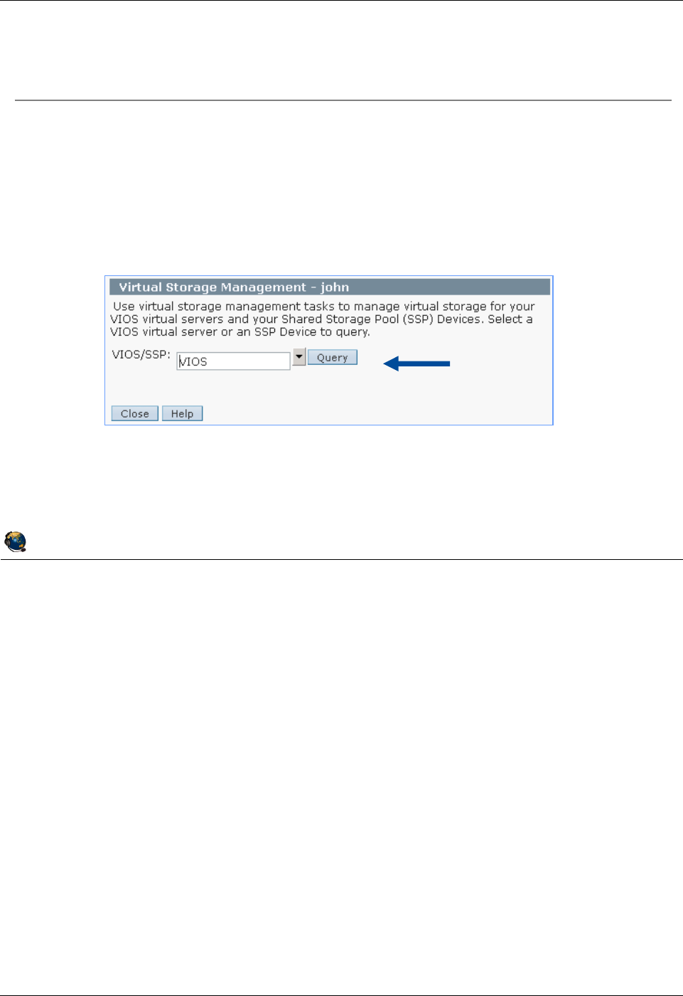
Student Notebook
Course materials may not be reproduced in whole or in part
without the prior written permission of IBM.
2-28 VIOS © Copyright IBM Corp. 2012
Figure 2-26. Managing devices from the HMC (1 of 2) QV3441.0
Notes:
Managing storage devices from the HMC
If you are running HMC V7 R3.4 service pack 2 or later, then you can also manage
storage devices from the HMC. Select the server name and run the tasks shown on the
visual above. The VIOS/SSP prompt means Virtual I/O Server or Shared Storage Pool
Storage Group (also known as a VIOS cluster).
Active Memory Sharing
Devices used for Active Memory Sharing paging devices will not be shown in queries.
© Copyright IBM Corporation 2012
UNIX Software Service Enablement
Managing devices from the HMC (1 of 2)
Select the server on the HMC and use Configuration -> Virtual
Resources -> Virtual Storage Management to manage virtual
devices
View and map backing storage devices to clients
Relies on RMC for communication (over the network)
Discover
devices on
VIOS
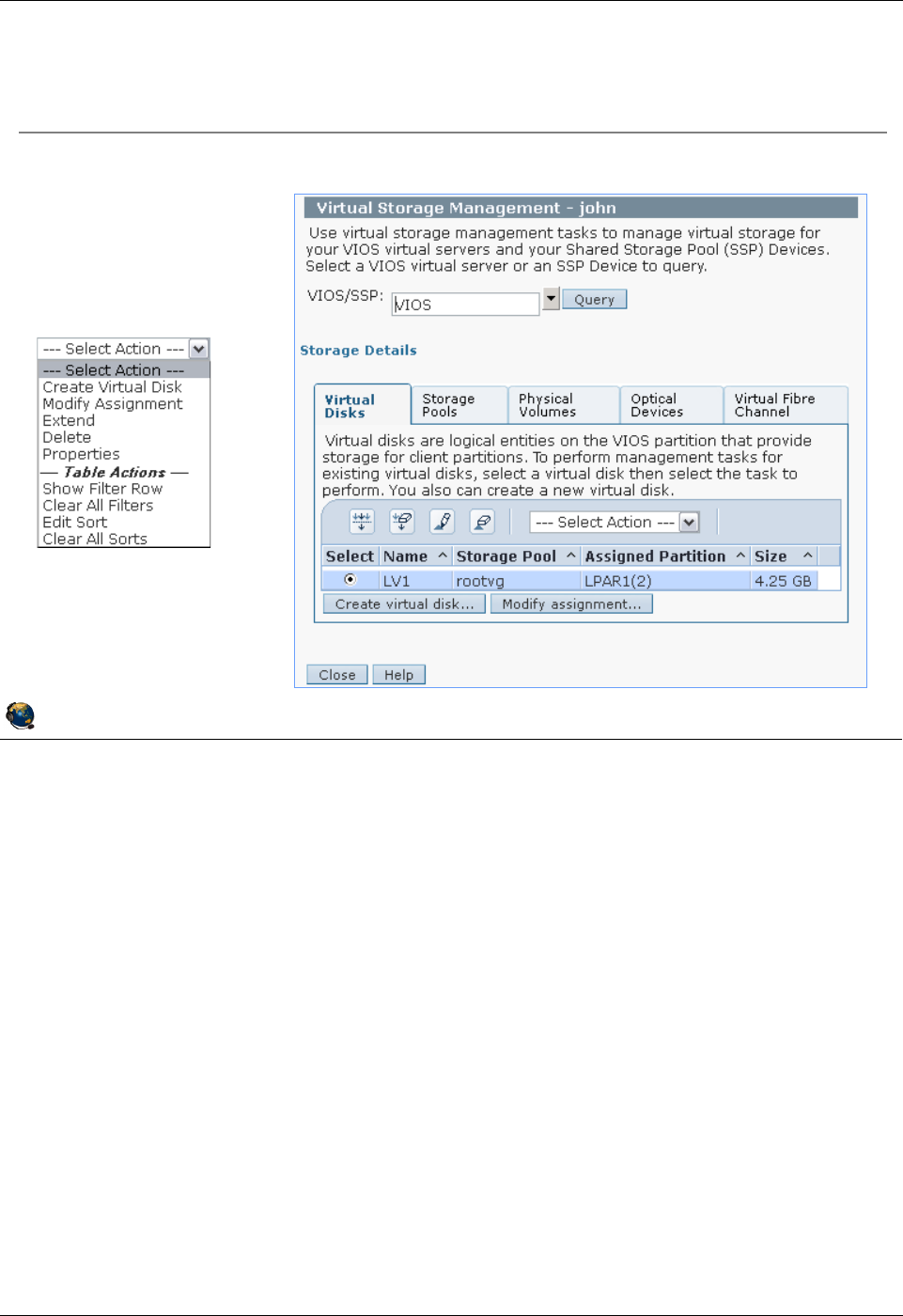
Student Notebook
Course materials may not be reproduced in whole or in part
without the prior written permission of IBM.
© Copyright IBM Corp. 2012 Unit 2. Virtual SCSI Configuration 2-29
V7.0
Uempty
Figure 2-27. Managing devices from the HMC (2 of 2) QV3441.0
Notes:
Create and assign backing storage devices from the HMC
Notice the tabs on the Virtual Storage Management screen. You can manage virtual
disks (logical volumes), storage pools (volume groups), physical volumes, optical
devices, and virtual Fibre Channel devices.
The Virtual Disks tab above shows that there is currently one logical volume created
and it is part of the rootvg volume group.
The Create virtual disk ... button allows you to create new logical volumes and assign
them to an LPAR in one step. It will do the mklv and mvdev commands (or the mkbdsp
command) in one step. The Modify assignment... button will allow you to change the
mapping of a device to a client.
The Actions menu has options to extend logical volumes and delete them.
© Copyright IBM Corporation 2012
UNIX Software Service Enablement
Managing devices from the HMC (2 of 2)
Create virtual disks (logical volumes) and storage groups (volume
groups)
Map devices
to clients
Actions menu:
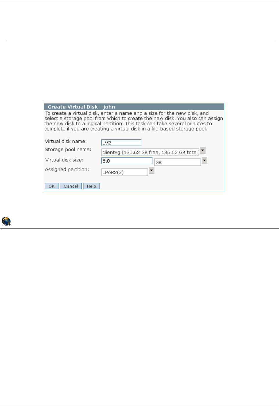
Student Notebook
Course materials may not be reproduced in whole or in part
without the prior written permission of IBM.
2-30 VIOS © Copyright IBM Corp. 2012
Figure 2-28. Create virtual disk example (1 of 2) QV3441.0
Notes:
Create a virtual disk
The window that is shown above appears when you click the Create virtual disk ...
button from the Virtual Disks tab. In the example, a logical volume named LV2 is being
created and assigned to LPAR2. The logical volume size will be 6 GB.
© Copyright IBM Corporation 2012
UNIX Software Service Enablement
Create virtual disk example (1 of 2)
Create a logical volume on the VIOS and map it to a client partition
From Virtual Disks tab, click the Create virtual disk button
This example configures the LV name, selects the volume group/storage
pool in which the LV will be created, sets the size, and assigns it to a
partition:
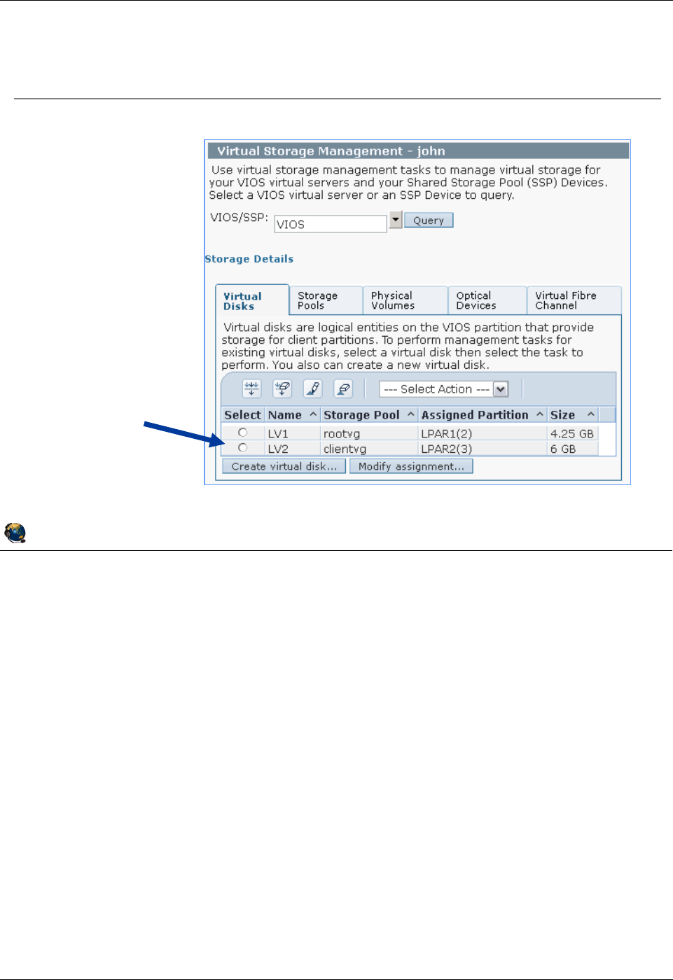
Student Notebook
Course materials may not be reproduced in whole or in part
without the prior written permission of IBM.
© Copyright IBM Corp. 2012 Unit 2. Virtual SCSI Configuration 2-31
V7.0
Uempty
Figure 2-29. Create virtual disk example (2 of 2) QV3441.0
Notes:
Create virtual disk example
The visual above shows the results of creating the new logical volume shown on the
previous visual.
Deleting virtual disks
To delete virtual disks using the HMC GUI, select the virtual disk in the table then click
the Modify assignment ... button. Set the LPAR assignment to None and click OK.
Then, select the virtual disk again and choose Delete from the --- Select Action ---
menu in the header of the table.
© Copyright IBM Corporation 2012
UNIX Software Service Enablement
Create virtual disk example (2 of 2)
New LV
assigned to
LPAR2
Student Notebook
Course materials may not be reproduced in whole or in part
without the prior written permission of IBM.
2-32 VIOS © Copyright IBM Corp. 2012
Figure 2-30. Modify assignment QV3441.0
Notes:
Modify virtual disk assignments
The example in the visual above will assign the LV2 logical volume to an LPAR. If the
virtual disk already belongs to an LPAR, then you’ll see the warning as shown in the
visual above. This warning doesn’t appear if the virtual disk is unassigned.
Notice that if there are multiple virtual adapter connections between a particular LPAR
and the VIOS, then you can choose the appropriate one by adapter ID (slot number). In
the example above, LPAR1 has two virtual SCSI client adapters with adapter IDs 2 and
7. LPAR2 only has one virtual client SCSI adapter so no slot ID is shown.
© Copyright IBM Corporation 2012
UNIX Software Service Enablement
Modify assignment
You can assign existing virtual disks (logical volumes) to LPARs
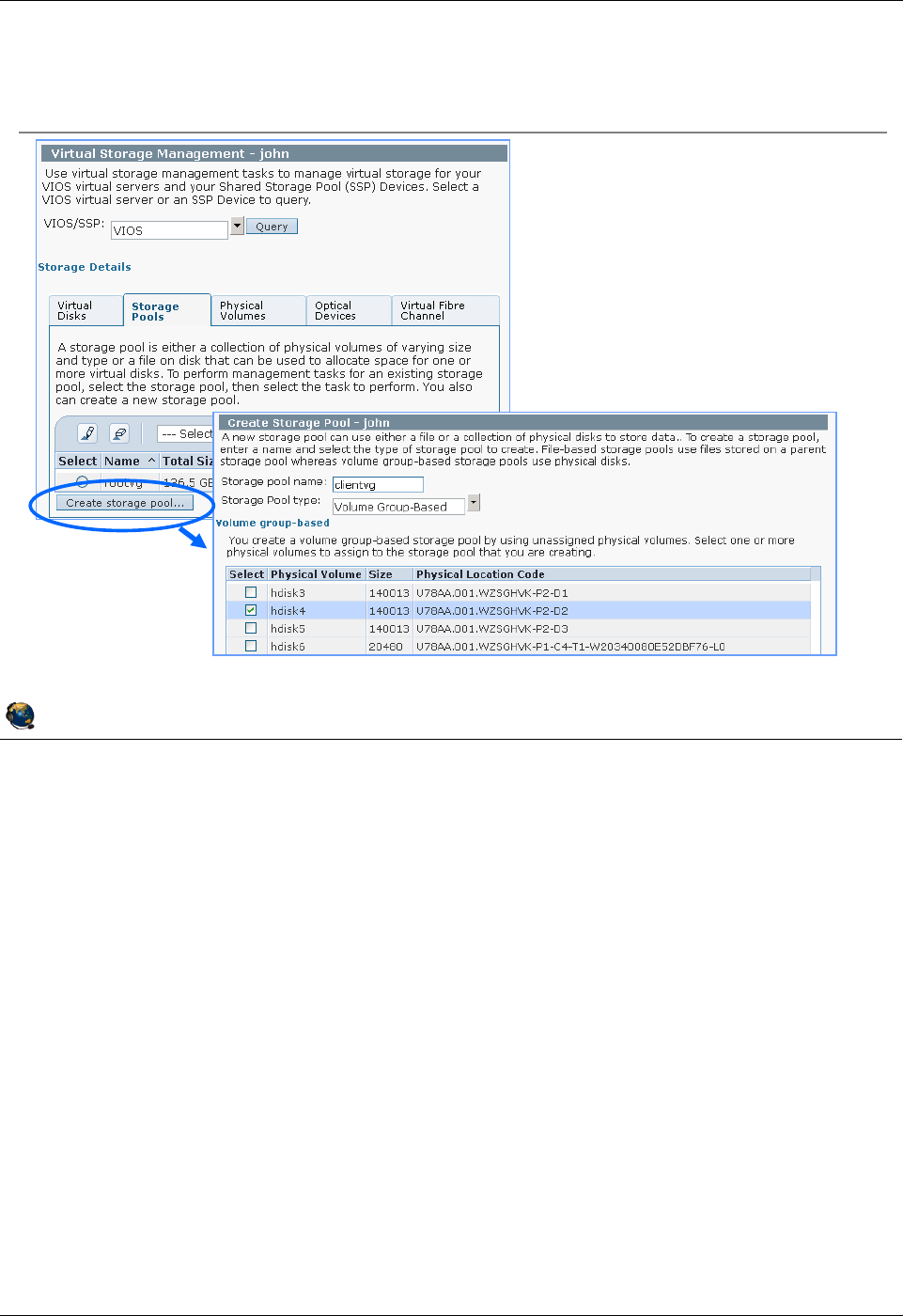
Student Notebook
Course materials may not be reproduced in whole or in part
without the prior written permission of IBM.
© Copyright IBM Corp. 2012 Unit 2. Virtual SCSI Configuration 2-33
V7.0
Uempty
Figure 2-31. Creating storage pools / volume groups QV3441.0
Notes:
Manage storage pools
The visual above shows the Storage Pools tab and how to create a new storage pool.
The resulting window shows only free physical volumes such as you would see if you
ran the lspv -free command on the VIOS.
The example above shows a new storage pool named clientvg being created with one
physical volume (hdisk4).
© Copyright IBM Corporation 2012
UNIX Software Service Enablement
Creating storage pools / volume groups
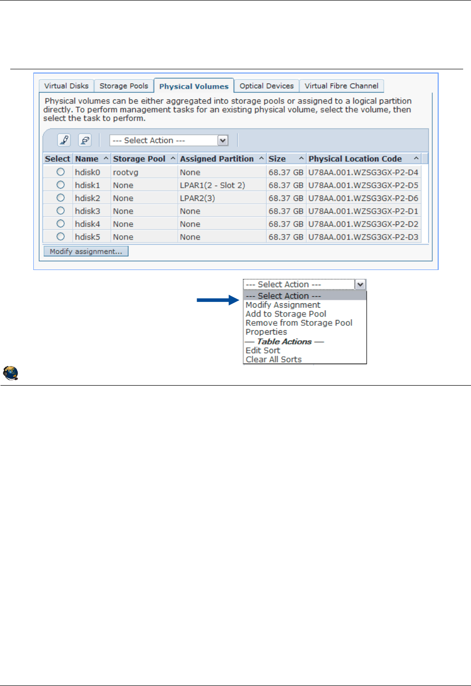
Student Notebook
Course materials may not be reproduced in whole or in part
without the prior written permission of IBM.
2-34 VIOS © Copyright IBM Corp. 2012
Figure 2-32. Physical volumes (1 of 2) QV3441.0
Notes:
Physical volumes
The Physical Volumes tab allows you to map physical volumes to clients. To do this,
click on the Modify assignment... button. Notice that the Select Action pulldown menu
allows you to add or remove physical volumes to or from storage pools (volume
groups).
© Copyright IBM Corporation 2012
UNIX Software Service Enablement
Physical volumes (1 of 2)
Actions
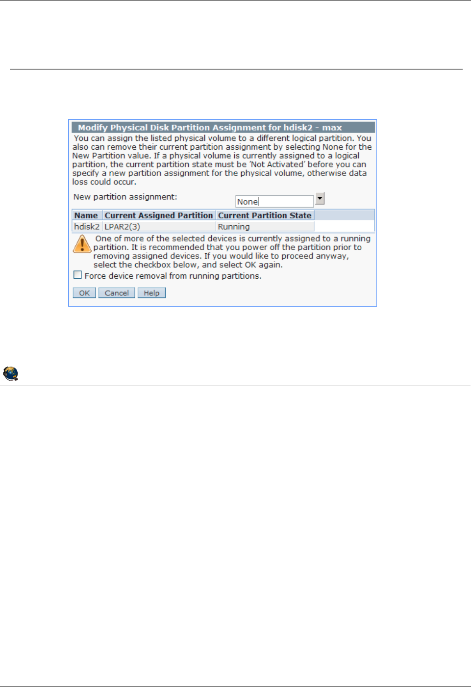
Student Notebook
Course materials may not be reproduced in whole or in part
without the prior written permission of IBM.
© Copyright IBM Corp. 2012 Unit 2. Virtual SCSI Configuration 2-35
V7.0
Uempty
Figure 2-33. Physical volumes (2 of 2) QV3441.0
Notes:
Modify physical volume assignments
The visual above shows what happens if you try to reassign a physical volume that is
already assigned to a running partition.
© Copyright IBM Corporation 2012
UNIX Software Service Enablement
Physical volumes (2 of 2)
Assign, or reassign physical volumes to LPARs
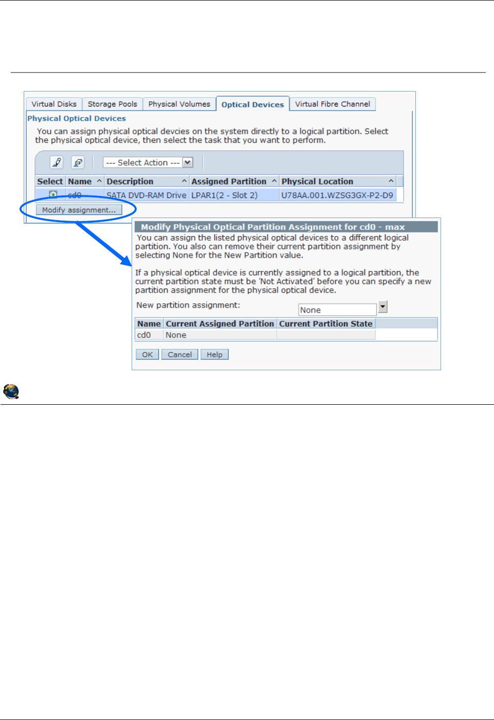
Student Notebook
Course materials may not be reproduced in whole or in part
without the prior written permission of IBM.
2-36 VIOS © Copyright IBM Corp. 2012
Figure 2-34. Optical devices QV3441.0
Notes:
Assign the optical media drive
You can assign the optical media drive to partitions as well.
© Copyright IBM Corporation 2012
UNIX Software Service Enablement
Optical devices

Student Notebook
Course materials may not be reproduced in whole or in part
without the prior written permission of IBM.
© Copyright IBM Corp. 2012 Unit 2. Virtual SCSI Configuration 2-37
V7.0
Uempty
Figure 2-35. Virtual SCSI storage and LVM QV3441.0
Notes:
Overview
Virtual storage can be manipulated on the client LPAR using the Logical Volume
Manager (LVM) just like an ordinary physical volume. Some performance
considerations from dedicated storage are still applicable when using virtual storage,
such as spreading hot logical volumes across multiple disks on multiple adapters so
that parallel access is possible. When the entire physical volume is served to the client,
the rules and procedures apply on the client side, as if the drive were native.
When a logical volume created on the server partition is served to the client partition,
the client partition thinks it has access to a single physical volume. The actual areas of
physical disk used to serve the virtual device to the client are decided on the server
partition when the logical volume is created, depending on the number of disks in the
volume group (on the server) and the inter-policy. If the logical volume on the server is
spread over multiple physical volumes, then reads and writes from the client may be
spread over those physical volumes.
© Copyright IBM Corporation 2012
UNIX Software Service Enablement
Virtual SCSI storage and LVM
LVM strategies such as mirroring and multi-path I/O (MPIO) can be
set up on the client using virtual disks just like with physical, dedicated
disks:
Caution: The virtual disk on the client may already be a logical volume on the
server
Performance strategies used for physical, dedicated disk storage still
apply to virtual storage, such as spreading out hot logical volumes:
Remember that virtual target disk devices can be backed by physical volumes,
logical volumes, or files so be sure you know what the physical backing storage
devices are and where they are located

Student Notebook
Course materials may not be reproduced in whole or in part
without the prior written permission of IBM.
2-38 VIOS © Copyright IBM Corp. 2012
Figure 2-36. Dynamically adding virtual SCSI storage (1 of 2) QV3441.0
Notes:
Maximum transfer
The maximum transfer attribute determines the size, in bytes, of the largest single data
transfer request that can be handled by a device. As devices are added to a vhost
adapter, the maximum transfer rate of the device is compared to the maximum transfer
rate for the adapter and the system uses the smaller of those values. For example, if
two disks are added to a vhost adapter, and one can handle 40000 bytes and the other
can handle 100000 bytes, then the maximum transfer rate is negotiated on the vhost
adapter to be 40000. If you add a device to a vhost adapter after the rate has been
negotiated and the new device has a lower max_transfer value than the vhost adapter,
then it cannot be added dynamically in the client. The client will have to reboot. If you
add a device to an existing vhost adapter and the new device has a higher
max_transfer value than the adapter, then it can be added dynamically in the client
however its max_transfer rate is lowered to the setting on the adapter.
Reference: http://www-304.ibm.com/support/docview.wss?uid=isg3T1010944
© Copyright IBM Corporation 2012
UNIX Software Service Enablement
Dynamically adding virtual SCSI storage (1 of 2)
Two strategies when adding backing storage dynamically
Add the backing device to an existing vhost adapter
Add a new vhost adapter and add backing device to new adapter
If the existing backing devices on the vhost adapter have a higher
maximum transfer rate, you have three choices:
Add a new vhost adapter to add the backing device dynamically
Reconfigure all of the devices onto a new vhost adapter
Add the device to the existing adapter and reboot the client LPAR
Message when max_transfer is too high for the new device:
$ mkvdev -vdev hdisk9 -vadapter vhost0
vtscsi4 Available
To see the newly added disk, client partition needs reboot.
View max_transfer value:
$ lsdev -dev hdisk9 attr max_transfer
max_transfer 0x40000 Maximum TRANSFER Size True

Student Notebook
Course materials may not be reproduced in whole or in part
without the prior written permission of IBM.
© Copyright IBM Corp. 2012 Unit 2. Virtual SCSI Configuration 2-39
V7.0
Uempty
Figure 2-37. Dynamically adding virtual SCSI storage (2 of 2) QV3441.0
Notes:
Discover physical volume
To discover on which physical volume a logical volume resides, run:
$ lslv -pv LV_name
LV_name:N/A
PV COPIES IN BAND DISTRIBUTION
hdisk0 001:000:000 100% 000:001:000:000:000
© Copyright IBM Corporation 2012
UNIX Software Service Enablement
Dynamically adding virtual SCSI storage (2 of 2)
Best to group devices by max_transfer rate for optimal
performance because reducing the rate for a particular device may
slow it down
If adding a logical volume, check the max_transfer rate of the
underlying physical volume
Example:
Existing vhost0 has three existing devices: cd0, hdisk1, LV1
cd0 max_transfer = 0x80000
hdisk1 (SAS disk) max_transfer = 0x100000
Logical volume LV1 on hdisk4 (SAS disk) max_transfer = 0x100000
hdisk9 (SAN DS3500 disk) is then added with max_transfer = 0x40000
hdisk9 can be added successfully to vhost0, however it causes the message
and will not be added dynamically in the client
Workaround that doesnt disturb existing devices: Dynamically add another vhost
adapter and add hdisk9 to the new vhost adapter

Student Notebook
Course materials may not be reproduced in whole or in part
without the prior written permission of IBM.
2-40 VIOS © Copyright IBM Corp. 2012
Figure 2-38. VIOS storage groups (1 of 2) QV3441.0
Notes:
VIOS storage groups
The first release of VIOS storage groups came out in December 2010 and was Virtual
I/O Server Version 2.2.0.11, Fix Pack 24, Service Pack 1. This release had limited
functionality as it only allowed one VIOS partition in the storage group. As of December
2011, Version 2.2.1.3 with iFix IV11852m13 allows up to 4 nodes in a storage group.
VIOS nodes in a storage group can continue to provide traditional virtual services such
as virtual SCSI, virtual Fibre Channel, and shared Ethernet adapter services separate
from the cluster.
See the IBM UNIX Software Service Enablement (USSE) course titled IBM PowerVM
Virtual I/O Server III: Configuring Shared Storage Pools (course code AHQV347) for
more information on this topic.
© Copyright IBM Corporation 2012
UNIX Software Service Enablement
VIOS storage groups (1 of 2)
Up to four VIOS partitions can be in a storage group (also known as
a VIOS cluster)
Each node in the cluster has access to a shared storage pool
VIOS provides the same standard VSCSI target interface to clients
Nodes in the cluster communicate via the network
Shared storage pool
Set of physical volumes accessible by all VIOS nodes in the cluster
Assign a large amount of SAN storage to the shared storage pool and
manage virtual disks from any of the VIOS nodes
Backing storage devices are called logical units and are standard file-
backed VSCSI
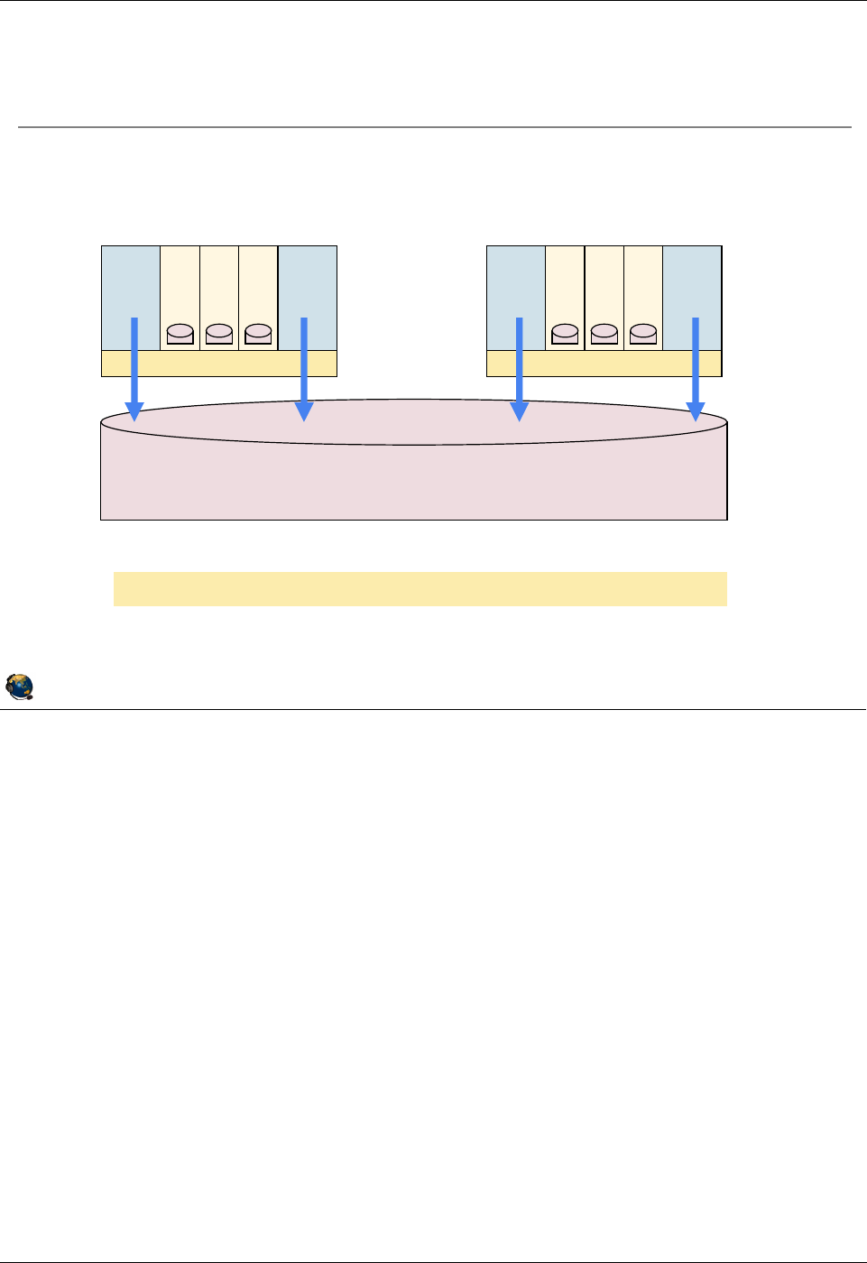
Student Notebook
Course materials may not be reproduced in whole or in part
without the prior written permission of IBM.
© Copyright IBM Corp. 2012 Unit 2. Virtual SCSI Configuration 2-41
V7.0
Uempty
Figure 2-39. VIOS storage groups (2 of 2) QV3441.0
Notes:
VIOS shared storage pool
A VIOS storage group, also known as a VIOS cluster, consists of one to four VIOS
partitions which share a single storage pool. Storage is provisioned from the shared
storage pool for clients and utilizes the virtual SCSI protocol. The VIOS storage group
can be managed from the VIOS CLI or from the cfgassist utility. The HMC can be also
used to create backing storage and map them to clients.
© Copyright IBM Corporation 2012
UNIX Software Service Enablement
VIOS storage groups (2 of 2)
VIOS nodes in a cluster see all LUNs and all logical units.
Storage could be IBM, EMC, Hitachi, SVC, and other SAN.
VIOS VIOS
Hypervisor
Client1
Client2
Client3
VIOS VIOS
Hypervisor
Client1
Client2
Client3
Shared Storage Pool
Up to 4 VIOS nodes are currently supported in a VIOS cluster
VIOS cluster nodes have global view into shared storage pool

Student Notebook
Course materials may not be reproduced in whole or in part
without the prior written permission of IBM.
2-42 VIOS © Copyright IBM Corp. 2012
Figure 2-40. Checkpoint (1 of 2) QV3441.0
Notes:
© Copyright IBM Corporation 2012
UNIX Software Service Enablement
Checkpoint (1 of 2)
1. Which one of the following statements about virtual SCSI devices is false?
A. The Virtual I/O Server partition owns the physical resources when virtual SCSI
devices are used.
B. To a client, a virtual SCSI device backed by a logical volume or an optical
device looks like an hdisk.
C. One virtual SCSI server adapter can have many associated backing devices.
D. The client partition cannot detect the type of backing storage device being used
for a virtual SCSI disk.
2. True or False: A partition may boot from virtual SCSI disk.
3. Virtual SCSI devices can be backed with which type of device(s)?
A. Logical volumes
B. Physical volumes
C. Optical media devices
D. All of the above

Student Notebook
Course materials may not be reproduced in whole or in part
without the prior written permission of IBM.
© Copyright IBM Corp. 2012 Unit 2. Virtual SCSI Configuration 2-43
V7.0
Uempty
Figure 2-41. Checkpoint (2 of 2) QV3441.0
Notes:
© Copyright IBM Corporation 2012
UNIX Software Service Enablement
Checkpoint (2 of 2)
4. True or False: On the Virtual I/O Server, the mkvdev command can be used to
create virtual target devices that map physical devices to virtual SCSI server
adapters.
5. Which VIO Server command will show the mapping between Virtual SCSI server
adapters and backing storage devices?
A. lsdev
B. lsmap
C. lscfg
D. lssp
6. True or False: To remove the mapping between a physical device and virtual
SCSI server adapter, simply remove the virtual target device.
7. True or False: Virtual SCSI client LPARs can use mirroring on virtual SCSI disks.

Student Notebook
Course materials may not be reproduced in whole or in part
without the prior written permission of IBM.
2-44 VIOS © Copyright IBM Corp. 2012
Figure 2-42. Exercise 2 - Virtual SCSI configuration QV3441.0
Notes:
Exercise 2
In the first two parts of this exercise, you will configure the boot disk for LPAR1 and
LPAR2. You’ll perform the procedure first on LPAR1 using commands on the VIOS CLI.
Then, you’ll perform this procedure for LPAR2 using the HMC GUI Virtual Storage
Management task.
In Part 3, you’ll create logical volumes and assign them to LPAR1, again using both the
VIOS CLI and the HMC GUI task.
In Part 4, you’ll check the configuration from the HMC CLI and from the HMC GUI.
If you have extra time you can perform the optional steps in Part 5. This will have you
assign the cd0 device on the VIOS to LPAR1 as a virtual cd device.
© Copyright IBM Corporation 2012
UNIX Software Service Enablement
Exercise 2 - Virtual SCSI configuration
Activity:
Configure a virtual SCSI disk using the VIOS CLI
Configure a virtual SCSI disk using the HMC GUI
Dynamically configure logical volumes as virtual disks
Check the virtual device configuration
Optional Lab
Configure a virtual optical media device

Student Notebook
Course materials may not be reproduced in whole or in part
without the prior written permission of IBM.
© Copyright IBM Corp. 2012 Unit 2. Virtual SCSI Configuration 2-45
V7.0
Uempty
Figure 2-43. Unit summary QV3441.0
Notes:
© Copyright IBM Corporation 2012
UNIX Software Service Enablement
Unit summary
Virtual SCSI target devices can have different types of backing
storage
Physical volume, logical volume, optical, file-backed, and tape devices
Virtual SCSI devices are implemented with a client-server model
Virtual I/O Server
Owns physical slots which contain physical adapters
Contains virtual SCSI server adapter and backing storage devices
Client partition
Contains virtual SCSI client adapter
HMC is used to configure virtual adapters
Virtual adapter IDs are used to refer to appropriate virtual adapters
As of HMC V7R3.4.0 SP2, you can use the HMC to manage backing
storage for virtual devices

Student Notebook
Course materials may not be reproduced in whole or in part
without the prior written permission of IBM.
2-46 VIOS © Copyright IBM Corp. 2012

Student Notebook
Course materials may not be reproduced in whole or in part
without the prior written permission of IBM.
© Copyright IBM Corp. 2012 Unit 3. File-backed Storage Devices 3-1
V7.0
Uempty Unit 3. File-backed Storage Devices
What this unit is about
The unit continues the discussion of virtual storage devices. Students
will learn how to create file-backed virtual disks and file-backed optical
media devices. The Virtual Media Repository is described as a way to
store media files and load them into client virtual optical media drives
where they can be used like physical media drives.
What you should be able to do
After completing this unit, you should be able to:
• Create file-backed storage pools
• Create file-backed storage devices for use as client virtual disks
• Create the Virtual Media Repository
• Create virtual optical media devices
• Load media into virtual optical media devices
• Install software using a virtual optical media device
How you will check your progress
Accountability:
• Checkpoint questions
• Machine exercises
References
IBM Power Systems Hardware Information Center:
http://publib.boulder.ibm.com/infocenter/powersys/v3r1m5/index.jsp
Virtual I/O Server product documentation from the IBM Power
Systems Hardware Information Center:
http://publib.boulder.ibm.com/infocenter/powersys/v3r1m5/index.jsp?t
opic=/p7hb1/iphb1kickoff.htm
IBM Redbooks documents can be found at:
http://www.redbooks.ibm.com
SG24-7940 IBM PowerVM Virtualization Introduction and
Configuration, an IBM Redbooks document

Student Notebook
Course materials may not be reproduced in whole or in part
without the prior written permission of IBM.
3-2 VIOS © Copyright IBM Corp. 2012
SG24-7590 IBM PowerVM Virtualization Managing and Monitoring, an
IBM Redbooks document

Student Notebook
Course materials may not be reproduced in whole or in part
without the prior written permission of IBM.
© Copyright IBM Corp. 2012 Unit 3. File-backed Storage Devices 3-3
V7.0
Uempty
Figure 3-1. Unit objectives QV3441.0
Notes:
© Copyright IBM Corporation 2012
UNIX Software Service Enablement
Unit objectives
After completing this unit, you should be able to:
Create file-backed storage pools
Create file-backed storage devices for use as client virtual disks
Create the Virtual Media Repository
Create virtual optical media devices
Load media into virtual optical media devices
Install software using a virtual optical media device

Student Notebook
Course materials may not be reproduced in whole or in part
without the prior written permission of IBM.
3-4 VIOS © Copyright IBM Corp. 2012
Figure 3-2. File-backed virtual devices (1 of 2) QV3441.0
Notes:
File-backed virtual device types
There are two types of file-backed virtual devices. One is a disk device and the other is
an optical media device. In the case of the disk device, the file is created of a certain
size and it is viewed by the client as an hdisk. In the case of the optical media device, a
client can use the file-backed device just like a DVD-ROM or DVD-RAM drive to write to
and read from.
There are commands to load media images into the virtual optical media device (on the
Virtual I/O Server CLI). A Virtual Media Repository is created to store images which can
be loaded into a virtual optical media device for a client partition to access. If the media
is read-only then multiple clients can access the media simultaneously.
The ability to create file-backed devices is available in VIOS V1.5 and above.
There can only be one Virtual Media Repository per Virtual I/O Server partition.
© Copyright IBM Corporation 2012
UNIX Software Service Enablement
File-backed virtual devices (1 of 2)
File-backed (FB) virtual device types:
File-backed disk devices
Files can be created and mapped to a vhost adapter which clients
see as hdisk# device
File-backed optical media devices:
Create a FB virtual optical media device that is mapped to a vhost
adapter which clients see as cd# device
Create a Virtual Media Repository to store virtual DVD-ROM/RAM
media files
Repository media files can be loaded into virtual optical media
device

Student Notebook
Course materials may not be reproduced in whole or in part
without the prior written permission of IBM.
© Copyright IBM Corp. 2012 Unit 3. File-backed Storage Devices 3-5
V7.0
Uempty
Figure 3-3. File-backed virtual devices (2 of 2) QV3441.0
Notes:
FB virtual devices
A client LPAR can boot from media in a virtual optical device, or from a file-backed disk
device if it has an operating system installed.
File-backed disks reside in a file-backed storage pool which is a logical volume with a
file system in which the file-backed backing devices are created.
© Copyright IBM Corporation 2012
UNIX Software Service Enablement
File-backed virtual devices (2 of 2)
FB virtual device characteristics:
Bootable FB devices appear in SMS
FB devices reside in FB storage pools
FB storage pool implemented as a file system residing in a LV storage
pool
Granularity as small as 1 MB or as large as parent file system
Read-only virtual media can be shared by multiple clients
FB device locations:
Disk = /var/vio/storagepools/<FBSP_Name>/<FB Disk>
Virtual Media Repository = /var/vio/VMLibrary
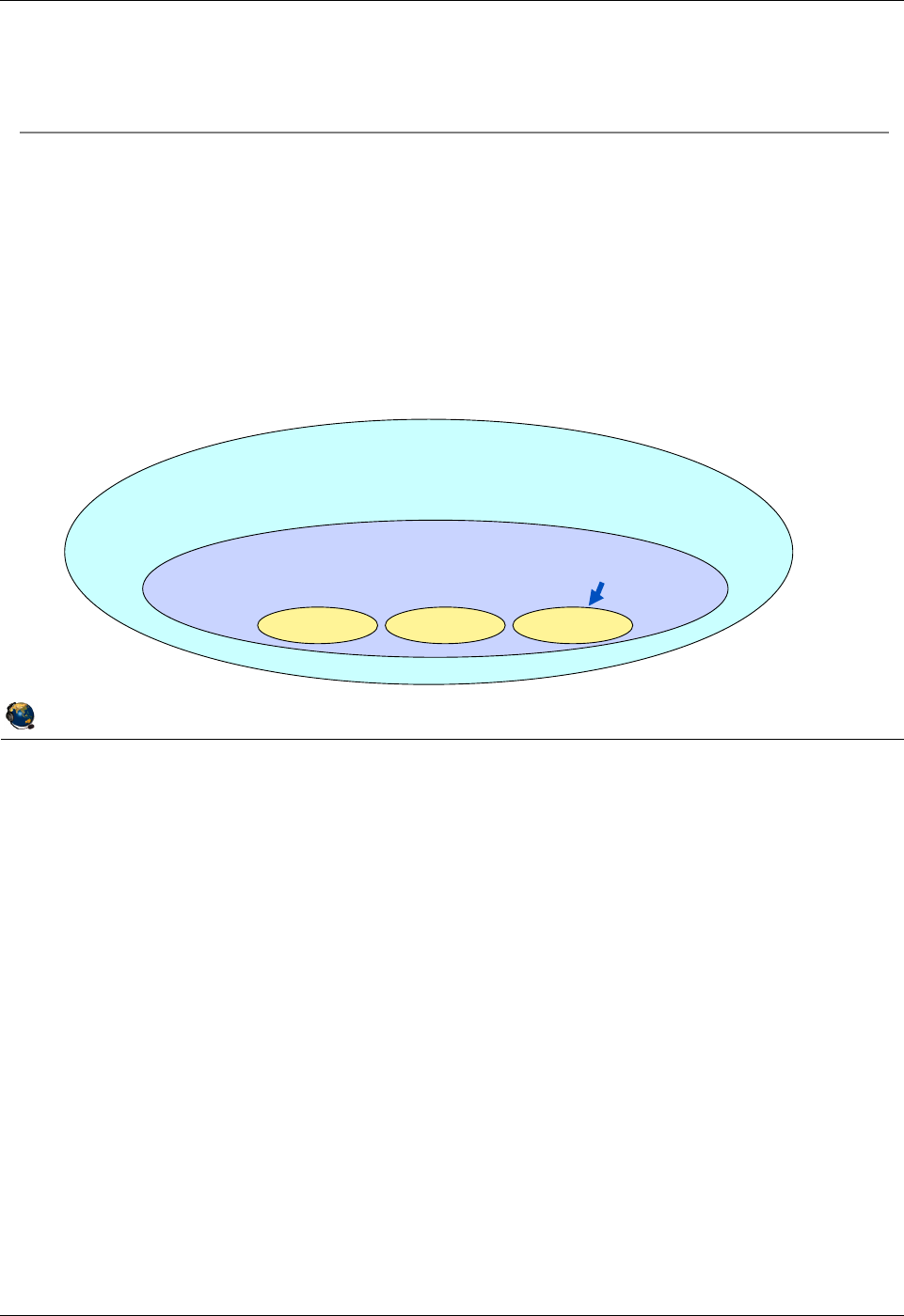
Student Notebook
Course materials may not be reproduced in whole or in part
without the prior written permission of IBM.
3-6 VIOS © Copyright IBM Corp. 2012
Figure 3-4. Creating file-backed virtual disks QV3441.0
Notes:
Creating FB virtual disks
The graphic in the visual above shows the relationship between the parent logical
volume storage group (also known as a volume group), the FB disk storage pool, and
the FB disk virtual target devices. When creating FB disk storage, you must create a FB
disk storage pool to contain the files which will be used for the FB virtual disks.
Step 3 in the visual above has two steps: create the backing device and map to the
vhost adapter. This can be accomplished in one mkbdsp command, or with two. That is,
you can perform these steps separately.
The graphic in the visual above shows that a volume group is the same as a logical
volume (LV) storage pool and it contains one or more physical volumes. An FB pool is
created inside an LV pool. The FB backing devices are contained in the FB pool.
© Copyright IBM Corporation 2012
UNIX Software Service Enablement
Creating file-backed virtual disks
Procedure for creating file-backed virtual disks:
1. Create a volume group (mkvg) or logical volume storage pool
(mksp -f)
2. Create a FB storage pool (mksp -fb) inside LV storage pool
3. Create a backing device (file) in the pool and map to a vhost adapter
(mkbdsp)
4. The client associated with that vhost adapter sees new FB device as
an hdisk
Volume Group/LV Storage Pool - contains hdisk(s)
FB Storage Pool (contains FB virtual disks)
Backing dev Backing dev Backing dev

Student Notebook
Course materials may not be reproduced in whole or in part
without the prior written permission of IBM.
© Copyright IBM Corp. 2012 Unit 3. File-backed Storage Devices 3-7
V7.0
Uempty
Figure 3-5. Create FB virtual disks example QV3441.0
Notes:
Create FB virtual disk example
The visual above shows an example command sequence to create a FB virtual disk.
To create the volume group or the logical volume storage pool use either the mkvg or
mksp command but not both. The result with either command is the same.
The second example command, which creates a new FB storage pool, uses the mksp
command with the -fb flag. If you use the -f flag, you will get a logical volume storage
pool and not a file backed storage pool. The FB storage pool in the example above will
be 10 GB in size. You can use g or G for gigabytes and m or M for megabytes in this
command.
The third example command creates a backing storage file (fb_disk1) and maps it to a
virtual host adapter (vhost3), creating the VTD (vtscsi3) to track this mapping. In this
example, the file is specified to be 30 MB in size.
© Copyright IBM Corporation 2012
UNIX Software Service Enablement
Create FB virtual disks example
Create new volume group/logical volume storage pool
$ mkvg -vg newvg hdisk1 OR mksp -f newvg hdisk1
Create new FB storage pool in the logical volume storage pool
$ mksp -fb fbpool -sp newvg -size 10g
fbpool
File system created successfully.
10444276 kilobytes total disk space.
New File System size is 20971520
Create new file device with a certain size, create the VTD, and map to
vhost adapter
$ mkbdsp -sp fbpool 30m -bd fb_disk1 -vadapter vhost3
Creating file "fb_disk1" in storage pool "fbpool".
Assigning file "fb_disk1" as a backing device.
vtscsi3 Available
fb_disk1
New storage pool (newvg)
New FB storage pool
(fbpool)that is 10 GB
located in newvg
Create new 30 MB file called fb_disk1
Resulting VTD is named vtscsi3
and is mapped to vhost3

Student Notebook
Course materials may not be reproduced in whole or in part
without the prior written permission of IBM.
3-8 VIOS © Copyright IBM Corp. 2012
Figure 3-6. View mapping of file-backed virtual disk QV3441.0
Notes:
View the configuration
The example lsmap command in the visual above shows the new backing storage
device that was created with the commands on the previous visual. Notice the backing
storage device location. The file-backed backing device is called fb_disk1 and the FB
pool is named fbpool.
© Copyright IBM Corporation 2012
UNIX Software Service Enablement
View mapping of file-backed virtual disk
View mapping of backing device
$ lsmap -vadapter vhost3
SVSA Physloc Client Partition
ID
------------- ---------------------------------- ----------------
vhost3 U8202.E4B.105F4EP-V1-C3 0x00000000
VTD vtscsi3
Status Available
LUN 0x8100000000000000
Backing device /var/vio/storagepools/fbpool/fb_disk1
Physloc
Mirrored N/A
Student Notebook
Course materials may not be reproduced in whole or in part
without the prior written permission of IBM.
© Copyright IBM Corp. 2012 Unit 3. File-backed Storage Devices 3-9
V7.0
Uempty
Figure 3-7. View storage pools and backing devices QV3441.0
Notes:
View storage pool information
The list storage pool (lssp) command will list all LVPOOLs and FBPOOLs. Volume
groups are LVPOOLS so they are listed too. Use the backing device (-bd) flag with the
FB storage pool name (-sp fbpool) to list all FB backing devices in the FBPOOL
named fbpool. The lssp -detail -sp LVPOOLname command will list the physical
volumes in the LVPOOL or volume group named LVPOOLname.
© Copyright IBM Corporation 2012
UNIX Software Service Enablement
View storage pools and backing devices
View all pools:
$ lssp
Pool Size(mb) Free(mb) Alloc Size(mb) BDs Type
rootvg 139776 78080 256 1 LVPOOL
newvg 139904 129664 128 0 LVPOOL
fbpool 10199 10168 128 2 FBPOOL
View backing devices in an FB pool:
$ lssp -bd -sp fbpool
Name Size(mb) VTD SVSA
fb_disk1 30 vtscsi5 vhost1
View physical volumes in an LV pool:
$ lssp -detail -sp newvg
Name PVID Size(mb)
hdisk3 00f6bcc8abfac919 139904

Student Notebook
Course materials may not be reproduced in whole or in part
without the prior written permission of IBM.
3-10 VIOS © Copyright IBM Corp. 2012
Figure 3-8. FB virtual disks remove commands QV3441.0
Notes:
Remove and rename commands
The rmbdsp command disassociates a backing device from its virtual SCSI adapter by
removing the virtual target device (VTD), and also removes the backing device itself by
default. Add the -savebd flag to only remove the VTD and not the backing device itself.
The example rmbdsp command above will remove the VTD (for example vtscsi3) and
the backing device. An equivalent command to the rmbdsp example above is:
$ rmbdsp -vtd vtscs3
The rmsp command removes an FBPOOL.
The chsp command changes the characteristics of a storage pool such as its size. Or,
as in the example in the visual above, you can perform the equivalent of the AIX
reducevg command and remove the LVPOOL by removing its last physical volume.
The chbdsp command changes the characteristics of a backing device within a storage
pool (such as its name).
© Copyright IBM Corporation 2012
UNIX Software Service Enablement
FB virtual disks remove commands
Remove a file backed disk named fb_disk1 which is in the file-
backed storage pool named fbpool
$ rmbdsp -sp fbpool -bd fb_disk1
Remove a file storage pool named fbpool that does not contain any
file backed disks mapped to a vhost adapter
$ rmsp fbpool
Remove a logical volume storage pool (volume group) named newvg
which has only one physical volume named hdisk1
$ chsp -rm -sp newvg hdisk1
Rename the backing device cl_data which is in the LV storage pool
datasp to bank_data
$ chbdsp -sp datasp -bd cl_data -mv bank_data
Student Notebook
Course materials may not be reproduced in whole or in part
without the prior written permission of IBM.
© Copyright IBM Corp. 2012 Unit 3. File-backed Storage Devices 3-11
V7.0
Uempty
Figure 3-9. File-backed virtual optical devices QV3441.0
Notes:
Procedure
The visual above shows the overall procedure for configuring and using file-backed
optical media device with media from the Virtual Media Repository. The repository is like
a jukebox which stores many different optical media images. You can copy in as many
media files as the volume group has space to store them.
The media images are copied into the repository from real media from the /dev/cd
device on the VIOS partition or from ISO formatted files. Media images can also be
empty files. For each client, create a virtual optical media device and map it to the
virtual SCSI server adapter (vhost#) for that client. Then, each time the client wishes to
use the optical device, a media file is loaded into the device. When the client has
finished the operation (such as loading software), the media can be unloaded.
Media which is copied in as read-only can be used by multiple clients.
© Copyright IBM Corporation 2012
UNIX Software Service Enablement
File-backed virtual optical devices
Procedure for creating and using file-backed virtual optical media
devices:
1. For each VIOS, create one
Virtual Media Repository
2. For each different media image, copy
an image into the repository
3. For each client, create a virtual optical
media device and map it to the appropriate
vhost adapter
4. For each optical media operation, load
a media file from the repository into the
client's virtual optical media device

Student Notebook
Course materials may not be reproduced in whole or in part
without the prior written permission of IBM.
3-12 VIOS © Copyright IBM Corp. 2012
Figure 3-10. Create FB virtual optical device (1 of 2) QV3441.0
Notes:
Changing the size of the Virtual Media Repository
You can increase the size of the repository with the chrep -size # command. For
example: chrep -size 5g
To add additional disks to a storage pool (volume group), you can use the command
chsp -add -sp storage_pool PhysicalVolume(s), where storage_pool is the name
of the volume group/storage pool to extend.
Create FB virtual optical device example
The example in the visual above creates the AIXinstall media "disk" with data on it from
the specified *.iso file. You can also create a blank 4 GB "disk" named LPAR1_file with
this command: mkvopt -name LPAR1_file -size 4g
Or, you can create a disk with data copied directly from a real cd0 device. Example
command: mkvopt -name vopt1 -dev cd0 [-ro]
© Copyright IBM Corporation 2012
UNIX Software Service Enablement
Create FB virtual optical device (1 of 2)
Create volume group/logical volume storage pool
$ mkvg -vg medrep hdisk4 OR mksp -f medrep hdisk1
Create the Virtual Media Repository in a LV pool
$ mkrep -sp medrep -size 10G
Virtual Media Repository Created
Repository created within "VMLibrary_LV" logical volume
Copy media (AIXinstall) into repository
Media could be blank, loaded from cd# device, or a blank file
$ mkvopt -name AIXinstall -file dvd.product.iso ro
Remove commands
Remove repository: $ rmrep
Remove media in the repository: $ rmvopt name media_name
This example creates a
10 GB repository
Copy this file
(from current directory)
This is the new name for
the media in the repository

Student Notebook
Course materials may not be reproduced in whole or in part
without the prior written permission of IBM.
© Copyright IBM Corp. 2012 Unit 3. File-backed Storage Devices 3-13
V7.0
Uempty
Figure 3-11. Create FB virtual optical device (2 of 2) QV3441.0
Notes:
Create the VTD and map it to the vhost adapter
The mkvdev command shown in the visual above creates a VTD and associates it with
the vhost4 adapter. Now there is a device that a client can use. If the client is already
running and has its virtual client SCSI adapter already configured to point to the vhost4
adapter on the Virtual I/O Server, then it just needs to run the cfgmgr command to see
the new cd# device.
There’s one more step before the client can use a media disk. You have to virtually load
the disk into the VTD so the client can see the media contents. The command to load
this disk is loadopt. You would use the unloadopt command to unload the virtual
media disk. (Or, alternatively, you can use loadopt with -f (force) which will unload
whatever is currently loaded before loading the new media.) The unloadopt command
syntax is: unloadopt -vtd vtopt0 where vtopt0 is the VTD name.
© Copyright IBM Corporation 2012
UNIX Software Service Enablement
Create FB virtual optical device (2 of 2)
View repository and its contents
$ lsrep
Size(mb) Free(mb) Parent Pool Parent Size Parent Free
10198 8429 medrep 69888 59648
Name File Size Optical Access
AIXinstall 1769 None ro
Create FB virtual optical device and map to vhost adapter
$ mkvdev -fbo -vadapter vhost4
vtopt1 Available
Load the image into the media device
$ loadopt -vtd vtopt1 -disk AIXinstall
Use the unloadopt command to unload or f option to loadopt
$ unloadopt -vtd vtopt1
VTD name

Student Notebook
Course materials may not be reproduced in whole or in part
without the prior written permission of IBM.
3-14 VIOS © Copyright IBM Corp. 2012
Figure 3-12. View repository information (1 of 2) QV3441.0
Notes:
Introduction
The visual above shows commands that can be used from the Virtual I/O Server CLI to
view information about the repository. The lsrep command is the primary command to
view information about the repository. It will also show whether any media in the
repository is loaded. The example in the visual above shows that the AIXinstall media
is loaded in the vtopt1 and in the vtopt3 devices. This media is marked as read only
and can be loaded into multiple vtopt# devices. Notice that the db_new disk is not
loaded.
The lssp command shows all storage pools: the logical volume storage pools
(LVPOOL) and the FB storage pools (FBPOOL). The lsvg command output only shows
the volume groups / parent logical volume storage pools.
© Copyright IBM Corporation 2012
UNIX Software Service Enablement
View repository information (1 of 2)
List the repository and media disks information:
$ lsrep
Size(mb) Free(mb) Parent Pool Parent Size Parent Free
10198 6099 medrep 139904 119424
Name File Size Optical Access
AIXinstall 2048 vtopt1 ro
AIXinstall 2048 vtopt3 ro
aixopt1 2048 vtopt2 rw
db_new 3 None rw

Student Notebook
Course materials may not be reproduced in whole or in part
without the prior written permission of IBM.
© Copyright IBM Corp. 2012 Unit 3. File-backed Storage Devices 3-15
V7.0
Uempty
Figure 3-13. View repository information (2 of 2) QV3441.0
Notes:
The mount command
The visual above shows an example mount command partial output. The last two lines
show the location for an FBPOOL and the media repository.
The lsvopt command
While lsrep lists all images and whether they are loaded, the lsvopt command lists the
virtual optical media drives and shows whether they have loaded media. If the media
column states No Media then an image is not loaded.
© Copyright IBM Corporation 2012
UNIX Software Service Enablement
View repository information (2 of 2)
The mount command shows FB storage pools and the media
repository:
$ mount
node mounted mounted over vfs date options
-------- --------------- --------------- ------ ------------ ------------
/dev/fbpool /var/vio/storagepools/fbpool jfs2 Apr 08 09:45 rw,log=INLINE
/dev/VMLibrary /var/vio/VMLibrary jfs2 Apr 08 09:57 rw,log=INLINE
View load status of virtual optical devices:
$ lsvopt
VTD Media Size(mb)
vtopt1 AIXinstall 2048
vtopt2 aixopt1 2048
vtopt3 No Media n/a
Student Notebook
Course materials may not be reproduced in whole or in part
without the prior written permission of IBM.
3-16 VIOS © Copyright IBM Corp. 2012
Figure 3-14. View virtual optical drive mapping QV3441.0
Notes:
Virtual optical drive mapping
The lsmap command will indicate whether a virtual optical drive has loaded media. If
media is loaded, the output will also list the media name as the backing device.
Loading and unloading of media must take place on the VIOS CLI or in the cfgassist
utility. It cannot be done from the client. From the HMC, you can use the viosvrcmd CLI
command or the GUI Operations -> Perform VIOS Command task to run the VIOS
loadopt or unloadopt command.
© Copyright IBM Corporation 2012
UNIX Software Service Enablement
View virtual optical drive mapping
The lsmap command will show loaded media:
$
lsmap -vadapter vhost2
SVSA Physloc Client Partition ID
--------------- ------------------------------- ------------------
vhost2 U8202.E4B.06BCC8P-V1-C17 0x00000002
VTD vtopt1
Status Available
LUN 0x8100000000000000
Backing device
Physloc
Mirrored N/A
$ loadopt -vtd vtopt1 -disk aixopt1
$ lsmap -vadapter vhost2
SVSA Physloc Client Partition ID
--------------- ------------------------------- ------------------
vhost2 U8202.E4B.06BCC8P-V1-C17 0x00000002
VTD vtopt1
Status Available
LUN 0x8100000000000000
Backing device /var/vio/VMLibrary/aixopt1
Physloc
Mirrored N/A
vtopt# device without a
loaded image does not
show a backing device
Loaded vtopt#
device shows
name of image
Student Notebook
Course materials may not be reproduced in whole or in part
without the prior written permission of IBM.
© Copyright IBM Corp. 2012 Unit 3. File-backed Storage Devices 3-17
V7.0
Uempty
Figure 3-15. Manage repository with cfgassist utility QV3441.0
Notes:
Manage the repository and media files with the cfgassist utility
Use the Virtual Media Repository submenu to list, create, remove or change the size
of the repository. You can also add or remove repository image files, change their
names, and change their access permissions between read-only and read-write.
Use the File Backed Virtual Optical Devices submenu to manage the FB virtual
optical drives. These are known by their VTD names, such as vtopt0. You can list all of
the devices, list their contents (loaded images), and load and unload images.
© Copyright IBM Corporation 2012
UNIX Software Service Enablement
Manage repository with cfgassist utility
The cfgassist utility can be used to manage the repository and
its media files
To manage the repository use:
Storage Management ÆVirtual
Media Repository
To manage media files use: Devices -> Virtual Devices -> File
Backed Virtual Optical Devices
List Contents of the Repository
Create the Repository
Change Characteristics of the Repository
Remove the Repository
Virtual Optical Media Disks
List All File Backed Virtual Optical Devices
List Contents of a File Backed Virtual Optical Device
Load a Virtual Optical Media Disk into Virtual Optical Device
Remove a Virtual Optical Media Disk from Virtual Optical Device
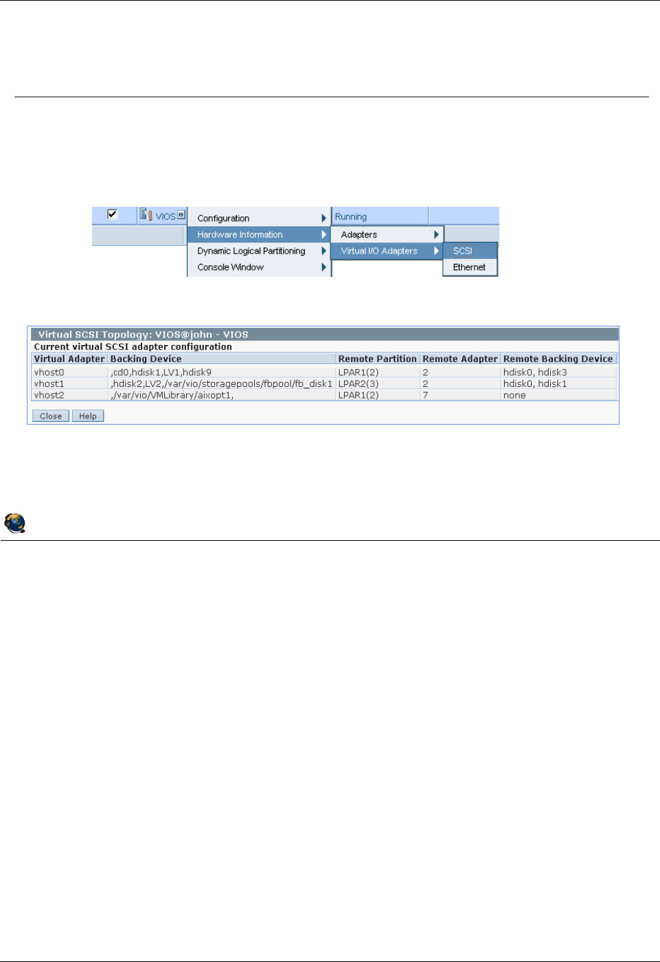
Student Notebook
Course materials may not be reproduced in whole or in part
without the prior written permission of IBM.
3-18 VIOS © Copyright IBM Corp. 2012
Figure 3-16. Viewing FB configuration from the HMC QV3441.0
Notes:
Viewing the configuration from the HMC
The graphic in the visual above shows two FB virtual devices, along with other types of
devices. This panel shows the information from both the VIOS perspective and from the
client LPAR’s perspective. It shows the VIOS vhost adapter names, the associated
backing devices, the remote (client in this case) partition names, adapter IDs, and the
device names on the client.
In the example above, the vhost1 adapter has a FB virtual disk and the vhost2 adapter
has a FB virtual optical media device with the aixopt1 image loaded.
The HMC panel shown in the visual above does not show cd devices in the remote
backing device column.
© Copyright IBM Corporation 2012
UNIX Software Service Enablement
Viewing FB configuration from the HMC
View the FB virtual configuration from the HMC
Select the VIOS partition and run Hardware Information ÆVirtual I/O
Adapters ÆSCSI task
Example output:
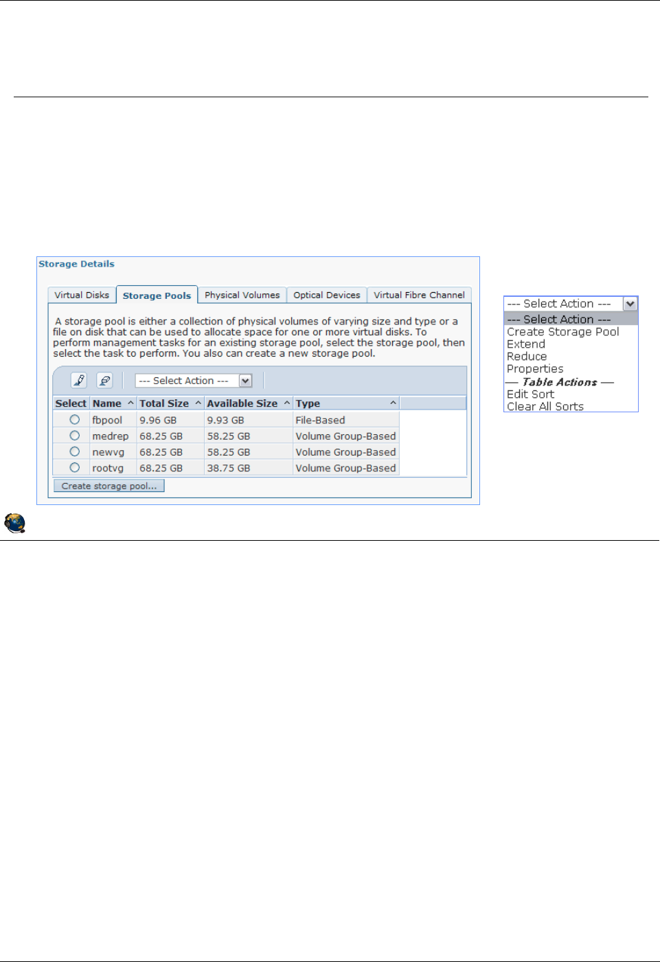
Student Notebook
Course materials may not be reproduced in whole or in part
without the prior written permission of IBM.
© Copyright IBM Corp. 2012 Unit 3. File-backed Storage Devices 3-19
V7.0
Uempty
Figure 3-17. Manage FB devices with the HMC (1 of 3) QV3441.0
Notes:
Using the HMC to manage FB devices
You can also use the HMC Virtual Storage Management task to create and manage
FB disks and optical media devices. The above visual shows an example screen which
lists the storage pools on the VIOS partition. In the example, there are three volume
groups/logical volume storage pools and there is one file-backed storage pool. Recall
that you must create a FB storage pool inside a LV storage pool before being able to
create FB virtual disks.
Select Action menu
If you select the storage pool, the actions menu will allow you to see the properties of
the pool, and extend or reduce the pool.
© Copyright IBM Corporation 2012
UNIX Software Service Enablement
Manage FB devices with the HMC (1 of 3)
You can manage file-backed devices from the Configuration ->
Virtual Resources -> Virtual Storage Management task
Storage Pools tab will create and show file-backed storage pools
When you create a storage pool, the options are File-Based and Volume
Group-Based
Action Menu
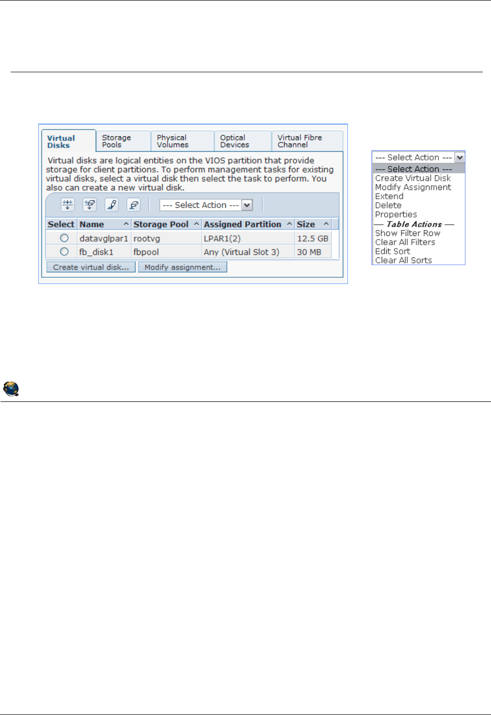
Student Notebook
Course materials may not be reproduced in whole or in part
without the prior written permission of IBM.
3-20 VIOS © Copyright IBM Corp. 2012
Figure 3-18. Manage FB devices with the HMC (2 of 3) QV3441.0
Notes:
Virtual Disks tab
Recall that you can create LV-based backing storage with the Virtual Disks tab. You can
also create FB backing storage as well. If you select the FB disk, you can extend it,
reduce it, modify its assignment, or look at its properties.
© Copyright IBM Corporation 2012
UNIX Software Service Enablement
Manage FB devices with the HMC (2 of 3)
Virtual Disks tab manages file-backed disks
Action Menu
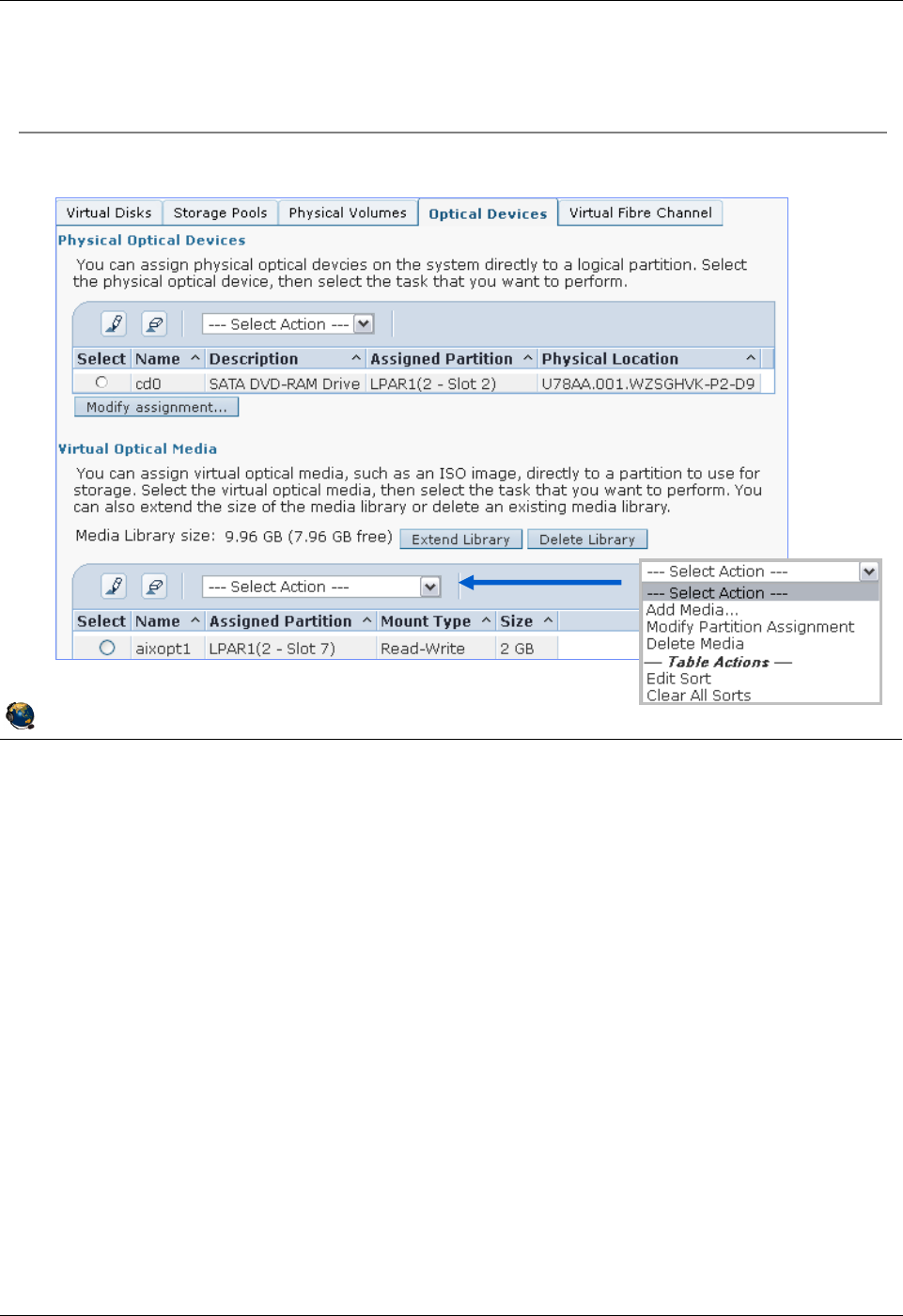
Student Notebook
Course materials may not be reproduced in whole or in part
without the prior written permission of IBM.
© Copyright IBM Corp. 2012 Unit 3. File-backed Storage Devices 3-21
V7.0
Uempty
Figure 3-19. Manage FB devices with the HMC (3 of 3) QV3441.0
Notes:
Optical devices tab
You can manage virtual optical media devices from the HMC. At the top of the panel as
shown in the visual above, you can manage physical optical devices. For example, the
physical /dev/cd0 drive on the VIOS partition can be mapped to a vhost adapter. The
client sees a virtual SCSI optical media drive.
At the bottom of the panel, you can manage file backed virtual optical media. If there is
no Virtual Media Repository, you can create one. The example above shows a system
on which a repository already exists. Once the repository exists, you can extend it,
delete it, or manage the media images. Notice that the Actions menu lists the ability to
add media, modify the partition assignment, and delete media.
The Modify Assignment action menu option will do both the mkvdev to create the VTD
and load the media.
© Copyright IBM Corporation 2012
UNIX Software Service Enablement
Manage FB devices with the HMC (3 of 3)
Optical Devices tab manages optical devices and media repository
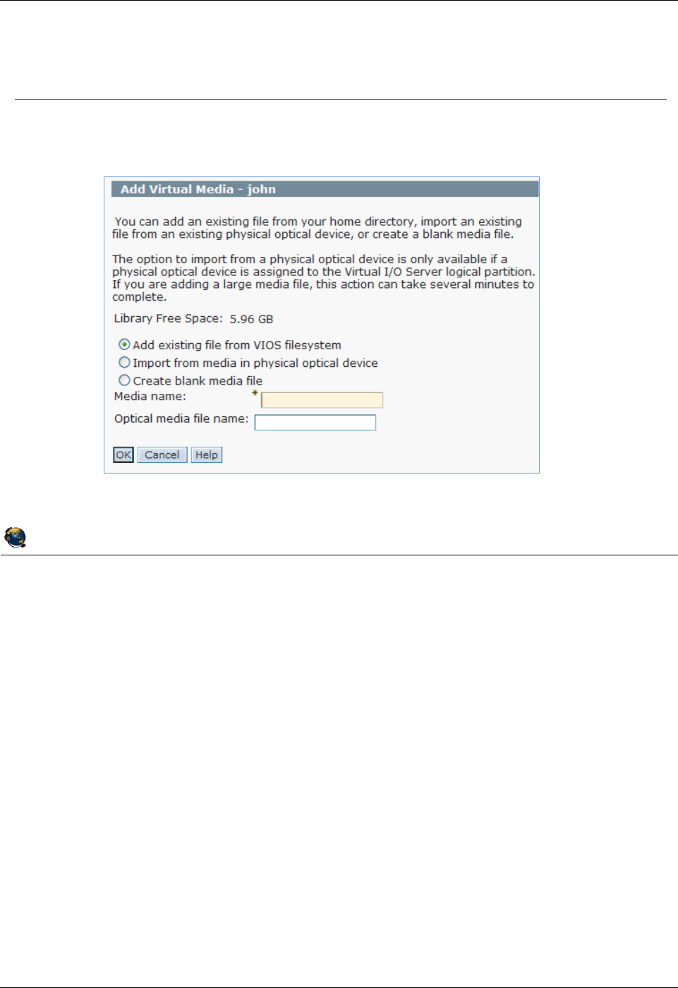
Student Notebook
Course materials may not be reproduced in whole or in part
without the prior written permission of IBM.
3-22 VIOS © Copyright IBM Corp. 2012
Figure 3-20. Adding image file from HMC GUI QV3441.0
Notes:
Adding media files to the repository
If you choose to create a blank media file an option to enter a size will appear.
When adding existing files from the VIOS file system, the file must be accessible from
/home/padmin directory and be owned by the padmin user.
© Copyright IBM Corporation 2012
UNIX Software Service Enablement
Adding image file from HMC GUI
You can add an existing file, import from a physical device, or create
blank media using the HMC GUI

Student Notebook
Course materials may not be reproduced in whole or in part
without the prior written permission of IBM.
© Copyright IBM Corp. 2012 Unit 3. File-backed Storage Devices 3-23
V7.0
Uempty
Figure 3-21. Checkpoint QV3441.0
Notes:
© Copyright IBM Corporation 2012
UNIX Software Service Enablement
Checkpoint
1. True or False: An LPAR can boot from a file-backed hdisk or optical
media device.
2. True or False: The operating system for an LPAR can be installed using
the media repository.
3. True or False: An FBPOOL is the same thing as a volume group.
4. The ____________________ command creates FB backing devices and
maps them to vhost adapters.
5. Before creating any file-backed virtual disks, what must you create first
inside the logical volume storage pool?
_____________________________________

Student Notebook
Course materials may not be reproduced in whole or in part
without the prior written permission of IBM.
3-24 VIOS © Copyright IBM Corp. 2012
Figure 3-22. Exercise 3 - File-backed storage devices QV3441.0
Notes:
© Copyright IBM Corporation 2012
UNIX Software Service Enablement
Exercise 3 File-backed storage devices
Activity:
Create a file-backed virtual disk
Create a Virtual Media Repository and Store an iso File
Install AIX Image From Virtual Optical Media Device
Note:
The root password on LPAR3 is passw0rd (0 = zero)

Student Notebook
Course materials may not be reproduced in whole or in part
without the prior written permission of IBM.
© Copyright IBM Corp. 2012 Unit 3. File-backed Storage Devices 3-25
V7.0
Uempty
Figure 3-23. Unit summary QV3441.0
Notes:
© Copyright IBM Corporation 2012
UNIX Software Service Enablement
Unit summary
There are two types of file-backed virtual SCSI devices
VSCSI disks and virtual optical media devices
File-backed storage pools are created in logical volume storage pools
File-backed devices are stored in file-backed pools
A virtual media repository can be created to store virtual media
Virtual media can be loaded into virtual optical media devices and
used by clients like physical optical media devices
Virtual media can even be used to install the operating system for a client LPAR

Student Notebook
Course materials may not be reproduced in whole or in part
without the prior written permission of IBM.
3-26 VIOS © Copyright IBM Corp. 2012

Student Notebook
Course materials may not be reproduced in whole or in part
without the prior written permission of IBM.
© Copyright IBM Corp. 2012 Unit 4. Virtual Fibre Channel Storage Devices 4-1
V7.0
Uempty Unit 4. Virtual Fibre Channel Storage Devices
What this unit is about
The unit continues the discussion of virtual storage devices. Students
will learn about the implementation of virtual Fibre Channel adapters
and the concept of N-Port ID Virtualization (NPIV).
What you should be able to do
After completing this unit, you should be able to:
• Configure virtual Fibre Channel adapters
• Map a physical Fibre Channel port to a virtual Fibre Channel
adapter
• Describe benefits of using NPIV
• View N_Port login status
• Log in to all N_Ports
• Use the chsyscfg HMC command to alter the WWPNs in a
partition profile
• Tune the max_xfer_size and num_cmd_elems attributes of
virtual Fibre Channel adapters
How you will check your progress
Accountability:
• Checkpoint questions
• Machine exercises
References
IBM Power Systems Hardware Information Center:
http://publib.boulder.ibm.com/infocenter/powersys/v3r1m5/index.jsp
Virtual I/O Server product documentation from the IBM Power
Systems Hardware Information Center:
http://publib.boulder.ibm.com/infocenter/powersys/v3r1m5/index.jsp?t
opic=/p7hb1/iphb1kickoff.htm
IBM Techdoc titled AIX disk queue depth tuning for performance
available from:

Student Notebook
Course materials may not be reproduced in whole or in part
without the prior written permission of IBM.
4-2 VIOS © Copyright IBM Corp. 2012
http://www-03.ibm.com/support/techdocs/atsmastr.nsf/WebIndex/TD1
05745
The following IBM Redbooks documents can be found at:
http://www.redbooks.ibm.com
SG24-7940 IBM PowerVM Virtualization Introduction and
Configuration
SG24-7590 IBM PowerVM Virtualization Managing and Monitoring

Student Notebook
Course materials may not be reproduced in whole or in part
without the prior written permission of IBM.
© Copyright IBM Corp. 2012 Unit 4. Virtual Fibre Channel Storage Devices 4-3
V7.0
Uempty
Figure 4-1. Unit objectives QV3441.0
Notes:
© Copyright IBM Corporation 2012
UNIX Software Service Enablement
Unit objectives
After completing this unit, you should be able to:
Configure virtual Fibre Channel adapters
Map a physical Fibre Channel port to a virtual Fibre Channel adapter
Describe benefits of using NPIV
View N_Port login status
Log in to all N_Ports
Use the chsyscfg HMC command to alter the WWPNs in a partition
profile
Tune the max_xfer_size and num_cmd_elems attributes of virtual
Fibre Channel adapters

Student Notebook
Course materials may not be reproduced in whole or in part
without the prior written permission of IBM.
4-4 VIOS © Copyright IBM Corp. 2012
Figure 4-2. Virtual Fibre Channel adapter (1 of 3) QV3441.0
Notes:
NPIV
This industry standard method allows multiple initiators to share a single physical port,
easing hardware requirements for Storage Area Networks. In the PowerVM case, the
VIOS partition will have the actual physical connection.
HBA
A host bus adapter (HBA) refers to any type of plug-in adapter card.
World wide port name (WWPN)
This is the unique identifier for a port on a Fibre Channel fabric. The fabric is a topology
where devices connect with each other via one or more network switches. Think of a
WWPN as being similar to a Media Access Control (MAC) address for Ethernet ports.
© Copyright IBM Corporation 2012
UNIX Software Service Enablement
Virtual Fibre Channel adapter (1 of 3)
Virtual Fibre Channel adapters support the use of N-Port ID
Virtualization (NPIV)
An N_Port is a nodes Fibre Channel port, in this case it is the virtual
Fibre Channels port
NPIV is a standardized method for virtualizing a physical N_Port
Enables multiple virtualized N_Port IDs to be configured on a physical
adapter port
Implementation requires NPIV support in the physical Fibre Channel
adapter and the first level SAN switch
Enables LPARs to have virtual Fibre Channel Host Bus Adapters (HBAs),
each with a dedicated world wide port name (WWPN)
This gives each virtual Fibre Channel HBA a unique SAN identity similar
to that of a physical adapter port

Student Notebook
Course materials may not be reproduced in whole or in part
without the prior written permission of IBM.
© Copyright IBM Corp. 2012 Unit 4. Virtual Fibre Channel Storage Devices 4-5
V7.0
Uempty
Figure 4-3. Virtual Fibre Channel adapter (2 of 3) QV3441.0
Notes:
Virtual Fibre Channel
With NPIV, the VIOS’s role is fundamentally different. The VIOS facilitates adapter
sharing only; there is no device level abstraction or emulation. Rather than a storage
virtualizer, the VIOS serving NPIV is a pass through, providing a Fibre Channel Protocol
(FCP) connection from the client to the SAN.
If you use VSCSI disks, you need to use the VIOS to create each VSCSI VTD and map
each to the vhost adapter for each client. With NPIV, the SAN can zone storage to the
client LPAR’s WWPN. You do not need to any VTDs on the VIOS in order for the client
to see the storage. This reduces the amount of VIOS management needed.
Just like virtual SCSI, when configuring the virtual Fibre Channel adapters you specify
the VIOS partition name and virtual adapter ID in the client configuration, and you
specify the client information when configuring the VIOS server adapter.
© Copyright IBM Corporation 2012
UNIX Software Service Enablement
Virtual Fibre Channel adapter (2 of 3)
With virtual SCSI, the storage is virtualized
The client operating system cannot distinguish between different types of
backing storage (SAN, SAS, etc.) because the VIOS uses SCSI
emulation
With NPIV, the Fibre Channel port is virtualized
The VIOS serving NPIV:
Acts as a pass through, providing an FC protocol (FCP) connection from the
client to the SAN
Does not see the LUNs zoned for the clients WWPN
The result is that the client partition has a unique identity to the SAN and
storage can be zoned to it, just as if it had a dedicated physical HBA
The client can see storage zoned for its WWPN and recognize different
types of physical storage

Student Notebook
Course materials may not be reproduced in whole or in part
without the prior written permission of IBM.
4-6 VIOS © Copyright IBM Corp. 2012
Figure 4-4. Virtual Fibre Channel adapter (3 of 3) QV3441.0
Notes:
Requirements
Not all Fibre Channel adapters and SAN switches support NPIV. NPIV-capable
switches present the virtual WWPN to other SAN switches and devices as if they
represent physical FC adapter endpoints. Additional SAN switches and disk/tape
devices don’t need to be NPIV aware.
The VIOS needs at least one 8 Gigabit PCI Express Dual Port Fibre Channel Adapter
(feature code 5735) which supports NPIV. The SAN switch not only needs to support
NPIV, but it may have to be configured to enable NPIV.
© Copyright IBM Corporation 2012
UNIX Software Service Enablement
Virtual Fibre Channel adapter (3 of 3)
Requires:
POWER6 (or above) processor-based servers
The physical Fibre Channel adapter and the first level SAN switch must
support NPIV
VIOS 2.1.0.10 (fixpack 20.1) or later
Update to VIOS V2.1 then install this fixpack
HMC V7R3.4.0 (Service Pack 0) or later
Supported client operating systems:
AIX version 6.1 Technology Level 2, or later
AIX 5.3 Technology Level 9, or later
IBM i version 6.1.1, or later
SUSE Linux Enterprise Server 11, or later
RHEL 5.4 (with an additional driver), or later

Student Notebook
Course materials may not be reproduced in whole or in part
without the prior written permission of IBM.
© Copyright IBM Corp. 2012 Unit 4. Virtual Fibre Channel Storage Devices 4-7
V7.0
Uempty
Figure 4-5. NPIV benefits QV3441.0
Notes:
NPIV benefits
There are many benefits to using NPIV versus VSCSI to access disks. Some are
related to increased functionality such as the ability for the client operating system to
see the real type of disk that is being used. Client level tools often need this for certain
functions to work.
Some benefits are related to performance such as the ability to load more sophisticated
PCMs in the client which provide load balancing or other benefits when using MPIO.
Some benefits are for ease of administration such as not having to document all of the
client endpoint devices on the VIOS to prevent accidental overwriting of data. With Live
Partition Mobility, any virtual SCSI disks used by a client partition must be accessible by
all VIOS partitions involved in a relocation. This means that disks which look free on
one VIOS could be in use by an LPAR somewhere on the network. This has to be
documented carefully.
© Copyright IBM Corporation 2012
UNIX Software Service Enablement
NPIV benefits
NPIV benefits versus VSCSI:
Client can see the real type of disk rather than a SCSI emulation
Easier for client tools to take advantage of copy service functions on SAN to
create flash copies or snap shots of the LUN
Client can install a load-balancing path control module (PCM) to improve
functionality and performance
VIOS doesnt have to keep track of all the clients devices
Especially helpful for Live Partition Mobility environments
For dual VIOS environments you no longer have to configure the
reserve_policy attribute for disks on both VIOSes
Manage disk queue_depth disk attribute on client only, rather than on
client and VIOS
To add VSCSI devices, its a two step process to add the device first to
the VIOS, then map it to the vhost adapter, but NPIV storage simply
needs to be zoned to the WWPN of the client partition

Student Notebook
Course materials may not be reproduced in whole or in part
without the prior written permission of IBM.
4-8 VIOS © Copyright IBM Corp. 2012
Figure 4-6. NPIV considerations QV3441.0
Notes:
NPIV considerations
While the ability to load PCMs in the client LPAR for added functionality and
performance is a benefit, this is also software that has to be maintained. If there are a
hundred LPARs using a PCM or drivers that have to be updated, this can take some
system administration time. This is not an issue if the client LPARs are using the
standard AIX MPIO PCM.
Related to the maintenance of PCMs and drivers, if these must be updated and the
client LPAR is using an NPIV disk or disks for rootvg, then as part of the update
process, you may have to map a new VSCSI disk, move rootvg to the VSCSI disk,
perform the update, then move rootvg back to the NPIV disk. It’s also possible that the
LPAR would need to be rebooted. For this reason, one recommendation is to use a
VSCSI disk or disks for rootvg and use NPIV for all other disks.
© Copyright IBM Corporation 2012
UNIX Software Service Enablement
NPIV considerations
Considerations
MPIO PCMs must be installed and updated in every client LPAR that
wants to use them
Best to use non-NPIV disks for rootvg to avoid difficulties when updating
MPIO disk drivers
With NPIV disks, you would have to move rootvg temporarily to another type
of disk (vSCSI for example), do the update, move it back, and potentially
reboot
A VSCSI benefit is to provide access to storage that is supported on the
VIOS but not in a particular clients operating system
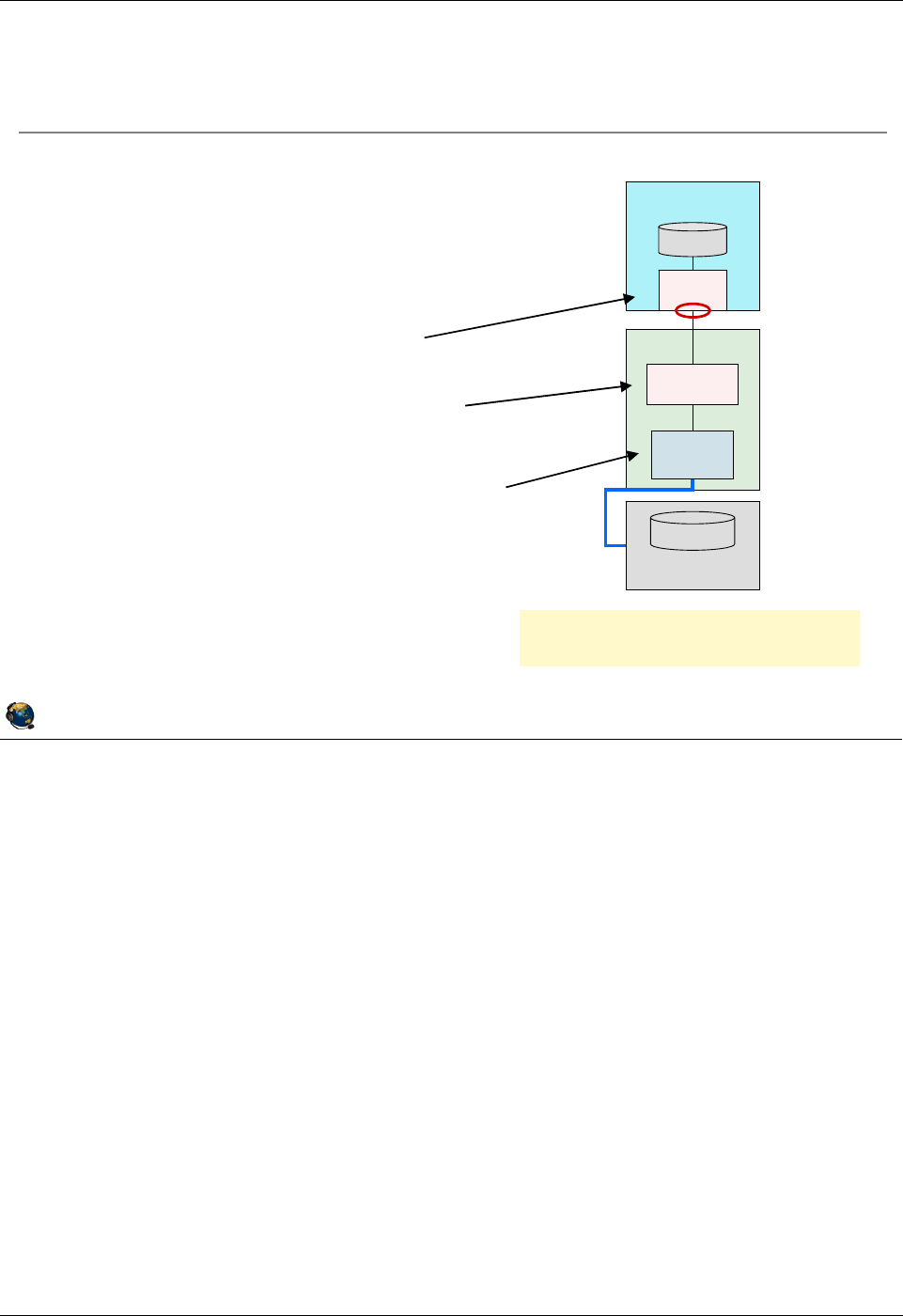
Student Notebook
Course materials may not be reproduced in whole or in part
without the prior written permission of IBM.
© Copyright IBM Corp. 2012 Unit 4. Virtual Fibre Channel Storage Devices 4-9
V7.0
Uempty
Figure 4-7. NPIV overview QV3441.0
Notes:
NPIV configuration
There is a one-to-one mapping of virtual Fibre Channel adapters between the client
LPAR and the VIOS, just like VSCSI adapters. The VIOS maps a physical FC port to its
virtual Fibre Channel server adapter. Then the administrator in the client LPAR contacts
the SAN system administrator to map LUNs. The client does not have to contact the
VIOS administrator to add endpoint devices.
© Copyright IBM Corporation 2012
UNIX Software Service Enablement
NPIV overview
Like VSCSI, virtual Fibre Channel with
NPIV is implemented with a physical
adapter and a virtual server adapter on
the VIOS, and a virtual client adapter
on the client
The client LPAR's virtual Fibre
Channel client adapter is associated
with a virtual Fibre Channel server
adapter in a VIOS
VIOS maps the virtual Fibre Channel
server adapter to a port on a physical
Fibre Channel adapter
The VIOS does not see the endpoint
devices
fcs0
hdisk0
LUN on SAN
Disk A
vfchost0
VIOS
LPAR
VIOS acts as a pass-through for
client I/O over the FC adapter
fcs0
Virtual
N_Port
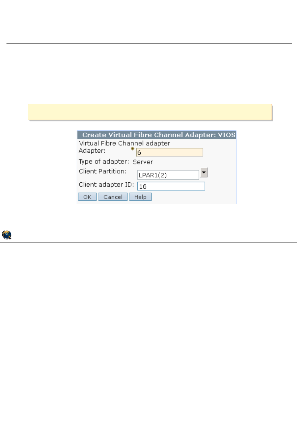
Student Notebook
Course materials may not be reproduced in whole or in part
without the prior written permission of IBM.
4-10 VIOS © Copyright IBM Corp. 2012
Figure 4-8. Add virtual Fibre Channel adapters (1 of 2) QV3441.0
Notes:
Adding a virtual Fibre Channel adapter
The visual above shows using the HMC GUI to create the virtual Fibre Channel server
adapter. Just like virtual SCSI adapters, it can be created in the Create LPAR wizard, in
a partition’s profile, or dynamically.
One difference for virtual FC adapters versus VSCSI adapters is that when creating the
server adapter, there is no choice to connect to any client. You must specify the client
and its client adapter ID.
It is best to fully configure the VIOS FC server adapter and map it to a physical port
before creating the virtual FC client adapter. If you create the client adapter first, you’ll
see a message in the HMC that the VIOS is not configured.
© Copyright IBM Corporation 2012
UNIX Software Service Enablement
Add virtual Fibre Channel adapters (1 of 2)
Add the virtual Fibre Channel adapters in a client/server pair
Dynamically or add to profile and activate
Configure the VIOS server adapter and map the port before creating the
client adapter
Use Actions -> Create Virtual Adapter -> Fibre Channel Adapter
Use Actions -> Create Virtual Adapter -> Fibre Channel Adapter
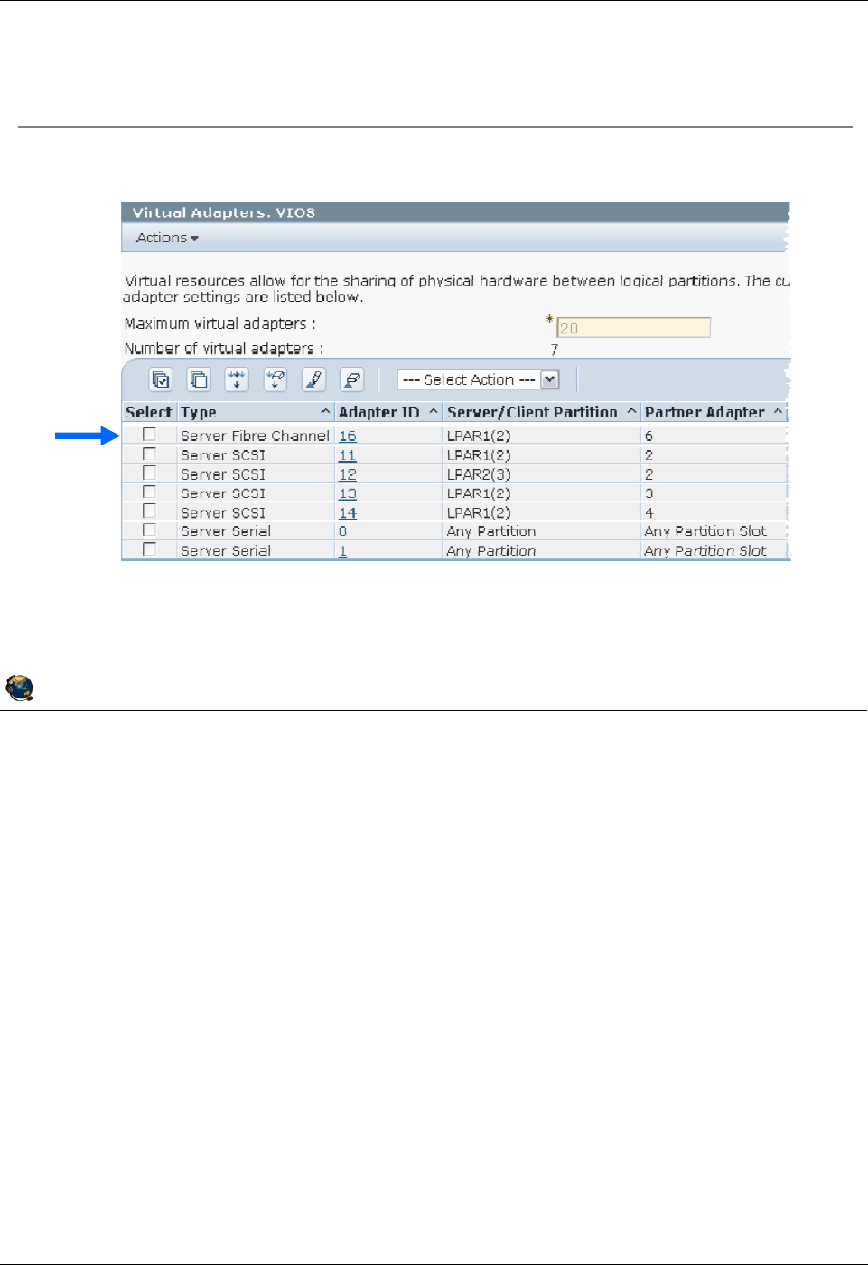
Student Notebook
Course materials may not be reproduced in whole or in part
without the prior written permission of IBM.
© Copyright IBM Corp. 2012 Unit 4. Virtual Fibre Channel Storage Devices 4-11
V7.0
Uempty
Figure 4-9. Add virtual Fibre Channel adapters (2 of 2) QV3441.0
Notes:
View added virtual Fibre Channel adapter
The virtual Fibre Channel adapter uses a virtual adapter slot like other virtual adapters
and its properties can be seen in the partition properties or the partition profile
properties.
On the VIOS, the virtual FC server adapter is named vfchost#. On the client, the virtual
FC client adapter is named just like a physical adapter port (fcs#).
© Copyright IBM Corporation 2012
UNIX Software Service Enablement
Resulting client Fibre Channel server adapter configuration
List the virtual FC server adapter in the VIOS:
$ lsdev -virtual | grep vfchost
vfchost0 Available Virtual FC Server Adapter
Add virtual Fibre Channel adapters (2 of 2)

Student Notebook
Course materials may not be reproduced in whole or in part
without the prior written permission of IBM.
4-12 VIOS © Copyright IBM Corp. 2012
Figure 4-10. View available N_Ports QV3441.0
Notes:
Check available ports on the VIOS
The lsnports command is run on the VIOS to see what physical FC ports are available
and NPIV capable. If the fabric column shows a 0, then this port is not available for
NPIV. Perhaps the switch connected to that port needs to be configured or does not
have NPIV capability. You can also check cables and hardware compatibility.
The lsnports output shown in the visual above shows that each port can support 64
virtual ports, so that a maximum of 64 client LPARs can share each physical port. The
output above also shows that this system has one virtual port.
© Copyright IBM Corporation 2012
UNIX Software Service Enablement
View available N_Ports
List the available physical NPIV capable ports on the VIOS with the
lsnports command
$ lsnports
name physloc fabric tports aports swwpns awwpns
fcs0 U789C.001.DQDC383-P1-C1-T1 1 64 63 2048 2037
fcs1 U789C.001.DQDC383-P1-C1-T2 1 64 64 2048 2037
Fields:
Fabric: 1=NPIV ready; 0=not ready for NPIV
Tports: Total number of virtual ports
Aports: Number of available (unused) virtual ports
Swwpns: Total number of client WWPNs supported
Awwpns: Number of client WWPNs available
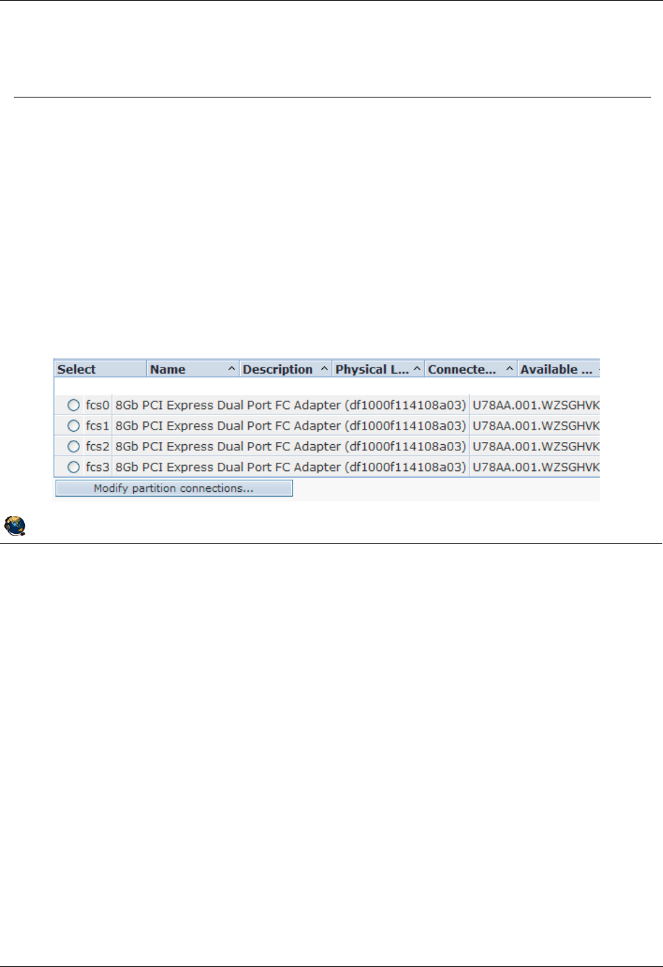
Student Notebook
Course materials may not be reproduced in whole or in part
without the prior written permission of IBM.
© Copyright IBM Corp. 2012 Unit 4. Virtual Fibre Channel Storage Devices 4-13
V7.0
Uempty
Figure 4-11. Map virtual Fibre Channel server adapter QV3441.0
Notes:
Unmapping
If no parameter is specified after the -fcp flag in the vfcmap command, the command
unmaps the virtual Fibre Channel adapter from the physical Fibre Channel port. For
example: $ vfcmap -vadapter vfchost0 -fcp
© Copyright IBM Corporation 2012
UNIX Software Service Enablement
Map virtual Fibre Channel server adapter
Map a virtual FC server adapter to a port on the physical HBA with
the vfcmap command
Example where vfchost0 is the virtual server adapter name and fcs0 is
the physical Fibre Channel port:
$ vfcmap vadapter vfchost0 fcp fcs0
Or, use the Configuration -> Virtual Resources -> Virtual Storage
Management -> Virtual Fibre Channel tab to map FC server
adapter to an FC port in HMC GUI

Student Notebook
Course materials may not be reproduced in whole or in part
without the prior written permission of IBM.
4-14 VIOS © Copyright IBM Corp. 2012
Figure 4-12. View Fibre Channel mapping QV3441.0
Notes:
View NPIV virtual mapping
The example lsmap command output in the visual above shows an example when a
virtual Fibre Channel adapter is configured and the client LPAR is currently active. If the
client LPAR is not active, the output will be similar to this:
$ lsmap -all -npiv
Name Physloc ClntID ClntName ClntOS
------------- ---------------------------------- ------ -------------- -------
vfchost0 U8202.E4B.06BCC8P-V1-C16 2
Status:NOT_LOGGED_IN
FC name:fcs0 FC loc code:U78AA.001.WZSGHVK-P1-C4-T1
Ports logged in:0
Flags:4<NOT_LOGGED>
VFC client name: VFC client DRC:
© Copyright IBM Corporation 2012
UNIX Software Service Enablement
View Fibre Channel mapping
Use the lsmap all npiv command for NPIV mapping
information
This example reflects a configuration in which the client LPAR has
been configured and is active:
$ lsmap -all -npiv
Name Physloc ClntID ClntName CIntOS
========= ========================== ====== =========== ======
vfchost1 U8203.E4A.0666BF2-V1-C16 2 LPAR1 AIX
Status:LOGGED_IN
FC name:fcs0 FC loc code:U789C.001.DQDC383-P1-C1-T1
Ports logged in:1
Flags:a<LOGGED_IN,STRIP_MERGE>
VFC client name:fcs2 VFC client DRC:U8203.E4A.0666BF2-V2-C5-T1
Virtual server adapter location code
Physical adapter port name and location code
Clients virtual adapter name and location code
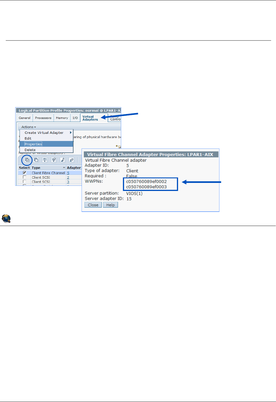
Student Notebook
Course materials may not be reproduced in whole or in part
without the prior written permission of IBM.
© Copyright IBM Corp. 2012 Unit 4. Virtual Fibre Channel Storage Devices 4-15
V7.0
Uempty
Figure 4-13. Zone LUNs on the SAN using client WWPNs QV3441.0
Notes:
WWPNs
The lscfg -vl fcs# AIX command output will show the active WWPN in the Network
Address field.
This HMC command will show WWPNS for the managed system MSname:
lshwres -m MSname -r virtualio --rsubtype fc --level lpar
lpar_name=LPAR1,lpar_id=2,slot_num=5,adapter_type=client,state=1,is_r
equired=0,remote_lpar_id=1,remote_lpar_name=VIOS,remote_slot_num=15,"
wwpns=c0507600417e0004,c0507600417e0005"
A SAN uses zones to provide access to the target storage based on WWPNs. Zoning
indicates which WWPNs are permitted to access each LUN. Use the SAN subsystem
management tool to zone the WWPNs that are created by the HMC for the virtual Fibre
Channel client adapter. This is the same procedure on the SAN that is required when
using physical Fibre Channel adapters.
© Copyright IBM Corporation 2012
UNIX Software Service Enablement
Zone LUNs on the SAN using client WWPNs
The SAN uses zones to provide access to targets based on WWPNs
See WWPNs on client's adapter properties or use the
lscfg vl fcs#command on the AIX client
Include both WWPNs to support Live Partition Mobility operations
Use only first WWPN if not using Live Partition Mobility
Go to the Virtual Adapters tab on
the client's partition properties.
Then, view the properties for the
virtual adapter.
WWPNs
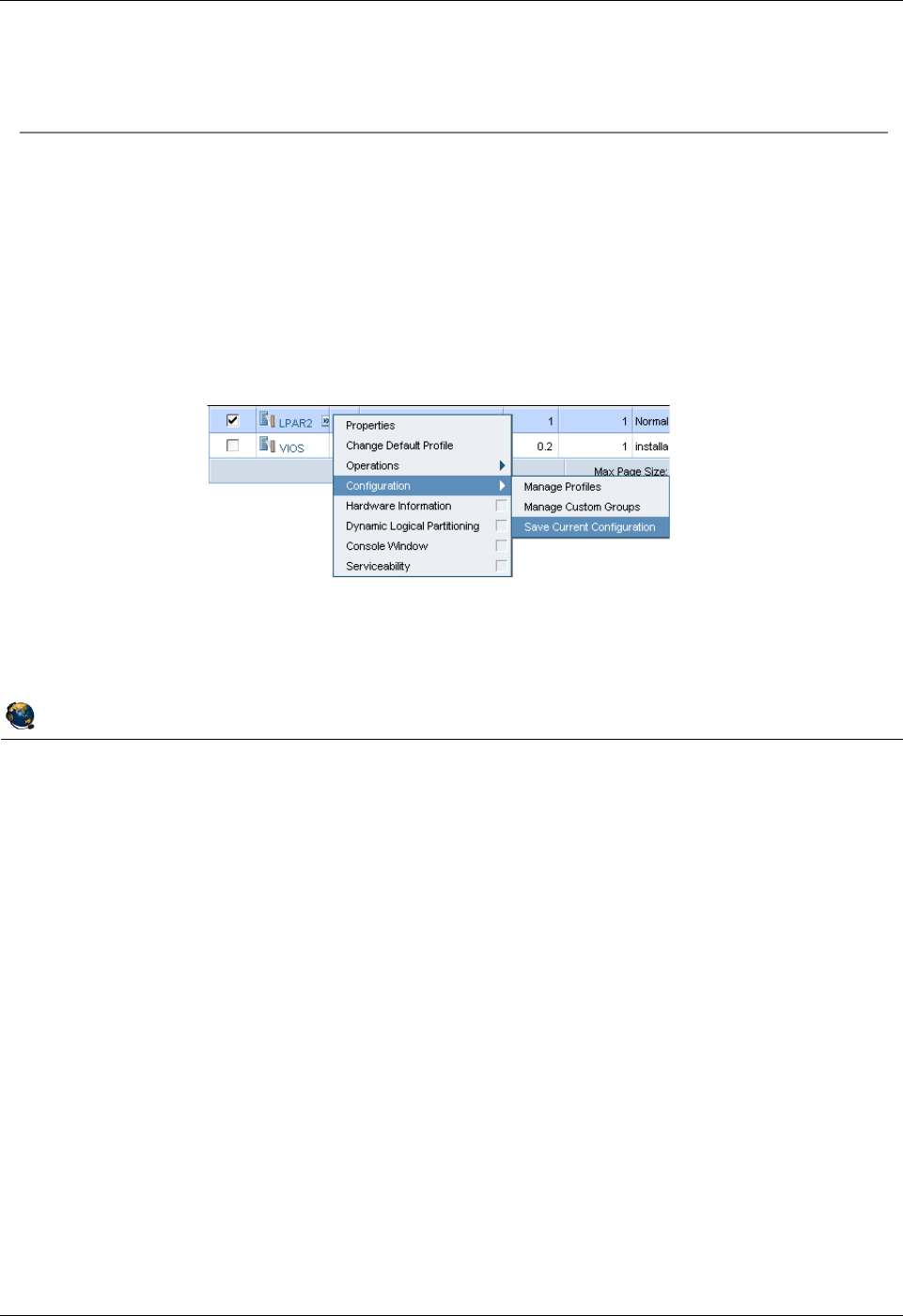
Student Notebook
Course materials may not be reproduced in whole or in part
without the prior written permission of IBM.
4-16 VIOS © Copyright IBM Corp. 2012
Figure 4-14. Virtual Fibre Channel DLPAR operations QV3441.0
Notes:
DLPAR operations for virtual Fibre Channel adapters
WWPNs are generated based on the range of names available for use based on a
prefix in the vital product data on the managed system. This 6 digit prefix comes with
the purchase of the managed system and includes the ability to use 32,000 pairs of
WWPNs.
When adding a virtual Fibre Channel client adapter, a pair of WWPNs is generated and
assigned. If you add the adapter with a DLPAR operation be sure to save the current
configuration as shown in the visual above. If, instead, you add the Fibre Channel client
adapter to the profile, then the next time the LPAR is activated, a new different pair of
WWPNs will be generated and of course this will affect connectivity to any storage
assigned to the LPAR. The Operations -> Save Current Configuration task will give
the option to save the configuration as a new profile or to overwrite an existing profile.
© Copyright IBM Corporation 2012
UNIX Software Service Enablement
Virtual Fibre Channel DLPAR operations
Each time a virtual Fibre Channel client adapter is created, the HMC
obtains a new, non-reusable, pair of WWPNs from the Hypervisor
WWPNs obtained by DLPAR add operations for virtual Fibre Channel
client adapters that are not saved to a profile will be discarded if the
partition is shut down or if the adapters are removed
For continued access to the storage, save the partition configuration
in a new profile so that the WWPNs are saved
The Hypervisor has a limit of 32,000 pairs of WWPNs
If you run out of WWPNs, you must obtain an activation code for an
additional set of 32,000 pairs

Student Notebook
Course materials may not be reproduced in whole or in part
without the prior written permission of IBM.
© Copyright IBM Corp. 2012 Unit 4. Virtual Fibre Channel Storage Devices 4-17
V7.0
Uempty
Figure 4-15. Activating all WWPNs to aid SAN mapping QV3441.0
Notes:
SAN mapping
For most data centers, there are many procedures to follow. For large data centers this
is very much the case. Often one of those procedures is that the SAN administrator will
zone only WWPNs that are active on the fabric, and thus can be seen. They may not
want to or be allowed to enter WWPNs manually. This causes a problem if the client
LPAR administrator needs both of the WWPNs for a virtual Fibre Channel adapter to
have access to all LUNs. There are two strategies to solve this situation. The first
strategy is to use the chnportlogin HMC command to activate (login to the SAN) both
WWPNs of each client virtual FC adapter in a specified client LPAR. If this strategy is
not available, then the client LPAR administrator can switch the WWPNs in the LPAR
profile. This is covered later in this unit.
The lsnportlogin and chnportlogin commands are available as of HMC V7R7.3.0
and VIOS 2.2.0.13 FixPack 24 SP03
© Copyright IBM Corporation 2012
UNIX Software Service Enablement
Activating all WWPNs to aid SAN mapping
Only active WWPNs will be seen by a SAN subsystem
Only the first WWPN listed in the adapter properties and shown by the
lscfg vl fcs#AIX command will be active by default
The second WWPN for a virtual Fibre Channel adapter is for Live Partition
Mobility and is only active for a short time during relocation
While SAN subsystems have the ability to add non-active WWPNs, some
data center policies do not allow this
View login status of N_Ports with the lsnportlogin HMC
command
The chnportlogin HMC command provides ability to log in to all
WWPNs so the SAN administrator can see them
After the ports are mapped, the inactive ones can be logged out with
the chnportlogin HMC command
Log out of the non-active ports before doing a Live Partition Mobility
relocation

Student Notebook
Course materials may not be reproduced in whole or in part
without the prior written permission of IBM.
4-18 VIOS © Copyright IBM Corp. 2012
Figure 4-16. Logging into N_Ports from the HMC CLI QV3441.0
Notes:
Log in and log out of N_Ports
Use lsnportlogin to view current login status for N_Ports. Use chnportlogin to log
the ports in and out of the SAN fabric.
The first time lsnportlogin is run, the status will be 2 which means unknown. Simply
log in and then log out again to get valid status information. There is nothing wrong on
the system when this initial unknown status is listed.
The --filter lpar_names=LPARname is a required flag for the lsnportlogin
command.
The chnportlogin will log out ports (WWPNs) that are not really active. That is, it will
not log out ports (WWPNs) that are actively in use to access disks. You’ll notice in the
lsnportlogin output that the truly active ports will show that they are logged in by the
client. The non-active ports will show that they’re logged in by the VIOS.
© Copyright IBM Corporation 2012
UNIX Software Service Enablement
Logging into N_Ports from the HMC CLI
The first time the lsnportlogin command is run, all ports
appear to be in the unknown state (status is 2)
Log in then log out to see valid status
Example log in command:
hscroot@hmc:~> chnportlogin -m john -p LPAR1 -o login
Example log out command:
hscroot@hmc:~> chnportlogin -m john -p LPAR1 -o logout
Example list command that shows one port logged in by the client:
hscroot@hmc:~> lsnportlogin -m john --filter lpar_names=LPAR1
lpar_name=LPAR1,lpar_id=2,profile_name=Install,slot_num=5,wwpn=c05076
042d6f0004,wwpn_status=1,logged_in=client
lpar_name=LPAR1,lpar_id=2,profile_name=Install,slot_num=5,wwpn=c05076
042d6f0005,wwpn_status=0
Any ports that were inactive when the chnportlogin command was
run to login to the fabric will show that they have been logged in by
the VIOS that owns the physical adapter

Student Notebook
Course materials may not be reproduced in whole or in part
without the prior written permission of IBM.
© Copyright IBM Corp. 2012 Unit 4. Virtual Fibre Channel Storage Devices 4-19
V7.0
Uempty
Figure 4-17. Alternate procedure to activate WWPNs (1 of 2) QV3441.0
Notes:
Alternate procedure
The procedure on the visual above addresses the problem of the virtual FC adapter’s
WWPN not appearing active on the fabric and the LPAR is not yet loaded with an
operating system. This might happen if the LPAR will only have NPIV disks. If the LPAR
has an operating system and is booted, then the first WWPN would be active and the
second could be logged in with the chnportlogin command.
Following the procedure above will allow the SAN administrator to see the first WWPN
as active and logged in on the SAN fabric. If you need to also show the second WWPN
as active on the fabric once an operating system is installed in the client LPAR, use
chnportlogin or follow the procedure on the next visual.
© Copyright IBM Corporation 2012
UNIX Software Service Enablement
Alternate procedure to activate WWPNs (1 of 2)
If you need to make the first WWPN active before installing an LPAR,
activate to Open Firmware (OF) mode and run the following
procedure:
Type ioinfo at the first OF prompt:
0> ioinfo
At the next prompt choose option 6. FCINFO
==> 6
At the next prompt chose the FC adapter. It should be option 1.
==> 1
Then choose 1. List Attached FC Devices
==> 1
After you press ENTER the first WWPN will be logged in

Student Notebook
Course materials may not be reproduced in whole or in part
without the prior written permission of IBM.
4-20 VIOS © Copyright IBM Corp. 2012
Figure 4-18. Alternate procedure to activate WWPNs (2 of 2) QV3441.0
Notes:
Alternate procedure
The visual above addresses the problem of the second WWPN not appearing active on
the fabric and the system is running code before the chnportlogin and lsnportlogin
commands are available. The first WWPN is active on the fabric if the LPAR is activated
or if you follow the OF procedure on the last visual.
The overall process is to have the SAN administrator zone the first WWPN which can
be seen, then switch the WWPNs in the profile and reactivate the LPAR. Now the SAN
administrator can zone the second (now the first) WWPN. This can take some time if
there is a week or longer turnaround time for SAN requests in large data centers!
This procedure can also be useful for another purpose. If a client administrator has a
particular set of WWPNs already configured with LUNs and for some reason the virtual
FC adapter with those WWPNs is deleted or otherwise no longer available, the
administrator can use chsyscfg to replace the WWPNs with the original ones.
© Copyright IBM Corporation 2012
UNIX Software Service Enablement
Alternate procedure to activate WWPNs (2 of 2)
If you need to make the second WWPN active, switch the WWPNs in
the profile and then activate LPAR
Use the chsyscfg HMC command to switch WWPNs:
chsyscfg -r prof -m MSname -i "name=profile,lpar_name=LPARname,
\"virtual_fc_adapters=\"\"#/client/#/VIOS/#/ZZZ,ZZZ/1\"\"\""
Format for the virtual_fc_adapters attribute:
Client slot ID /client/ VIOS ID / VIOS name / VIOS slot ID / WWPN1,WWPN2 / required
Example command:
chsyscfg -r prof -m john -i
"name=Normal,lpar_name=LPAR1,\"virtual_fc_adapters=\"\"5/
client/1/VIOS/15/c05076042d6f0005,c05076042d6f0004/1\"\"\""
This command can be also used to configure a different set of WWPNs.
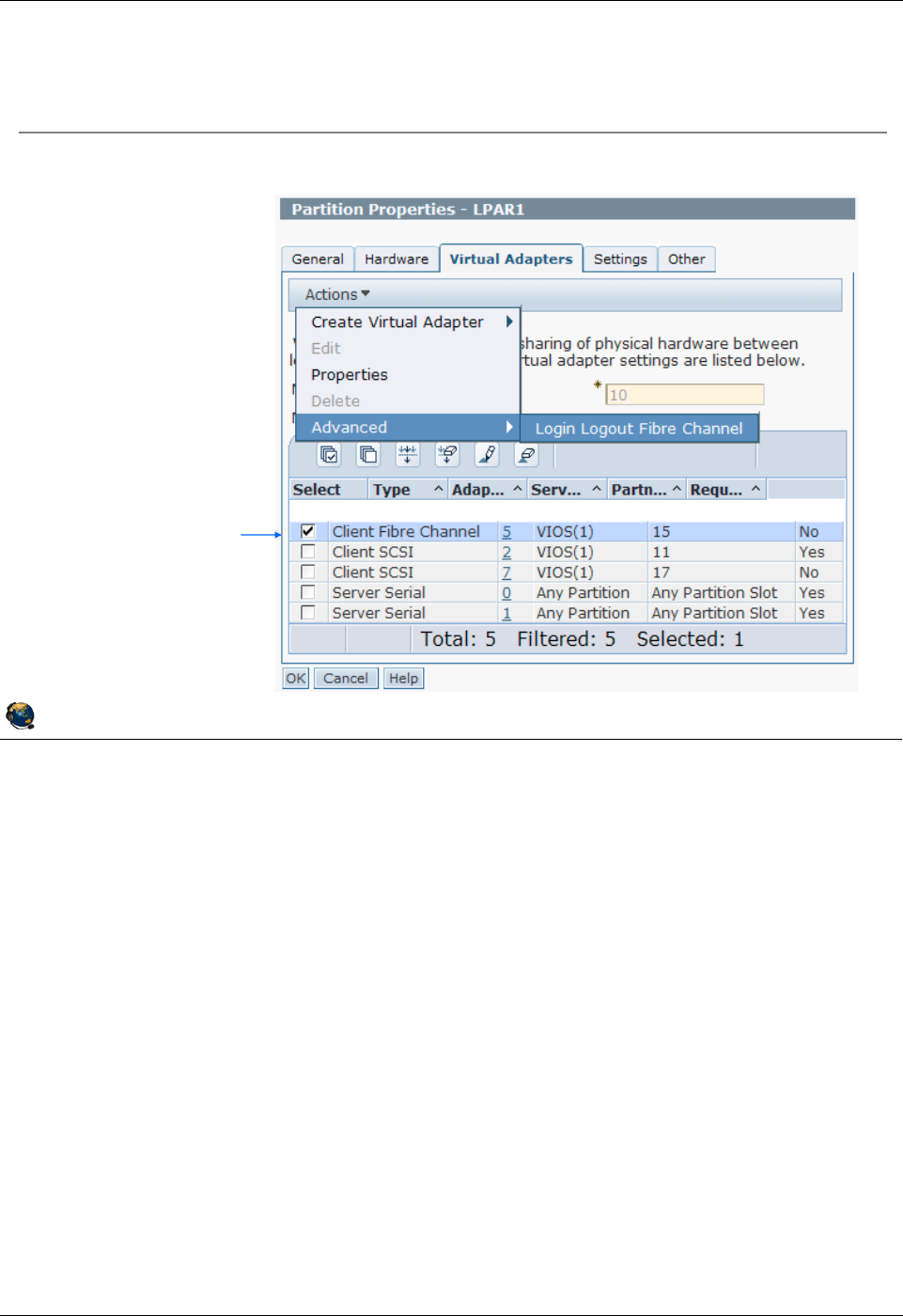
Student Notebook
Course materials may not be reproduced in whole or in part
without the prior written permission of IBM.
© Copyright IBM Corp. 2012 Unit 4. Virtual Fibre Channel Storage Devices 4-21
V7.0
Uempty
Figure 4-19. Activating WWPNs from the HMC GUI (1 of 2) QV3441.0
Notes:
Log in and log out of N_Ports from HMC GUI
Instead of using the HMC CLI chnportlogin and lsnportlogin commands, you can
use the HMC GUI. Select the client LPAR and run the Properties task. Go to the Virtual
Adapters tab. Use the Actions -> Advanced task. This will popup a window that is
shown on the next visual.
© Copyright IBM Corporation 2012
UNIX Software Service Enablement
Activating WWPNs from the HMC GUI (1 of 2)
Partition Properties -> Virtual Adapters tab
2) Run: Actions ->
Advanced -> Login
Logout Fibre Channel
1) Select the adapter
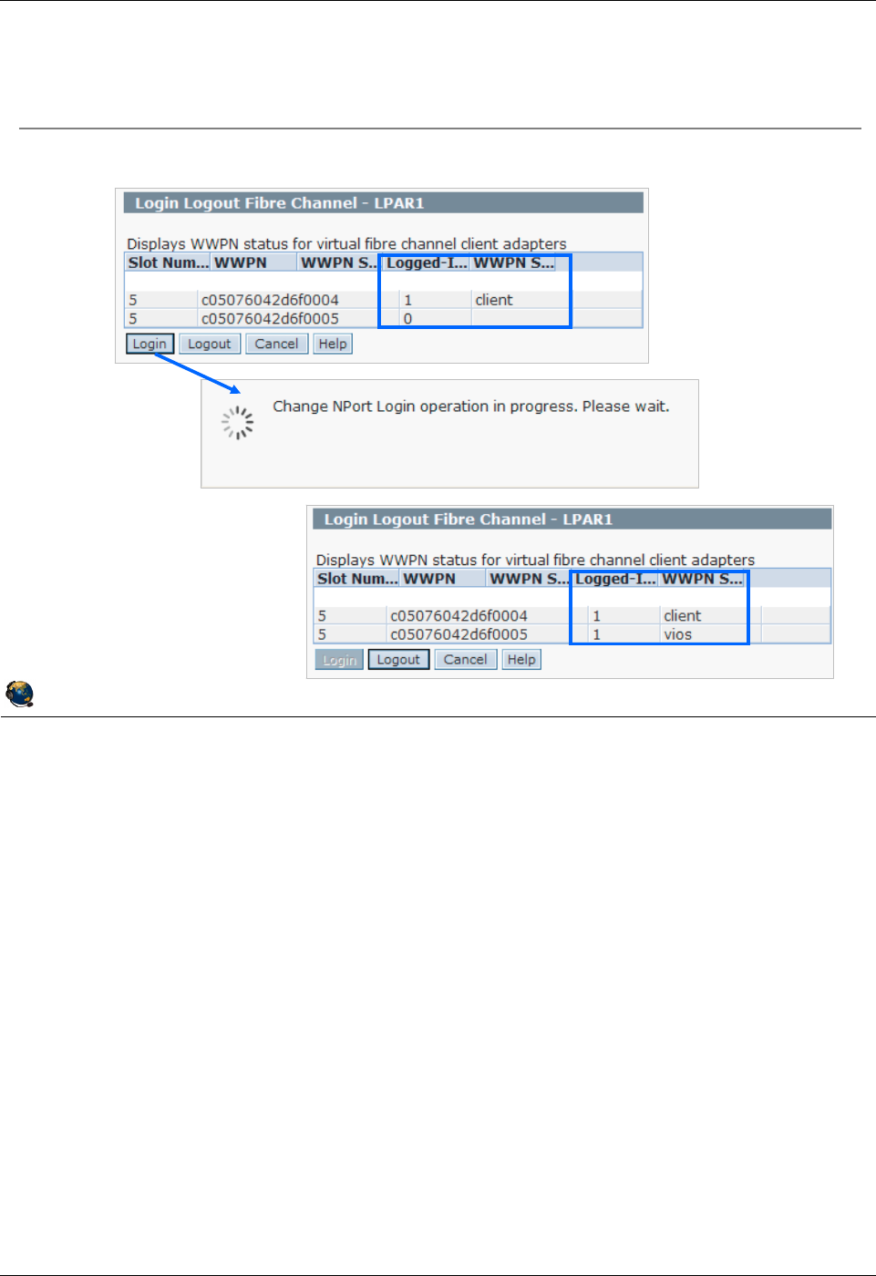
Student Notebook
Course materials may not be reproduced in whole or in part
without the prior written permission of IBM.
4-22 VIOS © Copyright IBM Corp. 2012
Figure 4-20. Activating WWPNs from the HMC GUI (2 of 2) QV3441.0
Notes:
Log in and log out of N_Ports from HMC GUI
The visual above shows three HMC GUI panels. The one at the top shows all of the
WWPNs available on the client. The login status is shown in the third column from the
left. In the example shown above, only one WWPN is currently logged in with a login
status of 1. Click the Login button to log all the ports into the fabric.
The middle panel shows the working window while the login (or logout) process is
running.
The third panel on the bottom shows a panel where all of the WWPNs are logged in.
Notice that the first WWPN is the truly active WWPN because the client is logged in.
The second WWPN shows that the VIOS is logged in. If you were to click the Logout
button at this point, the screen would update to look like the first panel again. Note that
client and vios are key words and not partition names.
© Copyright IBM Corporation 2012
UNIX Software Service Enablement
Activating WWPNs from the HMC GUI (2 of 2)
Use the Login and Logout buttons
Student Notebook
Course materials may not be reproduced in whole or in part
without the prior written permission of IBM.
© Copyright IBM Corp. 2012 Unit 4. Virtual Fibre Channel Storage Devices 4-23
V7.0
Uempty
Figure 4-21. Monitoring and tuning virtual Fibre Channel adapters (1 of 2) QV3441.0
Notes:
Monitoring
Monitor the virtual Fibre Channel adapter and any attached disks just like you would
physical devices. The nmon and fcstat commands are mentioned on the visual above
as example commands to monitor FC adapter statistics.
max_xfer_size
There are various strategies to tune the max_xfer_size attribute on physical FC
adapters. That is beyond the scope of this course. Once the VIOS administrator has
determined the proper physical FC adapter max_xfer_size value, then you should
configure any virtual FC adapters using the same value.
The example commands on the visual above show how to check the attribute on the
VIOS and on the client AIX LPAR. Use the chdev command with the -P flag to change
the attribute in the ODM then reboot.
© Copyright IBM Corporation 2012
UNIX Software Service Enablement
Monitoring and tuning virtual Fibre Channel
adapters (1 of 2)
Monitor virtual Fibre Channel activity like a physical adapter
Use nmon and fcstat
Use the ^ character to get to the nmon FC adapter monitor screen
On the VIOS, nmon must be run from root environment
Tune the max_xfer_size attribute of the clients vFC adapter (fcs#) to
match the physical adapter
Controls the maximum I/O size the adapter will handle
Example:
$ lsdev -dev fcs0 -attr max_xfer_size
value
0x200000
# lsattr -El fcs0 | grep max_xfer_size
max_xfer_size 0x100000 Maximum Transfer Size True
# chdev -l fcs0 -a max_xfer_size=0x200000 -P
fcs0 changed
On VIOS
On client
Student Notebook
Course materials may not be reproduced in whole or in part
without the prior written permission of IBM.
4-24 VIOS © Copyright IBM Corp. 2012
Figure 4-22. Monitoring and tuning virtual Fibre Channel adapters (2 of 2) QV3441.0
Notes:
num_cmd_elems
There are various strategies to tune the num_cmd_elems attribute on physical FC
adapters. That is beyond the scope of this course. Once the VIOS administrator has
determined the proper physical FC adapter num_cmd_elems value, then you should
configure any virtual FC adapters to an appropriate value. Similar to tuning the
queue_depth value for virtual disks, the appropriate value for num_cmd_elems varies
based on the configuration and workload. Recall that up to 64 virtual Fibre Channel
adapters can be connected to the same physical adapter port. If the physical adapter
can handle 200 commands, and all 64 virtual FC adapters send 200 commands all at
once, that is too many for the adapter to handle. If the physical adapter can handle
2048 commands and there is only one virtual FC adapter that is sending only 200
commands, then you may see improved performance with higher workloads by
increasing the virtual FC attribute value to 2048. The example commands above show
how to check the attribute on the VIOS and on the client AIX LPAR. Use the chdev
command with the -P flag to change the attribute in the ODM then reboot.
© Copyright IBM Corporation 2012
UNIX Software Service Enablement
Monitoring and tuning virtual Fibre Channel
adapters (2 of 2)
Tune the num_cmd_elems attribute of the vFC adapter
Number of commands the adapter can handle (command queue depth)
Tune similar to the way queue_depth is tuned for virtual disks
If the vFC adapter is the only adapter using a physical FC port, then make
the value on the virtual adapter the same as the physical adapter
If there are multiple vFC adapters for one physical FC port, decide on a
dedicated or shared strategy
Maximum value is 2048
Example:
$ lsdev -dev fcs0 -attr num_cmd_elems
value
500
# lsattr -El fcs0 | grep num_cmd_elems
num_cmd_elems 200 Maximum Number of COMMAND Elements True
# chdev -l fcs0 -a num_cmd_elems=500 -P
fcs0 changed
On VIOS
On client

Student Notebook
Course materials may not be reproduced in whole or in part
without the prior written permission of IBM.
© Copyright IBM Corp. 2012 Unit 4. Virtual Fibre Channel Storage Devices 4-25
V7.0
Uempty
Figure 4-23. Checkpoint (1 of 2) QV3441.0
Notes:
© Copyright IBM Corporation 2012
UNIX Software Service Enablement
Checkpoint (1 of 2)
1. True or False: When a client partition uses a virtual Fibre Channel
adapter to access its disks, the VIOS hosting the physical adapter does
not see the clients disks.
2. True or False: You must zone SAN LUNs to both the virtual FC adapter
WWPNs and the VIOSs physical adapter port WWPN.
3. When using virutal Fibre Channel instead of virtual SCSI, which of the
following is a false statement:
A. VIOS administrator doesnt have to keep documentation about all of the client
endpoint devices.
B. Clients can use other path control modules with added benefits such as load
balancing.
C. NPIV provides an emulated environment.
D. Clients see real type of disk so tools which are specific to a certain type of disk
will work.

Student Notebook
Course materials may not be reproduced in whole or in part
without the prior written permission of IBM.
4-26 VIOS © Copyright IBM Corp. 2012
Figure 4-24. Checkpoint (2 of 2) QV3441.0
Notes:
© Copyright IBM Corporation 2012
UNIX Software Service Enablement
Checkpoint (2 of 2)
4. The name for the virtual FC client adapters port is:
A. vfchost#
B. F_Port
C. N_Port
D. VTD
5. Once a client has a virtual Fibre Channel adapter connection through the
VIOS which supports NPIV, it has a unique identifier on the SAN fabric
called a _________________________.
6. The name of the virtual FC server adapter device on the VIOS is
_______________________.
7. True or False: The chsyscfg HMC command workaround procedure will
alter the running configuration of an LPAR.

Student Notebook
Course materials may not be reproduced in whole or in part
without the prior written permission of IBM.
© Copyright IBM Corp. 2012 Unit 4. Virtual Fibre Channel Storage Devices 4-27
V7.0
Uempty
Figure 4-25. Exercise 4 - Virtual Fibre Channel storage devices QV3441.0
Notes:
© Copyright IBM Corporation 2012
UNIX Software Service Enablement
Exercise 4 Virtual Fibre Channel storage
devices
Activity:
Configure virtual Fibre Channel NPIV disks
View information about the NPIV configuration
Use the HMC to log WWPNs into and out of the SAN fabric
Monitor activity on an NPIV device
Check virtual Fibre Channel tunables

Student Notebook
Course materials may not be reproduced in whole or in part
without the prior written permission of IBM.
4-28 VIOS © Copyright IBM Corp. 2012
Figure 4-26. Unit summary QV3441.0
Notes:
© Copyright IBM Corporation 2012
UNIX Software Service Enablement
Unit summary
Virtual Fibre Channel adapters are implemented with a client-server
virtual adapter model similar to VSCSI adapters
N-Port ID Virtualization (NPIV) allows a client LPAR to manage SAN
disk storage at the SAN storage manager rather than having to create
and map individual backing storage devices on the VIOS
Virtual FC adapters are configured in pairs with one on the VIOS and
one on the client LPAR
The client virtual FC adapter has two WWPNs and both should be
zoned for LUNs
The HMC CLI or GUI can be used to cause all of the virtual FC
adapter WWPNs in a client LPAR to login to the SAN fabric

Student Notebook
Course materials may not be reproduced in whole or in part
without the prior written permission of IBM.
© Copyright IBM Corp. 2012 Unit 5. Virtual Ethernet Adapter Configuration 5-1
V7.0
Uempty Unit 5. Virtual Ethernet Adapter Configuration
What this unit is about
This unit describes virtual Ethernet adapters, VLAN IDs, the Virtual
Network Management task, and virtual Ethernet switches.
What you should be able to do
After completing this unit, you should be able to:
• Describe how virtual Ethernet is implemented on POWER
processor-based systems
• Describe the IEE 802.1Q VLAN-aware Ethernet switch functionality
provided by the Hypervisor
• Configure communications between partitions using virtual
Ethernet adapters
• Describe the configuration of the Hypervisor virtual Ethernet
switches
How you will check your progress
Accountability:
• Checkpoint questions
• Machine exercises
References
IBM Power Systems Hardware Information Center:
http://publib.boulder.ibm.com/infocenter/powersys/v3r1m5/index.jsp
Virtual I/O Server product documentation from the IBM Power
Systems Hardware Information Center:
http://publib.boulder.ibm.com/infocenter/powersys/v3r1m5/index.jsp?t
opic=/p7hb1/iphb1kickoff.htm
IBM Redbooks documents can be found at:
http://www.redbooks.ibm.com
SG24-7940 IBM PowerVM Virtualization Introduction and
Configuration, an IBM Redbooks document

Student Notebook
Course materials may not be reproduced in whole or in part
without the prior written permission of IBM.
5-2 VIOS © Copyright IBM Corp. 2012
SG24-7590 IBM PowerVM Virtualization Managing and Monitoring, an
IBM Redbooks document
REDP4194 IBM System p Advanced POWER Virtualization
(PowerVM) Best Practices, an IBM Redbooks
document

Student Notebook
Course materials may not be reproduced in whole or in part
without the prior written permission of IBM.
© Copyright IBM Corp. 2012 Unit 5. Virtual Ethernet Adapter Configuration 5-3
V7.0
Uempty
Figure 5-1. Unit objectives QV3441.0
Notes:
© Copyright IBM Corporation 2012
UNIX Software Service Enablement
Unit objectives
After completing this unit, you should be able to:
Describe how virtual Ethernet is implemented on POWER processor-
based systems
Describe the IEEE 802.1Q VLAN-aware Ethernet switch functionality
provided by the Hypervisor
Configure communications between partitions using virtual Ethernet
adapters
Describe the configuration of the Hypervisor virtual Ethernet switches

Student Notebook
Course materials may not be reproduced in whole or in part
without the prior written permission of IBM.
5-4 VIOS © Copyright IBM Corp. 2012
Figure 5-2. Virtual Ethernet overview QV3441.0
Notes:
Virtual Ethernet overview
Virtual Ethernet enables inter-partition communication without the need for physical
network adapters assigned to each partition. This technology enables IP-based
communication between logical partitions on the same system.
The AIX virtual Ethernet device driver is limited to controlling 256 virtual Ethernet
devices.
There is no extra software or system feature that must be purchased to use virtual
Ethernet adapters. You do not need a Virtual I/O Server unless you wish to bridge the
internal virtual Ethernet traffic to an external network with a Shared Ethernet adapter.
© Copyright IBM Corporation 2012
UNIX Software Service Enablement
Virtual Ethernet overview
Virtual Ethernet on POWER5 and higher processor-based systems:
Enables inter-partition communication without the need for physical
network adapters assigned to each partition:
Adapters are virtual and if communication is only between partitions on
same managed system, no physical Ethernet adapter is needed
Partitions can run either AIX V5.3 and up, Linux, or IBM i 6.1 or above
256 virtual Ethernet adapters supported per partition for AIX
Support for large MTUs (up to 65390) on AIX
Supports both IPv4 and IPv6 standards
Implemented using the VLAN IEEE 802.1Q standard
A VLAN ID number is used to designate a virtual network

Student Notebook
Course materials may not be reproduced in whole or in part
without the prior written permission of IBM.
© Copyright IBM Corp. 2012 Unit 5. Virtual Ethernet Adapter Configuration 5-5
V7.0
Uempty
Figure 5-3. POWER Hypervisor Ethernet switch QV3441.0
Notes:
Introduction
The POWER Hypervisor switch allows partitions to communicate with each other by
using virtual Ethernet adapters and assigning VLAN IDs (VIDs) that enable them to
share a common logical network.
The virtual Ethernet adapters are created and the VID assignments are performed
using the Hardware Management Console (HMC) or the Integrated Virtualization
Manager (IVM). The system requires virtual Ethernet adapters to be configured with a
default VID that will be used by the POWER Hypervisor to tag untagged packets. The
default VID is called the Port VID (PVID).
The POWER Hypervisor transmits packets by copying the packet directly from the
memory of the sender partition to the receive buffers of the receiver partition without
any intermediate buffering of the packet.
The Hypervisor supports 4094 VLANs (1 - 4094). VLAN IDs 0 and 4095 are reserved.
© Copyright IBM Corporation 2012
UNIX Software Service Enablement
POWER Hypervisor Ethernet switch
The POWER Hypervisor provides the Ethernet switch functionality:
Implements a software Ethernet switch
Supports up to a maximum of 4094 networks (VLAN IDs)
Copies packets between partitions (memory to memory)
Consistent with VLAN IEEE 802.1Q standard
The ports on this switch are configured via the HMC and are part of the
partitions configuration:
Configuring a Port VLAN ID (PVID) is required on the Hypervisor
switch
Can create up to 16 virtual Ethernet switches
One by default
Allows you to reuse VLAN IDs for separate virtual LANs
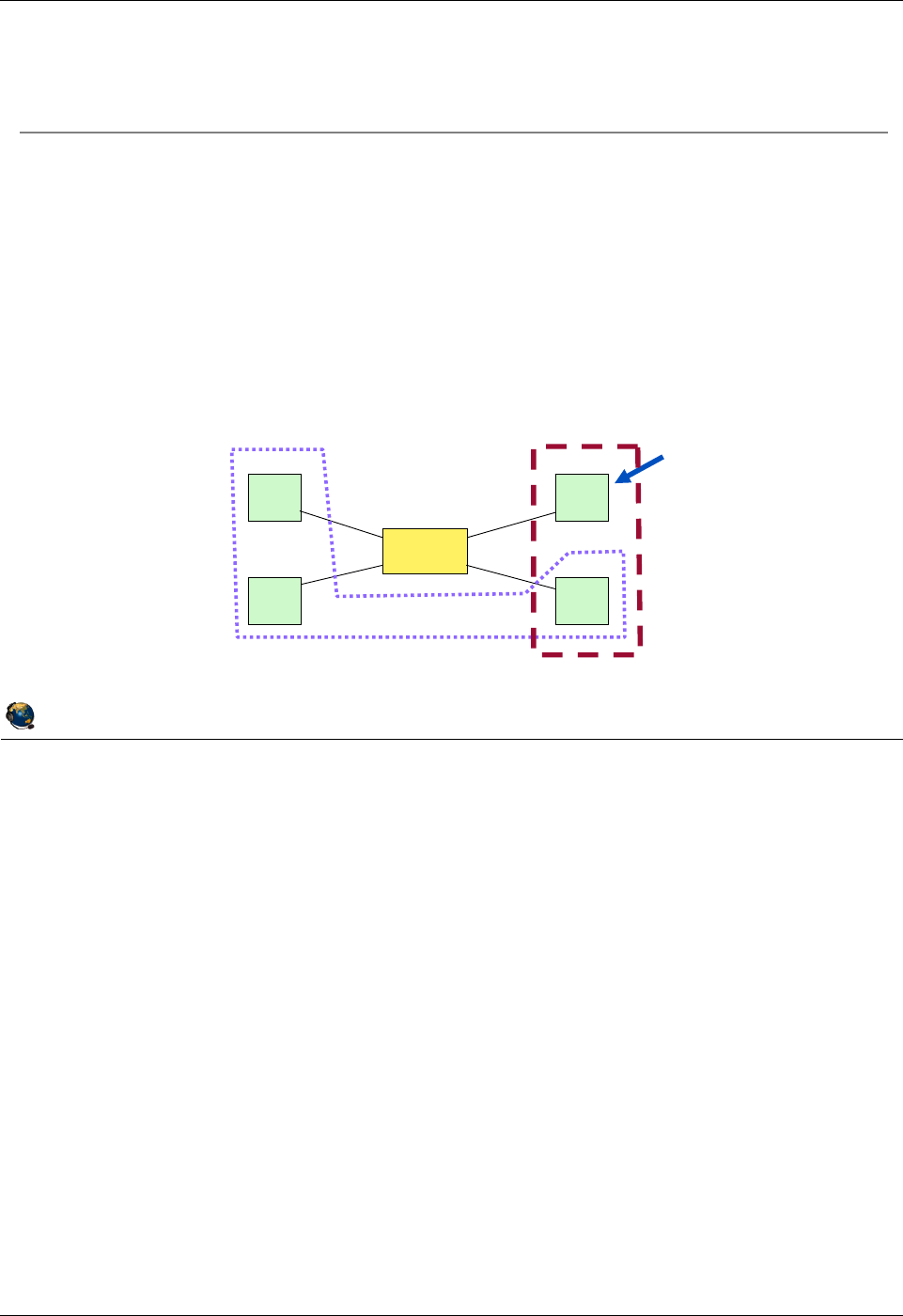
Student Notebook
Course materials may not be reproduced in whole or in part
without the prior written permission of IBM.
5-6 VIOS © Copyright IBM Corp. 2012
Figure 5-4. Virtual LAN (VLAN) overview QV3441.0
Notes:
VLAN Overview
Virtual LAN is a technology used for establishing virtual network segments on top of
physical switch devices. Multiple VLAN logical devices can be configured on a single
system. Each VLAN logical device constitutes an additional Ethernet adapter instance,
and can be used to configure the same types of Ethernet IP interfaces that are used
with physical Ethernet adapters.
VLAN support in AIX is based on the IEEE 802.1Q VLAN implementation. The IEEE
802.1Q VLAN is achieved by adding a VLAN ID tag to an Ethernet frame, and the
Ethernet switches restricting the frames to ports that are authorized to receive frames
with that VLAN ID. Switches also restrict broadcasts to the logical network by ensuring
that a broadcast packet is delivered to all ports which are configured to receive frames
with the VLAN ID that the broadcast frame was tagged with.
As VLAN ensures logical separation at layer 2, it is not possible to have an IP network
that spans multiple VLANs (different VIDs).
© Copyright IBM Corporation 2012
UNIX Software Service Enablement
Virtual LAN (VLAN) overview
Virtual LAN (VLAN) establishes virtual network segments on top of
physical switch devices:
Layer 2 connectivity restricted to members of the same VLAN:
ISO OSI Model: structured seven layer networking model
IP (and thus IP addresses and IP routing) is at Layer 3
Virtual and dedicated network devices can be used simultaneously
for communication
VLAN example with two VLANs:
A
B
C
D
Switch
Hosts
VLAN 1 VLAN 2

Student Notebook
Course materials may not be reproduced in whole or in part
without the prior written permission of IBM.
© Copyright IBM Corp. 2012 Unit 5. Virtual Ethernet Adapter Configuration 5-7
V7.0
Uempty
Figure 5-5. IEEE 802.1Q VLAN QV3441.0
Notes:
VLAN IEEE standard
The VID can be added to an Ethernet packet either by a VLAN aware host or by the
switch in the case of VLAN unaware hosts. Therefore ports on a VLAN-aware Ethernet
switch have to be configured with a PVID, and may be configured with additional VLAN
IDs.
For VLAN unaware hosts, the switch will tag all packets entering through that port with
the Port VLAN ID (PVID). It will also untag all packets tagged with the PVID that exit the
port for delivery to the VLAN unaware host.
Hosts that are VLAN aware insert and remove their own tags and can be members of
more than one VLAN. In this case, the switch does not have to insert and remove tags
for the host.
© Copyright IBM Corporation 2012
UNIX Software Service Enablement
IEEE 802.1Q VLAN
Ethernet packets are tagged with their VLAN membership information
Ethernet switch restricts delivery to members of that VLAN
The VID can be added to an Ethernet packet either by:
VLAN aware host
The switch (in the case of VLAN unaware hosts)
Recommendations
Single network per adapter use untagged port and PVID
Multiple networks per adapter use VID
For POWER5 and higher processor-based systems:
Virtual Ethernet adapter with only a PVID is configured just like physical Ethernet
adapter:
The Hypervisor Ethernet switch (Hypervisor) uses the PVID tag for untagged
packets
Virtual Ethernet adapter with multiple VIDs is configured as a VLAN device with
tagging
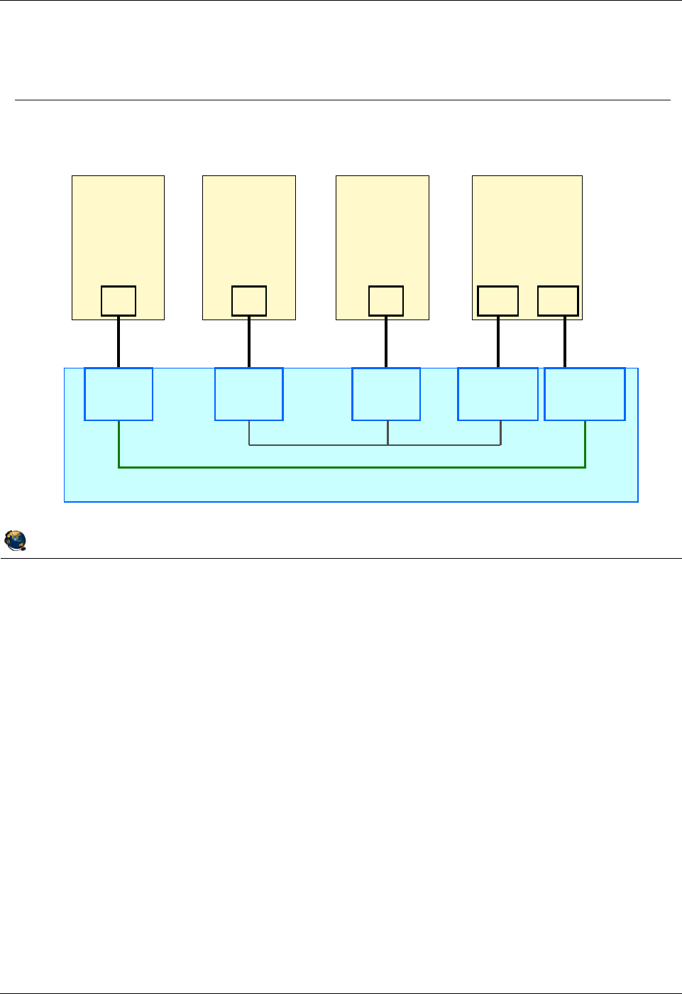
Student Notebook
Course materials may not be reproduced in whole or in part
without the prior written permission of IBM.
5-8 VIOS © Copyright IBM Corp. 2012
Figure 5-6. Virtual Ethernet configuration example (1 of 2) QV3441.0
Notes:
Simple configuration
In a simple configuration, virtual Ethernet adapters are defined only with PVIDs, and
LPARs configured with the same PVID can communicate with each other on the same
VLAN. In this scenario:
- The operating system running in such a partition is not aware of the VLANs.
- Only packets for the VLAN specified as PVID are received.
- Packets have their VLAN tag removed by the POWER Hypervisor before the
partitions receive them.
- Packets sent by these partitions have a VLAN tag attached for the VLAN specified
as PVID by the POWER Hypervisor.
When you create this type of adapter from the HMC, you do NOT check the IEEE
802.1Q checkbox, and only specify the adapter ID and PVID for the VLAN ID. This
configuration is demonstrated later in this unit.
© Copyright IBM Corporation 2012
UNIX Software Service Enablement
POWER Hypervisor (IEEE 802.1Q VLAN-aware switch)
LPAR 1
PVID 1
Switch Port
ent0
LPAR 2
ent0
PVID 10
Switch Port
LPAR 3
ent0
PVID 10
Switch Port
LPAR 4
ent0 ent1
PVID 10
Switch Port
PVID 1
Switch Port
PVID only example
Virtual Ethernet configuration example (1 of 2)
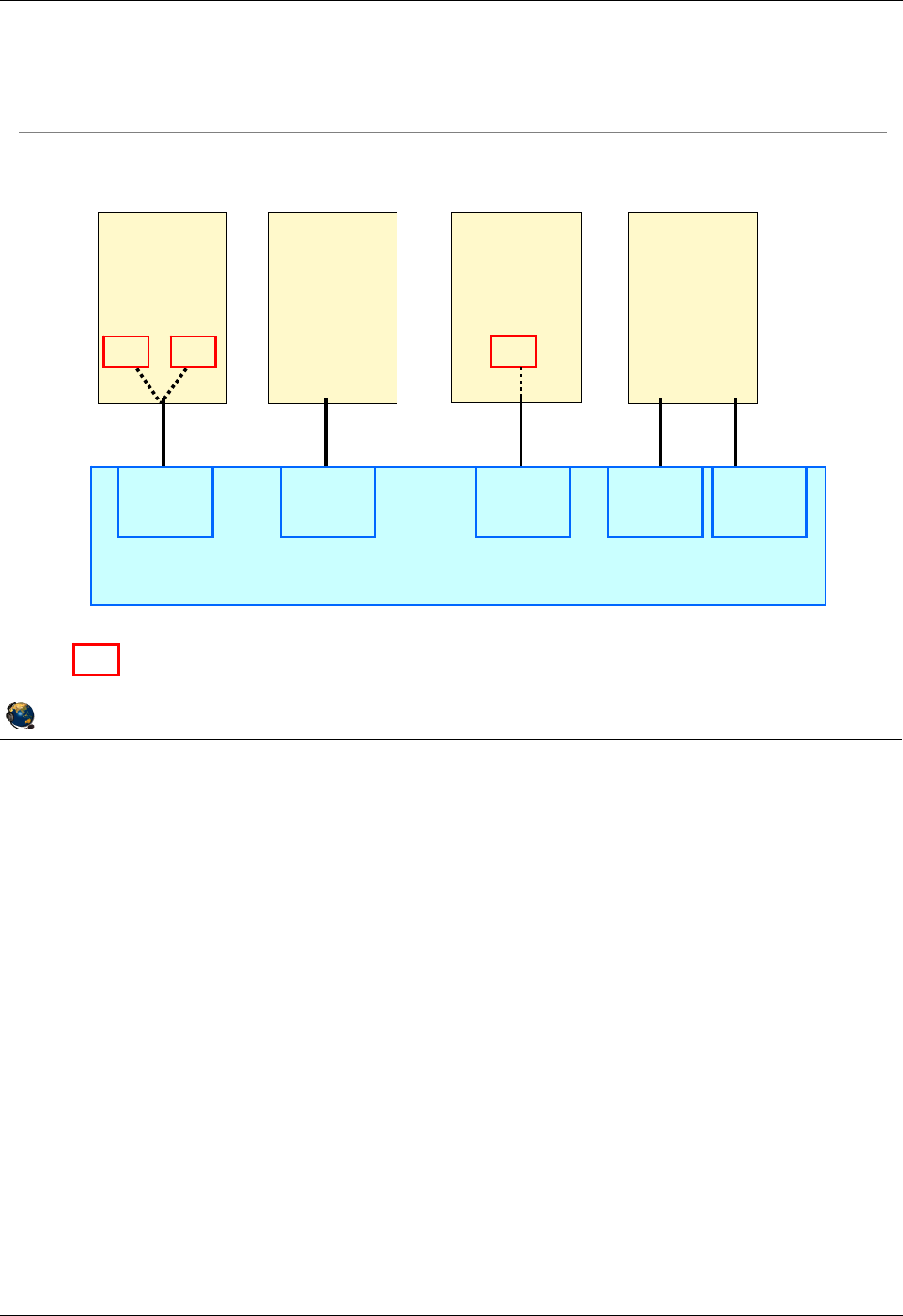
Student Notebook
Course materials may not be reproduced in whole or in part
without the prior written permission of IBM.
© Copyright IBM Corp. 2012 Unit 5. Virtual Ethernet Adapter Configuration 5-9
V7.0
Uempty
Figure 5-7. Virtual Ethernet configuration example (2 of 2) QV3441.0
Notes:
VLAN tagging
In the visual, all LPARs shown can communicate on VLAN ID 10, and all but LPAR2 can
communicate on VLAN ID 20. Examine the ways that VLAN access is provided for each
LPAR.
LPAR1 and LPAR3 define VLAN devices. These are ent1 and ent2 in LPAR1, and ent1
in LPAR3. Packets leaving these devices are tagged by the host. On the other hand,
LPAR2 and LPAR4 are VLAN-unaware hosts and use PVIDs to communicate on
VLANs 10 and 20. In this case, the POWER Hypervisor switch adds the VLAN tags to
packets when they enter the switch port from the virtual Ethernet adapter.
© Copyright IBM Corporation 2012
UNIX Software Service Enablement
POWER Hypervisor
LPAR 2
VLAN
Unaware
host
ent0
PVID 10
LPAR 4
VLAN
Unaware
host
ent0 ent1
PVID 10 PVID 20
ent1
Indicates VLAN device
ent0
LPAR 1
VLAN
Aware
host
PVID 1
VID 10, 20
VID 10 VID 20
ent0
LPAR 3
VLAN
Aware
host
ent1
PVID 10
VID 20
VID 20
Multiple VLANs example
ent1 ent2
Virtual Ethernet configuration example (2 of 2)
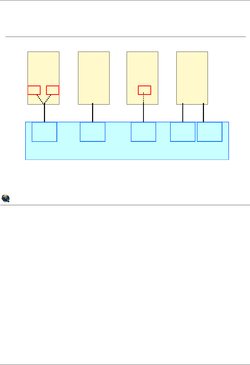
Student Notebook
Course materials may not be reproduced in whole or in part
without the prior written permission of IBM.
5-10 VIOS © Copyright IBM Corp. 2012
Figure 5-8. Packets leaving virtual Ethernet hosts QV3441.0
Notes:
VLAN tagging example
In the visual, two scenarios are shown that indicate how VLAN tagging is handled when
a packet leaves through a virtual Ethernet adapter.
In the first scenario (labeled with the number ‘1’), configured VLAN adapters tag the
packets leaving through those devices. Tagged packets enter the switch port, and the
tags are left intact. The port will discard packets that are tagged with a VLAN ID that is
not configured on the port.
In the second scenario (labeled with the number ‘2’), virtual Ethernet adapters that are
only configured with a PVID do not tag packets. The PVID is added to packets at the
switch port before they are processed and forwarded to other ports on the switch.
© Copyright IBM Corporation 2012
UNIX Software Service Enablement
M
Packets leaving VLAN adapters are tagged with their VID
N
Packets leaving VLAN-unaware adapters are tagged with the ports PVID by
the Hypervisor
POWER Hypervisor
LPAR 1 LPAR 2
VLAN
Unaware
host
ent0
PVID 10
LPAR 4
VLAN
Unaware
host
ent0 ent1
PVID 10 PVID 20
ent0
LPAR 3
VLAN
Aware
host
ent1
PVID 10
VID 20
VID 20
ent0
VLAN
Aware
host
PVID 1
VID 10, 20
VID
10
VID
20
ent1 ent2
MN
M
N
Packets leaving virtual Ethernet hosts
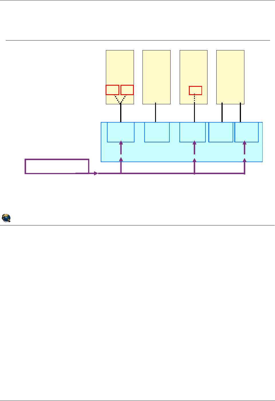
Student Notebook
Course materials may not be reproduced in whole or in part
without the prior written permission of IBM.
© Copyright IBM Corp. 2012 Unit 5. Virtual Ethernet Adapter Configuration 5-11
V7.0
Uempty
Figure 5-9. Packet delivered to virtual Ethernet hosts QV3441.0
Notes:
Packet delivery to virtual Ethernet hosts
The visual describes what happens when the POWER Hypervisor switch receives a
tagged packet for delivery to virtual Ethernet hosts. Each of the scenarios shown is
described below, where the packet being delivered is tagged with VID 20:
1. The switch port for the virtual Ethernet adapter in LPAR1 is configured to receive
packets on this VLAN. The tagged packet is delivered to the ent0 adapter, which
then presents the packet to the ent2 VLAN device.
2. The switch port for the adapter in LPAR2 is not configured for this VID, so the packet
is not delivered here.
3. The switch port for the adapter in LPAR3 is configured for VID 20, and it is delivered
to the ent0 adapter, which then presents the packet to the ent1 VLAN device.
4. The switch port for one of the adapters in LPAR4 is configured for VID 20, but since
it is the PVID, the tag is stripped before being delivered to ent1.
© Copyright IBM Corporation 2012
UNIX Software Service Enablement
MTagged packet is delivered to ent2
NPacket is NOT delivered (VID 20 not configured for this port)
OTagged packet is delivered to ent1
PTag is stripped by Hypervisor and untagged packet delivered to ent1
POWER Hypervisor
LPAR 2
VLAN
Unaware
host
ent0
LPAR 4
VLAN
Unaware
host
ent0 ent1
PVID 1
VID 10, 20
PVID 10 PVID 10
VID 20
PVID 10 PVID 20
VID 20 | IP 9.47.87.0
LPAR 1
ent0
VLAN
Aware
host
ent1 ent2
VID
10
VID
20
LPAR 3
ent0
VLAN
Aware
host
ent1
VID
20
OPNM
Packet delivered to virtual Ethernet hosts
Packet destined for VID
20 is delivered to virtual
Ethernet hosts via the
Hypervisor switch
Tagged packets are only
delivered to ports
configured on that VLAN
Student Notebook
Course materials may not be reproduced in whole or in part
without the prior written permission of IBM.
5-12 VIOS © Copyright IBM Corp. 2012
Figure 5-10. Virtual Ethernet adapters QV3441.0
Notes:
MAC address
The MAC address that the managed system assigns to the virtual Ethernet adapter is
unique within the managed system. However, this MAC address is not universally
unique, and might not be unique within a network containing multiple managed
systems. Having multiple virtual Ethernet adapters with the same MAC address can
cause network problems. To resolve these problems, you can change the MAC address
assigned to a virtual Ethernet adapter using the chhwres command on the Hardware
Management Console (HMC) or by configuring an alternate MAC address in the
operating system. This may be necessary when an LPAR is moved to another server
using Live Partition Mobility if the current MAC address is the same as one on the
destination server.
© Copyright IBM Corporation 2012
UNIX Software Service Enablement
Virtual Ethernet adapters
Virtual Ethernet adapters are required to access the Hypervisor
Ethernet switch
Use HMC to create virtual adapters
Created in a partitions profile or dynamically
HMC generates MAC address
Local bit to prevent conflict with physical Ethernet
Based on machine serial number for uniqueness
Access to 19 VLAN networks per adapter (plus the PVID)
VLAN 100 VLAN 200
VLAN 300
LPAR 1 LPAR 2 LPAR 3 LPAR 4 LPAR 5
POWER Hypervisor (switch)
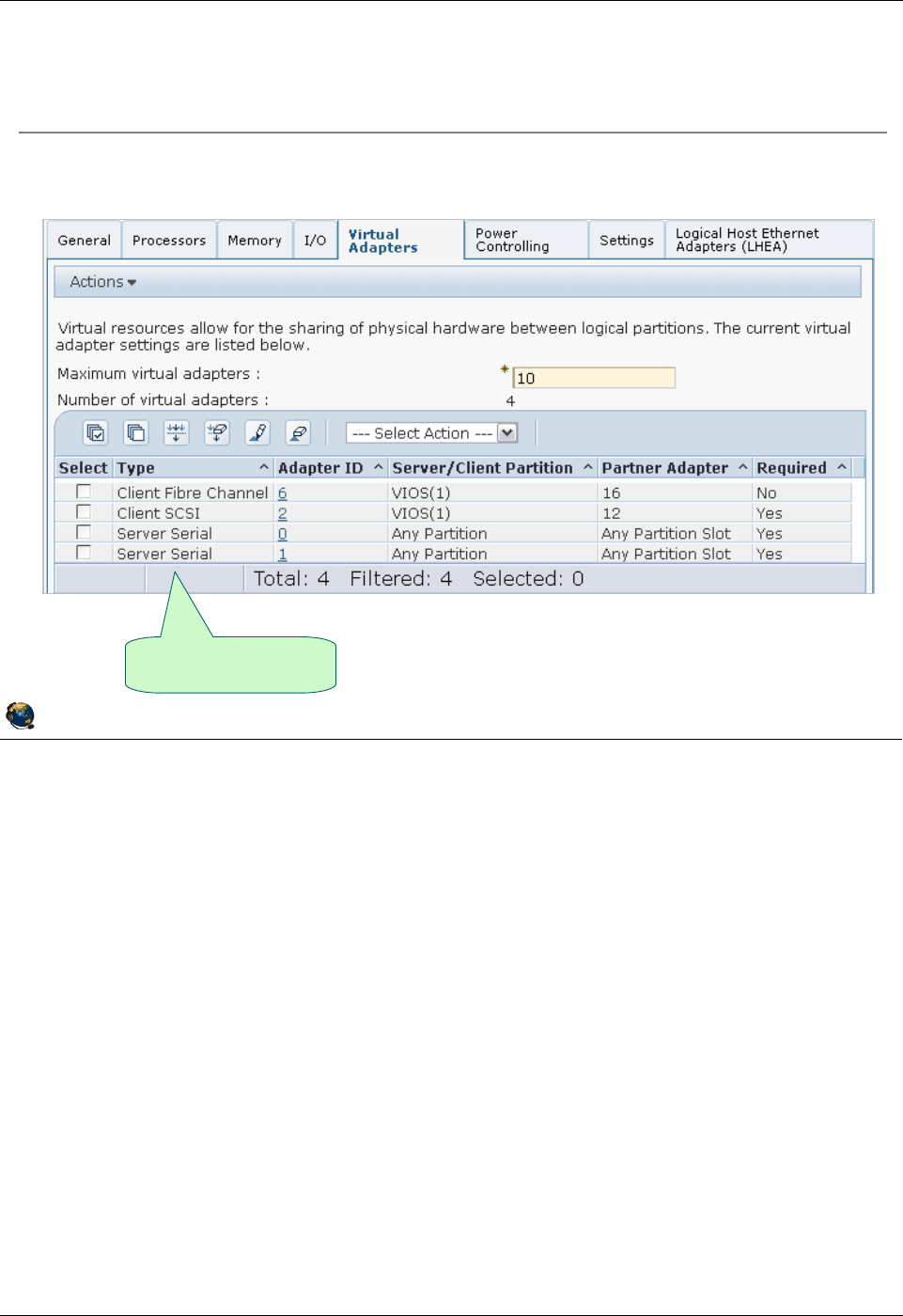
Student Notebook
Course materials may not be reproduced in whole or in part
without the prior written permission of IBM.
© Copyright IBM Corp. 2012 Unit 5. Virtual Ethernet Adapter Configuration 5-13
V7.0
Uempty
Figure 5-11. Creating a virtual Ethernet adapter (1 of 6) QV3441.0
Notes:
Creating virtual Ethernet adapters
You can change the maximum number of virtual adapters allowed for the partition only
in the profile. The new value will be used at the next activation and is not dynamic.
The maximum virtual adapters value does not affect Hypervisor memory overhead,
however, the more virtual adapters you create, the more memory the Hypervisor will
require to support the active adapters (in other words, the number of active virtual I/O
adapters affects the amount of Hypervisor memory).
Virtual adapters can be created using the Dynamic Logical Partitioning menu option
on the HMC. After adding any devices dynamically, run cfgmgr in the AIX partition so
the operating system will discover the new devices.
If you only change the partition profile, you will need to re-activate the partition for the
changes to take effect.
© Copyright IBM Corporation 2012
UNIX Software Service Enablement
Creating a virtual Ethernet adapter (1 of 6)
Configure adapters in a profile or using DLPAR
Currently configured
virtual adapters
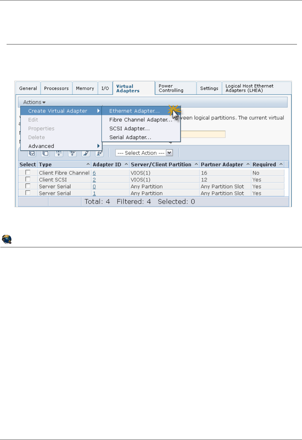
Student Notebook
Course materials may not be reproduced in whole or in part
without the prior written permission of IBM.
5-14 VIOS © Copyright IBM Corp. 2012
Figure 5-12. Creating a virtual Ethernet adapter (2 of 6) QV3441.0
Notes:
Actions menu
Once the Virtual Adapters tab is visible, select Actions -> Create Virtual Adapter->
Ethernet Adapter. This will bring up the dialog shown in the next visual.
Notice the other actions listed in the menu. Configured adapters shown in the table on
this tab can be deleted by selecting them and choosing the Delete action. An adapter’s
configuration can be modified by selecting the adapter and choosing the Edit action. An
adapter’s properties can be displayed with the Properties action.
© Copyright IBM Corporation 2012
UNIX Software Service Enablement
Creating a virtual Ethernet adapter (2 of 6)
Use the Actions menu to manage adapters
Actions -> Create Virtual Adapter-> Ethernet Adapter
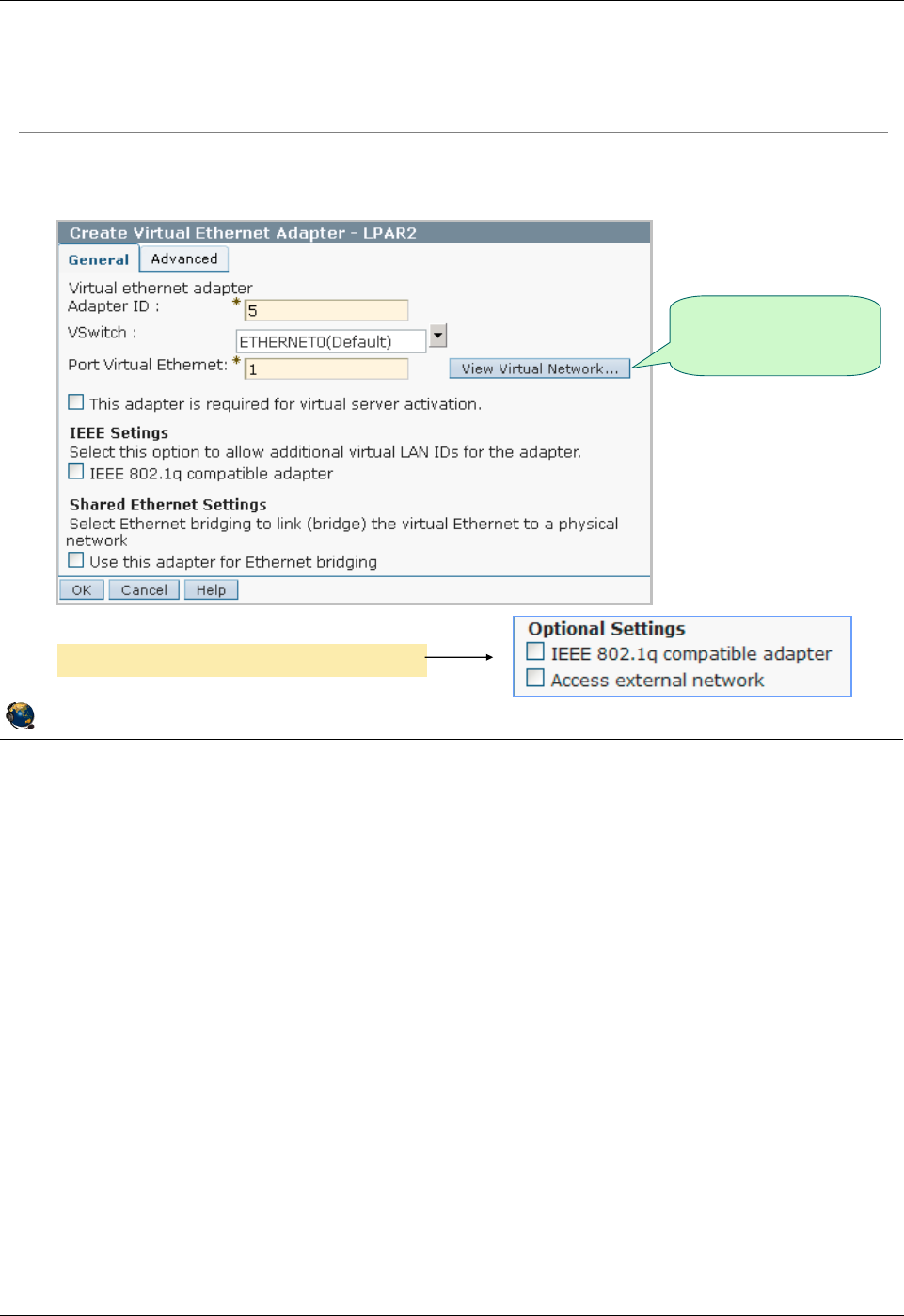
Student Notebook
Course materials may not be reproduced in whole or in part
without the prior written permission of IBM.
© Copyright IBM Corp. 2012 Unit 5. Virtual Ethernet Adapter Configuration 5-15
V7.0
Uempty
Figure 5-13. Creating a virtual Ethernet adapter (3 of 6) QV3441.0
Notes:
Introduction
The adapter will be created in the lowest numbered available virtual slot (or the lowest
available adapter ID). The adapter ID can be changed if desired, within the limits of the
maximum number available for the partition. You should enter the Port VLAN ID that will
be used for this adapter. Each adapter can connect to a single VLAN when using only
the PVID.
The checkbox below the VLAN ID field is used to mark the adapter as required. While
virtual adapters are always available at activation, it is possible that the Hypervisor does
not have enough memory to activate all virtual I/O adapters configured in the profile.
The required setting indicates that this partition cannot start without this adapter, and
that the adapter cannot be removed with a DLPAR operation.
The View Virtual Network button can be selected to view Virtual Switch (VSwitch) and
VLAN configurations.
© Copyright IBM Corporation 2012
UNIX Software Service Enablement
Creating a virtual Ethernet adapter (3 of 6)
Alter adapter ID and default VLAN ID (PVID) if necessary
Default VLAN ID (PVID) is 1
Display current
system VLAN
configuration
Optional settings prior to HMC V7R730
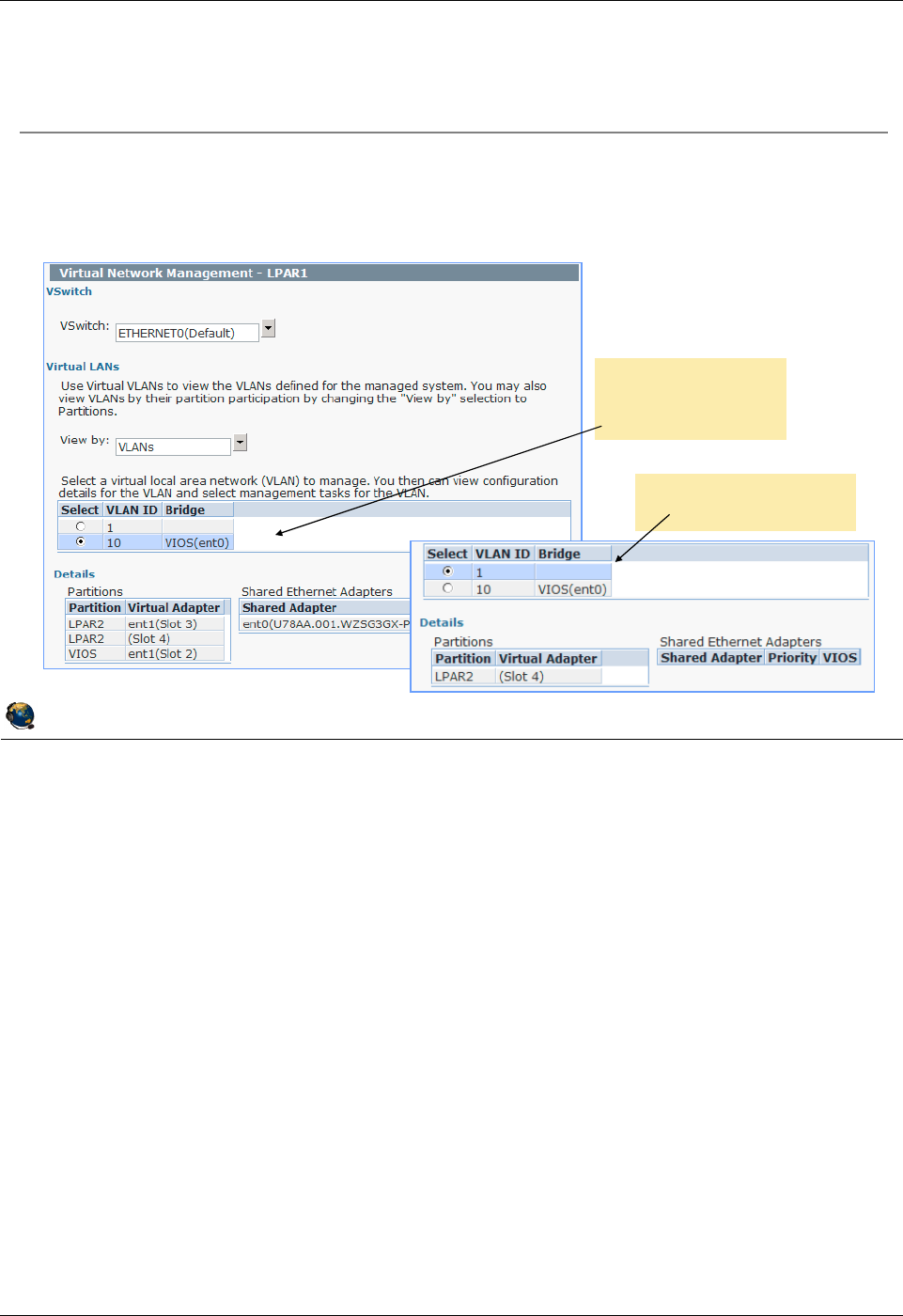
Student Notebook
Course materials may not be reproduced in whole or in part
without the prior written permission of IBM.
5-16 VIOS © Copyright IBM Corp. 2012
Figure 5-14. Creating a virtual Ethernet adapter (4 of 6) QV3441.0
Notes:
View Virtual Networks
Selecting the View Virtual Network button from the previous visual brings up this
dialog box shown in the visual above. From this task, you can:
- View existing VSwitches and their associated VLANs
- View VLANs by their definition or by partition participation
© Copyright IBM Corporation 2012
UNIX Software Service Enablement
Creating a virtual Ethernet adapter (4 of 6)
View virtual Ethernet configurations by clicking the View Virtual
Network button
Select a VLAN to view configuration details
Example where
VLAN 10 is
selected
Example where VLAN
1 is selected
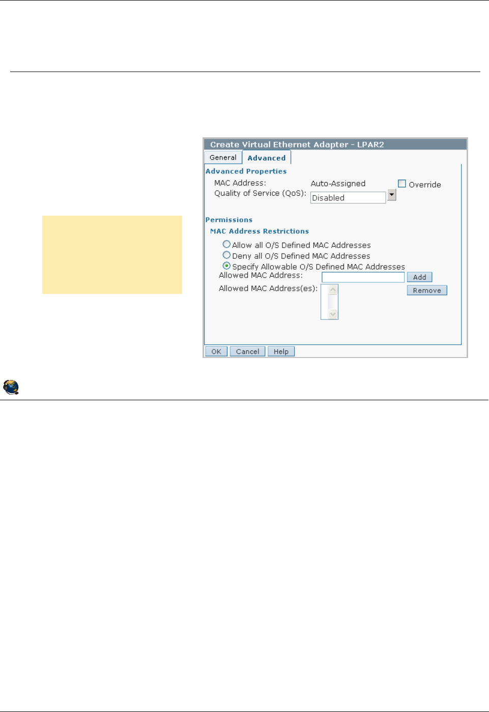
Student Notebook
Course materials may not be reproduced in whole or in part
without the prior written permission of IBM.
© Copyright IBM Corp. 2012 Unit 5. Virtual Ethernet Adapter Configuration 5-17
V7.0
Uempty
Figure 5-15. Creating a virtual Ethernet adapter (5 of 6) QV3441.0
Notes:
Advanced tab
Beginning with POWER7 servers with firmware level 720 and HMC at V7R7.2.0, you
can use this tab to configure advanced options for your virtual Ethernet adapter. When
adding a virtual Ethernet adapter to a logical partition, you can configure a custom MAC
address for the adapter and specify restrictions for operating system-defined MAC
addresses.
You can prioritize the logical partition network traffic by specifying the value of IEEE
802.1Q priority level for each virtual Ethernet adapter in the Quality of Service setting.
You can disable the setting, or set priorities 0 through 7, 7 being the highest priority. You
can edit the QoS priorities using the dynamic logical partitioning operation when the
partition is running.
© Copyright IBM Corporation 2012
UNIX Software Service Enablement
Creating a virtual Ethernet adapter (5 of 6)
The MAC address is automatically generated by the HMC
On POWER7 servers, you can:
Specify a custom MAC address
Set Quality of Service
(QoS)
Restrict MAC addresses
Beginning with
POWER7 servers, you
can use this tab to
configure advanced
options
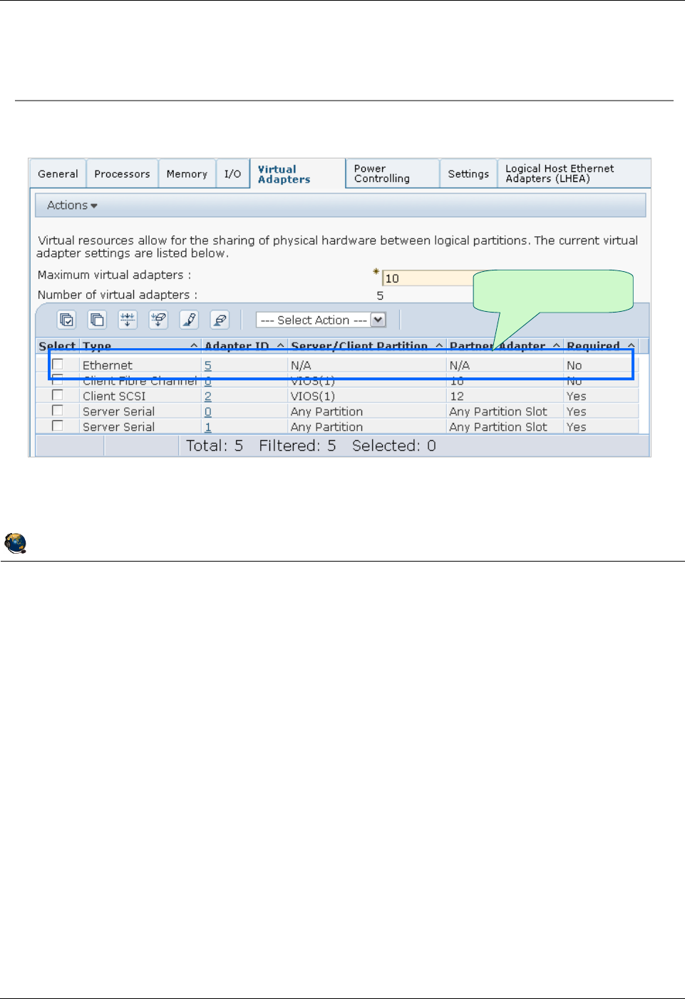
Student Notebook
Course materials may not be reproduced in whole or in part
without the prior written permission of IBM.
5-18 VIOS © Copyright IBM Corp. 2012
Figure 5-16. Creating a virtual Ethernet adapter (6 of 6) QV3441.0
Notes:
View new adapter
Once the adapter has been created, it shows up in the Virtual Adapters panel of the
partition profile. For virtual Ethernet adapters, the adapter table shown in the visual
above includes the adapter ID, the adapter type, and whether it is required or not. In this
example, you can see that the virtual Ethernet adapter was created with adapter ID 5
and it is not required. The Adapter ID is clickable to view the adapter’s properties such
as what PVID is configured.
© Copyright IBM Corporation 2012
UNIX Software Service Enablement
Creating a virtual Ethernet adapter (6 of 6)
Newly created
adapter

Student Notebook
Course materials may not be reproduced in whole or in part
without the prior written permission of IBM.
© Copyright IBM Corp. 2012 Unit 5. Virtual Ethernet Adapter Configuration 5-19
V7.0
Uempty
Figure 5-17. View adapter and interfaces QV3441.0
Notes:
Virtual Ethernet adapters in AIX
Once the virtual Ethernet adapter has been added, you should activate the partition
using the newly modified profile. Or, if the adapter was added dynamically, run the
cfgmgr command to discover the new device. The virtual Ethernet adapter will be listed
as an available boot device if you enter the Software Management Services (SMS)
menus.
On boot or when running the cfgmgr command, AIX detects the presence of the newly
added virtual Ethernet adapters, and adds appropriate ODM device entries, for example
ent1 as shown in the visual above. Since the newly added device is an Ethernet
adapter, the configure method for the adapter also defines associated network
interfaces, for example, en1 and et1 as shown in the visual above.
The virtual adapter instance and associated interfaces do not have AIX location codes,
since they are virtual devices.
© Copyright IBM Corporation 2012
UNIX Software Service Enablement
View adapter and interfaces
Activate the partition using the modified profile
Adapter is visible to partition
# lsdev -c adapter
ent0 Available Logical Host Ethernet Port (lp-hea)
ent1 Available Virtual I/O Ethernet Adapter (l-lan)
lhea0 Available Logical Host Ethernet Adapter (l-hea)
vsa0 Available LPAR Virtual Serial Adapter
Interfaces are available for configuration
Virtual interfaces do not have an AIX location code
+--------------------------------------------------------------------------+
| Available Network Interfaces |
| |
| Move cursor to desired item and press Enter. |
| |
| en0 Standard Ethernet Network Interface |
| en1 Standard Ethernet Network Interface |
| et0 IEEE 802.3 Ethernet Network Interface |
| et1 IEEE 802.3 Ethernet Network Interface |
| |
| Esc+1=Help Esc+2=Refresh Esc+3=Cancel |
| Esc+8=Image Esc+0=Exit Enter=Do |
| /=Find n=Find Next |
+--------------------------------------------------------------------------+
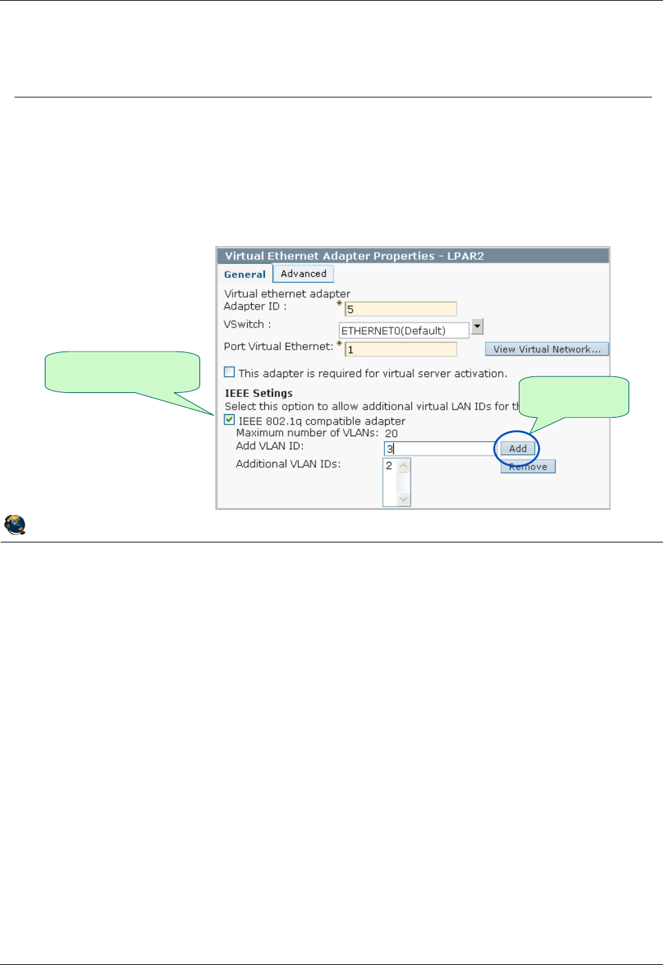
Student Notebook
Course materials may not be reproduced in whole or in part
without the prior written permission of IBM.
5-20 VIOS © Copyright IBM Corp. 2012
Figure 5-18. Adding VLAN access (1 of 3) QV3441.0
Notes:
Configuring VLAN access
In order to access multiple VLANs, the adapter must be configured as an IEEE 802.1Q
compatible adapter. Select the checkbox for this property. You can then add additional
VLAN IDs one at a time, up to a maximum of 19. This allows a single virtual Ethernet
adapter to access 20 different VLANs.
When you perform this configuration, you are configuring the switch port for this adapter
on the POWER Hypervisor switch to access multiple VLANs.
Once a virtual Ethernet adapter has been successfully added to a running partition
(either by configuring the profile and activating the partition or by DLPAR operation), the
VLAN configuration cannot be changed on POWER 5 and POWER6 servers. To alter
the list of VLAN IDs, you must remove the existing adapter and add a new one. This
can be done dynamically, but it means you must unconfigure the interfaces and remove
the devices from the operating system to complete the operation. Alternatively, you can
add an additional adapter with the proper VLAN ID.
© Copyright IBM Corporation 2012
UNIX Software Service Enablement
Adding VLAN access (1 of 3)
Check IEEE box, enter new VID, and click Add button
Up to 19 additional VIDs are allowed
As of POWER7, VIDs can be changed dynamically
Workaround for POWER5 and POWER6: Use DLPAR to remove the
adapter and re-add with new VIDs if networking to the HMC is provided
by another adapter
Check IEEE box to
be VLAN aware Add new VIDs
one at a time

Student Notebook
Course materials may not be reproduced in whole or in part
without the prior written permission of IBM.
© Copyright IBM Corp. 2012 Unit 5. Virtual Ethernet Adapter Configuration 5-21
V7.0
Uempty
Figure 5-19. Adding VLAN access (2 of 3) QV3441.0
Notes:
Adding the VLAN device
Once you have modified the virtual Ethernet adapter information in the partition profile
properties on the HMC, you should activate the partition. When the partition boots, you
will need to add one VLAN device for each additional VLAN ID that was configured on
the virtual adapter.
The easiest way to add a VLAN device is using the smit command, with the addvlan
fastpath. This will start the dialog shown in the visual above. The menu will allow you to
select the virtual Ethernet adapter that the VLAN device will be associated with, and
also specify the VLAN Tag ID that will be added to packets that are sent out on the
interface configured on the VLAN device. Once you have made appropriate selections,
press the Enter key. This will create the VLAN device (entN), and its associated
interfaces (enN and etN).
© Copyright IBM Corporation 2012
UNIX Software Service Enablement
Adding VLAN access (2 of 3)
Add VLAN devices in AIX
Use SMIT with addvlan fastpath
Select base virtual Ethernet adapter
VLAN priority is optional and used for prioritization of Shared Ethernet
adapter client traffic
Add A VLAN
Type or select values in entry fields.
Press Enter AFTER making all desired changes.
[Entry Fields]
VLAN Base Adapter ent1
* VLAN Tag ID [2] +#
VLAN Priority [] +#

Student Notebook
Course materials may not be reproduced in whole or in part
without the prior written permission of IBM.
5-22 VIOS © Copyright IBM Corp. 2012
Figure 5-20. Adding VLAN access (3 of 3) QV3441.0
Notes:
VLAN device
The VLAN device appears as an Ethernet device (ent2 in the visual above), with an
associated pair of interfaces (en2 and et2 in the visual). The interfaces can be
configured just like the ones on a regular physical Ethernet adapter. All packets sent on
the interfaces associated with the VLAN device will be tagged with the VLAN ID.
© Copyright IBM Corporation 2012
UNIX Software Service Enablement
Adding VLAN access (3 of 3)
VLAN device appears as Ethernet adapter (entN) with associated enN
and etNinterfaces
Configure interfaces as needed for access to VLAN
Virtual interfaces do not have an AIX location code
# lsdev -C | grep '^e'
en0 Available Standard Ethernet Network Interface
en1 Defined Standard Ethernet Network Interface
en2 Defined Standard Ethernet Network Interface
ent0 Available Logical Host Ethernet Port (lp-hea)
ent1 Available Virtual I/O Ethernet Adapter (l-lan)
ent2 Available VLAN
et0 Defined IEEE 802.3 Ethernet Network Interface
et1 Defined IEEE 802.3 Ethernet Network Interface
et2 Defined IEEE 802.3 Ethernet Network Interface
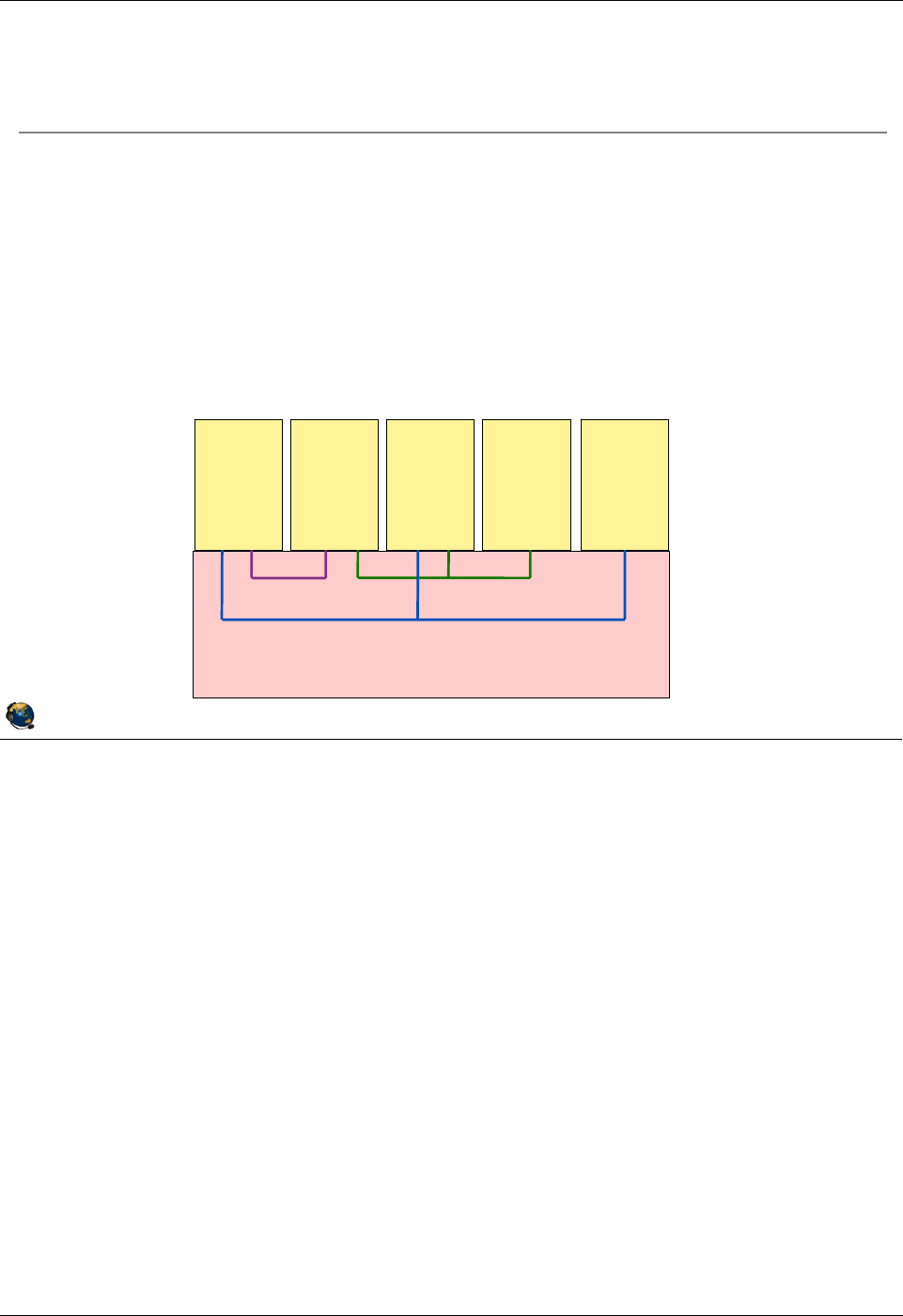
Student Notebook
Course materials may not be reproduced in whole or in part
without the prior written permission of IBM.
© Copyright IBM Corp. 2012 Unit 5. Virtual Ethernet Adapter Configuration 5-23
V7.0
Uempty
Figure 5-21. Virtual Ethernet switches QV3441.0
Notes:
Multiple Hypervisor virtual Ethernet switches
By default, there is one Hypervisor virtual Ethernet switch. You can create up to a
maximum of 16. Many customers will not need multiple switches, but it could be useful
in a server consolidation project when many hosts are moved to one server and they’re
already configured to use certain VLANs. To keep the communication separate
between partitions which are already configured for the same VIDs, you could put them
on different switches rather than changing the VIDs.
© Copyright IBM Corporation 2012
UNIX Software Service Enablement
Virtual Ethernet switches
When using multiple Ethernet switches with an HMC-managed
server, VLAN IDs on different switches are unique
That is, VLAN ID 100 on one switch is not the same as VLAN 100 on a
different switch
Example showing two switches (SW1 and SW2):
LPAR1 and LPAR5 can communicate with LPARs on SW1 with same VIDs
LPAR2 and LPAR3 can communicate with LPARs on both switches with same
VIDs
LPAR4 can communicate only with LPARs on SW2 with same VID
SW1 VID100 SW2 VID 100
SW1 VID 200
LPAR 1 LPAR 2 LPAR 3 LPAR 4 LPAR 5
POWER Hypervisor
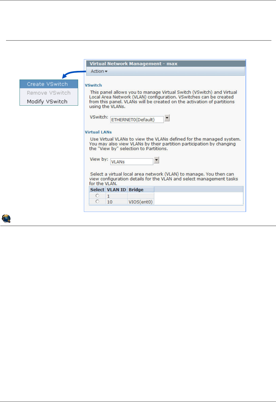
Student Notebook
Course materials may not be reproduced in whole or in part
without the prior written permission of IBM.
5-24 VIOS © Copyright IBM Corp. 2012
Figure 5-22. Manage virtual switches (1 of 2) QV3441.0
Notes:
Configuring virtual switches (VSwitches)
The Action menu will let you add and remove a vswitch, or change its name.
© Copyright IBM Corporation 2012
UNIX Software Service Enablement
Manage virtual switches (1 of 2)
Configuration -> Virtual Resources -> Virtual Network
Management
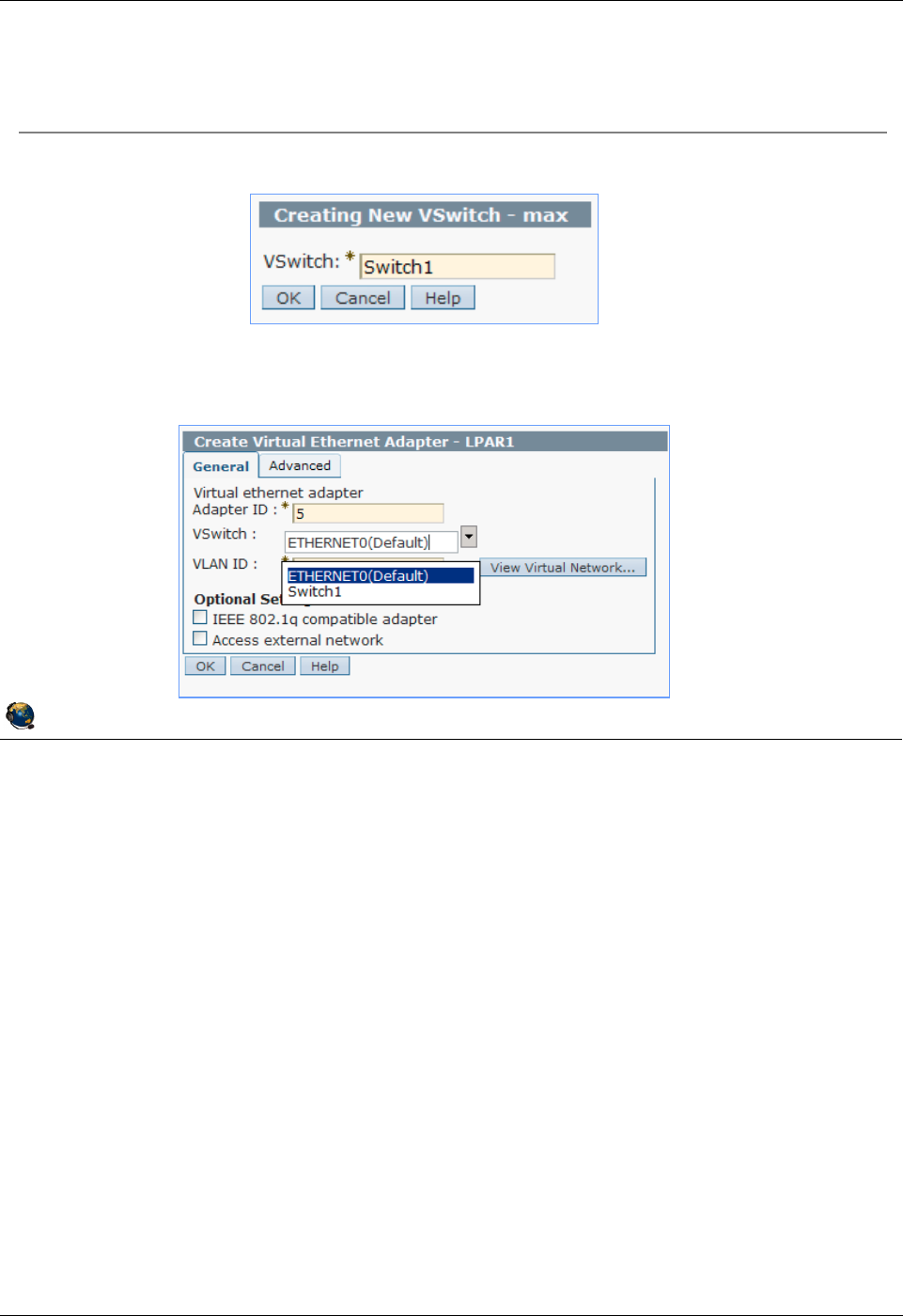
Student Notebook
Course materials may not be reproduced in whole or in part
without the prior written permission of IBM.
© Copyright IBM Corp. 2012 Unit 5. Virtual Ethernet Adapter Configuration 5-25
V7.0
Uempty
Figure 5-23. Manage virtual switches (2 of 2) QV3441.0
Notes:
Configuring virtual switches
After you create a new vswitch, it will appear as an option whenever you create or
modify virtual Ethernet adapters.
© Copyright IBM Corporation 2012
UNIX Software Service Enablement
Manage virtual switches (2 of 2)
Action -> Create VSwitch
Now, when configuring LPARs virtual Ethernet adapters, you can
choose which switch
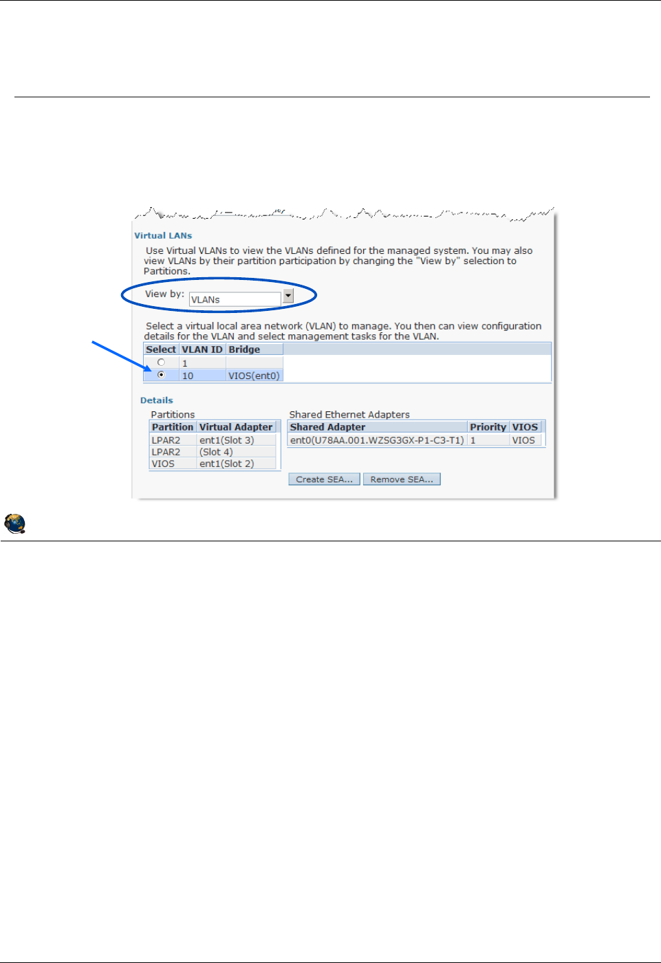
Student Notebook
Course materials may not be reproduced in whole or in part
without the prior written permission of IBM.
5-26 VIOS © Copyright IBM Corp. 2012
Figure 5-24. View virtual LANs (1 of 2) QV3441.0
Notes:
View virtual network configuration
The Virtual LANs section of the Virtual Network Management screen shows the current
configuration for VLANs on the managed system. If there are VLANs in use, it will list
them in the VLANs view.
Notice the Create SEA ... button in the visual above. This allows you to create a Shared
Ethernet adapter using the HMC. This is covered in the next unit of this course.
The View by: pulldown options are VLANs or partitions. If you choose partitions, then
the chart shows a list of partitions and what VLAN IDs they are using. This is shown on
the next visual.
© Copyright IBM Corporation 2012
UNIX Software Service Enablement
View virtual LANs (1 of 2)
Configuration -> Virtual Resources -> Virtual Network
Management
VLANs view shows VIDs in use
Select a VID to see which partitions are using that VID
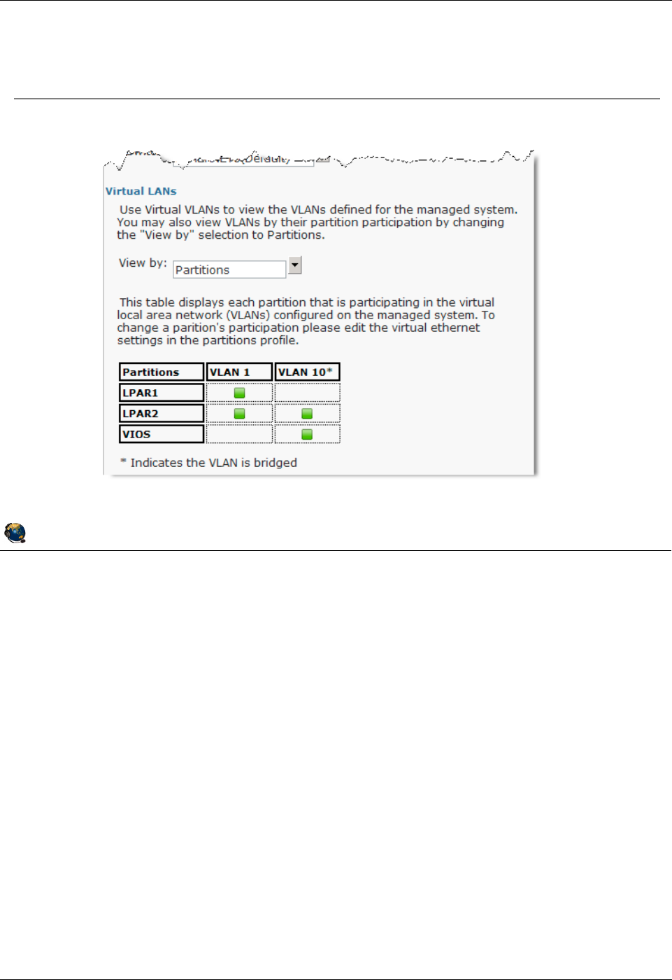
Student Notebook
Course materials may not be reproduced in whole or in part
without the prior written permission of IBM.
© Copyright IBM Corp. 2012 Unit 5. Virtual Ethernet Adapter Configuration 5-27
V7.0
Uempty
Figure 5-25. View virtual LANs (2 of 2) QV3441.0
Notes:
View virtual network configuration by partition
The Partitions view shows the VLANs in use by partition name.
© Copyright IBM Corporation 2012
UNIX Software Service Enablement
View virtual LANs (2 of 2)
Partitions view shows VLANs in use by partition

Student Notebook
Course materials may not be reproduced in whole or in part
without the prior written permission of IBM.
5-28 VIOS © Copyright IBM Corp. 2012
Figure 5-26. Checkpoint (1 of 2) QV3441.0
Notes:
© Copyright IBM Corporation 2012
UNIX Software Service Enablement
Checkpoint (1 of 2)
1. Which one of the following is not part of the IEEE 802.1Q VLAN protocol?
A. Ethernet packets are tagged with a VLAN ID
B. Ethernet switch restricts delivery to members of VLAN
C. Ethernet packets are delivered to target host based on IP address first, then
VLAN ID
2. Which one of the following statements about the Hypervisor switch is false?
A. It is the software implementation of an Ethernet switch and is consistent with the
IEEE 802.1Q protocol
B. Adds the PVID tag to packets from VLAN-unaware hosts
C. Configuring the default VLAN ID is optional when creating virtual Ethernet
adapters

Student Notebook
Course materials may not be reproduced in whole or in part
without the prior written permission of IBM.
© Copyright IBM Corp. 2012 Unit 5. Virtual Ethernet Adapter Configuration 5-29
V7.0
Uempty
Figure 5-27. Checkpoint (2 of 2) QV3441.0
Notes:
© Copyright IBM Corporation 2012
UNIX Software Service Enablement
Checkpoint (2 of 2)
3. True or False: When using only the default VLAN ID ("PVID") for a virtual
Ethernet adapter, you must also configure the VLAN device in the operating
system.
4. True or False: The Hypervisor Ethernet switch strips the PVID from any packets
that are being delivered to a VLAN-unaware host.
5. What is the maximum number of Hypervisor virtual Ethernet switches that may be
created on a single server? __________
6. True or False: It is possible to set up network communications between partitions
on the same server without any Ethernet hardware in use.
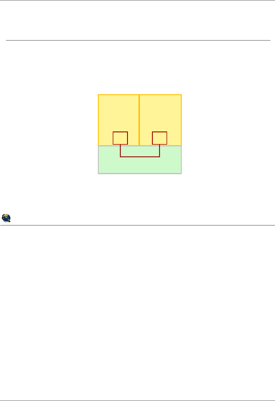
Student Notebook
Course materials may not be reproduced in whole or in part
without the prior written permission of IBM.
5-30 VIOS © Copyright IBM Corp. 2012
Figure 5-28. Exercise 5 - Virtual Ethernet adapter configuration QV3441.0
Notes:
© Copyright IBM Corporation 2012
UNIX Software Service Enablement
Exercise 5 Virtual Ethernet adapter
configuration
Activity:
Configure virtual Ethernet adapters
Configuration:
LPAR1 LPAR2
Hypervisor
ent1 ent1

Student Notebook
Course materials may not be reproduced in whole or in part
without the prior written permission of IBM.
© Copyright IBM Corp. 2012 Unit 5. Virtual Ethernet Adapter Configuration 5-31
V7.0
Uempty
Figure 5-29. Unit summary QV3441.0
Notes:
© Copyright IBM Corporation 2012
UNIX Software Service Enablement
Unit summary
Virtual Ethernet on POWER5 and higher processor-based systems is
implemented using:
The POWER Hypervisor as a software Ethernet switch
Virtual Ethernet adapters in partition configuration
VLAN IEEE 802.1Q standard
Virtual Ethernet adapters allow network communication between
partitions on the same managed system without using physical
Ethernet adapters
Virtual Ethernet adapters are created and the Hypervisor switch ports
are configured with the HMC, either in a partitions profile or by using
DLPAR
For one virtual Ethernet adapter to communicate on multiple VLANs,
VLAN devices must also be configured in the operating system
running in the LPAR

Student Notebook
Course materials may not be reproduced in whole or in part
without the prior written permission of IBM.
5-32 VIOS © Copyright IBM Corp. 2012

Student Notebook
Course materials may not be reproduced in whole or in part
without the prior written permission of IBM.
© Copyright IBM Corp. 2012 Unit 6. Shared Ethernet Adapter Configuration 6-1
V7.0
Uempty Unit 6. Shared Ethernet Adapter Configuration
What this unit is about
This unit describes the implementation of the Shared Ethernet adapter
and how to configure client partitions and Virtual I/O Server partitions
to use this type of device. Both command line and HMC GUI
instructions are covered for creating the Shared Ethernet adapter.
What you should be able to do
After completing this unit, you should be able to:
• Configure Shared Ethernet adapters in the Virtual I/O Server
partition using the VIOS command line and the HMC GUI
• Configure a client partition to use a Shared Ethernet adapter
• Configure a Shared Ethernet adapter for threading or
non-threading operation
How you will check your progress
Accountability:
• Checkpoint questions
• Machine exercises
References
IBM Power Systems Hardware Information Center:
http://publib.boulder.ibm.com/infocenter/powersys/v3r1m5/index.jsp
Virtual I/O Server product documentation from the IBM Power
Systems Hardware Information Center:
http://publib.boulder.ibm.com/infocenter/powersys/v3r1m5/index.jsp?tI
BM Redbooks documents can be found at:
http://www.redbooks.ibm.com
REDP4340 Integrated Virtual Ethernet Adapter Technical Overview
and Introduction, an IBM Redbooks document
SG24-7940 IBM PowerVM Virtualization Introduction and
Configuration, an IBM Redbooks document
SG24-7590 IBM PowerVM Virtualization Managing and Monitoring, an
IBM Redbooks document

Student Notebook
Course materials may not be reproduced in whole or in part
without the prior written permission of IBM.
6-2 VIOS © Copyright IBM Corp. 2012
SG24-6615 A Practical Guide for Resource Monitoring and Control
(RMC), an IBM Redbooks document
REDP4194 IBM System p Advanced POWER Virtualization
(PowerVM) Best Practices, an IBM Redbooks
document

Student Notebook
Course materials may not be reproduced in whole or in part
without the prior written permission of IBM.
© Copyright IBM Corp. 2012 Unit 6. Shared Ethernet Adapter Configuration 6-3
V7.0
Uempty
Figure 6-1. Unit objectives QV3441.0
Notes:
© Copyright IBM Corporation 2012
UNIX Software Service Enablement
Unit objectives
After completing this unit, you should be able to:
Configure Shared Ethernet adapters in the Virtual I/O Server partition
using the VIOS command line and the HMC GUI
Configure a client partition to use a Shared Ethernet adapter
Configure a Shared Ethernet adapter for threading or non-threading
operation
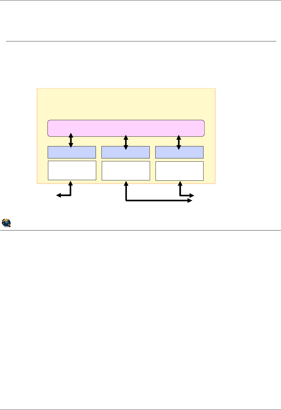
Student Notebook
Course materials may not be reproduced in whole or in part
without the prior written permission of IBM.
6-4 VIOS © Copyright IBM Corp. 2012
Figure 6-2. Shared Ethernet adapter overview (1 of 2) QV3441.0
Notes:
Shared Ethernet adapter overview
A Shared Ethernet adapter (SEA) is a bridge between a physical Ethernet adapter, or
aggregation of physical adapters, and one or more virtual Ethernet adapters on the
Virtual I/O Server. A SEA enables client partitions on the virtual Ethernet to share
access to the physical Ethernet to communicate with hosts on external networks. The
SEA provides this access by connecting the internal virtual Ethernets with the external
networks.
When there are not enough physical slots to allocate a physical network adapter to
each partition, network access using virtual Ethernet and Shared Ethernet adapters in a
Virtual I/O Server is preferable to IP forwarding as it does not complicate the IP network
topology.
As the Shared Ethernet processes packets at layer 2 of the OSI stack, the originating
MAC address, along with any VLAN tag information, is preserved when the packet is
bridged.
© Copyright IBM Corporation 2012
UNIX Software Service Enablement
Shared Ethernet adapter overview (1 of 2)
Shared Ethernet adapter bridges traffic between internal VLANs and
the external network
Forwards frames at OSI Layer 2 and is transparent to IP layer
Virtual I/O Server Partition
Layer 2 Bridge (Shared Ethernet adapter)
Device Driver Device Driver Device Driver
Physical
Adapter
Virtual
Adapter
Virtual
Adapter
External
LANs 1-16 virtual adapters
which connect to
VLANs (and client
partitions)

Student Notebook
Course materials may not be reproduced in whole or in part
without the prior written permission of IBM.
© Copyright IBM Corp. 2012 Unit 6. Shared Ethernet Adapter Configuration 6-5
V7.0
Uempty
Figure 6-3. Shared Ethernet adapter overview (2 of 2) QV3441.0
Notes:
Protocol support
Unicast, broadcast, and multicast is supported, so protocols that rely on broadcast or
multicast, such as Address Resolution Protocol (ARP), Dynamic Host Configuration
Protocol (DHCP), Boot Protocol (BOOTP), and Neighbor Discovery Protocol (NDP)
work across a Shared Ethernet adapter.
Benefits
The Shared Ethernet adapter allows client partitions to access a physical network
without dedicated physical Ethernet adapters. The clients share the bandwidth of the
physical adapter on the Virtual I/O Server. Also, while setting up a router to route
packets to external networks is a valid configuration, using bridging to perform this
function allows a simpler network topology, especially when servers are being migrated.
Existing network addresses can be retained with a bridging solution.
© Copyright IBM Corporation 2012
UNIX Software Service Enablement
Shared Ethernet adapter overview (2 of 2)
Shared Ethernet adapter
Originating virtual Ethernet MAC visible to outside systems
Broadcast/Multicast, ARP, and NDP support
Handles physical/virtual MTU mismatch:
Fragments IPv4 packets, or generate ICMP to aid PMTU discovery
Generates ICMPv6 for PMTU discovery for IPv6
Shared Ethernet adapter benefits:
Efficient use of physical Ethernet adapters when the bandwidth requirements of
client partitions is less than total bandwidth of an adapter
Maximum quantity of clients limited only by adapter's bandwidth
Simpler network topology
Routing is an option to connect LPAR VLANs to external hosts, however
bridging is often the preferred choice because network topology and
addressing do not need to change
A Virtual I/O Server is required in order to configure a
Shared Ethernet adapter
A Virtual I/O Server is required in order to configure a
Shared Ethernet adapter
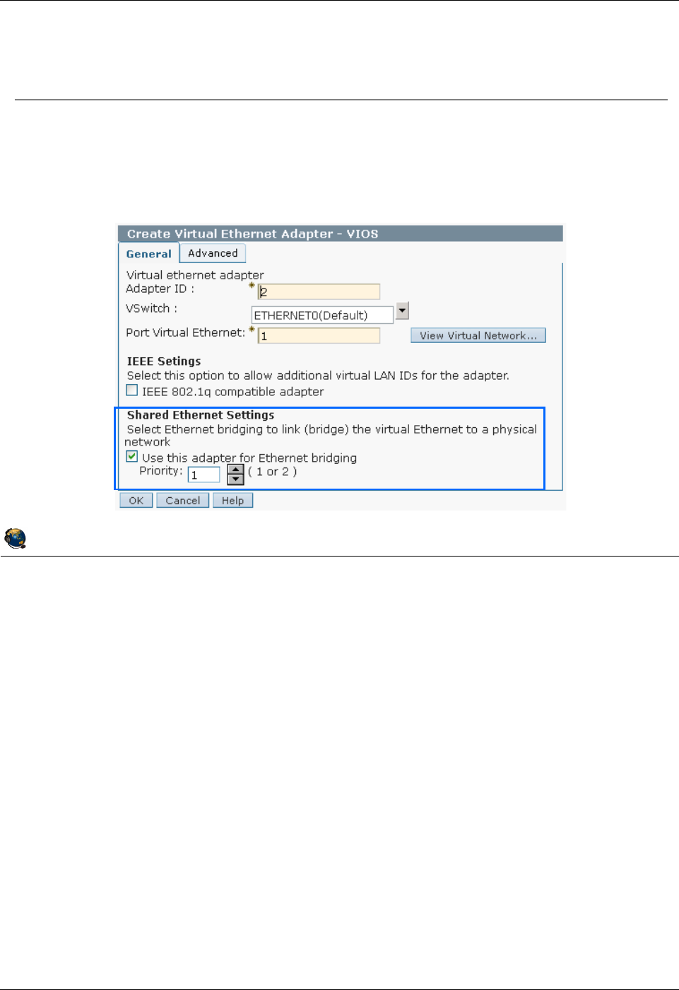
Student Notebook
Course materials may not be reproduced in whole or in part
without the prior written permission of IBM.
6-6 VIOS © Copyright IBM Corp. 2012
Figure 6-4. Configure virtual Ethernet adapter for SEA QV3441.0
Notes:
Access to external Network
If you want the internal network to be connected to the external physical network, then
the virtual Ethernet adapter that is used by the Virtual I/O Server should have the Use
this adapter for Ethernet bridging setting enabled. In HMC versions prior to HMC
V7R730, this checkbox was titled Access external network.
This setting causes the Hypervisor switch to send packets to the adapter when it
doesn't recognize the destination MAC address as internal. This setting should only be
used for the virtual Ethernet adapters that are part of a Shared Ethernet adapter setup
in the Virtual I/O Server. A virtual Ethernet adapter with this setting becomes the virtual
Ethernet trunk adapter for all the VLANs that it belongs to. Since there is one virtual
Ethernet adapter with this setting per VLAN (or two for failover), any overlap of the
VLAN memberships should be avoided between the virtual Ethernet trunk adapters.
© Copyright IBM Corporation 2012
UNIX Software Service Enablement
Configure virtual Ethernet adapter for SEA
Virtual Ethernet adapter configured as part of a SEA in the VIOS should have
Use this adapter for Ethernet bridging attribute checked
Causes the Hypervisor switch to send packets to this adapter when it doesn't recognize
the destination MAC address as being for an internal virtual Ethernet adapter
Normally one per VLAN; use priority setting if there are two
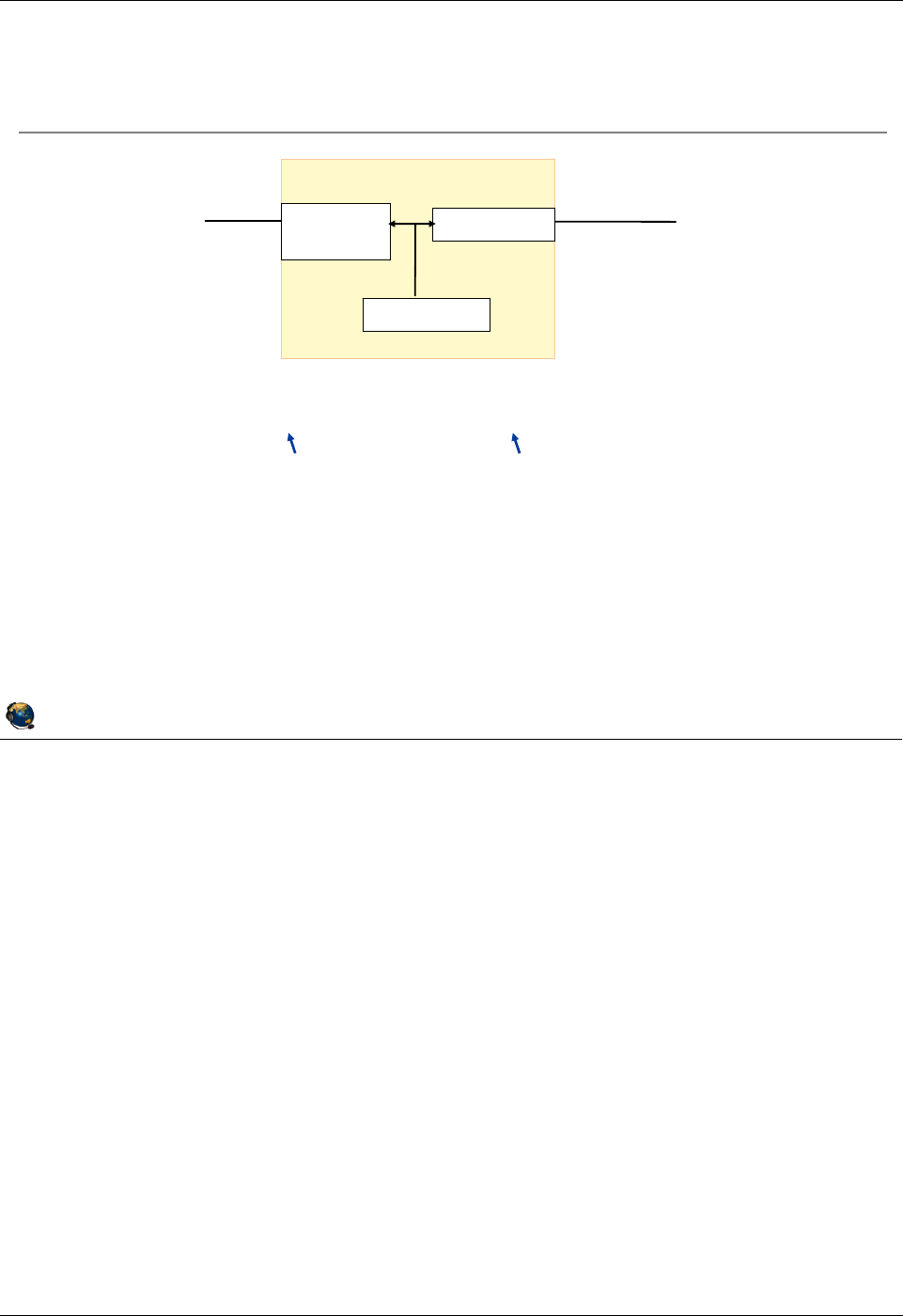
Student Notebook
Course materials may not be reproduced in whole or in part
without the prior written permission of IBM.
© Copyright IBM Corp. 2012 Unit 6. Shared Ethernet Adapter Configuration 6-7
V7.0
Uempty
Figure 6-5. Create Shared Ethernet adapter QV3441.0
Notes:
The mkvdev -sea command
The visual above shows a simple Shared Ethernet adapter scenario. The SEA ent2
uses physical adapter ent0 and virtual adapter ent1. The SEA setup requires the
administrator to specify a virtual Ethernet adapter on the VIOS that will be used to
receive any untagged packets from the physical adapter (-default). The PVID is also
specified for this virtual adapter (-defaultid). The PVID value specifies the tag that will
be added to any incoming untagged packets.
List SEA type devices
As of VIOS 2.1, there is a new -type flag for the lsdev command:
$ lsdev -type sea
name status description
ent2 Available Shared Ethernet Adapter
© Copyright IBM Corporation 2012
UNIX Software Service Enablement
Create Shared Ethernet adapter
Command to create Shared Ethernet Adapter:
$ mkvdev sea ent0 vadapter ent1 default ent1 \
defaultid 99
Creates device (ent2 in this case):
$ lsdev virtual
name status description
ent1 Available Virtual I/O Ethernet Adapter (l-lan)
ent2 Available Shared Ethernet Adapter
Physical Virtual
VLAN ID (PVID) 99
ent0
(Physical)
ent2 (SEA)
ent1 (Virtual)
VIOS
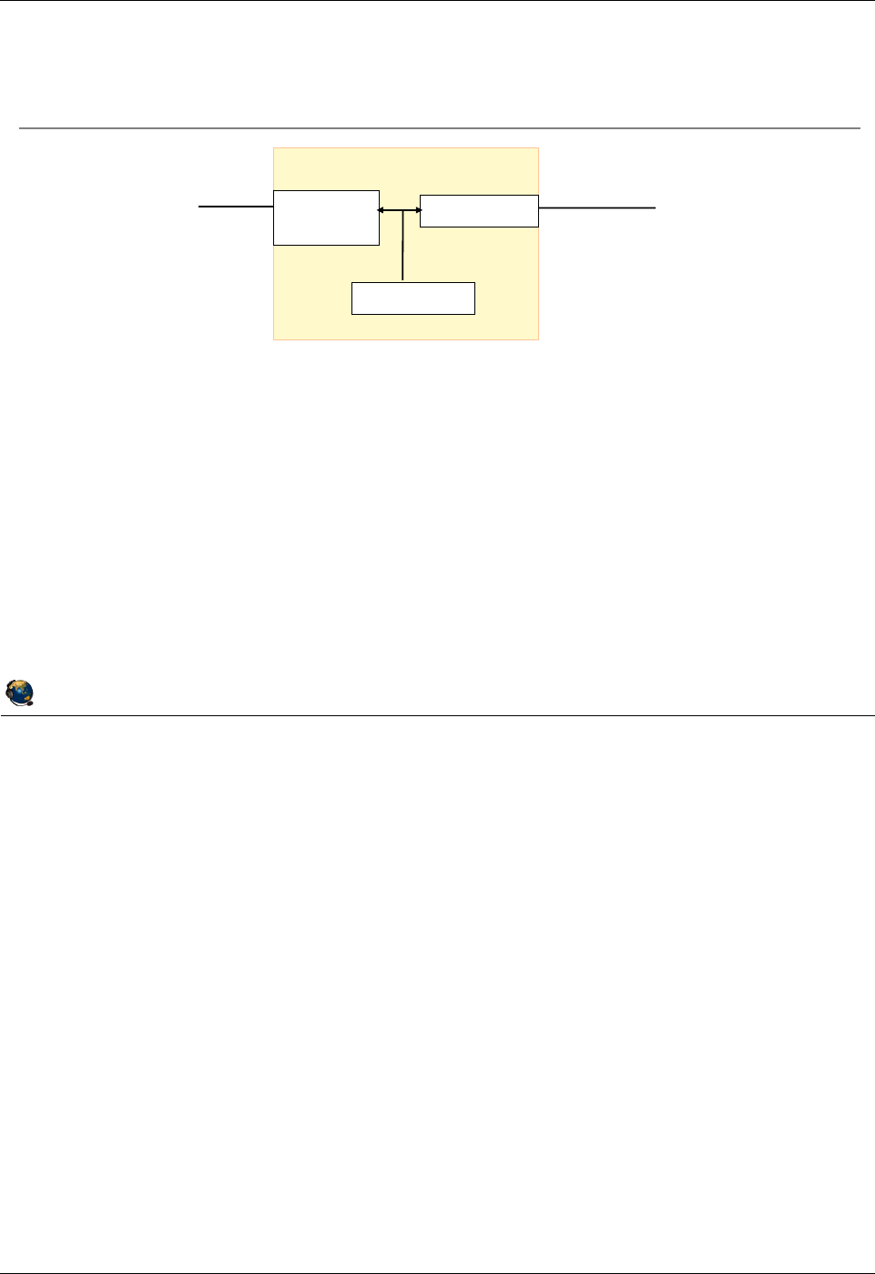
Student Notebook
Course materials may not be reproduced in whole or in part
without the prior written permission of IBM.
6-8 VIOS © Copyright IBM Corp. 2012
Figure 6-6. View SEA configuration QV3441.0
Notes:
Using lsmap to view the SEA configuration
The visual above shows the same Shared Ethernet adapter scenario as the last visual.
The output of the lsmap -net -all command in the visual above shows both the
virtual and physical location codes. ent1 in this example is the virtual Ethernet adapter
and it shows that it is in virtual slot 14. The physical adapter is ent0 which is in physical
PCI-X slot C2.
Using lsdev to view the SEA configuration
Another way to view the SEA configuration is with the VIOS CLI command:
$ lsdev -dev ent3 -attr
Fields displayed include the PVID in use, the virtual adapter(s), and the physical
adapter.
© Copyright IBM Corporation 2012
UNIX Software Service Enablement
View SEA configuration
Command to view Shared Ethernet Adapter configuration:
$ lsmap -net -all
SVEA Physloc
------ --------------------------------------------
ent1 U9131.52A.062A87G-V1-C14-T1
SEA ent2
Backing device ent0
Physloc U787F.001.DPM166X-P1-C2-T1
PVID 99
ent0
(Physical)
ent2 (SEA)
ent1 (Virtual)
VIOS
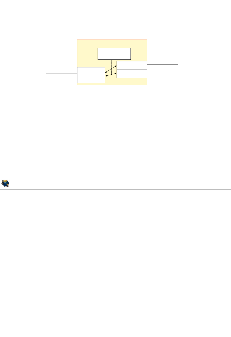
Student Notebook
Course materials may not be reproduced in whole or in part
without the prior written permission of IBM.
© Copyright IBM Corp. 2012 Unit 6. Shared Ethernet Adapter Configuration 6-9
V7.0
Uempty
Figure 6-7. SEA with multiple virtual adapters QV3441.0
Notes:
Multiple VLAN example
In the example in the visual above, the SEA (ent3) uses the physical adapter ent0 and
the virtual adapters ent1 and ent2. The physical adapter ent0 is connected to a
physical Ethernet switch which is VLAN capable and the port should be set up as a
tagged port with VID 200 and VID 300.
Both virtual Ethernet adapters ent1 and ent2 have the trunk attribute (Access external
network checkbox) using the HMC. Note, this configuration can also be achieved with
one virtual Ethernet adapter by creating an additional VLAN ID of 200 for the ent1
virtual adapter.
The Shared Ethernet adapter can only provide default VID connectivity for incoming
untagged packets to one of the virtual adapters and VLAN 99 was chosen in this
example. The PVID of 99 in this example is inconsequential only because a virtual
adapter cannot be created without a PVID and any other unused PVID value could
have been used here.
© Copyright IBM Corporation 2012
UNIX Software Service Enablement
Command to create Shared Ethernet Adapter:
$ mkvdev sea ent0 vadapter ent1 ent2 \
default ent1 defaultid 99
Device listing:
$ lsdev virtual
name status description
ent1 Available Virtual I/O Ethernet Adapter (l-lan)
ent2 Available Virtual I/O Ethernet Adapter (l-lan)
ent3 Available Shared Ethernet Adapter
SEA with multiple virtual adapters
ent3 (SEA)
ent2 (Virtual)
ent1 (Virtual)
ent0
(Physical)
VID 100, PVID 99
VID 200, PVID 98
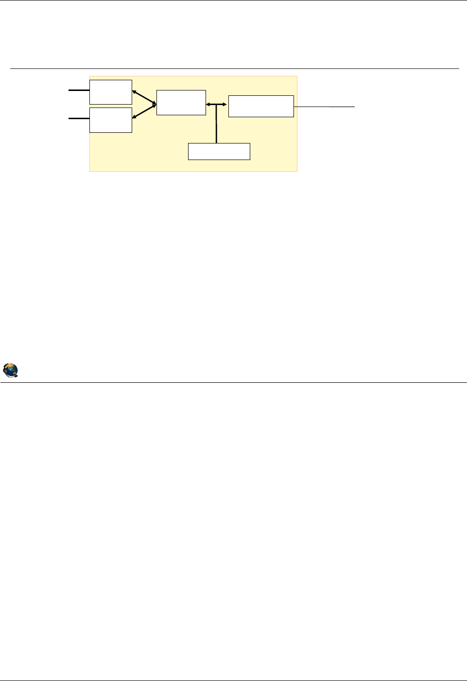
Student Notebook
Course materials may not be reproduced in whole or in part
without the prior written permission of IBM.
6-10 VIOS © Copyright IBM Corp. 2012
Figure 6-8. SEA with multiple physical adapters QV3441.0
Notes:
Link aggregation
Link aggregation is a network port aggregation technology that allows several Ethernet
adapters to be aggregated together to form a single pseudo Ethernet device. For
example, ent0 and ent1 can be aggregated to ent3; interface en3 would then be
configured with an IP address, or ent3 can be used as the physical adapter for an SEA.
The system considers these aggregated adapters as one adapter.
The main benefit of link aggregation is the ability to use the network bandwidth of all of
the adapters. Also, if an adapter fails, the packets are automatically sent on the next
available adapter without disruption to existing user connections. The adapter is
automatically returned to service on the link aggregation when it recovers.
© Copyright IBM Corporation 2012
UNIX Software Service Enablement
SEA with multiple physical adapters
Create Ethernet link aggregation device:
$ mkvdev lnagg ent0 ent1
ent3 shows up as:
$ lsdev adapter | grep ent3
ent3 Available EtherChannel / IEEE 802.3ad Link Aggregation
Create Shared Ethernet adapter:
$ mkvdev sea ent3 vadapter ent2 default ent2 defaultid 99
ent2 (Virtual)
PVID 99
(Physical)
ent4 (SEA)
ent0
ent1
ent3
(Aggregate)

Student Notebook
Course materials may not be reproduced in whole or in part
without the prior written permission of IBM.
© Copyright IBM Corp. 2012 Unit 6. Shared Ethernet Adapter Configuration 6-11
V7.0
Uempty
Figure 6-9. Create SEA with cfgassist tool QV3441.0
Notes:
Create SEA with cfgassist tool
Shared Ethernet adapters can be created with the cfgassist tool. You can specify
multiple virtual Ethernet adapters and use F4 (or ESC 4) to select devices.
© Copyright IBM Corporation 2012
UNIX Software Service Enablement
Create SEA with cfgassist tool
The cfgassist tool can be used to create a SEA
Devices ÆShared Ethernet Adapter ÆAdd a Shared Ethernet Adapter
Add a Shared Ethernet Adapter
Type or select values in entry fields.
Press Enter AFTER making all desired changes.
[Entry Fields]
* Physical Ethernet Adapter [ent0] +
* Virtual Ethernet Adapters [ent1] +
* Default Virtual Ethernet Adapter [ent1] +
* Default ID [1] #
ATTRIBUTES []
Migrate the settings from physical interface to no +
the SEA interface?
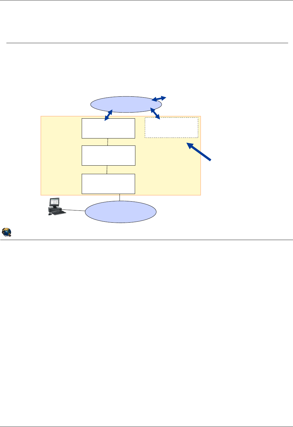
Student Notebook
Course materials may not be reproduced in whole or in part
without the prior written permission of IBM.
6-12 VIOS © Copyright IBM Corp. 2012
Figure 6-10. Configuring the VIOS interface (1 of 2) QV3441.0
Notes:
Configuring the TCP/IP parameters with a Shared Ethernet adapter
The visual above illustrates the different devices that can exist when implementing a
single Shared Ethernet adapter. In this example, there are two interfaces on which the
TCP/IP options can be configured and there is no performance gain for either
configuration.
The first option is to configure the TCP/IP parameters such as the IP address on the
interface associated with the Shared Ethernet adapter (en3 in this example).
The second option is to configure a second, optional, virtual Ethernet adapter and
configure the TCP/IP parameters on its interface (en2 in this example).
You cannot configure the interface for the actual physical adapter associated with a
Shared Ethernet adapter (en0 in this example). You also cannot configure the interface
associated with the Shared Ethernet adapter’s virtual Ethernet adapter (en1 in this
example).
© Copyright IBM Corporation 2012
UNIX Software Service Enablement
Configuring the VIOS interface (1 of 2)
Virtual
I/O
Server
External
LANs
Virtual ent1 Virtual ent2
Hypervisor
Virtual Ethernet
traffic
Physical ent0
Shared Ethernet
adapter ent3
Ethernet interface configuration options for the Virtual I/O Server:
Configure IP address on interface associated with the Shared Ethernet adapter (en3 in
this example)
Configure IP address on optional second virtual Ethernet adapter (configure the en2
interface this example)
If you have the SEA
interface configured, it
must be unconfigured to
alter the SEA
configuration.
Configuration on second
virtual Ethernet makes it
easier to change the
SEA configuration later
without affecting VIOS
traffic with other LPARs
on the same server.

Student Notebook
Course materials may not be reproduced in whole or in part
without the prior written permission of IBM.
© Copyright IBM Corp. 2012 Unit 6. Shared Ethernet Adapter Configuration 6-13
V7.0
Uempty
Figure 6-11. Configuring the VIOS interface (2 of 2) QV3441.0
Notes:
Migrating the interface configuration
If the physical adapter’s interface is already configured, you can migrate the settings to
the SEA’s interface when the SEA is created by adding the -migrate -auto flags.
Reverse the operation
Once the SEA is created and configured, if you want to remove it and restore the IP
configuration to the physical adapter, you can use the procedure on the visual above.
© Copyright IBM Corporation 2012
UNIX Software Service Enablement
Configuring the VIOS interface (2 of 2)
The configuration on the physical adapter's interface can be
migrated automatically to the SEA device
Add the
migrate
auto flags to the mkvdev
sea command
This example creates an SEA and migrates the current configuration on en0 to
the interface on the resulting SEA device:
$ mkvdev
sea ent0
vadapter ent1
default ent1 \
defaultid 10
migrate
auto
Example procedure to reverse the result of the above mkvdev
command:
Detach the SEA interface (en2):
$ chdev dev en2 attr state=detach
Remove the SEA (ent2) and its interfaces:
$ rmdev dev ent2; rmdev dev en2; rmdev dev et2
Return the configuration on the physical adapter's interface (en0):
$ chdev dev en0 attr state=up restoreroute
Log into the
console to perform
this procedure
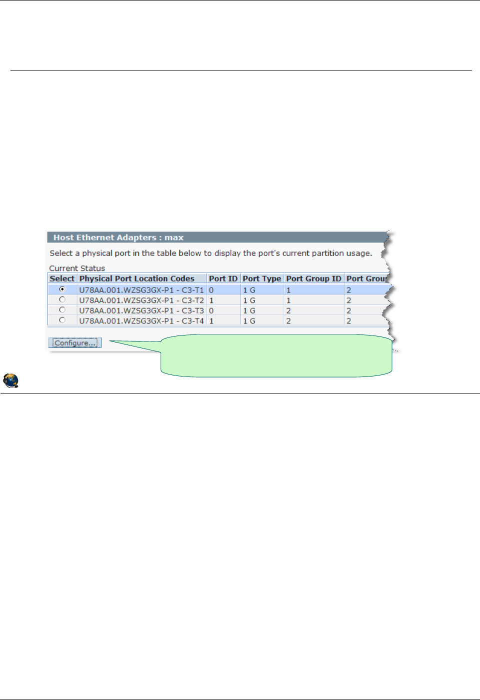
Student Notebook
Course materials may not be reproduced in whole or in part
without the prior written permission of IBM.
6-14 VIOS © Copyright IBM Corp. 2012
Figure 6-12. Using HEA logical ports for SEA QV3441.0
Notes:
Host Ethernet Adapter (HEA)
The HEA is also known as the Integrated Virtual Ethernet adapter and is available on
most POWER6 and some POWER7 processor-based servers. The HEA has 2 or 4
physical ports, depending on the model purchased. Multiple logical ports can share one
physical port providing direct network connectivity for LPARs. However, if the VIOS
partition uses an HEA logical port for an SEA configuration, the VIOS will use the entire
physical port so no other LPARs can be configured for the same physical port. Then,
you must list the VIOS partition as the promiscuous LPAR on the HEA physical port.
If LPARs are using HEA ports and you shut the partitions down, the system will still
consider the logical ports to be owned by the Not Activated LPARs. To clear this
situation, you can either reactivate the partitions without HEA ports or use this HMC
command where LPAR1 is the partition with the port and the managed system is MSname:
rsthwres -r hea -m MSname -p LPAR1
HEA ports can be configured in a link aggregation only with other HEA ports.
© Copyright IBM Corporation 2012
UNIX Software Service Enablement
Using HEA logical ports for SEA
A Host Ethernet Adapter (HEA) logical port can be used as the
physical adapter for an SEA
Requirements:
No other LPARs can share the same HEA physical port
The physical port must have the VIOS partition as its promiscuous LPAR before
SEA is configured
Run Hardware Information -> Adapters -> Host Ethernet task
Select Physical Port and click Configure button
Choose a physical port, then click the
Configure button to configure VIOS as
promiscuous LPAR

Student Notebook
Course materials may not be reproduced in whole or in part
without the prior written permission of IBM.
© Copyright IBM Corp. 2012 Unit 6. Shared Ethernet Adapter Configuration 6-15
V7.0
Uempty
Figure 6-13. Troubleshooting SEA "cfgsea"error QV3441.0
Notes:
Cause 2: From the VIOS CLI, before you make the SEA, you can check to see if the
virtual Ethernet adapter has the Access external network checkbox checked with this
command. If it is, the output will show: Trunk Adapter: True
$ entstat -all ent# | grep Trunk
Cause 3: To check the checksum offload attribute on the virtual and physical adapters
use the following command substituting ent# for the proper device name:
Virtual and Physical: $ lsdev -dev ent# -attr chksum_offload
If the lsdev command output is blank, then the device does not support the checksum
attribute. To change the attribute, use chdev. Set the value to yes to enable and no to
disable. This example command sets the chksum_offload attribute to enabled for the
ent0 device:
$ chdev -dev ent# -attr chksum_offload=yes
This attribute is set to yes by default for virtual adapters. For physical adapters, it
depends on the type of adapter.
© Copyright IBM Corporation 2012
UNIX Software Service Enablement
Troubleshooting SEA "cfgsea" error
Typical command:
$ mkvdev -sea ent0 -vadapter ent2 -default ent2 -defaultid 10
Example configuration error:
Method error (/usr/lib/methods/cfgsea):
0514-040 Error initializing a device into the kernel.
Check the following causes:
1. Is the physical or virtual interface already configured?
2. Does the virtual adapter have "Access external network" and "Trunk priority"
configured?
3. Is the checksum offload attribute mismatched between physical and virtual
devices?
4. If the physical device is an HEA logical port, is the VIOS listed as the
promiscuous LPAR for the physical port?
5. Is there enough free memory?
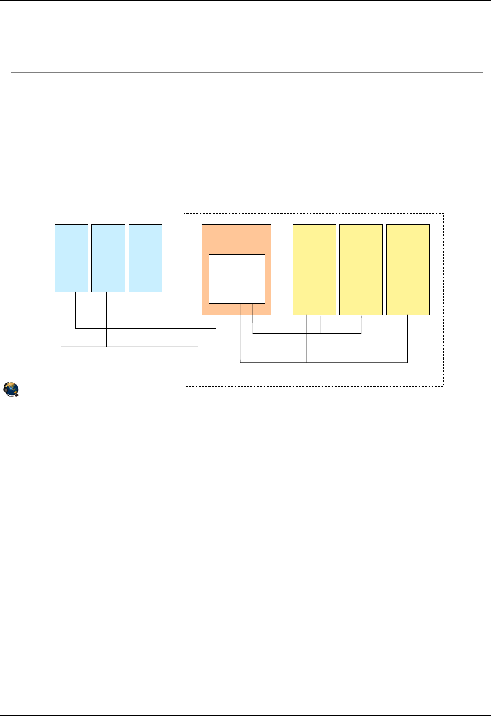
Student Notebook
Course materials may not be reproduced in whole or in part
without the prior written permission of IBM.
6-16 VIOS © Copyright IBM Corp. 2012
Figure 6-14. Shared Ethernet adapter with VLANs QV3441.0
Notes:
LPAR access to external VLANs
In the visual above, LPARs 1, 2, and 3 can participate on the VLANs that extend past
their managed system. The Hypervisor strips the VLAN ID tags from packets when
routing them out through the SEA if the VLAN ID matches the PVID of the virtual
Ethernet adapter on the VIOS which is in the SEA configuration. The VIOS must have
the checkbox labeled IEEE 802.1Q compatible adapter checked and additional VLAN
IDs that will be used for external VLANs listed.
© Copyright IBM Corporation 2012
UNIX Software Service Enablement
Shared Ethernet adapter with VLANs
VLAN tags will be stripped from exiting packets when the VLAN ID
matches the PVID of the VIOS virtual Ethernet adapter configured
with the SEA
Other VLAN ID tags will remain intact
Provides support for VLAN-unaware networks
In this example, the SEA will forward packets destined to the external
VLAN 100 and 200 with VLAN tags intact:
PVID=1
VLANs=
100,200
VLAN 100
VLAN 100
VLAN 200
VLAN 200
VIOS
Managed system
Ethernet Switch
External Hosts
LPAR1 LPAR2 LPAR3
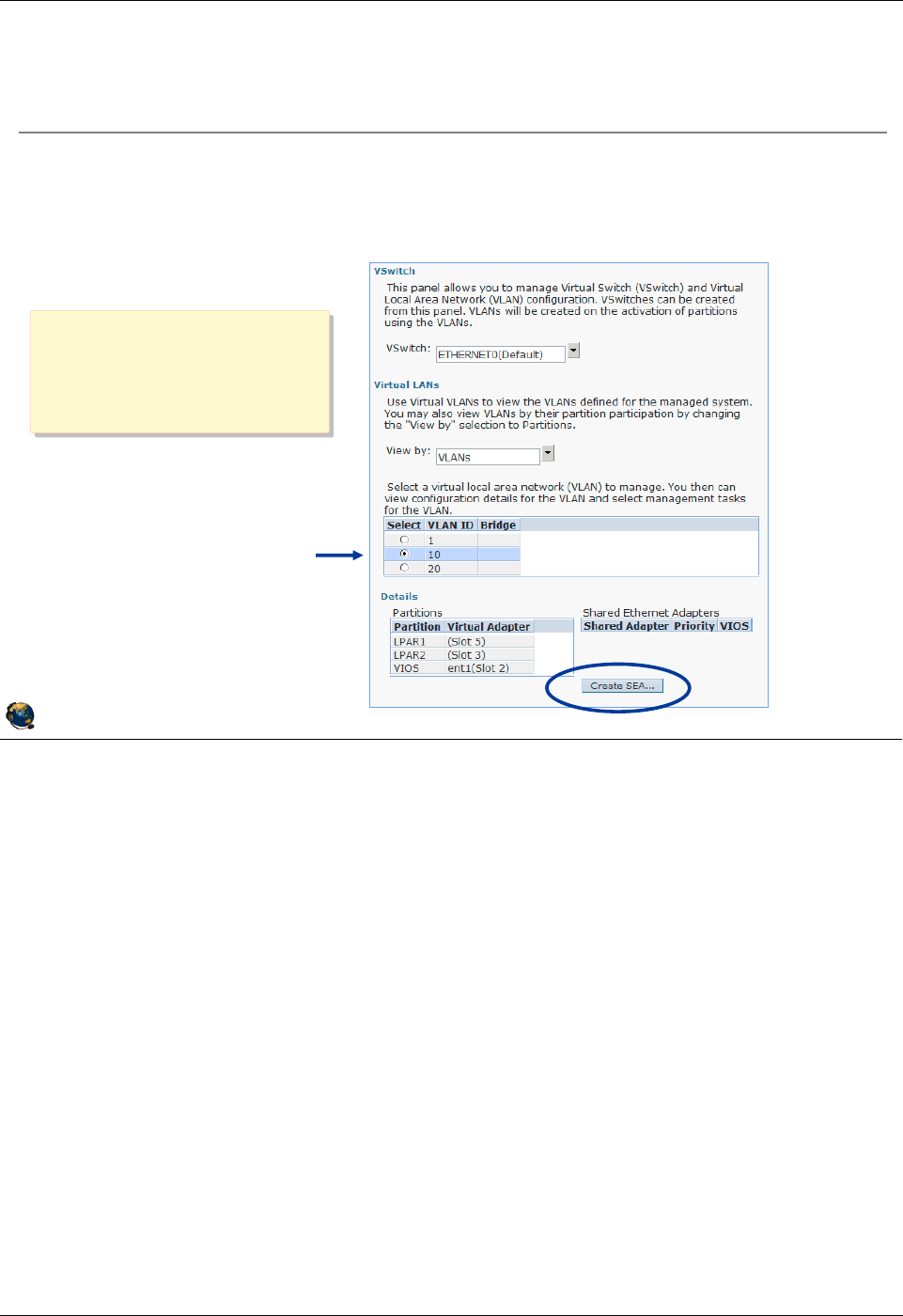
Student Notebook
Course materials may not be reproduced in whole or in part
without the prior written permission of IBM.
© Copyright IBM Corp. 2012 Unit 6. Shared Ethernet Adapter Configuration 6-17
V7.0
Uempty
Figure 6-15. Configure SEA using the HMC (1 of 2) QV3441.0
Notes:
Requirements
The following requirements need to be met to configure an SEA with the HMC:
- HMC V7 R3.4.2 or later
- VIOS has a physical network device or LHEA logical port that is already configured
with an IP address
- Virtual Ethernet adapter already exists on the VIOS and configured to access
external network
- Virtual I/O Server version 2.1.1.0 or later
- RMC connection between the HMC and the VIOS
• To check the RMC connection, execute the following command on the HMC:
# lspartition -all
© Copyright IBM Corporation 2012
UNIX Software Service Enablement
Configure SEA using the HMC (1 of 2)
Run the Configuration ÆVirtual Resources ÆVirtual Network
Management task
Select the VLAN ID to bridge to access the Create SEA button
Select
one of the
VLAN IDs
In this example, the VIOS
virtual adapter has a
PVID of 1, and additional
VLAN IDs of 10 and 20
In this example, the VIOS
virtual adapter has a
PVID of 1, and additional
VLAN IDs of 10 and 20
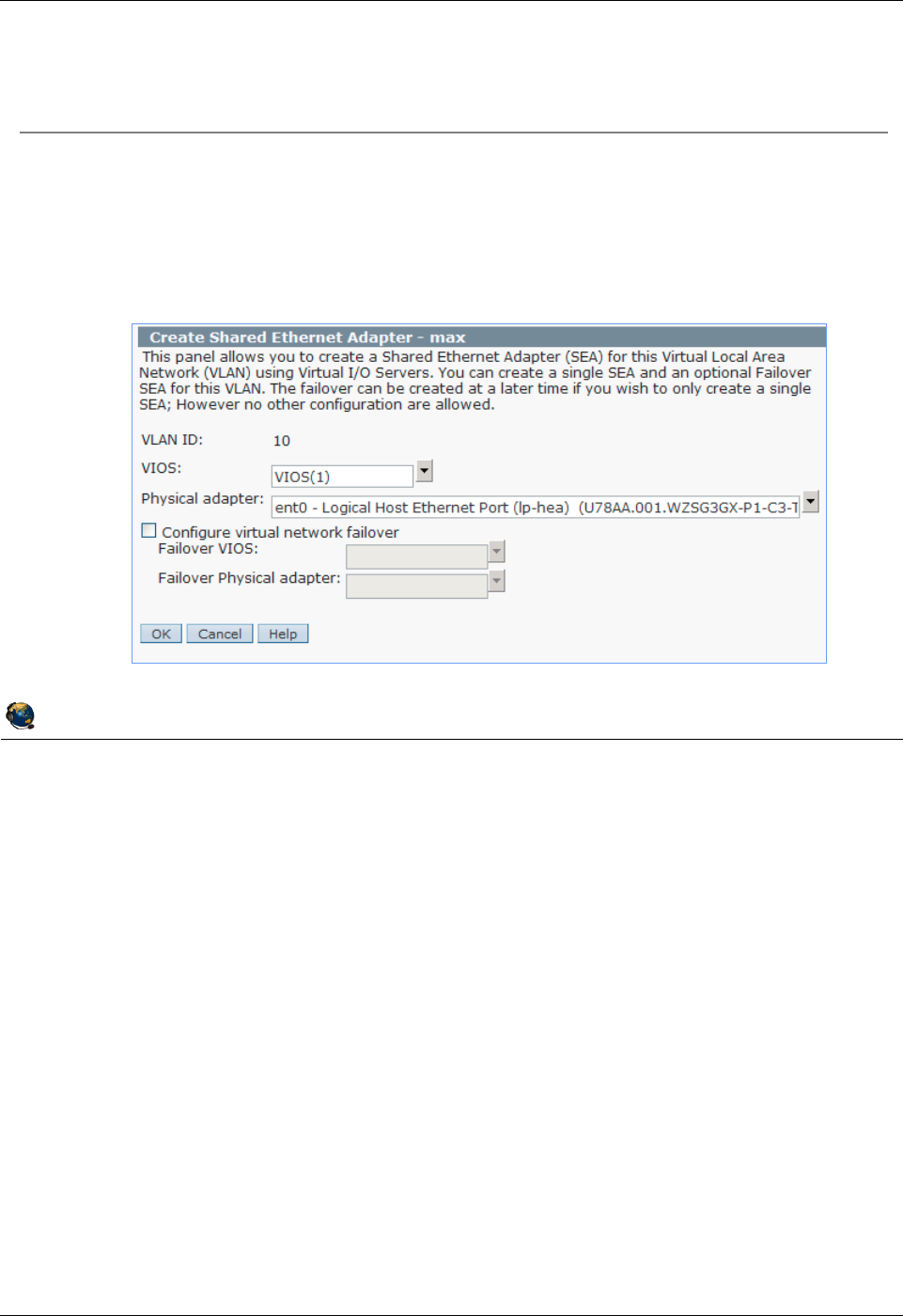
Student Notebook
Course materials may not be reproduced in whole or in part
without the prior written permission of IBM.
6-18 VIOS © Copyright IBM Corp. 2012
Figure 6-16. Configure SEA using the HMC (2 of 2) QV3441.0
Notes:
Create SEA ... button
The visual above shows the result of selecting a VLAN ID and clicking the Create SEA
... button. If there are multiple VIOS type partitions, choose the VIOS by name. If there
are multiple physical adapters, choose which adapter to configure. You can also
configure SEA failover from this task.
© Copyright IBM Corporation 2012
UNIX Software Service Enablement
Configure SEA using the HMC (2 of 2)
The HMC:
Configures the SEA device for all VLAN IDs included on same virtual Ethernet
adapter
Moves the TCP/IP configuration from the physical adapter to the SEA device (if
necessary)
Student Notebook
Course materials may not be reproduced in whole or in part
without the prior written permission of IBM.
© Copyright IBM Corp. 2012 Unit 6. Shared Ethernet Adapter Configuration 6-19
V7.0
Uempty
Figure 6-17. View SEA configuration from HMC QV3441.0
Notes:
View SEA configuration from the SEA
There are two “Views” available on the Virtual Network Management screen: VLANs
and Partitions. The visual above shows both and shows the SEA configuration
information available in each.
Notice that in the Partitions view, the three VLANs (1, 10, 20) are all marked with an
asterisk showing that all three are bridged. In the example from the last two pages, only
VLAN 10 was selected when the SEA was created. Because the virtual Ethernet
adapter that was configured for VLAN 10 was also configured for VLAN 1 and VLAN 20,
all three VLANs are bridged.
© Copyright IBM Corporation 2012
UNIX Software Service Enablement
View SEA configuration from HMC
Once an SEA is configured, it is visible in VLANs view
In the Partitions view, the
VLAN ID will have an *
to indicate it's bridged
Notice all 3
VLAN IDs are
bridged
Student Notebook
Course materials may not be reproduced in whole or in part
without the prior written permission of IBM.
6-20 VIOS © Copyright IBM Corp. 2012
Figure 6-18. Removing the SEA using the HMC QV3441.0
Notes:
Remove SEA ... button
If the Remove SEA ... button is selected, it will give you instructions using the proper
device names to remove the SEA. If failover mode was configured, you can choose the
appropriate VIOS partition by name. You must manually perform these steps to remove
the SEA. If the SEA interface was configured with the IP configuration, then the last
chdev command (as shown in the above visual) will restore the IP configuration on the
physical adapter’s interface.
© Copyright IBM Corporation 2012
UNIX Software Service Enablement
Removing the SEA using the HMC
The Remove SEA button gives instructions:

Student Notebook
Course materials may not be reproduced in whole or in part
without the prior written permission of IBM.
© Copyright IBM Corp. 2012 Unit 6. Shared Ethernet Adapter Configuration 6-21
V7.0
Uempty
Figure 6-19. Threading/non-threading (1 of 2) QV3441.0
Notes:
Threaded or non-threaded SEA device driver
The threaded model ensures that the SEA driver does not monopolize CPU resources
to the detriment of virtual SCSI and NPIV services. However, threading adds more
instruction path length, thus uses more CPU cycles. If the VIOS will only be providing
SEA services (and not virtual SCSI or NPIV services) then the SEA should be
configured with threading disabled in order to run in the most efficient mode.
Threading causes incoming packets to be queued to a buffer in memory. A special
kernel thread is dispatched to process the buffer, which uses more processing power
and allows the processor to be shared more evenly with virtual SCSI and NPIV. With
non-threading, the virtual Ethernet and SEA driver forward packets at the interrupt level
which is more efficient and is why throughput goes up.
The SEA threading attribute determines the implementation that will be used by the
SEA device driver, and is not related to simultaneous multi-threading.
© Copyright IBM Corporation 2012
UNIX Software Service Enablement
Threading/non-threading (1 of 2)
Threading is a feature that ensures that CPU resources are shared
fairly when a Virtual I/O Server hosts a SEA in addition to hosting
virtual SCSI or virtual Fibre Channel (NPIV) connections
Special kernel thread is used by SEA device driver for queuing SEA requests
Like most device drivers, virtual Ethernet and Shared Ethernet drivers typically drive high
interrupt rates and are CPU intensive
Without threading, network traffic will have a higher priority than virtual SCSI or
virtual Fibre Channel interrupts
On a CPU constrained system, this will result in worse virtual SCSI and virtual
Fibre Channel performance
With threading enabled, there is more consistent quality of service when CPU is
constrained, but at a lower overall network throughput and higher overall CPU
consumption (all the time)
Threading is enabled by default for Shared Ethernet adapter:
Disable threading when a Virtual I/O Server is not used for virtual SCSI or NPIV:
Can use separate Virtual I/O Servers for Shared Ethernet adapter and virtual
SCSI/NPIV services

Student Notebook
Course materials may not be reproduced in whole or in part
without the prior written permission of IBM.
6-22 VIOS © Copyright IBM Corp. 2012
Figure 6-20. Threading/non-threading (2 of 2) QV3441.0
Notes:
Threaded versus non-threaded performance
The threading option of the Shared Ethernet adapter may result in performance
degradation for network traffic if CPU resources are constrained. The degradation for a
streaming workload is around 16-20% when the MTU size is 1500, and around 31-39%
when the MTU size is 9000. The threading option causes more performance
degradation at lower workloads due to individual threads being started for each packet.
At higher workload rates, like full duplex or the request/response workloads, the threads
can run longer without waiting and being re-dispatched.
Enabling and disabling threading
The thread option for the Shared Ethernet adapter can be enabled (the default) or
disabled on a per-adapter basis using the chdev command in the Virtual I/O Server
command line interface (CLI).
© Copyright IBM Corporation 2012
UNIX Software Service Enablement
Threading/non-threading (2 of 2)
Threading increases overall CPU cycle usage:
Performance gains are 16-39% with it disabled, depending on MTU size
Threading can be enabled/disabled on a per Shared Ethernet
adapter basis on the Virtual I/O Server:
See the current status:
$ lsdev dev ent3 attr
thread 1 Thread mode enabled (1) or disabled (0)
To disable:
$ chdev dev ent3 attr thread=0
SEA device name

Student Notebook
Course materials may not be reproduced in whole or in part
without the prior written permission of IBM.
© Copyright IBM Corp. 2012 Unit 6. Shared Ethernet Adapter Configuration 6-23
V7.0
Uempty
Figure 6-21. Monitoring SEA traffic QV3441.0
Notes:
Monitoring network traffic when using an SEA
If you want to see only the VIOS traffic, then use a tool that shows the configured
interfaces such as the topas or netstat command.
When using an SEA however, often you wish to see the total traffic for all clients coming
in and going out of the physical adapter. The entstat command can be used in this
case.
If you wish to monitor each SEA client’s traffic individually, perhaps to see which clients
have the most traffic, then the seastat command is the one to use. You must enable
advanced accounting which can potentially incur a small performance impact so you
can disable it after monitoring.
When viewing seastat output, the first interface on each client will be listed with its
hostname. Subsequent interfaces will be listed by MAC address only. The seastat
command is available in VIOS V1.5 and up.
© Copyright IBM Corporation 2012
UNIX Software Service Enablement
Monitoring SEA traffic
Some network monitoring tools monitor the interface: netstat,
topas
Others monitor the adapter: entstat, seastat
seastat provides statistics per MAC address of all SEA clients
Must enable advanced accounting on the SEA first:
$ chdev -dev ent# -attr accounting=enabled
To view reports, use -d followed by SEA device name:
$ seastat -d ent#
Example entry from seastat output:
==========================================================
MAC: 7E:DF:45:0E:31:04
----------------------
VLAN: 10
VLAN Priority: None
IP: 9.47.87.82
Transmit Statistics: Receive Statistics:
-------------------- -------------------
Packets: 74 Packets: 112
Bytes: 14648 Bytes: 18425

Student Notebook
Course materials may not be reproduced in whole or in part
without the prior written permission of IBM.
6-24 VIOS © Copyright IBM Corp. 2012
Figure 6-22. Checkpoint QV3441.0
Notes:
© Copyright IBM Corporation 2012
UNIX Software Service Enablement
Checkpoint
1. True or False: To use Shared Ethernet adapters, you must have a Virtual I/O
Server partition.
2. True or False: The virtual adapters configured as part of a Shared Ethernet
adapter must have the Access external network option enabled.
3. True or False: Only one virtual Ethernet adapter per VLAN can be configured as
the SEA virtual adapter.
4. True or False: Shared Ethernet adapter threading is important on Virtual I/O
Servers that provide both virtual storage and Shared Ethernet adapter services.
5. Which of the following cannot be done from the HMC Virtual Network
Management task:
A. Create an SEA to connect multiple VLANs to an external network
B. Remove an SEA
C. When creating the SEA, move the TCP/IP configuration of the physical Ethernet
adapter to the SEA device
Student Notebook
Course materials may not be reproduced in whole or in part
without the prior written permission of IBM.
© Copyright IBM Corp. 2012 Unit 6. Shared Ethernet Adapter Configuration 6-25
V7.0
Uempty
Figure 6-23. Exercise 6 - Shared Ethernet adapter QV3441.0
Notes:
© Copyright IBM Corporation 2012
UNIX Software Service Enablement
Exercise 6 - Shared Ethernet adapter
Activity:
Configure a Shared Ethernet adapter
Configuration
Three partitions:
Two AIX partitions: LPAR2
and LPAR3
One Virtual I/O Server: VIOS
Physical Ethernet adapter is
an HEA logical port
LPAR1 VIOS LPAR2
Physical
Ethernet
Adapter
Hypervisor
SEA
Virtual
Physical Ethernet

Student Notebook
Course materials may not be reproduced in whole or in part
without the prior written permission of IBM.
6-26 VIOS © Copyright IBM Corp. 2012
Figure 6-24. Unit summary QV3441.0
Notes:
© Copyright IBM Corporation 2012
UNIX Software Service Enablement
Unit summary
Shared Ethernet adapter uses a physical Ethernet adapter of the
Virtual I/O Server to connect client partitions with virtual Ethernet
adapters to external networks
Shared Ethernet adapters can only be created in the Virtual I/O
Server partition
The virtual Ethernet adapters used in Shared Ethernet adapter
configurations must have the Access external network attribute
The Virtual Network Management HMC task can be used to create a
Shared Ethernet adapter
If a Virtual I/O Server provides Shared Ethernet adapter services but
not virtual SCSI services, then the threading attribute can be disabled
for better Shared Ethernet adapter performance

Student Notebook
Course materials may not be reproduced in whole or in part
without the prior written permission of IBM.
© Copyright IBM Corp. 2012 Unit 7. Virtual I/O Server Maintenance 7-1
V7.0
Uempty Unit 7. Virtual I/O Server Maintenance
What this unit is about
This unit describes common maintenance operations for Virtual I/O
Servers including backup and restore and updating the software level.
What you should be able to do
After completing this unit, you should be able to:
• Describe Virtual I/O Server backup tools
• Use viosbr to backup and restore virtual device mapping
• Describe the use of backupios and savevgstruct
• Describe how to update the VIOS software
How you will check your progress
Accountability:
• Checkpoint questions
• Machine exercises
References
IBM Power Systems Hardware Information Center:
http://publib.boulder.ibm.com/infocenter/powersys/v3r1m5/index.jsp
Virtual I/O Server product documentation from the IBM Power
Systems Hardware Information Center:
http://publib.boulder.ibm.com/infocenter/powersys/v3r1m5/index.jsp?t
IBM Redbooks documents can be found at:
http://www.redbooks.ibm.com
REDP4340 Integrated Virtual Ethernet Adapter Technical Overview
and Introduction, an IBM Redbooks document
SG24-7940 IBM PowerVM Virtualization Introduction and
Configuration, an IBM Redbooks document
SG24-7590 IBM PowerVM Virtualization Managing and Monitoring, an
IBM Redbooks document
SG24-7430 AIX 6 Advanced Security Features Introduction and
Configuration, an IBM Redbooks document

Student Notebook
Course materials may not be reproduced in whole or in part
without the prior written permission of IBM.
7-2 VIOS © Copyright IBM Corp. 2012
Figure 7-1. Unit objectives QV3441.0
Notes:
© Copyright IBM Corporation 2012
UNIX Software Service Enablement
Unit objectives
After completing this unit, you should be able to:
Describe Virtual I/O Server backup tools
Use viosbr to backup and restore virtual device mapping
Describe the use of backupios and savevgstruct
Describe how to update the VIOS software

Student Notebook
Course materials may not be reproduced in whole or in part
without the prior written permission of IBM.
© Copyright IBM Corp. 2012 Unit 7. Virtual I/O Server Maintenance 7-3
V7.0
Uempty
Figure 7-2. Maintaining the Virtual I/O Server QV3441.0
Notes:
When should you backup the VIOS?
To ensure that your backup of the VIOS accurately reflects your current running VIOS,
you should backup the VIOS each time that its configuration changes. The term
"backup" in this context means documenting anything that might have changed. For
example, you may need to backup the VIOS image after installing a fix pack, or you
may need to backup the virtual device configuration information after changing virtual
device mappings.
© Copyright IBM Corporation 2012
UNIX Software Service Enablement
Maintaining the Virtual I/O Server
VIOS back up strategy considerations:
What is your strategy for VIOS down time (planned or unplanned)?
Do you have multiple VIOS partitions? If not, schedule client down time
for VIOS updates or restores
How often does your virtual I/O configuration change?
Do you keep:
An updated copy of the LPAR configuration (profile data)?
A current back up of your virtual device mappings?
A documented change management procedure, updated system
configuration documents, and a test plan?
Best practice: Automatically back up your virtual I/O configuration
and have a plan for keeping the VIOS software updated
Best practice: Automatically back up your virtual I/O configuration
and have a plan for keeping the VIOS software updated

Student Notebook
Course materials may not be reproduced in whole or in part
without the prior written permission of IBM.
7-4 VIOS © Copyright IBM Corp. 2012
Figure 7-3. VIOS backup options QV3441.0
Notes:
Backing up profile data
Be sure to backup the LPAR profile information and document it as well, including all
virtual adapter configuration information such as VLAN IDs, adapter IDs, and SEA
failover control channel configuration. The HMC system plans or the lshwres command
are useful to create documentation.
Backing up disk structure data
The savevgstruct command backs up user-defined disk structures. This command
writes a backup of the structure of a named volume group (and therefore storage pool)
to the /home/ios/vgbackups directory. The savevgstruct command is automatically
called before the backup for all active non-rootvg volume groups or storage pools on a
VIOS when the backupios command is run. Because this command is called before the
backup starts, the volume group structures will be included in the system backup.
© Copyright IBM Corporation 2012
UNIX Software Service Enablement
VIOS backup options
Backing up the entire VIOS configuration involves backing up:
LPAR profile data (perform from the HMC)
Virtual device mappings on the Virtual I/O Server (manually, viosbr, or
backupios)
VIOS operating system image (backupios)
Structure data for non-rootvg volume groups (backupios and savevgstruct)
Client data is backed up from the client
Use viosbr (as of VIOS V2.1.2.0) to:
Back up user-defined virtual device configuration
Restore the configuration to the same VIOS partition
Use backupios to:
Back up the VIOS operating system image (rootvg)
Restore to same or different VIOS partition
Save disk structures (runs savevgstruct)

Student Notebook
Course materials may not be reproduced in whole or in part
without the prior written permission of IBM.
© Copyright IBM Corp. 2012 Unit 7. Virtual I/O Server Maintenance 7-5
V7.0
Uempty
Figure 7-4. Using backupios for backups QV3441.0
Notes:
The backupios command
The backupios command is available from the VIOS CLI. It can be used to backup the
VIOS rootvg volume group to create an installable image. The backup can be used to
reinstall the VIOS if the running image becomes corrupt or otherwise unusable.
Besides the -file and -cd flags, you can also specify a -tape flag followed by a tape
device name to create a bootable tape.
If you want backupios to create only the mksysb file, use the -mksysb flag with the
-file flag which specifies a filename, not a directory. Note that the mksysb backup of
the VIOS can be extracted from the tar file created in a full backup, so either method is
appropriate if the restoration method uses a NIM server.
By default, backupios will also save the structure information for any user-defined
volume groups, unless you specify the -nosvg flag.
© Copyright IBM Corporation 2012
UNIX Software Service Enablement
Using backupios for backups
backupios can backup VIOS rootvg to a DVD, tape, or file system:
Can create nim_resources.tar (used for HMC install)
Can create a mksysb (with the mksysb flag)
For NFS mounted file system, allow root access and make sure hostname
resolution works both ways
The nomedialib flag will exclude the Virtual Media Repository from the
backup
Example that creates bootable media:
$ backupios -cd /dev/cd0 -udf -accept
Example for a mounted NFS file system to create all resources NIM
needs to restore with installios [or create a mksysb]
$ backupios -file /mnt [-mksysb]
Add the nomedialib flag to exclude the optical media repository if
it is stored in rootvg

Student Notebook
Course materials may not be reproduced in whole or in part
without the prior written permission of IBM.
7-6 VIOS © Copyright IBM Corp. 2012
Figure 7-5. Manual backup of VIOS device mappings QV3441.0
Notes:
Backing up additional information
See the PowerVM virtualization on IBM System p Managing and Monitoring Redbooks
document to see a table of commands you can execute and the information they
provide. This chapter of the Redbooks document also gives information about using
Tivoli Storage Manager to perform backups.
For complex configurations, don’t forget things such as SEA control channels (for SEA
failover), IP addresses to ping, MTU settings, whether threading is enabled for the SEA
devices, and other tuning changes that may have been made.
You can write a script that runs the commands shown on the visual above, then add that
script to the VIOS crontab file so that it runs regularly. For example, to run a script
called /home/padmin/backup every Saturday at 2:00 AM, run the crontab -e
command first to put you in edit mode. Then, type 0 2 * * 6 /home/padmin/backup
and save and exit the editor. The crontab -l command will list crontab entries. The
crontab -r command will delete crontab entries.
© Copyright IBM Corporation 2012
UNIX Software Service Enablement
Manual backup of VIOS device mappings
Additional VIOS information can be saved in /home/padmin for back up by
backupios
Capture lsmap all and lsmap net -all output to document the
virtual device configuration
Example commands to capture other configuration information:
Network settings
lstcpip -stored, netstat -state, netstat -routinfo,
netstat -routtable, lsdev -dev entX -attr,
optimizenet -list, and entstat -all entX
All physical and logical volume SCSI devices
lspv, lsvg, and lsvg -lv VolumeGroup,
lsdev dev devicename -attr
All physical and logical adapters
lsdev -type adapter
Code levels, users and security
ioslevel, lssw, viosecure -firewall -view,
viosecure -view -nonint, motd, loginmsg, and lsuser
Student Notebook
Course materials may not be reproduced in whole or in part
without the prior written permission of IBM.
© Copyright IBM Corp. 2012 Unit 7. Virtual I/O Server Maintenance 7-7
V7.0
Uempty
Figure 7-6. VIOS manual backup examples QV3441.0
Notes:
Backing up additional information
Document information about network settings, adapters, users, and security settings to
the /home/padmin directory by running each command in conjunction with the tee
command as follows:
command | tee /home/padmin/filename
Where:
- command is the command that produces the information you want to save
- filename is the name of the file to which you want to save the information
The /home/padmin directory is backed up automatically when using the backupios
command; therefore, it is a good location to collect configuration information prior to a
backup.
The viosvrcmd is an HMC CLI command to run VIOS commands. You can create a
remote HMC shell script that runs the backup commands on a regular basis.
© Copyright IBM Corporation 2012
UNIX Software Service Enablement
VIOS manual backup examples
Run commands on VIOS CLI using:
$ command | tee backups/filename
Commands can be run from a remote system
Perhaps as part of a script run by cron
Commands can be run from HMC CLI:
hscroot@hmc:~> viosvrcmd -m MSNAME -p VIOLPAR -c "VIO_COMMAND"
Commands can be run from the HMC or from an HMC script:
# ssh hscroot@hmc ' viosvrcmd m MSNAME p VIOLPAR -c
"backupios -file /tmp/bkfile" '
Use real managed
server name
Use real VIOS LPAR name
or use --id with LPAR ID
"Use real VIOS CLI
command"
Notice use of single
and double quotes

Student Notebook
Course materials may not be reproduced in whole or in part
without the prior written permission of IBM.
7-8 VIOS © Copyright IBM Corp. 2012
Figure 7-7. Restore options with backupios . QV3441.0
Notes:
Restoring virtual device mappings
If you are restoring to new hardware, virtual devices cannot be automatically recovered
because the disk structures will not exist.
If the physical devices exist in the same location and structures such as logical volumes
are intact, the virtual devices such as virtual target SCSI and Shared Ethernet Adapters
will be recovered during the restoration.
© Copyright IBM Corporation 2012
UNIX Software Service Enablement
Restore options with backupios
Restore of VIOS is like an install
Use the mksysb or tar file from backup
Procedure for total restore:
1. Restore HMC LPAR configurations
2. Restore VIOS operating system from backup
If restoring to same LPAR, all virtual device configurations will be
restored
If restoring to a different LPAR (location codes are different) you will
need to manually recreate virtual devices (mkvdev)
If you need to restore the non-rootvg volume group structures on the
same LPAR, use restorevgstruct

Student Notebook
Course materials may not be reproduced in whole or in part
without the prior written permission of IBM.
© Copyright IBM Corp. 2012 Unit 7. Virtual I/O Server Maintenance 7-9
V7.0
Uempty
Figure 7-8. Backup and restore with viosbr . QV3441.0
Notes:
The viosbr command
This command is new as of VIOS V2.1.2.0. Use it to backup or restore VIOS virtual
device attributes or to view the contents of a viosbr backup file.
Information backed up includes: device attributes for disks, optical devices, tape
devices, Ethernet adapters, Ethernet interfaces, logical HEAs and logical devices like
storage pools, file-backed storage pools, optical repositories, virtual block storage
devices (vbsd), virtual devices like Etherchannel, SEA, virtual server adapter, and
virtual server fibre-channel adapters.
The restore function uses the information in the backup file to restore the VIOS partition
to the same state as when the backup was taken. The restore operation sets the
attribute values for physical devices, imports logical devices and creates virtual devices
and corresponding mappings.
© Copyright IBM Corporation 2012
UNIX Software Service Enablement
Backup and restore with viosbr
Use viosbr command to backup virtual device data to recover a
VIOS after a re-installation or to the same installation
Restore must be run on the same VIOS partition where the backup was done
viosbr is used to back up and restore devices and their mappings
Includes device attributes, logical and virtual devices information
Example definitions that are saved: storage pools, file-backed storage pools, the
virtual media repository, AMS paging space devices, SEA, VTDs, and link
aggregation devices
The restore function restores the VIOS to the same state as when the
backup was taken

Student Notebook
Course materials may not be reproduced in whole or in part
without the prior written permission of IBM.
7-10 VIOS © Copyright IBM Corp. 2012
Figure 7-9. viosbr command examples QV3441.0
Notes:
Using viosbr
Backup files are located by default in /home/padmin/cfgbackups unless another
directory is specified. All the configuration information is saved in a compressed XML
file.
When multiple backups are created through the use of the -frequency flag, the backup
files are named file.xx.tar.gz where file is the argument to the -file flag and xx is an
incremental number from 01 to 10. For example, the result of the daily backup
command shown in the visual above are these filenames: mybackup.01.tar.gz,
mybackup.02.tar.gz, mybackup.03.tar.gz, mybackup.04.tar.gz, and
mybackup.05.tar.gz for the five most recent files. After reaching the given number of
files, the oldest backup file is deleted during the next backup cycle.
Daily backups occur at 00:00, weekly backups on Sunday at 00:00, and monthly
backups on the first day of the month at 00:01.
© Copyright IBM Corporation 2012
UNIX Software Service Enablement
viosbr command examples
Backup to a file:
Creates a gzip tar file
$ viosbr -backup -file /home/padmin/backups/mybackup
Backup daily on the VIOS and keep the last five backup files:
Use daily, weekly, or monthly for frequency
$ viosbr -backup -file mybackup -frequency daily numfiles 5
View contents:
$ viosbr -view -file mybackup.012909.tar.gz
Restore:
$ viosbr -restore -file mybackup.012909.tar.gz

Student Notebook
Course materials may not be reproduced in whole or in part
without the prior written permission of IBM.
© Copyright IBM Corp. 2012 Unit 7. Virtual I/O Server Maintenance 7-11
V7.0
Uempty
Figure 7-10. Updating the Virtual I/O Server (1 of 2) QV3441.0
Notes:
Updating the VIOS
You can use the updateios VIOS CLI command with the -dev flag to install a fixpack.
For example, the following command updates the VIOS product using the updates it
finds in the specified directory (/home/padmin/update in the example below):
$ updateios -f -dev /home/padmin/update -install -accept
© Copyright IBM Corporation 2012
UNIX Software Service Enablement
Updating the Virtual I/O Server (1 of 2)
Use updateios from the VIOS CLI or cfgassist to install one
or more filesets or install a fixpack:
Syntax:
updateios -dev Media [-f] [ -install ] [ -accept ]
updateios -commit | -reject [ -f ]
updateios -cleanup
updateios -remove { -file RemoveListFile | RemoveList }
Uses installp to update the filesets, but may install new base filesets
Will install or update all filesets in the directory or on the device indicated with
dev (there is no way to specify a list of filesets)
For example, if your update fileset is located in /home/padmin/update directory:
$ updateios install accept dev /home/padmin/update
Unload all Optical Media Repository images before updating

Student Notebook
Course materials may not be reproduced in whole or in part
without the prior written permission of IBM.
7-12 VIOS © Copyright IBM Corp. 2012
Figure 7-11. Updating the Virtual I/O Server (2 of 2) QV3441.0
Notes:
Preparing for a VIOS update
Before updating the Virtual I/O Server it is recommended that you take the steps listed
in the visual.
© Copyright IBM Corporation 2012
UNIX Software Service Enablement
Updating the Virtual I/O Server (2 of 2)
Also possible to update with a cust operation from a NIM master:
Create an lpp_source with the updates
Before updating:
Perform a backup if a current backup is not available
For a single VIOS partition, shut down its virtual I/O clients
Unload all images in the virtual media repository

Student Notebook
Course materials may not be reproduced in whole or in part
without the prior written permission of IBM.
© Copyright IBM Corp. 2012 Unit 7. Virtual I/O Server Maintenance 7-13
V7.0
Uempty
Figure 7-12. View installed levels QV3441.0
Notes:
Viewing the installed code level
The lssw command will list installed filesets, their versions, and their status. It gives the
same output as if you ran the lslpp -l AIX command and then the emgr -l
command.
The ioslevel command lists the installed Virtual I/O Server product version.
The oem_platform_level command only shows the underlying base AIX version such
as shown above and not the actual underlying AIX level.
© Copyright IBM Corporation 2012
UNIX Software Service Enablement
View installed levels
Use lssw command to view all installed filesets and fixes
Similar to AIX lslpp l and emgr l commands
Use ioslevel to see current VIOS level
$ ioslevel
2.2.1.3
Use oem_platform_env to view base AIX level
$ oem_platform_level
AIX Version:
6.1.0.0

Student Notebook
Course materials may not be reproduced in whole or in part
without the prior written permission of IBM.
7-14 VIOS © Copyright IBM Corp. 2012
Figure 7-13. Sizing the Virtual I/O Server (1 of 2) QV3441.0
Notes:
Sizing the VIOS
Using virtual I/O devices uses more overall system processing resources than if
partitions use native devices because the VIOS partition itself requires processor
resources. It is important to monitor processor and memory utilization on the VIOS
partition since if it runs out of resources, all clients using virtual devices will be affected.
References
See the VIOS sizing document at:
http://publib.boulder.ibm.com/infocenter/powersys/v3r1m5/index.jsp?topic=/iphb1/iphb1
_vios_planning.htm
In the IBM Systems Hardware Information Center, search for “Virtual I/O Server
memory allocation” for more memory sizing information. Search for “Virtual SCSI sizing”
for more information on sizing processor resources for virtual SCSI.
© Copyright IBM Corporation 2012
UNIX Software Service Enablement
Sizing the Virtual I/O Server (1 of 2)
The memory and CPU needs on the virtual client when using virtual
I/O are not higher than when using physical (native) I/O
That is, size client as if it has all dedicated, physical devices
Memory sizing for Virtual I/O Server is typically 1 GB
Use 4 GB if using Shared Storage Pools
Needs are minimal because no disk data caching is done on the Virtual I/O
Server for clients
Possibly more memory is needed for servers with large amount of disks
(hundreds) or 10 Gbps Ethernet adapters
Partitions with IVE ports should configure 103 MB more memory per logical port

Student Notebook
Course materials may not be reproduced in whole or in part
without the prior written permission of IBM.
© Copyright IBM Corp. 2012 Unit 7. Virtual I/O Server Maintenance 7-15
V7.0
Uempty
Figure 7-14. Sizing the Virtual I/O Server (2 of 2) QV3441.0
Notes:
Processing sizing for VSCSI
Factors for processor sizing are the number of disks, the I/O operation block sizes, and
the expected workload (or the maximum I/O throughput for the disks). The IBM
Systems Hardware Information Center contains tables to help calculate the processing
resources needed. Search for “Virtual SCSI Sizing Considerations”.
Processor sizing for SEA
The IBM Systems Hardware Information Center contains tables of CPU utilization
percentages based on the various SEA factors which affect CPU use. Search for
“processor allocation.” For example: A simplex, streaming workload at 1500 MTU with
threading enabled will use a 80.6% of a POWER5 1.65 GHz processor core. All four
italicized words in that example are workload or configuration factors which will affect
the amount of processing resources used.
© Copyright IBM Corporation 2012
UNIX Software Service Enablement
Sizing the Virtual I/O Server (2 of 2)
Processor sizing
Dedicated versus shared processors:
Servers with dedicated processors will see slightly better device
performance due to virtual processor latency with shared processors
For shared processors, configure as uncapped with a weight value larger
than clients
When calculating exact CPU requirements for disk access, plan for this amount
on both the VIOS and the client
For example, if CLIENT1 sizing shows it needs 2.5 processing units for all
of its disk I/O needs, if these are backed by a VIOS plan for 2.5 also in
the VIOS partition
CPU sizing for storage services (VSCSI and virtual Fibre Channel) depends on
the number and type of disks and the workload
CPU sizing for SEA services depends on the type of workload and the
throughput needed

Student Notebook
Course materials may not be reproduced in whole or in part
without the prior written permission of IBM.
7-16 VIOS © Copyright IBM Corp. 2012
Figure 7-15. Monitoring Virtual I/O Server resources QV3441.0
Notes:
Monitoring resources on the VIOS
The topas command can monitor all of the key resource areas: CPU, memory, disk I/O,
and network I/O. In addition, for CPU and I/O usage statistics, you can use the viostat
command which is like the iostat AIX command. Use entstat for Shared Ethernet
adapter devices since topas monitors networking at the interface level. The seastat
command can be used to monitor SEA client traffic.
There are two key points when monitoring virtual devices. First, if you run out of
processing or memory resources on the VIOS then this affects all of the clients actively
using virtual devices. Careful monitoring and tuning of the VIOS partition is necessary.
Second, if you discover a performance issue, be sure to determine the exact physical
device. Then tune the physical device as you normally would in a non-virtualized
environment. For example, if a client sees performance problems on an hdisk, that
hdisk may be a logical volume on the VIOS that could be moved to a less-busy disk.
© Copyright IBM Corporation 2012
UNIX Software Service Enablement
Monitoring Virtual I/O Server resources
Monitor memory, processors, physical disk controllers, physical disks,
and logical volumes on the Virtual I/O Server:
If the Virtual I/O Server runs out of resources, it affects all clients actively using
virtual devices
For device performance issues, determine the physical device and tune
Virtual I/O Server CLI specific tools are available to monitor resources:
topas, viostat, entstat, vmstat, seastat, vasistat
viostat is the same as the iostat AIX command
Enable advanced accounting on SEA device to run the seastat command:
$ chdev dev ent# attr accounting=enabled
All AIX tools are accessible from the root shell (oem_setup_env) to
monitor resources:
sar, ps, lparstat, mpstat, smtctl, nmon, filemon, and so on

Student Notebook
Course materials may not be reproduced in whole or in part
without the prior written permission of IBM.
© Copyright IBM Corp. 2012 Unit 7. Virtual I/O Server Maintenance 7-17
V7.0
Uempty
Figure 7-16. Checkpoint QV3441.0
© Copyright IBM Corporation 2012
UNIX Software Service Enablement
Checkpoint
1. Use the __________ backup tool to create a mksysb or NIM resources tar file.
2. Use the __________ backup tool to back up virtual device mappings.
3. The ______________ backup tool also runs the _________________ command
to back up non-rootvg volume group structures.
4. True or False: In general, client partitions need more processor resources for
virtual SCSI devices than for native (directly attached) disk devices.
5. True or False: When using shared processors, set the priority (uncapped weight
value) of the Virtual I/O Server partition equal to its client partitions.

Student Notebook
Course materials may not be reproduced in whole or in part
without the prior written permission of IBM.
7-18 VIOS © Copyright IBM Corp. 2012
Figure 7-17. Exercise 7 - Virtual I/O Server Maintenance QV3441.0
Notes:
© Copyright IBM Corporation 2012
UNIX Software Service Enablement
Exercise 7 - Virtual I/O Server Maintenance
Activity:
Perform a backup and restore of virtual device mappings

Student Notebook
Course materials may not be reproduced in whole or in part
without the prior written permission of IBM.
© Copyright IBM Corp. 2012 Unit 7. Virtual I/O Server Maintenance 7-19
V7.0
Uempty
Figure 7-18. Unit Summary QV3441.0
Notes:
© Copyright IBM Corporation 2012
UNIX Software Service Enablement
Unit Summary
The backupios VIOS tool will back up the VIOS operating system
image including non-rootvg disk configuration
The viosbr tool is used to back up and restore virtual device
mapping
Use the updateios tool to keep the VIOS software up to date
Sizing the VIOS partition depends on the workload and devices used

Student Notebook
Course materials may not be reproduced in whole or in part
without the prior written permission of IBM.
7-20 VIOS © Copyright IBM Corp. 2012

Student Notebook
Course materials may not be reproduced in whole or in part
without the prior written permission of IBM.
© Copyright IBM Corp. 2012 Appendix A. Checkpoint solutions A-1
V7.0
AP Appendix A. Checkpoint solutions
Unit 1, "Virtual I/O Server Configuration"
Solutions for Figure 1-22, "Checkpoint (1 of 2)," on page 1-24
© Copyright IBM Corporation 2012
UNIX Software Service Enablement
Checkpoint solutions (1 of 2)
1. Which one of the following virtual devices can be used without a Virtual I/O Server?
A. Virtual Ethernet
B. Virtual SCSI
C. Shared Ethernet adapter
D. Virtual Fibre Channel adapter
The answer is A.
2. Which one of the following is NOT a function of virtual I/O?
A. Reduction or elimination of need for additional physical I/O adapters
B. Supports Live Partition Mobility operations
C. Enables partitions to take advantage of unused processing cycles
D. Allows clients to attach to storage that may be unsupported for Linux or IBM I
The answer is C.
3. Which one of the following is NOT a valid way to install the Virtual I/O Server product:
A. Directly from product media
B. Install AIX first, then install the Virtual I/O Server filesets and updates
C. Install from the HMC with the installios command
D. Install from an AIX NIM master
The answer is B.

Student Notebook
Course materials may not be reproduced in whole or in part
without the prior written permission of IBM.
A-2 VIOS © Copyright IBM Corp. 2012
Solutions for Figure 1-23, "Checkpoint (2 of 2)," on page 1-25
© Copyright IBM Corporation 2012
UNIX Software Service Enablement
Checkpoint solutions (2 of 2)
4. True or False: When installing the Virtual I/O Server, it installs just like an
AIX mksysb image. The answer is true.
5. To use virtual SCSI devices, which system feature must be purchased?
A. Virtual I/O Server Software
B. PowerVM Express, Standard, or Enterprise Edition
C. Live Partition Mobility
D. None of the above
The answer is B.
6. What is the command in the Virtual I/O Server command line interface that will
show a list of all available Virtual I/O Server command line commands? The
answer is the help command.
7. True or False: The Virtual I/O Server can be booted in any type of partition. The
answer is false. The Virtual I/O Server product can only be booted in a Virtual I/O
Server type partition.

Student Notebook
Course materials may not be reproduced in whole or in part
without the prior written permission of IBM.
© Copyright IBM Corp. 2012 Appendix A. Checkpoint solutions A-3
V7.0
AP Unit 2, "Virtual SCSI Configuration"
Solutions for Figure 2-40, "Checkpoint (1 of 2)," on page 2-42
© Copyright IBM Corporation 2012
UNIX Software Service Enablement
Checkpoint solutions (1 of 2)
1. Which one of the following statements about virtual SCSI devices is false?
A. The Virtual I/O Server partition owns the physical resources when virtual SCSI
devices are used.
B. To a client, a virtual SCSI device backed by a logical volume or an optical
device looks like an hdisk.
C. One virtual SCSI server adapter can have many associated backing devices.
D. The client partition cannot detect the type of backing storage device being used
for a virtual SCSI disk.
The answer is B. An optical device looks like a cd# device and not like an hdisk.
2. True or False: A partition may boot from virtual SCSI disk. The answer is true.
3. Virtual SCSI devices can be backed with which type of device(s):
A. Logical volumes
B. Physical volumes
C. Optical media devices
D. All of the above
The answer is A, All of the above.

Student Notebook
Course materials may not be reproduced in whole or in part
without the prior written permission of IBM.
A-4 VIOS © Copyright IBM Corp. 2012
Solutions for Figure 2-41, "Checkpoint (2 of 2)," on page 2-43
© Copyright IBM Corporation 2012
UNIX Software Service Enablement
Checkpoint solutions (2 of 2)
4. True or False: On the Virtual I/O Server, the mkvdev command can be used to
create virtual target devices that map physical devices to virtual SCSI server
adapters. The answer is true.
5. Which VIO Server command will show the mapping between Virtual SCSI server
adapters and backing storage devices?
A. lsdev
B. lsmap
C. lscfg
D. lssp
The answer is B.
6. True or False: To remove the mapping between a physical device and virtual
SCSI server adapter, simply remove the virtual target device. The answer is true
but be sure to first remove the virtual device from the client LPAR.
7. True or False: Virtual SCSI client LPARs can use mirroring on virtual SCSI disks.
The answer is true.

Student Notebook
Course materials may not be reproduced in whole or in part
without the prior written permission of IBM.
© Copyright IBM Corp. 2012 Appendix A. Checkpoint solutions A-5
V7.0
AP Unit 3, "File-backed Storage Devices"
Solutions for Figure 3-21, "Checkpoint," on page 3-23
© Copyright IBM Corporation 2012
UNIX Software Service Enablement
Checkpoint solutions
1. True or False: An LPAR can boot from a file-backed hdisk or optical
media device. The answer is true.
2. True or False: The operating system for an LPAR can be installed using
the media repository. The answer is true.
3. True or False: An FBPOOL is the same thing as a volume group. The
answer is false. An LVPOOL is the same thing as a volume group.
4. The ____________________ command creates FB backing devices and
maps them to vhost adapters. The answer is mkbdsp.
5. Before creating any file-backed virtual disks, what must you create first
inside the logical volume storage pool? The answer is an FBPOOL.

Student Notebook
Course materials may not be reproduced in whole or in part
without the prior written permission of IBM.
A-6 VIOS © Copyright IBM Corp. 2012
Unit 4, "Virtual Fibre Channel Storage Devices"
Solutions for Figure 4-23, "Checkpoint (1 of 2)," on page 4-25
© Copyright IBM Corporation 2012
UNIX Software Service Enablement
Checkpoint solutions (1 of 2)
1. True or False: When a client partition uses a virtual Fibre Channel
adapter to access its disks, the VIOS hosting the physical adapter does
not see the clients disks. The answer is true.
2. True or False: You must zone SAN LUNs to both the virtual FC adapter
WWPNs and the VIOSs physical adapter port WWPN. The answer is
false.
3. When using virutal Fibre Channel instead of virtual SCSI, which of the
following is a false statement:
A. VIOS administrator doesnt have to keep documentation about all of the client
endpoint devices.
B. Clients can use other path control modules with added benefits such as load
balancing.
C. NPIV provides an emulated environment.
D. Clients see real type of disk so tools which are specific to a certain type of disk
will work.
The answer is C. It does not provide an emulated environment.

Student Notebook
Course materials may not be reproduced in whole or in part
without the prior written permission of IBM.
© Copyright IBM Corp. 2012 Appendix A. Checkpoint solutions A-7
V7.0
AP Solutions for Figure 4-24, "Checkpoint (2 of 2)," on page 4-26
© Copyright IBM Corporation 2012
UNIX Software Service Enablement
Checkpoint solutions (2 of 2)
4. The name for the virtual FC client adapters port is:
A. vfchost#
B. F_Port
C. N_Port
D. VTD
The answer is C, N_Port.
5. Once a client has a virtual Fibre Channel adapter connection through the
VIOS which supports NPIV, it has a unique identifier on the SAN fabric
called a _________. The answer is WWPN.
6. The name of the virtual FC server adapter device on the VIOS is
_______________________. The answer is vfchost#.
7. True or False: The chsyscfg HMC command workaround procedure will
alter the running configuration of an LPAR. The answer is false. It alters
the profile and then the LPAR has to be activated.

Student Notebook
Course materials may not be reproduced in whole or in part
without the prior written permission of IBM.
A-8 VIOS © Copyright IBM Corp. 2012
Unit 5, "Virtual Ethernet Adapter Configuration"
Solutions for Figure 5-26, "Checkpoint (1 of 2)," on page 5-28
© Copyright IBM Corporation 2012
UNIX Software Service Enablement
Checkpoint solutions (1 of 2)
1. Which one of the following is not part of the IEEE 802.1Q VLAN protocol?
A. Ethernet packets are tagged with a VLAN ID
B. Ethernet switch restricts delivery to members of VLAN
C. Ethernet packets are delivered to target host based on IP address first, then
VLAN ID
The answer is that statement C is false.
2. Which one of the following statements is false about the Hypervisor switch?
A. It is the software implementation of an Ethernet switch and is consistent with the
IEEE 802.1Q protocol
B. Will add the PVID tag to packets from VLAN-unaware hosts
C. Configuring the default VLAN ID is optional when creating virtual Ethernet
adapters
The answer is that statement C is false.

Student Notebook
Course materials may not be reproduced in whole or in part
without the prior written permission of IBM.
© Copyright IBM Corp. 2012 Appendix A. Checkpoint solutions A-9
V7.0
AP Solutions for Figure 5-27, "Checkpoint (2 of 2)," on page 5-29
© Copyright IBM Corporation 2012
UNIX Software Service Enablement
Checkpoint solutions (2 of 2)
3. True or False: When using only the default VLAN ID ("PVID") for a virtual
Ethernet adapter, you must also configure the VLAN device in the operating
system. The answer is false. To use PVIDs you do not need to create a VLAN
device in the operating system.
4. True or False: The Hypervisor Ethernet switch strips the PVID from any packets
that are being delivered to a VLAN-unaware host. The answer is true.
5. What is the maximum number of Hypervisor virtual Ethernet switches that may be
created on a single server? __The answer is 16__
6. True or False: It is possible to set up network communications between partitions
on the same server without any Ethernet hardware in use. The answer is true.

Student Notebook
Course materials may not be reproduced in whole or in part
without the prior written permission of IBM.
A-10 VIOS © Copyright IBM Corp. 2012
Unit 6, "Shared Ethernet Adapter Configuration"
Solutions for Figure 6-22, "Checkpoint," on page 6-24
© Copyright IBM Corporation 2012
UNIX Software Service Enablement
Checkpoint solutions
1. True or False: To use Shared Ethernet adapters, you must have a Virtual I/O
Server partition. The answer is true.
2. True or False: The virtual adapters configured as part of a Shared Ethernet
adapter must have the Access external network option enabled. The answer is
true.
3. True or False: Only one virtual Ethernet adapter per VLAN can be configured as
the SEA virtual adapter. The answer is false. You can have two: one primary and
another as a failover.
4. True or False: Shared Ethernet adapter threading is important on Virtual I/O
Servers that provide both virtual storage and Shared Ethernet adapter services.
The answer is true.
5. Which of the following cannot be done from the HMC Virtual Network
Management task:
A. Create an SEA to connect multiple VLANs to an external network
B. Delete an SEA (The HMC gives you the list of commands to run.)
C. When creating the SEA, move the TCP/IP configuration of the physical Ethernet
adapter to the SEA device
The answer is B.

Student Notebook
Course materials may not be reproduced in whole or in part
without the prior written permission of IBM.
© Copyright IBM Corp. 2012 Appendix A. Checkpoint solutions A-11
V7.0
AP Unit 7, "Virtual I/O Server Maintenance"
Solutions for Figure 7-16, "Checkpoint," on page 7-17
© Copyright IBM Corporation 2012
UNIX Software Service Enablement
Checkpoint solutions
1. Use the _backupios_ backup tool to create a mksysb or NIM resources tar file.
The answer is backupios.
2. Use the _viosbr_ backup tool to back up virtual device mappings. The answer
is viosbr.
3. The _backupios_ backup tool also runs the _savevgstruct_ command to
back up non-rootvg volume group structures. The answer is savevgstruct.
4. True or False: In general, client partitions need more processor resources for
virtual SCSI devices than for native (directly attached) disk devices. The answer
is false. For clients, there is no difference in processing resources for virtual
versus native disks.
5. True or False: When using shared processors, set the priority (uncapped weight
value) of the Virtual I/O Server partition equal to its client partitions. The answer
is false. Use a higher weight value for the server.

Student Notebook
Course materials may not be reproduced in whole or in part
without the prior written permission of IBM.
A-12 VIOS © Copyright IBM Corp. 2012

V7.0
backpg Back page