T 20 Series Racor 500FG Turbine
User Manual: T-20 Series
Open the PDF directly: View PDF ![]() .
.
Page Count: 8
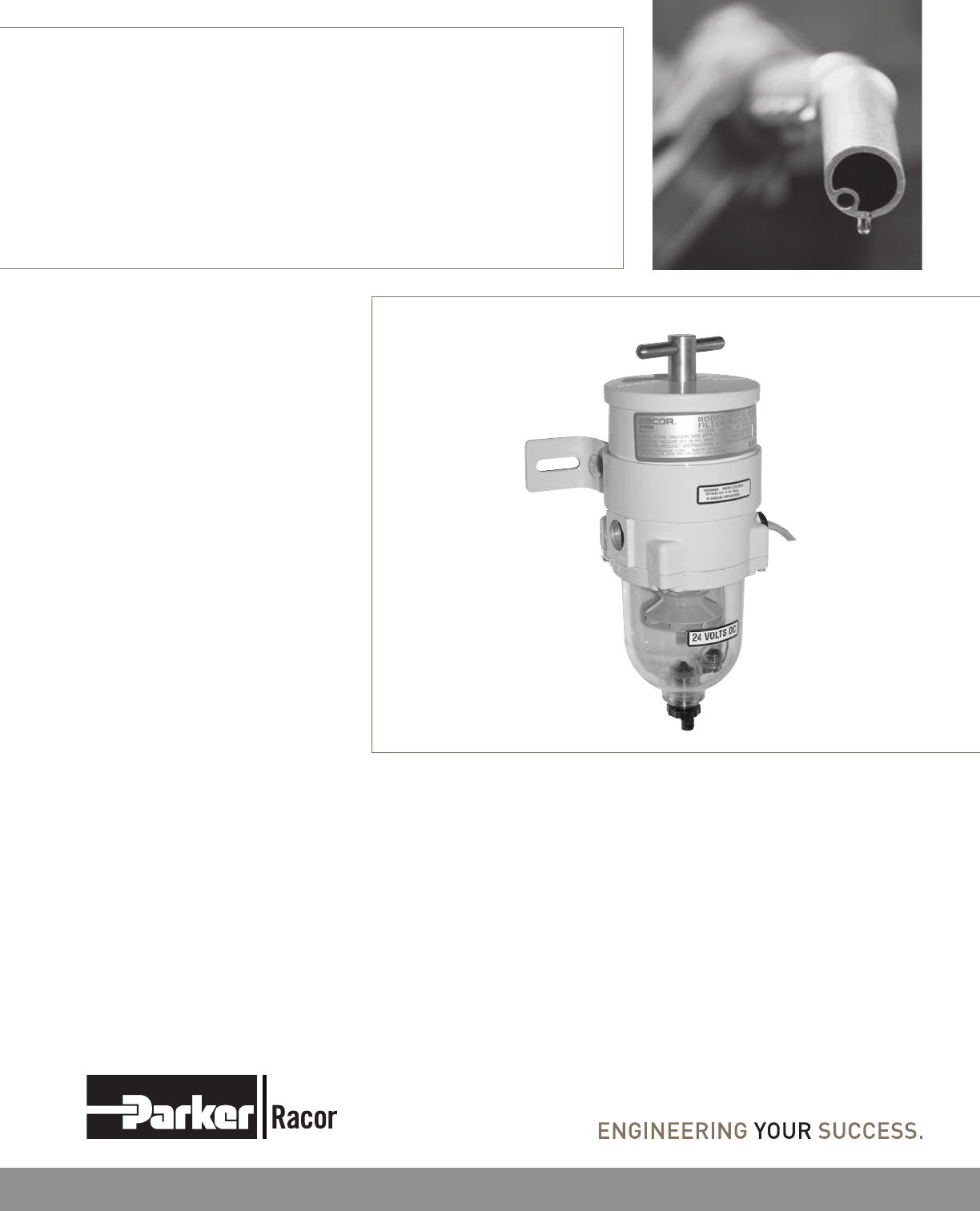
500FG Turbine Series
Fuel Filter/Water Separator
Contact Information
Parker Hannin Corporation
Racor Division
P.O. Box 3208
3400 Finch Road
Modesto, CA 95353
phone 800 344 3286
209 521 7860
fax 209 529 3278
racor@parker.com
www.racorcustomers.com
www.parker.com/racor
Instruction Part Number 15332 Rev E
The Racor 500FG Turbine Series
fuel filter/water separator protects
the precision components of
your engine from dirt, rust, algae,
asphaltines, varnishes and especially
water, which is prevalent in low
distillate fuels. Contaminants are
removed from fuel using the
legendary three stage process
described below.
How It Works
Stage 1 - Separation
Using the fuel flow, the stationary
turbine separates large solids and
free water through enchanced
centrifugal force.
Stage 2 - Coalescing
Smaller water droplets and solids
coalesce on the conical baffle and
fall to the collection bowl.
Stage 3 - Filtration
Engines will benefit from near 100%
water separation and fuel filtration
with Racor’s proprietary Aquabloc®
water repelling media. The
replaceable filters are available in 2,
10, and 30 micron ratings.
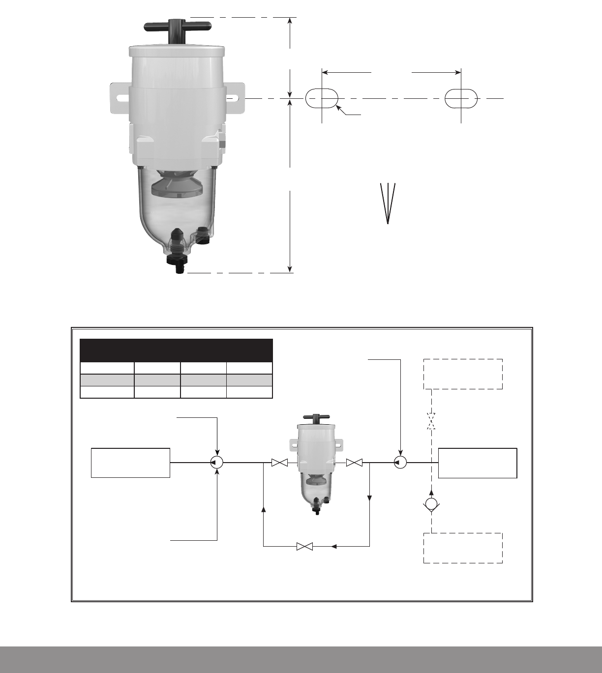
Mounting Instructions
Installation Diagram
Valve 1Valve 2
Fuel tanks above filter
head pressure should not
exceed maximum PSI of filter.
Fuel Tank
(Pressure Side Installation)
Install a shut-off valve when
fuel tank is higher than filter
Fuel tank below filter
Do not exceed 5’ (1.5m) of lift
or 4 inches of mercury (inHg)
of inlet piping restrictions
Fuel Tank
(Ideal Vacuum
Side Installation)
Fuel Tank
(Vacuum Side Installation)
Install a check valve
(with light or no restriction)
when tank is lower than filter
to maintain prime.
Pressure Side:
Fuel transfer pump not to exceed
maximum PSI or flow rate of filter.
Not ideal - pumps emulsify water
hindering filter performance.
Fuel transfer pump
(IDEAL vacuum side installation)
Engine
Maintain a clearance of at least 5
in. (12.7 cm) above and at least 2
in. (5.1 cm) below filter assembly
to service unit and drain bowl.
Valve 3
Suction (vacuum) Side:
Primary (first) filter - use 30 micron.
If it is the only filter in the system,
use 2 or 10 micron.
Optional Bypass Installation and Operation
(allows user to service filter without shutting down engine.)
Valves 123
Unit On-line Open Open Closed
Unit Off-line Closed Closed Open
500FG (Front)
4.0 in.
(10.2 cm)
7.5 in.
(19.1 cm)
4.5 in.
(11.4 cm)
3/8 in. (1.0 cm)
diameter clearance
for fasteners
V
± 10º
Install
500FG Assembly
within 10º of verticle

These customer supplied
materials should be on hand
before beginning installation.
Shop Towels•
Mounting Hardware •
Inlet/Outlet Fittings •
Fuel Hose •
Clean Diesel Fuel•
Parker Super O-lube or Clean •
Motor Oil
Thread Sealant •
(no thread tapes)
Positioning filter assembly:
Filter assemblies should be
installed on vacuum side of fuel
transfer pump for optimum
water separating efficiency.
See Installation Diagram.
Keep fuel line restrictions
to a minimum. Locate the
500FG filter assembly between
horizontal planes of bottom
of fuel tank and inlet of fuel
pump, if possible. If 500FG
filter assembly is installed in an
application where the fuel tank is
higher than filter, a shut-off valve
must be installed between the
tank and 500FG filter assembly
INLET. This will be used when
servicing the replacement filter.
Before installing filter assembly:
Obtain good ventilation and •
lighting.
Maintain a safe working •
environment.
Engine must be off for •
installation.
DO NOT smoke or allow open •
flames near installation.
Installing filter assembly:
Completely remove any vacuum
side filters in fuel line between
fuel tank and fuel pump. This is
where the Racor filter will mount.
Leaving these filters in place will
add to fuel line restriction. Filter
heads cast into engine or that are
non-removable or hard piped
should be serviced with a new
filter and left in place.
Keep fuel flow restriction
to a minimum. Always use
the maximum size fuel hose
possible. Do not make sharp
bends with flexible hose as kinks
may occur. Avoid use of two
45° elbow fittings where one 90°
elbow will work.
When routing hose, avoid
surfaces that move, have sharp
edges, or get hot (such as exhaust
piping).
Installation
Guidelines
Priming
The Unit
Draining Water:
Frequency of water draining is
determined by contamination
level of fuel. Inspect or drain
collection bowl of water daily
or as necessary. Collection
bowl must be drained before
contaminants reach top of
turbine or when Water Detection
Module (optional) indicates it’s
time to drain water.
Vacuum Applications /
Installations:
Close inlet valve (or valve #1) 1.
and open drain on bottom of
bowl with a suitable container
in place.
Close drain after all water 2.
and contaminants have been
evacuated – DO NOT leave
drain open too long as it will
eventually completely drain
entire filter assembly of water
AND fuel.
Follow Priming Instructions.3.
Pressure Applications /
Installations:
Open drain on bottom of 1.
bowl to evacuate water and
contaminants with a suitable
collection container in place.
Head pressure will push any
water and contaminants out
of drain while keeping filter
primed.
Close drain after all water 2.
and contaminants have been
evacuated – DO NOT leave
drain open too long as it will
eventually completely drain
entire filter assembly of water
AND fuel, and possibly drain
entire tank.
Service
Remove T-handle and lid 1.
from top of filter assembly.
Fill filter assembly with clean 2.
fuel.
Lubricate lid gasket and 3.
T-handle O-ring with clean
fuel or motor oil.
Replace lid and T-handle, 4.
tighten snuggly by hand only
– do not use tools.
If applicable, refer to 5.
equipment operator’s manual
to complete fuel priming
procedure.
Start engine, check for fuel 6.
system leaks. Correct as
necessary with engine off and
pressure relieved from filter
assembly.

Frequency of filter replacement
is determined by contamination
level of fuel. Replace filter
every 10,000 miles (16,000 km),
every 500 hours, every other oil
change, when vacuum gauge
(optional) reads between 7 to
10 inches of mercury (inHg),
if power loss is noticed, or
annually, whichever comes first.
Note – always carry extra
replacement filters as one tankful
of excessively dirty fuel can plug
a filter.
Use only genuine Racor
Aquabloc® replacement filters –
see Replacement Part List
All Applications:
Bypass filter assembly with 1.
bypass valves, if applicable.
Remove T-handle and lid.2.
Remove filters by holding bail 3.
handles and slowly pulling
upward with a twisting
motion. Dispose properly
according to local regulations.
Remove and discard old lid 4.
gasket and T-handle O-ring
and clean seal glands of any
dirt or debris. Lubricate new
gasket and seal (supplied with
new filter) with motor oil or
diesel fuel before installation.
Refer to Priming Instructions, 5.
otherwise, fill unit with clean
fuel, replace lid and T-handle
and tighten snuggly by hand
only – do not use tools.
Note - above ground tanks or
transfer pump applications
may use head pressure to
prime filter assembly.
Filter Replacement
A major cause of power loss or
hard starting is result of an air
leak (or clogged filter). If your
unit will not prime or fails to
hold prime, check that drain,
Troubleshooting Procedures
bowl and filter are properly
tightened. Next, check all fitting
connections and ensure fuel
lines are not pinched or clogged
with contaminants. If problems
persist (and filter is new) call
Racor Technical Support for
assistance: (800) 344-3286 or
(209) 575-7555.
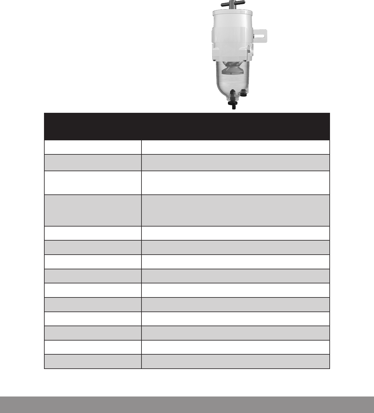
500FG
Maximum Flow Rate: 60 GPH (227 LPH)
Port Size 3/4´´-16 UNF
(SAE J1926)
Service Clearance
Above Assembly
Below Assembly
5.0 in. (12.7 cm)
2.0 in. (5.1 cm)
Replacement Filters
2 micron
10 micron
30 micron
2010SM-OR
2010TM-OR
2010PM-OR
Water In Bowl Capacity 3.7 oz. (109 ml)
Height 11.5 in. (29.2 cm)
Width 5.8 in. (14.7 cm)
Depth 4.8 in. (12.2 cm)
Weight (dry) 4.0 lb (1.8 kg)
Max. Working Pressure 25 PSI (1.7 bar)
Clean Pressure Drop 0.25 PSI (1.7 kPa)
Water Removal Efficiency 99%
Ambient Temp. Range -40°F to +250°F (-40°C to +121°C)
Max. Fuel Temperature 190°F (88°C)
Specifications
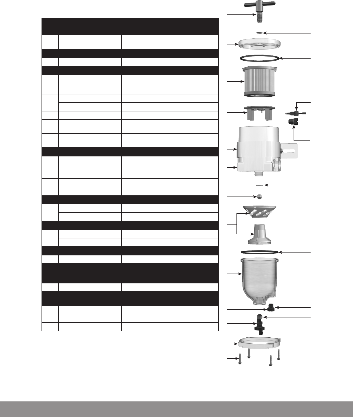
Part Number Description
1RK 11888 T-handle and O-ring Kit (9/16”-18 UNF Threads)
Hand Tighten
1a 11350 T-handle O-ring
2RK 15078 (FG) Lid Kit
2a 15005 Lid Seal
B
2010SM-OR (2 micron),
2010TM-OR (10 micron), or
2010PM-OR (30 micron)
Replacement Filter (All Models)
C
RK 15383-01 Heater Kit (12 vdc, 300 watt)
RK 15383-02 Heater Kit (24 vdc, 300 watt)
3RK 15081 Bowl Fasteners (4) Tighten to 60 in. lbs (6.78 Nm)
4RK 15035 (FG) Bowl Ring Kit
5RK15405 (FG >2002)
RK 15279-01 (FG <2002)
Clear Bowl Kit (includes 5, 5a, 9, 9a, 11, & 11a)
Clear Bowl Kit (includes 5*, 5a, 11, & 11a)
5a 15374 Bowl Seal
6RK 15013D Turbine Centrifuge and Conical Baffle Kit
Hand Tighten
7(not sold seperately) Check Ball Seal
8RK 15010B Check Ball Kit (includes 7)
9 RK 30476 (FG >2002) Self-venting Drain Kit Tighten to 30 in. lbs (3.39 Nm)
9a (not sold seperately) Drain Gasket
10
RK 21067 Heater Feedthru Kit Tighten to 15 in. lbs (1.69 Nm)
RK 11-1679 Feed-thru Plug Kit Tighten to 15 in. lbs (1.69 Nm)
10a 43506 Feedthru or plug O-ring
11
RK 21069 Water Probe Kit Tighten to 15 in. lbs (1.69 Nm)
RK 20126 (FG) Bowl Plug Kit Tighten to 15 in. lbs (1.69 Nm)
11a (not sold seperately) Water Probe or Plug O-ring
12 RK 11780 (FG <1993) Drain Assembly Kit
12a
12b
12c
(not sold seperately)
(not sold seperately)
(not sold seperately)
Drain Seal (Finger)
Drain Body O-ring
Drain O-ring
13 RK 30488 (FG 1994-2002) Drain Assembly
9a
12b
(not sold seperately)
(not sold seperately)
Drain Gasket
Drain Body O-ring
D
RK 15378 (FG) Clamp Bracket Kit
RK 11838 Carraige Bolt Kit
E(not sold seperately) 500 Body/Housing
1
2
2a
B
D
7
8
5
4
1a
6
5a
10a
3
C
9a
E
11a
11
9
10
Parts and kits listed can be purchased from a Racor distributor.
Go to www.racorcustomers.com for a distributor near you.
5*
12b
12a
12c
13
5*
12b
9a
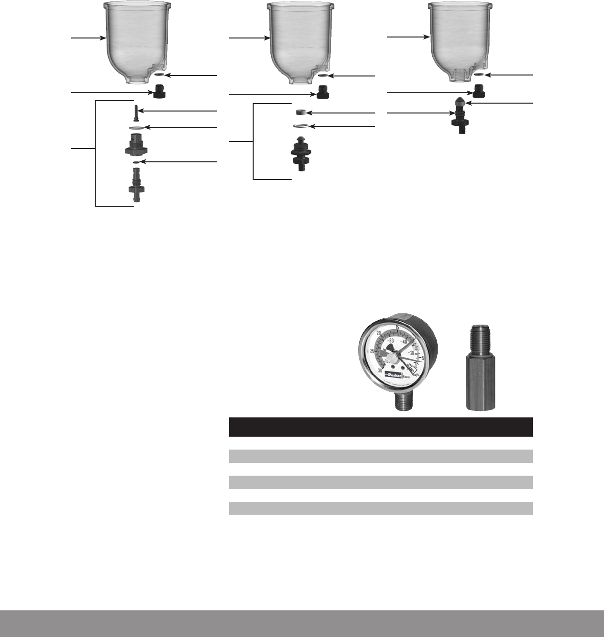
12
RK 11780 Drain Kit
(1993 & Older)
11 11
11a
11a
Drain Configurations
RK 30488 Drain Kit
(1994-2002)
5
9a
11a
11
9
RK 30476 Drain Kit
(2002-Current)
Specifications RK 11-1969
Application For 500 Filter Assemblies
Thread Size 1/4˝ NPT bottom boss mount
Fitting Thread 9/16˝-18 UNF
Dimensions 2.0˝ Diameter x 1.1˝ Depth
Weight (dry) 0.3 lb (0.1 kg)
Ambient Temperature Range -40o to +250oF (-40o to +121oC)
Special Notes: For severe vibration applications, mount gauge on a stable, remote location and
connect to the source using flexible tubing. After September 1999, Racor converted many liquid-
filled gauges to new silicone dampened movement. This new (dry) technology provides a vibration
resistant design that never leaks fluid or requires adjustments due to temperature or altitude
variations.
The T-handle vacuum gauge
monitors your filters condition.
As your filter slowly becomes
clogged with contaminates,
restriction (resistance to flow)
increases. Because of this
restriction, more air is mixed
with fuel and less fuel is
delivered to the engine (fuel de-
gassing). This will result in loss
of power and eventually stall the
engine.
Installing a T-handle vacuum
gauge in your fuel system gives
you a visual monitor of your filter
condition. Excessive resistance
on the gauge means it’s time to
change the filter.
T-handle Vacuum Gauge

July 2010© Parker Hannin Corporation
All products manufactured
or distributed by Racor are
subject to the following, and
only the following, LIMITED
EXPRESS WARRANTIES, and
no others: For a period of
one (1) year from and after
the date of purchase of a new
Racor product, Racor warrants
and guarantees only to the
original purchaser-user that
such a product shall be free
from defects of materials
and workmanship in the
manufacturing process. The
warranty period for pumps and
motors is specifically limited
to ninety (90) days from date of
purchase. A product claimed to
be defective must be returned
to the place of purchase. Racor,
at its sole option, shall replace
the defective product with a
comparable new product or
repair the defective product.
This express warranty shall be
inapplicable to any product not
properly installed and properly
used by the purchaser-user
or to any product damaged or
impaired by external forces.
THIS IS THE EXTENT OF
WARRANTIES AVAILABLE
ON THIS PRODUCT. RACOR
SHALL HAVE NO LIABILITY
WHATSOEVER FOR
CONSEQUENTIAL DAMAGES
FLOWING FROM THE USE OF
ANY DEFECTIVE PRODUCT
OR BY REASON OF THE
FAILURE OF ANY PRODUCT.
RACOR SPECIFICALLY
DISAVOWS ALL OTHER
WARRANTIES, EXPRESS
OR IMPLIED INCLUDING,
WITHOUT LIMITATION, ALL
WARRANTIES OF FITNESS
FOR A PARTICULAR PURPOSE
(EXCEPT FOR THOSE WHICH
APPLY TO PRODUCT OR
PART THEREOF THAT IS
USED OR BOUGHT FOR USE
PRIMARILY FOR PERSONAL,
FAMILY, OR HOUSEHOLD
PURPOSES), WARRANTIES OF
DESCRIPTION, WARRANTIES
OF MERCHANTABILITY,
TRADE USAGE OR
WARRANTIES OR TRADE
USAGE.
Warning
Failure or improper selection
or improper use of the
products and/or systems
described herein or related
items can cause death,
personal injury and property
damage. This document and
other information from Parker
Hannifin Corporation, its
subsidiaries and authorized
distributors provide product
and/or system options for
further investigation by users
having technical expertise.
It is important that you
analyze all aspects of your
application and review the
information concerning the
product or system in the
current product catalog. Due
to the variety of operating
conditions and applications
for these products or systems,
the user, through its own
analysis and testing, is solely
responsible for making the
final selection of the products
and systems and assuring that
all performance, safety and
warning requirements of the
applications are met.
The products described
herein, including with
limitation, product features,
specifications, designs,
availability and pricing, are
subject to change by Parker
Hannifin Corporation and
its subsidiaries at any time
without notice.
The following statement
is required pursuant to
proposition 65, applicable
in the State of California:
‘This product may contain a
chemical known to the State of
California to cause cancer or
reproductive toxicity’.
Limited Warranties Statement
