Pro Tech Computer Hardware ULV Celeron M 3.5 Embedded Card With VGA/ SOUND/ LAN Rtc1009
User Manual: Pro-Tech Computer Hardware ULV Celeron M 3.5 Embedded Card With VGA/ SOUND/ LAN
Open the PDF directly: View PDF ![]() .
.
Page Count: 56
Avalue Technology Inc. Tel: (732) 578-0200 Fax: (732) 578-0250
200 Tornillo Way, Suite 210, Tinton Falls, NJ 07712 E-mail: sales@avalue-usa.com www.avalue-tech.com
Onboard LV/ ULV Intel® Core™ i7 Processor
Intel® QM57 Chipset
One 204-pin SODIMM Up to 4GB DDR3 800/ 1066 SDRAM, Non-ECC
Dual View, 2-CH LVDS, DVI-I
Dual Intel® Gigabit Ethernet
1 CF, 4 SATA, 2 COM, 8 USB, 16-bit GPIO
Options: Express Card/ 34mm, Built-in Touch Screen Interface
Support iAMT 6.0
Support RAID 0/ 1/ 5/ 10
EPI-QM57
Intel® Core™ i7-620LE/ 620UE EPIC Module
with Intel® QM57 Chipset
EPIC
Onboard Intel® Core™ i7-620LE/ 620UE Processor
Intel® QM57 Chipset
One 204-pin DDR3 SODIMM Up to 4GB DDR3 800/ 1066 SDRAM
Dual View, 2-CH LVDS, VGA, HDMI
5.1-CH Audio, Dual Intel® Gigabit Ethernet
2 SATA, 2 COM, 7 USB, 16-bit GPIO
Support iAMT 6.0
ECM-QM57
Intel® Core™ i7-620LE/ 620UE 3.5” Micro
Module with Intel® QM57 Chipset
3.5” SBC
Dedicated to customer's success
www.avalue-tech.com
E
Avalue QM57 series veried Intel® AMT6.0 compliant
The new Intel® Core™ i7 processor,
32nm process technology
Delivers enhanced performance,
energy efficiency, manageability,
security functions & smoother visual experiences
Untitled-5 1 9/14/10 10:32:10 AM
RTC MAGAZINE SEPTEMBER 2010 3
TABLEOFCONTENTS
SEPTEMBER 2010
Digital Subscriptions Avaliable at http://rtcmagazine.com/home/subscribe.php
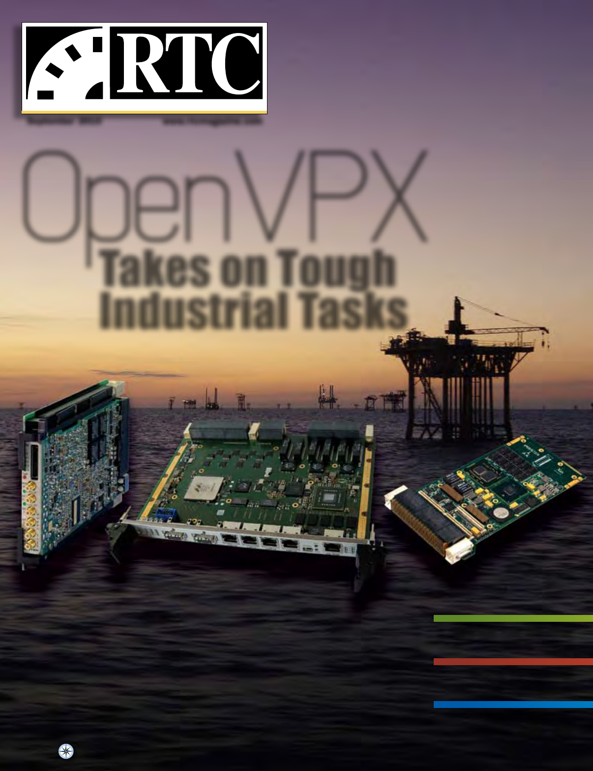
Cover Photo: New Open VPX boards: The Pentek Rugged Quad 200 MHz, 16-bit A/D with Virtex-5 FPGAs 3U VPX Module, the Elma T4340 6U OpenVPX switch and the
Extreme Engineering XPedite7370 3U VPX Intel Core i7-based SBC.
PC/104-Express Board Incorporates Qseven ModulesSound and Vibration Software Supports Data Translation
IEPE Modules
CPU Cooler Improves Airflow, Water Block and Heat
Dissipation Capacity
514846
38
42
34
TECHNOLOGY IN SYSTEMS
Thermal Management in Tight Places
Thermal Management and Power
Integrity in Tight Spaces
Syed W. Ali, Nexlogic
TECHNOLOGY DEPLOYED
Robotic Systems
Prototyping Autonomous Robots
with FPGAs
Jamie Brettle, National Instruments
INDuSTrY waTCH
Medical Devices
Transitioning from Analog to
Digital in Medical Designs
Joseph Sankman, Microchip Technology
28
18
22
14
TECHNOLOGY IN CONTExT
OpenVPX
The Quest to Navigate the
OpenVPX Standard: VITA 65
Ken Grob, Elma Electronic
Is There Life Beyond Defense and
Aerospace for VPX?
Ben Klam and Dave Barker,
Extreme Engineering Solutions
Beamforming Systems Moving
Toward New VPX and FPGA
Solutions
Rodger Hosking, Pentek
TECHNOLOGY CONNECTED
Options for Industrial Networks
Upgrade Existing Industrial
Networks with Fiber Optics
Mickaël Marie, Avago Technologies
46
12
10
6
5
DEParTMENTS
Editorial
Solid State Storage: Will the Enterprise
Fule an Upheaval in the Embedded
Space?
Industry Insider
Latest Developments in the Embedded
Marketplace
Small Form Factor Forum
The Emperor’s New Clothes
Products & Technology
Newest Embedded Technology Used
by Industry Leaders
EDITOr’S rEPOrT
Robotic Research
True Robots Differ Substantially
from Other Automated Systems
Tom Williams
OpenVPX
Takes on Tough Industrial Tasks
Publisher
PRESIDENT
John Reardon, johnr@rtcgroup.com
Editorial
EDITOR-IN-CHIEF
Tom Williams, tomw@rtcgroup.com
CONTRIBUTING EDITORS
Colin McCracken and Paul Rosenfeld
MANAGING EDITOR
Marina Tringali, marinat@rtcgroup.com
COPY EDITOR
Rochelle Cohn
Art/Production
CREATIVE DIRECTOR
Jason Van Dorn, jasonv@rtcgroup.com
ART DIRECTOR
Kirsten Wyatt, kirstenw@rtcgroup.com
GRAPHIC DESIGNER
Christopher Saucier, chriss@rtcgroup.com
GRAPHIC DESIGNER
Maream Milik, mareamm@rtcgroup.com
WEB DEVELOPER
Hari Nayar, harin@rtcgroup.com
Advertising/Web Advertising
WESTERN REGIONAL ADVERTISING MANAGER
Stacy Mannik, stacym@rtcgroup.com
(949) 226-2024
WESTERN REGIONAL ADVERTISING MANAGER
Lauren Trudeau, laurent@rtcgroup.com
(949) 226-2014
EASTERN REGIONAL ADVERTISING MANAGER
Shandi Ricciotti, shandir@rtcgroup.com
(949) 573-7660
ASIAN REGIONAL ADVERTISING MANAGER
Jessica Marinescu, jessicam@rtcgroup.com
(+852) 2548 5100
Billing
Cindy Muir, cmuir@rtcgroup.com
(949) 226-2021
To Contact RTC magazine:
HOME OFFICE
The RTC Group, 905 Calle Amanecer, Suite 250, San Clemente, CA 92673
Phone: (949) 226-2000 Fax: (949) 226-2050, www.rtcgroup.com
Editorial Office
Tom Williams, Editor-in-Chief
245-M Mt. Hermon Rd., PMB#F, Scotts Valley, CA 95066
Phone: (831) 335-1509 Fax: (408) 904-7214
SEPTEMBER 2010
Published by The RTC Group
Copyright 2010, The RTC Group. Printed in the United States. All rights reserved. All related
graphics are trademarks of The RTC Group. All other brand and product names are the property
of their holders.
Rugged SBC
Showcase
Featuring the latest in
Rugged SBC technologies
ADLGS45PC - Intel Core 2
Duo / Celeron M 1.20GHz
- 2.26GHz – PCI/104-
Express v1.0
Intel® Celeron® M / Core™ 2 Duo
(SFF)
Intel® GS45 / ICH9M-E Chipset /
DDR3-1066MHz DRAM – Up to 4GB
LAN Controllers 2x 1Gbit LAN, CRT/
LVDS
4x SATA 3GB/s with RAID Support
8x USB2.0 Ports, 2x COM, LPT, SM-
Bus TPM
For High Performance, Extreme
Rugged Applications
Advanced Digital Logic (ADL)
Phone: (858) 490-0597
Fax: (858) 490-0599
E-mail: sales@adl-usa.com
Web: www.adl-usa.com
SCOUT Miniature Wideband
Data Recorder
Removable solid-state storage
Capture a signal band of up to 40 MHz
at 70 MHz IF
512 GBytes of storage for up to 45
minutes of 8-bit data capture at 93
MSPS
Low power -- less than 12 watts
Future input interface options:
· Other IF frequencies (e.g., 60 MHz,
120 MHz, etc.)
· Selectable bandwidths
Acces I/O
Phone: (800) 620-7030
Fax: (410) 290-7715
E-mail: info@drs-srt.com
Web: www.drs-srt.com
USB Embedded Modem
Modules
USB modems, in module or stand-
alone form factor
Linux, Windows and Mac O/S support
-40C to +85C operating temperature
(Module)
Compact size: 1” x 1” x 0.2” (Module)
USB 2.0 compatible
up to 56K bps data rate, fax and voice
AT command
Transferable FCC68, CS03, CTR21
telecom certifi cations
Global safety: IEC60950-1, IEC60601-
1 (Medical) approved
CE marking
Radicom Research, Inc.
Phone: (408) 383-9006
Fax: (408) 383-9007
E-mail: sales@radi.com
Web: www.radi.com
Echotek® Series DCM-V6-
XMC
High speed transceiver powered by
Virtex™-6 FPGA
Four-channel 16-bit A/D conversion at
up to 160 MSPS
Single-channel 16-bit D/A conversion
at up to 1 GHz (optional)
Complementary to the Echotek Series
RF 3000T RF Tuner and Upconverter
Mercury Computer Systems
Phone: (866) 627-6951
Fax: (978) 256-3599
E-mail: sales@mc.com
Web: www.mc.com

RTC MAGAZINE SEPTEMBER 2010 5
EDITORIAL
SEPTEMBER 2010
Tom Williams
Editor-in-Chief
An undisclosed number of years ago I was in the ofce of
Alan Shugart, who was at that time the CEO of disk drive
manufacturer Seagate Technology here in the throbbing
metropolis of Scotts Valley, California. Shugart had previously
been one of the pioneers at IBM on the team that developed the
very rst hard disk drive, a large portrait of which was on the
wall of his ofce.
It was an enormous thing that looked to have been in a cabi-
net about eight feet long and six feet tall. On one end was a glass
panel through which you could see a spindle that held possibly
ve or six platters. Beside the platters there was another vertical
shaft that carried the arm with the read/write head, and attached
to that was a rubber air hose to produce an air cushion to keep the
head from physically contacting the disk surface. The arm could
be withdrawn from one platter and moved up or down and then
swung in again to access another platter. The whole monstrous
thing had a capacity of ve Megabytes—don’t ask about the ac-
cess speed.
Shugart said that at the time the other people in the company
thought his team was crazy. “What would anybody do with ve
Megabytes?” Well now, of course, we know. We carry around
iPods that have small rotating media containing multiple Giga-
bytes. That’s if we’re old codgers, of course. The newer devices
have solid state storage—NAND ash.
Now ash memory is nothing new. It has been around—
especially in embedded and mobile devices—for years. But its
use has until recently been conned to relatively modest data
storage tasks. Recently, however, its use for storing ever more
data has been growing, and with the incorporation of things like
SATA interfaces on small embedded modules, ash memory has
taken on an increasing role as a solid state drive (SSD) for embed-
ded applications. These modules realize they now have a larger
capacity, low-power, small, rugged and reliable storage medium
that can be used to accommodate those newer applications that
suddenly have more data they need to store.
At the recent Flash Memory Summit in Santa Clara, the
main concern of the vendors there appeared to be to move ash
memory into the turf of enterprise storage. Attendees were ock-
ing like packs of teenage Hannah Montana fans to sessions on
performance, benchmarks, storage for enterprise and data centers
and more, all lured by the promise of truly vast sales of NAND
and controller silicon when the ubiquitous hard drive is pushed
further to the sidelines. And truly, there were examples aplenty
of SSDs with hundreds of Gigabytes of capacity and impressive
performance.
Why should such a development targeted at the enterprise be
of interest to the embedded community?” Just remember: “What
would anybody do with ve Megabytes?” What would an embed-
ded controller or a portable medical device do with 280 Giga-
bytes? At the moment I’m sure I don’t know, but I do know that
someone will nd a compelling use for such capacity if it ts the
size, weight, power, performance, ruggedness and capacity needs
of the application. And applications tend to evolve to overtax the
capacity of the available hardware.
The conquest of the enterprise space by the flash-based
SSD vendors can only be a good thing as the resulting cost
reductions and technology improvements proliferate and be-
come attractive to embedded developers. Along with the rush
to the enterprise, we are already seeing numerous examples
of higher-end flash storage appearing in form factors and
with connectors that are clearly aimed at the needs of embed-
ded systems.
And yet, this level of storage is but one element of some
rather interesting advances that have yet to come together in ac-
tual systems. We are on the threshold of PCI Express 3.0, USB
3.0, faster multicore processors, connectivity such as Intel’s
LightPeak optical technology and more. And we haven’t even
mentioned some of the things that are waiting in the wings be-
hind ash, such as phase change memory. Get out the popcorn.
It should be quite a show.
Solid State Storage: Will the
Enterprise Fuel an Upheaval
in the Embedded Space?

6 SEPTEMBER 2010 RTC MAGAZINE
INDUSTRY
INSIDER
SEPTEMBER 2010
6 SEPTEMBER 2010 RTC MAGAZINE
SCSI Trade Association
Announces MultiLink SAS
Connectivity
The SCSI Trade Associa-
tion (STA) announced the Mul-
tiLink SAS initiative at the Flash
Memory Summit on August 17.
The initiative’s purpose is to im-
prove how slot-oriented Solid
State Drive (SSD) devices can be
congured to improve I/O perfor-
mance. The externally accessible
backplane slot-based drive archi-
tecture will be fully compatible
for use with existing SAS/SATA
storage devices as well as new de-
vices designed to achieve higher
performance.
A new form factor compat-
ible connector will extend SAS
to a 4-port conguration. When
running at 12 Gbit/s, a single
slot will be capable of provid-
ing up to 96 Gbit/s of bandwidth
(full duplex). Additional signals
will be provided for general
purpose use within the same
connector. The MultiLink SAS
architecture is a slot-compatible
implementation and will accom-
modate a variety of SSD form
factors as well as existing Hard
Disk Drives (HDDs).
Minimizing the impact to
protocol changes makes Mul-
tiLink SAS primarily an en-
hancement to the existing con-
nector. It was decided to maintain
the existing Small Form Factor
(SFF) slot dimensions for ease of
retting an existing system and
for providing maximum system
exibility for storage OEMs. STA
will be working with T10 and the
Small Form Factor (SFF) com-
mittee to standardize this latest
SAS innovation.
Fast/Rugged SDD
Technology Poised for
Growth
Solid state drives are poised
for rapid growth in certain niche
markets according to a new re-
port just published by Objective
Analysis, Solid State Disk Market
Outlook 2010. Although SSDs
have not found widespread ac-
ceptance in general-purpose PCs,
those applications that benet
from this technology will drive
the client SSD market to grow at
a predicted rate of 60%. Objec-
tive Analysis predicts that in 2015
nearly 40 million SSDs will ship,
accounting for over $7 billion in
revenues.
“The PC market for SSDs
has been slow to develop,” said
the report’s author, Jim Handy.
“The strongest growth has oc-
curred in areas where HDDs sim-
ply will not operate and in sys-
tems for which users are willing
to pay a signicant premium for
an SSD’s faster speed or greater
durability.”
The report spells out de-
tails of the SSD market, its me-
chanics and anticipated growth.
Analysis is based upon numer-
ous interviews with both manu-
facturers and users of the tech-
nology, and explains both what
will become of this market and
why it will develop the way that
it will.
Portwell Sponsors Winning
Autonomous Underwater
Vehicle Team
The Cornell University Au-
tonomous Underwater Vehicle
(CUAUV) team took top honors
in the 2010 RoboSub competition
using a robotic submarine pow-
ered by American Portwell Tech-
nology’s WADE-8067 Mini-ITX
embedded board. The Cornell
team builds robotic submarines
for both competition and research
purposes. They approached
American Portwell for sponsor-
ship when they were considering
an Intel Core processor to power
their AUV because they knew
their onboard computer would be
subject to severe size constraints
and were restricted to a Mini-
ITX form factor or smaller. Jack
Lam, American Portwell’s se-
nior product marketing manager,
recommended the WADE-8067
Mini-ITX form factor embedded
board, a combination that utilizes
the Intel Core 2 processor most
effectively.
The Association for Un-
manned Vehicle Systems Inter-
national (AUVSI) Foundation
organizes the RoboSub competi-
tion, and Cornell’s Tachyon AUV
beat out 23 other teams from ve
countries to take rst place at
the 13th annual competition held
from July 13-18, 2010 in San Di-
ego, California. The competition
required the autonomous subma-
rine to hit a targeted buoy, send
torpedoes into specic windows
and drop markers in bins. Accord-
ing to Daryl Davidson, AUVSI
Foundation’s executive director,
the course elements are designed
so that at least one or two of the
obstacles prove too challenging
Intel Buys McAfee for Over $7 Billion
In what turns out to be the biggest purchase in its history, Intel has
acquired anti-virus software maker McAfee for $7.68 billion. The deal
appears to have people scratching their heads speculating about just
what it is that Intel has in mind. Of course, there is the revenue stream
currently generated by McAfee as the second largest seller of security
software in the PC market. But the big question is what the strategic
intent may be.
That may include but most definitely is not limited to selling security
for PCs based on Intel processors. A clue was given by Intel CEO Paul
Otellini, who said, “Everywhere we sell a microprocessor, there’s an op-
portunity for a security software sale to go with it. It’s not just the op-
portunity to co-sell; it’s the opportunity to deeply integrate these into the
architecture of the products.”
From that it would appear that Intel is interested not only in the prod-
ucts and services that McAfee currently offers, but also in the underly-
ing technology that can be integrated with the existing Intel architecture
as hardware and/or firmware enhancements. This would take the scope
beyond the world of PCs, notebooks and netbooks and into the world of
connected devices, which are projected to grow into the billions. Add to
that the growing trend toward cloud computing and the fact that McAfee
had recently added Cloud Secure to its offerings, and it looks even more
attractive. Potentially everything with an IP address represents a potential
access point for hackers and malware.
It will be interesting to see how Intel goes about crafting joint prod-
ucts, especially in the embedded space to which it has been devoting
more attention than it has traditionally been wont to do. Since the ac-
ceptance of the Atom by vast numbers of embedded developers, Intel has
used the Atom technology in the new development of the Tunnel Creek
device, which it claims for the first time to have conceived specifically for
the embedded market. Will we see security chips or processors with built-
in hardware support for security? It should be interesting.
RTC MAGAZINE SEPTEMBER 2010 7
RTC MAGAZINE AUGUST 2010 7
RTC MAGAZINE JULY 2010 7
RTC MAGAZINE JUNE 2010 7
RTC MAGAZINE MAY 2010 7
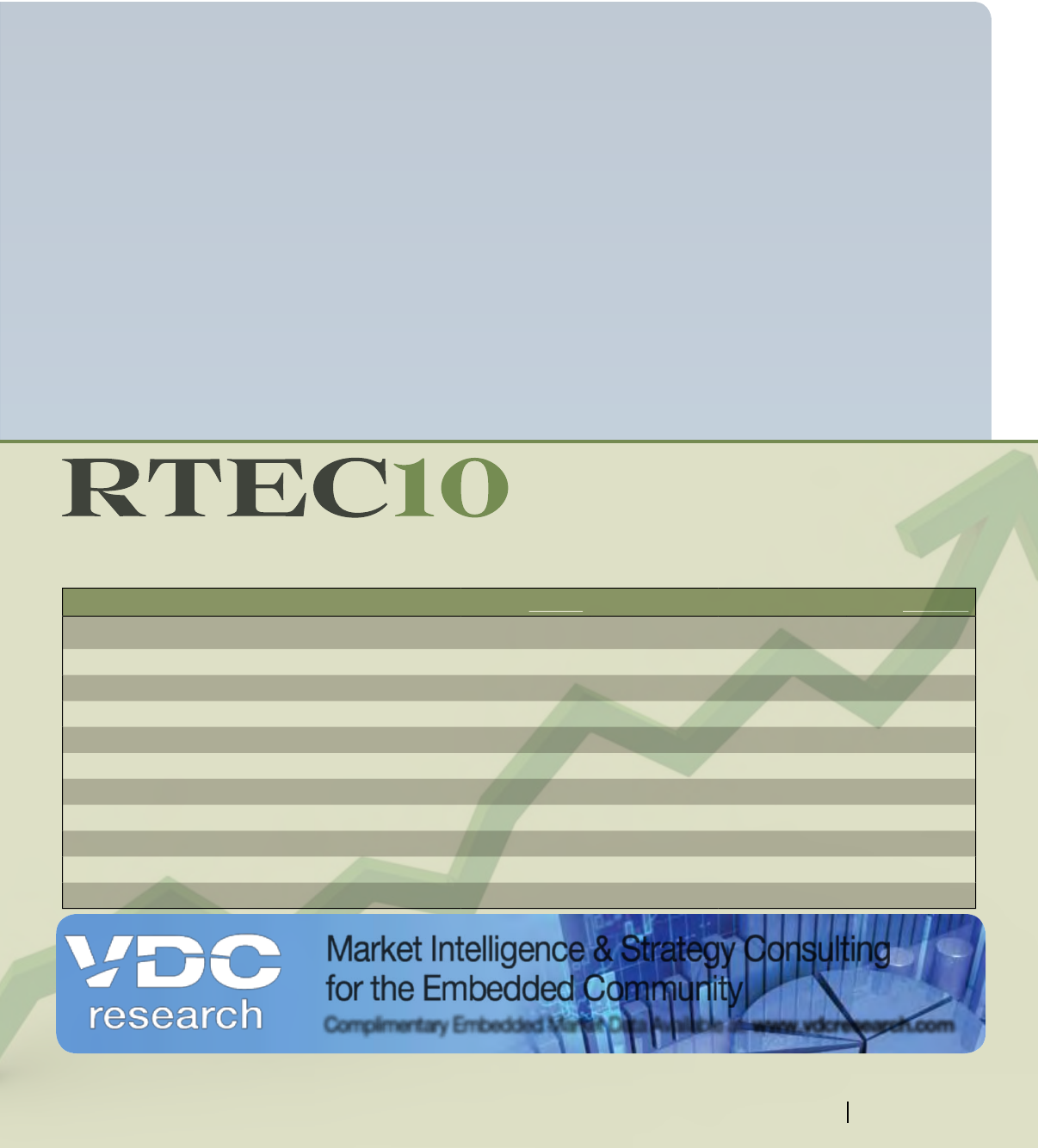
RTEC10 Index 46.85 — — 159.65
Company Market Performance
Adlink Technology 1.66 1.63 1.69 199.14M
Advantech 2.65 2.55 2.68 1.00M
Elma Electronic 419.35 412.44 419.35 95.70M
Enea 6.88 6.52 6.89 124.35M
Interphase Corporation 1.70 1.64 1.70 11.61M
Kontron 8.67 8.57 8.75 482.66M
Mercury Computer Systems 12.72 12.72 12.90 302.52M
Performance Technologies 2.08 2.07 2.13 23.12M
PLX Technology 3.60 3.52 3.75 133.54M
RadiSys Corporation 9.23 9.21 9.38 222.89M
Market Intelligence & Strategy Consulting
for the Embedded Community
Complimentary Embedded Market Data Available at: www.vdcresearch.com
Providing Market Inteligence for
Technology Executives and Investors
RTEC10 involves time sensitive information and currency conversions to determine the current value. All values converted to USD. Please note that these values are subject to certain delays and inaccuracies.
Do not use for buying or selling of securities.
Closing Price 52 Week Low 52 Week High Market Cap
RTEC10 is an index made up of 10 public companies which have revenue that is derived primarily from sales in the embedded sector. The
companies are made up of both soware and hardware companies being traded on public exchanges. All numbers are reflected in U.S. Dollars.
Learn more at rtcmagazine.com
RTC MAGAZINE SEPTEMBER 2010 7
for most teams. “However, we are
pleased to say that Cornell has
now proven us wrong twice,” he
explains.
Open Screen Project
to Deliver Seamless
Web Experience Across
Connected Devices
Wind River has announced
it is building on its collabora-
tion with Adobe by participating
in the Open Screen Project and
becoming a worldwide scaling
partner to bring the Adobe Flash
Platform to Internet-enabled de-
vices for rich and engaging Web
experiences. The Open Screen
Project is an industry wide ini-
tiative of more than 70 industry
partners led by Adobe to provide
consumers consistent Internet and
rich media experiences across the
broadest possible range of con-
sumer electronics.
Wind River will license,
distribute and support Adobe
Flash Player 10.x, Adobe AIR
2.x and Flash Lite 4.x across
its portfolio of Internet-facing
software platforms as well as of-
fer integration, certication and
support for these products. Join-
ing the Open Screen Project as a
scaling partner for Adobe, Wind
River is one of eight global scal-
ing partners entrusted to offer
licenses for these products di-
rectly to companies worldwide.
To kick off this initiative, Flash
Player 10.1 and AIR will rst be
incorporated with Wind River
Platform for Android. As an
Open Screen Project participant,
Wind River will work with cus-
tomers to integrate Adobe Flash
and AIR with their devices, and
ensure their devices are compli-
ant with the Open Screen Project
certication test suites.
With support for Flash
Lite already on products such
as Wind River Platform for An-
droid, Wind River is extending
its collaboration with Adobe to
further pave the way for custom-
ers to create products that deliver
the full experience of the Inter-
net with Flash Player 10.1, for a
variety of market segments. With
active participation in the Open
Screen Project, Wind River will
keep Flash open and updatable in
its software stack, as well as offer
support customers with upgrade
services. By integrating Flash
into Wind River’s products, de-
vice manufacturers can benet
from faster time-to-market and
reduced cost and engineering
effort. Additionally, application
providers can be condent that
their Flash-based content and
applications will run smoothly
8 SEPTEMBER 2010 RTC MAGAZINE
INDUSTRY INSIDER
across devices that use Wind
River’s Internet-facing software
platforms.
CANopen Profiles for
Laboratory Automation
CAN in Automation (CiA),
the international users’ and manu-
facturers’ group for CAN (Control-
ler Area Network), has released
additional device interfaces for lab-
oratory automation. The CiA 434
specications (part 2 and part 3)
describe device proles for heating,
cooling and shaking units as well
as dispensers, dilutors and pumps.
The proles specify process
data and conguration param-
eters. This makes the device in a
CANopen network interoperable
and even partly exchangeable,
simplifying system design.
CANopen is an internation-
ally standardized communication
system (EN 50325-4), which is
used in many different applica-
tion elds. The CANopen proles
for laboratory automation have
been developed by market-lead-
ing companies and are designed
especially for pipette automation
systems, but are also suitable for
other laboratory equipment. In
such systems, IEC 61131-3 pro-
grammable devices are increas-
ingly used, which are originally
developed for industrial automa-
tion. The CiA 434 specication
has been published for CiA inter-
nally; excerpts are available for
non-members.
AIT, Formerly AIM-USA,
Signs Strategic Alliance with
TTTech
AIT is pleased to an-
nounce the formation of a long-
term strategic alliance with
TTTech North America to add
ARINC664/AFDX, Ethernet,
Time-Triggered Ethernet and
Time-Triggered Protocol to their
product portfolio. AIT will pro-
vide local sales and support for
North American customers and
provide increased engagement
in the U.S. government and aero-
space market for TTTech. This
tightly coupled partnership will
capitalize on AIT’s experience in
product design, sales, production
and support, as well as TTTech’s
leadership in time-tr iggered com-
munication technologies.
AIT provides a suite of test
and simulation products for a wide
variety of avionics bus applica-
tions, including MIL-STD-1553,
ARINC429, ARINC615A, Fibre
Channel and MIL-STD-1760E.
With support from TTTech,
ARINC664/AFDX, Time-Trig-
gered Ethernet (TTE) and Time-
Triggered Protocol (TTP) will be
added to AIT’s portfolio. AIT will
remain an independent company
and will continue to enhance and
supply the newly combined vari-
ety of avionics products to aero-
space customers.
The TTP ASICs are mature
DO-254/DO-178B certied for
design of critical embedded ight
systems. TTEthernet and TTP are
open industry standards (SAE
AS6802 and AS6003 respective-
ly) that offer higher bandwidth
when compared to CAN, MIL-
STD-1553 and ARINC429. They
provide signicant advantages
in terms of reliability, modular-
ity, lower weight, certication,
reduced cost and faster time-to-
market for aerospace systems.
Untitled-7 1 8/10/10 11:21:04 AM
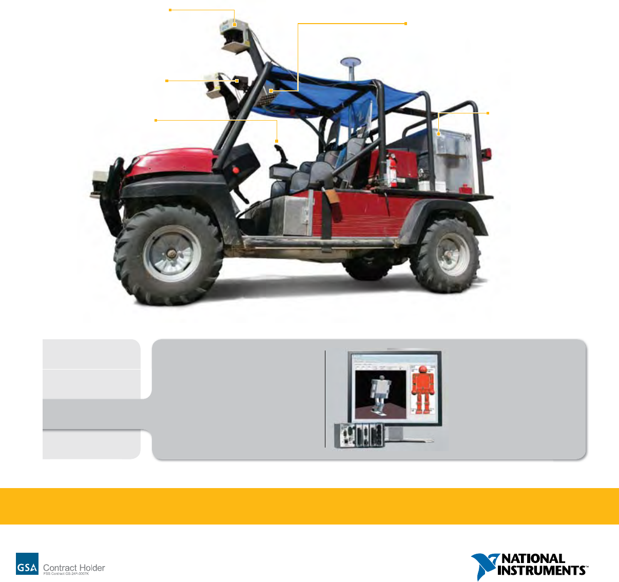
>> Find out what else LabVIEW can do at ni.com/imagine/robotics 866 337 5041
©2009 National Instruments. All rights reserved. CompactRIO, LabVIEW, National Instruments, NI, and ni.com are trademarks of National Instruments.
Other product and company names listed are trademarks or trade names of their respective companies. 0180
NI LabVIEW
Limited Only by Your Imagination
FPGA-based embedded hardware
for drive-by-wire systems
Drivers for
hundreds of sensors from
LIDAR to GPS
Multicore algorithms
for real-time navigation
and control
Image processing and
acquisition libraries
Standard communication
including JAUS
and Ethernet support
PRODUCT PLATFORM
NI LabVIEW graphical
and textual programming
NI CompactRIO embedded
control hardware
NI LabVIEW Real-Time Module
NI LabVIEW FPGA Module
LabVIEW graphical programming
software and modular NI hardware, such
as CompactRIO and PXI, are helping
engineers develop fully autonomous
robotics systems, including unmanned
vehicles designed to compete in DARPA
Grand Challenge events.
RF
Medical
Robotics
Multicore
Untitled-3 1 12/16/09 3:38:34 PM

10 SEPTEMBER 2010 RTC MAGAZINE
FORUM
Colin McCracken & Paul Rosenfeld
SMALL FORM FACTOR
News ash: The latest SFF standard has been approved,
and products are rolling off the line soon. Order your sample
or dev kit today!
Not so fast. How do you know this new “thing” will stand
the test of time? What if the spec was drafted by a lone techni-
cal guru, rubber-stamped by only a handful of others, and then
launched under the pretense of industry-wide support from a
respected trade group? Would that perspective lessen your de-
sign-in urge? Do we compliment the Emperor on his or her new
clothes, or form an opinion based on our own thorough technical
and market evaluation?
To analyze this consider how Corporations win or lose in
competitive markets based upon the relevance of their offerings.
The market decides. What would happen if your marketing folks
dened products without regard for what can actually be built?
At the other end of the spectrum, what would happen if your
engineers designed products in a vacuum without market input?
The days of “build-it-and-they-will-come” are over. Successful
new ideas come from an engineering / marketing partnership
where available technologies are applied to real customer needs.
Sounds simple. Yet the small form factor community is dis-
covering déjà vu all over again. Processor and chipset vendors
have appealing new products, and updated standards are needed
to take advantage of the new bells and whistles. Whether board-
level or SSD-level, a number of trade groups appear to have cre-
ated new standards incorporating new features that embedded
system OEMs don’t need or want simply because a processor or
chipset offers such a feature. Can you say, “type 2” or “type 6”?
What is going wrong?
The value of a standard derives from the ability of customers
to apply a variety of compliant products to solve design, manu-
facturing and lifecycle management challenges over time. Stan-
dards that do not meet the needs of a particular target market
likely won’t stand the test of time. However, in this market it takes
many years to determine success or failure of a standard, espe-
cially if the solution looks far forward into the future. Marketing
professionals are always rening their view of target customers
based upon perceived current requirements (the famous moving
target so detested by engineers everywhere) and upcoming chal-
lenges to reduce size, weight, power, cost and so on. Trade groups
could benet from the same level of market analysis that system
OEMs routinely use.
In creating these new standards or pinout variations, it is
very tempting for engineers merely to look at the latest chipsets
and map the buses and I/O to off-board connectors. But this tends
to disregard the installed base. The entire set of signals can be
massive overkill, even for mainstream applications. High-density
connectors allow many more pins in the same space. It doesn’t
mean we need to use them all. Smaller connectors with a well-
chosen pinout provide the opportunity to shrink overall system
size. Consumer ash modules offer greater data bandwidth at the
cost of higher power consumption, but in some cases these mod-
ules are literally too hot to handle by embedded OEMs.
A standard specication is the product of the input, creation
and review process of a trade group. It has to stand the test of the
market, regardless of the marketing hype surrounding its intro-
duction. Results can range from acceptance of a carefully tested
simple migratory step to an un-validated misre, and all shades
of gray between. Diversity of thoughts and ideas is critical to
the development process. The embedded community must not be
afraid to engage in painful debates during the standards creation
process about what features must stay and what can go. There just
isn’t enough space, cost and power for kitchen-sink solutions.
Users of standards-based products are faced with many
choices for next-generation designs, upgrades and retrots. To
make truly informed decisions, each OEM must research poten-
tial solutions using as many independent sources as practical.
Naturally, suppliers will position their products in the most fa-
vorable light possible, so one must dig deeper. Don’t assume t-
ness for use given prior successes or reputation of a trade group.
Check references and independent articles, evaluate standards
against system-level requirements, and then choose wisely. Irra-
tional exuberance doesn’t guarantee winning system designs. So
don’t kiss up to the Emperor. Join the debate and be prepared to
share your requirements rather than gush about the latest spec or
pinout type. Get involved!
As usual, comments about this topic can be mailed to sf3@
rtcgroup.com.
The Emperor’s New Clothes

12 SEPTEMBER 2010 RTC MAGAZINE
EDITOR’S REPORT
12 SEPTEMBER 2010 RTC MAGAZINE
The topic of robotics comes with a
certain number of preconceived no-
tions. On one end, robots are ambu-
latory, linguistically endowed anthropo-
morphic intelligent machines—the stuff of
science ction. On the other end, they are
synonymous with most semi-autonomous
automated control systems such as those
found on the factory oor. In actuality,
today’s robots are neither of these things.
Rather, they are systems at some point in
the transition from mundane machine to
as far toward the science ction image as
technology and ingenuity can take them.
But they are far from that goal despite
some fascinating advances.
So how do we differentiate between
an automated machine and a robot? Ac-
cording to Siddhartha Srinivasa, Senior
Research Scientist for Intel, two things
really distinguish robots: the ability to do
numerous adaptive general-purpose tasks
and the ability to operate in uncertain,
unstructured environments. For example,
an automated factory machine—and this
includes those electromechanical arms
that are often referred to as “industrial
robots”—works really well in a structured
environment such as a factory oor do-
ing one dened task that is dened for it.
Those tasks can, of course, be changed by
switching out equipment (a welding tip
for a paint sprayer) and loading a differ-
ent program.
Robots, on the other hand, are distin-
guished by their ability to perform many
general-purpose tasks and tasks that may
be similar but differ in terms of objects,
distances and other variables. For exam-
ple, the robot that can pick up a cup from
a coffee table and hand it to you should
be equally capable of moving across the
room, picking up a beer mug from a coun-
ter top and bringing it back to you with-
out reprogramming. That same robot, in
moving across the room, should be able
to recognize and avoid obstacles even if
they have been recently moved. These two
little stipulations bring with them an enor-
mous amount of added complexity, the
need for large amounts of computational
power and creative developments in ma-
chine intelligence. Such machines need
to be automatically adaptable both at the
task level and at the level of the surround-
ing environment.
One big issue of trying to write al-
gorithms for robotics, according to Srini-
vasa, is “to try to write them as general
as possible using words that have very
general meaning so that at the application
level they can be put together in different
ways to make different paragraphs, stories
and meanings.” He calls these “building
blocks of autonomy” so that the appli-
cation developer does not, for example,
have to worry about how many degrees
of freedom the arm has but can specify
instructions to “Pick up an object and put
the object there and don’t spill the coffee
in the object.”
Then, of course, there is the question
of how one uses such a level of abstrac-
tion to instruct the robot to “Pick up the
glass.” That concept is translated in the
human brain from its linguistic general-
ity to very specic arm and hand motions
that carry out the task for any number of
specic locations and circumstances. By
the same token, a robotic system must be
able to take a general description of pick-
ing up the glass and apply it to many spe-
cialized instances.
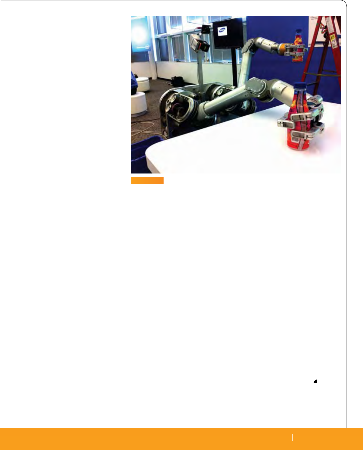
In the case of the robot used by Intel
Labs in Pittsburgh— HERB, the Home
Exploring Robotic Butler (Figure 1)—this
is done by literally taking the hand and
arm of the robot and moving it to the
object, wrapping the ngers of the hand
around the object and lifting it. That in-
volves, in this one teaching instance—a
large series of specic movements of mo-
tor encoders and other devices within the
machine. These are associated with algo-
rithms stored and classied in a very large
database. The robot tries to capture all the
possible states plus what the object looks
like, where it is located in its coordinate
space in addition to how its arm is mov-
ing. From this example, the robot builds
a model at a higher level of abstraction
within its brain. This internal model is
then used to search out and apply specic
algorithms and values to t a different in-
stance of “Pick up the glass.”
In addition to controlling major pe-
ripherals like its arms, HERB must also
integrate and constantly update informa-
tion about its surroundings. To that end, it
incorporates a vision system and a laser-
based coordinate system. The laser gen-
erates light pulses around the robot and
measures the frequency of the returning
beam to generate 40,000 points per second
around the robot. The data from the laser
system is used to build a 3D model of its
surrounding world. In addition, a camera
running vision processing algorithms is
by Tom Williams, Editor-in-Chief
Yes, it can put those cans on the pallet using its arm and
camera like a champ. But can it then run over to the fridge
and get me a beer—avoiding my kids’ toys in the way?
What makes a system really a robot?
True Robots Differ
Substantially from Other
Automated Systems
Robotic Research
RTC MAGAZINE SEPTEMBER 2010 13
EDITOR’S REPORT
RTC MAGAZINE SEPTEMBER 2010 13
used to recognize and manipulate objects.
The robot can pick up an object, twist it
around and build a 3D model that is stored
in its database.
Srinivasa stresses that the recent ad-
vances in compute power have been a tre-
mendous boon for robotics, especially in
providing the ability to search large spaces
to nd the proper motion algorithms for
a given task. The compute power in the
robot is also highly distributed with mo-
tor controllers at the lowest level—right at
the robot’s joints. These are very fast, spe-
cic-purpose devices that talk to the mo-
tors at 1,000 Hz, and their algorithms are
at the lowest level of the software hierar-
chy. The next level consists of behavioral
loops, such as image acquisition, that run
at about 10 Hz. Then at the highest level
are the planning algorithms that take the
data and make longer term plans to carry
out a task like picking up a glass.
To do this, the robot must execute one
of its general-purpose models, possibly
named “pick up the glass,” and adopt it to
the current situation. Thus it will not be ex-
ecuting the exact same routines that were
invoked when it learned the task. Rather,
it will assess the situation given the coor-
dinates from the laser system of objects
in its surroundings and images from the
vision system to invoke the proper model.
Then it will plan the execution of the task
by searching its database for the most ap-
propriate algorithms for that particular
instance of the task and arranging them
in a sequence, setting variables for those
algorithms that have been computed from
the coordinate space.
It is this adaptability that sets a ro-
botic system apart from a simpler semi-
autonomous automated system. The robot
selects a method that is similar to what it
has learned before. It then executes it while
asking if the object is still there (vision sys-
tem) and if it is feeling the forces it should
be feeling (tactile feedback). It is also mov-
ing its arm according to the algorithms that
have been set up based on the coordinate
space measured by the laser system. If it
notices an error, it propagates that error
back to the “brain,” which is the planning
level. The brain has a state machine that
reacts to errors. Recognizing, interpreting
and correcting for errors is one of the more
advanced areas of robotic research.
Of course, not all robots—even at
the research level—use exactly the same
mechanisms as the Intel HERB, but to
be truly robots as distinguished from
automated control systems, they must be
able to generalize, adapt and manage an
unstructured environment. One of the
best moments in his research, according
to Srinivasa, was “when I had never pro-
grammed the robot to pick up a given ob-
ject, but it gured it out from what it had
learned before.”
The question then naturally arises,
“Where are we going and what are we
getting from robotics research?” Interest-
ingly, much of the long-term goal seems
to be directed at things like personal and
home robots to take care of ordinary
chores. The word “robot,” after all, comes
from the Czech word “robota,” which
means “work” or “drudgery.” Obviously,
the same class of machines could and is
being used for work in harsh environments
like space. There are aspects of robotics
in unmanned aerial vehicles (UAVs), even
though these are also subject to direct hu-
man control as well.
There are annual competitions involv-
ing autonomous vehicles and autonomous
submersible vehicles, all of which have at-
tractive possibilities for applications. Al-
though we do not yet have commercially
available robotic cars, we do have some
advanced automobiles like the Lexus that
are capable of autonomous parallel park-
ing. This latter task must meet the more
stringent criteria for a robotic system in
that it must adapt a general task for paral-
lel parking to each individual situation—
especially if it involves a Hell’s Angels
bike. There are further more immediate
applications in health care, and there are
other aspects of current research that are
being examined for possible spin-offs for
applications. Along the way to 3-CPO we
will denitely nd creative and useful
ways to make use of more autonomous
and adaptable electromechanical systems
no matter what we call them.
Intel
Santa Clara, CA.
(408) 765-8080.
[www.intel.com].
FIGURE 1
The Home Exploring Robotic Butler—HERB—is an Intel research project for
proof of concept development in robotics. The system has two arms, a laser
system and a visual system for navigation and recognition, and a hierarchical
software architecture for adapting task models to particular situations for
execution.

14 SEPTEMBER 2010 RTC MAGAZINE
14 SEPTEMBER 2010 RTC MAGAZINE
CONTEXT
TECHNOLOGY IN
Much has been written recently
about the new OpenVPX standard
known as VITA 65. This article
provides an introduction to the structure
of the specication. In order to dene a
system, it’s important to understand how
to properly navigate through and decipher
the different sections of the specication
and its lexicon. Part two, a follow-on ar-
ticle scheduled for the November issue,
will discuss how VITA 65 enables a user
to build OpenVPX systems by combining
slot and backplane proles that support the
establishment of an end system topology.
The OpenVPX standard has been
brought to fruition through an intense ef-
fort driven rst outside, then subsequently
within the OpenVPX VITA Working
Group. In a few months, a short list of
companies and a team of dedicated in-
dustry veterans have brought us a 400+
page document that provides concepts and
methods to describe system topologies us-
ing a new breed of serial fabric technolo-
gies and high-speed backplanes.
As discussed in recent articles,
OpenVPX is based on prior VITA standards
that initially addressed VPX, including
VITA 46.0 and VITA 46.1. These standards
formed a good base to allow the design and
implementation of new high-speed, high-
power systems, but they fell short when it
came to fostering interoperability among
offerings from different manufacturers of
VPX boards and backplanes. So off on a
quest went these VPX Knights—a new stan-
dard they sought, to alleviate these plights.
Contending with MultiGig-2 wafer-based
connectors good for data rates up to 10 Gbit/s
and new backplane materials, including FR-
408 and Nelco 4000-13SI, OpenVPX is tak-
ing us to new data transfer rates where we
have not gone before (Figure 1).
SerDes-based physical interfaces sup-
porting baud rates of 3.125, 5.0 and 6.25
Gbit/s are now common within the OpenVPX
Module and Backplane lexicon. OpenVPX
has generated a well structured specication
volume, which at rst glance would send Don
Quixote back to the windmill. Introducing a
new set of terms for describing lane-based
point-to-point interconnects, the document
quickly grew large driven by the unique to-
pology required of each backplane described,
and using equation-based formulas that spec-
ify Slot, Module and Backplane proles.
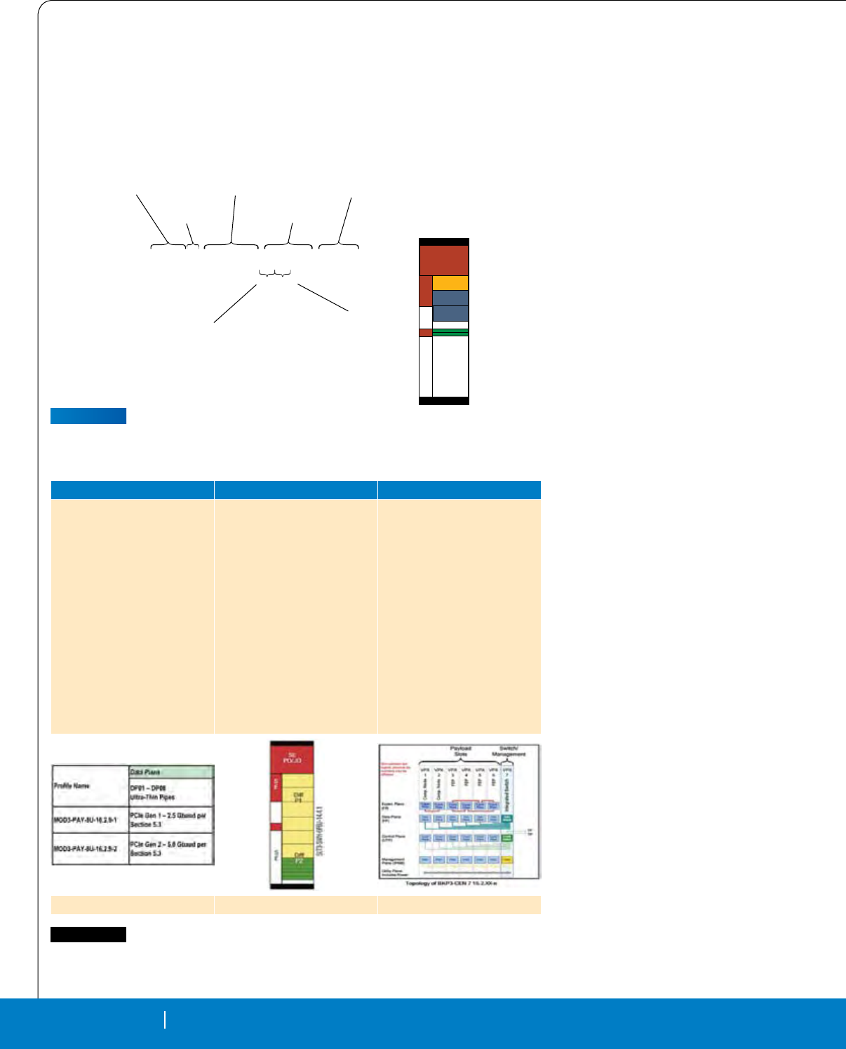
OpenVPX - the Standard
The standard was created to allow for
denition of system topologies and to pro-
mote interoperability. The specication
is divided into 16 sections. Section One
covers structure and denes terminol-
ogy. Key Words are dened. The concepts
of Prole Names are introduced and are
summarized in Figure 2.
Slot (SLT) in Types: Payload (PAY),
Peripheral (PER), Switch (SWH) and
Storage (STO).
Module (MOD): Same Attributes as
Slot but specic to the module (board) and
denes the protocol associated with the ports.
Backplane (BKP) in Types: CEN,
DIS, HYB, BRG, where:
• Central (Star)
• Distributed (Mesh)
• Hybrid (VME & VPX)
• BRG (Bridge, e.g., parallel VME to VPX)
Naming conventions for proles are
described to allow a user to create a name
by Ken Grob, Elma Electronic
OpenVPX offers huge potential for performance,
ruggedness and I/O in a wide variety of system
configurations. Navigating through the specification
can be intimidating at first, but once the terms have
been recognized and the map laid out, the path to truly
functional system topologies will open before us.
The Quest to Navigate
the OpenVPX Standard:
VITA 65
OpenVPX
FIGURE 1
VPX wafer-based connectors
fitting into backplane sockets.
RTC MAGAZINE SEPTEMBER 2010 15
RTC MAGAZINE SEPTEMBER 2010 15
TECHNOLOGY IN CONTEXT
to dene specic Module, Slot and Back-
plane proles. Figure 3 is an example of a
3U payload slot prole with one fat pipe
data plane, two fat pipe expansion planes
and two ultra thin pipe control planes. All
the additional attributes are found in the
document in Section 14.2.2 of VITA 65.
Module proles and backplane proles
follow a similar naming convention that
always includes the section number where
the prole is dened in full detail.
Section two of the VITA 65 standard
addresses compliance, which is an important
topic since it describes how one must consider
and comply with over 400 rules, permissions
and recommendations. These requirements
have been created to ensure interoperability be-
tween a backplane and the chosen module that
one is about to plug into a dened OpenVPX
Slot. Every VPX rule also has a compliance
requirement that must be documented and es-
tablished by one of four methods. These four
compliance methods are dened within the
OpenVPX standard as follows:
Inspection: The Inspection method
primarily uses a static, visual means to
demonstrate conformity.
Demonstration: The Demonstration
method primarily uses a dynamic, visual
means of showing functionality to demon-
strate conformity. While test equipment may
be required as part of the demonstration setup,
measurements are typically not required.
Analysis: The Analysis method primar-
ily uses theoretical means to demonstrate
conformity. Analysis 1063 input param-
eters may be based on component datasheet
or empirically derived parameters.
Test: The Test method primarily uses
physical measurements and test proce-
dures to demonstrate 1073 conformity.
The Testing method is necessary when in-
spection, demonstration and analysis 1074
methods are inadequate, not supported by
tools, or cost prohibitive.
Section three of VITA 65 discusses
the Utility Plane, Power Distribution, Sys-
tem Control Signals, the Reference Clocks
and the GPIO Signals. Pin Assignments are
dened for J0/P0 and J1/P1. In addition,
Section four covers the mechanical speci-
cations. Described here are Slot Pitch, Con-
nectors, Keying and RTM Connections.
In Section ve, we are getting into the
good stuff. This section covers the Fabric
Protocols referenced today by VITA 65.
Three major Protocols are dened, in-
cluding Ethernet, Serial Rapid I/O (SRIO)
and PCI Express (Table 1).
FP
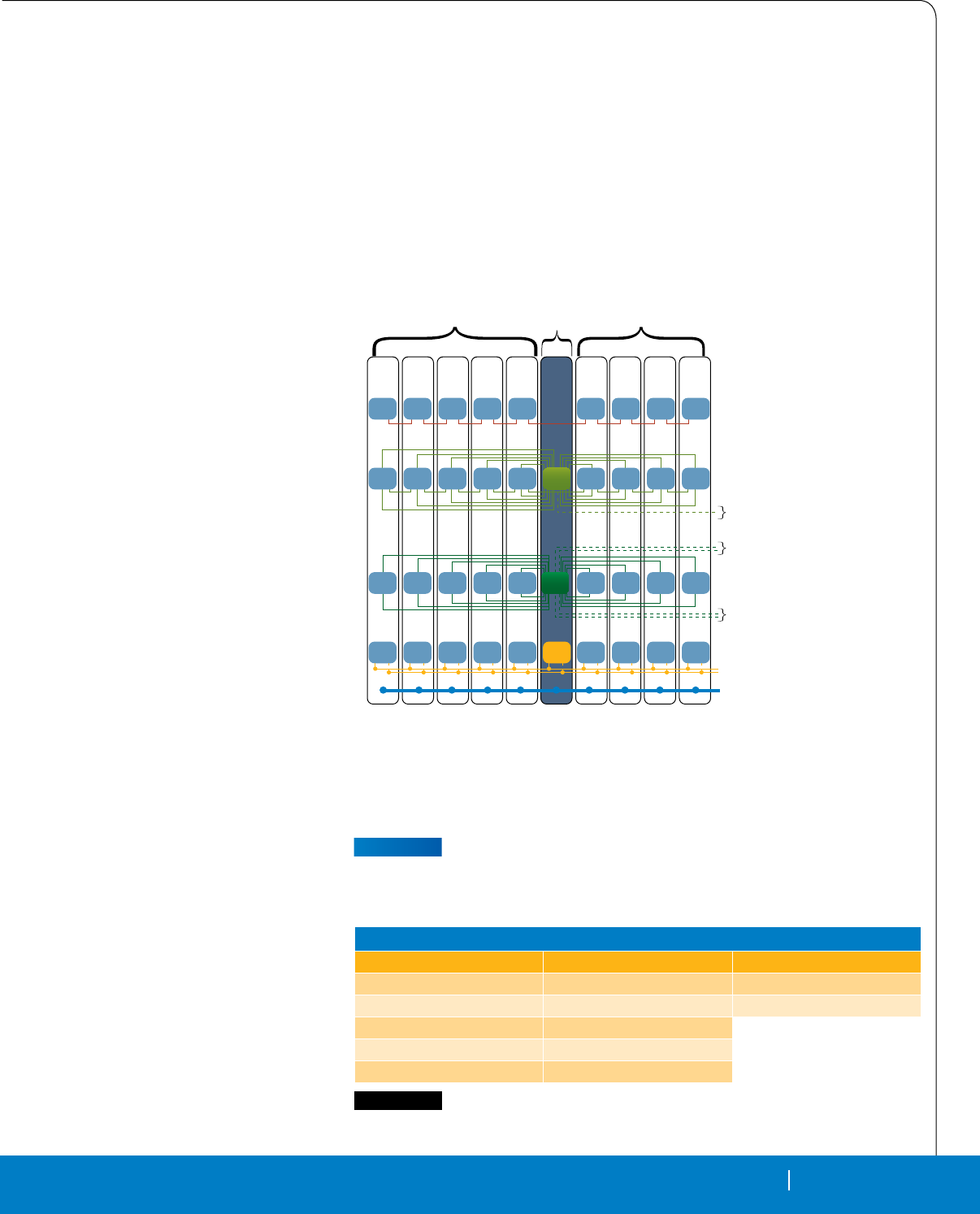
Expansion Plane
Used for local interconnects
Data Plane
Used to transfer data packets
Control Plane
Used to transfer control packets
Management Plane
IPMB used to manage nodes
Utility Plane
VPX Power and Control Signals
TP
UTP
Payload
Slots
VPX
1
Expan
Plane Expan
Plane Expan
Plane Expan
Plane
VPX
2
VPX
3
VPX
4
VPX
5
VPX
7
VPX
8
VPX
9
VPX
10
VPX
6
Payload
Slots
Switch/
Management
Expan
Plane Expan
Plane Expan
Plane Expan
Plane Expan
Plane
Data
Plane Data
Plane Data
Plane Data
Plane Data
Plane Data
Plane
Data
Switch Data
Plane Data
Plane Data
Plane
Contrl
Plane
IPMC IPMC IPMC IPMC IPMC IPMC IPMC IPMC IPMCChMC
Contrl
Plane Contrl
Plane Contrl
Plane Contrl
Plane Contrl
Switch Contrl
Plane Contrl
Plane Contrl
Plane Contrl
Plane
FIGURE 2
Planes in the VPX architecture are defined as Expansion, Data, Control,
Management and Utility.
OpenVPX Fabric Protocols
Ethernet Serial Rapid I/O PCI Express
1000Base-BX SRIO 1.3 – 3.125 Gbps PCI Express Gen 1 – 2.5 Gbps
1000Base-T SRIO 2.0 – 5.0 Gbps PCI Express Gen 2 – 5.0 Gbps
1000Base-KX SRIO 2.0 – 6.25 Gbps
10GBase-BX4 SRIO 2.1 – 5.0 Gbps
10GBase-KX4 SRIO 2.1 – 6.25 Gbp
TABLE 1
Summary of fabric protocols that can be used in OpenVPX
16 SEPTEMBER 2010 RTC MAGAZINE
TECHNOLOGY IN CONTEXT
16 SEPTEMBER 2010 RTC MAGAZINE
Sections six, seven and eight dis-
cuss Slot Proles, Backplane Proles and
Module Proles. Proles are used as the
central graphical representations of slots
and backplanes in OpenVPX. With that
said, it’s time to introduce a table called
Proles at a Glance that show the relation-
ship between Slot, Module and Backplane
proles (Table 2).
Our Knights had found themselves
banished from the Castle of OpenVPX un-
til they could decipher the cryptic termi-
nology to nd the prole they were look-
ing for, which would in turn enable them to
nd their path through the document—the
path that would lead to the denition of
a system. So armed with new knowledge
they added royal tools to the document to
help nd the fair prole in distress, at a
glance. These regal tools included very
nice hyperlinked tables, which summa-
rize available 6U Module Proles in Ta-
ble 11.2-1, and a 6U Module to Backplane
Prole reference Table 11.2.2-1. The 3U
tables are Table 15.2-1 and Table 15.2.2,
specifying similar information for the
3U form factor. These tables are a great
Module and Backplane navigational refer-
ence. Having deciphered the clues, they
can now read the tables, one example of
which is shown in Table 3.
Sections 10, 11 and 12 dene 6U Slot,
Backplane and Module Proles respec-
tively, while sections 14, 15 and 16 specify
3U Slot, Backplane and Module Proles.
Other new concepts include the de-
nition of Lanes, Channels, Ports and Pipes
to describe how bidirectional serial lanes
are grouped into different width channels.
Pipes, for example, come in different sizes:
• Ultra Thin Pipe = 1 Lane
• Thin Pipe = 2 Lanes
• Fat Pipe = Four Lanes
• Double Fat Pipe =8 Lanes
• Quad Fat Pipe = 16 Lanes
What Does OpenVPX Do for the
System Architect?
The specication gives the system de-
signer a set of terms, a common language
if you will, to describe a system uniquely.
The syntax dened uses graphical icons
that allow the visualization and descrip-
tion of the system topology. The denition
of slot and module proles establishes
rules for mapping pins to slots.
Systems are described by the back-
plane prole that is comprised of a set of
slot proles. A backplane is simply a set
of interconnected slot proles where each
pipe in one slot is mapped to a pipe in a
second slot. This point-to-point mapping
results in a unique topology for each back-
plane prole. It is unique because the lane
pairs in a serial fabric will be connected
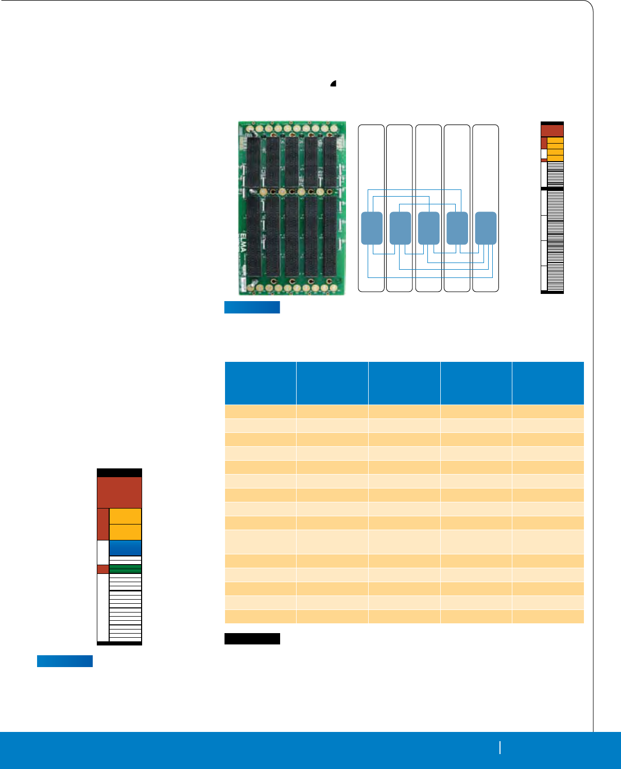
point-to-point as required. The backplane
in Figure 4 is full mesh, made up of ve
instances of Payload slot prole SLT-PAY-
4F 10.3.1, connected in slots one through
ve. Each slot has a fat pipe connection to
SE
PO/JO
S
E
S
E
Diff
P2/J2
SLT3-PAY 1F2F2U14.2.2
Categorization
Type
Form
Factor
Module
Type
Fabric
Information
Port
Quantity (1-32)
Port
(U, T, F, D, Q, O)
U= Ultra-thin pipe (x1)
T= Thin pipe (x2)
F= Fat pipe (x2)
D= Double-fat pipe (x8)
Q= Quad-fat pipe (x16)
O= Octal-fat pipe (x32)
OpenVPX Document
Section
SLT3-PAY-xYxY-z.z.z
FIGURE 3
Example of the nomenclature used to describe a VPX slot profile. A similar
schema applies to module and backplane profiles.
Module Slot Backplane
A Module Profile is:
Slot Profile + Protocol Defined
Defines:
• Module Number is keyed to Slot
Number
• Described by a Table not a Graphic
Relationship to Slot Profile
• Sufx (X) Denes Protocol in a
table
- Module…-12,4,1-(X)
A Slot Profile is:
Protocol Independent Mapping of
Slot I/O
Defines:
• User I/O
• SE=Single Ended
• DIF=Differential
• Port Mapping of Slot
• Form Factor Dened
Types: PAY, PER, SWH, STO
Relationship to Module Profile
• Slot Number is Keyed to Module
Number
• Module 12.4.1-(X) < --> Slot
10.4.1
A Backplane Profile is:
A collection of interconnected slots
Defines:
• Form Factor: 3U, 6U
• Pitch: .8’’, 1’’
• Number of Slots
• Slot Proles Used
Types CEN, DIS, HYB, BRG
• Channel Baud Rate
• Parameter for speed
MOD-SWH-20U19F-12.4.1-5 SLT6-SWH-20U19F-10.4.1 BKP6-CEN05-11.2.5-1
TABLE 2
Examples of the graphical representation of module, slot and backplane
profiles in OpenVPX.
RTC MAGAZINE SEPTEMBER 2010 17
TECHNOLOGY IN CONTEXT
RTC MAGAZINE SEPTEMBER 2010 17
each of the other four slots creating a full
mesh as shown in Figure 4.
In closing, one other navigational tip
would be useful to note about proles. Below
is a Payload Slot prole. Note that the planes
are described from top to bottom of the pro-
les and are associated with colors. However,
the color key for the slot proles is never ex-
plicitedly dened within the VITA 65 docu-
ment nor has the convention of working down
from the top of the connector to assign planes
ever been explicitedly explained. Rather, these
conventions are only implied and left for the
reader to gure out on his or her own. Take for
example the following 3U slot prole:
SLT3 -PAY-2F1F2U-14.2.1
Color Code Key: Yellow - Data Plane,
Blue - Expansion Plane,
Green - Control Plane
The rst two yellow data plane ports are
described by the rst eld as 2F, shown in
yellow representing two fat pipes. The sec-
ond eld, 1F, describes the expansion plane
in blue with one fat pipe. Finally, the green
section represents the 3rd eld, and the 3rd
position down in the connector, representing
the Control Plane shows 2U; two ultra thin
pipes used for Ethernet connections. These
can be followed in the slot prole diagram
in Figure 5 giving the adventurous reader a
more convenient means of following the for-
mula and being able to compare it quickly
with other prole diagrams.
Stay tuned for November when our
brave Knights will set off on a quest to
follow the proles, charts and documents
to establish an end user topology and de-
ne a real-world system.
Elma Electronic
Fremont, CA.
(510) 490-7388.
[www.elma.com].
SE
PO/JO
S
E
S
E
SLT3-PAY-2F1F2U-14.2.1
FIGURE 5
The unofficial color scheme and
top-down reading convention
in OpenVPX can be helpful in
navigating profile descriptions.
BKP6-DIS05-11.2.16.n
SE
PO/JO
S
E
S
E
S
E
S
E
S
E
S
E
SLT6-PAY-4F 10.3.1
Slot
1
Slot
2
Slot
3
Slot
4
Slot
5
Data
Plane
Data
Plane
Data
Plane
Data
Plane
Data
Plane
FIGURE 4
“The DIS05” in the backplane profile here indicates a distributed, or mesh,
connection of five instances of the payload slot profile (right), which has four
connected fat pipes.
Backplane Profiles
Prefix for all names
in this column is:
BKP6-
Payload Modules
Prefix for all names
in this column is:
MOD6-PAY-
Switch Modules
Prefix for all names
in this column is:
MOD6-SWH-
Peripheral Modules
Prefix for all names
in this column is:
MOD6-PER-
Miscellaneous
Modules Prefix for
all names in this
column is: MOD6-
CEN16-11.2.2-n 4F1Q2U2T-12.2.1-n 20U19F-12.4.1-n
CEN20-11.2.3-n 4F1Q2U2T-12.2.1-n 20U19F-12.4.1-n
CEN10-11.2.4-n 4F1Q2U2T-12.2.1-n 20U19F-12.4.1-n
CEN10-11.2.5-n 4F1Q2U2T-12.2.1-n 16U20F-12.4.2-n
CEN10-11.2.6-n 4F1Q2U2T-12.2.1-n 16U20F-12.4.2-n
CEN10-11.2.7-n 4F2T-12.2.2-n 24F-12.4.3
CEN06-11.2.8-n 4F2T-12.2.2-n 24F-12.4.3
CEN12-11.2.9-n 4F2T-12.2.2-n 24F-12.4.3
DIS06-11.2.10-n 4F2T-12.2.2-n 4F24T-12.4.4
HYB17-11.2.11-n 4F2T-12.2.2-n 4F24T-12.4.4 BGR-4F1V2T-
12.5.1-n
HYB08-11.2.11-n 8F-12.2.3-n 2F-12.3.2-n BRG-4F1V-12.5.2-n
CEN09-11.2.13-n 8F-12.2.3-n 2F-12.3.2-n
CEN06-11.2.14-n 8F-12.2.3-n 2F-12.3.2-n
DIS06-11.2.15-n 4F2T-12.2.2-n 4F24T-12.4.4
DIS05-11.2.16-n 4F-12.3.1-n
TABLE 3
VITA 65 establishes a family of 3U and 6U standard backplanes for
development applications. Each backplane is comprised of a number of
slot profiles which in turn correspond to various module profiles. This chart
summarizes all the defined 6U backplane profiles and shows the module
profiles that are compatible with the different slots that comprise each of the
15 different 6U backplane profiles.
18 SEPTEMBER 2010 RTC MAGAZINE
TECHNOLOGY IN
CONTEXT
18 SEPTEMBER 2010 RTC MAGAZINE
What does a Navy SH-60 helicopter
landing on a ship have in com-
mon with an oil rig and a coal
mine? Answer, they are all extremely dan-
gerous places with harsh environments of
temperature and humidity extremes, tre-
mendous amounts of shock and vibration,
and gaseous and liquid contaminants.
In 2010, unfortunately, we have be-
come all too familiar with just how dan-
gerous coal mines and off-shore oil rigs
can be. Earlier this year, the Upper Big
Branch mine explosion in West Virginia
killed 25 miners. And more recently, we
experienced the devastating consequences
of the explosion on the Deepwater Hori-
zon rig that killed 11 and is still causing
untold damage to the Gulf of Mexico’s en-
vironment and economy.
In the aftermath of these disasters, the
federal and state governments will most
likely tighten the regulation of the oil, gas
and mining industries. It is not a stretch to
imagine that in order for operators to meet
the regulations and avert future disasters
there will be a need for improved real-time
monitoring, analysis and reaction. Before
each of these disasters occurred there
were triggers that, if properly monitored
and acted upon, could have avoided or
minimized the impact. Improved real-time
monitoring could detect increased methane
levels in mines and problems at the well
head 5,000 feet below the surface sooner.
The technologies currently used in these
industries do not provide the level of real-
time monitoring necessary for operators to
be able to save lives and avert disasters.
An existing technology that has proven
its mettle in deployed embedded real-time
military applications is VPX. It is the stan-
dard of choice for new systems going into
the Navy SH-60 helicopter and many other
deployed military applications. It was de-
veloped specically with deployed military
applications in mind and supports both 3U
and 6U form factors (Figure 1).
Most deployed military applications
t into the C4ISR (Command, Control,
Compute, Communications, Intelligence,
Surveillance, Reconnaissance) classi-
cation. Many deployed C4ISR applica-
tions share several characteristics. First,
very large amounts of high-speed data
stream into these systems from sensors
such as digital receivers, A/Ds and cam-
eras. Second, the large amounts of high-
speed streaming data have to be moved
through the system and processed in real
time. Third, these systems are deployed
in harsh environments of extreme tem-
peratures, shock and vibration, and ex-
posure to dust, sea salt, chemicals, etc.
Fourth, since these systems are deployed
on vehicles and aircraft including UAVs,
they have severe Size, Weight and Power
(SWaP) constraints.
by Ben Klam and Dave Barker, Extreme Engineering Solutions
Developed primarily with military applications in mind, the VPX standard has
characteristics of ruggedness, high performance and high-speed I/O that
lend themselves naturally to non-military, commercial environments where
harsh conditions demand top of the line performance and reliability.
Is There Life Beyond Defense and
Aerospace for VPX?
OpenVPX
FIGURE 1
The XPedite5470 from Extreme Engineering Solutions is an example of a
conduction-cooled 3U VPX Freescale QorIQ P4080-based Single Board
Computer; (b) the XCalibur4341 is an example of a conduction-cooled 6U VPX
Intel Core i7 processor-based Single Board Computer.
(a) (b)
RTC MAGAZINE SEPTEMBER 2010 19
TECHNOLOGY IN CONTEXT
RTC MAGAZINE SEPTEMBER 2010 19
This same technology, with its abil-
ity to operate in harsh environments of
military applications, is very well suited
to handling oil, gas and mine real-time
monitoring in support of the stricter re-
quirements these industries will likely
incur moving forward. The three primary
features of VPX—its ability to oper-
ate in harsh environments, handle large
amounts of high-speed I/O and process
large amounts of data in real time—make
it a practical choice for oil, gas and min-
ing monitoring. We will now take a closer
look at each of these features.
VPX and OpenVPX
First, a short overview of the VPX
standard for readers not familiar with
VPX. VITA developed VPX as an open
industry standard. It denes a modular
embedded computing platform based on
the familiar 3U and 6U form factors used
by VME and CompactPCI. VPX denes a
common set of attributes including physi-
cal form factors, signal and power supply
interfaces, connectors and power supplies.
One of the key attributes of VPX is the
choice of backplane connectors. These
high-performance connectors enable
high-speed switched serial fabrics, such
as PCI Express and Gigabit Ethernet, to
be used to move data between boards and
into and out of the system.
As a module, or board-level specica-
tion, VPX does not address system-level
issues. To address these issues, VITA
developed OpenVPX. OpenVPX is a
system-level specication that builds on
the module-centric VPX specications. It
provides a nomenclature for system inte-
grators, module designers and backplane
providers to describe and dene aspects
and characteristics of a system. OpenVPX
addresses interoperability of modules,
backplanes, power supplies, enclosures
and other system-level components to
make it easy for system designers to inte-
grate components from different vendors
into a system.
The VPX standard was developed by
VITA to address the harsh environments
that many military and aerospace applica-
tions operate in. Many deployed military
applications face temperature extremes,
shock, vibration, humidity, dust, airborne
and liquid contaminants, and electro-
magnetic interference (EMI). If that isn’t
enough, many have to contend with dirty
power supplied by vehicle or aircraft elec-
trical systems.
To address these issues, the VPX
specications dene a number of stan-
dard techniques to isolate system-level
components from their environment such
as conduction-cooling, full product en-
capsulation and two-level maintenance.
VPX was designed from the ground up to
adhere to the strict military environmen-
tal testing methods of MIL-STD-810 and
electromagnetic interface testing methods
of MIL-STD-461. Systems constructed
using VPX modular components can sur-
vive exposure to the worst case environ-
ments.
In addition to addressing environmen-
tal issues, VPX has also dened a modu-
lar power supply designed to handle the
normal, abnormal and emergency power
characteristics outlined in MIL-STD-704.
Most rugged applications share common
requirements such as transient, overvolt-
age and under voltage conditions specied
in this military standard. By leveraging a
modular, military ruggedized power sup-
ply approach, VPX technology allows sys-
tem designers in any market to maximize
design reuse and efciency while mini-
mizing program risk and cost.
The VPX standard was developed to
support large amounts of high-speed I/O
through the backplane connectors. VPX
supports both front-panel I/O and rear
I/O. 3U VPX supports a total of 64 dif-
ferential pairs on the backplane connec-
tors, which can be divided between data,
control and I/O. 6U VPX extends this to
a total of 160 differential pairs. Some of
the backplane pins are dedicated for com-
munication between modules while other
pins are dedicated to external I/O. The
VPX backplane connectors support sig-
naling rates in excess of 6.25 Gbit/s. This
provides enough bandwidth to support
data and control fabrics consisting of the
latest high-speed serial fabric protocols
while also providing enough external I/O
for raw sensor data.
To support the high-bandwidth, low-
latency and low-overhead communication
requirements of many C4ISR applica-
tions, a switched serial fabric such as PCI
Express is utilized to move data through
a system. Currently, VPX systems utilize
three high-speed serial fabric protocols:
Serial RapidIO, PCI Express and Gigabit
Ethernet. As an example of a typical ap-
FIGURE 2
The XPand3200 (with a sidewall removed) from Extreme Engineering Solutions
is an example of a 1/2 Air Transport Rack (ATR) conduction-cooled chassis
that effectively isolates 3U VPX modules from the harsh environment in which
it is deployed.
20 SEPTEMBER 2010 RTC MAGAZINE
TECHNOLOGY IN CONTEXT
plication, let us consider running a VPX
x8 PCI Express link (16 differential pairs)
between two adjacent modules in a VPX
system. PCI Express 2.0 has a bandwidth
of 500 Mbyte/s per lane, which would
yield 4 Gbyte/s bandwidth for an x8 Link.
To ensure optimal system perfor-
mance, the computation bandwidth much
be matched with the communication band-
width. The VPX standard was developed
with this in mind. If VPX systems have
the processing power to detect incoming
missiles traveling at over mach 2, track
them, and launch a counterstrike against
them, they can handle the processing tasks
required for real-time mine and oil rig
monitoring. A variety of VPX single- and
multi-processor boards are available uti-
lizing today’s state-of-the-art processing
technologies such as the Freescale QorIQ
processor, the Intel Core i7 processor and
the Xilinx Virtex-6 FPGA.
With the large amount of process-
ing power that can be put into a system, a
very important consideration for high-per-
formance embedded systems is cooling. A
typical amount of power consumed by 3U
VPX processing cards is in the range of 30
to 70 watts. The amount of power that can
be dissipated by a module is heavily de-
pendent on the type of cooling method em-
ployed (conduction or air-cooled) as well as
the materials and techniques used to extract
power. 3U VPX ATR conduction-cooled
boxes, when designed properly, can address
the thermal challenges of most applica-
tions. 6U VPX cards offer a larger surface
area and thus improve air-cooling capacity,
and therefore work very well in forced air-
cooled systems. However, many applica-
tions are constrained to conduction-cooling,
and it should be noted that 6U cards have
the same amount of card edge rail area for
conduction-cooling as 3U solutions.
Expanding the Scope of
Applications
As we have seen, VPX systems are
rugged, they can handle a large amount
of high-speed I/O, and they have the capa-
bility to process large amounts of data in
real time. These are important attributes to
achieving more effective real-time mining
and oil rig monitoring. Mines and drilling
rigs are very harsh environments—having
ruggedized systems that can adequately
Core i7 SBC
Sensor Interface
Card
VPX BackplaneWireless Sensor
Interface Card
XChange3012
PCI Express & Gb
Ethernet Switch
XPm2010
Power Supply
Control Room
- Monitoring
- Output to alarms &
other equipment
Serial
Sensors
Wireless
Sensor
Wireless
Sensor
Wireless
Sensor
Gb
Ethernet
I/O Panel
Wireless
Sensor
Antennae
FIGURE 3
An example of real-time monitoring system that is monitoring a number of
wired and wireless sensors. With an Intel Core i7 processor-based SBC, the
system can process and analyze the sensor data in real time. When a problem
is detected, using Gb Ethernet, the system can alert operators and interface
directly to other equipment that can mitigate or resolve the problem.
Untitled-4 1 7/21/09 12:46:17 PM
RTC MAGAZINE SEPTEMBER 2010 21
TECHNOLOGY IN CONTEXT
protect the embedded computing hardware
from the harsh environment allows for op-
timal placement of monitoring systems
deep in a mine, on an oil rig, or even at
the well head. This in turn makes it easier
to optimally place sensors that are being
monitored. Because of VPX’s inherent I/O
capabilities, VPX systems can monitor a
very large number of sensors. Once data is
brought in from the sensors, VPX systems
have the processing bandwidth to perform
real-time processing and analysis of the
data to quickly and effectively deal with a
situation before it turns into a disaster.
If real-time mining and oil rig moni-
toring systems are to be deployed in harsh
environments, their internal processing
elements need to be isolated from their
surrounding environments. Air Trans-
port Rack (ATR) enclosures are a proven
method of achieving this. While not part
of the VPX specications, conduction-
cooled ATR chassis have been used for
years to house military systems deployed
in harsh environments of ground vehicles,
aircraft and sea vessels (Figure 2). These
same enclosures can be leveraged for real-
time monitoring systems deployed in the
harsh environments of mines and oil rigs.
Using VPX systems for real-time mine
and oil rig monitoring shows how a tech-
nology developed for one industry and its
associated applications, specically high-
end deployed C4ISR systems, can be uti-
lized within other industries. Applications
that have similar requirements, namely
ruggedization, high communication band-
width and high computation bandwidth,
can leverage this established standard.
Leveraging VPX technology allows sys-
tem designers in any market to maximize
design reuse and efciency while mini-
mizing program risk and cost. They gain
access to a thriving and competitive mar-
ket of Commercial Off the Shelf (COTS)
products from a number of vendors. They
can develop their own in-house products
designed to the VPX specications. And,
they can easily integrate COTS products
and VPX products they develop in-house
into systems (Figure 3). One other impor-
tant aspect to VPX that system designers
can leverage is software support. There is
wide OS and Real-Time Operating Sys-
tem (RTOS) support across VPX products
including Windows, Linux, Wind River
Systems VxWorks, Green Hills Software
Integrity and LynuxWorks LynxOS.
So, to answer the question, “Is there
life beyond defense and aerospace for
VPX?” Only time will tell. VPX certainly
has the features and market support to
make it a viable and practical choice for
high-end embedded computing applica-
tions in industries other than military.
With the emergence of VPX as an estab-
lished and viable technology, a new gen-
eration of real-time monitoring equipment
can be developed to meet more rigorous
mining and oil industry regulations and
to help these industries protect miners, oil
rig workers, sea life, coastal environments
and coastal economies.
Extreme Engineering Solutions
Middleton, WI.
(608) 833-1155.
[www.xes-inc.com].
Untitled-2 1 8/19/10 3:41:22 PM
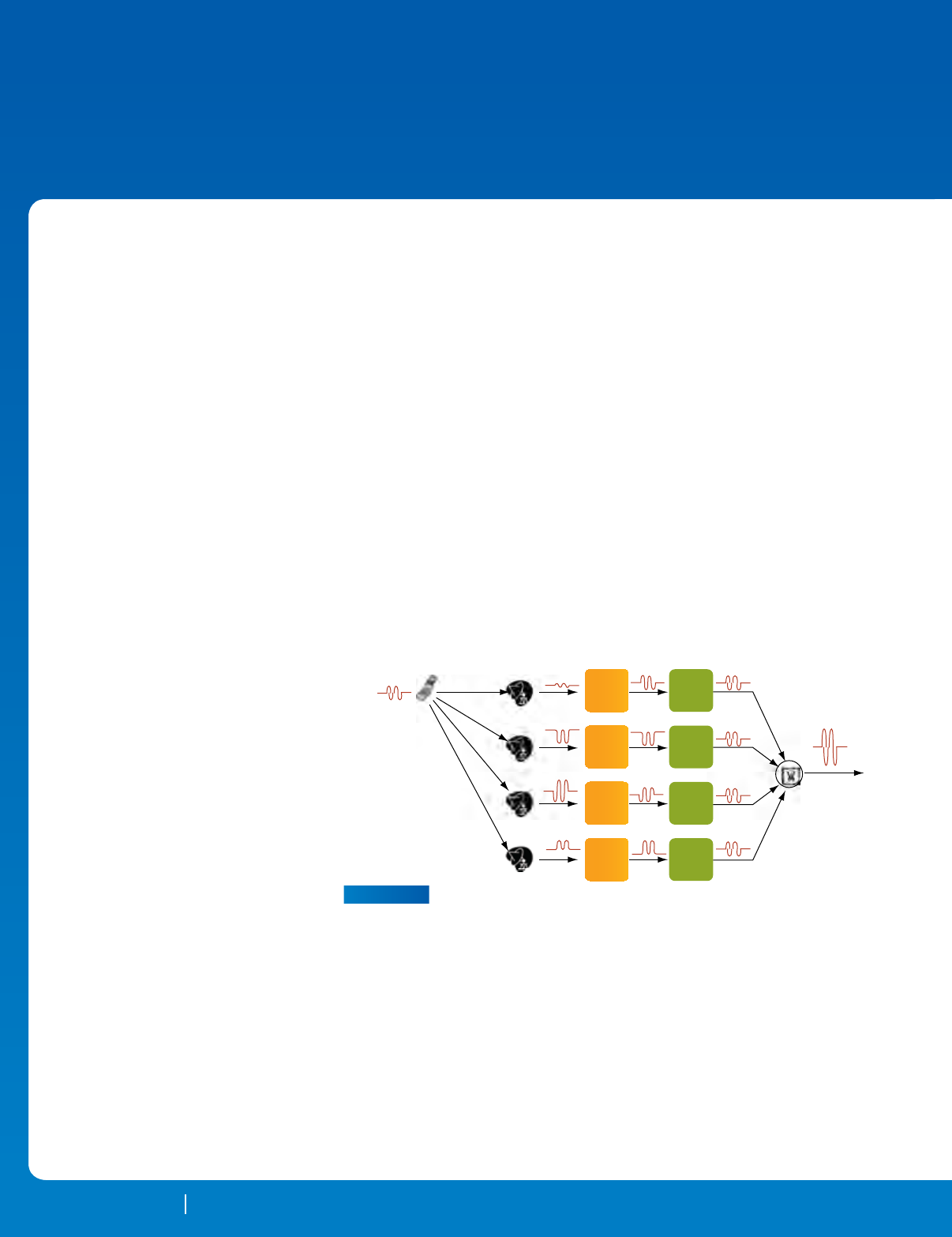
22 SEPTEMBER 2010 RTC MAGAZINE
TECHNOLOGY IN
CONTEXT
22 SEPTEMBER 2010 RTC MAGAZINE
Beamforming is a signal processing
technique that utilizes an array of
sensors to achieve directionality,
increase the strength of transmitted sig-
nals and improve the quality of received
signals. Beamforming applications span
frequencies from sub-audio to light, and
encompass a diverse range of critical ap-
plications for commerce, industry, govern-
ment and defense. Systems developers are
continuously exploiting new technology
to boost performance for specic applica-
tions, with signicant emphasis on com-
munications and signals intelligence.
Let’s rst look at the general prin-
ciples of beamforming as applied to the
reception of radio frequency signals,
followed by a basic discussion of the re-
quired signal processing algorithms. For
this technology, the latest generation of
eld programmable gate arrays (FPGAs)
is available to cover several important
roles in beamforming, including both the
key DSP resources, and the fast links for
data transmission. Finally, a powerful
new embedded system architecture called
OpenVPX is now at hand, whose features
are extremely well suited for implement-
ing deployable, highly scalable beam-
forming systems.
For software radio systems, the beam-
forming sensors are transmit and receive
antennas. For receiver systems, the signal
arrival delay at each antenna is directly
proportional to the path distance from the
source. The beamforming process adjusts
the gain and phase of each antenna signal
to cancel the delay path differences for sig-
nals arriving from a particular direction.
Aligned signals are then summed together
to produce high signal to noise reception
in the chosen direction (Figure 1).
By adjusting gain and phase in
each path, the antenna is electronically
by Rodger Hosking, Pentek
Today’s FPGAs incorporate so much functionality, including DSP
capabilities plus gigabit serial interfaces, that they can become the heart of
high-end signal processing systems. Combining these capabilities with the
serial system architecture provided by OpenVPX can lead to truly powerful
and expandable systems.
Beamforming Systems Moving
Toward New VPX and FPGA
Solutions
OpenVPX
t1 Gain
Adjust
G1
Phase
Adjust
P1
Phase
Adjust
P2
Phase
Adjust
P3
Phase
Adjust
P4
Gain
Adjust
G2
Gain
Adjust
G3
Gain
Adjust
G4
Beamformed
Sum Out
t2
t3
t4
FIGURE 1
Beamforming adjusts phase and gain of signals from each antenna in an array
to compensate for differential delays (tn) and attenuation, so that signals
arriving from a particular angle relative to the array add constructively when
combined in the summer.
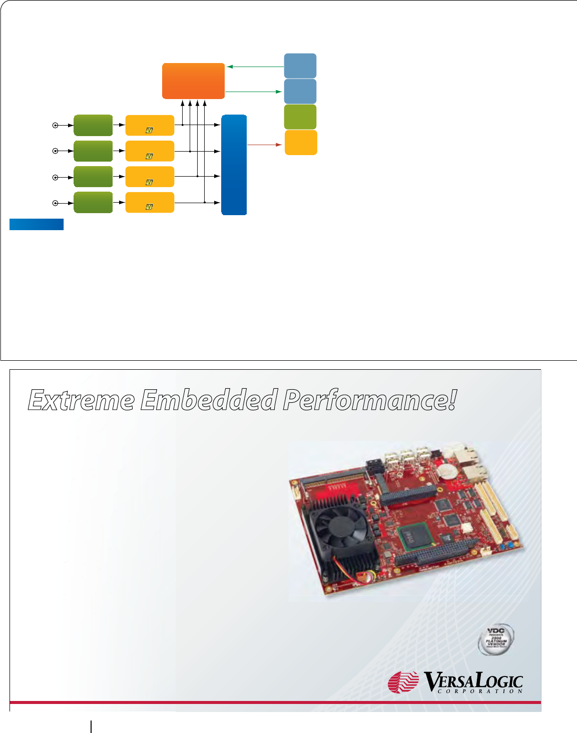
24 SEPTEMBER 2010 RTC MAGAZINE
TECHNOLOGY IN CONTEXT
“steered” without the need for moving
mechanical structures. An example of a
software radio application that uses beam-
forming is direction nding, in which a
beamformed antenna can be steered to
locate the arrival angle of a signal source.
Two or more of the arrays can be used
to triangulate the exact location of the
source, which is essential for many signal
intelligence and counter terrorism efforts.
In addition to directionality, beamform-
ing also improves reception in so-called
“diversity receivers.” The combined sig-
nal from multiple antennas boosts the
signal-to-noise ratio compared to a single
antenna, thus extending the operational
range of the receiver system.
Missile detection and countermeasure
applications use beamforming to improve
tracking of an object allowing for early
detection and improved responsiveness.
With no moving mechanisms, airborne
arrays take full advantage of electronic
steering to dramatically improve the range
and target resolution. And lastly, beam-
forming allows spatial frequency sharing
for commercial mobile phone carriers by
dividing one cell into several beamformed
pie-slice sectors that can share the same
frequency.
FPGAs: Ideal Beamforming
Engines
Each new generation of FPGAs deliv-
ers new features, higher levels of perfor-
mance and reduced power consumption
for a given function. The latest announce-
ment from Xilinx is the new 7 Series fea-
turing 28 nm technology, serial gigabit
transceivers with rates up to 13 GHz, fast
VPX P1
EP01
EP02
DDC 1
G + shift
200 MHz
16-bit A/D
200 MHz
16-bit A/D
200 MHz
16-bit A/D
200 MHz
16-bit A/D
DDC 2
G + shift
DDC 3
G + shift
DDC 4
G + shift
DP01
PCIe
X4
I/F
X4 Sum In
X4 Sum Out
X4 PCIe
AURORA
BEAMFORM
SUMMATION
FIGURE 2
Model 5353 3U VPX Beamformer Module with four A/Ds, four DDCs, X4 PCIe
interface, gain adjusts, phase shifters and summation engine for beamforming.
VersaLogic’s new “Mamba” single board computer provides extreme
performance and high reliability for the most demanding embedded
applications. It combines a 2.26 GHz Intel® Core™2 Duo
processor, high-performance video, and extensive on-board
I/O on an industry standard EBX platform.
2.26 GHz Intel Core 2 Duo processor
Up to 8 GB DDR3 RAM
Dual gigabit Ethernet
Mid power. 18.5W typical
PC/104-Plus expansion
Industrial temp. (-40º to +85ºC) version
High-performance video and audio
Standard EBX format (5.75” x 8”)
Mamba is backed by VersaLogic’s long-term (5+ year) product
availability guarantee and legendary quality. Customization is available even in
low volumes. Evaluate one today!
With more than 30 years experience delivering extraordinary support and on-time
delivery VersaLogic has perfected the art of service, one customer at a time.
Experience it for yourself. Call 800-824-3163 for more information!
Q
Q
Q
Q
Q
Q
Q
Q
Extreme Embedded Performance!
Intel Core 2 Duo processing on standard EBX footprint
800-824-3163 | 541-485-8575 | www.VersaLogic.com / mam
Recipient of the VDC
Platinum Vendor Award
for ve years running!
Untitled-4 1 9/10/10 10:20:09 AM
RTC MAGAZINE SEPTEMBER 2010 25
TECHNOLOGY IN CONTEXT
PCI Express end points, nearly 4,000 DSP
engines and over 900,000 logic cells. FP-
GAs have become extremely popular for
embedded software radio functions, and
they are especially appropriate for beam-
forming applications.
After amplication and analog down
conversion to an IF frequency, each an-
tenna signal must be digitized with an
A/D converter. To handle this task, FP-
GAs offer high-speed LVDS interfaces
supporting data converter peripherals
operating at sample rates to 500 MHz
and higher.
The next task is digital down con-
version of the IF signal to complex base-
band, which is performed by mixing
the input signal with the signal from a
numerically controlled local oscillator
(NCO). The mixer employs one of the
multipliers in an FPGA DSP block, and
the NCO is a phase accumulator (also
part of the DSP block) followed by a
sine look-up table. This is followed by a
low pass lter (using multipliers, regis-
ters and adders) set equal to the signal
VPX P1
Slot 1 VPX P1
Slot 5 CPU VPX P1
Slot 4
Model 5353
X4 Sum Out
X4 Sum In
X4 PCIe
X4 Sum Out
X4 Sum In
X4 PCIe
Model 5353
X4 PCIe - 1GB/sec
X4 Aurora - 1.25 GB/sec
Model 5353
Model 5353
VPX P1
Slot 3
EP01
EP02
DDC 1
G + shift
200 MHz
16-bit A/D
200 MHz
16-bit A/D
200 MHz
16-bit A/D
200 MHz
16-bit A/D
DDC 2
G + shift
DDC 3
G + shift
DDC 4
G + shift
DP01
EP01
EP02
DP01
EP01
EP02
DP01
PCIe
X4
I/F
PCIe
X4
I/F
X4 Sum In
X4 Sum Out
X4 PCIe
AURORA
BEAMFORM
SUMMATION
AURORA
BEAMFORM
SUMMATION
200 MHz
16-bit A/D
200 MHz
16-bit A/D
200 MHz
16-bit A/D
200 MHz
16-bit A/D
DDC 1
G + shift
DDC 2
G + shift
DDC 3
G + shift
DDC 4
G + shift
PCIe
X4
I/F
AURORA
BEAMFORM
SUMMATION
200 MHz
16-bit A/D
200 MHz
16-bit A/D
200 MHz
16-bit A/D
200 MHz
16-bit A/D
DDC 1
G + shift
DDC 2
G + shift
DDC 3
G + shift
DDC 4
G + shift
VPX P1
Slot 2
EP01
EP02
DDC 1
G + shift
200 MHz
16-bit A/D
200 MHz
16-bit A/D
200 MHz
16-bit A/D
200 MHz
16-bit A/D
DDC 2
G + shift
DDC 3
G + shift
DDC 4
G + shift
DP01
PCIe
X4
I/F
X4 Sum In
X4 Sum Out
X4 PCIe
AURORA
BEAMFORM
SUMMATION
DP01
DP01
DP01
DP01
FIGURE 3
16-Channel VPX Beamforming System. Each Model 5353 creates four
beamformed signals that contribute to a summation signal propagated through
X4 Aurora gigabit serial backplane links on the expansion plane. A CPU
module connects to all four 5353s using x4 PCIe using data plane gigabit serial
backplane links on the data plane.
Expertise only an Industry Leader can provide.
^ĞůĞĐƟŶŐĂĐŽŵƉůĞƚĞ͕ĚĞĚŝĐĂƚĞĚƉůĂƞŽƌŵĨƌŽŵ>ŽŐŝĐ^ƵƉƉůLJŝƐƐŝŵƉůĞ͗WƌĞͲĐŽŶĮŐƵƌĞĚ
ƐLJƐƚĞŵƐƉĞƌĨĞĐƚĨŽƌďŽƚŚďƵƐŝŶĞƐƐΘĚĞƐŬƚŽƉƵƐĞ͕tŝŶĚŽǁƐΘ>ŝŶƵdžĚĞǀĞůŽƉŵĞŶƚƐĞƌǀŝĐĞƐĨŽƌ
ŐƌĞĂƚĞƌƐLJƐƚĞŵĐƵƐƚŽŵŝnjĂƟŽŶ͕ĂŶĚĂǁĞĂůƚŚŽĨŽŶůŝŶĞƌĞƐŽƵƌĐĞƐĂůůǁŝƚŚŝŶĂĨĞǁĐůŝĐŬƐ͘
Rugged Devices with Exceptional Flexibility
Learn More > www.logicsupply.com/itx
ǦƤ̾̿
^ŵĂůůĨŽŽƚƉƌŝŶƚƉůĂƞŽƌŵĨĞĂƚƵƌŝŶŐƐŽůŝĚƐƚĂƚĞƐƚŽƌĂŐĞ͘
^LJƐƚĞŵŝƐůĞƐƐƚŚĂŶϭ͘ϱ͟ƚŚŝĐŬ͕LJĞƚƌƵŐŐĞĚĂŶĚƐƚƵƌĚLJ͘
͛Ǥ͝dz̾̿
EŽĨĂŶƐ͕ŶŽŵŽǀŝŶŐƉĂƌƚƐ͘:ƵƐƚƋƵŝĞƚ͕ƌĞůŝĂďůĞŽƉĞƌĂƟŽŶ͘
/ŶĐƌĞĚŝďůLJĐŽŵƉĂĐƚĂŶĚĨƵůůĨĞĂƚƵƌĞĚ͖ŶŽĐŽŵƉƌŽŵŝƐĞƐ͘
© 2010 Logic Supply, Inc. All products and company names listed are trademarks or trade names of their respective companies.
Untitled-14 1 8/10/10 11:38:54 AM
26 SEPTEMBER 2010 RTC MAGAZINE
TECHNOLOGY IN CONTEXT
channel bandwidth. Together, the mixer,
NCO and lter all comprise the DDC, or
digital down converter. Special circuitry
incorporated in the DDC allows the user
to adjust the phase and gain of the down
converted signals to support the special
requirements of beamforming. The ad-
justed outputs of each DDC are summed
together, again taking advantage of the
adder in the DSP block.
A/D conversion plus all beamform-
ing DSP operations for up to four chan-
nels can be handled in a contemporary
FPGA-based software radio module.
However, for larger systems with many
antennas, the summation must accom-
modate multiple modules that must oper-
ate with synchronous sampling and must
preserve strict alignment of DDC samples
forming the nal sum.
VPX Beamforming Module
OpenVPX, based on the recently
adopted VITA 65 standard, provides an
effective taxonomy for describing VPX
components, and also denes numerous
“proles” for boards, slots and gigabit se-
rial backplanes that detail specic cong-
urations of channels, interconnections and
fabrics. Instead of starting from scratch
each time, designers can browse through
these standardized proles to nd one that
satises the objectives of each new sys-
tem. By narrowing the eld of congura-
tions, these proles boost reusability and
interoperability between vendors.
Pentek’s Model 5353 Software Radio
Beamformer is a 3U OpenVPX module,
featuring four 200 MHz 16-bit A/D con-
verters and two Virtex-5 FPGAs. Inside
the rst FPGA are four digital down con-
verters (DDCs) with programmable phase
shift and gain, four power meters at each
DDC output and interfaces to the four A/D
converters. A simplied block diagram of
the 5353 is shown in Figure 2.
The Model 5353 also includes a sum-
mation block that adds the DDC outputs
to form a four-channel beamforming sum.
This block also accepts a propagated “sum
in” signal from another module and gen-
erates a propagated “sum out” signal to
the next module. The sum in and sum out
signals use two x4 Aurora gigabit serial
links connected to the VPX P1 backplane
connector, each capable of moving data at
1.25 Gbyte/s peak.
To support a 20 MHz IF channel
bandwidth with a 25% lter margin, the
DDC outputs deliver complex 16-bit I+Q
samples at 25 MHz, or 100 Mbyte/s. The
propagated sum in/sum out signals also
operate at 100 Mbyte/s and are thus eas-
ily handled by the 1.25 Gbyte/s x4 Aurora
links.
The 5353 system interface for control
and data is a x4 PCIe port, also connected
to P1. Bandwidth requirements for the
control and data port are dominated by
delivery of the nal beamformed sum out
to the control processor. This 100 Mbyte/s
stream falls well within the 2 Gbyte/s peak
rate of the x4 PCIe port when operating in
Gen 2 mode.
A programmable, fabric-transparent
crossbar switch allows free assignment of
Untitled-6 1 9/2/10 3:20:44 PM
RTC MAGAZINE SEPTEMBER 2010 27
TECHNOLOGY IN CONTEXT
the two x4 Aurora ports and the x4 PCIe
port, in any combination, to the four x4
links on P1. This exibility allows the
5353 to accommodate various VPX slot
proles and backplanes.
For a larger system with 16 anten-
nas, a total of four 4-channel 5353 mod-
ules are required. Since the summation
chain requires the same data rate as each
DDC, the two sum ports must simulta-
neously handle 100 Mbyte/s each. This
class of signal falls under the denition
of “expansion plane” in the OpenVPX
specication.
The x4 PCIe interface to handle the
data initialization and delivery of beam-
forming parameters is described as the
“control plane” under OpenVPX. Final
delivery of the beamformed result to the
system control processor is best clas-
sied as the “data plane” in OpenVPX
denitions.
16-Channel VPX Beamforming
System
A 16-channel VPX-based FPGA-
based beamformer system using four
Model 5353 3U VPX modules is shown
in Figure 3. Using the dedicated x4 PCIe
links, each module connects to a CPU card
located in slot 5, serving as the control and
status processor for the system. Each 5353
module digitizes four IF signals from four
antennas in the array. Four digital down
converters translate the antenna IF signals
to baseband as complex digital samples
and then perform beamforming signal
processing, including phase shifts and
gain adjustments. The OpenVPX back-
plane most appropriate for this system is
a ve-slot “full mesh” topology design,
which provides one x4 link from each slot
to every other slot.
Each summation engine accepts the
propagated sum from the previous mod-
ule, adds the four channels from the lo-
cal module, and then generates a new sum
signal for delivery to the sum input of
the next module in the chain. The sum-
mation paths use Aurora x4 gigabit serial
links for the expansion plane connections
across the backplane. The nal 16-chan-
nel sum is delivered from the 5353 in slot
4 to the CPU card in slot 5 across the x4
PCIe interface.
There are several major benets to
this system architecture. First, FPGAs
implement the data acquisition, digital
down conversion, beamforming DSP
tasks and gigabit serial system interfaces.
Secondly, all interboard summation paths
are supported with existing links on the
OpenVPX backplane. Third, the system
is highly modular and scalable: additional
5353 modules can be added as required to
increase the number of antenna channels.
Finally, OpenVPX provides a ruggedized
solution capable of operating in a wide
range of deployed environments.
Pentek
Upper Saddle River, NJ.
(201) 818-5900.
[www.pentek.com].
Untitled-5 1 2/17/09 4:47:07 PM

28 SEPTEMBER 2010 RTC MAGAZINE
TECHNOLOGY
CONNECTED
28 SEPTEMBER 2010 RTC MAGAZINE
Factory automation, control and man-
agement have become crucial to the
world’s supply chain. High-volume
consumer product and automotive manu-
facturing, for example, require secure,
cost-effective and robust data communi-
cations in order to react to problems that,
if not corrected quickly, can cause sub-
stantial prot loss and customer ill will.
Designers from many industries turn
to ber optic data links as an alternative to
copper media. Fiber optic solutions result
in reliable data links that are capable of
communicating over distances—ranging
from inches to kilometers—and are more
immune to noise. Industrial network ap-
plications beneting from ber optic solu-
tions span in-ight infotainment, locomo-
tive transportation, medical equipment,
casinos and wind and solar photovoltaic
renewable installations.
Easy to Install Fiber Optics
Replace Copper Data Links
Although both copper and ber are
used as a transmission medium, ber op-
tic solutions offer some clear benets for
the system designer. Industrial Fast Eth-
ernet working over plastic optical ber
(POF) or hard clad silica (HCS), for lon-
ger data links, has numerous advantages
over copper solutions. While copper-
based communication links are suscep-
tible to electromagnetic (EM) elds and
emit EM noise, which may interfere with
other instrumentation, ber optic links are
immune to EM elds and do not generate
any electromagnetic interference (EMI).
Other advantages of choosing ber
over copper include: low weight, com-
by Mickaël Marie, Avago Technologies
Fiber optic technology has many benefits for industrial networks including
high levels of electrical insulation and isolation, easy installation, survivability
in hostile environments and EMI immunity. Upgrading can bring these and
more, such as greater security, robustness and signal integrity.
Upgrade Existing Industrial
Networks with Fiber Optics
Options for Industrial Networks
Cable
Type
50 m 100 m 700 m
Multi-mode Cable (1300 nm)
Multi-mode Cable (820 nm)
HCS (650 nm)
POF (650nm)
2 km Length
AFBR-5978Z
SFH757V
AFBR-5978Z
HFBR-1527Z HFBR-0404Z
series
HFBR-1312TZ
Fast Ethernet (125 MBd) Link Distance
FIGURE 1
Fast Ethernet communication distances extend to kilometers with fiber
technology.

715 Stadium Drive • Arlington, Texas 76011
Phone 817-274-7553 • FAX 817-548-1358
E-mail: info@winsystems.com
Call 817-274-7553 or Visit
www.winsystems.com/EBC-Z510
Our fanless EBC-Z510-G is a powerful, next-
generation EBX-size computing platform.
Its outstanding complement of onboard I/O
is augmented with MiniPCIe, SUMIT,
and PC/104 connectors for high-
bandwidth PCIe and USB 2.0
interfaces plus standard legacy
bus expansion. This extended
temperature SBC is compact and
flexible enough to meet a broad
range of application requirements.
• Low power Intel® Atom™ processor:
fanless 1.1GHz or 1.6GHz with fan
• Intel® Graphics Media Accelerator
displays resolutions up to 1920 x 1080
• Supports CRT and LVDS flat panels
simultaneously
• Custom splash screen on startup
• Wireless supported with MiniPCIe socket
• Two independent Gigabit Ethernet ports
• CompactFlash (CF) connector
• Four serial RS-232/422/485 COM ports, four dUSB
USB 2.0 ports, 48 bidirectional TTL digital I/O
lines, and UDMA IDE port
• HD audio, LPT, and keyboard supported
• EBX sized: 5.75” x 8.0”
• Free software drivers for Windows® XPe and Linux
• SUMIT-AB and PC/104 connectors for additional
I/O expansion capability
• -40° to +70°C operational temperature range
• Responsive and knowledgeable technical support
• Quick Start Kit for software development
Contact our factory application engineers for additional
product information, custom configurations, and pricing.
TM
WinSystems also offers...
Quick Start Kits CompactFlash
Industrial-grade Reliability With SUMIT expansion
Convenient and efficient
Ask about our 30-day product evaluation.
PC/104 Modules
Embedded
Atom™
SBC
with SUMIT Expansion
Runs Fast, Stays Cool
Untitled-2 1 9/10/10 10:16:15 AM
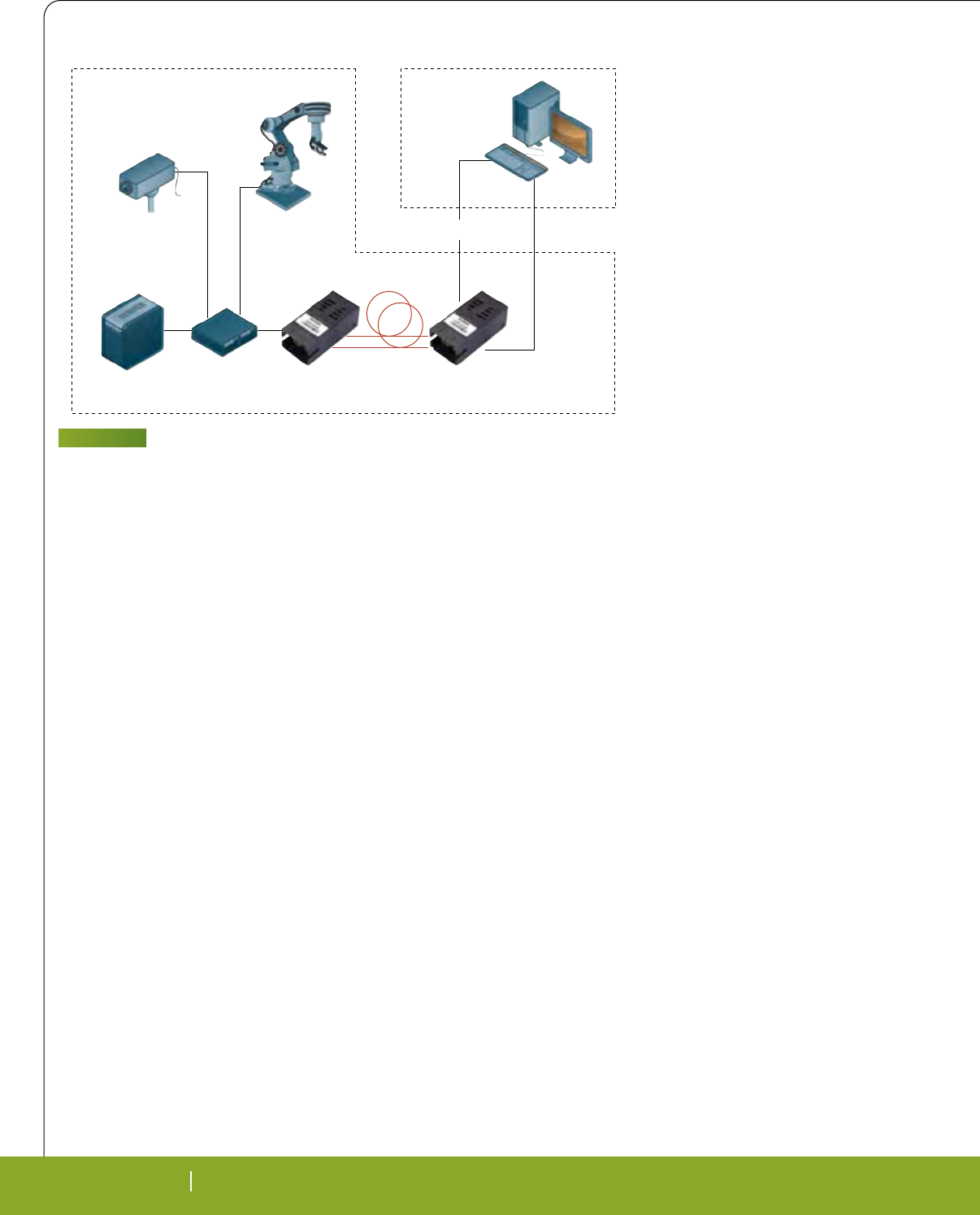
30 SEPTEMBER 2010 RTC MAGAZINE
TECHNOLOGY CONNECTED
30 SEPTEMBER 2010 RTC MAGAZINE
plete galvanic separation between link
partners, easy eld termination and main-
tenance, easier installation due to short
bending radius, and less susceptibility to
performance changes caused by tempera-
ture extremes and humidity. Fiber optic
solutions are also well suited for noisy,
industrial environments that have motors
and high-voltage; fast-switching circuits,
such as in power conversion; automotive
manufacturing; medical systems and re-
newable energy applications, such as wind
and solar photovoltaic farms. Fiber optic
technology also offers data security since,
for instance, it is almost impossible to tap
light wave communications.
As shown in Figure 1, multimode
(MM), hard clad silica (HCS) and POF
cables provide the highest levels of signal
integrity over long distances. Multimode
cables are especially suited for control
systems in offshore wind turbines (over 3
MW) where they are used as a link be-
tween the nacelle and the ground. In these
applications link length is more than
200m.
Fiber Media for Higher Reliability
and Better Safety
Given that the ber optic link media
is essentially glass or plastic, insulation
and isolation characteristics are superior
to common copper links in that they are
immune from EMI. Fiber optic cables
(e.g., 5m POF or 100m HCS as indicated
by the red lines in Figure 2), offer advan-
tages in noisy environments compared
with copper media. With ber optic solu-
tions, there is no crosstalk between ber
cables or between ber and copper cable,
which makes data transmission more se-
cure. Fiber cable has high immunity to
lightning strikes and helps to eliminate
ground loop induced errors. When hazard-
ous conditions exist or the environment is
potentially explosive, properly used ber
solutions can help increase safety by low-
ering the potential damage from lightning
strikes and ignition caused by electrical
sparking.
In addition to being a more cost-
effective solution than copper media, opti-
cal ber—such as single-mode (SM), MM,
HCS and POF—can be routed in cable
ducts, regardless of nearby power conduc-
tors; and it is easier to achieve compliance
with electromagnetic compliance (EMC)
directives and rules (Figure 3).
Additionally, in the case of plastic
optical ber, no special tools are needed
and installation training is easy. POF ca-
ble installations have been used in rugged
industrial environments, such as automo-
tive assembly, for over 15 years. POF is
also suitable to use for short to moderate
link distances, is easy to eld install, and
helps simplify connections to equipment
and exiting networks. Another key design
advantage in industrial applications is that
maintenance is low.
Fiber cable and optical transceivers/
receivers/transmitters all pass rigorous
quality standards. Fiber optics technology
has been proven in high-capacity telecom-
munication links where systems may have
a product life time exceeding 10 years. In
addition, some ber component suppliers
are vertically integrated and manufacture
their own laser diodes for transmitters and
PIN diodes for receivers. This provides
better control over quality and delivery.
Fiber Offers Bandwidth, Weight
and EMC Advantages
In-ight infotainment systems are be-
coming more sophisticated and advanced.
While video quality is improving, the
use of larger video screens is becoming
more widespread. Airplane manufactur-
ers always look for ways to reduce plane
weight. Since ber optic solutions are
much lighter and transmit more data than
copper, within a single line, ber optic so-
lutions are a good choice for use in avia-
tion infotainment systems.
Fiber optics technology also shows
up in aircraft carriers and cruise liners. In
addition, many modern trains also use -
ber cable and optical transceivers, receiv-
ers and transmitters. Reliable operation of
the train’s power source, propulsion sys-
tem and coach control systems are neces-
sary. However, passenger convenience, in-
formation and entertainment systems can
also take advantage of the benets from
using ber optics—high bandwidth over
long distance, inherent galvanic isolation,
excellent EMC characteristics, and elec-
trostatic discharge (ESD) resistance.
The IEC 61375 Train Communica-
tion Network (TCN) standard was created
to dene communication architecture and
protocols for trains. In general, the TCN
denes a Wire Train Bus (WTB) and Mul-
tifunction Vehicles Bus (MVB). WTB con-
nects the vehicles while MVB connects
equipment in a vehicle or group of vehicles.
MVB operates over three media types:
RS-485 for short distance, transformer-
Factory Office
Camera
Server Ethernet Hub
Server Data,
Camera, Robot
DMI
Noisy Environment
Engineering
Workstation
FIGURE 2
Fiber optic links are immune to the EMI generated in industrial manufacturing
environments.
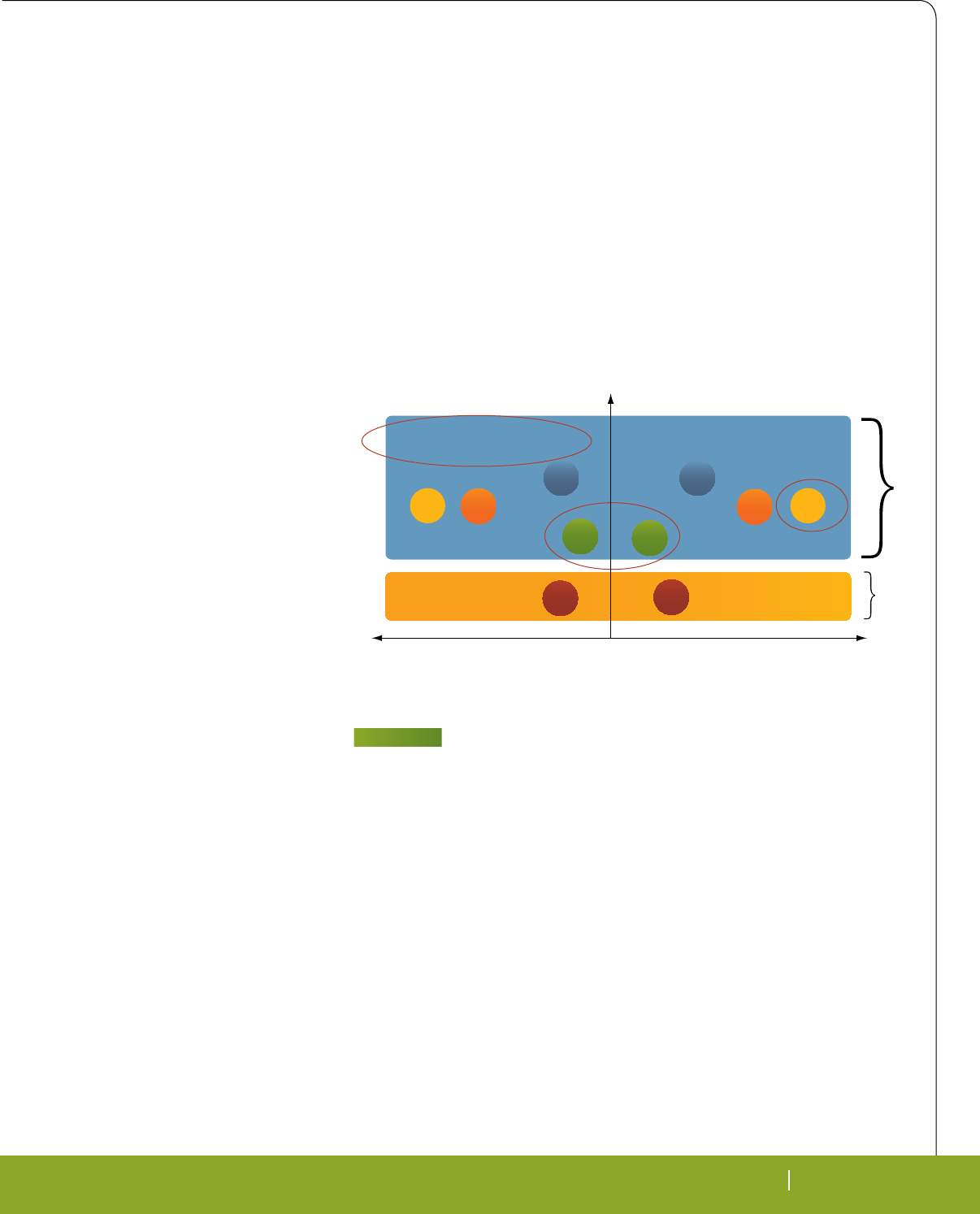
RTC MAGAZINE SEPTEMBER 2010 31
TECHNOLOGY CONNECTED
RTC MAGAZINE SEPTEMBER 2010 31
coupled twisted wire pairs for distances
up to 200 meters, and optical glass ber
for distances up to two kilometers. Optical
glass ber is often the preferred media in
a locomotive MVB since it has high im-
munity to electrical noise. Optical ber
connects the controller to devices and sub-
systems, such as power electronics, motor
controllers, brakes and radios. MVB also
connects equipment in a coach to control
lights, doors, air conditioning and passen-
ger convenience displays for train station
and arrival information. Redundancy im-
proves reliability since MVB is backed up
by a redundant ber line and devices trans-
mit on both lines. If one line fails, the other
line is available for communication.
Train networks have become more
complex, where each station is connected
to a central computer for scheduling and
event updates. Stations needing to send
data back and forth could be a few hun-
dred meters or kilometers away. By using
ber optic cable, more data can be trans-
mitted over longer distance—including
video—more reliably than copper cable.
In addition, these applications have wires
placed side-by-side, running from station
to station and from one train compartment
to another. When copper wire is used,
these adjacent wires can cause interfer-
ence. Fiber optic cables’ EMI advantages,
on the other hand, make them immune
from this problem.
In trains powered by the electrical
grid, single-phase power is taken from the
3-phase AC power grid line to supply the
train’s 2-phase AC power line. This cre-
ates an unbalance in the grid that must be
compensated for. One of the most com-
mon methods of balancing and restoring
the power quality of the grid uses Static
Var Compensation (SVC) with Thyris-
tor-Switched Capacitors (TSCs) and a
Thyristor-Controlled Reactor (TCR). The
TSCs and TCR operate and switch on/off
at high voltage and current. This creates
very high electromagnetic elds that will
induce electrical noise into nearby cop-
per lines. Fiber optic cables are the best
medium for sending control signals to the
devices in SVC systems because of their
immunity to electromagnetic elds.
Train signaling can also take advan-
tage of ber optic technology’s long, reli-
able data transmission capability in harsh
physical environments and in the presence
of very high EMI.
Fiber optic technology has become
common in medical imaging equipment
such as MRI and X-Ray machines. With
all the motors and electromagnetic radia-
tion present, these machines generate high
levels of EMI. Their communication and
control links must have high EMI immu-
nity for reliable and safe operation. High
EMI immunity products and electrical iso-
lation are always necessary components
for patient safety, so ber optic products
provide a well-suited solution.
In the entertainment area, casinos
have machines connected to the central
computer/server for data processing, mar-
keting programs and video surveillance.
Security is the most important need for
a casino’s communication network. Fiber
optics offer a safe and secure network for
casino operators, as it’s almost impossible
to tap into the signal of the ber optic
cable.
Finally, the renewable energy mar-
ket has adopted ber technology. In some
wind farm applications, ber optics is
the only suitable communications tech-
nology because of EMI. As wind farms
and photovoltaic installations operate in
remote areas and even offshore, the wide
adoption of ber technology speaks to
its reliability and robustness. Downtime
and unscheduled maintenance can signi-
cantly impact renewable energy costs and
adoption, which must be avoided from the
system design level. Fiber links are used
inside the wind turbine nacelle, which can
be over 100 meters above ground or sea
level, as well as for data links between tur-
bines and remote management locations.
Fiber’s inherent isolation has led to
the development of ber products that
need to communicate only over a few
inches. A ber optic short link device is a
cost-effective transmitter and receiver that
can provide up to 12 kV transient galvanic
isolation on a single PCB. Such a device
based on 650 nm ber optic technology
is suitable for use in applications such as
inverters (i.e. for wind turbines), IGBT/
MOSFET drives and medical equipment.
Adding a metal shield can help provide
even higher reliability.
Fiber Optics Help Prevent Down
Time
In terms of speed, reliability and
proactive system monitoring, the Avago
POF = Polymer [plastic] Optical Fiber, SM = Single Mode fiber, MM = Multi-mode fiber, CAT5 = Category 5 copper cable, HCS = Hard Clad Silica
Cable Cost
High Immunity to EM fields
Low Immunity to EM field
Difficult Easy
Ease of
Termination Link
Length
Short Long
Fiber Copper
SM MM
HCS HCS
MM SM
POF
POF
CAT5 CAT5
FIGURE 3
Fiber cable has EMI immunity and communication link distances copper media
cannot match. POF= Polymer (plastic) Optical Fiber; SM=Single-Mode fiber;
MM=Multi-Mode Fiber; HCS=Hard Clad Silica and CAT5= Category 5 copper
cable.

32 SEPTEMBER 2010 RTC MAGAZINE
TECHNOLOGY CONNECTED
AFBR-5978Z Industrial Fast Ether-
net Transceiver is an example of what
can be achieved with the use of optical
transceivers. In addition, the device’s
temperature range (-25° to 85°C) helps
ensure that the transceiver can stand up
to the rugged environment of industrial
applications.
The AFBR-5978Z transceiver fea-
tures an enhanced digital diagnostic
interface, compliant to the “Digital Di-
agnostic Monitoring Interface (DMI)
for Optical Transceivers” referenced
in the multisource agreement (MSA)
SFF-8472, in which fiber optics manu-
facturers propose similar product hous-
ing and features for easy replacement of
the transceiver. Industrial Fast Ethernet
fiber optic networks represent an up-
grade path for Fieldbus networks, with
a speed of up to 125 Mbaud compared
to 2 Mbaud for Interbus, 12 Mbaud for
Profibus, and 12 Mbaud and 16 Mbaud
for SERCOS. It also provides the open-
architecture, multi-protocol interface
that permits both standard and pro-
prietary Fieldbuses to interoperate.
Upgrading to industrial Fast Ethernet
allows machinery on the factory floor
to be assigned IP or MAC addresses,
which enables high-speed remote diag-
nostics and machine sequence changes
via Internet access.
DMI provides real-time operational
information from the transceiver module.
Parameters reported include module tem-
perature, power supply voltage level, and
receiver input average optical power level.
Also with DMI, the user gains the capa-
bility of performing component monitor-
ing, fault isolation and failure prediction
in their transceiver-based application.
In addition, DMI fully incorporates the
functionality needed to implement digital
alarms and warnings.
At the higher networking level, in-
dustrial Ethernet connects engineering
and management workstations to indus-
trial Ethernet hubs for data sharing and
control across the enterprise. The value
proposition is significant. Fiber solu-
tions are available with various data
rates and connectors that serve indus-
trial communications and factory auto-
mation applications.
The choice of being able to use dis-
crete or integrated ber optic component
solutions gives the designer the ability to
focus on specic design goals. Discrete
components give customers the design
exibility to meet their very specic re-
quirements, while the integrated compo-
nent solution saves design effort, mini-
mizes risk and reduces cost. Best of all,
ber’s inherent technology edge in EMI
immunity and isolation characteristics
suits the factory environment well.
Avago Technologies
San Jose, CA.
(800) 235-0313.
[www.avagotech.com].
4gRT_cX^]P[?TaU^a\P]RT
?TaFPccP]S5[TgXQX[Xch
3TbXV]TSU^aSXVXcP[bXV]PVT_^X]c^UbP[TcTRW]^[^VXTbRPbX]^VP\X]V
X]SdbcaXP[R^]ca^[b[^fT]SbTaeTabP]Sbc^aPVT
0<3·bbTR^]SVT]TaPcX^]4\QTSSTS160_[PcU^a\_a^eXSTbSTbXV]TabP\_[TÁTgXQX[Xchc^STbXV]
bRP[PQ[Tg'%QPbTS[^fR^bcP]SUTPcdaTaXRW_a^SdRcb=^fh^dRP]STbXV]T]TaVhR^]bTaeX]V
UTPcdaTbX]c^bhbcT\bfXcW^dcR^\_a^\XbX]VP__[XRPcX^]_TaU^a\P]RTR^\_PcXQX[XchVaP_WXRb
_TaU^a\P]RT^aUd]RcX^]P[XchCWXbR^\_[TcTP]Sa^QdbcT\QTSSTS_[PcU^a\RP]WT[_b_TTScX\T
c^\PaZTcP]SST[XeTacWTVaP_WXRbP]SX]]^ePcXeTSXb_[Ph^_cX^]bcWa^dVW^]TR^\_[TcTP]S
a^QdbcT\QTSSTS_[PcU^a\
! 0SeP]RTS<XRa^3TeXRTb8]R0[[aXVWcbaTbTaeTS0<3cWT0<30aa^f;^V^0C8cWT0C8[^V^0<30cW[^]0<3CdaX^]APST^]P]SR^\QX]PcX^]bcWTaT^UPaT
caPST\PaZb^U0SeP]RTS<XRa^3TeXRTb8]R>cWTa]P\TbdbTSPaTU^aXST]cXÀRPcX^]_da_^bTb^][hP]S\PhQTcaPST\PaZb^UcWTXaaTb_TRcXeTR^\_P]XTb#'"&!0
Untitled-5 1 9/10/10 10:22:37 AM
Focused on the essentials
Maximum Performance at Minimum Consumption
Quality Ruggedness
Utilize most
current
technology
High
Performance
per Watt
Reliability
Long Term Availability
LiPPERT Embedded Computers Inc.
5555 Glenridge Connector, Suite 200, Atlanta, GA 30342
Phone (404) 459 2870 · Fax (404) 459 2871
ussales@lippertembedded.com · www.lippertembedded.com
Trademarks and registered trademarks are the property of their respective owners.
Utilizing highest integration levels,
latest technologies, and the most
powerful processors, for more than
25 years LIPPERT‘s embedded
PCs provide the maximum possible
performance while maintaining mini-
mum power dissipation.
Integrated LEMT functions provide
condition monitoring.
LiPPERT - effi cient and rugged
components for market segments
as diverse as automotive, automati-
on, medical, military, and aerospace.
Cool XpressRunner-GS45
Model Format CPU, Clock RAM (max) Miscellaneous LEMT
CoreExpress-ECO CoreExpress®Intel® Atom
™ processor
Z5xx,
1.1 ... 1.6 GHz
2 GB
soldered
2 x PCI Express,
SDVO, USB ✔
Cool LiteRunner-
ECO PC/104 Intel® Atom
™ processor
Z5xx,
1.1 ... 1.6 GHz
2 GB
soldered
LAN, SATA, USB,
Micro SD ✔
Cool LiteRunner-
LX800 PC/104 Geode
™
LX800
500MHz
256 MB
soldered
Mini-PCI,
CF slot, 2 x LAN ✔
Cool SpaceRunner-
LX800 PC/104-Plus Geode
™
LX800
500 MHz
256 MB
soldered 2 GB SSD ✔
Cool RoadRunner-
945GSE PC/104-Plus Intel® Atom
™
processor
N270, 1.6 GHz
2 GB
soldered
2 GB SSD,
SATA ✔
Cool RoadRunner-
LX800 PC/104-Plus Geode
™
LX800
500 MHz 1 GB CF slot ✔
Cool XpressRunner-
GS45
PCI/104-
Express
Intel® Core
™
2 Duo pro-
cessor, 1.2 ... 2.26 GHz 1 GB GB LAN,
SATA, USB ✔
Hurricane-LX800 EPIC Geode
™
LX800
500 MHz 1 GB LAN, USB,
uDiskOnChip ✔
Hurricane-QM57 EPIC-
Express
Intel® Core
™
i7 proces-
sor, 1.06 ... 2.53 GHz 4 GB LAN, SATA, USB,
Display Port ✔
Thunderbird-GM45 Mini-ITX Intel® Core
™
2 Duo
processor, 2.53 GHz 4 GB LAN, SATA, USB,
AMT, Adaptive-IO
™
✔
Thunderbird-E3100 Mini-ITX Intel® Core
™
2 Duo pro-
cessor, 1.06 ... 2.2 GHz
8 GB
ECC
LAN, ASF, SATA,
USB, MiniCard ✔
Untitled-4 1 8/16/10 4:10:58 PM
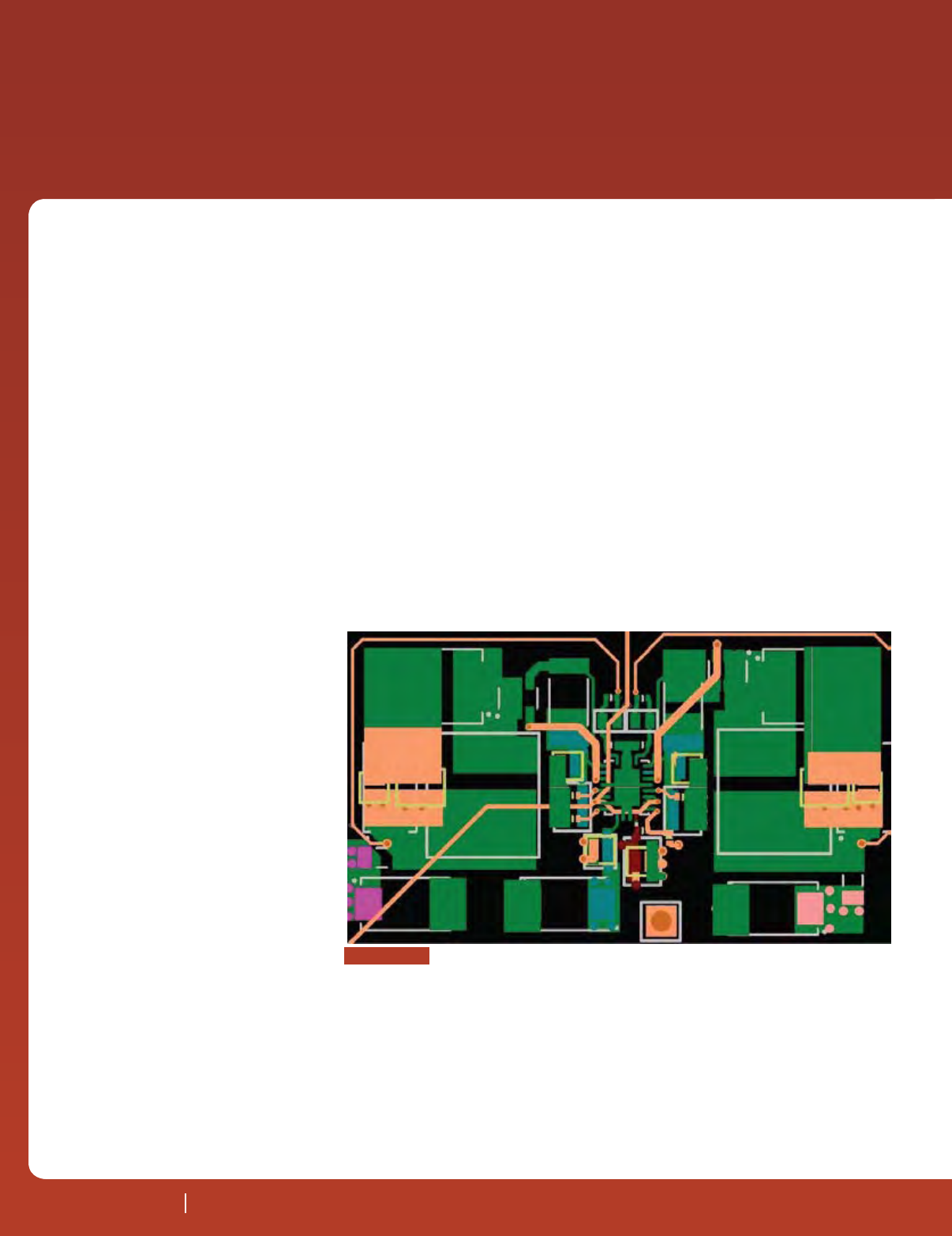
34 SEPTEMBER 2010 RTC MAGAZINE
TECHNOLOGY IN
SYSTEMS
34 SEPTEMBER 2010 RTC MAGAZINE
Thermal Management in Tight Places
certain logic families can be affected by
changes in junction temperatures. Such
changes, if drastic, can alter the voltage
levels. The logic family that experiences
a signicant effect is the emitter-coupled
logic (ECL). It has also been noted that
thermal offsets can trigger unhealthy ef-
fects on the performance of high power
The advent of programmable logic de-
vices (PLDs) increased circuit com-
ponent miniaturization and increas-
ing circuit densities on PCBs have intro-
duced an exponential increase in power
densities. Usually PCB thermal manage-
ment is considered as secondary to signal
integrity or power management. However,
this task can no longer be ignored. If am-
ple amount of work is not done at the lay-
out level, and heat sinking techniques are
not employed, heat generated by devices
can result in parasitic effects to the circuit
performance along with the reduced reli-
ability and lifetime of the product.
Failure rate or mean time between
failures (MTBF) measures component re-
liability. According to the Arrhenius equa-
tion, every 10°C rise in temperature above
the component’s maximum operating tem-
perature can increase the failure rate by as
much as 50%. Hence the reliability or life
expectancy of a component is related to
its operating temperature. Additionally,
above certain temperatures, a component
can be irreversibly destroyed. The task of
thermal management is to make sure that
electronic assemblies are maintained be-
low the maximum rated temperatures of
all the components. Maximum operating
temperatures of typical components are
85°-125°C for capacitors and 125°-175°C
for integrated circuits.
Secondly, self-heating can adversely
affect device performance. The value
of output voltages and the references of
Thermal Management and Power
Integrity in Tight Spaces
PCB thermal management has traditionally been seen as secondary to
signal integrity. But due to tremendous evolution of power densities in
transistors, PCB thermal management has now become a serious issue
that must be considered early in the design.
by Syed W. Ali, Nexlogic
FIGuRE 1
Layout of a triple switching power supply with 2 ounces of copper.
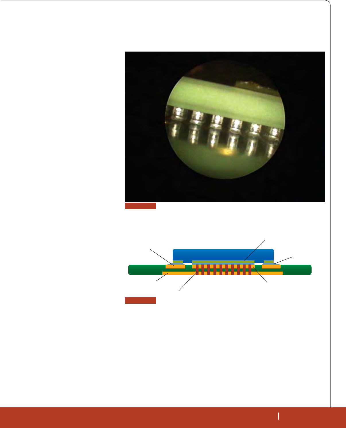
RTC MAGAZINE SEPTEMBER 2010 35
TECH IN SYSTEMS
RTC MAGAZINE SEPTEMBER 2010 35
while laying out boards with tight spaces
with due regard for thermal performance.
The designer should start with the power
section of the board.The reasons are that
switching power supplies are noisy and
their thermal management can be chal-
lenging. That’s because power dissipat-
ing components need to be close to each
other for electromagnetic compatibility
(EMC) purposes and space constraints. A
balance is required between too close for
thermal reasons and too far for EMC rea-
microwave transistors. This is due to the
fact that under high power conditions, de-
vice lattice temperature increases. This
causes a drop in carrier mobility thereby
negatively affecting device performance.
PCB Thermal Management
The rst stage of thermal management
is at the IC design level. Unfortunately, de-
sign engineers and layout designers have
little or no power at this stage. Hence, it
behooves the chip designer to consider
any IC hotspots at design stage.
The circuit design level is the second
stage of thermal management. The design
engineer can take into account thermal
characteristics of the circuit. For example,
when designing the matching networks
of power ampliers, they can choose to
implement harmonic tuning, which can
reduce the amplier’s operating tempera-
tures. The downside of this method is that
it may increase the circuit complexity.
The third stage is the layout level
for which both the design engineer and
the PCB designers are responsible. It’s
in the best interest of the design engineer
to identify PCB hotspots that need to be
communicated to the designer, who in
turn will use good layout practices with
PCB thermal performance in mind.
There are three mechanisms by which
heat can be transferred away from the
power dissipating devices: conduction,
convection and radiation. Conduction is the
primary means by which heat can be trans-
ferred through a solid, which in this case is
the PCB. Heat transferred by conduction is
directly proportional to the cross-sectional
area of the material and inversely pro-
portional to the thickness of the material.
Convection involves the transfer of heat
between the solid and uid, which in this
case would be the PCB or component body
and air. The rate of transfer is primarily
a function of exposed surface area of the
solid and the temperature gradient between
the solid and the uid. Radiation involves
the transfer of heat as electromagnetic ra-
diation, which does not require a medium
to travel. The rate of this transfer depends
on the surface area of the solid and the
temperature. Standard PCB materials like
FR-4 have low thermal conductivity, hence
copper will usually dominate the heat ow
on the PCB.
Layout Guidelines for Thermal
Management
Certain procedures must be em-
ployed during the layout stage and in fact
should be used as a standard practice
Solder
Exposed Heat Spreader
Peripheral Pads
Thermal Vias
PCB
QFN
Thermal Pad on Component side
Enlarged Thermal Pad on
Opposite side (optional)
FIGuRE 3
Cross-section of a typical QFN package mounted on a PCB.
FIGuRE 2
Microscopic lateral view of the BGA.
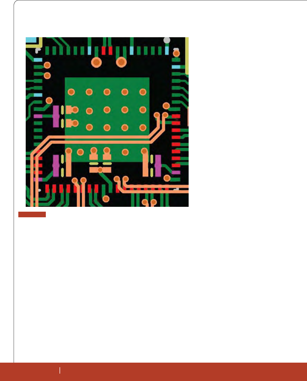
36 SEPTEMBER 2010 RTC MAGAZINE
TECH IN SYSTEMS
36 SEPTEMBER 2010 RTC MAGAZINE
After these critical components have
been placed, heat sinking guidelines as-
sociated with all leaded and non-leaded
devices like the ball grid arrays (BGAs),
quad at packs (QFPs) and quad at no-
leads (QFNs) must be followed. BGAs are
relatively better in terms of thermal per-
formance when compared to other types
of devices because they allow for airow
beneath the device and can perform well
when coupled with fan cooling methods.
Figure 2 shows one side of the BGA as
seen under a microscope.
RF power devices typically generate
heat that must be conducted away from
the device through its central pad. Gen-
erally housed in QFP or QFN packages,
such devices have a row of perimeter pads
around a larger central PAD encapsulated
in a plastic body.
The pad lowers the thermal resistance
of the package. The device runs cooler,
which translates into higher reliability.
The device center pad works both ways as
the device ground as well as the primary
conduction path to remove the package
heat. The advantage of having the center
pad at zero potential is that large copper
planes will not contribute to EMI.
During the layout of such devices, the
thermal pad on the PCB should ideally be
created as the same size as the spreader
underneath the package. This will help
the device to self-center during reow.
Secondly, the device central pad requires
an extensive thermal via structure that can
route the heat out to the cooler regions of
the PCB. The drill size of the thermal vias
should ideally be below 0.3 mm. This
will allow it to be completely lled dur-
ing reow. Filled vias help in two ways.
The vias will efciently conduct heat to
the other side, and the vias will not starve
the thermal pad of solder and pull down
on the device, which may have detrimen-
tal effect on the device assembly. Figure
3 shows a cross-section of a typical QFN
package mounted on a PCB.
It is a good idea to use as many vias
as possible placed on a 25 mil grid on the
thermal pad. These vias can be connected
to internal ground planes, or better yet, to
ing the area results in diminished returns.
Typically, for 1 ounce of copper, a copper
area of more than 1 square inch will not
give reasonable results. If space of about
3 square inches is available, then the ideal
copper weight would be 2 ounces or more.
Figure 1 shows a triple switching power
supply layout. Note that the copper weight
used in this case was 2 ounces.
Once the power layout is complete,
and all the critical mechanical issues have
been dealt with, the layout designer should
start with the placement of the critical
power dissipating devices. To avoid clus-
tering the hot components on the PCB,
power dissipating devices should be dis-
tributed across the PCB and positioned
close to heat sinks. This step is very im-
portant for tightly packed boards.
sons. It is always a good practice to have
some distance between switching transis-
tors and bulk electrolytic capacitors. One
method that the designer would use to re-
duce power supply temperature is to cre-
ate large areas of copper with the power
supply circuitry.
This method does work some of the
time, but overestimating the amount of
copper required can be both ineffective
as well as detrimental to circuit perfor-
mance because it contributes to electro-
magnetic interference (EMI). Remember
that perfect thermal conduction requires
not only an ample surface area, but also
a heat sink that is thick enough to radi-
ate enough heat away. Unfortunately PCB
copper is not thick enough for perfect con-
duction. Hence at some point just increas-
FIGuRE 4
PCB Layout of a typical QFN package. The thermal vias have been connected
to internal GND plane.
TECH IN SYSTEMS
RTC MAGAZINE SEPTEMBER 2010 37
an exposed pad on the other side of the
board, to draw the maximum amount of
heat. Use of thermal vias along with the
thermal pad can increase heat dissipation
by as much as 70%. Such vias act like
thermal shunts. A typical layout of QFN
is shown in Figure 4.
If the steps mentioned above are not
adequate to keep the junction tempera-
tures of components below their rated val-
ues, then heat sinks need to be employed.
In fact, most of the time the use of a heat
sink is the most effective method of ther-
mal management. The optimization crite-
rion is to minimize the exposed heat ex-
changer’s surface area while minimizing
the weight of the heat sink and distance
from the component to be cooled.
Heat sinks are made of thermally high
conductive materials like copper or alumi-
num. Increasing their surface area by the
use of ns removes the heat to the ambient.
The interface between heat sink and the
device is also important for efcient heat
transfer. The connecting surfaces should
be as even as possible and they should be
attached by using a high conductive grease
or elastomer (Figure 5).
Finally, the use of ground planes helps
in a lot of ways including improved PCB
thermal performance. Ground planes help
get returns directly underneath their sig-
nals, which becomes mandatory at higher
frequencies, and they provide a capaci-
tive link to noisy signals and hence aid in
crosstalk issues.
The PCB must be designed so that all
the semiconductor devices on board are
end up with a product that has sub-par
performance and reliability in the eld.
Nexlogic Technologies
San Jose, CA.
(408) 436-8150.
[www.nexlogic.com].
maintained at or below their maximum
rated temperature. Thermal management
can sometimes be problematic for dense
boards employing ne pitch devices. But if
certain layout guidelines are not followed
and due considerations are not given to
the PCB’s thermal performance, one can
FIGuRE 5
Fin-based heat sink mounted for
high-powered analog circuitry.
OpenVPX Development Platform
Call us or visit our
website for more details
www.elma.com
510.656.3400
www.elmasystems.com
215.956.1200
Embedded Computing Solutions by Elma
Making Sense of
p
en
VP
X
De
ve
lo
pm
en
t
Pl
at
fo
rm
Box Level Solutions
ATRs & Chassis Platforms
Pre-Integrated Subsystems
SystemPaks
Open VPX™
Storage
ATR Platform
High Performance FPGA
Fabric Switch
AT
AT
Elma’s solid foundation of core capabilities is based on
decades of hardware design expertise, extensive thermal
management techniques, and in-depth knowledge of all
the building blocks required for an application ready
platform. We leverage that experience along with the
long term relationships built with best in class partners to
deliver truly interoperable COTS based platforms.
Call us to find out how to navigate through the new
OpenVPX standard to design the right high performance
platform you need.
3U VPX Intel Processor
3U
U V
PX I
ntel
Pro
ce
Untitled-3 1 9/14/10 10:26:11 AM

38 MONTH 2010 RTC MAGAZINE
TECHNOLOGY DEPLOYED
2. The description of the digital logic
is then compiled down to a con-
guration le or bitstream that con-
tains information on how the FPGA
components should be connected
to implement the digital logic. The
tools for compiling and creating the
bitstreams are typically provided by
the FPGA hardware vendor.
3. Lastly, the FPGA bitstream is loaded
onto the FPGA, which congures its
operation as described in software.
The FPGA is said to take on a new
“personality,” which can then be up-
dated by following these three steps
again, allowing it to be recongured
as many times as necessary.
Traditionally, FPGAs have been viewed
as a tool used solely by digital design engi-
neers with an advanced understanding of
hardware description languages. However,
the rise of high-level and graphical program-
ming tools for FPGAs is enabling an increas-
ing number of domain experts to take advantage of the benets
FPGAs provide. This includes designers who are responsible for
creating the electronic subsystems of robotic applications.
One of the main reasons developers choose FPGAs in their
designs is because they provide the benets of an application-
specic integrated circuit (ASIC) combined with the exibility of
a software design. FPGAs feature hardware-timed speed and reli-
ability, yet they do not require the high volumes typically needed
to justify the large upfront expense of custom ASIC design. Re-
programmable silicon also has the same exibility as software
running on a processor-based system, but it is not limited by the
It may sound like science ction, but robots are becoming more
and more integral parts of our lives—from modern applica-
tions like cleaning oors and performing surgeries to future
applications like autonomously operating cars. The fact is these
applications that were once only in the realm of our imagina-
tion are quickly becoming a reality. However, in order for robots
to gain more autonomy to perform these higher-level tasks, they
require sensors to provide information about their environment
such as audio, video and proximity to obstacles. As more and
more sensors are required for robotic development, it becomes
imperative that engineers use prototyping tools and platforms
that allow them to design and iterate quickly. By developing
functional robotic prototypes with Field Programmable Gate Ar-
rays (FPGAs) and commercial off-the-shelf (COTS) hardware,
engineers can test ideas, algorithms and I/O combinations ef-
ciently to make next-generation robots a reality.
FPGA Technology
Fundamentally, FPGAs are reprogrammable silicon chips.
Engineers can use FPGAs to implement application-specic
custom hardware by using prebuilt logic blocks and routing re-
sources to congure the chip. The process of developing custom
FPGA hardware is a three-step process:
1. Develop digital logic using computer software to describe
the desired functionality. This can be done in several ways
including the use of text-based hardware description lan-
guages, precongured intellectual property (IP) or high-
level graphical programming tools such as National In-
struments LabView.
Prototyping
Autonomous Robots
with FPGAs
Producing a working prototype of a robotic design is an
important step in getting to a finished product. The use
of FPGAs presents the ability to rapidly try new ideas and
add I/O elements in the process of completing a forward
looking system to investors, managers and customers.
by Jamie Brettle, National Instruments
Robotic Systems
38 SEPTEMBER 2010 RTC MAGAZINE
FIGuRE 1
Engineers can get robotic prototypes running quickly
with COTS hardware.
RTC MAGAZINE SEPTEMBER 2010 39
TECHNOLOGY DEPLOYED
RTC MAGAZINE SEPTEMBER 2010 39
Prototypes are useful for proving the value of a particular design
and, in emerging elds like robotics, can be essential to reach-
ing the next stage of investor funding while better understanding
customer needs.
One of the rst tips to creating robotic system prototypes is
to develop and validate FPGA IP piece by piece. Robotic appli-
cations can often be separated into “Sense,” “Think” and “Act”
components, which means a portion of the code is responsible
for reading sensory input; an algorithmic portion decides what
action to take; and lastly sends output to the actuators to drive the
robot autonomously. By modularizing these three tasks, develop-
ers are able to decouple the I/O from the algorithms. This ben-
ets the engineer by allowing them to test and validate code as
independent units and make modications to subsystems without
impacting the stability of the entire prototype. The parallel nature
of an FPGA design makes it an ideal candidate for this type of
architecture as a variety of I/O components can be brought into
and out of the FPGA independently, while the recongurable fab-
ric allows continuous modications to algorithm level decisions.
Once sections of IP have been proven to work independently, the
sense, think and act code segments can be integrated to form a
fully functional embedded system for robotics that can be tested
and validated as a whole (Figure 2).
A trap that engineers often fall into when developing a pro-
totype is worrying about the cost of a system too early in the
design process. For the hardware components of a robot, one of
the great time sinks and potential failure points are early cost op-
timizations. Engineers can always try to trim the cost of a project
by searching for cheaper components, smaller memory and fewer
hardware connectors—however these benets are most measur-
able once the project is in a moderately large deployment. The
engineering time spent reducing the cost of the hardware bill of
materials can actually result in a project failing before it even
gets out the door. While cost is a factor, the goal of developing
a prototype is to remain within striking distance of creating a
protable design.
An FPGA may cost more than an ASIC in some scenarios,
but it has the exibility to consolidate multiple components into
a single package. For example, its recongurable nature allows
developers to congure different types of peripheral resources
on the FPGA such as serial communication interfaces. If at the
onset of a project you are unsure of the required number of inter-
faces, an FPGA allows you to programmatically congure what
you need, freeing up the additional cost of chips and potential
redesign work. As a result, engineers can focus on proving the
value of their design rather than the individual component costs.
By developing a robot prototype using an FPGA, one can con-
centrate on securing the rst set of customers and then work on
cost optimization.
When designing the prototype it is worthwhile to develop it
such that the maximum amount of IP can be reused in the nal
design. A couple of factors should be considered—anticipated de-
ployment numbers and the market the robot will be deployed into.
number of processing cores available. Unlike processors, FPGAs
are truly parallel in nature, which means different processing op-
erations do not have to compete for the same resources. Each
independent processing task is assigned to a dedicated section of
the chip and can function autonomously without any inuence
from other logic blocks.
Coupling an FPGA with COTS hardware and modular I/O
drastically improves the exibility of a design, allowing robotic
developers the ability to quickly iterate on their prototypes.
As mentioned previously, the amount of sensory data re-
quired for a truly autonomous robotic system is increasing.
Robotic developers face the challenging prospect of changing
feature sets and unknown requirements in terms of I/O. For ex-
ample, your robot may contain a single low-resolution sensor for
capturing video data. However, throughout the lifecycle of your
project, the price of the sensor may become cheaper, making it
feasible to add additional cameras to the system. Robotic devel-
opers need to create on platforms that allow them to quickly swap
out I/O to make the best possible designs. To mitigate risk, devel-
opers can choose COTS hardware that saves them board bring-up
time while maintaining the exibility to swap out different I/O
congurations to meet their needs. This is especially important
during time-sensitive endeavors like creating a rst functional
prototype (Figure 1).
Tips for Developing Your Prototype
Creating a prototype is a commonly overlooked step during
development—often it is viewed as a cost and time impediment
to creating the nal product. However, by selecting a platform
that allows engineers to rapidly produce and change designs, pro-
totyping can become an invaluable phase during development.
FIGuRE 2
FPGAs can help engineers create advanced, high-level
perception and planning algorithms for autonomous
vehicles.
TECHNOLOGY DEPLOYED
40 SEPTEMBER 2010 RTC MAGAZINE
Engineers should look at hardware platforms that can scale to the
number of robots they plan on selling while still maintaining the
prot margin that their company requires, such as using COTS
hardware that has deployment options. In terms of market pres-
sures, certain components need to be certied in different ways
depending on the environment. For example, robots for space ap-
plications often require protection from radiation. In this case, it
would be possible to prototype using an FPGA, understanding
there are FPGA components that are radiation hardened such that
the prototyped IP could be used in a nal design.
The ability to demonstrate the behavior of a system in front
of customers, investors and potential employees is one of the
greatest benets to creating a functional prototype of your ro-
botic system. In order to make sure that your development team
reaches the prototype stages, it is important to select tools that
allow you to reach the end goal efciently. By incorporating sys-
tem architecture that is exible in terms of I/O and programming
capabilities, engineers can make necessary changes to the system
based on client or investor feedback. FPGAs provide a rugged,
stable and recongurable platform for integrating I/O and pro-
gramming autonomy into robotics. Combined with the versatility
of COTS hardware, the next generation of robotics has the ability
to produce amazing results and become a more prevalent part of
our everyday lives.
National Instruments
Austin, TX.
(512) 794-0100
[www.ni.com]
Phoenix International’s VC1-250-SSD Conduction Cooled Serial
ATA (SATA) based Solid State Disk VME blade delivers high capac-
ity, high performance data storage for military, aerospace and
industrial applications requiring rugged, extreme environmental
and secure mass data storage.
tHNTPQFSBUJPOBMTIPDL
tHSNT)[SBOEPNWJCSBUJPO
t-PXQPXFSDPOTVNQUJPO
t0QFSBUJPOBM5FNQFSBUVSF¡UP¡$
t#VSTUEBUBUSBOTGFSSBUFUP.#TFD
t4VTUBJOFEEBUBUSBOTGFSUP.#TFD
t*OEJWJEVBMQPJOUUPQPJOUEFWJDFDPOOFDUJWJUZ
t*OUFHSBUFE4-$/"/%'MBTI
t.FFUTNJMJUBSZBOE*3*(EFDMBTTJGJDBUJPOTUBOEBSET
Conduction Cooled
VME Solid State Disk
FFUT
NJMJUBS
ZB
OE
*3*(
EFDMBTTJGJDBUJPO
TUBOEBSET
'PSPVSFOUJSFMJOFPGTUPSBHFQSPEVDUTXXXQIFOYJOUDPNt7142834800
An ISO 9001: 2000 Certified Service Disabled Veteran Owned Small Business
y,
p
e
m
e e
e e
nvi
i
ron
ron
men
me
tal
tal
Low Operational
Temperature
-40° C
per
r
atio
a
nal
w
O
O
Low
L
L
per
atio
nal
o
w
w
Op
Op
p
Op
e
e
r
er
a
r
r
a
a
ti
tio
io
on
al
al
p
er
rat
ure
ra
r
Te
T
Te
mp
mp
erat
em
Te
T
Tem
Te
mp
mp
em
p
mp
p
e
e
era
er
ra
t
u
tu
t
ur
ur
re
re
re
-4
40
-4
-4
° C
C
-4
4
-
0
0
°
4
4
-4
0
0
0
°
C
C
C
C
EE
High Operational
Temperature
+85° C
Operational Altitude
to 80,000 feet
-PX
QPXFS
DPOTVNQUJ
PO
a
n
d
secure mass
d
ata sto
rag
e
.
L
L
L
L
L
H
i
Hi
Hi
t
H
NTPQFSBUJPOBMTI
PDL
t
H
SNT)[SBOEPNWJCSBUJPO
t
-
PX
QPX
FS
DPO
TVN
QUJ
PO
Untitled-6 1 10/16/09 11:43:57 AM
++9,**:THSS-VYT-HJ[VYZ
• 244-pin MiniDIMM & VLP MniDIMM
• 204-pin SODIMM
• All ECC Registered or Unbuffered
• JEDEC Compliant
• Commercial & Industrial Temperature
ZZZYLNLQJPRGXODUFRP_VDOHV#YLNLQJPRGXODUFRP
;HYNL[LKMVY!
• Embedded
• Communication
• Enterprise
Untitled-3 1 3/15/10 11:18:23 AM

42 SEPTEMBER 2010 RTC MAGAZINE
INDUSTRY
WATCH
42 SEPTEMBER 2010 RTC MAGAZINE
Medical Devices
face area of digital integrated circuits have
not been matched by analog chips, giving
digital-based devices an advantage in re-
ducing system volume. Designers usually
need many discrete components for analog
designs, which could introduce problems
with reliability and increased cost.
The transition to digital alleviates
many of the problems that analog imple-
mentations incur. Generally speaking,
digital designs are inherently smaller than
analog designs. For example, analog sig-
nal processing, which commonly involves
one or more op amps and a number of pas-
sive components, can be completely trans-
lated into software routines. Not only does
this transition reduce the number of parts
and system volume, it also frees more
design time, since revisions only require
code alternations. Digital circuitry has
much better noise immunity compared to
analog circuits and is not as susceptible to
temperature drift. For wireless medical
devices, the superior noise immunity of
digital circuitry also improves the rejec-
tion of EMI noise.
Microchip’s dsPIC33F digital signal
controller (DSC) is well suited to realize a
The burgeoning medical device in-
dustry stands to make signicant
advances with a new generation of
microcontrollers that boasts high perfor-
mance and low power consumption. These
microcontrollers are integrated with a full
complement of peripheral devices that
meets the noise and accuracy require-
ments of medical devices. Traditionally,
medical designs have relied on discrete
analog circuit blocks, but digital micro-
controllers are now powerful enough
to assume the functions of their analog
counterparts; sacricing nothing in terms
of speed and accuracy, while gaining re-
liability and smaller system volume. By
moving to predominantly digital designs,
cost minimization, design exibility and
time-to-market are improved, since soft-
ware alterations are trivial in comparison
to hardware redesigns. Additionally, there
is a wide spectrum of available microcon-
trollers to meet the needs of next-genera-
tion, digital medical devices.
An Example Application
A pulse oximeter is an excellent ap-
plication to demonstrate the shift to digital
design. This noninvasive medical device
shines red and infrared (IR) light through a
patient’s nger or ear, and measures the ab-
sorption at each wavelength to determine
blood-oxygen saturation. In addition, the
pulsation of a patient’s heart is detectable,
allowing the heart rate to be calculated (see
“What is Pulse Oximetry?” p.xx). Portable
oximeters have several critical require-
ments: low power dissipation for maxi-
mum battery life, small size that does not
encumber the user, and high accuracy and
repeatability. The last requirement is par-
ticularly important, since incorrect blood-
oxygen saturation readings could endanger
the health of the user.
As with any analog-based product, a
gamut of factors affects the performance
and design. Semiconductor products, such
as operational ampliers (op amps), are
sensitive to temperature variations. Speci-
cations, such as offset voltage and input
offset current, drift with temperature and
lead to measurement variations. 1/f and
broadband noise also play a part in cor-
rupting the accuracy of measurements. An-
other issue to consider is system size. The
dramatic, ongoing reductions in the sur-
Transitioning from Analog to Digital
in Medical Designs
The move from analog to digital design in medical devices enables smaller
size, lower power, greater noise immunity and lower parts count for
powerful, portable solutions in the health care sector.
by Joseph Sankman, Microchip Technology
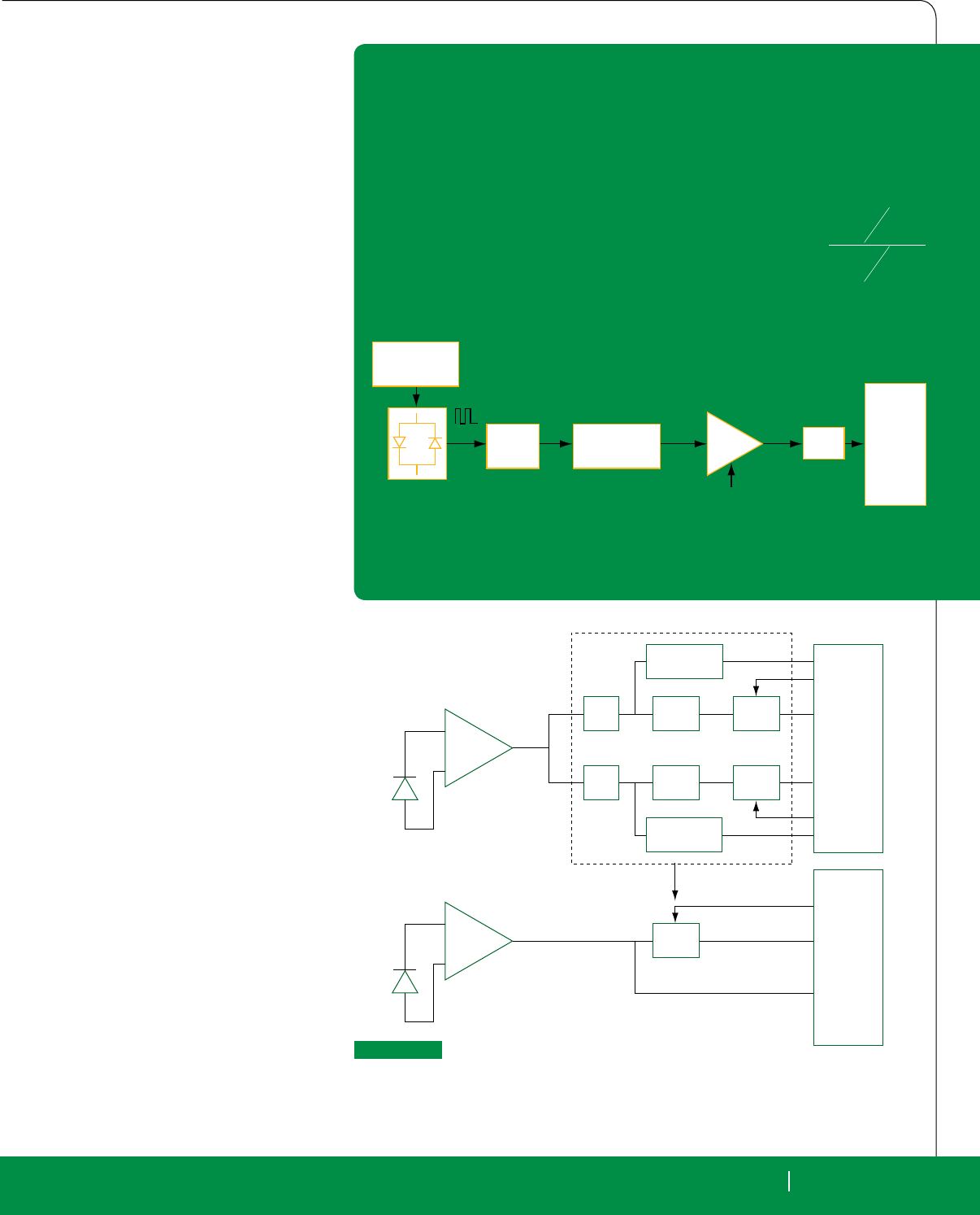
RTC MAGAZINE SEPTEMBER 2010 43
INDUSTRY WATCH
RTC MAGAZINE SEPTEMBER 2010 43
digital pulse oximeter, because the digital
signal processing (DSP) capabilities of the
dsPIC33F eliminate the need for substan-
tial analog signal-processing stages. Many
resources available in books and journals
are dated, and recommend the heavy use
of analog circuitry. The only book avail-
able on oximeter design, Design of Pulse
Oximeters edited by J.G. Webster, was
published in 1997 and recommends the
use of discrete sample-and-hold ampli-
ers, multiplexers and analog lters. Mi-
crocontrollers and DSCs have advanced
tremendously in the 13 years since, ren-
dering these solutions obsolete.
Figure 1 illustrates two different
signal-ow paths in a pulse oximeter: the
traditional, analog-centric design and a
new, digital approach. In the traditional
design, sample-and-holds separate and
demodulate the red and IR signals, which
bandpass lters (BPFs) then condition
(shown in the top of Figure 1). Program-
mable gain ampliers (PGAs) amplify the
signals for the microcontroller A/D con-
verter to sample. The microcontroller D/A
converter also applies DC offsets to ensure
that the signals are within the measurable
range of the A/D converter. The signals
are sampled before the bandpass lters, to
determine their DC levels and adjust the
red and IR LED brightness to equalize the
DC levels. Measuring the DC level is im-
portant in order to set LED brightness and
to simplify calculations. Since the red and
IR DC levels are due to tissues that have
constant absorption, if the two DC lev-
els are equalized, they can be eliminated
from the oxygen saturation calculation;
only AC levels matter. Traditional ana-
log designs rely on bulky DC pass lters
with cutoff frequencies around 0.5 Hz. In
digital designs, however, red and IR data
can be sampled and ltered quickly with a
moving average lter or other digital DC
pass lter.
The Benefits of Digital Signal
Processing
Utilizing a microcontroller with inte-
grated DSP capabilities, known as a digi-
tal signal controller (DSC), reduces the
entire stage into a single PGA. The DSC
performs the signal separation, demodula-
tion and ltering (bottom of Figure 1). The
compression of this stage into the digital
Red
Red/IR
IR
S/H
DC Pass
BPF PGA
DC offset
MCU
DSC
DC offset
DC offset
PGA
PGA
BPF
DC Pass
DC measurement
S/H
FIGuRE 1
Signal flow path, from photodiode to microcontroller with analog signal
processing (top) and digital signal processing (bottom). The DSC topology
drastically reduces the number of discrete components by relying on software
instead. Note: anti-aliasing filters not shown.
LED Driver
Finger Photodiode PGA MCU
Transimpedance
Amplifier
FIGuRE 3
Block diagram of a modern, digital pulse oximeter. Typically, the microcontroller provides feedback
to the PGA and LED driver to control gain and LED brightness, respectively.
Pulse oximetry is a noninvasive method of determining blood-oxygen saturation and heart rate.
Red and IR light (typically 660 nm and 940 nm) is pulsed through a patient’s finger or ear, and the
absorption is measured by a photodiode placed on the opposite side of the patient’s digit or ear.
The small current developed in the photodiode is amplified into a voltage read by a microcontroller.
The signals then undergo processing to determine blood-oxygen saturation and heart rate.
The ratio of red and IR light is proportional to blood-oxygen saturation over
a range useful for consumers: 100% saturation corresponds to R = 0.5
and 80% saturation corresponds to R = 1.0.
The DC levels are due to tissue as well as arterial and venous blood that
should not change in absorption. The AC levels are due to pulsating blood
flow that will change based on oxygen saturation.
What is Pulse Oximetry?
R=
AC
RED
DC
RED
AC
IR
DC
IR
INDUSTRY WATCH
44 SEPTEMBER 2010 RTC MAGAZINE
the case that analog ltering, such as in
the top of Figure 1, is worth the volume,
power and reliability trade-offs, because
the aliasing incurred by an A/D converter
modern microcontrollers have sample-
and-hold ampliers integrated with their
A/D converters, which obviate discrete
sample-and-holds. A designer might make
domain has the greatest impact on system
volume, reliability and cost, since multiple
discrete ICs, op amps and passive compo-
nents are eliminated. The elimination of
these sample-and-holds and analog lters
helps reduce variation in the measure-
ments that stem from temperature drift in
the components, and also improves overall
system reliability by reducing the number
of components that could eventually fail.
Moving to digital has an impact on
power consumption that is dependent on
several factors. If the analog lters, sam-
ple-and-holds and PGAs use tens of mili-
amperes, shifting to digital will likely im-
prove power usage for a microcontroller
operating at a few MIPS. Many microcon-
trollers also have advanced power-saving
modes that can reduce the power con-
sumption of the microcontroller to mere
nanoamps while idle.
Analog vs. Digital Filtering
Sample-and-hold circuits are a com-
posite of op amps, switches and capacitors
that require a nontrivial amount of system
volume, if they are built discretely. Most
REDRED
RED RED
IRIR
IR IR
FIGuRE 2
Diagrams for low sampling rate (top) and high sampling rate (bottom). Lower sampling
rates require lower power dissipation, but at the cost of greater aliased noise. Note:
the timing of red and IR pulses varies among designers. In some designs, red and IR
pulses have no separation, and delays occur in between pairs of red and IR pulses.
XTech Direct:
Your Direct Source for Standard Enclosures & Front Panel Components
The Right Solution, Right Now …
Just a Click Away
Visit XTech Direct to select the front
panel components and enclosures to
meet your requirements.
shop.xtech-outside.com
888.444.1644
email us at sales@xtech-outside.com
sStandard Extruded Aluminum
Enclosures
sCompact PCI Filler Panels
and Components
sVME, VXS and VPX Filler Panels
and Components
sAMC Filler Panels
sPMC and FMC Bezels
The Front Panel Source
Untitled-5 1 8/16/10 4:12:38 PM
RTC MAGAZINE SEPTEMBER 2010 45
INDUSTRY WATCH
transition to digital design from traditional
analog will enable consumer medical de-
vices to proliferate, and predominantly
digital designs will allow in-the-eld
upgradability and low-cost redesigns. As
the market for consumer medical devices
expands, making the leap to digital will
be necessary to deliver high-performance
products at a low cost with expedient
time-to-market.
Microchip Technology
Chandler, AZ.
(480) 792-7200.
[www.microchip.com].
mal high-frequency noise, sampling at the
end of each pulse of red or IR light is suf-
cient, as in the top of Figure 2. However,
if the accuracy and precision require-
ments are stringent, and aliased high-fre-
quency noise is a problem, a designer can
increase the sampling frequency to miti-
gate aliasing, as in the bottom of Figure 2.
Of course, the trade-offs are higher clock
frequency and higher power consumption,
which are required to support the larger
data set and higher order lters. Pulse oxi-
meters commonly have a blood-oxygen
saturation accuracy of ±2%, which a 10-
bit A/D—often integrated with a COTS
microcontroller—can support. For higher
precision, designers may want to use a 12-
bit A/D, which are also available in COTS
microcontrollers.
As a result of a new generation of mi-
crocontrollers and DSCs, medical devices
are trending toward digital signal process-
ing and the elimination of analog signal
conditioning. As the healthcare market
shifts toward early diagnosis and personal
health monitoring, reliable, cost-effective
medical devices will be necessary. The
can be avoided; with the ltering occur-
ring before the signals are digitized. How-
ever, this is not true; the sample-and-holds
still alias noise. Rather than the aliased
signals appearing in the digital domain
after digitization, they appear in the ana-
log domain after the sample-and-holds.
Since oximeter bandpass lters have
very low cutoff frequencies (0.5 Hz and
5 Hz), large-valued components may be
required. In addition, narrow stopband
width and strong stopband attenuation re-
quire cascading op-amp stages. Because
analog lters require a large number of
components and signicant system vol-
ume, the trade-offs that digital ltering
incurs are minimal. Pulse oximeter signal
processing has several avors, and if a de-
signer needs a DC-reject, DC-pass, low-
pass, or high-pass lter, Microchip’s free
DSP software libraries support the Finite
Impulse Response and Innite Impulse
Response realizations of these lters.
Data Acquisition Options
Designers have several choices re-
garding data acquisition. If there is mini-
&RJHQW&RPSXWHU6\VWHPV,QF
&2*(17
"ALWAYS COMPLETE"
,QGXVWULDO'ULYH6PLWKILHOG5,
WHOID[ZHEZZZFRJFRPSFRP
The CSB1725 is manufactured in our in-house state of the art, lead-free surface
mount manufacturing line. All products carry a 1-year warranty and are available in
commercial and industrial temperature versions. Cogent also offers standard and
custom carrier boards, plus royalty free licensing options for the CSB1725.
y1GHz Dual Superscalar ARMv5TE Cores w/512KB L2 Cache
y512MByte 64-Bit Wide DDR2-667 Memory with 8-Bit ECC
y64MByte NOR with Secure ID, and 512MByte SLC NAND
yTwo PCIe x4 Port (or one x4 and four x1's)
yTwo 10/100/1000 ports via 88E1121R RGMII to Copper PHY
yTwo SATA Gen 2 (1.5Gbit or 3.0Gbit/sec) Channels
yTwo 480Mbit USB 2.0 Host Ports
y<6W Typical, 10W Maximum, Both Cores Enabled
y70mm x 75mm x 5.2mm (on 4.3mm Low Profile MXM Socket)
yLinux 2.6.x BSP
Low-Power, Multi-Core RISC SOM
Shipping soon - Low Cost, sub-3W, 2Ghz 88F6282, Dual
GIGe, 256MB DDR2 and 70mm x 50mm compact size!
The CSB1725, based on the Marvell MV78200 Dual Sheeva Core SoC, is a highly integrated System On a
Module (SOM). The CSB1725 provides an ultra small, powerful, flexible engine for low-power 10/100/1000
Ethernet based networking systems. The main features include:
Untitled-7 1 9/9/10 3:26:21 PM
46 MONTH 2010 RTC MAGAZINE
products &
TECHNOLOGY
46 SEPTEMBER 2010 RTC MAGAZINE
CPU Cooler Improves Airflow, Water Block and Heat Dissipation Capacity
A CPU cooler is designed to provide an extremely ef-
cient cooling solution for CPUs from Intel and AMD. The
Hydro Series H70CPU cooler from Corsair is an evolution of
the Hydro Series H50, with several signicant upgrades that
enable it to deliver even greater cooling performance. These
upgrades include a double-thickness (50 mm) radiator with
higher heat-exchanging capacity and a pump/cold plate unit
with increased efciency. The H70 also features two 120 mm
speed-switchable cooling fans in a push-pull conguration to
provide increased airow at low noise levels.
Like the H50, the Hydro Series H70 provides the ben-
ets of water cooling in a sealed and pre-lled unit, with
no maintenance required. The low prole cold plate is ex-
tremely space efcient, and is very low in mass compared to
heat pipe based solutions, putting less stress on the system’s
motherboard. The H70 includes mounting hardware for most common AMD and Intel CPUs,
and, unlike some competitive CPU coolers, includes all necessary fans for high performance
operation. The Corsair Hydro Series H70 CPU Cooler is supplied with a two-year warranty, and
is backed by Corsair’s customer service and technical support.
Corsair, Fremont, CA. (510) 657-8747. [www.corsair.com].
3U VPX Backplane Equipped with
RF Connectors
A new 3U VPX Backplane comes with
connectors for RF and analog signals. The use
of RF interconnects is expected to be an im-
portant issue for many military and aerospace
applications where the VITA 46/65 specica-
tions for VPX are highly targeted.
The VPX Backplane from Elma Bus-
tronic is designed to meet OpenVPX design
considerations. Work is underway on a VITA
67 specication for RF signals over VPX, and
Bustronic plans to develop a version that will
meet the specication when it is nalized.
The backplane features a 5-slot mesh routing
conguration with the RF connectors in three
slots. The 4-cavity RF connector is installed
in the lower half of the standard J2 connec-
tor. This corresponds to rows 9-16 of slots 3, 4
and 5. The coax interconnects provide better
signaling, higher data rates, less noise and less
crosstalk than discrete wire.
Bustronic also offers a wide selection of
VPX and OpenVPX Backplanes in 3U and
6U heights. The company has the industry’s
largest offering of VPX accessories including
3U and 6U load boards (both convection- and
conduction-cooled styles), test extenders, air
bafes, RTMs and SerDes test devices. Pric-
ing for the 3U VPX Backplane including the
RF connectors is under $2,500 depending on
volume and conguration.
Elma Bustronic, Fremont, CA. (510) 490-7388.
[www.elma.com].
Full Size PICMG 1.3 SHB Supports Intel Core i7/i5/i3 Processors and
Q57 Express Chipset
A new PICMG 1.3 full-sized System Host
Board (SHB) supports next-generation Intel Core i7/
i5/i3 processors at clocks speeds up to 3.33 GHz, and
dual-channel DDR3 1066/1333 MHz memory up to
a maximum of 8 Gbytes in two DIMM slots. The
NuPRO-E330 from Adlink Technology is equipped
with the Intel Q57 Express Chipset to provide higher data transfer rates. The NuPRO-E330 is an ap-
propriate solution for applications requiring high-performance computing, data security and maxi-
mum data access bandwidth such as industrial control, automation and industrial vision.
For modern industrial applications where remote management and data protection are critical,
the NuPRO-E330 supports Intel Active Management Technology 6.0 (Intel AMT 6.0). Intel AMT
6.0 allows users to remotely manage assets, reduce downtime and minimize on-site visits. Utilizing
out-of-band system access, Intel AMT 6.0 allows users to remotely detect, isolate and recover sys-
tems, even when they are powered off. The NuPRO-E330 provides additional data security with six
SATA II interfaces supporting Intel Rapid Storage Technology for RAID 0/1/5/10 functionality.
The NuPRO-E330 features the latest Intel Core i7 processor supporting Intel Turbo Boost
Technology, which allows processor cores to run faster than the rated operating frequency if the
processor is operating below power, temperature and current specication limits. For more effective
use of processor resources, Intel Hyper-Threading Technology provides thread-level parallelism on
each processor core. The NuPRO-E330 also offers DDR3 memory support at higher data transfer
rates with less power consumption.
Adlink’s NuPRO-E330 provides a wide range of storage, I/O and expansion connectivity. It
supports one PCI Express x16 and four PCI Express x1 (or one x4) links to the backplane. To pro-
vide the latest in operation system support, the NuPRO-E330 has been veried for both 32-bit and
64-bit versions of Windows 7.
ADLINK Technology, San Jose, CA (408) 495-5557. [www.adlinktech.com].
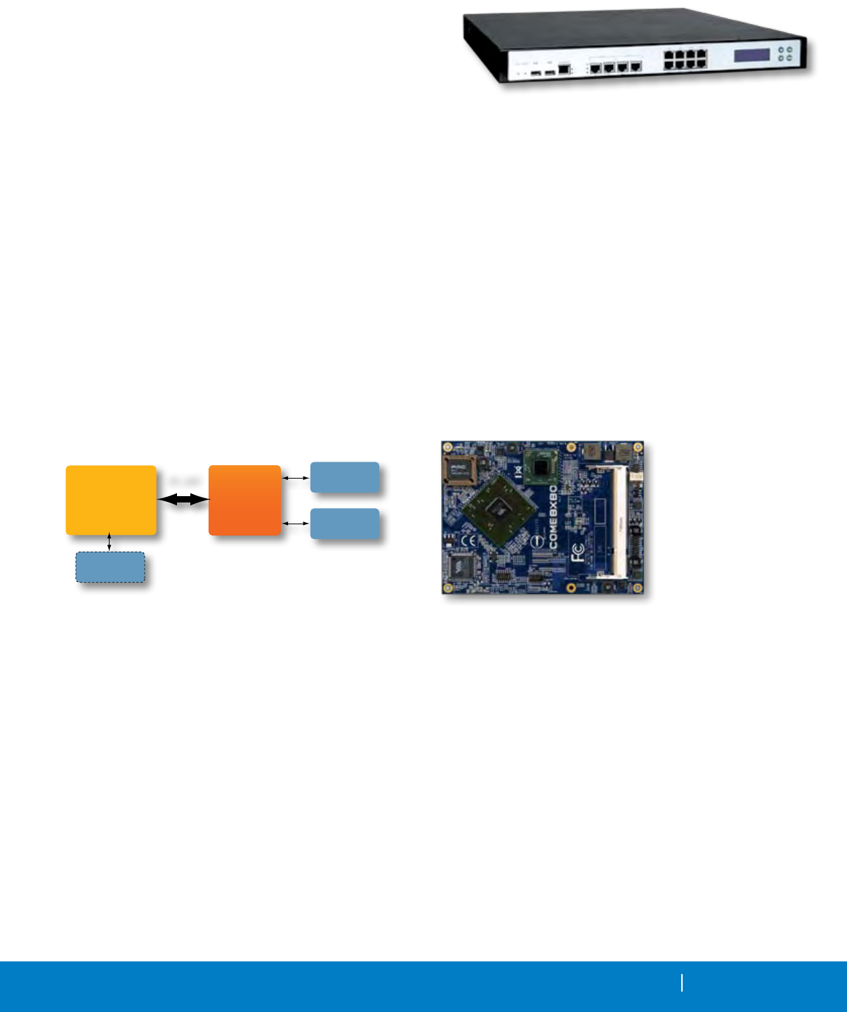
RTC MAGAZINE MONTH 2010 47
RTC MAGAZINE SEPTEMBER 2010 47
1U Network Appliance Based on the Quad-Core Intel Xeon 3400 Series
A 1U Communications Appliance is based on the quad-core Intel Xeon
processor X3400 or L3400 (formerly codenamed Lynneld) or Intel Core i5
or Core i3 processor. The CAR-4003 from American Portwell is a solution
targeted for security applications such as enterprise Internet security, rewall,
WAN optimization, unied threat management, network access control, net-
work behavior analysis and triple play broadcasting for both the enterprise and
medium-sized ofces.
Powered by the Intel Xeon processor 3400 series, the CAR-4003 supports
four DIMM slots with high-speed 1333 MHz dual-channel DDR3 ECC memory; dual x8 PCI Express Gen2 slots (8 Gbyte/s bi-directional) for
connecting expansion modules; expansion capabilities include two PCIe x8 interfaces for a modular bay for Portwell’s ABN/NIP module product
family; ber and copper port connections including dual-port 10G readiness (Intel 82598EB, Intel 92599ES with SFP+ Interface and Intel 82599EB
10Gbase-T Copper Interface) and PCIe Gen2 Quad Port GbE and SFP (Intel 82580) module.
In addition, the CAR-4003 provides Intelligent Platform Management Interface (IPMI) v2.0 functions for remote management, including IPMI
over LAN, IP over KVM (iKVM), Serial Over LAN (SOL) redirection, Event logging and OS independent Hardware Health Monitoring. IPMI
helps lower the overall costs of server management by enabling customers to save time, maximize IT resources and potentially manage multivendor
environments in the same way.
The IPMI consists of a main controller called the baseboard management controller (BMC) and other management controllers distributed
among different system modules that are referred to as "satellite" controllers. User can access IPMI functionality through the command line with the
IPMItool utility either in-band or out-of-band. Additionally, user can generate an IPMI-specic trap from the Web interface, or manage the server's
IPMI functions from any external management solution that is IPMI v1.5 or v2.0 compliant.
The IPMI operates independently of the operating system and allows administrators to manage a system remotely even in the absence of an
operating system or the system management software, or even if the monitored system is powered off, while connected to a power source. IPMI can
also function after the operating system has started, and offers enhanced features when used with system management software. IPMI prescribes
only the structure and format of the interfaces as a standard.
American Portwell Technology, Fremont, CA. (510) 403-3399. [www.portwell.com].
Certified Modules Ease Adding Wi-Fi to Device
Designs
A family of certied modules offers a quick, easy and cost-effec-
tive way for device and appliances manufacturers to add Wi-Fi capabili-
ties to their products. The GA1011M module from Gainspan provides
a serial UART or SPI interface, enabling connection to any embedded
design utilizing a 8/16/32-bit microcontroller via simple commands.
The GS1011M is a suitable solution for organizations with limited or
no Wi-Fi or RF expertise, as it not only dramatically reduces RF design
time, but also removes the burden of testing and certication, allowing
customers to focus on their core application, product or expertise. The
module supports data rates up to 11 Mbit/s, is compliant with 802.11b
and meets regulatory and Wi-Fi Alliance requirements.
Multiple software congurations are available for the stack run-
ning on the module. For applications utilizing a small 8-bit microcon-
troller host, the module supports a serial to Wi-Fi function and runs
the full Wi-Fi and TCP/IP networking stacks, completely ofoading
the host. For applications utilizing more powerful microcontrollers, the
networking stack and services can reside on the host while the module
provides the IP to Wi-Fi functionality. In addition, it supports WEP/
WPA/WPA2 security, Adhoc as well as Wi-Fi Protected Setup (WPS)
for ease of provisioning.
Gainspan, San Jose, CA. (408) 454-6630. [www.gainspan.com].
GainSpan
GS1011M
Module
Family
8/16/32 Bit
Micro-
Controllers
SPI, UART
Optional
Sensor
Devices
Peripheral
Devices
Sensor
Devices
Low-Power Processor Brings 64 Bits to COM Express
Via Technologies, Inc,
a leading innovator and
developer of embedded
silicon and platform tech-
nologies, today announced
the addition of the Via
COME8X80 module to its
COM Express portfolio.
The rst COM Ex-
press type product to in-
corporate the 64-bit Via
Nano E-Series processor
is targeted at IPC and larger OEM customers in a range of embed-
ded segments including gaming, healthcare and industrial automation.
Customers can also take advantage of a specially developed mutli-I/O
baseboard for evaluation purposes, as well as Via’s technical assis-
tance in developing custom baseboard designs. The Via COME8X80
from Via Technologies is available with a choice of either 1.3+ GHz or
800 MHz Via Nano E-Series processors, combining native 64-bit and
virtualization support with a high-performance superscalar architec-
ture in a low power thermal envelope.
The COME8X80 also integrates the unied Via VX800 media
system processor, bringing Via Chrome9 integrated graphics, sup-
port for VGA and dual channel LVDS displays, video acceleration
for MPEG-2, MPEG-4, WMV9 and VC1 video formats, plus a VMR
capable HD video processor. All Via components have a guaranteed
longevity of seven years. Additional highlights include three PCI and
one x4 plus two x1 PCIe slots, up to 2 Gbytes of DDR2 SO-DIMM
memory, 10/100 Mbit/s Ethernet, up to six USB 2.0 ports and up to two
SATA devices plus one IDE.
VIA Technologies Fremont, CA. (510) 683-3300. [www.viaembedded.com].
48 MONTH 2010 RTC MAGAZINE
PRODUCTS & TECHNOLOGY
48 SEPTEMBER 2010 RTC MAGAZINE
Mass Storage Mezzanine Offers Fast Secure Erasure and Write
Protection
A mass storage mezzanine for securely erasing and
write-protecting sensitive data in harsh environments
such as those often found in military and defense
applications is built on open standards-based
platforms like CompactPCI, ATCA, VME and
OpenVPX. The new, high-capacity Secure PMCDisk
mezzanine from Elma Electronic Systems supports
10 major defense agency secure erasure procedures
via a front panel push button with an LED indicator
to conrm data erasure. It also enables write
protection via a front panel toggle switch.
Specic defense agency standards supported by
the Secure PMCDisk include fast clear/initialize; clear; DoD NISPOM 5220.22-M and 5220.22-
M-Sup 1; NSA/CSS Manuals 130-2 and 9-12; AR 380-19; NAVSO P-5239-26; AFSSI-5020;
and IRIG 106-07.
The new RoHS-compliant Secure PMCDisk ships complete with a 2.5” solid state ash
drive. Current capacities support up to 128 Gbytes. Software drivers are available for VxWorks,
Linux and Windows. It can be used on any board with an IEEE1386.1-compliant PMC site, such
as CompactPCI, VMEbus, OpenVPX, VXS and ATCA, replacing external hard drives or disk
modules that require additional backplane slots or external connections.
The storage module supports SMART (self-monitoring analysis and reporting technol-
ogy), which detects remaining useful drive life in order to avoid system failures that lead to
catastrophic shutdowns, a key factor for applications requiring data safety. In addition, the SLC
(single level cell) 2.5” SATA solid state storage device further increases data reliability and
retention. The ruggedized mezzanine withstands shock to 1,500G at 0.5 ms half-sine and vibra-
tion to 16.4G rms (10 Hz to 2,000 Hz random). Pricing starts at $2,700 in low quantities.
Elma Electronic Systems, Fremont, CA. (510) 490-7388. [www.elma.com].
Family of IP Display Engines for Networked Video Connectivity
Targeted at networked video connectivity solutions for mission-critical systems, a new fam-
ily of video receivers is designed specically for viewing stations and specialized processing
appliances on high-performance video networks. The vDisplay family of IP engines from Pleora
is comprised of compact, purpose-built hardware that allows high-resolution video streams on
GigE (Gigabit Ethernet) networks to be displayed directly on monitors, in real time, without the
need for a PC. They can also be used for real-time video capture in specialized processing appli-
ances. The engines comply fully with
the open, global GigE Vision and
GenICam standards.
By replacing PCs with ultra-
efcient hardware, vDisplay engines
shrink the size, lower the cost, reduce
the power consumption and improve
the reliability of viewing stations and
video processing appliances. They
are suited for OEMs and integrators
building high-performance video
products and systems for the military,
medical and manufacturing sectors.
Pleora will initially offer the vDisplay HDMI-Pro IP engine. The HDMI-Pro engine con-
verts streaming IP video to standard HDMI/DVI (High-Denition Multimedia Interface/Digi-
tal Visual Interface) formats for real-time display on off-the-shelf monitors. It auto-senses the
display capabilities of the attached monitor and adjusts the image formats and resolution of the
incoming video stream to match the monitor’s refresh rate and resolution. The HDMI-Pro engine
is available as a compact OEM board set or a small enclosed unit.
Pleora Technologies, Kanata, Ontario, Canada. (613) 270-0625. [www.pleora.com].
Sound and Vibration Software
Supports Data Translation IEPE
Modules
A new software application for sound
and vibration measurement provides an
easy-to-use interface for individual channel
conguration and display for performing vi-
bration analysis. The VIBpoint Framework
Application from Data Translation now sup-
ports the company’s DT9837 and DT8837
series of sound and vibration measurement
products. Functions include: spectrum/spec-
tral display, power/magnitude, RMS/peak,
dB/linear and more. This hardware/software
combination supports both USB and Ethernet
(LXI-compliant) vibration analysis and mon-
itoring applications including noise emis-
sion monitoring, predictive maintenance and
shock analysis.
VIBpoint Framework Application sup-
ports all the features of the hardware modules
including discovery and selection of available
hardware, conguration, loading and saving
of hardware congurations as well as individ-
ual conguration of each channel for analy-
sis and display. It supports the hardware’s
per channel FFT parameter conguration
including: spectrum/spectral density, power/
magnitude, RMS/peak, dB/linear and more
for maximum vibration analysis exibility.
It also includes the FFT averaging modes for
linear, exponential and peak, and it can save,
display or analyze data with Excel. A 14-day
free trial of VIBpoint Framework Applica-
tion is available for download, or a license
key can be purchased for $995.
Data Translation, Marlboro, MA.
(508) 481-8620.
[www.datatranslation.com].
RTC MAGAZINE MONTH 2010 49
PRODUCTS & TECHNOLOGY
Get Connected with companies mentioned in this article.
www.rtcmagazine.com/getconnected
Get Connected
with companies mentioned in this article.
www.rtcmagazine.com/getconnected
Get Connected with companies and
products featured in this section.
www.rtcmagazine.com/getconnected
Ad Index
End of Article
Products
Get Connected with technology and
companies providing solutions now
Get Connected is a new resource for further exploration
into products, technologies and companies. Whether your goal
is to research the latest datasheet from a company, speak directly
with an Application Engineer, or jump to a company's technical page, the
goal of Get Connected is to put you in touch with the right resource.
Whichever level of service you require for whatever type of technology,
Get Connected will help you connect with the companies and products
you are searching for.
www.rtcmagazine.com/getconnected
Get Connected with technology and companies providing solutions now
Get Connected is a new resource for further exploration into products, technologies and companies. Whether your goal is to research the latest
datasheet from a company, speak directly with an Application Engineer, or jump to a company's technical page, the goal of Get Connected is to put you
in touch with the right resource. Whichever level of service you require for whatever type of technology,
Get Connected will help you connect with the companies and products you are searching for.
www.rtcmagazine.com/getconnected
Get Connected with companies and products featured in this section.
www.rtcmagazine.com/getconnected
RTC MAGAZINE SEPTEMBER 2010 49
Big Performance, Little Footprint: Rugged System Beats ATR-Short
A fast, powerful, rugged computer system packs features and options into a small, easily
mounted package that is one-quarter the size and weight of a ½ ATR-Short package. With a Core2
Duo processor running at up to 2.256 GHz and 8 Gbytes of main memory, the Golden Eye II from
General Microsystems is a super lightweight, rugged system that brings high performance in
harsh environments together with advanced graphics processing capabilities, making it suitable
for vehicular and avionic programs. Golden Eye II is available in several standard congurations:
S802-R with one removable Solid State Drive (SSD) offering up to 500 Gbytes of storage, and
S802-R4, which has four removable SSDs for a total of 2 Tbytes of storage. S802-R4 units are available with a
combination of drive bays for removable SSD and PCMCIA slots to accommodate Army legacy systems.
Golden Eye II in its S802-R conguration measures only 5.25”x5.25”x2”, and weighs just 2.5 pounds. The unit literally can replace four 6U
cards offering equivalent or better performance, and its peak drain on the system’s power bus never exceeds 25 watts. GMS’s patent-pending cool-
ing design enables its systems to easily operate in environments from -40° to +85°C. Because of its small footprint, about one-quarter the size of a
standard ½ Air Transport Rack (ATR)-Short, it is well suited for UAVs and vetronics applications. Golden Eye II was designed for rugged, military
applications and is compliant to MIL-STD-810F, MIL-STD-704E and MIL-STD-461E. Completely validated and certied, it also uses GPS for
time stamping every data packet within the stringent Army requirements of less than one micro second.
With dual pipe support for high-performance RGB video (2048x1536 at 32-bit color), DVI-D and NTSC/PAL composite video, Golden Eye II offers
a broad range of video output options.
Four-channel video capture, two Dual Redundant 1553 channels, Wi-Fi and Bluetooth give the unit a huge range of options for communications and
interface. Software support includes Windows XP/XPE/7, Linux and VxWorks and Network Attached Storage (NAS). It can replace four servers with one
Trusted Platform Module (TPM) virtual machine running up to four different operating systems. Single unit price (S802-R) starts under $10,000.
General Microsystems, Rancho Cucamonga, CA. (909) 980-4863. [www.gms4sbc.com].
2U Rackmount Network System Supports Xeon,
Core i7 and up to 32 x GbE LAN
A 2U rackmounted hardware platform designed with a redundant
power supply is tar-
geted for network ser-
vice applications. Built
with Intel Embedded
IA components with
warranty of longevity,
the PL-80160 from
Win Enterprises supports Intel quad-core processors with Intel Hyper-
Threading technology, including the Xeon, Core i7, Core i5, Core i3 and
Pentium Dual-Core processors.
The platform supports four unbuffered ECC or non-ECC DDR3
1066/1333 MHz DIMM sockets with memory up to 16 Gbytes. In order
to provide the best network performance and utilization, the powerful
storage interfaces include one 3.5" SATA HDD and CompactFlash. The
optional onboard Cavium Nitrox PX cn16xx security coprocessor sup-
ports multi-security protocol commands that can ofoad the CPU thus
increasing overall system throughput performance.
This platform affords 8 GbE and max to 32 GbE Ethernet ports via
PCI-E by8 on the front panel. To prevent network problems when the
platform shuts down, PL 80160 supports two segments of LAN bypass
function through WDT and GPIO pin denitions. The front panel also
has dual USB 2.0 ports, one RJ-45 console port and LED indicators that
monitor power and storage device activities for local system management,
maintenance and diagnostics. In addition, the PL-80160 supports one
PCI-E x8 slot, one PCI-E x8 Golden Fingers, one PCI slot and is RoHS,
FCC and CE compliant. Software support includes Windows XP, Server
2003, Server 2008, Windows 7 and Linux. OEM quantity pricing for PL-
80160 begins at $1,391.
WIN Enterprises, North Andover, MA. (978) 688-2000. [www.win-ent.com].
Solid State Drive in DIMM Form Factor Expands
Storage Options
An enterprise class
SATA II Solid State Drive
(SSD) in an industry-stan-
dard DDR3 240-pin DIMM
form factor is now avail-
able. This technology from
Viking Modular Solutions
allows users to signicantly
increase the capacity and
storage performance of their existing server, storage or cloud computing so-
lutions. It also allows system designers new options and greater exibility
when creating new server designs—and not coincidentally, it also lends itself
to embedded designs.
The SATADIMM offers a high-performance and high-availability solid
state drive in the DDR3 240-pin DIMM form factor (JEDEC MO-269). By
adding SATA to an existing DDR3 DIMM socket, Viking Modular has de-
livered the performance and power savings desired from an SSD at a fraction
of the space required to house a typical 2.5” SSD. This cost-effective solution
provides dramatically increased capacity and performance.
Features of the SATADIMM include best-in-class sequential and
random performance (30,000 IOPS), intelligent write management tech-
niques for optimized endurance and protection against catastrophic ash
failures, and power fail data protection enabled by super capacitor inte-
gration on the DIMM. SATADIMM is available in 50 Gbyte, 100 Gbyte
or 200 Gbyte capacities.
For current server storage appliances, the SATADIMM has been de-
signed to take advantage of any available 240-pin DDR3 DIMM socket. The
SATADIMM SSD derives its power from the 1.5V supply to the DIMM
socket, and data transfer is enabled by using a standard SATA cable. For new
designs, system architects will appreciate that the SATA data signals can be
routed directly to the socket, thus eliminating the need for any cables.
Viking Modular Solutions, Foothill Ranch, CA. (949) 643-7255.
[www.vikingmodular.com].
50 MONTH 2010 RTC MAGAZINE
PRODUCTS & TECHNOLOGY
50 SEPTEMBER 2010 RTC MAGAZINE
SAS Solid State Drive with Enterprise-Grade Multi-Level Cell
Technology
A new development in ash memory is a serial-attached
SCSI (SAS) solid state drive (SSD) equipped with
enterprise-grade multi-level cell (E-MLC) NAND ash
technology. The 2.5” XceedIOPS SAS SSD from Smart
delivers superior endurance in enterprise environments
due to the use of the latest 34nm E-MLC NAND ash
technology. Specied endurance for E-MLC ash is
30,000 program/erase (P/E) cycles, whereas competing
commercial MLC (C-MLC) technologies typically
demonstrate only 1,500 to 5,000 P/E cycles. Endurance
is further enhanced by an advanced wear leveling
algorithm combined with advanced data management
hardware, delivering the industry’s lowest levels of
write amplication while also signicantly boosting
performance. As a result, the Smart XceedIOPS SAS
SSD family of products will deliver a minimum of ve
years of operational life in environments that write up
to 10x the device’s total data capacity per day.
Specically optimized for high-performance enterprise storage and server systems,
the XceedIOPS SAS SSD achieves up to 26,000/20,000 IOPS random read/write and
250/230 Mbyte/s sustained read/write. Available in 100, 200 and 400 Gbyte capacities, the
new XceedIOPS SAS SSD offers high reliability and data integrity due to extensive error-
correction and detection capabilities, multi-level data-path and code protection, data-fail
recovery and data-integrity monitoring. Designed to t the restricted power envelope of en-
terprise storage environments, the XceedIOPS SAS SSD incorporates staggered power-on
support. In addition, the new XceedIOPS SAS SSD supports long data sector (LDS), which
allows host transfer sizes of 512, 520 and 528 bytes.
SMART Modular Technologies, Newark, CA. (510) 623-1231. [www.smarm.com].
Auto Tuning for Easy-to-
Implement Capacitive Touch
Sensing Solution
Replacing the billions of mechanical but-
tons in mobile handsets, laptops, consumer
electronics, white goods, automotive applica-
tions and
virtually
any sys-
tem that
has a me-
chanical
button
or switch, is the job of capacitive touch sens-
ing. Now the new CapSense capacitive touch-
sensing controller from Cypress Semiconduc-
tor enables designers to achieve mechanical
button replacement (MBR) without having to
write rmware or learn to use new software
tools. The CapSense Express eliminates the
requirement for system tuning. Cypress’s ac-
companying design toolbox provides detailed
resources to ensure optimal interface perfor-
mance, and advanced system debug features
allow taking designs directly to production
for signicantly shorter time-to-market. The
controller delivers robust touch-sensing with
ultra-low power consumption to extend bat-
tery life in a wide range of handheld products.
The hardware-congurable CY8C-
MBR2044 CapSense Express Mechanical But-
ton Replacement controller operates from 1.7
to 5.5V and offers low overall power consump-
tion with supply current in run mode as low as
15 uA per button, and industry-best deep sleep
current of 100 nA. The devices offer reliable
operation in harsh sensing conditions, and Cy-
press’s patented CSD (CapSense Sigma Delta)
sensing method provides superior immunity
to conducted and radiated noise. With Smart-
Sense auto-tuning, the device dynamically
optimizes the baseline and detection threshold
and adjusts for the optimal capacitance sens-
ing range at power up and during runtime as
environmental conditions change
Eliminating the need to tune the UI sub-
system is a signicant advantage for large
and small manufacturers alike, as it saves en-
gineering time and yield loss that can occur
with even slight variations in manufacturing
tolerances. This savings is greatly multiplied
for customers with a global factory footprint
and supply chain. SmartSense auto-tuning can
eliminate the need for additional test steps
currently required with competing solutions
to address the vendor-to-vendor variations in
PCBs and overlays.
Cypress Semiconductor, San Jose, CA.
(408) 943-2600. [www.cypress.com].
Battery-Free Energy Modules Back Up Critical Data During Power Loss
A new battery-free intelligent power subsystem prevents
the loss of critical data due to a power interruption. The
PowerGEM (Green Energy Module) power subsystem
from Agiga Tech uses ultracapacitors (or “ultracaps”)
to provide temporary power in the event of a system
power loss.
The PowerGEM modules allow designers to avoid
problems of battery-powered energy sources, including
environmental impact, increased design complexity, maintenance
and conditioning, short operating life and a high total cost of own-
ership. PowerGEM, when paired with an AgigaRAM memory module, provides a complete se-
cure and reliable non-volatile memory subsystem for mission-critical data back-up. In a related
announcement, AgigA Tech has introduced a high-speed and high-density DDR3 solution, rang-
ing from 1 Gbyte to 8 Gbyte.
When used as a write cache, AgigaRAM provides a performance-boosting building block
while guarding against power failures and data loss. In addition to providing power, PowerGEM
manages the charging/discharging, cycling, wear-monitoring and other module details to ensure
long life and high reliability.
The entire AgigaRAM Non-Volatile System (NVS) implements the AgigaSafe control pro-
tocol, a simple-to-use host-controlled I2C programming interface developed by AgigA Tech that
ensures safe, reliable, secure operation at the system level. This protocol allows ne control over
internal system functions such as managing the NAND Flash while providing precise health
monitoring and tracking. The complex system-readiness system has also been reduced to a single
“Good To Go” (or GTG) signal.
AgigA Tech, Poway, CA. (858) 375-4530. [www.agigatech.com].
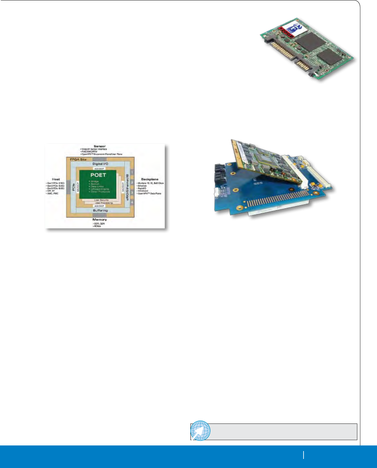
RTC MAGAZINE MONTH 2010 51
PRODUCTS & TECHNOLOGY
RTC MAGAZINE SEPTEMBER 2010 51
Get Connected with companies mentioned in this article.
www.rtcmagazine.com/getconnected
Get Connected
with companies mentioned in this article.
www.rtcmagazine.com/getconnected
Get Connected with companies and
products featured in this section.
www.rtcmagazine.com/getconnected
Ad Index
End of Article
Products
Get Connected with technology and
companies providing solutions now
Get Connected is a new resource for further exploration
into products, technologies and companies. Whether your goal
is to research the latest datasheet from a company, speak directly
with an Application Engineer, or jump to a company's technical page, the
goal of Get Connected is to put you in touch with the right resource.
Whichever level of service you require for whatever type of technology,
Get Connected will help you connect with the companies and products
you are searching for.
www.rtcmagazine.com/getconnected
Get Connected with technology and companies providing solutions now
Get Connected is a new resource for further exploration into products, technologies and companies. Whether your goal is to research the latest
datasheet from a company, speak directly with an Application Engineer, or jump to a company's technical page, the goal of Get Connected is to put you
in touch with the right resource. Whichever level of service you require for whatever type of technology,
Get Connected will help you connect with the companies and products you are searching for.
www.rtcmagazine.com/getconnected
Get Connected with companies and products featured in this section.
www.rtcmagazine.com/getconnected
Embedded SATA SSD Designed to the JEDEC MO-297Spec
A case-less, small form factor and rugged SATA SSD is an embedded solid state drive solution
that delivers outstanding performance in a standard form factor—and is less than half the size of a
2.5” SSD. With its 3 Gbit SATA II interface and sustained performance of up to 260 Mbyte/s the Slim
SATA SSD from Viking Modular is ideal for telecommunications, gaming, embedded server & stor-
age systems, eld computing and defense & aerospace applications.
Viking Modular’s Slim SATA SSD features intelligent write management techniques to optimize
endurance, and offers densities of 25 Gbyte, 60 Gbyte and 120 Gbyte. Slim SATA’s exclusive advanced
controller features protection against normally catastrophic ash page and block failures, as well as
data path CRC error detection for unparalleled data integrity. Viking Modular’s Slim SATA SSD conforms to the JEDEC MO-297 industry standard
and uses a standard SATA connector. It is available in a RoHS-compliant package and can be congured using MLC or SLC ash technologies.
Viking Modular Solutions, Foothill Ranch, CA. ((949) 643-7255. [www.vikingmodular.com].
PCI/104-Express Board Incorporates Qseven Modules
A new PCI/104-Express module incorporates industry standard
Qseven modules. The Xtreme/CPU from Connect Tech was designed
based on Qseven modules provided by congatec, which specializes in
the development and marketing of industrial computer modules using
standard form factors including Qseven, COM Express, XTX and
ETX. The Connect Tech Xtreme/CPU is an embedded carrier board
based on the PCI/104-Express form factor. This compact processor
module enables complete integration with any industry standard
Qseven module. The Xtreme/CPU conveniently provides onboard
connectors allowing for instant access to Qseven features.
The Xtreme/CPU Features a PCI/104-Express form factor with
4 x1 PCIe lanes, two SATA interfaces, two each RS-232 and RS-
422/485 connectors, four USB 2.0 ports, one Gigabit Ethernet connec-
tion, LVDS and VGA Video. Additionally, Xtreme/CPU gives instant
access to a full range of PCI/104-Express add-on cards, and incorpo-
rating Qseven creates an I/O platform with a scalable CPU. Simply
changing the Qseven module provides users with instant access to
Atom-based products that are easily upgradeable to take advantage of
future advancements of the Atom.
Xtreme/CPU is an attractive off-the-shelf solution for a broad
range of applications. Achieve rapid proof of concept and deploy sys-
tems for eld trials with off-the-shelf hardware. Connect Tech’s engi-
neering services offer customers the option of modied designs. The
Xtreme/CPU PCI/104-Express processor module is compatible with
all Qseven modules that are available at the time of this release.
Connect Tech, Guelph, Ontario. (519) 836-1291. [www.connecttech.com].
Protocol-Agnostic, Multi-Fabric Interconnect for
Intel Embedded Computing Line
A new multi-fabric connectivity solution for Intel processors
empowers companies to migrate to open solutions, future-proof their
applications and guard their investment by ensuring a wide range of
standards can be implemented without costly hardware changes. The
protocol-agnostic, multi-standard switch fabric technology or Protocol
Ofoad Engine Technology (POET) from Mercury Computer Systems
implements, at its highest level, a collection of standard interfaces to
create a bridge between processors and switched fabrics. Initially POET
will support both Serial RapidIO (sRIO), the overwhelmingly preferred
switch fabric for the defense industry, and 10 Gigabit Ethernet, the most
common commercial fabric.
The 10 Gigabit Ethernet fabric is traditionally a best-efforts net-
work. By ofoading and accelerating standard protocols, POET simul-
taneously facilitates high bandwidth and low latency operation giving
10 Gigabit Ethernet the guaranteed, deterministic delivery of Serial Ra-
pidIO. POET can improve size, weight and power (SWaP) constraints in
subsystems by providing local switching in the FPGA between multiple
fabric ports to create distributed mesh networks, thereby eliminating
the need for a centralized switched fabric card. In future releases POET
will support next-generation switched fabrics such as 40 Gigabit Eth-
ernet and InniBand as well as ofoad protocols such as RDMA over
Converged Ethernet (RoCE), an InniBand over Ethernet standard.
Through industry standard internal interfaces, customers can integrate
their own downloadable rmware with POET to add value to their sub-
systems, or engage with Mercury’s Services and Systems Integration
group to obtain customization services.
Mercury Computer Systems, Chelmsford, MA. [www.mc.com].
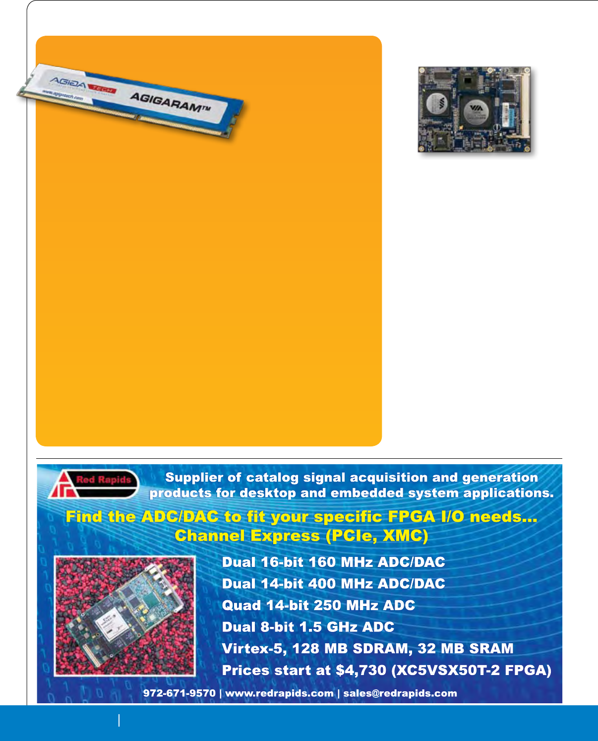
52 MONTH 2010 RTC MAGAZINE
PRODUCTS & TECHNOLOGY
52 SEPTEMBER 2010 RTC MAGAZINE
Highest-Density Non-Volatile DDR3 Memory Offers up to 8 Gbyte
A non-volatile system (NVS)
memory family delivers densities
up to 8 Gbytes providing exibility
to system architects and designers
to tailor non-volatile memory for
specic application requirements.
AgigA Tech, a subsidiary of Cy-
press Semiconductor, now extends
the market’s portfolio of battery-free non-volatile memory solutions with the Agigaram
product family. The technology merges NAND Flash, DRAM and a battery-free ultraca-
pacitor power source into a highly reliable non-volatile memory system.
When used as a write cache in enterprise-class applications, Agigaram provides a per-
formance-boosting building block while guarding against power failures and consequent
loss of critical data. The DDR3 products deliver data transfer speeds up to 1333 megatrans-
fers per second (MT/s). AgigA Tech offers product support to boost reliability, including
extensive ultracapacitor testing with a dedicated test lab, in-system health monitoring, a
system safe control protocol, and a product warranty up to the operating life of the system
Complementing the nvSRAM offerings from Cypress, the Agigaram system scales
and extends non-volatile solutions to much higher densities. The next best high-density
alternative, battery-backed memories, can offer high speeds but are subject to numerous
problems, such as hazardous material issues, increased design complexity, long charge
times, limited operating life and a high total cost of ownership.
The Agigaram system solves these problems with a novel use of a battery-free power
subsystem, teamed with high-speed SDRAM, NAND Flash, intelligent power management
and a proprietary system controller. During normal operation, the Agigaram system ap-
pears as a DDR3-registered DIMM to the host system, providing all the benets and speed
of a standard high-speed, high-density SDRAM. In the event of a power loss, the Agiga-
ram system can be commanded to take control of the SDRAM and transfer its contents to
ash memory using energy from its ultracapacitor power source, thereby preserving all the
SDRAM data. After power is restored, the Agigaram system can be commanded to transfer
the contents back into the SDRAM and returns control to the host system. This functional-
ity can be used for power interruption/loss immunity, write caching and posting, data log-
ging and journaling, instant-on recovery, and service and maintenance processing.
AgigA Tech, Poway, CA. (858) 375-4530. [www.agigatech.com].
Untitled-3 1 11/11/09 3:45:15 PM
COM Express Module Supports
Multimedia
A fanless COM Express form factor module
offers a complete, multimedia-capable platform
for a variety of embedded applications. Available
with a choice of Via C7 or Via Eden processors,
the Via COME7N80 from Via Technologies also
integrates Via CN896 North Bridge and VT8251
South Bridge chipsets providing a exible and com-
prehensive computer-on-module product. Targeted
at industrial PC and large OEM customers focused
on dynamic application segments, including gam-
ing, healthcare and industrial automation, custom-
ers can take advantage of a proprietary multi-I/O
baseboard, or can utilize Via’s extensive technical
support in developing a custom baseboard.
The COM Express specication integrates
core CPU, chipset and memory on the module,
providing support for extensive connectivity op-
tions, including USB, audio, graphics and Ether-
net, through board-to-board connectors to an I/O
baseboard. The Via COME7N80 features the Type
2 COM Express standard, three PCI and three
x1 lanes plus a x16 PCIe slot and up to 2 Gbyte
of DDR2. In addition, the module features 10/100
Ethernet, up to eight USB 2.0 ports and up to four
SATA devices.
VIA Technologies Fremont, CA. (510) 683-3300.
[www.viaembedded.com].

1 800 332 8638
www.em.avnet.com/embedded
©Avnet, Inc. 2010. All rights reserved. AVNET is a registered trademark of Avnet, Inc.
Follow us on Twitter!
www.twitter.com/avnetdesignwire
Accelerating Your Success.
™
Three Times the Power
People. Products. Services. The powerful combination of Avnet and
Bell Microproducts provides the expertise you need to accelerate your success.
Our combined team gives you access to world-class resources. Bringing industry
leading line cards together, we now deliver the most extensive inventory of brand
name systems, embedded hardware, displays, storage and software. And, with
our enhanced services you have access to Avnet’s leading ISO integration centers,
fi nancial solutions and supply chain strategies.
Avnet Embedded_BellMicro_RTC_8.5x11.125.indd 1 9/3/10 2:38:28 PM

54 SEPTEMBER 2010 RTC MAGAZINE
Advertiser Index
Company Page Website Company Page Website
RTC (Issn#1092-1524) magazine is published monthly at 905 Calle Amanecer, Ste. 250, San Clemente, CA 92673. Periodical postage paid at San Clemente and at additional mailing offices.
POSTMASTER: Send address changes to RTC, 905 Calle Amanecer, Ste. 250, San Clemente, CA 92673.
Get Connected with companies mentioned in this article.
www.rtcmagazine.com/getconnected
Get Connected
with companies mentioned in this article.
www.rtcmagazine.com/getconnected
Get Connected with companies and
products featured in this section.
www.rtcmagazine.com/getconnected
Ad Index
End of Article
Products
Get Connected with technology and
companies providing solutions now
Get Connected is a new resource for further exploration
into products, technologies and companies. Whether your goal
is to research the latest datasheet from a company, speak directly
with an Application Engineer, or jump to a company's technical page, the
goal of Get Connected is to put you in touch with the right resource.
Whichever level of service you require for whatever type of technology,
Get Connected will help you connect with the companies and products
you are searching for.
www.rtcmagazine.com/getconnected
Get Connected with technology and companies providing solutions now
Get Connected is a new resource for further exploration into products, technologies and companies. Whether your goal is to research the latest
datasheet from a company, speak directly with an Application Engineer, or jump to a company's technical page, the goal of Get Connected is to put you
in touch with the right resource. Whichever level of service you require for whatever type of technology,
Get Connected will help you connect with the companies and products you are searching for.
www.rtcmagazine.com/getconnected
Get Connected with companies and products featured in this section.
www.rtcmagazine.com/getconnected
ACCES I/O Products .................................. 27 .....................................www.accesio.com
AMD ......................................................... 32 ........................www.amd.com/embedded
American Portwell Technology, Inc. ............ 11 ....................................www.portwell.com
AVAGO ...................................................... 55 ................www.avagoresponsecenter.com
Avalue Technology ...................................... 2 ................................ www.avalue-usa.com
Avionics Interface Technologies - AVI .......... 8 ..............................................aviftech.com
Avnet Embedded ....................................... 52 .................www.em.avnet.com/embedded
CM Computer ............................................ 56 ......................................cmcomputer.com
Cogent ...................................................... 45 .................................. www.cogcomp.com
Elma Bustronic Corp. ................................. 21 ...........................www.elmabustronic.com
ELMA Electronic Inc .................................. 37 ...............................www.acttechnico.com
Innovative Integration ................................. 23 .......................... www.innovative-dsp.com
ISI Nallatech Inc. ....................................... 26 .................................. www.nallatech.com
Lippert Embedded Computers .................... 33 .................................. www.lippert-at.com
Logic Supply, Inc. ...................................... 25 ............................... www.logicsupply.com
National Instruments................................... 9 .............................................. www.ni.com
One Stop Systems ..................................... 41 ........................www.onestopsystems.com
Phoenix International ................................. 40 ................................... www.phenxint.com
Red Rapids, Inc. ........................................ 52 .......................................... redrapids.com
Rugged SBC Showcase .............................. 4 .................................................................
TRI-M Systems ......................................... 20 .........................................www.tri-m.com
VersaLogic Corporation ............................. 24 .................................www.versalogic.com
Viking Modular Solutions Sanmina-SCI Corporation........40 ........ www.vikingmodular.com
WinSystems .............................................. 29 ...............................www.winsystems.com
XTech ....................................................... 44 ........................... www.xtech-outside.com

© 2010 Avago Technologies. All rights reserved.
Your Imagination, Our Innovation
Your Imagination: Eciently control
and protect power generation systems
from lightning, EMI interference, extreme
temperatures and high winds, while
maximizing the energy produced.
Our Innovation: Avago’s ber optics,
isolated gate drivers, isolation ampliers
and digital optocouplers deliver solutions
for wind turbine and solar energy designers.
Avago delivers:
t)JHIWPMUBHFJTPMBUJPO
t&.*JNNVOJUZ
t/PHSPVOEQPUFOUJBMJTTVFT
t*ODSFBTFETBGFUZBOESFMJBCJMJUZ
t6MUSBMPXQPXFSN"TPMVUJPOT
If a commitment to technical excellence
and success is critical to your new designs –
contact Avago at:
www.avagoresponsecenter.com/302
Imagine...
)BSOFTTJOHRenewable Energy
More Eciently
Untitled-5 1 7/15/10 3:55:23 PM
All our chassis products are delivered Tested and Certied by independent authorized Labs per MIL-STD-461E
& MIL-STD-810F for immediate deployment in US Navy and US Air Force military UAVs, Fighters and Helicopters.
DͲdZͲϮϱͬ^/y,yͲϭϲ,W͗ЪdZ͕ϱ^ůŽƚϲh͕ϱϳϱtW^h͕ϵ<Ő
tĞŚĂǀĞŝŶĐŽƌƉŽƌĂƚĞĚϭϲ,ĞĂƚWŝƉĞƐǁŝƚŚŝŶŽƵƌůĂƚĞƐƚ^ŝdž,ĞĂƚdžĐŚĂŶŐĞƌĐŚĂƐƐŝƐƐĞƌŝĞƐŝŶ
ŽƌĚĞƌƚŽŝŵƉƌŽǀĞƚŚĞƌŵĂůƉĞƌĨŽƌŵĂŶĐĞĂƐƚĞƉĨƵƌƚŚĞƌ͘dŚĞŶĞǁ^ŝdž,ĞdžͲϭϲ,WdZƌĂŶŐĞǁŝůů
ŝŶĐƌĞĂƐĞLJŽƵƌƐLJƐƚĞŵDd&ďLJϰϬйǁŚĞŶĐŽŵƉĂƌĞĚƚŽŽƵƌŽƵƚƐƚĂŶĚŝŶŐ^ŝdž,ĞdžƐĞƌŝĞƐĂƐĂ
ƌĞƐƵůƚŽĨƚŚĞĂĚĚŝƟŽŶĂůƌĞĚƵĐƟŽŶŝŶƉĂLJůŽĂĚŽƉĞƌĂƟŶŐƚĞŵƉĞƌĂƚƵƌĞƐ͘
dŚŝƐĂĐŚŝĞǀĞŵĞŶƚƐƵƌƉĂƐƐĞĚŽƵƌĚĞƐŝŐŶĞdžƉĞĐƚĂƟŽŶƐ͘ƵƐƚŽŵĞƌƐǁŝůůĂƉƉƌĞĐŝĂƚĞƚŚĞƐƵƉĞƌď
ƋƵĂůŝƚLJ ĂŶĚƉĞƌĨŽƌŵĂŶĐĞ ĚĞůŝǀĞƌĞĚŝŶ ƐƵĐŚĐŽŵƉĂĐƚ ĞŶĐůŽƐƵƌĞƐ͘dŽĚĂLJ͕ ĞǀĞŶŽƵƌ ƐŵĂůůĞƐƚ
ϵ ŬŐ Ъ dZ ĐŚĂƐƐŝƐ ŝƐ ĐĂƉĂďůĞ ŽĨ ŚĂŶĚůŝŶŐ ƵƉ ƚŽ ϳϬϬ tĂƩƐ͘ dŚŝƐ Kd^ ŝŶĚƵƐƚƌLJ ƌĞĐŽƌĚ
ĞƐƚĂďůŝƐŚĞƐĂŶƵŶďĞĂƚĂďůĞƐĞĂůĞĚƉůĂƞŽƌŵĨŽƌƚŚĞŵŽƐƚĚĞŵĂŶĚŝŶŐDŝůŝƚĂƌLJĂƉƉůŝĐĂƟŽŶƐ͘
28VDC
OTHER
+5VDC
+3.3VDC
+12VDC
-12VDC
PSU Models
A-475W
40A
A-575W
B-450W
B-550W
C-475W
C-575W
†
VME64
cPCI
VPX
Backplane DC
All Inputs except 28VDC : 48VDC / 270VDC / Autorange 90-264VAC @ 47-880Hz / 200VAC-3Phase @ 47-880Hz
Suggested BUSVin Options
40A
20A
20A
20A
20A
22A
22A
45A
45A
22A
22A
8A
12A
8A
12A
16A
21A
8A
12A
8A
12A
8A
12A
†
%/#64
5KZ*GZ*2
Power Supply
Options
Max Input
Power
Excluding
Rear Fans
700W
850W
700W
800W
700W
850W
8
6
0
,
/
,
7
$
5
<
&
2
0
3
2
1
(
1
7
6
,
1
6
,
'
(
Visit www.cmcomputer.com or contact us at info@cmcomputer.com to request our latest Chassis Catalog.
ŽŶƚĂŵŝŶĂŶƚͲĨƌĞĞĞŶĐůŽƐƵƌĞ
ǀĂŝůĂďůĞŝŶЪ͕вΘϭdZƐŝnjĞ
sWy͕sDϲϰΘĐW/ƌĞĂĚLJ
ĐĐĞƉƚƐŽŶĚƵĐƟŽŶΘŝƌͲĐŽŽůĞĚϲhƐ
&ůĞdžŝďůĞdŽƉΘŽƩŽŵ/ͬKǁŝƌŝŶŐ
^ŝdžŝŶƚĞƌŶĂů,ĞĂƚdžĐŚĂŶŐĞƌƐ
ϭϲŝŶƚĞŐƌĂƚĞĚ,ĞĂƚWŝƉĞƐ
hƉƚŽϭ͘ϴ<tƚŽƚĂůWŽǁĞƌŝƐƐŝƉĂƟŽŶ
hƉƚŽϭϱϬtƉĞƌƐůŽƚ
/ŶƚĞŐƌĂƚĞĚdĞŵƉĞƌĂƚƵƌĞŽŶƚƌŽůhŶŝƚ
ƌĂŵĂƟĐĂůůLJŝŶĐƌĞĂƐĞƐƉĂLJůŽĂĚDd&
ϮhƐĞƌĚĞĮŶĞĚW^hŽƵƚƉƵƚƐ
ϮϱΣůĞƐƐƚŚĂŶŚĞĂƚĞdžĐŚĂŶŐĞƌdZƐ
ϱϬΣůĞƐƐƚŚĂŶĐŽŶǀĞŶƟŽŶĂůdZƐ
/ŶͲůŝŶĞD/ͬDD/>Ͳ^dϰϲϭ&ŝůƚĞƌ
^ƚĂŶĚĂůŽŶĞůŽǁǁĞŝŐŚƚƐŽůƵƟŽŶ
ƵƐƚŽŵŝnjĂďůĞƚŽƐƉĞĐŝĮĐƌĞƋƵŝƌĞŵĞŶƚƐ
DŽƵŶƟŶŐdƌĂLJǁŝƚŚƋƵŝĐŬƌĞůĞĂƐĞƐLJƐƚĞŵ
O
O
O
O
O
O
O
O
O
O
O
O
O
O
O
O
O
O
/ƚŚĂƐďĞĞŶĚĞŵŽŶƐƚƌĂƚĞĚŝŶƚŚĞĮĞůĚƚŚĂƚŵŝůŝƚĂƌLJdZĞŶĐůŽƐƵƌĞ Ɛ
ĂƌĞ ĐƌƵĐŝĂů ƚŽ LJŽƵƌ ĞŶĚ ƐLJƐƚĞŵ ƌĞůŝĂďŝůŝƚLJ ĂŶĚ ƉĞƌĨŽƌŵĂŶĐĞ͘
D ŽŵƉƵƚĞƌƐ ŝƐ ƉƌŽƵĚ ƚŽ ĚĞǀĞůŽƉ ƐƵƉĞƌŝŽƌ ƉƌŽĚƵĐƚƐ ƚŚĂƚ
ŐƵĂƌĂŶƚĞĞLJŽƵƌƉĂLJůŽĂĚĞůĞĐƚƌŽŶŝĐƐĂƌĞŵĂƚĐŚĞĚǁŝƚŚĞdžĐĞůůĞŶĐĞ͘
/KPWVGU
6GORGTCVWTGu%
5GNHFKUUKRCVKQP/KNKVCT[%JCUUKU(KIWTGU
6QVCN2QYGTXU$QCTF%CTFTCKN6GORGTCVWTG
#645GCNGF%JCUUKUUNQV
%/#645+:*':*28&%
4QQO6GOR
9
9
9
9
9
9
&
2
0
Product Highlights
The perfect Sealed COTS solution
VPX, VME & cPCI True Military ATR Enclosures
16HP - Embedded Heat Pipe transfer system
Untitled-4 1 9/16/10 3:56:12 PM
