Copley Controls Corp Rugged_guide Rugged Guide
User Manual: rugged_guide
Open the PDF directly: View PDF ![]() .
.
Page Count: 30
- About This Guide
- 1: Introduction
- 2: Conformance
- 2.1: In house Qualification Testing
- 2.2: Environmental Specifications and Conformance
- 2.2.1: R Series Environmental Specifications
- 2.2.2: R Series Baseline Environmental Standards Conformance
- 2.2.3: Environmental Standards Compliance: Third-Party Testing Overview
- 2.2.4: Extreme Temperature Conditions: Third-Party Test
- 2.2.5: Temperature Shock (Method 503.4): Third-Party Test
- 2.2.6: Humid Environment (Method 507.4): Third-Party Test
- 2.2.7: Altitude (Methods 500.4 and 520.2): Third-Party Test
- 2.2.8: Random Vibration Testing (Figure 514.5C 2): Third-Party Test
- 2.2.9: Shock (Method 516.5 and IEC 60068 2 27): Third-Party Test
- 2.3: Safety
- 2.4: Electromagnetic Compatibility (EMC)
- 2.5: Application Support
- 2.6: Summary

Copley Controls
Ruggedized Drives Standards Guide
P/N 95-01116-000
Revision 1
June 2008
Ruggedized Drives Standards Guide
This page for notes.
Copley Controls Corp. 3
TABLE OF CONTENTS
About This Guide................................................................................................................................................................................... 4
1: Introduction ................................................................................................................................................................................. 7
1.1: Overview ................................................................................................................................................................................ 8
1.2: R-Series Construction........................................................................................................................................................... 10
2: Conformance ............................................................................................................................................................................. 11
2.1: In-house Qualification Testing .............................................................................................................................................. 12
2.2: Environmental Specifications and Conformance................................................................................................................... 13
2.3: Safety................................................................................................................................................................................... 22
2.4: Electromagnetic Compatibility (EMC) ................................................................................................................................... 23
2.5: Application Support .............................................................................................................................................................. 24
2.6: Summary.............................................................................................................................................................................. 28

Copley Controls Corp. 4
ABOUT THIS GUIDE
Overview and Scope
The purpose of this guide is three-fold:
1To provide details on the rugged aspects of the R-Series amplifier design and construction.
2To provide a detailed overview of standards conformance including an in-depth discussion of
the rigorous R-Series qualification test protocol.
3To provide application guidance including suggestions regarding which R-Series models are
most appropriate for certain MIL electric power standards.
Related Documentation
For important setup and operation information, see the CME 2 User Guide.
For related information, see the Xenus XTL User Guide and the R-Series data sheets.
Users of the CANopen features should also read these Copley Controls documents:
•CANopen Programmer’s Manual
•CML Reference Manual
•Copley Motion Objects Programmer’s Guide
Also of related interest:
•Copley Indexer 2 Program User’s Guide (describes use of Indexer Program to create motion
control sequences)
•Copley Controls ASCII Interface Programmer’s Guide (describes how to send ASCII format
commands over an amplifier’s serial bus to set up and control one or more amplifiers)
•Copley Amplifier Parameter Dictionary
•Copley Camming User Guide
•Copley DeviceNet Programmer’s Guide
Information on Copley Controls Software can be found at:
http://www.copleycontrols.com/Motion/Products/Software/index.html
Comments
Copley Controls Corporation welcomes your comments on this guide.
For contact information, see http://www.copleycontrols.com
Copyrights
No part of this document may be reproduced in any form or by any means, electronic or
mechanical, including photocopying, without express written permission of Copley Controls
Corporation.
Xenus and XTL are registered trademarks of Copley Controls Corporation.
CME 2 is a registered trademark of Copley Controls Corporation.
Document Validity
We reserve the right to modify our products. The information in this document is subject to change
without notice and does not represent a commitment by Copley Controls Corporation. Copley
Controls Corporation assumes no responsibility for any errors that may appear in this document.

Ruggedized Drives Standards Guide About this Guide
Copley Controls Corp. 5
Revision History
Revision Date DECO Comments
1June 2008 17764 Initial release.
About this Guide Ruggedized Drives Standards Guide
6Copley Controls Corp.
This page for notes.

Copley Controls Corp. 7
CHAPTER
1: INTRODUCTION
This chapter provides an overview of the R-Series rugged amplifiers, including its applications and
construction. Contents include:
Title Page
1.1: Overview ................................................................................................................................................................................ 8
1.2: R-Series Construction........................................................................................................................................................... 10
Introduction Ruggedized Drives Standards Guide
8Copley Controls Corp.
1.1: Overview
The Copley R-Series is a line of digital motor amplifiers designed to operate in harsh
environments. An extension to Copley’s proven Xenus and AccelNet amplifier families, the
R-Series offers a comprehensive range of AC and DC powered amplifiers for brushless and brush
motors in high power density panel-mount and PCB mount packages, as summarized here:
Xenus Panel
Quad A/B
Encoder
Resolver Sin/Cos
Encoder
Continuous
Current
Peak
Current
Vac
R10-230-18 R10-230-18-R R10-230-18-S 6 A 18 A
R10-230-36 R10-230-36-R R10-230-36-S 12 A 36 A
R10-230-40 R10-230-40-R R10-230-40-S 20 A 40 A
Xenus Micro Panel
R11-230-02 R11-230-02-R R11-230-02-S 1 A 2 A
R11-230-06 R11-230-06-R R11-230-06-S 3 A 6 A
R11-230-10 R11-230-10-R R11-230-10-S 5 A 10 A
100-240
Accelnet Panel
Quad A/B Encoder Analog Encoder Continuous
Current (A)
Peak
Current (A) Vdc
R20-055-18 R20-055-18-S 6 18 20-55
R20-090-09 R20-090-09-S 3 9 20-90
R20-090-18 R20-090-18-S 6 18 20-90
R20-090-36 R20-090-36-S 12 36 20-90
R20-180-09 R20-180-09-S 3 9 20-180
R20-180-18 R20-180-18-S 6 18 20-180
Accelnet Micro Panel
R21-055-09 R21-055-09-S 3 9 20-55
R21--055-18 R21--055-18-S 6 18 20-55
R21--055-03 R21--055-03-S 1 3 20-90
R21-090-09 R21-090-09-S 3 9 20-90
R21-090-12 R21-090-12-S 6 12 20-90
Accelnet Module
R22-055-18 R22-055-18-S 6 18 20-55
R22-090-09 R22-090-09-S 3 6 20-90
R22-180-09 R22-180-09-S 3 9 20-180
R22-180-18 R22-180-18-S 6 18 20-180
R22-180-20 R22-180-20-S 10 20 20-180
Accelnet Micro Module
R-23-055-06 3 6 14-55
R-23-090-04 2 4 14-90
Because they share a common architecture with the standard Xenus and Accelnet amplifiers, the
R-Series amplifiers offer a highly cost-effective alternative to full MIL spec amplifiers, providing
qualification-test proven solutions for a wide range of harsh environment applications. Ruggedized
to endure temperature extremes, high humidity, vibration and shock, the R-Series finds application
in commercial off-the-shelf (COTS) military, nautical, aviation, oil refining, and vehicle based
systems.
The R-Series uses the same set of software tools as Copley’s commercial amplifiers. Our flagship
Java-based CME2 configuration software allows for fast, intuitive amplifier setup, tuning, and
debugging.
The amplifiers incorporate a range of command interfaces and communication channels for
system integration flexibility. CANopen, an international standard for motion control, is proven in
harsh environments. RS-232/422/485 interfaces enable control via ASCII commands.
Ruggedized Drives Standards Guide Introduction
Copley Controls Corp. 9
Step/direction and analog velocity/current command interfaces are ideal for integration into
traditional architectures.
Copley Controls Corporation has more that 25 years experience in the design and construction of
motion control and high power amplifiers. Copley products are designed and manufactured in the
United States in our Canton, MA facility. Copley is ISO 9001:2000 certified and all of our R-Series
products are RoHS compliant.

Introduction Ruggedized Drives Standards Guide
10 Copley Controls Corp.
1.2: R-Series Construction
1.2.1: Stability over Temperature
There are a number of key design features that distinguish the R-Series amplifiers from their
commercial grade counterparts and allow them to operate reliably in harsh environments. The
most common harsh environmental condition encountered in rugged applications is extreme
temperature. Copley’s commercial grade amplifiers are specified for an ambient operating
temperature range of 0° C to +45° C. The R-Series amplifiers have been designed for operation in
ambient temperatures ranging from -40° C to +70° C.
Anumber of component features allow the R-Series to achieve the wider operating temperature
range. For instance, all R-Series amplifier components (semiconductors, passives,
electromechanical components, etc.) are rated for at least -40° C to +85° C operation. In circuits
where temperature extremes might otherwise affect performance or function, the R-Series also
uses resistors and capacitors with excellent low temperature characteristics.
1.2.2: Moisture and Contamination Resistance
All circuit boards used in the R-Series amplifiers are conformal coated with Humiseal 1A33
polyurethane. This conformal coating provides exceptional resistance to moisture and
contaminants which can cause unprotected boards to fail in exteme environments. Humiseal 1A33
polyurethane is MIL-I-46508C and IPC-CC-830 qualified and is well suited for printed circuit board
applications. The conformal coating has excellent mechanical properties, complies fully with the
RoHS directive, and is UL recognized.
1.2.3: Enhanced EMI Protection
All of Copley’s commercial and R-Series amplifiers have been successfully tested to the
commercial EMI/EMC standards required for CE marking. These standards include EN 5011:1998
and EN 61000-6-1:2001. EMI/EMC requirements for harsh environment applications are often
more severe than these commercial standards. With the exception of the board-mounted R23
micro module, R-Series amplifiers are designed with features to enhance their EMI performance,
especially regarding susceptibility to external electromagnetic fields.
The plastic covers on the R-Series amplifiers are coated with a specialty silver/copper coating.
This coating, in conjunction with EMI gasketing at the cover-chassis interface and the aluminum
amplifier chassis, serve to form an electrically conductive shell around the amplifier circuit boards.
This conductive shell acts as a Faraday shield that greatly reduces the strengths of external
electromagnetic fields that could otherwise cause board-mounted electronics to malfunction.
1.2.4: Structural Enhancements
Copley amplifiers contain some tall, board-mounted components that are well suited for
commercial shock and vibration environments, but require additional mechanical support to
endure the high shock and vibration encountered in harsh environment applications.
In the R-Series, these components are secured to one another and to adjacent structures to
provide the necessary support to endure high shock and vibration levels.
1.2.5: RS-422 and RS-485 Serial Communications
R-Series amplifier configuration and control can be performed over the serial port. However, the
single-ended performance of RS-232 may not be robust enough for noisy environments. Although
RS-232 is the standard protocol on the R-Series amplifiers, RS-422 or RS-485 are available as
options. The differential nature of RS-422 and RS-485 provides for higher immunity and thus more
reliable communications in noisy environments.

Copley Controls Corp. 11
CHAPTER
2: CONFORMANCE
This chapter provides a detailed overview of standards conformance, including an in-depth
discussion of the rigorous R-Series qualification test protocol. It also provides application
guidance, including suggestions regarding which R-Series models are most appropriate for certain
MIL electric power standards.
Contents include:
Title Page
2.1: In-house Qualification Testing .............................................................................................................................................. 12
2.2: Environmental Specifications and Conformance................................................................................................................... 13
2.3: Safety................................................................................................................................................................................... 22
2.4: Electromagnetic Compatibility (EMC) ................................................................................................................................... 23
2.5: Application Support .............................................................................................................................................................. 24
2.6: Summary.............................................................................................................................................................................. 28
Conformance Ruggedized Drives Standards Guide
12 Copley Controls Corp.
2.1: In-house Qualification Testing
The R-Series design verification process starts with a pre-production build of approximately 20
units of each model. Each of these pre-production units is tested in-house at the extremes of
operating temperature. This qualification testing takes place before any formal third-party
environmental testing.
The R-Series in-house extreme temperature testing uses two connected pieces of test equipment.
The first is a Labview-based, automated test station. This is a Copley designed, universal test
stand identical to those used on Copley’s production test floor. The second is a temperature
forcing system, a portable environmental chamber that can heat or cool the amplifier under test
while the amplifier is connected to and under the full control of the automated test station. In this
system, only the temperature local to the amplifier under test is controlled by the temperature
forcing system. The temperature of all support equipment, including the universal test stand,
remains at room ambient.
In production, the test stands run each Copley Controls amplifier unit through a sequence of tests
that measure and record a variety of amplifier parameters including bandwidth, offset current,
peak current, and continuous current. Because the amplifier test stand is under computer control,
acomplete test sequence (consisting of 50 or more individual tests) can be repeated very
efficiently to exacting specifications. Using both production and customized test sequences, the
universal test stand with the temperature forcing system makes for a very powerful and accurate
design verification tool.
Aclean “all PASS” production test sequence at -40° C is required on each R-Series pre-
production build unit before proceeding with any third-party environmental testing.
Ruggedized Drives Standards Guide Conformance
Copley Controls Corp. 13
2.2: Environmental Specifications and Conformance
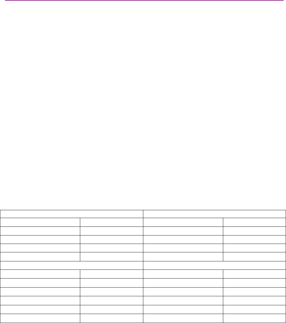
2.2.1: R Series Environmental Specifications
Environmental Condition Endurance Range MIL-STD 810F
Method
Other
Standards
Non-Operating -50ºC to 85ºC
Ambient
Temperature Operating -40ºC to 70ºC 501.4, 502.4
Thermal Shock Operating -40ºC to 70ºC in 1
minute
503.4
Non-Operating 95% non-condensing
at 60ºC
Relative Humidity Operating 95% non-condensing
at 60ºC
507.4
Vibration Operating 5 Hz to 500 Hz, up to
3.85 grms
514.5
(Figure 514.5C-2)
IEC 60068-2-6
Non-Operating -400 m to 12,200 m
Altitude Operating -400 m to 5,000 m 500.4
Crash Safety 75 gpeak acceleration
Shock Operating 40 gpeak acceleration 516.5 IEC 60068-2-27
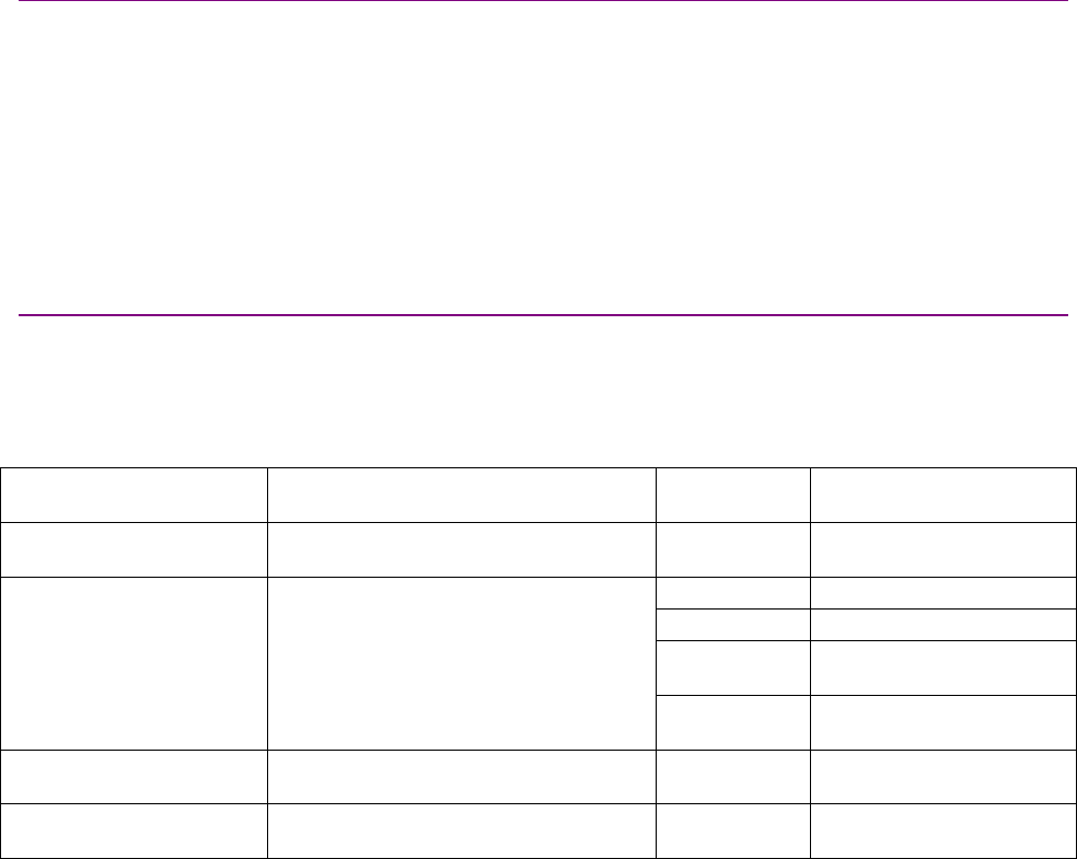
2.2.2: R Series Baseline Environmental Standards Conformance
Certain environmental endurance standards are highly relevant to extreme servo amplifier
applications. These include selected sections of MIL-STD 810F and IEC 60068. All R-Series servo
amplifiers have been qualified to the following baseline environmental standards. Conformance to
these standards has been verified through product testing at a certified, independent
environmental test lab.
Standard Description
MIL-STD 810F, 501.4 High Temperature
MIL-STD 810F, 502.4 Low Temperature
MIL-STD 810F, 503.4 Temperature Shock
MIL-STD 810F, 507.4 Humidity
MIL-STD 810F, 514.5
(Figure 514.5C-2)
IEC 60068-2-6
Vibration
MIL-STD 810F, 520.2 Temperature, Humidity, Vibration, and Altitude
MIL-STD 810F, 516.5
IEC 60068-2-27 Shock
The baseline standards are expected to cover the requirements in the vast majority of
applications. However, given the wide variety of potential applications for R-Series servo
amplifiers, it is not practical to anticipate and test to all environmental standards that customers
may require. In the event that conformance to other standards is required, please contact Copley
Controls.
Test data for specific R-Series models is available upon request.
Conformance Ruggedized Drives Standards Guide
14 Copley Controls Corp.
2.2.3: Environmental Standards Compliance: Third-Party Testing Overview
After in-house qualification testing and standard production floor testing, Copley R-Series
amplifiers are subject to rigorous enviornmental testing by a certified independent laboratory. The
third-party tests are performed on samples of each R-Series amplifier model in adherence to the
appropriate MIL-STD procedures as described in this section.
2.2.4: Extreme Temperature Conditions: Third-Party Test
High Temperature (Method 501.4)
Method 501.4 specifies the procedures for verifying the product for both storage at high
temperature (Procedure I) and operation at high temperature (Procedure II). The test method
allows for either a constant temperature test or a cyclic temperature test. The cyclic testing is
intended for applications where the item temperature is highly dependent on the time of day
(outdoors). The constant temperature testing is intended for applications where the item
temperature is mainly determined by local operating conditions (in an enclosure). Since servo
amplifiers are normally mounted within a vehicle or other enclosure, the constant temperature test
approach was selected for the R-Series amplifier testing.
Procedure I requires that the item under test be in a non-operating state and “soaked” at the
storage temperature extreme until the temperature of the item has remained stable at the extreme
for a minimum of 2 hours. Procedure II is similar to Procedure I except that the item under test is
run in a normal operating condition for the duration of the test.
Low Temperature (Method 502.4)
Method 502.4 specifies the procedures for verifying the product for storage at low temperature
(Procedure I), operation at low temperature (Procedure II) and manipulation at low temperature
(Procedure III). Procedure III is not applicable to servo amplifiers; it is applicable only to equipment
that is set-up/disassembled by personnel wearing cold-weather clothing.
Procedure I requires that the item under test be in a non-operating state and “soaked” at the
storage temperature extreme until the temperature of the item has remained stable at the extreme
for a duration as specified by the manufacturer’s test plan. Procedure II is similar to Procedure I
except that the item under test is run in a normal operating condition for the duration of the test.
Extreme Temperature Independent Test Description
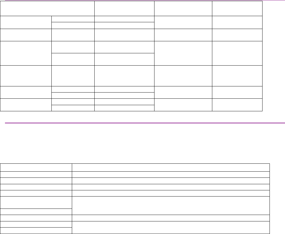
The following graph shows an actual temperature vs. time profile from the test lab report for the
Xenus R10-230-36-HS. Samples of each R-Series model undergo the same test.
Temp (degrees C, blue)
Time (hours)
Setpoint
Ruggedized Drives Standards Guide Conformance
Copley Controls Corp. 15
As described below, this profile covers all four of the required time/temperature test conditions
(low temperature storage, low temperature operation, high temperature storage, and high
temperature operation):
Low Temperature Storage:The test begins with the amplifier in a non-operating state at 25° C.
Within two hours, the temperature is lowered to -50° C, where it soaks for approximately 17 hours.
Low Temperature Operation:At hour 18, the temperature is raised to -40° C and power is
applied to the amplifier. The amplifier is enabled and used to drive a motor at -40° C for
approximately 6 hours. Power is then removed from the amplifier and the temperature is raised to
85° C.
High Temperature Storage:With the amplifier still un-powered, the temperature is stabilized at
85° C for approximately 17 hours.
High Temperature Operation:At approximately hour 44 the chamber setpoint temperature is
reduced to 70° C. Once the amplifier temperature stabilizes, power is restored and the amplifier is
enabled and used to continuously drive a motor for approximately six hours. The temperature is
lowered to base temperature (25° C) over a period of approximately an hour, and operated for
another two hours at 25° C, thus completing the test.
Conformance Ruggedized Drives Standards Guide
16 Copley Controls Corp.
2.2.5: Temperature Shock (Method 503.4): Third-Party Test
Temperature shock testing determines whether a product can withstand sudden changes of
ambient temperature without experiencing physical damage or deterioration in performance. This
type of testing simulates the rapid temperature changes that can occur during shipping and
handling. One example of temperature shock described in MIL-STD-810F is the temperature
change experienced by equipment when it is dropped from an aircraft at high altitude/low
temperature. Since equipment is typically un-powered during shipping and handling, temperature
shock testing is performed with the product in a non-operational state.
Method 503.4 contains two different procedures for performing temperature shock testing.
Procedure I is referred to as “steady-state” since it calls for the ambient temperature to be
alternated between two temperature extremes. Procedure II is referred to as “cyclic” and calls for
acareful simulation of the real environment a given product is expected to experience.
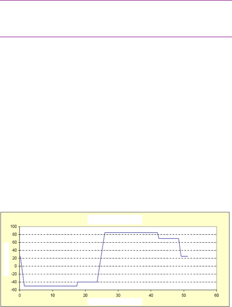
Procedure I testing is considered to be the most severe. Copley’s R-Series products are tested
using Procedure I. All R-Series amplifiers are tested against a time/temperature profile like the
actual test sample depicted in the following chart.
Temp (degrees C, blue)
Time (hours)
Setpoint
This profile can be described by the following sequence of phases:
Initialization:The Procedure I testing is initiated by raising the product temperature to 70° C.
High temperature soak:The amplifier is soaked at 70° C for approximately an hour.
Rapid drop to low temperature:Once the product temperature is stabilized at 70° C (fully
soaked), the temperature is rapidly reduced to the low temperature extreme (-40° C). As per
Method 503.4 Procedure I, the complete 70° C to -40° C temperature excursion takes place in one
minute or less.
Low temperature soak:The amplifier is then soaked at -40° C for approximately an hour.
Rapid rise to high temperature:Once the product temperature is stabilized at -40° C (fully
soaked), the temperature is rapidly increased to the high temperature extreme (70° C). As per
Method 503.4 Procedure I, the complete temperature excursion takes place in one minute or less.
This high-low-high temperature cycle is repeated nine times to expose the amplifier to a total of
ten temperature shock cycles.
Ruggedized Drives Standards Guide Conformance
Copley Controls Corp. 17
2.2.6: Humid Environment (Method 507.4): Third-Party Test
The purpose of humidity testing is to determine the resistance of the product to the effects of a
warm, humid operating environment. According to MIL-STD-810F, Method 507.4 does not
“attempt to duplicate the complex temperature/humidity environment.” Rather, it provides a
“generally stressful situation that is intended to reveal potential problem areas” of the equipment
being tested. The standard calls for a minimum of five 48-hour temperature/humidity cycles. This
requirement is based on data indicating that testing lasting 10 days or more is adequate to reveal
potential problems in the equipment under test.
The standard also specifies extreme conditions of 95% relative humidity (RH) and 60° C. Although
this combination of conditions does not occur in nature, “these levels of temperature and relative
humidity have historically provided an indication of potential problem areas” in the equipment
being tested.
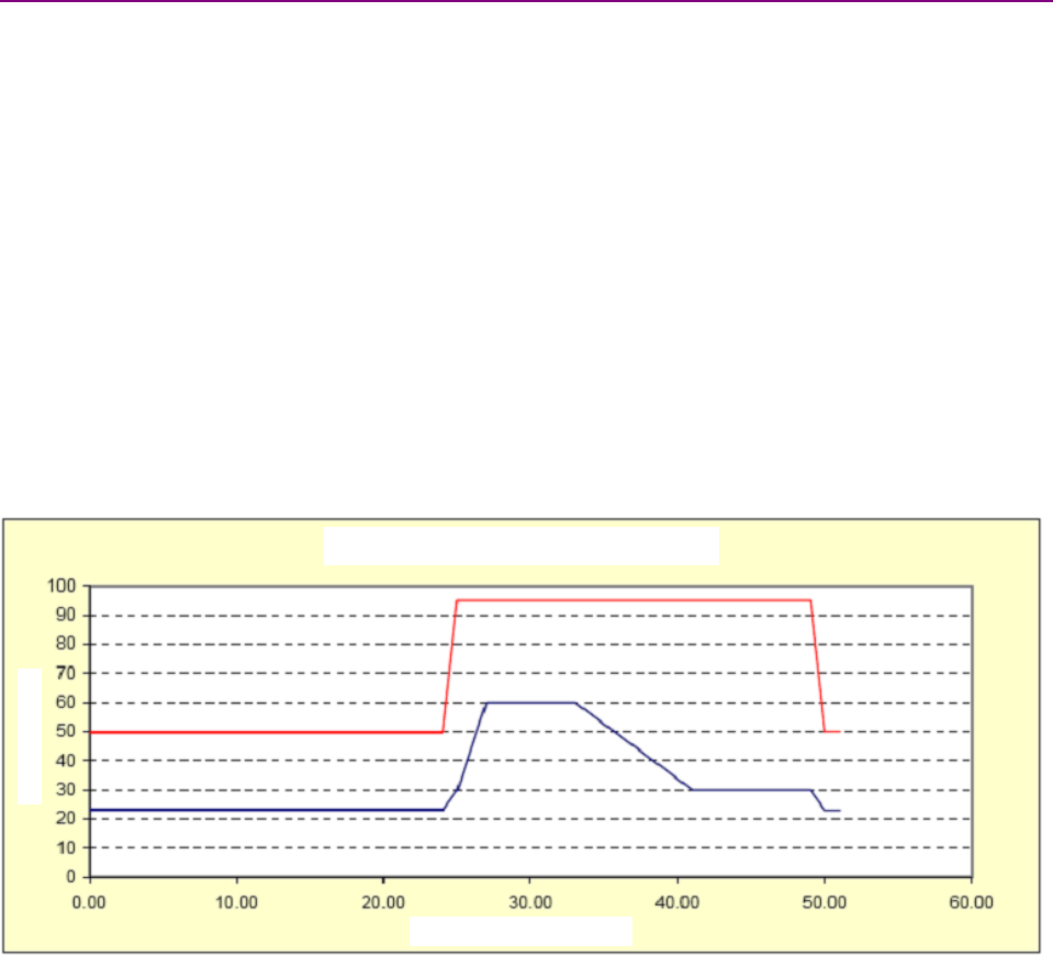
The following chart shows the time/temperature/humidity profile that the Copley R-Series
amplifiers are subjected to during the humid environment testing. The amplifier under test is
powered and controlling a motor for the duration of the test. This profile shows the 24-hour
initialization followed by the first of nine 27-hour temperature/humidity cycles. Note that the
amplifier under test is subjected to the extreme 60° C/95% RH operating point for approximately
eight hours out of every 27-hour cycle.
Temp (degrees C, blue), Humidity (% RH, red)
Time (hours)
Setpoint
Conformance Ruggedized Drives Standards Guide
18 Copley Controls Corp.
2.2.7: Altitude (Methods 500.4 and 520.2): Third-Party Test
Altitude testing on the Copley R-Series amplifiers is performed in accordance with Method 500.4
of MIL-STD-810F, but also with some guidance from Method 520.2. The primary concerns of
altitude on motor drive amplifiers and similar equipment are overheating due to reduced heat
transfer and malfunction due to arcing or corona.
The purpose of the altitude testing is to verify that the Copley R-Series amplifiers can withstand
and/or operate in low pressure (high altitude) environments without overheating or malfunction
due to arcing.
Method 500.4 deals strictly with altitude whereas Method 520.2 considers the combined effects of
temperature, humidity, vibration, and altitude. For the Copley R-Series testing, temperature is
varied along with altitude (pressure) since changes in temperature almost always coincide with
changes in altitude.
Method 500.4 Procedure I simulates air transport/storage conditions and is a non-operating test.
Procedure II is an operational test and is limited to altitudes encountered in typical applications for
Copley R-Series amplifiers.
Storage (Non-Operating) Altitude Test
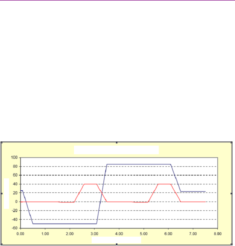
The following graph shows the time/altitude/temperature profile used for the non-operating storage
test. Note that the altitude is varied between -400 m (-1300 ft) and 12,200 m (40,000 ft) and that
the temperature is varied over the full rated storage temperature range (-50° C to +85° C). Note
too that the altitude and temperature are cycled such that the altitude extremes are reached
during both the high and low temperature excursions.
Temp (degrees C, blue), Altitude (K Ft, red)
Time (hours)
Setpoint
Ruggedized Drives Standards Guide Conformance
Copley Controls Corp. 19
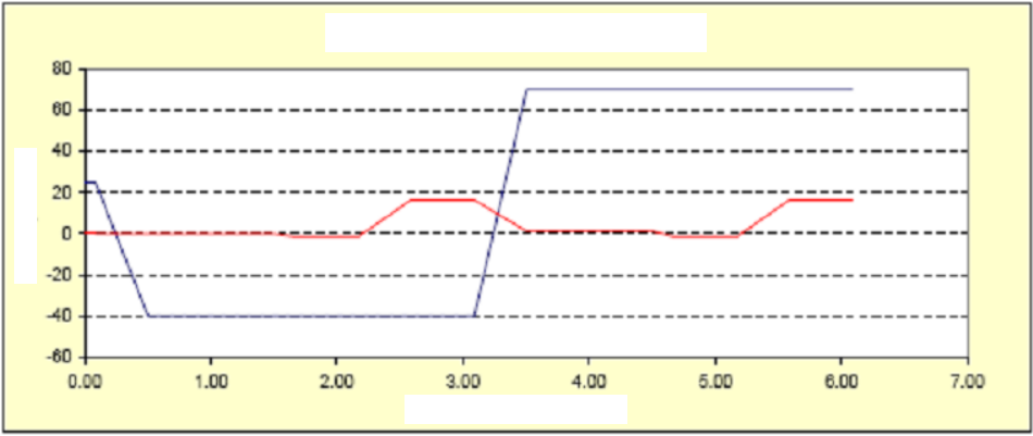
Operational Altitude Test
The next graph shows the time/altitude/temperature profile for the operational altitude test
(Procedure II). The altitude is varied between -400 m (-1300ft) and 5000 m (16,400 ft) and the
temperature is cycled over the full rated operating temperature range (-40° C to 70° C). As with
the storage test, altitude and temperature are varied so that the altitude extremes are reached
during both the high and low temperature excursions.
Temp (degrees C, blue), Altitude (K Ft, red)
Time (hours)
Setpoint
Conformance Ruggedized Drives Standards Guide
20 Copley Controls Corp.
2.2.8: Random Vibration Testing (Figure 514.5C-2): Third-Party Test
According to MIL-STD-810F, vibration testing is intended to verify that the device under test will
function in and withstand the vibration exposures of a life cycle. The section in MIL-STD-810F
concerning vibration testing is extensive, in part because it addresses a wide variety of end use
applications.
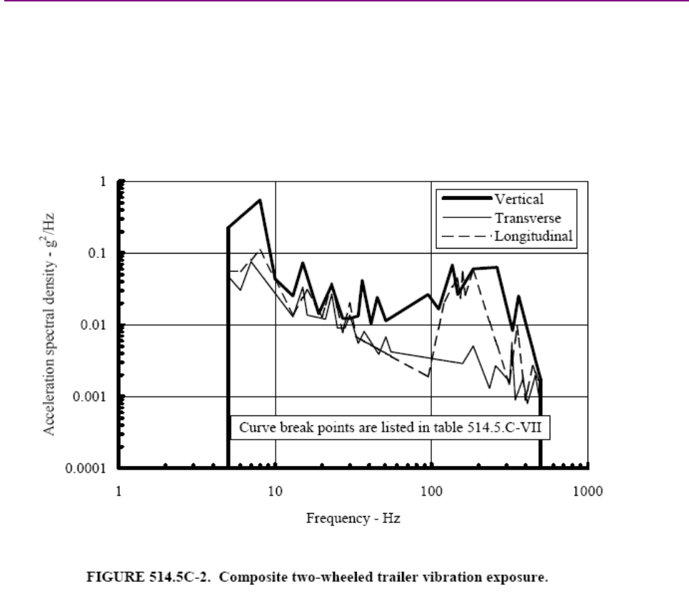
For the purposes of baseline product testing, Copley R-Series amplifiers are vibration-tested to the
random vibration profile given in MIL-STD-810F Fig. 514.5C-2. This profile applies to equipment
installed in ground vehicles. Figure 514.5C-2 is shown here for reference:
Random vibration, as opposed to sinusoidal vibration, is used in ground-based vehicle testing
because the vibrations induced by the road/terrain are not regular or periodic. For this testing the
R-Series amplifiers are mounted on a vibration table and subjected to the reference random
vibration profile for one hour on each axis. The amplifiers are fully operational during the test and
are continuously monitored to ensure they operate normally and without any faults for the duration
of the test.
Note that the amplifier under test is exposed to frequencies in the range from 5 Hz up to 500 Hz.
The net RMS acceleration defined by the vibration exposure curve (514.5C-2) is different for each
axis of vibration. For the complete 5 Hz to 500 Hz range, the net RMS acceleration is 3.85 grms,
1.28 grms and 2.40 grms for the vertical, transverse and longitudinal axes respectively. At the
completion of testing, all of the test amplifiers are disassembled and inspected to verify that no
damage or excessive wear has occurred.
Ruggedized Drives Standards Guide Conformance
Copley Controls Corp. 21
2.2.9: Shock (Method 516.5 and IEC 60068-2-27): Third-Party Test
According to MIL-STD-810F shock testing is performed to “provide a degree of confidence that
materiel can physically and functionally withstand the relatively infrequent, non-repetitive shocks
encountered in handling, transportation and service environments.” Method 516.5 covers all
aspects of mechanical shock testing. Copley R-Series amplifiers are shock tested using
Procedures I and V of Method 516.5.
Procedure I addresses functional shock. It covers mechanical shock events that can occur during
normal operation. The amplifier is expected to function normally before, during, and after these
shock events.
Procedure V is concerned with ensuring that materiel mounted inside of a vehicle does not break
loose from its mounts as a result of the high shock levels encountered during a vehicle crash. The
equipment under test does not have to functionally survive the crash event, but it must remain
safely mounted as originally installed.
Table 516.5-1 and Fig. 516.5-8 of method 516.5 specify both the functional and crash safety
shock levels for ground equipment.
For Procedure I functional shock testing, the R-Series amplifiers are mounted to a vibration table
and subjected to mechanical shock events affecting all three axes. During functional shock
testing, the amplifiers are fully functional (driving a motor) and are monitored continuously to
ensure proper operation throughout the test. Following functional shock testing, the amplifiers are
subjected to a full functional test and are then disassembled and inspected to ensure that no
damage or excessive wear has occurred.
Procedure V crash safety shock testing is performed only after successful Procedure I functional
shock testing. The crash shock test method is the same as for functional shock except that the
acceleration levels are much higher (75 g vs. 40 g).
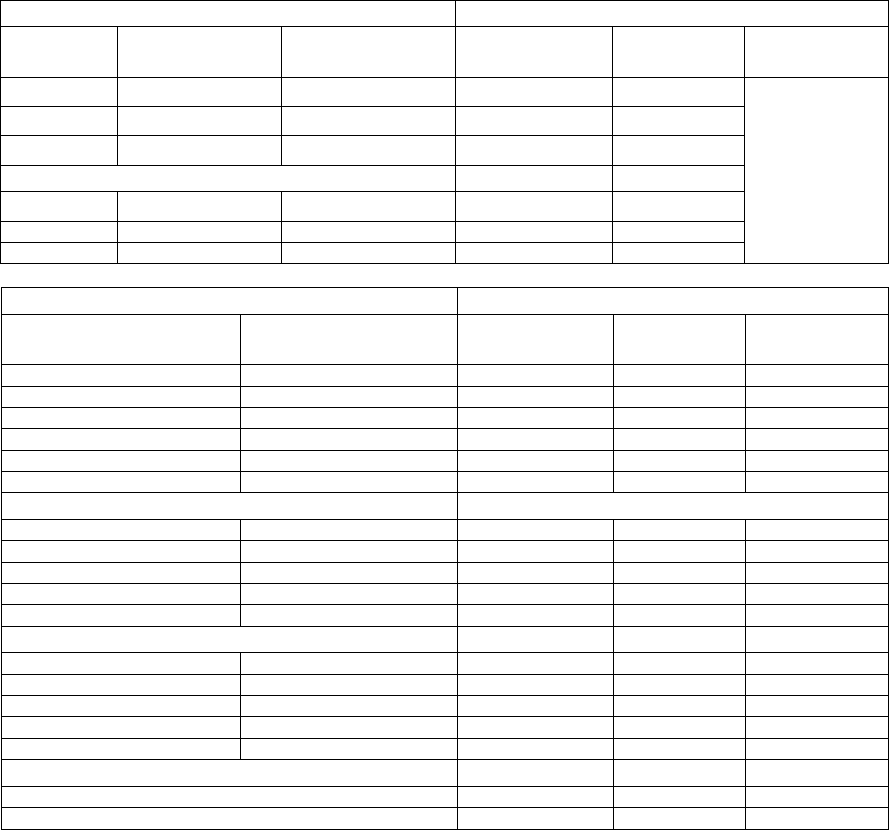
The following tables, from an Xenus R10 test report, show the crash shock levels along with a
record of the number and direction of shock pulses applied. Samples of each R-Series model
undergo the same test.
Functional Shock Crash Safety Shock
Frequency (Hz) G’s Frequency (Hz) G’s
10 9 10 9
45 40 80 75
2000 40 2000 75
#of Pulses Per Direction 3#of Pulses Per Direction 3
#of Axes 3#of Axes 3
Total # of Pulses 18 Total # of Pulses 12
Control Accel Location 1on fixture Control Accel Location 1on fixture
Response Accel 1 Location N/A Response Accel 1 Location N/A
Response Accel 2 Location N/A Response Accel 2 Location N/A
Response Accel 3 Location N/A Response Accel 3 Location N/A
The objective of the Procedure V crash safety shock testing is to ensure that the equipment under
test does not break loose from its mounting and thus create a safety hazard. The equipment does
not have to function following the test. Following the crash shock testing, the amplifiers are
disassembled and inspected for damage and wear.
It is worth noting that most of the Copley R-Series amplifiers survived the Procedure V crash
shock testing without damage or loss of function following the test.
Conformance Ruggedized Drives Standards Guide
22 Copley Controls Corp.
2.3: Safety
Copley’s R-Series amplifiers are reviewed and tested for conformance to the appropriate safety
standards for the purpose of CE marking and UL recognition. EN 61010-1 is an international
standard that specifies the “safety requirements for electrical equipment for measurement, control
and laboratory use.” UL508C is a UL standard for safety that specifically addresses power
conversion equipment. Conformance to both of these standards is verified through a
constructional review and laboratory testing performed and/or witnessed by UL engineers. Key
aspects of the constructional review and testing are as follows:
•Verification that critical components have the appropriate agency approvals and/or are
constructed in such a way to prevent electric shock and fire hazards.
•Verification that the spacing (creepage and clearance) between high voltage and low voltage
circuits meets the requirements given in the standards
•Temperature Test: The purpose of this test is to verify that the temperature of PCB mounted
components does not exceed the printed circuit board rating under worst case amplifier
loading conditions. For the R-Series amplifiers, this test is conducted at the 70° C maximum
rated operating temperature.
•Abnormal Test: The purpose of this test is to verify that electric shock and fire hazards do not
result from the failure of critical components. Failures are intentionally induced in one critical
component at a time. Components are either shorted or open circuited – whichever failure
mode is most likely to result in a hazard.
•Hi-pot Testing: This testing typically applies only to AC powered amplifier models (like the R10
and R11). Following the temperature and abnormal testing, a hi-pot test voltage is applied
between AC line connected circuits and low voltage circuits (including the chassis) to verify the
integrity of electrical safety isolation.
•Overload and Short Circuit Testing: This testing verifies that the amplifier’s overload and short
circuit functions operate effectively. Specifically, the test engineer induces an overload and/or
short circuit condition at the amplifier output and confirms that an electric shock or fire hazard
does not result.
In addition to the aforementioned safety standards, some R-Series customers have inquired about
conformance to IEC 60079-15. This standard addresses the construction, test and marking of
type “n” electrical apparatus for explosive gas atmospheres. Using design guidance from
engineers at a certified, independent laboratory and safety consulting firm, most of the Copley
R-Series amplifiers have been designed with the intent to meet IEC 60079-15. A key R-Series
design feature relevant to IEC 60079-15 is the use of conformal coated circuit board assemblies.
IEC 60079-15 is tailored toward the prevention of sparks and arcing in electrical apparatus.
Conformal coating as specified in section 6.7.3 of the standard provides a protective insulating
layer and thus reduces the chance of sparks and arcs occurring on a given circuit board.
Formal confirmation and declaration of conformance to IEC 60079-15 for R-Series amplifiers
(other than the R10) would require testing by an independent Notified Body organization. Please
contact Copley Controls in the event that a formal declaration of conformance is required. Note
that the Xenus R10 amplifiers do not meet the IEC 60079-15 requirements.
Ruggedized Drives Standards Guide Conformance
Copley Controls Corp. 23
2.4: Electromagnetic Compatibility (EMC)
The R-Series amplifiers are tested by a certified third-party EMC test house for conformance to
international standards concerning EMC for both emissions and immunity. Standard EN
55011:1998 addresses the limits for radio frequency interference for industrial, scientific and
medical equipment. Standard EN 61000-6-1:2001 covers the immunity requirements for electrical
equipment.
The R-Series amplifiers (R23 excluded) have been designed with features to enhance their EMI
performance, especially with regards to electromagnetic field susceptibility.
The plastic covers on the R-Series amplifiers are coated with a specialty silver/copper coating.
This coating, in conjunction with EMI gasketing at the cover/chassis interface and the aluminum
amplifier chassis, serves to form an electrically conductive shell around the amplifier circuit
boards. This conductive shell acts as a faraday shield to greatly reduce the strength of external
electromagnetic fields that could otherwise cause board-mounted electronics to malfunction.
In general, the R-Series amplifiers do not meet all of the detailed requirements of MIL-STD-461E
“out of the box.” Although the enhanced EMI features designed into the R-Series provide a
measurable benefit, several of the MIL-STD-461E detailed requirements are much more stringent
that the commercial standards. In these applications, the R-Series amplifier would require
additional enclosure, components, and/or shielding to achieve conformance to MIL-STD-461E.
MIL-STD-461E conformance is very application-specific. Not all of the standard’s detailed
specifications are required in every application. Contact Copley for assistance with using R-Series
amplifiers in applications requiring conformance to MIL-STD-461E.
Conformance Ruggedized Drives Standards Guide
24 Copley Controls Corp.
2.5: Application Support
2.5.1: Copley Application Design Support
The importance of supplier technical support in ensuring that projects are completed on time and
on budget cannot be overstated. This is especially true for rugged applications. Copley has over
25 years experience in the manufacture of innovative and reliable servos and power systems. We
have a very responsive R&D and applications team. These motion control and power experts
stand ready to support R-Series deployments.
The R-Series technical data sheets and design guides provide the level of detail needed to
design-in the amplifier. The technical data sheets contain detailed information on thermal
management and mounting to ensure proper operation at temperature extremes and in high
shock/vibration environments.
2.5.2: Application-Specific Electrical Standards
There is a wide variety of application-specific electrical standards relating to the types of military
and harsh environment equipment for which R-Series amplifiers are intended. The R-Series family
of amplifiers covers a range of input voltage levels and types (AC or DC). The following table is a
design guide that lists a number of these application-specific electrical standards and identifies
which R-Series amplifiers are most applicable to the given standard.
MIL-STD Description Primary
Voltage
Suggested R-Series
Amplifiers
MIL-STD-1275D Characteristics of 28 Volt DC Electrical
Systems in Military Vehicles
28Vdc R20, R21, R22, R23
28Vdc R20, R21, R2, R23
270Vdc R10, R11
115/200VAC,
400Hz
R10, R11
MIL-STD-704F Aircraft Electric Power Characteristics
115VAC,
60Hz
R10, R11
MIL-STD-1399 Section 300A, Electric Power, Alternating
Current
115VAC,
60Hz
R10, R11
MIL-STD-1399 Section 390, Electric Power, Direct
Current for Submarines
155Vdc R10, R11, R20-180,
R22-180
The preceding table is a set of application guidelines based on a careful review of R-Series
electrical designs against the standards requirements. If formal testing to these application-
specific electrical standards is needed, contact Copley Controls.
Ruggedized Drives Standards Guide Conformance
Copley Controls Corp. 25
MIL-STD-1275D
MIL-STD-1275D “covers the limits of steady state and transient voltage characteristics” of the 28
Vdc supply found in military vehicles. Based on careful review of R-Series electrical designs
against the 1275D requirements, Copley’s DC powered R-Series amplifiers are generally suitable
for systems requiring MIL-STD-1275D conformance.
There are some aspects of this standard that may require the addition of system level components
(external to the amplifier) in order to achieve conformance. They include starting disturbance and
ESD protection.
Starting Disturbance: The first aspect of the MIL-STD-1275D standards that may require the
addition of system level components is the set of starting disturbance characteristics described in
Fig. 4 of the standard. The starting disturbances are undervoltage variations caused by engine
starting and cranking. During the “initial engagement surge” the DC voltage drops down as low as
6 V and then recovers exponentially to 16 V over a one-second time period. Depending on how
the R-Series amplifier is used in the system, the amplifier will likely continue to operate through
this initial one-second time period. However, the amplifier’s ability to maintain control of
current/velocity/position will be compromised because of the reduced DC supply voltage.
Once the voltage has recovered to 16 V, it can remain at that level for up to 30 seconds (engine
cranking). With the exception of the model R23 amplifiers, the DC powered R-Series amplifiers
(R20, R21 and R22) are specified for steady state operation down to 20 V (the R23 amplifiers are
specified down to 14 V). At levels below 20 V, the standard R20, R21 and R22 amplifiers go into
an undervoltage fault condition. If operation below 20 V is required, please contact Copley
Controls.
ESD Protection: The second aspect of the MIL-STD-1275D standards that may require the
addition of system level components is the ESD (electrostatic discharge) requirement. The
standard specifies ESD conformance to the SAE J1113-13 automotive standard. All of the
R-Series amplifier designs have been qualified and tested to the ESD requirements of EN
61000-4-2, but the SAE standard is more severe. Depending on the system design, surge
suppression components on the amplifier signal level inputs and outputs may be required to meet
the SAE ESD levels.
Conformance Ruggedized Drives Standards Guide
26 Copley Controls Corp.
MIL-STD-704F
The aircraft electric power standard 704F addresses the five different power supply types found in
aircraft applications (three AC power supply types and two DC). The most common AC type is
115/200 Vac at 400Hz. The other two AC types are variable frequency (360 Hz to 800 Hz)
115/200 Vac and 115 Vac single phase, 60 Hz, which is intended for use only in support of COTS
equipment. These AC supplies are generally suitable for the R10 and R11 Xenus amplifiers under
“normal” operating conditions. However, there are two potential issues relating to these AC supply
voltages as defined in MIL-STD-704F.
The first issue is power factor: Paragraph 5.4.3 of the standard specifies that “power factor of AC
equipment greater than 500 VA shall be between 0.85 lagging and unity when operating at 50
percent or more of its rated load current in steady state condition.” The power factor for the R10
and R11 models is typically about 0.70 lagging. These amplifiers convert the incoming AC to DC
with a diode rectifier and capacitor bank, which accounts for the relatively low power factor.
Depending on loading, the R10 and R11 amplifiers may or may not meet the power factor
requirement as specified in the standard.
The second issue is leakage current. Leakage current is the current that flows from the incoming
AC line(s) to the chassis. The most common path for leakage current is through the EMI
suppression capacitors inside the equipment. These are connected between the AC line inputs
and chassis ground. The amount of leakage current depends on the AC input voltage and
frequency as well as the “wye” connected EMI capacitance. Some systems specify an upper limit
on the amount of leakage current for safety reasons. The user should compare the leakage
current requirements for each application with leakage current specifications published in the
amplifier data sheets.
The two DC supply types specified in the MIL-STD-704F requirements are 28 Vdc and 270 Vdc.
The 28 Vdc supply described in the standard is suitable for the powering the DC powered R-series
amplifiers (R20 through R23). However, none of the DC R-series amplifiers are rated for operation
from 270 Vdc. The maximum input voltage rating for the DC amplifier family is 180 Vdc.
Therefore, the only R-series drives capable of operating from 270 Vdc are the R10 and R11.
Although the R10 and R11 are normally considered for operation from AC input power, they can
be run from DC as well.
MIL-STD-704F defines a number of different operating conditions under which the power supply
characteristics differ from “normal.” Within the standard, the aircraft electric power characteristics
are specified for “Abnormal,” “Transfer,” “Emergency,” and “Starting” operating conditions. Some
of the transient voltage levels that occur in these non-normal operating conditions are outside of
the R-series ampliifier ratings. Depending on the magnitude and duration of these transients, the
R-series amplifiers may shut down due to overvoltage/undervoltage faults or may power down
completely. In sections 4.2.2.2 through 4.2.2.5, MIL-STD-704F requires that the “utilization
equipment shall provide the level of performance specified in its detail specification” in these non-
normal operating conditions. Thus, the suitabilty of a given R-series amplifier for an aircraft electric
power application depends on the requirements of the particular application and is not solely
determined by MIL-STD-704F.
Ruggedized Drives Standards Guide Conformance
Copley Controls Corp. 27
MIL-STD-1399 (Navy) Section 300A, Electric Power, Alternating Current
Section 300A of MIL-STD-1399 specifies several different types of AC electric power, but the
standard indicates a preference that most shipboard equipment operate from Type I 60 Hz power.
Type I power is available at both 440 Vac and 115 Vac levels, single-phase or three-phase, and is
ungrounded. Type I, 115 Vac power is suitable for operating the Copley R10 and R11 R-series
drives.
Unlike some of the other standards, MIL-STD-1399 Section 300A requires detailed testing to verify
conformance. Tests include the Voltage Spike Test (paragraph 5.3.3), the Emergency Condition
Test (paragraph 5.3.4), and the Current Waveform Test (paragraph 5.3.7). Due to the number and
extent of the required tests, full compliance testing to this standard typically takes 4-5 days of test
time at certified test facility. Although the R10 and R11 drives have not been tested to this
standard, we have reviewed the drive designs against the requirements.
The test methods and levels required in the Voltage Spike Test are quite similar to those in EN
61000-6-1:2001. The R10 and R11 have been tested to EM 61000-6-1:2001 for the purposes of
CE marking and thus they would be expected to pass the Voltage Spike Test. Other MIL-STD-
1399 Section 300A requirements and tests impose restrictions on power factor, in-rush current,
and current harmonics.
As mentioned in the MIL-STD-704F discussion, the R10 and R11 amplifiers convert the incoming
AC to DC with a diode rectifier and capacitor bank. The resulting power factor is typically about 0.7
lagging but depends on amplifier loading and whether the amplifier is powered from 3-phase or
single-phase. The MIL-STD-1399, low end requirement on power factor is 0.8 lagging, so this
could be an issue in some applications.The drives employ in-rush current limiting and as a result
should meet the requirements specified in Fig. 14 of the standard. The diode rectifier and PWM
action of the R10 and R11 also contribute to the harmonic content of the current drawn from the
AC supply. Compliance to the current harmonic requirements is difficult to determine analytically,
but some applications may require conditioning circuits between the AC supply and the amplifier to
meet the specifications given in the standard.
Conformance Ruggedized Drives Standards Guide
28 Copley Controls Corp.
MIL-STD-1399 (Navy) Section 390, Electric Power, Direct Current for Submarines
The 1399 standard specifically addresses the requirements for equipment operating from a 155
Vdc supply on submarines. This standard imposes more requirements than its AC counterpart
(Section 300A) in that it incorporates many aspects of MIL-STD-461E for EMC and specifically
requires conformance testing, a systems analysis and equipment schematics. Paragraph 6.1
makes note that the standard “does not prohibit the use of 60Hz power” as specified in Section
300A. This suggests that the use of Type I power is preferred over Section 390 DC power as well
as the other power types specified in Section 300A of MIL-STD-1399.
The model R10 and R11 R-series amplifiers as well as the 180V rated R20 and R22 models are
suitable for use with MIL-STD-1399 Section 390 power. There are several specification areas that
should be considered when deploying R-series amplifiers in a Section 390 system. The first area
consists of the EMC and ripple current requirements listed in paragraphs 5.3.1 and 5.3.2 . These
paragraphs impose aspects of MIL-STD-461E and as such additional components, enclosures,
and shields may be necessary to meet the requirements. Refer to the discussion on MIL-STD-
461E in Electromagnetic Compatibility (EMC) (p. 23).
Paragraph 5.3.8 specifies that “user equipment 155-Vdc input terminals shall be isolated from all
user equipment loads such as power conversion equipment outputs.” To maximize efficiency and
minimize size and cost, the R-series drives do not provide electrical isolation between the primary
power inputs and the motor power outputs. This motor drive architecture is widely accepted in the
industry. We believe that paragraph 5.3.8 is intended for DC/DC power supplies and is not
applicable to motor drives.
Paragraph 5.3.9.1 specifies that “user equipment requiring protection from polarity reversal shall
be internally protected from improper connection at any point in the system.” The primary power
connections for the R10 and R11 amplifiers do not have a polarity requirement, because these
models can be powered from AC as well as DC. The R20-180 and R22-180 models accept DC
power only and they do not have internal reverse polarity protection. Reverse polarity protection
would have to be employed external to the amplifier, but internal to the “user equipment” of which
the drive is a part.
2.6: Summary
Although the range of standards covered in the R-Series qualification testing is quite extensive,
Copley Controls recognizes that some applications may require qualification testing to additional
standards. Because of this we expect to add to the list of standards over time as
application-specific needs are addressed. If conformance to other standards is required, please
contact Copley Controls for the latest information or to inquire about working with us to qualify the
R-Series to other standards.
Ruggedized Drives Standards Guide Conformance
Copley Controls Corp. 29