ACM1 7 Installation And Op Manual 8 26 02 Sc 2k_manual 2k
User Manual: sc-2k_manual
Open the PDF directly: View PDF ![]() .
.
Page Count: 16
SC-2K
2000 lb Capacity
Lawnmower Storage Lift
INSTALLATION MANUAL
& OPERATING INSTRUCTIONS
REV A-081613

2,000 LB.
SINGLE COLUMN
STORAGE LIFT
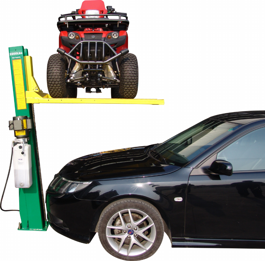
A 2,000 lb. capacity single column storage lift. Create extra space
in your garage for lawn mower, motorcycle, snow-mobile
or anything else you want to get out of the way.
Features:
✦Takes up a minimum
of space. Offers a
maximum of storage
✦Park front of car
under platform for full
use of garage space
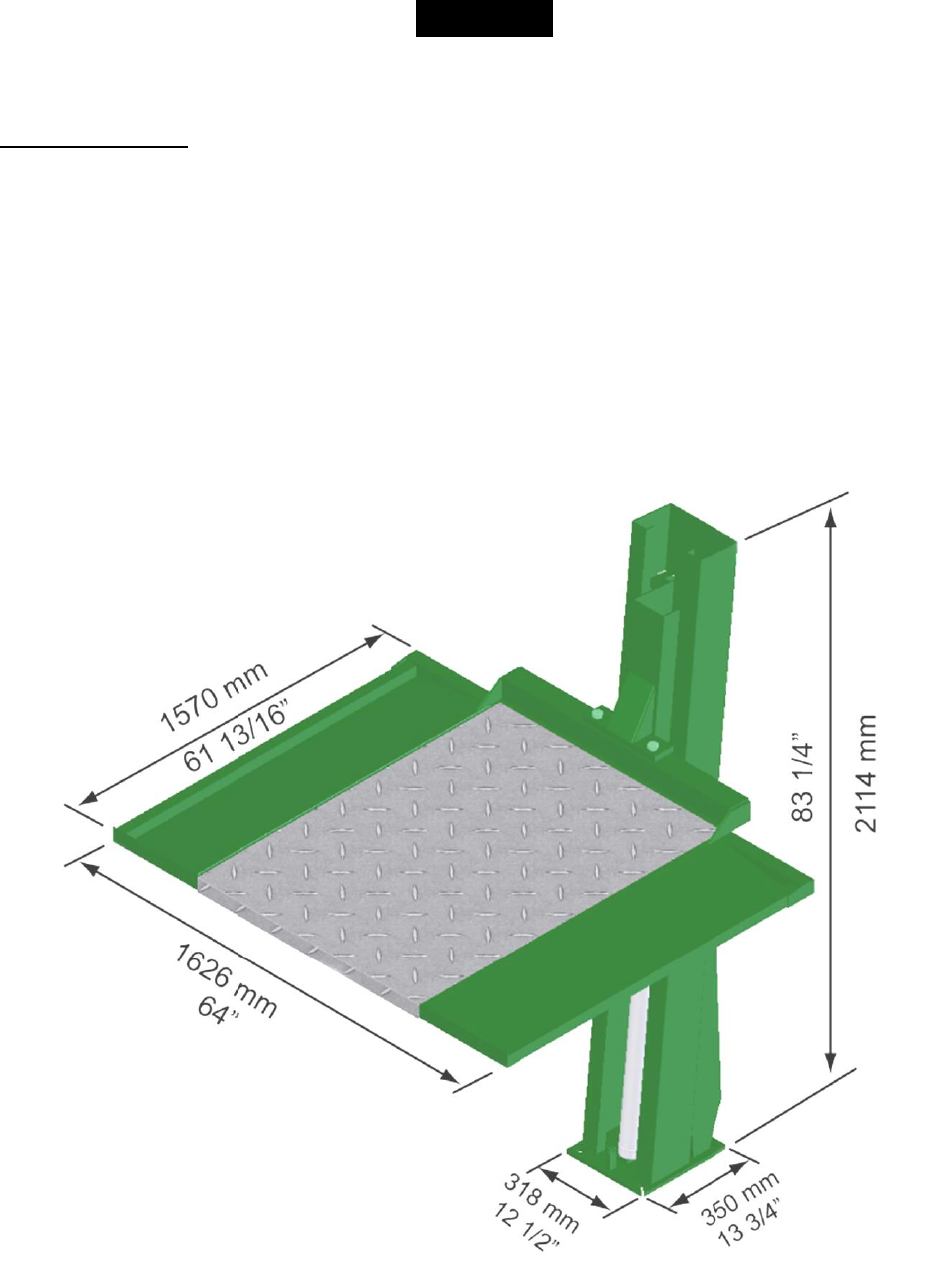
✦Platform dimensions
61” x 64”
✦58” of clearance
under platform
✦Column height 83 1⁄2”
✦Runs on regular 110 vac
✦Optional wheel vise
available
SPECIFICATIONS SC-2K
Capacity 2,000 lbs.
Lifting height
57 7⁄8”
Low height 2 1⁄8”
Table dimensions 65 3⁄8” - 53 5⁄8”
Column height 83 1⁄2”
Power unit 110vac 1phs
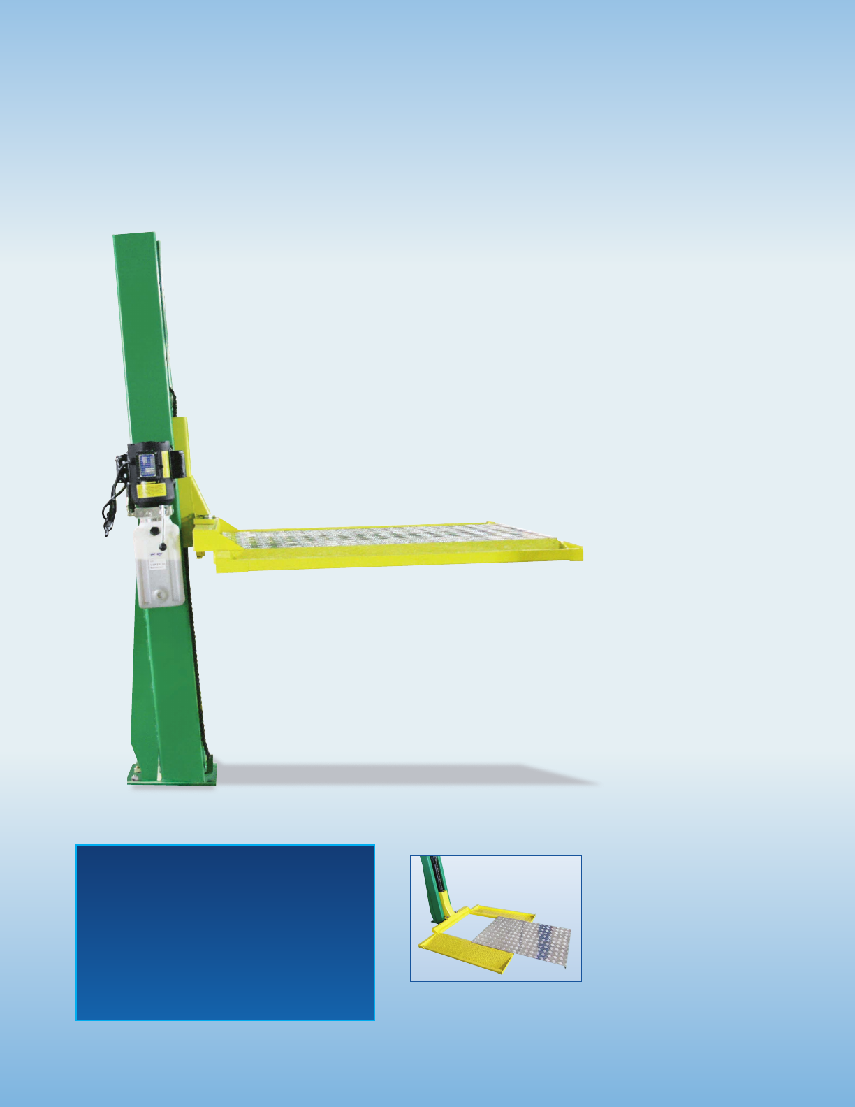
SC-2K
Single column
Storage lift
Removable aluminum platform for
under vehicle access

1905 N Main St Suite C, Cleburne, TX 76033
Ph 817-558-9337 Fax 817-558-9740
TUXEDO DISTRIBUTORS LIMITED WARRANTY
Structural Warranty:
The following parts and structural components carry a five year warranty:
Columns Top Rail Beam Uprights Arms Swivel Pins
Legs Carriages Tracks Overhead Beam Cross Rails
Limited One-Year Warranty:
Tuxedo Distributors, LLC (“Tuxedo”) offers a limited one-year warranty to the original purchaser of
Tuxedo lifts and Wheel Service in the United States and Canada. Tuxedo will replace, without charge, any
part found defective in materials or workmanship under normal use, for a period of one year after purchase.
The purchaser is responsible for all shipping charges. This warranty does not apply to equipment that has
been improperly installed or altered or that has not been operated or maintained according to specifications.
Other Limitations:
This warranty does not cover:
1. Parts needed for normal maintenance
2. Wear parts, including but not limited to cables, slider blocks, chains, rubber pads and pulleys
3. Replacement of lift and tire changer cylinders after the first 30 days. A seal kit and installation
instructions will be sent for repairs thereafter.
4. On-site labor
Upon receipt, the customer must visually inspect the equipment for any potential freight damage before
signing clear on the shipping receipt. Freight damage is not considered a warranty issue and therefore must
be noted for any potential recovery with the shipping company.
The customer is required to notify Tuxedo of any missing parts within 72 hours. Timely notification must
be received to be covered under warranty.
Tuxedo will replace any defective part under warranty at no charge as soon as such parts become available
from the manufacturer. No guarantee is given as to the immediate availability of replacement parts.
Tuxedo reserves the right to make improvements and/or design changes to its lifts without any obligation
to previously sold, assembled or fabricated equipment.
There is no other express warranty on the Tuxedo lifts and this warranty is exclusive of and in lieu of all
other warranties, expressed or implied, including all warranties of merchantability and fitness for a
particular purpose.
To the fullest extent allowed by law, Tuxedo shall not be liable for loss of use, cost of cover, lost profits,
inconvenience, lost time, commercial loss or other incidental or consequential damages.
This Limited Warranty is granted to the original purchaser only and is not transferable or
assignable.
Some states do not allow exclusion or limitation of consequential damages or how long an
implied warranty lasts, so the above limitations and exclusions may not apply. This warranty
gives you specific legal rights and you may have other rights, which may vary from state to state.
2
Important!
Be sure to read the operating instructions before operating your lift!
Getting Ready
Make sure you have made all necessary measurements to assure that your lift will fit in your garage
and accommodate the lawnmower you intend to store. Make sure you have enough clearance at the
top, and enough width to allow walking around. It is useful to chalk the outlines of the lift on your
garage floor, using the manufacturer’s dimensions to see how the lift will fit. Knowing where the
lift will sit will help you to place the lift column, which is the first step in the assembly process, and
will help to determine the location of the 110 volt receptacle that is required to operate this lift. The
circuit requirement is 110 volt, single phase, 15 amp. Seek advice from a qualified electrician on
receptacle and plug configurations, if necessary.
Fig. 1 Overall Lift Dimensions
REV A-081613
3
Description
Lifting Capacity
2000lbs (900Kg)
Min. height
4” (100mm)
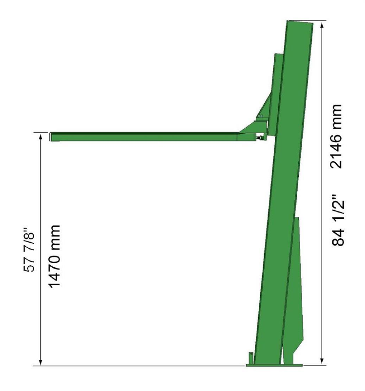
Max. Lifting Height
57.9” (1470mm)
Column Height
85.2” (2164mm)
Power Supply
110V, Single phase, 15Amp
Fig.2 Height Dimensions
Make sure you have someone to help you. The pieces of this lift are large, heavy, and cumbersome.
The lift column weighs about 332 pounds by itself. Lifting frame weighs a couple of hundred
pounds also. It is possible for two people to install this lift if they have the appropriate lifting and
handling equipment. As with any activities involving big heavy materials, safety must be of utmost
concern. This lift is not difficult to install because of its one-post design, which makes it extremely
effective for residential garage use. With proper preparation and installation, you will be very
pleased with this lift.
REV A-081613
4
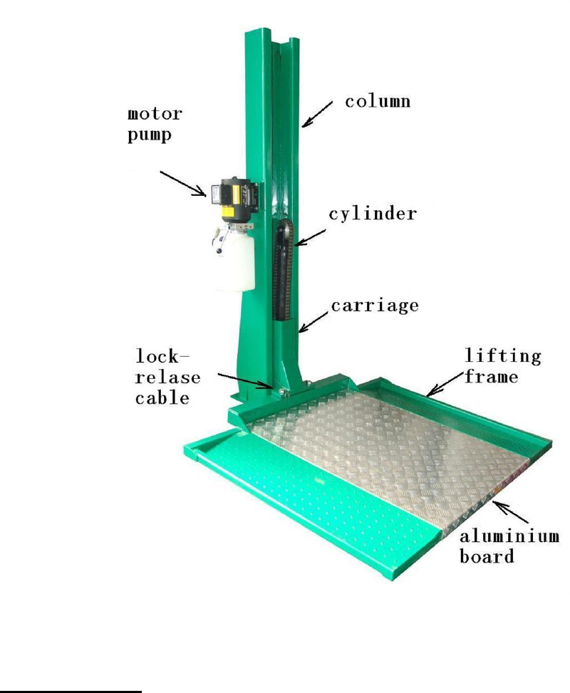
Fig. 3 Major Lift Components
Required Tools
1. Fork Lift and/or engine hoist for moving pieces and positioning lift leg. You will also need a
ten-foot length of 3/8” chain
2. 1 and 5/16” wrench and socket with ratchet
3. 1 and 1/8” socket and extension
4. ½” wrench
5. 11/16” wrench
6. Adjustable wrench
7. Small crowbar or large screwdriver for aligning bolt holes
8. Concrete hammer drill with a new ¾” concrete bit
9. Pliers
10. Flat blade screwdriver
REV A-081613
5
Receiving and Handling
When you receive your lift, it will come in two packages, and you may need a forklift to unload it.
Installation
You will need common hand tools that most homeowners have, like a hammer, screwdrivers and
pliers, but in addition, you will need some tools that are not common. Each installation is
somewhat different, and depends on how much room you have to work around the lift.
STEPS
The major piece is the lift column. It will have the carriage unit, the hydraulic piston and chain
assembly, the hydraulic hose and safety latch cable already assembled in it. It will also have a
bracket with four small holes on the side which will be used for installing the power unit later. The
hydraulic cylinder in the column will appear to be loose, and wobble around. This is normal. As
soon as a load is placed on the lift, the cylinder will right itself and remain righted. The objective of
this step is to pick the column up from a horizontal position, lift it vertically high enough to set it on
the ground .
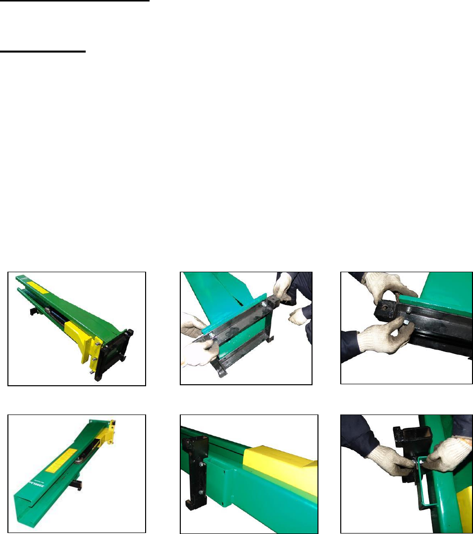
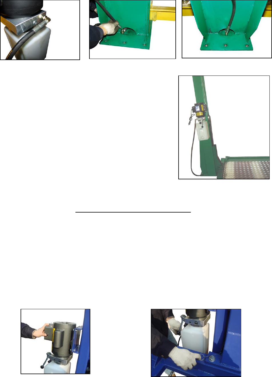
The first step is to take off the board and bracket for shipping. There is one board bolted to the
bottom of the column (Fig. 4,5,6) and another brcket bolted to the column.( Fig.7,8,9)
Fig.4 Fig.5 Fig. 6
Fig.7 Fig. 8 Fig.9
NOTICE:
If the end of the cylinder is not in the hole in the baseplate, please put it into the hole before
you lift the column upright. (Fig.10,11)
REV A-081613
6
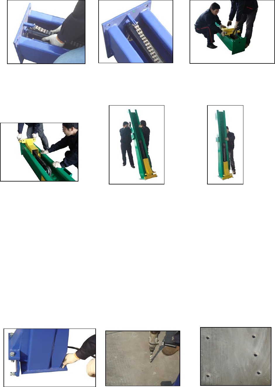
Fig.10 Fig. 11 Fig.12
Then slide the carriage to the bottom of the post by pulling the lock-release cable at the same
time (Fig. 12, 13) . After that , up-right the column and move it into position. (Fig. 14, 15)
Fig.13 Fig. 14 Fig. 15
After you’ve lifted the column into position, you’ll anchor it to the ground with anchor bolts. You’ll
need a hammer drill and a wrench to do this,
Before you drill the anchor holes, you shall mark them through the large holes in the baseplate of
the column ( Fig. 16). Then move the column apart, use a hammer drill with a new ¾” concrete bit
to drill down into the garage floor ( Fig.17, 18). The holes should be at least 5 1/2” deep, and it
won’t hurt if the holes go all the way through the floor. The anchor bolts are long enough to
protrude into the extensions and accept the washers and nuts that secure them to the concrete. After
that, move the column back to its position with holes lined, tap the anchor bolts through the holes
on the baseplate into the holes in the floor , with a drift or similar metal tool to set them. When the
nuts and washers go on the other end, they will draw up the anchors till they wedge in the holes and
lock the whole assembly down. You’ll need a 1 1/8” socket, ratchet (using a ½” drive), socket
extension and torque wrench to tighten the nuts to 90 foot-pounds.
Make any final position adjustments to the lift with the help of friends, and fasten the base plate to
the floor with the provided anchor bolts, nuts and washers.(Fig. 19, 20,21)
Fig. 16 Fig. 17 Fig. 18
REV A-081613
7
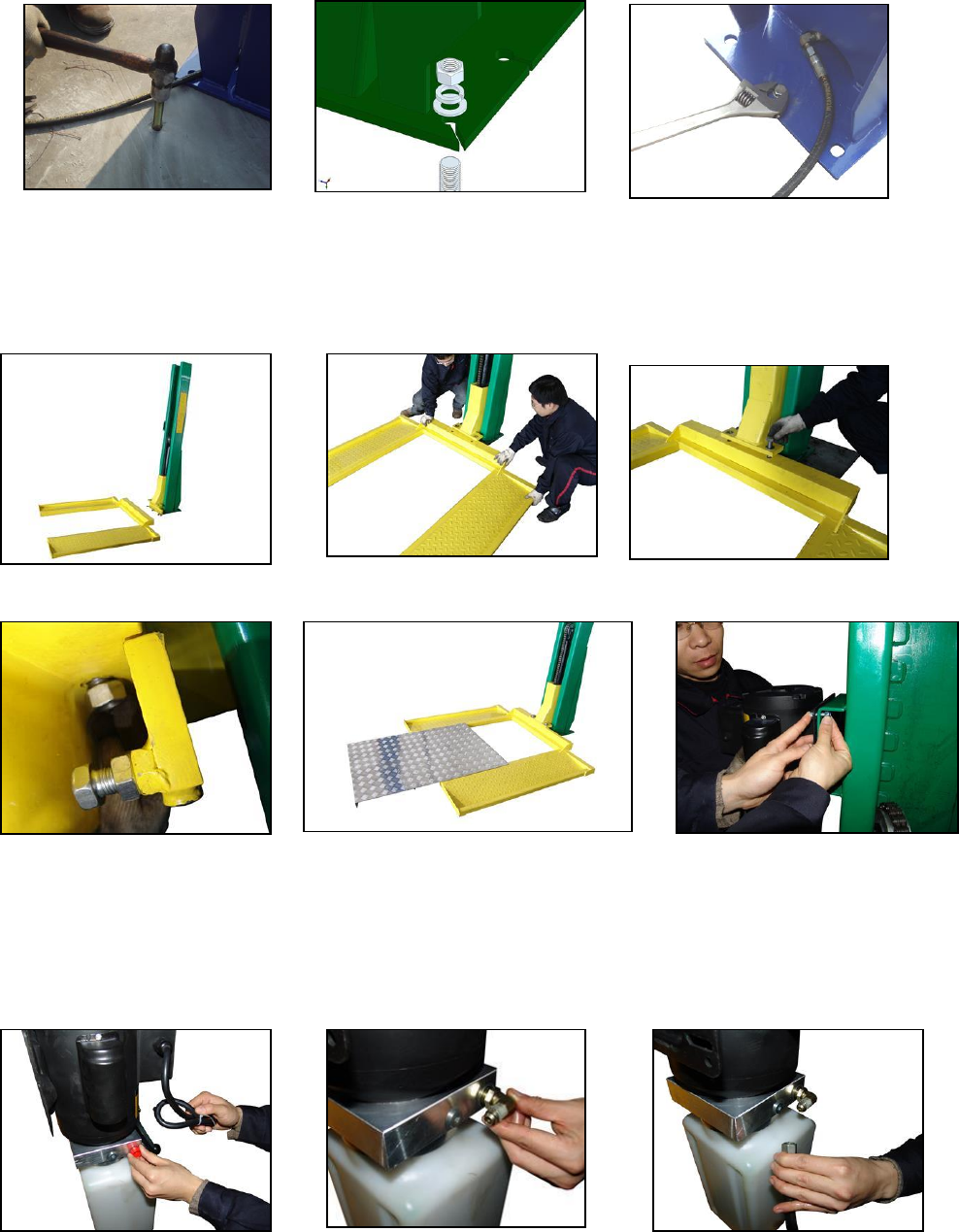
Fig. 19 Fig. 20 Fig. 21
The next task is to position the lift frame and bolt it to the carriage (at the bottom of the lift column)
with two bolts supplied. Move the lifting frame to the carriage then bolt it to the carriage. (Fig.
22,23,24,25)
Fig. 22 Fig. 23 Fig. 24
Fig. 25 Fig. 26 Fig.27
Put the aluminium board on the frame. (Fig. 26)
Using the screws supplied to mount the motor pump on the side of the column (Fig. 27). Take off
the red plug of the pump, screw in the elbow oil connector (Fig. 28,29). Then connect one end of the
oil hose to the elbow connector. (Fig. 30,31) Connect another end to the cylinder on the column
bottom at the back (Fig. 32,33). Make sure these fittings are tight.
Fig. 28 Fig. 29 Fig. 30
REV A-081613
8
Fig. 31 Fig. 32 Fig. 33
Now you need to get the correct plug installed on the
power cord. Your lift will come with a cord attached to
the control unit, but because there are so many receptacle
variations, you will need to install the proper plug on the
end of the cord. If you are not sure which plug to use,
consult your electrician
Remove the rubber cap from the top of the reservoir. Fill
the reservoir with 32 AWS hydraulic oil to near the top.
You will need about 5 gallons to fill the reservoir
completely.
Fig. 34
Recheck all bolts for tightness and the installation is complete.
(Fig. 34) Fig. 34
OPERATING INSTRUCTIONS
The lift is very simple to operate. The button on the control unit is pushed in and held to activate
the switch which turns the electric motor on. (Fig. 35) The motor operates an internal pump that
forces hydraulic oil into the lift piston, which extends the roller chain and raises the lift. As the lift
rises, an internal safety latch will pass over the steel stops (rectangular blocks which protrude from
the back, inside of the column), and you will hear clanks as it does so. This sound is normal, and
indicates that the safety latch is passing over the stops properly. The lift is raised to the desired
height by holding the button in while it is rising, and releasing the button when the lift has reached
its desired position. To lower the lift, you must hold down the lever to depress the release valve, at
the same time as you pull out the safety latch cable (Fig. 36). The weight of the lift will cause the
lift to lower by gravity. No power is required to lower the lift, but the safety latch must be
disengaged to allow the lift to lower past the stops.
Fig. 35 Fig. 36
REV A-081613
9
Occasionally the lift may be resting on a stop, which prevents the safety latch from being
disengaged. When this happens, simply press the "up" button momentarily, to bump the lift
upwards slightly, which takes the weight off of the safety latch. Now you can pull the release
cable, and again depress the release valve handle to lower the lift. After the installation is
complete, raise the lift about two feet and then lower it. Repeat this process two or three times,
and then top off the hydraulic oil reservoir again, if necessary. This assures that hydraulic oil is
distributed everywhere in the system that it needs to be.
NOTE: Only top off the reservoir with the lift in the “down” position. If you fill the reservoir in the
“up” position and then lower the lift, there will be too much hydraulic oil in the system, and it will
squirt out of the top of the control unit.
RAISING A VEHICLE
Drive the lawnmower onto the ramps until it is about centered. Set the parking brake. Depress
the “up” button and the vehicle will rise. Raise the vehicle until it is near the ceiling of the
garage.
BE CAREFUL NOT TO RAISE THE VEHICLE SO HIGH THAT IT STRIKES THE
CEILING! BE AWARE OF ANYTHING THAT PROTRUDES FROM THE CEILING,
LIKE LIGHTBULBS, GARAGE DOOR OPENERS OR DOOR TRACKS. IT IS VERY
HELPFUL IF YOU HAVE A SPOTTER ON A LADDER TO TELL YOU WHEN YOU
ARE NEAR THE CEILING FOR THE FIRST LIFT!
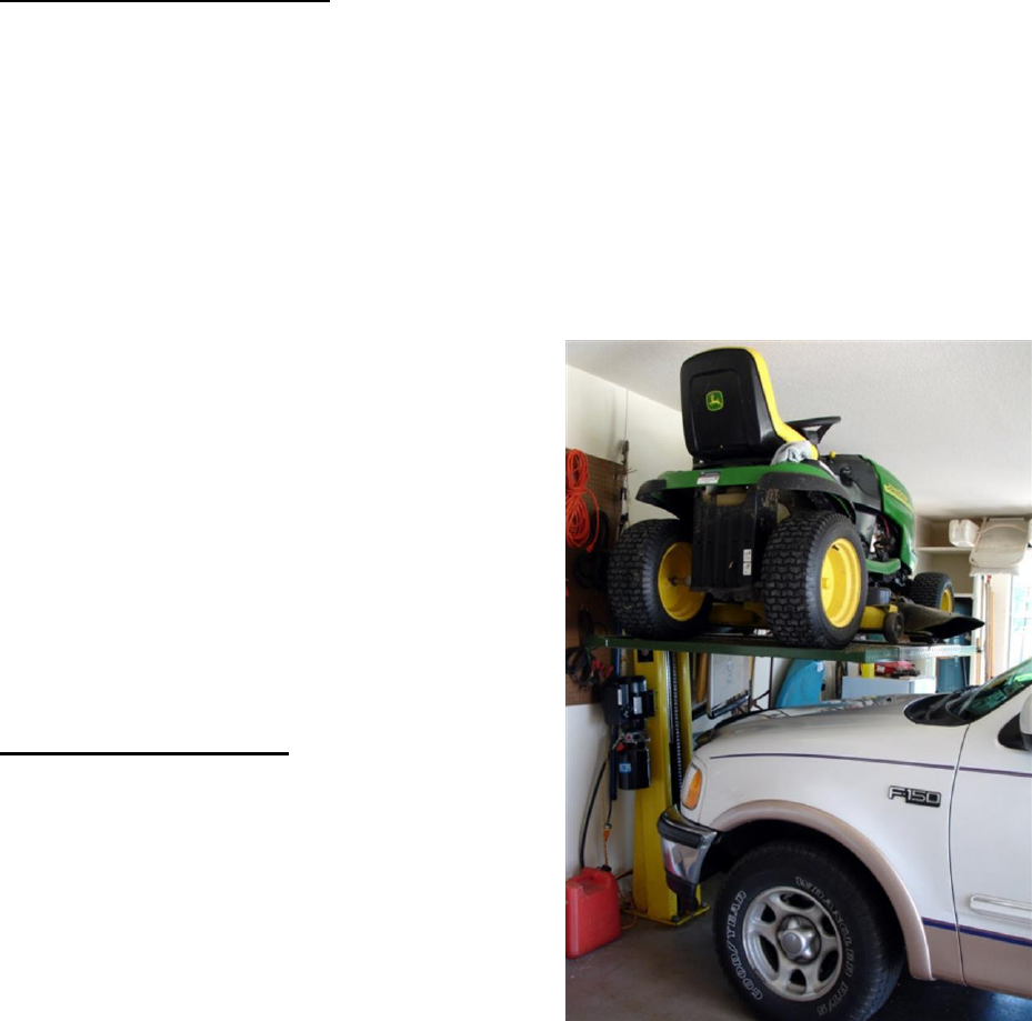
When the vehicle is in the correct position, it is
useful to mark the position of the carriage relative
to the column with two pieces of electrical tape or a
felt tip marker. When you make future lifts, all you
have to do is operate the lift till the reference marks
line up, and you will know that the vehicle is in the
right position. If you alternate vehicles that you will
lift, you will need a separate set of reference marks
for each. The higher you lift the raised vehicle,
the more headroom you will have to enter and exit
the one you park underneath.
MISCELLANEOUS
It is useful to spray paint the ends of the ramps
and the ends of the lift arms a bright fluorescent
color to help catch your eye and avoid head
bumps. The hydraulic oil should be replaced
every two years, and the inside corners of the lift
leg should be re-greased with a general-purpose
axle grease every year, or so, as it becomes
obvious that it needs it.
Fig. 37
REV A-081613
10
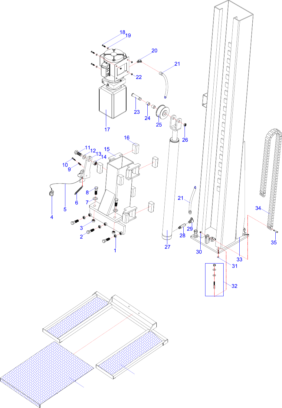
LAWNMOWER STORAGE LIFT SC-2K PARTS DRAWING
Column and power unit
Lifting frame and platform
Fig. 1
Fig. 2
37
38
REV A-081613

11
PARTS CODE LIST
ITEM
CODE
DESCRIPTION
QTY
1
SC-2K-01 NUT, M16
3
2
SC-2K-02 BOLT, M16 x 30
3
3
SC-2K-03 NUT, M20
2
4
SC-2K-04 KEY RING
1
5
SC-2K-05 LOCK RELEASE CABLE
1
6
SC-2K-06 LOCK RELEASE SPRING
1
7
SC-2K-07 FLAT WASHER #20
2
8
SC-2K-08 BOLT, M20 x 40
2
9
SC-2K-09 SPRING
1
10
SC-2K-10 SCREW, M8 x 50
1
11
SC-2K-11 BOLT, M20 x 40
1
12
SC-2K-12 FLAT WASHER #20
1
13
SC-2K-13 LATCH
1
14
SC-2K-14 LOCKNUT, M20
1
15
SC-2K-15 CARRIAGE
1
16
SC-2K-16 RUB BLOCK
8
17
SC-2K-17 POWER UNIT
1
18
SC-2K-18 BOLT, M8 x 25
16
19
SC-2K-19 FLAT WASHER #8
20
20
SC-2K-20 ELBOW FITTING
1
21
SC-2K-21 4" HYDRAULIC HOSE
1
22
SC-2K-22 LOCKNUT, M8
20
23
SC-2K-23 CHAIN ROLLER SHAFT
1
24
SC-2K-24 BUSHING
2
25
SC-2K-25 CHAIN ROLLER
1
26
SC-2K-26 LOCKNUT, M20
1
27
SC-2K-27 HYDRAULIC CYLINDER
1
28
SC-2K-28 STRAIGHT FITTING
1
29
SC-2K-29 ELBOW FITTING
1
30
SC-2K-30 LOCKNUT, M6
2
31
SC-2K-31 ADJUST WASHER
5
32
SC-2K-32 ANCHOR
5
33
SC-2K-33 COLUMN
1
34
SC-2K-34 CHAIN
1
35
SC-2K-35 CHAIN PIN
2
36
SC-2K-36 ALUMINUM DECK
1
37
SC-2K-37 PLATFORM
1
REV A-081613

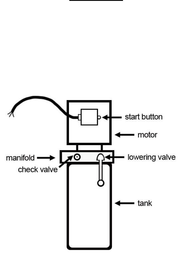
IMPORTANT
POWER UNIT PRIMING PROCEDURE
THE PROBLEM: Power unit runs fine but will not pump any fluid.
Step 1 – Locate the check valve, the flush plug to the left of the lowering valve.
(See drawing below.)
Step 2 – Using an Allen wrench and shop towel – with shop towel in place to catch
fluid – loosen the check valve plug 2 ½ turns to allow it to leak.
Step 3 – Push the START button for one second, then release for three seconds.
Repeat these steps until unit starts pumping fluid.
Step 4 – Tighten the check valve plug.
YOUR POWER UNIT SHOULD BE PRIMED
