SecF2_F23 Sectionl
User Manual: sectionl
Open the PDF directly: View PDF ![]() .
.
Page Count: 208 [warning: Documents this large are best viewed by clicking the View PDF Link!]
Section L
Li
NV2 Series
Class I, Div.2; NEMA 4X
.........
2-5
V Series
Standard Location
.................
6-8
Class I, Div. 2; NEMA 4
........
9-10
Accessories, Dimensions
....
11-13
DV Series
DV Dust Ignition Proof..............14
EMI Series
Hazardous Location
NEMA 4X Groups C,D
60-300 Watt Incandescent
...
120-121
H Series
Hazardous Location
Groups C,D
500 Watt Incandescent
...........
15
E Series
Hazardous Location
Groups A,B
200-300 Watt Incandescent
....
16
XHL Series
Hazardous Location
Handlamps
100 Watt Incandescent
...........
16
NV2F Series
18-42 Watt Quad-Pin...............2-5
MBF Series
13-39 Watt for
Standard & Certain
Hazardous Locations
...........
17-18
Accessories ........................24-25
VBF/VQF Series
26-84 Watt for
Standard & Certain
Hazardous Locations..........34-35
EBF/EQF Series
13-84 Watt for
Hazardous Location . . . . . . . . .120-121
XHLF Series
Hazardous Location
Handlamps
26 Watt Fluorescent
................
16
INCANDESCENT
FIXTURES
COMPACT
FLUORESCENT
Wet / Damp Location (or N3)
NEMA 4 (or 4X, or IP6x)
Class I, Div. 2 / Zone 2
Class I, Zone 2 Ex nR (option)
Class I, Div. 2 / Zone I
Class II / III Div. 1
Class II / III Div. 2
ClassI,Div.1C,D/ZoneI
Class I, Div. 1 A,B,C,D / Zone I
CENELEC Zone 2
CENELEC Zone 1
Wet / Damp Location (or N3)
NEMA 4 (or 4X, or IP6x)
Class I, Div. 2 / Zone 2
Class I, Zone 2 Ex nR (option)
Class I, Div. 2 / Zone I
Class II / III Div. 1
Class II / III Div. 2
ClassI,Div.1C,D/ZoneI
Class I, Div. 1 A,B,C,D / Zone I
CENELEC Zone 2
CENELEC Zone 1
General Suitability —
See catalog pages for details
General Suitability —
See catalog pages for details
XX
X
X
X
XX
XX
XX X X
XX
X
X
X
XXX
XXX
XX XX
XX
XXX
XXX
PRODUCT PAGE NO. PRODUCT PAGE NO.
XX
X
Section L
L
Lii
HID AND INDUCTION
FIXTURES
MB Series
Medium Base HID . . . . . . .17,19-21
Ex nR version . . . . . . . . . . . . . . . .22-23
Accessories . . . . . . . . . . . . . . . . . .24-25
Temperature Data . . . . . . . . . . . . . . .26
Photometrics . . . . . . . . . . . . . . . . .27-33
Series
Mogul Base HID . . . . . . . . . . . . . .42-71
Induction System ............72-74
Introduction . . . . . . . . . . . . . . . . .36-41
Quick Selector . . . . . . . . . . . . . . . . .37
“3rd Hand” Accessories . . . . . . .38
Restricted Breathing . . . . . . . . . . . . . .39
Food Optics . . . . . . . . . . . . . . . . . . . .40
Accessories . . . . . . . . . . . . . . . . .75-77
Temperature Data . . . . . . . . . .84-89
Dimensions . . . . . . . . . . . . . . . . .80-83
Photometrics . . . . . . . . . . . . . . .91-108
VM Series
Mogul Base HID . . . . . . . . . . .109-117
Accessories . . . . . . . . . . . . . . . . . . . . . .118
Cross Reference VM
to Certilite®V ......................119
EM Series
Medium Base HID . . . . . . . .120-122
Accessories . . . . . . . . . . . . . . . .123-124
Temperature Data . . . . . . . . .127-128
Photometric . . . . . . . . . . . . . . . .129-138
Cenelec Option . . . . . . . . . . . . . . . . .127
EZ Series
Mogul Base HID
..........
139-143
Accessories
...............
144-146
Temperature Data
........
148-149
Photometrics
..............
150-155
Cenelec Option . . . . . . . . . . . . . . . . .148
LINEAR FLUORESCENT
LLC Series
Task or Exit Fixture
............
170
LLC Series
Accessories
.....................
171
DBF Series
Fluorescent
Class l, Div. 2
...................
156
LZ2S Series
Fluorescent Stainless Steel
....
157
LZ2N Series
Linear Lite Non-Metallic
Class I, Div. 2
Class II, Div. I
..............
158-161
HFX-T Series
BIAXIAL Fluorescent
Class I, Div. I
...............
162-163
HFX Series
Hazardous Location
Paint Spray Suitable
......
164-169
Wet / Damp Location (or N3)
NEMA 4 (or 4X, or IP6x)
Class I, Div. 2 / Zone 2
Class I, Zone 2 Ex nR (option)
Class I, Div. 2 / Zone I
Class II / III Div. 1
Class II / III Div. 2
ClassI,Div.1C,D/ZoneI
Class I, Div. 1 A,B,C,D / Zone I
CENELEC Zone 2
CENELEC Zone 1
Wet / Damp Location (or N3)
NEMA 4 (or 4X, or IP6x)
Class I, Div. 2 / Zone 2
Class I, Zone 2 Ex nR (option)
Class I, Div. 2 / Zone I
Class II / III Div. 1
Class II / III Div. 2
ClassI,Div.1C,D/ZoneI
Class I, Div. 1 A,B,C,D / Zone I
CENELEC Zone 2
CENELEC Zone 1
General Suitability —
See catalog pages for details
General Suitability —
See catalog pages for details
XXX X
XXXXX
XX
XX
XXXX
XX X X
XXXX
XXX
XX X X
X
PRODUCT PAGE PRODUCT PAGE
XXX XXXXXX
XXX XXXX
XX
XX X X
XXXXXX
XXX X
XXX X
XX X X
XXX X
®
Section L
Liii
EMERGENCY LIGHTING
BATTERY-BACKED
DEB
Class II, Div. 1 ...........182-183
Exit Accessory ...............183
VEB/VEQ
Class I, Div. 2/N4
Class ll/N4 ..............184-185
Exit Accessory
.............
185
EEQ
Class I, Div. 1 ...............186
Exit Accessory .............186
EBB
Class I, D1/N3
Halogen Lamps . . . . . . . .190-191
BATTERY OPTION
FLUORESCENT
DBFE
Linear Fluorescent
Class I, D2/N4 ...............187
LZ2NE/LZ2SE (FRP or SS)
Class I, Div. 2
Class II, Div. 2 ..............188
HFXE
Class I, Div. 1
..............
189
Wet / Damp Location (or N3)
NEMA 4 (or 4X, or IP6x)
Class I, Div. 2 / Zone 2
Class I, Zone 2 Ex nR (option)
Class I, Div. 2 / Zone I
Class II / III Div. 1
Class II / III Div. 2
Class I, Div. 1 C,D / Zone I
Class I, Div. 1 A,B,C,D / Zone I
CENELEC Zone 2
CENELEC Zone 1
Wet / Damp Location (or N3)
NEMA 4 (or 4X, or IP6x)
Class I, Div. 2 / Zone 2
Class I, Zone 2 Ex nR (option)
Class I, Div. 2 / Zone I
Class II / III Div. 1
Class II / III Div. 2
Class I, Div. 1 C,D / Zone I
Class I, Div. 1 A,B,C,D / Zone I
CENELEC Zone 2
CENELEC Zone 1
General Suitability —
See catalog pages for details
General Suitability —
See catalog pages for details
X
XX X X
XXX
XXX X
XXX
XXX
XXX
X
XX
EMERGENCY SIGNALING
STROBE LIGHTING
GSH
Strobe Class I, Div. 2..........194
ESX
Strobe Class I, Div. 1.....192-193
PRODUCT PAGE NO. PRODUCT PAGE NO.
FLOODLIGHTS &
WALL MOUNT FIXTURES
KWP Series
Wallpack
for Class I, Div. 2 & N4. . . . . . . 178
QL
Quartz Floods . . . . . . . . . . . 172-173
KF Series
Floods Aluminum
Class I, Div. 2 Marine N4
150 to 1000 Watt .........174-175
KF-SS
MariGard Stainless
Class I, Div. 2 Marine N4
150-400 Watt. . . . . . . . . . . . 176-177
EM/DM
Portable Floods..............179
EZ-T Trunnion..........180-181
XXX
X
XXX
XXXX
XX XX
XX X
XXX X
XXX XX XX
Section L
L
Liv
FITTINGS & ADAPTERS
FKA & FHC ...............195
HOOK/LOOP ..............195
FH HOOK .................196
V Series
Fixture Hangers ............196
HXB & XFH ...............197
EKJ Series
Flexible Couplings .........197
JL & JAL ..................198
ENY-2SET
Pendant Seals .............198
VMCHVM
Adapter ...................199
EAC
Adapters ..................200
Wet / Damp Location (or N3)
NEMA 4 (or 4X, or IP6x)
Class I, Div. 2 / Zone 2
Class I, Zone 2 Ex nR (option)
Class I, Div. 2 / Zone I
Class II / III Div. 1
Class II / III Div. 2
Class I, Div. 1 C,D / Zone I
Class I, Div. 1 A,B,C,D / Zone I
CENELEC Zone 2
CENELEC Zone 1
X
X
X
X
XXX
X
X
XXXX
XXXX X
XX X X
XX
XXX
General Suitability —
See catalog pages for details
PRODUCT PAGE NO.
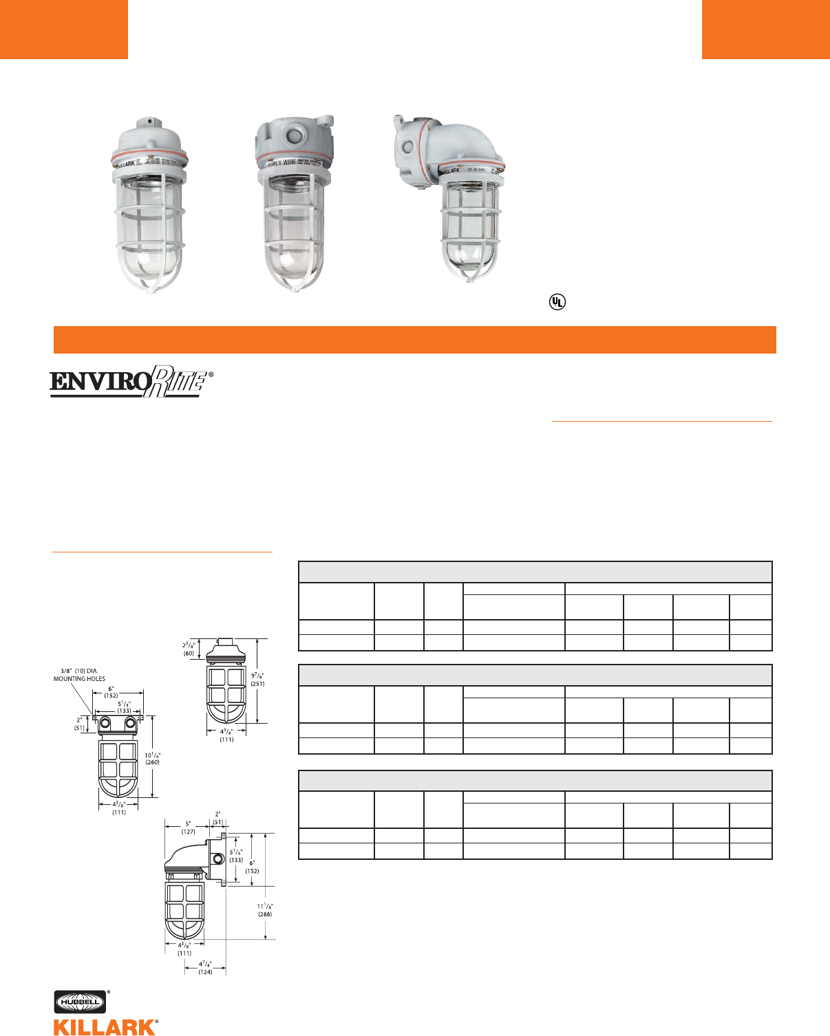
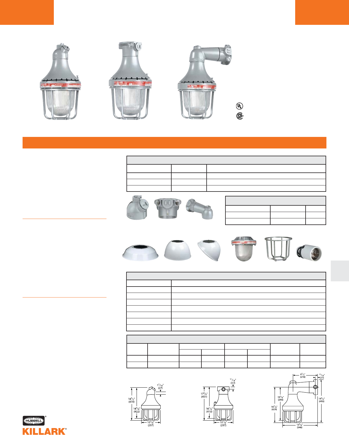
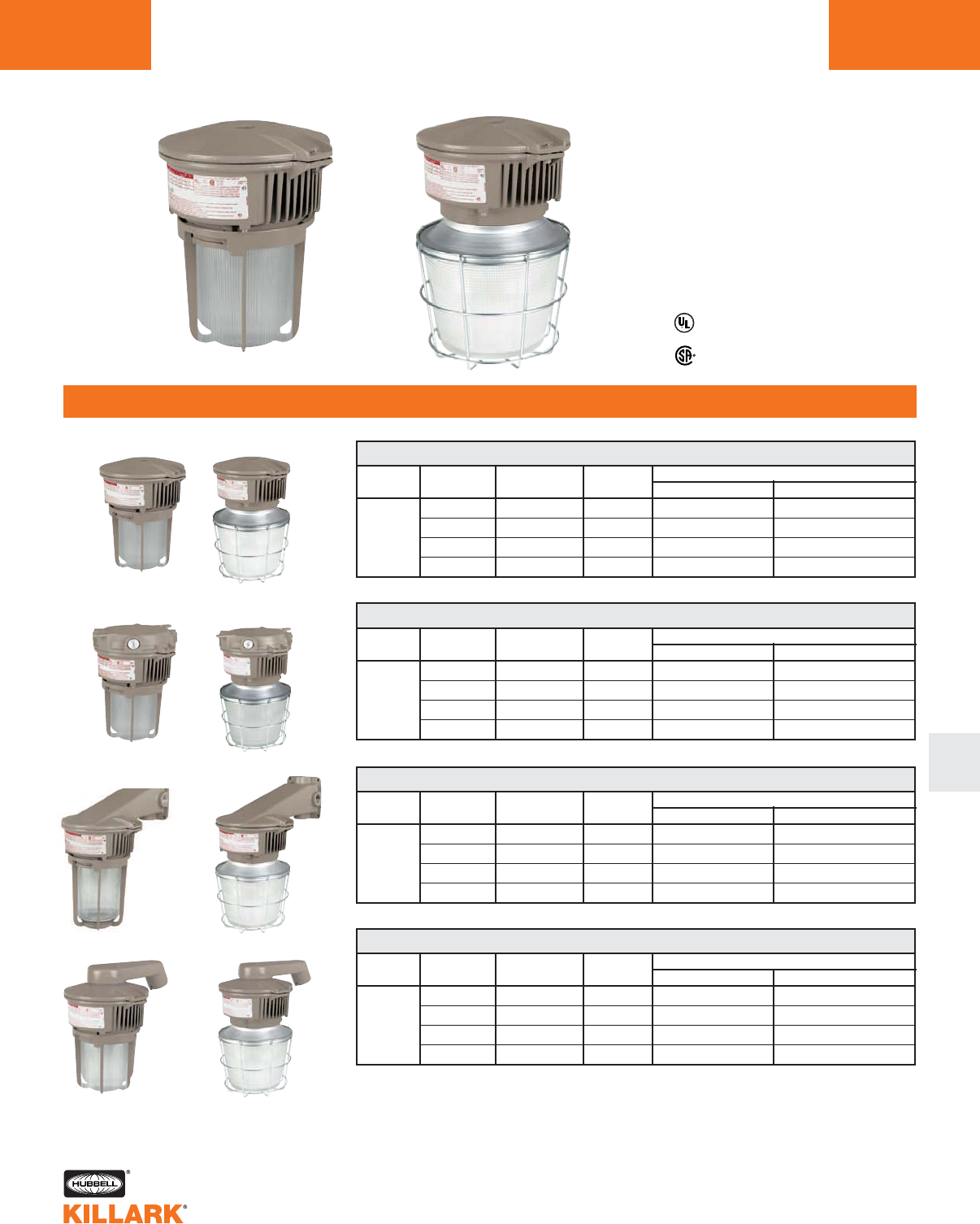
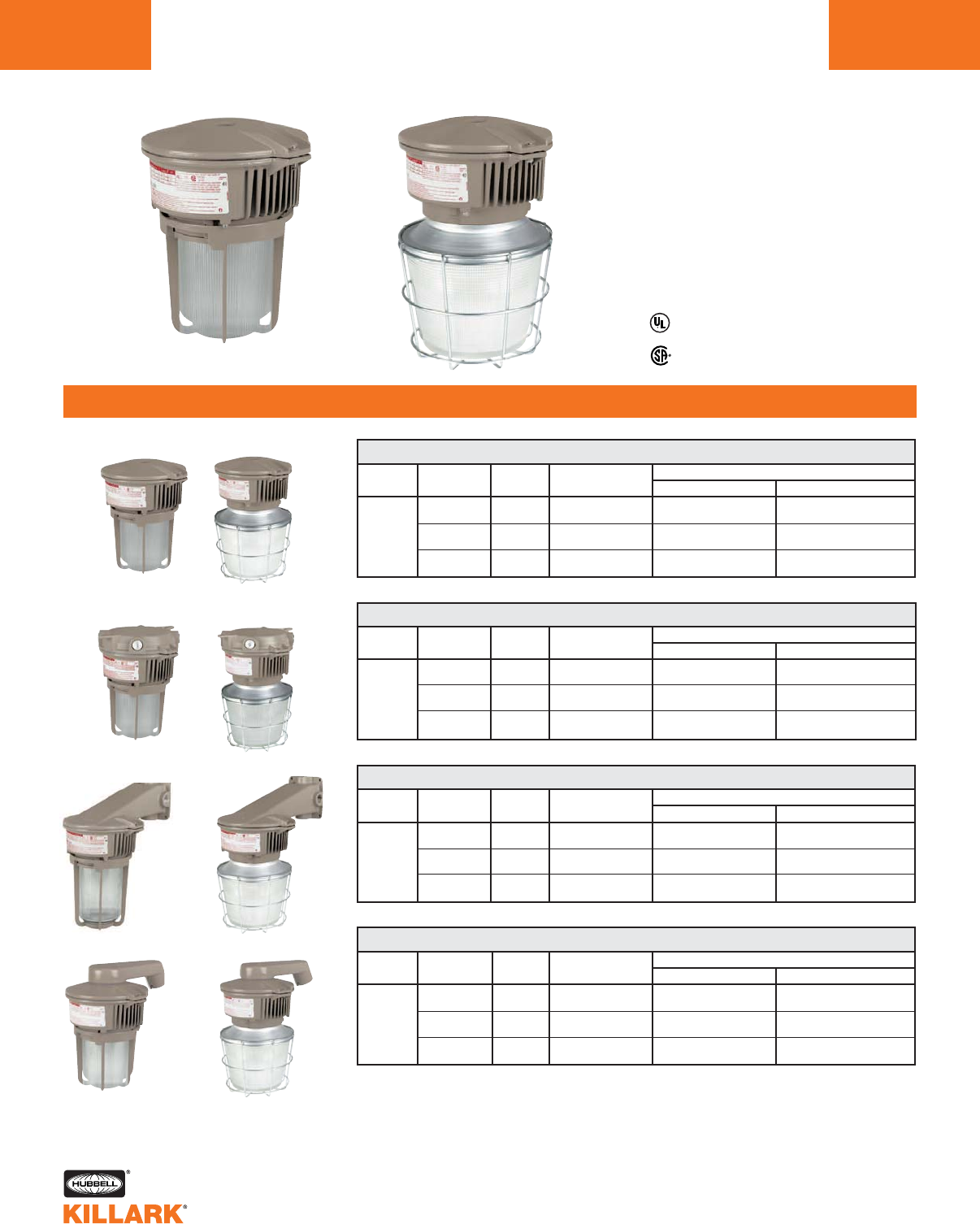
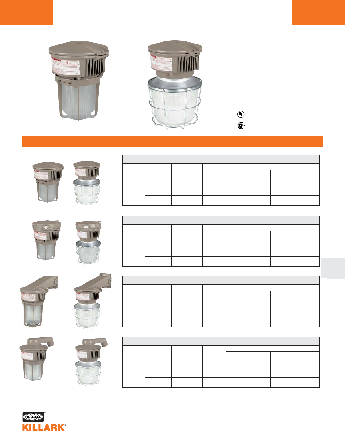
NV SERIES •LIGHTING
INCANDESCENT NON-METALLIC CORROSION RESISTANT FIXTURES
L2A
FEATURES-SPECIFICATIONS
•Accepts up to 150 watt, size A-21
lamp
•Compact size
Compliances
•UL-1571 standard
•UL Marine type fixtures
•Suitable for wet locations
•NEMA 3, 4X
•Material meets U.L. 94-V-O
standards for flame retardancy
Applications
Designed specifically for corrosive
environments.
Typical applications include manufac-
turing plants, chemical and petrochem-
ical processing facilities, sewage
treatment plants, off-shore and dock-
side installations, agricultural, commer-
cial/industrial, mining and marine facili-
ties.
Features
•Series NV non-metallic light fixtures
combine an outstanding balance of
strength, stiffness, toughness and
electrical properties
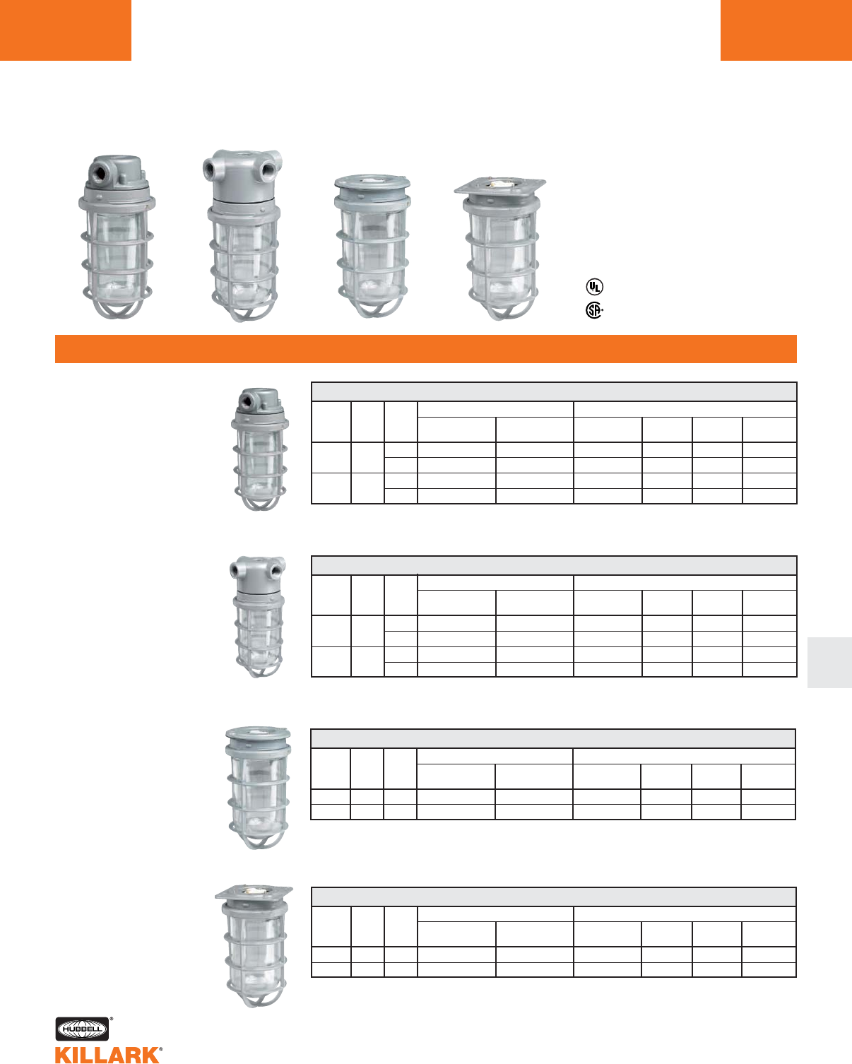
Pendant Ceiling Wall Mount
Listed - Files E227731 and E91793
1Maximum 150 watt lamp type A for standard GG models. Suitable for wet and damp locations when sup-
plied with heat resistant glass globes.
2Pendant and ceiling fictures are unit packed. Wall fixture supplied as ceiling mount unit with all necessary
components to make bracket conversion. Elbow bracket adapter shipped separately.
3Standard GG incandescent marked supply wire is 125°C at 25°C ambient. For suitability with 90°C mini-
mum supply wire, add suffix LT to catalog number. Example: NVA15GG-LT.
4GHG models are suitable for marine applications with maximum 100 watt lamp and are marked for 90°C
wire.
* Clear globe furnished. For other colors, order globes and fixture components separately See page L4.
PENDANT NON-METALLIC INCANDESCENT 12
FIXTURE LAMP HUB FIXTURE W/GLOBE MOUNTING FIXTURE
TYPE SIZE & GUARD BOX BODY GLOBE* GUARD
CATALOG NUMBER
CEILING NON-METALLIC INCANDESCENT 12
FIXTURE LAMP HUB FIXTURE W/GLOBE MOUNTING FIXTURE
TYPE SIZE & GUARD BOX BODY GLOBE* GUARD
CATALOG NUMBER
WALL MOUNT NON-METALLIC INCANDESCENT 12
FIXTURE LAMP HUB FIXTURE W/GLOBE MOUNTING FIXTURE
TYPE SIZE & GUARD BOX BODY GLOBE* GUARD
CATALOG NUMBER
NEMA 3, 4X
•Molded from 30% glass-filled thermo-
plastic polyester for high strength
•Resists corrosive effects of most
chemicals, hydrocarbons and
solvents
•Designed for indoor and outdoor
applications. Molded threads will
not “freeze”—components are easy
to remove, even after long exposure
to corrosive environments.
CONSISTS OF
CONSISTS OF
CONSISTS OF
Clear globe 150 A 3/4" NVX15GG 3NVX NVFC VCG-100 NVG
Heat resistant 150 A 3/4" NVX15GHG 4NVX NVFC VCGP-100 NVG
Clear globe 150 A 3/4" NVB15GG 3NVX+NVB NVFC VCG-100 NVG
Heat resistant 150 A 3/4" NVB15GHG 4NVX+NVB NVFC VCGP-100 NVG
Clear globe 150 A 3/4" NVA15GG 3NVA NVFC VCG-100 NVG
Heat resistant 150 A 3/4" NVA15GHG 4NVA NVFC VCGP-100 NVG
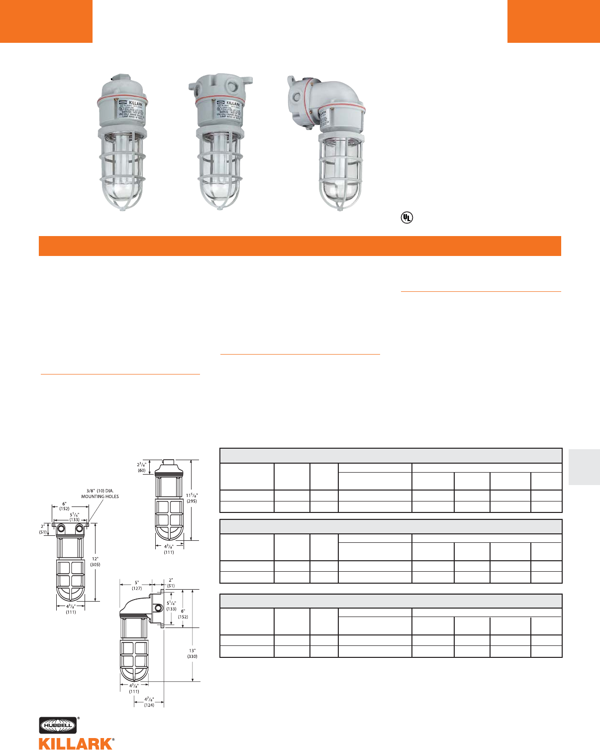
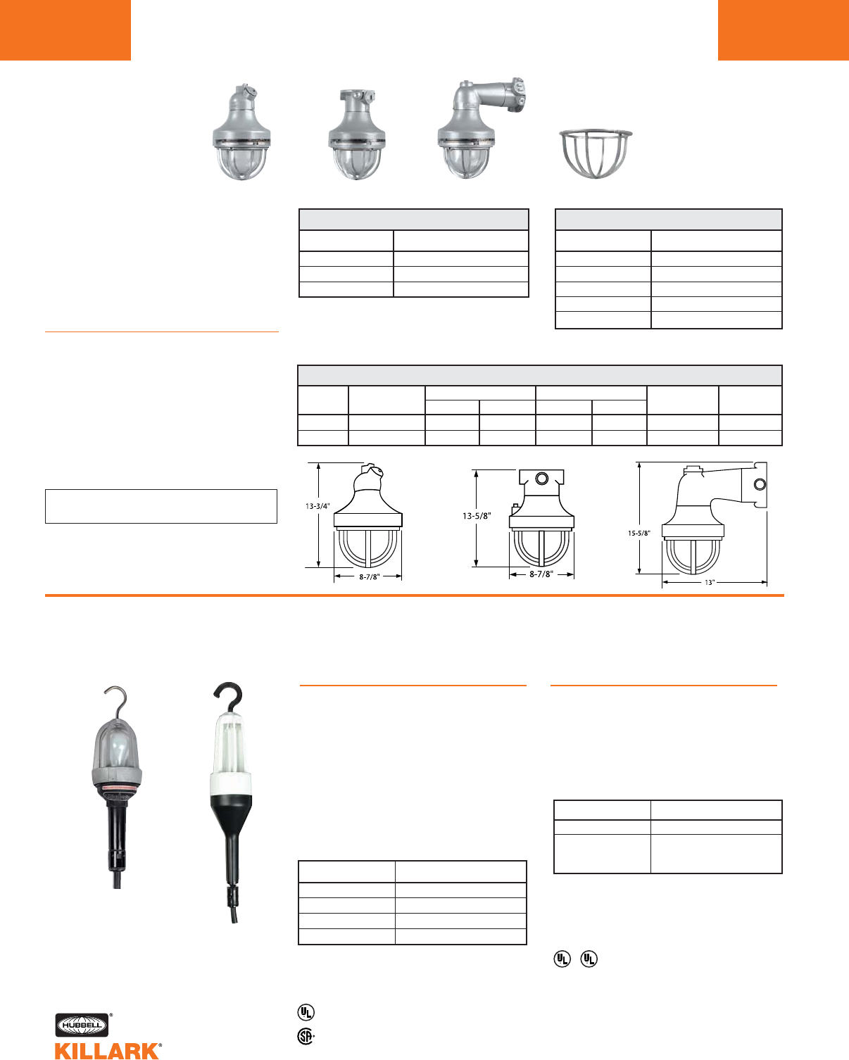
NVQ SERIES •LIGHTING
FLUORESCENT NON-METALLIC CORROSION RESISTANT FIXTURES L2B
FEATURES-SPECIFICATIONS
L
Applications
Designed specifically for corrosive
environments.
Typical applications include manufac-
turing plants, chemical and petrochem-
ical processing facilities, sewage
treatment plants, off-shore and dock-
side installations, agricultural, commer-
cial/industrial, mining and marine facili-
ties.
Features
•Series NVQ non-metallic light
fixtures combine an outstanding
balance of strength, stiffness,
toughness and electrical properties
•Molded from 30% glass-filled thermo-
plastic polyester for high strength
1Fixtures are unit packed and supplied with OSRAM®DuLux® D/E 18 watt Quad-Pin fluorescent lamp.
2Wall fixture supplied as ceiling mount unit with all necessary components to make bracket conversion.
Elbow bracket adapter shipped separately.
3Applications in Class I Div. 2 governed by NEC article 501.130(B)(1). 80% rule. NVQ maximum labeled
operating temperature is 162°C at 25°C ambient. Minimum ignition temperature of hazardous gas or
vapor is 203°C. Not UL listed or labeled for hazardous locations.
4Listed catalog numbers are 120V AC. Order components for 277V or insert a 4after the 18 for 277
assemblies; example NVQA184GG (assemblies are unit packed - not UL listed).
* Clear globe furnished. For other colors, order globes and fixture components separately. See page L4.
Listed - Files E227731 and E91793
•Resists corrosive effects of most
chemicals, hydrocarbons and
solvents
•Designed for indoor and outdoor
applications. Molded threads will
not “freeze”—components are easy
to remove, even after long exposure
to corrosive environments
Compliances
•UL-1570 standard
•UL Marine type fixtures
•Suitable for wet locations
•NEMA 3, 4X
•Material meets U.L. 94-V-O
standards for flame retardancy
PENDANT NON-METALLIC FLUORESCENT 14
FIXTURE LAMP1HUB FIXTURE W/GLOBE MOUNTING FIXTURE
TYPE SIZE & GUARD BOX BODY GLOBE* GUARD
CATALOG NUMBER
Clear globe PL-18 3/4" NVQA18GG NVA NVQFC VCG-100 NVG
Heat resistant PL-18 3/4" NVQA18GHG NVA NVQFC VCGP-100 NVG
CEILING NON-METALLIC FLUORESCENT 14
FIXTURE LAMP1HUB FIXTURE W/GLOBE MOUNTING FIXTURE
TYPE SIZE & GUARD BOX BODY GLOBE* GUARD
CATALOG NUMBER
Clear globe PL-18 3/4" NVQX18GG NVX NVQFC VCG-100 NVG
Heat resistant PL-18 3/4" NVQX18GHG NVX NVQFC VCGP-100 NVG
WALL MOUNT NON-METALLIC FLUORESCENT 90°124
FIXTURE LAMP1HUB FIXTURE W/GLOBE MOUNTING FIXTURE
TYPE SIZE & GUARD2BOX BODY GLOBE* GUARD
CATALOG NUMBER
Clear globe PL-18 3/4" NVQB18GG NVX+NVB NVQFC VCG-100 NVG
Heat resistant PL-18 3/4" NVQB18GHG NVX+NVB NVQFC VCGP-100 NVG
NVQ Fluorescent Fixture
Enclosed and Gasketed
Special Features
•Electronic ballast and lamp combina-
tion reduces energy consumption up
to 70%
•Lamp life rated 10,000 hours with
minimum starting temperature of
-25°C (-13°F)
•Rated for use with 60° minimum sup-
ply wire
•Furnished with 18W compact fluores-
cent lamp
Class I, Div. 2, Groups A,B,C,D3
Class l, Zone 2, Groups llC,llB,llA
NEMA 3, 4X
Pendant Ceiling Wall Mount
CONSISTS OF
CONSISTS OF
CONSISTS OF
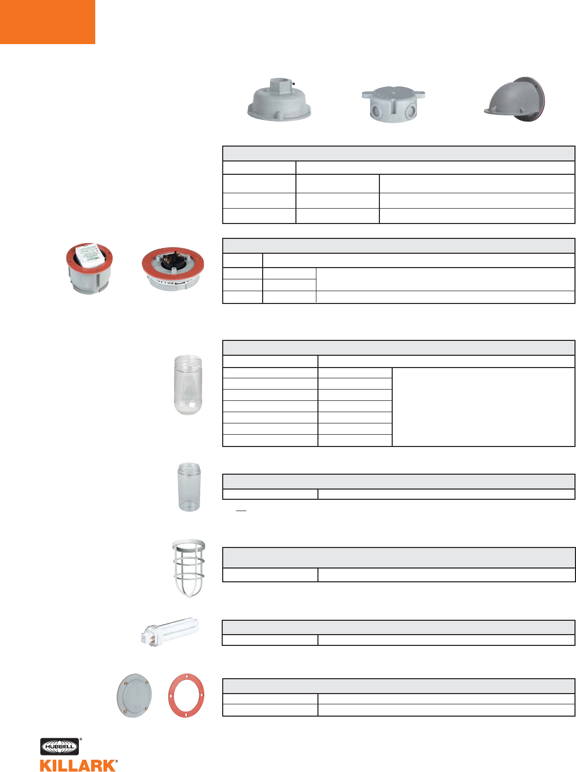
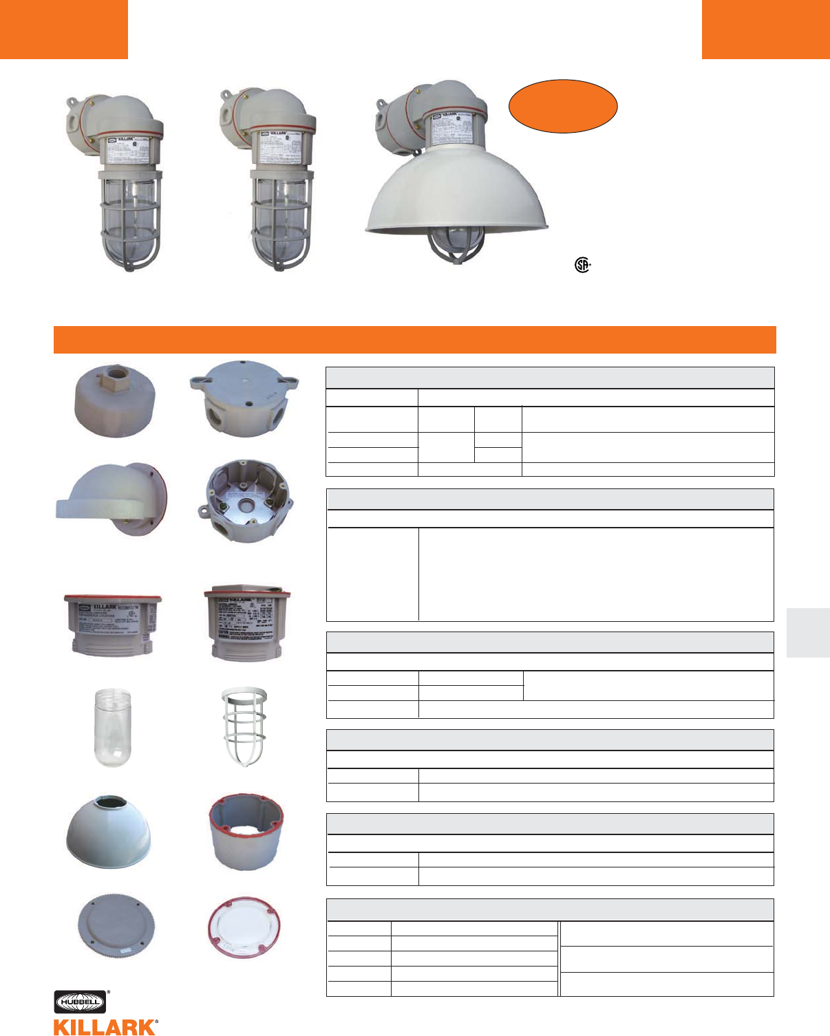
NVQ/NV SERIES •LIGHTING
WEATHER PROOF COMPONENT PARTS
L2C
Note: NVQFC rated for use with 60°C minimum supply wire. NVFC rated for use with 125°C minimum
supply wire. For suitability with 90°C minimum supply wire, add suffix LT to catalog number (NVFC-LT)
* Thermal and shock resistant tempered glass. See “V” 100 series globes for other available colors
CAT. NO.
NVQFC Fluorescent 120V
NVQFC184 Fluorescent 277V
NVFC Incandescent
NVQ/NV FIXTURE BODIES
DESCRIPTION
Quad-pin lamp socket, 18 watt electronic ballast, silicon gasket and brass screws
Includes heat resistant medium base socket, silicon gasket and brass screws
Cannot be used with guard
VPLCG-100
NVQ/NV POLYCARBONATE GLOBES
Polycarbonate 75 watt max. Lamp size A-19. Not UL Listed
NVG
NVQ/NV GUARD
Replacement guard
NVBC
NVSG
NVQ/NV COVER COMPONENTS
Blank cover supplied with gasket and screws
Replacement gasket - fits between splice box and fixture body
NVQ-18
NVQ FLUORESCENT LAMP
18 watt Quad-pin lamp
CATALOG NUMBER
VCG-100
VCGP-100*
VAMG-100
VGG-100
VBG-100
VRG-100
VRSG-100
NVQ/NV GLASS GLOBES
DESCRIPTION
Clear
Clear. Tempered
Amber
Blue Green 150 watt max. Lamp size A-21
Blue
Ruby
Green
Pendant Ceiling
NVFC
Incandescent
VCG-100
VPLCG-100
Splice Boxes
CATALOG NUMBER
NVA
NVX
NVB
VGA SPLICE BOXES - INCLUDES SILICONE GASKETS & BRASS SCREWS
DESCRIPTION
Pendant
Ceiling
Wall bracket
Pendant splice box includes a 316 stainless steel set
screw at the conduit connection
Direct ceiling mount or use with NVB for wall mount
Use with NVX for wall mount
NVQFC
120V Fluorescent
NVQFC184
277V Fluorescent
Mounting Splice Boxes For
NVQ/NV Series
For replacement or to make assem-
blies with special globes or voltages.
Supplied complete with silicone gasket
and brass screws. Pendant splice box
includes a 316 stainless steel set
screw at the conduit connection Wall Bracket
T-codes @ 40°C Max; with or without Reflector
Min. supply wire Fluor. 60oC, Incan. 90oC
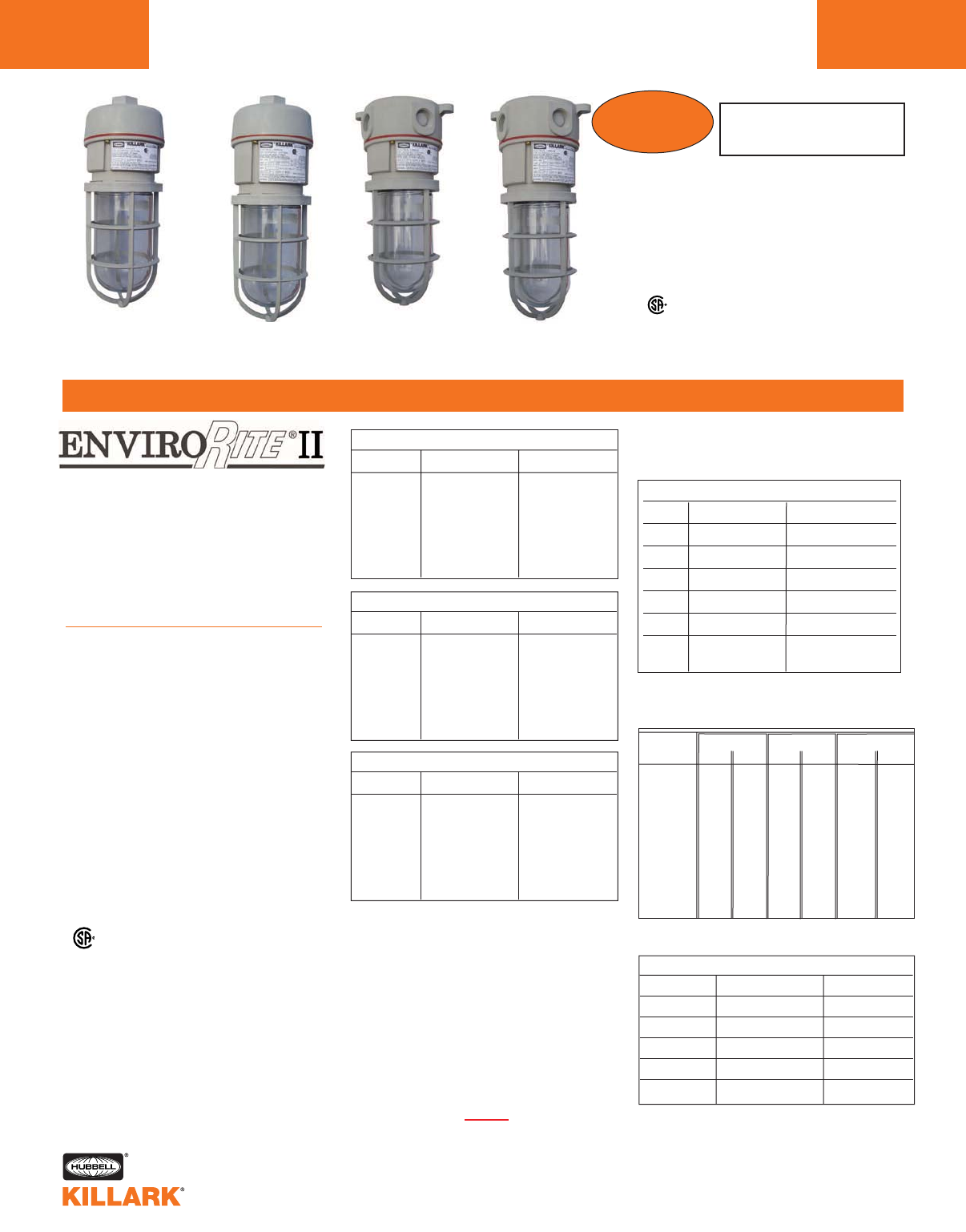
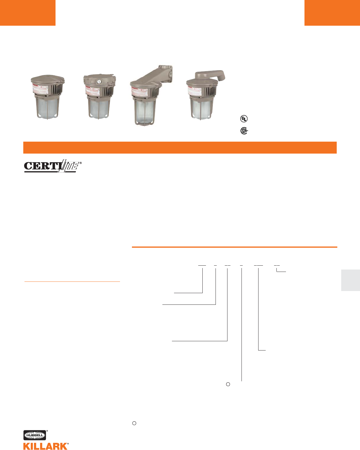
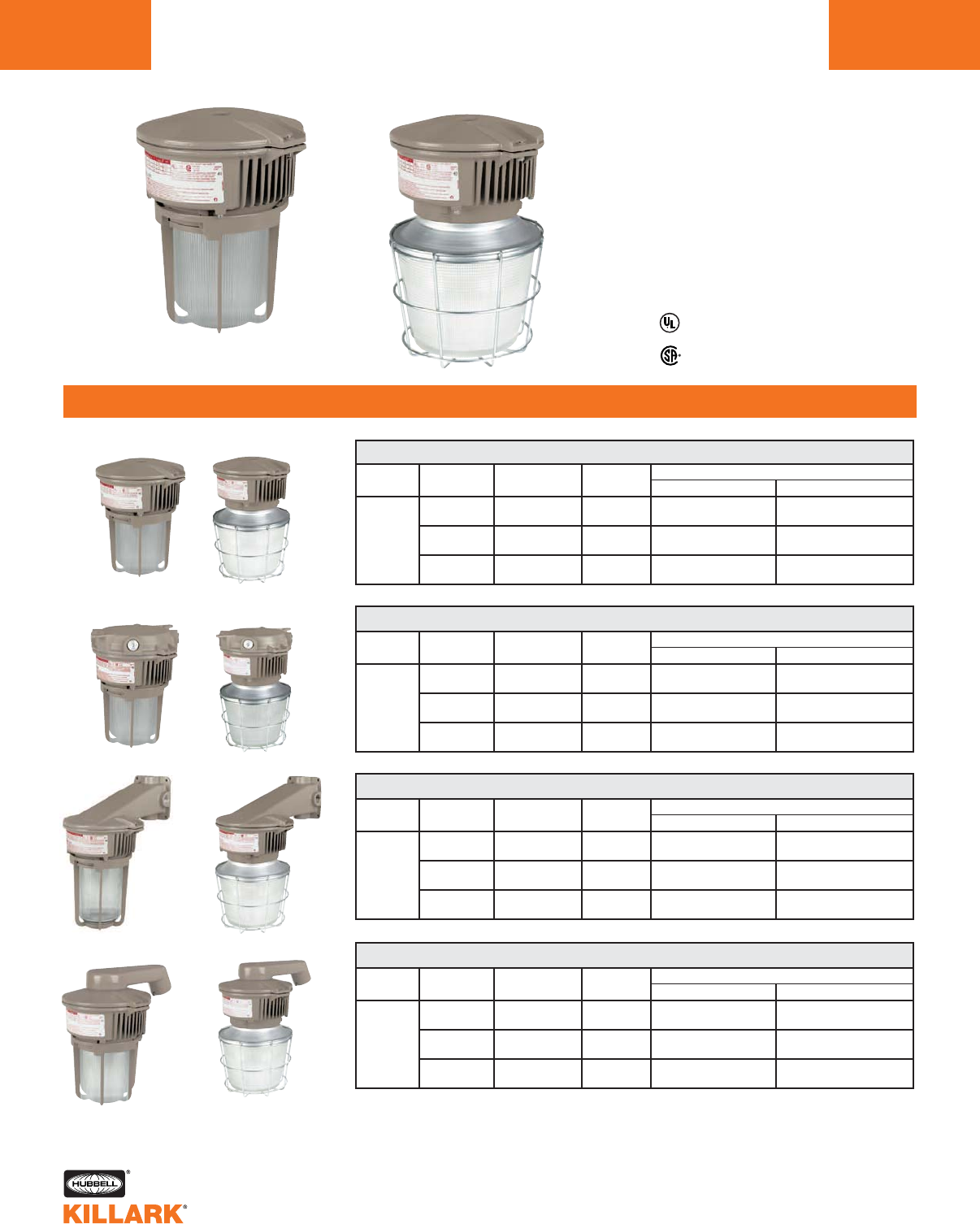
NV2 SERIES •LIGHTING
NON-METALLIC CORROSION RESISTANT HAZARDOUS FIXTURES
L2
FEATURES-SPECIFICATIONS
For original NV Series
see PDF cat. page L2A at
www.hubbell-killark.com
Pendant
Incandescent
Pendant
Fluorescent
Ceiling
Incandescent
Ceiling
Fluorescent
Class I, Div. 2, Groups A,B,C,D
Class l, Zone 2, Groups llC,llB,llA
Class II, Div. 2, Groups F,G
Class lII
Marine
NEMA 3, 4, 4X, IP66
ABS Type Approval
NEW!
Certified - File LR11713
CUS
Applications
Designed specifically for corrosive & wet
NEMA 4X and hazardous environments.
Typical applications include manufactur-
ing plants, chemical and petrochemical
processing facilities, sewage treatment
plants, off-shore and dockside installa-
tions, agricultural, commercial/industrial,
mining and marine facilities.
Features
•NV2 Series non-metallic light fixtures
combine an outstanding balance of
strength, stiffness, toughness and
electrical properties
•Energy and labor saving fluorescent
or incandescent models
•Accessories include polycarbonate
dome reflectors and wall extension
•Molded from 30% glass-filled ther-
moset polyester for high strength
•Resists corrosive effects of most
chemicals, hydrocarbons and
solvents
•Designed for indoor and outdoor
applications.
to the following standards:
UL 1598 Standard for luminaires
UL 1598A Marine type luminaires
UL 844 Standard for lighting fixtures for
hazardous locations
CSA C22.2 no. 137-M1981 electric lumi-
naires for use in hazardous locations
Enclosed and gasketed
NEMA 3, 4X, IP66
CUS
Colored Globe Options**
Example: NV2IG15ASG-R for Ruby Standard Globe
or NV2IG15AHG-R for Ruby Tempered Globe
Suffix and available combinations
Color Standard Globe Tempered Globe
Amber A A
Blue B B
Ruby R R
Green G NA
Purple P NA
Blue- BG BG
Green
**Tempered globes are required for wet locations.
Pendant 3/4” Fixture w/clear Globe & Guard*
Type Standard Globe Tempered Globe
150A Incan.
13 W Fluor.
18 W Fluor.
26 W Fluor.
32 W Fluor.
42 W Fluor.
NV2IG15ASG
NV2FG13ASG
NV2FG18ASG
NV2FG26ASG
NV2FG32ASG
NV2FG42ASG
NV2IG15AHG
NV2FG13AHG
NV2FG18AHG
NV2FG26AHG
NV2FG32AHG
NV2FG42AHG
150A Incan.
13 W Fluor.
18 W Fluor.
26 W Fluor.
32 W Fluor.
42 W Fluor.
150A Incan.
13 W Fluor.
18 W Fluor.
26 W Fluor.
32 W Fluor.
42 W Fluor.
NV2IG15XSG
NV2FG13XSG
NV2FG18XSG
NV2FG26XSG
NV2FG32XSG
NV2FG42XSG
NV2IG15XHG
NV2FG13XHG
NV2FG18XHG
NV2FG26XHG
NV2FG32XHG
NV2FG42XHG
NV2IG15BSG
NV2FG13BSG
NV2FG18BSG
NV2FG26BSG
NV2FG32BSG
NV2FG42BSG
NV2IG15BHG
NV2FG13BHG
NV2FG18BHG
NV2FG26BHG
NV2FG32BHG
NV2FG42BHG
*Notes:
•Tempered Globes are required for Wet
Location applications
•All assemblies are unit packed with
required components (not assembled)
•Fluorescent unit pack models (only) include
the lamp
•Reflector is sold separately. For wall mount-
ing with reflector, the NVEXTG extension is
required and sold separately
•Fluorescent models use "world voltage" bal-
lasts for 120VAC through 277VAC 50/60Hz
applications
•Incandescent models 277VAC max.
•For M20 ceiling units change “X” in part #
to “M”. For wall units change “B” to “W”.
M20 Pendant not available.
Ceiling 3/4” Fixture w/clear Globe & Guard*
Type Standard Globe Tempered Globe
75A
100A
150A
13 Fluor
18 Fluor
26 Fluor
32 Fluor
42 Fluor
Class I Div.2 Class II Div.2 Minimum Start
Globe Type Clear Color Clear Color oCoF
Wall 3/4” Fixture w/clear Globe & Guard*
Type Standard Globe Tempered Globe T2C
T2A
T2B
T3C
T3C
T3B
T3B
T2D
T2B
T2
T2
T3C
T3C
T3A
T3A
T2C
T3C
T3C
-
T4A
T4A
T4A
T4A
T4A
-
-
-
T4A
T4A
T4A
T4A
T4A
-
-
-
-15
-15
-15
-15
-15
-
-
-
5
5
5
5
5
Fluorescent Operating Max. Amps
Type 120 VAC 277 VAC
13W Fluor .144 .067
18W Fluor .158 .073
26W Fluor .22 .097
32W Fluor .285 .128
42W Fluor .38 .166
NV2AG Pendant 3/4” NPT Pendant splice box includes a 316 stainless steel set screw at
the conduit connection
NV2XG1Ceiling 3/4” NPT
NV2MG1Box M20
NV2BG Wall Bracket Use with NV2XG or NV2MG for wall mount
1NV2 ceiling (wall) boxes have 4 10-32 brass inserts with 2 ground screws. May be used for wet locations, as
terminal/junction, boxes ,or instruments using ‘clear’ blank cover.
2See page L12 for colored globes; use tempered for wet locations.
NV2 SERIES •LIGHTING
NON-METALLIC CORROSION RESISTANT HAZARDOUS FIXTURES L3
COMPONENT PARTS
L
ABS Type Approval
Class I, Div. 2, Groups A,B,C,D
Class l, Zone 2, Groups llC,llB,llA
Class II, Div. 2, Groups F,G
Class lII
Marine
NEMA 3, 4, 4X, IP66
NEW!
Certified - File LR11713
CUS
Wall Mount
Incandescent
Pendent
Wall Mount
Fluorescent
Wall Mount with
Extension and Dome
Reflector accessories
Ceiling/Wall
Wall Elbow Ceiling/Wall
(Interior Detail)
Incandescent Fluorescent
Globe Guard
Reflector Extension
Gray Blank Clear
NV2 SPLICE BOXES - INCLUDES SILICONE GASKETS & BRASS SCREWS
CATALOG NUMBER DESCRIPTION
NV2 BODIES
CATALOG NUMBER DESCRIPTION
NV2IG15 Incandescent Body with E-26 medium base socket; fixture rated voltage 277VAC max.
NV2FG13 13 W Fluorescent Body World Voltage 120V - 277V 50/60Hz
NV2FG18 18 W Fluorescent Body World Voltage 120V - 277V 50/60Hz
NV2FG26 26 W Fluorescent Body World Voltage 120V - 277V 50/60Hz
NV2FG32 32 W Fluorescent Body World Voltage 120V - 277V 50/60Hz
NV2FG42 42 W Fluorescent Body World Voltage 120V - 277V 50/60Hz
NV2 GLASS GLOBES & GUARDS2
CATALOG NUMBER DESCRIPTION
VCG-100 Clear
VCGP-100 Clear, Tempered
NV2GG Guard
Ceiling
Box
150 watt Lamp size A-21 max.
NV2 REFLECTORS AND EXTENSION
CATALOG NUMBER DESCRIPTION
NVPSD12 White Polycabonate Reflector (secured by guard)
NVEXTG Extension (for wall mount fixture with reflector)
BLANK COVERS FOR NV2XG CEILING BOXES
CATALOG NUMBER DESCRIPTION
NV2CG Gray Cover
NV2CC1Clear Cover
NV2F FLUORESCENT REPLACEMENT LAMPS AND BALLASTS
MQL13 13 W Quad-Pin Lamp 900 Lumens
MQL18 18 W Quad-Pin Lamp 1200 Lumens
MQL26 26 W Quad-Pin Lamp 1800 Lumens
MQL32 32 W Quad-Pin Lamp 2400 Lumens
MQL42 42 W Quad-Pin Lamp 3200 Lumens
Ceiling box vol. 24 cu. inches
B
B
K
K
F
F
1
1
3
3
1
1
8
8
3
3
0
0
13/18 Watt Rep. Ballast
B
B
K
K
F
F
2
2
6
6
3
3
2
2
3
3
0
0
26/32 Watt Rep. Ballast
B
B
K
K
F
F
3
3
2
2
4
4
2
2
3
3
0
0
32/42 Watt Rep. Ballast
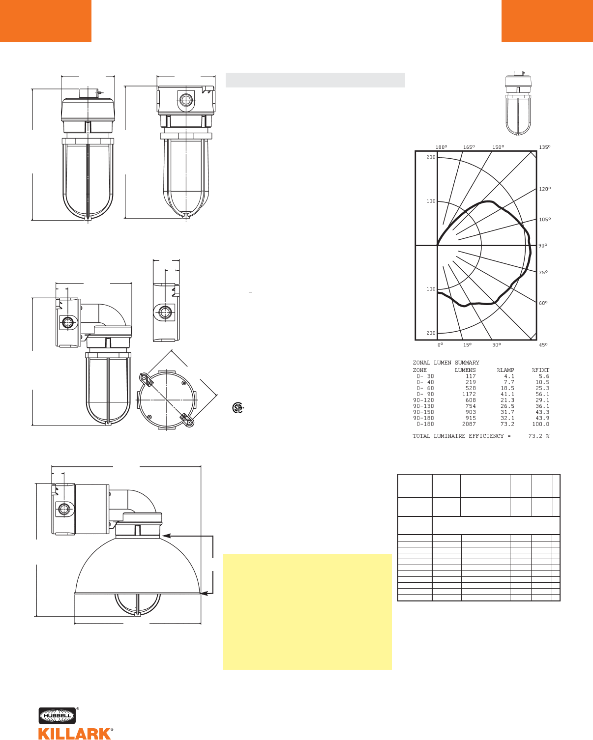
NV2IG15 Incandescent
With Globe & Guard
Candlepower - 150 Watt
A-21 lamp 2850 lumens
For 75 Watt multiply by .42
For 100 Watt multiply by .61
NV2XG
5.19
(132)
Volume
24 Cu. In.
њ.33
TYP
(0)
NV2 SERIES •LIGHTING
DIMENSIONS, CROSS REFERENCE, PHOTOMETRIC DATA
L4
Pendant
Dimensions* NV To NV2 Cross Reference Photometrics
Ceiling
Wall
Wall mount with optional reflector and with
extension. Extension required only for wall
mount units using reflector.
*NOTE: Dimensional diagrams show incan-
descent models, but include height also for
fluorescent.
11.20
Incandescent
(285)
12.31
Fluorescent
(340)
4.53 DIA.
(115)
11.69 DIA.
(297)
10.84
Incandescent
(275)
11.95
Fluorescent
(304)
4.75
(121)
12.26
Incandescent
(311)
13.37
Fluorescent
(340)
7.30
(185)
12.26 Incandescent
(311)
13.37 Fluorescent
(340)
13.78
(350)
Complete Fixtures
NVA15GG NV2IG15ASG INC 150W PEND STD GLOBE/GRD
NVA15GHG NV2IG15AHG INC 150W PEND TEMPER GLB/GRD
NVX15GG NV2IG15XSG INC 150W CEIL STD GLOBE/GRD
NVX15GHG NV2IG15XHG INC 150W CEIL TEMPER GLB/GRD
NVB15GG NV2IG15BSG INC 150W WALL STD GLOBE/GRD
NVB15GHG NV2IG15BHG INC 150W WALL TEMPER GLB/GRD
NVQA18GG NV2FG18ASG FL18 120-277 PEND STD GLOB/GRD
NVQA18GHG NV2FG18AHG FL18 120-277 PEND TEM GLOB/GRD
NVQX18GG NV2FG18XSG FL18 120-277 CEIL STD GLOB/GRD
NVQX18GHG NV2FG18XHG FL18 120-277 CEIL TEM GLB/GRD
NVQB18GG NV2FG18BSG FL18 120-277 WALL STD GLOB/GRD
NVQB18GHG NV2FG18BHG FL18 120-277 WALL TEM GLOB/GRD
Components
NVA NV2AG 3/4” Pendant
NVX NV2XG 3/4” Ceiling (Wall) Box
NVB NV2BG Elbow, use with Ceiling Box
NVQFC NV2FG18 Fluorescent Body 120-277VAC
50/60Hz
NVQFC184 (1) NV2FG18 Fluorescent Body 120-277VAC
50/60Hz
NVFC NV2IG15 Incandescent Body
NVFC-LT (2) NV2IG15 Incandescent Body
NVG NV2GG Guard
NVQ-18 MQL18 18W Compact Fluor. Lamp
NVBC NV2CG Blank Cover w/Two Gaskets
NVSG NV2CG Use Blank Cover’s extra gasket
(1) “4” for 277VAC Fluorescent no longer required
(2) Insulated socket incandescent no longer needed for 90c wire
Key New Features:
•Certified for Hostile Locations: Class I Div 2;
Class II Div 2; N4X; IP66
•ABS Approval
•120-277VAC 50/60Hz World Voltage Ballasts on Fluorescents
•Four new Fluorescent Wattages: 13, 26, 32, 42
•Only 90° C wire for Incandescent suitable for Marine with 150A
•New Dome Reflector
•Colored “100” Series globes can be ordered in assemblies
•M20 Metric ceiling/wall box
•Four 10-32 bosses in ceiling box for user applications
•Clear Blank covers available for user applications
Backward Compatability:
•NVG & NV2GG are interchangeable
•Globes are interchangeable
•Old NV Incandescent and Fluorescent bodies will fit new
NV2 Boxes and Elbow, but assembly is Wet Location listed only
•New NV2IG15 Incandescent will fit old NV Boxes and Elbow
•New NV2FGx Fluorescent will fit old NVX box, not pendant
or elbow
•Reflectors will fit old bodies for pendant or ceiling applications
OLD NEW# NEW DESCRIPTION
C US
% EFFECTIVE
FLOOR CAVITY
REFLECTANCE
0.20
80 70 50 30 10 0
70 50 30 10 70 50 30 10 50 30 10 50 30 10 50 30 10 0
20% Effective Floor Cavity Reflectance
0 .79 .79 .79 .79 .74 .74 .74 .74 .64 .64 .64 .54.54 .54 .45 .45 .45 .41
1 .69 .64 .59 .55 .63 .59 .55 .51 .50 .47 .44 .41 .39 .37 .34 .32.30 .26
2 .61 .53 .47 .42 .56 .49 .44 .39 .41 .37 .33 .34.31 .28 .27 .25 .23 .19
3 .55 .46 .39 .33 .50 .42.36 .31 .35 .30 .26 .29.25 .22 .23 .20 .18 .14
4 .49 .40 .33 .27 .45 .37.30 .25 .31 .26 .21 .25.21 .18 .20 .17 .14 .11
5 .45 .35 .28 .23 .41 .23.26 .21 .27 .22 .18 .22.18 .15 .18 .14 .12 .09
6 .41 .31 .24 .19 .38 .29 .22 .18 .24 .19 .15 .20 .16 .12 .16 .12 .10 .08
7 .38 .28 .21 .16 .35 .26 .20 .15 .22 .17 .13 .18 .14 .11 .14 .11 .08 .06
8 .35 .25 .19 .14 .32 .23 .17 .13 .20 .15 .11 .16 .12 .09 .13 .10 .07 .06
9 .33 .23 .17 .12 .30 .21 .15 .12 .18 .13 .10 .15 .11 .08 .12 .09 .06 .05
10 .30 .21 .15 .11 .28 .19 .14 .10 .16 .12 .09 .14 .10 .07 .11 .08 .06 .04
% WALL
REFLECTANCE
1w
ROOM CAVITY
RATIO
RCRW
COEFFICIENTS OF UTILIZATION ---ZONAL CAVITY METHOD
SPACING CRITERION = 2.3
TEST NO. 1716
1.15
(29)
5.37
(137)
2.12
(54)
1.15
(29)
1.15
(29)
NV2 SERIES •LIGHTING
PHOTOMETRIC DATA L5
L
% EFFECTIVE
FLOOR CAVITY
REFLECTANCE
0.20
80 70 50 30 10 0
70 50 30 10 70 50 30 10 50 30 10 50 30 10 50 30 10 0
20% Effective Floor Cavity Reflectance
0 .65 .65 .65 .65 .63 .63.63 .63 .60 .60 .60 .58 .58 .58 .55 .55 .55 .54
1 .58 .56 .53 .51 .57 .54 .52 .50 .52 .50 .48 .50 .48 .47 .48 .47 .45 .44
2 .53 .48 .43 .40 .51 .47.43 .40 .45 .41 .39 .43.40 .38 .41 .39 .37 .36
3 .47 .41 .36 .32 .46 .40.36 .32 .39 .35 .31 .37 .34 .31 .36 .33 .30 .29
4 .43 .36 .31 .27 .42 .35.30 .27 .34 .29 .26 .32.29 .26 .31 .28 .25 .24
5 .39 .32 .26 .23 .38 .31.26 .22 .30 .25 .22 .29.25 .22 .28 .24 .12 .20
6 .36 .28 .23 .19 .35 .28.23 .19 .27 .22 .19 .26.22 .19 .25 .21 .19 .17
7 .33 .25 .20 .17 .32 .25.20 .17 .24 .20 .17 .23.19 .16 .23 .19 .16 .15
8 .31 .23 .18 .15 .30 .23 .18 .15 .22 .18 .15 .27 .17 .14 .21 .17 .14 .13
9 .29 .21 .16 .13 .28 .21 .16 .13 .20 .16 .13 .19 .16 .13 .19 .15 .13 .12
10 .27 .19 .15 .12 .26 .19 .15 .12 .18 .14 .12 .18.14 .12 .17 .14 .12 .11
% WALL
REFLECTANCE
1w
ROOM CAVITY
RATIO
RCRW
COEFFICIENTS OF UTILIZATION ---ZONAL CAVITY METHOD
SPACING CRITERION = 1.5
TEST NO. 1717
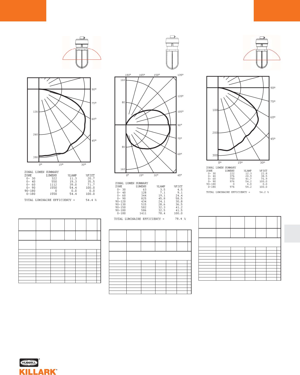
*Full cutoff distribution
*
*
Photometrics
NV2FG26 Fluorescent
With Globe & Guard
Candlepower - 26 Watt
CF26 lamp 1800 lumens
For 13 Watt multiply by .50
For 18 Watt multiply by .67
For 32 Watt multiply by 1.33
For 42 Watt multiply by 1.78
% EFFECTIVE
FLOOR CAVITY
REFLECTANCE
0.20
80 70 50 30 10 0
70 50 30 10 70 50 30 10 50 30 10 50 30 10 50 30 10 0
20% Effective Floor Cavity Reflectance
0 .86 .86 .86 .86 .80 .80.80 .80 .69 .69 .69 .59.59 .59 .50 .50 .50 .46
1 .73 .68 .63 .58 .68 .63.58 .54 .53 .50 .47 .45.42 .39 .37 .35 .33 .29
2 .65 .57 .50 .44 .60 .52.46 .41 .44 .39 .35 .36.33 .29 .30 .27 .24 .20
3 .58 .48 .41 .34 .53 .44.38 .32 .37 .32 .27 .31.26 .23 .25 .21 .18 .15
4 .52 .42 .34 .28 .48 .38.31 .26 .32 .27 .22 .27.22 .18 .21 .18 .15 .12
5 .48 .37 .29 .23 .44 .34.27 .21 .28 .23 .18 .23.19 .15 .19 .15 .12 .09
6 .44 .32 .25 .19 .40 .30 .23 .18 .25 .19 .15 .21 .16 .13 .17 .13 .10 .08
7 .40 .29 .22 .16 .37 .27 .20 .15 .22 .17 .13 .19 .14 .11 .15 .11 .08 .06
8 .37 .26 .19 .14 .34 .24 .18 .13 .20 .15 .11 .17 .12 .09 .14 .10 .07 .05
9 .34 .24 .17 .12 .32 .22 .16 .11 .18 .13 .10 .15 .11 .08 .12 .09 .06 .05
10 .32 .21 .15 .11 .30 .20 .14 .10 .17 .12 .09 .14 .10 .07 .11 .08 .06 .04
% WALL
REFLECTANCE
1w
ROOM CAVITY
RATIO
RCRW
COEFFICIENTS OF UTILIZATION ---ZONAL CAVITY METHOD
SPACING CRITERION = 3.5
TEST NO. 1720
% EFFECTIVE
FLOOR CAVITY
REFLECTANCE
0.20
80705030100
70 50 30 10 70 50 30 10 50 30 10 50 30 10 50 30 10 0
20% Effective Floor Cavity Reflectance
0 .64 .64 .64 .64 .63 .63.63 .63 .60 .60 .60 .58.58 .58 .55 .55 .55 .54
1 .59 .56 .54 .52 .57 .55.53 .51 .53 .51 .49 .50.49 .48 .48 .47 .46 .45
2 .53 .48 .45 .41 .52 .47.44 .41 .45 .42 .40 .44.41 .39 .42 .40 .38 .37
3 .48 .42 .37 .34 .47 .41.37 .34 .40 .36 .33 .38.35 .32 .37 .34 .32 .31
4 .44 .37 .32 .28 .42 .36.32 .28 .35 .31 .28 .34.30 .27 .32 .29 .27 .26
5 .40 .33 .28 .24 .39 .32.27 .24 .31 .27 .23 .30.26 .23 .29 .26 .23 .22
6 .37 .29 .24 .21 .36 .29.24 .20 .28 .23 .20 .27.23 .20 .26 .23 .20 .19
7 .34 .26 .21 .18 .33 .26.21 .18 .25 .21 .18 .24.20 .18 .23 .20 .17 .16
8 .32 .24 .19 .16 .31 .24 .19 .16 .23 .19 .16 .22 .18 .16 .21 .18 .15 .14
9 .29 .22 .17 .14 .29 .22 .17 .14 .21 .17 .14 .20 .17 .14 .20 .16 .14 .13
10 .27 .20 .16 .13 .27 .20 .16 .13 .19 .15 .13 .19.15 .13 .18 .15 .12 .11
% WALL
REFLECTANCE
1w
ROOM CAVITY
RATIO
RCRW
COEFFICIENTS OF UTILIZATION ---ZONAL CAVITY METHOD
SPACING CRITERION = 1.4
TEST NO. 1724
*Full cutoff distribution
NV2FG26 Fluorescent
With Globe, Guard & Reflector
Candlepower - 26 Watt
CF26 lamp 1800 lumens
For 13 Watt multiply by .50
For 18 Watt multiply by .67
For 32 Watt multiply by 1.33
For 42 Watt multiply by 1.78
NV2IG15 Incandescent
With Globe, Guard & Reflector
Candlepower - 150 Watt
A-21 lamp 2850 lumens
For 75 Watt multiply by .42
For 100 Watt multiply by .61
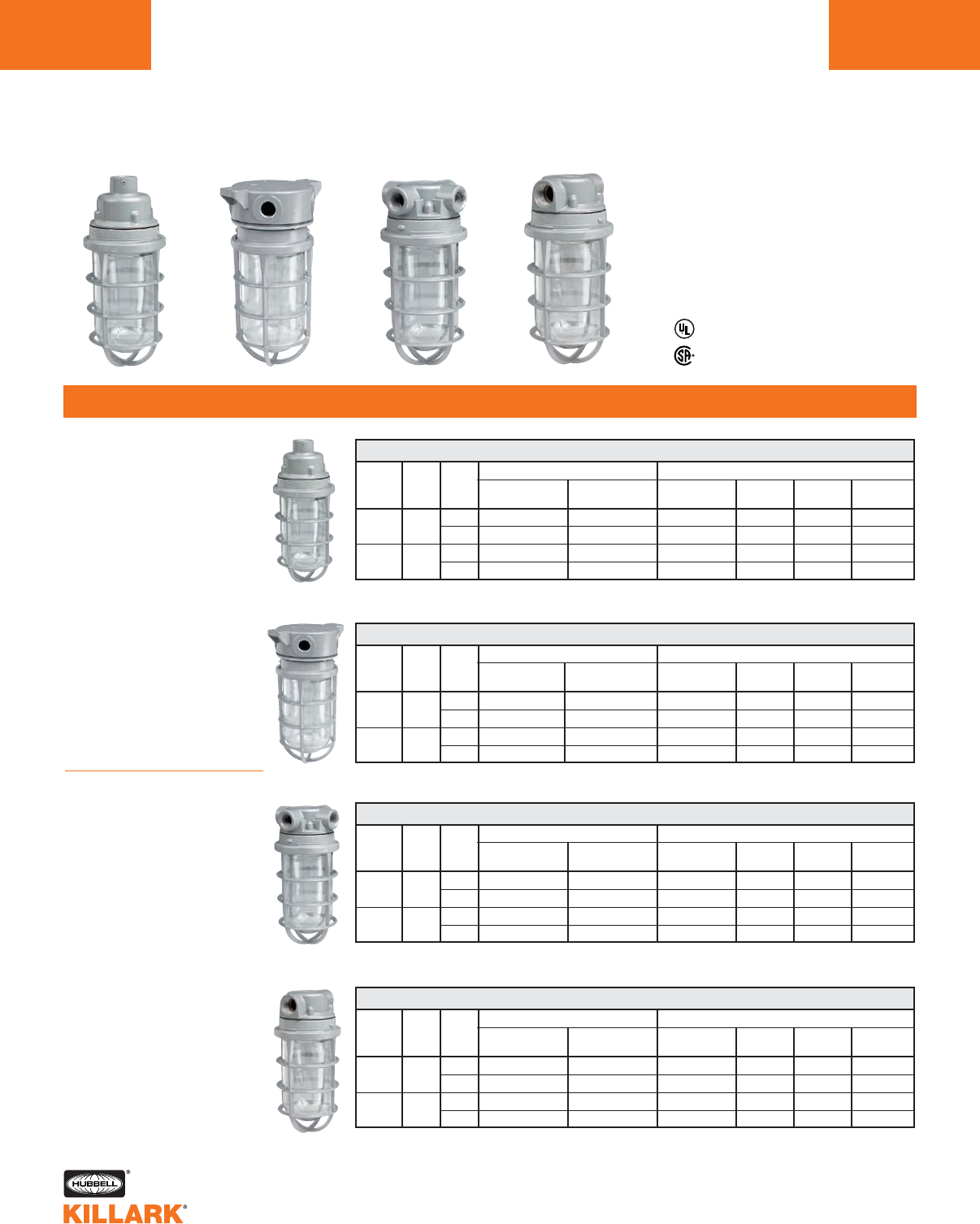
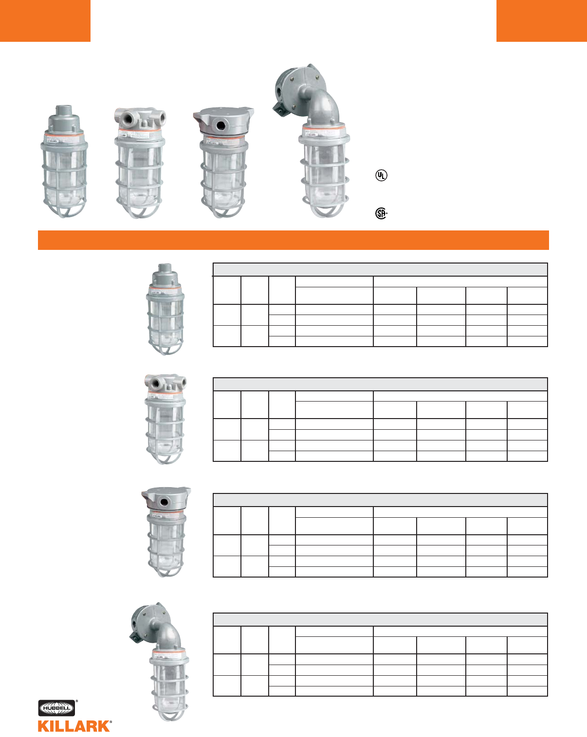
V SERIES •WEATHERPROOF
INCANDESCENT COPPER-FREE ALUMINUM FIXTURES
L6
INTRODUCTION AND ORDERING INFORMATION
Listed - File E27731
Certified - File LR11851
Enclosed & Gasketed
CATALOG NUMBER
PENDANT MOUNT WITH VGA SPLICE BOX
HUB
SIZE
1/2"
3/4"
1/2"
3/4"
FIXTURE
TYPE
100
200
LAMP
WATT
150
300
GUARD
(if selected)
VAG-100
VAG-100
VAG-200
VAG-200
FIXTURE
BODY
VFC-100
VFC-100
VFC-200
VFC-200
MOUNTING
BOX
VGA-1
VGA-2
VGA-1
VGA-2
CLEAR
GLOBE*
VCG-100
VCG-100
VCG-200
VCG-200
FIXTURE W/
GLOBE & GUARD
VUAGG-1-100 1
VUAGG-2-100 1
VUAGG-1-200 2
VUAGG-2-200 2
FIXTURE W/
GLOBE
VUAG-1-100 2
VUAG-2-100 2
VUAG-1-200 2
VUAG-2-200 2
CONSISTS OF
CATALOG NUMBER
CEILING MOUNT WITH VGX SPLICE BOX
HUB
SIZE
1/2"
3/4"
1/2"
3/4"
FIXTURE
TYPE
100
200
LAMP
WATT
150
300
GUARD
(if selected)
VAG-100
VAG-100
VAG-200
VAG-200
FIXTURE
BODY
VFC-100
VFC-100
VFC-200
VFC-200
MOUNTING
BOX
VGX-1
VGX-2
VGX-1
VGX-2
CLEAR
GLOBE*
VCG-100
VCG-100
VCG-200
VCG-200
FIXTURE W/
GLOBE & GUARD
VUXGG-1-100 2
VUXGG-2-100 2
VUXGG-1-200 2
VUXGG-2-200 2
FIXTURE W/
GLOBE
VUXG-1-100 2
VUXG-2-100 2
VUXG-1-200 2
VUXG-2-200 2
CONSISTS OF
CATALOG NUMBER
CEILING MOUNT WITH FEET USING VBC SPLICE BOX AND VBA ADAPTER
HUB
SIZE
1/2"
3/4"
1/2"
3/4"
FIXTURE
TYPE
100
200
LAMP
WATT
150
300
GUARD
(if selected)
VAG-100
VAG-100
VAG-200
VAG-200
FIXTURE
BODY
VFC-100
VFC-100
VFC-200
VFC-200
MOUNTING
BOX/ADAPTER
VBC-1 + VBA
VBC-2 + VBA
VBC-1 + VBA
VBC-2 + VBA
CLEAR
GLOBE*
VCG-100
VCG-100
VCG-200
VCG-200
FIXTURE W/
GLOBE & GUARD
VUXBGG-1-100 1
VUXBGG-2-100 1
VUXBGG-1-200 2
VUXBGG-2-200 2
FIXTURE W/
GLOBE
VUXBG-1-100 1
VUXBG-2-100 1
VUXBG-1-200 2
VUXBG-2-200 2
CONSISTS OF
CATALOG NUMBER
CEILING MOUNT WITH VGC SPLICE BOX - FEED THROUGH
HUB
SIZE
1/2"
3/4"
1/2"
3/4"
FIXTURE
TYPE
100
200
LAMP
WATT
150
300
GUARD
(if selected)
VAG-100
VAG-100
VAG-200
VAG-200
FIXTURE
BODY
VFC-100
VFC-100
VFC-200
VFC-200
MOUNTING
BOX
VGC-1
VGC-2
VGC-1
VGC-2
CLEAR
GLOBE*
VCG-100
VCG-100
VCG-200
VCG-200
FIXTURE W/
GLOBE & GUARD
VUCGG-1-100 1
VUCGG-2-100 2
VUCGG-1-200 2
VUCGG-2-200 2
FIXTURE W/
GLOBE
VUCG-1-100 2
VUCG-2-100 2
VUCG-1-200 2
VUCG-2-200 2
CONSISTS OF
*For other colors, order globes and fixture components separately.
1Fixture supplied as component unit pack when ordered by this catalog number.
2Catalog number for ordering convenience; fixture is shipped as components as listed in catalog number table.
V
V
S
S
e
e
r
r
i
i
e
e
s
s
E
E
n
n
c
c
l
l
o
o
s
s
e
e
d
d
&
&
G
G
a
a
s
s
k
k
e
e
t
t
e
e
d
d
Applications
Locations requiring durable,
protected lighting fixtures
Wet and dirt laden locations
Industrial environments
requiring enclosed and gas-
keted (vapor tight) fixtures
Fixtures intended for base-up
mounting
Heat resistant glass globes
recommended for wet loca-
tions
Features
•Electrostatically applied
epoxy/polyester finish
•Modular design
•Hubs are threaded for
attachment to conduit
•Set screws in pendant fix-
tures
•Copper-free aluminum (less
than 4/10 of 1%)
Class I, Div. 2, NEMA 4 mod-
els available - see VXFC
Series lighting assemblies
& components, pages L9-
L12. Dimensions page L13.
V SERIES •WEATHERPROOF
INCANDESCENT COPPER-FREE ALUMINUM FIXTURES L7
ORDERING INFORMATION
L
Listed - File E27731
Certified - File LR11851
Enclosed & Gasketed
CATALOG NUMBER
CEILING MOUNT WITH VBA ADAPTER FOR ROUND OUTLET BOX
FIXTURE
TYPE
100
200
LAMP
WATT
150
300
HUB
SIZE
1/2"
3/4"
GUARD
(if selected)
VAG-100
VAG-200
FIXTURE
BODY
VFC-100
VFC-200
BOX
ADAPTER
VBA
VBA
CLEAR
GLOBE*
VCG-100
VCG-200
FIXTURE W/
GLOBE & GUARD
VOBG-100 1
VOBG-200 1
FIXTURE W/
GLOBE
VOB-100 1
VOB-2002
CONSISTS OF
CATALOG NUMBER
CEILING MOUNT WITH VFPS ADAPTER FOR SQUARE OR OCTAGON OUTLET BOX
FIXTURE
TYPE
100
200
LAMP
WATT
150
300
HUB
SIZE
1/2"
3/4"
GUARD
(if selected)
VAG-100
VAG-200
FIXTURE
BODY
VFC-100
VFC-200
BOX
ADAPTER
VFPS
VFPS
CLEAR
GLOBE*
VCG-100
VCG-200
FIXTURE W/
GLOBE & GUARD
VFCAG-100 2
VFCAG-200 2
FIXTURE W/
GLOBE
VFCA-100 2
VFCA-200 2
CONSISTS OF
CATALOG NUMBER
CEILING MOUNT WITH VGH SPLICE BOX - DEAD END
HUB
SIZE
1/2"
3/4"
1/2"
3/4"
FIXTURE
TYPE
100
200
GUARD
(if selected)
VAG-100
VAG-100
VAG-200
VAG-200
FIXTURE
BODY
VFC-100
VFC-100
VFC-200
VFC-200
MOUNTING
BOX
VGH-1
VGH-2
VGH-1
VGH-2
CLEAR
GLOBE*
VCG-100
VCG-100
VCG-200
VCG-200
FIXTURE W/
GLOBE & GUARD
VUHGG-1-100 2
VUHGG-2-100 2
VUHGG-1-200 2
VUHGG-2-200 2
FIXTURE W/
GLOBE
VUHG-1-100 2
VUHG-2-100 2
VUHG-1-200 2
VUHG-2-200 2
CONSISTS OF
CATALOG NUMBER
CEILING MOUNT WITH VXA DEEP 5-HUB SPLICE BOX
HUB
SIZE
1/2"
3/4"
1/2"
3/4"
FIXTURE
TYPE
100
200
GUARD
(if selected)
VAG-100
VAG-100
VAG-200
VAG-200
FIXTURE
BODY
VFC-100
VFC-100
VFC-200
VFC-200
MOUNTING
BOX
VXA-1
VXA-2
VXA-1
VXA-2
CLEAR
GLOBE*
VCG-100
VCG-100
VCG-200
VCG-200
FIXTURE W/
GLOBE & GUARD
VXAGG-110 1
VXAGG-210 2
VXAGG-120 2
VXAGG-220 2
FIXTURE W/
GLOBE
VXAG-110 2
VXAG-210 2
VXAG-120 2
VXAG-220 2
CONSISTS OF
NOTES: Mounts directly to VJ ,VB or steel 3-1/2" or 4" outlet boxes. Supplied with gasket.
NOTES: Mounts directly to steel 4" square and 3-1/2" or 4" octagon outlet box. Supplied with gasket.
*For other colors, order globe and fixture components separately.
1Fixture supplied as component unit pack when ordered by this catalog number.
2Catalog number for ordering convenience; fixture is shipped as components as listed in catalog number table.
LAMP
WATT
150
300
LAMP
WATT
150
300
V SERIES •WEATHERPROOF
INCANDESCENT COPPER-FREE ALUMINUM FIXTURES
L8
ORDERING INFORMATION
CATALOG NUMBER
STANCHION MOUNT FOR 1-1/4" THREADED PIPE
FIXTURE
TYPE
100
200
LAMP
WATT
150
300
HUB
SIZE
1-1/4"
1-1/4"
GUARD
(if selected)
VAG-100
VAG-200
FIXTURE
BODY
VFC-100
VFC-200
MOUNTING
ARM
VD-4
VD-4
CLEAR
GLOBE*
VCG-100
VCG-200
FIXTURE W/
GLOBE & GUARD
VD-410GG 1
VD-420GG 2
FIXTURE W/
GLOBE
VD-410G 1
VD-420G 2
CONSISTS OF
CATALOG NUMBER
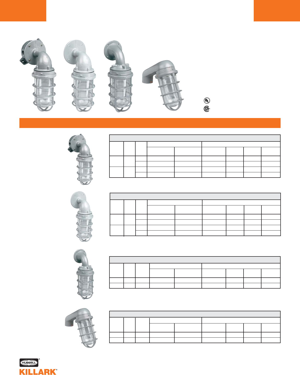
WALL MOUNT WITH VB ELBOW TO MOUNT TO 4" OUTLET BOX
HUB
SIZE
1/2"
3/4"
1/2"
3/4"
FIXTURE
TYPE
100
200
GUARD
(if selected)
VAG-100
VAG-100
VAG-200
VAG-200
FIXTURE
BODY
VFC-100
VFC-100
VFC-200
VFC-200
MOUNTING
ELBOW
VB-1
VB-2
VB-1
VB-2
CLEAR
GLOBE*
VCG-100
VCG-100
VCG-200
VCG-200
FIXTURE W/
GLOBE & GUARD
VFBGG-110 1
VFBGG-210 1
VFBGG-120 2
VFBGG-220 2
FIXTURE W/
GLOBE
VFBG-110 2
VFBG-210 2
VFBG-120 2
VFBG-220 2
CONSISTS OF
CATALOG NUMBER
WALL MOUNT WITH FEET USING VBC SPLICE BOX AND VB ELBOW
HUB
SIZE
1/2"
3/4"
1/2"
3/4"
FIXTURE
TYPE
100
200
LAMP
WATT
150
300
LAMP
WATT
150
300
GUARD
(if selected)
VAG-100
VAG-100
VAG-200
VAG-200
FIXTURE
BODY
VFC-100
VFC-100
VFC-200
VFC-200
MOUNTING
BOX/ELBOW
VBC-1+VB-1
VBC-2+VB-2
VBC-1+VB-1
VBC-2+VB-2
CLEAR
GLOBE*
VCG-100
VCG-100
VCG-200
VCG-200
FIXTURE W/
GLOBE & GUARD
VFBGG-1-100 1
VFBGG-2-100 1
VFBGG-1-200 2
VFBGG-2-200 2
FIXTURE W/
GLOBE
VFBG-1-100 1
VFBG-2-100 1
VFBG-1-200 2
VFBG-2-200 2
CONSISTS OF
CATALOG NUMBER
WALL MOUNT-WITH VFL ELBOW FOR DIRECT MOUNT TO V SERIES SPLICE BOXES
FIXTURE
TYPE
100
200
LAMP
WATT
150
300
HUB
SIZE
—
—
GUARD
(if selected)
VAG-100
VAG-200
FIXTURE
BODY
VFC-100
VFC-200
MOUNTING
ELBOW
VFL
VFL
CLEAR
GLOBE*
VCG-100
VCG-200
FIXTURE W/
GLOBE & GUARD
VOBLG-100 1
VOBLG-200 2
FIXTURE W/
GLOBE
VOBL-100 2
VOBL-200 2
CONSISTS OF
Mounts directly to V Series splice boxes, not to VBC box.
Mounts directly to VJ or VB Series or 4" steel outlet boxes. One hub in back, supplied with gasket.
*For other colors, order globe and fixture components separately.
1Fixture supplied as component unit pack when ordered by this catalog number.
2Catalog number for ordering convenience; fixture is shipped as components as listed in catalog number table.
Listed - File E27731
Certified - File LR11851
Enclosed & Gasketed
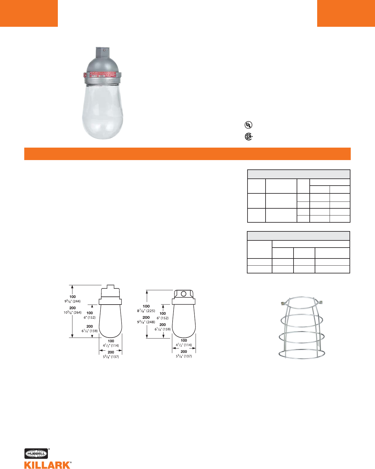
V SERIES •LIGHTING
INCANDESCENT NEMA 4 - CLASS I, DIV. 2 ALUMINUM FIXTURES L9
FEATURES-SPECIFICATIONS
L
* Wet location when used with tempered glass.
Listed - File E10514
Certified - File LR11713
UL-1571 Standard for incandescent fixtures
UL-844 Standard for hazardous location fixtures
Class I, Div. 2, Groups A,B,C,D
Class I, Zone 2, Groups IIC,IIB,IIA
NEMA 3, 4*
1Suitability based on base up installation
APPLICATION DATA1
FIXTURE
TYPE
100
100
100
100
100
200
200
200
200
200
LAMP
SIZE
A-19
60W
A-19
70W
A-19
100W
A-21
100W
A-21
150W
A-23
150W
PS-25
150W
A-23
200W
PS-25
200W
PS-25
300W
GLOBE
TYPE
colored &
clear
colored &
clear
colored &
clear
colored &
clear
colored &
clear
colored &
clear
colored &
clear
colored &
clear
colored &
clear
colored &
clear
TEMPERATURE
CODE @ 40°C
T2C
(230°C)
T2D
(215°C)
T2A
(280°C)
T2B
(260°C)
T2
(300°C)
T2A
(280°C)
T2B
(260°C)
T2
(300°C)
T2A
(280°C)
(350°C)
See dimensions page L13.
Applications
Killark “V” Series Vaportight fixtures are
now available Third Party Certified for
use in certain hazardous as well as wet
locations which require durable, pro-
tected lighting fixtures.
Wet and dirt laden industrial environ-
ments such as walkways, tunnels,
loading docks, stairwells, etc. made
hazardous by the presence of flammable
vapors as defined by the NEC.
Fixtures intended for base-up mounting
only.
Heat resistant (tempered) glass globes
recommended for wet locations.
Features
Killark Vaportight assemblies using VXFC
bodies & tempered glass have all the
features & advantages of “V” Enclosed &
Gasketed” models plus:
•Heavy-duty silicone gasketing for
NEMA 4 requirements
•Third party tested & labeled for use
in C1D2 areas
•Modular design permits selection of
splice box, fixture body, globe, guard
and reflector for specific or custom
applications
•Existing V Series mounting boxes may
be retrofitted to upgrade to NEMA 4;
C1D2 suitability
Copper-free aluminum construction with
electrostatically applied epoxy/polyester
finish resists corrosion
Pendant
Ceiling
V SERIES •LIGHTING
INCANDESCENT NEMA 4 - CLASS I, DIV. 2 ALUMINUM FIXTURES
L10
FEATURES-SPECIFICATIONS
CATALOG NUMBER
PENDANT MOUNT WITH VGA SPLICE BOX
HUB
SIZE
1/2"
3/4"
1/2"
3/4"
FIXTURE
TYPE
100
200
GUARD
VAG-100
VAG-100
VAG-200
VAG-200
FIXTURE
BODY
VXFC-100 N34
VXFC-100 N34
VXFC-200 N34
VXFC-200 N34
MOUNTING
BOX
VGA-1
VGA-2
VGA-1
VGA-2
CLEAR
GLOBE*
VCGP-100
VCGP-100
VCGP-200
VCGP-200
FIXTURE W/
GLOBE & GUARD
VUAGG-1-100PX 1
VUAGG-2-100PX 1
VUAGG-1-200PX 1
VUAGG-2-200PX 1
CONSISTS OF
CATALOG NUMBER
CEILING FIXTURE WITH VGX SPLICE BOX
HUB
SIZE
1/2"
3/4"
1/2"
3/4"
FIXTURE
TYPE
100
200
GUARD
VAG-100
VAG-100
VAG-200
VAG-200
FIXTURE
BODY
VXFC-100 N34
VXFC-100 N34
VXFC-200 N34
VXFC-200 N34
MOUNTING
BOX
VGX-1
VGX-2
VGX-1
VGX-2
CLEAR
GLOBE*
VCGP-100
VCGP-100
VCGP-200
VCGP-200
FIXTURE W/
GLOBE & GUARD
VUXGG-1-100PX 1
VUXGG-2-100PX 1
VUXGG-1-200PX 1
VUXGG-2-200PX 1
CONSISTS OF
CATALOG NUMBER
CEILING FIXTURE WITH MOUNTING FEET USING VBC SPLICE BOX & VBA ADAPTER
HUB
SIZE
1/2"
3/4"
1/2"
3/4"
FIXTURE
TYPE
100
200
FIXTURE
BODY
VXFC-100 N34
VXFC-100 N34
VXFC-200 N34
VXFC-200 N34
MOUNTING
BOX/ADAPTER
VBC-1+VBA
VBC-2+VBA
VBC-1+VBA
VBC-2+VBA
CLEAR
GLOBE*
VCGP-100
VCGP-100
VCGP-200
VCGP-200
FIXTURE W/
GLOBE & GUARD
VUXBGG-1-100PX 1
VUXBGG-2-100PX 1
VUXBGG-1-200PX 1
VUXBGG-2-200PX 1
CONSISTS OF
*For other colors, order globes and mounting components separately.
1Fixture supplied as component unit pack when ordered by this catalog number.
2See page L9 for temperature codes; NEMA 3, 4 when used with tempered glass.
CATALOG NUMBER
WALL FIXTURE WITH MOUNTING FEET USING VBC SPLICE BOX & VB ELBOW
HUB
SIZE
1/2"
3/4"
1/2"
3/4"
FIXTURE
TYPE
100
200
GUARD
VAG-100
VAG-100
VAG-200
VAG-200
FIXTURE
BODY
VXFC-100 N34
VXFC-100 N34
VXFC-200 N34
VXFC-200 N34
MOUNTING
BOX/ELBOW
VBC-1 + VB-1
VBC-2 + VB-2
VBC-1 + VB-1
VBC-2 + VB-2
CLEAR
GLOBE*
VCGP-100
VCGP-100
VCGP-200
VCGP-200
FIXTURE W/
GLOBE & GUARD
VFBGG-1-100PX 1
VFBGG-2-100PX 1
VFBGG-1-200PX 1
VFBGG-2-200PX 1
CONSISTS OF
Listed - File E10514
Certified - File LR11713
UL-1571 Standard for incandescent fixtures
UL-844 Standard for hazardous location fixtures
Class I, Div. 2, Groups A,B,C,D2
Class I, Zone 2, Groups IIC,IIB,IIA
NEMA 3, 4
GUARD
VAG-100
VAG-100
VAG-200
VAG-200
LAMP
WATT
150
300
LAMP
WATT
150
300
LAMP
WATT
150
300
LAMP
WATT
150
300
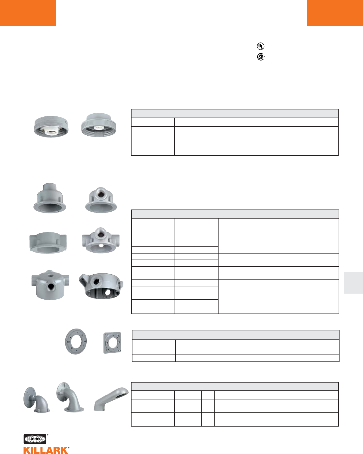
V SERIES •LIGHTING
COMPONENT PARTS/ACCESSORIES •INCANDESCENT FIXTURES L11
L
VFC Fixture Bodies
Fixture bodies contain lamp receptacle
and are threaded to accept globes,
guards and reflectors. These fixture
bodies are designed for metallic boxes
and mount directly to V Series splice
boxes. They may also be mounted to VJ
Series, VB Series or other 4” outlet
boxes with the use of the appropriate
adapter plate. Each fixture body is
supplied with gaskets.
Listed - File E27731
Certified - File LR11851
V Splice Boxes
For use with types 100 and 200
fixture bodies
VFC-100
VXFC-1001
VGA
VGC
VXA
VGX
VB VD
VFL
CATALOG NUMBER HUB SIZE & QTY.
VGA-1 1/2"
VGA-2 3/4"
VGH-1 1/2"
VGH-2 3/4"
VGC-1 1/2"
VGC-2 3/4"
VGX-1 1/2"
VGX-2 3/4"
VXA-1 1/2"
VXA-2 3/4"
VBC-1 1/2"
VBC-2* 3/4"
VXAB _
V SPLICE BOXES
DESCRIPTION
Pendant mount
Ceiling mount
Ceiling mount
Ceiling mount
Ceiling mount, deep box
Ceiling mount, with 3 close-up plugs (requires VBA Adapter)
Blank close-up plate (less gasket)
CATALOG NUMBER HUB SIZE QTY.
VB-1 1/2"
VB-2 3/4"
VFL —
VD-4 1-1/4"
V MOUNTING BRACKETS
DESCRIPTION
Wall mount to VJ or VB boxes
Wall mount to VJ or VB boxes
Wall mount to V boxes directly or to VJ, VB boxes with VBA adapter
Stanchion mount
CATALOG NUMBER
VFC-100
VFC-200
VXFC-100 N34
VXFC-200 N34
V FIXTURE BODIES
DESCRIPTION
150W max. Enclosed & Gasketed Fixture Boby
300W max. Enclosed & Gasketed Fixture Boby
150W max. NEMA 3,4 - Class I, Div. 2 Fixture Body1
300W max. NEMA 3,4 - Class I, Div. 2 Fixture Body1
1Use VXFC body with tempered globe for NEMA 3, 4 - Class I, Div. 2 applications. VXFC body is
Class I, Div. 2 only (not N3, N4) when used with standard globes. Consult temperature table, page
L9 for suitability.
* Volume cu. in. is 18.
VBC
VBA
VFPS
V ADAPTER MOUNTING PLATES
Adapts fixture body to VB, VJ or steel 3-1/2" & 4" splice boxes. Supplied with gasket.
Adapts fixture body to steel 4" square outlet boxes or 3-1/2" or 4" octagon boxes
VBA VFPS
VGH
VFC-200
VXFC-2001
1
1
1
1
2
2
4
4
5
5
4
4
_
1
1
—
1
CATALOG NUMBER DESCRIPTION
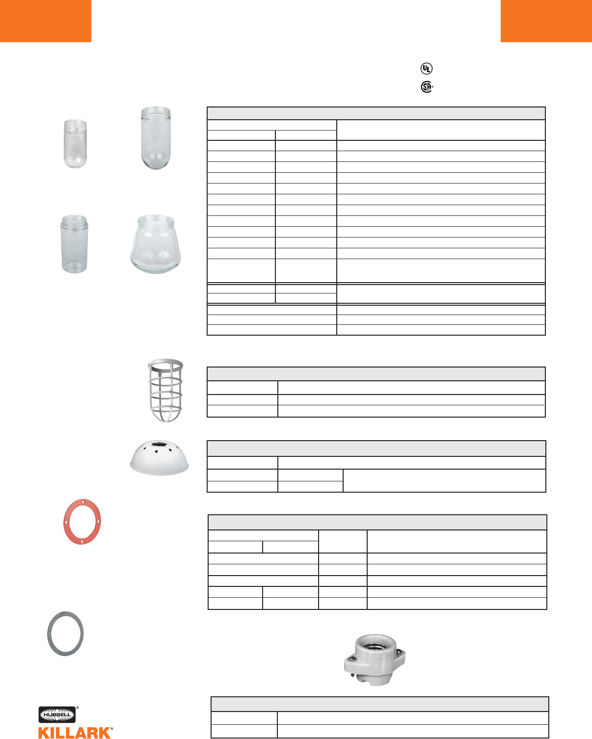
V SERIES •LIGHTING
COMPONENT PARTS/ACCESSORIES •INCANDESCENT FIXTURES
L12
150 W A-21 LAMP
VCG-100
VCGP-100
VCGPT-100
VAMG-100
VMAGP-100
VGG-100
VGGP-100
VRG-100
VRGP-100
VRSG-100
VPG-100
300 W PS-25 LAMP
VCG-200
VCGP-200
—
VAMG-200
—
VGG-200
VGGP-200
VBG-200
VRG-200
VRGP-200
—
—
V GLASS GLOBES
CATALOG NUMBER
500 W PS-35 LAMP
75 W A-19 LAMP
VPLCG-100
150 W A-21 LAMP
VPLCG-200
VCG-500
VCGP-500
CATALOG NUMBER
VAG-100
VAG-200
V GUARDS
DESCRIPTION
100 Series Vaportite guard
200 Series Vaportite guard
VPRSD-100
VPRSD-200
V REFLECTORS
100 Series Reflector 16 3/8" Dia. 5 5/8" High. White polypropylene for pendant & ceiling
200 Series Reflector applications. Not for use with wall or stanchion models.
V SERIES GASKETS
Fixture body to splice box
Silicone, Fixture body to splice box
Replacement Gaskets for VB-1/VB-2 and VBA
Globe gasket
Silicone, globe gasket
VRME
V LAMP SOCKET
For fixture types 100 and 200
Listed - File E27731
Certified - File LR11851
150 W Max.
Lamp Size A-21
Polycarbonate 500 W Max.
Lamp Size PS-35
Globe Gasket
100 Series Standard - 15871AABB
200 Series Standard - VTGG (pictured)
100 Series Silicone - VTGG1-S
200 Series Silicone - VTGG2-S
Body To Splice Box
Gasket
100 or 200 Series
VTG Standard
VTG-S Silicone (pictured)
300 W Max.
Lamp Size PS-25
VBG-100
VBGP-100 —
1Recommended for use with VXFC fixture basis.
2TM Thomas Manufacturing.
CATALOG NUMBER
CATALOG NUMBER
TYPE DESCRIPTION
DESCRIPTION
100 SERIES 200 SERIES
15871AABB VTGG
VTGG1-S VTGG2-S
VTG
VTG-S
VBNB
CATALOG NUMBER DESCRIPTION
VFC
VXFC
—
VFC
VFXC
DESCRIPTION
Clear
Clear Tempered. Thermal and shock resistant1
Clear Tempered with Tuffskin®coating2
Amber
Amber Tempered1
Blue Green
Blue Green Tempered1
Blue
Blue Tempered1
Ruby
Ruby Tempered1
Green
Purple
Polycarbonate. Cannot be used with guard or in high ambient
temperature locations (40°C/104°F max.) Not UL Listed.
Clear (for replacement) Formerly DCG-20
Tempered. Thermal and shock resistant (for replacement).
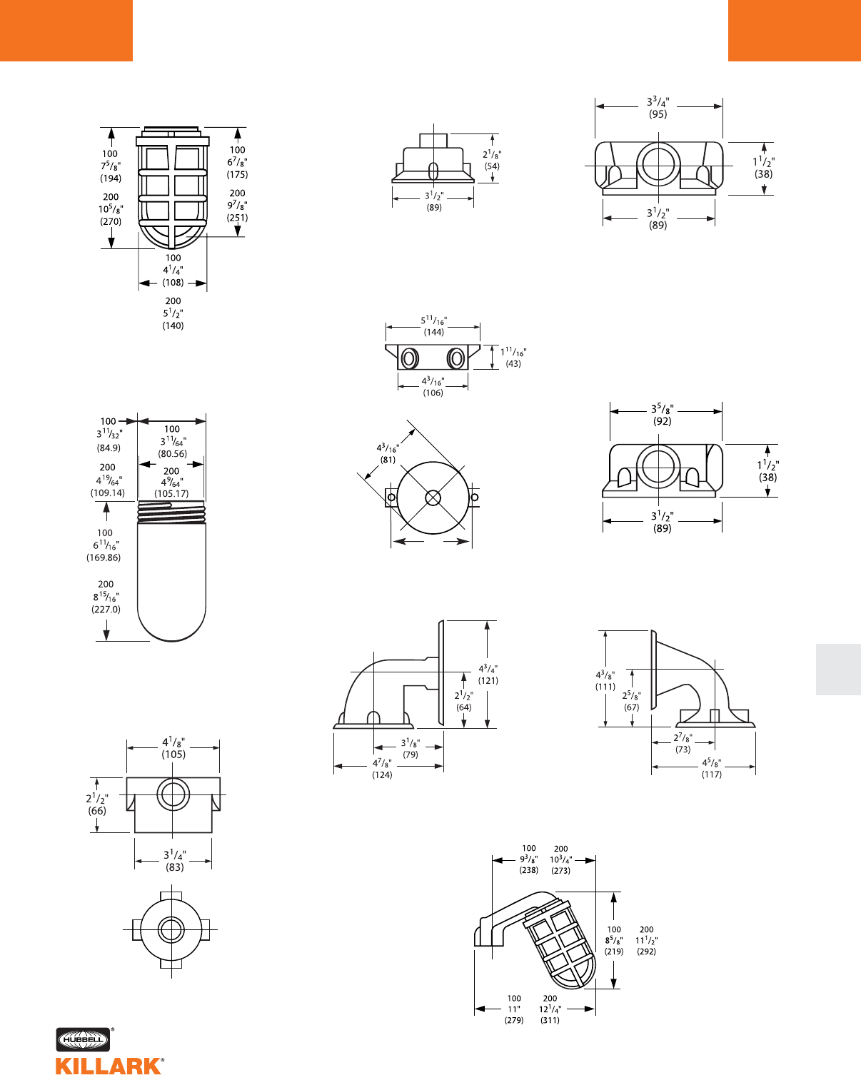
V SERIES •LIGHTING
DIMENSIONS L13
L
VGC VGX
V Stanchion
V Fixture
w/o Splice Box
VGH
VGA
VBC-1 & VBC-2
VXA
V Fixture
Globes
VFL
VB
5”
hole
.28”dia.
(11)
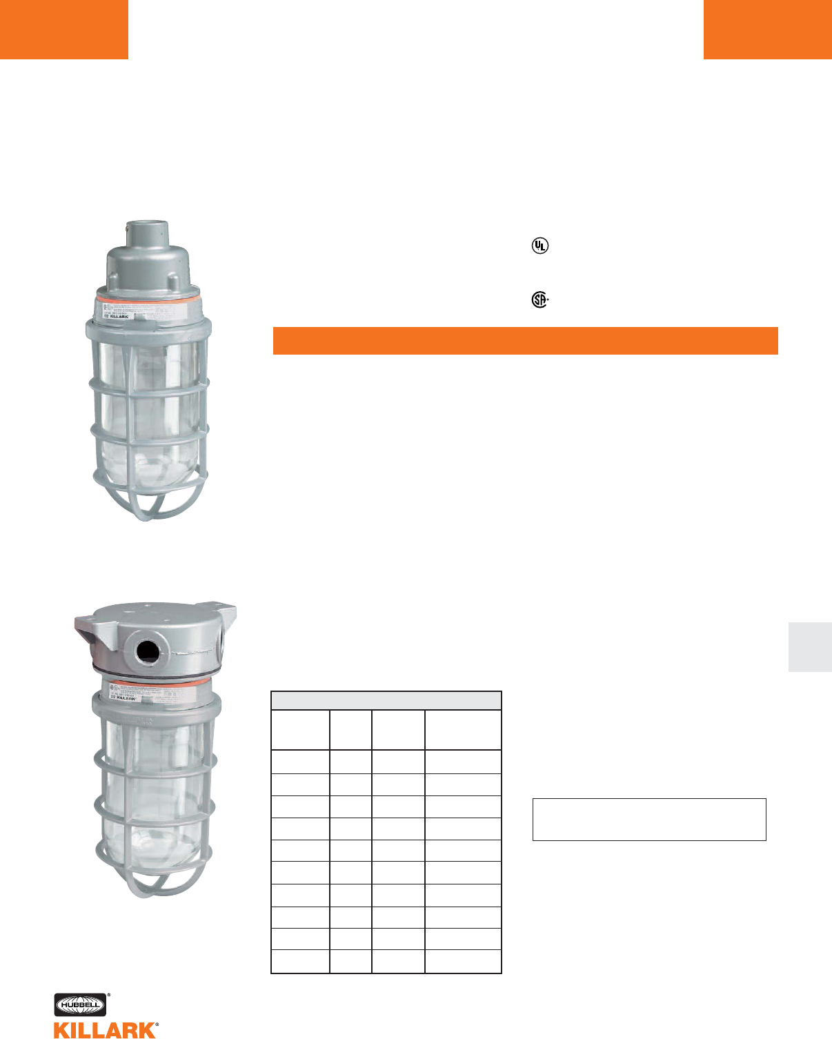
DV SERIES •LIGHTING
SPECIAL APPLICATION INCANDESCENT FIXTURES
L14
FEATURES-SPECIFICATIONS
DV DUST-IGNITION PROOF
Dimensions
Applications
For hazardous locations where suspended
metal, carbon (coal, etc.) and grain dusts
create explosive or ignitable mixtures
with the air
LAMP HUB
SIZE PENDANT CEILING
100 Watt A-21 1/2" DVA-110 DVX-110
150 Watt A-23 3/4" DVA-210 DVX-210
150 Watt PS-25 1/2" DVA-120 DVX-120
200 Watt PS-25 3/4" DVA-220 DVX-220
DV 100/200
FIXTURE
GLASS WIRE REPLACEMENT
TYPE
GLOBE GUARD RECEPTACLE
100 DCGE-10 DAG-100 VRME
200 DCGE-20 DAG-200 VRME
ACCESSORIES/REPLACEMENT PARTS
MODEL
SIZE
TYPE
100
TYPE
200
Ceiling 100-200
Pendant 100-200
Features
Cast of corrosion resistant aluminum alloy
with electrostatically applied epoxy/polyester
finish
Ceiling mounted units supplied with 4 hubs.
Class II, Div. 1 & 2 Groups E,F,G1
Class III
CATALOG NUMBER
CATALOG NUMBER
Listed - File E12976
Certified - File LR11713
1Temperature code T3B, use supply wire
suitable for 150° C.
DAG Guard
H SERIES •LIGHTING
FACTORY SEALED 500W INCANDESCENT FIXTURES L15
FEATURES-SPECIFICATIONS
L
Applications
H Series fixtures can be used for:
Hazardous locations indoors and
outdoors.
General lighting or process finish,
storage and handling areas where
flammable gases, vapor or dust
may be present in the air to pro-
duce explosive or ignitable mix-
tures.
Features
•Cast of corrosion resistant alu-
minum alloy with electrostatically
applied epoxy/polyester finish
•Heat and impact resistant pre-
stressed fluted globe
•Relamp without tools—no need to
remove accessories for relamping
•Fixture for lamp base-up mount-
ing only
•Reflectors-aluminum with white
finish
Fixture Ordering Information
•See catalog numbers shown at
right
•For mogul base 300 watt PS-35
or 500 watt PS-40 lamps
•Fixture hub size is 3/4"
•Omit “G” in fixture catalog
number to omit guard
Listed* - File E12976
Certified* - File LR11713
*Complete assemblies only
See Hazardous location application data
HPG-2-500F HBG-2-500F
HXG-2-500F
HP-2 HB-2HX-2
HRSD-500 HRA-500HRD-400 HGSA-500F HRMO
EZG1G
Wall
CeilingPendant
Dimensions
Class I, Div. 1 & 2, Groups C,D
Class l, Zones 1 & 2, Groups llB,llA
Class II, Div. 1 & 2, Groups E,F,G
HPG-2-500F
HXG-2-500F
HBG-2-500F
Pendant
Ceiling
Wall
3/4"
3/4"
3/4"
H COMPLETE FIXTURES
CATALOG NUMBER HUB SIZE DESCRIPTION
300
500
150
150
T3C
T3
C, D
C, D
T3C
T3
E F G
E
YES
NO
40
40
H APPLICATION DATA
LAMP
WATTS
CLASS III
SUITABILITY
SUPPLY
WIRE °C
RATED
AMBIENT °C
CLASS I, DIV. 1 & 2
T-CODE GROUPS
CLASS II, DIV. 1 & 2
T-CODE GROUPS
HP-2
HX-2
HB-2
Pendant
Ceiling
Wall
H MOUNTING SPLICE BOXES
HRSD-500
HRD-400
HRA-500
HGSA-500F
EZG1G
HG-500
HRMO
Standard dome reflector 18-1/4" dia. (or VMASD-40)
Deep reflector 21-1/8" dia.
Angle reflector 15-1/8" dia. (or VMPA-40)
Globe with support assembly (for replacement)
Guard
Guard (old style without “F” only )
Replacement mogul socket (HRME for discontinued medium base)
H ACCESSORIES
3/4"
3/4"
3/4"
CATALOG NUMBER DESCRIPTION
E/XHL/XHLF SERIES •LIGHTING
INCANDESCENT AND HAND LAMPS
L16
E INCANDESCENT
Applications
For hazardous locations including where
Group A or Group B gases are present,
indoors or outdoors.
General, local or supplementary lighting
in areas where Group A or Group B
gases are manufactured, used or han-
dled.
Features
•Cast of corrosion resistant aluminum
alloy with electrostatically applied
epoxy/polyester finish
•For 200 watt or 300 watt PS-30 medi-
um base lamps. Fixture for
lamp base-up mounting only
•Omit “G” in catalog number to omit
guard
CATALOG NUMBER DESCRIPTION
EPG-2-200 Pendant 3/4” hub
EXG-2-200 Ceiling 3/4” hub
EBG-2-200 Bracket 3/4” hub
E INCANDESCENT FIXTURE
CATALOG NUMBER DESCRIPTION
HG-200 Guard
EGSA-200 Globe w/ support assembly
HRME* Replacement socket
ERSD30 Dome reflector
ERA30 Angle reflector
E ACCESSORIES
EXG-2-200
Note: For 200 watt or 300 watt PS-30 lamps.
Fixture for lamp base-up mounting only.
* Also fits discontinued H series
medium base fixtures
EPG-2-200
XHL
XHLF
EBG-2-200 HG-200
200
300
90
150
T4
T3C
A, B, C, D
A, B, C, D
T3C
T3A
E F G
E, F
YES
NO
40
40
E APPLICATION DATA
LAMP
WATTS
CLASS III
SUITABILITY
SUPPLY
WIRE °C
RATED
AMBIENT °C
CLASS I, DIV. 1 & 2
T-CODE GROUPS
CLASS II, DIV. 1 & 2
T-CODE GROUPS
XHL SERIES HAND LAMPS
Features XHLF Fluorescent
•No exposed metal parts
•Furnished with 26 watt 1800 Lumen
fluorescent lamp and light shield
•Supplied with grommet for use with
16/3 user furnished SO cable
Listed File No. E97760
XHLF Fluorescent
Class I, Div. 1 & 2, Groups C,D
Class I, Zones 1 & 2, Groups llB,llA
Class lI, Div. 1 & 2, Groups F,G
XHLF26 Fluorescent hand lamp
XHLF26-50KP
Fluorescent hand lamp with
- 50' of 16/3 SOW cord and
15A Acceptor plug
Features XHL Incandescent
•Phenolic handle for long service in
rugged conditions
•Aluminum guard
•Heat and impact resistant globe
•Supplied with an A-21 100 Watt
(100A/RS) Rough Service lamp
•Supplied with 2 grommets for use
with either 14/3 or 16/3 user fur-
nished SO cable
XHL-100
XHL-GL
XHLG
XHLS
Handlamp
Replacement Globe
Replacement Guard
Replacement Socket
CATALOG NUMBER DESCRIPTION
XHL Incandescent
Class I, Div. 1 & 2, Groups C, D
Class I, Zones 1 & 2, Groups llB,llA
Listed File No. E97760
Certified File No. LR10019
CATALOG NUMBER
XHL Series Hand Lamps are a handy accessory to the ACCEPTOR®Series. Used
as a supplemental illumination source for areas where flammable materials are pre-
sent such as processed finished goods, storage vats or handling areas.
c
Class I, Div. 1 & 2, Groups A,B,C,D
Class I, Zones 1 & 2, Groups llC,llB,llA
Class II, Div. 1 & 2, Groups E,F,G
Groups A,B Rated
DESCRIPTION
MB SERIES •LIGHTING
FLUORESCENT BI-PIN/MEDIUM BASE HID L17
FEATURES-SPECIFICATIONS
L
Listed - Files E10514 and
E91793 (Marine)
Certified - File LR11713
Class I, Div. 2, Groups A,B,C,D*
Class l, Zone 2, Groups llC,llB,llA
Class II, Div. 1 & 2, Groups E,F,G*
Class III
Suitable for wet locations
Marine
NEMA 3, 4X
Pendant Ceiling Wall Stanchion
Applications
CERTILITE®MB fixtures are designed
for installations where moisture, dirt,
dust, corrosion and vibration may be
present, or NEMA 3 and 4X areas
where wind, water, snow or high ambi-
ents can be expected. They can be
used in locations made hazardous by
the presence of flammable vapors or
gases or combustible dusts as defined
by the NEC.
Typical applications include manufac-
turing plants, and certain chemical and
petrochemical processing facilities,
sewage treatment plants, off-shore and
dockside installations, garages and
storage facilities.
Compliances
•UL-1572 Standard for HID lighting fix-
tures
•UL-1570 Standard for Fluorescent fix-
tures
•UL Marine type lighting fixtures (HID
models) UL-844 Standard for lighting
fixtures for hazardous locations,
Class I, Division 2; Class II, Divisions
1 and 2; Class III
•CSA C22.2 no. 137-M1981 electric
luminaries for use in hazardous loca-
tions
•Enclosed and gasketed
•NEMA 3, 4X
Features
•Ballast tank and splice box —
corrosion resistant copper-free
aluminum alloy
•Baked powder epoxy/polyester finish,
electrostatically applied for complete,
uniform corrosion protection
•All external hardware — stainless
steel
•Guard — copper-free aluminum alloy
•Normally shipped as components for
quick delivery
•Refractor guard — steel with corro-
sion resistant finish
•Reflector — lightweight, corrosion
resistant polyester reinforced fiber-
glass
•Fluorescent models furnished with
lamps. Energy efficient instant on
white light (2700K). 10,000 hour
lamp life
•HID lamp holders are E26 medium
base
Catalog Number Logic
Series Constant
Lamp Type
F—Fluorescent
L—High Pressure Sodium
H—Metal Halide
K—MV Mercury Vapor
Lamp Wattage
13—(1) 13 Watt PL Lamp
26—(2) 13 Watt PL Lamp
39—(3) 13 Watt PL Lamp
50—50 Watt—HPS/MH/MV
70—70 Watt—HPS/MH
75—75 Watt—MV
10—100 Watt—HPS/MV/MH
15—150 Watt—HPS Voltage V
0—Quad - 120/208/240/277 Volts 60 Hz (50, 70 HPS/MH)
1—120 Volts 60 Hz (HPS/MV/Fluorescent)
4—277 Volts 60 Hz (13, 26 Watt Fluorescent/MV)
5—480 Volts (100MV only)
Optic
G—Fluted Glass Globe
GG—Globe and Guard
R5—Glass Refractor Type V
R5G—Glass Refractor & Guard
MB 0 00 0 - 000 00 (NR)
Consult factory for available lamp and voltage combinations.
* See Hazardous Location Application Data on page L26 for limitations.
1See page L22 for Ex nR Restricted Breathing models.
1
Mounting Style
A2—3/4" Pendant
A3—1" Pendant
X2—3/4" Ceiling
X3—1" Ceiling
B2—3/4" Wall Bracket
B3—1" Wall Bracket
D4—1-1/4" Stanchion
D5—1-1/2" Stanchion
Options
SU103—Assembled
w/Lamp
V
MB SERIES •LIGHTING
COMPACT BI-PIN FLUORESCENT, 13-39 WATT
L18
FEATURES-SPECIFICATIONS
Listed - Files E10514 and
E91793
Certified - File LR11713
Class I, Div. 2, Groups A,B,C,D*
Class l, Zone 2, Groups llC,llB,llA
Class II, Div. 1 & 2, Groups E,F,G*
Class III
Suitable for wet locations
NEMA 3, 4X
1Fixtures supplied with Bi-Pin fluorescent lamps. Replacement number MPL13.
2Catalog numbers shown are with 3/4" conduit openings (1-1/4" on stanchion mount) and include
globe and guard. See catalog logic for other possible configurations.
3Catalog numbers are shown with 120V ballasts. 1 & 2 lamp fixtures are available with 277V ballasts
Change 6th character from "1" to "4"; e.g. MBF264-GGA2.
* See Hazardous Location Application Data on page L26 for limitations.
CATALOG NUMBER2
GLOBE AND GUARD REFRACTOR AND GUARD
3/4" 120 MBF131-GGA2 MBF131-R5GA2
Bi-Pin 3/4" 120 MBF261-GGA2 MBF261-R5GA2
3/4" 120 MBF391-GGA2 MBF391-R5GA2
PENDANT FLUORESCENT
LAMP LAMP/1HUB
TYPE WATTS SIZE1
CEILING
PENDANT
STANCHION
WALL
CATALOG NUMBER2
GLOBE AND GUARD REFRACTOR AND GUARD
3/4" 120 MBF131-GGX2 MBF131-R5GX2
Bi-Pin 3/4" 120 MBF261-GGX2 MBF261-R5GX2
3/4" 120 MBF391-GGX2 MBF391-R5GX2
CEILING FLUORESCENT
LAMP LAMP/1HUB
TYPE WATTS SIZE2
CATALOG NUMBER2
GLOBE AND GUARD REFRACTOR AND GUARD
3/4" 120 MBF131-GGB2 MBF131-R5GB2
Bi-Pin 3/4" 120 MBF261-GGB2 MBF261-R5GB2
3/4" 120 MBF391-GGB2 MBF391-R5GB2
WALL FLUORESCENT
LAMP LAMP/1HUB
TYPE WATTS SIZE2
CATALOG NUMBER2
GLOBE AND GUARD REFRACTOR AND GUARD
1-1/4" 120 MBF131-GGD4 MBF131-R5GD4
Bi-Pin 1-1/4" 120 MBF261-GGD4 MBF261-R5GD4
1-1/4" 120 MBF391-GGD4 MBF391-R5GD4
STANCHION FLUORESCENT
LAMP LAMP/1HUB
TYPE WATTS SIZE2
13 Watt
(1 x 13)
26 Watt
(2 x 13)
39 Watt
(3 x 13)
13 Watt
(1 x 13)
26 Watt
(2 x 13)
39 Watt
(3 x 13)
13 Watt
(1 x 13)
26 Watt
(2 x 13)
39 Watt
(3 x 13)
13 Watt
(1 x 13)
26 Watt
(2 x 13)
39 Watt
(3 x 13)
VOLTAGE
60 HZ3
VOLTAGE
60 HZ3
VOLTAGE
60 HZ3
VOLTAGE
60 HZ3
MB SERIES •LIGHTING
HIGH PRESSURE SODIUM, 50-150W MEDIUM BASE HID L19
FEATURES-SPECIFICATIONS
L
Listed - Files E10514 and
E91793 (Marine)
Certified - File LR11713
Class I, Div. 2, Groups A,B,C,D*
Class l, Zone 2, Groups llC,llB,llA
Class II, Div. 1 & 2, Groups E,F,G*
Class III
Suitable for wet locations
UL Marine
NEMA 3, 4X
1Catalog numbers shown are 120. Consult factory for other available voltages.
2Catalog numbers shown with 3/4" conduit openings (1-1/4" on stanchion mount) and includes globe and
guard or IES type V 8" glass refractor and guard. See catalog logic for other possible configurations.
* See Hazardous Location Application Data on page L26 for limitations.
PENDANT 50-150W HIGH PRESSURE SODIUM
LAMP LAMP HUB
TYPE WATTS/ANSI SIZE2
CEILING 50-150W HIGH PRESSURE SODIUM
LAMP LAMP HUB
TYPE WATTS/ANSI SIZE2
WALL 50-150W HIGH PRESSURE SODIUM
LAMP LAMP HUB
TYPE WATTS/ANSI SIZE2
STANCHION 50-150W HIGH PRESSURE SODIUM
LAMP LAMP HUB
TYPE WATTS/ANSI SIZE2
CEILING
STANCHION
WALL
PENDANT
VOLTAGE
60 HZ1
VOLTAGE
60 HZ1
VOLTAGE
60 HZ1
VOLTAGE
60 HZ1
CATALOG NUMBER2
GLOBE AND GUARD REFRACTOR AND GUARD
50 (S68) 3/4" 120 MBL501-GGA2 MBL501-R5GA2
HPS 70 (S62) 3/4" 120 MBL701-GGA2 MBL701-R5GA2
100 (S54) 3/4" 120 MBL101-GGA2 MBL101-R5GA2
150 (S55) 3/4" 120 MBL151-GGA2 MBL151-R5GA2
CATALOG NUMBER2
GLOBE AND GUARD REFRACTOR AND GUARD
50 (S68) 3/4" 120 MBL501-GGX2 MBL501-R5GX2
HPS 70 (S62) 3/4" 120 MBL701-GGX2 MBL701-R5GX2
100 (S54) 3/4" 120 MBL101-GGX2 MBL101-R5GX2
150 (S55) 3/4" 120 MBL151-GGX2 MBL151-R5GX2
CATALOG NUMBER2
GLOBE AND GUARD REFRACTOR AND GUARD
50 (S68) 3/4" 120 MBL501-GGB2 MBL501-R5GB2
HPS 70 (S62) 3/4 120 MBL701-GGB2 MBL701-R5GB2
100 (S54) 3/4" 120 MBL101-GGB2 MBL101-R5GB2
150 (S55) 3/4" 120 MBL151-GGB2 MBL151-R5GB2
CATALOG NUMBER2
GLOBE AND GUARD REFRACTOR AND GUARD
50 (S68) 1-1/4" 120 MBL501-GGD4 MBL501-R5GD4
HPS 70 (S62) 1-1/4" 120 MBL701-GGD4 MBL701-R5GD4
100 (S54) 3/4" 120 MBL101-GGB2 MBL101-R5GB2
150 (S55) 1-1/4" 120 MBL101-GGD4 MBL101-R5GD4
MB SERIES •LIGHTING
METAL HALIDE, 50-100W MEDIUM BASE HID
L20
ORDERING INFORMATION
Listed - Files E10514 and
E91793 (Marine)
Certified - File LR11713
Class I, Div. 2, Groups A,B,C,D*
Class l, Zone 2, Groups llC,llB,llA
Class II, Div. 1 & 2, Groups E,F,G*
Class III
Suitable for wet locations
UL Marine
NEMA 3, 4X
PENDANT 50-100W METAL HALIDE
CEILING 50-100W METAL HALIDE
LAMP LAMP HUB
TYPE WATTS/ANSI SIZE2
WALL 50-100W METAL HALIDE
LAMP LAMP HUB
TYPE WATTS/ANSI SIZE2
STANCHION 50-100W METAL HALIDE
CEILING
STANCHION
WALL
PENDANT
1Metal Halide MB fixtures use quad-volt ballasts.
2Catalog numbers shown with 3/4" conduit openings (1-1/4" on stanchion mount) and include globe and
guard or IES type V 8" glass refractor and guard. See catalog logic for other possible configurations.
* See Hazardous Location Application Data on page L26 for limitations.
VOLTAGE
60 HZ1
VOLTAGE
60 HZ1
VOLTAGE
60 HZ1
LAMP LAMP HUB
TYPE WATTS/ANSI SIZE2
CATALOG NUMBER2
GLOBE AND GUARD REFRACTOR AND GUARD
MH
50 (M110) 3/4" 120/208/240/277 MBH500-GGA2 MBH500-R5GA2
70 (M98) 3/4" 120/208/240/277 MBH700-GGA2 MBH700-R5GA2
100 (M90) 3/4" 120/208/240/277 MBH100-GGA2 MBH100-R5GA2
VOLTAGE
60 HZ1
LAMP LAMP HUB
TYPE WATTS/ANSI SIZE2
CATALOG NUMBER2
GLOBE AND GUARD REFRACTOR AND GUARD
MH
50 (M110) 1-1/4" 120/208/240/277 MBH500-GGD4 MBH500-R5GD4
70 (M98) 1-1/4" 120/208/240/277 MBH700-GGD4 MBH700-R5GD4
100 (M90) 1-1/4" 120/208/240/277 MBH100-GGD4 MBH100-R5GD4
CATALOG NUMBER2
GLOBE AND GUARD REFRACTOR AND GUARD
MH
50 (M110) 3/4" 120/208/240/277 MBH500-GGB2 MBH500-R5GB2
70 (M98) 3/4" 120/208/240/277 MBH700-GGB2 MBH700-R5GB2
100 (M90) 3/4" 120/208/240/277 MBH100-GGB2 MBH100-R5GB2
CATALOG NUMBER2
GLOBE AND GUARD REFRACTOR AND GUARD
MH
50 (M110) 3/4" 120/208/240/277 MBH500-GGX2 MBH500-R5GX2
70 (M98) 3/4" 120/208/240/277 MBH700-GGX2 MBH700-R5GX2
100 (M90) 3/4" 120/208/240/277 MBH100-GGX2 MBH100-R5GX2
CATALOG NUMBER2
GLOBE AND GUARD REFRACTOR AND GUARD
50 (H46) 3/4" 120 MBK501-GGB2 MBK501-R5GB2
MV 75 (H43) 3/4" 120 MBK751-GGB2 MBK751-R5GB2
100 (H38) 3/4" 120 MBK101-GGB2 MBK101-R5GB2
MB SERIES •LIGHTING
MERCURY VAPOR, 50-100W MEDIUM BASE HID L21
ORDERING INFORMATION
Listed - Files E10514 and
E91793 (Marine)
Certified - File LR11713
Class I, Div. 2, Groups A,B,C,D*
Class l, Zone 2, Groups llC,llB,llA
Class II, Div. 1 & 2, Groups E,F,G*
Class III
Suitable for wet locations
UL Marine
NEMA 3, 4X
L
CATALOG NUMBER2
GLOBE AND GUARD REFRACTOR AND GUARD
50 (H46) 3/4" 120 MBK501-GGA2 MBK501-R5GA2
MV 75 (H43) 3/4" 120 MBK751-GGA2 MBK701-R5GA2
100 (H38) 3/4" 120 MBK101-GGA2 MBK101-R5GA2
PENDANT 50-100W MERCURY VAPOR
LAMP LAMP HUB
TYPE WATTS/ANSI SIZE2
CATALOG NUMBER2
GLOBE AND GUARD REFRACTOR AND GUARD
50 (H46) 3/4" 120 MBK501-GGX2 MBK501-R5GX2
MV 75 (H43) 3/4" 120 MBK751-GGX2 MBK751-R5GX2
100 (H38) 3/4" 120 MBK101-GGX2 MBK101-R5GX2
CEILING 50-100W MERCURY VAPOR
LAMP LAMP HUB
TYPE WATTS/ANSI SIZE2
WALL 50-100W MERCURY VAPOR
LAMP LAMP HUB
TYPE WATTS/ANSI SIZE2
CATALOG NUMBER2
GLOBE AND GUARD REFRACTOR AND GUARD
50 (H46) 1-1/4" 120 MBK501-GGD4 MBK501-R5GD4
MV 75 (H43) 1-1/4" 120 MBK751-GGD4 MBK751-R5GD4
100 (H38) 1-1/4" 120 MBK101-GGD4 MBK101-R5GD4
STANCHION 50-100W MERCURY VAPOR
LAMP LAMP HUB
TYPE WATTS/ANSI SIZE2
CEILING
STANCHION
WALL
PENDANT
1Catalog numbers shown are 120 volt. Consult factory for other available voltages.
2Catalog numbers shown with 3/4" conduit openings (1-1/4" on stanchion mount) and includes globe and
guard or IES type V 8" glass refractor and guard. See catalog logic for other possible configurations.
* See Hazardous Location Application Data on page L26 for limitations.
VOLTAGE
60 HZ1
VOLTAGE
60 HZ1
VOLTAGE
60 HZ1
VOLTAGE
60 HZ1
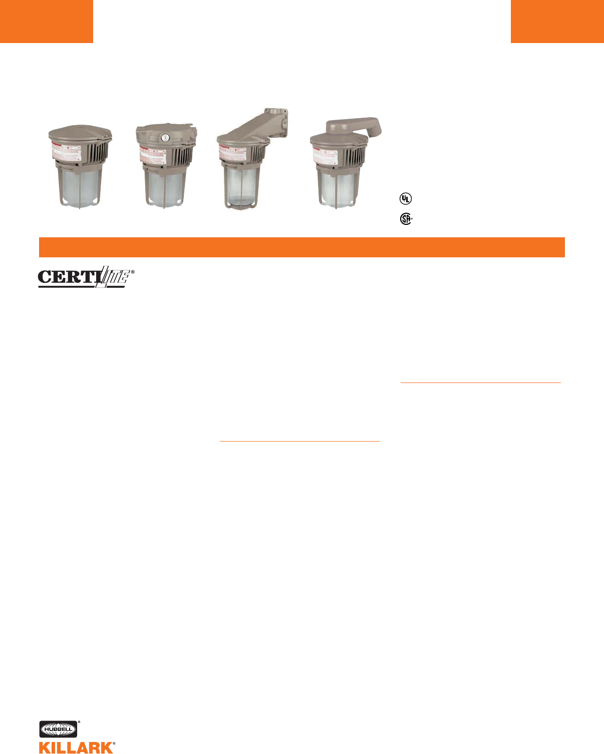
MB SERIES •LIGHTING
Ex nR 50-150W MEDIUM BASE HID
L22
FEATURES-SPECIFICATIONS
Pendant Ceiling Wall Stanchion
Applications
MB Restricted Breathing option
fixtures maintain all the features and
compliances listed for standard MB
HID lighting fixtures. An alternate test-
ing and installation method allows
much lower Temperature Codes when
compared to conventional units.
Installation requires sealed entry
(conduit or cable). See temperature
data charts to determine suitability per
applicable construction codes. Ex nR
Restricted Breathing fixtures are avail-
able with globe only, not refractors.
CERTILITE®MB fixtures are designed
for installations where moisture, dirt,
dust, corrosion and vibration may be
present, or NEMA 3 and 4X areas
where wind, water, snow or high ambi-
ents can be expected. They can be
used in locations made hazardous by
the presence of flammable vapors or
gases or combustible dusts as defined
by the NEC.
Typical applications include manufac-
turing plants, and certain chemical and
petrochemical processing facilities,
sewage treatment plants, off-shore and
dockside installations, garages and
storage facilities.
Compliances
•UL-1572 Standard for HID lighting fix-
tures
•UL Marine type lighting fixtures
•UL-844 Standard for lighting fixtures
for hazardous locations, Class I,
Division 2; Class II, Divisions 1 and 2;
Class III
•CSA C22.2 no. 137-M1981 electric
luminaries for use in hazardous
locations
•IEC 60079-15 Electrical apparatus
with “n” type protection
•Enclosed and gasketed
•NEMA 3, 4X
Features
•Ballast tank and splice box —
corrosion resistant copper-free
aluminum alloy
•HID lamp holders are E-26 medium
base
•Baked powder epoxy/polyester
finish, electrostatically applied
for complete, uniform corrosion
protection
•All external hardware — stainless
steel
•Guard — copper-free aluminum alloy
•Reflector — lightweight, corrosion
resistant polyester reinforced
fiberglass
Electrical
Fixtures are available in
•Fluorescent Bi-Pin: 13-39 watts1
•HPS: 50 through 150 watts
•MH: 50 through 100 watts
•MV: 50 through 100 watts
All HID ballast circuits are high power
factor. Consult catalog logic on page
L17 for available voltages.
* See Hazardous Location Application Data on page L26 for limitations.
Ex nR HID models listed page L23. For fluorescent models, add NR to “globe” model number from page L18.
Listed - Files E10514 and
E91793 (Marine)
Certified - File LR11713
AEx nR / Ex nR*
Class I, Div. 2, Groups A,B,C,D*
Class l, Zone 2, Groups llC,llB,llA
Class II, Div. 1 & 2, Groups E,F,G*
Class III
Suitable for wet locations
UL Marine
NEMA 3, 4X
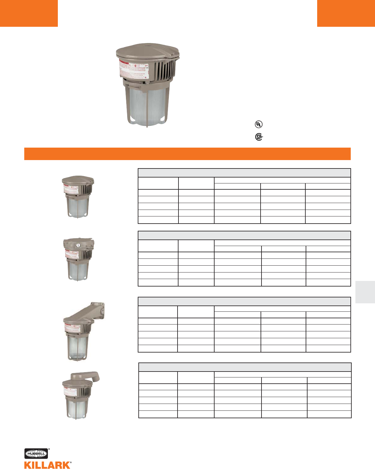
MB SERIES •LIGHTING
Ex nR 50-150W MEDIUM BASE HID L23
FEATURES-SPECIFICATIONS
L
50
70
75
100
150
1202
1202
120
120
120
MB 50-150W Ex nR PENDANT1
HPS
MBL501-GGA2NR
MBL701-GGA2NR
—
MBL101-GGA2NR
MBL151-GGA2NR
MH2
MBH500-GGA2NR
MBH700-GGA2NR
—
MBH100-GGA2NR
—
MV
MBK501-GGA2NR
—
MBK751-GGA2NR
MBK101-GGA2NR
—
CATALOG NUMBER
LAMP
WATTS3
VOLTAGE
@ 60 HERTZ
50
70
75
100
150
1202
1202
120
120
120
MB 50-150W Ex nR CEILING1
HPS
MBL501-GGX2NR
MBL701-GGX2NR
—
MBL101-GGX2NR
MBL151-GGX2NR
MH2
MBH500-GGX2NR
MBH700-GGX2NR
—
MBH100-GGX2NR
—
MV
MBK501-GGX2NR
—
MBK751-GGX2NR
MBK101-GGX2NR
—
CATALOG NUMBER
LAMP
WATTS3
VOLTAGE
@ 60 HERTZ
50
70
75
100
150
1202
120
120
120
MB 50-150W Ex nR WALL1
HPS
MBL501-GGB2NR
MBL701-GGB2NR
—
MBL101-GGB2NR
MBL151-GGB2NR
MH2
MBH500-GGB2NR
MBH700-GGB2NR
—
MBH100-GGB2NR
—
MV
MBK501-GGB2NR
—
MBK751-GGB2NR
MBK101-GGB2NR
—
CATALOG NUMBER
LAMP
WATTS3
VOLTAGE
@ 60 HERTZ
50
70
75
100
150
1202
1202
120
120
120
MB 50-150W Ex nR STANCHION1
HPS
MBL501-GGD4NR
MBL701-GGD4NR
—
MBL101-GGD4NR
MBL151-GGD4NR
MH2
MBH500-GGD4NR
MBH700-GGD4NR
—
MBH100-GGD4NR
—
MV
MBK501-GGD4NR
—
MBK751-GGD4NR
MBK101-GGD4NR
—
CATALOG NUMBER
LAMP
WATTS3
VOLTAGE
@ 60 HERTZ
CEILING
STANCHION
WALL
PENDANT
Listed - Files E10514 and
E91793 (Marine)
Certified - File LR11713
AEx nR / Ex nR*
Class I, Div. 2, Groups A,B,C,D*
Class l, Zone 2, Groups llC,llB,llA
Class II, Div. 1 & 2, Groups E,F,G*
Class III
Suitable for wet locations
UL Marine
NEMA 3, 4X
1Fixtures are shown with 120V ballasts, except Metal Halide. All assemblies with 3/4" conduit openings
(1-1/4" Stanchion), globe and guard. Consult prior pages and catalog logic for other options.
2Metal Halide fixtures are furnished with quad-volt ballasts.
3See standard MB Series HID fixtures for ANSI data.
* See Hazardous Location Application Data on page L26 for limitations.
Note: For fluorescent Ex nR models, add NR to “globe” model number from page L18.
1202
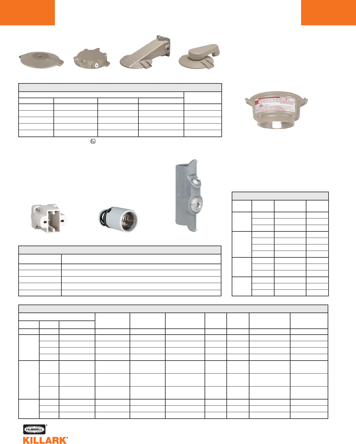
MB SERIES •LIGHTING
COMPONENT PARTS/BALLAST DATA
L24
Wall
Pendant Ceiling Stanchion
4Catalog numbers shown are 120 volt (except
Metal Halide). Consult catalog number logic on
page L17 and change sixth character to indi-
cate other available voltages.
5For Class l Ex nR Restricted Breathing ballast
housings, add “NR” to catalog number e.g.
MBL501NR. “NR” ballast housing not available
for use with refractors.
* MBX-8 furnished with 3 non-metallic plugs
LAMP TYPE OPEN INPUT MINIMUM
STARTING OPERATING CIRCUIT WATTS START
LAMP WATTS VOLTS - VAC AMPS AMPS AMPS MAX TEMPERATURE
FL113 120/277 .30/.3 — 16 0°F -18°C
50 120 .55 .90 60 -40°F -40°C
HPS 70 120 .75 1.30 82 -40°F -40°C
100 120 1.05 1.80 115 -40°F -40°C
150 120 1.50 2.35 170 -40°F -40°C
50 120/208 .6/.35/.3/.25 1.6/.67/.57/.5 67 -20°F -30°C
240/277
MH 70 120/208 .85/.5/.43/.37 1.7/1.04/.87/.78 95 -20°F -30°C
240/277
100 120/208 1.15/.66/.58/.5 2.3/1.4/1.15/1.0 129 -20°F -30°C
240/277
50 120/277 .67/.29 .30/.13 74 -20°F -30°C
75 120/277 .82/.36 .50/.22 93 -20°F -30°C
100 120/277/480 1.05/.45/.26 .64/.28/.16 118 -20°F -30°C
MB BALLAST DATA
1Per lamp, max available lamps @ 120 volt is .3; max @ 277 volt is .2.
2Ballasts are High Power Factor 90%+.
3Lamp watts within ANSI Trapezoid limitations.
HUB SIZE
3/4"
1"
M20
1-1/4"
1-1/2"
CATALOG NUMBER
PENDANT CEILING WALL STANCHION
MBA-2 MBX-2 MBB-2 —
MBA-3 MBX-3 MBB-3 —
— MBX-8* — —
— — — MBD-4
— — — MBD-5
120
120
120
120
120
120
120
120/208/240/277
120/208/240/277
120/208/240/277
120
120
120
MB BALLAST TANK45
CATALOG
NUMBER
MBF131
MBF261
MBF391
MBL501
MBL701
MBL101
MBL151
MBH500
MBH700
MBH100
MBK501
MBK751
MBK101
LAMP
TYPE
FL
HPS
MH
MV
LAMP
WATTAGE
13
26
39
50
70
100
150
50
70
100
50
75
100
MB MOUNTING BRACKETS
MV
ENY-2SET
EMRS
EBRS
.39/.35
.75
.85
1.50
2.20
.87/.51/.47/.39
.8/.5/.43/.39
1.2/.8/.65/.6
.60/.26
.80/.35
1.00/.43/.25
BALLAST
CIRCUIT REGULATIONS
—
±5% Line voltage3
±5% Line voltage3
±5% Line voltage3
±5% Line voltage3
±5% Line voltage3
±12% Lamp watts3
±5% Line voltage3
±12% Lamp watts3
±5% Line voltage3
±12% Lamp watts3
±10% Lamp watts3
±10% Lamp watts3
±10% Lamp watts3
EMRS
EBRS
MPL13
ENY-2SET
ENY-3SET
MB medium base replacement socket (E26)
MB Bi-Pin base replacement socket
Replacement lamp for MBF and EBF series
3/4" ENY seal with set screw for sealed (Ex nR) pendant installations
1" ENY seal with set screw for sealed (Ex nR) pendant installations
MB ACCESSORIES
CATALOG NUMBER DESCRIPTION
VOLTAGE
60 HZ
NPF
HX-HPF2
HX-HPF2
HX-HPF2
HX-HPF2
HX-HPF2
HX-HPF2
HX-HPF2
CWA2
CWA2
CWA2
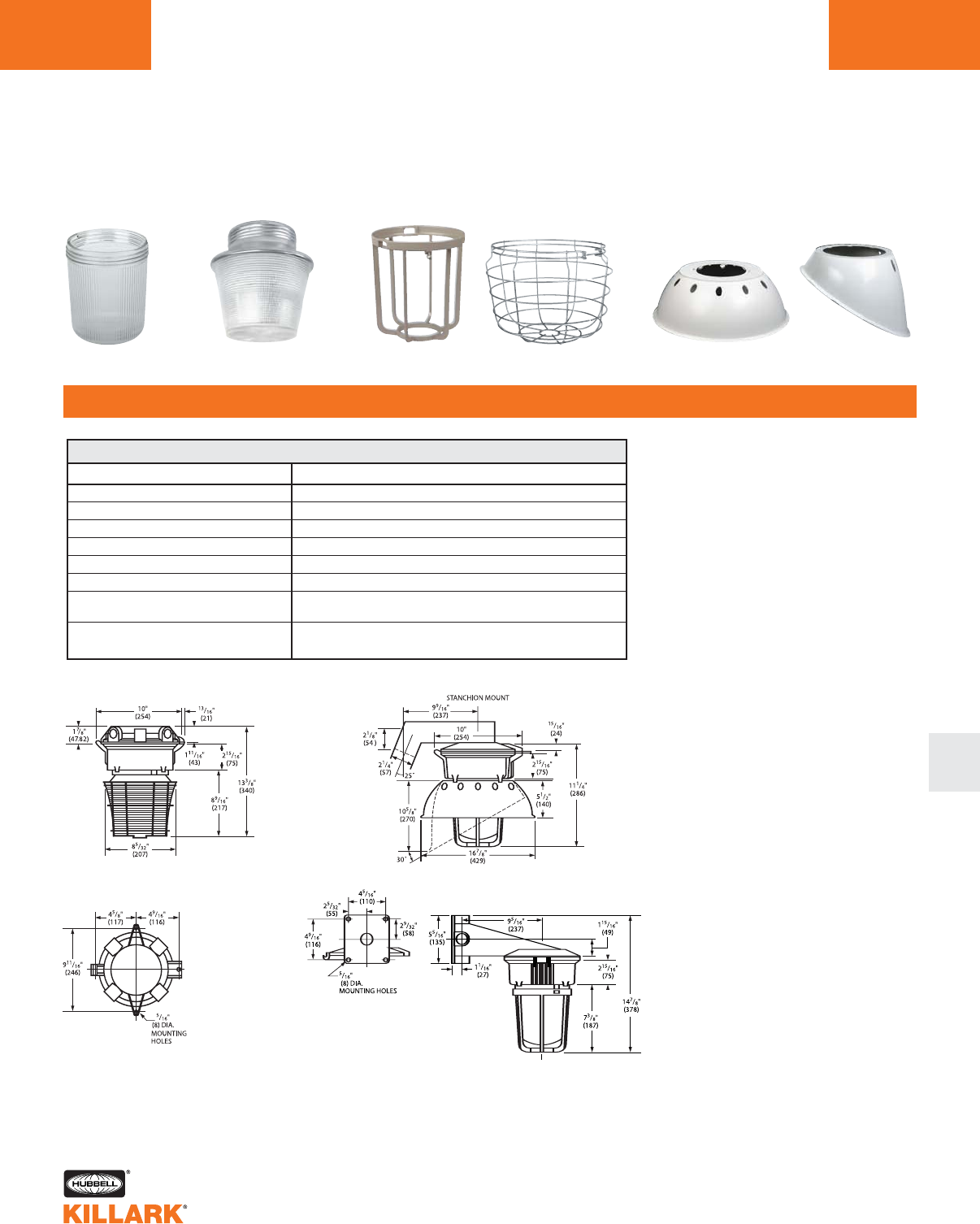
MB SERIES •LIGHTING
ACCESSORIES/DIMENSIONS L25
ORDERING INFORMATION
L
MBG
Globe
VZRG-1550
Refractor
MBAG VMRWG-8 VMPSD-17 VMPA-17
Reflectors
Guards
Dimensions
MBG
VZRG-1550
MBAG
VMRWG-8
VMPSD-17
VMPA-17
VMRD-17ALZ
MBPLG
Heat and impact resistant globe
(I.E.S. Type V) closed bottom 8" glass refractor
Globe guard - Epoxy/polyester painted aluminum
Refractor guard - plated steel
Standard dome reflector (polyester reinforced fiberglass)
Angle reflector (polyester reinforced fiberglass)
Deep Alzak full cutoff reflector. Suitable for “dark sky”
applications. 17” Dia.
Polycarbonate globe for non-hazardous locations. For use
with PL Fluorescent and HID to 75 W.
MB ACCESSORIES
CATALOG NUMBER DESCRIPTION
CLASS I, DIV. 2, GROUPS A, B, C, D1CLASS II, DIV. 1 & 2, GROUPS E, F, G35
LAMP RATED LAMP TEMPERATURES MAXIMUM SURFACE TEMPERATURES CLASS III, DIV. 1 & 23
AMBIENT
°C WITHOUT4WITH2WITH WITHOUT4WITH2WITH WITHOUT4WITH2WITH
TYPE WATTAGE REFLECTOR REFLECTOR REFRACTOR REFLECTOR REFLECTOR REFRACTOR REFLECTOR REFLECTOR REFRACTOR
50 40 215°C(T2D) 215°C(T2D) 215°C(T2D) 120°C(T4A) 135°C(T4) 120°C(T4A) YES YES YES 75
50 55 230°C(T2C) 230°C(T2C) 230°C(T2C) 135°C(T4) 160°C(T3C) 135°C(T4) YES YES YES 90
50 65 230°C(T2C) 230°C(T2C) 230°C(T2C) 160°C(T3C) 160°C(T3C) 160°C(T3C) YES YES YES 90
HPS 70 40 260°C(T2B) 260°C(T2B) 230°C(T2C) 120°C(T4A) 135°C(T4) 120°C(T4A) YES YES YES 75
100 40 280°C(T2A) 280°C(T2A) 280°C(T2A) 160°C(T3C) 160°C(T3C) 160°C(T3C) YES YES YES90
150 40 325°C(T1) 325°C(T1) 325°C(T1) — — 160°C(T3C) NO NO YES 110
150 40 325°C(T1) 325°C(T1) 325°C(T1) 180°C(T3A) 200°C(T3) — NO NO NO 110
50 40 230°C(T2C) 230°C(T2C) 230°C(T2C) 160°C(T3C) 160°C(T3C) 160°C(T3C) YES YES YES 90
MH 70 40 230°C(T2C) 230°C(T2C) 230°C(T2C) 160°C(T3C) 160°C(T3C) 160°C(T3C) YES YES YES 90
100 40 280°C(T2A) 280°C(T2A) 280°C(T2A) 160°C(T3C) 160°C(T3C) 160°C(T3C) YES YES YES 85
50 40 260°C(T2B) 260°C(T2B) 260°C(T2B) 160°C(T3C) 160°C(T3C) 160°C(T3C) YES YES YES 90
MV 50 55 260°C(T2B) 260°C(T2B) 260°C(T2B) 160°C(T3C) 160°C(T3C) 160°C(T3C) YES YES YES 90
75 40 325°C(T1) 325°C(T1) 325°C(T1) 160°C(T3C) 160°C(T3C) 160°C(T3C) YES YES YES 90
100 40 450°C(T1) 450°C(T1) 450°C(T1) 160°C(T3C) 160°C(T3C) 160°C(T3C) YES YES YES 110
MB SERIES •LIGHTING
APPLICATION DATA
L26
1Verify temperatures for suitability for intended use.
2Includes both standard dome and angle reflectors.
3Guard required for Class II, Division 1 and Class III
applications.
4Based on luminaire with globe and guard only.
5150 watt HPS—Groups E, F only with or without
reflector and Groups E, F and G with refractor.
LAMP
TYPE
PL
RATED
AMBIENT°C
40
40
25
CLASS I, DIVISION 2
GROUPS A, B, C, D1
LAMP TEMP, W/GLOBE,
GLOBE & REFLECTOR2
OR 8" GLASS REFRACTOR
CLASS II, DIVISION 1 & 21
MAXIMUM SURFACE
TEMPERATURE W/GLOBE,
GUARD3& REFLECTOR2
OR 8" GLASS REFRACTOR4
CLASS III, DIV. 1 & 21
W/GLOBE, W/GUARD3&
REFLECTOR2
OR 8" GLASS REFRACTOR
UL/CSA
TEMP I.D.5
(T3B) 165°C
(T3B) 165°C
(T3A) 180°C
GROUP
E, F & G
E, F & G
E, F & G
UL/CSA
YES
YES
YES
UL/CSA
TEMP I.D.
(T4) 135°C
(T4) 135°C
(T4) 135°C
LAMPS/
WATTS
13
26 (2x13)
39 (3x13)
MBF HAZARDOUS LOCATION DATA
1Verify temperatures for suitability for intended use.
2Includes both standard dome and angle reflectors.
3Guard required for Class II, Division 1 and Class III, Division 1 applications.
4Note: 8 inch glass refractor not CSA certified for Class II, Division 1 and Class III, Divisions 1 installations.
5Add NR to globe fluorescent models for Ex nR Restricted Breathing—all have T6 Temperature I.D.
SUPPLY WIRE
SUITABLE
FOR °C
90
90
90
MB-NR Ex nR RESTRICTED BREATHING DATA1CLASS 1, ZONE 2, IIC,IIB,IIA
LAMP WITH GLOBE
SERIES
MBL
MBL
MBL
MBL
MBH
MBH
MBH
MBK
MBK
MBK
RATED
AMBIENT
°C
40
55
65
40
40
40
40
40
40
40
55
40
40
UL/CSA
T6
T5
T5
T5
T4
T4
T5
T5
T4
T5
T5
T4
T4
SUPPLY WIRE
SUITABLE
FOR °C
75
90
90
75
90
110
90
90
90
90
110
90
110
TYPE
HPS
HPS
HPS
HPS
MH
MH
MH
MV
MV
MV
WATTAGE
50
70
100
150
50
70
100
50
75
100
GLOBE OR GLOBE
WITH REFLECTOR
SUPPLY
WIRE
SUITABLE
FOR °C
MB HAZARDOUS LOCATION DATA
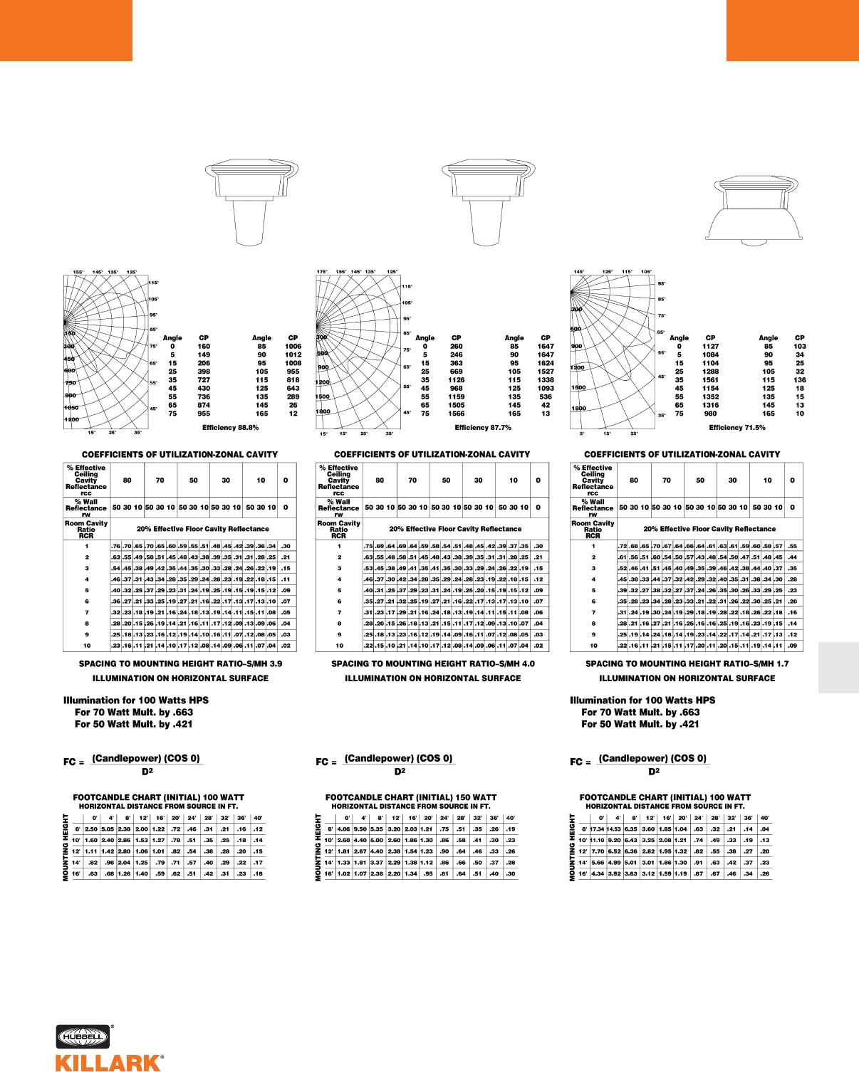
MB SERIES •LIGHTING
PHOTOMETRIC DATA L27
L
CANDLEPOWER–100 WATT
B-17 Clear Lamp
(9500 Lumens)
For CP of a 70 Watt
Luminaire multiply by .663;
For a 50 Watt Luminaire
multiply by .421
CANDLEPOWER–150 WATT
B-17 Clear Lamp
(16000 Lumens)
CANDLEPOWER–100 WATT
B-17 Clear Lamp
(9500 Lumens)
For CP of a 70 Watt
Luminaire multiply by .663;
For a 50 Watt Luminaire
multiply by .421
HIGH PRESSURE SODIUM
With Globe Only
50 – 100 Watt Medium Base
HIGH PRESSURE SODIUM
With Globe Only
150 Watt Medium Base
HIGH PRESSURE SODIUM
With Globe and Dome Reflector
50 – 100 Watt Medium Base
Test No. HP-03126 Test No. HP-03128 Test No. HP-03125
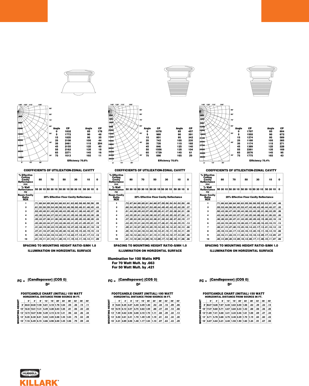
CANDLEPOWER–150 WATT
B-17 Clear Lamp
(16000 Lumens)
CANDLEPOWER–100 WATT
B-17 Clear Lamp
(9500 Lumens)
For CP of a 70 watt luminaire
multiply by .663;
For a 50 watt luminaire
multiply by .421
CANDLEPOWER–150 WATT
B-17 Clear Lamp
(16000 Lumens)
HIGH PRESSURE SODIUM
With Globe and Dome Reflector
150 Watt Medium Base
HIGH PRESSURE SODIUM
With Type V 8” Refractor
50 – 100 Watt Medium Base
HIGH PRESSURE SODIUM
With Type V 8” Refractor
150 Watt Medium Base
Test No. HP-03130 Test No. HP-03127 Test No. HP-03129
MB SERIES •LIGHTING
PHOTOMETRIC DATA
L28
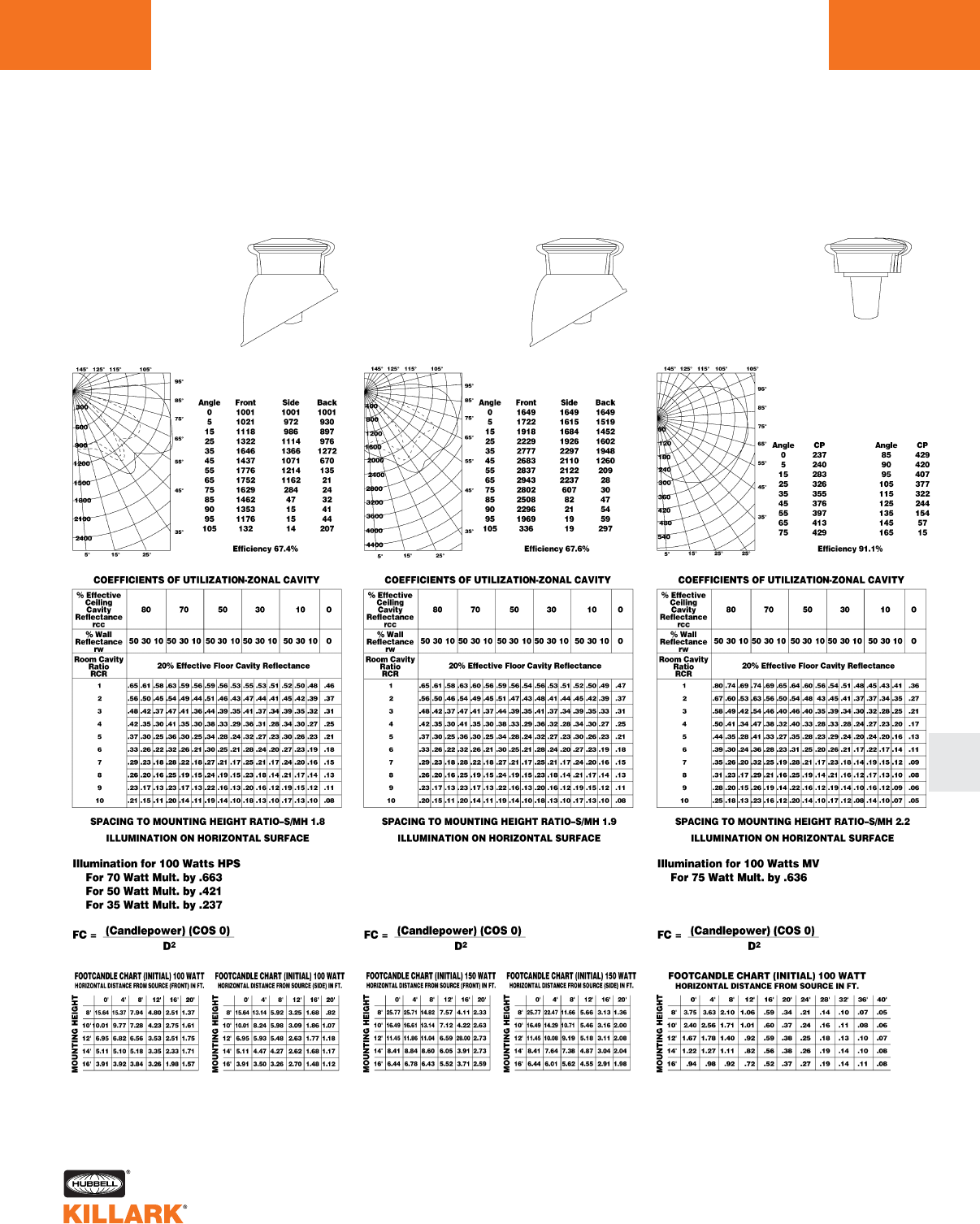
HIGH PRESSURE SODIUM
With Globe and 30° Angle Reflector
50 – 100 Watt Medium Base
HIGH PRESSURE SODIUM
With Globe and 30° Angle Reflector
150 Watt Medium Base
MERCURY VAPOR & METAL HALIDE
With Globe Only
50 – 100 Watt Medium Base
Test No. HP-03124 Test No. HP-03131 Test No. HP-03138
See above for other values
CANDLEPOWER–100
B-17 Clear Lamp
(9500 Lumens)
For CP of a 70 Watt Luminaire
multiply by .663;
For a 50 Watt Luminaire
multiply by .421
WATT CANDLEPOWER–150 WATT
B-17 Clear Lamp
(16000 Lumens)
CANDLEPOWER–100 WATT MV
B-17 Clear Lamp
(4400 Lumens)
For CP of a 75 Watt MV Luminaire
multiply by .636;
For a 50 Watt MV Luminaire
multiply by .359
For a 50 Watt MH Luminaire
multiply by .77;
For a 70 Watt MH Luminaire
multiply by 1.36
For a 100 Watt MH Luminaire
multiply by 1.93
MB SERIES •LIGHTING
PHOTOMETRIC DATA L29
L
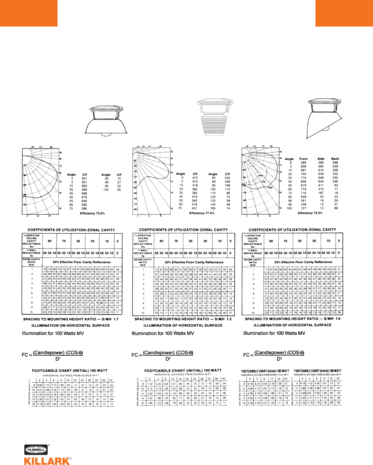
MB SERIES •LIGHTING
PHOTOMETRIC DATA
L30
CANDLEPOWER–100 WATT MV
B-17 Clear Lamp
(4400 Lumens)
For CP of a 75 Watt MV Luminaire
multiply by .636;
For a 50 Watt MV Luminaire
multiply by .359;
For a 50 Watt MH Luminaire
multiply by .77;
For a 70 Watt MH Luminaire
multiply by 1.36
For a 100 Watt MH Luminaire
multiply by 1.93
MERCURY VAPOR & METAL HALIDE
With Globe and Dome Reflector
50 – 100 Watt Medium Base
MERCURY VAPOR & METAL HALIDE
With Type V 8” Refractor
50 – 100 Watt Medium Base
MERCURY VAPOR & METAL HALIDE
With Globe and 30° Angle Reflector
50 – 100 Watt Medium Base
Test No. HP-03139 Test No. HP-03141 Test No. HP-03140
See above for other values See above for other values See above for other values
CANDLEPOWER–100 WATT MV
B-17 Clear Lamp
(4400 Lumens)
For CP of a 75 Watt Luminaire
multiply by .636;
For a 50 Watt MV Luminaire
multiply by .359;
For a 50 Watt MH Luminaire
multiply by .77;
For a 70 Watt MH Luminaire
multiply by 1.36
For a 100 Watt MH Luminaire
multiply by 1.93
CANDLEPOWER–100 WATT MV
B-17 Clear Lamp
(4400 Lumens)
For CP of a 75 Watt MV Luminaire
multiply by .636;
For a 50 Watt MV Luminaire
multiply by .359;
For a 50 Watt MH Luminaire
multiply by .77;
For a 70 Watt MH
Luminaire multiply by 1.36
For a 100 Watt MH Luminaire
multiply by 1.93
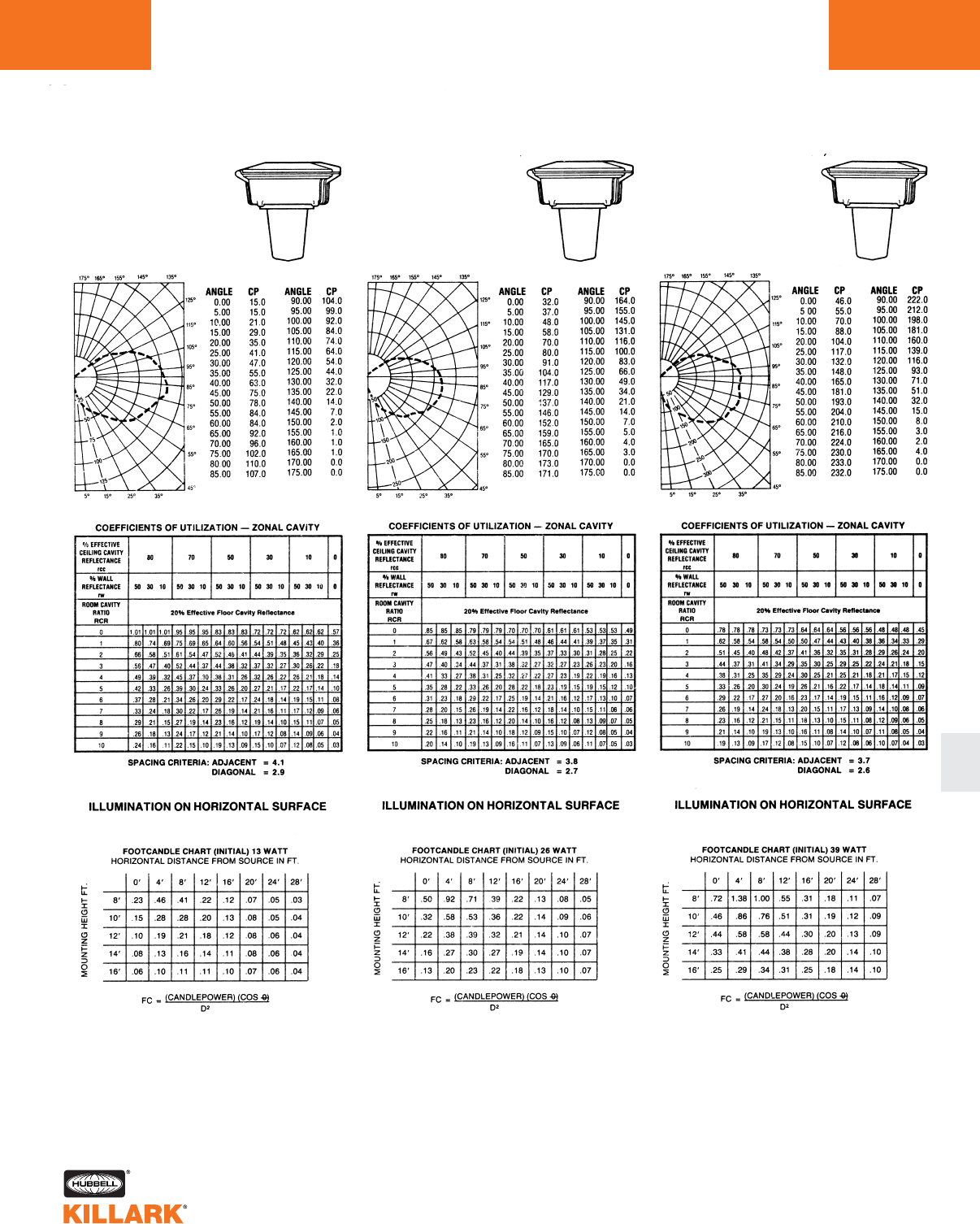
MBF SERIES •LIGHTING
PHOTOMETRIC DATA L31
L
FLUORESCENT
With Globe Only—13 Watt
CANDLEPOWER
—13 WATT
(900 Lumens
One Lamp)
FLUORESCENT
With Globe Only—26 Watt
CANDLEPOWER
—26 WATT
(1800 Lumens
Two Lamps)
FLUORESCENT
With Globe Only—39 Watt
CANDLEPOWER
—39 WATT
(2700 Lumens
Three Lamps)
Test No. 5659.1 Test No. 5658.0 Test No. 5657.0
Efficiency 92.4% Efficiency 76.7% Efficiency 70.6%
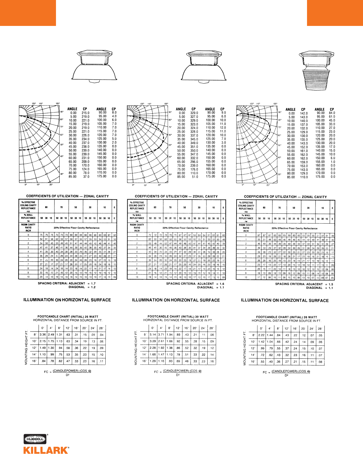
MBF SERIES •LIGHTING
PHOTOMETRIC DATA
L32
Test No. 5689.0 Test No. 5692.0 Test No. 5691.0
FLUORESCENT
With Globe and Dome
Reflector—26 Watt
CANDLEPOWER
—26 WATT
(1800 Lumens
Two Lamp)
For CP of a 13 Watt
Luminaire Multiply by .50
FLUORESCENT
With Globe and Dome Reflector—39
Watt
CANDLEPOWER
—39 WATT
(2700 Lumens
Three Lamps)
FLUORESCENT
With Type V “8”
Refractor—26 Watt
CANDLEPOWER
—26 WATT
(1800 Lumens
Two Lamps)
For CP of a 13 Watt
Luminaire multiply by .50
Efficiency 62.8% Efficiency 60.9% Efficiency 58.4%
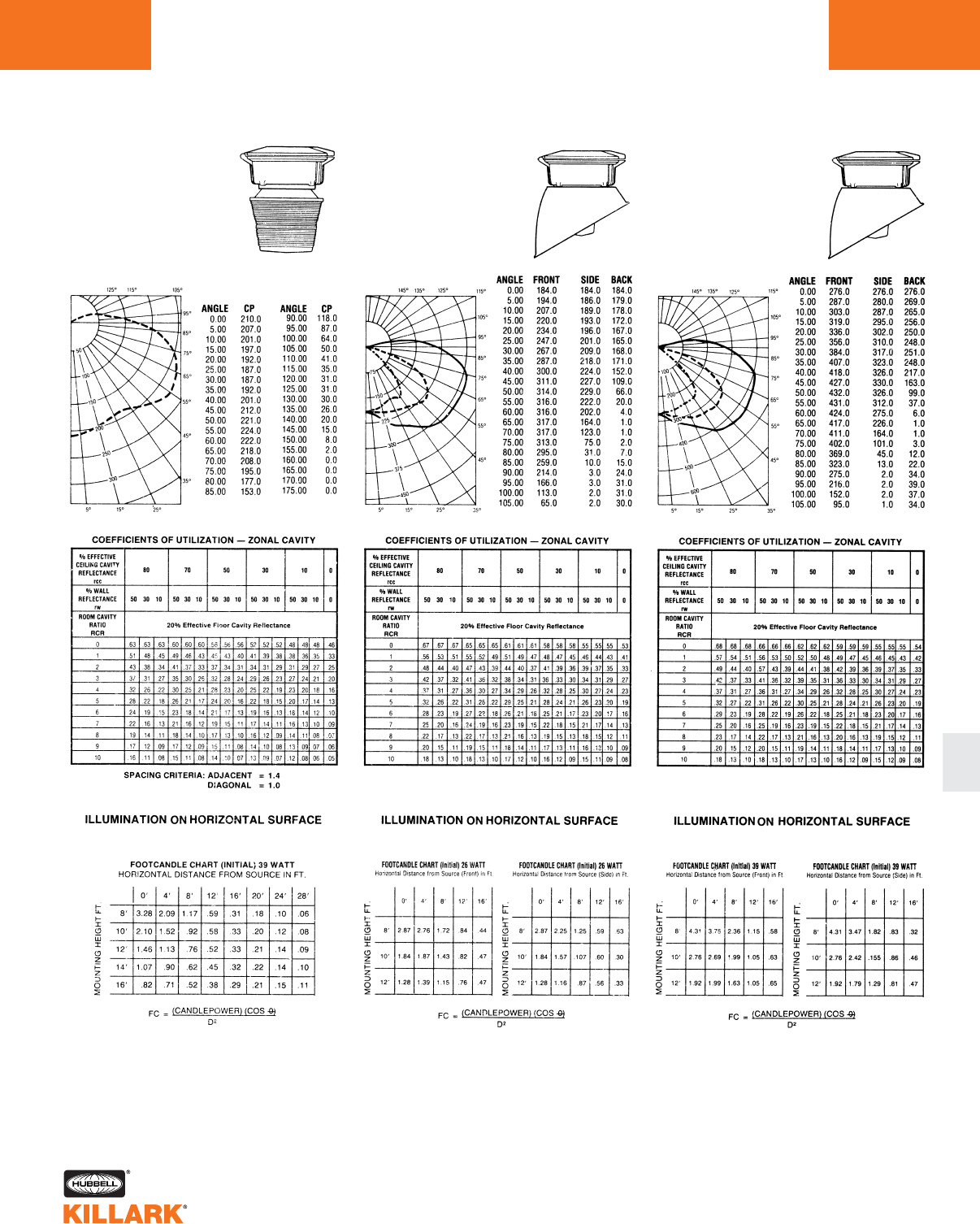
MBF SERIES •LIGHTING
PHOTOMETRIC DATA L33
L
CANDLEPOWER
–39 WATT
(2700 Lumens
Three Lamps)
CANDLEPOWER
–26 WATT
(1800 Lumens
Two Lamps)
For CP of a 13 Watt
Luminaire multiply by .50
Test No. 5694.0 Test No. 5690.0 Test No. 5693.0
FLUORESCENT
With Type V “8” Refractor—39 Watt
FLUORESCENT
With Globe and 30° Angle Reflector
—26 Watt
FLUORESCENT
With Globe and 30° Angle Reflector
—39 Watt
CANDLEPOWER
–39 WATT
(2700 Lumens
Three Lamps)
Efficiency 54.7%
Efficiency 57.2% Efficiency 58.3%
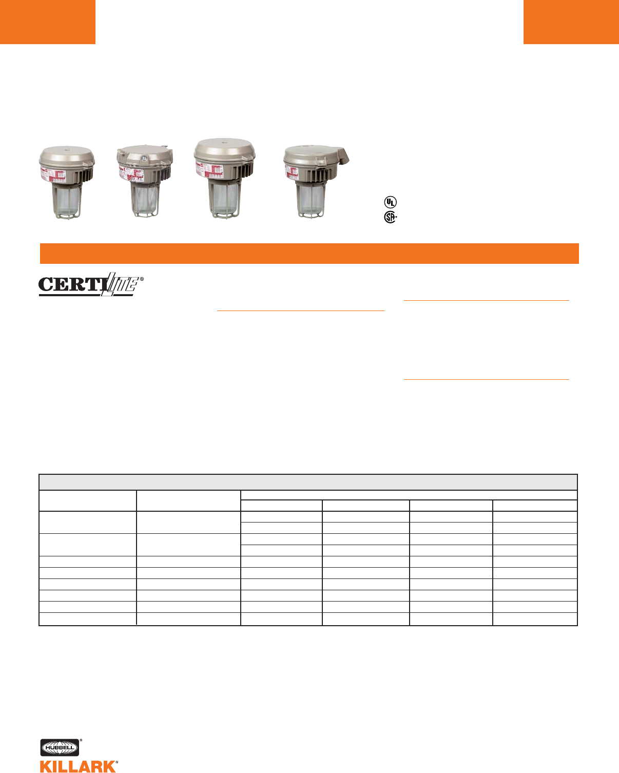
VBF/VQF SERIES •LIGHTING
COMPACT FLUORESCENT LIGHTING, 26-84 WATT
L34
FEATURES-SPECIFICATIONS
VBF/VQF 26-84WATT
26Watt (2x13) 120VAC 60Hz VBF261A2GGN4 VBF261X2GGN4 VBF261B2GGN4 VBF261D4GGN4
277VAC 60Hz VBF264A2GGN4 VBF264X2GGN4 VBF264B2GGN4 VBF264D4GGN4
39Watt (3x13) 120VAC 60Hz VBF391A2GGN4 VBF391X2GGN4 VBF391B2GGN4 VBF391D4GGN4
277VAC 60Hz VBF394A2GGN4 VBF394X2GGN4 VBF394B2GGN4 VBF394D4GGN4
26Watt (1x26) 120-277 50-60Hz VQF2630A2GGN4 VQF2630X2GGN4 VQF2630B2GGN4 VQF2630D4GGN4
32Watt (1x32) 120-277 50-60Hz VQF3230A2GGN4 VQF3230X2GGN4 VQF3230B2GGN4 VQF3230D4GGN4
42Watt (1x42) 120-277 50-60Hz VQF4230A2GGN4 VQF4230X2GGN4 VQF4230B2GGN4 VQF4230D4GGN4
52Watt (2x26) 120-277 50-60Hz VQF5230A2GGN4 VQF5230X2GGN4 VQF5230B2GGN4 VQF5230D4GGN4
64Watt (2x32) 120-277 50-60Hz VQF6430A2GGN4 VQF6430X2GGN4 VQF6430B2GGN4 VQF6430D4GGN4
84Watt (2x42) 120-277 50-60Hz VQF8430A2GGN4 VQF8430X2GGN4 VQF8430B2GGN4 VQF8430D4GGN4
COMPACT FLUORESCENT CATALOG NUMBER 345
LAMPS INCLUDED LINE VOLTAGE PENDANT 3/4" 1CEILING 3/4" 1WALL 3/4" 1STANCHION 1-1/4" 2
Class I, Div. 2, Groups A,B,C,D
Class I, Zone 2, Groups IIC, IIB, IIA
Class II, Div. 1 & 2, Groups E,F,G
Class III
NEMA 3, 4, 4X
Compliances: UL 844; UL 1570
Listed & CSA Certified
CSA C22.2 no. 137-M1981
Rated for 40Cº ambient. Minimum start 0º C.
Applications
CERTILITE®VBF and VQF are designed
for installations where moisture, dirt,
dust, corrosion and vibration may be
present, or NEMA 3 and 4X areas
where wind, water, snow or high ambi-
ents can be expected. They can be
used in locations made hazardous by
the presence of flammable vapors or
gases or combustible dusts as defined
by the NEC.
Typical applications include manufac-
turing plants, and certain chemical and
petro-chemical processing facilities,
sewage treatment plants, off-shore and
dockside installations, garages and
storage facilities.
Features
•Bi-Pin Twin (VBF) or Quad-Pin triple-
tube (VQF) long-life compact fluores-
cent lamps included
•World Voltage on Quad-Pin VQF
Series: 120 through 277VAC; 50/60 Hz
•Choice of Pendant, Ceiling, Wall or
Stanchion mount
•Energy-saving instant on white light
•Corrosion resistant-Copper-free
aluminum die-cast construction
(less than 4/10 of 1%) w/Baked-on
epoxy/polyester powder finish
•Exposed hardware is 316 grade
stainless steel
Accessories
Exit sign: Model VEXA-100 (Note: omit
2nd “G” in catalog number for globe-
only fixture), see page L183
Reflectors: Use standard dome
VMPSD-17 or angle model VMPA-17
(see page L118)
Options
For Factory Fusing on VBF and for
VQF to be used on 120V or 277V
systems, add -F to catalog number e.g.
VBF261A2GGN4-F. For VQF to be
used on 208V, 220V, 230V, 240V sys-
tems, add -FF to catalog number
e.g. VQF2630A2GGN4-FF.
1Pendant, Ceiling & Bracket models may be changed to 1" hubs by changing the 8th character
from 2to 3e.g. VBF261A3GGN4 (9th character in VQF series).
2For 1-1/2" angle Stanchion, change D4 to D5 in catalog number.
Change D4 to S5 for 1-1/2" Straight (90º) Stanchion.
3Omit 2nd “G” for globe-only fixture for use with VEXA-100 Exit Accessory.
4For VM series for dimensional data, contact factory.
5For refractor assemblies, order ballast tank, mounting splice box, “low wattage” optic and guard
from “VM” page L118.
Pendant Ceiling Wall Stanchion
VBF/VQF SERIES •LIGHTING
COMPACT FLUORESCENT LIGHTING, 26-84 WATT L35
FEATURES-SPECIFICATIONS
L
VBF/VQF 26-84WATT BALLAST TANKS ONLY3
26Watt (2x13) 120VAC 60Hz VBF261N4
277VAC 60Hz VBF264N4
39Watt (3x13) 120VAC 60Hz VBF391N4
277VAC 60Hz VBF394N4
26Watt (1x26) 120-277 50-60Hz VQF2630N4
32Watt (1x32) 120-277 50-60Hz VQF3230N4
42Watt (1x42) 120-277 50-60Hz VQF4230N4
52Watt (2x26) 120-277 50-60Hz VQF5230N4
64Watt (2x32) 120-277 50-60Hz VQF6430N4
84Watt (2x42) 120-277 50-60Hz VQF8430N4
LINE VOLTAGE
Class I, Div. 2, Groups A,B,C,D
Class I, Zone 2, Groups IIC, IIB, IIA
Class II, Div. 1 & 2, Groups E,F,G
Class III
NEMA 3, 4, 4X
Compliances: UL 844; UL 1570
UL Listed & CSA Certified
CSA C22.2 no. 137-M1981
Rated for 40Cº ambient. Minimum start 0º C.
LUMEN OUTPUT1
LAMP SOURCE LUMEN OUTPUT
26Watt (2x13) 1800
39Watt (3X13) 2700
26Watt (1x26) 1800
32Watt (1X32) 2400
42Watt (1X42) 3200
52Watt (2x26) 3600
64Watt (2X32) 4800
84Watt (2X42) 6400
HAZARDOUS LOCATION APPLICATION DATA FOR GLOBE & GUARD (SAME WITH REFLECTOR OR EXIT ACCESSORY)4
LAMP SOURCE CLASS I DIV. 2 A,B,C,D CLASS II DIV. 1 & 2 E,F,G CLASS III SUITABILITY SUPPLY WIRE
26Watt (2x13) 180°C (T3A) 85°C (T6) YES 85°C
39Watt (3X13) 180°C (T3A) 85°C (T6) YES 85°C
26Watt (1x26) 215°C (T2D) 120°C (T4A) YES 85°C
32Watt (1X32) 215°C (T2D) 120°C (T4A) YES 85°C
42Watt (1X42) 215°C (T2D) 120°C (T4A) YES 85°C
52Watt (2x26) 215°C (T2D) 120°C (T4A) YES 85°C
64Watt (2X32) 215°C (T2D) 120°C (T4A) YES 85°C
84Watt (2X42) 215°C (T2D) 120°C (T4A) YES 85°C
Pendant Ceiling Wall Stanchion
1Photometric characteristics similar to 26 watt
MBF pages L31-L33, except adjusted for
Lumen output.
2Order splice box, optic and guard separately.
3See pages L78, L79 for ballast data.
4VBF/VQF units are rated for simultaneous presence.
CATALOG
NUMBER
COMPACT FLUOR.2
LAMPS INCLUDED
REPLACEMENT LAMPS
CATALOG NUMBER DESCRIPTION
MPL13 13W Bi-Pin
MQL26 26W Quad-Pin
MQL32 32W Quad-Pin
MQL42 42W Quad-Pin
VBF/VBQ BALLAST DATA
LAMP
SOURCE
(2) Bi-Pin
Fluorescent
(3) Bi-Pin
Fluorescent
Quad-Pin
Fluorescent
Quad-Pin
Fluorescent
LAMP
WATTS/TYPE
26W (2 X 13)
39W (3 X 13)
26W (1 X 26)
32W (1 X 32)
42W (1 X 42)
52W (2 X 26)
64W (2 X 32)
84W (2 X 42)
VOLTAGE
60 HERTZ
120
277
120
277
120-277
120-277
START
(AMPS)
.78
.70
.78
.70
—
—
OPERATING
(AMPS)
.60
.60
.24(120)/.11(277)
.31(120)/.13(277)
.38(120)/.18(277)
.48(120)/.22(277)
.62(120)/.26(277)
.76(120)/.36(277)
BALLAST
CIRCUIT
NPF
NPF
HPF
HPF
REGULATION
—
—
Electronic
Electronic
MIN. START
32°F (0°C)
32°F (0°C)
-4°F (-20°C)
-4°F (-20°C)
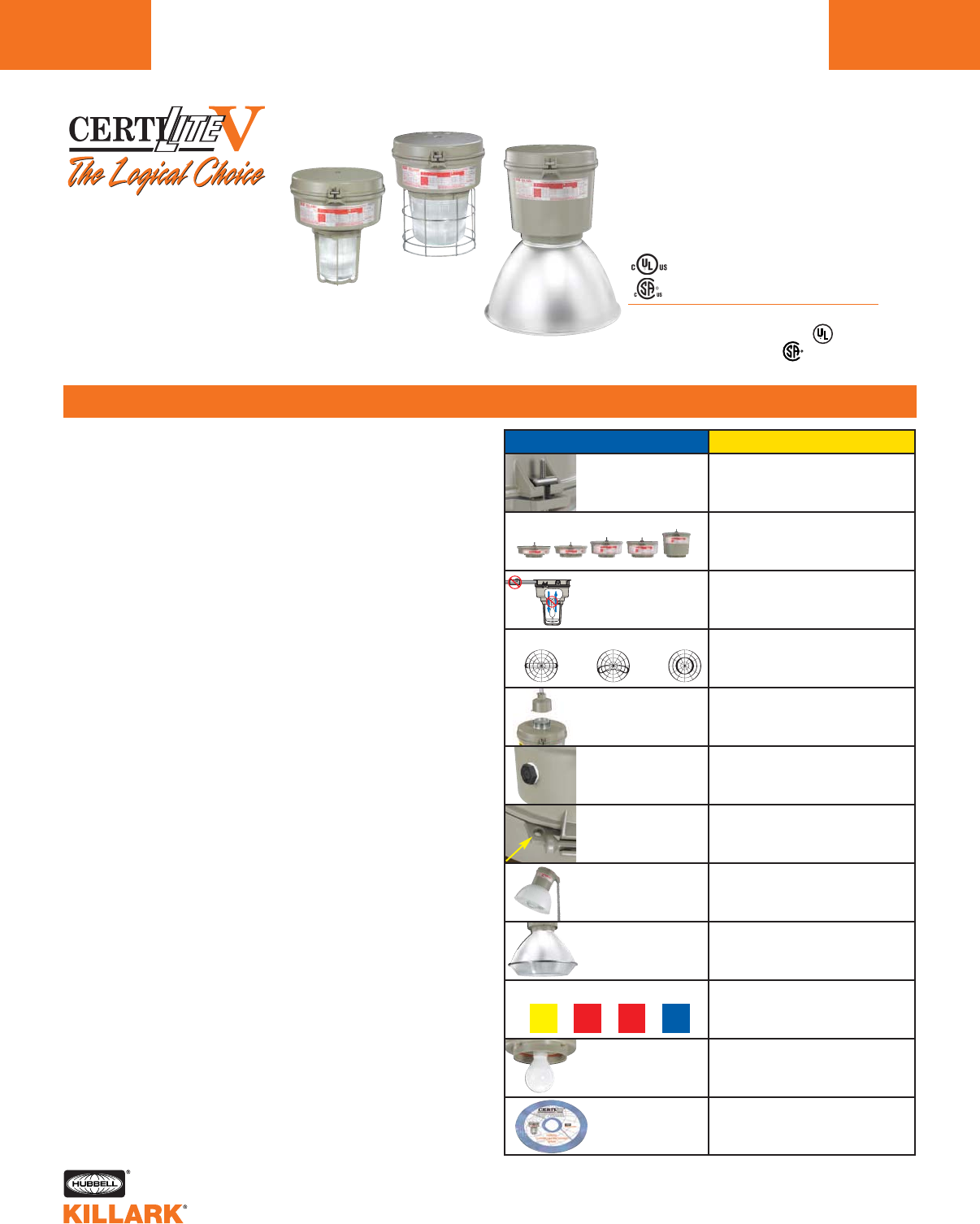
Class I, Div. 2, Groups A,B,C,D1
Class l, Zone 2, Groups IIC, llB, llA
Class II, Div. 1 & 2, Groups E,F,G
Class III
Suitable for wet locations
NEMA 3, 4, 4X; IP66
NR Restricted Breathing Option2
Class I, Zone 2 AEx nAnR
Class I, Zone 2 Ex nR
CERTILITE®V SERIES •LIGHTING
INTRODUCTION
L36
FEATURES-SPECIFICATIONS
VM3
VM4
KILLARK®CertiLite®VSeries sets a new standard for industrial
grade HID luminaires. Designed for installations where moisture,
dirt, dust, corrosion and vibration may be present, these fixtures
are suitable for NEMA 3 and 4X areas and where wind, water,
snow or high ambients can be expected. They also can be
used in locations made hazardous by the presence of flamma-
ble vapors and gases or combustible dusts, as defined by the
NEC®. Typical applications include manufacturing sites, chemi-
cal and petrochemical processing facilities, sewage treatment
plants, off-shore and dockside installations, garages and ware-
houses.
Standard Materials:
•Ballast tank and splice box – corrosion resistant copper-free alu-
minum alloy with baked powder epoxy/polyester finish, electrosta-
tically applied for complete, uniform corrosion protection.
•All external hardware – 316 stainless steel.
•Guards – Painted copper-free aluminum alloy or 316SS for 7-3/4"
glass optics and Enclosed Reflectors.
•Spin-top Refractor Guards are Plated Steel.
•Reflectors – lightweight, corrosion resistant polyester reinforced
fiberglass, or copper-free aluminum.
Additional Features:
• Seven mounting splice box types; Pendant, Flex Pendant, Ceiling,
Wall bracket, Cone Top, 25° Angle Stanchion, Straight Stanchion
– in a variety of entry sizes, including M20 for the VMX ceiling style.
• Quartz auxiliary, HPS instant restart, Ballast Protectors
• Minimum starting temperature: HPS – 40°C; MV, MH & MHP – 30°C
• Normally shipped as components for fast delivery, or may be
ordered factory assembled with or without lamps.
• Options for fuses and Quick Disconnect
Compliances
•UL1598 Standard for luminaires
•UL1598A Marine type luminaire
•UL-844 Standard for lighting fixtures for hazardous locations
• CSA C22.2 no. 137-M1981 electric luminaries for use in haz-
ardous locations
• Enclosed and gasketed
• NEMA 3, 4X IP66
• UL 60079-15 - Electrical apparatus for Explosive Gas
Atmospheres with Type of Protection “n” (Restricted Breathing and
non-sparking).
NEW FEATURES BENEFITS
Swing-Barrel Nut
Patented Tank
Mounting System
• Stainless-to-Stainless securement
• Takes load off during installation
• Uses ordinary tools
• Saves time and labor
Cover a wider range of wattage sizes and
socket types (will include five total) for
maximum user selection flexibility
Sealed Optic Zone 2
AEx nAR Restricted
Breathing (suffix NR)
NO External Seals. Lower T-codes, Suitable
for Class I Div. 2 Classified areas per the
NEC®
All glass refractors Compact (5-1/2" thread size, types I & V)
Standard (7-3/4", thread size,types I, III, V)
Enhances user selection flexibility
New “EZ” mount
adapter
Easier Maintenance, saves labor, move
fixture from the ladder to the workbench
Photo controls -
Class I Div. 2 /
N4X areas
Available as Field or Factory Installed to
save energy when light not required
Earthquake Tab -
Built-in attachment
point for safety cables
Safety: Secures fixture to structure in case
of conduit failure. “3rd hand” acces-
sories for lamp change out
“FULL CUTOFF” &
CUTOFF Optics
For “Dark Sky” Requirements. Helps to min-
imize offending light pollution
VMEP40
“Food Optic”
Expanded Offering
for Food or Grain Handling
Applications to minimize contamination
NEMA Decals Easier Maintenance, Saves labor
“Have the right lamp in hand
before going up the ladder”.
Expanded lamp
types and wattages
Philips®QL Induction type and 600Watt HPS
available for long life or high lumen require-
ments
CertiLite
Software
Used to determine number of fixtures
required and their proper layout for various
tasks and applications.
Listed - File E10514 (Hazardous & Marine)
15 17 17P 17
I III V
VM5
®
Philips®is a registered trademark of Koninklijke Philips Electronics N.V.
12 See Thermal Performance Tables beginning L84.
New ballast tank sizes
Certified - File LR11713
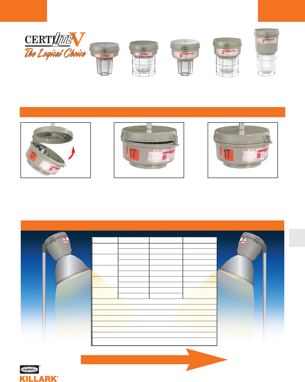
VM3
5 1/2" Optic
Low Wattage
Mogul Base
CERTILITE®V SERIES •LIGHTING
INTRODUCTION L37
SWING-BARREL NUT
L
®
VM1*
5 1/2" Optic
Compact Profile
Medium Base
VM2*
7 3/4" Optic
Compact Profile
Medium Base
VM4
7 3/4" Optic
Low Wattage
Mogul Base
VM5
7 3/4" Optic
High Wattage
Mogul Base
•The CertiLite®VSwing-Barrel Nut System provides a
Stainless-to-Stainless securement between tank and mounting
box. No more Stainless-to-Aluminum connections or need for
Stainless inserts.
•Users can easily lift the tank into place and “take the load off”,
then tighten. Saves time and labor.
•Only the patented Swing-Barrel Nut Stainless System can be
tightened with a common screwdriver or nut driver; others are
either stainless-to-aluminum, or require a wrench or special deep
socket.
NOTE: CertiLite®Vseries tanks are backwardly compatible with older CertiLite®
mounts. Simply remove Barrel Nut and thread into old mount.
Or turn the page for more features/comparisons
123
QUICK LOCATOR TABLE
Hang
Fixture Swing into Place Tighten
HPS
MH
MHP
MV
QL
50-150
200-600
70-250
400
150-200
250-400
100-250
400
85
165
VM3 & VM4
VM5
VM3 & VM4
VM5
VM3 & VM4
VM5
VM3 & VM4
VM5
VM4
VM5
L43
L60
L47
L64
L51
L66
L55
L70
L73
L75
L80
L84
L90
L42
L59
L72
L119
Lamp Type Wattage Range Luminaire Tank Begins on Page
Accessories
Dimensional Information
Temperature Data
Photometrics
VM3 & VM4 Logic Tree
VM5 Logic Tree
QL Logic Tree
Cross-reference guide CertiLite®to CertiLite®V
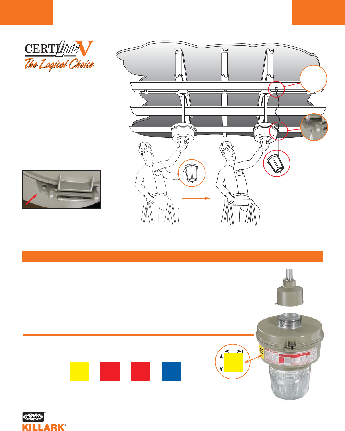
Maintenance personnel are often in
awkward positions when relamping: trying to
simultaneously hold on to a ladder, a globe
and the lamp. Available “3rd Hand” suspen-
sion cables support 5-1/2" VMG17/VMR17x
optics, utilizing the VMAG17 guard. 7-3/4"
VMG25/VMR25x/VMG40 optics utilize the
VMAGxxS guard and VMAGBC bottom clo-
sure. Cables attach to a special “Earthquake
Tab” built into the ballast tank housing. See
Suspension Accessories page L77.
CertiLite®Vtanks as standard have a built-in
“Earthquake Tab”. The tab is used to hold optic
suspension devices, and can simultaneously
be used to add a safety cable linked to the
building superstructure.
To enable easy and safe removal of CertiLite®Vfixtures for future maintenance, install with
the new VMEZA ballast tank to EZ mount adapter.
The complete assembly is removed for maintenance at the workbench.
Large facilities often keep spares so that a “new” fixture is put in at the time one needs
maintenance – thus eliminating the need to set up access equipment multiple times.
®
HAVE THE RIGHT LAMP IN HAND
BEFORE GOING UP THE LADDER.
For Personnel Safety
15 17 17
YELLOW
150W HPS
RED
175W MH
RED
175W MHP
BLUE
175W MV
15
3"
3"
NEMA Decals
for Lamp Type
& Wattage
* “P” designates newer Pulse Start Metal Halide lamps:
150, 175, 200, 250, 320, 350 and 400 watt models.
*
17 P
Attach to
Building
Structure.
Need a Hand?
CERTILITE®V SERIES •LIGHTING
INTRODUCTION
L38
EZ MOUNT & LAMP INDENTIFICATION
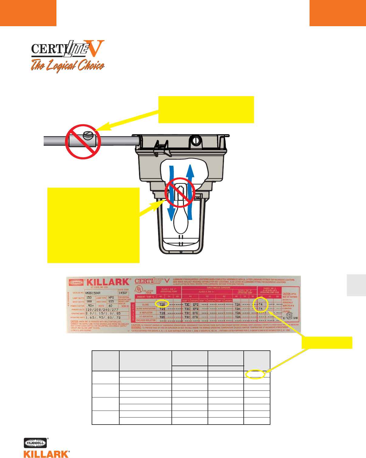
CERTILITE®V SERIES •LIGHTING
INTRODUCTION L39
L
®
NEW “Sealed Optic” construction, option “NR”. Rated for
Class I, Zone 2 AEx nAnR/Ex nR II Restricted Breathing.
“Sealed Entry” is no longer required to obtain significantly lower T-codes.
•CertiLite®Vluminaires with the NR option
are factory sealed to save installation time
and labor costs.
•AEx nAnR/Ex nR II is covered under
NEC®Article 505, and indicates Non-
Arcing and Non-Breathing.
•North American Class I Division 2 desig-
nated locations may use properly marked
Zone 2 rated equipment per NEC Article
501.5.
• The CertiLite®VNR option is available for
VMG, VMR, and VMER40 optics, but not
VZRG “Spin-top” Refractors.
• Permits the use of fewer higher wattage
luminaires for a given application.
No labor intensive conduit seals
or sealed cable glands required
for installation
Factory seal above lamp
chamber restricts air flow,
preventing hazardous vapors
from reaching the lamp. This
allows temperature code
measurement at the globe vs.
the lamp, allowing lower
T-codes for a given lamp size
and type.
150 HPS
400 HPS
175 MH
400 MH
VM3 w/VMG or VMR
VM4 w/VMG or VMR
VM5 w/VMG
VM5 w/VMER40
VM3 w/VMG or VMR
VM4 w/VMG or VMR
VM5 w/VMG40
VM5 w/VMER40
T2B (260°C)
T2B (260°C)
350° C
350° C
T2A (280°C)
T2B (260°C)
325° (300°C)
T2 (300°C)
T4 (135°C)
T4 (135°C)
T3 (200°C)
T3 (200°C)
T3 (200°C)
T4 (135°C)
T3 (200°C)
T3 (200°C)
-125°C
-125°C
-150°C
-150°C
-80°C
-125°C
-100°C
-100°C
Lamp Type
and
Wattage
Examples at 40c ambient.
See thermal performance
charts beginning L84 for
more information
Class I Div. 2/
Zone 2
Globe only
1
Class I Zone 2
AEX nAnR II
2
Reduction
in Applied
T-Code
For Lower T-Codes
See the Benefit!
1Based on Lamp temperature data
2Based on Globe temperature data
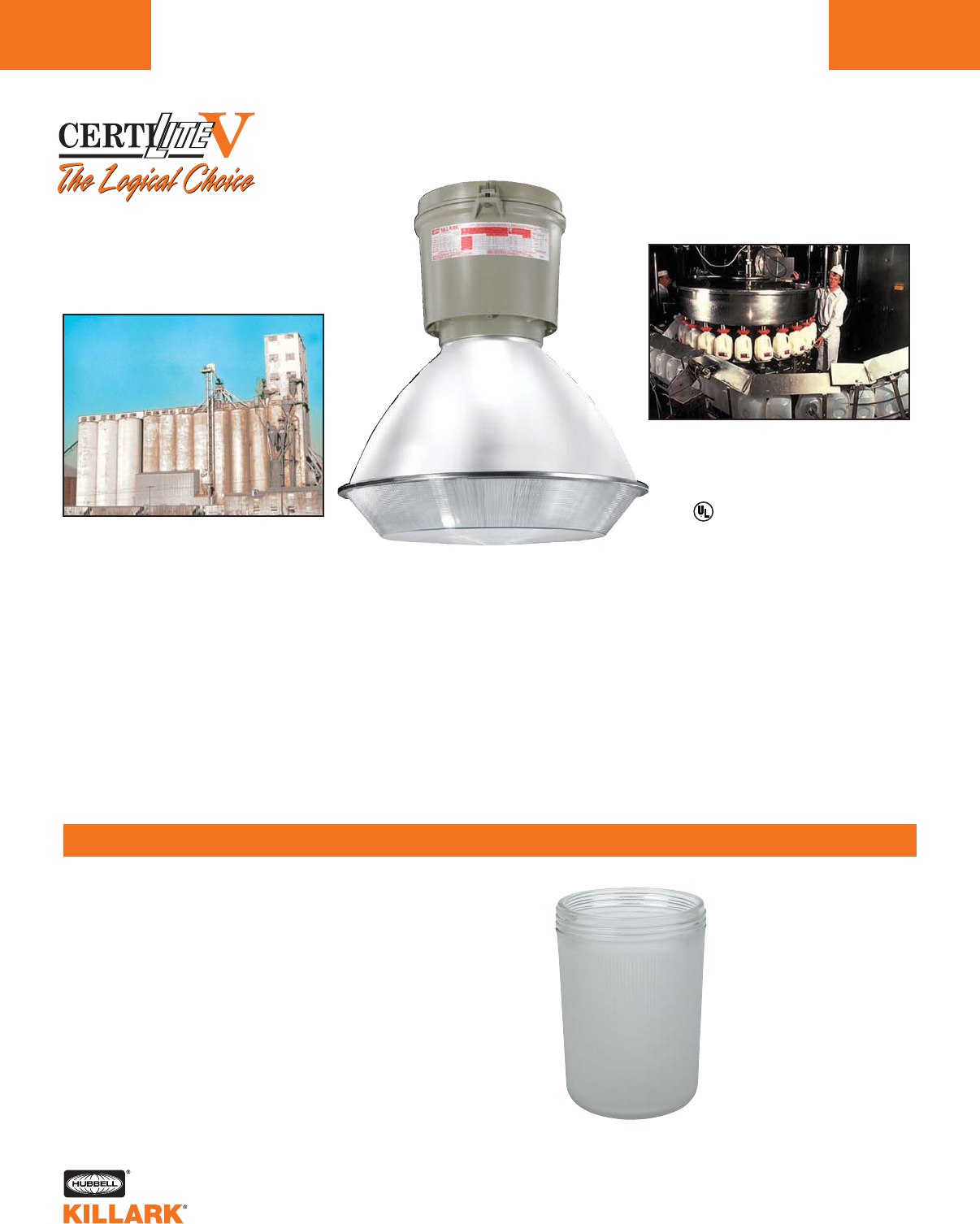
CERTILITE®V SERIES •LIGHTING
INTRODUCTION
L40
•CertiLite®VVM4 or VM5 series luminaires with the new
VMEP40 Optic have a strong non-glass polycarbonate
shield protecting food from potential broken glass contam-
ination, as could be the case even with heat-resistant
heavy duty globes.
•Unique design incorporates internal glass lens to seal out
dust and vapors from the lamp, with a polycarbonate
shield banded tightly at the bottom.
•Copper-free aluminum reflector is painted white for easy
cleaning; threaded portion at top is natural aluminum to
prevent paint dust contamination during maintenance
(from attaching/detaching).
•Polycarbonate shield is replaceable and must always be
used to maintain ratings.
•CertiLite®Vnow offers additional all-glass threaded
refractors, and many are available with a Teflon coating.
•Teflon®coating helps to reduce the likelihood of glass
breakage, and if broken, reduces the area of contamination.
Also enhances cleanability.
•See Accessories page L76 for more information.
Teflon®is a registered trademark of Dupont, Inc.
EXPANDED TEFLON®COATED OPTICS
VMG17T
®
Listed and Certified
Class I Div. 2; Class II Div. 1;
N4X; NSF
Grain Area
Food Area
VMEP40 Optic
For Food & Grain Safety
and Low Bay Applications
SAFETY COATING
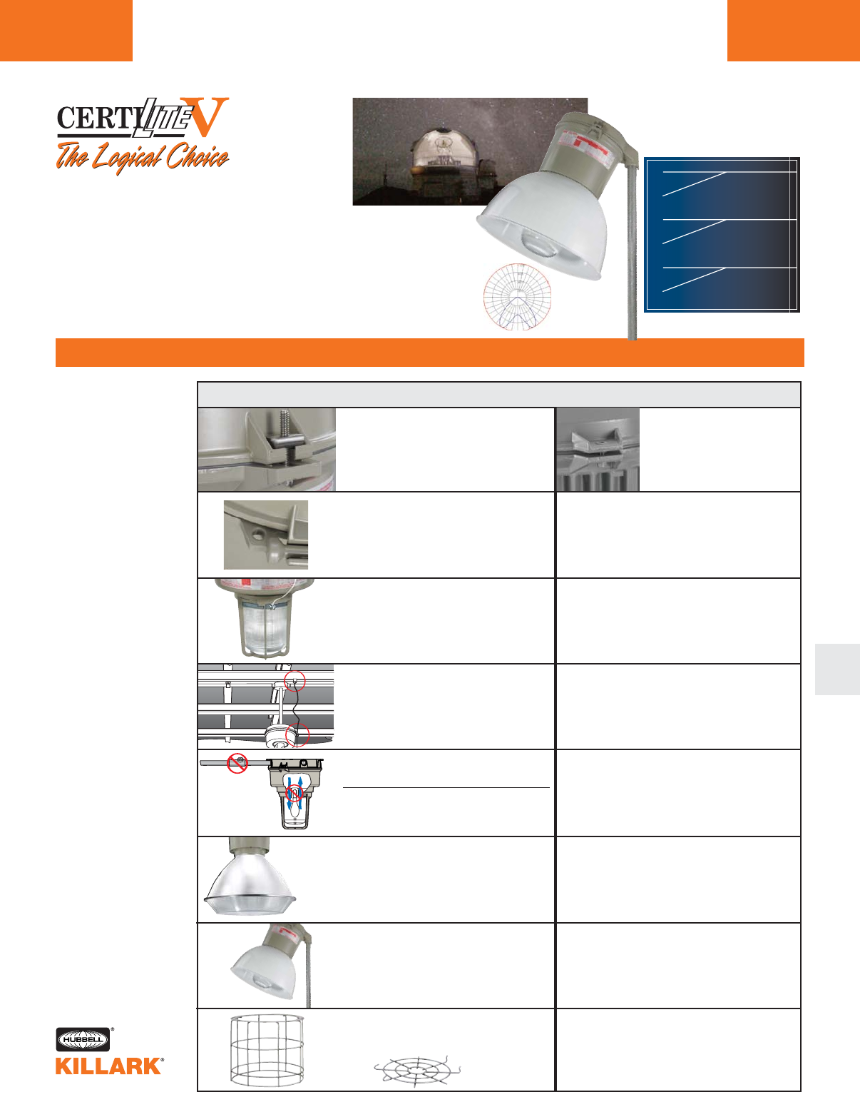
CERTILITE®V SERIES •LIGHTING
INTRODUCTION L41
L
COMPETITIVE COMPARISONS
®
90¡
80¡
90¡
80¡
90¡
80¡
<5%
<20%
<2.5%
<10%
ÊÊ0%
<10%
SEMI-CUTOFF
CUTOFF
FULL CUTOFF
For Dark Sky Needs
CertiLiteV
®
KILLARK vs. COMPETITION
Swing-barrel nut
Stainless-to-Stainless securement
between tank and mounting box.
Can be tightened with a common
screwdriver or nut driver.
Either not stainless, or
require a wrench or spe-
cial deep socket.
Earthquake tab
Built in securement location for
safety cables, optic “3rd Hand”
or to building structure.
Maintenance Safety Optic
suspension systems
Suspension safety cable to
building superstructure
“Sealed Optic”
Instead of more costly “Sealed Entry”
Meets AEx nAR Requirements
VMEP40
Food Area Suitable Optic
Dark Sky
Optics Available
316 Stainless Guards
For 7 3/4" All Glass Optics.
Optional Bottom Closure.
Not
Available
Not
Available
Not
Available
Only Glass
Optics Offered
“Sealed Entry” requires extra parts
(conduit seals) and labor to
install, and block pulling of
replacement wiring.
Limited, if any, solutions for light
pollution, a problem in many areas.
“Ordinary” stainless & open bottom type
only. Provides less protection
from bottom impact or corrosion.
•The CertiLite®VVMER40 Enclosed Reflector meets the “Full Cuttoff”
photometric requirement in many areas, such as observatories, to
minimize offending light pollution. Fits VM4 and VM5 Series tanks.
•“Dark Sky” Kits are available to enable the deep HRD-400 Series
Reflectors meet this requirement over globes on the VM4, “Full
Cutoff” or “Cutoff” on VM5 Series tanks. See L77 for more information.
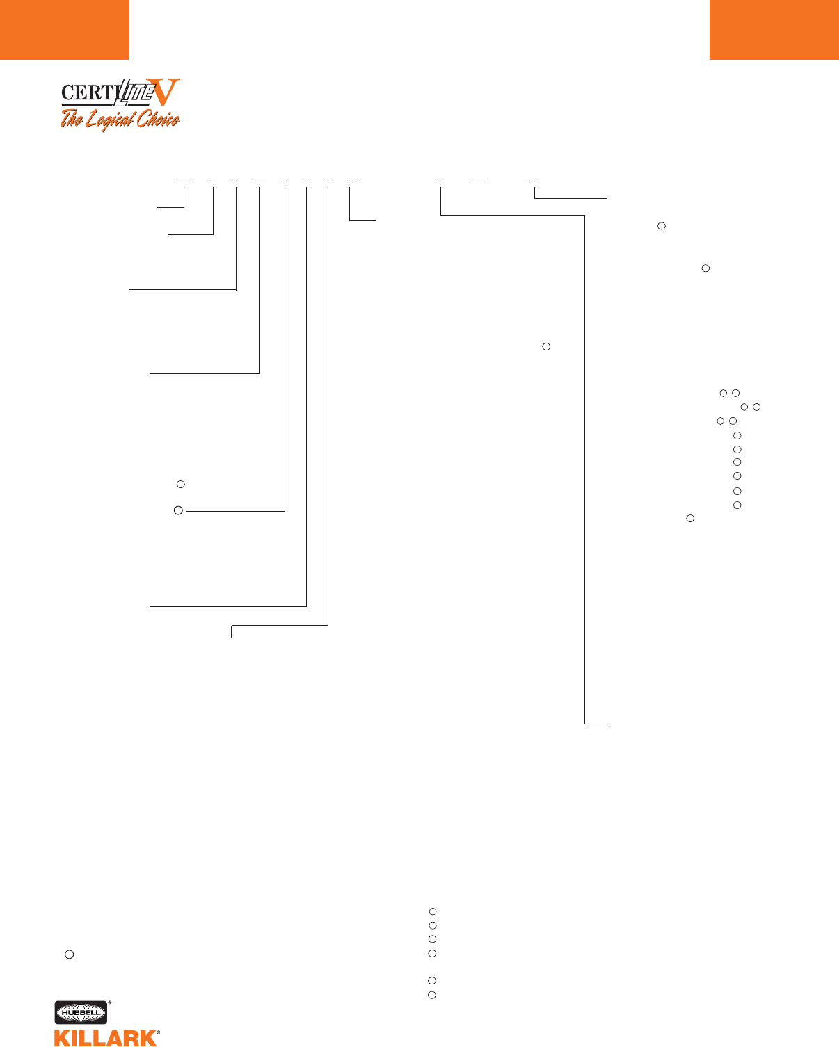
CERTILITE®V SERIES •LIGHTING
VM3/VM4 CATALOG ORDERING LOGIC
L42
CertiLite®VCatalog Number Logic; 50-250 Low Wattage (Mogul Base) HID Fixtures
Series Constant
Optic Thread Size
3—5 1/2"
4—7 3/4"
Lamp Type
S—HPS (50, 70, 100, 150)
H—MH (70, 100, 175, 250)
P—MHP (1251, 150, 175, 200)
M—MV (100, 175, 250)
Voltage @ 60 Hertz
0—Quadri-Volt (120, 208, 240, 277)
5—480V
6—Tri - 120, 277, 347 (Canada)
7—220V
8—220/240 50 Hz
Mounting Type
A—Pendant
F—Flexible Pendant
X—Ceiling
B—Wall Bracket
C—Cone Top
E—EZ Mount Adapter2
D—Stanchion 25°
S—Stanchion Straight 90°
N—None (mount ordered
separately)3
Lamp Wattage
05—50W, (HPS)
07—70W, (HPS, MH)
10—100W, (HPS, MH, MV)
12—125W, (MHP1)
15—150W, (HPS, MHP)
17—175W, (MH, MHP, MV)
20—200W, (MHP)
25—250W, (MH, MV)
Guard
G—Guard (Globes & Glass
refractors)
N—No Guard8
Options
IR—Instant Restrike - 50-150
HPS
QA—Quartz Auxiliary9
BP—Ballast Protector -
70-150 HPS
F1—Fusing 120V
F2—Fusing 208V
F3—Fusing 240V
F4—Fusing 277V
F5—Fusing 480V
F6—Fusing 347V
F7—Fusing 220V
F8—Fusing 240V 50 Hz
P1—Photocell 120V
P2—Photocell 208-277V
P3—Photocell 347V
Q1—QD Wired to 120V
Q2—QD Wired to 208V
Q3—QD Wired to 240V
Q4—QD Wired to 277V
Q5—QD Wired to 480V
Q6—QD Wired to 347V
Q7—QD 220V
Q8—QD 240V (50Hz)
TB—Terminal Blocks
AS—Assembled Fixture with
Standard Lamp
AD—Assembled Fixture with
Dual Arc Tube Lamp 70,
100, 150 HPS only
AN—Assembled, no lamp
CP—Component Pack-No
Lamp
CS—Component Pack with
Standard Lamp
Optic
GL—Globe (VM3, VM4)
R1—Type I Glass Refractor (VM3,
VM4)
R3—Type III Glass Refractor (VM4)
R5—Type V Glass Refractor (VM3,
VM4)
ER—Enclosed Reflector (VM4)
EP—Poylcarbonate Shielded
Enclosed Reflector (VM4)
S2—Type II 12" Spin-Top Refractor
(VM34, VM4)
S8—Type V 8" Spin-Top Refractor
(VM3)
S5—Type V 12" Spin-Top Refractor
(VM34, VM4)
P5—Type V 12" Plastic Spin-Top
Refractor (VM3-175W Max.)
FG—Tuffskin®5Coated Globe (VM3,
VM4)
TG—Teflon®6Coated Globe (VM3,
VM4)
T1—Teflon®6Coated Globe Type I
Glass Refractor (VM3, VM4)
T3—Teflon®6Coated Globe Type III
Glass Refractor (VM4)
T5—Teflon®6Coated Globe Type V
Glass Refractor (VM3, VM4)
T2—Teflon®6Coated Type II 12"
Spin-Top Refractor (VM34,
VM4)
T8—Teflon®6Coated Type V 8"
Spin-Top Refractor (VM3)
TV—Teflon®6Coated Type V 12"
Spin-Top Refractor (VM34,
VM4)
Entry (Mounts available)
2—3/4" NPT (A,B,C,X)
3—1" NPT (A,B,C,X)
4—1 1/4" NPT (D,S)
5—1 1/2" NPT (D,S)
6—3/4" NPT 5-Hub (X)
7—1" NPT 5-Hub (X)
8—M20 4-Hub (X)
9—M20 5-Hub (X)
Z—EZ Mount Adapter2
N—None (mount ordered
separately)3
VM 0 0 00 0 0 0 00 0 (NR7)00
1Special order lamp type/wattage not shown in grids, minimums apply.
2Completes as “EZ”, conduit mounting boxes ordered separately - See L63.
3NN mount ordered separately.
412" Spintops for use with VM3 tanks ship with a Mogul to Mogul socket
extender for enhanced photometrics vs. 7 3/4", which are used on VM5,
but will fit VM4.
5Tuffskin®is a registered trademark of Thomas Mfg. Corp.
6Teflon®is a registered trademark of DuPont, Inc.
Consult factory for available lamp and voltage combinations.
7Restricted Breathing - See L39 for more information.
8Order Guards for Spin-Tops & VMER40 separately.
9QA not suitable for Class I, Div. 2/Zone 2 applications; consult factory
for other hazardous applications.
Fusing not for Marine or Canadian installations.
Photo cells for Class I, Div. 2 only.
Field connection to proper tap in case of Multitap Ballasts.
Not for use with wall or straight (90°) Stanchion.
QD = Quick Disconnect. Allows easy tank removal for maintenance.
Electrician simply unplugs de-energized ballast from supply circuit.
220V 60Hz or 230V 50Hz used with QA-requires VM5 tank.
IR and BP cannot be ordered together.
®
11
12
13
13
14
15
15
16
11 12
11 12
11 12
14
16
16
14
14
14
14
14
14
V
V
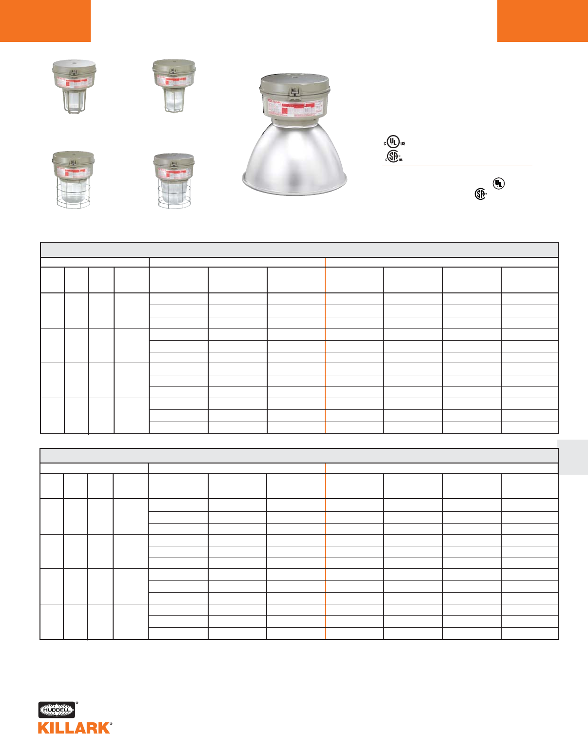
CERTILITE®V SERIES •LIGHTING
VM3/VM4 CATALOG ORDERING LOGIC L43
L
Class I, Div. 2, Groups A,B,C,D1
Class l, Zone 2, Groups IIC, llB, llA
Class II, Div. 1 & 2, Groups E,F,G
Class III
Suitable for wet locations
NEMA 3, 4, 4X; IP66
NR Restricted Breathing Option5
Class I, Zone 2 AEx nAnR
Class I, Zone 2 Ex nR
Listed - File E10514 (Hazardous & Marine)
Certified - File LR11713
Pendant
w/ Enclosed Reflector
Pendant
w/ 5-1/2"
Globe & Guard
Pendant
w/ 7-3/4"
Globe & Guard
Flexible Pendant
w/ 5-1/2"
Refractor & Guard
Flexible Pendant
w/ 7-3/4"
Refractor & Guard
VM 50-150 WATT HIGH PRESSURE SODIUM PENDANT
WATTS
50
70
100
150
DESCRIPTION
ANSI
S68
S62
S54
S55
HUB
SIZE3
3/4"
3/4"
3/4"
3/4"
VOLTAGE4
Quad
Tri
480
Quad
Tri
480
Quad
Tri
480
Quad
Tri
480
5-1/2" OPTIC THREAD SIZE 2
GLOBE
&GUARD
VM3S050A2GLG
VM3S056A2GLG
VM3S055A2GLG
VM3S070A2GLG
VM3S076A2GLG
VM3S075A2GLG
VM3S100A2GLG
VM3S106A2GLG
VM3S105A2GLG
VM3S150A2GLG
VM3S156A2GLG
VM3S155A2GLG
TYPE I GLASS
REFRACTOR
& GUARD
VM3S050A2R1G
VM3S056A2R1G
VM3S055A2R1G
VM3S070A2R1G
VM3S076A2R1G
VM3S075A2R1G
VM3S100A2R1G
VM3S106A2R1G
VM3S105A2R1G
VM3S150A2R1G
VM3S156A2R1G
VM3S155A2R1G
TYPE V GLASS
REFRACTOR
& GUARD
VM3S050A2R5G
VM3S056A2R5G
VM3S055A2R5G
VM3S070A2R5G
VM3S076A2R5G
VM3S075A2R5G
VM3S100A2R5G
VM3S106A2R5G
VM3S105A2R5G
VM3S150A2R5G
VM3S156A2R5G
VM3S155A2R5G
7-3/4" OPTIC THREAD SIZE 2
GLOBE
& GUARD
VM4S050A2GLG
VM4S056A2GLG
VM4S055A2GLG
VM4S070A2GLG
VM4S076A2GLG
VM4S075A2GLG
VM4S100A2GLG
VM4S106A2GLG
VM4S105A2GLG
VM4S150A2GLG
VM4S156A2GLG
VM4S155A2GLG
TYPE I GLASS
REFRACTOR
& GUARD
VM4S050A2R1G
VM4S056A2R1G
VM4S055A2R1G
VM4S070A2R1G
VM4S076A2R1G
VM4S075A2R1G
VM4S100A2R1G
VM4S106A2R1G
VM4S105A2R1G
VM4S150A2R1G
VM4S156A2R1G
VM4S155A2R1G
ENCLOSED
REFLECTOR
VM4S050A2ERN
VM4S056A2ERN
VM4S055A2ERN
VM4S070A2ERN
VM4S076A2ERN
VM4S075A2ERN
VM4S100A2ERN
VM4S106A2ERN
VM4S105A2ERN
VM4S150A2ERN
VM4S156A2ERN
VM4S155A2ERN
TYPE V GLASS
REFRACTOR
& GUARD
VM4S050A2R5G
VM4S056A2R5G
VM4S055A2R5G
VM4S070A2R5G
VM4S076A2R5G
VM4S075A2R5G
VM4S100A2R5G
VM4S106A2R5G
VM4S105A2R5G
VM4S150A2R5G
VM4S156A2R5G
VM4S155A2R5G
VM 50-150 WATT HIGH PRESSURE SODIUM FLEXIBLE PENDANT
WATTS
50
70
100
150
DESCRIPTION
ANSI
S68
S62
S54
S55
HUB
SIZE 3
3/4"
3/4"
3/4"
3/4"
VOLTAG4
Quad
Tri
480
Quad
Tri
480
Quad
Tri
480
Quad
Tri
480
5-1/2" OPTIC THREAD SIZE 2
GLOBE
& GUARD
VM3S050F2GLG
VM3S056F2GLG
VM3S055F2GLG
VM3S070F2GLG
VM3S076F2GLG
VM3S075F2GLG
VM3S100F2GLG
VM3S106F2GLG
VM3S105F2GLG
VM3S150F2GLG
VM3S156F2GLG
VM3S155F2GLG
TYPE I GLASS
REFRACTOR
& GUARD
VM3S050F2R1G
VM3S056F2R1G
VM3S055F2R1G
VM3S070F2R1G
VM3S076F2R1G
VM3S075F2R1G
VM3S100F2R1G
VM3S106F2R1G
VM3S105F2R1G
VM3S150F2R1G
VM3S156F2R1G
VM3S155F2R1G
TYPE V GLASS
REFRACTOR
& GUARD
VM3S050F2R5G
VM3S056F2R5G
VM3S055F2R5G
VM3S070F2R5G
VM3S076F2R5G
VM3S075F2R5G
VM3S100F2R5G
VM3S106F2R5G
VM3S105F2R5G
VM3S150F2R5G
VM3S156F2R5G
VM3S155F2R5G
7-3/4" OPTIC THREAD SIZE 2
GLOBE
& GUARD
VM4S050F2GLG
VM4S056F2GLG
VM4S055F2GLG
VM4S070F2GLG
VM4S076F2GLG
VM4S075F2GLG
VM4S100F2GLG
VM4S106F2GLG
VM4S105F2GLG
VM4S150F2GLG
VM4S156F2GLG
VM4S155F2GLG
TYPE I GLASS
REFRACTOR
& GUARD
VM4S050F2R1G
VM4S056F2R1G
VM4S055F2R1G
VM4S070F2R1G
VM4S076F2R1G
VM4S075F2R1G
VM4S100F2R1G
VM4S106F2R1G
VM4S105F2R1G
VM4S150F2R1G
VM4S156F2R1G
VM4S155F2R1G
ENCLOSED
REFLECTOR
VM4S050F2ERN
VM4S056F2ERN
VM4S055F2ERN
VM4S070F2ERN
VM4S076F2ERN
VM4S075F2ERN
VM4S100F2ERN
VM4S106F2ERN
VM4S105F2ERN
VM4S150F2ERN
VM4S156F2ERN
VM4S155F2ERN
TYPE V GLASS
REFRACTOR
& GUARD
VM4S050F2R5G
VM4S056F2R5G
VM4S055F2R5G
VM4S070F2R5G
VM4S076F2R5G
VM4S075F2R5G
VM4S100F2R5G
VM4S106F2R5G
VM4S105F2R5G
VM4S150F2R5G
VM4S156F2R5G
VM4S155F2R5G
1See hazardous application data on pages L84-L89 for limitations.
2Catalog numbers shown are with guard (except enclosed reflector); to omit guard change ending G to N; e.g. VM3S050A2GLN
3Catalog numbers shown are with 3/4" conduit openings; change 2 to 3 for 1"; e.g. VM3S050A3GLG.
4Consult catalog logic for other available voltages.
5Add suffix NR for restricted breathing; see page L39 for more information.

CERTILITE®V SERIES •LIGHTING
HIGH PRESSURE SODIUM, 50-150W MOGUL BASE HID
L44
Ceiling
w/ 5-1/2"
Globe & Guard
Ceiling
w/ 7-3/4"
Globe & Guard
Wall
w/ 5-1/2"
Refractor & Guard
Wall
w/ 7-3/4"
Refractor & Guard
Ceiling
w/ Enclosed Reflector
VM 50-150 WATT HIGH PRESSURE SODIUM CEILING
WATTS
50
70
100
150
DESCRIPTION
ANSI
S68
S62
S54
S55
HUB
SIZE3
3/4"
3/4"
3/4"
3/4"
VOLTAGE3
Quad
Tri
480
Quad
Tri
480
Quad
Tri
480
Quad
Tri
480
5-1/2" OPTIC THREAD SIZE 2
GLOBE
& GUARD
VM3S050X2GLG
VM3S056X2GLG
VM3S055X2GLG
VM3S070X2GLG
VM3S076X2GLG
VM3S075X2GLG
VM3S100X2GLG
VM3S106X2GLG
VM3S105X2GLG
VM3S150X2GLG
VM3S156X2GLG
VM3S155X2GLG
TYPE I GLASS
REFRACTOR
& GUARD
VM3S050X2R1G
VM3S056X2R1G
VM3S055X2R1G
VM3S070X2R1G
VM3S076X2R1G
VM3S075X2R1G
VM3S100X2R1G
VM3S106X2R1G
VM3S105X2R1G
VM3S150X2R1G
VM3S156X2R1G
VM3S155X2R1G
TYPE V GLASS
REFRACTOR
& GUARD
VM3S050X2R5G
VM3S056X2R5G
VM3S055X2R5G
VM3S070X2R5G
VM3S076X2R5G
VM3S075X2R5G
VM3S100X2R5G
VM3S106X2R5G
VM3S105X2R5G
VM3S150X2R5G
VM3S156X2R5G
VM3S155X2R5G
7-3/4" OPTIC THREAD SIZE 2
GLOBE
& GUARD
VM4S050X2GLG
VM4S056X2GLG
VM4S055X2GLG
VM4S070X2GLG
VM4S076X2GLG
VM4S075X2GLG
VM4S100X2GLG
VM4S106X2GLG
VM4S105X2GLG
VM4S150X2GLG
VM4S156X2GLG
VM4S155X2GLG
TYPE I GLASS
REFRACTOR
& GUARD
VM4S050X2R1G
VM4S056X2R1G
VM4S055X2R1G
VM4S070X2R1G
VM4S076X2R1G
VM4S075X2R1G
VM4S100X2R1G
VM4S106X2R1G
VM4S105X2R1G
VM4S150X2R1G
VM4S156X2R1G
VM4S155X2R1G
ENCLOSED
REFLECTOR
VM4S050X2ERN
VM4S056X2ERN
VM4S055X2ERN
VM4S070X2ERN
VM4S076X2ERN
VM4S075X2ERN
VM4S100X2ERN
VM4S106X2ERN
VM4S105X2ERN
VM4S150X2ERN
VM4S156X2ERN
VM4S155X2ERN
TYPE V GLASS
REFRACTOR
& GUARD
VM4S050X2R5G
VM4S056X2R5G
VM4S055X2R5G
VM4S070X2R5G
VM4S076X2R5G
VM4S075X2R5G
VM4S100X2R5G
VM4S106X2R5G
VM4S105X2R5G
VM4S150X2R5G
VM4S156X2R5G
VM4S155X2R5G
VM 50-150 WATT HIGH PRESSURE SODIUM WALL
WATTS
50
70
100
150
DESCRIPTION
ANSI
S68
S62
S54
S55
HUB
SIZE3
3/4"
3/4"
3/4"
3/4"
VOLTAGE4
Quad
Tri
480
Quad
Tri
480
Quad
Tri
480
Quad
Tri
480
5-1/2" OPTIC THREAD SIZE 2
GLOBE
& GUARD
VM3S050B2GLG
VM3S056B2GLG
VM3S055B2GLG
VM3S070B2GLG
VM3S076B2GLG
VM3S075B2GLG
VM3S100B2GLG
VM3S106B2GLG
VM3S105B2GLG
VM3S150B2GLG
VM3S156B2GLG
VM3S155B2GLG
TYPE I GLASS
REFRACTOR
& GUARD
VM3S050B2R1G
VM3S056B2R1G
VM3S055B2R1G
VM3S070B2R1G
VM3S076B2R1G
VM3S075B2R1G
VM3S100B2R1G
VM3S106B2R1G
VM3S105B2R1G
VM3S150B2R1G
VM3S156B2R1G
VM3S155B2R1G
TYPE V GLASS
REFRACTOR
& GUARD
VM3S050B2R5G
VM3S056B2R5G
VM3S055B2R5G
VM3S070B2R5G
VM3S076B2R5G
VM3S075B2R5G
VM3S100B2R5G
VM3S106B2R5G
VM3S105B2R5G
VM3S150B2R5G
VM3S156B2R5G
VM3S155B2R5G
7-3/4" OPTIC THREAD SIZE 2
GLOBE
& GUARD
VM4S050B2GLG
VM4S056B2GLG
VM4S055B2GLG
VM4S070B2GLG
VM4S076B2GLG
VM4S075B2GLG
VM4S100B2GLG
VM4S106B2GLG
VM4S105B2GLG
VM4S150B2GLG
VM4S156B2GLG
VM4S155B2GLG
TYPE I GLASS
REFRACTOR
& GUARD
VM4S050B2R1G
VM4S056B2R1G
VM4S055B2R1G
VM4S070B2R1G
VM4S076B2R1G
VM4S075B2R1G
VM4S100B2R1G
VM4S106B2R1G
VM4S105B2R1G
VM4S150B2R1G
VM4S156B2R1G
VM4S155B2R1G
ENCLOSED
REFLECTOR
VM4S050B2ERN
VM4S056B2ERN
VM4S055B2ERN
VM4S070B2ERN
VM4S076B2ERN
VM4S075B2ERN
VM4S100B2ERN
VM4S106B2ERN
VM4S105B2ERN
VM4S150B2ERN
VM4S156B2ERN
VM4S155B2ERN
TYPE V GLASS
REFRACTOR
& GUARD
VM4S050B2R5G
VM4S056B2R5G
VM4S055B2R5G
VM4S070B2R5G
VM4S076B2R5G
VM4S075B2R5G
VM4S100B2R5G
VM4S106B2R5G
VM4S105B2R5G
VM4S150B2R5G
VM4S156B2R5G
VM4S155B2R5G
1See hazardous application data on pages L84-L89 for limitations.
2Catalog numbers shown are with guard, to omit guard (except enclosed reflector); change ending G to N; e.g. VM3S050X2GLN
3Catalog numbers shown are with 3/4" conduit openings, change 2 to 3 for 1"; e.g. VM3S050X3GLG.
4Consult catalog logic for other available voltages.
5Add suffix NR for restricted breathing; see page L39 for more information.
Class I, Div. 2, Groups A,B,C,D1
Class l, Zone 2, Groups IIC, llB, llA
Class II, Div. 1 & 2, Groups E,F,G
Class III
Suitable for wet locations
NEMA 3, 4, 4X; IP66
NR Restricted Breathing Option5
Class I, Zone 2 AEx nAnR
Class I, Zone 2 Ex nR
Listed - File E10514 (Hazardous & Marine)
Certified - File LR11713

CERTILITE®V SERIES •LIGHTING
HIGH PRESSURE SODIUM, 50-150W MOGUL BASE HID L45
L
Cone
w/ 5-1/2"
Globe & Guard
Cone
w/ 7-3/4"
Globe & Guard
EZ Adapter
w/ 5-1/2"
Refractor & Guard
EZ Adapter
w/ 7-3/4"
Refractor & Guard
Cone
w/ Enclosed Reflector
VM 50-150 WATT HIGH PRESSURE SODIUM CONE
WATTS
50
70
100
150
DESCRIPTION
ANSI
S68
S62
S54
S55
HUB
SIZE3
3/4"
3/4"
3/4"
3/4"
VOLTAGE4
Quad
Tri
480
Quad
Tri
480
Quad
Tri
480
Quad
Tri
480
5-1/2" OPTIC THREAD SIZE 2
GLOBE
&GUARD
VM3S050C2GLG
VM3S056C2GLG
VM3S055C2GLG
VM3S070C2GLG
VM3S076C2GLG
VM3S075C2GLG
VM3S100C2GLG
VM3S106C2GLG
VM3S105C2GLG
VM3S150C2GLG
VM3S156C2GLG
VM3S155C2GLG
TYPE I GLASS
REFRACTOR
& GUARD
VM3S050C2R1G
VM3S056C2R1G
VM3S055C2R1G
VM3S070C2R1G
VM3S076C2R1G
VM3S075C2R1G
VM3S100C2R1G
VM3S106C2R1G
VM3S105C2R1G
VM3S150C2R1G
VM3S156C2R1G
VM3S155C2R1G
TYPE V GLASS
REFRACTOR
& GUARD
VM3S050C2R5G
VM3S056C2R5G
VM3S055C2R5G
VM3S070C2R5G
VM3S076C2R5G
VM3S075C2R5G
VM3S100C2R5G
VM3S106C2R5G
VM3S105C2R5G
VM3S150C2R5G
VM3S156C2R5G
VM3S155C2R5G
7-3/4" OPTIC THREAD SIZE 2
GLOBE
& GUARD
VM4S050C2GLG
VM4S056C2GLG
VM4S055C2GLG
VM4S070C2GLG
VM4S076C2GLG
VM4S075C2GLG
VM4S100C2GLG
VM4S106C2GLG
VM4S105C2GLG
VM4S150C2GLG
VM4S156C2GLG
VM4S155C2GLG
TYPE I GLASS
REFRACTOR
& GUARD
VM4S050C2R1G
VM4S056C2R1G
VM4S055C2R1G
VM4S070C2R1G
VM4S076C2R1G
VM4S075C2R1G
VM4S100C2R1G
VM4S106C2R1G
VM4S105C2R1G
VM4S150C2R1G
VM4S156C2R1G
VM4S155C2R1G
ENCLOSED
REFLECTOR
VM4S050C2ERN
VM4S056C2ERN
VM4S055C2ERN
VM4S070C2ERN
VM4S076C2ERN
VM4S075C2ERN
VM4S100C2ERN
VM4S106C2ERN
VM4S105C2ERN
VM4S150C2ERN
VM4S156C2ERN
VM4S155C2ERN
TYPE V GLASS
REFRACTOR
&GUARD
VM4S050C2R5G
VM4S056C2R5G
VM4S055C2R5G
VM4S070C2R5G
VM4S076C2R5G
VM4S075C2R5G
VM4S100C2R5G
VM4S106C2R5G
VM4S105C2R5G
VM4S150C2R5G
VM4S156C2R5G
VM4S155C2R5G
VM 50-150 WATT HIGH PRESSURE SODIUM EZ ADAPTER6
WATTS
50
70
100
150
DESCRIPTION
ANSI
S68
S62
S54
S55
HUB
SIZE6
6
6
6
6
VOLTAGE4
Quad
Tri
480
Quad
Tri
480
Quad
Tri
480
Quad
Tri
480
5-1/2" OPTIC THREAD SIZE 2
GLOBE
& GUARD
VM3S050EZGLG
VM3S056EZGLG
VM3S055EZGLG
VM3S070EZGLG
VM3S076EZGLG
VM3S075EZGLG
VM3S100EZGLG
VM3S106EZGLG
VM3S105EZGLG
VM3S150EZGLG
VM3S156EZGLG
VM3S155EZGLG
TYPE I GLASS
REFRACTOR
& GUARD
VM3S050EZR1G
VM3S056EZR1G
VM3S055EZR1G
VM3S070EZR1G
VM3S076EZR1G
VM3S075EZR1G
VM3S100EZR1G
VM3S106EZR1G
VM3S105EZR1G
VM3S150EZR1G
VM3S156EZR1G
VM3S155EZR1G
TYPE V GLASS
REFRACTOR
& GUARD
VM3S050EZR5G
VM3S056EZR5G
VM3S055EZR5G
VM3S070EZR5G
VM3S076EZR5G
VM3S075EZR5G
VM3S100EZR5G
VM3S106EZR5G
VM3S105EZR5G
VM3S150EZR5G
VM3S156EZR5G
VM3S155EZR5G
7-3/4" OPTIC THREAD SIZE 3
GLOBE
& GUARD
VM4S050EZGLG
VM4S056EZGLG
VM4S055EZGLG
VM4S070EZGLG
VM4S076EZGLG
VM4S075EZGLG
VM4S100EZGLG
VM4S106EZGLG
VM4S105EZGLG
VM4S150EZGLG
VM4S156EZGLG
VM4S155EZGLG
TYPE I GLASS
REFRACTOR
& GUARD
VM4S050EZR1G
VM4S056EZR1G
VM4S055EZR1G
VM4S070EZR1G
VM4S076EZR1G
VM4S075EZR1G
VM4S100EZR1G
VM4S106EZR1G
VM4S105EZR1G
VM4S150EZR1G
VM4S156EZR1G
VM4S155EZR1G
ENCLOSED
REFLECTOR
VM4S050EZERN
VM4S056EZERN
VM4S055EZERN
VM4S070EZERN
VM4S076EZERN
VM4S075EZERN
VM4S100EZERN
VM4S106EZERN
VM4S105EZERN
VM4S150EZERN
VM4S156EZERN
VM4S155EZERN
TYPE V GLASS
REFRACTOR
& GUARD
VM4S050EZR5G
VM4S056EZR5G
VM4S055EZR5G
VM4S070EZR5G
VM4S076EZR5G
VM4S075EZR5G
VM4S100EZR5G
VM4S106EZR5G
VM4S105EZR5G
VM4S150EZR5G
VM4S156EZR5G
VM4S155EZR5G
1See hazardous application data on pages L84-L89 for limitations.
2Catalog numbers shown are with guard (except enclosed reflector); to omit guard change ending G to N; e.g. VM3S050C2GLN
3Cone top catalog numbers shown are with 3/4" conduit openings, change 2 to 3 for 1"; e.g. VM3S050C3GLG.
4Consult catalog logic for other available voltages.
5Add suffix NR for restricted breathing; see page L39 for more information.
6VMEZA tank adapters UL “classified” as an assembly for use between VM tanks and EZ mounts. Order EZ mounts separately. See page L63.
Class I, Div. 2, Groups A,B,C,D1
Class l, Zone 2, Groups IIC, llB, llA
Class II, Div. 1 & 2, Groups E,F,G
Class III
Suitable for wet locations
NEMA 3, 4, 4X; IP66
NR Restricted Breathing Option5
Class I, Zone 2 AEx nAnR
Class I, Zone 2 Ex nR
Listed - File E10514 (Hazardous & Marine)
Certified - File LR11713
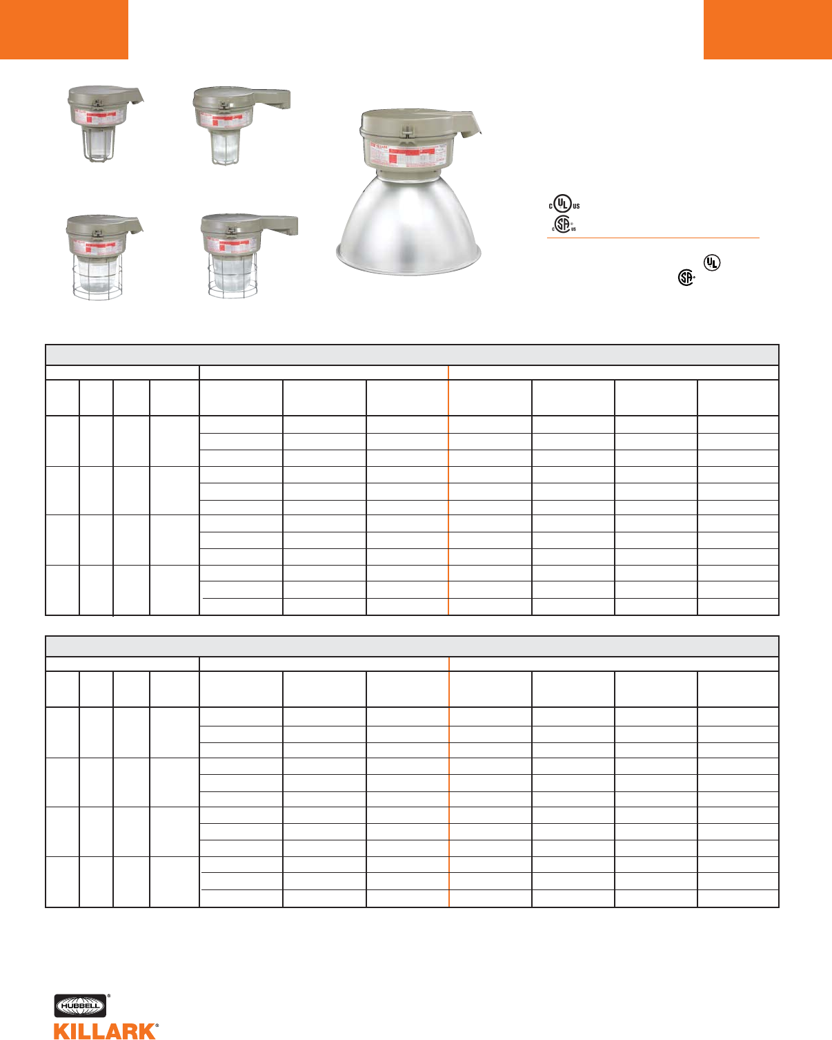
CERTILITE®V SERIES •LIGHTING
HIGH PRESSURE SODIUM, 50-150W MOGUL BASE HID
L46
Class I, Div. 2, Groups A,B,C,D1
Class l, Zone 2, Groups IIC, llB, llA
Class II, Div. 1 & 2, Groups E,F,G
Class III
Suitable for wet locations
NEMA 3, 4, 4X; IP66
NR Restricted Breathing Option5
Class I, Zone 2 AEx nAnR
Class I, Zone 2 Ex nR
Listed - File E10514 (Hazardous & Marine)
Certified - File LR11713
Stanchion 25°
w/ 5-1/2"
Globe & Guard
Stanchion 25°
w/ 7-3/4"
Globe & Guard
Stanchion Straight
w/ 5-1/2"
Refractor & Guard
Stanchion Straight
w/ 7-3/4"
Refractor & Guard
Stanchion 25°
w/ Enclosed Reflector
VM 50-150 WATT HIGH PRESSURE SODIUM STANCHION 25° ANGLE
WATTS
50
70
100
150
DESCRIPTION
ANSI
S68
S62
S54
S55
HUB
SIZE3
1-1/2"
1-1/2"
1-1/2"
1-1/2"
VOLTAGE4
Quad
Tri
480
Quad
Tri
480
Quad
Tri
480
Quad
Tri
480
5-1/2" OPTIC THREAD SIZE 2
GLOBE
& GUARD
VM3S050D5GLG
VM3S056D5GLG
VM3S055D5GLG
VM3S070D5GLG
VM3S076D5GLG
VM3S075D5GLG
VM3S100D5GLG
VM3S106D5GLG
VM3S105D5GLG
VM3S150D5GLG
VM3S156D5GLG
VM3S155D5GLG
TYPE I GLASS
REFRACTOR
& GUARD
VM3S050D5R1G
VM3S056D5R1G
VM3S055D5R1G
VM3S070D5R1G
VM3S076D5R1G
VM3S075D5R1G
VM3S100D5R1G
VM3S106D5R1G
VM3S105D5R1G
VM3S150D5R1G
VM3S156D5R1G
VM3S155D5R1G
TYPE V GLASS
REFRACTOR
& GUARD
VM3S050D5R5G
VM3S056D5R5G
VM3S055D5R5G
VM3S070D5R5G
VM3S076D5R5G
VM3S075D5R5G
VM3S100D5R5G
VM3S106D5R5G
VM3S105D5R5G
VM3S150D5R5G
VM3S156D5R5G
VM3S155D5R5G
7-3/4” OPTIC THREAD SIZE 2
GLOBE
& GUARD
VM4S050D5GLG
VM4S056D5GLG
VM4S055D5GLG
VM4S070D5GLG
VM4S076D5GLG
VM4S075D5GLG
VM4S100D5GLG
VM4S106D5GLG
VM4S105D5GLG
VM4S150D5GLG
VM4S156D5GLG
VM4S155D5GLG
TYPE I GLASS
REFRACTOR
& GUARD
VM4S050D5R1G
VM4S056D5R1G
VM4S055D5R1G
VM4S070D5R1G
VM4S076D5R1G
VM4S075D5R1G
VM4S100D5R1G
VM4S106D5R1G
VM4S105D5R1G
VM4S150D5R1G
VM4S156D5R1G
VM4S155D5R1G
ENCLOSED
REFLECTOR
VM4S050D5ERN
VM4S056D5ERN
VM4S055D5ERN
VM4S070D5ERN
VM4S076D5ERN
VM4S075D5ERN
VM4S100D5ERN
VM4S106D5ERN
VM4S105D5ERN
VM4S150D5ERN
VM4S156D5ERN
VM4S155D5ERN
TYPE V GLASS
REFRACTOR
& GUARD
VM4S050D5R5G
VM4S056D5R5G
VM4S055D5R5G
VM4S070D5R5G
VM4S076D5R5G
VM4S075D5R5G
VM4S100D5R5G
VM4S106D5R5G
VM4S105D5R5G
VM4S150D5R5G
VM4S156D5R5G
VM4S155D5R5G
VM 50-150 WATT HIGH PRESSURE SODIUM STANCHION STRAIGHT
WATTS
50
70
100
150
DESCRIPTION
ANSI
S68
S62
S54
S55
HUB
SIZE3
1-1/2"
1-1/2"
1-1/2"
1-1/2"
VOLTAGE4
Quad
Tri
480
Quad
Tri
480
Quad
Tri
480
Quad
Tri
480
5-1/2" OPTIC THREAD SIZE 2
GLOBE
& GUARD
VM3S050S5GLG
VM3S056S5GLG
VM3S055S5GLG
VM3S070S5GLG
VM3S076S5GLG
VM3S075S5GLG
VM3S100S5GLG
VM3S106S5GLG
VM3S105S5GLG
VM3S150S5GLG
VM3S156S5GLG
VM3S155S5GLG
TYPE I GLASS
REFRACTOR
& GUARD
VM3S050S5R1G
VM3S056S5R1G
VM3S055S5R1G
VM3S070S5R1G
VM3S076S5R1G
VM3S075S5R1G
VM3S100S5R1G
VM3S106S5R1G
VM3S105S5R1G
VM3S150S5R1G
VM3S156S5R1G
VM3S155S5R1G
TYPE V GLASS
REFRACTOR
& GUARD
VM3S050S5R5G
VM3S056S5R5G
VM3S055S5R5G
VM3S070S5R5G
VM3S076S5R5G
VM3S075S5R5G
VM3S100S5R5G
VM3S106S5R5G
VM3S105S5R5G
VM3S150S5R5G
VM3S156S5R5G
VM3S155S5R5G
7-3/4” OPTIC THREAD SIZE 2
GLOBE
& GUARD
VM4S050S5GLG
VM4S056S5GLG
VM4S055S5GLG
VM4S070S5GLG
VM4S076S5GLG
VM4S075S5GLG
VM4S100S5GLG
VM4S106S5GLG
VM4S105S5GLG
VM4S150S5GLG
VM4S156S5GLG
VM4S155S5GLG
TYPE I GLASS
REFRACTOR
& GUARD
VM4S050S5R1G
VM4S056S5R1G
VM4S055S5R1G
VM4S070S5R1G
VM4S076S5R1G
VM4S075S5R1G
VM4S100S5R1G
VM4S106S5R1G
VM4S105S5R1G
VM4S150S5R1G
VM4S156S5R1G
VM4S155S5R1G
ENCLOSED
REFLECTOR
VM4S050S5ERN
VM4S056S5ERN
VM4S055S5ERN
VM4S070S5ERN
VM4S076S5ERN
VM4S075S5ERN
VM4S100S5ERN
VM4S106S5ERN
VM4S105S5ERN
VM4S150S5ERN
VM4S156S5ERN
VM4S155S5ERN
TYPE V GLASS
REFRACTOR
& GUARD
VM4S050S5R5G
VM4S056S5R5G
VM4S055S5R5G
VM4S070S5R5G
VM4S076S5R5G
VM4S075S5R5G
VM4S100S5R5G
VM4S106S5R5G
VM4S105S5R5G
VM4S150S5R5G
VM4S156S5R5G
VM4S155S5R5G
1See hazardous application data on pages L84-L89 for limitations.
2Catalog numbers shown are with guard (except enclosed reflector); to omit guard change ending G to N; e.g. VM3S050D5GLN
3Catalog numbers shown are with 1-1/2" conduit openings, change 5 to 4 for 1-1/4"; e.g. VM3S050D4GLG.
4Consult catalog logic for other available voltages.
5Add suffix NR for restricted breathing; see page L39 for more information.
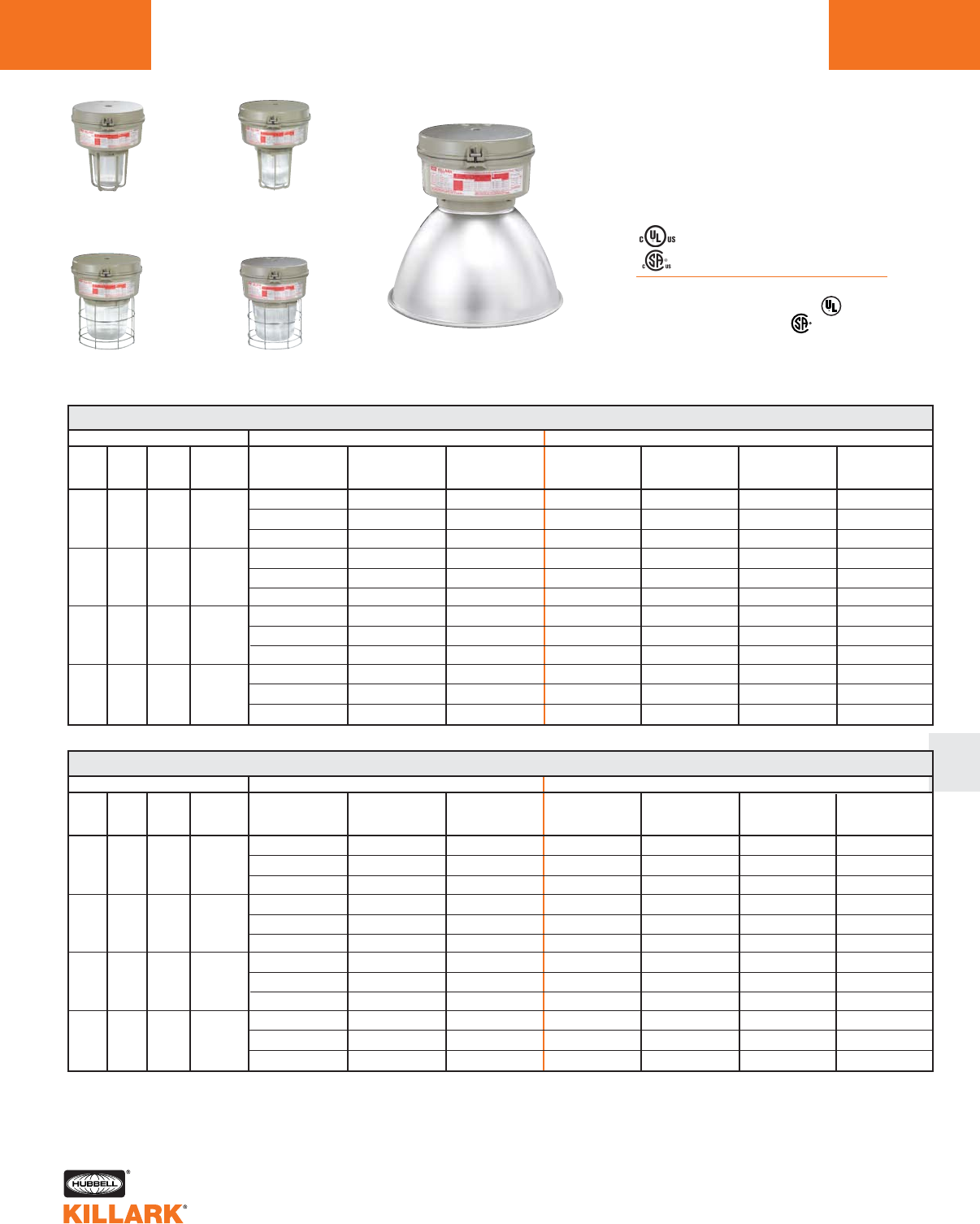
CERTILITE®V SERIES •LIGHTING
METAL HALIDE, 70-250W MOGUL BASE HID L47
L
Class I, Div. 2, Groups A,B,C,D1
Class l, Zone 2, Groups IIC, llB, llA
Class II, Div. 1 & 2, Groups E,F,G
Class III
Suitable for wet locations
NEMA 3, 4, 4X; IP66
NR Restricted Breathing Option5
Class I, Zone 2 AEx nAnR
Class I, Zone 2 Ex nR
Listed - File E10514 (Hazardous & Marine)
Certified - File LR11713
WATTS
70
100
175
250
DESCRIPTION
ANSI
M98
M143
M90
M140
M57
M58
HUB
SIZE3
3/4"
3/4"
3/4"
3/4"
VOLTAGE4
Quad
Tri
480
Quad
Tri
480
Quad
Tri
480
Quad
Tri
480
5-1/2" OPTIC THREAD SIZE 2
GLOBE
& GUARD
VM3H070A2GLG
VM3H076A2GLG
VM3H075A2GLG
VM3H100A2GLG
VM3H106A2GLG
VM3H105A2GLG
VM3H170A2GLG
VM3H176A2GLG
VM3H175A2GLG
VM3H250A2GLG
VM3H256A2GLG
VM3H255A2GLG
TYPE I GLASS
REFRACTOR
& GUARD
VM3H070A2R1G
VM3H076A2R1G
VM3H075A2R1G
VM3H100A2R1G
VM3H106A2R1G
VM3H105A2R1G
VM3H170A2R1G
VM3H176A2R1G
VM3H175A2R1G
VM3H250A2R1G
VM3H256A2R1G
VM3H255A2R1G
TYPE V GLASS
REFRACTOR
& GUARD
VM3H070A2R5G
VM3H076A2R5G
VM3H075A2R5G
VM3H100A2R5G
VM3H106A2R5G
VM3H105A2R5G
VM3H170A2R5G
VM3H176A2R5G
VM3H175A2R5G
VM3H250A2R5G
VM3H256A2R5G
VM3H255A2R5G
7-3/4" OPTIC THREAD SIZE 2
GLOBE
& GUARD
VM4H070A2GLG
VM4H076A2GLG
VM4H075A2GLG
VM4H100A2GLG
VM4H106A2GLG
VM4H105A2GLG
VM4H170A2GLG
VM4H176A2GLG
VM4H175A2GLG
VM4H250A2GLG
VM4H256A2GLG
VM4H255A2GLG
TYPE I GLASS
REFRACTOR
& GUARD
VM4H070A2R1G
VM4H076A2R1G
VM4H075A2R1G
VM4H100A2R1G
VM4H106A2R1G
VM4H105A2R1G
VM4H170A2R1G
VM4H176A2R1G
VM4H175A2R1G
VM4H250A2R1G
VM4H256A2R1G
VM4H255A2R1G
ENCLOSED
REFLECTOR
VM4H070A2ERN
VM4H076A2ERN
VM4H075A2ERN
VM4H100A2ERN
VM4H106A2ERN
VM4H105A2ERN
VM4H170A2ERN
VM4H176A2ERN
VM4H175A2ERN
VM4H250A2ERN
VM4H256A2ERN
VM4H255A2ERN
TYPE V GLASS
REFRACTOR
& GUARD
VM4H070A2R5G
VM4H076A2R5G
VM4H075A2R5G
VM4H100A2R5G
VM4H106A2R5G
VM4H105A2R5G
VM4H170A2R5G
VM4H176A2R5G
VM4H175A2R5G
VM4H250A2R5G
VM4H256A2R5G
VM4H255A2R5G
1See hazardous application data on pages L84-L89 for limitations.
2Catalog numbers shown are with guard (except enclosed reflector); to omit guard change ending G to N; e.g. VM3H070A2GLN
3Catalog numbers shown are with 3/4" conduit openings, change 2 to 3 for 1"; e.g. VM3H070A3GLG.
4Consult catalog logic for other available voltages.
5Add suffix NR for restricted breathing; see page L39 for more information.
VM 70-250 WATT METAL HALIDE FLEXIBLE PENDANT
WATTS
70
100
175
250
DESCRIPTION
ANSI
M98
M143
M90
M140
M57
M58
HUB
SIZE3
3/4"
3/4"
3/4"
3/4"
VOLTAGE4
Quad
Tri
480
Quad
Tri
480
Quad
Tri
480
Quad
Tri
480
5-1/2" OPTIC THREAD SIZE 2
GLOBE
& GUARD
VM3H070F2GLG
VM3H076F2GLG
VM3H075F2GLG
VM3H100F2GLG
VM3H106F2GLG
VM3H105F2GLG
VM3H170F2GLG
VM3H176F2GLG
VM3H175F2GLG
VM3H250F2GLG
VM3H256F2GLG
VM3H255F2GLG
TYPE I GLASS
REFRACTOR
& GUARD
VM3H070F2R1G
VM3H076F2R1G
VM3H075F2R1G
VM3H100F2R1G
VM3H106F2R1G
VM3H105F2R1G
VM3H170F2R1G
VM3H176F2R1G
VM3H175F2R1G
VM3H250F2R1G
VM3H256F2R1G
VM3H255F2R1G
TYPE V GLASS
REFRACTOR
& GUARD
VM3H070F2R5G
VM3H076F2R5G
VM3H075F2R5G
VM3H100F2R5G
VM3H106F2R5G
VM3H105F2R5G
VM3H170F2R5G
VM3H176F2R5G
VM3H175F2R5G
VM3H250F2R5G
VM3H256F2R5G
VM3H255F2R5G
7-3/4" OPTIC THREAD SIZE 2
GLOBE
& GUARD
VM4H070F2GLG
VM4H076F2GLG
VM4H075F2GLG
VM4H100F2GLG
VM4H106F2GLG
VM4H105F2GLG
VM4H170F2GLG
VM4H176F2GLG
VM4H175F2GLG
VM4H250F2GLG
VM4H256F2GLG
VM4H255F2GLG
TYPE I GLASS
REFRACTOR
& GUARD
VM4H070F2R1G
VM4H076F2R1G
VM4H075F2R1G
VM4H100F2R1G
VM4H106F2R1G
VM4H105F2R1G
VM4H170F2R1G
VM4H176F2R1G
VM4H175F2R1G
VM4H250F2R1G
VM4H256F2R1G
VM4H255F2R1G
ENCLOSED
REFLECTOR
VM3H070F2ERN
VM3H076F2ERN
VM3H075F2ERN
VM3H100F2ERN
VM3H106F2ERN
VM3H105F2ERN
VM3H170F2ERN
VM3H176F2ERN
VM3H175F2ERN
VM3H250F2ERN
VM3H256F2ERN
VM3H255F2ERN
TYPE V GLASS
REFRACTOR
& GUARD
VM4H070F2R5G
VM4H076F2R5G
VM4H075F2R5G
VM4H100F2R5G
VM4H106F2R5G
VM4H105F2R5G
VM4H170F2R5G
VM4H176F2R5G
VM4H175F2R5G
VM4H250F2R5G
VM4H256F2R5G
VM4H255F2R5G
Pendant
w/ Enclosed Reflector
Pendant
w/ 5-1/2"
Globe & Guard
Pendant
w/ 7-3/4"
Globe & Guard
Flexible Pendant
w/ 5-1/2"
Refractor & Guard
Flexible Pendant
w/ 7-3/4"
Refractor & Guard
VM 70-250 WATT METAL HALIDE PENDANT
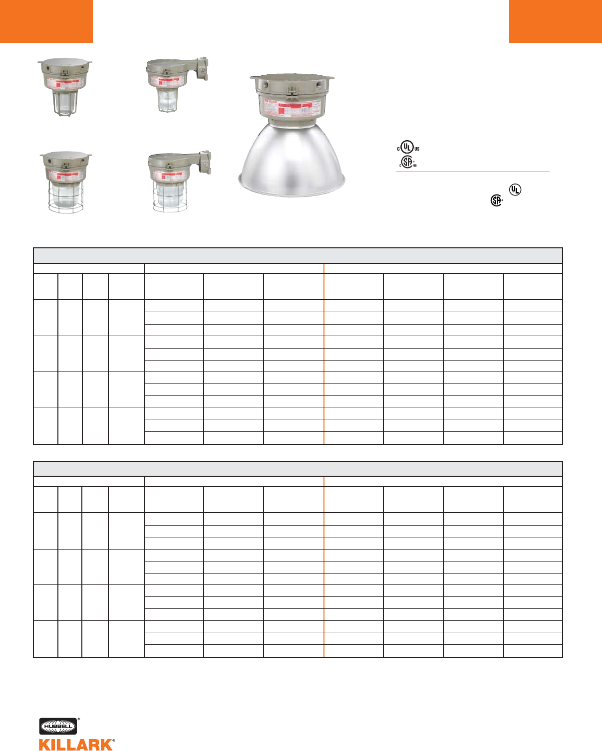
CERTILITE®V SERIES •LIGHTING
METAL HALIDE, 70-250W MOGUL BASE HID
L48
Class I, Div. 2, Groups A,B,C,D1
Class l, Zone 2, Groups IIC, llB, llA
Class II, Div. 1 & 2, Groups E,F,G
Class III
Suitable for wet locations
NEMA 3, 4, 4X; IP66
NR Restricted Breathing Option5
Class I, Zone 2 AEx nAnR
Class I, Zone 2 Ex nR
Listed - File E10514 (Hazardous & Marine)
Certified - File LR11713
WATTS
70
100
175
250
DESCRIPTION
ANSI
M98
M143
M90
M140
M57
M58
HUB
SIZE3
3/4"
3/4"
3/4"
3/4"
VOLTAGE3
Quad
Tri
480
Quad
Tri
480
Quad
Tri
480
Quad
Tri
480
5-1/2" OPTIC THREAD SIZE 2
GLOBE
& GUARD
VM3H070X2GLG
VM3H076X2GLG
VM3H075X2GLG
VM3H100X2GLG
VM3H106X2GLG
VM3H105X2GLG
VM3H170X2GLG
VM3H176X2GLG
VM3H175X2GLG
VM3H250X2GLG
VM3H256X2GLG
VM3H255X2GLG
TYPE I GLASS
REFRACTOR
& GUARD
VM3H070X2R1G
VM3H076X2R1G
VM3H075X2R1G
VM3H100X2R1G
VM3H106X2R1G
VM3H105X2R1G
VM3H170X2R1G
VM3H176X2R1G
VM3H175X2R1G
VM3H250X2R1G
VM3H256X2R1G
VM3H255X2R1G
TYPE V GLASS
REFRACTOR
& GUARD
VM3H070X2R5G
VM3H076X2R5G
VM3H075X2R5G
VM3H100X2R5G
VM3H106X2R5G
VM3H105X2R5G
VM3H170X2R5G
VM3H176X2R5G
VM3H175X2R5G
VM3H250X2R5G
VM3H256X2R5G
VM3H255X2R5G
7-3/4" OPTIC THREAD SIZE 2
GLOBE
& GUARD
VM4H070X2GLG
VM4H076X2GLG
VM4H075X2GLG
VM4H100X2GLG
VM4H106X2GLG
VM4H105X2GLG
VM4H170X2GLG
VM4H176X2GLG
VM4H175X2GLG
VM4H250X2GLG
VM4H256X2GLG
VM4H255X2GLG
TYPE I GLASS
REFRACTOR
& GUARD
VM4H070X2R1G
VM4H076X2R1G
VM4H075X2R1G
VM4H100X2R1G
VM4H106X2R1G
VM4H105X2R1G
VM4H170X2R1G
VM4H176X2R1G
VM4H175X2R1G
VM4H250X2R1G
VM4H256X2R1G
VM4H255X2R1G
ENCLOSED
REFLECTOR
VM4H070X2ERN
VM4H076X2ERN
VM4H075X2ERN
VM4H100X2ERN
VM4H106X2ERN
VM4H105X2ERN
VM4H170X2ERN
VM4H176X2ERN
VM4H175X2ERN
VM4H250X2ERN
VM4H256X2ERN
VM4H255X2ERN
TYPE V GLASS
REFRACTOR
& GUARD
VM4H070X2R5G
VM4H076X2R5G
VM4H075X2R5G
VM4H100X2R5G
VM4H106X2R5G
VM4H105X2R5G
VM4H170X2R5G
VM4H176X2R5G
VM4H175X2R5G
VM4H250X2R5G
VM4H256X2R5G
VM4H255X2R5G
1See hazardous application data on pages L84-L89 for limitations.
2Catalog numbers shown are with guard (except enclosed reflector); to omit guard change ending G to N; e.g. VM3H070X2GLN
3Catalog numbers shown are with 3/4” conduit openings, change 2 to 3 for 1”; e.g. VM3H070X3GLG.
4Consult catalog logic for other available voltages.
5Add suffix NR for restricted breathing; see page L39 for more information.
VM 70-250 WATT METAL HALIDE WALL
WATTS
70
100
175
250
DESCRIPTION
ANSI
M98
M143
M90
M140
M57
M58
HUB
SIZE3
3/4"
3/4"
3/4"
3/4"
VOLTAGE4
Quad
Tri
480
Quad
Tri
480
Quad
Tri
480
Quad
Tri
480
5-1/2" OPTIC THREAD SIZE 2
GLOBE
& GUARD
VM3H070B2GLG
VM3H076B2GLG
VM3H075B2GLG
VM3H100B2GLG
VM3H106B2GLG
VM3H105B2GLG
VM3H170B2GLG
VM3H176B2GLG
VM3H175B2GLG
VM3H250B2GLG
VM3H256B2GLG
VM3H255B2GLG
TYPE I GLASS
REFRACTOR
& GUARD
VM3H070B2R1G
VM3H076B2R1G
VM3H075B2R1G
VM3H100B2R1G
VM3H106B2R1G
VM3H105B2R1G
VM3H170B2R1G
VM3H176B2R1G
VM3H175B2R1G
VM3H250B2R1G
VM3H256B2R1G
VM3H255B2R1G
TYPE V GLASS
REFRACTOR
& GUARD
VM3H070B2R5G
VM3H076B2R5G
VM3H075B2R5G
VM3H100B2R5G
VM3H106B2R5G
VM3H105B2R5G
VM3H170B2R5G
VM3H176B2R5G
VM3H175B2R5G
VM3H250B2R5G
VM3H256B2R5G
VM3H255B2R5G
7-3/4" OPTIC THREAD SIZE 2
GLOBE
& GUARD
VM4H070B2GLG
VM4H076B2GLG
VM4H075B2GLG
VM4H100B2GLG
VM4H106B2GLG
VM4H105B2GLG
VM4H170B2GLG
VM4H176B2GLG
VM4H175B2GLG
VM4H250B2GLG
VM4H256B2GLG
VM4H255B2GLG
TYPE I GLASS
REFRACTOR
& GUARD
VM4H070B2R1G
VM4H076B2R1G
VM4H075B2R1G
VM4H100B2R1G
VM4H106B2R1G
VM4H105B2R1G
VM4H170B2R1G
VM4H176B2R1G
VM4H175B2R1G
VM4H250B2R1G
VM4H256B2R1G
VM4H255B2R1G
ENCLOSED
REFLECTOR
VM3H070B2ERN
VM3H076B2ERN
VM3H075B2ERN
VM3H100B2ERN
VM3H106B2ERN
VM3H105B2ERN
VM3H170B2ERN
VM3H176B2ERN
VM3H175B2ERN
VM3H250B2ERN
VM3H256B2ERN
VM3H255B2ERN
TYPE V GLASS
REFRACTOR
& GUARD
VM4H070B2R5G
VM4H076B2R5G
VM4H075B2R5G
VM4H100B2R5G
VM4H106B2R5G
VM4H105B2R5G
VM4H170B2R5G
VM4H176B2R5G
VM4H175B2R5G
VM4H250B2R5G
VM4H256B2R5G
VM4H255B2R5G
Ceiling
w/ 5-1/2"
Globe & Guard
Ceiling
w/ 7-3/4"
Globe & Guard
Wall
w/ 5-1/2"
Refractor & Guard
Wall
w/ 7-3/4"
Refractor & Guard
Ceiling
w/ Enclosed Reflector
VM 70-250 WATT METAL HALIDE CEILING
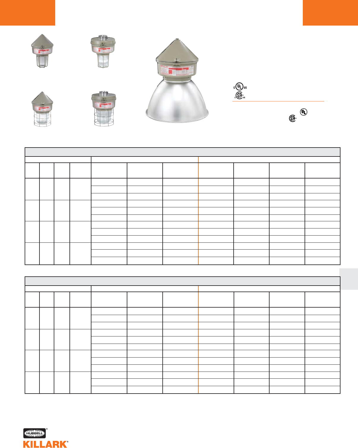
CERTILITE®V SERIES •LIGHTING
METAL HALIDE, 70-250W MOGUL BASE HID L49
L
Class I, Div. 2, Groups A,B,C,D1
Class l, Zone 2, Groups IIC, llB, llA
Class II, Div. 1 & 2, Groups E,F,G
Class III
Suitable for wet locations
NEMA 3, 4, 4X; IP66
NR Restricted Breathing Option5
Class I, Zone 2 AEx nAnR
Class I, Zone 2 Ex nR
Listed - File E10514 (Hazardous & Marine)
Certified - File LR11713
WATTS
70
100
175
250
DESCRIPTION
ANSI
M98
M143
M90
M140
M57
M58
HUB
SIZE3
3/4”
3/4”
3/4”
3/4”
VOLTAGE4
Quad
Tri
480
Quad
Tri
480
Quad
Tri
480
Quad
Tri
480
5-1/2" OPTIC THREAD SIZE 2
GLOBE
& GUARD
VM3H070C2GLG
VM3H076C2GLG
VM3H075C2GLG
VM3H100C2GLG
VM3H106C2GLG
VM3H105C2GLG
VM3H170C2GLG
VM3H176C2GLG
VM3H175C2GLG
VM3H250C2GLG
VM3H256C2GLG
VM3H255C2GLG
TYPE I GLASS
REFRACTOR
& GUARD
VM3H070C2R1G
VM3H076C2R1G
VM3H075C2R1G
VM3H100C2R1G
VM3H106C2R1G
VM3H105C2R1G
VM3H170C2R1G
VM3H176C2R1G
VM3H175C2R1G
VM3H250C2R1G
VM3H256C2R1G
VM3H255C2R1G
TYPE V GLASS
REFRACTOR
& GUARD
VM3H070C2R5G
VM3H076C2R5G
VM3H075C2R5G
VM3H100C2R5G
VM3H106C2R5G
VM3H105C2R5G
VM3H170C2R5G
VM3H176C2R5G
VM3H175C2R5G
VM3H250C2R5G
VM3H256C2R5G
VM3H255C2R5G
7-3/4" OPTIC THREAD SIZE 2
GLOBE
& GUARD
VM4H070C2GLG
VM4H076C2GLG
VM4H075C2GLG
VM4H100C2GLG
VM4H106C2GLG
VM4H105C2GLG
VM4H170C2GLG
VM4H176C2GLG
VM4H175C2GLG
VM4H250C2GLG
VM4H256C2GLG
VM4H255C2GLG
TYPE I GLASS
REFRACTOR
& GUARD
VM4H070C2R1G
VM4H076C2R1G
VM4H075C2R1G
VM4H100C2R1G
VM4H106C2R1G
VM4H105C2R1G
VM4H170C2R1G
VM4H176C2R1G
VM4H175C2R1G
VM4H250C2R1G
VM4H256C2R1G
VM4H255C2R1G
ENCLOSED
REFLECTOR
VM4H070C2ERN
VM4H076C2ERN
VM4H075C2ERN
VM4H100C2ERN
VM4H106C2ERN
VM4H105C2ERN
VM4H170C2ERN
VM4H176C2ERN
VM4H175C2ERN
VM4H250C2ERN
VM4H256C2ERN
VM4H255C2ERN
TYPE V GLASS
REFRACTOR
& GUARD
VM4H070C2R5G
VM4H076C2R5G
VM4H075C2R5G
VM4H100C2R5G
VM4H106C2R5G
VM4H105C2R5G
VM4H170C2R5G
VM4H176C2R5G
VM4H175C2R5G
VM4H250C2R5G
VM4H256C2R5G
VM4H255C2R5G
1See hazardous application data on pages L84-L89 for limitations.
2Catalog numbers shown are with guard (except enclosed reflector); to omit guard change ending G to N; e.g. VM3H070C2GLN
3Catalog numbers shown are with 3/4” conduit openings, change 2 to 3 for 1”; e.g. VM3H070C3GLG.
4Consult catalog logic for other available voltages.
5Add suffix NR for restricted breathing; see page L39 for more information.
6VMEZA tank adapters UL “classified” as an assembly for use between VM tanks and EZ mounts. Order EZ mounts separately. See
page L63.
VM 70-250 WATT METAL HALIDE EZ ADAPTER
WATTS
70
100
175
250
DESCRIPTION
ANSI
M98
M143
M90
M140
M57
M58
HUB
SIZE6
6
6
6
6
VOLTAGE4
Quad
Tri
480
Quad
Tri
480
Quad
Tri
480
Quad
Tri
480
5-1/2" OPTIC THREAD SIZE 2
GLOBE
& GUARD
VM3H070EZGLG
VM3H076EZGLG
VM3H075EZGLG
VM3H100EZGLG
VM3H106EZGLG
VM3H105EZGLG
VM3H170EZGLG
VM3H176EZGLG
VM3H175EZGLG
VM3H250EZGLG
VM3H256EZGLG
VM3H255EZGLG
TYPE I GLASS
REFRACTOR
& GUARD
VM3H070EZR1G
VM3H076EZR1G
VM3H075EZR1G
VM3H100EZR1G
VM3H106EZR1G
VM3H105EZR1G
VM3H170EZR1G
VM3H176EZR1G
VM3H175EZR1G
VM3H250EZR1G
VM3H256EZR1G
VM3H255EZR1G
TYPE V GLASS
REFRACTOR
& GUARD
VM3H070EZR5G
VM3H076EZR5G
VM3H075EZR5G
VM3H100EZR5G
VM3H106EZR5G
VM3H105EZR5G
VM3H170EZR5G
VM3H176EZR5G
VM3H175EZR5G
VM3H250EZR5G
VM3H256EZR5G
VM3H255EZR5G
7-3/4" OPTIC THREAD SIZE 2
GLOBE
& GUARD
VM4H070EZGLG
VM4H076EZGLG
VM4H075EZGLG
VM4H100EZGLG
VM4H106EZGLG
VM4H105EZGLG
VM4H170EZGLG
VM4H176EZGLG
VM4H175EZGLG
VM4H250EZGLG
VM4H256EZGLG
VM4H255EZGLG
TYPE I GLASS
REFRACTOR
& GUARD
VM4H070EZR1G
VM4H076EZR1G
VM4H075EZR1G
VM4H100EZR1G
VM4H106EZR1G
VM4H105EZR1G
VM4H170EZR1G
VM4H176EZR1G
VM4H175EZR1G
VM4H250EZR1G
VM4H256EZR1G
VM4H255EZR1G
ENCLOSED
REFLECTOR
VM3H070EZERN
VM3H076EZERN
VM3H075EZERN
VM3H100EZERN
VM3H106EZERN
VM3H105EZERN
VM3H170EZERN
VM3H176EZERN
VM3H175EZERN
VM3H250EZERN
VM3H256EZERN
VM3H255EZERN
TYPE V GLASS
REFRACTOR
& GUARD
VM4H070EZR5G
VM4H076EZR5G
VM4H075EZR5G
VM4H100EZR5G
VM4H106EZR5G
VM4H105EZR5G
VM4H170EZR5G
VM4H176EZR5G
VM4H175EZR5G
VM4H250EZR5G
VM4H256EZR5G
VM4H255EZR5G
Cone
w/ 5-1/2"
Globe & Guard
Cone
w/ 7-3/4"
Globe & Guard
EZ Adapter
w/ 5-1/2"
Refractor & Guard
EZ Adapter
w/ 7-3/4"
Refractor & Guard
Cone
w/ Enclosed Reflector
VM 70-250 WATT METAL HALIDE CONE

CERTILITE®V SERIES •LIGHTING
METAL HALIDE, 70-250W MOGUL BASE HID
L50
Class I, Div. 2, Groups A,B,C,D1
Class l, Zone 2, Groups IIC, llB, llA
Class II, Div. 1 & 2, Groups E,F,G
Class III
Suitable for wet locations
NEMA 3, 4, 4X; IP66
NR Restricted Breathing Option5
Class I, Zone 2 AEx nAnR
Class I, Zone 2 Ex nR
Listed - File E10514 (Hazardous & Marine)
Certified - File LR11713
WATTS
70
100
175
250
DESCRIPTION
ANSI
M98
M143
M90
M140
M57
M58
HUB
SIZE3
1-1/2"
1-1/2"
1-1/2"
1-1/2"
VOLTAGE4
Quad
Tri
480
Quad
Tri
480
Quad
Tri
480
Quad
Tri
480
5-1/2" OPTIC THREAD SIZE 2
GLOBE
& GUARD
VM3H070D5GLG
VM3H076D5GLG
VM3H075D5GLG
VM3H100D5GLG
VM3H106D5GLG
VM3H105D5GLG
VM3H170D5GLG
VM3H176D5GLG
VM3H175D5GLG
VM3H250D5GLG
VM3H256D5GLG
VM3H255D5GLG
TYPE I GLASS
REFRACTOR
& GUARD
VM3H070D5R1G
VM3H076D5R1G
VM3H075D5R1G
VM3H100D5R1G
VM3H106D5R1G
VM3H105D5R1G
VM3H170D5R1G
VM3H176D5R1G
VM3H175D5R1G
VM3H250D5R1G
VM3H256D5R1G
VM3H255D5R1G
TYPE V GLASS
REFRACTOR
& GUARD
VM3H070D5R5G
VM3H076D5R5G
VM3H075D5R5G
VM3H100D5R5G
VM3H106D5R5G
VM3H105D5R5G
VM3H170D5R5G
VM3H176D5R5G
VM3H175D5R5G
VM3H250D5R5G
VM3H256D5R5G
VM3H255D5R5G
GLOBE
& GUARD
VM4H070D5GLG
VM4H076D5GLG
VM4H075D5GLG
VM4H100D5GLG
VM4H106D5GLG
VM4H105D5GLG
VM4H170D5GLG
VM4H176D5GLG
VM4H175D5GLG
VM4H250D5GLG
VM4H256D5GLG
VM4H255D5GLG
TYPE I GLASS
REFRACTOR
& GUARD
VM4H070D5R1G
VM4H076D5R1G
VM4H075D5R1G
VM4H100D5R1G
VM4H106D5R1G
VM4H105D5R1G
VM4H170D5R1G
VM4H176D5R1G
VM4H175D5R1G
VM4H250D5R1G
VM4H256D5R1G
VM4H255D5R1G
ENCLOSED
REFLECTOR
VM4H070D5ERN
VM4H076D5ERN
VM4H075D5ERN
VM4H100D5ERN
VM4H106D5ERN
VM4H105D5ERN
VM4H170D5ERN
VM4H176D5ERN
VM4H175D5ERN
VM4H250D5ERN
VM4H256D5ERN
VM4H255D5ERN
TYPE V GLASS
REFRACTOR
& GUARD
VM4H070D5R5G
VM4H076D5R5G
VM4H075D5R5G
VM4H100D5R5G
VM4H106D5R5G
VM4H105D5R5G
VM4H170D5R5G
VM4H176D5R5G
VM4H175D5R5G
VM4H250D5R5G
VM4H256D5R5G
VM4H255D5R5G
1See hazardous application data on pages L84-L89 for limitations.
2Catalog numbers shown are with guard (except enclosed reflector); to omit guard change ending G to N; e.g. VM3H070D5GLN
3Catalog numbers shown are with 3/4" conduit openings, change 5 to 4 for 1-1/4"; e.g. VM3H070D4GLG.
4Consult catalog logic for other available voltages.
5Add suffix NR for restricted breathing; see page L39 for more information.
VM 70-250 WATT METAL HALIDE STANCHION STRAIGHT
WATTS
70
100
175
250
DESCRIPTION
ANSI
M98
M143
M90
M140
M57
M58
HUB
SIZE3
1-1/2"
1-1/2"
1-1/2"
1-1/2"
VOLTAGE4
Quad
Tri
480
Quad
Tri
480
Quad
Tri
480
Quad
Tri
480
5-1/2" OPTIC THREAD SIZE 2
GLOBE
& GUARD
VM3H070S5GLG
VM3H076S5GLG
VM3H075S5GLG
VM3H100S5GLG
VM3H106S5GLG
VM3H105S5GLG
VM3H170S5GLG
VM3H176S5GLG
VM3H175S5GLG
VM3H250S5GLG
VM3H256S5GLG
VM3H255S5GLG
TYPE I GLASS
REFRACTOR
& GUARD
VM3H070S5R1G
VM3H076S5R1G
VM3H075S5R1G
VM3H100S5R1G
VM3H106S5R1G
VM3H105S5R1G
VM3H170S5R1G
VM3H176S5R1G
VM3H175S5R1G
VM3H250S5R1G
VM3H256S5R1G
VM3H255S5R1G
TYPE V GLASS
REFRACTOR
& GUARD
VM3H070S5R5G
VM3H076S5R5G
VM3H075S5R5G
VM3H100S5R5G
VM3H106S5R5G
VM3H105S5R5G
VM3H170S5R5G
VM3H176S5R5G
VM3H175S5R5G
VM3H250S5R5G
VM3H256S5R5G
VM3H255S5R5G
7-3/4" OPTIC THREAD SIZE 2
GLOBE
& GUARD
VM4H070S5GLG
VM4H076S5GLG
VM4H075S5GLG
VM4H100S5GLG
VM4H106S5GLG
VM4H105S5GLG
VM4H170S5GLG
VM4H176S5GLG
VM4H175S5GLG
VM4H250S5GLG
VM4H256S5GLG
VM4H255S5GLG
TYPE I GLASS
REFRACTOR
& GUARD
VM4H070S5R1G
VM4H076S5R1G
VM4H075S5R1G
VM4H100S5R1G
VM4H106S5R1G
VM4H105S5R1G
VM4H170S5R1G
VM4H176S5R1G
VM4H175S5R1G
VM4H250S5R1G
VM4H256S5R1G
VM4H255S5R1G
ENCLOSED
REFLECTOR
VM3H070S5ERN
VM3H076S5ERN
VM3H075S5ERN
VM3H100S5ERN
VM3H106S5ERN
VM3H105S5ERN
VM3H170S5ERN
VM3H176S5ERN
VM3H175S5ERN
VM3H250S5ERN
VM3H256S5ERN
VM3H255S5ERN
TYPE V GLASS
REFRACTOR
& GUARD
VM4H070S5R5G
VM4H076S5R5G
VM4H075S5R5G
VM4H100S5R5G
VM4H106S5R5G
VM4H105S5R5G
VM4H170S5R5G
VM4H176S5R5G
VM4H175S5R5G
VM4H250S5R5G
VM4H256S5R5G
VM4H255S5R5G
Stanchion 25°
w/ 5-1/2"
Globe & Guard
Stanchion 25°
w/ 7-3/4"
Globe & Guard
Stanchion Straight
w/ 5-1/2"
Refractor & Guard
Stanchion Straight
w/ 7-3/4"
Refractor & Guard
Stanchion 25°
w/ Enclosed Reflector
VM 70-250 WATT METAL HALIDE STANCHION 25° ANGLE
7-3/4" OPTIC THREAD SIZE 2

CERTILITE®V SERIES •LIGHTING
METAL HALIDE PULSE, 150-200W MOGUL BASE HID L51
L
Class I, Div. 2, Groups A,B,C,D1
Class l, Zone 2, Groups IIC, llB, llA
Class II, Div. 1 & 2, Groups E,F,G
Class III
Suitable for wet locations
NEMA 3, 4, 4X; IP66
NR Restricted Breathing Option5
Class I, Zone 2 AEx nAnR
Class I, Zone 2 Ex nR
Listed - File E10514 (Hazardous & Marine)
Certified - File LR11713
Pendant
w/ Enclosed Reflector
Flexible Pendant
w/ 7-3/4"
Refractor & Guard
Pendant
w/ 7-3/4"
Globe & Guard
VM 150-200 WATT METAL HALIDE PULSE PENDANT
WATTS
150
175
200
DESCRIPTION
ANSI
M102
M142
M137
M152
M136
HUB
SIZE3
3/4"
3/4"
3/4"
VOLTAGE4
Quad
Tri
480
Quad
Tri
480
Quad
Tri
480
5-1/2" OPTIC THREAD SIZE 2
GLOBE
& GUARD
VM3P150A2GLG
VM3P156A2GLG
VM3P155A2GLG
VM3P170A2GLG
VM3P176A2GLG
VM3P175A2GLG
VM3P200A2GLG
VM3P206A2GLG
VM3P205A2GLG
TYPE I GLASS
REFRACTOR
& GUARD
VM3P150A2R1G
VM3P156A2R1G
VM3P155A2R1G
VM3P170A2R1G
VM3P176A2R1G
VM3P175A2R1G
VM3P200A2R1G
VM3P206A2R1G
VM3P205A2R1G
TYPE V GLASS
REFRACTOR
& GUARD
VM3P150A2R5G
VM3P156A2R5G
VM3P155A2R5G
VM3P170A2R5G
VM3P176A2R5G
VM3P175A2R5G
VM3P200A2R5G
VM3P206A2R5G
VM3P205A2R5G
7-3/4" OPTIC THREAD SIZE 2
GLOBE
& GUARD
VM4P150A2GLG
VM4P156A2GLG
VM4P155A2GLG
VM4P170A2GLG
VM4P176A2GLG
VM4P175A2GLG
VM4P200A2GLG
VM4P206A2GLG
VM4P205A2GLG
TYPE I GLASS
REFRACTOR
& GUARD
VM4P150A2R1G
VM4P156A2R1G
VM4P155A2R1G
VM4P170A2R1G
VM4P176A2R1G
VM4P175A2R1G
VM4P200A2R1G
VM4P206A2R1G
VM4P205A2R1G
ENCLOSED
REFLECTOR
VM4P156A2ERN
VM4P155A2ERN
VM4P170A2ERN
VM4P170A2ERN
VM4P176A2ERN
VM4P175A2ERN
VM4P200A2ERN
VM4P206A2ERN
VM4P205A2ERN
TYPE V GLASS
REFRACTOR
& GUARD
VM4P150A2R5G
VM4P156A2R5G
VM4P155A2R5G
VM4P170A2R5G
VM4P176A2R5G
VM4P175A2R5G
VM4P200A2R5G
VM4P206A2R5G
VM4P205A2R5G
VM 150-200 WATT METAL HALIDE PULSE FLEXIBLE PENDANT
WATTS
150
175
200
DESCRIPTION
ANSI
M102
M142
M137
M152
M136
HUB
SIZE3
3/4"
3/4"
3/4"
VOLTAGE4
Quad
Tri
480
Quad
Tri
480
Quad
Tri
480
5-1/2" OPTIC THREAD SIZE 2
GLOBE
& GUARD
VM3P150F2GLG
VM3P156F2GLG
VM3P155F2GLG
VM3P170F2GLG
VM3P176F2GLG
VM3P175F2GLG
VM3P200F2GLG
VM3P206F2GLG
VM3P205F2GLG
TYPE I GLASS
REFRACTOR
& GUARD
VM3P150F2R1G
VM3P156F2R1G
VM3P155F2R1G
VM3P170F2R1G
VM3P176F2R1G
VM3P175F2R1G
VM3P200F2R1G
VM3P206F2R1G
VM3P205F2R1G
TYPE V GLASS
REFRACTOR
& GUARD
VM3P150F2R5G
VM3P156F2R5G
VM3P155F2R5G
VM3P170F2R5G
VM3P176F2R5G
VM3P175F2R5G
VM3P200F2R5G
VM3P206F2R5G
VM3P205F2R5G
7-3/4" OPTIC THREAD SIZE 2
GLOBE
& GUARD
VM4P150F2GLG
VM4P156F2GLG
VM4P155F2GLG
VM4P170F2GLG
VM4P176F2GLG
VM4P175F2GLG
VM4P200F2GLG
VM4P206F2GLG
VM4P205F2GLG
TYPE I GLASS
REFRACTOR
& GUARD
VM4P150F2R1G
VM4P156F2R1G
VM4P155F2R1G
VM4P170F2R1G
VM4P176F2R1G
VM4P175F2R1G
VM4P200F2R1G
VM4P206F2R1G
VM4P205F2R1G
ENCLOSED
REFLECTOR
VM4P156F2ERN
VM4P155F2ERN
VM4P170F2ERN
VM4P170F2ERN
VM4P176F2ERN
VM4P175F2ERN
VM4P200F2ERN
VM4P206F2ERN
VM4P205F2ERN
TYPE V GLASS
REFRACTOR
& GUARD
VM4P150F2R5G
VM4P156F2R5G
VM4P155F2R5G
VM4P170F2R5G
VM4P176F2R5G
VM4P175F2R5G
VM4P200F2R5G
VM4P206F2R5G
VM4P205F2R5G
1See hazardous application data on pages L84-L89 for limitations.
2Catalog numbers shown are with guard (except enclosed reflector); to omit guard change ending G to N; e.g. VM3P150A2GLN
3Catalog numbers shown are with 3/4" conduit openings; change 2 to 3 for 1"; e.g. VM3P150A3GLG.
4Consult catalog logic for other available voltages.
5Add suffix NR for restricted breathing; see page L39 for more information.
Pendant
w/ 5-1/2"
Globe & Guard
Flexible Pendant
w/ 5-1/2"
Refractor & Guard
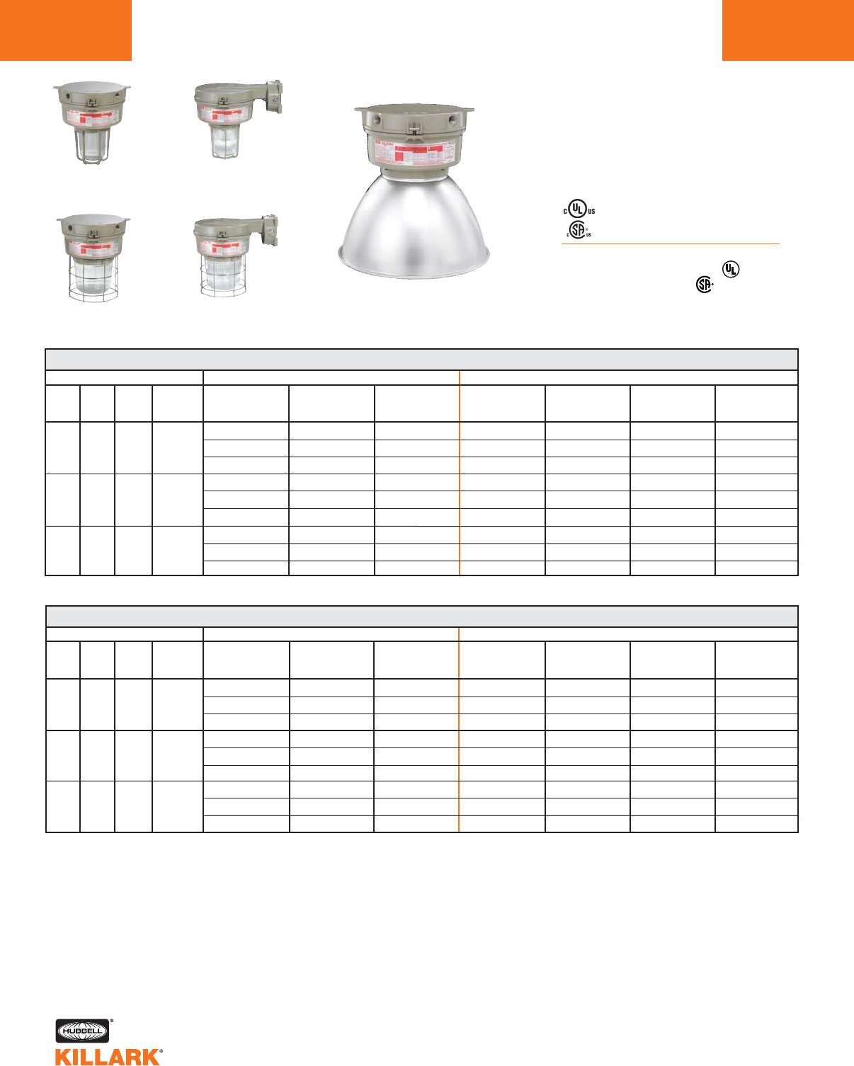
CERTILITE®V SERIES •LIGHTING
METAL HALIDE PULSE, 150-200W MOGUL BASE HID
L52
Class I, Div. 2, Groups A,B,C,D1
Class l, Zone 2, Groups IIC, llB, llA
Class II, Div. 1 & 2, Groups E,F,G
Class III
Suitable for wet locations
NEMA 3, 4, 4X; IP66
NR Restricted Breathing Option5
Class I, Zone 2 AEx nAnR
Class I, Zone 2 Ex nR
Listed - File E10514 (Hazardous & Marine)
Certified - File LR11713
Ceiling
w/ 5-1/2"
Globe & Guard
Ceiling
w/ 7-3/4"
Globe & Guard
Wall
w/ 5-1/2"
Refractor & Guard
Wall
w/ 7-3/4"
Refractor & Guard
Ceiling
w/ Enclosed Reflector
VM 150-200 WATT METAL HALIDE PULSE CEILING
WATTS
150
175
200
DESCRIPTION
ANSI
M102
M142
M137
M152
M136
HUB
SIZE3
3/4"
3/4"
3/4"
VOLTAGE3
Quad
Tri
480
Quad
Tri
480
Quad
Tri
480
5-1/2" OPTIC THREAD SIZE 2
GLOBE
& GUARD
VM3P150X2GLG
VM3P156X2GLG
VM3P155X2GLG
VM3P170X2GLG
VM3P176X2GLG
VM3P175X2GLG
VM3P200X2GLG
VM3P206X2GLG
VM3P205X2GLG
TYPE I GLASS
REFRACTOR
& GUARD
VM3P150X2R1G
VM3P156X2R1G
VM3P155X2R1G
VM3P170X2R1G
VM3P176X2R1G
VM3P175X2R1G
VM3P200X2R1G
VM3P206X2R1G
VM3P205X2R1G
TYPE V GLASS
REFRACTOR
& GUARD
VM3P150X2R5G
VM3P156X2R5G
VM3P155X2R5G
VM3P170X2R5G
VM3P176X2R5G
VM3P175X2R5G
VM3P200X2R5G
VM3P206X2R5G
VM3P205X2R5G
7-3/4" OPTIC THREAD SIZE 2
GLOBE
& GUARD
VM4P150X2GLG
VM4P156X2GLG
VM4P155X2GLG
VM4P170X2GLG
VM4P176X2GLG
VM4P175X2GLG
VM4P200X2GLG
VM4P206X2GLG
VM4P205X2GLG
TYPE I GLASS
REFRACTOR
&GUARD
VM4P150X2R1G
VM4P156X2R1G
VM4P155X2R1G
VM4P170X2R1G
VM4P176X2R1G
VM4P175X2R1G
VM4P200X2R1G
VM4P206X2R1G
VM4P205X2R1G
ENCLOSED
REFLECTOR
VM4P150X2ERN
VM4P156X2ERN
VM4P155X2ERN
VM4P170X2ERN
VM4P176X2ERN
VM4P175X2ERN
VM4P200X2ERN
VM4P206X2ERN
VM4P205X2ERN
TYPE V GLASS
REFRACTOR
& GUARD
VM4P150X2R5G
VM4P156X2R5G
VM4P155X2R5G
VM4P170X2R5G
VM4P176X2R5G
VM4P175X2R5G
VM4P200X2R5G
VM4P206X2R5G
VM4P205X2R5G
VM 150-200 WATT METAL HALIDE PULSE WALL
WATTS
150
175
200
DESCRIPTION
ANSI
M102
M142
M137
M152
M136
HUB
SIZE3
3/4"
3/4"
3/4"
VOLTAGE4
Quad
Tri
480
Quad
Tri
480
Quad
Tri
480
GLOBE
& GUARD
VM3P150B2GLG
VM3P156B2GLG
VM3P155B2GLG
VM3P170B2GLG
VM3P176B2GLG
VM3P175B2GLG
VM3P200B2GLG
VM3P206B2GLG
VM3P205B2GLG
TYPE I GLASS
REFRACTOR
& GUARD
VM3P150B2R1G
VM3P156B2R1G
VM3P155B2R1G
VM3P170B2R1G
VM3P176B2R1G
VM3P175B2R1G
VM3P200B2R1G
VM3P206B2R1G
VM3P205B2R1G
TYPE V GLASS
REFRACTOR
& GUARD
VM3P150B2R5G
VM3P156B2R5G
VM3P155B2R5G
VM3P170B2R5G
VM3P176B2R5G
VM3P175B2R5G
VM3P200B2R5G
VM3P206B2R5G
VM3P205B2R5G
7-3/4" OPTIC THREAD SIZE 2
GLOBE
& GUARD
VM4P150B2GLG
VM4P156B2GLG
VM4P155B2GLG
VM4P170B2GLG
VM4P176B2GLG
VM4P175B2GLG
VM4P200B2GLG
VM4P206B2GLG
VM4P205B2GLG
TYPE I GLASS
REFRACTOR
& GUARD
VM4P150B2R1G
VM4P156B2R1G
VM4P155B2R1G
VM4P170B2R1G
VM4P176B2R1G
VM4P175B2R1G
VM4P200B2R1G
VM4P206B2R1G
VM4P205B2R1G
ENCLOSED
REFLECTOR
VM4P150B2ERN
VM4P156B2ERN
VM4P155B2ERN
VM4P170B2ERN
VM4P176B2ERN
VM4P175B2ERN
VM4P200B2ERN
VM4P206B2ERN
VM4P205B2ERN
TYPE V GLASS
REFRACTOR
& GUARD
VM4P150B2R5G
VM4P156B2R5G
VM4P155B2R5G
VM4P170B2R5G
VM4P176B2R5G
VM4P175B2R5G
VM4P200B2R5G
VM4P206B2R5G
VM4P205B2R5G
1See hazardous application data on pages L84-L89 for limitations.
2Catalog numbers shown are with guard (except enclosed reflectors); to omit guard, change ending G to N; e.g. VM3P050X2GLN
3Catalog numbers shown are with 3/4" conduit openings, change 2 to 3 for 1"; e.g. VM3P150X3GLG.
4Consult catalog logic for other available voltages.
5Add suffix NR for restricted breathing; see page L39 for more information.
5-1/2" OPTIC THREAD SIZE 2

CERTILITE®V SERIES •LIGHTING
METAL HALIDE PULSE, 150-200W MOGUL BASE HID L53
L
Class I, Div. 2, Groups A,B,C,D1
Class l, Zone 2, Groups IIC, llB, llA
Class II, Div. 1 & 2, Groups E,F,G
Class III
Suitable for wet locations
NEMA 3, 4, 4X; IP66
NR Restricted Breathing Option5
Class I, Zone 2 AEx nAnR
Class I, Zone 2 Ex nR
Listed - File E10514 (Hazardous & Marine)
Certified - File LR11713
Cone
w/ 5-1/2"
Globe & Guard
Cone
w/ 7-3/4"
Globe & Guard
EZ Adapter
w/ 5-1/2"
Refractor & Guard
EZ Adapter
w/ 7-3/4"
Refractor & Guard
Cone
w/ Enclosed Reflector
WATTS
150
175
200
DESCRIPTION
ANSI
M102
M142
M137
M152
M136
HUB
SIZE3
3/4"
3/4"
3/4"
VOLTAGE4
Quad
Tri
480
Quad
Tri
480
Quad
Tri
480
5-1/2" OPTIC THREAD SIZE 2
GLOBE
& GUARD
VM3P150C2GLG
VM3P156C2GLG
VM3P155C2GLG
VM3P170C2GLG
VM3P176C2GLG
VM3P175C2GLG
VM3P200C2GLG
VM3P206C2GLG
VM3P205C2GLG
TYPE I GLASS
REFRACTOR
& GUARD
VM3P150C2R1G
VM3P156C2R1G
VM3P155C2R1G
VM3P170C2R1G
VM3P176C2R1G
VM3P175C2R1G
VM3P200C2R1G
VM3P206C2R1G
VM3P205C2R1G
TYPE V GLASS
REFRACTOR
& GUARD
VM3P150C2R5G
VM3P156C2R5G
VM3P155C2R5G
VM3P170C2R5G
VM3P176C2R5G
VM3P175C2R5G
VM3P200C2R5G
VM3P206C2R5G
VM3P205C2R5G
GLOBE
& GUARD
VM4P150C2GLG
VM4P156C2GLG
VM4P155C2GLG
VM4P170C2GLG
VM4P176C2GLG
VM4P175C2GLG
VM4P200C2GLG
VM4P206C2GLG
VM4P205C2GLG
TYPE I GLASS
REFRACTOR
& GUARD
VM4P150C2R1G
VM4P156C2R1G
VM4P155C2R1G
VM4P170C2R1G
VM4P176C2R1G
VM4P175C2R1G
VM4P200C2R1G
VM4P206C2R1G
VM4P205C2R1G
ENCLOSED
REFLECTOR
VM4P150C2ERN
VM4P156C2ERN
VM4P155C2ERN
VM4P170C2ERN
VM4P176C2ERN
VM4P175C2ERN
VM4P200C2ERN
VM4P206C2ERN
VM4P205C2ERN
TYPE V GLASS
REFRACTOR
& GUARD
VM4P150C2R5G
VM4P156C2R5G
VM4P155C2R5G
VM4P170C2R5G
VM4P176C2R5G
VM4P175C2R5G
VM4P200C2R5G
VM4P206C2R5G
VM4P205C2R5G
VM 150-200 WATT METAL HALIDE PULSE EZ ADAPTER
WATTS
150
175
200
DESCRIPTION
ANSI
M102
M142
M137
M152
M136
HUB
SIZE6
6
6
6
VOLTAGE4
Quad
Tri
480
Quad
Tri
480
Quad
Tri
480
5-1/2" OPTIC THREAD SIZE 2
GLOBE
& GUARD
VM3P150EZGLG
VM3P156EZGLG
VM3P155EZGLG
VM3P170EZGLG
VM3P176EZGLG
VM3P175EZGLG
VM3P200EZGLG
VM3P206EZGLG
VM3P205EZGLG
TYPE I GLASS
REFRACTOR
& GUARD
VM3P150EZR1G
VM3P156EZR1G
VM3P155EZR1G
VM3P170EZR1G
VM3P176EZR1G
VM3P175EZR1G
VM3P200EZR1G
VM3P206EZR1G
VM3P205EZR1G
TYPE V GLASS
REFRACTOR
& GUARD
VM3P150EZR5G
VM3P156EZR5G
VM3P155EZR5G
VM3P170EZR5G
VM3P176EZR5G
VM3P175EZR5G
VM3P200EZR5G
VM3P206EZR5G
VM3P205EZR5G
7-3/4" OPTIC THREAD SIZE 2
GLOBE
& GUARD
VM4P150EZGLG
VM4P156EZGLG
VM4P155EZGLG
VM4P170EZGLG
VM4P176EZGLG
VM4P175EZGLG
VM4P200EZGLG
VM4P206EZGLG
VM4P205EZGLG
TYPE I GLASS
REFRACTOR
& GUARD
VM4P150EZR1G
VM4P156EZR1G
VM4P155EZR1G
VM4P170EZR1G
VM4P176EZR1G
VM4P175EZR1G
VM4P200EZR1G
VM4P206EZR1G
VM4P205EZR1G
ENCLOSED
REFLECTOR
VM4P150EZERN
VM4P156EZERN
VM4P155EZERN
VM4P170EZERN
VM4P176EZERN
VM4P175EZERN
VM4P200EZERN
VM4P206EZERN
VM4P205EZERN
TYPE V GLASS
REFRACTOR
& GUARD
VM4P150EZR5G
VM4P156EZR5G
VM4P155EZR5G
VM4P170EZR5G
VM4P176EZR5G
VM4P175EZR5G
VM4P200EZR5G
VM4P206EZR5G
VM4P205EZR5G
1See hazardous application data on pages L84-L89 for limitations.
2Catalog numbers shown are with guard (except enclosed reflector); to omit guard change ending G to N; e.g. VM3P150C2GLN
3Catalog numbers shown are with 3/4" conduit openings; change 2 to 3 for 1"; e.g. VM3P150C3GLG.
4Consult catalog logic for other available voltages.
5Add suffix NR for restricted breathing; see page L39 for more information.
6VMEZA tank adapters UL “Classified” as an assembly for use between VM Tanks and EZ mounts. Order EZ mounts separately, see page L63.
VM 150-200 WATT METAL HALIDE PULSE CONE
7-3/4" OPTIC THREAD SIZE 2
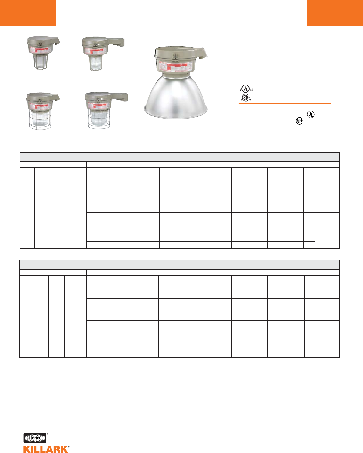
CERTILITE®V SERIES •LIGHTING
METAL HALIDE PULSE, 150-200W MOGUL BASE HID
L54
Class I, Div. 2, Groups A,B,C,D1
Class l, Zone 2, Groups IIC, llB, llA
Class II, Div. 1 & 2, Groups E,F,G
Class III
Suitable for wet locations
NEMA 3, 4, 4X; IP66
NR Restricted Breathing Option5
Class I, Zone 2 AEx nAnR
Class I, Zone 2 Ex nR
Listed - File E10514 (Hazardous & Marine)
Certified - File LR11713
Stanchion 25°
w/ 5-1/2"
Globe & Guard
Stanchion 25°
w/ 7-3/4"
Globe & Guard
Stanchion Straight
w/ 5-1/2"
Refractor & Guard
Stanchion Straight
w/ 7-3/4"
Refractor & Guard
Stanchion 25°
w/ Enclosed Reflector
WATTS
150
175
200
DESCRIPTION
ANSI
M102
M142
M137
M152
M136
HUB
SIZE3
1-1/2"
1-1/2"
1-1/2"
VOLTAGE4
Quad
Tri
480
Quad
Tri
480
Quad
Tri
480
5-1/2" OPTIC THREAD SIZE 2
GLOBE
& GUARD
VM3P150D5GLG
VM3P156D5GLG
VM3P155D5GLG
VM3P170D5GLG
VM3P176D5GLG
VM3P175D5GLG
VM3P200D5GLG
VM3P206D5GLG
VM3P205D5GLG
TYPE I GLASS
REFRACTOR
& GUARD
VM3P150D5R1G
VM3P156D5R1G
VM3P155D5R1G
VM3P170D5R1G
VM3P176D5R1G
VM3P175D5R1G
VM3P200D5R1G
VM3P206D5R1G
VM3P205D5R1G
TYPE V GLASS
REFRACTOR
& GUARD
VM3P150D5R5G
VM3P156D5R5G
VM3P155D5R5G
VM3P170D5R5G
VM3P176D5R5G
VM3P175D5R5G
VM3P200D5R5G
VM3P206D5R5G
VM3P205D5R5G
7-3/4” OPTIC THREAD SIZE 2
GLOBE
& GUARD
VM4P150D5GLG
VM4P156D5GLG
VM4P155D5GLG
VM4P170D5GLG
VM4P176D5GLG
VM4P175D5GLG
VM4P200D5GLG
VM4P206D5GLG
VM4P205D5GLG
TYPE I GLASS
REFRACTOR
& GUARD
VM4P150D5R1G
VM4P156D5R1G
VM4P155D5R1G
VM4P170D5R1G
VM4P176D5R1G
VM4P175D5R1G
VM4P200D5R1G
VM4P206D5R1G
VM4P205D5R1G
ENCLOSED
REFLECTOR
VM4P150D5ERN
VM4P156D5ERN
VM4P155D5ERN
VM4P170D5ERN
VM4P176D5ERN
VM4P175D5ERN
VM4P200D5ERN
VM4P206D5ERN
VM4P205D5ERN
TYPE V GLASS
REFRACTOR
& GUARD
VM4P150D5R5G
VM4P156D5R5G
VM4P155D5R5G
VM4P170D5R5G
VM4P176D5R5G
VM4P175D5R5G
VM4P200D5R5G
VM4P206D5R5G
VM4P205D5R5G
VM 150-200 WATT METAL HALIDE PULSE STANCHION STRAIGHT
WATTS
150
175
200
DESCRIPTION
ANSI
M102
M142
M137
M152
M136
HUB
SIZE3
1-1/2"
1-1/2"
1-1/2"
VOLTAGE4
Quad
Tri
480
Quad
Tri
480
Quad
Tri
480
5-1/2" OPTIC THREAD SIZE 2
GLOBE
& GUARD
VM3P150S5GLG
VM3P156S5GLG
VM3P155S5GLG
VM3P170S5GLG
VM3P176S5GLG
VM3P175S5GLG
VM3P200S5GLG
VM3P206S5GLG
VM3P205S5GLG
TYPE I GLASS
REFRACTOR
& GUARD
VM3P150S5R1G
VM3P156S5R1G
VM3P155S5R1G
VM3P170S5R1G
VM3P176S5R1G
VM3P175S5R1G
VM3P200S5R1G
VM3P206S5R1G
VM3P205S5R1G
TYPE V GLASS
REFRACTOR
& GUARD
VM3P150S5R5G
VM3P156S5R5G
VM3P155S5R5G
VM3P170S5R5G
VM3P176S5R5G
VM3P175S5R5G
VM3P200S5R5G
VM3P206S5R5G
VM3P205S5R5G
7-3/4" OPTIC THREAD SIZE 2
GLOBE
& GUARD
VM4P150S5GLG
VM4P156S5GLG
VM4P155S5GLG
VM4P170S5GLG
VM4P176S5GLG
VM4P175S5GLG
VM4P200S5GLG
VM4P206S5GLG
VM4P205S5GLG
TYPE I GLASS
REFRACTOR
& GUARD
VM4P150S5R1G
VM4P156S5R1G
VM4P155S5R1G
VM4P170S5R1G
VM4P176S5R1G
VM4P175S5R1G
VM4P200S5R1G
VM4P206S5R1G
VM4P205S5R1G
ENCLOSED
REFLECTOR
VM4P150S5ERN
VM4P156S5ERN
VM4P155S5ERN
VM4P170S5ERN
VM4P176S5ERN
VM4P175S5ERN
VM4P200S5ERN
VM4P206S5ERN
VM4P205S5ERN
TYPE V GLASS
REFRACTOR
& GUARD
VM4P150S5R5G
VM4P156S5R5G
VM4P155S5R5G
VM4P170S5R5G
VM4P176S5R5G
VM4P175S5R5G
VM4P200S5R5G
VM4P206S5R5G
VM4P205S5R5G
1See hazardous application data on pages L84-L89 for limitations.
2Catalog numbers shown are with guard (except enclosed reflectors); to omit guard change ending G to N; e.g. VM3P150D5GLN
3Catalog numbers shown are with 1-1/2" conduit openings, change 5 to 4 for 1-1/4"; e.g. VM3P150D4GLG.
4Consult catalog logic for other available voltages.
5Add suffix NR for restricted breathing; see page L39 for more information.
VM 150-200 WATT METAL HALIDE PULSE STANCHION 25° ANGLE
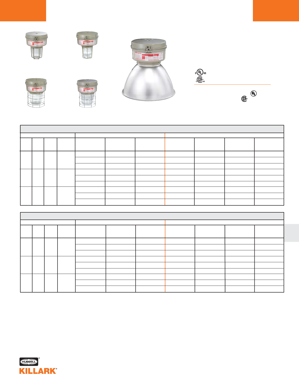
CERTILITE®V SERIES •LIGHTING
MERCURY VAPOR, 100-250W MOGUL BASE HID L55
L
Class I, Div. 2, Groups A,B,C,D1
Class l, Zone 2, Groups IIC, llB, llA
Class II, Div. 1 & 2, Groups E,F,G
Class III
Suitable for wet locations
NEMA 3, 4, 4X; IP66
NR Restricted Breathing Option5
Class I, Zone 2 AEx nAnR
Class I, Zone 2 Ex nR
Listed - File E10514 (Hazardous & Marine)
Certified - File LR11713
Pendant
w/ Enclosed Reflector
Pendant
w/ 5-1/2"
Globe & Guard
Pendant
w/ 7-3/4"
Globe & Guard
Flexible Pendant
w/ 5-1/2"
Refractor & Guard
Flexible Pendant
w/ 7-3/4"
Refractor & Guard
VM 100-250 WATT MERCURY VAPOR PENDANT
WATTS
100
175
250
DESCRIPTION
ANSI
H38
H39
H37
HUB
SIZE3
3/4"
3/4"
3/4"
VOLTAGE4
Quad
Tri
480
Quad
Tri
480
Quad
Tri
480
5-1/2" OPTIC THREAD SIZE 2
GLOBE
& GUARD
VM3M100A2GLG
VM3M106A2GLG
VM3M105A2GLG
VM3M170A2GLG
VM3M176A2GLG
VM3M175A2GLG
VM3M250A2GLG
VM3M256A2GLG
VM3M255A2GLG
TYPE I GLASS
REFRACTOR
& GUARD
VM3M100A2R1G
VM3M106A2R1G
VM3M105A2R1G
VM3M170A2R1G
VM3M176A2R1G
VM3M175A2R1G
VM3M250A2R1G
VM3M256A2R1G
VM3M255A2R1G
TYPE V GLASS
REFRACTOR
& GUARD
VM3M100A2R5G
VM3M106A2R5G
VM3M105A2R5G
VM3M170A2R5G
VM3M176A2R5G
VM3M175A2R5G
VM3M250A2R5G
VM3M256A2R5G
VM3M255A2R5G
7-3/4" OPTIC THREAD SIZE 2
GLOBE
& GUARD
VM4M100A2GLG
VM4M106A2GLG
VM4M105A2GLG
VM4M170A2GLG
VM4M176A2GLG
VM4M175A2GLG
VM4M250A2GLG
VM4M256A2GLG
VM4M255A2GLG
TYPE I GLASS
REFRACTOR
& GUARD
VM4M100A2R1G
VM4M106A2R1G
VM4M105A2R1G
VM4M170A2R1G
VM4M176A2R1G
VM4M175A2R1G
VM4M250A2R1G
VM4M256A2R1G
VM4M255A2R1G
ENCLOSED
REFLECTOR
VM4M100A2ERN
VM4M106A2ERN
VM4M105A2ERN
VM4M170A2ERN
VM4M176A2ERN
VM4M175A2ERN
VM4M250A2ERN
VM4M256A2ERN
VM4M255A2ERN
TYPE V GLASS
REFRACTOR
& GUARD
VM4M100A2R5G
VM4M106A2R5G
VM4M105A2R5G
VM4M170A2R5G
VM4M176A2R5G
VM4M175A2R5G
VM4M250A2R5G
VM4M256A2R5G
VM4M255A2R5G
VM 100-250 WATT MERCURY VAPOR FLEXIBLE PENDANT
WATTS
100
175
250
DESCRIPTION
ANSI
H38
H39
H37
HUB
SIZE3
3/4"
3/4"
3/4"
VOLTAGE4
Quad
Tri
480
Quad
Tri
480
Quad
Tri
480
5-1/2" OPTIC THREAD SIZE 2
GLOBE
& GUARD
VM3M100F2GLG
VM3M106F2GLG
VM3M105F2GLG
VM3M170F2GLG
VM3M176F2GLG
VM3M175F2GLG
VM3M250F2GLG
VM3M256F2GLG
VM3M255F2GLG
TYPE I GLASS
REFRACTOR
& GUARD
VM3M100F2R1G
VM3M106F2R1G
VM3M105F2R1G
VM3M170F2R1G
VM3M176F2R1G
VM3M175F2R1G
VM3M250F2R1G
VM3M256F2R1G
VM3M255F2R1G
TYPE V GLASS
REFRACTOR
& GUARD
VM3M100F2R5G
VM3M106F2R5G
VM3M105F2R5G
VM3M170F2R5G
VM3M176F2R5G
VM3M175F2R5G
VM3M250F2R5G
VM3M256F2R5G
VM3M255F2R5G
7-3/4" OPTIC THREAD SIZE 2
GLOBE
& GUARD
VM4M100F2GLG
VM4M106F2GLG
VM4M105F2GLG
VM4M170F2GLG
VM4M176F2GLG
VM4M175F2GLG
VM4M250F2GLG
VM4M256F2GLG
VM4M255F2GLG
TYPE I GLASS
REFRACTOR
& GUARD
VM4M100F2R1G
VM4M106F2R1G
VM4M105F2R1G
VM4M170F2R1G
VM4M176F2R1G
VM4M175F2R1G
VM4M250F2R1G
VM4M256F2R1G
VM4M255F2R1G
ENCLOSED
REFLECTOR
VM4M100F2ERN
VM4M106F2ERN
VM4M105F2ERN
VM4M170F2ERN
VM4M176F2ERN
VM4M175F2ERN
VM4M250F2ERN
VM4M256F2ERN
VM4M255F2ERN
TYPE V GLASS
REFRACTOR
& GUARD
VM4M100F2R5G
VM4M106F2R5G
VM4M105F2R5G
VM4M170F2R5G
VM4M176F2R5G
VM4M175F2R5G
VM4M250F2R5G
VM4M256F2R5G
VM4M255F2R5G
1See hazardous application data on pages L84-L89 for limitations.
2Catalog numbers shown are with guard (except enclosed reflector); to omit guard change ending G to N; e.g. VM3M100A2GLN
3Catalog numbers shown are with 3/4" conduit openings, change 2 to 3 for 1"; e.g. VM3M100A3GLG.
4Consult catalog logic for other available voltages.
5Add suffix NR for restricted breathing; see page L39 for more information.
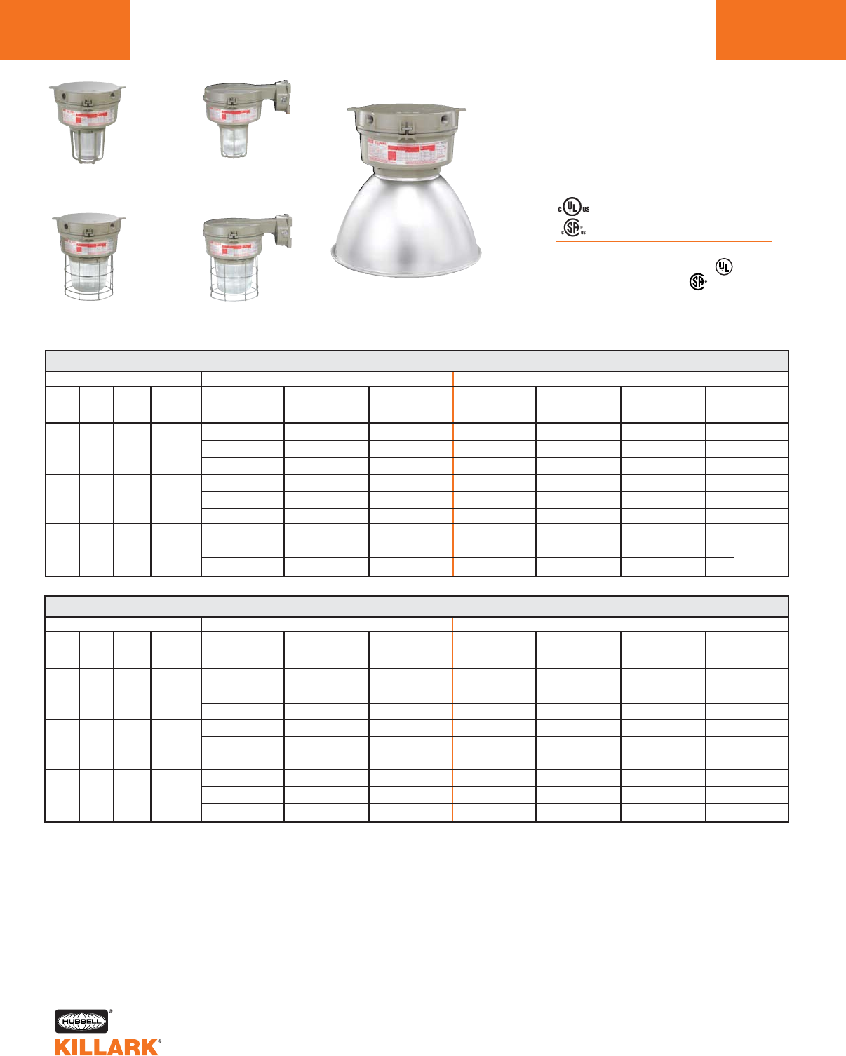
CERTILITE®V SERIES •LIGHTING
MERCURY VAPOR, 100-250W MOGUL BASE HID
L56
Ceiling
w/ 5-1/2"
Globe & Guard
Ceiling
w/ 7-3/4"
Globe & Guard
Wall
w/ 5-1/2"
Refractor & Guard
Wall
w/ 7-3/4"
Refractor & Guard
Ceiling
w/ Enclosed Reflector
VM 100-250 WATT MERCURY VAPOR CEILING
WATTS
100
175
250
DESCRIPTION
ANSI
H38
H39
H37
HUB
SIZE3
3/4"
3/4"
3/4"
VOLTAGE3
Quad
Tri
480
Quad
Tri
480
Quad
Tri
480
5-1/2" OPTIC THREAD SIZE 2
GLOBE
& GUARD
VM3M100X2GLG
VM3M106X2GLG
VM3M105X2GLG
VM3M170X2GLG
VM3M176X2GLG
VM3M175X2GLG
VM3M250X2GLG
VM3M256X2GLG
VM3M255X2GLG
TYPE I GLASS
REFRACTOR
& GUARD
VM3M100X2R1G
VM3M106X2R1G
VM3M105X2R1G
VM3M170X2R1G
VM3M176X2R1G
VM3M175X2R1G
VM3M250X2R1G
VM3M256X2R1G
VM3M255X2R1G
TYPE V GLASS
REFRACTOR
& GUARD
VM3M100X2R5G
VM3M106X2R5G
VM3M105X2R5G
VM3M170X2R5G
VM3M176X2R5G
VM3M175X2R5G
VM3M250X2R5G
VM3M256X2R5G
VM3M255X2R5G
7-3/4" OPTIC THREAD SIZE 2
GLOBE
& GUARD
VM4M100X2GLG
VM4M106X2GLG
VM4M105X2GLG
VM4M170X2GLG
VM4M176X2GLG
VM4M175X2GLG
VM4M250X2GLG
VM4M256X2GLG
VM4M255X2GLG
TYPE I GLASS
REFRACTOR
& GUARD
VM4M100X2R1G
VM4M106X2R1G
VM4M105X2R1G
VM4M170X2R1G
VM4M176X2R1G
VM4M175X2R1G
VM4M250X2R1G
VM4M256X2R1G
VM4M255X2R1G
ENCLOSED
REFLECTOR
VM4M100X2ERN
VM4M106X2ERN
VM4M105X2ERN
VM4M170X2ERN
VM4M176X2ERN
VM4M175X2ERN
VM4M250X2ERN
VM4M256X2ERN
VM4M255X2ERN
TYPE V GLASS
REFRACTOR
& GUARD
VM4M100X2R5G
VM4M106X2R5G
VM4M105X2R5G
VM4M170X2R5G
VM4M176X2R5G
VM4M175X2R5G
VM4M250X2R5G
VM4M256X2R5G
VM4M255X2R5G
VM 100-250 WATT MERCURY VAPOR WALL
WATTS
100
175
250
DESCRIPTION
ANSI
H38
H39
H37
HUB
SIZE3
3/4"
3/4"
3/4"
VOLTAGE4
Quad
Tri
480
Quad
Tri
480
Quad
Tri
480
5-1/2" OPTIC THREAD SIZE 2
GLOBE
& GUARD
VM3M100B2GLG
VM3M106B2GLG
VM3M105B2GLG
VM3M170B2GLG
VM3M176B2GLG
VM3M175B2GLG
VM3M250B2GLG
VM3M256B2GLG
VM3M255B2GLG
TYPE I GLASS
REFRACTOR
& GUARD
VM3M100B2R1G
VM3M106B2R1G
VM3M105B2R1G
VM3M170B2R1G
VM3M176B2R1G
VM3M175B2R1G
VM3M250B2R1G
VM3M256B2R1G
VM3M255B2R1G
TYPE V GLASS
REFRACTOR
& GUARD
VM3M100B2R5G
VM3M106B2R5G
VM3M105B2R5G
VM3M170B2R5G
VM3M176B2R5G
VM3M175B2R5G
VM3M250B2R5G
VM3M256B2R5G
VM3M255B2R5G
7-3/4" OPTIC THREAD SIZE 2
GLOBE
& GUARD
VM4M100B2GLG
VM4M106B2GLG
VM4M105B2GLG
VM4M170B2GLG
VM4M176B2GLG
VM4M175B2GLG
VM4M250B2GLG
VM4M256B2GLG
VM4M255B2GLG
TYPE I GLASS
REFRACTOR
& GUARD
VM4M100B2R1G
VM4M106B2R1G
VM4M105B2R1G
VM4M170B2R1G
VM4M176B2R1G
VM4M175B2R1G
VM4M250B2R1G
VM4M256B2R1G
VM4M255B2R1G
ENCLOSED
REFLECTOR
VM4M100B2ERN
VM4M106B2ERN
VM4M105B2ERN
VM4M170B2ERN
VM4M176B2ERN
VM4M175B2ERN
VM4M250B2ERN
VM4M256B2ERN
VM4M255B2ERN
TYPE V GLASS
REFRACTOR
& GUARD
VM4M100B2R5G
VM4M106B2R5G
VM4M105B2R5G
VM4M170B2R5G
VM4M176B2R5G
VM4M175B2R5G
VM4M250B2R5G
VM4M256B2R5G
VM4M255B2R5G
1See hazardous application data on pages L84-L89 for limitations.
2Catalog numbers shown are with guard (except enclosed reflector); to omit guard change ending G to N; e.g. VM3M100X2GLN
3Catalog numbers shown are with 3/4" conduit openings, change 2 to 3 for 1"; e.g. VM3M100X3GLG.
4Consult catalog logic for other available voltages.
5Add suffix NR for restricted breathing; see page L39 for more information.
Class I, Div. 2, Groups A,B,C,D1
Class l, Zone 2, Groups IIC, llB, llA
Class II, Div. 1 & 2, Groups E,F,G
Class III
Suitable for wet locations
NEMA 3, 4, 4X; IP66
NR Restricted Breathing Option5
Class I, Zone 2 AEx nAnR
Class I, Zone 2 Ex nR
Listed - File E10514 (Hazardous & Marine)
Certified - File LR11713

CERTILITE®V SERIES •LIGHTING
MERCURY VAPOR, 100-250W MOGUL BASE HID L57
L
Cone
w/ 5-1/2"
Globe & Guard
Cone
w/ 7-3/4"
Globe & Guard
EZ Adapter
w/ 5-1/2"
Refractor & Guard
EZ Adapter
w/ 7-3/4"
Refractor & Guard
Cone
w/ Enclosed Reflector
WATTS
100
175
250
DESCRIPTION
ANSI
H38
H39
H37
HUB
SIZE3
3/4"
3/4"
3/4"
VOLTAGE4
Quad
Tri
480
Quad
Tri
480
Quad
Tri
480
5-1/2" OPTIC THREAD SIZE 2
GLOBE
& GUARD
VM3M100C2GLG
VM3M106C2GLG
VM3M105C2GLG
VM3M170C2GLG
VM3M176C2GLG
VM3M175C2GLG
VM3M250C2GLG
VM3M256C2GLG
VM3M255C2GLG
TYPE I GLASS
REFRACTOR
& GUARD
VM3M100C2R1G
VM3M106C2R1G
VM3M105C2R1G
VM3M170C2R1G
VM3M176C2R1G
VM3M175C2R1G
VM3M250C2R1G
VM3M256C2R1G
VM3M255C2R1G
TYPE V GLASS
REFRACTOR
& GUARD
VM3M100C2R5G
VM3M106C2R5G
VM3M105C2R5G
VM3M170C2R5G
VM3M176C2R5G
VM3M175C2R5G
VM3M250C2R5G
VM3M256C2R5G
VM3M255C2R5G
7-3/4" OPTIC THREAD SIZE 2
GLOBE
& GUARD
VM4M100C2GLG
VM4M106C2GLG
VM4M105C2GLG
VM4M170C2GLG
VM4M176C2GLG
VM4M175C2GLG
VM4M250C2GLG
VM4M256C2GLG
VM4M255C2GLG
TYPE I GLASS
REFRACTOR
& GUARD
VM4M100C2R1G
VM4M106C2R1G
VM4M105C2R1G
VM4M170C2R1G
VM4M176C2R1G
VM4M175C2R1G
VM4M250C2R1G
VM4M256C2R1G
VM4M255C2R1G
ENCLOSED
REFLECTOR
VM4M100C2ERN
VM4M106C2ERN
VM4M105C2ERN
VM4M170C2ERN
VM4M176C2ERN
VM4M175C2ERN
VM4M250C2ERN
VM4M256C2ERN
VM4M255C2ERN
TYPE V GLASS
REFRACTOR
& GUARD
VM4M100C2R5G
VM4M106C2R5G
VM4M105C2R5G
VM4M170C2R5G
VM4M176C2R5G
VM4M175C2R5G
VM4M250C2R5G
VM4M256C2R5G
VM4M255C2R5G
VM 100-250 WATT MERCURY VAPOR EZ ADAPTER
WATTS
100
175
250
DESCRIPTION
ANSI
H38
H39
H37
HUB
SIZE6
6
6
6
VOLTAGE4
Quad
Tri
480
Quad
Tri
480
Quad
Tri
480
5-1/2" OPTIC THREAD SIZE 2
GLOBE
& GUARD
VM3M100EZGLG
VM3M106EZGLG
VM3M105EZGLG
VM3M170EZGLG
VM3M176EZGLG
VM3M175EZGLG
VM3M250EZGLG
VM3M256EZGLG
VM3M255EZGLG
TYPE I GLASS
REFRACTOR
& GUARD
VM3M100EZR1G
VM3M106EZR1G
VM3M105EZR1G
VM3M170EZR1G
VM3M176EZR1G
VM3M175EZR1G
VM3M250EZR1G
VM3M256EZR1G
VM3M255EZR1G
TYPE V GLASS
REFRACTOR
& GUARD
VM3M100EZR5G
VM3M106EZR5G
VM3M105EZR5G
VM3M170EZR5G
VM3M176EZR5G
VM3M175EZR5G
VM3M250EZR5G
VM3M256EZR5G
VM3M255EZR5G
7-3/4" OPTIC THREAD SIZE 2
GLOBE
& GUARD
VM4M100EZGLG
VM4M106EZGLG
VM4M105EZGLG
VM4M170EZGLG
VM4M176EZGLG
VM4M175EZGLG
VM4M250EZGLG
VM4M256EZGLG
VM4M255EZGLG
TYPE I GLASS
REFRACTOR
& GUARD
VM4M100EZR1G
VM4M106EZR1G
VM4M105EZR1G
VM4M170EZR1G
VM4M176EZR1G
VM4M175EZR1G
VM4M250EZR1G
VM4M256EZR1G
VM4M255EZR1G
ENCLOSED
REFLECTOR
VM4M100EZERN
VM4M106EZERN
VM4M105EZERN
VM4M170EZERN
VM4M176EZERN
VM4M175EZERN
VM4M250EZERN
VM4M256EZERN
VM4M255EZERN
TYPE V GLASS
REFRACTOR
& GUARD
VM4M100EZR5G
VM4M106EZR5G
VM4M105EZR5G
VM4M170EZR5G
VM4M176EZR5G
VM4M175EZR5G
VM4M250EZR5G
VM4M256EZR5G
VM4M255EZR5G
1See hazardous application data on pages L84-L89 for limitations.
2Catalog numbers shown are with guard (except enclosed reflector); to omit guard change ending G to N; e.g. VM3M100C2GLN
3Cone top catalog numbers shown are with 3/4" conduit openings, change 2 to 3 for 1"; e.g. VM3M100C3GLG.
4Consult catalog logic for other available voltages.
5Add suffix NR for restricted breathing; see page L39 for more information.
6VMEZA tank adapters UL “classified” as an assembly for use between VM tanks and EZ mounts. Order EZ mounts separately. See page L63.
VM 100-250 WATT MERCURY VAPOR CONE
Class I, Div. 2, Groups A,B,C,D1
Class l, Zone 2, Groups IIC, llB, llA
Class II, Div. 1 & 2, Groups E,F,G
Class III
Suitable for wet locations
NEMA 3, 4, 4X; IP66
NR Restricted Breathing Option5
Class I, Zone 2 AEx nAnR
Class I, Zone 2 Ex nR
Listed - File E10514 (Hazardous & Marine)
Certified - File LR11713
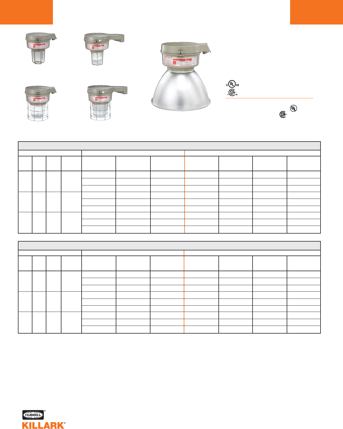
CERTILITE®V SERIES •LIGHTING
MERCURY VAPOR, 100-250W MOGUL BASE HID
L58
Class I, Div. 2, Groups A,B,C,D1
Class l, Zone 2, Groups IIC, llB, llA
Class II, Div. 1 & 2, Groups E,F,G
Class III
Suitable for wet locations
NEMA 3, 4, 4X; IP66
NR Restricted Breathing Option5
Class I, Zone 2 AEx nAnR
Class I, Zone 2 Ex nR
Listed - File E10514 (Hazardous & Marine)
Certified - File LR11713
WATTS
100
175
250
DESCRIPTION
ANSI
H38
H39
H37
HUB
SIZE3
1-1/2"
1-1/2"
1-1/2"
VOLTAGE4
Quad
Tri
480
Quad
Tri
480
Quad
Tri
480
5-1/2" OPTIC THREAD SIZE 2
GLOBE
& GUARD
VM3M100D5GLG
VM3M106D5GLG
VM3M105D5GLG
VM3M170D5GLG
VM3M176D5GLG
VM3M175D5GLG
VM3M250D5GLG
VM3M256D5GLG
VM3M255D5GLG
TYPE I GLASS
REFRACTOR
& GUARD
VM3M100D5R1G
VM3M106D5R1G
VM3M105D5R1G
VM3M170D5R1G
VM3M176D5R1G
VM3M175D5R1G
VM3M250D5R1G
VM3M256D5R1G
VM3M255D5R1G
TYPE V GLASS
REFRACTOR
& GUARD
VM3M100D5R5G
VM3M106D5R5G
VM3M105D5R5G
VM3M170D5R5G
VM3M176D5R5G
VM3M175D5R5G
VM3M250D5R5G
VM3M256D5R5G
VM3M255D5R5G
7-3/4" OPTIC THREAD SIZE 2
GLOBE
& GUARD
VM4M100D5GLG
VM4M106D5GLG
VM4M105D5GLG
VM4M170D5GLG
VM4M176D5GLG
VM4M175D5GLG
VM4M250D5GLG
VM4M256D5GLG
VM4M255D5GLG
TYPE I GLASS
REFRACTOR
& GUARD
VM4M100D5R1G
VM4M106D5R1G
VM4M105D5R1G
VM4M170D5R1G
VM4M176D5R1G
VM4M175D5R1G
VM4M250D5R1G
VM4M256D5R1G
VM4M255D5R1G
ENCLOSED
REFLECTOR
VM4M100D5ERN
VM4M106D5ERN
VM4M105D5ERN
VM4M170D5ERN
VM4M176D5ERN
VM4M175D5ERN
VM4M250D5ERN
VM4M256D5ERN
VM4M255D5ERN
TYPE V GLASS
REFRACTOR
& GUARD
VM4M100D5R5G
VM4M106D5R5G
VM4M105D5R5G
VM4M170D5R5G
VM4M176D5R5G
VM4M175D5R5G
VM4M250D5R5G
VM4M256D5R5G
VM4M255D5R5G
VM 100-250 WATT MERCURY VAPOR STANCHION STRAIGHT
WATTS
100
175
250
DESCRIPTION
ANSI
H38
H39
H37
HUB
SIZE3
1-1/2"
1-1/2"
1-1/2"
VOLTAGE4
Quad
Tri
480
Quad
Tri
480
Quad
Tri
480
5-1/2" OPTIC THREAD SIZE 2
GLOBE
& GUARD
VM3M100S5GLG
VM3M106S5GLG
VM3M105S5GLG
VM3M170S5GLG
VM3M176S5GLG
VM3M175S5GLG
VM3M250S5GLG
VM3M256S5GLG
VM3M255S5GLG
TYPE I GLASS
REFRACTOR
& GUARD
VM3M100S5R1G
VM3M106S5R1G
VM3M105S5R1G
VM3M170S5R1G
VM3M176S5R1G
VM3M175S5R1G
VM3M250S5R1G
VM3M256S5R1G
VM3M255S5R1G
TYPE V GLASS
REFRACTOR
& GUARD
VM3M100S5R5G
VM3M106S5R5G
VM3M105S5R5G
VM3M170S5R5G
VM3M176S5R5G
VM3M175S5R5G
VM3M250S5R5G
VM3M256S5R5G
VM3M255S5R5G
7-3/4" OPTIC THREAD SIZE 2
GLOBE
& GUARD
VM4M100S5GLG
VM4M106S5GLG
VM4M105S5GLG
VM4M170S5GLG
VM4M176S5GLG
VM4M175S5GLG
VM4M250S5GLG
VM4M256S5GLG
VM4M255S5GLG
TYPE I GLASS
REFRACTOR
& GUARD
VM4M100S5R1G
VM4M106S5R1G
VM4M105S5R1G
VM4M170S5R1G
VM4M176S5R1G
VM4M175S5R1G
VM4M250S5R1G
VM4M256S5R1G
VM4M255S5R1G
ENCLOSED
REFLECTOR
VM4M100S5ERN
VM4M106S5ERN
VM4M105S5ERN
VM4M170S5ERN
VM4M176S5ERN
VM4M175S5ERN
VM4M250S5ERN
VM4M256S5ERN
VM4M255S5ERN
TYPE V GLASS
REFRACTOR
& GUARD
VM4M100S5R5G
VM4M106S5R5G
VM4M105S5R5G
VM4M170S5R5G
VM4M176S5R5G
VM4M175S5R5G
VM4M250S5R5G
VM4M256S5R5G
VM4M255S5R5G
1See hazardous application data on pages L89-L89 for limitations.
2Catalog numbers shown are with guard (except enclosed reflector); to omit guard change ending G to N; e.g. VM3M100D5GLN
3Catalog numbers shown are with 3/4" conduit openings, change 5 to 4 for 1-1/4"; e.g. VM3M100D4GLG.
4Consult catalog logic for other available voltages.
5Add suffix NR for restricted breathing; see page L39 for more information.
Stanchion 25°
w/ 5-1/2"
Globe & Guard
Stanchion 25°
w/ 7-3/4"
Globe & Guard
Stanchion Straight
w/ 5-1/2"
Refractor & Guard
Stanchion Straight
w/ 7-3/4"
Refractor & Guard
Stanchion 25°
w/ Enclosed Reflector
VM 100-250 WATT MERCURY VAPOR STANCHION 25° ANGLE
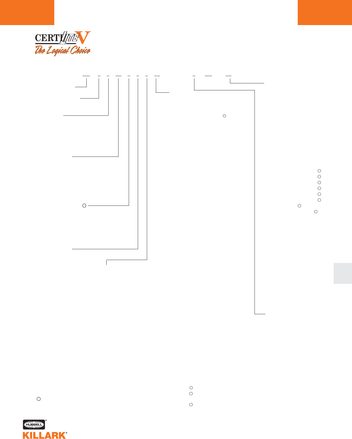
CERTILITE®V SERIES •LIGHTING
MERCURY VAPOR, 100-250W MOGUL BASE HID L59
L
CertiLite®VCatalog Number Logic; 200-400 High Wattage (Mogul Base) HID Fixtures
Series Constant
Optic Thread Size
5—7 3/4"
Lamp Type
S—HPS (200, 250, 400, 600)
H—MH (250, 400)
P—MHP (Pulse Start 250, 320,
350, 400)
M—MV (400)
Voltage @ 60 Hertz
0—Quadri-Volt (120, 208, 240, 277)
5—480V
6—Tri - 120, 277, 347 (Canada)
7—220V
8—220/240 50 Hz
Mounting Type
A—Pendant
X—Ceiling
B—Wall Bracket
C—Cone Top
D—Stanchion 25°
S—Stanchion Straight 90°
E—EZ Mount Adapter1
N—None (mount ordered
separately)2
Lamp Wattage
20—200 (HPS)
25—250 (HPS, MH. MHP)
32—320 (MHP)
35—350 (MHP)
40—400 (HPS, MH, MHP, MV)
60—600 (HPS)
Guard
G—Globe Guard
N—No Guard6
Options
QA—Quartz Auxiliary7
BP—Ballast Protector 250-
400W HPS only
F1—Fusing 120V8
F2—Fusing 208V8
F3—Fusing 240V8
F4—Fusing 277V8
F5—Fusing 480V8
F6—Fusing 347V8
F7—Fusing 220V8
F8—Fusing 240V 50 Hz8
P1—Photocell 120V9
P2—Photocell 208-277V9
P3—Photocell 347V9
Q1—QD Wired to 120V
Q2—QD Wired to 208V
Q3—QD Wired to 240V
Q4—QD Wired to 277V
Q5—QD Wired to 480V
Q6—QD Wired to 347V
Q7—QD 220V
Q8—QD 240V (50Hz)
TB—Terminal Blocks
AS—Assembled Fixture with
Standard Lamp
AD—Assembled Fixture with
Dual-Arc-Tube Lamp 250,
400 HPS only
AN—Assembled, no lamp
CS—Component Pack with
Standard Lamp
CP—Component Pack-No
Lamp
Optic
GL—Globe
ER—Enclosed Reflector
EP—Poylcarbonate Shielded
Enclosed Reflector
S2—Type II Spin-Top Refractor
S5—Type V Spin-Top Refractor
FG—Tuffskin®3Coated Globe
TG—Teflon®4Coated Globe
T2—Teflon®4Coated Type II
12" Spin-Top Refractor
TV—Teflon®4Coated Type V
12" Spin-Top Refractor
Entry (Mounts available)
2—3/4" NPT (A,B,C,X)
3—1" NPT (A,B,C,X)
4—1 1/4" NPT (D,S)
5—1 1/2" NPT (D,S)
6—3/4" NPT 5-Hub (X)
7—1" NPT 5-Hub (X)
8—M20 4-Hub (X)
9—M20 5-Hub (X)
Z—EZ Mount Adapter1
N—None (mount ordered
separately)2
VM 0 0 00 0 0 0 00 0 (NR5)00
1Completes as “EZ”, conduit mounting boxes ordered separately -
See L63.
2NN mount ordered separately.
3Tuffskin®is a registered trademark of Thomas Mfg. Corp.
4Teflon®is a registered trademark of DuPont, Inc.
5Restricted Breathing - See L39 for more information.
6Order Guards for Spin-Tops & VMER40 separately.
Consult factory for available lamp and voltage combinations.
7QA not suitable for Class I, Div. 2/Zone 2 applications; consult factory
for other hazardous applications.
8Fusing not for Marine or Canadian installations.
9Photo cells for Class I, Div. 2 only.
Field connection to proper tap in case of Multitap Ballasts.
Not for use with wall or straight (90°) Stanchion.
QD = Quick Disconnect. Allows easy tank removal for maintenance.
Electrician simply unplugs de-energized ballast from supply circuit.
250W MH w/quad, tri-tap, or 480V 60Hz, or 230V 50Hz w/o Quartz - use
VM5 tank.
®
11
12
11
12
13
V
V
12
12
12
12
12
12
12
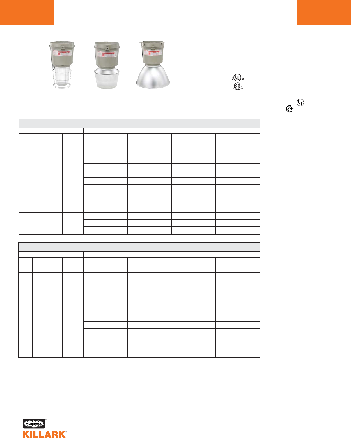
CERTILITE®V SERIES •LIGHTING
HIGH PRESSURE SODIUM, 200-600W MOGUL BASE HID
L60
Pendant
w/ Globe &
Guard
Pendant
w/ Spin-Top
Refractor
Ceiling
w/ Enclosed
Reflector
VM 200-600 WATT HIGH PRESSURE SODIUM PENDANT
WATTS
200
250
400
600
DESCRIPTION
ANSI
S66
S50
S51
S106
HUB
SIZE 3
3/4”
3/4”
3/4”
3/4”
VOLTAGE 4
Quad
Tri
480
Quad
Tri
480
Quad
Tri
480
Quad
Tri
480
7-3/4" OPTIC THREAD SIZE2
GLOBE
& GUARD
VM5S200A2GLG
VM5S206A2GLG
VM5S205A2GLG
VM5S250A2GLG
VM5S256A2GLG
VM5S255A2GLG
VM5S400A2GLG
VM5S406A2GLG
VM5S405A2GLG
—
—
—
TYPE V
SPIN-TOP GLASS
REFRACTOR
VM5S200A2S5N
VM5S206A2S5N
VM5S205A2S5N
VM5S250A2S5N
VM5S256A2S5N
VM5S255A2S5N
VM5S400A2S5N
VM5S406A2S5N
VM5S405A2S5N
—
—
—
ENCLOSED
REFLECTOR
VM5S200A2ERN
VM5S206A2ERN
VM5S205A2ERN
VM5S250A2ERN
VM5S256A2ERN
VM5S255A2ERN
VM5S400A2ERN
VM5S406A2ERN
VM5S405A2ERN
VM5S600A2ERN
VM5S606A2ERN
VM5S605A2ERN
POLYCARBONATE
SHIELDED
ENCLOSED REFLECTOR
VM5S200A2EPN
VM5S206A2EPN
VM5S205A2EPN
VM5S250A2EPN
VM5S256A2EPN
VM5S255A2EPN
VM5S400A2EPN
VM5S406A2EPN
VM5S405A2EPN
—
—
—
1See hazardous application data on pages L84-L89 for limitations.
2Globe catalog number shown with guard. To omit guard, change G to N; e.g. VM5S200A2GLN. Order spin top and enclosed reflec-
tor guards separately.
3Catalog numbers shown are with 3/4” conduit openings, change 2 to 3 for 1”; e.g. VM5S200A3GLG.
4Consult catalog logic for other available voltages.
5Add suffix NR for restricted breathing; see page L39 for more information.
VM 200-600 WATT HIGH PRESSURE SODIUM CEILING
WATTS
200
250
400
600
DESCRIPTION
ANSI
S66
S50
S51
S106
HUB
SIZE 3
3/4”
3/4”
3/4”
3/4”
VOLTAGE 4
Quad
Tri
480
Quad
Tri
480
Quad
Tri
480
Quad
Tri
480
7-3/4" OPTIC THREAD SIZE2
GLOBE
& GUARD
VM5S200X2GLG
VM5S206X2GLG
VM5S205X2GLG
VM5S250X2GLG
VM5S256X2GLG
VM5S255X2GLG
VM5S400X2GLG
VM5S406X2GLG
VM5S405X2GLG
—
—
—
TYPE V
SPIN-TOP GLASS
REFRACTOR
VM5S200X2S5N
VM5S206X2S5N
VM5S205X2S5N
VM5S250X2S5N
VM5S256X2S5N
VM5S255X2S5N
VM5S400X2S5N
VM5S406X2S5N
VM5S405X2S5N
—
—
—
ENCLOSED
REFLECTOR
VM5S200X2ERN
VM5S206X2ERN
VM5S205X2ERN
VM5S250X2ERN
VM5S256X2ERN
VM5S255X2ERN
VM5S400X2ERN
VM5S406X2ERN
VM5S405X2ERN
VM5S600X2ERN
VM5S606X2ERN
VM5S605X2ERN
POLYCARBONATE
SHIELDED
ENCLOSED REFLECTOR
VM5S200X2EPN
VM5S206X2EPN
VM5S205X2EPN
VM5S250X2EPN
VM5S256X2EPN
VM5S255X2EPN
VM5S400X2EPN
VM5S406X2EPN
VM5S405X2EPN
—
—
—
Class I, Div. 2, Groups A,B,C,D1
Class l, Zone 2, Groups IIC, llB, llA
Class II, Div. 1 & 2, Groups E,F,G
Class III
Suitable for wet locations
NEMA 3, 4, 4X; IP66
NR Restricted Breathing Option5
Class I, Zone 2 AEx nAnR
Class I, Zone 2 Ex nR
Listed - File E10514 (Hazardous & Marine)
Certified - File LR11713
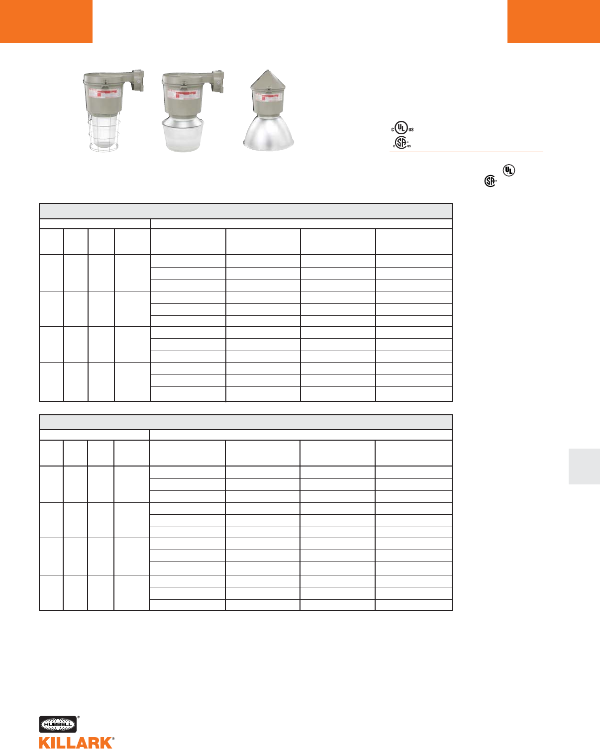
CERTILITE®V SERIES •LIGHTING
HIGH PRESSURE SODIUM, 200-600W MOGUL BASE HID L61
L
Class I, Div. 2, Groups A,B,C,D1
Class l, Zone 2, Groups IIC, llB, llA
Class II, Div. 1 & 2, Groups E,F,G
Class III
Suitable for wet locations
NEMA 3, 4, 4X; IP66
NR Restricted Breathing Option5
Class I, Zone 2 AEx nAnR
Class I, Zone 2 Ex nR
Listed - File E10514 (Hazardous & Marine)
Certified - File LR11713
Wall
w/ Globe &
Guard
Wall
w/ Spin-Top
Refractor
Cone
w/ Enclosed
Reflector
VM 200-600 WATT HIGH PRESSURE SODIUM WALL
WATTS
200
250
400
600
DESCRIPTION
ANSI
S66
S50
S51
S106
HUB
SIZE 3
3/4”
3/4”
3/4”
3/4”
VOLTAGE 4
Quad
Tri
480
Quad
Tri
480
Quad
Tri
480
Quad
Tri
480
7-3/4" OPTIC THREAD SIZE2
GLOBE
& GUARD
VM5S200B2GLG
VM5S206B2GLG
VM5S205B2GLG
VM5S250B2GLG
VM5S256B2GLG
VM5S255B2GLG
VM5S400B2GLG
VM5S406B2GLG
VM5S405B2GLG
—
—
—
TYPE V
SPIN-TOP GLASS
REFRACTOR
VM5S200B2S5N
VM5S206B2S5N
VM5S205B2S5N
VM5S250B2S5N
VM5S256B2S5N
VM5S255B2S5N
VM5S400B2S5N
VM5S406B2S5N
VM5S405B2S5N
—
—
—
ENCLOSED
REFLECTOR
VM5S200B2ERN
VM5S206B2ERN
VM5S205B2ERN
VM5S250B2ERN
VM5S256B2ERN
VM5S255B2ERN
VM5S400B2ERN
VM5S406B2ERN
VM5S405B2ERN
VM5S600B2ERN
VM5S606B2ERN
VM5S605B2ERN
POLYCARBONATE
SHIELDED
ENCLOSED REFLECTOR
—
—
—
—
—
—
—
—
—
—
—
—
1See hazardous application data on pages L84-L89 for limitations.
2Globe catalog number shown with guard. To omit guard, change G to N; e.g. VM5S200B2GLN. Order spin top and enclosed reflec-
tor guards separately.
3Catalog numbers shown are with 3/4” conduit openings, change 2 to 3 for 1”; e.g. VM5S200B3GLG.
4Consult catalog logic for other available voltages.
5Add suffix NR for restricted breathing; see page L39 for more information.
VM 200-600 WATT HIGH PRESSURE SODIUM CONE
WATTS
200
250
400
600
DESCRIPTION
ANSI
S66
S50
S51
S106
HUB
SIZE 3
3/4”
3/4”
3/4”
3/4”
VOLTAGE 4
Quad
Tri
480
Quad
Tri
480
Quad
Tri
480
Quad
Tri
480
7-3/4" OPTIC THREAD SIZE2
GLOBE
& GUARD
VM5S200C2GLG
VM5S206C2GLG
VM5S205C2GLG
VM5S250C2GLG
VM5S256C2GLG
VM5S255C2GLG
VM5S400C2GLG
VM5S406C2GLG
VM5S405C2GLG
—
—
—
TYPE V
SPIN-TOP GLASS
REFRACTOR
VM5S200C2S5N
VM5S206C2S5N
VM5S205C2S5N
VM5S250C2S5N
VM5S256C2S5N
VM5S255C2S5N
VM5S400C2S5N
VM5S406C2S5N
VM5S405C2S5N
—
—
—
ENCLOSED
REFLECTOR
VM5S200C2ERN
VM5S206C2ERN
VM5S205C2ERN
VM5S250C2ERN
VM5S256C2ERN
VM5S255C2ERN
VM5S400C2ERN
VM5S406C2ERN
VM5S405C2ERN
VM5S600C2ERN
VM5S606C2ERN
VM5S605C2ERN
POLYCARBONATE
SHIELDED
ENCLOSED REFLECTOR
VM5S200C2EPN
VM5S206C2EPN
VM5S205C2EPN
VM5S250C2EPN
VM5S256C2EPN
VM5S255C2EPN
VM5S400C2EPN
VM5S406C2EPN
VM5S405C2EPN
—
—
—
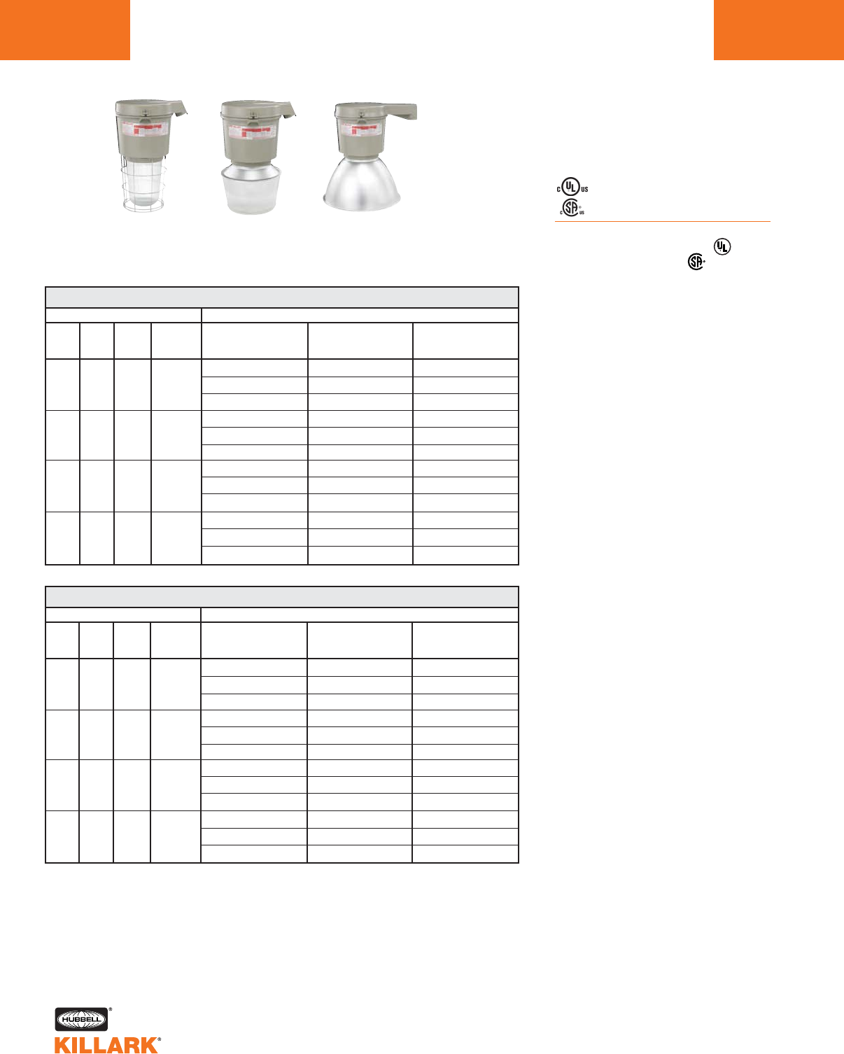
CERTILITE®V SERIES •LIGHTING
HIGH PRESSURE SODIUM, 200-600W MOGUL BASE HID
L62
Class I, Div. 2, Groups A,B,C,D1
Class l, Zone 2, Groups IIC, llB, llA
Class II, Div. 1 & 2, Groups E,F,G
Class III
Suitable for wet locations
NEMA 3, 4, 4X; IP66
NR Restricted Breathing Option5
Class I, Zone 2 AEx nAnR
Class I, Zone 2 Ex nR
Listed - File E10514 (Hazardous & Marine)
Certified - File LR11713
Stanchion 25°
w/ Globe &
Guard
Stanchion 25°
w/ Spin-Top
Refractor
Stanchion Straight
w/ Enclosed
Reflector
VM 200-600 WATT HIGH PRESSURE SODIUM STANCHION 25° ANGLE
WATTS
200
250
400
600
DESCRIPTION
ANSI
S66
S50
S51
S106
HUB
SIZE 3
1-1/2”
1-1/2”
1-1/2”
1-1/2”
VOLTAGE 4
Quad
Tri
480
Quad
Tri
480
Quad
Tri
480
Quad
Tri
480
7-3/4" OPTIC THREAD SIZE2
GLOBE
& GUARD
VM5S200D5GLG
VM5S206D5GLG
VM5S205D5GLG
VM5S250D5GLG
VM5S256D5GLG
VM5S255D5GLG
VM5S400D5GLG
VM5S406D5GLG
VM5S405D5GLG
—
—
—
TYPE V
SPIN-TOP GLASS
REFRACTOR
VM5S200D5S5N
VM5S206D5S5N
VM5S205D5S5N
VM5S250D5S5N
VM5S256D5S5N
VM5S255D5S5N
VM5S400D5S5N
VM5S406D5S5N
VM5S405D5S5N
—
—
—
ENCLOSED
REFLECTOR
VM5S200D5ERN
VM5S206D5ERN
VM5S205D5ERN
VM5S250D5ERN
VM5S256D5ERN
VM5S255D5ERN
VM5S400D5ERN
VM5S406D5ERN
VM5S405D5ERN
VM5S600D5ERN
VM5S606D5ERN
VM5S605D5ERN
1See hazardous application data on pages L84-L89 for limitations.
2Globe catalog number shown with guard. To omit guard, change G to N; e.g. VM5S200D5GLN. Order
spin top and enclosed reflector guards separately.
3Catalog numbers shown are with 1-1/2” conduit openings, change 5 to 4 for 1-1/4”; e.g. VM5S200D4GLG.
4Consult catalog logic for other available voltages.
5Add suffix NR for restricted breathing; see page L39 for more information.
VM 200-600 WATT HIGH PRESSURE SODIUM STANCHION STRAIGHT
WATTS
200
250
400
600
DESCRIPTION
ANSI
S66
S50
S51
S106
HUB
SIZE3
1-1/2”
1-1/2”
1-1/2”
1-1/2”
VOLTAGE 4
Quad
Tri
480
Quad
Tri
480
Quad
Tri
480
Quad
Tri
480
7-3/4" OPTIC THREAD SIZE2
GLOBE
& GUARD
VM5S200S5GLG
VM5S206S5GLG
VM5S205S5GLG
VM5S250S5GLG
VM5S256S5GLG
VM5S255S5GLG
VM5S400S5GLG
VM5S406S5GLG
VM5S405S5GLG
—
—
—
TYPE V
SPIN-TOP GLASS
REFRACTOR
VM5S200S5S5N
VM5S206S5S5N
VM5S205S5S5N
VM5S250S5S5N
VM5S256S5S5N
VM5S255S5S5N
VM5S400S5S5N
VM5S406S5S5N
VM5S405S5S5N
—
—
—
ENCLOSED
REFLECTOR
VM5S200S5ERN
VM5S206S5ERN
VM5S205S5ERN
VM5S250S5ERN
VM5S256S5ERN
VM5S255S5ERN
VM5S400S5ERN
VM5S406S5ERN
VM5S405S5ERN
VM5S600S2ERN
VM5S606S2ERN
VM5S605S2ERN
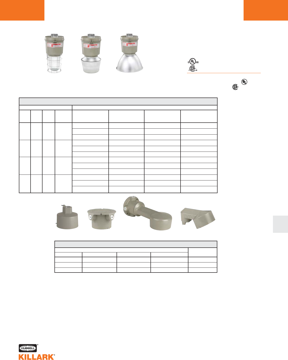
CERTILITE®V SERIES •LIGHTING
HIGH PRESSURE SODIUM, 200-600W MOGUL BASE HID L63
L
Class I, Div. 2, Groups A,B,C,D1
Class l, Zone 2, Groups IIC, llB, llA
Class II, Div. 1 & 2, Groups E,F,G
Class III
Suitable for wet locations
NEMA 3, 4, 4X; IP66
NR Restricted Breathing Option5
Class I, Zone 2 AEx nAnR
Class I, Zone 2 Ex nR
Listed - File E10514 (Hazardous & Marine)
Certified - File LR11713
EZ Adapter
w/ Globe &
Guard
EZ Adapter
w/ Spin-Top
Refractor
EZ Adapter
w/ Enclosed
Reflector
VM 200-600 WATT HIGH PRESSURE SODIUM EZ ADAPTER
WATTS
200
250
400
600
DESCRIPTION
ANSI
S66
S50
S51
S106
HUB
SIZE 3
3
3
3
3
VOLTAGE 4
Quad
Tri
480
Quad
Tri
480
Quad
Tri
480
Quad
Tri
480
7-3/4" OPTIC THREAD SIZE2
GLOBE
& GUARD
VM5S200EZGLG
VM5S206EZGLG
VM5S205EZGLG
VM5S250EZGLG
VM5S256EZGLG
VM5S255EZGLG
VM5S400EZGLG
VM5S406EZGLG
VM5S405EZGLG
—
—
—
TYPE V
SPIN-TOP GLASS
REFRACTOR
VM5S200EZS5N
VM5S206EZS5N
VM5S205EZS5N
VM5S250EZS5N
VM5S256EZS5N
VM5S255EZS5N
VM5S400EZS5N
VM5S406EZS5N
VM5S405EZS5N
—
—
—
ENCLOSED
REFLECTOR
VM5S200EZERN
VM5S206EZERN
VM5S205EZERN
VM5S250EZERN
VM5S256EZERN
VM5S255EZERN
VM5S400EZERN
VM5S406EZERN
VM5S405EZERN
VM5S600EZERN
VM5S606EZERN
VM5S605EZERN
POLYCARBONATE
SHIELDED
ENCLOSED REFLECTOR6
VM5S200EZEPN
VM5S206EZEPN
VM5S205EZEPN
VM5S250EZEPN
VM5S256EZEPN
VM5S255EZEPN
VM5S400EZEPN
VM5S406EZEPN
VM5S405EZEPN
—
—
—
1See hazardous application data on pages L84-L89 for limitations.
2Globe catalog number shown with guard. To omit guard, change G to N; e.g. VM5S200EZGLN. Order spin top and enclosed
reflector guards separately.
3VMEZA tank adapters UL “classified” as an assembly for use between VM tanks and EZ mounts. See above for separate ordering
information
4Consult catalog logic for other available voltages.
5Add suffix NR for restricted breathing; see page L39 for more information.
6VMEP40 not for use with EZ wall bracket.
HUB SIZE
3/4"
1"
1-1/4"/1-1/2"*
CATALOG NUMBER
PENDANT CEILING BRACKET STANCHION
EZA2 EZX2 EZB2 —
EZA3 EZX3 EZB3 —
— — — EZD4A*
MOUNTING BOXES
Wall Bracket 25° Stanchion
Pendant Ceiling
*1-1/2" furnished with 1-1/2"-1-1/4" reducer and extension.
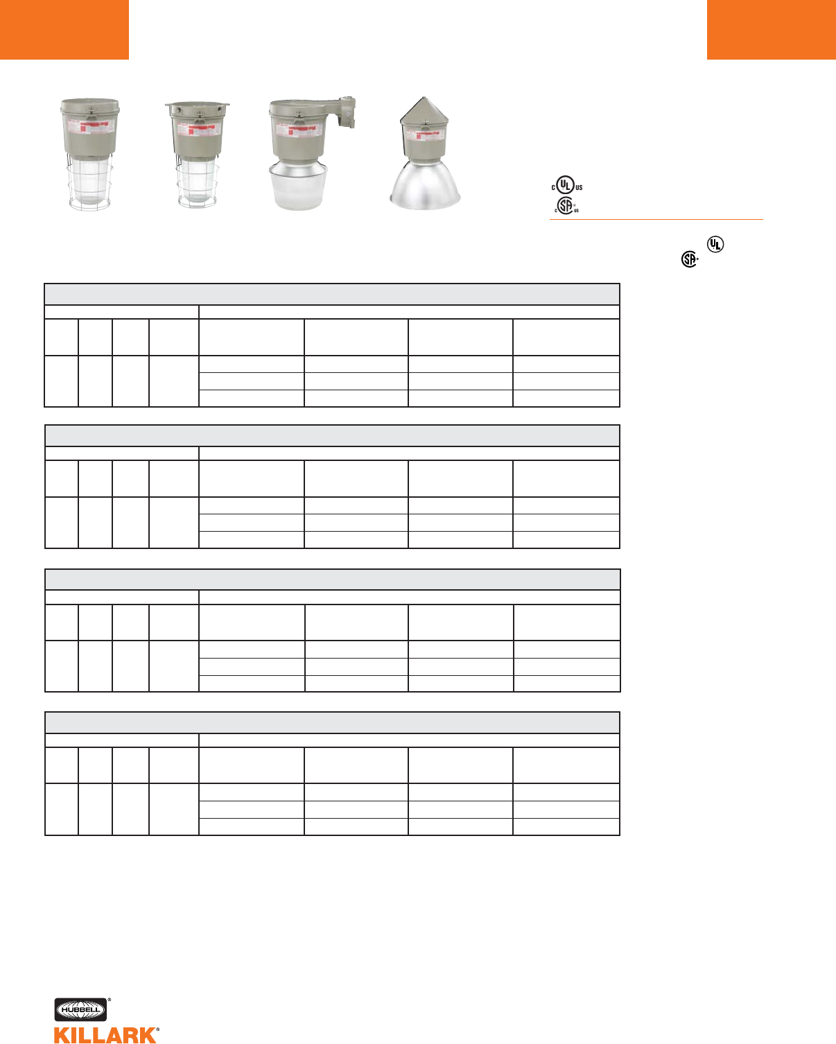
CERTILITE®V SERIES •LIGHTING
METAL HALIDE, 400W MOGUL BASE HID
L64
Class I, Div. 2, Groups A,B,C,D1
Class l, Zone 2, Groups IIC, llB, llA
Class II, Div. 1 & 2, Groups E,F,G
Class III
Suitable for wet locations
NEMA 3, 4, 4X; IP66
NR Restricted Breathing Option5
Class I, Zone 2 AEx nAnR
Class I, Zone 2 Ex nR
Listed - File E10514 (Hazardous & Marine)
Certified - File LR11713
Pendant
w/ Globe &
Guard
Ceiling
w/ Globe &
Guard
Wall
w/ Spin-Top
Refractor
VM 400 WATT METAL HALIDE PENDANT
WATTS
400
DESCRIPTION
ANSI
M59
HUB
SIZE 3
3/4”
VOLTAGE 4
Quad
Tri
480
7-3/4" OPTIC THREAD SIZE2
GLOBE
& GUARD
VM5H400A2GLG
VM5H406A2GLG
VM5H405A2GLG
TYPE V
SPIN-TOP GLASS
REFRACTOR
VM5H400A2S5N
VM5H406A2S5N
VM5H405A2S5N
ENCLOSED
REFLECTOR
VM5H400A2ERN
VM5H406A2ERN
VM5H405A2ERN
POLYCARBONATE
SHIELDED
ENCLOSED REFLECTOR
VM5H400A2EPN
VM5H406A2EPN
VM5H405A2EPN
1See hazardous application data on pages L84-L89 for limitations.
2Globe catalog number shown with guard. To omit guard, change G to N; e.g. VM5H400A2GLN. Order spin top and enclosed
reflector guards separately.
3Catalog numbers shown are with 3/4” conduit openings, change 2 to 3 for 1”; e.g. VM5H400A3GLG.
4Consult catalog logic for other available voltages.
5Add suffix NR for restricted breathing; see page L39 for more information.
Cone
w/ Enclosed
Reflector
VM 400 WATT METAL HALIDE CEILING
WATTS
400
DESCRIPTION
ANSI
M59
HUB
SIZE 3
3/4”
VOLTAGE 4
Quad
Tri
480
7-3/4" OPTIC THREAD SIZE2
GLOBE
& GUARD
VM5H400X2GLG
VM5H406X2GLG
VM5H405X2GLG
TYPE V
SPIN-TOP GLASS
REFRACTOR
VM5H400X2S5N
VM5H406X2S5N
VM5H405X2S5N
ENCLOSED
REFLECTOR
VM5H400X2ERN
VM5H406X2ERN
VM5H405X2ERN
POLYCARBONATE
SHIELDED
ENCLOSED REFLECTOR
VM5H400X2EPN
VM5H406X2EPN
VM5H405X2EPN
VM 400 WATT METAL HALIDE WALL
WATTS
400
DESCRIPTION
ANSI
M59
HUB
SIZE 3
3/4”
VOLTAGE4
Quad
Tri
480
7-3/4" OPTIC THREAD SIZE2
GLOBE
& GUARD
VM5H400B2GLG
VM5H406B2GLG
VM5H405B2GLG
TYPE V
SPIN-TOP GLASS
REFRACTOR
VM5H400B2S5N
VM5H406B2S5N
VM5H405B2S5N
ENCLOSED
REFLECTOR
VM5H400B2ERN
VM5H406B2ERN
VM5H405B2ERN
POLYCARBONATE
SHIELDED
ENCLOSED REFLECTOR
—
—
—
VM 400 WATT METAL HALIDE CONE
WATTS
400
DESCRIPTION
ANSI
M59
HUB
SIZE 3
3/4”
VOLTAGE 4
Quad
Tri
480
7-3/4" OPTIC THREAD SIZE2
GLOBE
& GUARD
VM5H400C2GLG
VM5H406C2GLG
VM5H405C2GLG
TYPE V
SPIN-TOP GLASS
REFRACTOR
VM5H400C2S5N
VM5H406C2S5N
VM5H405C2S5N
ENCLOSED
REFLECTOR
VM5H400C2ERN
VM5H406C2ERN
VM5H405C2ERN
POLYCARBONATE
SHIELDED
ENCLOSED REFLECTOR
VM5H400C2EPN
VM5H406C2EPN
VM5H405C2EPN
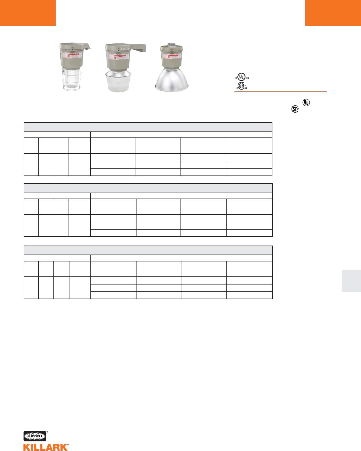
CERTILITE®V SERIES •LIGHTING
METAL HALIDE, 400W MOGUL BASE HID L65
L
Class I, Div. 2, Groups A,B,C,D1
Class l, Zone 2, Groups IIC, llB, llA
Class II, Div. 1 & 2, Groups E,F,G
Class III
Suitable for wet locations
NEMA 3, 4, 4X; IP66
NR Restricted Breathing Option5
Class I, Zone 2 AEx nAnR
Class I, Zone 2 Ex nR
Listed - File E10514 (Hazardous & Marine)
Certified - File LR11713
Stanchion 25°
w/ Globe &
Guard
Stanchion 90°
w/ Spin-Top
Refractor
VM 400 WATT METAL HALIDE STANCHION 25° ANGLE
WATTS
400
DESCRIPTION
ANSI
M59
HUB
SIZE 3
1-1/2”
VOLTAGE 4
Quad
Tri
480
7-3/4" OPTIC THREAD SIZE2
GLOBE
& GUARD
VM5H400D5GLG
VM5H406D5GLG
VM5H405D5GLG
TYPE V
SPIN-TOP GLASS
REFRACTOR
VM5H400D5S5N
VM5H406D5S5N
VM5H405D5S5N
ENCLOSED
REFLECTOR
VM5H400D5ERN
VM5H406D5ERN
VM5H405D5ERN
POLYCARBONATE
SHIELDED
ENCLOSED REFLECTOR
—
—
—
1See hazardous application data on pages L84-L89 for limitations.
2Globe catalog number shown with guard. To omit guard, change G to N; e.g. VM5H400D5GLN. Order spin top and enclosed
reflector guards separately.
3Catalog numbers shown with 1-1/2” conduit openings; change 5 to 4 for 1-1/4”; e.g. VM5H400D4GLG.
4Consult catalog logic for other available voltages.
5Add suffix NR for restricted breathing; see page L39 for more information.
6VMEZA tank adapters UL “classified” as an assembly for use between VM tanks and EZ mounts. Order EZ mounts separately.
See page L69.
7VMEP40 not for use with EZ wall bracket.
EZ Adapter
w/ Enclosed
Reflector
VM 400 WATT METAL HALIDE STANCHION STRAIGHT
WATTS
400
DESCRIPTION
ANSI
M59
HUB
SIZE 3
1-1/2”
VOLTAGE 4
Quad
Tri
480
7-3/4" OPTIC THREAD SIZE2
GLOBE
& GUARD
VM5H400S5GLG
VM5H406S5GLG
VM5H405S5GLG
TYPE V
SPIN-TOP GLASS
REFRACTOR
VM5H400S5S5N
VM5H406S5S5N
VM5H405S5S5N
ENCLOSED
REFLECTOR
VM5H400S5ERN
VM5H406S5ERN
VM5H405S5ERN
POLYCARBONATE
SHIELDED
ENCLOSED REFLECTOR
—
—
—
VM 400 WATT METAL HALIDE EZ ADAPTER
WATTS
400
DESCRIPTION
ANSI
M59
HUB
SIZE 6
6
VOLTAGE 4
Quad
Tri
480
7-3/4" OPTIC THREAD SIZE2
GLOBE
& GUARD
VM5H400EZGLG
VM5H406EZGLG
VM5H405EZGLG
TYPE V
SPIN-TOP GLASS
REFRACTOR
VM5H400EZS5N
VM5H406EZS5N
VM5H405EZS5N
ENCLOSED
REFLECTOR
VM5H400EZERN
VM5H406EZERN
VM5H405EZERN
POLYCARBONATE
SHIELDED
ENCLOSED REFLECTOR7
VM5H400EZEPN
VM5H406EZEPN
VM5H405EZEPN
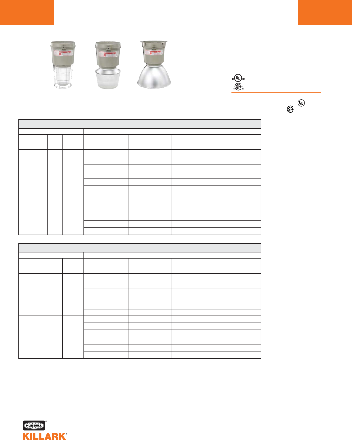
L66 CERTILITE®V SERIES •LIGHTING
METAL HALIDE, 400W MOGUL BASE HID
Class I, Div. 2, Groups A,B,C,D1
Class l, Zone 2, Groups IIC, llB, llA
Class II, Div. 1 & 2, Groups E,F,G
Class III
Suitable for wet locations
NEMA 3, 4, 4X; IP66
NR Restricted Breathing Option5
Class I, Zone 2 AEx nAnR
Class I, Zone 2 Ex nR
Listed - File E10514 (Hazardous & Marine)
Certified - File LR11713
VM 250-400 WATT METAL HALIDE PULSE PENDANT
WATTS
250
320
350
400
DESCRIPTION
ANSI
M138
M153
M132
M154
M131
M135
M155
HUB
SIZE 3
3/4”
3/4”
3/4”
3/4”
VOLTAGE 4
Quad
Tri
480
Quad
Tri
480
Quad
Tri
480
Quad
Tri
480
7-3/4" OPTIC THREAD SIZE2
GLOBE
& GUARD
VM5P250A2GLG
VM5P256A2GLG
VM5P255A2GLG
VM5P320A2GLG
VM5P326A2GLG
VM5P325A2GLG
VM5P350A2GLG
VM5P356A2GLG
VM5P355A2GLG
VM5P400A2GLG
VM5P406A2GLG
VM5P405A2GLG
TYPE V
SPIN-TOP GLASS
REFRACTOR
VM5P250A2S5N
VM5P256A2S5N
VM5P255A2S5N
VM5P320A2S5N
VM5P326A2S5N
VM5P325A2S5N
VM5P350A2S5N
VM5P356A2S5N
VM5P355A2S5N
VM5P400A2S5N
VM5P406A2S5N
VM5P405A2S5N
ENCLOSED
REFLECTOR
VM5P250A2ERN
VM5P256A2ERN
VM5P255A2ERN
VM5P320A2ERN
VM5P326A2ERN
VM5P325A2ERN
VM5P350A2ERN
VM5P356A2ERN
VM5P355A2ERN
VM5P400A2ERN
VM5P406A2ERN
VM5P405A2ERN
POLYCARBONATE
SHIELDED
ENCLOSED REFLECTOR
VM5P250A2EPN
VM5P256A2EPN
VM5P255A2EPN
VM5P320A2EPN
VM5P326A2EPN
VM5P325A2EPN
VM5P350A2EPN
VM5P356A2EPN
VM5P355A2EPN
VM5P400A2EPN
VM5P406A2EPN
VM5P405A2EPN
VM 250-400 WATT METAL HALIDE PULSE CEILING
WATTS
250
320
350
400
DESCRIPTION
ANSI
M138
M153
M132
M154
M131
M135
M155
HUB
SIZE 3
3/4”
3/4”
3/4”
3/4”
VOLTAGE 4
Quad
Tri
480
Quad
Tri
480
Quad
Tri
480
Quad
Tri
480
7-3/4" OPTIC THREAD SIZE2
GLOBE
& GUARD
VM5P250X2GLG
VM5P256X2GLG
VM5P255X2GLG
VM5P320X2GLG
VM5P326X2GLG
VM5P325X2GLG
VM5P350X2GLG
VM5P356X2GLG
VM5P355X2GLG
VM5P400X2GLG
VM5P406X2GLG
VM5P405X2GLG
TYPE V
SPIN-TOP GLASS
REFRACTOR
VM5P250X2S5N
VM5P256X2S5N
VM5P255X2S5N
VM5P320X2S5N
VM5P326X2S5N
VM5P325X2S5N
VM5P350X2S5N
VM5P356X2S5N
VM5P355X2S5N
VM5P400X2S5N
VM5P406X2S5N
VM5P405X2S5N
ENCLOSED
REFLECTOR
VM5P250X2ERN
VM5P256X2ERN
VM5P255X2ERN
VM5P320X2ERN
VM5P326X2ERN
VM5P325X2ERN
VM5P350X2ERN
VM5P356X2ERN
VM5P355X2ERN
VM5P400X2ERN
VM5P406X2ERN
VM5P405X2ERN
POLYCARBONATE
SHIELDED
ENCLOSED REFLECTOR
VM5P250X2EPN
VM5P256X2EPN
VM5P255X2EPN
VM5P320X2EPN
VM5P326X2EPN
VM5P325X2EPN
VM5P350X2EPN
VM5P356X2EPN
VM5P355X2EPN
VM5P400X2EPN
VM5P406X2EPN
VM5P405X2EPN
1See hazardous application data on pages L84-L89 for limitations.
2Globe catalog number shown with guard. To omit guard, change G to N; e.g. VM5P250A2GLN. Order spin top and enclosed reflec-
tor guards separately.
3Catalog numbers shown are with 3/4” conduit openings, change 2 to 3 for 1”; e.g. VM5P250A3GLG.
4Consult catalog logic for other available voltages.
5Add suffix NR for restricted breathing; see page L39 for more information.
Pendant
w/ Globe &
Guard
Pendant
w/ Spin-Top
Refractor
Ceiling
w/ Enclosed
Reflector
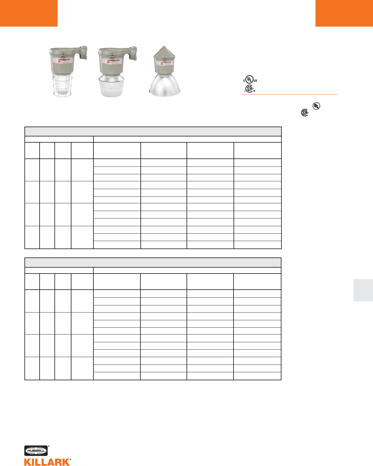
L67
CERTILITE®V SERIES •LIGHTING
METAL HALIDE, 400W MOGUL BASE HID
Class I, Div. 2, Groups A,B,C,D1
Class l, Zone 2, Groups IIC, llB, llA
Class II, Div. 1 & 2, Groups E,F,G
Class III
Suitable for wet locations
NEMA 3, 4, 4X; IP66
NR Restricted Breathing Option5
Class I, Zone 2 AEx nAnR
Class I, Zone 2 Ex nR
Listed - File E10514 (Hazardous & Marine)
Certified - File LR11713
VM 250-400 WATT METAL HALIDE PULSE WALL
WATTS
250
320
350
400
DESCRIPTION
ANSI
M138
M153
M132
M154
M131
M135
M155
HUB
SIZE 3
3/4”
3/4”
3/4”
3/4”
VOLTAGE 4
Quad
Tri
480
Quad
Tri
480
Quad
Tri
480
Quad
Tri
480
7-3/4" OPTIC THREAD SIZE2
GLOBE
& GUARD
VM5P250B2GLG
VM5P256B2GLG
VM5P255B2GLG
VM5P320B2GLG
VM5P326B2GLG
VM5P325B2GLG
VM5P350B2GLG
VM5P356B2GLG
VM5P355B2GLG
VM5P400B2GLG
VM5P406B2GLG
VM5P405B2GLG
TYPE V
SPIN-TOP GLASS
REFRACTOR
VM5P250B2S5N
VM5P256B2S5N
VM5P255B2S5N
VM5P320B2S5N
VM5P326B2S5N
VM5P325B2S5N
VM5P350B2S5N
VM5P356B2S5N
VM5P355B2S5N
VM5P400B2S5N
VM5P406B2S5N
VM5P405B2S5N
ENCLOSED
REFLECTOR
VM5P250B2ERN
VM5P256B2ERN
VM5P255B2ERN
VM5P320B2ERN
VM5P326B2ERN
VM5P325B2ERN
VM5P350B2ERN
VM5P356B2ERN
VM5P355B2ERN
VM5P400B2ERN
VM5P406B2ERN
VM5P405B2ERN
POLYCARBONATE
SHIELDED
ENCLOSED REFLECTOR
—
—
—
—
—
—
—
—
—
—
—
—
VM 250-400 WATT METAL HALIDE PULSE CONE
WATTS
250
320
350
400
DESCRIPTION
ANSI
M138
M153
M132
M154
M131
M135
M155
HUB
SIZE 3
3/4”
3/4”
3/4”
3/4”
VOLTAGE 4
Quad
Tri
480
Quad
Tri
480
Quad
Tri
480
Quad
Tri
480
7-3/4" OPTIC THREAD SIZE2
GLOBE
& GUARD
VM5P250C2GLG
VM5P256C2GLG
VM5P255C2GLG
VM5P320C2GLG
VM5P326C2GLG
VM5P325C2GLG
VM5P350C2GLG
VM5P356C2GLG
VM5P355C2GLG
VM5P400C2GLG
VM5P406C2GLG
VM5P405C2GLG
TYPE V
SPIN-TOP GLASS
REFRACTOR
VM5P250C2S5N
VM5P256C2S5N
VM5P255C2S5N
VM5P320C2S5N
VM5P326C2S5N
VM5P325C2S5N
VM5P350C2S5N
VM5P356C2S5N
VM5P355C2S5N
VM5P400C2S5N
VM5P406C2S5N
VM5P405C2S5N
ENCLOSED
REFLECTOR
VM5P250C2ERN
VM5P256C2ERN
VM5P255C2ERN
VM5P320C2ERN
VM5P326C2ERN
VM5P325C2ERN
VM5P350C2ERN
VM5P356C2ERN
VM5P355C2ERN
VM5P400C2ERN
VM5P406C2ERN
VM5P405C2ERN
POLYCARBONATE
SHIELDED
ENCLOSED REFLECTOR
VM5P250C2EPN
VM5P256C2EPN
VM5P255C2EPN
VM5P320C2EPN
VM5P326C2EPN
VM5P325C2EPN
VM5P350C2EPN
VM5P356C2EPN
VM5P355C2EPN
VM5P400C2EPN
VM5P406C2EPN
VM5P405C2EPN
1See hazardous application data on pages L84-L89 for limitations.
2Globe catalog number shown with guard. To omit guard, change G to N; e.g. VM5P250B2GLN. Order spin top and enclosed
reflector guards separately.
3Catalog numbers shown are with 3/4” conduit openings, change 2 to 3 for 1”; e.g. VM5P250B3GLG.
4Consult catalog logic for other available voltages.
4Add suffix NR for restricted breathing; see page L39 for more information.
Wall
w/ Globe &
Guard
Wall
w/ Spin-Top
Refractor
Cone
w/ Enclosed
Reflector

CERTILITE®V SERIES •LIGHTING
METAL HALIDE PULSE, 250-400W MOGUL BASE HID
L68
VM 250-400 WATT METAL HALIDE PULSE STANCHION 25° ANGLE
WATTS
250
320
350
400
DESCRIPTION
ANSI
M138
M153
M132
M154
M131
M135
M155
HUB
SIZE 3
1-1/2"
1-1/2"
1-1/2"
1-1/2"
VOLTAGE 4
Quad
Tri
480
Quad
Tri
480
Quad
Tri
480
Quad
Tri
480
7-3/4" OPTIC THREAD SIZE2
GLOBE
& GUARD
VM5P250D5GLG
VM5P256D5GLG
VM5P255D5GLG
VM5P320D5GLG
VM5P326D5GLG
VM5P325D5GLG
VM5P350D5GLG
VM5P356D5GLG
VM5P355D5GLG
VM5P400D5GLG
VM5P406D5GLG
VM5P405D5GLG
TYPE V
SPIN-TOP GLASS
REFRACTOR
VM5P250D5S5N
VM5P256D5S5N
VM5P255D5S5N
VM5P320D5S5N
VM5P326D5S5N
VM5P325D5S5N
VM5P350D5S5N
VM5P356D5S5N
VM5P355D5S5N
VM5P400D5S5N
VM5P406D5S5N
VM5P405D5S5N
ENCLOSED
REFLECTOR
VM5P250D5ERN
VM5P256D5ERN
VM5P255D5ERN
VM5P320D5ERN
VM5P326D5ERN
VM5P325D5ERN
VM5P350D5ERN
VM5P356D5ERN
VM5P355D5ERN
VM5P400D5ERN
VM5P406D5ERN
VM5P405D5ERN
VM 250-400 WATT METAL HALIDE PULSE STANCHION STRAIGHT
WATTS
250
320
350
400
DESCRIPTION
ANSI
M138
M153
M132
M154
M131
M135
M155
HUB
SIZE 3
1-1/2"
1-1/2"
1-1/2"
1-1/2"
VOLTAGE 4
Quad
Tri
480
Quad
Tri
480
Quad
Tri
480
Quad
Tri
480
7-3/4" OPTIC THREAD SIZE2
GLOBE
& GUARD
VM5P250S5GLG
VM5P256S5GLG
VM5P255S5GLG
VM5P320S5GLG
VM5P326S5GLG
VM5P325S5GLG
VM5P350S5GLG
VM5P356S5GLG
VM5P355S5GLG
VM5P400S5GLG
VM5P406S5GLG
VM5P405S5GLG
TYPE V
SPIN-TOP GLASS
REFRACTOR
VM5P250S5S5N
VM5P256S5S5N
VM5P255S5S5N
VM5P320S5S5N
VM5P326S5S5N
VM5P325S5S5N
VM5P350S5S5N
VM5P356S5S5N
VM5P355S5S5N
VM5P400S5S5N
VM5P406S5S5N
VM5P405S5S5N
ENCLOSED
REFLECTOR
VM5P250S5ERN
VM5P256S5ERN
VM5P255S5ERN
VM5P320S5ERN
VM5P326S5ERN
VM5P325S5ERN
VM5P350S5ERN
VM5P356S5ERN
VM5P355S5ERN
VM5P400S5ERN
VM5P406S5ERN
VM5P405S5ERN
1See hazardous application data on pages L84-L89 for limitations.
2Globe catalog number shown with guard. To omit guard, change G to N; e.g. VM5P250D5GLN. Order spin
top and enclosed reflector guards separately.
3Catalog numbers shown with 1-1/2" conduit openings; change 5 to 4 for 1-1/4"; e.g. VM5P250D4GLG.
4Consult catalog logic for other available voltages.
5Add suffix NR for restricted breathing; see page L39 for more information.
Stanchion 25°
w/ Globe &
Guard
Stanchion 25°
w/ Spin-Top
Refractor
Stanchion Straight
w/ Enclosed
Reflector
Class I, Div. 2, Groups A,B,C,D1
Class l, Zone 2, Groups IIC, llB, llA
Class II, Div. 1 & 2, Groups E,F,G
Class III
Suitable for wet locations
NEMA 3, 4, 4X; IP66
NR Restricted Breathing Option5
Class I, Zone 2 AEx nAnR
Class I, Zone 2 Ex nR
Listed - File E10514 (Hazardous & Marine)
Certified - File LR11713
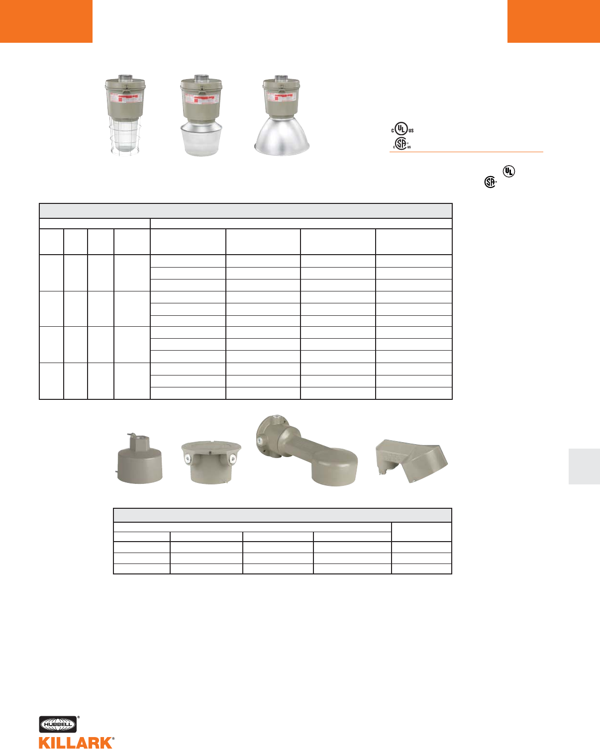
CERTILITE®V SERIES •LIGHTING
METAL HALIDE PULSE, 250-400W MOGUL BASE HID L69
L
Class I, Div. 2, Groups A,B,C,D1
Class l, Zone 2, Groups IIC, llB, llA
Class II, Div. 1 & 2, Groups E,F,G
Class III
Suitable for wet locations
NEMA 3, 4, 4X; IP66
NR Restricted Breathing Option5
Class I, Zone 2 AEx nAnR
Class I, Zone 2 Ex nR
Listed - File E10514 (Hazardous & Marine)
Certified - File LR11713
VM 250-400 WATT METAL HALIDE PULSE EZ ADAPTER
WATTS
250
320
350
400
DESCRIPTION
ANSI
M138
M153
M132
M154
M131
M135
M155
HUB
SIZE 3
3
3
3
3
VOLTAGE 4
Quad
Tri
480
Quad
Tri
480
Quad
Tri
480
Quad
Tri
480
7-3/4" OPTIC THREAD SIZE2
GLOBE
& GUARD
VM5P250EZGLG
VM5P256EZGLG
VM5P255EZGLG
VM5P320EZGLG
VM5P326EZGLG
VM5P325EZGLG
VM5P350EZGLG
VM5P356EZGLG
VM5P355EZGLG
VM5P400EZGLG
VM5P406EZGLG
VM5P405EZGLG
TYPE V
SPIN-TOP GLASS
REFRACTOR
VM5P250EZS5N
VM5P256EZS5N
VM5P255EZS5N
VM5P320EZS5N
VM5P326EZS5N
VM5P325EZS5N
VM5P350EZS5N
VM5P356EZS5N
VM5P355EZS5N
VM5P400EZS5N
VM5P406EZS5N
VM5P405EZS5N
ENCLOSED
REFLECTOR
VM5P250EZERN
VM5P256EZERN
VM5P255EZERN
VM5P320EZERN
VM5P326EZERN
VM5P325EZERN
VM5P350EZERN
VM5P356EZERN
VM5P355EZERN
VM5P400EZERN
VM5P406EZERN
VM5P405EZERN
POLYCARBONATE
SHIELDED
ENCLOSED REFLECTOR6
VM5P250EZEPN
VM5P256EZEPN
VM5P255EZEPN
VM5P320EZEPN
VM5P326EZEPN
VM5P325EZEPN
VM5P350EZEPN
VM5P356EZEPN
VM5P355EZEPN
VM5P400EZEPN
VM5P406EZEPN
VM5P405EZEPN
1See hazardous application data on pages L84-L89 for limitations.
2Globe catalog number shown with guard. To omit guard, change G to N; e.g. VM5P250EZGLN. Order spin top and enclosed
reflector guards separately.
3VMEZA tank adapters UL “classified” as an assembly for use between VM tanks and EZ mounts. See above for separate
ordering information.
4Consult catalog logic for other available voltages.
5Add suffix NR for restricted breathing; see page L39 for more information.
6VMEP40 not for use with EZ wall bracket.
HUB SIZE
3/4"
1"
1-1/4"/1-1/2"*
CATALOG NUMBER
PENDANT CEILING BRACKET STANCHION
EZA2 EZX2 EZB2 —
EZA3 EZX3 EZB3 —
—— — EZD4A*
MOUNTING BOXES
Wall Bracket 25° Stanchion
Pendant Ceiling
*1-1/2" furnished with 1-1/2"-1-1/4" reducer and extension.
EZ Adapter
w/ Globe &
Guard
EZ Adapter
w/ Spin-Top
Refractor
EZ Adapter
w/ Enclosed
Reflector
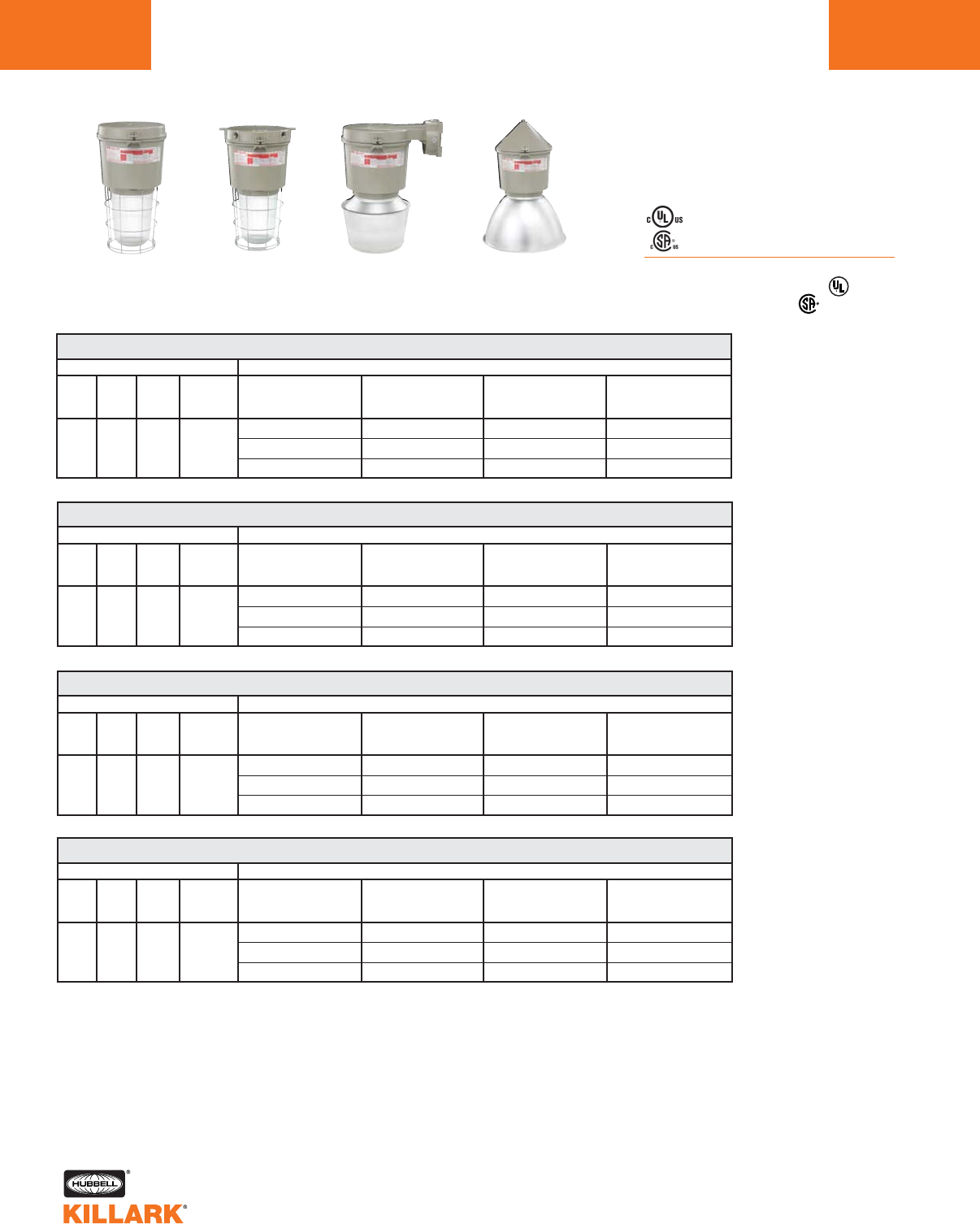
L70 CERTILITE®V SERIES •LIGHTING
METAL HALIDE, 400W MOGUL BASE HID
Class I, Div. 2, Groups A,B,C,D1
Class l, Zone 2, Groups IIC, llB, llA
Class II, Div. 1 & 2, Groups E,F,G
Class III
Suitable for wet locations
NEMA 3, 4, 4X; IP66
NR Restricted Breathing Option5
Class I, Zone 2 AEx nAnR
Class I, Zone 2 Ex nR
Listed - File E10514 (Hazardous & Marine)
Certified - File LR11713
VM 400 WATT MERCURY VAPOR PENDANT
WATTS
400
DESCRIPTION
ANSI
H33
HUB
SIZE 3
3/4”
VOLTAGE 4
Quad
Tri
480
7-3/4" OPTIC THREAD SIZE2
GLOBE
& GUARD
VM5M400A2GLG
VM5M406A2GLG
VM5M405A2GLG
TYPE V
SPIN-TOP GLASS
REFRACTOR
VM5M400A2S5N
VM5M406A2S5N
VM5M405A2S5N
ENCLOSED
REFLECTOR
VM5M400A2ERN
VM5M406A2ERN
VM5M405A2ERN
POLYCARBONATE
SHIELDED
ENCLOSED REFLECTOR
VM5M400A2EPN
VM5M406A2EPN
VM5M405A2EPN
VM 400 WATT MERCURY VAPOR CEILING
WATTS
400
DESCRIPTION
ANSI
H33
HUB
SIZE 3
3/4”
VOLTAGE 4
Quad
Tri
480
7-3/4" OPTIC THREAD SIZE2
GLOBE
& GUARD
VM5M400X2GLG
VM5M406X2GLG
VM5M405X2GLG
TYPE V
SPIN-TOP GLASS
REFRACTOR
VM5M400X2S5N
VM5M406X2S5N
VM5M405X2S5N
ENCLOSED
REFLECTOR
VM5M400X2ERN
VM5M406X2ERN
VM5M405X2ERN
POLYCARBONATE
SHIELDED
ENCLOSED REFLECTOR
VM5M400X2EPN
VM5M406X2EPN
VM5M405X2EPN
VM 400 WATT MERCURY VAPOR WALL
WATTS
400
DESCRIPTION
ANSI
H33
HUB
SIZE 3
3/4”
VOLTAGE 4
Quad
Tri
480
7-3/4" OPTIC THREAD SIZE2
GLOBE
& GUARD
VM5M400B2GLG
VM5M406B2GLG
VM5M405B2GLG
TYPE V
SPIN-TOP GLASS
REFRACTOR
VM5M400B2S5N
VM5M406B2S5N
VM5M405B2S5N
ENCLOSED
REFLECTOR
VM5M400B2ERN
VM5M406B2ERN
VM5M405B2ERN
POLYCARBONATE
SHIELDED
ENCLOSED REFLECTOR
—
—
—
VM 400 WATT MERCURY VAPOR CONE
WATTS
400
DESCRIPTION
ANSI
H33
HUB
SIZE 3
3/4”
VOLTAGE 4
Quad
Tri
480
7-3/4" OPTIC THREAD SIZE2
GLOBE
& GUARD
VM5M400C2GLG
VM5M406C2GLG
VM5M405C2GLG
TYPE V
SPIN-TOP GLASS
REFRACTOR
VM5M400C2S5N
VM5M406C2S5N
VM5M405C2S5N
ENCLOSED
REFLECTOR
VM5M400C2ERN
VM5M406C2ERN
VM5M405C2ERN
POLYCARBONATE
SHIELDED
ENCLOSED REFLECTOR
VM5M400C2EPN
VM5M406C2EPN
VM5M405C2EPN
1See hazardous application data on pages L84-L89 for limitations.
2Globe catalog number shown with guard. To omit guard, change G to N; e.g. VM5M400A2GLN. Order spin top and enclosed
reflector guards separately.
3Catalog numbers shown are with 3/4” conduit openings, change 2 to 3 for 1”; e.g. VM5M400A3GLG.
4Consult catalog logic for other available voltages.
5Add suffix NR for restricted breathing; see page L39 for more information.
Pendant
w/ Globe &
Guard
Ceiling
w/ Globe &
Guard
Wall
w/ Spin-Top
Refractor
Cone
w/ Enclosed
Reflector
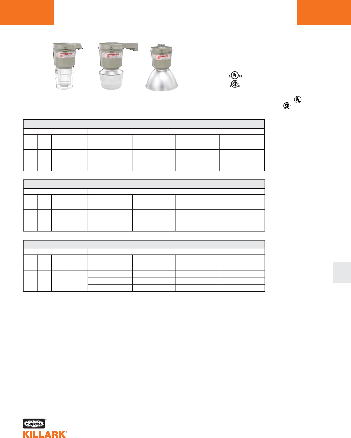
L71
CERTILITE®V SERIES •LIGHTING
METAL HALIDE, 400W MOGUL BASE HID
Class I, Div. 2, Groups A,B,C,D1
Class l, Zone 2, Groups IIC, llB, llA
Class II, Div. 1 & 2, Groups E,F,G
Class III
Suitable for wet locations
NEMA 3, 4, 4X; IP66
NR Restricted Breathing Option5
Class I, Zone 2 AEx nAnR
Class I, Zone 2 Ex nR
Listed - File E10514 (Hazardous & Marine)
Certified - File LR11713
VM 400 WATT MERCURY VAPOR STANCHION 25° ANGLE
WATTS
400
DESCRIPTION
ANSI
H33
HUB
SIZE 3
1-1/2”
VOLTAGE 4
Quad
Tri
480
7-3/4" OPTIC THREAD SIZE2
GLOBE
& GUARD
VM5M400D5GLG
VM5M406D5GLG
VM5M405D5GLG
TYPE V
SPIN-TOP GLASS
REFRACTOR
VM5M400D5S5N
VM5M406D5S5N
VM5M405D5S5N
ENCLOSED
REFLECTOR
VM5M400D5ERN
VM5M406D5ERN
VM5M405D5ERN
POLYCARBONATE
SHIELDED
ENCLOSED REFLECTOR
—
—
—
VM 400 WATT MERCURY VAPOR STANCHION STRAIGHT
WATTS
400
DESCRIPTION
ANSI
H33
HUB
SIZE 3
1-1/2”
VOLTAGE 4
Quad
Tri
480
7-3/4" OPTIC THREAD SIZE2
GLOBE
& GUARD
VM5M400S5GLG
VM5M406S5GLG
VM5M405S5GLG
TYPE V
SPIN-TOP GLASS
REFRACTOR
VM5M400S5S5N
VM5M406S5S5N
VM5M405S5S5N
ENCLOSED
REFLECTOR
VM5M400S5ERN
VM5M406S5ERN
VM5M405S5ERN
POLYCARBONATE
SHIELDED
ENCLOSED REFLECTOR
—
—
—
VM 400 WATT MERCURY VAPOR EZ ADAPTER
WATTS
400
DESCRIPTION
ANSI
H33
HUB
SIZE 6
6
VOLTAGE 4
Quad
Tri
480
7-3/4" OPTIC THREAD SIZE2
GLOBE
& GUARD
VM5M400EZGLG
VM5M406EZGLG
VM5M405EZGLG
TYPE V
SPIN-TOP GLASS
REFRACTOR
VM5M400EZS5N
VM5M406EZS5N
VM5M405EZS5N
ENCLOSED
REFLECTOR
VM5M400EZERN
VM5M406EZERN
VM5M405EZERN
POLYCARBONATE
SHIELDED
ENCLOSED REFLECTOR7
VM5M400EZEPN
VM5M406EZEPN
VM5M405EZEPN
1See hazardous application data on pages L84-L89 for limitations.
2Globe catalog number shown with guard. To omit guard, change G to N; e.g. VM5M400D5GLN. Order spin top and enclosed reflec-
tor guards separately.
3Catalog numbers shown are with 1-1/2” conduit openings, change 5 to 4 for 1-1/4”; e.g. VM5M400D4GLG.
4Consult catalog logic for other available voltages.
5Add suffix NR for restricted breathing; see page L39 for more information.
6VMEZA tank adapters UL “classified” as an assembly for use between VM tanks and EZ mounts. Order EZ mounts separately.
See page L63.
7VMEP40 not for use with EZ wall bracket.
Stanchion 25°
w/ Globe &
Guard
Stanchion 90°
w/ Spin-Top
Refractor
EZ Adapter
w/ Enclosed
Reflector
L
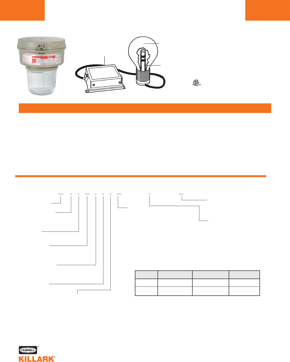
CERTILITE®V SERIES •LIGHTING
QL INDUCTION, 85-165W
CERTILITE®V LUMINAIRE WITH INDUCTION LIGHTING SYSTEM
L72
CertiLite®VCatalog Number Logic; 85-165W QL Induction Fixtures
Series Constant
Optic Thread Size
4—7 3/4" Medium Tank 85W
5—7 3/4" Large Tank 165W
Lamp Type
Q—QL Induction
Voltage @ 60 Hertz
1—120V (85W)
32—200-277V ( 85W, 165W)
Mounting Type
A—Pendant
X—Ceiling
B—Wall Bracket
C—Cone Top
D—Stanchion 25°
S—Stanchion 90°
E—EZ Mount Adapter4
N—None (mount ordered
separately)5
Lamp Wattage
08—85W (VM4)
16—165W (VM5)9
Guard
G—Guard (Globes & Glass
refractors)
N—No Guard3
Options
P1—Photocell 120V
P2—Photocell 208-277V
Optic
GL—Globe9
R1—Type I Glass Refractor
R3—Type III Glass Refractor
R5—Type V Glass Refractor
S2—Type II 12" Spin-Top Refractor
S5—Type V 12" Spin-Top Refractor
ER—Enclosed Reflector
EP—Poylcarbonate Shielded
Enclosed Reflector6
Entry (Mounts available)
2—3/4" NPT (A,B,C,X)
3—1" NPT (A,B,C,X)
4—1 1/4" NPT (D,S)
5—1 1/2" NPT (D,S)
6—3/4" NPT 5-Hub (X)
7—1" NPT 5-Hub (X)
8—M20 4-Hub (X)
9—M20 5-Hub (X)
Z—EZ Mount Adapter4
N—None (mount ordered
separately)5
VM 0 0 00 0 0 0 00 0 00
1See hazardous application data on pages L84-L89 for limitations.
2Must not exceed 40OC ambient.
3Order Guards for Spin-Tops & VMER40 separately.
4Completes as “EZ”, conduit mounts ordered separately - See L63.
5NN mount ordered separately.
6Not for use with wall or straight (90°) stanchion.
7At 100 hours; up to 75% of nominal value maintained at 60,000 hours.
8Lumens per watt.
9165W uses VMG25 in VM5 tank (or VMR25x all glass refractors).
Class I, Div. 2, Groups A,B,C,D1
Class l, Zone 2, Groups IIC, llB, llA
Class II, Div. 1 & 2, Groups E,F,G
Class III
Suitable for wet locations
NEMA 3, 4, 4x
APPLICATIONS
•Where long life lamp sources (up to 100,000 hours) 2are needed.
•In areas that require “instant on” illumination.
•Where cool globe temperatures are required.
•In dificult-to-reach installations.
•In cold environment applications.
Philips®is a registered trademark of Koninklijke Philips Electronics N.V.
FEATURES
•Almost maintenance-free Philips®QL Induction Lamp system.
•Includes lamp.
•Up to 100,000 hour life minimizes maintenance costs.
•Instant start and restart in low temperatures down to -40°C.
•White light with 80+ CRI (Color rendering Index).
•High lumen output & efficacy.
•Less than 10% THD (Total Hamonic Distortion) will not add elec-
trical noise to circuits.
A = Lamp
B = Power Coupler
C = HF generator
A
C
B
QL SIZE INITIAL LUMENS NOMINAL LUMENS7EFFICACY8
85 WATT 6500 6000 72
165 WATT 12200 12000 71
Listed - File LR11713
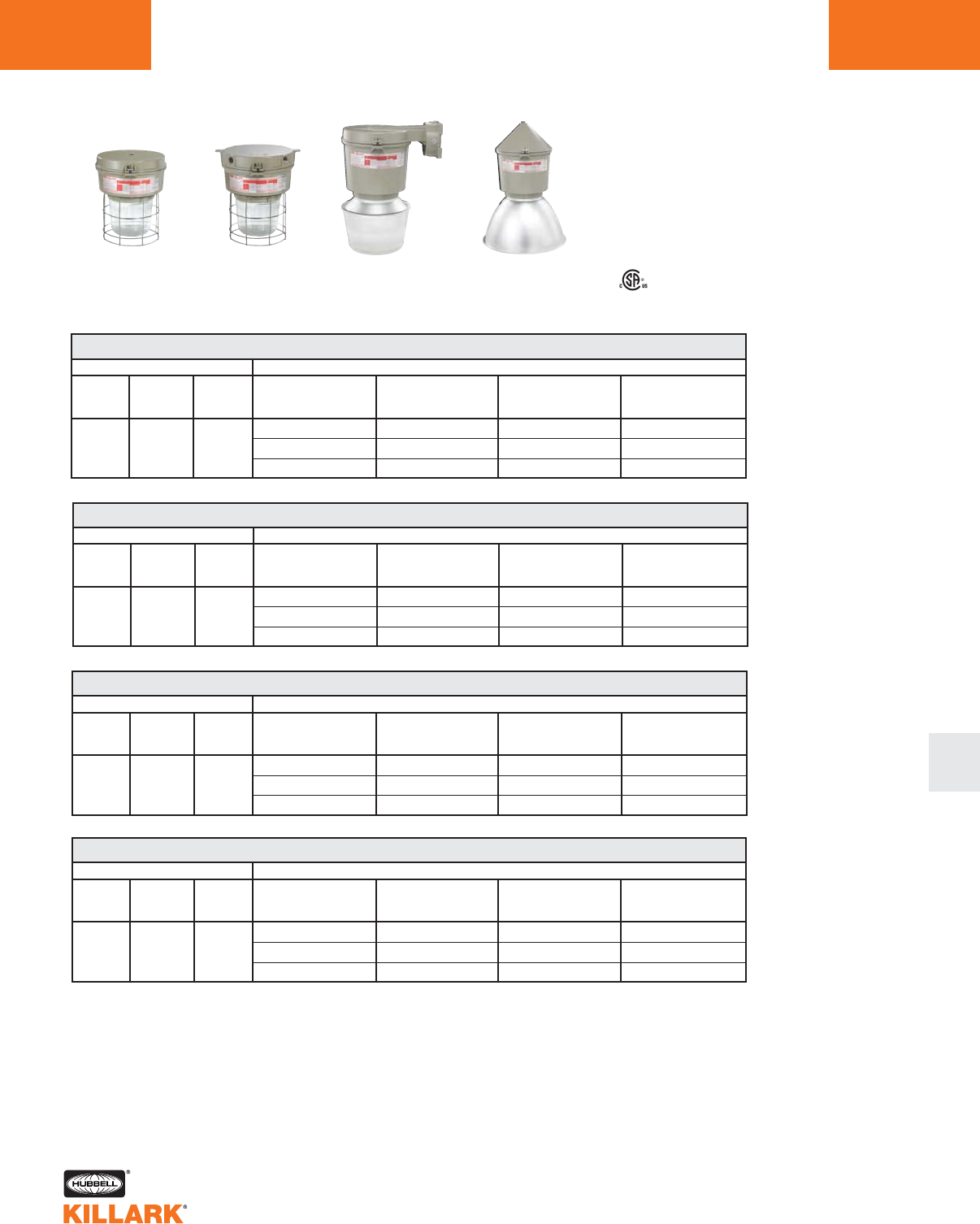
L
L
CERTILITE®V SERIES •LIGHTING
QL INDUCTION, 85-165W L73
VM 85-165W QL INDUCTION PENDANT
WATTS
85
85
165
DESCRIPTION
HUB
SIZE 3
3/4”
3/4”
3/4”
VOLTAGE 4
120
200-277
200-277
7-3/4" OPTIC THREAD SIZE2
TANK
STYLE
LOW WATTAGE (VM4)
LOW WATTAGE (VM4)
HIGH WATTAGE (VM5)
GLOBE
& GUARD
VM4Q081A2GLG
VM4Q0832A2GLG
VM5Q1632A2GLG
TYPE V
REFRACTOR
VM4Q081A2R5G
VM4Q0832A2R5G
VM5Q1632A2R5G
ENCLOSED
REFLECTOR
VM4Q081A2ERN
VM4Q0832A2ERN
VM5Q1632A2ERN
1See hazardous application data on pages L84-L89 for limitations.
2Globe catalog number shown with guard. To omit guard, change G to N; e.g. VM4Q081A2GLN. Order spin top and enclosed reflec-
tor guards separately.
3Catalog numbers shown are with 3/4” conduit openings, change 2 to 3 for 1”; e.g. VM4Q081A3GLG.
4Consult catalog logic for other available voltages.
VM 85-165W QL INDUCTION CEILING
WATTS
85
85
165
DESCRIPTION
HUB
SIZE 3
3/4”
3/4”
3/4”
VOLTAGE 4
120
200-277
200-277
7-3/4" OPTIC THREAD SIZE2
TANK
STYLE
LOW WATTAGE (VM4)
LOW WATTAGE (VM4)
HIGH WATTAGE (VM5)
GLOBE
& GUARD
VM4Q081X2GLG
VM4Q0832X2GLG
VM5Q1632X2GLG
TYPE V
REFRACTOR
VM4Q081X2R5G
VM4Q0832X2R5G
VM5Q1632X2R5G
ENCLOSED
REFLECTOR
VM4Q081X2ERN
VM4Q0832X2ERN
VM5Q1632X2ERN
VM 85-165W QL INDUCTION WALL
WATTS
85
85
165
DESCRIPTION
HUB
SIZE 3
3/4”
3/4”
3/4”
VOLTAGE 4
120
200-277
200-277
7-3/4" OPTIC THREAD SIZE2
TANK
STYLE
LOW WATTAGE (VM4)
LOW WATTAGE (VM4)
HIGH WATTAGE (VM5)
GLOBE
& GUARD
VM4Q081B2GLG
VM4Q0832B2GLG
VM5Q1632B2GLG
TYPE V
REFRACTOR
VM4Q081B2R5G
VM4Q0832B2R5G
VM5Q1632B2R5G
ENCLOSED
REFLECTOR
VM4Q081B2ERN
VM4Q0832B2ERN
VM5Q1632B2ERN
VM 85-165W QL INDUCTION CONE
WATTS
85
85
165
DESCRIPTION
HUB
SIZE 3
3/4”
3/4”
3/4”
VOLTAGE 4
120
200-277
200-277
7-3/4" OPTIC THREAD SIZE2
TANK
STYLE
LOW WATTAGE (VM4)
LOW WATTAGE (VM4)
HIGH WATTAGE (VM5)
GLOBE
& GUARD
VM4Q081C2GLG
VM4Q0832C2GLG
VM5Q1632C2GLG
TYPE V
REFRACTOR
VM4Q081C2R5G
VM4Q0832C2R5G
VM5Q1632C2R5G
ENCLOSED
REFLECTOR
VM4Q081C2ERN
VM4Q0832C2ERN
VM5Q1632C2ERN
Pendant
w/ Globe &
Guard
Ceiling
w/ Globe &
Guard
Wall
w/ Spin-Top
Refractor
Cone
w/ Enclosed
Reflector
Class I, Div. 2, Groups A,B,C,D1
Class l, Zone 2, Groups IIC, llB, llA
Class II, Div. 1 & 2, Groups E,F,G
Class III
Suitable for wet locations
NEMA 3, 4, 4x
Listed - File LR11713
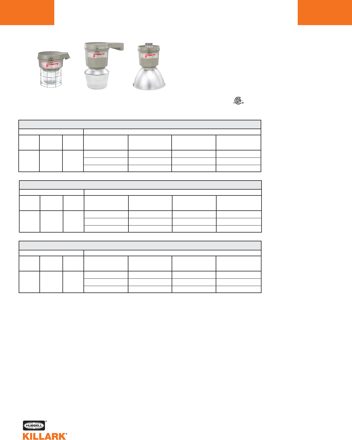
CERTILITE®V SERIES •LIGHTING
QL INDUCTION, 85-165W
L74
Class I, Div. 2, Groups A,B,C,D1
Class l, Zone 2, Groups IIC, llB, llA
Class II, Div. 1 & 2, Groups E,F,G
Class III
Suitable for wet locations
NEMA 3, 4, 4x
Listed - File LR11713
VM 85-165W QL INDUCTION STANCHION 25° ANGLE (INCLUDES LAMP)
WATTS
85
85
165
DESCRIPTION
HUB
SIZE 3
1-1/2”
1-1/2”
1-1/2”
VOLTAGE 4
120
200-277
200-277
7-3/4" OPTIC THREAD SIZE2
TANK
STYLE
LOW WATTAGE (VM4)
LOW WATTAGE (VM4)
HIGH WATTAGE (VM5)
GLOBE
& GUARD
VM4Q081D5GLG
VM4Q0832D5GLG
VM5Q1632D5GLG
TYPE V
REFRACTOR
VM4Q081D5R5G
VM4Q0832D5R5G
VM5Q1632D5R5G
ENCLOSED
REFLECTOR
VM4Q081D5ERN
VM4Q0832D5ERN
VM5Q1632D5ERN
1See hazardous application data on pages L84-L89 for limitations.
2Globe catalog number shown with guard. To omit guard, change G to N; e.g. VM4Q081D5GLN. Order spin top and enclosed reflec-
tor guards separately.
3Stanchion catalog numbers shown are with 1-1/2” conduit openings, change “5” to “4” for 1-1/4”; e.g. VM4Q081D4GLG.
4Consult catalog logic for other available voltages.
5VMEZA tank adapters are UL “classified” as an assembly for use between VM tanks and EZ mounts. Order EZ mounts separately.
See page L63.
VM 85-165W QL INDUCTION STANCHION STRAIGHT (INCLUDES LAMP)
WATTS
85
85
165
DESCRIPTION
HUB
SIZE 3
1-1/2”
1-1/2”
1-1/2”
VOLTAGE 4
120
200-277
200-277
7-3/4" OPTIC THREAD SIZE2
TANK
STYLE
LOW WATTAGE (VM4)
LOW WATTAGE (VM4)
HIGH WATTAGE (VM5)
GLOBE
& GUARD
VM4Q081S5GLG
VM4Q0832S5GLG
VM5Q1632S5GLG
TYPE V
REFRACTOR
VM4Q081S5R5G
VM4Q0832S5R5G
VM5Q1632S5R5G
ENCLOSED
REFLECTOR
VM4Q081S5ERN
VM4Q0832S5ERN
VM5Q1632S5ERN
VM 85-165W QL INDUCTION EZ ADAPTER (INCLUDES LAMP)
WATTS
85
85
165
DESCRIPTION
HUB
SIZE 5
5
5
5
VOLTAGE 4
120
200-277
200-277
7-3/4" OPTIC THREAD SIZE2
TANK
STYLE
LOW WATTAGE (VM4)
LOW WATTAGE (VM4)
HIGH WATTAGE (VM5)
GLOBE
& GUARD
VM4Q081EZGLG
VM4Q0832EZGLG
VM5Q1632EZGLG
TYPE V
REFRACTOR
VM4Q081EZR5G
VM4Q0832EZR5G
VM5Q1632EZR5G
ENCLOSED
REFLECTOR
VM4Q081EZERN
VM4Q0832EZERN
VM5Q1632EZERN
Stanchion 25°
w/ Globe &
Guard
Stanchion 90°
w/ Spin-Top
Refractor
EZ Adapter
w/ Enclosed
Reflector
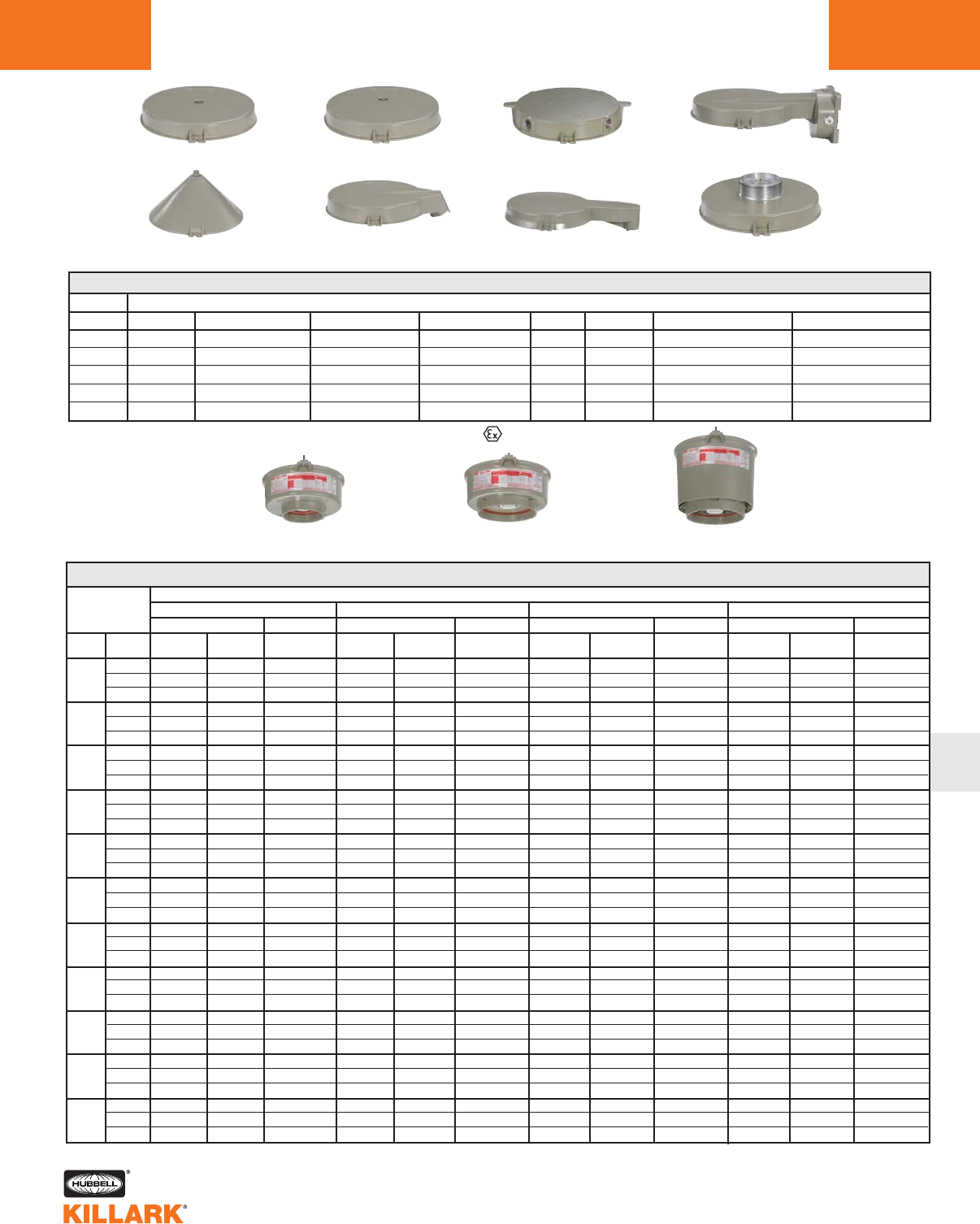
CERTILITE®VVM MOUNTING SPLICE BOXES
3/4”
1”
1-1/4”
1-1/2”
M-20
HUB SIZE
VMA2B
VMA3B
—
—
—
PENDANT
VMF2B
VMF3B
—
—
—
FLEXIBLE PENDANT
VMX2B
VMX3B
—
—
VMX8B**
CEILING 4 HUB
VMX6B
VMX7B
—
—
VMX9B
CEILING 5 HUB
VMB2B
VMB3B
—
—
—
WALL
VMC2B
VMC3B
—
—
—
CONE TOP
—
—
VMD4B
VMD5B
—
25 DEGREE STANCHION
—
—
VMS4B
VMS5B
—
90 DEGREE STANCHION
CATALOG NUMBER
Pendant Ceiling Wall
Flexible Pendant
25° StanchionCone Top Straight Stanchion EZ Adapter*
VMEZA
VM3 Low Wattage
5-1/2” Optic Thread Size
VM4 Low Wattage
7-3/4” Optic Thread Size
VM5 High Wattage
7-3/4” Optic Thread Size
*VMEZA is used between a
ballast tank and an EZ
mount-ordered separately.
See L63 for more info.
**VMX8B furnished with 3 non-metallic plugs.
CERTILITE®V SERIES •LIGHTING
ACCESSORIES/AUXILIARY LIGHTING L75
L
CERTILITE®VVM 50-600W BALLAST TANK ASSEMBLIES
WATTS
50
70
100
150
175
200
250
320
350
400
600
VOLTAGE
@ 60 Hz
Quad
Tri
480
Quad
Tri
480
Quad
Tri
480
Quad
Tri
480
Quad
Tri
480
Quad
Tri
480
Quad
Tri
480
Quad
Tri
480
Quad
Tri
480
Quad
Tri
480
Quad
Tri
480
CATALOG NUMBER
5-1/2"
VM3S050
VM3S056
VM3S055
VM3S070
VM3S076
VM3S075
VM3S100
VM3S106
VM3S105
VM3S150
VM3S156
VM3S155
—
—
—
—
—
—
—
—
—
—
—
—
—
—
—
—
—
—
—
—
—
LOW WATTAGE
7-3/4"
VM4S050
VM4S056
VM4S055
VM4S070
VM4S076
VM4S075
VM4S100
VM4S106
VM4S105
VM4S150
VM4S156
VM4S155
—
—
—
—
—
—
—
—
—
—
—
—
—
—
—
—
—
—
—
—
—
HPS
7-3/4"
—
—
—
—
—
—
—
—
—
—
—
—
—
—
—
VM5S200
VM5S206
VM5S205
VM5S250
VM5S256
VM5S255
—
—
—
—
—
—
VM5S400
VM5S406
VM5S405
VM5S600
VM5S606
VM5S605
HIGH WATTAGE
5-1/2"
—
—
—
VM3H070
VM3H076
VM3H075
VM3H100
VM3H106
VM3H105
—
—
—
VM3H170
VM3H176
VM3H175
—
—
—
VM3H250
VM3H256
VM3H255
—
—
—
—
—
—
—
—
—
—
—
—
LOW WATTAGE
7-3/4"
—
—
—
VM4H070
VM4H076
VM4H075
VM4H100
VM4H106
VM4H105
—
—
—
VM4H170
VM4H176
VM4H175
—
—
—
VM4H250
VM4H256
VM4H255
—
—
—
—
—
—
—
—
—
—
—
—
MH
7-3/4"
—
—
—
—
—
—
—
—
—
—
—
—
—
—
—
—
—
—
—
—
—
—
—
—
—
—
—
VM5H400
VM5H406
VM5H405
—
—
—
HIGH WATTAGE
5-1/2"
—
—
—
—
—
—
—
—
—
VM3P150
VM3P156
VM3P155
VM3P170
VM3P176
VM3P175
VM3P200
VM3P206
VM3P205
—
—
—
—
—
—
—
—
—
—
—
—
—
—
—
LOW WATTAGE
7-3/4"
—
—
—
—
—
—
—
—
—
VM4P150
VM4P156
VM4P155
VM4P170
VM4P176
VM4P175
VM4P200
VM4P206
VM4P205
—
—
—
—
—
—
—
—
—
—
—
—
—
—
—
MH PULSE
7-3/4"
—
—
—
—
—
—
—
—
—
—
—
—
—
—
—
—
—
—
VM5P250
VM5P256
VM5P255
VM5P320
VM5P326
VM5P325
VM5P350
VM5P356
VM5P355
VM5P400
VM5P406
VM5P405
—
—
—
HIGH WATTAGE
5-1/2"
—
—
—
—
—
—
VM3M100
VM3M106
VM3M105
—
—
—
VM3M170
VM3M176
VM3M175
—
—
—
VM3M250
VM3M256
VM3M255
—
—
—
—
—
—
—
—
—
—
—
—
7-3/4"
—
—
—
—
—
—
VM4M100
VM4M106
VM4M105
—
—
—
VM4M170
VM4M176
VM4M175
—
—
—
VM4M250
VM4M256
VM4M255
—
—
—
—
—
—
—
—
—
—
—
—
MV
HIGH WATTAGE
7-3/4"
—
—
—
—
—
—
—
—
—
—
—
—
—
—
—
—
—
—
—
—
—
—
—
—
—
—
—
VM5M400
VM5M406
VM5M405
—
—
—
LOW WATTAGE
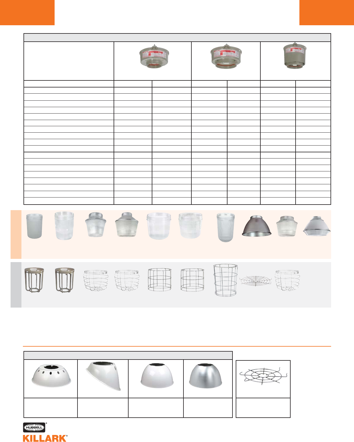
CERTILITE®V SERIES •LIGHTING
COMPONENT PARTS
L76
CERTILITE®VREFLECTORS
VMAG172VMRWG84
VMER40
VMG40
VMG25
VMAG25S3VMAG40S3
VMR255
VMR253
VMR251
VZRG1550 VZRG2550
VZRG2520
VZRP1756
VMEP40
CERTILITE®VOPTICS & GUARDS
DESCRIPTION
Globe (glass)
Refractor (all glass) Type V
Refractor (all glass) Type I
Refractor (all glass) Type III
Refractor (spin top glass) 8” Type V
Refractor (spin top glass) 12” Type V
Refractor (spin top glass) 12” Type II
Refractor (spin top plastic) 12” Type V
Enclosed Reflector (glass lens)
Enclosed Reflector (plastic lens)
Globe (Tuffskin®coated)5
Globe (Teflon®coated)5
Refractor (Teflon coated) Type V
Refractor (Teflon coated) Type I
Refractor (Teflon coated) Type III
Refractor (Spin Top Teflon coated) 8” Type V
Refractor (Spin Top Teflon coated) 12” Type V
Refractor (Spin Top Teflon coated) 12” Type II
OPTICS
VMG17
VMR175
VMR1717
—
VZRG1550
VZRG2550
VZRG2520
VZRP175
—
—
VMG17F
VMG17T
VMR175T
VMR171T
—
VZRG1550T
VZRG2550T
VZRG2520T
GUARD
VMAG17
VMAG17
VMAG17
—
VMRWG8
VMRWG
VMRWG
VMRWG
—
—
VMAG17
VMAG17
VMAG17
VMAG17
—
VMRWG8
VMRWG
VMRWG
OPTICS
VMG25
VMR255
VMR2517
VMR2537
—
VZRG40501
VZRG40201
—
VMER40
VMEP40
VMG25F
VMG25T
VMR255T
VMR251T
VMR253T
—
VZRG4050T1
VZRG4020T1
GUARD
VMAG25S
VMAG25S
VMAG25S
VMAG25S
—
VMRWG
VMRWG
—
VMERG
—
VMAG25S
VMAG25S
VMAG25S
VMAG25S
VMAG25S
—
VMRWG
VMRWG
OPTICS
VMG40
—
—
—
—
VZRG4050
VZRG4020
—
VMER40
VMEP40
VMG40F
VMG40T
—
—
—
—
VZRG4050T
VZRG4020T
GUARD
VMAG40S
—
—
—
—
VMRWG
VMRWG
—
VMERG
—
VMAG40S
VMAG40S
—
—
—
—
VMRWG
VMRWG
1For reference VM5 Spin Top optics fit VM4 tanks, but VM3 tanks and optics
are recommended for low wattage Spin Top applications. VM3 12” Spin Tops
ship with a mogul-to-mogul extender for improved photometrics.
2Standard material, copper-free aluminum painted.
3Standard material, 316 stainless steel.
4Standard material, plated steel.
5Tuffskin®is a registered trademark of Thomas Manufacturing, Co. Teflon®is a
registered trademark of DuPont, Inc. Alzak is a registered trademark of Alcoa.
6175W max; not hazloc listed
7Type I (III) all-glass refractors align with fixture hinge. Ceiling mount unit utiliz-
ing these optics must have offset conduit feed.
HRD400
VMPSD40 VMPA40 HRD400ALZ
Standard Dome
Fiberglass White Reflector
Dia: 16”
30OAngle
Fiberglass White
Reflector Dia: 16”
Deep Aluminum
White Reflector
Dia: 21”
Deep Aluminum
Alzak5finish Reflector
Dia: 21”
VMAG172
VMR175
VMR171
VMG17
VMRWG4VMAG25S3VMERG3
VZRG4050
VZRG4020
VMRWG4
O
P
T
I
C
S
G
U
A
R
D
S
VM5 High Wattage
7-3/4" Optic Thread Size
VM4 Low Wattage
7-3/4" Optic Thread Size
VM3 Low Wattage
5-1/2" Optic Thread Size
VMAGBC
Bottom Closure for
VMAG25S/VMAG40S
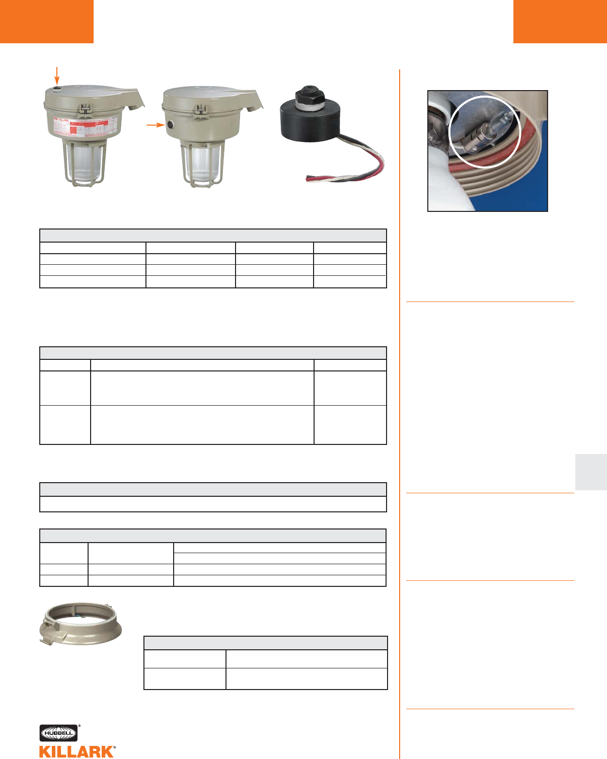
CERTILITE®V SERIES •LIGHTING
COMPONENT PARTS L77
L
PHOTO CONTROL FOR STANDARD AND HAZARDOUS CLASS I DIVISION 2 AREAS2
HUB2PC120
HUB2PC2273
HUB2PC347
CATALOG NUMBER
120VAC
208-277VAC3
347VAC
VOLTS
50/60Hz
50/60Hz
50/60Hz
FREQUENCY
400
400
440
WATTS
Photo Control
(Field Installed
in Splice cap)
Photo Control1
(Factory Installed
in ballast tank)
Photo Control
Component*
1Must be factory installed. Add P1 (for 120V), P2 (for 208-277V) or P3 (for 347V).
2Photo control cells for Class 1 Division 2 only.
3Marked 220-277V, suitable for 208V.
* Patent Pending
SUSPENSION DEVICES4
DESCRIPTION
“3rd hand” safety kits. 24” stainless cable holds globe using guard for lamp
change out. Attaches to tank’s built-in “Earthquake Tab”.
10’ Stainless Steel Safety Cable with loop grip. Drop limit 3’. Attaches to
“Earthquake Tab” (L41) and to building structure (e.g. I-beam).
CATALOG NUMBER
See catalog logic for factory installed fuses, or page L78-79 for field installation kits.
Auxiliary Lighting
Momentary voltage outages or dips can tem-
porarily extinguish HID lamps which may
require up to ten (10) minutes to restrike. To
provide illumination during this period, about
10% of the fixtures should be specified with
auxiliary lighting.
Quartz Auxiliary
Quartz auxiliary is available for all Certilite®V
Series fixtures (except those with plastic
refractors) by adding the suffix “QA” to the
fixture catalog number. Example:
VM3S050A2GLG-QA.
Low wattage fixtures with this option use 100
or 150 watt quartz lamps. High wattage fix-
tures can use up to 250 watt quartz lamps.
Quartz lamps are not supplied with the fixture.
Use quartz lamp type Q100 CL/DC (100W) or
Q150 CL/DC (150W) DC Bayonet T-4 Base.
Due to the quartz envelope surface tempera-
ture (exceeding 600°C), fixtures with this option
are not suitable for Class I, Division 2, Class l,
Zone 2, some Class l, Zone 2 Ex nR, Class II
and Class Ill hazardous locations. Contact the
factory for specific fixture suitabilities.
Instant Restrike
Available for low wattage High Pressure
Sodium Fixtures by adding Suffix “IR” to cata-
log number Example: VM3S050A2GLG-IR.
Additional instant restrike interior circuitry may
decrease High Pressure Sodium lamp life.
Feature will not affect fixture suitability in
hazardous location applications.
Ballast Protection Circuit
Optional factory installed special ballast pro-
tector replaces the standard HPS ignitor and
applies starting pulse to the lamp for 10 to 15
seconds each time voltage is supplied to the
ballast. If the lamp has not ignited by the end
of the time period, the starter will cease puls-
ing. Used to eliminate the continuous high
voltage pulsing of the ignitor when end of life,
lamp cycling, or missing lamp conditions
exist. Available for HPS fixtures. Add suffix
“BP” to fixture catalog number.
Notes: BP and IR cannot be used together.
QTZ and IR cannot beused together.
VMCHVM adapter for
upgrading existing
Crouse-Hinds®to Killark,
see page L199 for more
information.
TANK
VM GLOBE &
GUARD UNITS
VM
(ALL TANKS)
DARK SKY KITS
VMDARK1 Gasket Kit
VMDARK2 Spacer & Gasket Kit
VMER40 Enclosed Reflector
On VM4 “Full Cutoff” when used with HRD400 or HRD400ALZ
On VM5 “Cutoff” when used with HRD400 or HRD400ALZ
On VM5 “Full Cutoff” when used with HRD400 or HRD400ALZ
Enclosed Reflector “Full Cutoff” on VM4 OR VM5 as standard
4VM4, VM5 units require VMAGBC bottom closure, sold separately, in addition to guard.
FUSE KITS
VMAGSC4
VMSC10
Note: CertiLite®Vluminaires may be configured for “Full Cutoff”, or Semi-
Cutoff photometric distribution. See page L41 for pattern descriptions.
Local requirements dictate which parameter is required.
SOCKET REPLACEMENTS
0735015B
VMBNKIT
Mogul Socket VM3, VM4, VM5
Barrel nut and long bolt adapts older CertiLite
tanks to newer CertiLiteV®mounts.
Crouse-Hinds is a registered trademark of Cooper Crouse-Hinds, LLC,
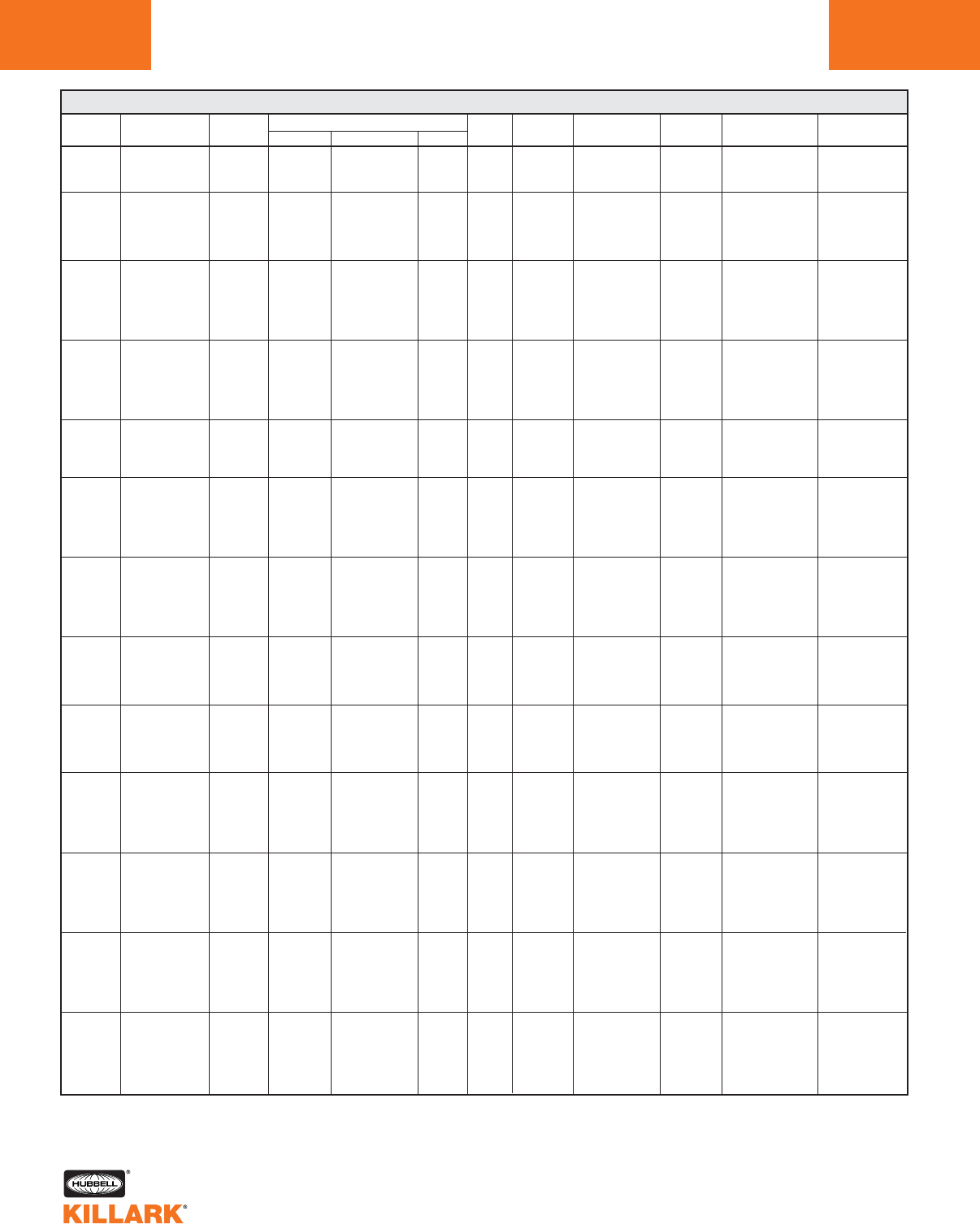
VM & EZ SERIES •LIGHTING
HID FIXTURES •BALLAST/FUSE KIT DATA
L78
LAMP LAMP CURRENT (AMPS) INPUT BALLAST MIN.
SOURCE WATTS/TYPE VOLTAGE START OPERATING OPEN WATTS CIRCUIT2REGULATION START
120 .58 .58 1.24
HPS 50 208 .35 .33 .59 62 HX/HPF ±5% VOLTAGE* -40C
S-68 240 .30 .29 .50 ±12% WATTAGE -40F
277 .24 .25 .44
120 .75 .81 1.45
208 .45 .47 .85
HPS 70 240 .35 .40 .75 93 HX/HPF ±5% VOLTAGE* -40C
S-62 277 .37 .35 .65 ±12% WATTAGE -40F
480 .21 .21 .36
347 .28 .30 0.52
120 1.30 1.15 2.20
208 .76 .67 1.27
240 .66 .58 1.10
HPS 100 277 .60 .50 .85 130 HX/HPF ±5% VOLTAGE* -40C
S-54 480 0.35 0.29 .55 ±12% WATTAGE -40F
347 .44 .39 .70
220-240/50 .56/.51 .67/.62 1.28/1.17
120 2.00 1.65 2.80
208 1.15 .95 1.60
150 240 1.00 .83 1.40
HPS (55 VOLT LAMP) 277 .85 .72 1.25 188 HX/HPF ±5% VOLTAGE* -40C
S-55 480 .50 .42 .70 ±12% WATTAGE -40F
347 .52 .59 .92
220-240/50 1.27/1.16 .91/.83 1.52/1.40
120 1.50 2.2 1.3
208 .90 1.28 .75
HPS 200 240 .75 1.11 .65
277 .65 .96 .60
240 CWA ±10% VOLTAGE* -40C
S-66
480 .35 .58 .58
±8% WATTAGE -40F
120 1.80 2.75 1.50
208 1.00 1.60 .87
240 .90 1.38 .75
HPS 250 277 .78 1.20 .65 295 CWA ±10% VOLTAGE* -40C
S-50 480 .38 .69 .37 ±5% WATTAGE -40F
347 .56 .93 .75
220-240/50 1.00/.90 .91/.83 .90/.80
120 2.82 4.30 1.83
208 1.56 2.48 1.15
240 1.36 2.15 .84 ±10% VOLTAGE*
HPS 400 277 1.18 1.86 .71 464 CWA ±5% WATTAGES-51 480 .60 1.00 .75
347 1.05 1.40 .75
220-240/50 1.65/1.50 2.30/2.10 1.20/1.10
120 5.25 5.50 3.0
208 3.00 3.25 1.75
240 2.60 2.85 1.80 ±10% VOLTAGE*
HPS 600 277 2.15 2.50 1.40 288 CWA ±10% WATTAGES-106 480 1.2 1.43 .75
347 1.7 2.00 1.10
120 .80 .85 1.70
208 .50 .50 1.04
MH 70 240 .43 .43 .87 90 HX-HPF ±5% VOLTAGE -30C
M-98 277 .39 .39 .78 ±12% WATTAGE -20F
480 0.19 0.23 .50
347 .30 .30 .60
120 1.20 1.15 2.3
208 .70 1.50 .60
100 240 .61 1.30 .55 ±5% VOLTAGE
MH M-90 277 .55 1.15 .45 129 HX-HPF ±12% WATTAGE
480 0.30 0.30 0.55
347 .40 .90 .40
220-240/50 .45/.41 .52/.51 .60/.85
120 .80 1.80 1.80
208 .42 1.04 1.04
240 .42 .90 .90
MH 175 277 .35 .78 .78 210 CWA ±10% VOLTAGE
M-57 480 .22 .45 .45 ±5% WATTAGE
347 .42 .62 .62
220-240/50 .60/.55 .98/.90 97/.89
120 1.25 2.60 2.50
208 .65 1.50 1.58
250
240 .60 1.30 1.25 ±10% VOLTAGE
MH M-58
277 .50 1.12 1.10 294 CWA
480 .25 .65 .65 ±5% WATTAGE
347 .90 .95 .65
220-240/50 .94/.86 1.35/1.24 1.20/1.10
120 1.10 4.00 3.80
208 .70 2.30 2.20
400
240 .52 2.00 1.90 ±10% VOLTAGE
MH M-59
277 .45 1.75 1.65 458 CWA
480 .38 1.00 1.00 ±5% WATTAGE
347 1.20 1.40 1.35
220-240/50 1.30/1.19 2.20/2.00 2.10/1.93
HID BALLAST DATA & FUSE KITS1
1Fuse kits, for field installation, must be used within guidelines of governing Electric Codes. Fuses not permitted by CSA C22.2 no. 37 for Canada.
2All ballasts circuits are High Power Factor 90%+.
* Lamp watts: within ANSI trapezoid limitations.
Consult major lamp & ballast manufacturer catalogs if more detailed data is needed.
VM FUSE KIT
1VM-5
2VM-3
2VM-3
1VM-2
1VM-5
2VM-3
2VM-2
1VM-2
2VM-2
1VM-2
1VM-7
2VM-5
2VM-3
1VM-3
2VM-3
1VM-3
1VM-4
1VM-10
2VM-5
2VM-5
1VM-4
2VM-2
1VM-3
1VM-5
1VM-6
2VM-4
2VM-3
1VM-3
2VM-2
1VM-7
2VM-4
2VM-4
1VM-3
2VM-2
1VM-2
1VM-4
1VM-10
2VM-8
2VM-5
1VM-5
2VM-3
1VM-5
1VM-6
1VM-20
2VM-15
2VM-10
1VM-10
2VM-4
1VM-5
1VM-4
2VM-3
2VM-2
1VM-2
2VM-1
1VM-2
1VM-6
2VM-4
2VM-3
1VM-3
2VM-2
1VM-2
1VM-4
1VM-5
2VM-3
2VM-3
1VM-2
2VM-2
1VM-2
1VM-3
1VM-8
2VM-5
2VM-5
1VM-3
2VM-2
1VM-3
1VM-4
1VM-10
2VM-7
2VM-5
1VM-5
2VM-4
1VM-4
1VM-6
EZ FUSE KIT
1FK-5
2FK-3
2FK-3
1FK-2
1FK-5
2FK-3
2FK-2
1FK-2
2FK-2
1FK-2
1FK-7
2FK-5
2FK-3
1FK-3
2FK-3
1FK-3
1FK-4
1FK-10
2FK-5
2FK-5
1FK-4
2FK-2
1FK-3
1FK-5
—
—
—
—
—
1FK-7
2FK-4
2FK-4
1FK-3
2FK-2
1FK-2
1FK-4
1FK-10
2FK-8
2FK-5
1FK-5
2FK-3
1FK-5
1FK-6
—
—
—
—
—
—
1FK-4
2FK-3
2FK-2
1FK-2
2FK-1
1FK-2
1FK-6
2FK-4
2FK-3
1FK-3
2FK-2
1FK-2
1FK-4
1FK-5
2FK-3
2FK-3
1FK-2
2FK-2
1FK-2
1FK-3
1FK-8
2FK-5
2FK-5
1FK-3
2FK-2
1FK-3
1FK-4
1FK-10
2FK-7
2FK-5
1FK-5
2FK-4
2FK-4
2FK-6
-40C
-40F
-30C
-20F
-30C
-20F
-30C
-20F
-30C
-20F
-30C
-20F
-40C
-40F
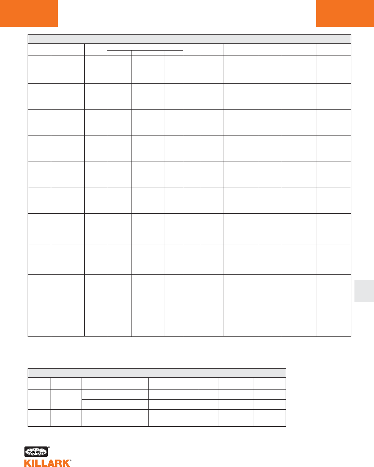
VM & EZ SERIES •LIGHTING
HID AND INDUCTION FIXTURES •BALLAST/FUSE KIT DATA L79
L
LAMP LAMP CURRENT (AMPS) INPUT BALLAST MIN.
SOURCE WATTS/TYPE VOLTAGE START OPERATING OPEN WATTS CIRCUIT2REGULATION START
120 1.75 1.60 3.65
208 1.30 1.00 2.10
MHP 150 240 0.85 0.80 1.80 185 HX-HPF ±5% VOLTAGE
M-102 277 0.77 0.70 1.58 ±12% WATTAGE
480 0.45 0.42 0.81
347 0.30 0.62 0.98
120 0.95 1.80 1.80
208 0.55 1.05 1.05
MHP 175 240 0.45 0.90 0.90 208 CWA ±10% VOLTAGE
M-137 277 0.40 0.80 0.80 ±10% WATTAGE
480 0.25 0.50 0.45
347 0.4 0.70 0.60
120 2.30 2.50 1.40
208 1.30 1.45 0.80
250 240 1.15 1.25 0.70 288 CWA ±10% VOLTAGE
MHP M-138 277 1.00 1.10 0.60 ±10% WATTAGE
480 0.21 0.57 0.48
347 0.45 0.95 0.75
120 1.80 3.25 2.30
208 1.05 1.90 1.35
320 240 0.30 1.65 1.15
MHP M-132 277 0.80 1.40 1.00 365 CWA
480 0.45 0.80 0.60
347 0.70 1.10 0.80
120 2.20 3.40 2.20
208 1.30 2.00 1.30
350 240 1.10 1.70 1.10
MHP M-131 277 1.00 1.50 1.00 400 CWA
480 0.60 0.85 0.60
347 0.85 1.20 0.80
120 2.85 3.80 2.20
208 1.65 2.20 1.50
400 240 1.45 1.90 1.10
MHP M-135 277 1.25 1.65 0.95 452 CWA
480 0.75 1.00 0.60
347 1.10 1.35 0.75
120 1.00 1.05 0.64
208 0.58 0.60 0.37
100 240 0.50 0.52 0.32
MV H-38 277 0.43 0.45 0.28 125 CWA
480 0.25 0.26 0.16
347 0.35 0.40 0.20
220-240/50 .56/.51 .59/.54 .25/.23
120 1.70 1.75 0.86
208 0.98 1.00 0.50
175 240 0.85 0.88 0.43
MV H-39 277 0.74 0.76 0.37 205 CWA
480 0.41 0.44 0.20
347 0.60 0.60 0.21
220-240/50 .83/.76 .97/.89 .62/.57
120 2.40 2.50 0.60
208 1.40 1.45 0.35
240 1.20 1.25 0.30
MV
250 277 1.00 1.10 0.29 285 CWA
H-37 480 0.60 0.62 0.20
347 0.80 0.85 0.50
220-240/50 1.40/1.28 1.40/1.28 .38/.35
120 2.90 3.90 1.30
208 1.67 2.20 0.75
400 240 1.45 1.95 0.65
MV H-33 277 1.25 1.70 0.56 454 CWA
480 0.95 0.98 0.24
347 1.00 1.30 0.45
220-240/50 1.75/1.61 2.20/2.00 .42/.39
HID BALLAST DATA & FUSE KIT1
VM FUSE KIT
1VM-10
2VM-5
2VM-5
1VM-4
2VM-3
1VM-3
1VM-5
2VM-3
2VM-3
1VM-2
2VM-2
1VM-2
1VM-8
2VM-5
2VM-5
1VM-3
2VM-2
1VM-3
1VM-8
2VM-6
2VM-5
1VM-3
2VM-5
1VM-3
1VM-10
2VM-7
2VM-5
1VM-5
2VM-3
1VM-3
1VM-10
2VM-7
2VM-5
1VM-5
2VM-3
1VM-4
1VM-3
2VM-2
2VM-2
1VM-2
2VM-1
1VM-1
1VM-2
1VM-5
2VM-3
2VM-3
1VM-2
2VM-2
1VM-2
1VM-3
1VM-8
2VM-5
2VM-5
1VM-3
2VM-2
1VM-3
1VM-4
1VM-10
2VM-7
2VM-5
1VM-5
2VM-4
1VM-4
1VM-6
EZ FUSE KIT
1FK-10
2FK-5
2FK-5
1FK-4
2FK-3
1FK-3
1FK-5
2FK-3
2FK-3
1FK-2
2FK-2
1FK-2
1FK-8
2FK-5
2FK-5
1FK-3
2FK-2
1FK-3
1FK-8
2FK-6
2FK-5
1FK-3
2FK-5
1FK-3
1FK-10
2FK-7
2FK-5
1FK-5
2FK-3
1FK-3
1FK-10
2FK-7
2FK-5
1FK-5
2FK-3
1FK-4
1FK-3
2FK-2
2FK-2
1FK-2
2FK-1
1FK-1
1FK-2
1FK-5
2FK-3
2FK-3
1FK-2
2FK-2
1FK-2
1FK-3
1FK-8
2FK-5
2FK-5
1FK-3
2FK-2
1FK-3
1FK-4
1FK-10
2FK-7
2FK-5
1FK-5
2FK-4
1FK-4
1FK-6
-30C
-20F
-30C
-20F
-30C
-20F
-30C
-20F
±10% VOLTAGE
±10% WATTAGE
±10% VOLTAGE
±10% WATTAGE
±10% VOLTAGE
±10% WATTAGE
-30C
-20F
-30C
-20F
±10% VOLTAGE
±5% WATTAGE
-30C
-20F
±10% VOLTAGE
±5% WATTAGE
-30C
-20F
±10% VOLTAGE
±5% WATTAGE
-30C
-20F
±10% VOLTAGE
±5% WATTAGE
1Fuse kits, for field installation, must be used within guidelines of governing Electric Codes. Fuses not permitted by CSA C22.2 no.137 for Canada.
2All ballasts circuits are High Power Factor 90%+.
* Lamp watts: within ANSI trapezoid limitations .
Consult major lamp & ballast manufacturer catalogs if more detailed data is needed.
-30C
-20F
LAMP LAMP VOLTAGE INRUSH CURRENT NOMINAL
SOURCE WATTS/TYPE .005 SEC OPERATING CURRENT THD REGULATION MIN. START
120 25A .71A <10% ±20V, ±2% W
Induction 85
240 45A .4A <10% ±20V, ±2% W
Induction 165 240-277 45A .58A <10% ±20V, ±2% W
QL INDUCTION BALLAST DATA
-40C
-40F
-40C
-40F
-40C
-40F
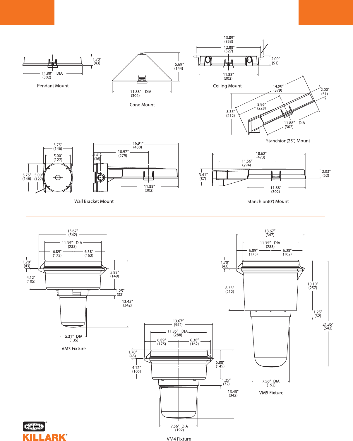
CERTILITE®V SERIES •MOUNTING BOX AND FIXTURE
DIMENSIONS
L80
hole dia.
.30”
(7.62)
hole dia.
.34”
(8.63)
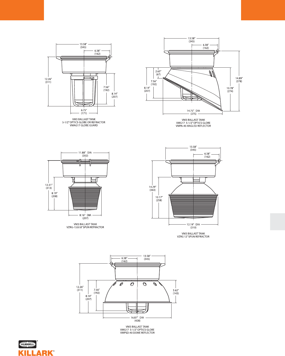
CERTILITE®V SERIES •FIXTURE
DIMENSIONS L81
L
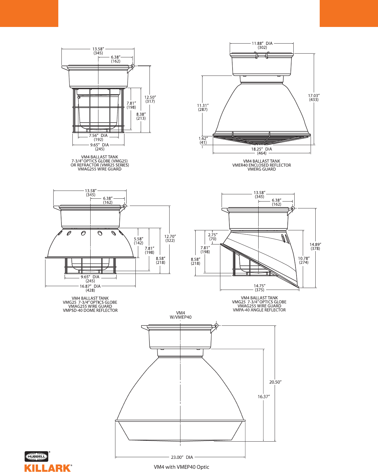
CERTILITE®V SERIES •FIXTURE
DIMENSIONS
L82
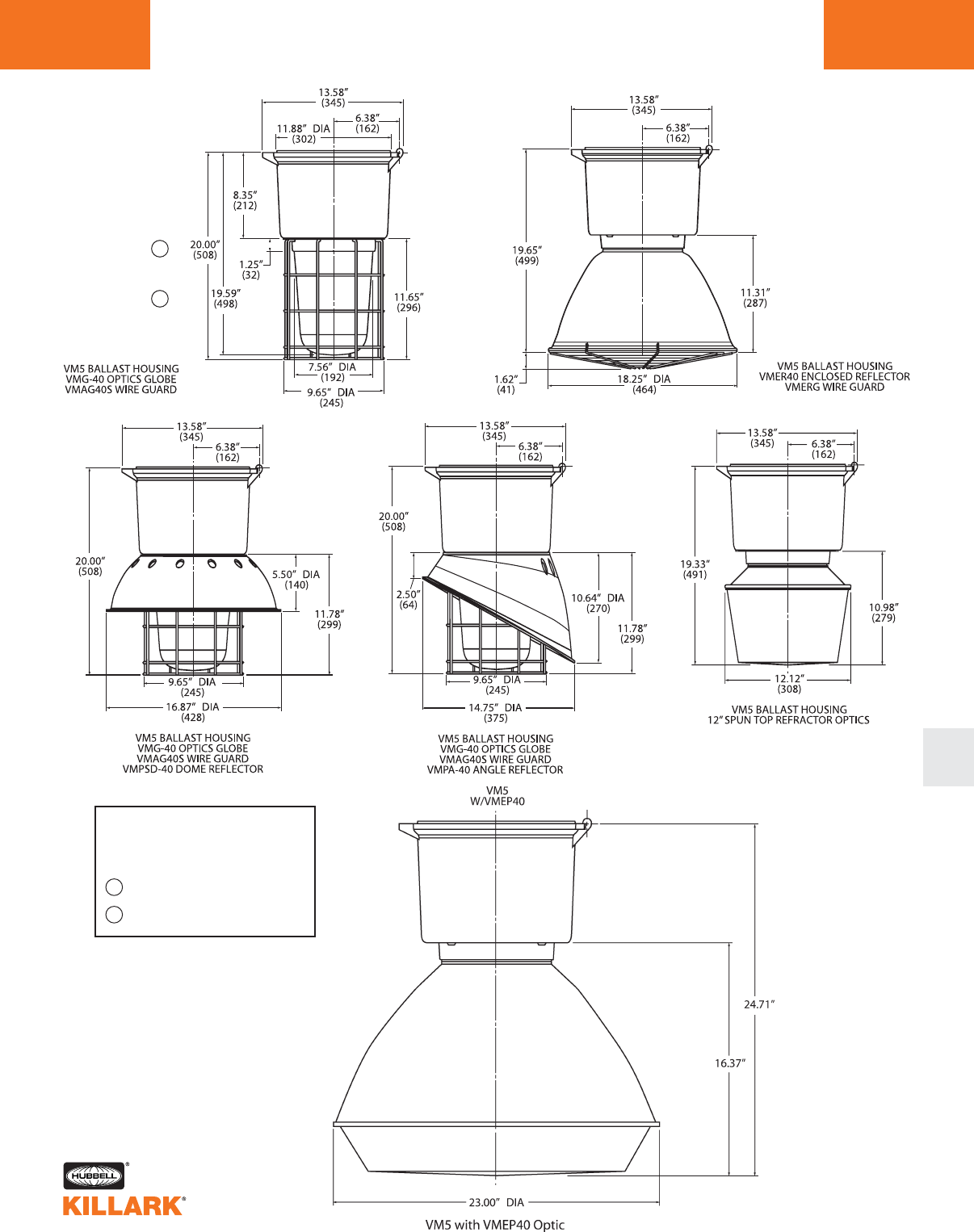
CERTILITE®V SERIES •FIXTURE
DIMENSIONS L83
L
A
B
A
B
QL 165W uses VM5 tank
and VMG25 series optics,
VMAG25S guard
16.59 (421)
16.11 (409)
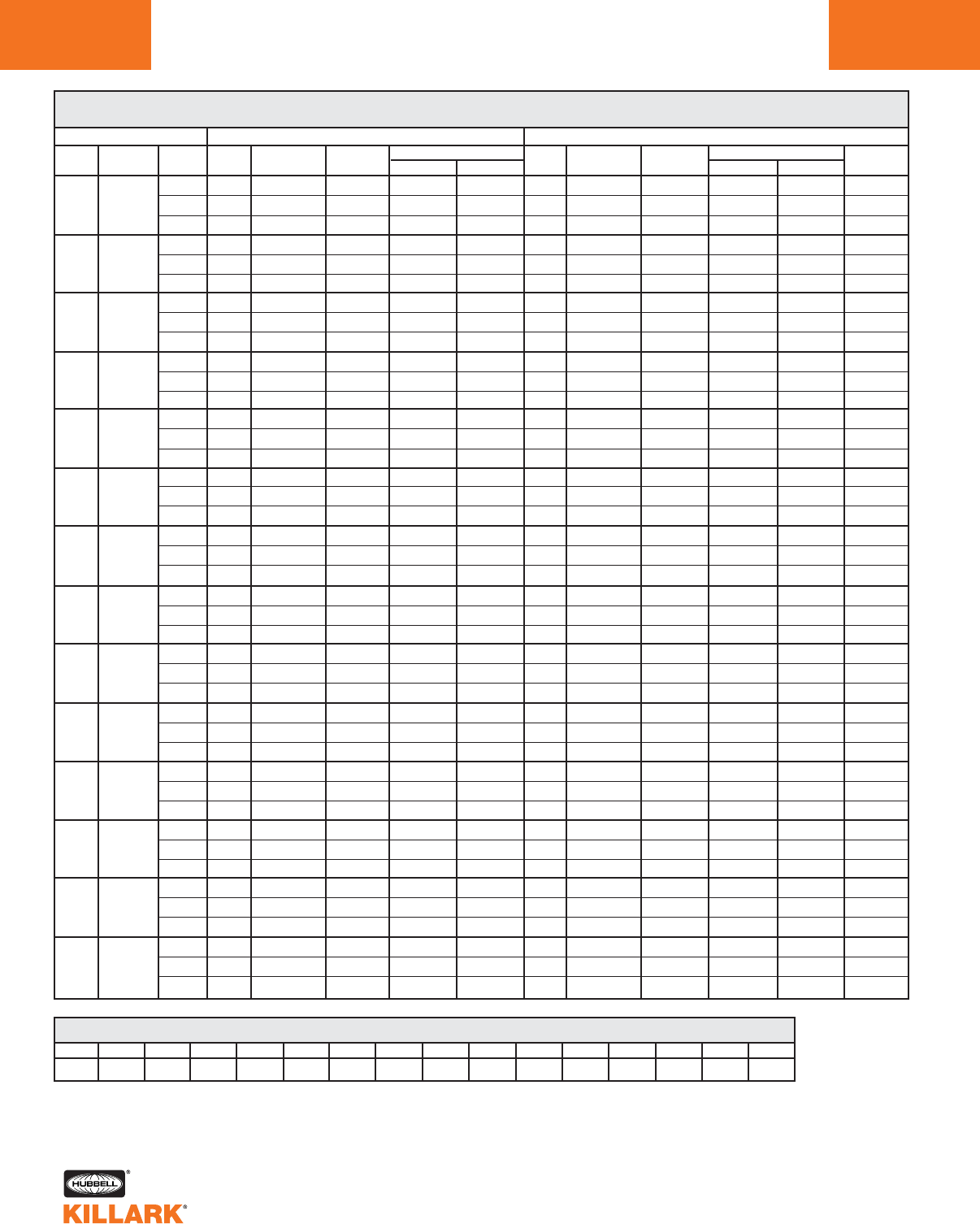
CERTILITE®V SERIES •LIGHTING
APPLICATION DATA FOR HAZARDOUS LOCATIONS
L84
VM3/VM4 SERIES THERMAL PERFORMANCE DATA1
CLASS I DIVISION 2 GROUPS A,B,C,D / ZONE 2 GROUPS IIC, IIB, IIA
LAMP
TYPE
HPS
HPS
HPS
HPS
MH
MH
MH
MH
MHP
MHP
MV
MV
MV
QL
DESCRIPTION
LAMP
WATTAGE
50
70
100
150
70
100
175
250
150/175
200
100
175
250
85
AMBIENT
°C
40
55
65
40
55
65
40
55
65
40
55
65
40
55
65
40
55
65
40
55
65
40
55
65
40
55
65
40
55
65
40
55
65
40
55
65
40
55
65
40
55
65
VM3 SERIES**
GLOBE
ONLY
T3B
T3A
T3
T3
T3
T3
T2D
T2C
T2C
T2B
T2B
—
T3B
T3A
T3
T3
T2D
T2D
T2A
T2
—
325°C
—
—
T2A
T3
—
T2A
T2
—
T2B
T2B
—
T2
T3
—
350°C
—
—
—
—
—
GLOBE
W/ REFLECTOR
T3B
T3A
T3
T3
T3
T3
T2D
T2C
T2C
T2B
T2B
—
T3A
T3
T3
T3
T2D
T2D
T2A
T2
—
325°C
—
—
T2A
T3
—
T2A
T2
—
T2B
T2A
—
T2
T3
—
350°C
—
—
—
—
—
VM4 SERIES**
VMR
T3B
T3A
T3
T3
T3
T3
T2D
T2C
T2C
T2B
T2B
—
T3B
T3A
T3
T3
T2D
T2D
T2A
T2
—
325°C
—
—
T2A
T3
—
T2A
T2
—
T2B
T2B
—
T2
T3
—
350°C
—
—
—
—
—
REFRACTORS
VZRG 8”
T3B
T3A
T3
T3
T3
T3
T2D
T2C
T2C
T2B
T2B
—
T3A
T3A
T3
T3
T2D
T2D
T2B
T2A
—
T2
—
—
T2B
T3
—
T2B
T2A
—
T2B
T2B
—
T2A
T3
—
350°C
—
—
—
—
—
VZRG 12”
T3B
T3A
T3
T3A
T3
T3
T3
T2C
T2C
T2B
T2B
—
T3C
T3A
T3
T3A
T2D
T2D
T2B
T2A
—
T2
—
—
T2B
T3
—
T2B
T2A
—
T2B
T2B
—
T2A
T3
—
350°C
—
—
—
—
—
GLOBE
ONLY
T3C
T3B
T3
T3A
T3
T3
T3
T2D
T2C
T2B
T2B
—
T3C
T3C
T3A
T3A
T3
T3
T2B
T2A
—
T2
—
—
T2B
T2B
T2A
T2B
T2A
—
T2B
T2B
—
T2A
T2A
—
350°C
—
—
T3
—
—
GLOBE
W/ REFLECTOR
T3C
T3B
T3
T3A
T3A
T3
T3
T2D
T2C
T2B
T2B
—
T3C
T3B
T3A
T3
T3
T3
T2B
T2A
—
T2
—
—
T2B
T2A
T2A
T2B
T2A
—
T2B
T2B
—
T2A
T2A
—
350°C
—
—
T3
—
—
SUPPLY
WIRE °C
90
90
90
90
90
90
90
90
110
90
90
—
90
90
90
90
90
90
90
110
—
90
—
—
90
90
110
90
110
—
90
90
—
90
90
—
110
—
—
75
—
—
ENCLOSED REFLECTORS
VMER40
T3C
T3B
T3
T3A
T3
T3
T3
T2D
T2C
T2B
T2B
—
T3C
T3C
T3A
T3A
T3
T3
T2B
T2A
—
T2
—
—
T2B
T2B
T2A
T2B
T2A
—
T2B
T2B
—
T2A
T2A
—
350°C
—
—
T3
—
—
VMEP40
T3C
T3B
T3
T3A
T3
T3
T3
T2D
T2C
T2B
T2B
—
T3C
T3C
T3A
T3A
T3
T3
T2B
T2A
—
T2
—
—
T2B
T2B
T2A
T2B
T2A
—
T2B
T2B
—
T2A
T2A
—
350°C
—
—
T3
—
—
REFRACTOR
VMR
T3C
T3B
T3
T3A
T3
T3
T3
T2D
T2C
T2B
T2B
—
T3C
T3C
T3A
T3A
T3
T3
T2B
T2A
—
T2
—
—
T2B
T2B
T2A
T2B
T2A
—
T2B
T2B
—
T2A
T2A
—
350°C
—
—
T3
—
—
T-CODE & TEMPERATURE RANGE CONVERSION TABLE °C
T1
351-450
350
326-350
325
301-325
T2
281-300
T2A
261-280
T2B
231-260
T2C
216-230
T2D
201-215
T3
181-200
T3A
166-180
T3B
161-165
T3C
136-160
T4
121-135
T4A
101-120
T5
86-100
T6
<=85
1Data does not apply to luminaries with auxiliary quartz lighting; consult factory with requirements. The
suitability of these fixtures for Class I Division 2 / Zone 2 locations must be determined for each applica-
tion based on NEC® Articles 501.125(B) or 505.
** VM3 Series accepts 5-1/2” threaded optics; VM4 accepts 7-3/4” optics.
— Not available.
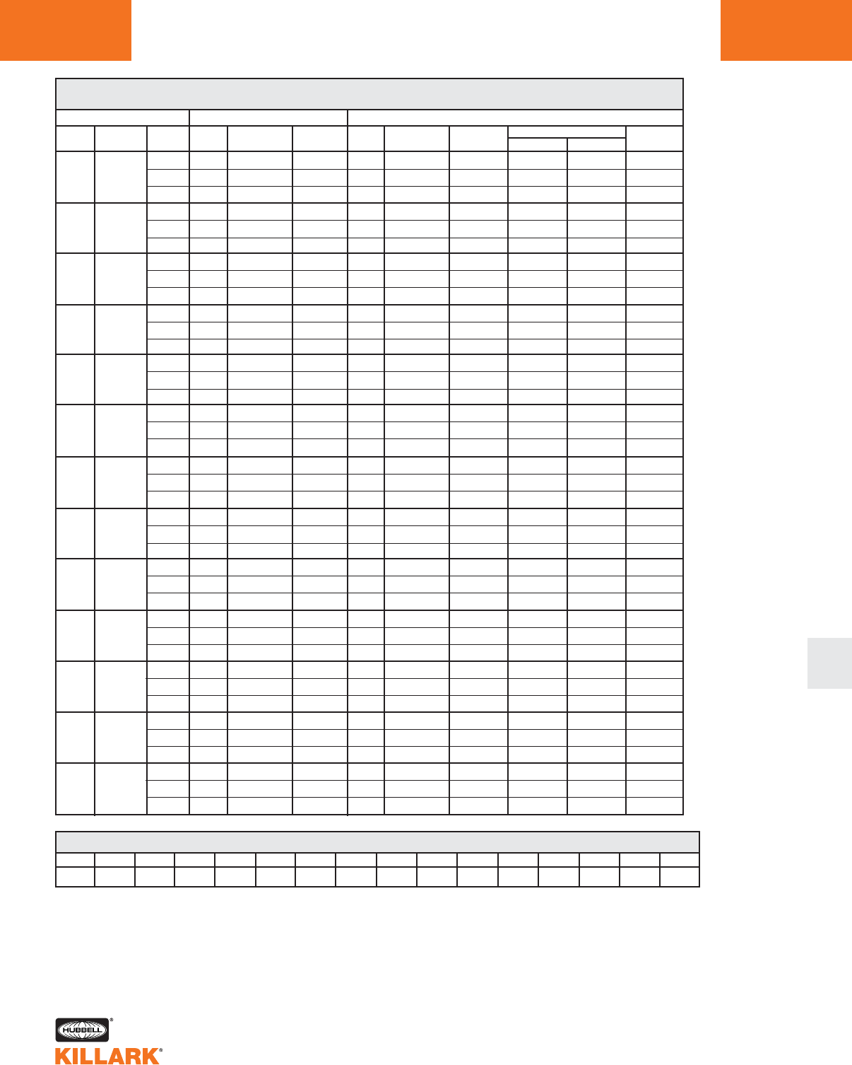
CERTILITE®V SERIES •LIGHTING
APPLICATION DATA FOR HAZARDOUS LOCATIONS L85
L
VM3/VM4 SERIES THERMAL PERFORMANCE DATA1
CLASS I ZONE 2 RESTRICTED BREATHING
LAMP
TYPE
HPS
HPS
HPS
HPS
MH
MH
MH
MH
MHP
MHP
MV
MV
MV
DESCRIPTION
LAMP
WATTAGE
50
70
100
150
70
100
175
250
150/175
200
100
175
250
AMBIENT
°C
40
55
65
40
55
65
40
55
65
40
55
65
40
55
65
40
55
65
40
55
65
40
55
65
40
55
65
40
55
65
40
55
65
40
55
65
40
55
65
VM3 SERIES**
GLOBE
ONLY
T6
T5
T4
T5
T5
T4
T5
T5
T4
T4
T3
—
T5
T4
T4
T4
T4
T4
T3
T3
—
T3
—
—
T3
T3
—
T3
T3
—
T4
T4
—
T3
T3
—
T3
—
—
GLOBE
W/ REFLECTOR
T6
T5
T4
T5
T5
T4
T5
T5
T4
T4
T3
—
T5
T4
T4
T4
T4
T4
T3
T3
—
T3
—
—
T3
T3
—
T3
T3
—
T4
T4
—
T3
T3
—
T3
—
VM4 SERIES**
REFRACTOR
VMR
T6
T5
T4
T5
T5
T4
T5
T5
T4
T4
T3
—
T5
T4
T4
T4
T4
T4
T3
T3
—
T3
—
—
T3
T3
—
T3
T3
—
T4
T4
—
T3
T3
—
T3
—
—
GLOBE
ONLY
T6
T6
T5
T6
T5
T5
T5
T5
T4
T4
T4
—
T6
T5
T4
T5
T4
T4
T4
T4
—
T3
—
—
T4
T4
T3
T4
T3
—
T5
T4
—
T4
T4
—
T3
—
—
GLOBE
W/ REFLECTOR
T6
T6
T5
T6
T5
T5
T5
T5
T4
T4
T4
—
T6
T5
T4
T5
T4
T4
T4
T4
—
T3
—
—
T4
T4
T3
T4
T3
—
T5
T4
—
T4
T3
—
T3
—
—
SUPPLY
WIRE °C
90
90
90
90
90
90
90
90
110
90
90
—
90
90
90
90
90
90
90
110
—
90
—
—
90
90
110
90
110
—
90
90
—
90
90
—
110
—
—
ENCLOSED REFLECTORS
VMER40
T6
T6
T5
T6
T5
T5
T5
T5
T4
T4
T4
—
T6
T5
T4
T5
T4
T4
T4
T4
—
T3
—
—
T4
T4
T3
T4
T3
—
T5
T4
—
T4
T4
—
T3
—
—
VMEP40
T6
T6
T5
T6
T5
T5
T5
T5
T4
T4
T4
—
T6
T5
T4
T5
T4
T4
T4
T4
—
T3
—
—
T4
T4
T3
T4
T3
—
T5
T4
—
T4
T4
—
T3
—
—
REFRACTOR
VMR
T6
T6
T5
T6
T5
T5
T5
T5
T4
T4
T4
—
T6
T5
T4
T5
T4
T4
T4
T4
—
T3
—
—
T4
T4
T3
T4
T3
—
T5
T4
—
T4
T4
—
T3
—
—
T-CODE & TEMPERATURE RANGE CONVERSION TABLE °C
T1
351-450
350
326-350
325
301-325
T2
281-300
T2A
261-280
T2B
231-260
T2C
216-230
T2D
201-215
T3
181-200
T3A
166-180
T3B
161-165
T3C
136-160
T4
121-135
T4A
101-120
T5
86-100
T6
<=85
1Data does not apply to luminaries with auxiliary quartz lighting; consult factory with requirements. The
suitability of these fixtures for Class I Zone 2 AEx nAR II locations must be determined for each appli-
cation based on NEC® Article 505.
** VM3 Series accepts 5-1/2” threaded optics; VM4 accepts 7-3/4” optics.
— Not available.
CERTILITE®V SERIES •LIGHTING
APPLICATION DATA FOR HAZARDOUS LOCATIONS
L86
VM3/VM4 SERIES THERMAL PERFORMANCE DATA1
CLASS II DIVISIONS 1 & 2 GROUPS E,F,G & CLASS III*
LAMP
TYPE
HPS
HPS
HPS
HPS
MH
MH
MH
MH
MHP
MHP
MV
MV
MV
DESCRIPTION
LAMP
WATTAGE
50
70
100
150
70
100
175
250
150/175
200
100
175
250
AMBIENT
°C
40
55
65
40
55
65
40
55
65
40
55
65
40
55
65
40
55
65
40
55
65
40
55
65
40
55
65
40
55
65
40
55
65
40
55
65
40
55
65
VM3 SERIES**
GLOBE
ONLY
T3C
—
—
T3C
—
—
T3C
—
—
T3C
—
—
T3C
—
—
T3C
—
—
—
—
—
—
—
—
—
—
—
—
—
—
—
—
—
—
—
—
—
—
—
GLOBE
W/ REFLECTOR
T3C
—
—
T3C
—
—
T3C
—
—
T3C
—
—
T3C
—
—
T3C
—
—
—
—
—
—
—
—
—
—
—
—
—
—
—
—
—
—
—
—
—
—
—
VM4 SERIES**
VMR
T3C
—
—
T3C
—
—
T3C
—
—
T3C
—
—
T3C
—
—
T3C
—
—
—
—
—
—
—
—
—
—
—
—
—
—
—
—
—
—
—
—
—
—
REFRACTORS
VZRG 8”
T3C
—
—
T3C
—
—
T3C
—
—
T3C
—
—
T3C
—
—
T3C
—
—
—
—
—
—
—
—
—
—
—
—
—
—
—
—
—
—
—
—
—
—
—
VZRG 12”
T3C
—
—
T3C
—
—
T3C
—
—
T3C
—
—
T3C
—
—
T3C
—
—
—
—
—
—
—
—
—
—
—
—
—
—
—
—
—
—
—
—
—
—
—
GLOBE
ONLY
T3B
—
—
T3B
—
—
T3B
—
—
T3B
—
—
T3B
—
—
T3B
—
—
T3B
—
—
T3B
—
—
T3B
—
—
T3B
—
—
T3B
—
—
T3B
—
—
T3A
—
—
GLOBE
W/ REFLECTOR
T3B
—
—
T3B
—
—
T3B
—
—
T3B
—
—
T3B
—
—
T3B
—
—
T3B
—
—
T3B
—
—
T3B
—
—
T3B
—
—
T3B
—
—
T3B
—
—
T3A
—
—
SUPPLY
WIRE °C
90
—
—
90
—
—
90
—
—
90
—
—
90
—
—
90
—
—
90
—
—
90
—
—
90
—
—
90
—
—
90
—
—
90
—
—
110
—
—
ENCLOSED REFLECTORS
VMER40
T3B
—
—
T3B
—
—
T3B
—
—
T3B
—
—
T3B
—
—
T3B
—
—
T3B
—
—
T3B
—
—
T3B
—
—
T3B
—
—
T3B
—
—
T3B
—
—
T3A
—
—
VMEP40
T3B
—
—
T3B
—
—
T3B
—
—
T3B
—
—
T3B
—
—
T3B
—
—
T3B
—
—
T3B
—
—
T3B
—
—
T3B
—
—
T3B
—
—
T3B
—
—
T3A
—
—
REFRACTOR
VMR
T3B
—
—
T3B
—
—
T3B
—
—
T3B
—
—
T3B
—
—
T3B
—
—
T3B
—
—
T3B
—
—
T3B
—
—
T3B
—
—
T3B
—
—
T3B
—
—
T3A
—
—
T-CODE & TEMPERATURE RANGE CONVERSION TABLE °C
T1
351-450
350
326-350
325
301-325
T2
281-300
T2A
261-280
T2B
231-260
T2C
216-230
T2D
201-215
T3
181-200
T3A
166-180
T3B
161-165
T3C
136-160
T4
121-135
T4A
101-120
T5
86-100
T6
<=85
1Data does not apply to luminaries with auxiliary quartz lighting; consult factory with requirements.
2Limit for E & F.
3Limit for G & Class III.
* Luminaries rated for Group G (=<165°C), T3B are also suitable for Class III applications; Luminaries
rated for E & F ≤ 200°C (T3).
** VM3 Series accepts 5-1/2” threaded optics; VM4 accepts 7-3/4” optics.
— Not available.
23
CERTILITE®V SERIES •LIGHTING
APPLICATION DATA FOR HAZARDOUS LOCATIONS
L
L87
VM3/VM4 SERIES THERMAL PERFORMANCE DATA12
“SIMULTANEOUS PRESENCE” CLASS I DIVISION 2 (LAMP TEMPERATURE IN DUST CONDITIONS) & CLASS II DIVISION I
LAMP
TYPE
HPS
HPS
HPS
HPS
MH
MH
MH
MH
MHP
MHP
MV
MV
MV
DESCRIPTION
LAMP
WATTAGE
50
70
100
150
70
100
175
250
150/175
200
100
175
250
AMBIENT
°C
40
55
65
40
55
65
40
55
65
40
55
65
40
55
65
40
55
65
40
55
65
40
55
65
40
55
65
40
55
65
40
55
65
40
55
65
40
55
65
VM3 SERIES**
GLOBE
ONLY
T3
—
—
T3
—
—
T2C
—
—
T2A
—
—
T3A
—
—
T2D
—
—
—
—
—
—
—
—
—
—
—
—
—
—
—
—
—
—
—
—
—
—
—
GLOBE
W/ REFLECTOR
T2D
—
—
T2D
—
—
T2C
—
—
T2A
—
—
T3A
—
—
T2D
—
—
—
—
—
—
—
—
—
—
—
—
—
—
—
—
—
—
—
—
—
—
—
VM4 SERIES**
VMR
T3
—
—
T3
—
—
T2C
—
—
T2A
—
—
T3A
—
—
T2D
—
—
—
—
—
—
—
—
—
—
—
—
—
—
—
—
—
—
—
—
—
—
—
REFRACTORS
VZRG 8”
T3
—
—
T3
—
—
T2C
—
—
T2A
—
—
T3A
—
—
T2D
—
—
—
—
—
—
—
—
—
—
—
—
—
—
—
—
—
—
—
—
—
—
—
VZRG 12”
T3
—
—
T3
—
—
T2C
—
—
T2A
—
—
T3A
—
—
T2D
—
—
—
—
—
—
—
—
—
—
—
—
—
—
—
—
—
—
—
—
—
—
—
GLOBE
ONLY
T3C
—
—
T3A
—
—
T3
—
—
T2B
—
—
T3C
—
—
T3A
—
—
T2A
—
—
325°C
—
—
T2A
—
—
T2A
—
—
T2B
—
—
T2A
—
—
350°C
—
—
GLOBE
W/ REFLECTOR
T3C
—
—
T3A
—
—
T3
—
—
T2B
—
—
T3C
—
—
T3
—
—
T2A
—
—
325°C
—
—
T2A
—
—
T2A
—
—
T2B
—
—
T2A
—
—
350°C
—
—
SUPPLY
WIRE °C
90
—
—
90
—
—
90
—
—
90
—
—
90
—
—
90
—
—
90
—
—
90
—
—
90
—
—
90
—
—
90
—
—
90
—
—
110
—
—
ENCLOSED REFLECTORS
VMER40
T3C
—
—
T3A
—
—
T3
—
—
T2B
—
—
T3C
—
—
T3A
—
—
T2A
—
—
325°C
—
—
T2A
—
—
T2A
—
—
T2B
—
—
T2A
—
—
350°C
—
—
VMEP40
T3C
—
—
T3A
—
—
T3
—
—
T2B
—
—
T3C
—
—
T3A
—
—
T2A
—
—
325°C
—
—
T2A
—
—
T2A
—
—
T2B
—
—
T2A
—
—
350°C
—
—
REFRACTOR
VMR
T3C
—
—
T3A
—
—
T3
—
—
T2B
—
—
T3C
—
—
T3A
—
—
T2A
—
—
325°C
—
—
T2A
—
—
T2A
—
—
T2B
—
—
T2A
—
—
350°C
—
—
T-CODE & TEMPERATURE RANGE CONVERSION TABLE °C
T1
351-450
350
326-350
325
301-325
T2
281-300
T2A
261-280
T2B
231-260
T2C
216-230
T2D
201-215
T3
181-200
T3A
166-180
T3B
161-165
T3C
136-160
T4
121-135
T4A
101-120
T5
86-100
T6
<=85
1Data does not apply to luminaries with auxiliary quartz lighting; consult factory with requirements.
2Table shows lamp temperature inside dust covered optic - see Class II table for Groups E, F, G and
Class III data.
** VM3 Series accepts 5-1/2” threaded optics; VM4 accepts 7-3/4” optics.
— Not available.
CERTILITE®V SERIES •LIGHTING
APPLICATION DATA FOR HAZARDOUS LOCATIONS
L88
VM5 SERIES THERMAL PERFORMANCE DATA1
LAMP
TYPE
HPS
HPS
HPS
HPS
MH
MH
MHP
MHP
MHP
MHP
MV
QL
DESCRIPTION
LAMP
WATTAGE
200
250
400
600
250
400
250
320
350
400
400
165
AMBIENT
°C
40
55
65
40
55
65
40
55
65
40
55
65
40
55
65
40
55
65
40
55
65
40
55
65
40
55
65
40
55
65
40
55
65
40
55
65
CLASS I DIVISION 2 GROUPS A, B, C, D / ZONE 2 GROUPS IIC, IIB, IIA
GLOBE
ONLY
325°C
350°C
—
325°C
350°C
350°C
350°C
450°C
—
—
—
—
T2
—
—
T2
—
—
T2B
T2A
—
T2B
T2A
T2A
T2A
T2
—
T2A
T2
—
325°C
—
—
T3
—
—
GLOBE
W/ REFLECTOR
325°C
350°C
—
325°C
350°C
350°C
450°C
—
—
—
—
—
325°C
—
—
325°C
—
—
T2B
T2A
—
T2B
T2A
—
T2A
T2
—
T2A
T2
—
350°C
—
—
T3
—
—
CLASS I ZONE 2, “RESTRICTED BREATHING”2
REFRACTOR
VZRG 12”
325°C
350°C
—
325°C
350°C
350°C
350°C
450°C
—
—
—
—
T2
—
—
T2
—
—
T2B
T2A
—
T2B
T2A
T2A
T2A
T2A
—
T2A
T2A
—
325°C
—
—
T3
—
—
ENCLOSED REFLECTORS
VMER40
T2
325°C
—
T2
325°C
325°C
350°C
450°C
—
450°C
450°C
—
T2
—
—
T2
—
—
T2B
T2B
—
T2B
T2B
T2A
T2B
T2A
—
T2B
T2A
—
325°C
—
—
T3
—
—
VMEP40
T2
325°C
—
T2
325°C
325°C
350°C
450°C
—
450°C
450°C
—
T2
—
—
T2
—
—
T2B
T2B
—
T2B
T2B
T2A
T2B
T2A
—
T2B
T2A
—
325°C
—
—
T3
—
—
GLOBE
ONLY
T3
T3
—
T3
T3
T3
T3
T3
—
—
—
—
T3
—
—
T3
—
—
T4
T3
—
T4
T3
T3
T3
T3
—
T3
T3
—
T3
—
—
—
—
—
GLOBE
W/ REFLECTOR
T3
T3
—
T3
T3
T3
T3
—
—
—
—
—
T3
—
—
T3
—
—
T4
T3
—
T4
T3
—
T3
T3
—
T3
T3
—
T3
—
—
—
—
—
SUPPLY
WIRE °C
90
110
—
90
110
110
90
110
—
90
110
—
90
—
—
90
—
—
90
90
—
90
90
110
90
110
—
90
110
—
90
—
—
75
—
—
ENCLOSED REFLECTORS
VMER40
T4
T3
—
T4
T3
T3
T3
T3
—
T3
T3
—
T3
—
—
T3
—
—
T4
T3
—
T4
T3
T3
T4
T3
—
T4
T3
—
T4
—
—
—
—
—
VMEP40
T4
T3
—
T4
T3
T3
T3
T3
—
T3
T3
—
T3
—
—
T3
—
—
T4
T3
—
T4
T3
T3
T4
T3
—
T4
T3
—
T4
—
—
—
—
—
T-CODE & TEMPERATURE RANGE CONVERSION TABLE °C
T1
351-450
350
326-350
325
301-325
T2
281-300
T2A
261-280
T2B
231-260
T2C
216-230
T2D
201-215
T3
181-200
T3A
166-180
T3B
161-165
T3C
136-160
T4
121-135
T4A
101-120
T5
86-100
T6
<=85
1Data does not apply to luminaries with auxiliary quartz lighting; consult factory with requirements. The suitability of these fixtures for
Class I Division 2/Zone 2 locations must be determined for each application based on NEC® Articles 501.125(B) or 505.
2See L39 for Restricted Breathing Information.
— Not available
CERTILITE®V SERIES •LIGHTING
APPLICATION DATA FOR HAZARDOUS LOCATIONS L89
L
VM5 SERIES THERMAL PERFORMANCE DATA12
LAMP
TYPE
HPS
HPS
HPS
MH
MH
MHP
MHP
MHP
MHP
MV
DESCRIPTION
LAMP
WATTAGE
200
250
400
250
400
250
320
350
400
400
AMBIENT
°C
40
55
65
40
55
65
40
55
65
40
55
65
40
55
65
40
55
65
40
55
65
40
55
65
40
55
65
40
55
65
CLASS II DIVISION 1 & 2 GROUPS E,F,G & CLASS III*
GLOBE
ONLY
T3C
—
—
T3C
—
—
T3B
—
—
—
—
—
—
—
—
—
—
—
—
—
—
—
—
—
—
—
—
—
—
—
GLOBE
W/ REFLECTOR
T3C
—
—
T3C
—
—
T3B
—
—
—
—
—
—
—
—
—
—
—
—
—
—
—
—
—
—
—
—
—
—
—
SIMULTANEOUS PRESENCE2LAMP TEMP. IN DUST CONDITIONS
REFRACTOR
VZRG 12”
T4A
T4
—
T4A
T4
T4
T4
T3C
—
T4
—
—
T4
—
—
T4
T4
—
T4
T3C
—
T4
T3C
—
T4
T3C
—
T3C
—
—
ENCLOSED REFLECTORS
VMER40
T4
T3C
—
T4
T3C
T3C
T4
T3B
—
T4
—
—
T4
—
—
T4
T4
—
T4
T3C
—
T4
T3C
—
T4
T3C
—
T4
—
—
VMEP40
T4
T3C
—
T4
T3C
T3C
T4
T3B
—
T4
—
—
T4
—
—
T4
T4
—
T4
—
—
T4
T3C
—
T4
T3C
—
T4
—
—
GLOBE
ONLY
350°C
—
—
350°C
—
—
T1
—
—
—
—
—
—
—
—
—
—
—
—
—
—
—
—
—
—
—
—
—
—
—
GLOBE
W/ REFLECTOR
350°C
—
—
350°C
—
—
T1
—
—
—
—
—
—
—
—
—
—
—
—
—
—
—
—
—
—
—
—
—
—
—
SUPPLY
WIRE °C
90
110
—
90
110
110
90
110
—
90
—
—
90
—
—
90
90
—
90
90
—
90
110
—
90
110
—
90
—
—
ENCLOSED REFLECTORS
VMER40
325°C
350°C
—
325°C
350°C
350°C
350°C
T1
—
325°C
—
—
325°C
—
—
T2B
T2A
—
T2B
T2A
—
T2A
T2
—
T2A
T2
—
325°C
—
—
VMEP40
325°C
350°C
—
325°C
350°C
350°C
350°C
T1
—
325°C
—
—
325°C
—
—
T2B
T2A
—
T2B
T2A
—
T2A
T2
—
T2A
T2
—
325°C
—
—
REFRACTOR
VZRG 12”
325°C
350°C
—
325°C
350°C
350°C
350°C
T1
—
325°C
—
—
325°C
—
—
T2B
T2A
—
T2B
T2A
—
T2A
T2
—
T2A
T2
—
325°C
—
—
T-CODE & TEMPERATURE RANGE CONVERSION TABLE °C
T1
351-450
350
326-350
325
301-325
T2
281-300
T2A
261-280
T2B
231-260
T2C
216-230
T2D
201-215
T3
181-200
T3A
166-180
T3B
161-165
T3C
136-160
T4
121-135
T4A
101-120
T5
86-100
T6
<=85
*** Table shows lamp temperature inside optic dust conditions, see Class II table for Groups E, F, G data.
1Data does not apply to luminaries with auxiliary quartz lighting; consult factory with requirements.
2Table shows lamp temperature inside dust covered optic - see Class II table for Groups E, F, G and Class III data.
3Limit for E & F.
4Limit for G & Class III.
* Luminares rated for Group G (=<165°C), T3B are also suitable for Class III applications; Luminaries rated for E & F ≤ 200°C (T3).
— Not available.
34

CERTILITE®V SERIES •LIGHTING
PHOTOMETRIC DATA
L90
Test No. HPK09950
HIGH PRESSURE SODIUM-VM3
With Globe Only
50-150 Watt
Mogul Base
CANDLEPOWER – 100 WATT
9500 lumens
For 50 watt multiply by 0.42
For 70 watt multiply by 0.68
For 150 watt multiply by 1.68
Efficiency 84.0%
ANGLE CP ANGLE CP
0227. 95.0 974.
5.0 175. 100.0 946.
10.0 152. 105.0 925.
15.0 255. 110.0 880.
20.0 391. 115.0 803.
25.0 284. 120.0 706.
30.0 390. 125.0 273.
35.0 542. 130.0 22.
40.0 662. 135.0 12.
45.0 687. 140.0 9.
50.0 744. 145.0 7.
55.0 788. 150.0 5.
60.0 843. 155.0 2.
65.0 887. 160.0 1.
70.0 941. 165.0 1.
75.0 968. 170.0 0.
80.0 994. 175.0 0.
85.0 1001. 180.0 0.
90.0 990.
% EFFECTIVE
CEILING CAVITY
REFLECTANCE
1cc
80 70 50 30 100
70 50 30 10 70 50 30 10 50 30 10 50 30 10 50 30 10 0
20% Effective Floor Cavity Reflectance
0 .91 .91 .91 .91 .85 .85 .85 .85 .74 .74 .74 .64.64 .64 .55 .55 .55 .50
1 .77 .71 .66 .61 .72 .66.61 .57 .56 .52 .49 .47.44 .42 .39 .37 .35 .30
2 .68 .59 .52 .45 .63 .55.48 .42 .46 .41 .36 .39.34 .31 .31 .28 .25 .21
3 .61 .50 .42 .35 .56 .46.39 .33 .39 .33 .28 .32.28 .23 .26 .22 .19 .16
4 .55 .43 .35 .28 .50 .40.32 .26 .33 .27 .22 .28.22 .18 .22 .18 .15 .11
5 .50 .37 .29 .23 .45 .35 .27 .21 .29 .23 .18 .24 .19 .15 .19 .15 .12 .09
6 .45 .33 .25 .19 .41 .30 .23 .17 .26 .19 .15 .21 .16 .12 .17 .13 .09 .07
7 .41 .29 .21 .16 .38 .27 .20 .14 .23 .17 .12 .19 .14 .10 .15 .11 .08 .05
8 .38 .26 .18 .13 .35 .24 .17 .12 .20 .14 .10 .17 .12 .08 .13 .09 .06 .04
9 .35 .23 .16 .11 .32 .22 .15 .10 .18 .12 .08 .15 .10 .07 .12 .08 .05 .03
10 .32 .21 .14 .09 .30 .19 .13 .08 .16 .11 .07 .13 .09 .05 .11 .07 .04 .02
%WALL
REFLECTANCE
1w
ROOM CAVITY
RATIO
RCR
COEFFICIENTS OF UTILIZATION ---ZONAL CAVITY METHOD
SPACING TO MOUNTING HEIGHT RATIO - 3.3
Test No. HPK09951
HIGH PRESSURE SODIUM-VM3
With Globe & Dome Reflector
50-150 Watt
Mogul Base
CANDLEPOWER – 100 WATT
9500 lumens
For 50 watt multiply by 0.42
For 70 watt multiply by 0.68
For 150 watt multiply by 1.68
Efficiency 66.7%
ANGLE CP ANGLE CP
01126. 95.0 25.
5.0 1067. 100.0 23.
10.0 1025. 105.0 43.
15.0 1127. 110.0 138.
20.0 1241. 115.0 132.
25.0 1113 . 120.0 31.
30.0 1178. 125.0 11.
35.0 1286. 130.0 10.
40.0 1357. 135.0 9.
45.0 1334. 140.0 9.
50.0 1347. 145.0 8.
55.0 1331. 150.0 7.
60.0 1325. 155.0 6.
65.0 1295. 160.0 6.
70.0 1233. 165.0 5.
75.0 647. 170.0 5.
80.0 228. 175.0 5.
85.0 105. 180.0 5.
90.0 21.
% EFFECTIVE
CEILING CAVITY
REFLECTANCE
1cc
80 70 50 30 10 0
70 50 30 10 70 50 30 10 50 30 10 50 30 10 50 30 10 0
20% Effective Floor Cavity Reflectance
0 .78 .78 .78 .78 .76 .76 .76 .76 .72 .72 .72 .69.69 .69 .65 .65 .65 .64
1 .70 .67 .64 .61 .68 .65.62 .60 .62 .59 .57 .59.57 .55 .56 .54 .53 .51
2 .63 .57 .52 .48 .61 .56 .51 .47 .53 .49 .46 .51.47 .45 .48 .46 .43 .42
3 .57 .49 .44 .39 .55 .48.43 .38 .46 .41 .37 .44.40 .36 .42 .38 .35 .34
4 .51 .43 .36 .31 .50 .41.36 .31 .39 .34 .30 .38.33 .29 .36 .32 .29 .27
5 .46 .37 .30 .26 .45 .36.30 .25 .34 .29 .25 .33.28 .24 .31 .27 .24 .22
6 .42 .33 .26 .22 .41 .32.26 .21 .30 .25 .21 .29.24 .21 .28 .24 .20 .19
7 .39 .29 .23 .18 .37 .28.22 .18 .27 .22 .18 .26.21 .17 .25 .20 .17 .16
8 .36 .26 .20 .15 .34 .25 .19 .15 .24 .19 .15 .23 .18 .15 .22 .18 .14 .13
9 .33 .23 .17 .13 .32 .23 .17 .13 .22 .16 .13 .21 .16 .13 .20 .16 .12 .11
10 .30 .20 .14 .11 .29 .20 .14 .11 .19 .14 .10 .18 .13 .10 .17 .13 .10 .09
% WALL
REFLECTANCE
1w
ROOM CAVITY
RATIO
RCR
COEFFICIENTS OF UTILIZATION ---ZONAL CAVITY METHOD
SPACING TO MOUNTING HEIGHT RATIO - 1.8
Test No. HPK09952
HIGH PRESSURE SODIUM-VM3
With Globe & Angle Reflector
50-150 Watt
Mogul Base
CANDLEPOWER – 100 WATT
9500 lumens
For 50 watt multiply by 0.42
For 70 watt multiply by 0.68
For 150 watt multiply by 1.68
Efficiency 64.9%
Front Side
ANGLE CP ANGLE CP
01026. 01026.
5.0 985. 5.0 981.
15.0 1191. 15.0 995.
25.0 1210. 25.0 1019.
35.0 1503. 35.0 1200.
45.0 1585. 45.0 1296.
45.0 1719. 45.0 1337.
65.0 1681. 65.0 1219.
75.0 1626. 75.0 276.
85.0 1484. 85.0 61.
90.0 1377. 145.0 17.
95.0 1011. 95.0 13.
105.0 163. 105.0 10.
115.0 46. 115.0 10.
125.0 13. 125.0 9.
135.0 5. 135.0 8.
145.0 5. 145.0 7.
155.0 5. 155.0 5.
165.0 4. 165.0 4.
175.0 3. 175.0 3.
180.0 3. 180.0 3.
Front
Side
% EFFECTIVE
CEILING CAVITY
REFLECTANCE
1cc
80 70 50 30 10 0
70 50 30 10 70 50 30 10 50 30 10 50 30 10 50 30 10 0
20% Effective Floor Cavity Reflectance
0 .76 .76 .76 .76. .74 .74 .74 .74 .69 .69 .69 .66 .66 .66 .62 .62.62 .60
1 .67 .63 .59 .56 .65 .61 .57 .54 .57 .54 .52 .54.51 .49 .51 .49 .47 .45
2 .60 .54 .48 .44 .58 .52 .47 .43 .49 .45 .41 .46.43 .40 .43 .41.38 .36
3 .54 .46 .40 .36 .52 .45 .39 .35 .42 .38 .34 .40.36 .33 .38 .34 .31 .30
4 .49 .40 .34 .29 .47 .39 .33 .29 .37 .32 .28 .35.30 .27 .33 .29.26 .24
5 .45 .35 .29 .24 .43 .34 .28 .24 .32 .27 .23 .31.26 .22 .29 .25 .22 .20
6 .41 .31 .25 .21 .39 .31 .25 .20 .29 .24 .20 .27.23 .19 .26 .22 .19 .17
7 .38 .28 .22 .17 .36 .27 .21 .17 .26 .20 .17 .24 .20 .16 .23 .19 .16 .14
8 .34 .25 .19 .15 .33.24 .19 .15 .23 .18 .14 .22.17 .14 .21 .17 .13 .12
9 .32 .22 .17 .13 .31.22 .16 .13 .21 .16 .12 .20.15 .12 .19 .15 .12 .10
10 .29 .20 .14 .10 .28.19 .14 .10 .18 .13 .10 .17 .13 .10 .16 .12.09 .08
% WALL
REFLECTANCE
1w
ROOM CAVITY
RATIO
RCR
COEFFICIENTS OF UTILIZATION ---ZONAL CAVITY METHOD
SPACING TO MOUNTING HEIGHT RATIO - 1.7
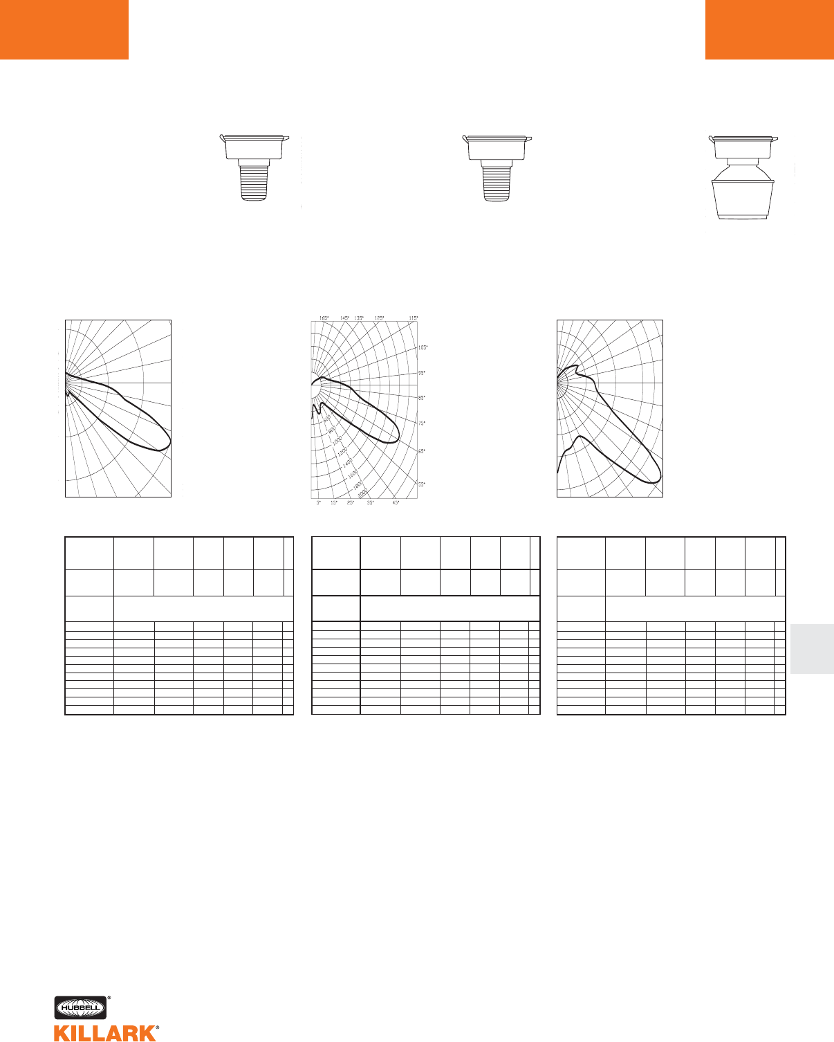
CERTILITE®V SERIES •LIGHTING
PHOTOMETRIC DATA L91
L
Test No. HPK09954
HIGH PRESSURE SODIUM-VM3
With Type I All Glass Refractor
50-150 Watt
Mogul Base
CANDLEPOWER – 100 WATT
9500 lumens
For 50 watt multiply by 0.42
For 70 watt multiply by 0.68
For 150 watt multiply by 1.68
Efficiency 86.2%
2683
1342
4025
5366
90˚
80˚
70˚
60˚
50˚
40˚30˚20˚10˚0˚
180˚ 160˚ 150˚ 140˚ 130˚ 120˚
110˚
100˚
% EFFECTIVE
CEILING CAVITY
REFLECTANCE
1cc
80 70 50 30 10 0
70 50 30 10 70 50 30 10 50 30 10 50 30 10 50 30 10 0
20% Effective Floor Cavity Reflectance
0 .99 .99 .99 .99 .95 .95.95 .95 .87 .87 .87 .81.81 .81 .74 .74 .74 .71
1 .83 .76 .70 .64 .79 .72 .67 .61 .66 .61 .57 .60.56 .52 .54 .51 .48 .45
2 .72 .61 .52 .44 .68 .58.49 .42 .52 .45 .39 .46.41 .36 .42 .37 .33 .30
3 .63 .50 .40 .32 .59 .47.38 .31 .42 .34 .28 .38.31 .26 .33 .28 .23 .20
4 .56 .42 .32 .24 .52 .40.30 .23 .35 .27 .21 .31.24 .19 .28 .22 .17 .14
5 .50 .36 .26 .19 .47 .34.25 .18 .30 .22 .16 .27.20 .14 .23 .18 .13 .10
6 .46 .31 .22 .15 .43 .30 .21 .14 .26 .19 .13 .23 .17 .11 .21 .15 .10 .08
7 .42 .28 .19 .12 .39 .26 .18 .12 .23 .16 .10 .21 .14 .09 .18 .13 .08 .06
8 .39 .25 .16 .10 .36 .24 .15 .10 .21 .14 .09 .19.12 .08 .17 .11 .07 .05
9 .36 .23 .14 .09 .34 .21 .14 .08 .19 .12 .07 .17 .11 .07 .15 .10 .06 .04
10 .34 .21 .13 .08 .32 .20 .12 .07 .18 .11 .06 .16 .10 .06 .14 .09 .05 .03
% WALL
REFLECTANCE
1w
ROOM CAVITY
RATIO
RCR
COEFFICIENTS OF UTILIZATION ---ZONAL CAVITY METHOD
SPACING TO MOUNTING HEIGHT RATIO - 6.76 90-270°
Test No. HPK09953
HIGH PRESSURE SODIUM-VM3
With Type V All Glass Refractor
50-150 Watt
Mogul Base
CANDLEPOWER – 100 WATT
9500 lumens
For 50 watt multiply by 0.42
For 70 watt multiply by 0.68
For 150 watt multiply by 1.68
Efficiency 81.7%
ANGLE CP ANGLE CP
0519. 95.0 550.
5.0 354. 100.0 418.
10.0 307. 105.0 349.
15.0 358. 110.0 312.
20.0 467. 115.0 279.
25.0 446. 120.0 247.
30.0 370. 125.0 168.
35.0 340. 130.0 117.
40.0 343. 135.0 75.
45.0 450. 140.0 45.
50.0 676. 145.0 25.
55.0 1092. 150.0 7.
60.0 1760. 155.0 2.
65.0 1958. 160.0 1.
70.0 1857. 165.0 1.
75.0 1377. 170.0 0.
80.0 995. 175.0 0.
85.0 858. 180.0 0.
90.0 711.
% EFFECTIVE
CEILING CAVITY
REFLECTANCE
1cc
80 70 50 30 10 0
70 50 30 10 70 50 30 10 50 30 10 50 30 10 50 30 10 0
20% Effective Floor Cavity Reflectance
0 .93 .93 .93 .93 .89 .89 .89 .89 .81 .81 .81 .75 .75 .75 .68 .68 .68 .65
1 .78 .72 .66 .61 .74 .68.63 .58 .62 .58 .54 .56.52 .49 .50 .48 .45 .42
2 .68 .58 .50 .43 .64 .55 .48 .41 .49 .43 .38 .44.39 .35 .39 .35 .32 .29
3 .60 .48 .39 .32 .56 .45 .37 .30 .40 .33 .28 .36 .30 .25 .32 .27 .23 .20
4 .53 .40 .30 .23 .49 .38 .29 .22 .33 .26 .20 .29.23 .19 .26 .21 .16 .13
5 .47 .34 .25 .18 .44 .32 .23 .17 .28 .21 .15 .25.19 .14 .22 .16 .12 .09
6 .43 .30 .21 .14 .40 .28 .20 .14 .25 .18 .12 .22 .16 .11 .19 .14 .10 .07
7 .40 .26 .18 .12 .37 .25 .17 .11 .22 .15 .10 .20 .13 .09 .17 .12 .08 .06
8 .36 .24 .16 .10 .34 .22 .15 .09 .20 .13 .08 .18 .12 .07 .15 .10 .06 .04
9 .34 .22 .14 .09 .32 .20 .13 .08 .18 .12 .07 .16 .11 .07 .14 .09 .06 .04
10 .32 .20 .12 .07 .30 .19 .12 .07 .17 .11 .06 .15 .09 .06 .13 .08 .05 .03
% WALL
REFLECTANCE
1w
ROOM CAVITY
RATIO
RCR
COEFFICIENTS OF UTILIZATION ---ZONAL CAVITY METHOD
SPACING TO MOUNTING HEIGHT RATIO - 1.1
Test No. HPK09483
HIGH PRESSURE SODIUM-VM3
With Type II 12" Spin-Top Refractor
50-150 Watt
Mogul Base
CANDLEPOWER – 100 WATT
9500 lumens
For 50 watt multiply by 0.42
For 70 watt multiply by 0.68
For 150 watt multiply by 1.68
Efficiency 64.9%
Front Side
ANGLE CP ANGLE CP
01504. 85.0
707
.
5.0
1329
.90.0
643
.
15.0
1094
.95.0
572
.
25.0
1057
.105.0
369
.
35.0
1306
.115.0
349
.
45.0
2230
.125.0
400
.
55.0
2482
.135.0
342
.
60.0
2089
.145.0
273
.
65.0
1477
.155.0
182
.
70.0
114 8
.165.0
64
.
75.0
925
.175.0
0.
80.0
798
.180.0
0.
1241
1862
2482
90˚
80˚
70˚
60˚
50˚
40˚30˚20˚10˚0˚
180˚ 160˚ 150˚ 140˚ 130˚ 120˚
110˚
100˚
621
% EFFECTIVE
CEILING CAVITY
REFLECTANCE
1cc
80 70 50 30 10 0
70 50 30 10 70 50 30 10 50 30 10 50 30 10 50 30 10 0
20% Effective Floor Cavity Reflectance
0 .84 .84 .84 .84 .80 .80 .80 .80 .73 .73 .73 .66 .66 .66 .60 .60 .60 .57
1 .75 .70 .66 .62 .71 .67 .63 .60 .60 .57 .55 .54 .52 .50 .49 .47 .45 .42
2 .67 .59 .53 .48 .63 .56.51 .46 .51 .46 .43 .46.42 .39 .41 .38 .36 .33
3 .60 .51 .44 .39 .56 .48.42 .37 .43 .38 .34 .39.35 .31 .35 .31 .29 .26
4 .54 .44 .37 .31 .51 .42 .35 .30 .38 .32 .28 .34.29 .25 .30 .26 .23 .21
5 .49 .39 .31 .26 .46 .37 .30 .25 .33 .27 .23 .30 .25 .21 .26 .22 .19 .17
6 .45 .34 .27 .22 .42 .32.26 .21 .29 .23 .19 .26.21 .18 .23 .19 .16 .14
7 .41 .30 .23 .18 .39 .29 .22 .18 .26 .20 .16 .23 .19 .15 .21 .17 .14 .12
8 .38 .27 .20 .16 .36 .26 .20 .15 .23 .18 .14 .21 .16 .13 .19 .15 .12 .10
9 .35 .25 .18 .14 .33 .23 .17 .13 .21 .16 .12 .19 .15 .11 .17 .13 .10 .09
10 .33 .22 .16 .12 .31 .21 .16 .12 .19 .14 .11 .18 .13 .10 .16 .12 .09 .08
% WALL
REFLECTANCE
1w
ROOM CAVITY
RATIO
RCR
COEFFICIENTS OF UTILIZATION ---ZONAL CAVITY METHOD
SPACING TO MOUNTING HEIGHT RATIO - 1.36 0 -180°
ANGLE CP ANGLE CP
0213.
5250.
15 533.
25 506.
35 457.
45 839.
55 2742.
60 4365.
65 5265.
70 5304.
75 4269.
80 3162.
85 2652.
90 1969.
95 1301.
105 763.
115 602.
125 294.
135 107.
145 32.
155 3.
165 1.
175 0.
180 0.
Angle Vertical
CP 90° Horizontal
Angle Vertical
CP 75° Horizontal
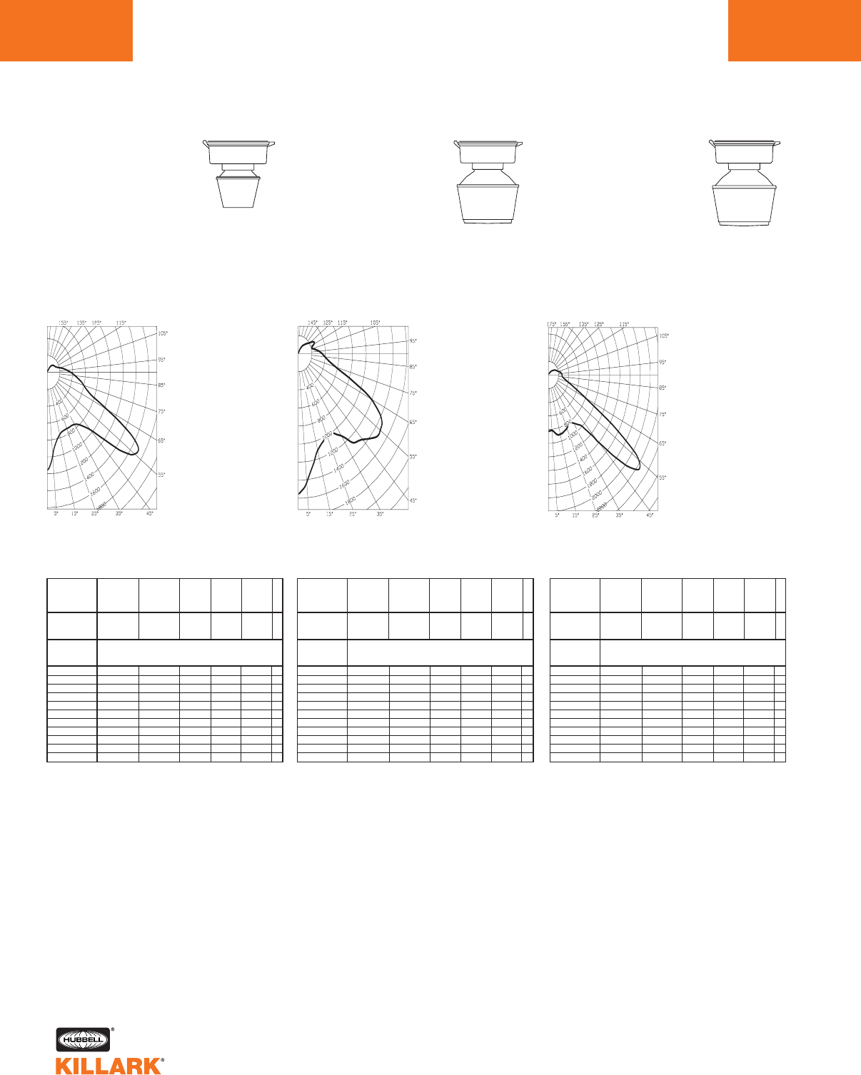
CERTILITE®V SERIES •LIGHTING
PHOTOMETRIC DATA
L92
Test No. HPK09472
HIGH PRESSURE SODIUM-VM3
With Type V 8" Spin-Top Refractor
50-150 Watt
Mogul Base
CANDLEPOWER – 100 WATT
9500 lumens
For 50 watt multiply by 0.42
For 70 watt multiply by 0.68
For 150 watt multiply by 1.68
Efficiency 69.1%
ANGLE CP ANGLE CP
01160. 95.0 312.
5.0 986. 100.0 258.
10.0 827. 105.0 204.
15.0 761. 110.0 169.
20.0 739. 115.0 149.
25.0 731. 120.0 136.
30.0 739. 125.0 135.
35.0 753. 130.0 133.
40.0 821. 135.0 123.
45.0 950. 140.0 109.
50.0 1366. 145.0 86.
55.0 1684. 150.0 59.
60.0 1595. 155.0 31.
65.0 1067. 160.0 5.
70.0 696. 165.0 1.
75.0 597. 170.0 0.
80.0 527. 175.0 0.
85.0 447. 180.0 0.
90.0 372.
% EFFECTIVE
CEILING CAVITY
REFLECTANCE
1cc
80 70 50 30 10 0
70 50 30 10 70 50 30 10 50 30 10 50 30 10 50 30 10 0
20% Effective Floor Cavity Reflectance
0 .79 .79 .79 .79 .76 .76 .76 .76 .71 .71 .71 .65.65 .65 .61 .61 .61 .58
1 .70 .66 .62 .59 .67 .63 .60 .57 .58 .56 .53 .54.52 .50 .50 .48 .46 .44
2 .63 .56 .50 .46 .60 .54 .48 .44 .49 .45 .42 .45.42 .39 .42 .39 .37 .34
3 .56 .48 .41 .36 .53 .46 .40 .35 .42 .37 .33 .39.34 .31 .36 .32 .29 .27
4 .51 .41 .34 .29 .48 .39 .33 .28 .36 .31 .27 .33.29 .25 .31 .27 .24 .22
5 .46 .35 .28 .23 .43 .34 .28 .23 .31 .26 .21 .29.24 .20 .26 .22 .19 .17
6 .41 .31 .24 .19 .39 .29 .23 .18 .27 .21 .17 .25.20 .16 .23 .19 .15 .14
7 .37 .27 .20 .15 .35 .26 .19 .15 .23 .18 .14 .22 .17 .13 .20 .15 .12 .10
8 .34 .24 .17 .13 .32 .23.17 .12 .21 .16 .12 .19.15 .11 .18 .14 .10 .09
9 .32 .21 .15 .11 .30 .21 .15 .11 .19 .14 .10 .17 .13 .09 .16 .12 .09 .07
10 .29 .19 .13 .09 .28 .19 .13 .09 .17 .12 .09 .16 .11 .08 .15 .11 .08 .06
% WALL
REFLECTANCE
1w
ROOM CAVITY
RATIO
RCR
COEFFICIENTS OF UTILIZATION ---ZONAL CAVITY METHOD
SPACING TO MOUNTING HEIGHT RATIO - 0.8
Test No. HPK09479
HIGH PRESSURE SODIUM-VM3
With Type V 12" Spin-Top Refractor
50-150 Watt
Mogul Base
CANDLEPOWER – 100 WATT
9500 lumens
For 50 watt multiply by 0.42
For 70 watt multiply by 0.68
For 150 watt multiply by 1.68
Efficiency 78.4%
ANGLE CP ANGLE CP
01555. 95.0 316.
5.0 1437. 100.0 258.
10.0 1254. 105.0 214.
15.0 1106. 110.0 213.
20.0 1045. 115.0 254.
25.0 1005. 120.0 268.
30.0 1212. 125.0 226.
35.0 1108. 130.0 179.
40.0 1291. 135.0 155.
45.0 1346. 140.0 133.
50.0 1449. 145.0 109.
55.0 1474. 150.0 80.
60.0 1414. 155.0 53.
65.0 1189. 160.0 27.
70.0 827. 165.0 9.
75.0 576. 170.0 0.
80.0 464. 175.0 0.
85.0 398. 180.0 0.
90.0 357.
% EFFECTIVE
CEILING CAVITY
REFLECTANCE
1cc
80 70 50 30 10 0
70 50 30 10 70 50 30 10 50 30 10 50 30 10 50 30 10 0
20% Effective Floor Cavity Reflectance
0 .90 .90 .90 .90 .87 .87 .87 .87 .80 .80 .80 .74 .74 .74 .68 .68 .68 .65
1 .80 .76 .72 .68 .77 .73 .69 .66 .67 .64 .61 .62.59 .57 .57 .55 .53 .50
2 .72 .65 .59 .54 .69 .62 .57 .52 .57 .53 .49 .53.49 .46 .49 .46 .43 .41
3 .65 .56 .49 .44 .62 .54 .48 .42 .50 .44 .40 .46.41 .38 .42 .30 .35 .33
4 .59 .49 .41 .35 .56 .47 .40 .34 .43 .37 .33 .40.35 .31 .36 .32 .29 .27
5 .53 .42 .35 .29 .51 .41 .34 .28 .38 .31 .27 .35.29 .25 .32 .27 .24 .22
6 .49 .37 .30 .25 .46 .36 .29 .24 .33 .27 .23 .31.25 .21 .28 .24 .20 .18
7 .45 .33 .26 .21 .42 .32 .25 .20 .29 .23 .19 .27.22 .18 .25 .20 .17 .15
8 .41 .29 .22 .17 .39 .28 .22 .17 .26 .20 .16 .24.19 .15 .22 .18 .14 .13
9 .38 .27 .20 .15 .36 .26 .19 .15 .24 .18 .14 .22.17 .13 .20 .16 .12 .11
10 .35 .23 .27 .12 .33 .23 .16 .12 .21 .15 .11 .19 .14 .11 .18 .13 .10 .09
% WALL
REFLECTANCE
1w
ROOM CAVITY
RATIO
RCR
COEFFICIENTS OF UTILIZATION ---ZONAL CAVITY METHOD
SPACING TO MOUNTING HEIGHT RATIO - 0.9
Test No. HPK09478
HIGH PRESSURE SODIUM-VM3
With Type V 12" Spin-Top Poly
Refractor
50-150 Watt
Mogul Base
CANDLEPOWER – 100 WATT
9500 lumens
For 50 watt multiply by 0.42
For 70 watt multiply by 0.68
For 150 watt multiply by 1.68
Efficiency 70.6%
ANGLE CP ANGLE CP
0829. 95.0 267.
5.0 810. 100.0 239.
10.0 874. 105.0 202.
15.0 901. 110.0 181.
20.0 887. 115.0 165.
25.0 864. 120.0 145.
30.0 815. 125.0 123.
35.0 863. 130.0 102.
40.0 956. 135.0 84.
45.0 1370. 140.0 68.
50.0 2123. 145.0 51.
55.0 2162. 150.0 34.
60.0 1438. 155.0 19.
65.0 823. 160.0 6.
70.0 .556 165.0 1.
75.0 407. 170.0 0.
80.0 319. 175.0 0.
85.0 275. 180.0 0.
90.0 265.
% EFFECTIVE
CEILING CAVITY
REFLECTANCE
1cc
80 70 50 30 10 0
70 50 30 10 70 50 30 10 50 30 10 50 30 10 50 30 10 0
20% Effective Floor Cavity Reflectance
0 .82 .82 .82 .82 .79.79 .79 .79 .73 .73 .73 .68.68 .68 .63 .63 .63 .61
1 .73 .70 .66 .63 .70.67 .64 .61 .62 .60 .57 .58.56 .54 .54 .52 .51 .49
2 .66 .60 .55 .50 .63.58 .53 .49 .54 .50 .46 .50 .47 .44 .47 .44 .42 .40
3 .60 .52 .46 .41 .57.50 .44 .40 .47 .42 .38 .43.39 .36 .40 .37 .34 .32
4 .54 .45 .38 .33 .51.43 .37 .32 .40 .35 .31 .37 .33 .29 .35 .31 .28 .26
5 .49 .39 .32 .27 .46.37 .31 .26 .35 .29 .25 .32.28 .24 .30 .26 .23 .21
6 .44 .34 .27 .22 .42.32 .26 .21 .30 .25 .20 .28.23 .19 .26 .22 .19 .17
7 .40 .29 .22 .18 .38 .28 .22 .17 .26 .20 .16 .24.19 .16 .22 .18 .15 .13
8 .36 .25 .19 .14 .34 .25 .18 .14 .23 .17 .13 .21 .16 .13 .20 .15 .12 .10
9 .33 .23 .17 .12 .32.22.16 .12 .21 .15 .11 .19 .14 .11 .18 .13 .10 .09
10 .30 .20 .14 .10 .29 .19 .14 .10 .18 .13 .09 .17 .12 .09 .15 .11 .08 .07
% WALL
REFLECTANCE
1w
ROOM CAVITY
RATIO
RCR
COEFFICIENTS OF UTILIZATION ---ZONAL CAVITY METHOD
SPACING TO MOUNTING HEIGHT RATIO - 2.8
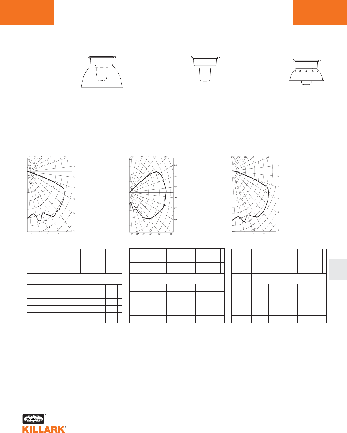
CERTILITE®V SERIES •LIGHTING
PHOTOMETRIC DATA L93
L
Test No. HPK10116
HIGH PRESSURE SODIUM-VM3
With Globe & Full Cutoff Deep White Reflector*
50-150 Watt
Mogul Base
CANDLEPOWER – 100 WATT
9500 lumens
For 50 watt multiply by 0.42
For 70 watt multiply by 0.68
For 150 watt multiply by 1.68
Efficiency 65.2%
ANGLE CP ANGLE CP
% EFFECTIVE
CEILING CAVITY
REFLECTANCE
1cc
80 70 50 30 10 0
70 50 30 10 70 50 30 10 50 30 10 50 30 10 50 30 10 0
20% Effective Floor Cavity Reflectance
0 .75 .75 .75 .75 .74 .74 .74 .74 .70 .70 .70 .67 .67 .67 .65 .65 .65 .63
1 .70 .67 .64 .62 .68 .65 .63 .61 .63 .61 .59 60 .59 .57 .58 .57 .56 .54
2 .64 .60 .56 .53 .63 .58 .55 .52 .56 .53 .51 .54 .52 .50 .52 .50 .49 .47
3 .59 .53 .49 .45 .58 .52 .48 .45 .51 .47 .44 .49 .46 .43 .47 .45 .43 .41
4 .54 .48 .42 .39 .53 .47 .42 .38 .45 .41 .38 .44 .40 .37 .42 .39 .37 .36
5 .50 .43 .37 .33 .49 .42 .37 .33 .41 .36 .33 .39 .36 .33 .38 .35 .32 .31
6 .46 .38 .33 .29 .45 .38 .33 .29 .37 .32 .29 .36 .32 .29 .35 .31 .28 .27
7 .43 .34 .29 .25 .42 .34 .29 .25 .33 .28 .25 .32 .28 .25 .31 .28 .25 .24
8 .39 .31 .26 .22 .38 .31 .26 .22 .30 .25 .22 .29 .25 .22 .28 .24 .22 .20
9 .36 .28 .23 .19 .35 .28 .23 .19 .27 .22 .19 .26 .22 .19 .26 .22 .19 .18
10 .33 .24 .19 .16 .32 .24 .19 .16 .23 .19 .16 .23 .18 .16 .22 .18 .15 .14
% WALL
REFLECTANCE
1w
ROOM CAVITY
RATIO
RCR
COEFFICIENTS OF UTILIZATION ---ZONAL CAVITY METHOD
SPACING TO MOUNTING HEIGHT RATIO - 1.5
*Values using Spacer Kit
Test No. HPK09935
Efficiency 81.0%
ANGLE CP ANGLE CP
0348. 95.0 1337.
5.0 297. 100.0 1306.
10.0 277. 105.0 1286.
15.0 411. 110.0 1269.
20.0 501. 115.0 1226.
25.0 430. 120.0 1128.
30.0 598. 125.0 616.
35.0 807. 130.0 56.
40.0 923. 135.0 20.
45.0 1007. 140.0 13.
50.0 1070. 145.0 10.
55.0 1120. 150.0 7.
60.0 1173. 155.0 3.
65.0 1235. 160.0 2.
70.0 1290. 165.0 2.
75.0 1327. 170.0 0.
80.0 1326. 175.0 0.
85.0 1328. 180.0 0.
90.0 1347.
% EFFECTIVE
CEILING CAVITY
REFLECTANCE
1cc
80 70 50 30 10 0
70 50 30 10 70 50 30 10 50 30 10 50 30 10 50 30 10 0
20% Effective Floor Cavity Reflectance
0 .88 .88 .88 .88 .83 .83.83 .83 .72 .72 .72 .62.62 .62 .52 .52 .52 .48
1 .76 .70 .64 .60 .70 .65.60 .56 .55 .51 .48 .46.43 .41 .38 .36 .34 .30
2 .67 .58 .51 .45 .61 .54.47 .42 .45 .40 .36 .38.34 .30 .30 .27 .25 .21
3 .60 .49 .41 .35 .55 .46.38 .33 .38 .33 .28 .32.27 .23 .25 .22 .19 .15
4 .54 .42 .34 .28 .49 .39.32 .26 .33 .27 .22 .27.22 .18 .22 .18 .15 .11
5 .49 .37 .29 .23 .44 .34 .27 .21 .29 .22 .18 .23 .18 .15 .19 .15 .11 .09
6 .44 .33 .25 .19 .41 .30 .23 .17 .25 .19 .15 .21 .16 .12 .16 .12 .09 .07
7 .41 .29 .21 .16 .37 .27 .20 .15 .22 .16 .12 .18 .13 .10 .14 .11 .08 .05
8 .37 .26 .18 .13 .34 .24 .17 .12 .20 .14 .10 .16 .12 .08 .13 .09 .06 .04
9 .35 .23 .16 .11 .32 .21 .15 .10 .18 .12 .09 .15 .10 .07 .12 .08 .05 .03
10 .32 .21 .14 .09 .29 .19 .13 .09 .16 .11 .05 .13 .09 .05 .10 .07 .04 .02
% WALL
REFLECTANCE
1w
ROOM CAVITY
RATIO
RCR
COEFFICIENTS OF UTILIZATION ---ZONAL CAVITY METHOD
SPACING TO MOUNTING HEIGHT RATIO - 3.0
Test No. HPK09936
Efficiency 63.7%
ANGLE CP ANGLE CP
01624. 95.0 37.
5.0 1566. 100.0 35.
10.0 1536. 105.0 47.
15.0 1652. 110.0 148.
20.0 1719. 115.0 212.
25.0 1606. 120.0 63.
30.0 1717. 125.0 15.
35.0 1856. 130.0 13.
40.0 1906. 135.0 12.
45.0 1920. 140.0 11.
50.0 1902. 145.0 11.
55.0 1879. 150.0 9.
60.0 1837. 155.0 8.
65.0 1783. 160.0 7.
70.0 1677. 165.0 7.
75.0 885. 170.0 6.
80.0 324. 175.0 6.
85.0 137. 180.0 7.
90.0 35.
% EFFECTIVE
CEILING CAVITY
REFLECTANCE
1cc
80 70 50 30 10 0
70 50 30 10 70 50 30 10 50 30 10 50 30 10 50 30 10 0
20% Effective Floor Cavity Reflectance
0 .75 .75 .75 .75 .73.73 .73 .73 .69.69 .69 .66.66.66 .63 .63 .63 .61
1 .68 .64 .61 .59 .66.63 .60 .57 .59.57 .55 .57.55.53 .54 .52 .51 .49
2 . 61 .55 .51 .47 .59 .54 .50 .46 .51 .48 .44 .49 .46.43 .46 .44 .42 .40
3 .55 .48 .42 .38 .53.47 .41 .37 .44.40 .36 .42.38.35 .40 .37 .34 .33
4 .50 .41 .35 .30 .48.40 .34 .30 .38.33 .29 .36.32.29 .35 .31 .28 .26
5 .45 .36 .30 .25 .43 .35 .29 .25 .33 .28 .24 .32 .27.24 .30 .26 .23 .22
6 .41 .32 .26 .21 .40.31 .25 .21 .30.24 .21 .28.24.20 .27 .23 .20 .18
7 .37 .28 .22 .18 .36 .27 .22 .18 .26 .21 .17 .25 .20.17 .24 .20 .17 .15
8 .34 .25 .19 .15 .33 .24 .19 .15 .23 .18 .15 .22 .18 .14 .21 .17 .14 .13
9 .32 .22 .17 .13 .31 .22 .17 .13 .21 .16 .13 .20 .16 .12 .19 .15 .12 .11
10 .29 .20 .14 .10 .28 .19 .14 .10 .18 .14 .10 .18 .13 .10 .17 .13 .10 .09
% WALL
REFLECTANCE
1w
ROOM CAVITY
RATIO
RCR
COEFFICIENTS OF UTILIZATION ---ZONAL CAVITY METHOD
SPACING TO MOUNTING HEIGHT RATIO - 1.8
METAL HALIDE, METAL HALIDE
PULSE, MERCURY VAPOR -VM3
With Globe and Dome Refractor
70-250 Watt
Mogul Base
CANDLEPOWER – 175 WATT
14000 lumens
For 70 MH watt multiply by 0.40
For 100 MH watt multiply by 0.64
For 250 MH watt multiply by 1.46
For 150 MHP watt multiply by 1.00
For 175 MHP watt multiply by 1.25
For 200 MHP watt multiply by 1.50
For 100 MV watt multiply by 0.31
For 175 MV watt multiply by 0.56
For 250 MV watt multiply by 0.93
METAL HALIDE, METAL HALIDE
PULSE, MERCURY VAPOR -VM3
With Globe
70-250 Watt
Mogul Base
CANDLEPOWER – 175 WATT
14000 lumens
For 70 MH watt multiply by 0.40
For 100 MH watt multiply by 0.64
For 250 MH watt multiply by 1.46
For 150 MHP watt multiply by 1.00
For 175 MHP watt multiply by 1.25
For 200 MHP watt multiply by 1.50
For 100 MV watt multiply by 0.31
For 175 MV watt multiply by 0.56
For 250 MV watt multiply by 0.93
01918.
5.0 1906.
10.0 1911.
15.0 1903.
20.0 1976.
25.0 1778.
30.0 1742.
35.0 1849.
40.0 1986.
45.0 1807.
50.0 1701.
55.0 1023.
60.0 757.
65.0 588.
70.0 438.
75.0 303.
80.0 181.
85.0 77.
90.0 0.
95.0 0.
100.0 0.
105.0 0.
110.0 0.
115.0 0.
120.0 0.
125.0 0.
130.0 0.
135.0 0.
140.0 0.
145.0 0.
150.0 0.
155.0 0.
160.0 0.
165.0 0.
170.0 0.
175.0 0.
180.0 0.
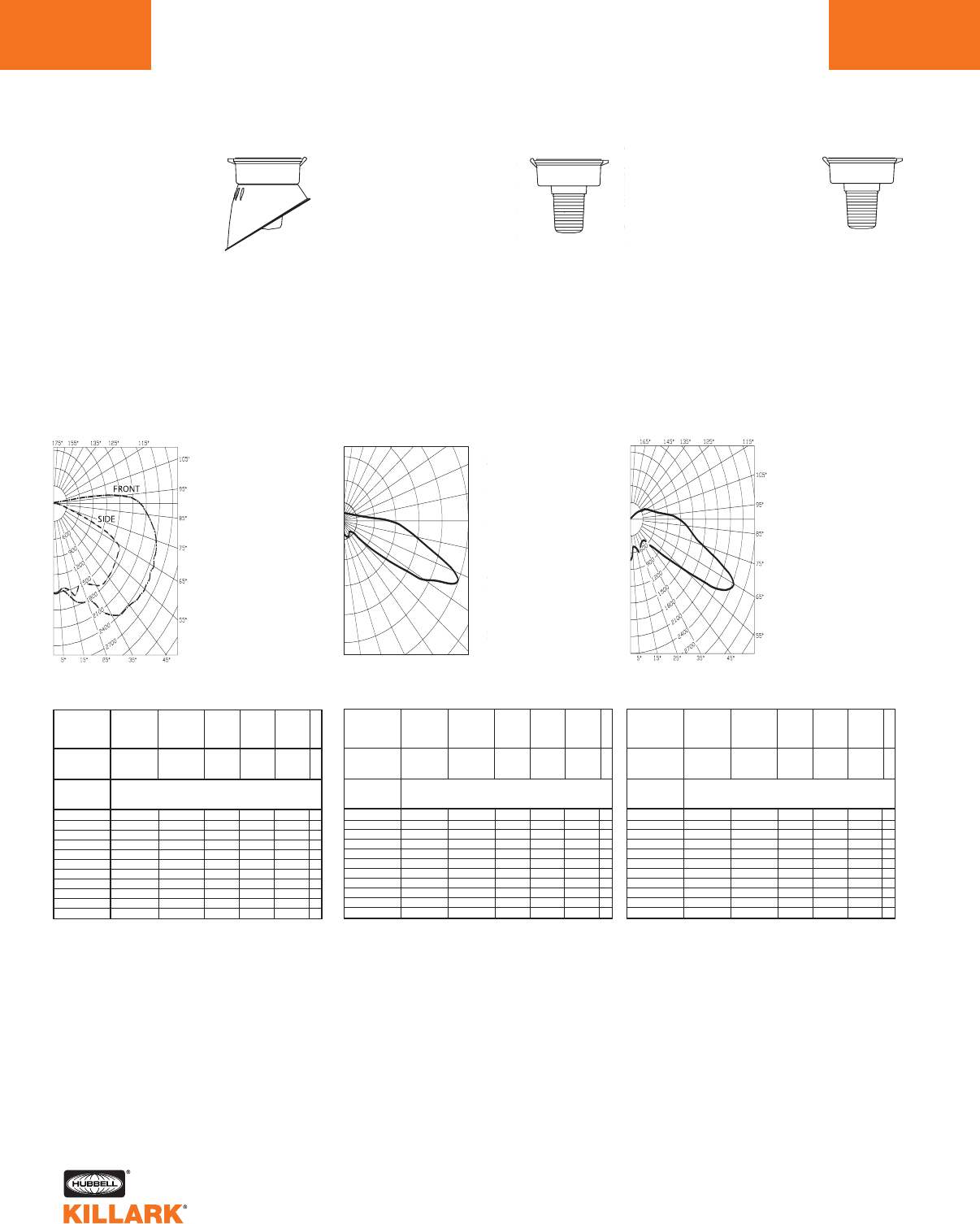
CERTILITE®V SERIES •LIGHTING
PHOTOMETRIC DATA
L94
Test No. HPK09937 Test No. HPK09980 Test No. HPK09946
METAL HALIDE, METAL HALIDE
PULSE, MERCURY VAPOR -VM3
With Globe and
Angle Refractor
70-250 Watt
Mogul Base
CANDLEPOWER – 175 WATT
14000 lumens
For 70 MH watt multiply by 0.40
For 100 MH watt multiply by 0.64
For 250 MH watt multiply by 1.46
For 150 MHP watt multiply by 1.00
For 175 MHP watt multiply by 1.25
For 200 MHP watt multiply by 1.50
For 100 MV watt multiply by 0.31
For 175 MV watt multiply by 0.56
For 250 MV watt multiply by 0.93
Efficiency 62.4%
Front Side
ANGLE CP ANGLE CP
0.0 1506. 0.0 1506.
5.0 1478. 5.0 1486.
15.0 1676. 15.0 1548.
25.0 1770. 25.0 1467.
35.0 2281. 35.0 1684.
45.0 2429. 45.0 1750.
55.0 2520. 55.0 1698.
65.0 2507. 65.0 1579.
75.0 2396. 75.0 409.
85.0 2149. 85.0 87.
90.0 1964. 90.0 24.
95.0 1523. 95.0 20.
105.0 240. 105.0 14.
115.0 64. 115.0 14.
125.0 18. 125.0 13.
135.0 6. 135.0 10.
145.0 6. 145.0 9.
155.0 6. 155.0 7.
165.0 5. 165.0 5.
175.0 4. 175.0 4.
180.0 4. 165.0 4.
1518
4554
6072
90˚
80˚
70˚
60˚
50˚
40˚30˚20˚10˚0˚
180˚ 160˚ 150˚ 140˚ 130˚ 120˚
110˚
100˚
3036
% EFFECTIVE
CEILING CAVITY
REFLECTANCE
1cc
80 70 50 30 10 0
70 50 30 10 70 50 30 10 50 30 10 50 30 10 50 30 10 0
20% Effective Floor Cavity Reflectance
0 .73 .73 .73.73 .71 .71 .71 .71 .67 .67 .67 .63.63 .63 .60 .60 .60 .58
1 .65 .61 .57.54 .63 .59 .56 .53 .55 .53 .50 .52.50 .48 .49 .47 .46 .44
2 .58 .52 .47.43 .56 .50 .46 .42 .47 .44 .40 .45.41 .39 .42 .39 .37 .35
3 .53 .45 .39 .35 .51 .44 .39 .34 .41 .37 .33 .39.35 .32 .37 .33 .31 .29
4 .48 .39 .33.29 .46 .38 .32 .28 .36 .31 .27 .34.30 .26 .32 .28 .25 .24
5 .44 .35 .28.24 .42 .34 .28 .23 .32 .27 .23 .30.26 .22 .28 .24 .21 .20
6 .40 .31 .25 .20 .38 .30 .24 .20 .28 .23 .19 .27.22 .19 .25 .21 .18 .17
7 .37 .27 .21 .17 .35 .27 .21 .17 .25 .20 .17 .24 .19 .16 .23 .19 .16 .14
8 .34 .24 .19 .15 .32 .24 .18 .14 .22 .18 .14 .21.17 .14 .20 .16 .13 .12
9 .31 .22 .16 .13 .30 .21 .16 .12 .20 .15 .12 .19.15 .12 .18 .14 .12 .10
10 .28 .19 .14 .10 .27 .19 .14 .10 .18 .13 .10 .17.13 .10 .16 .12 .09 .08
% WALL
REFLECTANCE
1w
ROOM CAVITY
RATIO
RCR
COEFFICIENTS OF UTILIZATION ---ZONAL CAVITY METHOD
SPACING TO MOUNTING HEIGHT RATIO - 1.7
METAL HALIDE, METAL HALIDE
PULSE, MERCURY VAPOR -VM3
With Type I All
Glass Refractor
70-250 Watt
Mogul Base
CANDLEPOWER – 175 WATT
14000 lumens
For 70 MH watt multiply by 0.40
For 100 MH watt multiply by 0.64
For 250 MH watt multiply by 1.46
For 150 MHP watt multiply by 1.00
For 175 MHP watt multiply by 1.25
For 200 MHP watt multiply by 1.50
For 100 MV watt multiply by 0.31
For 175 MV watt multiply by 0.56
For 250 MV watt multiply by 0.93
Efficiency 86.8%
ANGLE CP ANGLE CP
0433. 85.0 3813.
5.0 447. 90.0 3154.
15.0 703. 95.0 2185.
25.0 642. 105.0 1047.
35.0 598. 115.0 794.
45.0 1049. 125.0 389.
55.0 3738. 135.0 137.
60.0 5513. 145.0 40.
65.0 5774. 155.0 4.
70.0 6031. 165.0 2.
75.0 4991. 175.0 0.
80.0 4211. 180.0 0.
% EFFECTIVE
CEILING CAVITY
REFLECTANCE
1cc
80 70 50 30 10 0
70 50 30 10 70 50 30 10 50 30 10 50 30 10 50 30 10 0
20% Effective Floor Cavity Reflectance
0 .99 .99 .99 .99 .95 .95 .95 .95 .87 .87 .87 .80.80 .80 .73 .73 .73 .70
1 .83 .76 .69 .63 .79 .72 .66 .61 .65 .60 .56 .58.54 .51 .52 .49 .46 .43
2 .72 .61 .52 .44 .67 .58 .49 .42 .51 .44 .39 .46.40 .35 .40 .36 .32 .28
3 .63 .50 .40 .32 .59 .47 .38 .31 .42 .34 .28 .37.31 .25 .32 .27 .22 .19
4 .56 .42 .32 .24 .52 .40 .30 .23 .35 .27 .21 .31.24 .19 .27 .21 .17 .14
5 .51 .36 .26 .19 .47 .34 .25 .18 .30 .22 .16 .27.20 .14 .23 .17 .13 .10
6 .46 .32 .22 .15 .43 .30.21 .15 .26 .19 .13 .23.17 .11 .20 .14 .10 .07
7 .42 .28 .19 .13 .39 .27 .18 .12 .24 .16 .11 .21 .14 .09 .18 .12 .08 .06
8 .39 .25 .17 .11 .37 .24 .16 .10 .21 .14 .09 .19 .12 .08 .16 .11 .07 .05
9 .36 .23 .15 .09 .34 .22 .14 .09 .19 .12 .08 .17 .11 .07 .15 .10 .06 .04
10 .34 .21 .13 .08 .32 .20 .12 .07 .18 .11 .07 .16 .10 .06 .14 .09 .05 .03
% WALL
REFLECTANCE
1w
ROOM CAVITY
RATIO
RCR
COEFFICIENTS OF UTILIZATION ---ZONAL CAVITY METHOD
SPACING TO MOUNTING HEIGHT RATIO - 5.7 90-270°
METAL HALIDE, METAL HALIDE
PULSE, MERCURY VAPOR -VM3
With Type V All
Glass Refractor
70-250 Watt
Mogul Base
CANDLEPOWER – 175 WATT
14000 lumens
For 70 MH watt multiply by 0.40
For 100 MH watt multiply by 0.64
For 250 MH watt multiply by 1.46
For 150 MHP watt multiply by 1.00
For 175 MHP watt multiply by 1.25
For 200 MHP watt multiply by 1.50
For 100 MV watt multiply by 0.31
For 175 MV watt multiply by 0.56
For 250 MV watt multiply by 0.93
Efficiency 79.7%
ANGLE CP ANGLE CP
0731. 95.0 927.
5.0 562. 100.0 673.
10.0 489. 105.0 542.
15.0 542. 110.0 475.
20.0 640. 115.0 420.
25.0 592. 120.0 370.
30.0 519. 125.0 256.
35.0 498. 130.0 171.
40.0 491. 135.0 106.
45.0 641. 140.0 65.
50.0 921. 145.0 35.
55.0 1545. 150.0 9.
60.0 2543. 155.0 3.
65.0 2730. 160.0 1.
70.0 2320. 165.0 1.
75.0 1789. 170.0 0.
80.0 1509. 175.0 0.
85.0 1367. 180.0 0.
90.0 1186.
% EFFECTIVE
CEILING CAVITY
REFLECTANCE
1cc
80 70 50 30 10 0
70 50 30 10 70 50 30 10 50 30 10 50 30 10 50 30 10 0
20% Effective Floor Cavity Reflectance
0 .90 .90 .90 .90 .86 .86 .86 .86 .79 .79 .79 .72 .72 .72 .66 .66 .66 .63
1 .76 .70 .64 .59 .72 .66 .61 .57 .60 .56 .52 .54 .50 .47 .48 .45 .43 .40
2 .66 .57 .49 .42 .62 .54 .46 .40 .48 .42 .37 .43 .38 .33 .38.34 .30 .27
3 .58 .47 .38 .31 .55 .44 .36 .30 .39 .33 .27 .35 .29 .24 .30 .26 .22 .19
4 .52 .39 .30 .23 .48 .37 .29 .22 .33 .25 .20 .29 .23 .18 .25 .20 .16 .13
5 .46 .33 .24 .18 .43 .31 .23 .17 .28 .20 .15 .24 .18 .13 .21 .16 .12 .09
6 .42 .29 .21 .14 .39 .28 .20 .14 .24 .17 .12 .21 .15 .11 .18 .13 .09 .07
7 .39 .26 .18 .12 .36 .25 .17 .11 .22.15 .10 .19 .13 .09 .16.11 .08 .05
8 .36 .23 .15 .10 .33 .22 .15 .09 .19 .13 .08 .17 .11 .07 .15 .10 .06 .04
9 .33 .21 .14 .09 .31 .20 .13 .08 .18 .12 .07 .16 .10 .06 .14 .09 .06 .04
10 .31 .19 .12 .08 .29.18 .12 .07 .16 .10 .06 .14 .09 .05 .13.08 .05 .03
% WALL
REFLECTANCE
1w
ROOM CAVITY
RATIO
RCR
COEFFICIENTS OF UTILIZATION ---ZONAL CAVITY METHOD
SPACING TO MOUNTING HEIGHT RATIO - 1.1
Angle Vertical
CP 90° Horizontal
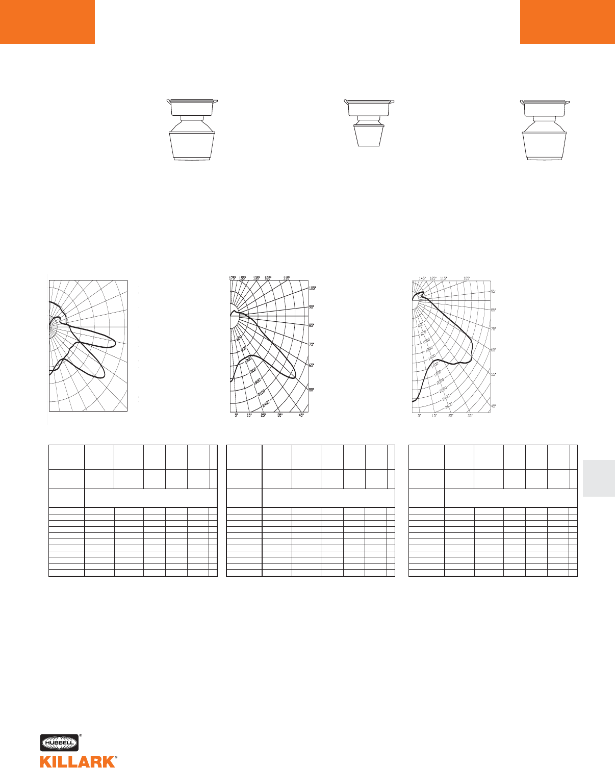
CERTILITE®V SERIES •LIGHTING
PHOTOMETRIC DATA L95
L
Test No. HPK09482 Test No. HPK09473 Test No. HPK09475
METAL HALIDE, METAL HALIDE
PULSE, MERCURY VAPOR -VM3
With Type II 12" Spin-Top
Refractor
70-250 Watt
Mogul Base
CANDLEPOWER – 175 WATT
14000 lumens
For 70 MH watt multiply by 0.40
For 100 MH watt multiply by 0.64
For 250 MH watt multiply by 1.46
For 150 MHP watt multiply by 1.00
For 175 MHP watt multiply by 1.25
For 200 MHP watt multiply by 1.50
For 100 MV watt multiply by 0.31
For 175 MV watt multiply by 0.56
For 250 MV watt multiply by 0.93
Efficiency 75.1%
ANGLE CP ANGLE CP
1000
3000
4000
90˚
80˚
70˚
60˚
50˚
40˚30˚20˚10˚0˚
1
80˚ 160˚ 150˚ 140˚ 130˚ 120˚
110˚
100˚
% EFFECTIVE
CEILING CAVITY
REFLECTANCE
1cc
80 70 50 30 10 0
70 50 30 10 70 50 30 10 50 30 10 50 30 10 50 30 10 0
20% Effective Floor Cavity Reflectance
0 .85 85 .85 .85 .81 .81 .81 .81 .74 .74 .74 .67 .67 .67 .60 .60 .60 .57
1 .75 .71 .67 .63 .71 .67 .63 .60 .61.58 .55 .55 .52.50 .49 .47 .46 .43
2 .67 .60 .54 .49 .63 .57 .51 .47 .51.47 .43 .46 .42.39 .41 .38 .36 .33
3 .60 .51 .44 .39 .57 .49 .42 .37 .44 .39 .34 .39 .35 .31 .35 .32 .29 .26
4 .54 .44 .37 .31 .51 .42 .35 .30 .38 .32 .28 .34 .29 .26 .30 .27 .23 .21
5 .49 .39 .31 .26 .46 .37 .30 .25 .33 .27 .23 .30 .25 .21 .27 .23 .19 .17
6 .45 .34 .27 .22 .42 .33 .26 .21 .29 .24 .19 .26 .22 .18 .24 .19 .16 .14
7 .41 .31 .23 .19 .39 .29 .23 .18 .26 .21 .16 .24 .19 .15 .21 .17 .14 .12
8 .38 .27 .21 .16 .36 .26 .20 .15 .24 .18 .14 .21 .17 .13 .19 .15 .12 .10
9 .35 .25 .18 .14 .33 .24 .18 .13 .21 .16 .12 .19 .15 .11 .17 .13 .10 .09
10 .33 .23 .16 .12 .31 .22 .16 .12 .20 .14 .11 .18 .13 .10 .16 .12 .09 .08
% WALL
REFLECTANCE
1w
ROOM CAVITY
RATIO
RCR
COEFFICIENTS OF UTILIZATION ---ZONAL CAVITY METHOD
SPACING TO MOUNTING HEIGHT RATIO - 1.48 0-180°
0.0 2111.
5.0 1908.
15.0 1598.
25.0 1521.
35.0 1810.
45.0 3016.
55.0 3608.
60.0 3065.
65.0 2257.
70.0 1712.
75.0 1367.
80.0 1182.
85.0 1076.
90.0 989.
95.0 888.
105.0 569.
115.0 522.
125.0 588.
135.0 498.
145.0 380.
155.0 239.
165.0 84.
175.0 0.
180.0 0.
METAL HALIDE, METAL HALIDE
PULSE, MERCURY VAPOR -VM3
With Type V 8" Spin-Top
Refractor
70-250 Watt
Mogul Base
CANDLEPOWER – 175 WATT
14000 lumens
For 70 MH watt multiply by 0.40
For 100 MH watt multiply by 0.64
For 250 MH watt multiply by 1.46
For 150 MHP watt multiply by 1.00
For 175 MHP watt multiply by 1.25
For 200 MHP watt multiply by 1.50
For 100 MV watt multiply by 0.31
For 175 MV watt multiply by 0.56
For 250 MV watt multiply by 0.93
Efficiency 70.2%
ANGLE CP ANGLE CP
% EFFECTIVE
CEILING CAVITY
REFLECTANCE
1cc
80 70 50 30 10 0
70 50 30 10 70 50 30 10 50 30 10 50 30 10 50 30 10 0
20% Effective Floor Cavity Reflectance
0 .81 .81 .81 .81 .78 .78 .78 .78 .72 .72 .72 .66 .66 .66 .62 .62 .62 .59
1 .71 .67 .63 .59 .68 .64 .61 .57 .59 .56 .54 .54 .52 .50 .50.48 .47 .44
2 .64 .57 .51 .46 .61 .54 .49 .45 .50 .46 .42 .46 .43 .40 .42.40 .37 .35
3 .57 .49 .42 .37 .54 .47 .41 .36 .43 .38 .34 .40 .35 .32 .36 .33 .30 .28
4 .51 .42 .35 .29 .49 .40 .34 .29 .37 .31 .27 .34 .29 .25 .31 .27 .24 .22
5 .46 .36 .29 .24 .44 .35 .28 .23 .32 .26 .22 .29 .24 .21 .27 .23 .19 .17
6 .42 .32 .25 .20 .40 .30 .24 .19 .28 .22 .18 .26 .21 .17 .24 .19 .16 .14
7 .38 .28 .21 .16 .36 .27 .20 .16 .24 .19 .15 .22 .17 .14 .21.16 .13 .11
8 .35 .24 .18 .13 .33 .23 .17 .13 .22 .16 .12 .20 .15 .11 .18 .14 .11 .09
9 .32 .22 .16 .11 .31 .21 .15 .11 .20 .14 .11 .18 .13 .10 .17 .12 .09 .08
10 .30 .20 .14 .09 .28 .19 .13 .09 .17 .12 .09 .16 .11 .08 .15 .11 .08 .06
% WALL
REFLECTANCE
1w
ROOM CAVITY
RATIO
RCR
COEFFICIENTS OF UTILIZATION ---ZONAL CAVITY METHOD
SPACING TO MOUNTING HEIGHT RATIO - 1.0
0.0 1574.
5.0 1427.
10.0 1229.
15.0 114 7.
20.0 1116 .
25.0 1109.
30.0 1125.
35.0 115 1.
40.0 1243.
45.0 1455.
50.0 2116.
55.0 2565.
60.0 2223.
65.0 1469.
70.0 1089.
75.0 930.
80.0 809.
85.0 672.
90.0 560.
95.0 475.
100.0 396.
105.0 313.
110.0 257.
115.0 226.
120.0 203.
125.0 200.
130.0 194.
135.0 179.
140.0 159.
145.0 127.
150.0 88.
155.0 46.
160.0 7.
165.0 2.
170.0 0.
175.0 0.
180.0 0.
METAL HALIDE, METAL HALIDE
PULSE, MERCURY VAPOR -VM3
With Type V 12"
Spin-Top Refractor
70-250 Watt
Mogul Base
CANDLEPOWER – 175 WATT
14000 lumens
For 70 MH watt multiply by 0.40
For 100 MH watt multiply by 0.64
For 250 MH watt multiply by 1.46
For 150 MHP watt multiply by 1.00
For 175 MHP watt multiply by 1.25
For 200 MHP watt multiply by 1.50
For 100 MV watt multiply by 0.31
For 175 MV watt multiply by 0.56
For 250 MV watt multiply by 0.93
Efficiency 78.8%
% EFFECTIVE
CEILING CAVITY
REFLECTANCE
1cc
80 70 50 30 10 0
70 50 30 10 70 50 30 10 50 30 10 50 30 10 50 30 10 0
20% Effective Floor Cavity Reflectance
0 .91 .91 .91 .91 .87 .87 .87 .87 .81 .81 .81 .74 .74 .74 .69 .69 .69 .66
1 .81 .76 .72 .69 .77 .73.70 .66 .68 .65 .62 .62.60 .58 .57 .55 .54 .51
2 .73 .66 .59 .54 .70 .63 .57 .53 .58 .53 .50 .53.50 .47 .49 .46 .44 .41
3 .66 .57 .50 .44 .63 .54.48 .43 .50 .45 .40 .46.42 .38 .43 .39 .36 .34
4 .59 .49 .41 .36 .56 .47.40 .35 .43 .38 .33 .40.35 .31 .37 .33 .29 .27
5 .54 .43 .35 .29 .51 .41 .34 .29 .38 .32 .27 .35.30 .26 .32 .28 .24 .22
6 .49 .38 .30 .25 .47 .36.29 .24 .34 .27 .23 .31.26 .22 .29 .24 .20 .18
7 .45 .33 .26 .21 .43 .32.25 .20 .30 .24 .19 .27.22 .18 .25 .21 .17 .15
8 .41 .30 .22 .18 .39 .29 .22 .17 .26 .20 .16 .24 .19 .15 .23 .18 .15 .13
9 .38 .27 .20 .15 .36 .26 .19 .15 .24 .18 .14 .22 .17 .13 .20 .16 .13 .11
10 .35 .24 .17 .13 .33 .23 .16 .12 .21 .15 .12 .20.14 .11 .18 .14 .10 .09
% WALL
REFLECTANCE
1w
ROOM CAVITY
RATIO
RCR
COEFFICIENTS OF UTILIZATION ---ZONAL CAVITY METHOD
SPACING TO MOUNTING HEIGHT RATIO - .9
ANGLE CP ANGLE CP
0.0 2261.
5.0 2146.
10.0 1868.
15.0 1657.
20.0 1555.
25.0 1502.
30.0 1534.
35.0 1664.
40.0 1857.
45.0 1970.
50.0 2168.
55.0 2205.
60.0 2104.
65.0 1809.
70.0 1176.
75.0 845.
80.0 696.
85.0 604.
90.0 517.
95.0 451.
100.0 380.
105.0 314.
110.0 305.
115.0 368.
120.0 391.
125.0 321.
130.0 260.
135.0 222.
140.0 191.
145.0 155.
150.0 115 .
155.0 80.
160.0 41.
165.0 12.
170.0 0.
175.0 0.
180.0 0.
Angle Vertical
CP 75° Horizontal
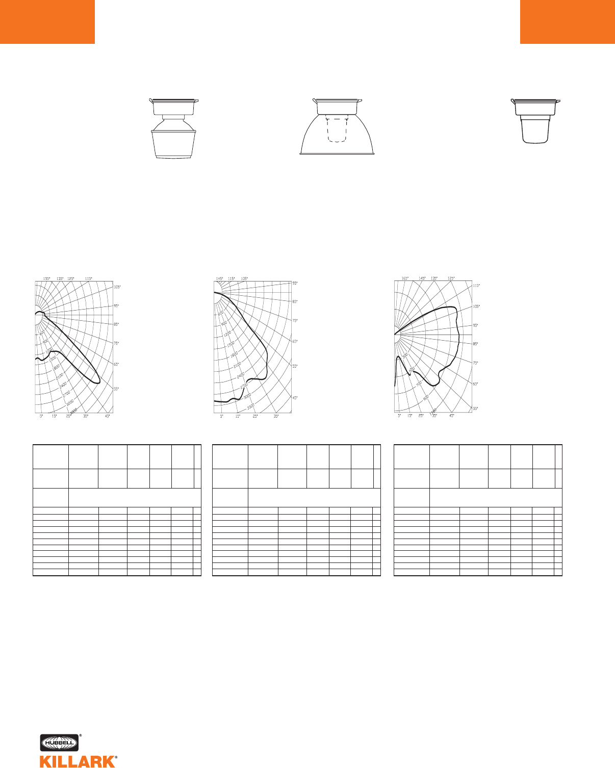
CERTILITE®V SERIES •LIGHTING
PHOTOMETRIC DATA
L96
Test No. HPK09477
METAL HALIDE, METAL HALIDE
PULSE, MERCURY VAPOR -VM3
With Type V 12" Spin-
Top Poly Refractor
70-250 Watt
Mogul Base
CANDLEPOWER –
175 WATT
14000 lumens
For 70 MH watt multiply by 0.40
For 100 MH watt multiply by 0.64
For 150 MHP watt multiply by 1.00
For 175 MHP watt multiply by 1.25
For 100 MV watt multiply by 0.31
For 175 MV watt multiply by 0.56
Efficiency 71.9%
%EFFECTIVE
CEILING CAVITY
REFLECTANCE
1cc
80 70 50 30 10 0
70 50 30 10 70 50 30 10 50 30 10 50 30 10 50 30 10 0
20% Effective Floor Cavity Reflectance
0 .83 .83 .83 .83 .80 .80 .80 .80 .74 .74 .74 .69.69 .69 .64 .64 .64 .62
1 .74 .70 .67 .64 .71 .68 .65 .62 .63 .60 .58 .58.56 .54 .54 .53 .51 .49
2 .67 .61 .55 .51 .64 .58.54 .49 .54 .50 .47 .50.47 .44 .47 .44 .42 .40
3 .61 .52 .46 .41 .58 .51.45 .40 .47 .42 .38 .44.40 .36 .41 .37 .35 .33
4 .54 .45 .38 .33 .52 .44.37 .32 .41 .35 .31 .38.33 .30 .35 .31 .28 .26
5 .49 .39 .32 .27 .47 .38.31 .26 .35 .30 .25 .33.28 .24 .30 .26 .23 .21
6 .45 .34 .27 .22 .42 .33.26 .22 .31 .25 .21 .28.24 .20 .26 .22 .19 .17
7 .40 .30 .23 .18 .38 .29.22 .18 .27 .21 .17 .25.20 .16 .23 .19 .15 .13
8 .37 .26 .19 .15 .35 .25 .19 .14 .23 .18 .14 .22 .17 .13 .20 .16 .12 .11
9 .34 .23 .17 .13 .32 .23 .16 .12 .21 .16 .12 .19 .15 .11 .18 .14 .11 .09
10 .31 .21 .14 .10 .29 .20 .14 .10 .18 .13 .09 .17.12 .09 .16 .12 .09 .07
% WALL
REFLECTANCE
1w
ROOM CAVITY
RATIO
RCR
COEFFICIENTS OF UTILIZATION ---ZONAL CAVITY METHOD
SPACING TO MOUNTING HEIGHT RATIO - 2.6
Test No. HPK10118
METAL HALIDE, METAL HALIDE
PULSE, MERCURY VAPOR -VM3
With Globe and Full
Cutoff Deep White
Reflector*
70-250 Watt
Mogul Base
CANDLEPOWER –
175 WATT
14000 lumens
For 70 MH watt multiply by 0.40
For 100 MH watt multiply by 0.64
For 250 MH watt multiply by 1.46
For 150 MHP watt multiply by 1.00
For 175 MHP watt multiply by 1.25
For 200 MHP watt multiply by 1.50
For 100 MV watt multiply by 0.31
For 175 MV watt multiply by 0.56
For 250 MV watt multiply by 0.93
Efficiency 65.5%
%EFFECTIVE
CEILING CAVITY
REFLECTANCE
1cc
80 70 50 30 10 0
70 50 30 10 70 50 30 10 50 30 10 50 30 10 50 30 10 0
20% Effective Floor Cavity Reflectance
0 .76 .76 .76 .76 .74 .74 .74 .74 .71 .71 .71 .68.68 .68 .65 .65 .65 .64
1 .70 .67 .65 .63 .68 .66.64 .62 .63 .61 .60 .61.59 .58 .58 .57 .56 .55
2 .65 .60 .56 .53 .63 .59.55 .52 .57 .54 .51 .55.52 .50 .53 .51 .49 .48
3 .60 .54 .49 .46 .58 .53.49 .45 .51 .48 .45 .49.46 .44 .48 .45 .43 .42
4 .55 .48 .43 .39 .54 .47.43 .39 .46 .42 .38 .44.41 .38 .43 .40 .37 .36
5 .51 .43 .38 .34 .49 .43.38 .34 .41 .37 .34 .40.36 .33 .39 .36 .33 .32
6 .47 .39 .34 .30 .46 .38.33 .30 .37 .33 .29 .36.32 .29 .35 .32 .29 .28
7 .43 .35 .30 .26 .42 .35.30 .26 .34 .29 .26 .33.29 .26 .32 .28 .25 .24
8 .40 .32 .26 .23 .39 .31.26 .23 .30 .26 .22 .29.25 .22 .29 .25 .22 .21
9 .37 .28 .23 .20 .36 .28.23 .20 .27 .23 .20 .27.23 .20 .26 .22 .19 .18
10 .33 .25 .20 .16 .32 .24 .19 .16 .24 .19 .16 .23.19 .16 .23 .19 .16 .15
% WALL
REFLECTANCE
1w
ROOM CAVITY
RATIO
RCR
COEFFICIENTS OF UTILIZATION ---ZONAL CAVITY METHOD
SPACING TO MOUNTING HEIGHT RATIO - 1.5
*Values using Dark Sky gasket kit
0.0 2879.
5.0 2911.
10.0 2938.
15.0 2913.
20.0 2914.
25.0 2678.
30.0 2648.
35.0 2810.
40.0 2926.
45.0 2682.
50.0 2492.
55.0 1443.
60.0 110 7.
65.0 849.
70.0 637.
75.0 442.
80.0 265.
85.0 110 .
90.0 0.
95.0 0.
100.0 0.
105.0 0.
110.0 0.
115.0 0.
120.0 0.
125.0 0.
130.0 0.
135.0 0.
140.0 0.
145.0 0.
150.0 0.
155.0 0.
160.0 0.
165.0 0.
170.0 0.
175.0 0.
180.0 0.
Test No. HPK09955
HIGH PRESSURE SODIUM-VM4
With Globe
50-150 Watt
Mogul Base
CANDLEPOWER – 100 WATT
9500 lumens
For 50 watt multiply by 0.42
For 70 watt multiply by 0.68
For 150 watt multiply by 1.68
Efficiency 84.6%
%EFFECTIVE
CEILING CAVITY
REFLECTANCE
1cc
80 70 50 30 10 0
70 50 30 10 70 50 30 10 50 30 10 50 30 10 50 30 10 0
20% Effective Floor Cavity Reflectance
0 .94 .94 .94 .94 .88 .88 .88 .88 .78 .78 .78 .68.68 .68 .59 .59 .59 .55
1 .80 .74 .68 .63 .74 .69 .64 .59 .59 .55 .52 .51 .47 .45 .43 .40 .38 .34
2 .71 .61 .54 .47 .65 .57 .50 .44 .49 .43 .38 .41.37 .33 .34 .31 .28 .24
3 .63 .52 .44 .37 .58 .48 .41 .35 .41 .35 .30 .35.30 .26 .29 .25 .21 .18
4 .57 .45 .36 .29 .52 .42 .34 .27 .36 .29 .24 .30.25 .20 .25 .20 .17 .14
5 .52 .39 .30 .24 .47 .36 .28 .22 .31 .24 .19 .26 .21 .16 .21 .17 .13 .11
6 .47 .34 .26 .20 .43 .32 .24 .19 .27 .21 .16 .23 .18 .13 .19 .14 .11 .08
7 .43 .30 .22 .17 .40 .28 .21 .15 .24 .18 .13 .20 .15 .11 .17 .12 .09 .07
8 .40 .27 .19 .14 .36 .25 .18 .13 .22 .15 .11 .18 .13 .09 .15 .11 .07 .05
9 .37 .24 .17 .12 .34 .23 .16 .11 .19 .14 .09 .16 .11 .08 .13 .09 .06 .04
10 .34 .22 .15 .10 .31 .20.14 .09 .17 .12 .08 .14.10 .06 .12 .08 .05 .03
% WALL
REFLECTANCE
1w
ROOM CAVITY
RATIO
RCR
COEFFICIENTS OF UTILIZATION ---ZONAL CAVITY METHOD
SPACING TO MOUNTING HEIGHT RATIO - 1.9
1346.
1290.
1380.
1389.
1365.
1319.
1264.
1342.
1436.
1961.
3177.
3107.
2035.
1273.
892.
643.
501.
430.
394.
398.
361.
306.
268.
247.
217.
182.
151.
124.
101.
77.
51.
29.
9.
2.
0.
0.
0.
614.
331.
265.
267.
325.
486.
501.
523.
599.
852.
903.
872.
849.
907.
970.
1006.
1026.
1036.
1035.
1007.
1004.
1035.
963.
649.
177.
37.
22.
15.
10.
8.
6.
4.
2
1.
0.
0.
0.
ANGLE CP ANGLE CP ANGLE CP ANGLE CP ANGLE CP ANGLE CP
0.0
5.0
10.0
15.0
20.0
25.0
30.0
35.0
40.0
45.0
50.0
55.0
60.0
65.0
70.0
75.0
80.0
85.0
90.0 .
95.0
100.0
105.0
110.0
115.0
120.0
125.0
130.0
135.0
140.0
145.0
150.0
155.0
160.0
165.0
170.0
175.0
180.0
0.0
5.0
10.0
15.0
20.0
25.0
30.0
35.0
40.0
45.0
50.0
55.0
60.0
65.0
70.0
75.0
80.0
85.0
90.0
95.0
100.0
105.0
110.0
115.0
120.0
125.0
130.0
135.0
140.0
145.0
150.0
155.0
160.0
165.0
170.0
175.0
180.0
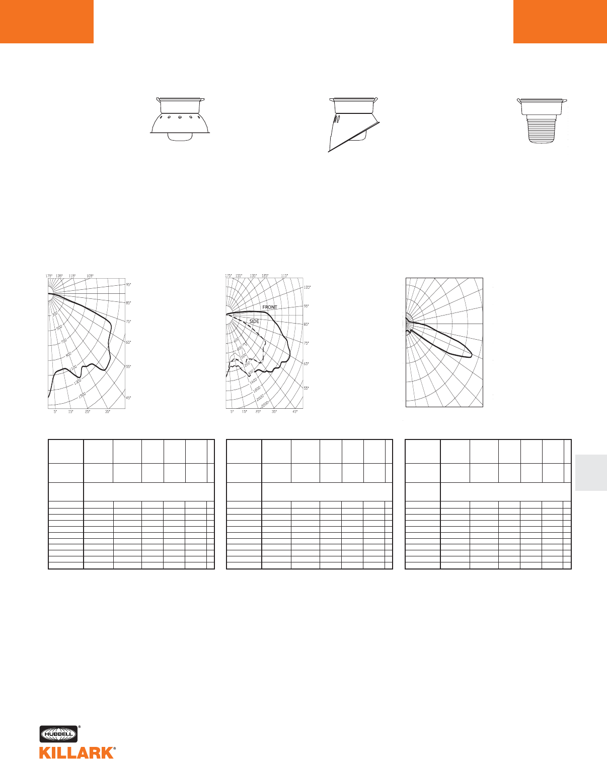
CERTILITE®V SERIES •LIGHTING
PHOTOMETRIC DATA L97
L
Test No. HPK09956
HIGH PRESSURE SODIUM-VM4
With Globe and
Dome Reflector
50-150 Watt
Mogul Base
CANDLEPOWER – 100 WATT
9500 lumens
For 50 watt multiply by 0.42
For 70 watt multiply by 0.68
For 150 watt multiply by 1.68
Efficiency 66.5%
%EFFECTIVE
CEILING CAVITY
REFLECTANCE
1cc
80 70 50 30 10 0
70 50 30 10 70 50 30 10 50 30 10 50 30 10 50 30 10 0
20% Effective Floor Cavity Reflectance
0 .79 .79 .79 .79 .77 .77 .77 .77 .73 .73 .73 .69.69 .69 .66 .66 .66 .64
1 .71 .68 .64 .61 .69 .66.63 .60 .62 .60 .58 .59.57 .56 .57 .55 .54 .52
2 .64 .58 .53 .49 .62 .57.52 .48 .54 .50 .47 .51.48 .45 .49 .46 .44 .42
3 .58 .50 .44 .39 .56 .49.43 .39 .46 .42 .38 .44.40 .37 .42 .39 .36 .34
4 .52 .43 .37 .32 .50 .42.36 .31 .40 .35 .31 .38.34 .30 .36 .33 .29 .28
5 .47 .38 .31 .26 .45 .37.31 .26 .35 .30 .25 .33.29 .25 .32 .28 .24 .23
6 .43 .33 .27 .22 .41 .32.26 .22 .31 .26 .21 .30.25 .21 .28 .24 .21 .19
7 .39 .29 .23 .19 .38 .29.23 .18 .27 .22 .18 .26.21 .18 .25 .21 .17 .16
8 .36 .26 .20 .16 .35 .26 .20 .16 .24 .19 .15 .23 .19 .15 .22 .18 .15 .13
9 .33 .23 .18 .13 .32 .23 .17 .13 .22 .17 .13 .21 .16 .13 .20 .16 .13 .11
10 .30 .20 .15 .11 .29 .20 .14 .11 .19 .14 .11 .18 .14 .10 .18 .13 .10 .09
% WALL
REFLECTANCE
1w
ROOM CAVITY
RATIO
RCR
COEFFICIENTS OF UTILIZATION ---ZONAL CAVITY METHOD
SPACING TO MOUNTING HEIGHT RATIO - 1.3
1399.
1123.
1052.
1049.
1100.
1227.
1205.
119 7.
1235.
1452.
1441.
1358.
1268.
1248.
1217.
643.
232.
110 .
32.
33.
32.
52.
138.
119 .
2.
21.
10.
9.
8.
8.
8.
7.
6.
5.
5.
5.
5.
Test No. HPK09957
HIGH PRESSURE SODIUM-VM4
With Globe
50-150 Watt
Mogul Base
CANDLEPOWER – 100 WATT
9500 lumens
For 50 watt multiply by 0.42
For 70 watt multiply by 0.68
For 150 watt multiply by 1.68
Efficiency 65.7%
%EFFECTIVE
CEILING CAVITY
REFLECTANCE
1cc
80 70 50 30 10 0
70 50 30 10 70 50 30 10 50 30 10 50 30 10 50 30 10 0
20% Effective Floor Cavity Reflectance
0 .78 .78 .78 .78 .76 .76 .76 .76 .71 .71 .71 .67 .67 .67 .63 .63 .63 .62
1 .69 .64 .61 .57 .66 .62.59 .56 .59 .56 .53 .55.53 .51 .52 .50 .48 .47
2 .62 .55 .50 .45 .59 .53.48 .44 .50 .46 .42 .47.44 .41 .45 .42 .39 .37
3 .56 .48 .42 .37 .54 .46.41 .36 .44 .39 .35 .41.37 .34 .39 .35 .32 .31
4 .50 .42 .35 .30 .49 .40.34 .30 .38 .33 .29 .36.31 .28 .34 .30 .27 .25
5 .46 .37 .30 .25 .44 .35.29 .25 .34 .28 .24 .32.27 .23 .30 .26 .23 .21
6 .42 .32 .26 .21 .41 .32.25 .21 .30 .25 .20 .28.24 .20 .27 .23 .19 .18
7 .39 .29 .23 .18 .37 .28.22 .18 .27 .21 .17 .25.20 .17 .24 .20 .16 .15
8 .35 .26 .20 .15 .34 .25 .19 .15 .24 .19 .15 .23 .18 .14 .21 .17 .14 .13
9 .33 .23 .17 .13 .32 .23 .17 .13 .21 .16 .13 .20 .16 .12 .19 .15 .12 .11
10 .30 .20 .14 .11 .29 .20 .14 .10 .19 .14 .10 .18 .13 .10 .17 .13 .10 .08
% WALL
REFLECTANCE
1w
ROOM CAVITY
RATIO
RCR
COEFFICIENTS OF UTILIZATION ---ZONAL CAVITY METHOD
SPACING TO MOUNTING HEIGHT RATIO - 1.3
Front Side
ANGLE CP ANGLE CP
0.0 1312. 0.0 1312.
5.0 1131. 5.0 1060.
15.0 1124. 15.0 956.
25.0 1366. 25.0 1143.
35.0 1464. 35.0 1155.
45.0 1671. 45.0 1440.
55.0 1892. 55.0 1320.
65.0 2017. 65.0 1143.
75.0 1700. 75.0 339.
85.0 1372. 85.0 81.
90.0 1243. 90.0 30.
95.0 895. 95.0 20.
105.0 161. 105.0 12.
115.0 52. 115.0 10.
125.0 16. 125.0 10.
135.0 7. 135.0 8.
145.0 5. 145.0 6.
155.0 4. 155.0 5.
165.0 4. 165.0 4.
175.0 3. 175.0 3.
180.0 3. 165.0 3.
ANGLE CP ANGLE CP
Test No. HPK09960
HIGH PRESSURE SODIUM-VM4
With Type I All Glass Refractor
50-150 Watt
Mogul Base
CANDLEPOWER – 100 WATT
9500 lumens
For 50 watt multiply by 0.42
For 70 watt multiply by 0.68
For 150 watt multiply by 1.68
Efficiency 82.1%
2000
5000
8000
90˚
80˚
70˚
60˚
50˚
40˚30˚20˚10˚0˚
180˚ 160˚ 150˚ 140˚ 130˚ 120˚
110˚
100˚
%EFFECTIVE
CEILING CAVITY
REFLECTANCE
1cc
80 70 50 30 10 0
70 50 30 10 70 50 30 10 50 30 10 50 30 10 50 30 10 0
20% Effective Floor Cavity Reflectance
0 .95 .95 .95 .95 .91 .91 .91 .91 .85 .85 .85 .79 .79 .79 .73 .73 .73 .71
1 .81 .74 .69 .63 .77 .71 .66 .61 .65 .61 .57 .60 .56 .53 .55 .52 .50 .47
2 .70 .60 .51 .44 .66 .57 .49 .43 .52 .45 .40 .47 .42 .37 .43 .38 .35 .32
3 .61 .49 .40 .32 .58 .47 .38 .31 .42 .35 .29 .38 .32 .27 .34 .29 .25 .22
4 .54 .41 .32 .24 .51 .39 .30 .23 .35 .28 .22 .32 .25 .20 .29 .23 .18 .16
5 .49 .35 .26 .19 .46 .34 .25 .18 .30 .23 .17 .27 .21 .15 .24 .19 .14 .12
6 .44 .31 .22 .15 .42 .29 .21 .15 .26 .19 .13 .24 .17 .12 .21 .16 .11 .09
7 .41 .27 .19 .12 .38 .26 .18 .12 .23 .16 .11 .21 .15 .10 .19 .13 .09 .07
8 .38 .24 .16 .10 .35 .23 .15 .10 .21 .14 .09 .19 .13 .08 .17 .12 .08 .06
9 .35 .22 .14 .09 .33 .21 .14 .09 .19 .13 .08 .17 .11 .07 .16 .10 .07 .05
10 .33 .20 .13 .08 .31 .19 .12 .07 .18 .11 .07 .16 .10 .06 .14 .09 .06 .04
% WALL
REFLECTANCE
1w
ROOM CAVITY
RATIO
RCR
COEFFICIENTS OF UTILIZATION --- ZONAL CAVITY METHOD
SPACING TO MOUNTING HEIGHT RATIO - 1.64 90 -270°
ANGLE CP ANGLE CP
0806. 85.0 2161.
5.0 561. 90.0 1446.
15.0 517. 95.0 1037.
25.0 669. 105.0 592.
35.0 921. 115.0 399.
45.0 777. 125.0 192.
55.0 2076. 135.0 105.
60.0 4845. 145.0 89.
65.0 6434. 155.0 34.
70.0 6638. 165.0 1.
75.0 4655. 175.0 0.
80.0 2893. 180.0 0.
0.0
5.0
10.0
15.0
20.0
25.0
30.0
35.0
40.0
45.0
50.0
55.0
60.0
65.0
70.0
75.0
80.0
85.0
90.0
95.0
100.0
105.0
110.0
115.0
120.0
125.0
130.0
135.0
140.0
145.0
150.0
155.0
160.0
165.0
170.0
175.0
180.0
Angle Vertical
CP 90° Horizontal

CERTILITE®V SERIES •LIGHTING
PHOTOMETRIC DATA
L98
Test No. HPK09962
HIGH PRESSURE SODIUM-VM4
With Type III All Glass Refractor
50-150 Watt
Mogul Base
CANDLEPOWER – 100 WATT
9500 lumens
For 50 watt multiply by 0.42
For 70 watt multiply by 0.68
For 150 watt multiply by 1.68
Efficiency 79.2%
1555
4665
6220
90˚
80˚
70˚
60˚
50˚
40˚30˚20˚10˚0˚
180˚ 160˚ 150˚ 140˚ 130˚ 120˚
110˚
100˚
3110
% EFFECTIVE
CEILING CAVITY
REFLECTANCE
1cc
80 70 50 30 10 0
70 50 30 10 70 50 30 10 50 30 10 50 30 10 50 30 10 0
20% Effective Floor Cavity Reflectance
0 .91 .91 .91 .91 .88 .88.88 .88 .81 .81 .81 .75.75 .75 .70 .70 .70 .67
1 .78 .71 .66 .61 .74 .68 .63 .59 .63 .58 .55 .57 .54 .51 .52 .50 .47 .44
2 .67 .57 .49 .43 .63 .55.47 .41 .50 .43 .38 .45.40 .35 .41 .37 .33 .30
3 .59 .47 .38 .31 .55 .45.36 .30 .40 .33 .28 .36.31 .26 .33 .28 .24 .21
4 .52 .40 .30 .23 .49 .38.29 .22 .34 .27 .21 .30.24 .19 .27 .22 .17 .15
5 .47 .34 .25 .18 .44 .32.24 .18 .29 .22 .16 .26.20 .15 .23 .18 .13 .11
6 .43 .30 .21 .15 .40 .28 .20 .14 .25 .18 .13 .23 .17 .12 .20 .15 .11 .08
7 .39 .26 .18 .12 .37 .25 .17 .12 .23 .16 .11 .20.14 .10 .18 .13 .09 .07
8 .36 .24 .16 .10 .34 .22 .15 .10 .20 .14 .09 .18 .12 .08 .16 .11 .07 .05
9 .34 .21 .14 .09 .32 .20 .13 .08 .19 .12 .08 .17 .11 .07 .15 .10 .06 .05
10 .31 .20 .12 .08 .30 .19 .12 .07 .17 .11 .07 .15 .10 .06 .14 .09 .06 .04
%WALL
REFLECTANCE
1w
ROOM CAVITY
RATIO
RCR
COEFFICIENTS OF UTILIZATION --- ZONAL CAVITY METHOD
SPACING TO MOUNTING HEIGHT RATIO - 0.16 0-180°
ANGLE CP ANGLE CP
01341. 85.0 1905.
5.0 515. 90.0 1369.
15.0 670. 95.0 1002.
25.0 721. 105.0 610.
35.0 885. 115.0 507.
45.0 764. 125.0 235.
55.0 2033. 135.0 151.
60.0 4230. 145.0 123.
65.0 5791. 155.0 36.
70.0 6081. 165.0 1.
75.0 3906. 175.0 0.
80.0 2425. 180.0 0.
Test No. HPK09959
HIGH PRESSURE SODIUM-VM4
With Type V All Glass Refractor
50-150 Watt
Mogul Base
CANDLEPOWER – 100 WATT
9500 lumens
For 50 watt multiply by 0.42
For 70 watt multiply by 0.68
For 150 watt multiply by 1.68
Efficiency 77.1%
ANGLE CP ANGLE CP
0556. 95.0 338.
5.0 433. 100.0 262.
10.0 393. 105.0 196.
15.0 419. 110.0 184.
20.0 510. 115.0 174.
25.0 640. 120.0 152.
30.0 566. 125.0 134.
35.0 468. 130.0 113 .
40.0 449. 135.0 101.
45.0 484. 140.0 86.
50.0 737. 145.0 75.
55.0 1105. 150.0 50.
60.0 2025. 155.0 18.
65.0 2255. 160.0 4.
70.0 1822. 165.0 1.
75.0 1107. 170.0 0.
80.0 767. 175.0 0.
85.0 612. 180.0 0.
90.0 458.
% EFFECTIVE
CEILING CAVITY
REFLECTANCE
1cc
80 70 50 30 10 0
70 50 30 10 70 50 30 10 50 30 10 50 30 10 50 30 10 0
20% Effective Floor Cavity Reflectance
0 .88 .88 .88 .88 .84 .84 .84 .84 .78 .78 .78 .73.73 .73 .68 .68 .68 .65
1 .75 .70 .65 .60 .72 .67.62 .58 .61 .58 .54 .56.53 .51 .52 .49 .47 .45
2 .66 .57 .49 .43 .62 .54.48 .42 .50 .44 .39 .45.41 .37 .41 .38 .34 .32
3 .58 .47 .38 .32 .54 .45.37 .31 .41 .34 .29 .37.31 .27 .34 .29 .25 .23
4 .51 .39 .30 .23 .48 .37.29 .23 .34 .27 .21 .30.24 .20 .27 .22 .18 .16
5 .45 .33 .24 .18 .43 .31 .23 .17 .28 .21 .16 .25 .19 .15 .23 .18 .13 .11
6 .41 .29 .20 .14 .39 .27 .20 .14 .25 .18 .13 .22 .16 .12 .20 .15 .11 .09
7 .38 .26 .18 .12 .36 .24 .17 .12 .22 .16 .11 .20.14 .10 .18 .13 .09 .07
8 .35 .23 .15 .10 .33 .22 .15 .10 .20 .14 .09 .18.12 .08 .16 .11 .08 .06
9 .33 .21 .14 .09 .31 .20 .13 .09 .18 .12 .08 .17 .11 .07 .15 .10 .07 .05
10 .30 .19 .12 .08 .29 .18 .12 .07 .17 .11 .07 .15 .10 .06 .14 .09 .06 .04
% WALL
REFLECTANCE
1w
ROOM CAVITY
RATIO
RCR
COEFFICIENTS OF UTILIZATION --- ZONAL CAVITY METHOD
SPACING TO MOUNTING HEIGHT RATIO - 1.4
Test No. HPK09958
HIGH PRESSURE SODIUM-VM4
With Enclosed Reflector
50-150 Watt
Mogul Base
CANDLEPOWER – 100 WATT
9500 lumens
For 50 watt multiply by 0.42
For 70 watt multiply by 0.68
For 150 watt multiply by 1.68
Efficiency 66.1%
ANGLE CP ANGLE CP
04742. 95.0 0.
5.0 4454. 100.0 0.
10.0 5878. 105.0 0.
15.0 8942. 110.0 0.
20.0 8200. 115.0 0.
25.0 4433. 120.0 0.
30.0 1992. 125.0 0.
35.0 1141. 130.0 0.
40.0 881. 135.0 0.
45.0 769. 140.0 0.
50.0 156. 145.0 0.
55.0 49. 150.0 0.
60.0 27. 155.0 0.
65.0 16. 160.0 0.
70.0 10. 165.0 0.
75.0 6. 170.0 0.
80.0 4. 175.0 0.
85.0 2. 180.0 0.
90.0 0.
% EFFECTIVE
CEILING CAVITY
REFLECTANCE
1cc
80 70 50 30 10 0
70 50 30 10 70 50 30 10 50 30 10 50 30 10 50 30 10 0
20% Effective Floor Cavity Reflectance
0 .80 .80 .80 .80 .78 .78 .78 .78 .75 .75 .75 .72.72 .72 .69 .69 .69 .67
1 .77 .76 .75 .74 .76 .75 .73 .72 .72 .71 .70 .69.69 .68 .67 .67 .66 .65
2 .75 .73 .71 .69 .74 .72 .70 .68 .70 .68 .67 .68 .67 .66 .66 .65 .64 .63
3 .73 .70 .68 .66 .72 .69.67 .65 .68 .66 .64 .66.65 .63 .65 .63 .62 .62
4 .71 .67 .65 .63 .70 .67.64 .62 .65 .63 .62 .64.62 .61 .63 .62 .60 .60
5 .69 .65 .62 .60 .68 .64.62 .60 .63 .61 .59 .62.60 .59 .61 .60 .59 .58
6 .67 .63 .60 .58 .66 .62 .60 .58 .61 .59 .58 .61.59 .57 .60 .58 .57 .56
7 .65 .61 .58 .56 .64 .60.58 .56 .60 .57 .56 .59.57 .55 .58 .56 .55 .54
8 .63 .59 .56 .54 .62 .58.56 .54 .58 .55 .54 .57.55 .53 .56 .55 .53 .53
9 .61 .56 .54 .52 .60 .56 .53 .52 .56 .53 .52 .55.53 .51 .55 .53 .51 .51
10 .57 .52 .49 .47 .57 .52 .49 .47 .52 .49 .47 .51.49 .47 .51 .49 .47 .46
% WALL
REFLECTANCE
1w
ROOM CAVITY
RATIO
RCR
COEFFICIENTS OF UTILIZATION --- ZONAL CAVITY METHOD
SPACING TO MOUNTING HEIGHT RATIO - 1.0
Angle Vertical
CP 75° Horizontal

CERTILITE®V SERIES •LIGHTING
PHOTOMETRIC DATA L99
L
Test No. HPK10125
HIGH PRESSURE SODIUM-VM4
With Globe & full Cutoff Deep White Reflector*
50-150 Watt
Mogul Base
CANDLEPOWER – 100 WATT
9500 lumens
For 50 watt multiply by 0.42
For 70 watt multiply by 0.68
For 150 watt multiply by 1.68
Efficiency 64.4%
% EFFECTIVE
CEILING CAVITY
REFLECTANCE
1cc
80 70 50 30 10 0
70 50 30 10 70 50 30 10 50 30 10 50 30 10 50 30 10 0
20% Effective Floor Cavity Reflectance
0 .76 .76 .76 .76 .74 .74 .74 .74 .71 .71 .71 .68.68 .68 .65 .65 .65 .64
1 .70 .67 .65 .62 .68 .66.63 .61 .63 .61 .59 .61.59 .58 .58 .57 .56 .55
2 .65 .60 .56 .53 .63 .59.55 .52 .57 .54 .51 .54.52 .50 .53 .51 .49 .47
3 .60 .54 .49 .45 .58 .53.48 .45 .51 .47 .44 .49.46 .43 .48 .45 .43 .41
4 .55 .48 .43 .39 .53 .47.42 .39 .45 .41 .38 .44.40 .38 .43 .40 .37 .36
5 .50 .43 .38 .34 .49 .42.37 .33 .41 .36 .33 .40.36 .33 .38 .35 .32 .31
6 .47 .39 .33 .29 .45 .38.33 .29 .37 .32 .29 .36.32 .29 .35 .31 .29 .27
7 .43 .35 .29 .26 .42 .34.29 .25 .33 .29 .25 .32.28 .25 .31 .28 .25 .24
8 .40 .31 .26 .22 .39 .31.26 .22 .30 .25 .22 .29.25 .22 .28 .25 .22 .21
9 .36 .28 .23 .19 .36 .28.23 .19 .27 .22 .19 .26.22 .19 .26 .22 .19 .18
10 .33 .24 .19 .16 .32 .24 .19 .16 .23 .19 .16 .23.18 .16 .22 .18 .15 .14
% WALL
REFLECTANCE
1w
ROOM CAVITY
RATIO
RCR
COEFFICIENTS OF UTILIZATION --- ZONAL CAVITY METHOD
SPACING TO MOUNTING HEIGHT RATIO - 1.3
*Values using Dark Sky gasket kit
Test No. HPK09919
METAL HALIDE, METAL HALIDE PULSE,
MERCURY VAPOR-VM4
With Globe
70-250 Watt
Mogul Base
CANDLEPOWER – 175 WATT
14000 lumens
For 70 MH watt multiply by 0.40
For 100 MH multiply by 0.64
For 250 MH multiply by 1.46
For 150 MHP multiply by 1.00
For 175 MHP multiply by 1.25
For 200 MHP multiply by 1.50
For 100 MV multiply by 0.31
For 175 MV multiply by 0.56
For 250 MV multiply by 0.93
Efficiency 85.8%
ANGLE CP ANGLE CP
0741. 95.0 1439.
5.0 566. 100.0 1436.
10.0 466. 105.0 1501.
15.0 459. 110.0 1567.
20.0 521. 115.0 1273.
25.0 717. 120.0 435.
30.0 681. 125.0 87.
35.0 824. 130.0 39.
40.0 936. 135.0 27.
45.0 1289. 140.0 17.
50.0 1304. 145.0 13.
55.0 1231. 150.0 10.
60.0 1287. 155.0 7.
65.0 1359. 160.0 3.
70.0 1423. 165.0 2.
75.0 1457. 170.0 0.
80.0 1436. 175.0 0.
85.0 1423. 180.0 0.
90.0 1459.
% EFFECTIVE
CEILING CAVITY
REFLECTANCE
1cc
80 70 50 30 10 0
70 50 30 10 70 50 30 10 50 30 10 50 30 10 50 30 10 0
20% Effective Floor Cavity Reflectance
0 .95 .95 .95 .95 .89 .89.89 .89 .78 .78 .78 .68.68 .68 .59 .59 .59 .54
1 .81 .75 .70 .65 .75 .70 .65 .60 .60 .56 .53 .51.48 .45 .43 .41 .38 .34
2 .72 .63 .55 .49 .66 .58 .51 .45 .50 .44 .39 .42.38 .34 .35 .31 .28 .24
3 .65 .53 .45 .38 .59 .50.42 .36 .42 .36 .31 .35.30 .26 .29 .25 .22 .18
4 .58 .46 .37 .30 .53 .43.35 .28 .36 .30 .25 .30.25 .21 .25 .21 .17 .14
5 .53 .40 .31 .25 .48 .37 .29 .23 .32 .25 .20 .26 .21 .17 .22 .17 .14 .11
6 .48 .35 .27 .21 .44 .33 .25 .19 .28 .21 .17 .23 .18 .14 .19 .15 .11 .09
7 .44 .31 .23 .17 .40 .29 .22 .16 .25 .18 .14 .21 .15 .12 .17 .13 .09 .07
8 .40 .28 .20 .15 .37 .26 .19 .14 .22 .16 .12 .18 .13 .10 .15 .11 .08 .05
9 .37 .25 .18 .12 .34 .23 .16 .12 .20 .14 .10 .17 .12 .08 .14 .09 .06 .04
10 .34 .22 .15 .10 .32 .21.14 .10 .18 .12 .08 .15.10 .07 .12 .08 .05 .03
%WALL
REFLECTANCE
1w
ROOM CAVITY
RATIO
RCR
COEFFICIENTS OF UTILIZATION --- ZONAL CAVITY METHOD
SPACING TO MOUNTING HEIGHT RATIO - 2.3
Test No. HPK09920
METAL HALIDE, METAL HALIDE PULSE,
MERCURY VAPOR-VM4
With Globe &
Dome Reflector
70-250 Watt
Mogul Base
CANDLEPOWER – 175 WATT
14000 lumens
For 70 MH watt multiply by 0.40
For 100 MH multiply by 0.64
For 250 MH multiply by 1.46
For 150 MHP multiply by 1.00
For 175 MHP multiply by 1.25
For 200 MHP multiply by 1.50
For 100 MV multiply by 0.31
For 175 MV multiply by 0.56
For 250 MV multiply by 0.93
Efficiency 67.1%
ANGLE CP ANGLE CP
01925. 95.0 49.
5.0 1750. 100.0 46.
10.0 1644. 105.0 64.
15.0 1626. 110.0 199.
20.0 1667. 115.0 225.
25.0 1816. 120.0 38.
30.0 1725. 125.0 17.
35.0 1811. 130.0 14.
40.0 1877. 135.0 13.
45.0 2180. 140.0 11.
50.0 2115. 145.0 11.
55.0 1952. 150.0 10.
60.0 1893. 155.0 9.
65.0 1839. 160.0 8.
70.0 1753. 165.0 7.
75.0 950. 170.0 7.
80.0 348. 175.0 6.
85.0 153. 180.0 7.
90.0 52.
% EFFECTIVE
CEILING CAVITY
REFLECTANCE
1cc
80 70 50 30 10 0
70 50 30 10 70 50 30 10 50 30 10 50 30 10 50 30 10 0
20% Effective Floor Cavity Reflectance
0 .80 .80 .80 .80 .77 .77.77 .77 .73 .73 .73 .70.70 .70 .66 .66 .66 .65
1 .72 .68 .65 .62 .70 .66.63 .61 .63 .61 .58 .60.58 .56 .57 .55 .54 .52
2 .65 .59 .54 .49 .63 .57.52 .49 .54 .50 .47 .52.48 .46 .49 .46 .44 .42
3 .58 .51 .45 .40 .56 .49.44 .39 .47 .42 .38 .45.41 .37 .43 .39 .36 .35
4 .53 .44 .37 .32 .51 .43.37 .32 .41 .35 .31 .39.34 .30 .37 .33 .30 .28
5 .48 .38 .32 .27 .46 .37.31 .26 .35 .30 .26 .34.29 .25 .32 .28 .25 .23
6 .44 .34 .27 .23 .42 .33.27 .22 .31 .26 .22 .30.25 .21 .29 .24 .21 .19
7 .40 .30 .23 .19 .38 .29.23 .19 .28 .22 .18 .27.22 .18 .25 .21 .18 .16
8 .36 .24 .18 .14 .35 .26 .20 .16 .25 .19 .16 .24 .19 .15 .23 .18 .15 .14
9 .34 .24 .18 .14 .33 .23 .18 .14 .22 .17 .13 .21 .17 .13 .20 .16 .13 .12
10 .31 .21 .15 .11 .30 .20 .15 .11 .19 .14 .11 .19 .14 .11 .18 .14 .10 .09
% WALL
REFLECTANCE
1w
ROOM CAVITY
RATIO
RCR
COEFFICIENTS OF UTILIZATION --- ZONAL CAVITY METHOD
SPACING TO MOUNTING HEIGHT RATIO - 1.5
ANGLE CP ANGLE CP
02081.
5.0 863.
10.0 784.
15.0 1807.
20.0 1826.
25.0 1884.
30.0 1825.
35.0 1772.
40.0 1817.
45.0 1862.
50.0 1759.
55.0 1060.
60.0 736.
65.0 577
70.0 430.
75.0 298.
80.0 177.
85.0 75.
90.0 0.
95.0 0.
100.0 0.
105.0 0.
110.0 0.
115.0 0.
120.0 0.
125.0 0.
130.0 0.
135.0 0.
140.0 0.
145.0 0.
150.0 0.
155.0 0.
160.0 0.
165.0 0.
170.0 0.
175.0 0.
180.0 0.
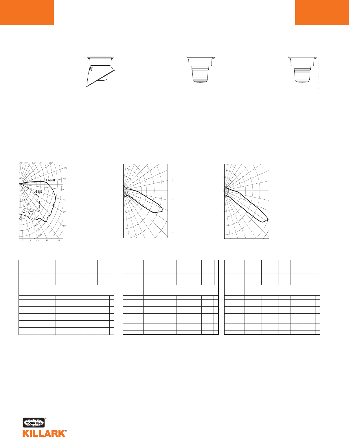
CERTILITE®V SERIES •LIGHTING
PHOTOMETRIC DATA
L100
Test No. HPK09921
METAL HALIDE, METAL HALIDE PULSE,
MERCURY VAPOR-VM4
With Globe &
Angle Reflector
70-250 Watt
Mogul Base
CANDLEPOWER – 175 WATT
14000 lumens
For 70 MH watt multiply by 0.40
For 100 MH multiply by 0.64
For 250 MH multiply by 1.46
For 150 MHP multiply by 1.00
For 175 MHP multiply by 1.25
For 200 MHP multiply by 1.50
For 100 MV multiply by 0.31
For 175 MV multiply by 0.56
For 250 MV multiply by 0.93
Efficiency 65.0%
% EFFECTIVE
CEILING CAVITY
REFLECTANCE
1cc
80 70 50 30 10 0
70 50 30 10 70 50 30 10 50 30 10 50 30 10 50 30 10 0
20% Effective Floor Cavity Reflectance
0 .77 .77 .77 .77 .75 .75.75 .75 .70 .70 .70 .66.66 .66 .63 .63 .63 .61
1 .68 .64 .60 .57 .66 .62.59 .55 .58 .55 .53 .55.52 .50 .51 .50 .48 .46
2 .61 .55 .49 .45 .59 .53 .48 .44 .50 .46 .42 .47.44 .41 .44 .41 .39 .37
3 .56 .48 .42 .37 .53 .46.41 .36 .43 .39 .35 .41.37 .34 .39 .35 .32 .31
4 .50 .42 .35 .30 .48 .40.34 .30 .38 .33 .29 .36.31 .28 .34 .30 .27 .25
5 .46 .37 .30 .25 .44 .36 .29 .25 .34 .28 .24 .32.27 .23 .30 .26 .23 .21
6 .42 .33 .26 .22 .40 .32.26 .21 .30 .25 .21 .28.24 .20 .27 .23 .20 .18
7 .39 .29 .23 .18 .37 .28.22 .18 .27 .21 .18 .25.21 .17 .24 .20 .17 .15
8 .35 .26 .20 .16 .34 .25 .19 .15 .24 .19 .15 .23 .18 .15 .21 .17 .14 .13
9 .33 .23 .17 .13 .31 .23 .17 .13 .21 .16 .13 .20 .16 .13 .19 .15 .12 .11
10 .30 .20 .15 .11 .29 .20 .14 .11 .19 .14 .10 .18 .13 .10 .17 .13 .10 .09
% WALL
REFLECTANCE
1w
ROOM CAVITY
RATIO
RCR
COEFFICIENTS OF UTILIZATION --- ZONAL CAVITY METHOD
SPACING TO MOUNTING HEIGHT RATIO - 1.6
Front Side
ANGLE CP ANGL CP
0.0 1795. 0.0 1795.
5.0 1573. 5.0 1595.
15.0 1676. 15.0 1484.
25.0 1997. 25.0 1649.
35.0 2244. 35.0 1694.
45.0 2722. 45.0 1980.
55.0 2726. 55.0 1764.
65.0 2660. 65.0 1451.
75.0 2656. 75.0 452.
85.0 2293. 85.0 109.
90.0 2050. 90.0 42.
95.0 1598. 95.0 28.
105.0 243. 100.0 16.
115.0 75. 115.0 14.
125.0 24. 125.0 13.
135.0 10. 135.0 11.
145.0 6. 145.0 8.
155.0 6. 155.0 6.
165.0 5. 165.0 5.
175.0 4. 175.0 4.
180.0 4. 180.0 4.
Test No. HPK09934
METAL HALIDE, METAL HALIDE PULSE,
MERCURY VAPOR-VM4
With Type I All
Glass Refractor
70-250 Watt
Mogul Base
CANDLEPOWER – 175 WATT
14000 lumens
For 70 MH watt multiply by 0.40
For 100 MH multiply by 0.64
For 250 MH multiply by 1.46
For 150 MHP multiply by 1.00
For 175 MHP multiply by 1.25
For 200 MHP multiply by 1.50
For 100 MV multiply by 0.31
For 175 MV multiply by 0.56
For 250 MV multiply by 0.93
Efficiency 80.1%
ANGLE CP ANGLE CP
0931. 85.0 2901.
5.0 822. 90.0 1775.
15.0 765. 95.0 1272.
25.0 904. 105.0 746.
35.0 1163. 115.0 514.
45.0 1137. 125.0 267.
55.0 2712. 135.0 153
60.0 7019. 145.0 130.
65.0 9087. 155.0 48.
70.0 7767. 165.0 2.
75.0 5367. 175.0 0.
80.0 3839. 180.0 0.
2000
5000
8000
10,000
90˚
80˚
70˚
60˚
50˚
40˚30˚20˚10˚0˚
180˚ 160˚ 150˚ 140˚ 130˚ 120˚
110˚
100˚
% EFFECTIVE
CEILING CAVITY
REFLECTANCE
1cc
80 70 50 30 10 0
70 50 30 10 70 50 30 10 50 30 10 50 30 10 50 30 10 0
20% Effective Floor Cavity Reflectance
0 .93 .93 .93 .93 .89 .89.89 .89 .83 .83 .83 .77.77 .77 .71 .71 .71 .68
1 .78 .72 .66 .61 .75 .69 .64 .59 .63 .59 .55 .58.54 .51 .53 .50 .48 .45
2 .68 .58 .50 .43 .64 .55.48 .41 .50 .44 .38 .45.40 .36 .41 .37 .33 .30
3 .59 .47 .38 .31 .56 .45.37 .30 .41 .34 .28 .37.31 .26 .33 .28 .24 .21
4 .53 .40 .30 .23 .50 .38.29 .22 .34 .27 .21 .31.24 .19 .27 .22 .18 .15
5 .47 .34 .25 .18 .45 .33.24 .17 .29 .22 .16 .26.20 .15 .23 .18 .14 .11
6 .43 .30 .21 .15 .41 .28 .20 .14 .26 .18 .13 .23 .17 .12 .21 .15 .11 .08
7 .40 .26 .18 .12 .37 .25 .17 .12 .23 .16 .11 .20 .14 .10 .18 .13 .09 .07
8 .36 .24 .16 .10 .34 .23 .15 .10 .20 .14 .09 .18.12 .08 .17 .11 .07 .05
9 .34 .21 .14 .09 .32 .20 .13 .08 .19 .12 .08 .17 .11 .07 .15 .10 .06 .04
10 .32 .20 .12 .08 .30 .19 .12 .07 .17 .11 .07 .15 .10 .06 .14 .09 .05 .04
% WALL
REFLECTANCE
1w
ROOM CAVITY
RATIO
RCR
COEFFICIENTS OF UTILIZATION --- ZONAL CAVITY METHOD
SPACING TO MOUNTING HEIGHT RATIO - 1.82 90-270°
Test No. HPK09930
METAL HALIDE, METAL HALIDE PULSE,
MERCURY VAPOR-VM4
With Type III All
Glass Refractor
70-250 Watt
Mogul Base
CANDLEPOWER – 175 WATT
14000 lumens
For 70 MH watt multiply by 0.40
For 100 MH multiply by 0.64
For 250 MH multiply by 1.46
For 150 MHP multiply by 1.00
For 175 MHP multiply by 1.25
For 200 MHP multiply by 1.50
For 100 MV multiply by 0.31
For 175 MV multiply by 0.56
For 250 MV multiply by 0.93
Efficiency 79.6%
ANGLE CP ANGLE CP
01124. 85.0 3401.
5.0 892. 90.0 2106.
15.0 933. 95.0 1538.
25.0 999. 105.0 950.
35.0 1321. 115.0 775.
45.0 1435. 125.0 388.
55.0 4091. 135.0 234.
60.0 9397. 145.0 191.
65.0 10450. 155.0 52.
70.0 8609. 165.0 2.
75.0 5577. 175.0 0.
80.0 4262. 180.0 0.
2613
5225
8000
7838
10450
12,000
90˚
80˚
70˚
60˚
50˚
40˚30˚20˚10˚0˚
180˚ 160˚ 150˚ 140˚ 130˚ 120˚
110˚
100˚
% EFFECTIVE
CEILING CAVITY
REFLECTANCE
1cc
80 70 50 30 10 0
70 50 30 10 70 50 30 10 50 30 10 50 30 10 50 30 10 0
20% Effective Floor Cavity Reflectance
0 .92 .92 .92 .92 .88 .88 .88 .88 .82 .82 .82 .76 .76 .76 .70 .70 .70 .67
1 .78 .72 .66 .61 .74 .68 .63 .59 .63 .58 .55 .57 .54 .51 .52 .50 .47 .44
2 .67 .57 .49 .43 .64 .55.47 .41 .50 .44 .38 .45.40 .35 .41 .36 .33 .30
3 .59 .47 .38 .31 .56 .45.37 .30 .41 .33 .28 .36.31 .26 .33 .28 .24 .21
4 .52 .40 .30 .23 .49 .38.29 .23 .34 .27 .21 .30.24 .19 .27 .22 .17 .15
5 .47 .34 .25 .18 .44 .32.24 .18 .29 .22 .16 .26.20 .15 .23 .18 .13 .11
6 .43 .30 .21 .15 .40 .28 .20 .14 .25 .18 .13 .23 .17 .12 .20 .15 .11 .08
7 .39 .26 .18 .12 .37 .25 .17 .12 .23 .16 .11 .20 .14 .10 .18 .13 .09 .07
8 .36 .24 .16 .10 .34 .23 .15 .10 .20 .14 .09 .18.12 .08 .16 .11 .07 .05
9 .34 .21 .14 .09 .32 .20 .13 .08 .19 .12 .08 .17 .11 .07 .15 .10 .06 .04
10 .32 .20 .12 .08 .30 .19 .12 .07 .17 .11 .07 .15 .10 .06 .14 .09 .05 .04
% WALL
REFLECTANCE
1w
ROOM CAVITY
RATIO
RCR
COEFFICIENTS OF UTILIZATION --- ZONAL CAVITY METHOD
SPACING TO MOUNTING HEIGHT RATIO - .74 0-180°
Angle Vertical
CP 90° Horizontal
Angle Vertical
CP 75° Horizontal
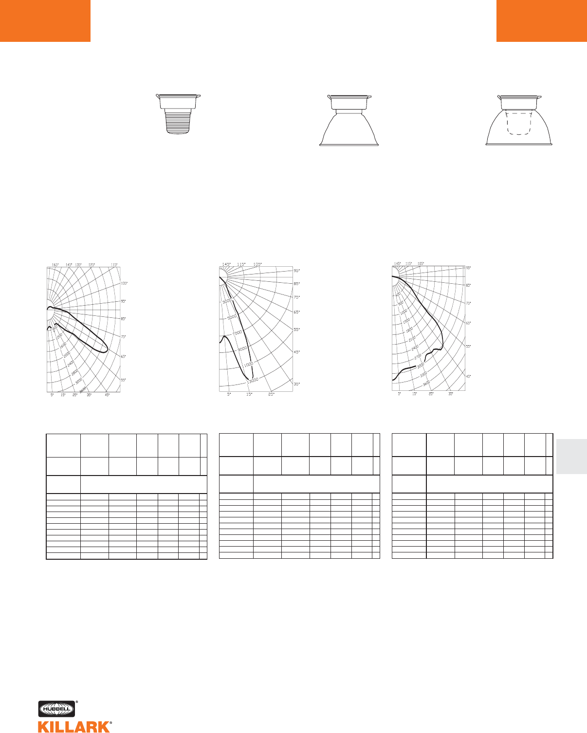
CERTILITE®V SERIES •LIGHTING
PHOTOMETRIC DATA L101
L
Test No. HPK09929
METAL HALIDE, METAL HALIDE PULSE,
MERCURY VAPOR-VM4
With Type V All
Glass Refractor
70-250 Watt
Mogul Base
CANDLEPOWER – 175 WATT
14000 lumens
For 70 MH watt multiply by 0.40
For 100 MH multiply by 0.68
For 250 MH multiply by 1.46
For 150 MHP multiply by 1.00
For 175 MHP multiply by 1.25
For 200 MHP multiply by 1.50
For 100 MV multiply by 0.31
For 175 MV multiply by 0.56
For 250 MV multiply by 0.93
Efficiency 81.2%
ANGLE CP ANGLE CP
0770. 95.0 565.
5.0 690. 100.0 429.
10.0 645. 105.0 325.
15.0 677. 110.0 291.
20.0 797. 115.0 272.
25.0 927. 120.0 234.
30.0 801. 125.0 203.
35.0 715. 130.0 171.
40.0 687. 135.0 150.
45.0 737. 140.0 129.
50.0 1105. 145.0 114 .
55.0 1498. 150.0 75.
60.0 3262. 155.0 27.
65.0 3523. 160.0 6.
70.0 2597. 165.0 2.
75.0 1739. 170.0 0.
80.0 1325. 175.0 0.
85.0 1064. 180.0 0.
90.0 765.
% EFFECTIVE
CEILING CAVITY
REFLECTANCE
1cc
80 70 50 30 10 0
70 50 30 10 70 50 30 10 50 30 10 50 30 10 50 30 10 0
20% Effective Floor Cavity Reflectance
0 .92 .92 .92 .92 .89 .89.89 .89 .82 .82 .82 .76.76 .76 .71 .71 .71 .68
1 .79 .73 .67 .62 .75 .70 .65 .60 .64 .60 .56 .59.55 .52 .54 .51 .49 .46
2 .69 .59 .51 .45 .65 .56.49 .43 .51 .46 .40 .47.42 .38 .43 .39 .35 .32
3 .60 .49 .40 .33 .57 .46.38 .32 .42 .35 .30 .38.32 .27 .34 .30 .25 .23
4 .53 .40 .31 .24 .50 .38 .30 .23 .35 .27 .22 .31.25 .20 .28 .23 .18 .16
5 .47 .34 .25 .18 .45 .32.24 .18 .29 .22 .16 .26.20 .15 .24 .18 .14 .11
6 .43 .30 .21 .15 .41 .29 .20 .14 .26 .19 .13 .23 .17 .12 .21 .15 .11 .09
7 .40 .27 .18 .13 .37 .26 .18 .12 .23 .16 .11 .21.15 .10 .19 .13 .09 .07
8 .37 .24 .16 .11 .35 .23 .15 .10 .21 .14 .09 .19 .13 .09 .17 .12 .08 .06
9 .34 .22 .14 .09 .32 .21 .14 .09 .19 .13 .08 .17 .12 .08 .16 .11 .07 .05
10 .32 .20 .13 .08 .30 .19 .12 .08 .17 .11 .07 .16 .10 .06 .14 .09 .06 .04
% WALL
REFLECTANCE
1w
ROOM CAVITY
RATIO
RCR
COEFFICIENTS OF UTILIZATION --- ZONAL CAVITY METHOD
SPACING TO MOUNTING HEIGHT RATIO - 1.4
Test No. HPK09922
METAL HALIDE, METAL HALIDE PULSE,
MERCURY VAPOR-VM4
With Enclosed Reflector
70-250 Watt
Mogul Base
CANDLEPOWER – 175 WATT
14000 lumens
For 70 MH watt multiply by 0.40
For 100 MH multiply by 0.68
For 250 MH multiply by 1.46
For 150 MHP multiply by 1.00
For 175 MHP multiply by 1.25
For 200 MHP multiply by 1.50
For 100 MV multiply by 0.31
For 175 MV multiply by 0.56
For 250 MV multiply by 0.93
Efficiency 66.0%
ANGLE CP ANGLE CP
07782. 95.0 0.
5.0 7098. 100.0 0.
10.0 8370. 105.0 0.
15.0 12328. 110.0 0.
20.0 11704. 115.0 0.
25.0 6692. 120.0 0.
30.0 3144. 125.0 0.
35.0 1799. 130.0 0.
40.0 1352. 135.0 0.
45.0 1136. 140.0 0.
50.0 253. 145.0 0.
55.0 86. 150.0 0.
60.0 47. 155.0 0.
65.0 29. 160.0 0.
70.0 19. 165.0 0.
75.0 12. 170.0 0.
80.0 7. 175.0 0.
85.0 4. 180.0 0.
90.0 0.
% EFFECTIVE
CEILING CAVITY
REFLECTANCE
1cc
80 70 50 30 10 0
70 50 30 10 70 50 30 10 50 30 10 50 30 10 50 30 10 0
20% Effective Floor Cavity Reflectance
0 .80 .80 .80 .80 .78 .78.78 .78 .75 .75 .75 .71.71 .71 .69 .69 .69 .67
1 .77 .76 .75 .73 .76 .74 .73 .72 .72 .71 .70 .69 .69 .68 .67 .66 .66 .65
2 .75 .73 .71 .69 .74 .71 .70 .68 .69 .68 .67 .67 .66 .65 .66 .65 .64 .63
3 .73 .70 .67 .65 .71 .69.67 .65 .67 .65 .64 .66.64 .63 .64 .63 .62 .61
4 .70 .67 .64 .62 .69 .66.64 .62 .65 .63 .61 .64.62 .61 .62 .61 .60 .59
5 .68 .64 .62 .60 .67 .64.61 .59 .63 .61 .59 .62.60 .58 .61 .59 .58 .57
6 .66 .62 .59 .57 .66 .62.59 .57 .61 .59 .57 .60.58 .57 .59 .58 .56 .56
7 .64 .60 .57 .55 .64 .60.57 .55 .59 .57 .55 .58.56 .55 .58 .56 .54 .54
8 .62 .58 .55 .53 .62 .58.55 .53 .57 .55 .53 .56.54 .53 .56 .54 .52 .52
9 .60 .56 .53 .51 .60 .55.53 .51 .55 .52 .51 .54.52 .51 .54 .52 .50 .50
10 .56 .51 .48 .46 .56 .51 .48 .46 .51 .48 .46 .50.48 .46 .50 .48 .46 .45
% WALL
REFLECTANCE
1w
ROOM CAVITY
RATIO
RCR
COEFFICIENTS OF UTILIZATION --- ZONAL CAVITY METHOD
SPACING TO MOUNTING HEIGHT RATIO - 1.0
Test No. HPK10129
METAL HALIDE, METAL HALIDE PULSE,
MERCURY VAPOR-VM4
With Globe & Full Cutoff
Deep White Reflector*
70-250 Watt
Mogul Base
CANDLEPOWER – 175 WATT
14000 lumens
For 70 MH watt multiply by 0.40
For 100 MH multiply by 0.68
For 250 MH multiply by 1.46
For 150 MHP multiply by 1.00
For 175 MHP multiply by 1.25
For 200 MHP multiply by 1.50
For 100 MV multiply by 0.31
For 175 MV multiply by 0.56
For 250 MV multiply by 0.93
Efficiency 69.1%
ANGLE CP ANGLE CP
03208. 95.0 0.
5.0 3031. 100.0 0.
10.0 2916. 105.0 0.
15.0 2924. 110.0 0.
20.0 2947. 115.0 0.
25.0 2989. 120.0 0.
30.0 2841. 125.0 0.
35.0 2855. 130.0 0.
40.0 2923. 135.0 0.
45.0 3017. 140.0 0.
50.0 2745. 145.0 0.
55.0 1591. 150.0 0.
60.0 1147. 155.0 0.
65.0 889. 160.0 0.
70.0 665. 165.0 0.
75.0 464. 170.0 0.
80.0 278. 175.0 0.
85.0 116 . 180.0 0.
90.0 0.
% EFFECTIVE
CEILING CAVITY
REFLECTANCE
1cc
80 70 50 30 10 0
70 50 30 10 70 50 30 10 50 30 10 50 30 10 50 30 10 0
20% Effective Floor Cavity Reflectance
0 .81 .81 .81 .81 .79 .79 .79 .79 .76 .76 .76 .73 .73 .73 .70 .70 .70 .68
1 .75 .72 .70 .67 .73 .71.68 .66 .68 .66 .64 .65.64 .62 .63 .61 .60 .59
2 .69 .64 .60 .57 .68 .63.59 .56 .61 .58 .55 .59.56 .54 .57 .55 .53 .51
3 .64 .58 .53 .49 .63 .57.52 .49 .55 .51 .48 .53.50 .47 .51 .49 .46 .45
4 .59 .52 .46 .42 .57 .51.46 .42 .49 .45 .41 .48.44 .41 .46 .43 .40 .39
5 .54 .46 .41 .36 .53 .46.40 .36 .44 .39 .36 .43.39 .36 .42 .38 .35 .34
6 .50 .42 .36 .32 .49 .41.36 .32 .40 .35 .32 .39.35 .31 .38 .34 .31 .30
7 .46 .37 .32 .28 .45 .37.32 .28 .36 .31 .27 .35.31 .27 .34 .30 .27 .26
8 .43 .34 .28 .24 .42 .33.28 .24 .32 .27 .24 .31.27 .24 .31 .27 .24 .22
9 .39 .30 .25 .21 .38 .30.25 .21 .29 .24 .21 .28.24 .21 .28 .24 .21 .19
10 .35 .26 .21 .17 .35 .26 .21 .17 .25 .20 .17 .25.20 .17 .24 .20 .17 .16
% WALL
REFLECTANCE
1w
ROOM CAVITY
RATIO
RCR
COEFFICIENTS OF UTILIZATION --- ZONAL CAVITY METHOD
SPACING TO MOUNTING HEIGHT RATIO - 1.4
*Values using Dark Sky gasket kit
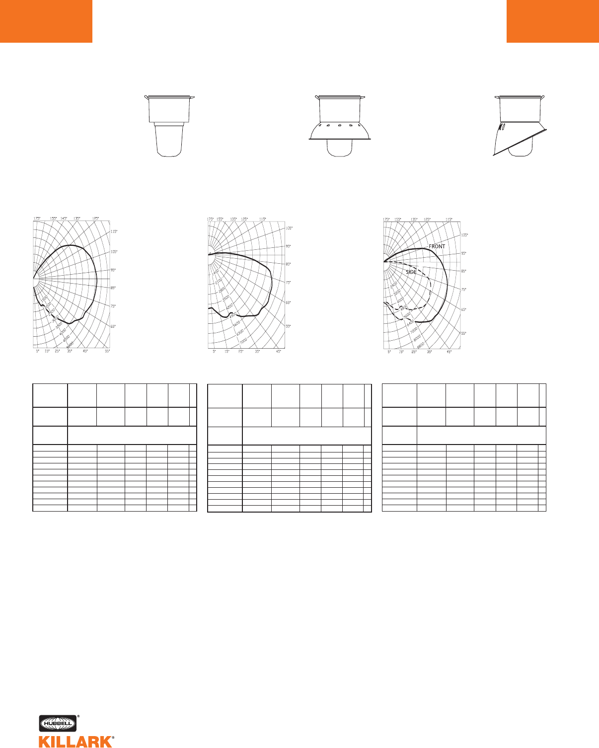
CERTILITE®V SERIES •LIGHTING
PHOTOMETRIC DATA
L102
Test No. HPK09924
HIGH PRESSURE SODIUM-VM5
With Globe
200-600 Watt
Mogul Base
CANDLEPOWER – 400 WATT
51000 lumens
For 200 watt multiply by 0.43
For 250 watt multiply by 0.53
Efficiency 89.6%
ANGLE CP ANGLE CP
0563. 95.0 5076.
5.0 518. 100.0 4976.
10.0 801. 105.0 4846.
15.0 1271. 110.0 4658.
20.0 1697. 115.0 4383.
25.0 1751. 120.0 4013.
30.0 2066. 125.0 3556.
35.0 2723. 130.0 3050.
40.0 3176. 135.0 2237.
45.0 3744. 140.0 1388.
50.0 4122. 145.0 653.
55.0 4341. 150.0 113.
60.0 4639. 155.0 32.
65.0 4708. 160.0 19.
70.0 4877. 165.0 9.
75.0 5015. 170.0 0.
80.0 5086. 175.0 0.
85.0 5124. 180.0 0.
90.0 5136.
% EFFECTIVE
CEILING CAVITY
REFLECTANCE
1cc
80 70 50 30 10 0
70 50 30 10 70 50 30 10 50 30 10 50 30 10 50 30 10 0
20% Effective Floor Cavity Reflectance
0 .97 .97 .97 .97 .90 .90.90 .90 .77 .77 .77 .66.66 .66 .55 .55 .55 .50
1 .83 .77 .71 .66 .76 .71 .66 .61 .59 .56 .52 .49 .46 .43 .40 .37 .35 .30
2 .73 .64 .56 .50 .67 .59.52 .46 .49 .44 .39 .40.36 .32 .32 .28 .26 .21
3 .66 .55 .46 .39 .60 .50.42 .36 .42 .35 .30 .34.29 .25 .26 .23 .19 .16
4 .59 .47 .38 .31 .54 .43.35 .29 .36 .29 .24 .29.24 .19 .22 .18 .15 .12
5 .54 .41 .32 .25 .49 .37 .29 .23 .31 .24 .19 .25 .20 .16 .19 .15 .12 .09
6 .49 .36 .27 .21 .45 .33 .25 .19 .27 .21 .16 .22 .17 .13 .17 .13 .10 .07
7 .45 .32 .23 .18 .41 .29 .22 .16 .24 .18 .13 .19 .14 .10 .15 .11 .08 .05
8 .41 .28 .20 .15 .37 .26 .19 .13 .21 .15 .11 .17 .12 .09 .13 .09 .06 .04
9 .38 .25 .18 .13 .35 .23 .16 .12 .19 .13 .09 .16 .11 .07 .12 .08 .05 .03
10 .35 .23 .15 .11 .32 .21 .14 .10 .17 .12 .08 .14 .09 .06 .11 .07 .04 .02
%WALL
REFLECTANCE
1w
ROOM CAVITY
RATIO
RCR
COEFFICIENTS OF UTILIZATION --- ZONAL CAVITY METHOD
SPACING TO MOUNTING HEIGHT RATIO - 4.3
Test No. HPK09928
HIGH PRESSURE SODIUM-VM5
With Globe & Angle Reflector
200-600 Watt
Mogul Base
CANDLEPOWER – 400 WATT
51000 lumens
For 200 watt multiply by 0.43
For 250 watt multiply by 0.53
% EFFECTIVE
CEILING CAVITY
REFLECTANCE
1cc
80 70 50 30 10 0
70 50 30 10 70 50 30 10 50 30 10 50 30 10 50 30 10 0
20% Effective Floor Cavity Reflectance
0 .83 .83 .83 .83 .80 .80 .80 .80 .74 .74 .74 .69.69 .69 .64 .64 .64 .61
1 .72 .67 .63 .59 .69 .64 .60 .57 .59 .56 .53 .55.52 .50 .50 .48 .46 .44
2 .64 .57 .50 .45 .61 .54.49 .44 .50 .45 .41 .46.42 .39 .42 .39 .36 .34
3 .58 .49 .42 .36 .55 .47.40 .35 .43 .38 .33 .40.35 .31 .36 .33 .29 .27
4 .52 .42 .35 .29 .49 .40.34 .28 .37 .31 .27 .34.29 .25 .31 .27 .24 .22
5 .47 .37 .29 .24 .45 .35 .28 .23 .32 .27 .22 .30.25 .21 .27 .23 .20 .18
6 .43 .32 .25 .20 .41 .31.24 .20 .29 .23 .19 .26.21 .18 .24 .20 .17 .15
7 .39 .29 .22 .17 .37 .27 .21 .16 .25 .20 .15 .23 .18 .15 .22 .17 .14 .12
8 .36 .25 .19 .14 .34 .24 .18 .14 .23 .17 .13 .21 .16 .12 .19 .15 .12 .10
9 .33 .23 .16 .12 .32 .22 .16 .12 .20 .15 .11 .19 .14 .11 .17 .13 .10 .08
10 .30 .20 .14 .10 .29 .19 .13 .09 .18 .13 .09 .17.12 .08 .15 .11 .08 .06
% WALL
REFLECTANCE
1w
ROOM CAVITY
RATIO
RCR
COEFFICIENTS OF UTILIZATION --- ZONAL CAVITY METHOD
SPACING TO MOUNTING HEIGHT RATIO - 2.2
Front Side
ANGLE CP ANGL CP
0.0 3671.0.0 3671.
5.0 3848.5.0 3650.
15.0 4977.15.0 4318.
25.0 5665.25.0 4556.
35.0 6622.35.0 5230.
45.0 7632.45.0 5923.
55.0 8016.55.0 6362.
65.0 8138.65.0 6188.
75.0 7962.75.0 5540.
85.0 7360.85.0 2953.
90.0 6987.90.0 1639.
95.0 6468.95.0 566.
105.0 4805.100.0 97.
115.0 2021.115.0 80.
125.0 166.125.0 62.
135.0 60.135.0 48.
140.0 42.140.0 41.
145.0 30.145.0 45.
155.0 20.155.0 28.
165.0 15.165.0 18.
175.0 12.175.0 12.
180.0 0.180.0 0.
Test No. HPK09927
HIGH PRESSURE SODIUM-VM5
With Globe & Reflector
200-600 Watt
Mogul Base
CANDLEPOWER – 400 WATT
51000 lumens
For 200 watt multiply by 0.43
For 250 watt multiply by 0.53
Efficiency 75.3%
ANGLE CP ANGLE CP
03828. 95.0 1835.
5.0 3788. 100.0 692.
10.0 4046. 105.0 137.
15.0 4430. 110.0 135.
20.0 4752. 115.0 120.
25.0 4674. 120.0 246.
30.0 4837. 125.0 314.
35.0 5337. 130.0 302.
40.0 5676. 135.0 271.
45.0 6115. 140.0 93.
50.0 6352. 145.0 38.
55.0 6439. 150.0 37.
60.0 6562. 155.0 31.
65.0 6474. 160.0 25.
70.0 6419. 165.0 23.
75.0 6211. 170.0 20.
80.0 5784. 175.0 17.
85.0 4480. 180.0 0.
90.0 3031.
% EFFECTIVE
CEILING CAVITY
REFLECTANCE
1cc
80 70 50 30 10 0
70 50 30 10 70 50 30 10 50 30 10 50 30 10 50 30 10 0
20% Effective Floor Cavity Reflectance
0 .88 .88 .88 .88 .85 .85.85 .85 .80 .80 .80 .76.76 .76 .72 .72 .72 .70
1 .76 .70 .65 .60 .73 .68 .63 .59 .63 .59 .56 .59 .56 .53 .55 .53 .50 .48
2 .67 .58 .51 .45 .64 .56.50 .44 .52 .47 .42 .49.44 .40 .46 .42 .38 .36
3 .60 .49 .42 .35 .57 .48.40 .34 .44 .38 .33 .41.36 .32 .39 .34 .30 .28
4 .54 .42 .34 .28 .51 .41.33 .27 .38 .32 .26 .36.30 .25 .33 .28 .24 .22
5 .49 .37 .29 .23 .46 .36.28 .22 .33 .27 .21 .31.25 .21 .29 .24 .20 .18
6 .44 .33 .25 .19 .42 .31.24 .19 .29 .23 .18 .28.22 .17 .26 .21 .17 .15
7 .41 .29 .21 .16 .39 .28 .21 .16 .26 .20 .15 .24 .19 .14 .23 .18 .14 .12
8 .37 .26 .18 .13 .36 .25 .18 .13 .23 .17 .13 .22 .16 .12 .20 .15 .12 .10
9 .35 .23 .16 .11 .33 .22 .16 .11 .21 .15 .11 .20 .14 .10 .19 .14 .10 .08
10 .32 .20 .14 .09 .30 .20 .13 .09 .19 .13 .09 .17 .12 .08 .16 .12 .08 .07
% WALL
REFLECTANCE
1w
ROOM CAVITY
RATIO
RCR
COEFFICIENTS OF UTILIZATION --- ZONAL CAVITY METHOD
SPACING TO MOUNTING HEIGHT RATIO - 2.2
Efficiency 71.6%
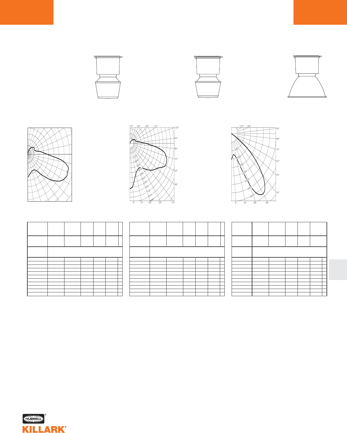
CERTILITE®V SERIES •LIGHTING
PHOTOMETRIC DATA L103
L
Test No. HPK09932
HIGH PRESSURE SODIUM-VM5
With Type II 12” Spintop Refractor
00-600 Watt
Mogul Base
CANDLEPOWER –
400 WATT
51000 lumens
For 200 watt multiply by 0.43
For 250 watt multiply by 0.53
Efficiency 78.7%
ANGLE CP ANGLE CP
05783. 85.0 8444.
5.0 5146. 90.0 5658.
15.0 4341. 95.0 4295.
25.0 4133. 105.0 2609.
35.0 4569. 115.0 1903.
45.0 7301. 125.0 2030.
55.0 10633. 135.0 1964.
60.0 11449. 145.0 1415.
65.0 11950. 155.0 764.
70.0 11914. 165.0 200.
75.0 11449. 175.0 0.
80.0 10538. 180.0 0.
2000
5000
10000
14000
90˚
80˚
70˚
60˚
50˚
40˚30˚20˚10˚0˚
180˚ 160˚ 150˚ 140˚ 130˚ 120˚
110˚
100˚
% EFFECTIVE
CEILING CAVITY
REFLECTANCE
1cc
80 70 50 30 10 0
70 50 30 10 70 50 30 10 50 30 10 50 30 10 50 30 10 0
20% Effective Floor Cavity Reflectance
0 .89 .89 .89 .89 .85 .85.85 .85 .78 .78 .78 .71.71 .71 .64 .64 .64 .61
1 .77 .72 .67 .63 .73 .68.64 .60 .62 .58 .55 .55.53 .50 .50 .48 .45 .42
2 .68 .60 .53 .47 .64 .56.50 .45 .51 .45 .41 .45.41 .37 .40 .37 .34 .31
3 .61 .50 .42 .36 .57 .48.40 .34 .43 .37 .32 .38.33 .29 .34 .30 .26 .23
4 .54 .43 .35 .28 .51 .41.33 .27 .36 .30 .25 .32.27 .23 .29 .24 .21 .18
5.49 .37 .29 .23 .46 .35 .28 .22 .32 .25 .20 .28.23 .18 .25 .20 .17 .14
6 .45 .33 .25 .19 .42 .31 .24 .18 .28 .21 .17 .25 .19 .15 .22 .17 .14 .11
7 .41 .29 .21 .16 .39 .28 .20 .15 .25 .19 .14 .22 .17 .13 .20 .15 .11 .09
8 .38 .26 .19 .14 .36 .25 .18 .13 .22 .16 .12 .20.15 .11 .18 .13 .10 .08
9 .35 .24 .17 .12 .33 .23 .16 .11 .20 .14 .10 .18.13 .09 .16 .12 .08 .07
10 .33 .22 .15 .10 .31 .21 .14 .10 .19 .13 .09 .17.12 .08 .15 .10 .07 .06
%WALL
REFLECTANCE
1w
ROOM CAVITY
RATIO
RCR
COEFFICIENTS OF UTILIZATION --- ZONAL CAVITY METHOD
SPACING TO MOUNTING HEIGHT RATIO - 1.38 0-180°
Test No. HPK09931
HIGH PRESSURE SODIUM-VM5
With Type V 12” Spintop Reflector
200-600 Watt
Mogul Base
CANDLEPOWER –
400 WATT
51000 lumens
For 200 watt multiply by 0.43
For 250 watt multiply by 0.53
Efficiency 83.6%
ANGLE CP ANGLE CP
06501. 95.0 2033.
5.0 6106. 100.0 1561.
10.0 5125. 105.0 1178.
15.0 4402. 110.0 1065.
20.0 4098. 115.0 1121.
25.0 3941. 120.0 1099.
30.0 4003. 125.0 955.
35.0 4315. 130.0 818.
40.0 4900. 135.0 688.
45.0 5411. 140.0 566.
50.0 5865. 145.0 433.
55.0 6247. 150.0 326.
60.0 6844. 155.0 237.
65.0 7429. 160.0 118.
70.0 7453. 165.0 32.
75.0 7142. 170.0 0.
80.0 6432. 175.0 0.
85.0 4703. 180.0 0.
90.0 2943.
% EFFECTIVE
CEILING CAVITY
REFLECTANCE
1cc
80 70 50 30 10 0
70 50 30 10 70 50 30 10 50 30 10 50 30 10 50 30 10 0
20% Effective Floor Cavity Reflectance
0 .96 .96 .96 .96 .93 .93.93 .93 .86 .86 .86 .80.80 .80 .74 .74 .74 .71
1 .83 .77 .71 .67 .79 .74 .69 .64 .68 .64 .60 .62 .59 .56 .57 .54 .52 .49
2 .73 .63 .55 .49 .69 .60.53 .47 .55 .49 .44 .50.45 .41 .46 .42 .38 .35
3 .64 .53 .44 .37 .61 .51.42 .36 .46 .39 .34 .42.36 .31 .38 .33 .29 .26
4 .58 .46 .37 .30 .55 .44.35 .29 .40 .33 .27 .36.30 .25 .33 .28 .24 .21
5.53 .40 .31 .24 .50 .38 .30 .23 .35 .27 .22 .32.25 .20 .29 .23 .19 .17
6 .48 .35 .26 .20 .45 .33.25 .19 .30 .23 .18 .28.22 .17 .25 .20 .16 .13
7 .44 .31 .22 .16 .41 .29 .22 .16 .27 .20 .15 .25 .18 .14 .22 .17 .13 .11
8 .41 .28 .20 .14 .38 .27 .19 .14 .24 .18 .13 .22.16 .12 .20 .15 .11 .09
9 .38 .25 .17 .12 .36 .24 .17 .12 .22 .16 .11 .20.14 .10 .18 .13 .10 .08
10 .35 .23 .15 .11 .33 .22 .15 .10 .20 .14 .10 .18.13 .09 .17 .12 .08 .07
%WALL
REFLECTANCE
1w
ROOM CAVITY
RATIO
RCR
COEFFICIENTS OF UTILIZATION --- ZONAL CAVITY METHOD
SPACING TO MOUNTING HEIGHT RATIO - .8
Test No. HPK09933
HIGH PRESSURE SODIUM-VM5
With Enclosed Reflector
200-600 Watt
Mogul Base
CANDLEPOWER –
400 WATT
51000 lumens
For 200 watt multiply by 0.43
For 250 watt multiply by 0.53
For 600 watt multiply by 1.76
Efficiency 71.1%
ANGLE CP ANGLE CP
06143. 95.0 0.
5.0 5212. 100.0 0.
10.0 5113. 105.0 0.
15.0 5867. 110.0 0.
20.0 8229. 115.0 0.
25.0 13084. 120.0 0.
30.0 16492. 125.0 0.
35.0 17256. 130.0 0.
40.0 16279. 135.0 0.
45.0 13771. 140.0 0.
50.0 10012. 145.0 0.
55.0 5931. 150.0 0.
60.0 2913. 155.0 0.
65.0 1160. 160.0 0.
70.0 263. 165.0 0.
75.0 128. 170.0 0.
80.0 60. 175.0 0.
85.0 27. 180.0 0.
90.0 0.
% EFFECTIVE
CEILING CAVITY
REFLECTANCE
1cc
80 70 50 30 10 0
70 50 30 10 70 50 30 10 50 30 10 50 30 10 50 30 10 0
20% Effective Floor Cavity Reflectance
0 .85 .85 .85 .85 .83 .83 .83 .83 .79 .79 .79 .76 .76 .76 .73 .73 .73 .71
1 .79 .77 .75 .72 .78 .75.73 .71 .72 .71 .69 .70.68 .67 .67 .66 .65 .64
2 .74 .70 .66 .63 .73 .68 .65 .62 .66 .63 .61 .64.62 .59 .62 .60 .58 .57
3 .69 .63 .59 .55 .68 .62.58 .54 .60 .57 .54 .58.55 .53 .57 .54 .52 .51
4 .64 .56 .51 .47 .62 .56.51 .47 .54 .50 .46 .52.49 .46 .51 .48 .45 .44
5.58 .51 .45 .41 .57 .50 .45 .41 .48 .44 .40 .47.43 .40 .46 .42 .39 .38
6 .54 .45 .39 .35 .52 .44.39 .35 .43 .38 .35 .42.38 .34 .41 .37 .34 .33
7 .49 .40 .34 .30 .48 .39.34 .30 .38 .33 .29 .37.33 .29 .36 .32 .29 .28
8 .44 .35 .29 .25 .43 .34 .29 .25 .34 .28 .25 .33.28 .25 .32 .28 .24 .23
9 .40 .31 .25 .21 .39 .30.25 .21 .29 .24 .21 .29.24 .20 .28 .24 .20 .19
10 .35 .25 .19 .15 .34 .25 .19 .15 .24 .19 .15 .23.19 .15 .23 .18 .15 .14
%WALL
REFLECTANCE
1w
ROOM CAVITY
RATIO
RCR
COEFFICIENTS OF UTILIZATION --- ZONAL CAVITY METHOD
SPACING TO MOUNTING HEIGHT RATIO - 2.3
Angle Vertical, CP 75° Horizontal
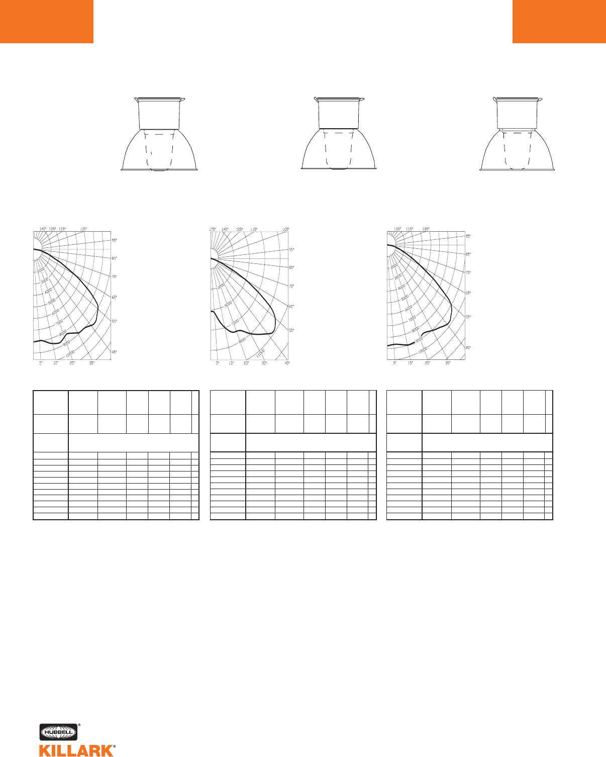
CERTILITE®V SERIES •LIGHTING
PHOTOMETRIC DATA
L104
Test No. HPK09925
HIGH PRESSURE SODIUM-VM5
With Globe & Deep White Reflector
200-400 Watt
Mogul Base
CANDLEPOWER –
400 WATT
51000 lumens
For 200 watt multiply by 0.43
For 250 watt multiply by 0.53
Efficiency 70.4%
ANGLE CP ANGLE CP
08039. 95.0 29.
5.0 7957. 100.0 36.
10.0 8160. 105.0 43.
15.0 8458. 110.0 49.
20.0 8642. 115.0 54.
25.0 8404. 120.0 59.
30.0 8416. 125.0 63.
35.0 8850. 130.0 64.
40.0 9018. 135.0 55.
45.0 9370. 140.0 43.
50.0 9428. 145.0 108.
55.0 9050. 150.0 88.
60.0 7641. 155.0 26.
65.0 5305. 160.0 15.
70.0 3143. 165.0 11.
75.0 1895. 170.0 0.
80.0 1073. 175.0 0.
85.0 448. 180.0 0.
90.0 30.
% EFFECTIVE
CEILING CAVITY
REFLECTANCE
1cc
80 70 50 30 10 0
70 50 30 10 70 50 30 10 50 30 10 50 30 10 50 30 10 0
20% Effective Floor Cavity Reflectance
0 .84 .84 .84 .84 .82 .82.82 .82 .78 .78 .78 .75.75 .75 .72 .72 .72 .70
1 .77 .74 .71 .68 .75 .72 .69 .67 .69 .67 .65 .66 .64 .62 .63 .62 .60 .59
2 .70 .65 .60 .56 .68 .63.59 .55 .61 .57 .54 .58.55 .53 .56 .54 .51 .50
3 .64 .57 .51 .47 .62 .56.51 .46 .54 .49 .45 .52.48 .45 .50 .46 .44 .42
4 .58 .50 .43 .39 .57 .49.43 .38 .47 .42 .38 .45.41 .37 .44 .40 .37 .35
5.53 .44 .37 .32 .51 .43 .37 .32 .41 .36 .32 .40.35 .31 .38 .34 .31 .29
6.48 .39 .32 .28 .47 .38 .32 .28 .37 .31 .27 .35.31 .27 .34 .30 .27 .25
7 .44 .34 .28 .23 .43 .34.28 .23 .33 .27 .23 .31.26 .23 .30 .26 .23 .21
8 .41 .30 .24 .20 .39 .30.24 .20 .29 .23 .20 .28.23 .19 .27 .23 .19 .18
9 .37 .27 .21 .17 .36 .27.21 .17 .26 .21 .17 .25.20 .17 .24 .20 .17 .15
10 .34 .24 .18 .14 .33 .23 .18 .14 .23 .17 .14 .22.17 .14 .21 .17 .13 .12
% WALL
REFLECTANCE
1w
ROOM CAVITY
RATIO
RCR
COEFFICIENTS OF UTILIZATION --- ZONAL CAVITY METHOD
SPACING TO MOUNTING HEIGHT RATIO - 1.7
Test No. HPK09926
HIGH PRESSURE SODIUM-VM5
With Globe & Deep Alzak Reflector
200-400 Watt
Mogul Base
CANDLEPOWER –
400 WATT
51000 lumens
For 200 watt multiply by 0.43
For 250 watt multiply by 0.53
Efficiency 69.2%
ANGLE CP ANGLE CP
05167. 95.0 14.
5.0 5283. 100.0 14.
10.0 6074. 105.0 14.
15.0 6962. 110.0 15.
20.0 7637. 115.0 14.
25.0 7876. 120.0 14.
30.0 8220. 125.0 13.
35.0 9004. 130.0 12.
40.0 9663. 135.0 11.
45.0 10471. 140.0 13.
50.0 10790. 145.0 86.
55.0 10201. 150.0 74.
60.0 8174. 155.0 19.
65.0 5041. 160.0 15.
70.0 2326. 165.0 10.
75.0 1015. 170.0 0.
80.0 426. 175.0 0.
85.0 153. 180.0 0.
90.0 21.
% EFFECTIVE
CEILING CAVITY
REFLECTANCE
1cc
80 70 50 30 10 0
70 50 30 10 70 50 30 10 50 30 10 50 30 10 50 30 10 0
20% Effective Floor Cavity Reflectance
0.
83 .83 .83 .83 .81 .81 .81 .81 .77 .77 .77 .74 .74 .74 .71 .71 .71 .69
1 .76 .73 .70 .68 .74 .71 .69 .67 .68 .66 .64 .66 .64 .62 .63 .62 .60 .59
2 .70 .64 .60 .56 .68 .63 .59 .55 .60 .57 .54 .58.55 .53 .56 .54 .52 .50
3 .64 .57 .51 .47 .62 .55.50 .46 .53 .49 .46 .51.48 .45 .50 .47 .44 .42
4 .57 .49 .43 .38 .56 .48.43 .38 .46 .42 .38 .45.41 .37 .43 .40 .37 .35
5 .52 .43 .37 .32 .51 .42 .36 .32 .41 .35 .31 .39.35 .31 .38 .34 .31 .29
6 .47 .38 .31 .27 .46 .37.31 .27 .36 .30 .26 .35.30 .26 .33 .29 .26 .24
7 .43 .33 .27 .22 .42 .32.26 .22 .31 .26 .22 .30.25 .22 .29 .25 .21 .20
8 .39 .29 .23 .18 .38 .28.22 .18 .27 .22 .18 .27.22 .18 .26 .21 .18 .16
9 .36 .26 .20 .16 .35 .25 .19 .15 .25 .19 .15 .24 .19 .15 .23 .18 .15 .14
10 .32 .22 .16 .12 .31 .22 .16 .12 .21 .16 .12 .20.15 .12 .20 .15 .12 .10
% WALL
REFLECTANCE
1w
ROOM CAVITY
RATIO
RCR
COEFFICIENTS OF UTILIZATION --- ZONAL CAVITY METHOD
SPACING TO MOUNTING HEIGHT RATIO - 2.5
Test No. HPK10103
HIGH PRESSURE SODIUM-VM5
With Globe & Full Cutoff Deep White Reflector*
200-400 Watt
Mogul Base
CANDLEPOWER –
400 WATT
51000 lumens
For 200 watt multiply by 0.43
For 250 watt multiply by 0.53
Efficiency 68.5%
ANGLE CP ANGLE CP
08758. 95.0 0.
5.0 8645. 100.0 0.
10.0 8771. 105.0 0.
15.0 9028. 110.0 0.
20.0 9106. 115.0 0.
25.0 8912. 120.0 0.
30.0 8752. 125.0 0.
35.0 9043. 130.0 0.
40.0 9341. 135.0 0.
45.0 9718. 140.0 0.
50.0 9515. 145.0 0.
55.0 8903. 150.0 0.
60.0 6615. 155.0 0.
65.0 4249. 160.0 0.
70.0 2598. 165.0 0.
75.0 1723. 170.0 0.
80.0 1006. 175.0 0.
85.0 430. 180.0 0.
90.0 0.
% EFFECTIVE
CEILING CAVITY
REFLECTANCE
1cc
80 70 50 30 10 0
70 50 30 10 70 50 30 10 50 30 10 50 30 10 50 30 10 0
20% Effective Floor Cavity Reflectance
0.
82 .82 .82 .82 .80 .80 .80 .80 .77 .77 .77 .73.73 .73 .70 .70 .70 .69
1 .75 .72 .70 .67 .74 .71 .68 .66 .68 .66 .64 .65 .63 .62 .63 .61 .60 .59
2 .69 .64 .59 .56 .67 .63 .59 .55 .60 .57 .54 .58.55 .53 .56 .54 .51 .50
3 .63 .57 .51 .47 .62 .56.51 .47 .53 .49 .46 .52.48 .45 .50 .47 .44 .43
4 .58 .50 .44 .39 .56 .49.43 .39 .47 .42 .39 .46.41 .38 .44 .40 .38 .36
5 .53 .44 .38 .33 .51 .43 .37 .33 .42 .37 .33 .40.36 .32 .39 .35 .32 .31
6 .48 .39 .33 .29 .47 .38.33 .28 .37 .32 .28 .36.31 .28 .35 .31 .28 .26
7 .44 .35 .29 .24 .43 .34.28 .24 .33 .28 .24 .32.27 .24 .31 .27 .24 .22
8 .40 .31 .25 .21 .39 .30.25 .21 .29 .24 .20 .29.24 .20 .28 .23 .20 .19
9 .37 .28 .22 .18 .36 .27.22 .18 .27 .21 .18 .26.21 .18 .25 .21 .18 .16
10 .34 .24 .18 .14 .33 .24 .18 .14 .23 .18 .14 .22.18 .14 .22 .17 .14 .13
% WALL
REFLECTANCE
1w
ROOM CAVITY
RATIO
RCR
COEFFICIENTS OF UTILIZATION --- ZONAL CAVITY METHOD
SPACING TO MOUNTING HEIGHT RATIO - 1.6
*Values using Spacer Kit
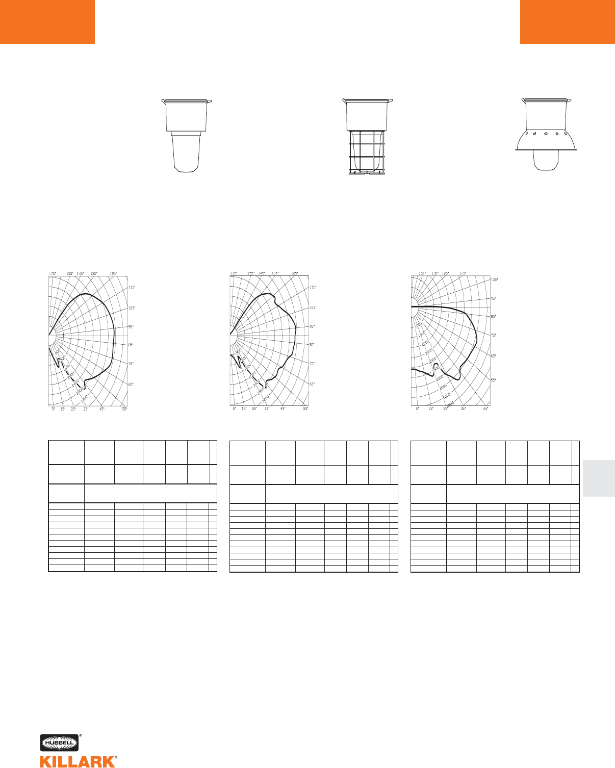
CERTILITE®V SERIES •LIGHTING
PHOTOMETRIC DATA L105
L
Test No. HPK09911
METAL HALIDE, METAL HALIDE PULSE,
MERCURY VAPOR-VM5
With Globe
250-400 Watt
Mogul Base
CANDLEPOWER –
400 WATT
36000 lumens
For 250 MH multiply by 0.61
For 250 MHP multiply by 0.66
For 320 MHP multiply by 0.92
For 350 MHP multiply by 1.00
For 400 MHP multiply by 1.22
For 400 MV multiply by 0.64
Efficiency 92.4%
ANGLE CP ANGLE CP
0529. 95.0 3527.
5.0 538. 100.0 3475.
10.0 690. 105.0 3403.
15.0 896. 110.0 3325.
20.0 1223. 115.0 3203.
25.0 1288. 120.0 3026.
30.0 1074. 125.0 2854.
35.0 2101. 130.0 2667.
40.0 2807. 135.0 2379.
45.0 2718. 140.0 1779.
50.0 2770. 145.0 508.
55.0 2942. 150.0 55.
60.0 3133. 155.0 26.
65.0 3353. 160.0 15.
70.0 3493. 165.0 8.
75.0 3530. 170.0 0.
80.0 3489. 175.0 0.
85.0 3497. 180.0 0.
90.0 3523.
% EFFECTIVE
CEILING CAVITY
REFLECTANCE
1cc
80 70 50 30 10 0
70 50 30 10 70 50 30 10 50 30 10 50 30 10 50 30 10 0
20% Effective Floor Cavity Reflectance
0.10 0 .10 0 .10 0 .100.92 .92 .92 .92 .79 .79 .79 .66.66 .66 .55 .55 .55 .50
1 .86 .79 .73 .68 .78 .73.68 .63 .61 .57 .53 .50.47 .44 .40 .38 .36 .31
2 .76 .66 .58 .52 .69 .61.54 .48 .50 .45 .40 .41.37 .33 .32 .29 .26 .22
3 .68 .57 .48 .41 .62 .52.44 .38 .43 .37 .31 .35.30 .26 .27 .23 .20 .16
4 .61 .49 .40 .33 .56 .45.36 .30 .37 .30 .25 .29.24 .20 .23 .19 .15 .12
5 .55 .42 .33 .27 .50 .39.31 .24 .32 .25 .20 .26.20 .16 .20 .16 .12 .09
6 .51 .37 .28 .22 .46 .34 .26 .20 .28 .22 .17 .23 .17 .13 .17 .13 .10 .07
7 .46 .33 .25 .18 .42 .30.22 .17 .25 .19 .14 .20.15 .11 .15 .11 .08 .05
8 .43 .29 .21 .16 .39 .27 .19 .14 .22 .16 .12 .18 .13 .09 .14 .10 .07 .04
9 .39 .26 .19 .13 .36 .24 .17 .12 .20 .14 .10 .16 .11 .08 .12 .08 .05 .03
10 .36 .24 .16 .11 .33 .22 .15 .10 .18 .12 .08 .14.10 .06 .11 .07 .04 .02
% WALL
REFLECTANCE
1w
ROOM CAVITY
RATIO
RCR
COEFFICIENTS OF UTILIZATION --- ZONAL CAVITY METHOD
SPACING TO MOUNTING HEIGHT RATIO - 3.6
Test No. HPK09912
METAL HALIDE, METAL HALIDE PULSE,
MERCURY VAPOR-VM5
With Globe & Guard
250-400 Watt
Mogul Base
CANDLEPOWER –
400 WATT
36000 lumens
For 250 MH multiply by 0.61
For 250 MHP multiply by 0.66
For 320 MHP multiply by 0.92
For 350 MHP multiply by 1.00
For 400 MHP multiply by 1.22
For 400 MV multiply by 0.64
Efficiency 88.7%
ANGLE CP ANGLE CP
0844. 95.0 3523.
5.0 804. 100.0 3454.
10.0 877. 105.0 3290.
15.0 998. 110.0 3030.
20.0 1266. 115.0 2863.
25.0 1240. 120.0 2764.
30.0 1071. 125.0 2832.
35.0 1830. 130.0 2643.
40.0 2625. 135.0 2324.
45.0 2730. 140.0 1482.
50.0 2787. 145.0 191.
55.0 2934. 150.0 107.
60.0 2932. 155.0 106.
65.0 3052. 160.0 109.
70.0 3155. 165.0 110 .
75.0 3309. 170.0 0.
80.0 3433. 175.0 0.
85.0 3465. 180.0 0.
90.0 3496.
% EFFECTIVE
CEILING CAVITY
REFLECTANCE
1cc
80 70 50 30 10 0
70 50 30 10 70 50 30 10 50 30 10 50 30 10 50 30 10 0
20% Effective Floor Cavity Reflectance
0 .96 .96 .96 .96 .89 .89 .89 .89 .76 .76 .76 .64 .64 .64 .53 .53 .53 .48
1 .82 .76 .70 .65 .75 .70.65 .61 .58 .55 .51 .48.45 .42 .38 .36 .34 .29
2 .73 .64 .56 .50 .66 .58.52 .46 .48 .43 .39 .39.35 .32 .31 .28 .25 .21
3 .65 .54 .46 .39 .59 .50.42 .36 .41 .35 .30 .33.29 .25 .26 .22 .19 .15
4 .59 .47 .38 .31 .53 .43.35 .29 .35 .29 .24 .28.23 .19 .22 .18 .15 .12
5.53 .41 .32 .26 .48 .37 .29 .24 .31 .24 .20 .25.20 .16 .19 .15 .12 .09
6 .49 .36 .27 .21 .44 .33 .25 .20 .27 .21 .16 .22 .17 .13 .17 .13 .10 .07
7 .45 .32 .24 .18 .40 .29.22 .16 .24 .18 .14 .19.14 .11 .15 .11 .08 .05
8.41 .28 .20 .15 .37 .26 .19 .14 .21 .16 .11 .17 .12 .09 .13 .09 .06 .04
9 .38 .26 .18 .13 .34 .23 .17 .12 .19 .14 .10 .15 .11 .07 .12 .08 .05 .03
10 .35 .23 .16 .11 .32 .21 .14 .10 .17 .12 .08 .14 .09 .06 .11 .07 .04 .02
% WALL
REFLECTANCE
1w
ROOM CAVITY
RATIO
RCR
COEFFICIENTS OF UTILIZATION --- ZONAL CAVITY METHOD
SPACING TO MOUNTING HEIGHT RATIO - 3.2
Test No. HPK09918
METAL HALIDE, METAL HALIDE PULSE,
MERCURY VAPOR-VM5
With Globe &
Dome Reflector
250-400 Watt
Mogul Base
CANDLEPOWER –
400 WATT
36000 lumens
For 250 MH multiply by 0.61
For 250 MHP multiply by 0.66
For 320 MHP multiply by 0.92
For 350 MHP multiply by 1.00
For 400 MHP multiply by 1.22
For 400 MV multiply by 0.64
Efficiency 76.1%
ANGLE CP ANGLE CP
03088. 95.0 551.
5.0 3105. 100.0 125.
10.0 3239. 105.0 106.
15.0 3370. 110.0 95.
20.0 3603. 115.0 83.
25.0 3544. 120.0 70.
30.0 3218. 125.0 171.
35.0 4119. 130.0 441.
40.0 4720. 135.0 257.
45.0 4510. 140.0 35.
50.0 4417. 145.0 36.
55.0 4478. 150.0 25.
60.0 4526. 155.0 21.
65.0 4629. 160.0 18.
70.0 4602. 165.0 15.
75.0 4381. 170.0 14.
80.0 4047. 175.0 12.
85.0 3613. 180.0 11.
90.0 2234.
% EFFECTIVE
CEILING CAVITY
REFLECTANCE
1cc
80 70 50 30 10 0
70 50 30 10 70 50 30 10 50 30 10 50 30 10 50 30 10 0
20% Effective Floor Cavity Reflectance
0 .90 .90 .90 .90 .87 .87.87 .87 .83 .83 .83 .78.78 .78 .74 .74 .74 .73
1 .76 .71 .65 .61 .74 .68 .64 .59 .64 .60 .57 .61 .57 .54 .57 .54 .52 .50
2 .68 .59 .51 .45 .65 .57.50 .44 .53 .48 .43 .50.45 .41 .47 .43 .40 .38
3 .61 .50 .42 .36 .58 .48.41 .35 .46 .39 .34 .43.37 .33 .40 .36 .32 .29
4 .54 .43 .35 .28 .52 .42.34 .28 .39 .32 .27 .37.31 .26 .35 .30 .25 .23
5.49 .37 .29 .23 .47 .36 .29 .23 .34 .27 .22 .32.26 .21 .30 .25 .21 .19
6 .45 .33 .25 .19 .43 .32.25 .19 .30 .24 .19 .29.23 .18 .27 .22 .18 .16
7 .41 .29 .22 .16 .40 .29.21 .16 .27 .20 .16 .25.20 .15 .24 .19 .15 .13
8.38 .26 .19 .14 .36 .25 .18 .13 .24 .18 .13 .23.17 .13 .22 .16 .12 .11
9 .35 .24 .16 .12 .34 .23 .16 .12 .22 .16 .11 .21.15 .11 .20 .14 .11 .09
10 .32 .21 .14 .09 .31 .20 .14 .09 .19 .13 .09 .18 .13 .09 .17 .12 .09 .07
% WALL
REFLECTANCE
1w
ROOM CAVITY
RATIO
RCR
COEFFICIENTS OF UTILIZATION --- ZONAL CAVITY METHOD
SPACING TO MOUNTING HEIGHT RATIO - 2.0
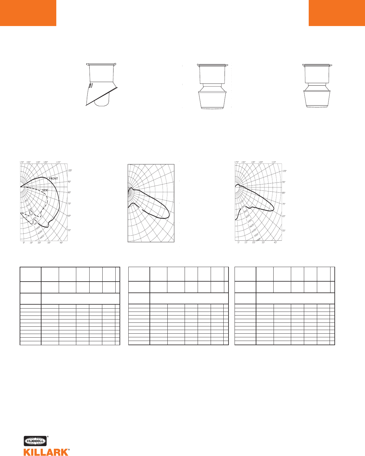
CERTILITE®V SERIES •LIGHTING
PHOTOMETRIC DATA
L106
Test No. HPK09917
METAL HALIDE, METAL HALIDE PULSE,
MERCURY VAPOR-VM5
With Globe & Angle Reflector
250-400 Watt
Mogul Base
CANDLEPOWER –
400 WATT
36000 lumens
For 250 MH multiply by 0.61
For 250 MHP multiply by 0.66
For 320 MHP multiply by 0.92
For 350 MHP multiply by 1.00
For 400 MHP multiply by 1.22
For 400 MV multiply by 0.64
Efficiency 73.3%
% EFFECTIVE
CEILING CAVITY
REFLECTANCE
1cc
80 70 50 30 10 0
70 50 30 10 70 50 30 10 50 30 10 50 30 10 50 30 10 0
20% Effective Floor Cavity Reflectance
0 .85 .85 .85 .85 .82 .82 .82 .82 .76 .76 .76 .70 .70 .70 .65 .65 .65 .63
1 .74 .69 .65 .61 .71 .66 .62 .59 .61 .58 .55 .56.54 .51 .52 .50 .48 .46
2 .66 .59 .52 .47 .63 .56.50 .46 .52 .47 .43 .48.44 .40 .44 .41 .38 .36
3 .60 .50 .43 .38 .57 .48.42 .37 .45 .39 .35 .41.37 .33 .38 .34 .31 .29
4 .54 .44 .36 .30 .51 .42.35 .30 .39 .33 .28 .36.31 .27 .33 .29 .25 .23
5 .49 .38 .31 .25 .46 .37.30 .24 .34 .28 .23 .31.26 .22 .29 .24 .21 .19
6 .45 .34 .26 .21 .42 .32.26 .21 .30 .24 .20 .28.22 .19 .26 .21 .18 .16
7 .41 .30 .23 .18 .39 .29 .22 .17 .27 .21 .16 .25 .19 .16 .23 .18 .15 .13
8 .37 .26 .20 .15 .36 .25 .19 .15 .24 .18 .14 .22 .17 .13 .20 .16 .12 .11
9 .35 .24 .17 .13 .33 .23 .17 .12 .21 .16 .12 .20 .15 .11 .18 .14 .11 .09
10 .32 .21 .15 .10 .30 .20 .14 .10 .19 .13 .10 .17 .12 .09 .16 .12 .08 .07
% WALL
REFLECTANCE
1w
ROOM CAVITY
RATIO
RCR
COEFFICIENTS OF UTILIZATION --- ZONAL CAVITY METHOD
SPACING TO MOUNTING HEIGHT RATIO - 2.2
Front Side
ANGLE CP ANGL CP
0.0 2962. 0.0 2962.
5.0 3212. 5.0 2991.
15.0 3923. 15.0 3278.
25.0 4545. 25.0 3440.
35.0 5416. 35.0 3975.
45.0 5946. 45.0 4381.
55.0 6169. 55.0 4289.
65.0 6365. 65.0 4443.
75.0 6074. 75.0 4137.
85.0 5553. 85.0 1868.
90.0 5239. 90.0 502.
95.0 4849. 95.0 145.
105.0 3991. 100.0 76.
115.0 1680. 115.0 57.
125.0 83. 125.0 46.
135.0 41. 135.0 35.
145.0 33. 145.0 31.
155.0 13. 155.0 19.
165.0 10. 165.0 13.
175.0 8. 175.0 8.
180.0 6. 180.0 6.
Test No. HPK10081
METAL HALIDE, METAL HALIDE PULSE,
MERCURY VAPOR-VM5
With Type II 12” Spintop Refractor
250-400 Watt
Mogul Base
CANDLEPOWER –
400 WATT
36000 lumens
For 250 MH multiply by 0.61
For 250 MHP multiply by 0.66
For 320 MHP multiply by 0.92
For 350 MHP multiply by 1.00
For 400 MHP multiply by 1.22
For 400 MV multiply by 0.64
Efficiency 78.8%
ANGLE CP ANGLE CP
03548. 85.0 3897.
5.0 3303. 90.0 3203.
15.0 2932. 95.0 2829.
25.0 2791. 105.0 1774.
35.0 3115. 115.0 1293.
45.0 5458. 125.0 1303.
55.0 8761. 135.0 1335.
60.0 10352. 145.0 1046.
65.0 10896. 155.0 621.
70.0 10085. 165.0 178.
75.0 8039. 175.0 0.
80.0 5379. 180.0 0.
2724
5448
8172
10896
90˚
80˚
70˚
60˚
50˚
40˚30˚20˚10˚0˚
180˚ 160˚ 150˚ 140˚ 130˚ 120˚
110˚
100˚
% EFFECTIVE
CEILING CAVITY
REFLECTANCE
1cc
80 70 50 30 10 0
70 50 30 10 70 50 30 10 50 30 10 50 30 10 50 30 10 0
20% Effective Floor Cavity Reflectance
0 .89 .89 .89 .89 .85 .85.85 .85 .77 .77 .77 .70.70 .70 .64 .64 .64 .61
1 .78 .73 .68 .64 .74 .69 .65 .61 .62 .59 .56 .56 .53 .51 .50 .48 .46 .43
2 .69 .60 .53 .48 .65 .57.51 .46 .51 .46 .42 .46.42 .38 .41 .38 .35 .32
3 .61 .51 .43 .37 .57 .48.41 .35 .43 .37 .32 .38.33 .29 .34 .30 .27 .24
4 .55 .44 .35 .29 .51 .41.34 .28 .37 .30 .25 .33.27 .23 .29 .25 .21 .18
5 .50 .38 .30 .23 .46 .36.28 .22 .32 .25 .21 .28.23 .19 .25 .20 .17 .14
6 .45 .33 .25 .19 .42 .31 .24 .19 .28 .22 .17 .25 .19 .15 .22 .17 .14 .12
7 .41 .29 .22 .16 .39 .28 .21 .16 .25 .19 .14 .22 .17 .13 .20 .15 .11 .09
8 .38 .26 .19 .14 .36 .25 .18 .13 .22 .16 .12 .20 .15 .11 .18 .13 .10 .08
9 .35 .24 .17 .12 .33 .23 .16 .11 .20 .14 .10 .18 .13 .09 .16 .12 .08 .07
10 .33 .22 .15 .10 .31 .20 .14 .10 .18 .13 .09 .16.12 .08 .15 .10 .07 .06
% WALL
REFLECTANCE
1w
ROOM CAVITY
RATIO
RCR
COEFFICIENTS OF UTILIZATION --- ZONAL CAVITY METHOD
SPACING TO MOUNTING HEIGHT RATIO - 1.88 0-180°
Test No. HPK10078
METAL HALIDE, METAL HALIDE PULSE,
MERCURY VAPOR-VM5
With Type V 12” Spintop Refractor
250-400 Watt
Mogul Base
CANDLEPOWER –
400 WATT
36000 lumens
For 250 MH multiply by 0.61
For 250 MHP multiply by 0.66
For 320 MHP multiply by 0.92
For 350 MHP multiply by 1.00
For 400 MHP multiply by 1.22
For 400 MV multiply by 0.64
Efficiency 82.3%
ANGLE CP ANGLE CP
04106. 95.0 1359.
5.0 3914. 100.0 1093.
10.0 3394. 105.0 856.
15.0 3010. 110.0 786.
20.0 2887. 115.0 823.
25.0 2709. 120.0 748.
30.0 2679. 125.0 621.
35.0 2886. 130.0 559.
40.0 3317. 135.0 511.
45.0 3681. 140.0 424.
50.0 3856. 145.0 316.
55.0 4557. 150.0 226.
60.0 5736. 155.0 161.
65.0 6936. 160.0 85.
70.0 6547. 165.0 26.
75.0 4564. 170.0 0.
80.0 3005. 175.0 0.
85.0 2015. 180.0 0.
90.0 1593.
% EFFECTIVE
CEILING CAVITY
REFLECTANCE
1cc
80 70 50 30 10 0
70 50 30 10 70 50 30 10 50 30 10 50 30 10 50 30 10 0
20% Effective Floor Cavity Reflectance
0 .95 .95 .95 .95 .91 .91.91 .91 .84 .84 .84 .78.78 .78 .73 .73 .73 .70
1 .82 .77 .72 .67 .79 .74 .69 .65 .68 .64 .61 .62 .59 .56 .57 .55 .53 .50
2 .73 .64 .56 .50 .69 .61.54 .48 .56 .50 .45 .51.46 .42 .47 .43 .40 .37
3 .64 .53 .45 .38 .61 .51.43 .37 .47 .40 .35 .43.37 .33 .39 .34 .30 .28
4 .57 .45 .36 .30 .54 .43.35 .29 .39 .32 .27 .36.30 .25 .33 .28 .23 .21
5 .52 .39 .30 .23 .49 .37.29 .23 .34 .27 .21 .31.25 .20 .28 .23 .18 .16
6 .47 .34 .26 .20 .45 .33.25 .19 .30 .23 .18 .27.21 .17 .25 .20 .15 .13
7 .43 .30 .22 .16 .41 .29 .21 .16 .27 .20 .15 .24 .18 .14 .22 .17 .13 .11
8 .40 .27 .19 .14 .38 .26 .19 .13 .24 .17 .13 .22 .16 .12 .20 .15 .11 .09
9 .37 .25 .17 .12 .35 .24 .17 .12 .22 .15 .11 .20.14 .10 .18 .13 .09 .08
10 .34 .22 .15 .10 .32 .21 .14 .10 .19 .13 .09 .18.12 .08 .16 .11 .08 .06
% WALL
REFLECTANCE
1w
ROOM CAVITY
RATIO
RCR
COEFFICIENTS OF UTILIZATION --- ZONAL CAVITY METHOD
SPACING TO MOUNTING HEIGHT RATIO - .9
Angle Vertical
CP 75° Horizontal
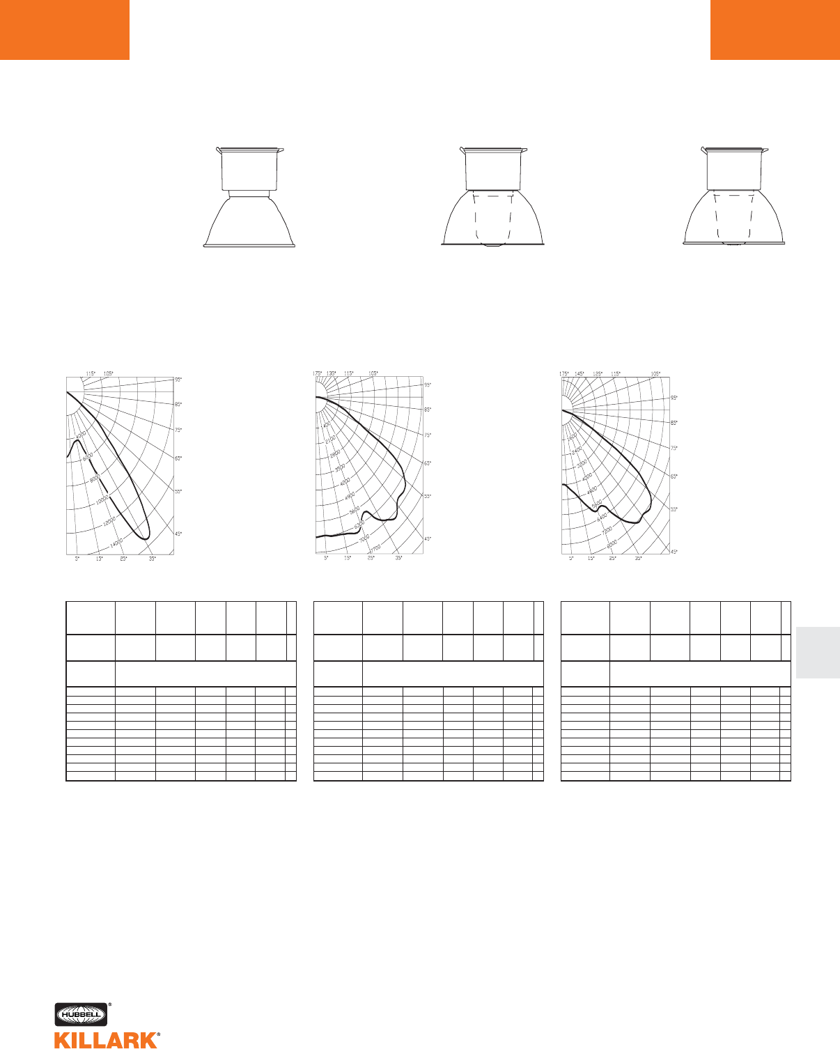
CERTILITE®V SERIES •LIGHTING
PHOTOMETRIC DATA L107
L
Test No. HPK10077
METAL HALIDE, METAL HALIDE PULSE,
MERCURY VAPOR-VM5
With Enclosed Reflector
250-400 Watt
Mogul Base
CANDLEPOWER –
400 WATT
36000 lumens
For 250 MH multiply by 0.61
For 250 MHP multiply by 0.66
For 320 MHP multiply by 0.92
For 350 MHP multiply by 1.00
For 400 MHP multiply by 1.22
For 400 MV multiply by 0.64
Efficiency 71.5%
ANGLE CP ANGLE CP
05576. 95.0 0.
5.0 5010. 100.0 0.
10.0 4513. 105.0 0.
15.0 4291. 110.0 0.
20.0 4758. 115.0 0.
25.0 6978. 120.0 0.
30.0 11554. 125.0 0.
35.0 15300. 130.0 0.
40.0 14033. 135.0 0.
45.0 9613. 140.0 0.
50.0 5974. 145.0 0.
55.0 3716. 150.0 0.
60.0 1324. 155.0 0.
65.0 521. 160.0 0.
70.0 295. 165.0 0.
75.0 143. 170.0 0.
80.0 60. 175.0 0.
85.0 21. 180.0 0.
90.0 0.
% EFFECTIVE
CEILING CAVITY
REFLECTANCE
1cc
80 70 50 30 10 0
70 50 30 10 70 50 30 10 50 30 10 50 30 10 50 30 10 0
20% Effective Floor Cavity Reflectance
0 .86 .86 .86 .86 .84 .84.84 .84 .80 .80 .80 .77.77 .77 .74 .74 .74 .72
1 .81 .78 .76 .73 .79 .76 .74 .72 .73 .72 .70 .71.69 .68 .68 .67 .66 .65
2 .75 .71 .67 .64 .73 .69.66 .63 .67 .64 .62 .65.62 .60 .63 .61 .59 .58
3 .70 .64 .59 .56 .68 .63.59 .55 .61 .57 .54 .59.56 .53 .57 .55 .52 .51
4 .64 .57 .52 .48 .63 .56.51 .47 .54 .50 .47 .53.49 .46 .51 .48 .46 .44
5 .59 .51 .45 .41 .58 .50.45 .41 .49 .44 .40 .47.43 .40 .46 .43 .40 .38
6 .54 .45 .39 .35 .53 .44.39 .35 .43 .38 .35 .42.38 .34 .41 .37 .34 .33
7 .49 .40 .34 .29 .48 .39.33 .29 .38 .33 .29 .37.32 .29 .36 .32 .29 .27
8 .44 .35 .28 .24 .43 .34.28 .24 .33 .28 .24 .32.27 .24 .31 .27 .24 .22
9 .40 .30 .24 .20 .39 .29.24 .20 .29 .23 .20 .28.23 .19 .27 .23 .19 .18
10 .35 .25 .18 .14 .34 .24 .18 .14 .23 .18 .14 .23.18 .14 .22 .17 .14 .13
% WALL
REFLECTANCE
1w
ROOM CAVITY
RATIO
RCR
COEFFICIENTS OF UTILIZATION --- ZONAL CAVITY METHOD
SPACING TO MOUNTING HEIGHT RATIO - 2.1
Test No. HPK09915
METAL HALIDE, METAL HALIDE PULSE,
MERCURY VAPOR-VM5
With Globe & Deep White Reflector
250-400 Watt
Mogul Base
CANDLEPOWER –
400 WATT
36000 lumens
For 250 MH multiply by 0.61
For 250 MHP multiply by 0.66
For 320 MHP multiply by 0.92
For 350 MHP multiply by 1.00
For 400 MHP multiply by 1.22
For 400 MV multiply by 0.64
Efficiency 71.6%
ANGLE CP ANGLE CP
06298. 95.0 21.
5.0 6273. 100.0 26.
10.0 6354. 105.0 30.
15.0 6408. 110.0 35.
20.0 6542. 115.0 39.
25.0 6352. 120.0 42.
30.0 5943. 125.0 44.
35.0 6787. 130.0 45.
40.0 7215. 135.0 37.
45.0 6823. 140.0 33.
50.0 6732. 145.0 183.
55.0 6471. 150.0 35.
60.0 5358. 155.0 20.
65.0 2951. 160.0 12.
70.0 2049. 165.0 8.
75.0 1303. 170.0 0.
80.0 706. 175.0 0.
85.0 272. 180.0 0.
90.0 18.
% EFFECTIVE
CEILING CAVITY
REFLECTANCE
1cc
80 70 50 30 10 0
70 50 30 10 70 50 30 10 50 30 10 50 30 10 50 30 10 0
20% Effective Floor Cavity Reflectance
0 .84 .84 .84 .84 .82 .82.82 .82 .79 .79 .79 .75.75 .75 .72 .72 .72 .70
1 .78 .74 .71 .69 .76 .73 .70 .68 .70 .67 .65 .67 .65 .63 .64 .63 .61 .60
2 .71 .66 .61 .57 .69 .64.60 .57 .62 .58 .55 .59.56 .54 .57 .55 .52 .51
3 .65 .58 .53 .48 .63 .57.52 .48 .55 .50 .47 .53.49 .46 .51 .48 .45 .44
4 .59 .51 .45 .40 .58 .50.44 .40 .48 .43 .39 .47.42 .39 .45 .41 .38 .37
5 .54 .45 .39 .34 .53 .44.38 .34 .43 .38 .34 .41.37 .33 .40 .36 .33 .31
6 .50 .40 .34 .29 .48 .40.34 .29 .38 .33 .29 .37.32 .28 .36 .31 .28 .27
7 .45 .36 .29 .25 .44 .35.29 .25 .34 .28 .24 .33.28 .24 .32 .27 .24 .23
8 .42 .32 .25 .21 .40 .31.25 .21 .30 .25 .21 .29.24 .21 .28 .24 .20 .19
9 .38 .28 .22 .18 .37 .28.22 .18 .27 .22 .18 .26.21 .18 .25 .21 .18 .16
10 .35 .25 .19 .15 .34 .24 .19 .15 .24 .18 .15 .23.18 .15 .22 .18 .14 .13
% WALL
REFLECTANCE
1w
ROOM CAVITY
RATIO
RCR
COEFFICIENTS OF UTILIZATION --- ZONAL CAVITY METHOD
SPACING TO MOUNTING HEIGHT RATIO - 1.6
Test No. HPK09914
METAL HALIDE, METAL HALIDE PULSE,
MERCURY VAPOR-VM5
With Globe & Deep Alzak Reflector
250-400 Watt
Mogul Base
CANDLEPOWER –
400 WATT
36000 lumens
For 250 MH multiply by 0.61
For 250 MHP multiply by 0.66
For 320 MHP multiply by 0.92
For 350 MHP multiply by 1.00
For 400 MHP multiply by 1.22
For 400 MV multiply by 0.64
Efficiency 70.8%
ANGLE CP ANGLE CP
03982. 95.0 9.
5.0 4067. 100.0 10.
10.0 4471. 105.0 10.
15.0 4949. 110.0 11.
20.0 5584. 115.0 10.
25.0 5932. 120.0 10.
30.0 5933. 125.0 10.
35.0 7123. 130.0 9.
40.0 7950. 135.0 8.
45.0 8017. 140.0 14.
50.0 8145. 145.0 173.
55.0 7441. 150.0 25.
60.0 5491. 155.0 16.
65.0 2411. 160.0 12.
70.0 1327. 165.0 7.
75.0 651. 170.0 0.
80.0 268. 175.0 0.
85.0 90. 180.0 0.
90.0 10.
% EFFECTIVE
CEILING CAVITY
REFLECTANCE
1cc
80 70 50 30 10 0
70 50 30 10 70 50 30 10 50 30 10 50 30 10 50 30 10 0
20% Effective Floor Cavity Reflectance
0 .83 .83 .83 .83 .81 .81.81 .81 .78 .78 .78 .74 .74 .74 .71 .71 .71 .70
1 .77 .74 .71 .69 .75 .72.70 .68 .69 .67 .65 .67.65 .63 .64 .63 .61 .60
2 .71 .66 .61 .58 .69 .64.60 .57 .62 .58 .56 .59.57 .54 .57 .55 .53 .52
3 .65 .58 .53 .49 .63 .57.52 .48 .55 .51 .47 .53.49 .46 .51 .48 .46 .44
4 .59 .51 .45 .40 .57 .50.44 .40 .48 .43 .40 .47.42 .39 .45 .41 .38 .37
5 .54 .45 .39 .34 .52 .44.38 .34 .42 .37 .33 .41.36 .33 .40 .36 .32 .31
6 .49 .39 .33 .28 .47 .39.33 .28 .37 .32 .28 .36.31 .28 .35 .31 .27 .26
7 .44 .34 .28 .23 .43 .34.28 .23 .33 .27 .23 .31.27 .23 .30 .26 .23 .21
8 .40 .30 .24 .19 .39 .30.24 .19 .29 .23 .19 .28.23 .19 .27 .22 .19 .17
9 .37 .27 .21 .16 .36 .26.20 .16 .25 .20 .16 .25.20 .16 .24 .19 .16 .15
10 .33 .23 .17 .13 .32 .22 .17 .13 .22 .16 .13 .21.16 .12 .20 .16 .12 .11
% WALL
REFLECTANCE
1w
ROOM CAVITY
RATIO
RCR
COEFFICIENTS OF UTILIZATION --- ZONAL CAVITY METHOD
SPACING TO MOUNTING HEIGHT RATIO - 2.5
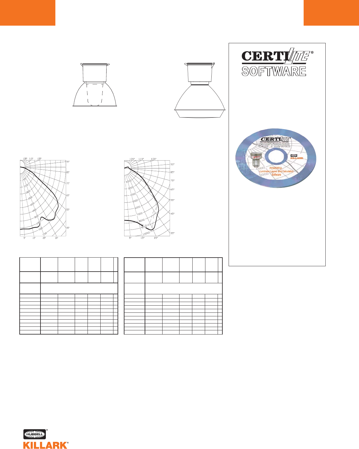
CERTILITE®V SERIES •LIGHTING
PHOTOMETRIC DATA
L108
Test No. HPK10075
METAL HALIDE, METAL HALIDE PULSE,
MERCURY VAPOR-VM5
With Globe & Full Cutoff Deep White
Reflector*
250-400 Watt
Mogul Base
CANDLEPOWER –
400 WATT
36000 lumens
For 250 MH multiply by 0.61
For 250 MHP multiply by 0.66
For 320 MHP multiply by 0.92
For 350 MHP multiply by 1.00
For 400 MHP multiply by 1.22
For 400 MV multiply by 0.64
Efficiency 69.7%
ANGLE CP ANGLE CP
06448. 95.0 0.
5.0 6460. 100.0 0.
10.0 6515. 105.0 0.
15.0 6535. 110.0 0.
20.0 6633. 115.0 0.
25.0 6477. 120.0 0.
30.0 5980. 125.0 0.
35.0 6708. 130.0 0.
40.0 7093. 135.0 0.
45.0 6837. 140.0 0.
50.0 6709. 145.0 0.
55.0 6318. 150.0 0.
60.0 4786. 155.0 0.
65.0 2685. 160.0 0.
70.0 1976. 165.0 0.
75.0 1259. 170.0 0.
80.0 716. 175.0 0.
85.0 296. 180.0 0.
90.0 0.
% EFFECTIVE
CEILING CAVITY
REFLECTANCE
1cc
80 70 50 30 10 0
70 50 30 10 70 50 30 10 50 30 10 50 30 10 50 30 10 0
20% Effective Floor Cavity Reflectance
0 .83 .83 .83 .83 .81 .81.81 .81 .77 .77 .77 .74 .74 .74 .71 .71 .71 .69
1 .76 .73 .70 .67 .74 .71 .69 .66 .68 .66 .64 .66 .64 .62 .63 .62 .60 .59
2 .70 .64 .60 .56 .68 .63.59 .56 .61 .57 .54 .58.56 .53 .56 .54 .52 .51
3 .64 .57 .52 .48 .62 .56.51 .47 .54 .50 .46 .52.49 .46 .50 .47 .45 .43
4 .58 .50 .45 .40 .57 .49.44 .40 .48 .43 .39 .46.42 .39 .45 .41 .38 .37
5 .53 .45 .39 .34 .52 .44.38 .34 .42 .37 .33 .41.37 .33 .40 .36 .33 .31
6 .49 .40 .34 .29 .48 .39.33 .29 .38 .33 .29 .37.32 .29 .36 .32 .28 .27
7 .45 .35 .29 .25 .44 .35.29 .25 .34 .28 .25 .33.28 .24 .32 .27 .24 .23
8 .41 .31 .25 .21 .40 .31.25 .21 .30 .25 .21 .29.24 .21 .28 .24 .21 .19
9 .38 .28 .22 .18 .37 .28.22 .18 .27 .22 .18 .26.22 .18 .26 .21 .18 .17
10 .34 .25 .19 .15 .33 .24 .19 .15 .23 .18 .15 .23.18 .15 .22 .18 .15 .13
% WALL
REFLECTANCE
1w
ROOM CAVITY
RATIO
RCR
COEFFICIENTS OF UTILIZATION --- ZONAL CAVITY METHOD
SPACING TO MOUNTING HEIGHT RATIO - 1.8
*Values using Spacer Kit
Test No. HPK09904
METAL HALIDE, METAL HALIDE PULSE,
MERCURY VAPOR-VM5
With Enclosed Poly Shielded Reflector
250-400 Watt
Mogul Base
CANDLEPOWER –
400 WATT
36000 lumens
For 250 MH multiply by 0.61
For 250 MHP multiply by 0.66
For 320 MHP multiply by 0.92
For 350 MHP multiply by 1.00
For 400 MHP multiply by 1.22
For 400 MV multiply by 0.64
Efficiency 63.4%
ANGLE CP ANGLE CP
07528. 95.0 542.
5.0 7607. 100.0 498.
10.0 7813. 105.0 463.
15.0 8263. 110.0 429.
20.0 8750. 115.0 365.
25.0 8768. 120.0 277.
30.0 7997. 125.0 174.
35.0 7518. 130.0 75.
40.0 7245. 135.0 12.
45.0 6107. 140.0 0.
50.0 4565. 145.0 0.
55.0 3680. 150.0 0.
60.0 2976. 155.0 0.
65.0 2334. 160.0 0.
70.0 1816. 165.0 0.
75.0 1408. 170.0 0.
80.0 1073. 175.0 0.
85.0 800. 180.0 .
90.0 614.
% EFFECTIVE
CEILING CAVITY
REFLECTANCE
1cc
80 70 50 30 10 0
70 50 30 10 70 50 30 10 50 30 10 50 30 10 50 30 10 0
20% Effective Floor Cavity Reflectance
0 .75 .75 .75 .75 .72 .72.72 .72 .68 .68 .68 .65.65 .65 .61 .61 .61 .59
1 .69 .66 .63 .61 .66 .64.61 .59 .60 .58 .57 .57.56 .54 .54 .53 .52 .50
2 .63 .59 .55 .51 .61 .57.54 .50 .54 .51 .49 .52.49 .47 .49 .47 .45 .44
3 .59 .53 .48 .44 .57 .51.47 .44 .49 .45 .43 .47.44 .41 .45 .42 .40 .39
4 .54 .47 .42 .38 .52 .46.41 .38 .44 .40 .37 .42.39 .36 .40 .37 .35 .34
5 .50 .43 .37 .34 .48 .42.37 .33 .40 .36 .33 .38.35 .32 .37 .34 .31 .30
6 .46 .39 .33 .30 .45 .38.33 .29 .36 .32 .29 .35.31 .28 .34 .30 .28 .27
7 .43 .35 .30 .26 .42 .34.29 .26 .33 .29 .26 .32.28 .25 .31 .27 .25 .23
8 .40 .32 .27 .23 .39 .31.26 .23 .30 .26 .23 .29.25 .22 .28 .24 .22 .21
9 .37 .29 .24 .21 .36 .28.24 .20 .27 .23 .20 .26.23 .20 .26 .22 .20 .18
10 .34 .25 .20 .17 .33 .25 .20 .17 .24 .20 .17 .23.19 .16 .22 .19 .16 .15
% WALL
REFLECTANCE
1w
ROOM CAVITY
RATIO
RCR
COEFFICIENTS OF UTILIZATION --- ZONAL CAVITY METHOD
SPACING TO MOUNTING HEIGHT RATIO - 1.5
POWERFUL
Luminaire Layout
and Calculation
Software
Software is used to determine
number of fixtures required and
their proper layout for various
tasks and applications.
Contact you local Killark sales
representative for availability.
**QTZ not for hazardous locations
VM SERIES •LIGHTING
CERTILITE®50-400W MOGUL BASE HID FIXTURE L109
L
Listed - Files E10514 and
E91793 (Marine)
Certified - File LR11713
Class I, Div. 2, Groups A,B,C,D*
Class l, Zone 2, Groups llC, llB, llA
Class II, Div. 1 & 2, Groups E,F,G,*
Class III
Suitable for wet locations
UL Marine
NEMA 3, 4X
Applications
CERTILITE®VM fixtures are designed
for installations where moisture, dirt,
dust, corrosion and vibration may be
present, or NEMA 3 and 4X areas
where wind, water, snow or high ambi-
ents can be expected. They can be
used in locations made hazardous by
the presence of flammable vapors or
gases or combustible dusts as defined
by the NEC.
Typical applications include manufac-
turing plants, and certain chemical and
petrochemical processing facilities,
sewage treatment plants, off-shore and
dockside installations, garages and
storage facilities.
Features
•CERTILITE®VM fixtures are now
available with Pulse Start Metal
Halide ballasts. Pulse Start systems
provide higher and better maintained
light output with longer life compared
standard Metal Halide systems
Pulse Start and standard Metal
Halide lamps and ballasts are not
interchangeable
•Ballast tank and splice box —
corrosion resistant copper-free
aluminum alloy
•Baked powder epoxy polyester finish,
electrostatically applied for complete,
uniform corrosion protection
•All external hardware — stainless
steel
•Guard — copper-free aluminum alloy
•Normally shipped as components for
quick delivery
Consult factory for available lamp
and voltage combinations.
Series Constant
Ballast and Housing
L—HPS 50-150 Watt
V—HPS 250-400 Watt
M—MH 70-250 Watt
F—MH 400 Watt
U—MHP 175 Watt
P—MHP 250-400 Watt
K—MV 100-250 Watt
E—MV 400 Watt
Splice Box
A—Pendant
B—Wall
C—Cone Top
D—Stanchion 25°
S—Straight Stanchion
X—Ceiling
Suffix
QTZ—Quartz Auxiliary**
IR—Instant Restrike
HPS only(150W max.)
BP—Ballast Protector
HPS only
SU103—Assembled w/Lamp
Wattage
1—50
4—70
5—100
6—175
7—250
8—400
9—150
32—320
35—350
Conduit Size
2—3/4"
3—1"
4—1-1/4"
5—1-1/2"
Voltage
0—Quadri-Volt
(120, 208, 240, 277) 60Hz
5—480 60Hz
6—Tri-Tap 120, 277, 347 60Hz
(Canada)
7—220V, 60Hz.
8—220/240, 50Hz
9—Special
Globe & Guard or Refractor
Globe
G—Globe Only
GG—Globe and Guard
ER—Enclosed Reflector
Refractor
G1—Glass IES Type I 12"
G5—Glass IES Type V 12"
P5—Plastic IES Type V
G58—Glass IES Type V 8"
Catalog Number Logic
VM 0 0 -0-0 0 000 -000 (NR)
•Refractor guard — steel with corro-
sion resistant finish
•Reflector — lightweight, corrosion
resistant polyester reinforced
fiberglass
•Five mounting splice box types;
pendant, ceiling, bracket, cone top,
stanchion
•Quartz and incandescent auxiliary
or HPS instant restart
•Minimum starting temperature
HPS – 40°C, MV, MH & MHP – 30°C
Compliances
•UL-1572 Standard for HID lighting
fixtures
•UL Marine type lighting fixtures
•UL-844 Standard for lighting fixtures
for hazardous locations, Class I,
Division 2; Class II, Divisions 1
and 2; Class III
•CSA C22.2 #137-M1981 electric lumi-
naries for use in hazardous locations
•Enclosed and gasketed
•NEMA 3, 4X
*Contact factory for hazardous
location application data
See pages L36 - L108 for CertiLite®VLuminaries
Cross Reference from VM Series to CertiLite®Von L119
NEW
FEATURES-SPECIFICATIONS
V
V
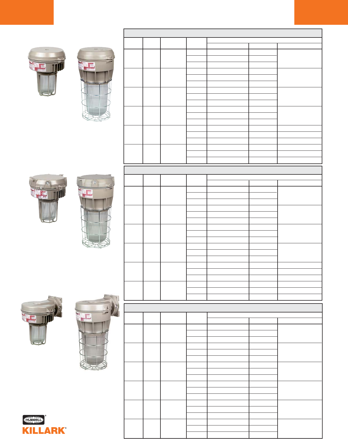
L110 VM SERIES •LIGHTING
HIGH PRESSURE SODIUM, 50-400W MOGUL BASE HID
VM 50-400 WATT HIGH PRESSURE SODIUM PENDANT1
PENDANT
50
70
100
150
250
400
S-68
S-62
S-54
S-55
S-50
S-51
250-400W
50-150W
CEILING
50
70
100
150
250
400
S-68
S-62
S-54
S-55
S-50
S-51
VM 50-400 WATT HIGH PRESSURE SODIUM CEILING1
1See L109 for hazardous location application information.
2Hub size shown is 3/4" NPT .For 1", change “2” to “3”
in catalog number.
3Omit 2nd “G” for Globe only.
4Order Refractor Guards separately.
QUAD VMLX-2-10GG VMLX-2-10G58
3/4" TRI ———
480 ——
QUAD VMLX-2-40GG VMLX-2-40G58
3/4" TRI VMLX-2-46GG VMLX-2-46G58 —
480 VMLX-2-45GG VMLX-2-45G58
QUAD VMLX-2-50GG VMLX-2-50G58
3/4" TRI VMLX-2-56GG VMLX-2-56G58 —
480 VMLX-2-55GG VMLX-2-55G58
QUAD VMLX-2-90GG VMLX-2-90G58
3/4" TRI VMLX-2-96GG VMLX-2-96G58 —
480 VMLX-2-95GG VMLX-2-95G58
QUAD VMVX-2-70GG VMVX-2-70G5 VMVX-2-70ER
3/4" TRI VMVX-2-76GG VMVX-2-76G5 VMVX-2-76ER
480 VMVX-2-75GG VMVX-2-75G5 VMVX-2-75ER
QUAD VMVX-2-80GG VMVX-2-80G5 VMVX-2-80ER
3/4" TRI VMVX-2-86GG VMVX-2-86G5 VMVX-2-86ER
480 VMVX-2-85GG VMVX-2-85G5 VMVX-2-85ER
250-400W
50-150W
ANSI HUB
WATTS LAMP SIZE2VOLTAGE CATALOG NUMBER
GLOBE AND GUARD3REFRACTOR4ENCLOSED REFLECTOR
VM 50-400 WATT HIGH PRESSURE SODIUM WALL1
50
70
100
150
250
400
S-68
S-62
S-54
S-55
S-50
S-51
WALL
50-150W 250-400W
CATALOG NUMBER
GLOBE AND GUARD3REFRACTOR4ENCLOSED REFLECTOR
QUAD VMLA-2-10GG VMLA-2-10G58
3/4" TRI ———
480 ——
QUAD VMLA-2-40GG VMLA-2-40G58
3/4" TRI VMLA-2-46GG VMLA-2-46G58 —
480 VMLA-2-45GG VMLA-2-45G58
QUAD VMLA-2-50GG VMLA-2-50G58
3/4" TRI VMLA-2-56GG VMLA-2-56G58 —
480 VMLA-2-55GG VMLA-2-55G58
QUAD VMLA-2-90GG VMLA-2-90G58
3/4" TRI VMLA-2-96GG VMLA-2-96G58 —
480 VMLA-2-95GG VMLA-2-95G58
QUAD VMVA-2-70GG VMVA-2-70G5 VMVA-2-70ER
3/4" TRI VMVA-2-76GG VMVA-2-76G5 VMVA-2-76ER
480 VMVA-2-75GG VMVA-2-75G5 VMVA-2-75ER
QUAD VMVA-2-80GG VMVA-2-80G5 VMVA-2-80ER
3/4" TRI VMVA-2-86GG VMVA-2-86G5 VMVA-2-86ER
480 VMVA-2-85GG VMVA-2-85G5 VMVA-2-85ER
ANSI HUB
WATTS LAMP SIZE2VOLTAGE
CATALOG NUMBER
GLOBE AND GUARD3REFRACTOR4ENCLOSED REFLECTOR
QUAD VMLB-2-10GG VMLB-2-10G58
3/4" TRI ———
480 ——
QUAD VMLB-2-40GG VMLB-2-40G58
3/4" TRI VMLB-2-46GG VMLB-2-46G58 —
480 VMLB-2-45GG VMLB-2-45G58
QUAD VMLB-2-50GG VMLB-2-50G58
3/4" TRI VMLB-2-56GG VMLB-2-56G58 —
480 VMLB-2-55GG VMLB-2-55G58
QUAD VMLB-2-90GG VMLB-2-90G58
3/4" TRI VMLB-2-96GG VMLB-2-96G58 —
480 VMLB-2-95GG VMLB-2-95G58
QUAD VMVB-2-70GG VMVB-2-70G5
3/4" TRI VMVB-2-76GG VMVB-2-76G5 —
480 VMVB-2-75GG VMVB-2-75G5
QUAD VMVB-2-80GG VMVB-2-80G5
3/4" TRI VMVB-2-86GG VMVB-2-86G5 —
480 VMVB-2-85GG VMVB-2-85G5
ANSI HUB VOLTAGE
WATTS LAMP SIZE2@ 60Hz
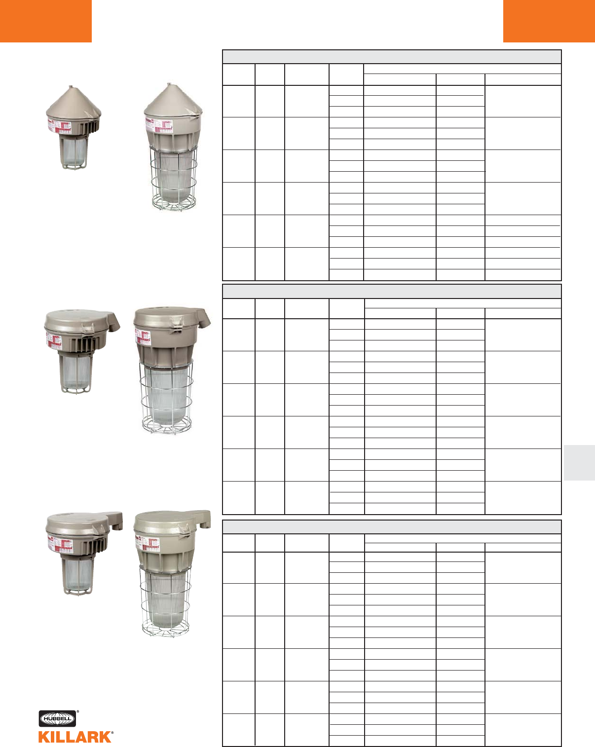
L111
VM SERIES •LIGHTING
HIGH PRESSURE SODIUM, 50-400W MOGUL BASE HID
L
CONE TOP
50
70
100
150
250
400
S-68
S-62
S-54
S-55
S-50
S-51
VM 50-400 WATT HIGH PRESSURE SODIUM CONE TOP1
QUAD VMLC-2-10GG VMLC-2-10G58
3/4" TRI ———
480 ——
QUAD VMLC-2-40GG VMLC-2-40G58
3/4" TRI VMLC-2-46GG VMLC-2-46G58 —
480 VMLC-2-45GG VMLC-2-45G58
QUAD VMLC-2-50GG VMLC-2-50G58
3/4" TRI VMLC-2-56GG VMLC-2-56G58 —
480 VMLC-2-55GG VMLC-2-55G58
QUAD VMLC-2-90GG VMLC-2-90G58
3/4" TRI VMLC-2-96GG VMLC-2-96G58 —
480 VMLC-2-95GG VMLC-2-95G58
QUAD VMVC-2-70GG VMVC-2-70G5 VMVC-2-70ER
3/4" TRI VMVC-2-76GG VMVC-2-76G5 VMVC-2-76ER
480 VMVC-2-75GG VMVC-2-75G5 VMVC-2-75ER
QUAD VMVC-2-80GG VMVC-2-80G5 VMVC-2-80ER
3/4" TRI VMVC-2-86GG VMVC-2-86G5 VMVC-2-86ER
480 VMVC-2-85GG VMVC-2-85G5 VMVC-2-85ER
50-150W 250-400W ANSI HUB VOLTAGE
WATTS LAMP SIZE @ 60Hz
CATALOG NUMBER
GLOBE AND GUARD3REFRACTOR4ENCLOSED REFLECTOR
1See L109 for hazardous location application information.
2Hub size shown is 3/4" NPT . For 1", change “2” to “3”
in catalog number, or change “4” to “5” for 1-1/2” VMD
25° stanchion.
3Omit 2nd “G” for Globe only.
4Order Refractor Guards separately.
50
70
100
150
250
400
CATALOG NUMBER
GLOBE AND GUARD3REFRACTOR4ENCLOSED REFLECTOR
QUAD VMLD-4-10GG VMLD-4-10G58
1-1/4" TRI ———
480 ——
QUAD VMLD-4-40GG VMLD-4-40G58
1-1/4" TRI VMLD-4-46GG VMLD-4-46G58 —
480 VMLD-4-45GG VMLD-4-45G58
QUAD VMLD-4-50GG VMLD-4-50G58
1-1/4" TRI VMLD-4-56GG VMLD-4-56G58 —
480 VMLD-4-55GG VMLD-4-55G58
QUAD VMLD-4-90GG VMLD-4-90G58
1-1/4" TRI VMLD-4-96GG VMLD-4-96G58 —
480 VMLD-4-95GG VMLD-4-95G58
QUAD VMVD-4-70GG VMVD-4-70G5 VMVD-4-70ER
1-1/4" TRI VMVD-4-76GG VMVD-4-76G5 VMVD-4-76ER
480 VMVD-4-75GG VMVD-4-75G5 VMVD-4-75ER
QUAD VMVD-4-80GG VMVD-4-80G5 VMVD-4-80ER
1-1/4" TRI VMVD-4-86GG VMVD-4-86G5 VMVD-4-86ER
480 VMVD-4-85GG VMVD-4-85G5 VMVD-4-85ER
STANCHION
25° ANGLE
50-150W 250-400W
50
70
100
150
250
400
S-68
S-62
S-54
S-55
S-50
S-51
VM 50-400 WATT HIGH PRESSURE SODIUM STANCHION STRAIGHT1
STANCHION
STRAIGHT
50-150W 250-400W
ANSI HUB VOLTAGE
WATTS LAMP SIZE @ 60Hz
CATALOG NUMBER
GLOBE AND GUARD3REFRACTOR4ENCLOSED REFLETOR
VM 50-400 WATT HIGH PRESSURE SODIUM STANCHION 25° ANGLE1
S-68
S-62
S-54
S-55
S-50
S-51
ANSI HUB VOLTAGE
WATTS LAMP SIZE2@ 60Hz
QUAD VMLS-5-10GG VMLS-5-10G58
1-1/2" TRI —— —
480 ——
QUAD VMLS-5-40GG VMLS-5-40G58
1-1/2" TRI VMLS-5-46GG VMLS-5-46G58 —
480 VMLS-5-45GG VMLS-5-45G58
QUAD VMLS-5-50GG VMLS-5-50G58
1-1/2" TRI VMLS-5-56GG VMLS-5-56G58 —
480 VMLS-5-55GG VMLS-5-55G58
QUAD VMLS-5-90GG VMLS-5-90G58
1-1/2" TRI VMLS-5-96GG VMLS-5-96G58 —
480 VMLS-5-95GG VMLS-5-95G58
QUAD VMVS-5-70GG VMVS-5-70G5
1-1/2" TRI VMVS-5-76GG VMVS-5-76G5 —
480 VMVS-5-75GG VMVS-5-75G5
QUAD VMVS-5-80GG VMVS-5-80G5
1-1/2" TRI VMVS-5-86GG VMVS-5-86G5 —
480 VMVS-5-85GG VMVS-5-85G5
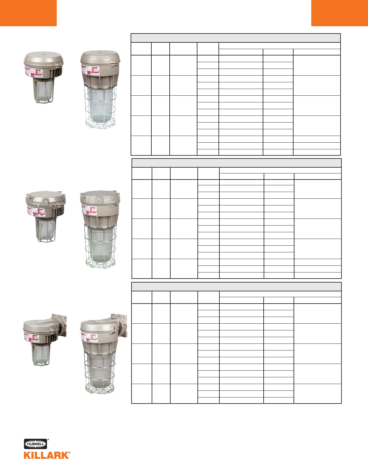
VM SERIES •LIGHTING
METAL HALIDE, 70-400W MOGUL BASE HID
L112
70
100
175
250
400
M-98
M-90
M-57
M-58
M-59
CATALOG NUMBER
GLOBE AND GUARD3REFRACTOR4ENCLOSED REFLECTOR
QUAD VMMA-2-40GG VMMA-2-40G58
3/4" TRI VMMA-2-46GG VMMA-2-46G58 —
480 VMMA-2-45GG VMMA-2-45G58
QUAD VMMA-2-50GG VMMA-2-50G58
3/4" TRI VMMA-2-56GG VMMA-2-56G58 —
480 VMMA-2-55GG VMMA-2-55G58
QUAD VMMA-2-60GG VMMA-2-60G58
3/4" TRI VMMA-2-66GG VMMA-2-66G58 —
480 VMMA-2-65GG VMMA-2-65G58
QUAD VMMA-2-70GG VMMA-2-70G58
3/4" TRI VMFA-2-76GG VMFA-2-76G58 —
480 VMMA-2-75GG VMMA-2-75G58
QUAD VMFA-2-80GG VMFA-2-80G5 VMFA-2-80ER
3/4" TRI VMFA-2-86GG VMFA-2-86G5 VMFA-2-86ER
480 VMFA-2-85GG VMFA-2-85G5 VMFA-2-85ER
ANSI HUB VOLTAGE
WATTS LAMP SIZE2@60Hz
PENDANT
70-250W 400W
70-250W 400W
CEILING
WALL
70-250W 400W
1See L109 for hazardous location application information.
2Hub size shown is 3/4" NPT. For 1", change “2” to “3” in catalog number.
3Omit 2nd “G” for Globe only.
4Order Refractor Guards separately.
VM 70-400 WATT METAL HALIDE PENDANT1
70
100
175
250
400
M-98
M-90
M-57
M-58
M-59
VM 70-400 WATT METAL HALIDE CEILING1
QUAD VMMX-2-40GG VMMX-2-40G58
3/4" TRI VMMX-2-46GG VMMX-2-46G58 —
480 VMMX-2-45GG VMMX-2-45G58
QUAD VMMX-2-50GG VMMX-2-50G58
3/4" TRI VMMX-2-56GG VMMX-2-56G58 —
480 VMMX-2-55GG VMMX-2-55G58
QUAD VMMX-2-60GG VMMX-2-60G58
3/4" TRI VMMX-2-66GG VMMX-2-66G58 —
480 VMMX-2-65GG VMMX-2-65G58
QUAD VMMX-2-70GG VMMX-2-70G58
3/4" TRI VMFX-2-76GG VMFX-2-76G58 —
480 VMMX-2-75GG VMMX-2-75G58
QUAD VMFX-2-80GG VMFX-2-80G5 VMFX-2-80ER
3/4" TRI VMFX-2-86GG VMFX-2-86G5 VMFX-2-86ER
480 VMFX-2-85GG VMFX-2-85G5 VMFX-2-85ER
ANSI HUB VOLTAGE
WATTS LAMP SIZE2@ 60Hz
CATALOG NUMBER
GLOBE AND GUARD3REFRACTOR4ENCLOSED REFLECTOR
VM 70-400 WATT METAL HALIDE WALL1
70
100
175
250
400
M-98
M-90
M-57
M-58
M-59
CATALOG NUMBER
GLOBE AND GUARD2REFRACTOR4ENCLOSED REFLECTOR
QUAD VMMB-2-40GG VMMB-2-40G58
3/4" TRI VMMB-2-46GG VMMB-2-46G58 —
480 VMMB-2-45GG VMMB-2-45G58
QUAD VMMB-2-50GG VMMB-2-50G58
3/4" TRI VMMB-2-56GG VMMB-2-56G58 —
480 VMMB-2-55GG VMMB-2-55G58
QUAD VMMB-2-60GG VMMB-2-60G58
3/4" TRI VMMB-2-66GG VMMB-2-66G58 —
480 VMMB-2-65GG VMMB-2-65G58
QUAD VMMB-2-70GG VMMB-2-70G58
3/4" TRI VMFB-2-76GG VMFB-2-76G58 —
480 VMMB-2-75GG VMMB-2-75G58
QUAD VMFB-2-80GG VMFB-2-80G5
3/4" TRI VMFB-2-86GG VMFB-2-86G5 —
480 VMFB-2-85GG VMFB-2-85G5
ANSI HUB VOLTAGE
WATTS LAMP SIZE2@ 60Hz
VM SERIES •LIGHTING
METAL HALIDE, 70-400W MOGUL BASE HID L113
L
70
100
175
250
400
M-98
M-90
M-57
M-58
M-59
QUAD VMMC-2-40GG VMMC-2-40G58
3/4" TRI VMMC-2-46GG VMMC-2-46G58 —
480 VMMC-2-45GG VMMC-2-45G58
QUAD VMMC-2-50GG VMMC-2-50G58
3/4" TRI VMMC-2-56GG VMMC-2-56G58 —
480 VMMC-2-55GG VMMC-2-55G58
QUAD VMMC-2-60GG VMMC-2-60G58
3/4" TRI VMMC-2-66GG VMMC-2-66G58 —
480 VMMC-2-65GG VMMC-2-65G58
QUAD VMMC-2-70GG VMMC-2-70G58
3/4" TRI VMFC-2-76GG VMFC-2-76G58 —
480 VMMC-2-75GG VMMC-2-75G58
QUAD VMFC-2-80GG VMFC-2-80G5 VMFC-2-80ER
3/4" TRI VMFC-2-86GG VMFC-2-86G5 VMFC-2-86ER
480 VMFC-2-85GG VMFC-2-85G5 VMFC-2-85ER
CONE TOP
70-250W 400W
ANSI HUB VOLTAGE
WATTS LAMP SIZE @ 60Hz
CATALOG NUMBER
GLOBE AND GUARD3REFRACTOR4ENCLOSED REFLECTOR
STANCHION
25° ANGLE
70-250W 400W
70
100
175
250
400
M-98
M-90
M-57
M-58
M-59
VM 70-400 WATT METAL HALIDE STANCHION STRAIGHT1
QUAD VMMS-5-40GG VMMS-5-40G58
1-1/2" TRI VMMS-5-46GG VMMS-5-46G58 —
480 VMMS-5-45GG VMMS-5-45G58
QUAD VMMS-5-50GG VMMS-5-50G58
1-1/2" TRI VMMS-5-56GG VMMS-5-56G58 —
480 VMMS-5-55GG VMMS-5-55G58
QUAD VMMS-5-60GG VMMS-5-60G58
1-1/2" TRI VMMS-5-66GG VMMS-5-66G58 —
480 VMMS-5-65GG VMMS-5-65G58
QUAD VMMS-5-70GG VMMS-5-70G58
1-1/2" TRI VMFS-5-76GG VMFS-5-76G58 —
480 VMMS-5-75GG VMMS-5-75G58
QUAD VMFS-5-80GG VMFS-5-80G5
1-1/2" TRI VMFS-5-86GG VMFS-5-86G5 —
480 VMFS-5-85GG VMFS-5-85G5
STANCHION
STRAIGHT
70-250W 400W
ANSI HUB VOLTAGE
WATTS LAMP SIZE @ 60Hz
CATALOG NUMBER
GLOBE AND GUARD3REFRACTOR4ENCLOSED REFLECTOR
1See L109 for hazardous location application information.
2Hub size shown is 3/4" NPT. For 1", change “2” to “3” in catalog number, or change “4” to “5” for 1-
1/2” VMD 25° stanchion.
3Omit 2nd “G” for Globe only.
4Order Refractor Guards separately.
VM 70-400 WATT METAL HALIDE STANCHION 25° ANGLE1
70
100
175
250
400
M-98
M-90
M-57
M-58
M-59
CATALOG NUMBER
GLOBE AND GUARD3REFRACTOR4ENCLOSED REFLECTOR
QUAD VMMD-4-40GG VMMD-4-40G58
1-1/4" TRI VMMD-4-46GG VMMD-4-46G58 —
480 VMMD-4-45GG VMMD-4-45G58
QUAD VMMD-4-50GG VMMD-4-50G58
1-1/4" TRI VMMD-4-56GG VMMD-4-56G58 —
480 VMMD-4-55GG VMMD-4-55G58
QUAD VMMD-4-60GG VMMD-4-60G58
1-1/4" TRI VMMD-4-66GG VMMD-4-66G58 —
480 VMMD-4-65GG VMMD-4-65G58
QUAD VMMD-4-70GG VMMD-4-70G58
1-1/4" TRI VMFD-4-76GG VMFD-4-76G58 —
480 VMMD-4-75GG VMMD-4-75G58
QUAD VMFD-4-80GG VMFD-4-80G5 VMFD-4-80ER
1-1/4" TRI VMFD-4-86GG VMFD-4-86G5 VMFD-4-80ER
480 VMFD-4-85GG VMFD-4-85G5 VMFD-4-80ER
ANSI HUB VOLTAGE
WATTS LAMP SIZE2@ 60Hz
VM 70-400 WATT METAL HALIDE CONE TOP1
VM SERIES •LIGHTING
METAL HALIDE PULSE, 175-400W MOGUL BASE HID
L114
175
250
320
350
400
M-137
M-138
M-132
M-131
M-135
VM 175-400 WATT PULSE START METAL HALIDE PENDANT1
QUAD VMUA-2-60GG VMUA-2-60G58
3/4" TRI VMUA-2-66GG VMUA-2-66G58 —
480 VMUA-2-65GG VMUA-2-65G58
QUAD VMPA-2-70GG VMPA-2-70G5 VMPA-2-70ER
3/4" TRI VMPA-2-76GG VMPA-2-76G5 VMPA-2-76ER
480 VMPA-2-75GG VMPA-2-75G5 VMPA-2-75ER
QUAD VMPA-2-320GG VMPA-2-320G5 VMPA-2-320ER
3/4" TRI VMPA-2-326GG VMPA-2-326G5 VMPA-2-326ER
480 VMPA-2-325GG VMPA-2-325G5 VMPA-2-325ER
QUAD VMPA-2-350GG VMPA-2-350G5 VMPA-2-350ER
3/4" TRI VMPA-2-356GG VMPA-2-356G5 VMPA-2-356ER
480 VMPA-2-355GG VMPA-2-355G5 VMPA-2-355ER
QUAD VMPA-2-80GG VMPA-2-80G5 VMPA-2-80ER
3/4" TRI VMPA-2-86GG VMPA-2-86G5 VMPA-2-86ER
480 VMPA-2-85GG VMPA-2-85G5 VMPA-2-85ER
ANSI HUB
WATTS LAMP SIZE2
CATALOG NUMBER
GLOBE AND GUARD3REFRACTOR4ENCLOSED REFLECTOR
PENDANT
175W 250-400W
VOLTAGE
@ 60Hz
CATALOG NUMBER
GLOBE AND GUARD3REFRACTOR4ENCLOSED REFLECTOR
175
250
320
350
400
M-137
M-138
M-132
M-131
M-135
VM 175-400 WATT PULSE START METAL HALIDE CEILING1
QUAD VMUX-2-60GG VMUX-2-60G58
3/4" TRI VMUX-2-66GG VMUX-2-66G58 —
480 VMUX-2-65GG VMUX-2-65G58
QUAD VMPX-2-70GG VMPX-2-70G5 VMPX-2-70ER
3/4" TRI VMPX-2-76GG VMPX-2-76G5 VMPX-2-76ER
480 VMPX-2-75GG VMPX-2-75G5 VMPX-2-75ER
QUAD VMPX-2-320GG VMPX-2-320G5 VMPX-2-320ER
3/4" TRI VMPX-2-326GG VMPX-2-326G5 VMPX-2-326ER
480 VMPX-2-325GG VMPX-2-325G5 VMPX-2-325ER
QUAD VMPX-2-350GG VMPX-2-350G5 VMPX-2-350ER
3/4" TRI VMPX-2-356GG VMPX-2-356G5 VMPX-2-356ER
480 VMPX-2-355GG VMPX-2-355G5 VMPX-2-355ER
QUAD VMPX-2-80GG VMPX-2-80G5 VMPX-2-80ER
3/4" TRI VMPX-2-86GG VMPX-2-86G5 VMPX-2-86ER
480 VMPX-2-85GG VMPX-2-85G5 VMPX-2-85ER
175W 250-400W
CEILING ANSI HUB
WATTS LAMP SIZE2
VOLTAGE
@ 60Hz
175
250
320
350
400
M-137
M-138
M-132
M-131
M-135
VM 175-400 WATT PULSE START METAL HALIDE WALL1
QUAD VMUB-2-60GG VMUB-2-60G58
3/4" TRI VMUB-2-66GG VMUB-2-66G58 —
480 VMUB-2-65GG VMUB-2-65G58
QUAD VMPB-2-70GG VMPB-2-70G5
3/4" TRI VMPB-2-76GG VMPB-2-76G5 —
480 VMPB-2-75GG VMPB-2-75G5
QUAD VMPB-2-320GG VMPB-2-320G5
3/4" TRI VMPB-2-326GG VMPB-2-326G5 —
480 VMPB-2-325GG VMPB-2-325G5
QUAD VMPB-2-350GG VMPB-2-350G5
3/4" TRI VMPB-2-356GG VMPB-2-356G5 —
480 VMPB-2-355GG VMPB-2-355G5
QUAD VMPB-2-80GG VMPB-2-80G5
3/4" TRI VMPB-2-86GG VMPB-2-86G5 —
480 VMPB-2-85GG VMPB-2-85G5
ANSI HUB
WATTS LAMP SIZE2
CATALOG NUMBER
GLOBE AND GUARD3REFRACTOR4ENCLOSED REFLECTOR
WALL
175W 250-400W
VOLTAGE
@ 60Hz
1See L109 for hazardous location application information.
2Hub size shown is 3/4" NPT .For 1", change “2” to “3” in catalog number.
3Omit 2nd “G” for Globe only.
4Order Refractor Guards separately.
QUAD VMUD-4-60GG VMUD-4-60G58
1-1/4" TRI VMUD-4-66GG VMUD-4-66G58 —
480 VMUD-4-65GG VMUD-4-65G58
QUAD VMPD-4-70GG VMPD-4-70G5 VMPD-4-70ER
1-1/4" TRI VMPD-4-76GG VMPD-4-76G5 VMPD-4-76ER
480 VMPD-4-75GG VMPD-4-75G5 VMPD-4-75ER
QUAD VMPD-4-320GG VMPD-4-320G5 VMPD-4-320ER
1-1/4" TRI VMPD-4-326GG VMPD-4-326G5 VMPD-4-326ER
480 VMPD-4-325GG VMPD-4-325G5 VMPD-4-325ER
QUAD VMPD-4-350GG VMPD-4-350G5 VMPD-4-350ER
1-1/4" TRI VMPD-4-356GG VMPD-4-356G5 VMPD-4-356ER
480 VMPD-4-355GG VMPD-4-355G5 VMPD-4-355ER
QUAD VMPD-4-80GG VMPD-4-80G5 VMPD-4-80ER
1-1/4" TRI VMPD-4-86GG VMPD-4-86G5 VMPD-4-86ER
480 VMPD-4-85GG VMPD-4-85G5 VMPD-4-85ER
VM SERIES •LIGHTING
METAL HALIDE PULSE, 175-400W MOGUL BASE HID L115
L
175
250
320
350
400
M-137
M-138
M-132
M-131
M-135
VM 175-400 WATT PULSE START METAL HALIDE CONE TOP1
QUAD VMUC-2-60GG VMUC-2-60G58
3/4" TRI VMUC-2-66GG VMUC-2-66G58 —
480 VMUC-2-65GG VMUC-2-65G58
QUAD VMPC-2-70GG VMPC-2-70G5 VMPC-2-70ER
3/4" TRI VMPC-2-76GG VMPC-2-76G5 VMPC-2-76ER
480 VMPC-2-75GG VMPC-2-75G5 VMPC-2-75ER
QUAD VMPC-2-320GG VMPC-2-320G5 VMPC-2-320ER
3/4" TRI VMPC-2-326GG VMPC-2-326G5 VMPC-2-326ER
480 VMPC-2-325GG VMPC-2-325G5 VMPC-2-325ER
QUAD VMPC-2-350GG VMPC-2-350G5 VMPC-2-350ER
3/4" TRI VMPC-2-356GG VMPC-2-356G5 VMPC-2-356ER
480 VMPC-2-355GG VMPC-2-355G5 VMPC-2-355ER
QUAD VMPC-2-80GG VMPC-2-80G5 VMPC-2-80ER
3/4" TRI VMPC-2-86GG VMPC-2-86G5 VMPC-2-86ER
480 VMPC-2-85GG VMPC-2-85G5 VMPC-2-85ER
ANSI HUB
WATTS LAMP SIZE
CATALOG NUMBER
GLOBE AND GUARD3REFRACTOR4ENCLOSED REFLECTOR
CONE TOP
175W 250-400W
VOLTAGE
@ 60Hz
175
250
320
350
400
M-137
M-138
M-132
M-131
M-135
VM 175-400 WATT PULSE START METAL HALIDE STANCHION 25° ANGLE1
ANSI HUB
WATTS LAMP SIZE2
CATALOG NUMBER
GLOBE AND GUARD3REFRACTOR4ENCLOSED REFLECTOR
STANCHION
25° ANGLE
175W 250-400W
VOLTAGE
@ 60Hz
CATALOG NUMBER
GLOBE AND GUARD3REFRACTOR4ENCLOSED REFLECTOR
M-137
M-138
M-132
M-131
M-135
VM 175-400 WATT PULSE START METAL HALIDE STANCHION STRAIGHT1
QUAD VMUS-5-60GG VMUS-5-60G58
1-1/2" TRI VMUS-5-66GG VMUS-5-66G58 —
480 VMUS-5-65GG VMUS-5-65G58
QUAD VMPS-5-70GG VMPS-5-70G5
1-1/2" TRI VMPS-5-76GG VMPS-5-76G5 —
480 VMPS-5-75GG VMPS-5-75G5
QUAD VMPS-5-320GG VMPS-5-320G5
1-1/2" TRI VMPS-5-326GG VMPS-5-326G5 —
480 VMPS-5-325GG VMPS-5-325G5
QUAD VMPS-5-350GG VMPS-5-350G5
1-1/2" TRI VMPS-5-356GG VMPS-5-356G5 —
480 VMPS-5-355GG VMPS-5-355G5
QUAD VMPS-5-80GG VMPS-5-80G5
1-1/2" TRI VMPS-5-86GG VMPS-5-86G5 —
480 VMPS-5-85GG VMPS-5-85G5
STANCHION
STRAIGHT
175W
250-400W
VOLTAGE
@ 60Hz
1See L109 for hazardous location application information.
2Hub size shown is 3/4" NPT .For 1", change “2” to “3” in catalog number, or change “4” to “5”
for 1-1/2” VMD 25° stanchion.
3Omit 2nd “G” for Globe only.
4Order Refractor Guards separately.
ANSI HUB
WATTS LAMP SIZE
175
250
320
350
400
VM SERIES •LIGHTING
MERCURY VAPOR, 100-400W MOGUL BASE HID
L116
VM 100-400 WATT MERCURY VAPOR PENDANT1
QUAD VMKA-2-50GG VMKA-2-50G58
3/4" TRI VMKA-2-56GG VMKA-2-56G58 —
480 VMKA-2-55GG VMKA-2-55G58
QUAD VMKA-2-60GG VMKA-2-60G58
3/4" TRI VMKA-2-66GG VMKA-2-66G58 —
480 VMKA-2-65GG VMKA-2-65G58
QUAD VMKA-2-70GG VMKA-2-70G58
3/4" TRI VMKA-2-76GG VMKA-2-76G58 —
480 VMKA-2-75GG VMKA-2-75G58
QUAD VMEA-2-80GG VMEA-2-80G5 VMEA-2-80ER
3/4" TRI VMEA-2-86GG VMEA-2-86G5 VMEA-2-86ER
480 VMEA-2-85GG VMEA-2-85G5 VMEA-2-85ER
ANSI HUB
WATTS LAMP SIZE2
CATALOG NUMBER
GLOBE AND GUARD3REFRACTOR4ENCLOSED REFLECTOR
100
175
250
400
H-38
H-39
H-37
H-33
PENDANT
100-250W 400W VOLTAGE
@ 60Hz
VM 100-400 WATT MERCURY VAPOR CEILING1
QUAD VMKX-2-50GG VMKX-2-50G58
3/4" TRI VMKX-2-56GG VMKX-2-56G58 —
480 VMKX-2-55GG VMKX-2-55G58
QUAD VMKX-2-60GG VMKX-2-60G58
3/4" TRI VMKX-2-66GG VMKX-2-66G58 —
480 VMKX-2-65GG VMKX-2-65G58
QUAD VMKX-2-70GG VMKX-2-70G58
3/4" TRI VMKX-2-76GG VMKX-2-76G58 —
480 VMKX-2-75GG VMKX-2-75G58
QUAD VMEX-2-80GG VMEX-2-80G5 VMEX-2-80ER
3/4" TRI VMEX-2-86GG VMEX-2-86G5 VMEX-2-86ER
480 VMEX-2-85GG VMEX-2-85G5 VMEX-2-85ER
100
175
250
400
H-38
H-39
H-37
H-33
100-250W 400W
CEILING ANSI HUB
WATTS LAMP SIZE2
VOLTAGE
@ 60Hz
VM 100-400 WATT MERCURY VAPOR WALL1
QUAD VMKB-2-50GG VMKB-2-50G58
3/4" TRI VMKB-2-56GG VMKB-2-56G58 —
480 VMKB-2-55GG VMKB-2-55G58
QUAD VMKB-2-60GG VMKB-2-60G58
3/4" TRI VMKB-2-66GG VMKB-2-66G58 —
480 VMKB-2-65GG VMKB-2-65G58
QUAD VMKB-2-70GG VMKB-2-70G58
3/4" TRI VMKB-2-76GG VMKB-2-76G58 —
480 VMKB-2-75GG VMKB-2-75G58
QUAD VMEB-2-80GG VMEB-2-80G5
3/4" TRI VMEB-2-86GG VMEB-2-86G5 —
480 VMEB-2-85GG VMEB-2-85G5
ANSI HUB
WATTS LAMP SIZE2
CATALOG NUMBER
GLOBE AND GUARD3REFRACTOR4ENCLOSED REFLECTOR
100
175
250
400
H-38
H-39
H-37
H-33
WALL
100-250W 400W VOLTAGE
@ 60Hz
1See L109 for hazardous location application information.
2Hub size shown is 3/4" NPT .For 1", change “2” to “3” in catalog number.
3Omit 2nd “G” for Globe only.
4Order Refractor Guards separately.
CATALOG NUMBER
GLOBE AND GUARD3REFRACTOR4ENCLOSED REFLECTOR
VM SERIES •LIGHTING
MERCURY VAPOR, 100-400W MOGUL BASE HID L117
L
ANSI HUB
WATTS LAMP SIZE
VM 100-400 WATT MERCURY VAPOR CONE TOP1
QUAD VMKC-2-50GG VMKC-2-50G58
3/4" TRI VMKC-2-56GG VMKC-2-56G58 —
480 VMKC-2-55GG VMKC-2-55G58
QUAD VMKC-2-60GG VMKC-2-60G58
3/4" TRI VMKC-2-66GG VMKC-2-66G58 —
480 VMKC-2-65GG VMKC-2-65G58
QUAD VMKC-2-70GG VMKC-2-70G58
3/4" TRI VMKC-2-76GG VMKC-2-76G58 —
480 VMKC-2-75GG VMKC-2-75G58
QUAD VMEC-2-80GG VMEC-2-80G5 VMEC-2-80ER
3/4" TRI VMEC-2-86GG VMEC-2-86G5 VMEC-2-86ER
480 VMEC-2-85GG VMEC-2-85G5 VMEC-2-85ER
100
175
250
400
H-38
H-39
H-37
H-33
CONE TOP
100-250W 400W VOLTAGE
@ 60Hz
VM 100-400 WATT MERCURY VAPOR STANCHION 25° ANGLE1
QUAD VMKD-4-50GG VMKD-4-50G58
1-1/4" TRI VMKD-4-56GG VMKD-4-56G58 —
480 VMKD-4-55GG VMKD-4-55G58
QUAD VMKD-4-60GG VMKD-4-60G58
1-1/4" TRI VMKD-4-66GG VMKD-4-66G58 —
480 VMKD-4-65GG VMKD-4-65G58
QUAD VMKD-4-70GG VMKD-4-70G58
1-1/4" TRI VMKD-4-76GG VMKD-4-76G58 —
480 VMKD-4-75GG VMKD-4-75G58
QUAD VMED-4-80GG VMED-4-80G5 VMED-4-80ER
1-1/4" TRI VMED-4-86GG VMED-4-86G5 VMED-4-86ER
480 VMED-4-85GG VMED-4-85G5 VMED-4-85ER
ANSI HUB
WATTS LAMP SIZE2
CATALOG NUMBER
GLOBE AND GUARD3REFRACTOR4ENCLOSED REFLECTOR
100
175
250
400
H-38
H-39
H-37
H-33
STANCHION
25° ANGLE
100-250W 400W
VOLTAGE
@60Hz
ANSI HUB
WATTS LAMP SIZE
VM 100-400 WATT MERCURY VAPOR STANCHION STRAIGHT1
QUAD VMKS-5-50GG VMKS-5-50G58
1-1/2" TRI VMKS-5-56GG VMKS-5-56G58 —
480 VMKS-5-55GG VMKS-5-55G58
QUAD VMKS-5-60GG VMKS-5-60G58
1-1/2" TRI VMKS-5-66GG VMKS-5-66G58 —
480 VMKS-5-65GG VMKS-5-65G58
QUAD VMKS-5-70GG VMKS-5-70G58
1-1/2" TRI VMKS-5-76GG VMKS-5-76G58 —
480 VMKS-5-75GG VMKS-5-75G58
QUAD VMES-5-80GG VMES-5-80G5
1-1/2" TRI VMES-5-86GG VMES-5-86G5 —
480 VMES-5-85GG VMES-5-85G5
100
175
250
400
H-38
H-39
H-37
H-33
STANCHION
STRAIGHT
100-250W 400W
VOLTAGE
@ 60Hz
1See L109 for hazardous location application information.
2Hub size shown is 3/4" NPT .For 1", change “2” to “3” in catalog number, or change “4”
to “5” for 1-1/2” VMD 25° stanchion.
3Omit 2nd “G” for Globe only.
4Order Refractor Guards separately.
CATALOG NUMBER
GLOBE AND GUARD3REFRACTOR4ENCLOSED REFLECTOR
CATALOG NUMBER
GLOBE AND GUARD3REFRACTOR4ENCLOSED REFLECTOR
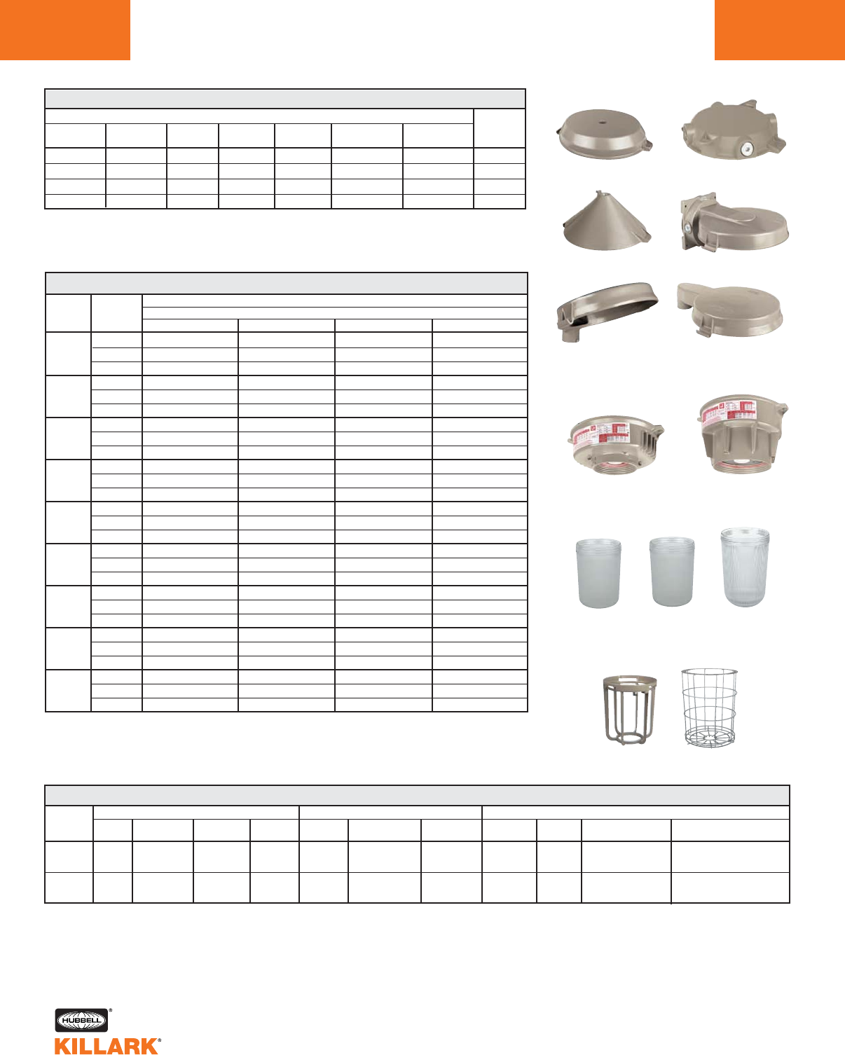
VM SERIES •LIGHTING
COMPONENT PARTS/ACCESSORIES
L118
Pendant Ceiling
Wall
25° Stanchion
CATALOG NUMBER
PENDANT1PENDANT2CEILING WALL CONE TOP 25° STRAIGHT
STANCHION STANCHION
VMA-2 VMA-24 VMX-2 VMB-2 VMC-2 — —
VMA-3 — VMX-3 VMB-3 — — —
— — — — — VMD-4 —
— — — — — VMD-5 VMDS-5
VM MOUNTING SPLICE BOX
HUB
SIZE
3/4"
1"
1-1/4"
1-1/2"
Cone Top
Straight Stanchion
Splice Boxes
1For use with Series VML, VMK, VMM and VMU fixtures.
2For use with Series VMV, VME, VMF and VMP fixtures.
Flexible pendant mounting-order VMA-24.
Cone top pendant not suitable for flexible mounting.
250-400 Watt
50-250 Watt
Ballast Tanks
50-400W BALLAST TANK ASSEMBLY
Quad VMLO-0-100 — — —
50 Tri ——— —
480 ——— —
Quad VMLO-0-400 VMMO-0-400 — —
70 Tri VMLO-0-460 VMMO-0-460 — —
480 VMLO-0-450 VMMO-0-450 — —
Quad VMLO-0-500 VMMO-0-500 — VMKO-0-500
100 Tri VMLO-0-560 VMMO-0-560 — VMKO-0-560
480 VMLO-0-550 VMMO-0-550 — VMKO-0-550
Quad VMLO-0-900 — — —
150 Tri VMLO-0-960 — — —
480 VMLO-0-950 — — —
Quad — VMMO-0-600 VMUO-0-600 VMKO-0-600
175 Tri — VMMO-0-660 VMUO-0-660 VMKO-0-660
480 — VMMO-0-650 VMUO-0-650 VMKO-0-650
Quad VMVO-0-700 VMMO-0-700 VMPO-0-700 VMKO-0-700
250 Tri VMVO-0-760 VMFO-0-760 VMPO-0-760 VMKO-0-760
480 VMVO-0-750 VMMO-0-750 VMPO-0-750 VMKO-0-750
Quad — — VMPO-0-3200 —
320 Tri — — VMPO-0-3260 —
480 — — VMPO-0-3250 —
Quad — — VMPO-0-3500 —
350 Tri — — VMPO-0-3560 —
480 — — VMPO-0-3550 —
Quad VMVO-0-800 VMFO-0-800 VMPO-0-800 VMEO-0-800
400 Tri VMVO-0-860 VMFO-0-860 VMPO-0-860 VMEO-0-860
480 VMVO-0-850 VMFO-0-850 VMPO-0-850 VMEO-0-850
CATALOG NUMBER
LAMP TYPE
WATTS
HPS MH PULSE START MH MV
Note: For Class l, Zone 2 ExnR Restricted Breathing ballast housings, add “NR” suffix to catalog number;
e.g. VMLO-0-400NR.“NR” ballast housings are NOT approved for use with refractors.
VOLTAGE
@ 60Hz
*Registered trademark of Thomas Manufacturing Corp.
**Registered trademark of DuPont, Inc.
Coatings for added resistance to thermal shock, but diminish light output and may hinder heat dissipation.
3Plated steel 8” guard VMRWG-8.
4Plated steel 12” guard VMRWG.
TUFF-SKIN
COATED*
VMGT-17
—
TEFLON
COATED**
VMGTC-17
—
GUARD
VMAG-17
VMAG-40
SERIES
VML,VMM
VMU, VMK
VMV, VMF
VMP, VME
GLOBE
VMG-17
VMG-40
CATALOG NUMBER
VM SERIES GLOBES & GUARDS
Globes
Guards
VMG-17 VMGTC-17* VMG-40
VMAG-17 VMAG-40
SPINTOP REFRACTORS
8”3
VZRG-1550
—
12” TYPE V4
VZRG2550
VZRG4050
12” POLY.4
VZRP-175
—
REFLECTORS
STD. DOME
VMPSD-17
VMPSD-40
ANGLE
VMPA-17
VMPA-40
DEEP REFLECTOR
VMRD-17ALZ
HRD-400
HRD-400ALZ
ENCLOSED REFLECTOR
—
VMER40
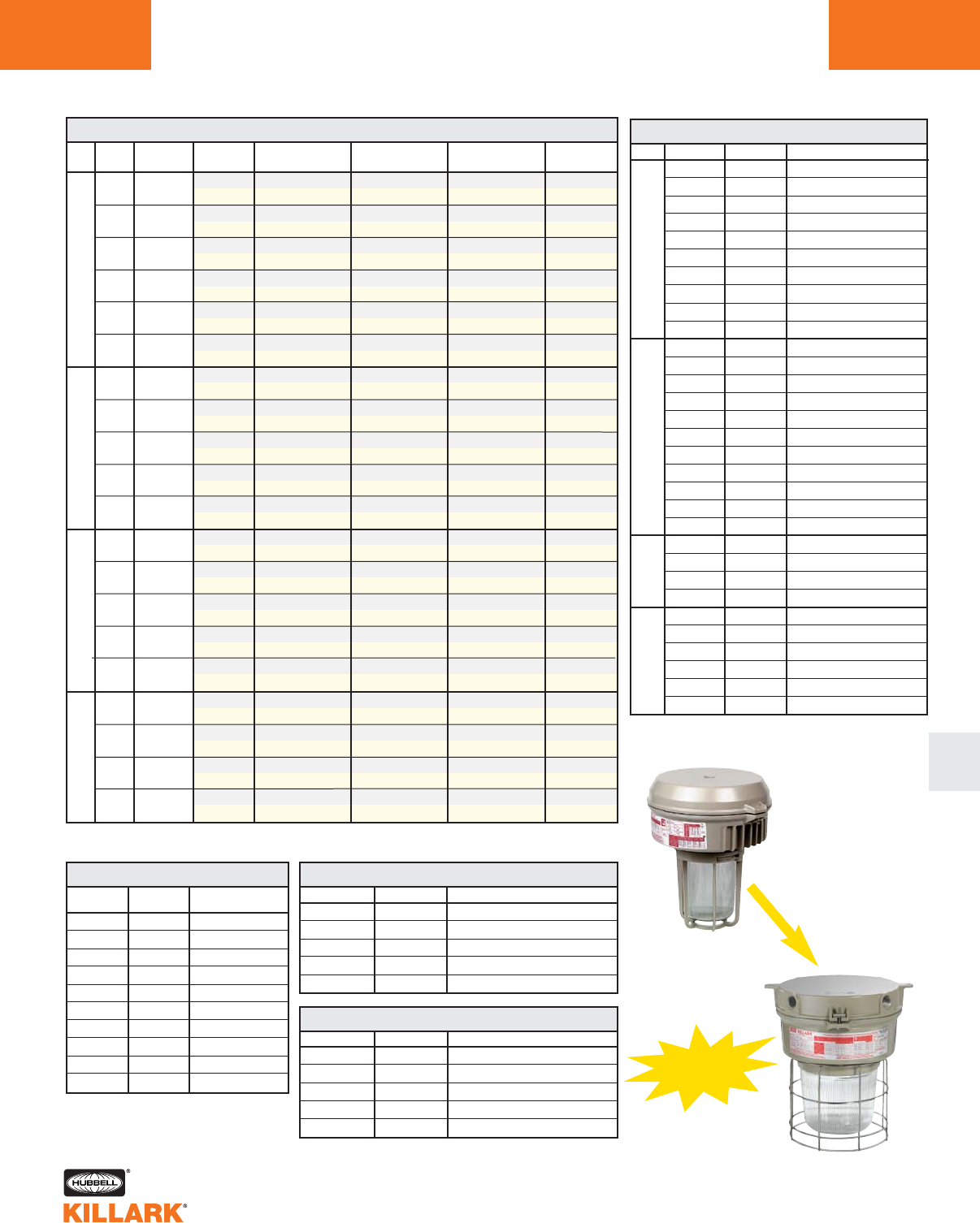
VM SERIES •LIGHTING
CERTILITE®TO CERTILITE®VL119
L
GENERAL CROSS-REFERENCE FOR CERTILITE®TO NEW CERTILITE®V***
WATTS
50
70
100
150
250
400
70
100
175
250
400
175
250
320
350
400
100
175
250
400
ANSI
LAMP TYPE
S68
S62
S54
S55
S50
S51
M98
M90
M57
M58
M59
M137
M138
M132
M131
M135
H38
H39
H37
H33
GLOBE
& GUARD
VML1-1-13GG
VM3S05211GLG
VML1-1-42GG
VM3S07211GLG
VML1-1-52GG
VM3S10211GLG
VML1-1-92GG
VM3S15211GLG
VMV1-1-72GG
VM5S25211GLG
VMV1-1-82GG
VM5S40211GLG
VMM1-1-42GG
VM3H07211GLG
VMM1-1-52GG
VM3H10211GLG
VMM1-1-62GG
VM3H17211GLG
VMM1-1-72GG
VM3H25211GLG
VMF1-1-82GG
VM5H40211GLG
VMU1-1-62GG
VM3P17211GLG
VMP1-1-72GG
VM5P25211GLG
VMP1-1-322GG
VM5P32211GLG
VMP1-1-352GG
VM5P35211GLG
VMP1-1-82GG
VM5P40211GLG
VMK1-1-52GG
VM3M10211GLG
VMK1-1-62GG
VM3M17211GLG
VMK1-1-72GG
VM3M25211GLG
VME1-1-82GG
VM5M40211GLG
HPS
MH
MHP
MV
Certilite®
Certilite®V
Certilite®
Certilite®V
Certilite®
Certilite®V
Certilite®
Certilite®V
Certilite®
Certilite®V
Certilite®
Certilite®V
Certilite®
Certilite®V
Certilite®
Certilite®V
Certilite®
Certilite®V
Certilite®
Certilite®V
Certilite®
Certilite®V
Certilite®
Certilite®V
Certilite®
Certilite®V
Certilite®
Certilite®V
Certilite®
Certilite®V
Certilite®
Certilite®V
Certilite®
Certilite®V
Certilite®
Certilite®V
Certilite®
Certilite®V
Certilite®
Certilite®V
SPIN-TOP
REFRACTOR
VML1-1-12G58
VM3S05211S8N
VML1-1-42G58
VM3S07211S8N
VML1-1-52G58
VM3S10211S8N
VML1-1-92G58
VM3S15211S8N
VMV1-1-72G5
VM5S25211S5N
VMV1-1-82G5
VM5S40211S5N
VMM1-1-42G58
VM3H07211S8N
VMM1-1-52G58
VM3H10211S8N
VMM1-1-62G58
VM3H17211S5N
VMM1-1-72G58
VM3H25211S5N
VMF1-1-82G5
VM5H40211S5N
VMU1-1-62G58
VM3P17211S8N
VMP1-1-72G5
VM5P25211S5N
VMP1-1-322G5
VM5P32211S5N
VMP1-1-352G5
VM5P35211S5N
VMP1-1-82G5
VM5P40211S5N
VMK1-1-52G58
VM3M10211S8N
VMK1-1-62G58
VM3M17211S8N
VMK1-1-72G58
VM3M25211S8N
VME1-1-82G5
VM5M40211S5N
ENCLOSED
REFLECTOR
—
—
—
—
—
—
—
—
VMV1-1-72ER
VM5S25211ERN
VMV1-1-82ER
VM5S40211ERN
—
—
—
—
—
—
—
—
VMF1-1-82ER
VM5H40211ERN
—
—
VMP1-1-72ER
VM5P25211ERN
VMP1-1-322ER
VM5P32211ERN
VMP1-1-352ER
VM5P35211ERN
VMP1-1-82ER
VM5P40211ERN
—
—
—
—
—
—
VME1-1-82ER
VM5M40211ERN
TANK ONLY
VMLO-0-120
VM3S052
VMLO-0-420
VM3S072
VMLO-0-520
VM3S102
VMLO-0-920
VM3S152
VMVO-0-720
VM5S252
VMVO-0-820
VM5S402
VMMO-0-420
VM3H072
VMMO-0-520
VM3H102
VMMO-0-620
VM3H172
VMMO-0-720
VM3H252
VMFO-0-820
VM5H402
VMUO-0-620
VM3P172
VMPO-0-720
VM5P252
VMPO-0-3220
VM5P322
VMPO-0-3520
VM5P352
VMPO-0-820
VM5P402
VMKO-0-520
VM3M102
VMKO-0-620
VM3M172
VMKO-0-720
VM3M252
VMEO-0-820
VM5M402
*** See catalog logic for more information regarding additional conduit sizing and fixture options and accessories.
MOUNT CODES 11
Certilite®
1-1
A-2
A-3
B-2
B-3
C-2
D-4
D-5
S-5
X-2
X-3
Certilite®V
11
A2
A3
B2
B3
C2
D4
D5
S5
X2
X3
DESCRIPTION
3/4” Pendant
1” Pendant
3/4” Wall Bracket
1” Wall Bracket
3/4” Cone Top
1-1/4” 25° Stanchion
1-1/2” 25° Stanchion
1-1/2” 90° Stanchion
3/4” Ceiling
1” Ceiling
VOLTAGE CODES 2
Certilite®
0
6
5
7
8
Certilite®V
0
6
5
7
8
DESCRIPTION
Quad-Tap 120, 208, 240, 277V 60Hz
Tri-Tap 120, 277, 347V 60Hz
480V 60Hz
220V 60Hz
240V 50Hz
OPTIONS
Certilite®
QTZ
IR
BP
NR
SU103
Certilite®V
QA
IR
BP
NR
AS
DESCRIPTION
Quartz Auxiliary
Instant Restart
Ballast Protector
Restricted Breathing
Assembled w/Standard Lamp
COMPONENTS
CertiLite®
VMA-2
VMA-3
VMB-2
VMB-3
VMC-2
VMD-4
VMD-5
VMDS-5
VMX-2
VMX-3
VMG-17
VMGT-17
VMGTC-17
VMG-40
VZRG-1550
VZRG-2550
VZRG-2510
VZRP-175
VZRG-4050
VZRG-4020
VMER40
VMAG-17
VMAG-40
VMRWG-8
VMRWG
VMPSD-17
VMPA-17
VMPSD-40
VMPA-40
HRD-400
HRD-400ALZ
CertiLite®V
VMA2B
VMA3B
VMB2B
VMB3B
VMC2B
VMD4B
VMD5B
VMS5B
VMX2B
VMX3B
VMG17
VMG17F
VMG17T
VMG40
VZRG1550
VZRG2550
VZRG2520
VZRP175
VZRG4050
VZRG4020
VMER40
VMAG17
VMAG40S
VMRWG8
VMRWG
VMPSD40
VMPA40
VMPSD40
VMPA40
HRD400
HRD400ALZ
DESCRIPTION
3/4" Pendant
1" Pendant
3/4" Wall Bracket
1" Wall Bracket
3/4" Cone Top
1-1/4" 25° Stanchion
1-1/2" 25° Stanchion
1-1/2" 90° Stanchion
3/4" Ceiling
1" Ceiling
5-1/2" GLOBE
TUFFSKIN GLOBE
TELFON GLOBE
7-3/4" HIGH WATT GLOBE
8" SPIN-TOP V REFRACTOR
12" SPIN-TOP V REFRACTOR
12" SPIN-TOP II REFRACTOR
12" POLY REFRACTOR
12" SPIN-TOP V REFRACTOR
12" SPIN-TOP II REFRACTOR
ENCLOSED REFLECTOR
5-1/2" GLOBE GUARD
HIGH WATT GLOBE GUARD
8" SPIN-TOP GUARD
12" SPIN-TOP GUARD
WHITE REFLECTOR3
WHITE ANGLE REFLECTOR3
WHITE REFLECTOR
WHITE ANGLE REFLECTOR
DEEP WHITE REFLECTOR
DEEP ALZAK REFLECTOR
M
O
U
N
T
S
O
P
T
I
C
S
G
U
A
R
D
S
R
E
F
L
E
C
T
O
R
S
3All Certilite®V tanks use “40” reflectors.
CertiLite®
VM Fixture
CertiLite®V
Fixture
NEW
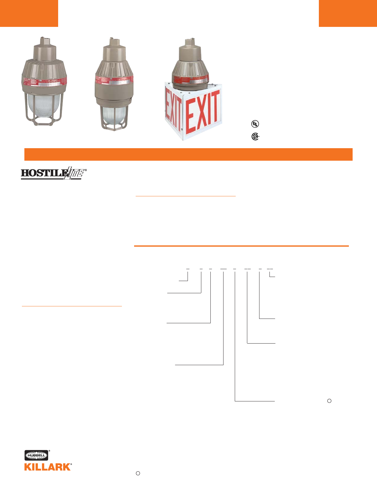
EM/EB/EQ SERIES •LIGHTING
INCANDESCENT/COMPACT FLUORESCENT/MEDIUM BASE HID
L120
FEATURES-SPECIFICATIONS
Listed - Files E10514 and
E91793 (Marine)
Certified - File LR11713
Class I, Div. 1 & 2, Groups C,D
Class I, Zones 1 & 2, Groups llB, llA
Class II, Div. 1 & 2, Groups E,F,G
Class III, Div. 1 & 2
Suitable for wet locations
Marine
NEMA 3, 4, 4X
Factory Sealed
Catalog Number Logic
Series Constant
Lamp Base
M—Medium Base
B—Bi-Pin Base
Q—Quad-Pin Base
Lamp Type
I—Incandescent
F—Fluorescent (lamp included)
S—HPS
H—MH
M—MV
Voltage @ 60 Hertz
0—Quadri-Volt
(120, 208, 240, 277)
1—120
4—277
5—480
6—347 Canada (70,100MH/HPS)
30—120-277 50/60 Hz
EQF Series Only
Mounting Type
A2—3/4" Pendant
A3—1" Pendant
X2—3/4" Ceiling
X3—1" Ceiling
B2—3/4" Bracket
B3—1" Bracket
D4—1-1/4"/1-1/2" Stanchion
Lamp Wattage
15—150W, A-21, INC
20—300W, PS-25, INC
30—300W, PS-30, INC
13—(1) 13W, Bi-Pin FLUOR
26—(2) 13W Bi-Pin EBF or (1) Quad-Pin
EQF 26Watt FLUOR
32—Quad-Pin FLUOR
42—Quad-Pin FLUOR
52—Quad-Pin FLUOR (2 X 26)
64—Quad-Pin FLUOR (2 X 32)
84—Quad-Pin FLUOR (2 X 42)
35—35W, HPS
05—50W, HPS, MH, MV
07—70W, HPS, MH
75—75W, MV
10—100W, HPS, MH, MV
15—150W, HPS
Guard
G—Omit G if guard is not
required
Options
ML—UL Marine Listing for
EMI. Standard on EMS,
EMM and EMH. Not avail-
able on EBF, EQF
SU103—Assembled w/Lamp
E 0 0 00 0 00 0 -00(CEN)*
Applications
HOSTILELITE®EM, EB, & EQ Series fix-
tures are designed for installations
where moisture, dirt, dust, corrosion
and vibration may be present, or
NEMA 3 and 4x areas where wind,
water, snow or high ambients can be
expected. They can be used in loca-
tions made hazardous due to the pres-
ence of flammable or explosive gases,
vapors and combustible dusts as
defined by the NEC.
Applications include classified areas
such as paint manufacturing plants,
ammunition facilities, oil and gas pro-
ducing and refining plants, off-shore
and dockside installations, tank farms,
pipeline pumping stations and marine
loading and fuel transfer terminals.
Features:
•Five light sources—Incandescent,
compact fluorescent, high pressure
sodium, metal halide and mercury
vapor
•Mounting choice—Pendant, ceiling,
25˚ stanchion or 90˚ wall mount, all
with “wireless” design that allows
fast, easy fixture installation
•Factory sealed—No external seal
needed. Simply wire mounting cap
and thread on fixture to install
•Compact size—Medium base
incandescent and HID lamps, plus
PL fluorescent lamps allow smaller
fixture design
•Corrosion resistant—-Copper-free
aluminum die-cast construction.
Baked powder epoxy finish, electro-
statically applied. Exposed hardware
is 316 grade stainless steel
Accessories
•Available with or without guard, stan-
dard dome or 25˚ angle reflector, exit
sign and inner colored globes
Compliances
•UL-844 Electric Lighting Fixtures for
use in Hazardous Locations
•UL Marine Type Electric Lighting
Fixtures
•UL-1570 Standard for Fluorescent
Lighting Fixtures
•UL-1571 Standard for Incandescent
Lighting Fixtures
•UL-1572 Standard for HID Lighting
Fixtures
•CSA C22.2 no. 137-M1981 Electric
Luminaires for use in Hazardous
Locations
•NEMA 3, 4, 4X, 7CD, 9EFG
*CEN (CENELEC) approval option available on certain models. See page L127 for more information.
Consult factory for available lamp and voltage combinations.
V
V
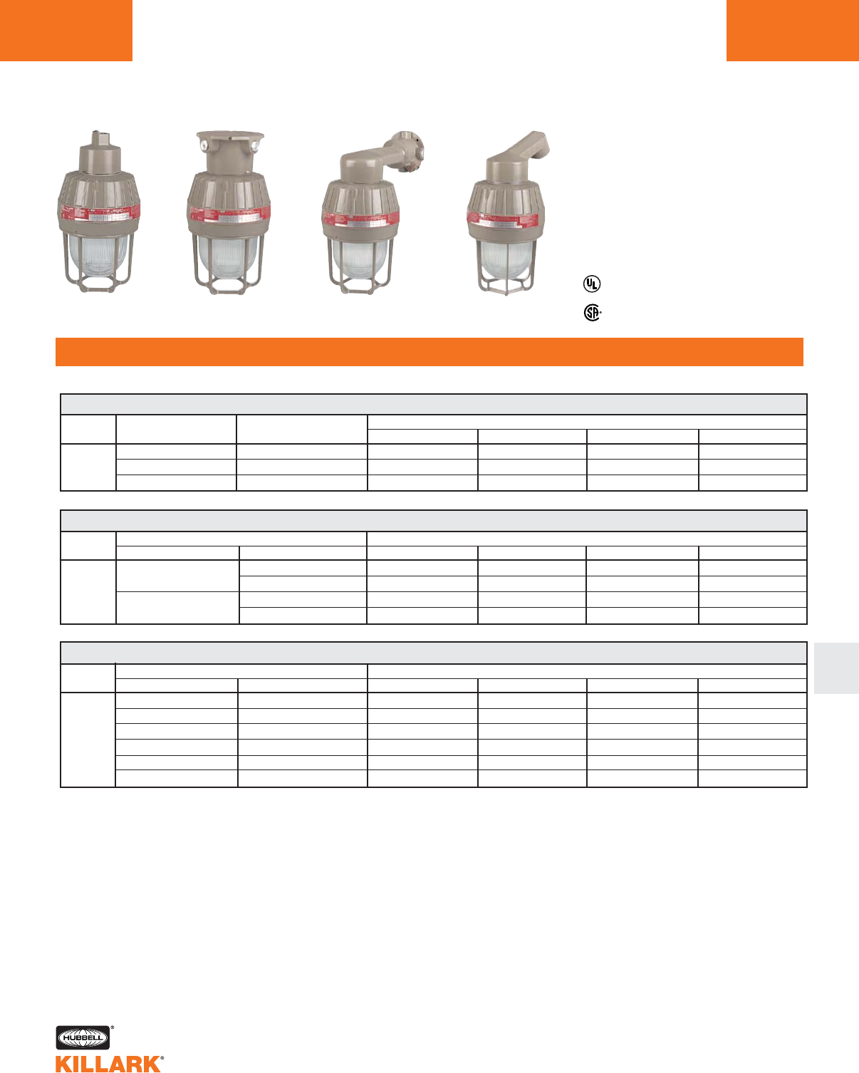
EM/EB/EQ SERIES •LIGHTING
INCANDESCENT, 60-300W MEDIUM BASE; COMPACT FLUORESCENT, 13-84W L121
ORDERING INFORMATION
L
Listed - Files E10514 and
E91793 (Marine)
Certified - File LR11713
EM 60–300W MEDIUM BASE INCANDESCENT1
Class I, Div. 1 & 2, Groups C,D
Class I, Zones 1 & 2, Groups llB, llA
Class II, Div. 1 & 2, Groups E,F,G
Class III, Div. 1 & 2
Suitable for wet locations
Marine
NEMA 3, 4, 4X
Factory Sealed
LAMP LAMP/WATTS LAMP SIZE CATALOG NUMBER4
TYPE PENDANT 3/4"2CEILING 3/4"2WALL 3/4"2STANCHION 1-1/4"3
EMI15A2G
EMI20A2G
EMI30A2G
EMI15X2G
EMI20X2G
EMI30X2G
EMI15B2G
EMI20B2G
EMI30B2G
EMI15D4G
EMI20D4G
EMI30D4G
60, 75, 100, 150 A-19, A-21
INC 100, 150, 200, 300 A-23, PS-25
200, 300 PS-25, PS-30
EQF 26-42W WORLD VOLTAGE QUAD-PIN COMPACT FLUORESCENT1
Quad-Pin FLUORESCENT CATALOG NUMBER4
LAMP INCLUDED LINE VOLTAGE PENDANT 3/4"2CEILING 3/4"2WALL 3/4"2STANCHION 1-1/4"3
EQF2630A2G
EQF3230A2G
EQF4230A2G
EQF5230A2G
EQF6430A2G
EQF8430A2G
EQF2630X2G
EQF3230X2G
EQF4230X2G
EQF5230X2G
EQF6430X2G
EQF8430X2G
EQF2630B2G
EQF3230B2G
EQF4230B2G
EQF5230B2G
EQF6430B2G
EQF8430B2G
EQF2630D4G
EQF3230D4G
EQF4230D4G
EQF5230D4G
EQF6430D4G
EQF8430D4G
26 Watt5120-277VAC 50-60Hz
32 Watt5120-277VAC 50-60Hz
42 Watt5120-277VAC 50-60Hz
52 Watt (2 X 26) 120-277VAC 50-60Hz
64 Watt (2 X 32) 120-277VAC 50-60Hz
84 Watt (2 X 42) 120-277VAC 50-60Hz
EBF 13-26W Bi-Pin COMPACT FLUORESCENT1
LAMP Bi-Pin FLUORESCENT CATALOG NUMBER4
TYPE LAMP INCLUDED LINE VOLTAGE @60Hz PENDANT 3/4"2CEILING 3/4"2WALL 3/4"2STANCHION 1-1/4"3
120
13 (1 X 13) 277
26 (2 X 13) 120
277
EBF131A2G
EBF134A2G
EBF261A2G
EBF264A2G
EBF131X2G
EBF134X2G
EBF261X2G
EBF264X2G
EBF131B2G
EBF134B2G
EBF261B2G
EBF264B2G
EBF131D4G
EBF134D4G
EBF261D4G
EBF264D4G
1See Hazardous Location Application Data on pages L127-128 for specific suitabilities.
2For 1" pendant, ceiling and wall hubs, substitute “3” for “2” in catalog number; example: EBF131A3G.
3Stanchion conduit hub size supplied is 1-1/2" with 1-1/2" to 1-1/4" reducer for 1-1/4" mounting. (refer to catalog logic).
4Luminaire catalog numbers include guards. To order luminaire without guard, omit last letter “G” from catalog number.
5EQF 26-42 Watt fixtures use a tank extension ring and are 2.5" taller than EBF fixtures.
NOTE: Reflectors must be ordered separately (see page L123). All luminaires are designed for mounting with lamp in
base up position.
Pendant Ceiling Wall Stanchion
COMPACT
FLUOR.
COMPACT
FLUOR.
LAMP
TYPE
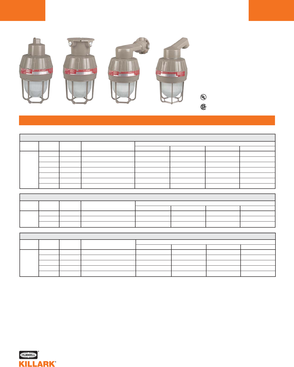
EM/EB/EQ SERIES •LIGHTING
HID, 35-150W MEDIUM BASE
L122
FEATURES-SPECIFICATIONS
Listed - Files E10514 and
E91793 (Marine)
Certified - File LR11713
1See Hazardous Location Application Data on page L127-128 for specific suitabilities.
2For 1" pendant, ceiling and wall hubs, substitute “3” for “2” in catalog number; example: EMS351A3G.
3Stanchion conduit hub size supplied is 1-1/2" with 1-1/2" to 1-1/4" reducer for 1-1/4" mounting. (refer to catalog logic).
4Luminaire catalog numbers include guards. To order luminaire without guard, omit last letter “G” from catalog number.
NOTE: Reflectors must be ordered separately (see page L123). All luminaires are designed for mounting with lamp in base
up position.
EMS351A2G
EMS050A2G
EMS070A2G
EMS075A2G
EMS100A2G
EMS105A2G
EMS151A2G
EMH050A2G
EMH070A2G
EMH100A2G
EMH050X2G
EMH070X2G
EMH100X2G
EMH050B2G
EMH070B2G
EMH100B2G
EMH050D4G
EMH070D4G
EMH100D4G
EMS351X2G
EMS050X2G
EMS070X2G
EMS075X2G
EMS100X2G
EMS105X2G
EMS151X2G
EMS351B2G
EMS050B2G
EMS070B2G
EMS075B2G
EMS100B2G
EMS105B2G
EMS151B2G
EMS351D4G
EMS050D4G
EMS070D4G
EMS075D4G
EMS100D4G
EMS105D4G
EMS151D4G
35 S-76 120
50 S-68 120, 208, 240, 277
70 S-62 120, 208, 240, 277
HPS 70 S-62 480
100 S-54 120, 208, 240, 277
100 S-54 480
150 S-55 120
EM 35-150W MEDIUM BASE HIGH PRESSURE SODIUM14
LAMP LAMP ANSI VOLTAGE CATALOG NUMBER4
TYPE WATTS LAMP TYPE @60 HERTZ PENDANT 3/4"2CEILING 3/4"2WALL 3/4"2STANCHION 1-1/4"3
50 M-110 120, 208, 240, 277
MH 70 M-98 120, 208, 240, 277
100 M-90 120, 208, 240, 277
EM 50-100W MEDIUM BASE METAL HALIDE14
LAMP LAMP ANSI VOLTAGE CATALOG NUMBER4
TYPE WATTS LAMP TYPE @60 HERTZ PENDANT 3/4"2CEILING 3/4"2WALL 3/4"2STANCHION 1-1/4"3
EM 50-100W MEDIUM BASE MERCURY VAPOR14
LAMP LAMP ANSI VOLTAGE CATALOG NUMBER4
TYPE WATTS LAMP TYPE @60 HERTZ PENDANT 3/4" 2CEILING 3/4"2WALL 3/4"2STANCHION 1-1/4"3
50 H-46 120/277
75 H-43 120
MV 75 H-43 277
100 H-38 120, 208, 240, 277
100 H-38 480
EMM0510A2G
EMM751A2G
EMM754A2G
EMM100A2G
EMM105A2G
EMM0510X2G
EMM751X2G
EMM754X2G
EMM100X2G
EMM105X2G
EMM0510B2G
EMM751B2G
EMM754B2G
EMM100B2G
EMM105B2G
EMM0510D4G
EMM751D4G
EMM754D4G
EMM100D4G
EMM105D4G
Class I, Div. 1 & 2, Groups C,D
Class I, Zones 1 & 2, Groups llB, llA
Class II, Div. 1 & 2, Groups E,F,G
Class III, Div. 1 & 2
Suitable for wet locations
Marine
NEMA 3, 4, 4X
Factory Sealed
Pendant Ceiling Wall Stanchion
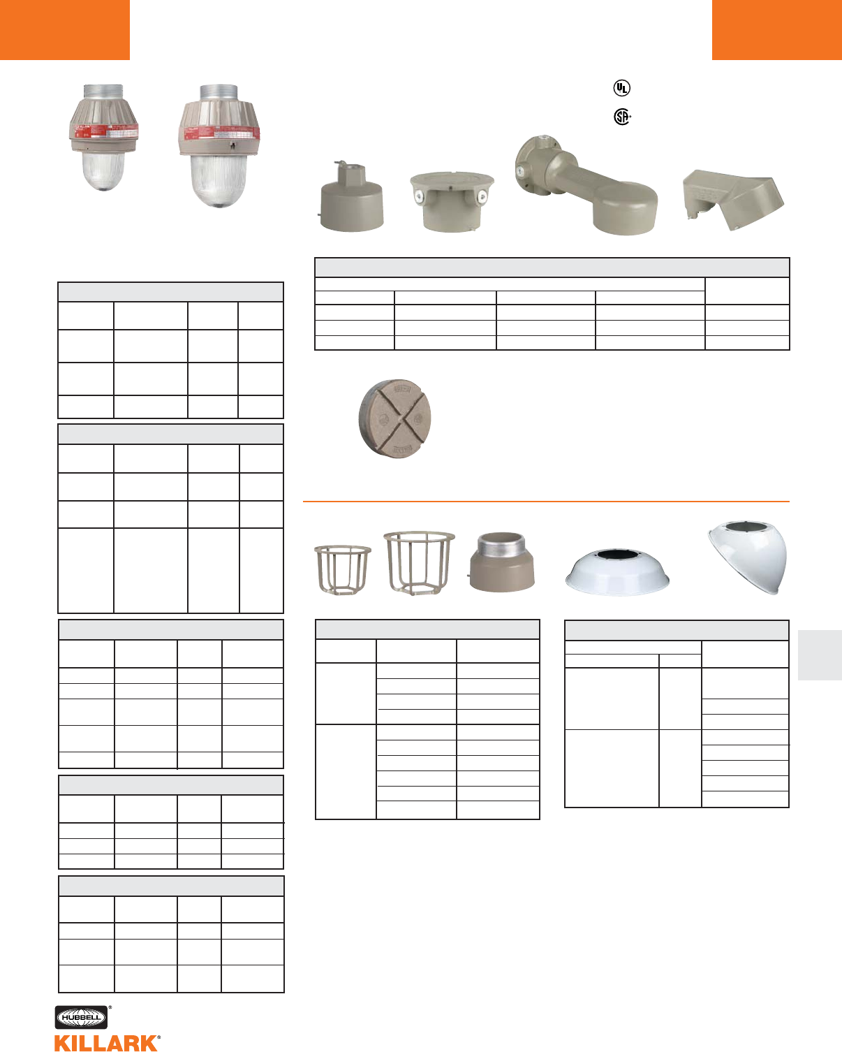
EM/EB/EQ SERIES •LIGHTING
COMPONENT PARTS/ACCESSORIES L123
L
Housing, Globe and
Globe Support Assemblies1
Angle DomeStandard Dome
SERIES LAMP TYPE
EMI15 INC
EMI20 INC
EBF Bi-Pin
EQF (26, 32, 42) Quad-Pin
EMI30 INC
EMS HPS
EMH MH
EMM MV
ESX Strobe
EQF (52, 64, 84) Quad-Pin
CATALOG
NUMBER
EMG1
EMG2
GUARDS
Guards are cast of copper-free aluminum with
electrostatically applied epoxy/polyester finish.
1Assemblies may be ordered with the
CEN (CENELEC) suffix. See pageL127 for
more information.
2Adapters for discontinued Killark “H” Series
and Crouse Hinds®available. See page L200
for more information.
3UL fixture rating; socket rated 600V.
* Consult factory for 52, 64 and 84 Watt
availability.
HUB SIZE
3/4"
1"
1-1/4"/1-1/2"*
CATALOG NUMBER
PENDANT CEILING BRACKET STANCHION
EZA2 EZX2 EZB2 —
EZA3 EZX3 EZB3 —
— — — EZD4*
MOUNTING BOXES
Wall Bracket 25° Stanchion
SERIES
EMI15/EMI20
EBF
EQF
EMI30
EMS
EMH
EMM
EQF (52, 64, 84)
CATALOG NUMBER
STANDARD DOME ANGLE
ERSD15 ERA15
ERSD30 ERA30
REFLECTORS
VOLTS3
250 MAX.
VAC
250 MAX.
VAC
250 MAX.
VAC
INCANDESCENT
CATALOG
NUMBER
EMI15
EMI20
EMI30
LAMP TYPE
A-19
A-19, A-21
A-21
A-23, PS-25
A-23, PS-25
PS-25
PS-25
PS-30
WATTS
60, 75
100
150
150
200
300
200
300
HPS
CATALOG
NUMBER
EMS351
EMS050
EMS070
EMS075
EMS100
EMS105
EMS151
WATTS
35
50
70
100
150
VOLTS
120VAC
277VAC
120VAC
277VAC
120-277
VAC
50-60Hz
VOLTS
@60HZ.
120
Quadri-Volt
Quadri-Volt
480
Quadri-Volt
480
120
FLUORESCENT with lamp(s)*
CATALOG
NUMBER
EBF131
EBF134
EBF261
EBF264
EQF2630
EQF3230
EQF4230
EQF5230
EQF6430
EQF6430
ANSI
LAMP TYPE
S-76
S-68
S-62
S-54
S-55
ANSI
LAMP TYPE
Bi-Pin
Fluorescent
Bi-Pin
Fluorescent
Quad Pin
Fluorescent
WATTS
13
26 (2x13)
26
32
42
52 (2X26)
64 (2X32)
84 (2X42)
VOLTS
@60HZ.
Quadri-Volt
Quadri-Volt
Quadri-Volt
METAL HALIDE
CATALOG
NUMBER
EMH050
EMH070
EMH100
ANSI
LAMP TYPE
M-110
M-98
M-90
WATTS
50
70
100
VOLTS
@60HZ.
120, 277
120
277
Quadri-Volt
480
MERCURY VAPOR
CATALOG
NUMBER
EMM0510
EMM751
EMM754
EMM100
EMM105
ANSI
LAMP TYPE
H-46
H-43
H-38
WATTS
50
70
100
Pendant Ceiling
EMG1 EMG2 EAC2
Listed - Files E10514 and
E91793 (Marine)
Certified - File LR11713
EMI15/20/EBF EMI30 & HID
Reflectors are aluminum with white finish.
*1-1/2" furnished with 1-1/2"-1-1/4" reducer
EZCUP
Close up plug for EZ mounting boxes.
Used for maintenance when fixture is
removed for service.
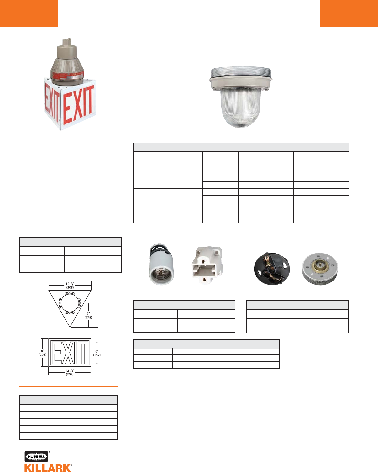
EM/EB/EQ SERIES •LIGHTING
REPLACEMENT PARTS/ACCESSORIES
L124
Hazardous Locations Exit Sign
Applications
For use in hazardous areas to mark
exits over doorways and in hallways.
Features
•Three sided illuminated sign visible
from all three sides
•EXIT printed in 6" high red letters with
3/4" strokes as required by OSHA.
Sign has open bottom
providing light on exit area while
illuminating the panel
Replacement Globe & Support Assemblies
Exit Sign Accessory
KIT NO. GLOBE COLOR
KT-100SU41R RED
KT-100SU41G GREEN
Used to modify EMI20 Series only fixtures to accept a colored inner
globe. The kit includes the globe plus an adapter assembly and
mounting instructions.
2Maximum lamp size A-21 150 Watt.
COLORED GLOBE KITS FOR HAZARDOUS LOCATIONS2
EM Series EB Series
SERIES LAMP TYPE MAX. WATTAGE
EMI15 INC 150
EMI20 INC 300
EBF13/26 PL Bi-Pin Fluorescent 26
EQF PL Quad-Pin Fluorescent 26, 32, 42
EMI30 INC 300
EMS HPS 150
EMH MH 100
EMM MV 100
EQF PL Quad-Pin Fluorescent 52, 62, 84
CATALOG NUMBER1
EMGS1
EMGS2
EMGS3
REPLACEMENT GLOBE AND GLOBE SUPPORTS
REPLACEMENT CONNECTION BLOCKS
CATALOG NUMBER
EZTB
EZCB
DESCRIPTION
Female
Male
REPLACEMENT SOCKETS
CATALOG NUMBER
EMRS
EBRS
DESCRIPTION
EM Series E-26 Medium Base
EB Series
EXIT SIGN
CATALOG NUMBER
HEXA-100
DESCRIPTION
Fits EMI15, EMI20, EBF/EQF/EEQ
Series without guard *
(Fixture not included)
1EMGS1, EMGS3 are internally fluted glass. EMGS2 is smooth clear glass used for ESX strobe.
MPL13 13W Bi-Pin
MQL26 26W Quad-Pin
MQL32 32W Quad-Pin
MQL42 42W Quad-Pin
REPLACEMENT FLUORESCENT LAMPS
CATALOG NUMBER SIZE & TYPE
* EQF to 42W
Male
EZCB
Female
EZTB
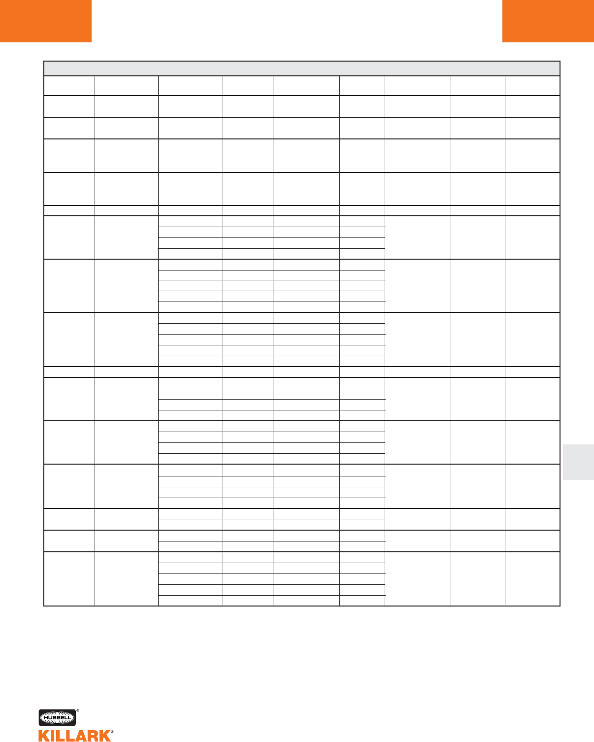
EM/EB/EQ SERIES •LIGHTING
BALLAST DATA L125
L
LAMP LAMP OPERATING OPEN
SOURCE WATTS/TYPE (AMPS) (AMPS) BALLAST CIRCUIT REGULATION MIN, START
(1) Bi-Pin .39
Fluorescent 13W (1 X 13) .35 .30 — NPF — 32°F (0°C)
(2) Bi-Pin .78
Fluorescent 26W (2 X 13) .70 .60 — NPF — 32°F (0°C)
0°F (-18°C)
0°F (-18°C)
HPS 35W S-76 .55 .40 .65 R-HPF1±5% Line Voltage* 0°F (-40°C)
.58 .58 1.24
HPS 50W S-68 .35 .33 .59
.30 .29 .50 HX-HPF1±5% Line Voltage* 0°F (-40°C)
.24 .25 .44
.75 .81 1.45
.45 .47 .85
HPS 70W S-62 .37 .40 .75 HX-HPF1±5% Line Voltage* 0°F (-40°C)
.35 .35 .65
.21 .21 .36
1.30 1.15 2.20
.76 .66 1.27
.66 .57 1.10 HX-HPF1±5% Line Voltage* 0°F (-40°C)
HPS 100W S-54 .60 .49 .85
.33 .28 .57
HPS 150W S-55 2.20 1.50 2.35 HX-HPF1±5% Line Voltage* 0°F (-40°C)
.87 .60 1.16
MH 50W M-110 .51 .35 .67 HX-HPF1±5% Line Voltage -20°F (-30°C)
.47 .30 .57 ±12% Lamp Watts
.39 .25 .50
.80 .85 1.70
MH 70W M-98 .50 .50 1.04 HX-HPF1±5% Line Voltage -20°F (-30°C)
.43 .43 .87 ±12% Lamp Watts
.39 .37 .78
1.20 1.15 2.30
MH 100W M-90 .70 .60 1.30 HX-HPF1±5% Line Voltage -20°F (-30°C)
.61 .55 1.10 ±12% Lamp Watts
.55 .45 .95
.60 .67 .30 CWA1±5% Line Voltage -20°F (-30°C)
MV 50W H-46 .26 .29 .13 ±10% Lamp Watts
MV 75W H-43 .80 .82 .50 CWA1±5% Line Voltage -20°F (-30°C)
.35 .36 .22 ±10% Lamp Watts
1.00 1.05 .64
.58 .60 .37 ±5%Line Voltage -20°F (-30°C)
MV 100W H-38 .50 .52 .32 CWA1
±10% Lamp Watts
.43 .45 .28
.26 .26 .15
EM/EB BALLAST DATA
* Lamp watts within ANSI Trapezoid limitations.
1Ballast circuits are High Power Factor 90%+.
START
(AMPS)
Quad-Pin
Fluorescent
26W
32W
42W
120-277
Quad-Pin
Fluorescent
52W (2X26)
64W (2X36)
84W (2X42)
120-277
.24(120)/.11(277)
.31(120)/.13(277)
.38(120)/.18(277)
—
HPF
.48(120)/.22(277)
.62(120)/.26(277)
.76(120)/.36(277)
——
—ELECTRONIC
ELECTRONIC
HPF
VOLTAGE @
60 HERTZ
120
277
120
277
120
120
208
240
277
120
208
240
277
480
120
208
240
277
480
120
120
208
240
277
120
208
240
277
120
208
240
277
120
277
120
277
120
208
240
277
480
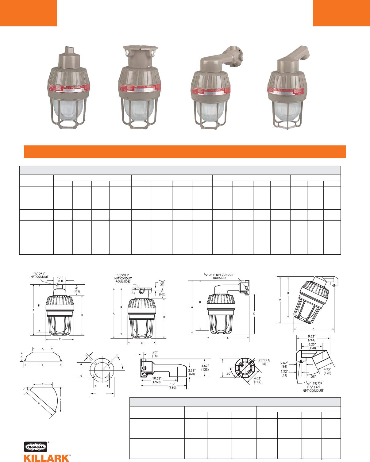
EM/EB/EQ/ESX/EEQ SERIES •LIGHTING
DIMENSIONS
L126
FEATURES-SPECIFICATIONS
Pendant Ceiling Wall 25° Stanchion
PENDANT CEILING WALL STANCHION
SERIES A B C D A B C D A B C D A B C
EMI15
EMI20 14-5/16" 13-11/16" 7-7/16" 10-5/16" 14-5/16" 13-11/16" 7-7/16" 10-5/16" 15-13/16" 14-7/16" 14-1/2" 10-5/16" 14" 13-1/4" 13"
EBF13 (363) (346) (188) (261) (363) (347) (188) (261) (385) (366) (369) (26) (256) (337) (330)
EBF26
16-13/16" 16-3/16" 7-7/16" 12-5/8" 16-13/16" 16-3/16" 7-7/16" 12-5/8" 18-5/16" 16-15/16" 14-1/2" 12-5/8" 16-1/4" 15-3/4" 15-1/4”
(427) (411) (188) (321) (427) (411) (188) (321) (465) (430) (368) (321) (413) (400) (387)
EMI30
EMH
EMM 15-15/1" 15-1/16" 8-13/16" 11-15/16" 15-15/16" 15-1⁄/16" 8-13/16" 11-15/16" 16-13/16" 15-15/16" 15" 11-15/16" 15-1/8" 14" 13-1/2"
EMS (404) (382) (224) (303) (404) (382) (224) (303) (426) (404) (379) (303) (384) (356) ( 343)
ESX
EQF 52, 64, 84
EM/EMB/ESX DIMENSIONS
Standard Dome
Angle
STANDARD DOME ANGLE
SERIES AB CABCD
7-3/8" 14" 3-3/4" 7" 11-1/2" 7-3/4" 1"
(187) (356) (95) (178) (292) (197) (25)
8-3/4" 16-1/8" 3-15/16" 8-3/4" 14-3/16" 7-3/4" 1"
(222) (409) (100) (222) (360) (197) (25)
REFLECTOR DIMENSIONS
Pendant Ceiling Wall Stanchion
.31"
(8)
4.25"
(107)
4.75"
(120)
7.00"
(177)
45°
EMI15/EMI20
EBF/EQF to 42W
EMI30/EMS
EMH/EMM
EQF 52, 64, 84
EQF to 42W
EEQ
5.25”
(133)
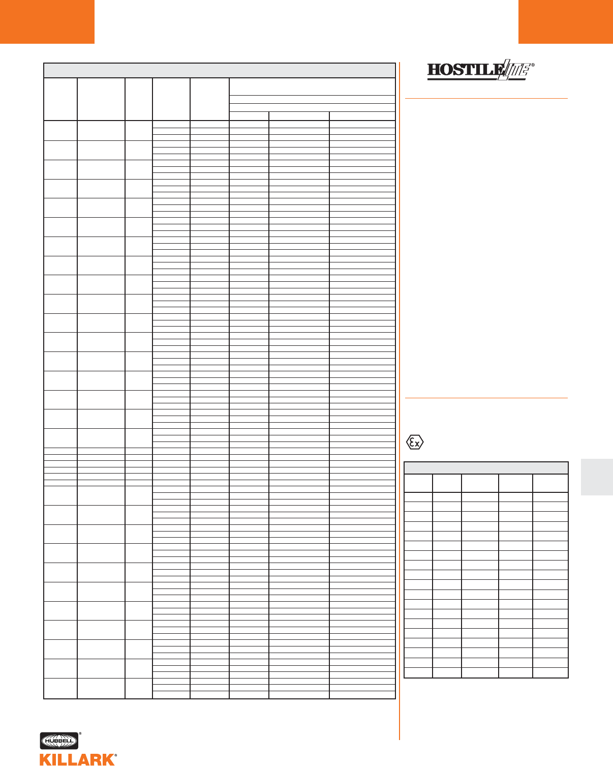
EM/EB/EQ SERIES •LIGHTING
APPLICATION DATA L127
L
EM/EB/EQ HAZARDOUS LOCATION DATA–CLASS I, DIV. 1 & 212
SUPPLY CLASS I, DIVISIONS 1 & 2
WIRE MAXIMUM SURFACE TEMPERATURE °CLAMP RATED
SUITABLE UL/CSA
FIXTURE TYPE/SIZE LAMP AMBIENT
FOR °C WITH OR WITHOUT REFLECTOR
SERIES MAX. WATTS °C
MIN. TEMP. I.D. ACTUAL TEMP. UL/CSA GROUPS
40 75 T6 79 C,D
EMI15 INC A-19 60 55 75 T6 C,D
65 75 T4A C,D
40 75 T4A 103 C,D
EMI15 INC A-19 75 55 90 T4A C,D
65 90 T4 C,D
40 75 T4A 103 C,D
EMI15 INC A-19 100 55 90 T4A C,D
65 90 T4 C,D
40 75 T4A 101 C,D
EMI15 INC A-21 100 55 90 T4A C,D
65 90 T4 C,D
40 75 T4 123 C,D
EMI15 INC A-21 150 55 90 T3C C,D
65 90 T3C C,D
40 90 T4A 107 C,D
EMI20 INC A-23 100 55 90 T4 C,D
65 90 T4 C,D
40 90 T4 132 C,D
EMI20 INC A-23 150 55 90 T3C C,D
65 111 T3C C,D
40 90 T4 126 C,D
EMI20 INC PS-25 150 55 110 T3C C,D
65 110 T3C C,D
40 90 T3C 146 C,D
EMI20 INC A-23 200 55 90 T3B C,D
65 110 T3A C,D
40 90 T3C 154 C,D
EMI20 INC PS-25 200 55 90 T3A C,D
65 110 T3A C,D
40 90 T3 190 C,D
EMI20 INC PS-25 300 55 110 T2D C,D
65 C,D
40 110 T3C 146 C,D
EMI30 INC PS-25 200 55 110 T3B C,D
65 125 T3A C,D
40 110 T3C 143 C,D
EMI30 INC PS-25 300 55 110 T3B C,D
65 125 T3A C,D
40 110 T3C 146 C,D
EMI30 INC PS-30 200 55 110 T3B C,D
65 125 T3A C,D
40 110 T3C 146 C,D
EMI30 INC PS-30 300 55 110 T3B C,D
65 125 T3A C,D
40 75 T6 62 C,D
EBF13 1 13W Bi-Pin 13 55 90 T6 C,D
65 90 T5 C,D
40 75 T6 62 C,D
EBF26 2 13W Bi-Pin 26 55 90 T6 C,D
65 90 T5 C,D
EQF26 1 26W Quad-Pin 26 40 75 T6 75 C,D
EQF32 1 32W Quad-Pin 32 40 75 T6 75 C,D
EQF42 1 42W Quad-Pin 42 40 75 T6 75 C,D
EQF52 2 26W Quad-Pin 52 40 75 T6 85 C,D
EQF64 2 32W Quad-Pin 64 40 75 T6 85 C,D
EQF84 2 42W Quad-Pin 84 40 75 T6 85 C,D
40 75 T6 65 C,D
EMS35 HPS S-70 35 55 90 T5 C,D
65 90 T4A C,D
40 75 T6 68 C,D
EMS05 HPS S-68 50 55 75 T6 C,D
65 90 T5 C,D
40 75 T6 83 C,D
EMS07 HPS S-62 70 55 90 T5 C,D
65 90 T4A C,D
40 75 T5 99 C,D
EMS100 HPS S-54 100 55 90 T4A C,D
65 110 T4A C,D
40 75 T4A 119 C,D
EMS151 HPS S-55 150 55 90 T4 C,D
65 110 T3C C,D
40 75 T6 78 C,D
EMM05 MV H-46 50 55 90 T5 C,D
65 90 T4A C,D
40 75 T5 95 C,D
EMM75 MV H-43 75 55 90 T4A C,D
65 90 T4A C,D
40 75 T4A 111 C,D
EMM100 MV H-38 100 55 90 T4 C,D
65 110 T3C C,D
40 75 T6 78 C,D
EMH05 MH M-110 50 55 90 T5 C,D
65 110 T4A C,D
40 75 T5 95 C,D
EMH07 MH M-98 75 55 90 T4A C,D
65 110 T4A C,D
40 75 T4A 101 C,D
EMH100 MH M-90 100 55 90 T4 C,D
65 110 T3C C,D
1Do not install where marked operating temperature exceeds
ignition temperature of hazardous atmosphere.
2See Class II table for simultaneous presence ratings.
CEN Option
Applications
Killark EM/EB/ESX series fixtures are
available with a European “Certificate of
Conformity” from PTB (Physikalisch-
Technische Bundesanstalt), the approval
agency based in Germany. Fixtures with
this rating will be useful for Original
Equipment Manufacturers and others
who build and ship apparatus into
European markets.
This approval is granted by PTB with the
use of a special ground lug and label.
Fixtures carrying an EEx d llB approval
are automatically granted an IP54
(ingress protection) rating. See
Temperature Code chart below for PTB
certified ratings. Killark EM/EB/ESX fix-
tures with the PTB rating and labels still
carry all UL & CSA ratings.
Fixture housing/globe/globe support
assemblies (e.g. EM120 CEN) may be
ordered with the CEN suffix. Complete fix-
ture numbers, with the CEN suffix, will be
shipped with the mounting boxes, guards
and accessories as component parts.
Reflectors and other accessory parts, as
listed on pages L123-124, may be used.
Killark fixtures are NPT tapped and
plugged with at least one conduit hole
open.
Compliances
•EN 50014:1992
•EN 50018:1994
EEx d IIB T6 (or T5-T2)
PTB No. Ex-98.E.1076
MAXIMUM AMBIENT TEMPERATURE RANGE -20°C TO 40°C
TYPE OF
LUMINAIRE
EMI15
EMI20
EMI30
EMH05
EMH07
EMH10
EMM05
EMM75
EMM10
EMS35
EMS05
EMS07
EMS10
EMS15
EBF13
EBF26
ESX( )120
ESX( )240
ESX( )1274
TYPE OF
ENCLOSURE
EMO20
EMO20
EMO30
EMO30
EMO30
EMO30
EMO30
EMO30
EMO30
EMO30
EMO30
EMO30
EMO30
EMO30
EMO20
EMO20
EMO30
EMO30
EMO30
FORM OF
THE LAMP
A-19/A-21
A-23/PS-25
PS-25/PS-30
BD17/M-110
BD17/M-98
BD17/M-90
ED17/H-46
ED17/H-43
ED17/H-38
ED17/S-76
ED17/S-68
ED17/S-62
ED17/S-54
ED17/S-55
PL13
PL13
120V AC
240V AC
12 TO 74 V DC
MAXIMUM
WATTAGE
150W
300W
300W
50W
70W
100W
50W
75W
100W
35W
50W
70W
100W
150W
13W
26W
0.17 A
0.12 A
1.25 TI 0.2 A
TEMPERATURE
CLASS
T4
T3
T2
T6
T5
T4
T5
T4
T4
T6
T6
T5
T5
T4
T6
T6
T6
T6
T6
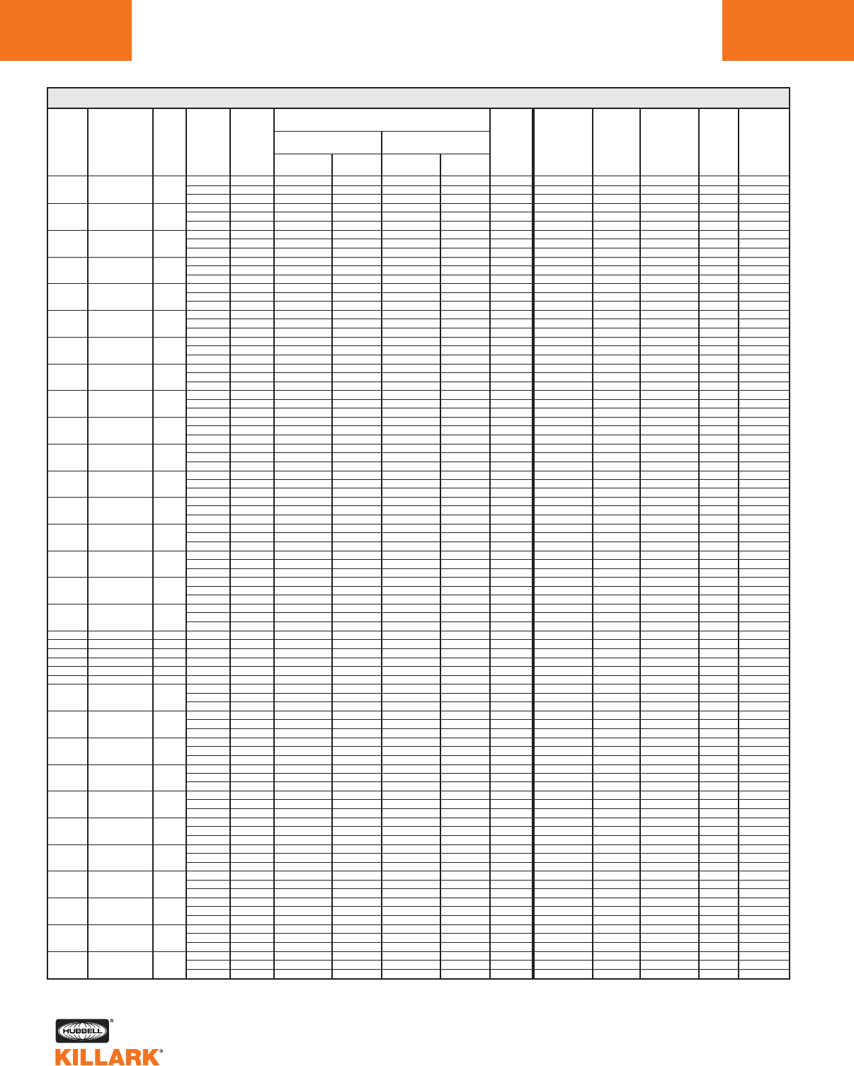
EM/EB/EQ SERIES •LIGHTING
APPLICATION DATA
L128
CLASS II, DIV. 1 & 2
SUPPLY MAXIMUM SURFACE TEMPERATURE °C
FIXTURE LAMP LAMP RATED WIRE UL/CSA UL/CSA UL/CSA
CLASS III UL/CSA UL/CSA
SERIES TYPE/SIZE WATTS AMBIENT SUITABLE WITHOUT REFLECTOR WITH REFLECTOR GROUPS
DIV. 1 & 2 UL U.L. PAINT TYPE 3 TYPE 4
MAX. °C FOR °C ACTUAL ACTUAL
UL/CSA MARINE SPRAY (RAIN- (HOSE-
MIN. TEMP. I.D. TEMP. °C TEMP. I.D. TEMP. °C
SUITABILITY LISTEDSUITABILITY TIGHT) DOWN)3
40 75 T3C 132 T3C 132 E,F,G YES YES NO YES YES
EMI15 INC A-19 60 55 75 T3A E,F NO YES NO YES YES
65 75 T3A E,F NO
40 75 T3A 163 T3A 162 E,F NO YES NO YES YES
EMI15 INC A-19 75 55 90 T3A T3A E,F NO YES NO YES YES
65 90 T3A T3A E,F NO YES NO YES YES
40 75 T3A 163 T3A 162 E,F NO YES NO YES YES
EMI15 INC A-19 100 55 90 T3A T3A E,F NO YES NO YES YES
65 90 T3A T3 E,F NO YES NO YES YES
40 75 T3A 172 T3A 172 E,F NO YES NO YES YES
EMI15 INC A-21 100 55 90 T3 E,F NO YES NO YES YES
65 90 T3 E,F NO YES NO YES YES
40 75 N/A 192 T3 192 E,F NO YES NO YES YES
EMI15 INC A-21 150 55 N/A
65 N/A
40 90 T3A 166 T3A 166 E,F NO YES NO YES YES
EMI20 INC A-23 100 55 90 T3 E,F NO YES NO YES YES
65 N/A
40 90 T3 196 T3A 178 E,F NO YES NO YES YES
EMI20 INC A-23 150 55 90 T3 E,F NO YES NO YES YES
65 N/A
40 90 N/A N/A N/A N/A NO NO YES NO YES YES
EMI20 INC PS-25 150 55 N/A
65 N/A
40 90 N/A N/A N/A N/A NO NO YES NO YES YES
EMI20 INC A-23 200 55 N/A
65 N/A
40 90 N/A N/A N/A N/A NO NO YES NO YES YES
EMI20 INC PS-25 200 55 N/A
65 N/A
40 90 N/A N/A N/A N/A NO NO YES NO YES YES
EMI20 INC PS-25 300 55 N/A
65 N/A
40 110 N/A N/A N/A N/A NO NO YES NO YES YES
EMI30 INC PS-25 200 55 N/A
65 N/A
40 110 N/A N/A N/A N/A NO NO YES NO YES YES
EMI30 INC PS-25 300 55 N/A
65 N/A
40 110 N/A N/A N/A N/A NO NO YES NO YES YES
EMI30 INC PS-30 200 55 N/A
65 N/A
40 110 N/A N/A N/A N/A NO NO YES NO YES YES
EMI30 INC PS-30 300 55 N/A
65 N/A
40 75 T6 69 T6 66 E,F,G YES NO YES YES YES
EBF13 1 13W Bi-Pin 13 55 90 T6 T6 E,F,G YES NO YES YES YES
65 90 T5 T5 E,F,G YES NO YES YES YES
40 75 T6 69 T6 66 E,F,G YES NO YES YES YES
EBF26 2 13W Bi-Pin 26 55 90 T6 T6 E,F,G YES NO YES YES YES
65 90 T5 T5 E,F,G YES NO YES YES YES
EQF26 1 26W Quad-Pin 26 40 75 T4 135 T4 135 E,F,G YES NO YES YES YES
EQF32 1 32W Quad-Pin 32 40 75 T4 135 T4 135 E,F,G YES NO YES YES YES
EQF42 1 42W Quad-Pin 42 40 75 T4 135 T4 135 E,F,G YES NO YES YES YES
EQF52 2 26W Quad-Pin 52 40 75 T4 135 T4 135 E,F,G YES NO YES YES YES
EQF64 2 32W Quad-Pin 64 40 75 T4 135 T4 135 E,F,G YES NO YES YES YES
EQF84 2 42W Quad-Pin 84 40 75 T4 135 T4 135 E,F,G YES NO YES YES YES
40 75 T4A 116 T4A 116 E,F,G YES YES YES YES YES
EMS35 HPS S-70 35 55 N/A
65 N/A
40 75 T4A 116 T4A 116 E,F,G YES YES YES YES YES
EMS05 HPS S-68 50 55 75 T4 E,F,G
65 90 T3C E,F,G
40 75 T4A 116 T4A 116 E,F,G YES YES YES YES YES
EMS07 HPS S-62 70 55 90 T4 E,F,G YES YES YES YES YES
65 90 T3C E,F,G YES YES YES YES YES
40 75 T3B 161 T3B 161 E,F,G YES YES NO YES YES
EMS100 HPS S-54 100 55 N/A
65 N/A
40 75 T3A 180 T3B 180 E,F NO YES NO YES YES
EMS150 HPS S-55 150 55 90 T3 T3A E,F NO YES NO YES YES
65 N/A
40 75 T4 121 T4 121 E,F,G YES YES YES YES YES
EMM05 MV H-46 50 55 N/A
65 N/A
40 75 T4 121 T4 121 E,F,G YES YES YES YES YES
EMM75 MV H-43 75 55 90 T3C T3C E,F,G YES YES YES YES YES
65 90 T3B T3C E,F,G YES YES YES YES YES
40 75 T3C 153 T3C 153 E,F,G YES YES NO YES YES
EMM100 MV H-38 100 55 N/A
65 N/A
40 75 T4 121 T4 121 E,F,G YES YES YES YES YES
EMH05 MH M-110 50 55 90 T3C T3A E,F NO YES YES YES YES
65 110 T3B T3A E,F,G NO YES YES YES YES
40 75 T4 121 T4 121 E,F,G YES YES YES YES YES
EMH07 MH M-98 70 55 90 T3C T3C E,F,G YES YES YES YES YES
65 110 T3B T3C E,F,G YES YES YES YES YES
40 75 T3C 153 T3C 153 E,F,G YES YES NO YES YES
EMH100 MH M-90 100 55 90 T3A NO YES YES NO YES YES
65 N/A
1Do not install where marked operating temperature exceeds ignition temperature of hazardous atmosphere.
2Fixtures rated for simultaneous presence as shown in Class II table (unless marked with N/A).
3For UL-Marine and UL/CSA Type 4 listing add suffix “ML” to “EMI” Series fixture catalog number;
standard on “EMS”, “EMH”, “EMM” series. Not available on “EBF”, or “EQF” series.
EM/EB/EQ HAZARDOUS LOCATION DATA–CLASS II, III, DIVISIONS 1 & 2 12
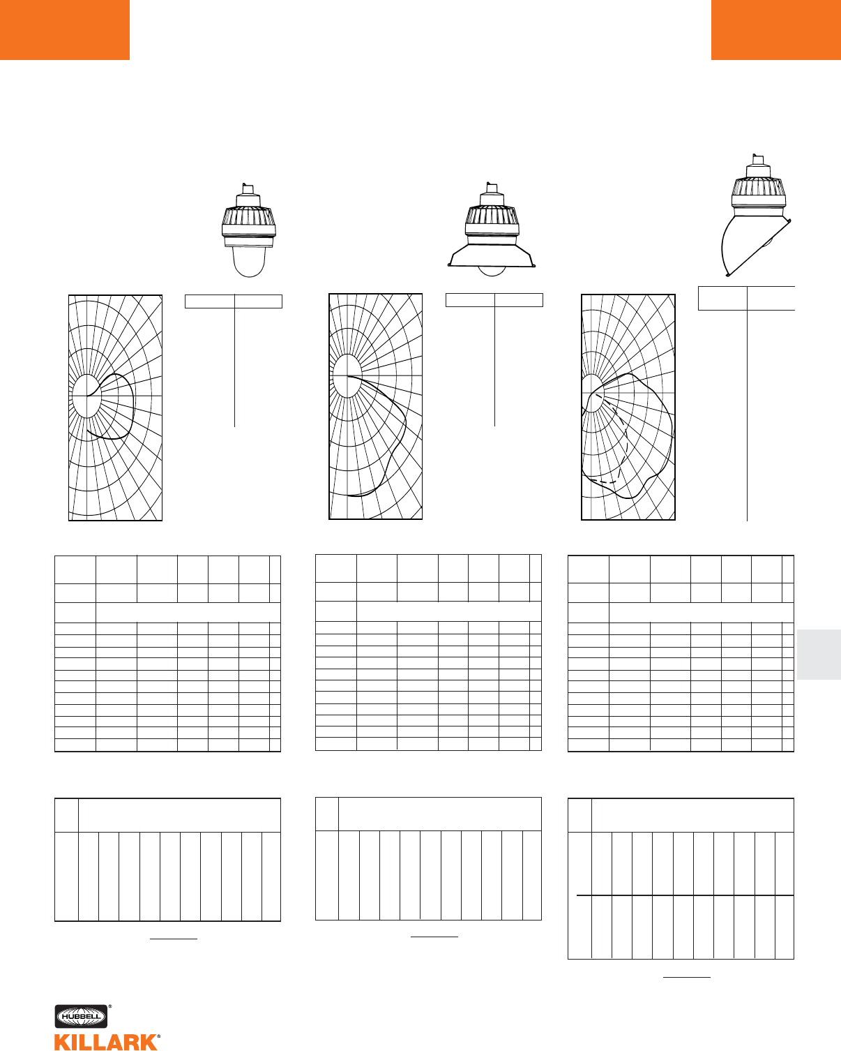
EM/EB/EQ SERIES •LIGHTING
PHOTOMETRIC DATA L129
L
Illumination on Horizontal Surface
0
ANGLE CP ANGLE CP
.0
5.0
15.0
25.0
35.0
45.0
55.0
65.0
75.0
85.0
90.0
95.0
105.0
115.0
125.0
135.0
145.0
155.0
165.0
175.0
180.0
72.
74.
86.
100.
109.
123.
148.
160.
155.
149.
146.
143.
130.
65.
9.
0.
0.
0.
0.
0.
0.
% Effective
Ceiling Cavity
Reflectance 1cc
% Wall
Reflectance 1w
Room Cavity
Ratio RCR
.79
.68
.60
.53
.48
.44
.40
.36
.34
.31
.29
.79
.63
.52
.44
.38
.33
.29
.26
.23
.21
.19
.79
.58
.46
.37
.31
.26
.22
.19
.17
.15
.13
.74
.63
.56
.49
.45
.40
.37
.34
.31
.29
.27
.74
.59
.49
.41
.36
.31
.27
.24
.22
.20
.18
.74
.55
.43
.35
.29
.25
.21
.18
.16
.14
.12
.74
.51
.38
.30
.24
.20
.16
.13
.12
.10
.09
.79
.54
.40
.31
.25
.21
.17
.14
.12
.10
.09
.66
.52
.43
.36
.31
.27
.24
.21
.19
.17
.16
.66
.49
.38
.31
.26
.22
.18
.16
.14
.12
.11
.66
.46
.34
.26
.21
.17
.14
.12
.10
.09
.08
.59
.45
.37
.31
.27
.24
.21
.18
.17
.15
.14
.59
.43
.33
.27
.23
.19
.16
.14
.12
.11
.09
.59
.40
.30
.23
.19
.15
.13
.10
.09
.08
.07
.52
.40
.32
.27
.23
.20
.18
.16
.14
.13
.12
.52
.38
.29
.23
.20
.16
.14
.12
.10
.09
.08
.52
.36
.26
.20
.16
.13
.11
.09
.08
.06
.06
.49
.33
.23
.18
.14
.11
.09
.07
.06
.05
.04
0
1
2
3
4
5
6
7
8
9
10
20% Effective Floor Cavity Reflectance
70 50 30 10 70 50 30 10 50 30 10 50 30 10 50 30 10
80 70 50 30 10 0
Coefficients of Utilization -- Zonal Cavity Method
Spacing Criterion -- SC = 2.4
Test No. LTL-00676
50
100
150
200
250
130
120
110
100
90
80
70
60
50
0 10 20 30 40
200
150
100
50
190 180 170 160 150 140
FOOTCANDLE CHART (Inital) 100 WATT H.P.S
Horizontal Distance From Source in Feet
Mounting Height in Feet
FC = (Candlepower) (COS Ø)
DISTANCE2
8'
10'
12'
14'
16'
18'
0' 5' 10' 12' 14' 16' 18' 20' 25' 30'
1.12
.72
.50
.36
.28
.22
1.02
.71
.51
.39
.30
.23
.55
.43
.36
.29
.25
.21
.39
.35
.30
.27
.21
.19
.23
.29
.25
.22
.19
.16
.22
.22
.21
.18
.16
.14
.16
.18
.17
.15
.14
.13
.12
.14
.14
.14
.12
.12
.07
.08
.09
.09
.09
.09
.04
.05
.05
.06
.06
.06
0
% Effective
Ceiling Cavity
Reflectance 1cc
% Wall
Reflectance 1w
Room Cavity
Ratio RCR
.70
.64
.58
.52
.48
.43
.39
.36
.33
.31
.29
.70
.61
.53
.46
.40
.35
.31
.28
.25
.22
.20
.70
.58
.49
.41
.35
.30
.26
.22
.20
.17
.15
.68
.62
.56
.51
.46
.42
.38
.35
.32
.30
.28
.68
.59
.52
.45
.40
.35
.31
.27
.24
.22
.20
.68
.57
.48
.40
.35
.29
.25
.22
.19
.17
.15
.68
.55
.45
.37
.31
.26
.22
.18
.16
.14
.12
.70
.56
.45
.37
.31
.26
.22
.18
.16
.14
.12
.65
.57
.50
.43
.38
.33
.30
.26
.24
.21
.19
.65
.55
.46
.39
.34
.29
.25
.22
.19
.17
.15
.65
.53
.44
.36
.30
.25
.21
.18
.16
.14
.12
.62
.55
.48
.42
.37
.32
.29
.25
.23
.21
.19
.62
.53
.45
.38
.33
.28
.24
.21
.19
.17
.15
.62
.52
.43
.35
.30
.25
.21
.18
.16
.14
.12
.60
.53
.46
.40
.35
.31
.28
.24
.22
.20
.18
.60
.51
.44
.37
.32
.28
.24
.21
.18
.16
.15
.60
.50
.42
.35
.29
.25
.21
.18
.16
.14
.12
.58
.49
.41
.33
.28
.23
.20
.17
.14
.12
.11
0
1
2
3
4
5
6
7
8
9
10
20% Effective Floor Cavity Reflectance
70 50 30 10 70 50 30 10 50 30 10 50 30 10 50 30 10
80 70 50 30 10 0
Coefficients of Utilization -- Zonal Cavity Method
Spacing Criterion -- SC = 1.4
Test No. LTL-00677
ANGLE CP ANGLE CP
.0
5.0
15.0
25.0
35.0
45.0
55.0
65.0
75.0
85.0
90.0
95.0
105.0
115.0
125.0
135.0
145.0
155.0
165.0
175.0
180.0
261.
260.
254.
252.
236.
220.
221.
203.
72.
10.
2.
0.
0.
0.
0.
0.
0.
0.
0.
0.
0.
50
100
150
200
250
120
110
100
90
80
70
60
50
40
0 10 20 30
150
100
50
180 170 160 150 140 130
Illumination on Horizontal Surface
FOOTCANDLE CHART (Inital) 100 WATT H.P.S
Horizontal Distance From Source in Feet
Mounting Height in Feet
FC = (Candlepower) (COS Ø)
DISTANCE2
8'
10'
12'
14'
16'
18'
0' 5' 10' 12' 14' 16' 18' 20' 25' 30'
4.07
2.61
1.81
1.33
1.01
.80
2.28
1.80
1.38
1.07
.86
.70
.83
.77
.71
.64
.57
.50
.58
.57
.54
.50
.46
.42
.40
.43
.42
.39
.37
.35
.28
.32
.33
.32
.30
.29
.21
.24
.26
.26
.25
.24
.13
.18
.20
.21
.21
.20
.04
.08
.11
.12
.13
.13
.02
.03
.05
.07
.08
.09
Illumination on Horizontal Surface
0
.0
5.0
15.0
25.0
35.0
45.0
55.0
65.0
75.0
85.0
90.0
95.0
105.0
115.0
125.0
135.0
145.0
155.0
165.0
175.0
180.0
.0
5.0
15.0
25.0
35.0
45.0
55.0
65.0
75.0
85.0
90.0
95.0
105.0
115.0
125.0
135.0
145.0
155.0
165.0
175.0
180.0
209.
216.
241.
281.
291.
292.
304.
314.
296.
264.
238.
185.
63.
28.
7.
0.
0.
0.
0.
0.
0.
209.
213.
222.
227.
206.
190.
149.
55.
25.
6.
2.
0.
0.
0.
0.
0.
0.
0.
0.
0.
0.
% Effective
Ceiling Cavity
Reflectance 1cc
% Wall
Reflectance 1w
Room Cavity
Ratio RCR
.63
.56
.50
.45
.41
.38
.35
.32
.30
.27
.26
.63
.52
.45
.39
.34
.31
.27
.24
.22
.20
.18
.63
.49
.41
.34
.29
.25
.22
.19
.17
.15
.14
.61
.54
.48
.44
.40
.36
.33
.31
.29
.26
.25
.61
.51
.44
.38
.34
.30
.26
.24
.21
.19
.18
.61
.48
.40
.33
.29
.25
.22
.19
.17
.15
.14
.61
.46
.36
.30
.25
.21
.18
.16
.14
.12
.11
.63
.47
.37
.30
.26
.22
.19
.16
.14
.12
.11
.57
.48
.41
.36
.32
.28
.25
.22
.20
.19
.17
.57
.46
.38
.32
.28
.24
.21
.18
.16
.15
.13
.57
.44
.35
.29
.24
.21
.18
.15
.13
.12
.11
.54
.45
.39
.34
.30
.27
.24
.21
.19
.18
.16
.54
.43
.36
.30
.27
.23
.20
.18
.16
.14
.13
.54
.42
.34
.28
.24
.20
.17
.15
.13
.12
.10
.51
.42
.36
.32
.28
.25
.23
.20
.19
.17
.16
.51
.41
.34
.29
.25
.22
.19
.17
.15
.14
.12
.51
.40
.32
.27
.23
.20
.17
.15
.13
.11
.10
.50
.38
.31
.25
.22
.18
.16
.13
.12
.10
.09
0
1
2
3
4
5
6
7
8
9
10
20% Effective Floor Cavity Reflectance
70 50 30 10 70 50 30 10 50 30 10 50 30 10 50 30 10
80 70 50 30 10 0
Coefficients of Utilization -- Zonal Cavity Method
0-DEG / 90-DEG
Spacing Criterion -- SC = 2.0 / 1.5
Test No. LTL-00678
50
100
150
200
250
120
110
100
90
80
70
60
50
0 10 20 30 40
200
150
100
50
180 170 160 150 140 130
FC = (Candlepower) (COS Ø)
DISTANCE2
FOOTCANDLE CHART (Inital) 100 WATT H.P.S
Horizontal Distance From Source in Feet
Mounting Height in Feet
8'
10'
12'
14'
16'
18'
0' 5' 10' 12' 14' 16' 18' 20' 25' 30'
3.26
2.09
1.45
1.06
.81
.64
2.74
2.01
1.46
1.09
.80
.66
1.13
1.03
.91
.80
.68
.58
.81
.78
.71
.64
.58
.51
.59
.59
.56
.52
.48
.44
.43
.45
.45
.43
.40
.37
.32
.35
.36
.35
.33
.31
.24
.27
.29
.29
.28
.27
.13
.15
.17
.18
.18
.18
.08
.09
.10
.12
.12
.12
8'
10'
12'
14'
16'
18'
3.26
2.09
1.45
1.06
.81
.64
2.09
1.62
1.23
.96
.76
.61
.64
.67
.62
.57
.52
.45
.37
.45
.44
.44
.41
.36
.19
.28
.33
.34
.33
.30
.10
.19
.24
.25
.26
.25
.05
.11
.17
.19
.20
.21
.03
.07
.09
.14
.16
.16
.02
.02
.03
.06
.08
.09
.01
.01
.02
.02
.04
.04
0˚
90˚
SIDE
FRONT
0˚
(FRONT)
ANGLE CP
90˚
(SIDE)
ANGLE CP
FOOTCANDLE CHART (Initial) 100 WATT INCANDESCENT FOOTCANDLE CHART (Initial) 100 WATT INCANDESCENT
FOOTCANDLE CHART (Initial) 100 WATT INCANDESCENT
EMI15 INCANDESCENT
With Globe Only
60 – 100 Watt Medium Base
CANDLEPOWER – 100 WATT
A-19 lamp 1740 lumens
For 60 watt multiply by .494
For 75 watt multiply by .678
EMI15 INCANDESCENT
With Globe and Angle Reflector
60 – 100 Watt Medium Base
CANDLEPOWER – 100 WATT
A-19 lamp 1740 lumens
For 60 watt multiply by .494
For 75 watt multiply by .678
EMI15 INCANDESCENT
With Globe and Standard Dome Reflector
60 – 100 Watt Medium Base
CANDLEPOWER – 100 WATT
A-19 lamp 1740 lumens
For 60 watt multiply by .494
For 75 watt multiply by .678
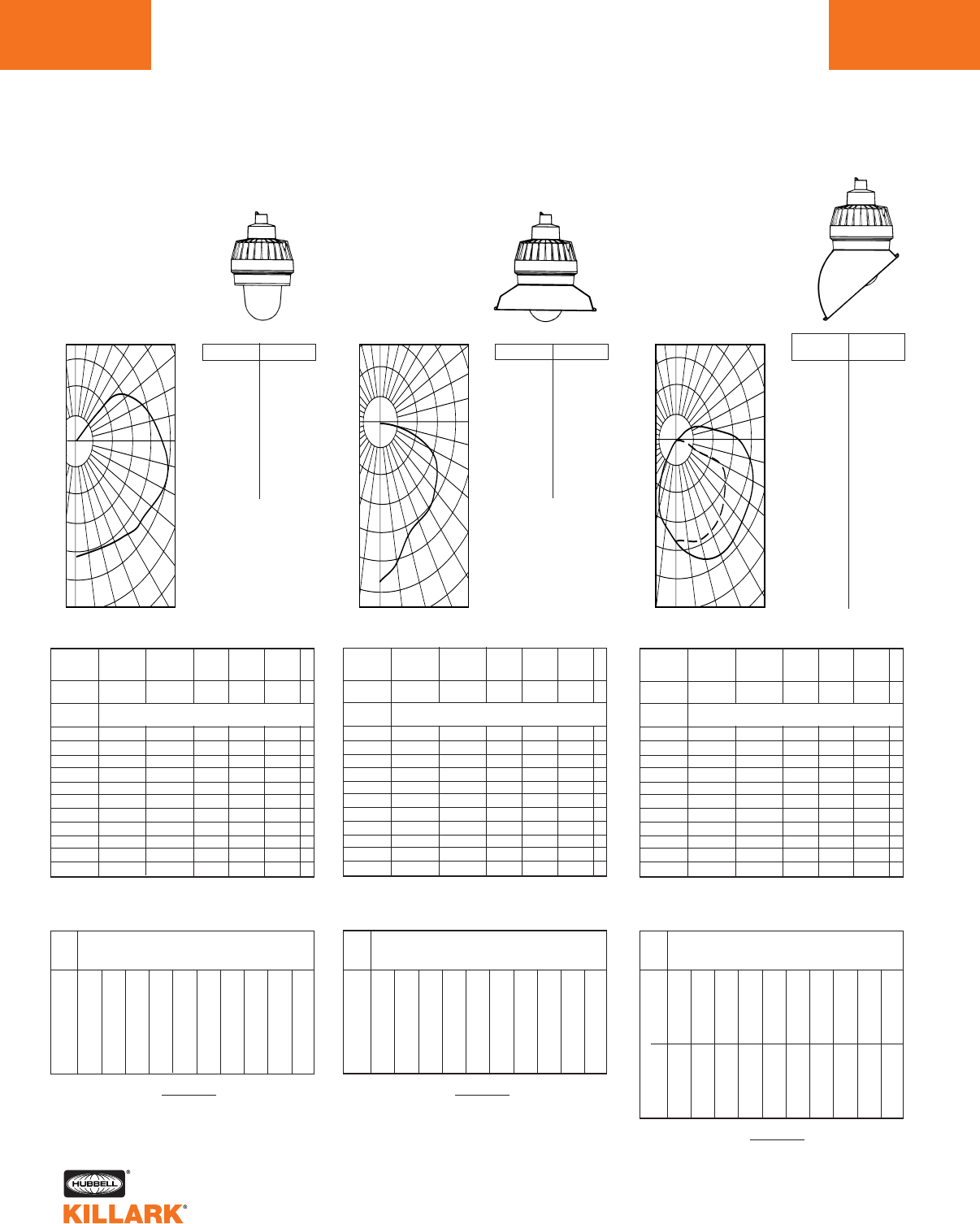
EM/EB/EQ SERIES •LIGHTING
PHOTOMETRIC DATA
L130
0
% Effective
Ceiling Cavity
Reflectance 1cc
% Wall
Reflectance 1w
Room Cavity
Ratio RCR
.87
.75
.67
.60
.55
.50
.45
.42
.38
.36
.33
.87
.70
.59
.50
.44
.39
.34
.30
.27
.25
.22
.87
.65
.52
.43
.36
.31
.26
.23
.20
.18
.16
.82
.70
.62
.56
.51
.46
.42
.38
.36
.33
.31
.82
.66
.55
.47
.41
.36
.32
.28
.26
.23
.21
.82
.61
.49
.40
.34
.29
.25
.22
.19
.17
.15
.82
.58
.44
.35
.29
.24
.20
.17
.15
.13
.11
.87
.61
.46
.37
.30
.25
.21
.18
.15
.13
.12
.72
.57
.48
.41
.36
.31
.28
.25
.22
.20
.18
.72
.54
.43
.35
.30
.26
.22
.19
.17
.15
.13
.72
.51
.39
.31
.25
.21
.18
.15
.13
.11
.10
.64
.50
.41
.35
.31
.27
.24
.21
.19
.17
.16
.64
.47
.37
.31
.26
.22
.19
.17
.15
.13
.12
.64
.45
.34
.27
.22
.18
.15
.13
.11
.10
.08
.56
.43
.35
.30
.26
.23
.20
.18
.16
.15
.14
.56
.41
.32
.26
.22
.19
.16
.14
.13
.11
.10
.56
.39
.29
.23
.19
.16
.13
.11
.10
.08
.07
.52
.35
.26
.20
.16
.13
.11
.09
.08
.07
.06
0
1
2
3
4
5
6
7
8
9
10
20% Effective Floor Cavity Reflectance
70 50 30 10 70 50 30 10 50 30 10 50 30 10 50 30 10
80 70 50 30 10 0
Coefficients of Utilization -- Zonal Cavity Method
Spacing Criterion -- SC = 1.6
Test No. LTL-00679
ANGLE CP ANGLE CP
.0
5.0
15.0
25.0
35.0
45.0
55.0
65.0
75.0
85.0
90.0
95.0
105.0
115.0
125.0
135.0
145.0
155.0
165.0
175.0
180.0
214.
215.
214.
213.
218.
230.
242.
249.
251.
246.
242.
235.
212.
171.
100.
27.
1.
0.
0.
0.
0.
50
100
150
200
250
120
110
100
90
80
70
60
50
0 10 20 30 40
150
100
50
180 170 160 150 140 130
Illumination on Horizontal Surface
FOOTCANDLE CHART (Inital) 100 WATT H.P.S
Horizontal Distance From Source in Feet
Mounting Height in Feet
FC = (Candlepower) (COS Ø)
DISTANCE2
8'
10'
12'
14'
16'
18'
0' 5' 10' 12' 14' 16' 18' 20' 25' 30'
3.34
2.14
1.48
1.09
.83
.66
2.05
1.65
1.17
.91
.73
.59
.90
.81
.70
.60
.51
.44
.65
.62
.56
.50
.44
.38
.47
.47
.45
.41
.37
.33
.34
.36
.36
.34
.32
.29
.26
.28
.29
.28
.27
.25
.20
.22
.23
.23
.23
.22
.11
.13
.14
.15
.15
.15
.07
.08
.09
.10
.10
.10
Illumination on Horizontal Surface
0
ANGLE CP ANGLE CP
.0
5.0
15.0
25.0
35.0
45.0
55.0
65.0
75.0
85.0
90.0
95.0
105.0
115.0
125.0
135.0
145.0
155.0
165.0
175.0
180.0
571.
559.
505.
455.
431.
405.
372.
327.
206.
35.
4.
0.
0.
0.
0.
0.
0.
0.
0.
0.
0.
% Effective
Ceiling Cavity
Reflectance 1cc
% Wall
Reflectance 1w
Room Cavity
Ratio RCR
.79
.72
.65
.58
.53
.49
.45
.41
.38
.35
.32
.79
.68
.59
.51
.45
.40
.35
.31
.28
.26
.23
.79
.65
.54
.45
.39
.33
.29
.25
.22
.20
.18
.77
.70
.63
.57
.52
.47
.43
.40
.37
.34
.32
.77
.67
.58
.50
.44
.39
.35
.31
.28
.25
.23
.77
.64
.53
.45
.38
.33
.29
.25
.22
.20
.18
.77
.61
.49
.40
.34
.29
.24
.21
.18
.16
.14
.79
.62
.50
.41
.34
.29
.24
.21
.18
.16
.14
.74
.64
.55
.48
.42
.37
.33
.30
.27
.24
.22
.74
.62
.51
.43
.37
.32
.28
.24
.22
.19
.17
.74
.59
.48
.40
.34
.28
.24
.21
.18
.16
.14
.70
.61
.53
.46
.41
.36
.32
.29
.26
.24
.22
.70
.59
.50
.42
.37
.32
.27
.24
.21
.19
.17
.70
.58
.47
.39
.33
.28
.24
.20
.18
.16
.14
.67
.59
.51
.44
.39
.35
.31
.28
.25
.23
.21
.67
.57
.48
.41
.36
.31
.27
.23
.21
.19
.17
.67
.56
.46
.38
.33
.28
.24
.20
.18
.16
.14
.66
.54
.45
.37
.31
.26
.22
.19
.16
.14
.13
0
1
2
3
4
5
6
7
8
9
10
20% Effective Floor Cavity Reflectance
70 50 30 10 70 50 30 10 50 30 10 50 30 10 50 30 10
80 70 50 30 10 0
Coefficients of Utilization -- Zonal Cavity Method
Spacing Criterion -- SC = 1.2
Test No. LTL-00680
100
200
300
400
500
600
120
110
100
90
80
70
60
50
40
0 10 20 30
200
100
180 170 160 150 140 130
FOOTCANDLE CHART (Inital) 100 WATT H.P.S
Horizontal Distance From Source in Feet
Mounting Height in Feet
FC = (Candlepower) (COS Ø)
DISTANCE2
8'
10'
12'
14'
16'
18'
0' 5' 10' 12' 14' 16' 18' 20' 25' 30'
8.92
5.71
3.96
2.91
2.23
1.76
4.17
3.17
2.57
2.05
1.68
1.39
1.47
1.43
1.32
1.18
1.04
.91
.98
1.02
.99
.93
.86
.76
.67
.72
.75
.73
.69
.65
.48
.51
.57
.57
.56
.54
.33
.40
.44
.46
.45
.44
.23
.30
.33
.36
.37
.36
.11
.14
.19
.21
.22
.23
.06
.08
.10
.13
.14
.15
0
% Effective
Ceiling Cavity
Reflectance 1cc
% Wall
Reflectance 1w
Room Cavity
Ratio RCR
.70
.63
.56
.51
.47
.43
.40
.36
.34
.31
.29
.70
.59
.51
.44
.39
.35
.31
.28
.25
.23
.21
.70
.56
.46
.39
.34
.29
.26
.23
.20
.18
.16
.68
.60
.54
.49
.45
.41
.38
.35
.33
.30
.28
.68
.57
.49
.43
.38
.34
.30
.27
.25
.22
.20
.68
.54
.45
.38
.33
.29
.25
.22
.20
.18
.16
.68
.52
.41
.34
.29
.25
.21
.18
.16
.14
.13
.70
.53
.42
.35
.30
.25
.22
.19
.16
.14
.13
.64
.54
.46
.40
.36
.32
.29
.26
.23
.21
.20
.64
.51
.43
.36
.32
.28
.24
.21
.19
.17
.15
.64
.49
.40
.33
.28
.24
.21
.18
.16
.14
.12
.60
.50
.43
.38
.34
.30
.27
.24
.22
.20
.19
.60
.48
.41
.35
.30
.26
.23
.20
.18
.16
.15
.60
.47
.38
.32
.27
.23
.20
.17
.15
.14
.12
.57
.47
.41
.36
.32
.29
.26
.23
.21
.19
.18
.57
.46
.38
.33
.29
.25
.22
.20
.18
.16
.14
.57
.44
.36
.30
.26
.23
.20
.17
.15
.13
.12
.55
.43
.35
.29
.25
.21
.18
.16
.14
.12
.11
0
1
2
3
4
5
6
7
8
9
10
20% Effective Floor Cavity Reflectance
70 50 30 10 70 50 30 10 50 30 10 50 30 10 50 30 10
80 70 50 30 10 0
Coefficients of Utilization -- Zonal Cavity Method
0-DEG / 90-DEG
Spacing Criterion -- SC = 1.8 / 1.4
Test No. LTL-00681
0˚
(FRONT)
ANGLE CP
.0
5.0
15.0
25.0
35.0
45.0
55.0
65.0
75.0
85.0
90.0
95.0
105.0
115.0
125.0
135.0
145.0
155.0
165.0
175.0
180.0
.0
5.0
15.0
25.0
35.0
45.0
55.0
65.0
75.0
85.0
90.0
95.0
105.0
115.0
125.0
135.0
145.0
155.0
165.0
175.0
180.0
435.
451.
486.
504.
520.
525.
518.
502.
479.
438.
401.
348.
204.
72.
14.
0.
0.
0.
0.
0.
0.
435.
437.
428.
416.
399.
372.
291.
157.
52.
10.
0.
0.
0.
0.
0.
0.
0.
0.
0.
0.
0.
150
250
350
450
550
120
110
100
90
80
70
60
50
40
0 10 20 30
350
250
150
180 170 160 150 140 130
Illumination on Horizontal Surface
FC = (Candlepower) (COS Ø)
DISTANCE2
90˚
(SIDE)
ANGLE CP
FOOTCANDLE CHART (Inital) 100 WATT H.P.S
Horizontal Distance From Source in Feet
Mounting Height in Feet
8'
10'
12'
14'
16'
18'
0' 5' 10' 12' 14' 16' 18' 20' 25' 30'
6.79
4.35
3.02
2.21
1.69
1.34
4.90
3.61
2.73
2.11
1.66
1.34
1.99
1.86
1.64
1.43
1.23
1.06
1.38
1.37
1.29
1.17
1.04
.92
.97
1.02
1.00
.95
.87
.79
.70
.77
.77
.76
.73
.67
.53
.58
.61
.62
.60
.57
.40
.45
.48
.50
.50
.48
.22
.25
.28
.30
.32
.28
.13
.15
.18
.19
.21
.21
8'
10'
12'
14'
16'
18'
6.79
4.35
3.02
2.22
1.70
1.34
3.86
2.98
2.29
1.80
1.45
1.18
1.26
1.32
1.21
1.10
.96
.84
.78
.87
.91
.86
.80
.70
.43
.57
.64
.67
.64
.60
.28
.39
.46
.51
.51
.50
.16
.26
.34
.41
.36
.41
.09
.16
.21
.28
.32
.29
.04
.06
.08
.13
.16
.18
.01
.03
.04
.06
.09
.09
0˚
90˚
SIDE
FRONT
FOOTCANDLE CHART (Initial) 150 WATT INCANDESCENT FOOTCANDLE CHART (Initial) 150 WATT INCANDESCENT FOOTCANDLE CHART (Initial) 150 WATT INCANDESCENT
EMI15 INCANDESCENT
With Globe Only
100 – 150 Watt Medium Base
CANDLEPOWER – 150 WATT
A-21 lamp 2880 lumens
For 100 watt multiply by .587
EMI15 INCANDESCENT
With Globe and Angle Reflector
100 – 150 Watt Medium Base
CANDLEPOWER – 150 WATT
A-21 lamp 2880 lumens
For 100 watt multiply by .587
EMI15 INCANDESCENT
With Globe and Standard Dome Reflector
100 – 150 Watt Medium Base
CANDLEPOWER – 150 WATT
A-21 lamp 2880 lumens
For 100 watt multiply by .587
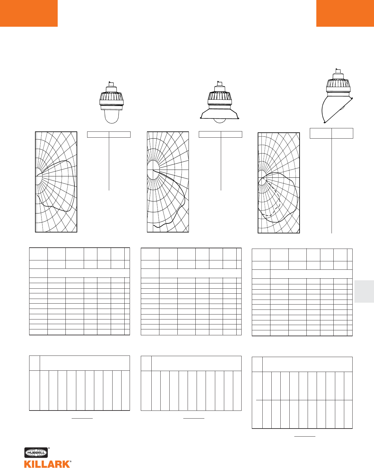
EM/EB/EQ SERIES •LIGHTING
PHOTOMETRIC DATA L131
L
Illumination on Horizontal Surface
0
ANGLE CP ANGLE CP
.0
5.0
15.0
25.0
35.0
45.0
55.0
65.0
75.0
85.0
90.0
95.0
105.0
115.0
125.0
135.0
145.0
155.0
165.0
175.0
180.0
127.
132.
177.
209.
235.
296.
370.
369.
351.
339.
332.
322.
241.
87.
11.
1.
0.
0.
0.
0.
0.
% Effective
Ceiling Cavity
Reflectance 1cc
% Wall
Reflectance 1w
Room Cavity
Ratio RCR
.76
.65
.57
.51
.46
.41
.38
.34
.32
.29
.27
.76
.60
.50
.42
.36
.31
.27
.24
.22
.19
.18
.76
.55
.43
.35
.29
.24
.21
.18
.15
.13
.12
.72
.61
.53
.47
.43
.39
.35
.32
.30
.27
.25
.72
.57
.47
.39
.34
.30
.26
.23
.20
.18
.17
.72
.53
.41
.33
.28
.23
.20
.17
.15
.13
.11
.72
.49
.36
.28
.23
.18
.15
.12
.10
.09
.08
.76
.51
.38
.29
.24
.19
.16
.13
.11
.09
.08
.65
.50
.41
.35
.30
.26
.23
.20
.18
.16
.15
.65
.47
.37
.30
.25
.21
.17
.15
.13
.11
.10
.65
.44
.33
.25
.20
.16
.13
.11
.09
.08
.07
.58
.45
.36
.30
.26
.23
.20
.18
.16
.14
.13
.58
.42
.33
.26
.22
.18
.15
.13
.11
.10
.09
.58
.40
.29
.23
.18
.15
.12
.10
.08
.07
.06
.52
.39
.32
.26
.23
.20
.17
.15
.14
.12
.11
.52
.37
.29
.23
.19
.16
.13
.11
.10
.09
.08
.52
.35
.26
.20
.16
.13
.10
.08
.07
.06
.05
.49
.33
.23
.17
.14
.11
.08
.07
.05
.04
.04
0
1
2
3
4
5
6
7
8
9
10
20% Effective Floor Cavity Reflectance
70 50 30 10 70 50 30 10 50 30 10 50 30 10 50 30 10
80 70 50 30 10 0
Coefficients of Utilization -- Zonal Cavity Method
Spacing Criterion -- SC = 3.0
Test No. LTL-00670
50
100
150
200
250
120
110
100
90
80
70
60
50
0 10 20 30 40
200
150
100
50
180 170 160 150 140 130
FOOTCANDLE CHART (Inital) 100 WATT H.P.S
Horizontal Distance From Source in Feet
Mounting Height in Feet
FC = (Candlepower) (COS Ø)
DISTANCE2
8'
10'
12'
14'
16'
18'
0' 5' 10' 12' 14' 16' 18' 20' 25' 30'
1.98
1.27
.88
.64
.49
.39
2.16
1.50
1.09
.82
.62
.49
1.30
1.05
.83
.65
.54
.46
.99
.87
.73
.59
.47
.40
.71
.73
.64
.53
.44
.37
.52
.55
.52
.46
.41
.34
.39
.42
.44
.41
.40
.32
.28
.33
.35
.36
.32
.29
.16
.19
.21
.22
.23
.23
.09
.11
.13
.14
.15
.16
0
% Effective
Ceiling Cavity
Reflectance 1cc
% Wall
Reflectance 1w
Room Cavity
Ratio RCR
.66
.61
.55
.50
.46
.41
.38
.34
.32
.29
.27
.66
.58
.51
.44
.39
.34
.30
.26
.24
.21
.19
.66
.56
.47
.40
.34
.29
.25
.21
.19
.16
.15
.65
.59
.54
.49
.44
.40
.37
.33
.31
.28
.26
.65
.55
.46
.39
.33
.28
.24
.21
.18
.16
.14
.65
.53
.43
.36
.30
.25
.21
.17
.15
.13
.11
.66
.54
.44
.36
.30
.25
.21
.17
.15
.13
.11
.62
.55
.48
.42
.37
.32
.28
.25
.22
.20
.18
.62
.53
.45
.38
.33
.28
.24
.20
.18
.16
.14
.62
.51
.42
.35
.29
.24
.21
.17
.15
.13
.11
.59
.52
.46
.40
.35
.31
.27
.24
.22
.20
.18
.59
.51
.44
.37
.32
.27
.23
.20
.18
.16
.14
.59
.50
.41
.34
.29
.24
.20
.17
.15
.13
.11
.57
.50
.44
.39
.34
.30
.26
.23
.21
.19
.17
.57
.49
.42
.36
.31
.27
.23
.20
.17
.15
.14
.57
.48
.40
.34
.29
.24
.20
.17
.15
.13
.11
.56
.47
.39
.33
.27
.23
.19
.16
.14
.12
.10
0
1
2
3
4
5
6
7
8
9
10
20% Effective Floor Cavity Reflectance
70 50 30 10 70 50 30 10 50 30 10 50 30 10 50 30 10
80 70 50 30 10 0
Coefficients of Utilization -- Zonal Cavity Method
Spacing Criterion -- SC = 1.5
Test No. LTL-00671
100
200
300
400
500
120
110
100
90
80
70
60
50
0 10 20 30 40
300
200
100
180 170 160 150 140 130
Illumination on Horizontal Surface
FOOTCANDLE CHART (Inital) 100 WATT H.P.S
Horizontal Distance From Source in Feet
Mounting Height in Feet
FC = (Candlepower) (COS Ø)
DISTANCE2
ANGLE CP ANGLE CP
.0
5.0
15.0
25.0
35.0
45.0
55.0
65.0
75.0
85.0
90.0
95.0
105.0
115.0
125.0
135.0
145.0
155.0
165.0
175.0
180.0
517.
529.
534.
556.
519.
503.
531.
451.
108.
20.
1.
0.
0.
0.
0.
0.
0.
0.
0.
0.
0.
.65
.57
.50
.43
.38
.33
.29
.26
.23
.21
.19
8'
10'
12'
14'
16'
18'
0' 5' 10' 12' 14' 16' 18' 20' 25' 30'
8.08
5.17
3.59
2.64
2.02
1.60
5.06
3.98
3.00
2.32
1.83
1.47
1.97
1.78
1.61
1.43
1.26
1.11
1.42
1.36
1.24
1.14
1.04
.94
.94
1.04
.99
.91
.85
.78
.61
.77
.78
.74
.69
.66
.47
.56
.63
.62
.59
.55
.28
.42
.46
.51
.49
.47
.09
.18
.25
.29
.32
.33
.03
.09
.12
.17
.20
.21
Illumination on Horizontal Surface
0
.0
5.0
15.0
25.0
35.0
45.0
55.0
65.0
75.0
85.0
90.0
95.0
105.0
115.0
125.0
135.0
145.0
155.0
165.0
175.0
180.0
.0
5.0
15.0
25.0
35.0
45.0
55.0
65.0
75.0
85.0
90.0
95.0
105.0
115.0
125.0
135.0
145.0
155.0
165.0
175.0
180.0
448.
473.
544.
590.
613.
641.
716.
700.
643.
563.
460.
316.
120.
58.
14.
0.
0.
0.
0.
0.
0.
448.
457.
486.
497.
460.
462.
353.
129.
59.
14.
5.
1.
0.
0.
0.
0.
0.
0.
0.
0.
0.
% Effective
Ceiling Cavity
Reflectance 1cc
% Wall
Reflectance 1w
Room Cavity
Ratio RCR
.60
.53
.48
.43
.40
.36
.33
.30
.28
.26
.24
.60
.50
.43
.37
.33
.29
.26
.23
.21
.19
.17
.60
.48
.39
.33
.28
.24
.21
.18
.16
.15
.13
.58
.51
.46
.42
.38
.35
.32
.29
.27
.25
.23
.58
.49
.42
.36
.32
.28
.25
.23
.20
.18
.17
.58
.46
.38
.32
.28
.24
.21
.18
.16
.14
.13
.58
.44
.35
.29
.24
.20
.17
.15
.13
.11
.10
.60
.45
.36
.29
.25
.21
.18
.15
.13
.12
.10
.55
.46
.40
.34
.31
.27
.24
.21
.19
.18
.16
.55
.44
.36
.31
.27
.23
.20
.17
.16
.14
.12
.55
.42
.34
.28
.24
.20
.17
.15
.13
.11
.10
.52
.43
.37
.33
.29
.26
.23
.20
.19
.17
.15
.52
.42
.35
.29
.26
.22
.19
.17
.15
.13
.12
.52
.40
.33
.27
.23
.19
.17
.14
.13
.11
.10
.49
.41
.35
.31
.27
.24
.22
.20
.18
.16
.15
.49
.40
.33
.28
.25
.21
.19
.16
.15
.13
.12
.49
.39
.31
.26
.22
.19
.16
.14
.12
.11
.10
.48
.37
.30
.25
.21
.18
.15
.13
.11
.10
.09
0
1
2
3
4
5
6
7
8
9
10
20% Effective Floor Cavity Reflectance
70 50 30 10 70 50 30 10 50 30 10 50 30 10 50 30 10
80 70 50 30 10 0
Coefficients of Utilization -- Zonal Cavity Method
0-DEG / 90-DEG
Spacing Criterion -- SC = 2.0 / 1.6
Test No. LTL-00672
100
200
300
400
500
600
120
110
100
90
80
70
60
50
0 10 20 30 40
500
400
300
200
100
180 170 160 150 140 130
FC = (Candlepower) (COS Ø)
DISTANCE2
FOOTCANDLE CHART (Inital) 100 WATT H.P.S
Horizontal Distance From Source in Feet
Mounting Height in Feet
8'
10'
12'
14'
16'
18'
0' 5' 10' 12' 14' 16' 18' 20' 25' 30'
7.00
4.48
3.11
2.28
1.75
1.38
5.77
4.22
3.04
1.98
1.88
1.50
2.58
2.27
1.97
1.69
1.44
1.24
1.91
1.78
1.57
1.40
1.23
1.08
1.35
1.41
1.30
1.16
1.04
.94
.98
1.06
1.05
.97
.89
.81
.73
.81
.85
.82
.74
.70
.55
.63
.65
.69
.65
.61
.29
.34
.39
.42
.44
.44
.17
.21
.23
.27
.29
.30
8'
10'
12'
14'
16'
18'
7.00
4.48
3.11
2.28
1.75
1.38
4.50
3.56
2.69
2.09
1.67
1.26
1.55
1.63
1.45
1.26
1.12
.99
.94
1.07
1.13
1.03
.92
.83
.46
.69
.78
.83
.77
.70
.24
.46
.56
.63
.64
.59
.14
.27
.42
.44
.49
.50
.09
.15
.23
.34
.39
.40
.04
.06
.07
.14
.19
.22
.02
.03
.04
.05
.10
.10
0˚
90˚
0˚
(FRONT)
ANGLE CP
90˚
(SIDE)
ANGLE CP
SIDE
FRONT
FOOTCANDLE CHART (Initial) 200 WATT INCANDESCENT FOOTCANDLE CHART (Initial) 200 WATT INCANDESCENT FOOTCANDLE CHART (Initial) 200 WATT INCANDESCENT
EMI20 INCANDESCENT
With Globe Only
150 – 200 Watt Medium Base
CANDLEPOWER – 200 WATT
A-23 lamp 4000 lumens
For 150 watt multiply by .695
EMI20 INCANDESCENT
With Globe and Angle Reflector
150 – 200 Watt Medium Base
CANDLEPOWER – 200 WATT
A-23 lamp 4000 lumens
For 150 watt multiply by .695
EMI20 INCANDESCENT
With Globe and Standard Dome Reflector
150 – 200 Watt Medium Base
CANDLEPOWER – 200 WATT
A-23 lamp 4000 lumens
For 150 watt multiply by .695
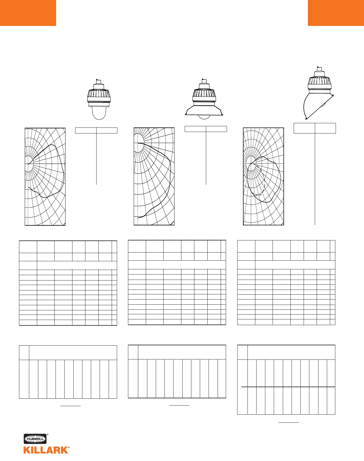
EM/EB/EQ SERIES •LIGHTING
PHOTOMETRIC DATA
L132
0
% Effective
Ceiling Cavity
Reflectance 1cc
% Wall
Reflectance 1w
Room Cavity
Ratio RCR
.58
.50
.44
.40
.36
.32
.30
.27
.25
.23
.21
.58
.46
.39
.33
.28
.25
.22
.19
.17
.16
.14
.58
.43
.34
.28
.23
.19
.17
.14
.12
.11
.10
.55
.47
.41
.37
.33
.30
.27
.25
.23
.21
.20
.55
.41
.32
.26
.22
.18
.16
.13
.12
.10
.09
.55
.38
.28
.22
.18
.15
.12
.10
.09
.07
.06
.58
.40
.30
.23
.19
.16
.13
.11
.09
.08
.07
.49
.38
.31
.27
.23
.20
.18
.16
.14
.13
.11
.49
.36
.28
.23
.19
.16
.14
.12
.10
.09
.08
.49
.34
.25
.19
.16
.13
.11
.09
.08
.06
.06
.43
.33
.27
.23
.20
.17
.15
.13
.12
.11
.10
.43
.31
.24
.20
.16
.14
.12
.10
.09
.08
.07
.43
.29
.22
.17
.14
.11
.09
.08
.06
.06
.05
.38
.28
.23
.19
.17
.15
.13
.11
.10
.09
.08
.38
.27
.21
.17
.14
.12
.10
.08
.07
.07
.06
.38
.26
.19
.15
.12
.10
.08
.06
.05
.05
.04
.35
.23
.17
.13
.10
.08
.06
.05
.04
.03
.03
0
1
2
3
4
5
6
7
8
9
10
20% Effective Floor Cavity Reflectance
70 50 30 10 70 50 30 10 50 30 10 50 30 10 50 30 10
80 70 50 30 10 0
Coefficients of Utilization -- Zonal Cavity Method
Spacing Criterion -- SC = 2.6
Test No. LTL-00673
75
125
200
275
325
400
120
110
100
90
80
70
60
50
0 10 20 30 40
200
125
75
180 170 160 150 140 130
Illumination on Horizontal Surface
FOOTCANDLE CHART (Inital) 100 WATT H.P.S
Horizontal Distance From Source in Feet
Mounting Height in Feet
FC = (Candlepower) (COS Ø)
DISTANCE2
.0
5.0
15.0
25.0
35.0
45.0
55.0
65.0
75.0
85.0
90.0
95.0
105.0
115.0
125.0
135.0
145.0
155.0
165.0
175.0
180.0
165.
169.
206.
257.
298.
332.
380.
409.
405.
396.
388.
379.
348.
238.
66.
6.
0.
0.
0.
0.
0.
.55
.44
.36
.31
.27
.23
.20
.18
.16
.15
.13
ANGLE CP ANGLE CP
8'
10'
12'
14'
16'
18'
0' 5' 10' 12' 14' 16' 18' 20' 25' 30'
2.58
1.65
1.15
.84
.64
.51
2.24
1.84
1.32
.98
.73
.57
1.36
1.17
.99
.82
.68
.57
1.01
.93
.82
.70
.60
.52
.75
.75
.68
.60
.52
.46
.56
.57
.56
.50
.46
.41
.43
.45
.45
.43
.40
.36
.33
.36
.37
.37
.34
.32
.18
.21
.23
.24
.24
.23
.11
.13
.14
.16
.16
.17
Illumination on Horizontal Surface
0
.0
5.0
15.0
25.0
35.0
45.0
55.0
65.0
75.0
85.0
90.0
95.0
105.0
115.0
125.0
135.0
145.0
155.0
165.0
175.0
180.0
725.
722.
675.
657.
646.
605.
580.
542.
255.
26.
2.
0.
0.
0.
0.
0.
0.
0.
0.
0.
0.
% Effective
Ceiling Cavity
Reflectance 1cc
% Wall
Reflectance 1w
Room Cavity
Ratio RCR
.52
.48
.43
.39
.35
.32
.29
.27
.25
.23
.21
.52
.45
.39
.34
.30
.26
.23
.20
.18
.17
.15
.52
.44
.36
.30
.26
.22
.19
.16
.14
.13
.11
.51
.46
.42
.38
.34
.31
.28
.26
.24
.22
.21
.51
.44
.38
.33
.29
.26
.23
.20
.18
.16
.15
.51
.43
.36
.30
.26
.22
.19
.16
.14
.13
.11
.51
.41
.33
.27
.23
.19
.16
.13
.12
.10
.09
.52
.42
.34
.27
.23
.19
.16
.13
.12
.10
.09
.49
.43
.37
.32
.28
.25
.22
.19
.18
.16
.14
.49
.41
.35
.29
.25
.21
.18
.16
.14
.12
.11
.49
.40
.32
.27
.22
.19
.16
.13
.12
.10
.09
.47
.41
.35
.31
.27
.24
.21
.19
.17
.15
.14
.47
.40
.33
.28
.24
.21
.18
.16
.14
.12
.11
.47
.39
.32
.26
.22
.18
.16
.13
.12
.10
.09
.45
.39
.34
.30
.26
.23
.20
.18
.16
.15
.14
.45
.38
.32
.27
.24
.20
.18
.15
.14
.12
.11
.45
.37
.31
.26
.22
.18
.15
.13
.11
.10
.09
.44
.37
.30
.25
.21
.17
.14
.12
.11
.09
.08
0
1
2
3
4
5
6
7
8
9
10
20% Effective Floor Cavity Reflectance
70 50 30 10 70 50 30 10 50 30 10 50 30 10 50 30 10
80 70 50 30 10 0
Coefficients of Utilization -- Zonal Cavity Method
Spacing Criterion -- SC = 1.4
Test No. LTL-00674
100
200
300
400
500
600
700
110
90
80
70
60
50
40
0 10 20 30
100
180 160 140 130 120
FOOTCANDLE CHART (Inital) 100 WATT H.P.S
Horizontal Distance From Source in Feet
Mounting Height in Feet
FC = (Candlepower) (COS Ø)
DISTANCE2
ANGLE CP ANGLE CP
8'
10'
12'
14'
16'
18'
0' 5' 10' 12' 14' 16' 18' 20' 25' 30'
11.32
7.25
5.03
3.70
2.83
2.24
6.23
4.70
3.60
2.83
2.26
1.86
2.16
2.14
1.97
1.78
1.55
1.34
1.55
1.49
1.48
1.40
1.29
1.15
1.07
1.14
1.09
1.09
1.04
.97
.78
.85
.88
.83
.84
.81
.57
.64
.69
.66
.65
.66
.36
.49
.53
.56
.54
.53
.15
.23
.31
.33
.35
.36
.07
.13
.16
.21
.23
.24
0
% Effective
Ceiling Cavity
Reflectance 1cc
% Wall
Reflectance 1w
Room Cavity
Ratio RCR
.47
.41
.37
.34
.31
.28
.26
.24
.22
.20
.19
.47
.39
.33
.29
.26
.23
.20
.18
.16
.15
.13
.47
.37
.30
.25
.22
.19
.16
.14
.13
.11
.10
.45
.40
.36
.32
.30
.27
.25
.23
.21
.20
.18
.45
.36
.30
.25
.21
.19
.16
.14
.13
.11
.10
.45
.34
.27
.22
.19
.16
.14
.12
.10
.09
.08
.47
.35
.28
.23
.19
.16
.14
.12
.10
.09
.08
.43
.36
.31
.27
.24
.21
.19
.17
.15
.14
.13
.43
.34
.28
.24
.21
.18
.16
.14
.12
.11
.10
.43
.33
.26
.21
.18
.15
.13
.11
.10
.09
.08
.40
.34
.29
.25
.22
.20
.18
.16
.14
.13
.12
.40
.32
.27
.23
.20
.17
.15
.13
.12
.10
.09
.40
.31
.25
.21
.18
.15
.13
.11
.10
.08
.07
.38
.32
.27
.24
.21
.19
.17
.15
.14
.12
.11
.38
.31
.26
.22
.19
.16
.14
.13
.11
.10
.09
.38
.30
.24
.20
.17
.15
.13
.11
.09
.08
.07
.37
.29
.23
.19
.16
.14
.12
.10
.09
.07
.07
0
1
2
3
4
5
6
7
8
9
10
20% Effective Floor Cavity Reflectance
70 50 30 10 70 50 30 10 50 30 10 50 30 10 50 30 10
80 70 50 30 10 0
Coefficients of Utilization -- Zonal Cavity Method
0-DEG / 90-DEG
Spacing Criterion -- SC = 2.1 / 1.6
Test No. LTL-00675
50
100
150
200
250
120
110
100
90
80
70
60
50
40
0 10 20 30
150
100
50
180 170 160 150 140 130
Illumination on Horizontal Surface
FC = (Candlepower) (COS Ø)
DISTANCE2
.0
5.0
15.0
25.0
35.0
45.0
55.0
65.0
75.0
85.0
90.0
95.0
105.0
115.0
125.0
135.0
145.0
155.0
165.0
175.0
180.0
.0
5.0
15.0
25.0
35.0
45.0
55.0
65.0
75.0
85.0
90.0
95.0
105.0
115.0
125.0
135.0
145.0
155.0
165.0
175.0
180.0
536.
558.
633.
750.
795.
797.
808.
813.
778.
696.
625.
501.
195.
68.
15.
0.
0.
0.
0.
0.
0.
536.
544.
572.
602.
585.
541.
432.
208.
73.
22.
10.
2.
0.
0.
0.
0.
0.
0.
0.
0.
0.
.45
.38
.32
.28
.25
.22
.20
.18
.16
.14
.13
FOOTCANDLE CHART (Inital) 100 WATT H.P.S
Horizontal Distance From Source in Feet
Mounting Height in Feet
8'
10'
12'
14'
16'
18'
0' 5' 10' 12' 14' 16' 18' 20' 25' 30'
8.38
5.36
3.72
2.73
2.09
1.65
7.44
5.37
3.90
2.94
2.27
1.75
3.05
2.82
2.51
2.19
1.86
1.59
2.15
2.10
1.96
1.78
1.59
1.40
1.55
1.59
1.54
1.44
1.33
1.21
1.13
1.20
1.21
1.17
1.10
1.03
.85
.93
.96
.95
.92
.87
.64
.73
.77
.78
.76
.74
.35
.41
.46
.48
.50
.50
.21
.25
.29
.31
.33
.34
8'
10'
12'
14'
16'
18'
8.38
5.36
3.72
2.73
2.09
1.65
5.63
4.31
3.24
2.50
1.96
1.58
1.86
1.91
1.77
1.61
1.41
1.22
1.15
1.28
1.33
1.26
1.17
1.05
.61
.85
.93
.98
.94
.87
.29
.54
.62
.74
.75
.72
.22
.37
.51
.55
.58
.59
.13
.19
.30
.42
.46
.47
.05
.09
.12
.19
.25
.27
.02
.04
.06
.08
.13
.13
0˚
90˚
0˚
(FRONT)
ANGLE CP
90˚
(SIDE)
ANGLE CP
SIDE
FRONT
FOOTCANDLE CHART (Initial) 300 WATT INCANDESCENT FOOTCANDLE CHART (Initial) 300 WATT INCANDESCENT FOOTCANDLE CHART (Initial) 300 WATT INCANDESCENT
EMI20 INCANDESCENT
With Globe Only Reflector
150, 200 and 300 Watt Medium Base
CANDLEPOWER – 300 WATT
PS-25 lamp 6360 lumens
For 150 watt multiply by .421
For 200 watt multiply by .506
EMI20 INCANDESCENT
With Globe and Angle Reflector
150, 200 and 300 Watt Medium Base
CANDLEPOWER – 300 WATT
PS-25 lamp 6360 lumens
For 150 watt multiply by .421
For 200 watt multiply by .506
EMI20 INCANDESCENT
With Globe and Standard Dome Reflector
150, 200 and 300 Watt Medium Base
CANDLEPOWER – 300 WATT
PS-25 lamp 6360 lumens
For 150 watt multiply by .421
For 200 watt multiply by .506
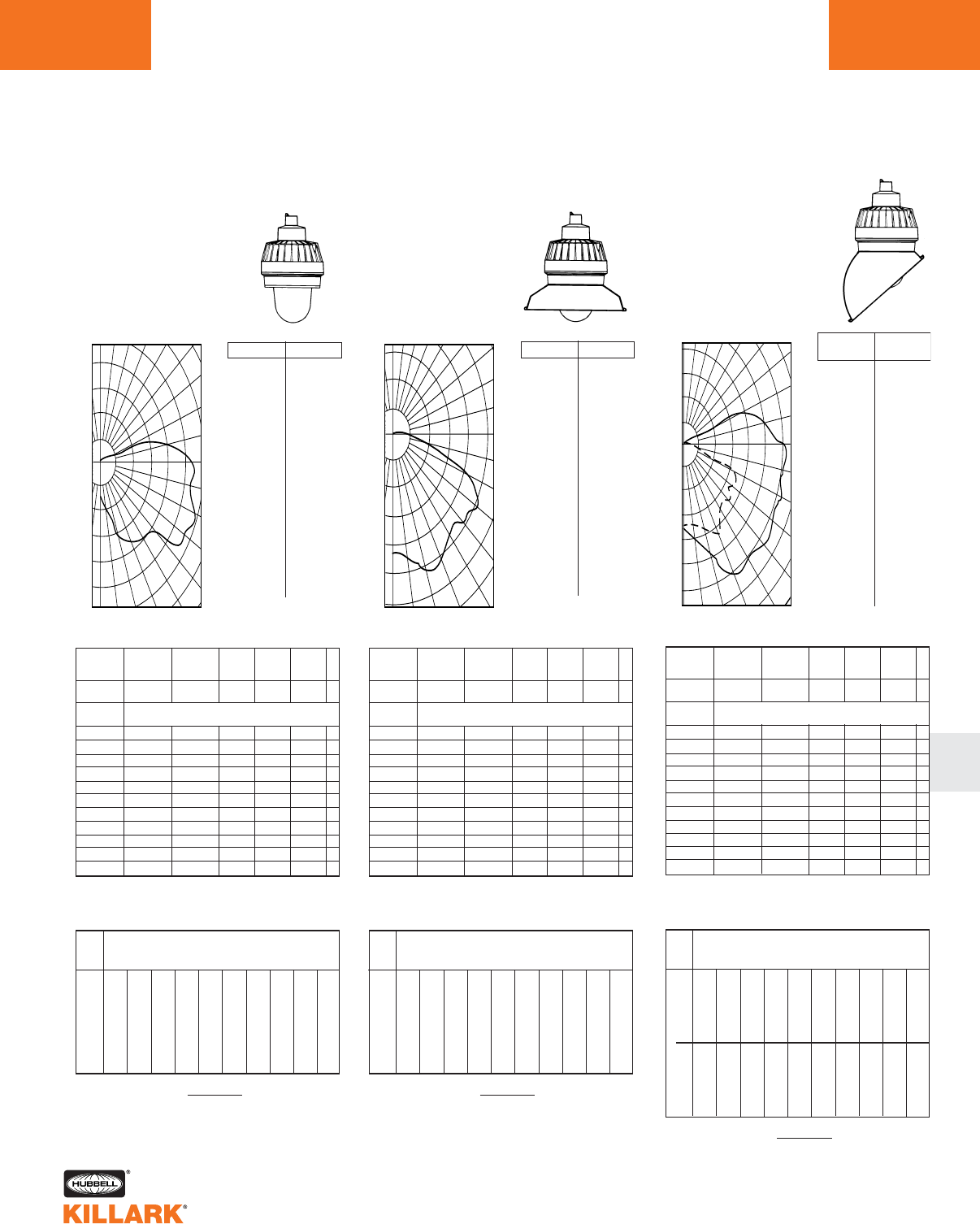
EM/EB/EQ SERIES •LIGHTING
PHOTOMETRIC DATA L133
L
Illumination on Horizontal Surface
0
.0
5.0
10.0
15.0
20.0
25.0
30.0
35.0
40.0
45.0
50.0
55.0
60.0
65.0
70.0
75.0
80.0
85.0
90.0
95.0
100.0
105.0
110.0
115.0
120.0
125.0
130.0
.135.0
140.0
145.0
150.0
155.0
160.0
165.0
170.0
175.0
180.0
139.
184.
213.
268.
364.
371.
381.
410.
402.
434.
488.
586.
573.
604.
585.
567.
566.
549.
515.
485.
389.
234.
80.
15.
11.
7.
3.
1.
0.
0.
0.
0.
0.
0.
0.
0.
0.
% Effective
Ceiling Cavity
Reflectance 1cc
% Wall
Reflectance 1w
Room Cavity
Ratio RCR
.72
.61
.54
.48
.43
.39
.35
.32
.30
.27
.25
.72
.57
.46
.39
.34
.29
.25
.23
.20
.18
.16
.72
.52
.40
.33
.27
.22
.19
.16
.14
.12
.11
.68
.58
.51
.45
.41
.36
.33
.30
.28
.26
.24
.68
.54
.44
.37
.32
.28
.24
.21
.19
.17
.16
.68
.50
.39
.31
.26
.21
.18
.16
.13
.12
.10
.68
.47
.34
.26
.21
.17
.14
.11
.10
.08
.07
.72
.49
.35
.28
.22
.17
.14
.12
.10
.08
.07
.63
.49
.40
.34
.29
.25
.22
.19
.17
.15
.14
.63
.46
.35
.29
.24
.19
.16
.14
.12
.11
.09
.63
.43
.31
.24
.19
.15
.13
.10
.09
.07
.06
.57
.44
.36
.30
.26
.22
.19
.17
.15
.14
.13
.57
.42
.32
.26
.21
.18
.15
.13
.11
.10
.08
.57
.39
.29
.22
.18
.14
.11
.09
.08
.07
.06
.52
.40
.32
.27
.23
.20
.17
.15
.14
.12
.11
.52
.38
.29
.23
.19
.16
.13
.11
.10
.08
.08
.52
.36
.26
.20
.16
.13
.10
.08
.07
.06
.05
.50
.33
.24
.18
.14
.11
.09
.07
.06
.04
.04
0
1
2
3
4
5
6
7
8
9
10
20% Effective Floor Cavity Reflectance
70 50 30 10 70 50 30 10 50 30 10 50 30 10 50 30 10
80 70 50 30 10 0
Coefficients of Utilization -- Zonal Cavity Method
Spacing Criterion -- SC = 3.5
Test No. BALL-6769.1
100
200
300
400
500
120
110
100
90
80
70
60
50
0 10 20 30 40
400
300
200
100
180 170 160 150 140 130
FOOTCANDLE CHART (Inital) 100 WATT H.P.S
Horizontal Distance From Source in Feet
Mounting Height in Feet
FC = (Candlepower) (COS Ø)
DISTANCE2
ANGLE CP ANGLE CP
8'
10'
12'
14'
16'
18'
0' 5' 10' 12' 14' 16' 18' 20' 25' 30'
2.17
1.39
.96
.71
.54
.43
3.67
2.65
1.97
1.55
1.01
.74
1.86
1.53
1.26
1.13
.92
.79
1.56
1.28
1.06
.90
.82
.67
1.09
1.15
.93
.78
.67
.62
.84
.85
.80
.69
.60
.52
.63
.66
.69
.66
.54
.47
.47
.54
.54
.56
.46
.43
.26
.30
.34
.34
.35
.36
.15
.19
.21
.23
.23
.24
0
% Effective
Ceiling Cavity
Reflectance 1cc
% Wall
Reflectance 1w
Room Cavity
Ratio RCR
.61
.56
.51
.46
.42
.37
.34
.31
.28
.26
.24
.61
.53
.46
.41
.35
.30
.27
.24
.21
.19
.17
.61
.51
.43
.36
.31
.25
.22
.19
.16
.14
.13
.59
.54
.49
.45
.40
.36
.33
.30
.28
.25
.23
.59
.50
.42
.36
.30
.25
.22
.19
.16
.14
.12
.59
.49
.40
.33
.27
.22
.18
.15
.13
.11
.10
.61
.49
.40
.33
.27
.22
.18
.15
.13
.11
.10
.57
.50
.44
.38
.33
.29
.25
.22
.20
.18
.16
.57
.49
.41
.35
.30
.25
.21
.18
.16
.14
.12
.57
.47
.39
.32
.27
.21
.18
.15
.13
.11
.10
.54
.48
.42
.37
.32
.28
.24
.22
.19
.17
.16
.54
.47
.40
.34
.29
.24
.21
.18
.16
.13
.12
.54
.46
.38
.31
.26
.21
.18
.15
.13
.11
.09
.52
.46
.40
.35
.31
.27
.23
.21
.19
.17
.15
.52
.45
.39
.33
.28
.23
.20
.18
.15
.13
.12
.52
.44
.37
.31
.26
.21
.18
.15
.13
.11
.09
.51
.43
.36
.30
.25
.20
.17
.14
.12
.10
.08
0
1
2
3
4
5
6
7
8
9
10
20% Effective Floor Cavity Reflectance
70 50 30 10 70 50 30 10 50 30 10 50 30 10 50 30 10
80 70 50 30 10 0
Coefficients of Utilization -- Zonal Cavity Method
Spacing Criterion -- SC = 1.7
Test No. BALL-6770.1
150
300
450
600
750
900
120
110
100
90
80
70
60
50
0 10 20 30 40
450
300
150
180 170 160 150 140 130
Illumination on Horizontal Surface
FOOTCANDLE CHART (Inital) 100 WATT H.P.S
Horizontal Distance From Source in Feet
Mounting Height in Feet
FC = (Candlepower) (COS Ø)
DISTANCE2
.0
5.0
10.0
15.0
20.0
25.0
30.0
35.0
40.0
45.0
50.0
55.0
60.0
65.0
70.0
75.0
80.0
85.0
90.0
95.0
100.0
105.0
110.0
115.0
120.0
125.0
130.0
135.0
140.0
145.0
150.0
155.0
160.0
165.0
170.0
175.0
180.0
649.
647.
684.
747.
825.
842.
768.
754.
738.
693.
705.
749.
774.
735.
458.
132.
82.
32.
3.
1.
0.
0.
0.
0.
0.
0.
0.
0.
0.
0.
0.
0.
0.
0.
1.
0.
1.
.59
.52
.46
.40
.35
.30
.26
.23
.21
.18
.17
ANGLE CP ANGLE CP
8'
10'
12'
14'
16'
18'
0' 5' 10' 12' 14' 16' 18' 20' 25' 30'
10.14
6.49
4.51
3.31
2.53
2.00
7.26
6.02
4.57
3.51
2.63
2.06
2.68
2.45
2.32
2.07
1.81
1.58
2.00
1.85
1.70
1.65
1.51
1.36
1.48
1.47
1.35
1.25
1.23
1.14
1.06
1.13
1.03
1.02
.96
.95
.77
.89
.89
.86
.80
.76
.42
.67
.73
.72
.67
.64
.16
.27
.41
.46
.47
.46
.03
.14
.18
.28
.32
.32
Illumination on Horizontal Surface
0
% Effective
Ceiling Cavity
Reflectance 1cc
% Wall
Reflectance 1w
Room Cavity
Ratio RCR
.52
.46
.41
.37
.34
.31
.28
.26
.24
.22
.20
.52
.43
.37
.32
.28
.24
.22
.19
.17
.16
.14
.52
.41
.33
.28
.23
.20
.17
.15
.13
.12
.10
.51
.45
.40
.36
.32
.29
.27
.25
.23
.21
.20
.51
.42
.36
.31
.27
.24
.21
.19
.17
.15
.14
.51
.40
.32
.27
.23
.19
.17
.15
.13
.11
.10
.51
.38
.29
.24
.20
.16
.14
.12
.10
.09
.08
.52
.39
.30
.24
.20
.16
.14
.12
.10
.09
.08
.48
.40
.33
.29
.25
.22
.20
.18
.16
.14
.13
.48
.38
.31
.26
.22
.19
.16
.14
.12
.11
.10
.48
.36
.28
.23
.19
.16
.13
.12
.10
.09
.08
.45
.37
.31
.27
.24
.21
.19
.17
.15
.14
.12
.45
.36
.29
.25
.21
.18
.15
.14
.12
.11
.09
.45
.34
.27
.22
.19
.15
.13
.11
.10
.08
.07
.42
.35
.30
.26
.23
.20
.18
.16
.14
.13
.12
.42
.34
.28
.23
.20
.17
.15
.13
.11
.10
.09
.42
.33
.26
.21
.18
.15
.13
.11
.09
.08
.07
.41
.32
.25
.20
.17
.14
.12
.10
.08
.07
.06
0
1
2
3
4
5
6
7
8
9
10
20% Effective Floor Cavity Reflectance
70 50 30 10 70 50 30 10 50 30 10 50 30 10 50 30 10
80 70 50 30 10 0
Coefficients of Utilization -- Zonal Cavity Method
0-DEG / 90-DEG
Spacing Criterion -- SC =2.14 / 1.5
Test No. BALL-6771.1
200
400
600
800
1000
1200
120
110
100
90
80
70
60
50
0 10 20 30 40
800
600
400
200
180 170 160 150 140 130
FC = (Candlepower) (COS Ø)
DISTANCE2
FOOTCANDLE CHART (Inital) 100 WATT H.P.S
Horizontal Distance From Source in Feet
Mounting Height in Feet
8'
10'
12'
14'
16'
18'
0' 5' 10' 12' 14' 16' 18' 20' 25' 30'
8.80
5.63
3.91
2.87
2.20
1.74
8.18
6.63
5.01
3.90
3.03
2.45
3.43
3.09
2.77
2.34
2.04
1.77
2.53
2.37
2.15
1.96
1.71
1.52
1.87
1.86
1.73
1.58
1.46
1.30
1.39
1.42
1.41
1.44
1.21
1.13
1.04
1.12
1.13
1.08
1.03
.95
.79
.89
.93
.91
.86
.83
.43
.50
.56
.58
.58
.58
.24
.31
.35
.38
.40
.41
8'
10'
12'
14'
16'
18'
8.80
5.63
3.91
2.87
2.20
1.74
5.18
4.16
3.30
2.56
2.06
1.68
2.17
1.90
1.73
1.53
1.29
1.11
1.58
1.49
1.32
1.23
1.12
.99
.59
1.16
1.09
.97
.91
.84
.25
.80
.88
.82
.74
.71
.16
.36
.70
.68
.64
.59
.09
.16
.29
.57
.54
.52
.04
.04
.08
.18
.36
.36
.02
.03
.03
.06
.13
.13
0˚
90˚
.0
5.0
15.0
25.0
35.0
45.0
55.0
65.0
75.0
85.0
90.0
95.0
105.0
115.0
125.0
135.0
145.0
155.0
165.0
175.0
180.0
.0
5.0
15.0
25.0
35.0
45.0
55.0
65.0
75.0
85.0
90.0
95.0
105.0
115.0
125.0
135.0
145.0
155.0
165.0
175.0
180.0
563.
714.
888.
927.
853.
875.
950.
998.
890.
807.
561.
179.
96.
33.
0.
0.
0.
0.
0.
0.
0.
563.
499.
608.
582.
558.
538.
592.
150.
68.
15.
0.
0.
0.
0.
0.
0.
0.
0.
0.
0.
0.
0˚
(FRONT)
ANGLE CP
90˚
(SIDE)
ANGLE CP
SIDE
FRONT
FOOTCANDLE CHART (Initial) 300 WATT INCANDESCENT FOOTCANDLE CHART (Initial) 300 WATT INCANDESCENT FOOTCANDLE CHART (Initial) 300 WATT INCANDESCENT
EMI30 INCANDESCENT
With Globe Only
200 – 300 Watt Medium Base
CANDLEPOWER – 300 WATT
PS-25 lamp 6360 lumens
For 200 watt multiply by .597
EMI30 INCANDESCENT
With Globe and Angle Reflector
200 – 300 Watt Medium Base
CANDLEPOWER – 300 WATT
PS-25 lamp 6360 lumens
For 200 watt multiply by .597
EMI30 INCANDESCENT
With Globe and Standard Dome Reflector
200 – 300 Watt Medium Base
CANDLEPOWER – 300 WATT
PS-25 lamp 6360 lumens
For 200 watt multiply by .597
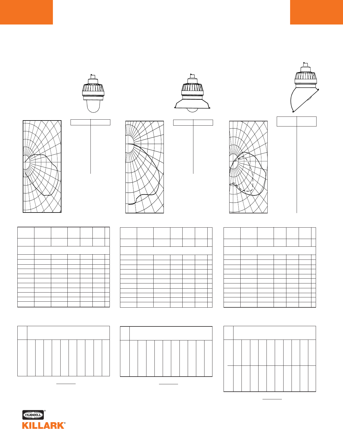
EM/EB/EQ SERIES •LIGHTING
PHOTOMETRIC DATA
L134
Illumination on Horizontal Surface
0
.0
5.0
15.0
25.0
35.0
45.0
55.0
65.0
75.0
85.0
90.0
95.0
105.0
115.0
125.0
135.0
145.0
155.0
165.0
175.0
180.0
13.
14.
21.
31.
48.
60.
66.
66.
63.
57.
52.
48.
37.
24.
13.
2.
0.
0.
0.
0.
0.
% Effective
Ceiling Cavity
Reflectance 1cc
% Wall
Reflectance 1w
Room Cavity
Ratio RCR
.60
.52
.45
.40
.37
.33
.30
.27
.25
.23
.21
.60
.48
.40
.33
.29
.25
.22
.19
.17
.15
.14
.60
.44
.35
.28
.23
.19
.16
.14
.12
.10
.09
.57
.49
.43
.38
.34
.31
.28
.25
.23
.22
.20
.57
.45
.37
.31
.27
.23
.20
.18
.16
.14
.13
.57
.42
.33
.26
.22
.18
.15
.13
.11
.10
.09
.57
.39
.29
.22
.18
.14
.12
.10
.08
.07
.06
.60
.41
.31
.24
.19
.15
.12
.10
.08
.07
.06
.51
.40
.33
.28
.24
.21
.18
.16
.14
.13
.11
.51
.38
.29
.24
.20
.16
.14
.12
.10
.09
.08
.51
.35
.26
.20
.16
.13
.10
.08
.07
.06
.05
.46
.36
.29
.24
.21
.18
.16
.14
.12
.11
.10
.46
.34
.26
.21
.17
.14
.12
.10
.09
.08
.07
.46
.32
.24
.18
.14
.11
.09
.07
.06
.05
.04
.41
.31
.25
.21
.18
.16
.13
.12
.11
.09
.08
.41
.30
.23
.18
.15
.12
.10
.09
.08
.06
.06
.41
.28
.21
.16
.13
.10
.08
.06
.05
.04
.04
.39
.26
.19
.14
.11
.08
.06
.05
.04
.03
.02
0
1
2
3
4
5
6
7
8
9
10
20% Effective Floor Cavity Reflectance
70 50 30 10 70 50 30 10 50 30 10 50 30 10 50 30 10
80 70 50 30 10 0
Coefficients of Utilization -- Zonal Cavity Method
Spacing Criterion -- SC = 3.8
Test No. LTL 00667
10
20
30
40
50
60
120
110
100
90
80
70
60
50
0 10 20 30 40
50
40
30
20
10
180 170 160 150 140 130
FOOTCANDLE CHART (Inital) 100 WATT H.P.S
Horizontal Distance From Source in Feet
Mounting Height in Feet
FC = (Candlepower) (COS Ø)
DISTANCE2
ANGLE CP ANGLE CP
8'
10'
12'
14'
16'
18'
0' 5' 10' 12' 14' 16' 18' 20' 25' 30'
.20
.13
.09
.07
.05
.04
.40
.22
.15
.11
.08
.06
.24
.21
.17
.13
.10
.08
.18
.16
.15
.12
.10
.07
.12
.13
.12
.11
.09
.07
.09
.10
.10
.09
.08
.07
.07
.07
.07
.07
.07
.06
.05
.06
.06
.06
.06
.06
.03
.03
.04
.04
.04
.04
.02
.02
.02
.02
.03
.03
0
% Effective
Ceiling Cavity
Reflectance 1cc
% Wall
Reflectance 1w
Room Cavity
Ratio RCR
.52
.48
.43
.39
.35
.32
.29
.27
.25
.23
.21
.52
.45
.39
.34
.30
.26
.23
.20
.18
.16
.15
.52
.43
.36
.30
.26
.22
.19
.16
.14
.12
.11
.51
.46
.42
.38
.34
.31
.28
.26
.24
.22
.20
.51
.43
.36
.30
.26
.22
.19
.16
.14
.12
.11
.51
.41
.33
.27
.23
.19
.16
.13
.11
.10
.08
.52
.42
.33
.27
.23
.19
.16
.13
.11
.10
.08
.49
.42
.37
.32
.28
.25
.22
.19
.17
.15
.14
.49
.41
.34
.29
.25
.21
.18
.16
.14
.12
.11
.49
.40
.32
.26
.22
.19
.16
.13
.11
.10
.08
.47
.41
.35
.31
.27
.24
.21
.19
.17
.15
.13
.47
.39
.33
.28
.24
.21
.18
.15
.13
.12
.10
.47
.38
.32
.26
.22
.18
.15
.13
.11
.10
.08
.45
.39
.34
.30
.26
.23
.20
.18
.16
.14
.13
.45
.38
.32
.27
.24
.20
.18
.15
.13
.12
.10
.45
.37
.31
.26
.22
.18
.15
.13
.11
.09
.08
.44
.36
.30
.25
.21
.17
.14
.12
.10
.09
.07
0
1
2
3
4
5
6
7
8
9
10
20% Effective Floor Cavity Reflectance
70 50 30 10 70 50 30 10 50 30 10 50 30 10 50 30 10
80 70 50 30 10 0
Coefficients of Utilization -- Zonal Cavity Method
Spacing Criterion -- SC = 1.6
Test No. LTL 00668
15
30
45
60
75
90
110
100
90
80
70
60
50
40
0 10 20 30
30
15
180 160 150 130 120
Illumination on Horizontal Surface
FOOTCANDLE CHART (Inital) 100 WATT H.P.S
Horizontal Distance From Source in Feet
Mounting Height in Feet
FC = (Candlepower) (COS Ø)
DISTANCE2
.0
5.0
15.0
25.0
35.0
45.0
55.0
65.0
75.0
85.0
90.0
95.0
105.0
115.0
125.0
135.0
145.0
155.0
165.0
175.0
180.0
92.
93.
86.
86.
95.
97.
88.
64.
35.
7.
1.
0.
0.
0.
0.
0.
0.
0.
0.
0.
0.
.51
.44
.38
.33
.29
.26
.23
.20
.18
.16
.14
ANGLE CP ANGLE CP
8'
10'
12'
14'
16'
18'
0' 5' 10' 12' 14' 16' 18' 20' 25' 30'
1.44
.92
.64
.47
.36
.28
.88
.61
.47
.37
.29
.24
.35
.34
.30
.26
.22
.18
.22
.24
.24
.21
.19
.16
.14
.17
.18
.17
.16
.14
.10
.12
.14
.14
.13
.12
.07
.07
.10
.11
.11
.10
.05
.06
.07
.08
.09
.09
.02
.03
.04
.04
.05
.05
.00
.01
.02
.02
.03
.03
Test No. LTL 00669
Illumination on Horizontal Surface
0
.0
5.0
15.0
25.0
35.0
45.0
55.0
65.0
75.0
85.0
90.0
95.0
105.0
115.0
125.0
135.0
145.0
155.0
165.0
175.0
180.0
.0
5.0
15.0
25.0
35.0
45.0
55.0
65.0
75.0
85.0
90.0
95.0
105.0
115.0
125.0
135.0
145.0
155.0
165.0
175.0
180.0
36.
27.
35.
53.
81.
106.
121.
126.
123.
113.
106.
97.
77.
54.
32.
12.
1.
0.
0.
0.
0.
36.
37.
46.
58.
70.
81.
81.
68.
60.
52.
46.
41.
30.
19.
8.
0.
0.
0.
0.
0.
0.
% Effective
Ceiling Cavity
Reflectance 1cc
% Wall
Reflectance 1w
Room Cavity
Ratio RCR
.50
.44
.39
.35
.31
.28
.26
.24
.22
.20
.19
.50
.41
.34
.29
.25
.22
.19
.17
.15
.14
.13
.50
.38
.30
.25
.21
.18
.15
.13
.11
.10
.09
.48
.41
.37
.33
.30
.27
.24
.22
.21
.19
.18
.48
.39
.32
.28
.24
.21
.18
.16
.15
.13
.12
.48
.36
.29
.24
.20
.17
.14
.12
.11
.10
.08
.48
.34
.26
.20
.17
.14
.11
.10
.08
.07
.06
.50
.36
.27
.21
.17
.14
.12
.10
.08
.07
.06
.44
.35
.29
.25
.22
.19
.17
.15
.13
.12
.11
.44
.33
.26
.22
.18
.15
.13
.11
.10
.09
.08
.44
.31
.24
.19
.15
.13
.11
.09
.08
.06
.06
.40
.32
.26
.22
.19
.17
.15
.13
.12
.11
.10
.40
.30
.24
.20
.17
.14
.12
.10
.09
.08
.07
.40
.29
.22
.17
.14
.12
.10
.08
.07
.06
.05
.36
.28
.23
.20
.17
.15
.13
.12
.11
.10
.09
.36
.27
.22
.18
.15
.13
.11
.09
.08
.07
.06
.36
.26
.20
.16
.13
.11
.09
.07
.06
.05
.05
.35
.24
.18
.14
.12
.09
.08
.06
.05
.04
.04
0
1
2
3
4
5
6
7
8
9
10
20% Effective Floor Cavity Reflectance
70 50 30 10 70 50 30 10 50 30 10 50 30 10 50 30 10
80 70 50 30 10 0
Coefficients of Utilization -- Zonal Cavity Method
0-DEG / 90-DEG
Spacing Criterion -- SC = 3.2 / 2.7
0
25
50
75
100
120
110
100
90
80
70
60
50
0 10 20 30 40
75
50
25
0
180 170 160 150 140 130
FC = (Candlepower) (COS Ø)
DISTANCE2
FOOTCANDLE CHART (Inital) 100 WATT H.P.S
Horizontal Distance From Source in Feet
Mounting Height in Feet
8'
10'
12'
14'
16'
18'
0' 5' 10' 12' 14' 16' 18' 20' 25' 30'
.56
.36
.25
.18
.14
.11
.69
.38
.26
.19
.13
.10
.43
.37
.29
.22
.17
.14
.32
.30
.26
.21
.16
.13
.24
.24
.22
.19
.15
.13
.17
.18
.18
.16
.15
.12
.13
.14
.14
.14
.13
.11
.10
.11
.12
.12
.11
.10
.05
.06
.07
.07
.07
.07
.03
.04
.04
.05
.05
.04
8'
10'
12'
14'
16'
18'
.56
.36
.25
.18
.14
.11
.63
.41
.29
.22
.17
.13
.31
.29
.24
.19
.16
.13
.22
.21
.20
.17
.14
.12
.14
.16
.15
.15
.12
.11
.10
.12
.12
.12
.11
.10
.07
.08
.10
.09
.09
.09
.05
.06
.07
.08
.08
.07
.03
.03
.04
.04
.05
.05
.02
.02
.02
.03
.03
.03
0˚
90˚
0˚
(FRONT)
ANGLE CP
90˚
(SIDE)
ANGLE CP
SIDE
FRONT
FOOTCANDLE CHART (Initial) (1) 13 WATT FLUORESCENT FOOTCANDLE CHART (Initial) (1) 13 WATT FLUORESCENT FOOTCANDLE CHART (Initial) (1) 13 WATT FLUORESCENT
EBF13/EQF SERIES FLUORESCENT
With Globe Only
One 13 Watt Bi-Pin Base
or one 26/32/42 Quad-Pin
CANDLEPOWER – (1) 13 WATT
PL lamp 900 lumens
For 26 watt quad-pin
multiply by 2.0
For 32 watt quad-pin
multiply by 2.66
For 42 watt quad-pin
multiply by 3.55
EBF13/EQF SERIES FLUORESCENT
With Globe and Angle Reflector
One 13 Watt Bi-Pin Base
or one 26/32/42 Quad-Pin
CANDLEPOWER – (1) 13 WATT
PL lamp 900 lumens
For 26 watt quad-pin
multiply by 2.0
For 32 watt quad-pin
multiply by 2.66
For 42 watt quad-pin
multiply by 3.55
EBF13/EQF SERIES FLUORESCENT
With Globe and Standard Dome Reflector
One 13 Watt Bi-Pin Base
or one 26/32/42 Quad-Pin
CANDLEPOWER – (1) 13 WATT
PL lamp 900 lumens
For 26 watt quad-pin
multiply by 2.0
For 32 watt quad-pin
multiply by 2.66
For 42 watt quad-pin
multiply by 3.55
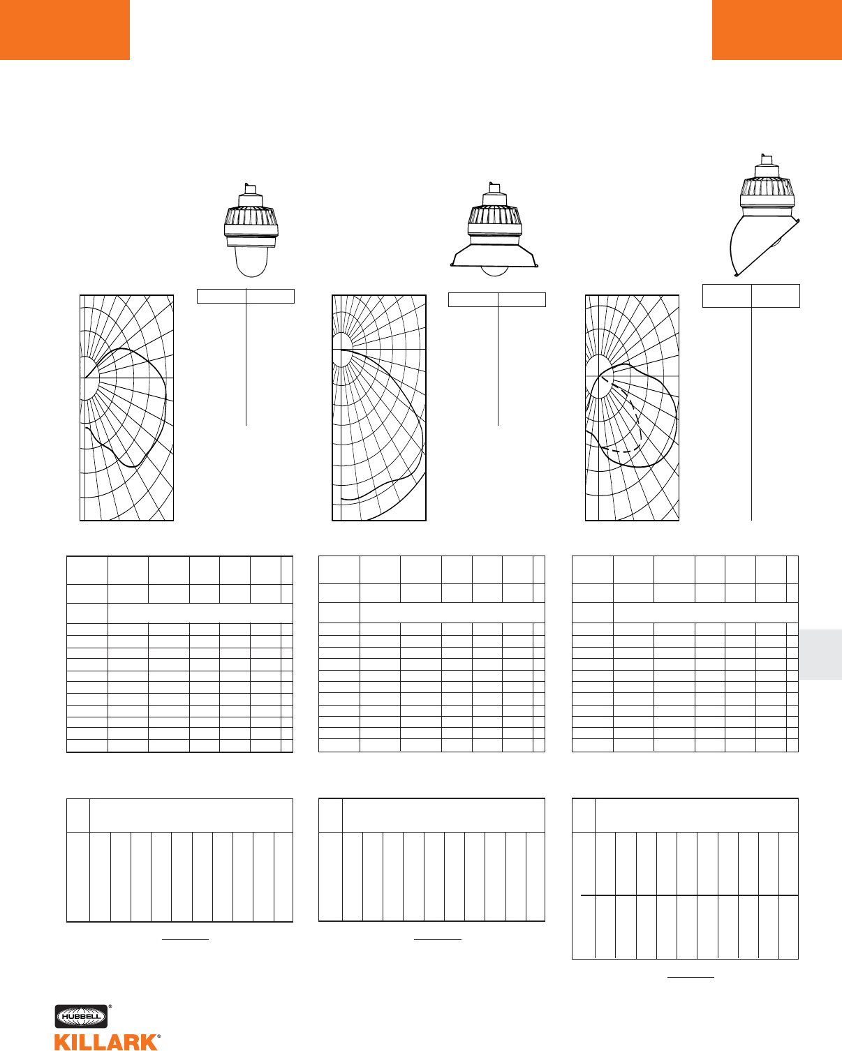
EM/EB/EQ SERIES •LIGHTING
PHOTOMETRIC DATA L135
L
Test No. LTL 00682
0
% Effective
Ceiling Cavity
Reflectance 1cc
% Wall
Reflectance 1w
Room Cavity
Ratio RCR
.52
.44
.39
.35
.31
.28
.26
.23
.22
.20
.18
.52
.41
.34
.29
.25
.22
.19
.17
.15
.13
.12
.52
.38
.30
.24
.20
.17
.14
.12
.10
.09
.08
.49
.42
.37
.32
.29
.26
.24
.22
.20
.19
.17
.49
.36
.28
.23
.19
.16
.13
.11
.10
.09
.08
.49
.34
.25
.19
.16
.13
.10
.08
.07
.06
.05
.52
.36
.26
.20
.16
.13
.11
.09
.07
.06
.05
.44
.34
.28
.24
.21
.18
.16
.14
.12
.11
.10
.44
.32
.25
.20
.17
.14
.12
.10
.09
.08
.07
.44
.30
.23
.17
.14
.11
.09
.07
.06
.05
.04
.39
.30
.25
.21
.18
.16
.14
.12
.11
.10
.09
.39
.29
.22
.18
.15
.12
.10
.09
.08
.07
.06
.39
.27
.20
.15
.13
.10
.08
.07
.05
.05
.04
.35
.27
.22
.18
.16
.13
.12
.10
.09
.08
.07
.35
.25
.20
.16
.13
.11
.09
.08
.07
.06
.05
.35
.24
.18
.14
.11
.09
.07
.06
.05
.04
.03
.33
.22
.16
.12
.09
.07
.06
.04
.04
.03
.02
0
1
2
3
4
5
6
7
8
9
10
20% Effective Floor Cavity Reflectance
70 50 30 10 70 50 30 10 50 30 10 50 30 10 50 30 10
80 70 50 30 10 0
Coefficients of Utilization -- Zonal Cavity Method
Spacing Criterion -- SC = 3.5
0
25
50
75
100
120
110
100
90
80
70
60
50
0 10 20 30 40
50
25
0
180 170 160 150 140 130
Illumination on Horizontal Surface
FOOTCANDLE CHART (Inital) 100 WATT H.P.S
Horizontal Distance From Source in Feet
Mounting Height in Feet
FC = (Candlepower) (COS Ø)
DISTANCE2
.0
5.0
15.0
25.0
35.0
45.0
55.0
65.0
75.0
85.0
90.0
95.0
105.0
115.0
125.0
135.0
145.0
155.0
165.0
175.0
180.0
28.
29.
40.
58.
82.
100.
110.
111.
106.
96.
90.
82.
63.
44.
24.
7.
1.
0.
0.
0.
0.
.49
.39
.32
.27
.23
.20
.18
.16
.14
.12
.11
ANGLE CP ANGLE CP
8'
10'
12'
14'
16'
18'
0' 5' 10' 12' 14' 16' 18' 20' 25' 30'
.44
.28
.19
.14
.11
.09
.71
.41
.28
.21
.15
.11
.40
.35
.29
.22
.17
.14
.29
.27
.24
.20
.16
.13
.21
.22
.20
.18
.15
.13
.15
.16
.16
.15
.14
.12
.12
.13
.13
.13
.12
.11
.09
.10
.10
.10
.10
.09
.05
.06
.06
.06
.07
.07
.03
.03
.04
.04
.04
.05
Test No. LTL 00683
Illumination on Horizontal Surface
0
.0
5.0
15.0
25.0
35.0
45.0
55.0
65.0
75.0
85.0
90.0
95.0
105.0
115.0
125.0
135.0
145.0
155.0
165.0
175.0
180.0
189.
193.
191.
190.
204.
205.
188.
136.
74.
15.
1.
0.
0.
0.
0.
0.
0.
0.
0.
0.
0.
% Effective
Ceiling Cavity
Reflectance 1cc
% Wall
Reflectance 1w
Room Cavity
Ratio RCR
.56
.51
.46
.42
.38
.35
.31
.29
.26
.24
.22
.56
.49
.42
.36
.32
.28
.25
.22
.20
.17
.16
.56
.46
.39
.32
.28
.24
.20
.17
.15
.13
.12
.55
.50
.45
.40
.37
.33
.30
.28
.26
.24
.22
.55
.47
.41
.36
.31
.28
.24
.21
.19
.17
.16
.55
.46
.38
.32
.27
.23
.20
.17
.15
.13
.12
.55
.44
.36
.29
.24
.20
.17
.14
.12
.11
.09
.56
.45
.36
.39
.35
.20
.17
.14
.12
.11
.09
.52
.45
.39
.34
.30
.27
.23
.21
.19
.17
.15
.52
.44
.37
.31
.27
.23
.20
.17
.15
.13
.11
.52
.42
.35
.28
.24
.20
.17
.14
.12
.10
.09
.50
.44
.38
.33
.29
.26
.23
.20
.18
.16
.15
.50
.42
.36
.30
.26
.22
.19
.17
.15
.13
.11
.50
.41
.34
.28
.24
.20
.17
.14
.12
.10
.09
.48
.42
.36
.32
.28
.25
.22
.19
.17
.16
.14
.48
.41
.35
.29
.25
.22
.19
.16
.14
.13
.11
.48
.40
.33
.27
.23
.20
.17
.14
.12
.10
.09
.47
.39
.32
.26
.22
.19
.16
.13
.11
.09
.08
0
1
2
3
4
5
6
7
8
9
10
20% Effective Floor Cavity Reflectance
70 50 30 10 70 50 30 10 50 30 10 50 30 10 50 30 10
80 70 50 30 10 0
Coefficients of Utilization -- Zonal Cavity Method
Spacing Criterion -- SC = 1.6
25
50
75
100
125
150
175
200
110
100
90
80
70
50
40
0 10 20 30
50
25
180 160 140 130 120
FOOTCANDLE CHART (Inital) 100 WATT H.P.S
Horizontal Distance From Source in Feet
Mounting Height in Feet
FC = (Candlepower) (COS Ø)
DISTANCE2
ANGLE CP ANGLE CP
8'
10'
12'
14'
16'
18'
0' 5' 10' 12' 14' 16' 18' 20' 25' 30'
2.95
1.89
1.31
.96
.73
.58
1.85
1.36
1.04
.81
.65
.53
.75
.72
.64
.56
.46
.41
.50
.52
.50
.45
.41
.34
.31
.37
.38
.37
.34
.31
.21
.28
.29
.29
.28
.26
.14
.18
.22
.23
.23
.22
.09
.13
.15
.18
.19
.18
.04
.06
.08
.10
.12
.11
.02
.03
.04
.05
.06
.07
Test No. LTL 00684
0
% Effective
Ceiling Cavity
Reflectance 1cc
% Wall
Reflectance 1w
Room Cavity
Ratio RCR
.49
.44
.40
.36
.33
.30
.27
.25
.23
.21
.20
.49
.41
.36
.31
.27
.24
.21
.19
.17
.15
.14
.49
.39
.32
.27
.23
.20
.17
.15
.13
.12
.10
.48
.42
.38
.34
.31
.29
.26
.24
.22
.21
.19
.48
.38
.32
.27
.23
.20
.17
.15
.13
.12
.10
.48
.36
.29
.24
.20
.17
.14
.12
.11
.09
.08
.49
.37
.30
.24
.20
.17
.15
.12
.11
.09
.08
.45
.38
.32
.28
.25
.22
.20
.18
.16
.14
.13
.45
.36
.30
.25
.22
.19
.16
.14
.13
.11
.10
.45
.35
.28
.23
.19
.16
.14
.12
.10
.09
.08
.42
.36
.31
.27
.24
.21
.19
.17
.15
.14
.12
.42
.34
.29
.24
.21
.18
.16
.14
.12
.11
.10
.42
.33
.27
.22
.19
.16
.14
.12
.10
.09
.08
.40
.33
.29
.25
.22
.20
.18
.16
.14
.13
.12
.40
.32
.27
.23
.20
.17
.15
.13
.12
.10
.09
.40
.31
.26
.21
.18
.15
.13
.11
.10
.09
.07
.39
.30
.25
.20
.17
.14
.12
.10
.09
.08
.07
0
1
2
3
4
5
6
7
8
9
10
20% Effective Floor Cavity Reflectance
70 50 30 10 70 50 30 10 50 30 10 50 30 10 50 30 10
80 70 50 30 10 0
Coefficients of Utilization -- Zonal Cavity Method
0-DEG / 90-DEG
Spacing Criterion -- SC = 2.3 / 1.8
50
100
150
200
250
120
110
100
90
80
70
60
50
40
0 10 20 30
150
100
50
180 170 160 150 140 130
Illumination on Horizontal Surface
FC = (Candlepower) (COS Ø)
DISTANCE2
.0
5.0
15.0
25.0
35.0
45.0
55.0
65.0
75.0
85.0
90.0
95.0
105.0
115.0
125.0
135.0
145.0
155.0
165.0
175.0
180.0
.0
5.0
15.0
25.0
35.0
45.0
55.0
65.0
75.0
85.0
90.0
95.0
105.0
115.0
125.0
135.0
145.0
155.0
165.0
175.0
180.0
155.
166.
190.
211.
242.
264.
274.
269.
238.
189.
161.
132.
75.
27.
4.
0.
0.
0.
0.
0.
0.
155.
155.
160.
171.
188.
174.
130.
78.
35.
10.
4.
1.
0.
0.
0.
0.
0.
0.
0.
0.
0.
.48
.40
.35
.30
.27
.23
.21
.19
.17
.15
.14
FOOTCANDLE CHART (Inital) 100 WATT H.P.S
Horizontal Distance From Source in Feet
Mounting Height in Feet
8'
10'
12'
14'
16'
18'
0' 5' 10' 12' 14' 16' 18' 20' 25' 30'
2.42
1.55
1.08
.79
.60
.48
3.53
1.51
1.11
.85
.66
.30
1.02
.93
.80
.66
.55
.46
.73
.70
.65
.56
.48
.34
.52
.54
.51
.48
.42
.37
.38
.41
.41
.39
.36
.33
.28
.28
.32
.32
.30
.29
.21
.24
.26
.26
.26
.25
.11
.13
.15
.16
.17
.17
.06
.08
.09
.10
.11
.11
8'
10'
12'
14'
16'
18'
2.42
1.55
1.08
.79
.60
.48
1.73
1.22
.91
.70
.55
.44
.58
.61
.57
.52
.43
.37
.35
.40
.43
.40
.38
.32
.20
.25
.29
.31
.30
.29
.13
.18
.21
.23
.24
.23
.08
.12
.15
.17
.18
.19
.05
.05
.10
.12
.14
.15
.02
.03
.04
.06
.07
.08
.00
.02
.02
.03
.04
.04
0˚
90˚
0˚
(FRONT)
ANGLE CP
90˚
(SIDE)
ANGLE CP
SIDE
FRONT
FOOTCANDLE CHART (Initial) (2) 13 WATT FLUORESCENT FOOTCANDLE CHART (Initial) (2) 13 WATT FLUORESCENT
FOOTCANDLE CHART (Initial) (2) 13 WATT FLUORESCENT
EBF26 FLUORESCENT
With Globe Only
Two 13 Watt Bi-Pin Base
CANDLEPOWER – (2) 13 WATT
PL lamps
900 lumens per lamp
EBF26 FLUORESCENT
With Globe and Angle Reflector
Two 13 Watt Bi-Pin Base
CANDLEPOWER – (2) 13 WATT
PL lamps
900 lumens per lamp
EBF26 FLUORESCENT
With Globe and Standard Dome Reflector
Two 13 Watt Bi-Pin Base
CANDLEPOWER – (2) 13 WATT
PL lamps
900 lumens per lamp
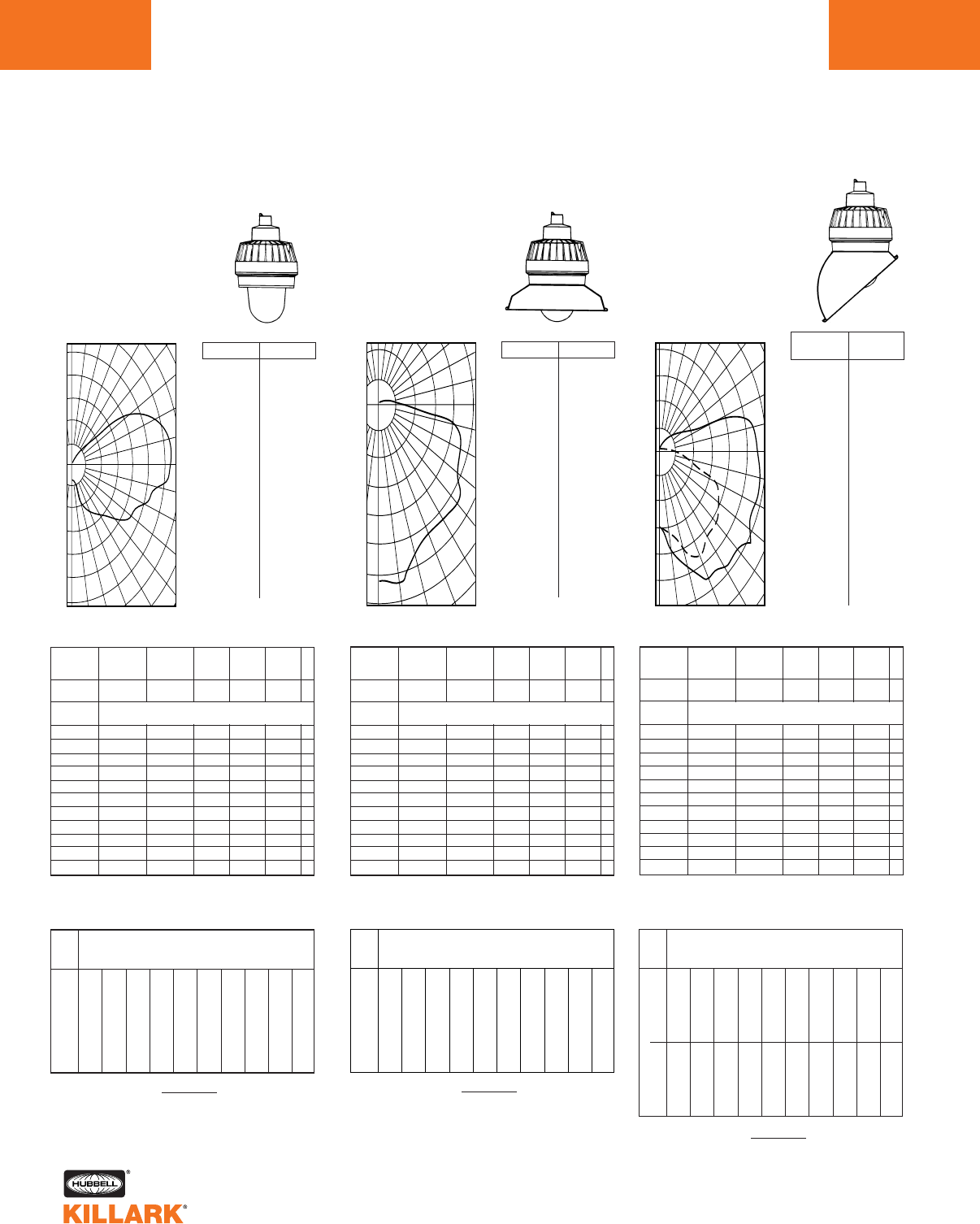
EM/EB/EQ SERIES •LIGHTING
PHOTOMETRIC DATA
L136
Illumination on Horizontal Surface
0
.0
5.0
10.0
15.0
20.0
25.0
30.0
35.0
40.0
45.0
50.0
55.0
60.0
65.0
70.0
75.0
80.0
85.0
90.0
95.0
100.0
105.0
110.0
115.0
120.0
125.0
130.0
135.0
140.0
145.0
150.0
155.0
160.0
165.0
170.0
175.0
180.0
80.
84.
108.
148.
202.
262.
298.
321.
352.
397.
444.
467.
471.
540.
562.
603.
618.
633.
644.
651.
635.
624.
581.
505.
250.
23.
8.
3.
3.
1.
0.
0.
0.
0.
0.
0.
0.
% Effective
Ceiling Cavity
Reflectance 1cc
% Wall
Reflectance 1w
Room Cavity
Ratio RCR
.85
.72
.64
.57
.51
.46
.42
.39
.36
.33
.31
.85
.67
.55
.47
.41
.35
.31
.27
.25
.22
.20
.85
.62
.48
.39
.33
.27
.23
.20
.18
.15
.14
.79
.67
.58
.52
.47
.42
.39
.36
.33
.30
.28
.79
.62
.51
.43
.37
.32
.28
.25
.23
.20
.19
.79
.58
.45
.36
.30
.25
.21
.19
.16
.14
.13
.79
.54
.39
.31
.25
.20
.16
.14
.12
.10
.09
.85
.57
.42
.33
.27
.21
.18
.15
.13
.11
.10
.69
.53
.43
.37
.32
.27
.24
.21
.19
.17
.16
.69
.50
.38
.31
.26
.21
.18
.16
.14
.12
.11
.69
.46
.34
.26
.21
.17
.14
.12
.10
.08
.07
.60
.45
.36
.30
.26
.22
.20
.18
.16
.14
.13
.60
.42
.32
.26
.21
.18
.15
.13
.11
.10
.09
.60
.40
.29
.22
.18
.14
.11
.09
.08
.07
.06
.51
.37
.30
.25
.21
.18
.16
.14
.13
.11
.10
.51
.35
.26
.21
.17
.14
.12
.10
.09
.08
.07
.51
.33
.24
.18
.14
.11
.09
.07
.06
.05
.04
.47
.29
.20
.15
.11
.08
.07
.05
.04
.03
.03
0
1
2
3
4
5
6
7
8
9
10
20% Effective Floor Cavity Reflectance
70 50 30 10 70 50 30 10 50 30 10 50 30 10 50 30 10
80 70 50 30 10 0
Coefficients of Utilization -- Zonal Cavity Method
Spacing Criterion -- SC = 4.3
Test No. BALL 6686.0
100
200
300
400
500
600
120
110
100
90
80
70
60
50
0 10 20 30 40
500
400
300
200
100
180 170 160 150 140 130
FOOTCANDLE CHART (Inital) 100 WATT H.P.S
Horizontal Distance From Source in Feet
Mounting Height in Feet
FC = (Candlepower) (COS Ø)
DISTANCE2
ANGLE CP ANGLE CP
8'
10'
12'
14'
16'
18'
0' 5' 10' 12' 14' 16' 18' 20' 25' 30'
1.25
.80
.55
.41
.31
.25
2.94
1.87
1.21
.86
.57
.41
1.69
1.40
1.11
.88
.74
.61
1.24
1.16
.97
.77
.64
.55
.90
.92
.85
.71
.59
.50
.73
.70
.69
.62
.55
.45
.56
.54
.55
.54
.48
.43
.43
.47
.44
.45
.42
.39
.25
.28
.30
.28
.29
.29
.16
.18
.19
.21
.19
.20
Illumination on Horizontal Surface
0
% Effective
Ceiling Cavity
Reflectance 1cc
% Wall
Reflectance 1w
Room Cavity
Ratio RCR
.66
.58
.52
.47
.42
.38
.35
.32
.30
.27
.25
.66
.54
.46
.39
.34
.30
.27
.24
.21
.19
.17
.66
.51
.41
.34
.29
.24
.21
.18
.16
.14
.12
.64
.55
.49
.44
.40
.36
.33
.31
.28
.26
.24
.64
.52
.44
.38
.33
.29
.26
.23
.20
.18
.17
.64
.49
.39
.33
.28
.23
.20
.18
.16
.14
.12
.64
.46
.35
.29
.24
.19
.16
.14
.12
.10
.09
.66
.48
.36
.29
.24
.20
.17
.14
.12
.11
.09
.59
.48
.40
.35
.31
.27
.24
.21
.19
.17
.16
.59
.46
.37
.31
.26
.22
.19
.17
.15
.13
.11
.59
.43
.33
.27
.22
.18
.16
.13
.12
.10
.09
.55
.44
.37
.32
.28
.25
.22
.20
.18
.16
.14
.55
.42
.34
.29
.24
.21
.18
.16
.14
.12
.11
.55
.40
.31
.26
.21
.18
.15
.13
.11
.09
.08
.51
.41
.34
.30
.26
.23
.20
.18
.16
.15
.13
.51
.39
.32
.27
.23
.19
.17
.15
.13
.11
.10
.51
.38
.30
.24
.20
.17
.14
.12
.10
.09
.08
.50
.36
.28
.22
.19
.15
.13
.11
.09
.08
.07
0
1
2
3
4
5
6
7
8
9
10
20% Effective Floor Cavity Reflectance
70 50 30 10 70 50 30 10 50 30 10 50 30 10 50 30 10
80 70 50 30 10 0
Coefficients of Utilization -- Zonal Cavity Method
0-DEG / 90-DEG
Spacing Criterion -- SC = 2.53 / 1.87
Test No. BALL 6688.0
150
300
450
600
750
120
110
100
90
80
70
60
50
0 10 20 30 40
600
450
300
150
180 170 160 150 140 130
FC = (Candlepower) (COS Ø)
DISTANCE2
FOOTCANDLE CHART (Inital) 100 WATT H.P.S
Horizontal Distance From Source in Feet
Mounting Height in Feet
8'
10'
12'
14'
16'
18'
0' 5' 10' 12' 14' 16' 18' 20' 25' 30'
7.33
4.69
3.26
2.39
1.83
1.45
9.07
6.05
4.11
3.11
2.31
1.81
3.67
3.44
3.04
2.57
2.27
1.97
2.69
2.53
2.39
2.16
1.87
1.69
1.89
1.98
1.85
1.76
1.61
1.43
1.39
1.50
1.46
1.40
1.34
1.25
1.04
1.13
1.20
1.15
1.10
1.03
.79
.89
.94
.97
.92
.89
.44
.51
.56
.59
.65
.62
.26
.31
.35
.38
.40
.42
8'
10'
12'
14'
16'
18'
7.33
4.69
3.26
2.39
1.83
1.45
6.88
5.27
3.59
2.72
1.91
1.50
2.45
2.39
2.06
1.96
1.74
1.52
1.64
1.69
1.66
1.46
1.43
1.30
1.12
1.20
1.23
1.22
1.09
1.06
.81
.90
.93
.95
.93
.84
.60
.67
.73
.75
.74
.74
.34
.52
.55
.59
.61
.59
.15
.17
.32
.35
.37
.38
.02
.12
.13
.22
.24
.25
0˚
90˚
.0
5.0
15.0
25.0
35.0
45.0
55.0
65.0
75.0
85.0
90.0
95.0
105.0
115.0
125.0
135.0
145.0
155.0
165.0
175.0
180.0
.0
5.0
15.0
25.0
35.0
45.0
55.0
65.0
75.0
85.0
90.0
95.0
105.0
115.0
125.0
135.0
145.0
155.0
165.0
175.0
180.0
469.
520.
655.
846.
937.
974.
1011.
993.
994.
955.
915.
786.
120.
39.
0.
0.
0.
0.
0.
0.
0.
469.
479.
543.
736.
713.
677.
614.
578.
84.
21.
0.
0.
0.
0.
0.
0.
0.
0.
0.
0.
0.
0˚
(FRONT)
ANGLE CP
90˚
(SIDE)
ANGLE CP
SIDE
FRONT
FOOTCANDLE CHART (Initial) 70 WATT H.P.S. FOOTCANDLE CHART (Initial) 70 WATT H.P.S.
EMS HIGH PRESSURE SODIUM
With Globe Only
35 – 100 Watt Medium Base
CANDLEPOWER – 70 WATT
B-17 clear lamp 6300 lumens
For 35 watt multiply by .357
For 50 watt multiply by .635
For 100 watt multiply by 1.508
EMS HIGH PRESSURE SODIUM
With Globe and Angle Reflector
35 – 100 Watt Medium Base
CANDLEPOWER – 70 WATT
B-17 clear lamp 6300 lumens
For 35 watt multiply by .357
For 50 watt multiply by .635
For 100 watt multiply by 1.508
0
% Effective
Ceiling Cavity
Reflectance 1cc
% Wall
Reflectance 1w
Room Cavity
Ratio RCR
.76
.69
.61
.55
.50
.45
.41
.38
.34
.32
.29
.76
.65
.55
.47
.41
.36
.31
.28
.25
.22
.20
.76
.62
.50
.41
.35
.29
.25
.22
.19
.16
.15
.74
.67
.59
.53
.48
.43
.40
.36
.33
.31
.29
.74
.61
.49
.41
.34
.29
.25
.22
.19
.16
.15
.74
.59
.45
.36
.30
.24
.20
.17
.15
.13
.11
.76
.60
.46
.37
.30
.24
.20
.17
.15
.13
.11
.71
.61
.52
.44
.39
.33
.30
.26
.24
.21
.19
.71
.59
.48
.40
.33
.28
.24
.21
.18
.16
.14
.71
.57
.44
.36
.29
.24
.20
.17
.15
.12
.11
.68
.59
.49
.42
.37
.32
.28
.25
.23
.20
.18
.68
.57
.46
.38
.33
.27
.24
.21
.18
.16
.14
.68
.55
.43
.35
.29
.24
.20
.17
.14
.12
.11
.65
.56
.47
.41
.36
.31
.27
.24
.22
.20
.18
.65
.55
.45
.37
.32
.27
.23
.20
.18
.15
.14
.65
.53
.42
.34
.28
.23
.20
.17
.14
.12
.11
.64
.52
.41
.33
.27
.22
.18
.15
.13
.11
.10
0
1
2
3
4
5
6
7
8
9
10
20% Effective Floor Cavity Reflectance
70 50 30 10 70 50 30 10 50 30 10 50 30 10 50 30 10
80 70 50 30 10 0
Coefficients of Utilization -- Zonal Cavity Method
Spacing Criterion -- SC = 1.3
Test No. BALL 6687.0
150
300
450
600
750
900
1150
110
100
90
80
70
60
50
40
0 10 20 30
300
150
180 160 140 130 120
Illumination on Horizontal Surface
FOOTCANDLE CHART (Inital) 100 WATT H.P.S
Horizontal Distance From Source in Feet
Mounting Height in Feet
FC = (Candlepower) (COS Ø)
DISTANCE2
.0
5.0
10.0
15.0
20.0
25.0
30.0
35.0
40.0
45.0
50.0
55.0
60.0
65.0
70.0
75.0
80.0
85.0
90.0
95.0
100.0
105.0
110.0
115.0
120.0
125.0
130.0
135.0
140.0
145.0
150.0
155.0
160.0
165.0
170.0
175.0
180.0
960.
933.
957.
902.
856.
808.
805.
789.
786.
812.
804.
766.
722.
740.
724.
689.
170.
31.
3.
1.
0.
0.
0.
0.
0.
0.
0.
0.
0.
0.
0.
0.
0.
0.
0.
0.
0.
.74
.64
.54
.46
.40
.35
.31
.27
.24
.22
.20
ANGLE CP ANGLE CP
8'
10'
12'
14'
16'
18'
0' 5' 10' 12' 14' 16' 18' 20' 25' 30'
15.00
9.60
6.67
4.89
3.75
2.96
7.63
5.78
4.54
3.65
2.97
2.49
3.06
2.87
2.47
2.17
2.14
1.66
2.04
2.11
1.99
1.75
1.58
1.41
1.38
1.50
1.54
1.46
1.31
1.19
1.02
1.11
1.18
1.18
1.12
1.01
.77
.83
.91
.92
.92
.89
.58
.65
.68
.74
.76
.75
.31
.38
.42
.43
.45
.47
.18
.23
.26
.28
.29
.30
FOOTCANDLE CHART (Initial) 70 WATT H.P.S.
EMS HIGH PRESSURE SODIUM
With Globe and Standard Dome Reflector
35 – 100 Watt Medium Base
CANDLEPOWER – 70 WATT
B-17 clear lamp 6300 lumens
For 35 watt multiply by .357
For 50 watt multiply by .635
For 100 watt multiply by 1.508
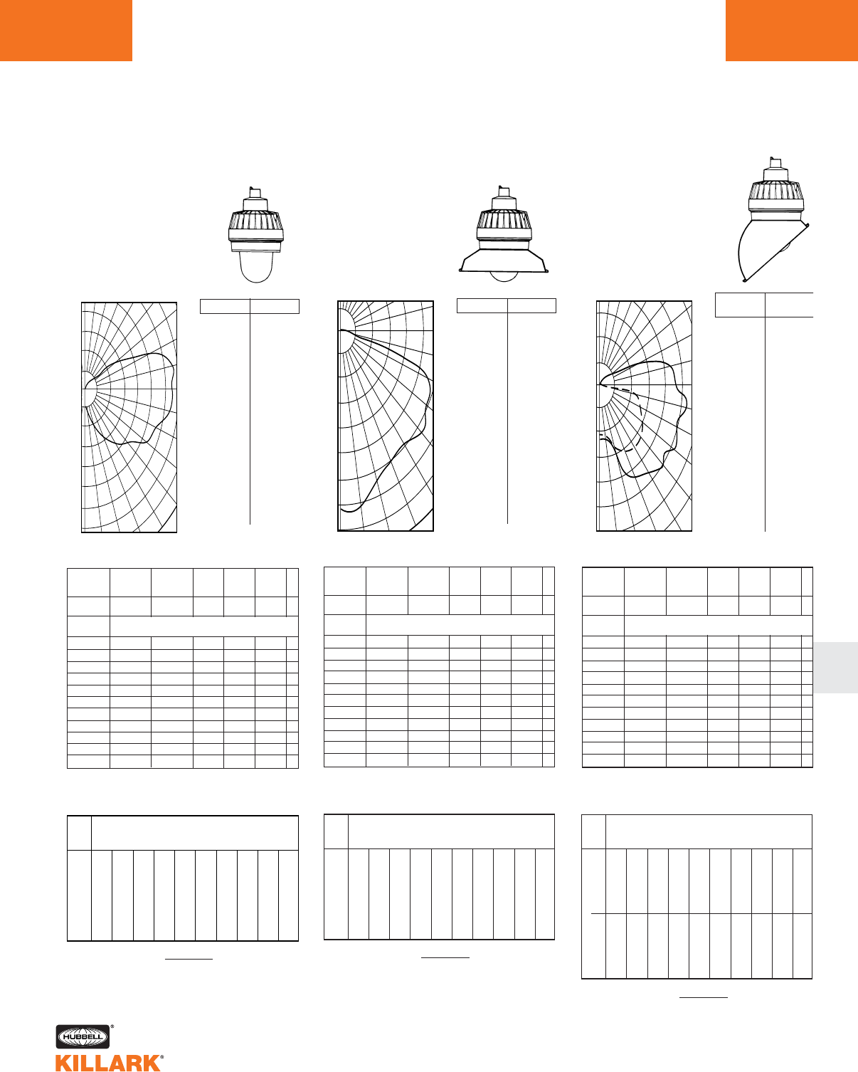
EM/EB/EQ SERIES •LIGHTING
PHOTOMETRIC DATA L137
L
0
% Effective
Ceiling Cavity
Reflectance 1cc
% Wall
Reflectance 1w
Room Cavity
Ratio RCR
.82
.70
.61
.55
.49
.45
.41
.37
.34
.32
.30
.82
.64
.53
.45
.39
.34
.30
.26
.24
.21
.19
.82
.60
.46
.38
.31
.26
.22
.19
.17
.15
.13
.76
.65
.56
.50
.45
.41
.37
.34
.32
.29
.27
.76
.56
.43
.35
.29
.24
.21
.18
.16
.14
.12
.76
.52
.38
.29
.24
.19
.16
.13
.11
.10
.08
.82
.55
.40
.32
.25
.20
.17
.14
.12
.10
.09
.66
.51
.42
.35
.30
.26
.23
.21
.18
.17
.15
.66
.48
.37
.30
.25
.20
.17
.15
.13
.12
.10
.66
.45
.32
.25
.20
.16
.13
.11
.09
.08
.07
.57
.43
.35
.29
.25
.22
.19
.17
.15
.14
.12
.57
.41
.31
.25
.21
.17
.14
.12
.11
.09
.08
.57
.38
.27
.21
.17
.13
.11
.09
.08
.06
.05
.49
.36
.28
.24
.20
.17
.15
.13
.12
.11
.10
.49
.34
.25
.20
.17
.13
.11
.10
.08
.07
.06
.49
.32
.22
.17
.14
.10
.08
.07
.06
.05
.04
.45
.28
.19
.14
.11
.08
.06
.05
.04
.03
.02
0
1
2
3
4
5
6
7
8
9
10
20% Effective Floor Cavity Reflectance
70 50 30 10 70 50 30 10 50 30 10 50 30 10 50 30 10
80 70 50 30 10 0
Coefficients of Utilization -- Zonal Cavity Method
Spacing Criterion -- SC = 4.3
Test No. BALL 6683.0
250
500
750
1000
1250
1500
1750
120
110
100
90
80
70
60
50
0 10 20 30 40
1000
750
500
250
180 170 160 150 140 130
Illumination on Horizontal Surface
FOOTCANDLE CHART (Inital) 100 WATT H.P.S
Horizontal Distance From Source in Feet
Mounting Height in Feet
FC = (Candlepower) (COS Ø)
DISTANCE2
.0
5.0
10.0
15.0
20.0
25.0
30.0
35.0
40.0
45.0
50.0
55.0
60.0
65.0
70.0
75.0
80.0
85.0
90.0
95.0
100.0
105.0
110.0
115.0
120.0
125.0
130.0
135.0
140.0
145.0
150.0
155.0
160.0
165.0
170.0
175.0
180.0
195.
212.
267.
362.
480.
611.
701.
763.
864.
960.
1048.
1117.
1264.
1304.
1374.
1505.
1555.
1568.
1546.
1576.
1596.
1514.
1386.
1150.
685.
245.
25.
10.
3.
2.
0.
0.
0.
0.
0.
0.
0.
.76
.60
.49
.42
.36
.31
.27
.24
.22
.20
.18
ANGLE CP ANGLE CP
8'
10'
12'
14'
16'
18'
0' 5' 10' 12' 14' 16' 18' 20' 25' 30'
3.05
1.95
1.35
.99
.76
.60
7.35
4.37
2.76
2.04
1.31
1.00
3.99
3.39
2.72
2.10
1.70
1.44
2.98
2.75
2.36
1.93
1.53
1.27
2.41
2.19
2.01
1.73
1.44
1.19
1.78
1.71
1.65
1.50
1.32
1.11
1.36
1.45
1.32
1.25
1.18
1.05
1.09
1.14
1.19
1.07
1.00
.95
.62
.67
.73
.75
.70
.69
.40
.43
.48
.50
.51
.53
Illumination on Horizontal Surface
0
.0
5.0
10.0
15.0
20.0
25.0
30.0
35.0
40.0
45.0
50.0
55.0
60.0
65.0
70.0
75.0
80.0
85.0
90.0
95.0
100.0
105.0
110.0
115.0
120.0
125.0
130.0
135.0
140.0
145.0
150.0
155.0
160.0
165.0
170.0
175.0
180.0
2289.
2296.
2282.
2117.
1981.
1921.
1911.
1888.
1898.
1940.
1959.
1898.
1869.
1851.
1763.
1469.
601.
93.
7.
3.
0.
0.
0.
0.
0.
0.
0.
0.
0.
0.
0.
0.
0.
0.
0.
0.
0.
% Effective
Ceiling Cavity
Reflectance 1cc
% Wall
Reflectance 1w
Room Cavity
Ratio RCR
.71
.65
.58
.52
.47
.42
.38
.35
.32
.30
.28
.71
.61
.52
.45
.39
.34
.30
.26
.23
.21
.19
.71
.59
.47
.39
.33
.27
.24
.20
.18
.15
.14
.70
.63
.56
.50
.45
.41
.37
.34
.31
.29
.27
.70
.60
.51
.44
.38
.33
.29
.26
.23
.20
.19
.70
.57
.47
.39
.32
.27
.23
.20
.18
.15
.14
.70
.55
.43
.34
.28
.23
.19
.16
.14
.12
.10
.71
.56
.43
.35
.28
.23
.19
.16
.14
.12
.10
.67
.57
.49
.42
.36
.31
.28
.25
.22
.20
.18
.67
.55
.45
.37
.32
.26
.23
.20
.17
.15
.13
.67
.53
.42
.34
.28
.23
.19
.16
.14
.12
.10
.64
.55
.47
.40
.35
.30
.27
.24
.21
.19
.17
.64
.53
.44
.36
.31
.26
.22
.19
.17
.15
.13
.64
.52
.41
.33
.27
.22
.19
.16
.14
.12
.10
.61
.53
.45
.39
.34
.29
.26
.23
.21
.18
.17
.61
.52
.42
.35
.30
.25
.22
.19
.17
.14
.13
.61
.50
.40
.33
.27
.22
.19
.16
.14
.11
.10
.60
.49
.39
.31
.26
.21
.17
.15
.12
.10
.09
0
1
2
3
4
5
6
7
8
9
10
20% Effective Floor Cavity Reflectance
70 50 30 10 70 50 30 10 50 30 10 50 30 10 50 30 10
80 70 50 30 10 0
Coefficients of Utilization -- Zonal Cavity Method
Spacing Criterion -- SC = 1.3
Test No. BALL 6684.0
300
600
900
1200
1500
1800
2100
2400
100
90
80
70
60
50
40
0 10 20 30
300
180 160 140 120
FOOTCANDLE CHART (Inital) 100 WATT H.P.S
Horizontal Distance From Source in Feet
Mounting Height in Feet
FC = (Candlepower) (COS Ø)
DISTANCE2
ANGLE CP ANGLE CP
8'
10'
12'
14'
16'
18'
0' 5' 10' 12' 14' 16' 18' 20' 25' 30'
35.76
22.89
15.89
11.68
8.94
7.06
18.03
13.74
10.75
8.44
7.10
5.84
7.46
6.86
5.97
5.19
4.54
3.94
5.06
5.14
4.76
4.24
3.78
3.36
3.57
3.73
3.75
3.50
3.16
2.88
2.57
2.82
2.87
2.85
2.68
2.44
1.94
2.14
2.25
2.33
2.24
2.12
1.42
1.66
1.77
1.83
1.86
1.81
.75
.91
1.04
1.11
1.16
1.17
.39
.56
.63
.71
.76
.78
0
% Effective
Ceiling Cavity
Reflectance 1cc
% Wall
Reflectance 1w
Room Cavity
Ratio RCR
.64
.56
.50
.45
.41
.37
.34
.31
.29
.26
.25
.64
.52
.44
.38
.33
.29
.26
.23
.21
.18
.17
.64
.49
.39
.33
.28
.23
.20
.18
.15
.13
.12
.62
.54
.47
.43
.39
.35
.32
.30
.27
.25
.23
.62
.47
.38
.32
.27
.23
.20
.17
.15
.13
.12
.62
.44
.34
.28
.23
.19
.16
.14
.12
.10
.09
.64
.46
.35
.28
.23
.19
.16
.14
.12
.10
.09
.57
.46
.39
.34
.29
.26
.23
.20
.18
.16
.15
.57
.44
.35
.29
.25
.21
.18
.16
.14
.12
.11
.57
.42
.32
.26
.22
.18
.15
.13
.11
.09
.08
.53
.43
.36
.31
.27
.24
.21
.19
.17
.15
.14
.53
.41
.33
.28
.23
.20
.17
.15
.13
.12
.10
.53
.39
.30
.25
.20
.17
.14
.12
.10
.09
.08
.50
.40
.33
.29
.25
.22
.20
.18
.16
.14
.13
.50
.38
.31
.26
.22
.19
.16
.14
.12
.11
.10
.50
.36
.28
.23
.19
.16
.14
.12
.10
.08
.07
.48
.35
.27
.21
.18
.14
.12
.10
.09
.07
.06
0
1
2
3
4
5
6
7
8
9
10
20% Effective Floor Cavity Reflectance
70 50 30 10 70 50 30 10 50 30 10 50 30 10 50 30 10
80 70 50 30 10 0
Coefficients of Utilization -- Zonal Cavity Method
0-DEG / 90-DEG
Spacing Criterion -- SC = 2.53 / 1.87
Test No. BALL 6685.0
500
1000
1500
2000
2500
120
110
100
90
80
70
60
50
0 10 20 30 40
1500
1000
500
180 170 160 150 140 130
Illumination on Horizontal Surface
FC = (Candlepower) (COS Ø)
DISTANCE2
.62
.50
.42
.37
.32
.28
.25
.22
.20
.18
.16
FOOTCANDLE CHART (Inital) 100 WATT H.P.S
Horizontal Distance From Source in Feet
Mounting Height in Feet
8'
10'
12'
14'
16'
18'
0' 5' 10' 12' 14' 16' 18' 20' 25' 30'
18.17
11.63
8.08
5.93
4.54
3.59
21.86
15.18
10.34
7.82
5.63
4.39
9.74
8.76
7.24
6.34
5.46
4.72
6.62
6.71
6.08
5.13
4.62
4.08
4.80
4.87
4.90
4.47
3.85
3.49
3.50
3.70
3.74
3.71
3.42
2.96
2.62
2.88
2.94
3.00
2.89
2.70
1.96
2.24
2.38
2.39
2.43
2.35
1.08
1.26
1.41
1.50
1.52
1.53
.68
.78
.88
.97
1.02
1.06
8'
10'
12'
14'
16'
18'
18.17
11.63
8.08
5.93
4.54
3.59
16.06
11.99
8.62
6.63
4.63
3.63
5.59
5.38
4.76
4.49
4.02
3.50
3.92
3.85
3.74
3.37
3.27
2.93
2.78
2.88
2.81
2.75
2.51
2.44
1.91
2.18
2.20
2.15
2.10
1.95
1.40
1.67
1.74
1.73
1.67
1.66
.74
1.22
1.38
1.41
1.40
1.37
.31
.47
.75
.86
.90
.90
.07
.26
.33
.52
.59
.61
0˚
90˚
.0
5.0
15.0
25.0
35.0
45.0
55.0
65.0
75.0
85.0
90.0
95.0
105.0
115.0
125.0
135.0
145.0
155.0
165.0
175.0
180.0
.0
5.0
15.0
25.0
35.0
45.0
55.0
65.0
75.0
85.0
90.0
95.0
105.0
115.0
125.0
135.0
145.0
155.0
165.0
175.0
180.0
1163.
1259.
1590.
2122.
2308.
2478.
2481.
2506.
2540.
2431.
2307.
1868.
584.
104.
3.
2.
0.
0.
0.
0.
0.
1163
.
1170
.
1315
.
1676
.
1635
.
1523
.
1469
.
1341
.
256
.
32
.
0
.
0
.
0
.
0
.
0
.
0
.
0
.
0
.
0
.
0
.
0
.
0˚ (FRONT)
ANGLE CP
90˚ (SIDE)
ANGLE CP
SIDE
FRONT
FOOTCANDLE CHART (Initial) 150 WATT H.P.S. FOOTCANDLE CHART (Initial) 150 WATT H.P.S. FOOTCANDLE CHART (Initial) 150 WATT H.P.S.
EMS HIGH PRESSURE SODIUM
With Globe Only Reflector
150 Watt Medium Base
CANDLEPOWER – 150 WATT
B-17 clear lamp
16000 lumens
EMS HIGH PRESSURE SODIUM
With Globe and Angle Reflector
150 Watt Medium Base
CANDLEPOWER – 150 WATT
B-17 clear lamp
16000 lumens
EMS HIGH PRESSURE SODIUM
With Globe and Standard Dome Reflector
150 Watt Medium Base
CANDLEPOWER – 150 WATT
B-17 clear lamp
16000 lumens
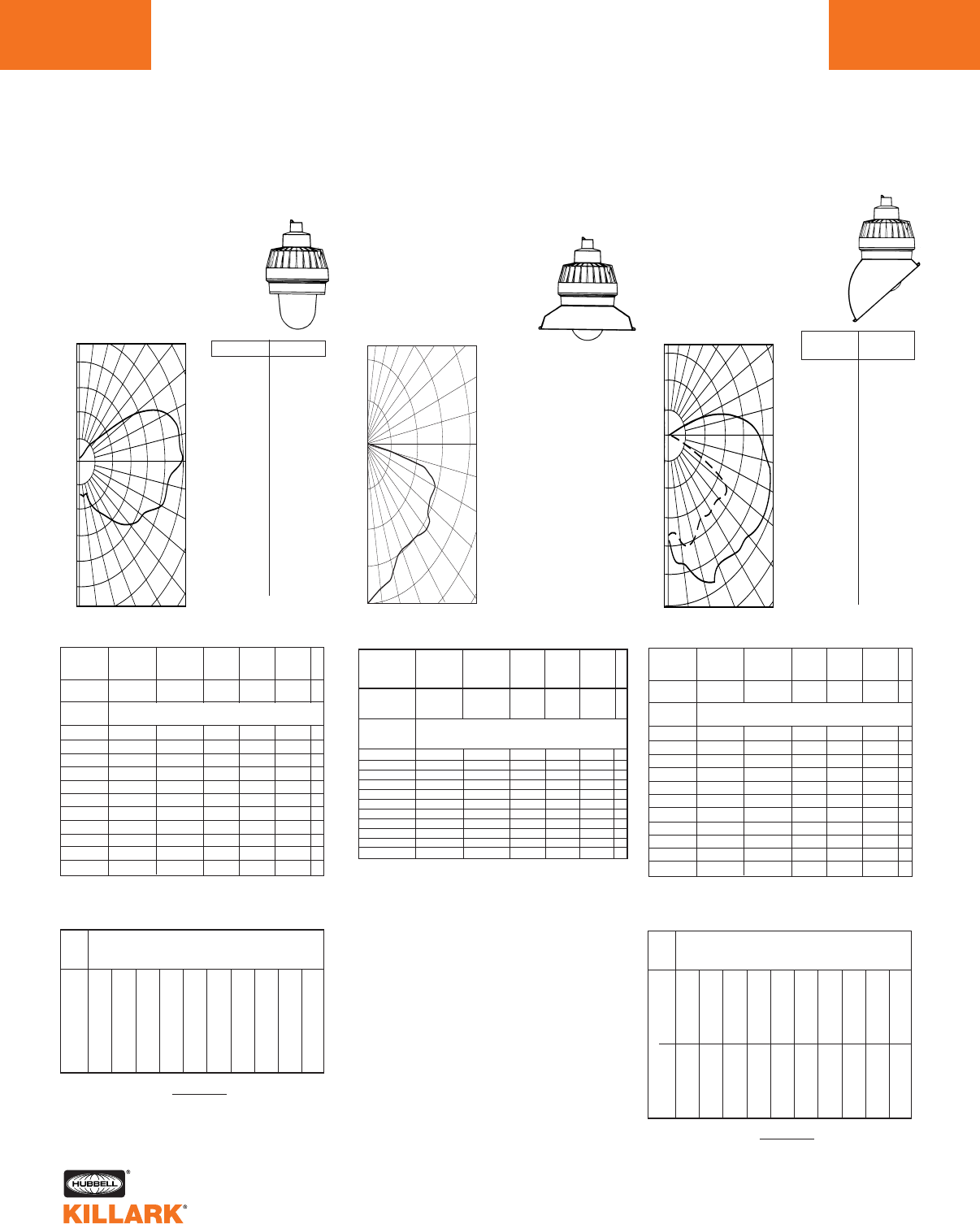
EM/EB/EQ SERIES •LIGHTING
PHOTOMETRIC DATA
L138
Illumination on Horizontal Surface
0
.0
5.0
10.0
15.0
20.0
25.0
30.0
35.0
40.0
45.0
55.0
50.0
65.0
60.0
75.0
70.0
80.0
85.0
90.0
95.0
100.0
105.0
110.0
115.0
120.0
125.0
130.0
135.0
140.0
145.0
150.0
155.0
160.0
165.0
170.0
175.0
180.0
173.
206.
188.
225.
290.
361.
403.
452.
492.
552.
610.
618.
658.
731.
796.
776.
787.
863.
874.
847.
846.
832.
750.
641.
440.
88.
14.
5.
2.
1.
0.
0.
0.
0.
0.
0.
0.
% Effective
Ceiling Cavity
Reflectance 1cc
% Wall
Reflectance 1w
Room Cavity
Ratio RCR
.84
.72
.63
.57
.51
.46
.42
.39
.36
.33
.31
.84
.67
.55
.47
.41
.35
.31
.28
.25
.22
.20
.84
.62
.48
.39
.33
.27
.23
.20
.18
.16
.14
.79
.67
.58
.52
.47
.42
.39
.36
.33
.30
.28
.79
.62
.51
.43
.38
.32
.29
.25
.23
.21
.19
.79
.58
.45
.36
.30
.25
.22
.19
.16
.14
.13
.79
.53
.39
.31
.25
.20
.17
.14
.12
.10
.09
.84
.57
.42
.33
.27
.22
.18
.15
.13
.11
.10
.69
.53
.43
.37
.32
.27
.24
.21
.19
.17
.16
.69
.50
.38
.31
.26
.22
.18
.16
.14
.12
.11
.69
.46
.34
.27
.21
.17
.14
.12
.10
.09
.07
.60
.45
.36
.31
.26
.23
.20
.18
.16
.14
.13
.60
.42
.32
.26
.22
.18
.15
.13
.11
.10
.09
.60
.40
.29
.22
.18
.14
.12
.10
.08
.07
.06
.51
.38
.30
.25
.21
.18
.16
.14
.13
.11
.10
.51
.35
.27
.21
.18
.14
.12
.11
.09
.08
.07
.51
.33
.24
.18
.15
.11
.09
.08
.06
.05
.04
.47
.30
.20
.15
.12
.09
.07
.05
.04
.03
.03
0
1
2
3
4
5
6
7
8
9
10
20% Effective Floor Cavity Reflectance
70 50 30 10 70 50 30 10 50 30 10 50 30 10 50 30 10
80 70 50 30 10 0
Coefficients of Utilization -- Zonal Cavity Method
Spacing Criterion -- SC = 3.4
Test No. BALL 6689.0
150
300
450
600
750
120
110
100
90
80
70
60
50
0 10 20 30 40
600
450
300
150
180 170 160 150 140 130
FOOTCANDLE CHART (Inital) 100 WATT H.P.S
Horizontal Distance From Source in Feet
Mounting Height in Feet
FC = (Candlepower) (COS Ø)
DISTANCE2
ANGLE CP ANGLE CP
8'
10'
12'
14'
16'
18'
0' 5' 10' 12' 14' 16' 18' 20' 25' 30'
2.70
1.73
1.20
.88
.67
.53
3.93
2.58
1.66
1.23
.80
.62
2.32
1.95
1.55
1.24
.98
.83
1.65
1.60
1.35
1.10
.90
.73
1.25
1.21
1.17
.99
.82
.70
1.00
.93
.92
.87
.76
.63
.76
.75
.73
.72
.68
.60
.59
.64
.62
.59
.58
.55
.35
.38
.41
.39
.38
.38
.21
.25
.26
.28
.27
.27
Illumination on Horizontal Surface
0
% Effective
Ceiling Cavity
Reflectance 1cc
% Wall
Reflectance 1w
Room Cavity
Ratio RCR
.61
.54
.48
.43
.39
.36
.33
.30
.28
.25
.24
.61
.50
.42
.37
.32
.28
.25
.22
.20
.18
.16
.61
.47
.38
.32
.27
.23
.20
.17
.15
.13
.12
.59
.51
.46
.41
.37
.34
.31
.28
.26
.24
.23
.59
.48
.41
.35
.31
.27
.24
.21
.19
.17
.16
.59
.46
.37
.31
.26
.22
.19
.17
.15
.13
.11
.59
.43
.33
.27
.22
.18
.15
.13
.11
.10
.08
.61
.44
.34
.27
.23
.19
.16
.14
.12
.10
.09
.55
.45
.38
.33
.29
.25
.22
.20
.18
.16
.15
.55
.42
.34
.29
.24
.21
.18
.16
.14
.12
.11
.55
.40
.31
.25
.21
.17
.15
.13
.11
.09
.08
.51
.41
.35
.30
.26
.23
.21
.18
.17
.15
.14
.51
.40
.32
.27
.23
.19
.17
.15
.13
.11
.10
.51
.38
.29
.24
.20
.16
.14
.12
.10
.09
.08
.48
.38
.32
.28
.24
.21
.19
.17
.15
.14
.13
.48
.37
.30
.25
.21
.18
.16
.14
.12
.11
.10
.48
.35
.28
.23
.19
.16
.13
.11
.10
.08
.07
.46
.34
.26
.21
.17
.14
.12
.10
.09
.07
.06
0
1
2
3
4
5
6
7
8
9
10
20% Effective Floor Cavity Reflectance
70 50 30 10 70 50 30 10 50 30 10 50 30 10 50 30 10
80 70 50 30 10 0
Coefficients of Utilization -- Zonal Cavity Method
0-DEG / 90-DEG
Spacing Criterion -- SC = 2.25 / 1.58
Test No. BALL 6703.0
150
300
450
600
750
1000
120
110
100
90
80
70
60
50
0 10 20 30 40
450
300
150
180 160 150 140 130
FC = (Candlepower) (COS Ø)
DISTANCE2
FOOTCANDLE CHART (Inital) 100 WATT H.P.S
Horizontal Distance From Source in Feet
Mounting Height in Feet
8'
10'
12'
14'
16'
18'
0' 5' 10' 12' 14' 16' 18' 20' 25' 30'
11.58
7.41
5.14
3.78
2.89
2.29
11.82
7.86
5.61
4.31
3.21
2.56
4.86
4.38
3.81
3.43
2.96
2.55
3.48
3.35
3.04
2.70
2.50
2.22
2.39
2.56
2.44
2.23
2.02
1.88
1.75
1.93
1.95
1.85
1.71
1.56
1.32
1.43
1.55
1.52
1.45
1.35
1.01
1.12
1.18
1.26
1.22
1.17
.55
.64
.71
.74
.80
.80
.32
.40
.45
.48
.51
.52
8'
10'
12'
14'
16'
18'
11.58
7.41
5.14
3.78
2.89
2.29
7.52
6.40
4.54
3.47
2.57
2.05
2.73
2.74
2.38
2.13
1.88
1.62
2.04
1.88
1.90
1.69
1.55
1.40
1.32
1.50
1.37
1.40
1.26
1.17
.62
1.12
1.13
1.03
1.07
.97
.47
.79
.90
.86
.84
.85
.16
.40
.65
.73
.68
.67
.04
.11
.25
.41
.46
.47
.02
.04
.07
.17
.28
.29
0˚
90˚
.0
5.0
15.0
25.0
35.0
45.0
55.0
65.0
75.0
85.0
90.0
95.0
105.0
115.0
125.0
135.0
145.0
155.0
165.0
175.0
180.0
.0
5.0
15.0
25.0
35.0
45.0
55.0
65.0
75.0
85.0
90.0
95.0
105.0
115.0
125.0
135.0
145.0
155.0
165.0
175.0
180.0
741.
775.
928.
1099.
1249.
1239.
1305.
1258.
1218.
1262.
1119.
938.
163.
54.
0.
0.
0.
0.
0.
0.
0.
741.
692.
744.
895.
776.
776.
764.
454.
70.
2.
0.
0.
0.
0.
0.
0.
0.
0.
0.
0.
0.
5
0˚ (FRONT)
ANGLE CP
90˚ (SIDE)
ANGLE CP
SIDE
FRONT
FOOTCANDLE CHART (Initial) 100 WATT METAL HALIDE
FOOTCANDLE CHART (Initial) 100 WATT METAL HALIDE
EMH (MH) AND EMM (MV)
With Globe Only
50 – 100 Watt Medium Base
CANDLEPOWER – 100 WATT MH
B-17 clear lamp 8500 lumens
For 70 watt M.H. multiply by .647
For 50 watt M.H. multiply by .447
For 100 watt M.V. multiply by .518
For 75 watt M.V. multiply by .353
For 50 watt M.V. multiply by .129
EMH (MH) AND EMM (MV)
With Globe and Angle Reflector
50 – 100 Watt Medium Base
CANDLEPOWER – 100 WATT MH
B-17 clear lamp 8500 lumens
For 70 watt M.H. multiply by .647
For 50 watt M.H. multiply by .447
For 100 watt M.V. multiply by .518
For 75 watt M.V. multiply by .353
For 50 watt M.V. multiply by .129
Test No. BAL 6702
Test No. BAL 6689.0
Test No. BAL 6703.0
EMH (MH) AND EMM (MV)
With Globe and Standard Dome
Reflector 50 – 100 Watt Medium Base
CANDLEPOWER – 100 WATT MH
B-17 clear lamp 8500 lumens
For 70 watt M.H. multiply by .647
For 50 watt M.H. multiply by .447
For 100 watt M.V. multiply by .518
For 75 watt M.V. multiply by .353
For 50 watt M.V. multiply by .129
Efficiency 60.6%
694
1041
1388
90˚
80˚
70˚
60˚
50˚
40˚30˚20˚10˚0˚
180˚ 160˚ 150˚ 140˚ 130˚ 120˚
110˚
100˚
347
% EFFECTIVE
CEILING CAVITY
REFLECTANCE
1cc
80 70 50 30 10 0
70 50 30 10 70 50 30 10 50 30 10 50 30 10 50 30 10 0
20% Effective Floor Cavity Reflectance
0 .72 .72 .72 .72 .70 .70 .70 .70 .67 .67 .67 .64.64 .64 .62 .62 .62 .61
1 .65 .61 .58 .55 .63 .60.57 .54 .57 .55 .53 .55.53 .51 .52 .51 .49 .48
2 .58 .52 .47 .43 .56 .50 .46 .42 .48 .44 .41 .46.43 .40 .44 .41 .39 .38
3 .52 .44 .38 .34 .50 .43.38 .33 .41 .37 .33 .39.36 .32 .38 .34 .32 .30
4.47 .38 .32 .28 .45 .37 .32 .27 .36 .31 .27 .34.30 .27 .33 .29 .26 .25
5 .42 .34 .28 .23 .41 .33.27 .23 .32 .27 .23 .30.26 .22 .29 .25 .22 .21
6 .39 .30 .24 .20 .38 .29 .24 .20 .28 .23 .19 .27 .23 .19 .26 .22 .19 .18
7 .36 .27 .21 .17 .35 .26.21 .17 .25 .20 .17 .25.20 .17 .24 .20 .17 .15
8 .33 .24 .19 .15 .32 .24 .19 .15 .23 .18 .15 .22 .18 .15 .22 .18 .15 .13
9 .31 .22 .17 .13 .30 .22 .17 .13 .21 .17 .13 .21 .16 .13 .20 .16 .13 .12
10 .29 .21 .15 .12 .28 .20 .15 .12 .20 .15 .12 .19.15 .12 .18 .15 .12 .11
% WALL
REFLECTANCE
1w
ROOM CAVITY
RATIO
RCR
COEFFICIENTS OF UTILIZATION ---ZONAL CAVITY METHOD
SPACING TO MOUNTING HEIGHT RATIO - 1.12
ANGLE CP ANGLE CP
01388. 95.0 2.
5.0 1323. 100.0 1.
10.0 1257. 105.0 0.
15.0 1225. 110.0 0.
20.0 1102. 115.0 0.
25.0 1032. 120.0 0.
30.0 1033. 125.0 0.
35.0 1037. 130.0 0.
40.0 1048. 135.0 0.
45.0 1075. 140.0 0.
50.0 1073. 145.0 0.
55.0 1006. 150.0 0.
60.0 982. 155.0 0.
65.0 999. 160.0 0.
70.0 992. 165.0 0.
75.0 792. 170.0 0.
80.0 210. 175.0 0.
85.0 48. 180.0 0.
90.0 7.
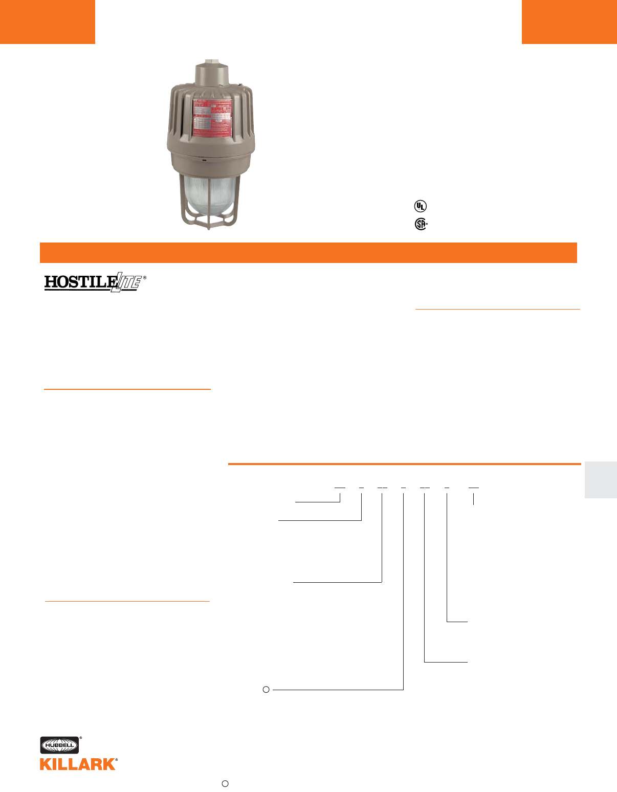
EZ SERIES •LIGHTING
MOGUL BASE HID FIXTURES L139
FEATURES-SPECIFICATIONS
L
Listed - File E10514 and E91793
Certified - File LR11713
Class I, Div. 1 & 2 Groups C,D
Class l, Zone 1 & 2, Groups llB,llA
Class l, Zone 1, AEx d IIB
Class II, Div. 1 & 2, Groups E,F,G
Class III, Div. 1 & 2
Suitable for wet locations
Marine
NEMA 3, 4, 4X
Factory Sealed
Applications
HOSTILELITE®EZ Series mogul base
fixtures are designed for installations
where moisture, dirt, dust, corrosion
and vibration may be present, or NEMA
3 and 4x areas where wind, water,
snow or high ambients can be ex-
pected. They can be used in locations
made hazardous due to the presence
of flammable or explosive gases,
vapors and combustible dusts as
defined by the NEC.
Typical applications include classified
areas such as paint manufacturing
plants, ammunition facilities, oil and
gas producing and refining plants,
off-shore and dockside installations,
tank farms, pipeline pumping stations
and marine loading and fuel transfer
terminals.
Features
• Four light sources—High Pressure
Sodium (50-400W), Metal Halide (70-
400W), Pulse Start Metal Halide (175-
400W) and Mercury Vapor
(100-400W)
• HOSTILELITE® EZ fixtures are now
available with Pulse Start Metal
Halide ballasts
• Mounting choice—Pendant, ceiling,
25˚ stanchion or 90˚ wall mount, all
with “wireless” design that allows fast,
easy fixture installation or removal for
maintenance. See pages L180-181 for
trunnion mounted fixtures
• Factory sealed—No external seal
needed. Simply wire mounting cap
and thread on fixture to install
• Corrosion resistant—Copper-free alu-
minum die cast construction. Baked
powder epoxy finish, electrostatically
applied. Exposed hardware is 316
grade stainless steel
• Accessories—Available with or with-
out guard, standard dome or angle
reflector
• Options—EZ Series fixtures can be
specified with instant restart for HPS
Catalog Number Logic
Series Constant
Lamp Type
S—High Pressure Sodium
H—Metal Halide
M—Mercury Vapor
P—Pulse Start Metal Halide
Lamp Wattage
05—50 Watt HPS
07—70 Watt HPS/MH
10—100 Watt HPS/MH/MV
15—150 Watt HPS
17—175 Watt MH/MV/MHP
25—250 Watt HPS/MH/MV/MHP
32—320 Watt MHP
35—350 Watt MHP
40—400 Watt HPS/MH/MV/MHP
Voltage
0—Quadri-Volt, 60 Hz. (120, 208, 240, 277)
5—480 Volts, 60 Hz.
6—TriTap Canada (120, 277, 347), 60 Hz.
7—220V, 60Hz
8—220/240 Volt, 50 Hz.
9—Special (Specify)
Options
Q—Auxiliary Quartz
Standby
R—Instant Restrike
(150W HPS Max)
BP—Ballast Protector
PS—Paint Spray
(50, 70, 100W HPS,
100W MV, 70, 100, MH)
EB—Eyebolts1
SU103—Assembled w/Lamp
Guard
G—Omit G if guard
is not required
Mounting Type
A2—3/4" Pendant
A3—1" Pendant
X2—3/4" Ceiling
X3—1" Ceiling
B2—3/4" Bracket
B3—1" Bracket
D4—1-1/4"/1-1/2" Stanchion
EZ 0 00 0 00 0 - 00(CEN*)
lamps, auxiliary quartz circuit, ballast
protector, and fuse kits. (See page
L144 for details)
Compliances
• UL-844 Electric Lighting Fixtures for
use in Hazardous Locations
• UL Marine Type Electric Lighting
Fixtures
• UL-1572 Standard for HID Lighting
Fixtures
• CSA C22.2 no. 137-M1981 Electric
Luminaires for use in Hazardous
Locations
• CSA C22.2 no. 94-1976 Special
purpose enclosure
• NEMA 3, 4, 4x, 7CD, 9EFG
*CEN (CENELEC) Approved option available on some models. See page L148 for more information.
1Two eyebolts plus 12” of connecting chain included. Can be used with VMSC10 on page L77.
Consult factory for available lamp and voltage combinations.
HOSTILELITE®EZ fixtures are now
available with Pulse Start Metal Halide
ballasts. Pulse Start systems provide
higher and better maintained light out-
put with longer life compared standard
metal halide systems. Pulse start and
standard Metal Halide lamps and bal-
lasts are not interchangeable.
V
V
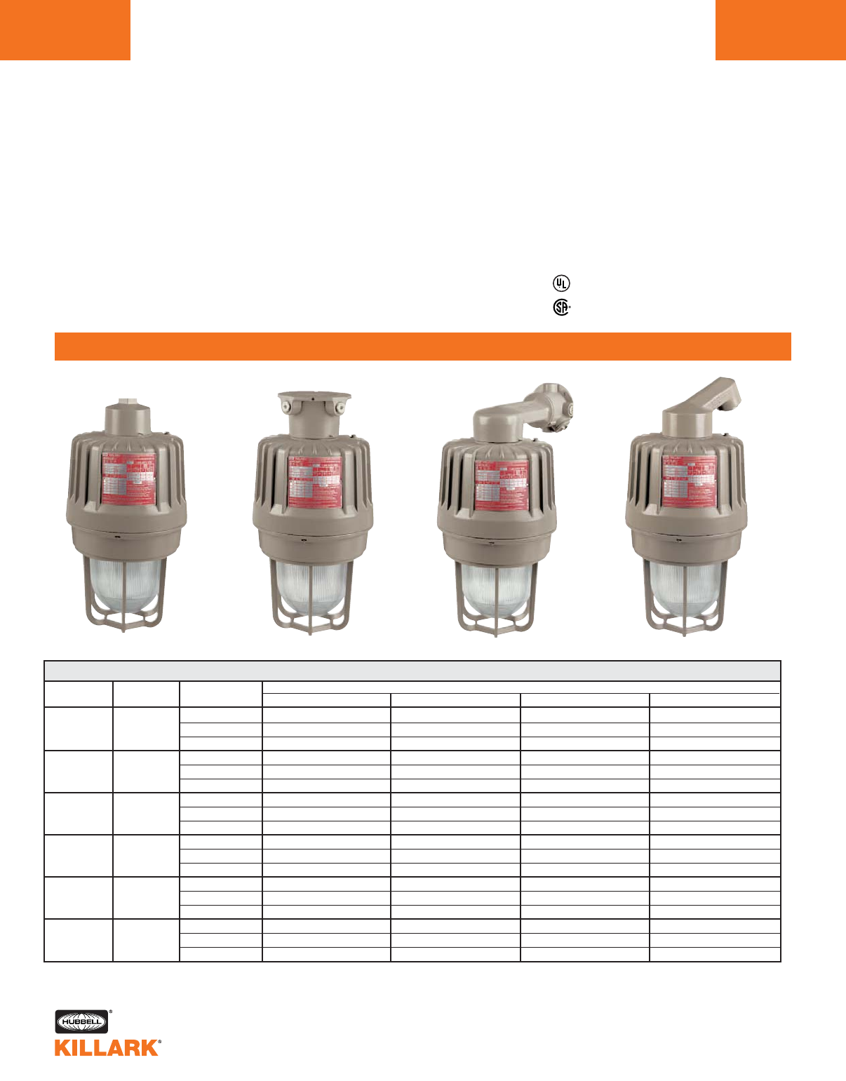
EZ SERIES •LIGHTING
HIGH PRESSURE SODIUM 50-400W MOGUL BASE HID
L140
ORDERING INFORMATION
120, 208, 240, 277 EZS050A2G EZS050X2G EZS050B2G EZS050D4G
50 120, 277, 347 ————
480 ————
120, 208, 240, 277 EZS070A2G EZS070X2G EZS070B2G EZS070D4G
70 120, 277, 347 EZS076A2G EZS076X2G EZS076B2G EZS076D4G
480 EZS075A2G EZS075X2G EZS075B2G EZS075D4G
120, 208, 240, 277 EZS100A2G EZS100X2G EZS100B2G EZS100D4G
100 120, 277, 347 EZS106A2G EZS106X2G EZS106B2G EZS106D4G
480 EZS105A2G EZS105X2G EZS105B2G EZS105D4G
120, 208, 240, 277 EZS150A2G EZS150X2G EZS150B2G EZS150D4G
150 120, 277, 347 EZS156A2G EZS156X2G EZS156B2G EZS156D4G
480 EZS155A2G EZS155X2G EZS155B2G EZS155D4G
120, 208, 240, 277 EZS250A2G EZS250X2G EZS250B2G EZS250D4G
250 120, 277, 347 EZS256A2G EZS256X2G EZS256B2G EZS256D4G
480 EZS255A2G EZS255X2G EZS255B2G EZS255D4G
120, 208, 240, 277 EZS400A2G EZS400X2G EZS400B2G EZS400D4G
400 120, 277, 347 EZS406A2G EZS406X2G EZS406B2G EZS406D4G
480 EZS405A2G EZS405X2G EZS405B2G EZS405D4G
ANSI
LAMP
S-68
S-62
S-54
S-55
S-50
S-51
EZ 50-400 WATT, HIGH PRESSURE SODIUM 14
CATALOG NUMBER
PENDANT 3/4"2CEILING 3/4"2WALL 3/4"2STANCHION 1-1/4"3
WATTS VOLTAGE @ 60Hz
Listed - File E10514 and E91793 (Marine)
Certified - File LR11713
Class I, Div. 1 & 2 Groups C,D
Class l, Zone 1 & 2, Groups llB,llA
Class l, Zone 1, AEx d IIB
Class II, Div. 1 & 2, Groups E,F,G
Class III, Div. 1 & 2
Suitable for wet locations
Marine
NEMA 3, 4, 4X
Factory Sealed
1See Hazardous Location Application Data on pages L148-149 for specific suitabilities.
2For 1 inch pendant, ceiling and wall hubs, substitute “3” for “2” in catalog number; example: EZS070A3G.
3Stanchion conduit hub size supplied is 1-1/2" with 1-1/2" to 1-1/4" reducer for 1-1/4" mounting. (Refer to catalog logic).
4Luminaire catalog numbers include guards. To order luminaire without guard, omit last letter “G” from catalog number.
NOTE: Reflectors must be ordered separately (see page L145).
All luminaires are designed for mounting with lamp in base up position.
Pendant Ceiling Wall Stanchion
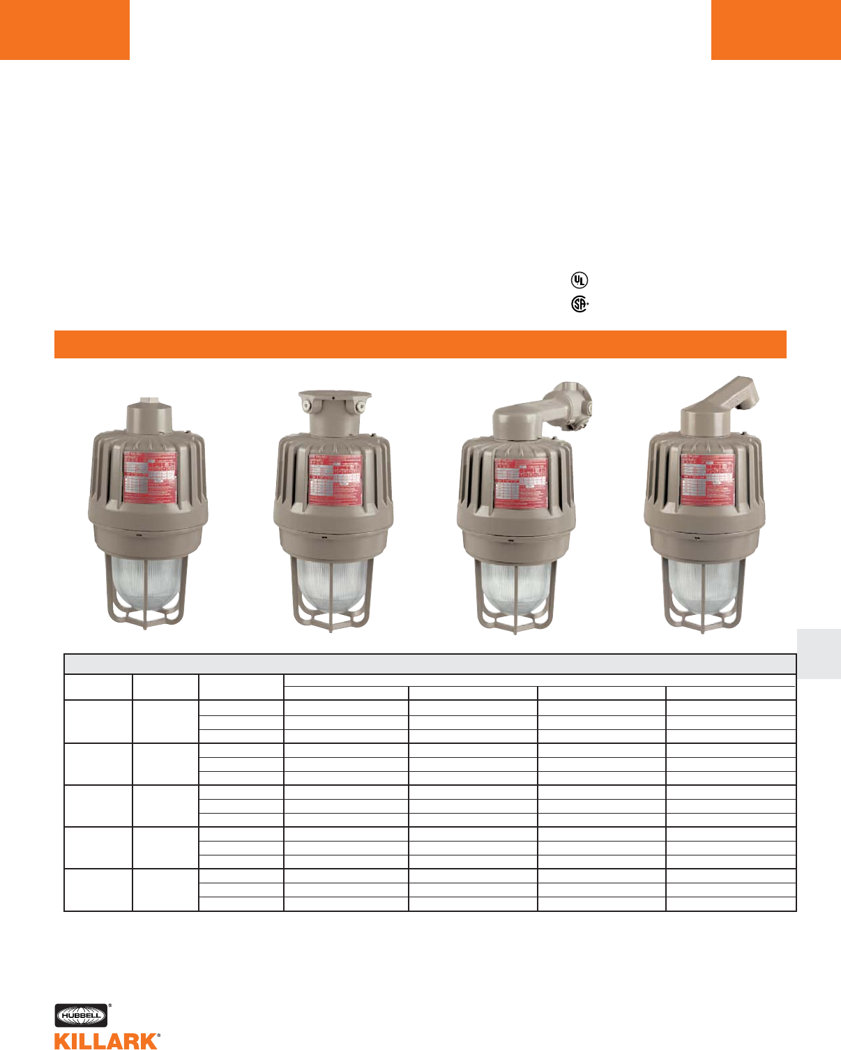
EZ SERIES •LIGHTING
METAL HALIDE 70-400W MOGUL BASE HID L141
ORDERING INFORMATION
L
Listed - File E10514 and E91793 (Marine)
Certified - File LR11713
Class I, Div. 1 & 2 Groups C,D
Class l, Zone 1 & 2, Groups llB,llA
Class l, Zone 1, AEx d IIB
Class II, Div. 1 & 2, Groups E,F,G
Class III, Div. 1 & 2
Suitable for wet locations
Marine
NEMA 3, 4, 4X
Factory Sealed
120, 208, 240, 277 EZH070A2G EZH070X2G EZH070B2G EZH070D4G
70 120, 277,347 EZH076A2G EZH076X2G EZH076B2G EZH076D4G
480 EZH075A2G EZH075X2G EZH075B2G EZH075D4G
120, 208, 240, 277 EZH100A2G EZH100X2G EZH100B2G EZH100D4G
100 120, 277,347 EZH106A2G EZH106X2G EZH106B2G EZH106D4G
480 EZH105A2G EZH105X2G EZH105B2G EZH105D4G
120, 208, 240, 277 EZH170A2G EZH170X2G EZH170B2G EZH170D4G
175 120, 277,347 EZH176A2G EZH176X2G EZH176B2G EZH176D4G
480 EZH175A2G EZH175X2G EZH175B2G EZH175D4G
120, 208, 240, 277 EZH250A2G EZH250X2G EZH250B2G EZH250D4G
250 120, 277,347 EZH256A2G EZH256X2G EZH256B2G EZH256D4G
480 EZH255A2G EZH255X2G EZH255B2G EZH255D4G
120, 208, 240, 277 EZH400A2G EZH400X2G EZH400B2G EZH400D4G
400 120, 277,347 EZH406A2G EZH406X2G EZH406B2G EZH406D4G
480 EZH405A2G EZH405X2G EZH405B2G EZH405D4G
ANSI
LAMP
M-98
M-90
M-575
M-58
M-59
EZ 70-400 WATT, METAL HALIDE 14
CATALOG NUMBER
PENDANT 3/4"2CEILING 3/4"2WALL 3/4"2STANCHION 1-1/4"3
WATTS VOLTAGE @ 60HZ
1See Hazardous Location Application Data on pages L148-149 for specific suitabilities.
2For 1 inch pendant, ceiling and wall hubs, substitute “3” for “2” in catalog number; example: EZH070A3G.
3Stanchion conduit hub size supplied is 1-1/2" with 1-1/2" to 1-1/4" reducer for 1-1/4" mounting. (Refer to catalog logic).
4Luminaire catalog numbers include guards. To order luminaire without guard, omit last letter “G” from catalog number.
5Will also operate 150W M107 Metal Halide Lamps.
NOTE: Reflectors must be ordered separately (see page L145).
All luminaires are designed for mounting with lamp in base up position.
Pendant Ceiling Wall Stanchion

120, 208, 240, 277 EZP150A2G EZP150X2G EZP150B2G EZP150D4G
150 120,277,347 EZP156A2G EZP156X2G EZP156B2G EZP156D4G
480 EZP155A2G EZP155X2G EZP155B2G EZP155D4G
120, 208, 240, 277 EZP170A2G EZP170X2G EZP170B2G EZP170D4G
175 120,277,347 EZP176A2G EZP176X2G EZP176B2G EZP176D4G
480 EZP175A2G EZP175X2G EZP175B2G EZP175D4G
120, 208, 240, 277 EZP250A2G EZP250X2G EZP250B2G EZP250D4G
250 120,277,347 EZP256A2G EZP256X2G EZP256B2G EZP256D4G
480 EZP255A2G EZP255X2G EZP255B2G EZP255D4G
120, 208, 240, 277 EZP320A2G EZP320X2G EZP320B2G EZP320D4G
320 120,277,347 EZP326A2G EZP326X2G EZP326B2G EZP326D4G
480 EZP325A2G EZP325X2G EZP325B2G EZP325D4G
120, 208, 240, 277 EZP350A2G EZP350X2G EZP350B2G EZP350D4G
350 120,277,347 EZP356A2G EZP356X2G EZP356B2G EZP356D4G
480 EZP355A2G EZP355X2G EZP355B2G EZP355D4G
120, 208, 240, 277 EZP400A2G EZP400X2G EZP400B2G EZP400D4G
400 120,277,347 EZP406A2G EZP406X2G EZP406B2G EZP406D4G
480 EZP405A2G EZP405X2G EZP405B2G EZP405D4G
EZ 175-400 WATT, PULSE START METAL HALIDE 14
EZ SERIES •LIGHTING
PULSE START METAL HALIDE 175-400W MOGUL BASE HID
L142
ORDERING INFORMATION
Listed - File E10514 and E91793 (Marine)
Certified - File LR11713
Class I, Div. 1 & 2 Groups C,D
Class l, Zone 1 & 2, Groups llB,llA
Class l, Zone 1, AEx d IIB
Class II, Div. 1 & 2, Groups E,F,G
Class III, Div. 1 & 2
Suitable for wet locations
Marine
NEMA 3, 4, 4X
Factory Sealed
ANSI
LAMP
CATALOG NUMBER
VOLTAGE @ 60Hz PENDANT 3/4"2CEILING 3/4"2WALL 3/4"2STANCHION 1-1/4"3
1See Hazardous Location Application Data on pages L148-149 for specific suitabilities.
2For 1 inch pendant, ceiling and wall hubs, substitute “3” for “2” in catalog number; example: EZP170A3G.
3Stanchion conduit hub size supplied is 1-1/2" with 1-1/2" to 1-1/4" reducer for 1-1/4" mounting. (Refer to catalog logic).
4Luminaire catalog numbers include guards. To order luminaire without guard, omit last letter “G” from catalog number.
NOTE: Reflectors must be ordered separately (see page L145).
All luminaires are designed for mounting with lamp in base up position.
Pendant Ceiling Wall Stanchion
WATTS
M-102
M-142
M-137
M-138
M-132
M-131
M-135
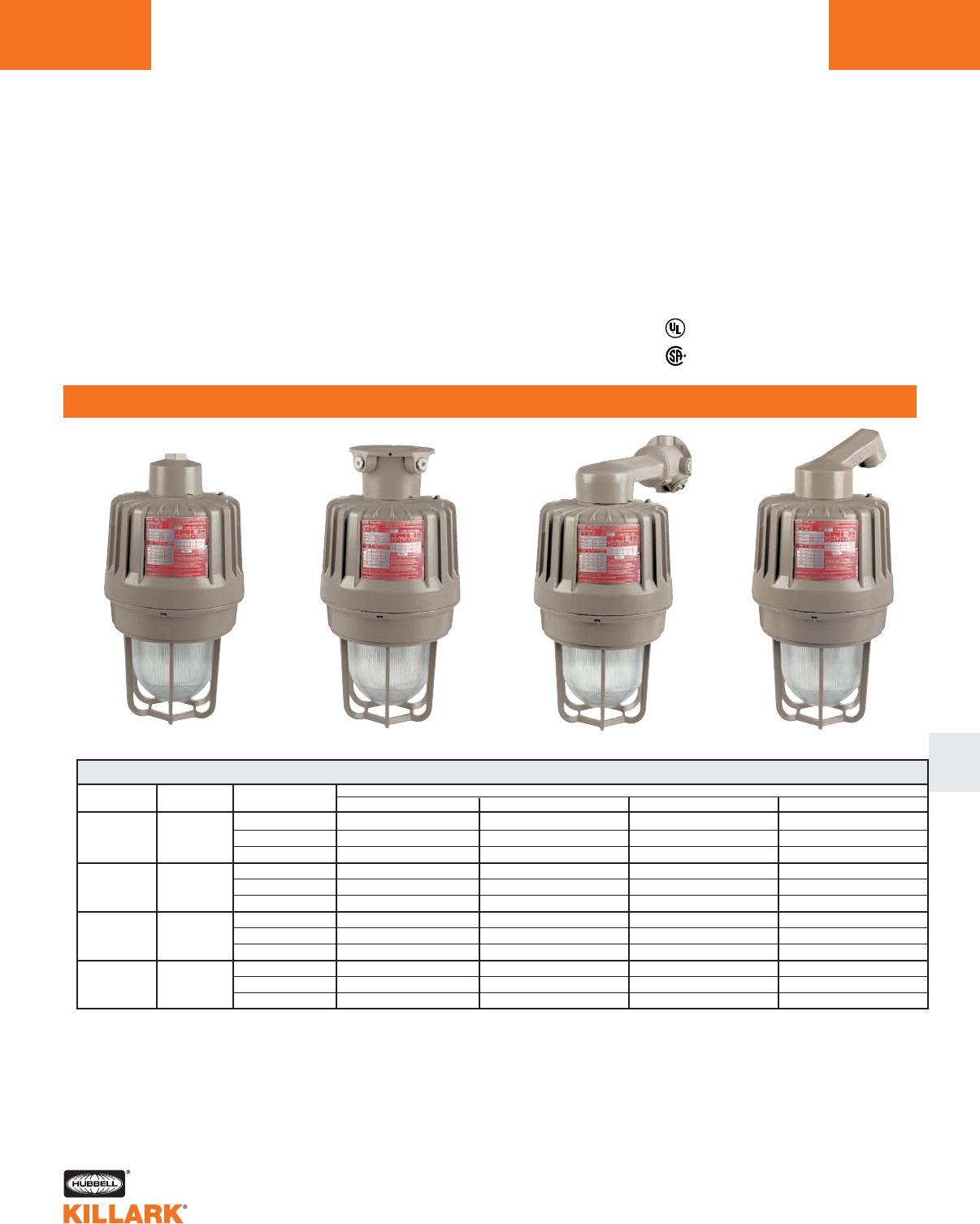
EZ SERIES •LIGHTING
MERCURY VAPOR 100-400W MOGUL BASE HID L143
ORDERING INFORMATION
L
ANSI
LAMP
H-38
H-39
H-37
H-33
EZ 175-400 WATT, MERCURY VAPOR14
120, 208, 240, 277 EZM100A2G EZM100X2G EZM100B2G EZM100D4G
100 120, 277, 347 EZM106A2G EZM106X2G EZM106B2G EZM106D4G
480 EZM105A2G EZM105X2G EZM105B2G EZM105D4G
120, 208, 240, 277 EZM170A2G EZM170X2G EZM170B2G EZM170D4G
175 120, 277, 347 EZM176A2G EZM176X2G EZM176B2G EZM176D4G
480 EZM175A2G EZM175X2G EZM175B2G EZM175D4G
120, 208, 240, 277 EZM250A2G EZM250X2G EZM250B2G EZM250D4G
250 120, 277, 347 EZM256A2G EZM256X2G EZM256B2G EZM256D4G
480 EZM255A2G EZM255X2G EZM255B2G EZM255D4G
120, 208, 240, 277 EZM400A2G EZM400X2G EZM400B2G EZM400D4G
400 120, 277, 347 EZM406A2G EZM406X2G EZM406B2G EZM406D4G
480 EZM405A2G EZM405X2G EZM405B2G EZM405D4G
CATALOG NUMBER
Listed - File E10514 and E91793 (Marine)
Certified - File LR11713
Class I, Div. 1 & 2 Groups C,D
Class l, Zone 1 & 2, Groups llB,llA
Class l, Zone 1, AEx d IIB
Class II, Div. 1 & 2, Groups E,F,G
Class III, Div. 1 & 2
Suitable for wet locations
Marine
NEMA 3, 4, 4X
Factory Sealed
1See Hazardous Location Application Data on pages L148-149 for specific suitabilities.
2For 1 inch pendant, ceiling and wall hubs, substitute “3” for “2” in catalog number. Example: EZM070A3G.
3Stanchion conduit hub size supplied is 1-1/2" with 1-1/2" to 1-1/4" reducer for 1-1/4" mounting. (Refer to catalog logic).
4Luminaire catalog numbers include guards. To order luminaire without guard, omit last letter “G” from catalog number.
NOTE: Reflectors must be ordered separately (see page L145).
All luminaires are designed for mounting with lamp in base up position.
Pendant Ceiling Wall Stanchion
PENDANT 3/4"2CEILING 3/4"2WALL 3/4"2STANCHION 1-1/4"3
WATTS VOLTAGE @ 60Hz
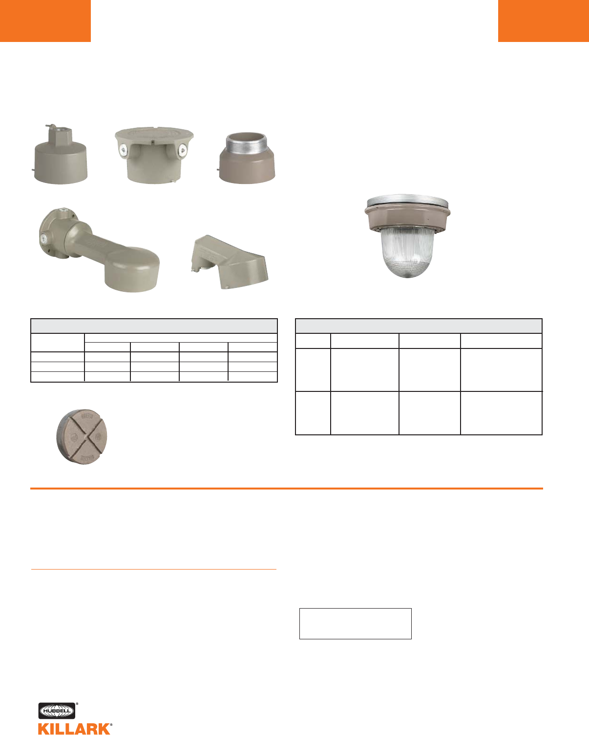
EZ SERIES •LIGHTING
COMPONENT PARTS/ACCESSORIES/OPTIONS •HID FIXTURES
L144
EZ Options
Instant Restart Option
Factory installed special ignitor provides hot lamp instant
restart of HPS lamps after power interruption of up to
1 minute. Available for 50, 70, 100 and 150 watt HPS lamps
only. Add suffix “R” to fixture catalog number (50/60 Hz).
Quartz Emergency Lamp
Factory installed special auxiliary quartz relay and D.C. bayo-
net base socket installed to accept 100 watt, 120 volt quartz
(100Q/DC) lamps only. Lamps not supplied. Refer to
Hazardous Location Application Data chart to verify suitability.
Add suffix “Q” to fixture catalog number.
Ballast Protection Cutout
Optional factory installed special ballast protector replaces
the standard HPS ignitor and applies starting pulse to the
lamp for 10 to 15 seconds each time voltage is supplied to
the ballast. If the lamp has not ignited by the end of the time
period, the starter will cease pulsing. Used to eliminate the
continuous high voltage pulsing of the ignitor when end of
life, lamp cycling, or missing lamp conditions exist. Available
for 70, 100, 150, 250 and 400 watt HPS fixtures. Add suffix
“BP” to fixture catalog number.
CATALOG NUMBER
EZGS1
EZGS2
LAMP TYPE
HPS
MH
MHP
MV
HPS
MH
MHP
MV
SERIES
EZS
EZH
EZP
EZM
EZS
EZH
EZP
EZM
WATTAGE
50-150
70-250
150, 175, 250
100-250
250, 400
400
320-400
400
REPLACEMENT GLOBE & GLOBE SUPPORT ASSEMBLY
CATALOG NUMBER
PENDANT CEILING BRACKET STANCHION
EZA2 EZX2** EZB2 —
EZA3 EZX3 EZB3 —
—— —EZD4*
HUB SIZE
3/4"
1"
1-1/4"/1-1/2"
MOUNTING BOXES
25° Stanchion
Replacement Globe
& Support Assemblies
Wall Bracket
Mounting Boxes
EAC1
Pendant Ceiling
1Adapters for discontinued Killark “H” Series & Crouse-Hinds®.
See page L200 for more information.
Notes:
BP & R cannot be used together.
Q & R cannot be used together.
* Supplied as 1-1/2" NPT with 1-1/2" x 1-1/4" reducer
** 25 cu. in. below EZTB tangs.
EZCUP
Close up plug for EZ mounting
boxes. Used for maintenance
when fixture is removed
for service.
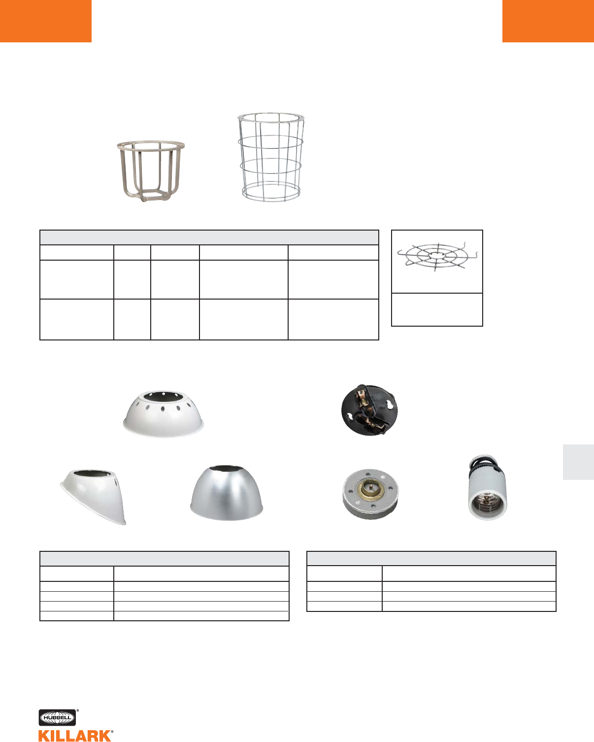
EZ SERIES •LIGHTING
COMPONENT PARTS/ACCESSORIES L145
L
CATALOG NUMBER DESCRIPTION
EZTB Female (goes in splice box)
EZCB Male (goes in top of fixture body)
EZMO Replacement lamp socket
REPLACEMENT CONNECTION BLOCKS AND LAMP SOCKET
CATALOG NUMBER DESCRIPTION
VMPSD-40 Standard dome. Polyester reinforced fiberglass
VMPA-40 Angle Polyester reinforced fiberglass
HRD-400 Deep dome. Aluminum with white finish1
HRD-400ALZ Deep dome with Alzak finish (tm Alcoa) 1
REFLECTORS
CATALOG NUMBER SERIES LAMP TYPE WATTAGE DESCRIPTION
EZS HPS 50-150
EZH MH 70-250 Painted cast aluminumEZG1 EZP MHP 150, 175, 250
EZM MV 100-250
EZS HPS 250, 400
EZH MH 400 Cadmium plated steelVMAG40S EZP MHP 320-400
EZM MV 400
GUARDS
VMPSD-40
VMPA-40 HRD-400 (pictured)
HRD-400ALZ
EZTB
EZCB EZMO
EZG1 VMAG40S
1For clearance, wall mount models require standoff of 1/2” if not bottom feed;
1-1/2” if bottom feed.
VMAGBC
Bottom Closure for
VMAG40S
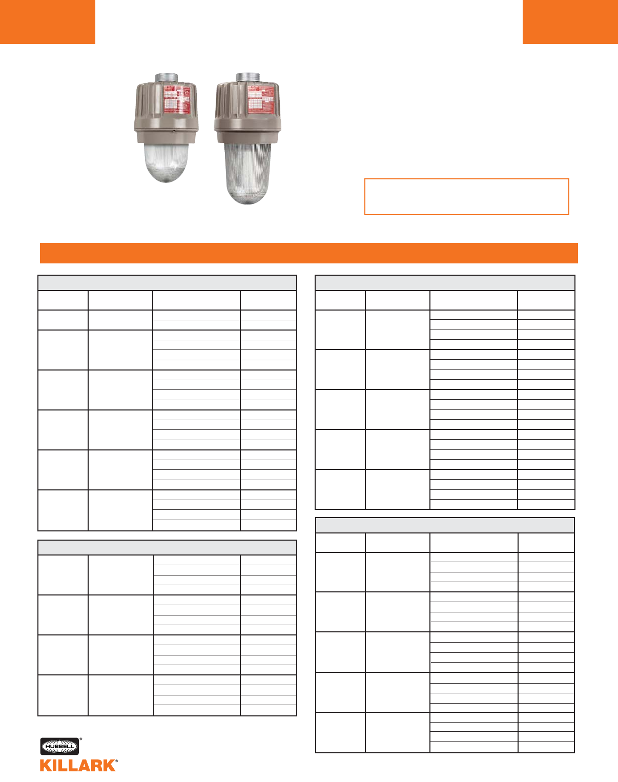
EZ SERIES •LIGHTING
BALLAST HOUSING WITH GLOBE SUPPORT ASSEMBLY
L146
FEATURES-SPECIFICATIONS
CATALOG
NUMBER
EZS050
EZS058
EZS070
EZS075
EZS076
EZS078
EZS100
EZS105
EZS106
EZS108
EZS150
EZS155
EZS156
EZS158
EZS250
EZS255
EZS256
EZS258
EZS400
EZS405
EZS406
EZS408
VOLTAGE
120, 208, 240, 277/60Hz
220, 240V/50Hz
120, 208, 240, 277/60Hz
480 60Hz
120, 277, 347/60Hz
220, 240V/50Hz
120, 208, 240, 277/60Hz
480 60Hz
120, 277, 347/60Hz
220, 240V/50Hz
120, 208, 240, 277/60Hz
480 60Hz
120, 277, 347/60Hz
220, 240V/50Hz
120, 208, 240, 277/60Hz
480 60Hz
120, 277, 347/60Hz
220, 240V/50Hz
120, 208, 240, 277/60Hz
480 60Hz
120, 277, 347/60Hz
220, 240V/50Hz
WATTS
50
70
100
150
250
400
ANSI LAMP
TYPE
S-68/HPS
S-62/HPS
S-54/HPS
S-55/HPS
S-50/HPS
S-51/HPS
HPS HOUSING GLOBE & GLOBE SUPPORT ASSEMBLIES1
H-38/MV
H-39/MV
H-37/MV
H-33/MV
MERCURY VAPOR HOUSING GLOBE & GLOBE SUPPORT ASSEMBLIES1
CATALOG
NUMBER
EZH070
EZH076
EZH075
EZH078
EZH100
EZH106
EZH108
EZH105
EZH170
EZH175
EZH176
EZH178
EZH250
EZH255
EZH256
EZH258
EZH400
EZH405
EZH406
EZH408
METAL HALIDE HOUSING GLOBE & GLOBE SUPPORT ASSEMBLIES1
Housing Globe & Globe Support
Assemblies
NOTE: See pages L78-79 for
ballast data & fuse kit information.
EZM100
EZM105
EZM106
EZM108
EZM170
EZM175
EZM176
EZM178
EZM250
EZM255
EZM256
EZM258
EZM400
EZM405
EZM406
EZM408
120, 208, 240, 277/60Hz
480V/60Hz
120, 277, 347/60Hz
220, 240V/50 Hz
120, 208, 240, 277/60Hz
480 60Hz
120, 277, 347/60Hz
220, 240V/50Hz
120, 208, 240, 277/60Hz
480V/60Hz
120, 277, 347/60Hz
220, 240V/50Hz
120, 208, 240, 277/60Hz
480 60Hz
120, 277, 347/60Hz
220, 240V/50Hz
100
175
250
400
VOLTAGE
120, 208, 240, 277/60Hz
120, 277, 347V/60Hz
480 60Hz
220/240V/50Hz
120, 208, 240, 277/60Hz
120, 347V/60Hz
120, 220, 240V/50Hz
480 60Hz
120, 208, 240, 277/60Hz
480 60Hz
120, 277, 347V/60Hz
220, 240V/50Hz
120, 208, 240, 277/60Hz
480 60Hz
120, 277, 347V/60Hz
220, 240V/50Hz
120, 208, 240, 277/60Hz
480 60Hz
120, 277, 347V/60Hz
220, 240V/50Hz
WATTS
70
100
175
250
400
ANSI LAMP
TYPE
M-98/MH
M-90/MH
M-57/MH2
M-58/MH
M-59/MH
CATALOG
NUMBER
EZP170
EZP175
EZP176
EZP178
EZP250
EZP255
EZP256
EZP258
EZP320
EZP325
EZP326
EZP328
EZP350
EZP355
EZP356
EZP358
EZP400
EZP405
EZP406
EZP408
VOLTAGE
120, 208, 240, 277/60Hz
480
120, 277, 347V/60Hz
220, 240V/50 Hz
120, 208, 240, 277/60Hz
480
120, 277, 347V/60Hz
220, 240V/50Hz
120, 208, 240, 277/60Hz
480
120, 277, 347V/60Hz
220, 240V/50Hz
120, 208, 240, 277/60Hz
480
120, 277, 347V/60Hz
220, 240V/50Hz
120, 208, 240, 277/60Hz
480
120, 277, 347V/60Hz
220, 240V/50Hz
WATTS
1753
250
320
350
400
ANSI LAMP
TYPE
M137/MHP
M138/MHP
M132/MHP
M131/MHP
M135/MHP
PULSE START HOUSING GLOBE & GLOBE SUPPORT ASSEMBLIES1
1Assemblies may be ordered with the CEN (CENELEC) suffix;
see page L148 for more information.
2Will also operate 150W M107 Metal Halide Lamps.
3For 150 Watt, change “7” to “5” in catalog number.
Example EZP150.
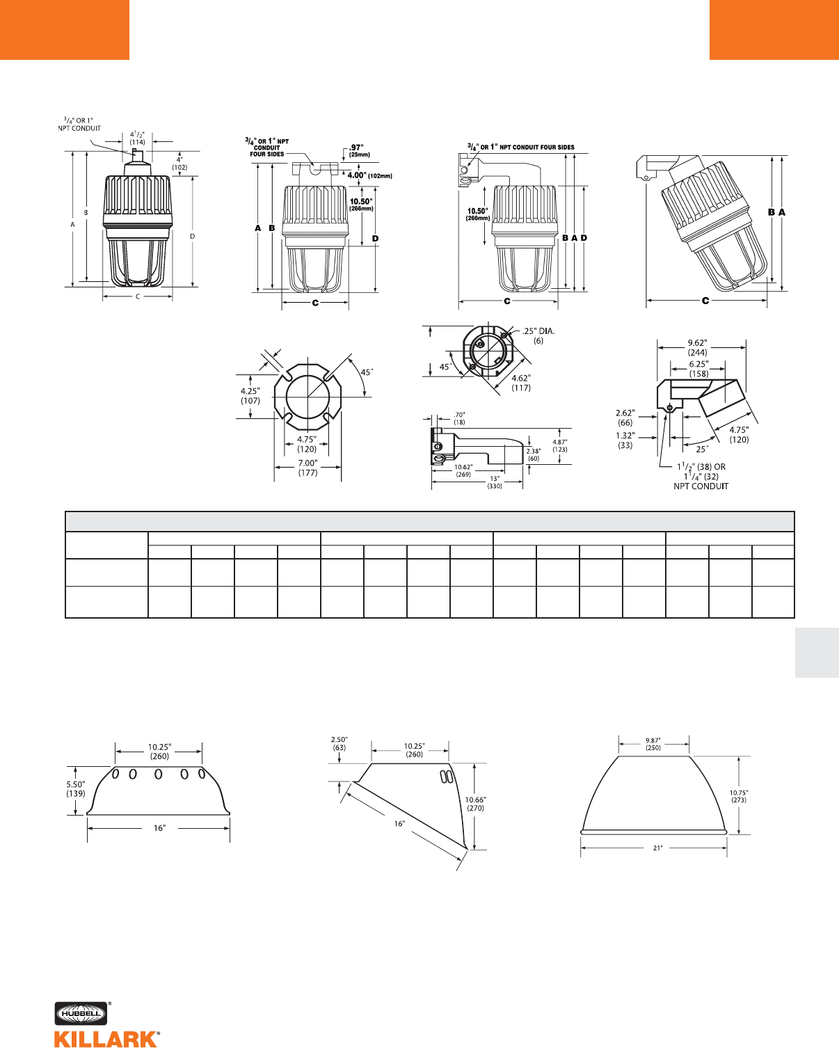
EZ SERIES •LIGHTING
DIMENSIONS L147
L
PENDANT CEILING BRACKET STANCHION
A BC DABCDABCDABC
50-250W* 22" 21-1/4" 11-1/4" 18" 22" 21-1/4" 11-1/4" 18" 22-7/8" 22-1/8" 16-3/4" 18" 24-7/8" 24" 19-13/16"
(558) (539) (285) (457) (558) (539) (285) (457) (580) (561) (425) (457) (631) (609) (503)
250-400W** 26-1/4" 24-1/4" 11-1/4" 22-1/4" 26-1/4" 24-1/4" 11-1/4" 22-1/4" 26-7/8" 24-7/8" 16-3/4" 22-1/4" 28-1/2" 26-11/16" 21-1/2"
(666) (615) (285) (565) (666) (615) (285) (565) (682) (631) (425) (565) (724) (678) (546)
MOUNTING DIMENSIONS
Pendant Ceiling Wall Bracket 25° Stanchion
Standard Dome Angle Deep Dome
Reflector Dimensions
* 50, 70, 100, and 150W HPS; 70, 100, 175 and 250W MH; 100, 175, 250W MV; 150, 175, 250W MHP.
** 250 and 400W HPS, 400W MH and MV; 320, 350, 400W MHP.
.31”
(8) 5.25”
(133)
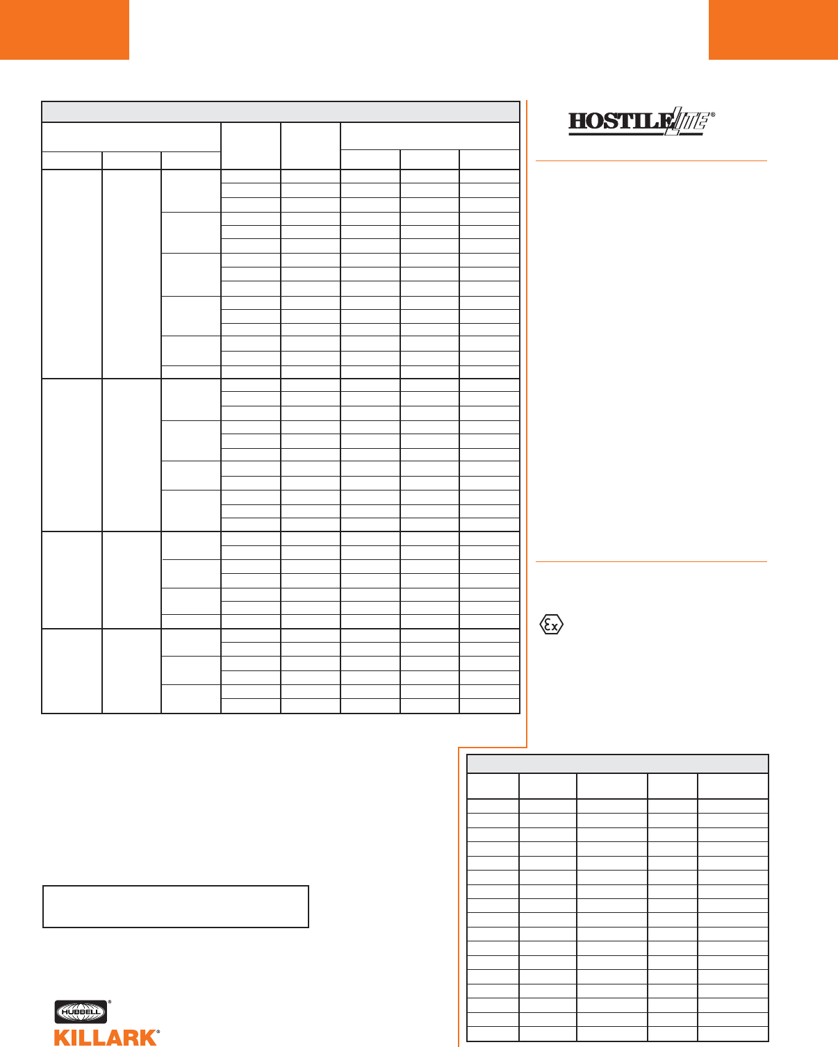
SUPPLY CLASS I, DIVISIONS 1 & 2
LAMP RATED WIRE MAXIMUM SURFACE TEMPERATURE
AMBIENT SUITABLE UL/CSA
SERIES TYPE WATTS °C FOR °C TEMP. I.D. TEMP. I.D. UL/CSA
MIN. W/O QTZ. W/QTZ.3GROUPS
40 85 T5 T4 C,D
50 55 85 T5 N/A C,D
65 85 T4A N/A C,D
40 85 T5 T4 C,D
70 55 85 T5 N/A C,D
65 85 T4A N/A C,D
EZS HPS 40 85 T5 T4 C,D
100 55 85 T5 N/A C,D
65 85 T4A N/A C,D
40 85 T4A T4 C,D
150 55 85 T4A N/A C,D
65 85 T4 N/A C,D
250 40 85 T3C T3C C,D
55 85 T3C N/A C,D
400 40 85 T3C T3C C,D
40 85 T4A N/A C,D
70 55 85 T4A N/A C,D
65 85 T4A N/A C,D
40 85 T4A N/A C,D
100 55 85 T4A N/A C,D
EZH MH 65 85 T4A N/A C,D
40 85 T4 T3C C,D
175 55 85 T4 N/A C,D
40 85 T3C T3C C,D
250 55 85 T3C N/A C,D
400 40 85 T3A T3A C,D
40 85 T4 T3C C,D
55 85 T4 N/A C,D
40 85 T3C T3C C,D
EZP MHP 250 55 25 T3C N/A C,D
320 40 85 T3A T3A C,D
350 40 85 T3A T3A C,D
400 40 85 T3A T3A C,D
40 85 T4 T3C C,D
100 55 85 T4 N/A C,D
40 85 T4 T3C C,D
EZM MV 175 55 85 T4 N/A C,D
250 40 85 T3C T3C C,D
400 40 85 T3A T3A C,D
EZ SERIES •LIGHTING
CLASS I APPLICATION DATA FOR HAZARDOUS LOCATIONS
L148
EZ HAZARDOUS LOCATION DATA—CLASS I, DIVISIONS 1 & 2124
See page L149 for Class II, III tables.
CEN Option
Applications
Killark EZ series fixtures are available with a
European “Certificate of Conformity” from
PTB (Physikalisch-Technische
Bundesanstalt), the approval agency
based in Germany. Fixtures with this rating
will be useful for Original Equipment
Manufacturers and others who build and
ship apparatus into European markets.
This approval is granted by PTB with the
use of a special ground lug and label.
Fixtures carrying an EEx d llB approval are
automatically granted an IP54 (ingress pro-
tection) rating. See Temperature Code
chart below for PTB certified ratings. Killark
EZ fixtures with the PTB rating and labels
still carry all UL & CSA ratings.
Fixture housing/globe/globe support
assemblies (e.g. EMS050 CEN) may be
ordered with the CEN suffix. Complete fix-
ture numbers, with the CEN suffix, will be
shipped with the mounting boxes, guards
and accessories as component parts.
Reflectors and other accessory parts, as
listed on pages L144-145, may be used.
Killark fixtures are NPT tapped and
plugged with at least one conduit
hole open.
Compliances
• EN 50014:1992
• EN 50018:1994
EEx d IIB T6 (or T5-T2)
PTB No. Ex-98.E.1076
Notes for Class I, II, III Application Data Tables.
1Instant restrike limited to 55°C ambient maximum.
2Temperature code ID marked with an asterisk on Class ll table are listed for simultaneous
use in Class I, Groups C, D, and Class II, Groups E, F, G or Groups E, F.
3Fixtures marked “N/A” not suitable for Class ll applications when supplied with auxiliary
quartz.
4See Class II table for fixtures suitable for locations having deposits of readily combustible
paint residue (paint spray booths).
Do not install where marked operating temperature exceeds ignition temperature of haz-
ardous atmosphere.
MAXIMUM AMBIENT TEMPERATURE RANGE -20°C TO 40°C
TYPE OF
LUMINAIRE
EZH50
EZH70
EZH10
EZH15
EZH17
EZH25
EZH40
EZM10
EZM17
EZM25
EZM40
EZS50
EZS70
EZS10
EZS15
EZS25
EZS40
TYPE OF
ENCLOSURE
EZO25
EZO25
EZO25
EZO25
EZO25
EZO25
EZO40
EZO25
EZO25
EZO25
EZO40
EZO25
EZO25
EZO25
EZO25
EZO40
EZO40
FORM OF
THE LAMP
ED28/M-110
ED28/M-98
ED28/M-90
ED28/M-102
ED28/M-57
ED28/M-58
ED37/M-59
ED23-1/2/H-38
ED28/H-39
ED28/H-37
ED37/H-33
ED23-1/2/S-68
ED23-1/2/S-62
ED23-1/2/S-54
ED23-1/2/S-55
ED18/S-50
ED18/S-51
MAXIMUM
WATTAGE
50W
70W
100W
150W
175W
250W
400W
100W
175W
250W
400W
50W
70W
100W
150W
250W
400W
TEMPERATURE
CLASS
T4
T4
T4
T4
T4
T3
T3
T4
T3
T3
T3
T4
T4
T4
T4
T3
T3
150 or 175
*
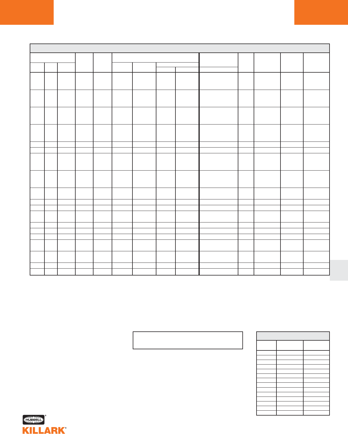
L
EZ SERIES •LIGHTING
CLASS II/III APPLICATION DATA FOR HAZARDOUS LOCATIONS L149
Notes for Class I, II, III Application Data Tables.
1Instant restrike limited to 55°C ambient maximum.
2Temperature code ID marked with an asterisk on Class ll table are listed for simultaneous use in Class I, Groups C, D, and Class II, Groups E, F, G or Groups E, F.
3Fixtures marked “NO” or “N/A” are not suitable for Class ll or II applications when supplied with auxiliary quartz.
4Suitability for locations having deposits of readily combustible paint residue (paint spray booths).
Do not install where marked operating temperature exceeds ignition temperature of hazardous atmosphere.
EZ HAZARDOUS LOCATION DATA1–CLASS II & III, DIVISIONS 1 & 212
E,F,G
N/A
N/A
E,F,G
N/A
N/A
E,F,G
N/A
N/A
E,F,G
N/A
N/A
E,F
N/A
N/A
N/A
N/A
N/A
N/A
N/A
N/A
N/A
N/A
N/A
EF
N/A
N/A
N/A
N/A
EF
N/A
EF
N/A
N/A
N/A
SUPPLY
WIRE
SUITABLE
FOR C°
See page L148 for Class l data.
CLASS III, DIV. 1 & 2
UL/CSA SUITABILITY
W/O QTZ. WITH QTZ.3
YES YES YES YES YES
YES NO YES NO YES
YES NO YES NO YES
YES NO YES YES YES
YES NO YES NO YES
YES YES YES NO YES
YES NO YES YES YES
YES NO YES NO YES
YES YES YES NO YES
YES YES YES NO YES
YES YES YES NO YES
YES YES YES NO YES
NO NO YES NO YES
NO NO YES NO YES
YES NO YES YES YES
YES NO YES NO YES
YES NO YES NO YES
YES NO YES YES YES
YES NO YES NO YES
YES NO YES NO YES
YES NO YES NO YES
YES NO YES NO YES
NO NO YES NO YES
NO NO YES NO YES
YES NO YES NO YES
YES NO YES NO YES
NO NO YES NO YES
NO NO YES NO YES
NO NO YES NO YES
YES NO YES YES YES
YES NO YES NO YES
YES NO YES NO YES
YES NO YES NO YES
NO NO YES NO YES
NO NO YES NO YES
YES
YES
YES
YES
YES
YES
YES
YES
YES
YES
YES
YES
YES
YES
YES
YES
YES
YES
YES
YES
YES
YES
YES
YES
YES
YES
YES
YES
YES
YES
YES
YES
YES
YES
YES
TEMP. I.D.
W/O QTZ. W/O QTZ.
TEMP. I.D.
WITH QTZ
3
WITH QTZ
3
CLASS II, DIV. 1 & 2, MAX. SURFACE
TEMP. UL/CSA SUITABILITY
GROUPS
I.D.
NUMBER
T1
T2
T2A
T2B
T2C
T2D
T3
T3A
T3B
T3C
T4
T4A
T5
T6
TABLE N.E.C. 500-5 (d)
DEGREES C
450
300
280
260
230
215
200
180
165
160
135
120
100
85
DEGREES F
842
572
536
500
446
419
392
356
329
320
275
248
212
185
*
LAMP
LAMP
RATED
AMBIENT
°C
40 85 T3C* T3B* E,F
EZS HPS 50 55 85 T3C* N/A E,F,G
85 T3B* N/A E,F,G
85 T3C* T3B* E,F,G
EZS HPS 70 55 85 T3C* N/A E,F,G
65 85 T3B* N/A E,F,G
40 85 T3C* T3B* E,F,G
EZS HPS 100 55 85 T3C* N/A E,F,G
65 85 T3B N/A E,F,G
40 85 T3C* T3B* E,F,G
EZS HPS 150 55 85 T3C* N/A E,F,
65 85 T3B* N/A E,F,G
EZS HPS 250 40 85 T3 T3 E,F
EZS HPS 400 40 85 N/A N/A N/A
40 85 T4A N/A E,F,
EZH MH 70 55 85 T4 N/A E,F,G
65 85 T3C N/A E,F,
4 85 T4A N/A E,F,G
EZH MH 100 55 85 T4 N/A E,F,G
65 85 T3C N/A E,F,G
EZH MH 175 40 85 T3C* T3A* E,F,G
55 85 T3C* N/A E,F,G
EZH MH 250 40 85 N/A N/A N/A
EZH MH 400 40 85 N/A N/A N/A
EZP MHP 150 or 40 85 T3C* T3A* E,F,G
175 55 85 T3C* N/A E,F,G
EZP MHP 250 40 85 N/A N/A N/A
EZP MHP 320, 350 40 85 N/A N/A N/A
EZP MHP 400 40 85 N/A N/A N/A
EZM MV 100 40 85 T3C* T3A* E,F,G
55 85 T3C* N/A E,F,G
EZM MV 175 40 85 T3C T3A* E,F,G
55 85 T3C N/A E,F,G
EZM MV 250 40 85 N/A N/A N/A
EZM MV 400 40 85 N/A N/A N/A
UL-595
MARINE
UL/CSA
TYPE 3
(RAINTIGHT)
UL/CSA
TYPE 4
(HOSEDOWN)
U.L. PAINT
SPRAY
SUITABILITY4
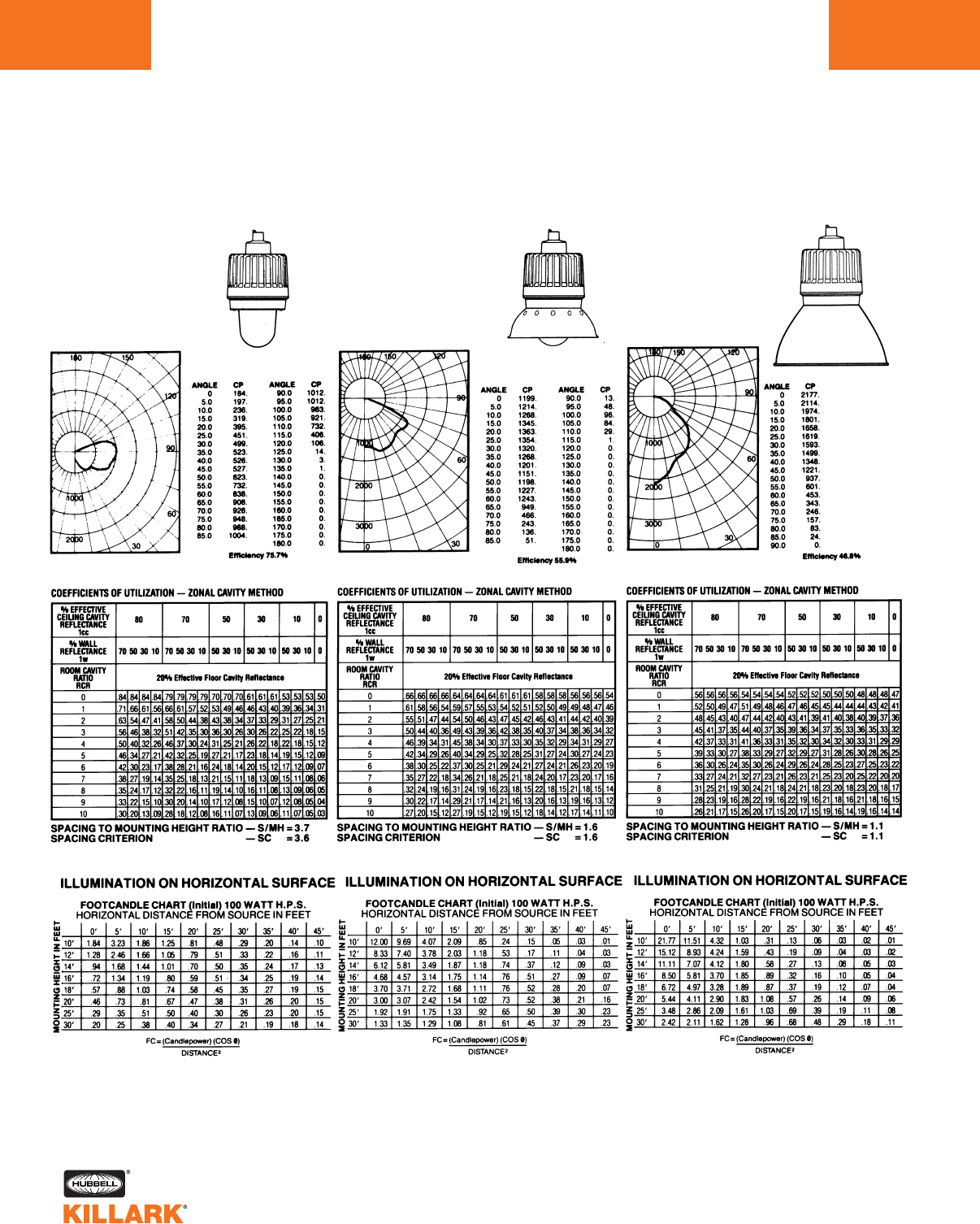
EZ SERIES •LIGHTING
PHOTOMETRIC DATA •HID FIXTURES
Test No. LSI-9182
HIGH PRESSURE SODIUM
With Globe Only
50 – 150 Watt Mogul Base
CANDLEPOWER – 100 WATT
E-231⁄2clear lamp
9500 lumens
For 50 watt multiply by .42
For 70 watt multiply by .67
For 150 watt multiply by 1.68
HIGH PRESSURE SODIUM
With Globe and Standard Dome Reflector
50 – 150 Watt Mogul Base
CANDLEPOWER – 100 WATT
E-231⁄2clear lamp
9500 lumens
For 50 watt multiply by .42
For 70 watt multiply by .67
For 150 watt multiply by 1.68
Test No. LSI-9228 Test No. LSI-9230
HIGH PRESSURE SODIUM
With Globe and Deep Dome HRD-400 Reflector
50 – 150 Watt Mogul Base
CANDLEPOWER – 100 WATT
E-231⁄2clear lamp
9500 lumens
For 50 watt multiply by .42
For 70 watt multiply by .67
For 150 watt multiply by 1.68
L150
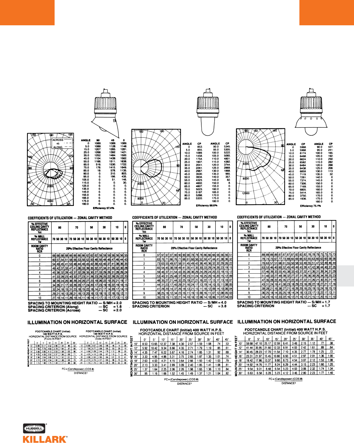
EZ SERIES •LIGHTING
PHOTOMETRIC DATA •HID FIXTURES L151
L
HIGH PRESSURE SODIUM
With Globe and Angle Reflector
50 – 150 Watt Mogul Base
CANDLEPOWER – 100 WATT
E-231⁄2clear lamp
9500 lumens
For 50 watt multiply by .42
For 70 watt multiply by .67
For 150 watt multiply by 1.68
HIGH PRESSURE SODIUM
With Globe Only
250 – 400 Watt Mogul Base
CANDLEPOWER – 400 WATT
E-18 clear lamp
50000 lumens
For 250 watt multiply by .60
HIGH PRESSURE SODIUM
With Globe and Standard Dome Reflector
250 – 400 Watt Mogul Base
CANDLEPOWER – 400 WATT
E-18 clear lamp
50000 lumens
For 250 watt multiply by .60
Test No. LSI-9229
Test No. LSI-9055 Test No. LSI-9056
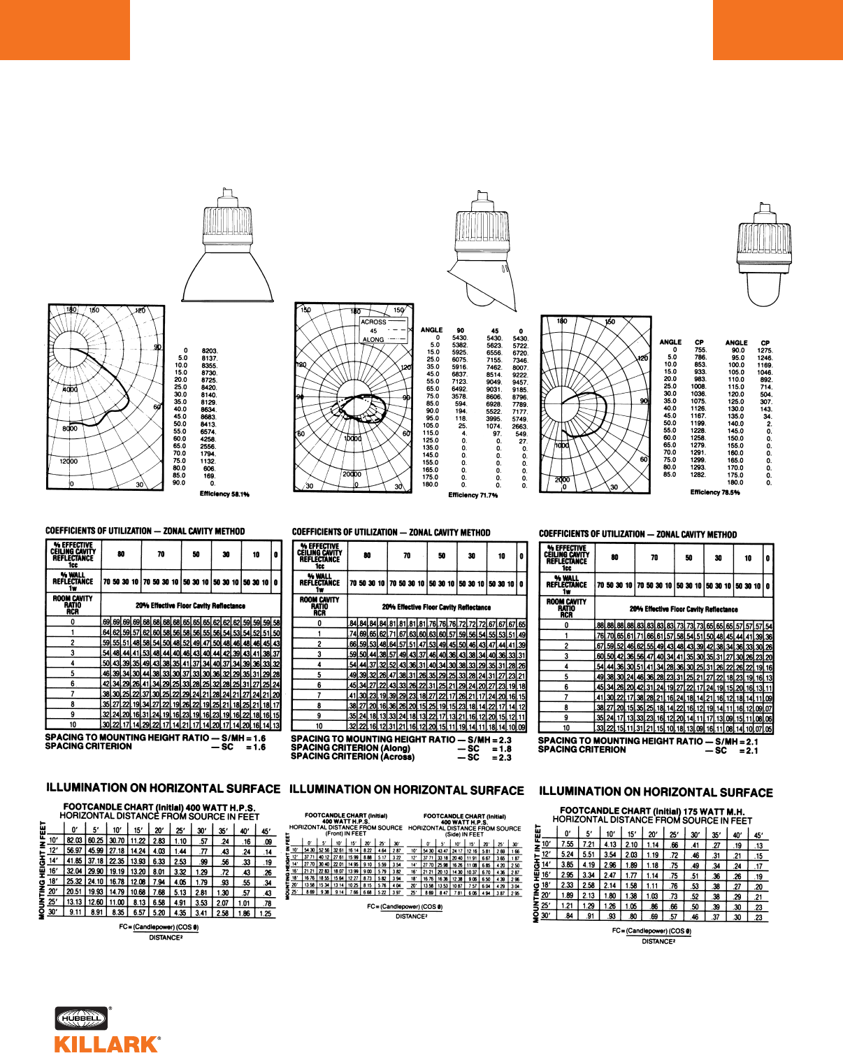
EZ SERIES •LIGHTING
PHOTOMETRIC DATA •HID FIXTURES
L152
HIGH PRESSURE SODIUM
With Globe and Deep Dome HRD-400 Reflector
250 and 400 Watt Mogul Base
CANDLEPOWER – 400 WATT
E-18 clear lamp
50000 lumens
For 250 watt multiply by .60
HIGH PRESSURE SODIUM
With Globe and Angle Reflector
250 – 400 Watt Mogul Base
CANDLEPOWER – 400 WATT
E-18 clear lamp
50000 lumens
For 250 watt multiply by .60
Test No. LSI-9058 Test No. LSI-9057 Test No. LSI-9183
MERCURY VAPOR, METAL HALIDE,
PULSE START METAL HALIDE
With Globe and Standard Dome Reflector
70 – 250 Watt Mogul Base
CANDLEPOWER – 175 WATT MH
E-28 coated MH (14000 lumens)
For CP of 70W MH multiply by .40
For CP of 100W MH multiply by .56
For CP of 150W MH multiply by .96
For CP of 250W MH multiply by 1.46
For CP of 100W MV multiply by .30
For CP of 175W MV multiply by .61
For CP of 250W MV multiply by .86
For CP of 175W MHP multiply by 1.14
For CP of 250W MHP multiply by 1.69
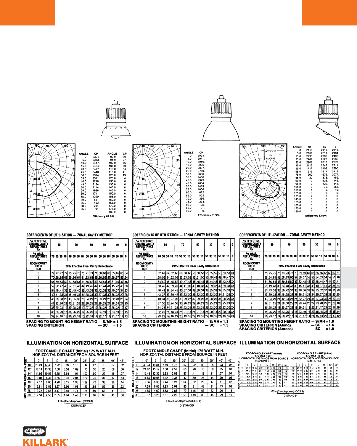
EZ SERIES •LIGHTING
PHOTOMETRIC DATA •HID FIXTURES L153
L
Test No. LSI-9231 Test No. LSI-9233 Test No. LSI-9232
MERCURY VAPOR, METAL HALIDE,
PULSE START METAL HALIDE
With Globe and Standard Dome Reflector
70 – 250 Watt Mogul Base
CANDLEPOWER – 175 WATT MH
E-28 coated MH (14000 lumens)
For CP of 70W MH multiply by .40
For CP of 100W MH multiply by .56
For CP of 150W MH multiply by .96
For CP of 250W MH multiply by 1.46
For CP of 100W MV multiply by .30
For CP of 175W MV multiply by .61
For CP of 250W MV multiply by .86
For CP of 175W MHP multiply by 1.14
For CP of 250W MHP multiply by 1.69
MERCURY VAPOR, METAL HALIDE,
PULSE START METAL HALIDE
With Globe and Deep Dome HRD-400 Reflector
70 – 250 Watt Mogul Base
CANDLEPOWER – 175 WATT MH
E-28 coated MH (14000 lumens)
For CP of 70W MH multiply by .40
For CP of 100W MH multiply by .56
For CP of 150W MH multiply by .96
For CP of 250W MH multiply by 1.46
For CP of 100W MV multiply by .30
For CP of 175W MV multiply by .61
For CP of 250W MV multiply by .86
For CP of 175W MHP multiply by 1.14
For CP of 250W MHP multiply by 1.69
MERCURY VAPOR, METAL HALIDE,
PULSE START METAL HALIDE
With Globe and Angle Reflector
70 – 250 Watt Mogul Base
CANDLEPOWER – 175 WATT MH
E-28 coated MH (14000 lumens)
For CP of 70W MH multiply by .40
For CP of 100W MH multiply by .56
For CP of 150W MH multiply by .96
For CP of 250W MH multiply by 1.46
For CP of 100W MV multiply by .30
For CP of 175W MV multiply by .61
For CP of 250W MV multiply by .86
For CP of 175W MHP multiply by 1.14
For CP of 250W MHP multiply by 1.69
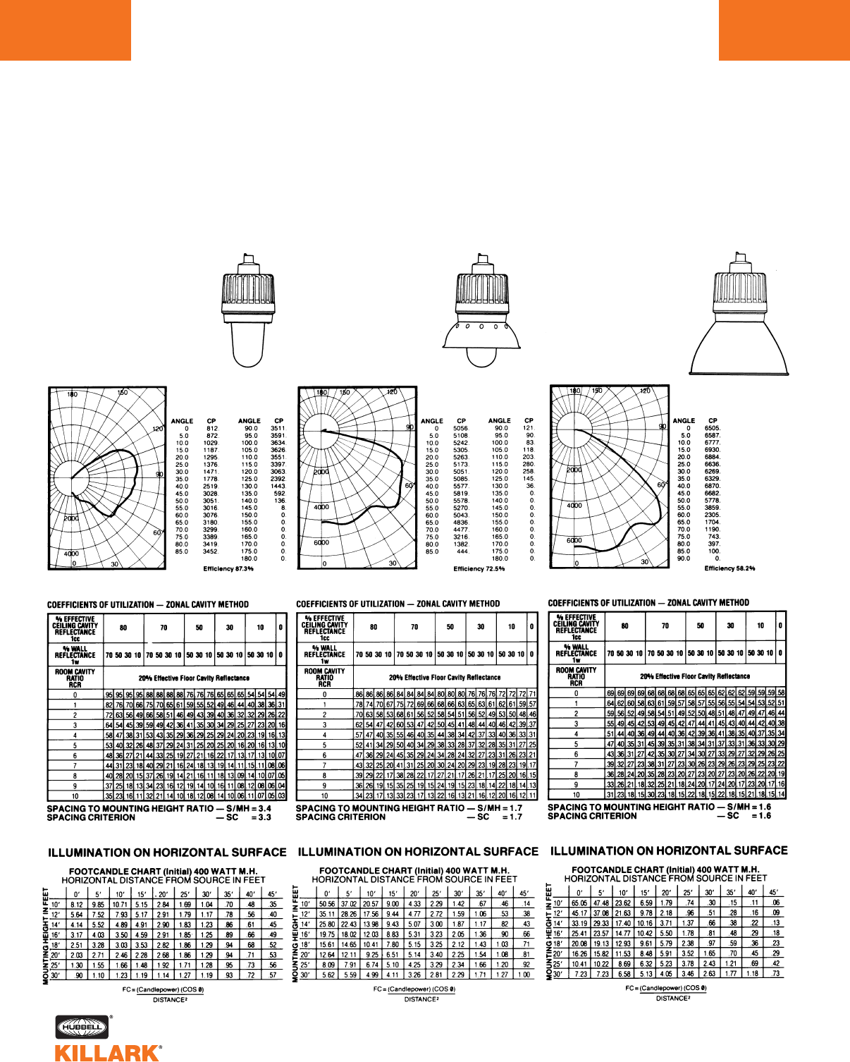
EZ SERIES •LIGHTING
PHOTOMETRIC DATA •HID FIXTURES
L154
Test No. LSI-9051 Test No. LSI-9052 Test No. LSI-9054
MERCURY VAPOR, METAL HALIDE,
PULSE START METAL HALIDE
With Globe Only
320 - 400 Watt Mogul Base
CANDLEPOWER – 400 WATT MH
E-37 coated MH
36000 lumens
For 400 watt mercury vapor
lamp multiply by .625
For CP of MHP320 multiply by .87
For CP of MHP350 multiply by 1.05
For CP of MHP400 multiply by 1.22
MERCURY VAPOR, METAL HALIDE,
PULSE START METAL HALIDE
With Globe and Standard Dome Reflector
320 - 400 Watt Mogul Base
CANDLEPOWER – 400 WATT MH
E-37 coated MH
36000 lumens
For 400 watt mercury vapor
lamp multiply by .625
For CP of MHP320 multiply by .87
For CP of MHP350 multiply by 1.05
For CP of MHP400 multiply by 1.22
MERCURY VAPOR, METAL HALIDE,
PULSE START METAL HALIDE
With Globe and Deep Dome Reflector
320 - 400 Watt Mogul Base
CANDLEPOWER – 400 WATT MH
E-37 coated MH
36000 lumens
For 400 watt mercury vapor
lamp multiply by .625
For CP of MHP320 multiply by .87
For CP of MHP350 multiply by 1.05
For CP of MHP400 multiply by 1.22
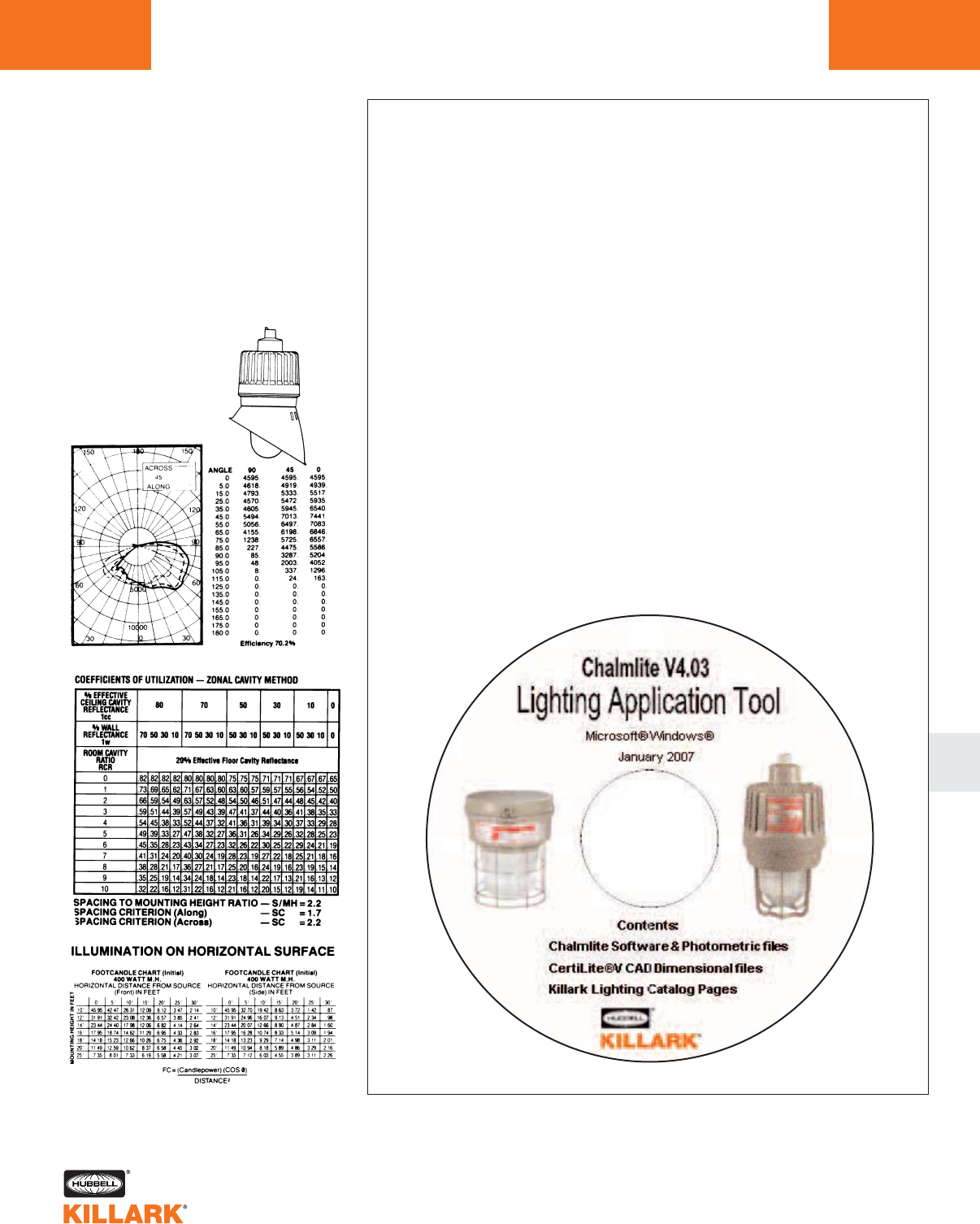
EZ SERIES •LIGHTING
PHOTOMETRIC DATA •HID FIXTURES L155
L
CALCULATION SOFTWARE &
PHOTOMETRIC FILES
in IES Format are available
The Illuminating Engineering Society (IES) has developed a
recommended standard file format for the electronic trans-
fer of photometric data (Standard IES LM-63-1986).
Photometric files for all KILLARK fixture configurations are
available on a single CD, which includes lighting calcula-
tion and design software.
Use of this CD, available from your KILLARK Sales
Representative, will eliminate the time and effort required to
manually key in photometric data. Included on each disk
are “README” and “INDEX” .txt files. The README file pro-
vides instructions on how to access data while the INDEX
file lists all fixture catalog numbers cross referenced to their
appropriate IES format photometric database file name and
other descriptive data.
Test No. LSI-9053
MERCURY VAPOR, METAL HALIDE,
PULSE START
With Globe and Angle Reflector
320 - 400 Watt Mogul Base
CANDLEPOWER – 400 WATT MH
E-37 coated MH
36000 lumens
For 400 watt mercury vapor
lamp multiply by .625
For CP of MHP320 multiply by .87
For CP of MHP350 multiply by 1.05
For CP of MHP400 multiply by 1.22
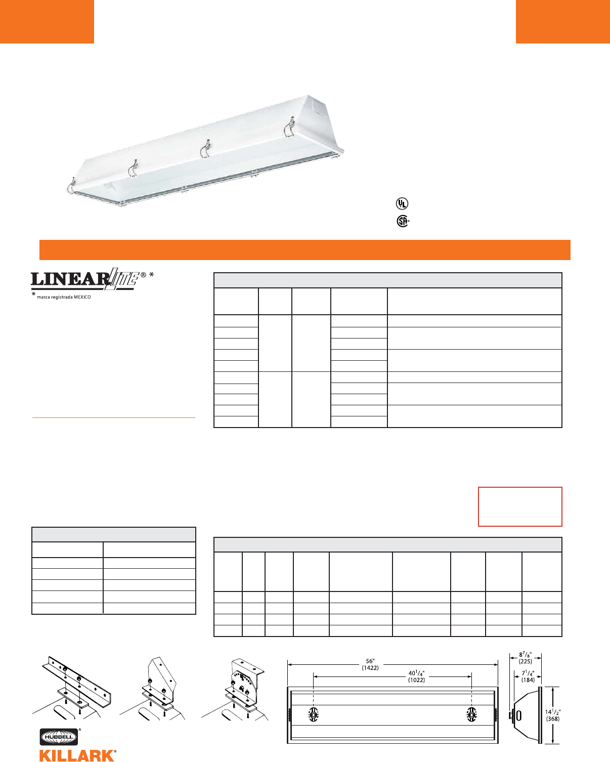
DBF SERIES •LIGHTING
FLUORESCENT FIXTURES
L156
FEATURES-SPECIFICATIONS
Listed - File E12976
Certified - File LR11713
Class I, Div. 2, Groups A,B,C,D1
Class l, Zone 2, Groups llC,llB,llA
Class II, Div. 1 & 2, Groups E,F,G5
Class III, Div. 1 & 2
Suitable for wet locations
NEMA 3, 4
Applications
LINEARLITE DBF fluorescent fixtures
are designed for general and task light-
ing of areas where flammable gases or
vapors or combustible dusts may exist
due to abnormal conditions resulting in
the creation of a Class I, Division 2 or
Class II or III, Div. 1 or 2, hazardous
location as defined in the NEC. Also
for lighting non-hazardous wet loca-
tions indoors and outdoors.
Features
•Sheet steel 20 ga. housing with con-
tinuous weld prevents foreign matter
from entering enclosure
•Lens frame assembly has silicon
rubber gasketing and heat tempered
glass lens
•Electrostatically applied
polyester finish
CATALOG CONDUIT NUMBER LINE
NUMBER SIZE3OF LAMPS VOLTAGE DESCRIPTION
DBF32302 120-277V 50/60 Hz 32W T8 electronic ballast 265 MA 0°F start
DBF40124120V 60 Hz
DBF4042 3/4" 2 277V 60 Hz 40W rapid start electronic F40T12 medium bi-pin 430MA
DBF60124120V 60 Hz 60W rapid start high output F48T12/HO recessed
DBF6042 277V 60 Hz double contact 800MA
DBF32303 120-277V 50/60 Hz 32W T8 electronic ballast 265 MA 0°F start
DBF4013
3/4" 3
120V 60 Hz 40W rapid start electronic F40T12 medium bi-pin 430MA
DBF4043 277V 60 Hz
DBF6013 120V 60 Hz 60W rapid start high output F48T12/HO recessed
DBF6043 277V 60 Hz double contact 800MA
DBF FLUORESCENT FIXTURES
CATALOG NUMBER DESCRIPTION
ABK Angle bar chain bracket
AFK 45° fixed angle bracket
AAK 45° adjustable angle bracket
DBF-HUB Replacement hub
DBF-DL Door & Lens
MOUNTING HARDWARE2
SUPPLY CLASS I, DIV. 2, CLASS II, DIV.1&2,
NUMBER LAMP RATED WIRE GROUPS A, B, C, D GROUPS E, F, G CLASS III NEMA NEMA
OF AMBIENT MAX. LAMP MAX. SURFACE DIV. 1 & 2 TYPE 3 TYPE 4
LAMPS WATTS °C SUITABLE TEMP.°C TEMP
. °CSUITABILITY UL/CSA (RAINTIGHT) (HOSEDOWN)
FOR °C MIN. UL/CSA TEMP/I.D. UL/CSA TEMP/I.D.
2 32/40 40 90 T6 (85°C/185°F) T6 (85°C/185°F) YES YES YES
3 32/40 40 90 T5 (100°C/212°F) T6 (85°C/185°F) YES YES YES
2 60 40 90 T4A (120°C/248°F) T6 (85°C/185°F) YES YES YES
3 60 40 90 T4 (138°C/275°F) T6 (85°C/185°F) YES YES YES
DBF HAZARDOUS LOCATION APPLICATION DATA15
• Standard ballast starting temperature for 40 watt is 50°F.
• Ballasts are Class P Type with internal, automatic, thermally-activated protective device.
• Optional external ballast fusing availability by adding suffix FB.
• For other voltages consult factory.
• 60 watt high output ballasts are standard -20°F start.
Fixtures are supplied without lamps. To order with lamps installed add suffix WL.
1UL/CSA Class I, Div. 2
3Hubs can be relocated in field to fixture end for feed-thru wiring.
4Change 1 to 8 for 230V 50 Hz.
5CSA Class II, Div. I
2Must be ordered separately. Brackets sold as sets.
AFK AAK
ABK
SEE PAGE L187
FOR DBFE
EMERGENCY MODELS
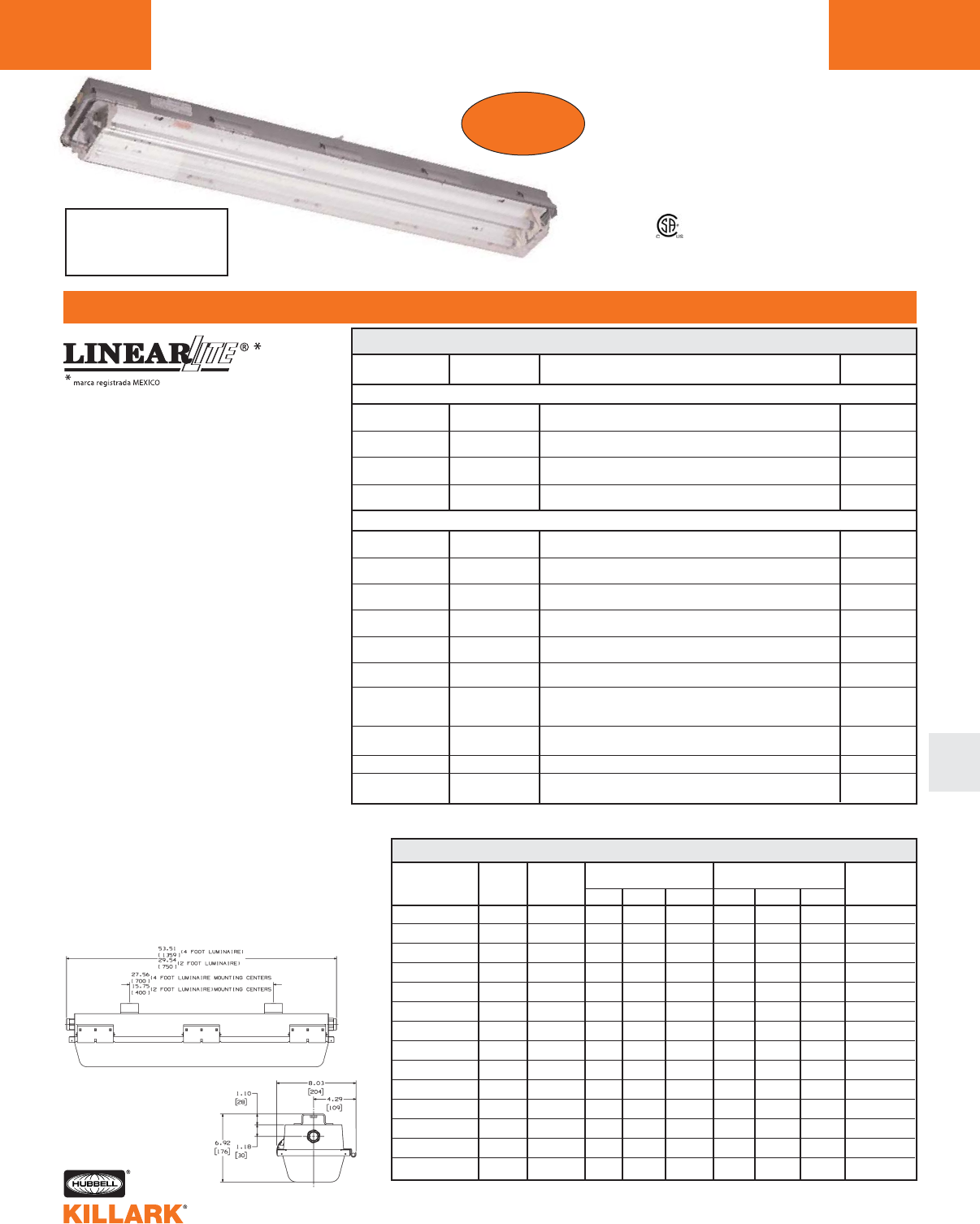
LZ2S STAINLESS
FEATURES-SPECIFICATIONS
Applications
LINEARLITE®rugged 316 stainless fluo-
rescent fixtures are suitable for wet, harsh,
corrosive and hazardous locations. The
LZ2S Series can be used in Class I, Divi-
sion 2 and Zone 2 hazardous vapors and
in Class II combustible dust areas typically
found in refineries, chemical plants, waste
water & sewage treatment facilities, as
well as in tunnels, food processing and
coastal areas.
ABS (American Bureau of Shipping) type
approval for use on decks, vessels, plat-
forms, barges, ships and boats. Also
suitable for docks and marinas.
Features
•NEMA 4X & IP66 rated stainless enclo-
sure with Lexan®impact resistant poly-
carbonate lens.
•Two 3/4” NPT stainless hubs - one at
each end (includes aluminum 3/4” close-
up plug and two 3/4” x 1/2” reducers for
maximum user flexibility).
•Two 1/4” - 20 stainless bushings furnished
in top of fixture for threaded rod.
Lexan®is a registered trademark of General Electric
Additional Data
L188 - Emergency models
L159 - Ballast data
L160 - Mounting accessories
L160 - L161 - Photometrics
150 Hz ballast is magnetic.
NUMBER OF
LAMPS/WATTS
1-40W
1-55W
2-40W
4-40W
2-17W
3-17W
2-28W
3-28W
2-32W
3-32W
2-40W
2-44W
2-54W
2-60W
BIAXIAL LAMP TYPE FIXTURES
VOLTAGE
AC 60 Hz
120-277V
120-277V
120-277V
120-277V
120-277V
120-277V
120-277V
50-60 Hz
120-277V
50-60 Hz
120-277V
347V
120-277V
347V
120V
277V
230V 50 Hz1
120V
277V
120-277V
120-277V
DOUBLE-ENDED LAMP TYPE FIXTURES
DESCRIPTION
2' 1-Lamp Biaxial Electronic 50/60 Hz, 0°F Start 4-Pin
2' 1-Lamp Biaxial Electronic 50/60 Hz, 0°F Start 4-Pin
2' 2-Lamp Biaxial Electronic 50/60 Hz, 0°F Start 4-Pin
4' 4-Lamp Biaxial Electronic 50/60 Hz, 0°F Start 4-Pin
2' 2-Lamp T-8 Electronic 50/60 Hz, 0°F Start Medium Bi-Pin
2' 3-Lamp T-8 Electronic 50/60 Hz, 0°F Start Medium Bi-Pin
4' 2-Lamp T-5 Electronic 0°F Start Miniature Bi-Pin
4' 3-Lamp T-5 Electronic 0°F Start Miniature Bi-Pin
4' 2-Lamp T-8 Electronic 50/60 Hz 0°F Start Medium Bi-Pin
4' 3-Lamp T-8 Electronic 50/60 Hz 0°F Start Medium Bi-Pin
4' 2-Lamp T-12 Electronic Medium Bi-Pin Start 50°F 40W/60°F 34W
4' 2-Lamp T-8 Electronic -20°F Start High Output
Recessed Double Contact
4' 2-Lamp T5 Electronic 50/60 Hz, -20°F Start Miniature Bi-Pin
4' 2-Lamp T-12 Electronic -20°F Start High Output
Recessed Double Contact
LZ2S
LZ2S40130
LZ2S55130
LZ2S40230
LZ2S40430
LZ2S17230
LZ2S17330
LZ2S28230
LZ2S28330
LZ2S32230
LZ2S32215
LZ2S32330
LZ2S32315
LZ2S40201
LZ2S40204
LZ2S40208
LZ2S44230
LZ2S54230
LZ2S60201
LZ2S60204
LZ2S SERIES •LIGHTING
316 STAINLESS FLUORESCENT L157
Certified - File LR11713
Class I, Div. 2, Groups A,B,C,D
Class l, Zone 2, Groups llC, llB, llA
Class II, Div. 1 & 2, Group E,F,G
AEx nAII, Ex nAII
Wet Locations
NEMA 4X, IP66
Type Approval
ABS
NEW!
L
NUMBER OF RATED SUITABLE CLASS I, DIV, 2 CLASS II, DIV. 1 & 2 CLASS III
AMBIENT FOR °C MAX. SURFACE TEMP. MAX. SURFACE TEMP. DIV.1&2
LAMPS/WATTS ° C SUPPLY WIRE TEMP. T-CODE GROUPS TEMP. T-CODE GROUPS SUITABILITY
1 X 40W BIAXIAL 40° 75 160°C T3C A, B, C, D 100°C T5 E, F, G Yes
1 X 55W BIAXIAL 40° 60 160°C T3C A, B, C, D 100°C T5 E, F, G Yes
2 X 40W BIAXIAL 40° 75 160°C T3C A, B, C, D 100°C T5 E, F, G Yes
4 X 40W BIAXIAL 40° 75 160°C T3C A, B, C, D 100°C T5 E, F, G Yes
2 X 17W 40° 60 85°C T5 A, B, C, D 100°C T5 E, F, G Yes
3 X 17W 40° 60 85°C T5 A, B, C, D 100°C T5 E, F, G Yes
2 X 28W 40° 60 120°C T4A A, B, C, D 100°C T5 E, F, G Yes
3 X 28W 40° 60 120°C T4A A, B, C, D 100°C T5 E, F, G Yes
2 X 32W 40° 60 85°C T6 A, B, C, D 100°C T5 E, F, G Yes
3 X 32W 40° 60 85°C T6 A, B, C, D 100°C T5 E, F, G Yes
2 X 40W 40° 60 120°C T4A A, B, C, D 100°C T5 E, F, G Yes
2 X 44W 40° 60 120°C T4A A, B, C, D 100°C T5 E, F, G Yes
2 X 54W 40° 75 160°C T3C A, B, C, D 100°C T5 E, F, G Yes
2 X 60W 40° 75 135°C T4 A, B, C, D 100°C T5 E, F, G Yes
LZ2S, LZ2SE HAZARDOUS LOCATION APPLICATION DATA
Replaces
SSHZ Series
LZ2N SERIES •LIGHTING
NON-METALLIC FLUORESCENT FIXTURES
L158
FEATURES-SPECIFICATIONS
Certified - File LR11713
Class I, Div. 2 Groups A,B,C,D
Class l, Zones 2, Groups IIC,llB,llA
Class II, Div. 1 & 2, Groups F,G
AEx nAII, Ex nAII
Wet Locations
NEMA 4X, IP66
4’ Nominal Style
2’ Nominal Style
Type Approval
ABS
Food Handling
NSF
Applications
LINEARLITE ®rugged Non-Metallic fluo-
rescent fixtures are suitable for wet, harsh
and hazardous locations. Use where
enclosed and gasketed fixtures are
required to withstand exposure to mois-
ture, dust and corrosives. The LZ2N
Series can also be used in Class I,
Division 2 and Zone 2 hazarous vapors
and in Class II areas where combustible
dusts may exist. Typical areas used are in
refineries, chemical plants, waste water &
sewage treatment facilities, as well as in
tunnels, food processing and coastal
areas.
ABS (American Bureau of Shipping) type
approval for use on decks, vessels, plat-
forms, barges, ships and boats. Also suit-
able for docks and marinas.
NSF (National Sanitation Foundation)
approved for “Food Handling” areas, typi-
cally requiring non-glass lighting.
Features
•Housing-one piece fiberglass reinforced
polyester, NEMA 4X & IP66 rated.
•Lexan®Clear Lens, impact resistant
polycarbonate
•Two 3/4” NTP aluminum hubs - one at
each end (includes one 3/4” close-up
plug and two 3/4” x 1/2” reducers for
maximum user flexibility)
•Two 1/4”-20 aluminum bushings fur-
nished in top of fixture for threaded rod
Lexan® is a registered trademark of General Electric
Product Range
•2’ and 4’ luminaries
•Lamp types-
Linear 17, 28, 32, 40, 44, 54, 60W
Long compact 40, 55W (single ended)
Catalog Number Logic
Constant for LZ2N Series
1Emergency (Battery backed)
E1—40W BIAXIAL, 44W, 60W
E2—32W, 40W
Lamp Wattage
17
28
32
40-Linear & BIAXIAL
44
54
55
60
Voltage
30—120-277V 50/60 Hz
40, 55 - BIAXIAL
17, 28, 32, 44, 54W
01—120V 60 Hz
40W, 60W
04—277V 60 Hz
40W, 60W
08—230V 50 Hz
40W
15—347V 60 Hz
32W
LZ2N - (E0-) -00-0-00-F2
NUMBER OF RATED SUITABLE CLASS I, DIV, 2 CLASS II, DIV, 1 & 2 CLASS III NEMA 4X
AMBIENT FOR °C MAX. SURFACE TEMP. MAX. SURFACE TEMP. DIV.1&2
LAMPS/WATTS ° C SUPPLY WIRE TEMP. T-CODE GROUPS TEMP. T-CODE GROUPS SUITABILITY IP66
2 X 17W 40° 60 85°C T5 A, B, C, D 100°C T5 F, G Yes Yes
3 X 17W 40° 60 85°C T5 A, B, C, D 100°C T5 F, G Yes Yes
1 X 40W BIAXIAL 40° 60 100°C T5 A, B, C, D 100°C T5 F, G Yes Yes
1 X 55W BIAXIAL 40° 60 160°C T3C A, B, C, D 100°C T5 F, G Yes Yes
2 X 40W BIAXIAL 40° 60 100°C T5 A, B, C, D 100°C T5 F, G Yes Yes
4 X 40W BIAXIAL 40° 60 120°C T4A A, B, C, D 100°C T5 F, G Yes Yes
2 X 28W 40° 60 120°C T4A A, B, C, D 100°C T5 F, G Yes Yes
3 X 28W 40° 60 120°C T4A A, B, C, D 100°C T5 F, G Yes Yes
2 X 32W 40° 75 85°C T6 A, B, C, D 100°C T5 F, G Yes Yes
3 X 32W 40° 75 85°C T6 A, B, C, D 100°C T5 F, G Yes Yes
2 X 40W 40° 60 120°C T4A A, B, C, D 100°C T5 F, G Yes Yes
2 X 44W 40° 60 100°C T5 A, B, C, D 100°C T5 F, G Yes Yes
2 X 54W T5 40° 75 160°C T3C A, B, C, D 100°C T5 F, G Yes Yes
2 X 60W 40° 75 135°C T4 A, B, C, D 100°C T5 F, G Yes Yes
LZ2N, LZ2NE HAZARDOUS LOCATION APPLICATION DATA
1 lamp
2 lamps
3 lamps
4 lamps
F1—fuse 120V
F4—fuse 277V
F8—fuse 230V
1See page L188 for complete catalog grid listing.
2Fuses not for marine or Canadian use.
Quick release diffuser clamp and hinged cover
requires no special tools.
•Electronic ballast standard
•World voltage (most models) 120 thru
277V, 50/60 Hz
LZ2NAND LZ2S BALLAST DATA1
LZ2N NON-METALLIC
LZ2N SERIES •LIGHTING
NON-METALLIC FLUORESCENT FIXTURES L159
L
NUMBER OF
LAMPS/WATTS
1-40W
1-55W
2-40W
4-40W
2-17W
3-17W
2-28W
3-28W
2-32W
3-32W
2-40W
2-44W
2-54W
2-60W
BIAXIAL LAMP TYPE FIXTURES
VOLTAGE
AC 60 Hz
120-277V
120-277V
120-277V
120-277V
120-277V
120-277V
120-277V
50-60 Hz
120-277V
50-60 Hz
120-277V
347V
120-277V
347V
120V-277V
230V 50 Hz2
120-277V
120-277V
120-277V
DOUBLE-ENDED LAMP TYPE FIXTURES
DESCRIPTION
2' 1-Lamp Biaxial Electronic 50/60 Hz
0°F Start 4-Pin
2' 1-Lamp Biaxial Electronic
0°F Start 4-Pin
2' 2-Lamp Biaxial Electronic 50/60 Hz
0°F Start 4-Pin
4' 4-Lamp Biaxial Electronic 50/60 Hz
0°F Start 4-Pin
2' 2-Lamp T8 Electronic 50/60 Hz
0°F Start Medium Bi-Pin
2' 3-Lamp T8 Electronic 50/60 Hz
0°F Start Medium Bi-Pin
4' 2-Lamp T-5 Electronic
0°F Start Miniature Bi-Pin
4' 3-Lamp T-5 Electronic
0°F Start Miniature Bi-Pin
4' 2-Lamp T-8 Electronic 50/60 Hz
0°F Start Medium Bi-Pin
4' 3-Lamp T-8 Electronic 50/60 Hz
0°F Start Medium Bi-Pin
4' 2-Lamp T-12 Electronic, Medium Bi-Pin
Start 50°F 40W/60°F 34W
4' 2-Lamp T-8 Electronic -20°F Start High Output
Recessed Double Contact
4' 2-Lamp T-5 Electronic 50/60 Hz
-20°F Start Miniature Bi-Pin
4' 2-Lamp T-12 Electronic -20°F Start High Output
Recessed Double Contact
LZ2N
LZ2N40130
LZ2N55130
LZ2N40230
LZ2N40430
LZ2N17230
LZ2N17330
LZ2N28230
LZ2N28330
LZ2N32230
LZ2N32215
LZ2N32330
LZ2N32315
LZ2N40201
LZ2N40204
LZ2N40208
LZ2N44230
LZ2N54230
LZ2N60201
LZ2N60204
1Includes normal powered LZ2NE and LZ2SE models, lamps not included.
2Magnetic ballast.
NUMBER OF
LAMPS/WATTS
1 X 40W BIAXIAL
1 X 55W BIAXIAL
2 X 40W BIAXIAL
4 X 40W BIAXIAL
2 X 17W
3 X 17W
2 X 28W
3 X 28W
2 X 32W
3 X 32W
2 X 40W
2 X 44W
2 X 54W
2 X 60W
VOLTAGE
120-277V
120-277V
120-277V
120-277V
120-277V
120-277V
120-277V
120-277V
120-277V
120-277V
120-277V
120-277V
120-277V
120-277V
.35 (120V)
.49 (120V)
.60 (120V)
1.32 (120V)
.32 (120V)
.39 (120V)
.55 (120V)
.83 (120V)
.54 (120V)
.71 (120V)
.62 (120V)
.84 (120V)
1.00 (120V)
1.13 (120V)
.15 (277V)
.22 (277V)
.28 (277V)
.56 (277V)
.14 (277V)
.17 (277V)
.23 (277V)
.35 (277V)
.24 (277V)
.31 (277V)
.24 (277V)
.36 (277V)
.43 (277V)
.48 (277V)
LINE CURRENT AMPS
INPUT
WATTS
39
58
78
156
38
48
66
99
65
85
71
99
120
125
STARTING
TEMPERATURE
0°F (-18°C)
0°F (-18°C)
0°F (-18°C)
0°F (-18°C)
0°F (-18°C)
0°F (-18°C)
0°F (-18°C)
0°F (-18°C)
0°F (-18°C)
0°F (-18°C)
50°F (10°C)
-20°F (-29°C)
-20°F (-29°C)
-20°F (-29°C)
See page L188
for LZ2NE
Non-metallic
and LZ2SE
316 Stainless
Emergency
Models
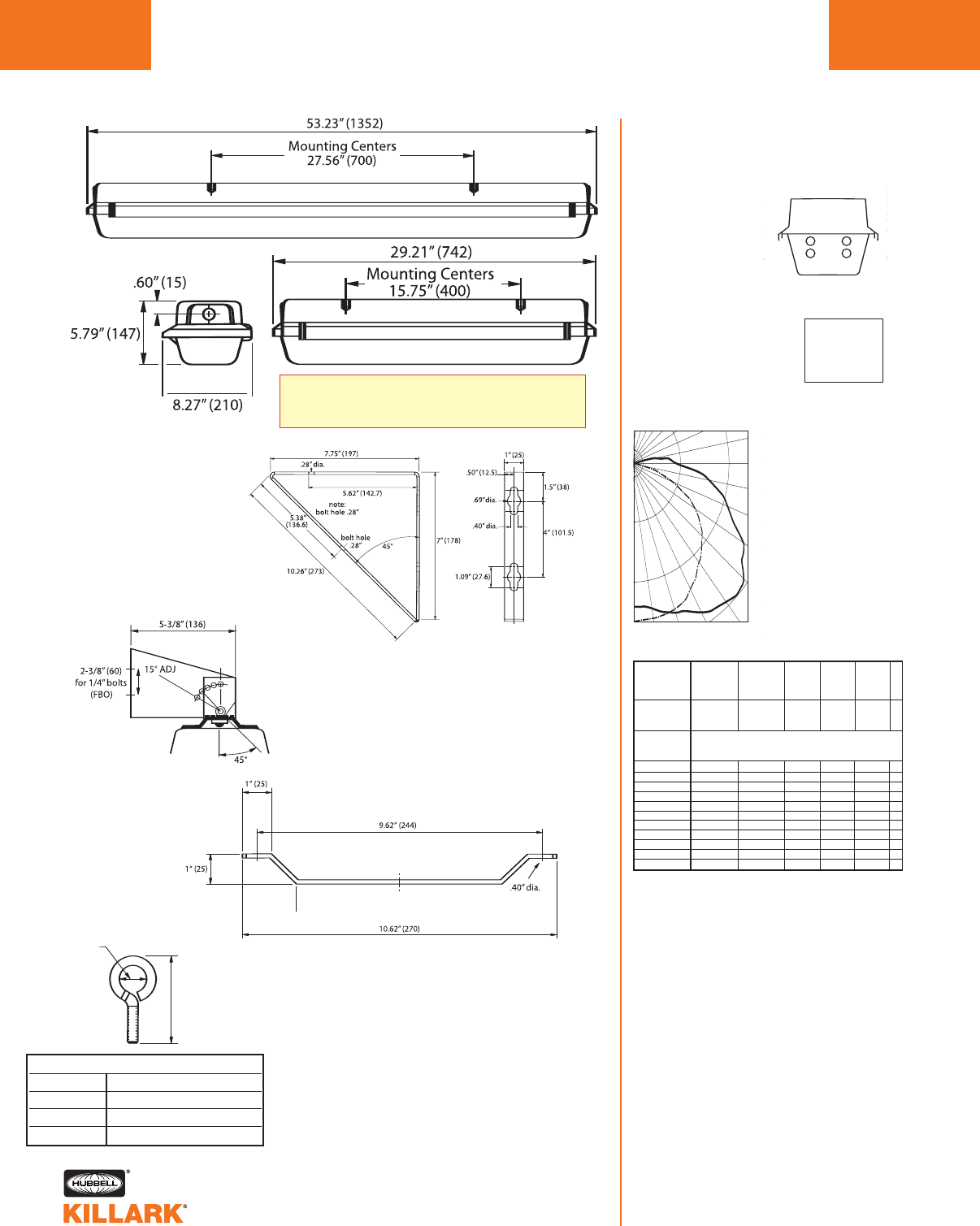
Test No. BAL12356
FLUORESCENT FIXTURE- LZ2N(S)40230
2’ – 2 40 Watt Biaxial
Lamp Type F40/2G11/835/RS
Lumens 3150 each
Total Bare Lamp
Lumens 6300
All data provided is for
F40/2G11/835/RS lamps
For LZ2N40130 1-lamp
models multiply x .50
For LZ2N55130
1-lamp models
multiply x .76
Efficiency 78.5%
90˚
80˚
70˚
60˚
50˚
40˚
30˚20˚10˚0˚
180˚ 140˚ 120˚ 110˚
100˚
307
613
920
1226
90°
0°
SPACING TO MOUNTING HEIGHT RATIO - 1.28 0-180°
SPACING TO MOUNTING HEIGHT RATIO - 1.88 90-270°
SPACING TO MOUNTING HEIGHT RATIO - 1.28 0-180°
SPACING TO MOUNTING HEIGHT RATIO - 1.88 90-270°
ZONAL LUMENS
ZONE LUMENS
0-30 826
0-40 1447
0-60 2977
0-90 4638
% EFFECTIVE
CEILING CAVITY
REFLECTAN
1cc
80 70 50 30 10 0
70 50 30 10 70 50 30 10 50 30 10 50 30 10 50 30 10 0
20% Effective Floor Cavity Reflectance
0 .92 .92 .92 .92 .90 .90 .90 .90 .84 .84 .84 .80 .80 .80 .76 .76 .76 .74
1 .81 .76 .72 .68 .79 .74 .70 .66 .70 .66 .63 .66.63 .61 .62 .60 .58 .56
2 .73 .65 .58 .53 .70 .63 .57 .52 .59 .54 .50 .56.52 .48 .53 .49 .46 .44
3 .65 .56 .48 .42 .63 .54 .47 .42 .51 .45 .40 .48.43 .39 .45 .41 .37 .35
4.59 .49 .41 .35 .57 .47 .40 .34 .45 .38 .33 .42 .37 .32 .40 .35 .31 .29
5 .54 .43 .35 .29 .52 .42 .34 .29 .39 .33 .28 .37.32 .27 .35 .30 .26 .24
6 .50 .38 .30 .25 .48 .37 .30 .25 .35 .29 .24 .33.28 .23 .32 .27 .23 .21
7.46 .34 .27 .22 .44 .33 .26 .21 .32 .25 .21 .30.25 .20 .29 .24 .20 .18
8 .43 .31 .24 .19 .41 .30 .24 .19 .29 .23 .18 .27.22 .18 .26 .21 .17 .16
9 .40 .28 .21 .17 .38 .28 .21 .17 .26 .20 .16 .25.20 .16 .24 .19 .16 .14
10 .37 .26 .19 .15 .36 .25 .19 .15 .24 .19 .15 .23 .18 .14 .22 .17 .14 .12
% WALL
REFLECTANCE
1w
ROOM CAVITY
RATIO
RCR
VERT. ZONAL
ANGLE 0 22.5 45 67.5 90 LUMENS
0.0 948. 948. 948. 948. 948.
5.0 948. 951. 959. 958. 954. 91.20
10.0 937. 950. 977. 989. 989.
15.0 917. 944. 989. 1017. 1023. 277.80
20.0 889. 931. 1000. 1041. 1051.
25.0 855. 912. 1003. 1065. 1079. 456.80
30.0 809. 886. 1004. 1103. 1143.
35.0 757. 852. 1006. 1137. 1176. 622.10
40.0 698. 809. 1012. 1149. 1198.
45.0 635. 760. 1000. 1155. 1226. 744.40
50.0 559. 711. 981. 1175. 1206.
55.0 478. 667. 967. 1094. 1118. 791.00
60.0 395. 617. 896. 1002. 1069.
65.0 307. 552. 784. 928. 930. 715.20
70.0 224. 481. 707. 804. 834.
75.0 147. 383. 597. 712. 765. 568.30
80.0 88. 308. 520. 632. 670.
85.0 50. 236. 402. 472. 515. 379.80
90.0 19. 134. 244. 315. 341.
COEFFICIENTS OF UTILIZATION ---ZONAL CAVITY METHOD
approx. 1-3/4“
(44.4)
1/4“ (20)
1/2“ (12)
1
*
*
Mounting Accessories
Wall Bracket Set2
Part Number LZWB
Stainless Steel
(natural finish)
Adjustable
Wall Bracket Set2
Part Number LZAB
Stainless Steel bracket with ceramic
coated pivot bolt
Ceiling Bracket Set2
Part Number LZCB
Stainless Steel
(natural finish)
Eyebolt Set
Part Number LZEB
Stainless Steel bolt with lockwasher & nut
(natural finish)
Suspension Chains (2 required)
Part Number HFX-SC
36" length plated steel chain with snap link ends
For use with LZEB
*Mounting Centers are 1/4-20" tapped for user all
thread rod or below accessories.
1Dimensions in ( ) are millimeters.
2Product accessories have hardware for attachment to
fixture; hardware to attach to wall/ceiling F.B.O.
NOTE: Eyebolts are 316 Series, brackets are 300 Series
Stainless Steel.
LZ2N, LZ2S, LZ2NE, LZ2SE SERIES •LIGHTING
DIMENSIONS, ACCESSORIES, PHOTOMETRIC
L160
DIMENSIONS LZ2N, LZ2NE SERIES
For All LZ2N, LZ2S Series
Replacement Parts:
LZ2N4LENS 4’Lens only LZ2N/LZ2S
LZ2N2LENS 2’Lens only LZ2N/LZ2S
LZ2N4BAR 4’Locking Bar only LZ2N
LZ2N2BAR 2’Locking Bar only LZ2N
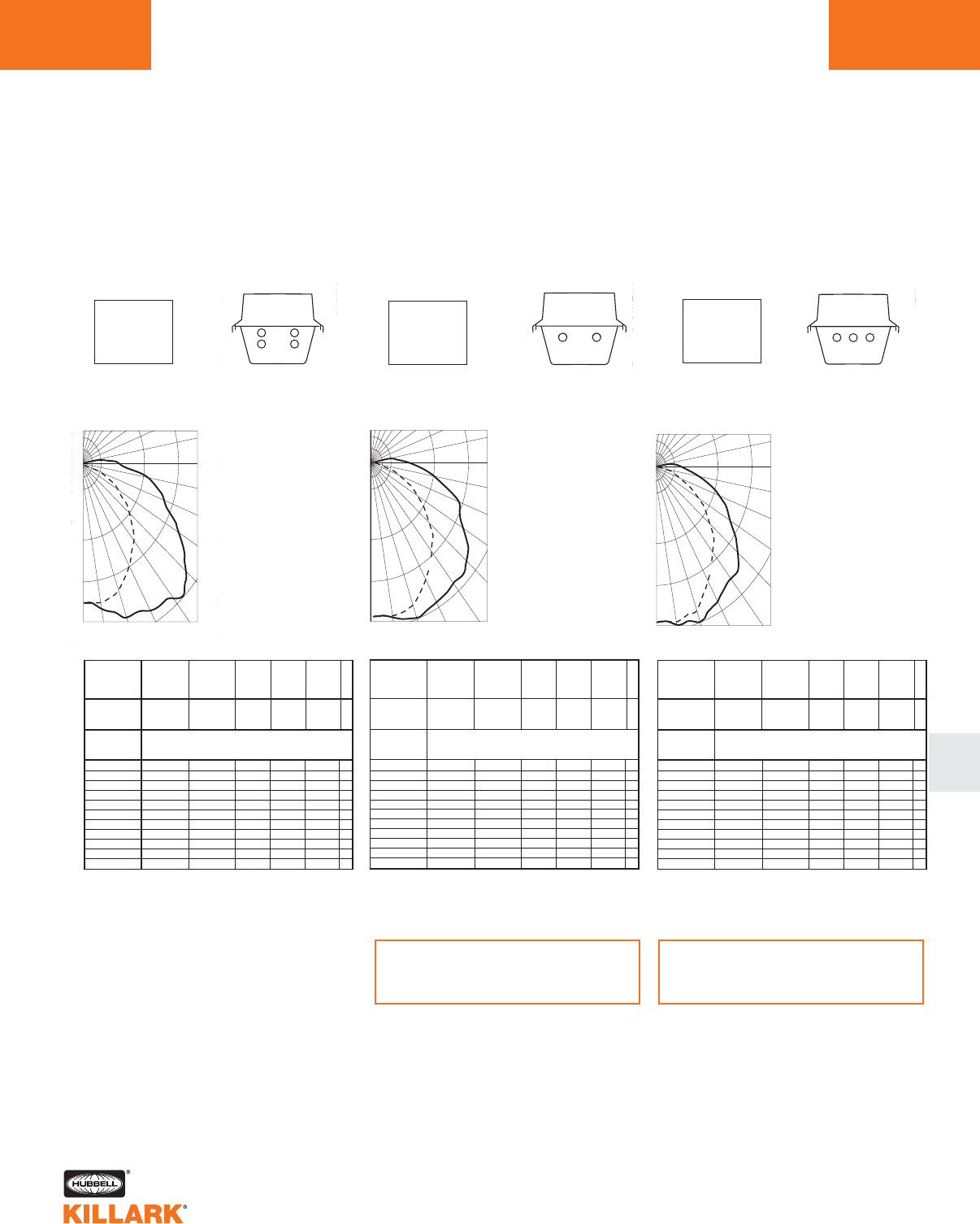
Test No. BAL 12357
FLUORESCENT FIXTURE- LZ2N(S)40430
4' – 4 40 Watt BIAXIAL Lumens 3150 each
Lamp Type F40/2G11/835/RS
Total Bare Lamp Lumens 12600
All data provided is for F40/2G11/835/RS lamps
Efficiency 76%
90˚
80˚
70˚
60˚
50˚
40˚
30˚20˚10˚0˚
180˚ 140˚ 120˚ 110˚
100˚
631
1261
1892
2522
90°
0°
SPACING TO MOUNTING HEIGHT RATIO - 1.28 0-180°
SPACING TO MOUNTING HEIGHT RATIO - 1.94 90-270°
ZONAL LUMENS
ZONE LUMENS
0-30 1649
0-40 2863
0-60 5876
0-90 8993
% EFFECTIVE
CEILING CAVITY
REFLECTAN
1cc
80 70 50 30 10 0
70 50 30 10 70 50 30 10 50 30 10 50 30 10 50 30 10 0
20% Effective Floor Cavity Reflectance
0 .89 .89 .89 .89 .87 .87.87 .87 .82 .82 .82 .77.77 .77 .73 .73 .73 .71
1 .79 .74 .70 .66 .76 .72 .68 .65 .68 .65 .62 .64 .61 .59 .61 .58 .57 .54
2.71 .63 .57 .52 .68 .61 .56 .51 .58 .53 .49 .54.50 .47 .51 .48 .45 .43
3 .64 .54 .47 .41 .61 .53.46 .41 .50 .44 .39 .47.42 .38 .44 .40 .37 .35
4 .58 .47 .40 .34 .56 .46.39 .34 .44 .37 .33 .41.36 .32 .39 .34 .31 .29
5 .53 .42 .34 .29 .51 .41.34 .28 .39 .32 .28 .36.31 .27 .35 .30 .26 .24
6 .48 .37 .30 .25 .47 .36.29 .24 .34 .28 .24 .33.27 .23 .31 .26 .22 .21
7 .45 .34 .26 .21 .43 .33.26 .21 .31 .25 .21 .30.24 .20 .28 .23 .20 .18
8 .41 .30 .23 .19 .40 .30.23 .19 .28 .22 .18 .27.22 .18 .26 .21 .17 .16
9 .39 .28 .21 .17 .37 .27 .21 .16 .26 .20 .16 .25 .19 .16 .24 .19 .15 .14
10 .36 .25 .19 .15 .35 .25 .19 .15 .24 .18 .14 .23.18 .14 .22 .17 .14 .12
% WALL
REFLECTANCE
1w
ROOM CAVITY
RATIO
RCR
VERT. ZONAL
ANGLE 0 22.5 45 67.5 90 LUMENS
0.0 1852. 1852. 1852. 1852. 1852.
5.0 1852. 1852. 1860. 1870. 1876. 177.7
10.0 1876. 1889. 1932. 1971. 1987.
15.0 1840. 1873. 1957. 2032. 2061. 553.6
20.0 1808. 1874. 2022. 2143. 2196.
25.0 1693. 1790. 1978. 2145. 2193. 909.1
30.0 1588. 1730. 1991. 2172. 2269.
35.0 1475. 1650. 1943. 2229. 2340. 1213.9
40.0 1350. 1571. 1959. 2256. 2345.
45.0 1267. 1564. 2083. 2385. 2522. 1534.8
50.0 1073. 1394. 1895. 2288. 2380.
55.0 912. 1280. 1854. 2176. 2247. 1545.2
60.0 730. 1149. 1673. 1938. 2013.
65.0 571. 1038. 1541. 1785. 1833. 1381.1
70.0 400. 885. 1342. 1549. 1558.
75.0 250. 698. 1075. 1321. 1433. 1040.9
80.0 132. 533. 968. 1208. 1262.
85.0 56. 397. 726. 921. 983. 699.6
90.0 28. 212. 464. 619. 665.
COEFFICIENTS OF UTILIZATION ---ZONAL CAVITY METHOD
Test No. BAL 12359
FLUORESCENT FIXTURE- LZ2N(S)32330
4' – 3 32W F32WT8/835/RS LAMPS
2950 Lumens Each
Total Bare Lamp Lumens 8850
For 28 Watt T5 Multiply By .98
Efficiency 77.5%
90˚
80˚
70˚
60˚
50˚
40˚
30˚20˚10˚0˚
180˚ 140˚ 120˚ 110˚
100˚
475
950
1899
90°
0°
1424
SPACING TO MOUNTING HEIGHT RATIO - 1.26 0-180°
SPACING TO MOUNTING HEIGHT RATIO - 1.48 90-270°
ZONAL LUMENS
ZONE LUMENS
0-30 1482
0-40 2470
0-60 4651
0-90 6562
% EFFECTIVE
CEILING CAVITY
REFLECTAN
1cc
80 70 50 30 10 0
70 50 30 10 70 50 30 10 50 30 10 50 30 10 50 30 10 0
20% Effective Floor Cavity Reflectance
0 .91 .91 .91 .91 .89 .89.89 .89 .84 .84 .84 .80.80 .80 .76 .76 .76 .74
1 .82 .78 .74 .70 .79 .75 .72 .69 .71 .68 .66 .68 .65 .63 .64 .62 .61 .59
2.74 .67 .61 .56 .71 .65 .59 .55 .61 .57 .53 .58.55 .51 .55 .52 .50 .48
3 .67 .58 .51 .45 .64 .56.50 .45 .53 .48 .44 .51.46 .42 .48 .44 .41 .39
4 .61 .51 .44 .38 .59 .50.43 .37 .47 .41 .37 .45.40 .36 .43 .38 .35 .33
5 .56 .45 .38 .32 .54 .44.37 .32 .42 .36 .31 .40.35 .31 .38 .34 .30 .28
6 .51 .40 .33 .28 .50 .40.33 .28 .38 .32 .27 .36.31 .27 .35 .30 .26 .24
7 .47 .37 .29 .24 .46 .36.29 .24 .34 .28 .24 .33.27 .23 .31 .27 .23 .21
8 .44 .33 .26 .22 .43 .33.26 .21 .31 .25 .21 .30.25 .21 .29 .24 .20 .19
9 .41 .30 .24 .19 .40 .30.23 .19 .29 .23 .19 .28.22 .19 .27 .22 .18 .17
10 .39 .28 .22 .17 .37 .27 .21 .17 .26 .21 .17 .25.20 .17 .25 .20 .17 .15
% WALL
REFLECTANCE
1w
ROOM CAVITY
RATIO
RCR
VERT. ZONAL
ANGLE 0 22.5 45 67.5 90 LUMENS
0.0 1786. 1786. 1786. 1786. 1786.
5.0 1774. 1774. 1778. 1781. 1781. 169.6
10.0 1800. 183. 1819. 1834. 1840.
15.0 1751. 1761. 1794. 1822. 1834. 508.1
20.0 1745. 1771. 1827. 1879. 1899.
25.0 1609. 1644. 1724. 1790. 1814. 794.9
30.0 1517. 1571. 1679. 1748. 1784.
35.0 1391. 1458. 1590. 1684. 1714. 986.9
40.0 1272. 1364. 1520. 1632. 1674.
45.0 1194. 1315. 1507. 1643. 1687. 1143.4
50.0 1010. 1150. 1353. 1491. 1551.
55.0 856. 1014. 1248. 1402. 1420. 1077.2
60.0 685. 857. 1124. 1215. 1245.
65.0 534. 741. 978. 1092. 1121. 902.9
70.0 372. 610. 830. 956. 990.
75.0 229. 452. 671. 779. 824. 642.3
80.0 116. 340. 531. 617. 650.
85.0 53. 213. 356. 453. 489. 352.6
90.0 16. 108. 245. 342. 378.
COEFFICIENTS OF UTILIZATION ---ZONAL CAVITY METHOD
Test No. BAL 12358
FLUORESCENT FIXTURE- LZ2N(S)32230
4' – 2 32W F32WT8/835/RS LAMPS
2950 Lumens Each
Total Bare Lamp Lumens 5900
For 28 Watt T5 Multiply By .98
For 34/40 Watt T12 Multiply By 1.07
For 44 Watt T8 Multiply By 1.36
For 54 Watt T5 Multiply By 1.69
For 60 Watt T12 Multiply By 1.46
Efficiency 80.9%
90˚
80˚
70˚
60˚
50˚
40˚
30˚20˚10˚0˚
180˚ 140˚ 120˚ 110˚
100˚
306
611
1222
90°
0°
917
SPACING TO MOUNTING HEIGHT RATIO - 1.26 0-180°
SPACING TO MOUNTING HEIGHT RATIO - 1.56 90-270°
ZONAL LUMENS
ZONE LUMENS
0-30 957
0-40 1608
0-60 3077
0-90 4521
% EFFECTIVE
CEILING CAVITY
REFLECTAN
1cc
80 70 50 30 10 0
70 50 30 10 70 50 30 10 50 30 10 50 30 10 50 30 10 0
20% Effective Floor Cavity Reflectance
0 .95 .95 .95 .95 .93 .93.93 .93 .88 .88 .88 .83.83 .83 .79 .79 .79 .77
1 .85 .80 .76 .72 .82 .78.74 .70 .73 .70 .67 .69.67 .64 .66 .64 .62 .60
2.76 .68 .62 .57 .73 .66 .61 .56 .63 .58 .54 .59.55 .52 .56 .53 .50 .48
3 .69 .59 .52 .46 .66 .58.51 .45 .54 .49 .44 .52.47 .42 .49 .45 .41 .39
4 .63 .52 .44 .38 .60 .51.43 .38 .48 .42 .37 .45.40 .36 .43 .39 .35 .33
5.57 .46 .38 .32 .55 .45 .37 .32 .43 .36 .31 .40.35 .30 .39 .34 .30 .28
6 .53 .41 .33 .28 .51 .40.33 .28 .38 .32 .27 .36.31 .26 .35 .30 .26 .24
7 .49 .37 .30 .24 .47 .36.29 .24 .35 .28 .24 .33.27 .23 .32 .27 .23 .21
8 .45 .34 .27 .22 .44 .33 .26 .21 .32 .25 .21 .30.25 .21 .29 .24 .20 .18
9 .42 .31 .24 .19 .41 .30.24 .19 .29 .23 .19 .28.22 .18 .27 .22 .18 .16
10 .40 .28 .22 .17 .38 .28 .21 .17 .27 .21 .17 .26.20 .17 .25 .20 .16 .15
% WALL
REFLECTANCE
1w
ROOM CAVITY
RATIO
RCR
VERT. ZONAL
ANGLE 0 22.5 45 67.5 90 LUMENS
0.0 1145. 1145. 1145. 1145. 1145.
5.0 1143. 1143. 1141. 1143. 1144. 109.1
10.0 1154. 1154. 1163. 1176. 1182.
15.0 1141. 1143. 1169. 1192. 1204. 331.4
20.0 1104. 1116. 1162. 1206. 1222.
25.0 1035. 1057. 1122. 1175. 1190. 516.8
30.0 971. 1008. 1096. 1146. 1182.
35.0 900. 949. 1035. 1134. 1166. 651.9
40.0 812. 881. 1005. 1100. 1138.
45.0 755. 849. 1003. 1109. 1150. 757.7
50.0 636. 739. 909. 1037. 1097.
55.0 538. 650. 845. 994. 1033. 734.4
60.0 432. 573. 771. 878. 928.
65.0 333. 488. 686. 792. 846. 634.2
70.0 230. 397. 595. 771. 817.
75.0 140. 302. 544. 638. 683. 501.3
80.0 71. 233. 437. 523. 557.
85.0 32. 170. 303. 397. 434. 300.9
90.0 11. 88. 205. 294. 330.
COEFFICIENTS OF UTILIZATION ---ZONAL CAVITY METHOD
LZ2N, LZ2S SERIES •LIGHTING
PHOTOMETRIC DATA L161
L
For 2’ 2 x 17W estimate
use multiplier of .44
For 2’ 3 x 17W estimate
use multiplier of .44
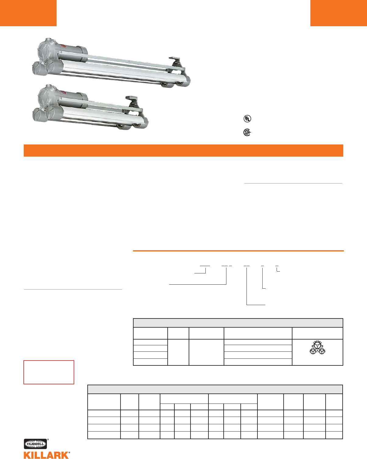
HFX-T SERIES •LIGHTING
BIAXIAL (LONG TWIN TUBE)
L162
FEATURES-SPECIFICATIONS
Listed - File E12976 and E89665 (Marine)
Certified - File LR11713
Class I, Div. 1 & 2, Groups C,D
Class l, Zones 1 & 2, Groups llB, llA
Class II, Div. 1 & 2, Groups E,F,G
Class III, Div. 1 & 2
NEMA 3, 4X, 7(C,D) 9(E,F,G)
Suitable for wet locations
Suitable for paint spray booths
2’ Nominal
Style
4’ Nominal
Style
Applications
Biaxial single ended lamp type HFX-T fix-
tures provide greater efficiency and
lumen output than standard models.
Designed for installations where moisture,
dirt, dust, corrosion and vibration may be
present, or NEMA 3 and 4X areas where
wind, water and snow can be expected.
They can also be used in locations made
hazardous due to the presence of flam-
mable or explosive gases, vapors and
combustible ducts as defined by the
NEC.
Typical applications include classified
areas such as inside paint spray booths,
paint manufacturing plants, ammunition
facilities, oil and gas producing and
refining plants, off-shore and dockside
installations, tank farms, pipeline pump-
ing stations and marine loading and fuel
transfer terminals.
Features
• UL Listed and labeled for use inside
paint spray booths and rooms
• 2’ nominal compact models facilitate
use in areas too small for nominal 4’
models, or where the light must be
confined
• Standard ballast is 120-277V
at 50/60 Hz1
• 0°F starting temperature
• Construction is strong lightweight corro-
sion resistant copper-free aluminum alloy,
less than 4/10 of 1%
• All external hardware is corrosion resis-
tant 316 stainless steel
• UL Listed externally fused ballast option;
protects fixture on line side of ballast,
prevents ballast burnout
• Suitable for use in both indoor and
outdoor wet locations
• Relamping easily accomplished by
removing screw in cap and socket
• Factory sealed construction
• Extruded aluminum reflectors are easily
removable for cleaning. White baked
enamel finish
Compliances
• UL-1570, Standard for Fluorescent
Lighting Fixtures
• UL Marine Type Lighting Fixtures
• UL-844, Standard for Lighting Fixtures
for Hazardous Locations
• CSA C22.2 137-M1981
• Meets requirements of NFPA 70-1987
Article 516 and NFPA standard 33
Catalog Number Logic
Constant for HFX Series
Lamp Wattage
40—40 Watt BIAXIAL Type
55—55 Watt BIAXIAL Type
2 lamps (2’ Nominal)
4 lamps (4’ Nominal)
Voltage
30—120-277V 50/60 Hz.
HFX - 00 T - 00- 0 - F
F1 Fuse 120V
F2 Fuse 277V
RATED SUITABLE CLASS I, DIV, 1 & 2 CLASS II, DIV, 1 & 2 CLASS III UL PAINT NEMA
DESCRIPTION AMBIENT FOR °C MAX. SURFACE TEMP. MAX. SURFACE TEMP. DIV. 1 & 2 SPRAY
° C SUPPLY WIRE TEMP. T-CODE GROUPS TEMP. T-CODE GROUPS SUITABILITY MARINE SUITABLE 3 & 4X
HFX-T 40W 2 LAMP 40 60 85°C T6 C, D 120°C T4A E, F, G Yes Yes Yes Yes
HFX-T 55W 2 LAMP 40 60 85°C T6 C, D 120°C T4A E, F, G Yes Yes Yes Yes
HFX-T 40W 4 LAMP 40 60 85°C T6 C, D 120°C T4A E, F, G Yes Yes Yes Yes
HFX-T 55W 4 LAMP 40 60 85°C T6 C, D 120°C T4A E, F, G Yes Yes Yes Yes
HFX-T, HFXE-T HAZARDOUS LOCATION APPLICATION DATA
CONDUIT LINE VOLTAGE DESCRIPTION PROFILE
SIZE
HFX-40T-302 2’ 2 Lamp 40W BIAXIAL
HFX-55T-302 3⁄4" 120V-277V 2’ 2 Lamp 55W BIAXIAL
HFX-40T-304 50/60 Hz 4’ 4 Lamp 40W BIAXIAL
HFX-55T-304 4’ 4 Lamp 55W BIAXIAL
HFX-T BIAXIAL TYPE LIGHT FIXTURES2
Two Glass Tubes
2’ or 4’ Nominal
1See page L162 for ballast current information.
2Consult HFX page L163 for dimensions and accessories. Photometrics on following page.
CATALOG
NUMBER
SEE PAGE L189
FOR HFXE
EMERGENCY MODELS
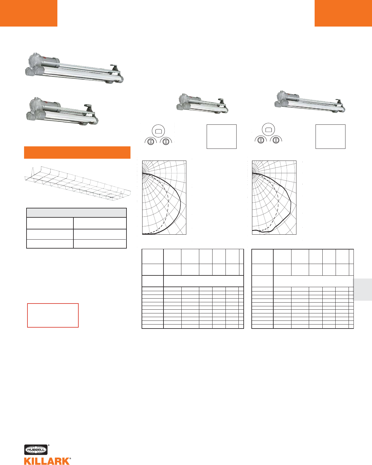
HFX-T SERIES •LIGHTING
BIAXIAL LONG TWIN TUBE ACCESSORIES, PHOTOMETRIC DATA L163
L
Test No. BAL12360
FLUORESCENT FIXTURE-
HFX-40T-302
Lamp Type F40/2G11/835/RS
2' – 2 40 Watt Biaxial 3150 Lumens each.
Total Bare Lamp Lumens 6300
For 55W Biaxial multiply by 1.52.
Efficiency 83.2%
90˚
80˚
70˚
60˚
50˚
40˚
30˚20˚10˚0˚
180˚ 140˚ 120˚ 110˚
100˚
90˚
386
772
1158
1544
0˚
SPACING TO MOUNTING HEIGHT RATIO - 1.28 0-180°
SPACING TO MOUNTING HEIGHT RATIO - 1.50 90-270°
Test No. BAL12361
ZONAL LUMENS
ZONE LUMENS
0-30 1246
0-40 2102
0-60 3989
0-90 5237
% EFFECTIVE
CEILING CAVITY
REFLECTAN
1cc
80 70 50 30 10 0
70 50 30 10 70 50 30 10 50 30 10 50 30 10 50 30 10 0
20% Effective Floor Cavity Reflectance
0 .99 .99 .99 .99 .97 .97 .97 .97 .92 .92 .92 .88.88 .88 .85 .85 .85 .83
1 .90 .86 .82 .79 .88 .84 .81 .78 .80 .78 .75 .77.75 .73 .74 .72 .71 .69
2 .81 .74 .68 .63 .79 .73 .67 .63 .70 .65 .61 .67.63 .60 .64 .61 .58 .56
3 .74 .65 .58 .52 .72 .63 .57 .51 .61 .55 .50 .58.54 .50 .56 .52 .49 .47
4 .67 .57 .49 .43 .65 .56 .49 .43 .54 .47 .42 .52.46 .42 .50 .45 .41 .39
5 .62 .50 .43 .37 .60 .50 .42 .37 .48 .41 .36 .46.40 .36 .44 .39 .35 .34
6 .57 .45 .37 .32 .55 .44 .37 .32 .43 .36 .31 .41.36 .31 .40 .35 .31 .29
7 .52 .41 .33 .28 .51 .40 .33 .28 .39 .32 .28 .38 .32 .27 .36 .31 .27 .25
8 .49 .37 .30 .25 .47 .36 .30 .25 .35 .29 .24 .34.29 .24 .33 .28 .24 .23
9 .45 .34 .27 .22 .44 .33 .27 .22 .32 .26 .22 .32.26 .22 .31 .25 .22 .20
10 .43 .31 .24 .20 .41 .31.24 .20 .30 .24 .20 .29.24 .20 .28 .23 .20 .18
% WALL
REFLECTANCE
1w
ROOM CAVITY
RATIO
RCR
VERT. ZONAL
ANGLE 0 22.5 45 67.5 90 LUMENS
01530. 1530. 1530. 1530. 1530.
5.0 1533. 1524. 1520. 1533. 1531. 145.8
10.0 1515. 1509. 1515. 1527. 1536.
15.0 1484. 1486. 1508. 1531. 1544. 428.0
20.0 1435. 1453. 1492. 1526. 1543.
25.0 1379. 1410. 1464. 1511. 1540. 676.4
30.0 1310. 1355. 1427. 1485. 1530.
35.0 1227. 1286. 1377. 1448. 1490. 858.9
40.0 1132. 1209. 1313. 1403. 1440.
45.0 1026. 1123. 1242. 1354. 1389. 953.7
50.0 913. 1024. 1168. 1287. 1326.
55.0 783. 902. 1083. 1205. 1236. 941.8
60.0 649. 781. 982. 1094. 1090.
65.0 507. 667. 862. 875. 857. 765.8
70.0 346. 543. 641. 601. 600.
75.0 197. 396. 408. 425. 428. 407.7
80.0 72. 218. 224. 242. 240.
85.0 14. 74. 56. 52. 51. 58.8
90.0 1. 1 0 . 6 . 7. 8 .
COEFFICIENTS OF UTILIZATION ---ZONAL CAVITY METHOD
FLUORESCENT FIXTURE-
HFX-40T-304
Lamp Type F40/2G11/835/RS
4' – 4 40 Watt Biaxial 3150 Lumens each.
Total Bare Lamp Lumens 12600
For 55W Biaxial multiply by 1.52.
Efficiency 76%
90˚
80˚
70˚
60˚
50˚
40˚
30˚20˚10˚0˚
180˚ 140˚ 120˚ 110˚
100˚
90˚
698
1397
2095
2793
0˚
SPACING TO MOUNTING HEIGHT RATIO - 1.28 0-180°
SPACING TO MOUNTING HEIGHT RATIO - 1.52 90-270°
ZONAL LUMENS
ZONE LUMENS
0-30 2197
0-40 3685
0-60 7050
0-90 9559
% EFFECTIVE
CEILING CAVITY
REFLECTAN
1cc
80 70 50 30 10 0
70 50 30 10 70 50 30 10 50 30 10 50 30 10 50 30 10 0
20% Effective Floor Cavity Reflectance
0 .90 .90 .90 .90 .88 .88 .88 .88 .84 .84 .84 .81.81 .81 .77 .77 .77 .76
1 .82 .78 .74 .71 .80 .76 .73 .70 .73 .70 .68 .70.68 .65 .67 .65 .63 .62
2 .74 .67 .61 .57 .72 .66 .60 .56 .63 .58 .55 .60.56 .53 .58 .55 .52 .50
3 .67 .58 .52 .46 .65 .57 .51 .46 .55 .49 .45 .52.48 .44 .50 .47 .43 .42
4 .61 .51 .44 .39 .59 .50 .43 .38 .48 .42 .38 .46.41 .37 .45 .40 .37 .35
5 .56 .45 .38 .33 .54 .44 .38 .33 .43 .37 .32 .41.36 .32 .40 .35 .31 .30
6 .51 .41 .33 .28 .50 .40 .33 .28 .38 .32 .28 .37.32 .28 .36 .31 .27 .26
7 .47 .37 .30 .25 .46 .36 .29 .25 .35 .29 .24 .34.28 .24 .33 .28 .24 .22
8 .44 .33 .27 .22 .43 .33 .26 .22 .32 .26 .22 .31.25 .22 .30 .25 .21 .20
9 .41 .30 .24 .20 .40 .30 .24 .20 .29 .23 .19 .28.23 .19 .27 .23 .19 .18
10 .38 .28 .22 .18 .37 .28 .22 .18 .27 .21 .17 .26.21 .17 .25 .21 .17 .16
% WALL
REFLECTANCE
1w
ROOM CAVITY
RATIO
RCR
VERT. ZONAL
ANGLE 0 22.5 45 67.5 90 LUMENS
0.0 2625 2625 2625 2625 2625
5.0 2606 2607 2611 2617 2620 249.3
10.0 2661 2669 2692 2716 2726
15.0 2621 2641 2693 2738 2756 762.6
20.0 2559 2597 2692 2766 2793
25.0 2393 2450 2564 2653 2685 1181.0
30.0 2254 2335 2477 2590 2635
35.0 2102 2207 2381 2528 2587 1485.7
40.0 1959 2094 2306 2502 2571
45.0 1778 1951 2236 2473 2544 1707.9
50.0 1609 1793 2106 2325 2387
55.0 1404 1612 1966 2169 2234 1697.1
60.0 1140 1369 1701 1890 1942
65.0 928 1202 1542 1680 1698 1423.7
70.0 676 984 1268 1290 1277
75.0 425 735 871 860 889 825.8
80.0 204 473 548 623 643
85.0 58 202 256 248 251 234.9
90.0 15 36 44 53 60
COEFFICIENTS OF UTILIZATION ---ZONAL CAVITY METHOD
CATALOG
NUMBER DESCRIPTION
2HFX-G2 302 HFX-T Models
2HFX-G4 304 HFX-T Models
WIRE GUARD1
1316 Stainless Steel
Consult page L167 for dimensions
and accessories.
SEE PAGE L189
FOR HFXE
EMERGENCY MODELS
2’ Nominal
Style
4’ Nominal
Style
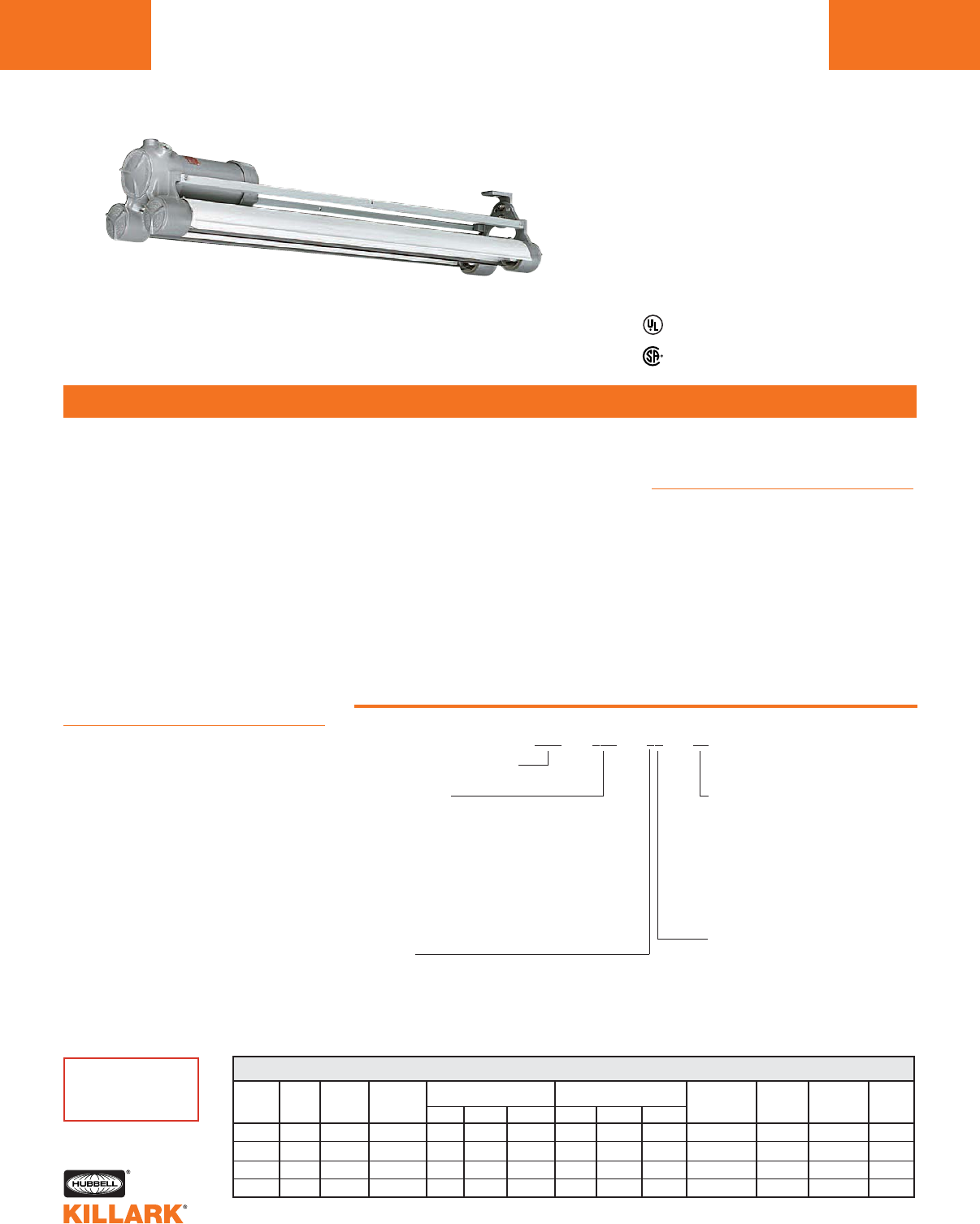
HFX SERIES •LIGHTING
FLUORESCENT FIXTURES
L164
FEATURES-SPECIFICATIONS
Applications
HFX Series fluorescent fixtures are
designed for installations where moisture,
dirt, dust, corrosion and vibration may be
present, or NEMA 3 and 4X areas where
wind, water and snow can be expected.
They can also be used in locations made
hazardous due to the presence of flam-
mable or explosive gases, vapors and
combustible ducts as defined by the NEC.
Typical applications include classified
areas such as inside paint spray booths,
paint manufacturing plants, ammunition
facilities, oil and gas producing and
refining plants, off-shore and dockside
installations, tank farms, pipeline pump-
ing stations and marine loading and fuel
transfer terminals.
Features
• UL Listed and labeled for use inside
paint spray booths and rooms
• Construction is strong lightweight corro-
sion resistant copper-free aluminum
alloy, less than 4/10 of 1%
• Class P ballast(s) with internal automat-
ic thermally activated protective device
• All external hardware is corrosion
resistant 316 stainless steel to provide
maintenance free long life
• UL factory sealed construction (no
external seals required). Saves installa-
tion time and cost
•Electronic energy efficient ballasts
are standard on 430 MA fixtures and
meet the requirements of many states
• Extruded aluminum reflectors are easily
removable for cleaning. White baked
enamel finish
• Optional 316 stainless steel wire guard for
added protection
• Threaded O-Ring gasketed covers
provide easy access to lamp chambers,
ballast and wiring compartment
• UL Listed externally fused ballast option;
protects fixture on line side of ballast,
prevents ballast burnout
• Suitable for use in both indoor and
outdoor wet locations
• Relamping from either end permits easy
access, speed and flexibility in relamping
Catalog Number Logic
Constant for HFX Series
Lamp Current
265—265 MA, 32W T8 (0°F Starting,
Electronic)
430—430 MA, 40W RS (50°F Starting
Electronic)2
800—800 MA, 60W RS HO
(-20°F Starting)
1500—1500 MA, 110W RS VHO
(-20°F Starting)
Voltage
1—120V, 60 Hz.
4—277, 60 Hz.
7—220V, 60 Hz. 430 MA
8—220/240V, 50 Hz., 430 MA
30—120-277V 50/60 Hz 265 MA only.
Options
FB—Individually in-line fused
ballast (not Marine or CSA)
WL—With lamps supplied
Number of Lamps
2—2 lamps
3—3 lamps
4—4 lamps
HFX - 000 - 00- 00
Listed - File E12976 and E89665 (Marine)
Class I, Div. 1 & 2 Groups C,D
Class l, Zones 1 & 2, Groups llB,llA
Class II, Div. 1 & 2, Groups E,F,G
Class III, Div. 1 & 2
NEMA 3, 4X, 7(C,D) 9(E,F,G)
Suitable for wet locations
Suitable for paint spray booths
• Spring loaded sockets on both lamp
ends provide positive electrical contact
and improved vibration resistance
Compliances
• UL-1570, Standard for Fluorescent
Lighting Fixtures
• UL Marine Type Lighting Fixtures
• UL-844, Standard for Lighting Fixtures
for Hazardous Locations
• CSA C22.2 137-M1981
• Meets requirements of NFPA 70-1987
Article 516 and NFPA standard 33
FIXTURE LAMP RATED SUITABLE CLASS I, DIV, 1 & 2 CLASS II, DIV, 1 & 2 CLASS III UL PAINT NEMA
AMBIENT FOR °C MAX. SURFACE TEMP. MAX. SURFACE TEMP. DIV. 1 & 2 SPRAY
SERIES WATTS ° C SUPPLY WIRE TEMP. T-CODE GROUPS TEMP. T-CODE GROUPS SUITABILITY MARINE SUITABLE 3 & 4
HFX 32 40 90 100°C T5 C, D 120°C T4A E, F, G Yes Yes Yes Yes
HFX 40 40 90 100°C T5 C, D 120°C T4A E, F, G Yes Yes Yes Yes
HFX 60 40 90 100°C T5 C, D 120°C T4A E, F, G Yes Yes Yes Yes
HFX 110 40 90 100°C T5 C, D 120°C T4A E, F, G Yes Yes Yes Yes
HFX, HFXE HAZARDOUS LOCATION APPLICATION DATA1
1Ratings apply to all 2, 3, and 4 lamp models.
2430 MA ballasts 60°F start with 34 watt lamps.
Certified - File LR11713
SEE PAGE L189
FOR HFXE
EMERGENCY MODELS
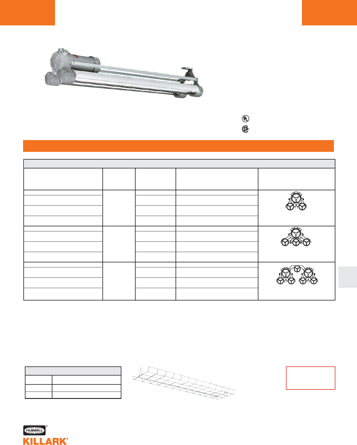
HFX SERIES •LIGHTING
FLUORESCENT FIXTURES L165
ORDERING INFORMATION
L
CONDUIT LINE VOLTAGE DESCRIPTION NUMBER
SIZE @60 HERTZ OF LAMPS
HFX-265-302 120V-277V 32W T8 electronic ballast 265MA
HFX-430-12 120V 40W rapid start electronic F40T12
HFX-430-42 3/4" 277V medium Bi-Pin 430MA
HFX-800-12 120V 60W rapid start high output F48T12/HO
HFX-800-42 277V recessed double contact 800MA
HFX-1500-12 120V 110W rapid start VHO F48T12/VHO
HFX-1500-42 277V recessed double contact 1500MA
HFX-265-303 120V-277V 32W T8 electronic ballast 265MA
HFX-430-13 120V 40W rapid start electronic F40T12
HFX-430-43 277V medium Bi-Pin 430MA
HFX-800-13 3/4" 120V 60W rapid start high output F48T12/HO
HFX-800-43 277V recessed double contact 800MA
HFX-1500-13 120V 110w rapid start VHO F48T12/VHO
HFX-1500-43 277V recessed double contact 1500MA
HFX-265-304 120V-277V 32W T8 electronic ballast 265MA
HFX-430-14 120V 40W rapid start electronic F40T12
HFX-430-44 277V medium Bi-Pin 430MA
HFX-800-14 3/4" 120V 60W rapid start high output F48T12/HO
HFX-800-44 277V recessed double contact 800MA
HFX-1500-14 120V 110W rapid start VHO F48T12/VHO
HFX-1500-44 277V recessed double contact 1500MA
HFX FLUORESCENT LIGHT FIXTURES
Listed - File E12976 and E89665 (Marine)
Two Glass Tubes
4’ Nominal
Three Glass Tubes
4’ Nominal
1Standard ballasts starting temperatures:
32 Watt (265MA) Electronic 0°F
40 Watt (430MA) Electronic 50°F, 60°F with 34 Watt lamps
60 Watt (800MA) Electronic -20°F
110 Watt (1500MA) Electronic -20°F
Optional cold weather electromagnetic ballast (0°F starting 40 Watt 430MA) add suffix CW to catalog number.
2Optional UL listed in-line ballast fusing is available by adding suffix FB to catalog number (UL only).
3Safety chain accessory catalog number HFX-SC available, supplied standard with 4 lamp fixtures.
Four Glass Tubes
4’ Nominal
3
CATALOG NUMBER12
Certified - File LR11713
CATALOG DESCRIPTION
NUMBER
2HFX-G4 2-Lamp 316 grade stainless steel
3HFX-G4 3-Lamp 316 grade stainless steel
WIRE GUARD
4 lamp fixture requires two 2HFX-G4 guards.
Class I, Div. 1 & 2 Groups C,D
Class l, Zones 1 & 2, Groups llB,llA
Class II, Div. 1 & 2, Groups E,F,G
Class III, Div. 1 & 2
NEMA 3, 4X, 7(C,D) 9(E,F,G)
Suitable for wet locations
Suitable for paint spray booths
SEE PAGE L189
FOR HFXE
EMERGENCY MODELS
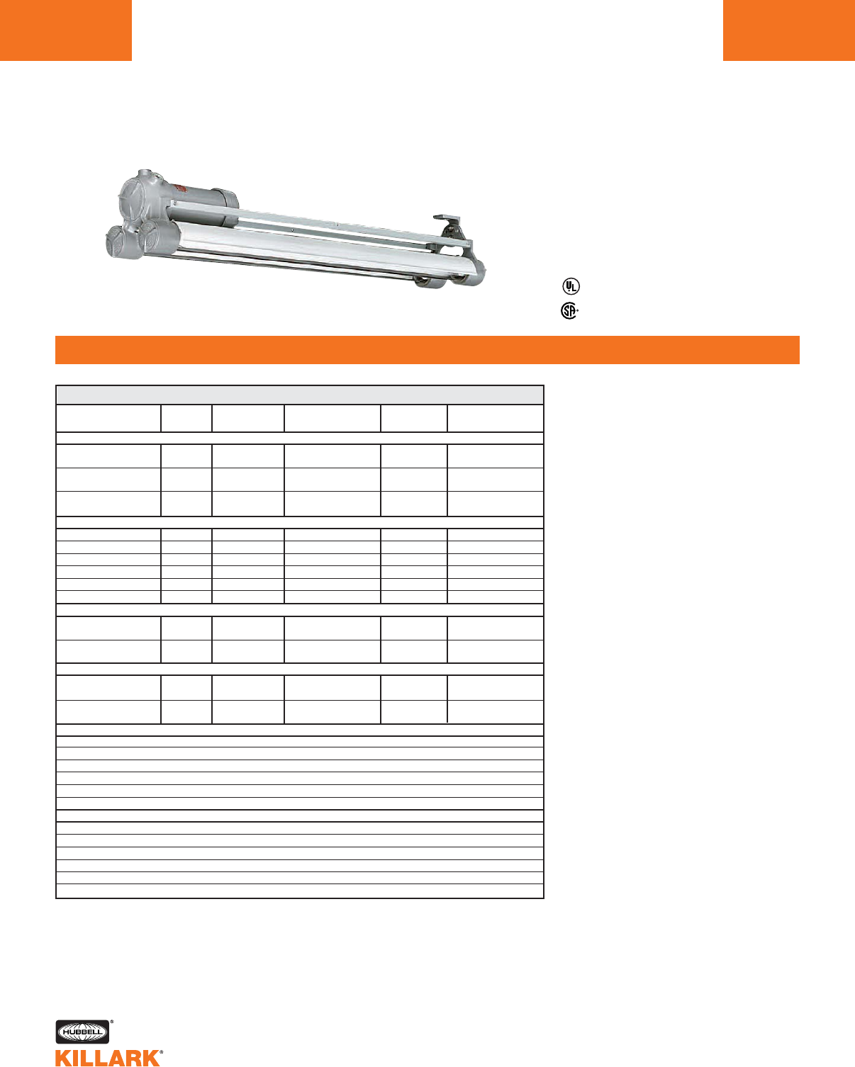
HFX(T) SERIES •LIGHTING
BALLAST DATA
L166
CATALOG NO. OF LINE CURRENT INPUT STARTING
NUMBER LAMPS VOLTAGE AMPS WATTS TEMPERATURE
32 WATT T-8 ELECTRONIC 48" 265MA
HFX-265-302 2 120-277 .54 (120V) 71 0°F (-18°C)
.24 (277V)
HFX-265-30313 120-277 .71 (120V) 88 0°F (-18°C)
.31 (277V)
HFX-265-304 4 120-277 1.10 (120V) 142 0°F (-18°C)
.48 (277V)
40 WATT RAPID START ELECTRONIC T-12 MEDIUM BI-PIN 48" 430MA
HFX-430-12 2 120 .51260 60°F (16°C)
HFX-430-42 2 277 .22260 60°F (16°C)
HFX-430-1313 120 .69291 60°F (16°C)
HFX-430-4313 277 .30291 60°F (16°C)
HFX-430-14 4 120 1.022120 60°F (16°C)
HFX-430-44 4 277 .442120 60°F (16°C)
40 WATT BIAXIAL TYPE
HFX-40T-302 2120-277 .63 (120V) 76 0°F (-18°C)
50/60 Hz .27 (277V)
HFX-40T-304 4120-277 1.32 (120V) 156 0°F (-18°C)
50/60 Hz .54 (277V)
55 WATT BIAXIAL TYPE
HFX-55T-302 2120-277 .94 (120V) 112 0°F (-18°C)
50/60 Hz .41 (277V)
HFX-55T-304 4120-277 1.97 (120V) 232 0°F (-18°C)
50/60 Hz .84 (277V)
60 WATT RAPID START HIGH OUTPUT T-12 RECESSED DOUBLE CONTACT 48" 800MA
HFX-800-12 2 120 1.40 135 -20°F (-29°C)
HFX-800-42 2 277 .61 145 -20°F (-29°C)
HFX-800-13 3 120 2.40 260 -20°F (-29°C)
HFX-800-43 3 277 1.03 235 -20°F (-29°C)
HFX-800-14 4 120 2.80 270 -20°F (-29°C)
HFX-800-44 4 277 1.22 290 -20°F (-29°C)
110 WATT RAPID START VERY HIGH OUTPUT T-12 RECESSED DOUBLE CONTACT 48" 1500MA
HFX-1500-12 2 120 2.10 242 -20°F (-29°C)
HFX-1500-42 2 277 .92 242 -20°F (-29°C)
HFX-1500-13 3 120 3.38 376 -20°F (-29°C)
HFX-1500-43 3 277 1.48 377 -20°F (-29°C)
HFX-1500-14 4 120 4.20 484 -20°F (-29°C)
HFX-1500-44 4 277 1.84 484 -20°F (-29°C)
HFX BALLAST DATA
Listed - File E12976 and E89665 (Marine)
13 lamp 265MA and 430MA fixtures use a single ballast.
2Line current and 60°F start using 34 Watt lamps. Start temperature for
40 Watt lamps is 50°F (10°C). 40 Watt lamps current approximately
24% higher.
Certified - File LR11713
Class I, Div. 1 & 2 Groups C,D
Class l, Zones 1 & 2, Groups llB,llA
Class II, Div. 1 & 2, Groups E,F,G
Class III, Div. 1 & 2
NEMA 3, 4X, 7(C,D) 9(E,F,G)
Suitable for wet locations
Suitable for paint spray booths
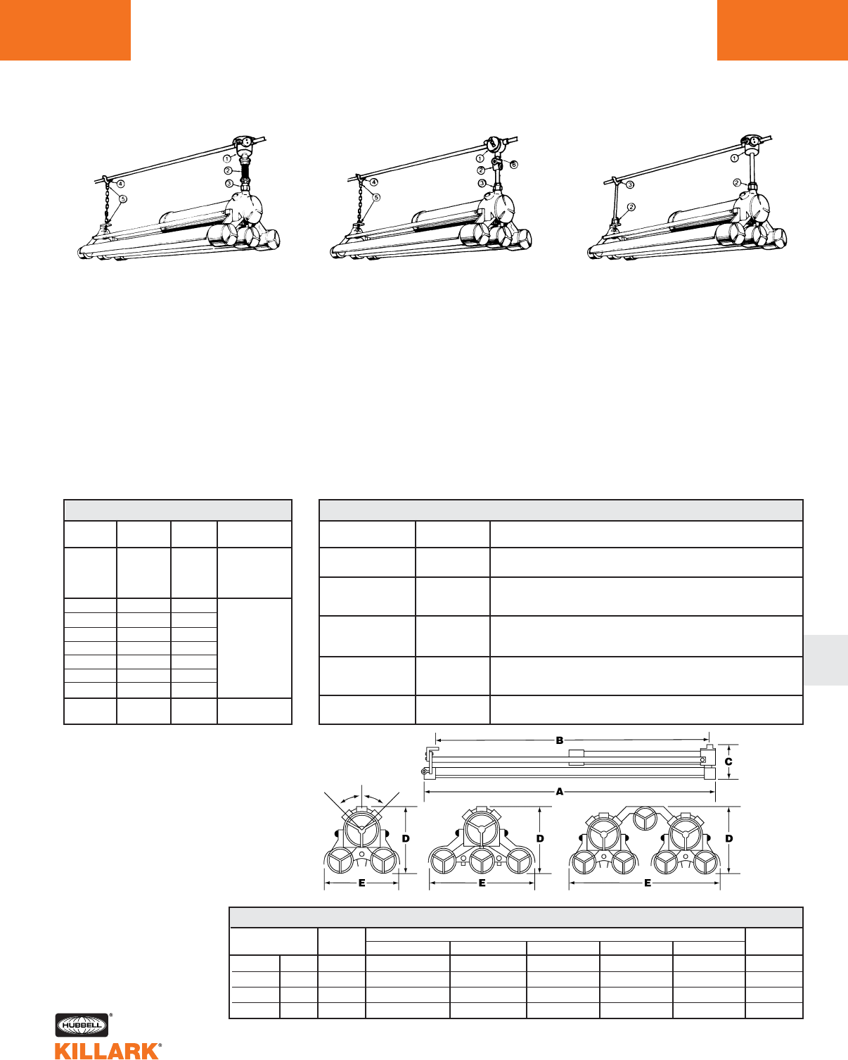
HFX(T) SERIES •LIGHTING
BALLAST DATA
L
Typical installation using conduit hardware.
Dummy (non-powered) end lowers for
relamping clearance, which is required
when fixtures are mounted in close
proximity. Flexible mounting provides
free swing and impact protection.
1. Splice Box/Fixture Hanger (HXB)
2. Flexible Pendant Hanger (EKJ)
3. Union (GUM)
4. Rigid Support Saddle Bracket (KFHS)
5. Support Hook (KEFHM)
Note: Leave extra links to support
fixture in relamping position. Chain
furnished by others.
Dummy (non-powered) end lowers for
relamping clearance, which is required
when fixtures are mounted in close
proximity.
1. Splice Box/Fixture Hanger (XFH)
2. Swivel Hanger (KESD)
3. Union (GUM)
4. Rigid Support Saddle Bracket (KFHS)
5. Support Hook (KEFHM)
Note: Leave extra links to support
fixture in relamping position. Chain
furnished by others.
Rigid mounted—for installations where
relamping can be accomplished without
lowering dummy end.
1. Splice Box/Fixture Hanger (HXB)
2. Union (GUM)
3. Rigid Support Saddle Bracket (KFHS)
For wall mounting, use securely fas-
tened 3/4" pipe 6" or less in length.
Floor flange (furnished by others)
recommended for dummy end as well
as chain or cable providing vertical
strain relief from above fixture. Chain
furnished by others.
CATALOG
NUMBER HUB SIZE DESCRIPTION
XFH-22 3/4" XFH SERIES
Splice box/fixture hanger
KESD SERIES
KESD-75 3/4" Swivel Hanger
15° swivel drop from center and full 360° free swing
KFHS SERIES
KFHS-5075 3/4" Rigid support saddle bracket for fluorescent fixtures (dummy end)
Will support 350 lbs. and straddle Max. 1-1⁄4" conduit
KEFHM SERIES
KEFHM-75 3/4" Safety support hook with 3/4" male end For dummy end of fixture
Will support 200 lbs. screw closed 3/8" jaw opening
HFX-SC —HFX SERIES
Safety chain (36" length plated steel), standard on 4-tube fixture
MOUNTING HARDWARE
CATALOG HUB
NUMBER SIZE LENGTH DESCRIPTION
HXB-12 1/2" —
HXB-22 3/4" —
EKJ-24 3/4" 4
EKJ-26 3/4" 6
EKJ-28 3/4" 8
EKJ-210 3/4" 10
EKJ-212 3/4" 12
EKJ-215 3/4" 15
EKJ-218 3/4" 18
GUM-2 3/4"
MOUNTING HARDWARE
EKJ SERIES
Flexible
Pendant
Hanger
GU SERIES
Male Union
HXB SERIES
Splice Box/
3/4" Fixture
Hanger
HFX MODEL CONDUIT DIMENSIONS NET
SIZE ABCDE
WEIGHT
Nominal 2’ 2 Tubes 3/4-14 NPT 28-15/16” (735) 24-3/8” (619) 9-3/32" (231) 9-3/32" (231) 11" (279) 36.0 Lbs.
Nominal 4’ 2 Tubes 3/4-14 NPT 52-13/16" (1367) 48-3/8" (1229) 9-3/32" (231) 9-3/32" (231) 11" (279) 47.7 Lbs.
Nominal 4’ 3 Tubes 3/4-14 NPT 52-13/16" (1367) 48-3/8" (1229) 9-3/32" (231) 9-3/32" (231) 15-5/8" (397) 63.0 Lbs.
Nominal 4’ 4 Tubes 3/4-14 NPT 52-13/16" (1367) 48-3/8" (1229) 9-3/32" (231) 10-1/8" (257) 23" (584) 99.9 Lbs.
HFX DIMENSIONS
L167
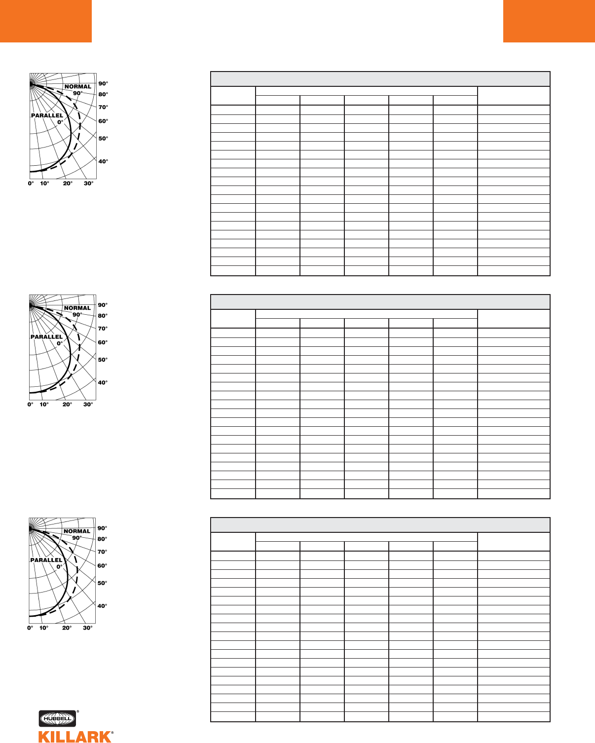
HFX SERIES •LIGHTING
PHOTOMETRIC DATA/CANDLEPOWER DISTRIBUTION
L168
VERTICAL HORIZONTAL ANGLE
ANGLE 0 22.5 45 67.5 90 ZONAL LUMENS
0.0 1325. 1325. 1325. 1325. 1325. —
5.0 1359. 1366. 1366. 1369. 1365. 130
10.0 1313. 1321. 1328. 1338. 1325. —
15.0 1309. 1315. 1323. 1333. 1333. 375
20.0 1288. 1302. 1318. 1331. 1333. —
25.0 1196. 1213. 1238. 1252. 1259. 571
30.0 1147. 1169. 1198. 1229. 1236. —
35.0 1037. 1065. 1104. 1145. 1160. 693
40.0 961. 1000. 1047. 1105. 1126. —
45.0 819. 857. 921. 990. 1019. 714
50.0 737. 784. 867. 950. 982. —
55.0 634. 690. 796. 899. 937. 711
60.0 518. 584. 711. 821. 836. —
65.0 412. 498. 645. 693. 699. 594
70.0 263. 363. 465. 485. 487. —
75.0 172. 281. 326. 339. 343. 318
80.0 80. 168. 189. 215. 223. —
85.0 25. 75. 89. 89. 84. 84
90.0 6. 11. 14. 20. 22. —
CANDLEPOWER 2-40/T12 RAPID START
VERTICAL HORIZONTAL ANGLE
ANGLE 0 22.5 45 67.5 90 ZONAL LUMENS
0.0 1971. 1971. 1971. 1971. 1971. —
5.0 1988. 1985. 1987. 1994. 1990. 190
10.0 1946. 1949. 1953. 1960. 1962. —
15.0 1929. 1934. 1944. 1959. 1963. 552
20.0 1897. 1907. 1926. 1947. 1961. —
25.0 1773. 1788. 1817. 1850. 1866. 842
30.0 1688. 1713. 1758. 1802. 1819. —
35.0 1551. 1580. 1640. 1701. 1722. 1030
40.0 1427. 1467. 1545. 1626. 1661. —
45.0 1232. 1281. 1376. 1487. 1528. 1070
50.0 1101. 1159. 1284. 1417. 1463. —
55.0 952. 1027. 1188. 1340. 1395. 1061
60.0 780. 871. 1068. 1233. 1254. —
65.0 620. 735. 961. 1042. 1049. 887
70.0 403. 540. 706. 739. 742. —
75.0 247. 414. 486. 512. 520. 475
80.0 120. 253. 290. 323. 323. —
85.0 30. 93. 92. 84. 81. 89
90.0 3. 9. 12. 19. 19. —
CANDLEPOWER 3-40/T12 RAPID START
VERTICAL HORIZONTAL ANGLE
ANGLE 0 22.5 45 67.5 90 ZONAL LUMENS
0.0 2650. 2650. 2650. 2650. 2650. —
5.0 2718. 2733. 2733. 2738. 2730. 261
10.0 2627. 2641. 2656. 2677. 2650. —
15.0 2617. 2630. 2646. 2665. 2665. 750
20.0 2577. 2604. 2635. 2663. 2666. —
25.0 2393. 2427. 2476. 2504. 2518. 1141
30.0 2294. 2338. 2396. 2458. 2472. —
35.0 2074. 2131. 2207. 2290. 2321. 1386
40.0 1922. 2000. 2095. 2209. 2252. —
45.0 1637. 1713. 1843. 1980. 2037. 1427
50.0 1474. 1567. 1734. 1901. 1963. —
55.0 1269. 1381. 1592. 1798. 1874. 1422
60.0 1035. 1168. 1422. 1643. 1672. —
65.0 823. 997. 1291. 1386. 1398. 1187
70.0 526. 726. 929. 970. 973. —
75.0 343. 562. 652. 678. 686. 636
80.0 159. 336. 378. 431. 446. —
85.0 50. 149. 177. 177. 168. 167
90.0 13. 22. 28. 41. 44. —
CANDLEPOWER 4-40/T12 RAPID START
Total Bare Lamp
Lumens 6400
All data provided is for
F40T12RS/WW lamps 40W
rapid start warm white. For
Candlepower/Lumen multipliers
of other lamps use the follow-
ing:
32W T8 (2850 lumen lamp) .89
34W T12 (2700 lumen lamp) .84
60W F48T12/WW/HO Warm
White High Output 1.35
110W F48T12/WW/VHO Warm
White Very High Output 1.97
ZONAL LUMENS
ZONE LUMENS
0-30 1076
0-40 1769
0-60 3194
0-90 4189
Total Bare Lamp
Lumens 9600
All data provided is for
F40T12RS/WW lamps 40W
rapid start warm white. For
Candlepower/Lumen multipliers
of other lamps use the follow-
ing:
32W T8 (2850 lumen lamp) .89
34W T12 (2700 lumen lamp) .84
60W F48T12/WW/HO Warm
White High Output 1.35
110W F48T12/WW/VHO Warm
White Very High Output 1.97
ZONAL LUMENS
ZONE LUMENS
0-30 1583
0-40 2613
0-60 4743
0-90 6194
Total Bare Lamp
Lumens 12800
All data provided is for
F40T12RS/WW lamps 40W
rapid start warm white. For
Candlepower/Lumen multipliers
of other lamps use the follow-
ing:
32W T8 (2850 lumen lamp) .89
34W T12 (2700 lumen lamp) .84
60W F48T12/WW/HO Warm
White High Output 1.35
110W F48T12/WW/VHO Warm
White Very High Output 1.97
ZONAL LUMENS
ZONE LUMENS
0-30 2152
0-40 3538
0-60 6388
0-90 8379
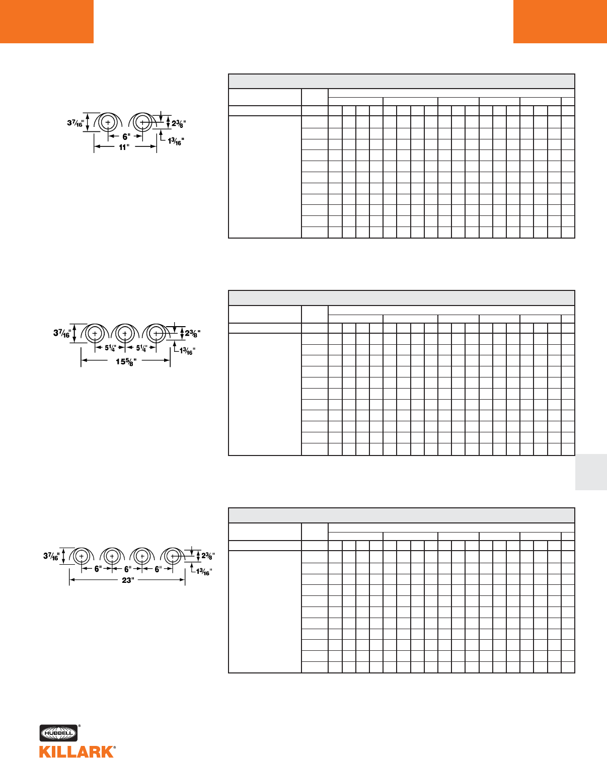
HFX SERIES •LIGHTING
PHOTOMETRIC DAA/DOEFFICIENTS OF UTILIZATION
ZONAL CAVITY METHOD •FLUORESCENT FIXTURES
L169
L
% EFFECTIVE CEILING 20% EFFECTIVE FLOOR CAVITY REFLECTANCE
CAVITY REFLECTANCE rcc .80 .70 .50 .30 .10 .00
% WALL REFLECTANCE rw .70 .50 .30 .10 .70 .50 .30 .10 .50 .30 .10 .50 .30 .10 .50 .30 .10 .00
0 .77 .77 .77 .77 .75 .75 .75 .75 .72 .72 .72 .69 .69 .69 .66 .66 .66 .65
1 .71 .68 .65 .63 .69 .66 .64 .62 .63 .61 .60 .61 .59 .58 .59 .57 .56 .55
2 .64 .59 .55 .51 .63 .58 .54 .51 .56 .52 .49 .54 .51 .48 .52 .49 .47 .46
3 .59 .52 .47 .43 .57 .51 .46 .43 .49 .45 .42 .47 .44 .41 .46 .43 .40 .39
4 .54 .46 .41 .36 .52 .45 .40 .36 .44 .39 .36 .42 .38 .35 .41 .37 .35 .33
5 .49 .41 .35 .30 .47 .40 .34 .30 .38 .34 .30 .37 .33 .30 .36 .32 .29 .28
6 .45 .36 .30 .26 .44 .36 .30 .26 .34 .29 .26 .33 .29 .26 .32 .28 .25 .24
7 .41 .32 .27 .23 .40 .32 .26 .23 .31 .26 .22 .30 .25 .22 .29 .25 .22 .21
8 .38 .29 .23 .19 .37 .28 .23 .19 .28 .23 .19 .27 .22 .19 .26 .22 .19 .18
9 .35 .26 .20 .17 .34 .26 .20 .17 .25 .20 .17 .24 .20 .17 .23 .19 .16 .15
10 .32 .24 .18 .15 .32 .23 .18 .15 .23 .18 .15 .22 .18 .15 .21 .17 .14 .13
3 LAMP
ROOM CAVITY RATIOS
Spacing Criteria: End = 1.3 Diagonal = 1.3 Cross = 1.4
% EFFECTIVE CEILING 20% EFFECTIVE FLOOR CAVITY REFLECTANCE
CAVITY REFLECTANCE rcc .80 .70 .50 .30 .10 .00
% WALL REFLECTANCE rw .70 .50 .30 .10 .70 .50 .30 .10 .50 .30 .10 .50 .30 .10 .50 .30 .10 .00
0 .78 .78 .78 .78 .76 .76 .76 .76 .73 .73 .73 .70 .70 .70 .67 .67 .67 .65
1 .71 .68 .66 .63 .70 .67 .64 .62 .64 .62 .60 .62 .60 .58 .59 .58 .57 .55
2 .65 .60 .56 .52 .63 .59 .55 .51 .56 .53 .50 .54 .51 .49 .52 .50 .48 .46
3 .60 .53 .48 .43 .58 .52 .47 .43 .50 .46 .42 .48 .45 .42 .46 .43 .41 .39
4 .54 .47 .41 .37 .53 .46 .41 .36 .44 .40 .36 .43 .39 .35 .41 .38 .35 .34
5 .50 .41 .35 .31 .48 .40 .35 .31 .39 .34 .30 .38 .33 .30 .36 .33 .30 .28
6 .45 .37 .31 .26 .44 .36 .30 .26 .35 .30 .26 .34 .29 .26 .33 .29 .26 .24
7 .42 .33 .27 .23 .41 .32 .27 .23 .31 .26 .23 .30 .26 .22 .29 .25 .22 .21
8 .38 .29 .24 .20 .37 .29 .33 .20 .28 .23 .20 .27 .23 .19 .26 .22 .19 .18
9 .35 .26 .21 .17 .34 .26 .21 .21 .17 .25 .20 .17 .24 .20 .17 .24 .20 .17
10 .33 .24 .19 .15 .32 .24 .18 .15 .23 .18 .15 .22 .18 .15 .22 .18 .15 .14
2 LAMP
ROOM CAVITY RATIOS
Spacing Criteria: End = 1.3 Diagonal = 1.3 Cross = 1.4
% EFFECTIVE CEILING 20% EFFECTIVE FLOOR CAVITY REFLECTANCE
CAVITY REFLECTANCE rcc .80 .70 .50 .30 .10 .00
% WALL REFLECTANCE rw .70 .50 .30 .10 .70 .50 .30 .10 .50 .30 .10 .50 .30 .10 .50 .30 .10 .00
0 .78 .78 .78 .78 .76 .76 .76 .76 .73 .73 .73 .70 .70 .70 .67 .67 .67 .65
1 .71 .68 .66 .63 .70 .67 .64 .62 .64 .62 .60 .62 .60 .58 .59 .58 .57 .55
2 .65 .60 .56 .52 .63 .59 .55 .51 .56 .53 .50 .54 .51 .49 .52 .50 .48 .46
3 .60 .53 .48 .43 .58 .52 .47 .43 .50 .46 .42 .48 .45 .42 .46 .43 .41 .39
4 .54 .47 .41 .37 .53 .46 .41 .36 .44 .40 .36 .43 .39 .35 .41 .38 .35 .34
5 .50 .41 .35 .31 .48 .40 .35 .31 .39 .34 .30 .38 .33 .30 .36 .33 .30 .28
6 .45 .37 .31 .26 .44 .36 .30 .26 .35 .30 .26 .34 .29 .26 .33 .29 .26 .24
7 .42 .33 .27 .23 .41 .32 .27 .23 .31 .26 .23 .30 .26 .22 .29 .25 .22 .21
8 .38 .29 .24 .20 .37 .29 .23 .20 .28 .23 .20 .27 .23 .19 ..26 .22 .19 .18
9 .35 .26 .21 .17 .34 .26 .21 .17 .25 .20 .17 .24 .20 .17 .24 .20 .17 .15
10 .33 .24 .19 .15 .32 .24 .18 .15 .23 .18 .15 .22 .18 .15 .22 .18 .15 .14
4 LAMP
ROOM CAVITY RATIOS
Spacing Criteria: End = 1.3 Diagonal = 1.3 Cross = 1.4
HFX-430-12
Lamp Type F40T12RS/WW
2 – 48" 40 Watt 3200 Lumen
Warm White Lamps
HFX-430-13
Lamp Type F40T12RS/WW
3 – 48" 40 Watt 3200 Lumen
Warm White Lamps
HFX-430-14
Lamp Type F40T12RS/WW
4 – 48" 40 Watt 3200 Lumen
Warm White Lamps
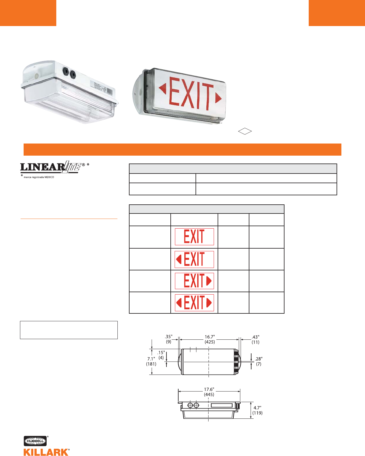
LLC SERIES •FLUORESCENT LIGHTING
NORTH AMERICAN ZONE 2
L170
FEATURES-SPECIFICATIONS
Class l, Div. 2, Groups A,B,C,D
Class l, Zone 2, Groups IIC, llB, llA, T4
Class lI, Div. 1 & 2, Groups E,F,G
Class lII
Enclosure 3, 4, 4X, IP66
Fixture with EXIT Sign
Fixture with Clear Lens File J.I. 3012168
LLC SERIES FOR NORTH AMERICAN ZONE 2
CATALOG NUMBER DESCRIPTION
LLC22312DN 2 x F8 T5 lamp fixture, 120VAC 50/60Hz
3/4" NPT threaded entry
Applications
Hazardous and corrosive environments
where reliability and rugged performance
are critical.
Ideal for exit sign applications.
Features
•Housing constructed of heavy-duty
fiber reinforced polyester (FRP) with
a single piece, low glare polycarbon-
ate lens
•Single point latching mechanism
•Fixture includes threaded opening to
accept 3/4" NPT hub
•Clear lens supplied as standard
•Order exit signs separately from
chart at right. Signs are adhesive
foil type
•For use with F8T5 lamps
CATALOG NUMBER ILLUSTRATION SIGN COLOR BACKGROUND
LLC SERIES EXIT SIGN DECALS
Red White
Red White
Red White
Red White
LL-EXIT-80
LL-EXIT-81
LL-EXIT-82
LL-EXIT-83
See parts and accessories
on page L171.
FM
APPROVED
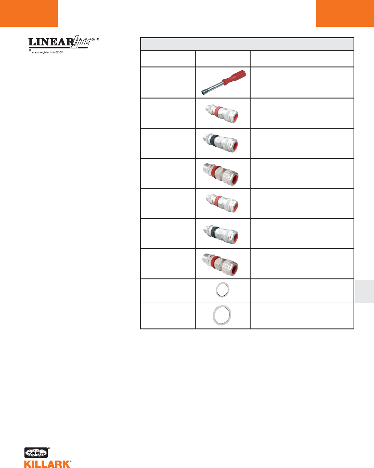
LLC SERIES •LIGHTING
ACCESSORIES L171
L
ACCESSORIES
SWZ60-075NPT
SWZ60-050NPT
CMCXAB075
CMCAB075
CMCAA050
Socket Wrench,
1/2"(13mm)
to operate central lock
8198005400
CMCXAA050
1/2” NPT, Aluminum Cable Connector
(Zone 2 fixture) for MC cable
Applications
Hazardous and corrosive environments
where reliability and rugged performance
are critical.
CATALOG NUMBER PRODUCT DESCRIPTION
3/4" NPT, Nylon Washer
for 3/4” cable fitting
1/2" NPT Nylon Washer
for 1/2” cable fitting
3/4” NPT, Aluminum Cable Connector
(Zone I fixture) for MC-HL or
ITC-HL cable
3/4” NPT, Aluminum Cable Connector
(Zone 2 fixture) for MC cable
1/2” NPT, Aluminum Cable Connector
(Zone I fixture) for MC-HL or
ITC-HL cable
CTCAO050
CTCAB075
1/2” NPT, Aluminum Barrier Type
Connector (Zone 2 fixture) for non
armored cable
3/4” NPT, Aluminum Barrier Type
Connector (Zone 2 fixture) for non
armored cable
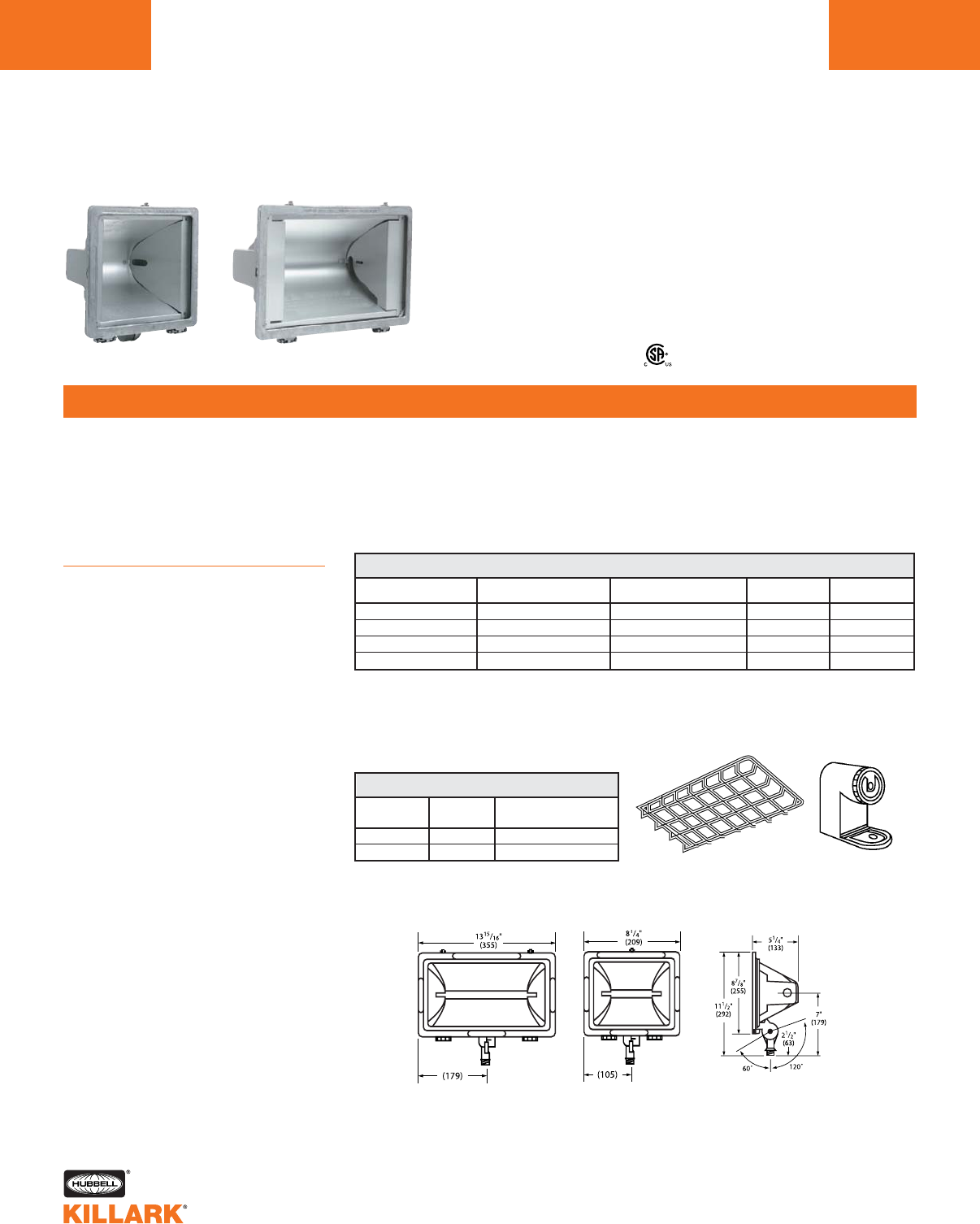
QL SERIES •LIGHTING
QUARTZ FLOODLIGHTS
L172
FEATURES-SPECIFICATIONS
Applications
Provides maximum light output with low
initial cost. Designed for instant turn-on
and high illumination levels where H.I.D.
costs are prohibitive. Used to illuminate
construction sites, security areas, sports
areas, sign lighting and other applica-
tions.
QL Series Features
• Tempered Glass Lens Assembly—
Thermal shock-and impact-resistant
glass lens mounted in a die cast
aluminum door frame
• Cast Aluminum Housing—The cast
aluminum body is designed with a
specialized heat dissipating fin system
for cooler operation
• Versatile Mounting—The standard unit
has a 1⁄2 inch swivel knuckle with cast
construction for strength and durability
• High Temperature Gasketing—A weath-
ertight seal is provided by a high tem-
perature silicone door gasket
• Exclusive Socket System—This two-
piece, high temperature socket allows
easy relamping and prevents socket
from binding
• Reflector—Linear parabolic reflector
system provides maximum light output
and control
QL-1505KQL-500K
• High Temperature Gasketing—A weath-
ertight seal is provided by a high tem-
perature silicone gasket attached to the
housing. Four lens clips positively seal
the lens to the gasket with consistent
pressure to assure a weathertight seal
CATALOG NUMBER LAMP AND WATTAGE BEAM SPREAD WEIGHT E.P.A. SQ. FT.
QL-500K1300/500 Wide 4 Lbs. (1.8) .53
QL-500K-WQ2300/500 Wide 4 Lbs. (1.8) .53
QL-1505K31000/1500 Wide 6 Lbs. (2.7) .86
QL-1505K-WQ23 1000/1500 Wide 6 Lbs. (2.7) .86
QL QUARTZ FLOODLIGHTS
Certified
• Versatile Mounting—The standard unit
has a 1⁄2 inch swivel knuckle with cast
construction for strength and universal
aiming
See photometric data for QL Series
fixtures on page L175.
SERIES GUARD CROSSARM
TRUNNION BOX
QL-500K QL-5G QL-TB
QL-1505K QL-15G QL-TB
QL ACCESSORIES (FIELD INSTALLED)
Guard Trunnion Box
1Lamps not included.
2Lamps supplied-shipped separately.
3Should not be aimed ± 10° from horizontal or higher on 1500 watt models.
QL-1500 Watt QL-500 Watt QL-1500 and QL-500 Watt
Dimensions
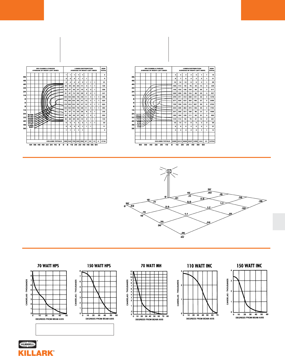
QL/QM/EM/DM SERIES •LIGHTING
FLOODLIGHT PHOTOMETRICS L173
L
EM/DM SERIES
QL SERIES
500 Watt Tungsten Halogen
Footcandle Array Based on:
•15' Mounting Height
•Aimed at 30° below horizontal
•Not to scale. All values are initial footcandles.
•Data calculated from Test No. HP-02305.
QL SERIES
QL-500K
Test No: HP-00930 IES/NEMA Type: 5H X 5V
Source: Incandescent Beam Spread Horiz: 88°
Lamp: Q500T3/CL Beam Spread Vert: 82°
Watts: 500 Beam Efficiency: 65%
LCL: —Beam Lumens: 7060
Lumens: 10950 Max. Beam Candle: 9265
Avg. Max. Candle: 8356
QL-1505K
Test No: HP-00854 IES/NEMA Type: 6H X 5V
Source: Incandescent Beam Spread Horiz: 115°
Lamp: Q1500T3/CL Beam Spread Vert: 78°
Watts: 1500 Beam Efficiency: 68%
LCL: —Beam Lumens: 24306
Lumens: 35800 Max. Beam Candle: 33219
Avg. Max. Candle: 28374
See page L181 for catalog data.
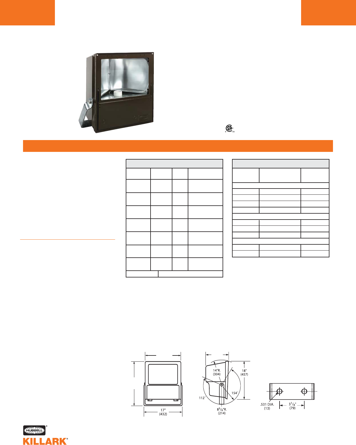
KF SERIES •LIGHTING
FLOODLIGHTS, 150-1000W HID
L174
FEATURES-SPECIFICATIONS
Applications
KF series floodlights can be used in
industrial installations where flammable
gases or vapors may exist due to
abnormal conditions resulting in the
creation of a Class I, Div. 2 hazardous
location as defined by the NEC. Also
can be used where general corrosive
atmospheric conditions exist such as
ocean piers, marinas and costal areas.
Designed for heavy duty applications
where long life and maintenance-free
service are essential.
Features
• Rugged weathertight housing of
copper-free aluminum with corrosion
resistant bronze finish
• Wide beam distribution
• Thermal shock, impact-resistant lens
• Continuous silicone gasketing
• All external hardware is corrosion
resistant including HubbellGard®
ceramic coated screws
• Trunnion mounting-heavy gauge, hot
dip galvanized steel mounting with
stainless steel hardware
• Photometric data & accessories—see
page L175
• NR suffix Restricted Breathing models
provide lower T-codes
• 3/4” NPT entry on back lower left
Suitable for wet locations
N
N
E
E
M
M
A
A
4
4
X
X
,
,
I
I
P
P
6
6
6
6
T
T
y
y
p
p
e
e
A
A
p
p
p
p
r
r
o
o
v
v
a
a
l
l
Type approval for shipboard use5
Class I, Div. 2 Groups A,B,C,D12
Class I, Zone 2, Groups llC,llB,llA (nR6)
CATALOG LAMP AND ** BEAM SPREAD
NUMBER WATTAGE VOLTS Hº X Vº
KFS150-76 150 HPS QUAD 7 (144°) X 6 (113°)
KFS155-76 480
KFS250-76 250 HPS QUAD 7 (144°) X 6 (113°)
KFS255-76 480
KFS400-76 400 HPS QUAD 7 (144°) X 6 (113°)
KFS405-76 480
KFS1000-76 1000 HPS QUAD 7 (144°) X 6 (113°)
KFS1005-76 23 480
KFH250-76 250 MH* QUAD 7 (145°) X 6 (115°)
KFH255-76 480
KFH400-76 400 MH* QUAD 7 (146°) X 6 (119°)
KFH405-76 480
KFH1000-76 1000 MH QUAD 7 (144°) X 6 (113°)
KFH1005-76 24 480
K800-2918-0135 Replacement Lens and Door Assembly
KF HID FLOODLIGHTS
CLASS I, DIV. 212
LAMP AND MAX. LAMP TEMP. CODE
WATTAGE TEMP. RATING ºC CLI Div.2/nR
HIGH PRESSURE SODIUM
150 260 T2B/T4
250 325 T1/T3
400 350 T1/T3
1000 2378 T1/T2
METAL HALIDE
250 325 T1/T4
400 325 T1/T4
1000 2442 T1/T2
MERCURY
250 350 T1/T3
400 350 T1/T3
TEMPERATURE DATA5
1150-400 watt lamp temperature data was
obtained in 40°C ambient. UL listed for
25°C ambient operation.
21000 watt fixture aiming angle limited to
45°-135° (no straight up or down).
1000 watt fixtures are rated and listed for
40° ambient.
* Mercury lamps may be used if desired.
Lamps not included.
** Change 0 or 5 voltage code to 8 for 240V
50HZ e.g. KFH408-76. Consult factory for
other available voltages.
3Use Phillips C1000S52/ED37 11-1/2" lamp.
4Use 11-1/2" BT37 lamp available from GE,
Venture or Phillips.
5Not suitable for submersion or wave impact
applications.
6Add suffix NR to catalog number for restricted
breathing, See chart above for lower T-codes
Front Side Trunnion Mounting Detail
ABS
16 3/8”
(415)
9”
(229)
25”
(647)
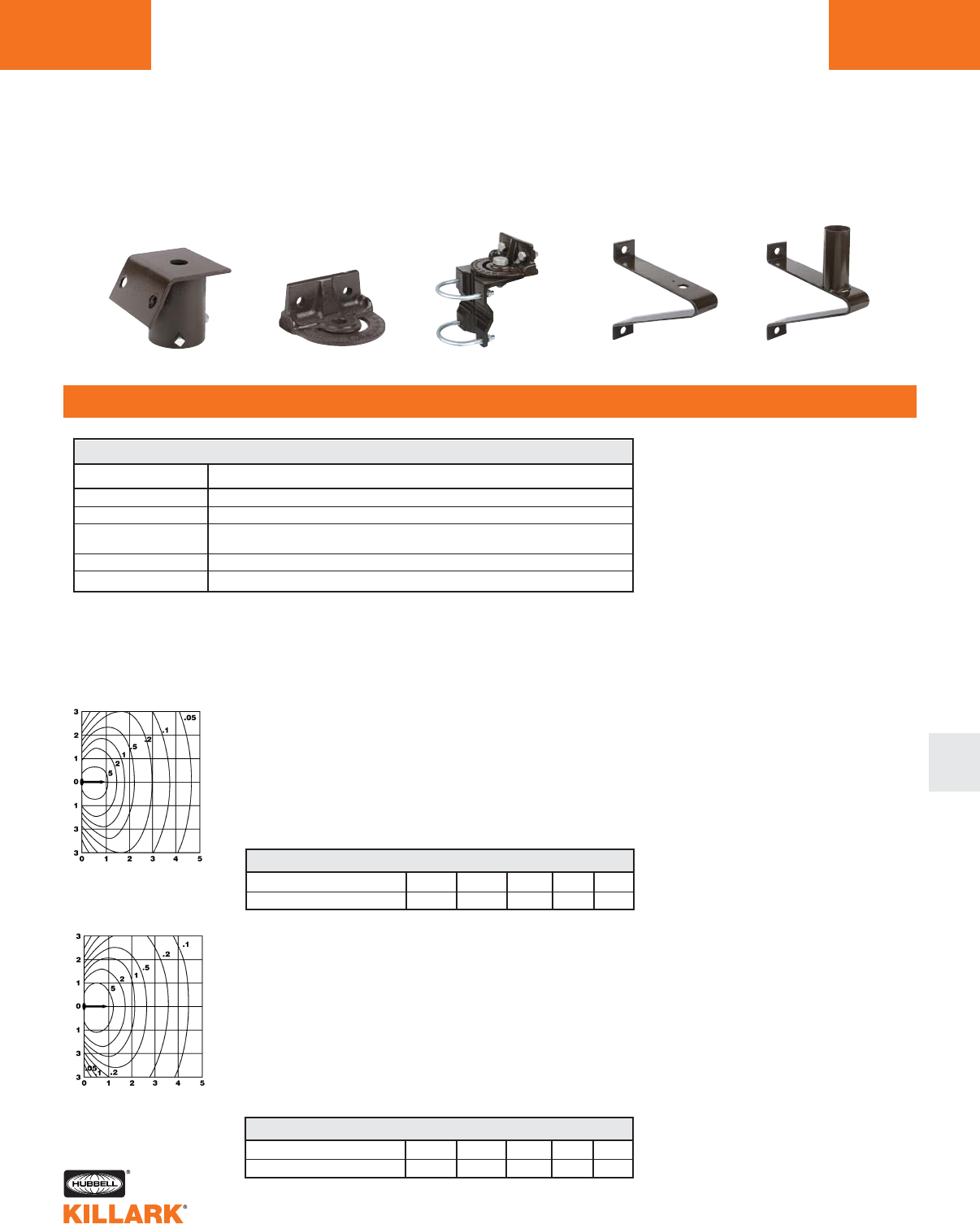
KF SERIES •LIGHTING
MOUNTING ACCESSORIES •PHOTOMETRICS L175
FEATURES-SPECIFICATIONS
L
KFH-XXX-76
IES Type—7H x 6V (146° x 119°)
Source—Metal Halide (Clear) 34000 Lumens
Wattage—400 (ANSI M59)
For 250W MH multiply by .6
For 1000W MH multiply by 3.1
Mounting Height (Grid Value)—25 feet
Aiming Angle—45°
Test Number—HP-00738
KFS-XXX-76
IES Type—7H x 6V (144° x 117°)
Source—High Pressure Sodium (Clear) 50000 Lumens
Wattage—400 (ANSI S51)
For 150W HPS multiply by .32
For 250W HPS multiply by .6
For 1000W HPS multiply by 2.5
Mounting Height (Grid Value)—25 feet
Aiming Angle—45°
Test Number—HP-00740
KF SERIES
CONVERSION CHART
MOUNTING HEIGHT (FEET) 20 25 28 30 35
CORRECTION FACTOR 1.56 1.00 .80 .69 .51
CONVERSION CHART
MOUNTING HEIGHT (FEET) 23 25 30 35 40
CORRECTION FACTOR 1.18 1.00 .69 .51 .39
1In converting to a different mounting height,
multiply all footcandle values by the correc-
tion factor and convert the grid size to the
mounting height selected. Example: to
convert 25 foot to 30 foot mounting height,
multiply all footcandle values by .69. (Grid
now becomes 30 replacing 25). To convert
footcandles to Lux, multiply values by 10.76.
To convert feet to meters, divide values
by 3.281.
KFS-6 KFWB K4040 4041
KFCB
CATALOG NUMBER DESCRIPTION
KFS-6 Steel slipfitter for 2" pipe (2-3/8" o.d.) tenon. Slips 3.75” over pipe.
KFCB Heavy duty cast-iron crossarm fitting for horizontal trunnion
KFWB Heavy duty wall mount and/or pipe clamp fitting
Clamps 2" pipe (2-3/8" o.d.) thru 2-1/2" pipe (2-7/8" o.d.)
K4040 Heavy duty steel wall/pole bracket. (Must use with KFCB crossarm fitting)
4041 Heavy duty steel wall/pole bracket 2" pipe (2-3/8" o.d.) tenon fitting
KF MOUNTING ACCESSORIES1
1Fittings available to adapt trunnion mount floodlights to crossarms, poles and walls.
Must be ordered separately.
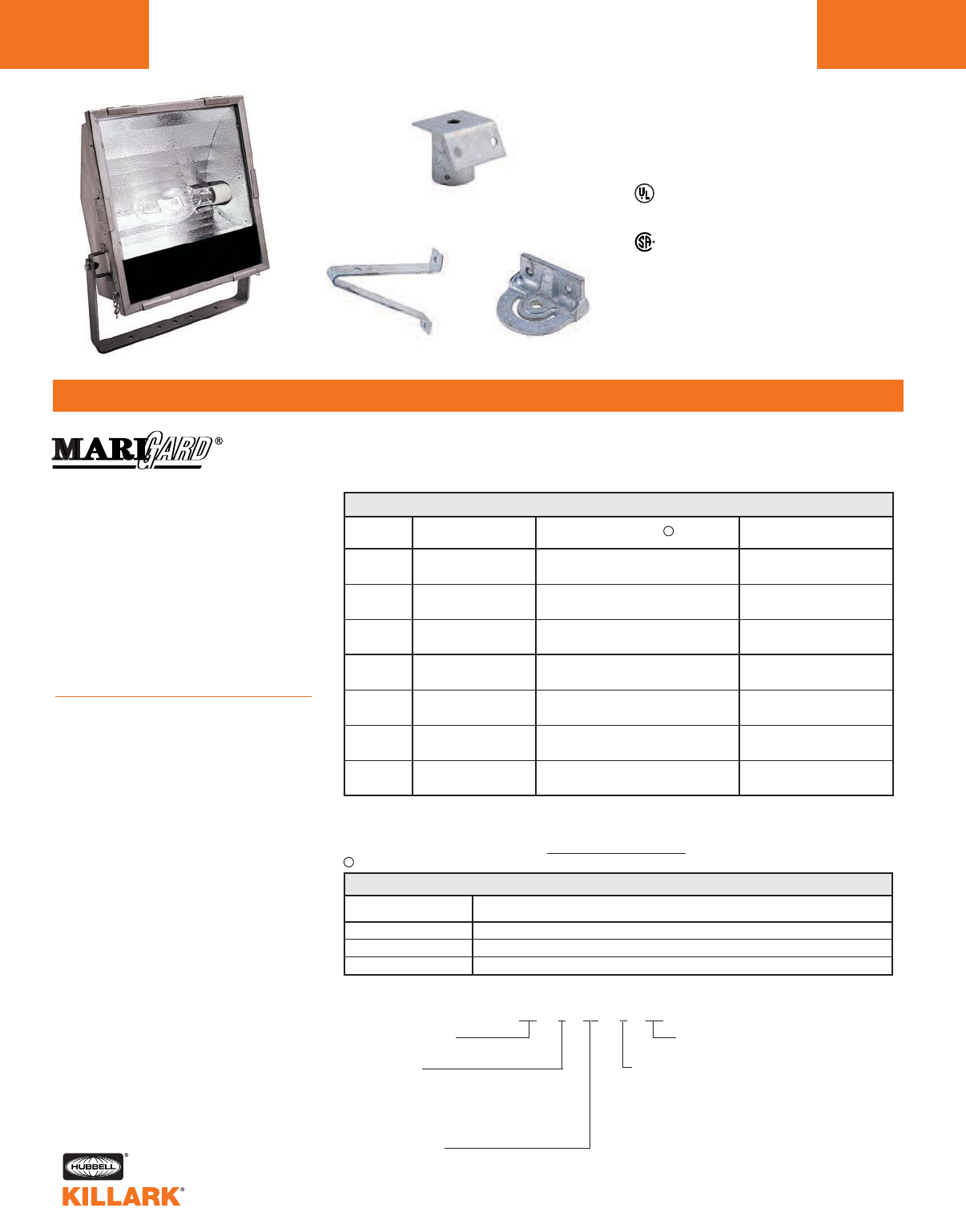
KFSS SERIES •LIGHTING
MARINE FLOODLIGHTS, 150-400W HID
L176
FEATURES-SPECIFICATIONS
Class I Div. 2, Groups A,B,C,D*
AEx nR/Ex nR**
Class I Zone 2, IIC, IIB, IIA*
UL 1572 HID Marine for Wet Locations
UL 844 Hazardous Locations
CSA C22.2 9.9-9.6 General Requirements
CSA C22.2 137-M1981 Hazardous
Locations
CSA Enclosure type IP66/67
ABS Type Approval for Shipboard Use
* Consult temperature data table on next page to
determine application suitability.
Steel Slipfitter
(includes bolts)
Steel Wall/Pole Bracket Cross Arm Fitting
KF 0 00 0 SS (NR)**
Catalog Number Logic
Series Constant Series Constant
Lamp Type
S—High Pressure Sodium
H—Metal Halide
P—Pulse Start Metal Halide
Lamp Wattage
15—150 Watt, HPS
25—250 Watt, HPS, MH, MHP
40—400 Watt, HPS, MH, MHP
Voltage
0—Quad; 120/208/240/277 60 Hz.
5—480 60 Hz.
6—Tritap 120/277/347 60 Hz. (Canada)
7—220 60 Hz. (S. America),
MHP250 & MHP 400 N/A
8—220/240 50 Hz.
(Europe & S. America),
MHP250 N/A
Applications
• Offshore production platforms
• Refineries
• Offshore drilling rigs and barges
• Ocean-going vessels
• Commercial fishing vessels
• Ports, wharfs and jetties
• Waste water and sewage treatment
facilities
• Any type of washdown, corrosive,
abrasive, or dirty environment
Features and Benefits
•Type 316 Stainless Steel Housing.
16-gauge housing ensures low
corrosion and long life, reducing
maintenance costs
•Rugged quick-release 316 SS Lens
Latches. No hardware seizing on
disassembly saves maintenance
time and money. Only tool needed
is a screwdriver
•316 SS Safety Lens Door Chains.
Enables hands-free safe re-lamping
•316 SS Mounting Yoke Reliable and
safe installation
•Highly efficient photometrics and
excellent asymmetrical distribution.
Photometrics above 85%. Minimizes
the number of required fixtures to
deliver desired light levels. Saves in
energy costs
•Hot-dipped Galvanized Steel
Mounting Accessories. Corrosion
resistant in marine and corrosive
environments, assuring reliable
installation
•316 SS 3/4" Conduit Hub. Maintains
grounding continuity. Watertight
seal. Corrosion resistant
•Silicone Gasketed Lens Door Frame.
Provides watertight seal, protecting
interior from moisture and corrosives
KFSS STAINLESS STEEL FLOOD LIGHTS
KFSS ACCESSORIES
KFS150SS
KFS156SS
KFS250SS
KFS256SS
KFS400SS
KFS406SS
KFH250SS
KFH256SS
KFP250SS
KFP256SS
KFH400SS
KFH406SS
KFP400SS
KFP406SS
150 HPS
S-55
250 HPS
S-50
400 HPS
S-51
250 MH2
M-58
250 MHP3
M-138
400 MH2
M-59
400 MHP3
M-135
CATALOG
NUMBER
CATALOG NUMBER DESCRIPTION
LAMP TYPE
AND CIRCUIT VOLTAGE1VBEAM SPREAD
H° X V°
6 (118) x 6 (118)
6 (118) x 6 (118)
6 (118) x 6 (118)
6 (118) x 6 (118)
6 (118) x 6 (118)
6 (118) x 6 (118)
6 (118) x 6 (118)
120/208/240/277 @60Hz
120/277/347 @60 Hz
120/208/240/277 @60Hz
120/277/347 @60 Hz
120/208/240/277 @60Hz
120/277/347 @60 Hz
120/208/240/277 @60Hz
120/277/347 @60 Hz
120/208/240/277 @60Hz
120/277/347 @60 Hz
120/208/240/277 @60Hz
120/277/347 @60 Hz
120/208/240/277 @60Hz
120/277/347 @60 Hz
KFS-6G
K4040G
KFCBG
Steel slipfitter for 2" pipe (2-3/8" O.D.) tenon. Hot-dipped galvanized (bolts included)
Steel wall/pole bracket. Hot-dipped galvanized (bolts included)
Cross arm fitting for horizontal trunnion. Hot-dipped galvanized (bolts included)
1Voltage: 6th character in the catalog number denotes voltage. See “Catalog Number Logic” for details; e.g.
KFS155SS = 480 Volt 60Hz.; KFH408SS=240V 50HZ.
2Mercury Vapor Lamps of the same wattage may be used if desired.
3Use a Pulse Start Metal Halide Lamp rated for Horizontal Position.
VConsult factory for available lamp and voltage combinations.
**Restricted Breathing option-see next page.
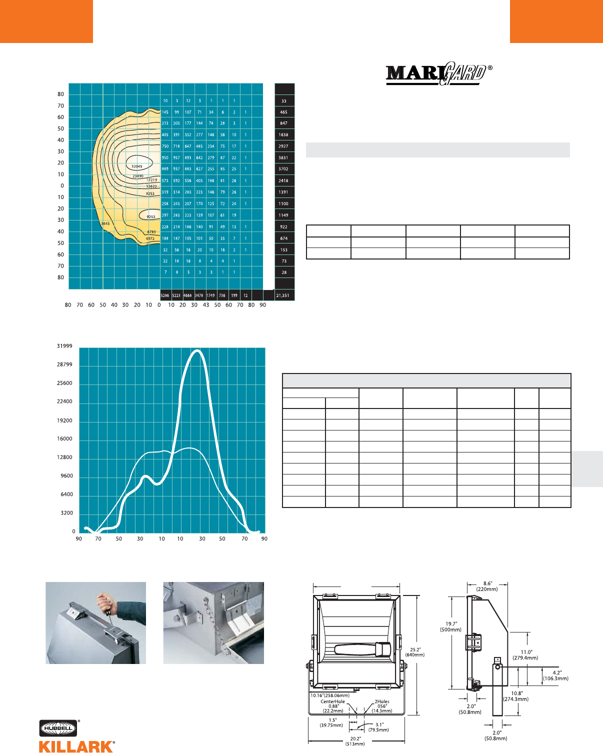
KFSS SERIES •LIGHTING
MARINE FLOODLIGHTS L177
L
MARIGARD TEMPERATURE CODES
ANGLE FROM BEAM AXIS (DEGREES HORIZONTAL)
HPS
HPS
HPS
HPS
HPS
HPS
MH-MHP-MV
MH-MHP-MV
MH-MHP-MV
Test Number: HP-07477
Source: HPS
Lamp: ED-18
Lamp Watts: 400
LCL: 5.75"
Lumens: 50,000
IES/NEMA Type: 6H x 6V
Maximum Beam Candlepower: 36,447
Average Maximum Candlepower: 32,045
Total Efficiency: 85.41%
RATED
AMBIENT C°
TYPE
LAMP
HORIZONTALLY VERTICALLY LUMENS
BEAM
FIELD
EFFICIENCY
WATTAGE
CLASS 1 DIV. 2
TEMP. (CODE)
270°C (T2A)
285°C (T2)
295°C (T2)
380°C (T1)
395°C (T1)
380°C (T1)
365°C (T1)
380°C (T1)
365°C (T1)
CLASS 1 ZONE 2
TEMP. (CODE)
270°C (T2)
285°C (T2)
295°C (T2)
380°C (T1)
395°C (T1)
380°C (T1)
365°C (T1)
380°C (T1)
365°C (T1)
T4
T4
T3
T3
T3
T3
T3
T2
T3
150
150
150
250
250
400
250
250
400
40
55
65
40
55
40
40
55
40
81.8
118.4
41.0
118.6
44.39%
81.18%
22,196
40,591
90°C
90°C
110°C
90°C
110°C
110°C
110°C
110°C
110°C
Dimensions
17.95”
(456mm)
SUPPLY
WIRE C°
Ex nR
1
Rugged yet easy-to-open 316
SS Latches require no special
tools!
Two 316 SS Lens Chains
allow for hands-free mainte-
nance!
1Ex nR with NR adder. Allows lower T-CODE approvals through the use of sealed
cable entrance fittings. See fittings section or select other gland/connector as
appropriate for type of cable used.
ANGLE FROM BEAM AXIS (DEGREES VERTICAL)
AVERAGE OF RIGHT-LEFT SIDES
ISO CANDELA CURVES LUMEN DISTRIBUTION
ANGLE FROM BEAM AXIS (DEGREE HORIZONTAL)
VERTICAL TOTALS
HORIZONTAL TOTALS
AXIAL CANDELA TRACES
LUMINOUS INTENSITY - CANDELA
LEFT/DOWN DEGREES UP/RIGHT
VERTICAL - HEAVY LINE HORIZONTAL - THIN LINE
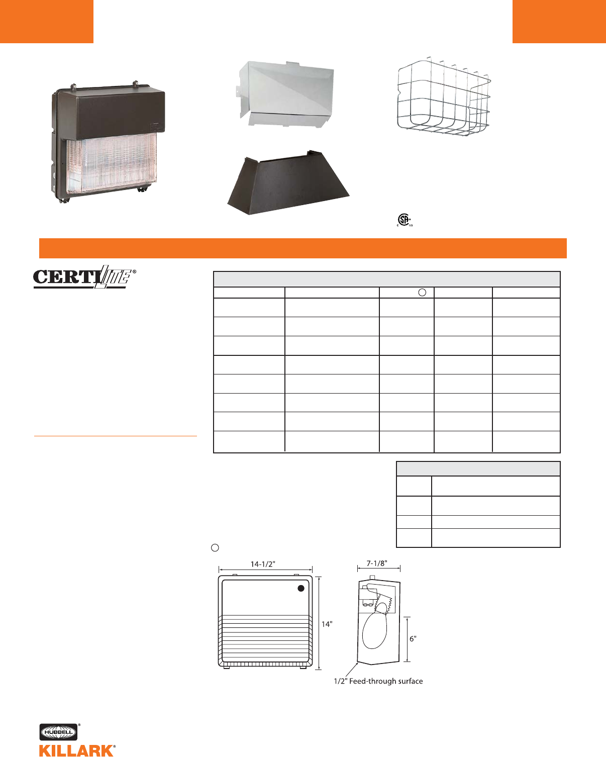
KWP SERIES •LIGHTING
WALLPACK, 70-175W HID
L178
FEATURES-SPECIFICATIONS
CATALOG
NUMBER DESCRIPTION
PGPS Clear Shield (Polycarbonate) for
Protecting Lens
PGWG Wire Guard, Cadmium Plated Steel
Glare Shield Cutoff Visor - Formed Bronze
PVLV Aluminum. Forces Light to Walkway
1Voltage Change 7th character in catalog number
for voltage
Example KWPS075 = 480 Volt 60Hz
0=QUAD - 120/208/240/277 60Hz
5=480 60Hz
6=TRI - 120/277/347 60Hz (Canada)
7=220 60Hz (S. America)
8=220/240 50Hz (Europe / S. America)
VConsult factory for available lamp and voltage combinations.
Class I, Div. 2, Groups A,B,C,D
Class I, Zone 2, Groups IIC, IIB, IIA
NEMA 4X
Certified
Applications
KWP Wall Luminaires are ideally suited
for applications requiring a pleasing
aesthetic appearance or hazardous
location suitability in a compact energy
saving fixture. Units are of copper-free
aluminum construction for cool opera-
tion with a bronze electrostatically
applied powder-coat finish. Suitable for
locations such as perimeter security
lighting, parking areas, factories and
parking garages.
Features
•Aluminum with Bronze finish 1/2" hub
on either side for conduit entry
•Mogul Porcelain Socket
• Reflector is specular aluminum preci-
sion formed for optimal performance
•Suitability for 40°C ambient, 90°C
supply wire required
•Lens thermal shock and impact
resistant prismatic borosilicate glass
• Full front access available for lamp or
ballast service by hinging front door
• Two Hubbell Guard®Corrosion
resistant hex head fasteners provide
water-tight seal for door gasket
KWP WALL PACK
LAMP TYPE AND CIRCUIT VOLTAGE1VWEIGHT LBS. T-CODE AT 40°C
70 HPS QUAD 23 215°C (T2D)
S-62 480
100 HPS QUAD 24 215°C (T2D)
S-54 480
150 HPS QUAD 25 260°C (T2B)
S-55 480
70 MH QUAD 24 200°C (T3)
M-98 480
100 MH QUAD 25 200°C (T3)
M-90 480
175 MH QUAD 25 260°C (T2B)
M-57 480
150 MH QUAD 25 260°C (T2B)
M-102/M142 480
175 MH QUAD 26 260°C (T2B)
M-137/M152 480
Clear Shield Wire Guard
Wall Pack Luminaires Glare Shield
KWP ACCESSORIES
CATALOG NUMBER
KWPS070
KWPS075
KWPS100
KWPS105
KWPS150
KWPS155
KWPH070
KWPH075
KWPH100
KWPH105
KWPH170
KWPH175
KWPP150
KWPP155
KWPP170
KWPP175
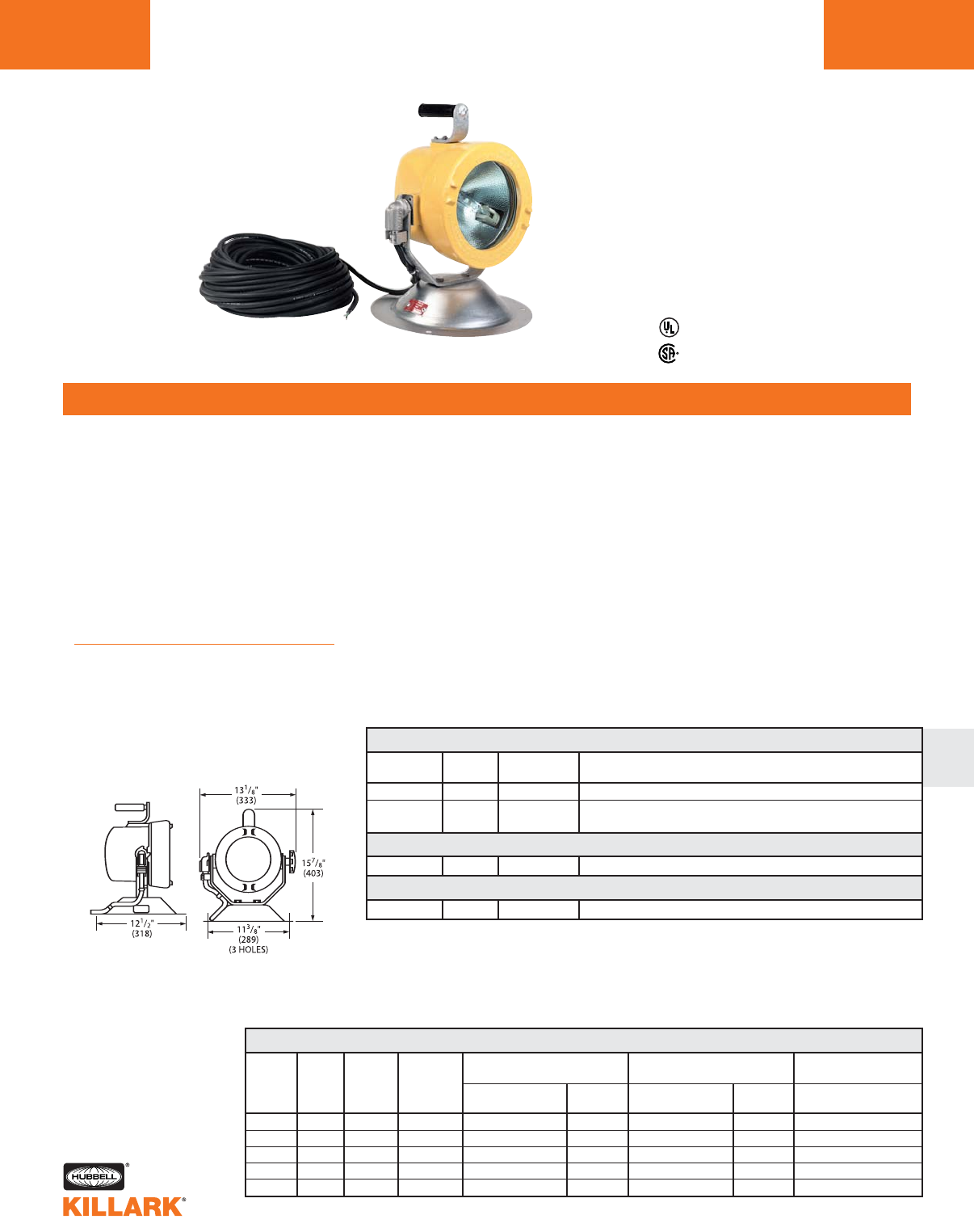
EM/DM SERIES •LIGHTING
HID PORTABLE FLOODLIGHTS L179
FEATURES-SPECIFICATIONS
L
Applications
EM & DM Series portable floodlights
provide emergency or maintenance light-
ing in wet locations or areas made haz-
ardous due to the presence of flammable
gases or vapors and combustible dusts
as defined by the NEC.
Typical uses are in manufacturing plants,
chemical, petrochemical and other indus-
trial process facilities, oil refineries, grain
storage sights, aircraft maintenance and
refueling areas, tank farms and pipeline
pumping stations.
Features
• Factory sealed 100 foot 16/3 SOW cord
supplied as standard. See catalog
section PR for Acceptor® plugs and
receptacles
Listed - File E89665 and E97760
Certified - File LR11713
Class I, Div. 1 & 2 Groups C,D
Class I, Zones 1 & 2 Groups llB,llA
Class II, Div. 1 & 2, Groups F,G
Class III, Div. 1 & 2
NEMA 3, 4X, 7(C,D) 9(F,G)
Suitable for wet locations
• Corrosion resistant, rain tight, copper-
free cast aluminum housing helps
assure safe, reliable operation
• Light weight, strong spun aluminum
base provides stability, permits hanging
fixture temporarily on wall or lowering it
inverted
• Aluminum specular reflector directs light
beam for concentrated illumination
• Tempered glass lens resists heat and
shock
• Nitrile rubber O-ring gasketing provides
an excellent seal for use in wet locations
• Photometric data—see page L175
• Lamps included on all models
EM/DM HPS PORTABLE FLOODLIGHTS
RATED CLASS I, DIV. 1 & 2 CLASS II, DIV. 1 & 2 CLASS III, DIV. 1 & 2
SERIES LAMP LAMP AMBIENT MAX. SURFACE TEMP. MAX. SURFACE TEMP. MAX. SURFACE TEMP.
TYPE WATTS DEGREES UL/CSA UL/CSA UL/CSA UL/CSA UL/CSA
°F/°C TEMP. I.D. °F/°C GROUPS TEMP. I.D. °F/°C GROUPS TEMP. I.D. °F/°C
EMS HPS 150 77°/25° T3C (320°/160°) CD — — —
DMS HPS 100 104°/40° T4A (248°/120°) CD T3C (320°-160°) FG T3C (320°-160°)
EMH MH 70 104°/40° T4 (275°/135°) CD T3 (392°-200°) F —
EMI INC 110 104°/40° T3A (356°/180°) CD T3 (392°-200°) F —
EMI INC 150 104°/40° T3A (356°/180°) CD — — —
EM INCANDESCENT1
1Refer to hazardous location application data below for specific T codes and temperatures.
2EMIP111 can be used with PAR 38 150 Watt incandescent lamp. See hazardous location application
data.
* DMS series units have a limiting device to prevent positioning of the fixture head in an orientation where
dust could build up on the lens. Any attempt to defeat its purpose can be dangerous.
CATALOG LAMP VOLTAGE
NUMBER WATTS @60 HERTZ DESCRIPTION1
EMSP151 150 120 Class I, Div. 1 & 2, Groups C & D
DMSP101* 100 120 Class I, Div. 1 & 2, Groups C & D; Class II, Div. 1 & 2,
Groups F & G; Class III
EM MH
EM INCANDESCENT
EMIP111 110 120 Class I, Div. 1 & 2, Groups C & D; Class II, Div. 1 & 2, Group F
EMHP071 70 120 Class I, Div. 1 & 2, Groups C & D; Class II, Div. 1 & 2, Group F
1Do not install where marked operating temperature exceeds ignition temperature of Hazardous Atmosphere.
Compliances
• UL-781 portable electric lighting units
for use in hazardous locations
• UL-1571 standard for incandescent
lighting fixtures
• UL-1572 standard for HID lighting
fixtures
• UL Marine type electric lighting
fixtures
• CSA-C22.2 nos. 12 & 137
• NEMA 3, 4
EMHPO71
Dimensions
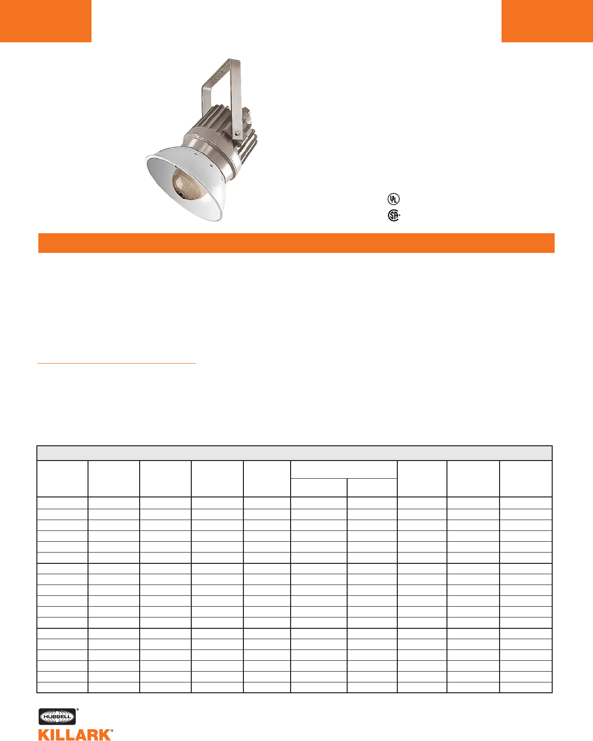
EZ SERIES •LIGHTING
HID FLOODLIGHT FIXTURES
L180
FEATURES-SPECIFICATIONS
Applications
HOSTILELITE®EZ series trunnion
mount luminaires provide directional
lighting in both vertical and horizontal
planes when used with floodlight
mounting hardware.
Typical applications include refineries,
drilling rigs and platforms, loading
docks, bulk fuel loading terminals,
and pipeline pumping stations.
Features
• Four light sources
– High Pressure Sodium (50-400W)
– Metal Halide (70-400)
– Metal Halide Pulse (175-400)
– Mercury Vapor (100-400)
Listed - file E10514
CSA LR11713
• Trunnion mounted–Trunnion yoke of
316 grade stainless steel attaches via
mounting blocks to fixture ballast
housing
• Factory sealed–No external seal
needed
• Corrosion resistant–Fixture of copper-
free aluminum die cast construction.
Baked powder epoxy finish, electro-
statically applied. Exposed hardware
of 316 grade stainless steel
• Accessories–Guards, reflectors and
mounting hardware available. Must be
ordered separately, see illustration
• Mounting method–See page L183 for
typical installation using mounting
accessories
Class I, Div. 1 & 2, Groups C,D
Class I, Zones 1 & 2, Groups llB,llA
NEMA 3, 4, 4X, 7(C,D)
Factory Sealed
Compliances
• UL-844 Electric Lighting Fixtures for
use in Hazardous Locations
• UL-1572 Standard for HID Lighting
Fixtures
• CSA C22.2 no. 137-M1981 Electric
Luminaires for use in Hazardous
Locations
• NEMA 3, 4, 4X, 7CD
CLASS I, DIV. 1 & 2
FIXTURE LAMP LAMP SUITABLE SUPPLY MAX. SURFACE TEMP. TYPE 3 TYPE 4 TYPE 4X
SERIES TYPE WATTS AMBIENT °C WIRE TEMP. I.D. (RAINTIGHT) (HOSEDOWN) (CORROSION
MIN. °C (ACTUAL TEMP.) GROUPS RESISTANT)
EZS HPS 50 40 85 T4 (135°C) C,D YES YES YES
EZS HPS 70 40 85 T4 (135°C) C,D YES YES YES
EZS HPS 100 40 85 T4 (135°C) C,D YES YES YES
EZS HPS 150 40 85 T4 (135°C) C,D YES YES YES
EZS HPS 250 40 85 T3C (160°C) C,D YES YES YES
EZS HPS 400 40 85 T3 (200°C) C,D YES YES YES
EZH MH 70 40 85 T4A (120°C) C,D YES YES YES
EZH MH 100 40 85 T4A (120°C) C,D YES YES YES
EZH MH 175 40 85 T3B (165°C) C,D YES YES YES
EZH MH 250 40 85 T3A (180°C) C,D YES YES YES
EZH MH 400 40 85 T2D (215°C) C,D YES YES YES
EZP MHP 175/200 40 85 T3C (160°C) C,D YES YES YES
EZP MHP 250/320 40 85 T3 (200°C) C,D YES YES YES
EZP MHP 350/400 40 85 T2D (215°C) C,D YES YES YES
EZM MV 100 40 85 T3B (165°C) C,D YES YES YES
EZM MV 175 40 85 T3B (165°C) C,D YES YES YES
EZM MV 250 40 85 T3A (180°C) C,D YES YES YES
EZM MV 400 40 85 T2D (215°C) C,D YES YES YES
EZ HAZARDOUS LOCATION APPLICATION DATA
Shown with optional
VMPSD-40 reflector
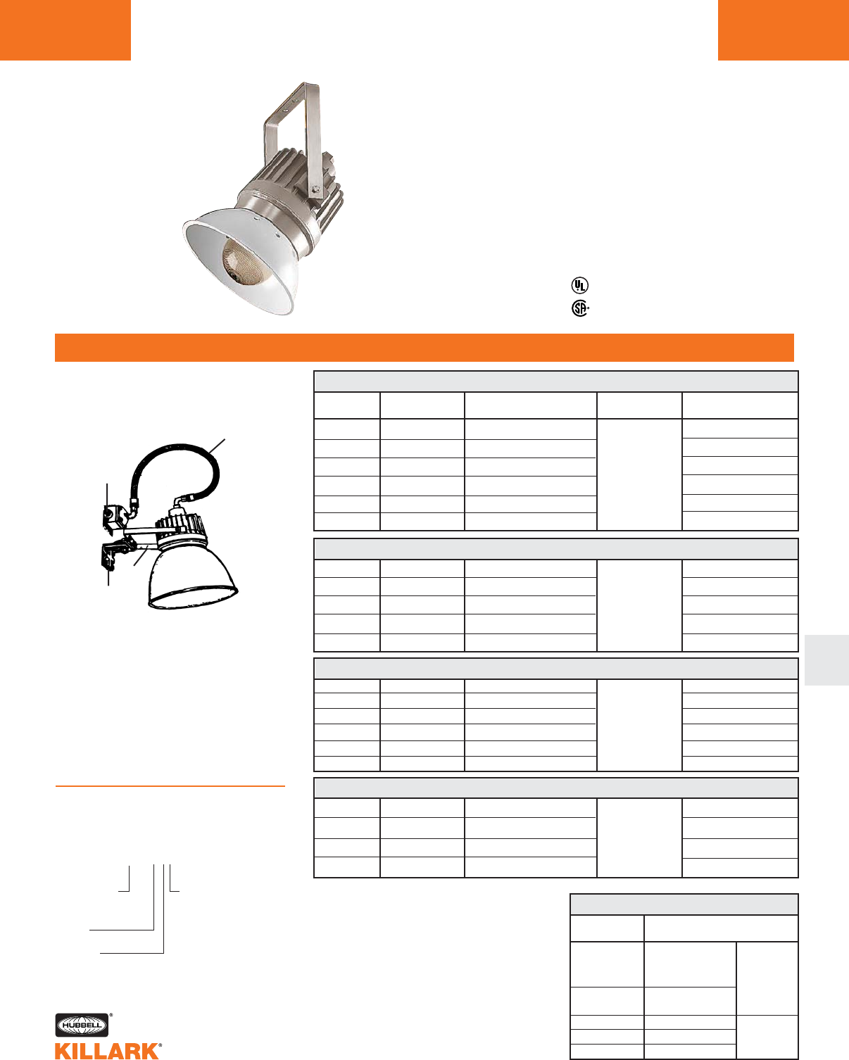
EZ SERIES •LIGHTING
HID FLOODLIGHT FIXTURES L181
ORDERING INFORMATION
L
WATTS ANSI LAMP VOLTAGE HUB CATALOG
TYPE @60 HERTZ SIZE NUMBER
50 HPS S-68 120, 208, 240, 277 EZS050A2-T
70 HPS S-62 120, 208, 240, 277 EZS070A2T
100 HPS S-54 120, 208, 240, 277 3/4"1EZS100A2-T
150 HPS S-55 120, 208, 240, 277 EZS150A2-T
250 HPS S-50 120, 208, 240, 277 EZS250A2-T
400 HPS S-51 120, 208, 240, 277 EZS400A2-T
EZ 50–400W HPS FLOODLIGHTS123
CATALOG
NUMBER DESCRIPTION
HPS 50-150
EZG1 MH 175-250
MV 100-250 Guard
VMAG-40 HPS 250-400
MH, MV 400
VMPSD-40 Standard dome
HRD-400 Deep dome white Reflector
HRD-400ALZ Deep dome Alzak*
EZ ACCESSORIES3
1Luminaire catalog numbers provide for a single
3⁄4" NPT flexible conduit connection only.
For 1" NPT conduit connection, substitute
“3” for “2” in catalog number;
example: EZS050A3-T
2Consult page L139 for other available voltage.
Listed - E10514
LR 11713
Class I, Div. 1 & 2, Groups C,D
Class I, Zones 1 & 2, Groups llB,llA
NEMA 3, 4, 4X, 7(C,D)
Factory Sealed
A. Flexible coupling. See page L198
for EKJ series
B. Splice box. See page L199 for
JL/JAL series
C. Trunnion yoke supplied with EZ-T
series floodlight fixture
D. Mounting accessory wall mount
(KFWB) shown. See page L177 for
this and other fittings available to
adapt trunnion mount floodlights to
crossarms, poles or walls
3Accessories may be ordered with fixture as a
single catalog number with the following logic.
Components shipped separately.
A
B
C
D
Installation Method
Typical EZ Series trunnion mounted
luminaire using conduit hardware.
Shown with optional
VMPSD-40 reflector3
EZH400A2G-TS
4Optional Accessory
S-Standard Dome
Cat. No. VMPSD-40
D-Deep Dome
Cat. No. HRD-400
Z-Deep Dome
Cat. No. HRD-400ALZ
Trunnion
Guard
Base Catalog
Number (INC/”T”)
4
4
*(tm Alcoa)
70 MH M-98 120, 208, 240, 277 EZH070A2-T
100 MH M-90 120, 208, 240, 277 EZH100A2-T
175 MH M-57 120, 208, 240, 277 3/4"1EZH170A2-T
250 MH M-58 120, 208, 240, 277 EZH250A2-T
400 MH M-59 120, 208, 240, 277 EZH400A2-T
EZ 70–400W MH FLOODLIGHTS123
100 MV H-38 120, 208, 240, 277 EZM100A2-T
175 MV H-39 120, 208, 240, 277 3/4"1EZM170A2-T
250 MV H-37 120, 208, 240, 277 EZM250A2-T
400 MV H-33 120, 208, 240, 277 EZM400A2-T
EZ 100–400W MV FLOODLIGHTS123
175 MHP M-137/M-152 120, 208, 240, 277 EZP170A2-T
200 MHP M-136 120, 208, 240, 277 EZP200A2-T
250 MHP M-138/M153 120, 208, 240, 277 3/4"1EZP250A2-T
320 MHP M-132/M154 120, 208, 240, 277 EZP320A2-T
350 MHP M-131 120, 208, 240, 277 EZP350A2-T
400 MHP M-135/M155 120, 208, 240, 277 EZP400A2-T
EZ 175–400W MH PULSE FLOODLIGHTS123
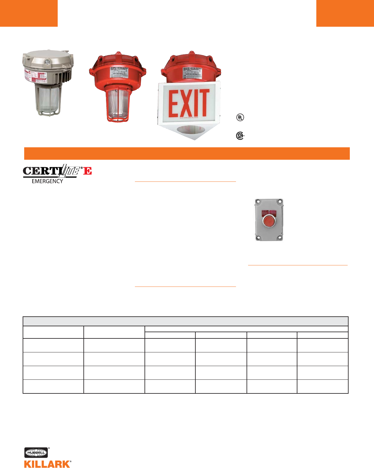
DEB SERIES •LIGHTING
COMPACT FLUORESCENT EMERGENCY LIGHTING
L182
FEATURES-SPECIFICATIONS
Applications
CERTILITE® DEB Emergency Lighting
fixtures provide continuous illumination
under normal power and switch to
emergency battery backup during
power outages. Emergency Units ONLY
are available that operate only when
normal power fails.
Units contain battery unit(s) that pro-
vides the OSHA required 90 minutes of
illumination for egress.
Units are designed for general and task
lighting in indoor or outdoor wet loca-
tions or where combustible dusts may
exist and create a hazardous location,
as defined by the NEC.
Use Push-To-Test station suitable for
area of use for testing purposes. FXCS
Class II, Div. 1 & 2, Groups E,F,G
Class III
NEMA 3, 4, 4X
UL844; UL1570; UL924 (File E162407)
UL Wet Location Listed (Indoor & Outdoor)
UL Listed (Indoor & Outdoor)
Rated for 40Cº ambient. Minimum Start 0°
series control stations should be used
for hazardous locations.
Features
• Bi-Pin Twin long-life compact fluores-
cent lamps included
• Choice of Pendant, Ceiling, Wall or
Stanchion mount
• Corrosion resistant-Copper-free alu-
minum die-cast construction (less
than 4/10 of 1%) with Baked-on
epoxy/polyester powder finish
• Exposed hardware is 316 grade stain-
less steel
• LED charging indicator light visible
through lens
• Pre-wired terminal block for easy
power connection
Accessories
•Exit sign: Model VEXA-100 (Note: omit
2nd “G” in catalog number for globe-
only fixture)
• Reflectors: Use standard dome
VMPSD-17 or angle model
VMPA-17 (see page L118 )
• XCS-OB3-PTT: “Push-To-Test” cover
only with N.C. contact. Order SWB
back box separately.
Options
• For Factory Fusing add -F to catalog
number, e.g. DEB2613E1A2GGN4-F
• For Red Painted Fixtures, add -R
to catalog number, e.g.
DEB2613E1A2GGN4-R
DEB 26-39 WATT NORMAL & EMERGENCY MODE FIXTURES
1Pendant, Ceiling & Wall models may be changed to 1" hubs by changing
the 11th character from 2to 3; e.g. DEB2613E1A3GGN4.
2For 1-1/2" angle Stanchion, change D4 to D5 in catalog number.
Change D4 to S5 for 1-1/2" Straight (90º) Stanchion
3Omit 2nd “G” for globe-only fixture for use with VEXA-100 Exit Accessory.
4Standard color for fixtures is Killark beige. Add -R for RED adder.
NOTES: See page L78 for ballast data.
26W (2x13) Normal 120VAC 60Hz DEB2613E1A2GGN4 DEB2613E1X2GGN4 DEB2613E1B2GGN4 DEB2613E1D4GGN4
13W (1x13) Emergency 277VAC 60Hz DEB2613E4A2GGN4 DEB2613E4X2GGN4 DEB2613E4B2GGN4 DEB2613E4D4GGN4
26W (2x13) Normal 120VAC 60Hz DEB2626E1A2GGN4 DEB2626E1X2GGN4 DEB2626E1B2GGN4 DEB2626E1D4GGN4
26W (2x13) Emergency 277VAC 60Hz DEB2626E4A2GGN4 DEB2626E4X2GGN4 DEB2626E4B2GGN4 DEB2626E4D4GGN4
39W (3x13) Normal 120VAC 60Hz DEB3913E1A2GGN4 DEB3913E1X2GGN4 DEB3913E1B2GGN4 DEB3913E1D4GGN4
13W (1x13) Emergency 277VAC 60Hz DEB3913E4A2GGN4 DEB3913E4X2GGN4 DEB3913E4B2GGN4 DEB3913E4D4GGN4
39W (3x13) Normal 120VAC 60Hz DEB3926E1A2GGN4 DEB3926E1X2GGN4 DEB3926E1B2GGN4 DEB3926E1D4GGN4
26W (2x13) Emergency 277VAC 60Hz DEB3926E4A2GGN4 DEB3926E4X2GGN4 DEB3926E4B2GGN4 DEB3926E4D4GGN4
COMPACT FLUORESCENT CATALOG NUMBER34
LAMPS INCLUDED LINE VOLTAGE PENDANT 3/4"1CEILING 3/4"1WALL 3/4"1STANCHION 1-1/4"2

DEB 13-26 WATT EMERGENCY-ONLY MODE FIXTURES
DEB SERIES •LIGHTING
COMPACT FLUORESCENT EMERGENCY LIGHTING L183
FEATURES-SPECIFICATIONS
L
COMPACT FLUOR. CATALOG NUMBER34
LAMP INCL. LINE VOLTAGE PENDANT 3/41CEILING 3/41WALL 3/41STANCHION 1-1/42
13W (1x13) Emergency 120 or 277VAC 60Hz DEB0013E10A2GGN4 DEB0013E10X2GGN4 DEB0013E10B2GGN4 DEB0013E10D4GGN4
26W (2x13) Emergency 120 or 277VAC 60Hz DEB0026E10A2GGN4 DEB0026E10X2GGN4 DEB0026E10B2GGN4 DEB0026E10D4GGN4
1Pendant, Ceiling & Wall models may be changed to 1" hubs
by changing the 12th character from 2to 3e.g. DEB0013E10A3GGN4.For
1-1/2" angle Stanchion, change D4 to D5 in catalog number.
Change D4 to S5 for 1-1/2" Straight (90º) Stanchion.
3Omit 2nd “G” for globe-only fixture for use with VEXA-100 Exit Accessory.
4Standard color for fixtures is Killark beige. Add -R for RED adder.
5Photometric characteristics similar to 39 watt MBF pages L31-33,
except adjusted for lumen output.
*One used per “Emergency” lamp .
LUMEN OUTPUT5
LAMP SOURCE NORMAL POWER EMERGENCY POWER
13Watt (1X13) — 625
26Watt (2x13) 1800 1250
39Watt (3X13) 2700 —
REPLACEMENT PARTS
CATALOG NUMBER DESCRIPTION
MPL13 Replacement Lamp
KFBP6 Replacement Battery Units*
HAZARDOUS LOCATION APPLICATION DATA FOR GLOBE & GUARD AND WITH REFLECTOR
LAMP SOURCE CLASS II DIV 1 & 2 E,F,G CLASS III SUITABILITY SUPPLY WIRE
13Watt (1X13) 85°C (T6) YES 85°C
26Watt (2x13) 85°C (T6) YES 85°C
39Watt (3X13) 85°C (T6) YES 85°C
Class II, Div. 1 & 2, Groups E,F,G
Class III
NEMA 3, 4, 4X
UL844; UL1570; UL924 (File E162407)
UL Wet Location Listed (Indoor & Outdoor)
UL Listed (Indoor & Outdoor)
Rated for 40Cº ambient. Minimum start 0ºC.
VEXA-100 Exit
Accessory Dimensions
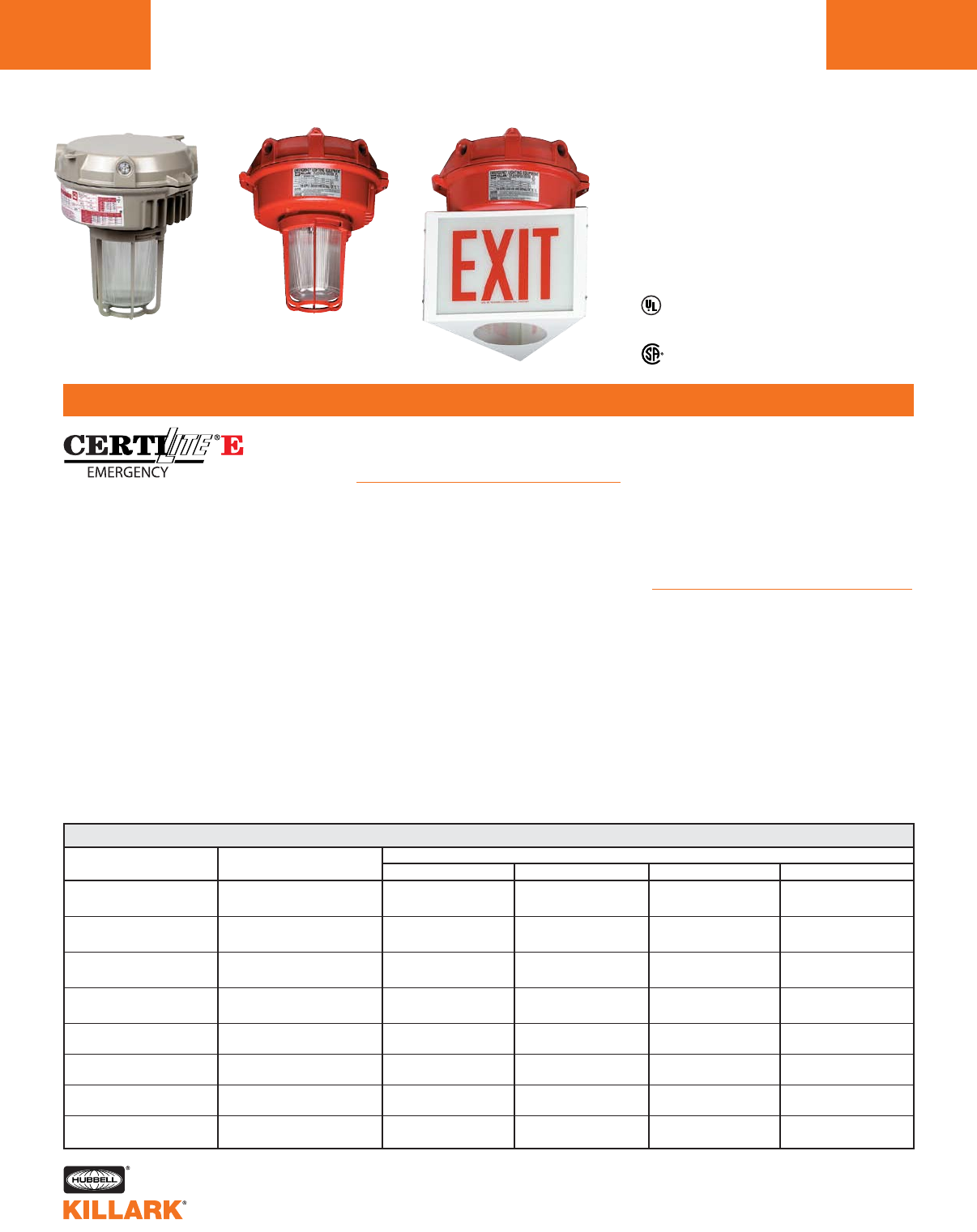
VEB/VEQ SERIES 26 - 84WATT NORMAL & EMERGENCY MODE FIXTURES
VEB/VEQ SERIES •LIGHTING
COMPACT FLUORESCENT EMERGENCY LIGHTING
L184
FEATURES-SPECIFICATIONS
Applications
CERTILITE® VEB and VEQ Emergency
Lighting fixtures provide continuous illu-
mination under normal power and
switch to emergency battery backup
during power outages. Emergency
Units ONLY are available that operate
only when normal power fails.
Units contain battery unit(s) that pro-
vides the OSHA required 90 minutes of
illumination for egress.
Units are designed for general and task
lighting indoors or outdoors where flam-
mable gases or vapors, combustible
dusts, or simultaneous presence may
exist and create a hazardous location,
as defined by the NEC.
Use Push-To-Test station suitable for
area of use for testing purposes. FXCS
series control stations should be used
for hazardous locations.
Features
• Bi-Pin Twin (VEB) or Quad-Pin triple-
tube (VEQ) long-life compact fluores-
cent lamps included
• World Voltage on Quad-Pin VEQ
Series: 120 through 277VAC; 50
through 60 Hz
• Choice of Pendant, Ceiling, Wall or
Stanchion mount
• Corrosion resistant-Copper-free alu-
minum die-cast construction with
Baked-on epoxy/polyester powder fin-
ish
• Exposed hardware is 316 grade stain-
less steel
• LED charging indicator light visible
through lens
• Pre-wired terminal block for easy
power connection
Accessories
•Exit sign: Model VEXA-100 (Note:
omit 2nd “G” in catalog number for
globe-only fixture)
• Reflectors: Use standard dome
VMPSD-17 or angle model
VMPA-17 (see page L118)
• XCS-OB3-PTT “Push-To-Test” (see
L182 for details)
Options
• For Factory Fusing on VEB and for
VEQ to be used on 120V or 277V
systems, add -F to catalog number
e.g. VEB2613E1A2GGN4-F. For VEQ
to be used on 208V, 220V, 230V, 240V
systems, add -FF to
catalog number, e.g.
VEQ2626E30A2GGN4-FF
• For Red Painted Fixtures, add -R
to catalog number, e.g.
VEB2613E1A2GGN4-R
26W (2x13) Normal 120VAC 60Hz VEB2613E1A2GGN4 VEB2613E1X2GGN4 VEB2613E1B2GGN4 VEB2613E1D4GGN4
13W (1x13) Emergency 277VAC 60Hz VEB2613E4A2GGN4 VEB2613E4X2GGN4 VEB2613E4B2GGN4 VEB2613E4D4GGN4
26W (2x13) Normal 120VAC 60Hz VEB2626E1A2GGN4 VEB2626E1X2GGN4 VEB2626E1B2GGN4 VEB2626E1D4GGN4
26W (2x13) Emergency 277VAC 60Hz VEB2626E4A2GGN4 VEB2626E4X2GGN4 VEB2626E4B2GGN4 VEB2626E4D4GGN4
39W (3x13) Normal 120VAC 60Hz VEB3913E1A2GGN4 VEB3913E1X2GGN4 VEB3913E1B2GGN4 VEB3913E1D4GGN4
13W (1x13) Emergency 277VAC 60Hz VEB3913E4A2GGN4 VEB3913E4X2GGN4 VEB3913E4B2GGN4 VEB3913E4D4GGN4
39W (3x13) Normal 120VAC 60Hz VEB3926E1A2GGN4 VEB3926E1X2GGN4 VEB3926E1B2GGN4 VEB3926E1D4GGN4
26W (2x13) Emergency 277VAC 60Hz VEB3926E4A2GGN4 VEB3926E4X2GGN4 VEB3926E4B2GGN4 VEB3926E4D4GGN4
26W (1x26) Normal 120 through 277 50-60Hz VEQ2626E30A2GGN4 VEQ2626E30X2GGN4 VEQ2626E30B2GGN4 VEQ2626E30D4GGN4
26W (1x26) Emergency
52W (2x26) Normal 120 through 277 50-60Hz VEQ5226E30A2GGN4 VEQ5226E30X2GGN4 VEQ5226E30B2GGN4 VEQ5226E30D4GGN4
26W (1x26) Emergency
64W (2x32) Normal 120 through 277 50-60Hz VEQ6432E30A2GGN4 VEQ6432E30X2GGN4 VEQ6432E30B2GGN4 VEQ6432E30D4GGN4
32W (1x32) Emergency
84W (2x42) Normal 120 through 277 50-60Hz VEQ8442E30A2GGN4 VEQ8442E30X2GGN4 VEQ8442E30B2GGN4 VEQ8442E30D4GGN4
42W (1x42) Emergency
COMPACT FLUORESCENT CATALOG NUMBER 34
LAMP INCLUDED LINE VOLTAGE PENDANT 3/4"1CEILING 3/4"1WALL 3/4"1STANCHION 1-1/4"2
1Pendant, Ceiling & Bracket models may be changed to 1" hubs by changing the 11th character
from 2to 3; e.g. VEB2613E1A3GGN4 (12th character in VEQ series).
2For 1-1/2" angle Stanchion, change D4 to D5 in catalog number. Change D4 to S5 for 1-1/2" Straight (90º) Stanchion.
3Omit 2nd “G” for globe-only fixture for use with VEXA-100 Exit Accessory.
4Standard color for fixtures is Killark beige. Add -R for RED adder.
Class I, Div. 2, Groups A,B,C,D
Class I, Zone 2, Groups IIC, IIB, IIA
Class II, Div. 1 & 2, Groups E,F,G
Class III
NEMA 3, 4, 4X
UL844; UL1570; UL924 (File E162407)
UL Wet Location Listed (Indoor & Outdoor)
UL Listed (Indoor & Outdoor)
Rated for 40Cº ambient.
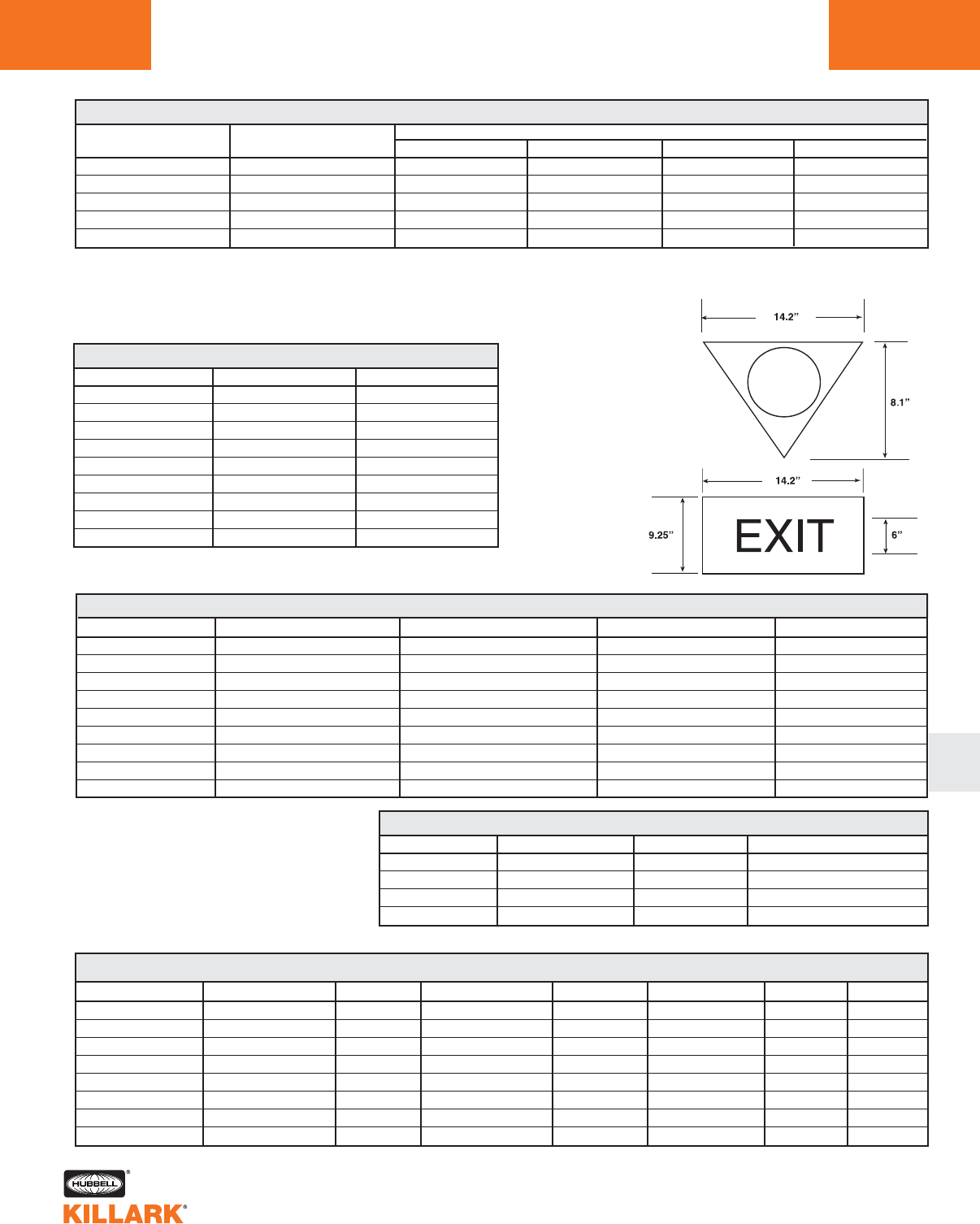
VEB/VEQ 13 - 42WATT EMERGENCY-ONLY MODE FIXTURES
VEB/VEQ SERIES •LIGHTING
COMPACT FLUORESCENT EMERGENCY LIGHTING L185
L
COMPACT FLUOR. CATALOG NUMBER 34
LAMP INCLUDED LINE VOLTAGE PENDANT 3/4"1CEILING 3/4"1WALL 3/4"1STANCHION 1-1/4"2
13W (1x13) Emergency 120 or 277VAC 60Hz VEB0013E10A2GGN4 VEB0013E10X2GGN4 VEB0013E10B2GGN4 VEB0013E10D4GGN4
26W (2x13) Emergency 120 or 277VAC 60Hz VEB0026E10A2GGN4 VEB0026E10X2GGN4 VEB0026E10B2GGN4 VEB0026E10D4GGN4
26W (1x26) Emergency 120 through 277 50-60Hz VEQ0026E30A2GGN4 VEQ0026E30X2GGN4 VEQ0026E30B2GGN4 VEQ0026E30D4GGN4
32W (1x32) Emergency 120 through 277 50-60Hz VEQ0032E30A2GGN4 VEQ0032E30X2GGN4 VEQ0032E30B2GGN4 VEQ0032E30D4GGN4
42W (1x42) Emergency 120 through 277 50-60Hz VEQ0042E30A2GGN4 VEQ0042E30X2GGN4 VEQ0042E30B2GGN4 VEQ0042E30D4GGN4
1Pendant, Ceiling & Wall models may be changed to 1" hubs by changing the 12th character from “2” to “3”; e.g. VEB0013E10A3GGN4.
2For 1-1/2" angle Stanchion, change “D4” to “D5” in catalog number.
Change “D4” to “S5” for 1-1/2" Straight (90º) Stanchion.
3Omit 2nd “G” for globe-only fixture for use with VEXA-100 Exit Accessory.
4Standard color for fixtures is Killark beige. Add -R for RED adder.
6VEB/VEQ units are rated for simultaneous presence.
LUMEN OUTPUT5
LAMP SOURCE NORMAL POWER EMERGENCY POWER
13Watt (1X13) — 625
26Watt (2x13) 1650 1250
39Watt (3X13) 2475 —
26Watt (1x26) 1800 425
32Watt (1X32) — 525
42Watt (1X42) — 700
52Watt (2x26) 3600 —
64Watt (2X32) 4800 —
84Watt (2X42) 6400 —
HAZARDOUS LOCATION APPLICATION DATA FOR GLOBE & GUARD (SAME WITH REFLECTOR OR EXIT ACCESSORY)6
LAMP SOURCE CLASS I DIV. 2 A,B,C,D CLASS II DIV. 1 & 2 E,F,G CLASS III SUITABILITY SUPPLY WIRE
13Watt (1X13) 180°C (T3A) 85°C (T6) YES 85°C
26Watt (2x13) 180°C (T3A) 85°C (T6) YES 85°C
39Watt (3X13) 180°C (T3A) 85°C (T6) YES 85°C
26Watt (1x26) 215°C (T2D) 120°C (T4A) YES 85°C
32Watt (1X32) 215°C (T2D) 120°C (T4A) YES 85°C
42Watt (1X42) 215°C (T2D) 120°C (T4A) YES 85°C
52Watt (2x26) 215°C (T2D) 120°C (T4A) YES 85°C
64Watt (2X32) 215°C (T2D) 120°C (T4A) YES 85°C
84Watt (2X42) 215°C (T2D) 120°C (T4A) YES 85°C
MPL13 13W Bi-Pin
MQL26 26W Quad-Pin
MQL32 32W Quad-Pin
MQL42 42W Quad-Pin
KFBP5 13W Bi-Pin*
KFBP7 26/32/42W Quad-Pin
KFBP7 26/32/42W Quad-Pin
KFBP7 26/32/42W Quad-Pin
BALLAST DATA NORMAL POWER
LAMP WATTS VOLTAGE AC START AMPS OPERATING AMPS INPUT WATTS BALLAST CIRCUIT REGULATION MIN. START
26Watt (2x13) 120 / 277 0.78/.70 0.6 32 NPF — 32°F (0°C)
39Watt (3X13) 120 / 277 1.17/1.05 0.9 48 NPF — 32°F (0°C)
26Watt (1x26) 120 through 277 — .27@120V /.13 @277V 29 HPF Electronic -4°F (-20°C)
32Watt (1X32) 120 through 277 — .31@120V /.15 @277V 36 HPF Electronic -4°F (-20°C)
42Watt (1X42) 120 through 277 — .37@120V /.17 @277V 46 HPF Electronic -4°F (-20°C)
52Watt (2x26) 120 through 277 — .54@120V /.26 @277V 58 HPF Electronic -4°F (-20°C)
64Watt (2X32) 120 through 277 — .62@120V /.30 @277V 72 HPF Electronic -4°F (-20°C)
84Watt (2X42) 120 through 277 — .74@120V /.34 @277V 92 HPF Electronic -4°F (-20°C)
For fixture dimensions consult factory.
REPLACEMENT PARTS
CATALOG NUMBER REPLACEMENT LAMPS CATALOG NUMBER REPLACEMENT BATTERY UNITS
VEXA-100 Exit
Accessory
Dimensions
5Photometric characteristics similar to 39 watt MBF pages L31-33,
except adjusted for lumen output.
*One used per “Emergency” lamp.
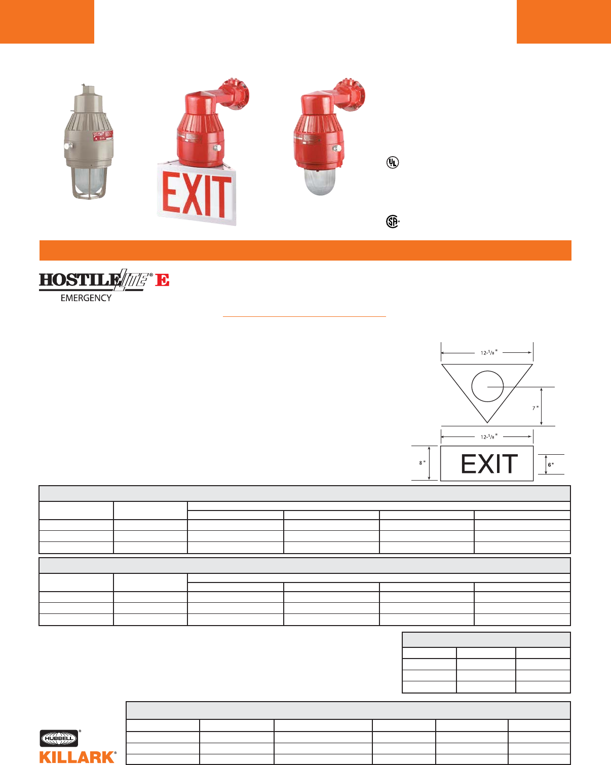
Use Push-To-Test station suitable for
area of use for testing purposes. FXCS
series control stations should be used
for hazardous locations.
Features
•Quad-Pin long-life triple-tube com-
pact fluorescent lamps included
• Choice of Pendant, Ceiling, Wall or
Stanchion mount
• Factory Sealed - No external seal
required
• Corrosion resistant-Copper-free
aluminum (less than 4/10 of 1%)
die-cast construction w/Baked-on
epoxy/polyester powder finish
• Exposed hardware is 316 grade
stainless steel
• LED charging indicator light visible
through lens
EEQ SERIES •LIGHTING
COMPACT FLUORESCENT EMERGENCY LIGHTING
L186
FEATURES-SPECIFICATIONS
Class I, Div. 1 & 2, Groups C,D
Class I, Zones 1 & 2, Groups IIB, IIA
Class II, Div. 1 & 2, Groups E,F,G
Class III
NEMA 3
Compliances: UL 844; UL 1570, UL924 (File E162407)
UL Wet Location Listed (Indoor & Outdoor)
Rated for 40Cº ambient. Minimum start 0º C
Temperature codes:
Class I C,D T6;
Class II E,F,G T4;
Suitable for Class III
Certified File LR11713
EEQ 26, 32 & 42WATT NORMAL & EMERGENCY MODE FIXTURES
QUAD-PIN FLUOR. LINE VOLTAGE CATALOG NUMBER 346
LAMP INCLUDED @ 60 HZ PENDANT 3/4" 1CEILING 3/4" 1BRACKET 3/4" 1STANCHION 1-1/4" 2
26Watt 120 or 277VAC5EEQ2626E10A2GG EEQ2626E10X2GG EEQ2626E10B2GG EEQ2626E10D4GG
32Watt 120 or 277VAC5EEQ3232E10A2GG EEQ3232E10X2GG EEQ3232E10B2GG EEQ3232E10D4GG
42Watt 120 or 277VAC5EEQ4242E10A2GG EEQ4242E10X2GG EEQ4242E10B2GG EEQ4242E10D4GG
Applications
HOSTILELITE®EEQ Emergency
Lighting fixtures provide continuous illu-
mination under normal power and
switch to emergency battery backup
during power outages. Emergency
Units ONLY are available that operate
only when normal power fails.
Units contain battery unit that provides
the OSHA required 90 minutes of illumi-
nation (same lamp) for egress.
Units are designed for general and task
lighting indoors or outdoors where flam-
mable gases or vapors or combustible
dusts exist and create a hazardous
location, as defined by the NEC.
Accessories
Exit sign: Model HEXA-100 (note omit
2nd “G” in catalog number for globe-only
fixture) see page L124.
Reflectors: Use standard dome ERSD15
or angle model ERA15 (see page L123).
EEQ 26, 32 & 42WATT EMERGENCY-ONLY MODE FIXTURES
QUAD-PIN FLUOR. LINE VOLTAGE CATALOG NUMBER 346
LAMP INCLUDED @ 60 HZ PENDANT 3/4" 1CEILING 3/4" 1BRACKET 3/4" 1STANCHION 1-1/4" 2
26Watt 120 or 277VAC5EEQ0026E10A2GG EEQ0026E10X2GG EEQ0026E10B2GG EEQ0026E10D4GG
32Watt 120 or 277VAC5EEQ0032E10A2GG EEQ0032E10X2GG EEQ0032E10B2GG EEQ0032E10D4GG
42Watt 120 or 277VAC5EEQ0042E10A2GG EEQ0042E10X2GG EEQ0042E10B2GG EEQ0042E10D4GG
LUMEN OUTPUT7
LAMP SOURCE NORMAL POWER EMERG. POWER
26Watt 1800 450
32Watt 2400 575
42Watt 3200 750
BALLAST DATA
LAMP WATTS VOLTAGE OPERATING AMPS INPUT WATTS BALLAST CIRCUIT REGULATION
26Watt (1x26) 120 / 277 VAC .24@120V /.11 @277V 29 HPF Electronic
32Watt (1X32) 120 / 277 VAC .31@120V /.13 @277V 36 HPF Electronic
42Watt (1x42) 122 / 277 VAC .38@120V /.17 @277V 46 HPF Electronic
1Pendant, Ceiling & Bracket models may be
changed to 1" hubs by changing the 12th character
from 2to 3; e.g. EEQ2626E10A3GG.
2Stanchion fixtures are 1-1/2" with a 1-1/2 to 1-1/4"
reducer.
3Omit 2nd “G” for globe-only fixture for use with
HEXA-100 Exit Accessory.
4Standard color for fixtures is Killark beige. Add -R
for RED adder..
5All EEQ fixtures are factory set to 120V and can be
changed to 277V in field by following included
instructions. Replacement battery pack kit KFBP9.
6EEQ fixtures use a tank extension ring and are 2-
1/2" taller than EBF fixtures (see page L126).
7Photometric characteristics similar to EBF26 page
L135, except adjusted for lumen output.
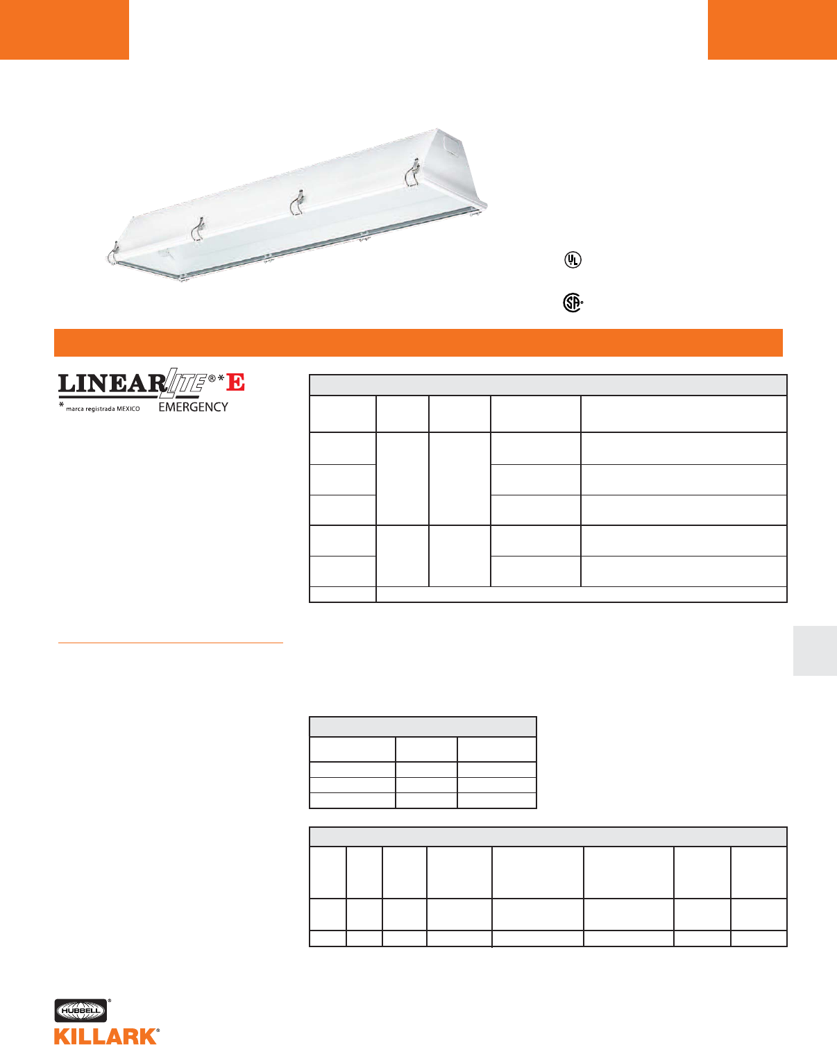
DBFE SERIES •LIGHTING
LINEAR FLUORESCENT EMERGENCY LIGHTING L187
FEATURES-SPECIFICATIONS
L
Class I, Div. 2, Groups A,B,C,D
Class I, Zone 2, Groups IIC, IIB, IIA
Class ll, Div. 2 Groups F,G
NEMA 3, 4
UL Listed
Compliances: UL 44; UL 81570, UL924
UL Wet Location Listed (Indoor & Outdoor)
Applications
LINEARLITE DBFE Emergency Lighting
fixtures provide continuous illumination
under normal power and switch to
emergency battery backup during
power outages. Units contain
a battery unit that provides the OSHA
required 90 minutes of illumination for
egress.
Units are designed for general and task
lighting in areas where flammable
gases or vapors or combustible dusts
may exist due to abnormal conditions,
and create a Division 2 hazardous
location, as defined by the NEC.
Features
•Sheet steel 20 ga. housing with con-
tinuous weld prevents foreign matter
from entering enclosure
•Lens frame assembly has silicon rub-
ber gasketing and heat tempered
glass lens
•Electrostatically applied polyester
finish
• NEMA 4 construction for wet locations
•LED charging indicator light visible
through lens
•Push-To-Test Button mounted on
sloping side of fixture - allows
end-to-end mounting of fixtures
EMERGENCY LUMEN CHART
LAMPS INITIAL AFTER
LUMENS 90 MINUTES
2 32W Lamps 625 455
2 40W Lamps 610 420
1 60W Lamp 780 460
Notes: Emergency unit will start lamps at 0ºF
32W T8 Electronic ballast minimum start is 0ºF;
40W ballast is electronic with 50ºF start (add CW for electromagnetic 0ºF);
60W electromagnetic ballast start -20ºF
32W & 40W units operate 2 Lamps in emergency mode for maximum illumination
60W units operate a single lamp. 3 Lamp 60W emergency units not available.
For dimensional data and mounting accessories, see DBF series page L156.
Digit after E is number of lamps energized during power loss.
CATALOG CONDUIT NUMBER LINE DESCRIPTION
NUMBER SIZE OF LAMPS VOLTAGE
DBFE232302 120-277V 50/60 Hz 32W T8 electronic ballast OºF start
Medium bi-pin base
DBFE24012 3/4" 120V 60 Hz 40W T12 bi-pin 50ºF start electronic
DBFE24042 2 277V 60 Hz Medium bi-pin base
DBFE16012 120V 60 Hz 60W rapid start high output F48T12/HO
DBFE16042 277V 60 Hz Recessed double contact 800MA
DBFE232303 120-277V 50/60 Hz 32W T8 electronic ballast OºF start
3/4" 3 Medium bi-pin base
DBFE24013 120V 60 Hz 40W T12 bi-pin 50ºF start electronic
DBFE24043 277V 60 Hz Medium bi-pin base
KFBP7 (32/40 or 60 Watt) Replacement battery unit
DBFE FLUORESCENT EMERGENCY LIGHTING
DBFE HAZARDOUS LOCATION APPLICATION DATA
NO.
OF
LAMPS
LAMP
WATTS
RATED
AMBIENT
°C
NEMA
TYPE 3
(RAINTIGHT)
NEMA
TYPE 4
(HOSEDOWN)
SUPPLY WIRE
SUITABLE
FOR °C MIN.
CLASS I, DIV. 2,
GROUPS A,B,C,D
MAX. LAMP TEMP.°C
UL/CSA TEMP./I.D.
CLASS II, DIV. 2,
GROUPS E.F,G
MAX. SURF. TEMP.°C
UL/CSA TEMP./I.D.
2
3
2
32/40
32/40
60
YES
YES
YES
YES
YES
YES
40
40
40
90
90
90
T6 (85°C/185°F)
T5 (100°C/212°F)
T4A (120°C/248°F)
T6 (85°C/185°F)
T6 (85°C/185°F)
T6 (85°C/185°F)
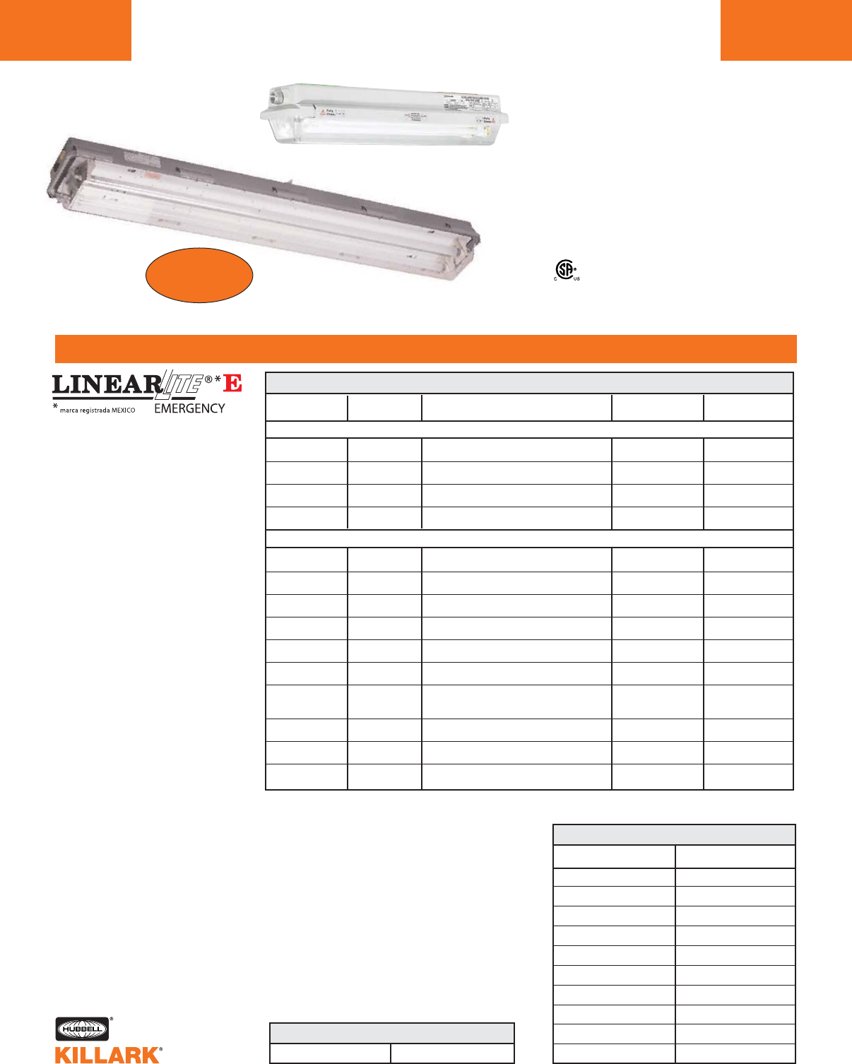
LZ2NE/LZ2SE BATTERY-BACKED
EMERGENCY LUMEN CHART
NEW!
LZ2NE/LZ2NSE SERIES EMERGENCY FLUORESCENT
L188
FEATURES-SPECIFICATIONS
Certified - File LR11713
Class I, Div. 2 Groups A,B,C,D
Class l, Zones 2, Groups IIC,llB,llA
Class II, Div. 1 & 2, Groups E3,F,G
AEx nAII, Ex nAII
Wet Locations
NEMA 4X, IP66
LZ2SE 4’ Stainless
LZ2NE 2’ Non-metallic
Type Approval
ABS
Food Handling4
NSF
1Digit after E is number of lamps energized during power loss. For optional fused ballasts, add to catalog
number F1 for 120V, F4 for 277V, F8 for 230V. Fusing not for marine or Canadian use. Lamps not included.
2Magnetic ballast
NUMBER OF
LAMPS/WATTS
1-40W6
1-55W6
2-40W6
4-40W6
2-17W5
3-17W5
2-28W6
3-28W6
2-32W5
3-32W5
2-40W5
2-44W6
2-54W6
2-60W5
BIAXIAL LAMP TYPE FIXTURES
VOLTAGE
AC 60 Hz
120-277V
120-277V
120-277V
120-277V
120-277V
120-277V
120-277V
120-277V
120-277V
347V
120-277V
347V
120V
277V
230V 50 Hz2
120-277V
120-277V
120V
277V
DOUBLE-ENDED LAMP TYPE FIXTURES
DESCRIPTION
2' 1-Lamp Biaxial Electronic 50/60 Hz
0°F Start 4-Pin
2' 1-Lamp Biaxial Electronic 50/60 Hz
0°F Start 4-Pin
2' 2-Lamp Biaxial Electronic 50/60 Hz
0°F Start 4-Pin
4' 4-Lamp Biaxial Electronic 50/60 Hz
0°F Start 4-Pin
2' 2-Lamp T-8 Electronic 50/60 Hz
0°F Start Medium Bi-Pin
2' 3-Lamp T-8 Electronic 50/60 Hz
0°F Start Medium Bi-Pin
4' 2-Lamp T-5 Electronic 50/60 Hz
0°F Start Miniature Bi-Pin
4' 3-Lamp T-8 Electronic 50/60 Hz
0°F Start Miniature Bi-Pin
4' 2-Lamp T-8 Electronic 50/60 Hz
0°F Start Medium Bi-Pin
4' 3-Lamp T-8 Electronic 50/60 Hz
0°F Start Medium Bi-Pin
4' 2-Lamp T-12 Electronic Medium Bi-Pin
Start 50°F 40W/60°F 34W
4' 2-Lamp T-8 Electronic -20°F Start
High Output Recessed Double Contact
4' 2-Lamp T-5 Electronic 50/60 Hz
-20°F Start Miniature Bi-Pin
4' 2-Lamp T-12 Electronic -20°F Start
High Output Recessed Double Contact
LZ2NE1
LZ2NE1-40130
LZ2NE1-55130
LZ2NE1-40230
LZ2NE1-40430
LZ2NE2-17230
LZ2NE2-17330
LZ2NE1-28230
LZ2NE1-28330
LZ2NE2-32230
LZ2NE2-32215
LZ2NE2-32330
LZ2NE2-32315
LZ2NE2-40201
LZ2NE2-40204
LZ2NE2-40208
LZ2NE1-44230
LZ2NE1-54230
LZ2NE1-60201
LZ2NE1-60204
REPLACEMENT BATTERY UNIT
LAMPS
2 X 17 T8
1 X 40 BIAXIAL
1 X 55 BIAXIAL
1 X 28 T5
1 X 32 T8
2 X 32 T8
2 X 40 T12
1 X 44 T8
1 X 54 T5
1 X 60 T12
INITIAL LUMENS
550
900
950
1175
925
625
610
950
1200
780
Applications
LINEARLITE Emergency Lighting
fixtures provide continuous illumi-
nation under normal power and
switch to emergency battery back-
up during power outages. Units
contain a battery unit that provides
the OSHA required 90 minutes of
illumination for egress.
Units are available in non-metallic
or 316 Stainless construction and
designed for wet, harsh and corro-
sive environments. The LZ2NE and
LZ2SE Series can also be used in
Class I, Division 2 and Zone 2 haz-
ardous vapors and in Class II areas
where combustible dusts may
exist. Typical areas used are in
refineries, chemical plants, waste
water & sewage treatment facilities,
as well as in tunnels, food process-
ing and coastal areas.
ABS (American Bureau of
Shipping) type approval for use on
decks, vessels, platforms, garages,
ships and boats. Also suitable for
docks and marinas.
3LZ2SE only for Group E
4LZ2NE is NSF approved
Additional Data
L157 or L158 - Features
L159 - Ballast Data
L160 - Mounting Accessories
L160 - L161 - Photometrics
Features
•NEMA 4 & IP66 rated enclosure
•Housing-one piece fiberglass reinforced poly-
ester or 316 Stainless Steel
•Clear Lexan®impact resistant polycarbonate
lens (Lexan is a registered trademark of
General Electric)
•Two 3/4” NTP hubs - one at each end
(includes one 3/4” close-up plug and two 3/4”
X 1/2” reducers for maximum user flexibility
•Two 1/4”- 20 bushings furnished in top of fix-
ture for threaded rod
5KFBP7 6KFBPHO
LZ2SE1
LZ2SE1-40130
LZ2SE1-55130
LZ2SE1-40230
LZ2SE1-40430
LZ2SE2-17230
LZ2SE2-17330
LZ2SE1-28230
LZ2SE1-28330
LZ2SE2-32230
LZ2SE2-32215
LZ2SE2-32330
LZ2SE2-32315
LZ2SE2-40201
LZ2SE2-40204
LZ2SE2-40208
LZ2SE1-44230
LZ2SE1-54230
LZ2SE1-60201
LZ2SE1-60204
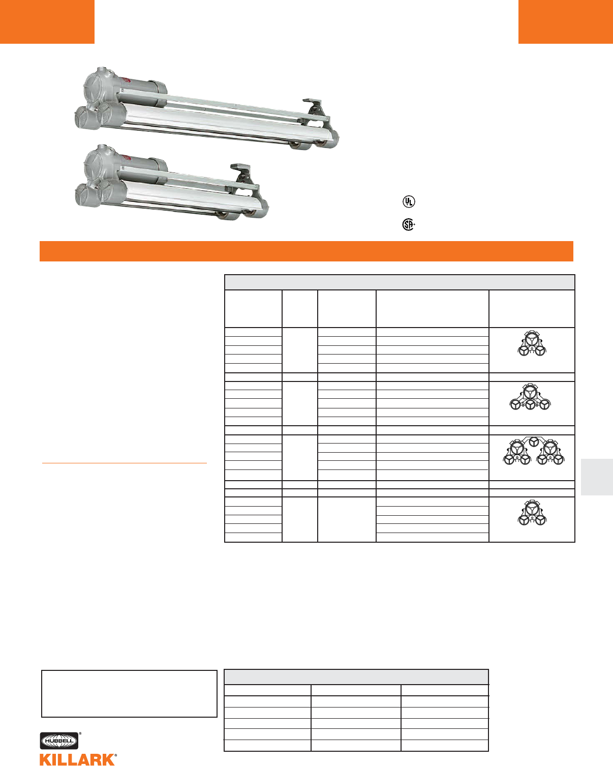
HFXE SERIES •LIGHTING
LINEAR FLUORESCENT EMERGENCY LIGHTING L189
FEATURES-SPECIFICATIONS
L
Listed - File E12976 and E89665 (Marine)3
UL 924, UL 844
Certified - File LR11713
Class I, Div. 1 & 2, Groups C,D
Class l, Zones 1 & 2, Groups llB, llA
Class II, Div. 1 & 2, Groups E,F,G
Class III, Div. 1 & 2
NEMA 3, 7(C,D) 9(E,F,G)
Suitable for wet locations
2’ Nominal
Style
4’ Nominal
Style
Applications
HFXE Series Emergency Lighting fix-
tures provide continuous illumination
under normal power and switch to
emergency battery backup during
power outages. Units contain
a battery unit that provides the OSHA
required 90 minutes of illumination for
egress.
Units are designed for installations
where moisture, dirt, dust, corrosion
and vibration may be present, or wet
locations where wind, water and snow
can be expected. They can also be
used in locations made hazardous due
to the presence of flammable or explo-
sive gases, vapors and combustible
ducts as defined by the NEC.
Features
•Construction is strong lightweight
corrosion resistant copper-free alu-
minum alloy, less than 4/10 of 1%
•All external hardware is corrosion
resistant 316 stainless steel to pro-
vide maintenance free long life
• World voltage ballasts standard on
32W and BIAXIAL models (120-277V
50/60 Hz)
•LED charging indicator light on bal-
last enclosure.
CONDUIT LINE VOLTAGE DESCRIPTION PROFILE
SIZE
HFXE2-265-302 120-277V 50/60 Hz 32W T8 electronic ballast 265MA
HFXE2-430-12 120V 60 Hz 40W T12 electronic ballast 430MA
HFXE2-430-42 3/4" 277V 60 Hz 40W T12 electronic ballast 430MA
HFXE1-800-12 120V 60 Hz 60W T12 electronic ballast 800MA
HFXE1-800-42 277V 60 Hz 60W T12 electronic ballast 800MA
HFXE2-265-303 120-277V 50/60 Hz 32W T8 electronic ballast 265MA
HFXE2-430-13 120V 60 Hz 40W T12 electronic ballast 430MA
HFXE2-430-43 3/4" 277V 60 Hz 40W T12 electronic ballast 430MA
HFXE1-800-13 120V 60 Hz 60W T12 electronic ballast 800MA
HFXE2-265-304 120-277V 50/60 Hz 32W T8 electronic ballast 265MA
HFXE2-430-14 120V 60 Hz 40W T12 electronic ballast 430MA
HFXE2-430-44 277V 60 Hz 40W T12 electronic ballast 430MA
HFXE1-800-14
3/4"
120V 60 Hz 60W T12 electronic ballast 800MA
HFXE1-800-44 277V 60 Hz 60W T12 electronic ballast 800MA
BIAXIAL SERIES
HFXE1-40T-302 2’ 2 Lamp 40W BIAXIAL
HFXE1-55T-302 2’ 2 Lamp 55W BIAXIAL
HFXE1-40T-304 3/4" 120-277V 50/60 HZ 4’ 4 Lamp 40W BIAXIAL
HFXE1-55T-304 4’ 4 Lamp 55W BIAXIAL
HFXE FLUORESCENT EMERGENCY LIGHTING
Two Glass Tubes
4’ Nominal
Three Glass Tubes
4’ Nominal
1Digit after “E” in catalog logic indicates number of lamps energized in emergency mode.
2Consult non-emergency HFX pages L164-169 for thermal, dimensional and other data, plus for avail-
able accessories. 40W & 60W are not available with universal voltage or 240V 50Hz ballasts.
31,2 and 3 tube models are third party certified. 4 tube models are self-certified.
NOTES: For fusing, add suffix F1 for 120V; F4 for 277V.
Emergency unit will start lamps at 0°F
32W T8 electronic ballast minimum start is 0°F
40W ballast is electronic with 50°F start (add CW for electromagnetic 0°F)
60W elecromagnetic ballast start at -20°F
32W & 40W units operate 2 lamps in emergency mode for a maximum illumination
60W and BIAXIAL units operate a single lamp. 3 lamp 277V 60W emergency units not available.
Replacement Battery Pack #KFBP10
Four Glass Tubes
4’ Nominal
CATALOG
NUMBER12
Two Glass Tubes
4’ Nominal
EMERGENCY LUMEN CHART
LAMPS INITIAL LUMENS AFTER 90 MINUTES
2 32W lamps 1350 900
2 40W lamps 1100 640
1 60W lamp 1200 810
1 40W BIAXIAL 900 540
1 55W BIAXIAL 900 465
SEE PAGES L164 TO L169 FOR DIMENSIONS,
ACCESSORIES AND PHOTOMETRICS
3
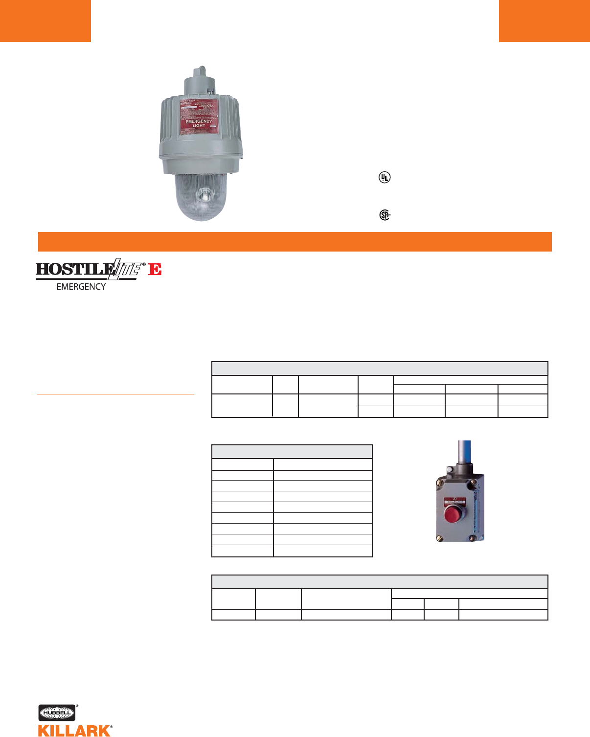
EBB SERIES •LIGHTING
HALOGEN LAMP EMERGENCY LIGHTING
L190
FEATURES-SPECIFICATIONS
Remote test station (included) allows “Push-To-
Test” at a location convenient to the user. 2
Applications
Where required by NEC, Life Safety
Code, etc., to provide illumination dur-
ing interruption of normal power to
lighting system.
Hazardous Locations (gas, vapor,
dust), include such areas as: Oil & Gas
Refining, Production & Storage, Grain
Processing, Paint Manufacture.
Features
•Three high intensity lamps can be
independently adjusted to provide
custom emergency lighting to a spe-
cific area
• Three 20 watt MR16 lamps included
• Pendant, bracket and ceiling mount-
ing styles for a mounting arrange-
ment that suits any lighting layout
• Remote hazardous location test sta-
tion (included) allows testing of fixture
at a convenient ground level location
• Dual voltage transformer can be con-
nected to 120V or 277V systems
• Four tough, long life lead-acid batter-
ies require no maintenance and have
a 12 VDC output of 60 watts for 90
minutes
•Safety disconnect feature automati-
cally disconnects lamps from battery
if globe is removed
•Solid state battery charger has a low
voltage disconnect feature
•Red pilot light, easily visible inside
globe, indicates AC power is being
supplied to batter charger
•Fixture housings are factory sealed
by the electro-mechanical connection
block
•The only wiring required is attaching
supply wires to the integral female
connection block in the mounting
Class I, Div. 1 & 2, Groups C,D
Class I, Zones 1 & 2, Groups IIB, IIA
Class ll, Div. 1 & 2 Groups E,F,G
Class lll, Div. 1 & 2
NEMA 7CD, 9EFG
Listed File E162407
UL-844 Electric Lighting Fixtures for use in
Hazardous Locations
UL-924 Emergency Lighting & Power Equipment
Certified File LR11713
cap. Threading fixture onto mounting
cap makes the electrical connection
•Electrical continuity is not made dur-
ing assembly or disassembly without
five or more threads secured to
insure a flame path
1Suitable for 220V/50Hz.
HAZARDOUS LOCATION APPLICATION DATA
LAMP TYPE LAMP WATTS RATED AMBIENT DEGREES MAX SURFACE TEMPERATURE
CLASS I CLASS II SIMULTANEOUS CLASS I & II
MR16 Halogen 60W Total 40°C T6 (85°C) T5 (100°C) T5 (100°C)
ANSI LAMP TYPE WATTS VOLTAGE1HUB SIZE PENDANT WALL CEILING
MR16 3x20W 120, 208, 240, 277V 3/4" EBB32010A2 EBB32010B2 —
EBB32010A3 EBB32010B3 EBB32010X3
EBB ACCESSORIES
CATALOG NUMBER DESCRIPTION
EZG1
VMPSD40
EBB-L12
17505AAAB
EBB-RB
EBB-BC
EBB-TRANS
EBB-PL
Guard (die cast aluminum)
Reflector (standard dome)
MR16 12 volt lamp
MR16 lamp socket
Rechargeable battery (4 used per unit)
Battery charger (circuit board)
Transformer Kit 120, 208, 240, 277V
LED pilot light
EBB HALOGEN EMERGENCY LIGHTING
CATALOG NUMBER
1"
Note: EBB Series fixtures should not be stored for extended periods before energizing.
2Furnished with 3/4” feed thru mounting box. For Push-To-Test N.C. momentary cover only. Use also
with HFXE, DEB, VEB, EEQ, and LZ2NE. Cover only XCSOB3-PTT. Order SWB back box separately.
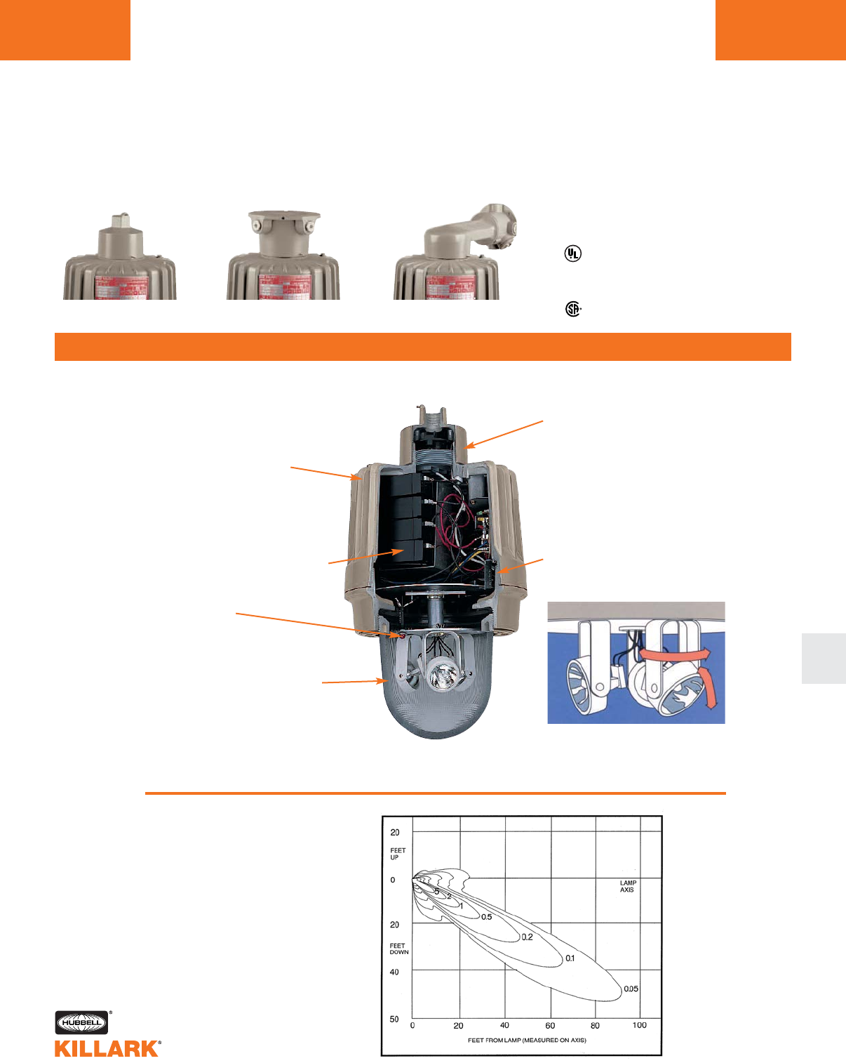
EBB SERIES •LIGHTING
HALOGEN LAMP EMERGENCY LIGHTING L191
FEATURES-SPECIFICATIONS
L
Dimensions: See EZ 50-250 Watt dimensions on page L147
Photometrics
Typical vertical ISO foot candle
distribution.
One 20 watt lamp aimed at 20° below
horizontal.
Note: Some minor variations in light
spread will occur as each lamp is rotat-
ed up/down within the glass globe.
Pendant Ceiling Wall Mount
Lamps adjustable on 2 axis for
maximum aiming flexibility.
Factory sealed; external seals not
required
Cast of copper-free Aluminum
(Less than 0.4% copper)
Electrostatically applied epoxy polyester
finish is baked on for high density
corrosion protection
Four lead-acid batteries are mainte-
nance free and provide 60 watts to the
lamps for 90 minutes*
Red pilot light indicates AC power flow
to battery charger
Lamps automatically disconnect from
battery if globe is disengaged
Glass globe prestressed for heat and
impact resistance - Globe is internally
fluted on sides and prismatic on bottom
* EBB Series fixtures should not be
stored for extended periods before
energizing.
Wireless assembly of fixture tank to
mounting cap — Electro-mechani-
cal male/female block allows fast,
easy installation and bench top ser-
vicing without disconnecting supply
wires
Nameplate displays Third Party
Certifications and ratings in English
and French (large red plate identi-
fies it as an emergency fixture)
Acme double lead threads assure
quick and trouble free assembly
Class I, Div. 1 & 2, Groups C,D
Class I, Zones 1 & 2, Groups IIB, IIA
Class ll, Div. 1 & 2 Groups E,F,G
Class lll, Div. 1 & 2
NEMA 7CD, 9EFG
Listed File E162407
UL-844 Electric Lighting Fixtures for use in
Hazardous Locations
UL-924 Emergency Lighting & Power Equipment
Certified File LR11713
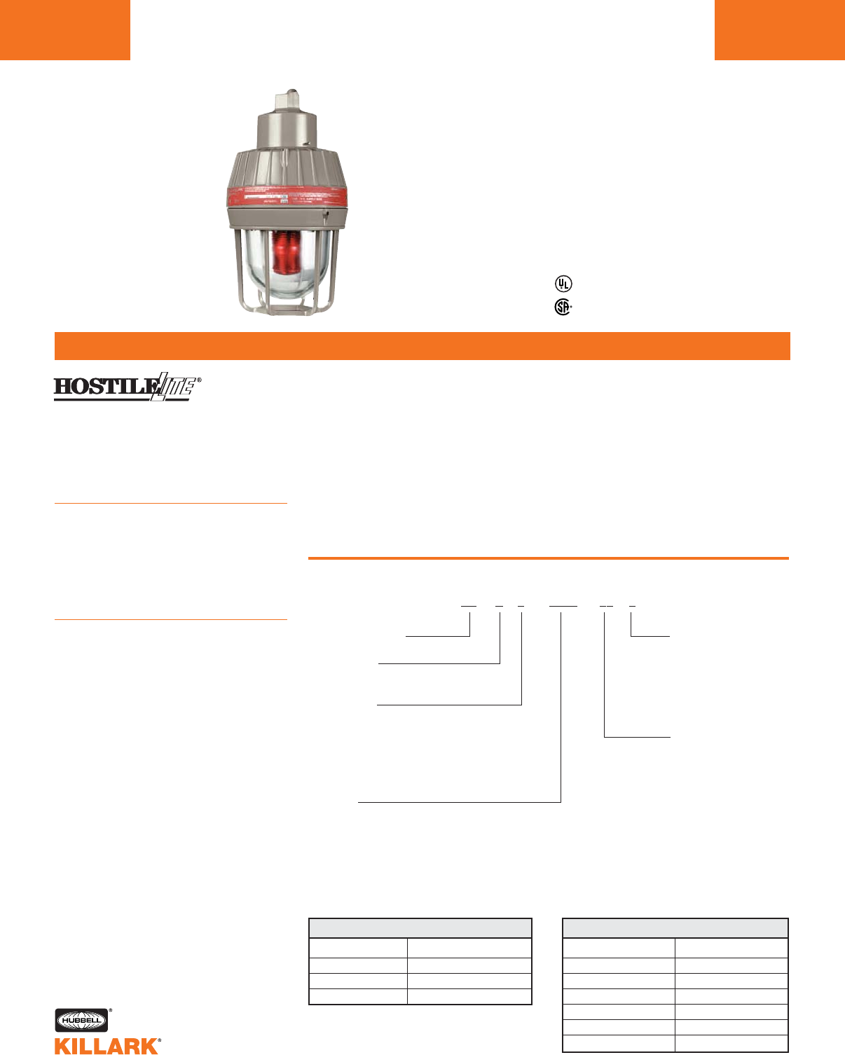
ESX SERIES •LIGHTING
STROBE SIGNAL LIGHT
L192
FEATURES-SPECIFICATIONS
Listed - File E84609
Certified - File LR11713
Class I, Div. 1 & 2, Groups C,D
Class l, Zones 1 & 2, Groups llB, llA
Class II, Div. 1 & 2, Groups E,F,G
Class III, Div. 1 & 2
Suitable for wet locations
UL Marine
NEMA 3, 4X
Factory sealed
ES X 0 0000 00 0 (CEN)*
Catalog Number Logic
Series Constant
Signal Type
X—Strobe
Lens Color
A—Amber
B—Blue
C—Clear
G—Green
R—Red
Voltage
120A—120 VAC 50/60 Hz.
240A—240 VAC 50/60 Hz.
1274—12 through 74 VDC
Mounting Style
A2—3/4" Pendant
A3—1" Pendant
X2—3/4" Ceiling
X3—1" Ceiling
B2—3/4" Bracket
B3—1" Bracket
D4—1-1/4"/1-1/2"
Stanchion
Guard
G—Guard
Add letter “G”
to end of catalog
number if guard
is required.
CATALOG NUMBER VOLTAGE
ESX120PS 120VAC, 50/60 HZ.
ESX240PS 220/240VAC, 50/60 HZ.
ESX1274PS 12-74 VDC
REPLACEMENT POWER SUPPLY
CATALOG NUMBER DESCRIPTION
ESXAL Amber
ESXBL Blue
ESXCL Clear
ESXGL Green
ESXRL Red
EMGS2 Rep globe support assembly
REPLACEMENT LENS & LAMP ASSEMBLY
Applications
HOSTILELITE®ESX Series strobe fixtures
can be an excellent warning device in
hazardous, hostile or wet locations
where hearing is impaired due to high
ambient noise conditions.
Compliances
•UL-1203 explosion-proof and dust igni-
tion-proof electrical equipment for use
in hazardous (classified) locations
•UL-1638 visual signaling appliances
•UL Marine-type electric lighting fixtures
•NEMA 3, 4, 4X, 7CD, 9EFG
Specifications
•Electronic component temperature
range –40˚C to +55˚C
•NEC temperature code, T6 (<85°C)
•Flash rate–85 flashes per minute
•Zenon type lamp
*CEN (CENELEC) approved option available. See pages L127 for more information. ESX Series
strobes with CENELEC labeling are rated T6 by PTB.
•Voltage and amperage:
12-74 VDC:
Draws 1.25A avg. @ 12 VDC
tapering to 0.2A avg. @ 74 VDC,
.75A avg. @ 24 VDC
120 VAC (50/60 HZ):
Draws 0.30A avg.
240 VAC (50/60 HZ):
Draws 0.17A avg.
•Power supply output:
13 watts standard
11 watts for 12-74 VDC
•Intensity:
Clear 200 candela effective
Amber 170 candela effective
Blue 90 candela effective
Red 40 candela effective
Green 70 candela effective
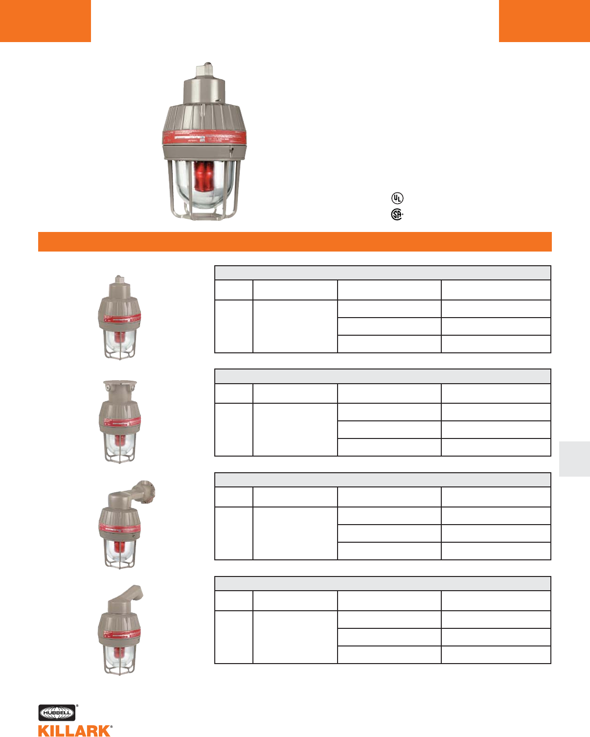
ESX SERIES •LIGHTING
STROBE SIGNAL LIGHT L193
FEATURES-SPECIFICATIONS
L
Listed - File E84609
Certified - File LR11713
Class I, Div. 1 & 2, Groups C,D
Class l, Zones 1 & 2, Groups llB, llA
Class II, Div. 1 & 2, Groups E,F,G
Class III, Div. 1 & 2
Suitable for wet locations
Marine
NEMA 3, 4X
Factory sealed
1Catalog numbers do not include guards. To order add letter “G” to end of catalog number
or order EMG2 separately.
2Catalog numbers include Red lens. To specify different colored lens, change fourth character in
catalog number to one of the following: “B”=Blue, “C”=Clear, “A”=Amber, “G”=Green.
3Standard hub size is 3⁄4" NPT. To order 1" NPT, change last character of catalog number from “2” to “3”.
4Stanchion mount is standard with 1-1⁄2" NPT and a 1-1⁄2" NPT to 1-1⁄4" NPT reducer installed.
NOTE: See EM series for dimensions, page L126.
120 VAC, 50/60 HZ. ESXR120AA2
STROBE 3/4" 240 VAC, 50/60 HZ. ESXR240AA2
12-74 VDC ESXR1274A2
PENDANT ESX STROBE SIGNAL LIGHT12
LAMP HUB SIZE3VOLTAGE @60 HERTZ CATALOG NUMBER
TYPE GLOBE AND MOUNT1
CEILING
STANCHION
WALL
PENDANT
120 VAC, 50/60 HZ. ESXR120AX2
STROBE 3/4" 240 VAC, 50/60 HZ. ESXR240AX2
12-74 VDC ESXR1274X2
CEILING ESX STROBE SIGNAL LIGHT12
LAMP HUB SIZE3VOLTAGE @60 HERTZ CATALOG NUMBER
TYPE GLOBE AND MOUNT1
120 VAC, 50/60 HZ. ESXR120AB2
STROBE 3/4" 240 VAC, 50/60 HZ. ESXR240AB2
12-74 VDC ESXR1274B2
WALL ESX STROBE SIGNAL LIGHT12
LAMP HUB SIZE3VOLTAGE @60 HERTZ CATALOG NUMBER
TYPE GLOBE AND MOUNT1
120 VAC, 50/60 HZ. ESXR120AD4
STROBE 1-1/4" 240 VAC, 50/60 HZ. ESXR240AD4
12-74 VDC ESXR1274D4
STANCHION ESX STROBE SIGNAL LIGHT12
LAMP HUB SIZE4VOLTAGE @60 HERTZ CATALOG NUMBER
TYPE GLOBE AND MOUNT1
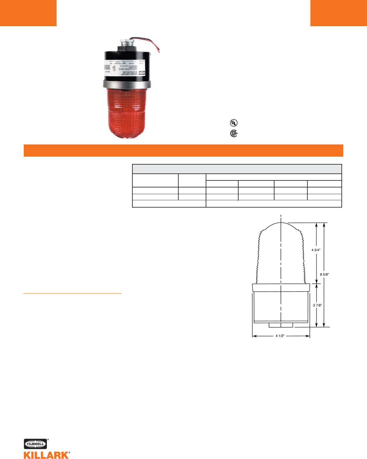
GSH STROBE SIGNAL LIGHT
GSH SERIES •LIGHTING
STROBE SIGNAL FOR HAZARDOUS AND WET LOCATIONS
FEATURES-SPECIFICATIONS
L194
Applications
With an all aluminum housing and poly-
carbonate lens assembly, the GSH
Series Strobe Signal Light will withstand
the rigors of everyday harsh usage -
even in locations that are classified as
“Hazardous”. The GSH’s helix shaped
Xenon lamp produces 400 effective
candela, making it visible over broad
distances. This warning light can be
used for plant evacuation or any other
communication need.
Hazardous and Wet Locations in indus-
trial facilities where high ambient noise
levels prevent the use of audible sig-
naling devices.
As a visual warning of a fault, leak,
accident or other condition.
To indicate the status of a particular
process or operation.
Features
•High-intensity strobe produces 400
candela with 60 flashes per minute
•Reliable solid state components
•All aluminum housing is compact in
size and light in weight
•Polycarbonate Lexan lens resists
breakage and impacts
•Available in four different globe
colors and two voltages
•Designed for mounting with globe in
up or down position
Class l, Div. 2, Groups C,D
Class l, Zone 2, Groups IIB, IIA
Class Il, Div. 2, Group G
NEMA 3
Suitable for Indoor and Outdoor Use
UL-1638 Visual Signaling Appliances
UL File No. E121305
CSA File No. LR-97692
VOLTAGE
120VAC. 50/60Hz.
24VDC
CATALOG NUMBER
HUB SIZE
1" NPT
1" NPT
RED LENS
GSH2RA1
GSH2RD2
AMBER LENS
GSH2AA1
GSH2AD2
BLUE LENS
GSH2BA1
GSH2BD2
CLEAR LENS
GSH2CA1
GSH2CD2
Replacement Lamp ST77C
Specifications:
Lamp Life 2,000 hours
Style/Lamp Xenon flash lamp
Shipping Weight 4 lbs.
Height 8-5/8"
Diameter 4-1/2"
Electrical Ratings
120 VAC 50/60Hz .28 Amps
24 VDC .35 Amps
Temperature Code T4A (120°C/248°F)
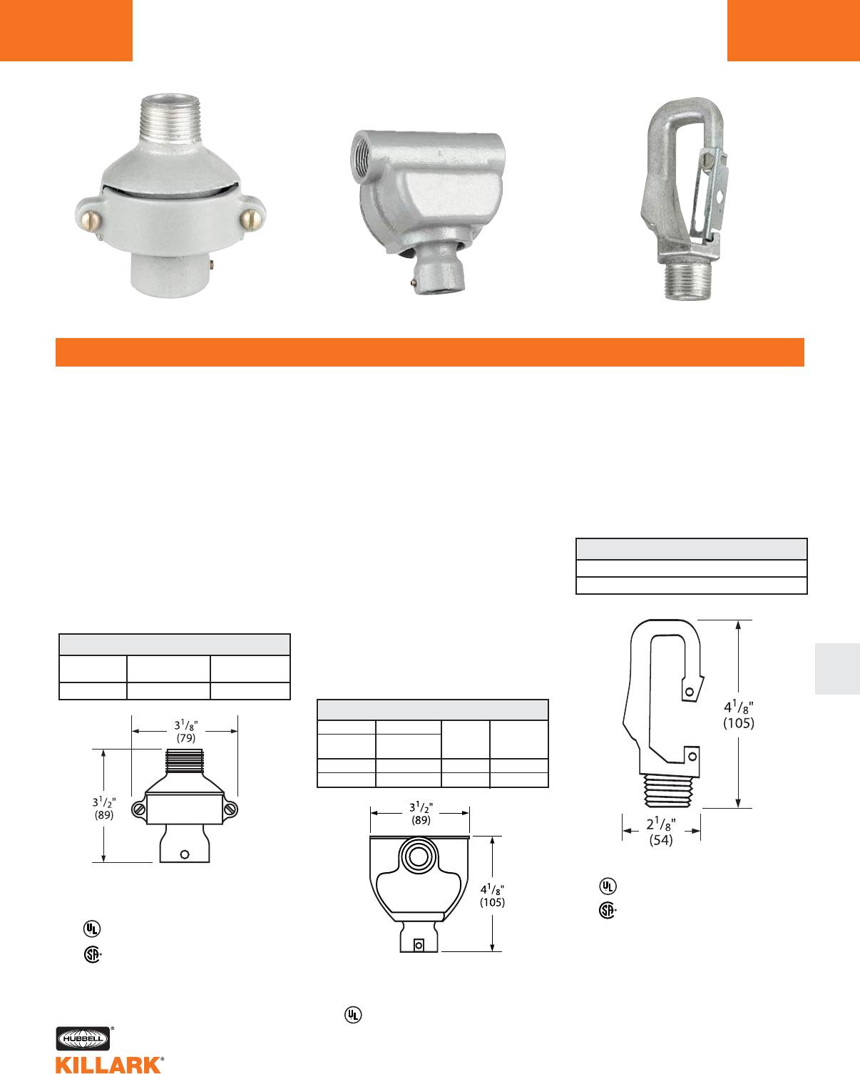
FKA/FH HOOK/LOOP •LIGHTING
FIXTURE HANGERS
FEATURES-SPECIFICATIONS
L
L195
FKA FH HOOKLOOP
FKA
Features
•Ball joint permits fixture to hang
plumb. Fixture may swing up to 20°
from vertical in any direction
•Cast of aluminum alloy (copper-free
aluminum; less than 4/10 of 1%)
•Set screw locks fixture stem in place.
Cannot accidently loosen – intended
for use with threaded
metal conduit
•Joint cannot twist conductor
•Suitable for fixtures up to
125 pounds
FH
Features
•Combination splice box and flexible
fixture hanger
•Ball joint permits fixture to hang
plumb. Fixture may swing up to 20°
from vertical
•Cast of aluminum alloy (copper-free
aluminum; less than 4/10 of 1%)
•Set screw locks fixture stem in place –
intended for use with threaded
metal conduit
•Joint cannot twist conductors
•Cover may be removed for easy
wiring
•Mounts directly to conduit
•Suitable for fixtures up to
125 pounds
HOOKLOOP
Features
•Pendant fixture hanger consists of a
“HOOK” and safety bar which allows
conversion to a “LOOP” configuration
as necessary
•3/4" male thread
•Maximum load 125 pounds
CATALOG MALE FIXTURE
NUMBER THREAD STEM SIZE
FKA-22 3/4" 3/4"
FKA
CATALOG NUMBER
HOOKLOOP
HOOKLOOP
TWO HUBS THREE HUBS
FEED CONDUIT FIXTURE
THRU T SIZE STEM SIZE
FHC-21 FHT-21 3/4" 1/2"
FHC-22 FHT-22 3/4" 3/4"
FH
Listed - File E27731
Certified - File LR11851
See files for details or call Killark.
For replacement ball only
catalog number 00890545
Listed - File E27731
For replacement ball only
catalog number 00890545
Listed - File E27731
Certified - File LR11851
See files for details or call Killark.
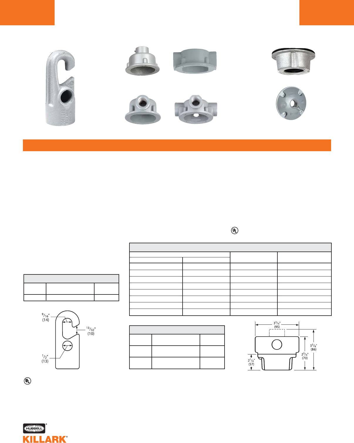
FH/VX SERIES •LIGHTING
FIXTURE HANGERS
L196
FEATURES-SPECIFICATIONS
Hook
VGA VGC
VGH VGX
Hub Covers
(for Rigid Mounting)
Flexible Hanger Covers
FH V Hanger Boxes Covers
FH HOOK
Features
•Economical hanger for pendant
fixtures
•Fixtures may absorb minor bumps
and vibration through free swinging
action
•Hub provided with a set screw to pre-
vent accidental loosening of
fixture stem
•A 1/2 inch hole in body is for flexible
cable. Cord may be assembled with
plug for quick removal of fixtures
•Cast of aluminum alloy (copper-free—
less than 4/10 of 1%)
•FH supports up to 125 pounds
V SERIES
Features
•Flexible fixture hanger for threaded
fixture stem
•Enclosed and gasketed, suitable for
wet locations
•Permits angular displacement of
fixture without twisting wires
•Cushioned—absorbs shock and
vibration. Internal strap assures
ground continuity
CATALOG NUMBER
HANGER W/SPLICE BOX SPLICE BOX ONLY HUB SIZE FIXTURE STEM SIZE
VPFHA-12 VGA-1 1/2" 3/4"
VPFHA-22 VGA-2 3/4" 3/4"
VPFHC-12 VGC-1 1/2" 3/4"
VPFHC-22 VGC-2 3/4" 3/4"
VPFHH-12 VGH-1 1/2" 3/4"
VPFHH-22 VGH-2 3/4" 3/4"
VPFHX-12 VGX-1 1/2" 3/4"
VPFHX-22 VGX-2 3/4" 3/4"
FLEXIBLE HANGERS, V SERIES ENCLOSED AND GASKETED
CATALOG FIXTURE
NUMBER DESCRIPTION STEM SIZE
FH-2 Hook 3/4"
FH HOOK, LOOP
CATALOG FIXTURE
NUMBER DESCRIPTION STEM SIZE
VPFH-2 Flexible hanger cover, 3/4"
maximum load 125 Lbs.
VG-2 Hub cover 3/4"
for rigid mounting
FIXTURE HANGERS ONLY
Listed - File E27731 or E3397
See files for details or call Killark.
Listed - File E27731 or E3397
•Combines splice box and hanger in one
unit. Splice box available in four config-
urations
•Cast of corrosion resistant aluminum
alloy (copper-free—less than 4/10 of
1%)
•Supports up to 125 pounds
See page L11 for other box configurations.
Flexible cover with box, dotted line is VGA pen-
dant.
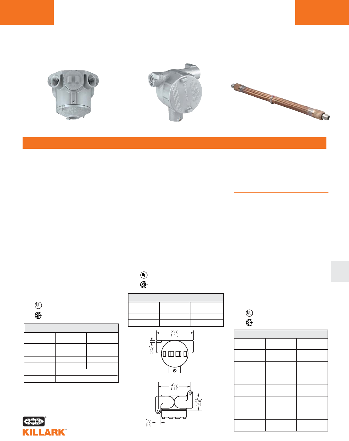
HXB/XFH/EKJ SERIES •LIGHTING
FIXTURE HANGERS L197
FEATURES-SPECIFICATIONS
L
HXB XFH EKJ
HXB
Class I, Div. 1 & 2, Groups C,D
Class l, Zones 1 & 2, Groups llB,llA
Class II, Div. 1 & 2, Groups E,F,G
Class III
Features
•Fixture hanger for hazardous locations
combining splice box and hanger
•Set screws in female hub prevents
accidental loosening of fixture stem;
set screws in hub cover lock cover to
the splice box
•Four hubs in “X” configuration up
to 3⁄4"
•Flange mounting ring cast as integral
part of box
•Splice box wiring hole with cover for
access to box interior
•Cast of corrosion resistant aluminum
alloy (copper-free aluminum; less than
4/10 of 1%)
•Supports to 125 pounds; vol. 16 cu.”
EKJ
Class I, Div. 1 & 2, Groups A,B,C,D
Class l, Zones 1 & 2, Groups
llC,llB,llA
Class II, Div. 1 & 2, Groups E,F,G
Class III
Features
•Fixture pendant hanger for
hazardous locations
•Permits free swing and plumb hang
•Set screws in each hub prevents acci-
dental loosening of fixture
•Constructed of seamless bronze hose
with brass outer braid. Asphaltum
impregnated jute inner insulates and
protects wire from abrasion. Brass
female end fittings are supplied with
short nipples
•Electrical ground continuity without
bonding jumper
•Suitable for wet locations as well as
hazardous locations
•Flexible lengths 4 to 18 inches
•Supports to 125 pounds
XFH
Class I, Div. 1 & 2, Groups C,D
Class l, Zones 1 & 2, Groups llB,llA
Class II, Div. 1 & 2, Groups E,F,G
Class III
Features
•Fixture hanger for hazardous locations
combining splice box and hanger
•Set screws in female hub prevents
accidental loosening of fixture
•Straight through conduit hubs for
through feed
•Mounting lugs are standard
•Cast of corrosion resistant aluminum
alloy (copper-free aluminum; less than
4/10 of 1%)
•Supports to 125 pounds
Listed - File E10514
Certified - File LR11716
Listed - File E10514
Certified - File LR11716
Listed - File E10514
Certified - File LR11716
CATALOG CONDUIT FIXTURE
NUMBER HUB SIZE STEM SIZE
HXB-11 1/2" 1/2"
HXB-12 1/2" 3/4"
HXB-21 3/4" 1/2"
HXB-22 3/4" 3/4"
HXBC Blank Cover
HIC Replacement Wiring Plug
HXB SPLICE BOX AND HANGER
CATALOG CONDUIT FIXTURE
NUMBER HUB SIZE STEM SIZE
XFH-21 3/4" 1/2"
XFH-22 3/4" 3/4"
XFH SPLICE BOX AND HANGER
CATALOG CONDUIT FIXTURE
NUMBER HUB SIZE STEM SIZE
EKJ-14 1/2" 4"
EKJ-24 3/4"
EKJ-16 1/2" 6"
EKJ-26 3/4"
EKJ-18 1/2" 8"
EKJ-28 3/4"
EKJ-110 1/2" 10"
EKJ-210 3/4"
EKJ-112 1/2" 12"
EKJ-212 3/4"
EKJ-115 1/2" 15"
EKJ-215 3/4"
EKJ-118 1/2" 18"
EKJ-218 3/4"
EKJ FLEXIBLE PENDANT HANGER*
*See page F68 for EKJ 1" sizes
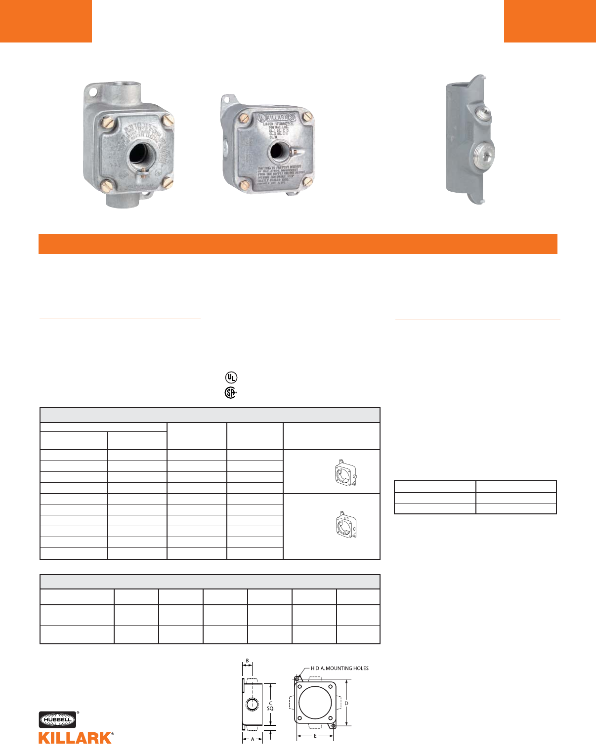
JL/JAL/ENY SERIES •LIGHTING
FIXTURE HANGERS
L198
FEATURES-SPECIFICATIONS
JL JAL ENY Pendant Seal
JL/JAL
Class I, Div. 1 & 2, Groups C,D
Class l, Zones 1 & 2, Groups llC,llB
Class II, Div. 1 & 2, Groups E,F,G
Class III
Features
•Splice box and hub cover for mount-
ing pendant fixtures in hazardous
locations
•Conduit openings in two configura-
tions
•Flange type cover. Set screw in hub
prevents accidental loosenings of
fixture stem
•Integral lugs for mounting box to ceil-
ing
•Cast of corrosion resistant aluminum
alloy (copper-free aluminum; less than
4/10 of 1%)
•Supports up to 125 pounds
ENY PENDANT SEALS
Class I, Div. 1 & 2, Groups A,B,C,D
Class l, Zones 1 & 2, Groups llC,llB,llA
Class II, Div. 1 & 2, Groups E,F,G
Class III
Features
•ENY Pendant Seals are designed for
hazardous locations and meet code
requirements for a safety set-screw
when hanging fixtures. Common appli-
cations are for Class l Division l Group
B or Class l Zone 2 Ex nR restricted
breathing fixtures
•Cast of corrosion resistant aluminum
alloy (copper-free aluminum; less than
4/10 of 1%)
•Supports up to 125 pounds
See page F49 for sealing compound and
packing fiber
Listed - File E10514
Certified - File LR11716
CATALOG NUMBER
JL SERIES JAL SERIES CONDUIT BOX COVER TYPE
W/HUB COVER W/HUB COVER
JLC-11 — 1/2" 1/2"
JLC-12 — 1/2" 3/4"
JLC-21 — 3/4" 1/2"
JLC-22 — 3/4" 3/4"
JLX-11 JALX-11 1/2" 1/2"
JLX-12 JALX-12 1/2" 3/4"
JLX-21 JALX-21 3/4" 1/2"
JLX-22 JALX-22 3/4" 3/4"
—JALX-31 1" 1/2"
—JALX-32 1" 3/4"
JL/JAL SPLICE BOX AND HUB COVER FIXTURE HANGER
C
Straight
Through
X
Four
Hubs
SERIES A B C D E H
JL 1-15/16" 11/16" 3-1/4" 4-7/32" 2-3/8" 5/16"
(49) (17) (95) (107) (60) (8)
JAL 2-3/8" 15/32" 4-5/8" 5-1/4" 4-1/8" 5/16"
(60) (12) (117) (133) (105) (8)
JL/JAL DIMENSIONS
CATALOG NUMBER SIZE
ENY-2SET 3/4"
ENY-3SET 1"
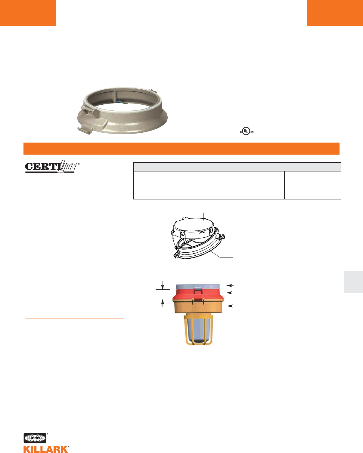
VM SERIES •LIGHTING
COMPETITIVE ADAPTER L199
FEATURES-SPECIFICATIONS
L
Class I, Div. 2, Groups A,B,C,D
Class I, Zone 2, Groups IIC, IIB, IIA
Class II, Div. 1 & 2, Groups E,F,G
Class III
NEMA 3, 4, 4X
Certified
Applications
VMCHVM adapters are designed to
ease upgrading of existing Crouse-
Hinds® “VM,LM,DM” series fixtures to
Killark “VM” CERTILITE®fixtures. Units
are primarily designed to aid replace-
ment of old ceiling or wall mount units
where removal of the existing mounting
box and conduit would be difficult or
time consuming. Adapter & Killark fix-
tures rated NEMA 4.
Adapters allow the upgrade of older
Mercury Vapor fixtures to newer HID
lamp sources, Compact Fluorescent
Lamps, or to Emergency Lighting such
as VEB or VEQ series.
Note: Adapters are used with Fixture
Ballast Tanks (plus globes & guards),
e.g. VM3S150, VMG17, VMAG17.
Complete fixture with mounting splice
box is not required. Adapters are paint-
ed to match Killark beige fixture finish.
Features
•Allows use of CertiLite®V’s new Swing-
Barrel nut for ease of maintenence.
Attaches to Crouse-Hinds®mount with
hinge and set screw.
Temperature codes:
See Certilite®V or VM series product
pages or as listed with other desired
product series.
CATALOG DESCRIPTION EXAMPLE OF MODEL
NUMBER UTILIZED OR REPLACED
Crouse ceiling mount or wall mount splice box.
VMCHXM Adapter allows simple attachment of Killark ballast tank Ceiling mounts CM2, CM3
to existing mount. Wall mounts TWM2, TWM3
Existing mount
Adapter
Existing box
VMCHVM adapter shown
in red for illustration
New Killark VM series
fixture
VM COMPETITIVE ADAPTER
2.59"
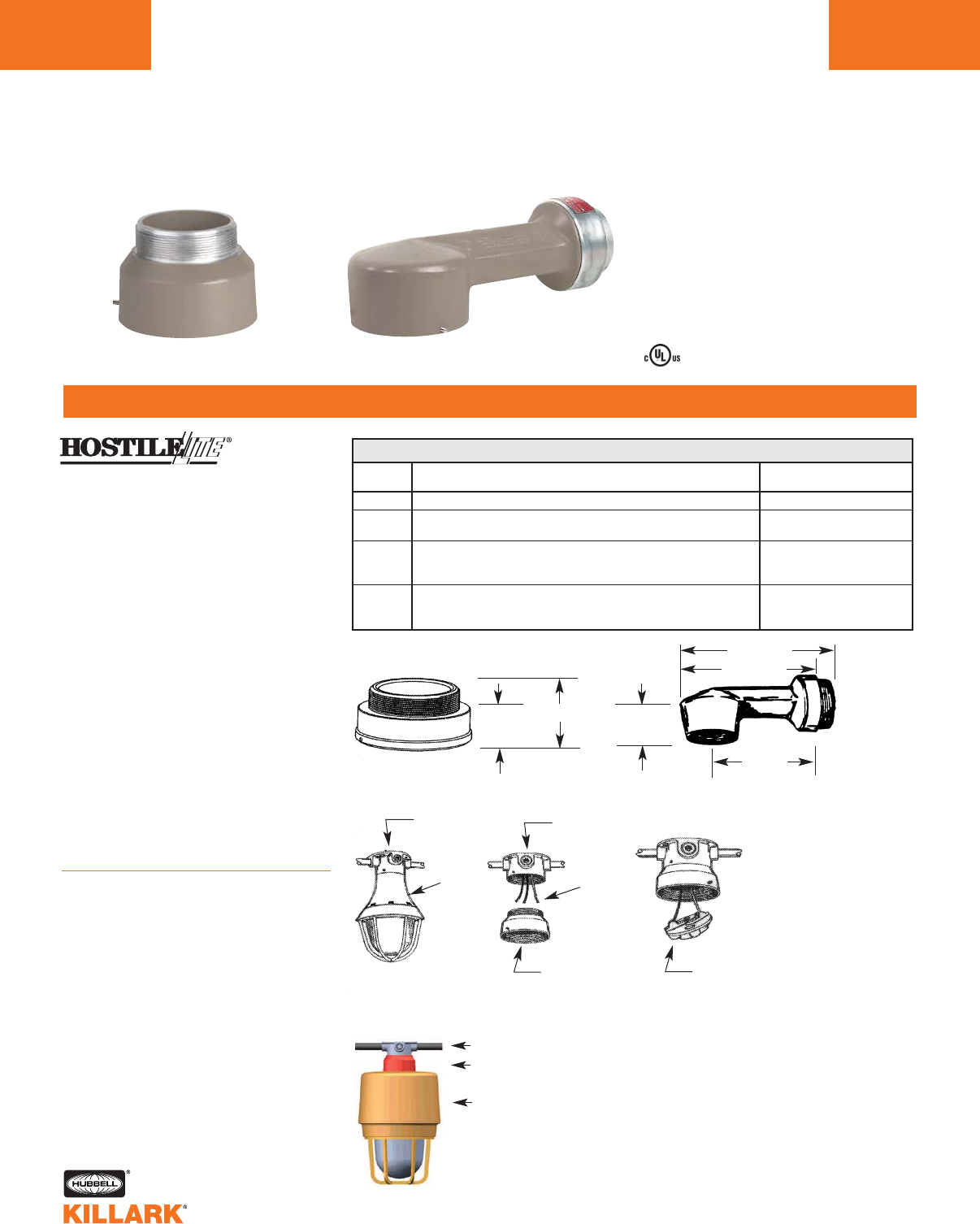
EAC/EZBA SERIES •LIGHTING
FIXTURE ADAPTERS
L200
FEATURES-SPECIFICATIONS
EAC/EACH EZBA12
Class I, Div. 1 & 2, Group D
Class I, Zones 1 & 2, Groups IIA
Class II, Div. 1 & 2, Groups E,F,G
Class III
Applications
EAC Series adapters are designed to
ease upgrading of existing Crouse-
Hinds® “EV” series or existing Killark
“H” series to Killark HOSTILELITE®EM
or EZ series. Units are primarily
designed to aid replacement of old ceil-
ing or wall mount units where removal of
the existing mounting box and conduit
would be difficult or time consuming.
Adapter & Killark fixtures rated NEMA 4.
Adapters allow the upgrade of older
incandescent fixtures to newer
Fluorescent or HID lamp sources, or
to Emergency Lighting including ESX
strobes or EEQ emergency series.
Note: Adapters are used with Fixture
Housing, Globe, Globe Support assem-
blies, e.g. EBF261 & EMG1; EMS151 &
EMG2; or EZH100 & EZG1. Complete
fixture with mounting box is not required.
Adapters are painted to match Killark
beige fixture finish.
Features
•Setscrews permit secure adapter
attachment into old mounting box and
to new fixture
•Converted fixtures may be easily
removed for service using the Killark
EZ mounting system. Wire terminals
are included in the adapter (EZTB
Terminal Block)
Temperature codes:
See EM/EB/EQ series pages L127 to
L128
EZ series pages L148 to L149
ESX series pages L192 to L193
EEQ series page L186
CATALOG DESCRIPTION EXAMPLE OF MODEL
NUMBER UTILIZED OR REPLACED
EAC Killark “H” series Ceiling or Wall HXG-2-125 Fixture
EACH12 Crouse old style Ceiling Mount with lamp socket in
adapter ring between fixture body and a GUF 12 pitch box “GUF” box w/Set Screw
Crouse old style Wall Mount, old style Arm with integral
EZBA12 lamp socket (socket in fixture in newer models) attached “GUF” box w/Set Screw
to GUF 12 pitch mounting box. EZBA12 includes arm
Crouse newer style ceiling or wall fixtures w/lamp socket in
EACH16 fixture body; mounted to EV series 16 pitch threaded box; EVA26/EV22 Box; EVBX240
adapter fits in ceiling box or existing arm attached to wall fixture
2.31" 2.38"
3.30"
7.38"
11.91"
11.11"
Existing
mount
Existing
mount
Existing box & conduit
Fixture
body
Supply
leads
EACH12 or
EACH16 adapter
EACH12 or EACH16 adapter
shown in red for illustration
New Killark EM or EZ series
fixture
EZTB terminal
block (typical)
EAC/EZBA FIXTURE ADAPTERS
Certified
INTRODUCTION
NOTES L201
L

HUBBELL®INC. Corporate Headquarters 584 Derby Milford Rd. Orange, CT 06477-4024
HUBBELL INC. GROUPS AND SUBSIDIARIES - DOMESTIC
ELECTRICAL PRODUCTS
Chalmit -(see International)
Hawke International USA
(218) 445-7400 4140 World Houston Parkway Houston, TX 77032
Suite 130
Hubbell Electrical Products
(800) 722-6437 3902 West Sample St. South Bend, IN 46634-4002
Killark (314) 531-0460 3940 Dr. Martin Luther King Drive St. Louis, MO 63113
Raco/Bell (800) 722-6437 3902 West Sample St. South Bend, IN 46634-4002
INDUSTRIAL TECHNOLOGY
GAI-Tronics (800) 492-1212 400 East Wyomissing Ave. Mohnton, PA 19540
Gleason Reel (920) 387-4120 600 South Clark St. Mayville, WI 53050-0026
Industrial Controls -(also Euclid and Lexington Brands
(336) 434-2800 4301 Cheyenne Dr. Archdale, NC 27263
Hipotronics & Hefely N. America
(845) 279-8091 1650 Route 22 Brewster, NY 10509
Pulse Com (800) 381-1997 2900 Towerview Rd. Herndon, VA 20171
Wiegmann (618) 539-3193 501 West Apple St. Freeburg, IL 62243
LIGHTING PRODUCTS
Hubbell Lighting -(also Hubbell Outdoor & Industrial Lighting, plus Alera, Cornerstone, Devine, Dual-Lite, Prescolite, Progress,
Spaulding, Sportsliter Solutions, Sterner and Whiteway Brands)
(864) 678-1000 701 Millennium Blvd. Greemville, SC 29607
Architectural Area Lighting & Moldcast
(714) 994-2700 14249 Artesia Blvd. La Mirada, CA 90638
Kim Lighting (626) 968-5666 16555 East Gale Ave. City of Industry, CA 91745
Security Lighting Systems (847) 279-0627 1085 Johnson Drive Buffalo Grove, IL 60089
POWER SYSTEMS
Hubbell Power Systems -(including A.B. Chance, Anderson, Fargo and Ohio Brass Brands)
(573) 682-8714 210 N. Allen Centralia, MO 65240
Polycast and Quazite (800) 346-3062 3621 Industrial Park Drive Lenoir City, TN 37771
TELECOM & DATA
Pulsecom and Seiscor (800) 381-1997 2900 Towerview Road Herndon, VA 20171
Premise Wiring (800) 626-0005 14 Lords Hill Road Stonington, CT 06339
WIRING SYSTEMS
Wiring Device-Kellems -(also Bryant and Marine Brands)
(203) 882-4900 185 Plains Rd. Milford, CT 06461
Premise Wiring (800) 626-0005 14 Lords Hill Road Stonington, CT 06339
Hubbell Building Automation
(888) 698-3242 9601 Dessau Rd. Bldg.1, Suite 100 Austin, TX 78754
KILLARK Divisional Headquarters
St. Louis, MO 63113 (314) 531-0460
