View / The Manual Seuserm
User Manual: View / the Manual Stride Manual and Data Sheets - AutomationDirect
Open the PDF directly: View PDF ![]() .
.
Page Count: 230 [warning: Documents this large are best viewed by clicking the View PDF Link!]
- Stride Industrial Ethernet Switches and Media Converters USER MANUAL
- WARNING
- Publication History
- Table of Contents
- Chapter 1 - Hardware
- Chapter 2 - Managed Switch Quick Start
- Chapter 3 - Managed Switch Software Monitoring
- Chapter 4 - Managed Switch Software Setup
- Chapter 5 - Managed Switch Software Advanced Operations
- Appendix A - Troubleshooting
- Appendix B - Glossary
- Appendix C - Switch Settings
- Appendix D - CLI Commands
- Introduction
- CLI Commands:
- Global Commands:
- Access Configuration:
- Alarm Configuration:
- Modbus Configuration:
- Info Configuration:
- Network Configuration:
- Port Security Configuration:
- Port Configuration:
- Ring Configuration:
- RSTP Configuration:
- QoS Configuration:
- VLAN Configuration:
- IGMP Configuration:
- Checkpoint Configuration:
- Firmware Configuration:
- TFTP Configuration:
- Timezone Configuration:
- MSTI Configuration:
- General Configuration:
- Appendix E - Licensing and Policies
Manual Number: SE-USER-M
Industrial Ethernet Switches
and Media Converters
USER MANUAL

~ WARNING ~
Thank you for purchasing automation equipment from AutomationDirect.com®, doing business as,
AutomationDirect. We want your new automation equipment to operate safely. Anyone who installs or
uses this equipment should read this publication (and any other relevant publications) before installing or
operating the equipment.
To minimize the risk of potential safety problems, you should follow all applicable local and national
codes that regulate the installation and operation of your equipment. These codes vary from area to area
and usually change with time. It is your responsibility to determine which codes should be followed, and
to verify that the equipment, installation, and operation is in compliance with the latest revision of these
codes.
At a minimum, you should follow all applicable sections of the National Fire Code, National Electrical
Code, and the codes of the National Electrical Manufacturer’s Association (NEMA). There may be local
regulatory or government offices that can also help determine which codes and standards are necessary for
safe installation and operation.
Equipment damage or serious injury to personnel can result from the failure to follow all applicable
codes and standards. We do not guarantee the products described in this publication are suitable for
your particular application, nor do we assume any responsibility for your product design, installation, or
operation.
Our products are not fault-tolerant and are not designed, manufactured or intended for use or resale as
on-line control equipment in hazardous environments requiring fail-safe performance, such as in the
operation of nuclear facilities, aircraft navigation or communication systems, air traffic control, direct life
support machines, or weapons systems, in which the failure of the product could lead directly to death,
personal injury, or severe physical or environmental damage (“High Risk Activities”). AutomationDirect
specifically disclaims any expressed or implied warranty of fitness for High Risk Activities.
For additional warranty and safety information, see the Terms and Conditions section of our catalog.
If you have any questions concerning the installation or operation of this equipment, or if you need
additional information, please call us at 770-844-4200.
This publication is based on information that was available at the time it was printed. At
AutomationDirect we constantly strive to improve our products and services, so we reserve the right to
make changes to the products and/or publications at any time without notice and without any obligation.
This publication may also discuss features that may not be available in certain revisions of the product.
Trademarks
This publication may contain references to products produced and/or offered by other companies. The
product and company names may be trademarked and are the sole property of their respective owners.
AutomationDirect disclaims any proprietary interest in the marks and names of others.
Copyright 2017, AutomationDirect.com® Incorporated
All Rights Reserved
No part of this manual shall be copied, reproduced, or transmitted in any way without the prior, written
consent of AutomationDirect.com® Incorporated. AutomationDirect retains the exclusive rights to all
information included in this document.

~ ADVERTENCIA ~
Gracias por comprar equipo de automatización de AutomationDirect.com®. Deseamos que su nuevo equipo
de automatización opere de manera segura. Cualquier persona que instale o use este equipo debe leer esta
publicación (y cualquier otra publicación pertinente) antes de instalar u operar el equipo.
Para reducir al mínimo el riesgo debido a problemas de seguridad, debe seguir todos los códigos de seguridad
locales o nacionales aplicables que regulan la instalación y operación de su equipo. Estos códigos varian de
área en área y usualmente cambian con el tiempo. Es su responsabilidad determinar cuales códigos deben ser
seguidos y verificar que el equipo, instalación y operación estén en cumplimiento con la revisión mas reciente
de estos códigos.
Como mínimo, debe seguir las secciones aplicables del Código Nacional de Incendio, Código Nacional Eléctrico,
y los códigos de (NEMA) la Asociación Nacional de Fabricantes Eléctricos de USA. Puede haber oficinas de
normas locales o del gobierno que pueden ayudar a determinar cuales códigos y normas son necesarios para una
instalación y operación segura.
Si no se siguen todos los códigos y normas aplicables, puede resultar en daños al equipo o lesiones serias a
personas. No garantizamos los productos descritos en esta publicación para ser adecuados para su aplicación
en particular, ni asumimos ninguna responsabilidad por el diseño de su producto, la instalación u operación.
Nuestros productos no son tolerantes a fallas y no han sido diseñados, fabricados o intencionados para uso
o reventa como equipo de control en línea en ambientes peligrosos que requieren una ejecución sin fallas,
tales como operación en instalaciones nucleares, sistemas de navegación aérea, o de comunicación, control de
tráfico aéreo, máquinas de soporte de vida o sistemas de armamentos en las cuales la falla del producto puede
resultar directamente en muerte, heridas personales, o daños físicos o ambientales severos (“Actividades de Alto
Riesgo”). AutomationDirect.com específicamente rechaza cualquier garantía ya sea expresada o implicada
para actividades de alto riesgo.
Para información adicional acerca de garantía e información de seguridad, vea la sección de Términos
y Condiciones de nuestro catálogo. Si tiene alguna pregunta sobre instalación u operación de este equipo, o
si necesita información adicional, por favor llámenos al número 770-844-4200 en Estados Unidos.
Esta publicación está basada en la información disponible al momento de impresión. En AutomationDirect.
com nos esforzamos constantemente para mejorar nuestros productos y servicios, así que nos reservamos el
derecho de hacer cambios al producto y/o a las publicaciones en cualquier momento sin notificación y sin
ninguna obligación. Esta publicación también puede discutir características que no estén disponibles en ciertas
revisiones del producto.
Marcas Registradas
Esta publicación puede contener referencias a productos producidos y/u ofrecidos por otras compañías. Los nombres de las
compañías y productos pueden tener marcas registradas y son propiedad única de sus respectivos dueños. Automationdirect.com,
renuncia cualquier interés propietario en las marcas y nombres de otros.
PROPIEDAD LITERARIA 2017, AUTOMATIONDIRECT.COM® INCORPORATED
Todos los derechos reservados
No se permite copiar, reproducir, o transmitir de ninguna forma ninguna parte de este manual sin previo consentimiento por escrito
de AutomationDirect.com® Incorprated. AutomationDirect.com retiene los derechos exclusivos a toda la información incluida en
este documento. Los usuarios de este equipo pueden copiar este documento solamente para instalar, configurar y mantener el equipo
correspondiente. También las instituciones de enseñanza pueden usar este manual para propósitos educativos.

~ AVERTISSEMENT ~
Nous vous remercions d’avoir acheté l’équipement d’automatisation de AutomationDirect.com®, en faisant des
affaires comme, AutomationDirect. Nous tenons à ce que votre nouvel équipement d’automatisation fonctionne en
toute sécurité. Toute personne qui installe ou utilise cet équipement doit lire la présente publication (et toutes les
autres publications pertinentes) avant de l’installer ou de l’utiliser.
Afin de réduire au minimum le risque d’éventuels problèmes de sécurité, vous devez respecter tous les codes locaux
et nationaux applicables régissant l’installation et le fonctionnement de votre équipement. Ces codes diffèrent d’une
région à l’autre et, habituellement, évoluent au fil du temps. Il vous incombe de déterminer les codes à respecter et
de vous assurer que l’équipement, l’installation et le fonctionnement sont conformes aux exigences de la version la
plus récente de ces codes.
Vous devez, à tout le moins, respecter toutes les sections applicables du Code national de prévention des incendies,
du Code national de l’électricité et des codes de la National Electrical Manufacturer’s Association (NEMA). Des
organismes de réglementation ou des services gouvernementaux locaux peuvent également vous aider à déterminer
les codes ainsi que les normes à respecter pour assurer une installation et un fonctionnement sûrs.
L’omission de respecter la totalité des codes et des normes applicables peut entraîner des dommages à l’équipement
ou causer de graves blessures au personnel. Nous ne garantissons pas que les produits décrits dans cette publication
conviennent à votre application particulière et nous n’assumons aucune responsabilité à l’égard de la conception, de
l’installation ou du fonctionnement de votre produit.
Nos produits ne sont pas insensibles aux défaillances et ne sont ni conçus ni fabriqués pour l’utilisation ou la revente
en tant qu’équipement de commande en ligne dans des environnements dangereux nécessitant une sécurité absolue,
par exemple, l’exploitation d’installations nucléaires, les systèmes de navigation aérienne ou de communication, le
contrôle de la circulation aérienne, les équipements de survie ou les systèmes d’armes, pour lesquels la défaillance du
produit peut provoquer la mort, des blessures corporelles ou de graves dommages matériels ou environnementaux
(«activités à risque élevé»). La société AutomationDirect nie toute garantie expresse ou implicite d’aptitude à
l’emploi en ce qui a trait aux activités à risque élevé.
Pour des renseignements additionnels touchant la garantie et la sécurité, veuillez consulter la section Modalités et
conditions de notre documentation. Si vous avez des questions au sujet de l’installation ou du fonctionnement de cet
équipement, ou encore si vous avez besoin de renseignements supplémentaires, n’hésitez pas à nous téléphoner au
770-844-4200.
Cette publication s’appuie sur l’information qui était disponible au moment de l’impression. À la société
AutomationDirect, nous nous efforçons constamment d’améliorer nos produits et services. C’est pourquoi nous
nous réservons le droit d’apporter des modifications aux produits ou aux publications en tout temps, sans préavis ni
quelque obligation que ce soit. La présente publication peut aussi porter sur des caractéristiques susceptibles de ne
pas être offertes dans certaines versions révisées du produit.
Marques de commerce
La présente publication peut contenir des références à des produits fabriqués ou offerts par d’autres entreprises. Les
désignations des produits et des entreprises peuvent être des marques de commerce et appartiennent exclusivement à
leurs propriétaires respectifs. AutomationDirect nie tout intérêt dans les autres marques et désignations.
Copyright 2017, AutomationDirect.com® Incorporated
Tous droits réservés
Nulle partie de ce manuel ne doit être copiée, reproduite ou transmise de quelque façon que ce soit sans le
consentement préalable écrit de la société AutomationDirect.com® Incorporated. AutomationDirect conserve les
droits exclusifs à l’égard de tous les renseignements contenus dans le présent document.
Industrial Unmanaged and Managed
Ethernet Switches and Media Converters
USER MANUAL
Please include the User Manual Number and Issue, both shown below, when
communicating with Technical Support regarding this publication.
Manual Number: SE-USER-M
Issue: 2nd Ed. Rev. C
Issue Date: 10/17
Publication History
Issue Date Description of Changes
1st Edition 11/07 Original issue
Rev. A 01/08 Corrected table on page 4
Rev. B 04/09 Added high temp (-WT) models
Rev. C 07/11 Added SC fiber port models
2nd Edition 12/11 Added Managed Switches
Rev. A 01/12 Minor corrections and additions
Rev. B 01/17 Added MAC security note for 5-port models. Minor corrections and additions
Rev. C 10/17 Revised UL listing info, IP30 and IP40 info. Added Ingress note.

Table of ConTenTs
Chapter 1: Hardware ......................................1–1
Introduction . . . . . . . . . . . . . . . . . . . . . . . . . . . . . . . . . . . . . . . . . . . . . . . . . . . . . . . .1–2
Conventions Used ...................................................1–2
Product Overview ...................................................1–3
Managed Switch Accessories ..........................................1–5
General Information .................................................1–6
LED Indicators ......................................................1–9
Installation, Plastic Case Switches ......................................1–11
Installation, Metal Case Switches ......................................1–12
Power and Alarm Wiring .............................................1–25
Communication Ports Wiring .........................................1–27
Technical Specifications ..............................................1–31
Chapter 2: Managed Switch Quick Start .......................2–1
Connecting to the Switch for the first time ...............................2–2
Connecting to the switch over Ethernet: .................................2–2
Setting up PC for USB connection to switch: .............................2–7
PC to switch using Serial Port: .........................................2–8
USB and Serial connection to switch with Terminal Software Program: ..........2–9
Default Setup ......................................................2–13
Why might you need a Managed Switch? ...............................2–16
Enhanced traffic filtering: ............................................2–16
Troubleshooting: ..................................................2–16
Redundancy: .....................................................2–16
Security: . . . . . . . . . . . . . . . . . . . . . . . . . . . . . . . . . . . . . . . . . . . . . . . . . . . . . . . . . 2–17
Better Network ‘Awareness’: ..........................................2–18

Stride Industrial Ethernet Switches User Manual 2nd Ed. Rev. B
Table of Contents
Chapter 3: Managed Switch Software Monitoring ...............3–1
System Information ..................................................3–2
Port and Power Status ................................................3–4
Network Statistics ...................................................3–5
Spanning Tree Status ................................................3–8
Real-Time Ring Status ...............................................3–10
Multicast Filtering Status .............................................3–11
IGMP Port Status: .................................................3–11
IGMP Group Status: ................................................3–12
MAC Table . . . . . . . . . . . . . . . . . . . . . . . . . . . . . . . . . . . . . . . . . . . . . . . . . . . . . . . .3–13
Configuration Summary .............................................3–14
Chapter 4: Managed Switch Software Setup ...................4–1
Main Settings .......................................................4–2
System Settings ....................................................4–2
Remote Access Security ..............................................4–4
Port Settings .......................................................4–6
Port Mirroring .....................................................4–8
Set IP per Port .....................................................4–9
Switch Time Settings ...............................................4–10
Manage Firmware .................................................4–11
Install Firmware ...................................................4–12
Redundancy Settings ................................................4–14
Spanning Tree Settings .............................................4–18
Spanning Tree Port Settings ..........................................4–21
Real-Time Ring Settings .............................................4–23
RSTP Examples ....................................................4–24
Traffic Priority (Priority Queuing QoS, CoS, ToS/DS) ......................4–29
QoS / CoS Settings .................................................4–30
802.1p Tag Settings ................................................4–31
Message Rate Limiting ..............................................4–32
QoS Example .....................................................4–33
Multicast Filtering (IGMP) ............................................4–36
ii

Stride Industrial Ethernet Switches User Manual 2nd Ed. Rev. B
Table of Contents
IGMP Protocol Settings .............................................4–37
Port Settings ......................................................4–38
IGMP Example ....................................................4–39
Virtual LANs (VLANs). . . . . . . . . . . . . . . . . . . . . . . . . . . . . . . . . . . . . . . . . . . . . . . .4–40
VLAN Settings ....................................................4–41
VLAN Port Settings .................................................4–43
VLAN with RSTP ...................................................4–44
VLAN Examples ...................................................4–46
Security Settings ...................................................4–51
Remote Access Security .............................................4–51
Port Security Enables and Port Security MAC Entries .......................4–52
IPsec Settings .....................................................4–54
IKE Policy . . . . . . . . . . . . . . . . . . . . . . . . . . . . . . . . . . . . . . . . . . . . . . . . . . . . . . . .4–57
IKE Pre-shared Keys ................................................4–59
IKE Certificates ....................................................4–60
Monitoring Settings ................................................4–62
Alarm (OK) Output. . . . . . . . . . . . . . . . . . . . . . . . . . . . . . . . . . . . . . . . . . . . . . . . .4–62
Modbus . . . . . . . . . . . . . . . . . . . . . . . . . . . . . . . . . . . . . . . . . . . . . . . . . . . . . . . . .4–63
Register Mapping: .................................................4–64
SNMP Notifications ................................................4–65
Chapter 5: Managed Switch Software Advanced Operations ......5–1
Configuration Management ...........................................5–2
Restore Factory Defaults ..............................................5–4
Reset Switch . . . . . . . . . . . . . . . . . . . . . . . . . . . . . . . . . . . . . . . . . . . . . . . . . . . . . . . .5–5
Update Firmware ....................................................5–6
Update Firmware using a TFTP Server: ...................................5–6
Appendix A: Troubleshooting ...............................A–1
Troubleshooting Fiber Connections: .....................................A–2
Troubleshooting Real-Time Ring ........................................A–4
Troubleshooting VLANs ...............................................A–6
Installing Switch Firmware ............................................A–8
iii

Stride Industrial Ethernet Switches User Manual 2nd Ed. Rev. B
Table of Contents
Appendix B: Glossary ......................................B–1
Glossary of Terms ...................................................B–2
Appendix C: Switch Settings ................................C–1
General Switch Information ...........................................C–2
Alarm Configuration .................................................C–2
Mirror Configuration .................................................C–3
VLAN Configuration .................................................C–3
Port Configuration ...................................................C–3
QOS Configuration ..................................................C–3
Appendix D: CLI Commands ................................D–1
Introduction . . . . . . . . . . . . . . . . . . . . . . . . . . . . . . . . . . . . . . . . . . . . . . . . . . . . . . . D–2
Accessing the CLI .................................................. D–2
CLI Commands: .................................................... D–3
Global Commands: ................................................ D–3
Access Configuration: ............................................... D–3
Alarm Configuration: ............................................... D–4
Modbus Configuration: ............................................. D–4
Info Configuration: ................................................. D–4
Network Configuration: ............................................. D–5
Ring Configuration: ................................................ D–6
RSTP Configuration: ................................................ D–7
QoS Configuration: ................................................ D–7
VLAN Configuration: ............................................... D–8
IGMP Configuration: ............................................... D–9
Checkpoint Configuration: ........................................... D–9
Firmware Configuration:. . . . . . . . . . . . . . . . . . . . . . . . . . . . . . . . . . . . . . . . . . . . . D–9
TFTP Configuration: ................................................ D–9
Timezone Configuration: ........................................... D–10
MSTI Configuration: ............................................... D–10
General Configuration: ............................................. D–10
iv

Stride Industrial Ethernet Switches User Manual 2nd Ed. Rev. B
Table of Contents
Appendix E: License Agreements .............................E–1
Overview . . . . . . . . . . . . . . . . . . . . . . . . . . . . . . . . . . . . . . . . . . . . . . . . . . . . . . . . . . E–2
PCRE Library .......................................................E–2
libpcap Software ....................................................E–3
lighttpd Software ...................................................E–3
spawn-fcgi Software .................................................E–4
ipsec-tools Software .................................................E–4
net-snmp Software ..................................................E–6
FastCGI Library ....................................................E–11
watchdog Software .................................................E–12
GPLv2 (General Public License v2) .....................................E–12
Crossbrowser/x-tools Library .........................................E–18
OpenSSL License ...................................................E–30
Open SSH License ..................................................E–32
PPP License . . . . . . . . . . . . . . . . . . . . . . . . . . . . . . . . . . . . . . . . . . . . . . . . . . . . . . . E–33
Shadow License ....................................................E–39
Sudo License . . . . . . . . . . . . . . . . . . . . . . . . . . . . . . . . . . . . . . . . . . . . . . . . . . . . . . E–41
v

1
1
1
Hardware
Chapter
Chapter
Chapter
UL
CUS
R
In This Chapter...
Introduction . . . . . . . . . . . . . . . . . . . . . . . . . . . . . . . . . . . . . . . . . . . . . . . . . . . . . . . .1–2
Conventions Used ...................................................1–2
Product Overview ...................................................1–3
Managed Switch Accessories ..........................................1–5
General Information .................................................1–6
LED Indicators ......................................................1–9
Installation, Plastic Case Switches ......................................1–11
Installation, Metal Case Switches ......................................1–12
Power and Alarm Wiring .............................................1–25
Communication Ports Wiring .........................................1–27
Technical Specifications ..............................................1–31
Introduction
The Purpose of this User’s Manual
Thank you for purchasing our Stride™ Industrial Ethernet Switches and Media Converters.
This manual describes AutomationDirect.com’s Stride industrial Ethernet switches and media
converters, their specifications, included components, and provides you with important
information for installation, connectivity and setup. The manual shows you how to install,
wire and use the products.
Technical Support
We strive to make our manuals the best in the industry. We rely on your feedback to let us
know if we are reaching our goal. If you cannot find the solution to your particular application,
or, if for any reason you need technical assistance, please call us at:
770–844–4200
Our technical support group will work with you to answer your questions. They are available
Monday through Friday from 9:00 A.M. to 6:00 P.M. Eastern Time. We also encourage you
to visit our web site where you can find technical and non-technical information about our
products and our company.
http://www.automationdirect.com
If you have a comment, question or suggestion about any of our products, services, or manuals,
please let us know.
Conventions Used
When you see the “notepad” icon in the left-hand margin, the paragraph to its immediate right will be a special note. The
word NOTE: in boldface will mark the beginning of the text.
When you see the “exclamation mark” icon in the left-hand margin, the paragraph to its immediate right
will be a warning or a caution. This information could prevent injury, loss of property, or even death (in
extreme cases). The words WARNING or CAUTION: in boldface will mark the beginning of the text.
Stride Industrial Ethernet Switches User Manual 2nd Ed. Rev. B
Chapter 1 - Hardware
1-2
Stride Industrial Ethernet Switches User Manual 2nd Ed. Rev. B
Chapter 1 - Hardware
Product Overview
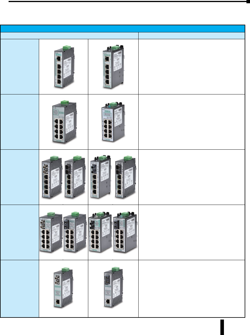
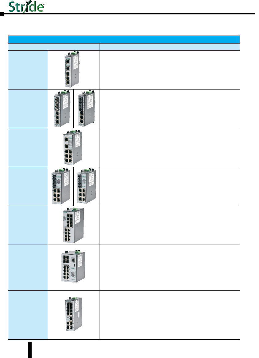
Stride Unmanaged Ethernet Switches
Part Number Description
SE-SW5U
SE-SW5U-WT
STRIDE ™ SlimLine Industrial Unmanaged Ethernet Switch
with five 10/100BaseT RJ45 Ethernet ports. Redundant
power inputs with surge and spike protection. Auto-
crossover. 35 mm DIN rail mounting. Supports store &
forward wire speed switching and full-duplex with flow
control. UL, CSA (CUL), & CE
Note: -WT models have a metal case and are rated for a
wider temperature range, from -40 ° to +85 °C.
SE-SW8U
SE-SW8U-WT
STRIDE ™ SlimLine Industrial Unmanaged Ethernet Switch
with eight 10/100BaseT RJ45 Ethernet ports. Redundant
power inputs with surge and spike protection. Auto-
crossover. 35 mm DIN rail mounting. Supports store &
forward wire speed switching and full-duplex with flow
control. UL, CSA (CUL), & CE
Note: -WT models have a metal case and are rated for a
wider temperature range, from -40 ° to +85 °C.
SE-SW5U-ST
SE-SW5U-SC
SE-SW5U-ST-WT
SE-SW5U-SC-WT
STRIDE ™ SlimLine Industrial Unmanaged Ethernet Switch
with four 10/100BaseT RJ45 Ethernet Ports and one
100BaseFX Fiber Optic Port (ST or SC type multimode
fiber connector for links up to 4km). Redundant power
inputs with surge and spike protection. Auto-crossover.
35 mm DIN rail mounting. Supports store & forward wire
speed switching and full-duplex with flow control. UL, CSA
(CUL), & CE
Note: -WT models have a metal case and are rated for a
wider temperature range, from -40 ° to +85 °C.
SE-SW9U-ST
SE-SW9U-SC
SE-SW9U-ST-WT
SE-SW9U-SC-WT
STRIDE ™ SlimLine Industrial Unmanaged Ethernet Switch
with eight 10/100BaseT RJ45 Ethernet Ports and one
100BaseFX Fiber Optic Port (ST or SC type multimode
fiber connector for links up to 4km). Redundant power
inputs with surge and spike protection. Auto-crossover.
35 mm DIN rail mounting. Supports store & forward wire
speed switching and full-duplex with flow control. UL, CSA
(CUL), & CE
Note: -WT models have a metal case and are rated for a
wider temperature range, from -40 ° to +85 °C.
SE-MC2U-ST
SE-MC2U-SC
STRIDE ™ SlimLine Industrial Unmanaged Ethernet to
Fiber Converter with one 10/100BaseT auto-detecting,
auto-crossover and auto-polarity RJ45 Ethernet Port and
one 100BaseFX Fiber Optic Port (ST or SC type multimode
fiber connector for links up to 4km). Redundant power
inputs with surge and spike protection. 35 mm DIN rail
mounting. Supports store & forward wire speed switching
and full-duplex with flow control. UL, CSA (CUL), & CE
1-3
Stride Industrial Ethernet Switches User Manual 2nd Ed. Rev. B
Chapter 1 - Hardware
Product Overview (cont’d)
Stride Managed Ethernet Switches
Part Number Description
SE-SW5M
STRIDE ™ SlimLine industrial managed 5-port Ethernet switch, metal
housing, -40 to +75 deg. C operating temperature range, five 10/100BaseT
RJ45 Ethernet ports. Redundant power inputs with surge and spike
protection, auto-crossover, 35 mm DIN rail mounting. Supports Store and
Forward wire speed switching and full-duplex with flow control. UL/CUL
HazLoc (Class I, Div. 2, Groups A, B, C, D) and CE marked.
SE-SW5M-2ST
SE-SW5M-2SC
STRIDE ™ SlimLine industrial managed 5-port Ethernet switch, metal
housing, -40 to +75 deg., three 10/100BaseT RJ45 Ethernet ports and
two multi-mode 100BaseFX fiber ports(ST or SC type multimode fiber
connector for links up to 4km). Redundant power inputs with surge and
spike protection, auto-crossover, 35 mm DIN rail mounting. Supports
Store and Forward wire speed switching and full-duplex with flow control.
UL/CUL HazLoc (Class I, Div. 2, Groups A, B, C, D) and CE marked.
SE-SW8M
STRIDE ™ SlimLine industrial managed 8-port Ethernet switch,
metal housing, -40 to +75 deg. C operating temperature range, eight
10/100BaseT RJ45 Ethernet ports. Redundant power inputs with surge
and spike protection, auto-crossover, 35 mm DIN rail mounting. Supports
Store and Forward wire speed switching and full-duplex with flow control.
UL/CUL HazLoc (Class I, Div. 2, Groups A, B, C, D) and CE marked.
SE-SW8M-2ST
SE-SW8M-2SC
STRIDE ™ SlimLine industrial managed 8-port Ethernet switch, metal
housing, -40 to +75 deg., six 10/100BaseT RJ45 Ethernet ports and
two multi-mode 100BaseFX fiber ports(ST or SC type multimode fiber
connector for links up to 4km). Redundant power inputs with surge and
spike protection, auto-crossover, 35 mm DIN rail mounting. Supports
Store and Forward wire speed switching and full-duplex with flow control.
UL/CUL HazLoc (Class I, Div. 2, Groups A, B, C, D) and CE marked.
SE-SW16M
STRIDE ™ SlimLine industrial managed 16-port Ethernet Switch,
metal housing, -40 to +75 deg. C operating temperature range, sixteen
10/100BaseT RJ45 Ethernet ports. Redundant power inputs with surge
and spike protection, auto-crossover, 35 mm DIN rail mounting. Supports
Store and Forward wire speed switching and full-duplex with flow control.
UL/CUL HazLoc (Class I, Div. 2, Groups A, B, C, D) and CE marked.
SE-SW8MG-4P
STRIDE ™ SlimLine industrial managed 8-port Ethernet switch all Gigabit,
metal housing, -40 to +75 deg., eight 10/100/1000 BaseT RJ45 Ethernet
ports and four advanced combination SFP ports that accept noise-immune
fiber optic links up to 40 km. Redundant power inputs with surge and
spike protection, auto-crossover, 35 mm DIN rail mounting. Supports
Store and Forward wire speed switching and full-duplex with flow control.
UL/CUL HazLoc (Class I, Div. 2, Groups A, B, C, D) and CE marked. SFP
option modules sold separately.
SE-SW10MG-2P
STRIDE ™ SlimLine industrial managed 10-port Ethernet switch with
Gigabit, metal housing, -40 to +75 deg., seven 10/100 BaseT RJ45
Ethernet ports, three Gigabit 10/100/1000 BaseT RJ45 port and two
advanced combination SFP ports that accept noise-immune fiber optic
links up to 40 km. Redundant power inputs with surge and spike
protection, auto-crossover, 35 mm DIN rail mounting. Supports Store and
Forward wire speed switching and full-duplex with flow control. UL/CUL
HazLoc (Class I, Div. 2, Groups A, B, C, D) and CE marked. SFP option
modules sold separately.
1-4
Stride Industrial Ethernet Switches User Manual 2nd Ed. Rev. B
Chapter 1 - Hardware
Managed Switch Accessories
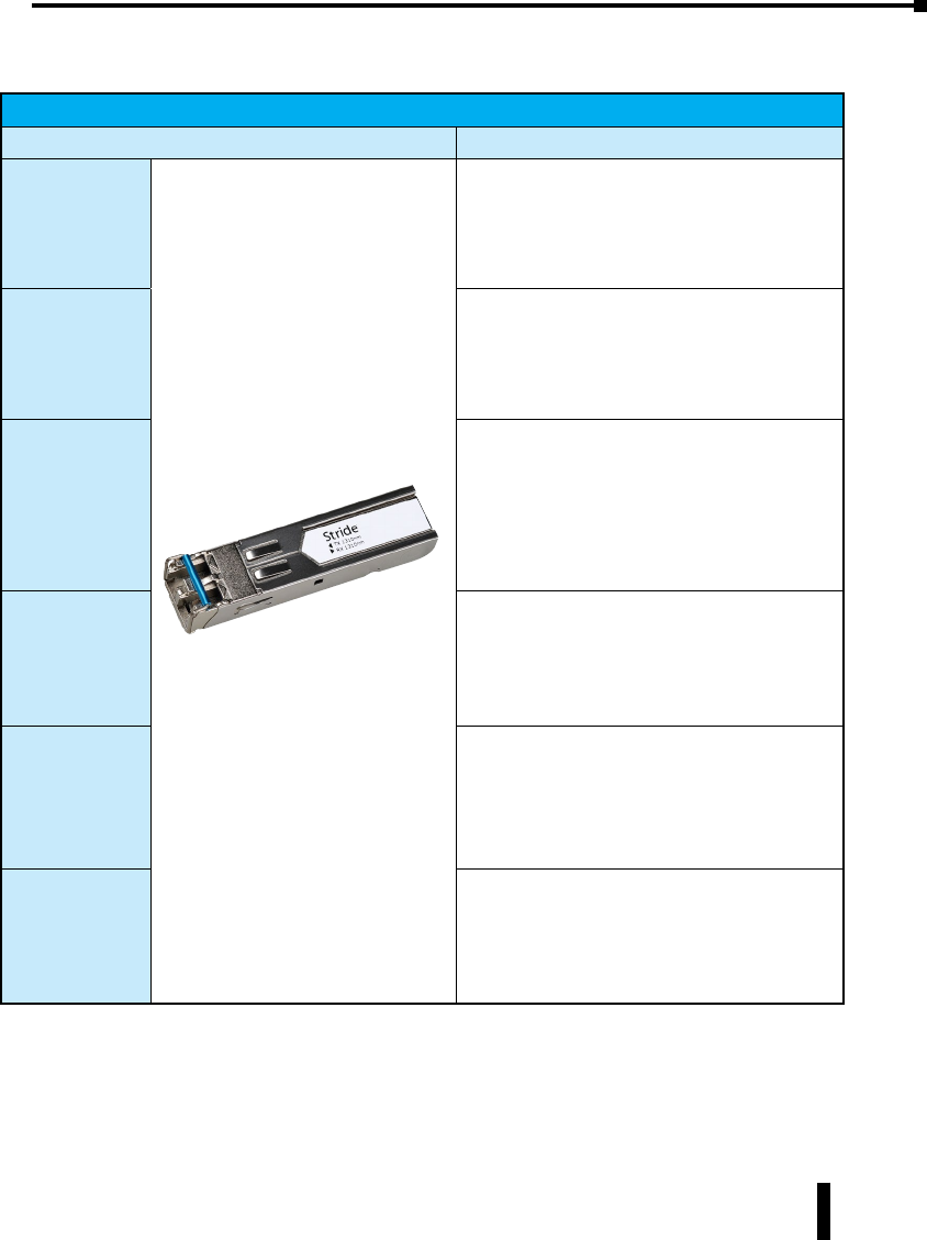
SFP Transceiver
Part Number Description
SFP-4K-FMF
STRIDE ™ 100Mb Small Form Factor Pluggable (SFP)
transceiver module (Transmit/Receive). Uses a long
wavelength of 1310nm, supports data transmission up
to 4km on a multi-mode fiber. LC duplex receptacle,
SFP Multi-Source Agreement compliant. 125Mbps
IEEE802.3u 100Base-FX compliant, 125Mbps FDDI ISO/
IEC 9314-1 compliant.
SFP-30K-FSF
STRIDE ™ 100Mb Small Form Factor Pluggable (SFP)
transceiver module (Transmit/Receive). Uses a long
wavelength of 1310nm, supports data transmission up
to 30km on a singlemode fiber. LC duplex receptacle,
SFP Multi-Source Agreement compliant.
SFP-500-GMF
STRIDE ™ Gigabit (1.25GB) Small Form Factor
Pluggable (SFP) transceiver module (Transmit/
Receive). Uses a short wavelength of 850nm, supports
data transmission up to 550 meters on a multi-
mode fiber. LC duplex receptacle, SFP Multi-Source
Agreement compliant. 1.0625Gbps Fibre Channel FC-PI
100-M5-SN-I compliant. 1.0625Gbps Fibre Channel
FC-PI 100-M6-SN-I compliant. 1.25Gbps IEEE802.3z
1000Base-SX compliant. 1.25Gbps IEEE802.3ah
compliant.
SFP-2K-GMF
STRIDE ™ Gigabit (1.25GB) Small Form Factor
Pluggable (SFP) transceiver module. Uses a long
wavelength of 1310nm, supports data transmission up
to 2km on a multi-mode fiber. LC duplex receptacle,
SFP Multi-Source Agreement compliant. IEEE 802.3
1000Base-SX compliant.
SFP-10K-GSF
STRIDE ™ Gigabit (1.25GB) Small Form Factor
Pluggable (SFP) transceiver module (Transmit/
Receive). Uses a long wavelength of 1310nm, supports
data transmission up to 10km on a singlemode
fiber. LC duplex receptacle, SFP Multi-Source
Agreement compliant. 1.0625Gbps Fiber Channel
FC-PI 100-SM-LC-L compliant. 1.25Gbps IEEE 802.3
1000Base-LX compliant.
SFP-30K-GSF
STRIDE ™ Gigabit (1.25GB) Small Form Factor
Pluggable (SFP) transceiver module (Transmit/
Receive). Uses a long wavelength of 1310nm, supports
data transmission up to 30km on a singlemode fiber.
LC duplex receptacle, SFP Multi-Source Agreement
compliant. 1.25Gbps IEEE 802.3 1000Base-LX
compliant.
1-5

General Information
Overview
This user’s manual will help you install and maintain the STRIDE industrial Ethernet switches
and media converters. Installation of these devices is very easy and they will begin to operate as
soon as they are powered up.
Operation
Unlike an Ethernet hub that broadcasts all messages out all ports, these industrial Ethernet
switches will intelligently route Ethernet messages only out the appropriate port. The major
benefits of this are increased bandwidth and speed, reduction or elimination of message
collisions, and deterministic performance when tied with real-time systems.
These industrial Ethernet switches can support 10BaseT (10 Mbps) or 100BaseT (100 Mbps)
on their RJ45 ports. Each of these ports will independently auto-sense the speed and duplex,
mdi/mdix-crossover and polarity allowing you to use patch or crossover cables. Managed
switches include models that support gigabit Ethernet.
Some models include fiber optic ports, or slots that accept SFP fiber optic transceivers.
Stride Industrial Ethernet Switches User Manual 2nd Ed. Rev. B
Chapter 1 - Hardware
1-6

Safety Standards
These industrial Ethernet switches meet the following standards plus others:
Electrical Safety -
CE per Low Voltage Directive and EN61010-1 (IEC1010)
UL recognition per UL508 (UL File #E200031)
CSA per C22.2/14 (cUL File #E200031)
See Warnings on following page
Install the Switches in accordance with local and national electrical codes.
Lightning Danger: Do not work on equipment during periods of lightning activity.
Do not connect a telephone line into one of the Ethernet RJ45 connectors.
EMC (emmissions and immunity) -
• CE per the EMC directive, EN61000-6-2, EN61000-6-4
• FCC part 15 and ICES 003; Class B.
See FCC statement on following page.
Marine, maritime and offshore -
These devices, when installed in an appropriately IP rated enclosure. Comply with
DNV No. 2.4 and equivalent Lloyds and ABS standards.
For marine and maritime compliance, do not install this product within 5 meters
of a standard or a steering magnetic compass.
WEEE compliance -
These devices comply with the WEEE directive. Dispose of properly.
RoHS
RoHS compliance -
These devices comply with the RoHS directive and are considered lead and other
hazardous substance free.
Hazardous Locations -
• CE per ATEX directive and EN60079-15 (Zone 2);
EEx nA II T4 X (-40 °C m Ta m +85 °C)
UL
CUS
R
• UL per UL HazLoc (Class 1, Div. 2), Groups A, B, C, D (UL File #E200031)
• CSA per C22.2/213 (Class 1, Div.2), Groups A, B, C, D (cUL File #E200031)
See Warnings on following page
Stride Industrial Ethernet Switches User Manual 2nd Ed. Rev. B
Chapter 1 - Hardware
1-7
Stride Industrial Ethernet Switches User Manual 2nd Ed. Rev. B
Chapter 1 - Hardware
Installation and Hazardous Area Warnings
Warning: These products should not be used to replace proper safety interlocking. No software-based
device (or any other solid-state device) should ever be designed to be responsible for the maintenance
of consequential equipment or personnel safety. In particular, AutomationDirect.com disclaims any
responsibility for damages, either direct or consequential, that result from the use of this equipment in
any application. All power, input and output (I/O) wiring must be in accordance with Class I, Division 2
wiring methods and in accordance with the authority having jurisdiction.
FCC Statement
This equipment has been tested and found to comply with the limits for a Class B digital
device, pursuant to Part 15 of the FCC Rules. These limits are designed to provide reasonable
protection against harmful interference in a residential installation. This equipment generates,
uses and can radiate radio frequency energy and, if not installed and used in accordance with
the instructions, may cause harmful interference to radio communications. However, there
is no guarantee that interference will not occur in a particular installation. If this equipment
does cause harmful interference to radio or television reception, which can be determined by
turning the equipment off and on, the user is encouraged to try to correct the interference by
one or more of the following measures: Reorient or relocate the receiving antenna; Increase
the separation between the equipment and receiver; Connect the equipment into an outlet
on a circuit different from that to which the receiver is connected; Consult the dealer or an
experienced radio/TV technician for help.
NOTE: All information in this document is subject to change without notice.
WARNING
(EXPLOSION HAZARD)
SUBSTITUTION OF COMPONENTS MAY IMPAIR SUITABILITY FOR
CLASS 1, DIVISION 2 (ZONE 2).
WARNING
(EXPLOSION HAZARD)
WHEN IN HAZARDOUS LOCATIONS, DISCONNECT POWER BEFORE
REPLACING OR WIRING UNITS.
WARNING
(EXPLOSION HAZARD)
DO NOT DISCONNECT EQUIPMENT UNLESS POWER HAS BEEN
SWITCHED OFF OR THE AREA IS KNOWN TO BE NONHAZARDOUS.
WARNING
(EXPLOSION HAZARD)
IN HAZARDOUS OR POTENTIALLY HAZARDOUS LOCATIONS, DO
NOT SEPARATE ANY PART OF THE UNIT WHEN ENERGIZED. USE
THE UNIT FOR INTERNAL CONNECTIONS ONLY.
1-8
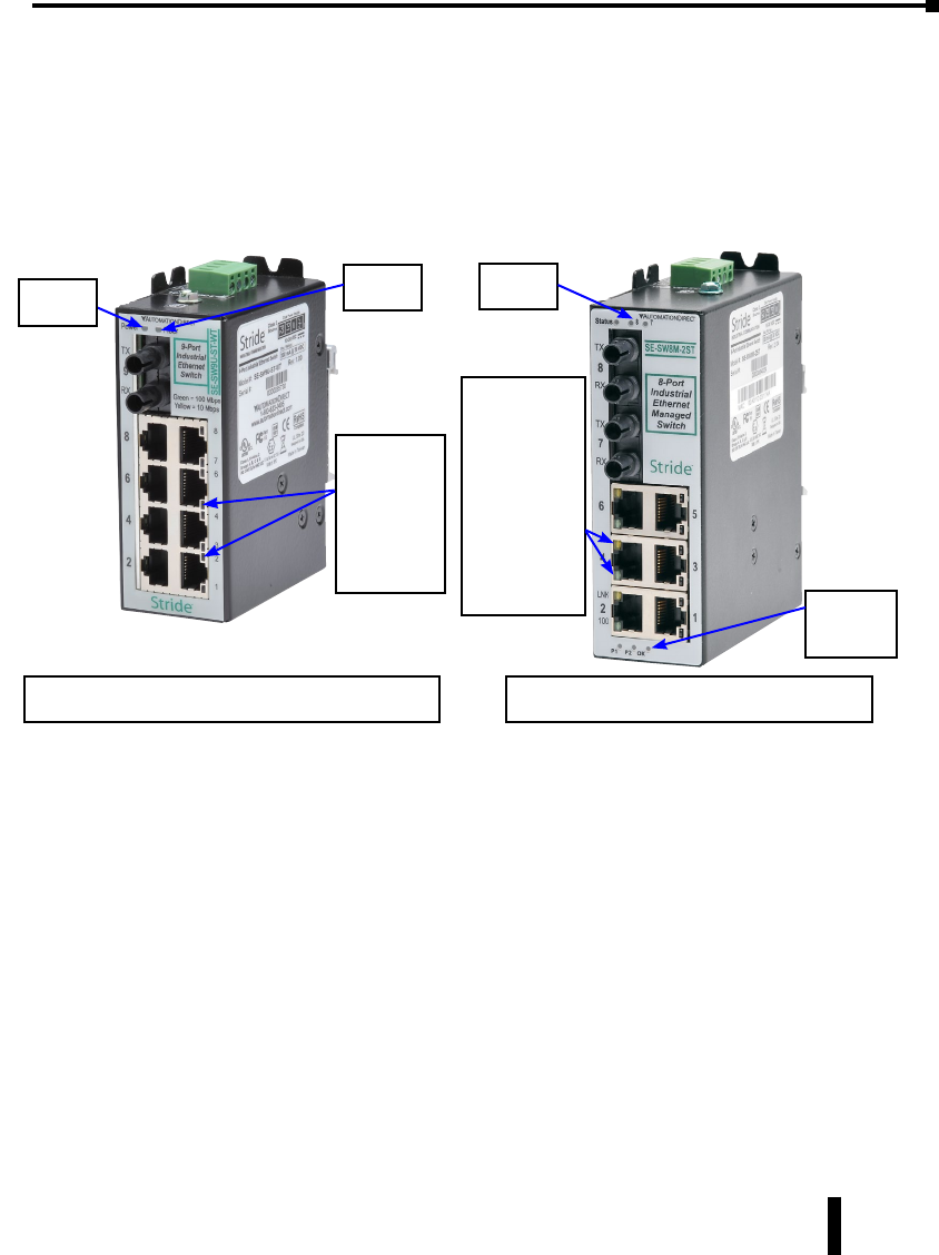
LED Indicators
Overview
The Stride industrial Ethernet switches have 1 or 2 communication LEDs for each port and
a power LED. The managed models also have an “OK” output LED, a status LED and dual
power LEDs.
Status LED
Managed Models Only: The Status LED indicates the overall health of the switch. It is
normally ON solid indicating that no internal CPU or software problems are detected. It
will flash when loading firmware and briefly on power up or reset. Otherwise, if it is OFF or
flashing for an extended period of time then a problem is detected. In this case, please contact
AutomationDirect for support.
Power LED
On unmanaged models there is one power LED that is ON if either power input(P1 or P2) has
power applied to it. On the managed models there are two Power LEDs that indicate if there
is power applied to the respective input.
Explanation of LED Indicators continued on next page.
Stride Industrial Ethernet Switches User Manual 2nd Ed. Rev. B
Chapter 1 - Hardware
The activity,
link and
speed LEDs
are
integrated
into the
RJ45 ports
Status
LED
The activity,
link and
speed LEDs
are
integrated
into a single
multi-color
LED. They
are labeled
for each port
number. Power &
OK
LEDs
See the ACT/LNK and Speed 10/100 LED
explanations that follow below & on next page
See the ACT/LNK/Speed LED explanation
that follows on the next page.
Power
LED
1-9
Fiber
LED
Managed Unmanaged
1-10 Stride Industrial Ethernet Switches User Manual 2nd Ed. Rev. B
Chapter 1 - Hardware
ACT/LNK LED
This is the Yellow LED on models with two LEDs per RJ45 port.
Speed 10/100 LED
This is the Green LED on models with two LED’s per RJ45 port.
ACT/LNK/Speed LED
This is a bi-color (Green / Yellow) LED on models with one LED per RJ45 port.
ON Solid (not flashing) Indicates that there is a proper Ethernet connection (Link) between the port and another
Ethernet device, but no communications activity is detected.
Flashing Indicates that there is a proper Ethernet connection (Link) between the port and another
Ethernet device, and that there is communications activity.
Green On 10/100 ports, a 100 Mbps connection is detected.
On 10/100/1000 ports, a 1000 Mbps connection is detected.
Yellow On 10/100 ports, a 10 Mbps connection is detected.
On 10/100/1000 ports, a 10 or 100 Mbps connection is detected.
OFF Indicates that there is not a proper Ethernet connection (Link) between the port and
another Ethernet device. Make sure the cable has been plugged securely into the ports
at both ends.
OK LED
Managed Models: This LED indicates the status of the power inputs. There is an output
screw terminal that can be connected as shown in the wiring diagram. The output voltage
between the screw terminal marked ‘OK’ and the terminal marked ‘–’ will be the same as
the applied switch input voltage. The output will be ON when both the PI and P2 terminals
have power applied to them. It will be OFF if either input does not have power or the switch
software is not running.
ON (yellow)
(not flashing)
Indicates that there is a proper Ethernet connection (Link) between the port and another
Ethernet device, but no communications activity is detected.
ON (yellow)
(flashing)
Indicates that there is a proper Ethernet connection (Link) between the port and another
Ethernet device, and that there is communications activity.
OFF Indicates that there is not a proper Ethernet connection (Link) between the port and
another Ethernet device. Make sure the cable has been plugged securely into the ports
at both ends.
ON (green) A 100 Mbps (100BaseT) connection is detected.
OFF A 10 Mbps (10BaseT) connection is detected.
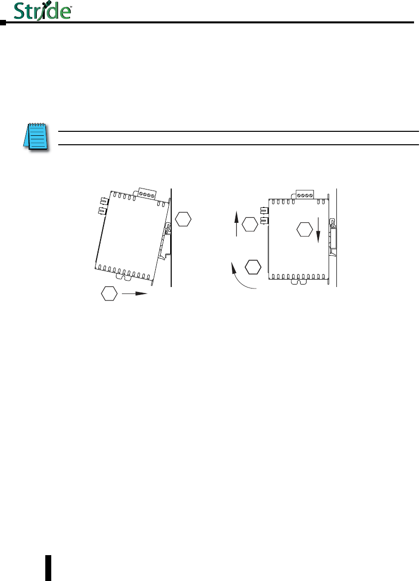
Installation, Plastic Case Switches
Overview
These industrial Ethernet switches and media converters can be snapped onto a standard 35
mm x 7.5 mm height DIN rail (Standard: CENELEC EN50022). The switches and media
converters can be mounted either vertically or horizontally. Refer to the mechanical drawings
that follow for proper mounting.
NOTE: Make sure to allow enough room to route your Ethernet copper or fiber optic cables.
DIN Rail Mounting
DIN rail mounting steps:
1. Hook top back of unit over the DIN rail.
2. Push bottom back onto the DIN rail until it snaps into place.
DIN rail removal steps:
A. Insert screwdriver into DIN clip and pry until it releases from the DIN rail.
B. Unhook top of unit from DIN rail.
Mounting Removal
1
2
A
B
Stride Industrial Ethernet Switches User Manual 2nd Ed. Rev. B
Chapter 1 - Hardware
1-11
Stride Industrial Ethernet Switches User Manual 2nd Ed. Rev. B
Chapter 1 - Hardware
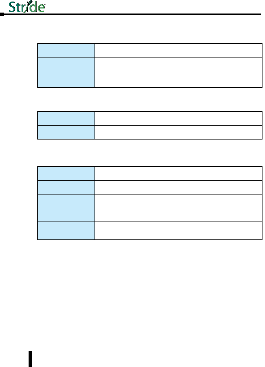
Installation, Metal Case Switches
Overview
These industrial Ethernet switches can be snapped onto a standard 35 mm x 7.5 mm height
DIN rail (Standard: CENELEC EN50022). They can be mounted either vertically or
horizontally. Refer to the mechanical drawings that follow for proper mounting.
NOTE: Make sure to allow enough room to route your Ethernet copper or fiber optic cables.
DIN Rail Mounting
DIN rail mounting steps:
1. Hook top back of unit over the DIN rail.
2. Push bottom back onto the DIN rail until it snaps into place.
DIN rail removal steps:
A. Push the unit down to free the bottom of the DIN rail.
B. Rotate the bottom of the unit away from the DIN rail.
C. Unhook top of unit from DIN rail.
Mounting
1
2
A
B
Removal
C
1-12
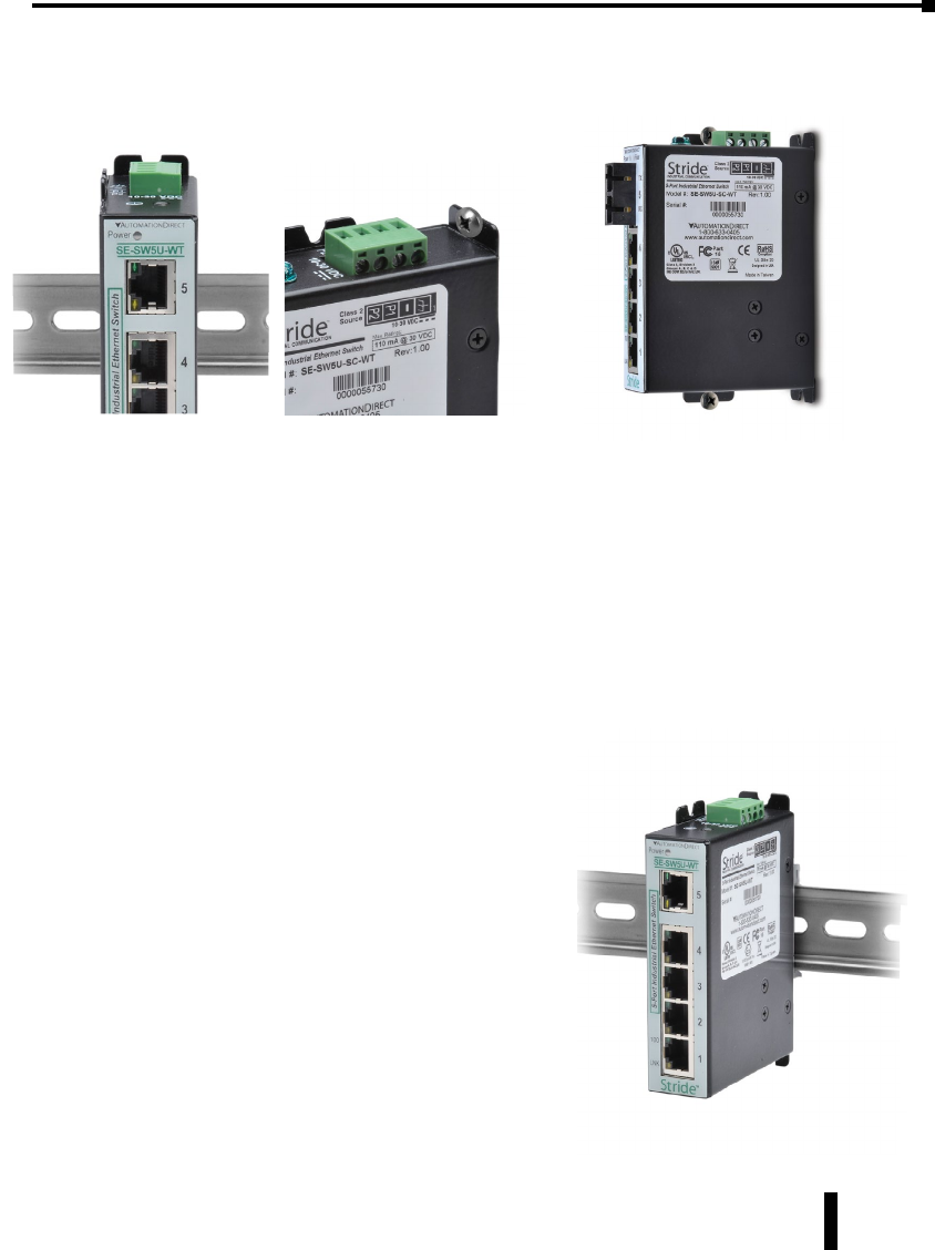
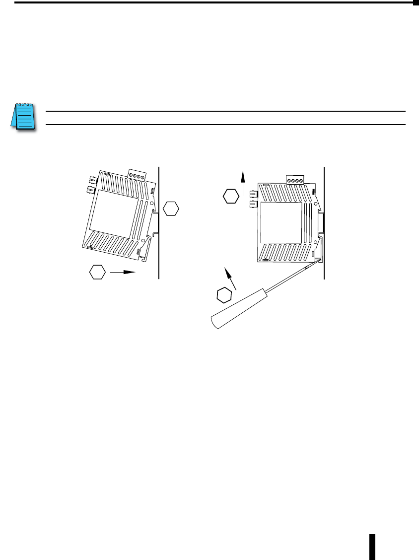
Mounting Options
Stride switches with metal cases offer the following optional mounting methods.
A. Vertical DIN rail mount.
This mounting option allows for quickest installation and optimal utilization of rail space.
B. Vertical screw to panel mount.
This mounting option gives better shock and vibration resistance.
C. Flat screw to panel mount.
This mounting option offers a low profile orientation in shallow boxes plus the best shock and
vibration resistance. The power connection terminal block is removable for access to the mounting tab.
Important Notes about Thermal Performance
Stride switches with metal cases use an innovative
technique to remove excess heat from the product and
its components. This technique effectively utilizes the
heavy gauge all-aluminum case as a large heat sink.
Therefore, the case may be warm during operation,
especially with heavy loads such as all ports linked and
active. This is normal operation. For best performance,
it is recommended that a DIN rail spacer such as end
clamp, part number DN-EB35, be used between the
switch and any adjacent device. This will leave an air
gap for best heat dissipation off the case.
For best thermal performance when direct panel
mounting to a metal surface, thermal compound may
be used between the switch and mounting surface.
This will reduce any air gaps and optimize the transfer
of heat from the case to the mounting surface.
ABC
Stride Industrial Ethernet Switches User Manual 2nd Ed. Rev. B
Chapter 1 - Hardware
1-13
Stride Industrial Ethernet Switches User Manual 2nd Ed. Rev. B
Chapter 1 - Hardware
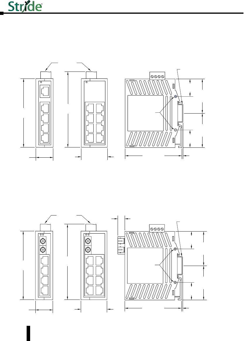
Mechanical Dimensions for 5 and 8-Port Unmanaged Models in Plastic Case
Inches [mm]
Mechanical Dimensions for 5 and 9-Port Unmanaged Models with Fiber in
Plastic Case
Inches [mm]
5 Port
9
Port
3.96
[100.6]
1.00
[25.4]
4.35
[110.5]
1.50
[38.1]
Dia. 0.15 [3.8]
Use for direct
panel mounting
to a flat surface.
1.98
[50.3]
3.26
[82.8]
0.06
[1.5]
0.40
[10.2]
1.98
[50.3]
Snaps to standard
35 mm x 7.5 mm height
DIN rail (EN50022)
Removable
Screw Block,
Phoenix
p/n 1757035
SE-SW5U-ST, SE-SW5U-SC
SE-SW9U-ST and SE-SW9U-SC
1.01
[25.7]
1.01
[25.7]
1-14
5 Port 8 Port
3.95
[100.3]
1.00
[25.4]
4.20
[106.7]
1.50
[38.1]
Dia. 0.15 [3.8]
Use for direct
panel mounting
to a flat surface.
1.98
[50.3]
3.26
[82.8]
0.06
[1.5]
Snaps to standard
35 mm x 7.5 mm height
DIN rail (EN50022)
1.98
[50.3]
Removable
Screw Block,
Phoenix
p/n 1757035
1.01
[25.7]
1.01
[25.7]
5 or 8 Port –
S
E-
S
W5U
&
S
E-
S
W8U
Stride Industrial Ethernet Switches User Manual 2nd Ed. Rev. B
Chapter 1 - Hardware
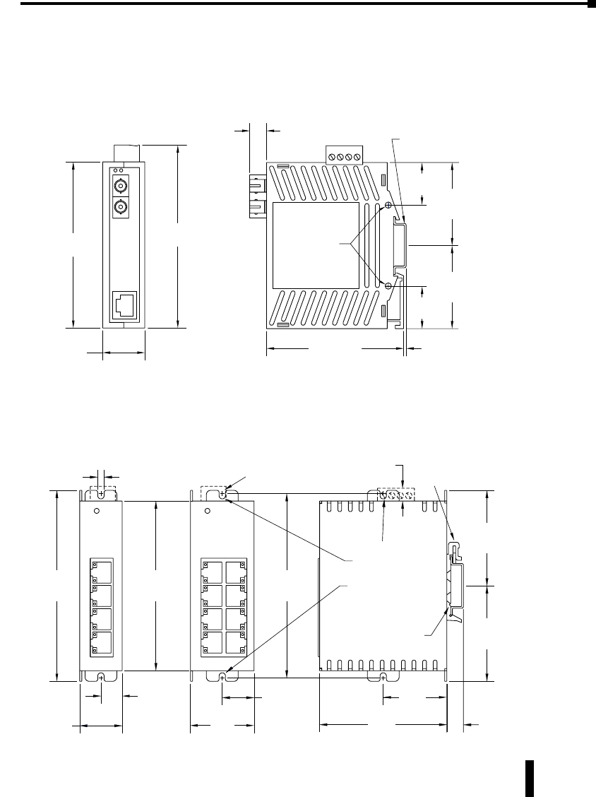
Mechanical Dimensions for 2-Port Media Converter in Plastic Case
Inches [mm]
Mechanical Dimensions for 5 and 8-Port Unmanaged Models in Metal Case
Inches [mm]
1-15
3.96
[100.6]
1.00
[
25.4
]
Removable
Screw Block,
Phoenix
p/n 1757035
Media Converters – SE-MC2U-ST and SE-MC2U-SC
Dia. 0.15 [3.8]
Use for direct
panel mounting
to a flat surface.
3.26
[82.8]
0.06
[1.5]
0.40
[10.2] Snaps to standard
35 mm x 7.5 mm height
DIN rail (EN50022)
4.35
[110.5]
1.98
[50.3]
1.98
[50.3]
1.01
[25.7]
1.01
[25.7]
Snaps to standard
35 mm x 7.5 mm height
DIN rail (EN50022)
Removable
Screw Block,
Phoenix
p/n 1757035
C
2.25
[57.1]
2.25
[57.1]
Dia. 0.175 [4.4]
Use for direct
panel mounting to
a flat surface with
up to #8 screw.
0.175
[4.4]
4.50
[114.3]
4.00
[101.6]
0.30
[7.6]
1.10
[27.9]
4.35
[110.5]
Removable
for direct panel
mounting
1.50
[3.81]
0.55
[14.0]
1.60
[40.6]
5 Port 8 Port
0.80
[20.3]
3.00
[76.2]
0.39
[9.9]
5 or 8 Port – SE-SW5U-WT & SE-SW8U-WT
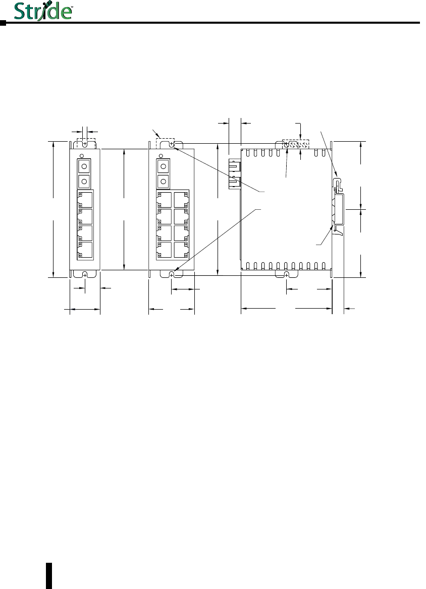
Mechanical Dimensions for 5 and 9-Port Unmanaged Models with Fiber in
Metal Case
Inches [mm]
Snaps to standard
35 mm x 7.5 mm height
DIN rail (EN50022)
Removable
Screw Block,
Phoenix
p/n 1757035
C
2.25
[57.1]
2.25
[57.1]
0.40
[10.2]
Dia. 0.175 [4.4]
Use for direct
panel mounting to
a flat surface with
up to #8 screw.
0.175
[4.4]
4.50
[114.3]
4.00
[101.6]
0.30
[7.6]
1.10
[27.9]
4.35
[110.5]
Removable
for direct panel
mounting
1.50
[3.81]
0.55
[14.0]
1.60
[40.6]
5 Port 9 Port
0.80
[20.3]
3.00
[76.2]
0.39
[9.9]
SE-SW5U-ST-WT, SE-SW5U-SC-WT
SE-SW9U-ST-WT and SE-SW9U-SC-WT
Stride Industrial Ethernet Switches User Manual 2nd Ed. Rev. B
Chapter 1 - Hardware
1-16
Stride Industrial Ethernet Switches User Manual 2nd Ed. Rev. B
Chapter 1 - Hardware
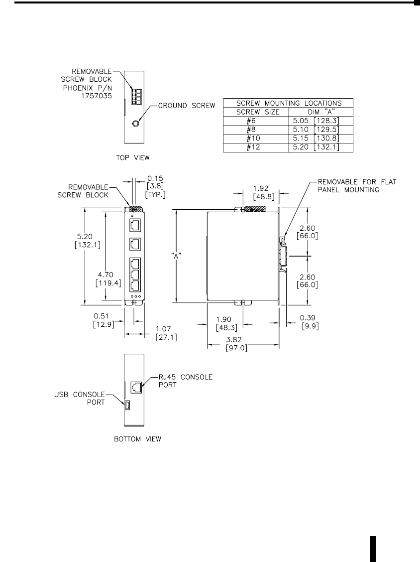
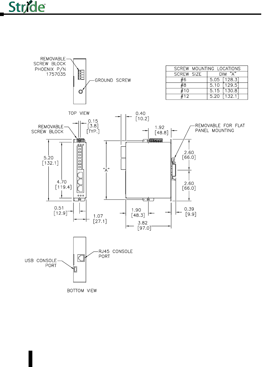
Mechanical Dimensions for 5-Port Managed Model
Inches [mm]
1-17
SE-SW5M
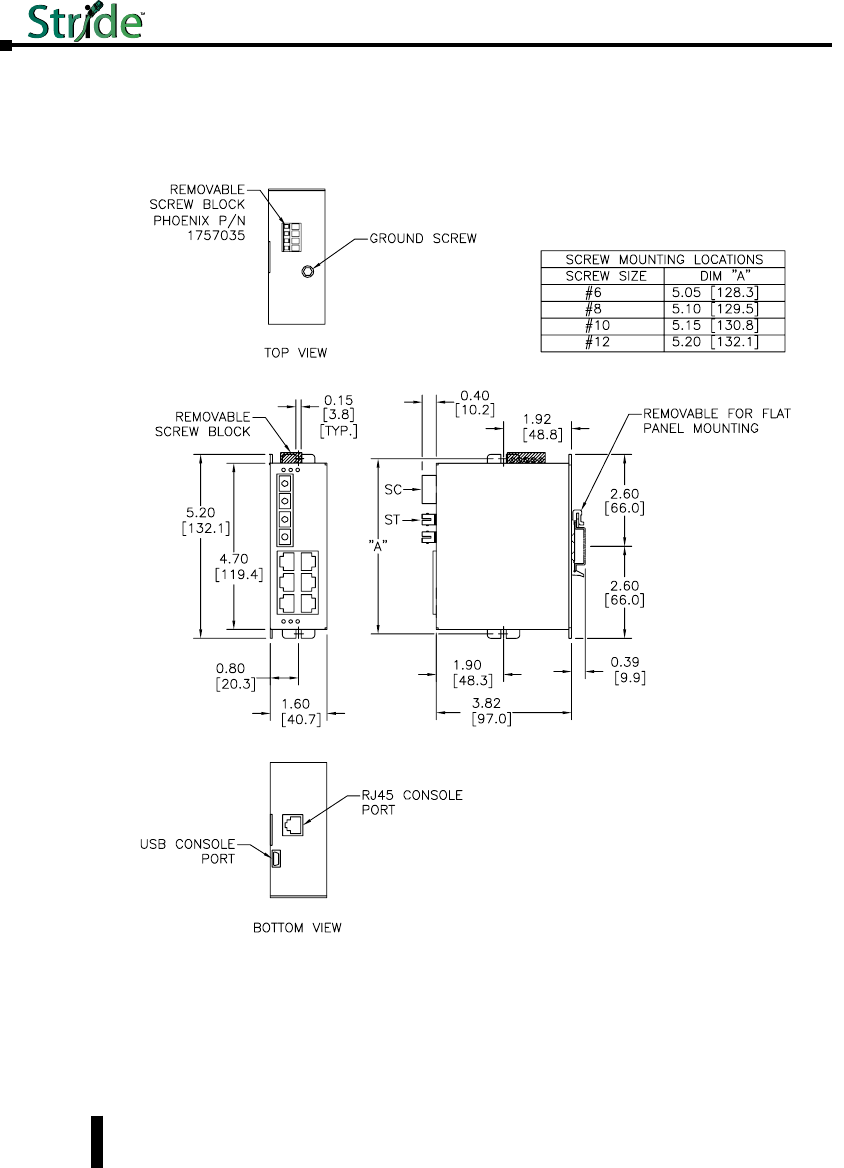
Mechanical Dimensions for 5-Port Managed Models with Fiber
Inches [mm]
SE-SW5M-2ST and SE-SW5M-2SC
1-18
Chapter 1 - Hardware
Stride Industrial Ethernet Switches User Manual 2nd Ed. Rev. B
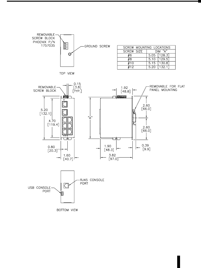
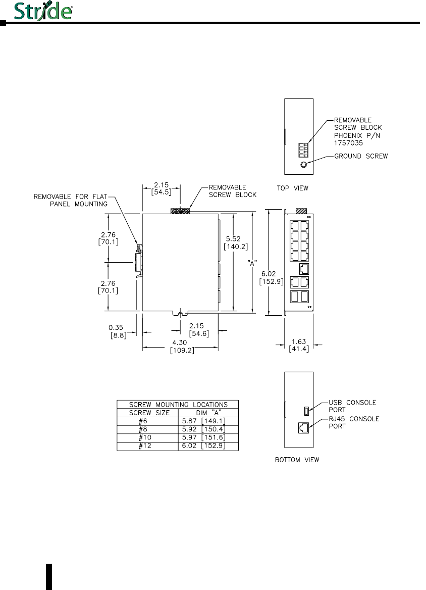
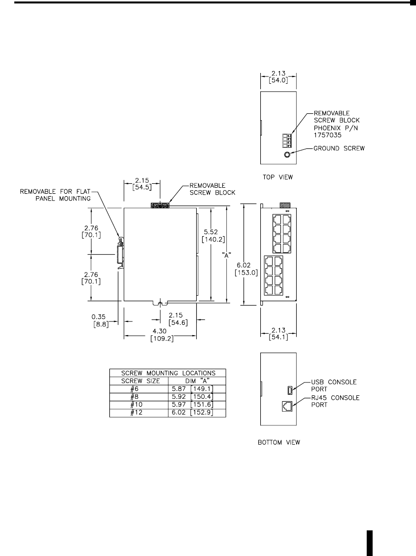
Mechanical Dimensions for 8-Port Managed Model
Inches [mm]
SE-SW8M
1-19
Chapter 1 - Hardware
Stride Industrial Ethernet Switches User Manual 2nd Ed. Rev. B
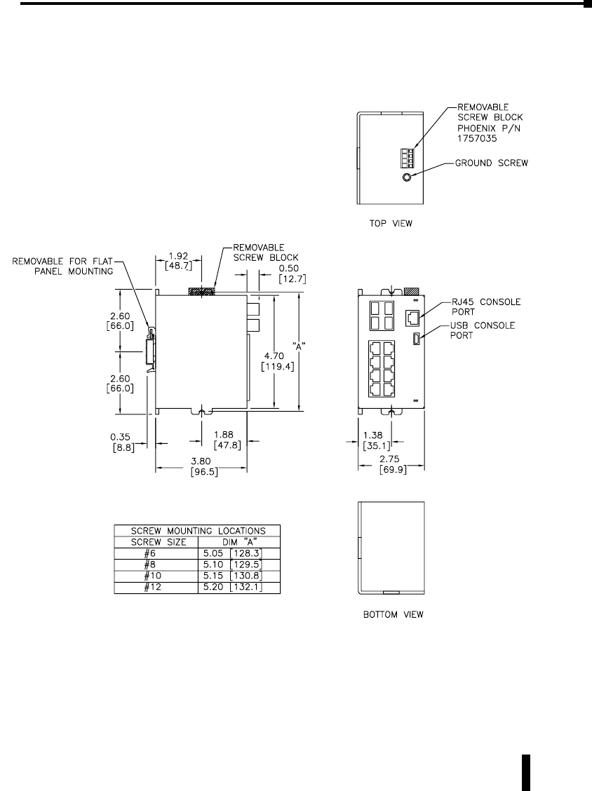
Mechanical Dimensions for 8-Port Managed Models with Fiber
Inches [mm]
SE-SW8M-2ST and SE-SW8M-2SC
1-20
Chapter 1 - Hardware
Stride Industrial Ethernet Switches User Manual 2nd Ed. Rev. B
Mechanical Dimensions for 8-Port Managed Gigabit Switch with Four SFP
Ports
Inches [mm] SE-SW8MG-4P
1-21
Chapter 1 - Hardware
Stride Industrial Ethernet Switches User Manual 2nd Ed. Rev. B
Mechanical Dimensions for 10-Port Managed Gigabit Switch with Two SFP
Ports
Inches [mm]
SE-SW10MG-2P
1-22
Chapter 1 - Hardware
Stride Industrial Ethernet Switches User Manual 2nd Ed. Rev. B
Mechanical Dimensions for 16-Port Managed Model
Inches [mm]
SE-SW16M
1-23
Chapter 1 - Hardware
Stride Industrial Ethernet Switches User Manual 2nd Ed. Rev. B
1-24
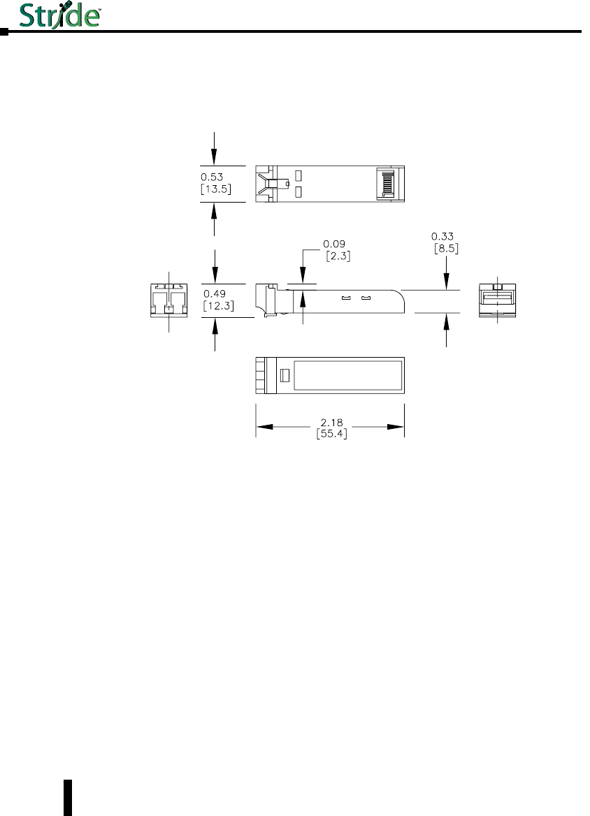
Mechanical Dimensions for SFP Transceiver Modules
Inches [mm]
Chapter 1 - Hardware
Stride Industrial Ethernet Switches User Manual 2nd Ed. Rev. B
SFP-4K-FMF, SFP-30K-FSF, SFP-500-GMF, SFP-2K-GMF, SFP-10K-GSF and SFP-30K-GSF
1-25
Power and Alarm Wiring
Overview
DC voltage in the range of 10 to 30 VDC (3.0W) needs to be applied between the P1 (plus)
terminal and the Minus terminal as shown below. To maintain a UL 508 panel listing use a
Class 2 power supply. The chassis screw terminal should be tied to panel or chassis ground. To
reduce down time resulting from power loss, these industrial Ethernet switches can be powered
redundantly with a second power supply as shown below.
NOTE: When powering multiple switches from a common power supply, it is most reliable to power the switches
sequentially rather than simultaneously. The characteristics of the power supply and the significant startup current of the
switches may result in an error in booting the switches when powered simultaneously.
Screw Torque
When tightening the screws be careful to tighten to a max. torque of 5 lb-in [0.57 Nm]. Wire
size should be between 24 AWG and 12 AWG.
Before performing any wiring to these switches make sure...
• The area is currently nonhazardous (especially when working in Class 1, Div 2 or Zone 2
hazardous locations).
• Power is off to the switch
• The screw terminal block is unplugged. This is especially important on the aluminum housed
units as shown below. Connecting or disconnecting wires to the screw block when its in place
and power is turned on can allow the screwdriver to short the power to the case
Unmanaged Models:
One DC Supply
+ –
P2 P1
Single DC Power Redundant DC Power
Chassis
GND
(panel)
+ –
+ –
Chassis
GND
(panel)
Dual DC Supplies
P2 P1
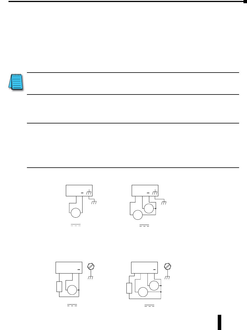
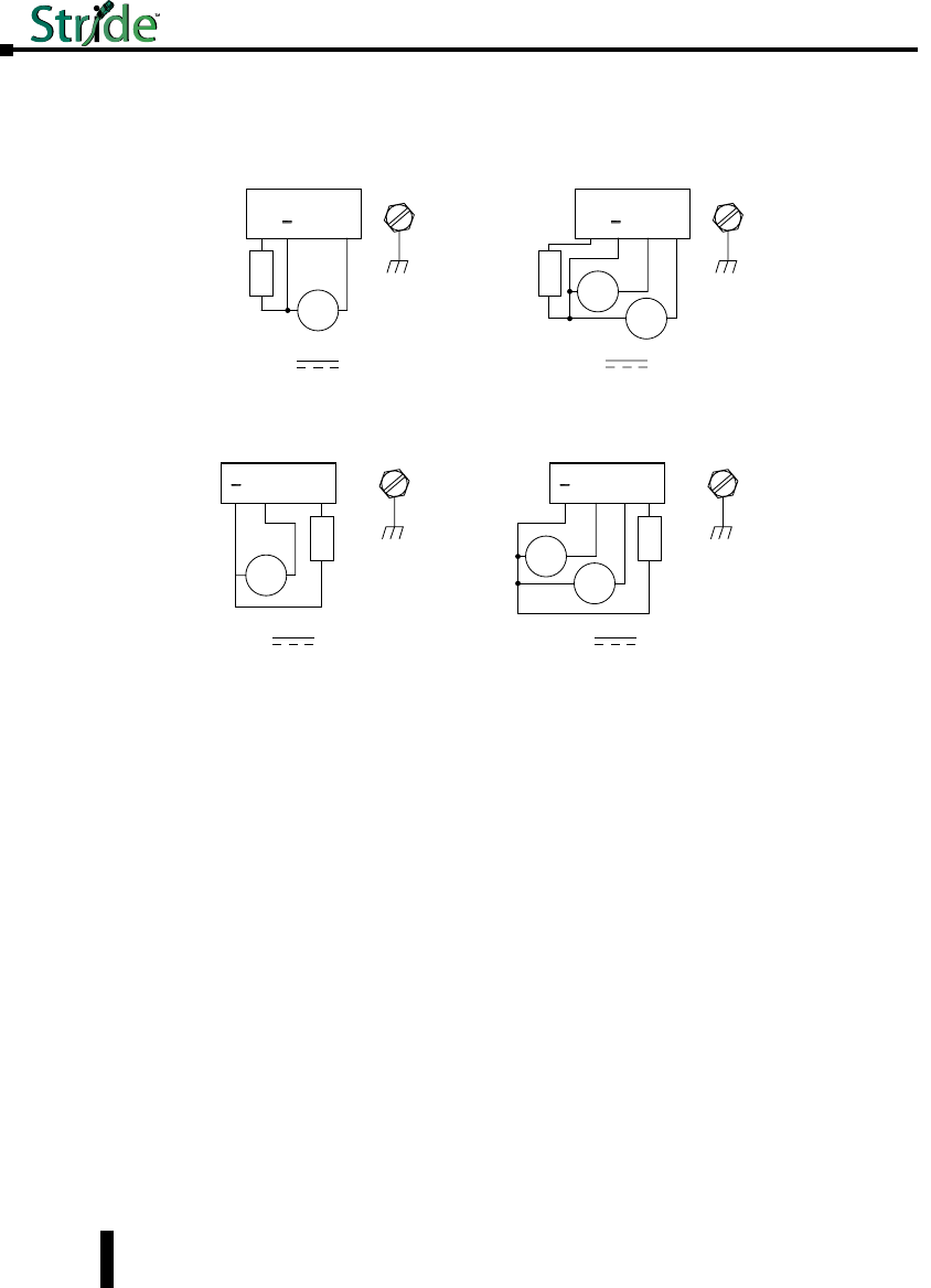
Managed Models:
SE-SW5M, SE-SW5M-2ST, SE-SW5M-2SC, SE-SW8M, SE-SW8M-2ST and
SE-SW8M-2SC
OK P2
One DC Supply
+–
Chassis
GND
(panel)
P1
Chassis
GND
(panel)
Single DC Power Redundant DC Power
+–
+–
Dual DC Supplies
OK P2 P1
+
–+
–
Alarm
Output
Load
(opt.)
Alarm
Output
Load
(opt.)
Chapter 1 - Hardware
Stride Industrial Ethernet Switches User Manual 2nd Ed. Rev. B
1-26
Managed Models:
SE-SW16M and SE-SW10MG-2P
–+
OK P1P2
One DC Supply
Chassis
GND
(panel)
Single DC PowerRedundant DC Power
–+
Dual DC Supplies
Chassis
GND
(panel)
OK P1P2
–+
+
–
+
–
Alarm
Output
Load
(opt.)
Alarm
Output
Load
(opt.)
SE-SW8MG-4P
P2P1
One DC Supply
Chassis
GND
(panel)
OK
Chassis
GND
(panel)
Single DC Power Redundant DC Power
Dual DC Supplies
P2
P1 OK
–+
–+
–+
+
–
+
–
Alarm
Output
Load
(opt.)
Alarm
Output
Load
(opt.)
Chapter 1 - Hardware
Stride Industrial Ethernet Switches User Manual 2nd Ed. Rev. B
Communication Ports Wiring
Overview
The industrial Ethernet switches and media converters provide connections to standard
Ethernet devices such as PLCs, Ethernet I/O, industrial computers and much more. RJ45
(copper) Ethernet ports and fiber optic Ethernet ports are available depending on model.
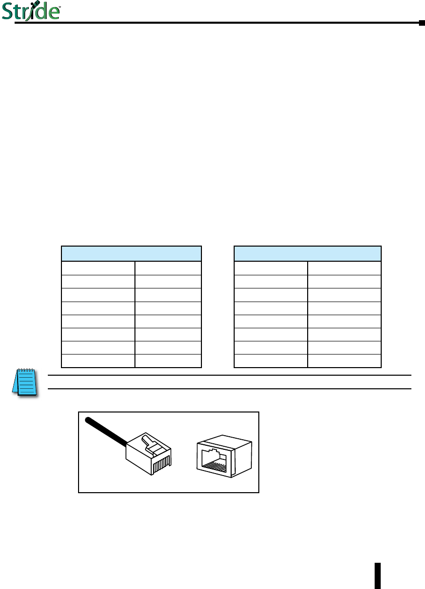
RJ45 Ethernet Wiring
Use data-quality (not voice-quality) twisted pair cable rated category 5e (or better) with
standard RJ45 connectors. Straight-through or crossover Ethernet cable can be used for all
devices the switch is connected to because all the ports are capable of auto-mdi/mdix-crossover
detection.
The RJ45 Ethernet port connector bodies on these products are metallic and connected to the
Chassis GND terminal. Therefore, shielded cables may be used to provide further protection.
To prevent ground loops, the cable shield should be tied to the metal connector body at one
end of the cable only. Electrical isolation is also provided on the Ethernet ports for increased
reliability.
NOTE: For reference only. Either cable wiring will work.
RJ45 Cable Distance
The maximum cable length for 10/100BaseT is 100 meters (328 ft.).
8
11
8
Straight-thru Cable Wiring
Pin 1 Pin 1
Pin 2 Pin 2
Pin 3 Pin 3
Pin 4 Pin 4
Pin 5 Pin 5
Pin 6 Pin 6
Pin 7 Pin 7
Pin 8 Pin 8
Cross-over Cable Wiring
Pin 1 Pin 3
Pin 2 Pin 6
Pin 3 Pin 1
Pin 4 Pin 4
Pin 5 Pin 5
Pin 6 Pin 2
Pin 7 Pin 7
Pin 8 Pin 8
Ethernet
Plug & Connector
Pin Positions
1-27
Chapter 1 - Hardware
Stride Industrial Ethernet Switches User Manual 2nd Ed. Rev. B
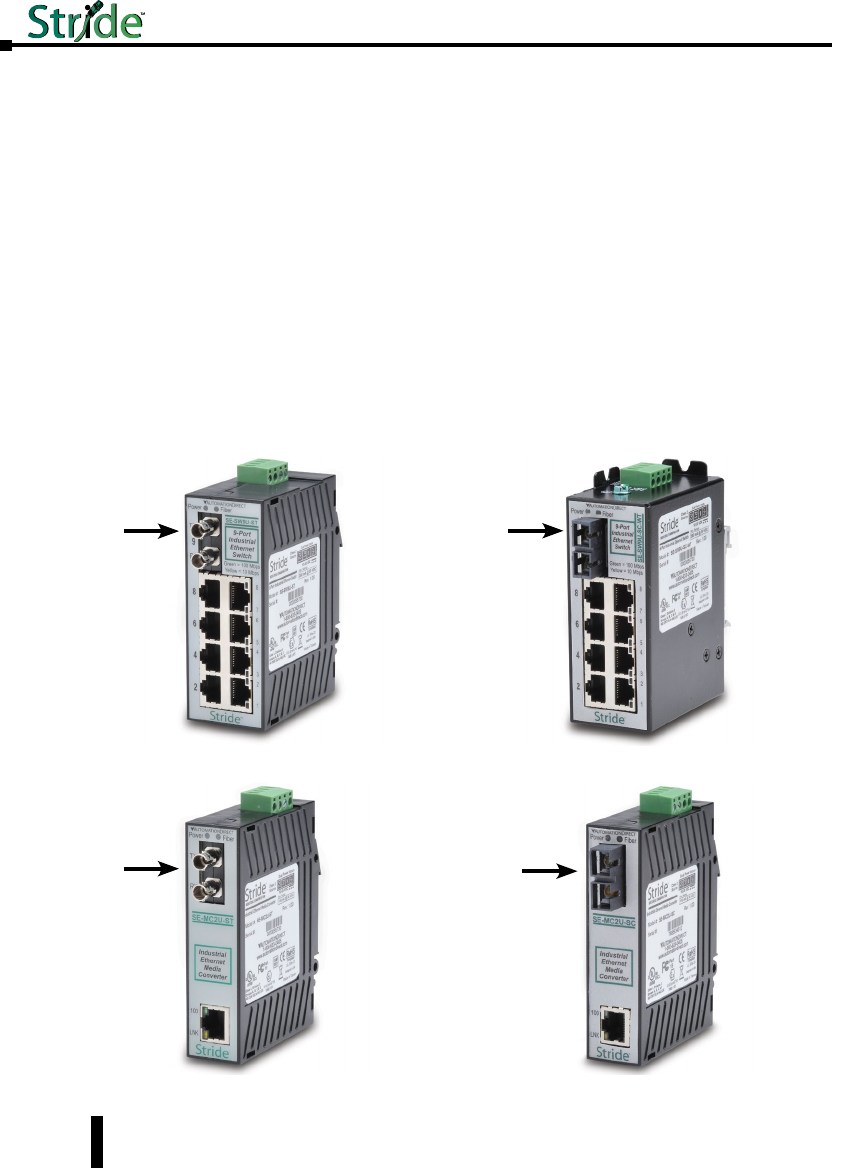
Ethernet Fiber Wiring Guidelines
Depending on the model these industrial Ethernet switches may include one, two or four
fiber optic ports. All 100 Mbps fiber ports are available with dual SC or ST multimode style
connectors. Refer to the technical specifications for details.
All 1000 Mbps fiber ports are provided as SFP (small form pluggable). These accept plug-in
fiber transceivers that have an LC style connector. They are available with either multimode
or singlemode transceivers. Refer to the technical specifications for details.
For each fiber port there is a transmit (TX) and receive (RX) signal. When making your
fiber optic connections, make sure that the transmit (TX) port of the switch connects to the
receive (RX) port of the other device, and the receive (RX) port of the switch connects to the
transmit (TX) port of the other device.
Use standard fiber optic wiring techniques (not covered by this manual) to make your
connections. The corresponding ACT/LNK LED will be ON solid or flashing when you
have made a proper connection.
Fiber Ports on Switches
Fiber Ports on Media Converters
1-28
Chapter 1 - Hardware
Stride Industrial Ethernet Switches User Manual 2nd Ed. Rev. B
Duplex Operation
The RJ45 ports will auto-sense for Full or Half duplex operation; the fiber ports are configured
for full duplex operation. On managed switches the duplex setting is software configurable.
NOTE: Fiber devices with half duplex settings will communicate with the switch in most situations.
Network Device Check
The industrial Ethernet switches and media converters support 10/100BaseT or 10/100/100
Base T on the RJ45 (copper) ports and 100BaseFX or gigabit Ethernet on the fiber optic ports
depending on model. Make sure you connect the appropriate devices to each port.
NOTE: The following AutomationDirect PLC Ethernet Modules are not compatible with the Stride Ethernet switches
and Media Converters with fiber optic connections because the modules have a speed of 10BaseF (fiber optic) only:
Ethernet Communications Module, p/n H2-ECOM-F & H4-ECOM-F; Ethernet Base Controller Module, p/n H2-EBC-F &
H4-EBC-F; Ethernet Remote Master Module, p/n H2-ERM-F & H4-ERM-F.
Verifying Connectivity
After all Ethernet and/or fiber connections are made, check the LEDs corresponding to the
ports that each of the devices are connected to. Ensure that for each port that is in use, the LED
is on or blinking. If a port LED is off, go back and check for connectivity problems between
that port and the network device connected to that port. In addition, the color of the LED
should indicate the speed at which your device is connected (see prior section on LEDs).
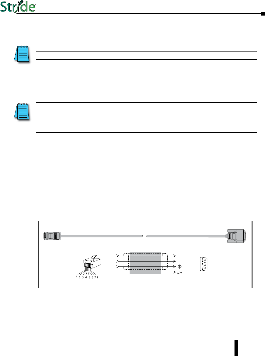
Serial Console Port Wiring
An optional way to configure the managed switch is through the RJ45 console RS232 port.
Wire a serial console cable as shown below to make a connection between a COM port on your
PC (DB9 male) and the RS232 port of the managed switch (RJ45 female).
1-29
Chapter 1 - Hardware
Stride Industrial Ethernet Switches User Manual 2nd Ed. Rev. B
Serial Configuration Cable
Switch RJ-45
Serial Port
PC Serial Port
6
1 = do not use
2 = RXD
3 = TXD
4 = do not use
5 = Signal GND
6 = do not use
7 = do not use
8 = do not use
9 = do not use
5
4
TXD
RXD
GND
2
3
5
1
RXD
TXD
shield
Wiring Diagram
Note: Use the above wiring diagram to make your own cable. We recommend using 22 AWG shielded cable.
1 = do not use
2 = do not use
3 = do not use
4 = Signal GND
5 = RXD
6 = TXD
7 = do not use
8 = do not use
RJ45 8-pin
Phone Plug
(8P8C)
9-pin
D-sub
(female)
1
9
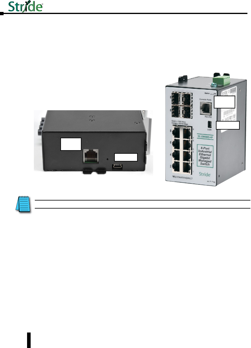
USB Console Port Wiring
The managed switches also have an USB port alternative to the RS232 port. Use a standard
USB cable with a mini-USB plug on one end and an A-type-USB plug on the other end. The
A-type plug goes into a standard USB port on a computer. The mini-USB plug goes into the
USB port on the switch.
The USB driver is available for download at automationdirect.com.
NOTE: The RS-232 and/or USB ports may be located on the bottom edge or front face of the switch.
1-30
Chapter 1 - Hardware
Stride Industrial Ethernet Switches User Manual 2nd Ed. Rev. B
RS232
RJ45F
Mini-USB
RS232
RJ45F
Mini-USB

Technical Specifications
Technical Specs
Here are the hardware technical specifications for the industrial Ethernet switches and media
converters covered by this manual.
Technical Specifications continued on the next page.
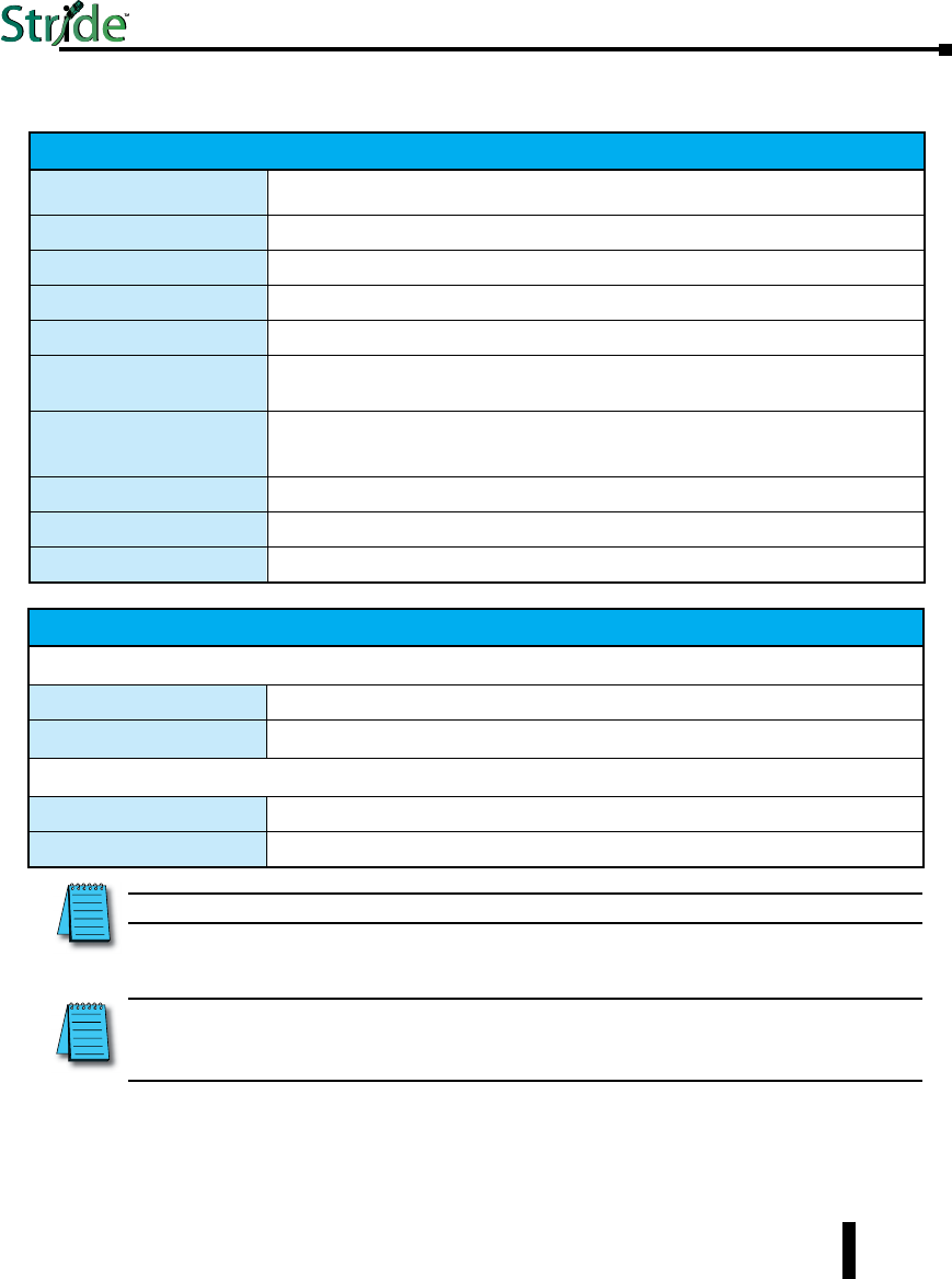
General Specifications
Ethernet switch type Unmanaged or Managed
Operating mode Store & forward, wire speed switching, non-blocking
Devices supported All IEEE 802.3 compliant devices are supported
Protocols
(managed models only)
SNMPv1/v2/v3, RMON, DHCP, SNTP, TFTP, STP, RSTP, QoS/CoS/ToS/DS, IGMPv1/v2,
VLAN (tag and port based), HTTP, HTTPS (SSL & TSL), Telnet, SSH and more
Industrial Protocols supported Modbus/TCP, EtherNet/IP, PROFInet, Foundation Fieldbus HSE and others
Standards
(depends on model) IEEE 802.3, 802.3u, 802.3ab/z, 802.3x, 802.1D/w, 802.1p, 802.1Q and others
Management Interfaces
(managed models only)
Web, text (Telnet & SSH), CLI (command line
interface) and SNMP (see Chapter 2 - Managed Switch Software for supported MIBs)
MAC addresses 1024 on unmanaged models;
2048 on managed models with 5, 8 or 9 ports
8192 on Gigabit models with more than 9 ports
Memory bandwidth 3.2 Gbps on models with 9 or fewer ports
3.2 Gbps on models with more than 9 ports
Latency for 10 Mbps ports* 16 us + frame time (typical)
Latency for 100 Mbps ports* < 5 us + frame time (typical)
Ethernet isolation 1500 VRMS 1 minute
Management Serial Port
(managed models only) RS232 (TXD, RXD and GND), 9600, 8, N, 1 fixed and/or mini-USB
* Varies on load and settings
1-31
Chapter 1 - Hardware
Stride Industrial Ethernet Switches User Manual 2nd Ed. Rev. B

Technical Specifications (cont’d)
Technical Specifications continued on the next page.
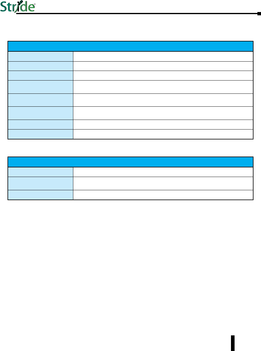
Copper RJ45 Ports: (10/100 Mbps or 10/100/1000 Mbps)
Copper Ports Shielded RJ45
Speed 10/100 Mbps or 10/100/1000 Mbps (depending on model)
Protocols supported All standard IEEE 802.3
Auto-crossover Yes, allows you to use straight-through or crossover wired cables
Auto-sensing operation Yes, Full and half duplex
Auto-negotiating Yes, 10BaseT and 100BaseT
Auto-polarity Yes, on the TD and RD pair
Flow control Automatic
Ethernet isolation 1500 VRMS 1 minute
Plug and play Yes
Cable requirements Twisted pair (Cat. 5 or better) (shielded recommended)
Max. cable distance 100 meters (328 ft)
1-32
Chapter 1 - Hardware
Stride Industrial Ethernet Switches User Manual 2nd Ed. Rev. B
Technical Specifications (cont’d)
NOTE: Refer to SFP module specifications for details specific to the SFP installed.
NOTE: When powering multiple switches from a common power supply, it is most reliable to power the switches
sequentially rather than simultaneously. The characteristics of the power supply and the significant startup current of the
switches may result in an error in booting the switches when powered simultaneously.
SFP (Small Form Factor pluggable) Ports
Note: On the Gigabit (MG) models these ports are pluggable and accept any SFP Multi-Source Agreement compliant transceiver.
Gigabit SFP ports 2 or 4 depending on model
Port Types Supported All SFP Multi-Source Agreement compliant transceivers
Note: 100 Mbps fiber transceiver modules are also supported on these ports.
Ethernet Compliance 1000BaseT and 1000BaseF (SX/LX/LH)
Eye safety IEC 60825-1, Class 1; FDA 21 CFR 1040.10 and 1040.11
SC or ST Fiber Ports: 100BaseF multimode
100BaseFX ports 1 on some unmanaged switch models
2 on some managed switch models
Fiber port mode Multimode (mm)
Fiber port connector Duplex SC or ST
Optimal fiber cable 50/125 or 62.5/125 µm for mm; 9/125 µm for sm
Center wavelength 1300 nm
Multimode Links up to 4 km typ.; 1300 nm; use with 50 or 62.5/125 um fiber
> Transmitter power (dB): -21 min, -17 typ, -14 max
> Receiver sensitivity (dB): -34 typ, -31 max
Nominal max. distance
(full duplex)
(see web for details)
4 km
Half and Full Duplex Full duplex
Ethernet Compliance 100BaseF
Eye Safety IEC 60825-1, Class 1; FDA 21 CFR 1040.10 and 1040.11
1-33
Chapter 1 - Hardware
Stride Industrial Ethernet Switches User Manual 2nd Ed. Rev. B

Stride Industrial Ethernet Switches User Manual 2nd Ed. Rev. B
Chapter 1 - Hardware
Technical Specifications (cont’d)
1-34
“OK” Alarm Output (Managed models only)
“OK” Output ON if P1 and P2 have power and switch software is running
Voltage Same as switch input voltage
Maximum Current Output 0.5 Amp
Power Input
Power Input Redundant Input Terminals
Input power (typical with
all ports active at 100
Mbps)
SE-MC2U-SC - 2.0W
SE-MC2U-ST - 2.0W
SE-SW5U - 2.0W
SE-SW5U-WT - 2.0W
SE-SW5U-SC - 3.0W
SE-SW5U-SC-WT - 3.0W
SE-SW5U-ST - 3.0W
SE-SW5U-SC-WT - 3.0W
SE-SW8U - 4.0W
SE-SW8U-WT - 4.0W
SE-SW9U-SC - 5.0W
SE-SW9U-SC-WT - 5.0W
SE-SW9U-ST - 5.0W
SE-SW9U-ST-WT - 5.0W
SE-SW5M - 3.6W
SE-SW5M-2SC - 5.6W
SE-SW5M-2ST - 5.6W
SE-SW8M - 4.3W
SE-SW8M-2SC - 6.3W
SE-SW8M-2ST - 6.3W
SE-SW8MG-4P - 12.0W - No Fiber
SE-SW8MG-4P - 15.0W - With 4 Fiber plugged in
SE-SW10MG-2P - 5.0W - No Fiber
SE-SW10MG-2P - 7.0W - With 4 Fiber plugged in
SE-SW16M - 7.0W
Input Voltage (all models) 10-30 VDC (continuous)
Reverse Power Protection Yes
Transient Protection 15,000 watts peak
Spike Protection 5,000 watts (10x for 10 uS)
Stride Industrial Ethernet Switches User Manual 2nd Ed. Rev. B
Technical Specifications (cont’d)
1-35
Mechanical
Ingress Protection IP30 for all plastic cased units. IP40 for all metal cased units.
Packaging and Protection UL94V0 Lexan plastic for all plastic cased units.
Aluminum w/ protective finish for all metal cased units.
Dimensions (L x W x H) See mechanical drawings for details
Environmental
Storage Temperature Range -40 to +85 °C (-40 to +185 °F)
Humidity (non-condensing) 5 to 95% RH
Electrical Safety UL508/CSA C22, EN61010-1, CE
EMC: emissions and
immunity
FCC part 15, ICES-003;
EN61000-6-2, EN61000-6-4 Typical 8 or 9/125 µm for singlemode (sm)
Hazardous Locations UL HazLoc, CSA C22.2/213 (Class I, Div.2) ;
EN60079-15 (Zone2), CE (ATEX)
Eye Safety (fiber models) IEC60825-1, Class 1; FDA 21 CFR
1040.10 and 1040.11
RoHS and WEEE RoHS (Pb free) and WEEE compliant
ISO9001:2000 Certified “Total Quality” company

Managed swiTCH
QuiCk sTarT 2
2
2
Chapter
Chapter
Chapter
In This Chapter...
Connecting to the Switch for the first time ...............................2–2
Connecting to the switch over Ethernet: .................................2–2
Setting up PC for USB connection to switch: .............................2–7
PC to switch using Serial Port: .........................................2–8
USB and Serial connection to switch with Terminal Software Program: ..........2–9
Default Setup ......................................................2–13
Why might you need a Managed Switch? ...............................2–16
Enhanced traffic filtering: ............................................2–16
Troubleshooting: ..................................................2–16
Redundancy: .....................................................2–16
Security: . . . . . . . . . . . . . . . . . . . . . . . . . . . . . . . . . . . . . . . . . . . . . . . . . . . . . . . . . 2–17
Better Network ‘Awareness’: ..........................................2–18
Connecting to the Switch for the first time
Connecting to the switch over Ethernet:
Connecting to the switch for the first time over Ethernet requires no extra tools or driver
installation and is, therefore, the recommended way to accomplish this.
The default IP address and subnet mask of the switch is 192.168.0.1 and 255.255.255.0.
This means that your PC’s network interface card (NIC) that is connected to the switch
must be set to a compatible IP address and subnet mask to access the web-based switch
configuration tool. It is recommended that you connect your PC directly to the switch for
the initial setup of the network settings. An example IP address and subnet mask to set your
PC’s network interface to is 192.168.0.100 and 255.255.255.0.
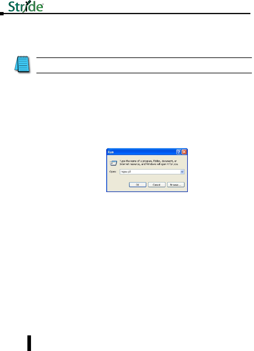
1. Go to the Start Button and click on “Run” (if you do not see a “Run” option, type Run in the
search box and hit Enter). Type in ncpa.cpl and hit OK.
NOTE: See Setting up PC for USB connection to Switch later in this chapter for the option of using USB for switch
connection.
Stride Industrial Ethernet Switches User Manual 2nd Ed. Rev. B
Chapter 2 - Managed Switch Quick Start
2-2
Stride Industrial Ethernet Switches User Manual 2nd Ed. Rev. B
Chapter 2 - Managed Switch Quick Start
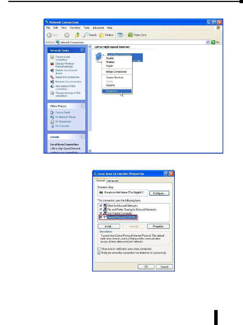
2. Right click on the Network Interface that is connected to your switch and choose Properties.
3. Scroll down and highlight the “Internet Protocol Version 4 (TCP/IPv4)” selection and click on the
Properties button.
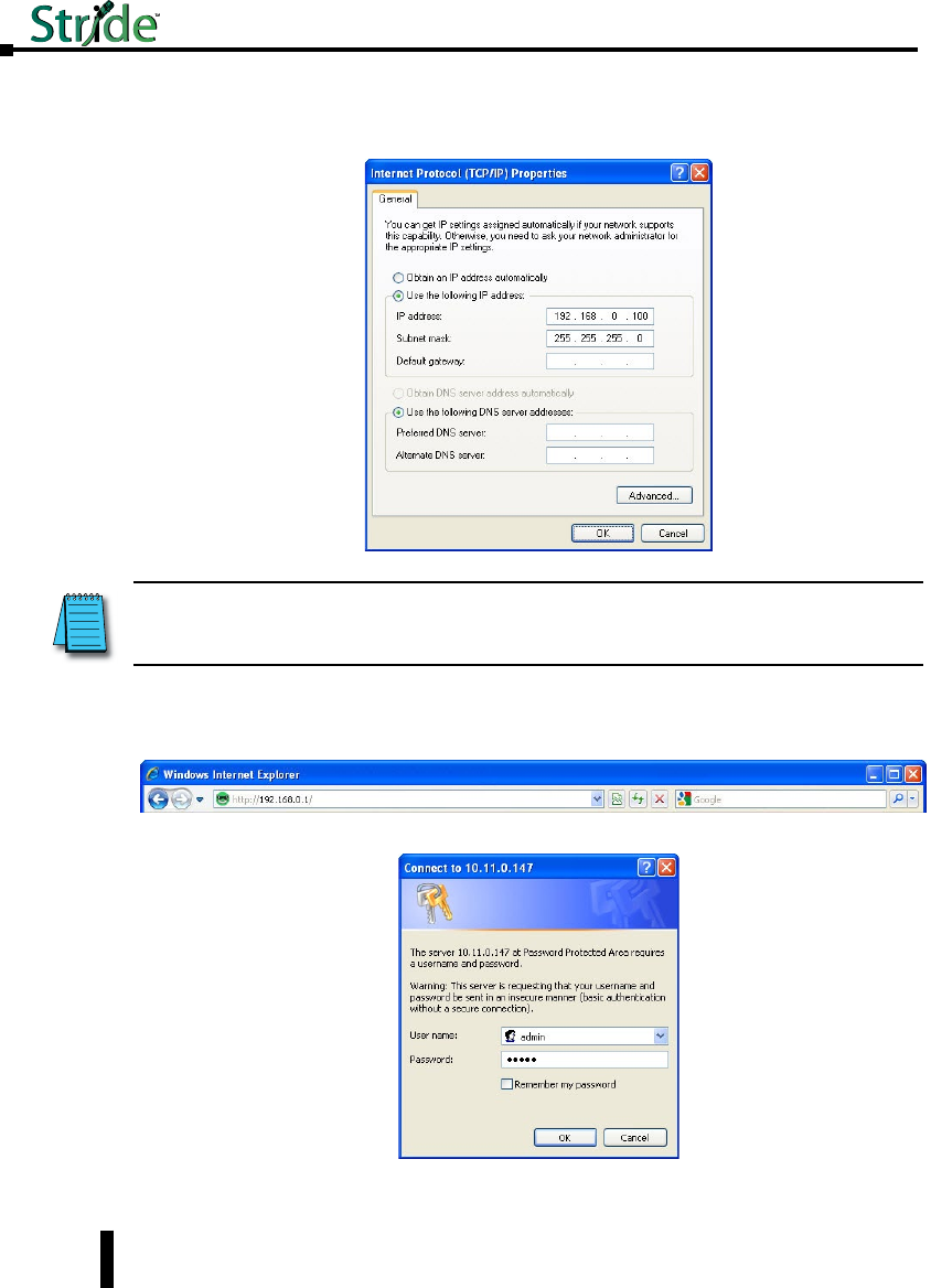
4. Write down the current settings so that you may put them back in after configuring the Network
settings of the switch to a compatible setup for your environment.
2-3
Stride Industrial Ethernet Switches User Manual 2nd Ed. Rev. B
Chapter 2 - Managed Switch Quick Start
5. Type in the IP address and subnet mask of 192.168.0.100 and 255.255.255.0 or another
compatible IP address and subnet mask. Click on the OK button. Click on the OK button for
the Network Interface Properties window and close the Network Connections window.
6. Open up your web browser program such as Internet Explorer, Mozilla Firefox or other and type
in 192.168.0.1 in the URL line.
7. Enter in admin for the User name and admin for the password and click on OK.
NOTE: Neither the Network Address nor the Broadcast Address for you subnet are valid host addresses. For our
example that has a Subnet Mask or 255.255.255.0 and the first three octets are 192.168.0, neither the pc nor the switch
are permitted to be assigned 192.168.0.0 or 192.168.0.255 as an IP address.
2-4

Stride Industrial Ethernet Switches User Manual 2nd Ed. Rev. B
Chapter 2 - Managed Switch Quick Start
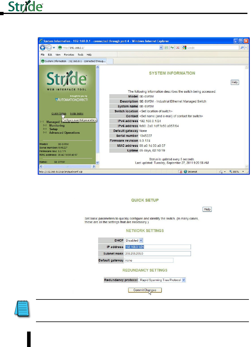
8. Read the Software License Agreement and click the “I Accept the License” button.
2-5
Stride Industrial Ethernet Switches User Manual 2nd Ed. Rev. B
Chapter 2 - Managed Switch Quick Start
9. Click on the “Quick Setup” link on the upper left hand side of the window to access the Network
Settings.
10. Enter in the desired IP address and subnet mask that is compatible with the network that the
switch will go on or enable DHCP if that is the method you choose to assign the network
settings. Click on the “Commit Changes” button to enable the new settings.
NOTE: Neither the Network Address nor the Broadcast Address for you subnet are valid host addresses. For our
example that has a Subnet Mask or 255.255.255.0 and the first three octets are 192.168.0, neither the pc nor the switch
are permitted to be assigned 192.168.0.0 or 192.168.0.255 as an IP address.
2-6

Stride Industrial Ethernet Switches User Manual 2nd Ed. Rev. B
Chapter 2 - Managed Switch Quick Start
11. Return to steps 1 – 4 to put in the original network settings for your PC.
12. Connect your PC and the switch to the network and enter in the new IP address into your web
browser URL to access the switch. If you chose DHCP as the method for assigning the network
settings to your switch, you will need to contact the network administrator to see which IP
address has been assigned to the switch or connect via USB or serial (explained further down in
this document) to ascertain what the IP address is on the switch.
13. Now that you can access the switch, you may begin to configure the switch with the settings
appropriate for your network. If you are unsure of where to start with the configuration, go
the section titled, “Why do you need a managed switch?” to understand more about the Stride
managed switch, its capabilities and how these features can be used. Note that the default
settings enable RSTP and IGMP which will be adequate for many networks with no further
configuration.
Setting up PC for USB connection to switch:
This method can be used to initially configure the switch settings. It may also be needed
if the switch has been previously configured and the network settings are unknown. If the
switch has been set to DHCP, this method can be used to ascertain the current IP address
that has been assigned to the switch by the DHCP server.
Three things will be required in order to connect to the switch via the USB port:
1. USB driver: This can be obtained from www.automationdirect.com. Download the executable and
run it to install the driver.
2. Cable: The cable required is a Male-A connector (plugs into PC) to Male Mini B-type (5 pin)
connector (plugs into switch).
3. Terminal software tool: Hyperterminal used to come pre-installed in Windows until Windows
Vista and 7 were released. TeraTerm is another tool that can be downloaded and installed for free.
After the USB driver EXE file has been downloaded and run, plug the USB cable into the PC
and switch.
Windows will install the driver. If the New Hardware Wizard appears, select the “No, not
this time” selection and click Next. On the following screen, select the “Install Software
automatically” option and click Next. Once the driver is loaded, you may get prompted by
a window that says the driver has not been verified by Windows. Click on the “Continue
Anyway” button to complete the installation.
2-7
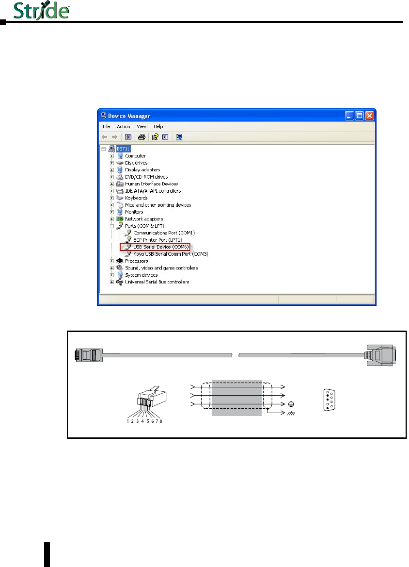
Stride Industrial Ethernet Switches User Manual 2nd Ed. Rev. B
Chapter 2 - Managed Switch Quick Start
To locate which COM Port has been assigned to the switch, click on “Start” menu in the
PC taskbar and choose “Control Panel”. Double click on the “System” icon. Select the
“Hardware” tab.
Click on the “Device Manager” button and then expand the “Ports (COM & LPT)” option
on the left hand side and you should see a “USB Serial Device” with a COMxx beside it.
This will be the COM port number that you will select with your Terminal software tool.
PC to switch using Serial Port:
Serial Configuration Cable
Switch RJ-45
Serial Port
PC Serial Port
6
1 = do not use
2 = RXD
3 = TXD
4 = do not use
5 = Signal GND
6 = do not use
7 = do not use
8 = do not use
9 = do not use
5
4
TXD
RXD
GND
2
3
5
1
RXD
TXD
shield
Wiring Diagram
Note: Use the above wiring diagram to make your own cable. We recommend using 22 AWG shielded cable.
1 = do not use
2 = do not use
3 = do not use
4 = Signal GND
5 = RXD
6 = TXD
7 = do not use
8 = do not use
RJ45 8-pin
Phone Plug
(8P8C)
9-pin
D-sub
(female)
1
9
In addition to the USB console port, the switches have an RJ45 console port. The RJ45
console port can connect to a -pin serial port on your PC. A driver does not need to be
installed.
2-8
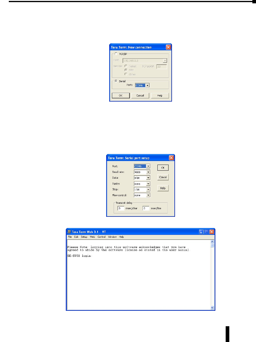
Stride Industrial Ethernet Switches User Manual 2nd Ed. Rev. B
Chapter 2 - Managed Switch Quick Start
USB and Serial connection to switch with Terminal Software Program:
The software terminal program used for this tutorial will be TeraTerm. Any serial terminal
software should work fine. TeraTerm is free and can be downloaded from www.teraterm.org.
1. Open the TeraTerm software and choose Serial and the COM port connected to the switch.
2. Configure the terminal program to connect to the switch with the following parameters:
a. Baud rate: 9600
b. Data bits: 8
c. Parity: None
d. Stop bits: 1
e. Flow control: None
3. Press Enter to get the prompt shown below.
2-9
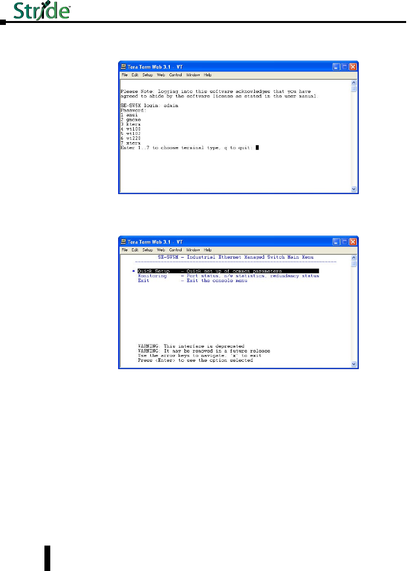
Stride Industrial Ethernet Switches User Manual 2nd Ed. Rev. B
Chapter 2 - Managed Switch Quick Start
4. Enter the login, then the password. The default user name is admin and the default password is
admin.
5. Choose selection 4 for vt100.
6. Highlight (by using the up and down arrow keys on the PC keyboard) the “Quick Setup” option
and press Enter.
7. To enable DHCP, highlight the DHCP option and press Enter. Arrow down and choose the
Enable option and press Enter. Press the c key to commit the change.
8. To set a static IP address, arrow down and highlight the “IP address” option and press Enter.
2-10
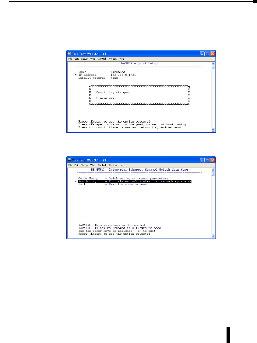
Stride Industrial Ethernet Switches User Manual 2nd Ed. Rev. B
Chapter 2 - Managed Switch Quick Start
9. Enter in the desired IP address and subnet mask. Note that the subnet mask is configured using,
what is called CIDR notation. The “/xx” number denotes how many 1’s are in the subnet mask
starting from the most significant bit. A /24 indicates a subnet mask of 255.255.255.0. A /16
indicates a subnet mask of 255.255.0.0 and a /8 indicates a subnet mask of 255.0.0.0. Once the
IP address and subnet mask have been configured, press Enter. Press the c key to commit this
change and to activate the new IP address for the switch.
10. If the switch has been configured to obtain an IP address from a DHCP server, you can also view
the IP address that is currently assigned to the switch by hitting ESC to go back to the main
menu. Arrow down and highlight the “Monitoring” option and press Enter.
2-11
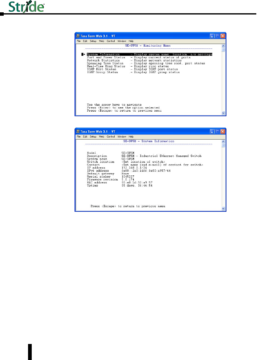
Stride Industrial Ethernet Switches User Manual 2nd Ed. Rev. B
Chapter 2 - Managed Switch Quick Start
11. Highlight the first option called, “System Information” and press Enter.
12. The IP address currently assigned to the switch will be shown here.
You are now able to use your web browser with the new IP address to configure the switch.
2-12

Stride Industrial Ethernet Switches User Manual 2nd Ed. Rev. B
Chapter 2 - Managed Switch Quick Start
Default Setup
The table below shows the Default settings for the switch:
Stride Managed Switch Default Settings
Configuration Parameter Default Setting
Main Settings
System Settings
DHCP Disabled
IP Address 192.168.0.1
Subnet Mask 255.255.255.0
Default Gateway none
Primary DNS Server none
Secondary DNS Server none
Domain
Redundancy Protocol Rapid Spanning Tree Protocol
System Name Switch model (i.e. SE-SW8MG-4P)
Switch Location <Set Location of Switch>
Contact <Set Name (and email) of contact for Switch>
Remote Access Security
SNMP Access Basic and secure SNMP access
Terminal Access SSH and telnet access
Web Access Basic and secute SNMP access
SNMP Firmware Loading Disabled
Command Line Access Enabled
Automatic Logout Disabled
SNMP Read-Only Name: public No Password
SNMP Read/Write Name: private No Password
Terminal and Web Name: admin Password: admin
Port Settings
Name port x (x being port number)
Admin Enabled
Negotiation Auto
Speed/Duplex For non Gigabit Switches: 10h,10f,100h,100f all on
For Gigabit Switches: 10h,10f,100h,100f,1000f all on
Flow Control Off
SFP 1000f selected
Set IP per Port
Provide/Do Not Provide IP Do not provide IP address to any device
Enabled Off for all ports
Address blank for all ports
Switch Time Settings
NTP Server none
Timezone Not set
Set Switch Date 1970-01-01
Set Switch Time current time
Manage Firmware Default Top line selected
Install Firmware Protocol HTTP
All Other Fields blank
2-13

Stride Industrial Ethernet Switches User Manual 2nd Ed. Rev. B
Chapter 2 - Managed Switch Quick Start
Stride Managed Switch Default Settings (cont’d)
Configuration Parameter Default Setting
Redundancy Settings
Spanning Tree Settings
Redundancy Protocol Rapid Spanning Tree Protocol
Bridge Priority 32768
Maximum Age 20
Hello Time 2
Forward Delay 15
Transmission Limit 6
Region Name
Configiguration Revision 0 (grayed out)
Max Hops 20 (grayed out)
MST Instance None by default
Spanning Tree Port
Settings
Exclude Off for all ports
Priority 128 for all ports
Path Cost 20000 for all 10 / 100 / 1000 Ports,
200,000 for all 10 / 100 ports
Type Auto for all ports
Point-to-Point Auto for all ports
Real-time Ring Settings
Enable Off for all ports
Ring Name Ring x (x being port number) Grayed out by default
Primary Port none
Backup Port none
Ring Master Automatic Master
Settings
QoS/CoS Settings
Priority Frame Setting Send all high priority fames before any others
Use 802.1p Tag Priority On for all ports
Use IP ToS/DiffServ On for all ports
Priority Precedence Tag for all ports
Default Out Q Normal for all ports
Type Transparent for all ports
802.1p Tag Settings
Priority 0 (Best Effort) Normal
Background
Priority 2 (Spare) Background
Priority 3 (Excellent Effort) Normal
Priority 4 (Controlled Load) Expedited
Priority 5 (Video) Expedited
Priority 6 (Voice) Urgent
Priority 7 (Network Control) Urgent
Message Rate Limiting
Limit Broadcast and
Multicast Disabled for all ports
Forward Unknown Enabled for all ports
2-14

Stride Industrial Ethernet Switches User Manual 2nd Ed. Rev. B
Chapter 2 - Managed Switch Quick Start
Stride Managed Switch Default Settings (cont’d)
Configuration Parameter Default Setting
Multicast Filtering
(IGMP)
Protocol Settings
IGMP Mode Active IGMP handling
Multicast Suppression All unreserved multicast
IGMP Version Version 2
Robustness 2
Query Interval 125
Query Response Interval 10
Port Settings Exclude Disabled for all ports
Router Auto detect for all ports
Virtual LANs
(VLANs)
VLAN Settings
VLAN Mode Disabled
Core Type 0x8100
Learning Shared
Default VLAN Settings Management: Tag-Based, ID=1, FID=0, CPU selected
as well as all ports
VLAN Port Settings
PVID 1
Force Off for all ports
Type Transparent for all ports
Security Settings
Remote Access Security Same settings as in Main
Settings
Port Security Enables Global Security Enable Off
Port Enabled Off for all ports
Port Security MAC Entries Entry None
Ipsec Settings Disabled by default
IKE Policy
IKE Phase 1 Policies None
IKE Phase 2 Policies 1 by default but Disabled with 8h lifetime (anonymous
source and dest)
IKE Phase 2 Algorithms
Cipher aes (AES Rijndael) Enabled
Cipher 3DES Enabled
Hash hmac_SHA1 Enabled
Hash hmac_SHA256 Enabled
Compression deflate Enabled
All others disabled
Monitoring Settings
Alarm (OK) Output A power input lost enabled
All others disabled
Modbus
Enabled Disabled
Station Number 1
Transport Layers TCP & UDP
TCP Timeout 0
TCP Connection Limit 4
Port 502
SNMP Notifications Everything disabled by
default
2-15

Stride Industrial Ethernet Switches User Manual 2nd Ed. Rev. B
Chapter 2 - Managed Switch Quick Start
Why might you need a Managed Switch?
Enhanced traffic filtering:
An unmanaged switch will filter out many packets from an end device that a hub would not
but there are still many types of packets that an unmanaged switch cannot determine what
to do with and must forward on to all ports. Whenever a device receives a packet that is not
specifically targeted to that device, there is a certain amount of processing time that takes
away from other important tasks that the device may really need to be spending time on.
These ‘unintentional’ packets also get in the way of the packets that are intended for that
device. This hurts the determinism of a process. A managed switch can help with this in
several different ways:
• Multicast Filtering (IGMP): It is common in a control system to see a large amount of Multicast
packets. These packets cannot be filtered out by an unmanaged switch. The Stride managed switch
can intelligently ‘learn’ whether certain Multicast packets should be sent to the devices on its ports
and will filter them or not filter them appropriately.
• VLANs: A VLAN is a logical way to separate networks in ways that used to require physical
separation. Because of existing network infrastructure or for ease of wiring (and reduced cost), it
may be difficult to physically separate networks that need separation due to the type of packets that
are on them. Setting up VLANs can simplify the setup for these situations.
• Traffic Priority (QoS/CoS): Some traffic may be more important to a specific device than other
traffic. Using the Quality of Service feature, the Stride switch can apply tags to a packet coming
into the switch to give that packet a higher priority going to another switch. The last switch will
then remove the tag before sending the packet to the device. It can also use the tags applied to the
packets by the devices themselves if they support this.
Troubleshooting:
As Ethernet messaging becomes more of the standard for communications between devices
in a control system, it may become more necessary to gain visibility to these types of
communications. With hubs, it was possible to see the messages between devices because
hubs broadcast every packet to all ports. Unmanaged switches took away this capability as
they filter unicast packets to only the intended physical ports. Managed switches can help
with this by utilizing the Port Mirroring feature. The Stride managed switch can also give
you visibility in to the type of packets that are being sent across the switch by viewing the
Network Statistics page in the configuration.
• Port Mirroring: With the Port Mirroring feature you simply specify which ports’ data you want to
view and where to send that data. Plug your PC into that port and use Ethernet sniffing software
(such as Wireshark) and you can now see the data being sent back and forth.
• Network Statistics: By looking at what kind of packets that are coming in and out of the switch,
you can determine what action needs to be taken to make your network work better. If you see a
lot of Multicast traffic, utilize the Multicast Filtering feature. If there are lots of broken packets,
troubleshoot the wiring to determine where the problem lies.
Redundancy:
The downside of any Ethernet switch is the simple fact that it is another electronic
component in the system that could be subject to failure. There is also the risk that as a
network grows and more switches are added to it, a ‘ring’ may accidentally be created causing
2-16

Stride Industrial Ethernet Switches User Manual 2nd Ed. Rev. B
Chapter 2 - Managed Switch Quick Start
the network to go down. Utilizing the Spanning Tree and/or Real-Time Ring feature of the
Stride managed switch can reduce these risks.
• STP: The Spanning Tree protocol simply allows you to purposely create a ring that allows for
multiple, redundant paths on the network but intelligently decides one path when the network
comes up and assigns alternate paths if some part of the original path goes down.
• RSTP: The Rapid Spanning Tree Protocol is the preferred method in the industry today as the
manner in which it decides the original paths and the time in which it changes over to alternate
paths is much, much faster than the original Spanning Tree Protocol. It is really only useful to
enable the older STP if your legacy network requires this protocol. The RSTP feature is enabled by
default.
• Real-Time Ring: In many Control Systems, the time it takes for the RSTP algorithm to change
paths upon some network event is too slow. The Real-Time Ring is proprietary to the Stride
managed switches but it has the advantage of changing paths very, very quickly.
Security:
Network security has become a great concern for facilities these days. And while the network
devices themselves are only one part of a network security strategy, the Stride managed
switches have several security features:
• Port Control: In the “Port Settings” setup, you can disable ports that are not being used. This can
limit unauthorized access.
• Security Settings: There are several different methods of enabling security in the switch. There
are security methods to prevent access to the switch (Remote Access Security), you can determine
which devices can connect to the switch (Port Security MAC Entries) and you can enable
encryption for data going between switches (IPsec).
• Remote Access Security: You can disable access to the switch or implement secure pass-wording in
order to access the switch.
• IPsec: There are many different methods that can be employed to encrypt the data going to
or from the switch. The particular method (encryption protocol/algorithm) will most likely be
determined by your network administrator.
2-17

Stride Industrial Ethernet Switches User Manual 2nd Ed. Rev. B
Chapter 2 - Managed Switch Quick Start
Better Network ‘Awareness’:
The ability of the process to know when something is wrong with the network and what
is wrong with the network is a great feature of the Stride managed switches. Your PLC or
controlling device can make ‘smarter’ decisions as to what alarms or fallback behavior to
trigger based upon the different diagnostic data that is supplied by the switch.
• Modbus Stats: If you have a controlling device on the network that has Modbus TCP or UDP
client capability, there are several diagnostic tags that can be read from the switch to indicate the
health of the network.
• SNMP: SNMP stands for Simple Network Management Protocol and is used for just that. There
are many software tools out there that can query or receive ‘traps’ sent by the Stride managed switch
to ascertain events or health of the switch.
• Port and Power Status (Alarm Output): The Stride managed switch has two power inputs that
can be used for redundancy. If one of the power inputs fails, there is a relay contact that can be
configured to report this failure.
• Spanning Tree Status: The switch can be configured to report when something in the Spanning
Tree has changed.
• Real-Time Ring Status: The Real-Time Ring status can be ascertained from other devices as well.
• MAC Table: The switch keeps a table of the MAC IDs of devices that are communicating on it
2-18

Managed swiTCH
sofTware MoniToring
In This Chapter...
System Information ..................................................3–2
Port and Power Status ................................................3–4
Network Statistics ...................................................3–5
Spanning Tree Status ................................................3–8
Real-Time Ring Status ...............................................3–10
Multicast Filtering Status .............................................3–11
IGMP Port Status: .................................................3–11
IGMP Group Status: ................................................3–12
MAC Table . . . . . . . . . . . . . . . . . . . . . . . . . . . . . . . . . . . . . . . . . . . . . . . . . . . . . . . .3–13
Configuration Summary .............................................3–14
2
3
3
Chapter
Chapter
Chapter

System Information
The System Information screen simply provides the information shown below. The screen is
updated every five seconds.
Model: This field shows the model number of this particular switch. It is set by the factory
and cannot be changed.
Description: This field displays more descriptive information about this particular switch
model. It is also set by the factory and is not changeable. This data is available via SNMP as
SYSTEM.SYSDESCR.0.
System Name: This field is configured by the user with the appropriate text for their
application. It is configured in the “System Settings” tab under the Main Settings section.
This field is also used as the hostname of the switch and, therefore, must contain only digits,
dashes and letters. It is also available via SNMP as SYSTEM.SYSNAME.0.
Switch Location: This field is configured by the user with the appropriate text for their
application. It is configured in the “System Settings” tab under the Main Settings section.
This data is available via SNMP as SYSTEM.SYSLOCATION.0.
Contact: This field is configured by the user with the appropriate text for their application.
It is configured in the “System Settings” tab under the Main Settings section. This data is
available via SNMP as SYSTEM.SYSCONTACT.0.
IPv4 address: This field displays the current configured IPv4 address. IPv4 is the traditional
4 octet Internet Protocol address. An IPv4 address comprises 4 8-bit numbers separated
by a period. Each number can be between 0 and 255 (some of the fields have more strict
Stride Industrial Ethernet Switches User Manual 2nd Ed. Rev. B
Chapter 3 - Managed Switch Software Monitoring
3-2

Stride Industrial Ethernet Switches User Manual 2nd Ed. Rev. B
Chapter 3 - Managed Switch Software Monitoring
limitations). The IPv4 address can be manually configured in the “System Settings” tab
under the Main Settings section or the address can be set to be automatically retrieved
using the DHCP protocol. If the address has been configured via DHCP, it will indicate
this. This field also indicates the Subnet Mask by using the ‘slash’ notation that indicates
the number of bits that are 1 in the mask. For example: A Subnet Mask of 255.255.0.0
would be indicated by a /16. A Subnet Mask of 255.255.255.0 would be indicated by a
/24 and so on. The subnet mask is accessible via SNMP as RFC1213-MIB::IPADENT-
NETMASK.<IPADDRESS> where <IPADDRESS> is the IP address of the switch (example:
192.168.0.1).
IPv6 address: This field displays the current configured IPv6 address. IPv6 is the newer
standard of Internet Protocol addressing that greatly expands the number of addressing
possibilities. Instead of the standard 4 x 8-bit address format that is used IPv4, IPv6 uses
8 fields of 16 bit values separated by colons. Each address display in hex format. If one
particular fields contains a 0, a :: can be used. An IPv6 address can also be retrieved by
DHCP. This field also uses the / designator for the subnet mask.
Default Gateway: This field contains the IP address of the router that this switch should
send external packets to. This address can be assigned manually in the “System Settings”
tab under the Main Settings section or can be retrieved automatically through DHCP. The
default gateway is accessible via SNMP as RFC1213-MIB::IPROUTENEXTHOP.
Serial Number: This is the serial number assigned to this switch at the factory and cannot be
changed.
Firmware revision: This is the current running firmware revision of this switch.
MAC address: This is the MAC address of this switch. It is configured at the factory and
cannot be changed.
Uptime: This is the amount of time this switch has been running since power was applied.
This data is available via SNMP as SYSTEM.SYSUPTIME.0.
3-3

Stride Industrial Ethernet Switches User Manual 2nd Ed. Rev. B
Chapter 3 - Managed Switch Software Monitoring
Port and Power Status
The current status of each port and the Power and Ok terminal status can be viewed in this
section.
Port Status: The status for each port can be viewed in this section. Some of the information
shown for the ports is configured through the “Port Settings” tab of the Main Settings
section. If the negotiation settings have been set to Auto, this tab will show what settings
were negotiated between the switch and the attached device. On this page, the color
highlighting the port number indicates the speed:
Yellow = 10 Mbps
Green = 100 Mbps
Red = 1000 Mbps
Power Status: There are 2 power input terminals for the input 24VDC. This tab will show
which terminals have power. This tab will also show if the criteria for enabling the OK
output is true or false. The configuration for this output is configured in the “Alarm (OK)
Output” tab of the Monitoring Settings section.
3-4
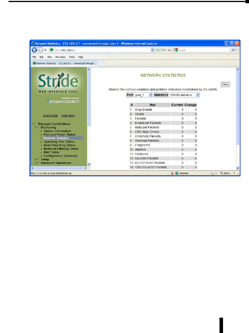
Stride Industrial Ethernet Switches User Manual 2nd Ed. Rev. B
Chapter 3 - Managed Switch Software Monitoring
Network Statistics
The Network Statistics display can be a very useful diagnostic tool for indication of the type
of traffic and packets that the switch is receiving.
RMON Statistics: RMON stands for “Remote Monitoring” statistics and includes the
following:
• Drop Events = The number of packets that have been dropped by the switch because of a lack of
resources and/or large queues.
• Octets = The number of data 8-bit units received into this port.
• Packets = The number of Ethernet packets received into this port.
• Broadcast packets = The number of broadcast packets received into this port.
• Multicast packets = The number of multicast packets received into this port.
• CRC Align errors = The number of Ethernet packets received into this port with an invalid CRC.
• Undersize packets = The number of Ethernet packets received into this port that were less than 64
bytes in size but contained a valid CRC (64 bytes is the minimum required in Ethernet).
• Oversize packets = The number of Ethernet packets received into this port that were greater than
1536 bytes in size but contained a valid CRC (1536 is the maximum size allowed in Ethernet).
• Fragments = The number of Ethernet packets received into this port that were less than 64 bytes in
size and did not contain a valid CRC.
• Jabbers = The number of Ethernet packets received into this port that were greater than 1536 bytes
in size and did not contain a valid CRC.
• Collisions = The number of collisions detected on this port.
3-5
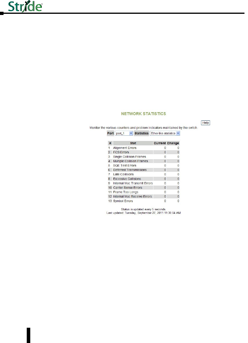
Stride Industrial Ethernet Switches User Manual 2nd Ed. Rev. B
Chapter 3 - Managed Switch Software Monitoring
• 64-octet Packets = The number of Ethernet packets received into this port that were 64 bytes in
length.
• 65 – 127-octet Packets = The number of Ethernet packets received into this port that were between
65 and 127 bytes in length.
• 128 – 255-octet Packets = The number of Ethernet packets received into this port that were
between 128 and 255 bytes in length.
• 256 – 511-octet Packets = The number of Ethernet packets received into this port that were
between 256 and 511 bytes in length.
• 512 – 1023-octet Packets = The number of Ethernet packets received into this port that were
between 512 and 1023 bytes in length.
• 1024 – 1518-octet Packets = The number of Ethernet packets received into this port that were
between 1024 and 1518 bytes in length.
Ether-like statistics: The Ether-like statistics provide information on possible hardware,
electrical and/or noise problems on the network.
• Alignment Errors = These errors are more indicative of receiving the improper number of bits.
These errors are a good indication of noise and/or electrical problems. Check the wiring and
routing of cables in the event that many of these errors are seen.
• FCS Errors = This is the error that results from an incorrect CRC calculation. These errors along
with the Alignment Errors indicate noise and/or electrical problems. Check the wiring and routing
of cables in the event that many of these errors are seen.
• Single Collision Frames = This error occurs when only 1 collision occurs and the sending device is
able to send the packet on the subsequent attempt.
• Multiple Collision Frames = This error occurs when collisions occur on more than 1 attempt to
send a packet from a device.
• SQE Test Errors = The Signal Quality Error test verifies that the collision detection circuit is
working correctly. If the device does not detect the SQE test, this causes an error.
3-6

Stride Industrial Ethernet Switches User Manual 2nd Ed. Rev. B
Chapter 3 - Managed Switch Software Monitoring
• Deferred Transmissions = A deferred transmission occurs when the device detects a carrier signal (a
device is already transmitting).
• Late Collisions = In some situations, a collision is not detected until after the Ethernet device has
started transmitting the packet. This is called a Late Collision. A Late Collision is more specifically
defined as a collision that is detected 51.2 microseconds after the device has started sending on a
10BASE-T network and 5.12 microseconds on a 100BASE-T network. Late collisions are usually
caused by improper network configurations, compliance issues between devices, incorrect cabling
and/or fault Network Interface Cards.
• Excessive Collisions = As part of the CSMA/CD mechanism, an Ethernet device will attempt to
re-transmit a frame 16 times if a collision is detected. If the device is unsuccessful after 16 times, it
will give up and that frame will not be transmitted.
• Internal MAC Transmit Errors = This error occurs when frames fail to be transmitted correctly
due to an internal MAC sub-layer transmit error.
• Carrier Sense Errors = This error occurs when the carrier sense is lost during a transmission from
the Ethernet device. The error only increments once during the transmission even if the carrier
sense is lost and regained multiple times during that transmission.
• Frame Too Long = This error occurs when a frame is encountered that exceeds the maximum
frame size.
• Internal MAC Receive Errors = This error occurs when frames fail to be received correctly due to
an internal MAC sub-layer receive error.
• Symbol Errors = These errors occur when the device could not correctly decode a symbol that has
been received. This is usually indicative of bad cabling and/or electrical noise problems. A symbol
is a waveform change on the wire that may contain 1 or many bits of information.
3-7

Stride Industrial Ethernet Switches User Manual 2nd Ed. Rev. B
Chapter 3 - Managed Switch Software Monitoring
Spanning Tree Status
This section shows the current status of the Spanning Tree redundancy feature of the switch.
For more information on the particular details of the Spanning Tree features of the switch,
refer to the “Spanning Tree Settings” section under the “Redundancy Settings” section of this
document.
On this page, the color highlighting the port number indicates the speed:
Yellow = 10 Mbps
Green = 100 Mbps
Red = 1000 Mbps
Redundancy protocol: This is the protocol that the switch has been configured for. The
selections available are Spanning Tree Protocol, Rapid Spanning Tree Protocol or None.
Designated root: This field specifies which device is the Root switch and what the Bridge ID
of that switch is along with the MAC ID.
Topology changes: This counter tracks the number of times that the topology has changed
on the network layout. There are a number of things that can cause the topology to change.
If the link is lost on a port that is forwarding and the switch has to change its path, this will
cause a topology change. If a Topology Change Notice is received by the switch from some
other switch, the counter will also increment.
Time since last chg: Informs how long it has been since the last topology change occurred.
Port: The number of the port. This corresponds to the labels on the switch.
3-8

Stride Industrial Ethernet Switches User Manual 2nd Ed. Rev. B
Chapter 3 - Managed Switch Software Monitoring
Name: The user configured name of the port.
Status: The configured state of the port in the STP protocol (included or excluded). An
included port is part of the managed network. An excluded port will not be used as part
of the managed network. For example, a single uplink from a managed network of factory
devices to a business network would be configured to be excluded from STP use. A pair of
ports configured for Real-Time Ring should be excluded from Spanning Tree.
State: The STP/RSTP state of the port:
STP:
• Blocking = A port in this state does not participate in frame relay (pass frames received to other
locations). Once a port is in this state, it prevents frame duplication caused by multiple paths in an
active topology.
• Listening = A port in this state is about to participate in frame relay, but is not involved in any
relay of frames (no frames will be forwarded). The reason for not entering frame relay immediately
is to ensure that there are no temporary loops introduced when the network topology is changing.
During this state, the switch will disable all learning states on its ports to prevent the race
conditions when ports are changing roles and the forwarding process will discard all frames and not
submit any frames for transmission. Meanwhile BPDUs (Configuration Messages - Bridge Protocol
Data Units) can still be received and forwarded to keep the algorithm running.
• Learning = A port in this state is about to participate in frame relay, but it is not involved in any
relay of frames. Frame relays are not performed to prevent the creation of temporary loops during
the active topology of a changing bridged LAN. In addition, the forwarding process will discard all
frames and not submit any frames for transmission. The reason for enabling learning is to acquire
information prior to any frame relay activities. Information gathered will be used and placed in the
filtering database (MAC table) to reduce the number of frames being unnecessarily relayed.
• Forwarding = A port in the forwarding state is currently participating in frame relay. BPDUs
will include the forwarding port in the computation of the active topology. BPDUs received are
processed according to the Spanning Tree algorithm and transmitted based on the hello time or
BPDU information received.
RSTP:
• Discarding = In this state, station location information is not added to the Filtering Database
(MAC table) because any changes in port role will make the Filtering Database information
inaccurate.
• Learning = In this state, information is being added to the Filtering Database under the assumption
that the port role is not changing. Gathering information before frame relay (forwarding state) will
reduce the number of frames sent out when entering the forwarding state.
• Forwarding = Frames will be forwarded to and from the particular port that is in the forwarding
state. In addition, during the forwarding state, the learning process is still incorporating station
information into the Filtering database.
Cost: The cost of using this port to reach other parts of the managed network. The cost
is used in calculating the best path from the switch to the root bridge. The lower the cost,
the more likely that the path will be used. See the configuration section for Spanning Tree
settings for more detail.
3-9

Stride Industrial Ethernet Switches User Manual 2nd Ed. Rev. B
Chapter 3 - Managed Switch Software Monitoring
Real-Time Ring Status
Each ring that is configured is assigned a number and can be given a name. For more
information on the Real-Time Ring feature, refer to the “Real-Time Ring Settings” section
under the “Redundancy Settings” section of this document.
On this page, green hightlight on the ring number indicates the ring is complete, red
indicates the ring is broken. On the Port, green indicates both ends of the link are connected
and communicating. Red indicates on side of the link is not connected or communicating.
For each ring configured a Primary port is assigned and a Backup port (if the Primary port
is disrupted). The Ring Status page shows the status of the Primary port, its Link status, the
status of the Backup port and its Link status.
The Status field indicates whether the Ring is complete or if there is a break in the Ring. If
the Ring is broken at the switch being monitored, it will indicate “Local”. If the Ring is
broken at another switch, it will indicate “Remote”.
3-10
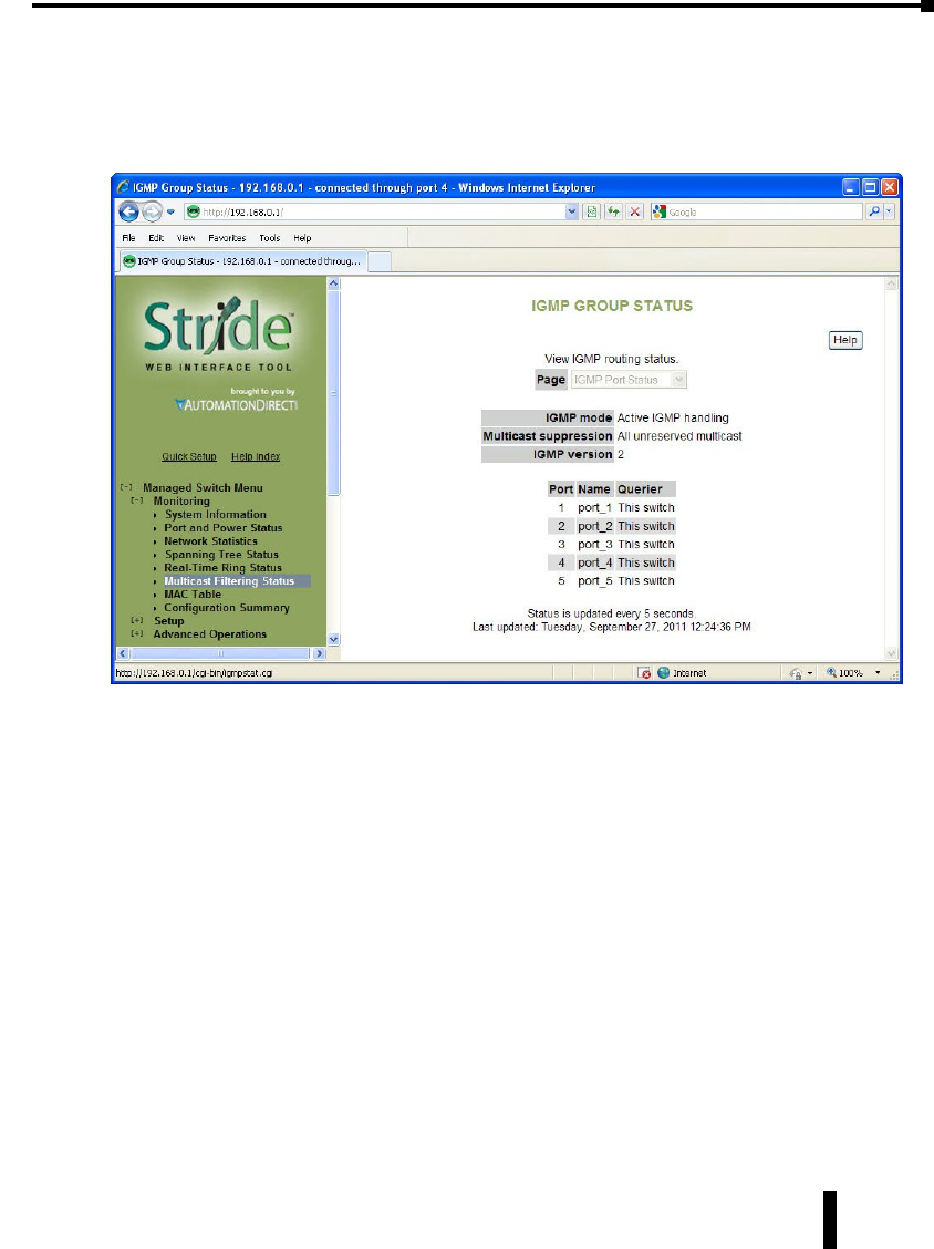
Stride Industrial Ethernet Switches User Manual 2nd Ed. Rev. B
Chapter 3 - Managed Switch Software Monitoring
Multicast Filtering Status
This section shows the current IGMP Multicast Filtering Status. For more information on
the particular details of the Multicast Filtering features of the switch, refer to the “Multicast
Filtering (IGMP)” section of this document.
IGMP Port Status:
• IGMP mode: Displays the configured mode of IGMP handling. The three choices are: IGMP
disabled, Passive IGMP handling and Active IGMP handling. The specific details of each mode are
discussed in more detail in the “Multicast Filtering (IGMP)” configuration section.
• Multicast suppression: Displays the configured mode of Multicast suppression. The three choices
are: None, IP multicast groups and All unreserved multicast. The specific details of each mode are
discussed in more detail in the “Multicast Filtering (IGMP)” configuration section.
• IGMP version: Displays the configured version of IGMP for this switch. The choices are Version
1 or Version 2. The specific details of these versions are discussed in more detail in the “Multicast
Filtering (IGMP)” configuration section.
• Querier: Indicates what device is sending out IGMP query messages. When the switch is set to
“Active IGMP handling”, the Querier will most often be this same switch.
3-11

Stride Industrial Ethernet Switches User Manual 2nd Ed. Rev. B
Chapter 3 - Managed Switch Software Monitoring
IGMP Group Status:
• Group: Displays the Multicast IP address of a particular multicast group.
• Port: Displays the port that the particular multicast group is active on.
• Reporter: Displays the IP address of the last host to report membership in this group on this
port. Hosts send IGMP reports to a switch or router for the purpose of having the switch or router
include them into a particular multicast group.
• Age: The number of seconds since this group was last reported on this port.
• Expiration: The number of seconds until this group will be dropped unless a new report is
received.
3-12
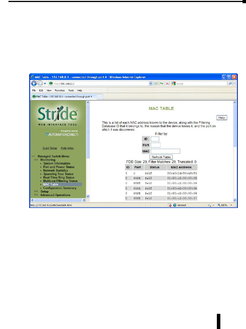
Stride Industrial Ethernet Switches User Manual 2nd Ed. Rev. B
Chapter 3 - Managed Switch Software Monitoring
MAC Table
The MAC address table page displays the current MAC address table of the switch. This
data can be filtered by the Filter Database ID (FID: Values that are applied as the devices are
encountered, no other significance to the value), the port(s) of discovery or by all or part of
the MAC address. Please note that Port 33 or 65 is the internal CPU port, depending upon
the model.
Entries in the MAC table will time out after 300 seconds of inactivity. Alternatively, the
MAC table can be flushed by power cycling the switch.
3-13

Stride Industrial Ethernet Switches User Manual 2nd Ed. Rev. B
Chapter 3 - Managed Switch Software Monitoring
Configuration Summary
The Configuration Summary Page provides a complete overview of the configuration settings
of the switch. The summary is generated in a print-friendly format. If an NTP (Network
Time Protocol) server is configured, the report will also report a timestamp. To save these
settings to a configuration file, click the “Save these settings” button to be redirected to the
Configuration Management screen.
NOTE: This page is for viewing settings only. To change settings, please go to the individual configuration screens.
3-14

Managed swiTCH
sofTware seTup
In This Chapter...
Main Settings .............................................................................................................4–2
System Settings ........................................................................................................ 4–2
Remote Access Security ............................................................................................4–4
Port Settings .............................................................................................................4–6
Port Mirroring ..........................................................................................................4–8
Set IP per Port ..........................................................................................................4–9
Switch Time Settings .............................................................................................. 4–10
Manage Firmware ..................................................................................................4–11
Install Firmware ...................................................................................................... 4–12
Redundancy Settings ............................................................................................... 4–14
Spanning Tree Settings ..........................................................................................4–18
Spanning Tree Port Settings ...................................................................................4–21
Real-Time Ring Settings ..........................................................................................4–23
RSTP Examples .......................................................................................................4–24
Traffic Priority (Priority Queuing QoS, CoS, ToS/DS) ............................................4–29
QoS / CoS Settings .................................................................................................4–30
802.1p Tag Settings ............................................................................................... 4–31
Message Rate Limiting............................................................................................4–32
QoS Example..........................................................................................................4–33
Multicast Filtering (IGMP) .......................................................................................4–36
IGMP Protocol Settings ..........................................................................................4–37
Port Settings ...........................................................................................................4–38
IGMP Example .......................................................................................................4–39
Virtual LANs (VLANs)...............................................................................................4–40
VLAN Settings ........................................................................................................4–41
VLAN Port Settings ................................................................................................. 4–43
4
4
4
Chapter
Chapter
Chapter

VLAN with RSTP .....................................................................................................4–44
VLAN Examples ......................................................................................................4–46
Security Settings ...................................................................................................... 4–51
Remote Access Security ..........................................................................................4–51
Port Security Enables and Port Security MAC Entries ..............................................4–52
IPsec Settings .........................................................................................................4–54
IKE Policy................................................................................................................4–57
IKE Pre-shared Keys ................................................................................................4–59
IKE Certificates .......................................................................................................4–60
Monitoring Settings ................................................................................................4–62
Alarm (OK) Output.................................................................................................4–62
Modbus ..................................................................................................................4–63
Register Mapping: .................................................................................................. 4–64
SNMP Notifications ................................................................................................4–65

This page intentionally left blank
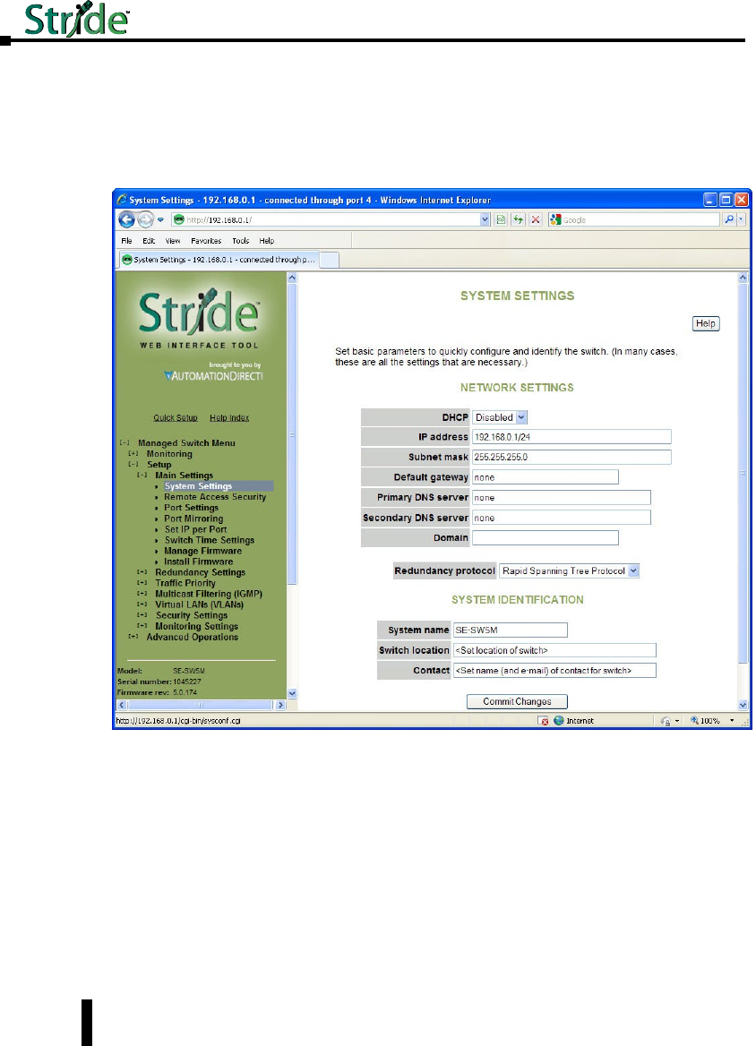
Main Settings
The Main Settings section is where the general network settings of the switch are configured,
such as the IP address and security access User name and password.
System Settings
To control and monitor the switch via the network, it must be configured with basic network
settings, including an IP address and subnet mask. Refer to the quick start guide in Chapter
2 to learn how to initially access your switch.
To configure the switch for network access, select Quick Setup from the Main menu to reach
the System Settings menu. The settings in this menu control the switch’s general network
configuration.
4-2
Chapter 4 - Managed Switch Software Setup
Stride Industrial Ethernet Switches User Manual 2nd Ed. Rev. A

DHCP Enabled/Disabled: The switch can automatically obtain an IP address from a server
using the Dynamic Host Configuration Protocol (DHCP). This can speed up initial set up,
as the network administrator does not have to find an open IP address.
IP address and Subnet Mask: The IP address of the switch can be changed to a user-defined
address along with a customized subnet mask.
Default gateway: A Gateway address is the address of a router that connects two different
networks. This can be an IP address or a Fully Qualified Domain Name (FQDN) such as
“domainname.org”.
Primary DNS server: A DNS server address will be required if domain names are used in
the switch settings. A Domain Name System Server converts a name, such as “domainname.
org”, into an IP address that is usable in the Ethernet messaging. Consult your network
administrator for the proper DNS address for your network.
Secondary DNS server: A secondary DNS server can be configured in the case that the
Primary DNS server is unreachable.
NOTE: For additional security, advanced users can set the IP address to 0.0.0.0 to disable the web browser access .
However, any features requiring an IP address (i.e., web interface, etc.) will no longer be available.
NOTE: If DHCP has been enabled, it will be necessary to connect to the console port serially or via USB in order to
ascertain which IP address has been assigned so that you may be able to access the Switch using the web browser.
4-3
Chapter 4 - Managed Switch Software Setup
Stride Industrial Ethernet Switches User Manual 2nd Ed. Rev. A
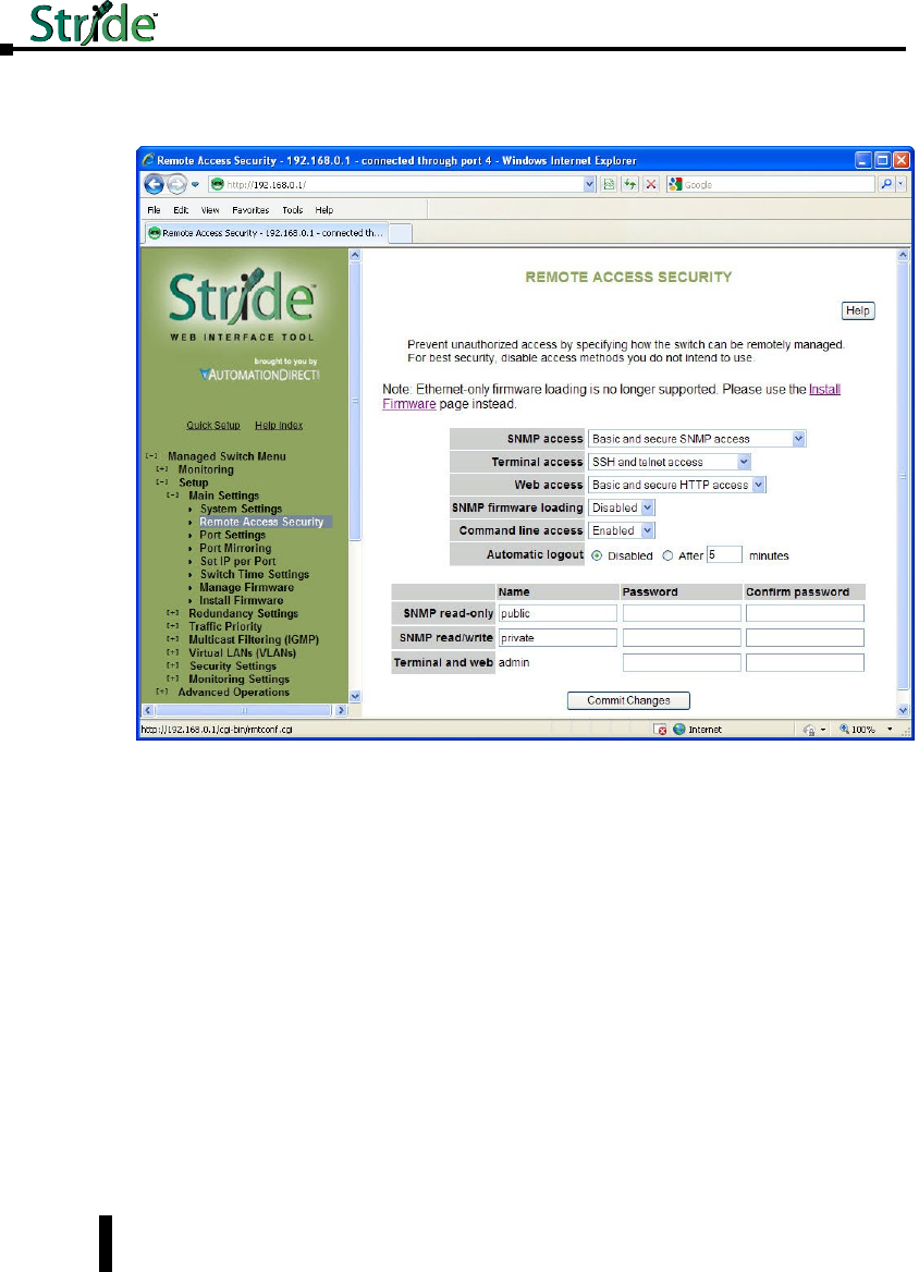
Remote Access Security
This screen allows you to set your remote access security settings.
SNMP Access: Choose the level of SNMP access to allow.
• None: No SNMP access allowed.
• SNMPv1 & SNMPv2 access (no passwords): SNMP v1 and SNMPv2 access with community
string (None) sent in clear text and no password required.
• SNMPv3 access: SNMPv3 access with encrypted password.
• Basic and secure SNMP access: SNMPv1, SNMPv2 and SNMPv3 access allowed.
Terminal access: Choose the type of terminal access to allow
• None: No terminal access to the switch will be allowed.
• Non-secure access via telnet: Non-secure access via telnet protocol. Remote access is possible
through this protocol, although all information being transacted between server and client will be
sent as clear text. Should security be of concern, use the Secure Shell protocol instead.
• Secure access via SSH: Secure access can be achieved through the use of the Secure Shell protocol
(SSH), which implements strong authentication and secure communications using encryption.
Using this protocol will ensure that your login information never gets sent as clear text, keeping the
switch protected against possible attacks coming from the network.
4-4
Chapter 4 - Managed Switch Software Setup
Stride Industrial Ethernet Switches User Manual 2nd Ed. Rev. A

• SSH and telnet access: The switch can be accessed through secure (SSH) and non-secure (telnet)
terminal access.
The switch supports these encryption algorithms for SSH:
• 3DES
• Blowfish
• AES
• Arcfour
To take advantage of the SSH capability in the switch, you will need to use an SSH client
program. There are many SSH client programs available for you to log onto the host (the
switch).
Two open source SSH client programs are available on the Internet:
• Program name: OpenSSH for Windows: http://sshwindows.sourceforge.net/
• Program name: PuTTY: http://www.chiark.greenend.org.uk/~sgtatham/putty/
The SSH protocol requires some way for clients to be sure they are communicating with the
intended host. The host computes a “fingerprint” based on its key and provides that to the
client for verification. The first time a client program sees a fingerprint, it typically displays it
and asks something like “The host is offering me these credentials, should I trust it?”
If you agree, the fingerprint is stored for later reuse.
For the system to be secure, the fingerprint used for comparison must be transmitted “out of
band” (by a means other than the channel that is being secured by the fingerprint). In this
case, via documentation.
The RSA fingerprint for the managed switch’s encryption key is:
1e:0f:31:39:26:3f:23:8c:ba:7e:e9:d1:56:ff:98:f6
Web access: Choose the level of web access to allow.
• No web access: No web access allowed.
• HTTP access: Basic HTTP access allowed.
• Secure HTTP (HTTPS) access: Secure HTTP (HTTPS) required. Attempts to access the switch
via http will be redirected to the secure protocol.
• Basic and secure HTTP access: Basic and secure HTTP access allowed.
SNMP firmware loading: Allows or disallows loading firmware via the SNMP protocol.
Command line access: Allows or disallows Command Line (CLI) access.
Automatic Logout: Specify the number of minutes of inactivity before terminal sessions
automatically logout to prevent unauthorized access. The default is 5 minutes.
SNMP read-only name: This parameter sets the SNMPv2 community string and SNMPv3
user name that may be used by SNMP clients for read-only access of settings. Enter your
own value if you wish to secure read-only access. (Default is “public”).
SNMP read-only password: These parameters set the password for secure SNMPv3 access
by the read-only user. SNMP passwords must be at least eight characters long. The default
read-only password is ‘publicpwd’ (w/out quotes).
4-5
Chapter 4 - Managed Switch Software Setup
Stride Industrial Ethernet Switches User Manual 2nd Ed. Rev. A
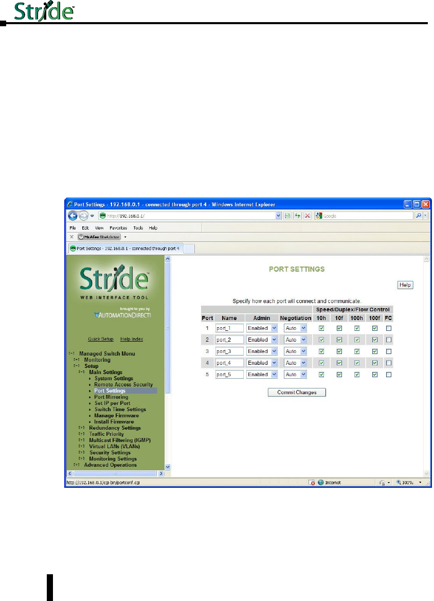
SNMP read/write name: This parameter sets the SNMPv2 community string and SNMPv3
user name that may be used by SNMP clients for read/write access to settings. Enter your
own value if you wish to secure read/write access. (Default is “private”).
SNMP read/write password: These parameters set the password for secure SNMPv3 access
by the read/write user. SNMP passwords must be at least 8 characters long. The default
read/write password is ‘privatepwd’ (w/out quotes).
Terminal and web: Password set here is used for Telnet and web access. To change the
administrative password, select this option. (Default password is ‘admin’).
Port Settings
The switch comes with default port settings that allow you to connect to the Ethernet
Ports without any configuration. Should there be a need to change the name of the ports,
negotiation settings or flow control settings, you can do this in the Port Settings menu.
Port Name: Each port in the managed switch can be identified with a custom name. Specify
a name for each port here.
Admin: Ports can be enabled or disabled in the managed switch. For ports that are disabled,
they are virtually non-existent (not visible in terms of switch operation or spanning tree
algorithm). Choose to enable or disable a port by selecting Enabled or Disabled, respectively.
4-6
Chapter 4 - Managed Switch Software Setup
Stride Industrial Ethernet Switches User Manual 2nd Ed. Rev. A

Negotiation: All copper ports and gigabit fiber ports in the managed switch are capable
of auto-negotiation such that the fastest bandwidth is selected. Choose to enable auto-
negotiation or use fixed settings. 100Mbps fiber ports are fixed speed only.
Speed/Duplex/Flow Control: Each port can be set to allow speed and duplex to be
negotiated to any or all Speed/Duplex/Flow control options. Network performance can be
optimized by using Fixed Negotiation and restricting Speed/Duplex/Flow Control to a single
value if network traffic is known.
These options are available:
• 10h – 10 Mbps, Half Duplex
• 10f – 10 Mbps, Full Duplex
• 100h – 100 Mbps, Half Duplex
• 100f – 100 Mbps, Full Duplex
• 1000f – 1000 Mbps, Full Duplex
On managed switches with gigabit combination ports, those ports will have two rows,
a standard row of check boxes and a row labeled “SFP” with radio buttons. The SFP
setting independently sets the speed at which a transceiver will operate if one is plugged in.
Otherwise, the switch will use the fixed Ethernet port and the corresponding settings for it.
Flow Control: Flow control can also be enabled or disabled, and is indicated by ‘FC’ when
enabled. Devices use flow control to ensure that the receiving devices takes in all the data
without error. If the transmitting device sends at a faster rate than the receiving device,
then the receiving device will eventually have its buffer full. No further information can be
taken when the buffer is full, so a flow control signal is sent to the transmitting device to
temporarily stop the flow of incoming data.
NOTE: The SFP settings are NOT automatically sensed or negioated. If a 100 Mbps SFP is installed in the switch, that
port must be manually set on the port settings page to 100 Mbps.
4-7
Chapter 4 - Managed Switch Software Setup
Stride Industrial Ethernet Switches User Manual 2nd Ed. Rev. A
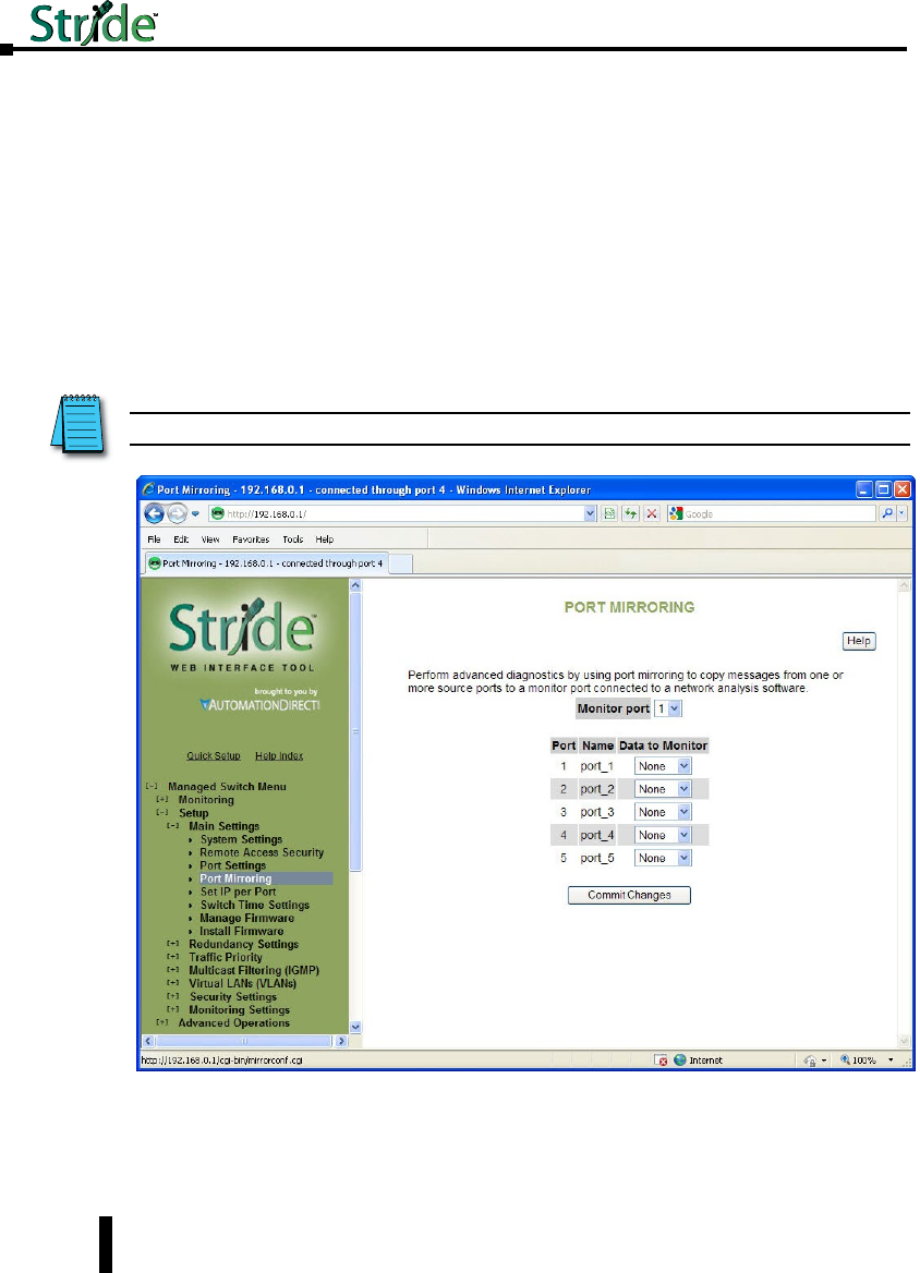
Port Mirroring
In an unmanaged switch, each port is filtered to only send and receive Ethernet packets to
devices physically connected to that port. This makes it impossible to view the messages
occurring between two other devices from a third device (such as a PC running a tool like
“Wireshark”).
The mirroring option is ideal for performing diagnostics by allowing traffic that is being sent
to and received from one or more source ports to be replicated out the monitor port.
Choose a monitor port.
Choose the source ports to be mirrored (monitored). For each source port choose the data
to monitor: choose to monitor messages being sent (select Egress), messages being received
(select Ingress) or messages being sent and received (select Both).
NOTE: The Ingress Only option is not supported on SE-SW5M-xxx and SE-SW8M-xxx models.
To view the traffic, connect a PC running network monitoring software (such as Wireshark)
to the Monitor port.
4-8
Chapter 4 - Managed Switch Software Setup
Stride Industrial Ethernet Switches User Manual 2nd Ed. Rev. A
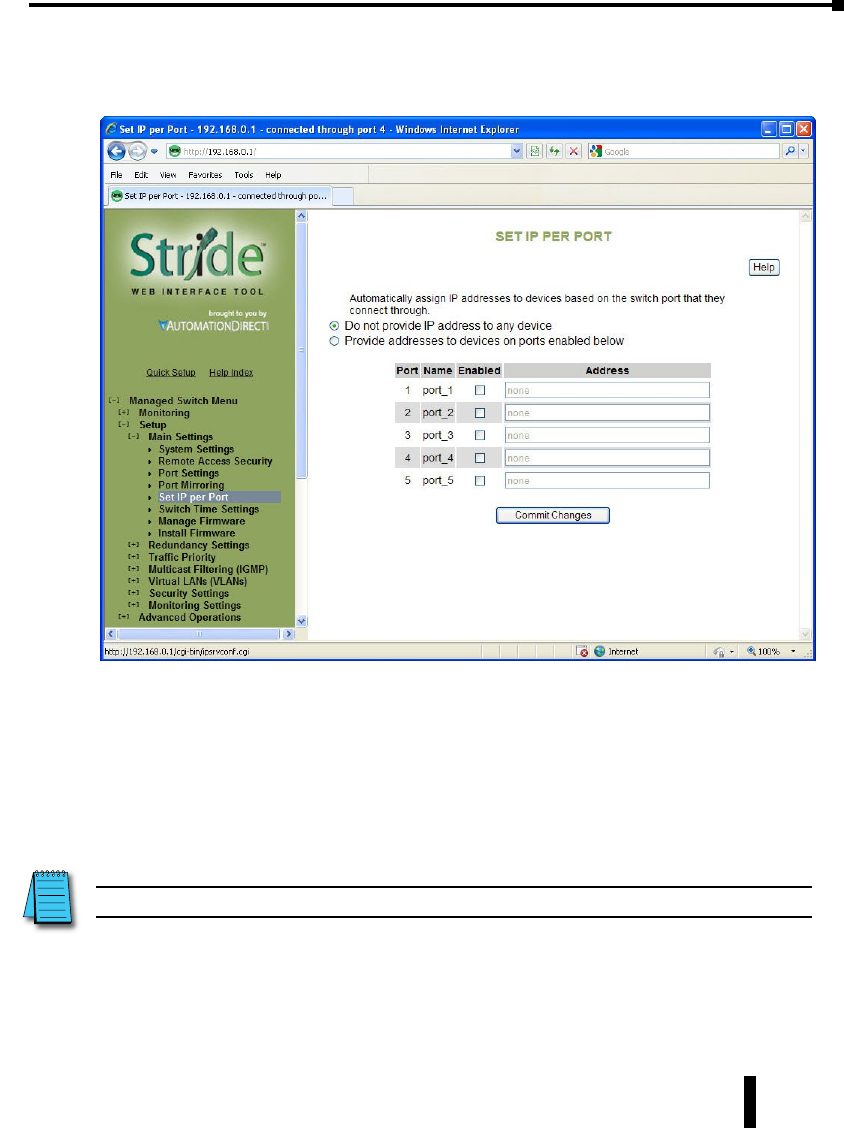
Set IP per Port
The switch may provide an IP address to one device on each network port. This feature may
be turned on and off for the whole switch and individually controlled for each port.
This feature is not a DHCP service. With Set IP per Port enabled on a port, the switch will
respond to a DHCP request on that port with an IP address only.
For the feature to function properly, the host and network must meet the following criteria:
1. A single host must be directly connected to the switch port.
2. The host must not require a Subnet Mask to be offered.
3. The host and network must not require a Default Gateway to be offered.
4. There must be no other DHCP server on the network.
5. VLAN’s must not be configured on the network.
NOTE: Productivity3000, ECOM/ERM modules and C-more panels require a Subnet Mask in the DHCP.
4-9
Chapter 4 - Managed Switch Software Setup
Stride Industrial Ethernet Switches User Manual 2nd Ed. Rev. A
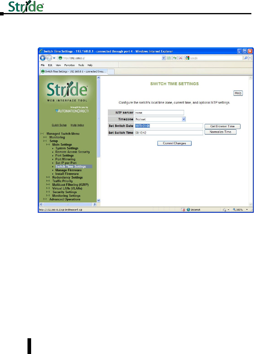
Switch Time Settings
This screen allows you to configure the switch’s time settings, including time zone, current
date and time as well as an NTP (Network Time Protocol) time server.
NTP server: You may specify an NTP server to automatically set the switch’s clock. If a
DNS server is configured, you may use a fully qualified domain name; otherwise, you must
specify an IP address.
Timezone: This is the local timezone where the switch is installed. The switch will offset
accordingly from the current time configured in the switch.
Set Switch Date: This is where the date is set for the switch. The format of the date is Year-
Month-Day (YYYY-MM-DD).
Set Switch Time: This is where the time is set for the switch. The format of the time is
hour:minute:second (HH:MM:SS).
There is also a “Get Browser Time” button to synchronize the switch’s clock to your local
browser’s time and a “Normalize Time” button to format the time in a manner that the
switch will view it. In other words, if the seconds are left out in time field, the normalize
button will show the seconds field that will be set when the Commit button is pressed.
4-10
Chapter 4 - Managed Switch Software Setup
Stride Industrial Ethernet Switches User Manual 2nd Ed. Rev. A
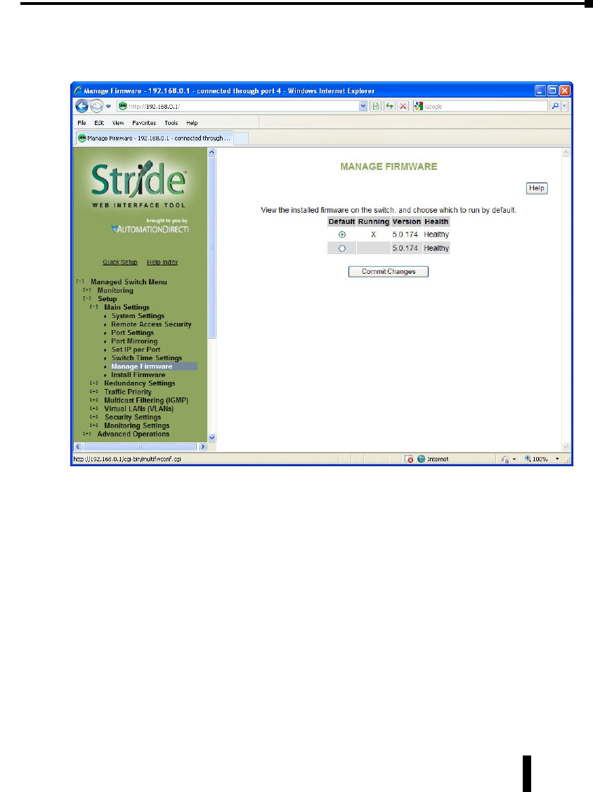
Manage Firmware
The Manage firmware page displays the current status of each of the two firmware images on
a switch, and allows for changing which one will run the next time the switch is reset.
Default: Shows the current default firmware image to run when the switch is reset. May be
changed to run a different firmware on the next reset.
Running: Shows the current running firmware image. This may be different from the
current default firmware image if the switch failed to boot recently.
Version: Displays the firmware version number for each installed firmware. If the version
cannot be determined, this will report “Unknown”.
Health: Shows the health of each firmware image. The health can be one of the following:
• Healthy: The firmware is running or is expected to be in good enough shape to run.
• Broken: The firmware is known to be in a state that would prevent it from booting. The Default
column will not allow this image to be selected for booting.
• Unknown: The firmware may be bootable, but the switch cannot be certain. This will happen if
the switch is running the non-default firmware. This can happen if the default firmware somehow
became corrupt, or if the switch lost power part way through booting.
If the firmware that is currently running is not the default, and the switch is reset without
explicitly saving the default (“Commit Changes”), the current firmware will be run again. To
4-11
Chapter 4 - Managed Switch Software Setup
Stride Industrial Ethernet Switches User Manual 2nd Ed. Rev. A

boot the firmware marked as the default, first, commit this page and then reset the switch.
Install Firmware
The Install Firmware page allows the inactive firmware (the selection not marked Running on
the Manage Firmware page) to be replaced with a new version. To make the new version be
the running version on the switch, after uploading the new version, you must:
• Go to the Manage Firmware page
• Select the new version as default
• Reset the switch
Firmware may be directly uploaded to the switch from the local system.
MD5 Checksum (Optional): If an MD5 checksum of the file is available, it may be entered
into this field. Providing a checksum will ensure the firmware arrives at the switch intact and
without any glitches. An MD5 checksum is not required.
File name: Use the “Browse” button to locate the .fwb firmware file.
Firmware may also be uploaded to the switch from a remote machine serving the .fwb
firmware file. The server must be providing the file via TFTP, HTTP, HTTPS, FTP or
FTPS.
Protocol: Choose one of the following protocols to retrieve the .fwb firmware file: TFTP,
4-12
Chapter 4 - Managed Switch Software Setup
Stride Industrial Ethernet Switches User Manual 2nd Ed. Rev. A

HTTP, HTTPS, or FTP (FTPS when available).
Server Address: Enter the address of the server in this field. This may be an IP address, or a
domain name if a DNS server has been configured on the System Settings page. Literal IPv6
addresses must be surrounded with square brackets. Example: the address fdda:2301: :2
must be entered as [fdda:2301: :2].
User Name: Enter the user name in this field if required by the server. Note that this is not
available for TFTP.
Password: Enter the password in this field if required by the server. Note that this is not
available for TFTP.
Anonymous Download: Check this box if no User Name and Password are required by the
remote server.
Remote Filename: Enter the remote .fwb firmware file name into this field. The full path is
required.
MD5 Checksum (Optional): If an MD5 checksum of the file is available, it may be entered
into this field. Providing a checksum will ensure the firmware arrives at the switch intact and
without any glitches. An MD5 checksum is not required.
4-13
Chapter 4 - Managed Switch Software Setup
Stride Industrial Ethernet Switches User Manual 2nd Ed. Rev. A

Redundancy Settings
Another benefit of using managed switches over unmanaged switches is their redundancy
capabilities. This allows you to have an Ethernet network with extra connections, so if one
path between two points on the network fails, another path can be used to deliver messages.
If one link or switch fails, another link or switch can take over transparently to prevent
unnecessary down time. So why not just physically connect each of the switches in your
network in various loop configurations such that there are always at least two paths going to
and from each switch? That would create a broadcast loop that will bring a network to its
knees very quickly.
In an unmanaged Ethernet network there can be only one path between any two ports on the
network. If there is more than one path from one switch to another a broadcast message (and
in some cases other messages) sent by the network will be forwarded until it completes a loop
by returning on the second path. Since the switches forward all broadcasts and do not keep
track of the messages they have sent, the returning message will be sent around the loop again
and again. A single message circulating forever around a loop at high speed is clearly not a
good thing, so no loops are allowed.
The limitations of having only one path are even simpler to see. If the one and only path
fails for any reason, such as a broken cable or power failure at one of the switches, there are
no paths left and no network traffic can get through. We need a way to add alternate paths
without creating loops. A redundancy protocol such as RSTP, a loop prevention protocol, is
used such that switches can communicate with each other to discover and prevent loops.
There are four methods of accomplishing redundancy in the Stride managed switches:
• Spanning Tree Protocol (STP)
• Rapid Spanning Tree Protocol (RSTP)
• Multiple Spanning Tree Protocol (MSTP)
• Real-Time Ring
The Spanning Tree Protocols (STP, RSTP and MSTP) are an industry standard and are thus
compatible with other manufacturer’s managed switches for situations where both need to
coexist and communicate. The recovery time, however, is slower with the Spanning Tree
Protocols than with the proprietary Real-Time Ring protocol. The merits of both will be
discussed in more detail below.
4-14
Chapter 4 - Managed Switch Software Setup
Stride Industrial Ethernet Switches User Manual 2nd Ed. Rev. A
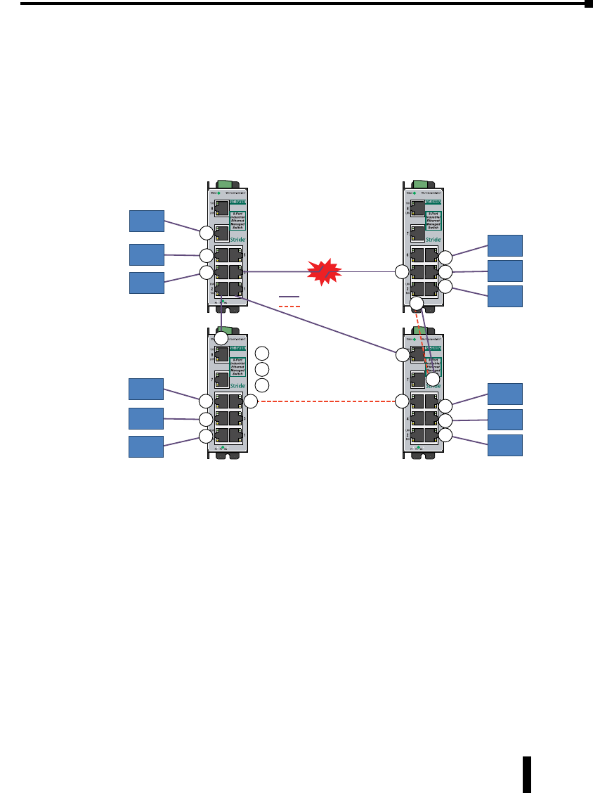
Spanning Tree Protocols:
In the diagram below all the links are the same speed, 100 Mbps. The root ports are those
connected directly to the root bridge because they have the lowest path cost (only one hop).
The paths that must go through another bridge (switch) have a higher path cost (two hops)
and are designated as backup ports (decisions made internal to the switch by the Spanning
Tree Protocol). The ports connected directly to end stations are assigned as edge ports
(manually assigned on the Spanning Tree Port Settings page) so that RSTP doesn’t waste
time considering them.
End
Station
End
Station
End
Station
E
E
E
End
Station
End
Station
End
Station
E
E
E
End
Station
End
Station
End
Station
E
E
EEnd
Station
End
Station
End
Station
E
E
E
R
B
B
B
R
B
R
= Root Port
= Backup Port
= Edge Port
B
R
E
Designated
Bridge
Designated
Bridge
Root
Bridge
Designated
Bridge
Path
Failure
Active Path
Backup Path (blocked)
Backup path
activated after
root path
failure
The Rapid Spanning Tree Protocol provides a standardized means for intelligent switches
(also called bridges) to enable or disable network paths so there are no loops, but there is an
alternative path if it is needed. Why is it called Rapid Spanning Tree Protocol?
• ‘Rapid’ – it is faster than the previous (and completely compatible) version called Spanning Tree
Protocol (STP).
• ‘Spanning’ – it spans (connects) all of the stations and switches of the network.
• ‘Tree’ – its branches provide only one connection between two points.
In a Spanning Tree network, only one bridge (managed switch) is responsible for forwarding
packets between two adjacent LAN segments to ensure that no loops exist in a LAN. To
ensure that only one bridge is responsible, all other bridges on the network must cooperate
with each other to form a logical spanning tree that defines the pathways that packets should
take from bridge to bridge.
The logical spanning tree has exactly one bridge that is assigned the role of root. All of the
other bridges need to have exactly one active path to the root. The job of the root bridge
4-15
Chapter 4 - Managed Switch Software Setup
Stride Industrial Ethernet Switches User Manual 2nd Ed. Rev. A

is to notify all bridges connected in the tree that there has been a topology change and
restructuring of the tree is in progress (due to a communications link failure somewhere in
the network or a new switch added in the network). The root bridge is determined by the
bridge priority assigned to it and the MAC address.
By default, it is the bridge with the lowest MAC address that gets assigned the role as “root”,
but a specific bridge can be forced to be the root bridge by changing its bridge priority setting
(a lower number with respect to other bridges means higher priority, set on the Spanning
Tree Settings page).
Every communication path between each bridge (managed switch) on the network has an
associated cost. This “path cost” may be determined by the speed of each segment, because it
costs more time to move data at a slower speed, or the path cost can be manually configured
to encourage or discourage the use of a particular network. For example, you may not want
to use a particular high-speed link except when absolutely necessary because you pay a fee to a
service providor for data using that path, while another path is free (no monetary cost).
The path cost is the cumulative cost of all the hops from the root bridge to a particular port
on the network. A Spanning Tree network always uses the lower cost path available between
a port and the root bridge. When the available network connections change, it reconfigures
itself as necessary.
See the RSTP examples topic in this section for an example of how the path cost can be
utilized to establish the primary and backup connections.
During the start-up of a Spanning Tree Network, all bridges (managed switches) are
transmitting configuration messages (BPDUs) claiming to be the root. If a switch receives
a BPDU that is “better” than the one it is sending, it will immediately stop claiming itself
as the root and send the “better” root information instead. Assuming the working network
segments actually connect all of the switches, after a certain period of time there will be only
one switch that is sending its own root information and this switch is the root. All other
switches transmit the root bridge’s information at the rate of the root bridge’s “hello time” or
when the root bridge’s BPDU is received on one of their ports.
The factor for determining which switch is the root (has the “best” root information) is
the bridge priority and its tie-breaker, the switch MAC address. If a switch has more than
one path to get messages from the root, other information in the configuration message
determines which path is the best.
Once the root bridge is determined, all other switches see the root bridge’s information and
information about path (or paths) to the root. If more than one port provides a path to the
root the non-root switches must decide which port to use. They check all of their ports to
select the port that is receiving messages indicating the best path to the root.
The selected port for each bridge is called the root port. It provides the best path to
communicate with the root. The best path is determined first by the lowest total path
cost to the root (root path cost). Each port is assigned a cost (usually based on the speed)
for messages received on that port. The root path cost for a given path is just sum of the
individual port costs for that path. The lowest path cost indicates the shortest, fastest path to
the root. If more than one path has the same cost the port priority assigned to each port, and
its tie-breaker the port number pick the best path.
4-16
Chapter 4 - Managed Switch Software Setup
Stride Industrial Ethernet Switches User Manual 2nd Ed. Rev. A

Recovery Time, Hops and Convergence:
The typical RSTP recovery time (time to start forwarding messages on the backup port) on a
link-loss failure is <50ms per “hop”. A hop is defined as a link between two switches. A link
to an end station is not considered a hop.
The Max Age setting controls how long RSTP messages may circulate in the network. Since
the largest value allowed for Max Age is 40, the largest RSTP network hop-diameter is also
40.
See the RSTP Examples topic in this section for a more detailed explanation about hops and
recovery time.
The time it takes for all of the switches to have a stable configuration and send network
traffic is called the convergence time. STP was developed when it was acceptable to have
a convergence time of maybe a minute or more, but that is not the case anymore. Due to
the increased demand for better convergence times, Rapid Spanning Tree Protocol was
developed, bringing the normal convergence time for a properly configured network down
to a few seconds. The RSTP takes advantage of the fact that most modern Ethernet links
between switches are point-to-point connections. With a point-to-point link, the switches
can quickly decide if the link should be active or not.
4-17
Chapter 4 - Managed Switch Software Setup
Stride Industrial Ethernet Switches User Manual 2nd Ed. Rev. A
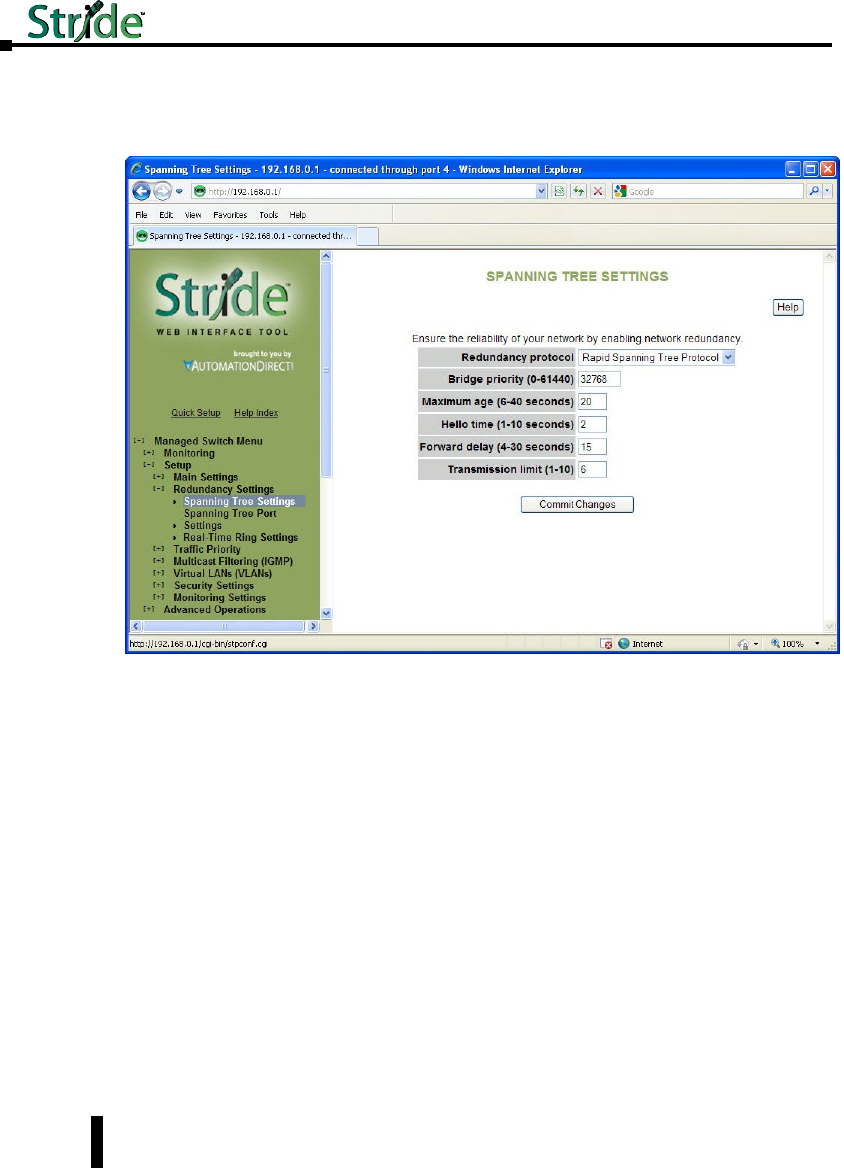
Spanning Tree Settings
The Spanning Tree Settings enable you to choose the redundancy protocol and set
parameters related to that protocol.
Redundancy Protocol: Choose the protocol by selecting STP (Spanning Tree Protocol),
RSTP (Rapid Spanning Tree Protocol) or MSTP (Multiple Spanning Tree Protocol). A
selection of None will disable this advanced feature. Choosing STP, RSTP or MSTP will
allow the wiring of redundant networks (such as rings) for automatic failover. RSTP is
compatible with STP so in most cases you should choose RSTP. Only choose STP if you
want to force the switch to only use this protocol. STP/RSTP/MSTP use BPDUs (Bridge
Protocol Data Units) to keep bridges informed of the network status.
MSTP is compatible with RSTP and STP but adds the ability to route VLANs over distinct
spanning trees within an MSTP region. In order to configure spanning trees, you must create
spanning tree instances using the STP configuration page and assign VLANS to them using
the VLAN configuration page.
MSTP falls back to RSTP behavior outside of an MSTP region. A region is identified by the
unique combination of Region Name, Configuration Revision and VLAN to MSTI mapping
for each switch in that region. If those values match for linked switches running MSTP,
those switches consider themselves to be in the same region.
4-18
Chapter 4 - Managed Switch Software Setup
Stride Industrial Ethernet Switches User Manual 2nd Ed. Rev. A

Select none if you do not require the switch to manage redundant network connections. All
ports will forward network traffic just as an unmanaged switch would. Otherwise RSTP
(Rapid Spanning Tree Protocol) should usually be selected. A selection of STP or RSTP will
allow redundant links between switches so those links can keep the network connected even
when a primary link fails. RSTP is compatible with switches that only implement STP, an
older version of the protocol. If STP is selected only the original STP format messages will
be generated. Selecting STP reduces the chances of network packets being duplicated or
delivered out of order, but at the expense of much longer reconfiguration time.
Bridge Priority (0 to 61440; Default = 32768): The bridge priority is used to determine
the root bridge in the spanning tree. For MSTP, the bridge priority is used to determine the
CIST root. The priority ranges from 0 to 61440 (default 32768) and must be a multiple of
4096. Lower numbers indicate a better priority.
By default, the bridge with the lowest bridge priority is selected as the root. In the event of a
tie, the bridge with the lowest priority and lower MAC address is selected.
There are two ways to select a root bridge (switch). The first is to leave all the bridge priority
settings at the default setting of 32768. When all the switches are set at the default priority,
the managed switch with the lowest MAC address is selected as the root. This may be
adequate for networks with light or evenly distributed traffic.
The second way to select a root bridge is to customize priority settings of each bridge.
Customizing the bridge priority settings allows the network to select a root bridge that gives
the best network performance. The goal is generally to have the network traffic pass through
the network as directly as possible, so the root should be central in the network. If most
messages are between one central server and several clients, the root should probably be a
switch near the server so messages do not take a long path to the root and another long path
back to the server.
Once you decide which switch should be the root, it should be given the best (numerically
lowest) bridge priority number in the network.
Maximum Age (6 to 40; Default = 20): For STP, the max age indicates the maximum
time (in seconds) that the switch will wait for configuration messages (BPDUs) from other
managed switches. If that time expires, the switch assumes that it is no longer connected to
the root of the network. If a link goes down in a way that the switch can detect the loss of
link, it does not wait before reconfiguring the network.
RSTP waits 3 times the Hello Time instead of Max Age before assuming that it is no longer
connected to the root of the network. However, Max Age is used to limit the number of
hops Spanning Tree information may travel from the root bridge before being discarded as
invalid. Furthermore, MSTP only counts hops that take place to or from switches outside the
CAUTION: If VLANS and redundancy (STP/RSTP/MSTP) are both enabled, situations can arise where
the physical LAN is intact but one or more VLANs are being blocked by the redundancy algorithm and
communication over those VLANS fails. The best practice is to make all switch-to-switch connections
members of all VLANs to ensure connectivity at all times. Should you intend to use RSTP and VLANs
at the same time, please see the “VLAN with RSTP” section for important information concerning the
setup of your network. Otherwise, communication failures may occur.
4-19
Chapter 4 - Managed Switch Software Setup
Stride Industrial Ethernet Switches User Manual 2nd Ed. Rev. A

MSTP region for this check. The value of Max Hops (below) is used to limit hops within an
MSTP region.
The maximum age must satisfy the following constraints:
2 X (Hello Time + 1.0 seconds) < max message age < 2 X (forward delay – 1.0 seconds)
Hello Time (1 to 10; Default = 2): Configuration messages (BPDUs) are sent periodically to
other bridges based on a time period labeled hello time. Decreasing the hello time gives faster
recovery times; increasing the hello time interval decreases the overhead involved.
The hello time must satisfy the following constraints:
2 x (hello time + 1.0 seconds) < max message age < 2 x (forward delay - 1.0 seconds)
Forward Delay (4 to 30; Default = 15): The forward delay is a time (in seconds) used by all
switches in the network. This value is controlled by the root bridge and is used as a timeout
value to allow ports to begin forwarding traffic after network topology changes. If a port is
not configured as an edge port and RSTP cannot negotiate the link status, a port must wait
twice the forward delay before forwarding network traffic. In a properly configured network
using RSTP (not STP) this setting has very little effect. For STP networks, setting the time
too short may allow temporary loops when the network structure changes (switches turn on
or off or links are added or broken). A longer time will prevent temporary loops, but network
traffic will be disrupted for a longer time.
The default value for the forward delay is 15 seconds. If you change this setting, the switch
will not allow a value unless it satisfies the following formula:
2 × (hello time + 1.0 seconds) < max message age < 2 x (forward delay - 1.0 seconds)
Transmission Limit (1 to 10; Default = 6): The transmission limit controls the maximum
number of BPDUs that can be sent in one second.
The transmission limit can range from 1 to 10 messages/second (6 messages/second default).
Increasing Transmission limit can speed convergence of the network but at the cost of
configuration messages using a larger share of the available network bandwidth.
Region Name (MSTP): The region name is used together with the configuration revision
and VLAN to MSTI (MST Instance) mapping to define an MSTP region.
Configuration Revision (MSTP; 0 – 65535): The configuration revision is used together
with the region name and VLAN to MSTI (MST Instance) mapping to define an MSTP
region.
Max Hops (MSTP; 6 to 40; Default = 20): Max Hops determines the maximum number of
switches a BPDU will be propagated through within an MSTP region. This value is used to
prevent old data from endlessly circulating within a region.
MST Instances: For MSTP, you can configure multiple spanning tree instances. Add an
instance by clicking Add MSTI. For each MSTI, you can configure a name, the MST ID,
and this bridge’s priority in that spanning tree.
NOTE: Assign all Switches in an RSTP/STP network the same Max Age.
4-20
Chapter 4 - Managed Switch Software Setup
Stride Industrial Ethernet Switches User Manual 2nd Ed. Rev. A
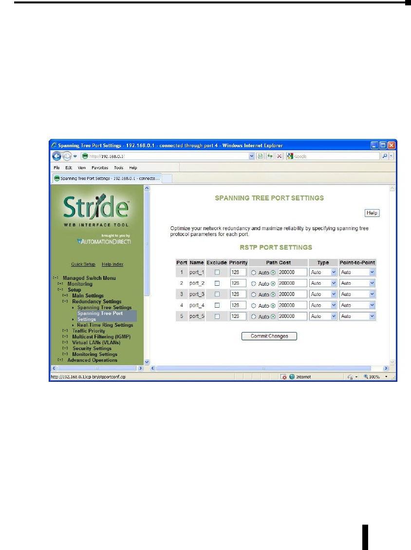
Spanning Tree Port Settings
Each port can be configured to tune the STP/RSTP/MSTP spanning tree. With MSTP, each
spanning tree instance can be tuned independently.
Using MSTP, you can configure separate port settings for the CIST (Common Internal
Spanning Tree) and for every spanning tree created by MSTP. Settings for individual MSTIs
(Multiple Spanning Tree Instances) only affect ports connected to switches within the same
MSTP Region.
By default, MSTIs inherit their settings from the CIST. To configure an MSTI individually,
you must select it from the drop-down box and click the Customize button for the instance.
Click Inherit if you want a spanning tree’s values to be inherited from the CIST again.
Exclude (Default = Included): Normally all ports should be included in determining the
Spanning Tree network topology, either as a normal port or an edge port. It is possible to
completely exclude a port, so that it will always forward network traffic and never generate or
respond to network messages for RSTP or STP. Excluding a port is an advanced option that
should be used only if absolutely necessary. The pair of ports assigned to a Real-Time Ring
should be excluded from Spanning Tree.
This option excludes the port from all spanning tree instances and appears with the other
CIST settings.
Port Priority (0 to 240; Default = 128): Selection of the port to be assigned “root” if two
ports are connected in a loop is based on the port with the lowest port priority. If the root
bridge fails, the bridge with the next lowest priority then becomes the root.
4-21
Chapter 4 - Managed Switch Software Setup
Stride Industrial Ethernet Switches User Manual 2nd Ed. Rev. A

This option may be set per port per MSTI.
If the switch has more than one port that provides a path to the root bridge and they have the
same root path cost, the selection of which port to use is based on the port priority. The port
with the best (numerically lowest) priority will be used. If the port priority is the same, the
switch will use the lowest numbered port. The port priority can range from 0 to 240 seconds
(128 second default).
Path Cost (1 to 200,000,000; Default = 20,000 for 10 / 100 / 1000 ports and 200,000 for
10 / 100 ports): As with any network, there is an associated cost to go from a source location
to a destination location. For RSTP, the root path cost is calculated based on the bandwidth
available for that particular connection to the root bridge. The port with the lowest cost for
delivering messages to the root is used to pass traffic toward the root.
The path cost can be assigned automatically based on the port speed, using the IEEE standard
values of 200,000 for 100Mbps links and 2,000,000 for 10Mbps links, or the value can be
specified in the range 1 to 200,000,000.
The default value depends on the capabilities of the port: 200,000 for 100 Mbps and 20,000
for 1000 Mbps ports.
This option can be set per port per MSTI.
See RSTP Examples for an illustration of how the path cost can be utilized to establish the
primary and backup connections.
Type (Default = Auto): A port that connects to other switches in the network may be part of
a loop. To ensure such loops do not occur, the switch will not put a port in the Forwarding
state until enough time has passed for the spanning tree to stabilize (twice the forwarding
delay, 30 seconds by default). However, if a port connects directly to a single device at the
edge of the network, it may safely be put in Forwarding state almost immediately. The port
Type controls the switch’s assumptions about what is connected to the port.
• Auto: The port will initially be assumed to be an Edge port and go to Forwarding quickly. It will
automatically adjust to being a Network port if BPDUs are received and revert to being an Edge
port any time no BPDUs are received for 3 seconds.
• Network: The port will always wait a safe time before going to the Forwarding state.
• Edge: The port will initially be assumed to be a direct connection to a single device but will change
to being a Network port if any BPDUs are received. Thereafter, it will always wait a safe time before
going to Forwarding whenever a link is reestablished on the port.
This option can be set per port per MSTI.
Point-to-Point (Default = Auto): A port is part of a point-to-point network segment when
there can be no more than one other network port connected to it. RSTP can decide whether
it is safe to forward network traffic very quickly on point-to-point links to other managed
switches, otherwise the port must wait many seconds (30 seconds by default, twice the
forward delay) before forwarding network traffic. When set to Auto, full-duplex links are
assumed to be point-to-point; half-duplex ports are not. This setting can be forced true or
false if the automatic determination would be wrong.
4-22
Chapter 4 - Managed Switch Software Setup
Stride Industrial Ethernet Switches User Manual 2nd Ed. Rev. A

Real-Time Ring Settings
The Real-Time Ring Settings page, accessed through the Redundancy Settings, allows
configuration of Real-Time Ring protocol in supported switches.
A real-time ring increases network reliability by providing an alternative path for message
flow in the event of a network segment failure. When a ring port detects a communications
break, it quickly notifies the other switches in the ring. Messages are automatically rerouted
through the alternative ring path within milliseconds.
STP (Spanning Tree Protocol) is more flexible than a ring configuration, but recovery times
for spanning trees may be in the hundreds of milliseconds. The real-time ring protocol
exchanges topological flexibility for recovery times in the tens of milliseconds.
Activate a ring by selecting the appropriate Enable check box. You can configure one ring for
every two ports on the switch.
When a ring is enabled, be sure to choose the two ports being used to connect the switch into
that particular ring. To do so, pick ports from the Primary Port and Backup Port dropdown
lists. Each port should be assigned to only one ring.
The pair(s) or ports assigned to ring(s) should be excluded from Spanning Tree on the
Spanning Tree Ports Setup page.
The port defined as Backup will be blocked under normal operating conditions. By default,
the switch with the lowest numbered MAC address in a ring will be the master switch,
meaning that the communication in the ring will be blocked from one of the two ring ports
of that switch. Only the master switch in a ring does this. You may designate a different
4-23
Chapter 4 - Managed Switch Software Setup
Stride Industrial Ethernet Switches User Manual 2nd Ed. Rev. A

switch as the master switch by choosing “This is Master” from the Ring Master dropdown list
for the desired switch. All other switches in the ring should be set to the default “Automatic”
setting.
RSTP Examples
Example 1: Maximum “Hops” and Switches in a Redundant Ring:
The Max Age setting controls how long RSTP messages may circulate in the network. When
a switch receives a message, it compares the age of the message with the Max Age (also carried
in the message) and if the age has reached the Max Age, the message is discarded. Otherwise,
the message age is incremented before the message is forwarded. Therefore, the maximum
diameter of a RSTP network is controlled by Max Age. Since the largest value allowed for
Max Age is 40, the largest RSTP network hop diameter is also 40.
Number of Hops vs. Recovery Time:
The diagram below shows a typical redundant ring network with 6 managed switches and 5
hops between stations.
The overall recovery time when there is a network segment failure is dependent on the
number of hops. The recovery time is typically less than 50 ms per hop. Therefore, in the
diagram below of a typical ring with 6 managed switches the overall recovery time would be
less than 250 ms (5 hops x <50 ms).
NOTE: When a port is configured as a Ring port, that port cannot be used for communication to or through the Switch.
It can ONLY be connected to another Ring port on a managed Switch or Real-Time Ring Switch.
4-24
Chapter 4 - Managed Switch Software Setup
Stride Industrial Ethernet Switches User Manual 2nd Ed. Rev. A
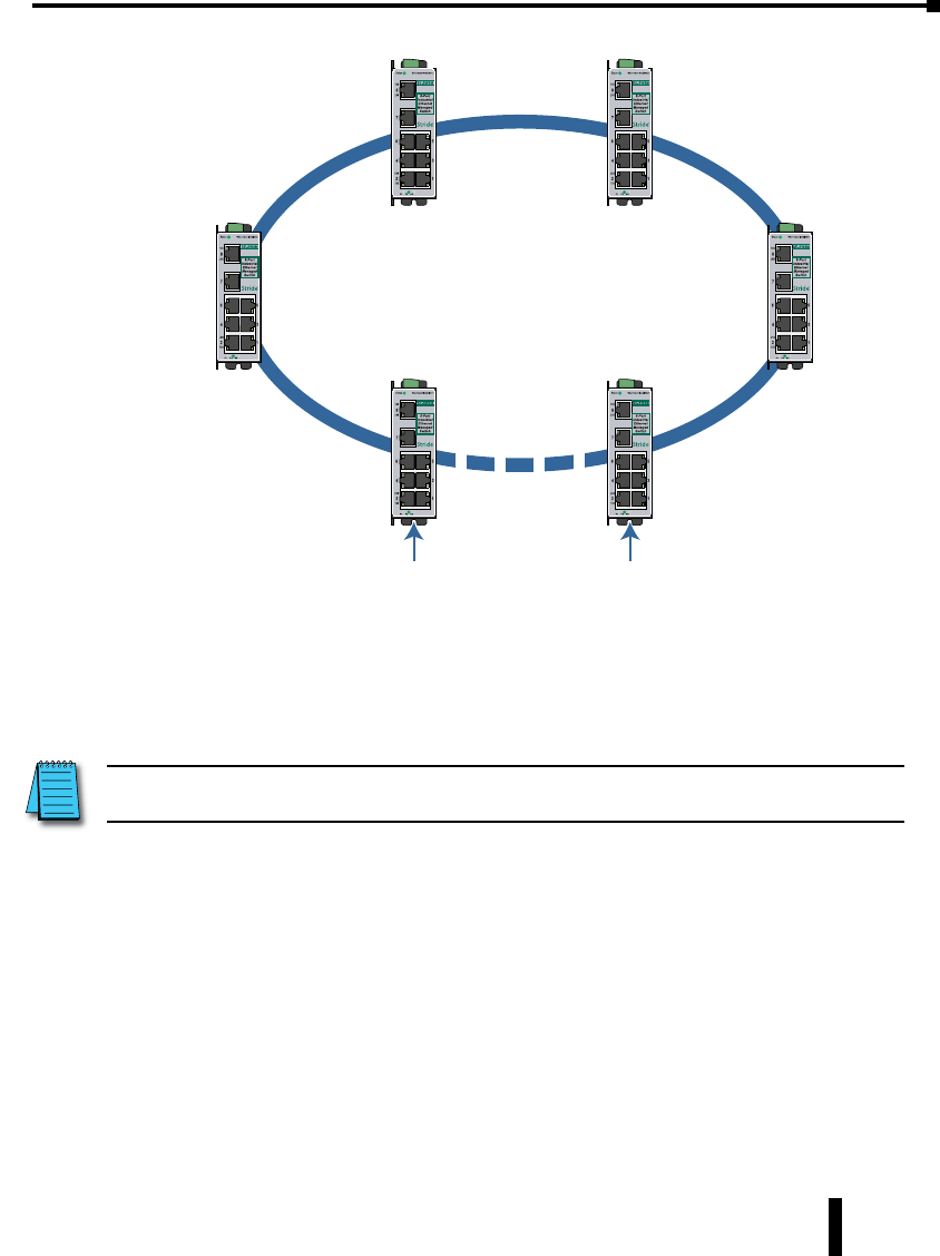
Typical Redundant Ring Network with
6 Managed Switches
(Recovery time < 250ms)
1
2
3
4
5
5 “hops”
between
A & B
AB
Switch Switch
Switch
Switch Switch
Switch
Example 2: Using Path Costs to Establish Primary & Backup Connections:
The path cost can be used to distinguish the best connections to use. You can assign a higher
cost to pathways that are more expensive, slower or less desirable in any way. The managed
switches will then add up the path costs to determine the best route back to the root switch.
See the example below.
NOTE: In most networks you may leave the path costs set to the default settings and allow the Switches to automatically
determine the best paths.
4-25
Chapter 4 - Managed Switch Software Setup
Stride Industrial Ethernet Switches User Manual 2nd Ed. Rev. A
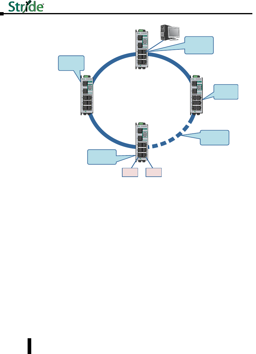
Switch
Switch
This is a
Designated Bridge
with root path
cost of 10.
This is a Designated
Bridge with root
path cost of 20
(10 + 10).
Ethernet
Device
Ethernet
Device
Path cost = 10
Path cost = 15
Path cost = 10
Path cost = 10
This is the backup
path since it will
cost 25 (10 + 15)
to reach the root.
This is a
Designated
Bridge with root
path cost of 15.
This is the Root
Bridge because it
either has the highest
priority or lowest
bridge ID.
Supervisory
Computer
Switch
Switch
4-26
Chapter 4 - Managed Switch Software Setup
Stride Industrial Ethernet Switches User Manual 2nd Ed. Rev. A
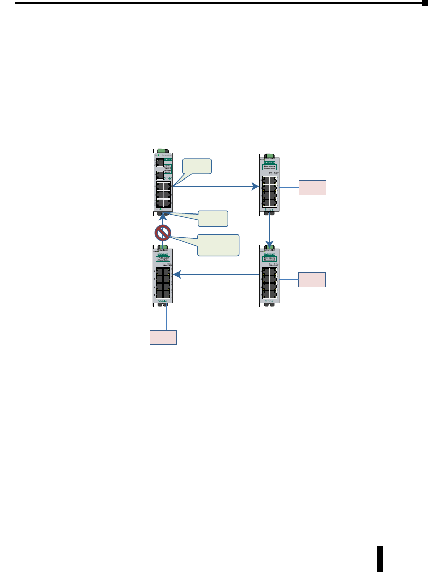
Example 3: Ring Topology with only 1 Managed Switch (Bad idea!):
Implementing a ring topology with a single managed switch and several unmanaged switches
is occasionally considered to try to save money. The topology is legal only if that single
managed switch is a member of each ring. Although it is legal, it is not recommended, as the
hypothetical scenario indicated below will explain.
Hypothetical Scenario:
An integrator wishes to implement a single Ethernet ring topology for the proposed network.
Only one managed switch is used to connect to three or more unmanaged switches in the
loop (Figure below).
Device C
Unmanage
d
Switch #3
Unmanaged
Switch #2
Device B
Unmanaged
Switch #1
Managed
Switch
Device A
Connection is not
active because of
blocked port
Port is
forwarding
Port is
blocking
Initially, everything is working fine in the network. The managed switch detects the loop by
seeing its own configuration messages and based on STP parameters, chooses one port to be
in the forwarding state, and the other port to be in the blocking state. No loop is formed and
device A can talk to device B.
4-27
Chapter 4 - Managed Switch Software Setup
Stride Industrial Ethernet Switches User Manual 2nd Ed. Rev. A
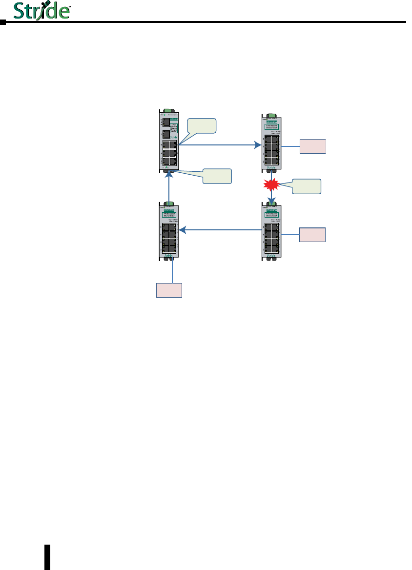
Somewhere in the plant, a construction vehicle accidentally cuts the connection between
unmanaged switch #1 and unmanaged switch #2. The managed switch in the network
notices (typically around 6 seconds when connected to an unmanaged switch) that the port in
blocking mode is not receiving configuration messages and transitions through the listening,
learning, and forwarding states (Figure below).
Device C
Unmanage
d
Switch #3
Unmanaged
Switch #2
Device B
Unmanaged
Switch #1
Managed
Switch
Device A
Port is
forwarding
Port is
blocking
Link is
broken
This would seem to have solved the problem as both ports in the managed switch are in
forwarding mode, but it is not the case. Due to the fact that the other three switches are
unmanaged, they do not have the intelligence to know that there has been a change in the
network topology. switch #1 still points to switch #2 when device A is trying to talk to device
B (across the broken Ethernet link). The bottleneck has been discovered, as we have to wait
until the MAC table in switch #1 ages out its entries of device A and device B. The same
applies for devices connected to switch #2 (B talking to A) and switch #3 (C talking to A).
As a result of this “money saving” configuration, the network redundancy performance is
traded off and left at the mercy of the time it takes to age out MAC table entries in switches
1, 2, and 3. Depending on the model of unmanaged Ethernet switch, entries in the MAC
table are usually aged out in a time period of 5 minutes or more.
This introduces at least 5 minutes of downtime for the plant, which could have a very
detrimental cost with respect to the operation of the plant. By replacing switches 1, 2, and 3
with managed switches, the network convergence time is reduced to a less than a second. An
additional benefit is that the network is not limited to only one redundant loop and can have
a “mesh” of connections for a truly redundant network scheme at all points in the network.
4-28
Chapter 4 - Managed Switch Software Setup
Stride Industrial Ethernet Switches User Manual 2nd Ed. Rev. A

Traffic Priority (Priority Queuing QoS, CoS, ToS/DS)
Without enabling special handling, a network provides a “best effort” service to all
applications. This means that there are no assurances regarding the Quality of Service (QoS)
for any particular application because all packets are treated equally at each switch or router.
However, certain applications require deterministic response from the network to assure
proper operation.
Consider a drilling machine in a plant that is controlled by a computer on a local network.
The depth of the machine’s drill is critical; such that if the hole is drilled is too deep, the
material will have to be thrown out. Under normal conditions, the drill process is running
smoothly (controller and computer are communicating efficiently over the network) but
when another user on the network accesses records from an online database, the large volume
of traffic can interfere with timely communication with the drill. A delay in communications
between the drill and controller causes the drill to go too far and the material has to be
thrown away. To prevent this from happening, we need to provide a certain QoS for all drill-
controller communications so delay is avoided.
Numerous mechanisms exist to help assure reliable and timely network communication. The
managed switch supports two common means of prioritizing messages: IP header and 802.1p
user priorities.
The IP header is present in all frames and contains a priority field, which defaults to 0 and
may be set as high as 255. This field is sometimes referred to as the Type of Service (ToS)
field, or the Differentiated Services (DS or DiffServ) field.
Applications may add IEEE 802.1p tags, which contain a priority field that may be set from
0 to 7. Each value has a traffic type associated with it. For example, a tag of 5 is prescribed for
video data.
The switch provides four priority queues for expediting outbound data. The 256 IP priorities
and the 7 IEEE priorities are mapped into these ports in a way that optimizes throughput of
high priority data.
Scheduling:
When choosing how to handle lower priority data, the switch can use strict or fair scheduling.
This choice affects all queues on all ports.
Send All Priority Frames before any others: With strict scheduling, all data in the highest
priority queue will be sent before any lower priority data, then all data from the second
highest priority, and so on. This assures that high-priority data always gets through as quickly
as possible.
Allow Lower Priority Frames through, a few at a time: With fair scheduling, a round-robin
algorithm is used, weighted so that more high-priority than low priority data gets through.
Specifically, the switch will send eight frames from the urgent queue, then four from the
expedited queue, two from the normal queue, and one from the background queue, then start
over with the urgent queue. This assures that the lower priority queues will not be starved.
4-29
Chapter 4 - Managed Switch Software Setup
Stride Industrial Ethernet Switches User Manual 2nd Ed. Rev. A
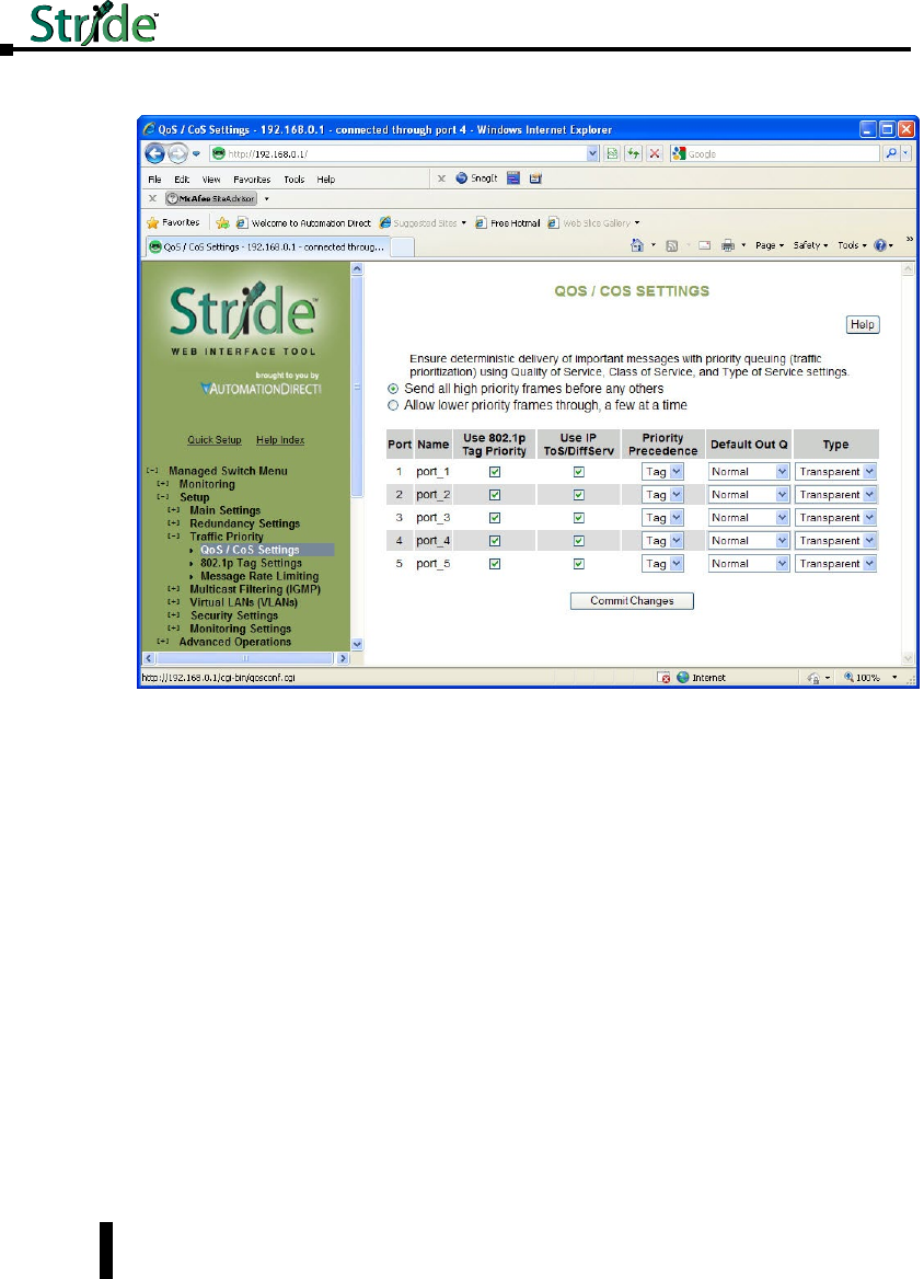
QoS / CoS Settings
Use 802.1p Tag Priority: This setting controls whether the switch will honor IEEE tags if
present in frames. When enabled, tagged data will routed to an outbound priority queue
based on the configure tag mapping (See below). Disable this setting to ignore IEEE tags on
all in-coming frames.
Use IP ToS/DiffServ: This setting controls whether the switch will honor priority fields in
the IP header. When enabled, and not overridden by an IEEE tag, data will be routed to an
outbound priority queue based on IPv4 Type of Service or Ipv6 Traffic Class. The priority
queue will be the IP priority field value divided by 64. Disable this setting to ignore IP
priority fields.
Priority Precedence: This setting controls which priority mark – IEEE tag or IP header –
takes precedence if both are present and enabled. It has no effect if either Use Tags or Use IP
is disabled.
Default Out Q: This setting controls the default priority to be assigned to frames when it
cannot otherwise be determined. For example, if a frame without an IEEE tag arrived at a
port where Use IP was disabled. Select an out-bound priority queue from the list.
Port Type: This setting controls how IEEE tags are handled in out-going data:
• Transparent: Maintains any tag that may have been present in a frame when it entered the switch.
• Edge: Removes tags from all out-going frames.
4-30
Chapter 4 - Managed Switch Software Setup
Stride Industrial Ethernet Switches User Manual 2nd Ed. Rev. A
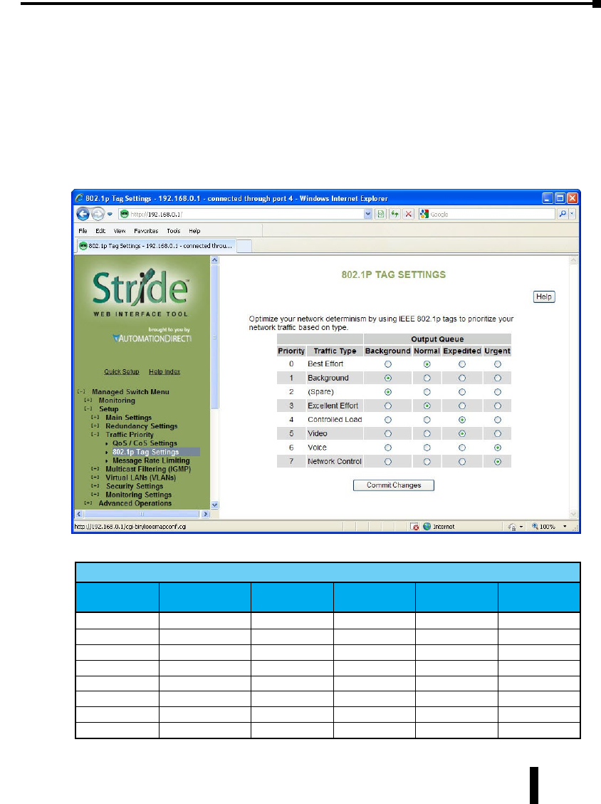
• Network: Adds a tag if none is present. The value of the tag is the queue number times two (six
for queue 3, etc…)
• Core: All frames exiting this port will be tagged, in some cases double-tagged.
802.1p Tag Settings
The managedswitch has four Output Queues: Background, Normal, Expedited and Urgent
with Background being the lowest priority and Urgent being the highest priority. In the
IEEE 802.1p specification, there are eight different priorities that are carried in the tag.
Configure each of the 802.1p priorities for the output queue that is appropriate. More than
one 802.1p priority may be configured for a given output queue.
The table below indicates the defaults:
Managed Switch Output Queue
Priority Traffic Type
(802.1p priority) Background Normal Expedited Urgent
0Best Effort X
1Background X
2(Spare) X
3Excellent Effort X
4Controlled Load X
5Video X
6Voice X
7Network Control X
4-31
Chapter 4 - Managed Switch Software Setup
Stride Industrial Ethernet Switches User Manual 2nd Ed. Rev. A

Message Rate Limiting
Message Rate Limiting can prevent your switch and network from being overwhelmed by
high volumes of broadcast and multicast messages. When enabled on a port, message rate
limiting controls the percentage of messages which are allowed to be broadcast or multicast.
Messages over the limit are dropped.
Poorly configured applications and devices or malicious users can flood your network
with broadcast packets that are forwarded to all ports and can quickly consume most of a
network’s bandwidth. The managed switch provides some protection from such “broadcast
storms” by allowing you to limit the rate at which these messages are accepted by the switch.
For each port, you may choose to limit the rate of broadcast and multicast messages accepted.
Messages over the preset limit will be discarded.
Limiting is done based on message type and priority. Broadcast and multicast messages are
prioritized (by IP ToS) then limited to approximately the following rates:
Priority Limit
Background 10% of link capacity
Normal 20% of link capacity
Expedited 40% of link capacity
Urgent 80% of link capacity
The exact limit depends on link speed.
Messages directly addressed to a single station (unicast messages) are not affected by message
rate limiting.
4-32
Chapter 4 - Managed Switch Software Setup
Stride Industrial Ethernet Switches User Manual 2nd Ed. Rev. A

Forward Unknown: By default, messages addressed to unicast addresses that have not
yet been learned by the switch are flooded to all other ports. This is important for some
protocols that transfer data primarily in one direction, but it can overwhelm smaller systems
that do not expect a large amount of traffic. Forwarding of unknown unicast messages can be
disabled on a port-by-port basis by disabling “Forward Unknown”.
QoS Example
Let us investigate a detailed example of how to manage a network such that critical real time
data will not be interrupted by data that is not as urgent
Hypothetical Scenario:
There is a power plant that is controlled by a central control system. In addition, because of
security concerns, cameras have been mounted and installed at each location of mechanical
control. The mechanical control devices and video cameras at each site communicate via
Ethernet to their own switch. (For reasons of simplicity and clarity, we will assume that only
video and control data reside on the network).
• Problem: Should any of the mechanical control devices receive delayed control data from
the central control system, the power plant can’t generate the maximum energy that it
is capable of. Customers will experience brown outs, and the plant will be looked upon
with negative scrutiny. It is therefore very important that the video traffic created by the
cameras not delay critical data.
• Goal: To optimize the forwarding of critical real-time control data and minimize or
eliminate the impact of video data traversing the network.
• Solution: Configure the switch such that video data has lower priority than control data
by adjusting the priority queuing settings in the switch.
Configuration of the Switch:
As mentioned earlier in this manual, some applications require a certain Quality of Service
(QoS) from the network to achieve a desired level of service. In this example, it is important
that we achieve timeliness for control data. Without taking advantage of the switch’s priority
queuing abilities, we are using the best-effort network model. This means that the network
will try to deliver all packets of information, but will not make any sort of promise or
guarantees with respect to the timeliness of data for specific applications. Considering our
control/video example, there is no guarantee that we can get the response time needed for
control data if the video cameras are sending data at the same time.
A way to achieve the QoS desired is to prioritize network traffic. Prioritization of network
traffic can be achieved even if the devices (video cameras and control systems) do not support
selection or configuration of Quality of Service parameters.
Configure all the ports used to interconnect the switches as follows:
• Use 802.1p Tag Priority = Checked
• Use IP ToS/DiffServ = Checked
• Default Priority Precedence = Tag
• Output Tag = Add Tag
4-33
Chapter 4 - Managed Switch Software Setup
Stride Industrial Ethernet Switches User Manual 2nd Ed. Rev. A

Where the data originates (the camera or control system), configure the QoS/CoS settings for
the video camera ports as follows:
• Use 802.1p Tag Priority = Unchecked
• Use IP ToS/DiffServ = Unchecked
• Default Priority Precedence = Expedited
• Output Tag = Remove Tag
Also, configure the control system ports as follows:
• Use 802.1p Tag Priority = Unchecked
• Use IP ToS/DiffServ = Unchecked
• Default Priority Precedence = Urgent
• Output Tag = Remove Tag
In this way, the switches will handle the packets appropriately and tag them for handling
elsewhere in the network.
At the destination, configure the control system port as follows:
• Use 802.1p Tag Priority = Checked
• Output Tag = Remove Tag
Also, configure the video concentrator port as follows:
• Output Tag = Remove Tag
Result:
Configuring the video data to have a lower priority than control data results in the QoS
required for the control data.
In the following diagram, we have an IPm controlling a turbine and some torque converters.
In addition, we have a video concentrator device that is collecting video data. Since the
switch was configured such that video data (Triangles) has lower priority than control data
(circles), we see that the control data gets sent out more often than the video data. For clarity,
the diagram notes that untagged data in the network consists of open triangles and circles,
while tagged data in the network consists of filled triangles and circles. This achieves the QoS
needed for the control application.
4-34
Chapter 4 - Managed Switch Software Setup
Stride Industrial Ethernet Switches User Manual 2nd Ed. Rev. A
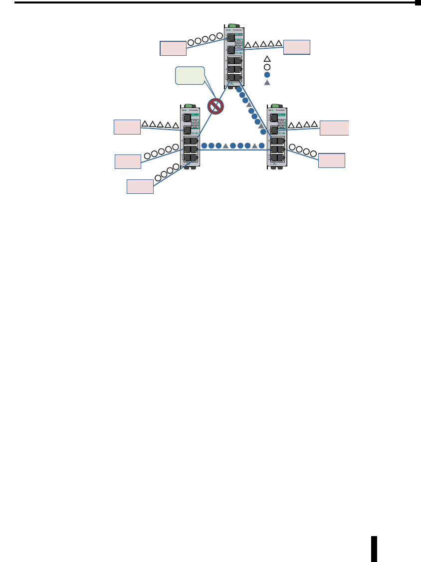
Managed
Switch
Redundant
Path
Blocked
Torque
Coverter
Turbine
Video
IPm
Controller
Video
Concentrator
Video
Torque
Coverter
Managed
Switch
Managed
Switch
Camera Data
Control Data
Tagged Camera Data
Tagged Control Data
(Destination)
4-35
Chapter 4 - Managed Switch Software Setup
Stride Industrial Ethernet Switches User Manual 2nd Ed. Rev. A

Multicast Filtering (IGMP)
IGMP (Internet Group Management Protocol) allows hosts and routers to work together to
optimize forwarding of multicast traffic on a network. Without IGMP, all multicast packets
must be forwarded to all network segments. With IGMP, multicast traffic is only forwarded
to those network segments which connect interested hosts.
IGMPv1 provides a basic mechanism for hosts and routers to communicate about multicast
groups. Routers send Query messages and hosts respond with group membership Report
messages.
IGMPv2 adds a maximum response time to the Query and adds a Leave message to the
protocol. IGMPv1 and IGMPv2 should not coexist on the same network. Also, IGMPv2
routers are expected to perform IGMPv1 on segments where IGMPv1 hosts are found.
An IGMP snooping switch performs many of the functions of an IGMP router. In passive
mode, such a switch processes IGMP protocol messages sent by hosts and routers to configure
efficient forwarding of multicast traffic. In active mode, a switch will also send its own queries
to speed network convergence.
Periodically, routers and IGMP snooping switches in active mode send an IGMP Query on
each attached network. (The query interval is generally around 1-2 minutes.) A host that
wishes to be a member of a group sets a timer for a short, random delay when it sees the
Query. If it sees a Report from another host before its timer expires, it cancels the timer and
takes no further action until another Query is seen. If no other Report is seen, a Report is
sent when the timer expires. The router or switch uses the Report to configure multicast
forwarding.
The router or switch keeps track of how long it has been since the last Report on each port
for each group. When the group expires, the router or switch stops forwarding multicast data
to that port. Since the query interval is less than the expiration time, data for active groups
continues to be forwarded without interruption.
4-36
Chapter 4 - Managed Switch Software Setup
Stride Industrial Ethernet Switches User Manual 2nd Ed. Rev. A
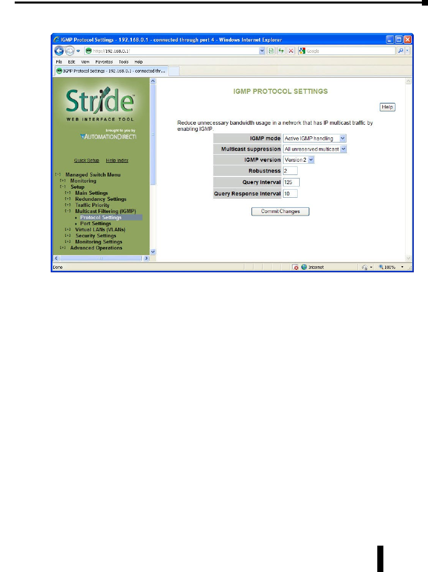
IGMP Protocol Settings
The default settings will allow the switch to regognize members of a multicast group and
forward the multicast message to only members of that group.
IGMP Mode: This setting controls how the switch handles IGMP messages to determine
how to forward multicast traffic.
• IGMP Disabled: Causes the switch to ignore IGMP messages. All multicast traffic will
be sent to all ports.
• Passive IGMP handling: Causes the switch to listen to IGMP messages and configure
forwarding of multicast traffic accordingly.
• Active IGMP handling: Causes the switch to act as an IGMP router, sending queries
when needed and configuring multicast forwarding according to IGMP membership
reports.
Multicast suppression: This enhanced feature can intelligently suppress multicast packets
that no host has requested with IGMP.
• None: Multicast packets will be sent to all ports unless IGMP is enabled and one or
more clients have sent IGMP Report requests.
• IP multicast groups: Multicast packets corresponding to IP multicast groups (with MAC
addresses starting 01:00:5e) will be suppressed unless one or more clients have sent IGMP
Report messages. Multicast packets with other addresses will be sent to all ports.
• All unreserved multicast: Multicast packets with reserved multicast addresses
(01:80:c2:00:00:0x where x is 0..f) will be sent to all ports. All other multicast packets
will be suppressed unless one or more clients have sent IGMP Report messages.
4-37
Chapter 4 - Managed Switch Software Setup
Stride Industrial Ethernet Switches User Manual 2nd Ed. Rev. A

IGMP Version: This setting controls the highest IGMP version that the switch will use. All
IGMP routers and snooping switches on a network should be configured for the same IGMP
version. Select 1 or 2 as appropriate for your installation.
Robustness: This setting specifies how many queries may be lost without impacting
forwarding as the switch tries to find IGMP hosts.
Query Interval: This setting specifies how often the switch will send IGMP queries in
seconds.
Query Response Interval: This setting specifies the maximum time for hosts to respond to
IGMP queries. (For IGMPv1, this is fixed at 10 seconds).
Port Settings
Like the default IGMP Protocol Settings, the default IGMP port settings will allow a switch
to function in a network with multicast groups. Generally, the switch will dynamically learn
which ports have IGMP routers attached to them by listening for IGMP Query messages.
Under some circumstances, it is necessary to statically configure ports as leading to IGMP
routers. Force the switch to forward IGMP messages to a specific port by choosing Static as
the router type.
Exclude: A port may be excluded from IGMP processing. IGMP queries and reports
received on an excluded port are ignored so devices reached via the excluded port cannot join
multicast groups filtered by the switch. IGMP queries and reports will not be forwarded
to the excluded port so IGMP routers reached via the excluded port will not know of
memberships for devices reached by other ports.
4-38
Chapter 4 - Managed Switch Software Setup
Stride Industrial Ethernet Switches User Manual 2nd Ed. Rev. A
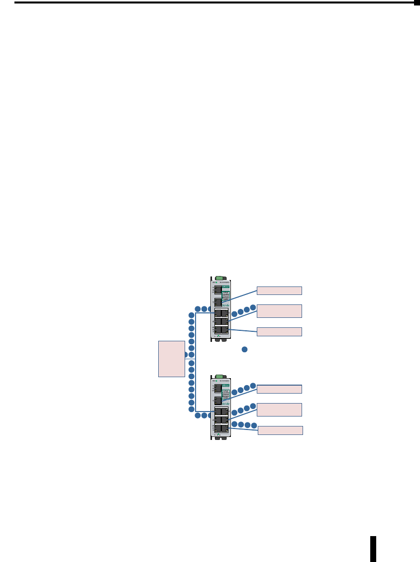
Static Router: Specifies whether the switch should assume there is an IGMP router on this
port even if no IGMP query messages are received.
IGMP Example
The Benefits of Enabling IGMP:
Take an already established control network that has an Ethernet device sending multicast
data to several other Ethernet devices. Between the source of the multicast data, and the
destination Ethernet devices that are interested in the multicast data, multicast packets might
pass through a number of switches or routers.
To make this control network more efficient, the switches or routers should know how
to handle the flow of multicast data by means of IGMP (Internet Group Management
Protocol). Switches or routers that are not capable of supporting IGMP will not know what
to do with the multicast data and forward multicast data out all ports. This will slow down
the network.
Take a look at the following diagram, where the IGMP server is the source of the multicast
data, and the IGMP hosts are the devices interested in receiving multicast data. On the
network are two switches, where one has IGMP enabled and the other has IGMP disabled.
We see that the switch with IGMP enabled only forwards multicast data to the interested
host (Ethernet Station 2). The switch with IGMP disabled will not know where to send
the multicast data; thus Ethernet Stations 4 and 6 unnecessarily receive multicast data even
though only Station 5 is the interested host.
Managed
Switch
Managed
Switch
IGMP
Server
Ethernet Station 1
Ethernet Station 3
Ethernet Station 2
(IGMP Host)
Ethernet Station 4
Ethernet Station 6
Ethernet Station 5
(IGMP Host)
Multicast Traffic
– IGMP enabled
– IGMP disabled
4-39
Chapter 4 - Managed Switch Software Setup
Stride Industrial Ethernet Switches User Manual 2nd Ed. Rev. A

Virtual LANs (VLANs)
VLANs can segregate traffic flowing through a switch to improve bandwidth utilization or
security. Segregation is done based on membership in a group of ports (port-based VLANs)
or on IEEE 802.1Q tags which include a VLAN ID (tag-based VLANs).
A port-based VLAN limits forwarding traffic coming in a port to the group of ports to which
that port belongs. For example, on a 10-port switch if ports 1, 3, 5, 7, and 9 were placed
in a port-based VLAN, broadcast frames coming in port 3 would be sent to ports 1, 5, 7,
and 9 (which are members of port 3’s VLAN) but not to ports 2, 4, 6, and 8 (which are not
members).
A port may be a member of two port-based VLANs, although results of this configuration
are not always desirable or easily predictable. When initializing port-based VLANs the switch
configures each port to be able to send data to all ports in all the port-based VLANs in which
it is a member. For example, if one VLAN had ports 1-5 and another had ports 5-9, traffic
from port 1-4 could go to ports 1-5, traffic from ports 6-9 could go to ports 5-9, and traffic
from port 5 could go to all ports.
A tag-based VLAN is more common. A tag-based VLAN limits traffic based on the VLAN
ID in a ‘tag’ associated with the frame. VLAN tags may be explicitly placed in frames by
applications or switching equipment, or implicitly assigned to frames based on the switch
port where they arrive.
VLAN IDs are 12-bits long providing 4096 possible IDs but several values are reserved:
• 0 = Indicates that the tag is not being used for VLAN routing but only to carry priority
information. (See QoS/CoS topic).
• 1 = Used for switch configuration and management.
• 4095 = Not allowed by the 802.1Q standard.
4-40
Chapter 4 - Managed Switch Software Setup
Stride Industrial Ethernet Switches User Manual 2nd Ed. Rev. A
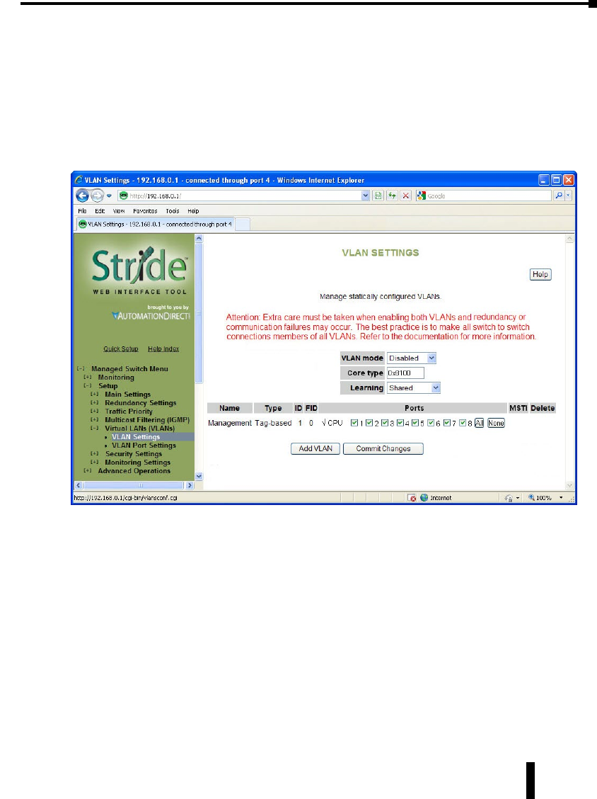
VLAN Settings
There are several VLAN modes, which provide varying levels of flexibility and security.
Configuring VLANs requires creating VLANs on the VLAN Settings page and configuring
ports for participation in the VLAN on the VLAN Port Settings page.
The VLAN settings page identifies which traffic a port can “listen” to. The VLAN Port
Settings page identifies traffic a port can “talk” to. For ports to participate effectively in
a VLAN, each port should be assigned to one VLAN on the VLAN settings page, then
configured with that VLAN ID on the VLAN Port Settings page.
VLAN Mode:
• Disabled: No VLAN processing is done. VLAN IDs and port-based VLANs are ignored.
• Port-Based: Only port-based VLANs are used to route frames. VLAN IDs are ignored.
• Standard: (Most commonly configured) Port-based VLANs are ignored; all routing is done by
VLAN ID. The source port of a frame need not be part of a VLAN for the frame to be forwarded.
• Secure: All routing is done by VLAN ID; however, if the source port of a frame is not a member of
the target VLAN, then the frame is dropped. For example, if a tag-based VLAN for ID 1024 was
configured to include ports 1-5 and a frame with VLAN ID 1204 in its tag arrived at port 6, the
frame would not be forwarded.
Core Type: (gigabit switch only) Specify the Ethertype for double-tagged (“Q-in-Q”) frames
exiting ports of type Core. The value may be specified in hexadecimal with a 0x prefix.
Learning: This setting describes how different addresses on different VLANs are ‘learned’ by
the switch.
4-41
Chapter 4 - Managed Switch Software Setup
Stride Industrial Ethernet Switches User Manual 2nd Ed. Rev. A
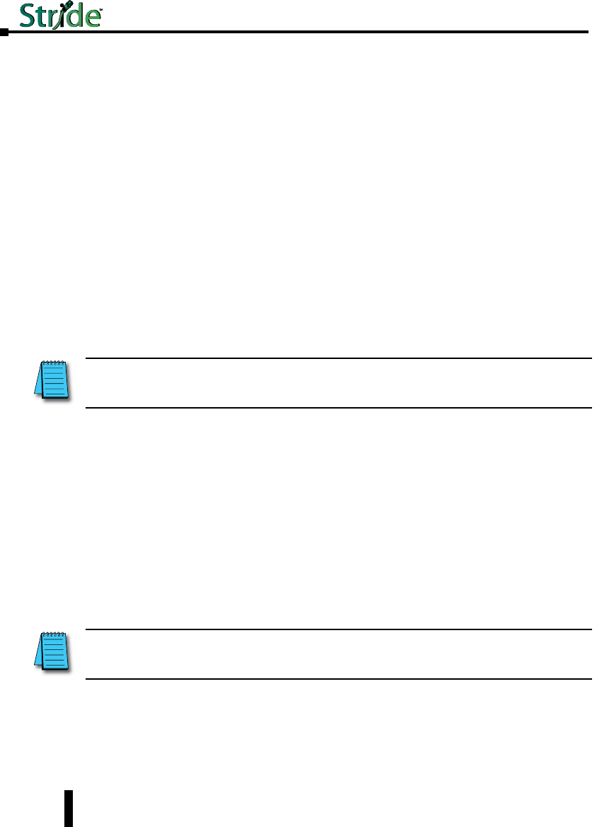
• Shared: All VLANs (if MSTP is enabled, all VLANs assigned to the same MSTI) use the same
forwarding database.
• Independent: The forwarding database used by each tag-based VLAN can be configured
independently.
The switch supports up to 64 configurable VLANs including the management VLAN. To
configure additional VLANs, click the “Add VLAN” button to create an empty row in the
table. Then choose the name, ID information and ports for your VLAN. For tag based
VLANs, the CPU should not be included in any VLAN other than the default management
VLAN (1). The CPU should be included in port based VLANs.
To remove a VLAN, simply click the “X” in the delete column for that VLAN. When your
settings have been changed as needed, click “Commit Changes” to save them.
Name: A mnemonic name for a VLAN such as “Cell 7”, “Line 4”, “Building 58”. This is
used for display only.
Type: The VLAN’s type, port-based or tag-based.
ID: For tag-based VLANs, this is the ID to look for in the tag. This ID identifies the
individual VLANs you create on your network. The VLAN ID must be specified in the
range from 2 to 4094.
FID: For tag-based VLANs, the forwarding database to use when independent learning is
enabled. If MSTP is running, all VLANs in the same MSTI must be configured to use the
same forwarding database in independent learning mode. Shared learning automatically
assigns a different forwarding database to each MSTI.
This filtering ID allows multiple VLANs to be grouped for easy filtering in the MAC address
monitoring page.
Ports: The ports included in this VLAN. For tag based VLANs, the CPU should not be
included in any VLAN other than the default management VLAN (1). The CPU should be
included in port based VLANs.
To select the ports to include in this VLAN, check the box for each port you wish to include.
Remember that if the “CPU” box is not checked, you will be unable to communicate with
the switch from within this VLAN.
Delete: Select to delete the corresponding VLAN when changes are committed. When
selected, this VLAN will be deleted when changes are committed.
NOTE: When working with tag-based VLANs, ports included in a VLAN may lead to other network devices (which
require tags to properly route data) or to end devices, which cannot process VLAN tags. Use the VLAN Port Settings
page to configure the appropriate type for each port.
NOTE: Take care when setting the management VLAN ID. If the device you are configuring from cannot work with
VLANs and the port it is connected to does not have the proper PVID and port type setting the management VLAN may
make the Switch inaccessible and require a local serial connection to reconnect.
4-42
Chapter 4 - Managed Switch Software Setup
Stride Industrial Ethernet Switches User Manual 2nd Ed. Rev. A
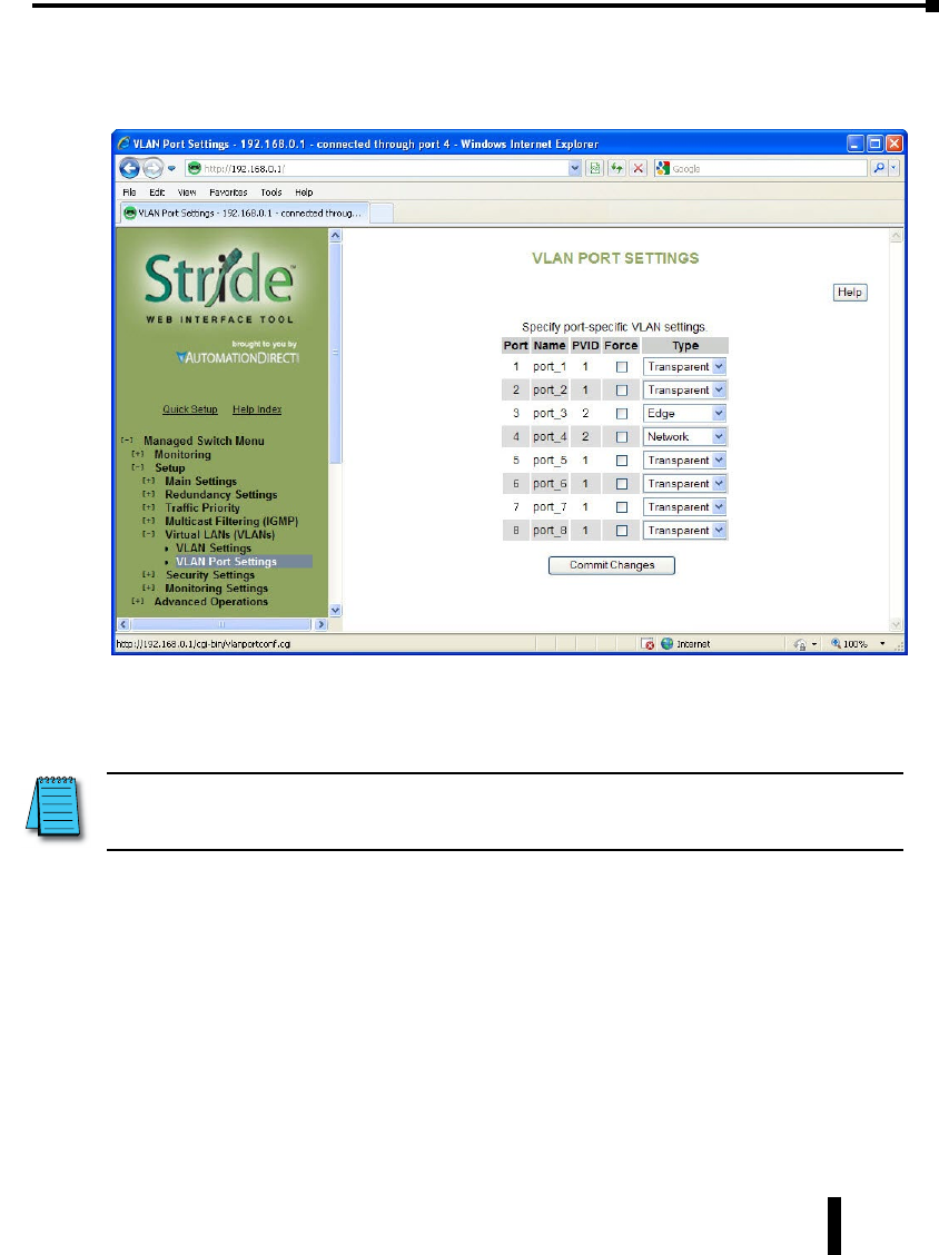
VLAN Port Settings
Each switch port can be configured to control how VLAN tags are handled for frames coming
in and going out of the port.
PVID: This is the port’s default VLAN ID. It is applied to frames which arrive at the port
without a VLAN tag or with a priority-only VLAN tag (one which contains the special
VLAN ID 0). Set the desired PVID to make sure your untagged packets for the port get
forwarded to other ports in the desired VLAN.
Force: When this is checked, the PVID is forced on all frames coming in this port regardless
of any existing tag.
Type: The port type controls how tags are handled on frames exiting this port.
• Network: This is a Trunking port that connects to another switch. All frames exiting this port will
be tagged. If no tag was present when the frame entered the switch, the source port’s PVID will be
used. Typically, a Network port will be a member of many or all tag-based LANs on a switch and is
used to forward VLAN traffic to another switch which then distributes it to other network segments
based on the tags. A Network port can only send packets for VLANs in which it is a member.
• Edge: This is an Access port that typically connects to an end device or perhaps an unmanaged
switch. No frames exiting this port will be tagged. (Use this setting for ports leading to legacy or
end devices without VLAN support.)
• Transparent: Frames will be forwarded unchanged.
NOTE: Switch management and configuration is only possible through the port if the PVID is set to 1
(the default). Setting the PVID to another value prevents the Switch from being managed/configured via that port
(unless the system you are using to configure the Switch can explicitly tag frames for VLAN 1, the management VLAN).
4-43
Chapter 4 - Managed Switch Software Setup
Stride Industrial Ethernet Switches User Manual 2nd Ed. Rev. A
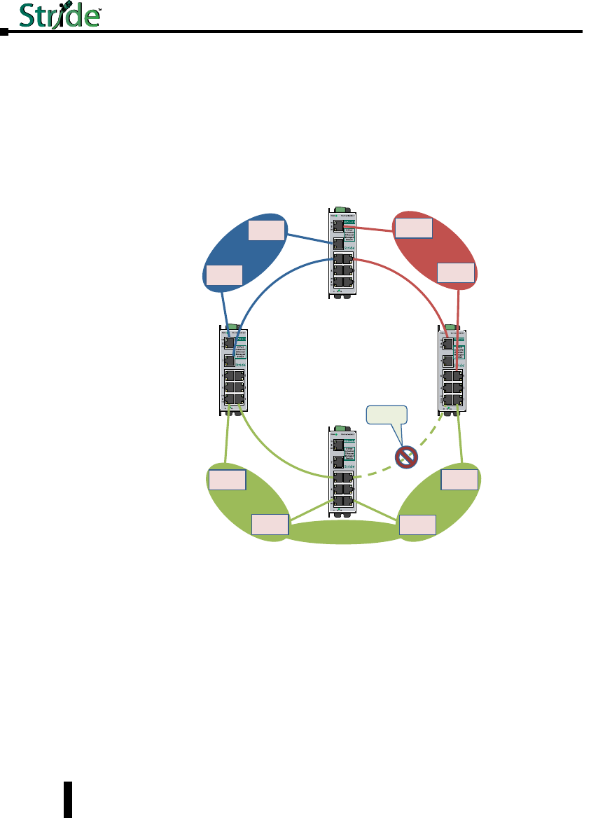
VLAN with RSTP
Extra care must be taken when enabling both VLANs and redundancy, or communications
failures may occur.
The example shown in the following diagram depicts the problem with running the Rapid
Spanning Tree Protocol (RSTP) and VLANs at the same time. The IEEE 802.1D based
RSTP is not aware of the VLAN configuration. Therefore, in the example, one of the
Network Ports for VLAN 3 is being blocked (see VLAN Port Settings topic in this section
about Network type ports). This prevents VLAN 3 from being able to forward data to all its
members.
Blocked by
RSTP
T
a
g
g
e
d
f
o
r
V
L
A
N
3
T
a
g
g
e
d
f
o
r
V
L
A
N
3
T
a
g
g
e
d
f
o
r
V
L
A
N
2
T
a
g
g
e
d
f
o
r
V
L
A
N
1
Switch
Switch
Ethernet
Device
Ethernet
Device
VLAN 1
Switch
Ethernet
Device
Ethernet
Device
VLAN 2
Switch
Ethernet
Device
Ethernet
Device
Ethernet
Device
Ethernet
Device
VLAN 3
4-44
Chapter 4 - Managed Switch Software Setup
Stride Industrial Ethernet Switches User Manual 2nd Ed. Rev. A
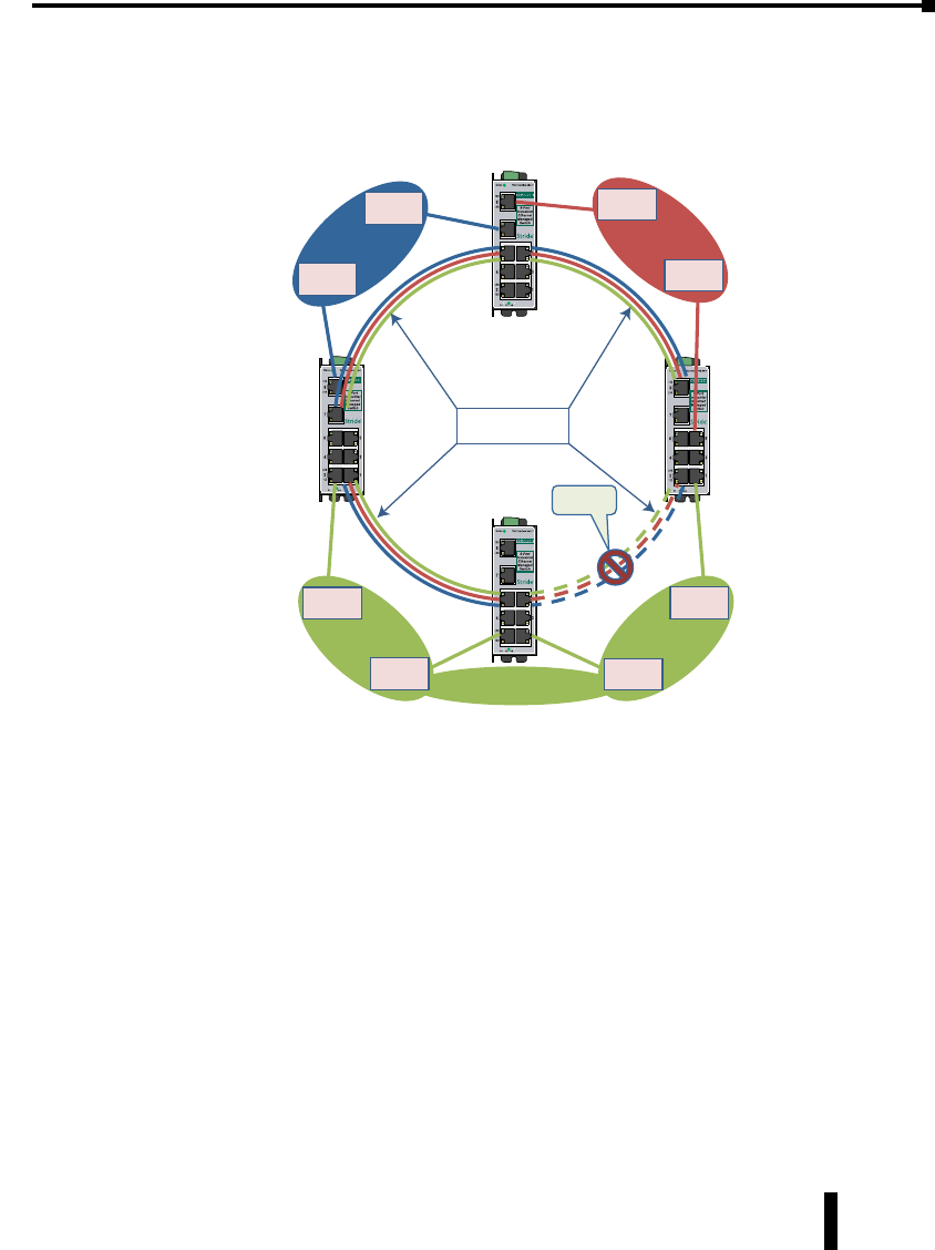
The solution to the problem above is to configure all “Network” type ports to carry all
VLANs in the network. In other words, the Network Port should be a member of all VLANs
defined in the switch. As seen from the example shown in the following diagram, VLAN
3 can forward to all its members through the other Network Port connections and is not
affected by the block RSTP connection.
Blocked by
RSTP
Switch
Switch
Ethernet
Device
Ethernet
Device
VLAN 1
Switch
Ethernet
Device
Ethernet
Device
VLAN 2
Switch
Ethernet
Device
Ethernet
Device
Ethernet
Device
Ethernet
Device
VLAN 3
Tagged for all
VLAN’s (1, 2, & 3)
4-45
Chapter 4 - Managed Switch Software Setup
Stride Industrial Ethernet Switches User Manual 2nd Ed. Rev. A
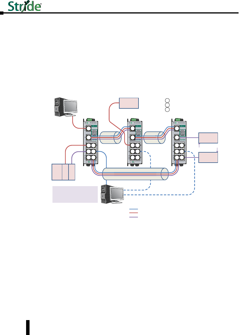
VLAN Examples
Shown below are two examples of using VLANs and how they can solve common network
problems found in a factory automation facility. Note that the end devices used in these
examples do not recognize nor originate VLAN tags.
Problem #1: The process requires a PLC, Remote I/O, Frequency Drive control, HMI
access as well as a PC for Data Logging and a PC for configuration management. The
Remote I/O device and drive communicate via Multicast and Broadcast messaging which an
unmanaged switch cannot filter out. The PLC and the Remote I/O and Drive are remotely
located from each other. Running multiple Ethernet connections would be costly and
logistically complex so the customer wants to utilize existing wiring connections.
Switch 1
Remote
I / O
HMI
Switch 2 Switch 3
PLC/
PAC
Ether
Interface 1
Ether
Interface 2
Drive
Heavy Multicast
and Broadcast
Traffic
Configuration and/or diagnostic of all
switches can be accomplished for all
switches by plugging into Port 3 of
any of the switches by using the
management VLAN (VLAN1)
VLAN 1 = Management VLAN
VLAN 2 = PLC (Ethernet Interface 1), Office PC, HMI
VLAN 3 = PLC (Ethernet Interface 2), Remote I/O, Drive
Configuration
/ Diagnostic
PC for VLAN
Management
Office PC
for Data
Logging E
E
E
T
N
T
E
N
E
N
T
N
E
T
T
T
E
T
N
E
T
NE
T
Structured Wiring
Tag-based VLAN example
E
N
T= Transparent Port
= Network Port (Trunk Port)
= Edge Port
Solution: Use Stride managed switches, utilizing the VLAN feature to separate the broadcast
and multicast traffic from all the devices except for the PLC. We will also wire the three
switches into a Ring configuration so that we can take advantage of the redundancy feature
of the switch. In this situation, we need to use Tag-based VLANs since the Ethernet packets
will be traversing across multiple switches.
How to configure this setup:
We created 3 VLANs:
• VLAN 1 is the default VLAN and we leave it there and enable it on what we will call a
‘management port’ for each switch. In this way, we can plug our laptop into the management port
of any switch and be able to access the other switches across this VLAN to tweak the configuration
or view the diagnostics.
• VLAN 2 will contain one of the Ethernet interfaces of the PLC, the HMI and the Office PC.
• VLAN 3 will contain the other Ethernet interface of the PLC, the Remote I/O drop and the Drive.
4-46
Chapter 4 - Managed Switch Software Setup
Stride Industrial Ethernet Switches User Manual 2nd Ed. Rev. A
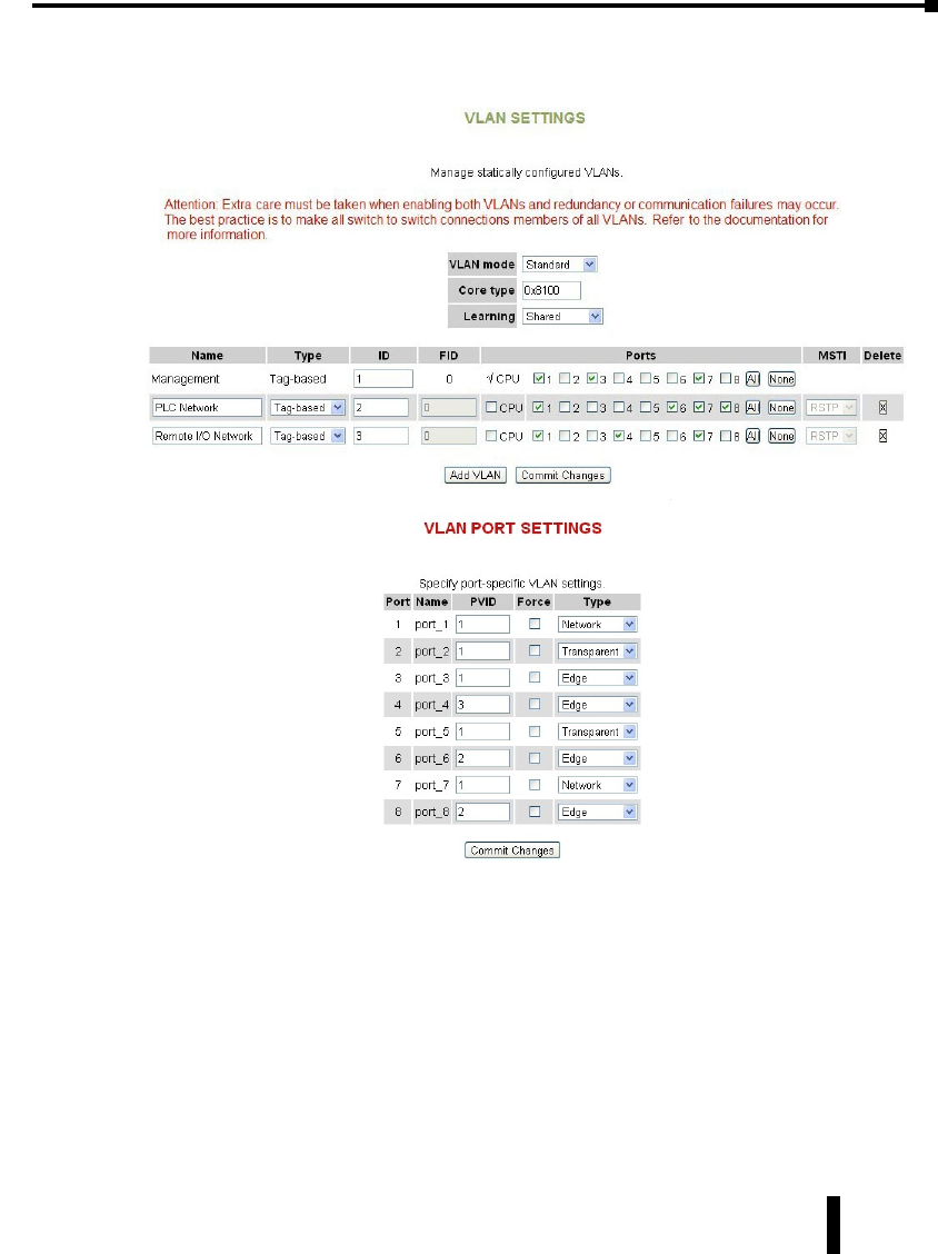
Switch Setup:
Switch1:
4-47
Chapter 4 - Managed Switch Software Setup
Stride Industrial Ethernet Switches User Manual 2nd Ed. Rev. A
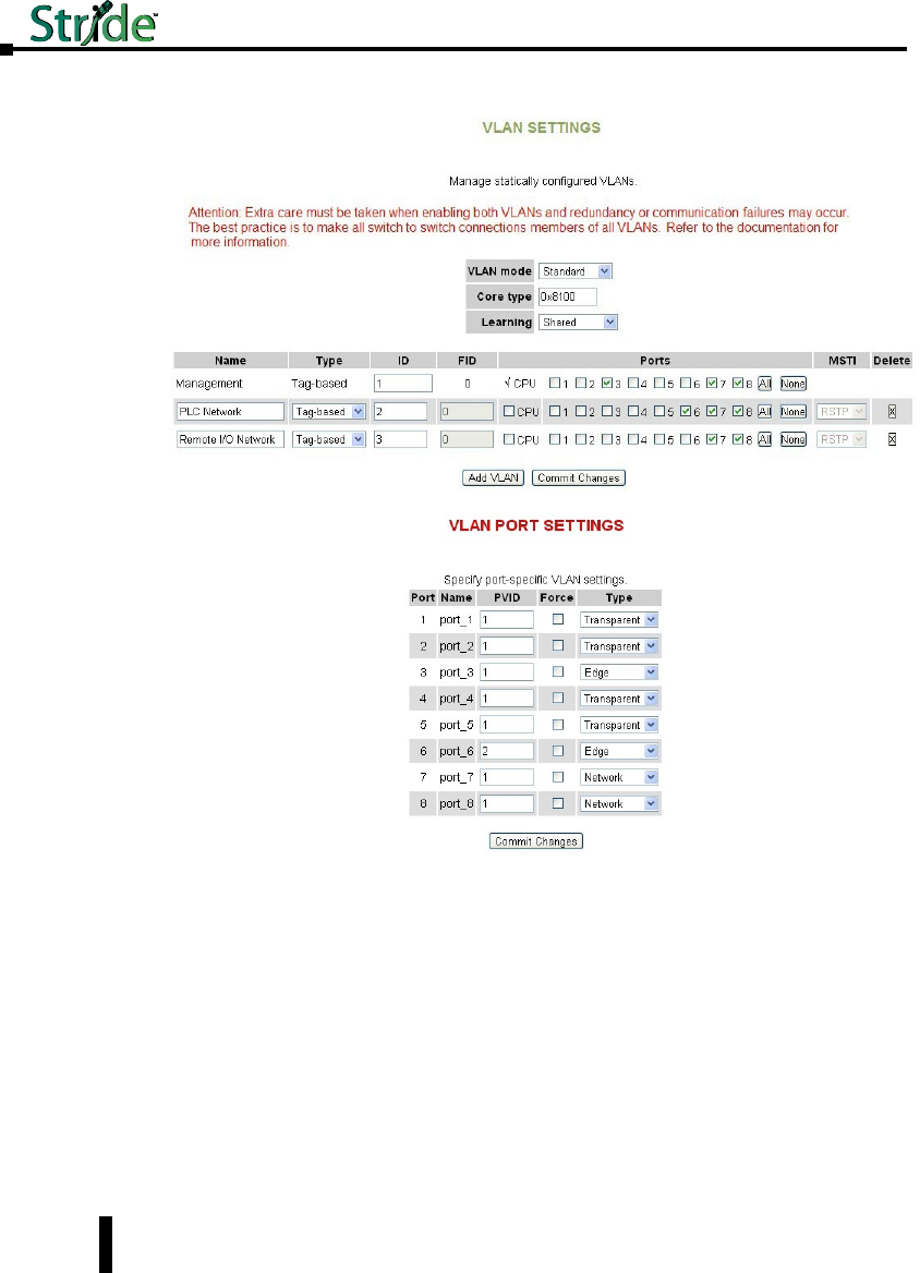
Switch 2:
4-48
Chapter 4 - Managed Switch Software Setup
Stride Industrial Ethernet Switches User Manual 2nd Ed. Rev. A
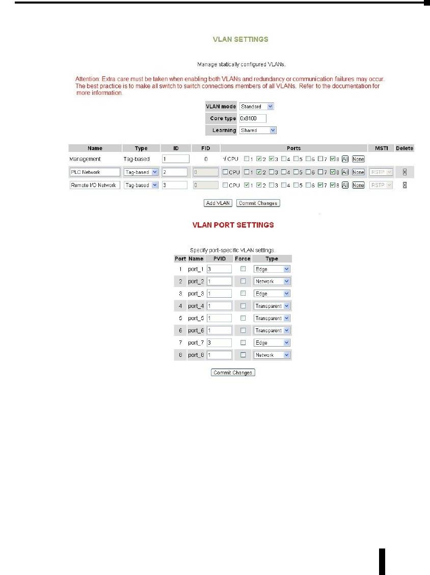
Switch 3:
4-49
Chapter 4 - Managed Switch Software Setup
Stride Industrial Ethernet Switches User Manual 2nd Ed. Rev. A
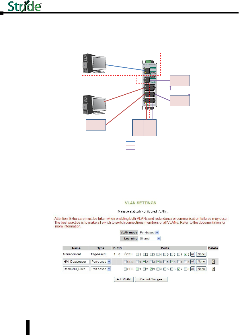
Problem #2: This scenario is very similar to the first. We have the same problem to solve
but the logistics are simpler, in that all of the devices are local and can be wired into the same
switch.
Remote
I / O
PLC/
PAC
Ether
Interface 1
Ether
Interface 2
Drive
VLAN 1 = Management VLAN
VLAN 2 = PLC (Ethernet Interface 1), Office PC, HMI
VLAN 3 = PLC (Ethernet Interface 2), Remote I/O, Drive
Configuration
/ Diagnostic
PC for VLAN
Management
Office PC
HMI
Heavy Multicast
and Broadcast
Traffic
Port-based VLAN example
VLAN 1
VLAN 2
VLAN 3
Solution: We will use a Stride managed switch, utilizing the Port-based VLAN feature. The
question could be posed, “Why not just use two unmanaged switches?” While this would
work, the customer wants to use as few components in the system as possible to minimize
points for possible equipment faults and he would like the enhanced diagnostic capabilities
that a managed switch provides.
Switch Setup:
When using port-based VLANs, VLAN tags don’t determine which VLAN a port is in so it is
not necessary to configure the ports.
4-50
Chapter 4 - Managed Switch Software Setup
Stride Industrial Ethernet Switches User Manual 2nd Ed. Rev. A

Security Settings
The managed switch offers several ways to secure access to the management functions. It can
be remotely managed (monitored and configured) via the following methods:
• Telnet: This accesses the terminal or CLI interface (same as you would get through the console
serial port) but over the Ethernet network. This type of access offers only password protection
(authentication) but no encryption.
• SSH: Secure Shell, like Telnet, accesses the terminal or CLI interface over the Ethernet network. It
offers both password protection and encryption.
• SNMP/SNMPv3: This method accesses the Management Information Bases (MIBs) using an
SNMP server or master utility. Standard SNMPv1 or SNMPv2 has password security. SNMPv3
adds encryption.
• HTTP/HTTPs: This method accesses the web interface. Standard HTTP has password security.
The more secure HTTPS adds encryption through SSL (Secure Socket Layers) or TLS (Transport
Layer Security).
Remote Access Security
See the “Remote Access Security” selection under the “Main Settings”.
NOTE: The best security policy is to turn off or disable any access methods that you are not using.
4-51
Chapter 4 - Managed Switch Software Setup
Stride Industrial Ethernet Switches User Manual 2nd Ed. Rev. A
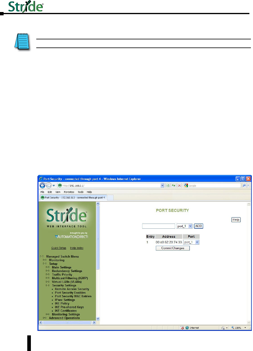
Port Security Enables and Port Security MAC Entries
Port Security Enables and Port Security MAC Entries settings must be used in conjunction
with one another.
The Port Security feature will drop packets from devices that are NOT entered in to the Port
Security MAC Entries table. The security can be enabled for each port individually. The
“Global Port Security Enable” selection must be enabled for the switch to start using the
MAC Entries table.
First, on the Port Security MAC Entries page, create the table of MAC addresses allowed on
each port and enter Commit Changes.
• The MAC address must be entered in the format 12:34:56:78:9A:BC.
• If a MAC address is configured to be allowed on one port AND that port is enabled on the Port
Security Enables page, that MAC address is disallowed access on any other port, including ports for
which security is not enabled on the Security Enables page. For example: If the MAC address for
Device A has been configured for Port 1 in the MAC Entries table and Device A is plugged in to
Port 5, the messages for Device A will be dropped even if Port 5 does not have security enabled.
• More than one MAC address may be configured for a port.
• A MAC address may be configured for only one port.
• If no MAC addresses are entered on the Port Security MAC Entries page AND that port is enabled
on the Port Security Enables page, the port is effectively shut down and all packets will be dropped
at that port.
NOTE: This feature is not supported in the 5-port models
4-52
Chapter 4 - Managed Switch Software Setup
Stride Industrial Ethernet Switches User Manual 2nd Ed. Rev. A
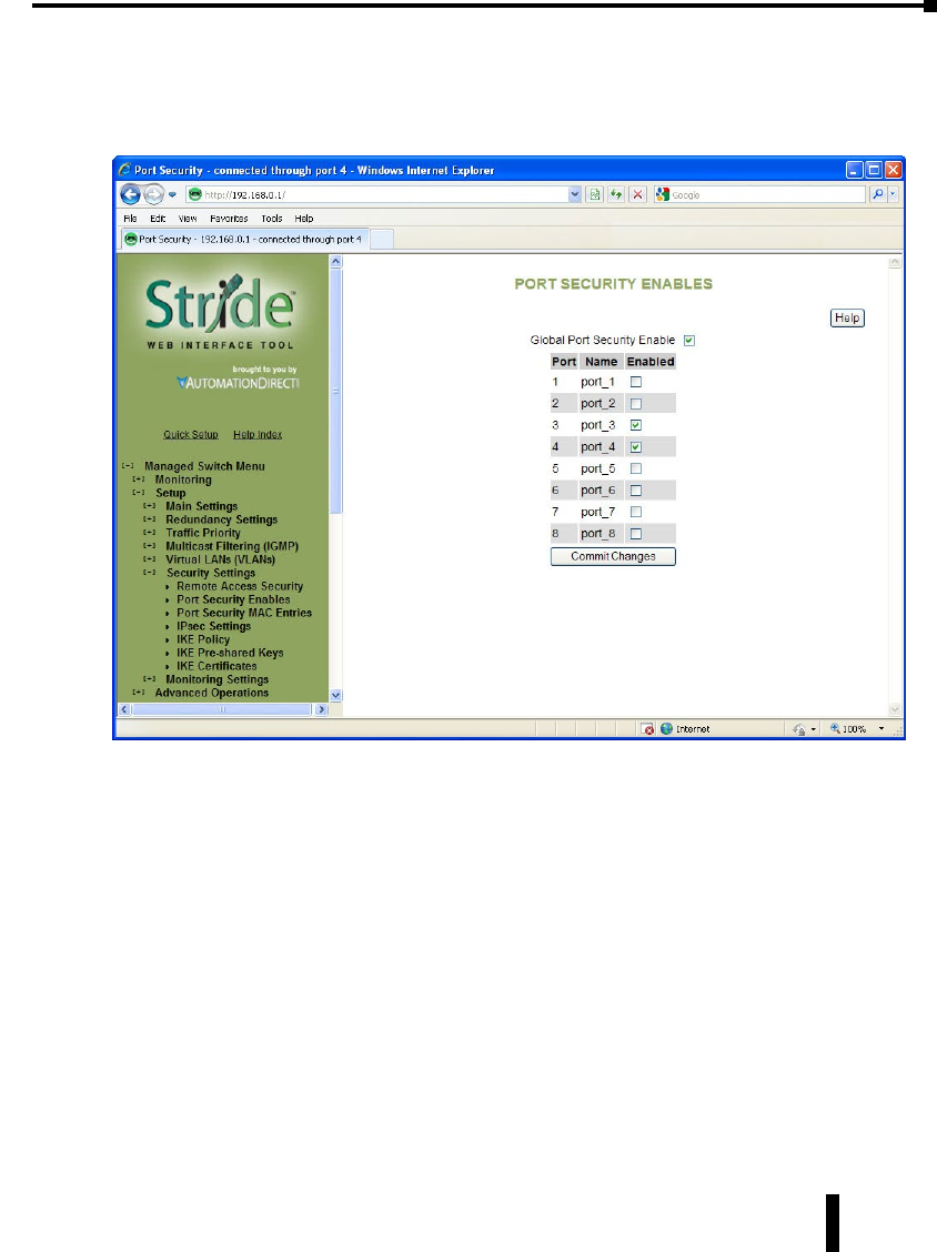
Second, to enable the MAC address security for the ports configured, select the ports and the
Global Port Security selection on the “Port Security Enables” page.
Finally enter Commit Changes to write the configuration to the switch. The switch will
then begin limiting access according to the configuration on these two pages.
Once an entry has been configured and committed to the switch, a power cycle will be
necessary after deletion of an entry in order for that security to be removed.
4-53
Chapter 4 - Managed Switch Software Setup
Stride Industrial Ethernet Switches User Manual 2nd Ed. Rev. A
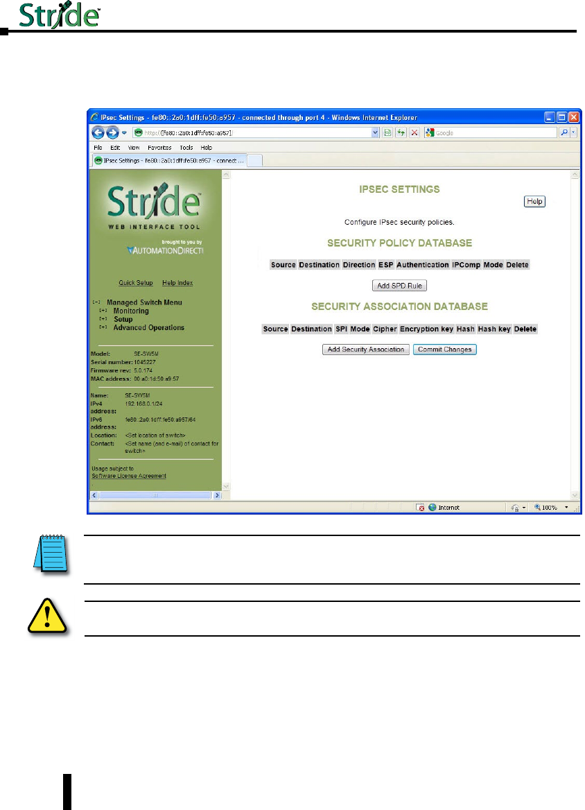
IPsec Settings
IPsec can authenticate, encrypt or compress IPv6 traffic to or from a switch. The IPsec
software in this switch only affects management traffic addressed to or sent from the switch.
Configuration is done via two databases. The SPD (Security Policy Database) sets the
required IPsec protocols for traffic going from or to configured hosts or networks. The SAD
(Security Association Database) contains the encryption, compression and hash parameters
needed to implement the policies required by the SPD for traffic between specific hosts.
Warning: Misconfiguration on this screen may block network access to the Switch’s configuration
interface.
NOTE: IPsec can only be used when the Switch’s primary access address is configured with an IPv6 address. To
connect to the switch via IPv6 with Internet Explorer, you must surround the address with http://[...]. Example: http://
[fe80:0000:0000:0000:02a0:1dff:fe50:bfca]
4-54
Chapter 4 - Managed Switch Software Setup
Stride Industrial Ethernet Switches User Manual 2nd Ed. Rev. A
The AH IPsec protocol is used for authentication. It uses cryptography to detect that the
sender has the same hash key the receiver does. It does not provide any secrecy in transit.
The ESP protocol is used for encryption. It uses cryptography to hide the contents of traffic
in transit from anyone who does not have the secret key it was encrypted with.
IPComp is used to compress traffic. It does not provide any secrecy or authenticity
guarantees.
Security Policy Database: This section is used to create, delete, and modify SPD entries.
To create an SPD entry, click “Add SPD Rule” and set the source, destination, direction, and
protocol requirements as appropriate. To save your changes, click Commit Changes.
To delete an SPD entry, click the ‘X’ button at the end of the row and click Commit
Changes.
To modify an SPD entry, change parameters as desired and click Commit Changes.
• Source: An address of the form address, address/prefixlen, address/prefixlen[port], or address[port].
This specifies the source host or hosts that this policy will affect.
• Destination: An address in one of the same forms accepted by the Source field. This specifies the
destination host or hosts that this policy will affect.
• Direction: The direction traffic is traveling through the switch. If the switch’s address is specified
in the source field, the direction should be Out. If the switch’s address is in the destination field,
the direction should be In.
• ESP: Whether to require encryption for communication between the specified hosts.
• Authentication (AH): Whether to require authentication for communication between the specified
hosts.
• IPComp: Whether to require compression for communication between the specified hosts.
• Delete: When the button is clicked, this SPD entry will be deleted when changes are committed.
Security Association Database:
To create an SAD entry, click “Add Security Association” and set the source, destination, SPI,
mode, cipher, hash algorithm, and keys as appropriate. To save your changes, click Commit
Changes.
CAUTION: Take care when configuring SAD entries. If the keys and SPI values are not the same on
two communicating hosts and their security policies require encryption or authentication they will be
unable to successfully communicate. You may find yourself unable to communicate with the Switch.
NOTE: SPD entries will not apply to ICMPv6 Neighbor Discovery traffic. This allows Neighbor Discovery to function
together with IKE. (Internally, the system adds high-priority rules bypassing IPsec for Neighbor Advertisement and
Neighbor Solicitation packets.)
CAUTION: Take care when configuring SPD entries. If you do not configure appropriate SAD entries to
go along with them and an SPD entry affects the host you are using to configure the Switch, you may
find yourself unable to communicate with the Switch
4-55
Chapter 4 - Managed Switch Software Setup
Stride Industrial Ethernet Switches User Manual 2nd Ed. Rev. A

To delete an SAD entry, click the ‘X’ button at the end of the row and click Commit
Changes.
To modify an SAD entry, change parameters as desired and click Commit Changes.
• Source: An address of the form address or address[port]. This specifies the source host (and
optionally port) for the security association.
• Destination: An address of the form address or address[port]. This specifies the destination host
(and optionally port) for the security association.
• SPI: A locally unique value identifying this security association. This is assigned locally and may be
specified in hex or decimal formats. This should be at least 0x100 (256 decimal) and must be the
same on both peers in an association.
• Mode: The IPsec mode to use: ESP, AH, ESP and AH, or IPComp.
• Cipher: The cipher to use when an ESP mode is selected.
• Encryption key: The key to use when ESP is enabled. This must be specified in hexadecimal
(beginning with 0x) and should be 24 bytes (48 digits) long for 3DES or 16, 24 or 32 bytes (32,
48, or 64 digits) long for AES.
• Hash: The hash algorithm to use when an AH mode is selected. MD5 is not recommended.
• Hash key: The hash key to use when AH is enabled. This must be specified in hexadecimal
(beginning with 0x) and should be 20 bytes (40 digits) long for SHA1 or 32 bytes (64 digits) long
for SHA256.
• Delete: When the button is clicked, this SAD entry will be deleted when changes are committed.
4-56
Chapter 4 - Managed Switch Software Setup
Stride Industrial Ethernet Switches User Manual 2nd Ed. Rev. A
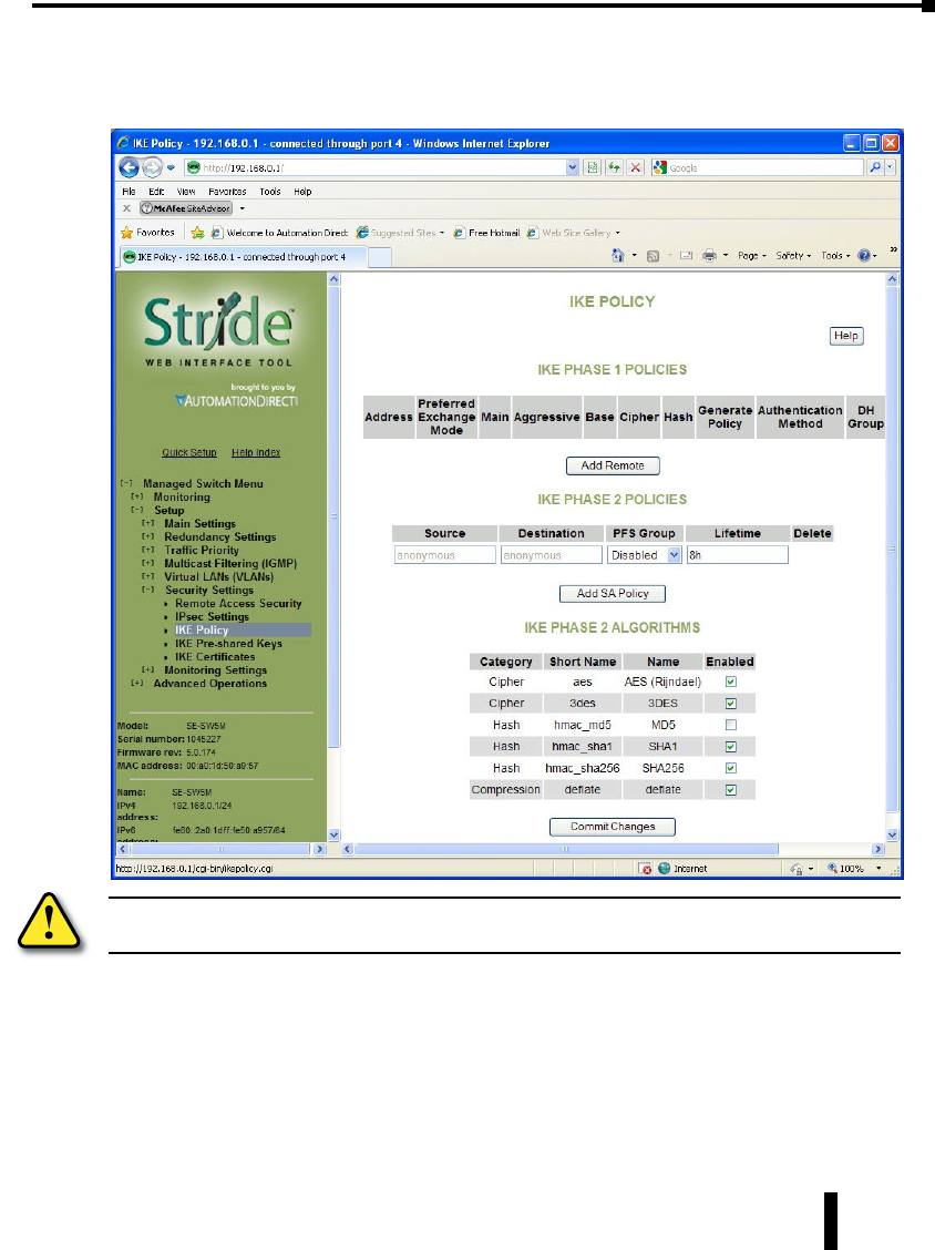
IKE Policy
This screen allows you to configure IKE policy for auto negotiating IPsec Security
Associations over IPv6.
IKE Phase 1 Policies: This section may be used to create, delete, and modify ISAKMP (IKE
phase 1) policies. Phase 1 is used to securely authenticate peers.
• Address: The address of the peer the policy will apply to. A policy for “anonymous” will apply to
all peers without a more specific policy.
• Preferred Exchange Mode: The preferred exchange mode is the one that will be sent in any
proposal to a peer. If other exchange modes are specified, they will be accepted in received
proposals. With Aggressive, the DH Group in the sent proposal must exactly match the peer’s
configuration.
Warning: Misconfiguration on this screen may block network access to the Switch’s configuration
interface.
4-57
Chapter 4 - Managed Switch Software Setup
Stride Industrial Ethernet Switches User Manual 2nd Ed. Rev. A

• Cipher: The cipher used to encrypt proposal exchanges. You must choose a cipher.
• Hash: The hash used to authenticate proposal exchanges. You must choose a hash algorithm.
• DH Group: The Diffie-Hellman group used for exponentiations. Larger groups should be more
secure, but may take so long to compute that completing negotiation becomes impossible due to
timeouts, preventing connectivity to the switch management interface. This should generally be set
to the same value on both peers in a connection.
IKE Phase 2 Policies: This section, together with IKE Phase 2 Algorithms is used to
configure the parameters used to establish Security Associations between peers once they have
authenticated each other in phase 1.
The policy to use is selected using the source and destination selectors from the Security
Policy Database entry or the ID payload from the received IKE packet which triggered the
negotiation. The match for any values other than “anonymous” must be exact.
• Source: The source address to match against. The address specified should exactly match the
Destination address field in a phase 2 policy on the peer, unless either value is “anonymous”. The
value “anonymous” matches sources not handled by other rules.
• Destination: The destination address to match against. The address specified should exactly match
the Source address field in a phase 2 policy on the peer, unless either value is “anonymous”. The
value “anonymous” matches the destinations not handled by other rules.
• PFS Group: The Diffie-Hellman exponentiation group used for Perfect Forward Secrecy. This
may be disabled if not required, but any proposal suggesting it will still be accepted. Larger groups
may require an excessive amount of processing time during negotiation, causing timeouts.
IKE Phase 2 Algorithms: This section is used to configure the algorithms which may be used
for phase 2. The exact algorithms chosen will be an intersection between the sets specified
here and on a peer.
You must enable at least one algorithm from each category (cipher, hash, and compression),
even if the switch’s IPsec policies do not require one of the given protocols to be used.
The default values should be compatible with most installations.
AES (default = Enabled) Cipher
3DES (default = Enabled) Cipher
SHA1 (default = Enabled) Hash
SHA256 (default = Enabled) Hash
MD5 (default = Disabled) Hash MD5 is known to be insecure and is included only for compatibility
with old implementations.
Deflate (default = Enabled) Compression
4-58
Chapter 4 - Managed Switch Software Setup
Stride Industrial Ethernet Switches User Manual 2nd Ed. Rev. A
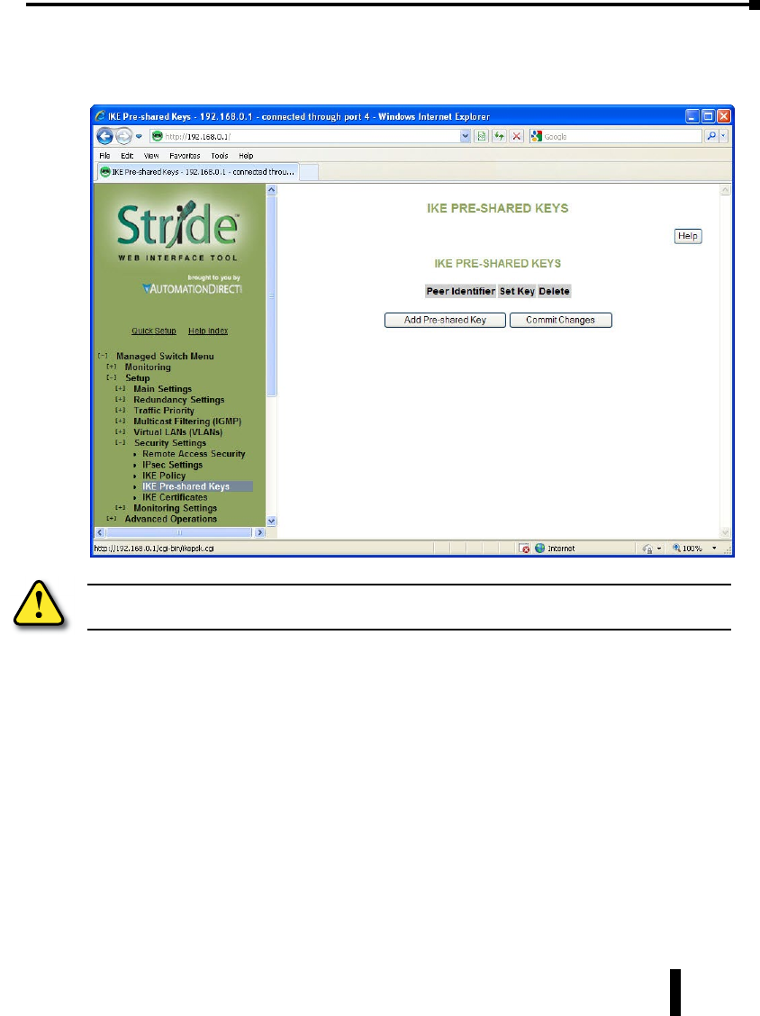
IKE Pre-shared Keys
This screen allows you to configure IKE PSKs (pre-shared keys) used to negotiate with the
IKE peers with which the switch communicates over IPv6.
The same pre-shared key must be set for both peers. For example, if communicating between
two hosts fe80::1 and fe80::2 with a pre-shared key “secret”, fe80::1 must have “secret” set as
the pre-shared key for peer fe80::2, and fe80::2 must have “secret” set as the pre-shared key
for peer fe80::1.
• Peer Identifier: The identifier of the peer with which this pre-shared key should be used. Typically
this will be the peer’s address.
• Set Key: The value to set the pre-shared key to. If left blank, the current value will be preserved.
• Delete: Mark this pre-shared key for removal when changes are committed.
Warning: Misconfiguration on this screen may block network access to the Switch’s configuration
interface.
4-59
Chapter 4 - Managed Switch Software Setup
Stride Industrial Ethernet Switches User Manual 2nd Ed. Rev. A
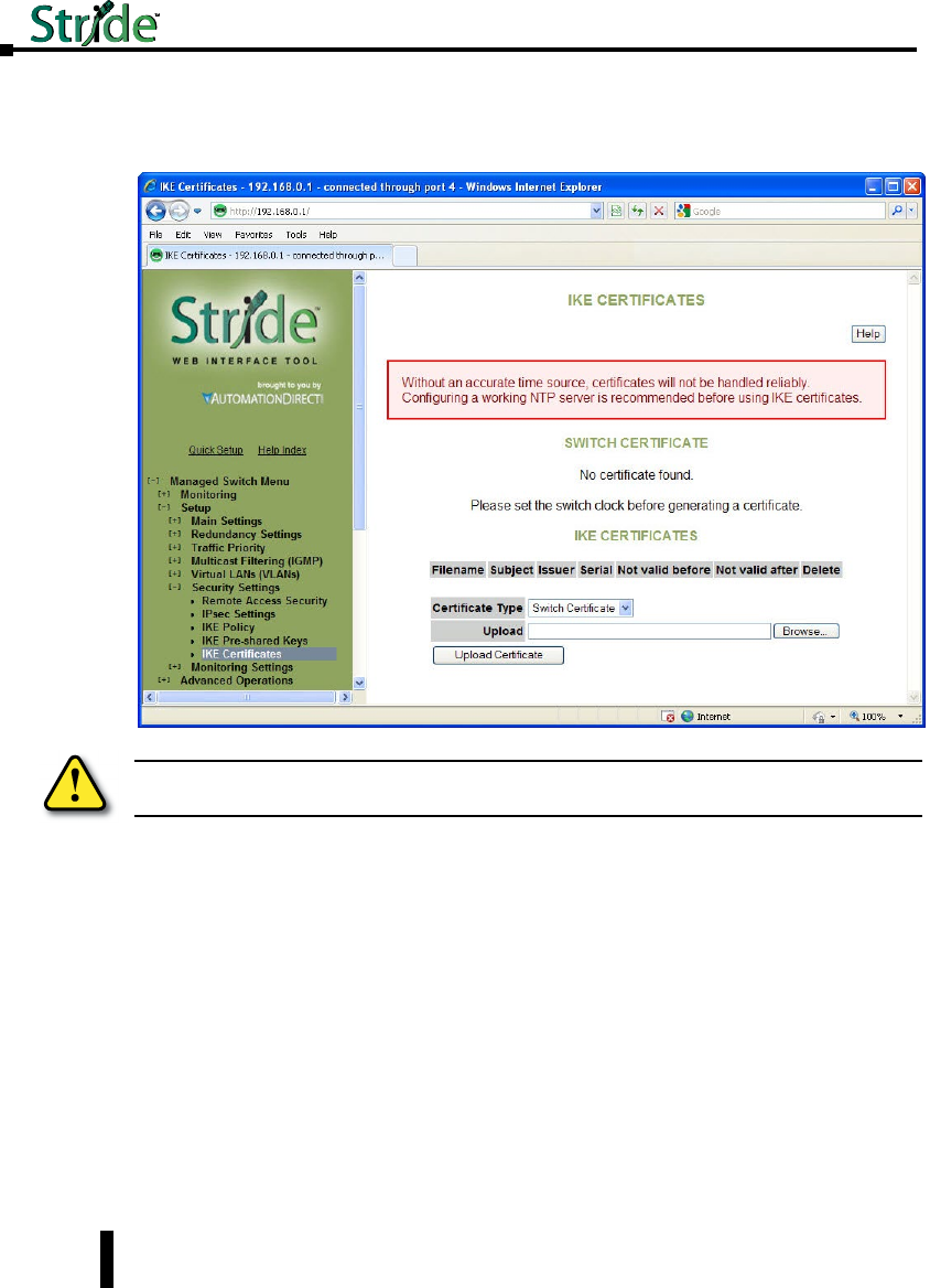
IKE Certificates
This screen allows you to configure IKE certificates used to identify the switch and IKE peers
with which it communicates over IPv6.
Providing a reliable time source, such as NTP, is highly recommended, as IKE will reject
certificates which are not valid according to the system time, whether it is before the ‘not
valid before’ time or after the expiration time. If NTP is used, pre-shared keys or hard-wired
Security Associations should be used for IPsec communications with the NTP server or
updating the clock will fail.
The HTTPS certificate used by the switch’s Web interface cannot be changed on this screen.
Switch Certificate: This section may be used to generate or view the details of an X.509
certificate which the switch uses to identify itself via IKE.
A certificate request which can be provided to a third-party Certificate Authority (CA) is also
generated. A CA-signed certificate can be uploaded using the form at the bottom of the page
and will replace the self-signed certificate used by the switch for IKE. Note that the certificate
provided should be generated from the certificate request generated by the switch.
Warning: Misconfiguration on this screen may block network access to the Switch’s configuration
interface.
4-60
Chapter 4 - Managed Switch Software Setup
Stride Industrial Ethernet Switches User Manual 2nd Ed. Rev. A

• Subject: The DN (distinguished name) identifying the holder of the certificate.
• Issuer: The DN (distinguished name) identifying the issuer of the certificate.
• Serial: The certificate’s serial number.
• Certificate: A link which can be used to download the certificate for inspection.
• Request: A link which can be used to download a certificate request to be signed by a CA.
• Not valid before: The earliest time for which the certificate is valid.
• Not valid after: The latest time for which the certificate is valid.
• Delete: Pressing this button will delete the certificate and private key, allowing a new one to be
generated. This operation cannot be undone.
When no IKE certificate is present on the switch, a certificate and key may be generated. The
following options may be set.
• Common Name: The CN to use as the subject of the new certificate. This should identify the
switch and is typically a hostname or IP address. It defaults to the switch’s hostname.
• Bits: The size of the private key to create, in bits.
• Expires: The number of days the certificate will be valid for, starting from the current day according
to the switch’s clock. This setting is used only for the self-signed certificate; CAs provides their own
expiration dates for certificates they produce.
IKE Certificate: This section is used to add, delete, and view certificates which are trusted by
the switch during IKE negotiation.
• Subject: The DN (distinguished name) identifying the holder of the certificate.
• Issuer: The DN (distinguished name) identifying the issuer of the certificate.
• Serial: The certificate’s serial number.
• Not valid before: The earliest time for which the certificate is valid.
• Not valid after: The latest time for which the certificate is valid.
• Delete: Pressing this button will delete the certificate.
Certificates can be added to the switch using the upload form.
• Certificate Type: Whether the uploaded certificate is to be used as the switch’s identity (“Switch
Certificate”), or to be added to the certificates trusted by the switch when negotiating with IKE
peers (“CA Certificate”). The CA Certificate option may also be used to trust self-signed certificates
from peers.
• Upload: The certificate to upload.
4-61
Chapter 4 - Managed Switch Software Setup
Stride Industrial Ethernet Switches User Manual 2nd Ed. Rev. A
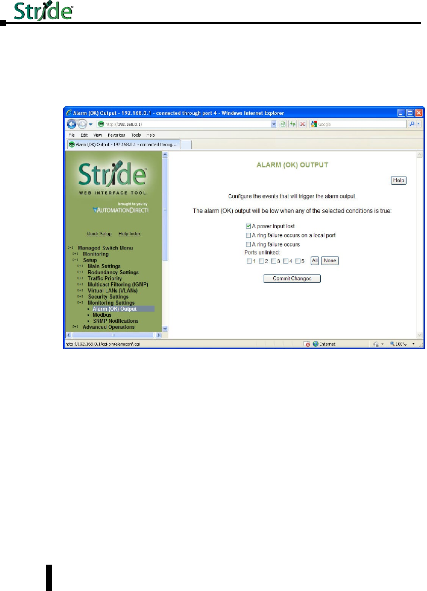
Monitoring Settings
Alarm (OK) Output
These settings control the events that will trigger the alarm output. The OK discrete output is
on during normal conditions and turned off in the event of an alarm condition.
Both Power Inputs On: An alarm condition will be triggered if power is not on for both
power inputs.
Ring Failure: An alarm condition will be triggered when a ring failure occurs.
Ring failure on a local port will be triggered when one of this switch’s neighbors in the ring
goes down; the general ring failure option will be triggered when any switch in the ring goes
down.
The general ring failure option implies that local ring port failure is also detected.
Ports Linked: An alarm condition will be triggered whenever any of the selected ports are not
linked.
4-62
Chapter 4 - Managed Switch Software Setup
Stride Industrial Ethernet Switches User Manual 2nd Ed. Rev. A
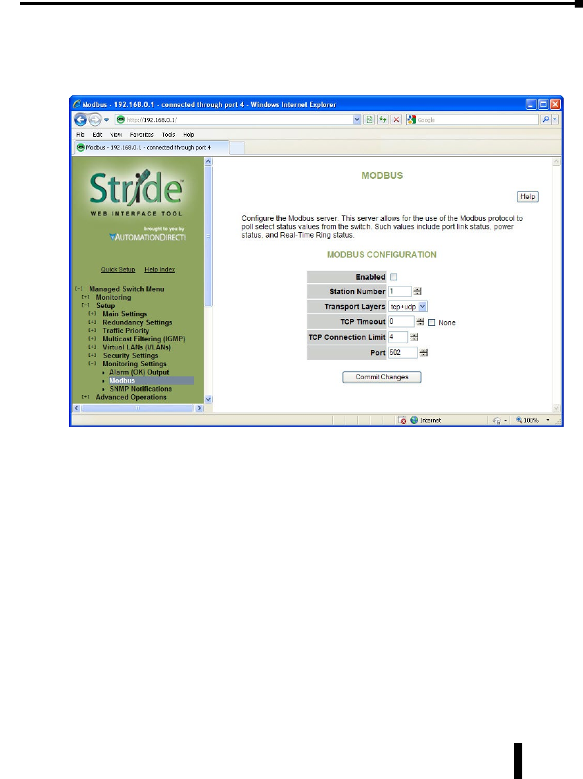
Modbus
These settings control whether and how the switch will respond to Modbus requests. Modbus
registers are available for monitoring link status on each Ethernet port, the power and OK
status, and the status of each configured Real-Time Ring.
Enabled: If selected, the switch will respond to Modbus requests.
Station Number: The Modbus station number that the switch will respond as.
Transport Layers: The switch will respond to Modbus requests only on the chosen transport
layers.
TCP Timeout: If a new TCP connection is received when there are no more free connections
(see the TCP Connection Limit), this determines what happens:
0: The least recently active connection will be dropped in favor of the new connection.
>0: The least recently active connection will be dropped in favor of the new connection, but only if
the least recently active connection has been inactive for at least this many seconds.
None: The new connection will be dropped immediately after it is accepted.
TCP Connection Limit: The maximum number of active TCP connections that the Modbus
server will maintain. Above this limit, the TCP Timeout value will be used to decide how
new connections should be handled.
Port: The TCP/UDP port number on which to listen for new connections/requests.
4-63
Chapter 4 - Managed Switch Software Setup
Stride Industrial Ethernet Switches User Manual 2nd Ed. Rev. A

Register Mapping:
The Modbus registers (all discrete inputs) that may be polled for switch status are:
Link Status for Ports 1-16:
10001 Link status of port 1 (1 = link present, 0 = no link present)
10002 Link status of port 2
...10016 Link status of port (register - 10000)
Real-Time Ring Status for Rings 1-4:
10017 Ring 1: Ring is complete (1 = complete, 0 = broken)
10018 Ring 1: First port is passing data (1 = active, 0 = blocked)
10019 Ring 1: Second port is passing data (1 = active, 0 = blocked)
10020 Ring 2: Ring is complete
10021 Ring 2: First port is passing data
10022 Ring 2: Second port is passing data
10023 Ring 3: Ring is complete
10024 Ring 3: First port is passing data
10025 Ring 3: Second port is passing data
10026 Ring 4: Ring is complete
10027 Ring 4: First port is passing data
10028 Ring 4: Second port is passing data
Switch Status:
10030 OK output (1 = on/no alarm, 0 = off/alarm)
10031 First power input active (1 = P1 on, 0 = P1 off)
10032 Second power input active (1 = P2 on, 0 = P2 off)
Extended Link Status for Ports 1-99:
10101 Link status of port 1 (1 = link present, 0 = no link present)
10102 Link status of port 2
10199 Link status of port (register - 10100)
4-64
Chapter 4 - Managed Switch Software Setup
Stride Industrial Ethernet Switches User Manual 2nd Ed. Rev. A

Extended Switch Status:
10300 OK output (1 = on/no alarm, 0 = off/alarm)
10301 First power input active (1 = P1 on, 0 = P1 off)
10302 Second power input active (1 = P2 on, 0 = P2 off)
SNMP Notifications
SNMP (Simple Network Management Protocol) and RMON (Remote Monitoring) provide
a means to monitor and manage your network. Each SNMP device maintains Management
Information Bases (MIBs) containing information about the operation and configuration of
the device.
The MIBs can be accessed with SNMP tools ranging from simple command-line tools like
snmpwalk and snmpget (part of the open source Net-SNMP package available at http://
www.net-snmp.org) to commercial network management products from various vendors. Key
information from the MIBs is also available via the switch’s terminal and web interfaces.
The MIBs are divided into groups of related objects. Objects may be scalar (having only a
single value) or tabular (having a list of values varying over time, by port number, etc.).
SNMP Security:
SNMP provides several options for securing access to MIBs. SNMPv1 and SNMPv2 provide
only weak authentication. SNMPv3 uses encryption to add stronger authentication as well as
privacy. In all versions, you may configure read-only and read/write users.
SNMPv1 and SNMPv2 authenticate users with a “community string” which is sent in clear
text (unencrypted) and no password is required. Some measure of security can be achieved by
setting long, obscure community strings.
SNMPv3 provides three levels of security and encryption:
• None: No password is required to read or write values in the MIB.
• Authentication: A password is required and is used to encrypt the user credentials so that security
information is not sent in clear text. A variation of MD5 is used for encryption.
• Privacy: A password is required and is used to encrypt the user credentials. A second password is
used to encrypt the details of the SNMP request using DES encryption.
For SNMPv3 access, the managed switch requires authentication and allows privacy. Only
one password is configurable and it is used for both authentication and privacy.
The following examples use snmpget from the Net-SNMP tools to illustrate the use of
authentication and privacy when accessing the managed switch.
If SNMPv2 access is enabled, values may be read without a password with a command like:
snmpget -v 2c -c public 10.2.0.1 system.sysDescr.0
If SNMPv3 access is enabled, values may be read with a command like the following (entered
all on one line):
NOTE: This product uses Net-SNMP (available from www.net-snmp.org) which is subject to the copyrights and license
found at: http://www.net-snmp.org/COPYING.txt
4-65
Chapter 4 - Managed Switch Software Setup
Stride Industrial Ethernet Switches User Manual 2nd Ed. Rev. A

snmpget -v 3 -u public -l authNopriv -a MD5 -A publicpwd 10.2.0.1 system.sysDescr.0
Finally, if SNMPv3 access is enabled, an authenticated, private request could be made with a
command like the following:
snmpget -v 3 -u public -l authpriv -a MD5 -A publicpwd -x DES -X publicpwd 10.2.0.1
system.sysDescr.0
The switch supports SNMPv1, v2, and v3. SNMPv1 and v2 access are essentially the same
from a security standpoint and are enabled and disabled together. SNMPv3 security may
be separately controlled. Thus you may prevent unauthenticated access to your switch by
disabling SNMPv1/v2 access entirely while retaining password-secured access via SNMPv3.
4-66
Chapter 4 - Managed Switch Software Setup
Stride Industrial Ethernet Switches User Manual 2nd Ed. Rev. A
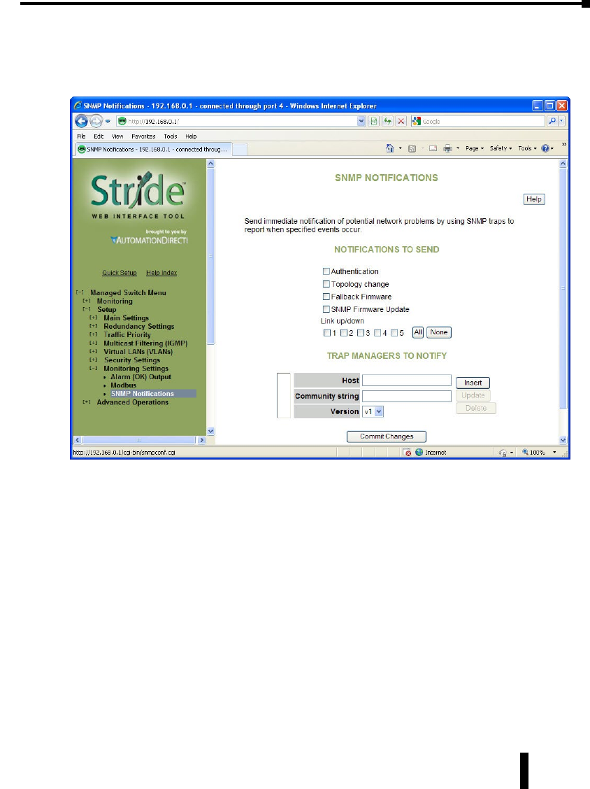
SNMP Notifications:
Use the SNMP Notifications Menu to enable traps to be sent when the state of the switch
changes. Access this menu by selecting Setup from the Main Menu, and then selecting Main
Settings.
Use the SNMP Notifications Menu to enable traps to be sent when the state of the switch
changes. Access this menu by selecting Setup from the Main Menu, and then selecting Main
Settings.
• Authentication: Traps can be sent when invalid credentials (such as an unrecognized community
string) are presented to the SNMP agent. Enable this setting to generate authentication traps.
• Topology change: Traps can be sent when the topology of the spanning tree changes. Enable this
setting to generate topology change traps.
• Failback Firmware: Check this box to send a trap when the switch resets into the non-default
firmware image. This can happen if the switch loses power while booting, or if the default firmware
image somehow becomes corrupt and is no longer bootable.
• SNMP Firmware Update: Check this box to send a trap when the switch has completed an
SNMP-initiated firmware update. The trap will trigger regardless of whether the firmware update
succeeded. Check the firmware Health entry in the firmware Table over SNMP to determine
whether the update was successful. If it lists the non-running image as Healthy (1), then the update
succeeded. Otherwise, it failed.
• Link 1 up/down-Link 18 up/down: Traps can be sent when a link goes up or down (the same state
reflected in the LED for each port). Enable these settings to generate link up/down traps.
4-67
Chapter 4 - Managed Switch Software Setup
Stride Industrial Ethernet Switches User Manual 2nd Ed. Rev. A

Stride Industrial Ethernet Switches User Manual 2nd Ed. Rev. A
Chapter 4 - Managed Switch Software Setup
4-68
Trap Managers to Notify:
Use the Trap Managers Menu to specify where traps will be sent. The Trap Managers Menu
can be accessed by selecting Setup from the Main Menu and then selecting Main Settings. Up
to five trap managers may be configured. For each one, the following values may be specified.
• Host: The IP address of the host where the trap manager is located.
• Community String: The community string to use when contacting the trap manager on the host.
• Version: The SNMP trap version to send.
NOTE: There are two system traps that cannot be disabled and will be sent to any configured trap managers. A coldStart
trap will be sent whenever the SNMP agent starts up (usually, this is only when the Switch is reset). A NotifyRestart trap
will be sent whenever the SNMP agent’s configuration changes and is reloaded. This will happen, for example, when
you commit changes on a configuration menu that includes SNMP settings.

Managed swiTCH
sofTware advanCed
operaTions
In This Chapter...
Configuration Management ...........................................5–2
Restore Factory Defaults ..............................................5–4
Reset Switch . . . . . . . . . . . . . . . . . . . . . . . . . . . . . . . . . . . . . . . . . . . . . . . . . . . . . . . .5–5
Update Firmware ....................................................5–6
Update Firmware using a TFTP Server: ...................................5–6
5
5
5
Chapter
Chapter
Chapter
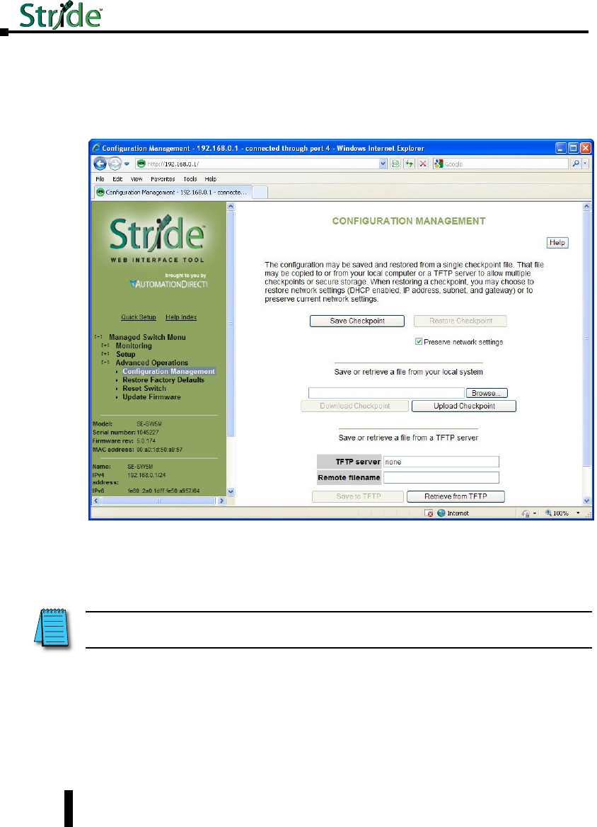
Configuration Management
One “checkpoint” (backup) version of the switch’s configuration can be stored in a local file
on the switch. Unlimited backups can also be saved to your local system (web interface only)
or to a TFTP server elsewhere on the network.
Save Checkpoint: Saves a checkpoint configuration in the switch, which may be used later to
revert back to the current state if changes lead to an undesirable configuration.
Restore Checkpoint: Reverts to the settings in the saved checkpoint. You can choose to keep
your current network settings or use the ones in the checkpoint file.
Download Checkpoint: Saves a zipped file of the current configuration file external to the
switch
Upload Checkpoint: Unzips the selected file and stores a copy on the switch. It must be
restored via Restore Checkpoint to be written as the switch configuration.
TFTP Configuration: Specifies the name or IP address of the TFTP (Trivial File Transfer
Protocol) server where configuration checkpoints may be stored.
NOTE: The current administrator’s password will remain in effect after the restoration. SNMP passwords will be restored
to the values in the checkpoint.
Stride Industrial Ethernet Switches User Manual 2nd Ed. Rev. B
Chapter 5 - Managed Switch Software Advanced Operations
5-2

Stride Industrial Ethernet Switches User Manual 2nd Ed. Rev. B
Chapter 5 - Managed Switch Software Advanced Operations
Save to TFTP: Saves the current configuration checkpoint file to the defined TFTP server.
You must specify the name of a file on the server.
Retrieve from TFTP: Retrieves a previously saved configuration checkpoint file from the
defined TFTP server. After retrieval, the configuration still must be restored to be made
active.
NOTE: The web interface also allows you to download (save) and upload (retrieve) files directly from your local system.
No TFTP server is needed.
5-3
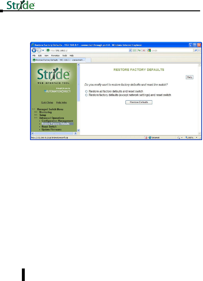
Stride Industrial Ethernet Switches User Manual 2nd Ed. Rev. B
Chapter 5 - Managed Switch Software Advanced Operations
Restore Factory Defaults
This option sets the switch back to factory default settings. The switch will automatically
restart (reset) to put the default settings into effect.
You can optionally choose to maintain the IP address configuration of the switch in order to
more easily reconnect to the switch for configuration after resetting the defaults.
5-4
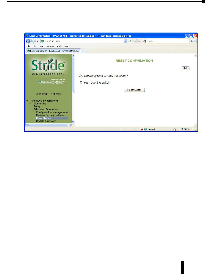
Stride Industrial Ethernet Switches User Manual 2nd Ed. Rev. B
Chapter 5 - Managed Switch Software Advanced Operations
Reset Switch
This feature will cause the switch to perform a “soft” restart (software reset). A software reset
may take 30 seconds or more depending on what features are enabled in the switch.
5-5

Stride Industrial Ethernet Switches User Manual 2nd Ed. Rev. B
Chapter 5 - Managed Switch Software Advanced Operations
Update Firmware
Use Manage Firware to install a complete firmware file with a *.tgz filename. The Update
Firware page is used for incremental changes to firmware versions applied by a file with a
*.fwb filename. Firmware updates are released periodically to add features and fix problems.
The recommended and easiest way to update firmware is from the web interface. It allows
you to Browse and select the firmware update package from your local computer or a
computer on your local network. Then just click the Update from File button to load and
install the latest firmware files.
This method of updating the firmware will retain all your settings. However, it is still
recommended that you save a “checkpoint” configuration as a backup.
Update Firmware using a TFTP Server:
Another option for updating firmware is via a TFTP server elsewhere on the network. Simply
specify the IP address of the remote TFTP server and the filename of the update. If necessary,
the switch will automatically reboot after installing the new firmware files. After the reboot
you may see an “Internal Server Error” message. Simply click refresh on your browser to
reestablish communications with the switch.
This method of updating the firmware will retain all your settings. However, it is still
recommended that you save a “checkpoint” configuration as a backup.
5-6

TroublesHooTing
UL
CUS
R
In This Appendix...
Troubleshooting Fiber Connections: .....................................A–2
Troubleshooting Real-Time Ring ........................................A–4
Troubleshooting VLANs ...............................................A–6
Installing Switch Firmware ............................................A–8
appendix
appendix
appendix
A
A
A

Troubleshooting Fiber Connections:
1. If you are using a 100Mbps SFP in a Stride switch, you must manually change the
port speed on the Port Settings page of the Switch Setup interface. Note that if matching
100Mbps SFPs are installed and connected by a proper mode-type patch cable but the Port
Setting has not been changed from the default 1000Mbps (Gigabit speed), the Port Status
and RSTP Port Status pages will not indicate the port speed mismatch. That is, the browser
interface will not alert the user to this speed mismatch.
• Verify the type of SFP.
• Verify the port number.
• Verify the Port Speed Setting on the Main Settings – Port Settings page:
2. Make sure that the speeds of both ends of a link match: a 100Mbps SFP on one switch
must connect to a 100Mbps connection on the other switch or end device. Fiber ports do
not negotiate speed.
3. Ensure that the cable type you are using matches the transceiver type. That is, Multimode
cable requires Multimode transceivers, and Single-mode cable requires Single-mode
transceivers.
4. Additionally, it is important that 62.5um is used with 62.5um and 50um used with 50um.
Stride Industrial Ethernet Switches User Manual 2nd Ed. Rev. B
Appendix A - Troubleshooting
A-2

Stride Industrial Ethernet Switches User Manual 2nd Ed. Rev. B
Appendix A - Troubleshooting
If the fiber cores are not aligned correctly significant attenuation will occur.
5. Make sure that all of your connectors are clean. Even a little bit of dust, dirt or grease on a
connector face can significantly degrade a fiber signal. This includes the main fiber optic link
as well as any patch cables that you may be using. When cleaning, it is important to use lint-
free swabs or wipes, preferably of a clean room quality. These can be used dry or wet (with
99% isopropyl alcohol solutions).
• Make certain that you are not cleaning an active fiber, as the laser can cause permanent damage to
your eyes should you look into the end face.
• Additionally, it is not necessary to scrub the end face, rather to just gently wipe it clean and then
double-check the link. If additional cleaning is required simply repeat this process.
6. Make sure that all connectors are plugged completely into their proper ports. Again, if end
faces are not lined up correctly with transceivers and/or mated fiber ends, the system may fail
due to excess attenuation.
7. Make sure that the transmit cable at the near end is the receive cable at the far end. There
needs to be a crossover for a fiber link to work correctly. Be sure to factor in all patch cords
that may be used.
NOTE: The physical connectors on the ends of a fiber cable do NOT need to match: a link may use an LC connector on
one end and an SC connector on the other end.
A-3
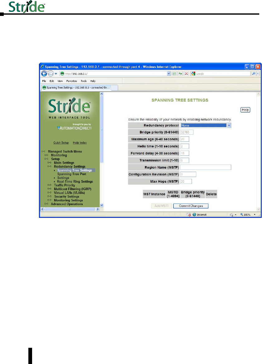
Stride Industrial Ethernet Switches User Manual 2nd Ed. Rev. B
Appendix A - Troubleshooting
Troubleshooting Real-Time Ring
1. Typically a switch will be protected by either Real-Time Ring or RSTP. If Real-Time
Ring is configured on a switch, disable RSTP.
•
On the Redundancy Settings – Spanning Tree Settings page, set Redundancy protocol to “None”
2. It is possible for Real-Time Ring and RSTP to coexist on a switch. If a switch participates
in both a Real-Time Ring and a spanning tree, exclude the Real-Time Ring ports from
spanning tree:
A-4
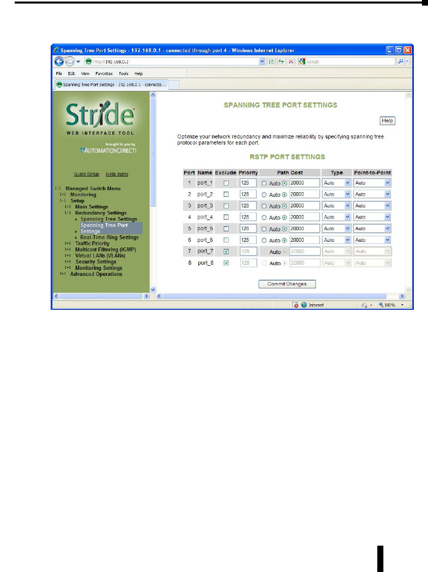
Stride Industrial Ethernet Switches User Manual 2nd Ed. Rev. B
Appendix A - Troubleshooting
• On the Redundancy Settings – Spanning Tree Port Settings page, check the boxes to exclude the
Real-Time Ring ports from Spanning Tree
A-5
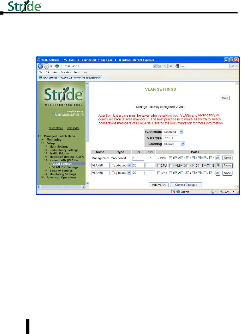
Stride Industrial Ethernet Switches User Manual 2nd Ed. Rev. B
Appendix A - Troubleshooting
Troubleshooting VLANs
The most common VLAN is the Tag-based VLAN. A typical tag-based VLAN
implementation requires configuring the VLANs on the VLAN Settings page AND
configuring the ports for each VLAN on the VLAN Port Settings page:
For a Tag-based VLAN (commonly referred to as an 802.1q or a Dot 1q VLAN)
On the VLAN Settings page:
Set VLAN mode to Standard
Add the VLANs you wish to have configured, leaving the Type selection “Tag-based.” In
our example, we are creating two VLANs called VLAN 20 and VLAN 30. The names are for
your convenience. The IDs on this page will match the PVIDs we configure on the VLAN
Port Settings page and will determine VLAN participation.
We will configure port 2 as a Network (Trunking) port on the VLAN Port Settings page, so
here on the VLAN Settings page we include Port 2 in both of our VLANs.
For security, we have chosen to reserve Port 1 as the only port through which the Switch
Configuration utility can be accessed; we have eliminated all other ports from the
Management VLAN and we have not included port 1 in the other VLANs.
A-6
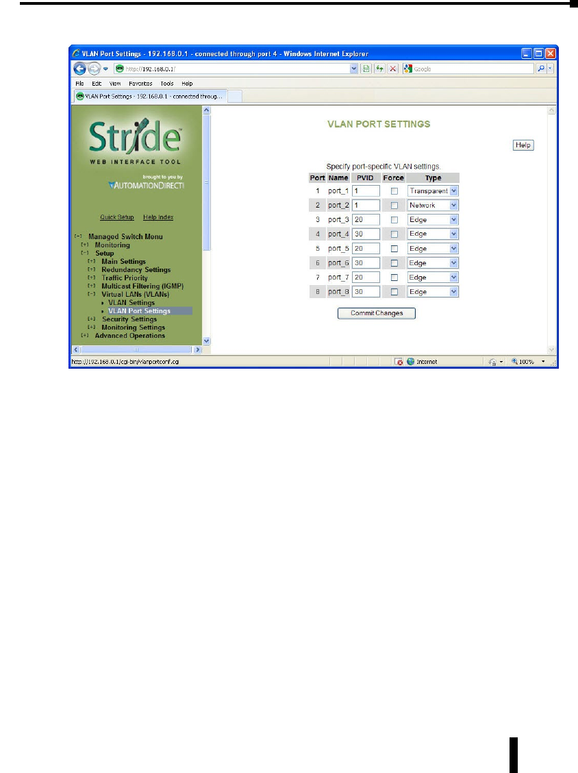
Stride Industrial Ethernet Switches User Manual 2nd Ed. Rev. B
Appendix A - Troubleshooting
On the VLAN Port Settings page:
Set Port 2’s type to Network. We will connect another managed switch configured with
VLANs 20 and 30 to port 2.
For ports 3 through 8, enter the PVID (Port VLAN ID) to match the VLAN ID that each
port was configured to participate in on the VLAN Settings page. In our example, a device
such as a PLC, HMI, etc is assumed to be connected to ports 3-8; no managed switch is
connected to these ports. So they are identified as Edge ports here.
With this configuration committed to the switch, a device on port 3 can communicate with
devices on ports 5 and 7 as well as devices on the VLAN 20 ports from the switch connected
to port 2. None of those devices (ports 3, 5 or 7 here or any device on a VLAN 20 port on
the switch connected to port 2) can communicate with devices connected to ports 4,6 or 8, or
VLAN 30 ports on the switch connected to port 2.
Devices on ports 4, 6 and 8 can communicate with each other and with devices connected to
VLAN 30 ports on the switch connected to port2, but not to the VLAN 20 devices.
Port 1 is reserved for switch management and is assumed to have a laptop occasionally
connected for that purpose
Although the tag-based VLANs are the most common and most versatile, the Port-based
VLANs are the simplest. The Port-based VLANs are restricted to ports on this one switch.
There is no Network (trunking) port to carry the VLANs across multiple switches.
Set VLAN mode to Port-based and Add VLANs with Type set to Port-based. Select which
ports belong to each VLAN. A port should belong to only one Port-based VLAN. CPU
should be checked for each Port-based VLAN.
A-7
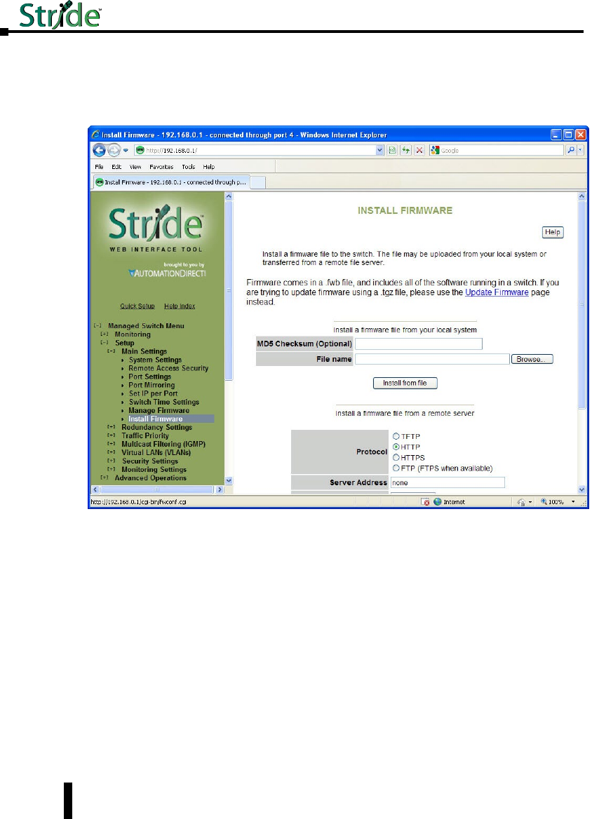
Stride Industrial Ethernet Switches User Manual 2nd Ed. Rev. B
Appendix A - Troubleshooting
Installing Switch Firmware
Installing switch firmware from the browser interface requires 3 steps:
1. Install the firmware .fwb file from the Main Settings – Install Firmware page
Browse to the file either on your local system or from a remote server. The MD5 Checksum
is an error detection value that your IT department may calculate and give you, especially
when they install firmware from a remote server. It is not required. The purpose of the
Checksum is to verify the file you are using to upgrade exactly matches the version sent.
Click the Install from File or Install from Server button
2. After the firmware file has been installed, go to the Main Settings - Manage Firmware page:
A-8
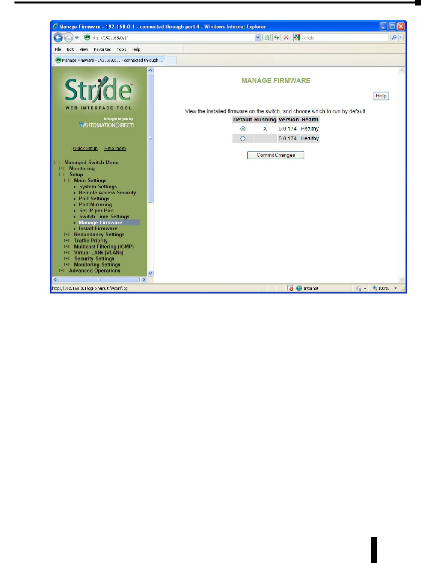
Stride Industrial Ethernet Switches User Manual 2nd Ed. Rev. B
Appendix A - Troubleshooting
Set the Default radio button to the new version you installed
3. Either power cycle the switch or go to the Advanced Operations – Reset Switch page. There, click
the Yes check box then click the Reset Switch button.
After the switch has been reset, the new firmware version will be identified on the Manage
Firmware page as the Running version.
A-9


Glossary of Terms
802.1p: The IEEE standard that specifies QoS
802.1q: The IEEE standard that specifies VLANs
BPDU: Bridge Protocol Data unit
Broadcast: Communicating one-to-all
CA: Certificate Authority
CIDR: Classless inter-domain routing
CLI: command line interface
CoS: IEEE 802.1p Class of Service
CRC: Cyclic redundancy check
Default gateway: The node on the computer network that the network software uses when
an IP address does not match any other routes in the routing table.
DHCP: Dynamic Host Control Protocol
DiffServ: Differentiated Services – class based network traffic management
DNS: Domain Name System
DNS server: Resolves domain names and host names into IP addresses
FCS: Frame check sequence
Frame: A single unit of data received and transmitted by a switch
FTP: File Transfer Protocol
IGMP: Internet Group Management Protocol
IKE: Internet Key Exchange, a protocol in IPSec, results in a Security Association between
two devices that will communicate over IP
IKE policy: The parameters that will be allow communication between two devices
IP: Internet Protocol
IP address (IPv4): A 32 bit number assigned to each device on a network communicating
via IP version 4. Typically written in dotted-decimal notation, e.g.
192.168.0.1
IP address (IPv6): A 128 bit number assigned to each device on a network communicating
via IP version 6. Typically written in hexadecimal notation, e.g. fe80:0000
:0000:0000:2a0:1dff:fe51:f5da
IPSec: A group of protocols to provide security for IP communications, including
authentication and encryption at the packet level
IPv4: Internet Protocol version 4
IPv6: Internet Protocol version 6
Jabber: A frame greater than the Ethernet maximum 1518 bytes with a bad CRC. Jabber is
often cause by a failing NIC.
Stride Industrial Ethernet Switches User Manual 2nd Ed. Rev. B
Appendix B - Glossary
B-2

Stride Industrial Ethernet Switches User Manual 2nd Ed. Rev. B
Appendix B - Glossary
LAN: Local area network
MAC address: Media Access Control address - hardware identifier
Modbus/TCP: A Modbus protocol over Ethernet
MSTI: Multiple Spanning Tree Instance, sometimes written “MST instance”
MSTP: Multiple Spanning Tree Protocol
Multicast: communicating one-to-many
NIC: Network Interface Card
NTP: Network Time Protocol
Octet: Eight bits
Packet: A single unit of data received and transmitted by a router
PVID: Per-VLAN identifier
QoS: Quality of Service
Real-time ring: Proprietary redundancy protocol
RMON: Remote network monitoring
Root bridge: In STP and RSTP, bridge with the smallest Bridge ID
Root port: The port on a switch facing the root bridge.
RSA: The RSA fingerprint for the managed Switch’s encryption key is: 1e:0f:31:39:26:3f:23:
8c:ba:7e:e9:d1:56:ff:98:f6
RSTP: Rapid Spanning Tree Protocol
RSTP terms:
• Discarding = In this state, station location information is not added to the Filtering Database
(MAC table) because any changes in port role will make the Filtering Database
information inaccurate.
• Learning = In this state, information is being added to the Filtering Database under the
assumption that the port role is not changing. Gathering information before frame
relay (forwarding state) will reduce the number of frames sent out when entering the
forwarding state.
• Forwarding = Frames will be forwarded to and from the particular port that is in the forwarding
state. In addition, during the forwarding state, the learning process is still
incorporating station information
RSTP recovery time: Time to start forwarding messages on the backup port.
SAD: Security association database
SFP: Small form-factor pluggable
SNMP: Simple Network Management Protocol
SPD: Security policy database
SQE: Signal Quality Error
SSH: Secure Shell protocol
B-3

Stride Industrial Ethernet Switches User Manual 2nd Ed. Rev. B
Appendix B - Glossary
STP: Spanning Tree Protocol
STP terms:
• Blocking = A port in this state does not participate in frame relay (pass frames received to other
locations). Once a port is in this state, it is prevented from the possibility of frame
duplication causes by multiple paths in an active topology.
• Listening = A port in this state is about to participate in frame relay, but is not involved in any
relay of frames (no frames will be forwarded). The reason for not entering frame
relay immediately is to ensure that there are no temporary loops introduced when the
network topology is changing. During this state, the bridge will disable all learning
states on its ports to prevent the race conditions when ports are changing roles and the
forwarding process will discard all frames and not submit any frames for transmission.
Meanwhile BPDUs can still be received and forwarded to keep the algorithm running.
• Learning = A port in this state is about to participate in frame relay, but it is not involved in any
relay of frames. Frame relays are not performed to prevent the creation of temporary
loops during the active topology of a changing bridged LAN. In addition, the
forwarding process will discard all frames and not submit any frames for transmission.
The reason for enabling learning is to acquire information prior to any frame relay
activities. Information gathered will be used and placed in the filtering database (MAC
table) to reduce the number of frames being unnecessarily relayed.
• Forwarding = A port in the forwarding state is currently participating in frame relay. BPDUs will
include the forwarding port in the computation of the active topology. BPDUs
received are processed according to the Spanning Tree algorithm and transmitted
based on the hello time or BPDU information received.
Subnet mask: A number representing the digits that identify the network portion of an IP
address that includes network and host identification.
TCP: Transmission Control Protocol
Telnet: Means of accessing the CLI
TFTP: Trivial File Transfer Protocol
TOS: Type of Service
UDP: User Datagram Protocol
VLAN: Virtual Local Area Network
B-4

swiTCH seTTings -
swiTCH ConfiguraTion
reCords
UL
CUS
R
In This Appendix...
General Switch Information ...........................................C–2
Alarm Configuration .................................................C–3
Mirror Configuration .................................................C–3
VLAN Configuration .................................................C–3
Port Configuration ...................................................C–3
QOS Configuration ..................................................C–4
C
C
C
appendix
appendix
appendix

General Switch Information
Installation Date Date
Model Model
Description Description
System Name System
Switch Location Location
Contact Contact Name
IPv4 Address IPv$ address
DHCP DHCP
IPv6 Address IPv6 address
Default Gateway Default Gateway
Primary DNS DNS
Secondary DNS Secondary DNS
Domain Domain
Serial Number Serial number
Firmware Revision Firmware revision
MAC Address MAC address
IGMP Mode Active IGMP handling
Multicast Suppression All unreserved multicast
IGMP Version 2
Redundancy Protocol RSTP
Bridge Priority 32768
Max Message Age 20
Hello Timer 2
Rorwarding Delay 15
Transmission Limit 6
MSTP Region Name
MSTP Configuration Revision 0
MSTP Max Hop Count 20
Topology Change Trap Disabled
Telnet Unknown
Terminal Mode both
Web Mode both
SNMP Version both
Command-Line Interface Enabled
User Interface Timeout 0
NTP Server none
Stride Industrial Ethernet Switches User Manual 2nd Ed. Rev. B
Appendix C - Switch Settings
C-2

Stride Industrial Ethernet Switches User Manual 2nd Ed. Rev. B
Appendix C - Switch Settings
Alarm Configuration
Mirror Configuration
VLAN Configuration
Port Configuration
Name Port 2 Port 3 Port 4 Port 5 Port 6 Port 7 Port 8
Admin Enabled Enabled Enabled Enabled Enabled Enabled Enabled Enabled
Negotiation Enabled Enabled Enabled Enabled Enabled Enabled Enabled Enabled
Speed / Duplex 00080f 00080f 00080f 00080f 00080f 00080f 00080f 00080f
Flow Control Disabled Disabled Disabled Disabled Disabled Disabled Disabled Disabled
Exclude Included Included Included Included Included Included Included Included
Priority 128 128 128 128 128 128 128 128
Path Cost 200000 200000 200000 200000 200000 200000 200000 200000
Type Disabled Disabled Disabled Disabled Disabled Disabled Disabled Disabled
Point-to-Point Auto Auto Auto Auto Auto Auto Auto Auto
Path Cost Auto Disabled Disabled Disabled Disabled Disabled Disabled Disabled Disabled
VLAN Mode Disabled
Number of VLAN’s 0
Port 1 Port 2 Port 3 Port 4 Port 5 Port 6 Port 7 Port 8
PVID 11111111
Force Disabled Disabled Disabled Disabled Disabled Disabled Disabled Disabled
Monitor Port 1
Port 1 Port 2 Port 3 Port 4 Port 5 Port 6 Port 7 Port 8
Direction none none none none none none none none
Ports to Monitor
A power input lost Enabled
Port 1 Port 2 Port 3 Port 4 Port 5 Port 6 Port 7 Port 8
link down Disabled Disabled Disabled Disabled Disabled Disabled Disabled Disabled
C-3

Stride Industrial Ethernet Switches User Manual 2nd Ed. Rev. B
Appendix C - Switch Settings
QOS Configuration
Schedule strict
Tag 0 Priority 1
Tag 1 Priority 0
Tag 2 Priority 0
Tag 3 Priority 1
Tag 4 Priority 2
Tag 5 Priority 2
Tag 6 Priority 3
Tag 7 Priority 3
Port 1 Port 2 Port 3 Port 4 Port 5 Port 6 Port 7 Port 8
Use 802.1p Tag
Priority Enabled Enabled Enabled Enabled Enabled Enabled Enabled Enabled
Use IP ToS/DiffServ Enabled Enabled Enabled Enabled Enabled Enabled Enabled Enabled
Priority Precedence tag tag tag tag tag tag tag tag
Default Out Q 11111111
Path Cost Auto normal normal normal normal normal normal normal normal
C-4

Cli CoMMands
In This Appendix...
Introduction .............................................................................................................. D–2
Accessing the CLI .................................................................................................... D–2
CLI Commands: ......................................................................................................... D–3
Global Commands: ................................................................................................. D–3
Access Configuration: .............................................................................................. D–3
Alarm Configuration: ............................................................................................... D–4
Modbus Configuration: ........................................................................................... D–4
Info Configuration: .................................................................................................. D–4
Network Configuration:........................................................................................... D–5
Ring Configuration: ................................................................................................. D–6
RSTP Configuration: ................................................................................................ D–7
QoS Configuration: ................................................................................................. D–7
VLAN Configuration: ............................................................................................... D–8
IGMP Configuration: ............................................................................................... D–9
Checkpoint Configuration: ...................................................................................... D–9
Firmware Configuration:.......................................................................................... D–9
TFTP Configuration: ................................................................................................ D–9
Timezone Configuration: ....................................................................................... D–10
MSTI Configuration: .............................................................................................. D–10
General Configuration: .......................................................................................... D–10
appendix
appendix
appendix
D
D
D
CLI Commands
Introduction
The command-line interface (CLI) is constructed with an eye towards automation of CLI-
based configuration. The interaction is modeled on that used in many Internet protocols
such as Telnet, FTP, and SMTP. After each command is entered and processed, the switch
will issue a reply that consists of a numeric status code and a human-readable explanation of
the status. See, for example, the SMTP protocol specification in RFC 821 – Simple Mail
Transfer Protocol (http://www.faqs.org/rfcs/rfc821.html), specifically, “Appendix E – Theory of
Reply Codes.” for more details.
The general format of commands is:
section parameter [value]
where:
• section is used to group parameters.
• parameter will specify the parameter within the section. For example, the network section will have
parameters for DHCP, IP address, subnet mask, and default gateway.
• value is the new value of the parameter. If value is omitted, the current value is displayed.
Sections and parameter names are case sensitive (e.g., “Network” is not the same as
“network”).
Accessing the CLI
To access the CLI, establish an Ethernet or serial connection to the switch.
To connect by Ethernet, open a command prompt window and type:
telnet <switchIP> (where <switchIP> is the IP address of the switch) eg. telnet
192.168.0.1
At the login prompt, type “cli” for the username and “admin” for the password. The switch
will respond with “Managed Switch configuration CLI ready”.
Likewise, for serial access, via Tera Term for example, use...
login: cli
password: admin
NOTE: Any commands in the CLI commands section of this section, with the exception of the global
commands, must be prefaced with the name of the section they are in. For example, to change the IP
address of the Switch, you would type:
network address <newIP>
This is because the address command is in the Network Configuration section of this Appendix.
NOTE: The new values will not take effect until explicitly committed.
Stride Industrial Ethernet Switches User Manual 2nd Ed. Rev. B
Appendix D - CLI Commands
D-2
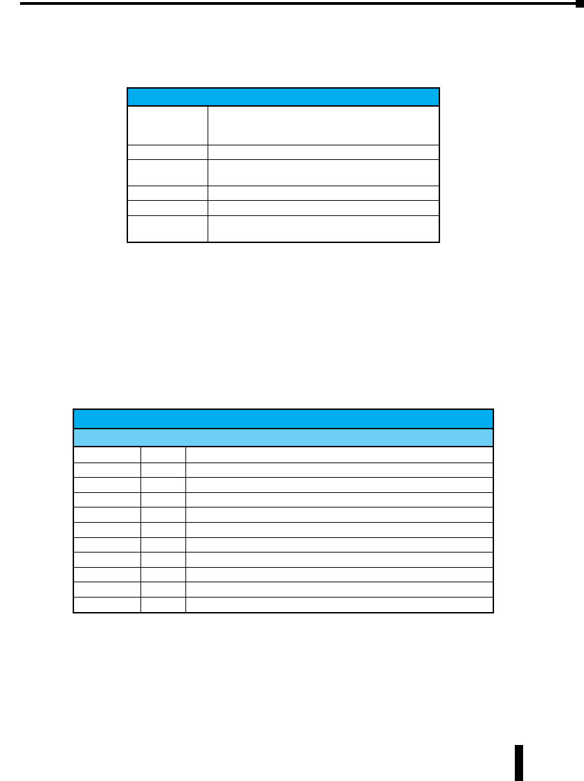
Stride Industrial Ethernet Switches User Manual 2nd Ed. Rev. B
Appendix D - CLI Commands
CLI Commands:
Global Commands:
The following global commands are available anywhere in the CLI:
Command Effect
commit
10% of link capacityValues are inter-validated as needed.
If valid, values are committed. Please note that this may
take some time depending on changes.
defaults Restore factory defaults
quit CLI is exited. Uncomitted changes are discarded without
prompting.
reset Reset the Switch.
help Print a help message.
prompt Enable/disable the prompt (usage: “prompt enabled” or
“prompt disabled”)
When restoring factory defaults, network settings may be maintained by adding a “savenw”
option. In other words:
defaults
restores all values, but
defaults savenw
restores all defaults except the current settings for DHCP, IP address, etc…
Access Configuration:
The following administrative access settings are settable via the CLI:
Access Configuration
Parameter Default Allowable Values
snmp both none, snmpv2, snmpv3, both
terminal both none, telnet, ssh, both
web both none, http, https, both
cli 10, 1
uitimeout 00 - 999
rouser public Any valid user name
rwuser private Any valid user name
ropass none A password, followed by the same password repeated
rwpass none A password, followed by the same password repeated
adminpass admin A password, followed by the same password repeated
fwload serial “serial” for serial firmware loading or “network” to enable Ethernet only
D-3

Stride Industrial Ethernet Switches User Manual 2nd Ed. Rev. B
Appendix D - CLI Commands
Alarm Configuration:
Alarm Configuration
Parameter Default Allowable Values / Description
list n/a No value, view all current alarm settings
powerloss enabled ‘enabled’, ‘disabled’ / alarm output will be low if a power input is lost
ringfailure disabled ‘enabled’, ‘disabled’ / alarm output will be low if a power input is lost
These settings require a port number, usage:
alarm <parameter> <port #> [<new value>]
linkloss disabled 0 - ‘enabled’, ‘disabled’ / alarm output is triggered when link is down on the
specified port
Modbus Configuration:
Modbus Configuration
Parameter Default Allowable Values / Description
enabled 00 or 1, 1 meaning enabled
stanum 11 to 247, used to get or set modbus station number
transport tcp+udp tcp / udp / tcp+udp, used to specify allowed transport layer for modbus
timeout 00 to 3600 or none, time is in seconds
maxcon 41 to 20, sets maximum number of concurrent connections
port 502 1 to 65535, set port number to listen for Modbus polling requests
Info Configuration:
Info Configuration
Parameter Default Allowable Values / Description
fwversion n/a View the current firmware version
cfgversion n/a View the configuration version number
macaddr n/a View the MAC address of the Switch
link n/a ‘all’, port# / show specified port (s) link status
support n/a displays useful support information (IP, etc.)
These settings require a filter to be specified:
info <parameter> <filter> [<value>]
For the info mactable command, the filter parameters are:
id = {*|#} Show all/one specific filtering database by ID
port = {*|#[,#[,…]]} Show all/one/multiple specific port(s)
NOTE: port 33 is the switch CPU.
mac = {*|xx}:{*|xx}:{*|xx}:{*|xx}:{*|xx}:{*|xx} Show only MAC addresses matching the given
pattern
D-4

Stride Industrial Ethernet Switches User Manual 2nd Ed. Rev. B
Appendix D - CLI Commands
Network Configuration:
The switch can have DHCP enabled or disabled. When it is enabled, settings for IP address,
subnet mask, and default gateway may still be set. The values will be stored and used should
DHCP be disabled in the future.
Info Configuration
Parameter Default Allowable Values / Description
fwversion n/a View the current firmware version
cfgversion n/a View the configuration version number
macaddr n/a View the MAC address of the Switch
link n/a ‘all’, port# / show specified port (s) link status
support n/a displays useful support information (IP, etc.)
These settings require a filter to be specified:
info <parameter> <filter> [<value>]
Port Security Configuration:
Port Security Configuration
Parameter Default Allowable Values / Description
list n/a List all current port security information
enable n/a Enables MAC-based port security
disable n/a Disables MAC-based port security
add n/a Any valid MAC and port number / allow communication by the specified
MAC on the specified port.
remove n/a Any valid MAC / remove a MAC address from the security table
Port Configuration:
Port Configuration
Parameter Default Allowable Values / Description
list n/a No value, lists all settings for all ports
monitor 1Any port number
These settings require a port number, usage:
port <port #> <parameter> [<new value>]
name port_# A string
admin enabled enabled, disabled
negotiation enabled enabled (auto-negotiation), disabled (fixed negotiation)
ratelimit enabled enabled, disabled
direction none none, egress, both
giveip disabled enabled, disabled
ipaddr none An IP address
Sfp 1000 100, 1000
speed (see below) (see below)
With auto negotiation, <speed> may be:
10H, 10F, 100H, 100F, 1000F or FC
With fixed negotiation, <speed> may be:
100H or 100F
D-5
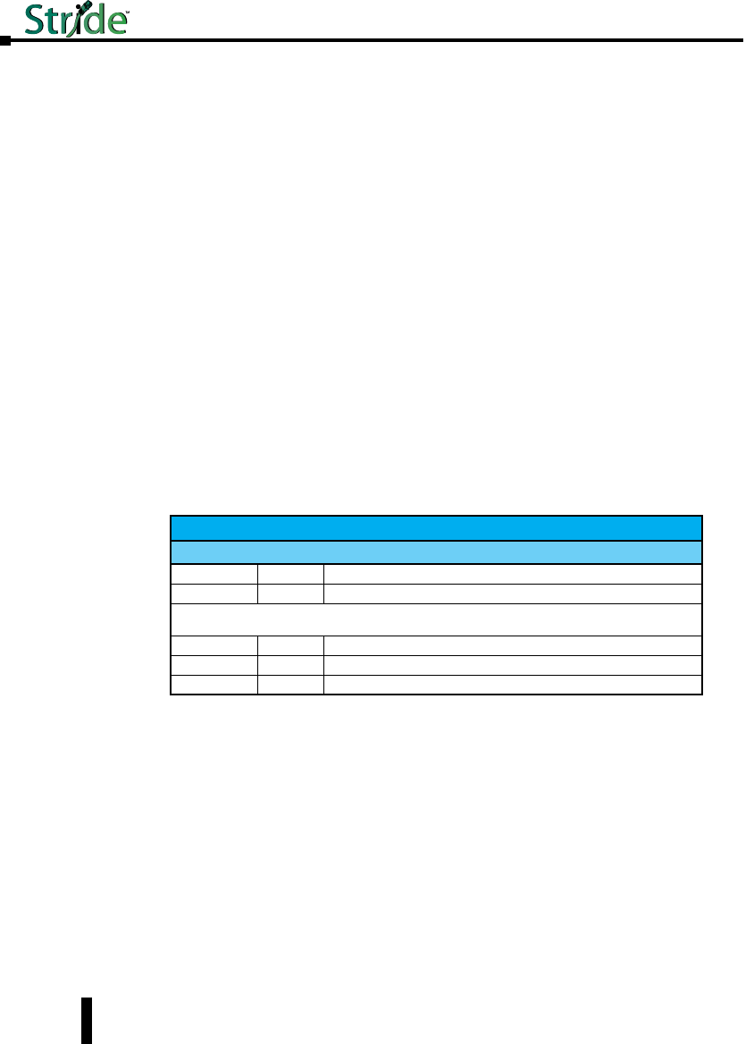
Stride Industrial Ethernet Switches User Manual 2nd Ed. Rev. B
Appendix D - CLI Commands
Valid settings: ‘enabled’ (will automatically set other speeds to ‘disabled’)
The syntax for the port speed command is as follows:
port <port #> speed …
(negotiation enabled)
speed 10H enabled
speed 10F disabled
…
Which act like check boxes on a web form.
Or, with negotiation disabled, the syntax is:
speed 10H enabled
speed 100F enabled
…
Which act like radio buttons on a web form.
Speed FC enabled/disabled is available in both modes.
For combo ports, the SFP speed may be set as follows:
port <port#> sftp <speed>
Ring Configuration:
Ring Configuration
Parameter Default Allowable Values / Description
list n/a View the list of configured rings
master auto auto’, ‘this’ / configure how the Switch determines the ring master
The settings below require a ring number, usage:
ring <parameter> <ring #> [<new value>]
enable 0‘0’, ‘1’ / view or change whether the ring is enabled
name n/a Any text value / View or change the specified ring name
ports n/a (see below) / View or change this ring’s primary and backup ports
To set the primary and backup ports for a specified ring, the syntax is:
ring ports <ring#> <primary port #> <secondary port #>
D-6

Stride Industrial Ethernet Switches User Manual 2nd Ed. Rev. B
Appendix D - CLI Commands
RSTP Configuration:
RSTP Configuration
Parameter Default Allowable Values / Description
protocol none none, stp, rstp or mstp / View or change the spanning tree protocol
priority 0A multiple of 4096 in the range of 0 - 61440 / View or change the priority
mma 6An integer in the range 6 - 40 / View or change the maximum message
age
hellowtime 1An integer in the range 1 - 10 / View or change the hello time
fwddelay 4An integer in the range 4 - 30 / View or change the forwarding delay
Txlimit 1An integer in the range 1 - 10 / View or change the transmission limit
region n/a any valid region name
cfgrevision n/a any valid revision number
maxhops 20 any number from 6 - 40
The settings below require a port number, usage:
rstp <parameter> <port #> [<new value>]
exclude 0‘2’, ‘1’, ‘0’ / View or change whether this port is excluded from STP
pprio 0An integer in the range of 0 - 240 / View or change this port’s priority
pcost none ‘auto’ or integer in the range of 0 - 200,000,000 / View or change this port’s
cost
type 1‘1’, ‘0’ / View or change this port’s edge type
ptp Auto ‘ForceTrue’, ‘ForceFalse’, ‘Auto’ / View or change this port’s point-to-point
setting
QoS Configuration:
QoS Configuration
Parameter Default Allowable Values / Description
schedule strict ‘strict’, ‘fair’ / View or change the fairness rule
The settings below require a port number, usage:
qos <parameter> <port #> [<new value>]
usetag 0‘0’, ‘1’ / View or change whether tag priorities are used
useip n/a ‘0’, ‘1’ / View or change whether IP priorities are used
pref tag ‘tag’, ‘ip’ / View or change which to use if both tags and IP are enabled
priority 10 - 3 / Defaul priority to give to packets received on this port
type normal ‘normal’, ‘add’, ‘remove’, ‘double’ / The type of connection to this port
The setting below requires a tag number, usage:
qos tag <tag #> [<new value>]
tag (depends
on the tag) 0 - 3 / View or change the priority of the specified tag
If <new value> is not present, the current setting will be displayed.
D-7

Stride Industrial Ethernet Switches User Manual 2nd Ed. Rev. B
Appendix D - CLI Commands
VLAN Configuration:
VLAN Configuration
Parameter Default Allowable Values / Description
vlist none No value, lists all configured VLANs
plist none No value, lists the VLAN settings for each port
mode disabled ‘disabled’, ‘port’, ‘standard’, ‘secure’ / View or change VLAN mode
coretype none Value in hexadecimal with a 0x prefix / View or set Ethertype for core tags
mgmtvlan 11 - 4094 / View or set the management VLAN ID
learning shared ‘shared’, ‘independent’ / Change VLAN learning mode
mgmtports all 1 - 9 / View or set the management VLAN port
The commands below require a vlan # from vlist
name n/a A string of no more than 33 characters
vtype n/a ‘port’, ‘tag’ / View or change the type of this VLAN
id n/a An integer between 1 and 4095 / View or change the ID of this VLAN
ports n/a Syntax: vlan ports <vlan#> <add/remove> <port#>
The commands below require a port #
pvid 1A VLAN # from vlist valid range of 1 - 4094
force 0‘0’, ‘1’
add (see below) (see below)
remove (see below) (see below)
The examples below explain the syntax of the “port”, “add” and “remove” commands:
To add a Port Based VLAN:
vlan ports <vlan #> add <port #>
vlan ports <vlan #> remove <port #>
vlan add <name> port <port #> <port #> […]
To add a Tag based VLAN:
vlan add <name> tag <vlan ID> <port #> <port #> […]
To remove a VLAN:
vlan remove <vlan # or all>
D-8
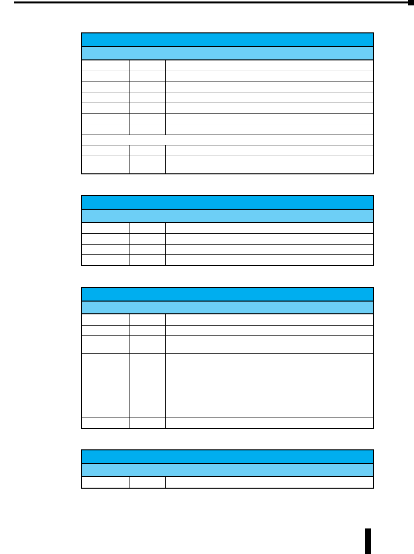
Stride Industrial Ethernet Switches User Manual 2nd Ed. Rev. B
Appendix D - CLI Commands
IGMP Configuration:
IGMP Configuration
Parameter Default Allowable Values / Description
rlist n/a No value / Lists router settings for all ports
mode disabled disabled, snoop, router / view or change IGMP mode
msupp none none, ip, all / view or change the multicast suppression method
version 21, 2 / IGMP version
robustness 21 - 99 / IGMP robustness
ginterval 125 60 - 125 / IGMP query interval
gresponse 10 1 - 30 / IGMP query response interval
The commands below require a port #
router 00, 1 / identify ports which lead to IGMP routers
exclude 00, 1 / Exclude a port from the processing of IGMP requests and queries
Checkpoint Configuration:
Checkpoint Configuration
Parameter Default Allowable Values / Description
save n/a None / saves a check point
restore n/a net, nonet / net saves current network settings, nonet discards them
ftpsave n/a a file name
ftprestore n/a a file name
Firmware Configuration:
Firmware Configuration
Parameter Default Allowable Values / Description
default n/a 1 or 2 / View or change the default firmware
running n/a View which firmware image is running
list n/a View list of currently available firmware images and corresponding health
status
update n/a
Followed by [showProgress] [md5=<md5>] <url>
If the ‘showProgress’ argument is provided, progress printouts will be
displayed.
If the ‘md5’ argument is provided, the MD5 checksum of the received
firmware will be tested against the provided MD5 checksum.
The URL must be a valid HTTP or HTTPS address to which the Switch
has direct access.
ftpload n/a Followed by the filename to be uploaded from the TFTP server
TFTP Configuration:
TFTP Configuration
Parameter Default Allowable Values / Description
tftp “ “ A valid fully-qualified domain name
D-9

Stride Industrial Ethernet Switches User Manual 2nd Ed. Rev. B
Appendix D - CLI Commands
Timezone Configuration:
Timezone Configuration
Parameter Default Allowable Values / Description
list (see below) (see below)
value none A time zone from list
MSTI Configuration:
MSTI Configuration
Parameter Default Allowable Values / Description
list n/a Lists all MSTIs and their priorities
plist n/a Followed by mstid, used to show all ports in the specified MSTI with their
costs and priorities
add n/a Followed by name mstid [priority]
remove n/a any valid MSTI, or all to remove all MSTIs
priority 32768 Followed by mstid [priority]
pprio varies Followed by mstid portno [pprio], used for per-MSTI port priorities
pcost varies Followed by mstid portno [pcost], used for per-MSTI port costs
name n/a Followed by mstid [name]
mstid n/a Followed by mstid [newmstid]
inherit n/a Any valid MSTI. Used to inherit from the CIST
General Configuration:
The following commands are general commands which are not part of another subsection:
General Configuration
Parameter Default Allowable Values / Description
location <set location of
switch> Any text value / location of the Switch
contact none Any text value / contact information of the network or site administrator
NOTE: To view a list of all timezones, use the command “tz list [<prefix>]” with the option to filter by
timezones beginning with the characters in <prefix>.
D-10

liCensing and poliCies
UL
CUS
R
In This Appendix...
Overview . . . . . . . . . . . . . . . . . . . . . . . . . . . . . . . . . . . . . . . . . . . . . . . . . . . . . . . . . . E–2
PCRE Library .......................................................E–2
libpcap Software ....................................................E–3
lighttpd Software ...................................................E–3
spawn-fcgi Software .................................................E–4
ipsec-tools Software .................................................E–4
net-snmp Software ..................................................E–6
FastCGI Library ....................................................E–11
watchdog Software .................................................E–12
GPLv2 (General Public License v2) .....................................E–12
Crossbrowser/x-tools Library .........................................E–18
OpenSSL License ...................................................E–30
Open SSH License ..................................................E–32
PPP License . . . . . . . . . . . . . . . . . . . . . . . . . . . . . . . . . . . . . . . . . . . . . . . . . . . . . . . E–33
Shadow License ....................................................E–39
Sudo License . . . . . . . . . . . . . . . . . . . . . . . . . . . . . . . . . . . . . . . . . . . . . . . . . . . . . . E–41
appendix
appendix
appendix
E
E
E

Overview
The following is a list of the license agreements of the software and libraries used in the
development of the firmware.
PCRE Library
PCRE is a library of functions to support regular expressions whose syntax and semantics are
as close as possible to those of the Perl 5 language.
Release 8 of PCRE is distributed under the terms of the “BSD” licence, as specified below.
The documentation
for PCRE, supplied in the “doc” directory, is distributed under the same terms as the software
itself.
The basic library functions are written in C and are freestanding. Also included in the
distribution is a set of C++ wrapper functions.
THE BASIC LIBRARY FUNCTIONS
Written by: Philip Hazel
Email local part: ph10
Email domain: cam.ac.uk
University of Cambridge Computing Service,
Cambridge, England.
Copyright (c) 1997-2009 University of Cambridge
All rights reserved.
THE C++ WRAPPER FUNCTIONS
Contributed by: Google Inc.
Copyright (c) 2007-2008, Google Inc.
All rights reserved.
THE “BSD” LICENCE
Redistribution and use in source and binary forms, with or without modification, are
permitted provided that the following conditions are met:
• Redistributions of source code must retain the above copyright notice, this list of conditions and the
following disclaimer.
• Redistributions in binary form must reproduce the above copyright notice, this list of conditions
and the following disclaimer in the documentation and/or other materials provided with the
distribution.
• Neither the name of the University of Cambridge nor the name of Google Inc. nor the names of
their contributors may be used to endorse or promote products derived from this software without
specific prior written permission.
THIS SOFTWARE IS PROVIDED BY THE COPYRIGHT HOLDERS AND
Stride Industrial Ethernet Switches User Manual 2nd Ed. Rev. B
Appendix E - License Agreements
E-2

Stride Industrial Ethernet Switches User Manual 2nd Ed. Rev. B
Appendix E - License Agreements
CONTRIBUTORS “AS IS” AND ANY EXPRESS OR IMPLIED WARRANTIES,
INCLUDING, BUT NOT LIMITED TO, THE IMPLIED WARRANTIES OF
MERCHANTABILITY AND FITNESS FOR A PARTICULAR PURPOSE ARE
DISCLAIMED. IN NO EVENT SHALL THE COPYRIGHT OWNER OR
CONTRIBUTORS BE LIABLE FOR ANY DIRECT, INDIRECT, INCIDENTAL,
SPECIAL, EXEMPLARY, OR CONSEQUENTIAL DAMAGES (INCLUDING, BUT
NOT LIMITED TO, PROCUREMENT OF SUBSTITUTE GOODS OR SERVICES;
LOSS OF USE, DATA, OR PROFITS; OR BUSINESS INTERRUPTION) HOWEVER
CAUSED AND ON ANY THEORY OF LIABILITY, WHETHER IN CONTRACT,
STRICT LIABILITY, OR TORT (INCLUDING NEGLIGENCE OR OTHERWISE)
ARISING IN ANY WAY OUT OF THE USE OF THIS SOFTWARE, EVEN IF
ADVISED OF THE POSSIBILITY OF SUCH DAMAGE.
libpcap Software
License: BSD
Redistribution and use in source and binary forms, with or without modification, are
permitted provided that the following conditions are met:
1. Redistributions of source code must retain the above copyright notice, this list of conditions and
the following disclaimer.
2. Redistributions in binary form must reproduce the above copyright notice, this list of conditions
and the following disclaimer in the documentation and/or other materials provided with the
distribution.
3. The names of the authors may not be used to endorse or promote products derived from this
software without specific prior written permission.
THIS SOFTWARE IS PROVIDED ``AS IS’’ AND WITHOUT ANY EXPRESS OR
IMPLIED WARRANTIES, INCLUDING, WITHOUT LIMITATION, THE IMPLIED
WARRANTIES OF MERCHANTABILITY AND FITNESS FOR A PARTICULAR
PURPOSE.
lighttpd Software
Copyright (c) 2004, Jan Kneschke, incremental
All rights reserved.
Redistribution and use in source and binary forms, with or without modification, are
permitted provided that the following conditions are met:
• Redistributions of source code must retain the above copyright notice, this list of conditions and the
following disclaimer.
• Redistributions in binary form must reproduce the above copyright notice, this list of conditions
and the following disclaimer in the documentation and/or other materials provided with the
distribution.
• Neither the name of the ‘incremental’ nor the names of its contributors may be used to endorse or
promote products derived from this software without specific prior written permission.
THIS SOFTWARE IS PROVIDED BY THE COPYRIGHT HOLDERS AND
CONTRIBUTORS “AS IS” AND ANY EXPRESS OR IMPLIED WARRANTIES,
E-3

Stride Industrial Ethernet Switches User Manual 2nd Ed. Rev. B
Appendix E - License Agreements
INCLUDING, BUT NOT LIMITED TO, THE IMPLIED WARRANTIES OF
MERCHANTABILITY AND FITNESS FOR A PARTICULAR PURPOSE ARE
DISCLAIMED. IN NO EVENT SHALL THE COPYRIGHT OWNER OR
CONTRIBUTORS BE LIABLE FOR ANY DIRECT, INDIRECT, INCIDENTAL,
SPECIAL, EXEMPLARY, OR CONSEQUENTIAL DAMAGES (INCLUDING, BUT
NOT LIMITED TO, PROCUREMENT OF SUBSTITUTE GOODS OR SERVICES;
LOSS OF USE, DATA, OR PROFITS; OR BUSINESS INTERRUPTION) HOWEVER
CAUSED AND ON ANY THEORY OF LIABILITY, WHETHER IN CONTRACT,
STRICT LIABILITY, OR TORT (INCLUDING NEGLIGENCE OR OTHERWISE)
ARISING IN ANY WAY OUT OF THE USE OF THIS SOFTWARE, EVEN IF
ADVISED OF THE POSSIBILITY OF SUCH DAMAGE.
spawn-fcgi Software
Copyright (c) 2004, Jan Kneschke, incremental
All rights reserved.
Redistribution and use in source and binary forms, with or without modification, are
permitted provided that the following conditions are met:
• Redistributions of source code must retain the above copyright notice, this list of conditions and the
following disclaimer.
• Redistributions in binary form must reproduce the above copyright notice, this list of conditions
and the following disclaimer in the documentation and/or other materials provided with the
distribution.
• Neither the name of the ‘incremental’ nor the names of its contributors may be used to endorse or
promote products derived from this software without specific prior written permission.
THIS SOFTWARE IS PROVIDED BY THE COPYRIGHT HOLDERS AND
CONTRIBUTORS “AS IS” AND ANY EXPRESS OR IMPLIED WARRANTIES,
INCLUDING, BUT NOT LIMITED TO, THE IMPLIED WARRANTIES OF
MERCHANTABILITY AND FITNESS FOR A PARTICULAR PURPOSE ARE
DISCLAIMED. IN NO EVENT SHALL THE COPYRIGHT OWNER OR
CONTRIBUTORS BE LIABLE FOR ANY DIRECT, INDIRECT, INCIDENTAL,
SPECIAL, EXEMPLARY, OR CONSEQUENTIAL DAMAGES (INCLUDING, BUT
NOT LIMITED TO, PROCUREMENT OF SUBSTITUTE GOODS OR SERVICES;
LOSS OF USE, DATA, OR PROFITS; OR BUSINESS INTERRUPTION) HOWEVER
CAUSED AND ON ANY THEORY OF LIABILITY, WHETHER IN CONTRACT,
STRICT LIABILITY, OR TORT (INCLUDING NEGLIGENCE OR OTHERWISE)
ARISING IN ANY WAY OUT OF THE USE OF THIS SOFTWARE, EVEN IF
ADVISED OF THE POSSIBILITY OF SUCH DAMAGE.
ipsec-tools Software
This is the Debian packaged version of ipsec-tools.
Sources for this package can be found at its homepage at: http://ipsec-tools.sourceforge.net/.
The code is copyright 1995, 1996, 1997, 1998, and 1999 by the WIDE Project and licensed
E-4

Stride Industrial Ethernet Switches User Manual 2nd Ed. Rev. B
Appendix E - License Agreements
under the BSD license. On Debian systems a copy of the license can be found in usr/share/
common-licenses/BSD.
The GSSAPI code is copyright 2000 Wasabi Systems, Inc and licensed under the following
license:
Redistribution and use in source and binary forms, with or without modification, are
permitted provided that the following conditions are met:
• Redistributions of source code must retain the above copyright notice, this list of conditions and the
following disclaimer.
• Redistributions in binary form must reproduce the above copyright notice, this list of conditions
and the following disclaimer in the documentation and/or other materials provided with the
distribution.
• All advertising materials mentioning features or use of this software must display the following
acknowledgement: This product includes software developed by Wasabi Systems for Zembu Labs,
Inc. http://www.zembu.com/
• The name of Wasabi Systems, Inc. may not be used to endorse or promote products derived from
this software without specific prior written permission.
THIS SOFTWARE IS PROVIDED BY WASABI SYSTEMS, INC. ``AS IS’’ AND ANY
EXPRESS OR IMPLIED WARRANTIES, INCLUDING, BUT NOT LIMITED TO,
THE IMPLIED WARRANTIES OF MERCHANTABILITY AND FITNESS FOR A
PARTICULAR PURPOSE ARE DISCLAIMED. IN NO EVENT SHALL WASABI
SYSTEMS, INC BE LIABLE FOR ANY DIRECT, INDIRECT, INCIDENTAL,
SPECIAL, EXEMPLARY, OR CONSEQUENTIAL DAMAGES (INCLUDING, BUT
NOT LIMITED TO, PROCUREMENT OF SUBSTITUTE GOODS OR SERVICES;
LOSS OF USE, DATA, OR PROFITS; OR BUSINESS INTERRUPTION) HOWEVER
CAUSED AND ON ANY THEORY OF LIABILITY, WHETHER IN CONTRACT,
STRICT LIABILITY, OR TORT (INCLUDING NEGLIGENCE OR OTHERWISE)
ARISING IN ANY WAY OUT OF THE USE OF THIS SOFTWARE, EVEN IF
ADVISED OF THE POSSIBILITY OF SUCH DAMAGE.
The racoon-tool perl script is:
Copyright Matthew Grant, Catalyst IT Ltd 2004.
This program is free software; you can redistribute it and/or modify it under the terms of the
GNU General Public License as published by the Free Software Foundation; version 2 dated
June, 1991.
This program is distributed in the hope that it will be useful, but WITHOUT ANY
WARRANTY; without even the implied warranty of MERCHANTABILITY or FITNESS
FOR A PARTICULAR PURPOSE. See the GNU General Public License for more details.
On Debian GNU/Linux systems, the complete text of the GNU General Public License can
be found in `/usr/share/common-licenses/GPL’. A copy of the GNU General Public License
is also available at:
<URL:http://www.gnu.org/copyleft/gpl.html>.
You may also obtain it by writing to the Free Software Foundation, Inc., 51 Franklin St,
Fifth Floor, Boston, MA 02110-1301, USA.
E-5

Stride Industrial Ethernet Switches User Manual 2nd Ed. Rev. B
Appendix E - License Agreements
net-snmp Software
Various copyrights apply to this package, listed in various separate parts below. Please make
sure that you read all the parts.
---- Part 1: CMU/UCD copyright notice: (BSD like) -----
Copyright 1989, 1991, 1992 by Carnegie Mellon University
Derivative Work – 1996, 1998-2000
Copyright 1996, 1998-2000 The Regents of the University of California
All Rights Reserved
Permission to use, copy, modify and distribute this software and its documentation for
any purpose and without fee is hereby granted, provided that the above copyright notice
appears in all copies and that both that copyright notice and this permission notice appear in
supporting documentation, and that the name of CMU and The Regents of the University
of California not be used in advertising or publicity pertaining to distribution of the software
without specific written permission.
CMU AND THE REGENTS OF THE UNIVERSITY OF CALIFORNIA DISCLAIM
ALL WARRANTIES WITH REGARD TO THIS SOFTWARE, INCLUDING ALL
IMPLIED WARRANTIES OF MERCHANTABILITY AND FITNESS. IN NO EVENT
SHALL CMU OR THE REGENTS OF THE UNIVERSITY OF CALIFORNIA BE
LIABLE FOR ANY SPECIAL, INDIRECT OR CONSEQUENTIAL DAMAGES OR
ANY DAMAGES WHATSOEVER RESULTING FROM THE LOSS OF USE, DATA
OR PROFITS, WHETHER IN AN ACTION OF CONTRACT, NEGLIGENCE OR
OTHER TORTIOUS ACTION, ARISING OUT OF OR IN CONNECTION WITH
THE USE OR PERFORMANCE OF THIS SOFTWARE.
---- Part 2: Networks Associates Technology, Inc copyright notice (BSD) -----
Copyright (c) 2001-2003, Networks Associates Technology, Inc
All rights reserved.
Redistribution and use in source and binary forms, with or without modification, are
permitted provided
that the following conditions are met:
• Redistributions of source code must retain the above copyright notice, this list of conditions and the
following disclaimer.
• Redistributions in binary form must reproduce the above copyright notice, this list of conditions
and the following disclaimer in the documentation and/or other materials provided with the
distribution.
• Neither the name of the Networks Associates Technology, Inc nor the names of its contributors
may be used to endorse or promote products derived from this software without specific prior written
permission.
THIS SOFTWARE IS PROVIDED BY THE COPYRIGHT HOLDERS AND
CONTRIBUTORS ``AS IS’’ AND ANY EXPRESS OR IMPLIED WARRANTIES,
INCLUDING, BUT NOT LIMITED TO, THE IMPLIED WARRANTIES OF
E-6

Stride Industrial Ethernet Switches User Manual 2nd Ed. Rev. B
Appendix E - License Agreements
MERCHANTABILITY AND FITNESS FOR A PARTICULAR PURPOSE ARE
DISCLAIMED. IN NO EVENT SHALL THE COPYRIGHT HOLDERS OR
CONTRIBUTORS BE LIABLE FOR ANY DIRECT, INDIRECT, INCIDENTAL,
SPECIAL, EXEMPLARY, OR CONSEQUENTIAL DAMAGES (INCLUDING, BUT
NOT LIMITED TO, PROCUREMENT OF SUBSTITUTE GOODS OR SERVICES;
LOSS OF USE, DATA, OR PROFITS; OR BUSINESS INTERRUPTION) HOWEVER
CAUSED AND ON ANY THEORY OF LIABILITY, WHETHER IN CONTRACT,
STRICT LIABILITY, OR TORT (INCLUDING NEGLIGENCE OR OTHERWISE)
ARISING IN ANY WAY OUT OF THE USE OF THIS SOFTWARE, EVEN IF
ADVISED OF THE POSSIBILITY OF SUCH DAMAGE.
---- Part 3: Cambridge Broadband Ltd. copyright notice (BSD) -----
Portions of this code are copyright (c) 2001-2003, Cambridge Broadband Ltd.
All rights reserved.
Redistribution and use in source and binary forms, with or without modification, are
permitted provided that the following conditions are met:
• Redistributions of source code must retain the above copyright notice, this list of conditions and the
following disclaimer.
• Redistributions in binary form must reproduce the above copyright notice, this list of conditions
and the following disclaimer in the documentation and/or other materials provided with the
distribution.
• The name of Cambridge Broadband Ltd. may not be used to endorse or promote products derived
from this software without specific prior written permission.
THIS SOFTWARE IS PROVIDED BY THE COPYRIGHT HOLDER ``AS IS’’ AND
ANY EXPRESS OR IMPLIED WARRANTIES, INCLUDING, BUT NOT LIMITED
TO, THE IMPLIED WARRANTIES OF MERCHANTABILITY AND FITNESS
FOR A PARTICULAR PURPOSE ARE DISCLAIMED. IN NO EVENT SHALL THE
COPYRIGHT HOLDER BE LIABLE FOR ANY DIRECT, INDIRECT, INCIDENTAL,
SPECIAL, EXEMPLARY, OR CONSEQUENTIAL DAMAGES (INCLUDING, BUT
NOT LIMITED TO, PROCUREMENT OF SUBSTITUTE GOODS OR SERVICES;
LOSS OF USE, DATA, OR PROFITS; OR BUSINESS INTERRUPTION) HOWEVER
CAUSED AND ON ANY THEORY OF LIABILITY, WHETHER IN CONTRACT,
STRICT LIABILITY, OR TORT (INCLUDING NEGLIGENCE OR OTHERWISE)
ARISING IN ANY WAY OUT OF THE USE OF THIS SOFTWARE, EVEN IF
ADVISED OF THE POSSIBILITY OF SUCH DAMAGE.
---- Part 4: Sun Microsystems, Inc. copyright notice (BSD) -----
Copyright © 2003 Sun Microsystems, Inc., 4150 Network Circle, Santa Clara,
California 95054, U.S.A. All rights reserved.
Use is subject to license terms below.
This distribution may include materials developed by third parties.
Sun, Sun Microsystems, the Sun logo and Solaris are trademarks or registered trademarks of
Sun Microsystems, Inc. in the U.S. and other countries.
Redistribution and use in source and binary forms, with or without modification, are
E-7

Stride Industrial Ethernet Switches User Manual 2nd Ed. Rev. B
Appendix E - License Agreements
permitted provided that the following conditions are met:
• Redistributions of source code must retain the above copyright notice, this list of conditions and the
following disclaimer.
• Redistributions in binary form must reproduce the above copyright notice, this list of conditions
and the following disclaimer in the documentation and/or other materials provided with the
distribution.
• Neither the name of the Sun Microsystems, Inc. nor the names of its contributors may be used to
endorse or promote products derived from this software without specific prior written permission.
THIS SOFTWARE IS PROVIDED BY THE COPYRIGHT HOLDERS AND
CONTRIBUTORS ``AS IS’’ AND ANY EXPRESS OR IMPLIED WARRANTIES,
INCLUDING, BUT NOT LIMITED TO, THE IMPLIED WARRANTIES OF
MERCHANTABILITY AND FITNESS FOR A PARTICULAR PURPOSE ARE
DISCLAIMED. IN NO EVENT SHALL THE COPYRIGHT HOLDERS OR
CONTRIBUTORS BE LIABLE FOR ANY DIRECT, INDIRECT, INCIDENTAL,
SPECIAL, EXEMPLARY, OR CONSEQUENTIAL DAMAGES (INCLUDING, BUT
NOT LIMITED TO, PROCUREMENT OF SUBSTITUTE GOODS OR SERVICES;
LOSS OF USE, DATA, OR PROFITS; OR BUSINESS INTERRUPTION) HOWEVER
CAUSED AND ON ANY THEORY OF LIABILITY, WHETHER IN CONTRACT,
STRICT LIABILITY, OR TORT (INCLUDING NEGLIGENCE OR OTHERWISE)
ARISING IN ANY WAY OUT OF THE USE OF THIS SOFTWARE, EVEN IF
ADVISED OF THE POSSIBILITY OF SUCH DAMAGE.
---- Part 5: Sparta, Inc copyright notice (BSD) -----
Copyright (c) 2003-2009, Sparta, Inc
All rights reserved.
Redistribution and use in source and binary forms, with or without modification, are
permitted provided that the following conditions are met:
• Redistributions of source code must retain the above copyright notice, this list of conditions and the
following disclaimer.
• Redistributions in binary form must reproduce the above copyright notice, this list of conditions
and the following disclaimer in the documentation and/or other materials provided with the
distribution.
• Neither the name of Sparta, Inc nor the names of its contributors may be used to endorse or
promote products derived from this software without specific prior written permission.
THIS SOFTWARE IS PROVIDED BY THE COPYRIGHT HOLDERS AND
CONTRIBUTORS ``AS IS’’ AND ANY EXPRESS OR IMPLIED WARRANTIES,
INCLUDING, BUT NOT LIMITED TO, THE IMPLIED WARRANTIES OF
MERCHANTABILITY AND FITNESS FOR A PARTICULAR PURPOSE ARE
DISCLAIMED. IN NO EVENT SHALL THE COPYRIGHT HOLDERS OR
CONTRIBUTORS BE LIABLE FOR ANY DIRECT, INDIRECT, INCIDENTAL,
SPECIAL, EXEMPLARY, OR CONSEQUENTIAL DAMAGES (INCLUDING, BUT
NOT LIMITED TO, PROCUREMENT OF SUBSTITUTE GOODS OR SERVICES;
LOSS OF USE, DATA, OR PROFITS; OR BUSINESS INTERRUPTION) HOWEVER
CAUSED AND ON ANY THEORY OF LIABILITY, WHETHER IN CONTRACT,
E-8

Stride Industrial Ethernet Switches User Manual 2nd Ed. Rev. B
Appendix E - License Agreements
STRICT LIABILITY, OR TORT (INCLUDING NEGLIGENCE OR OTHERWISE)
ARISING IN ANY WAY OUT OF THE USE OF THIS SOFTWARE, EVEN IF
ADVISED OF THE POSSIBILITY OF SUCH DAMAGE.
---- Part 6: Cisco/BUPTNIC copyright notice (BSD) -----
Copyright (c) 2004, Cisco, Inc and Information Network
Center of Beijing University of Posts and Telecommunications.
All rights reserved.
Redistribution and use in source and binary forms, with or without modification, are
permitted provided that the following conditions are met:
• Redistributions of source code must retain the above copyright notice, this list of conditions and the
following disclaimer.
• Redistributions in binary form must reproduce the above copyright notice, this list of conditions
and the following disclaimer in the documentation and/or other materials provided with the
distribution.
• Neither the name of Cisco, Inc, Beijing University of Posts and Telecommunications, nor the
names of their contributors may be used to endorse or promote products derived from this software
without specific prior written permission.
THIS SOFTWARE IS PROVIDED BY THE COPYRIGHT HOLDERS AND
CONTRIBUTORS ``AS IS’’ AND ANY EXPRESS OR IMPLIED WARRANTIES,
INCLUDING, BUT NOT LIMITED TO, THE IMPLIED WARRANTIES OF
MERCHANTABILITY AND FITNESS FOR A PARTICULAR PURPOSE ARE
DISCLAIMED. IN NO EVENT SHALL THE COPYRIGHT HOLDERS OR
CONTRIBUTORS BE LIABLE FOR ANY DIRECT, INDIRECT, INCIDENTAL,
SPECIAL, EXEMPLARY, OR CONSEQUENTIAL DAMAGES (INCLUDING, BUT
NOT LIMITED TO, PROCUREMENT OF SUBSTITUTE GOODS OR SERVICES;
LOSS OF USE, DATA, OR PROFITS; OR BUSINESS INTERRUPTION) HOWEVER
CAUSED AND ON ANY THEORY OF LIABILITY, WHETHER IN CONTRACT,
STRICT LIABILITY, OR TORT (INCLUDING NEGLIGENCE OR OTHERWISE)
ARISING IN ANY WAY OUT OF THE USE OF THIS SOFTWARE, EVEN IF
ADVISED OF THE POSSIBILITY OF SUCH DAMAGE.
---- Part 7: Fabasoft R&D Software GmbH & Co KG copyright notice (BSD) -----
Copyright (c) Fabasoft R&D Software GmbH & Co KG, 2003
oss@fabasoft.com
Author: Bernhard Penz <bernhard.penz@fabasoft.com>
Redistribution and use in source and binary forms, with or without modification, are
permitted provided that the following conditions are met:
• Redistributions of source code must retain the above copyright notice, this list of conditions and the
following disclaimer.
• Redistributions in binary form must reproduce the above copyright notice, this list of conditions
and the following disclaimer in the documentation and/or other materials provided with the
distribution.
E-9

Stride Industrial Ethernet Switches User Manual 2nd Ed. Rev. B
Appendix E - License Agreements
• The name of Fabasoft R&D Software GmbH & Co KG or any of its subsidiaries, brand or product
names may not be used to endorse or promote products derived from this software without specific
prior written permission.
THIS SOFTWARE IS PROVIDED BY THE COPYRIGHT HOLDER ``AS IS’’ AND
ANY EXPRESS OR IMPLIED WARRANTIES, INCLUDING, BUT NOT LIMITED
TO, THE IMPLIED WARRANTIES OF MERCHANTABILITY AND FITNESS
FOR A PARTICULAR PURPOSE ARE DISCLAIMED. IN NO EVENT SHALL THE
COPYRIGHT HOLDER BE LIABLE FOR ANY DIRECT, INDIRECT, INCIDENTAL,
SPECIAL, EXEMPLARY, OR CONSEQUENTIAL DAMAGES (INCLUDING, BUT
NOT LIMITED TO, PROCUREMENT OF SUBSTITUTE GOODS OR SERVICES;
LOSS OF USE, DATA, OR PROFITS; OR BUSINESS INTERRUPTION) HOWEVER
CAUSED AND ON ANY THEORY OF LIABILITY, WHETHER IN CONTRACT,
STRICT LIABILITY, OR TORT (INCLUDING NEGLIGENCE OR OTHERWISE)
ARISING IN ANY WAY OUT OF THE USE OF THIS SOFTWARE, EVEN IF
ADVISED OF THE POSSIBILITY OF SUCH DAMAGE.
---- Part 8: Apple Inc. copyright notice (BSD) -----
Copyright (c) 2007 Apple Inc. All rights reserved.
Redistribution and use in source and binary forms, with or without modification, are
permitted provided that the following conditions are met:
• Redistributions of source code must retain the above copyright notice, this list of conditions and the
following disclaimer.
• Redistributions in binary form must reproduce the above copyright notice, this list of conditions
and the following disclaimer in the documentation and/or other materials provided with the
distribution.
• Neither the name of Apple Inc. (“Apple”) nor the names of its contributors may be used to endorse
or promote products derived from this software without specific prior written permission.
THIS SOFTWARE IS PROVIDED BY APPLE AND ITS CONTRIBUTORS “AS
IS” AND ANY EXPRESS OR IMPLIED WARRANTIES, INCLUDING, BUT NOT
LIMITED TO, THE IMPLIED WARRANTIES OF MERCHANTABILITY AND
FITNESS FOR A PARTICULAR PURPOSE ARE DISCLAIMED. IN NO EVENT
SHALL APPLE OR ITS CONTRIBUTORS BE LIABLE FOR ANY DIRECT,
INDIRECT, INCIDENTAL, SPECIAL, EXEMPLARY, OR CONSEQUENTIAL
DAMAGES (INCLUDING, BUT NOT LIMITED TO, PROCUREMENT OF
SUBSTITUTE GOODS OR SERVICES; LOSS OF USE, DATA, OR PROFITS; OR
BUSINESS INTERRUPTION) HOWEVER CAUSED AND ON ANY THEORY
OF LIABILITY, WHETHER IN CONTRACT, STRICT LIABILITY, OR TORT
(INCLUDING NEGLIGENCE OR OTHERWISE) ARISING IN ANY WAY OUT OF
THE USE OF THIS SOFTWARE, EVEN IF ADVISED OF THE POSSIBILITY OF
SUCH DAMAGE.
---- Part 9: ScienceLogic, LLC copyright notice (BSD) -----
Copyright (c) 2009, ScienceLogic, LLC
All rights reserved.
Redistribution and use in source and binary forms, with or without modification, are
E-10

Stride Industrial Ethernet Switches User Manual 2nd Ed. Rev. B
Appendix E - License Agreements
permitted provided that the following conditions are met:
• Redistributions of source code must retain the above copyright notice, this list of conditions and the
following disclaimer.
• Redistributions in binary form must reproduce the above copyright notice, this list of conditions
and the following disclaimer in the documentation and/or other materials provided with the
distribution.
• Neither the name of ScienceLogic, LLC nor the names of its contributors may be used to endorse
or promote products derived from this software without specific prior written permission.
THIS SOFTWARE IS PROVIDED BY THE COPYRIGHT HOLDERS AND
CONTRIBUTORS ``AS IS’’ AND ANY EXPRESS OR IMPLIED WARRANTIES,
INCLUDING, BUT NOT LIMITED TO, THE IMPLIED WARRANTIES OF
MERCHANTABILITY AND FITNESS FOR A PARTICULAR PURPOSE ARE
DISCLAIMED. IN NO EVENT SHALL THE COPYRIGHT HOLDERS OR
CONTRIBUTORS BE LIABLE FOR ANY DIRECT, INDIRECT, INCIDENTAL,
SPECIAL, EXEMPLARY, OR CONSEQUENTIAL DAMAGES (INCLUDING, BUT
NOT LIMITED TO, PROCUREMENT OF SUBSTITUTE GOODS OR SERVICES;
LOSS OF USE, DATA, OR PROFITS; OR BUSINESS INTERRUPTION) HOWEVER
CAUSED AND ON ANY THEORY OF LIABILITY, WHETHER IN CONTRACT,
STRICT LIABILITY, OR TORT (INCLUDING NEGLIGENCE OR OTHERWISE)
ARISING IN ANY WAY OUT OF THE USE OF THIS SOFTWARE, EVEN IF
ADVISED OF THE POSSIBILITY OF SUCH DAMAGE.
FastCGI Library
This FastCGI application library source and object code (the “Software”) and its
documentation (the “Documentation”) are copyrighted by Open Market, Inc (“Open
Market”). The following terms apply to all files associated with the Software and
Documentation unless explicitly disclaimed in individual files. Open Market permits you to
use, copy, modify, distribute, and license this Software and the Documentation
for any purpose, provided that existing copyright notices are retained in all copies and that
this notice is included verbatim in any distributions. No written agreement, license, or
royalty fee is required for any of the authorized uses. Modifications to this Software and
Documentation may be copyrighted by their authors and need not follow the licensing terms
described here. If modifications to this Software and Documentation have new licensing
terms, the new terms must be clearly indicated on the first page of each file where they apply.
OPEN MARKET MAKES NO EXPRESS OR IMPLIED WARRANTY WITH RESPECT
TO THE SOFTWARE OR THE DOCUMENTATION, INCLUDING WITHOUT
LIMITATION ANY WARRANTY OF MERCHANTABILITY OR FITNESS FOR
A PARTICULAR PURPOSE. IN NO EVENT SHALL OPEN MARKET BE LIABLE
TO YOU OR ANY THIRD PARTY FOR ANY DAMAGES ARISING FROM OR
RELATING TO THIS SOFTWARE OR THE DOCUMENTATION, INCLUDING,
WITHOUT LIMITATION, ANY INDIRECT, SPECIAL OR CONSEQUENTIAL
DAMAGES OR SIMILAR DAMAGES, INCLUDING LOST PROFITS OR LOST
DATA, EVEN IF OPEN MARKET HAS BEEN ADVISED OF THE POSSIBILITY
E-11

Stride Industrial Ethernet Switches User Manual 2nd Ed. Rev. B
Appendix E - License Agreements
OF SUCH DAMAGES. THE SOFTWARE AND DOCUMENTATION ARE
PROVIDED “AS IS”. OPEN MARKET HAS NO LIABILITY IN CONTRACT, TORT,
NEGLIGENCE OR OTHERWISE ARISING OUT OF THIS SOFTWARE OR THE
DOCUMENTATION.
watchdog Software
Copyright (C) 1996-1999 Michael Meskes
WATCHDOG is free software; you can redistribute it and/or modify it under the terms
of the GNU General Public License as published by the Free Software Foundation; either
version 1, or (at your option) any later version. WATCHDOG is distributed in the hope that
it will be useful, but WITHOUT ANY WARRANTY; without even the implied warranty
of MERCHANTABILITY or FITNESS FOR A PARTICULAR PURPOSE. See the GNU
General Public License for more details.
GPLv2 (General Public License v2)
The following software is distributed under GPLv2:
• busybox
• iptables
• quagga and quagga libs
• mgetty
• linux
• dhcpcd
The GPLv2 is given below.
GNU GENERAL PUBLIC LICENSE
Version 2, June 1991
Copyright (C) 1989, 1991 Free Software Foundation, Inc.
51 Franklin St, Fifth Floor, Boston, MA 02110-1301 USA
Everyone is permitted to copy and distribute verbatim copies of this license document, but
changing it is not allowed.
Preamble
The licenses for most software are designed to take away your freedom to share and change it.
By contrast, the GNU General Public License is intended to guarantee your freedom to share
and change free software—to make sure the software is free for all its users. This General
Public License applies to most of the Free Software Foundation’s software and to any other
program whose authors commit to using it. (Some other Free Software Foundation software
is covered by the GNU Library General Public License instead.) You can apply it to your
programs, too. When we speak of free software, we are referring to freedom, not price. Our
General Public Licenses are designed to make sure that you have the freedom to distribute
copies of free software (and charge for this service if you wish), that you receive source code
E-12

Stride Industrial Ethernet Switches User Manual 2nd Ed. Rev. B
Appendix E - License Agreements
or can get it if you want it, that you can change the software or use pieces of it in new free
programs; and that you know you can do these things. To protect your rights, we need to
make restrictions that forbid anyone to deny you these rights or to ask you to surrender the
rights. These restrictions translate to certain responsibilities for you if you distribute copies
of the software, or if you modify it. For example, if you distribute copies of such a program,
whether gratis or for a fee, you must give the recipients all the rights that you have. You must
make sure that they, too, receive or can get the source code. And you must show them these
terms so they know their rights. We protect your rights with two steps: (1) copyright the
software, and (2) offer you this license which gives you legal permission to copy, distribute
and/or modify the software.
Also, for each author’s protection and ours, we want to make certain that everyone
understands that there is no warranty for this free software. If the software is modified by
someone else and passed on, we want its recipients to know that what they have is not the
original, so that any problems introduced by others will not reflect on the original authors’
reputations.
Finally, any free program is threatened constantly by software patents. We wish to avoid the
danger that redistributors of a free program will individually obtain patent licenses, in effect
making the program proprietary. To prevent this, we have made it clear that any patent must
be licensed for everyone’s free use or not licensed at all.
The precise terms and conditions for copying, distribution and modification follow.
GNU GENERAL PUBLIC LICENSE
TERMS AND CONDITIONS FOR COPYING, DISTRIBUTION AND
MODIFICATION
0. This License applies to any program or other work which contains a notice placed by
the copyright holder saying it may be distributed under the terms of this General Public
License. The “Program”, below, refers to any such program or work, and a “work based on
the Program” means either the Program or any derivative work under copyright law: that is to
say, a work containing the Program or a portion of it, either verbatim or with modifications
and/or translated into another language. (Hereinafter, translation is included without
limitation in the term “modification”.) Each licensee is addressed as “you”. Activities other
than copying, distribution and modification are not covered by this License; they are outside
its scope. The act of running the Program is not restricted, and the output from the Program
is covered only if its contents constitute a work based on the Program (independent of having
been made by running the Program). Whether that is true depends on what the Program
does.
1. You may copy and distribute verbatim copies of the Program’s source code as you receive
it, in any medium, provided that you conspicuously and appropriately publish on each copy
an appropriate copyright notice and disclaimer of warranty; keep intact all the notices that
refer to this License and to the absence of any warranty; and give any other recipients of the
Program a copy of this License along with the Program.
You may charge a fee for the physical act of transferring a copy, and you may at your option
offer warranty protection in exchange for a fee.
E-13

Stride Industrial Ethernet Switches User Manual 2nd Ed. Rev. B
Appendix E - License Agreements
2. You may modify your copy or copies of the Program or any portion of it, thus forming a
work based on the Program, and copy and distribute such modifications or work under the
terms of Section 1 above, provided that you also meet all of these conditions:
a. You must cause the modified files to carry prominent notices stating that you changed
the files and the date of any change.
b. You must cause any work that you distribute or publish, that in whole or in part
contains or is derived from the Program or any part thereof, to be licensed as a whole at no
charge to all third parties under the terms of this License.
c. If the modified program normally reads commands interactively when run, you must
cause it, when started running for such interactive use in the most ordinary way, to print
or display an announcement including an appropriate copyright notice and a notice that
there is no warranty (or else, saying that you provide a warranty) and that users may
redistribute the program under these conditions, and telling the user how to view a copy of
this License.
(Exception: if the Program itself is interactive but does not normally print such an
announcement, your work based on the Program is not required to print an announcement.)
These requirements apply to the modified work as a whole. If identifiable sections of that
work are not derived from the Program, and can be reasonably considered independent and
separate works in themselves,
then this License, and its terms, do not apply to those sections when you distribute them as
separate works. But when you distribute the same sections as part of a whole which is a work
based on the Program, the distribution of the whole must be on the terms of this License,
whose permissions for other licensees extend to the entire whole, and thus to each and every
part regardless of who wrote it.
Thus, it is not the intent of this section to claim rights or contest your rights to work written
entirely by you; rather, the intent is to exercise the right to control the distribution of
derivative or collective works based on the Program.
In addition, mere aggregation of another work not based on the Program with the Program
(or with a work based on the Program) on a volume of a storage or distribution medium does
not bring the other work under the scope of this License.
3. You may copy and distribute the Program (or a work based on it, under Section 2) in
object code or executable form under the terms of Sections 1 and 2 above provided that you
also do one of the following:
a. Accompany it with the complete corresponding machine-readable source code, which
must be distributed under the terms of Sections 1 and 2 above on a medium customarily
used for software interchange; or,
b. Accompany it with a written offer, valid for at least three years, to give any third
party, for a charge no more than your cost of physically performing source distribution,
a complete machine-readable copy of the corresponding source code, to be distributed
under the terms of Sections 1 and 2 above on a medium customarily used for software
interchange; or,
c. Accompany it with the information you received as to the offer to distribute
corresponding source code. (This alternative is allowed only for noncommercial
distribution and only if you received the program in object code or executable form with
such an offer, in accord with Subsection b above.)
E-14

Stride Industrial Ethernet Switches User Manual 2nd Ed. Rev. B
Appendix E - License Agreements
The source code for a work means the preferred form of the work for making modifications
to it. For an executable work, complete source code means all the source code for all
modules it contains, plus any associated interface definition files, plus the scripts used to
control compilation and installation of the executable. However, as a special exception, the
source code distributed need not include anything that is normally distributed (in either
source or binary form) with the major components (compiler, kernel, and so on) of the
operating system on which the executable runs, unless that component itself accompanies the
executable.
If distribution of executable or object code is made by offering access to copy from a
designated place, then offering equivalent access to copy the source code from the same place
counts as distribution of the source code, even though third parties are not compelled to copy
the source along with the object code.
4. You may not copy, modify, sublicense, or distribute the Program except as expressly
provided under this License. Any attempt otherwise to copy, modify, sublicense or distribute
the Program is void, and will automatically terminate your rights under this License.
However, parties who have received copies, or rights, from you under this License will not
have their licenses terminated so long as such parties remain in full compliance.
5. You are not required to accept this License, since you have not signed it. However, nothing
else grants you permission to modify or distribute the Program or its derivative works. These
actions are prohibited by law if you do not accept this License. Therefore, by modifying or
distributing the Program (or any work based on the Program), you indicate your acceptance
of this License to do so, and all its terms and conditions for copying, distributing or
modifying the Program or works based on it.
6. Each time you redistribute the Program (or any work based on the Program), the recipient
automatically receives a license from the original licensor to copy, distribute or modify the
Program subject to these terms and conditions. You may not impose any further restrictions
on the recipients’ exercise of the rights granted herein. You are not responsible for enforcing
compliance by third parties to this License.
7. If, as a consequence of a court judgment or allegation of patent infringement or for any
other reason (not limited to patent issues), conditions are imposed on you (whether by
court order, agreement or otherwise) that contradict the conditions of this License, they do
not excuse you from the conditions of this License. If you cannot distribute so as to satisfy
simultaneously your obligations under this License and any other pertinent obligations,
then as a consequence you may not distribute the Program at all. For example, if a patent
license would not permit royalty-free redistribution of the Program by all those who receive
copies directly or indirectly through you, then the only way you could satisfy both it and
this License would be to refrain entirely from distribution of the Program. If any portion of
this section is held invalid or unenforceable under any particular circumstance, the balance
of the section is intended to apply and the section as a whole is intended to apply in other
circumstances. It is not the purpose of this section to induce you to infringe any patents
or other property right claims or to contest validity of any such claims; this section has the
sole purpose of protecting the integrity of the free software distribution system, which is
implemented by public license practices. Many people have made generous contributions
to the wide range of software distributed through that system in reliance on consistent
E-15

Stride Industrial Ethernet Switches User Manual 2nd Ed. Rev. B
Appendix E - License Agreements
application of that system; it is up to the author/donor to decide if he or she is willing to
distribute software through any other system and a licensee cannot impose that choice. This
section is intended to make thoroughly clear what is believed to be a consequence of the rest
of this License.
8. If the distribution and/or use of the Program is restricted in certain countries either by
patents or by copyrighted interfaces, the original copyright holder who places the Program
under this License may add an explicit geographical distribution limitation excluding those
countries, so that distribution is permitted only in or among countries not thus excluded. In
such case, this License incorporates the limitation as if written in the body of this License.
9. The Free Software Foundation may publish revised and/or new versions of the General
Public License from time to time. Such new versions will be similar in spirit to the present
version, but may differ in detail to address new problems or concerns.
Each version is given a distinguishing version number. If the Program specifies a version
number of this License which applies to it and “any later version”, you have the option of
following the terms and conditions either of that version or of any later version published
by the Free Software Foundation. If the Program does not specify a version number of this
License, you may choose any version ever published by the Free Software Foundation.
10. If you wish to incorporate parts of the Program into other free programs whose
distribution conditions are different, write to the author to ask for permission. For
software which is copyrighted by the Free Software Foundation, write to the Free Software
Foundation; we sometimes make exceptions for this. Our decision will be guided by the two
goals of preserving the free status of all derivatives of our free software and of promoting the
sharing and reuse of software generally.
NO WARRANTY
11. BECAUSE THE PROGRAM IS LICENSED FREE OF CHARGE, THERE IS
NO WARRANTY FOR THE PROGRAM, TO THE EXTENT PERMITTED BY
APPLICABLE LAW. EXCEPT WHEN OTHERWISE STATED IN WRITING THE
COPYRIGHT HOLDERS AND/OR OTHER PARTIES PROVIDE THE PROGRAM
“AS IS” WITHOUT WARRANTY OF ANY KIND, EITHER EXPRESSED OR
IMPLIED, INCLUDING, BUT NOT LIMITED TO, THE IMPLIED WARRANTIES
OF MERCHANTABILITY AND FITNESS FOR A PARTICULAR PURPOSE. THE
ENTIRE RISK AS TO THE QUALITY AND PERFORMANCE OF THE PROGRAM IS
WITH YOU. SHOULD THE PROGRAM PROVE DEFECTIVE, YOU ASSUME THE
COST OF ALL NECESSARY SERVICING, REPAIR OR CORRECTION.
12. IN NO EVENT UNLESS REQUIRED BY APPLICABLE LAW OR AGREED TO IN
WRITING WILL ANY COPYRIGHT HOLDER, OR ANY OTHER PARTY WHO MAY
MODIFY AND/OR REDISTRIBUTE THE PROGRAM AS PERMITTED ABOVE,
BE LIABLE TO YOU FOR DAMAGES, INCLUDING ANY GENERAL, SPECIAL,
INCIDENTAL OR CONSEQUENTIAL DAMAGES ARISING OUT OF THE USE OR
INABILITY TO USE THE PROGRAM (INCLUDING BUT NOT LIMITED TO LOSS
OF DATA OR DATA BEING RENDERED INACCURATE OR LOSSES SUSTAINED
BY YOU OR THIRD PARTIES OR A FAILURE OF THE PROGRAM TO OPERATE
WITH ANY OTHER PROGRAMS), EVEN IF SUCH HOLDER OR OTHER PARTY
E-16

Stride Industrial Ethernet Switches User Manual 2nd Ed. Rev. B
Appendix E - License Agreements
HAS BEEN ADVISED OF THE POSSIBILITY OF SUCH DAMAGES.
END OF TERMS AND CONDITIONS
How to Apply These Terms to Your New Programs
way to achieve this is to make it free software which everyone can redistribute and change
under these terms.
To do so, attach the following notices to the program. It is safest to attach them to the start of
each source file to most effectively convey the exclusion of warranty; and each file should have
at least the “copyright” line and a pointer to where the full notice is found.
<One line to give the program’s name and a brief idea of what it does.>
Copyright (C) <year> <name of author>
This program is free software; you can redistribute it and/or modify it under the terms of the GNU
General Public License as published by the Free Software Foundation; either version 2 of the License,
or (at your option) any later version.
This program is distributed in the hope that it will be useful, but WITHOUT ANY WARRANTY;
without even the implied warranty of MERCHANTABILITY or FITNESS FOR A PARTICULAR
PURPOSE. See the GNU General Public License for more details.
You should have received a copy of the GNU General Public License along with this program; if not,
write to the Free Software Foundation, Inc., 51 Franklin St, Fifth Floor, Boston, MA 02110-1301
USA
Also add information on how to contact you by electronic and paper mail.
If the program is interactive, make it output a short notice like this when it starts in an
interactive mode.
Gnomovision version 69, Copyright (C) year name of author Gnomovision comes with
ABSOLUTELY NO WARRANTY; for details type `show w’. This is free software, and you are
welcome to redistribute it under certain conditions; type `show c’ for details.
The hypothetical commands `show w’ and `show c’ should show the appropriate parts of the
General Public License. Of course, the commands you use may be called something other
than `show w’ and `show c’; they could even be mouse-clicks or menu items--whatever suits
your program. You should also get your employer (if you work as a programmer) or your
school, if any, to sign a “copyright disclaimer” for the program, if necessary. Here is a sample;
alter the names:
Yoyodyne, Inc., hereby disclaims all copyright interest in the program `Gnomovision’ (which makes
passes at compilers) written by James Hacker.
<signature of Ty Coon>, 1 April 1989
Ty Coon, President of Vice
This General Public License does not permit incorporating your program into proprietary
programs. If your program is a subroutine library, you may consider it more useful to permit
linking proprietary applications with the library. If this is what you want to do, use the GNU
Library General Public License instead of this License.
E-17

Stride Industrial Ethernet Switches User Manual 2nd Ed. Rev. B
Appendix E - License Agreements
Crossbrowser/x-tools Library
The Crossbrowser/x-tools library is distributed under the GNU General Public License, v. 3
and the GNU General Lesser Public License, v. 3.
The licenses are given below:
GNU GENERAL PUBLIC LICENSE
Version 3, 29 June 2007
Copyright (C) 2007 Free Software Foundation, Inc. <http://fsf.org/> Everyone is permitted
to copy and distribute verbatim copies of this license document, but changing it is not
allowed.
Preamble
The GNU General Public License is a free, copyleft license for software and other kinds of
works.
The licenses for most software and other practical works are designed to take away your
freedom to share and change the works. By contrast, the GNU General Public License is
intended to guarantee your freedom to share and change all versions of a program—to make
sure it remains free software for all its users. We, the Free Software Foundation, use the GNU
General Public License for most of our software; it applies also to any other work released this
way by its authors. You can apply it to your programs, too.
When we speak of free software, we are referring to freedom, not price. Our General Public
Licenses are designed to make sure that you have the freedom to distribute copies of free
software (and charge for them if you wish), that you receive source code or can get it if you
want it, that you can change the software or use pieces of it in new free programs, and that
you know you can do these things.
To protect your rights, we need to prevent others from denying you these rights or asking you
to surrender the rights. Therefore, you have certain responsibilities if you distribute copies of
the software, or if you modify it: responsibilities to respect the freedom of others.
For example, if you distribute copies of such a program, whether gratis or for a fee, you must
pass on to the recipients the same freedoms that you received. You must make sure that they,
too, receive or can get the source code. And you must show them these terms so they know
their rights. Developers that use the GNU GPL protect your rights with two steps: (1) assert
copyright on the software, and (2) offer you this License giving you legal permission to copy,
distribute and/or modify it. For the developers’ and authors’ protection, the GPL clearly
explains that there is no warranty for this free software. For both users’ and authors’ sake,
the GPL requires that modified versions be marked as changed, so that their problems will
not be attributed erroneously to authors of previous versions. Some devices are designed to
deny users access to install or run modified versions of the software inside them, although the
manufacturer can do so. This is fundamentally incompatible with the aim of protecting users’
freedom to change the software. The systematic pattern of such abuse occurs in the area of
products for individuals to use, which is precisely where it is most unacceptable. Therefore,
we have designed this version of the GPL to prohibit the practice for those products. If such
problems arise substantially in other domains, we stand ready to extend this provision to
E-18

Stride Industrial Ethernet Switches User Manual 2nd Ed. Rev. B
Appendix E - License Agreements
those domains in future versions of the GPL, as needed to protect the freedom of users.
Finally, every program is threatened constantly by software patents. States should not allow
patents to restrict development and use of software on general-purpose computers, but in
those that do, we wish to avoid the special danger that patents applied to a free program
could make it effectively proprietary. To prevent this, the GPL assures that patents cannot be
used to render the program non-free.
The precise terms and conditions for copying, distribution and modification follow.
TERMS AND CONDITIONS
0. Definitions.
“This License” refers to version 3 of the GNU General Public License.
“Copyright” also means copyright-like laws that apply to other kinds of works, such as
semiconductor masks.
“The Program” refers to any copyrightable work licensed under this License. Each licensee
is addressed as “you”. “Licensees” and “recipients” may be individuals or organizations. To
“modify” a work means to copy from or adapt all or part of the work in a fashion requiring
copyright permission, other than the making of an exact copy. The resulting work is called a
“modified version” of the earlier work or a work “based on” the earlier work.
A “covered work” means either the unmodified Program or a work based on the Program.
To “propagate” a work means to do anything with it that, without permission, would make
you directly or secondarily liable for infringement under applicable copyright law, except
executing it on a computer or modifying a private copy. Propagation includes copying,
distribution (with or without modification), making available to the public, and in some
countries other activities as well.
To “convey” a work means any kind of propagation that enables other parties to make or
receive copies. Mere interaction with a user through a computer network, with no transfer of
a copy, is not conveying. An interactive user interface displays “Appropriate Legal Notices”
to the extent that it includes a convenient and prominently visible feature that (1) displays
an appropriate copyright notice, and (2) tells the user that there is no warranty for the work
(except to the extent that warranties are provided), that licensees may convey the work under
this License, and how to view a copy of this License. If the interface presents a list of user
commands or options, such as a menu, a prominent item in the list meets this criterion.
1. Source Code.
The “source code” for a work means the preferred form of the work or making modifications
to it. “Object code” means any non-source form of a work.
A “Standard Interface” means an interface that either is an official standard defined by a
recognized standards body, or, in the case of interfaces specified for a particular programming
language, one that is widely used among developers working in that language.
The “System Libraries” of an executable work include anything, other than the work as a
whole, that (a) is included in the normal form of packaging a Major Component, but which
is not part of that Major Component, and (b) serves only to enable use of the work with
that Major Component, or to implement a Standard Interface for which an implementation
E-19

Stride Industrial Ethernet Switches User Manual 2nd Ed. Rev. B
Appendix E - License Agreements
is available to the public in source code form. Major Component”, in this context, means
a major essential component (kernel, window system, and so on) of the specific operating
system (if any) on which the executable work runs, or a compiler used to produce the work,
or an object code interpreter used to run it.
The “Corresponding Source” for a work in object code form means all the source code
needed to generate, install, and (for an executable work) run the object code and to modify
the work, including scripts to control those activities. However, it does not include the work’s
System Libraries, or general-purpose tools or generally available free programs which are used
unmodified in performing those activities but which are not part of the work. For example,
Corresponding Source includes interface definition files associated with source files for the
work, and the source code for shared libraries and dynamically linked subprograms that the
work is specifically designed to require, such as by intimate data communication or control
flow between those subprograms and other parts of the work.
The Corresponding Source need not include anything that users can regenerate automatically
from other parts of the Corresponding Source.
The Corresponding Source for a work in source code form is that same work.
2. Basic Permissions.
All rights granted under this License are granted for the term of copyright on the Program,
and are irrevocable provided the stated conditions are met. This License explicitly affirms
your unlimited permission to run the unmodified Program. The output from running a
covered work is covered by this License only if the output, given its content, constitutes
a covered work. This License acknowledges your rights of fair use or other equivalent, as
provided by copyright law.
You may make, run and propagate covered works that you do not convey, without conditions
so long as your license otherwise remains in force. You may convey covered works to others
for the sole purpose of having them make modifications exclusively for you, or provide
you with facilities for running those works, provided that you comply with the terms of
this License in conveying all material for which you do not control copyright. Those thus
making or running the covered works for you must do so exclusively on your behalf, under
your direction and control, on terms that prohibit them from making any copies of your
copyrighted material outside their relationship with you.
Conveying under any other circumstances is permitted solely under the conditions stated
below. Sublicensing is not allowed; section 10 makes it unnecessary.
3. Protecting Users’ Legal Rights From Anti-Circumvention Law.
No covered work shall be deemed part of an effective technological measure under any
applicable law fulfilling obligations under article 11 of the WIPO copyright treaty adopted on
20 December 1996, or similar laws prohibiting or restricting circumvention of such measures.
When you convey a covered work, you waive any legal power to forbid circumvention of
technological measures to the extent such circumvention is effected by exercising rights
under this License with respect to the covered work, and you disclaim any intention to limit
operation or modification of the work as a means of enforcing, against the work’s users, your
or third parties’ legal rights to forbid circumvention of technological measures.
E-20

Stride Industrial Ethernet Switches User Manual 2nd Ed. Rev. B
Appendix E - License Agreements
4. Conveying Verbatim Copies.
You may convey verbatim copies of the Program’s source code as you receive it, in any
medium, provided that you conspicuously and appropriately publish on each copy an
appropriate copyright notice; keep intact all notices stating that this License and any non-
permissive terms added in accord with section 7 apply to the code; keep intact all notices
of the absence of any warranty; and give all recipients a copy of this License along with the
Program. You may charge any price or no price for each copy that you convey, and you may
offer support or warranty protection for a fee.
5. Conveying Modified Source Versions.
You may convey a work based on the Program, or the modifications to produce it from the
Program, in the form of source code under the terms of section 4, provided that you also
meet all of these conditions:
a. The work must carry prominent notices stating that you modified it, and giving a relevant date.
b. The work must carry prominent notices stating that it is released under this License and any
conditions added under section 7. This requirement modifies the requirement in section 4 to “keep
intact all notices”.
c. You must license the entire work, as a whole, under this License to anyone who comes into
possession of a copy. This License will therefore apply, along with any applicable section 7
additional terms, to the whole of the work, and all its parts, regardless of how they are packaged.
This License gives no permission to license the work in any other way, but it does not invalidate such
permission if you have separately received it.
d. If the work has interactive user interfaces, each must display Appropriate Legal Notices; however, if
the Program has interactive interfaces that do not display Appropriate Legal Notices, your work need
not make them do so.
A compilation of a covered work with other separate and independent works, which are not
by their nature extensions of the covered work, and which are not combined with it such as
to form a larger program, in or on a volume of a storage or distribution medium, is called an
“aggregate” if the compilation and its resulting copyright are not used to limit the access or
legal rights of the compilation’s users beyond what the individual works permit. Inclusion of
a covered work in an aggregate does not cause this License to apply to the other parts of the
aggregate.
6. Conveying Non-Source Forms.
You may convey a covered work in object code form under the terms of sections 4 and 5,
provided that you also convey the machine-readable Corresponding Source under the terms
of this License, in one of these ways:
a. Convey the object code in, or embodied in, a physical product (including a physical distribution
medium), accompanied by the Corresponding Source fixed on a durable physical medium
customarily used for software interchange.
b. Convey the object code in, or embodied in, a physical product (including a physical distribution
medium), accompanied by a written offer, valid for at least three years and valid for as long as you
offer spare parts or customer support for that product model, to give anyone who possesses the object
code either (1) a copy of the Corresponding Source for all the software in the product that is covered
by this License, on a durable physical medium customarily used for software interchange, for a price
E-21

Stride Industrial Ethernet Switches User Manual 2nd Ed. Rev. B
Appendix E - License Agreements
no more than your reasonable cost of physically performing this conveying of source, or (2) access to
copy the Corresponding Source from a network server at no charge.
c. Convey individual copies of the object code with a copy of the written offer to provide the
Corresponding Source. This alternative is allowed only occasionally and noncom me rc i ally, and
only if you received the object code with such an offer, in accord with subsection 6b.
d. Convey the object code by offering access from a designated place (gratis or for a charge), and offer
equivalent access to the Corresponding Source in the same way through the same place at no further
charge. You need not require recipients to copy the Corresponding Source along with the object
code. If the place to copy the object code is a network server, the Corresponding Source may be on a
different server (operated by you or a third party) that supports equivalent copying facilities, provided
you maintain clear directions next to the object code saying where to find the Corresponding Source.
Regardless of what server hosts the Corresponding Source, you remain obligated to ensure that it is
available for as long as needed to satisfy these requirements.
e. Convey the object code using peer-to-peer transmission, provided you inform other peers where
the object code and Corresponding Source of the work are being offered to the general public at no
charge under subsection 6d.
A separable portion of the object code, whose source code is excluded from the
Corresponding Source as a System Library, need not be included in conveying the object
code work.
A “User Product” is either (1) a “consumer product”, which means any tangible personal
property which is normally used for personal, family, or household purposes, or (2) anything
designed or sold for incorporation into a dwelling. In determining whether a product is a
consumer product, doubtful cases shall be resolved in favor of coverage. For a particular
product received by a particular user, “normally used” refers to a typical or common use of
that class of product, regardless of the status of the particular user or of the way in which
the particular user actually uses, or expects or is expected to use, the product. A product is a
consumer product regardless of whether the product has substantial commercial, industrial
or non-consumer uses, unless such uses represent the only significant mode of use of the
product.
“Installation Information” for a User Product means any methods, procedures, authorization
keys, or other information required to install and execute modified versions of a covered work
in that User Product from a modified version of its Corresponding Source. The information
must suffice to ensure that the continued functioning of the modified object code is in no
case prevented or interfered with solely because modification has been made.
If you convey an object code work under this section in, or with, or specifically for use
in, a User Product, and the conveying occurs as part of a transaction in which the right of
possession and use of the User Product is transferred to the recipient in perpetuity or for a
fixed term (regardless of how the transaction is characterized), the Corresponding Source
conveyed under this section must be accompanied by the Installation Information. But this
requirement does not apply if neither you nor any third party retains the ability to install
modified object code on the User Product (for example, the work has been installed in
ROM).
The requirement to provide Installation Information does not include a requirement to
continue to provide support service, warranty, or updates for a work that has been modified
or installed by the recipient, or for the User Product in which it has been modified or
E-22

Stride Industrial Ethernet Switches User Manual 2nd Ed. Rev. B
Appendix E - License Agreements
installed. Access to a network may be denied when the modification itself materially
and adversely affects the operation of the network or violates the rules and protocols for
communication across the network.
Corresponding Source conveyed, and Installation Information provided, in accord with
this section must be in a format that is publicly documented (and with an implementation
available to the public in source code form), and must require no special password or key for
unpacking, reading or copying.
7. Additional Terms.
“Additional permissions” are terms that supplement the terms of this License by making
exceptions from one or more of its conditions. Additional permissions that are applicable to
the entire Program shall be treated as though they were included in this License, to the extent
that they are valid under applicable law. If additional permissions apply only to part of the
Program, that part may be used separately under those permissions, but the entire Program
remains governed by this License without regard to the additional permissions.
When you convey a copy of a covered work, you may at your option remove any additional
permissions from that copy, or from any part of it. (Additional permissions may be written
to require their own removal in certain cases when you modify the work.) You may place
additional permissions on material, added by you to a covered work, for which you have
or can give appropriate copyright permission. Notwithstanding any other provision of this
License, for material you add to a covered work, you may (if authorized by the copyright
holders of that material) supplement the terms of this License with terms:
a. Disclaiming warranty or limiting liability differently from the terms of sections 15 and 16 of this
License; or
b. Requiring preservation of specified reasonable legal notices or author attributions in that material
or in the Appropriate Legal Notices displayed by works containing it; or
c. Prohibiting misrepresentation of the origin of that material, or requiring that modified versions of
such material be marked in reasonable ways as different from the original version; or
d. Limiting the use for publicity purposes of names of licensors or authors of the material; or
e. Declining to grant rights under trademark law for use of some trade names, trademarks, or service
marks; or
f. Requiring indemnification of licensors and authors of that material by anyone who conveys the
material (or modified versions of it) with contractual assumptions of liability to the recipient, for any
liability that these contractual assumptions directly impose on those licensors and authors.
All other non-permissive additional terms are considered “further restrictions” within the
meaning of section 10. If the Program as you received it, or any part of it, contains a notice
stating that it is governed by this License along with a term that is a further restriction, you
may remove that term. If a license document contains a further restriction but permits relic
ens i ng or conveying under this License, you may add to a covered work material governed
by the terms of that license document, provided that the further restriction does not survive
such relic ens i ng or conveying. If you add terms to a covered work in accord with this
section, you must place, in the relevant source files, a statement of the additional terms that
apply to those files, or a notice indicating where to find the applicable terms.
Additional terms, permissive or non-permissive, may be stated in the form of a separately
E-23

Stride Industrial Ethernet Switches User Manual 2nd Ed. Rev. B
Appendix E - License Agreements
written license, or stated as exceptions; the above requirements apply either way.
8. Termination.
You may not propagate or modify a covered work except as expressly provided under this
License. Any attempt otherwise to propagate or modify it is void, and will automatically
terminate your rights under this License (including any patent licenses granted under the
third paragraph of section 11).
However, if you cease all violation of this License, then your license from a particular
copyright holder is reinstated (a) provisionally, unless and until the copyright holder explicitly
and finally terminates your license, and (b) permanently, if the copyright holder fails to notify
you of the violation by some reasonable means prior to 60 days after the cessation.
Moreover, your license from a particular copyright holder is reinstated permanently if the
copyright holder notifies you of the violation by some reasonable means, this is the first
time you have received notice of violation of this License (for any work) from that copyright
holder, and you cure the violation prior to 30 days after your receipt of the notice.
Termination of your rights under this section does not terminate the licenses of parties
who have received copies or rights from you under this License. If your rights have been
terminated and not permanently reinstated, you do not qualify to receive new licenses for the
same material under section 10.
9. Acceptance Not Required for Having Copies.
You are not required to accept this License in order to receive or run a copy of the Program.
Ancillary propagation of a covered work occurring solely as a consequence of using peer-to-
peer transmission to receive a copy likewise does not require acceptance. However, nothing
other than this License grants you permission to propagate or modify any covered work.
These actions infringe copyright if you do not accept this License. Therefore, by modifying or
propagating a covered work, you indicate your acceptance of this License to do so.
10. Automatic Licensing of Downstream Recipients.
Each time you convey a covered work, the recipient automatically receives a license from the
original licensors, to run, modify and propagate that work, subject to this License. You are
not responsible for enforcing compliance by third parties with this License.
An “entity transaction” is a transaction transferring control of an organization, or
substantially all assets of one, or subdividing an organization, or merging organizations.
If propagation of a covered work results from an entity transaction, each party to that
transaction who receives a copy of the work also receives whatever licenses to the work the
party’s predecessor in interest had or could give under the previous paragraph, plus a right to
possession of the Corresponding Source of the work from the predecessor in interest, if the
predecessor has it or can get it with reasonable efforts.
You may not impose any further restrictions on the exercise of the rights granted or affirmed
under this License. For example, you may not impose a license fee, royalty, or other charge
for exercise of rights granted under this License, and you may not initiate litigation (including
a cross-claim or counterclaim in a lawsuit) alleging that any patent claim is infringed by
making, using, selling, offering for sale, or importing the Program or any portion of it.
11. Patents.
E-24

Stride Industrial Ethernet Switches User Manual 2nd Ed. Rev. B
Appendix E - License Agreements
A “contributor” is a copyright holder who authorizes use under this License of the Program
or a work on which the Program is based. The work thus licensed is called the contributor’s
“contributor version”.
A contributor’s “essential patent claims” are all patent claims owned or controlled by the
contributor, whether already acquired or hereafter acquired, that would be infringed by some
manner, permitted by this License, of making, using, or selling its contributor version, but do
not include claims that would be infringed only as a consequence of further modification of
the contributor version. For purposes of this definition, “control” includes the right to grant
patent sublicenses in a manner consistent with the requirements of this License.
Each contributor grants you a non-exclusive, worldwide, royalty-free patent license under the
contributor’s essential patent claims, to make, use, sell, offer for sale, import and otherwise
run, modify and propagate the contents of its contributor version.
In the following three paragraphs, a “patent license” is any express agreement or commitment,
however denominated, not to enforce a patent (such as an express permission to practice a
patent or covenant not to sue for patent infringement). To “grant” such a patent license to a
party means to make such an agreement or commitment not to enforce a patent against the
party.
If you convey a covered work, knowingly relying on a patent license, and the Corresponding
Source of the work is not available for anyone to copy, free of charge and under the terms of
this License, through a publicly available network server or other readily accessible means,
then you must either (1) cause the Corresponding Source to be so available, or (2) arrange
to deprive yourself of the benefit of the patent license for this particular work, or (3) arrange,
in a manner consistent with the requirements of this License, to extend the patent license
to downstream recipients. “Knowingly relying” means you have actual knowledge that, but
for the patent license, your conveying the covered work in a country, or your recipient’s use
of the covered work in a country, would infringe one or more identifiable patents in that
country that you have reason to believe are valid.
If, pursuant to or in connection with a single transaction or arrangement, you convey, or
propagate by procuring conveyance of, a covered work, and grant a patent license to some of
the parties receiving the covered work authorizing them to use, propagate, modify or convey a
specific copy of the covered work, then the patent license you grant is automatically extended
to all recipients of the covered work and works based on it.
A patent license is “discriminatory” if it does not include within the scope of its coverage,
prohibits the exercise of, or is conditioned on the non-exercise of one or more of the rights
that are specifically granted under this License. You may not convey a covered work if you are
a party to an arrangement with a third party that is in the business of distributing software,
under which you make payment to the third party based on the extent of your activity
of conveying the work, and under which the third party grants, to any of the parties who
would receive the covered work from you, a discriminatory patent license (a) in connection
with copies of the covered work conveyed by you (or copies made from those copies), or
(b) primarily for and in connection with specific products or compilations that contain the
covered work, unless you entered into that arrangement, or that patent license was granted,
prior to 28 March 2007.
E-25

Stride Industrial Ethernet Switches User Manual 2nd Ed. Rev. B
Appendix E - License Agreements
Nothing in this License shall be construed as excluding or limiting any implied license or
other defenses to infringement that may otherwise be available to you under applicable patent
law.
12. No Surrender of Others’ Freedom.
If conditions are imposed on you (whether by court order, agreement or otherwise) that
contradict the conditions of this License, they do not excuse you from the conditions of this
License. If you cannot convey a covered work so as to satisfy simultaneously your obligations
under this License and any other pertinent obligations, then as a consequence you may not
convey it at all. For example, if you agree to terms that obligate you to collect a royalty for
further conveying from those to whom you convey the Program, the only way you could
satisfy both those terms and this License would be to refrain entirely from conveying the
Program.
13. Use with the GNU Affero General Public License.
Notwithstanding any other provision of this License, you have permission to link or combine
any covered work with a work licensed under version 3 of the GNU Affero General Public
License into a single combined work, and to convey the resulting work. The terms of
this License will continue to apply to the part which is the covered work, but the special
requirements of the GNU Affero General Public License, section 13, concerning interaction
through a network will apply to the combination as such.
14. Revised Versions of this License.
The Free Software Foundation may publish revised and/or new versions of the GNU General
Public License from time to time. Such new versions will be similar in spirit to the present
version, but may differ in detail to address new problems or concerns.
Each version is given a distinguishing version number. If the Program specifies that a certain
numbered version of the GNU General Public License “or any later version” applies to it, you
have the option of following the terms and conditions either of that numbered version or of
any later version published by the Free Software Foundation. If the Program does not specify
a version number of the GNU General Public License, you may choose any version ever
published by the Free Software Foundation.
If the Program specifies that a proxy can decide which future versions of the GNU General
Public License can be used, that proxy’s public statement of acceptance of a version
permanently authorizes you to choose that version for the Program.
Later license versions may give you additional or different permissions. However, no
additional obligations are imposed on any author or copyright holder as a result of your
choosing to follow a later version.
15. Disclaimer of Warranty.
THERE IS NO WARRANTY FOR THE PROGRAM, TO THE EXTENT PERMITTED
BY APPLICABLE LAW. EXCEPT WHEN OTHERWISE STATED IN WRITING THE
COPYRIGHT HOLDERS AND/OR OTHER PARTIES PROVIDE THE PROGRAM
“AS IS” WITHOUT WARRANTY OF ANY KIND, EITHER EXPRESSED OR
IMPLIED, INCLUDING, BUT NOT LIMITED TO, THE IMPLIED WARRANTIES
OF MERCHANTABILITY AND FITNESS FOR A PARTICULAR PURPOSE. THE
E-26

Stride Industrial Ethernet Switches User Manual 2nd Ed. Rev. B
Appendix E - License Agreements
ENTIRE RISK AS TO THE QUALITY AND PERFORMANCE OF THE PROGRAM IS
WITH YOU. SHOULD THE PROGRAM PROVE DEFECTIVE, YOU ASSUME THE
COST OF ALL NECESSARY SERVICING, REPAIR OR CORRECTION.
16. Limitation of Liability.
IN NO EVENT UNLESS REQUIRED BY APPLICABLE LAW OR AGREED TO IN
WRITING WILL ANY COPYRIGHT HOLDER, OR ANY OTHER PARTY WHO
MODIFIES AND/OR CONVEYS THE PROGRAM AS PERMITTED ABOVE, BE
LIABLE TO YOU FOR DAMAGES, INCLUDING ANY GENERAL, SPECIAL,
INCIDENTAL OR CONSEQUENTIAL DAMAGES ARISING OUT OF THE USE OR
INABILITY TO USE THE PROGRAM (INCLUDING BUT NOT LIMITED TO LOSS
OF DATA OR DATA BEING RENDERED INACCURATE OR LOSSES SUSTAINED
BY YOU OR THIRD PARTIES OR A FAILURE OF THE PROGRAM TO OPERATE
WITH ANY OTHER PROGRAMS), EVEN IF SUCH HOLDER OR OTHER PARTY
HAS BEEN ADVISED OF THE POSSIBILITY OF SUCH DAMAGES.
17. Interpretation of Sections 15 and 16.
If the disclaimer of warranty and limitation of liability provided above cannot be given local
legal effect according to their terms, reviewing courts shall apply local law that most closely
approximates an absolute waiver of all civil liability in connection with the Program, unless a
warranty or assumption of liability accompanies a copy of the Program in return for a fee.
END OF TERMS AND CONDITIONS
How to Apply These Terms to Your New Programs
If you develop a new program, and you want it to be of the greatest possible use to the public,
the best way to achieve this is to make it free software which everyone can redistribute and
change under these terms.
To do so, attach the following notices to the program. It is safest to attach them to the start of
each source file to most effectively state the exclusion of warranty; and each file should have at
least the “copyright” line and a pointer to where the full notice is found.
<one line to give the program’s name and a brief idea of what it does.>
Copyright (C) <year> <name of author>
This program is free software: you can redistribute it and/or modify it under the terms of the GNU
General Public License as published by the Free Software Foundation, either version 3 of the License,
or (at your option) any later version.
This program is distributed in the hope that it will be useful, but WITHOUT ANY WARRANTY;
without even the implied warranty of MERCHANTABILITY or FITNESS FOR A PARTICULAR
PURPOSE. See the GNU General Public License for more details.
You should have received a copy of the GNU General Public License along with this program. If not,
see <http://www.gnu.org/licenses/>.
Also add information on how to contact you by electronic and paper mail.
If the program does terminal interaction, make it output a short notice like this when it starts
in an interactive mode:
<program> Copyright (C) <year> <name of author>
E-27

Stride Industrial Ethernet Switches User Manual 2nd Ed. Rev. B
Appendix E - License Agreements
This program comes with ABSOLUTELY NO WARRANTY; for details type `show w’. This is free
software, and you are welcome to redistribute it under certain conditions; type `show c’ for details.
The hypothetical commands `show w’ and `show c’ should show the appropriate parts of the
General Public License. Of course, your program’s commands might be different; for a GUI
interface, you would use an “about box”.
You should also get your employer (if you work as a programmer) or school, if any, to sign a
“copyright disclaimer” for the program, if necessary. For more information on this, and how
to apply and follow the GNU GPL, see <http://www.gnu.org/licenses/>.
The GNU General Public License does not permit incorporating your program into
proprietary programs. If your program is a subroutine library, you may consider it more
useful to permit linking proprietary applications with the library. If this is what you want to
do, use the GNU Lesser General Public License instead of this License. But first, please read
<http://www.gnu.org/philosophy/why-notlgpl.html>.
GNU General Lesser Public License
Version 3, 29 June 2007
Copyright © 2007 Free Software Foundation, Inc. <http://fsf.org/>
Everyone is permitted to copy and distribute verbatim copies of this license document, but
changing it is not allowed.
This version of the GNU Lesser General Public License incorporates the terms and
conditions of version 3 of the GNU General Public License, supplemented by the additional
permissions listed below.
0. Additional Definitions.
As used herein, “this License” refers to version 3 of the GNU Lesser General Public License,
and the “GNU GPL” refers to version 3 of the GNU General Public License.
“The Library” refers to a covered work governed by this License, other than an Application or
a Combined Work as defined below.
An “Application” is any work that makes use of an interface provided by the Library, but
which is not otherwise based on the Library. Defining a subclass of a class defined by the
Library is deemed a mode of using an interface provided by the Library.
A “Combined Work” is a work produced by combining or linking an Application with the
Library. The particular version of the Library with which the Combined Work was made is
also called the “Linked Version”.
The “Minimal Corresponding Source” for a Combined Work means the Corresponding
Source for the Combined Work, excluding any source code for portions of the Combined
Work that, considered in isolation, are based on the Application, and not on the Linked
Version. The “Corresponding Application Code” for a Combined Work means the object
code and/or source code for the Application, including any data and utility programs needed
for reproducing the Combined
Work from the Application, but excluding the System Libraries of the Combined Work.
1. Exception to Section 3 of the GNU GPL.
E-28

Stride Industrial Ethernet Switches User Manual 2nd Ed. Rev. B
Appendix E - License Agreements
You may convey a covered work under sections 3 and 4 of this License without being bound
by section 3 of the GNU GPL.
2. Conveying Modified Versions.
If you modify a copy of the Library, and, in your modifications, a facility refers to a function
or data to be supplied by an Application that uses the facility (other than as an argument
passed when the facility is invoked), then you may convey a copy of the modified version:
a. under this License, provided that you make a good faith effort to ensure that, in the event an
Application does not supply the function or data, the facility still operates, and performs whatever
part of its purpose remains meaningful, or
b. under the GNU GPL, with none of the additional permissions of this License applicable to that
copy.
3. Object Code Incorporating Material from Library Header Files.
The object code form of an Application may incorporate material from a header file that is
part of the Library. You may convey such object code under terms of your choice, provided
that, if the incorporated material is not limited to numerical parameters, data structure
layouts and accessors, or small macros, inline functions and templates (ten or fewer lines in
length), you do both of the following:
a. Give prominent notice with each copy of the object code that the Library is used in it and that the
Library and its use are covered by this License.
b. Accompany the object code with a copy of the GNU GPL and this license document.
4. Combined Works.
You may convey a Combined Work under terms of your choice that, taken together,
effectively do not restrict modification of the portions of the Library contained in the
Combined Work and reverse engineering for debugging such modifications, if you also do
each of the following:
a. Give prominent notice with each copy of the Combined Work that the Library is used in it and
that the Library and its use are covered by this License.
b. Accompany the Combined Work with a copy of the GNU GPL and this license document.
c. For a Combined Work that displays copyright notices during execution, include the copyright
notice for the Library among these notices, as well as a reference directing the user to the copies of the
GNU GPL and this license document.
d. Do one of the following:
0) Convey the Minimal Corresponding Source under the terms of this License, and the
Corresponding Application Code in a form suitable for, and under terms that permit, the user to
recombine or relink the Application with a modified version of the Linked Version to produce a
modified Combined Work, in the manner specified by section 6 of the GNU GPL for conveying
Corresponding Source.
1) Use a suitable shared library mechanism for linking with the Library. A suitable mechanism is one
that (a) uses at run time a copy of the Library already present on the user’s computer system, and (b)
will operate properly with a modified version of the Library that is
interface-compatible with the Linked Version.
E-29

Stride Industrial Ethernet Switches User Manual 2nd Ed. Rev. B
Appendix E - License Agreements
e. Provide Installation Information, but only if you would otherwise be required to provide such
information under section 6 of the GNU GPL, and only to the extent that such information is
necessary to install and execute a modified version of the Combined Work produced by recombining
or relinking the Application with a modified version of the Linked Version. (If you use option
4d0, the Installation Information must accompany the Minimal Corresponding Source and
Corresponding Application Code. If you use option 4d1, you must provide the Installation
Information in the manner specified by section 6 of the GNU GPL for conveying Corresponding
Source.)
5. Combined Libraries.
You may place library facilities that are a work based on the Library side by side in a single
library together with other library facilities that are not Applications and are not covered by
this License, and convey such a combined library under terms of your choice, if you do both
of the following:
a. Accompany the combined library with a copy of the same work based on the Library, uncombined
with any other library facilities, conveyed under the terms of this License.
b. Give prominent notice with the combined library that part of it is a work based on the Library,
and explaining where to find the accompanying uncombined form of the same work.
6. Revised Versions of the GNU Lesser General Public License.
The Free Software Foundation may publish revised and/or new versions of the GNU Lesser
General Public License from time to time. Such new versions will be similar in spirit to the
present version, but may differ in detail to address new problems or concerns.
Each version is given a distinguishing version number. If the Library as you received it
specifies that a certain numbered version of the GNU Lesser General Public License “or any
later version” applies to it, you have the option of following the terms and conditions either
of that published version or of any later version published by the Free Software Foundation.
If the Library as you received it does not specify a version number of the GNU Lesser General
Public License, you may choose any version of the GNU Lesser General Public License ever
published by the Free Software Foundation.
If the Library as you received it specifies that a proxy can decide whether future versions
of the GNU Lesser General Public License shall apply, that proxy’s public statement of
acceptance of any version is permanent authorization for you to choose that version for the
Library.
OpenSSL License
LICENSE ISSUES
The OpenSSL toolkit stays under a dual license, i.e. both the conditions of the OpenSSL
License and the original SSLeay license apply to the toolkit. See below for the actual license
texts. Actually both licenses are BSD-style Open Source licenses. In case of any license issues
related to OpenSSL please contact openssl-core@openssl.org.
OpenSSL License
Copyright (c) 1998-2008 The OpenSSL Project. All rights reserved.
E-30

Stride Industrial Ethernet Switches User Manual 2nd Ed. Rev. B
Appendix E - License Agreements
Redistribution and use in source and binary forms, with or without modification, are
permitted provided that the following conditions are met:
• Redistributions of source code must retain the above copyright notice, this list of conditions and the
following disclaimer.
• Redistributions in binary form must reproduce the above copyright notice, this list of conditions
and the following disclaimer in the documentation and/or other materials provided with the
distribution.
• All advertising materials mentioning features or use of this software must display the following
acknowledgment: “This product includes software developed by the OpenSSL Project for use in the
OpenSSL Toolkit. (http://www.openssl.org/)”
• The names “OpenSSL Toolkit” and “OpenSSL Project” must not be used to endorse or promote
products derived from this software without prior written permission. For written permission, please
contact openssl-core@openssl.org.
• Products derived from this software may not be called “OpenSSL” nor may “OpenSSL” appear in
their names without prior written permission of the OpenSSL Project.
• Redistributions of any form whatsoever must retain the following acknowledgment: “This product
includes software developed by the OpenSSL Project for use in the OpenSSL Toolkit (http:// www.
openssl.org/)”
IMPLIED WARRANTIES, INCLUDING, BUT NOT LIMITED TO, THE IMPLIED
WARRANTIES OF MERCHANTABILITY AND FITNESS FOR A PARTICULAR
PURPOSE ARE DISCLAIMED. IN NO EVENT SHALL THE OpenSSL PROJECT OR
ITS CONTRIBUTORS BE LIABLE FOR ANY DIRECT, INDIRECT, INCIDENTAL,
SPECIAL, EXEMPLARY, OR CONSEQUENTIAL DAMAGES (INCLUDING, BUT
NOT LIMITED TO, PROCUREMENT OF SUBSTITUTE GOODS OR SERVICES;
LOSS OF USE, DATA, OR PROFITS; OR BUSINESS INTERRUPTION) HOWEVER
CAUSED AND ON ANY THEORY OF LIABILITY, WHETHER IN CONTRACT,
STRICT LIABILITY, OR TORT (INCLUDING NEGLIGENCE OR OTHERWISE)
ARISING IN ANY WAY OUT OF THE USE OF THIS SOFTWARE, EVEN IF
ADVISED OF THE POSSIBILITY OF SUCH DAMAGE.
This product includes cryptographic software written by Eric Young (eay@cryptsoft.com).
This product includes software written by Tim Hudson (tjh@cryptsoft.com).
Original SSLeay License
Copyright (C) 1995-1998 Eric Young (eay@cryptsoft.com)
All rights reserved.
This package is an SSL implementation written by Eric Young (eay@cryptsoft.com). The
implementation was written so as to conform with Netscape’s SSL.
This library is free for commercial and non-commercial use as long as the following
conditions are adhered to. The following conditions apply to all code found in this
distribution, be it the RC4, RSA, lhash, DES, etc., code; not just the SSL code. The SSL
documentation included with this distribution is covered by the same copyright terms except
that the holder is Tim Hudson (tjh@cryptsoft.com).
Copyright remains Eric Young’s, and as such any Copyright notices in the code are not to
E-31

Stride Industrial Ethernet Switches User Manual 2nd Ed. Rev. B
Appendix E - License Agreements
be removed. If this package is used in a product, Eric Young should be given attribution as
the author of the parts of the library used. This can be in the form of a textual message at
program startup or in documentation (online or textual) provided with the package.
Redistribution and use in source and binary forms, with or without modification, are
permitted provided that the following conditions are met:
• Redistributions of source code must retain the copyright notice, this list of conditions and the
following disclaimer.
• Redistributions in binary form must reproduce the above copyright notice, this list of conditions
and the following disclaimer in the documentation and/or other materials provided with the
distribution.
• All advertising materials mentioning features or use of this software must display the following
acknowledgement:
“This product includes cryptographic software written by Eric Young (eay@cryptsoft.com)”
The word ‘cryptographic’ can be left out if the routines from the library being used are not
cryptographic related :-).
• If you include any Windows specific code (or a derivative thereof) from the apps directory
(application code) you must include an acknowledgement: “This product includes software written
by Tim Hudson (tjh@cryptsoft.com)”
THIS SOFTWARE IS PROVIDED BY ERIC YOUNG ``AS IS’’ AND ANY EXPRESS
OR IMPLIED WARRANTIES, INCLUDING, BUT NOT LIMITED TO, THE
IMPLIED WARRANTIES OF MERCHANTABILITY AND FITNESS FOR A
PARTICULAR PURPOSE ARE DISCLAIMED. IN NO EVENT SHALL THE AUTHOR
OR CONTRIBUTORS BE LIABLE FOR ANY DIRECT, INDIRECT, INCIDENTAL,
SPECIAL, EXEMPLARY, OR CONSEQUENTIAL DAMAGES (INCLUDING, BUT
NOT LIMITED TO, PROCUREMENT OF SUBSTITUTE GOODS OR SERVICES;
LOSS OF USE, DATA, OR PROFITS; OR BUSINESS INTERRUPTION) HOWEVER
CAUSED AND ON ANY THEORY OF LIABILITY, WHETHER IN CONTRACT,
STRICT LIABILITY, OR TORT (INCLUDING NEGLIGENCE OR OTHERWISE)
ARISING IN ANY WAY OUT OF THE USE OF THIS SOFTWARE, EVEN IF
ADVISED OF THE POSSIBILITY OF SUCH DAMAGE.
The licence and distribution terms for any publically available version or derivative of this
code cannot be changed; i.e. this code cannot simply be copied and put under another
distribution licence [including the GNU Public Licence.]
Open SSH License
This file is part of the OpenSSH software.
The licences which components of this software fall under are as follows. First, we will
summarize and say that all components are under a BSD licence, or a licence more free than
that.
OpenSSH contains no GPL code.
1)
Copyright (c) 1995 Tatu Ylonen <ylo@cs.hut.fi>, Espoo, Finland
All rights reserved
E-32

Stride Industrial Ethernet Switches User Manual 2nd Ed. Rev. B
Appendix E - License Agreements
As far as I am concerned, the code I have written for this software can be used freely for any
purpose. Any derived versions of this software must be clearly marked as such, and if the
derived work is incompatible with the protocol description in the RFC file, it must be called
by a name other than “ssh” or “Secure Shell”. [Tatu continues] However, I am not implying
to give any licenses to any patents or copyrights held by third parties, and the software
includes parts that are not under my direct control. As far as I know, all included source
code is used in accordance with the relevant license agreements and can be used freely for
any purpose (the GNU license being the most restrictive); see below for details. [However,
none of that term is relevant at this point in time. All of these restrictively licenced software
components which he talks about have been removed from OpenSSH, i.e.,
• RSA is no longer included, found in the OpenSSL library
• IDEA is no longer included, its use is deprecated
• DES is now external, in the OpenSSL library
• GMP is no longer used, and instead we call BN code from OpenSSL
• Zlib is now external, in a library
• The make-ssh-known-hosts script is no longer included
• TSS has been removed
• MD5 is now external, in the OpenSSL library
• RC4 support has been replaced with ARC4 support from OpenSSL
• Blowfish is now external, in the OpenSSL library
[The licence continues]
Note that any information and cryptographic algorithms used in this software are publicly
available on the Internet and at any major bookstore, scientific library, and patent office
worldwide. More information can be found e.g. at “http://www.cs.hut.fi/crypto”.
The legal status of this program is some combination of all these permissions and restrictions.
Use only at your own responsibility. You will be responsible for any legal consequences
yourself; I am not making any claims whether possessing or using this is legal or not in your
country, and I am not taking any responsibility on your behalf.
PPP License
Follows the BSD-like licenses. Not all of them apply to all parts of pppd.
Copyright (c) 2003 Paul Mackerras. All rights reserved.
Redistribution and use in source and binary forms, with or without modification, are
permitted provided that the following conditions are met:
• Redistributions of source code must retain the above copyright notice, this list of conditions
and the following disclaimer.
• The name(s) of the authors of this software must not be used to endorse or promote
products derived from this software without prior written permission.
• Redistributions of any form whatsoever must retain the following acknowledgment: “This
product includes software developed by Paul Mackerras <paulus@samba.org>”.
E-33

Stride Industrial Ethernet Switches User Manual 2nd Ed. Rev. B
Appendix E - License Agreements
THE AUTHORS OF THIS SOFTWARE DISCLAIM ALL WARRANTIES WITH
REGARD TO THIS SOFTWARE, INCLUDING ALL IMPLIED WARRANTIES OF
MERCHANTABILITY AND FITNESS, IN NO EVENT SHALL THE AUTHORS
BE LIABLE FOR ANY SPECIAL, INDIRECT OR CONSEQUENTIAL DAMAGES
OR ANY DAMAGES WHATSOEVER RESULTING FROM LOSS OF USE, DATA
OR PROFITS, WHETHER IN AN ACTION OF CONTRACT, NEGLIGENCE OR
OTHER TORTIOUS ACTION, ARISING OUT OF OR IN CONNECTION WITH
THE USE OR PERFORMANCE OF THIS SOFTWARE.
Copyright (c) 1995 Pedro Roque Marques. All rights reserved.
Redistribution and use in source and binary forms, with or without modification, are
permitted provided that the following conditions are met:
• Redistributions of source code must retain the above copyright notice, this list of conditions and the
following disclaimer. Redistributions in binary form must reproduce the above copyright notice, this
list of conditions and the following disclaimer in the documentation and/or other materials provided
with the distribution.
• The names of the authors of this software must not be used to endorse or promote products derived
from this software without prior written permission.
• Redistributions of any form whatsoever must retain the following acknowledgment: “This product
includes software developed by Pedro Roque Marques <pedro_m@yahoo.com>”
THE AUTHORS OF THIS SOFTWARE DISCLAIM ALL WARRANTIES WITH
REGARD TO THIS SOFTWARE, INCLUDING ALL IMPLIED WARRANTIES OF
MERCHANTABILITY AND FITNESS, IN NO EVENT SHALL THE AUTHORS
BE LIABLE FOR ANY SPECIAL, INDIRECT OR CONSEQUENTIAL DAMAGES
OR ANY DAMAGES WHATSOEVER RESULTING FROM LOSS OF USE, DATA
OR PROFITS, WHETHER IN AN ACTION OF CONTRACT, NEGLIGENCE OR
OTHER TORTIOUS ACTION, ARISING OUT OF OR IN CONNECTION WITH
THE USE OR PERFORMANCE OF THIS SOFTWARE.
Copyright (c) 1995 Eric Rosenquist. All rights reserved.
Redistribution and use in source and binary forms, with or without modification, are
permitted provided that the following conditions are met:
• Redistributions of source code must retain the above copyright notice, this list of conditions and the
following disclaimer.
• Redistributions in binary form must reproduce the above copyright notice, this list of conditions
and the following disclaimer in the documentation and/or other materials provided with the
distribution.
• The name(s) of the authors of this software must not be used to endorse or promote products
derived from this software without prior written permission.
THE AUTHORS OF THIS SOFTWARE DISCLAIM ALL WARRANTIES WITH
REGARD TO THIS SOFTWARE, INCLUDING ALL IMPLIED WARRANTIES OF
MERCHANTABILITY AND FITNESS, IN NO EVENT SHALL THE AUTHORS
BE LIABLE FOR ANY SPECIAL, INDIRECT OR CONSEQUENTIAL DAMAGES
OR ANY DAMAGES WHATSOEVER RESULTING FROM LOSS OF USE, DATA
OR PROFITS, WHETHER IN AN ACTION OF CONTRACT, NEGLIGENCE OR
E-34

Stride Industrial Ethernet Switches User Manual 2nd Ed. Rev. B
Appendix E - License Agreements
OTHER TORTIOUS ACTION, ARISING OUT OF OR IN CONNECTION WITH
THE USE OR PERFORMANCE OF THIS SOFTWARE.
Copyright (c) 2002 Google, Inc. All rights reserved.
Redistribution and use in source and binary forms, with or without modification, are
permitted provided that the following conditions are met:
• Redistributions of source code must retain the above copyright notice, this list of conditions and the
following disclaimer.
• Redistributions in binary form must reproduce the above copyright notice, this list of conditions
and the following disclaimer in the documentation and/or other materials provided with the
distribution.
• The name(s) of the authors of this software must not be used to endorse or promote products
derived from this software without prior written permission.
THE AUTHORS OF THIS SOFTWARE DISCLAIM ALL WARRANTIES WITH
REGARD TO THIS SOFTWARE, INCLUDING ALL IMPLIED WARRANTIES OF
MERCHANTABILITY AND FITNESS, IN NO EVENT SHALL THE AUTHORS
BE LIABLE FOR ANY SPECIAL, INDIRECT OR CONSEQUENTIAL DAMAGES
OR ANY DAMAGES WHATSOEVER RESULTING FROM LOSS OF USE, DATA
OR PROFITS, WHETHER IN AN ACTION OF CONTRACT, NEGLIGENCE OR
OTHER TORTIOUS ACTION, ARISING OUT OF OR IN CONNECTION WITH
THE USE OR PERFORMANCE OF THIS SOFTWARE.
Copyright (c) 2001 by Sun Microsystems, Inc.
All rights reserved.
Non-exclusive rights to redistribute, modify, translate, and use this software in source and
binary forms, in whole or in part, is hereby granted, provided that the above copyright notice
is duplicated in any source form, and that neither the name of the copyright holder nor the
author is used to endorse or promote products derived from this software.
THIS SOFTWARE IS PROVIDED ``AS IS’’ AND WITHOUT ANY EXPRESS OR
IMPLIED WARRANTIES, INCLUDING, WITHOUT LIMITATION, THE IMPLIED
WARRANTIES OF MERCHANTIBILITY AND FITNESS FOR A PARTICULAR
PURPOSE.
Copyright (c) 1999 Tommi Komulainen. All rights reserved.
Redistribution and use in source and binary forms, with or without modification, are
permitted provided that the following conditions are met:
• Redistributions of source code must retain the above copyright notice, this list of conditions and the
following disclaimer.
• Redistributions in binary form must reproduce the above copyright notice, this list of conditions
and the following disclaimer in the documentation and/or other materials provided with the
distribution.
• The name(s) of the authors of this software must not be used to endorse or promote products
derived from this software without prior written permission.
• Redistributions of any form whatsoever must retain the following acknowledgment:
“This product includes software developed by Tommi Komulainen
<Tommi.Komulainen@iki.fi>”.
E-35

Stride Industrial Ethernet Switches User Manual 2nd Ed. Rev. B
Appendix E - License Agreements
THE AUTHORS OF THIS SOFTWARE DISCLAIM ALL WARRANTIES WITH
REGARD TO THIS SOFTWARE, INCLUDING ALL IMPLIED WARRANTIES OF
MERCHANTABILITY AND FITNESS, IN NO EVENT SHALL THE AUTHORS
BE LIABLE FOR ANY SPECIAL, INDIRECT OR CONSEQUENTIAL DAMAGES
OR ANY DAMAGES WHATSOEVER RESULTING FROM LOSS OF USE, DATA
OR PROFITS, WHETHER IN AN ACTION OF CONTRACT, NEGLIGENCE OR
OTHER TORTIOUS ACTION, ARISING OUT OF OR IN CONNECTION WITH
THE USE OR PERFORMANCE OF THIS SOFTWARE.
Copyright (c) 1984-2000 Carnegie Mellon University. All rights reserved.
Redistribution and use in source and binary forms, with or without modification, are
permitted provided that the following conditions are met:
• Redistributions of source code must retain the above copyright notice, this list of conditions and the
following disclaimer.
• Redistributions in binary form must reproduce the above copyright notice, this list of conditions
and the following disclaimer in the documentation and/or other materials provided with the
distribution.
• The name “Carnegie Mellon University” must not be used to endorse or promote products derived
from this software without prior written permission. For permission or any legal details, please
contact:
Office of Technology Transfer
Carnegie Mellon University
5000 Forbes Avenue
Pittsburgh, PA 15213-3890
(412) 268-4387, fax: (412) 268-7395
tech-transfer@andrew.cmu.edu
• Redistributions of any form whatsoever must retain the following acknowledgment:
“This product includes software developed by Computing Services at Carnegie Mellon University
(http://www.cmu.edu/computing/).”
CARNEGIE MELLON UNIVERSITY DISCLAIMS ALL WARRANTIES WITH
REGARD TO THIS SOFTWARE, INCLUDING ALL IMPLIED WARRANTIES OF
MERCHANTABILITY AND FITNESS, IN NO EVENT SHALL CARNEGIE MELLON
UNIVERSITY BE LIABLE FOR ANY SPECIAL, INDIRECT OR CONSEQUENTIAL
DAMAGES OR ANY DAMAGES WHATSOEVER RESULTING FROM LOSS OF USE,
DATA OR PROFITS, WHETHER IN AN ACTION OF CONTRACT, NEGLIGENCE
OR OTHER TORTIOUS ACTION, ARISING OUT OF OR IN CONNECTION
WITH THE USE OR PERFORMANCE OF THIS SOFTWARE.
***********************************************************************
Copyright (C) 1990, RSA Data Security, Inc. All rights reserved.
License to copy and use this software is granted provided that it is identified as the “RSA
Data Security, Inc. MD5 Message-Digest Algorithm” in all material mentioning or
referencing this software or this function.
License is also granted to make and use derivative works provided that such works are
identified as “derived from the RSA Data Security, Inc. MD5 Message-Digest Algorithm” in
E-36

Stride Industrial Ethernet Switches User Manual 2nd Ed. Rev. B
Appendix E - License Agreements
all material mentioning or referencing the derived work.
RSA Data Security, Inc. makes no representations concerning either the merchantability of
this software or the suitability of this software for any particular purpose. It is provided “as is”
without express or implied warranty of any kind.
These notices must be retained in any copies of any part of this documentation and/or
software.
***********************************************************************
The `chat’ program is in the public domain. spinlock.c and tdb.c are licensed under the
GNU LGPL version 2 or later and they are:
Copyright (C) Anton Blanchard 2001
Copyright (C) Andrew Tridgell 1999-2004
Copyright (C) Paul `Rusty’ Russell 2000
Copyright (C) Jeremy Allison 2000-2003
On Debian systems, the complete text of the GNU General Public License can be found in `/
usr/share/ common-licenses/GPL’.
pppd/plugins/rp-pppoe/* is:
Copyright (C) 2000 by Roaring Penguin Software Inc.
This program may be distributed according to the terms of the GNU General Public License,
version 2 or (at your option) any later version.
The rp-pppoe author stated in a private email to Marco d’Itri that, as an exception to the
license, linking with OpenSSL is allowed.
pppd/plugins/winbind.c is licensed under the GNU GPL version 2 or later and is:
Copyright (C) 2003 Andrew Bartlet <abartlet@samba.org>
Copyright 1999 Paul Mackerras, Alan Curry.
Copyright (C) 2002 Roaring Penguin Software Inc.
pppd/plugins/pppoatm.c is licensed under the GNU GPL version 2 or later and is:
Copyright 2000 Mitchell Blank Jr.
The following copyright notices apply to plugins/radius/*:
Copyright (C) 2002 Roaring Penguin Software Inc.
Permission to use, copy, modify, and distribute this software for any purpose and without
fee is hereby granted, provided that this copyright and permission notice appear on all copies
and supporting documentation, the name of Roaring Penguin Software Inc. not be used
in advertising or publicity pertaining to distribution of the program without specific prior
permission, and notice be given in supporting documentation that copying and distribution
is by permission of Roaring Penguin Software Inc.
Roaring Penguin Software Inc. makes no representations about the suitability of this software
for any purpose. It is provided “as is” without express or implied warranty.
Copyright (C) 1995,1996,1997,1998 Lars Fenneberg <lf@elemental.net>
E-37

Stride Industrial Ethernet Switches User Manual 2nd Ed. Rev. B
Appendix E - License Agreements
Permission to use, copy, modify, and distribute this software for any purpose and without
fee is hereby granted, provided that this copyright and permission notice appear on all copies
and supporting documentation, the name of Lars Fenneberg not be used in advertising or
publicity pertaining to distribution of the program without specific prior permission, and
notice be given in supporting documentation that copying and distribution is by permission
of Lars Fenneberg. Lars Fenneberg makes no representations about the suitability of this
software for any purpose. It is provided “as is” without express or implied warranty.
Copyright 1992 Livingston Enterprises, Inc.
Livingston Enterprises, Inc. 6920 Koll Center Parkway Pleasanton, CA 94566
Permission to use, copy, modify, and distribute this software for any purpose and without
fee is hereby granted, provided that this copyright and permission notice appear on all
copies and supporting documentation, the name of Livingston Enterprises, Inc. not be used
in advertising or publicity pertaining to distribution of the program without specific prior
permission, and notice be given in supporting documentation that copying and distribution
is by permission of Livingston Enterprises, Inc.
Livingston Enterprises, Inc. makes no representations about the suitability of this software for
any purpose. It is provided “as is” without express or implied warranty.
[C] The Regents of the University of Michigan and Merit Network, Inc. 1992,1993, 1994,
1995
All Rights Reserved
Permission to use, copy, modify, and distribute this software and its documentation for any
purpose and without fee is hereby granted, provided that the above copyright notice and
this permission notice appear in all copies of the software and derivative works or modified
versions thereof, and that both the copyright notice and this permission and disclaimer notice
appear in supporting documentation.
THIS SOFTWARE IS PROVIDED “AS IS” WITHOUT WARRANTY OF ANY
KIND, EITHER EXPRESS OR IMPLIED, INCLUDING WITHOUT LIMITATION
WARRANTIES OF MERCHANTABILITY AND FITNESS FOR A PARTICULAR
PURPOSE. THE REGENTS OF THE UNIVERSITY OF MICHIGAN AND MERIT
NETWORK, INC. DO NOT WARRANT THAT THE FUNCTIONS CONTAINED
IN THE SOFTWARE WILL MEET LICENSEE’S REQUIREMENTS OR THAT
OPERATION WILL BE UNINTERRUPTED OR ERROR FREE. The Regents of the
University of Michigan and Merit Network, Inc. shall not be liable for any special, indirect,
incidental or consequential damages with respect to any claim by Licensee or any third party
arising from use of the software.
Copyright (C) 1991-2, RSA Data Security, Inc. Created 1991.
All rights reserved.
License to copy and use this software is granted provided that it is identified as the “RSA
Data Security, Inc. MD5 Message-Digest Algorithm” in all material mentioning or
referencing this software or this function.
License is also granted to make and use derivative works provided that such works are
identified as “derived from the RSA Data Security, Inc. MD5 Message-Digest Algorithm” in
E-38

Stride Industrial Ethernet Switches User Manual 2nd Ed. Rev. B
Appendix E - License Agreements
all material mentioning or referencing the derived work.
RSA Data Security, Inc. makes no representations concerning either the merchantability of
this software or the suitability of this software for any particular purpose. It is provided “as is”
without express or implied warranty of any kind.
These notices must be retained in any copies of any part of this documentation and/or
software.
radius.c
Copyright (C) 2002 Roaring Penguin Software Inc.
This plugin may be distributed according to the terms of the GNU General Public License,
version 2 or (at your option) any later version.
Shadow License
Parts of this software are copyright 1988 - 1994, Julianne Frances Haugh.
All rights reserved.
Parts of this software are copyright 1997 - 2001, Marek Michałkiewicz.
All rights reserved.
Parts of this software are copyright 2001 - 2004, Andrzej Krzysztofowicz
All rights reserved.
Parts of this software are copyright 2000 - 2007, Tomasz Kłoczko.
All rights reserved.
Redistribution and use in source and binary forms, with or without modification, are
permitted provided that the following conditions are met:
• Redistributions of source code must retain the above copyright notice, this list of conditions and the
following disclaimer.
• Redistributions in binary form must reproduce the above copyright notice, this list of conditions
and the following disclaimer in the documentation and/or other materials provided with the
distribution.
• Neither the name of Julianne F. Haugh nor the names of its contributors may be used to endorse or
promote products derived from this software without specific prior written permission.
THIS SOFTWARE IS PROVIDED BY JULIE HAUGH AND CONTRIBUTORS ``AS
IS’’ AND ANY EXPRESS OR IMPLIED WARRANTIES, INCLUDING, BUT NOT
LIMITED TO, THE IMPLIED WARRANTIES OF MERCHANTABILITY AND
FITNESS FOR A PARTICULAR PURPOSE ARE DISCLAIMED. IN NO EVENT
SHALL JULIE HAUGH OR CONTRIBUTORS BE LIABLE FOR ANY DIRECT,
INDIRECT, INCIDENTAL, SPECIAL, EXEMPLARY, OR CONSEQUENTIAL
DAMAGES (INCLUDING, BUT NOT LIMITED TO, PROCUREMENT OF
SUBSTITUTE GOODS OR SERVICES; LOSS OF USE, DATA, OR PROFITS; OR
BUSINESS INTERRUPTION) HOWEVER CAUSED AND ON ANY THEORY
OF LIABILITY, WHETHER IN CONTRACT, STRICT LIABILITY, OR TORT
(INCLUDING NEGLIGENCE OR OTHERWISE) ARISING IN ANY WAY OUT OF
E-39

Stride Industrial Ethernet Switches User Manual 2nd Ed. Rev. B
Appendix E - License Agreements
THE USE OF THIS SOFTWARE, EVEN IF ADVISED OF THE POSSIBILITY OF
SUCH DAMAGE.
This source code is currently archived on ftp.uu.net in the comp.sources.misc portion of
the USENET archives. You may also contact the author, Julianne F. Haugh, at jockgrrl@
ix.netcom.com if you have any questions regarding this package.
THIS SOFTWARE IS BEING DISTRIBUTED AS-IS. THE AUTHORS DISCLAIM
ALL LIABILITY FOR ANY CONSEQUENCES OF USE. THE USER IS SOLELY
RESPONSIBLE FOR THE MAINTENANCE OF THIS SOFTWARE PACKAGE. THE
AUTHORS ARE UNDER NO OBLIGATION TO PROVIDE MODIFICATIONS OR
IMPROVEMENTS. THE USER IS ENCOURAGED TO TAKE ANY AND ALL STEPS
NEEDED TO PROTECT AGAINST ACCIDENTAL LOSS OF INFORMATION OR
MACHINE RESOURCES.
Special thanks are due to Chip Rosenthal for his fine testing efforts; to Steve Simmons for
his work in porting this code to BSD; and to Bill Kennedy for his contributions of LaserJet
printer time and energies. Also, thanks for Dennis L. Mumaugh for the initial shadow
password information and to Tony Walton (olapw@olgb1.oliv.co.uk) for the System
V Release 4 changes. Effort in porting to SunOS has been contributed by Dr. Michael
Newberry (miken@cs.adfa.oz.au) and Micheal J. Miller, Jr. (mke@kaberd. rain.com). Effort
in porting to AT&T UNIX System V Release 4 has been provided by Andrew Herbert
(andrew@werple.pub.uu.oz.au). Special thanks to Marek Michalkiewicz (marekm@i17linuxb.
ists.pwr.wroc.pl) for taking over the Linux port of this software.
Source files: login_access.c, login_desrpc.c, login_krb.c are derived from the logdaemon-5.0
package, which is under the following license:
************************************************************************
Copyright 1995 by Wietse Venema. All rights reserved. Individual files may be covered by
other copyrights (as noted in the file itself.)
This material was originally written and compiled by Wietse Venema at Eindhoven
University of Technology, The Netherlands, in 1990, 1991, 1992, 1993, 1994 and 1995.
Redistribution and use in source and binary forms are permitted provided that this entire
copyright notice is duplicated in all such copies.
This software is provided “as is” and without any expressed or implied warranties, including,
without limitation, the implied warranties of merchantibility and fitness for any particular
purpose.
************************************************************************/
Some parts substantially in src/su.c derived from an ancestor of su for GNU. Run a shell with
substitute user and group IDs.
Copyright (C) 1992-2003 Free Software Foundation, Inc.
This program is free software; you can redistribute it and/or modify it under the terms of the
GNU General Public License as published by the Free Software Foundation; either version 2,
or (at your option) any later version.
This program is distributed in the hope that it will be useful, but WITHOUT ANY
E-40

Stride Industrial Ethernet Switches User Manual 2nd Ed. Rev. B
Appendix E - License Agreements
WARRANTY; without even the implied warranty of MERCHANTABILITY or FITNESS
FOR A PARTICULAR PURPOSE. See the GNU General Public License for more details.
On Debian GNU/Linux systems, the complete text of the GNU General Public License can
be found in ‘/ usr/share/common-licenses/GPL’
Sudo License
Sudo is distributed under the following ISC-style license:
Copyright (c) 1994-1996, 1998-2009
Todd C. Miller <Todd.Miller@courtesan.com>
Permission to use, copy, modify, and distribute this software for any purpose with or without
fee is hereby granted, provided that the above copyright notice and this permission notice
appear in all copies.
THE SOFTWARE IS PROVIDED “AS IS” AND THE AUTHOR DISCLAIMS
ALL WARRANTIES WITH REGARD TO THIS SOFTWARE INCLUDING ALL
IMPLIED WARRANTIES OF MERCHANTABILITY AND FITNESS. IN NO EVENT
SHALL THE AUTHOR BE LIABLE FOR ANY SPECIAL, DIRECT, INDIRECT, OR
CONSEQUENTIAL DAMAGES OR ANY DAMAGES WHATSOEVER RESULTING
FROM LOSS OF USE, DATA OR PROFITS, WHETHER IN AN ACTION OF
CONTRACT, NEGLIGENCE OR OTHER TORTIOUS ACTION, ARISING OUT
OF OR IN CONNECTION WITH THE USE OR PERFORMANCE OF THIS
SOFTWARE.
Sponsored in part by the Defense Advanced Research Projects Agency (DARPA) and Air
Force Research Laboratory, Air Force Materiel Command, USAF, under agreement number
F39502-99-1-0512.
Additionally, fnmatch.c, fnmatch.h, getcwd.c, glob.c, glob.h and snprintf.c bear the following
UCB license:
Copyright (c) 1987, 1989, 1990, 1991, 1992, 1993, 1994
The Regents of the University of California. All rights reserved.
Redistribution and use in source and binary forms, with or without modification, are
permitted provided that the following conditions are met:
• Redistributions of source code must retain the above copyright notice, this list of conditions and the
following disclaimer.
• Redistributions in binary form must reproduce the above copyright notice, this list of conditions
and the following disclaimer in the documentation and/or other materials provided with the
distribution.
• Neither the name of the University nor the names of its contributors may be used to endorse or
promote products derived from this software without specific prior written permission.
THIS SOFTWARE IS PROVIDED BY THE REGENTS AND CONTRIBUTORS
``AS IS’’ AND ANY EXPRESS OR IMPLIED WARRANTIES, INCLUDING, BUT
NOT LIMITED TO, THE IMPLIED WARRANTIES OF MERCHANTABILITY AND
FITNESS FOR A PARTICULAR PURPOSE ARE DISCLAIMED. IN NO EVENT
E-41

Stride Industrial Ethernet Switches User Manual 2nd Ed. Rev. B
Appendix E - License Agreements
SHALL THE REGENTS OR CONTRIBUTORS BE LIABLE FOR ANY DIRECT,
INDIRECT, INCIDENTAL, SPECIAL, EXEMPLARY, OR CONSEQUENTIAL
DAMAGES (INCLUDING, BUT NOT LIMITED TO, PROCUREMENT OF
SUBSTITUTE GOODS OR SERVICES; LOSS OF USE, DATA, OR PROFITS; OR
BUSINESS INTERRUPTION) HOWEVER CAUSED AND ON ANY THEORY
OF LIABILITY, WHETHER IN CONTRACT, STRICT LIABILITY, OR TORT
(INCLUDING NEGLIGENCE OR OTHERWISE) ARISING IN ANY WAY OUT OF
THE USE OF THIS SOFTWARE, EVEN IF ADVISED OF THE POSSIBILITY OF
SUCH DAMAGE.
nonunix.h and vasgroups.c bear the following license:
Copyright (c) 2006 Quest Software, Inc. All rights reserved.
Redistribution and use in source and binary forms, with or without modification, are
permitted provided that the following conditions are met:
• Redistributions of source code must retain the above copyright notice, this list of conditions and the
following disclaimer.
• Redistributions in binary form must reproduce the above copyright notice, this list of conditions
and the following disclaimer in the documentation and/or other materials provided with the
distribution.
• Neither the name of Quest Software, Inc. nor the names of its contributors may be used to endorse
or promote products derived from this software without specific prior written permission.
THIS SOFTWARE IS PROVIDED BY THE COPYRIGHT HOLDERS AND
CONTRIBUTORS “AS IS” AND ANY EXPRESS OR IMPLIED WARRANTIES,
INCLUDING, BUT NOT LIMITED TO, THE IMPLIED WARRANTIES OF
MERCHANTABILITY AND FITNESS FOR A PARTICULAR PURPOSE ARE
DISCLAIMED. IN NO EVENT SHALL THE COPYRIGHT OWNER OR
CONTRIBUTORS BE LIABLE FOR ANY DIRECT, INDIRECT, INCIDENTAL,
SPECIAL, EXEMPLARY, OR CONSEQUENTIAL DAMAGES (INCLUDING, BUT
NOT LIMITED TO, PROCUREMENT OF SUBSTITUTE GOODS OR SERVICES;
LOSS OF USE, DATA, OR PROFITS; OR BUSINESS INTERRUPTION) HOWEVER
CAUSED AND ON ANY THEORY OF LIABILITY, WHETHER IN CONTRACT,
STRICT LIABILITY, OR TORT (INCLUDING NEGLIGENCE OR OTHERWISE)
ARISING IN ANY WAY OUT OF THE USE OF THIS SOFTWARE, EVEN IF
ADVISED OF THE POSSIBILITY OF SUCH DAMAGE.
E-42