Implementing And Managing InfiniBand Coupling Links On IBM System Z 7539 Sg247539
User Manual: 7539
Open the PDF directly: View PDF ![]() .
.
Page Count: 288 [warning: Documents this large are best viewed by clicking the View PDF Link!]
- Go to the current abstract on ibm.com/redbooks
- Front cover
- Contents
- Notices
- Preface
- Summary of changes
- Chapter 1. Introduction to InfiniBand on System z
- Chapter 2. InfiniBand technical description
- 2.1 InfiniBand connectivity
- 2.2 InfiniBand fanouts
- 2.3 Fanout plugging
- 2.4 Adapter ID assignment and VCHIDs
- 2.5 InfiniBand coupling links
- 2.5.1 12X PSIFB coupling links on System z9
- 2.5.2 12X PSIFB coupling links on System z10
- 2.5.3 PSIFB Long Reach coupling links on System z10
- 2.5.4 12X PSIFB coupling links on z196 and z114
- 2.5.5 Long Reach PSIFB coupling links on zEnterprise 196 and 114
- 2.5.6 PSIFB coupling links and Server Time Protocol
- 2.6 InfiniBand cables
- Chapter 3. Preinstallation planning
- 3.1 Planning considerations
- 3.2 CPC topology
- 3.3 Hardware and software prerequisites
- 3.4 Considerations for Server Time Protocol
- 3.5 Multisite sysplex considerations
- 3.6 Planning for future nondisruptive growth
- 3.7 Physical and logical coupling link capacity planning
- 3.8 Physical Coupling link addressing
- 3.9 Cabling considerations
- Chapter 4. Migration planning
- Chapter 5. Performance considerations
- Chapter 6. Configuration management
- 6.1 Configuration overview
- 6.2 PSIFB link support
- 6.3 Sample configuration with PSIFB links
- 6.4 Defining your configuration to the software and hardware
- 6.5 Determining which CHPIDs are using a port
- 6.6 Cabling documentation considerations
- 6.7 Dynamic reconfiguration considerations
- 6.8 CHPID Mapping Tool support
- Chapter 7. Operations
- 7.1 Managing your InfiniBand infrastructure
- 7.2 z/OS commands for PSIFB links
- 7.3 Coupling Facility commands
- 7.4 Hardware Management Console and Support Element tasks
- 7.4.1 Display Adapter IDs
- 7.4.2 Determining the CHPIDs that are associated with an AID/port
- 7.4.3 Toggling a CHPID on or offline using HMC
- 7.4.4 Displaying the status of a CIB link (CPC view)
- 7.4.5 Display the status of a logical CIB link (Image view)
- 7.4.6 View Port Parameters panel
- 7.4.7 Useful information from the Channel Problem Determination display
- 7.4.8 System Activity Display
- 7.5 PSIFB Channel problem determination
- 7.6 Environmental Record Editing and Printing
- Appendix A. Resource Measurement Facility
- Appendix B. Processor driver levels
- Appendix C. Link buffers and subchannels
- Appendix D. Client experience
- Related publications
- Index
- Back cover


International Technical Support Organization
Implementing and Managing InfiniBand Coupling Links
on IBM System z
January 2014
SG24-7539-03

© Copyright International Business Machines Corporation 2008, 2012, 2014. All rights reserved.
Note to U.S. Government Users Restricted Rights -- Use, duplication or disclosure restricted by GSA ADP Schedule
Contract with IBM Corp.
Fourth Edition (January 2014)
This edition applies to the InfiniBand features that are available on IBM System z servers.
Note: Before using this information and the product it supports, read the information in “Notices” on
page vii.
© Copyright IBM Corp. 2008, 2012, 2014. All rights reserved. iii
Contents
Notices . . . . . . . . . . . . . . . . . . . . . . . . . . . . . . . . . . . . . . . . . . . . . . . . . . . . . . . . . . . . . . . . . vii
Trademarks . . . . . . . . . . . . . . . . . . . . . . . . . . . . . . . . . . . . . . . . . . . . . . . . . . . . . . . . . . . . . viii
Preface . . . . . . . . . . . . . . . . . . . . . . . . . . . . . . . . . . . . . . . . . . . . . . . . . . . . . . . . . . . . . . . . . ix
Authors. . . . . . . . . . . . . . . . . . . . . . . . . . . . . . . . . . . . . . . . . . . . . . . . . . . . . . . . . . . . . . . . . . ix
Now you can become a published author, too! . . . . . . . . . . . . . . . . . . . . . . . . . . . . . . . . . . . .x
Comments welcome. . . . . . . . . . . . . . . . . . . . . . . . . . . . . . . . . . . . . . . . . . . . . . . . . . . . . . . . xi
Stay connected to IBM Redbooks publications . . . . . . . . . . . . . . . . . . . . . . . . . . . . . . . . . . . xi
Summary of changes. . . . . . . . . . . . . . . . . . . . . . . . . . . . . . . . . . . . . . . . . . . . . . . . . . . . . xiii
January 2014, Fourth Edition . . . . . . . . . . . . . . . . . . . . . . . . . . . . . . . . . . . . . . . . . . . . . . . . xiii
March 2012, Third Edition . . . . . . . . . . . . . . . . . . . . . . . . . . . . . . . . . . . . . . . . . . . . . . . . . . xiii
Chapter 1. Introduction to InfiniBand on System z . . . . . . . . . . . . . . . . . . . . . . . . . . . . . 1
1.1 Objective of this book . . . . . . . . . . . . . . . . . . . . . . . . . . . . . . . . . . . . . . . . . . . . . . . . . . . 2
1.2 InfiniBand architecture . . . . . . . . . . . . . . . . . . . . . . . . . . . . . . . . . . . . . . . . . . . . . . . . . . 2
1.2.1 Physical layer . . . . . . . . . . . . . . . . . . . . . . . . . . . . . . . . . . . . . . . . . . . . . . . . . . . . . 3
1.3 IBM System z InfiniBand implementation . . . . . . . . . . . . . . . . . . . . . . . . . . . . . . . . . . . . 5
1.3.1 Host channel adapters . . . . . . . . . . . . . . . . . . . . . . . . . . . . . . . . . . . . . . . . . . . . . . 5
1.3.2 Processor-specific implementations . . . . . . . . . . . . . . . . . . . . . . . . . . . . . . . . . . . . 6
1.4 InfiniBand benefits. . . . . . . . . . . . . . . . . . . . . . . . . . . . . . . . . . . . . . . . . . . . . . . . . . . . . . 7
1.5 The importance of an efficient coupling infrastructure . . . . . . . . . . . . . . . . . . . . . . . . . . 9
1.5.1 Coupling link performance factors. . . . . . . . . . . . . . . . . . . . . . . . . . . . . . . . . . . . . 11
1.5.2 PSIFB 12X and 1X InfiniBand links. . . . . . . . . . . . . . . . . . . . . . . . . . . . . . . . . . . . 12
1.6 Terminology . . . . . . . . . . . . . . . . . . . . . . . . . . . . . . . . . . . . . . . . . . . . . . . . . . . . . . . . . 13
1.7 Structure of this book . . . . . . . . . . . . . . . . . . . . . . . . . . . . . . . . . . . . . . . . . . . . . . . . . . 15
Chapter 2. InfiniBand technical description . . . . . . . . . . . . . . . . . . . . . . . . . . . . . . . . . . 17
2.1 InfiniBand connectivity . . . . . . . . . . . . . . . . . . . . . . . . . . . . . . . . . . . . . . . . . . . . . . . . . 18
2.2 InfiniBand fanouts . . . . . . . . . . . . . . . . . . . . . . . . . . . . . . . . . . . . . . . . . . . . . . . . . . . . . 19
2.2.1 Adapter types . . . . . . . . . . . . . . . . . . . . . . . . . . . . . . . . . . . . . . . . . . . . . . . . . . . . 20
2.3 Fanout plugging . . . . . . . . . . . . . . . . . . . . . . . . . . . . . . . . . . . . . . . . . . . . . . . . . . . . . . 22
2.3.1 Fanout plugging rules for zEnterprise 196 . . . . . . . . . . . . . . . . . . . . . . . . . . . . . . 22
2.3.2 Fanout plugging rules for zEnterprise 114 . . . . . . . . . . . . . . . . . . . . . . . . . . . . . . 23
2.3.3 Fanout plugging rules for System z10 EC. . . . . . . . . . . . . . . . . . . . . . . . . . . . . . . 24
2.3.4 Fanout plugging rules for System z10 BC. . . . . . . . . . . . . . . . . . . . . . . . . . . . . . . 25
2.4 Adapter ID assignment and VCHIDs. . . . . . . . . . . . . . . . . . . . . . . . . . . . . . . . . . . . . . . 26
2.4.1 Adapter ID assignment . . . . . . . . . . . . . . . . . . . . . . . . . . . . . . . . . . . . . . . . . . . . . 26
2.4.2 VCHID - Virtual Channel Identifier . . . . . . . . . . . . . . . . . . . . . . . . . . . . . . . . . . . . 28
2.5 InfiniBand coupling links . . . . . . . . . . . . . . . . . . . . . . . . . . . . . . . . . . . . . . . . . . . . . . . . 30
2.5.1 12X PSIFB coupling links on System z9. . . . . . . . . . . . . . . . . . . . . . . . . . . . . . . . 30
2.5.2 12X PSIFB coupling links on System z10. . . . . . . . . . . . . . . . . . . . . . . . . . . . . . . 30
2.5.3 PSIFB Long Reach coupling links on System z10 . . . . . . . . . . . . . . . . . . . . . . . . 31
2.5.4 12X PSIFB coupling links on z196 and z114 . . . . . . . . . . . . . . . . . . . . . . . . . . . . 32
2.5.5 Long Reach PSIFB coupling links on zEnterprise 196 and 114 . . . . . . . . . . . . . . 33
2.5.6 PSIFB coupling links and Server Time Protocol . . . . . . . . . . . . . . . . . . . . . . . . . . 34

iv Implementing and Managing InfiniBand Coupling Links on IBM System z
2.6 InfiniBand cables. . . . . . . . . . . . . . . . . . . . . . . . . . . . . . . . . . . . . . . . . . . . . . . . . . . . . . 34
Chapter 3. Preinstallation planning. . . . . . . . . . . . . . . . . . . . . . . . . . . . . . . . . . . . . . . . . 37
3.1 Planning considerations . . . . . . . . . . . . . . . . . . . . . . . . . . . . . . . . . . . . . . . . . . . . . . . . 38
3.2 CPC topology . . . . . . . . . . . . . . . . . . . . . . . . . . . . . . . . . . . . . . . . . . . . . . . . . . . . . . . . 38
3.2.1 Coexistence . . . . . . . . . . . . . . . . . . . . . . . . . . . . . . . . . . . . . . . . . . . . . . . . . . . . . 39
3.2.2 Supported coupling link types . . . . . . . . . . . . . . . . . . . . . . . . . . . . . . . . . . . . . . . . 40
3.3 Hardware and software prerequisites . . . . . . . . . . . . . . . . . . . . . . . . . . . . . . . . . . . . . . 42
3.3.1 Hardware prerequisites. . . . . . . . . . . . . . . . . . . . . . . . . . . . . . . . . . . . . . . . . . . . . 42
3.3.2 Software prerequisites . . . . . . . . . . . . . . . . . . . . . . . . . . . . . . . . . . . . . . . . . . . . . 43
3.4 Considerations for Server Time Protocol . . . . . . . . . . . . . . . . . . . . . . . . . . . . . . . . . . . 45
3.4.1 Considerations for STP with PSIFB coupling links . . . . . . . . . . . . . . . . . . . . . . . . 45
3.5 Multisite sysplex considerations . . . . . . . . . . . . . . . . . . . . . . . . . . . . . . . . . . . . . . . . . . 48
3.6 Planning for future nondisruptive growth. . . . . . . . . . . . . . . . . . . . . . . . . . . . . . . . . . . . 49
3.7 Physical and logical coupling link capacity planning . . . . . . . . . . . . . . . . . . . . . . . . . . . 50
3.7.1 Availability . . . . . . . . . . . . . . . . . . . . . . . . . . . . . . . . . . . . . . . . . . . . . . . . . . . . . . . 50
3.7.2 Connectivity . . . . . . . . . . . . . . . . . . . . . . . . . . . . . . . . . . . . . . . . . . . . . . . . . . . . . 52
3.7.3 Capacity and performance . . . . . . . . . . . . . . . . . . . . . . . . . . . . . . . . . . . . . . . . . . 55
3.8 Physical Coupling link addressing. . . . . . . . . . . . . . . . . . . . . . . . . . . . . . . . . . . . . . . . . 58
3.9 Cabling considerations . . . . . . . . . . . . . . . . . . . . . . . . . . . . . . . . . . . . . . . . . . . . . . . . . 61
Chapter 4. Migration planning . . . . . . . . . . . . . . . . . . . . . . . . . . . . . . . . . . . . . . . . . . . . . 63
4.1 Migration considerations . . . . . . . . . . . . . . . . . . . . . . . . . . . . . . . . . . . . . . . . . . . . . . . . 64
4.1.1 Connectivity considerations . . . . . . . . . . . . . . . . . . . . . . . . . . . . . . . . . . . . . . . . . 65
4.2 Introduction to the scenario notation . . . . . . . . . . . . . . . . . . . . . . . . . . . . . . . . . . . . . . . 66
4.3 Scenario 1 . . . . . . . . . . . . . . . . . . . . . . . . . . . . . . . . . . . . . . . . . . . . . . . . . . . . . . . . . . . 68
4.4 Scenario 2 . . . . . . . . . . . . . . . . . . . . . . . . . . . . . . . . . . . . . . . . . . . . . . . . . . . . . . . . . . . 76
4.5 Scenario 3 . . . . . . . . . . . . . . . . . . . . . . . . . . . . . . . . . . . . . . . . . . . . . . . . . . . . . . . . . . . 86
4.6 Scenario 4 . . . . . . . . . . . . . . . . . . . . . . . . . . . . . . . . . . . . . . . . . . . . . . . . . . . . . . . . . . . 95
4.7 Scenario 5 . . . . . . . . . . . . . . . . . . . . . . . . . . . . . . . . . . . . . . . . . . . . . . . . . . . . . . . . . . 108
4.8 Concurrent switch between IFB modes . . . . . . . . . . . . . . . . . . . . . . . . . . . . . . . . . . . 112
Chapter 5. Performance considerations . . . . . . . . . . . . . . . . . . . . . . . . . . . . . . . . . . . . 121
5.1 Introduction to performance considerations . . . . . . . . . . . . . . . . . . . . . . . . . . . . . . . . 122
5.2 Our measurements . . . . . . . . . . . . . . . . . . . . . . . . . . . . . . . . . . . . . . . . . . . . . . . . . . . 127
5.3 Our configuration. . . . . . . . . . . . . . . . . . . . . . . . . . . . . . . . . . . . . . . . . . . . . . . . . . . . . 127
5.4 Testing background. . . . . . . . . . . . . . . . . . . . . . . . . . . . . . . . . . . . . . . . . . . . . . . . . . . 128
5.4.1 z/OS LPAR configurations . . . . . . . . . . . . . . . . . . . . . . . . . . . . . . . . . . . . . . . . . 128
5.4.2 CF configurations . . . . . . . . . . . . . . . . . . . . . . . . . . . . . . . . . . . . . . . . . . . . . . . . 128
5.4.3 Workloads used for our measurements . . . . . . . . . . . . . . . . . . . . . . . . . . . . . . . 129
5.4.4 Run-time test composition. . . . . . . . . . . . . . . . . . . . . . . . . . . . . . . . . . . . . . . . . . 130
5.4.5 Measurement summaries . . . . . . . . . . . . . . . . . . . . . . . . . . . . . . . . . . . . . . . . . . 130
5.5 Simplex performance measurements results . . . . . . . . . . . . . . . . . . . . . . . . . . . . . . . 130
5.5.1 Measurements on z10 . . . . . . . . . . . . . . . . . . . . . . . . . . . . . . . . . . . . . . . . . . . . 131
5.5.2 Measurements on z196 . . . . . . . . . . . . . . . . . . . . . . . . . . . . . . . . . . . . . . . . . . . 133
5.6 ISC and PSIFB 1X performance measurements results. . . . . . . . . . . . . . . . . . . . . . . 140
5.7 SM Duplex performance measurements results . . . . . . . . . . . . . . . . . . . . . . . . . . . . . 143
5.8 Summary. . . . . . . . . . . . . . . . . . . . . . . . . . . . . . . . . . . . . . . . . . . . . . . . . . . . . . . . . . . 152
Chapter 6. Configuration management. . . . . . . . . . . . . . . . . . . . . . . . . . . . . . . . . . . . . 155
6.1 Configuration overview . . . . . . . . . . . . . . . . . . . . . . . . . . . . . . . . . . . . . . . . . . . . . . . . 156
6.2 PSIFB link support . . . . . . . . . . . . . . . . . . . . . . . . . . . . . . . . . . . . . . . . . . . . . . . . . . . 156
6.2.1 PSIFB connectivity options . . . . . . . . . . . . . . . . . . . . . . . . . . . . . . . . . . . . . . . . . 157
Contents v
6.3 Sample configuration with PSIFB links . . . . . . . . . . . . . . . . . . . . . . . . . . . . . . . . . . . . 158
6.4 Defining your configuration to the software and hardware . . . . . . . . . . . . . . . . . . . . . 161
6.4.1 Input/output configuration program support for PSIFB links . . . . . . . . . . . . . . . . 161
6.4.2 Defining PSIFB links using HCD. . . . . . . . . . . . . . . . . . . . . . . . . . . . . . . . . . . . . 164
6.4.3 Defining timing-only PSIFB links. . . . . . . . . . . . . . . . . . . . . . . . . . . . . . . . . . . . . 173
6.4.4 IOCP sample statements for PSIFB links . . . . . . . . . . . . . . . . . . . . . . . . . . . . . . 176
6.4.5 Using I/O configuration data to document your coupling connections . . . . . . . . 177
6.5 Determining which CHPIDs are using a port. . . . . . . . . . . . . . . . . . . . . . . . . . . . . . . . 179
6.6 Cabling documentation considerations . . . . . . . . . . . . . . . . . . . . . . . . . . . . . . . . . . . . 183
6.7 Dynamic reconfiguration considerations . . . . . . . . . . . . . . . . . . . . . . . . . . . . . . . . . . . 183
6.8 CHPID Mapping Tool support . . . . . . . . . . . . . . . . . . . . . . . . . . . . . . . . . . . . . . . . . . . 183
Chapter 7. Operations. . . . . . . . . . . . . . . . . . . . . . . . . . . . . . . . . . . . . . . . . . . . . . . . . . . 189
7.1 Managing your InfiniBand infrastructure . . . . . . . . . . . . . . . . . . . . . . . . . . . . . . . . . . . 190
7.2 z/OS commands for PSIFB links. . . . . . . . . . . . . . . . . . . . . . . . . . . . . . . . . . . . . . . . . 191
7.2.1 z/OS CF-related commands . . . . . . . . . . . . . . . . . . . . . . . . . . . . . . . . . . . . . . . . 191
7.3 Coupling Facility commands . . . . . . . . . . . . . . . . . . . . . . . . . . . . . . . . . . . . . . . . . . . . 202
7.4 Hardware Management Console and Support Element tasks . . . . . . . . . . . . . . . . . . 211
7.4.1 Display Adapter IDs . . . . . . . . . . . . . . . . . . . . . . . . . . . . . . . . . . . . . . . . . . . . . . 213
7.4.2 Determining the CHPIDs that are associated with an AID/port. . . . . . . . . . . . . . 214
7.4.3 Toggling a CHPID on or offline using HMC. . . . . . . . . . . . . . . . . . . . . . . . . . . . . 216
7.4.4 Displaying the status of a CIB link (CPC view) . . . . . . . . . . . . . . . . . . . . . . . . . . 219
7.4.5 Display the status of a logical CIB link (Image view). . . . . . . . . . . . . . . . . . . . . . 221
7.4.6 View Port Parameters panel . . . . . . . . . . . . . . . . . . . . . . . . . . . . . . . . . . . . . . . . 223
7.4.7 Useful information from the Channel Problem Determination display. . . . . . . . . 224
7.4.8 System Activity Display. . . . . . . . . . . . . . . . . . . . . . . . . . . . . . . . . . . . . . . . . . . . 227
7.5 PSIFB Channel problem determination. . . . . . . . . . . . . . . . . . . . . . . . . . . . . . . . . . . . 228
7.5.1 Checking that the link is physically working . . . . . . . . . . . . . . . . . . . . . . . . . . . . 228
7.5.2 Verifying that the physical connections match the IOCDS definitions. . . . . . . . . 229
7.5.3 Setting a coupling link online . . . . . . . . . . . . . . . . . . . . . . . . . . . . . . . . . . . . . . . 230
7.6 Environmental Record Editing and Printing . . . . . . . . . . . . . . . . . . . . . . . . . . . . . . . . 231
Appendix A. Resource Measurement Facility . . . . . . . . . . . . . . . . . . . . . . . . . . . . . . . 233
Resource Measurement Facility overview . . . . . . . . . . . . . . . . . . . . . . . . . . . . . . . . . . . . . 234
Introduction to performance monitoring . . . . . . . . . . . . . . . . . . . . . . . . . . . . . . . . . . . . 234
Introduction to RMF . . . . . . . . . . . . . . . . . . . . . . . . . . . . . . . . . . . . . . . . . . . . . . . . . . . 234
Interactive reporting with RMF Monitor III . . . . . . . . . . . . . . . . . . . . . . . . . . . . . . . . . . . 235
RMF Postprocessor reporting . . . . . . . . . . . . . . . . . . . . . . . . . . . . . . . . . . . . . . . . . . . . 240
Appendix B. Processor driver levels. . . . . . . . . . . . . . . . . . . . . . . . . . . . . . . . . . . . . . . 245
Driver level cross-reference . . . . . . . . . . . . . . . . . . . . . . . . . . . . . . . . . . . . . . . . . . . . . . . . 246
Appendix C. Link buffers and subchannels . . . . . . . . . . . . . . . . . . . . . . . . . . . . . . . . . 247
Capacity planning for coupling links overview . . . . . . . . . . . . . . . . . . . . . . . . . . . . . . . . . . 248
Subchannels and link buffers . . . . . . . . . . . . . . . . . . . . . . . . . . . . . . . . . . . . . . . . . . . . 248

vi Implementing and Managing InfiniBand Coupling Links on IBM System z
Appendix D. Client experience. . . . . . . . . . . . . . . . . . . . . . . . . . . . . . . . . . . . . . . . . . . . 253
Overview of the client experience . . . . . . . . . . . . . . . . . . . . . . . . . . . . . . . . . . . . . . . . . . . 254
Large production sysplex . . . . . . . . . . . . . . . . . . . . . . . . . . . . . . . . . . . . . . . . . . . . . . . . . . 254
Exploiting InfiniBand for link consolidation . . . . . . . . . . . . . . . . . . . . . . . . . . . . . . . . . . . . . 259
Related publications . . . . . . . . . . . . . . . . . . . . . . . . . . . . . . . . . . . . . . . . . . . . . . . . . . . . 263
IBM Redbooks publications . . . . . . . . . . . . . . . . . . . . . . . . . . . . . . . . . . . . . . . . . . . . . . . . 263
Other publications . . . . . . . . . . . . . . . . . . . . . . . . . . . . . . . . . . . . . . . . . . . . . . . . . . . . . . . 263
Online resources . . . . . . . . . . . . . . . . . . . . . . . . . . . . . . . . . . . . . . . . . . . . . . . . . . . . . . . . 264
How to get IBM Redbooks publications . . . . . . . . . . . . . . . . . . . . . . . . . . . . . . . . . . . . . . . 264
Help from IBM . . . . . . . . . . . . . . . . . . . . . . . . . . . . . . . . . . . . . . . . . . . . . . . . . . . . . . . . . . 264
Index . . . . . . . . . . . . . . . . . . . . . . . . . . . . . . . . . . . . . . . . . . . . . . . . . . . . . . . . . . . . . . . . . 265
© Copyright IBM Corp. 2014. All rights reserved. vii
Notices
This information was developed for products and services offered in the U.S.A.
IBM may not offer the products, services, or features discussed in this document in other countries. Consult
your local IBM representative for information on the products and services currently available in your area. Any
reference to an IBM product, program, or service is not intended to state or imply that only that IBM product,
program, or service may be used. Any functionally equivalent product, program, or service that does not
infringe any IBM intellectual property right may be used instead. However, it is the user's responsibility to
evaluate and verify the operation of any non-IBM product, program, or service.
IBM may have patents or pending patent applications covering subject matter described in this document. The
furnishing of this document does not grant you any license to these patents. You can send license inquiries, in
writing, to:
IBM Director of Licensing, IBM Corporation, North Castle Drive, Armonk, NY 10504-1785 U.S.A.
The following paragraph does not apply to the United Kingdom or any other country where such
provisions are inconsistent with local law: INTERNATIONAL BUSINESS MACHINES CORPORATION
PROVIDES THIS PUBLICATION "AS IS" WITHOUT WARRANTY OF ANY KIND, EITHER EXPRESS OR
IMPLIED, INCLUDING, BUT NOT LIMITED TO, THE IMPLIED WARRANTIES OF NON-INFRINGEMENT,
MERCHANTABILITY OR FITNESS FOR A PARTICULAR PURPOSE. Some states do not allow disclaimer of
express or implied warranties in certain transactions, therefore, this statement may not apply to you.
This information could include technical inaccuracies or typographical errors. Changes are periodically made
to the information herein; these changes will be incorporated in new editions of the publication. IBM may make
improvements and/or changes in the product(s) and/or the program(s) described in this publication at any time
without notice.
Any references in this information to non-IBM websites are provided for convenience only and do not in any
manner serve as an endorsement of those websites. The materials at those websites are not part of the
materials for this IBM product and use of those websites is at your own risk.
IBM may use or distribute any of the information you supply in any way it believes appropriate without incurring
any obligation to you.
Any performance data contained herein was determined in a controlled environment. Therefore, the results
obtained in other operating environments may vary significantly. Some measurements may have been made
on development-level systems and there is no guarantee that these measurements will be the same on
generally available systems. Furthermore, some measurements may have been estimated through
extrapolation. Actual results may vary. Users of this document should verify the applicable data for their
specific environment.
Information concerning non-IBM products was obtained from the suppliers of those products, their published
announcements or other publicly available sources. IBM has not tested those products and cannot confirm the
accuracy of performance, compatibility or any other claims related to non-IBM products. Questions on the
capabilities of non-IBM products should be addressed to the suppliers of those products.
This information contains examples of data and reports used in daily business operations. To illustrate them
as completely as possible, the examples include the names of individuals, companies, brands, and products.
All of these names are fictitious and any similarity to the names and addresses used by an actual business
enterprise is entirely coincidental.
COPYRIGHT LICENSE:
This information contains sample application programs in source language, which illustrate programming
techniques on various operating platforms. You may copy, modify, and distribute these sample programs in
any form without payment to IBM, for the purposes of developing, using, marketing or distributing application
programs conforming to the application programming interface for the operating platform for which the sample
programs are written. These examples have not been thoroughly tested under all conditions. IBM, therefore,
cannot guarantee or imply reliability, serviceability, or function of these programs.

viii Implementing and Managing InfiniBand Coupling Links on System z
Trademarks
IBM, the IBM logo, and ibm.com are trademarks or registered trademarks of International Business Machines
Corporation in the United States, other countries, or both. These and other IBM trademarked terms are
marked on their first occurrence in this information with the appropriate symbol (® or ™), indicating US
registered or common law trademarks owned by IBM at the time this information was published. Such
trademarks may also be registered or common law trademarks in other countries. A current list of IBM
trademarks is available on the Web at http://www.ibm.com/legal/copytrade.shtml
The following terms are trademarks of the International Business Machines Corporation in the United States,
other countries, or both:
CICS®
DB2®
FICON®
GDPS®
Global Technology Services®
IBM®
IMS™
MVS™
OS/390®
Parallel Sysplex®
Redbooks®
Redbooks (logo) ®
Resource Link®
Resource Measurement Facility™
RMF™
System z10®
System z9®
System z®
System/390®
WebSphere®
z/OS®
z/VM®
z10™
z9®
zEnterprise®
The following terms are trademarks of other companies:
Intel, Intel logo, Intel Inside logo, and Intel Centrino logo are trademarks or registered trademarks of Intel
Corporation or its subsidiaries in the United States and other countries.
Microsoft, and the Windows logo are trademarks of Microsoft Corporation in the United States, other
countries, or both.
UNIX is a registered trademark of The Open Group in the United States and other countries.
Other company, product, or service names may be trademarks or service marks of others.

© Copyright IBM Corp. 2008, 2012, 2014. All rights reserved. ix
Preface
This IBM® Redbooks® publication provides introductory, planning, migration, and
management information about InfiniBand coupling links on IBM System z® servers.
The book will help you plan and implement the migration from earlier coupling links (ISC3 and
ICB4) to InfiniBand coupling links. It provides step-by-step information about configuring
InfiniBand connections. Information is also provided about the performance of InfiniBand links
compared to other link types.
This book is intended for systems programmers, data center planners, and systems
engineers. It introduces and explains InfiniBand terminology to help you understand the
InfiniBand implementation on System z servers. It also serves as a basis for configuration
planning and management.
Authors
This book was produced by a team of specialists from around the world working at the IBM
International Technical Support Organization (ITSO), Poughkeepsie Center.
Frank Kyne is an Executive IT Specialist and Project Leader at the IBM International
Technical Support Organization, Poughkeepsie Center. He writes extensively and teaches
IBM classes worldwide on all areas of IBM Parallel Sysplex® and high availability. Before
joining the ITSO 13 years ago, Frank worked in IBM Ireland as an IBM MVS™ Systems
Programmer.
Hua Bin Chu is an Advisory I/T Specialist in China. He has five years of experience with
IBM Global Technology Services® and in supporting clients of large System z products. His
areas of expertise include IBM z/OS®, Parallel Sysplex, System z high availability solutions,
IBM GDPS®, and IBM WebSphere® MQ for z/OS.
George Handera has more than 30 years of data processing experience, ranging across
application development, DB2/MQ Subsystem support, performance management, systems
architecture, and capacity roles at Aetna. He has also worked independently, creating and
selling the copyrights to several mainframe products. George presents at a variety of user
group conferences with a performance-oriented focus related to new hardware offerings,
specialty engines, and coupling technology options and their impact on WebSphere MQ and
IBM DB2® services.
Marek Liedel is a System z IT Specialist in the TSCC Hardware FE System z center in
Mainz, Germany. He worked for 10 years as a Customer Engineer for large banking and
insurance customers and has a total of 16 years of experience in supporting System z clients.
Since 2002, Marek has held a degree as a Certified Engineer in the data processing
technology domain. His areas of expertise include MES installations, HMC/SE code, and
client support in the solution assurance process.
Masaya Nakagawa is a Senior IT Specialist in IBM Japan. He has 12 years of experience in
technical support at the IBM Advanced Technical Support and Design Center. His areas of
expertise include System z, Parallel Sysplex, and z/OS UNIX. Masaya has supported several
projects for mission-critical large systems for IBM clients in Japan and Asia.

x Implementing and Managing InfiniBand Coupling Links on IBM System z
Iain Neville is a Certified Consulting IT Specialist with IBM United Kingdom. He has 19 years
of experience in System z technical support and consultancy. His areas of expertise include
Parallel Sysplex, z/OS, IBM FICON®, Server Time Protocol (STP), and System z high
availability solutions. Iain’s other responsibilities include pre-sales System z technical
consultancy with numerous large financial institutions across the UK.
Christian Zass is a System z IT Specialist working in the TSCC Hardware FE System z
center in Germany and at EPSG European FE System z in France. He has 10 years of
experience working with and supporting System z clients. Christian’s areas of expertise
include System z servers and Telematics engineering.
Thanks to the following people for their contributions to this project:
Rich Conway
International Technical Support Organization, Poughkeepsie Center
Friedrich Beichter
IBM Germany
Connie Beuselinck
Noshir Dhondy
Pete Driever
Rich Errickson
Nicole Fagen
Robert Fuga
Steve Goss
Gary King
Phil Muller
Glen Poulsen
Dan Rinck
Donna Stenger
David Surman
Ambrose Verdibello
Barbara Weiler
Brian Zerba
IBM US
Thanks also to the authors of the original edition of this document:
Dick Jorna
IBM Netherlands
Jeff McDonough
IBM US
Special thanks to Bob Haimowitz of the International Technical Support Organization,
Poughkeepsie Center, for his tireless patience and support of this residency.
Now you can become a published author, too!
Here's an opportunity to spotlight your skills, grow your career, and become a published
author - all at the same time! Join an ITSO residency project and help write a book in your
area of expertise, while honing your experience using leading-edge technologies. Your efforts
will help to increase product acceptance and customer satisfaction, as you expand your
network of technical contacts and relationships. Residencies run from two to six weeks in
Preface xi
length, and you can participate either in person or as a remote resident working from your
home base.
Find out more about the residency program, browse the residency index, and apply online at:
ibm.com/redbooks/residencies.html
Comments welcome
Your comments are important to us.
We want our books to be as helpful as possible. Send us your comments about this book or
other IBM Redbooks publications in one of the following ways:
Use the online Contact us review IBM Redbooks publications form found at:
ibm.com/redbooks
Send your comments in an email to:
redbooks@us.ibm.com
Mail your comments to:
IBM Corporation, International Technical Support Organization
Dept. HYTD Mail Station P099
2455 South Road
Poughkeepsie, NY 12601-5400
Stay connected to IBM Redbooks publications
Find us on Facebook:
http://www.facebook.com/IBMRedbooks
Follow us on twitter:
http://twitter.com/ibmredbooks
Look for us on LinkedIn:
http://www.linkedin.com/groups?home=&gid=2130806
Explore new Redbooks publications, residencies, and workshops with the IBM Redbooks
publications weekly newsletter:
https://www.redbooks.ibm.com/Redbooks.nsf/subscribe?OpenForm
Stay current on recent Redbooks publications with RSS Feeds:
http://www.redbooks.ibm.com/rss.html
xii Implementing and Managing InfiniBand Coupling Links on IBM System z

© Copyright IBM Corp. 2008, 2012, 2014. All rights reserved. xiii
Summary of changes
This section describes the technical changes made in this edition of the book. This edition
might also include minor corrections and editorial changes that are not identified.
Summary of Changes
for SG24-7539-03
for Implementing and Managing InfiniBand Coupling Links on IBM System z
as created or updated on January 27, 2014.
January 2014, Fourth Edition
This revision adds information about the enhancements introduced with the IBM zEC12 to
provide more information about the InfiniBand infrastructure in operator commands and
IBM RMF™ reports.
Note that the whole book was not updated to include information about the zEC12 and zBC12
servers. For information about the InfiniBand support on those servers refer to the IBM
Redbooks documents IBM zEnterprise BC12 Technical Guide, SG24-8138 and IBM
zEnterprise EC12 Technical Guide, SG24-8049.
New information
Added recommendation about when to specify seven subchannels for a CF link CHPID,
and when to specify 32.
Changed information
Table 1-2 on page 9 was updated to remove IBM z9® and add IBM zEC12 and IBM
zBC12.
Table 1-3 on page 11 was updated to add the expected response times for zEC12.
Table 3-2 on page 42 was updated to reflect the recommended driver and microcode
levels for zEC12 and zBC12.
“Connecting PSIFB links between z196 and later processors” on page 169 was updated to
reflect changes in the default number of subchannels for PSIFB CHPIDs in HCD.
Appendix B, “Processor driver levels” on page 245 was updated to include the driver levels
for IBM zEC12 and IBM zBC12.
Because the InfiniBand support on zEC12 and zBC12 is similar to that on z196 and z114,
minor changes have been made to the text throughout the book to include zEC12 and
zBC12.
March 2012, Third Edition
This revision is a significant rework of the previous edition of this Redbooks document. It
reflects the latest InfiniBand-related announcements at the time of writing. In addition, it
reflects IBM experience with the use of, and migration to, InfiniBand links since their
announcement.
xiv Implementing and Managing InfiniBand Coupling Links on IBM System z
New information
A chapter describing common migration scenarios has been added.
Information about the relative performance of InfiniBand coupling links, compared to other
coupling link types, has been added.
Information has been added about the IBM zEnterprise® 196 and IBM zEnterprise 114
processors.
The July 2011 announcements added:
– A new, high-performance, protocol for PSIFB 12X links.
– More subchannels and link buffers for PSIFB 1X links.
– Four ports on PSIFB 1X adapters.
The focus of the book has altered to concentrate more on the use of InfiniBand for
coupling and STP in System z servers, with less focus on the other possible uses of
InfiniBand.
At the time of writing, IBM System z9® has been withdrawn from marketing. Therefore,
information about adding InfiniBand to System z9 has been removed. However,
information about the considerations for System z9 as part of an InfiniBand migration
scenario has been retained or enhanced.
Changed information
There are numerous changes throughout the book to reflect software or hardware
changes, or new guidance based on client experiences.
Deleted information
Much of the information about the z9 generation of servers has been removed because
upgrades to those servers have been withdrawn from marketing.
Various information about the InfiniBand architecture has been removed to reflect the
focus in this book on the use of InfiniBand links for coupling.

© Copyright IBM Corp. 2008, 2012, 2014. All rights reserved. 1
Chapter 1. Introduction to InfiniBand on
System z
In this chapter, we introduce the InfiniBand architecture and technology and discuss the
advantages that InfiniBand brings to a Parallel Sysplex environment compared to earlier
coupling technologies. InfiniBand is a powerful and flexible interconnect technology designed
to provide connectivity for large server infrastructures, and it plays a vital role in the
performance, availability, and cost-effectiveness of your Parallel Sysplex.
In this chapter, we discuss the following topics:
InfiniBand architecture
IBM System z InfiniBand implementation
Advantages of InfiniBand
The importance of an efficient coupling infrastructure
Ter m in ol og y
1
Note: This document reflects the enhancements that were announced for
IBM zEnterprise 196 on July 12, 2011 and delivered with Driver Level 93.
Any z196 that is using Driver 86 must be migrated to Driver 93 before an upgrade to add
HCA3 adapters can be applied. Therefore, this document reflects the rules and capabilities
for a z196 at Driver 93a or later CPCs.
a. For more information about Driver levels, see Appendix B, “Processor driver levels” on page 245.
2 Implementing and Managing InfiniBand Coupling Links on IBM System z
1.1 Objective of this book
This book is a significant update to a previous introductory edition. Since that edition was
published several years ago, IBM has made many announcements related to InfiniBand on
System z. We also have more experience with implementing InfiniBand in large production
environments. We provide that information here so that all clients can benefit from those that
have gone before them. Finally, the focus of this book has changed somewhat, with less
emphasis on InfiniBand architecture and more focus on how InfiniBand is used in a System z
environment.
1.2 InfiniBand architecture
The use, management, and topology of InfiniBand links is significantly different from
traditional coupling links, so a brief explanation of InfiniBand architecture is useful before
continuing on to the rest of the book.
InfiniBand background and capabilities
In 1999, two competing I/O standards called Future I/O (developed by Compaq, IBM, and
Hewlett-Packard) and Next Generation I/O (developed by Intel, Microsoft, and Sun) merged
into a unified I/O standard called InfiniBand. The InfiniBand Trade Association (IBTA) is the
organization that maintains the InfiniBand specification. The IBTA is led by a steering
committee staffed by members of these corporations. The IBTA is responsible for compliance
testing of commercial products, a list of which can be found at:
http://www.infinibandta.org/content/pages.php?pg=products_overview
InfiniBand is an industry-standard specification that defines an input and output architecture
that can be used to interconnect servers, communications infrastructure equipment, storage,
and embedded systems. InfiniBand is a true fabric architecture that leverages switched,
point-to-point channels with data transfers up to 120 Gbps, both in chassis backplane
applications and through external copper and optical fiber connections.
InfiniBand addresses the challenges that IT infrastructures face. Specifically, InfiniBand can
help you in the following ways:
Superior performance
InfiniBand provides superior latency performance and products, supporting up to
120 Gbps connections.
Reduced complexity
InfiniBand allows for the consolidation of multiple I/Os on a single cable or backplane
interconnect, which is critical for blade servers, data center computers and storage
clusters, and embedded systems.
Highest interconnect efficiency
InfiniBand was developed to provide efficient scalability of multiple systems. InfiniBand
provides communication processing functions in hardware, thereby relieving the processor
of this task, and it enables full resource utilization of each node added to the cluster.
In addition, InfiniBand incorporates Remote Direct Memory Access (RDMA), which is an
optimized data transfer protocol that further enables the server processor to focus on
application processing. RDMA contributes to optimal application processing performance
in server and storage clustered environments.

Chapter 1. Introduction to InfiniBand on System z 3
Reliable and stable connections
InfiniBand provides reliable end-to-end data connections. This capability is implemented in
hardware. In addition, InfiniBand facilitates the deployment of virtualization solutions that
allow multiple applications to run on the same interconnect with dedicated application
partitions.
1.2.1 Physical layer
The physical layer specifies the way that the bits are put on the wire in the form of symbols,
delimiters, and idles. The InfiniBand architecture defines electrical, optical, and mechanical
specifications for this technology. The specifications include cables, receptacles, and
connectors and how they work together, including how they need to behave in certain
situations, such as when a part is hot-swapped.
Physical lane
InfiniBand is a point-to-point interconnect architecture developed for today’s requirements for
higher bandwidth and the ability to scale with increasing bandwidth demand. Each link is
based on a two-fiber 2.5 Gbps bidirectional connection for an optical (fiber cable)
implementation or a four-wire 2.5 Gbps bidirectional connection for an electrical (copper
cable) implementation. This 2.5 Gbps connection is called a physical lane.
Each lane supports multiple transport services for reliability and multiple prioritized virtual
communication channels. Physical lanes are grouped in support of one physical lane (1X),
four physical lanes (4X), eight physical lanes (8X), or 12 physical lanes (12X).
InfiniBand currently defines bandwidths at the physical layer. It negotiates the use of:
Single Data Rate (SDR), delivering 2.5 Gbps per physical lane
Double Data Rate (DDR), delivering 5.0 Gbps per physical lane
Quadruple Data Rate (QDR), delivering 10.0 Gbps per physical lane
Bandwidth negotiation determines the bandwidth of the interface on both sides of the link to
determine the maximum data rate (frequency) achievable based on the capabilities of either
end and interconnect signal integrity.
In addition to the bandwidth, the number of lanes (1X, 4X, 8X, or 12X) is negotiated, which is
a process in which the maximum achievable bandwidth is determined based on the
capabilities of either end.
Combining the bandwidths with the number of lanes gives the link or signaling rates that are
shown in Table 1-1.
Table 1-1 Interface width and link ratings
Width Single Data Rate Double Data Ratea
a. All InfiniBand coupling links on IBM z10™ and later CPCs use Double Data Rate.
Quadruple Data Rate
1X 2.5 Gbps 5.0 Gbps 10 Gbps (1 GBps)
4X 10.0 Gbps (1 GBps) 20.0 Gbps (2 GBps) 40 Gbps (4 GBps)
8X 20.0 Gbps (2 GBps) 40.0 Gbps (4 GBps) 80 Gbps (8 GBps)
12X 30.0 Gbps (3 GBps) 60.0 Gbps (6 GBps) 120 Gbps (12 GBps)

4 Implementing and Managing InfiniBand Coupling Links on IBM System z
Links use 8 B/10 B encoding (every 10 bits sent carry 8 bits of data), so that the useful data
transmission rate is four-fifths the signaling or link rate (signaling and link rate equal the raw
bit rate). Therefore, the 1X single, double, and quad rates carry 2 Gbps, 4 Gbps, or 8 Gbps of
useful data, respectively.
In this book we use the following terminology:
Data rate This is the data transfer rate expressed in bytes where one byte equals
eight bits.
Signaling rate This is the raw bit rate expressed in bits.
Link rate This is equal to the signaling rate expressed in bits.
We use the following terminology for link ratings. Notice that the terminology is a mix of
standard InfiniBand phrases and implementation wording:
12X IB-SDR
This uses 12 lanes for a total link rate of 30 Gbps. It is a point-to-point connection with a
maximum length of 150 meters.
12X IB-DDR
This uses 12 lanes for a total link rate of 60 Gbps. It is a point-to-point connection with a
maximum length of 150 meters.
1X IB-SDR LR (Long Reach)
This uses one lane for a total link rate of 2.5 Gbps. It supports an unrepeated distance of
up to 10 km1, or up to 175 km2 with a qualified DWDM solution.
1X IB-DDR LR (Long Reach)
This uses one lane for a total link rate of 5 Gbps. It supports an unrepeated distance of up
to 10 km 1, or up to 175 km2 with a qualified DWDM solution.
The link and physical layers are the interface between the packet byte stream of higher layers
and the serial bit stream of the physical media. Physically, you can implement the media as 1,
4, 8, or 12 physical lanes. The packet byte stream is striped across the available physical
lanes and encoded using the industry standard 8 B/10 B encoding method that is also used
by Ethernet, FICON or Fibre Channel CONnection, and Fibre Channel.
Virtual lanes
InfiniBand allows for multiple independent data streams over the same physical link, which
are called virtual lanes (VLs). VLs are separate logical flows with their own buffering. They
allow more efficient and speedier communications between devices because no buffer or task
can slow down the communication on the physical connection. InfiniBand supports up to 16
virtual lanes (numbered 0 to 15).
Important: The quoted link rates are only theoretical. The message architecture, link
protocols, CF utilization, and CF MP effects make the effective data rate lower than these
values.
1 RPQ 8P2340 may be used to increase the unrepeated distance to up to 20 km.
2 The supported repeated distance can vary by DWDM vendor and specific device and features.
Note: There is no relationship between the number of CHPIDs associated with an
InfiniBand port and the number of lanes that will be used. You can potentially assign
16 CHPIDs to a port with only one lane, or assign only one CHPID to a port with 12 lanes,
and the signals will be spread over all 12 lanes.
Chapter 1. Introduction to InfiniBand on System z 5
1.3 IBM System z InfiniBand implementation
As you can see, InfiniBand is an industry architecture. It is supported by many vendors, and
each vendor might have its own unique way of implementing or exploiting it. This section
describes how InfiniBand is implemented on IBM System z CPCs.
1.3.1 Host channel adapters
Host channel adapters (HCAs) are physical devices in processors and I/O equipment that
create and receive packets of information. The host channel adapter is a programmable
Direct Memory Access (DMA) engine that is able to initiate local memory operations. The
DMA engine offloads costly memory operations from the processor, because it can access
system memory directly for reading and writing independently from the central processor.
This enables the transfer of data with significantly less CPU overhead. The CPU initiates the
transfer and switches to other operations while the transfer is in progress. Eventually, the CPU
receives an interrupt after the transfer operation has been completed.
A channel adapter has one or more ports. Each port has its own set of transmit and receive
buffers that enable the port to support multiple simultaneous send and receive operations. For
example, the host channel adapter ports provide multiple communication interfaces by
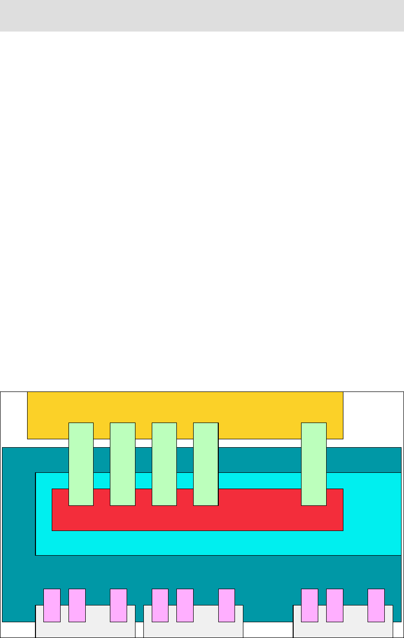
providing separate send and receive queues for each CHPID. Figure 1-1 shows a schematic
view of the host channel adapter.
A host channel adapter provides an interface to a host device and supports “verbs” defined to
InfiniBand. Verbs describe the service interface between a host channel adapter and the
software that supports it. Verbs allow the device driver and the hardware to work together.
Figure 1-1 Host channel adapter
Note: There is no relationship between virtual lanes and CHPIDs. The fact that you can
have up to 16 of each is coincidental.
.......
.....
... ... ...
Memory
Transport
Port Port Port
DMA
Channel
Adapter
Send and
Receive Queues
Send and
Receive Queues
Send and
Receive Queues
Send and
Receive Queues
Send and
Receive Queues
VL
VL
VL
VL
VL
VL
VL
VL
VL

6 Implementing and Managing InfiniBand Coupling Links on IBM System z
1.3.2 Processor-specific implementations
System z10 and subsequent CPCs exploit InfiniBand for internal connectivity and
CPC-to-CPC communication. System z9 CPCs only use InfiniBand for CPC-to-CPC
communication. Fabric components, such as routers and switches, are not supported in these
environments, although qualified DWDMs can be used to extend the distance of 1X InfiniBand
links.
System z CPCs take advantage of InfiniBand technology in the following ways:
On System z10 and later CPCs, for CPC-to-I/O cage connectivity, InfiniBand, which
includes the InfiniBand Double Data Rate (IB-DDR) infrastructure, replaces the Self-Timed
Interconnect (STI) features found in prior System z CPCs.
Parallel Sysplex InfiniBand (PSIFB) 12X links (both IFB and IFB3 mode) support
point-to-point connections up to 150 meters (492 feet).
Parallel Sysplex InfiniBand (PSIFB) Long Reach links (also referred to as 1X links) support
point-to-point connections up to 10 km unrepeated (up to 20 km with RPQ 8P2340), or up
to 175 km when repeated through a Dense Wave Division Multiplexer (DWDM) and
normally replace InterSystem Channel (ISC-3). The PSIFB Long Reach feature is not
available on System z9.
Server Time Protocol (STP) signals are supported on all types of PSIFB links.
Host channel adapter types on System z CPCs
System z CPCs provide a number of host channel adapter types for InfiniBand support:
HCA1-O A host channel adapter that is identified as HCA1-O (Feature Code
(FC) 0167) provides an optical InfiniBand connection on System z93.
HCA1-O is used in combination with the 12X IB-SDR link rating to
provide a link rate of up to 3 GBps.
HCA2-C A host channel adapter that is identified as HCA2-C (FC 0162)
provides a copper InfiniBand connection from a book to I/O cages and
drawers on a System z10, zEnterprise 196, or zEnterprise 114.
HCA2-O A host channel adapter that is identified as HCA2-O (FC 0163)
provides an optical InfiniBand connection.
Note: At the time of writing, System z9 CPCs are withdrawn from marketing, meaning that
if you have a z9 and it does not already have InfiniBand adapters on it, it is no longer
possible to purchase those adapters from IBM. For this reason, this book focuses on
IBM System z10® and later CPCs.
Note: InfiniBand is used for both coupling links and internal processor-to-I/O cage (and
process-to-drawer) connections in System z10 and later CPCs.
However, you do not explicitly order the InfiniBand fanouts that are used for
processor-to-I/O cage connections; the number of those fanouts that you need will depend
on the I/O configuration of the CPC. Because the focus of this book is on the use of
InfiniBand links for coupling and STP, we do not go into detail about the use of InfiniBand
for internal connections.
3 InfiniBand cannot be used to connect one System z9 CPC to another z9 CPC. Only connection to a later CPC type
is supported.

Chapter 1. Introduction to InfiniBand on System z 7
HCA2-O supports connection to:
HCA1-O For connection to System z9.
HCA2-O For connection to System z10 or later CPCs.
HCA3-O For connection to zEnterprise 196 and later CPCs.
HCA2-O is used in combination with the 12X IB-DDR link rating to
provide a link rate of up to 6 GBps between z10 and later CPCs and
up to 3 GBps when connected to a z9 CPC.
HCA2-O LR4A host channel adapter that is identified as HCA2-O LR (FC 0168)
provides an optical InfiniBand connection for long reach coupling links
for System z10 and later CPCs. HCA2-O LR is used in combination
with the 1X IB-DDR link rating to provide a link rate of up to 5 Gbps. It
automatically scales down to 2.5 Gbps (1X IB-SDR) depending on the
capability of the attached equipment. The PSIFB Long Reach feature
is available only on System z10 and later CPCs.
HCA3-O A host channel adapter that is identified as HCA3-O (FC 0171)
provides an optical InfiniBand connection to System z10 and later
CPCs. A HCA3-O port can be connected to a port on another HCA3-O
adapter, or a HCA2-O adapter. HCA3 adapters are only available on
zEnterprise 196 and later CPCs.
HCA3-O adapters are used in combination with the 12X IB-DDR link
rating to provide a link rate of up to 6 GBps. A port on a HCA3-O
adapter can run in one of two modes:
IFB mode This is the same mode that is used with HCA2-O adapters and
offers equivalent performance.
IFB3 mode This mode is only available if the HCA3-O port is connected to
another HCA3-O port and four or fewer CHPIDs are defined to
share that port. This mode offers improved performance compared
to IFB mode5.
HCA3-O LR A host channel adapter that is identified as HCA3-O LR (FC 0170)
provides an optical InfiniBand connection for long reach coupling links.
The adapter is available for z196, z114, and later CPCs, and is used to
connect to:
HCA2-O LR For connection to z10, and z196.
HCA3-O LR For connection to z196, z114, and later CPCs.
HCA3-O LR is used in combination with the 1X IB-DDR link rating to
provide a link rate of up to 5 Gbps. It automatically scales down to 2.5
Gbps (1X IB-SDR) depending on the capability of the attached
equipment. This adapter also provides additional ports (four ports
versus two ports on HCA2-O LR adapters).
1.4 InfiniBand benefits
System z is used by enterprises in different industries in different ways. It is probably fair to
say that no two mainframe environments are identical. System z configurations span from
4 HCA2-O LR adapters are still available for z10. However, they have been withdrawn from marketing for z196. On
z196, HCA3-O LR functionally replaces HCA2-O LR.
5 The maximum bandwidth for a HCA3-O link is 6 GBps, regardless of the mode. IFB3 mode delivers better response
times through the use of a more efficient protocol.

8 Implementing and Managing InfiniBand Coupling Links on IBM System z
sysplexes with over 100,000 MIPS to configurations with only one or two CPCs. Various
configurations intensively exploit sysplex capabilities for data sharing and high availability.
Others exploit simply the resource sharing functions. There are enterprises that run a single
sysplex containing both production and non-production systems. Others have multiple
sysplexes, each with a different purpose.
InfiniBand addresses the requirements of all these configurations. Depending on your
configuration and workload, one or more InfiniBand attributes might particularly interest you.
The benefits that InfiniBand offers compared to previous generation of System z coupling
technologies are listed here:
The ability to have ICB4-levels of performance for nearly all in-data-center CPC coupling
connections.
ICB4 links are limited to 10 meters, meaning that the maximum distance between
connected CPCs is limited to about 7 meters. As a result, many installations wanting to
use ICB4 links were unable to because of physical limitations on how close the CPCs
would be located to each other.
InfiniBand 12X links can provide performance similar to or better than ICB4 links, and yet
support distances of up to 150 meters. It is expected that InfiniBand 12X links will be
applicable to nearly every configuration where the CPCs being connected are in the same
data center. This is designed to result in significant performance (and overhead)
improvements for any installation that was forced to use ISC links in the past.
The ability to provide coupling connectivity over large distances with performance that is
equivalent to or better than ISC3 links, but with significantly fewer links.
HCA2-O LR and HCA3-O LR 1X links on z196 and later support either 7 or 32
subchannels and link buffers6 per CHPID, depending on the Driver level of the CPCs at
both ends of the link. For long-distance sysplexes, the use of 32 subchannels means that
fewer links are required to provide the same number of subchannels and link buffers than
is the case with ISC3 links. And if 64 subchannels (two CHPIDs with 32 subchannels
each) are not sufficient, additional CHPIDs can be defined to use the same link (in the
past, the only way to add CHPIDs was to add more physical links).
For a long-distance sysplex, the ability to deliver the same performance with fewer links
might translate to fewer DWDM ports or fewer dark fibers for unrepeated links. Also, fewer
host channel adapters might be required to deliver the same number of subchannels. Both
of these characteristics can translate into cost savings.
The ability to more cost effectively handle peak CF load situations.
Because InfiniBand provides the ability to assign multiple CHPIDs to a single port, you can
potentially address high subchannel utilization or high path busy conditions by adding
more CHPIDs (and therefore more subchannels) to a port. This is a definition-only
change; no additional hardware is required, and there is no financial cost associated with
assigning another CHPID to an InfiniBand port.
The IBM experience has been that many clients with large numbers of ICB4 links do not
actually require that much bandwidth. The reason for having so many links is to provide
more subchannels to avoid delays caused by all subchannels or link buffers being busy
during workload spikes. You might find that the ability to assign multiple CHPIDs to an
InfiniBand port means that you actually need fewer InfiniBand ports than you have ICB4
links today.
6 The relationship between subchannels and link buffers is described in Appendix C, “Link buffers and subchannels”
on page 247.

Chapter 1. Introduction to InfiniBand on System z 9
Every Parallel Sysplex requires connectivity from the z/OS systems in the sysplex to the
CFs being used by the sysplex. Link types prior to InfiniBand cannot be shared across
sysplexes, meaning that every sysplex required its own set of links.
Although InfiniBand does not provide the ability to share CHPIDs across multiple
sysplexes, it does provide the ability to share links across sysplexes. Because InfiniBand
supports multiple CHPIDs per link, multiple sysplexes can each have their own CHPIDs on
a shared InfiniBand link. For clients with large numbers of sysplexes, this can mean
significant savings in the number of physical coupling links that must be provided to deliver
the required connectivity.
zEnterprise 196 and later support larger numbers of CF link CHPIDs (increased to 128
CHPIDs from the previous limit of 64 CHPID). The InfiniBand ability to assign multiple
CHPIDs to a single link helps you fully exploit this capability7.
1.5 The importance of an efficient coupling infrastructure
Efficient systems must provide a balance between CPU performance, memory bandwidth
and capacity, and I/O capabilities. However, semiconductor technology evolves much faster
than I/O interconnect speeds, which are governed by mechanical, electrical, and
speed-of-light limitations, thus increasing the imbalance and limiting overall system
performance. This imbalance suggests that I/O interconnects must change to maintain
balanced system performance.
Each successive generation of System z CPC is capable of performing more work than its
predecessors. To keep up with the increasing performance, it is necessary to have an
interconnect architecture that is able to satisfy the I/O interconnect requirements that go
along with it. InfiniBand offers a powerful interconnect architecture that by its nature is better
able to provide the necessary I/O interconnect to keep the current systems in balance.
Table 1-2 highlights the importance that link technology plays in the overall performance and
efficiency of a Parallel Sysplex. The cells across the top indicate the CPC where z/OS is
running. The cells down the left side indicate the type of CPC where the CF is running and the
type of link that is used to connect z/OS to the CF.
Table 1-2 Coupling z/OS CPU cost
7 The number of physical coupling links that you can install depends on your CPC model and the number of books
that are installed.
CF/Host z10 BC z10 EC z114 z196 zBC12 zEC12
z10 BC ISC3 16% 18% 17% 21% 19% 24%
z10 BC 1X IFB 13% 14% 14% 17% 18% 19%
z10 BC 12X IFB 12% 13% 13% 16% 16% 17%
z10 BC ICB4 10% 11% NA NA NA NA
z10 EC ISC3 16% 17% 17% 21% 19% 24%
z10 EC 1X IFB 13% 14% 14% 17% 17% 19%
z10 EC 12X IFB 11% 12% 12% 14% 14% 16%
z10 EC ICB4 9% 10% NA NA NA NA
These values are based on 9 CF requests per second per MIPS.
The XES Synch/Async heuristic algorithm effectively caps overhead at about 18%.

10 Implementing and Managing InfiniBand Coupling Links on IBM System z
To determine the z/OS CPU cost associated with running z/OS on a given CPC and using a
CF on a given CPC, find the column that indicates the CPC your z/OS is on, and the row that
contains your CF and the type of link that is used. For example, if you are running z/OS on a
z10 EC, connected to a z10 EC CF using ISC3 links and performing 9 CF requests per
second per MIPS, the overhead is 17%.
The overhead reflects the percent of available CPC cycles that are used to communicate with
the CF. A given CF with a given link type will deliver a certain average response time. For a
given response time, a faster z/OS CPC is able to complete more instructions in that amount
of time than a slower one. Therefore, as you move z/OS to a faster CPC, but do not change
the CF configuration, the z/OS CPU cost (in terms of “lost” CPU cycles) increases. Using the
table, you can see that upgrading the z/OS CPC from a z10 EC to a faster CPC (a z196)
increases the cost to 21%8.
To keep the z/OS CPU cost at a consistent level, you also need to reduce the CF response
time by a percent that is similar to the percent increase in the z/OS CPU speed. The most
effective way to address this is by improving the coupling technology. In this example, if you
upgrade the CF to a z196 with the same link type (ISC3), the cost remains about the same
(21%). Replacing the ISC3 links with 12X IFB links further reduces the response time,
resulting in a much larger reduction in the cost, to 14%. And replacing the ISC3 links with 12X
IFB3 links reduces the cost further, to 11%.
These z/OS CPU cost numbers are based on a typical data sharing user profile of 9 CF
requests per MIPS per second. The cost scales with the number of requests. For example, if
your configuration drives 4.5 CF requests per MIPS per second, the cost is 50% of the
numbers in Table 1-2 on page 9.
z114 ISC3 16% 18% 17% 21% 19% 24%
z114 1X IFB 13% 14% 14% 17% 17% 19%
z114 12X IFB 12% 13% 12% 15% 15% 17%
z114 12X IFB3 NA NA 10% 12% 12% 13%
z196 ISC3 16% 17% 17% 21% 19% 24%
z196 1X IFB 13% 14% 13% 16% 16% 18%
z196 12X IFB 11% 12% 11% 14% 14% 15%
z196 12X IFB3 NA NA 9% 11% 10% 12%
zBC12 1X IFB 14% 15% 14% 18% 17% 20%
zBC12 12X IFB 13% 13% 12% 15% 14% 17%
zBC12 12X IFB3 NA NA 10% 11% 11% 12%
zEC12 1X IFB 13% 13% 13% 16% 16% 18%
zEC12 12X IFB 11% 11% 11% 13% 13% 15%
zEC12 12X IFB3 NA NA 9% 10% 10% 11%
8 In practice, the XES heuristic algorithm effectively caps overhead at about 18% by converting longer-running
synchronous CF requests to be asynchronous.
CF/Host z10 BC z10 EC z114 z196 zBC12 zEC12
These values are based on 9 CF requests per second per MIPS.
The XES Synch/Async heuristic algorithm effectively caps overhead at about 18%.

Chapter 1. Introduction to InfiniBand on System z 11
To further illustrate the relationship between coupling link types and response times,
Table 1-3 contains information about expected response times for different link types and
different types of requests on z10, z196, and EC12 CPCs.
Table 1-3 Expected CF synchronous response time ranges
These represent average numbers. Many factors (distance, CF CPU utilization, link utilization,
and so on) can impact the actual performance. However, you can see a similar pattern in this
table to Table 1-3; that is, faster link types deliver reduced response times, and those reduced
response times can decrease the z/OS CPU cost of using a CF with that link type.
1.5.1 Coupling link performance factors
Note that there is a difference between speed (which is typically observed through the CF
service times) and bandwidth.
Consider the example of a 2-lane road and a 6-lane highway. A single car can travel at the
same speed on both roads. However, if 1000 cars are trying to traverse both roads, they will
traverse the highway in much less time than on the narrow road. In this example, the
bandwidth is represented by the number of lanes on the road. The speed is represented by
the ability of the car to travel at a given speed (because the speed of light is the same for all
coupling link types that exploit fiber optic cables9).
To take the analogy a step further, the time to traverse the road depends partially on the
number of lanes that are available on the entry to the highway. After the traffic gets on to the
highway, it will tend to travel at the speed limit. However, if many cars are trying to get on the
highway and there is only a single entry lane, there will be a delay for each car to get on the
highway. Similarly, the time to get a large CF request (a 64 KB DB2 request, for example) into
a low-bandwidth link will be significantly longer than that required to place the same request
into a higher bandwidth link.
ISC3 PSIFB 1X ICB-4 PSIFB 12X
IFB
PSIFB 12X
IFB3
ICP
zEC12
Lock request 20-30 12-16 N/A 10-14 5-8 2-6
Cache/List
request
25-40 14-24 N/A 13-17 7-9 4-8
z196
Lock request 20-30 14-17 N/A 10-14 5-8 2-8
Cache/List
request
25-40 16-25 N/A 14-18 7-9 4-9
z10
Lock request 20-30 14-18 8-12 11-15 N/A 3-8
Cache/List
request
25-40 18-25 10-16 15-20 N/A 6-10
9 The speed of light in a fiber is about 2/3 of the speed of light in a vacuum. The speed of a signal in a copper
coupling link (ICB4, for example) is about 75% of the speed of light in a vacuum.
12 Implementing and Managing InfiniBand Coupling Links on IBM System z
Therefore, the “performance” of a coupling link is a combination of:
The type of requests being sent on the link (large or small, or some specific mix of
short-running or long-running).
The bandwidth of the link (this becomes more important for requests with large amounts of
data, or if there is a significantly large volume of requests).
The technology in the card or adapter that the link is connected to.
The distance between the z/OS system and the CF.
The number of buffers associated with the link.
Another aspect of the performance of CF requests that must be considered is, how many CF
requests do your systems issue and how does that affect the cost of using the CF? Changing
from one link type to another is expected to result in a change in response times. How that
change impacts your systems depends to a large extent on the number and type of requests
that are being issued.
If your CF is processing 1000 requests a second and the synchronous response time
decreases by 10 microseconds, that represents a savings of .01 seconds of z/OS CPU time
per second across all the members of the sysplex, which is a change that is unlikely to even
be noticeable.
However, if your CF processes 200,000 synchronous requests a second and the synchronous
response time improves by just half that amount (5 microseconds), that represents a saving of
one second of z/OS CPU time per second; that is, a savings of one z/OS engine’s worth of
capacity.
Using this example, you can see that the impact of CF response times on z/OS CPU
utilization is heavily influenced by the number and type of requests being sent to the CF; the
larger the number of requests, the more important the response time is.
This section illustrates the importance of using the best performing coupling links possible.
However, the coupling link connectivity in many enterprises has not kept up with changes to
the z/OS CPCs, resulting in performance that is less than optimal.
As you migrate from your current link technology to InfiniBand links, you are presented with
an ideal opportunity to create a coupling infrastructure that delivers the optimum
performance, flexibility, availability, and financial value. The primary objective of this book is to
help you make the best of this opportunity.
1.5.2 PSIFB 12X and 1X InfiniBand links
As stated previously, there are two bandwidths available for System z InfiniBand links: 12X
and 1X.
12X links support a maximum distance of 150 meters. It is expected that anyone with a
need to connect two CPCs within a single data center is able to exploit 12X InfiniBand
links.
1X links support larger distances, and therefore are aimed at enterprises with a need to
provide coupling connectivity between data centers.
The InfiniBand enhancements announced in July 2011 further differentiate the two types of
links. The new HCA3-O 12X adapters were enhanced to address the high bandwidth/low
response time needs that typically go with a sysplex that is contained in a single data center.
Specifically, they support a new, more efficient, protocol that enables reduced response
times, and the ability to process a larger number of requests per second.

Chapter 1. Introduction to InfiniBand on System z 13
The InfiniBand 1X adapters were enhanced in a different way. Sysplexes that span large
distances often experience high response times, resulting in high subchannel and link buffer
utilization. However, because each subchannel and link buffer can only handle one CF
request at a time, the utilization of the fiber between the two sites tends to be quite low.
To alleviate the impact of high subchannel and link buffer utilization, Driver 93 delivered the
ability to specify 32 subchannels and link buffers per CHPID for 1X links on z196 and later
CPCs. This provides the ability to process more requests in parallel without requiring
additional physical links. Additionally, because of the greatly increased capability to handle
more concurrent requests on each CHPID, the HCA3-O LR adapters have four ports rather
than two. This allows you to connect to more CPCs with each adapter, while still supporting
more concurrent requests to each CPC than was possible with the previous two-port adapter.
1.6 Terminology
Before the availability of InfiniBand coupling links, there was a one-to-one correspondence
between CF link CHPIDs and the actual link. As a result, terms such as link, connection, port,
and CHPID tended to be used interchangeably. However, because InfiniBand supports the
ability to assign multiple CHPIDs to a single physical link, it becomes much more important to
use the correct terminology. To avoid confusion, the following list describes how common
terms are used in this book:
CF link Before InfiniBand links, there was a one-to-one correspondence
between CF links and CF link CHPIDs. As a result, the terms were
often used interchangeably. However, given that InfiniBand technology
supports multiple CHPIDs sharing a given physical connection, it is
important to differentiate between CF link CHPIDs and CF links. In this
book, to avoid confusion, we do not use the term “CF link” on its own.
CF link CHPID A CF link CHPID is used to communicate between z/OS and CF, or
between two CFs. A CF link CHPID can be associated with one, and
only one, coupling link. However, an InfiniBand coupling link can have
more than one CF link CHPID associated with it.
Coupling link When used on its own, “coupling link” is used generically to describe
any type of link that connects z/OS-to-CF, or CF-to-CF, or is used
purely for passing STP timing signals. It applies to all link types:
PSIFB, ICB4, ISC3, and ICP.
Timing-only link This is a link that is used to carry only STP signals between CPCs.
CPCs that are in the same Coordinated Timing Network (CTN) must
be connected by some type of coupling link. If either of the CPCs
connected by a coupling link contain a CF LPAR, the CHPIDs
associated with all links between those CPCs must be defined in
hardware configuration definition (HCD) as Coupling Link CHPIDs. If
neither CPC contains a CF LPAR, the CHPIDs must be defined as
timing-only link CHPIDs. You cannot have both coupling links and
timing-only links between a given pair of CPCs.
Port A port is a receptacle on an HCA adapter into which an InfiniBand
cable is connected. There is a one-to-one correspondence between
Note: IBM recommends specifying seven subchannels per CHPID for coupling links
between CPCs in the same site. For links that will span sites, it is recommended to specify
32 subchannels per CHPID.

14 Implementing and Managing InfiniBand Coupling Links on IBM System z
ports and InfiniBand links. Depending on the adapter type, an
InfiniBand adapter will have either two or four ports.
PSIFB coupling linksThis refers generically to both 1X and 12X PSIFB links.
12X InfiniBand links This refers generically to both IFB and IFB3-mode 12X links.
1X InfiniBand links This refers generically to HCA2-O LR and HCA3-O LR links.
12X IFB links This refers to InfiniBand links connected to HCA1-O adapters,
HCA2-O adapters, or HCA3-O adapters when running in IFB mode.
12X IFB3 links This refers to InfiniBand links where both ends are connected to
HCA3-O adapters, and that are operating in IFB3 mode.
Gbps or GBps The convention is that the bandwidth of ISC3 and 1X PSIFB links is
described in terms of Gigabits per second, and the bandwidth of ICB4
and 12X PSIFB links is described in terms of Gigabytes per second.
Subchannel In the context of coupling links, a subchannel is a z/OS control block
that represents a link buffer. Each z/OS LPAR that shares a CF link
CHPID will have one subchannel for each link buffer associated with
that CHPID.
Link buffer Every CF link CHPID has a number of link buffers associated with it.
The number of link buffers will be either 7 or 32, depending on the
adapter type, the Driver level of the CPC, and the type of adapter and
driver level of the other end of the associated coupling link. Link
buffers reside in the link hardware.
For more information about the relationship between subchannels and
link buffers, see Appendix C, “Link buffers and subchannels” on
page 247.
System z server This refers to any System z CPC that contains either a z/OS LPAR or
CF LPAR or both and, in the context of this book, supports InfiniBand
links.
zEC12 This is the short form of zEnterprise System zEC12.
zBC12 This is the short form of zEnterprise System zBC12.
z196 This is the short form of zEnterprise System 196.
z114 This is the short form of zEnterprise System 114.
zEnterprise server This refers to both zEnterprise System 196 and zEnterprise
System 114.
z10 or System z10 This refers to both System z10 EC and System z10 BC.
z9 or System z9 This refers to both System z9 EC and System z9 BC.
CPC Many different terms have been used to describe the device that is
capable of running operating systems such z/OS or IBM z/VM®,
namely, server, CPU, CEC, CPC, machine, and others. For
consistency, we use the term “CPC” throughout this book. One
exception is in relation to STP, where we continue to use the term
“server” to be consistent with the terminology on the Hardware
Management Console (HMC), the Support Element (SE), and the STP
documentation.

Chapter 1. Introduction to InfiniBand on System z 15
1.7 Structure of this book
The objective of this book is to help you successfully implement InfiniBand links in a System z
environment. To this end, the following chapters are provided:
Chapter 2, “InfiniBand technical description” on page 17 describes the InfiniBand
hardware.
Chapter 3, “Preinstallation planning” on page 37 describes the information that you need
as you plan for the optimum InfiniBand infrastructure for your configuration
Chapter 4, “Migration planning” on page 63 provides samples of what we believe are the
most common migration scenarios for clients moving to InfiniBand links.
Chapter 5, “Performance considerations” on page 121 provides information about the
results of a number of measurements we conducted, to compare the relative performance
of the various coupling link technologies.
Chapter 6, “Configuration management” on page 155 provides information to help you
successfully define the configuration you want using HCD.
Chapter 7, “Operations” on page 189 provides information to help you successfully
manage an InfiniBand configuration.
The following Redbooks provide information that supplements the information provided in this
book:
IBM System z Connectivity Handbook, SG24-5444
Server Time Protocol Planning Guide, SG24-7280
Server Time Protocol Implementation Guide, SG24-7281
Server Time Protocol Recovery Guide, SG24-7380
IBM System z10 Enterprise Class Technical Guide, SG24-7516
IBM System z10 Business Class Technical Overview, SG24-7632
IBM zEnterprise 196 Technical Guide, SG24-7833
IBM zEnterprise 114 Technical Guide, SG24-7954
IBM zEnterprise EC12 Technical Guide, SG24-8049
IBM zEnterprise BC12 Technical Guide, SG24-8138
16 Implementing and Managing InfiniBand Coupling Links on IBM System z

© Copyright IBM Corp. 2008, 2012, 2014. All rights reserved. 17
Chapter 2. InfiniBand technical description
In this chapter, we describe the technical implementation of the InfiniBand technology on IBM
zEnterprise and System z processors.
zEnterprise and System z CPCs use InfiniBand technology for interconnecting CPCs in a
Parallel Sysplex environment.
We discuss the following topics:
InfiniBand connectivity
InfiniBand fanouts
Fanout plugging
Adapter ID assignment and VCHIDs
InfiniBand coupling links
InfiniBand cables
2
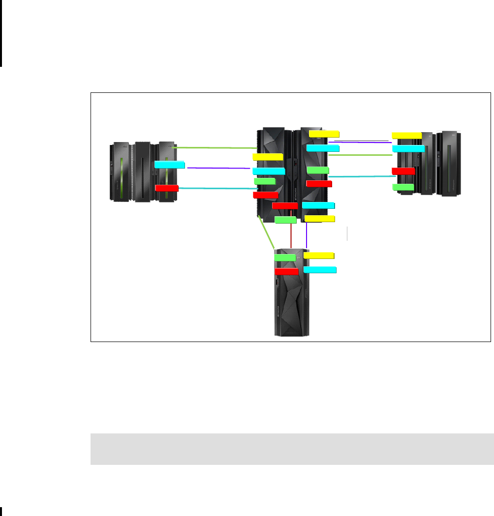
18 Implementing and Managing InfiniBand Coupling Links on IBM System z
2.1 InfiniBand connectivity
zEnterprise and System z CPCs benefit from the high speed and low latency offered by
InfiniBand technology. This technology provides improved reliability, scalability, and
performance, which are all attributes important in a Parallel Sysplex.
Because we are dealing with increased I/O data rates and faster CPCs, we need a way to
connect two CPCs with a faster and more flexible interconnection. Also, as enterprises move
from Sysplex Timers to STP for time coordination, interconnectivity between the CPCs in the
Common Time Network (CTN) is required. InfiniBand provides all of this functionality.
Figure 2-1 provides an overview of the InfiniBand coupling implementation options that are
available with InfiniBand on zEnterprise and System z CPCs. The connectivity options are:
Any-to-any coupling and timing-only 12X IFB mode connectivity between zEC12, zBC12,
z196, z114, and z10 CPCs.
Any-to-any coupling and timing-only 12X IFB3 mode connectivity between zEC12, zBC12,
z196, and z114 CPCs.
Any-to-any coupling and timing-only 1X connectivity between zEC12, zBC12, z196, z114,
and z10 CPCs (optical link - long reach).
Figure 2-1 InfiniBand connectivity options
Note that Parallel Sysplex InfiniBand (PSIFB) coupling link channel-path identifiers (CHPIDs)
can be shared or spanned across logical partitions and channel subsystems on zEnterprise
and System z CPCs. However, the total number of CF link CHPIDs (including ICP, ISC, and
InfiniBand CHPIDs) must not exceed 128 (64 on CPC generations prior to z196). See 3.1,
“Planning considerations” on page 38 for more information.
Note: Whenever the text refers to coupling links or coupling link fanouts, this also applies
to STP timing-only links.
ISC-3*, 2 Gbps
10/100 km
z196 and z114
12x IFB, 12x IFB3, 1x IFB, & ISC-3
12x IFB, 6 GBps
Up to 150 m
z10 EC and z10 BC
12x IFB, 1x IFB & ISC-3
1x IFB, 5 Gbps
10/100 km
ISC-3*
10/100 km 1x IFB, 5 Gbps
10/100 km
12x IFB3
or IFB
6 GBps
150 m
HCA3-O
HCA3-O ISC-3*, 2 Gbps
10/100 km
HCA2-O*
HCA2-O*
HCA2-O
OR
OR
*HCA2-O, HCA2-O LR, & ISC-3 carry
forward only on zEC12
HCA3-O LR
OR
HCA3-O LR
OR
HCA2-O LR*
HCA2-O LR*
HCA2-O LR*
zEC12
zEC12
HCA2-O LR
1x IFB, 5 Gbps
10/100 km HCA3-O LR
OR
HCA2-O LR*
HCA2-O 12x IFB3 or IFB
6 GBps
150 m
OR
HCA3-O
HCA3-O LR
OR
HCA3-O
HCA2-O*
OR
HCA3-O LR
OR
HCA2-O LR*
HCA3-O
HCA2-O*
OR
zBC12

Chapter 2. InfiniBand technical description 19
Table 2-1 provides more information about the InfiniBand options that are available on
zEnterprise and System z CPCs. We describe these options in more detail in subsequent
sections.
Table 2-1 Available InfiniBand options for zEnterprise and System z CPCs
2.2 InfiniBand fanouts
This section describes the various InfiniBand fanouts that are offered on the zEnterprise and
System z CPCs.
There are six fanout types that are based on InfiniBand technology:
HCA1-O (z9 only).
HCA2-O (z196, z114, and z10. They can be carried forward to a zEC12 or a zBC12 on an
upgrade).
HCA2-O LR (Orderable on z10 only - but can be carried forward to z196, z114, zEC12, or
zBC12 on an MES).
HCA2-C (z196, z114, and z10 - depending on the ordered I/O configuration. They cannot
be used for timing links or coupling to a CF.)
HCA3-O (z114, z196, zBC12, and zEC12).
HCA3-O LR (z114, z196, zBC12, and zEC12).
Fanout type Description System z9 System z10 zEC12
aBC12
zEnterprise 196
zEnterprise 114
Maximum
distance
Data link
rate
HCA1-O 12X IB-SDR Optical
coupling link
N/A N/A 150 meters
(492 feet)
3 GBps
HCA2-O 12X IB-DDR
12X IB-SDR
N/A Optical
coupling link
Optical
coupling link
150 meters
(492 feet)
6 GBps
3 GBps
HCA2-O LRa
a. RPQ 8P2340 for extended distance is available on client request.
1X IB-DDR
1X IB-SDR
N/A Optical
coupling link
Optical coupling
link (carry forward)
10 km
(6.2 miles)b
b. An extended distance of 175 km (108 miles) is supported with DWDM. The data rate (DDR or SDR) depends on
the capability of the attached equipment.
5 Gbps
2.5 Gbps
HCA2-Cc
c. These are only used for internal connections within the CPC. HCA2-C fanouts cannot be used for STP or for
connecting to a CF. They are only included here for completeness.
12X IB-DDR N/A Copper
I/O cage link
Copper
I/O cage link
1 - 3.5 meters
(3.2 - 11.4 feet)
6 GBps
HCA3-O 12x IB-DDR N/A N/A Optical
coupling linkd
d. The improved IFB3 protocol can be used if two HCA3-O fanouts are connected.
150 meters
(492 feet)
6 GBps
HCA3-O LR 1x IB-DDR
1x IB-SDR
N/A N/A Optical
coupling link
10 kma
(6.2 miles)b5 Gbps
2.5 Gbps
Note: InfiniBand links can be used to connect a z9 to a z10 or later. However, they cannot
be used to connect two z9 CPCs to each other.
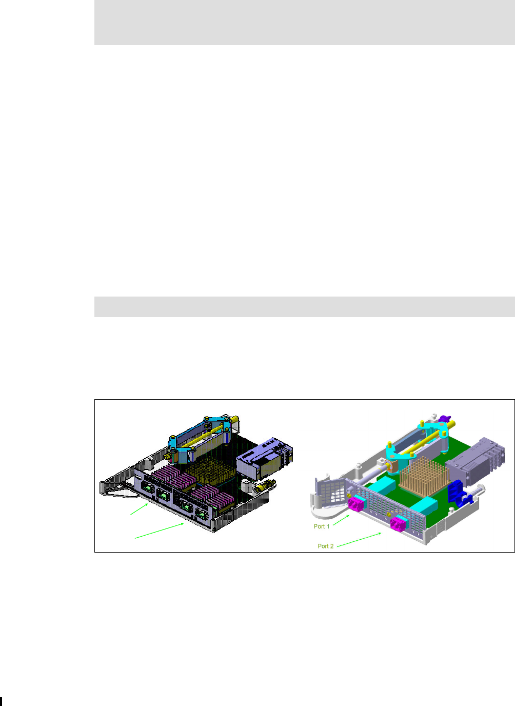
20 Implementing and Managing InfiniBand Coupling Links on IBM System z
Each PSIFB fanout has either two ports or four ports (for the HCA3-O LR) to connect an
optical cable (see Figure 2-2 and Figure 2-3 on page 21).
2.2.1 Adapter types
This section provides further information about the different types of InfiniBand coupling link
adapters:
HCA1-O
This fanout is only available on System z9. It provides interconnectivity for Parallel Sysplex
and STP connections between zEnterprise 196, zEnterprise 114, System z10, and
System z9.
The fanout has two optical multifiber push-on (MPO) ports. The link operates at a
maximum speed of 3 GBps.
HCA1-O fanouts can be connected only to HCA2-O fanouts on z196, z114, and z10
CPCs. Ports on the HCA1-O fanout are exclusively used for coupling links or STP
timing-only links and cannot be used for any other purpose.
HCA2-O
This fanout, shown in Figure 2-2, can be ordered on z196, z114, and z10 CPCs. It
provides interconnectivity for Parallel Sysplex and STP connections between these CPCs,
and supports connection to a HCA1-O fanout on a z9.
Figure 2-2 HCA2-O fanout and HCA2-O LR fanout
The fanout has two optical MPO ports. The link can operate at either double data rate (if
connected to another HCA2-O or a HCA3-O) or single data rate (if connected to an
HCA1-O).
Ports on the HCA2-O fanout are used exclusively for coupling links or STP timing-only
links and cannot be used for any other purpose.
HCA2-O fanouts can also be carried forward during an MES upgrade from a System z10
to a zEnterprise system.
Note: HCA1-O, HCA2-O, HCA2-O LR, HCA3-O, and HCA3-O LR adapters are used
exclusively by InfiniBand coupling and timing-only links. Throughout this document, we
refer to them as PSIFB fanouts.
Note: z9-to-z9 PSIFB link connections are not supported.
Port 1
Port 2
Port 1
Port 2
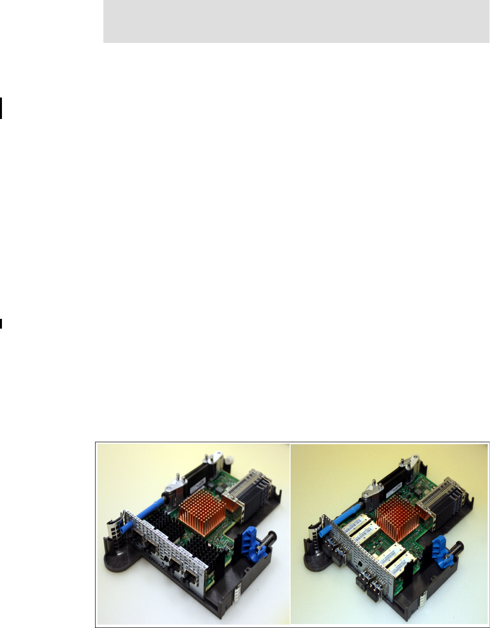
Chapter 2. InfiniBand technical description 21
HCA2-O LR
This fanout (also shown in Figure 2-2 on page 20) can only be ordered on System z10.
HCA2-O LR fanouts can be carried forward to z196 and z114 by way of an MES upgrade.
It provides interconnectivity for Parallel Sysplex and STP connections between zEC12,
zBC12, z196, z114, and z10.
The fanout has two optical Small Form-Factor Pluggable (SFP) ports. The link operates at
either 5 Gbps or 2.5 Gbps depending on the capability of the attached equipment.
Ports on the HCA2-O LR fanout are used exclusively for coupling links or STP timing-only
links and cannot be used for any other purpose.
HCA2-C
This fanout is available on z196, z114, and z10 CPCs, depending on the I/O configuration.
The number of HCA2-C fanouts is not chosen by you; it is determined by the number and
type of I/O cards that are ordered. HCA2-C fanouts are only relevant to coupling from the
perspective that the number of HCA2-C fanouts that are installed can have an impact on
the number of fanouts that can be used for coupling.
The HCA2-C fanout provides the connection between the CPC complex and the IFB-MP
cards that are installed in the I/O cages or drawers. Ports on the HCA2-C fanout are
exclusively used for I/O interfaces and cannot be used for any other purpose.
HCA3-O
This fanout (shown on the left side in Figure 2-3) is only available on z196 and later CPCs.
It provides interconnectivity for Parallel Sysplex and STP connections.
The fanout has two optical MPO ports. Each link operates at 6 GBps.
If the connection is made between two HCA3-O fanouts and there are no more than four
CHPIDs per port defined, the connection will automatically use the improved IFB3 protocol
mode.
Ports on the HCA3-O fanout are exclusively used for coupling links or STP timing-only
links and cannot be used for any other purpose.
Figure 2-3 HCA3-O and HCA3-O LR fanout
Note: On zEnterprise or later CPCs, the only reason for ordering HCA2-O fanouts is if
you need to connect to a z9 CPC using PSIFB. In all other situations, order HCA3-O (or
HCA3-O LR) fanouts.

22 Implementing and Managing InfiniBand Coupling Links on IBM System z
HCA3-O LR
This fanout (shown on the right side in Figure 2-3 on page 21) is only available on z196
and later CPCs. It provides interconnectivity for Parallel Sysplex and STP connections
between zEC12, zBC12, z196, z114, and z10 CPCs.
The fanout has four optical Small Form-Factor Pluggable (SFP) ports. Each link operates
at either 5 Gbps or 2.5 Gbps depending on the capability of the attached equipment.
Ports on the HCA3-O LR fanout are exclusively used for coupling links or STP timing-only
links and cannot be used for any other purpose.
Table 2-2 summarizes the InfiniBand interconnectivity options.
Table 2-2 InfiniBand interconnectivity options
2.3 Fanout plugging
This section describes the fanout plugging rules for the zEnterprise and System z CPCs.
2.3.1 Fanout plugging rules for zEnterprise 196
With the introduction of the zEnterprise CPCs, there are now six fanout types available.
Depending on the number of I/O cages or drawers installed and the I/O domains in use, you
have different numbers of fanout slots available for use as coupling or timing-only links. A
maximum of 16 coupling link fanouts are supported for a z196.
Note that a z196 CPC that is fully populated for I/O connectivity has a maximum of 12 HCA
slots remaining for coupling link fanouts. It has six I/O drawers or up to three I/O cages
installed and uses up to 24 I/O domains. To connect each of the domains, you need 24 I/O
interfaces, which can be provided by 12 I/O interface fanouts. This means that only 12 fanout
slots are left to install coupling link fanouts (either HCA2-Os, HCA2-O LRs, HCA3-Os,
HCA3-O LRs, or any combination of the four).
The fanout plugging rules vary and are dependent upon the z196 model. Figure 2-4 on
page 23 can serve as a reference, but use the IBM configuration tool to determine the correct
allocation.
HCA1 HCA2 12X HCA2 1X HCA3 12X HCA3 1X
HCA1 NoYesNoNoNo
HCA2 12X Yes Yes (IFB) No Yes (IFB) No
HCA2 1X No No Yes No Yes
HCA3 12X No Yes (IFB) No Yes (IFB3) No
HCA3 1X No No Yes No Yes
Note: For the fanout plugging rules for zEC12 or zBC12, refer to the IBM Redbooks
documents IBM zEnterprise EC12 Technical Guide, SG24-8049, or IBM zEnterprise BC12
Technical Guide, SG24-8138.
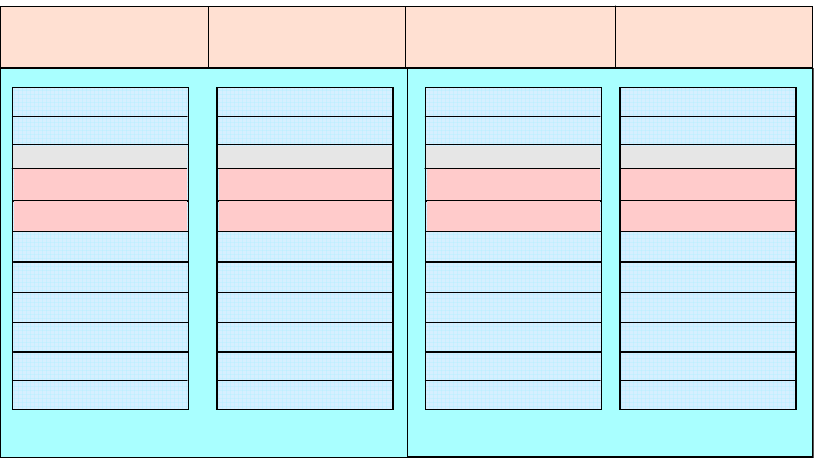
Chapter 2. InfiniBand technical description 23
Figure 2-4 z196 fanout positions
Positions D1 and D2 are not available on z196 models M66 and M80. For model M49, the
positions D1 and D2 in the book positions LG10 and LG15 are not available.
For more information about this topic, see IBM zEnterprise 196 Technical Guide, SG24-7833.
2.3.2 Fanout plugging rules for zEnterprise 114
The z114 CPC has two hardware models. In the hardware model M05, only the first CPC
drawer is installed with a maximum of four fanout slots. The hardware model M10 has both
CPC drawers installed and provides up to eight fanout slots; see Figure 2-5 on page 24.
ECF ECFOSC OSC
LG 10
D1 I/O
D2 I/O
D5 I/O
D6 I/O
D7 I/O
D8 I/O
D9 I/O
DA I/O
D3 FSP
D4 FSP
LG 01
D1 I/O
D2 I/O
D5 I/O
D6 I/O
D7 I/O
D8 I/O
D9 I/O
DA I/O
D3 FSP
D4 FSP
LG 06
D1 I/O
D2 I/O
D5 I/O
D6 I/O
D7 I/O
D8 I/O
D9 I/O
DA I/O
D3 FSP
D4 FSP
LG 15
D1 I/O
D2 I/O
D5 I/O
D6 I/O
D7 I/O
D8 I/O
D9 I/O
DA I/O
D3 FSP
D4 FSP
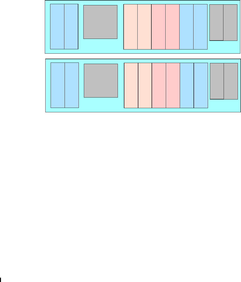
24 Implementing and Managing InfiniBand Coupling Links on IBM System z
Depending on the number of installed I/O drawers, a different number of I/O interconnection
fanouts are used. This can range from zero I/O interconnection fanouts for a dedicated
stand-alone Coupling Facility model, through a Model M05 with a maximum of four legacy I/O
drawers (where all four fanout slots are used for I/O interconnection fanouts), to a model M10
with three I/O drawers (where a maximum of six fanout slots will be used for I/O
interconnection fanouts). So, depending on the model and the I/O connectivity that is
required, there will be zero to eight fanout slots available to install coupling link fanouts (either
HCA2-Os, HCA2-O LRs, HCA3-Os, HCA3-O LRs, or any combination of these).
Figure 2-5 zEnterprise 114 fanout positions
For more information, refer to IBM zEnterprise 114 Technical Guide, SG24-7954.
2.3.3 Fanout plugging rules for System z10 EC
System z10 supports three fanout types.
The HCA2-C fanout provides the I/O interfaces. Depending on the number of I/O cages
installed and the I/O domains in use, you have different numbers of fanout slots available for
use as coupling links. A fully populated CPC has three I/O cages installed and uses 21 I/O
domains. To connect each of them, you need 24 I/O interfaces, which can be provided by 12
HCA2-C fanouts. That means a maximum of 12 fanout slots are available to install coupling
link fanouts (either HCA2-Os, HCA2-O LRs, or MBAs, or any combination of the three).
Depending on the System z10 model, the plugging rules for fanouts vary. Figure 2-6 on
page 25 can serve as a reference, but use the IBM configuration tool to determine the correct
allocation.
D8
I/O
D7
I/O
D6
FSP
D1
I/O
D2
I/O
D5
FSP
D3
OSC
ECF
D4
OSC
ECF
DCA
1
DCA
2
CPC Drawer 1
CPC
Blower
D8
I/O
D7
I/O
D6
FSP
D1
I/O
D2
I/O
D5
FSP
D3
Pass
thru
D4
Pass
thru
DCA
1
DCA
2
CPC Drawer 2
CPC
Blower
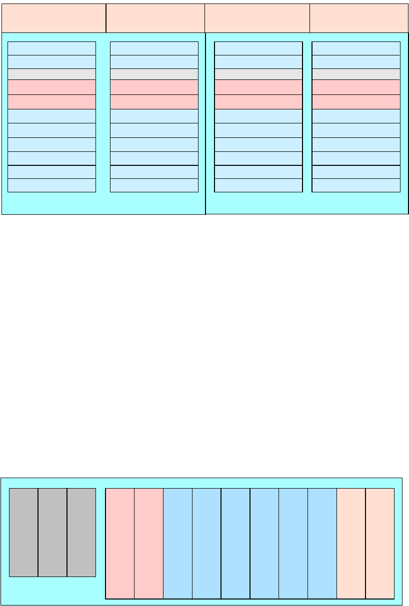
Chapter 2. InfiniBand technical description 25
Figure 2-6 System z10 EC fanout positions
Positions D1 and D2 are not available in z10 models E56 and E64. For model E40, the
positions D1 and D2 in the book positions LG10 and LG15 are not available.
More information about the plugging rules for System z10 EC is available in IBM System z10
Enterprise Class Technical Guide, SG24-7516.
2.3.4 Fanout plugging rules for System z10 BC
The System z10 BC offers the possibility to work without any I/O drawers and can act as a
dedicated Coupling Facility CPC without the need for HCA2-C fanouts. Depending on the
number of installed I/O drawers, a different number of HCA2-C fanouts for I/O connections
are needed.
A fully-populated CPC has four I/O drawers with a total of eight I/O domains installed and
uses four fanout slots for I/O connections; see Figure 2-7. A CPC without an I/O drawer
installed will have six fanouts available for coupling connections. So there will be between two
and six fanout slots available to install coupling link fanouts (either HCA2-Os, HCA2-O LRs, or
MBAs, or any combination of these).
Figure 2-7 System z10 BC fanout positions
For more information about the plugging rules for System z10 BC, see IBM System z10
Business Class Technical Overview, SG24-7632.
ETR ETROSC OSC
LG 10
D1 I/O
D2 I/O
D5 I/O
D6 I/O
D7 I/O
D8 I/O
D9 I/O
DA I/O
D3 FSP
D4 FSP
LG 01
D1 I/O
D2 I/O
D5 I/O
D6 I/O
D7 I/O
D8 I/O
D9 I/O
DA I/O
D3 FSP
D4 FSP
LG 06
D1 I/O
D2 I/O
D5 I/O
D6 I/O
D7 I/O
D8 I/O
D9 I/O
DA I/O
D3 FSP
D4 FSP
LG 15
D1 I/O
D2 I/O
D5 I/O
D6 I/O
D7 I/O
D8 I/O
D9 I/O
DA I/O
D3 FSP
D4 FSP
D8
D7
D6
D5
D2
FSP
D3 D4
D1
FSP
D9
OSC
ECF
DA
OSC
ECF
DCA
1
DCA
2
DCA
3
CPC Drawer

26 Implementing and Managing InfiniBand Coupling Links on IBM System z
2.4 Adapter ID assignment and VCHIDs
This section describes the assignment of the Adapter IDs (AIDs) and explains the relationship
between the AID, the virtual channel path identifier (VCHID), and the channel path identifier
(CHPID). A solid understanding of these concepts facilitates the management and
maintenance of PSIFB links from the HMC or SE.
2.4.1 Adapter ID assignment
An adapter ID (AID) is assigned to every PSIFB link fanout at installation time. It is unique for
the CPC. There is only one AID per fanout, so all ports on the fanout share the same AID. The
adapter ID is:
A number between 00 and 1F on z196, z10 EC, and z9 EC
A number between 00 and 0B on z114
A number between 00 and 05 on z10 BC
A number between 08 and 0F on a z9 BC
In the input/output configuration program (IOCP) or hardware configuration definition (HCD),
the AID and port number are used to connect the assigned CHPID to the physical location of
the fanout.
There are distinct differences between zEnterprise systems, System z10, and System z9 for
the assignment and handling of the AID; for example:
For z196, the AID is bound to the serial number of the fanout. If the fanout is moved, the
AID moves with it. For newly-built systems or newly-installed books, you can determine
the AID from Table 2-3.
Table 2-3 Initial AID number assignment for zEnterprise 196
Note: For adapter and VCHID information specific to zEC12 or zBC12, refer to the IBM
Redbooks documents IBM zEnterprise EC12 Technical Guide, SG24-8049, or IBM
zEnterprise BC12 Technical Guide, SG24-8138.
Adapter
location
Book
Fourth First Third Second
D1 00 08 10 18
D2 01 09 11 19
D3 N/A N/A N/A N/A
D4 N/A N/A N/A N/A
D5 02 0A 12 1A
D6 03 0B 13 1B
D7 04 0C 14 1C
D8 05 0D 15 1D
D9 06 0E 16 1E
DA 07 0F 17 1F

Chapter 2. InfiniBand technical description 27
For zEnterprise 114, the AID is bound to the serial number of the fanout. If the fanout is
moved, the AID moves with it. For newly-built systems you can determine the AID from
Table 2-4.
Table 2-4 Initial AID number assignment for zEnterprise 114
For z10 EC, the AID is bound to the serial number of the fanout. If the fanout is moved, the
AID moves with it. For newly-built systems or newly-installed books, you can determine
the AID from Table 2-5.
Table 2-5 Initial AID number assignment for System z10 EC
Note: The fanout positions D3 and D4 are reserved for Functional Service Processor
(FSP) cards and cannot be used for fanouts. Also, positions D1 and D2 are not
available in zEnterprise 196 models M66 and M80. For model M49, the positions D1
and D2 in the book positions LG10 and LG15 are not available.
Fanout position D1 D2 D3 D4 D5 D6 D7 D8
CEC Drawer 1 AID 08 09 N/A N/A N/A N/A 0A 0B
CEC Drawer 2 AID 00 01 N/A N/A N/A N/A 02 03
Note: The fanout positions D3, D4, D5, and D6 are reserved for the Functional Service
Processors and Oscillator cards and cannot be used for fanouts.
Adapter
location
Book
Fourth First Third Second
D1 00 08 10 18
D2 01 09 11 19
D3 N/A N/A N/A N/A
D4 N/A N/A N/A N/A
D5 02 0A 12 1A
D6 03 0B 13 1B
D7 04 0C 14 1C
D8 05 0D 15 1D
D9 06 0E 16 1E
DA 07 0F 17 1F
Note: The fanout positions D3 and D4 are reserved for Functional Service Processor
(FSP) cards and cannot be used for fanouts. Also, positions D1 and D2 are not
available in System z10 models E56 and E64. For model E40 the positions D1 and D2
in the book positions LG10 and LG15 are not available.
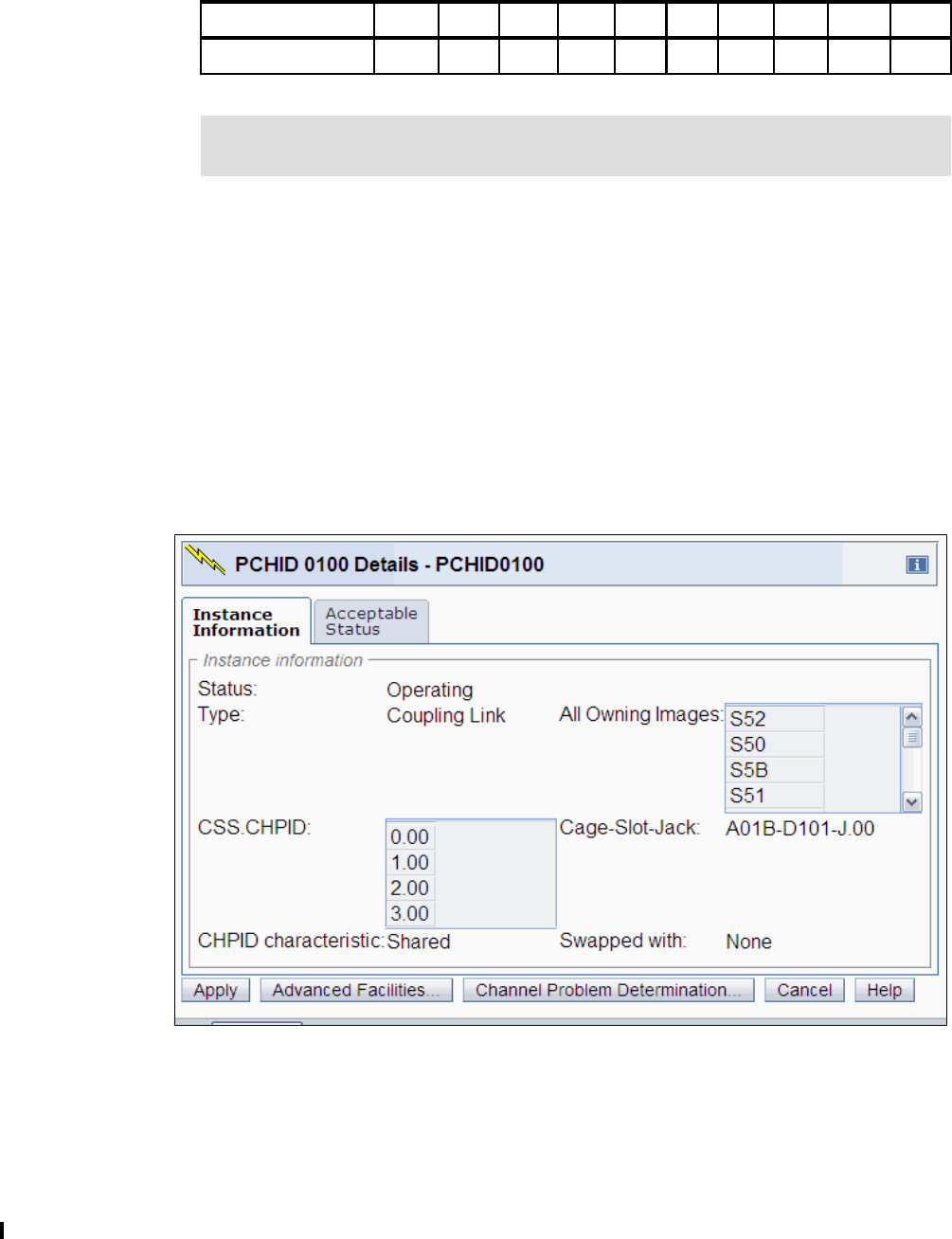
28 Implementing and Managing InfiniBand Coupling Links on IBM System z
For z10 BC, the AID is bound to the serial number of the fanout. If the fanout is moved, the
AID moves with it. For newly-built systems, you can determine the AID from Table 2-6.
Table 2-6 Initial AID number assignment for System z10 BC
The AID for z9 is bound to the physical fanout position. If the fanout is moved to another
slot, the AID changes for that specific fanout, and it might be necessary to adjust the
input/output configuration data set (IOCDS).
The Physical Channel ID (PCHID) Report lists the assignments of the AIDs for new CPCs or
miscellaneous equipment specification (MES) upgrades, and in the Hardware Management
Console (HMC) and Support Element (SE) panels after installation. See 3.7, “Physical and
logical coupling link capacity planning” on page 50 for an example of a PCHID Report.
2.4.2 VCHID - Virtual Channel Identifier
A physical channel identifier (PCHID) normally has a one-to-one relationship between the
identifier and a physical location in the machine; see Figure 2-8 for an example.
Figure 2-8 The PCHID refers to the physical location
Fanout position D1 D2 D3 D4 D5 D6 D7 D8 D9 DA
AID N/A N/A 00 01 02 03 04 05 N/A N/A
Note: The fanout positions D1, D2, D9, and DA are reserved for the Functional Service
Processors and Oscillator cards and cannot be used for fanouts.

Chapter 2. InfiniBand technical description 29
However, a PCHID in the range from 0700 to 07FF lacks the one-to-one relationship between
the identifier and the physical location, either because they do not have a physical card (like
Internal Coupling connections (ICPs)), or because they are administered through different
identifiers (as for PSIFB links, with the AIDs). No one-to-one relationship is possible due to
the capability to define more than one CHPID for a physical location. Therefore, these are
sometimes referred to as Virtual Channel Path Identifiers (VCHIDs). Note that the SE and
HMC still refer to these as PCHIDs; see Figure 2-9 for an example.
Figure 2-9 The VCHID refers to the physical location of the HCA and Port
VCHIDs for IC channels have been implemented for several generations of System z CPCs.
However, prior to the introduction of PSIFB links, there was no requirement for the operators
to interact with the VCHID objects on the SE. With the introduction of PSIFB, there might now
be situations where you have to query or manage the VCHID objects.
To manage PSIFB links, the SE and HMC tasks have been changed to handle the VCHIDs
that support the physical hardware. In the SE Channel task, the VCHID for every CHPID that
is associated with a PSIFB link is shown, and all traditional channel operations can be carried
out against each VCHID. The AID and port that the VCHID is assigned to can be found under
the channel details for each VCHID (see Figure 2-9 for an example).
VCHIDs are assigned automatically by the system and are not defined by you in the IOCDS.
A VCHID is also not permanently tied to an AID. Therefore the VCHID assignment can
change after a Power-On Reset (POR) if the hardware configuration changed (if an HCA was
added or removed, for example). Due to the automatic assignment of the VCHID at every
POR, the client or SSR needs to make sure that the correlation for the channel that they
intend to manipulate has not changed. The VCHID that is currently associated with a coupling
CHPID can be found by issuing an MVS D CF,CFNM=xxxx command for the associated CF.

30 Implementing and Managing InfiniBand Coupling Links on IBM System z
2.5 InfiniBand coupling links
This section discusses the various PSIFB coupling links that are available for each individual
zEnterprise and System z CPC from the CPC point of view.
2.5.1 12X PSIFB coupling links on System z9
An HCA1-O fanout is installed in a fanout slot in the front of a z9 book and takes an empty slot
or the place of one of the previous MBAs. It supports the 12X IB-SDR link option and is used
to connect a System z9 to a zEnterprise or a System z10. The fanout has two optical MPO
ports and the order increment for the HCA1-O fanout is always one complete fanout with both
ports enabled.
The point-to-point coupling link connection is established by connecting the HCA1-O fanout to
a zEnterprise or System z10 HCA2-O fanout through a 50-micron OM3 (2000 MHz-km)
multimode fiber optic cable. A HCA1-O fanout can only be connected to a HCA2-O fanout.
The cable contains 12 lanes (two fibers per lane, one each for transmit and receive); 24 fibers
in total. The maximum supported length for these connections is 150 meters (492 feet). The
link bandwidth is 3 GBps for a single data rate connection (SDR) and is auto-negotiated.
Each HCA1-O fanout has an AID that is bound to the physical position in which it is installed.
That means that if you move the fanout to another position, the AID changes and you need to
adjust the AID in the IOCP or HCD. See 2.4, “Adapter ID assignment and VCHIDs” on
page 26 for more information.
It is possible to define up to 16 CHPIDs per fanout (AID), which can be freely distributed
across both ports.
A maximum of 8 HCA1-O fanouts per book are supported on a System z9, providing a total of
16 ports. Regardless of how many fanouts are installed, the maximum combined total of 64
CF link CHPIDs per CPC applies.
2.5.2 12X PSIFB coupling links on System z10
An HCA2-O fanout is installed in a fanout slot in the front of the System z10 CPC cage (or
CPC drawer for the z10 BC). It supports the 12X IB-DDR link option. This link connects to a
zEnterprise, a System z10, or a System z9 CPC, in a point-to-point coupling link connection.
Note: For coupling link information specific to zEC12 or zBC12, refer to the IBM Redbooks
documents IBM zEnterprise EC12 Technical Guide, SG24-8049, or IBM zEnterprise BC12
Technical Guide, SG24-8138.
Note: At the time of writing, upgrades for System z9 CPCs have been withdrawn from
marketing.
Important: For optimal performance, define no more than four CIB CHPIDs per port.
Note: HCA1-O adapters cannot be carried forward on an upgrade to a z10 or z196.
Upgrades to either of those CPCs requires replacing the HCA1 adapters with HCA2 or
HCA3 adapters.

Chapter 2. InfiniBand technical description 31
The fanout has two optical MPO ports (see Figure 2-2 on page 20). The order increment for
the HCA2-O fanout is always one complete fanout with both ports enabled.
The connection is established by connecting the HCA2-O to the other system’s PSIFB fanout
(either an HCA1-O for a System z9, a HCA2-O for a zEnterprise or a System z10, or a
HCA3-O for a zEnterprise) through a 50-micron OM3 (2000 MHz-km) multimode fiber optic
cable. The cable contains 12 lanes (two fibers per lane, one each for transmit and receive); 24
fibers in total. The maximum supported length for these connections is 150 meters (492 ft).
The maximum bandwidth is 6 GBps for a double data rate connection (DDR) or 3 GBps for a
single data rate connection (SDR) and is auto-negotiated.
Each HCA2-O fanout has an AID, which is bound to the HCA serial number. See 2.4,
“Adapter ID assignment and VCHIDs” on page 26 for more information.
It is possible to define up to 16 CHPIDs per fanout (AID), which can be freely distributed
across both ports.
A maximum of 16 fanouts for InfiniBand coupling are supported on a z10 EC. All 16 can be
HCA2-O fanouts providing a total of 32 ports. On a z10 BC, a maximum of 6 HCA2-O fanouts
are supported, providing a total of 12 ports. Regardless of the number of fanouts installed or
used, the maximum of 64 CF link CHPIDs per CPC still applies (including IC, Inter-Cluster
Bus-4 (ICB4), active InterSystem Coupling Facility-3 (ISC3), and PSIFB).
2.5.3 PSIFB Long Reach coupling links on System z10
An HCA2-O LR fanout is installed in a fanout slot in the front of the z10 CPC cage (or CPC
drawer for the z10 BC). It supports the 1X IB-DDR LR link option. This link connects either to
a zEnterprise or to a z10 CPC in a point-to-point coupling link connection. The fanout has two
optical SFP ports, and the order increment for the HCA2-O LR fanout is always one complete
fanout with both ports enabled.
The connection is established by connecting the HCA2-O LR to the other system’s
HCA2-O LR or HCA3-O LR port through a 9-micron single mode fiber optic cable. The cable
contains one lane with one fiber for transmit and one for receive. The maximum supported
length for these connections is 10 km1 (6.2 miles) unrepeated and 175 km (108 miles) when
repeated through a DWDM. The maximum bandwidth is 5 Gbps for a double data rate
connection (DDR) or 2.5 Gbps for a single data rate connection (SDR) and is auto-negotiated.
Each HCA2-O LR fanout has an AID, which is bound to the HCA serial number. See 2.4,
“Adapter ID assignment and VCHIDs” on page 26 for more information.
It is possible to define up to 16 CHPIDs per fanout (AID), which can be freely distributed
across both ports.
Important: For optimal performance, define no more than four CIB CHPIDs per port.
Note: The InfiniBand link data rate of 6 GBps or 3 GBps does not represent the
performance of the link. The actual performance depends on many factors, such as
latency through the adapters, cable lengths, and the type of workload.
1 Refer to RPQ 8P2340 for information about extending the unrepeated distance to 20 km.

32 Implementing and Managing InfiniBand Coupling Links on IBM System z
A maximum of 16 fanouts for coupling are supported on a z10 EC. All 16 can be HCA2-O LR
fanouts providing a total of 32 ports. On a z10 BC, a maximum of 6 HCA2-O LR fanouts are
supported, providing a total of 12 ports. Nevertheless, the maximum value of 64 CF link
CHPIDs per system (including IC, Inter-Cluster Bus-4 (ICB-4), active InterSystem Coupling
Facility-3 (ISC-3), and PSIFB) still applies.
\
2.5.4 12X PSIFB coupling links on z196 and z114
An HCA3-O or HCA2-O fanout is installed in a fanout slot in the front of the z196 CPC cage
(or CPC drawer for the z114). It supports the 12X IB-DDR link option. This link connects to a
zEnterprise, a System z10, or a System z9 CPC, in a point-to-point coupling link connection.
The fanout has two optical MPO ports (see Figure 2-2 on page 20), and the order increment
for the HCA3-O or HCA2-O fanout is always one complete fanout with both ports enabled.
The connection is established by connecting the HCA3-O or HCA2-O to the other system’s
PSIFB fanout (either an HCA1-O for a z9, a HCA2-O for a zEnterprise or z10, or a HCA3-O
for a zEnterprise) through a 50-micron OM3 (2000 MHz-km) multimode fiber optic cable. The
cable contains 12 lanes (two fibers per lane, one each for transmit and receive); 24 fibers in
total. The maximum supported length for these connections is 150 meters (492 ft). The
maximum bandwidth is 6 GBps for a double data rate connection (DDR) or 3 GBps for a
single data rate connection (SDR) and is auto-negotiated.
With the introduction of the HCA3-O fanout, it is possible to utilize an improved IFB protocol
which is called IFB3. This new protocol provides improved service times for the PSIFB 12X
link. However, certain conditions must be met to utilize it:
The IFB3 protocol will only be used when both ends of the link are connected to an
HCA3-O fanout.
The IFB3 protocol will only be used if a maximum of four CHPIDs are defined per HCA3-O
fanout port for all logical partitions (LPAR) combined.
For example, IFB3 mode will be used in the following situations:
– Four CHPIDs are assigned to a HCA3-O port, and all four CHPIDs are shared across
z/OS LPARs that are in the same sysplex.
– Four CHPIDs are assigned to a HCA3-O port, and each CHPID is in use by a different
sysplex.
– Four CHPIDs are assigned to a HCA3-O port. The CHPIDs are defined as SPANNED,
and are shared across z/OS LPARs in multiple CSSs.
IFB3 mode will not be used in the following cases:
– More than four CHPIDs are assigned to the port.
– More than four CHPIDs are assigned to the port, but some of the CHPIDs are offline,
bringing the number of online CHPIDs below five. The port will still run in IFB mode.
Important: For optimal performance, it is best to avoid defining more than four CHPIDs
per port. However, if the link is being used to provide connectivity for sysplexes with low
levels of Coupling Facility activity over greater distances, it might be acceptable to assign
more than four CHPIDs per port to be able to utilize a greater number of subchannels.
Note: The InfiniBand link data rate of 5 Gbps or 2.5 Gbps does not represent the
performance of the link. The actual performance depends on many factors, such as
latency through the adapters, cable lengths, and the type of workload.

Chapter 2. InfiniBand technical description 33
The PSIFB link will automatically detect if the given requirements are met and will
auto-negotiate the use of the IFB3 protocol. The two ports of an HCA3-O fanout are able to
work in different protocol modes. It is possible to determine from the Support Element which
protocol is currently being used on any given HCA3-O port. See “Analyze Channel
Information option” on page 226 for more information.
Each HCA3-O or HCA2-O fanout has an AID, which is bound to the HCA serial number. See
2.4, “Adapter ID assignment and VCHIDs” on page 26 for more information.
It is possible to define up to 16 CHPIDs per fanout (AID), which can be freely distributed
across both ports. For optimum performance, especially when using HCA3-O links, do not
define more than four CHPIDs per port. However, if the link is being used to provide
connectivity for sysplexes with low levels of Coupling Facility activity, it might be acceptable to
assign more than four CHPIDs per port.
A maximum of 16 fanouts for coupling are supported on a z196. All 16 can be HCA3-O
fanouts, HCA2-O fanouts, or a mix of both, providing a total of 32 ports. On z114, a maximum
of eight HCA3-O fanouts, HCA2-O fanouts, or a mix of both, is supported, providing a total of
16 ports. Even though the maximum number of CF link CHPIDs was raised to 128 for
zEnterprise systems, remember that this includes IC, InterSystem Coupling Facility-3 (ISC3),
and PSIFB connections.
2.5.5 Long Reach PSIFB coupling links on zEnterprise 196 and 114
An HCA3-O LR or HCA2-O LR fanout is installed in a fanout slot in the front of the z196 CPC
cage (or CPC drawer for the z114). It supports the 1X IB-DDR LR link option. This link
connects to either a zEnterprise or a z10 CPC in a point-to-point coupling link connection.
The fanout has four optical SFP ports for HCA3-O LR or two optical SFP ports for HCA2-O
LR, and the order increment for the HCA3-O LR fanout is always one complete fanout with all
ports enabled. The HCA2-O LR fanout can no longer be ordered for a zEnterprise CPC. It can
only be carried forward through an MES from a z10 or a z196 at Driver level 86.
The connection is established by connecting the HCA3-O LR or HCA2-O LR to the other
system’s HCA3-O LR or HCA2-O LR port through a 9-micron single mode fiber optic cable.
The cable contains one lane with one fiber for transmit and one for receive. The maximum
supported length for these connections is 10 km2 (6.2 miles) unrepeated and 175 km (108
miles) when repeated through a DWDM. The maximum bandwidth is 5 Gbps for a double data
rate connection (DDR) or 2.5 Gbps for a single data rate connection (SDR) and is
auto-negotiated.
Important: In the case where a dynamic I/O configuration change results in an IFB
protocol mode change on an HCA3-O port, the physical port will automatically perform a
reinitialization. This will result in all defined CHPIDs on this port being toggled offline
concurrently and then back online. As a result, all connectivity to any connected Coupling
Facilities and STP through this port will be lost for a short period of time.
This means that you must ensure that all your CFs are connected through at least two
physical links, and that any change you make is not going to affect more than one port.
Note: The InfiniBand link data rate of 6 GBps or 3 GBps does not represent the
performance of the link. The actual performance depends on many factors, such as
latency through the adapters, cable lengths, and the type of workload.
2 Refer to RPQ 8P2340 for information about extending the unrepeated distance to 20 km.

34 Implementing and Managing InfiniBand Coupling Links on IBM System z
Each HCA3-O LR and HCA2-O LR fanout has an AID, which is bound to the HCA serial
number. See 2.4, “Adapter ID assignment and VCHIDs” on page 26 for more information.
It is possible to define up to 16 CHPIDs per fanout (AID), which can be freely distributed
across both ports.
An overall maximum of 16 coupling link fanouts is supported on a z196 and 12 of those can
be long reach coupling link fanouts. Therefore, the maximum number of up to 48 long reach
coupling ports can be reached if all 12 long reach fanouts installed are HCA3-O LRs.
On z114, a maximum of eight HCA3-O LR fanouts, HCA2-O LR fanouts, or a mix of both, is
supported, providing a total of up to 32 ports.
Even though the maximum number of CF link CHPIDs was raised to 128 for zEnterprise
systems, it still has to be taken into consideration because it includes IC, InterSystem
Coupling Facility-3 (ISC3), and PSIFB connections.
\
2.5.6 PSIFB coupling links and Server Time Protocol
External PSIFB coupling links can also be used to pass time synchronization signals using
Server Time Protocol (STP). Therefore, you can use the same coupling links to exchange
both time synchronization information and Coupling Facility messages in a Parallel Sysplex.
See 3.4, “Considerations for Server Time Protocol” on page 45 for more information.
Note that all the links between a given pair of CPCs must be defined as coupling links or as
timing-only links; you cannot have a mix of coupling and timing-only links between one pair of
CPCs.
2.6 InfiniBand cables
Two cable types are used for PSIFB connections in the zEnterprise, System z10 and
System z9 environment.
The cable types are:
Standard 9 µm single mode fiber optic cable (see Figure 2-10 on page 35) with LC Duplex
connectors for PSIFB LR (1X) links.
Note: The InfiniBand link data rate of 5 Gbps or 2.5 Gbps does not represent the
performance of the link. The actual performance depends on many factors, such as
latency through the adapters, cable lengths, and the type of workload.
Note: To avoid a single point of failure, use at least two physical connections for all CPCs
that are connected using InfiniBand, and spread those connections over multiple adapters
(different AIDs).
Note: Fiber optic cables and cable planning, labeling, and placement are client
responsibilities for new installations and upgrades.
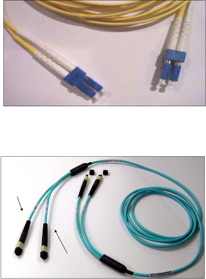
Chapter 2. InfiniBand technical description 35
Figure 2-10 Single mode fiber optic cable with LC Duplex connectors
The 50-micron OM3 (2000 MHz-km) multimode fiber cable with MPO connectors (see
Figure 2-11) for PSIFB 12X links.
The 50-micron OM3 fiber cable is an InfiniBand Trade Association (IBTA) industry
standard cable. It has one pair of fibers per lane (24 fibers in total) for a 12X connection.
Figure 2-11 Optical InfiniBand cable, including TX and RX labels
The sender and receiver are clearly marked with either RX or TX, and the connectors are
keyed. Also, on all field-replaceable units (FRUs) using IFB optical modules, the keys face
upward, the Transmitter module (TX) is on the left side, and the Receiver module (RX) is
on the right side.
Transmitter (TX)
Receiver (RX)
Transmitter (TX)
Receiver (RX)

36 Implementing and Managing InfiniBand Coupling Links on IBM System z
To avoid problems or lengthy problem determination efforts, use the IBM part numbers to
order cables that are designed to provide 99.999% availability.
Important: The fiber optic modules and cable connectors are sensitive to dust and debris.
Component and cable dust plugs must always cover unused ports and cable ends.

© Copyright IBM Corp. 2008, 2012, 2014. All rights reserved. 37
Chapter 3. Preinstallation planning
In this chapter, we provide information to assist you with planning for the installation of
InfiniBand coupling links on IBM zEC12, zBC12, zEnterprise 196, zEnterprise 114, and
System z10 CPCs.
3

38 Implementing and Managing InfiniBand Coupling Links on IBM System z
3.1 Planning considerations
To ensure that your migration to InfiniBand coupling links takes place as transparently as
possible, having a well-researched and documented implementation plan is critical. To assist
you in creating your plan, we discuss the following topics in this chapter:
Planning the topology of the CPC types you will connect using PSIFB coupling links
There are differences in the implementation of PSIFB on z196, z114, z10, and z9.
Planning for the hardware and software prerequisites
In addition to the minimum hardware and software levels that are necessary to install and
define the PSIFB coupling links, there are restrictions on the type of CPCs that can coexist
in a Parallel Sysplex.
Considerations for Server Time Protocol
In addition to its use to connect z/OS and CF LPARs, InfiniBand also provides connectivity
for the members of a Coordinated Timing Network.
Planning for connectivity in a sysplex that spans multiple data centers
InfiniBand provides potential performance and cost-saving advantages over ISC3 links for
connecting a sysplex that spans many kilometers.
Planning for future growth with minimal disruption
Because stand-alone CFs do not have the ability to do a dynamic reconfiguration, adding
coupling links normally requires a POR of the CF CPC. However, changes introduced in
z/OS 1.13, together with advance planning, provide the ability to add coupling link capacity
without requiring an outage of the affected CF LPAR.
Determining how many physical coupling links and logical CHPIDs you require
The number of coupling links you require reflects your connectivity requirements (how
many CPCs must be connected to each other and how many sysplexes span those
CPCs), availability requirements (making sure that there are no single points of failure),
and capacity and performance requirements.
Preparing the information that you need to define your configuration to hardware
configuration definition (HCD)
This involves planning your adapter IDs (AIDs) for the PSIFB coupling links and the
channel path identifiers (CHPIDs) that will be assigned to them. The InfiniBand host
channel adapters (HCAs) are represented by an identifier called an AID, and multiple
CHPIDs can be defined to the ports associated with the AID.
Planning your cabling requirements
PSIFB coupling links might require new types of cable and connectors, depending on the
type of links that are being used prior to the InfiniBand links.
3.2 CPC topology
PSIFB links are available on IBM zEC12, zBC12, z196, z114, z10, and z9 CPCs. They
support the use of coupling and timing-only links between these CPCs.
The full list of supported link types for these CPCs is contained in Table 3-1 on page 41.
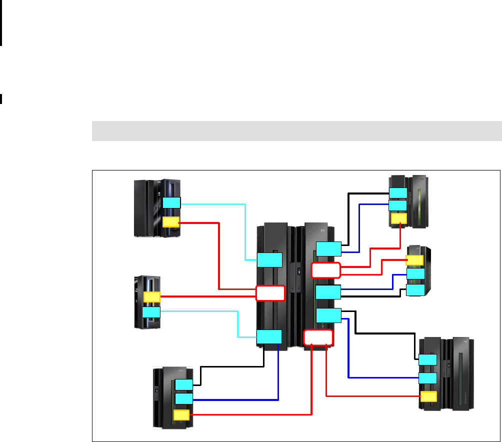
Chapter 3. Preinstallation planning 39
3.2.1 Coexistence
You must consider the requirements for CPC coexistence when implementing PSIFB coupling
links. The z196 and z114 CPCs can only coexist in a Parallel Sysplex or a Coordinate Timing
Network (CTN) with z10 (EC or BC) and z9 (EC or BC) CPCs. You must remove any earlier
CPCs (such as z990, z890, z900, and z800) from the Parallel Sysplex or CTN or replace
them with a supported CPC before you can add a z196 or z114 to the sysplex. This statement
applies regardless of the type of coupling link that is being used.
Figure 3-1 illustrates the supported coexistence environments and the types of supported
coupling links for z196, z10, and z9 CPCs. For detailed hardware prerequisites, see 3.3.1,
“Hardware prerequisites” on page 42.
Figure 3-1 Coupling link configuration options and supported coexistence for zEnterprise 196/114
Note: z9 CPCs cannot be coupled to other z9 CPCs using PSIFB links.
2818
z114
PSIFB, ISC3
2817
z196
PSIFB, ISC3
z9 BC
PSIFB, ISC3, ICB4
12x IFB-SDR
3 GBps
12x IFB/IFB3-DDR
6 GBps
12x IFB-SDR
3 GBps
2094
z196 or z114
(No ICB-4)
2094
z9 EC
PSIFB, ISC3, ICB4
2817
or
2818
12x IFB/IFB3-DDR
6 GBps
z10 BC
PSIFB, ISC3,
and ICB4
2098
2096
z10 EC
PSIFB, ISC3, and
ICB4 (Except E64)
2097
1x IFB-DDR
5 Gbps
1x IFB-DDR
5 Gbps
STI
2097 STI
STI
STI
STI
STI
STI
STI
STI
ISC3
ISC3
ISC3
ISC3
ISC3
1x IFB-DDR 5
Gbps
1x IFB-DDR
5 Gbps
12x IFB-DDR 6 GBps
12x IFB-DDR 6 GBps
ISC3
IFBIFB
IFBIFB
IFBIFB
IFBIFB
IFBIFB
IFBIFB
IFBIFB
IFBIFB
IFBIFB
IFBIFB
IFBIFB
IFBIFB
IFBIFB
IFBIFB
IFBIFB
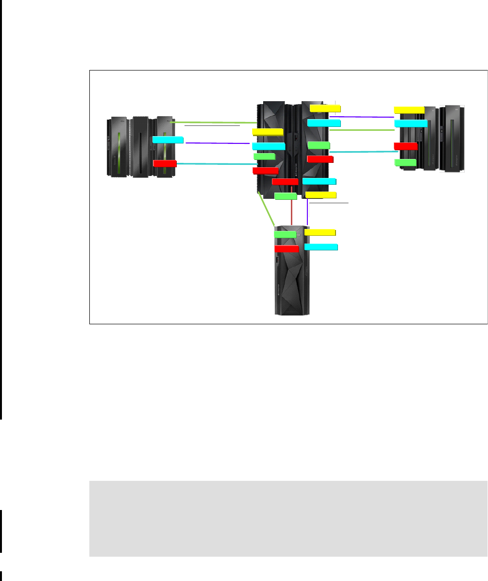
40 Implementing and Managing InfiniBand Coupling Links on IBM System z
Figure 3-2 shows the supported coexistence environments and the types of supported
coupling links for zEC12, zBC12, z196, z114, and z10 CPCs. Remember that a Parallel
Sysplex or a CTN can only contain three consecutive generations of System z servers, so the
guidelines that are related to upgrading or removing older CPCs that apply to z196 and z114
also apply to zEC12 and zBC12.
Figure 3-2 Coupling link configuration options and supported coexistence for zEC12 and zBC12
Also, remember that z196 and later do not support IBM Sysplex Timer connection, so you
must have commenced your migration to STP mode prior to installing your first z196 or later
CPC, and must plan on completing the migration before removing the last pre-z196 CPC.
Also, z196 and later CPCs do not support ICB4 links. If your current coupling infrastructure
uses ICB4 links, you must migrate to InfiniBand before installing your first z196 or later CPC if
you want to connect that CPC to the other CPCs in your configuration.
3.2.2 Supported coupling link types
IBM z196 and later CPCs support up to 128 CF link CHPIDs. Table 3-1 on page 41
summarizes the maximum number of physical coupling links that are supported for each CPC
type.
ISC-3*, 2 Gbps
10/100 km
z196 and z114
12x IFB, 12x IFB3, 1x IFB, & ISC-3
12x IFB, 6 GBps
Up to 150 m
z10 EC and z10 BC
12x IFB, 1x IFB & ISC-3
1x IFB, 5 Gbps
10/100 km
ISC-3*
10/100 km 1x IFB, 5 Gbps
10/100 km
12x IFB3
or IFB
6 GBps
150 m
HCA3-O
HCA3-O ISC-3*, 2 Gbps
10/100 km
HCA2-O*
HCA2-O*
HCA2-O
OR
OR
*HCA2-O, HCA2-O LR, & ISC-3 carry
forward only on zEC12
HCA3-O LR
OR
HCA3-O LR
OR
HCA2-O LR*
HCA2-O LR*
HCA2-O LR*
zEC12
zEC12
HCA2-O LR
1x IFB, 5 Gbps
10/100 km HCA3-O LR
OR
HCA2-O LR*
HCA2-O 12x IFB3 or IFB
6 GBps
150 m
OR
HCA3-O
HCA3-O LR
OR
HCA3-O
HCA2-O*
OR
HCA3-O LR
OR
HCA2-O LR*
HCA3-O
HCA2-O*
OR
zBC12
Statement Of Direction: The zEnterprise 196 and zEnterprise 114 will be the last
generation of System z CPCs to support ordering of ISC3 links. However, it will be possible
to carry forward ISC3 links on an upgrade from earlier CPC generations.
zEC12 and zBC12 also support carry forward of ISC3 links on an upgrade. However, this is
the last generation of System z CPC that will support this capability.

Chapter 3. Preinstallation planning 41
Table 3-1 Maximum number of coupling links supported
Link type Maximum supported linksa
a. Maximum number of coupling links combined (ICB, PSIFB, ISC3, and IC) for all System z10 and z9 CPCs is 64.
The limit for zEnterprise CPCs has been increased to 128.
zEC12 zBC12 z196b
b. Maximum of 56 PSIFB links on z196.
z114 z10
ECc
c. Maximum of 32 PSIFB links and ICB4 links on z10 EC. ICB4 links are not supported on model E64.
z10
BC
z9 EC z9 BC
IC 32 32 32 32 32 32 32 32
ISC3 48d
d. zEC12 only supports ISC3, HCA2-O, and HCA2-LR adapters when carried forward as part of an upgrade.
32 48 48 48 48 48 48
ICB4 n/a n/a n/a n/a 16 12 16 16
ICB3 n/a n/a n/a n/a n/a n/a 16 16
HCA1-O (12X IFB)e
e. HCA1-O is only available on System z9 (withdrawn from marketing in June 2010).
n/a n/a n/a n/a n/a n/a 16 12
HCA2-O LR (1X IFB)f
f. HCA2-O LR adapters are still available for z10, however they have been withdrawn from marketing for z196 and
z114. On z196 and z114, HCA3-O LR functionally replaces HCA2-O LR.
32 12 32g
g. A maximum of 16 HCA2-O LR and HCA2-O coupling links are supported on the z196 model M15.
12h
h. A maximum of 8 HCA2-O LR and HCA2-O coupling links are supported on the z114 model M05.
32i
i. A maximum of 16 HCA2-O LR and HCA2-O coupling links are supported on the z10 model E12.
12 n/a n/a
HCA2-O (12X IFB) 32 16 32g16h32i12 n/a n/a
HCA3-O LR (1X IFB)j
j. HCA3-O and HCA3-O LR are only available on z196 and z114.
64 32 48k
k. A maximum of 32 HCA3-O LR and 16 HCA3-O coupling links are supported on the z196 model M15.
32l
l. A maximum of 16 HCA3-O LR and 8 HCA3-O coupling links are supported on the z114 model M05.
n/an/an/an/a
HCA3-O (12X IFB & 12X IFB3)j32 16 32k16ln/an/an/an/a
Max External Linksm
m. Maximum external links is the maximum total number of physical link ports (does not include IC).
104 72 104n
n. The number of maximum external links is dependent on the number of HCA fanout slots available. The maximum
of 104 external links (72 for z114) can only be achieved with a combination of ISC3, HCA3-O LR, and HCA3-O
links.
72n64o
o. Maximum number of external links for all z10 and z9 CPCs is 64.
64 64 64
Max Coupling CHPIDsp
p. Maximum coupling CHPIDs defined in IOCDS include IC and multiple CHPIDs defined on PSIFB links.
128 128 128 128 64 64 64 64
Important: Be aware of the following points:
For z196 and zEC12, the maximum number of external links and the maximum number of
CHPIDs that can be defined are 104 and 128, respectively.
For z114 and zBC12, the maximum number of external links and the maximum number of
CHPIDs that can be defined are 72 and 128, respectively.
For z10 and z9, the maximum number of coupling links and the maximum number of
CHPIDs that can be defined are both 64.
The use of internal coupling (IC) links and assigning multiple CHPIDs to a PSIFB link can
cause the CHPID limit to be reached before the maximum number of physical links.

42 Implementing and Managing InfiniBand Coupling Links on IBM System z
Supported CHPID types for PSIFB links
All PSIFB coupling link CHPIDs are defined to HCD as type CIB. They conform to the general
rules for Coupling Facility peer channels (TYPE=CFP, TYPE=CBP, TYPE=ICP, or
TYPE=CIB).
You can configure a CFP, CBP, ICP, or CIB CHPID as:
A dedicated CHPID to a single LPAR.
A dedicated reconfigurable CHPID that can be configured to only one CF LPAR at a time,
but that can be dynamically moved to another CF LPAR in the same CSS.
A shared CHPID that can be concurrently used by LPARs in the same CSS to which it is
configured.
A spanned CHPID that can be concurrently used by LPARs in more than one CSS.
For further details, see 6.4.1, “Input/output configuration program support for PSIFB links” on
page 161.
3.3 Hardware and software prerequisites
In this section, we discuss the hardware and software prerequisites for implementing PSIFB
links on the z9 and later CPCs.
3.3.1 Hardware prerequisites
The implementation of PSIFB coupling links requires a zEnterprise, z10, or z9 CPC. The
base prerequisites for PSIFB are satisfied by the base zEnterprise or z10 models at general
availability. The recommended microcode levels are highlighted as part of the order process.
When installing an MES, the required microcode levels are documented in the MES
installation instructions. When installing a new machine with HCA adapters installed, there is
a minimum code requirement documented in the appropriate Solution Assurance Product
Review (SAPR) guide that is available to your IBM representative.
Additional hardware system area (HSA) is required to support the HCA1-O fanout on a z9
CPC. For z9, a power-on reset (POR) is required when the first PSIFB feature is installed;
however, this is not necessary on later CPCs.
See 2.2, “InfiniBand fanouts” on page 19 for a detailed description of the InfiniBand fanouts
that are offered on zEnterprise and System z CPCs.
Bring your CPCs to at least the Driver and bundle levels shown in Table 3-2 prior to moving to
InfiniBand. CPCs older than z9 are not supported in the same Parallel Sysplex or CTN as
z196 or z114. CPCs older than z10 are not supported in the same Parallel Sysplex or CTN as
zEC12 or zBC12.
Table 3-2 Recommended minimum hardware service levels
CPC Recommended Driver Recommended minimum
bundle level
z9 67L 63
z10 79 51a
z196 GA1b86 38

Chapter 3. Preinstallation planning 43
3.3.2 Software prerequisites
PSIFB links are supported by z/OS 1.7 and later releases. Several releases might require
additional program temporary fixes (PTFs) in support of PSIFB.
The information necessary to identify the required service is available in the following
Preventive Service Planning (PSP) buckets:
2097DEVICE for z10 EC
2098DEVICE for z10 BC
2817DEVICE for z196
2818DEVICE for z114
2827DEVICE for zEC12
2828DEVICE for zBC12
Rather than using the PSP buckets, however, we suggest using the SMP/E REPORT
MISSINGFIX command in conjunction with the FIXCAT type of HOLDDATA. The PSP
upgrades and the corresponding FIXCAT names are shown in Table 3-3. Because of the
relationship between STP and InfiniBand, we have included the STP FIXCATs in the table1.
Table 3-3 PSP bucket upgrades and FIXCAT values for z/OS CPCs
z196 GA2 and z114 93 13c
zEC12 GA1 12 38
zEC12 GA2, zBC12 15 6B
a. Minimum level required to couple z10 HCA2 adapters to HCA3 adapters is Bundle 46.
b. Minimum required to couple HCA2 adapters to HCA3 adapters.
c. If the CPC will have both HCA2 12X and HCA3 12X links to the same CF, install Bundle 18 or
later.
CPC Recommended Driver Recommended minimum
bundle level
1 For information about the available FIXCATs and how to download them, see the following site:
http://www.ibm.com/systems/z/os/zos/features/smpe/fix-category.html
CPC Upgrade FIXCAT value
zEC12 2827DEVICE IBM.Device.Server.zEC12-2827
IBM.Device.Server.zEC12-2827.ParallelSysplexInfiniBandCoupling
IBM.Device.Server.zEC12-2827.ServerTimeProtocol
zBC12 2828DEVICE IBM.Device.Server.zBC12-2828
IBM.Device.Server.zBC12-2828.ParallelSysplexInfiniBandCoupling
IBM.Device.Server.zBC12-2828.ServerTimeProtocol
z196 2817DEVICE IBM.Device.Server.z196-2817
IBM.Device.Server.z196-2817.ParallelSysplexInfiniBandCoupling
IBM.Device.Server.z196-2817.ServerTimeProtocol
z114 2818DEVICE IBM.Device.Server.z114-2818
IBM.Device.Server.z114-2818.ParallelSysplexInfiniBandCoupling
IBM.Device.Server.z114-2818.ServerTimeProtocol

44 Implementing and Managing InfiniBand Coupling Links on IBM System z
You must review the PSP information or REPORT MISSINGFIX output from SMP/E early in
the planning process to allow time for ordering any necessary software maintenance and then
rolling it out to all the members of all your sysplexes. Example 3-1 shows a sample REPORT
MISSINGFIX output for z196.
Example 3-1 Sample REPORT MISSINGFIX output for InfiniBand
MISSING FIXCAT SYSMOD REPORT FOR ZONE ZOSTZON
HOLD MISSING HELD _____RESOLVING SYSMOD____
FIX CATEGORY FMID CLASS APAR SYSMOD NAME STATUS RECEIVED
_______________ _______ _______ _______ _______ _______ ______ _______
IBM.Device.server.z196-2817.ParallelSysplexInfiniBandCoupling
HBB7750 AA25400 HBB7750 UA43825 GOOD YES
Additionally, we recommend that all System z clients subscribe to the IBM System z Red Alert
service. For more information, see the following subscription site:
https://www14.software.ibm.com/webapp/set2/sas/f/redAlerts/home.html
If you want to exploit the 32 subchannels per CHPID functionality, ensure that both your
hardware and HCD support levels are correct. Figure 3-3 shows the CPC options that are
presented after the HCD PTF to support 32 subchannels per coupling CHPID has been
installed. See Chapter 6, “Configuration management” on page 155 for more information.
Figure 3-3 HCD processor type support levels for zEnterprise CPCs
z10 EC 2097DEVICE IBM.Device.Server.z10-EC-2097
IBM.Device.Server.z10-EC-2097.ParallelSysplexInfiniBandCoupling
IBM.Device.Server.z10-EC-2097.ServerTimeProtocol
z10 BC 2098DEVICE IBM.Device.Server.z10-BC-2098
IBM.Device.Server.z10-BC-2098.ParallelSysplexInfiniBandCoupling
IBM.Device.Server.z10-BC-2098.ServerTimeProtocol
Command ===> ___________________________________________ Scroll ===> PAGE
Select one to view more details.
Processor
Type-Model Support Level
# 2817-M32
2817-M49 XMP, 2817 support, SS 2, 32 CIB CF LINKS
# 2817-M49
2817-M66 XMP, 2817 support, SS 2, 32 CIB CF LINKS
# 2817-M66
2817-M80 XMP, 2817 support, SS 2, 32 CIB CF LINKS
# 2817-M80
CPC Upgrade FIXCAT value

Chapter 3. Preinstallation planning 45
3.4 Considerations for Server Time Protocol
Server Time Protocol (STP) provides a coordinated time source for systems connected
through coupling links. It replaces the Sysplex Timer (9037) as the time source for
interconnected systems.
STP uses coupling links to transmit time signals between interconnected systems. All types of
PSIFB coupling links (on supported CPCs) can be used to transmit STP timing signals in a
Coordinated Timing Network. STP interconnectivity using other types of coupling links (ISC3,
ICB4) are also possible on CPCs that support them.
3.4.1 Considerations for STP with PSIFB coupling links
STP communication is at the CPC level, not the LPAR level. This means that STP
communication is not dependent on any particular LPAR being available or even activated.
Also, the speed of STP links (ISC3, ICB4, or PSIFB) has no impact on STP performance or
timing accuracy. However, you need to carefully consider the STP CPC roles and coupling
link connectivity when planning the links for your Coordinated Timing Network (CTN).
Server roles and connectivity
There are several server roles within an STP-only CTN. These are defined using the “System
(Sysplex) Time” icon on the HMC:
Current Time Server (CTS)
The Current Time Server is the active stratum 1 server and provides the time source in an
STP-only CTN. Only the Preferred Time Server or Backup Time Server can operate as the
CTS.
Preferred Time Server (PTS)
This refers to the server that has preference to operate as the CTS and Stratum 1 server
of the STP-only CTN is assigned the role of Preferred Time Server. This server requires
connectivity to the Backup Time Server and the Arbiter (if present).
Backup Time Server (BTS)
Although this is an optional role, it is strongly recommended. This server will take over as
the CTS and Stratum 1 server in recovery conditions or as part of a planned maintenance
operation to the PTS. The BTS requires connectivity to the PTS and Arbiter (if present).
Note: The ability to define 32 subchannels for PSIFB links in HCD and input/output
configuration program (IOCP) is provided by APARs OA32576 and OA35579. Those
APARs changed the default number of subchannels for all CF link CHPIDs to 32. APAR
OA36617 subsequently changed the default back to seven. You should only specify 32
subchannels if the link will span two sites.
Review REPORT MISSINGFIX output and PSP information to ensure that you have the
latest required service.
Note: Connection to Sysplex Timer (ETR) is not supported on z196 and later.
The use of STP is required for time synchronization in a Coordinated Timing Network
containing these CPCs.
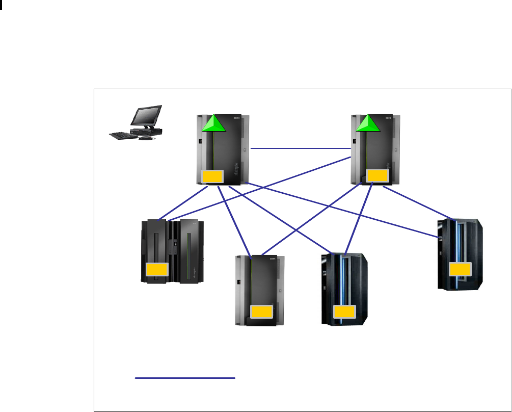
46 Implementing and Managing InfiniBand Coupling Links on IBM System z
Arbiter
This is an optional role, although it is strongly recommended when three or more servers
participate in the CTN. The Arbiter provides additional validation of role changes for
planned or unplanned events that affect the CTN. The Arbiter is a stratum 2 server that
should have connectivity to both the PTS and the BTS.
Alternate servers
Any time a PTS, BTS, or Arbiter is going to be removed from service, move that role to
another member of the CTN. Make sure that alternate server has the same connectivity as
the server that it is replacing.
For more information, refer to Important Considerations for STP server role assignments,
available on the web at the following site:
http://www.ibm.com/support/techdocs/atsmastr.nsf/WebIndex/WP101833
All other servers
The remaining servers in the CTN should have two failure-isolated links to the PTS and
the BTS, and also to the alternate locations for those roles.
Figure 3-4 Sample STP server roles and connectivity with coupling links
Figure 3-4 shows a CTN with the following elements:
There are two stand-alone CFs:
– C1 is the PTS and CTS.
–C2 is the BTS
P1, P2, P3, and P4 all contain z/OS systems participating in the Parallel Sysplex.
PTS
CTS
S1
P2
Arbiter
S2
S2
S2
Standalone CFs
C o u pling link s
for ST P
2 C o up lin g lin ks
BTS
S2
S2
CTS – Current Time Server – Active S1
P 1, P2 , P3, P4 – z/O S system s w ithin the P arallel Sysplex
C1 C2
P1
P2 P3
P4
HMC
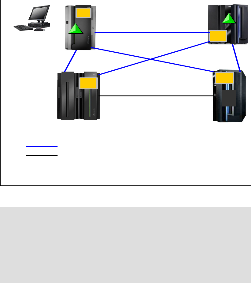
Chapter 3. Preinstallation planning 47
P1 is the Arbiter.
The PTS, BTS, and Arbiter must be connected to each other.
Additional coupling links have been defined between the PTS and BTS for STP purposes
only.
There might be a requirement to configure links between two servers in the CTN that have
only z/OS LPARs defined. With no Coupling Facility LPARs at either end of the link, the links
must be defined as timing-only links. A timing-only link is shown in Figure 3-5 between
P3 and P4.
Figure 3-5 Sample STP server roles and connectivity with coupling and timing-only links
To ensure the highest levels of availability, it is vital that all servers in the CTN are able to
receive timing signals from the CTS or a stratum 2 server at all times. The best way to avoid
connectivity failures that impact STP is to ensure that every server is connected to the PTS
and the BTS (and their backups) by two failure-isolated coupling links. STP is designed to
issue a warning message if it detects that it only has one path to the CTS. However, STP is
Note: Be aware of the following points:
A timing-only link can only be defined when the CPCs at either end of the link contains
no CF LPARs.
A mixture of Timing-only and coupling links is not allowed between the same pair of
servers. HCD will not allow this definition.
The PTS, BTS and Arbiter must be connected to each other.
Define at least two failure-isolated coupling links or timing-only links between each pair
of servers for redundancy.
Timing-only links
PTS/CTS
S1
S2
CTS – Current Time Server – Active S1
P1, P2, P3, P4 – systems in a Parallel Sysplex
2 x Timing-only links
2 x Couplin g links
HMC P1
P2
P3 P4
BTS
S2

48 Implementing and Managing InfiniBand Coupling Links on IBM System z
not aware of the underlying InfiniBand infrastructure; it only sees CHPIDs. So, if there are two
online CHPIDs to the CTS, but both of those CHPIDs are using the same InfiniBand link, STP
will not be aware of that and therefore not issue a warning message.
Also note that STP’s ability to use a coupling link for timing signals is independent of any
LPARs. So, for example, following the successful completion of a power-on reset, all coupling
CHPIDs should be available for STP use, regardless of whether any LPARs are activated or
not. Similarly, if the LPAR that owns a coupling link that is currently being used by STP is
deactivated, that does not stop STP from using that link. For additional information about STP,
see Server Time Protocol Planning Guide, SG24-7280.
3.5 Multisite sysplex considerations
Extended distance sysplex connectivity is provided by ISC3 and PSIFB 1X links. The
maximum unrepeated distance of both these link types is 10 km (20 km with RPQ2).
Distances greater than this require a Dense Wave Division Multiplexer (DWDM).
Careful planning is needed to ensure there are redundant and diverse fiber routes between
sites to avoid single points of failure on a fibre trunk.
IBM supports only those DWDM products qualified by IBM for use in high availability,
multi-site sysplex solutions, such as GDPS. The latest list of qualified DWDM vendor products
can be found on the IBM Resource Link® website at the following link:
https://www.ibm.com/servers/resourcelink
To transmit timing information, STP can choose any defined coupling link or timing-only link
that is online between two IBM zEnterprise or System z CPCs; you cannot limit STP to only
certain CHPIDs. This means that you must not configure the links over a mixture of qualified
and unqualified equipment. Doing so might result in timing problems where CPCs might
become unsynchronized without your knowledge. When coupling links or timing-only links are
2 The relevant RPQs are 8P2197, 8P2263, and 8P2340, depending on the link type and CPC type.
Important: Check the qualification letters in detail to determine your precise requirements
and how best to address those requirements:
Selecting a qualified WDM vendor does not necessarily mean that the selected WDM
model is qualified.
Selecting a qualified WDM model does not mean that a specific release level is
qualified.
A vendor’s WDM model might be qualified for ISC3 or PSIFB 1X links for transfer of CF
requests but not qualified for ISC3 or PSIFB 1X IFB links when also exchanging STP
messages.
Ensure that the vendor qualification letter is inspected carefully by a DWDM technical
expert. The letter specifies model number, release level, interface modules qualified,
protocols, application limitations and so on.
The maximum supported distance is not the same for all vendors, and changes over
time as new devices, features, and capabilities are introduced and qualified.
For more information about qualified WDMs, search on the keywords “qualified WDM” on
the Redbooks website at the following link:
http://www.redbooks.ibm.com

Chapter 3. Preinstallation planning 49
configured over DWDM equipment, all links must use specific DWDM hardware (optical
modules, transponders, TDM modules) with interface cards qualified by IBM for the STP
protocol.
Coupling Facility response times at extended distances
Coupling Facility (CF) performance needs especially careful consideration when the CF is
located at a significant distance away from the connected z/OS or CF CPC.
As the distance between the z/OS and CF CPCs increases, the speed of light becomes the
dominant factor in the response time, adding around 10 microseconds per km for the round
trip to the CF. This results in a direct impact to the service time, and most synchronous
requests being converted to asynchronous.
Because the subchannel and link buffer that are used for the CF request are allocated for the
entire duration of the service time, the increased service times caused by the distance result
in high subchannel and link buffer usage and potentially more subchannel delay and Path
Busy events. There are two attributes of InfiniBand links that can be particularly beneficial to
long-distance sysplexes:
On zEnterprise CPCs using Driver 93 and later, 1X InfiniBand links support either 7 or 32
subchannels per CHPID, compared to the 7 subchannels per CHPID that were supported
previously.
This means that more CF requests can be active concurrently on each CHPID, reducing
instances of requests being delayed because all subchannels or link buffers are busy.
The ability to define multiple CHPIDs to a single PSIFB link can help because additional
CHPIDs (which provide more subchannels) can be added without having to add more
physical links.
With ISC links, you were limited to seven subchannels per link, and a maximum of eight links
between a z/OS and a CF, giving a maximum of 56 subchannels. With PSIFB 1X links prior to
Driver 93, you were still able to have only seven subchannels per CHPID. However, you were
able to have your eight CHPIDs to the CF spread over just two physical links, which is a
significant decrease in the number of required adapters and DWDM ports. With PSIFB 1X
links and Driver 93, the same eight CHPIDs support 256 subchannels.
For more information about the relationships between subchannels and link buffers and how
they are used, see Appendix C, “Link buffers and subchannels” on page 247.
Find additional reference information in the following documents:
Considerations for Multisite Sysplex Data Sharing, SG24-7263
IBM System z Connectivity Handbook, SG24-5444
Server Time Protocol Planning Guide, SG24-7280
3.6 Planning for future nondisruptive growth
If your CF LPARs reside in the same CPC as z/OS or IBM z/VM, it is possible to add links to
the CF dynamically by using the dynamic reconfiguration support provided by these operating
systems. This means that as your configuration and capacity requirements increase in the
future, you can add more physical links and more CHPIDs dynamically. But if your CF LPARs
reside in a CPC with no operating system (no z/OS or z/VM LPARs), there is currently no way
to add links or CHPIDs to that CPC without a POR.

50 Implementing and Managing InfiniBand Coupling Links on IBM System z
For coupling links prior to InfiniBand, you were able to define and install a link in the CF CPC
at one time, and then add a corresponding link in the z/OS CPC later. A POR was required to
add the link to the CF CPC. But when the link is later added to the z/OS CPC, a dynamic
reconfiguration can be used to make the link available to LPARs on the z/OS CPC, and no
POR is required on the CF CPC. This means that when the link is installed in the z/OS CPC,
you are immediately able to use it without interrupting CF operations.
However, prior to z/OS 1.13, when you define an InfiniBand CHPID, both the CF and the z/OS
CHPIDs must be defined and must be connected to each other3. And because you must
specify the AID when you define the InfiniBand CHPID, you cannot define the CHPID unless
the link was already installed or an order had been placed and the eConfig report providing
the AID is available. This effectively meant that you had to install the InfiniBand adapter in the
CF and z/OS CPCs at the same time.
This restriction is alleviated starting with z/OS 1.13 (and rolled back to z/OS 1.10 with APAR
OA29367). HCD will now accept an AID of an asterisk (*), meaning that you can install the
adapter in the CF CPC now and assign the real AID, but for the z/OS end you use a
placeholder AID of *. Then, when the adapter is subsequently installed in the z/OS CPC, you
replace * with the real AID and perform a dynamic reconfiguration. When the reconfiguration
completes, the new coupling link can be used without having to perform another POR on the
CF CPC.
This support and its use is discussed in more detail in “Overdefining CIB links” on page 160.
3.7 Physical and logical coupling link capacity planning
All sysplex clients will have to migrate to InfiniBand over the next few years as they move to
newer CPC generations. An InfiniBand infrastructure is significantly different from a
pre-InfiniBand infrastructure and will involve replacing all your previous coupling infrastructure
with InfiniBand links.
Therefore, the migration presents an ideal opportunity to ensure that the infrastructure that
you configure will deliver the best possible availability, performance, and flexibility, in the most
cost-effective manner.
To obtain the optimum benefit from this opportunity, rather than simply replacing your existing
configuration with an equivalent number of PSIFB links, you can go through an exercise to
determine the most appropriate configuration for your environment.
In this section we discuss the various aspects of your coupling infrastructure, and help you
identify the number of physical InfiniBand links and the connectivity that you need. We then
discuss the best way to configure that hardware for optimum performance.
3.7.1 Availability
Because the Coupling Facility is the heart of your Parallel Sysplex, it is vital that all systems in
the sysplex have access to it at all times. If one member of the sysplex loses all access to a
Coupling Facility, it is likely that all the contents of the CF will be moved to another CF,
meaning that the capacity of that CF will be lost to the sysplex until connectivity can be
restored. This also potentially creates a single point of failure if all structures now reside in the
same CF.
3 HCD will not build a production IODF if there are uncoupled CIB CHPIDs defined.

Chapter 3. Preinstallation planning 51
To avoid this situation, there are guidelines to follow when planning the availability aspects of
your PSIFB infrastructure:
Always configure at least two physical links between each pair of connected CPCs.
It is important to have no single points of failure in the connection between z/OS and the
CFs. This means using more than one physical link, and distributing those links over
multiple HCAs.
Additionally, if the CPC contains more than one book, distribute the links to each
connected CPC over multiple books (both in the z/OS CPC and in the CPC containing the
CF). Plan availability by BOOK/HCA/PORT.
For example, if you decide to have two CF link CHPIDs and two PSIFB links, and multiple
books are available in your CPC, your two CHPIDs can be mapped as follows:
– CHPID 00 - BOOK 0, HCA1, PORT 1
– CHPID 01 - BOOK 1, HCA2, PORT 1
In a single book system this is not possible, so spread your links across multiple HCAs.
When planning your physical configuration, be aware that different CPC types support
differing numbers of fanouts. For large configurations, it might be necessary to configure
multiple books to provide the number of required fanouts. Refer to the footnotes in
Table 3-1 on page 41 for more details.
Additionally, depending on your availability requirements, you might decide to add a
second book for availability rather than purely for capacity reasons.
The CHPID Mapping Tool (CMT) does not provide a CHPID availability mapping function
for InfiniBand links. However, it will validate that your manual mapping does not contain
any intersects. To understand the process better, refer to “CHPID Mapping Tool support”
on page 183.
In addition to their use for providing connectivity between z/OS and CF LPARs, coupling links
are also used to provide connectivity for STP signaling. For a CPC to be part of a multiCPC
sysplex, it must be able to send and receive timing signals to and from other members of the
timing network. When using STP, these signals are sent and received over coupling links, so
configure each CPC so that it has two failure-isolated connections to the PTS, the BTS, and
to any CPC that might take over those roles during an outage. For more information, see
Redbooks Server Time Protocol Planning Guide, SG24-7280 and Server Time Protocol
Recovery Guide, SG24-7380.
The number of physical links that you require between each pair of CPCs will reflect a
balance of availability and performance. InfiniBand is a powerful and flexible interconnect
architecture where only significantly high volume workloads are likely to require more than
two physical links between connecting CPCs. However, for availability reasons, every pair of
connected CPCs should have at least two failure-isolated physical links, regardless of the
bandwidth requirements.
Note: At the time of writing, the various functions in z/OS that check for single points of
failure are unaware of the relationship between CHPIDs and the underlying InfiniBand
infrastructure.
If two CHPIDs are online to the CF, those functions will assume that those CHPIDs do
not represent a single point of failure.
This places extra responsibility on you to ensure that you design a robust configuration
and to ensure on an ongoing basis that no real single points of failure exist.
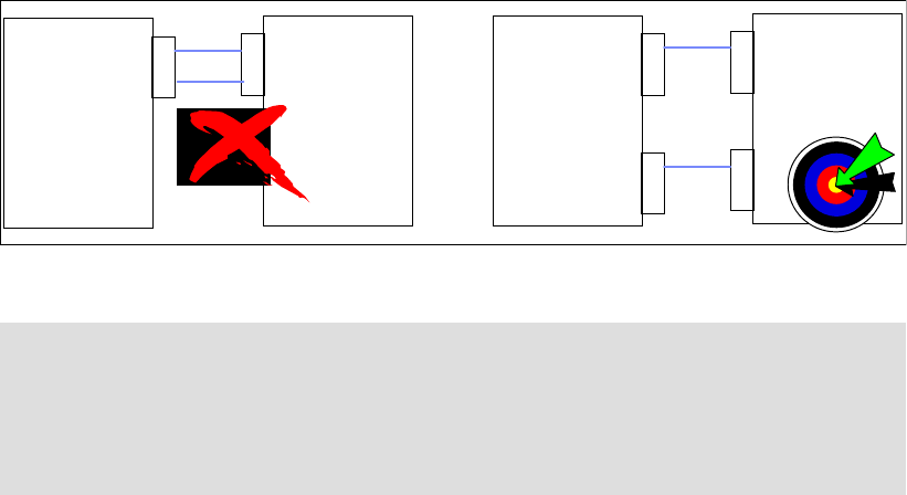
52 Implementing and Managing InfiniBand Coupling Links on IBM System z
Figure 3-6 shows two configurations. The configuration on the left side has two CPCs, with
one HCA fanout on each CPC. Although this provides connectivity and sufficient bandwidth,
both links are connected to the same adapter, meaning that all communication between the
two CPCs will be lost if that adapter were to fail. The preferred solution is to install two fanouts
in each CPC and use one port in each adapter, as shown in the configuration on the right
side.
Figure 3-6 Configuring for availability
3.7.2 Connectivity
When determining the number of PSIFB links you require on a CPC, one of the
considerations is the number of other CPCs that it will need to connect to. Prior to InfiniBand
links, the number of links was driven by the number of CPCs that needed to be
interconnected (the physical configuration), the performance considerations, and the number
of sysplexes (the logical configuration), because pre-InfiniBand coupling links cannot be
shared between multiple sysplexes.
Important: Configure a minimum of two physical InfiniBand links connected to different
HCAs between every pair of connected CPCs.
Defining multiple CHPIDs on a single physical PSIFB coupling link does not satisfy the
high availability recommendation. You must implement multiple physical links, on multiple
HCAs, to avoid single points of failure.
1
2
1
2
1
2
1
2
1
2
1
2
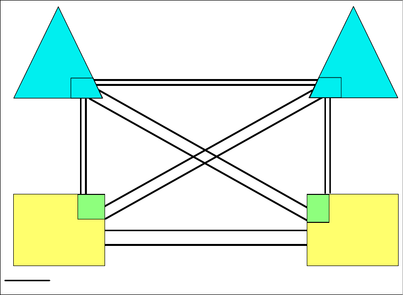
Chapter 3. Preinstallation planning 53
Prior to InfiniBand, each z/OS CPC required at least two links (for availability reasons) per
sysplex for each connected CF. If you had two sysplexes, two z/OS CPCs, two CF CPCs, and
are using System Managed Duplexing, you need at least ten links. This is shown in the
configuration diagram in Figure 3-7.
Figure 3-7 Pre-InfiniBand configuration with two sysplexes
Additionally, if you want to provide STP connectivity between the two z/OS CPCs (which is
highly recommended in a configuration like this), an additional two timing-only links are
required between that pair of CPCs.
PCF1
PSY1 PSY2
PCF2
(timing-only links)
SM Duplex and STP links
Configuration with 1 sysplex
Pre-InfiniBand links
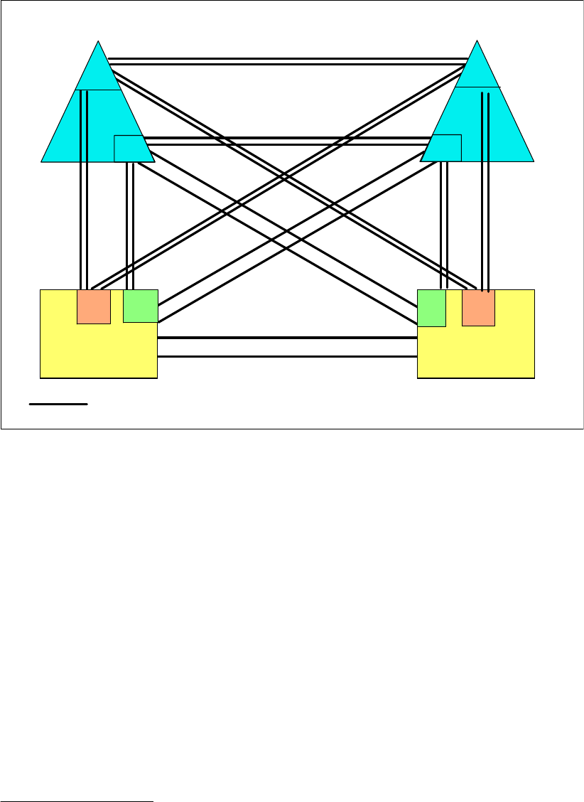
54 Implementing and Managing InfiniBand Coupling Links on IBM System z
Also remember that if System Managed Duplexing is being exploited, you need a pair of links
for each pair of CF LPARs4. So two sysplexes, with both sysplexes using System Managed
Duplexing, require at least twenty links, as shown in Figure 3-8.
Figure 3-8 Pre-InfiniBand configuration with two sysplexes
And that is with just four CPCs, two sysplexes, and a minimum number of links between each
z/OS and its CFs. Imagine a configuration with eight sysplexes (as some clients have). Or four
or more coupling links from each z/OS CPC for each sysplex. As the number of CPCs,
systems, coupling links, and CFs increases, the physical connectivity requirement increases
dramatically.
Because InfiniBand supports the ability to share physical links across multiple sysplexes, the
number of sysplexes is less likely to be a factor in the number of coupling links you require5.
4 Prior to InfiniBand, CF-to-CF links used for System Managed Duplexing cannot be shared by more than one
sysplex.
5 Although PSIFB links can be shared between sysplexes, CF link CHPIDS cannot. If you have a significantly high
number of sysplexes, you might find that the number of sysplexes drives a requirement for more physical links
because of the limit on the number of CHPIDs that can be assigned to an HCA.
PCF1
PSY1 PSY2
PCF2
(timing-only links)
DSY1 DSY2
DCF1 DCF2
SM Duplex and STP links
SM Duplex and STP links
Configuration with 2 sysplexes
Pre-InfiniBand links
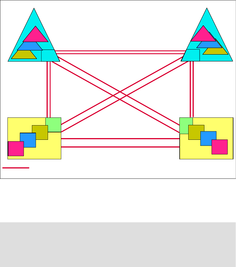
Chapter 3. Preinstallation planning 55
Figure 3-9 shows how the use of InfiniBand simplifies the configuration by supporting multiple
sysplexes over (in this case) just two InfiniBand links between each pair of CPCs. This
example has twice as many sysplexes as the configuration shown in Figure 3-8 on page 54,
and yet it only has half as many coupling links.
Figure 3-9 InfiniBand support for multiple sysplexes
At some point, the capacity or connectivity requirements of the sysplexes might drive a need
for more links. However, in most cases, the required number of links reflects the number of
CPCs to be connected and the required capacity, and not the number of sysplexes.
3.7.3 Capacity and performance
The third aspect of planning your InfiniBand connectivity is to ensure that the number of links
you plan will provide acceptable performance.
There are two aspects to how coupling links contribute to performance:
Capacity If you are trying to send 1 GB of data to a cache structure in the CF
every second, your coupling link infrastructure must be capable of
handling that volume of traffic. This is typically referred to as
Summary: After you have mapped out the links you will need for availability and STP
connectivity, verify that connectivity is sufficient to connect every z/OS LPAR to each CF in
the same sysplex.
Providing timing-only links between the z/OS CPCs is highly recommended because it
provides additional flexibility in the placement of the STP roles during outages.
PCF1
PSY1 PSY2
PCF2
(timing-only links)
SM Duplex and STP links
Configuration with n sysplexes
InfiniBand links
CSY1
BSY1
ASY1
CSY2
BSY2
ASY2
CCF1
BCF1
ACF1
CCF2
BCF2
ACF2

56 Implementing and Managing InfiniBand Coupling Links on IBM System z
bandwidth: the larger the bandwidth, the more data can be moved in a
given amount of time.
Response time The response time for a synchronous CF request consists of:
1) Potentially having to wait for an available link buffer or subchannel.
2) Latency within the hardware before the request is placed on the link.
3) The size of the request and the bandwidth of the link.
4) The distance between the z/OS LPAR and the CF LPAR.
5) The speed and utilization of the CF.
Items 2 and 3 in this list are directly impacted by the link technology.
Different coupling link types support different bandwidths. For example, 12X InfiniBand links
have a larger bandwidth than 1X InfiniBand links. This means that a 12X link can process
more requests per second than a 1X link (all other things being equal). The relationship
between bandwidth and response time is discussed in 1.5.1, “Coupling link performance
factors” on page 11.
IBM RMF does not provide any information about the bandwidth utilization of coupling
CHPIDs. For 12X InfiniBand links, especially when running in IFB3 mode, we do not believe
that utilization of the link bandwidth is a concern. More important is to ensure that utilization of
the subchannels and link buffers does not exceed the guideline of 30%.
Because 1X links have a significantly smaller bandwidth and they support more subchannels
per CHPID, it is possible in various situations that link bandwidth utilizations can reach high
levels before subchannel or link buffer utilization reaches or exceeds the 30% threshold. This
is most likely to be observed if the links are used in conjunction with large numbers of large
cache or list requests. In this situation, significantly elongated response times will be
observed when the request rate increases. Distributing the load across more physical links
can result in a reduction in response times if high-bandwidth utilization is the problem.
From a response time perspective, there are considerations:
Large requests can experience shorter response times on 12X links than on 1X links. The
response time difference can be expected to be less pronounced for small requests (lock
requests, for example).
HCA3-O adapters running in IFB3 mode deliver significantly reduced response times
compared to IFB mode. However, those improvements are only available on the 12X
(HCA3-O) links, not on the 1X (HCA3-O LR) links.
Another potential source of delay is if all subchannels or link buffers are busy when z/OS tries
to start a new request. This is most often seen with workloads that generate CF requests in
bursts. The obvious solution to this problem is to add more subchannels and link buffers.
Prior to InfiniBand links, the only way to add more subchannels and link buffers6 was to add
more physical links. However, because InfiniBand supports the ability to assign multiple
CHPIDs to a single physical link, you can add subchannels and link buffers by simply adding
more CHPIDs to the existing links (at no financial cost). This capability is especially valuable
for extended distances and configurations that exploit System Managed Duplexing because
both of these cause increased subchannel utilization.
Adapter types
Generally speaking, the adapter generation (HCA1, HCA2, or HCA3) that you can install is
determined by the CPC that the link will be installed in. The one exception, perhaps, is z196,
6 If you are not familiar with the relationship between coupling links and link buffers and subchannels, review
Appendix C, “Link buffers and subchannels” on page 247 before proceeding with this section.

Chapter 3. Preinstallation planning 57
where you can install either HCA3-O (12X) adapters or HCA2-O (12X) adapters. When you
have a choice like this, install the most recent adapter type (HCA3-O, in this case).
In relation to selecting between 1X and 12X adapters:
If your sysplex is contained within one data center, and is unlikely to be extended over
distances larger than 150 meters, then 12X links are likely to be the most appropriate for
you.
If your sysplex spans multiple sites, 1X links support larger distances, potentially up to
175km with a DWDM, and therefore provide a greater degree of flexibility.
Additionally, in certain situations, HCA3-O LR adapters might be attractive because they
provide more connectivity (four ports per adapter instead of two) for each adapter.
Number of CHPIDs per link
InfiniBand supports up to 16 CHPIDs per adapter. You have flexibility to distribute those
CHPIDs across the available ports on the adapter in whatever manner is the most appropriate
way for you.
HCA2-O 12X adapters operate at optimum efficiency when there are not more than eight
CHPIDs assigned to the adapter. Given that there are two ports on an HCA2-O adapter, this
results in the recommendation of having not more than four CHPIDs on each port of an
HCA2-O adapter if your objective is to maximize throughput.
The more efficient IFB3 protocol is used when HCA3-O (12X) ports with four or fewer CHPIDs
assigned are connected to another HCA3-O port. This results in significantly improved
response time and the ability to process more requests per second.
Therefore, for both HCA2-O and HCA3-O adapters, if the best response time and maximum
throughput for a particular CF is important to you, ensure that the ports that are used to
connect to that CF are not defined with more than four CHPIDs.
Alternatively, if your use of the CF is such that optimum response times are not critical to your
enterprise, you can define up to 16 CHPIDs to a single port. To obtain the full benefit from all
ports on the adapter, however, you will probably want to aim for a more even distribution of
CHPIDs across the ports on the card.
When planning for the number of CHPIDs you need to connect a z/OS LPAR to a CF, it is
valuable to consider the number of CHPIDs you are using today. Note the following
considerations:
If you are replacing ISC links with any type of InfiniBand links, you can see a dramatic
decrease in response times. The reduced response times probably means that you will not
require as many links to connect to the CF as you have today.
If you are replacing ICB4 links with HCA3-O links running in IFB3 mode, you are likely to
see improved response times.
Remember that the determination of whether a port runs in IFB or IFB3 mode is based on
the total number of CHPIDs, across all sysplexes, that are defined on the port. For
information about determining how many CHPIDs are defined to the port, see 6.5,
“Determining which CHPIDs are using a port” on page 179.
Regardless of the type of link you are migrating from, you are unlikely to require more
CHPIDs than you have today unless your current configuration is experiencing high
numbers of subchannel busy and Path Busy events.
If your CFs reside in a CPC that does not contain a z/OS or a z/VM, remember that adding
CHPIDs in the future will require a POR of the CF CPC because it is not possible to do a
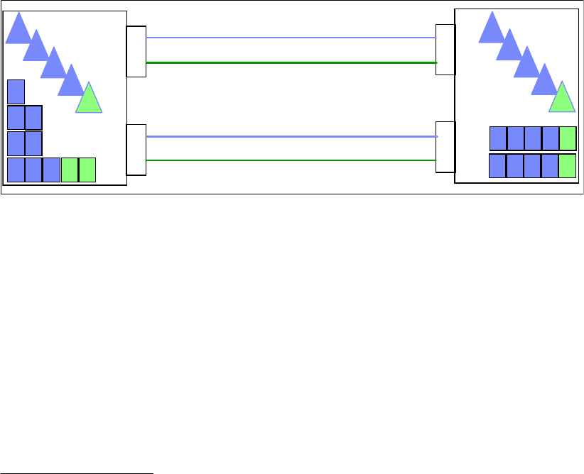
58 Implementing and Managing InfiniBand Coupling Links on IBM System z
dynamic reconfiguration on that CPC. For that reason, you might consider defining more
CHPIDs than you actually need to avoid a POR in the future. However, consider this
course of action only if the total number of CHPIDs defined on the InfiniBand port does not
exceed four.
If your configuration contains one or more performance-sensitive production sysplexes
and a number of less important sysplexes, consider the number of CHPIDs that you want
to assign to each HCA3-O port. For example, if you have a production sysplex and plan to
assign two of its CHPIDs to a given HCA3-O port, and assuming that the port at the other
end of the link is also on an HCA3-O adapter, that port will run in IFB3 mode.
Now consider your other sysplexes. Although the CF load that they generate might be
insignificant, adding more CHPIDs to that HCA3-O port results in more than four CHPIDs
being defined for that port, and the performance observed by the production sysplex will
be impacted because the port will now run in IFB mode.
In a situation like this, it might be better to keep the number of CHPIDs defined on any
HCA3-O port being used by a production sysplex to four or fewer, and have a larger
number of CHPIDs on ports that are being used by the other sysplexes.
An example configuration is shown in Figure 3-10. In this case, there is one production
sysplex (P), two test sysplexes (T), one development sysplex (D), and one system
programmer sandbox sysplex (S). The production sysplex is using port 2 on each adapter.
Because those ports only have two CHPIDs defined to them, they run in IFB3 mode. All
the other sysplexes are sharing port 1 on the two adapters. Because there are more than
four CHPIDs defined to those ports, they will run in IFB mode. However, the performance
difference is less likely to be important to those sysplexes.
Figure 3-10 Separating production and non-production sysplexes
3.8 Physical Coupling link addressing
PSIFB coupling link fanouts are identified by an Adapter ID (AID). This is different from
channels installed in an I/O cage or drawer (and ISC3 and ICB4 links), which are identified by
a physical channel identifier (PCHID) number that relates to the physical location.
The AID is used to associate CHPIDs with PSIFB coupling links in a similar way that PCHIDs
are used to define CHPIDs for other types of coupling links. However, when you look at the
channel list on the Support Element (SE), rather than seeing AIDs, you will still see Virtual
Channel Identifiers (VCHIDs) in the address range from 0700 to 07FF. To determine the
VCHID that is currently associated with a given coupling CHPID7, issue a D CF MVS
command; the output shows the VCHID for each CHPID that is connected to the CF.
TTDSP
TTDSP
1
2
1
2
1
2
1
2
IFB
IFB
IFB3
IFB3
90
91
98
99
80 82 84 86
81 83 85 87
88 8A 8C 8E
89 8B 8D 8F
7 VCHIDs are assigned to CHPIDs at IML time or when a dynamic I/O reconfiguration is performed, so always verify
the CHPID-to-VCHID relationship before performing any operation on a VCHID.
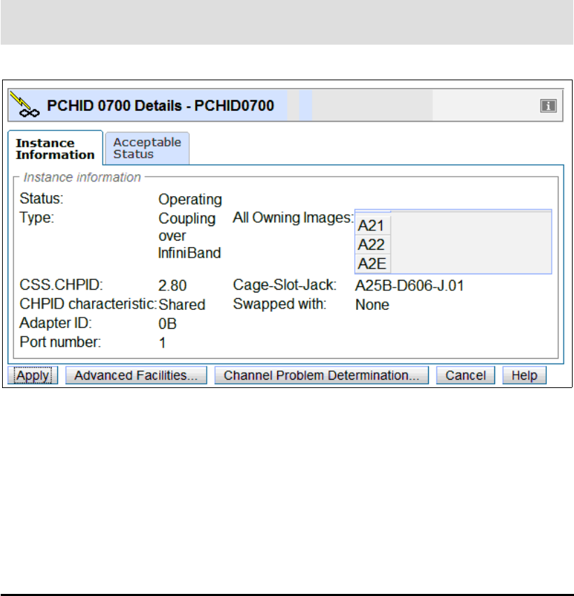
Chapter 3. Preinstallation planning 59
Figure 3-11 shows a sample PSIFB channel detail information display from the SE. This
display is for VCHID 0700, which is associated with CHPID 80 in CSS 2. The AID is 0B and
the port is 1. We describe the assignment of AIDs and VCHIDs in 2.4, “Adapter ID
assignment and VCHIDs” on page 26.
Figure 3-11 PSIFB Channel Detail information from SE
You can find the AID assignments for each fanout in the PCHID report. This report is provided
by your IBM technical representative for a new CPC or for miscellaneous equipment
specification (MES) upgrades to an existing CPC.
Example 3-2 shows part of a PCHID report for a z196 model M80. In this example, you can
see that there are four adapters in the first book (location 01). The adapters are installed in
location D7/D8/D9/DA in each case. The AID that is assigned to the first adapter in the first
book (location D7) is 04.
Example 3-2 Sample PCHID REPORT showing AID assignments
CHPIDSTART
15879371 PCHID REPORT Jun 07,2011
Machine: 2817-M80 NEW1
- - - - - - - - - - - - - - - - - - - - - - - - - - - - - - - - - - - - - - -
Source Cage Slot F/C PCHID/Ports or AID Comment
01/D7 A25B D701 0163 AID=04
01/D8 A25B D801 0171 AID=05
01/D9 A25B D901 0171 AID=06
01/DA A25B DA01 0170 AID=07
06/D7 A25B D706 0163 AID=0C
06/D8 A25B D806 0171 AID=0D
06/D9 A25B D906 0171 AID=0E
06/DA A25B DA06 0170 AID=0F
10/D7 A25B D710 0163 AID=14
Note: The panel still refers to the term PCHID for this Virtual Channel Identifier. This can
be ignored.

60 Implementing and Managing InfiniBand Coupling Links on IBM System z
10/D8 A25B D810 0171 AID=15
10/D9 A25B D910 0171 AID=16
10/DA A25B DA10 0170 AID=17
15/D7 A25B D715 0163 AID=1C
15/D8 A25B D815 0171 AID=1D
15/D9 A25B D915 0171 AID=1E
15/DA A25B DA15 0170 AID=1F
Legend:
Source Book Slot/Fanout Slot/Jack
A25B Top of A frame
0163 HCA2
0171 HCA3 O
0170 HCA3 O LR
There is an important difference in how AIDs are handled for different CPC types when
changes to the machine configuration are made.
For System z9 CPCs, the AID is determined by its physical location, much like a PCHID. If
a Host channel adapter (HCA) is moved from one slot location on a processor book to
another slot location, it will assume the AID that is assigned to the new physical location.
For System z10 CPCs or later, when a PSIFB HCA is moved from one fanout slot location
to another fanout slot location, the AID moves with it (the AID is retained).
These differences illustrate the importance of referring to the PCHID report detail.
Figure 3-12 shows the HCD Channel Path List and several CIB CHPIDs. If you page right
(F20) the AID detail is displayed. Here we can see that CHPID 8C is assigned to AID 09 and
port number 1.
Figure 3-12 HCD Channel Path List
Detailed information about defining your InfiniBand infrastructure in HCD is contained in
Chapter 6, “Configuration management” on page 155.
Channel Path List
Command ===> _______________________________________________ Scroll ===> PAGE
Select one or more channel paths, then press Enter. To add, use F11.
Processor ID : SCZP301 CSS ID : 2
1=A21 2=A22 3=A23 4=A24 5=A25
6=* 7=* 8=A28 9=* A=*
B=* C=* D=* E=* F=A2F
I/O Cluster --------- Partitions 2x ----- PCHID
/ CHPID Type+ Mode+ Mngd Name + 1 2 3 4 5 6 7 8 9 A B C D E F AID/P
_ 7E FC SPAN No ________ a a a a a # # a # # # # # # _ 253
_ 7F FC SPAN No ________ a a a a a # # a # # # # # # _ 1F3
_ 8C CIB SHR No ________ a a _ _ _ # # _ # # # # # # a 09/1
_ 8D CIB SHR No ________ a a _ _ _ # # _ # # # # # # a 1A/1
_ 98 CIB SHR No ________ a a _ _ _ # # _ # # # # # # a 0C/1
_ 99 CIB SHR No ________ a a _ _ _ # # _ # # # # # # a 0C/2

Chapter 3. Preinstallation planning 61
3.9 Cabling considerations
PSIFB links utilize industry-standard optical fiber cables:
The HCA2-O and HCA3-O (12X IB-DDR) feature and the HCA1-O (12X IB-SDR) feature
require an OM3 50 micron multimode optical fiber with 12 fiber pairs (total of 24 optical
fibers)
The maximum cable length for the HCA2-O, HCA3-O and HCA1-O features is 150 meters
(492 feet) This provides more flexibility for physical placement of CPCs in the data center
than an ICB-4 implementation.
The HCA2-O LR and HCA3-O LR (1X IB-DDR) feature require a 9 micron single mode
optical fiber cable with one fiber pair. This is the same type of cable, and the same
connectors that are used by ISC3 links.
The maximum cable length for the HCA3-O LR and HCA2-O LR features is 10 km (6.2
miles).
See 2.6, “InfiniBand cables” on page 34 for additional cabling information.
Tip: A CPC must have an established local system name (LSYSTEM) to define a
connected CIB CHPID. HCD will default to the Central Processor Complex (CPC) name
that is specified for the Processor ID. Define a name for LSYSTEM that will be carried over
from one CPC to its replacement (that is, without any machine type information).
If the LSYSTEM parameter is changed (because of a machine upgrade (z10 to z196, for
example), the remote systems at the other end of the PSIFB connection might need a
dynamic activate or a power-on reset (for a stand-alone CF) for the name of the replaced
CPC to reflect the new name.
The LSYSTEM value is only used in PSIFB CHPID definitions, so any changes you make
to your LSYSTEM naming convention are unlikely to affect anything else. This is discussed
further in “LSYSTEM” on page 162.
Note: Clearly label both ends of all cables to avoid confusion and expedite problem
determination.
62 Implementing and Managing InfiniBand Coupling Links on IBM System z

© Copyright IBM Corp. 2008, 2012, 2014. All rights reserved. 63
Chapter 4. Migration planning
The migration from earlier sysplex connectivity solutions to InfiniBand connectivity options
provides you with the opportunity to completely refresh your coupling infrastructure, resulting
in improved availability, flexibility, and performance. However, because it involves the eventual
replacement of all your existing coupling links, you must plan the migration carefully,
especially if you need to complete the migration without impacting application availability.
It is safe to say that every enterprise’s sysplex environment is unique. It might range from a
small 1-CPC sysplex in a single computer room to a large n-way sysplex using structure
duplexing technology spread over many kilometers. Some enterprises are able to schedule a
window to perform a disruptive migration; others need to perform the migration without any
outage to their core applications.
This chapter describes several of the most common migration scenarios. They have been
tested and documented to help you plan your specific migration. All scenarios focus on the
basic steps to successfully complete the migration. You will need to adapt each scenario to
your specific installation, depending on the number of coupling links, Coupling Facility CPCs,
involved logical partitions, and number of System z servers in your configuration.
The following topics and scenarios are presented in this chapter:
Migration considerations
Connectivity considerations
Introduction to the scenario notation
Scenario 1: Disruptive CPC upgrade, PSIFB already in use (ICFs)
Scenario 2: Migration to PSIFB with no POR (ICFs)
Scenario 3: Concurrent CPC and link upgrade
Scenario 4: Concurrent PSIFB implementation (stand-alone CFs)
Scenario 5: Concurrent migration from IFB to IFB3 mode
Scenario 6: Concurrent switch between IFB modes
4

64 Implementing and Managing InfiniBand Coupling Links on IBM System z
4.1 Migration considerations
You must carefully plan for the migration to PSIFB coupling links. Introducing PSIFB links into
an existing environment requires a thorough understanding of the different System z CPC
implementations of Coupling Facility technology. When implementing a new CPC (like a z196
and z114) you need to consider migration to InfiniBand as part of the overall migration plan. A
conservative approach aimed at providing easy fallback and minimizing application disruption
is likely to consist of multiple steps.
We assume that you have familiarized yourself with the technical aspects of InfiniBand
technology on IBM zEnterprise and System z servers as described in Chapter 2, “InfiniBand
technical description” on page 17. Further, we assume that you have finished the planning for
the implementation of the InfiniBand technology in your specific environment by taking into
account all considerations listed in Chapter 3, “Preinstallation planning” on page 37.
This chapter focuses on the actual implementation steps, providing sample step-by-step
guidance for each of the most common implementation scenarios. Table 4-1 contains a list of
the scenarios discussed in this chapter.
Table 4-1 Sample migration scenarios
Depending on your environment and migration goals, you might need to use several of the
migration scenarios, one after the other. The following example shows how you might need to
combine a number of scenarios to get from where you are now to where you want to end up.
Example implementation steps
The sysplex environment consists of several System z10 CPCs, currently connected using
ICB4 links. Your company has decided to upgrade to the latest generation of zEnterprise
servers, and you are responsible for ensuring that the migration is carried out with no
application outages. In this case, you need to use several of the sample scenarios.
First, you need to add the InfiniBand adapters to your existing System z10 CPCs; see 4.4,
“Scenario 2” on page 76, “Migration to PSIFB with no POR (ICFs)”.
Next, you need to upgrade the z10s to z196s. There are a number of options for that
migration:
– 4.3, “Scenario 1” on page 68, “Disruptive CPC upgrade, PSIFB already in use (ICFs)”
– 4.5, “Scenario 3” on page 86, “Concurrent CPC and link upgrade” or
– 4.6, “Scenario 4” on page 95, “Concurrent PSIFB implementation (stand-alone CFs)”,
depending on your configuration.
Finally, you want to achieve the performance benefits of IFB3 mode, and this will involve
replacing your HCA2-O adapters with HCA3-O adapters. 4.7, “Scenario 5” on page 108,
Section Description Page
4.3 Scenario 1 - Disruptive CPC upgrade, PSIFB already in use (ICFs) 68
4.4 Scenario 2 - Migration to PSIFB with no POR (ICFs) 76
4.5 Scenario 3 - Concurrent CPC and link upgrade 86
4.6 Scenario 4 - Concurrent PSIFB implementation (stand-alone CFs) 95
4.7 Scenario 5 - Concurrent migration from IFB to IFB3 mode 108
4.8 Concurrent switch between IFB modes 112

Chapter 4. Migration planning 65
“Concurrent migration from IFB to IFB3 mode” provides an example of how such a
migration can be completed without impacting application availability.
Although this multistep process might seem complex, it can help you progress through a
number of technology changes without impacting your application availability (depending on
which migration option you select). Alternatively, if you are able to plan for an application
outage, it might be possible to consolidate a number of changes into a single outage, thereby
reducing the total number of steps that are required.
4.1.1 Connectivity considerations
In the migration scenarios we sometimes connect one version of an HCA adapter (HCA2, for
example) to a different version (HCA3). The ability to mix and match adapters like this
depends on the CPC generations that are to be connected. For example, a z10 with an
HCA2-O fanout can be connected to a zEC12 with HCA3-O fanout; however, the link will run
in IFB mode rather than in IFB3 mode.
Table 4-2 lists which 12X InfiniBand HCA fanouts can be interconnected, along with specific
considerations.
Table 4-2 12X connectivity options
Table 4-3 provides similar information for the 1X InfiniBand fanouts.
Table 4-3 1X connectivity options
Server
(Link type)a
a. Refer to 2.2, “InfiniBand fanouts” on page 19 and 2.5, “InfiniBand coupling links” on page 30 for
further detail regarding HCA fanouts.
z9
(HCA1-O)
z10
(HCA2-O)
zEC12/zBC12
z196/z114
(HCA2-O)
zEC12/zBC12
z196/z114
(HCA3-O)b
z9
(HCA1-O)
NO YES YES NO
z10
(HCA2-O)
YES YES YES YES
zEC12/zBC12
z196/z114
(HCA2-O)
YES YES YES YES
zEC12/zBC12
z196/z114
(HCA3-O)b
b. HCA3-O fanouts support two modes, IFB and IFB3. The improved 12X IFB3 mode can only be
used if the link is implemented between two HCA3-O fanouts and a maximum of four CHPIDs
are defined to the HCA3-O ports at each end of the link.
NO YES YES YES
Server
(Link type)az9
(N/A)bz10
(HCA2-O LR)
zEC12/zBC12
z196/z114
(HCA2-O LR)c
zEC12/zBC12
z196/z114
(HCA3-O LR)
z9
(N/A)bN/A N/A N/A N/A
z10
(HCA2-O LR)
N/A YES YES YES

66 Implementing and Managing InfiniBand Coupling Links on IBM System z
4.2 Introduction to the scenario notation
To make it easier to understand and compare the various scenarios, we present each one
using the same structure. After a brief description of the scenario, a diagram of the starting
configuration is presented. The target configuration of each scenario is also shown in a
diagram, typically at the end of the steps in the scenario. Depending on the complexity of the
scenario, intermediate configurations might be shown as well.
The descriptions refrain from using actual PCHID or CHPID numbers because they will be
different for each client. Instead, the relevant links are numbered and referred to accordingly,
where necessary.
Different kinds of coupling link types are used in each scenario. For the legacy links we might
have ISC3 links, ICB4 links, or a mixture of both link types. The links will be updated to the
most appropriate PSIFB link types; for example, an ISC3 link is replaced by a 1x PSIFB link
and an ICB4 link is replaced by a 12x PSIFB link. However, the handling of the various link
types is identical, so the link type used in each scenario can be replaced to suit your
configuration.
Table 4-4 lists the systems used in our examples. Note that the CPC name-to-CPC
relationship might change in a scenario where the current CPC is going to be replaced by
another one.
Table 4-4 CPCs used in migration scenarios
zEC12/zBC12
z196/z114
(HCA2-O LR)c
N/A YES YES YES
zEC12/zBC12
z196/z114
(HCA3-O LR)
N/A YES YES YES
a. Subchannels and link buffers need to be considered during the migration phase; see
Appendix C, “Link buffers and subchannels” on page 247.
b. Long-reach HCA fanouts are not supported on System z9.
c. HCA2-O LR adapters are still available for z10, but they have been withdrawn from marketing
for z196 and z114. On z196 and z114, the replacement is HCA3-O LR. However, you still might
have HCA2-O LR HCAs on a z196 if they were carried forward during a CPC upgrade.
Note: To avoid making the scenarios overly complex, the number of links used in each
scenario (and shown in the diagrams) represent the minimum number of links that are
recommended to avoid any single point of failure.
If you use more than the minimum number of links, the scenario steps will be still the same
with the exception that steps that deal with managing the links themselves will have to be
repeated based on the number of links actually in use.
CPC Model CPC name aLPAR types
System z10 EC E26 CPC1 z/OS
CF

Chapter 4. Migration planning 67
The LPARs and their associated names from Table 4-5 are used in our examples. Depending
on the scenario, the LPARs might reside in the same or in different CPCs.
Table 4-5 LPARs used in migration scenarios
Disruptive versus concurrent migrations scenarios
Whenever we describe a migration scenario as “concurrent”, we mean that it is required that
all z/OS LPARs on the involved CPCs (and therefore all core applications) continue to be
available throughout the migration. In these scenarios we assume that it is acceptable to
move coupling structures between CF LPARs and also to deactivate a CF LPAR as long as at
least one CF LPAR remains connected to all systems in the sysplex.
Note that if your critical applications exploit sysplex data sharing and dynamic workload
routing, you have greater flexibility because the availability of your critical application is no
longer tied to the availability of particular z/OS LPARs. This means that you can use a
scenario that we describe as disruptive but without impacting your application availability.
If all involved CPCs, and therefore all z/OS LPARs and all applications, need to be shut
down, the scenario is considered to be disruptive. Also, if the core applications are not
configured for sysplex-wide data sharing, this also means that the scenario needs to be
considered disruptive.
The terms “disruptive” and “concurrent” can be interpreted differently by one enterprise than
by another. There is no absolute definition possible, because you might consider a given
scenario to be disruptive, but it might be considered concurrent by someone else. Therefore it
is important that you define your migration objectives as clearly as possible to be able to
match them to one of our migration scenarios.
System z10 EC E40 CPC2 z/OS
CF
System z9 EC S18 CPC3 z/OS
CF
zEnterprise 196 M32 CPC4 z/OS
CF
zEnterprise 196 M32 CPC5 z/OS
CF
System z10 EC E26 CF01 CF only
System z10 EC E26 CF02 CF only
a. CPC name that is specified for the CPC ID in the IOCDS.
LPAR Type Name
z/OS ZOS1, ZOS2
CF CF1, CF2, CF3, CF4
CPC Model CPC name aLPAR types

68 Implementing and Managing InfiniBand Coupling Links on IBM System z
4.3 Scenario 1
Disruptive CPC upgrade, PSIFB already in use (ICFs)
There are two servers installed at the start of this scenario: a z9 EC and a z10 EC. Both
CPCs already have InfiniBand fanouts installed and are connected with 12x PSIFB links. The
z9 EC is going to be upgraded to a z196 server. Two LPARs, ZOS1 and CF1, are in use and
reside in the z9 EC. Two more LPARs, ZOS2 and CF2, reside in the z10 EC. Figure 4-1 on
page 69 shows the configuration at the start of the project.
In this case, the installation has already planned for a complete outage to allow for an
upgrade to the computer room environment (for recabling and power maintenance), so they
are going to take the opportunity of the outage to upgrade the z9. Because both CPCs will be
down, this is considered to be a disruptive scenario where all LPARs on both CPCs are being
stopped. However, if the installation prefers, it is possible to complete this migration without
impacting the systems on the z10; that type of migration is described in 4.5, “Scenario 3” on
page 86.
Note: The scenarios in this document reflect the current best practice guidance for CF
outages as described in the white paper titled Best Practices: Upgrading a Coupling
Facility, which is available at the following website:
http://www.ibm.com/support/techdocs/atsmastr.nsf/WebIndex/WP101905
Tip: Regardless of which scenario applies to your situation, at the start of the migration it is
useful to clearly map which LPAR and CPC is connected to every coupling CHPID in each
LPAR, for CF and z/OS LPARs.
Also, if the migration will consist of a number of configuration changes, document the
expected configuration at the start of each step. This might take a little time, but it will prove
invaluable in helping avoid human error (and potential outages) by configuring the wrong
CHPID on or offline.
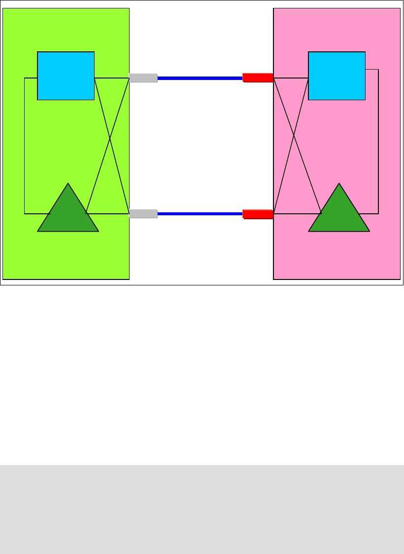
Chapter 4. Migration planning 69
Figure 4-1 Scenario 1: Starting configuration
In this scenario, the z9 system uses HCA1-O fanouts for the PSIFB coupling connections.
The z10 system has HCA2-O fanouts installed. The upgrade of the z9 is done as a “frame roll
MES”, which means that the actual frames of the z9 will be replaced with the new frames of
the z196, but the serial number will stay the same. Due to the nature of a frame roll MES, the
CPC that is being upgraded will always have to be shut down.
In a frame roll MES, several I/O cards or fanouts might be transferred to the new frame.
However, in this specific case, no InfiniBand fanouts are carried forward because the z196
does not support the HCA1-O fanouts. Therefore, new HCA fanouts are ordered. To be better
positioned for future upgrades, order new HCA3 fanouts for the z196 because they are not
only compatible with the HCA2 fanouts in the z10, but will also allow utilization of the
improved IFB3 mode when the client upgrades their z10 CPC to a z196 in the future.
Following are the steps in this migration:
1. Update hardware configuration definition (HCD) for the new z196 and create the z196
IOCDS.
The new IOCDS for the z196 is generated and saved to the z9. The IOCDS will be carried
forward during the upgrade to the z196 by the System Service Representative (SSR). This
is the most convenient way to install an IOCDS on an upgraded CPC.
Note: The process described here, and in subsequent scenarios, might seem intricate.
However, the objective is to shut down everything in an orderly manner, ensuring that the
subsequent restart will be clean and will complete in a timely manner.
In this first scenario, we include steps that are not strictly necessary if one or both CPCs
are going to be powered-down. However, we included the steps in an effort to have more
consistency between the various scenarios presented in this chapter.
IC
z10 EC
z10 EC –
–CPC2
CPC2
z9 EC
z9 EC –
–CPC3
CPC3
ZOS2ZOS1
CF
CF2
12x PSIFB 1
12x PSIFB 2
CF
CF1
IC
HCA1-O HCA2-O
HCA1-O HCA2-O
IC
z10 EC
z10 EC –
–CPC2
CPC2
z9 EC
z9 EC –
–CPC3
CPC3
ZOS2ZOS1
CF
CF2
12x PSIFB 1
12x PSIFB 2
CF
CF1
IC IC
z10 EC
z10 EC –
–CPC2
CPC2
z9 EC
z9 EC –
–CPC3
CPC3
ZOS2ZOS2ZOS1ZOS1
CF
CF2
CF
CF2
12x PSIFB 1
12x PSIFB 2
CF
CF1
CF
CF1
IC
HCA1-O HCA2-O
HCA1-O HCA2-O
BTS PTS

70 Implementing and Managing InfiniBand Coupling Links on IBM System z
2. Write the changed IOCDS for the z10 EC.
Depending on the z196 definitions in HCD, the IOCDS for the z10 EC might need to be
updated. If the LSYSTEM name of the z196 will be different than the LSYSTEM name of
the z9, and/or the CHPID numbers for the HCA3 adapters in the z196 will be different than
the corresponding numbers in the z9, then the z10 IOCDS will need to be updated.
If you use the same CHPIDs and CSSs on the new PSIFB links that you used before on
the coupling links, and the same LSYSTEM name, then no IOCDS change is required in
relation to the coupling links. For more information, see “LSYSTEM” on page 162.
3. The CFRM policy is updated.
Because the z9 EC is being upgraded to a z196, the CFRM policy needs to be updated.
The changes that you need to make depend on whether you plan to use the same name
for the z196 CF. The CPC serial number will remain the same because this is an upgrade
MES, but the CPC type is going to change and that needs to be reflected in the CFRM
policy as well.
The structure sizes have to be updated as well, because the new z196 will have a different
Coupling Facility Control Code (CFCC) level than the z9. To determine the correct sizes,
use either CFSizer or the Sizer tool available on the CFSizer site. An alternate process is
described in the document titled “Determining Structure Size Impact of CF Level
Changes”, available on the web at:
http://www.redbooks.ibm.com/abstracts/tips0144.html?Open
Save the updated policy with a new name, for example, “newpol”. This gives you the ability
to fall back to the previous CFRM policy if problems are encountered.
Note that the new policy will not actually be activated until after the upgrade is complete.
4. Quiesce all work on all z/OS LPARs in preparation for stopping z/OS and powering down
both CPCs.
5. Set the CF in the z9 EC into maintenance mode.
As the first step to emptying the CF1 CF on the z9 EC, set the CF into maintenance mode
by using the following z/OS command:
SETXCF START,MAINTMODE,CFNM=CF1
6. Move CF structures from the CF in the z9 EC to the CF in the z10 EC.
Reallocate the structures into the CF LPAR on the z10 EC using the following command:
SETXCF START,REALLOCATE
It is important that you empty the CF in the CPC that is being upgraded before you shut
down the sysplex. If you do not do this, information about the structures in the z9 CF will
be retained in the Coupling Facility Resource Management (CFRM) Couple Data Set and
cannot be removed.
7. Check that all structures have been moved.
Determine if any structures have remained in the CF by using this command:
D XCF,CF,CFNAME=CF1
Note: If you are running z/OS 1.12 or higher, verify that the reallocation will have the
desired effect by using this command first:
D XCF,REALLOCATE,TEST
Address any problem that is detected before you reallocate the structures.

Chapter 4. Migration planning 71
If any structure did not move, check whether application-specific protocols are needed and
use these to move (or rebuild) the structure. Repeat this step until all structures have been
moved.
For more information about moving structures out of a CF, refer to the sections titled
“Removing structures from a coupling facility for shutdown” and “Removing a structure
from a coupling facility” in z/OS MVS Setting Up a Sysplex, SA22-7625.
8. Set the z9 EC CF logically offline to all z/OS LPARs.
Placing CF1 in MAINTMODE and verifying that the REALLOCATE command was
successful can ensure that no structures are left in CF1. However, to be sure that no active
structures remain in the CF, it is prudent to take the CF logically offline to all connected
z/OS systems before shutting it down.
This is achieved using the following command in each z/OS system:
V PATH(CF1,xx),OFFLINE (you will have to add the UNCOND option for the last CHPID)
This has the effect of stopping the issuing z/OS from being able to use the named CF. If
this z/OS is still connected to any structure in the CF, the command will fail.
Note that this command does not make the named CHPIDs go offline; it is simply access
to the CF that is removed. The CHPIDs will be taken offline later. If you issue a
D CF,CFNM=CF1 command at this time, you will see that each CHPID still shows as being
physically ONLINE, but logically OFFLINE.
9. Shut down CF1.
Next you need to deactivate the CF1 LPAR. If the CF is empty, use the SHUTDOWN command
from the CF1 console on the HMC. The advantage of using a SHUTDOWN command,
compared to deactivating the LPAR using the HMC DEACTIVATE function, is that the
SHUTDOWN command will fail if the CF is not empty. The end result of the SHUTDOWN is
effectively the same as the end result of performing a DEACTIVATE, so it is not necessary
to perform a DEACTIVATE of a CF LPAR that was successfully shut down using the
SHUTDOWN command.
If the CF still contains one or more structures, but the decision has been made that the
instance of the structure does not need to be moved or recovered, the SHUTDOWN command
will not complete successfully, so DEACTIVATE the CF LPAR instead.
10.Stop ZOS1 and deactivate the ZOS1 LPAR.
The z/OS LPAR on the z9 is now shut down (using V XCF,sysname,OFFLINE). When that
system has entered a wait state, the LPAR should be is deactivated.
All LPARs on the z9 should now be in a state that is ready for the CPC to be powered
down.
Note: If you are running z/OS 1.12 or higher, review the reallocation report to determine
why a structure was not moved by using this command:
D XCF,REALLOCATE,REPORT
If you have a z/OS 1.13 or higher system in the sysplex, you might find that system
provides more helpful messages to explain why a structure is not being moved to the
CF you expect.
Note: The paths to the CF can be brought logically back online by using the
VARY PATH(cfname,chpid) command or by performing an IPL of the z/OS system.

72 Implementing and Managing InfiniBand Coupling Links on IBM System z
11.STP-related preparation.
Note the current STP definitions and the STP roles (CTS, PTS, BTS, and Arbiter) before
any changes are made, so they can be reinstated later.
For more details refer to the Redbooks document Server Time Protocol Recovery Guide,
SG24-7380, and the white paper Important Considerations for STP and Planned
Disruptive Actions, available on the web at:
http://www.ibm.com/support/techdocs/atsmastr.nsf/WebIndex/WP102019
To better protect a sysplex against potential operational problems, STP was changed so
that it prevents the shutdown of a zEnterprise or System z10 CPC that has any STP role
assigned. This change is documented in the white paper Important Considerations for
STP server role assignments, available on the web at:
http://www.ibm.com/support/techdocs/atsmastr.nsf/WebIndex/WP101833
As a result of this change, you need to remove the STP server roles in the STP
configuration panel before the CPCs are shut down. Remove the Arbiter role first (not
applicable in this scenario) and then the BTS role1.
To implement the role changes, check the setting of the option called “Only allow the
server(s) specified above to be in the CTN”2 in the STP network configuration tab on the
HMC:
– If this option is currently selected:
• It must be cleared so that the BTS role can be removed from the z9 (because no
server role assignment changes can be made if this option is enabled).
• Remove the BTS role from the z9.
– If this option is not selected:
• Remove the BTS role from the z9.
Note the original setting of this option because it is required in step 21.
When the z9 is upgraded to a z196, the STP definitions on that CPC will need to be
updated to specify the name of the CTN that the CPC is to join. If you remove the z9 from
the CTN prior to powering it down, you will be able to configure offline all coupling links
between the two CPCs because they are no longer being used by STP.
To remove the z9 from the CTN, logon to the z9 SE, go into the System (Sysplex) Time
option, select the STP Configuration tab and blank out the Coordinated timing network ID
field.
Finally, select the “Only allow the server(s) specified above to be in the CTN” option on the
HMC so that after the POR, the CTN configuration will be remembered.
1 The PTS should always be the last CPC to be shut down, and the first CPC to be restarted, so ensure that the CPC
that is not being upgraded is the one that is the PTS. Therefore, prior to making any other STP-related changes,
make the CPC that is not being upgraded the PTS if that is not already the case; in this example, that is the z10 EC.
If you need to make changes to the STP configuration to achieve this, work those changes into the process
described here.
2 Enabling this option causes the CTN’s timing and configuration settings to be saved so that they will not need to be
re-entered after a loss of power or a planned POR of the servers.
Note: Remove the STP server roles only if the complete CTN will be shut down. If your
CTN contains other CPCs that will continue to work, the STP server roles need to be
reassigned to the still-active CPCs.

Chapter 4. Migration planning 73
12.Configure offline all paths to the z9 EC CPC.
When all LPARs on the z9 EC are down, configure offline all coupling links to that CPC. To
do this, issue the following command for each CHPID going to CF1, for each z/OS LPAR
that is communicating with CF1:
CONFIG CHP(xx),OFFLINE
Because the CF1 LPAR is down at this point, it should not be necessary to use the
CONFIG CHP(xx),OFFLINE,UNCOND command for the last CHPID from each z/OS LPAR to
CF1.
Note that each z/OS LPAR might use different CHPIDs to connect to CF1, so ensure that
you configure the appropriate CHPIDs for each LPAR (in our example, there is only one
z/OS at this point, ZOS2).
After issuing all the CONFIG CHP commands, issue a D CF,CFNM=CF1 command from each
connected z/OS to ensure that all the CHPIDs to that CF are now both logically and
physically offline to that LPAR.
When the CONFIG OFFLINE command is issued for a z/OS CHPID, the z/OS end of the link
will be taken offline; however, the CF end will remain online. In this example, that is not an
issue because the CPC containing CF1 is going to be replaced.
If there are any CF-to-CF links between CF2 and CF1, issue the following command on
CF2 to take those CHPIDs offline:
CON xx OFF
Finally, use the z10 SE to check if there are any remaining coupling links online to the z9.
Toggle offline any such VCHIDs or PCHIDs at this point, using the HMC.
13.Shut down z/OS LPARs on z10.
The next step is to prepare the z10 for power-down to enable the computer room
maintenance.
Use your normal procedures to shut down the z/OS LPARs on the z10 (in our example,
ZOS2). After the z/OS systems have been stopped, deactivate those LPARs.
14.Deactivate the CF2 CF LPAR.
Prior to stopping the CF1 CF, any structures in that CF were moved to the CF2 CF. When
the z/OS LPARs are shut down, various structures will remain in the CF2 CF. For that
reason, the CF SHUTDOWN command will fail. Therefore, simply deactivate the CF2 LPAR.
15.Power down the CPCs.
Power down the z9 now.
Then power down the z10 EC.
16.The SSR starts the upgrade of the z9 EC.
17.The z10 is powered on and activated with the updated IOCDS (if an IOCDS update was
necessary); however, no LPARs are activated yet.
Note that if the IOCDS was updated as part of the z9 upgrade, then all CHPIDs will be
online at the end of the activation. However, if the IOCDS was not updated, then any
CHPIDs that were taken offline as part of the shutdown will be offline after the activation
completes.
18.After the SSR is finished with the z9 upgrade, the z196 is powered on and activated with
the new IOCDS3. Again, no LPARs should be activated yet.
3 If a CPC is activated with an IOCDS that was not previously used, all CHPIDs will be brought online as part of the
activation, regardless of the status of the CHPIDs before the CPC was powered down.
74 Implementing and Managing InfiniBand Coupling Links on IBM System z
19.Ensure that there is an available timing link between the z10 and the z196.
Use the z10 SE to ensure there is at least one coupling CHPID online from the z10 to the
z196 so that STP can exchange time signals between the two CPCs.
20.Add CTN ID to the z196.
In this step and the next one, we make changes to the STP configuration, so disable the
“Only allow the server(s) specified above to be in the CTN” option on the z10 HMC before
proceeding.
Because the z196 is considered to be a new CPC by STP, you must log on to the z196
HMC, select the System (Sysplex) Time option, and enter the CTN ID on the STP
Configuration tab.
After the CTN ID of the z196 has been added, use the STP panels on the z10 and z196 to
ensure that the change was successful and that both CPCs are now in the CTN.
21.STP roles reassignment.
Define or reassign the STP roles that were removed or reassigned in step 11.
After all required STP changes have been made, return the “Only allow the server(s)
specified above to be in the CTN” option to the original setting as noted in step 11.
22.z10 CF LPAR is activated.
The sequence in which the LPARs are activated needs to be controlled.
Activate the CF2 LPAR in the z10. The CF1 CF is not activated yet because we want to be
able to control the allocation of structures in that CF. Even though CF1 was in
maintenance mode prior to the power-down, changing the CPC type from z9 to z196 will
cause that to be reset. We want to place it back in maintenance mode before the CF
connects to the systems in the sysplex.
23.Activate z/OS LPARs.
After CF2 has successfully initialized (and you have verified this using the CF console),
activate and load the z/OS LPARs.
24.Activate the new CFRM policy with the following command:
SETXCF START,POLICY,TYPE=CFRM,POLNAME=newpol
Note that this will make z/OS aware of the newly-upgraded CF. However, because the CF1
LPAR has not been activated yet, z/OS will not be able to place any structures in that CF.
25.Place CF1 back in maintenance mode.
Use the following command to place CF1 in maintenance mode:
SETXCF START,MAINTMODE,CFNM=CF1
26.Activate CF1 CF.
Now that CF1 has been placed in maintenance mode, it can be initialized without fear of
structures immediately being placed in it.
27.Bring paths to CF1 online.
If the z10 IOCDS was updated as part of the upgrade, all CHPIDs will be online now, so
you can skip to the next step.
If the z10 IOCDS was not updated as part of the upgrade, the coupling CHPIDs from the
z10 to CF1 will still be offline. To make CF1 accessible to the z10 z/OS system, you now
need to bring all those CHPIDs back online. Verify that none of the CHPIDs used to
connect to CF1 have changed as a result of the upgrade. Configure the CHPIDs online
using the following command:
CONFIG CHP(xx),ONLINE
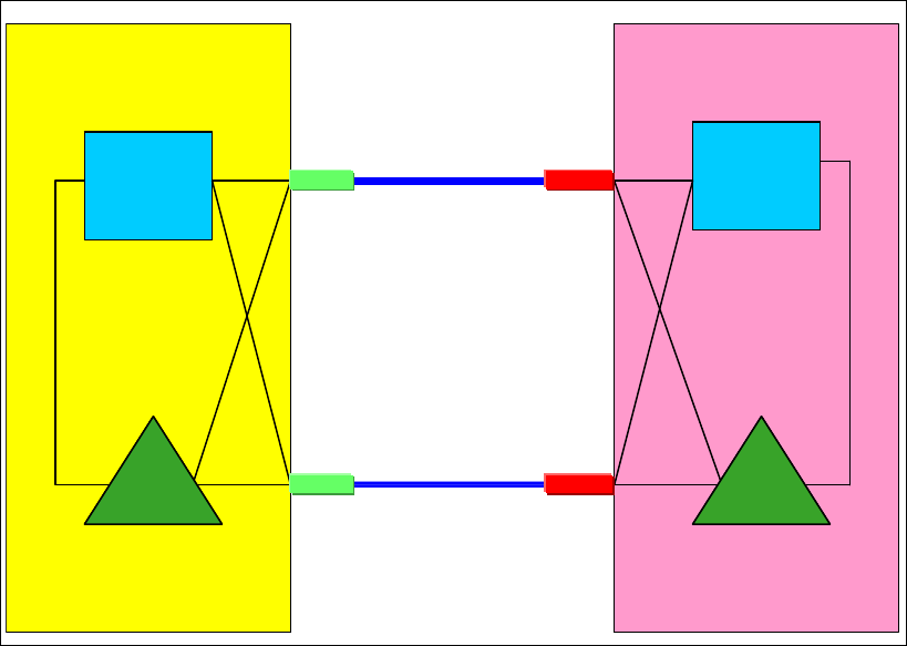
Chapter 4. Migration planning 75
After all the CONFIG commands have been issued, verify that all CHPIDs have the expected
status using the D CF,CFNM=CF1 command.
If CF-to-CF paths were in use prior to the upgrade, the CF2 end of those paths will need to
be brought online again. Do this using the following command from the CF2 console:
CON xx ON for each CF-to-CF CHPID.
Verify that the CHPIDs were successfully brought online by issuing the DISP CHP ALL
command on the CF console.
28.Make CF1 available for use again.
Before structures can be moved into CF1, you must take it out of maintenance mode. To
do this, issue the following command:
SETXCF STOP,MAINTMODE,CFNM=CF1
29.Move all the structures that normally reside in CF1 back into that CF.
If you are running z/OS 1.12 or later, issue the following command to ensure that all
structures will successfully move into the correct CF as defined by their PREFLIST:
D XCF,REALLOCATE,TEST
If any errors or warnings are reported, identify the reason and address them.
Complete the process of placing all structures in the correct by issuing the following
command:
SETXCF START,REALLOCATE
30.After all steps are completed, the final configuration is as shown in Figure 4-2.
Figure 4-2 Scenario 1: Final configuration
IC
z196
z196 –
–CPC4
CPC4
LPAR
01
CF
FACIL03
12x PSIFB 1
12x PSIFB 2
IC
z10 EC
z10 EC –
–CPC2
CPC2
LPAR
00
CF
FACIL04
HCA2-O
HCA2-O
HCA3-O
HCA3-O
IC
z196
z196 –
–CPC4
CPC4
LPAR
01
CF
FACIL03
12x PSIFB 1
12x PSIFB 2
IC
z10 EC
z10 EC –
–CPC2
CPC2
IC
z196
z196 –
–CPC4
CPC4
LPAR
01
LPAR
01
CF
FACIL03
CF
FACIL03
12x PSIFB 1
12x PSIFB 2
IC
z10 EC
z10 EC –
–CPC2
CPC2
LPAR
00
CF
FACIL04
LPAR
00
CF
FACIL04
HCA2-O
HCA2-O
HCA3-O
HCA3-O
BTS PTS
IC
z196
z196 –
–CPC4
CPC4
ZOS2ZOS2
12x PSIFB 1
12x PSIFB 2
IC
z10 EC
z10 EC –
–CPC2
CPC2
ZOS1 HCA2-O
HCA2-O
HCA3-O
HCA3-O
CF
CF1
CF
CF1
CF
CF2
CF
CF2
BTS PTS

76 Implementing and Managing InfiniBand Coupling Links on IBM System z
4.4 Scenario 2
Migration to PSIFB with no POR (ICFs)
This scenario describes how to migrate from pre-InfiniBand coupling links to InfiniBand
coupling links without requiring an outage of any of the LPARs that are using those links. This
scenario consists of a two-CPC configuration with one z/OS and one CF LPAR in each CPC.
There are two ICB4 links in place and they are to be replaced with PSIFB links.
The migration objective is to implement the new coupling link technology without any
interruption to our z/OS LPARs.
In this scenario, the InfiniBand technology is added to an existing sysplex configuration of
System z10 CPCs. This scenario can also be used as an interim step in migrating your
environment to the latest zEnterprise generation without taking an outage to your sysplex.
Because the zEnterprise generation does not support ICB4 coupling link technology,
implementing the InfiniBand technology on your System z10 CPCs prior to the upgrade to
zEnterprise might (depending on your sysplex configuration) be the only way to complete the
migration concurrently.
We describe two ways to achieve the objectives:
A concurrent migration, using two additional CF LPARs.
This is described in “Option 1 - Concurrent migration using two additional CF LPARs” on
page 77.
This option performs the migration by creating another CF LPAR on each of the two CPCs.
It requires updating the CFRM policy and moving your structures into the new CF LPARs.
This might be the preferred option if you already have the maximum number of links
between z/OS and your CFs, or if you want to have an interim step during the migration
where you have an opportunity to compare the performance of the different coupling link
technologies.
A concurrent migration, adding the new PSIFB links alongside the existing CF links.
This is described in “Option 2 - Concurrent migration by adding PSIFB links alongside the
existing CF links” on page 82.
This option accomplishes the migration by performing several dynamic activates on both
CPCs to add the new InfiniBand links, and subsequently to remove the legacy links. This
might be the preferred option if you have less than the maximum number of links (eight) to
your CFs, or if you do not want to temporarily use more resources for another set of CF
LPARs. In this case, you do not need to update the CFRM policies or move any structures.
Note that this option makes it more difficult to perform a performance comparison between
the two technologies.
Note: This example can be used for any type of coupling link. For instance, if you want to
migrate ISC3 links to InfiniBand links, the methodology is the same.
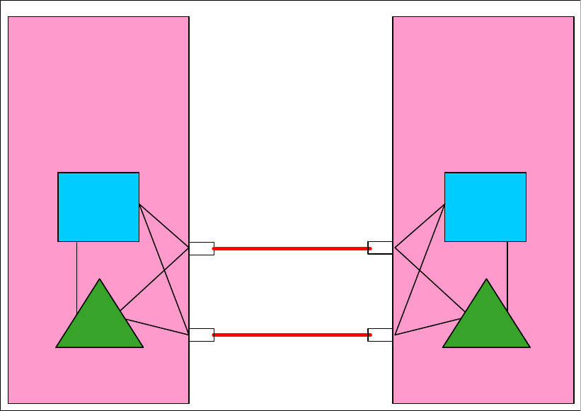
Chapter 4. Migration planning 77
Which of the two methods is the best for you depends on your sysplex configuration and your
migration objectives. Regardless of which option you choose to perform this migration,
Figure 4-3 shows the starting configuration.
Figure 4-3 Scenario 2: Starting configuration
In this scenario, two z10 EC CPCs, CPC1 and CPC2, are installed. Both CPCs have ICB4
fanouts installed and are connected using those links. The new PSIFB fanouts will be
installed alongside the ICB4 fanouts. Then the connections will be concurrently moved to the
new PSIFB links. After the PSIFB environment has been validated, the ICB4 fanouts will be
removed from the CPCs. CPC1 contains two LPARs, ZOS1 and CF1, and CPC2 contains
ZOS2 and CF2.
Option 1 - Concurrent migration using two additional CF LPARs
The advantages of this option are listed here:
The maximum number of coupling CHPIDs between a z/OS LPAR and a CF is eight. If the
configuration already has eight links to the CF, then migrating to InfiniBand links by
defining new CF LPARs and moving the structures to those new CFs might be more
attractive than having to remove some of the current CF links to free CHPIDs that would
then be used for the new InfiniBand links.
For more information about using this methodology, see Appendix D, “Client experience”
on page 253.
This option provides the ability to compare the performance of the old and new
configuration, and to be able to quickly move back to the original configuration in case of
any problems.
Only two dynamic activates are required.
IC
z10 EC
z10 EC –
–CPC2
CPC2z10 EC
z10 EC –
–CPC1
CPC1
MBA ICB 4
ICB 4ICB 4
IC
ZOS2ZOS2ZOS1ZOS1
MBAMBA
MBA
BTS PTS
CF
CF2
CF
CF2
CF
CF1
CF
CF1

78 Implementing and Managing InfiniBand Coupling Links on IBM System z
To achieve the objective of a concurrent migration, create two new CF LPARs called CF3 and
CF4. These are then connected to the z/OS LPARs using the new InfiniBand fanouts. When
the new CFs are up and available, the structures can be moved to them either together, or in
a controlled manner. At the end of the scenario the old CF LPARs can be removed.
Migration steps, using two additional CF LPARs:
1. Starting point.
The current configuration is shown in Figure 4-3 on page 77.
2. SSR starts the upgrade.
The SSR starts the concurrent MES to add the new 12x InfiniBand fanouts on both z10
ECs. When the fanouts have been installed, the required cabling is installed.
3. Update IOCDS on CPC1 and define the new LPAR profile.
The new IOCDS for CPC1 is generated and activated through the IOCDS dynamic
activate function to make the new CF3 LPAR and the 12x PSIFB coupling links available
for use, and to add the z/OS LPARs and the CF3 LPAR to the access list of those new
links. In addition, a new LPAR profile has to be created on CPC1 to allocate resources to
the new CF LPAR.
4. Update IOCDS on CPC2.
The new IOCDS for the CPC2 is generated and activated through the IOCDS dynamic
activate function to make the new CF4 LPAR and the 12x PSIFB coupling links available
for use, and to add the z/OS LPARs and the CF4 LPAR to the access list of those new
links. In addition, a new LPAR profile has to be created on CPC2 to allocate resources to
the new CF LPAR.
Note: In this example, we are not using System-Managed Structure Duplexing
(SM duplexing). If you do use this function, you need to consider the CF-to-CF link
requirements if you want to maintain the duplex relationship as you move the structures to
the new CFs.
For an example illustrating where SM duplexing is being used, see 4.6, “Scenario 4” on
page 95.
Note: This methodology requires that you have additional ICF engines and additional
memory available so that you can have all four CF LPARs up and running during the
migration.
ICF engines can be added concurrently to the LPARs if there are sufficient ICFs defined as
Reserved Processors in the LPAR profile. If you do not have unused ICFs for use by the
new CF LPARs, one option is to use Capacity on Demand (CoD) engines. Refer to
Redbooks document IBM System z10 Capacity on Demand, SG24-7504, and discuss your
options with your IBM sales representative.
Links that have been added to a CF LPAR using dynamic activate can be configured online
by the CF without any interruption to the CF activity.
Additional physical memory can be concurrently installed on the CPC ahead of time if
required. Note, however, that storage cannot be added to, or removed from, a CF LPAR
without a DEACTIVATE followed by a REACTIVATE.

Chapter 4. Migration planning 79
5. Update CFRM policy to add new CF LPAR in CPC1.
To move the structures from the old CF LPAR CF1 to the new CF LPAR CF3, the new CF
is added to the CFRM policy and the structure preference lists are modified accordingly.
For example, the CFRM policy definition for a structure might currently look like this:
STRUCTURE NAME(ISGLOCK)
INITSIZE(33792)
SIZE(33792)
PREFLIST(CF1,CF2)
To make CF3 the logical replacement for CF1, update the statements to look like this:
STRUCTURE NAME(ISGLOCK)
INITSIZE(33792)
SIZE(33792)
PREFLIST(CF1,CF3,CF2)
Update the policy with a new name “newpol1” for fallback reasons. After the policy has
been updated, the new policy is activated with the following command:
SETXCF START,POLICY,TYPE=CFRM,POLNAME=newpol1
6. New CF LPAR activation including new links on CPC1.
The CF3 LPAR on CPC1 is now activated and all the defined PSIFB links to that CF
should be brought online to both z/OS LPARs. For more details see 7.3, “Coupling Facility
commands” on page 202.
At this point, verify that you have the desired connectivity for the new CF LPAR.
You can use the HMC (see 7.2, “z/OS commands for PSIFB links” on page 191) and the
following z/OS command to check the connectivity:
RO *ALL,D CF,CFNAME=CF3
7. Move structures to CF3 CF.
After the new PSIFB links are brought online and it is verified that the new CF has the
desired connectivity, you can move the structures. To prepare for emptying out the current
CF, CF1, it is set to maintenance mode using the following command:
SETXCF START,MAINTMODE,CFNM=CF1
With CF1 now in maintenance mode, the REALLOCATE command causes all the
structures to be moved from CF1 to CF3 (assuming that is how you set up your preference
lists):
SETXCF START,REALLOCATE
Note: The IOCDS for each CPC can be prepared before the MES is started. However,
only activate it after the SSR has finished the installation of the new PSIFB fanouts.
If the new IOCDS is activated before the hardware is installed, the IOCDS definitions
will point to hardware that does not yet exist in the CPCs.
Note: If you are running z/OS 1.12 or higher, use the following command to test the
reallocation first:
D XCF,REALLOCATE,TEST
Address any problem that is detected before you reallocate the structures.
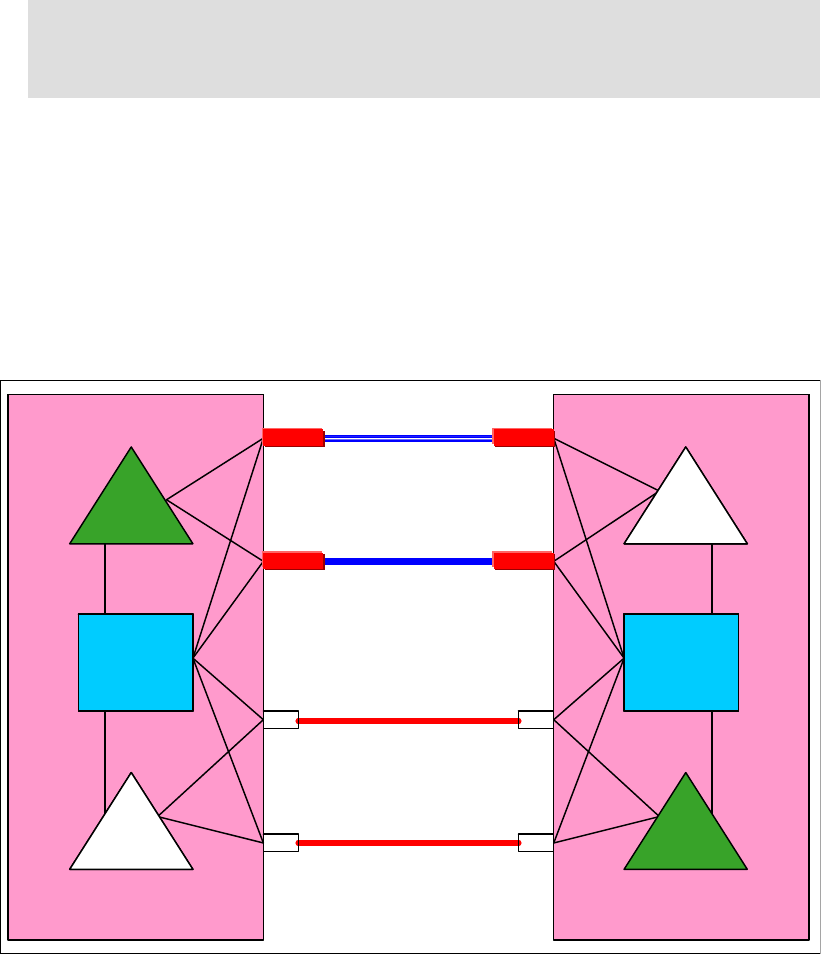
80 Implementing and Managing InfiniBand Coupling Links on IBM System z
Alternatively, you might want to move the structures in a more controlled manner (one by
one), which might be appropriate for more sensitive structures. In that case, you need to
use the following set of commands:
SETXCF START,MAINTMODE,CFNM=CF1
SETXCF START,REBUILD,STRNAME=”structure name”
8. Check that all structures have been moved.
Determine if any structures are still in CF1 by using this command:
D XCF,CF,CFNAME=CF1
If any structure did not move, check whether application-specific protocols are needed and
use these to move (or rebuild) the structure. Repeat this step until all structures have been
moved.
9. Middle step: test and decide if you will proceed with the migration.
Now you are at the middle step of the migration. Figure 4-4 shows that both CF LPARs are
defined and connected and the type of connections to each CF. At this point, both ICB4
and 12x InfiniBand links are available.
If you want to compare the performance of the different link types, this is the ideal
opportunity to do that because each system has access to both ICB4-connected and
HCA2-connected CFs, and structures can be moved between the CFs to measure and
compare the response times.
Figure 4-4 Scenario 2: Middle step of the adding additional CF LPARs scenario
Note: If you are running z/OS 1.12 or higher, review the reallocation report to more
easily determine why a structure was not moved by using this command:
D XCF,REALLOCATE,REPORT
ICB 4ICB 4
ICB 4ICB 4
ZOS2ZOS2ZOS1ZOS1
12x PSIFB12x PSIFB
12x PSIFB12x PSIFB
CF
CF2
z10 EC
z10 EC –
–CPC2
CPC2z10 EC
z10 EC –
–CPC1
CPC1
CF
CF3
CF
CF1
CF
CF1
CF
CF4
CF
CF4
ICIC
ICIC
MBAMBA
MBA
HCA2-O
HCA2-O
HCA2-O
HCA2-O
MBA
BTS PTS

Chapter 4. Migration planning 81
10.New CFRM policy definition and activation for CPC2.
Assuming that everything goes well with the migration to CF3, the next step is to replace
CF2 with CF4. This requires that the CFRM policy is updated again and activated. To allow
for fallback to the previous policy, the updated policy is given a new name, “newpol2”. The
preference list is also updated with the new CF4 information as was done earlier to add
CF3 to the PREFLISTs.
After the updates have been made, the new CFRM policy is activated using the following
command:
SETXCF START,POLICY,TYPE=CFRM,POLNAME=newpol2
11.New CF LPAR activation including new links on CPC2.
The CF4 LPAR on CPC2 is now activated and all the defined PSIFB links are configured
online. For more details see 7.3, “Coupling Facility commands” on page 202.
At this point, verify that you have the desired connectivity for the new CF LPAR. You can
use the HMC (see 7.2, “z/OS commands for PSIFB links” on page 191) and the following
z/OS commands to check the connectivity:
RO *ALL,D CF,CFNAME=CF4
RO *ALL,D XCF,CF,CFNAME=CF4
12.Structure move to CF4.
To move the contents of CF2 to the new CF (CF4), the current CF (CF2) is first set to
maintenance mode using the following command:
SETXCF START,MAINTMODE,CFNM=CF2
With CF2 in maintenance mode, the structures can now be moved using the following
command:
SETXCF START,REALLOCATE
If you want to move the structures in a more controlled way, you can move them one by
one. This might be useful for more performance-sensitive structures. In this case, use the
following set of commands:
SETXCF START,MAINTMODE,CFNM=CF2
SETXCF START,REBUILD,STRNAME=”structure name”
13.Check that all structures have been moved.
Determine if any structures have remained in the old CF by using this command:
D XCF,CF,CFNAME=CF2
If any structure did not move, check whether application-specific protocols are needed and
use these to move (or rebuild) the structure. Repeat this step until all structures have been
moved and CF1 and CF2 are both empty.
14.Clean up the configuration.
At this point, the ICB4 links and the old CF LPARs CF1 and CF2 are no longer in use and
can be removed. The first step is to remove those CFs from the CFRM policy. Then
configure the ICB4 links offline and deactivate the old CF LPARs (if not already done).
Note: If you are running z/OS 1.12 or higher, review the reallocation report to determine
why a structure was not moved by using this command:
D XCF,REALLOCATE,REPORT
82 Implementing and Managing InfiniBand Coupling Links on IBM System z
Finally, generate a new IOCDS for each CPC that does not contain those resources
(assuming that they are no longer needed). The final configuration is shown in Figure 4-6
on page 86.
Option 2 - Concurrent migration by adding PSIFB links alongside the
existing CF links
The benefits of this option (compared to adding a second set of CF LPARs) are listed here:
If System Managed Duplexing is being used, the migration can be completed without the
complexity of having to add additional CF-to-CF links.
No interrupt to any CF activity is required.
No CF policy or preference list changes are required.
Alternatively, this methodology has possible disadvantages compared to the first option:
More IOCDS dynamic activations are needed.
This method is more difficult to pursue if the configuration already has eight CHPIDs
between each z/OS and the CF.
It is more difficult to compare the performance between the old configuration and the new
configuration.
To achieve the objective of a concurrent migration, this option uses several dynamic activates
to introduce the new PSIFB links and remove the legacy CF links in several small steps. The
number of dynamic activates required depends mainly on the number of links that are
currently in use.
If there are, for example, six ICB4 links in use, and a minimum of four are needed to handle
the workload (assuming the maintenance window is set for a low utilization time), you can add
two PSIFB links (which will bring you to the maximum of eight links to the CF) with the first
IOCDS change.
In the second step, you remove four ICB4 links, leaving you with four active links (two PSIFB
and two ICB4). In the third step, you add four more PSIFB CHPIDs to the PSIFB links that
were added in the first step (so there are two physical links, each with three CHPIDs). In the
last step, you then remove the last two ICB4 links.
In the scenario described here, to avoid making it overly complex, we use a configuration with
only two links of each type. Therefore, the scenario might need to be adjusted to fit your
actual configuration by repeating several of the steps as many times as necessary.
The steps for the documented scenario are the following: first, we dynamically add two PSIFB
links between the z/OS LPARs (ZOS1 and ZOS2) and the CF LPARs CF1 and CF2. There will
be a mix of two ICB4 and two PSIFB links in the middle step of the migration. In the second
step, we remove the two ICB4 links from the configuration.
By using this method, you need to perform several dynamic IOCDS changes. However, there
will be no interruption to the CF activity (although we still advise migrating the coupling links in
a period of low CF activity), and, if you use duplexing for any structures, duplexing does not
have to be stopped.
The downside of this scenario is that it is not as easy to measure the performance of each link
type separately in the middle step when both link types are in use. Therefore, we suggest that
you carry out any desired performance measurements in advance in a test environment.

Chapter 4. Migration planning 83
You can also try using the VARY PATH command to remove one or other set of links from use
while you perform measurements, but you need to be careful that such activity does not leave
you with a single point of failure.
Concurrent migration by adding PSIFB links alongside existing CF links
1. Starting point.
Our sample configuration is shown in Figure 4-3 on page 77.
2. SSR starts MES.
The SSR starts the MES to add the new HCA2-O 12x InfiniBand fanouts on both z10 ECs.
Cabling is also done between both CPCs to connect these fanouts.
3. IOCDS change on CPC1 and CPC2.
The new IOCDSs for CPC1 and CPC2 are generated and dynamically activated. They
include the definitions for the two new PSIFB links.
4. Configure the new PSIFB links on the CF LPARs online.
The new PSIFB links are configured online on CF LPARs CF1 and CF2. Make sure that
you configure online all links, namely, those that are connecting the z/OS LPARs to the CF
LPARs, and any links that might be needed between the CF LPARs.
This is done with the following CFCC command (where xx stands for the CHPID) on the
CF console:
CON xx ONLINE
The status of the links can be verified with the CFCC command:
DISPLAY CHP ALL
See Chapter 7, “Operations” on page 189 for more details.
5. Configure the new PSIFB links online on the z/OS LPARs.
Configuring the CF end of the links online does not necessarily cause the z/OS end of the
links to come online. To ensure the z/OS CHPIDs come online, issue the following
command for each CHPID on each system that is connected to the CF:
CF CHP(xx),ONLINE
See Chapter 7, “Operations” on page 189 for more details.
6. Verify that the new PSIFB links are online.
Check the link status between the z/OS and CF LPARs and between the two CF LPARs
with the following z/OS commands:
RO *ALL,D CF,CFNM=CF1
RO *ALL,D CF,CFNM=CF2
Make sure that you check the response from each system to ensure that all expected links
are online. Also check the “REMOTELY CONNECTED COUPLING FACILITIES” section of the
Note: The IOCDS for each CPC can be prepared ahead of time of the MES, but only
activate it after the SSR finishes the installation of the new PSIFB fanouts.
Otherwise, the IOCDS definitions will point to hardware that does not yet exist in the
CPCs.
Note: It is also possible to use the “Configure Channel Path On/Off” function on the
HMC or SE to toggle the channel online.
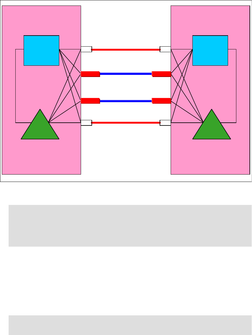
84 Implementing and Managing InfiniBand Coupling Links on IBM System z
output to ensure that all the expected CF-to-CF links are online. For more detailed
information, see 7.2, “z/OS commands for PSIFB links” on page 191.
7. Middle step: decide if you will go ahead.
Now you are at the middle step of our scenario.
Figure 4-5 shows the configuration at this point. You are now using the legacy links and
the new PSIFB links between CPC1 and CPC2.
Figure 4-5 Scenario 2: Middle step of the dynamic activation implementation
8. Configure the legacy ICB4 links on the z/OS LPARs offline.
Assuming that everything is working as expected, the next step is to remove the ICB4
links. The legacy ICB4 links are configured offline on the ZOS1 and ZOS2 LPARs. This is
done with the following z/OS command (where xx stands for the CHPID):
CF CHP(xx),OFFLINE
This command must be issued on each z/OS system, and for each ICB4 link.
See Chapter 7, “Operations” on page 189 for more details.
Note: As mentioned, it is difficult to compare the performance between the old and new
configuration while we are using both coupling link technologies together. Perform
testing in a separate test environment with production levels of loads before the start of
the production migration to determine whether the new PSIFB links are capable of
taking over the complete workload from the ICB4 links with acceptable response times.
Note: It is also possible to use the “Configure Channel Path On/Off” function on the
HMC or SE to toggle the CHPIDs offline.
IC
z10 EC
z10 EC –
–CPC2
CPC2
z10 EC
z10 EC –
–CPC1
CPC1
ICB 4
ICB 4
IC
12x PSIFB
12x PSIFB
ZOS2ZOS2ZOS1ZOS1
CF
CF1
CF
CF2
MBA
MBA
MBA
MBA
HCA2-O
HCA2-O
HCA2-O
HCA2-O
BTS PTS
CF
CF1
CF
CF2
Chapter 4. Migration planning 85
9. Configure the legacy ICB4 links on the CF LPARs offline.
The legacy ICB4 links are configured offline on the CF1 and CF2 LPARs. Make sure that
you configure offline all links, those that are connecting the z/OS LPARs to the CF LPARs,
and the links between the CF LPARs.
This is done with the following CFCC command (where xx stands for the CHPID) on the
CF console:
CON xx OFFLINE
Then check the status with the CFCC command:
DISPLAY CHP ALL
See also Chapter 7, “Operations” on page 189 for more details.
10.Verify that the legacy ICB4 links are offline.
Check the link status between the z/OS and CF LPARs and the SM duplexing links
between the two CF LPARs with the following z/OS commands:
RO *ALL,D CF,CFNM=CF1
RO *ALL,D CF,CFNM=CF2
Remember to check the response from all systems, and to ensure that the ICB4 CF-to-CF
links are also offline. For more detailed information, see 7.2, “z/OS commands for PSIFB
links” on page 191.
11.Remove the ICB4 links in the IOCDS on CPC1 and CPC2.
A new IOCDS for CPC1 and CPC2 is generated and dynamically activated to remove the
definitions for the ICB4 coupling links.
12.Depending on your configuration, you will need to repeat steps 3 to 11 to bring in more
PSIFB links and to remove legacy ICB4 links. Also, the number of links you add and
remove per dynamic activate depends on your configuration and your performance
requirements.
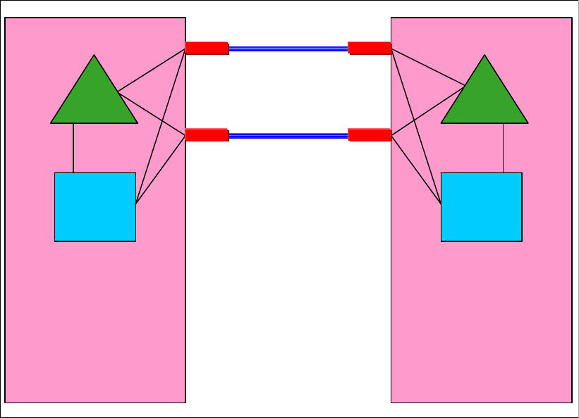
86 Implementing and Managing InfiniBand Coupling Links on IBM System z
After all steps are complete, the final configuration for our example is as shown in Figure 4-6.
Figure 4-6 Scenario 2: Final configuration
4.5 Scenario 3
Concurrent CPC and link upgrade
This scenario describes how to concurrently implement the InfiniBand coupling technology
while upgrading a System z server at the same time. It shows a two-CPC configuration, with
one CF LPAR in each CPC. One CPC is a z9 EC and the other is a z10 EC.
The new InfiniBand technology is implemented at the same time that the z9 EC CPC is
upgraded to a z196 CPC. This scenario is similar to 4.3, “Scenario 1” on page 68, with several
important differences:
The InfiniBand coupling technology has not yet been implemented in any of the CPCs at
the start of the scenario.
This implementation scenario is designed to be concurrent, which means that the CF
LPAR and the z/OS LPAR on the z10 EC continue to be available throughout the
migration.
This scenario carries over the old coupling technology from the z9 EC to the z196 purely
for the purpose of fallback in case of problems.
In practice, the performance of any InfiniBand link is so much better than the ISC3 links
that are used in this scenario that it is unlikely that there will be any reason to fall back to
the ISC3 links. Nevertheless, we included that option in this scenario to help those that
might prefer to have an easier fallback capability.
ZOS2ZOS2ZOS1ZOS1
12x PSIFB12x PSIFB
12x PSIFB12x PSIFB
z10 EC
z10 EC –
–CPC2
CPC2z10 EC
z10 EC –
–CPC1
CPC1
CF
CF1
CF
CF2
ICIC
HCA2-O
HCA2-O
HCA2-O
HCA2-O
BTS PTS
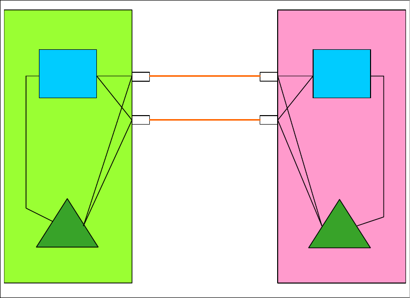
Chapter 4. Migration planning 87
Figure 4-10 on page 96 shows the starting configuration.
Figure 4-7 Scenario 3: Starting configuration
This option performs the migration by performing two dynamic activations on the z10 EC, one
to add the new InfiniBand links, and a second one to remove the legacy links. In this scenario,
there is a z/OS system on both CPCs, so that gives more flexibility in terms of being able to
activate new configurations without having to interrupt either of the CFs.
In this scenario, the z9 EC CPC is upgraded to a z196 CPC and HCA3-O LR 1X adapters are
added to eventually replace the existing ISC3 links. At the same time, HCA2-O LR 1X
InfiniBand fanouts are installed in the z10 EC. The z9 EC needs to be powered off for the
“frame roll MES” upgrade. Therefore, the CF1 LPAR and the ZOS1 LPAR are going to be shut
down. However, the CF2 and ZOS2 LPARs on the z10 EC will remain up throughout the
process.
To avoid unnecessary complexity, this scenario assumes that two ISC3 links are being used
in the current configuration, and they will be replaced with two 1X InfiniBand links, bringing
the total number of links between the two CPCs to four in the period when both link types are
defined. If eight ISC3 links were in use in the current configuration, you have two options:
Create a migration configuration with a reduced number of ISC3 links, and some
InfiniBand links.
Create two configurations: one with only the PSIFB links, and a fallback configuration with
only the eight ISC3 links.
The first option has the advantage of making it easier to switch back and forth between the
ISC3 and InfiniBand links (all you need to do is configure on or off whichever links you do or
do not want to use).
ISC
ISC
IC
z10 ECz9 EC
ISC
ISC ISC 3
ISC 3
IC
ZOS2ZOS2
CF
CF1
CF
CF2
ZOS1ZOS1
BTS PTS
88 Implementing and Managing InfiniBand Coupling Links on IBM System z
The second option gives you the ability to switch back to a configuration of only ISC3 links
after the CPC upgrade. However, the CF needs to be emptied during the switch.
In both cases, you also create a configuration consisting of only InfiniBand links. This is the
configuration that will be your production one at the end of the migration.
The upgrade of the z9 is done as a “frame roll MES”, which means that the frames of the z9
will be replaced with the new frames of the z196 but the serial number will stay the same. Due
to the nature of a frame roll MES, the CPC that is being upgraded will always have to be
powered off.
The upgrade might involve transferring several I/O cards or fanouts to the new frame. In this
scenario, the ISC3 links are being kept so the ISC3 cards will be carried forward to the z196.
New HCA3-O LR 1X fanouts are ordered for the z196 because these fanouts types are the
only fanouts for Long Reach (1x PSIFB) InfiniBand connections that are supported on z196
CPCs at GA2 level.
Additionally, new HCA2-O LR 1X fanouts are installed in the z10 EC because these fanout
types are the only fanouts for Long Reach (1x PSIFB) InfiniBand connections that are
supported on z10 CPCs. The two fanout types are compatible with each other.
To reach the objective of a concurrent implementation, two sets of dynamic activations are
required:
One to introduce the new PSIFB links to the z10 EC
One on each of the z10 EC and the z196 at the end of the migration to remove the ISC3
links
The specific changes that are implemented in each dynamic activate depend mainly on the
number of links in use and the setup for a fallback scenario. In the example we use here, the
starting configuration consists of two ISC3 links between the CPCs. Two InfiniBand links will
be added, resulting in a configuration with two ISC3 links and two InfiniBand links. So the first
dynamic activate is to move to that configuration. When the InfiniBand links have been fully
tested and the performance has been deemed acceptable, a second dynamic activate is
performed to remove the ISC3 links.
Concurrent implementation steps using dynamic activates
1. Starting point.
Our current configuration is shown in Figure 4-7 on page 87.
2. The CFRM policy is updated.
Because the z9 EC is being upgraded to a z196, the CFRM policy needs to be updated.
The changes that you need to make depend on whether you plan to use the same name
for the z196 CF. The CPC serial number will remain the same because this is an upgrade
MES, but the CPC type is going to change and that needs to be reflected in the CFRM
policy.
The structure sizes will also have to be updated because the new z196 will run a different
Coupling Facility Control Code (CFCC) level. To determine the correct sizes, use the
CFSizer or Sizer tools. The correct structure sizes will avoid performance problems
resulting from constraint structure spaces and application restarting problems.
Update the policy with a new name (for example, “newpol”) for fallback reasons.

Chapter 4. Migration planning 89
3. Update HCD for the new z196 and create the z196 IOCDS.
The new IOCDS for the z196 is generated and saved to the z9. The IOCDS will be carried
forward during the upgrade to the z196 by the System Service Representative (SSR). This
is the most convenient way to install an IOCDS on an upgraded CPC.
4. Prepare IOCDS for the z10 EC.
Update the IOCDS for the z10 EC to include the new PSIFB links.
5. Move all workload off the ZOS1 LPAR.
Make sure that all applications that are required during the upgrade window are running
successfully in the z/OS LPAR on the z10 EC.
6. Shut down and deactivate the z9 EC z/OS LPAR.
After all critical applications have been moved to the other z/OS system and all other
workload has been stopped in an orderly manner, partition the ZOS1 system out of the
sysplex using the following command:
V XCF,sysname,OFFLINE
After the system is down, deactivate the ZOS1 LPAR.
7. Place the CF in the z9 EC in maintenance mode.
To prepare for shutting down the CF in the z9 EC, place that CF in maintenance mode so
that all structures can be moved to the surviving CF (CF2). This is achieved using the
following z/OS command:
SETXCF START,MAINTMODE,CFNM=CF1
8. Empty the CF in the z9 EC.
Move the structures that currently reside in CF1 into CF2 on the z10 EC by using the
following command:
SETXCF START,REALLOCATE
Note: The IOCDS can be prepared ahead of time to minimize the length of the
maintenance slot.
Note: The IOCDS can be prepared ahead of time, but only activate it after the SSR has
finished the installation of the new PSIFB fanouts.
If you activate the new configuration before the hardware has been installed, the
IOCDS definitions will point to hardware that does not yet exist in the CPCs and this
might cause confusing messages.
Note: If you are running z/OS 1.12 or higher, use the new option to test the reallocation
first by using this command:
D XCF,REALLOCATE,TEST
Address any problem that is detected before you reallocate the structures.

90 Implementing and Managing InfiniBand Coupling Links on IBM System z
9. Set the z9 EC CF logically offline to all z/OS LPARs
Placing CF1 in MAINTMODE and ensuring that the REALLOCATE command was
successful can ensure that no structures are left in CF1. However, to be completely sure
that no active structures remain in the CF, it is prudent to take the CF logically offline to all
connected z/OS systems before shutting it down.
This is achieved using the following command in each z/OS system:
V PATH(CF1,xx),OFFLINE (you will have to add the UNCOND option for the last CHPID).
This has the effect of stopping the issuing z/OS from being able to use the named CF. If
this z/OS is still connected to any structure in the CF, the command will fail.
Note that this command does not make the named CHPIDs go offline; it is simply access
to the CF that is removed. The CHPIDs will be taken offline later.
If you issue a D CF,CFNM=CF1 command at this time, you will see that each CHPID still
shows as being physically ONLINE, but logically OFFLINE.
10.Verify that all structures have been moved.
Determine if any structures have remained in the CF by using this command:
D XCF,CF,CFNAME= CF1
If any structure did not move, check if application specific protocols might be needed and
use these to move (or rebuild) the structure. Repeat this step until all structures have been
moved.
11.Shut down CF1.
Deactivate the CF1 LPAR. Assuming that the CF is empty, use the SHUTDOWN command
from the CF1 console on the HMC. The advantage of using a SHUTDOWN command,
compared to deactivating the LPAR using the HMC DEACTIVATE function, is that the
SHUTDOWN command will fail if the CF is not empty. The end result of the SHUTDOWN is
effectively the same as the end result of performing a DEACTIVATE, so it is not necessary
to perform a DEACTIVATE of a CF LPAR that was successfully shut down using the
SHUTDOWN command.
If the CF still contains one or more structures, but the decision has been made that the
instance of the structure does not need to be moved or recovered, the SHUTDOWN command
will not complete successfully, so DEACTIVATE the CF LPAR instead.
12.STP-related preparation.
Note the current STP definitions and the STP roles (CTS, PTS, BTS, and Arbiter) before
any changes are made, so they can be reinstated later.
For more details see the Redbooks document Server Time Protocol Recovery Guide,
SG24-7380, and the white paper Important Considerations for STP and Planned
Disruptive Actions available on the web at:
http://www.ibm.com/support/techdocs/atsmastr.nsf/WebIndex/WP102019
To better protect a sysplex against potential operational problems, STP prevents the
shutdown of a zEnterprise or System z10 CPC that has any STP role assigned. This
change is documented in the white paper Important Considerations for STP server role
assignments, available on the web at:
http://www.ibm.com/support/techdocs/atsmastr.nsf/WebIndex/WP101833
Note: If you are running z/OS 1.12 or higher, review the reallocation report to determine
why a structure was not moved by using this command:
D XCF,REALLOCATE,REPORT

Chapter 4. Migration planning 91
As a result of this change, you need to remove the STP server roles in the STP
configuration panel before the CPCs are shut down. Remove the Arbiter role first (not
applicable in this scenario) and then the BTS role4.
To implement the role changes, check the setting of the option called “Only allow the
server(s) specified above to be in the CTN”5 in the STP network configuration tab on the
HMC:
– If this option is currently selected:
• It must be cleared so that the BTS role can be removed from the z9 (because no
server role assignment changes can be made if this option is enabled).
• Remove the BTS role from the z9.
– If this option is not selected:
• Remove the BTS role from the z9.
Note the original setting of this option, because it is required in step 22.
When the z9 is upgraded to a z196, the STP definitions on that CPC will need to be
updated to specify the name of the CTN that the CPC is to join. If you remove the z9 from
the CTN prior to powering it down, you will be able to configure offline all coupling links
between the two CPCs because they are no longer being used by STP.
To remove the z9 from the CTN, logon to the z9 SE, go into the System (Sysplex) Time
option, select the STP Configuration tab and blank out the Coordinated timing network ID
field.
Finally, select the “Only allow the server(s) specified above to be in the CTN” option on the
HMC so that after the POR, the CTN configuration will be remembered.
13.Configure offline all paths to the z9 EC CPC
Now that all LPARs on the z9 EC are down, configure offline all coupling links to that CPC.
To do this, issue the following command for each CHPID going to CF1, for each z/OS
LPAR that is communicating with CF1:
CONFIG CHP(xx),OFFLINE
Because the CF1 LPAR is down at this point, it should not be necessary to use the
CONFIG CHP(xx),OFFLINE,UNCOND command for the last CHPID from each z/OS LPAR to
CF1.
Note that each z/OS LPAR might use different CHPIDs to connect to CF1, so ensure that
you configure the appropriate CHPIDs for each LPAR (in our example, there is only one
z/OS at this point, ZOS2).
After issuing all the CONFIG CHP commands, issue a D CF,CFNM=CF1 command from each
connected z/OS to ensure that all the CHPIDs to that CF are now both logically and
physically offline to that LPAR.
When the CONFIG OFFLINE command is issued for a z/OS CHPID, the z/OS end of the link
will be taken offline. However, the CF end will remain online. In this scenario, that is not an
issue because the CPC containing CF1 is going to be replaced.
4 The PTS should always be the last CPC to be shut down, and the first CPC to be restarted, so ensure that the CPC
that is not being upgraded is the one that is the PTS. Therefore, prior to making any other STP-related changes,
make the CPC that is not being upgraded the PTS if that is not already the case. In this example, that is the
z10 EC. If you need to make changes to the STP configuration to achieve this, work those changes into the
process described here.
5 Enabling this option causes the CTN’s timing and configuration settings to be saved so that they will not need to be
re-entered after a loss of power or a planned POR of the servers.

92 Implementing and Managing InfiniBand Coupling Links on IBM System z
To cleanly configure offline all the links to CPC1, also configure offline the CF end of any
coupling links to CPC1.To do this, issue the following command on CF2 for each CHPID to
CPC1:
CON xx OFF
Finally, use the z10 SE to check if there are any remaining coupling links online to the z9.
Any such VCHIDs or PCHIDs should be toggled offline now using the HMC.
14.Power off the z9 EC.
15.The SSR performs the upgrade of the z9 EC to the z196 and the concurrent installation of
the new PSIFB fanouts on the z10 EC.
16.Activate the updated IOCDS on the z10 EC.
Perform a dynamic activate on the z10 EC with the prepared IOCDS to include the new
PSIFB links.
17.Start the new z196.
After all the hardware rework and cabling is complete, power on the new z196 and
perform a POR.
18.The updated CFRM policy is activated.
Activate the CFRM policy that you updated earlier. This is done using the following
command:
SETXCF START,POLICY,TYPE=CFRM,POLNAME=newpol
19.Place CF1 in maintenance mode again.
Because the CPC type of CF1 has changed, the maintenance mode flag for that CF will be
automatically reset. To control the movement of structures back into that CF1, place the
CF back in maintenance mode using the following command:
SETXCF START,MAINTMODE,CFNM=CF1
20.Bring coupling links to z196 back online.
Before the systems on the z196 can join the sysplex, the z196 must be brought back into
the CTN. For the z196 to join the CTN, there must be online coupling links between the
two CPCs.
Because you configured the CF2 end of all links to CPC1 offline in step 13, you will need
to bring them back online before they can be used by CF2. To achieve this, issue the
following command on the CF2 console for each of the CHPIDs that is connected to an
LPAR in CPC1:
CON xx ONLINE
You also need to bring the z/OS-to-CF1 links back online. Because you took the links
logically offline earlier using the V PATH command, they must be brought logically online
again. Do this using the following command (for each CHPID that is used to connect to
CF1):
V PATH(cfname,xx),ONLINE
Bring all links to CF1 (both the original ISC3 links and the new PSIFB links) physically
online using the following command for each CHPID:
CF CHP(xx),ONLINE
Note: The creation or update of the CFRM policy can be performed ahead of the time
of the actual maintenance window to minimize the interruption.

Chapter 4. Migration planning 93
Use the HMC to verify the correct status of all CF links.
21.Add CTN ID to the z196.
In this step and the next one, we will be making changes to the STP configuration, so the
“Only allow the server(s) specified above to be in the CTN” option must be disabled on the
z10 HMC before proceeding.
Because the z196 is considered to be a new CPC by STP, you must logon to the z196
HMC, select the System (Sysplex) Time option, and enter the CTN ID on the STP
Configuration tab.
After the CTN ID of the z196 has been added, use the STP panels on the z10 and z196 to
ensure that the change was successful and that both CPCs are now in the CTN.
22.STP roles.
Define or reassign the STP roles that were removed or reassigned in step 12.
After all required STP changes have been made, the “Only allow the server(s) specified
above to be in the CTN” option should be returned to the original setting as noted in
step 12.
23.Activate CF1 LPAR.
Now that the coupling links between the two CPCs are online and the z196 is in the same
CTN as the z10 EC, activate the CF1 LPAR.
Log on to the CF1 console and using the following command to ensure that all the links to
the z10 EC LPARs are online:
DISP CHP ALL
24.Start the z/OS LPAR on the new z196.
Activate and load the ZOS1 LPAR on the new z196.
When the system has finished initializing, issue the following commands on all z/OS
systems to ensure that they have the expected connectivity to the z196 CF, and that the
z/OS system on the z196 has access to the z/OS systems on the z10 EC:
D XCF,CF,CFNM=ALL
D CF
25.Prepare to move structures back into CF1.
Before structures can be allocated in CF1, that CF must be taken out of maintenance
mode. To do this, issue the following command:
SETXCF STOP,MAINTMODE,CFNM=CF1
To ensure that the command completed successfully and that the CF is now available for
use, issue the following command (this only has to be issued on one z/OS system):
D XCF,CF,CFNM=ALL
The response should show that all systems are connected to the CF, and that it is not in
maintenance mode.
Note: It is also possible to use the “Configure Channel Path On/Off” function on the
HMC or SE to toggle the channel online. See Chapter 7, “Operations” on page 189 for
more details.
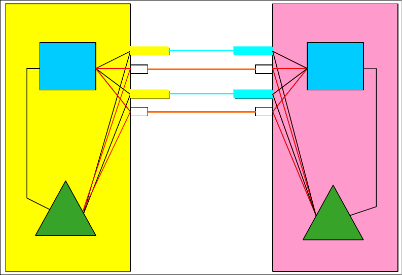
94 Implementing and Managing InfiniBand Coupling Links on IBM System z
26.Repopulate CF1.
To bring everything back to its normal state, move all the structures that normally reside in
CF1 back into that CF1. This is achieved by issuing the following command:
SETXCF START,REALLOCATE
When the command completes, issue a D XCF,REALLOCATE,REPORT command (if running
on z/OS 1.12 or later) or check the output from the REALLOCATE command to ensure that all
structures are now in the correct CF.
27.Middle step of the implementation.
See Figure 4-8 for the configuration at the middle step.
Assuming that your configuration contains both ISC3 and PSIFB links at this point, and
that everything is working as you expect, take the ISC3 CHPIDs offline in all LPARs, so
that you are sure that the PSIFB links are being used.
Decide whether you can go ahead with the implementation. In case of major problems
with the PSIFB links, this is the point to decide whether a fallback is needed.
Figure 4-8 Scenario 3: Middle step of the implementation using dynamic activates
28.Configure all ISC3 links offline.
In preparation for removing the ISC3 from the IOCDS and physically removing them from
the CPCs, ensure that the ISC3 CHPIDs are offline in all z/OS and CF LPARs, and
confirm the offline state using the HMC or SE.
29.Remove ISC3 links from IOCDS and dynamically activate new IOCDS.
Update the IOCDS for both CPCs to remove the legacy CF links and perform a dynamic
activate to move to the IOCDS that no longer contains the ISC3 links.
At this point, the SSR can remove the legacy CF link hardware concurrently from both
CPCs if desired.
ISC
ISC
IC
z10 ECz196
ISC 3
ISC 3
IC
ZOS2ZOS2
CF
CF2
HCA2-O LR
HCA2-O LR
HCA3-O LR
HCA3-O LR
1x PSIFB
1x PSIFB
CF
CF1
ZOS1ZOS1
BTS PTS
ISC
ISC
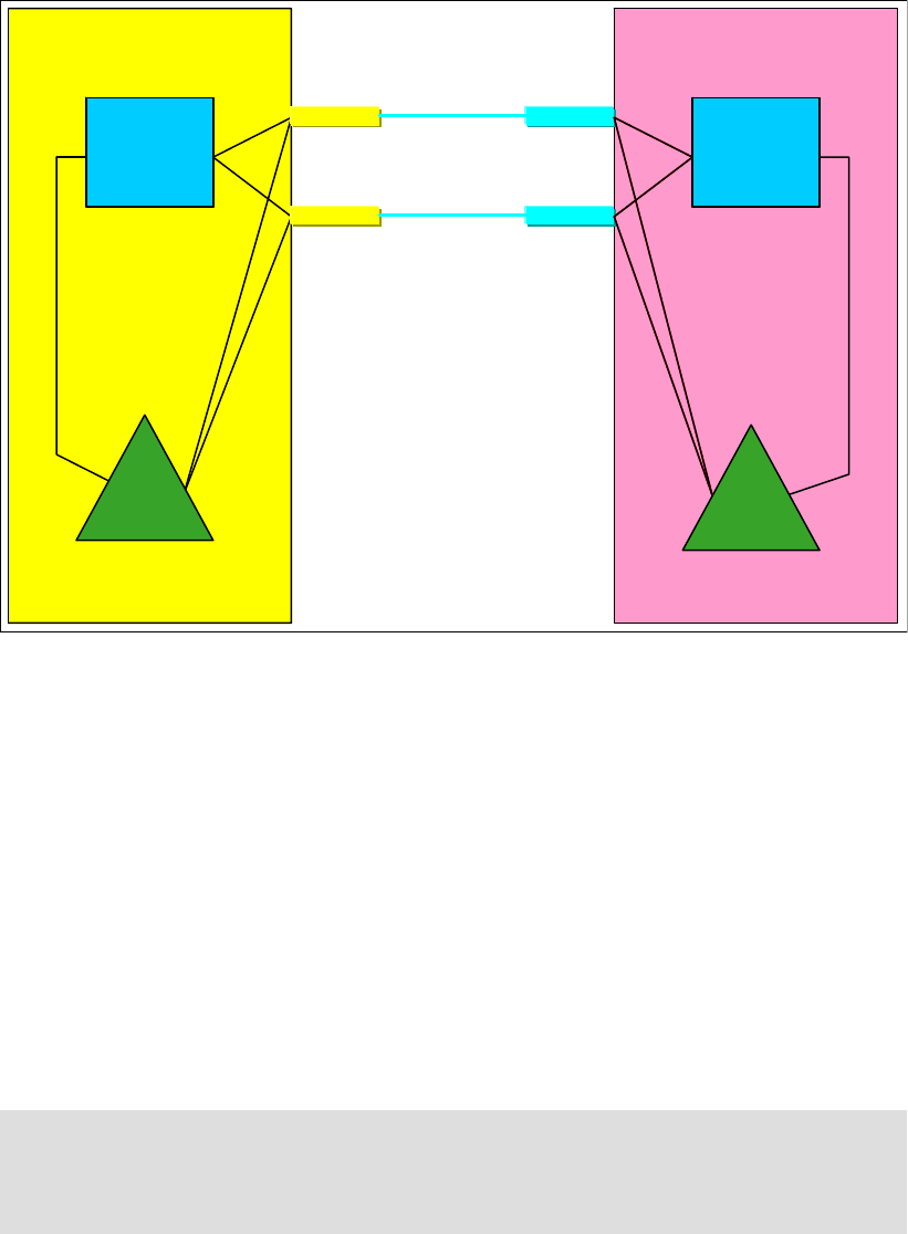
Chapter 4. Migration planning 95
Figure 4-9 shows the final configuration.
Figure 4-9 Scenario 3: Final configuration of the adding new PSIFB links alongside existing CF links
scenario
4.6 Scenario 4
Concurrent PSIFB implementation (stand-alone CFs)
This scenario describes how to concurrently migrate legacy coupling links to InfiniBand
coupling links in a configuration with stand-alone CFs. In this scenario, we have a two-site
sysplex configuration with one stand-alone Coupling Facility in each site. The CPCs in one
site are connected with ICB4 links. The CPCs in the other site are currently connected using
ISC3 links, and all links between the two sites are also ISC3. All links will be replaced with
appropriate PSIFB links.
The migration objective is to implement the new coupling link technology without interruption
to the z/OS LPARs. Figure 4-10 on page 96 shows the starting configuration.
IC
z10 ECz196
IC
ZOS2ZOS2
CF
CF2
HCA2-O LR
HCA2-O LR
HCA3-O LR
HCA3-O LR
1x PSIFB
1x PSIFB
CF
CF1
ZOS1ZOS1
BTS PTS
Note: To make the figures easier to understand, the drawings for this scenario only show
one link between each pair of CPCs. However, to avoid a single point of failure, always
have at least two links between each pair of CPCs. We are assuming that multiple links are
installed.
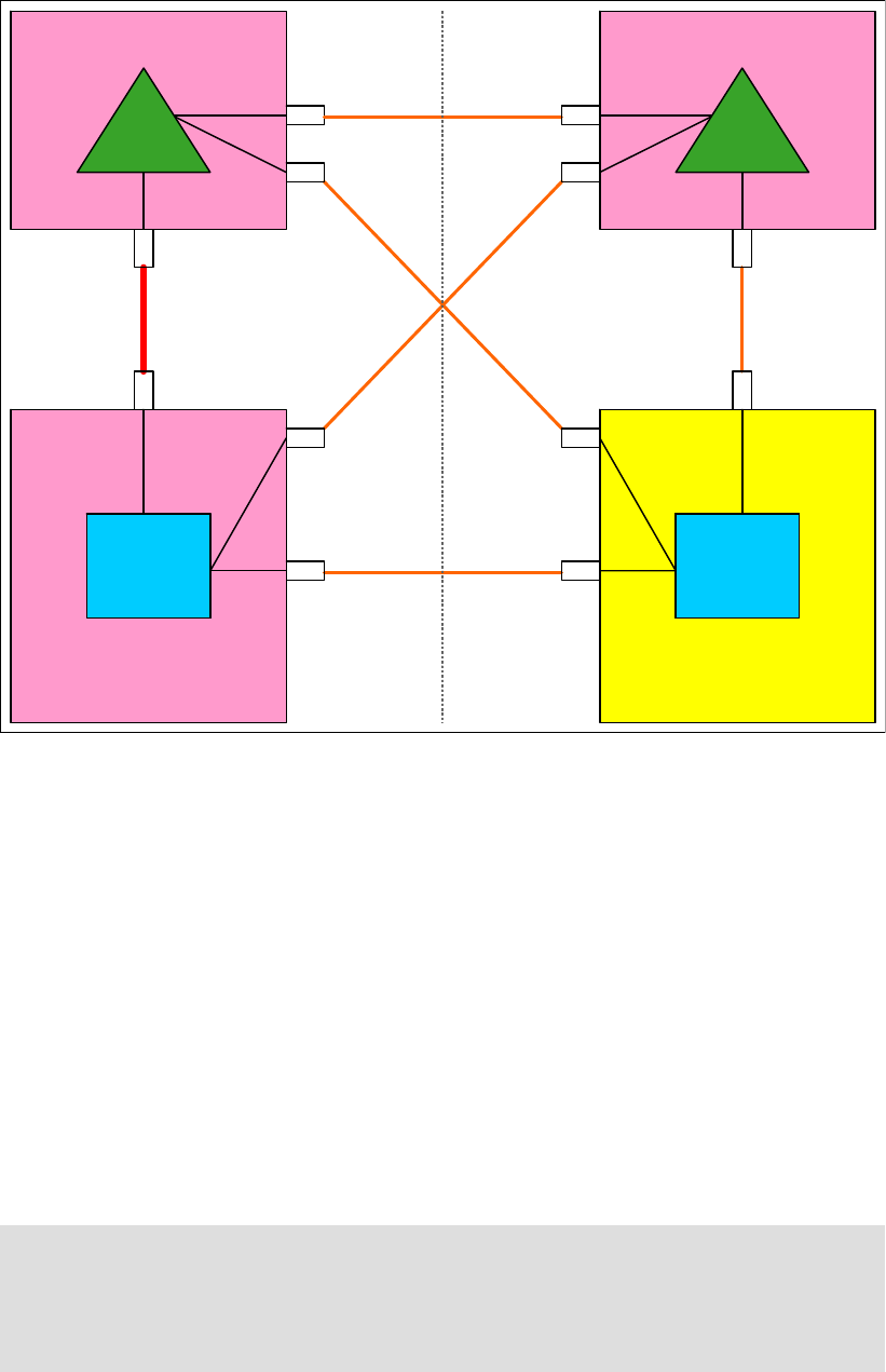
96 Implementing and Managing InfiniBand Coupling Links on IBM System z
Figure 4-10 Scenario 4: Starting configuration
In this scenario, a z10 EC server (CPC1), a z196 server (CPC4) and two z10 EC servers
acting as stand-alone CFs (CF01 and CF02) are installed. Two z/OS LPARs (“ZOS1” and
“ZOS2”) are in use and reside in CPC1 and CPC4 accordingly. The stand-alone CF CPCs
each have one CF LPAR (“CF1” on CF01 and “CF2” on CF02). CPC1 and CF01 are
connected by ICB4 links. All other connections between the CPCs are currently using ISC3
links. They will all be replaced by PSIFB links.
The plan is to concurrently migrate the ICB4 links to 12X InfiniBand links. The cross-site ISC3
links will be replaced with 1X LR InfiniBand links. And the ISC3 links between CPC4 and
CF02 will be replaced with 12X InfiniBand links.
Because we have two stand-alone CFs in this scenario, we cannot perform dynamic IOCDS
changes on those CPCs. We need to perform a power-on reset (POR) to add the new PSIFB
links to the stand-alone CF CPCs. To complete the migration, two PORs, one for each CF
CPC, are required. Therefore, our plan is to separate all changes into two maintenance
windows, one for each CF CPC.
Note: The two CPCs in site two are connected by ISC3 links. Those CPCs reside in the
same data center but not the same computer room, and are therefore located further apart
than the maximum of seven meters that ICB4 links support. Due to the longer distances
supported by 12X InfiniBand links, those ISC3 links will be replaced by 12X InfiniBand links
as part of the migration project.
z196
z196 –
–CPC4
CPC4
z10 EC
z10 EC –
–CPC1
CPC1
ZOS2ZOS2ZOS1ZOS1
ISC
ISC 3
z10 EC
z10 EC –
–CF01
CF01 z10 EC
z10 EC –
–CF02
CF02
ISC 3
Site 1 Site 2
ISC ISC
ISC 3
ISC 3
ISC 3
CF
CF2
ICB 4
MBA
CF
CF1
Timing only
MBA
ISC
ISC ISC
ISC ISC
ISC ISC
PTS BTS
ARB

Chapter 4. Migration planning 97
For this scenario, we have the following considerations:
Dynamic IOCDS activations cannot be performed on stand-alone CFs. This capability is
only available on CPC1 and CPC4.
Dynamic activations will be used to implement the hardware changes on the z/OS CPCs.
This scenario is more complex if every system already had eight links to each CF.
No CF policy or preference list changes are required.
This scenario provides the opportunity to compare the performance of the legacy and
InfiniBand links. In the middle step of the scenario (between the two maintenance slots)
one of the CFs will be connected using both PSIFB and legacy links. The other
stand-alone CF is still connected to all z/OS LPARs by only legacy coupling links.
By configuring one set or the other set of CHPIDs offline, or by moving structures from one
CF to the other, you can compare the performance of either link type.
Migration steps for the first maintenance window with planned POR for CF01
1. Starting point.
Our current configuration is shown in Figure 4-10 on page 96.
2. Create a new production input/output definition file (IODF) that contains all the new
InfiniBand CHPIDs.
Even though no changes will be made to the CF02 CPC during the first maintenance
window, create an IODF that reflects the final configuration (one that retains the legacy
links; they will be removed at a later time).
Remember that every defined PSIFB CHPID must be connected to another CHPID to be
able to create a production IODF. If you do not define the links on CF02 at this time, you
will not be able to define the other end of those links, either. Adding those links later
requires a second POR of CF01 to add the links from CF01 to CF02.
The IOCDSs for all four CPCs should be saved to their respective CPCs at this time. The
IOCDS for CF02 should also be saved to the CPC at this time, even though it will not be
activated until the second maintenance window.
3. Move PTS function to alternate CPC.
Unlike the previous scenarios, this scenario has more than two CPCs, so there is an STP
PTS, a BTS, and an Arbiter. At the start of the scenario, CPC1 does not have a specific
STP role; however, it has been designated as the alternate location for the PTS role if
CF01 needs to be taken down for some reason.
Because CF01 is going to be PORed, the PTS role should be moved from CF01 to CPC1.
Because there are more than two CPCs in the CTN, the “Only allow the server(s) specified
above to be in the CTN” option does not apply, so no changes are required to that option.
To move the PTS role to CPC1:
– Log on to the HMC.
– Select the CPC1 system (this change must be done from the CPC that is going to
become the PTS).
– Open the Configuration option.
– Select the System (sysplex) Time option.
– Select the Network Configuration tab, as shown in Figure 4-11 on page 98.
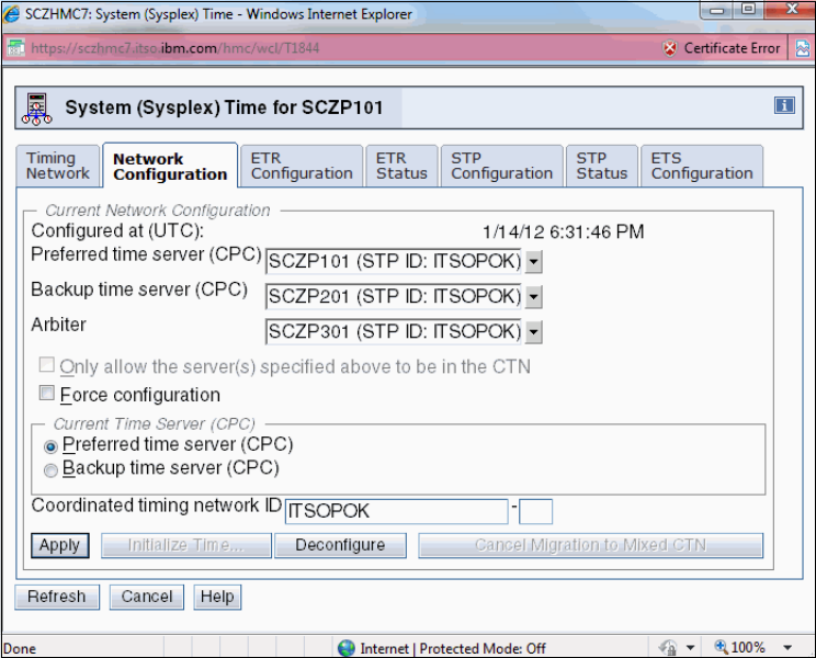
98 Implementing and Managing InfiniBand Coupling Links on IBM System z
Figure 4-11 STP Network Configuration tab
– In the Preferred time server (CPC) drop-down menu, select CPC1 and press Apply.
This will move the PTS role to CPC1 after verifying that CPC1 has the required
connectivity.
For more information about managing the STP roles, see the Redbooks document Server
Time Protocol Recovery Guide, SG24-7380.
4. Prepare to empty all structures out of CF1.
We need to move the structures out of the CF LPAR on CF01 because the implementation
of the PSIFB links on this stand-alone CF CPC requires a POR to activate the updated
IOCDS. To empty out the CF LPAR “CF1”, it is first set to maintenance mode using the
following command:
SETXCF START,MAINTMODE,CFNM=CF1
5. Move structures to CF2.
We now move all structures to CF2 using this command:
SETXCF START,REALLOCATE
All simplex structures will be moved from CF1 to CF2. Duplexed structures will transition to
simplex mode, with the surviving instance being in CF2.

Chapter 4. Migration planning 99
6. Take CF1 logically offline to all systems.
To ensure that there are no structures left in CF1 and that it is not currently being used by
any system, use the following command on each connected system to remove access to
the CF:
VARY PATH(CF1,xx),OFFLINE,UNCOND
Issue this command for each CHPID, bearing in mind that different systems might be
using different CHPIDs to access the CF.
Because no changes are being made to the legacy links at this time, it is not necessary
physically configure them offline using the CONFIG command.
7. Check that CF1 is empty and offline to all systems.
Determine if any structures have remained in the CF by using this command:
D XCF,CF,CFNAME=CF1
The response shows that the CF is in maintenance mode, and contains the following
messages:
NO SYSTEMS ARE CONNECTED TO THIS COUPLING FACILITY
and
NO STRUCTURES ARE IN USE BY THIS SYSPLEX IN THIS COUPLING FACILITY
If any structure did not move, check whether application-specific protocols are needed and
use these to move (or rebuild) the structure. Repeat this step until all structures have been
moved.
8. Shut down CF1 LPAR.
In preparation for the POR of the CF01 CPC, shut down the CF1 LPAR now.
The CF should be empty because all structures were moved to CF2. Therefore, issue the
SHUTDOWN command from the CF console, rather than using the HMC DEACTIVATE
function to stop the CF1 LPAR.
9. The SSR starts the upgrade on CF01, CPC1, and CPC4.
The SSR is going to add the PSIFB fanouts for the following links:
– HCA2-O 12X IFB links on CPC1 to connect to CF01.
– HCA2-O LR 1X links on CPC1 to connect to CPC4 and CF02 (the cables going to
CF02 will not be connected at this time because the corresponding adapter on CF02
will not be installed until the second maintenance window).
– HCA2-O 12X IFB links on CF01 to connect to CPC1.
– HCA2-O LR 1x links on CF01 to connect to CF02 and CPC4 (the cables going to CF02
will not be connected at this time because the corresponding adapter on CF02 will not
be installed until the second maintenance window).
– HCA3-O LR 1X links on CPC4 to connect to CPC1 and CF01.
Note: If you are running z/OS 1.12 or higher, use the following command to test that the
reallocation will complete successfully:
D XCF,REALLOCATE,TEST
Address any problems that might be detected before you proceed with the
SETXCF START,REALLOCATE command.
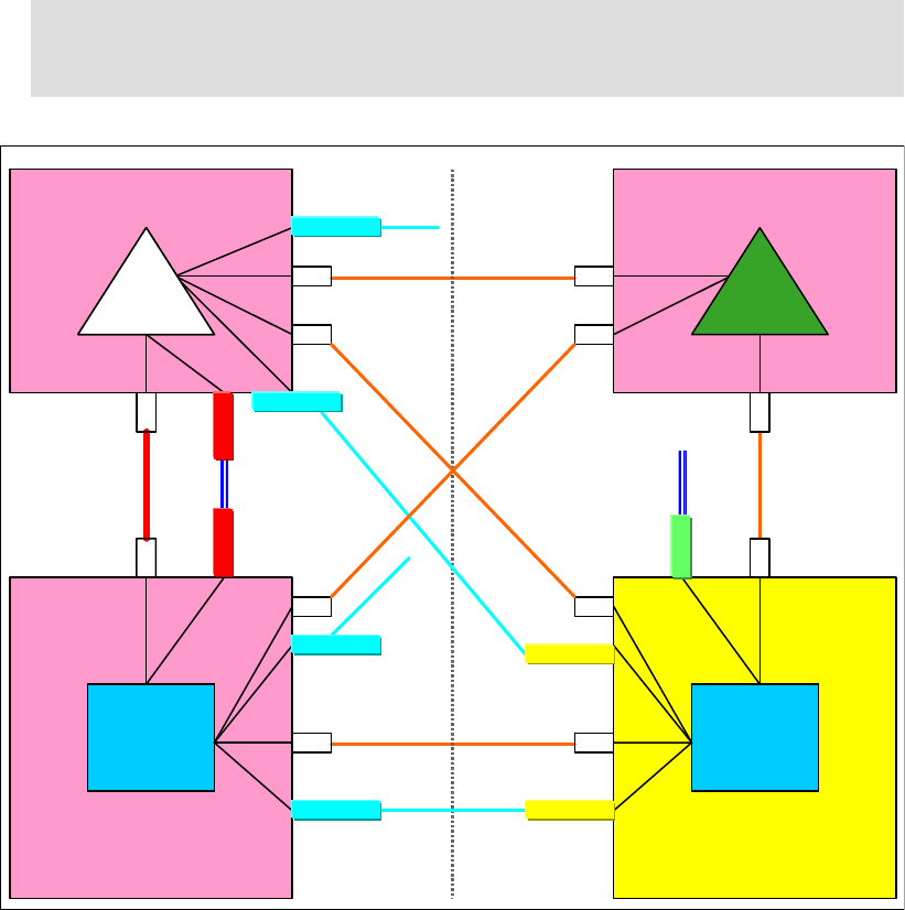
100 Implementing and Managing InfiniBand Coupling Links on IBM System z
– HCA3-O 12X IFB links on CPC4 to connect to CF02 (the cables going to CF02 will not
be connected at this time because the corresponding adapter on CF02 will not be
installed until the second maintenance window).
Figure 4-12 shows the middle step after the hardware has been installed.
Figure 4-12 Scenario 4: Configuration during first maintenance window
10.Perform an Activate from the new production IODF on CPC1 and CPC4.
To make the new links available to z/OS, the updated IODF is activated dynamically on
the two z/OS CPCs. Remember to use the Switch IOCDS function in HCD to update
CPC1 and CPC4 so that they will use the updated IOCDS at the next POR.
Because the new PSIFB links are being added dynamically, they will go into standby mode
at the end of the activation process. We will configure them online after the POR of the
CF01 CPC.
11.Power-on reset CF01 CPC.
To implement the new PSIFB links, a power-on reset using the updated IOCDS is required
on CF01.
Note: The PSIFB links from CF01, CPC1, and CPC4 to CF02 cannot be used until
CF02 has the PSIFB HCA fanouts installed, and its IOCDS has been updated and
activated through a POR.
z196
z196 –
–CPC4
CPC4
z10 EC
z10 EC –
–CPC1
CPC1
ZOS2ZOS2ZOS1ZOS1 ISC 3
z10 EC
z10 EC –
–CF01
CF01 z10 EC
z10 EC –
–CF02
CF02
ISC 3
Site 1 Site 2
ISC 3
ISC 3
ISC 3
CF
CF2
1x PSIFB
12x PSIFB
ICB 4
1x PSIFB
Timing only
Timing only
1x PSIFB
MBA
ISC
ISC ISC
ISC ISC
ISC ISC
MBA
ISC ISC
ISC
HCA2-O LR
HCA2-O
HCA3-O LR
HCA2-O
HCA2-O LR
HCA3-O LR
1x PSIFB
HCA2-O LR
HCA2-O LR
CF
CF1
CF
CF1
PTS
BTS
ARB
HCA3-O
12x PSIFB

Chapter 4. Migration planning 101
When the POR completes, LPAR “CF1” should be activated. Because this is the first time
the new IOCDS has been used, the CPC will attempt to configure all CHPIDs online. This
means that you do not need to issue any commands on CF1 to configure online the new
InfiniBand CHPIDs.
12.Configure online the new PSIFB links on the z/OS LPARs.
Because the legacy coupling links to CF1 were not configured physically offline before the
POR, when CF1 finishes initializing, those links will automatically be physically online
again.
However, the new PSIFB coupling links that were added by the dynamic activate need to
be brought online in the ZOS1 and ZOS2 LPARs before they can be used. This is done
with the following z/OS command on each system (where xx stands for the CHPID):
CF CHP(xx),ONLINE
Remember that the new links can have different CHPIDs on each system, so be careful to
use the correct CHPID numbers.
13.Verify that the new PSIFB links and the legacy coupling links are online.
Use the following commands (on every z/OS system) to check the status of all coupling
links:
D CF,CFNM=CF1
D CF,CFNM=CF2
Use your configuration map to compare the actual configuration against your expectation.
Ensure that all the expected links show a physical status of ONLINE. Remember to also
check that the expected CF-to-CF links are online.
14.Restore original STP configuration.
Now that you have confirmed that all the coupling links are working as expected, bring the
STP configuration back to its original topology.
Using the steps described in step 3, move the PTS back to the CF01 CPC.
15.Bring all paths to CF1 logically online.
The CHPIDs that were placed logically offline by the VARY PATH command in step 6 will still
be offline (because the z/OS systems were not IPLed).
To have both the legacy and the new InfiniBand links online, bring the legacy CHPIDs back
online now by issuing the following command in each z/OS system:
VARY PATH(CF1,xx),ONLINE
Remember that the CHPIDs used to connect to the CF might be different in each z/OS.
The CHPIDs associated with the new InfiniBand links should already be logically online
(because they were never taken offline with the VARY PATH command).
Verify that all expected paths are available.
Before moving all the structures back into CF1, verify that all expected paths are logically
and physically online. To do this, issue the following command from each z/OS system:
D CF,CFNM=CF1
In the response, ensure that each CHPID that you expect to be online has a status of
ONLINE in both the PHYSICAL and LOGICAL columns.
Note: It is also possible to use the “Configure Channel Path On/Off” function on the
HMC or SE to toggle the channels online. See Chapter 7, “Operations” on page 189 for
more details.
102 Implementing and Managing InfiniBand Coupling Links on IBM System z
To ensure that each system is connected to the CF, enter the following command:
D XCF,CF,CFNM=CF1
It is sufficient to enter this command on only one system in the sysplex. In the response,
check that all members of the sysplex are listed in the CONNECTED SYSTEMS section.
16.Move structures back to CF01.
To prepare for repopulating CF1, that CF must be taken out of maintenance mode. Use
the following command to do this:
SETXCF STOP,MAINTMODE,CFNM=CF1
Next, repopulate CF1 using the following command:
SETXCF START,REALLOCATE
The structures will be moved back to CF1 based on each structure’s preference lists. Any
structures that should be duplexed will be reduplexed, with the primary and secondary
instances being in the correct CF based on the preference lists. Note that SM duplexing
will still be using the legacy ISC3 link between CF01 and CF02.
17.Middle step of the migration: decide if you will go ahead.
Now we are at the middle step of the migration. Figure 4-13 on page 103 shows the
configuration at this point. There is a mix of ICB4, ISC3, PSIFB 12X IFB, and PSIFB 1X
links during the migration phase.
Perform any testing of the InfiniBand links and compare the performance over the varying
link types. If you encounter problems, the legacy links are still available and in the
configuration, so fallback is simply a matter of configuring the InfiniBand links offline.
To proceed with the migration, configure the legacy links from CPC1 and CPC4 to CF1
offline.
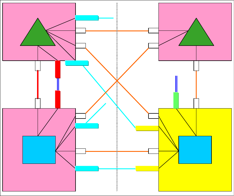
Chapter 4. Migration planning 103
The legacy links will not be removed from the IOCDS and physically removed from the
CPCs until the end of the migration.
Figure 4-13 Scenario 4: Configuration at end of first maintenance window
The steps to prepare for the second maintenance window, where the InfiniBand links will be
installed on CF02 and a POR performed, are basically the same as those that were used to
prepare for the first maintenance window.
18.Move the BTS role off the CF02 CPC.
At the start of the scenario, the CF02 CPC is assigned the role of BTS. To be able to
perform a POR of that CPC, that role must be moved to another CPC. Because the CPC1
CPC does not have a specific STP role, the BTS role will be moved to that CPC.
To move the BTS role to CPC1:
– Log on to the HMC.
– Select the CPC1 system (note that this must be done from the CPC that is going to
become the BTS).
– Open the Configuration option.
– Select the System (sysplex) Time option.
– Select the Network Configuration tab, as shown in Figure 4-11 on page 98.
– In the Backup time server (CPC) drop-down menu, select CPC1 and press Apply. This
will move the BTS role to CPC1 after verifying that CPC1 has the required connectivity.
z196
z196 –
–CPC4
CPC4
z10 EC
z10 EC –
–CPC1
CPC1
ZOS2ZOS2ZOS1ZOS1 ISC 3
z10 EC
z10 EC –
–CF01
CF01 z10 EC
z10 EC –
–CF02
CF02
ISC 3
Site 1 Site 2
ISC 3
ISC 3
ISC 3
CF
CF2
1x PSIFB
12x PSIFB
ICB 4
1x PSIFB
Timing only
Timing only
1x PSIFB
MBA
ISC
ISC ISC
ISC ISC
ISC ISC
MBA
ISC ISC
ISC
HCA2-O LR
HCA2-O
HCA3-O LR
HCA2-O
HCA2-O LR
HCA3-O LR
1x PSIFB
HCA2-O LR
HCA2-O LR
CF
CF1
PTS BTS
ARB
HCA3-O
12x PSIFB
104 Implementing and Managing InfiniBand Coupling Links on IBM System z
For more information about managing the STP roles, see the Redbooks document Server
Time Protocol Recovery Guide, SG24-7380.
19.Prepare to empty all structures out of CF2.
We need to move the structures out of the CF LPAR on CF02 because the implementation
of the PSIFB links on this stand-alone CF CPC requires a POR to activate the updated
IOCDS. To empty out the CF LPAR “CF2”, it is first set to maintenance mode using the
following command:
SETXCF START,MAINTMODE,CFNM=CF2
20.Move structures to CF1.
We now move all structures to CF1 using this command:
SETXCF START,REALLOCATE
All simplex structures will be moved from CF2 to CF1. Duplexed structures will transition to
simplex mode, with the surviving instance being in CF1.
21.Take CF2 logically offline to all systems.
To ensure that there are no structures left in CF2 and that it is not currently being used by
any system, use the following command on each connected system to remove access to
the CF:
VARY PATH(CF2,xx),OFFLINE,UNCOND
Issue this command for each CHPID, bearing in mind that different systems might be
using different CHPIDs to access the CF.
Because no changes are being made to the legacy links at this time, it is not necessary
physically configure them offline using the CONFIG command.
22.Check that CF2 is empty and offline to all systems.
Determine whether any structures have remained in the CF by using this command:
D XCF,CF,CFNAME=CF2
The response shows that the CF is in maintenance mode, and contains the following
messages:
NO SYSTEMS ARE CONNECTED TO THIS COUPLING FACILITY
and
NO STRUCTURES ARE IN USE BY THIS SYSPLEX IN THIS COUPLING FACILITY
If any structure did not move, check whether application-specific protocols might be
needed and use these to move (or rebuild) the structure. Repeat this step until all
structures have been moved.
23.Shut down CF2 LPAR.
In preparation for the POR of the CF02 CPC, shut down the CF2 LPAR now.
The CF should be empty because all structures were moved to CF1. Therefore, issue the
SHUTDOWN command from the CF console, rather than using the HMC DEACTIVATE
function to stop the CF2 LPAR.
24.The SSR starts the MES on CF02.
At this point, the new InfiniBand fanouts are installed on the CF02 CPC. After the fanouts
have been installed, they are then connected to the corresponding fanouts on CPC1,
CPC4, and CF01.
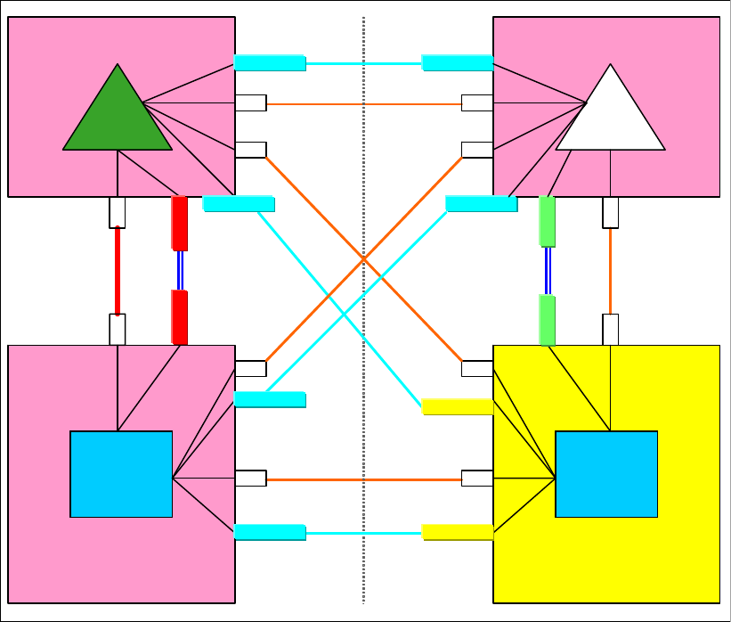
Chapter 4. Migration planning 105
Figure 4-14 shows the configuration at this point. All the InfiniBand fanouts have been
installed and connected. The legacy coupling is still installed, CF2 has not been
repopulated yet, and the BTS role is still on CPC1.
Figure 4-14 Scenario 4: Configuration during second maintenance window
25.Power-on reset of CF02.
To implement the new InfiniBand links, it is necessary to perform a POR on the CF02 CPC
with the updated IOCDS.
When the POR is complete, the CF2 LPAR is activated. Because this is the first POR from
the new IOCDS, all CHPIDs will be online by default at the end of the POR, so the new
InfiniBand CHPIDs will be online. And because the legacy CHPIDs were online prior to the
POR, they should also be online after the POR.
26.Verify that the new PSIFB links on the CF2 are online.
The new PSIFB coupling links on CF2 automatically come online after the POR. To verify
that, issue the following command on the CF2 console:
DISPLAY CHP ALL
If any of the expected CHPIDs are not online, use the following command on the CF
console to bring them online:
CON xx ONLINE
z196
z196 –
–CPC4
CPC4
z10 EC
z10 EC –
–CPC1
CPC1
ZOS2ZOS2ZOS1ZOS1 ISC 3
z10 EC
z10 EC –
–CF01
CF01 z10 EC
z10 EC –
–CF02
CF02
ISC 3
Site 1 Site 2
ISC 3
ISC 3
ISC 3
CF
CF2
1x PSIFB
12x PSIFB
ICB 4
1x PSIFB
Timing only
Timing only
1x PSIFB
MBA
ISC
ISC ISC
ISC ISC
ISC ISC
MBA
ISC ISC
ISC
HCA2-O LR
HCA2-O
HCA3-O LR
HCA2-O
HCA2-O LR
HCA3-O LR
1x PSIFB
HCA2-O LR
HCA2-O LR
CF
CF1
PTS
BTS ARB
HCA3-O
12x PSIFB
HCA3-O
HCA2-O LR
HCA2-O LR

106 Implementing and Managing InfiniBand Coupling Links on IBM System z
27.Verify that the PSIFB links from CF1 to CF2 are online.
The PSIFB links from CF1 to ZOS1 and ZOS2 are online since the first maintenance
window. And the PSIFB links to CF2 automatically come online when CF2 is activated
after the POR. To verify this, issue the following command on the CF1 console:
DISP CHP ALL
If the CHPIDs to CF2 are not online, issue the following command on the CF1 console to
bring them online:
CON xx ON
28.Configure the new PSIFB links online on the z/OS LPARs.
The new PSIFB coupling links were defined to ZOS1 and ZOS2 as part of the dynamic
reconfiguration in the first maintenance window. However, the associated CHPIDs cannot
be brought online until the CF end of the links are installed. To bring the z/OS end of the
new links online, issue the following command on each z/OS system (where xx stands for
the CHPID):
CF CHP(xx),ONLINE
29.Restore original STP configuration.
Now that you have confirmed that all the coupling links are working as expected, bring the
STP configuration back to its original topology.
Using the steps described in step 20, move the BTS back to the CF02 CPC.
30.Bring all paths to CF2 logically online.
The legacy CHPIDs that were placed logically offline by the VARY PATH command in step
16 will still be offline (because the z/OS systems were not IPLed).
To have both the legacy and the InfiniBand links online to CF02, bring those CHPIDs back
online now by issuing the following command in each z/OS system:
VARY PATH(CF2,xx),ONLINE
Remember that the CHPIDs used to connect to the CF might be different in each z/OS.
The CHPIDs associated with the new InfiniBand links should already be logically online
(because they were never taken offline with the VARY PATH command).
Verify that all expected paths are available.
Before moving all the structures back into CF2, verify that all expected paths are logically
and physically online. To do this, issue the following command from each z/OS system:
D CF,CFNM=CF2
In the response, ensure that each CHPID has a status of ONLINE in both the PHYSICAL
and LOGICAL columns.
To ensure that each system is connected to the CF, enter the following command:
D XCF,CF,CFNM=CF2
It is sufficient to enter this command on only one system in the sysplex. In the response,
check that all members of the sysplex are listed in the CONNECTED SYSTEMS section.
Note: It is also possible to use the “Configure Channel Path On/Off” function on the
HMC or SE to toggle the channel online. See Chapter 7, “Operations” on page 189 for
more details.
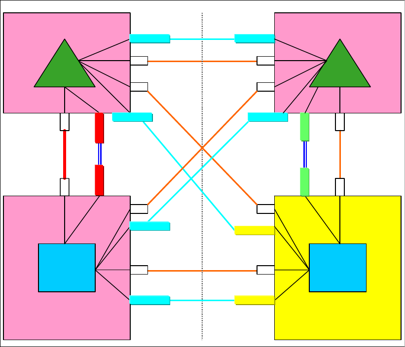
Chapter 4. Migration planning 107
31.Move structures back to CF02.
To move the structures back to CF2, first turn off maintenance mode by using the following
command:
SETXCF STOP,MAINTMODE,CFNM=CF2
Now that CF2 is available for allocation, repopulate the CF using the following command:
SETXCF START,REALLOCATE
If you are using z/OS 1.12 or later, issue a D XCF,REALLOCATE,REPORT command and
review the output to ensure that all structures are in the correct CF.
32.End of the second maintenance window: decide whether you will go ahead.
Now we are at the end of the second maintenance window. Figure 4-15 shows the
configuration. Notice that there is still a mix of various link types at this point in the
migration.
Figure 4-15 Scenario 4: Configuration after second maintenance window
33.When you are satisfied that the PSIFB links are all working as expected, the legacy links
can be removed.
For CPC1 and CPC4, the legacy links can be removed from the IODF, and the new
configuration can be activated dynamically.
The new IOCDSs for CF01 and CF02 can be written to the CPCs; however, activating the
new IOCDSs will require a POR. Activating the new IOCDS can be postponed until a POR
z196
z196 –
–CPC4
CPC4
z10 EC
z10 EC –
–CPC1
CPC1
ZOS2ZOS2ZOS1ZOS1 ISC 3
z10 EC
z10 EC –
–CF01
CF01 z10 EC
z10 EC –
–CF02
CF02
ISC 3
Site 1 Site 2
ISC 3
ISC 3
ISC 3
CF
CF2
1x PSIFB
12x PSIFB
ICB 4
1x PSIFB
Timing only
Timing only
1x PSIFB
MBA
ISC
ISC ISC
ISC ISC
ISC ISC
MBA
ISC ISC
ISC
HCA2-O LR
HCA2-O
HCA3-O LR
HCA2-O
HCA2-O LR
HCA3-O LR
1x PSIFB
HCA2-O LR
HCA2-O LR
CF
CF1
PTS BTS
ARB
HCA3-O
12x PSIFB
HCA3-O
HCA2-O LR
HCA2-O LR
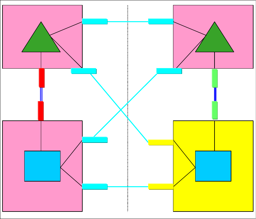
108 Implementing and Managing InfiniBand Coupling Links on IBM System z
is required for some other reason. If necessary, it is possible to concurrently uninstall the
legacy links on those CPCs before the new IOCDSs are activated.
The final configuration, after all the legacy links have been removed, is shown in
Figure 4-16.
Figure 4-16 Scenario 4: Final configuration
4.7 Scenario 5
Concurrent migration from IFB to IFB3 mode
This scenario describes a concurrent migration from HCA2-O 12x PSIFB links to HCA3-O
12x PSIFB links running in IFB3 mode. In this scenario, we have a two-CPC configuration
with one CF LPAR in each CPC. There are two 12x PSIFB links in place between the CPCs,
using separate HCA2-O fanouts. The fanouts will be concurrently replaced by HCA3-O
fanouts (one at a time) and all requirements will be met so that the new HCA3-O 12x PSIFB
links will operate in IFB3 mode.
The migration objective is to migrate the PSIFB links without any interruption to any of the
z/OS or CF LPARs.
Certain restrictions must be met to utilize the IFB3 mode:
The IFB3 protocol will only be used when both ends of the link are connected to an
HCA3-O fanout.
z196
z196 –
–CPC4
CPC4
z10 EC
z10 EC –
–CPC1
CPC1
ZOS2ZOS2ZOS1ZOS1
z10 EC
z10 EC –
–CF01
CF01 z10 EC
z10 EC –
–CF02
CF02
Site 1 Site 2
CF
CF2
1x PSIFB
12x PSIFB
1x PSIFB
Timing only
1x PSIFB
HCA2-O LR
HCA2-O
HCA3-O LR
HCA2-O
HCA2-O LR
HCA3-O LR
1x PSIFB
HCA2-O LR
HCA2-O LR
CF
CF1
PTS BTS
ARB
HCA3-O
12x PSIFB
HCA3-O
HCA2-O LR
HCA2-O LR
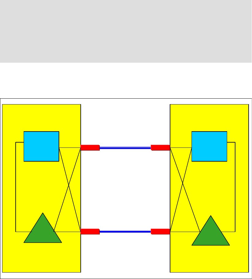
Chapter 4. Migration planning 109
The IFB3 protocol will only be used if a maximum of four CHPIDs are defined per HCA3-O
fanout port for all LPARs combined.
The PSIFB link will automatically detect whether the given requirements are met and will
auto-negotiate the use of the IFB3 protocol. The two ports of an HCA3-O fanout are able to
work in different protocol modes. It is possible to determine from the Support Element which
protocol is currently being used on any given HCA3-O port. See “Analyze Channel
Information option” on page 226 for more information.
In this scenario, two z196 servers, CPC4 and CPC5, are installed. See Figure 4-17 for the
starting configuration.
Figure 4-17 Scenario 5: Starting configuration
Migrating from HCA2-O 12X to HCA3-O 12X in IFB3 mode
1. Starting point.
Our current configuration is shown in Figure 4-17.
Important: In the case where a dynamic I/O configuration change results in an IFB
protocol mode change on an HCA3-O port, the physical port will automatically perform a
reinitialization. This will result in all defined CHPIDs on this port being toggled offline
together and then online again. As a result, all connectivity to the Coupling Facility and
STP through this port will be lost for a short period of time.
This means that you must ensure that all your CFs are connected through at least two
physical links, and that any change you make is not going to affect more than one port.
IC
z196
z196 –
–CPC4
CPC4
ZOS2ZOS1
CF
CF2
Link 1
12x PSIFB
IFB mode
Link 2
12x PSIFB
IFB mode
CF
CF1
IC
z196
z196 –
–CPC5
CPC5
HCA2-O HCA2-O
HCA2-O HCA2-O
BTS PTS

110 Implementing and Managing InfiniBand Coupling Links on IBM System z
2. Check current 12x PSIFB link status and CF connectivity.
Check the link status between the z/OS and CF LPARs with the following z/OS
commands:
D CF,CFNM=CF1
D CF,CFNM=CF2
Make sure that you have redundant connectivity between all z/OS and CF LPARs through
both PSIFB fanouts.
3. Configure the CHPIDs for PSIFB link 1 offline from the z/OS LPARs.
Use the information from your configuration map (and confirm that the information is
correct using the SE) to determine the CHPIDs that are associated with the first of the two
current HCA2-O fanouts. Those CHPIDs should then be configured offline on both z/OS
systems using the following z/OS command (where xx stands for the CHPID):
CF CHP(xx),OFFLINE
See Chapter 7, “Operations” on page 189 for more information.
4. Configure the CHPIDs for PSIFB link 1 offline from both CF LPARs.
The CHPIDs associated with both ends of PSIFB link 1 are next configured offline on the
CF LPARs “CF1” and “CF2”. This is done with the following CFCC command (where xx
stands for the CHPID) on the CF console:
CON xx OFFLINE
Use the following command to ensure that the CHPIDs went offline successfully:
DISPLAY CHP ALL
All CHPIDs associated with both ends of link 1 should be offline now, meaning that fanout
can be removed by the SSR. See Chapter 7, “Operations” on page 189 for more
information about how to use the SE to confirm that all CHPIDs are offline.
5. First pair of HCA2-O fanouts is replaced by HCA3-O fanouts by the SSR.
The SSR concurrently replaces the first pair of HCA2-O fanouts with HCA3-O fanouts, one
fanout per CPC.
6. IOCDS change on CPC4 and CPC5 might be required.
If an IODF update is required, activate the new IODF on CPC4 and CPC5 now.
Note: The IODF only needs to be updated if the AID of the fanout changes or the
number of defined CHPIDs have to be adjusted.
The AID for the fanout is bound to the fanout itself. If the HCA2-O fanout is removed, it
releases its AID. The HCA3-O fanout that is newly installed will be assigned AID that is
predefined to the fanout slot. The AID for the new installed fanout will be different only if
the new fanout is installed in a different slot than the old fanout. See 2.4, “Adapter ID
assignment and VCHIDs” on page 26 for more details and confer with the SSR to
determine if the AID is changing in your specific case.
An IODF update might also be necessary if you currently have more than four CHPIDs
defined per HCA2-O fanout port for all logical partitions (LPAR) combined. This will
result in the link running in IFB mode. To get the link to run in IFB3 mode, ensure that
the number of CHPIDs defined to the port is four or less.
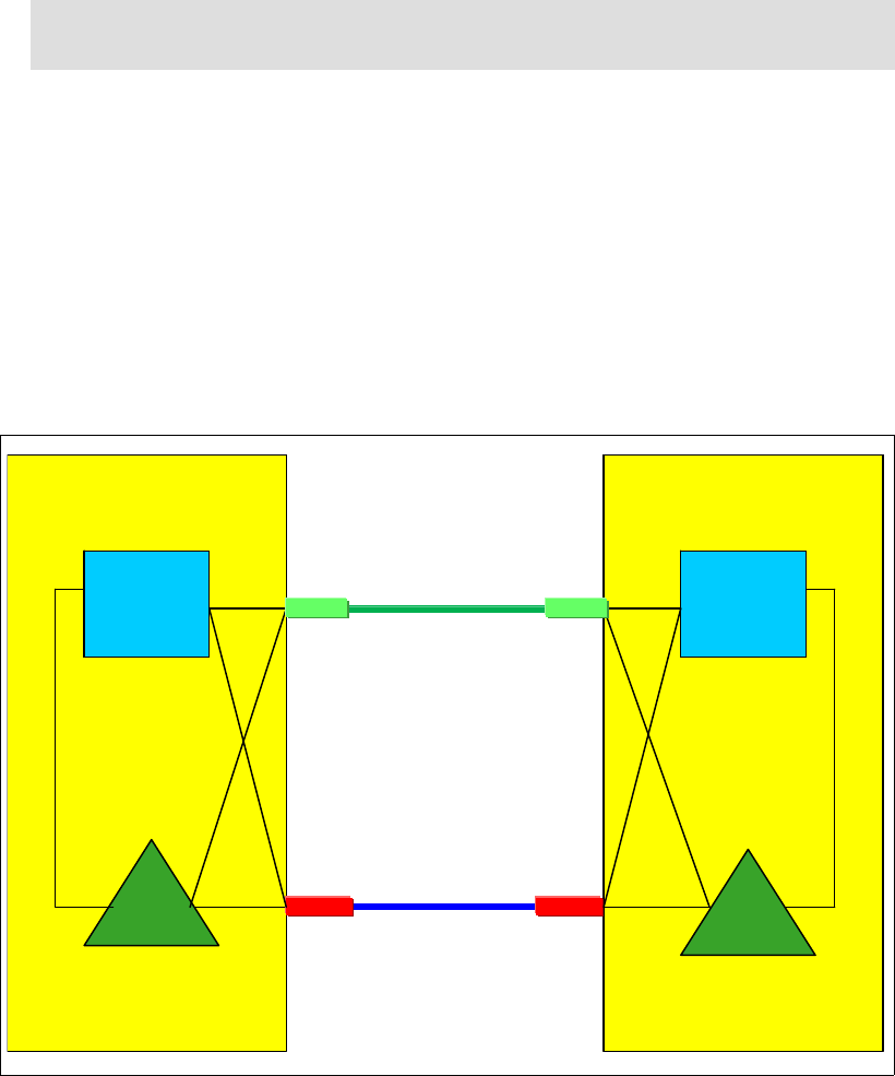
Chapter 4. Migration planning 111
7. Configure the CHPIDs associated with link 1 on the CF LPARs “CF1” and “CF2” online.
The PSIFB CHPIDs are configured online on CF LPARs “CF1” and “CF2”. This is done
with the following CFCC command (where xx stands for the CHPID) on the CF console:
CON xx ONLINE
Check that the command completed successfully with the CFCC command:
DISPLAY CHP ALL
8. Configure the CHPIDs associated with link 1 on the z/OS LPARs online.
The PSIFB CHPIDs are configured online on z/OS LPARs “ZOS1” on CPC4 and “ZOS2”
on CPC5. This is done with the following z/OS command (where xx stands for the CHPID):
CF CHP(xx),ONLINE
9. Verify that the all PSIFB CHPIDs are online and the PSIFB CHPIDs for link 1 are running
in IFB3 mode.
Check the link status between the z/OS and CF LPARs with the following z/OS commands
on each z/OS system:
D CF,CFNM=CF1
D CF,CFNM=CF2
The response will show that all expected CHPIDs are logically and physically online.
To check that the CHPIDs associated with the new HCA3-O 12X fanout are running in
IFB3 mode, use the “Analyze Channel Information” panel on the Service Element. Refer to
“Analyze Channel Information option” on page 226 for more information.
Figure 4-18 Scenario 5: Middle step
Note: It is also possible to use the “Configure Channel Path On/Off” function on the
HMC or SE to toggle the channel online.
IC
z196
z196 –
–CPC4
CPC4
ZOS2ZOS2ZOS1ZOS1
CF
CF2
Link 1
12x PSIFB
IFB3 mode
Link 2
12x PSIFB
IFB mode
CF
CF1
IC
z196
z196 –
–CPC5
CPC5
HCA2-O HCA2-O
HCA3-O HCA3-O
BTS PTS
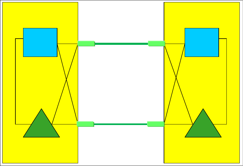
112 Implementing and Managing InfiniBand Coupling Links on IBM System z
10.Middle step.
Now one link is running in IFB mode and one link is running in IFB3 mode. You can
measure the performance of the IFB3 mode link by configuring offline the CHPIDs
associated with the other link. However, be aware that doing this will create a single point
of failure, because all online CHPIDs will now be using only one coupling link. It is
advisable to perform such testing outside the online window, and to bring all CHPIDs back
online as soon as your testing is complete.
11.Assuming that the PSIFB link 1 is working properly and that the performance is
acceptable, repeat steps 4 to 10 for link 2.
12.The final configuration, with both links now migrated to HCA3-O 12X fanouts and running
in IFB3 mode, is shown in Figure 4-19.
Figure 4-19 Scenario 5: Final configuration
4.8 Concurrent switch between IFB modes
This scenario describes the switch between the IFB modes.
In the case where a dynamic I/O configuration change results in an IFB protocol mode
change on an HCA3-O port, the physical port will automatically perform reinitialize as soon as
the change is activated. This will result in all defined CHPIDs on this port being toggled offline
together and then online again. As a result, all connectivity to the Coupling Facility (or multiple
Coupling Facilities, if multiple sysplexes are sharing the link) and STP through this port will be
lost for a short period of time.
This means that you must ensure that all your CFs are connected through at least two
physical links, and that any change you make is not going to affect more than one port.
IC
z196
z196 –
–CPC4
CPC4
ZOS2ZOS2ZOS1ZOS1
CF
CF2
Link 1
12x PSIFB
IFB3 mode
CF
CF1
IC
z196
z196 –
–CPC5
CPC5
HCA3-O HCA3-O
Link 2
12x PSIFB
IFB3 mode
HCA3-O HCA3-O
BTS PTS
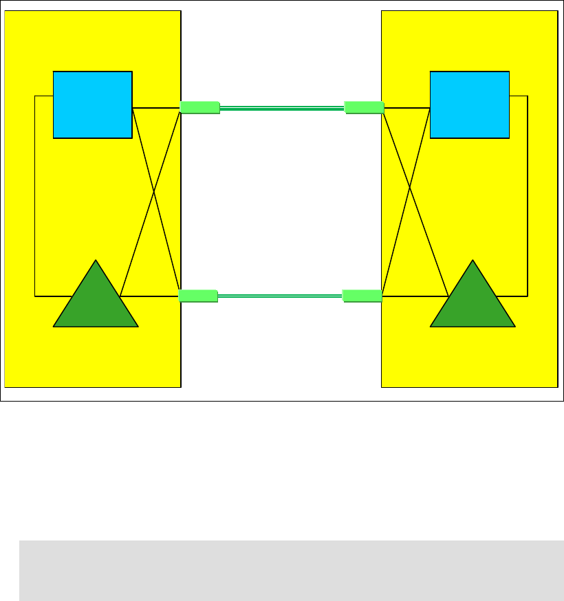
Chapter 4. Migration planning 113
This section describes a way to perform the switch in either direction concurrently to your
sysplex operation. If you follow these steps carefully, you are able to switch between the two
modes concurrently to your sysplex operations even though the mode switch is disruptive to
each link by itself.
This scenario assumes that there are already two z196 CPCs at Driver 93 or later and that
both CPCs have already HCA3-O 12X fanouts installed. Each CPC contains one z/OS LPAR
and one CF LPAR. There are two 12x PSIFB links in place between the two CPCs, and each
link has four CHPIDs defined. Because all the requirements for the use of IFB3 mode are
being met, both links are utilizing the IFB3 mode at this time.
Figure 4-20 Switching between IFB modes - starting configuration
Concurrent switch from IFB3 to IFB mode
1. Starting point.
Our current configuration is shown in Figure 4-20.
2. Update HCD to add a fifth CHPID to one of the two links.
3. Identify which CHPIDs will be impacted by the change.
It is vital to understand which CHPIDs will be affected when the port reinitializes itself, for a
number of reasons:
– If you know the CHPIDs, you are able to determine which sysplexes will be affected.
Note: This example is based on adding a fifth CHPID to one of the two 12x PSIFB links,
because the mode switch will occur when we go above four defined CHPIDs. However,
the behavior is the same for any number of CHPIDs above four.
IC
z196
z196 –
–CPC4
CPC4
ZOS2ZOS2ZOS1ZOS1
CF
CF2
Link 1
12x PSIFB
IFB3 mode
CF
CF1
IC
z196
z196 –
–CPC5
CPC5
HCA3-O HCA3-O
Link 2
12x PSIFB
IFB3 mode
HCA3-O HCA3-O
BTS PTS
4 CHPIDs
defined
4 CHPIDs
defined

114 Implementing and Managing InfiniBand Coupling Links on IBM System z
– Knowing which CHPIDs will go offline allows you to check each sysplex to ensure that
every CF is also connected by CHPIDs that will not go offline when the port
reinitializes.
Use your configuration map, and the SEs of the affected CPCs, to identify the CHPIDs that
will be affected by the change. For information about how to identify the CHPIDs that are
assigned to a given port, refer to 7.4.2, “Determining the CHPIDs that are associated with
an AID/port” on page 214.
4. Verify that all PSIFB CHPIDs are online.
Use the following z/OS commands in every z/OS system in every sysplex that will be
affected by the change to determine which CHPIDs are online to each CF:
D CF,CFNM=CF1
D CF,CFNM=CF2
Check that there are online CHPIDs that are not associated with the port that is going to
be affected by the change.
5. Perform the dynamic IODF activation on CPC4.
The new IODF for CPC4 is dynamically activated to add the fifth CHPID to PSIFB link 2.
Figure 4-21 on page 115 shows the configuration after the dynamic activation.
When the IODF is activated, IXL158I messages might be generated, informing you that
the CHPIDs associated with the port have gone offline, followed a few seconds later by
more IXL158I messages, indicating that the CHPIDs are now online again.
Note: At this step, all defined CHPIDs to PSIFB link 2 are toggled offline and online by
the CPC to reinitialize the PSIFB link in IFB mode. Depending on the utilization of your
CF links, you might (or might not) see corresponding z/OS messages. But regardless of
whether you get the corresponding z/OS messages, the PSIFB link is l reinitialized.
Also note that the ports at both ends of the link will reinitialize at this time. This is
important because it means that the link will not go down a second time when the
changed IODF on the other CPC is activated.
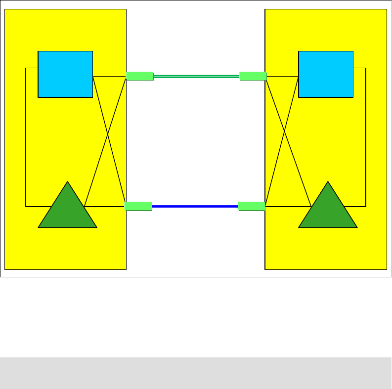
Chapter 4. Migration planning 115
Figure 4-21 Configuration after CPC4 has five CHPIDs defined to PSIFB link 2
6. Dynamic IOCDS activation on CPC5.
The new IOCDS for CPC5 is dynamically activated to add the fifth CHPID to the PSIFB
link 2.
7. Configure the fifth PSIFB CHPID online as required.
The new PSIFB CHPIDs (one at each end of the link) will now be configured online to the
CF or z/OS LPARs that will be using them.
8. Verify that the all PSIFB CHPIDs are online.
Check the status of all coupling CHPIDs between the two CPCs to ensure that they have
the expected status by using the following z/OS commands:
D CF,CFNM=CF1
D CF,CFNM=CF2
Remember to check both the logical and physical status of each CHPID, and also the state
of the CHPIDs that are used by the CFs to communicate with each other.
Note: At this point, the PSIFB link is not reinitialized and all CHPIDs keep their
connectivity.
IC
z196
z196 –
–CPC4
CPC4
ZOS2ZOS2ZOS1ZOS1
CF
CF2
Link 1
12x PSIFB
IFB3 mode
CF
CF1
IC
z196
z196 –
–CPC5
CPC5
HCA3-O HCA3-O
Link 2
12x PSIFB
IFB mode
HCA3-O HCA3-O
BTS PTS
5 CHPIDs
defined
4 CHPIDs
defined
116 Implementing and Managing InfiniBand Coupling Links on IBM System z
You can check that all five CHPIDs which are defined for link 2 are now running in IFB
mode through the “Analyze Channel Information” panel on the Service Element. Refer to
“Analyze Channel Information option” on page 226 for more information. The configuration
at this point is shown in Figure 4-22.
Figure 4-22 Configuration after both CPCs have five CHPIDs defined to PSIFB link 2
Concurrent switch from IFB to IFB3 mode
1. Starting point.
The current configuration is shown in Figure 4-23 on page 117. The plan is to reduce the
number of CHPIDs on link 2 to four to benefit from the better performance that is available
in IFB3 mode.
Attention: Make sure that you never make a change that alters the IFB mode of all
links at the same time. Activating an IODF containing such a change can result in a loss
of all coupling connectivity between the two CPCs.
IC
z196
z196 –
–CPC4
CPC4
ZOS2ZOS2ZOS1ZOS1
CF
CF2
Link 1
12x PSIFB
IFB3 mode
CF
CF1
IC
z196
z196 –
–CPC5
CPC5
HCA3-O HCA3-O
Link 2
12x PSIFB
IFB mode
HCA3-O HCA3-O
BTS PTS
5 CHPIDs
defined
5 CHPIDs
defined
Chapter 4. Migration planning 117
Figure 4-23 Configuration where both CPCs have five CHPIDs defined to PSIFB link 2
2. Update HCD to remove the fifth CHPID from both ends of link 2.
3. Identify the CHPIDs that will be impacted by the change.
Remember, when the IFB mode of the port is changed, all CHPIDs using that port will
temporarily go offline. This, it is not only the CHPID that is being removed that you need to
consider.
Use your configuration map and the SEs of the affected CPCs to verify the CHPIDs that
will be affected by the change. For information about how to identify the CHPIDs that are
assigned to a given port, see 7.4.2, “Determining the CHPIDs that are associated with an
AID/port” on page 214.
4. Verify that all PSIFB CHPIDs are online.
Use following z/OS commands in every z/OS system in every sysplex that will be affected
by the change to determine which CHPIDs are online to each CF:
D CF,CFNM=CF1
D CF,CFNM=CF2
Check that there are online CHPIDs that are not associated with the port that is going to
be affected by the change.
5. Configure the fifth PSIFB CHPID on the z/OS LPARs offline.
The fifth PSIFB CHPID is configured offline on z/OS LPARs “ZOS1” on CPC4 and “ZOS2”
on CPC5. This is done with the following z/OS command (where xx stands for the CHPID):
CF CHP(xx),ONLINE
Note: It is also possible to use the “Configure Channel Path On/Off” function on the
HMC or SE to toggle the channel online.
IC
z196
z196 –
–CPC4
CPC4
ZOS2ZOS2ZOS1ZOS1
CF
CF2
Link 1
12x PSIFB
IFB3 mode
CF
CF1
IC
z196
z196 –
–CPC5
CPC5
HCA3-O HCA3-O
Link 2
12x PSIFB
IFB mode
HCA3-O HCA3-O
BTS PTS
5 CHPIDs
defined
5 CHPIDs
defined
118 Implementing and Managing InfiniBand Coupling Links on IBM System z
Also, see Chapter 7, “Operations” on page 189 for more details.
6. Configure offline the CHPID that is being removed.
Configure the CHPID that is being removed (on both ends of the link) offline to any LPAR
that is using it. Remember that the CHPIDs might be in use by both CF and z/OS LPARs.
Use the SE to verify that CHPIDs are offline in all LPARs before proceeding. See
Chapter 7, “Operations” on page 189 for more details.
7. Perform the dynamic IODF activation on CPC4.
The new IODF for CPC4 is dynamically activated to remove the fifth CHPID from PSIFB
link 2. Figure 4-24 shows the configuration after the dynamic activation.
When the IODF is activated, IXL158I messages might be generated, informing you that
the CHPIDs associated with the port have gone offline, followed a few seconds later by
more IXL158I messages, indicating that the CHPIDs are now online again.
Figure 4-24 Configuration after CPC4 has only four CHPIDs defined to PSIFB link 2
8. Perform the dynamic IODF activation on CPC5.
The updated IODF is activated on CPC5 to remove the fifth CHPID from PSIFB link 2.
Note: At this step, all CHPIDs defined on PSIFB link 2 are toggled offline and online by
the CPC to reinitialize the PSIFB link. However, the mode is not switched because the
port at the other end of the link still has five CHPIDs defined.
Depending on the utilization of your CF links, you might (or might not) see
corresponding z/OS messages. However, even if you do not see any IXL158I
messages, the PSIFB link is reinitialized.
IC
z196
z196 –
–CPC4
CPC4
ZOS2ZOS2ZOS1ZOS1
CF
CF2
Link 1
12x PSIFB
IFB3 mode
CF
CF1
IC
z196
z196 –
–CPC5
CPC5
HCA3-O HCA3-O
Link 2
12x PSIFB
IFB mode
HCA3-O HCA3-O
BTS PTS
4 CHPIDs
defined
5 CHPIDs
defined
Chapter 4. Migration planning 119
9. Verify that the all PSIFB CHPIDs are online.
Check that all CHPIDs have the expected status. Use the following z/OS commands to
make sure that all CHPIDs, including those between the CFs, are online:
D CF,CFNM=CF1
D CF,CFNM=CF2
To verify that the links are now operating in IFB3 mode, use the “Analyze Channel
Information” panel on the Service Element. See “Analyze Channel Information option” on
page 226 for more information.
Figure 4-25 Configuration after both CPCs have four CHPIDs defined to PSIFB link 2
10.The final configuration is shown in Figure 4-25.
Note: At this point, all CHPIDs defined on PSIFB link 2 are again toggled offline and
online by the CPC to reinitialize the PSIFB link in IFB3 mode. Once again, you might (or
might not) see corresponding z/OS messages.
IC
z196
z196 –
–CPC4
CPC4
ZOS2ZOS2ZOS1ZOS1
CF
CF2
Link 1
12x PSIFB
IFB3 mode
CF
CF1
IC
z196
z196 –
–CPC5
CPC5
HCA3-O HCA3-O
HCA3-O HCA3-O
BTS PTS
4 CHPIDs
defined
4 CHPIDs
defined
Link 2
12x PSIFB
IFB3 mode
120 Implementing and Managing InfiniBand Coupling Links on IBM System z

© Copyright IBM Corp. 2008, 2012, 2014. All rights reserved. 121
Chapter 5. Performance considerations
As you prepare to replace your existing coupling links with InfiniBand links, you need to
understand the relative performance of the different link types. This is especially important for
installations that are currently using ICB4 links, because those link types are not available on
the z196 and later families.
The actual service times that will be experienced in a given configuration depend on many
things, so it is not possible to provide a specific service time value that will apply in all cases.
However, to help you get some indication of the relative performance of different link types,
we performed a number of measurements with different types of links, and present the results
of those measurements in this chapter.
5
Performance Disclaimer: The measurements presented here were taken using a
configuration that was also being used for other projects. Although we strove to have
repeatable and comparable results, the measurements were not taken in a controlled
environment. Actual results might vary. Performance information is provided “AS IS” and
no warranties or guarantees are expressed or implied by IBM. For official IBM performance
information, refer to the Large Systems Performance Reference documentation.

122 Implementing and Managing InfiniBand Coupling Links on IBM System z
5.1 Introduction to performance considerations
Although the type of CF link used plays a significant role in the service times that you
observe, CF performance is affected by many things. To understand the performance that you
are seeing, and to identify the configuration that is required to deliver the performance that
your business requires, it is important to understand the configuration choices that contribute
to CF service times. The following sections briefly discuss several of these choices.
Dedicated engines
When CF performance is critical, the recommendation is that the CF should be defined with
dedicated engines. Sharing engines potentially increases the service times and utilization of
the CPCs. This can add significant costs (elapsed time, z/OS CPU consumption, and
throughput), to the requesters of the CF services, potentially resulting in software charges
increasing to the point that the cost of providing a dedicated engine might be a more
cost-effective option.
External or Internal CF LPARs
External CFs for this discussion are considered to be CF LPARs that reside on a CF-only
CPC or CF LPARs that do not connect to any z/OS LPARs that might reside in the same CPC.
An Internal CF, for the purposes of this discussion, is one that resides in the same CPC as at
least one z/OS that is connected to it.
Various structures (DB2 lock structures, for example) require either failure isolation from any
connectors or the use of System Managed Duplexing to be able to recover from the loss of a
CPC containing a CF and a connected z/OS system. The use of external CFs meets the
failure-isolation requirement for those structures, thereby avoiding the cost associated with
the use of System Managed Duplexing.
The use of a zBC12 CPC as external CF might be a cost-effective alternative for clients that
currently use Internal CFs and System Managed Duplexing. The 2828 Model H13 supports
up to eight HCA fanouts, thereby providing significant flexibility. For more information about
the cost of System Managed Duplexing, so that you can make an informed decision about the
most cost-effective way to achieve your resiliency requirements, see the System Managed
Duplexing white paper, available on the web at the following site:
http://public.dhe.ibm.com/common/ssi/ecm/en/zsw01975usen/ZSW01975USEN.PDF
Synchronous versus asynchronous requests
Depending on how the structure connector issues the request, XES can behave in one of two
ways when it sends a request to the CF:
It can send the request as a synchronous request. In this case, XES spins on the CP,
consuming CPU in the requester’s address space until the response is received from the
CF.
It can send the request as an asynchronous request. In this case, after the request is sent
to the CF, XES returns control to the MVS dispatcher. The dispatcher will pass control to
another task. After some time, control is returned to the dispatcher. If the response has
arrived back from the CF, the dispatcher passes control back to XES.
Most of the CPU time required to process an asynchronous request gets charged back to
various operating system components rather than to the requester. The CPU time is still
consumed (asynchronous CF requests are not free); it is simply a question of which
address space gets charged for it. Also, because of all the task switching involved, the
elapsed time for an asynchronous request is always higher than if the same request had
been processed synchronously.
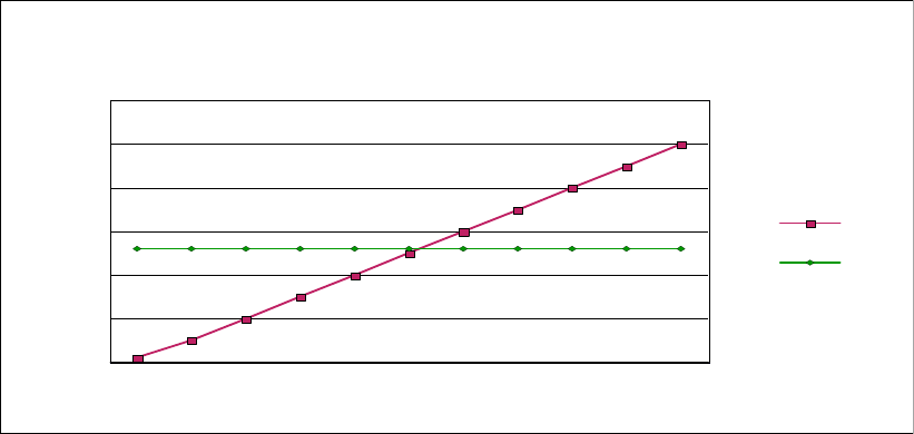
Chapter 5. Performance considerations 123
This is an important point, because a change in CF performance that results in a different
balance of synchronous and asynchronous requests might have the affect that some
address spaces appear to be consuming more or less CPU time. In either case, the CPU
is still consumed; it is simply a question of which address space is charged.
The amount of z/OS CPU time that is consumed to process an asynchronous request,
including the task switches, will vary with the speed of the CPU. But for the sake of example,
assume that it is 26 microseconds. Regardless of the actual time, the important point is that
the z/OS CPU cost will be the same, regardless of whether the response arrived back from
the CF in very little time, or if it took a very long time. This is illustrated by the horizontal line in
the chart in Figure 5-1.
Figure 5-1 Comparison of synchronous and asynchronous requests
In contrast, for a synchronous request, the z/OS CPU time associated with the request will be
equal to the CF service time. If the response arrives back from the CF in 5 microseconds, the
CPU time will be 5 microseconds. If the response takes 50 microseconds to arrive back from
the CF, then the CPU cost will be 50 microseconds. This is shown by the diagonal line in
Figure 5-1.
Starting in z/OS 1.2, XES is able to decide whether to convert synchronous requests to be
asynchronous, depending on whether the expected service time is above a certain threshold.
If the service time is expected to be below the threshold, XES will leave the request as a
synchronous one. The threshold is based on the expected z/OS CPU cost of processing the
request asynchronously.
For example, assume that XES expects the service time for a given request to be 5
microseconds. Using the chart in Figure 5-1, we can see that if the request was issued
synchronously, the z/OS CPU time to process that request would be 5 microseconds. If that
request was issued asynchronously, the z/OS CPU time would be about 26 microseconds.
So, for this request, the most efficient option (in terms of z/OS CPU time to process the
request) is to issue it synchronously. If XES expects the service time for another request to be
50 microseconds, the z/OS CPU time to process it would be 50 microseconds if it was issued
synchronously, but only 26 microseconds if it was issued asynchronously. In this case, issuing
the request asynchronously is the most efficient option.
Based on these examples, the most efficient option for a given service time is for XES to
select the lower of the two lines. For short service times (up to about 26 microseconds in this
example), the most efficient option would be for XES to issue the request synchronously. For
1 5 10 15 20 25 30 35 40 45 50
Service time
0
10
20
30
40
50
60
z/OS CPU Time
Sync Req
Async Req
z/OS CPU Cost
Sync vs Async Requests

124 Implementing and Managing InfiniBand Coupling Links on IBM System z
longer service times (greater than 26 microseconds) it would be more efficient for XES to
issue the request asynchronously.
This decision process is called the z/OS heuristic algorithm and is described in detail in the
section titled “How z/OS performs synchronous to asynchronous conversion of coupling
facility requests” in z/OS MVS Setting Up a Sysplex, SA22-7625.
To minimize the z/OS CPU cost of using the CF, ideally the CF service times should be as low
as possible. And, as illustrated by the chart in Figure 5-1 on page 123, low service times will
result in the requests being issued synchronously. Based on this, it is generally a positive sign
to see a high percentage of CF requests being issued synchronously1. If the percentage of
CF requests being issued asynchronously increases over time (but the workload mix remains
consistent), that is a possible indicator that CF service times are increasing.
CF CPU speed and utilization
The life of a CF request consists of the following steps:
Finding an available subchannel
Finding an available link buffer
Sending the request over the link to the CF
Processing the request in the CF
Sending the request over the link back to z/OS
z/OS retrieving the request from the link buffer
Notice that the time that the request spends in the CF is only one part of the service time. And
the amount of time that is spent in the CF depends on:
The utilization of the CF engine - higher utilization increases the likelihood that the request
will need to queue for access to the engine
The request type - some requests involve more extensive processing for the CF than
others
The speed of the CF engine - this is more important for requests that involve a lot of
processing in the CF.
To understand the difference that a change in CF engine speed might deliver, you need to
know how much time, on average, each request is spending in the CF. You can derive this
information from the RMF CF Usage Summary report. An annotated example is shown in
Figure 5-2 on page 125.
1 Various CF requests (XCF and secondary DB2 GBP, for example) are specifically issued as asynchronous
requests and XES does not change an asynchronous request to make it synchronous, regardless of the actual
service times.
Chapter 5. Performance considerations 125
At the bottom of the report, the AVERAGE CF UTILIZATION field reports how busy the CF was
over the interval and the LOGICAL PROCESSORS field shows the number of engines in the
interval. In this example, there was one engine in the CF, and that was busy for 35% of the
time. The INTERVAL field at the top of the report shows the amount of time that is being
reported on; in this case, the interval is one minute.
Figure 5-2 Calculating CF CPU time per CF request
To determine the average amount of CF CPU time that is spent to process requests for the
THRLSTCQS_1 structure, obtain the number of requests that were processed (from the
# REQUESTS column) and the percent of the used CF CPU that was used to process those
requests (from the % OF CF UTIL column). In this example, those values are 120237 and 4.1,
respectively.
Insert these values into the following equation:
((INTERVAL (in mics.) * CF CPU BUSY * # ENGINES) * % OF CF UTIL) / # REQUESTS
((60000000 * .35 * 1) * .041) / 120237
7.16 mics per request
Then compare the CF CPU time for an average request to that structure to the service time
for that structure as reported by z/OS. In this case, the overall average service time for the
THRLSTCQS_1 structure was 16.4 microseconds. So doubling the speed of the CF CPU
would be expected to decrease the overall service time for this structure by between 20% and
25%, plus possibly a decrease in queuing time within the CF.
C O U P L I N G F A C I L I T Y A C T I V I T Y
PAGE 1
z/OS V1R12 SYSPLEX #@$#PLEX DATE 01/04/2012 INTERVAL 001.00.000
RPT VERSION V1R12 RMF TIME 08.55.00 CYCLE 01.000 SECONDS
-----------------------------------------------------------------------------------------------------------------------------
-
COUPLING FACILITY NAME = FACIL04
TOTAL SAMPLES(AVG) = 60 (MAX) = 60 (MIN) = 60
-----------------------------------------------------------------------------------------------------------------------------
-
COUPLING FACILITY USAGE SUMMARY
-----------------------------------------------------------------------------------------------------------------------------
-
STRUCTURE SUMMARY
-----------------------------------------------------------------------------------------------------------------------------
-
% OF % OF % OF AVG LST/DIR DATA LOCK DIR REC/
STRUCTURE ALLOC CF # ALL CF REQ/ ENTRIES ELEMENTS ENTRIES DIR REC
TYPE NAME STATUS CHG SIZE STOR REQ REQ UTIL SEC TOT/CUR TOT/CUR TOT/CUR XI'S
LIST THRLSTCQS
_
1 ACTIVE 391M 10.7 120237 2.3 4.1 2003.9 111K 666K N/A N/A
41K 228K N/A N/A
THRLSTLOG
_
1 ACTIVE 128M 3.5 118128 2.2 2.7 1968.8 27K 216K N/A N/A
1500 12K N/A N/A
THRLSTLOG
_
2 ACTIVE 128M 3.5 117060 2.2 2.5 1951.0 90K 181K N/A N/A
1500 3000 N/A N/A
LIST THRLSTMQ
_
1 ACTIVE 128M 3.5 63213 1.2 1.3 1053.5 41K 327K 1024 N/A
225 8344 0 N/A
THRLSTMQ
_
2 ACTIVE 128M 3.5 63420 1.2 1.3 1057.0 41K 327K 1024 N/A
23 323 0 N/A
THRLSTMQ
_
3 ACTIVE 128M 3.5 65001 1.2 1.4 1083.3 41K 327K 1024 N/A
154 6197 0 N/A
THRLSTMQ
_
4 ACTIVE 128M 3.5 66006 1.3 1.3 1100.1 41K 327K 1024 N/A
111 4123 0 N/A
PROCESSOR SUMMARY
-----------------------------------------------------------------------------------------------------------------------------
-
COUPLING FACILITY 2817 MODEL M32 CFLEVEL 17 DYNDISP OFF
AVERAGE CF UTILIZATION (% BUSY) 35.0 LOGICAL PROCESSORS: DEFINED 1 EFFECTIVE 1.0
SHARED 0 AVG WEIGHT 0.0
126 Implementing and Managing InfiniBand Coupling Links on IBM System z
CF link type and length of link
The link type plays a significant part in how long it takes for the request to get from z/OS to
the CF and back again. Table 5-1 is a subset of the coupling cost table contained in 1.5, “The
importance of an efficient coupling infrastructure” on page 9. It shows how a CF that is
capable of delivering better service times (z196 with HCA2-O 12X IFB links compared to
z196 with ISC3 links, for example) results in a lower coupling cost for the connected z/OS
systems. That lower coupling cost translates into better application response times and a
reduction in the amount of z/OS CPU capacity required to complete a given piece of work.
As you look through that table, notice that changing the link technology to a faster one
generally results in a larger reduction in coupling cost than replacing the CF CPU with a faster
one. This illustrates the importance of focusing on providing an efficient and appropriate
coupling infrastructure.
Table 5-1 Coupling z/OS CPU cost
The other aspect of CF links that can have a significant impact on service times is the length
of the fiber connecting z/OS to the CF. Every 1 km of cable length increases service times by
10 microseconds. So 10 kms (a common distance between data centers) increases service
times by 100 microseconds. 100 microseconds might not seem like a long time, but compared
to lock service times of 5 microseconds, 100 microseconds becomes a very significant
number. There probably is not much that you can do to influence the length of cable that you
need, but you do need to bear the impact of that distance in mind when considering service
times.
The remainder of this chapter reports the results of various measurements we carried out on
different combinations of CPCs and link types.
Note: Because the link type pays such a large role in sysplex performance, in this chapter
we use the full name of each link type (for example, HCA3-O 12X IFB3) in every case to
ensure that there is no confusion or misunderstanding.
CF/Host z10 BC z10 EC z114 z196 zBC12 zEC12
z10 EC ISC3 16% 17% 17% 21% 19% 24%
z10 EC ICB4 9% 10% NA NA NA NA
z10 EC 12X IFB 11% 12% 12% 14% 14% 16%
z196 ISC3 16% 17% 17% 21% 19% 24%
z196 12X IFB 11% 12% 11% 14% 14% 15%
z196 12X IFB3 NA NA 9% 11% 10% 12%
The XES Synch/Async heuristic algorithm effectively caps overhead at about 18%.
These values are based on nine CF requests per second per MIPS.
Important: The results are reported here cannot be used to determine service times to be
seen in your configuration. There are many variables that can affect service times. It is
possible that your service times will be better than those that we observed, or they might
be longer. What is more valuable is to compare the service time we got from one
configuration with the service times we observed in a different configuration.
Chapter 5. Performance considerations 127
5.2 Our measurements
Because all sysplex clients using ISC3 and ICB4 links will move to InfiniBand links as part of
their migration to z196 or later CPCs, we performed a number of measurements using a
variety of link types. Presumably you will find a measurement of an environment that is similar
to your current configuration, and one that resembles your target configuration.
Because System z10 CPCs do not support HCA3 fanouts, and z196 CPCs do not support
ICB4 links, we were unable to perform a direct comparison of ICB4 to HCA3-O 12X
IFB3-mode links. Despite this, the measurements we carried out should still be valuable to
you.
We carried out the following measurements running z/OS on our z10:
Two z/OS systems connected to a z10 CF using ICB4 links
Two z/OS systems connected to a z10 CF using HCA2-O 12X IFB links
Two z/OS systems connected to a z196 CF using HCA2-O 12X IFB links
Two z/OS systems connected to two z10 CFs with ICB4 links and using System Managed
Duplexing
Two z/OS systems connected to two z10 CFs with HCA2-O 12X IFB links and using
System Managed Duplexing
With z/OS running on our z196, we carried out the following measurements:
Two z/OS systems connected to a z196 CF using ISC3 links
Two z/OS systems connected to a z196 CF using HCA2-O 12X IFB links
Two z/OS systems connected to a z196 CF using HCA3-O 12X IFB3 links with 4 CHPIDs
defined (so they would run in IFB3 mode)
Two z/OS systems connected to a z196 CF using HCA2-O LR 1X links
Two z/OS systems connected to a z196 CF using HCA3-O LR 1X links with 32
subchannels defined for each CHPID
Two z/OS systems connected to two z196 CFs using HCA2-O 12X IFB links and using
System Managed Duplexing
Two z/OS systems connected to two z196 CFs using HCA3-O 12X IFB3 links and using
System Managed Duplexing
5.3 Our configuration
The configuration we used for our measurements consisted of one System z10 CPC and one
zEnterprise 196 CPC. To reflect a configuration with two CPCs of the same type, most of the
measurements were carried out with the z/OS LPARs connected to CF LPARs in the same
physical CPC using physical links that were attached to separate cards. In an attempt to get
more repeatable results, and provide a degree of isolation from the other work running on the
CPCs, all the LPARs used for the measurements were defined with dedicated engines.

128 Implementing and Managing InfiniBand Coupling Links on IBM System z
The links from the z/OS LPARs to the CF LPARs were shared in all cases. Also, in the
InfiniBand measurements, four CHPIDs were assigned to each link. In practice, we did not
actually need that many CHPIDs, partially because our workload did not contain the bursty
type of activity that exists in a production environment. However, we used a configuration with
four CHPIDs on each InfiniBand port for the following reasons:
Based on early IBM recommendations to avoid assigning more than four CHPIDs per
InfiniBand port, many clients use a configuration of four CHPIDs per InfiniBand port.
For HCA3-O 12X ports to run in IFB3 mode, no more than four CHPIDs can be assigned
to each port.
Stand-alone CFs currently require a power-on reset (POR) to change the number of
CHPIDs assigned to an InfiniBand port. Even if your workload does not require four
CHPIDs today, assigning four CHPIDs to each InfiniBand port can allow you to grow the
workload in the future without requiring a POR to implement that change.
5.4 Testing background
This section provides background about the methodology and philosophy associated with our
testing for collection of performance data used in our comparisons.
5.4.1 z/OS LPAR configurations
All testing of the workloads was driven by two z/OS LPARs. The driving LPARs were always
configured to have three dedicated CPs. The z/OS level was 1.12. The actual workloads that
we used for the measurement are described in 5.4.3, “Workloads used for our
measurements” on page 129.
5.4.2 CF configurations
For all tests, the CF LPARs were assigned dedicated ICF engines. The only structures in the
CF that was the focus of the measurement were those being used by the workload driver
jobs. Regular system traffic was directed to another CF LPAR to remove any variability
caused by activity that was not part of the workload being measured2.
The CF LPAR on the z10 had two dedicated engines. The CF on the z196 had one dedicated
engine. Based on information from zPCR, the 2-way z10 CF had 1.23 times more capacity
than the 1-way z196 CF. When normalizing the CF CPU utilization later in this chapter, we will
use that relative capacity in our calculations.
Even though the capacity of the z196 CF (with just one engine) was less than that of the z10
CF (with two engines), the engine speed of the z196 CF is higher. “HCA2-O 12X IFB links to
z196 CF” on page 132 shows how the higher engine speed resulted in reduced response
times when the CF was moved from the z10 to the z196.
For the System Managed Duplexing measurements, we used a third CF, with the secondary
copy of the DB2 and IBM IMS™ lock structures being the only structures in that CF.
2 In a production environment, all structure types would normally be spread across the available CFs to achieve a
balanced configuration and meet performance and availability objectives.

Chapter 5. Performance considerations 129
5.4.3 Workloads used for our measurements
The workload we used to generate the activity for the measurements is a custom-written set
of programs that generate requests to CF structures. Although these programs do not use
IBM CICS® or DB2 or IMS, they do generate CF requests that are intended to reflect the type
of list, lock, and cache requests that are generated by those subsystems. The advantage of
these programs is that they provide great flexibility over the request rate, the size of the
requests, the ratio of reads-to-writes, whether the requests are synchronous or
asynchronous, and so on. Also, all they do is generate CF requests, so there are no
secondary delays that can be caused by resource contention or any of the other delays that
can impact a “real” subsystem. Because the jobs do nothing other than generate CF
requests, their behavior is very consistent, resulting in repeatable and reliable results.
However, they tend to generate requests at a consistent rate, whereas real workloads tend to
be more “bursty”. This results in our probably seeing fewer subchannel or path busy
conditions than you might expect in a real production environment.
Because one of the objectives of this document is to provide comparative analysis of link
performance, we felt that the repeatability and consistency provided by these drivers
outweighed the small disadvantage of not being completely real-world in nature.
Custom program description
The programs used to simulate the various workloads are designed to generate CF requests
that are similar to those produced by DB2, GRS, IMS, System Logger, and WebSphere MQ.
Each program ran as a batch job, with each program writing to just one structure. To generate
activity from both z/OS systems, we ran multiple copies of the jobs. More detail about the
structures they used and the target level of activity for each structure is listed in Table 5-2.
Table 5-2 Performance measurement structures and loads
Structure type and attributes Target request rate
IMS Shared Message Queue 1000
DB2 GBP 4 KB heavy write bias 2500
DB2 GBP 32 KB heavy read bias 2500
DB2 GBP 4 KB heavy read bias 2500
DB2 GBP 4 KB read bias 2500
DB2 GBP 4 KB read bias 2500
DB2 Lock 10000
GRS Lock 5000
IMS Lock 5000
IMS Cache 4 KB read bias 3000
IMS Cache 4 KB read bias 3000
System Logger 4 K only writes 1000
System Logger 1KB mainly writes 1000
WebSphere MQ 1 KB read and write 500
WebSphere MQ 1 KB read and write 500

130 Implementing and Managing InfiniBand Coupling Links on IBM System z
5.4.4 Run-time test composition
All measurement runs consisted of running the test programs in both z/OS systems. The
programs themselves were not changed at all; the only changes that were made were to the
configuration. All measurements were run for at least 15 minutes, and the measurement
interval did not start until all jobs had been running for a few minutes and the level of activity
had settled down.
5.4.5 Measurement summaries
If you are familiar with RMF CF reports, you know that there is a plethora of data about
various aspects of CF and CF structure usage. Reporting all of that information here would
serve little purpose. Our objective is to provide you with a few key metrics, particularly the
ones that provide insight into performance and link usage, so that you can easily see the
changes that were brought about by each configuration change. For that reason, we settled
on the following metrics:
The link type
The number of physical links to the target CF
The number of CHPIDs used to connect the target CF
CF CPU Utilization
The percent of synchronous and asynchronous CF requests
The average synchronous and average asynchronous service time
The total request rate to the CF
In addition, for the System Managed Duplexing measurements, we provide:
CF utilization for each of the peer CFs
For each of the duplexed structures, we provide:
– The synchronous request rate
– The average synchronous service time
– The asynchronous request rate
– The average asynchronous service time
5.5 Simplex performance measurements results
As described in 5.1, “Introduction to performance considerations” on page 122, ICB4 links are
not available on CPC generations after System z10, so to obtain a baseline set of
WebSphere MQ 1 KB read and write 500
WebSphere MQ 1 KB read and write 500
WebSphere MQ 1 KB read and write 500
WebSphere MQ 1 KB read and write 500
Total (per z/OS system) 44,500
Structure type and attributes Target request rate

Chapter 5. Performance considerations 131
measurements, we started with a measurement of ICB4 links on our z10, followed by a run
with HCA2-O 12X IFB links on the same CPC. We then ran a wider set of measurements on
our z196, measuring ISC, HCA2 (1X and 12X), and HCA3 (1X and 12X) links. The results of
those measurements are presented in this section.
Because only a subset of clients is using System Managed Duplexing, the results of the
duplexing runs are presented separately, in 5.7, “SM Duplex performance measurements
results” on page 143. There is also a separate section with a comparison of ISC3 links with
HCA2-O LR 1X and HCA3-O LR 1X links, in 5.6, “ISC and PSIFB 1X performance
measurements results” on page 140.
5.5.1 Measurements on z10
In this section we compare our experiences with the ICB4 and HCA2-O 12X IFB links on our
z10 (including one HCA2-O 12X IFB measurement where we ran z/OS on the z10 and
connected to the CF running on the z196).
ICB4 links
Prior to the announcement of the HCA3-O links running in IFB3 mode, the best-performing
physical CF links (as opposed to ICP internal links) were ICB4 links. Table 5-3 summarizes
the results of the measurement for the ICB4 links. The interesting numbers are:
The total request rate, which was a little under the target rate of 89,000 requests a second
The CF CPU utilization, of 24.3%
The high percent of requests that were issued synchronously, 94.6%
The average synchronous service time of 14.1 microseconds
Table 5-3 ICB4 on z10 results
These results reflect the activity across all 19 structures. Various structures (the lock
structures, for example) experienced better service times than the average. Other structures
(the 32 KB DB2 GBP, for example) experienced longer service times than the average.
We only used two ICB4 links for these measurements. However, we had zero path busy and
zero subchannel busy events, indicating that the number of links did not pose a bottleneck.
HCA2-O 12X IFB links
If you have ICB4 links today, the most likely upgrade path is to install HCA2-O 12X fanouts on
your existing z10 CPCs in preparation for a migration to z196. Therefore, the next
measurement we performed was to run the same workload, using the same z/OS and CF
LPARs, but with HCA2-O 12X fanouts instead of the ICB4 links.
The HCA2-O 12X fanouts are the best performing InfiniBand technology available on z10.
Compared to ICB4, the big advantages of the HCA2-O 12X fanouts are that they support a
maximum distance of 150 meters compared to the 10 meters that are supported by ICB4
links3, and that you can easily add more CHPIDs to an existing link to address subchannel or
path busy conditions. The results of the z10 HCA2-O 12X IFB measurement are summarized
in Table 5-4 on page 132.
Link
type
Number
links
Number
CHPIDs
CF type CF %
util
Sync % Sync
serv
time
Async
%
Async
serv
time
Total
req rate
ICB4 2 2 z10 24.3% 94.6% 14.1 5.4% 84 86959

132 Implementing and Managing InfiniBand Coupling Links on IBM System z
Table 5-4 HCA2-O 12X IFB on z10 results
Note the following interesting comparisons between the ICB4 and HCA2-O 12X IFB
measurements:
The average synchronous service time increased from 14.1 microseconds to 18.7
microseconds. This is in line with the expectation of an increase in synchronous service
times when moving from ICB4 links to HCA2-O 12X IFB on z10.
As a result of the increased synchronous service times, the percentage of requests that
were processed synchronously dropped a little, from 94.6% to 90.3%.
The overall number of requests also dropped a little, from 86,959 per second to 85,435 per
second.
The design of the workload generating programs is that, regardless of the target request
rate, they will not submit a new CF request until they have received the response from the
previous request. Therefore, as the average service time increases, you might see a
corresponding decrease in the request rate.
When we changed from the ICB4 to the HCA2-O 12X IFB links, the CF utilization
increased, from 24.3% to 36.7%. This is a pattern that we observed over all the
measurements, namely that there is a direct correlation between the speed of the CF links
and the utilization of the CF CPU: as the link speed increases, the CF CPU utilization
decreases.
The results of this measurement were broadly in line with expectations: that moving from
ICB4 to HCA2-O 12X IFB links (and all other parts of the configuration remaining unchanged)
will result in an increase in average synchronous service times4, and that increased average
service times will result in a lower percent of requests being handled synchronously.
HCA2-O 12X IFB links to z196 CF
Because the remaining measurements will be run with a z196 CF, and thereby benefit from
the faster CPU of that processer, we ran one more measurement on the z10. This one
involved running both z/OS systems on the z10, and using the HCA2-O 12X fanouts to
connect to a CF in the z196. As we move on to more measurements on the z196, this will
provide an indication of how much benefit those measurements are getting from the fact that
they are using a faster CF.
The results of this measurement are shown in Table 5-5 on page 133.
3 To minimize the performance impact of sending the signal over a larger distance than necessary, we suggest using
cables that are close to the actual distance between the z/OS and CF CPCs. The InfiniBand 12X cables we used in
our measurements were 25 feet (about 7.5 meters) long, and the 1X cables were 50 feet (15 meters) long.
Link
type
Number
links
Number
CHPIDs
CF type CF %
util
Sync % Sync
serv
time
Async
%
Async
serv
time
Total
req rate
ICB4 2 2 z10 24.3% 94.6 14.1 5.4 84 86959
HCA2-O 2 8 z10 36.7% 90.3 18.7 9.7 92.4 85435
4 In our measurements, the increase was about 29%, a little less than rule of thumb of 40% that is used for planning
purposes.

Chapter 5. Performance considerations 133
Table 5-5 HCA2-O 12X IFB on z10 to z196 results
Comparing the HCA2-O 12X IFB to z10 run with the HCA2-O 12X IFB to z196 CF run, we
make the following observations:
For this workload mix, the faster CPU speed on the z196 CF delivered a reduction of 4.7
microseconds in the average synchronous service time, across all the structures.
As a result of the improved average synchronous service times, the percent of requests
that were processed synchronously was actually a little higher than the base case on the
z10 with the ICB4 links. This was because the service times improved enough that some
border-line requests were no longer being converted to run asynchronously.
The average asynchronous service time increased. However, the nature of asynchronous
requests is that their service time tends not to be very consistent, particularly at low
request rates. Also, asynchronous service times are often seen to improve as the number
of asynchronous requests increases. So, conversely, as the number of asynchronous
requests decreases, the service times might increase. Because of this behavior, and the
inconsistency of their service times, the asynchronous service times are not really of much
interest here.
The overall number of requests that were processed is still a fraction lower than was the
case with the ICB4 links on the z10; however, it is within the margin of error, and is still
more than was the case with the HCA2-O 12X IFB links to the z10 CF.
The net result was that replacing a z10 CF that is connected using ICB4 links with a z196 CF
that is connected using HCA2-O 12X IFB links results in about the same CF service times.
5.5.2 Measurements on z196
The remaining measurements were all taken on the z196. We wanted to take as many of the
measurements as possible with the same CPC, thereby removing the effect of the speed of
the z/OS or CF CPCs from the differences between one measurement and another.
ISC3 links
The first set of measurements we took were using ISC3 links. There are many installations
using ISC3 links within a single data center, so it was important to determine a baseline for
clients that are using ISC3 links on z196 today.
Link
type
Number
links
Number
CHPIDs
CF type CF %
util
Sync % Sync
serv
time
Async
%
Async
serv
time
Total
req rate
ICB4 2 2 z10 24.3% 94.6 14.1 5.4 84 86959
HCA2-O 2 8 z10 36.7% 90.3 18.7 9.7 92.4 85435
HCA2-O
to z196
2 8 z196 34.9%a
a. Note that this is 34.9% of a 1-way z196 CF, and that the previous two measurements were using a 2-way z10 CF.
The z10 CF had about 1.23 times as much capacity as the 1-way z196 CF.
95.4 14 4.6 105.5 86204
Note: All the measurements in this section were taken using a 1-way z196 CF. The
reported CPU utilizations were not normalized to the z10 measurements, however the text
takes note of this where appropriate.

134 Implementing and Managing InfiniBand Coupling Links on IBM System z
IBM has issued a statement of direction that z196 is the last generation of CPCs that will
support ordering of ISC3 links, so clients using ISC3 links today should be planning for a
migration to InfiniBand as part of their future upgrade path.
We took a measurement using ISC3 so that those clients can see how the performance of
InfiniBand links compares to the performance of ISC3. The results of that measurement are
summarized in Table 5-6.
Table 5-6 ISC3 on z196 results
Reviewing the ISC3 measurement, we make the following observations:
The percent of requests that were issued synchronously dropped to just 41.2%, which is
an indication that the synchronous service times were going to be poor.
The average synchronous service time was 26.5 microseconds. The current threshold at
which synchronous requests get converted to asynchronous is about 26 microseconds, so
when you see an average service time that is close to that threshold, it is an indication that
a large number of requests were above the threshold.
The CF CPU utilization was very high, at 52.1%. In a production environment, such a high
utilization indicates an urgent need to add more capacity.5
To put the 52.1% in perspective, the CF CPU utilization when using the HCA2-O 12X IFB
links to connect from the z/OS systems on the z10 to the CF in the z196 was just 34.9%,
despite the fact that the CF processed over 12% more requests when using the
HCA2-O 12X IFB links than when using the ISC3 links.
The total number of requests was down by over 11% compared to the run where z/OS was
on the z10, and the CF was on the z196, connected using HCA2-O 12X IFB links. The
decrease was because the increased service times delayed the initiation of new requests
by the workload generator.
Notice that for this measurement we used eight ISC3 links, compared to only two links
(with four CHPIDs per link) for all the InfiniBand measurements. However, even the
increased number of links cannot compensate for the weaker performance of the ISC3
links. It is not shown in Table 5-6, but there were no subchannel busy or path busy events,
so the slow performance of the ISC3 links was not related to any bottlenecks in that area.
Link
type
Number
links
Number
CHPIDs
CF type CF %
util
Sync % Sync
serv
time
Async
%
Async
serv
time
Total
req rate
ISC3 8 8 z196 52.1% 41.2 26.5 58.8 105.5 76528
5 To deliver consistent service times, CF utilization should not exceed about 70%. Assuming that your workload is
balanced across the available CFs, running a CF at 52% busy would indicate that the combined utilization in case
of the unavailability of one CF would be close to 100%.
Note: The design intent of Parallel Sysplex is that if a CF is unavailable, its workload
can be moved to another CF in the sysplex. Therefore, CFs should be sized so that
each CF has sufficient capacity to be able to run the entire CF workload and still deliver
acceptable service times. The general IBM guideline is that the combined CF CPU
utilization is to not exceed 70% to 80%, meaning that if you have two CFs and a
balanced configuration, each CF should not exceed about 35% to 40% busy.
In the example here, if you have two CFs and both of them are over 50% utilized, the
utilization of the surviving CF in case of an outage would be over 100%, which is well
above the IBM guideline.

Chapter 5. Performance considerations 135
For anyone using ISC3 links to connect CPCs in a single data center today, this is all good
news, because it means that benefits in terms of reduced service times, reduced CF CPU
utilization, a reduction in the number of links that are required, and a reduction in the z/OS
CPU required to drive the same number of CF requests can result when you migrate to
InfiniBand 12X links.
HCA2-O 12X IFB links
The next set of measurements were with the HCA2-O 12X IFB links. These are the ones that
were available when z196 was initially delivered, and are the links that are carried over if a
z10 is upgraded to a z1966. The results of those measurements are summarized in Table 5-7.
Table 5-7 HCA2-O 12X IFB on z196 results
We can make the following observations about the results of this run compared to the ISC3
on z196 measurement:
The request rate increased, from 76,528 requests a second to 87,175 requests a second,
which is an increase of nearly 14%. This was the highest request rate achieved in any of
the measurements so far.
Despite the increased number of requests being processed, the CF CPU utilization
actually dropped, from 52.1% to 34.5%.
The percent of requests that were processed synchronously increased from 41.2% with
ISC3, to 94.7% with HCA2-O 12X IFB. This was also a slightly higher percent than was
achieved with the ICB4 links on the z10.
Compared to the ISC3 links, the average synchronous service time dropped by nearly
50%, to 14 microseconds, and this included many requests that previously were being
processed asynchronously, so the service time improvement for those requests would be
even more than 50%.
Notice that the results of this measurement were similar to those of the run where z/OS
was on the z10 and the CF was on the z196. For synchronous requests, and assuming
that there are no delays due to lack of available subchannels or link buffers, most of the
service time consists of going to the CF over the link, getting processed in the CF, and
coming back over the link to z/OS. For these two measurements, the link type was the
same and the CF was the same, and there were no delays due to lack of available
subchannels or link buffers, so it is to be expected that the service times (especially for
synchronous requests) will be similar.
If you are using ISC3 links today and are contemplating a migration to 12X InfiniBand links,
the results of these measurements can give you the confidence to proceed and help you in
planning for the number of links you will require. For information about planning for an
appropriate number of CHPIDs, see 3.7, “Physical and logical coupling link capacity planning”
on page 50.
6 It is advisable to order HCA3-O fanouts rather than HCA2-O fanouts when ordering 12X links on any CPC that
supports both options.
Link
type
Number
links
Number
CHPIDs
CF type CF %
util
Sync % Sync
serv
time
Async
%
Async
serv
time
Total
req rate
ISC3 8 8 z196 52.1% 41.2 26.5 58.8 105.5 76528
HCA2-O 2 8 z196 34.5% 94.7 14 5.3 108.3 87175

136 Implementing and Managing InfiniBand Coupling Links on IBM System z
HCA3-O 12X links in IFB3 mode
The next set of measurements was to determine the impact of the new HCA3-O 12X links
running in IFB3 mode. The results are summarized in Table 5-8.
Table 5-8 HCA3-O 12X IFB3 mode on z196 results
Based on the results of the measurement with the HCA3-O 12X links in IFB3 mode, and
comparing those results to the ICB4 measurement on the z10 and the HCA2-O 12X IFB
measurement on the z196, we have the following observations:
The percent of requests that were processed synchronously increased to 99.7%, the
highest by far of all the measurements. This indicates that the overall average
synchronous service time is going to be very good.
The average synchronous service time dropped 50% from 14 microseconds on both the
HCA2-O 12X IFB on z196 measurement and the ICB4 on z10 measurements, to 7
microseconds on the HCA3-O 12X IFB3 measurement.
The improved service time contributed to an increase in the request rate from 87,175 per
second with HCA2-O 12X IFB, to 89,476 per second on the HCA3-O 12X IFB3 links. The
request rate with the ICB4 links was 86,959 per second.
The more efficient coupling links also contributed to a reduction in the CF CPU utilization,
from 34.5% with HCA2-O 12X IFB links to 25.8% with the HCA3-O 12X IFB3 links.
Overall, the results of the HCA3-O links in IFB3 mode were excellent. There was no aspect of
the performance where the HCA3-O 12X IFB3 links were not significantly better than the
HCA2-O 12X IFB. They were also better than our experiences with the ICB4 links. The
relationship between CF service times and z/OS CPU utilization will be discussed in “z/OS
CPU utilization” on page 139.
Summary of 12X and legacy link measurements
To help you more clearly evaluate the performance of one link type versus another, this
section investigates some of the aspects of performance and presents the results in a
graphical format.
Link
type
Number
links
Number
CHPIDs
CF type CF %
util
Sync % Sync
serv
time
Async
%
Async
serv
time
Total
req rate
ISC3 8 8 z196 52.1% 41.2 26.5 58.8 105.5 76528
HCA2-O 2 8 z196 34.5% 94.7 14 5.3 108.3 87175
HCA3-O 2 8 z196 25.8% 99.7% 7 0.3 148.5 89476
Note: This set of measurements was for HCA3-O 12X links, with HCA3-O adapters at both
ends of the link, and with only four CHPIDs assigned to those ports, meaning that the ports
were running in IFB3 mode.
If the HCA3-O 12X ports had been connected to HCA2-O 12X ports, or had more than four
CHPIDs assigned to them, they would have run in IFB mode and the performance would
have been equivalent to the performance of HCA2-O 12X links.
Note: All the measurements in this section have been normalized to the capacity of our
z196 and the request rate that was achieved during the HCA3-O 12X IFB3 measurement.
Chapter 5. Performance considerations 137
CF CPU utilization
The utilization of the CF CPU is important for a number of reasons:
Higher utilization results in more queuing in the CF. This manifests itself in higher service
times.
As CF CPU utilization increases, a point (known as “the knee of the curve”) is reached
where the service times start increasing more sharply.
CFs should be configured so that the full sysplex workload can be handled by the
surviving CFs if one CF is unavailable for some reason. This means that CFs are to be
configured with spare capacity (known as white space) so that they can take over the
workload from a failed or unavailable CF. Additionally, to protect service times during such
an event, the utilization of the CF should not exceed the point at which the knee of the
curve is reached. This typically means aiming for a combined utilization that is not greater
than the 70% to 80% range. If you have two CFs, and the load is balanced between the
two, then the normal peak utilization should not exceed 35% to 40%.
As shown by the measurements, there is a clear relationship between the utilization of the CF
and the speed of the links that are being used. To be able to make a fair comparison between
the various configurations and measurement results, we performed the following calculations:
We multiplied the CF CPU utilization of the z10 CF by 1.23 (because the z10 CF LPAR
had 23% more capacity than the z196 CF). This converted the utilization percentages into
z196 terms.
We divided the request rate for the HCA3-O 12X IFB3 measurement by the request rate
for each of the other measurements, and then multiplied the CF CPU utilization of each
measurement by the result of that calculation.
For example, if the request rate of the HCA3-O 12X IFB3 measurement was 90,000 requests
a second, and the request rate of some other measurement was 60,000 requests a second,
dividing 90,000 by 60,000 equals 1.5. So if the CF CPU utilization of that other measurement
was 40%, we multiplied that by 1.5 to show (approximately) what the utilization would have
been if it had processed the same request rate as the HCA3-O 12X IFB3 configuration.
The result of these calculations gave a normalized number that showed what the CF CPU
utilization would have been for each configuration if its CF had been in the z196, and if it had
processed 89476 requests a second (the actual rate achieved by the HCA3-O 12X IFB3
configuration).
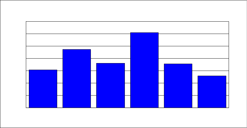
138 Implementing and Managing InfiniBand Coupling Links on IBM System z
Figure 5-3 shows the result of these calculations for all of the measurements.
Figure 5-3 CF CPU utilization
In this particular environment, if the ISC3 links are not going to replaced, the CF needs to be
upgraded to add another engine to bring the white space back to a level that can successfully
handle a CF outage situation. Alternatively, if the ISC3 links are replaced with HCA3-O 12X
links and those links are configured so that they run in IFB3 mode, not only will the upgrade
be avoided, but there will be spare capacity available to handle more workload growth.
Overall, you can see the relationship between link technology and utilization of the CF
engines.
Synchronous service times
There are many reasons why good service times for synchronous requests are important:
Low service times reduce utilization of the subchannels and link buffers associated with
those requests.
The CF exploiters that issued the request to the CF will benefit from shorter service times,
enabling better transaction service times or reduced batch job elapsed times.
The shorter the synchronous service time, the less CPU is consumed in z/OS to process
that request.
Converting a request to run asynchronously rather than synchronously increases the
service time of the request, typically by 2 to 3 times the synchronous service time. This
results in increased concurrency and more competition for CF-related resources.
ICB4 z10
HCA2-O to z10
HCA2-O to z196
ISC3 z196
HCA2-O z196
HCA3-O IFB3 z196
0
10
20
30
40
50
60
70
Utilization %
Normalized CF CPU Utilization
Chapter 5. Performance considerations 139
The average synchronous service times for the various configurations we measured are
shown in Figure 5-4.
Figure 5-4 Synchronous service times
Figure 5-4 is an excellent example of the importance of CF link technology to CF service
times. Moving the CF from a z10 to a z196 reduced service times by a little over
4 microseconds (compare the second and third bars in the chart). However, replacing the
HCA2-O 12X IFB links with HCA3-O 12X links in IFB3 mode, but keeping the same CF CPC,
reduced the service time by 7 microseconds. Replacing the ISC3 links with any type of
InfiniBand link resulted in an even larger decrease in service times.
z/OS CPU utilization
As discussed in “Synchronous versus asynchronous requests” on page 122, CF requests can
be handled synchronously or asynchronously. Processing a request asynchronously
consumes a relatively fixed amount of z/OS CPU time, whereas the z/OS CPU time to
process a synchronous request is equal to the CF service time. So, the lower the
synchronous service time, the less z/OS CPU is consumed to process the request.
Calculating the approximate z/OS CPU time to process a set of CF requests is relatively easy.
Simply multiply the number of synchronous CF requests by the synchronous service time and
add to that the sum of the number of asynchronous requests multiplied by the Sync/Async
heuristic threshold (about 26 microseconds at the time of writing).
ICB4 z10
HCA2-O to z10
HCA2-O to z196
ISC3 z196
HCA2-O z196
HCA3-O IFB3 z196
0
5
10
15
20
25
30
Mics
Average Synchronous Response Times
140 Implementing and Managing InfiniBand Coupling Links on IBM System z
Figure 5-5 shows the results of applying this formula to our measurements (normalized to the
capacity of a z196 and the request rate during the HCA3-O 12X in IFB3 mode measurement).
Figure 5-5 z/OS CPU utilization
Changing from one link type to another might (or might not) result in a noticeable change in
overall z/OS CPU utilization; it depends on how constrained the system is and what the
bottlenecks are. What is more likely is that because each request completes in less time, the
elapsed time for batch jobs and transactions will reduce, so the same amount of work will be
done in less time. However, it is fair to say that moving to links that reduce your synchronous
service times can free up z/OS CPU capacity that is then available to other work.
5.6 ISC and PSIFB 1X performance measurements results
The next set of measurements we performed were aimed at comparing ISC3 and long reach
InfiniBand (1X) links. These link types are most typically used for long-distance connections.
Although we did not have very long cables, we were able to perform various measurements to
compare the underlying performance of the two link types. The impact of distance on service
times (10 microseconds per km) will be the same on both link types.
The ability of InfiniBand to assign multiple CHPIDs to a single link might allow you to provide
equivalent performance and connectivity with InfiniBand 1X, but with fewer adapters, cables,
and DWDM ports than required to provide equivalent performance with ISC3 links.
Because each subchannel and link buffer cannot accept a new CF request until the previous
one that it was handling has completed, long distances (and the resulting high service times)
significantly increase subchannel and link buffer utilization. Assigning multiple CHPIDs to a
single InfiniBand link allows you to drive more value from the physical links than can be
achieved with ISC3 links. Also, Driver 93 on z196 and z114 changed 1X links (both
HCA2-O LR 1X and HCA3-O LR 1X) to have 32 link buffers per CHPID instead of the 7 that
were supported previously. Both of these characteristics make 1X InfiniBand links a very
attractive alternative to ISC3 links for connecting over relatively large distances.
In this set of measurements we concentrated on the underlying performance differences
between ISC3 links and HCA2-O LR 1X and HCA3-O LR 1X links, because we did not have
the long distances that generate high service times.
ICB4 10
HCA2-O z10
HCA2-O z196
ISC3 z196
HCA2-O z196
HCA3-O IFB3 z196
0
0.5
1
1.5
2
2.5
z196 engines
Normalized z/OS CPU Utilization

Chapter 5. Performance considerations 141
ISC3
The base case for this set of runs is the legacy (and widely-used) ISC3 links. We used the
results of the same run that we used in “ISC3 links” on page 133; they are repeated in
Table 5-9.
Table 5-9 ISC3 on z196 results
Because long-distance links are particularly intensive on subchannel and link buffer
utilization, for this measurement we also calculated the link buffer utilization. There were eight
ISC3 links shared between the two z/OS LPARs, which equate to 56 subchannels in each
z/OS system and 56 link buffers in the link adapters. The average link buffer utilization was
9.97% over the measurement interval.
HCA2-O LR 1X
The next run was to compare the ISC3 links to the HCA2-O LR 1X links. The results are
summarized in Table 5-10.
Table 5-10 HCA2-O LR 1X on z196 results
Reviewing the results from the ISC3 and HCA2-O LR 1X runs, we can make the following
observations:
The percent of requests that were issued synchronously increased from 41.2% with ISC3
links to 83.7% with the HCA2-O LR 1X links. This indicates significantly better service
times with the HCA2-O LR 1X links.
The request rate that was handled with the HCA2-O LR 1X links increased more than 10%
from the load that was processed with the ISC3 links (from 76,528 per second to 84,099
per second).
The average synchronous service time decreased from 26.5 microseconds with ISC3 to
19.5 microseconds with HCA2-O LR 1X. This facilitated the increases in the percent of
requests that were processed synchronously and the increase in the overall request rate.
In line with the pattern of CF utilization being related to the link speed, the CF CPU
utilization decreased from 52.1% to 34.7%, despite the fact that the request rate increased
by more than 10%.
Due to the decreased service times, the link buffer utilization dropped to 4.89%, a
reduction of over 50%. Remember that only two physical links were used in this
measurement, compared to the eight links that were used in the ISC3 measurement.
Although the performance delivered by the HCA2-O LR 1X links was not as good as the
HCA2-O 12X IFB links, it was still a significant improvement over the performance of the ISC3
links. Given that HCA2-O 12X IFB links support distances up to 150 meters, it is expected
Link
type
Number
links
Number
CHPIDs
CF type CF %
util
Sync % Sync
serv
time
Async
%
Async
serv
time
Total
req rate
ISC3 8 8 z196 52.1% 41.2 26.5 58.8 105.5 76528
Link
type
Number
links
Number
CHPIDs
CF type CF %
util
Sync % Sync
serv
time
Async
%
Async
serv
time
Total
req rate
ISC3 8 8 z196 52.1% 41.2 26.5 58.8 105.5 76528
HCA2-O LR 2 8 z196 34.7% 83.7 19.5 16.3 99.7 84099

142 Implementing and Managing InfiniBand Coupling Links on IBM System z
that most connections within a data center will use the 12X links, and that HCA2-O LR 1X
links will be used more for cross-site connectivity.
As the length of the connection increases, the latency caused by the speed of light comes to
dominate the service time. So, at distances of 10 km or more, the performance advantage of
HCA2-O 12X IFB links compared to ISC3 links becomes less noticeable. However, you still
obtain the significant benefit of more subchannels and more link buffers, which lets you
reduce the number of physical links required.
HCA3-O LR 1X
The final run of this suite was based on the HCA3-O LR 1X links. These provide 32 link
buffers per CHPID instead of the 7 that you had prior to Driver 937. However, given that we
did not have very long links (and very high service times) and therefore did not encounter any
subchannel or link buffer busy conditions, we did not expect any performance benefit from the
additional link buffers.
In a configuration that was experiencing high path or subchannel busy, the additional link
buffers are expected to result in better service times and less contention. The results are
summarized in Table 5-11.
Table 5-11 HCA3-O LR 1X with 32 link buffers on z196 results
As shown, the results for the HCA3-O LR 1X links were very similar to our experiences with
the HCA2-O LR 1X links. This is what we expected. Unlike the HCA3-O 12X adapters, the
HCA3-O LR 1X adapters do not use the IFB3 protocol, so the performance in an environment
that is not constrained for subchannels or link buffers would be expected to be similar to the
HCA2-O LR 1X links. Also, the HCA2-O LR 1X and HCA3-O LR 1X measurements were
taken some weeks apart (before and after the CPC upgrade to Driver 93 and to add new
adapters).
The small performance difference between the HCA2-O LR 1X and HCA3-O LR 1X
measurements is a good example of how small changes in the environment can result in
small differences in performance. The performance differences are only likely to be noticeable
in a benchmark environment; the variances in workload in a production environment mean
that such differences probably are not even noticed.
Specifically of interest to installations planning to use 1X links to connect two sites is the link
buffer utilization. In the ISC3 measurement, it was 9.9% of eight physical links. Migrating to
HCA2-O LR 1X links prior to Driver 93 (so there are still only seven link buffers per CHPID),
reduced link buffer utilization to 4.9% of just two physical links. Installing Driver 93 increased
the number of link buffers. Even though the service times increased by a small amount, the
link buffer utilization dropped to just 1.1% of two physical links. Given that the rule of thumb
for subchannel and link buffer utilization is that it should not exceed 30%, the use of 1X links
combined with Driver 93 or later provides significantly more scope for growth than the ISC3
7 HCA2-O LR 1X CHPIDs also have 32 link buffers when used with Driver 93 or later.
Link
type
#
links
#
CHPIDs
Total #
subch
CF
type
CF %
util
Sync % Sync
serv
time
Async
%
Async
serv
time
Total
req rate
ISC3 8 8 56 z196 52.1% 41.2 26.5 58.8 105.5 76528
HCA2-O
LR
2 8 56 z196 34.7% 83.7 19.5 16.3 99.7 84099
HCA3-O
LR
2 8 256 z196 34.9% 82.01 20 17.99 105.5 81388
Chapter 5. Performance considerations 143
links. HCA3-O LR 1X fanouts also provide four ports instead of the two that are provided on
the HCA2-O LR 1X fanouts. This might be especially attractive to installations with large
numbers of CPCs to interconnect.
Relationship between bandwidth and service times
Different types of CF requests cause different amounts of data to be sent to or retrieved from
the CF. For example, writing a 32 KB buffer to a DB2 GBP structure involves moving 32 KB to
the CF. In contrast, a lock request might be as small as 256 bytes.
The bandwidth of a CF link has an impact on the amount of time it takes to move data into the
link and retrieve it from the link at the other end. And the smaller the bandwidth, the larger the
impact. Figure 5-6 shows the service times for each of the structures in our measurement, for
both ISC3 and HCA2-O LR 1X links. ISC3 links have a data rate of 2.0 GBps, and HCA2-O
LR 1X and HCA3-O LR 1X links have a data rate of 5.0 Gbps.
Figure 5-6 Comparison of HCA2-O LR 1X and ISC3 structure service times
In the figure, the cache structures are all 4 KB except for Cache 2, which is 32 KB. As shown,
the service time difference is more pronounced for the 32 KB structure than the other cache
structures. And the lock structures, which tend to have the smallest requests, have the best
service times, and the smallest difference between the ISC3 and HCA2-O LR 1X links. This
information might be helpful if you are attempting to predict the change in service time if you
move from ISC3 to HCA2-O LR 1X or HCA3-O LR 1X adapters.
5.7 SM Duplex performance measurements results
The final set of measurements we took are for clients that are using System Managed
Duplexing with ICB4 links today, and are facing a migration to InfiniBand.
System Managed Duplexing was never envisioned to be a high performance solution. It was
designed to provide a high availability capability for CF exploiters that do not support
user-managed rebuild and to provide protection for exploiters that cannot survive a double
failure. It is expected that clients with high volume and high performance requirements will not
use System Managed Duplexing for database manager lock structures.
Cache 1
Cache 2
Cache 3
Cache 4
Cache 5
Cache 6
Cache 7
Lock 1
Lock 2
Lock 3
List 1
List 2
List 3
List 4
List 5
List 6
List 7
List 8
List 9
0
50
100
150
200
250
300
Mics
HCA2-O LR
ISC3
Synch Response Times
ISC vs HCA2 1X

144 Implementing and Managing InfiniBand Coupling Links on IBM System z
Nevertheless, it is valuable to provide information about the relative performance changes
that clients can expect when migrating from ICB4 links to HCA3-O 12X links running in IFB3
mode.
ICB4 on z10
The base case measurement consisted of the following configuration:
Two z/OS systems, both on z10. Both z/OS LPARs had three dedicated engines.
Two CF LPARs, both on z10. Both CF LPARs had two dedicated engines.
ICB4 links from the z/OS LPARs to each of the CF LPARs.
ICB4 links between the two CF LPARs.
In an attempt to be more client-like, the full workload was used, but only the IMS-like and
DB2-like lock structures were duplexed using System Managed Duplexing.
The second CF (referred to as CF2) contained only the secondary lock structures. All
other structures were in CF1, as in all the other measurements.
There was also a third CF that contained all structures other than those that were
associated with the workload. The performance of that CF and its associated structures
was not part of the measurement.
The results of this measurement are summarized in Table 5-12 and Table 5-13.
Table 5-12 ICB4 System Managed Duplexing results
Table 5-13 shows the information for ICB4 System Managed Duplexing for CF1 and CF2.
Table 5-13 ICB4 System Managed Duplexing results for CF1 and CF2
Because the focus of these measurements is on System Managed Duplexing, we extracted
performance information for the two structures that were duplexed; that information is
presented in Table 5-14 and Table 5-15 on page 145.
Table 5-14 shows the information for System Managed Duplexing with the ICB4 - DB2 lock
structure.
Table 5-14 System Managed Duplexing with ICB4: DB2 lock structure
Link
type
Number
links to each
CF
Number
CHPIDs to
each CF
CF types Total req rate
ICB4 2 2 z10 75607
Link
type/
CF CPU
type
CF1 %
Util
CF1
Sync %
CF1
Sync
serv
time
CF1
Async
%
CF1
Async
serv
time
CF2 %
Util
CF2
Sync %
CF2
Sync
serv
time
CF2
Async
%
CF2
Async
serv
time
ICB4
z10
33.2% 71.24 17 28.76 73.5 16.8% 0.44 42 99.56 72
Config Prim
Sync rate
Prim
Sync
resp time
Prim
Async
rate
Prim
Async
resp time
Secondry
Sync rate
Secondry
Sync
resp time
Secondry
Async
rate
Secondry
Async
resp time
ICB4 z10 46.4 42 10022 76 46 44 10022 74

Chapter 5. Performance considerations 145
Table 5-15 shows the information for System Managed Duplexing with the ICB4 - IMS lock
structure.
Table 5-15 System Managed Duplexing with ICB4 - IMS lock structure
Because this is the baseline measurement, there are no observations other than that the
overall CF CPU utilization and average service times are increased compared to the simplex
case, but this is in line with expectations.
HCA2-O 12X IFB on z10
The next set of measurements were performed with the same workload drivers, and with the
following configuration:
Two z/OS systems, both on z10. Both z/OS LPARs had three dedicated engines.
Two CF LPARs, both on z10. Both CF LPARs had two dedicated engines.
HCA2-O 12X IFB links from the z/OS LPARs to each of the CF LPARs.
HCA2-O 12X IFB links between the two CF LPARs.
The results of this measurement are shown in Table 5-16 and Table 5-17.
Table 5-16 HCA2-O 12X IFB System Managed Duplexing results
Table 5-17 shows the information for HCA2-O 12X IFB System Managed Duplexing for CF1
and CF2.
Table 5-17 HCA2-O 12X IFB System Managed Duplexing results for CF1 and CF2
At the CF level, notice that there was an increase in the CPU consumption when the ICB4
links were replaced with HCA2-O 12X IFB links, but that is in line with the pattern that we saw
earlier, where the CF CPU consumption changes in line with the speed of the links that are
being used. Interestingly, the CPU utilization of the peer CF (CF2) did not increase following
the move to HCA2-O 12X IFB links; that CF contained only lock structures, which indicates
Config Prim
Sync rate
Prim
Sync
resp time
Prim
Async
rate
Prim
Async
resp time
Secondry
Sync rate
Secondry
Sync
resp time
Secondry
Async
rate
Secondry
Async
resp time
ICB4 z10 29.7 36 7199 71 29.7 38 7199 68
Link
type
Number
links to each
CF
Number
CHPIDs to
each CF
CF types Total req rate
ICB4 2 2 z10 75607
HCA2-O 2 8 z10 71810
Link
type/
CF CPU
type
CF1 %
Util
CF1
Sync %
CF1
Sync
serv
time
CF1
Async
%
CF1
Async
serv
time
CF2 %
Util
CF2
Sync %
CF2
Sync
serv
time
CF2
Async
%
CF2
Async
serv
time
ICB4
z10
33.2% 71.24 17 28.76 73.5 16.8% 0.44 42 99.56 72
HCA2-O
z10
44.2% 67.3 21.5 32.7 104.2 16.4% 0.40 78.25 99.6 114

146 Implementing and Managing InfiniBand Coupling Links on IBM System z
that there is a relationship between the mix of CF requests and the impact on CF CPU
utilization (lock structures tend to have the smallest CF requests).
For a better understanding of the impact on System Managed Duplexing of changing the link
types, we really need to look at information for the two structures that were being duplexed.
That information is contained in Table 5-18 and Table 5-19.
Table 5-18 shows the information for the HCA2-O 12X IFB on z10 with the DB2 lock structure.
Table 5-18 System Managed Duplexing with HCA2-O 12X IFB on z10 - DB2 lock structure
Table 5-19 shows the information for the HCA2-O 12X IFB on z10 with the IMS lock structure.
Table 5-19 System Managed Duplexing with HCA2-O 12X IFB on z10 - IMS lock structure
As shown, there was a decrease in the rate of requests that were being processed
synchronously. That decrease was caused by a sizeable increase in the average
synchronous service time for both duplexed structures (both experienced an increase in
average synchronous service time of about 40 microseconds.). That increase resulted in a
decrease in the total number of requests that were processed, from 75,607 per second with
ICB4 links, down to 71,810 with the HCA2-O 12X IFB links.
Recall from the simplex measurements that the HCA2-O 12X IFB links caused an increase in
service times compared to ICB4 links. When using System Managed Duplexing, the impact is
compounded by the fact that there are four interactions back and forth between the peer CFs.
Thus, not only is the time to send the request to the CF increased, but also each of the
interactions between the CFs also experiences an increase.
HCA2-O 12X IFB on z196
The next set of measurements were taken on the z196, using HCA2-O 12X IFB links. Given
our experiences when we moved the workload to the z196 CF connected by
HCA2-O 12X IFB links, we were expecting an improvement in overall performance, compared
to the HCA2-O 12X IFB links on the z10. The results are summarized in Table 5-20 and
Table 5-21 on page 147.
Table 5-20 HCA2-O 12X IFB on z196 System Managed Duplexing results
Config Prim
Sync rate
Prim
Sync
resp time
Prim
Async
rate
Prim
Async
resp time
Secondry
Sync rate
Secondry
Sync
resp time
Secondry
Async
rate
Secondry
Async
resp time
ICB4 z10 46.4 42 10022 76 46 44 10022 74
HCA2 z10 33.5 81.3 8073 116.5 33.8 82.1 8073 117.8
Config Prim
Sync rate
Prim
Sync
resp time
Prim
Async
rate
Prim
Async
resp time
Secondry
Sync rate
Secondry
Sync
resp time
Secondry
Async
rate
Secondry
Async
resp time
ICB4 z10 29.7 36 7199 71 29.7 38 7199 68
HCA2 z10 25.2 71.4 6195 109.6 25.2 73.1 6195 109.0
Link
type
Number
links to each
CF
Number
CHPIDs to
each CF
CF types Total req rate
ICB4 2 2 z10 75607
HCA2-O 2 8 z10 71810

Chapter 5. Performance considerations 147
Table 5-21 shows the information for HCA2-O 12X IFB on z196 System Managed Duplexing
for CF1 and CF2.
Table 5-21 HCA2-O 12X IFB on z196 System Managed Duplexing results for CF1 and CF2
We can make a number of observations at the CF level:
The faster engine in the z196 helped by reducing both synchronous and asynchronous
service times.
The improved service times resulted in the workload generators sending more requests to
the CF, up from 71,810 per second on the z10 to 74,514 on the z196. This is still less than
were processed with the ICB4 on the z10, but it is line with the pattern we saw with the
simplex HCA2-O 12X IFB links measurement, where the z196 HCA2-O 12X IFB
measurements were closer to the ICB4 results than the HCA2-O 12X IFB on z10 results.
When normalized for the relative capacities of the z10 and z196 CFs, there was a
significant reduction in CF CPU utilization from 44.2% of the z10 CF capacity to the
equivalent of 35% on that same CF when the workload was moved to the z196. This was
despite an increase in the volume of requests being processed, compared to the
HCA2-O 12X IFB on z10 measurement. This change reflects greater link layer efficiencies
on the z196 than on the z10.
For a better understanding of the impact on System Managed Duplexing, Table 5-22 and
Table 5-23 on page 148 show the results for the two duplexed structures.
Table 5-22 shows the information for System Managed Duplexing with HCA2-O 12X IFB on
z196 with the DB2 lock structure.
Table 5-22 System Managed Duplexing with HCA2-O 12X IFB on z196: DB2 lock structure
HCA2-O on z196 2 8 z196 74514
Link
type
Number
links to each
CF
Number
CHPIDs to
each CF
CF types Total req rate
Link
type/
CF CPU
type
CF1 %
Util
CF1
Sync %
CF1
Sync
serv
time
CF1
Async
%
CF1
Async
serv
time
CF2 %
Util
CF2
Sync %
CF2
Sync
serv
time
CF2
Async
%
CF2
Async
serv
time
ICB4
z10
33.2% 71.24 17 28.76 73.5 16.8% 0.44 42 99.56 72
HCA2-O
z10
44.2% 67.3 21.5 32.7 104.2 16.4% 0.40 78.25 99.6 114
HCA2-O
z196
43.1% 72.4 18 27.6 97 17.1% 0.41 65 99.59 102
Config Prim
Sync rate
Prim
Sync
resp time
Prim
Async
rate
Prim
Async
resp time
Secondry
Sync rate
Secondry
Sync
resp time
Secondry
Async
rate
Secondry
Async
resp time
ICB4 z10 46.4 42 10022 76 46 44 10022 74
HCA2 z10 33.5 81.3 8073 116.5 33.8 82.1 8073 117.8
HCA2
z196
37.9 69 9085 101 37.6 69 9085 105

148 Implementing and Managing InfiniBand Coupling Links on IBM System z
Table 5-23 shows the information for System Managed Duplexing with HCA2-O 12X IFB on
z196 with the IMS lock structure.
Table 5-23 System Managed Duplexing with HCA2-O 12X IFB on z196 - IMS lock structure
At the structure level, when compared to HCA2-O 12X IFB on the z10, HCA2-O 12X IFB on
the z196 did noticeably better. The rate increased for both synchronous and asynchronous
requests, all of the service times decreased by at least 10 microseconds, and the overall
number of requests that was processed also increased.
Although the results are not yet equivalent to the performance observed when using the ICB4
links on z10, they are an improvement over HCA2-O 12X IFB on z10. The next step is to
replace the HCA2-O 12X IFB adapters with HCA3-O 12X adapters and configure them to run
in IFB3 mode.
HCA3-O 12X IFB3 mode on z196
The final set of System Managed Duplexing measurements that we undertook were of the
same workload and configuration, except using HCA3-O 12X links in IFB3 mode in place of
the HCA2-O 12X IFB links. The results at the CF level are summarized in Table 5-24 and
Table 5-25 on page 149.
Table 5-24 HCA3-O 12X IFB3 on z196 System Managed Duplexing results
Table 5-25 on page 149 shows the information for HCA3-O 12X IFB3 on z196 System
Managed Duplexing for CF1 and CF2.
Config Prim
Sync rate
Prim
Sync
resp time
Prim
Async
rate
Prim
Async
resp time
Secondry
Sync rate
Secondry
Sync
resp time
Secondry
Async
rate
Secondry
Async
resp time
ICB4 z10 29.7 36 7199 71 29.7 38 7199 68
HCA2 z10 25.2 71.4 6195 109.6 25.2 73.1 6195 109.0
HCA2
z196
27.3 60 6758 92 27.3 59 6758 97
Link
type
Number
links to each
CF
Number
CHPIDs to
each CF
CF types Total req rate
ICB4 2 2 z10 75607
HCA2-O 2 8 z10 71810
HCA2-O on z196 2 8 z196 74514
HCA3-O IFB3 on
z196
2 8 z196 77467

Chapter 5. Performance considerations 149
Table 5-25 HCA3-O 12X IFB3 on z196 System Managed Duplexing results for CF1 and CF2
At the CF level, notice the following points:
The number of requests being processed was up by nearly 4% compared to the
HCA2-O 12X IFB on z196 run.
The CF CPU utilization of CF1 was down by nearly 20%. The utilization of CF2 (which only
handles requests to the secondary structures) was also down, although by a smaller
amount. This is another indication that it is not only the link speed that affects CF CPU
utilization, but a combination of link speed and workload mix.
The average synchronous service time for CF1 was reduced by 50%. The average
synchronous service time for CF2 was down by over 43%.
For a better understanding of the impact of the HCA3-O 12X IFB3 links on the duplexed
structures, Table 5-26 and Table 5-27 on page 150 contain information about the two
duplexed structures.
Table 5-26 shows the information for System Managed Duplexing with HCA3-O 12X in IFB3
mode on z196 with the DB2 lock structure.
Table 5-26 System Managed Duplexing with HCA3-O 12X in IFB3 mode on z196 - DB2 lock structure
Table 5-27 on page 150 shows the information for System Managed Duplexing with HCA3-O
12X in IFB3 mode on z196 with the IMS lock structure.
Link
type/
CF CPU
type
CF1 %
Util
CF1
Sync %
CF1
Sync
serv
time
CF1
Async
%
CF1
Async
serv
time
CF2 %
Util
CF2
Sync %
CF2
Sync
serv
time
CF2
Async
%
CF2
Async
serv
time
ICB4
z10
33.2% 71.24 17 28.76 73.5 16.8% 0.44 42 99.56 72
HCA2-O
z10
44.2% 67.3 21.5 32.7 104.2 16.4% 0.40 78.25 99.6 114
HCA2-O
z196
43.1% 72.4 18 27.6 97 17.1% 0.41 65 99.59 102
HCA3-O
IFB3
z196
34.7% 76.25 9 23.75 70 15.7% 0.42 37 99.58 74
Config Prim
Sync rate
Prim
Sync
resp time
Prim
Async
rate
Prim
Async
resp time
Secondry
Sync rate
Secondry
Sync
resp time
Secondry
Async
rate
Secondry
Async
resp time
ICB4 z10 46.4 42 10022 76 46 44 10022 74
HCA2 z10 33.5 81.3 8073 116.5 33.8 82.1 8073 117.8
HCA2
z196
37.9 69 9085 101 37.6 69 9085 105
HCA3
IFB3 z196
45.3 37 10283 71 44.9 39 10283 76
150 Implementing and Managing InfiniBand Coupling Links on IBM System z
Table 5-27 System Managed Duplexing with HCA3-O 12X in IFB3 mode on z196: IMS lock structure
The results are the structure level are equally impressive:
The rate for both synchronous and asynchronous requests increased again, compared to
the HCA2-O 12X IFB links on z196 and were now equivalent to the request rate with the
ICB4 links.
All of the service times, both synchronous and asynchronous, for both structures were
significantly improved compared to the HCA2-O 12X IFB on z196 run and the baseline
ICB4 run.
Summary of System Managed Duplexing measurements
The following figures summarize the results for the various configurations for you in graphical
format.
Figure 5-7 shows how the total request rate to the duplexed structures changed as the link
type was changed.
Figure 5-7 Summary of duplexed structure average synchronous service times
Config Prim
Sync rate
Prim
Sync
resp time
Prim
Async
rate
Prim
Async
resp time
Secondry
Sync rate
Secondry
Sync
resp time
Secondry
Async
rate
Secondry
Async
resp time
ICB4 z10 29.7 36 7199 71 29.7 38 7199 68
HCA2 z10 25.2 71.4 6195 109.6 25.2 73.1 6195 109.0
HCA2
z196
27.3 60 6758 92 27.3 59 6758 97
HCA3
IFB3 z196
29.3 33 7126 66 29.2 34 7126 71
17297
14326
15908
17483
ICB4 z10
HCA2-O z10 HCA2-O z196
HCA3-O IFB3 z196
0
5
10
15
20
Thousands
System-Managed Duplexing
Total Structure Request Rates
Chapter 5. Performance considerations 151
Figure 5-8 shows how the average synchronous service time changed as the link types were
changed.
Figure 5-8 Summary of duplexed structure average synchronous service times
Although asynchronous service times tend to be less predictable and consistent because
such a large percent of the duplexed requests were processed asynchronously, it is valuable
to provide that information as well. The average asynchronous service times for each
configuration are shown in Figure 5-9.
Figure 5-9 Summary of duplexed structure average asynchronous service times
39
76
65
35
ICB4 z10
HCA2-O z10 HCA2-O z196
HCA3-O IFB3 z196
0
10
20
30
40
50
60
70
80
Microseconds
System-Managed Duplexing
Structure Synchronous Response times
39
76
65
35
ICB4 z10
HCA2-O z10 HCA2-O z196
HCA3-O IFB3 z196
0
10
20
30
40
50
60
70
80
Microseconds
System-Managed Duplexing
Structure Synchronous Response times

152 Implementing and Managing InfiniBand Coupling Links on IBM System z
If you are using ICB4 links and exploiting System Managed Duplexing today, there are a
number of scenarios which might describe your environment:
You are not duplexing many CF requests, or the service time of those requests is not
critical for your workload.
In this case, the performance impact as you move to HCA2-O 12X IFB on z10 and then
migrate to HCA2-O 12X IFB on z196 might be acceptable, so it will not be necessary to
replace the HCA2-O 12X IFB links with HCA3-O 12X IFB3 links at this time.
You are duplexing a large number of requests, and the service time of those requests is
critical to meeting your online service time targets and your batch window deadlines.
In this case, you have two options:
– Provide a failure-isolated CF (such as a z114 or a z196) and discontinue duplexing for
your lock structures. Turning off duplexing will result in a significant improvement in
structures service times, regardless of the type of links that are being used. For
example, a simplex lock request using ISC3 links (which are the slowest link type
available) will have a better service time than a duplexed lock request using the fastest
link type available.
Note that structure types that do not provide user-managed rebuild support will still
need to be duplexed even if you have a failure-isolated CF. For more information, see
the System Managed Duplexing white paper, available on the web at the following link:
ftp://ps.boulder.ibm.com/common/ssi/ecm/en/zsw01975usen/ZSW01975USEN.PDF
– Try to minimize the time between the start of the migration to z196 and the time when
all CPCs will have migrated to HCA3-O fanouts. If you have multiple CPCs, try to move
the ones that contain the CFs to z196 first. You can then implement HCA3-O fanouts
for communication between the peer CFs, and get the benefit of the better
performance for those requests while you are waiting to move the remaining CPCs to
z196.
The migration from legacy CF link technology to InfiniBand provides an opportunity to
reevaluate your use of System Managed Duplexing and create a strategy for moving forward
that will deliver the optimum performance and availability in the most cost-effective manner.
5.8 Summary
For clients that exploit high performance ICB4 links today, our results confirm the general IBM
guidance that migrating from ICB4 links on a z10 to InfiniBand links on the z10 will result in
elongated CF service times. However, replacing the z10 CF with a z196 CF can deliver
performance improvements that bring the service times back into line with the ICB4 on z10
configuration. Completing the migration by replacing the HCA2-O 12X IFB links with HCA3-O
12X links running in IFB3 mode will deliver further performance benefits and bring the z/OS
coupling cost back in line with z10/ICB4 levels.
Clients that are currently exploiting ISC3 links within a single data center can migrate to 12X
InfiniBand links and experience significant performance improvements. Further, the migration
can provide one or more of the following benefits:
Better connectivity
More flexibility
Fewer links
Reduced CF CPU utilization

Chapter 5. Performance considerations 153
Clients that are currently exploiting ISC3 links to connect across data centers can benefit from
the ability to assign multiple CHPIDs to a single link and the greater number of link buffers
that 1X links support8. This can result in a reduction in the number of coupling links that are
required to connect the two sites (which means fewer fanouts and fewer DWDM ports) and
possible performance improvements (depending on the distance between the sites).
8 When used with Driver 93 or later and connected to a CPC that is also running Driver 93 or later.
154 Implementing and Managing InfiniBand Coupling Links on IBM System z

© Copyright IBM Corp. 2008, 2012, 2014. All rights reserved. 155
Chapter 6. Configuration management
In this chapter, we provide an overview of the configuration management requirements for
Parallel Sysplex using InfiniBand (PSIFB) links.
We discuss the following topics:
Configuration overview
PSIFB link support
Sample configuration with PSIFB links
Defining your configuration to the software and hardware
Cabling documentation considerations
Dynamic reconfiguration considerations
CHPID Mapping Tool support
6
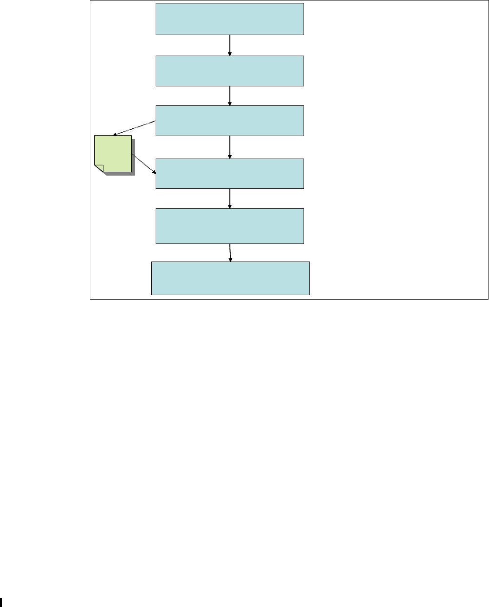
156 Implementing and Managing InfiniBand Coupling Links on IBM System z
6.1 Configuration overview
Figure 6-1 represents a basic roadmap to follow to help establish a typical PSIFB link
configuration.
Figure 6-1 PSIFB configuration roadmap
Document your planned PSIFB link environment so that all physical and logical connections
can be easily and concisely referenced. The resulting documentation will ensure a smooth
setup of your configuration and will also be a beneficial reference for problem determination
purposes, if needed. As we go through this chapter, you will see an example of our use of
such documentation.
6.2 PSIFB link support
In this section, we describe the configuration support and options that are available for PSIFB
links.
PCHID
report
PCHID
report
1. Review connectivity topology and
cabling requirements
3. Verify hardware requirements and
configure order.
4. Assign CHPIDs to AIDs & PORTs
(paper exercise using PCHID report)
5. Create IODF with PSIFB links
6. Validate mapping with CHPID Mapping
Tool and generate production IODF
2. Review and install software
prerequisites.
PCHID
report
PCHID
report
1. Review connectivity topology and
cabling requirements
3. Verify hardware requirements and
configure order.
4. Assign CHPIDs to AIDs & PORTs
(paper exercise using PCHID report)
5. Create IODF with PSIFB links
6. Validate mapping with CHPID Mapping
Tool and generate production IODF
2. Review and install software
prerequisites.
See 2.1, “InfiniBand connectivity” on
page 18 and 2.6, “InfiniBand cables” on
page 34.
See 3.3, “Hardware and software
prerequisites” on page 42.
See 2.2, “InfiniBand fanouts” on page 19
and 3.2.2, “Supported coupling link
types” on page 40.
See 2.3, “Fanout plugging” on page 22
and 6.2, “PSIFB link support” on
page 156.
See 6.2, “PSIFB link support” on
page 156 and 6.4, “Defining your
configuration to the software and
See 6.8, “CHPID Mapping Tool support”
on page 183.
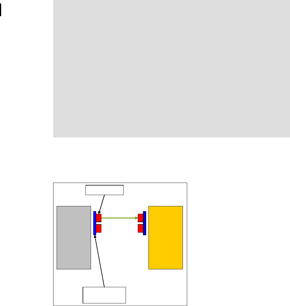
Chapter 6. Configuration management 157
6.2.1 PSIFB connectivity options
PSIFB link
A PSIFB link is a coupling link that connects a z/OS logical partition to a Coupling Facility
(CF) logical partition through a port on a host channel adapter (HCA) using a physical cable
to a compatible adapter on a different processor (see Figure 6-2).
Figure 6-2 PSIFB link between two System z processors
InfiniBand links can be used for coupling z/OS LPARs to CF LPARs, CF LPARs to other CF
LPARs (coupling links), or for use solely by STP (timing-only links). In all cases, the links are
defined as a channel path type of CIB. The specifics of defining both coupling and timing-only
links are described in 6.4, “Defining your configuration to the software and hardware” on
page 161.
Note: The definition of PSIFB links in hardware configuration definition (HCD) and
input/output configuration program (IOCP) does not differentiate between the various
PSIFB link types. A CHPID that is assigned to any type of PSIFB link is defined simply as
“CIB”.
Additionally, HCD does not differentiate between a z196 at Driver Level 86 and one at a
later level.
It is important to remember this because different PSIFB features (HCA3 versus HCA2 and
1X versus 12X) have different characteristics as follows:
The number of available ports
The number of available link buffers
Different performance characteristics
Use different types of cables
Because HCD does not know the capability of the processor, it is unable to verify that the
definitions that you provide are accurate. For further details, see 6.4.2, “Defining PSIFB
links using HCD” on page 164.
z/OS CF
Port on HCA
HCA identified
by AID
z/OS CF
Port on HCA
HCA identified
by AID
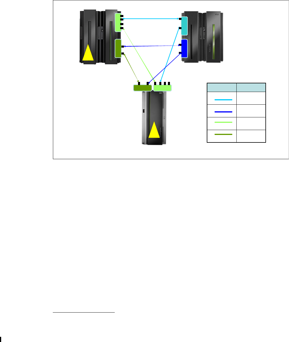
158 Implementing and Managing InfiniBand Coupling Links on IBM System z
6.3 Sample configuration with PSIFB links
In this section, we reference a sample Parallel SyspIex configuration that exploits PSIFB links,
and describe the process to define it. Figure 6-3 shows the processors and PSIFB links in this
configuration. The sections that follow describe the connectivity details and steps that are
required to define the different types of PSIFB link.
Figure 6-3 Sample configuration with PSIFB links
The configuration shown in Figure 6-3 reflects the following information:
Each PSIFB link is attached to a PORT on an HCA adapter (that is identified by an AID).
Multiple CHPIDs can be assigned to each link.
Multiple sysplexes can be using each link. The link can be shared across sysplexes by
assigning multiple CHPIDs to the link and having the different sysplexes using different
CHPIDs. Although the link can be shared by multiple sysplexes, CF link CHPIDs can only
be shared by systems in the same sysplex1.
There cannot be more than one Coupling Facility in the access list of a given CHPID.
If an HCA3-O (12X) port is connected to another HCA3-O (12X) port, both IFB and IFB3
modes are possible. IFB3 mode is used when four or less CHPIDs are assigned to the
port. IFB mode is used if more than four CHPIDs are assigned to the port.
All PSIFB links shown are coupling links. No timing-only links exist in this configuration
because all three processors contain a Coupling Facility and all processors are connected
by coupling links with a CF connected to at least one end of each link. Timing-only links
cannot be defined between a pair of processors if there are existing coupling links already
defined between those processors.
1 HCD is unable to enforce this restriction, because it does not know which sysplex any LPAR will be a part of.
Therefore, it is important that you have manual checks in place to ensure that this restriction is adhered to.
IB022097
IB042097
IB012097
HCA2 O L R
IB022817
IB032818
IC F
HCA2 O
HCA3 O LR
HCA3 O
HCA3 O
HCA3 O L R
PS IFB 1 2X
IFB or IFB3
PS IFB 1 X
IFB
PS IFB 1 2X
IFB only
PS IFB 1 X
IFB
Link typeLink color
**Note: This is for illustrative purposes only. Multiple HCAs of the same type should be configured for availability.
Each HCA fanout actually reflects a pair of features.
IC F

Chapter 6. Configuration management 159
AID and port assignments
AID information is found in the PCHID report for a processor. Example 6-1 contains the report
for the processors in this configuration.
Example 6-1 PCHID reports for sample configuration
PCHID report for System IB012097
CHPIDSTART
16177822 PCHID REPORT Jun 10,2011
Machine: 2097-E12 SN1
- - - - - - - - - - - - - - - - - - - - - - - - - - - - - - - - - - - - - - -
Source Cage Slot F/C PCHID/Ports or AID Comment
06/D5 A25B D506 0163 AID=0A
06/D6 A25B D606 0163 AID=0B
06/D7 A25B D706 0168 AID=0C
06/D8 A25B D806 0168 AID=0D
PCHID report for System IB022817
CHPIDSTART
16177867 PCHID REPORT Jun 10,2011
Machine: 2817-M15 SN1
- - - - - - - - - - - - - - - - - - - - - - - - - - - - - - - - - - - - - - -
Source Cage Slot F/C PCHID/Ports or AID Comment
06/D5 A25B D506 0171 AID=0A
06/D6 A25B D606 0171 AID=0B
06/D7 A25B D706 0170 AID=0C
06/D8 A25B D806 0170 AID=0D
PCHID report for System IB032818
CHPIDSTART
16177909 PCHID REPORT Jun 10,2011
Machine: 2818-M10 SN1
- - - - - - - - - - - - - - - - - - - - - - - - - - - - - - - - - - - - - - -
Source Cage Slot F/C PCHID/Ports or AID Comment
A26/D1 A26B D1 0171 AID=00
A26/D8 A26B D8 0170 AID=03
A21/D1 A21B D1 0171 AID=08
A21/D8 A21B D8 0170 AID=0B
Mapping CIB CHPIDs for availability across the fanouts and ports
Map the CIB CHPIDs across the available books, fanouts, and ports for optimum availability
at both ends of the PSIFB link.
This is a manual process, because the CHPID Mapping Tool does not perform this mapping
for you. You must be careful to avoid any single points of failure within your configuration by

160 Implementing and Managing InfiniBand Coupling Links on IBM System z
ensuring that systems and sysplexes are mapped across multiple fanouts and ports.
Table 6-1 reflects a sample configuration. It helps you see how many CHPIDs are assigned to
each port, how many adapters are being used by each sysplex, and which sysplexes will be
impacted if you were to make a change to any given port.
Table 6-1 System CHPID assignments across IFB fanouts and ports
Although the CHPID Mapping Tool does not perform this mapping for you, it does provide a
validation capability where single points of failure are highlighted in the form of intersects. For
further details, see 6.8, “CHPID Mapping Tool support” on page 183.
Overdefining CIB links
Because stand-alone Coupling Facilities do not support dynamic configuration changes,
adding PSIFB CHPIDs to a stand-alone CF requires one of the following:
Installing and defining the adapters and CHPIDs in advance (when the processor is
initially installed, for example).
Shutting down all CF LPARs on the processor and performing a POR when the adapters
or CHPIDs are added. This means an outage for those CFs.
If you have a business need to avoid any type of planned outage, you might decide to install
the adapters and CHPIDs in advance. Prior to APAR OA29367, you had to install and define
the adapter and CHPIDs on both the CF and the z/OS processors because it is not possible
to build a production input/output definition file (IODF) that contains unconnected CIB
CHPIDs.
However, APAR OA29367 delivered the ability to specify an AID of an asterisk (*). This means
that you can:
Install the adapter on the CF processor.
Define the CIB CHPIDs on the CF processor, pointing to the actual AID and port.
Define CIB CHPIDs on the z/OS processor, pointing to the placeholder AID of *.
Connect the CHPID on the CF processor to the CHPID on the z/OS processor.
System Fanout type Adapter ID PORT PROD sysplex
CHPIDs
DEV sysplex
CHPIDs
IB022817 HCA3-O LR 0A 1 00
220 50
301
430
HCA3-O LR 0B 1 02
221 51
303
431
HCA3-O 0C 1 40 60
270
HCA3-O 0D 1 41 61
271

Chapter 6. Configuration management 161
This allows you to build and activate a production IODF. Then, in the future when you need
the additional capacity, you install the adapter on the z/OS processor, update HCD to replace
the * with the actual AID, build the new production IODF, and activate that IODF. You can then
immediately use the new links to communicate with the CF without having to take an outage
on the CF.
For more information about this capability, see the APAR documentation or z/OS Hardware
Configuration Definition User’s Guide, SC33-7988.
Documenting your target environment
At this point, you probably have a diagram that shows at a high level the InfiniBand
connectivity that you plan to implement between your processors (including the number and
type of physical links, the number of CHPIDs you want to assign to each AID and port, and
which LPARs will be in the access lists for those CHPIDs).
Now translate that diagram into a table similar to that shown in Figure 6-4. Taking a few
minutes to do this now will make it much easier to add the definitions in HCD or HCM, and
reduce any errors or omissions that might arise during that process.
Figure 6-4 Sample configuration table
6.4 Defining your configuration to the software and hardware
You are now ready to define your target InfiniBand infrastructure in an IODF and an IOCDS.
We first describe the input/output configuration program (IOCP) statements that are related to
InfiniBand links, and then lead you through the process of using HCD to define your
configuration.
6.4.1 Input/output configuration program support for PSIFB links
IOCP statements are typically built using HCD or the Hardware Configuration Manager
(HCM).
For full details of the rules and limitations related to defining InfiniBand links using IOCP
statements, refer to the Input/Output Configuration Program User’s Guide for your processor,
available on the web at the following site:
https://ibm.com/servers/resourcelink
CHPID type CIB (Coupling over InfiniBand)
The CHPID type CIB is used to identify a Coupling over InfiniBand channel path. CIB CHPIDs
can be defined as dedicated (DED), reconfigurable (REC), shared (SHR), or spanned
(SPAN). The high-level configuration guidelines for CIB CHPIDs are:
You do not specify a Physical Channel ID (PCHID) for a CIB CHPID. For InfiniBand
CHPIDs, instead of specifying a PCHID, the adapter ID (AID) and PORT are specified.
Cage/Slot/Jack AID/Port CHPID(s) Sharing LPARs Type connected
to...
Type Cage/Slot/Jack AID/Port CHPID(s) Sharing LPARs Comment
A25B-D206-J02 09/2 0.93 A0E (FACIL03) HCA2 12X HCA2 12X A25B/D506/J01 0A/1 2.85 A21 - Prodplex
A22 - Prodplex Online
A25B-D606-J02 0B/2 0.B9 A0E (FACIL03) HCA2 12X HCA2 12X A25B/D606/J01 0B/1 0.80 A0B - (CHPID holder) Offline
A25B-D615-J01 1B/1 0.9C
0.9D A0F (CHPID holder)
A0F (CHPID holder) HCA2 12X HCA2 12X A25B/D715/J02 1C/2 0.8B
0.8C A0B - (CHPID holder)
A0B - (CHPID holder Offline
Offline
A25B-D615-J02 1B/2 0.BB A0E (FACIL03) HCA2 12X HCA2 12X A25B/D715/J01 1C/1 0.86 A0B - (CHPID holder) Offline

162 Implementing and Managing InfiniBand Coupling Links on IBM System z
A spanned CIB CHPID requires that you specify the same AID and PORT for all channel
subsystems where it is defined.
You can assign up to 16 CIB CHPIDs to the same AID. This configuration is verified at the
adapter level, which means that you can potentially assign all 16 CIB CHPIDs to one port.
You can combine CIB, CBP, CFP, and ICP CHPID types to the same control unit (CF
image), up to the maximum of eight paths per CU.
All CIB CHPIDs on a single control unit must have the same connecting system
(CSYSTEM) specified (this is handled automatically by HCD or HCM).
You can only connect a CIB CHPID to another CIB CHPID.
All CIB CHPIDs defined in the IODF must be connected to another CIB CHPD before a
production input/output definition file (IODF) can be built. Any attempt to build either a
production or validated work IODF with unconnected CIB CHPIDs results in a message
similar to that shown in Figure 6-5.
Figure 6-5 Error message for unconnected CIB CHPID when trying to build a validated work IODF
Any processor with CIB channel path must have a local system name (LSYSTEM). This
value is defined in the processor definition panel in HCD. For further details, see
“LSYSTEM” on page 162.
Adapter ID (AID)
The adapter ID (AID) identifies the host channel adapter (HCA) that the CHPID is to be
associated with. This value is in the range of 00 through 1F (for processor-specific details,
see 2.4, “Adapter ID assignment and VCHIDs” on page 26). Adapter IDs are assigned when
the processor is configured. AIDs are listed in the PCHID report that is provided by your IBM
service support representative (IBM SSR) when the HCA is ordered. They are also available
on the SE panels after the adapters have been installed.
PORT
This specifies the port number (1-4) on the HCA.
LSYSTEM
LSYSTEM specifies the system name of the processor. It is an alphanumeric value of 1-8
characters and can begin with either an alphabetic character or a numeric character.
Note: Even though HCD and IOCP allow this, it is best to assign no more than four
CHPIDs per port for optimum throughput. Assigning more than four CHPIDs has further
implications for HCA3-O (12X) fanouts, where the less efficient IFB mode will be used
instead of IFB3 mode if more than four CHPIDs are assigned to that port.
Message List
Save Query Help
--------------------------------------------------------------------------
Row 1 of 8
Command ===> ___________________________________________ Scroll ===> CSR
Messages are sorted by severity. Select one or more, then press Enter.
/ Sev Msg. ID Message Text
_ E CBDG432I CIB channel path 0.88 of processor IB032818 is not
# connected. It must be connected to a channel path of
# type CIB.

Chapter 6. Configuration management 163
All alphabetic characters are automatically folded to uppercase. If the processor definition in
HCD does not contain a value for LSYSTEM, HCD will default to the CPC name that is
specified for the Processor. The HCD panel where the LSYSTEM name is specified is shown
in Figure 6-6. In this example, the LSYSTEM name is IB01CPC. If the LSYSTEM field is left
blank, an LSYSTEM name of 2097E123 (from the CPC name field) will be assigned.
Figure 6-6 Defining the local system name
CSYSTEM
CSYSTEM is used to identify the connected system. It is the LSYSTEM name of the
processor at the other end of the InfiniBand link. HCD will automatically provide the
CSYSTEM name, based on the specific CIB CHPIDs that are being connected.
Change Processor Definition
Specify or revise the following values.
Processor ID . . . . . . . . : IB012097
Support level:
XMP, 2097 support
Processor type . . . . . . . . 2097 +
Processor model . . . . . . . E12 +
Configuration mode . . . . . . LPAR +
Serial number . . . . . . . . __________ +
Description . . . . . . . . . ________________________________
Specify SNA address only if part of an S/390 microprocessor cluster:
Network name . . . . . . . . . ABCD1234 +
CPC name . . . . . . . . . . . 2097E123 +
Local system name . . . . . . IB01CPC
Note: Use a name for LSYSTEM that will carry over from one processor to its replacement,
instead of accepting the default of the CPC name, for the following reason:
If the LSYSTEM parameter is changed (because of a CPC upgrade of z10 to z196, for
example) the systems at the other end of the PSIFB connections might need a dynamic
activate or a power-on reset (for a stand-alone CF) to pick up the new LSYSTEM name. If
the LSYSTEM statement remains unchanged from its original value, then this is not
necessary. The LSYSTEM name is only used in relation to CF link CHPIDs, so using an
LSYSTEM name that is different from the CPC name should not cause any confusion.
For more details, see the latest version of the Solution Assurance Product Review (SAPR)
guide. This is available to your IBM representative from Resource Link at:
https://ibm.com/servers/resourcelink
The SAPR guides are listed under “Mainframes” on the Library page.

164 Implementing and Managing InfiniBand Coupling Links on IBM System z
CPATH
CPATH specifies the Channel SubSystem (CSS) ID and CHPID on the connected system.
This is handled by HCD.
6.4.2 Defining PSIFB links using HCD
In this section, we describe the steps necessary to define PSIFB links between two
processors called IB012097 (a z10) and IB022817 (a z196) using HCD. For the purpose of
this illustration, we only show the process of defining the links on IB022817. The links have
already been defined on IB012097.
Defining the CIB CHPIDs
To define the CIB CHPIDs:
1. From the HCD main menu, select option 1.3 and press Enter. This option takes you to the
Processor List panel as shown in Figure 6-7.
Figure 6-7 HCD Processor List panel
2. In the processor list, select the processor that you want to work with (in our case,
IB022817) by entering s to the left of the Processor ID. Enter s to work with the channel
subsystems for this processor, as shown in Figure 6-8.
Figure 6-8 Channel Subsystem List
Specify s for the appropriate CSS ID (0 in our example in Figure 6-8) and press Enter to
display the Channel Path List for this processor.
Processor List Row 1 of 3 More: >
Command ===> _______________________________________________ Scroll ===> PAGE
Select one or more processors, then press Enter. To add, use F11.
/ Proc. ID Type + Model + Mode+ Serial-# + Description
_ IB012097 2097 E12 LPAR __________ ________________________________
s IB022817 2817 M15 LPAR __________ ________________________________
_ IB032818 2818 M10 LPAR __________ ________________________________
Channel Subsystem List Row 1 of 4 More: >
Command ===> _______________________________________________ Scroll ===> PAGE
Select one or more channel subsystems, then press Enter. To add, use F11.
Processor ID . . . : IB022817
CSS Devices in SS0 Devices in SS1 Devices in SS2
/ ID Maximum + Actual Maximum + Actual Maximum + Actual
s 0 65280 0 65535 0 65535 0
_ 1 65280 0 65535 0 65535 0
_ 2 65280 0 65535 0 65535 0
_ 3 65280 0 65535 0 65535 0
******************************* Bottom of data *******************************

Chapter 6. Configuration management 165
3. From the Channel Path List, press PF11 to add a CHPID, as shown in Figure 6-9.
Figure 6-9 Adding a CIB channel path
On the Add Channel Path panel, enter the appropriate details:
Channel path ID (20 in our configuration)
Channel path type (CIB for a Coupling over InfiniBand CHPID)
Operation mode (SHR in our configuration)
Description (optional, but highly advisable)
Then, press Enter.
Add Channel Path
Specify or revise the following values.
Processor ID . . . . : IB022817
Configuration mode . : LPAR
Channel Subsystem ID : 0
Channel path ID . . . . 20 + PCHID . . . ___
Number of CHPIDs . . . . 1
Channel path type . . . cib +
Operation mode . . . . . shr +
Managed . . . . . . . . No (Yes or No) I/O Cluster ________ +
Description . . . . . . HCA3-1X IB02 PROD CHP20 TO IB01
Specify the following values only if connected to a switch:
Dynamic entry switch ID + (00 - FF)
Entry switch ID . . . . __ +
Entry port . . . . . . . __ +
Notes:
The PCHID field is invalid for a CIB CHPID, so that field should be left blank.
Because PSIFB links allow for multiple logical connections, configuration details can be
complex and difficult to interpret. We strongly advise adding (and maintaining) useful
details (such as the link type and the sysplex that will use that CHPID) in the description
field.
HCD does not distinguish between the different InfiniBand features. Additionally, if the
processor you are working with is a z196 or a z114, HCD is unaware of the capability of
that processor. A CHPID type of CIB can be an HCA2 or HCA3 fanout, which can be
either 12X or 1X. This means that a PSIFB 12X fanout on a z196 or z114 can be
incorrectly defined as having four ports (because four ports are supported for HCA3-O
LR (1X) links) and HCD will not be aware that the definition is invalid.
Be careful to cross-reference your CHPID definitions against your PCHID report to ensure
that your CHPID definitions correctly match the available AIDs and ports of your configured
HCA fanouts. This is the process described in “Mapping CIB CHPIDs for availability across
the fanouts and ports” on page 159.

166 Implementing and Managing InfiniBand Coupling Links on IBM System z
4. The next panel (Figure 6-10) requires the details of the HCA attributes for this CHPID. This
detail was established in the mapping exercise that we performed earlier (see Table 6-1 on
page 160).
Figure 6-10 Defining Adapter ID and Port assignments
Type the Adapter ID and Port number and press Enter.
Figure 6-11 Channel Path Access List
5. The Define Access List panel appears as shown in Figure 6-11. Specify the forward slash
character (/) for each LPAR that is to be in the access list. In our configuration, both of the
production LPARs in CSS0 are included.
6. Press Enter and add any additional LPARs to the Candidate List for this CIB channel
(none in our case) until the Channel Path List for this CSS ID appears as shown in
Figure 6-12, which shows the unconnected CIB CHPID on IB022817.
Figure 6-12 Channel Path list with unconnected CIB CHPID 20
Specify HCA Attributes
Specify or revise the values below.
Adapter ID of the HCA . . 0A +
Port on the HCA . . . . . 2 +
Define Access List
Row 1 of 2
Command ===> _________________________________________ Scroll ===> PAGE
Select one or more partitions for inclusion in the access list.
Channel subsystem ID : 0
Channel path ID . . : 20 Channel path type . : CIB
Operation mode . . . : SHR Number of CHPIDs . . : 1
/ CSS ID Partition Name Number Usage Description
/ 0 IB02CF1 2 CF
/ 0 IB02OS1 1 OS
Channel Path List Row 1 of 1 More: >
Command ===> _______________________________________________ Scroll ===> PAGE
Select one or more channel paths, then press Enter. To add use F11.
Processor ID . . . . : IB022817
Configuration mode . : LPAR
Channel Subsystem ID : 0
PCHID Dyn Entry +
/ CHPID AID/P Type+ Mode+ Sw+ Sw Port Con Mng Description
f 20 0A/2 CIB SHR __ __ __ N No HCA3-1X IB02 PROD CHP20 TO IB01

Chapter 6. Configuration management 167
Connecting the CIB CHPIDs
In this section, the CIB CHPIDs are connected together.
At this stage, we have defined the CIB CHPIDs at either end of the PSIFB link. However, we
cannot use the CIB CHPIDs until they have been connected and the subchannels have been
generated. Furthermore, an attempt to build a production IODF will fail if there are
unconnected CIB CHPIDs. To connect the CIB CHPIDs, do the following:
1. Return to the Channel Path List of either of the associated processors as shown in
Figure 6-12 on page 166. Specify f next to the associated CHPID and press Enter to
display the CF Channel Path Connectivity List as shown in Figure 6-13.
Figure 6-13 CF Channel Path Connectivity List with unconnected CIB CHPID 20
2. Enter p next to the associated CHPID to display the Channel Path Connection panel
shown in Figure 6-14.
Figure 6-14 Channel Path Connection panel
On the Connect to CF Channel Path panel, type in the following information:
– Destination processor ID (IB012097 in our configuration)
– Destination channel subsystem ID (0 in our configuration)
– Destination channel path ID (20 in our configuration)
CF Channel Path Connectivity List Row 1 of 1
Command ===> ___________________________________________ Scroll ===> PAGE
Select one or more channel paths, then press Enter.
Source processor ID . . . . . : IB022817
Source channel subsystem ID . : 0
Source partition name . . . . : *
--------Source-------- ---------Destination--------- -CU- -#-
/ CHPID CF Type Mode Occ Proc.CSSID CHPID CF Type Mode Type Dev
p 20 Y CIB SHR N
Connect to CF Channel Path
Specify the following values.
Source processor ID . . . . . : IB022817
Source channel subsystem ID . : 0
Source channel path ID . . . . : 20
Source channel path type . . . : CIB
Destination processor ID . . . . . . IB012097 +
Destination channel subsystem ID . . 0 +
Destination channel path ID . . . . 20 +
Timing-only link . . . . . . . . . . No

168 Implementing and Managing InfiniBand Coupling Links on IBM System z
Because this is not a timing-only link, accept the default “Timing-only link” value of No.
3. Press Enter to display a confirmation panel that includes the Control Unit number and the
number of devices that are to be generated as a result of the operation (see Figure 6-15).
Figure 6-15 Channel path connection confirmation panel
HCD selects the highest unused control unit and device number, although you can
override these numbers if you prefer.
This panel also proposes a value for the number of “devices” to be generated, based on
the processor types being connected. Note that this value determines the number of
subchannels that will be generated in z/OS for this control unit. The number of link buffers
in the hardware is controlled by the hardware Driver level, not by HCD.2
It might be necessary to change this value to accurately reflect your configuration. The
correct number to specify for various combinations of processors is shown in Table 6-2.
Note that 12X links should always be defined with 7 devices. It is only 1X links that support
32 devices in certain situations.
Table 6-2 Number of subchannels for 1X links
Tip: The use of function key F4 is useful here to prompt for the input to these fields.
Add CF Control Unit and Devices
Confirm or revise the CF control unit number and device numbers
for the CF control unit and devices to be defined.
Processor ID . . . . . . . : IB012097
Channel subsystem ID . . . : 0
Channel path ID . . . . . : 20 Operation mode . . : SHR
Channel path type . . . . : CIB
Control unit number . . . . FFFE +
Device number . . . . . . . FFF9
Number of devices . . . . . 7
2 For more information about the relationship between subchannels and link buffers, see Appendix C, “Link buffers
and subchannels” on page 247.
Note: Even though 1X links now support 32 subchannels, you should only specify 32
subchannels for links that will span sites. If the connected systems are in the same site,
specify 7 subchannels.
z10 z196
Driver 86
z196
Driver 93
z114 zEC12 zBC12
z10 777777
z196 Driver 86 777777
z196 Driver 93 7 7 7 or 32 7 or 32 7 or 32 7 or 32

Chapter 6. Configuration management 169
4. Press Enter to complete the operation, and the CF Channel Path Connectivity List is
redisplayed (see Figure 6-16). The CF Channel Path Connectivity List panel now displays
our new CHPIDs in connected status.
Figure 6-16 CF Channel Path Connectivity List with connected CIB CHPIDs
The PSIFB link definition is now complete.
Connecting PSIFB links between z196 and later processors
The process to connect CIB CHPIDs between z196 and z10 processors is described in the
preceding section. However, there are implications for interconnecting z196 and later
processors because the CHPIDs can be defined in HCD with either 32 or 7 subchannels.
z114 7 7 7 or 32 7 or 32 7 or 32 7 or 32
zEC12 7 7 7 or 32 7 or 32 7 or 32 7 or 32
zBC12 7 7 7 or 32 7 or 32 7 or 32 7 or 32
Note: Our PSIFB link connects a z196 and a z10 EC. This combination of processors
supports a maximum of seven devices (subchannels) because a z10 EC does not support
more than seven subchannels for a PSIFB link. HCD will not allow any other value to be
specified for this link definition.
CF Channel Path Connectivity List Row 1 of 1
Command ===> ___________________________________________ Scroll ===> PAGE
Select one or more channel paths, then press Enter.
Source processor ID . . . . . : IB022817
Source channel subsystem ID . : 0
Source partition name . . . . : *
--------Source-------- ---------Destination--------- -CU- -#-
/ CHPID CF Type Mode Occ Proc.CSSID CHPID CF Type Mode Type Dev
_ 20 Y CIB SHR N IB012097.0 20 N CIB SHR CFP 7
Important: Prior to APAR OA36617, the default number of subchannels provided by HCD
for all PSIFB CHPIDs was 32; 32 subchannels should only be used for extended distance
links, so APAR OA36617 changes the default back to 7 subchannels. The examples in this
section assume that you have that APAR installed.
z10 z196
Driver 86
z196
Driver 93
z114 zEC12 zBC12

170 Implementing and Managing InfiniBand Coupling Links on IBM System z
With z196 and later processors at Driver level 93 or later, PSIFB 1X CHPIDs (either HCA3-O
LR or HCA2-O LR fanout) have 32 link buffers. When defining these CHPIDs in HCD, specify
32 subchannels for optimal performance if the connected CPCs are in different sites. If the
connected CPCs are in the same site, specify 7 subchannels.
When defining a PSIFB 12X link between IB022817 and IB032818, we are presented with the
default of 7 subchannels as shown in Figure 6-17.
Figure 6-17 Connecting z196 and z114 processors: Defining the subchannels
For a PSIFB 12X link (HCA3-O or HCA2-O), accept the default of 7 subchannels to limit the
number of subchannels to match the number of link buffers. The resulting definition is shown
in Figure 6-18 on page 171.
Note: Only PSIFB 1X links (both HCA2-O LR and HCA3-O LR) fanouts have 32 link buffers
on z196 and z114 processors when Driver 93 or later is installed. This is intended for
extended distance links.
HCD is not aware of the difference between different types of PSIFB links and will allow
you to specify either 7 or 32 subchannels for any PSIFB CHPID on these processor types.
PSIFB 12X links (HCA3-O and HCA2-O) have only seven link buffers available. Specifying
32 subchannels when connecting the CIB CHPIDs might have a detrimental effect for
PSIFB 12X links because 32 z/OS subchannels will be competing for seven link buffers.
Add CF Control Unit and Devices
Confirm or revise the CF control unit number and device numbers
for the CF control unit and devices to be defined.
Processor ID . . . . . . . : IB022817
Channel subsystem ID . . . : 0
Channel path ID . . . . . : 70 Operation mode . . : SHR
Channel path type . . . . : CIB
Control unit number . . . . FFFD +
Device number . . . . . . . FFD9
Number of devices . . . . . 7

Chapter 6. Configuration management 171
Also shown is an HCA3-O LR to HCA3-O LR link on CHPID 30 where we have overridden the
default of 7 subchannels to show how the CHPID would be defined if the connected CPCs
were not in the same site.
Figure 6-18 PSIFB links and different subchannel definitions
Redefining PSIFB 1X links on z196 processors
An existing CHPID on a z196 processor that is assigned to an HCA2-O LR (PSIFB 1X)
adapter will have been defined with seven subchannels prior to the HCD support added for
Driver 93.
When a zEnterprise processor is upgraded to Driver 93, 32 link buffers immediately become
available for PSIFB 1X links. The prerequisite HCD maintenance for Driver 93 complements
this by giving you the ability to specify 32 subchannels when connecting two of these
processors together. However, although you automatically get the additional link buffers, you
will not automatically get the corresponding additional subchannels unless you update your
configuration using HCD.
In the case of extended distance PSIFB 1X links, changing this CHPID definition to provide 32
subchannels is advised. To effect this change, the existing CHPIDs will need to be
disconnected (using option n) then reconnected (using option p) from the CF Channel Path
Connectivity List (see Figure 6-13 on page 167). Then activate the updated IODF to fully
implement the change.
Adding more CHPIDs to an existing PSIFB link
You can configure up to 16 CHPIDs across the available ports on an HCA. However, for
systems requiring optimal performance, no more than four CHPIDs per port are
recommended.
In this section, we describe the steps to add CHPIDs to an existing PSIFB link. In “Defining
the CIB CHPIDs” on page 164, we defined the following CHPIDs for the PROD sysplex:
IB012097 CHPID 20 on AID 0C, PORT2
IB022817 CHPID 20 on AID 0A, PORT2
We will now assign additional CHPIDs to those PSIFB links. This will provide connectivity for
the DEV sysplex from IB012097 to IB022817.
CF Channel Path Connectivity List Row 1 of 3
Command ===> ___________________________________________ Scroll ===> PAGE
Select one or more channel paths, then press Enter.
Source processor ID . . . . . : IB022817
Source channel subsystem ID . : 0
Source partition name . . . . : *
--------Source-------- ---------Destination--------- -CU- -#-
/ CHPID CF Type Mode Occ Proc.CSSID CHPID CF Type Mode Type Dev
_ 20 Y CIB SHR N IB012097.0 20 N CIB SHR CFP 7
_ 30 Y CIB SHR N IB032818.0 30 Y CIB SHR CFP 32
_ 70 Y CIB SHR N IB032818.0 70 Y CIB SHR CFP 7

172 Implementing and Managing InfiniBand Coupling Links on IBM System z
The same AIDs and PORTs are used to add CHPIDs as follows:
IB012097 CHPID 50 on AID 0C, PORT2
IB022817 CHPID 50 on AID 0A, PORT2
The process is identical to the process that we followed for the definition of the original
CHPIDs on these AIDs and PORTs:
1. Select the IB012097 processor from the HCD processor list. For reference, see Figure 6-7
on page 164.
2. Select the appropriate CSS ID (1 in this example). For reference, see Figure 6-8 on
page 164.
3. Define the new CHPID (50 in our example) and add to it AID 0C, PORT2. For reference,
see Figure 6-9 on page 165 and Figure 6-10 on page 166.
4. Add the appropriate LPARs to the Access list (as in Figure 6-11 on page 166) and press
Enter to return to the CF Channel Path Connectivity List, which will show the new CHPID
50 as unconnected (see Figure 6-19).
Figure 6-19 CF Channel Path Connectivity List with unconnected CIB CHPID 50
5. Repeat the process to add CHPID 50 in CSS1 to the IB022817 processor.
6. Connect CHPID 50 on IB012097 to CHPID 50 on IB022817 as described in “Connecting
the CIB CHPIDs” on page 167.
CF Channel Path Connectivity List Row 1 of 4
Command ===> ___________________________________________ Scroll ===> CSR
Select one or more channel paths, then press Enter.
Source processor ID . . . . . : IB012097
Source channel subsystem ID . : 1
Source partition name . . . . : *
--------Source-------- ---------Destination--------- -CU- -#-
/ CHPID CF Type Mode Occ Proc.CSSID CHPID CF Type Mode Type Dev
_ 50 Y CIB SHR N

Chapter 6. Configuration management 173
7. The connected CIB CHPIDs are then displayed on the CF Channel Path Connectivity List,
as shown in Figure 6-20.
Figure 6-20 CF Channel Path Connectivity List with connected CIB CHPID50
6.4.3 Defining timing-only PSIFB links
In this section, we describe the necessary steps to define a timing-only PSIFB link. A
timing-only PSIFB link is required for connectivity in a Coordinated Timing Network (CTN)
when exploiting the Server Time Protocol (STP) capability. When there are no coupling links
defined between the processors, a timing-only link must be defined to provide the required
connectivity.
The process to define the timing-only links is similar to that described in “Defining the CIB
CHPIDs” on page 164. The only difference is the specification of “Timing-only Link”, which we
override to “Yes.”
Our configuration in Figure 6-3 on page 158 has a Coupling Facility partition in the access list
in all examples. This means there is no requirement for timing-only links.
Consider a new scenario that connects two z10 EC processors with only z/OS LPARs:
IB042097 CHPIDs 53 and 54 connect to CHPIDs 53 and 54 on IB022097 as timing-only links.
1. Define your new CIB CHPIDs using the process documented in “Defining the CIB
CHPIDs” on page 164. When defined, the Channel Path list will reflect the CHPIDs as
unconnected. This is shown in Figure 6-21 on page 174.
Note that there must be at least one z/OS LPAR in the access list for the timing-only
CHPIDs. However, the CHPID will still be available for use by STP regardless of whether
or not those LPARs have been activated.
CF Channel Path Connectivity List Row 1 of 1
Command ===> ___________________________________________ Scroll ===> CSR
Select one or more channel paths, then press Enter.
Source processor ID . . . . . : IB022817
Source channel subsystem ID . : 1
Source partition name . . . . : *
--------Source-------- ---------Destination--------- -CU- -#-
/ CHPID CF Type Mode Occ Proc.CSSID CHPID CF Type Mode Type Dev
_ 50 Y CIB SHR N IB012097.1 50 Y CIB SHR CFP 7

174 Implementing and Managing InfiniBand Coupling Links on IBM System z
2. Connect the CIB CHPIDs between processors IB022097 and IB042097 by specifying f
next to one of the unconnected CHPIDs, as shown in Figure 6-21.
Figure 6-21 Channel Path List with unconnected CHPIDs 53 and 54
This displays the CF Channel Path Connectivity List panel (Figure 6-22).
3. Specify p next to the CHPID that you want to connect (as shown in Figure 6-22).
Figure 6-22 CF Channel Path Connectivity List panel
Channel Path List Row 1 of 2 More: >
Command ===> _______________________________________________ Scroll ===> PAGE
Select one or more channel paths, then press Enter. To add use F11.
Processor ID . . . . : IB042097
Configuration mode . : LPAR
Channel Subsystem ID : 0
Dyn Entry +
/ CHPID AID/P Type+ Mode+ Sw+ Sw Port Con Mng Description
f 53 08/1 CIB SHR __ __ __ N No HCA2-12X IB04 T/O 53 TO IB02
_ 54 09/1 CIB SHR __ __ __ N No HCA2-12X IB04 T/O 54 TO IB02
CF Channel Path Connectivity List Row 1 of 2
Command ===> ___________________________________________ Scroll ===> PAGE
Select one or more channel paths, then press Enter.
Source processor ID . . . . . : IB042097
Source channel subsystem ID . : 0
Source partition name . . . . : *
-------Source-------- -----------Destination-------- -CU-
/ CHPID Type Mode Occ Proc.CSSID CHPID Type Mode Type
p 53 CIB SHR N
_ 54 CIB SHR N

Chapter 6. Configuration management 175
This displays the Connect to CF Channel Path panel (see Figure 6-23).
Figure 6-23 Connect to CF Channel Path panel
Figure 6-24 Channel path connection confirmation panel for timing-only link
Connect to CF Channel Path
Specify the following values.
Source processor ID . . . . . : IB042097
Source channel subsystem ID . : 0
Source channel path ID . . . . : 53
Source channel path type . . . : CIB
Destination processor ID . . . . . . IB022097 +
Destination channel subsystem ID . . 0 +
Destination channel path ID . . . . 53 +
Timing-only link . . . . . . . . . . Yes
Note: No device numbers are generated or used by a timing-only link, so the Device
number field is left blank.
Any attempt to add a value in this field will be rejected as invalid.
Add CF Control Unit and Devices
Confirm or revise the CF control unit number and device numbers
for the CF control unit and devices to be defined.
Processor ID . . . . . . . : IB042097
Channel subsystem ID . . . : 0
Channel path ID . . . . . : 53 Operation mode . . : SHR
Channel path type . . . . : CIB
Control unit number . . . . FFDA +
Device number . . . . . . . ____
Number of devices . . . . : 0

176 Implementing and Managing InfiniBand Coupling Links on IBM System z
4. Pressing Enter completes the connection and returns you to the CF Channel Path
Connectivity List. This list will now show the connected PSIFB timing-only link with a
control unit (CU) type of STP, as shown in Figure 6-25.
Figure 6-25 CF Channel Path Connectivity List with connected timing-only link
5. The PSIFB timing-only link definition is now complete for CHPID 53. The same process
can now be followed for CHPID 54.
6.4.4 IOCP sample statements for PSIFB links
This section provides a sample set of IOCP statements that define the configuration that is
described in Example 6-2.
Sample IOCP for PSIFB links
This sample lists the IOCP statements for the following PSIFB link between processors
IB012097 and IB022817:
IB012097 CHPID 20 on AID 0C, PORT2
IB022817 CHPID 20 on AID 0A, PORT2
Example 6-2 shows the IOCP statements for each of these processors.
Example 6-2 IOCP for PSIFB Link between IB012097 and IB022817
IOCP Statements from IB012097:
ID MSG1='IB012097', *
MSG2='TRAINER.IODF00.WORK - 2011-06-14 11:50', *
SYSTEM=(2097,1),LSYSTEM=IB01CPC, *
TOK=('IB012097',008002213BD52817115049230111165F00000000*
,00000000,'11-06-14','11:50:49','........','........')
CHPID PATH=(CSS(0),20),SHARED, *
Goto Filter Backup Query Help
--------------------------------------------------------------------------
CF Channel Path Connectivity List Row 1 of 2
Command ===> ___________________________________________ Scroll ===> PAGE
Select one or more channel paths, then press Enter.
Source processor ID . . . . . : IB042097
Source channel subsystem ID . : 0
Source partition name . . . . : *
-------Source-------- -----------Destination-------- -CU-
/ CHPID Type Mode Occ Proc.CSSID CHPID Type Mode Type
_ 53 CIB SHR N IB022097.0 53 CIB SHR STP
_ 54 CIB SHR N
Note: Ensure that there are two timing links and that they are connected to different HCAs,
avoid single points of failure.
Note: Various IOCP statements, such as RESOURCE, have been removed from these
examples to improve readability of the PSIFB link detail.

Chapter 6. Configuration management 177
PARTITION=((IB01CFA,IB01OS1),(=)),CPATH=(CSS(0),20), *
CSYSTEM=IB02CPC,AID=0C,PORT=2,TYPE=CIB
CNTLUNIT CUNUMBR=FFFE,PATH=((CSS(0),20,21,40,41)),UNIT=CFP
IODEVICE ADDRESS=(FE42,007),CUNUMBR=(FFFE),UNIT=CFP
IOCP Statements from IB022817:
ID MSG1='IB022817', *
MSG2='TRAINER.IODF00.WORK - 2011-06-14 11:50', *
SYSTEM=(2817,1),LSYSTEM=IB02CPC, *
TOK=('IB022817',008002213BD52817115049230111165F00000000*
,00000000,'11-06-14','11:50:49','........','........')
CHPID PATH=(CSS(0),20),SHARED, *
PARTITION=((IB02CF1,IB02OS1),(=)),CPATH=(CSS(0),20), *
CSYSTEM=IB01CPC,AID=0A,PORT=2,TYPE=CIB
CNTLUNIT CUNUMBR=FFF8,PATH=((CSS(0),20,21,40,41)),UNIT=CFP
IODEVICE ADDRESS=(FE49,007),CUNUMBR=(FFF8),UNIT=CFP
Sample IOCP for timing-only PSIFB links
This sample shows the different CNTLUNIT type when defining Timing-only links.
Example 6-3 shows the IOCP statements. Note that the timing-only link is reflected by a
CNTLUNIT type of STP for which no devices are generated.
Example 6-3 IOCP reference for a timing-only PSIFB link
CHPID PATH=(CSS(0),53),SHARED, *
PARTITION=((IB02PR03,IB02PR04),(=)),CPATH=(CSS(0),53), *
CSYSTEM=IB042097,AID=1E,PORT=1,TYPE=CIB
CNTLUNIT CUNUMBR=FFD9,PATH=((CSS(0),53,54)),UNIT=STP
6.4.5 Using I/O configuration data to document your coupling connections
Because InfiniBand provides the ability to have multiple logical CHPIDs per physical link, it
enables quite complex configurations to be established. The use of I/O configuration data can
help you document your InfiniBand infrastructure. The data is presented by CHPID and
includes the target path along with control unit and device detail for both sides of the link.
Note: In Example 6-2, CHPID 20 is one of multiple paths on the generated CNTLUNIT.
Prior to the enhancements of Driver 93, HCD proposed the same CNTLUNIT for all
connections from a processor to a target CF LPAR. This allowed a maximum of 224
devices (8 paths x 7 subchannels x 4 CSS).
The enhancements of Driver 93 allow 32 subchannels. This would limit the connections to
as little as 2 for the whole processor (2 x 32 subchannels x 4 CSSs) because we are
limited to 256 devices per CNTLUNIT.
To resolve this, HCD now proposes a different CNTLUNIT per CSS. This allows 8
connections for each CSS to the target CF LPAR, so you can potentially have more than 8
CHPIDs from one processor to a CF in another processor. However, each z/OS system is
still limited to 8 CHPIDs to a given CF.

178 Implementing and Managing InfiniBand Coupling Links on IBM System z
To generate I/O Configuration data, use option 2.10 from the HCD menu as shown in
Figure 6-26.
Figure 6-26 Building I/O Configuration Data
The resulting output is placed in the target data set. Sample statements are shown in
Figure 6-27.
Figure 6-27 Sample I/O Configuration Data
Figure 6-27 shows a sample CHPID connection from the source processor (IB022817) to the
target processor (IB032818).
The first half of the TPATH statement contains information about the target processor and the
second half provides the equivalent information for the source processor (IB022817 in our
example).The parameters on each half of the TPATH statement are:
The CSS ID (0)
The processor LSYSTEM name (IB032818)
The CHPID (31)
The CNTLUNIT (FFFC)
The device number of the first device associated with that control unit (FE9E)
The number of devices (32) in the control unit
Although the statements in Figure 6-27 look similar to IOCP statements, they actually contain
additional data that is only intended to be processed by the HCD migration function. For
example, TPATH is not an IOCP statement. However, if you prefer, you can use this
information to obtain an end-to-end picture of each InfiniBand CHPID. The example also
illustrates the importance of documenting each CHPID using the description field; in this
example, the description field tells us that CHPID 31 is assigned to a HCA3-O LR adapter and
is in use by the PROD sysplex.
Build I/O Configuration Data
Specify or revise the following values.
IODF name . . . . . : 'TRAINER.IODF00.WORK'
Configuration type . . 1 1. Processor
2. Operating System
3. Switch
4. FCP Device Data
Configuration ID . . . IB022817 +
Output data set . . . 'TRAINER.IODF00.CONFIG.DATA'________________
ID NAME=IB022817,UNIT=2817,MODEL=M15,MODE=LPAR,LEVEL=H100331, *
LSYSTEM=IB02CPC
CHPID PATH=(CSS(0),31),SHARED, *
PARTITION=((IB02CF1,IB02OS1),(=)), *
TPATH=((CSS(0),IB032818,31,FFFC,FE9E,32),(CSS(0),IB02281*
7,31,FFFD,FEBE,32)), *
DESC='HCA3-1X IB02 PROD CHP31 to IB03',AID=0B,PORT=4, *
TYPE=CIB
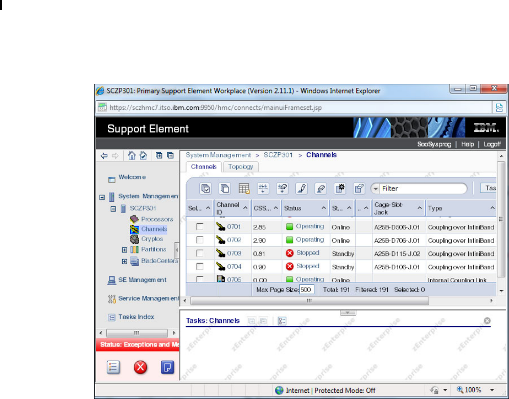
Chapter 6. Configuration management 179
6.5 Determining which CHPIDs are using a port
There are two mechanisms to identify the CHPIDs that have been assigned to a given port.
The first one involves using the processor SE. You log on to the SE. Display the channel list
for the processor, as shown in Figure 6-28.
As shown, the list displays the VCHID (in the Channel ID column) and the CSS and CHPID (in
the CSS.CHPID column). It also shows the cage, slot, and jack and the channel type as
defined in HCD. The cage, slot, and jack are the physical location of the AID and port.
Figure 6-28 SE processor channel list
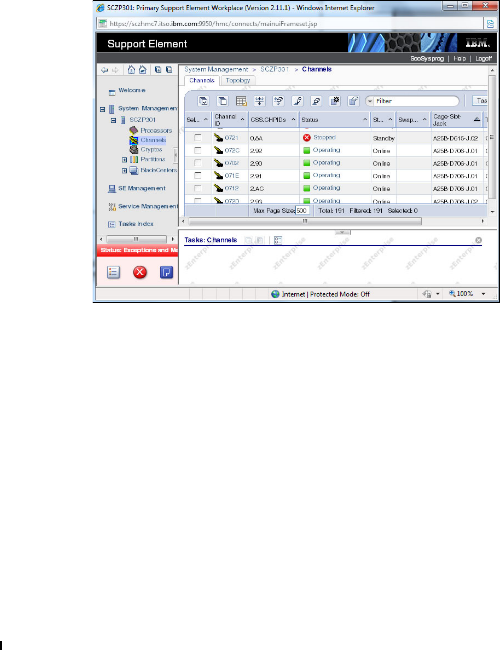
180 Implementing and Managing InfiniBand Coupling Links on IBM System z
To determine which CHPIDs are associated with a given port, note the cage, slot, and jack of
one of the CHPIDs that you know is assigned to that port. Then click the up-arrow beside the
Cage-Slot-Jack column heading. This results in the list shown in Figure 6-29.
Figure 6-29 Processor channel list sorted by cage-slot-jack
If we take CHPID 90 in CSS 2 as an example, we can see in Figure 6-28 on page 179 that
CHPID is associated with the port that is at cage A25B, slot D706, jack J01. In the sorted
version of the list in Figure 6-29, you can see that there are four CHPIDs associated with that
cage-slot-jack: CHPIDs 90, 91, 92, and AC, which are all in CSS 2.
The other method for determining which CHPIDs are associated with a given port is to use
HCD. In this case, go into HCD and enter the name of the currently-active IODF. Select option
1 (Define, modify, or view configuration data), and then option 3 (Processors).

Chapter 6. Configuration management 181
In the resulting process list, place an s (to work with attached channel paths) beside the
processor that you are interested in. In the list of channel subsystems that you are then
presented with, place an s (to work with attached channel paths) beside the CSS that you are
interested in. See Figure 6-30.
Figure 6-30 Channel list in HCD
Goto Filter Backup Query Help
------------------------------------------------------------------------------
Channel Path List Row 1 of 122 More: >
Command ===> _______________________________________________ Scroll ===> CSR
Select one or more channel paths, then press Enter. To add use F11.
Processor ID . . . . : SCZP301
Configuration mode . : LPAR
Channel Subsystem ID : 2
DynEntry Entry +
/ CHPID Type+ Mode+ Switch + Sw Port Con Mngd Description
_ 00 OSD SPAN __ __ __ No Exp3 1KBaseT All LPARs 9.12.4 #1
_ 01 OSC SPAN __ __ __ No Exp3 1KBaseT All LPARs OSC #1
_ 06 OSD SPAN __ __ __ No Exp3 1KBaseT
_ 08 OSD SPAN __ __ __ No Exp3 1KBaseT
_ 09 OSD SPAN __ __ __ No Exp3 1KBaseT Yellow zone
_ 0A OSM SPAN __ __ __ No Exp3 1KBaseT
_ 0B OSM SPAN __ __ __ No Exp3 1KBaseT
_ 0C OSD SPAN __ __ __ No Exp3 1KBaseT All LPARs 9.12.4 #2
_ 0D OSC SPAN __ __ __ No Exp3 1KBaseT All LPARs OSC #2
_ 0E OSD SPAN __ __ __ No Exp3 1KBaseT Yellow zone
_ 10 OSD SPAN __ __ __ No Exp3 GbE SX

182 Implementing and Managing InfiniBand Coupling Links on IBM System z
In the resulting Channel list (Figure 6-30 on page 181), place the cursor on Filter on the top
line and press Enter. Select option 1 to set a filter. The panel shown in Figure 6-31 is
displayed.
Figure 6-31 Setting a channel list filter
In this case, we entered 0C/1, which is the AID and port that CHPID 90 in CSS 2 is assigned
to. Pressing Enter displays the panel that is shown in Figure 6-32.
Figure 6-32 List of CHPIDs assigned to a specific AID and port
Goto Filter Backup Query Help
------------------------------------------------------------------------------
Channel Path List
Command ===> _______________________________________________ Scroll ===> CSR
Sel ------------------------ Filter Channel Path List -------------------------
| |
| |
Specify or revise the following filter criteria.
Channel path type . ___
Operation mode . . . ____ +
Managed . . . . . . _ (Y = Yes; N = No) I/O Cluster ________ +
Dynamic entry switch __ +
Entry switch . . . . __ +
CF connected . . . . _ (Y = Connected; N = Not connected)
PCHID or AID/P . . . 0C/1
Description . . . . ________________________________
Partition . . . . . ________ +
Connected to CUs . . _ (Y = Connected; N = Not connected)
Goto Filter Backup Query Help
------------------------------------------------------------------------------
Channel Path List Filter Mode. More: < >
Command ===> _______________________________________________ Scroll ===> CSR
Select one or more channel paths, then press Enter. To add, use F11.
Processor ID : SCZP301 CSS ID : 2
1=A21 2=A22 3=A23 4=A24 5=A25
6=* 7=* 8=A28 9=* A=A2A
B=A2B C=* D=* E=A2E F=A2F
I/O Cluster --------- Partitions 2x ----- PCHID
/ CHPID Type+ Mode+ Mngd Name + 1 2 3 4 5 6 7 8 9 A B C D E F AID/P
_ 90 CIB SHR No ________ _ _ _ _ _ # # _ # _ _ # # a _ 0C/1
_ 91 CIB SHR No ________ _ _ _ _ _ # # _ # _ _ # # a _ 0C/1
_ 92 CIB SHR No ________ _ _ _ _ _ # # _ # _ _ # # a _ 0C/1
_ AC CIB SHR No ________ _ _ _ _ _ # # _ # _ _ # # a _ 0C/1

Chapter 6. Configuration management 183
The list shows all the CHPIDs in this CSS that are assigned to the AID and port that you
selected. It also shows which partitions are in the access list for those CHPIDs (in this
example, partition 2E is in the access list for all these CHPIDs).
Either of these methods can be used to obtain information about the current InfiniBand
connectivity. Using the SE has the advantage that you know that the information you are
seeing represents the current, active configuration. Also, the SE is likely to be accessible to
the operators if they need this type of information, whereas operators typically do not have
access to HCD.
6.6 Cabling documentation considerations
You can define multiple CHPIDs for multiple sysplexes across a single PSIFB link. When
performing maintenance to the cabling environment, this makes the impact of pulling a cable
potentially far more significant than the one-to-one CHPID to PCHID mapping of non-PSIFB
links.
The cabling documentation might now also become more complex. In these circumstances,
the use of the Hardware Configuration Manager (HCM) can prove useful. This tool provides a
Cabling Assignment Dialog for this purpose. For further details, see z/OS Hardware
Configuration Manager (HCM) User's Guide, SC33-7989.
6.7 Dynamic reconfiguration considerations
Using dynamic reconfiguration is highly advisable when you make changes to your I/O
configuration. This makes changes concurrent, avoiding IPLs or power-on resets of your
processor.
At this time, dynamic reconfiguration is not available for stand-alone Coupling Facilities.
However, if the impact of emptying a CF LPAR to perform a POR is unacceptable, you can
consider defining a small z/OS LPAR on the CF processor whose sole purpose is to drive
dynamic reconfigurations on that processor. Note that this requires a CP on that processor
(although it does not need to be a powerful one).
6.8 CHPID Mapping Tool support
When planning and configuring a System z processor, you must plan for maximum processor
and device availability. The CHPID Mapping Tool (CMT) provides an availability mapping
function to assign CHPIDs across control units and to avoid single points of failure. The
CHPID mapping tool is available from the IBM Resource Link web site at:
https://www.ibm.com/servers/resourcelink
Full documentation is available in the CHPID Mapping Tool, and full usage guidelines are
available in IBM zEnterprise 196 Configuration Setup, SG24-7834.
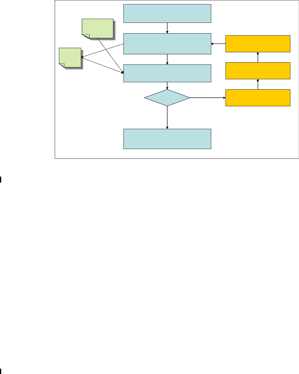
184 Implementing and Managing InfiniBand Coupling Links on IBM System z
Support for PSIFB links
The CMT provides the capability to identify potential availability exposures attributable to the
mapping of CHPIDs across Adapter IDs and PORTs. The process to follow is shown in
Figure 6-33.
Figure 6-33 CHPID Mapping Tool process for PSIFB links
The following stages are shown in Figure 6-33:
1. HCD or HCM is used to define and connect the CIB CHPIDs to create the PSIFB links.
2. Before a stand-alone IOCP file can be generated, a validated Work IODF must be
generated using HCD option 2.12, as shown in Figure 6-34 on page 185.
IOCP
Text
File
IOCP
Text
File
.CFR
file from IBM
resourcelink
.CFR
file from IBM
resourcelink
1. HCD/HCM definitions to define
new PSIFB links in WORK IODF.
3. Invoke CMT availability mapping.
Analyze intersects.
5. Generate Production IODF.
Activate and write IOCDS.
2.Create Validated Work IODF (HCD
Option 2.12) and generate stand-alone
IOCP txt file.
4. Intersects ?
NO YES
4a. Disconnect CIB CHPIDs
for remapping
4b. Redefine CIB CHPIDs to
new AIDs / PORTs
4c. Reconnect CIB CHPIDs
IOCP
Text
File
IOCP
Text
File
.CFR
file from IBM
resourcelink
.CFR
file from IBM
resourcelink
1. HCD/HCM definitions to define
new PSIFB links in WORK IODF.
3. Invoke CMT availability mapping.
Analyze intersects.
5. Generate Production IODF.
Activate and write IOCDS.
2.Create Validated Work IODF (HCD
Option 2.12) and generate stand-alone
IOCP txt file.
4. Intersects ?
NO YES
4a. Disconnect CIB CHPIDs
for remapping
4b. Redefine CIB CHPIDs to
new AIDs / PORTs
4c. Reconnect CIB CHPIDs
4a. Disconnect CIB CHPIDs
for remapping
4b. Redefine CIB CHPIDs to
new AIDs / PORTs
4c. Reconnect CIB CHPIDs

Chapter 6. Configuration management 185
Figure 6-34 HCD: Building the Validated Work IODF
Then, download the IOCP file to the PC where the CHPID Mapping Tool will be run.
Download the file as TEXT. Alternatively, if you are an HCM user and download the CMT
to the same PC, you can create the IOCP input file directly from HCM.
3. Invoke the CHPID Mapping Tool, load the CFR, and import the IOCP file. Perform
availability mapping. (Hardware Configuration Manager (HCM) can also be used for this
process.)
Activate or Process Configuration Data
Select one of the following tasks.
12 1. Build production I/O definition file
2. Build IOCDS
3. Build IOCP input data set
4. Create JES3 initialization stream data
5. View active configuration
6. Activate or verify configuration
dynamically
7. Activate configuration sysplex-wide
8. Activate switch configuration
9. Save switch configuration
10. Build I/O configuration statements
11. Build and manage S/390 microprocessor
IOCDSs and IPL attributes
12. Build validated work I/O definition file
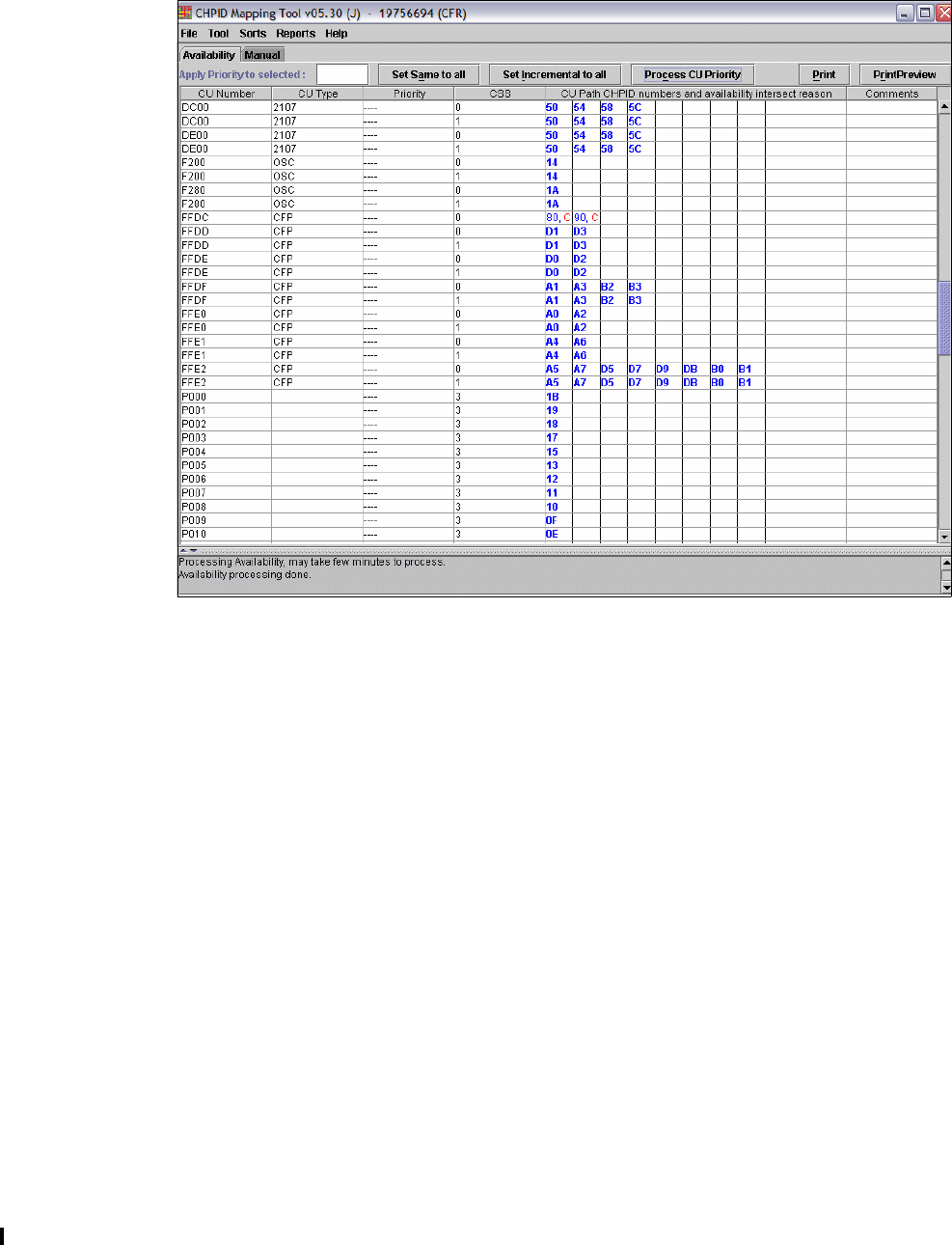
186 Implementing and Managing InfiniBand Coupling Links on IBM System z
4. Analyze the output for intersects across AIDs and PORTs. Intersects are displayed with
the CHPID Mapping Tool as shown in the CMT panel sample in Figure 6-35, where C
indicates that two channels use the same channel card.
Figure 6-35 Sample CMT Panel showing detected intersects
If no unacceptable intersects exist, go to step 5. Otherwise, you can either use the manual
process in the CMT to associate the CIB CHPIDs to different AIDs/ports or follow steps 4a
through 4c:
a. Disconnect CIB CHPIDs that are to be remapped. You perform this from the CF
Channel Path Connectivity List shown in Figure 6-36 on page 187. Specify n next to
each CHPID to be disconnected.

Chapter 6. Configuration management 187
Figure 6-36 CF Channel Path Connectivity List
b. Redefine the CHPIDs to new AIDs and PORTs; see “Defining PSIFB links using HCD”
on page 164.
c. Reconnect the CIB CHPIDs from the CF Channel Path Connectivity List; see
“Connecting the CIB CHPIDs” on page 167. At this point, the configuration can be
revalidated for intersects by returning to Step 2.
5. With all the necessary intersects removed, the production IODF can be built. Use HCD to
perform a dynamic reconfiguration to write the IOCDS and activate the IODF.
For more information, see the following publications:
I/O Configuration Using z/OS HCD and HCM, SG24-7804
z/OS Hardware Configuration Definition Planning, GA22-7525
z/OS Hardware Configuration User’s Guide, SC33-7988
z/OS Hardware Configuration Manager (HCM) User's Guide, SC33-7989
CF Channel Path Connectivity List Row 1 of 4
Command ===> ___________________________________________ Scroll ===> PAGE
Select one or more channel paths, then press Enter.
Source processor ID . . . . . : IB022097
Source channel subsystem ID . : 0
Source partition name . . . . : *
-------Source-------- -----------Destination-------- -CU-
/ CHPID Type Mode Occ Proc.CSSID CHPID Type Mode Type
n 01 CIB SHR N IB012097.0 01 CIB SHR CFP
_ 02 CIB SHR N IB012097.0 02 CIB SHR CFP
_ 53 CIB SHR N IB042097.0 53 CIB SHR STP
_ 54 CIB SHR N IB042097.0 54 CIB SHR STP

188 Implementing and Managing InfiniBand Coupling Links on IBM System z

© Copyright IBM Corp. 2008, 2012, 2014. All rights reserved. 189
Chapter 7. Operations
This chapter discusses the interfaces that are available to monitor and manage configurations
using Parallel Sysplex InfiniBand coupling links.
The following topics are covered:
Managing your InfiniBand infrastructure
z/OS commands for PSIFB links
Coupling Facility commands
Hardware Management Console and Support Element tasks
PSIFB Channel problem determination
Environmental Record, Editing, and Printing
7

190 Implementing and Managing InfiniBand Coupling Links on IBM System z
7.1 Managing your InfiniBand infrastructure
One thing that you need to be aware of when you start using InfiniBand links is a greater need
for strong system management practices. Strong practices will make management of the
InfiniBand infrastructure easier and reduce the possibility of operational errors.
Prior to InfiniBand, each coupling link was only able to be associated with one channel-path
identifier (CHPID) and one sysplex. So if you accidentally disconnected the wrong coupling
link, you would only lose access from one CHPID, and only one sysplex would be affected.
Also, because of the one-to-one relationship between links and CHPIDs, if you have two (or
more) online links to a CF, you knew that you had two (or more) working physical links.
However, with InfiniBand, you can have multiple CHPIDs assigned to a link. So a link might be
in use by multiple sysplexes. Therefore, if you accidentally disconnect one InfiniBand link, you
can remove access for multiple CHPIDs, which can impact multiple sysplexes.
In addition, prior to zEC12 and zBC12, it was not possible to determine the relationship
between CHPIDs and physical InfiniBand links from RMF reports or by using z/OS
commands. As a result, you might actually be down to just one working physical link but it
would not be obvious. When you look in z/OS, you could see multiple CHPIDs online and
therefore not realize that you have a single point of failure.
zEC12 provided significant enhancements in the manageability of InfiniBand links. Just about
all the information you are likely to need about an InfiniBand CHPID is now available both on
the z/OS console, and also in RMF.
Because of the performance characteristics of InfiniBand links, you might find that you need
fewer physical coupling links than you had with previous link types. Most clients are likely to
find that two InfiniBand links will provide sufficient bandwidth to meet their coupling needs.
You need, though, to ensure that your InfiniBand link infrastructure does not contain any
single points of failure; because a single InfiniBand adapter supports either two or four ports,
ordering a minimal configuration might result in both links being on the same adapter.
Also keep in mind that STP might be using InfiniBand links to transmit timing signals between
processors. STP works at the CHPID level, so if you were to physically vary all the CHPIDs
associated with an InfiniBand link offline, STP would no longer be able to use that link1.
1 Configuring a shared CHPID offline to a z/OS system using the MVS CONFIG command, or deactivating an LPAR
that is using a particular CHPID does not impact STP’s ability to use that CHPID for timing signals. The CHPID will
only become inaccessible to STP if it is configured offline in all sharing LPARs.

Chapter 7. Operations 191
For these reasons, it is especially important to keep current information available for the
operators, system programmers, and hardware engineers that clearly shows the relationships
between physical links, which HCA and port they are connected to, which CHPIDs are
associated with that port, and which sysplexes are using those CHPIDs. They should also
have easy-to-use documentation that shows how to retrieve this information from the Support
Element (SE) if the system is on a CPC prior to zEC12. Figure 7-1 shows an example of the
type of table you might use. This chapter is intended to show how to manage your InfiniBand
infrastructure, and how to obtain information to help you create and verify your
documentation.
Figure 7-1 Documenting InfiniBand infrastructure
This chapter provides an overview of the interfaces and tools that are available to operate and
monitor Parallel Sysplex InfiniBand (PSIFB) coupling links:
z/OS commands for PSIFB managing coupling links
Corresponding CFCC commands
Hardware Management Console (HMC) and Support Element (SE) tasks related to PSIFB
coupling links
7.2 z/OS commands for PSIFB links
To successfully manage an InfiniBand configuration, you need to be able to display the status
of the components in the current configuration, to understand and be able to control the
status of the CF, and to be able to take paths on and offline. As described in Chapter 4,
“Migration planning” on page 63, there can be situations where you want to take a link offline
on both the z/OS and CF ends; we describe the CF commands to achieve this in 7.3,
“Coupling Facility commands” on page 202.
In a normal production environment, several z/OS images are typically attached to a given CF
image. When you display the status from the z/OS systems, you will see information about the
z/OS end of the links to the CFs. When you display information from the CF side, you will be
presented with information about the CHPIDs that are used to connect that CF to the
members of the sysplex. Information about links between two CFs will be provided in both the
output from the CF and also from z/OS.
7.2.1 z/OS CF-related commands
The following z/OS commands are used to display the PSIFB coupling links and status. You
enter the z/OS commands at a z/OS console.
Cage/Slot/Jack AID/Port CHPID(s) Sharing LPARs Type connected
to...
Type Cage/Slot/Jack AID/Port CHPID(s) Sharing LPARs Comment
A25B-D206-J02 09/2 0.93 A0E (FACIL03) HCA2 12X HCA2 12X A25B/D506/J01 0A/1 2.85 A21 - Prodplex
A22 - Prodplex Online
A25B-D606-J02 0B/2 0.B9 A0E (FACIL03) HCA2 12X HCA2 12X A25B/D606/J01 0B/1 0.80 A0B - (CHPID holder) Offline
A25B-D615-J01 1B/1 0.9C
0.9D A0F (CHPID holder)
A0F (CHPID holder) HCA2 12X HCA2 12X A25B/D715/J02 1C/2 0.8B
0.8C A0B - (CHPID holder)
A0B - (CHPID holder Offline
Offline
A25B-D615-J02 1B/2 0.BB A0E (FACIL03) HCA2 12X HCA2 12X A25B/D715/J01 1C/1 0.86 A0B - (CHPID holder) Offline

192 Implementing and Managing InfiniBand Coupling Links on IBM System z
D CF,CFNAME=yyyy
zEC12 and later
The D CF,CFNM=yyyy command displays the status of the named CF and detailed information
about the connections to that CF. Example 7-1 shows the output from this command. It shows
detailed information about the CF with the name FACIL04, which is the name that was
defined in the Coupling Facility Resource Management (CFRM). The output of this command
(which was issued from a z/OS system on a zEC12) contains details about the following
items:
The processor and logical partition (LPAR) that the CF resides in
Storage utilization in the CF
The Coupling Facility Control Code (CFCC) level
The CHPIDs that are defined as having access to the CF
A list of the device numbers and associated subchannels for the CF
Information about any peer CFs and how they are connected to this CF
Example 7-1 D CF,CFNAME=FACIL04 output
COUPLING FACILITY 002817.IBM.02.0000000B3BD5 1
PARTITION: 2F CPCID: 00
CONTROL UNIT ID: FFFC
NAMED FACIL04
COUPLING FACILITY SPACE UTILIZATION
ALLOCATED SPACE DUMP SPACE UTILIZATION
STRUCTURES: 1426 M STRUCTURE DUMP TABLES: 0 M
DUMP SPACE: 20 M TABLE COUNT: 0
FREE SPACE: 2208 M FREE DUMP SPACE: 20 M
TOTAL SPACE: 3654 M TOTAL DUMP SPACE: 20 M
MAX REQUESTED DUMP SPACE: 1 M
VOLATILE: YES
CFLEVEL: 17
CFCC RELEASE 17.00, SERVICE LEVEL 10.29
BUILT ON 07/30/2013 AT 10:28:00
STORAGE INCREMENT SIZE: 1 M
COUPLING FACILITY HAS 0 SHARED AND 1 DEDICATED PROCESSORS
DYNAMIC CF DISPATCHING: OFF
COUPLING FACILITY IS NOT STANDALONE
...
2
PATH PHYSICAL LOGICAL CHANNEL TYPE AID PORT
B1 / 0723 ONLINE ONLINE CIB 12X-IFB3 000A 02
B5 / 0724 ONLINE ONLINE CIB 12X-IFB3 001A 02
BA / 0727 ONLINE ONLINE CIB 1X-IFB 001D 01
BB / 0728 ONLINE ONLINE CIB 1X-IFB 001D 02
COUPLING FACILITY SUBCHANNEL STATUS
TOTAL: 78 IN USE: 78 NOT USING: 0 NOT USABLE: 0
OPERATIONAL DEVICES / SUBCHANNELS:
FC54 / 2A12 FC55 / 2A13 FC56 / 2A14 FC57 / 2A15
Tip: zEC12 delivered significant enhancements to the D CF command. This section shows
the command on a CPC prior to zEC12 and also on a zEC12.
It is important to note that the CF does not have to be running on a zEC12 or zBC12. If
z/OS is running on a zEC12 or later, detailed information will be provided about the z/OS
end of the link. If the CF is running on a zEC12 or later, detailed information about that
CF’s end of any CF-to-CF links will be provided.

Chapter 7. Operations 193
...
REMOTELY CONNECTED COUPLING FACILITIES
CFNAME COUPLING FACILITY
-------- --------------------------
3 FACIL03 002827.IBM.02.00000000B8D7
PARTITION: 3F CPCID: 00
CHPIDS ON FACIL04 CONNECTED TO REMOTE FACILITY
RECEIVER: CHPID TYPE
96 CIB
99 CIB
SENDER: CHPID TYPE
96 CIB
99 CIB
The output of this command shows information from the coupling link perspective, as
explained here:
1 The output provides the type and serial number for the processor that contains the CF LPAR
and the ID of the LPAR that the CF resides in.
2 Information is provided for each CHPID that is defined to access the CF. Specifically, it
displays:
The CHPID and the VCHID number, for example, CHPID B1 and VCHID 0723.
The physical status, ONLINE in this case. Also, if the CHPID is running in degraded mode,
the display will say “DEGRADED” and the speed that the link associated with that CHPID
is running at.
The logical status, ONLINE in this case.
The channel type now includes not only the fact that the CHPID is for an InfiniBand link. It
also displays the adapter speed (1X or 12X) and the mode (IFB or IFB3).
The Adapter ID (AID) and Port. This is really vital information to help you determine if there
are any single points of failure in the connection to this CF. Ideally, every CF will be
connected using at least two different AIDs. In the worst case, if all CHPIDs are on the
same AID, they should at least be spread across more than one Port.
3 FACIL03 is another CF. It might be connected to FACIL04 to enable the use of System
Managed Duplexing, or it might be connected to transmit STP signals between the two
processors. This section contains information about the CHPIDs that are used to connect the
two CFs, and the type of each CHPID. The CHPIDs are sorted by receiver and sender
depending on the CHPID configuration. If the same CHPID is displayed under both sections,
the same CHPID is capable of acting as a receiver and a sender.
In this example, because FACIL04 is in a z196, detailed information about the CF-to-CF
CHPIDs is not provided. However, Example 7-2 contains an example of the information that is
provided by a CF that is running on a zEC12. This information is from a CF that was running
on the zEC12 and connected to FACIL04.
Example 7-2 Sample CF-to-CF CHPID information about zEC12
FACIL04 002817.IBM.02.0000000B3BD5
PARTITION: 2F CPCID: 00
CHPIDS ON FACIL06 CONNECTED TO REMOTE FACILITY

194 Implementing and Managing InfiniBand Coupling Links on IBM System z
RECEIVER: CHPID TYPE
B1 CIB 12X-IFB3
B5 CIB 12X-IFB3
SENDER: CHPID TYPE
B1 CIB 12X-IFB3
B5 CIB 12X-IFB3
5
5Any CHPIDs that are not operational for the selected CF are listed. If you make dynamic
changes to the processor that the CF is running on, and those changes remove CHPIDs from
the CF LPAR, those CHPIDs will be listed in this part of the display. Even though they are no
longer in the configuration for that LPAR, the CFCC remembers that it was using that link
previously, and will continue to list the CHPID in the NOT OPERATIONAL section until the CF
is deactivate and reactivated.
Remember that each z/OS that is connected to the CF could potentially be using different
CHPIDs to communicate with the CF. Also, it is possible for a CHPID to be offline in one z/OS
system, but online in another z/OS in the same processor. Therefore, to obtain a complete
picture of the connectivity to the CF, issue the command on all members of the sysplex. You
can easily achieve this by using the ROUTE command, for example, RO *ALL,D CF,CFNM=yyyy.
Pre-zEC12
The D CF,CFNM=yyyy command displays the status of the named CF and connections to that
CF. Example 7-3 shows the output from this command. It shows detailed information about
the CF with the name FACIL04, which is the name that was defined in the Coupling Facility
Resource Management (CFRM). The output of this command (which was issued from a z/OS
system on the z10 in Example 7-3) contains details about the following items:
The processor and LPAR that the CF resides in
Storage utilization in the CF
The Coupling Facility Control Code (CFCC) level
The CHPIDs that are defined as having access to the CF
A list of the device numbers and associated subchannels for the CF
Information about any peer CFs and how they are connected to this CF
Example 7-3 D CF,CFNAME=FACIL04 output
D CF,CFNM=FACIL04
IXL150I 12.09.50 DISPLAY CF 662
COUPLING FACILITY 002817.IBM.02.0000000B3BD5 1
PARTITION: 2F CPCID: 00
CONTROL UNIT ID: FFF2
NAMED FACIL04
COUPLING FACILITY SPACE UTILIZATION
ALLOCATED SPACE DUMP SPACE UTILIZATION
STRUCTURES: 0 M STRUCTURE DUMP TABLES: 0 M
DUMP SPACE: 20 M TABLE COUNT: 0
FREE SPACE: 3635 M FREE DUMP SPACE: 20 M
TOTAL SPACE: 3655 M TOTAL DUMP SPACE: 20 M
Tip: More information about each CHPID is provided by RMF, both in Monitor III and in a
new Channel Path Details RMF Post Processor report. For more information about the
enhanced RMF support, refer to Appendix A, “Resource Measurement Facility” on
page 233.

Chapter 7. Operations 195
MAX REQUESTED DUMP SPACE: 0 M
VOLATILE: YES STORAGE INCREMENT SIZE: 1 M
CFLEVEL: 17
CFCC RELEASE 17.00, SERVICE LEVEL 04.18
BUILT ON 10/26/2011 AT 13:31:00
COUPLING FACILITY HAS 0 SHARED AND 1 DEDICATED PROCESSORS
DYNAMIC CF DISPATCHING: OFF
CF REQUEST TIME ORDERING: REQUIRED AND ENABLED
COUPLING FACILITY SPACE CONFIGURATION
IN USE FREE TOTAL
CONTROL SPACE: 20 M 3635 M 3655 M
NON-CONTROL SPACE: 0 M 0 M 0 M
SENDER PATH PHYSICAL LOGICAL CHANNEL TYPE 2
B7 / 0704 ONLINE ONLINE CIB
B8 / 0705 ONLINE ONLINE CIB
B9 / 0731 ONLINE ONLINE CIB
BA / 0732 ONLINE ONLINE CIB
BB / 0733 ONLINE ONLINE CIB
BC / 0734 ONLINE ONLINE CIB
BD / 0735 ONLINE ONLINE CIB
BE / 0736 ONLINE ONLINE CIB
COUPLING FACILITY SUBCHANNEL STATUS
TOTAL: 56 IN USE: 56 NOT USING: 0 NOT USABLE: 0
OPERATIONAL DEVICES / SUBCHANNELS:
FCD7 / 4F46 FCD8 / 4F47 FCD9 / 4F48 FCDA / 4F49
...
REMOTELY CONNECTED COUPLING FACILITIES
CFNAME COUPLING FACILITY 3
-------- --------------------------
FACIL03 002097.IBM.02.00000001DE50 4
PARTITION: 0E CPCID: 00
CHPIDS ON FACIL04 CONNECTED TO REMOTE FACILITY
RECEIVER: CHPID TYPE
80 CIB
86 CIB
SENDER: CHPID TYPE
80 CIB
86 CIB
NOT OPERATIONAL CHPIDS ON FACIL04 5
A5 A7 A9 AB
The output of this command shows information from the coupling link perspective, as
explained here:
1 The output provides the type and serial number for the processor that contains the CF LPAR
and the ID of the LPAR that the CF resides in.
2 Information is provided for each CHPID that is defined to access the CF. The information in
the PATH column is the VCHID number. You can use this information to display the VCHID

196 Implementing and Managing InfiniBand Coupling Links on IBM System z
information about the Support Element. On the Support Element, you can determine which
AID and Port is associated with that CHPID.
3 In some cases, you might notice that the CF being reported on is also listed as a remote CF.
This happens when the CF is in the same processor as the system the command was issued
from, and is a corollary of the use of peer mode links. In this example, FACIL04 is on a
different processor than the z/OS system, so FACIL04 is not listed as a remote CF for
FACIL04.
4 FACIL03 is another CF. It might be connected to FACIL04 to enable the use of System
Managed Duplexing, or it might be connected to transmit STP signals between the two
processors. This section contains information about the CHPIDs that are used to connect the
two CFs, and the type of each CHPID. The CHPIDs are sorted by receiver and sender
depending on the CHPID configuration. If the same CHPID is displayed under both sections,
the same CHPID is capable of acting as a receiver and a sender.
5Any CHPIDs that are not operational for the selected CF are listed. If you make dynamic
changes to the processor that the CF is running on, and those changes remove CHPIDs from
the CF LPAR, those CHPIDs will be listed in this part of the display. Even though they are no
longer in the configuration for that LPAR, the CFCC remembers that it was using that link
previously, and will continue to list the CHPID in the NOT OPERATIONAL section until the CF
is deactivate and reactivated.
Remember that each z/OS that is connected to the CF could potentially be using different
CHPIDs to communicate with the CF. Also, it is possible for a CHPID to be offline in one z/OS
system, but online in another z/OS in the same processor. Therefore, to obtain a complete
picture of the connectivity to the CF, issue the command on all members of the sysplex. You
can easily achieve this by using the ROUTE command, for example,
RO *ALL,D CF,CFNM=yyyy.
D M=CHP(xx)
zEC12
You can also use the D M=CHP command to obtain information about the CHPIDs that are used
to connect to the CF (the CHPIDs that are displayed in the response to the D CF command).
This command displays the status of any CHPID, including the path status to all of its defined
devices. Example 7-4 on page 197 shows an example of the output from the display matrix
command for an InfiniBand CHPID. It shows which devices have been defined and the
subchannel status for each device. It also provides summary information about the attached
CFs.
Important: If you review the output from the command, you will see that it reports the
CHPIDs that are defined to connect to the CF. However, it does not provide any information
about the relationship between those CHPIDs and the underlying InfiniBand infrastructure.
At the time of writing, it is not possible to get this information from z/OS; it is only available
on the SE or in hardware configuration definition (HCD).
Therefore, although the D CF command is effective for checking that the CF is online and
how many CHPIDs are online, it does not help identify any single points of failure that
might exist in the underlying coupling links.
Note: Just as the D CF command provides additional information when issued on a zEC12
or later, similarly the D M=CHP command also provides additional information, so we will
show the result of a D M=CHP command separately for zEC12 and for pre-zEC12.

Chapter 7. Operations 197
Example 7-4 D M=CHP(B1) output
D M=CHP(B1)
IEE174I 10.54.24 DISPLAY M 287
CHPID B1: TYPE=26, DESC=COUPLING OVER INFINIBAND, ONLINE
COUPLING FACILITY 002817.IBM.02.0000000B3BD5 1
PARTITION: 2F CPCID: 00
NAMED FACIL04 2CONTROL UNIT ID: FFFC
3
PATH PHYSICAL LOGICAL CHANNEL TYPE AID PORT
B1 / 0723 ONLINE ONLINE CIB 12X-IFB3 000A 02
COUPLING FACILITY SUBCHANNEL STATUS 4
TOTAL: 78 IN USE: 78 NOT USING: 0 NOT USABLE: 0
OPERATIONAL DEVICES / SUBCHANNELS:
5 FC54 / 2A12 FC55 / 2A13 FC56 / 2A14 FC57 / 2A15
...
The output for this command shows the following items:
1 The type and serial number for the processor that is attached to this coupling link.
2 The CF name is provided, to help you ensure that you are looking at the intended CHPID.
3 The CHPID number and the associated VCHID number are shown, together with all the
other information for that CHPID that is displayed in the response to the D CF command.
4 A summary of the state of the CF subchannels associated with this CF. Note that the
summary includes information about the subchannels associated with the full set of CHPIDs
that are defined for this CF. It does not show simply the subset associated with the selected
CHPID:
– TOTAL: The total number of subchannels that were defined for this CF. The number
depends on the number of defined coupling links and the number of subchannels that
were defined for each CHPID.
– IN USE: The number of subchannels that are currently online.
– NOT USING: The number of subchannels that have temporarily been taken offline by
the XES subchannel tuning function. This number can rise and fall, depending on the
level of link buffer contention.
– NOT USEABLE: The number of subchannels that are not usable either because there
is a problem with the associated CHPID, or because the CHPID has been configured
offline.
5 All defined devices with their associated subchannels are shown and the status for each is
provided.
The D CF and D M=CHP commands provide physical information about the CHPID and the
connected CF.
Pre-zEC12
You can also use the D M=CHP command to obtain information about the CHPIDs that are used
to connect to the CF (the CHPIDs that are displayed in the response to the D CF command).
This command displays the status of any CHPID, including the path status to all of its defined
devices. Example 7-5 on page 198 shows an example of the output from the display matrix
command for an InfiniBand CHPID. It shows which devices have been defined and the

198 Implementing and Managing InfiniBand Coupling Links on IBM System z
subchannel status for each device. It also provides summary information about the attached
CFs.
Example 7-5 D M=CHP(B7) output
D M=CHP(B7)
CHPID B7: TYPE=26, DESC=COUPLING OVER INFINIBAND, ONLINE
COUPLING FACILITY 002817.IBM.02.0000000B3BD5 1
PARTITION: 2F CPCID: 00
NAMED FACIL04 CONTROL UNIT ID: FFF0 3
SENDER PATH PHYSICAL LOGICAL CHANNEL TYPE
B7 / 0704 ONLINE ONLINE CIB
COUPLING FACILITY SUBCHANNEL STATUS
TOTAL: 56 IN USE: 56 NOT USING: 0 NOT USABLE: 0 4
OPERATIONAL DEVICES / SUBCHANNELS:
FCD7 / 4F46 FCD8 / 4F47 FCD9 / 4F48 FCDA / 4F49 5
FCDB / 4F4A FCDC / 4F4B FCDD / 4F4C FCDE / 4F0E
FCDF / 4F0F FCE0 / 4F10 FCE1 / 4F11 FCE2 / 4F12
FCE3 / 4F13 FCE4 / 4F14 FCE5 / 4F15 FCE6 / 4F16
FCE7 / 4F17 FCE8 / 4F18 FCE9 / 4F19 FCEA / 4F1A
FCEB / 4F1B FCEC / 4F1C FCED / 4F1D FCEE / 4F1E
FCEF / 4F1F FCF0 / 4F20 FCF1 / 4F21 FCF2 / 4F22
FDA9 / 4F2A FDAA / 4F2B FDAB / 4F2C FDAC / 4F2D
FDAD / 4F2E FDAE / 4F2F FDAF / 4F30 FDD3 / 4F31
The output for this command shows the following items:
1 The type and serial number for the processor that is attached to this coupling link.
2 The CF name is provided, to help you ensure that you are looking at the intended CHPID.
3 The CHPID number and the associated VCHID number are shown, together with the
physical and logical status of the CHPID, and the type (CIB, CBP, CFP, or ICP) of the
associated coupling link.
4 A summary of the state of the CF subchannels associated with this CF. Note that the
summary includes information about the subchannels associated with the full set of CHPIDs
that are defined for this CF. It does not show simply the subset associated with the selected
CHPID.
– TOTAL: The total number of subchannels that were defined for this CF. The number
depends on the number of defined coupling links and the number of subchannels that
were defined for each CHPID.
– IN USE: The number of subchannels that are currently online.
– NOT USING: The number of subchannels that have temporarily been taken offline by
the XES subchannel tuning function. This number can rise and fall, depending on the
level of link buffer contention.
– NOT USEABLE: The number of subchannels that are not usable either because there
is a problem with the associated CHPID, or because the CHPID has been configured
offline.
5 All defined devices with their associated subchannels are shown and the status for each is
provided.

Chapter 7. Operations 199
The D CF and D M=CHP commands provide physical information about the CHPID and the
connected CF. It obtains this information by querying those devices.
Other helpful z/OS commands
There is another command that might be helpful, namely the D XCF,CF command. The
difference with this command is that it displays information about the CF as it is defined in the
CFRM CDS. An example is shown in Example 7-6.
Example 7-6 Using the D XCF,CF command
D XCF,CF,CFNM=FACIL04
IXC362I 17.46.31 DISPLAY XCF 402
CFNAME: FACIL04
COUPLING FACILITY : 002817.IBM.02.0000000B3BD5 1
PARTITION: 2F CPCID: 00
SITE : N/A
POLICY DUMP SPACE SIZE: 20000 K
ACTUAL DUMP SPACE SIZE: 20 M
STORAGE INCREMENT SIZE: 1 M
CONNECTED SYSTEMS: 2
#@$2 #@$A
MONITORING SYSTEM: #@$A
NO STRUCTURES ARE IN USE BY THIS SYSPLEX IN THIS COUPLING FACILITY
Again, notice that the processor type and serial number is displayed (1). However in this case,
this information is obtained from the CFRM CDS instead of from the CF itself. These two
values should match. It also provides a list of the z/OS systems that are connected to the CF
(2). However, note that it does not provide information about the number of CHPIDs or the
number of physical links between each z/OS and the CF.
There is another z/OS MVS command that might be helpful in displaying information about
the current configuration. The CONFIGxx members of SYS1.PARMLIB can be used to define
the desired status of all channels and devices in the configuration. The CONFIGxx member
can be created using option 2.6.6 in HCD. You can then use the D M=CONFIG(xx) command to
request the system to compare the desired status to the current status for each channel and
device defined in the corresponding member. Any deviations from the desired configuration
will be listed in the output.
You can also use the CONFIG MEMBER(xx) command to issue commands intended to bring the
current configuration to the desired state as defined in the CONFIGxx member. For more
information, see the Redbooks publication I/O Configuration Using z/OS HCD and HCM,
SG24-7804 and z/OS MVS System Commands, SA22-7627.
If you want to make changes to the configuration relating to a CF, always obtain the latest
version of the white paper titled “Best Practices: Upgrading a Coupling Facility”, available on
the web at the following site:
http://www.ibm.com/support/techdocs/atsmastr.nsf/WebIndex/WP101905
Tip: Before changing any aspect of the system configuration, it is always useful to display
the status before making any changes. This information can be invaluable if you later
encounter problems trying to bring the configuration back to its original status.

200 Implementing and Managing InfiniBand Coupling Links on IBM System z
Unlike this Redbooks document, that white paper will be updated over time as new features
and functions become available, so it is important to always retrieve the most recent version
to ensure that you are using the latest guidance.
The specific commands to use, and the sequence in which the commands are to be issued,
depend on the specific situation and the change that you are trying to effect. See the Best
Practices document and Chapter 4, “Migration planning” on page 63 for more information.
The following list is a brief summary of the commands you are likely to use during such a
procedure:
SETXCF START,MAINTMODE,CFNM=xxxx
This command places the CF into a mode where it will not be eligible
for new structure allocations. Further, if a SETXCF START,REALLOCATE
command is issued, that CF will appear to have been removed from all
structure’s PREFLISTs, meaning that structures that currently reside
in that CF will be moved to another CF in their PREFLIST. This is the
recommended method for emptying a CF.
SETXCF STOP,MAINTMODE,CFNM=xxxx
This command makes the CF available for use again. However, this
command does not trigger the re-duplexing process, meaning that you
have an opportunity to use the SETXCF START,REALLOCATE command to
evaluate each allocated structure on a one-by-one basis, resulting in
less performance impact as the CF is repopulated and structure
placement that more closely reflects the objectives specified in the
PREFLISTs.
D XCF,REALLOCATE,TEST
This command (delivered with z/OS 1.13) provides a report describing
what actions would be taken if a SETXCF START,REALLOCATE command
were to be issued.
Review the output from this command any time you plan to issue a
SETXCF START,REALLOCATE command, to ensure that the actions it will
take are in line with your expectations, and that no error or warning
conditions will arise.
SETXCF START,REALLOCATE
This is the recommended command to use to empty a CF (in
conjunction with the SETXCF START,MAINTMODE command) or to
re-populate a CF after it has been made available again.
D XCF,REALLOCATE,REPORT
Because the SETXCF START,REALLOCATE command can potentially
cause many structures to be moved or duplexed, it can produce a
significant number of messages, which might make it difficult to
determine precisely which structures were affected.
To make this task easier, the D XCF,REALLOCATE,REPORT command was
introduced in z/OS 1.13. This command provides a succinct,
structure-by-structure report of what, if any, actions were carried out
against each allocated structure.
CONFIG CHP(xx),OFFLINE|ONLINE
The MVS CONFIG command is used to take the named CHPID online
or offline.

Chapter 7. Operations 201
If the CHPID is the last online link to the CF, the UNCOND keyword
must be added to the command.
If the CHPID is the last timing link between two processors, the
CONFIG command will not allow you to take the link offline.
VARY PATH(PATH(CFname,xx),OFFLINE,UNCOND)
This command does not take the CF Link CHPID offline. However, it
does stop z/OS from using the indicated CHPIDs to access the
named CF.
Considerations for configuring CHPIDs offline from HMC
An alternative to taking CHPIDs offline from z/OS or the CF is to use the Toggle function on
the HMC or the SE. Generally speaking, it is preferred that the CHPIDs are taken offline from
z/OS or the CF. In that case, the operating system takes the CHPID offline in a planned
manner. If you Toggle the CHPID offline from the HMC or SE, the event appears as an error to
the operating system and normal channel error recovery must be invoked.
Considerations for dynamic activate
z/OS and z/VM provide the ability to dynamically activate configuration changes without
performing a power-on reset. This means that you can add CHPIDs to a CF that is running on
a processor that also has z/OS or z/VM LPARs. Further, the new CHPIDs can be brought
online by the CF without having to deactivate and activate that LPAR.
This dynamic reconfiguration capability is especially powerful when combined with the fact
that you can have multiple CHPIDs on a single InfiniBand link. If a new sysplex is added to the
configuration, or additional CHPIDs are needed for other reasons, they can be added at short
notice, with no procurement cost, by simply updating the configuration definition in HCD and
activating the new configuration.
But there is one point to be aware of relating to dynamic configuration changes for HCA3-O
12X InfiniBand links. Remember that HCA3-O 12X ports, when connected to another
HCA3-O 12X port, can run in either IFB or IFB3 mode. The mode is determined dynamically,
based on the number of CHPIDs defined to the port. The mode can change in the following
dynamic change situations:
The number of CHPIDs defined to the port is increased from four or less to more than four.
The number of CHPIDs defined to the port is reduced from more than four to four or less.
Note: Because CHPIDs can be shared by multiple LPARs, configuring a shared CHPID
offline in one LPAR will not make the CHPID go physically offline. When the CHPID is
taken offline in the last LPAR that is using that CHPID, it will go physically offline at that
point.
With traditional coupling links, there was a one-to-one relationship between CHPIDs and
links, so after the CHPID was configured offline in all LPARs using that CHPID, the link
could be opened at that point.
However, with InfiniBand links, many CHPIDs could be associated with a single link. The
link should not be opened until all the CHPIDs associated with both ends of that link have
been configured offline in all LPARs using each of those CHPIDs. The physical status of
the CHPIDs sharing a link can be checked on the HMC or the SE, as discussed in 7.4.4,
“Displaying the status of a CIB link (CPC view)” on page 219.

202 Implementing and Managing InfiniBand Coupling Links on IBM System z
When the mode of the port is changed, the port will reinitialize itself. This means that all
CHPIDs assigned to the port will go offline concurrently for a short time. When this happens,
access to whatever is at the other end of the link will be lost. This includes situations where
the link was the last link between the two processors.
Normally, if you try to use an MVS CONFIG command to take the last path to a CF offline, the
command will be rejected and you must use the UNCOND or FORCE parameter. And if the
path was the last timing link between the two processors, there is no way using MVS
commands to remove that link.
However, if you perform an ACTIVATE that results in the mode of an HCA3-O 12X port
changing, and that port supported the last coupling link to the CF or the last timing link
between the two processors, the port will reinitialize and all access across that link will be
lost. You will not be prompted with a WTOR asking if it is OK to proceed.
7.3 Coupling Facility commands
CFCC commands are used to display the information about the Coupling Facility (CF) end of
coupling links and their status. The CFCC commands are entered at the CF console, which is
integrated in the HMC.
Important: Use care when making dynamic changes that affect the number of CHPIDs
assigned to a HCA3-O 12X port. Always ensure that there is at least one other, active, link
connecting to the same CFs and the same processor as the port you are changing.
Also, remember that with InfiniBand links, multiple sysplexes can be using a single link,
meaning that a change that causes a port to reinitialize can potentially impact multiple
sysplexes. This is a significant change from traditional coupling links, where each link can
only be used by one sysplex.
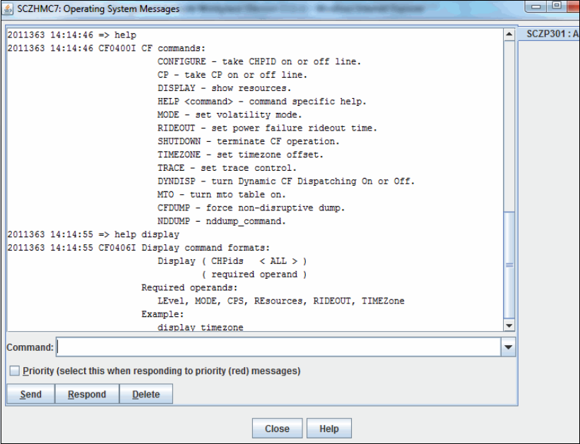
Chapter 7. Operations 203
Get help for CF commands
You can get help for all CF commands by entering help directly in the Operating System
Messages command line when logged on to the CF console. To get more help for a specific
command, enter help followed by the command name. Figure 7-2 shows an example of the
help and the help display commands.
Figure 7-2 Example of the help display command from the CF console
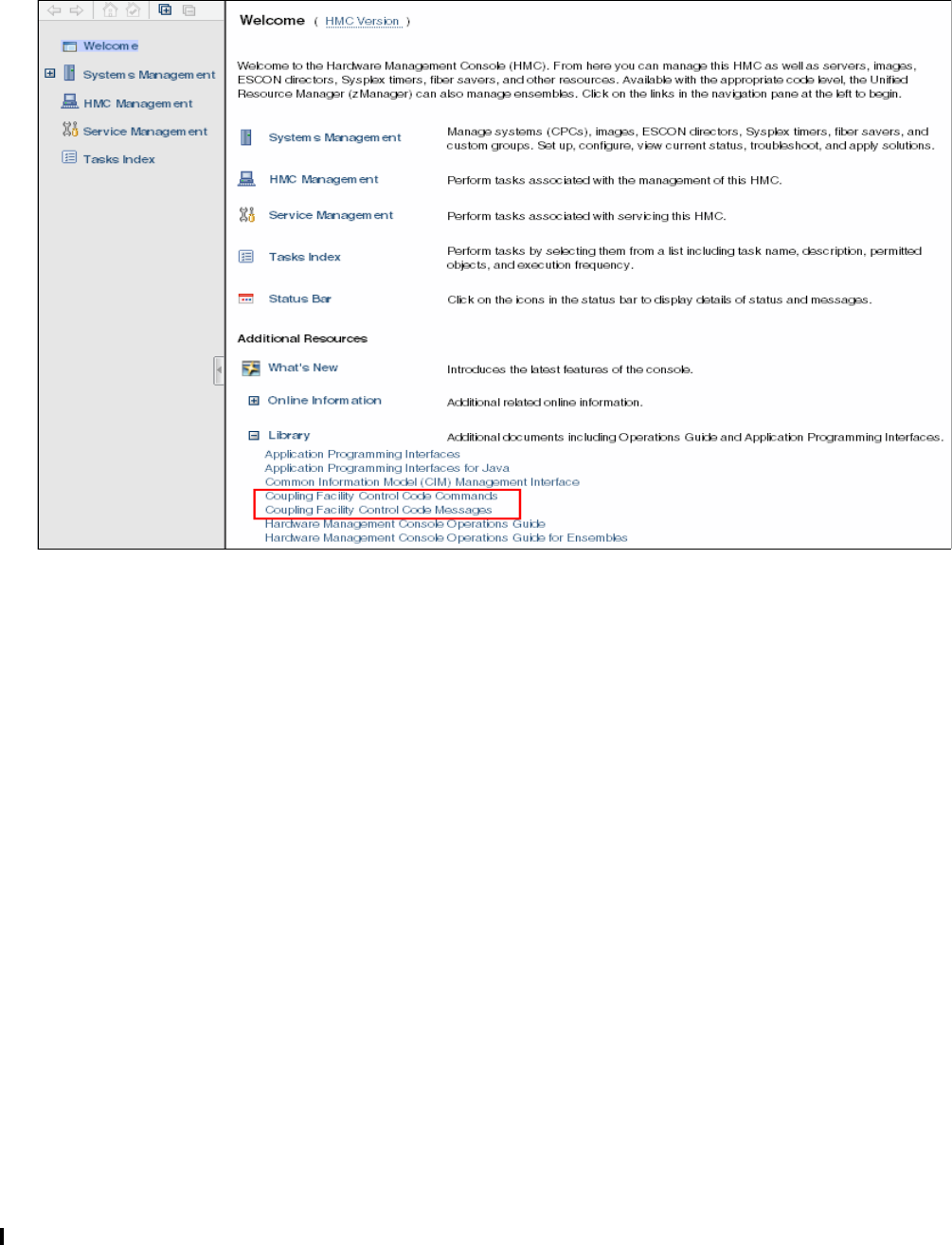
204 Implementing and Managing InfiniBand Coupling Links on IBM System z
There is also a CF command online document on the HMC itself. You can find it in the
Welcome section under Library. Figure 7-3 shows the Library resource on the HMC.
Figure 7-3 Picture of Library contents on the HMC Welcome section
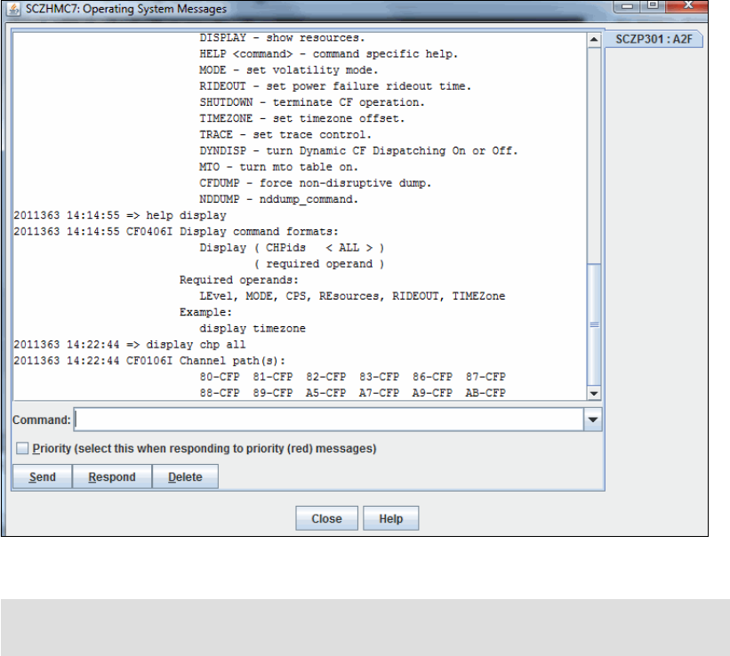
Chapter 7. Operations 205
DISPLAY CHP command
The Display CHP command shows a summary of all available CHPIDs for the CF and the
definition type. Figure 7-4 shows the result of the Display CHP command. Each CHPID that is
active in the CF in which the command was entered is listed here.
Figure 7-4 Example of the Display CHP ALL command from the CF console
Notice that the CF does not provide any information about what is on the other end of each
link. Also, CHPIDs that are used to communicate with a peer CF are included in the same list,
with no way to determine which CHPIDs are communicating with z/OS LPARs, and which are
communicating with a peer CF (and, of course, the same CHPID might be used to
communicate with both a peer CF and z/OS LPARs if they are both in the same processor).
CHPIDs or links that are offline or not operational on the CF end are not shown in the list.
Therefore, to ensure that everything is as you expect, you need to have information about the
expected configuration, and then compare that to the actual configuration as reported by the
D CHP command. Also be aware that a CHPID that was configured offline on the z/OS end will
still show in the list, because as far as the CF is concerned, that CHPID is still available and
ready to be used as soon as the z/OS end comes back online.
Note: All coupling CHPIDs are shown as type CFP regardless of the actual physical link
type.
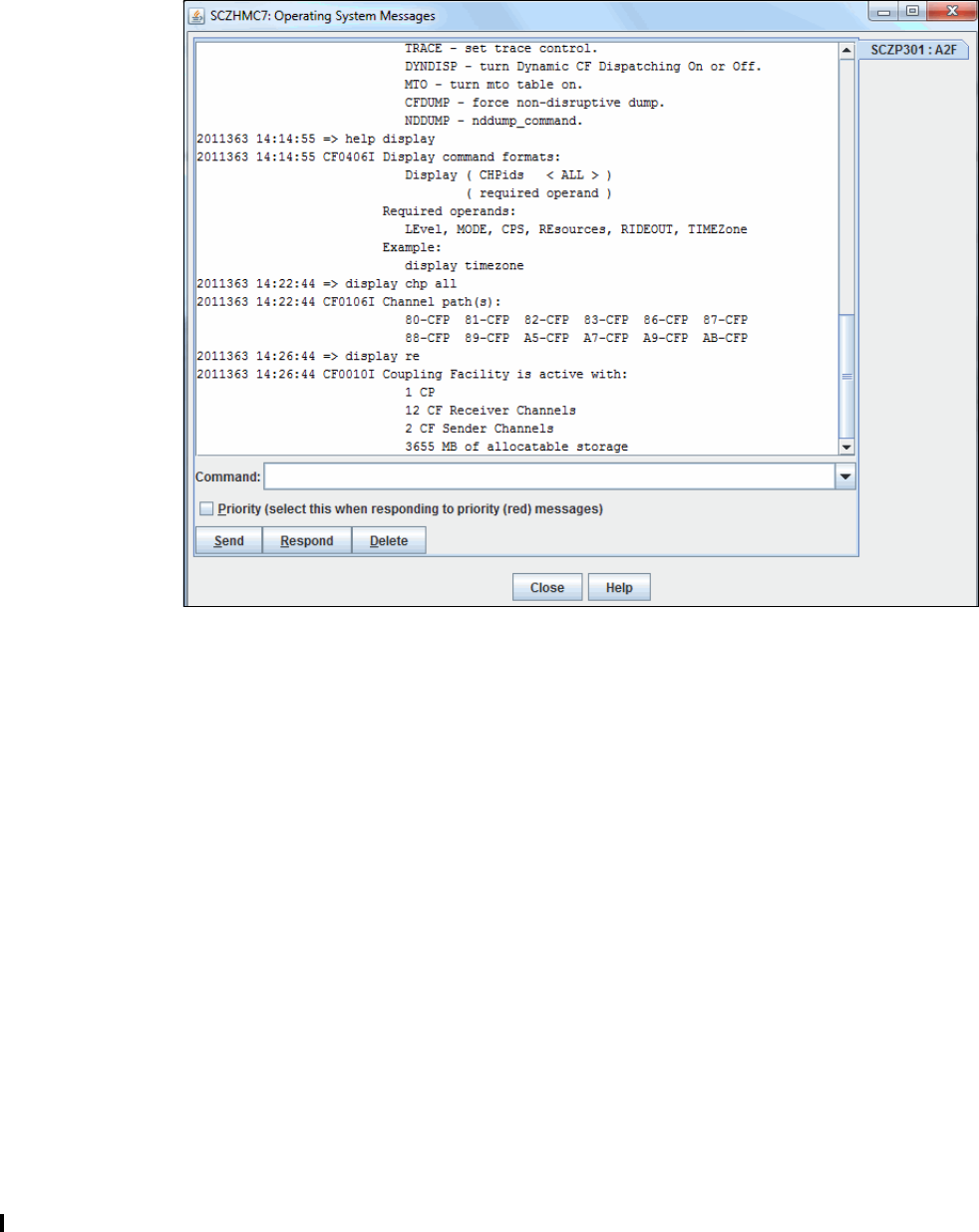
206 Implementing and Managing InfiniBand Coupling Links on IBM System z
DISPLAY RESOURCES
The Display RE command shows a summary of all available resources for the selected CF
partition. Figure 7-5 shows the result of the Display RE command, and shows the number of
CPs, the number of CF link CHPIDs sorted by type, and the allocated memory for the CF in
which the command was entered.
Figure 7-5 Example of the Display RE command from the CF console
The output from the DISPLAY RE command differentiates between CF Receiver and CF
Sender channels. From the CF’s perspective, any channel that can be used to communicate
with another LPAR (either a z/OS LPAR or a CF LPAR) is a Receiver. However, Sender links
are those that have a CF LPAR at the other end. In the example in Figure 7-5, notice that
there are two CHPIDs that can be used to communicate with a peer CF, and a total of 12
CHPIDs that are connected to either a CF LPAR or a z/OS LPAR.
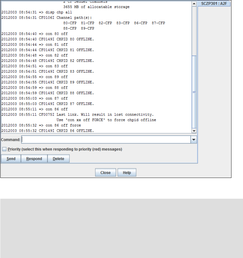
Chapter 7. Operations 207
CONFIGURE chpid ON or OFF
The CON xx ON or CON xx OFF command configures CHPIDs online or offline in the CF
configuration. Trying to configure offline the last CHPID will result in a message saying it is the
last CHPID and the CHPID will not be taken offline. This can be overridden by using the
optional FORCE keyword. Figure 7-6 shows the result from configuring the last CHPID offline.
Figure 7-6 Example of the Configure CHPID off command from the CF console
CP CP_Addr ON or OFF
The CP xx OFF(ON) command (where xx stands for the CP number) configures central
processors (CPs) online or offline in the CF configuration. The maximum number of CPs that
can be used by the CF is the total of the INITITAL and RESERVED values from the LPAR’s
activation profile. The INITIAL CPs are configured online when the CF LPAR is activated. The
CP command must be used to bring RESERVED CPs online.
Important: Remember that the CF0075I Last link message applies to peer CFs, as well
as to connected z/OS LPARs.
If fewer links are used to connect the CFs to each other than are used to connect the CF to
z/OS, it is possible that you will receive this message even though there are still more
CHPIDs available to communicate with z/OS.
The message does not indicate which LPARs the CF is going to lose communication with.
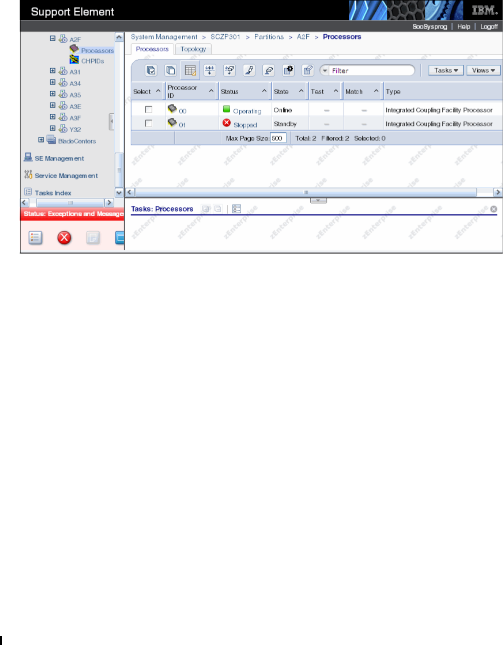
208 Implementing and Managing InfiniBand Coupling Links on IBM System z
Figure 7-7 shows the status of the CF LPAR (on the SE) prior to the CP command being
used. Notice that the LPAR has one CP online, and a second one defined, but currently not
operating.
Figure 7-7 Example of the CF-CP Processor view from the SE with CP 01 stopped
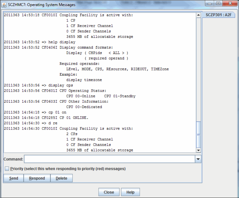
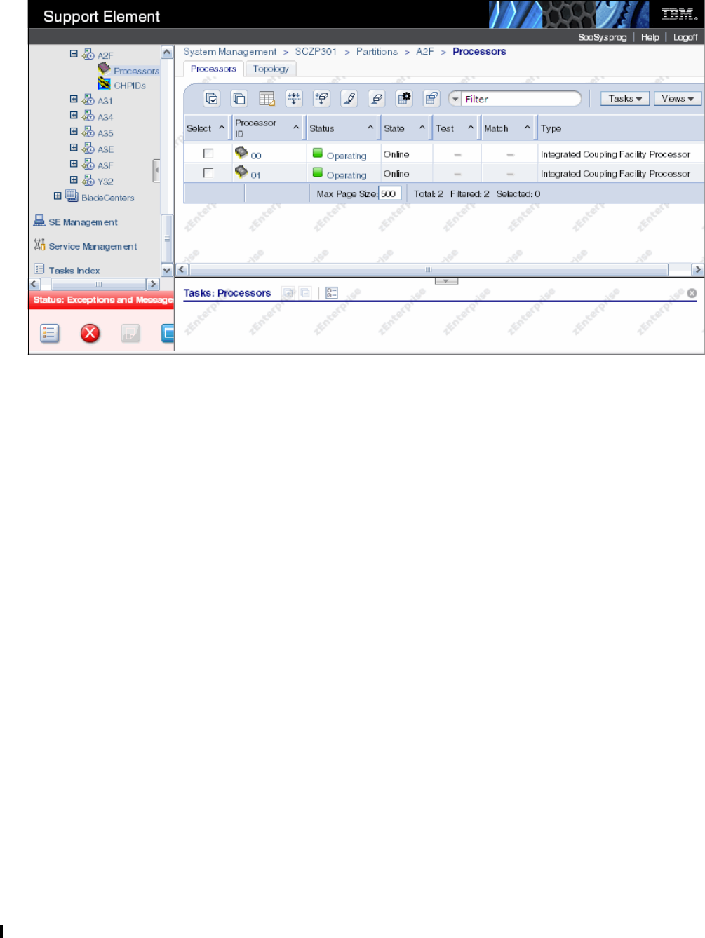
210 Implementing and Managing InfiniBand Coupling Links on IBM System z
Figure 7-9 shows that both CPs are shown as Operating on the SE.
Figure 7-9 Example of the CF-CP Processor view from the SE with CP 01 operating
SHUTDOWN
The SHUTDOWN command ends CF operation, puts all CF logical central processors (CPs)
into a disabled wait state, and then performs a System Reset for the CF LPAR, but only if no
structures are present in the CF.
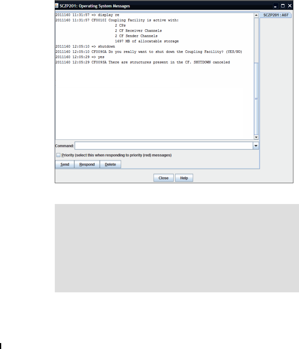
Chapter 7. Operations 211
Figure 7-10 shows the confirmation panel after the command has been entered.
Figure 7-10 Example of the shutdown command from the CF console
7.4 Hardware Management Console and Support Element tasks
The Hardware Management Console (HMC) and Support Element (SE) provide link
information from a hardware point of view. All panels discussed here are based on a z196
with the HMC and the SE running the code level shown in Figure 7-11 on page 212.
Note: If structures are present in the CF, the shutdown operation is canceled and the CF
continues operating. This is a safer way to shut down a CF than using the Deactivate task
on the HMC. Even though the operator is warned that doing a Deactivate could be
disruptive, the same message is issued regardless of whether the CF contains structures
or not. If the operator replies to proceed with the deactivation, the CF will be deactivated,
regardless of whether it contains structures or not.
If the SHUTDOWN completed successfully for the CF, there will be no need to then
perform a DEACTIVATE for the CF.
In the case where a SHUTDOWN cannot be completed successfully (for the last CF in the
sysplex, for example), the HMC DEACTIVATE function must be used.
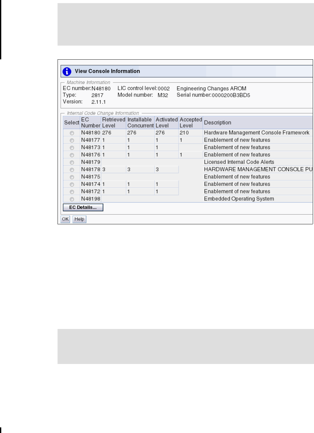
212 Implementing and Managing InfiniBand Coupling Links on IBM System z
Figure 7-11 System information
For all the examples, we were logged on in SYSPROG mode (User role) and we used the
Tree-Style User Interface (UI).
The HMC and SE can also be set to the User Interface style called Classic User Interface.
This is the well-known style used by IBM for a long time but the default style was recently set
to the Tree-Style User Interface because it allows more flexibility and is easy to use. For
details about both UI styles or how to change the UI style, see System z Hardware
Management Console Operations Guide, SC28-6905.
The panels might differ when viewing another processor generation or LIC level. However, the
basic information and data that can be gathered should be the same.
The following functions are explained in this section:
“Display Adapter IDs” on page 213
The Display Adapter ID panel shows the correlation between the physical adapter location
and the assigned AID.
Important: The information in this section is relevant to both z196 and zEC12 CPCs.
However, on zEC12 and later, you can use the D CF command to obtain information that
was previously only available on the HMC or SE. If your system is running on a zEC12 or
later, check if the D CF command will provide the information you require before using the
SE.
Note: Channels can be displayed on the SE by selecting the processor or an image. The
key difference is that the PCHID or physical link status is shown when selecting the
processor perspective, whereas the logical channel or link status is shown if you select the
image perspective.
Chapter 7. Operations 213
“Displaying the status of a CIB link (CPC view)” on page 219
Displaying the status of a CIB link provides information about the status, type of link,
logical channel, CHPID characteristic, AID and port number, all owning images, hardware
location, and the swapped status from the processor point of view.
“Display the status of a logical CIB link (Image view)” on page 221
Displaying the status of a logical CIB link provides information about the status, type of
link, PCHID, CHPID characteristic, AID and port number, owning images, hardware
location, and the swapped status from the image point of view.
“View Port Parameters panel” on page 223
The View Port Parameters panel shows information such as Link Width, bandwidth, and
the Port state about a coupling link.
“Useful information from the Channel Problem Determination display” on page 224
The Channel Problem Determination function provides access to several selections. One
of these in particular will be discussed in detail because it provides useful information:
– “Analyze Channel Information option” on page 226
The Analyze Channel Information panel shows information about a coupling link such
as the Connection Type, Node Descriptor, the State and Status and several
configuration details about the selected coupling link.
“System Activity Display” on page 227
The System Activity Display provides information about the activity of the selected
resources, which can be links, channels, or processors.
7.4.1 Display Adapter IDs
The Display Adapter ID panel can be accessed by performing the following steps:
1. Log on at the HMC (using SYSPROG authority).
2. Open Systems Management.
3. Open Servers.
4. Select the processor whose AIDs you want to look at (SCZP301, in our example).
5. Click Single Object Operation under the Recovery task list and confirm the selection in
the new window that is brought up. You are now logged on to the Support Element.
6. Open System Management.
7. Open Server Name (SCZP301, in our example).
8. Open CPC Configuration in the Tasks area.
9. Click Display Adapter ID.
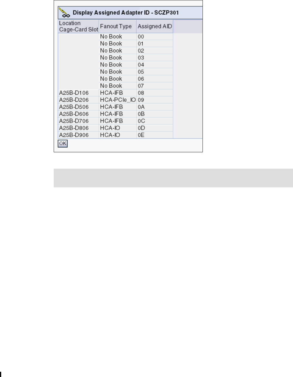
214 Implementing and Managing InfiniBand Coupling Links on IBM System z
Figure 7-12 shows the Display Adapter ID panel from our z196. All installed fanouts are listed
with their location code, the type of the fanout, and the assigned AID. Note, however, that this
display does not differentiate between the different types of InfiniBand coupling fanouts.
Figure 7-12 Display Adapter ID
7.4.2 Determining the CHPIDs that are associated with an AID/port
If you are going to perform actions that result in an InfiniBand port going offline, you will need
to identify all the CHPIDs and LPARs that might be affected by that action. There are two
ways to get this information. One way is by using the SE, and the other is through HCD.
However, because operators typically do not have access to HCD, we focus on the SE
method here. There is no mechanism to display the AID/Port that is associated with a CHPID
on z/OS, or to get a list by AID/Port on the HMC or SE. However, the AID/Port are assigned to
a Cage/Slot/Jack in the CPC, and we can get a list of all the Vouched and CHPIDs that are
associated with the Cage/Slot/Jack. To do this, perform the following steps:
1. Log on at the HMC (using SYSPROG authority).
2. Open Systems Management.
3. Open Servers.
4. Select the processor containing the AID/port that you will be working on (SCZP301, in our
example).
5. Click Single Object Operation under the Recovery task list and confirm the selection in
the new window that is brought up. You are now logged on to the Support Element.
6. Open System Management.
7. Expand the CPC (SCZP301, in our example).
Note: All fanouts have an AID assigned but only PSIFB fanouts use them. The MBA and
HCA-IO fanouts do not use an AID.
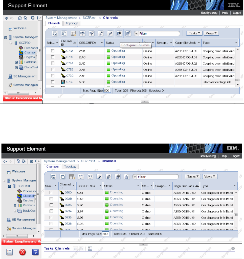
Chapter 7. Operations 215
8. Click Channels.
A list of all the channels on the CPC will be presented, sorted by the PCHID/VCHID value.
Scroll through the list until you find one of the VCHIDs that you know will be impacted by
the change. In this example, we will assume that VCHID 73B is assigned to the port that is
being changed.
In the list shown in Figure 7-13, notice that VCHID 073B is assigned to CHPID AE in
CSS 2, and that CHPID is assigned to a port that resides at Cage-Slot-Jack
A25B-D215-J01.
Figure 7-13 SE Channel list
To determine which other CHPIDs are assigned to the same port, note that location and
then sort the Cage-Slot-Jack column by clicking the up-arrow in that column heading.
Scroll down to the Cage-Slot-Jack that you noted. An example is shown in Figure 7-14.
Figure 7-14 Sorted channel list
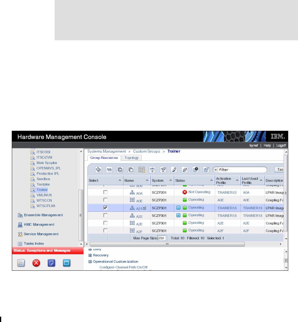
216 Implementing and Managing InfiniBand Coupling Links on IBM System z
You can see that CHPIDs AE, 98, 97, and 96, all in CSS 2, are assigned to that port. Using
the CSS and CHPIDs information, it should be possible to identify all the LPARs on that CPC
that will be affected by any change to that port. Follow the same process to identify the
CHPIDs (and therefore, the LPARs) that are assigned to the port on the other end of the link.
7.4.3 Toggling a CHPID on or offline using HMC
As discussed in “Considerations for configuring CHPIDs offline from HMC” on page 201, it is
generally preferable for CHPIDs to be configured online or offline from the operating systems
that are using them, rather than from the HMC. However, there might be situations where you
need to perform this action from the HMC, so we illustrate here how to do this.
1. Log on to the HMC (using SYSPROG authority).
2. Open Systems Management.
3. Open Servers.
4. Select the processor whose CHPID status you want to change (SCZP301, in our
example).
5. Select the LPAR or LPARs that uses the CHPID that you want to change.
6. Expand the Operational Customization option.
7. Click the Configure Channel Path On/Off option. This is shown in Figure 7-15.
Figure 7-15 Toggling a CHPID offline using the HMC
Important: When performing a toggle action, you must select the LPAR where you want
the change to take effect. For example, if LPARs A21 and A22 are using CHPID 93 in
CSS 2, and you attempt to perform the toggle action after selecting both LPARs, you will be
presented with a panel indicating that the action can only be performed against one LPAR,
and asking you to select which of the two LPARs you want to perform the action against.
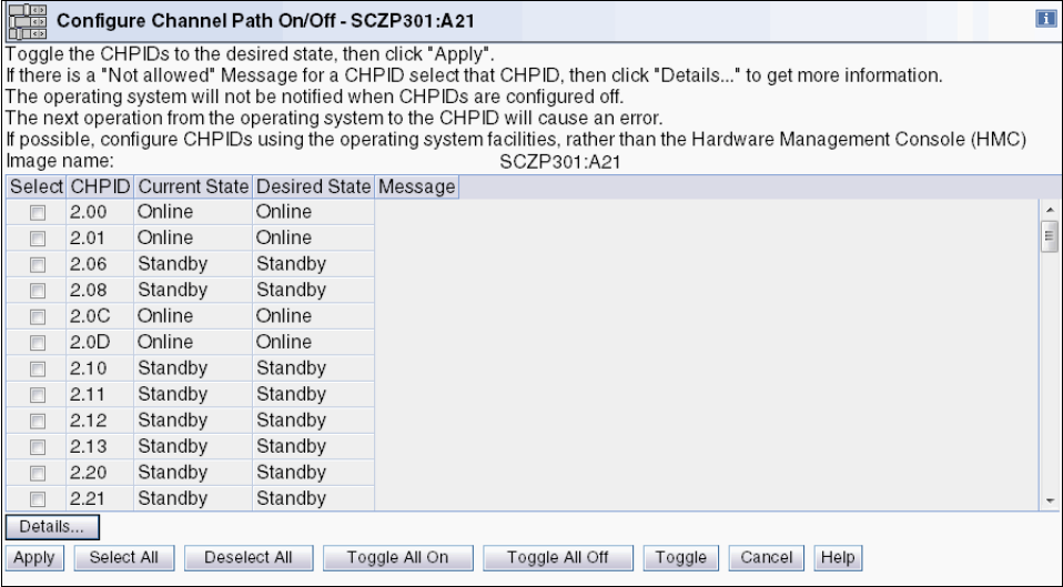
Chapter 7. Operations 217
8. You are presented with a list of the CHPIDs that are available to the selected LPAR, and
the status of each CHPID. This is shown in Figure 7-16.
Figure 7-16 List of CHPIDs available for toggle action
9. Select the CHPIDs that you want to toggle offline. In this example, we select CHPID 93.
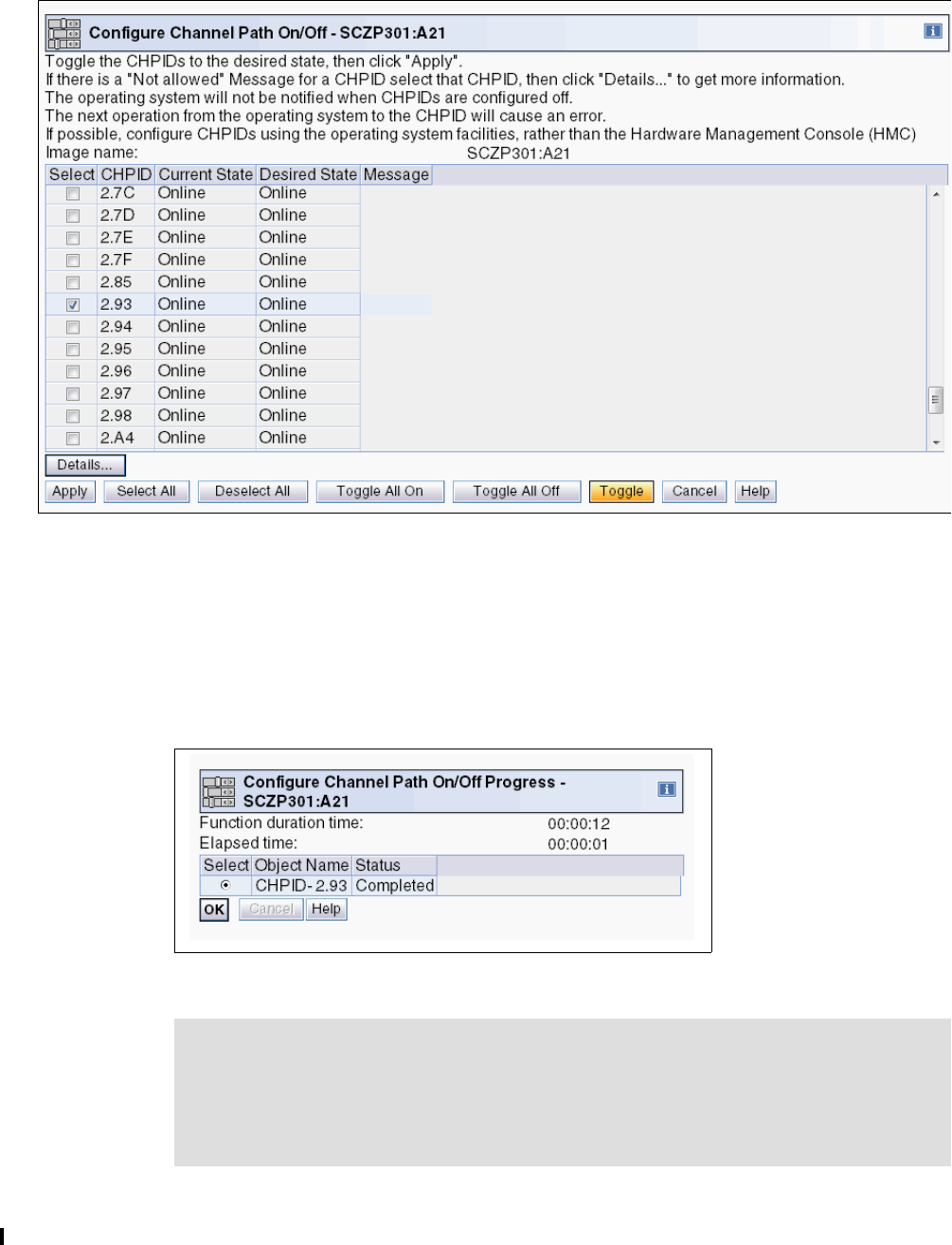
218 Implementing and Managing InfiniBand Coupling Links on IBM System z
10.To change the state of the selected CHPID from offline to online, or online to offline, click
the Toggle button at the bottom of the window, as shown in Figure 7-17.
Figure 7-17 Toggling a CHPID offline
11.After you press Toggle, the desired state of the CHPID will change to Standby. However,
the action to configure the CHPID offline has not started yet. If you prefer, you can clear
the CHPID, or select additional CHPIDs.
12.When you are ready to implement the change, click the Apply button.
13.When the status change completes, you are presented with a status panel as shown in
Figure 7-18.
Figure 7-18 Result of toggle action
Note: If you have a valid reason for toggling the CHPID offline to several LPARs
simultaneously, you can do that from the SE.
Select the CHPIDs that you want to toggle from the channel list and select the Configure
On/Off option under Channel Operations. If the CHPID is in use by multiple LPARs, you
will be asked to select which LPARs you want to be affected by the toggle action.

Chapter 7. Operations 219
7.4.4 Displaying the status of a CIB link (CPC view)
The channel and link work area can be opened by performing the following steps:
1. Log on at the HMC (using SYSPROG authority).
2. Open Systems Management.
3. Open Servers.
4. Select the processor whose CHPID status you want to look at (SCZP301, in our example).
5. Click Single Object Operation under the Recovery task list and confirm the selection in
the new window that is brought up. You are now logged on to the Support Element.
6. Open System Management.
7. Open Server Name (SCZP301, in our example).
8. Click Channels.
Figure 7-19 on page 220 shows the channel status of a processor called SCZP301. This
panel shows the following information for each defined channel:
– Channel ID (PCHID or VCHID number)
– Logical channel, consisting of channel subsystem ID (CSS ID) and CHPID
– Channel status and State (physical link status)
– The hardware location of the channel consisting of the Cage, Slot, and Jack
– Type (Coupling over InfiniBand, in our case)
Tip: On a zEC12 or later, much of the information that you can obtain about a CIB CHPID
from the SE can also be obtained using the z/OS D CF or D M=CHP(xx) command.
Note: A PCHID in the range from 0700 to 07FF lacks the exact one-to-one
relationship between the identifier and the physical location. For more information
see 2.4.2, “VCHID - Virtual Channel Identifier” on page 28.
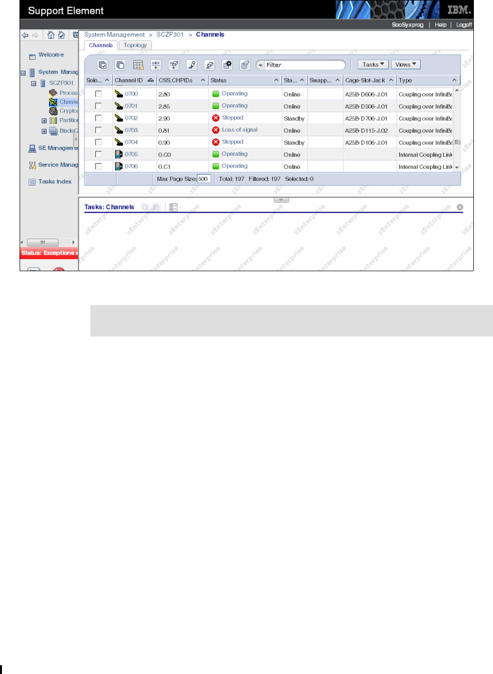
220 Implementing and Managing InfiniBand Coupling Links on IBM System z
Figure 7-19 Status of CIB links (processor view)
For a better understanding of how changes in z/OS and the CF are reflected on the SE, try
the following actions on a test sysplex after making sure that more than one link is
available and check the SE changes for both ends of the link after each one:
– Configure a shared CHPID offline in one of the sharing z/OS systems.
– Configure that CHPID offline in all the other systems that are sharing it.
– Configure a CHPID offline from the CF console.
9. To get additional information, click the Channel ID (PCHID or VCHID) you want to look at.
A detailed coupling link status is shown in Figure 7-20 on page 221.
From this panel you can see the following information:
Channel status
Type (Coupling over InfiniBand, in our case)
Logical channels, consisting of CSS ID and CHPID
CHPID characteristic
Adapter ID and port number
The LPARs in the CHPID’s access list
The hardware location of the channel consisting of Cage, Slot, and Jack
Swapped status
Tip: All parts of the window and the table can be readjusted in size to provide more
flexibility in viewing specific information.
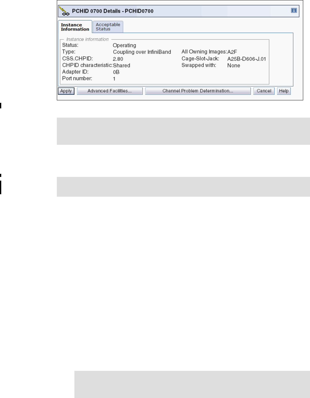
Chapter 7. Operations 221
Figure 7-20 PSIFB coupling link details: Processor view
7.4.5 Display the status of a logical CIB link (Image view)
You can open the CHPID work area by following these steps:
1. Log on at the HMC (using SYSPROG authority).
2. Open Systems Management.
3. Open Servers.
4. Select the processor whose CHPID status you want to look at (SCZP301, in our example).
5. Click Single Object Operation under the Recovery task list and confirm the selection in
the new window that is brought up. You are now logged on to the Support Element.
6. Open System Management.
7. Open Server Name (SCZP301, in our example).
8. Open Partitions.
9. Open Partition Name (A2F, in our example).
10.Click CHPIDs.
Figure 7-21 on page 222 shows the CHPID status of an image called A2F. This panel
shows the following information for each channel defined for this specific LPAR:
– Logical channel, consisting of CSS ID and CHPID
– PCHID (or VCHID number)
Tip: You can go directly to Channel Problem Determination from here. This option is
described in 7.4.7, “Useful information from the Channel Problem Determination display”
on page 224.
Tip: On a zEC12 or later, much of the information that you can obtain about a CIB CHPID
from the SE can also be obtained using the z/OS D CF or D M=CHP(xx) command.
Note: A PCHID in the range from 0700 to 07FF lacks the exact one-to-one
relationship between the identifier and the physical location. For more information
see 2.4.2, “VCHID - Virtual Channel Identifier” on page 28.
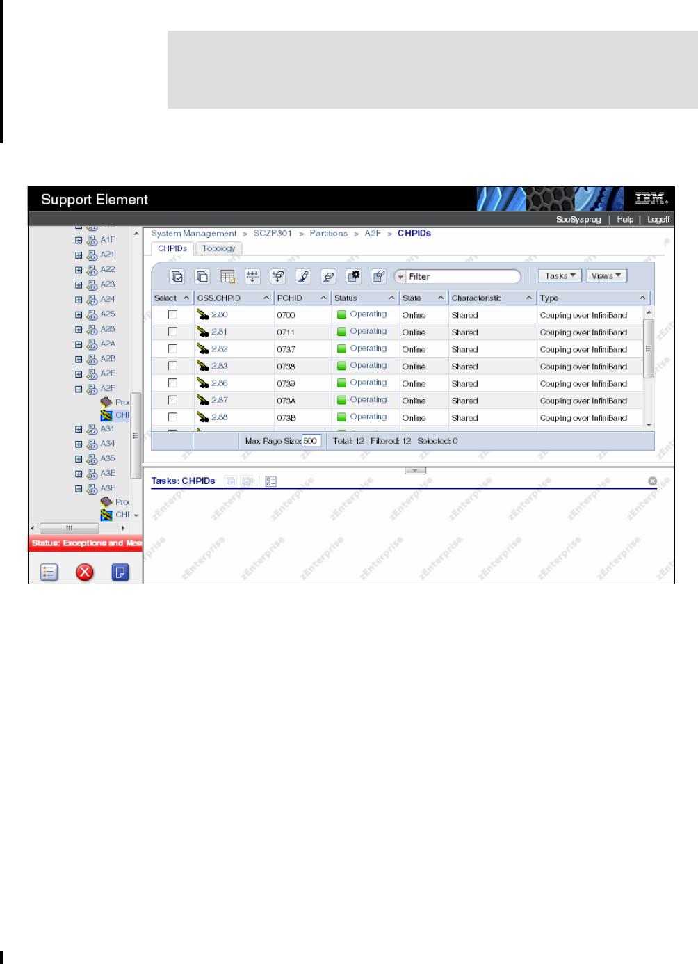
222 Implementing and Managing InfiniBand Coupling Links on IBM System z
– Channel status and State (logical link status specific to this LPAR)
– CHPID characteristic
– Type (that is, Coupling over InfiniBand)
Figure 7-21 Status of logical CIB link (Image view)
11.To get additional information, click the logical channel number that you want to look at. A
detailed coupling link status is shown in Figure 7-22 on page 223. This is similar, but not
identical to, the display that is shown in Figure 7-20 on page 221.
This panel shows the following information:
Channel status
Type (Coupling over InfiniBand, in our case)
PCHID (or VCHID)
CHPID characteristic
Adapter ID and port number
Owning Image and all owning images
The hardware location of the channel consisting of Cage, Slot, and Jack
Swapped status
Important: When looking at a shared coupling link from two logical partitions
(Image view), the coupling link (CHPID) might have a different status for each. It is
essential to select the CHPID through the desired logical partition from which you
want to view.
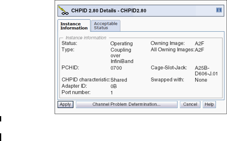
Chapter 7. Operations 223
Figure 7-22 PSIFB coupling link details: Logical partition view
7.4.6 View Port Parameters panel
You can open the View Port Parameters panel by following these steps:
1. Log on at the HMC (using SYSPROG authority).
2. Open Systems Management.
3. Open Servers.
4. Select the processor whose CHPID status you want to look at (SCZP301, in our example).
5. Click Single Object Operation under the Recovery task list and confirm the selection in
the new window that is brought up. You are now logged on to the Service Element.
6. Open System Management.
7. Open Server Name (SCZP301, in our example).
8. Click Channels.
9. Select the coupling link you want to view the port parameters (CHPID 2.80, in our
example).
10.Now the PSIFB coupling link details panel is shown. Click Advanced Facilities.
11.In the new Advanced Facilities panel, click Card Specific Advanced Facilities.
12.Another Advanced Facilities panel is loaded. Click View Port Parameters here.
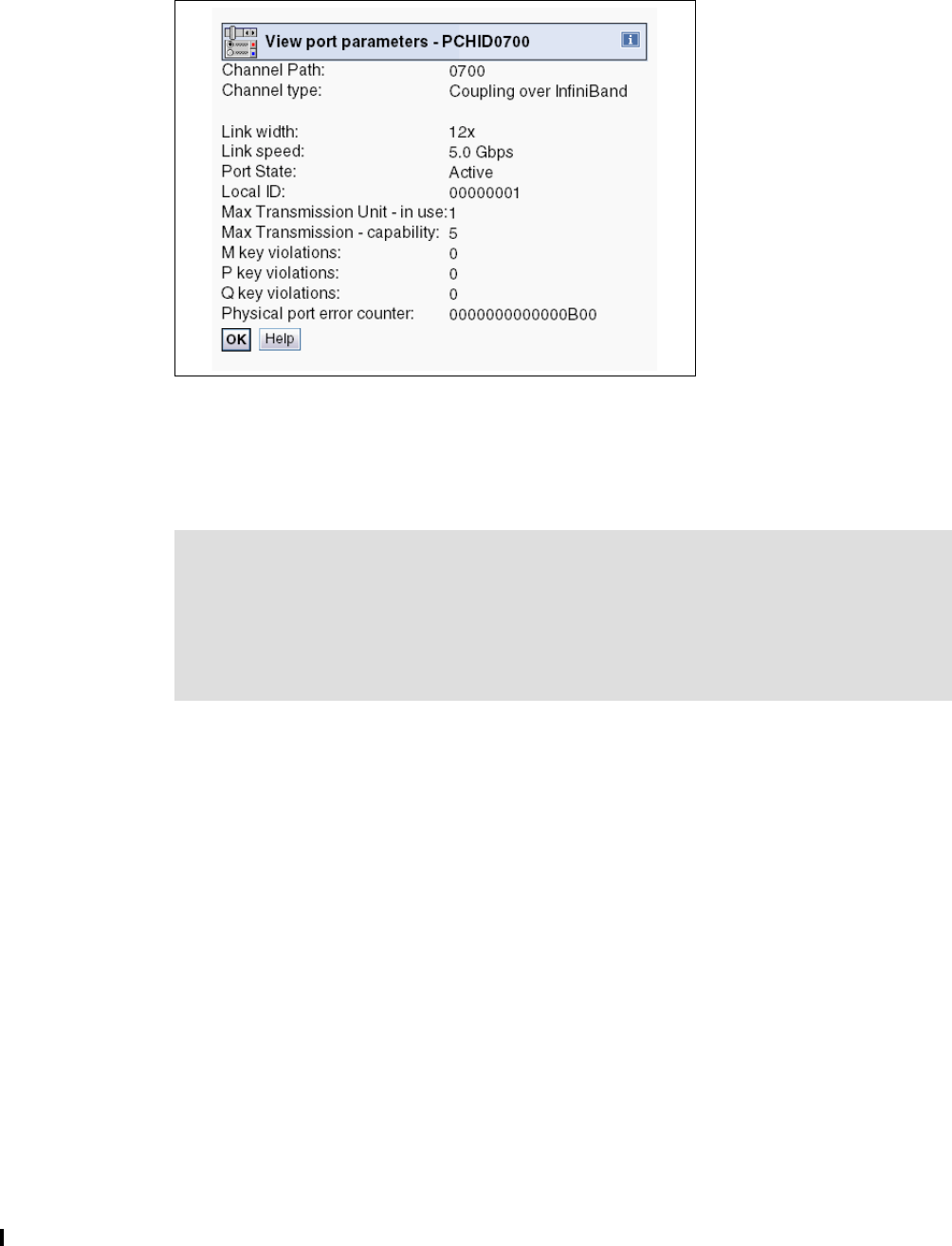
224 Implementing and Managing InfiniBand Coupling Links on IBM System z
Figure 7-23 shows the View Port Parameters panel. The panel shows the Link Width, the
bandwidth, and the Port State for the selected PSIFB coupling link.
Figure 7-23 View port parameters
This panel helps you determine the physical status of the link for link problem determination.
Further, it provides information about the current Link width. For example, in case of a
problem with a 12x link, the Link width field could have values down to 8x, 4x, 2x, or 1x. The
Port State shows whether the physical link is active or down.
7.4.7 Useful information from the Channel Problem Determination display
You can open the Channel Problem Determination panel by following these steps:
1. Log on at the HMC (using SYSPROG authority).
2. Open Systems Management.
3. Open Servers.
4. Select the processor whose CHPID status you want to look at (SCZP301, in our example).
5. Click Single Object Operation under the Recovery task list and confirm the selection in
the new window that is brought up. You are now logged on to the Service Element.
6. Open System Management.
7. Open Server Name (SCZP301, in our example).
8. Click Channels.
9. Select the coupling link you want to see detailed information about (CHPID 2.80, in our
example).
Note: In the panel, the Link speed field actually reports the speed of each fibre pair in the
link (for example, it could be 2.5 Gbps for a Single Data Rate link or 5.0 Gbps for a Double
Data Rate link). To determine the full bandwidth of the link, multiply the value in the Link
speed field by the number of lanes, as reported in the Link width field.
Thus, in this example, the design bandwidth of the link is 6 GBps (5.0 Gbps per lane times
12 lanes).
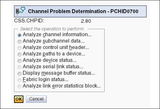
Chapter 7. Operations 225
10.Now the PSIFB coupling link details panel is shown. Click Channel Problem
Determination.
11.In the Select Partition and CSS.CHPID panel, select the partition from where you want to
look at the coupling link (in our example, we select partition A21).
On the Channel Problem Determination panel, there are several valid options to choose from
for the selected coupling link; see Figure 7-24. We now discuss two of these options in more
detail because they provide useful information about the status of the selected coupling link.
Figure 7-24 Channel Problem Determination
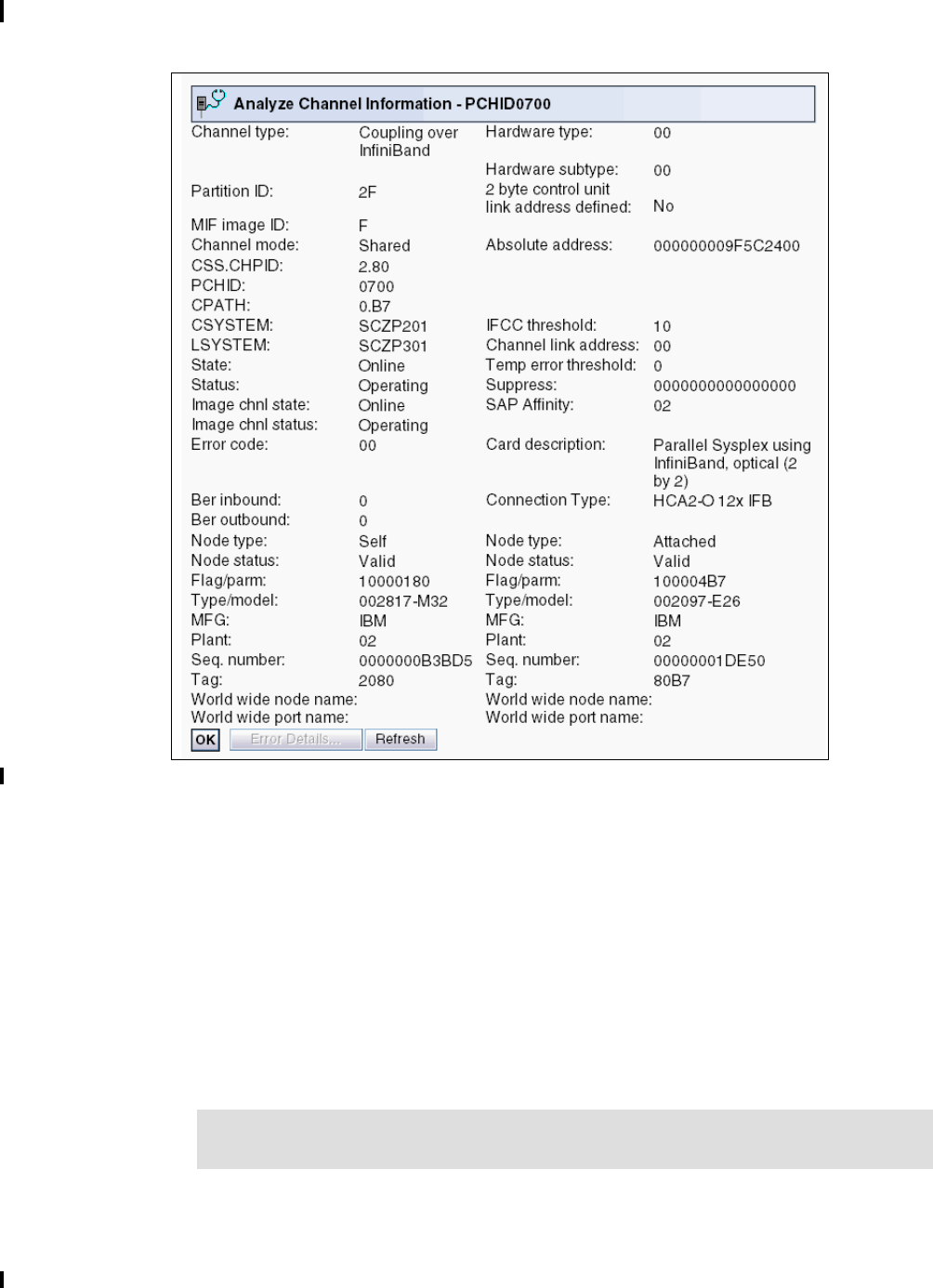
226 Implementing and Managing InfiniBand Coupling Links on IBM System z
Analyze Channel Information option
The Analyze Channel Information option is shown in Figure 7-25.
Figure 7-25 Analyze Channel Information option
Here are the details for the information provided in Figure 7-25:
Channel Type (Coupling over InfiniBand).
Partition ID - Provides the Partition ID of the selected partition.
MIF ID - Provides the MIF ID of the selected partition.
Channel Mode - Shows whether the link is spanned, shared, or dedicated.
CSS.CHPID - Shows the logical channel, consisting of CSS ID and CHPID.
PCHID - Shows the currently selected PCHID.
CPATH - Provides the CSS and CHPID of the CHPID at the other end of this link.
CSYSTEM - Provides the system name of the processor at the other end of this link.
LSYSTEM - Provides the system name of the local system as defined in the HCD.
Note: The CPATH and the CSYSTEM must match the Tag value from the attached
node.

Chapter 7. Operations 227
State and Status (from the processor view).
Provides the state and status of the link as seen from the processor view.
Image Channel State and Image Channel Status (from the image view).
Provides the state and status of the link as seen from the image view.
Node Descriptor for the local system (on the left side of the display) and the connected
system (on the right side of the display).
– Node type - Self means the shown Node Descriptor (ND) information is from the
channel itself. Attached indicates the shown Node Descriptor (ND) information is from
the attached node.
– Node status - Valid means that there has been a successful port login. Invalid means
there has not been any port login. A node status Valid but not current means there
has been a port login, but the link was dropped afterward.
– Type/Model - Provides the CPC type and model of the node.
– Plant - This is the plant of manufacture of the node.
– Sequence number - The serial number of the node.
– Tag - The Tag field represents the CSS/CHPID for System z processors. The first
character of the Tag field represents the CSS. The last two digits represent the CHPID
(the second digit showing a 0 is reserved).
Table 7-1 illustrates the CSS-to-Tag relation. Read the tag value in the top line and get
the corresponding CSS IDs the link has been defined to. For instance, Tag = C080; C
indicates the link is defined to CHPID 80 in CSS0 and CSS1.
Table 7-1 CSS-to-tag relationship
Card Description (InfiniBand fanout card - optical).
Connection Type (HCA2-O 12x IFB, in our example).
7.4.8 System Activity Display
This displays the system activity for CPCs or a group of CPCs. System activity includes the
channel activity and physical processing activity that has been defined in the system activity
profiles that are stored in the selected CPCs. For more information about assigning and
customizing activity profiles, see System z Hardware Management Console Operations
Guide, SC28-6905.
With the System Activity Display, you can create a list of links you want to monitor (that is, if a
problem is suspected to be caused by one or more CIB links). Figure 7-26 on page 228
CSS/Tag 123456789ABCDEF
0 XXXXXXXX
1 XXXX XXXX
2 XXXXXXXX
3 XXXXXXXX
Note: At the time of writing, this panel is the only place where you can obtain
information about the physical type (HCA1, HCA2, or HCA3, and 1X or 12X) and
protocol (IFB or IFB3).
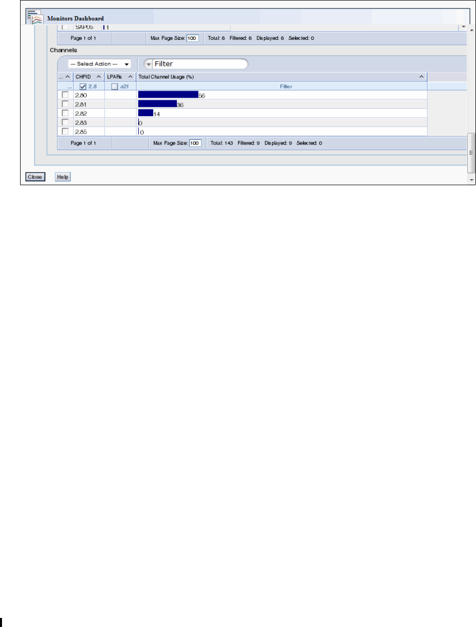
228 Implementing and Managing InfiniBand Coupling Links on IBM System z
shows a System Activity Display customized for CHPIDs 2.8* on processor SCZP301 as an
example. These are the CHPIDs that are in use by our CF, FACIL04.
Note that the utilization reported on the System Activity Display is the utilization of the CHPID,
not the utilization of the bandwidth of the associated InfiniBand link.
Figure 7-26 System Activity Display for InfiniBand CHPIDs
7.5 PSIFB Channel problem determination
There can be situations where a channel is not working as expected. Reasons for this include
the following possibilities:
A CPC has been added or an existing CPC was upgraded
A physical cable might be broken or damaged
Hardware errors
Network issues
Configuration errors
This section describes the actions you can take to investigate the cause of the problems.
7.5.1 Checking that the link is physically working
The first step to take in your investigation is to determine whether the physical link is working.
See 7.4.4, “Displaying the status of a CIB link (CPC view)” on page 219 for a description of
how to display the physical link status of a PSIFB channel. If the channel is online to at least
one LPAR, use the “Channel Problem Determination” button to display the PCHID details
panel as shown in Figure 7-20 on page 221.
See 7.4.7, “Useful information from the Channel Problem Determination display” on page 224
for further details about the configuration from the perspective of the selected LPAR.
Additionally, the “View Port Parameter” function, described in 7.4.6, “View Port Parameters
panel” on page 223, is a useful place to determine whether the link is running at the correct
speed. These three points are the basics from the hardware perspective.
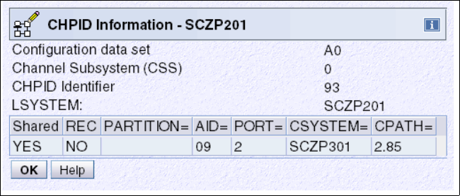
Chapter 7. Operations 229
7.5.2 Verifying that the physical connections match the IOCDS definitions
A useful way to determine whether the current IOCDS accurately reflects how the adapters
and ports are connected to each other is to display the IOCDS CIB channel information about
the SE using the Input/Output (I/O) Configuration task, and then to compare that information
to the physical cabling and connections.
The following example displays the IOCDS information for both ends of a defined CIB
coupling channel link. In this example, we were logged on in SYSPROG mode (User role) and
we used the Tree-Style User Interface (UI).
1. Log on to the HMC (using SYSPROG authority), and then open Systems Management.
2. Open Servers.
3. Select the CPC whose IOCDS you want to look at (SCZP201, in our example).
4. Click Single Object Operation under the Recovery task list and confirm the selection in
the window that is brought up. You are now logged on to the Support Element.
5. Open System Management.
6. Open Server Name (SCZP201, in our example).
7. Open CPC Configuration in the Tasks area.
8. Click Input/output (I/O) Configuration.
9. Select the active IOCDS and click View on the taskbar and then click Channel Path
Configuration.
10.In the Channel Path Configuration click the CHPID you want to look at (0.93 in our
example), select View on the taskbar, and then click CHPID Information.
Figure 7-27 shows the CHPID Information for CHPID 0.93. In our IOCDS A0, the AID 09,
Port 2 is linked to CHPID 2.85 on the SCZP301 CPC.
Figure 7-27 CHPID Information from the Input/output (I/O) Configuration for System SCZP201

230 Implementing and Managing InfiniBand Coupling Links on IBM System z
Next, we followed the same steps for the system at the other end of the link, SCZP301.
Figure 7-28 shows the result for that system. In IOCDS A0 on that CPC, AID 0A, Port 1 is
connected to CHPID 0.93 on the SCZP201 CPC.
Use this information to verify that the actual cabling matches the definitions. Note that, unlike
FICON channels, there is no way on the SE to view the actual connection information, so this
checking must be carried out physically.
Figure 7-28 CHPID Information from the Input/output (I/O) Configuration for System SCZP301
7.5.3 Setting a coupling link online
A coupling link should be set online from the CF LPAR first, and then from the z/OS LPAR.
The management of the coupling link for the CF LPAR is normally handled from the Operating
System Console on the HMC or SE.
Although a coupling CHPID can be toggled offline using the Configure Channel Path On/Off
selection on the HMC or SE, the CF console must be used to bring the CHPID online to
the CF.
If you are unable to configure online a correctly defined coupling link, use the following
checklist to check the status and attempt to resolve the error:
1. Make sure that the CF LPAR is activated.
You can obtain the status of the CF LPAR by using the LPAR operating view on the
HMC/SE panels, as shown in Figure 7-15 on page 216.
2. Make sure that the z/OS LPAR is activated.
You can obtain the status of the z/OS LPAR by using the LPAR operating view on the
HMC/SE panels, as shown in Figure 7-15 on page 216.
3. Check the physical coupling link status.
Use the procedure described in 7.5.1, “Checking that the link is physically working” on
page 228 to determine whether the link is working correctly; if the link is working correctly,
then proceed to the next step.
If the link is not working correctly, follow your normal installation procedures for addressing
coupling link problems.
4. Check the logical coupling link status.
The logical status of the coupling link is determined by using the z/OS and CF consoles.
a. Check the CHPID status on the CF by issuing the following command on the CF
console:
DISPLAY CHP ALL

Chapter 7. Operations 231
b. Next, display the CHPID status on z/OS, using the following command:
D M=CHP(xx)
In the output from this command, check the LOGICAL column near the start of the
output. The LOGICAL status should be ONLINE.
If it is OFFLINE, use a VARY PATH command to bring it logically online.
c. On the SE where the z/OS LPAR resides, obtain the status from the associated
CHPIDs, as explained in 7.4.4, “Displaying the status of a CIB link (CPC view)” on
page 219.
5. Configure the channel on from the CF LPAR side.
On the Operating System Console for the CF LPAR on the HMC, use the following
command:
CON xx,ONLINE
6. Configure the channel on from the z/OS LPAR side.
Use the following MVS command to configure the link online:
CF CHP(xx),ONLINE
If the D CF command indicated that the logical status of the CHPID was OFFLINE, use the
following command to bring the path logically online:
V PATH(cfname,xx),ONLINE
7. The coupling link should now be online.
7.6 Environmental Record Editing and Printing
When an error occurs, the system records information about the error in the Logrec data set
or the Logrec log stream. The information provides you with a history of all hardware failures,
selected software errors, and selected system conditions.
Use the Environmental Record Editing and Printing (EREP) program to print reports about
the system records to determine the history of the system, or to learn about a particular error.
For further information, refer to z/OS MVS Diagnosis: Tools and Service Aids, GA22-7589.
Note: If the z/OS LPAR is not activated, the channel status of “Online/Loss of
Signal” or “Online / Sequence Timeout” is a normal status.
Note: If the CHPID is only online on the z/OS LPAR, then configure it off first using
the procedure from the HMC, as described in 7.4.3, “Toggling a CHPID on or offline
using HMC” on page 216.

232 Implementing and Managing InfiniBand Coupling Links on IBM System z

© Copyright IBM Corp. 2008, 2012, 2014. All rights reserved. 233
Appendix A. Resource Measurement Facility
In this appendix, we show you how to use the IBM Resource Measurement Facility™ (RMF)
tool to display information about Coupling Facility (CF) performance. We also discuss how to
calculate the utilization of subchannels used to communicate with the CF.
The following topics are covered:
Introduction to performance monitoring
Introduction to RMF
RMF Postprocessor reporting
A

234 Implementing and Managing InfiniBand Coupling Links on IBM System z
Resource Measurement Facility overview
RMF is a powerful tool for monitoring and analyzing the performance of many aspects of
z/OS. This appendix provides a brief overview of RMF and performance measurements and
techniques for analyzing the CF, and the related calculations for CF subchannel utilization.
For more information about using RMF, see Effective zSeries Performance Monitoring Using
Resource Measurement Facility, SG24-6645.
Introduction to performance monitoring
Before doing any performance measurements or analysis, it is imperative to establish your
performance objectives. The goal of performance management is to make the best use of
your current resources and to meet your objectives without excessive tuning efforts.
You will probably use RMF for a number of purposes:
To determine a baseline - what are the expected response times based on the current
configuration.
To investigate performance problems that might be related to the CF.
To gather data for a CF capacity planning exercise.
Our focus for performance monitoring in relation to this document is the PSIFB coupling links.
Because the hardware and the software do not provide information about coupling link
bandwidth utilization, we discuss options that are available to help you determine if additional
link capacity is required.
Introduction to RMF
RMF provides an interface to your System z environment that facilitates gathering and
reporting on detailed measurements of your critical resources.
RMF consists of several components:
Monitor I, Monitor II, Monitor III
Postprocessor
RMF Performance Monitoring
Client/Server support
Spreadsheet Reporter
Sysplex Data Server
Distributed Data Server
These components complement each other to provide the infrastructure for performance
management:
Gathering data
Reporting data
Accessing data across the sysplex
Data gathering
RMF gathers data using three monitors:
Short-term data collection with Monitor III
Snapshot monitoring with Monitor II
Long-term data gathering with Monitor I and Monitor III

Appendix A. Resource Measurement Facility 235
The system operator starts all monitors as non-interactive (background) sessions with various
options that determine what type of data is collected and where it is stored. The data
gathering functions run independently on each system, but each monitor can be started
sysplex-wide by one operator command.
RMF reporting
RMF has three monitors and a postprocessor for reporting performance statistics:
RMF Monitor I produces interval reports that are created at the end of a measurement
interval, for example, 30 minutes. You can obtain Monitor I session reports during or at the
end of RMF processing, or they can be generated later by the postprocessor.
RMF Monitor II is a snapshot reporting tool that quickly provides information about how
specific address spaces or system resources (processor, DASD, volumes, storage) are
performing. Monitor II has two modes for reporting on system performance:
– A Monitor II display session, which can be invoked from either an ISPF dialog or
directly with a TSO command (RMFMON).
– A Monitor II background session, which is a non-interactive session to create a report
for printing.
The RMF Monitor III data gather runs as a started task to gather information about
aspects of the system that are not covered by the Monitor I gatherer. It also provides an
ISPF interface to allow you to access sysplex or system performance reports interactively:
– Displaying real-time information about your current system status
– Showing previously collected data that is still available in either storage buffers or
allocated VSAM data sets
Monitor III offers a wide spectrum of reports answering questions that arise during the
various performance management tasks. The ISPF interface is able to present information
from any system in the sysplex, so there is no need to log on to different systems in the
sysplex to get all performance data.
The postprocessor is invoked through a batch job and offers the following types of reports:
– Interval reports reflect a picture of performance for each interval for which the data has
been gathered.
– Duration reports summarize data over longer periods of time with a maximum value of
100 hours.
– Summary and exception/overview reports.
In addition, the postprocessor can create overview records that are ideal for further
processing with a spreadsheet application.
Interactive reporting with RMF Monitor III
This section summarizes the CF performance information that is available through the
Monitor III ISPF interface. Historical reporting is typically performed using the RMF
postprocessor, as described in “RMF Postprocessor reporting” on page 240.
RMF Monitor III usage tips
There are a few tips to help a new user around the usage of Monitor III.

236 Implementing and Managing InfiniBand Coupling Links on IBM System z
Coupling Facility reports
The following Monitor III reports will help you investigate CF performance:
Option S.5 - CFOVER - Coupling Facility Overview. A fast path to this report is available by
typing CO on the command line.
Option S.6 - CFSYS - Coupling Facility Systems. A fast path to this report is available by
typing CS on the command line.
Option S.7 - CFACT - Coupling Facility Activity report. A fast path to this report is available
by typing CA on the command line.
Report Options
You access the Options panel by entering the letter O from the RMF Monitor III primary menu.
From here, you can select “Session options” to tailor defaults (such as refresh period and time
range).
Additionally, typing RO from any CF report panel provides useful filtering criteria for your CF
reports. The following filters apply to the Coupling Facility reports:
NAME - restrict the displays to a specific Coupling Facility.
TYPE - restrict the display to a specific structure type (for example, LOCK).
DETAIL - lets you control the level of granularity of the reports; a sysplex view, or
information for each system in the sysplex.
Scrolling forward and backwards through different intervals
Moving between different intervals is both interactive and straightforward. Use PF10 to move
back one interval and PF11 to move forward one interval. It is also possible to jump to a
specific time by typing this into the time field. And you can enter CURRENT to be brought to the
most recent interval.
You can also control the length of the interval you are looking at by changing the number of
seconds in the Range field. If investigating a problem, you might want to use an interval as
low as 10 seconds. If you are comparing performance, it is probably better to use longer
intervals, like 900 seconds, to reduce the impact of intermittent spikes in activity.
Creating hardcopy data
The RMF session options have a Hardcopy option. When turned ON, this will save your RMF
Monitor III screens to a dynamically allocated RMF sysout DDNAME within your TSO
session. Using SDSF, you can then save this in a data set for later reference.
RMF Monitor III Screens
Figure A-1 on page 237 shows the Sysplex Report Selection menu. From here you can
access reports to analyze your Coupling Facility performance.
Note: We have filtered our Coupling Facility report options to display only LOCK structures
in our examples.
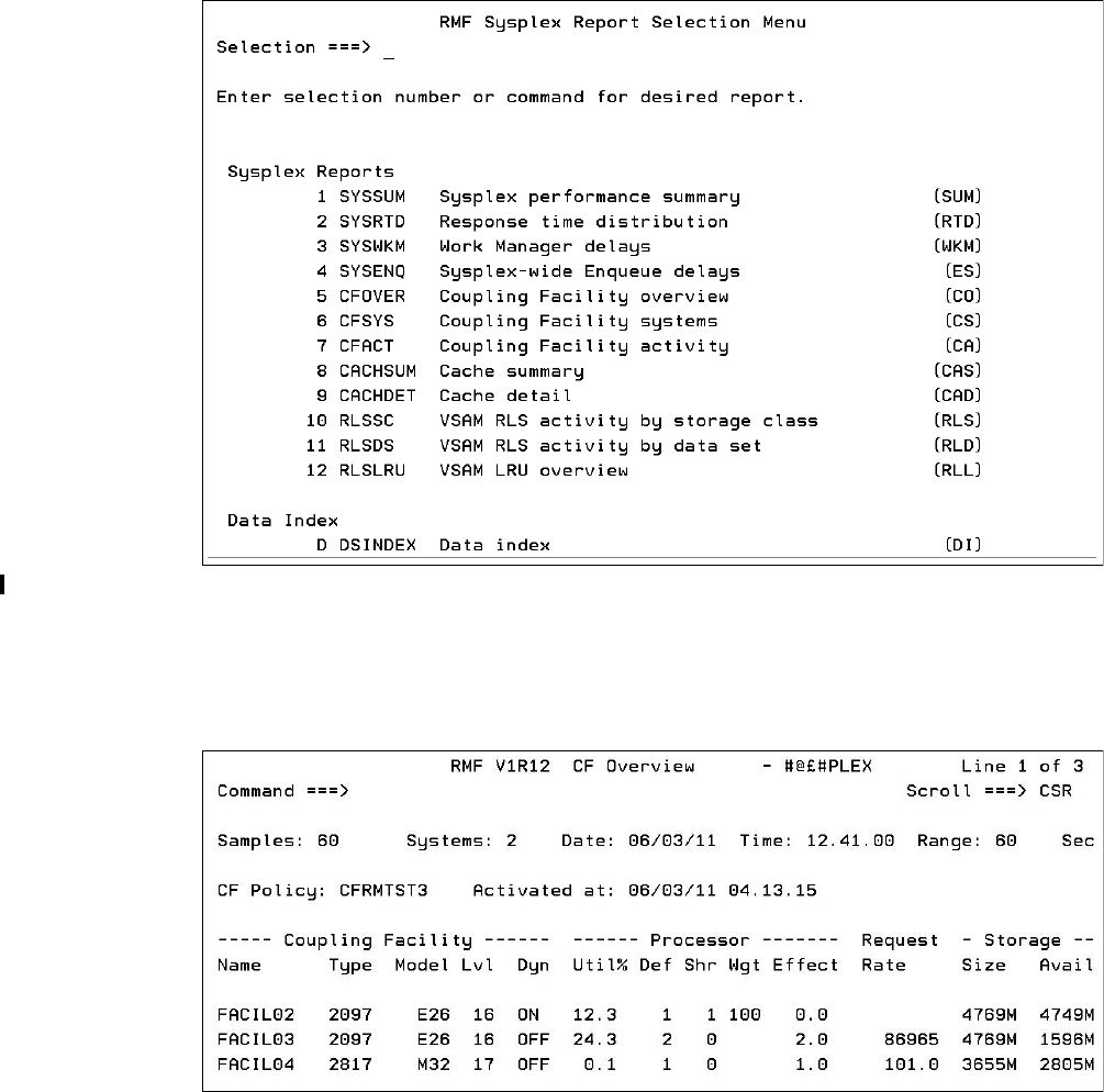
Appendix A. Resource Measurement Facility 237
Figure A-1 RMF Monitor III: Sysplex reports
The sysplex reports of interest for Coupling Facility performance are options 5, 6, and 7 from
the Selection menu shown in Figure A-1.
The Coupling Facility overview panel (option 5) is shown in Figure A-2.
Figure A-2 Coupling Facility Overview panel
Figure A-2 shows an overview of the available Coupling Facilities with performance details
such as:
Coupling Facility type and model
CFLEVEL (Lvl column)
Dynamic Dispatching settings (Dyn column)
CF Processor information
The total request rate to each CF
The total and the unused amount of storage in each CF
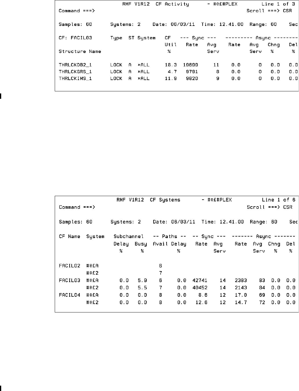
238 Implementing and Managing InfiniBand Coupling Links on IBM System z
Moving the cursor over CF FACIL03 and pressing Enter displays detailed information about
the structures in that CF; see Figure A-3.
Figure A-3 CF FACIL03: Activity report
Figure A-3 shows structure detail for the lock structures (filtered) in FACIL03.
The percentage of total used CF CPU that was used by each structure. For example, if the
total CF CPU utilization (from the CFOVER panel) was 50%, and the CF Util % for
structure THRLCKDB2_1 is 18.3, that means the operations against structure
THRLCKDB2_1 accounted for 9.2% of the capacity in FACIL03.
Synchronous and asynchronous request rates.
Average service time, in microseconds, for each type of request.
The percentage of requests that were delayed.
Selecting the Coupling Facility Systems report displays detailed information; see Figure A-4.
Figure A-4 Coupling Facility systems report
Figure A-4 shows a summary of performance, broken out by connected system, for these
CFs. Various details are listed here:
The systems that are connected to each CF.
Subchannel usage and contention information.
Number of available paths (CHPIDs) from each system to the CF.
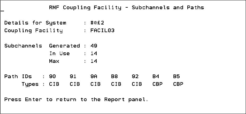
Appendix A. Resource Measurement Facility 239
Percentage of requests that were delayed because all link buffers were in use.
Synchronous and asynchronous request rates and average service times for each CF for
each connected z/OS system.
Moving the cursor over one of the system names and pressing Enter displays more detailed
information about the available paths between the named system and the selected CF; see
Figure A-5.
Figure A-5 Coupling Facility FACIL03, System #@£2 subchannels and paths
Figure A-5 shows the available subchannels, CHPIDs, and CHPID types for this system. Note
that if CHPIDs are taken offline from the z/OS end, they will be removed from the list of
CHPIDs for the CF. However, if the CHPIDs are taken offline from the CF end, they will not be
removed from the list (because they are available for use again if the CF end is configured
back online). In either case, the In Use number of subchannels is designed to accurately
reflect the number of subchannels that are currently available for communication with the CF.
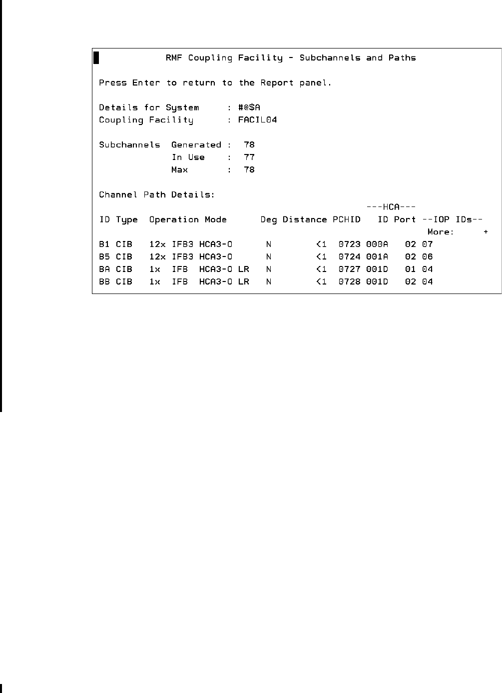
240 Implementing and Managing InfiniBand Coupling Links on IBM System z
If your z/OS is running on a zEC12 or later, more detailed information about each CF link
CHPID is provided in the Subchannels and Paths report in Monitor III. An example is shown in
Figure A-6.
Figure A-6 RMF Subchannels and Paths display for zEC12
As you can see in Figure A-6, much more information is provided about each CF link CHPID
when z/OS is running on a zEC12 or later. In addition to the CHPID and the fact that it is an
InfiniBand (CIB) CHPID, the speed (1X or 12X), adapter type (HCA2 or HCA3), and the mode
(IFB or IFB3) is also shown. There is also a flag to indicate if the link is running in degraded
mode (“Deg”), and the approximate distance to the CF is shown. The Adapter ID and Port for
each CHPID is also provided.
RMF Monitor III is especially powerful for helping you understand performance and workload
changes over small periods of time; the minimum reporting interval is 10 seconds. This allows
you to investigate problems and determine if something in the CF configuration is causing the
problem. For example, was there a spike in the number of requests? Did the CF response
times change dramatically? Was there a change in the split between synchronous and
asynchronous requests? Was the distribution of requests across the allocated structures in
line with normal activity, or did a particular structure experience an abnormally high load?
This information can be invaluable in helping you narrow what you want to look at in the RMF
postprocessor report.
RMF Postprocessor reporting
The RMF postprocessor can be used to produce reports over intervals of variable intervals.
This section provides examples of using the report to analyze the performance of your CF
resources.

Appendix A. Resource Measurement Facility 241
Coupling Facility Activity report
To investigate potential InfiniBand performance issues, you need to understand the utilization
of the subchannels and link buffers that are associated with those links1. Figure A-7 shows
the Subchannel Activity part of the Coupling Facility Activity section of the postprocessor
report. We discuss this part of the postprocessor report in detail because it provides the
necessary information to calculate the subchannel and link buffer utilization. Although this
report provides information from all systems in the sysplex, here we only focus on the links
used by one system, namely SC80.
Figure A-7 Extract of a postprocessor report
The relevant fields in the Subchannel Activity report are listed here:
1 INTERVAL - The time interval that was defined for the length of the report. It is 10 minutes in
our example.
2 COUPLING FACILITY NAME - The defined name of the CF. The name is CF8C in our example.
3 SYSTEM NAME - All information here is provided for each system that is part of the sysplex.
The systems SC80 and SC81 are part of the WTSCPLX8 sysplex in our example.
4 CF LINKS - The type of coupling links, and the number of each type defined and currently in
use, are shown here. System SC80 has two types defined, namely ICB-4 links and PSIFB
coupling links. Two ICB-4 links are defined and in use and four PSIFB coupling links are
defined and in use. Because each link provides seven subchannels, we can see the total of
42 defined subchannels, and that all 42 are in use.
An important field in this part of the report is the PTH BUSY (Path Busy) column, which contains
a count of the number of requests that found that all link buffers were in use when the system
tried to send the request to the CF. If this number exceeds 10% of the total number of
requests, that is an indicator that additional coupling CHPIDs might be required. Another
possible indicator of link buffer contention is if the number of subchannels in the USE column is
less than the number in the GEN column.
5 REQUESTS - The number of synchronous and asynchronous requests, along with the average
response time for each, is shown in this section.
1 For more information about the relationship between subchannels and link buffers, refer to Appendix C, “Link
buffers and subchannels” on page 247.
C O U P L I N G F A C I L I T Y A C T I V I T Y
z/OS V1R10 SYSPLEX WTSCPLX8 DATE 10/15/2008 INTERVAL 010.00.000 1
RPT VERSION V1R10 RMF TIME 15.40.00 CYCLE 01.000 SECONDS
------------------------------------------------------------------------------------------------------------------------------
COUPLING FACILITY NAME = CF8C 2
------------------------------------------------------------------------------------------------------------------------------
SUBCHANNEL ACTIVITY
------------------------------------------------------------------------------------------------------------------------------
# REQ ----------- REQUESTS ----------------------------- DELAYED REQUESTS -----------------
SYSTEM 3 TOTAL -- CF LINKS --4 PTH 5 # -SERVICE TIME(MIC)- 6 # % OF ------ AVG TIME(MIC) ------
NAME AVG/SEC TYPE GEN USE BUSY REQ AVG STD_DEV REQ REQ /DEL STD_DEV /ALL
SC80 1958K CBP 2 2 0 SYNC 50150 63.9 303.7 LIST/CACHE 42 0.0 5.5 5.6 0.0
3262.9 CIB 4 4 ASYNC 1760K 176.0 737.2 LOCK 0 0.0 0.0 0.0 0.0
SUBCH 42 42 CHANGED 146 INCLUDED IN ASYNC TOTAL 42 0.0
UNSUCC 0 0.0 0.0
SC81 1963K ICP 2 2 0 SYNC 1589K 48.1 460.7 LIST/CACHE 0 0.0 0.0 0.0 0.0
3271.7 SUBCH 14 14 ASYNC 101394 429.3 2269 LOCK 0 0.0 0.0 0.0 0.0
CHANGED 0 INCLUDED IN ASYNC TOTAL 0 0.0
UNSUCC 0 0.0 0.0

242 Implementing and Managing InfiniBand Coupling Links on IBM System z
6 DELAYED REQUESTS - A high number of delayed requests provides an indication of
performance problems. In our example, the percentage of delayed requests lies below 0.1%
and can therefore be disregarded.
Channel Path Details report
If z/OS is running on a zEC12 or later, the Subchannel Activity Report is followed by an
additional report that provides detailed information about each coupling CHPID for that CF. A
sample report is shown in Figure A-8.
Figure A-8 RMF Channel Path Details report
As you can see in Figure A-8, information is provided about each CF link CHPID in each z/OS
that is connected to the CF. However, detailed information is only provided for systems that
are running on a zEC12 or later (systems #@$A and #@$3 in this example). In addition to the
CHPID and the fact that it is an InfiniBand (CIB) CHPID (which is also shown for the system
that is running on a CPC prior to zEC12), the speed (1X or 12X), adapter type (HCA2 or
HCA3), and the mode (IFB or IFB3) are also shown. There is also a flag to indicate if the link
is running in degraded mode (“Deg”), and the approximate distance to the CF is shown. The
Adapter ID and Port for each CHPID is also provided. Apart from the fact that so much
information is provided, the other nice thing about this is that all of this information is recorded
in the RMF SMF records. So you can use RMF reports to determine the precise coupling link
configuration at some time in the past.
Calculating coupling link utilization
To calculate the usage of an InfiniBand link, there are a number of points you must consider:
The RMF Subchannel Activity Report does not provide information at the individual
CHPID level. Instead, information is provided for the set of CHPIDs that are used by the
named system to communicate with the CF. As a result, you can only calculate average
utilization across the set of CHPIDs.
If multiple systems are sharing that set of CHPIDs, RMF does not know that. Therefore,
you need to calculate the average subchannel utilization for each system, and then
manually sum the utilization for all the systems that are sharing that set of CHPIDs.
Because InfiniBand links support the ability to have multiple CHPIDs on a single link, you
can (and probably will) have multiple sysplexes sharing a single physical link. The scope of
an RMF Subchannel Activity Report is a single sysplex.
Therefore, to derive a comprehensive view of the use of the links, you must perform this
set of calculations for each sysplex that is sharing the links you are interested in.
----------------------------------------------------------------------------------------------------------------
CHANNEL PATH DETAILS
----------------------------------------------------------------------------------------------------------------
SYSTEM NAME ID TYPE OPERATION MODE DEGRADED DISTANCE PCHID HCA ID HCA PORT ------- IOP IDS ---
#@$A B1 CIB 12X IFB3 HCA3-O N <1 723 000A 02 07
B5 CIB 12X IFB3 HCA3-O N <1 724 001A 02 06
BA CIB 1X IFB HCA3-O LR N <1 727 001D 01 04
BB CIB 1X IFB HCA3-O LR N <1 728 001D 02 04
#@$2 88 CIB 725
8A CIB 726
A4 CFP 199
A6 CFP 190
A8 CFP 111
D0 ICP
D1 ICP
#@$3 BB CIB 1X IFB HCA3-O LR N <1 728 001D 02 04

Appendix A. Resource Measurement Facility 243
Although the RMF postprocessor Subchannel Activity report provides all the data necessary
to calculate the utilization of the coupling links, it does not actually provide the subchannel
utilization information. You need to perform the calculation that is shown in Example A-1 to
calculate the utilization of that set of CHPIDs by that system.
Example: A-1 Coupling link utilization formula
Link Utilization % = (((Sync #Req * Sync service time) + (Async #Req * Async
service time)) / Interval time in microseconds * #Subchannels in use) * 100
Example A-2 shows the formula filled in with all necessary values and the calculation
process.
Example: A-2 Example calculation
Utilization % = (((50150 * 63.9 mic) + (1760000 * 176 mic)) / 10 min * 42) * 100
Utilization % = ((3204585 mic + 309760000 mic) / 600000000 mic * 42) * 100
Utilization % = (312964585 mic / 25200000000 mic) * 100
Utilization % = 1.24
We see that the link utilization is 1.24% for all active coupling links. Because there are two
types of coupling links active, and the request numbers are not broken out to that level of
detail, we cannot calculate the exact utilization for each coupling link.
Then perform the calculation again for each system that you know is using the same CHPIDs
as SC80. Summing the result for that set of LPARs shows the utilization for the subchannels
(and link buffers) associated with that set of CHPIDs.
Finally, to see the total usage of the shared InfiniBand links, perform this set of calculations for
each sysplex and sum the sysplexes.
Although this is not a trivial process, it is the only way to obtain a clear picture of the total
utilization of the subchannels and link buffers.
After completing the calculations, compare the results to the following guidelines:
Subchannel utilization should not exceed 30%.
Link buffer utilization should not exceed 30%.
Utilization of the underlying InfiniBand link should not exceed 30%.
The number of Path Busy events should not exceed 10% of the total number of requests.
Because of the large bandwidth of PSIFB 12X links, and the fact that each 12X CHPID
supports only seven link buffers, it is likely that all link buffers will be used before the available
bandwidth is fully utilized, so the subchannel and link buffer utilization is an important metric
to monitor.
However, because the PSIFB 1X links have less bandwidth, but significantly more link buffers,
it is possible that the bandwidth can be fully utilized before all link buffers are used. This
means that subchannel and link buffer utilization might not provide a complete picture of the
utilization of the underlying InfiniBand 1X links. For more information about the considerations
for PSIFB 1X links, refer to 3.7.3, “Capacity and performance” on page 55.

244 Implementing and Managing InfiniBand Coupling Links on IBM System z

© Copyright IBM Corp. 2008, 2012, 2014. All rights reserved. 245
Appendix B. Processor driver levels
The capabilities of a processor depend to an extent on the level of microcode that is installed
on the processor. This is referred to as a Driver level, and documentation will sometimes refer
to a particular function being delivered with a specific Driver level.
In this appendix we provide a cross-reference showing the Driver levels that were delivered
for each of System z9, System z10, zEnterprise 196, and zEnterprise z114.
B
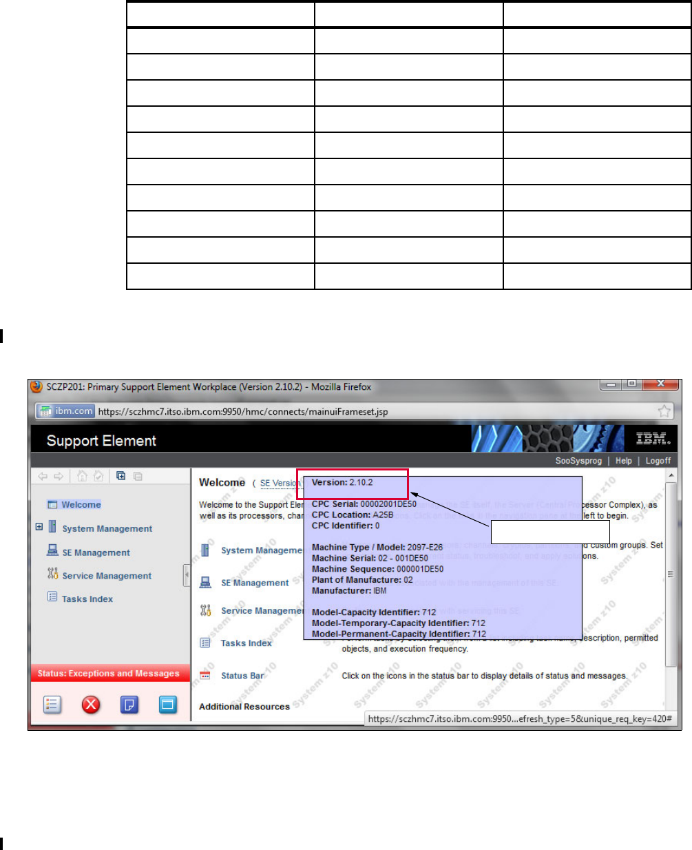
246 Implementing and Managing InfiniBand Coupling Links on IBM System z
Driver level cross-reference
Table B-1 lists the Driver levels that were provided for the most recent generations of
System z servers at the time of writing.
Table B-1 System z Server Driver levels
The value listed in the Version code column refers to the version information that is provided
on the Support Element of the respective processor. You see this information when you log on
to the SE, as shown in Figure B-1.
Figure B-1 Displaying Support Element Version code
Server generation Driver level Version code
zEC12, zBC12 15 2.12.1
zEC12 12 2.12.0
z196, z114 93 2.11.1
z196 86 2.11.0
z10 EC, z10 BC 79 2.10.2
z10 EC, z10 BC 76 2.10.1
z10 EC 73 2.10.0
z9 EC, z9 BC 67 2.9.2
z9 BC 64 2.9.1
z9 EC 63 2.9.0
Version code

© Copyright IBM Corp. 2008, 2012, 2014. All rights reserved. 247
Appendix C. Link buffers and subchannels
In this appendix, we explain the relationship between z/OS subchannels for CF link CHPIDs,
link buffers in the coupling link hardware, and the InfiniBand coupling links themselves.
C
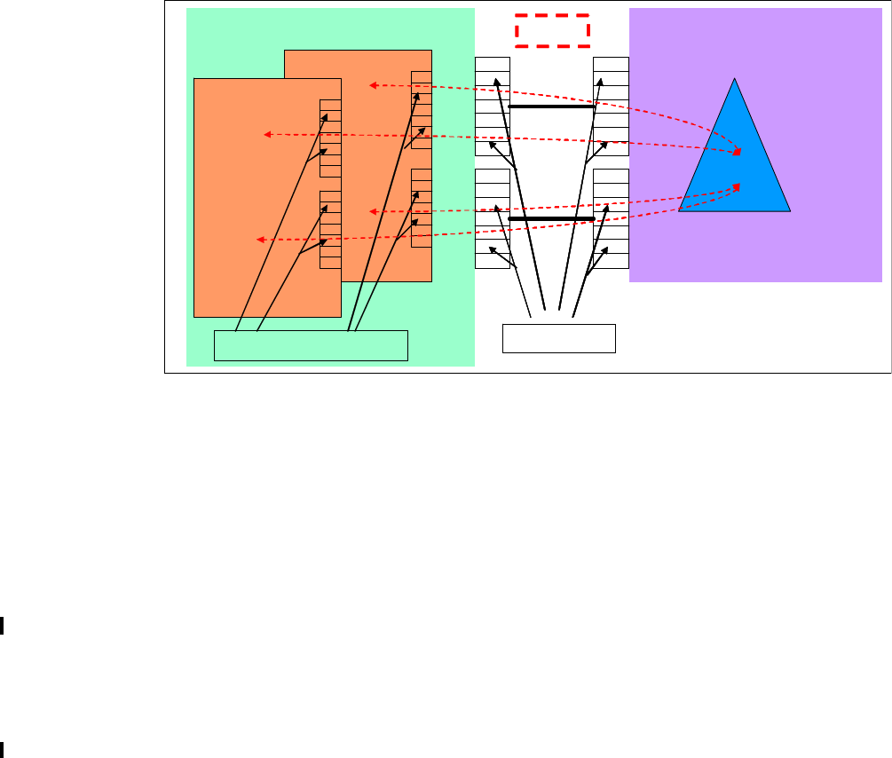
248 Implementing and Managing InfiniBand Coupling Links on IBM System z
Capacity planning for coupling links overview
Capacity planning for coupling links is different from other channel types. For one thing, RMF
does not provide accurate bandwidth utilization information for Coupling Facility (CF) links.
Also, the RMF Postprocessor, the tool that is typically used to perform capacity planning,
does not report CF link subchannel or link buffer utilization (although it does provide the
numbers to allow you to calculate that value yourself). However, even this information does
not reflect the complete picture.
To help you understand the reasons for the performance and behavior that you might
observe, this appendix explains the relationship between the various components that play a
role in processing CF requests, particularly from the perspective of the CF links.
Subchannels and link buffers
Figure C-1 shows two processors. The processor on the left side contains two logical
partitions running z/OS. The processor on the right side contains a CF LPAR that is in the
same sysplex as the two z/OS LPARs. The z/OS processor is connected to the CF through
two physical coupling links. In this example, there is only one CHPID assigned to each
coupling link.
Figure C-1 CF request components
The terms shown in Figure C-1 have the following meanings:
Link Links physically connect the z/OS processor and the CF processor.
The link type can be ICB4, ISC3, or PSIFB. In this example, there is
only one CHPID defined for each coupling link.
Path A path acts as a logical link between the system (z/OS) and the CF.
There can be multiple paths on a single link because multiple CHPIDs
can be defined on a single PSIFB link. Also, multiple z/OS images can
share the CHPID.
Link Buffers The link buffer (also called a message buffer) is the buffer used to hold
CF requests within the hardware layer. The number of link buffers per
CHPID depends on the hardware type and the Driver level. Note that if
CPC
CF
LINK
LINK
Link Buffers
z/OS 1
z/OS 2
Software Subchannels
PATH
CPC
CF
LINK
LINK
Link Buffers
z/OS 1
z/OS 2
Software Subchannels
PATH
Appendix C. Link buffers and subchannels 249
you define two CHPIDs sharing a single InfiniBand link, each CHPID
will have its own set of link buffers.
For HCA1-O, HCA2-O, and HCA3-O (12X IFB or IFB3) links, each CF
link CHPID has seven link buffers (meaning that seven concurrent I/O
operations can be active to the Coupling Facility over that CHPID).
With a maximum of 16 CIB CHPIDs per fanout, this equates to a
maximum of 112 link buffers per fanout.
For zEnterprise servers with Driver 93 or later, HCA2-O LR and
HCA3-O LR (1X IFB) links support 32 link buffers per CHPID. With up
to 16 CIB CHPIDs per fanout, this equates to a maximum of 512 link
buffers per fanout.
In Figure C-1 on page 248 there are 14 link buffers in the hardware (7
for each of the two coupling links).
Software subchannels
The control block in z/OS that represents a link buffer is known as a
subchannel. There will be one subchannel in each z/OS for each link
buffer. In Figure C-1 on page 248 there are 14 link buffers in the
fanouts and 14 subchannels in each z/OS that is sharing those
CHPIDs.
When a CF exploiter initiates a CF request, that request is initially sent to an operating system
component called Cross System Extended Services (XES). XES then processes the request
by following these steps:
Finding an available subchannel that is assigned to the CF containing the required
structure.
Allocating that subchannel to the current request.
Passing the request to the hardware, along with a list of the CHPIDs that can be used to
communicate with the target CF. Note that the subchannel remains assigned to the
request and cannot be used by another request until this request completes.
The hardware then searches for an available link buffer in one of the CHPIDs.
When an available link buffer is found, the request is placed in the link buffer. The link
buffer remains assigned to the request and cannot handle any other request until this
request completes.
A temporary bind is established between the subchannel and the link buffer. This bind is
performed by path selection logic as part of the process of sending the CF request. The
subchannel-to-link buffer bind is maintained by the channel subsystem until that CF
request completes.
The CHPID that has been selected might or might not share the link with other CHPIDs. In
either case, the link will be shared between the link buffers that are associated with that
CHPID. As soon no other CHPID or link buffer is moving a request into the link, the
request will be sent to the CF.
The CF processes the request and sends the response back to the requesting z/OS, to
the same CHPID and link buffer that the request arrived from.
The response arrives back in the link buffer that sent the request.
– If the request was issued synchronously, XES will see the response arriving back and
immediately retrieve it.
– If the request was issued asynchronously, an SAP will detect the arrival and update a
flag in HSA that indicates to XES that the response has arrived back. At some time

250 Implementing and Managing InfiniBand Coupling Links on IBM System z
after this, XES will get dispatched, detect the state of the flag, and retrieve the
response.
XES processes the response and passes it back to the requester.
It is only at this point that the subchannel and link buffer are made available for use by
another request.
This sequence describes the ideal situation, where there are available subchannels and link
buffers. However, this is not always the case. For instance, a single DB2 commit can result in
multiple simultaneous requests to release locks and to write committed data to a group buffer
pool (GBP) structure, followed by another period of relatively low activity. This can result in
low average link utilization, but short periods when the subchannels and link buffers are
overrun by these bursts of activity.
If XES detects that no subchannels are available when it tries to start the request, it might
convert that request to an asynchronous request and queue it for later processing. Or in some
cases, it might determine that it is more efficient to spin, waiting for a subchannel to come
available. In either case, this represents a delay to CF requests because new requests must
wait for a subchannel to come available. There is also an additional z/OS CPU cost
associated with the additional processing resulting from the busy conditions. High numbers of
subchannel busy events are typically caused by:
Bursts of activity; many more requests are generated as a result of an event than there
are subchannels available
Delays in finding an unavailable link buffer
High CF service times
Long response times caused by long distances between z/OS and the CF
The number of subchannel busy events at the system or CF level is reported in the RMF CF
Subchannel Activity report. The number of events for each structure is reported in the
structure detail part of the report. The RMF CF Subchannel Activity report can also be used to
calculate the subchannel utilization. The formula for that calculation, together with guidelines
for subchannel and link utilization thresholds, is described in “Calculating coupling link
utilization” on page 242.
If no link buffers are available when the request is sent into the hardware by z/OS
(presumably because they are all already being used by other requests from this z/OS and
other z/OS LPARs that are sharing those CHPIDs), that is reported in RMF as a “path busy”
event1. In that case, the CP that is handling that request will spin, looking for an available link
buffer.
If the CF link CHPIDs are dedicated to a z/OS LPAR, path busy events can be rare, because
every subchannel will effectively have a dedicated link buffer. If the CF link CHPIDs are
shared, high path busy numbers indicate:
The systems are trying to send more requests to the CF than can be handled by the
number of available link buffers.
CF requests are being issued in bursts, meaning that the available link buffers are being
overwhelmed by the arrival rate of requests2.
CF service times are quite long (perhaps because the CF is far away), meaning that the
link buffers are busy for a long time for each request.
1 Starting with APAR OA35117, the Path Busy count is only incremented once per CF request, regardless of how
many passes were required to find an available link buffer.
2 This is the most common reason for high path busy numbers.
Appendix C. Link buffers and subchannels 251
A high ratio between the number of z/OS LPARs sharing the link and the number of link
buffers. As that ratio increases, it becomes more likely that a new CF request will be able
to find an available subchannel, but that all link buffers are busy handling requests from
one of the other z/OS LPARs.
With InfiniBand links, there is another situation where high path busy numbers might be
experienced. If the links are 12X links, but the default of 32 devices was accepted when the
coupling CHPIDs were connected, there will be more than four times as many subchannels in
each sharing z/OS as there are link buffers in the fanouts (this is discussed in “Connecting
PSIFB links between z196 and later processors” on page 169). This means that z/OS can
attempt to start many more requests than can be handled by the number of link buffers. This
is one of the reasons why it is so important to ensure that the number of devices you select
when connecting coupling CHPIDs is consistent with the number of link buffers supported by
the underlying InfiniBand links.
Prior to InfiniBand links, the most common way to address high numbers of subchannel busy
or path busy events was to use more CHPIDs to connect to the CF. (You can also reduce
subchannel busy events by reducing the number of z/OS LPARs that are sharing the CF link
CHPIDs, but reducing the degree of sharing typically means that more CHPIDs must be
provided overall.) Remember that you have no control over the number of link buffers for each
CHPID in the hardware, and the number of subchannels defined in z/OS for each CHPID
should match the number of link buffers in the corresponding hardware.
As a result, these situations were typically addressed by installing more CF links, and prior to
InfiniBand, the only way to get more CHPIDs was to get more links. However, when using
InfiniBand links, it might be possible to address high path or subchannel busy numbers by
simply defining an additional CIB CHPID and assigning that to an existing InfiniBand link (but
remember that you are still limited to 8 CHPIDs per z/OS to each connected CF).
The last place that link-related delays might be observed is in placing the request into the link
from the link buffer. Because of the bandwidth of 12X links, the amount of time that is required
to place a typical request into the link is small. As a result, it is unlikely that there will be any
noticeable delay in sending a request on a 12X link. Because 1X links have a lower
bandwidth, it might take slightly longer to place a large request into the link. As a result, if a
1X link is being used to send many large requests to the CF, the delay that is experienced
waiting to send a request to the link might become noticeable in increased response times.
Capacity tools like zPCR and zCP3000 can be used to perform capacity planning based on
the analysis of current coupling link and CF utilization. For more information, refer to capacity
and performance considerations in Chapter 5, “Performance considerations” on page 121.
You can also refer to the following publications for more information:
z/OS RMF Report Analysis, SC33-7991
System/390® Parallel Sysplex Performance, SG24-4356
OS/390® MVS Parallel Sysplex Capacity Planning, SG24-4680

252 Implementing and Managing InfiniBand Coupling Links on IBM System z

© Copyright IBM Corp. 2008, 2012, 2014. All rights reserved. 253
Appendix D. Client experience
In this appendix, we describe the experiences of a large Parallel Sysplex client as they
migrated two of their data centers from z10 processors with ICB4 links to z196 processors
with InfiniBand links.
D

254 Implementing and Managing InfiniBand Coupling Links on IBM System z
Overview of the client experience
For high-speed coupling, ICB4 links offered the best response time prior to the introduction of
HCA3 adapters. Because of the large number of CF requests that are generated by the
client’s workload (over 300,000 requests a second in one of their sysplexes), they used ICB4
links.
The client’s initial configuration in one of the data centers consisted of six z10 processors
running z/OS, and two z10 processors that acted as stand-alone Coupling Facilities. The
sysplex in that site consisted of 10 LPARs and two 5-way CFs. Because of the performance
requirements of that sysplex, it used only ICB4 links.
The other data center had four z10 processors running z/OS and two z10 processors
containing simply CF LPARs. That data center contained six sysplexes. Because of the
connectivity requirements of all those sysplexes, that site originally used both ICB4 and ISC3
links and migrated to InfiniBand over the course of two sets of processor upgrades.
Although the client found that the ICB4 links generally provided excellent response times,
they wanted to be able to have more of them, specifically to address the following issues:
Times when bursts of CF requests resulted in subchannel busy and path busy conditions
The need for better response times in sysplexes other than the large production sysplexes
The client saw the migration to InfiniBand technology as an opportunity to address both of
these issues.
Large production sysplex
The production sysplex in the first data center configuration consisted of ten z/OS LPARs and
two CFs. These ran on eight z10 processors that were to be migrated to z196 processors.
Two of these were single-book, CF-only processors that each supported a maximum of 16
ICB4 links. The CFs were home to the PTS and BTS STP roles, so two of the 16 ports were
used for CF-to-CF connections that enable STP signals to be exchanged between those
processors (STP is required for migration to z196). The remaining 14 links were used to
connect to the remaining six processors as coupling links.
Four of the processors were configured with two ICB4 links to each CF, and the remaining two
processors (with the highest volume CF traffic) were configured with three ICB4 links, thus
accounting for all 16 ports on the external CF processors.
Due to the heavy DB2 data sharing activity the client used external CFs to avoid the need to
use System Managed Duplexing for the DB2 lock structure, which was thought to cause an
unacceptable impact on performance.
The CF LPARs were configured with five dedicated ICF engines, each of which normally ran
between 20% and 30% utilization, with the exception of several heavy batch intervals. During
those batch intervals, CF utilization increased to the 40% to 50% range. Bursts of DB2 activity
during those intervals had a tendency to cause subchannels to be overrun, resulting in more
synchronous requests being converted to asynchronous and increasing the service times.
With the elimination of ICB4 support on the z196 processors, the client was somewhat
concerned that implementing InfiniBand technology might result in a significant increase in
response times; the general guideline was that replacing ICB4 links with InfiniBand
technology results in response times increasing by about 40%. The client was concerned that
the combination of moving to a faster processor technology with slower CF links might result
Appendix D. Client experience 255
in an unacceptable increase in coupling overhead (see Table 1-2 on page 9 for more
information about coupling overhead for various combinations of processor models and link
types).
As part of the client’s involvement in the z196 Early Support Program, they conducted a
number of measurements with a combination of z10 and z196 processors. The evaluation
sysplex consisted of two z/OS LPARs and up to eight CF LPARs. The hardware consisted of
one z10 and one z196.
The processors were connected with both ICB4 links (wrapped on the z10, from the z/OS
LPARs to the CF LPAR) and HCA2-O 12X InfiniBand links (to both the z10 and z196 CFs). All
the LPARs were able to be brought up on either processor. During the measurements, the
client varied the number of CFs, the number of engines in each CF, the type and number of
CF links, and the placement of various important (high use) structures. The results of this
exercise gave them the confidence to proceed with the migration to InfiniBand and also
caused them to adjust their CF infrastructure.
Production migration to z196 with InfiniBand links
One effect of this extensive testing was that the client discovered how easy it is to move
structures between CFs using the SETXCF REALLOCATE and MAINTMODE commands.
Combined with the results of various measurements, that led the client to implement the new
z196 hardware with an entirely new CF configuration.
Instead of having two CFs (each with five engines) as used previously, the client decided to
migrate to a 4-CF LPAR configuration on the two z196 processors. The new configuration
would have two 2-way CFs and two 3-way CFs. The reason for this change was to reduce the
n-way effect and achieve more usable capacity from the same installed configuration.
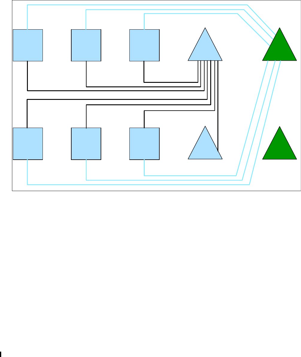
256 Implementing and Managing InfiniBand Coupling Links on IBM System z
To facilitate the migration, HCA2-O 12X adapters were installed in the z/OS z10 processors in
preparation for the first z196 installs. The first z196s to be installed were the external CF
processors, which expanded their sysplex configuration to 10 processors as shown in
Figure D-1. The ICB4 links continued to be used to connect to the z10 CFs, and the HCA2-O
links were used to connect the z10 z/OS processors to the z196 CFs. In the interests of
readability, the figure only shows the logical connectivity. However, in reality, two InfiniBand
links were installed between every z10 and each of the two z196 CFs.
Figure D-1 Interim configuration with both z10 and z196 CFs
Implementing InfiniBand consisted of expanding the structure candidate list in the CFRM
policy to include all six CF LPARs: the original two on the z10s, and the four on the new z196
CF processors.
The migration (which was carried out at a time of low activity) consisted of issuing the
following commands:
SETXCF START,MAINTMODE,CFNAME=(CF1,CF2)
SETXCF START,REALLOCATE
When the REALLOCATE command completed, all structures had been moved from the
z10 CFs to the z196 CFs. The client then waited for the high volume processing to start. Just
in case the performance proved to be unacceptable, they were fully prepared to return to the
z10 CF processors by simply stopping MAINTMODE on the z10 CFs, placing the z196 CF
LPARs into MAINTMODE, and then reissuing the REALLOCATE command.
Monitoring the peak processing times provided a pleasant surprise. Rather than experiencing
the anticipated 40% increase in response times, the new configuration was showing more
than a 20% improvement over the service times that the client experienced with the ICB4
z10
z/OS
z10
z/OS
z10
z/OS
z10
z/OS
z10
z/OS
z10
z/OS
z10
CF
z10
CF
z196
CF
z196
CF
z196
CF
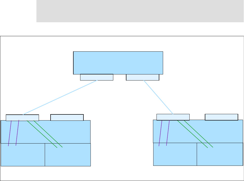
Appendix D. Client experience 257
configuration. CF utilization had dropped to between 8 and 12%. Additionally, the high
number of NO SUBCHANNEL events that had been an ongoing issue when batch kicked off
was no longer evident. The client attributed the unexpected conversion improvements to the
new 4-CF implementation and the increase in the number of available subchannels.
The addition of the two new CF LPARs was enabled by the migration to InfiniBand. The
performance issues the client had experienced from time to time with ICB4 indicated a
requirement for more subchannels and link buffers. However, the only way to get more of
these was by adding more ICB4 links to the CF processors, which required installing another
book in each of those processors and an RPQ to support more than 16 ICB4 links.
With InfiniBand, the client was able to define four CHPIDs between the z/OS and CF
processors on the same physical connection, as shown in Figure D-2. Two of the four CHPIDs
on each physical link were connected to each CF LPAR. With a minimum of two physical
(failure-isolated) links between the processors, they increased the number of available
subchannels from 14 to 28 per CF LPAR.
Furthermore, because the client had four CFs now, with 28 subchannels to each one, they
now had a total of 112 subchannels in each z/OS for the CFs rather than the 28 they had
previously. The increase in subchannels was a primary reason for the improved tolerance of
our batch burst activity.
Figure D-2 Sharing InfiniBand links between CF LPARs
Note: Only consider splitting CF LPARs if the original CF LPAR has multiple ICF engines.
CF LPARs require dedicated engines for optimum performance, so splitting the CF LPAR is
only valuable if you can dedicate a minimum of one engine for each CF LPAR.
AID 1D
AID 08 AID 08
Port 1 Port 1
Port 1 Port 2
Port 2 Port 2
CF1A CF1B CF2A CF2B
CF1CPC CF2CPC
01 02 03 04 01 02 03 04
11 12 13 14 21 22 23 24
ZOSCPC

258 Implementing and Managing InfiniBand Coupling Links on IBM System z
Based on their experiences, the client attributed the performance improvements to these factors:
There are faster engines in the new z196 CFs.
The 2-way and 3-way CFs had more usable capacity than 5-way CFs (because of the
reduced multiprocessor effect).
Based on projections from the zPCR tool, configuring a z196 in this manner can deliver
9.3% more capacity than configuring it as a single 5-way CF LPAR.
Each CF processed a subset of the prior activity and structures.
Additional subchannels were better able to handle burst activity processing.
Structure allocation was divided by the attributes of the workloads. The structures that
were most sensitive to short response times were placed in the 3-way CFs, and structures
that had mainly asynchronous requests were placed in the CFs with two engines.
Serialization delays that might have been caused by having all structures in only two CFs
were reduced.
Because this client is an intensive user of DB2 data sharing, the response time of the DB2
lock structure is critical to their applications. Table D-1 lists the request rate and response
time for the DB2 lock structure when using ICB4 links compared to HCA2-O links.
Table D-1 Critical DB2 lock structure
The performance of the Coupling Facilities and increased number of coupling subchannels
also had an impact on overall z/OS CPU utilization, batch job elapsed times, and online
response times; see Table D-2.
Table D-2 Overall average synchronous requests over 12-hour shift
As shown, although more requests were processed every second, the average synchronous
response time was reduced by over 20%.
One effect of the lack of subchannels in the ICB4 configuration was that synchronous
requests were converted to asynchronous, with the corresponding increase in response
times. Therefore, one of the objectives of the InfiniBand configuration was to reduce the
number of instances of subchannel busy. Table D-3 shows that moving to InfiniBand resulted
in a 60% reduction in the number of these events.
Table D-3 Subchannel busy conditions
Average Sync Request Rate Average Sync Resp Time (in
microseconds)
z10/ICB4 51342 12.4
z196/HCA2-O 55560 9.7
Average Sync Request Rate Average Sync Resp Time (in
microseconds)
z10/ICB4 166043 14.7
z196/HCA2-O 180360 11.8
CF configuration Number of subchannel busy over 12 hours
z10/ICB4 2753375
z196/HCA2-O 841730

Appendix D. Client experience 259
The net result was that the migration to z196 and HCA2-O 12X links was quite successful for
the client’s largest production sysplex.
Exploiting InfiniBand for link consolidation
The second data center contained six sysplexes spread over four z10 processors running
z/OS and two z10s running only CF LPARs. In this data center, the sysplex loads were
smaller. However, the large number of sysplexes meant that many CF links were required for
connectivity reasons rather than performance reasons. In this data center, the client’s primary
requirement was to be able to support multiple sysplexes, with optimal performance for each
one, while minimizing the number of coupling links.
As part of the previous upgrade to z10 processors, the client had installed InfiniBand links
alongside the ICB4 links that were carried over from the previous processors. With six
sysplexes spread over four processors, ICB4 links would not have been able to provide all the
connectivity they required. z10 CF processors support a maximum of 16 ICB4 links (32 with
an RPQ modification).
Because a single book can support 8 HCA fanout cards, a single book has the ability to
support the entire 16 ICB4 connections. ICB4 links support a single CHPID per link, and each
CHPID can only be used by one sysplex. In an environment with many sysplexes, the ICB4
links were quickly exhausted.
As part of the upgrade to the z196s, the client planned to eliminate the remaining ICB4 links
and consolidate on simply two physical InfiniBand links between each z/OS processor and
each CF.
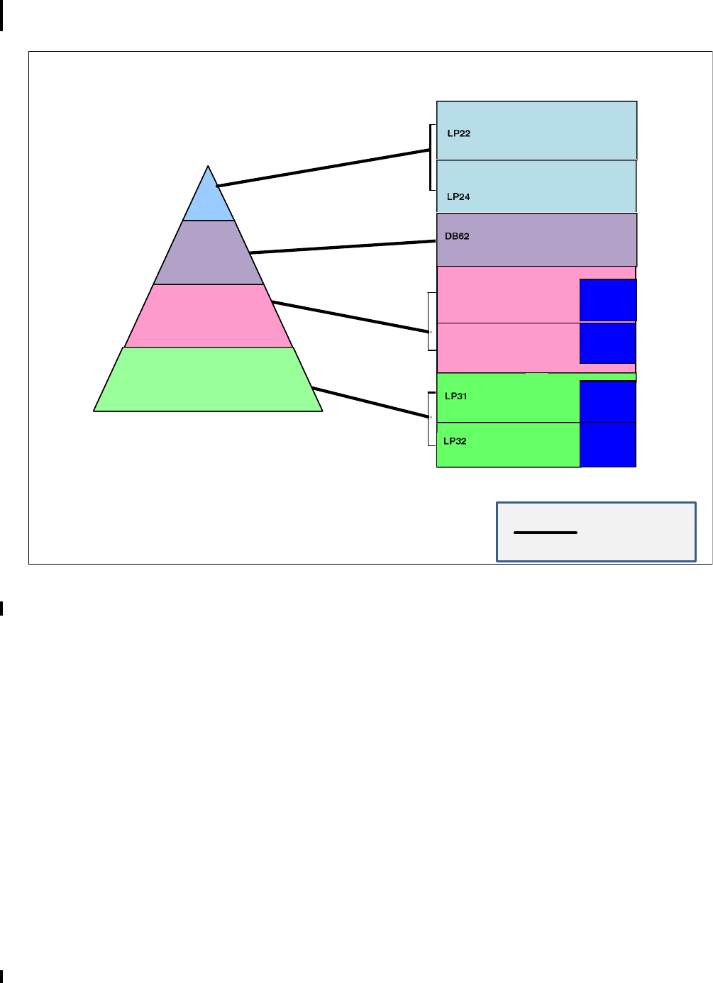
260 Implementing and Managing InfiniBand Coupling Links on IBM System z
Figure D-3 shows how each sysplex had its own ICB4 links prior to the installation of the first
InfiniBand links (in reality, each sysplex had two ICB4 links for availability).
Figure D-3 Coupling requirements pre-InfiniBand
CF2 1/2
2 Gb
CF631/2
4 Gb
CF51/2
2 Gb
CF31/2
2 Gb
zAAP
MIPS**
zAAP
MIPS**
zAAP
MIPS**
zAAP
MIPS**
zAAP
MIPS**
zAAP
MIPS**
LP51
LP52
ICB4 Link
ICB4 Link
ICB4 links require a physical link for each sysplex
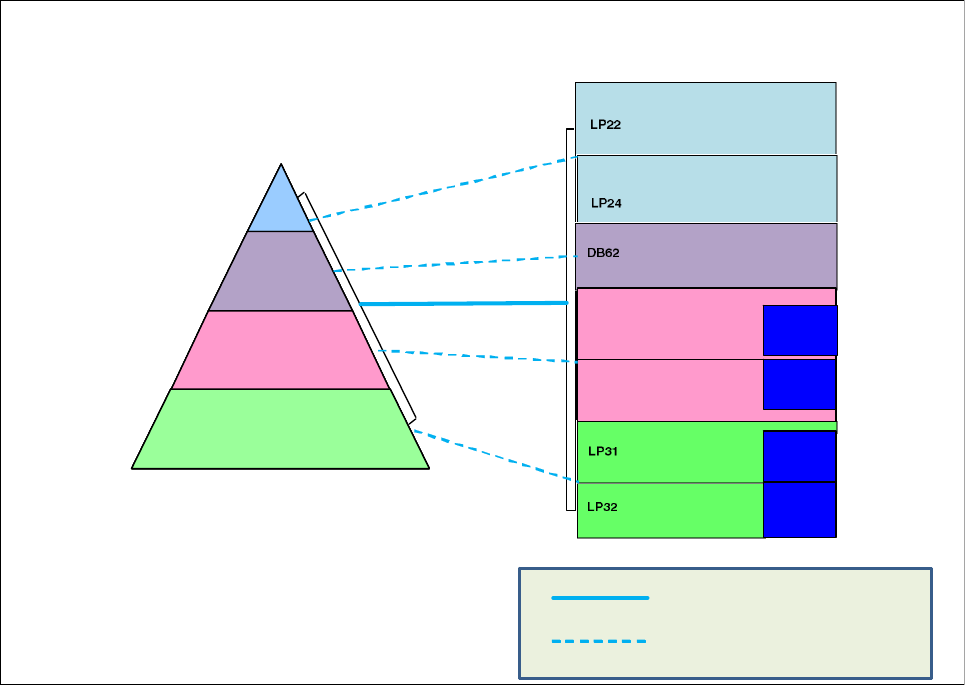
Appendix D. Client experience 261
Figure D-4 shows how the four sysplexes were able to use a single InfiniBand link to replace
the four ICB4 links.
Figure D-4 Coupling connectivity with PSIFB links
Due to the consolidation capabilities of InfiniBand, this client was able to reduce the number
of links on each CF from the 48 used before they started introducing InfiniBand to only 24
links today. The 24 links also contain enough spare capacity to enable that data center to act
as a disaster recovery backup for the site discussed in “Large production sysplex” on
page 254.
CF21/2
2 Gb
CF631/2
4 Gb
CF51/2
2 Gb
CF31/2
2 Gb
zAAP
MIPS**
zAAP
MIPS**
zAAP
MIPS**
zAAP
MIPS**
zAAP
MIPS**
zAAP
MIPS**
LP51
LP52
PSIFB physical linkPSIFB physical link
PSIFB logical link (CHPID)
PSIFB Link
PSIFB links support multiple sysplexes on a
single physical link

262 Implementing and Managing InfiniBand Coupling Links on IBM System z

© Copyright IBM Corp. 2008, 2012, 2014. All rights reserved. 263
Related publications
The publications listed in this section are considered particularly suitable for a more detailed
discussion of the topics covered in this book.
IBM Redbooks publications
For information about ordering this publication, see “How to get IBM Redbooks publications”
on page 264. The following documents might be available in softcopy only:
System/390 Parallel Sysplex Performance, SG24-4356
IBM System z Connectivity Handbook, SG24-5444
OS/390 MVS Parallel Sysplex Capacity Planning, SG24-4680
Effective zSeries Performance Monitoring Using Resource Measurement Facility,
SG24-6645
Considerations for Multisite Sysplex Data Sharing, SG24-7263
Server Protocol Planning Guide, SG24-7280
Server Protocol Implementation Guide, SG24-7281
Server Time Protocol Recovery Guide, SG24-7380
IBM System z10 Capacity on Demand, SG24-7504
IBM System z10 Enterprise Class Technical Guide, SG24-7516
IBM System z10 Enterprise Class Configuration Setup, SG24-7571
IBM System z10 Business Class Technical Overview, SG24-7632
I/O Configuration Using z/OS HCD and HCM, SG24-7804
IBM zEnterprise 196 Technical Guide, SG24-7833
IBM zEnterprise 196 Configuration Setup, SG24-7834
IBM zEnterprise 114 Technical Guide, SG24-7954
IBM zEnterprise BC12 Technical Guide, SG24-8138
IBM zEnterprise EC12 Technical Guide, SG24-8049
Other publications
These publications are also relevant as further information sources:
z/OS Hardware Configuration Definition Planning, GA22-7525
z/OS MVS Diagnosis: Tools and Service Aids, GA22-7589
z/OS MVS Setting Up a Sysplex, SA22-7625
z/OS MVS System Commands, SA22-7627
Input/Output Configuration Program User’s Guide for ICP IOCP, SB10-7037
System z9 HMC Operations Guide, SC28-6821

264 Implementing and Managing InfiniBand Coupling Links on IBM System z
System z10 HMC Operations Guide, SC28-6867
System z Hardware Management Console Operations Guide, SC28-6905
z/OS Hardware Configuration User’s Guide, SC33-7988
z/OS Hardware Configuration Manager (HCM) User's Guide, SC33-7989
z/OS RMF User’s Guide, SC33-7990
z/OS RMF Report Analysis, SC33-7991
z/OS RMF Reference Summary, SX33-9033
Online resources
These websites are also relevant as further information sources:
InfiniBand specification
http://www.infinibandta.org
IBM Resource Link
http://ibm.com/servers/resourcelink
“Best Practices for Upgrading a CF”
http://www.ibm.com/support/techdocs/atsmastr.nsf/WebIndex/WP101905
“Important Considerations for STP and Planned Disruptive Actions” white paper
http://www.ibm.com/support/techdocs/atsmastr.nsf/WebIndex/WP102019
“Important Considerations for STP Server Role Assignments” white paper
http://www.ibm.com/support/techdocs/atsmastr.nsf/WebIndex/WP101833
Parallel Sysplex home page
http://www.ibm.com/systems/z/advantages/pso
How to get IBM Redbooks publications
You can search for, view, or download IBM Redbooks publications, Redpapers, Technotes,
draft publications and Additional materials, as well as order hardcopy IBM Redbooks
publications, at this website:
ibm.com/redbooks
Help from IBM
IBM Support and downloads
ibm.com/support
IBM Global Services
ibm.com/services
© Copyright IBM Corp. 2008, 2012, 2014. All rights reserved. 265
Index
Numerics
12X IB-DDR 4, 30–33
12X IB-SDR 4
1X IB-DDR 19
1X IB-DDR LR 4
1X IB-SDR 19
1X IB-SDR LR (Long Reach) 4
A
access list considerations for timing-only links 173
Adapter identifier 162
Adapter IDs (AIDs) 26
adding CHPIDs to an existing link 171
adding link and CHPIDs to CF CPCs 50
addressing high subchannel utilization 251
advantages of HCA3-O LR links over ISC3 142
advantages of InfiniBand compared to traditional coupling
links 8
advantages of PSIFB 1X links 49
AID 26, 60, 159, 162
Analyze Channel Information 226
Arbiter 46
asynchronous CF requests 122
avoiding planned CF outages 160
avoiding single points of failure 190
avoiding single points of failure for coupling links 51
B
background 2
Backup Time Server 45
balanced system performance 9
balanced systems 9
bandwidth capacity planning for 1X links 56
C
cable requirements 34
cable requirements for 12X links 31
cable requirements for 1X links 31
cable types 34
cage, slot, and jack in SE channel list 179
calculating subchannel utilization 243
capabilities 2
capacity planning for coupling links 248
CF command document 204
CF commands 203
CON xx OFF 207
CON xx ON 207
CP xx OFF 207
Display CHP 205
Display RE 206
SHUTDOWN 210
CF link 13
CF link CHPID 13
CF response times
impact of CF link type 10
CF subchannel counts and statuses 197–198
CF support for dynamic reconfiguration 49
CF view of CHPID status 205
CFP link type as used in CF messages 205
CFSizer tool 70
CF-to-CF links 194, 196
changing port mode between IFB and IFB3 33, 201
channel adapter operations 5
channel status 196–197
CHPID Mapping Tool 51, 159, 183
CHPID Toggle function 201
CIB 161
CIB CHPID type in HCD 42
CIB CHPIDs
requirement to be connected to another CIB CHPID
162
client experience 253
CMT 183
coexistence between different processor generations 39
comparison of ISC and PSIFB 1X links 49
comparison to ICB4 links 8
concurrent migration
description 67
CONFIG MEMBER(xx) command 199
configuration for our measurements 127
CONFIGxx member of SYS1.PARMLIB 199
Connecting CIB CHPIDs om HCD 167
connecting z9 using PSIFB links 30
connectivity flexibility 9
connectivity options 18
considerations for long distance sysplexes 8
considerations for multi-site sysplexes 48
considerations for sharing ports between sysplexes 58
Coordinated Timing Network 45, 173
coupling cost 126
Coupling Facility Control Code (CFCC) 192, 194
Coupling Facility Resource Management (CFRM) 192,
194
Coupling link 13
coupling link bandwidth utilization 234
coupling links 34, 40, 65
Coupling over IB 161
coupling z/OS CPU cost 9, 126
CPATH 164
CPC name 163
CSYSTEM 163
CTN 45, 173
Current Time Server 45
D
D CF,CFNM=yyyy command 192, 194

266 Implementing and Managing InfiniBand Coupling Links on IBM System z
D M=CHP command 196–197
D M=CONFIG(xx) command 199
D XCF,CF command 199
D XCF,REALLOCATE,TEST command 200
DEACTIVATE HMC function for a CF LPAR 211
defining CIB CHPIDs in HCD 164
defining InfiniBand links in HCD 157
Dense Wave Division Multiplexer 48
description of link types
HCA1-O 6
HCA2-C 6
HCA2-O 6
HCA2-O LR 7
HCA3-O 7
HCA3-O LR 7
detailed channel status 222
determining CHPID to HCA relationship 191
determining physical type of an InfiniBand CHPID 227
determining required number of PSIFB links 50
determining structure sizes 70
determining the CHPIDs that are associated with an
AID/port 214
difference between speed and bandwidth 11
Direct Memory Access 5
Display Adapter ID 213
displaying information about a VCHID on SE 219
displaying the status of a CIB link 219
displaying the status of a logical CIB link 221
disruptive migration
definition 67
documenting your InfiniBand infrastructure 161, 177, 191
Double Data Rate (DDR) 3
Driver 93
considerations for upgrading z196 to new driver level
171
DWDM considerations 8
dynamic activate 201
E
effective data rates 4
enhancements
to PSIFB 12X links 12
to PSIFB 1X links 13
Environmental Record, Editing, and Printing program
(EREP) 231
extended distance RPQ for 1X links 6
extended distance sysplex connectivity 48
external CFs 122
F
factors affecting performance of a CF link type 12
failure-isolated CFs 122
fanout 20
fanout plugging rules 22
fanout plugging rules for zEnterprise 114 23
finding the VCHID number of a coupling CHPID 193, 195
frame roll MES 69
G
getting list of all CHPIDs assigned to an InfiniBand port
179
H
Hardware Configuration Manager 161
hardware system area considerations for z9 42
HC 162
HCA 157
HCA1-O 20, 31–32
HCA1-O fanout 30
HCA2-C 21
HCA2-O 20, 31–32
HCA2-O LR 7, 21
HCA3-O 21
HCA3-O LR 22
HCD 161
HCD I/O configuration data 177
HCD support levels 44
HCM 161
HMC code level 211
HMC User Interface styles 212
Host Channel Adapter (HCA) 5, 60, 162
I
ICB4 considerations for z196 and z114 40
identifying single points of failure 196
IFB links 14
IFB3 links 14
IFB3 mode 201
considerations for HCD 162
IFB3 protocol requirements 32
impact of CF CPU speed on CF service times 124–125
impact of CF response times on z/OS CPU utilization 9
impact of distance on CF service times 126
implementation 5
InfiniBand advantages 7–8
InfiniBand architecture 2
InfiniBand link utilization guidelines 243
InfiniBand support for STP 6
InfiniBand support in System z9 6
InfiniBand Trade Association (IBTA) 2
influencers of CF service time 122
Input/Output Configuration Program User’s Guide 161
internal CF 122
ISC3 links statement of direction 40
L
life of a CF request 124, 249
link buffer 14
link buffer utilization 49
link buffer utilization guidelines 243
link buffers 248
links 248
long distance links 8
LSYSTEM 162–163
LSYSTEM name recommendation 61
Index 267
M
making a shared InfiniBand link go physically offline 201
management differences between InfiniBand and tradi-
tional coupling links 190
managing an InfiniBand configuration 191
managing PSIFB links on HMC or SE 29
maximum number of coupling links by server type 40
maximum supported CF link CHPIDs 18
maximum supported distances 19
metrics used for performance measurements 130
migration to InfiniBand 63
N
no subchannel condition 250
Number of CHPIDs per link 57
number of subchannels for 12X links 168
number of subchannels for 1X links 168
O
order increment for HCA1-O fanout 30
order increment for HCA2-O fanout 31
order increment for HCA2-O LR fanout 31
order increment for HCA3-O fanout 32
order increment for HCA3-O LR fanout 33
overconfiguring CF links 50
overdefining CF link CHPIDs 50
overdefining CIB links 160
P
Parallel Sysplex 189
Parallel Sysplex InfiniBand (PSIFB) 191
Parallel Sysplex InfiniBand (PSIFB) coupling links 30
Parallel Sysplex InfiniBand (PSIFB) Long Reach 6
path busy conditions 250
Path Busy count in RMF 250
PCHID 60
PCHID report 59, 159
peer mode links 196
Performance Disclaimer 121
performance experiences 121
performance impact of distance on CF response times
49
performance measurement workloads 129
performance measurements
HCA2-O LR on z196 141
HCA2-O on z10 131
HCA2-O on z10 to z196 CF 132
HCA2-O on z196 135
HCA3-O IFB3 on z196 136
HCA3-O LR on z196 142
ICB4 on z10 131
ISC3 on z196 133, 141
SMD with HCA2-O on z10 145
SMD with HCA2-O on z196 146
SMD with HCA3-O IFB3 on z196 148
SMD with ICB4 on z10 144
performance testing configuration 128
physical lanes 3
physical layer 3
placeholder AID 160–161
plugging rules 22, 24
Port 13
Preferred Time Server 45
prerequisite hardware levels for InfiniBand 42
prerequisite software levels 43
prerequisites
hardware 42
Preventive Service Planning (PSP) buckets 43
pre-z9 server considerations for z196 or z114 39
processor coexistence rules 39
processor Driver levels 246
processor support for PSIFB link types 19
PSIFB fanouts 20
PSIFB link availability considerations 51
PSIFB link capacity planning 50
PSIFB link definitions 156
putting CF response times into perspective 12
Q
Quadruple Data Rate (QDR) 3
qualified DWDM products 48
R
Redbooks website 264
Contact us xi
relationship between CF link type and z/OS coupling cost
126
relationship between CHPIDs and lanes 4
relationship between PSIFB links and CF performance
over large distances 49
relationship between subchannels and link buffers 249
Remote Direct Memory Access (RDMA) 2
removing last timing link between two processors 201
removing the last coupling link 201, 207
Resource Link web site 48
RMF CF Usage Summary report 124
RMF Monitor I 234–235
RMF Monitor II 234–235
RMF Monitor III 234–235
using to analyze CF performance issues 240
RMF performance monitor 234
RMF postprocessor 235
RMF reporting 231
RPQ 8P2340 6
rules for InfiniBand links 158
S
safe procedure for shutting down a CF 211
sample Parallel SyspIex configuration 158
Self-Timed Interconnect 6
Server Time Protocol 173
Server Time Protocol (STP) 34, 45
SETXCF START,MAINTMODE,CFNM=xxxx command
200
SETXCF START,REALLOCATE command 200
Single Data Rate (SDR) 3

268 Implementing and Managing InfiniBand Coupling Links on IBM System z
single point of failure checking 48, 51, 196
single point of failure checking with CHPID Mapping Tool
160
single points of failure for InfiniBand 190
SMP/E FIXCATs 43
SMP/E REPORT MISSINGFIX function 44
software prerequisites 43
spanned CIB CHPID
defining in HCD 162
specifying AIDs in CIB CHPID definitions 50
Statement Of Direction for ISC support 40
STP 173
STP availability considerations 45
STP mode 40
STP role reassignment 46
STP selection of coupling paths 48
subchannel 14, 167, 248
subchannel utilization 49
subchannel utilization guidelines 243
supported inter-connectivity options 22
synchronous CF requests 122
Sysplex Timer considerations for z196 and z114 40
Sysplex Timer considerations for z196, z114 45
System Managed Duplexing
impact on performance 122
system management practices 190
System z9 20
systems management requirements 190
T
Tag field, in Analyze Channel Information display 227
terminology definitions 13
timing-only 173
Timing-only link 13, 47
Toggle function on HMC compared to MVS CONFIG com-
mand 201
TPATH statement 178
type and number of link types supported on each server
41
typical data sharing user profile 10
U
understanding relationship between CF response times
and z/OS overhead 10
use of dedicated CF engines 122
using FIXCATs to obtain required software service 43
using HCD to get list of CHPIDs using an InfiniBand port
180
using mixed coupling link types to connect to a CF 162
using the channel list display on SE 179
utilization calculations for InfiniBand links 242
V
VCHID 26, 58
VCHID assignment and persistence 29
VCHID definition 29
View Port Parameters 223
Virtual Channel Identifiers 58
Virtual Channel Path ID (VCHID) 29
virtual channel path identifier (VCHID) 26
virtual lanes (VL) 4
X
XES heuristic algorithm 124
Z
z/OS CPU cost of using a CF 10
z/OS CPU time to process CF request 123
z10 performance measurements 127
z196 performance measurements 127

(0.5” spine)
0.475”<->0.873”
250 <-> 459 pages
Implementing and Managing InfiniBand Coupling Links on IBM System z
Implementing and Managing
InfiniBand Coupling Links on IBM
Implementing and Managing
InfiniBand Coupling Links on IBM
System z
Implementing and Managing InfiniBand Coupling Links on IBM System z
Implementing and Managing
InfiniBand Coupling Links on IBM
System z
Implementing and Managing
InfiniBand Coupling Links on IBM
System z
®
SG24-7539-03 ISBN 0738438987
INTERNATIONAL
TECHNICAL
SUPPORT
ORGANIZATION
BUILDING TECHNICAL
INFORMATION BASED ON
PRACTICAL EXPERIENCE
IBM Redbooks are developed
by the IBM International
Technical Support
Organization. Experts from
IBM, Customers and Partners
from around the world create
timely technical information
based on realistic scenarios.
Specific recommendations
are provided to help you
implement IT solutions more
effectively in your
environment.
For more information:
ibm.com/redbooks
®
Implementing and Managing
InfiniBand Coupling Links
on IBM System z
Concepts,
terminology, and
supported topologies
Planning, migration,
and implementation
guidance
Performance
information
This IBM Redbooks publication provides introductory,
planning, migration, and management information about
InfiniBand coupling links on IBM System z servers.
The book will help you plan and implement the migration
from earlier coupling links (ISC3 and ICB4) to InfiniBand
coupling links. It provides step-by-step information about
configuring InfiniBand connections. Information is also
provided about the performance of InfiniBand links
compared to other link types.
This book is intended for systems programmers, data
center planners, and systems engineers. It introduces and
explains InfiniBand terminology to help you understand the
InfiniBand implementation on System z servers. It also
serves as a basis for configuration planning and
management.
Back cover
