Integration Guide For IBM Tivoli Service Request Manager V7.1 3.1 Sg247580
User Manual: 3.1
Open the PDF directly: View PDF ![]() .
.
Page Count: 292 [warning: Documents this large are best viewed by clicking the View PDF Link!]
- Go to the current abstract on ibm.com/redbooks
- Front cover
- Contents
- Figures
- Tables
- Examples
- Notices
- Preface
- Chapter 1. Integration benefits
- Chapter 2. Integration components
- Chapter 3. Event management integration
- 3.1 Event management
- 3.2 IBM TEC integration
- 3.2.1 Prerequisites
- 3.2.2 Architecture
- 3.2.3 Predefined scenarios
- 3.2.4 Steps for implementing TEC integration
- 3.2.5 Installing the non-TME logfile adapter
- 3.2.6 Installing TDI
- 3.2.7 Editing the mxe.properties file (optional)
- 3.2.8 Installing the SRM rulebase
- 3.2.9 Starting the TDI server
- 3.2.10 Ticket synchronization
- 3.3 IBM Tivoli Netcool/Omnibus integration (preview)
- Chapter 4. Service Desk Tool integration
- Chapter 5. IBM Tivoli Identity Manager integration
- Chapter 6. CCMDB integration
- Chapter 7. Lotus Sametime integration
- Chapter 8. Computer Telephony integration
- Chapter 9. High availability best practices
- Abbreviations and acronyms
- Related publications
- Index
- Back cover

ibm.com/redbooks
Integration Guide for
IBM Tivoli Service
Request Manager V7.1
Vasfi Gucer
Welson Tadeau Barbosa
Maamar Ferkoun
Kannan Kidambhi
Marc Lambert
Reynaldo Mincov
Richard Noppert
Uday Pradeep
Insider’s guide for Tivoli Service
Request Manager integrations
Covers integration best
practices and architecture
Includes demonstration
scenarios
Front cover

Integration Guide for IBM Tivoli Service Request
Manager V7.1
September 2008
International Technical Support Organization
SG24-7580-00

© Copyright International Business Machines Corporation 2008. All rights reserved.
Note to U.S. Government Users Restricted Rights -- Use, duplication or disclosure restricted by GSA ADP
Schedule Contract with IBM Corp.
First Edition (September 2008)
This edition applies to IBM Tivoli Service Request Manager Version 7, Release 1, Modification 0.
Note: Before using this information and the product it supports, read the information in
“Notices” on page xv.
© Copyright IBM Corp. 2008. All rights reserved. iii
Contents
Figures . . . . . . . . . . . . . . . . . . . . . . . . . . . . . . . . . . . . . . . . . . . . . . . . . . . . . . vii
Tables . . . . . . . . . . . . . . . . . . . . . . . . . . . . . . . . . . . . . . . . . . . . . . . . . . . . . . . . xi
Examples. . . . . . . . . . . . . . . . . . . . . . . . . . . . . . . . . . . . . . . . . . . . . . . . . . . . . xiii
Notices . . . . . . . . . . . . . . . . . . . . . . . . . . . . . . . . . . . . . . . . . . . . . . . . . . . . . . xv
Trademarks . . . . . . . . . . . . . . . . . . . . . . . . . . . . . . . . . . . . . . . . . . . . . . . . . . . xvi
Preface . . . . . . . . . . . . . . . . . . . . . . . . . . . . . . . . . . . . . . . . . . . . . . . . . . . . . xvii
The team that wrote this book . . . . . . . . . . . . . . . . . . . . . . . . . . . . . . . . . . . . xvii
Become a published author . . . . . . . . . . . . . . . . . . . . . . . . . . . . . . . . . . . . . . . xix
Comments welcome. . . . . . . . . . . . . . . . . . . . . . . . . . . . . . . . . . . . . . . . . . . . . xx
Chapter 1. Integration benefits . . . . . . . . . . . . . . . . . . . . . . . . . . . . . . . . . . . 1
1.1 Integration requirements . . . . . . . . . . . . . . . . . . . . . . . . . . . . . . . . . . . . . . . 2
1.2 Process Management and Operation Management products integration . . 2
1.3 Benefits of integration . . . . . . . . . . . . . . . . . . . . . . . . . . . . . . . . . . . . . . . . . 5
1.4 Integration scenarios . . . . . . . . . . . . . . . . . . . . . . . . . . . . . . . . . . . . . . . . . . 7
1.4.1 Integration with event management solutions. . . . . . . . . . . . . . . . . . . 8
1.4.2 Integration with other service desk solutions . . . . . . . . . . . . . . . . . . . 9
1.4.3 Integration with other solutions . . . . . . . . . . . . . . . . . . . . . . . . . . . . . 11
Chapter 2. Integration components. . . . . . . . . . . . . . . . . . . . . . . . . . . . . . . 17
2.1 IBM Tivoli Directory Integrator. . . . . . . . . . . . . . . . . . . . . . . . . . . . . . . . . . 18
2.1.1 TDI architecture. . . . . . . . . . . . . . . . . . . . . . . . . . . . . . . . . . . . . . . . . 19
2.1.2 AssemblyLines . . . . . . . . . . . . . . . . . . . . . . . . . . . . . . . . . . . . . . . . . 22
2.1.3 Connectors . . . . . . . . . . . . . . . . . . . . . . . . . . . . . . . . . . . . . . . . . . . . 23
2.1.4 Parsers . . . . . . . . . . . . . . . . . . . . . . . . . . . . . . . . . . . . . . . . . . . . . . . 25
2.1.5 EventHandlers. . . . . . . . . . . . . . . . . . . . . . . . . . . . . . . . . . . . . . . . . . 26
2.2 TDI component. . . . . . . . . . . . . . . . . . . . . . . . . . . . . . . . . . . . . . . . . . . . . 27
2.2.1 Supported platform and compatibility matrix . . . . . . . . . . . . . . . . . . . 28
2.2.2 Hardware and software prerequisites . . . . . . . . . . . . . . . . . . . . . . . . 29
2.3 Planning to deploy TDI . . . . . . . . . . . . . . . . . . . . . . . . . . . . . . . . . . . . . . . 30
2.3.1 Installation scenarios. . . . . . . . . . . . . . . . . . . . . . . . . . . . . . . . . . . . . 30
2.3.2 Installation procedure . . . . . . . . . . . . . . . . . . . . . . . . . . . . . . . . . . . . 31
2.4 Integration Framework or MEA . . . . . . . . . . . . . . . . . . . . . . . . . . . . . . . . . 35
2.4.1 Integration Framework overview . . . . . . . . . . . . . . . . . . . . . . . . . . . . 35
2.4.2 Architecture . . . . . . . . . . . . . . . . . . . . . . . . . . . . . . . . . . . . . . . . . . . . 38
iv Integration Guide for IBM Tivoli Service Request Manager V7.1
2.4.3 Integration Framework components . . . . . . . . . . . . . . . . . . . . . . . . . 43
2.4.4 Integration enhancements and changes from V6.x to V7.1 . . . . . . . 86
2.4.5 Sample scenario . . . . . . . . . . . . . . . . . . . . . . . . . . . . . . . . . . . . . . . . 93
Chapter 3. Event management integration . . . . . . . . . . . . . . . . . . . . . . . . 105
3.1 Event management . . . . . . . . . . . . . . . . . . . . . . . . . . . . . . . . . . . . . . . . . 106
3.2 IBM TEC integration . . . . . . . . . . . . . . . . . . . . . . . . . . . . . . . . . . . . . . . . 106
3.2.1 Prerequisites . . . . . . . . . . . . . . . . . . . . . . . . . . . . . . . . . . . . . . . . . . 108
3.2.2 Architecture . . . . . . . . . . . . . . . . . . . . . . . . . . . . . . . . . . . . . . . . . . . 108
3.2.3 Predefined scenarios . . . . . . . . . . . . . . . . . . . . . . . . . . . . . . . . . . . 112
3.2.4 Steps for implementing TEC integration . . . . . . . . . . . . . . . . . . . . . 114
3.2.5 Installing the non-TME logfile adapter. . . . . . . . . . . . . . . . . . . . . . . 114
3.2.6 Installing TDI . . . . . . . . . . . . . . . . . . . . . . . . . . . . . . . . . . . . . . . . . . 116
3.2.7 Editing the mxe.properties file (optional). . . . . . . . . . . . . . . . . . . . . 116
3.2.8 Installing the SRM rulebase . . . . . . . . . . . . . . . . . . . . . . . . . . . . . . 117
3.2.9 Starting the TDI server . . . . . . . . . . . . . . . . . . . . . . . . . . . . . . . . . . 123
3.2.10 Ticket synchronization. . . . . . . . . . . . . . . . . . . . . . . . . . . . . . . . . . 124
3.3 IBM Tivoli Netcool/Omnibus integration (preview) . . . . . . . . . . . . . . . . . 130
3.3.1 Event workflow (outbound) . . . . . . . . . . . . . . . . . . . . . . . . . . . . . . . 131
3.3.2 Event workflow (inbound) . . . . . . . . . . . . . . . . . . . . . . . . . . . . . . . . 132
Chapter 4. Service Desk Tool integration . . . . . . . . . . . . . . . . . . . . . . . . . 135
4.1 Introduction to integration landscape . . . . . . . . . . . . . . . . . . . . . . . . . . . 136
4.2 Integration scenario. . . . . . . . . . . . . . . . . . . . . . . . . . . . . . . . . . . . . . . . . 137
4.3 Service Desk integration planning and installation . . . . . . . . . . . . . . . . . 139
4.3.1 Installation instructions for the HP ServiceCenter connector . . . . . 141
4.3.2 HP Service Desk configuration . . . . . . . . . . . . . . . . . . . . . . . . . . . . 143
4.3.3 TDI properties configuration . . . . . . . . . . . . . . . . . . . . . . . . . . . . . . 152
4.4 Scenario window flow . . . . . . . . . . . . . . . . . . . . . . . . . . . . . . . . . . . . . . . 156
Chapter 5. IBM Tivoli Identity Manager integration . . . . . . . . . . . . . . . . . 167
5.1 TIM introduction. . . . . . . . . . . . . . . . . . . . . . . . . . . . . . . . . . . . . . . . . . . . 168
5.2 Installation and configuration procedure . . . . . . . . . . . . . . . . . . . . . . . . . 170
5.2.1 Software prerequisites . . . . . . . . . . . . . . . . . . . . . . . . . . . . . . . . . . 170
5.2.2 Installation and configuration procedure for integration . . . . . . . . . 171
Chapter 6. CCMDB integration. . . . . . . . . . . . . . . . . . . . . . . . . . . . . . . . . . 187
6.1 CCMDB overview . . . . . . . . . . . . . . . . . . . . . . . . . . . . . . . . . . . . . . . . . . 188
6.1.1 Tivoli SRM and CCMDB integration . . . . . . . . . . . . . . . . . . . . . . . . 189
6.2 Change Management integration . . . . . . . . . . . . . . . . . . . . . . . . . . . . . . 190
6.2.1 Installing CCMDB on top of SRM scenario . . . . . . . . . . . . . . . . . . . 190
Contents v
6.3 Working with SRM and CCMDB . . . . . . . . . . . . . . . . . . . . . . . . . . . . . . . 197
Chapter 7. Lotus Sametime integration . . . . . . . . . . . . . . . . . . . . . . . . . . 201
7.1 Sametime overview . . . . . . . . . . . . . . . . . . . . . . . . . . . . . . . . . . . . . . . . . 202
7.2 Sametime in the context of Tivoli SRM . . . . . . . . . . . . . . . . . . . . . . . . . . 202
7.3 Sametime installation and configuration . . . . . . . . . . . . . . . . . . . . . . . . . 202
7.3.1 Installation . . . . . . . . . . . . . . . . . . . . . . . . . . . . . . . . . . . . . . . . . . . . 202
7.3.2 SRM configuration. . . . . . . . . . . . . . . . . . . . . . . . . . . . . . . . . . . . . . 205
7.3.3 Sametime server configuration . . . . . . . . . . . . . . . . . . . . . . . . . . . . 208
7.3.4 Sametime instant messaging with Tivoli SRM . . . . . . . . . . . . . . . . 209
7.4 Service desk scenario . . . . . . . . . . . . . . . . . . . . . . . . . . . . . . . . . . . . . . . 210
Chapter 8. Computer Telephony integration. . . . . . . . . . . . . . . . . . . . . . . 217
8.1 CTI functions . . . . . . . . . . . . . . . . . . . . . . . . . . . . . . . . . . . . . . . . . . . . . . 218
8.2 CTI installation. . . . . . . . . . . . . . . . . . . . . . . . . . . . . . . . . . . . . . . . . . . . . 219
8.3 CTI configuration . . . . . . . . . . . . . . . . . . . . . . . . . . . . . . . . . . . . . . . . . . . 231
8.3.1 Custom lookup configuration. . . . . . . . . . . . . . . . . . . . . . . . . . . . . . 233
8.4 Using your CTI implementation . . . . . . . . . . . . . . . . . . . . . . . . . . . . . . . . 234
8.4.1 Changing the URL. . . . . . . . . . . . . . . . . . . . . . . . . . . . . . . . . . . . . . 234
8.4.2 CTI buttons . . . . . . . . . . . . . . . . . . . . . . . . . . . . . . . . . . . . . . . . . . . 235
8.4.3 An example . . . . . . . . . . . . . . . . . . . . . . . . . . . . . . . . . . . . . . . . . . . 236
8.5 Troubleshooting. . . . . . . . . . . . . . . . . . . . . . . . . . . . . . . . . . . . . . . . . . . . 241
8.5.1 Log files and debug information . . . . . . . . . . . . . . . . . . . . . . . . . . . 241
8.5.2 CTI Java applet did not load . . . . . . . . . . . . . . . . . . . . . . . . . . . . . . 241
8.5.3 CTI Java applet failed to load successfully . . . . . . . . . . . . . . . . . . . 242
Chapter 9. High availability best practices . . . . . . . . . . . . . . . . . . . . . . . . 245
9.1 Accuracy and availability . . . . . . . . . . . . . . . . . . . . . . . . . . . . . . . . . . . . . 246
9.2 Event Management integration . . . . . . . . . . . . . . . . . . . . . . . . . . . . . . . . 246
9.2.1 TEC considerations. . . . . . . . . . . . . . . . . . . . . . . . . . . . . . . . . . . . . 247
9.2.2 TDI considerations . . . . . . . . . . . . . . . . . . . . . . . . . . . . . . . . . . . . . 248
9.2.3 Multiple service desks . . . . . . . . . . . . . . . . . . . . . . . . . . . . . . . . . . . 252
Abbreviations and acronyms . . . . . . . . . . . . . . . . . . . . . . . . . . . . . . . . . . . 257
Related publications . . . . . . . . . . . . . . . . . . . . . . . . . . . . . . . . . . . . . . . . . . 259
IBM Redbooks publications . . . . . . . . . . . . . . . . . . . . . . . . . . . . . . . . . . . . . . 259
Online resources . . . . . . . . . . . . . . . . . . . . . . . . . . . . . . . . . . . . . . . . . . . . . . 259
How to get IBM Redbooks publications . . . . . . . . . . . . . . . . . . . . . . . . . . . . . 259
Help from IBM . . . . . . . . . . . . . . . . . . . . . . . . . . . . . . . . . . . . . . . . . . . . . . . . 260
Index . . . . . . . . . . . . . . . . . . . . . . . . . . . . . . . . . . . . . . . . . . . . . . . . . . . . . . . 261
vi Integration Guide for IBM Tivoli Service Request Manager V7.1
© Copyright IBM Corp. 2008. All rights reserved. vii
Figures
1-1 Logical component overview. . . . . . . . . . . . . . . . . . . . . . . . . . . . . . . . . . . . 3
1-2 Event management integration data flow . . . . . . . . . . . . . . . . . . . . . . . . . . 9
1-3 Password reset integration solution flow. . . . . . . . . . . . . . . . . . . . . . . . . . 12
1-4 CTI process flow . . . . . . . . . . . . . . . . . . . . . . . . . . . . . . . . . . . . . . . . . . . . 14
2-1 Integration possibilities using TDI . . . . . . . . . . . . . . . . . . . . . . . . . . . . . . . 19
2-2 AssemblyLines . . . . . . . . . . . . . . . . . . . . . . . . . . . . . . . . . . . . . . . . . . . . . 23
2-3 Connector puzzle pieces. . . . . . . . . . . . . . . . . . . . . . . . . . . . . . . . . . . . . . 24
2-4 Add Connectors to the AssemblyLine . . . . . . . . . . . . . . . . . . . . . . . . . . . . 25
2-5 AssemblyLine puzzle pieces . . . . . . . . . . . . . . . . . . . . . . . . . . . . . . . . . . . 26
2-6 TDI components: the node, the interpreter, and the connector . . . . . . . . 28
2-7 Compatibility matrix: Architecture and operating systems supported . . . . 29
2-8 IBM TDI 6.1.1 menu . . . . . . . . . . . . . . . . . . . . . . . . . . . . . . . . . . . . . . . . . 34
2-9 TDI user interface . . . . . . . . . . . . . . . . . . . . . . . . . . . . . . . . . . . . . . . . . . . 34
2-10 Integration Framework . . . . . . . . . . . . . . . . . . . . . . . . . . . . . . . . . . . . . . 36
2-11 Integration Framework overview . . . . . . . . . . . . . . . . . . . . . . . . . . . . . . . 38
2-12 Integration Framework for data exchange . . . . . . . . . . . . . . . . . . . . . . . 41
2-13 Integration Framework for OMP . . . . . . . . . . . . . . . . . . . . . . . . . . . . . . . 42
2-14 Integration Framework for UI . . . . . . . . . . . . . . . . . . . . . . . . . . . . . . . . . 43
2-15 Object structure service . . . . . . . . . . . . . . . . . . . . . . . . . . . . . . . . . . . . . 45
2-16 Object Structures interface . . . . . . . . . . . . . . . . . . . . . . . . . . . . . . . . . . . 45
2-17 Publish channel. . . . . . . . . . . . . . . . . . . . . . . . . . . . . . . . . . . . . . . . . . . . 46
2-18 Publish channel interface . . . . . . . . . . . . . . . . . . . . . . . . . . . . . . . . . . . . 47
2-19 Invocation channel . . . . . . . . . . . . . . . . . . . . . . . . . . . . . . . . . . . . . . . . . 48
2-20 Invocation channel interface . . . . . . . . . . . . . . . . . . . . . . . . . . . . . . . . . . 49
2-21 Asynchronous Enterprise Services . . . . . . . . . . . . . . . . . . . . . . . . . . . . . 50
2-22 Synchronous Enterprise Services . . . . . . . . . . . . . . . . . . . . . . . . . . . . . . 51
2-23 Enterprise Services interface . . . . . . . . . . . . . . . . . . . . . . . . . . . . . . . . . 52
2-24 Web services library interface . . . . . . . . . . . . . . . . . . . . . . . . . . . . . . . . . 54
2-25 Endpoints interface . . . . . . . . . . . . . . . . . . . . . . . . . . . . . . . . . . . . . . . . . 56
2-26 External systems interface . . . . . . . . . . . . . . . . . . . . . . . . . . . . . . . . . . . 70
2-27 LMO interface . . . . . . . . . . . . . . . . . . . . . . . . . . . . . . . . . . . . . . . . . . . . . 71
2-28 Integration modules interface . . . . . . . . . . . . . . . . . . . . . . . . . . . . . . . . . 73
2-29 Launch in Context interface . . . . . . . . . . . . . . . . . . . . . . . . . . . . . . . . . . 75
2-30 Message Tracking interface . . . . . . . . . . . . . . . . . . . . . . . . . . . . . . . . . . 81
2-31 Message Reprocessing interface . . . . . . . . . . . . . . . . . . . . . . . . . . . . . . 86
2-32 Invocation Channel . . . . . . . . . . . . . . . . . . . . . . . . . . . . . . . . . . . . . . . . . 87
2-33 Object Structure Service . . . . . . . . . . . . . . . . . . . . . . . . . . . . . . . . . . . . . 88
2-34 Enterprise Services . . . . . . . . . . . . . . . . . . . . . . . . . . . . . . . . . . . . . . . . . 89
viii Integration Guide for IBM Tivoli Service Request Manager V7.1
2-35 Standard Services. . . . . . . . . . . . . . . . . . . . . . . . . . . . . . . . . . . . . . . . . . 90
2-36 Services . . . . . . . . . . . . . . . . . . . . . . . . . . . . . . . . . . . . . . . . . . . . . . . . . 90
2-37 Web Services Library application . . . . . . . . . . . . . . . . . . . . . . . . . . . . . . 91
2-38 Web Services Library architecture . . . . . . . . . . . . . . . . . . . . . . . . . . . . . 91
2-39 Enabling JMS queues . . . . . . . . . . . . . . . . . . . . . . . . . . . . . . . . . . . . . . . 94
2-40 Object Structure application . . . . . . . . . . . . . . . . . . . . . . . . . . . . . . . . . . 95
2-41 Creating a new Enterprise Services record. . . . . . . . . . . . . . . . . . . . . . . 96
2-42 Creating a Web service. . . . . . . . . . . . . . . . . . . . . . . . . . . . . . . . . . . . . . 97
2-43 Selecting the enterprise service . . . . . . . . . . . . . . . . . . . . . . . . . . . . . . . 98
2-44 Web Service deployed . . . . . . . . . . . . . . . . . . . . . . . . . . . . . . . . . . . . . . 99
2-45 Wsdl definition. . . . . . . . . . . . . . . . . . . . . . . . . . . . . . . . . . . . . . . . . . . . 100
3-1 The components that take part in the integration . . . . . . . . . . . . . . . . . . 109
3-2 Communication methods . . . . . . . . . . . . . . . . . . . . . . . . . . . . . . . . . . . . 111
3-3 TDI architecture. . . . . . . . . . . . . . . . . . . . . . . . . . . . . . . . . . . . . . . . . . . . 112
3-4 Automated logfile adapter configuration window. . . . . . . . . . . . . . . . . . . 116
3-5 New rule set created and activate. . . . . . . . . . . . . . . . . . . . . . . . . . . . . . 123
3-6 Configuration required to establish the communication (1 of 2) . . . . . . . 125
3-7 Configuration required to establish the communication (2 of 2) . . . . . . . 126
3-8 Event with severity “Fatal”. . . . . . . . . . . . . . . . . . . . . . . . . . . . . . . . . . . . 127
3-9 Run AssemblyLine . . . . . . . . . . . . . . . . . . . . . . . . . . . . . . . . . . . . . . . . . 127
3-10 The incident is generated within Tivoli SRM . . . . . . . . . . . . . . . . . . . . . 130
3-11 Outbound event. . . . . . . . . . . . . . . . . . . . . . . . . . . . . . . . . . . . . . . . . . . 131
3-12 Inbound event . . . . . . . . . . . . . . . . . . . . . . . . . . . . . . . . . . . . . . . . . . . . 132
3-13 Netcool/Omnibus event. . . . . . . . . . . . . . . . . . . . . . . . . . . . . . . . . . . . . 132
3-14 Incident created by automation in Tivoli SRM. . . . . . . . . . . . . . . . . . . . 133
4-1 Integration types . . . . . . . . . . . . . . . . . . . . . . . . . . . . . . . . . . . . . . . . . . . 138
4-2 Tivoli SRM V7.1 and HP ServiceCenter integration environment . . . . . . 140
4-3 AssemblyLine configuration: Querying HP ServiceCenter database . . . 142
4-4 AssemblyLine configuration: Disabling the SRM ticket generation . . . . . 143
4-5 Opening of the integration scenarios, known as an AssemblyLine. . . . . 157
4-6 Running AssemblyLine manually . . . . . . . . . . . . . . . . . . . . . . . . . . . . . . 158
4-7 Opening the incident application within SRM . . . . . . . . . . . . . . . . . . . . . 160
4-8 Opening the incident created from HP ServiceCenter . . . . . . . . . . . . . . 161
5-1 Start center window. . . . . . . . . . . . . . . . . . . . . . . . . . . . . . . . . . . . . . . . . 174
5-2 System properties window . . . . . . . . . . . . . . . . . . . . . . . . . . . . . . . . . . . 175
5-3 Enterprise Applications window . . . . . . . . . . . . . . . . . . . . . . . . . . . . . . . 179
5-4 Map modules to servers window. . . . . . . . . . . . . . . . . . . . . . . . . . . . . . . 180
5-5 Classpath entry . . . . . . . . . . . . . . . . . . . . . . . . . . . . . . . . . . . . . . . . . . . . 182
5-6 ChangePassword Workflow Extension modified to create Maximo tickets. .
184
6-1 CCMDB Welcome window . . . . . . . . . . . . . . . . . . . . . . . . . . . . . . . . . . . 191
6-2 Language selection . . . . . . . . . . . . . . . . . . . . . . . . . . . . . . . . . . . . . . . . . 192
6-3 Upgrade window . . . . . . . . . . . . . . . . . . . . . . . . . . . . . . . . . . . . . . . . . . . 193
Figures ix
6-4 TADDM . . . . . . . . . . . . . . . . . . . . . . . . . . . . . . . . . . . . . . . . . . . . . . . . . . 194
6-5 Run Configuration Step window . . . . . . . . . . . . . . . . . . . . . . . . . . . . . . . 195
6-6 Summary window . . . . . . . . . . . . . . . . . . . . . . . . . . . . . . . . . . . . . . . . . . 196
6-7 Pre-Installation Summary . . . . . . . . . . . . . . . . . . . . . . . . . . . . . . . . . . . . 197
6-8 Problem window . . . . . . . . . . . . . . . . . . . . . . . . . . . . . . . . . . . . . . . . . . . 197
6-9 Open change option . . . . . . . . . . . . . . . . . . . . . . . . . . . . . . . . . . . . . . . . 198
6-10 Change ticket number . . . . . . . . . . . . . . . . . . . . . . . . . . . . . . . . . . . . . . 198
6-11 Related Tickets panel . . . . . . . . . . . . . . . . . . . . . . . . . . . . . . . . . . . . . . 199
7-1 Installing Sametime integration . . . . . . . . . . . . . . . . . . . . . . . . . . . . . . . . 203
7-2 Installing Sametime integration . . . . . . . . . . . . . . . . . . . . . . . . . . . . . . . . 204
7-3 Installing Sametime integration . . . . . . . . . . . . . . . . . . . . . . . . . . . . . . . . 204
7-4 Properties configuration . . . . . . . . . . . . . . . . . . . . . . . . . . . . . . . . . . . . . 206
7-5 System Properties (1 of 3) . . . . . . . . . . . . . . . . . . . . . . . . . . . . . . . . . . . 207
7-6 System Properties (2 of 3) . . . . . . . . . . . . . . . . . . . . . . . . . . . . . . . . . . . 207
7-7 System Properties (3 of 3) . . . . . . . . . . . . . . . . . . . . . . . . . . . . . . . . . . . 208
7-8 Sametime server . . . . . . . . . . . . . . . . . . . . . . . . . . . . . . . . . . . . . . . . . . . 209
7-9 Incident raised. . . . . . . . . . . . . . . . . . . . . . . . . . . . . . . . . . . . . . . . . . . . . 211
7-10 Open IM connection . . . . . . . . . . . . . . . . . . . . . . . . . . . . . . . . . . . . . . . 212
7-11 Enter the password for the IM application. . . . . . . . . . . . . . . . . . . . . . . 212
7-12 IM connection . . . . . . . . . . . . . . . . . . . . . . . . . . . . . . . . . . . . . . . . . . . . 213
7-13 Away status. . . . . . . . . . . . . . . . . . . . . . . . . . . . . . . . . . . . . . . . . . . . . . 213
7-14 Chat window . . . . . . . . . . . . . . . . . . . . . . . . . . . . . . . . . . . . . . . . . . . . . 214
7-15 Sametime session. . . . . . . . . . . . . . . . . . . . . . . . . . . . . . . . . . . . . . . . . 214
7-16 Close connection. . . . . . . . . . . . . . . . . . . . . . . . . . . . . . . . . . . . . . . . . . 215
7-17 Connection closed. . . . . . . . . . . . . . . . . . . . . . . . . . . . . . . . . . . . . . . . . 215
8-1 Deployment engine system check . . . . . . . . . . . . . . . . . . . . . . . . . . . . . 220
8-2 Package validation . . . . . . . . . . . . . . . . . . . . . . . . . . . . . . . . . . . . . . . . . 221
8-3 Package validation results when already installed . . . . . . . . . . . . . . . . . 222
8-4 Package validation results when not installed yet. . . . . . . . . . . . . . . . . . 223
8-5 License agreement . . . . . . . . . . . . . . . . . . . . . . . . . . . . . . . . . . . . . . . . . 224
8-6 Required credentials . . . . . . . . . . . . . . . . . . . . . . . . . . . . . . . . . . . . . . . . 225
8-7 Maximo Database credentials. . . . . . . . . . . . . . . . . . . . . . . . . . . . . . . . . 226
8-8 WebSphere credentials. . . . . . . . . . . . . . . . . . . . . . . . . . . . . . . . . . . . . . 227
8-9 Validating middleware credentials. . . . . . . . . . . . . . . . . . . . . . . . . . . . . . 228
8-10 Package options . . . . . . . . . . . . . . . . . . . . . . . . . . . . . . . . . . . . . . . . . . 229
8-11 Pre-Install Summary . . . . . . . . . . . . . . . . . . . . . . . . . . . . . . . . . . . . . . . 230
8-12 Deployment progress . . . . . . . . . . . . . . . . . . . . . . . . . . . . . . . . . . . . . . 231
8-13 System Properties configuration example. . . . . . . . . . . . . . . . . . . . . . . 233
8-14 Start Center with CTI solution active. . . . . . . . . . . . . . . . . . . . . . . . . . . 235
8-15 CTI status before login . . . . . . . . . . . . . . . . . . . . . . . . . . . . . . . . . . . . . 235
8-16 CTI status after login . . . . . . . . . . . . . . . . . . . . . . . . . . . . . . . . . . . . . . . 237
8-17 CTI login credentials . . . . . . . . . . . . . . . . . . . . . . . . . . . . . . . . . . . . . . . 237
8-18 CTI set user status to ready . . . . . . . . . . . . . . . . . . . . . . . . . . . . . . . . . 237
x Integration Guide for IBM Tivoli Service Request Manager V7.1
8-19 CTI status set to ready . . . . . . . . . . . . . . . . . . . . . . . . . . . . . . . . . . . . . 237
8-20 Incoming call . . . . . . . . . . . . . . . . . . . . . . . . . . . . . . . . . . . . . . . . . . . . . 238
8-21 Incoming call accepted . . . . . . . . . . . . . . . . . . . . . . . . . . . . . . . . . . . . . 238
8-22 New Service Request (SR) using CTI. . . . . . . . . . . . . . . . . . . . . . . . . . 238
8-23 Mute call . . . . . . . . . . . . . . . . . . . . . . . . . . . . . . . . . . . . . . . . . . . . . . . . 239
8-24 Muted call . . . . . . . . . . . . . . . . . . . . . . . . . . . . . . . . . . . . . . . . . . . . . . . 239
8-25 Resume call . . . . . . . . . . . . . . . . . . . . . . . . . . . . . . . . . . . . . . . . . . . . . 239
8-26 End call . . . . . . . . . . . . . . . . . . . . . . . . . . . . . . . . . . . . . . . . . . . . . . . . . 239
8-27 Perform after-call work . . . . . . . . . . . . . . . . . . . . . . . . . . . . . . . . . . . . . 239
8-28 Performing after-call work . . . . . . . . . . . . . . . . . . . . . . . . . . . . . . . . . . . 240
8-29 Stop performing after-call work . . . . . . . . . . . . . . . . . . . . . . . . . . . . . . . 240
8-30 CTI set user status to ready . . . . . . . . . . . . . . . . . . . . . . . . . . . . . . . . . 240
8-31 CTI status set to ready . . . . . . . . . . . . . . . . . . . . . . . . . . . . . . . . . . . . . 240
8-32 CTI logout . . . . . . . . . . . . . . . . . . . . . . . . . . . . . . . . . . . . . . . . . . . . . . . 240
8-33 CTI logout options . . . . . . . . . . . . . . . . . . . . . . . . . . . . . . . . . . . . . . . . . 241
8-34 Java Console . . . . . . . . . . . . . . . . . . . . . . . . . . . . . . . . . . . . . . . . . . . . 242
9-1 TEC integrated with Tivoli SRM for high availability . . . . . . . . . . . . . . . . 247
9-2 TDI high availability . . . . . . . . . . . . . . . . . . . . . . . . . . . . . . . . . . . . . . . . . 254
© Copyright IBM Corp. 2008. All rights reserved. xi
Tables
1-1 Client value/benefits: ISM V7.1 Service Desk integration . . . . . . . . . . . . 10
2-1 Integration Framework for data exchange components . . . . . . . . . . . . . . 40
2-2 Integration Framework for OMP components . . . . . . . . . . . . . . . . . . . . . . 42
2-3 Predefined endpoints . . . . . . . . . . . . . . . . . . . . . . . . . . . . . . . . . . . . . . . . 55
2-4 EJB handler properties . . . . . . . . . . . . . . . . . . . . . . . . . . . . . . . . . . . . . . . 57
2-5 FLATFILE handler properties . . . . . . . . . . . . . . . . . . . . . . . . . . . . . . . . . . 58
2-6 HTTP handler properties. . . . . . . . . . . . . . . . . . . . . . . . . . . . . . . . . . . . . . 59
2-7 IFACETABLE handler properties . . . . . . . . . . . . . . . . . . . . . . . . . . . . . . . 60
2-8 JMS handler properties . . . . . . . . . . . . . . . . . . . . . . . . . . . . . . . . . . . . . . . 62
2-9 WEBSERVICE handler properties . . . . . . . . . . . . . . . . . . . . . . . . . . . . . . 64
2-10 XMLFILE handler properties . . . . . . . . . . . . . . . . . . . . . . . . . . . . . . . . . . 66
2-11 CMDLINE handler properties . . . . . . . . . . . . . . . . . . . . . . . . . . . . . . . . . 67
2-12 Tags . . . . . . . . . . . . . . . . . . . . . . . . . . . . . . . . . . . . . . . . . . . . . . . . . . . . 68
2-13 Return value tags . . . . . . . . . . . . . . . . . . . . . . . . . . . . . . . . . . . . . . . . . . 69
2-14 Predefined attributes . . . . . . . . . . . . . . . . . . . . . . . . . . . . . . . . . . . . . . . . 76
2-15 Assigned attributes . . . . . . . . . . . . . . . . . . . . . . . . . . . . . . . . . . . . . . . . . 76
2-16 Dynamic attributes . . . . . . . . . . . . . . . . . . . . . . . . . . . . . . . . . . . . . . . . . 77
2-17 Inbound message status . . . . . . . . . . . . . . . . . . . . . . . . . . . . . . . . . . . . . 79
2-18 Outbound message status . . . . . . . . . . . . . . . . . . . . . . . . . . . . . . . . . . . 79
2-19 Message statuses . . . . . . . . . . . . . . . . . . . . . . . . . . . . . . . . . . . . . . . . . . 82
3-1 Action performed for a particular event status . . . . . . . . . . . . . . . . . . . . 112
3-2 Action resolving the service request or the incident record. . . . . . . . . . . 113
3-3 Action closing the event record . . . . . . . . . . . . . . . . . . . . . . . . . . . . . . . . 114
4-1 Supported versions . . . . . . . . . . . . . . . . . . . . . . . . . . . . . . . . . . . . . . . . . 140
4-2 Adding the API database attributes to fields . . . . . . . . . . . . . . . . . . . . . . 146
4-3 Adding the API database attribute fields . . . . . . . . . . . . . . . . . . . . . . . . . 146
4-4 Adding the API database attributes to fields . . . . . . . . . . . . . . . . . . . . . . 147
4-5 Adding the API database attributes to fields . . . . . . . . . . . . . . . . . . . . . . 147
4-6 Adding the API database attributes to fields . . . . . . . . . . . . . . . . . . . . . . 147
4-7 Adding the API database attributes to fields . . . . . . . . . . . . . . . . . . . . . . 148
4-8 MXE properties store in TDI. . . . . . . . . . . . . . . . . . . . . . . . . . . . . . . . . . 153
5-1 Installation and configuration procedure for integration . . . . . . . . . . . . . 171
5-2 Steps to perform on Tivoli SRM . . . . . . . . . . . . . . . . . . . . . . . . . . . . . . . 172
5-3 Configuring TIM. . . . . . . . . . . . . . . . . . . . . . . . . . . . . . . . . . . . . . . . . . . . 181
8-1 System Properties changes . . . . . . . . . . . . . . . . . . . . . . . . . . . . . . . . . . 232
xii Integration Guide for IBM Tivoli Service Request Manager V7.1
© Copyright IBM Corp. 2008. All rights reserved. xiii
Examples
2-1 Windows example . . . . . . . . . . . . . . . . . . . . . . . . . . . . . . . . . . . . . . . . . . . 33
2-2 UNIX example . . . . . . . . . . . . . . . . . . . . . . . . . . . . . . . . . . . . . . . . . . . . . . 33
2-3 Example of an error xml file . . . . . . . . . . . . . . . . . . . . . . . . . . . . . . . . . . . 83
2-4 Request xml . . . . . . . . . . . . . . . . . . . . . . . . . . . . . . . . . . . . . . . . . . . . . . 100
2-5 Response xml . . . . . . . . . . . . . . . . . . . . . . . . . . . . . . . . . . . . . . . . . . . . . 102
3-1 TECInReadQueue assembly line . . . . . . . . . . . . . . . . . . . . . . . . . . . . . . 113
3-2 Files required to add the ruleset . . . . . . . . . . . . . . . . . . . . . . . . . . . . . . . 118
3-3 Summary. . . . . . . . . . . . . . . . . . . . . . . . . . . . . . . . . . . . . . . . . . . . . . . . . 121
3-4 Output of the Run command . . . . . . . . . . . . . . . . . . . . . . . . . . . . . . . . . . 128
4-1 Jar files required for the HP ServiceCenter connector . . . . . . . . . . . . . . 141
4-2 mxe.properties file. . . . . . . . . . . . . . . . . . . . . . . . . . . . . . . . . . . . . . . . . . 142
4-3 mxetdi.cmd file . . . . . . . . . . . . . . . . . . . . . . . . . . . . . . . . . . . . . . . . . . . . 142
4-4 Link added within the HP ServiceCenter record . . . . . . . . . . . . . . . . . . . 150
4-5 PeregrineIncident in AssemblyLine output . . . . . . . . . . . . . . . . . . . . . . . 158
4-6 Peregrine IncidentOUT AssemblyLine output . . . . . . . . . . . . . . . . . . . . . 162
5-1 Maximo Workflow Extension Properties . . . . . . . . . . . . . . . . . . . . . . . . . 183
5-2 Scriptframework.properties: Add a line . . . . . . . . . . . . . . . . . . . . . . . . . . 183
5-3 Text to be added . . . . . . . . . . . . . . . . . . . . . . . . . . . . . . . . . . . . . . . . . . . 183
8-1 Custom lookup example . . . . . . . . . . . . . . . . . . . . . . . . . . . . . . . . . . . . . 234
9-1 SYSTEM STORE section one. . . . . . . . . . . . . . . . . . . . . . . . . . . . . . . . . 250
9-2 SYSTEM STORE section two . . . . . . . . . . . . . . . . . . . . . . . . . . . . . . . . . 250
9-3 Solution.properties file. . . . . . . . . . . . . . . . . . . . . . . . . . . . . . . . . . . . . . . 251
xiv Integration Guide for IBM Tivoli Service Request Manager V7.1
© Copyright IBM Corp. 2008. All rights reserved. xv
Notices
This information was developed for products and services offered in the U.S.A.
IBM may not offer the products, services, or features discussed in this document in other countries. Consult
your local IBM representative for information on the products and services currently available in your area.
Any reference to an IBM product, program, or service is not intended to state or imply that only that IBM
product, program, or service may be used. Any functionally equivalent product, program, or service that
does not infringe any IBM intellectual property right may be used instead. However, it is the user's
responsibility to evaluate and verify the operation of any non-IBM product, program, or service.
IBM may have patents or pending patent applications covering subject matter described in this document.
The furnishing of this document does not give you any license to these patents. You can send license
inquiries, in writing, to:
IBM Director of Licensing, IBM Corporation, North Castle Drive, Armonk, NY 10504-1785 U.S.A.
The following paragraph does not apply to the United Kingdom or any other country where such
provisions are inconsistent with local law: INTERNATIONAL BUSINESS MACHINES CORPORATION
PROVIDES THIS PUBLICATION "AS IS" WITHOUT WARRANTY OF ANY KIND, EITHER EXPRESS OR
IMPLIED, INCLUDING, BUT NOT LIMITED TO, THE IMPLIED WARRANTIES OF NON-INFRINGEMENT,
MERCHANTABILITY OR FITNESS FOR A PARTICULAR PURPOSE. Some states do not allow disclaimer
of express or implied warranties in certain transactions, therefore, this statement may not apply to you.
This information could include technical inaccuracies or typographical errors. Changes are periodically made
to the information herein; these changes will be incorporated in new editions of the publication. IBM may
make improvements and/or changes in the product(s) and/or the program(s) described in this publication at
any time without notice.
Any references in this information to non-IBM Web sites are provided for convenience only and do not in any
manner serve as an endorsement of those Web sites. The materials at those Web sites are not part of the
materials for this IBM product and use of those Web sites is at your own risk.
IBM may use or distribute any of the information you supply in any way it believes appropriate without
incurring any obligation to you.
Information concerning non-IBM products was obtained from the suppliers of those products, their published
announcements or other publicly available sources. IBM has not tested those products and cannot confirm
the accuracy of performance, compatibility or any other claims related to non-IBM products. Questions on
the capabilities of non-IBM products should be addressed to the suppliers of those products.
This information contains examples of data and reports used in daily business operations. To illustrate them
as completely as possible, the examples include the names of individuals, companies, brands, and products.
All of these names are fictitious and any similarity to the names and addresses used by an actual business
enterprise is entirely coincidental.
COPYRIGHT LICENSE:
This information contains sample application programs in source language, which illustrate programming
techniques on various operating platforms. You may copy, modify, and distribute these sample programs in
any form without payment to IBM, for the purposes of developing, using, marketing or distributing application
programs conforming to the application programming interface for the operating platform for which the
sample programs are written. These examples have not been thoroughly tested under all conditions. IBM,
therefore, cannot guarantee or imply reliability, serviceability, or function of these programs.

xvi Integration Guide for IBM Tivoli Service Request Manager V7.1
Trademarks
BM, the IBM logo, and ibm.com are trademarks or registered trademarks of International Business Machines
Corporation in the United States, other countries, or both. If these and other IBM trademarked terms are
marked on their first occurrence in this information with a trademark symbol (® or ™), these symbols
indicate U.S. registered or common law trademarks owned by IBM at the time this information was
published. Such trademarks may also be registered or common law trademarks in other countries. A current
list of IBM trademarks is available on the Web at “Copyright and trademark information” at:
http://www.ibm.com/legal/copytrade.shtml
The following terms are trademarks of the International Business Machines Corporation in the United States,
other countries, or both:
AIX®
Cloudscape®
DB2®
Domino®
Enterprise Asset Management®
HACMP™
IBM®
Lotus Notes®
Lotus®
Maximo®
MQSeries®
Netcool/OMNIbus™
Netcool®
Notes®
Redbooks®
Redbooks (logo) ®
Sametime®
Tivoli Enterprise Console®
Tivoli®
TME®
WebSphere®
The following terms are trademarks of other companies:
Rad, and Portable Document Format (PDF) are either registered trademarks or trademarks of Adobe
Systems Incorporated in the United States, other countries, or both.
ITIL is a registered trademark, and a registered community trademark of the Office of Government
Commerce, and is registered in the U.S. Patent and Trademark Office.
Oracle, JD Edwards, PeopleSoft, Siebel, and TopLink are registered trademarks of Oracle Corporation
and/or its affiliates.
SAP, and SAP logos are trademarks or registered trademarks of SAP AG in Germany and in several other
countries.
EJB, Enterprise JavaBeans, J2EE, Java, JavaBeans, JavaScript, JDBC, JVM, Solaris, Sun, Sun Java, and
all Java-based trademarks are trademarks of Sun Microsystems, Inc. in the United States, other countries,
or both.
Internet Explorer, Microsoft, SQL Server, Windows, and the Windows logo are trademarks of Microsoft
Corporation in the United States, other countries, or both.
Intel, Intel logo, Intel Inside logo, and Intel Centrino logo are trademarks or registered trademarks of Intel
Corporation or its subsidiaries in the United States, other countries, or both.
UNIX is a registered trademark of The Open Group in the United States and other countries.
Linux is a trademark of Linus Torvalds in the United States, other countries, or both.
Other company, product, or service names may be trademarks or service marks of others.
© Copyright IBM Corp. 2008. All rights reserved. xvii
Preface
IBM® Tivoli® Service Request Manager V7.1 provides a unified and integrated
approach for handling all aspects of service requests to enable a one-touch IT
service experience, backed up by an optimized delivery and support process. It
is a powerful solution that closely aligns business and IT operations to improve IT
service support and delivery performance.
This IBM Redbooks® publication presents an integration guide for IBM Tivoli
Service Request Manager V7.1. We describe all major integration scenarios,
such as:
Event management
IBM Lotus® Sametime® Connect
Change and Configuration Management Database
Third-party Service Desk programs, such as HP Service Center
Computer Telephony Interface
IBM Tivoli Identity Manager
This book helps you design and create a solution to integrate IBM Tivoli Service
Request Manager V7.1 with other products to provide an Information Technology
Infrastructure Library (ITIL®)-based integrated solution for your client
environments.
The team that wrote this book
This book was produced by a team of specialists from around the world working
at the International Technical Support Organization (ITSO), Austin Center.
Vasfi Gucer is an IBM Certified Consultant IT Specialist at the ITSO Austin
Center. He started working for the ITSO in January 1999 and has been writing
IBM Redbooks publications since. He has more than 15 years of experience in
teaching and implementing systems management, networking hardware, and
distributed platform software. He has worked on various Tivoli client projects as a
Systems Architect and Consultant. Vasfi is also a Certified Tivoli Consultant.
xviii Integration Guide for IBM Tivoli Service Request Manager V7.1
Welson Tadeau Barbosa is a Certified Sr. IT Specialist and IBM IT Specialist
board member, Pre-Sales Specialist in IBM Brazil. He holds a degree in Data
Processing, with post graduation work in Business Administration. He has 12
years of experience in IT of which nine years were in Tivoli. He is responsible for
technical pre-sales in the financial sector in Brazil, which includes banks and
insurance companies. His background is in Tivoli Performance and Availability
products along with ISM family products.
Maamar Ferkoun is a Senior Product Professional with the IBM worldwide
Software Advanced Technology group. He is based in IBM China and Hong
Kong and has over 20 years experience in the IT industry among which over 10
years were with IBM. He holds a degree in computer science, an EXIN ITIL
Manager, and a COBIT certification. Maamar began his career in IBM as a
software field engineer engaged across the Asia Pacific region. His area of
expertise covers the service management product portfolio and best practices.
Kannan Kidambhi is a Computer Application graduate from Madras University
INDIA. He is presently working in IBM Tivoli Software labs, India, as a Tivoli
Consultant. He has over 10 years of experience in Support, Administration,
Consultation, and Implementation in the areas of IT Infrastructure Management
and IT Service Management. Kannan has certifications in the following areas:
ITIL Foundation, Sun™ Certified System Administrator, Cisco Certified Network
Administrator, Microsoft® Certified System Engineer, and IBM Certified Tivoli
Monitoring 6.1 Deployment Professional.
Marc Lambert has been employed with IBM for 13 years. During this time, he
has been working for five years with most of the system management tools within
the Tivoli portfolio. These five years have been followed by being a Senior IT
Specialist to implement different Service Management Tools, such as
HP-Peregrine, BMC Remedy, and Magic. In the last two years, he mostly has
been working as an IT Architect for this particular field of business of Service
Management.
Reynaldo Mincov is an IT Specialist at IBM Brazil, São Paulo. He joined IBM in
1999 where he has been working with IT Service Management tools and ITIL. He
has implemented HP/Peregrine in many client accounts, and he is currently
engaged in several Tivoli Service Request Manager (Maximo®) projects,
including Service Provider.
Richard Noppert is a Solution Architect at MACS BV in the Netherlands. He
holds a degree in Computer Science and has 14 years of experience in IT,
focussing on system design, project implementation, and system management.
He is a Certified Tivoli Consultant with expertise in service management, ITIL
processes, and project management. He is currently engaged in several Tivoli
Service Desk implementation projects in Europe.
Preface xix
Uday Pradeep is a Solutions Consultant - Asset and Service Management with
Birlasoft, Inc., USA. His skills include Tivoli Asset Management IT, Tivoli Service
Request Management Solutions, Tivoli Maximo Enterprise Asset Management®,
and is ITIL Foundation-Certified. He is an engineer in Computer Science and has
expertise in the areas of envisaging solutions around the Tivoli suite of products.
His current focus area is implementing innovative integrations around Tivoli TAM
and SM solutions for multiple clients and establishing best practices benchmarks
for rollouts.
Thanks to the following people for their contributions to this project:
Renee’ Johnson
International Technical Support Organization, Austin Center
Pandian Athirajan, Russ Babbitt, John Christena, Boris Dozortsev, Allen Gilbert,
Praveen Hirsave, Mohammad Kamruzzoha, Eric Lund, Trevor Livingston, Tara
Marshburn, Ramachandran Puthukode, Tom Sarasin, Nisha Singh, Jedd Weise,
Mark Williams, Doug Wood, Lisa Wood
IBM USA
Fabio Silva Carvalho, Leucir Marin Junior
IBM Brazil
Jonathan Lawder, Andrew Stevenson
IBM UK
Become a published author
Join us for a two- to six-week residency program. Help write a book dealing with
specific products or solutions, while getting hands-on experience with
leading-edge technologies. You will have the opportunity to team with IBM
technical professionals, IBM Business Partners, and clients.
Your efforts will help increase product acceptance and client satisfaction. As a
bonus, you will develop a network of contacts in IBM development labs, and
increase your productivity and marketability.
Find out more about the residency program, browse the residency index, and
apply online at:
ibm.com/redbooks/residencies.html
xx Integration Guide for IBM Tivoli Service Request Manager V7.1
Comments welcome
Your comments are important to us.
We want our books to be as helpful as possible. Send us your comments about
this book or other IBM Redbooks publications in one of the following ways:
Use the online Contact us review IBM Redbooks publication form found at:
ibm.com/redbooks
Send your comments in an e-mail to:
redbooks@us.ibm.com
Mail your comments to:
IBM Corporation, International Technical Support Organization
Dept. HYTD Mail Station P099
2455 South Road
Poughkeepsie, NY 12601-5400

© Copyright IBM Corp. 2008. All rights reserved. 1
Chapter 1. Integration benefits
This chapter discusses the benefits of integration. We provide an overview of
several possible (preconfigured and prepackaged) integrations. We do not cover
all possible integrations. However, we include the best practices for the most
common solutions in a service desk environment.
This chapter discusses the following topics:
Integration requirements on page 2
Process Management and Operation Management products integration on
page 2
Benefits of integration on page 5
Integration scenarios on page 7
1
2 Integration Guide for IBM Tivoli Service Request Manager V7.1
1.1 Integration requirements
In the world of IT, finding one solution that handles the business requirements of
the whole company is virtually impossible. Integration is necessary for the
following reasons:
Specific functions of financial processes
Complex financial processes
IT processes and their alignment
Earlier versions of Tivoli Service Request Manager (SRM) use the Maximo
Enterprise Adapter (MEA) to connect to third-party solutions. However, these
versions require a lot of manual configurations, and using several IT specialists
is not an easy task.
The Tivoli SRM V7.1 has an integration module, which is called the integration
toolkit. The integration toolkit is part of the content that is being delivered to
support the IBM Service Management (ISM) 7.1. It is an easy way to build a data
level integration with any application hosted in Maximo by taking advantage of
Tivoli Directory Integrator (TDI) capabilities. The toolkit extends standard MEA
architecture by using ISM/Maximo object structures on one end and TDI
connectors on the external end. Clients include Tivoli Enterprise Console®
(TEC), Omnibus, and Tivoli Identity Manager (TIM).
1.2 Process Management and Operation Management
products integration
There are two types of Tivoli SRM integration:
Process Management products (PMPs)
Operation Management products (OMPs)
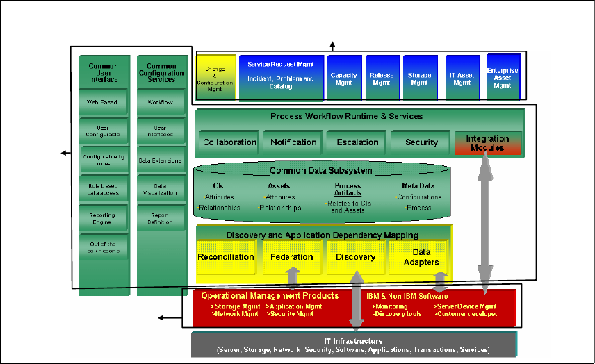
To understand this better, refer to Figure 1-1 on page 3. It outlines a logical
component overview for the Tivoli SRM solution and all related products.
Chapter 1. Integration benefits 3
Figure 1-1 Logical component overview
TPAP
Process Management Products
Operational Management
Products
4 Integration Guide for IBM Tivoli Service Request Manager V7.1
Let us start with the bottom layer, OMP. OMPs automate tasks to address
application or business service operational management challenges. These
products help optimize performance, availability of business-critical applications,
and IT infrastructure support. They also help ensure confidentiality and data
integrity of information assets while protecting and maximizing the utility and
availability of your e-business data.
OMPs can be implemented quickly to address immediate, specific IT challenges.
As you implement a more comprehensive IT Service Management solution,
these products can also integrate into the IT Service Management Platform and
be utilized by IT PMPs.
Examples of OMPs are IBM TEC, IBM TIM, and HP Service Center. The majority
of these integrations use the MEA and Tivoli TDI services. Refer to Chapter 2,
“Integration components” on page 17 for an in-depth discussion of MEA and TDI.
A PMP (or application) is a system for managing process executions. Think of a
process request as a ticket with a written note on it that is forwarded to various
people (or entities) to perform various actions and, in the end, result in the
objective of the process.
PMPs are applications that provide custom predefined implementations of best
practice processes to help clients integrate and automate IT management
processes across organizational silos, improving productivity and efficiency.
Tivoli SRM and Tivoli Change and Configuration Management Database
(CCMDB) are examples of PMPs.
PMPs focus on providing implementations of best practice processes as
workflows with roles, tasks, user interfaces, and integration modules stored in
the process database. In addition, they provide the ability to adapt the predefined
implementation to match the client’s unique process and workflow requirements;
allowing clients to capture and implement their current processes as workflows.
Clients are also able to evolve to Information Technology Infrastructure Library
(ITIL)-defined best practices over time. PMPs also provide the ability to monitor
and report process status and execution; showing business owners process
bottlenecks within an organization, and providing the opportunity to improve and
enhance their processes. The IBM IT PMP bridge organizational silos, automate,
and integrate IT management.
Chapter 1. Integration benefits 5
The TPAP provides the platform to run the applications (incident management,
problem management, change management, and so on). The TPAP is the
foundation layer of the ISM process. TPAP is also known as Base Services,
which you might still find in certain menus after installation. TPAP provides rich
tooling for configuring process flows, user interfaces, and process artifacts for
the PMPs implemented on top of it. TPAP provides the integration platform for all
PMPs. For an in-depth discussion about TPAP, refer to Chapter 2, “IBM Tivoli
SRM architecture” of the IBM Redbooks publication, Implementing IBM Tivoli
Service Request Manager V7.1 Service Desk, SG24-7579.
1.3 Benefits of integration
The advantages of integration with third-party solutions or other external
solutions are:
Having one primary location where data is stored and maintained, while you
still have the option to exchange and use the data in other solutions.
Exchanging data using automated integration requires less manual
interaction and reduces costs.
Exchanging data using automated integration requires less manual
interaction and reduces the number of errors.
Exchanging data using automated integration takes care of data
synchronization, enforcing data integrity.
When implementing a synchronized solution, the result is an environment where
shared data looks the same for all consuming applications. This is because
changes are propagated throughout the synchronized network of systems,
molded in transit to fit the needs of each consumer. Each data source is kept
up-to-date, maintaining the illusion of a single, common repository. Each
application accesses its data in an optimal manner, utilizing the repository to its
full potential without creating problems for the other applications.
Synchronization strategies are increasingly chosen for deploying new IT
systems. For identity management, this is usually a centralized, or metadirectory
style synchronization, where a high speed store (such as a directory) is used to
publish the enterprise view of its data. This approach has a number of
advantages:
Security requirements vary from system to system, and they can change over
time. A good repository (such as a directory) provides fine-grained control
over how each piece of data is secured. Certain repositories provide group
management features as well. These tools enable you to sculpt the enterprise
security profile.
6 Integration Guide for IBM Tivoli Service Request Manager V7.1
Each new IT deployment can be made on an optimal platform instead of
shoe-horned between existing systems into an uninviting infrastructure.
Applications live in individually suited environments bridged by metadirectory
synchronization services.
If the availability and performance requirements are not met by a system
(past, existing, or new), it can be left in place and synchronize its contents to
a new repository with the required profile, or multiple repositories to scale.
A metadirectory uncouples the availability of your data from its underlying
data sources. It cuts the cord, making it easier to maintain uptime on
enterprise data.
Disruption of IT operations and services must be managed and minimized.
Fortunately, the metadirectory network of synchronized systems evolves over
time in managed steps. Branches are added or pruned as required. TDI is
designed for infrastructure gardening.
The introduction of the integration toolkit, TDI included, provides significant
advantages in different areas. It not only makes configuration of an integration
easier and more flexible, but reduces the need for specific code development.
Several advantages of the integration toolkit include:
Connector communication can be set up from a simple configuration window:
– Drag-n-Drop attribute mapping
– Easily customizable mapping using simple mapping or Java™ Script
Extends standard MEA architecture:
– Uses ISM/Maximo object structures on one end
– Uses TDI connectors on the external end
Easy maximo connector configuration
No need for creating SOAP clients to communicate with Maximo
Eliminates the need to write communication code
Many integrations can be built with only a small amount of Java Script
Integration solutions built with TDI are easily extended to support changes in
data model:
– Most connectors support auto discover of the target data model
– TDI includes an easy to use visual configuration editor for building and
modifying data mappings
Maximo connector can be used in unlimited assembly line configurations
Supports reliability features to prevent the loss of incoming ticket data
Chapter 1. Integration benefits 7
Maximo connector supports multiple Maximo servers
More than two dozen predefined connectors for handling data I/O
Logging support in all connectors and Java Script mapping
TDI connectors exist for many common protocols and data sources,
including:
–Maximo
– Web Service, Java Database Connectivity (JDBC™), Lightweight
Directory Access Protocol (LDAP), Remedy, HTTP, Really Simple
Syndication (RSS), International Development Markup Language (IDML),
and many more
It is reusable:
– Custom TDI connectors that you build for your product adds to the value of
your product:
• TDI is the standard integration tool for field services
• TDI is the strategic integration tool both for ISM and the data
integration initiative
– Utilized common integration architecture supported by ISM
– Connectors are fairly interchangeable, so an integration can be cloned
with a new connector to create an integration with a new target. For
example, a connector to integrate OMNIbus with Maximo can be cloned to
provide an integration between OMNIbus and Remedy.
1.4 Integration scenarios
The integration architecture of Tivoli SRM makes it possible to connect to any
third-party solution. It is created based on several industry standards, as well as
TDI. The architecture of Tivoli SRM provides a robust integration platform.
In the following chapters, we discuss a number of possible integration scenarios,
such as:
Event management products or Event Generators
Third-party Service Desk tooling, such as HP Service Center
TIM
Computer telephony integration
Sametime and instant messaging
CCMDB
8 Integration Guide for IBM Tivoli Service Request Manager V7.1
1.4.1 Integration with event management solutions
Any service, or incident request, can originate from different sources, for
instance:
A self-service user generates a new self-service request; no plausible
solution is found in the knowledge base.
A service desk agent is taking your call; the agent can register a request
manually.
An automated event generating the request, detected by your event
management solution.
We are interested in automated events to synchronize with Tivoli SRM.
Integrating Tivoli SRM with Event Management solutions is probably the most
obvious integration we can think of. Out-of-the-box integrations exist for
customers using:
Tivoli Netview
Tivoli Monitoring
TEC
Netcool® Omnibus
The integration allows service desk tickets (service requests) to open
automatically based on predefined rules when an event arrives. The benefit is
that the integration saves time by assisting in the automation of a common
operator task.
Chapter 1. Integration benefits 9
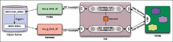
During normal operation, the integration allows data to flow between the TDI and
an Object Server in the form of Event Integration Facility (EIF) messages. The
Tivoli EIF is a toolkit that expands event types and system information that you
can monitor. Event adapters monitor managed resources and send events to the
Event Management product or other applications. You can use the Tivoli EIF to
develop your own adapters that are tailored to your network environment and
your specific needs. Figure 1-2 shows the flow of data between an Object Server
and Tivoli SRM through the various components of Event Management
integration with Tivoli SRM.
Figure 1-2 Event management integration data flow
For more details about how to install, configure, and manage Service Desk
integrations, refer to Chapter 3, “Event management integration” on page 105.
1.4.2 Integration with other service desk solutions
Most clients already have a type of ISM solution in place. Typically, a new ISM
product requires replacing the existing ISM product, or Tivoli ISM products
coexisting and inter-operating with past ISM products. The Service Desk
integration provides the necessary tools to support migration from past ISM
products and the interoperability of Tivoli ISM solutions with past ISM products.
ISM Service Desk integration is a complex topic. There are a variety of Service
Desk products being used today. Most Service Desks are customized by their
users. Different clients focus on different areas of integration.

10 Integration Guide for IBM Tivoli Service Request Manager V7.1
ISM provides a Service Desk integration toolkit that includes integration
examples and documentation. Peregrine and Remedy examples are available
and described in the following chapters. You can extend the examples to create
new integration points.
To build a complete solution, the predefined code must be extended to:
Handle any customization to either the third-party Service Desk or the IBM
Service Desk data model for the objects addressed by the base solution.
The predefined code must be cloned and modified to handle objects required
by the base solution that are not covered by the base code.
Table 1-1 shows the benefits of ISM V7.1 Service Desk integration.
Table 1-1 Client value/benefits: ISM V7.1 Service Desk integration
Capability Benefits
TDI connector for Maximo Integrates Maximo into the TDI family. Functions
as an extension to the MEA bringing drag and
drop data mapping and other TDI features to
Maximo.
Can be used with most MEAs/Business objects.
Many uses beyond Service Desk integration. Can
be used in conjunction with any standard TDI
connector. Examples include EIF connector for
event integration and XML for knowledge import.
TDI assembly lines Provides predefined integration for most common
Service Desk and CMDB business objects.
Near real-time, bi-directional symbolization of
data.
Can be easily customized to accommodate
changes and extensions to the data model.
Can be easily cloned to integrate other business
objects.
Incident/problem application Provides ticket management applications for
Tivoli SRM without requiring the third-party
Service Desk.
Operations personnel do not need to launch a
third-party Service Desk for basic tasks.
Supports creating, managing, and viewing
relationships between tickets and other Tivoli
SRM objects.

Chapter 1. Integration benefits 11
For more details about how to install, configure, and manage Service Desk
integrations, refer to Chapter 4, “Service Desk Tool integration” on page 135.
1.4.3 Integration with other solutions
You can probably think of several other integrations to learn, but to describe all
possible scenarios is impossible. We selected and described a few of the
existing and useful integrations in more detail.
Identity management
Several interpretations of identity management are developed in the IT industry.
Computer scientists now associate the phrase, quite restrictively, with the
management of user credentials and how users might log on to an online
system. You can consider identity management as the management of
information (as held in a directory) that represents items identified in real life
(users, devices, services, and so forth).
The self-service password reset is defined as any process or technology that
allows users who have either forgotten their password, or triggered an intruder
lock-out, to authenticate with an alternate factor and repair their own problem
without calling the help desk. It is a common feature in identity management
software and often bundled in the same software package as a password
synchronization capability.
Typically, users who have forgotten their password launch a self-service
application from an extension to their workstation login prompt, using their own or
another user’s Web browser, or through a telephone call. Users establish their
identity without using their forgotten or disabled password by answering a series
of personal questions, using a hardware authentication token, responding to a
password notification e-mail, or less often, by providing a biometric sample.
Users can then either specify a new unlocked password or ask that a randomly
generated one be provided.
Launch in context Provides launch based on external keys in
synchronized data objects from the Tivoli SRM to
an external Service Desk, and from an external
Service Desk to Tivoli SRM.
Capability Benefits
12 Integration Guide for IBM Tivoli Service Request Manager V7.1
Self-service password reset expedites problem resolution for users after the fact
and thus reduces help desk call volume. It can also be used to ensure that
password problems are only resolved after adequate user authentication,
eliminating an important weakness of many help desks: social engineering
attacks, where an intruder calls the help desk, pretends to be the intended victim
user, claims that the password is forgotten, and asks for a new password.
IBM TIM helps enterprises strengthen and automate internal controls governing
user access rights. It provides a secure, automated, and policy-based solution
that helps effectively manage user privileges across heterogeneous IT
resources.
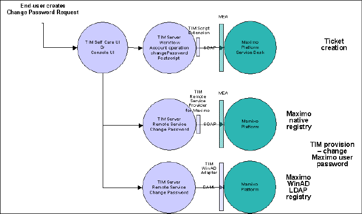
The integration of TIM and SRM is used to identity and manage password resets.
Figure 1-3 shows the solution flow used.
Figure 1-3 Password reset integration solution flow
TIM creates a Service Desk ticket every time a password reset (change) is
performed by TIM. The ticket is created and closed if the password reset is
successful. The ticket is created and left open if the password reset fails.
The integration uses the TIM Self Care UI (also referred to as Judith UI or End
User UI) or TIM console UI to perform the password reset. Installing the
integration makes sure the Maximo Logon page Forgot Your Password link is
redirected to the TIM Self Care UI. TIM manages the Maximo native registry or
WinAD LDAP registry.
Chapter 1. Integration benefits 13
For more details about how to install, configure, and manage identity
management integrations, refer to Chapter 5, “IBM Tivoli Identity Manager
integration” on page 167.
Computer telephony integration
Computer telephony integration (CTI) is the name given to the merger of
traditional telecommunications (PBX) equipment with computers and computer
applications. The use of Caller ID to automatically retrieve client information from
a database is an example of a CTI application. It is also used to explain the
connection between a computer and a telephone switch, which allows recording
and using information obtained by telephone access. For example, CTI enables
activities, such as dial-up registration, and fax-back.
CTI solutions are often used in call center environments, but can be used in a
service desk environment. Integrating the CTI solution with your service desk
solution reduces the number of manual steps for operators, but it increases the
speed of handling for any operator even more, reducing the average call time.
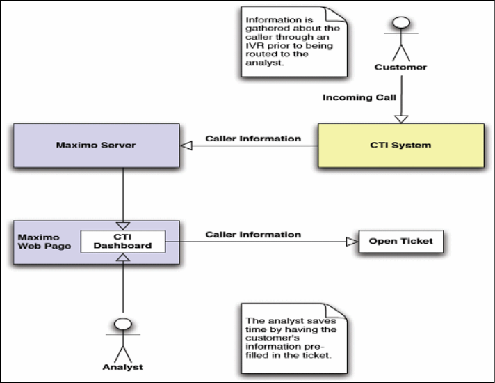
CTI is new to Tivoli SRM. It has features that enables your telephony system to
interact with Tivoli SRM. CTI allows you to populate Tivoli SRM records and
fields with mapped information based on lookup information provided by the CTI
system. Figure 1-4 on page 14 shows a simple process flow to open a ticket,
based on information provided by the CTI system.
14 Integration Guide for IBM Tivoli Service Request Manager V7.1
Figure 1-4 CTI process flow
You can also control your CTI solution from the Tivoli SRM user interface,
creating a single application for all service desk-related activities.
For more details about how to install, configure, and use the existing CTI
integrations, refer to Chapter 8, “Computer Telephony integration” on page 217.
Sametime and instant messaging
Communication has always been a keyword in many organizations. For a service
desk analyst, communication is one of the most important aspects of the job.
Several tools are available for an analyst to communicate with clients, such as
the obvious e-mail and telephony. In recent years, many companies introduced
other tools to support mostly internal communication, known as instant
messaging.
Sametime is the IBM Lotus product for instant messaging, which now has a
predefined integration with Tivoli SRM. It allows a service desk analyst, or IT
specialist, to initiate contact with a Tivoli SRM user, based on the Sametime
status (which can be found in the user information on the request) and chat
functions provided by Sametime.
Chapter 1. Integration benefits 15
For more details about how to install, configure, and use the existing Instant
Messaging integrations, refer to Chapter 7, “Lotus Sametime integration” on
page 201.
CCMDB integration
It is not the most obvious integration, but you can call an installation of Tivoli
SRM and CCMDB on the same base services an integration.
CCMDB provides information to help the Service Desk team isolate the source of
the problem more quickly. Suppose a switch that is used for production goes
down, and the affected users are calling the help desk. By looking at the
applications and servers that are down (affected configuration items (CIs) in
CCMDB terminology), a Service Desk person, or a Specialist, can understand
that they are all related with a certain switch (through the CI relationship
information provided by CCMDB). They can also see that this switch has caused
problems before, and after a closer analysis, they can understand that the
software or firmware on this switch is back-level. All this information is provided
by the CCMDB. At this point, they can start a change request to upgrade the
switch software or firmware. This change request is reviewed by the Change
Manager or the change review board to analyze the impact of the change (again
using the CCMDB, looking at the CIs affected), and after the change is
authorized, it is implemented.
All these are ITIL processes, and by integrating your help desk processes with
configuration and change management processes, you greatly increase the
efficiently of these processes.
For more details about how to install and use CCMDB PMPs on top of Tivoli
SRM, refer to Chapter 6, “CCMDB integration” on page 187.
Remote control
Remote control or Remote administration refers to any method of controlling a
computer from a remote location. Software that allows remote administration is
becoming increasingly common and is often used when it is difficult or
impractical to be physically near a system to use it.
Any computer with an Internet connection, TCP/IP, or on a local area network
can be remotely administered. For non-malicious administration, the user must
install or enable server software on the host system in order to be viewed. Then,
the user or client can access the host system from another computer using the
installed software.
The IBM product delivered for this purpose is Tivoli Remote Control (TRC). Tivoli
SRM is shipped with a light version of TRC, enabling a service desk agent to
take over the user desktop from within Tivoli SRM and solve incidents as quickly
16 Integration Guide for IBM Tivoli Service Request Manager V7.1
as possible. If a service desk agent can solve incidents quickly using remote
control, there is no need to transfer requests to a second line. Remote control
can also be used to gather more information about the request to open a second
line so that an IT specialist can quickly solve an incident. The requester is not
required to provide technical details. Using TRC can make your key performance
indicators (KPIs) look better than ever.

© Copyright IBM Corp. 2008. All rights reserved. 17
Chapter 2. Integration components
This chapter discusses integration components that are available in IBM Tivoli
Service Request Manager (SRM) V7.1.
This chapter discusses the following topics:
IBM Tivoli Directory Integrator on page 18
TDI component on page 27
Planning to deploy TDI on page 30
Integration Framework or MEA on page 35
2
18 Integration Guide for IBM Tivoli Service Request Manager V7.1
2.1 IBM Tivoli Directory Integrator
IBM Tivoli Directory Integrator (TDI) is a generic data integration tool that is used
to address problems that require custom coding and more resources than
traditional integration tools. It is designed to move, transform, harmonize,
propagate, and synchronize data across otherwise incompatible systems.
TDI can be used in conjunction with the deployment of integration with the IBM
Tivoli SRM product to provide a feed from multiple Service Desk Systems, such
as HP Service Desk and Remedy Service Desk. TDI can also function as a
custom adapter to integrate with network monitoring tools, such as Tivoli
Enterprise Console (TEC) and Netcool Omnibus.
A TDI Connector provides access to anything else for which there is a TDI
connector available. There is a large set of over 20 existing connectors. As
shipped, it can synthesize data from many feeds at a time. TDI provides a visual
drag and drop data mapping environment, and it provides JavaScript™ for data
mapping and transforms. Figure 2-1 on page 19 shows additional types of
integration that are made possible by using TDI, but they are not covered in this
book.
Integrations are available as a TDI-unified adapter, and they can be used with
minor adjustments.These scenarios are further expanded later in this book.
Regardless of the scenario, it is essential to gain a full understanding of the
environment. Understanding the environment allows you to document the
solution. Typically, understanding the environment is accomplished by the
development of a series of use cases that are designed to clarify the business
needs and refine the solution through an iterative process that ultimately
provides you with a complete list of documented customer business
requirements.
Integration problems are all about communication and are typically broken down
into three parts:
The systems and devices that communicate
The flow of data between these systems
The trigger of events when the data flow occurs
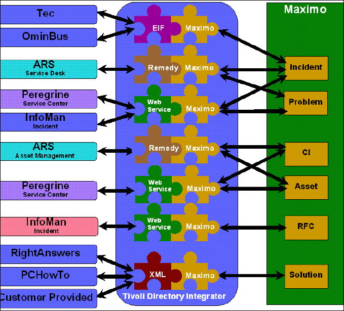
Chapter 2. Integration components 19
Figure 2-1 Integration possibilities using TDI
2.1.1 TDI architecture
TDI architecture consists of the elements of a communications scenario that can
be described as data sources:
Data repositories, systems, and devices that talk to each other. For example:
– An enterprise directory that you are implementing or trying to maintain
– Your customer relationship management (CRM) application
– The office phone system
– An access database with a list of company equipment and who owns the
equipment
20 Integration Guide for IBM Tivoli Service Request Manager V7.1
Data sources represent a wide variety of systems and repositories. For
example:
– Databases:
•IBM DB2®
•Oracle®
– SQL Server® directories:
• iPlanet
• IBM Directory Server
• Domino®
• eDirectory
• ActiveDirectory
– Directory services
Exchange
– Files:
• Extensible Markup Language (XML)
• Lightweight Directory Access Protocol (LDAP)
• LDAP Directory Interchange Format (LDIF)
• SOAP documents
• Specially formatted e-mail
Data sources also represent any number of interfacing mechanisms that internal
systems and external business partners use to communicate with your
information assets and services: data flows and events.
Data flows are the threads of communication and their content. They are usually
drawn as arrows that point in the direction of data movement. Each data flow
represents a dialogue between two or more systems.
However, for a conversation to be meaningful to all participants, everyone
involved must understand what is being communicated. You can probably count
on the data sources representing their data content in multiple ways. One system
might represent a telephone number as textual information, including the dashes
and parentheses that are used to make the number easier to read. Another
system might store them as numerical data. If these two systems are to
communicate about this data, the information must be translated during the
conversation. Furthermore, the information in one source might not be complete
and might need to be augmented with attributes from other data sources. In
addition, only parts of the data in the flow might be relevant to receiving systems.
Chapter 2. Integration components 21
A data flow must include the mapping, filtering, and transformation of information,
shifting its context from input sources to that of the destination systems.
Events can be described as the circumstances dictate, when one set of data
sources communicates with another set, for example, when an employee is
added, updated, or deleted from the human resources (HR) system. Another
example is when the access control system detects a keycard being used in a
restricted area. You can base an event on a calendar or a clock-based timer; for
example, start communications every 10 minutes or at 12:00 midnight on
Sundays. An event can also be a manually initiated one-off event, such as
populating a directory or washing the data in a system.
Events are usually tied to a data source and are related to data flows that are
triggered when the specified set of circumstances arise. Each element is handled
by TDI components:
Connectors: Connectors are components that connect to and access data in
a data source. For example, we use a Java Database Connectivity (JDBC)
Connector to read and write to an SQL database, while an LDAP Connector
allows us to access a directory. Certain types of data sources do not store
data as structured objects (records, entries, and so on); they use bytestreams
instead. Two examples are data over IP and flat files.
Parsers: Parsers turn bytestreams into structured information or structured
information into bytestreams. The data flows are implemented by clicking one
or more Connectors together (associating Connectors with Parsers where
necessary).
EventHandlers: EventHandlers can be configured to pick up change
notifications in connected systems (such as directories or Post Office Protocol
Version 3 (POP3)/Internet Message Access Protocol (MAP) mailboxes) and
then dispatch these events to the designated AssemblyLines.
The architecture of TDI is divided into two parts:
The core system where most of the system functions are provided. The TDI
core handles log files, error detection and dispatching, and data flow
execution parameters. The core system is also where your customized
configuration and business logic are maintained.
The components, which serve to hide the complexity of the technical details of
the data systems and formats with which you want to work. TDI provides you
with three types of components: Connectors, Parsers, and EventHandlers.
Because the components are wrapped by core functions that handle
integration flow control and customization, the components themselves can
remain small and lightweight. For example, if you want to implement your own
Parser, you only have to provide two functions: one function for interpreting
the structure of an incoming bytestream and one function for adding structure
22 Integration Guide for IBM Tivoli Service Request Manager V7.1
to an outgoing bytestream. If you look in the jars subdirectory of TDI, you see
how lightweight the standard components are, which makes them easy to
create and extend.
This core/component design makes TDI easily extensible. It also means that you
can rapidly build the framework of your solutions by selecting the relevant
components and clicking them into place. Components are interchangeable and
can be swapped out without affecting the customized logic and the configured
behavior of your data flows. Therefore, you can build integration solutions that
are quickly augmented and extended, while keeping them less vulnerable to
changes in the underlying infrastructure.
2.1.2 AssemblyLines
The data flow arrows in the diagram (Figure 2-1 on page 19) represent
AssemblyLines in TDI, which work in a similar fashion to real-world industrial
assembly lines.
Real-world assembly lines are made up of a number of specialized machines that
differ in both function and construction, but they have one significant attribute in
common: They can be linked together to form a continuous path from the input
sources to the output.
An assembly line generally has one or more input units that are designed to
accept whatever raw materials are needed for production. These ingredients are
processed and merged together. Sometimes, by-products are extracted from the
line along the way. At the end of the production line, the finished goods are
delivered to the waiting output units.
If a production crew receives an order to produce something else, they break the
line down, keeping the machines that are still relevant to the new order. The new
units are connected in the right places, the line is adjusted, and production starts
again. The TDI AssemblyLines work in much the same way.
The TDI AssemblyLines receive information from various input units, perform
operations on this input, and then, convey the finished product through output
units. TDI AssemblyLines work on one item at a time, for example, one data
record, directory entry, registry key, and so forth. Refer to Figure 2-2 on page 23.

Chapter 2. Integration components 23
Figure 2-2 AssemblyLines
Data attributes from the connected input sources are accumulated in a Java
bucket (called the work object). Scripts can be added to work with this
information: verifying data content, computing new attributes and values, as well
as changing existing attributes and values, until the data is ready for delivery
from the line into one or more output data sources.
The input and output units of an TDI AssemblyLine are called Connectors, and
each Connector is linked into a data store. Connectors tie the data flow to the
outside world and are also where data transformation and aggregation take
place. you can layer your business, security, and identity management logic
through the Connectors.
2.1.3 Connectors
Connectors are similar to puzzle pieces that click together, while at the same
time, they link to a specific data source, as shown in Figure 2-3 on page 24.
Each time that you select one of these puzzle pieces and add it to an
AssemblyLine, you must:
1. Choose the Connector type.
2. Assign the Connector to its role in the data flow.
This is called the Connector mode, and it tells the TDI how to use the
Connector:
– An input Connector iterates through or looks up information in its source.
– An output Connector inserts, updates, or deletes data in the connected
system or device.
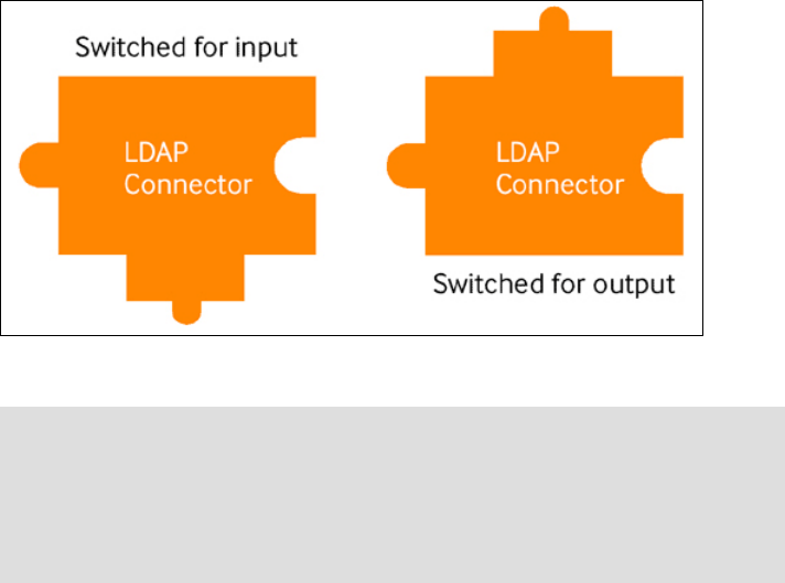
24 Integration Guide for IBM Tivoli Service Request Manager V7.1
Figure 2-3 Connector puzzle pieces
You can change the type and the mode of a Connector to meet changes in your
infrastructure or in the goals of your solution. If you plan for these changes, the
rest of the AssemblyLine, including data transformations and filtering, is not
impacted. Therefore, it is important to treat each Connector as a black box that
either delivers data into the mix or extracts part of it to send to a data source. The
more independent each Connector is, the easier it is to augment and maintain
your solution.
By making your Connectors as autonomous as possible, you can also readily
transfer them to your Connector Library and reuse them to create new solutions
more quickly, even sharing them with other Connectors. Using the TDI library
feature also makes maintaining and enhancing your Connectors easier, because
you only have to update the Connector template in your library, and all of the
AssemblyLines that are derived from this template inherit these enhancements.
When you are ready to put your solution to serious work, you can reconfigure
your library Connectors to connect to the production data sources instead of
those data sources in your test environment, and you can move your solution
from lab to live deployment in minutes.
To include new data into the flow, add the relevant Connector to the
AssemblyLine. Refer to Figure 2-4 on page 25.
Note: You might think that these puzzle pieces are rendered incorrectly and
that data must flow from above, and then, flow down to the receiving data
sources. But anyone who has ever tried to implement an integration solution
knows that data does not tend to flow on its own. Data must be pulled out of
input sources and then pushed into the output destinations, which is where
Connectors excel.
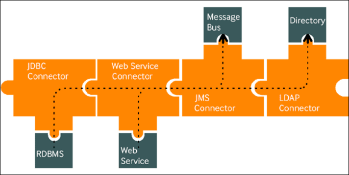
Chapter 2. Integration components 25
Figure 2-4 Add Connectors to the AssemblyLine
IBM TDI provides a library of Connectors from which to choose, such as LDAP,
JDBC, Microsoft Windows® NT4 Domain, Lotus Notes®, and POP3/IMAP. And if
you cannot find the Connector that you want, you can extend an existing
Connector by overriding any or all of its functions by using one of the leading
scripting languages, including JavaScript, VBScript, and PerlScript. You can also
create your own Connector either with a scripting language inside of the Script
Connector wrapper or by using Java or C/C++.
Furthermore, TDI supports most transport protocols and mechanisms, such as
TCP/IP, FTP, HTTP, and Java Message Service (JMS)/message queuing (MQ),
with or without Secure Sockets Layer (SSL) or other encryption mechanisms to
secure the information flow.
For more information about scripting languages and about how to create your
own scripting language, refer to the IBM Directory Integrator 6.1.1: Reference
Guide, SC32-2566.
2.1.4 Parsers
TDI handles unstructured data, such as text files or bytestreams coming over an
IP port, quickly and simply by passing the bytestream through one or more
Parsers. Parsers are another type of TDI component, and the system ships with
a variety of Parsers, including LDAP Directory Interchange Format (LDIF),
Directory Services Markup Language (DSML), XML, comma-separated values
(CSV), and fixed-length field. And, you can extend and modify Parsers in the
same way that you can extend and modify Connectors, as well as create your
own Parsers.
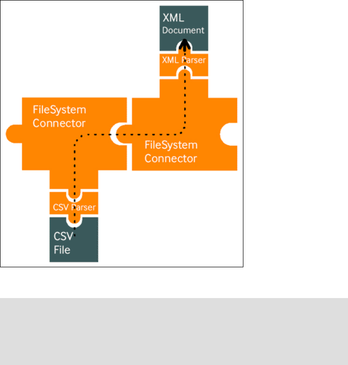
26 Integration Guide for IBM Tivoli Service Request Manager V7.1
Continuing with the previous example, the next step is to identify the data
sources. Because the input data source is a text file in comma-separated value
format, you use the File System Connector paired with the CSV Parser. You use
a File System Connector for output as well, but this time, choose the XML Parser
to format the file as an XML document. First, we look at the AssemblyLine using
the puzzle pieces, as shown in Figure 2-5.
Figure 2-5 AssemblyLine puzzle pieces
2.1.5 EventHandlers
EventHandlers are the third and last type of TDI component and provide
functions for building real-time integration solutions.
Note: We created the examples in this book on a UNIX® platform and use the
UNIX path name conventions. In order for your solution to be platform
independent, use the forward slash (/) instead of the backward slash character
(\) in your path names. For example, examples/Tutorial/Tutorial1.cfg works
with both Windows and UNIX/Linux®.
Chapter 2. Integration components 27
Like Connectors, EventHandlers can have data source intelligence that allows
them to connect to a system or service and wait for an event notification.
Examples are the Mailbox EventHandler, which can detect when new messages
arrive in a POP3 or IMAP mailbox, and the LDAP EventHandler, which can catch
changes made to a directory. When an event occurs, the EventHandler stores the
specifics of the event, then performs logic, and starts the AssemblyLines
according to the condition or action rules that you set up.
Sometimes you can also use Connectors to capture events, such as the JMS
(MQ) Connector or the LDAP Changelog Connector. You can configure both of
these Connectors to wait until new data appears and then retrieve it. However,
because the EventHandler operates in its own thread, you can use
EventHandlers to dispatch events to multiple AssemblyLines, which provides a
cleaner and more straightforward method of filtering and handling multiple types
of events from the same source (for example, SOAP or Web services calls). You
can also configure EventHandlers for auto start, which means that if you start up
a server with Config, these EventHandlers are immediately activated. Auto start
saves you from having to specifically name the AssemblyLines to run in the
command line parameters to the server.
2.2 TDI component
The connection between these components can be established either
unidirectionally or bidirectionally to keep your system or record synchronized.
Refer to Figure 2-6 on page 28. If the connector for an external application has
not been developed by IBM, you have the ability to develop your own connector
by using another type of language, such as JavaScript.
TDI is divided into three internal components:
Node: This component is the heart of the system, which allows you to
configure, communicate, and exchange data in various modes between two
systems.
Interpreter: This component is the function, which allows you to map various
fields together. Also, you can write script in JavaScript to make your data
exchange process more flexible.
Connector: This component allows you to establish a connection to the
third-party application to facilitate the data exchange between two
components.
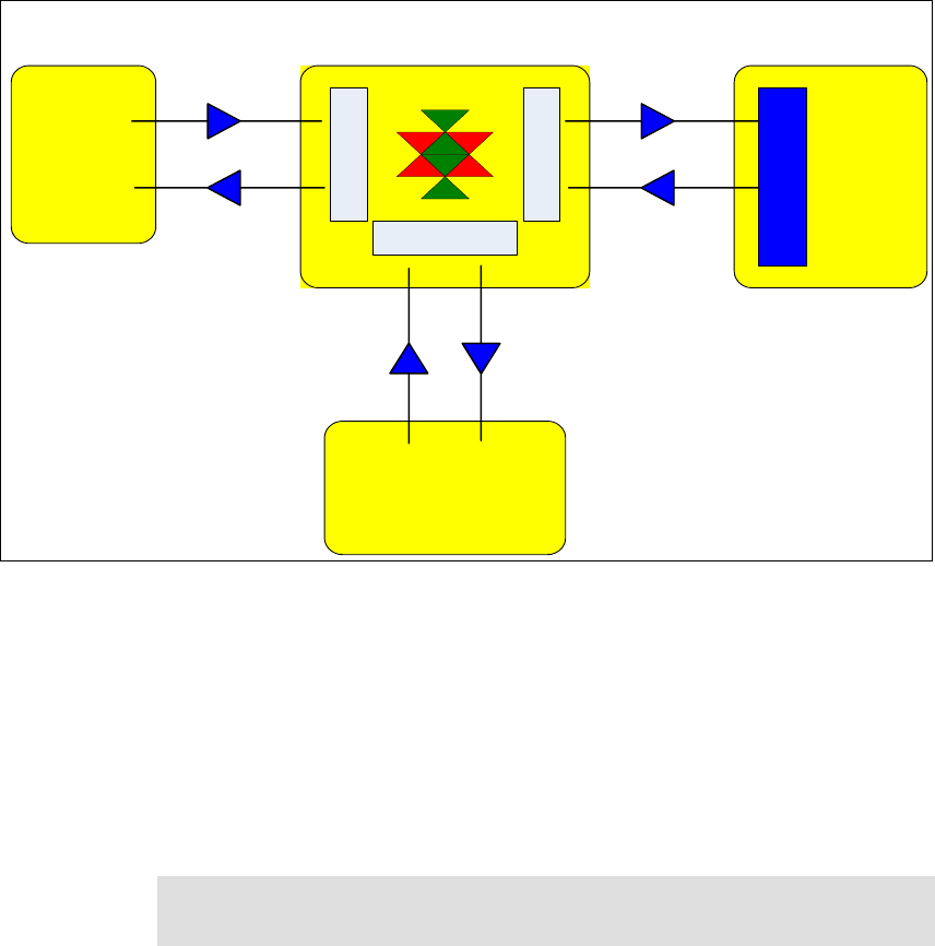
28 Integration Guide for IBM Tivoli Service Request Manager V7.1
Figure 2-6 TDI components: the node, the interpreter, and the connector
Many ready-to-use connectors are available to provide the exchanged
information between various products.
2.2.1 Supported platform and compatibility matrix
One of the most important points for this type of integration is the ability to define
which platform and operating system are supported before proceeding to the
installation. Refer to Figure 2-7 on page 29.
Tivoli
Enterprise
Console
Tivoli
Service
Request
Manager
External
Service
Desk
NODE
Tivoli Directory Integrator
External External
Integration Object
(M E A)
Create/Update
TEC Event
Update
TEC Event
Create/Update
Ticket
Update
Ticket
CONNECTOR
TEC
CONNECTOR
SRM
INTERPRETER
CONNECTOR
HP-Peregrine / Remedy
Create/Update
Ticket
Update
Ticket
Web Services Integration
Web Services Integration
Note: Make sure that your actual infrastructure is within these components to
ensure the continuity of your support contract.

Chapter 2. Integration components 29
Figure 2-7 Compatibility matrix: Architecture and operating systems supported
2.2.2 Hardware and software prerequisites
This section provides TDI installation prerequisites.
2000 Professional*
2000 Server Std Edit.
2000 Adv. Server
XP Pro*
2003 Server - Std Ed.
2003 Server - Ent. Edit.
AIX 5L 5.2 (MP 5200-08)
AIX 5L 5.3 (MP 5300-03)
HP-UX11iv2 (11.23)
RedHat Enterprise Linux ES / AS 3.0
RedHat Enterprise
Linux ES / AS 4.0 32 bit / 64 bit
SLES 9 (32 bit / 64 bit)
SLES 10 (32 bit / 64 bit
Red Flag Data Center 5.0 SPI / Aisan
i
2.0 SP1
Microsoft Windows
Intel IA32 - 32 Bit 999999
Microsoft Windows
AMD64/EMT64 - 64 Bit 99
IBM (Non-Admin installs not
supported) 99
HP-UX PA-RISC 9
HP-UX Itanium 9
Linux Intel IA 32 9999 9
Linux AMD64/EMT64 999
Linux on Power (pSeries,
iSeries, OpenPower, and
JS20 Blades)
9999
30 Integration Guide for IBM Tivoli Service Request Manager V7.1
Hardware prerequisites
The installation procedure requires 450 Mb disk space during the installation.
Disk space requirements by platform for a typical installation are:
Windows (32-bit and 64-bit): 341 MB
Linux (32-bit and 64-bit): 413 MB
AIX®: 342 MB
Solaris™: 453 MB
HP-UX: 562 MB
Disk space requirements by platform for a custom installation in which all
components are selected are:
Windows (32-bit and 64-bit): 564 MB
Solaris: 773 MB
HP-UX: 858 MB
Software prerequisites
The administrative workstation is not used for daily operations, although it is an
important SRM support component for administrative activities.
2.3 Planning to deploy TDI
Before installing TDI, you need to understand the interaction between the TDI
component connectors and the third-party applications with which you expect to
exchange data.
We have included various types of scenarios that you might encounter when
implementing TDI.
2.3.1 Installation scenarios
The first scenario is integrating an event management product, such as Tivoli
Enterprise Console (TEC). At any time, a server, network, or any other type of
event can be generated and must be managed within this console.
Assume that this scenario uses the default value that is provided by TEC where a
ticket in Tivoli SRM is created for each Critical event generated. When this ticket
is closed, this information is updated in TEC to synchronize the open ticket and
the open event. This type of integration is required to ensure the integrity of the
generated data.

Chapter 2. Integration components 31
The second part of this integration in this scenario consists of keeping two
Service Desk operations synchronized. The first part consists of the Tivoli SRM,
and the second part consists of HP ServiceCenter V6.1.
2.3.2 Installation procedure
In this section, we focus on the installation of the TDI application, which allows
you to develop, configure, and define the mapping between two components. We
do not discuss the integration scenarios here.
For event management integration scenarios, refer to Chapter 3, “Event
management integration” on page 105. For third-party service desk integration,
refer to Chapter 4, “Service Desk Tool integration” on page 135.
The latest version of TDI that is available at this time is V6.1.1. Prior to installing
the application, make sure that:
You copy the installation files from the IBM Tivoli SRM Integration Toolkit
image to a temporary directory on the computer where you want to install TDI.
You have enough disk space left, as shown in the prerequisites.
You have Administrator’s rights on the Windows server or the Windows
machine.
Note: At this time, as shipped, only HP ServiceCenter V6.1 is supported. For
any other version, you must modify the assembly line configuration within the
connector configuration.
Important: Use the procedure (command line installation) that is described in
this section rather than the TDI product documentation to install a TDI
environment that supports the integration of Tivoli SRM with event
management, third-party service desk integration, and so forth.
If you install TDI using the TDI V6.1.1 Launchpad (as described in the TDI
manuals), several installation parameters that are necessary for Tivoli SRM
integration are not available during the installation.
For general information about IBM TDI, refer to the product documentation at:
http://publib.boulder.ibm.com/tividd/td/IBMDirectoryIntegrator6.1.1.
html

32 Integration Guide for IBM Tivoli Service Request Manager V7.1
Complete the following steps to install TDI:
1. At a command prompt, change to the directory where the installation files are
located.
2. Run the installation command that is appropriate for your platform:
–Windows:
installTDI.cmd -silent tdi_home tdi_working_dir "srm_host
[srm_host2 srm_host3 ...]" tec_log_file_adapter_home Y | N
–Linux or AIX:
./installTDI.sh -silent tdi_home tdi_working_dir \"srm_host
[srm_host2 srm_host3 ...]\" tec_log_file_adapter_home Y | N
The descriptions of the parameters are:
-silent: Specifies to install the product in silent mode,
where the installation is performed with no user
interaction.
tdi_home: Specifies the directory where you want to install the
TDI binary files. Specify any directory. The
directory that you specify is created for you if it
does not exist.
tdi_working_dir: Specifies the directory where you want to install the
TDI files that are required by the products that are
supported for integration with Tivoli SRM. Specify
any directory.
srm_host [srm_host2 srm_host3 ...]:
Specifies the hostname or IP address of one or
more servers that host Tivoli SRM. Specify the fully
qualified host name with the HTTP listener port of
the supporting application server. (Port number
9080 is typically used for a WebSphere®
Application Server.) Be sure to enclose these
arguments in double quotes ("), including the
escape character (\) for UNIX, as shown in the
command syntax.
Note: Typically, the working directory is a subdirectory of the tdi_home
directory. The directory that you specify is created for you if it does not
exist.

Chapter 2. Integration components 33
tec_log_file_adapter_home:
Specifies the full directory path where you installed,
or plan to install, the TEC non-TME logfile adapter
on this computer. The non-TME logfile adapter
supports the integration of Tivoli SRM with TEC.
Y | N : Specifies whether you want to use a common
queue in a multiple TDI server environment. The
default is Y (yes).
3. Repeat the preceding steps on each computer where you want to install TDI.
Example 2-1 specifies that you want the TDI server to connect to two Tivoli SRM
servers (tsrm1 and tsrm2). No logfile adapter is specified (na).
Example 2-1 Windows example
installTDI.cmd -silent C:\TDI C:\TDI\work "tsrm1.itso.ibm.com:9080
tsrm2.itso.ibm.com:9080" na Y
The UNIX command in Example 2-2 specifies a single Tivoli SRM Server (TSRM)
and the location of the logfile adapter on the TDI server.
Example 2-2 UNIX example
./installTDI.sh -silent /opt/TDI /opt/TDI/work
\"tsrm.itso.ibm.com:9080\" /opt/IBM/Tivoli/tec/nonTME Y
Note: At the time of writing this book, there was a defect in the
installTDI command. Although srm_host(s) is specified in the silent
install, this parameter is not used during the execution of the command.
You have to manually update the mxe.properties or TDI config file to
specify the hostname or IP address of the servers that host Tivoli SRM.
This is expected to be corrected in a later fixpack.
Note: If you do not plan to integrate with TEC, or you do not know the
location of the TEC logfile adapter, enter any valid character or
character string for this parameter. For example, enter a dot (.) or any
word (na). After installation, you can edit a properties file
(mxe.properties) on the TDI server to specify the location of the TEC
logfile adapter.
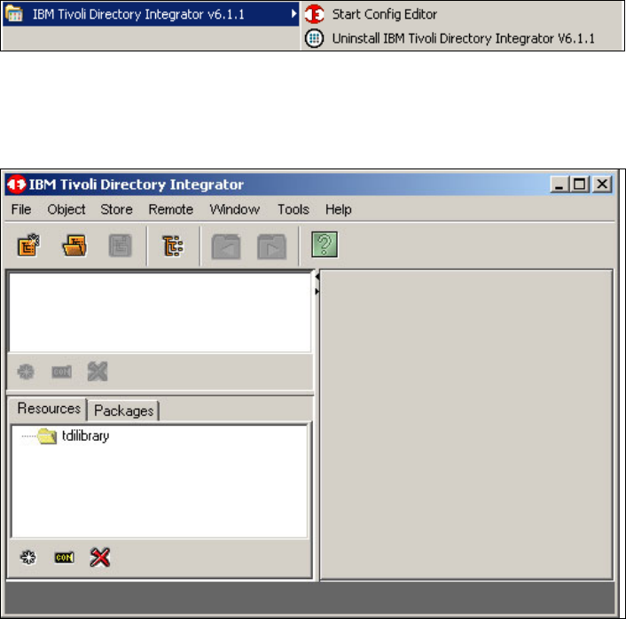
34 Integration Guide for IBM Tivoli Service Request Manager V7.1
Post-installation verification
This section verifies that the installation is complete:
1. If the following component is in the All Programs folder, it confirms the
success of the installation. Refer to Figure 2-8 on page 34.
2. Select Start → All Programs → IBM TDI 6.1.1:
– Start Config Editor
– Uninstall IBM TDI 6.1.1.
Figure 2-8 IBM TDI 6.1.1 menu
3. To complete the post-installation check, launch the TDI as shown in
Figure 2-8 by selecting Start Config Editor, as shown in Figure 2-9.
Figure 2-9 TDI user interface
Chapter 2. Integration components 35
2.4 Integration Framework or MEA
This section provides information about Integration Framework, which is one
component of the Service Desk Integration Toolkit. In Maximo V6.x, the
integration application is referred to as MEA. Now, in Tivoli SRM V7.1, MEA is
referred to as the Integration Framework. In this section, we discuss:
Overview of Integration Framework
Architecture
Integration Framework components
Cluster configuration
Integration enhancements and changes from Version 6.x to 7.1
Sample scenario
2.4.1 Integration Framework overview
Integration Framework is a set of applications to help you integrate the system
with your framework applications. You also can create business flows between
the system and the other framework applications.
Integration Framework comes embedded with the Tivoli SRM installation.
Figure 2-10 shows how to access the Integration application from the Web user
interface.
To access the integration application, complete the follow steps:
1. Log on to an account with integration privileges.
2. Open the integration application by selecting Go To → Integration.
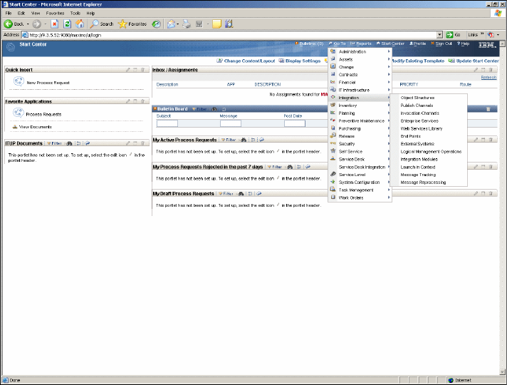
36 Integration Guide for IBM Tivoli Service Request Manager V7.1
Figure 2-10 Integration Framework
Operational Management Products (OMPs) are individual external products that
you can use to implement Logical Management Operations (LMOs). Tivoli
Application Dependency Discovery Manager (TADDM), Tivoli Provisioning
Manager (TPM), and Tivoli Configuration Manager (TCM) are examples of
OMPs. You can bring OMPs into the system from the IBM Tivoli Application
Dependency Discovery Manager (TADDM) using the Integration Composer.
OMPs are artifacts within the system that can exist when there is no OMP.
The key features of the Integration Framework include:
Predefined content to assist in implementing integration requirements in a
timely manner. This content is a comprehensive set of outbound (Channels)
and inbound (Services) integration interfaces that are available to use
immediately.
Applications to configure, predefine, and to create new integration definitions.
Applications to facilitate the customization of predefined content using a
processing rule engine, Java, and Extensible Stylesheet Language
Transformations (XSLT).
Support for multiple communication modes, including:
Chapter 2. Integration components 37
–Web services
– HTTP
–JMS
– Database interface tables
– XML/flat files
Event-based, batch, program-initiated, and user-initiated processing of
outbound and inbound messages.
Load and performance scalability using JMS queues.
Support for clustered environments that reduce system downtime, increase
system availability, and improve system performance.
Support for user interface (UI)-based integration, including the context-based
launching of external applications.
Support for integration to OMPs.
Support for bulk export of data using user-defined SQL query.
Support for bulk importing of XML or flat files.
Dynamic XML schema generation for all integration interfaces.
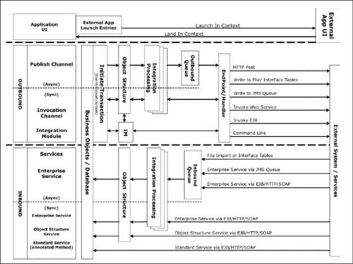
38 Integration Guide for IBM Tivoli Service Request Manager V7.1
Dynamic generation of Web services Interoperability (WS-I) compliant Web
services, including Web Service Definition Language (WSDL).
Provides the concept of an adapter that is used to group related integration
artifacts. You can configure and deploy adapters for enterprise connectivity
with various systems. Each adapter can have its own interface and delivery
mode. Preconfigured adapters for Oracle and SAP® are available as add-ons.
2.4.2 Architecture
This section describes the architecture of Integration Framework processing. The
Integration Framework facilitates bidirectional data exchange between the
system and external applications in a real-time or batch mode. Through the
Integration Framework, you can exchange data synchronously and
asynchronously using a variety of communication protocols. Refer to
Figure 2-11.
Figure 2-11 Integration Framework overview
Chapter 2. Integration components 39
You can implement the system within a cluster of application servers, and
integration services can run across the cluster.
The Integration Framework also provides features that support integration with
OMPs, such as Tivoli Provisioning Manager. You also can use a system
application UI to launch an external application UI. The following sections
describes:
Integration Framework for data exchange
Integration Framework for OMP integration
Integration Framework for UI integration
Integration Framework for data exchange
Through the Integration Framework, you can send and receive XML messages
between the system and external applications. The Integration Framework
provides the following capabilities:
Build, transform, and customize message content
Send and receive messages using multiple protocols, including:
–Web services
– Hypertext Transfer Protocol (HTTP)
–JMS
Exchange data synchronously and asynchronously
Exchange event-based messages
Batch import and export messages
The Integration Framework components that support data integration are shown
in Table 2-1 on page 40.

40 Integration Guide for IBM Tivoli Service Request Manager V7.1
Table 2-1 Integration Framework for data exchange components
Figure 2-12 on page 41 illustrates the Integration Framework for data exchange.
Component Description
Object structures Define message content
Services Receive data into the system
Channels Send data out of the system
External systems Define external applications and services
that integrate with the system
Communication Modes you use to communicate with
external applications. Modes include Web
services, HTTP, Enterprise JavaBeans™
(EJB™), and flat files.
Events The business object events that you use
to initiate data exchange. Events include
data import, data export, and record status
changes, that is, work order approvals.
Web services Query or send transactions to the
Integration Framework.
Content System-provided content that is
configured to enable integration.
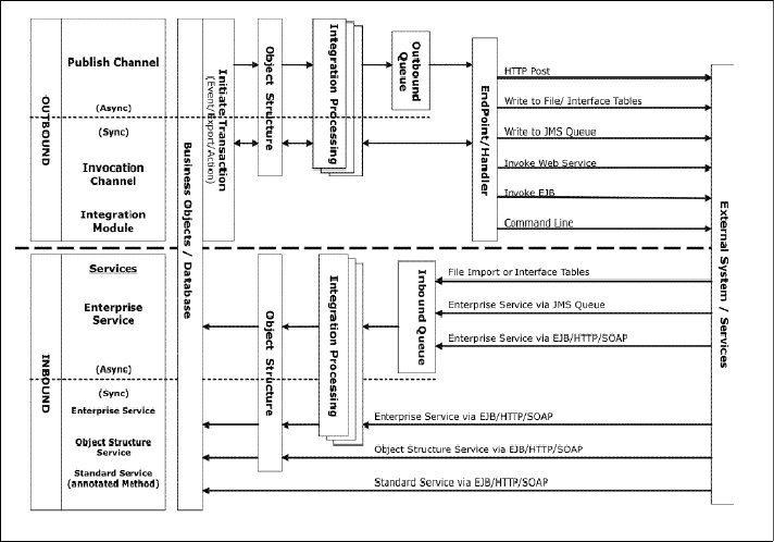
Chapter 2. Integration components 41
Figure 2-12 Integration Framework for data exchange
Integration Framework for OMP integration
OMPs are external products (to the system) that provide services for
configuration items (CIs), such as a server that runs applications. PMPs are
system applications and processes that use OMPs to automate IT-related
services. Such services include software deployment on CIs.
OMP integration takes place through a series of system calls and invocations. A
PMP calls an Integration Module (IM), which in turn communicates with the OMP
to perform a Logical Management Operation (LMO). With this framework,
actions, such as software deployment, can be automated where the PMP
initiates the IM to invoke the OMP to perform such actions.
Through the Integration Framework, IMs are configured to support specific LMOs
and OMPs. As part of the IM, an EndPoint/Handler is configured to identify the
communication protocol (HTTP, Web service) that IM uses to invoke the OMP.
The IM can map the service response so it is returned to the PMP. The service
response then can be processed in multiple ways. The service can open a
response in a UI application or save the response data to the application
database.
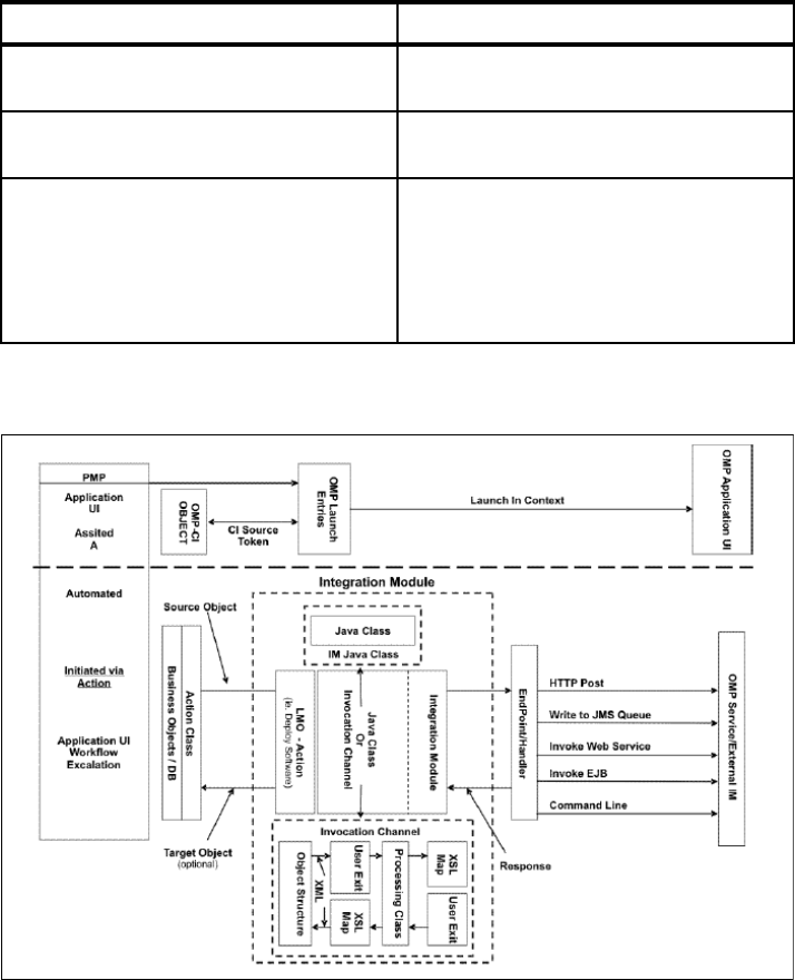
42 Integration Guide for IBM Tivoli Service Request Manager V7.1
OMPs can also choose to integrate in an assisted, (non-automated) approach by
using the Integration Framework.
The Integration Framework components that the IMs and PMPs use for OMP
integration are shown in Table 2-2.
Table 2-2 Integration Framework for OMP components
Figure 2-13 illustrates the Integration Framework for OMP.
Figure 2-13 Integration Framework for OMP
Component Description
LMO Define the actions that the IM supports for
an OMP.
Integration modules (IMs) Define the configurations and the
relationships to LMOs and OMPs.
Actions Use to implement an automated (no user
interaction) or semi-automated (user
initiates from a UI application) invocation
of an IM/OMP by a PMP. You can initiate
actions from UI Applications, Escalations,
and Workflows.
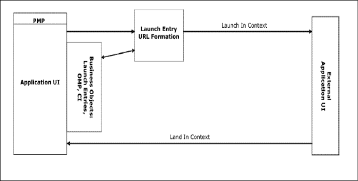
Chapter 2. Integration components 43
Integration Framework for UI integration
The Integration Framework provides a mechanism for you to launch from a
system application UI to an external application UI. You can define the context to
facilitate the landing into your wanted external application interface. For example,
you can configure in the system to launch and to display a specific part number in
an external application. The Integration Framework supports URL substitutions
of any values (part number) of any system business object.
You can use OMP-specific features when you launch to an OMP application UI.
Features include retrieving the registered host name of the OMP and a CI Source
token for the OMP. Refer to Figure 2-14.
You also can launch into a system UI from an external application (Land in
Context).
Figure 2-14 Integration Framework for UI
2.4.3 Integration Framework components
This section describes individual Integration Framework components and
features. Familiarity with framework components is essential when using the
Integration Framework application. The following components are described in
this section:
Object structures
Publish Channels
Invocation channels
Enterprise Services
Web services library

44 Integration Guide for IBM Tivoli Service Request Manager V7.1
Endpoints
External systems
LMO
Integration modules
Launch in context
Message tracking
Message reprocessing
Object structures
An object structure (OS) is the common data layer that the Integration
Framework uses for all outbound and inbound application data processing. An
OS consists of one or more business objects that make up the content of an XML
message. You can use the message content of a single OS to support
bidirectional inbound and outbound messages.
An OS can have the same object more than one time in its definition. Objects
must have a reference to a valid parent/child relationship within the system. The
OS has a Definition Class (Java) that you can code to perform logic, such as
filtering for outbound messages. For inbound messages, you can use an OS
Processing Class (Java) to invoke specific business object logic. The logic is
beyond the normal insert, update, and delete Integration Framework processing.
The OS is the building block of the Integration Framework that lets integration
applications perform the following functions:
Publish and query application data
Add, update, and delete application data
Import and export application data
In addition to being a building block, you can use the OS as a service to support
inbound message processing. You can invoke the OS service as a Web service,
as an EJB, or through HTTP. The object structure service supports system data
updates, as well as data queries outside of the system. Refer to Figure 2-15 on
page 45.
Note: Several components are specific, depending on your integration type,
such as Integration Framework for data exchange, OMPs (OPMs), and UI.
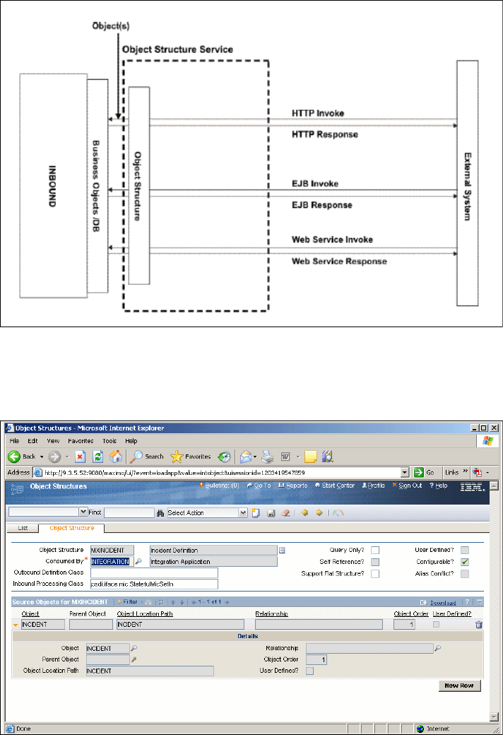
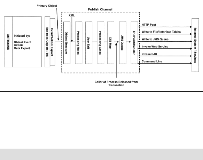
46 Integration Guide for IBM Tivoli Service Request Manager V7.1
Publish channels
A publish channel is the pipeline for sending data asynchronously from the
system to an external system. Refer to Figure 2-17.
The following events trigger publish channel processing:
Object events (insert, update, and delete)
Application-initiated calls
Workflow calls
Data export
Figure 2-17 Publish channel
The content of a publish channel data structure is based on the associated object
structure. When you trigger publish channel processing, the Integration
Framework builds the XML message based on the object structure. The system
then moves the message through multiple processing layers before dropping the
message into a queue and releasing the initiator of the transaction.
The processing layers are:
Processing rules Use the Integration Framework rule engine to filter and
transform XML messages. You can also implement rules
through the publish channel application.
User exit Use to filter and transform data and implement business
logic. You can use this class as part of an installation or
customization process.
Note: Each processing layer is optional.
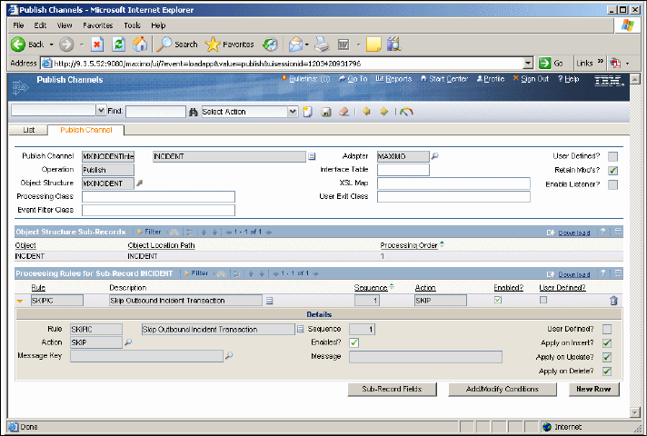
Chapter 2. Integration components 47
Processing class Is a Java class that is used to filter and transform data and
implement business logic. Oracle and SAP Adapters
provide processing classes to support product integration.
XSL map Is an XSLT style sheet that is used to transform data and
map the XML message to another format.
When the system drops the message into the queue, a polling thread (system
cron task) picks up the message and sends it to an external system through the
endpoint. The endpoint identifies the protocol that the system uses to send data,
such as HTTP or Web service. The endpoint also identifies the property values
that are specific to that endpoint, such as the URL, user name, and password.
To access the Publish Channel application (Figure 2-18), select Go →
Integration → Publish Channel.
Figure 2-18 Publish channel interface
Invocation channels
A service-oriented architecture (SOA) environment enables the use of external
services to process data from multiple sources. Invocation channels support this
generic SOA capability by enabling the system to call an external service
synchronously. The system also returns the response of the service back to the
caller for subsequent processing.
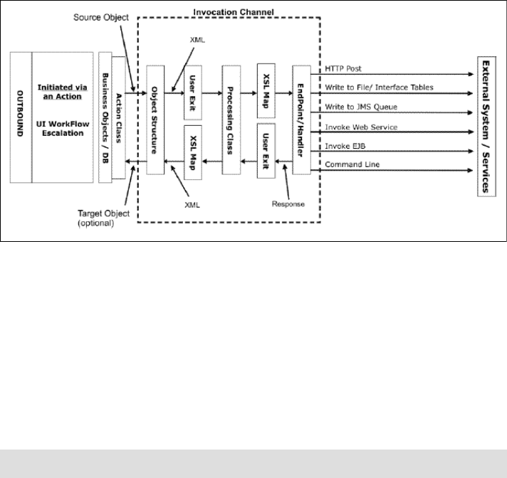
48 Integration Guide for IBM Tivoli Service Request Manager V7.1
For example, you can use an external system to calculate a tax amount for a
product that you are purchasing. Configure an invocation channel to call the
external tax service. The channel takes the returned tax amount and saves the
value in the system database.
The initiation of an invocation channel is implemented through an action class
that calls an invocation channel. Refer to Figure 2-19. You can implement an
action through the following means:
A user interface control (within an application)
Workflow routing
Escalation
Figure 2-19 Invocation channel
You can only initiate an invocation channel through an action class. The system
call is synchronous (no JMS queue), and a response can be returned from the
service to the caller.
The content of an invocation channel data structure is based on the associated
object structure. When you trigger invocation channel processing, the Integration
Framework builds the XML message based on the object structure. The system
then moves the message through multiple processing layers (optional) before
calling the external service.
Note: Each processing layer is optional.
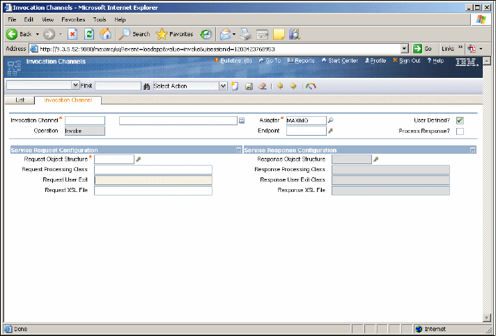
Chapter 2. Integration components 49
The processing layers are:
User exit Is used to filter and transform data and implement
business logic. You can use this class as part of an
installation or customization process.
Processing class Is a Java class used to filter and transform data and
implement business logic. Oracle and SAP Adapters
provide processing classes to support product integration.
XSL map Is an XSLT style sheet that is used to transform data and
map the XML message to another format.
After the message goes through the processing layers, the Integration
Framework uses the endpoint to call the external service. The endpoint identifies
the protocol that the system uses to send data, such as HTTP or Web service.
The endpoint also identifies the property values that are specific to that endpoint,
such as the URL, user name, and password.
To access the Invocation Channel application (Figure 2-20), select Go →
Integration → Invocation Channel.
Figure 2-20 Invocation channel interface
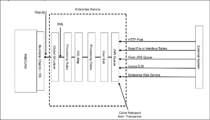
50 Integration Guide for IBM Tivoli Service Request Manager V7.1
Enterprise service
The enterprise service is a pipeline for querying system data and importing data
into the system from an external system. You can configure the enterprise
service to process data synchronously (no queue) or asynchronously (through a
queue as shown in Figure 2-21). The enterprise service can use multiple
protocols, such as Web services and HTTP.
Figure 2-21 Asynchronous Enterprise Services
The synchronous enterprise service processes data without a queue, as shown
in Figure 2-22 on page 51.
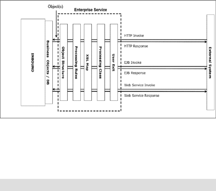
Chapter 2. Integration components 51
Figure 2-22 Synchronous Enterprise Services
The enterprise service has processing layers to transform data and to apply
business processing rules before the data reaches the system objects. The
Integration Framework builds the XML message based on the object structure.
The XML message must be in the format of the object structure so the system
can process it successfully.
The processing layers are:
Processing rules Use the Integration Framework rule engine to filter and
transform XML messages.
User exit Use to filter and transform data and and implement
business logic. You can use this class as part of an
installation or customization process.
Processing class Is a Java class that is used to filter and transform data and
implement business logic. Oracle and SAP Adapters
provide processing classes to support product integration.
XSL map Is an XSLT style sheet that is used to transform data and
map the XML message to another format.
To access the Enterprise Services application, (Figure 2-23 on page 52), select
Go → Integration → Enterprise Services.
Note: Each processing layer is optional.
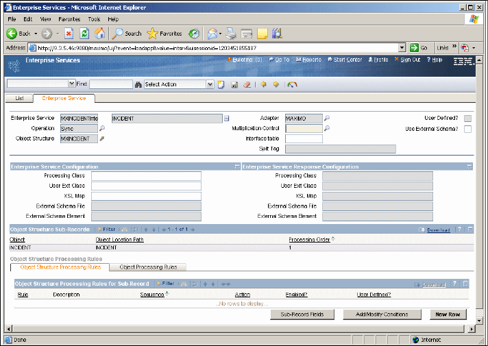
52 Integration Guide for IBM Tivoli Service Request Manager V7.1
Figure 2-23 Enterprise Services interface
Web Services Library
External applications, Enterprise Service Bus (ESB), and Business Process
Execution Language (BPEL) processes use Web services to query or send
transactions to the Integration Framework. The Integration Framework provides
three types of Web services:
Object structure service
Enterprise service
Standard service
You can invoke these services as an EJB or HTTP.
When deploying Web services, the system generates a schema and Web
services description language (WSDL) file that you can access through a URL.
Optionally, a Universal Description, Discovery, and Integration (UDDI) registry is
updated for each deployed service.
Chapter 2. Integration components 53
The Integration Framework supports the following Web services:
Object Structure Web service: Created from an object structure. Object
structure Web services do not provide a processing layer that is available to
Enterprise Services. An object structure Web service supports five operations
through its WSDL:
–Create
–Delete
– Query
– Sync
– Update
Enterprise Web service: Created from an enterprise service. Enterprise
Services provide exit processing and optional JMS support. The Integration
Framework creates individual enterprise Web services for the operation
defined in an enterprise service (one operation per service). The operations
supported in an object structure service are also supported in an enterprise
Web service. You can deploy an enterprise Web service to use a JMS queue
(asynchronous process) or to bypass the JMS queue (synchronous process).
Standard Web service: Created from methods defined in application services.
The methods must be annotated in the application service to be available for
Web service implementation. The Integration Framework links the input and
output parameters of the methods to the WSDL operations.
To access the Web services library application (Figure 2-24 on page 54), select
Go → Integration → Web Services Library.
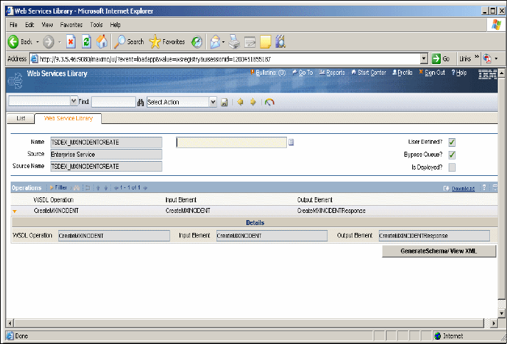
54 Integration Guide for IBM Tivoli Service Request Manager V7.1
Figure 2-24 Web services library interface
Endpoints
Endpoints and their handlers facilitate the routing of outbound messages from
the outbound JMS queue to its destination or from an invocation channel directly
to its destination. The endpoint and handler combination contains the protocol
client and the necessary data to identify the specifics of communicating with that
destination, such as a URL.
The outbound queue cron task process or invocation channel invokes the
handler and passes the message body and the metadata properties to it. The
handler uses the metadata properties to determine the external system (for a
publish channel message only) and override values for the configured endpoint
properties. The handler then sends the data to the destination specified by the
endpoint with which the handler is associated (Table 2-3 on page 55).
An endpoint represents an application component to which the system delivers
outbound transactions. The system provides the following predefined endpoints.

Chapter 2. Integration components 55
Table 2-3 Predefined endpoints
The configuration of an endpoint involves the definition of the endpoint, the
association of a handler to the endpoint, and setting the handler properties, if
any, for that endpoint.
An endpoint is an instance of a handler with specific properties that the handler
needs in order to connect and send outbound data.
You can use the predefined handlers or create new handlers that enable physical
entities, such as File Transfer Protocol (FTP) servers, for which predefined
handlers do not exist. You must define the handler before you define the
endpoint. You configure endpoints and handlers in the Endpoints application.
To access the Endpoints application (Figure 2-25 on page 56), select Go →
Integration → EndPoint.
Endpoint Handler Description
MXFLATFILE FLATFILE Writes flat files to a
previously specified
directory location
MXIFACETABLE IFACETABLE Writes outbound
transactions to local
interface tables
MXXMLFILE XMLFILE Writes XML files to a
previously specified
directory location
MXCMDLINE CMDLINE Implements the CMDL
handler, takes a command
and an endpoint as input,
and uses the SSH protocol
to securely invoke the
command on the target
system and return the
results
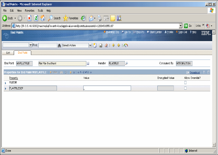
56 Integration Guide for IBM Tivoli Service Request Manager V7.1
Figure 2-25 Endpoints interface
Handlers
In this section, we describe the predefined handlers and their required and
optional properties. The system provides the following predefined handler types,
which you can access through the Select Action menu in the Endpoints
application:
EJB
FLATFILE
HTTP
IFACETABLE
JMS
WEBSERVICE
XMLFILE
CMDLINE

Chapter 2. Integration components 57
The EJB handler is a Java component that delivers system data (Table 2-4) to an
EJB executing on the local application server or on a remote application server.
Table 2-4 shows the EJB handler’s properties.
Table 2-4 EJB handler properties
Note: If the EJB is on a remote application server, the remote and home
classes of the EJB must be available on the local application server. For more
information, refer to the documentation for your application server.
Property Description
CONTEXTFACTORY This required property specifies a Java
Two Platform, Enterprise Edition (J2EE™)
context. Refer to the documentation for
your application server for the name of the
default context factory.
EJBEXIT Property This optional property is used for
customization. It specifies the fully
qualified name of a custom Java class that
implements the EJBExit interface. If you
do not specify a value for this property, the
system executes the default exit,
DefaultEJBExit, which attempts to resolve
the EJB’s method signature and
parameters.
JNDINAME This required property specifies the name
by which the EJB is registered in the
application server Java Naming and
Directory Interface (JNDI) tree.
METHODNAME This required property specifies the public
business method exposed by the EJB that
is invoked through this handler.
PROVIDERURL This required property specifies the URL
that provides access to the EJB
component.
USERNAME and PASSWORD If access to the EJB requires a user name
and password, these properties specify
those values. The user name must match
the value that was configured during the
definition of Users and Groups in the
application server.

58 Integration Guide for IBM Tivoli Service Request Manager V7.1
The FLATFILE handler converts outbound data from the queue into a flat file
and writes it to a directory whose location is configurable. Flat files contain ASCII
data in the form of rows and columns. Each line of text constitutes one row, and a
separator separates each column in the row.
The FLATFILE handler encodes outbound flat files in the standard UTF-8 format,
and the Data Import mechanism assumes that inbound flat files are encoded in
UTF-8 format.
The FLATFILE handler naming convention is:
File names have the following format:
externalsystemname_publishchannelname_uniqueidentifier.DAT
where:
–externalsystemname is the identifier of the system (the value of
MAXVARS.MXSYSID).
–publishchannelname is the name of the publish channel.
–uniqueidentifier is a number based on the current system time.
The FLATFILE handler (Table 2-5) has the following properties.
Table 2-5 FLATFILE handler properties
Note: You can only use the FLATFILE handler with Publish Channels, not
Invocation Channels.
Property Description
FLATFILEDIR This required property specifies the
location of the flat file. The location must
already exist on the local machine where
the application server is executing or on a
shared network drive.
FLATFILESEP This required property specifies the
character that separates the columns in
each row.

Chapter 2. Integration components 59
The HTTP handler is a Java component that delivers data (Table 2-6) as an XML
document to a URL using HTTP or HTTPS protocols and evaluates the response
code received from the external system.
The HTTP handler has the following properties.
Table 2-6 HTTP handler properties
Property Description
HTTPEXIT This optional property is used for
customization. It specifies the fully
qualified name of a Java class that
interprets the HTTP response. An external
system might require additional code to
interpret the HTTP response, and this exit
lets users implement the necessary code.
The Java class must be available in the
classpath specified for the application
server or the application enterprise
archive (EAR) file.
URL This optional property specifies a valid
URL to which XML data can be posted. It
is expected that a response is generated
whenever an HTTP POST is performed
upon this URL.
USERNAME and PASSWORD If the URL requests basic authorization,
these properties specify the required
values. The system encodes both values
and passes them to the URL. For more
information about basic authorization for
HTTP, refer to the documentation for your
HTTP server.
CONNECTTIMEOUT This optional property specifies the
connection timeout value in milliseconds.
READTIMEOUT This optional property specifies the read
timeout value in milliseconds.
HTTPMETHOD This optional property specifies the HTTP
method to use. The allowed values are
POST and GET, and the value defaults to
POST if no value is specified.

60 Integration Guide for IBM Tivoli Service Request Manager V7.1
The IFACETABLE handler writes data from an outbound queue to an interface
table in a local or remote database. There are no Java exits (Table 2-7) for this
handler. The IFACETABLE handler has the following properties.
Table 2-7 IFACETABLE handler properties
Property Description
ISREMOTE This required property specifies if
interface tables are available in the local
system database in the system schema or
in a different schema. Its value can be 0
(zero) or 1.
A value of 0 (false) indicates that the
interface tables are available in the local
system database in the system schema.
You do not have to enter any other
handler properties. For the predefined
MAXIFACETABLE handler, the value of
this property is 0.
A value of 1 (true) indicates that the
interface tables are in a remote database.
If so, you must specify the values for all of
the handler properties.
DRIVER This property specifies the JDBC driver to
be used to connect to a remote database
containing the interface tables. This
property applies only when the value of
ISREMOTE is 1.
URL This property specifies the JDBC URL that
indicates the location, port number, and
database name. This property applies
only when the value of ISREMOTE is 1.
For example:
jdbc:db2://mea6:5000/MERLIN
USERNAME and PASSWORD If access to the database instance
requires a user name and password,
these properties specify those values.
These properties apply only when the
value of ISREMOTE is 1.

Chapter 2. Integration components 61
The JMS handler is a Java component that delivers XML data into a messaging
system that has been enabled through JMS. Depending on the messaging model
that you implement, messages are placed in a virtual channel called a queue or
topic.
In the point-to-point messaging model, messages are generated by a sender and
placed in a queue. Only one receiver can obtain the message from the queue. In
the publish-subscribe messaging model, messages are generated by a publisher
and placed in a topic. Multiple subscribers can retrieve the message from the
topic. The messaging system that is discussed in this section represents a queue
or topic that is available in the local application server, a remote application
server, or a remote dedicated queuing system, such as IBM MQSeries®. To use
this handler, all of these messaging systems must be enabled through JMS
(Table 2-8 on page 62).
For more information, refer to the documentation for the application server.
The JMS handler has the following properties.
Note: The messaging system that is discussed in this section is distinct from
the standard internal queues used by the system. The standard internal
queues reside in the local application server where the system is executing.

62 Integration Guide for IBM Tivoli Service Request Manager V7.1
Table 2-8 JMS handler properties
Property Description
CONFACTORYJNDINAME This required property specifies a Java
object that is used to manufacture
connections to a Java Message Server
provider. Before directly connecting to a
queue or topic, the system must first
obtain a reference to a queue or topic
connection factory. Application servers
usually provide a default connection
factory. However, implementing your own
connection factory lets you tune the
resource attributes and properties to suit
your implementation. In this case, use the
following value for this property:
jms/mro/int/qcf/intqcf
DESTINATIONTYPE This required property specifies the JMS
entity (queue or topic) to which the
message is delivered.
DESTJNDINAME This required property specifies the name
by which the JMS queue or topic is
registered in the application server’s Java
Naming and Directory Interface (JNDI)
tree.
CONTEXTFACTORY This required property specifies a J2EE
context. Refer to the documentation for
your application server for the name of the
default context factory.
ISCOMPRESS This required property specifies whether
the message is compressed before being
placed into a queue or topic.
Compression is an optimization
technique that delivers smaller messages
to a queue or topic.
Note: Compressed messages must be
decompressed after receipt. Decompress
the messages by creating the appropriate
JMS receiver or subscriber component
and placing Java decompression logic
within the receiver or subscriber. Use the
standard Java Inflater() class that is part of
the java.util.zip package. The
system-provided compression uses the
standard Java Deflator() class.

Chapter 2. Integration components 63
JMSEXIT This optional property is used for
customization. It specifies the fully
qualified name of a Java class that
extends the JMSExit interface. The Java
class must implement the
getMessageProperties() method that is
defined in the JMSExit interface.
This option lets you change or add header
information in the JMS message. If this
property does not contain a value, the
header attributes for the message are not
changed when the message is delivered
to the external queue or topic.
PROVIDERURL This required property specifies a local or
remote URL where the JMS component
can be accessed. It can be local or
remote.
PROVIDERPASSWORD If the application server controls access to
the JMS resource, these properties
specify the user name and password that
are needed to connect to the resource.
USERNAME and PASSWORD If the application server controls access to
the JMS resource, these properties
specify the user name and password
needed to connect to the resource. The
user name must match the value
configured during the definition of Users
and Groups in the application server.
For more information, refer to the
documentation for your application server.
Property Description

64 Integration Guide for IBM Tivoli Service Request Manager V7.1
The WEBSERVICE handler is a Java component that invokes a specified Web
service with system data as a SOAP request parameter. This handler is a
Dynamic Invocation Interface (DII) using the JAX-RPC API. It supports a
document-literal type Web service.
The Webservice handler has the properties that are listed in Table 2-9.
Table 2-9 WEBSERVICE handler properties
Property Description
ENDPOINTURL This required property specifies a valid
Web service URL on which to invoke the
document-literal style Web service. You
can use the WSEXIT class to override the
endpoint URL just before the Web service
is invoked.
SERVICENAME This optional property specifies the name
of the Web service deployed in the URL. If
you do not provide a value, the system
uses the interface name in the XML. You
can use the WSEXIT class to override the
service name just before the Web service
is invoked.
SOAPACTION This optional property specifies the value
of the SOAPAction HTTP header to be
used while invoking the Web service. If
you do not provide a value, the system
uses the default value (an empty string).
You can use the WSEXIT class to override
the value that is specified in the user
interface just before the Web service is
invoked.
USERNAME and PASSWORD If the specified Web service is secured
(that is, if HTTP basic authentication is
enabled), specify a user name and
password. The system encodes the
password.
WSEXIT This optional property is used for
customization. It specifies the fully
qualified name of a custom Java class that
implements the psdi.iface.router.WSExit
interface.

Chapter 2. Integration components 65
HTTPCONNTIMEOUT This optional property specifies the
connection timeout value in milliseconds.
If nothing is set, the default value is 60000
milliseconds.
HTTPREADTIMEOUT This optional property specifies the read
timeout value in milliseconds. If nothing is
set, the default value is 60000
milliseconds.
CFGXMLPATH This property specifies the path to the
configuration XML file.
MEP This optional property specifies the
message exchange pattern for the Web
service. Valid values are fireandforget,
sendreceive, sendrobust, and null. If you
do not provide a value, the system uses
the default value sendreceive:
sendreceive - Request/Response
sendrobust - Request with void or
fault response
fireandforget - Request only. No
response or fault.
HTTPVERSION This optional property specifies the
version of the HTTP protocol to be used
for the Web service invocation. The valid
values are "HTTP/1.0" and "HTTP/1.1". If
no value is specified, it defaults to
"HTTP/1.1".
Property Description

66 Integration Guide for IBM Tivoli Service Request Manager V7.1
The XMLFILE handler is a Java component that converts data in the outbound
queue into an XML file format and then delivers it to the xmlfiles directory within
the global directory. You define the global directory (Table 2-10) through the
mxe.int.globaldir property in the System Configuration application.
Table 2-10 XMLFILE handler properties
File names have the following format:
externalsystemname_publishchannelname_uniqueidentifier.xml (for publish
channel)
invocationchannelname_uniqueidentifier.xml (for publish channel)
where:
–externalsystemname is the identifier of the system (the value of
MAXVARS.MXSYSID).
–publishchannelname is the name of the publish channel.
–invocationchannelname is the name of the invocation channel.
–uniqueidentifier is a number based on the current system time.
The CMDLINE handler is a handler that takes a command and an endpoint as
input. The CMDLINE uses the SSH protocol to securely invoke the command on
the target system and return the results.
The metaData parameter passed during the invocation of the handler is a map
that contains, among other things, the name of the endpoint that represents the
target system. Passing the endpoint to the Command Handler allows the caller to
Property Description
PRETTYPRINT This required property specifies whether
the handler “pretty prints” the XML file.
The valid values are 0 and 1. A value of 1
indicates for the handler to pretty print the
xml file.
FILEDIR This optional property specifies the folder
location where the handler creates XML
files. If no value is specified, the handler
defaults this property to the value of
<mxe.int.globaldir>/xmlfiles. You define
the global directory through the
mxe.int.globaldir property in the System
Configuration application.

Chapter 2. Integration components 67
target any system at run time, using whatever configuration exists for that
endpoint at the time of invocation.
Table 2-11 shows the CMDLINE handler properties.
Table 2-11 CMDLINE handler properties
The data parameter is a byte array representation of an XML document that
contains tags corresponding to the setup command, the working directory, the
command to invoke, and any substitution parameters.
Table 2-12 on page 68 shows the tags.
Property Description
CMDTIMEOUT Timeout value for command execution
CONNTIMEOUT Timeout value for connection
USERNAME User name for connection
PASSWORD Password for corresponding user name
HOST Host name of target where command is to
be executed
PORTNO Port number of target where command is
to be executed
IGNORESETUPERR Boolean to ignore an error executing the
Setup command
RETRYINTERVAL Time to wait before retrying a command
MAXRETRY Number of attempts to execute a
command before returning an exception
SSHEXIT A Java exit class that can be implemented
to customize processing of the handler

68 Integration Guide for IBM Tivoli Service Request Manager V7.1
Table 2-12 Tags
The return byte array representation of an XML document contains the results of
the command invocation. It contains tags corresponding to the return values:
STDOUT and STDERR.
Table 2-13 on page 69 shows the return value tags.
Tag Description
CLWORKINGDIR A directory to which to change (cd) on the
remote system before the command is
invoked. If this tag is nonexistent or
empty, no directory change is performed.
CLSSETUPCMD A setup command is to be invoked prior to
the main command. This tag is provided
to allow for any environmental setup that
must occur on the remote system before
the main command is issued. If this tag is
nonexistent or empty, no setup command
is issued.
CLCMDPATTERN A string that defines the pattern of the
command to be invoked. The format of
this pattern is similar to that used by the
java.text.MessageFormat class. An
example is “ls -l {0}”, where {0} represents
a parameter that is substituted.
CLSUB0 The value that is to be substituted into
positions marked by {0} in the
CLCMDPATTERN.
CLSUB1 The value that is to be substituted into
positions marked by {1} in the
CLCMDPATTERN.
CLSUBnThe value that is to be substituted into
positions marked by {n} in the
CLCMDPATTERN. In general, there must
be a CLSUBn corresponding to each
substitution position in the
CLCMDPATTERN.

Chapter 2. Integration components 69
Table 2-13 Return value tags
External systems
Any business application that sends data to the system or receives data from the
system is an external system. External systems let you synchronize external data
through an endpoint (location) and internal data through an external source.
You can use the External Systems application to perform the following functions:
Name the external applications or systems that exchange data with the
Integration Framework
Specify how the Integration Framework exchanges data with the defined
systems
Identify the specific Publish Channels and Enterprise Services process
between the Integration Framework and each system
Create interface tables
To create an external system, you specify an end point, queues, and integration
control values in the external system record. You also can define the properties
on the external system.
The endpoint identifies how and where the Integration Framework exchanges
data with the system:
The JMS queues that the system uses.
Whether the external system is ready to begin integration processing.
The Integration Framework can exchange data with one or more external
systems.
To access the External Systems application (Figure 2-26 on page 70), select
Go → Integration → External Systems.
Tag Description
CLRETURNCODE The return code from the remote
command
CLRESPONSEOUT The data returned by the remote
command in stdout
CLRESPONSEERR The data returned by the remote
command in stderr
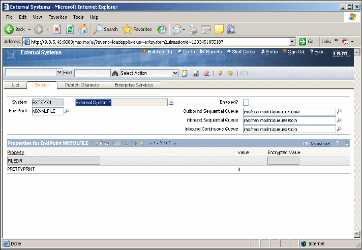
70 Integration Guide for IBM Tivoli Service Request Manager V7.1
Figure 2-26 External systems interface
Logical Management Operations
Logical Management Operations (LMOs) define an action, such as Get Status or
Deploy Software. LMOs identify actions that integration modules (IMs) support
and for PMPs to request. The LMO acts as an interface between the PMP and
IM; you can design and develop these entities to be independent of each other.
The LMO defines the action and the data, which is required to support that
action. You can install an LMO definition with the installation of an IM. You also
can define an LMO definition using the LMO application. The LMO definition
includes:
Name: Name of the action
Invocation Pattern
There are four types of invocation patterns:
– Synchronous: The PMP issues a request, and the IM returns the results of
the operation.
– Asynchronous one-way: The PMP issues a request, and there is no
response.
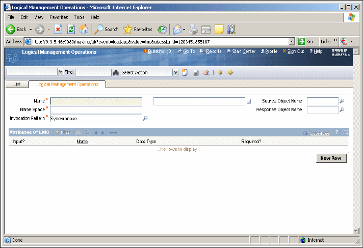
Chapter 2. Integration components 71
– Asynchronous deferred response: The PMP issues a request, and the IM
returns a token that the PMP can pass as input on another LMO. The PMP
passes the token at a later time to obtain the status of the original action.
– Asynchronous call back: The PMP issues a request, and the IM returns an
optional token that the target uses to report the results of the request. A
call back by the OMP to the PMP, possibly using the IM, can insert or
update a business object using the token.
Source Business Object: Input object for the LMO
Response Business Object: Output object for the LMO
Business Object Attributes: Specific attributes of the objects that are needed
either for input or output and their data types
To access the LMO application (Figure 2-27), select Go → Integration →
Logical Management Operations.
Figure 2-27 LMO interface
Integration modules
You can create integration modules (IMs) to assist PMP processes in
automating actions. You implement actions, such as Deploy Software, using the
Tivoli Provisioning Manager (TPM) OMP. An IM can support multiple LMOs for an
72 Integration Guide for IBM Tivoli Service Request Manager V7.1
OMP. You can configure and view your installed IM definitions in the Integration
Modules application.
IM processing is responsible for converting the LMO into the OMP-specific
interface. If the system returns a response to the IM, it converts the response to
an OMP response. The OMP response then returns data that is defined by the
LMO.
Typically, there is a one-to-one correspondence between an LMO and an OMP
function. However, your single LMO invocation can result in one or more IM
functions being invoked on an OMP.
You can implement an IM through a Java class or an invocation channel. The
underlying IM implementation (Java class or Invocation Channel) is transparent
to the PMP.
The IM definition includes:
The LMOs supported by the IM
The OMP products that the IM supports, including specific LMOs supported
for specific IMs
Optional properties that you can configure as part of an implementation to
control IM behavior
IM implementation as either a Java class or an invocation channel
To access the Integration Modules application (Figure 2-28 on page 73), select
Go → Integration → Integration Modules.
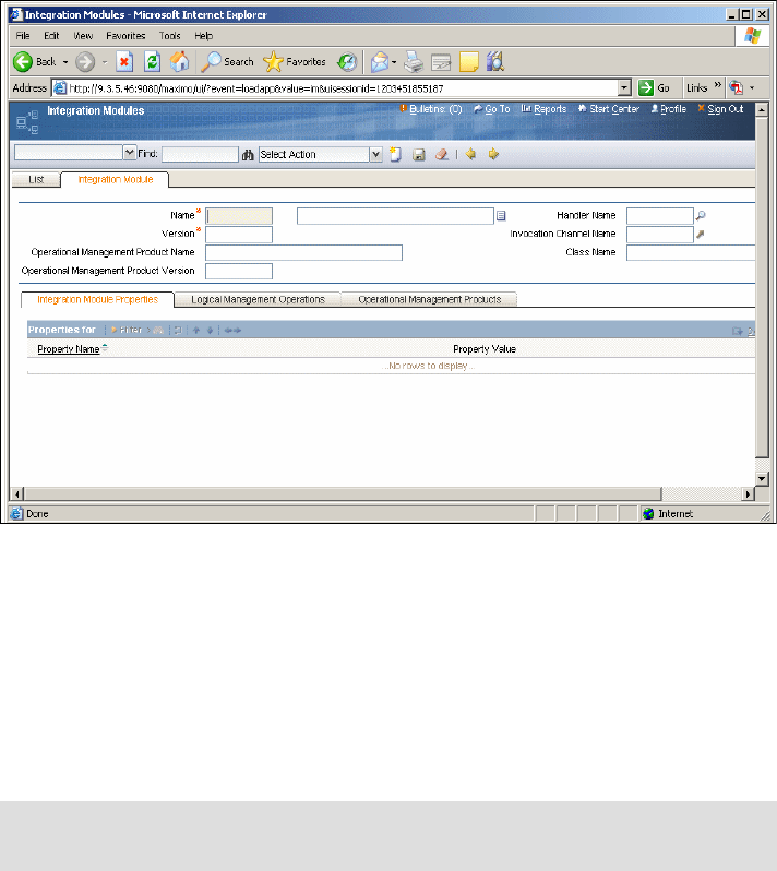
Chapter 2. Integration components 73
Figure 2-28 Integration modules interface
Launch in Context
In certain cases, your PMP integration to an OMP might not use an automated
solution through an IM. Instead, your integration can use an assisted approach
through a Launch in Context (LIC). Using an assisted approach lets you
navigate from a PMP application UI to an application UI of the OMP. The context
represents the data that you pass from the PMP, such as the software identifier
and the CI for which the software deployment applies.
A LIC requires:
Configuration of a PMP application to have a UI control that is tied to a
registered launch entry (push button or Select Action menu items)
A proper security assigned to it (limit users’ and user groups’ access to the
control)
Registered launch entries that are configured to the applicable OMP
applications
Note: Although this discussion is specific to OMP launches, LIC capabilities
can apply to any external application launch.

74 Integration Guide for IBM Tivoli Service Request Manager V7.1
Launch entry definitions include:
The OMP product that the launch can support
The URL of the OMP product application
Whether the launch opens a new browser session or uses the existing
window
The business objects to which the launch entry is specific (optional)
The classifications supported by the launch entry
The LIC provides additional capabilities:
The URL can contain substitution variables that use data from the business
object that you view in the application. For example, you can substitute a CI
number into the URL string. Your substitution can take place only if the OMP
application URL supports your substitution value. You can use this feature
when you launch into any application, not just OMPs.
Specific to OMP integration, you can substitute a host name instance from the
registered OMP data within the system.
Specific to OMP integration for a CI, you can retrieve the source token of the
CI for the specific OMP. The source token is the CI identifier that the OMP
product understands. If managed by multiple OMPs, a CI might have multiple
source tokens.
To access the Launch in Context application (Figure 2-29 on page 75), select
Go → Integration → Launch in Context.
Note: A launch entry might support a single or multiple business objects.
Note: For business objects that support classifications, this requirement
can limit your URL access to the data that contains the same classification
that you configured on the launch entry. For example, a launch entry that
has a classification value of “Server” is available to you in the CI
application if the CI that you view has a classification value of “Server.”
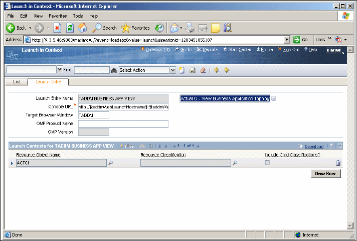
Chapter 2. Integration components 75
Figure 2-29 Launch in Context interface
Message tracking
In this section, we discuss how the Integration Framework tracks messages while
processing publish channels (outbound messages) and enterprise services
(inbound messages) and how system administrators work with the displayed
messages. It contains the following subsections:
Message details
Message tracking configuration
Message statuses
Message events
Message details
The Message Tracking application tracks and displays the processing history of
queue-based inbound (Enterprise Services) and queue-based outbound (Publish
Channels) messages.
The Message Tracking application works with the Message Reprocessing
application. Through the Message Tracking application, you can determine which
messages are flagged with an error. You then can select a specific failed
message and get redirected to the Message Reprocessing application to take
appropriate action to correct erroneous data.

76 Integration Guide for IBM Tivoli Service Request Manager V7.1
When you enable message tracking, the Integration Framework writes all
processed messages to the MAXINTMSGTRK table. The system assigns a
status to each message, which represents its current position in the Integration
Framework queue-based processing cycle. The system also displays individual
message events in the Message Details table window.
Table 2-14 shows the values that are assigned to the noted attributes based on
the originating enterprise service or publish channel.
Table 2-14 Predefined attributes
Table 2-15 shows the values that are assigned to the noted attributes at the time
that the transaction record is created.
Table 2-15 Assigned attributes
Attribute Description
Integration Mode Name of the integration mode that is used
in processing the message. For inbound
messages, the system assigns a MXJMS
default value. For outbound messages,
the system assigns the name of the
endpoint used in processing the message.
Operation Operation value that determines the
processing operation that the system
applies to the message (publish).
System External system value.
Integration Component Name of enterprise service or publish
channel.
Adapter Adapter name.
Queue Name Name of queue that is used by the
Integration Framework to process the
message.
Attribute Description
Received Datetime The date and time that the message is
received in the queue
External Message ID Unique message identifier that is assigned
by an external application
Search ID Unique message identifier that the
Integration Framework assigns

Chapter 2. Integration components 77
Table 2-16 shows the values that are assigned to the attributes that are dynamic
and the changes based on the transaction events.
Table 2-16 Dynamic attributes
Message tracking configuration
You can maintain a record of processing actions that are associated with publish
channels or enterprise services. The Message Tracking action in the Publish
Channels and Enterprise Services applications lets you track transactions and
perform the following functions:
Enable or disable transaction tracking
Store transaction messages on the application file server
Identify data that is used by the Message Tracking application search function
Identify transactions by a unique ID value through an XPATH expression
Identify XPATH expressions to let you search for a message
For the enable or disable transaction tracking function, you can maintain a record
of processing actions that are associated with an enterprise service or a publish
channel. To do so, select the Enable Message Tracking? check box in the
Message Tracking dialog box. You access the Message Tracking dialog box from
the Select Action menu in the Publish Channels and Enterprise Services
applications.
In the Message Tracking application, you can use the External Message ID
attribute to locate specific messages. In order to do so, an XPATH expression
must be entered in the External Message ID field in the Message Tracking dialog
box. You can set this value in the Publish Channels and Enterprise Services
applications. The syntax that you use to identify the node values must be a fully
qualified XPATH expression.
Attribute Description
Current status Most current processing status that is
associated with the tracked message
Status The status that is associated with the
individual message event in the
transaction history
Status date The status date that is associated with the
individual message event in the
transaction history
Error The error message that is associated with
the individual error message event in the
transaction history
78 Integration Guide for IBM Tivoli Service Request Manager V7.1
The Message Tracking action allows you to use an XPATH expression to specify
the location of your message identifier in the inbound XML. The Integration
Framework assigns an internal message identifier to guarantee uniqueness in
the messages that are being tracked. The system stores the external message
identifier as the EXTMSGIDFIELDDATA attribute in the MAXINTMSGTRK table.
In the event of receiving a multi-noun inbound message, the Integration
Framework uses the enterprise service External Message ID XPATH as the
identifier of the message. If the path expression points to an element included in
each one of the nouns in the inbound message, the Integration Framework
creates a multi-noun, comma-separated list of external identifiers.
Through the Advanced Search dialog box in the Message Tracking application,
you can use the Search ID attribute to locate specific messages. In order to do
so, an XPATH expression must be entered in the Search ID field in the Message
Tracking dialog box. You can set this value in the Publish Channels and
Enterprise Services applications. The syntax that you use to identify the node
values must be a fully qualified XPATH expression.
The Message Tracking action allows you to use an XPATH expression to specify
the location of an identifier in the inbound XML transaction. The XPATH
expression enables you to perform efficient record searches. The system stores
the search identifier in the SEARCHFIELDDATA field in the MAXINTMSGTRK
table.
In the event of receiving a multi-noun inbound message, the Integration
Framework uses the enterprise service Search ID XPATH as the search identifier
of the message. If the path expression points to an element included in each one
of the nouns in the inbound message, the Integration Framework creates a
multi-noun, comma-separated list of search identifiers.
You can store the original message that you receive from an enterprise service or
a publish channel definition. To store messages, select the Store Message?
check box in the Message Tracking dialog box. You access the Message Tracking
dialog box in the Select Action menu in the Publish Channels and Enterprise
Services applications.
The system stores files in the msgdata folder in the system global directory. You
define the global directory location in the mxe.int.globaldir system property, in the
System Properties application.
The naming convention of the stored messages is:
ExternalSystemName_IntegrationComponent_UniqueId.xml.

Chapter 2. Integration components 79
Message status
Every inbound and outbound queue-based message, which is registered in the
Message Tracking application, has a status value that indicates its position in the
transaction processing cycle (Table 2-17). The message tracking designated
status indicates whether the message has been successfully received or
processed. The message tracking designated status also indicates whether the
message has been deleted or flagged with errors.
Table 2-17 Inbound message status
Table 2-18 shows the outbound message status.
Table 2-18 Outbound message status
Message events
The Message Tracking application tracks and displays inbound and outbound
queue-based transaction processing events. Transaction processing events
trigger the system to update the MAXINTMSGTRK table. The system updates
the following message table attributes, according to event type:
STATUS
STATUDATETIME
ERRORMSGR
Status Description
Error Message processing failed due to
validation issues.
Deleted Message is deleted from the queue.
Processed Message is successfully processed.
Received Message is successfully written to the
inbound queue.
Status Description
Error Message processing failed due to
validation issues.
Deleted Message is deleted from the queue.
Processed Message is successfully processed.
Received Message is successfully written to the
inbound queue.
80 Integration Guide for IBM Tivoli Service Request Manager V7.1
Tracking inbound and outbound events
The following inbound and outbound events cause the system to update the
MAXINTMSGTRK table:
Message Written to Queue: The system creates a record in the message
tracking table when the Integration Framework first writes the message to the
queue. When the Integration Framework successfully writes the message to
the queue, the system sets the message record status to RECEIVED.
If the Integration Framework encounters an error when writing an inbound
message to the queue, it replies to the process caller with a message
detailing the cause of failure.
Error in Message Processing: The system updates the existing record in the
message tracking table in the event of a processing error. When the
Integration Framework encounters a processing error, the system updates the
message record status to ERROR. If you retry your message and a
processing error is again identified, the system maintains the ERROR
message status.
End of Queue Processing: The following transaction processing events cause
the system to update the existing record:
– The system successfully completes the message processing and updates
the message record status to PROCESSED. Because the processing
cycle is complete, the system no longer applies further updates to the
message tracking table.
– If you delete the message from the queue, the system sets the message
record status to DELETED. The system no longer applies further updates
to the message tracking table.
To access the Message Tracking application (Figure 2-30 on page 81), select
Go → Integration → Message Tracking.
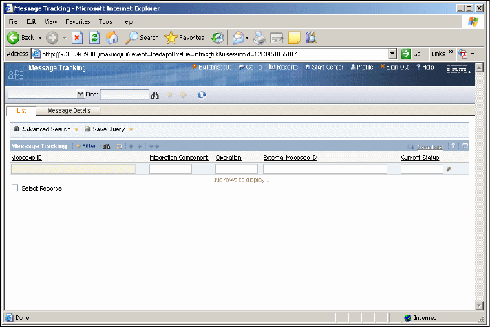
Chapter 2. Integration components 81
Figure 2-30 Message Tracking interface
Message Reprocessing
The Message Reprocessing application allows you to manage and view
integration transaction messages that have been flagged with an error. Through
the Message Reprocessing application, you can view the error Extensible
Markup Language (XML) file without needing to gain access to the integration
server error files.
The Message Reprocessing application works with the Message Tracking
application and displays queue-based messages that failed any Integration
Framework process validation. When you enable message tracking in either the
Publish Channels or Enterprise Services applications, you can determine which
messages are flagged with an error in the Message Tracking application. You
then can take appropriate action to correct erroneous data in the Message
Reprocessing application.
If you have not enabled message tracking, you can go directly to the Message
Reprocessing application to check for transaction errors.
You can manage messages in the following ways:
Change the message statuses to stop message processing or to reprocess a
message

82 Integration Guide for IBM Tivoli Service Request Manager V7.1
Correct, process, save, or cancel the error XML file
Delete the message from the database
To change the message status, you use the Change Status action in the
Message Reprocessing application. The system designates a status to each
message to indicate whether they are ready for processing.
Messages can have the following statuses (Table 2-19).
Table 2-19 Message statuses
The RETRY status is the default status for messages that have been flagged with
an error. Until you correct the processing problem, the system continues to
reprocess and encounter errors with the applicable transaction.
You can halt message reprocessing by changing the message status to HOLD.
Assigning a hold status prevents the system from automatically reprocessing the
flagged message and from updating the system database tables.
For error correction, you use the Message Details dialog box in the Message
Reprocessing application to view the message details and to manually change
the contents of a message in error. You can choose to process or save your XML
changes. You also can choose to cancel the error XML file changes.
For error details, when you select the Message Details icon for each listed error,
the Message Details dialog box opens and displays the error XML file.
Example 2-3 on page 83 is an example of an error XML file that is displayed in
the Message Details dialog box. It contains the following information:
The error message in the ERRORMESSAGE element
The message from the queue in the ER element
The object structure XML in the IR element
Status Description
Retry Indicates that the message is ready to be
reprocessed by the system
Hold Indicates that the message is not ready to
be reprocessed by the system
Note: You only can edit a message if it is in a HOLD status. If the message
has a RETRY status, the error data content is read-only.

Chapter 2. Integration components 83
The IR element is present only for inbound transactions, and only if enterprise
service processing and user exit processing (Example 2-3) are successfully
applied to the message. It represents the object structure that was created during
enterprise service or user exit processing (or both).
Example 2-3 Example of an error xml file
<?xml version="1.0" encoding="UTF-8"?>
<ERROR>
<ERRORMESSAGE>Error occurred while processing PO (Object
Structure number 1). Error is:[system:unknownerror] An unknown
error has occurred. Contact your system administrator for
assistance. null</ERRORMESSAGE>
<ER> <SyncMXPO xmlns="http://www.ibm.com/maximo"
xmlns:xsi="http://www.w3.org/2001/XMLSchema-instance"
creationDateTime="2007-05-22T14:04:03-04:00"
transLanguage="EN" baseLanguage="EN"
messageID="11798570432187483" maximoVersion="7 1 Harrier 038a
HARRIER-042" event="1" messageid="11798570432652428">
<MXPOSet>
<PO action="Update">
.
.
.
</PO>
</MXPOSet>
</SyncMXPO>
</ER>
<IR>
<SyncMXPO xmlns="http://www.ibm.com/maximo"
xmlns:xsi="http://www.w3.org/2001/XMLSchema-instance"
creationDateTime="2007-05-22T14:04:03-04:00"
transLanguage="EN" baseLanguage="EN"
messageID="11798570432187483" maximoVersion="7 1 Harrier 038a
HARRIER-042" event="1" messageid="11798570432652428">
<MXPOSet>
<PO action="Update">
.
.
.
</PO>
</MXPOSet>
</SyncMXPO>
</IR>
</ERROR>

84 Integration Guide for IBM Tivoli Service Request Manager V7.1
To process a message, when you have completed your error XML changes in the
Error Data window, you can choose to resubmit the message by selecting the
Process option. The Message Details dialog box closes, and the application
starts reprocessing the message.
If the system successfully processes the message, it performs the following
actions:
Deletes the error file
Deletes the record in the MAXINTERRORMSG table
Updates the DELETEFLAG, CHANGEBY, and CHANGEDATE attributes in
the MAXINTERROR table
The application refreshes the result set and omits the successful message listing
on the main tab of the Message Reprocessing application.
If the system does not successfully process the message, it performs the
following actions:
The MAXINTERRORMSG table is updated with the new error.
Updates the CHANGEBY and CHANGEDATE attributes in the
MAXINTERROR table.
Opens an “Error encountered in processing transaction” error.
The application refreshes the result set and displays the new error for the
unsuccessful message listing on the main tab of the Message Reprocessing
application.
Save the message
When you have completed your error XML changes in the Error Data window,
you can choose to save the message by selecting the Save option. The Message
Details dialog box closes, and the application saves your XML changes.
The system saves the message and updates the CHANGEBY and
CHANGEDATE attributes in the MAXINTERROR table.
Note: The ER element in an error file that was created for inbound messages
from interface tables or flat files has a flat (non-hierarchical) structure.
Only the <ER> element can be edited; the <IR> element is provided for
information only, and any change to the <IR> is ignored when the message is
reprocessed.

Chapter 2. Integration components 85
Cancel the message
When you have edited your error XML file, you can choose not to proceed with
the message changes by selecting the Cancel option. The Message Details
dialog box closes, and the application cancels your XML changes.
When the system cancels the message, it does not perform any system
database updates. The error XML file remains in its original state.
Message deletion
You use the Delete Message action in the Message Reprocessing application to
delete a message from a queue, if necessary.
Critical errors
Critical errors are transaction processing exceptions that the Integration
Framework error correction process cannot retry. Transaction processing
exceptions can occur when invalid data, such as a special character, is in the
XML file. When the Integration Framework identifies a critical error, ER and IR
sections in the corresponding (Figure 2-31 on page 86) error file are not present.
To correct the critical error, remove the invalid data from the error XML. You can
see invalid data associated with a critical error in the main tab of the Message
Reprocessing application.
You can access the Message Reprocessing application by selecting Go →
Integration → Message Reprocessing.
Important: After you delete a message, the system cannot reprocess it. When
the system deletes the message, it deletes the record from the
MAXINTERRORMSG and MAXINTERROR tables.
The application refreshes the result set and omits the deleted message listing
on the main tab of the Message Reprocessing application.
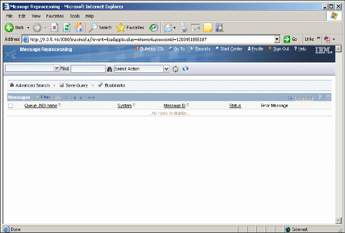
86 Integration Guide for IBM Tivoli Service Request Manager V7.1
Figure 2-31 Message Reprocessing interface
2.4.4 Integration enhancements and changes from V6.x to V7.1
In this section, we provide information about enhancements and changes from
MEA V6.x and Integration Framework MEA V7.1.
Changes to existing Version 6 MEA
The following changes have been made to the existing Version 6 MEA:
Integration Components Integration components application changed to
Object Structures
Integration Point Integration Point is removed. Now, it is collapsed into
the Object Structure.
Interfaces The interfaces are split into outbound and inbound:
The outbound interfaces are Publish Channels and
the Inbound interfaces are Enterprise Services.
Integration Framework V7.1 (MEA) new features
Next, we list the new features of Integration Framework 7.1.
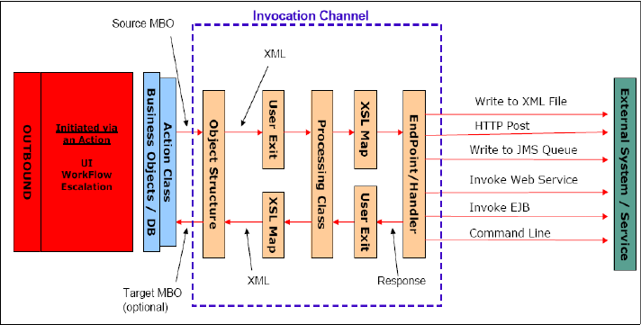
Chapter 2. Integration components 87
Invocation Channels
Integration Framework has been improved to support the synchronous invocation
of an external service or application. The system also returns the response of the
service back to the caller for subsequent processing (Figure 2-32). It can be
initiated by the UI button, Escalation, or Work Flow.
Invocation channel provides the framework to:
Transform Object Structure to service input.
Associate an endpoint.
Transform service response to Object Structure.
Figure 2-32 Invocation Channel
For detailed information about invocation channels, refer to Invocation channels
on page 47.
Services
External applications can use Web services to query or to send transactions to
the Integration Framework. The Integration Framework provides three types of
services that you can choose to deploy as a Web service:
Object Structure Service:
– New feature in V7.1 (Figure 2-33 on page 88).
– These services rely entirely on Object Structure definitions and do not
utilize the exit processing available to Enterprise Services.
– Requires less configuration because there is no Enterprise Service or
External System required.
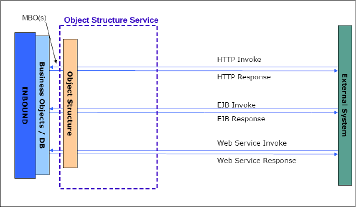
88 Integration Guide for IBM Tivoli Service Request Manager V7.1
– Each Object Structure supports five operations (create, update, delete,
sync, and query).
– The query operation provides object structure as the response content.
– The create operation provides the key of the top Maximo Business Object
(MBO) of the object structure as the response content.
Figure 2-33 Object Structure Service
Enterprise Service:
– Replaces the 6.x inbound interfaces (Figure 2-34 on page 89).
– Supports processing through the queue (async) or by bypassing the
queue (sync).
– The exit processing layer allows for mapping the external XML to the
object structure XML for both the invocation and the response.
– Enterprise Services are defined for a single operation.
– The query operation provides object structure as the response content.
– The create operation provides the key of the top MBO of the object
structure as the response content.
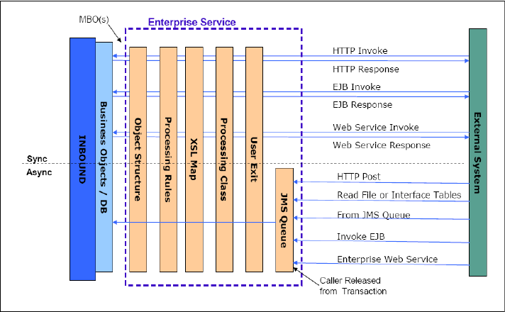
Chapter 2. Integration components 89
Figure 2-34 Enterprise Services
Standard Service:
– New in V7.1 (Figure 2-35 on page 90).
– Created from annotated methods (such as changeStatus) in an MBO
within an application service.
– The inputs and outputs (if any) for these services are tied to the input and
output parameters of the method.
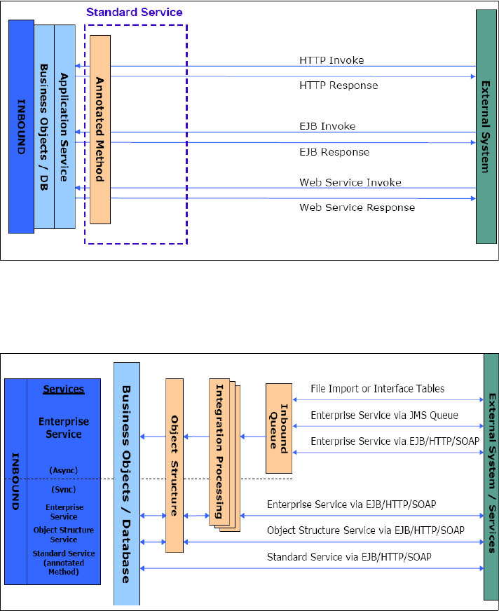
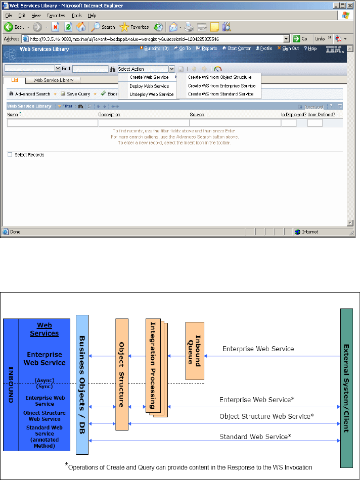
Chapter 2. Integration components 91
Web Services Library
Web Services Library (Figure 2-37) is a new application in V7.1 to support the
management and deployment of Web services for all three service classes.
Figure 2-37 Web Services Library application
Figure 2-38 illustrates the Web Services Library architecture.
Figure 2-38 Web Services Library architecture
92 Integration Guide for IBM Tivoli Service Request Manager V7.1
PMP and OMP integration
OMPs are external products (to the system) that provide services for CIs, such
as a server that runs applications. PMPs are system applications and processes
that use OMPs to automate IT-related services. These services include software
deployment on CIs.
OMP integration supports:
Assisted and automated approaches for PMPs, such as Change and
Release, to integrate with OMPs, such as Tivoli Provisioning Manager (TPM).
Maximo is fed updates of CIs, OMPs, and their relationships through the IMIC
adapter from TADDM (discovery data).
Integration Framework supports the installation and configuration of
Integration Modules (IMs) and LMO.
The PMP processes (UI, workflow, and escalations) invoke IMs to perform
actions (LMOs) on CIs through OMPs. For example: Release PMPs invoke an
IM to distribute software (LMO) on a server (CI) using TPM (OMP).
The PMP application can also launch (UI) to an OMP application to support
integration in an “assisted” model.
For detailed information about OPM integration, refer to Integration Framework
for OMP integration on page 41.
Message tracking and reprocessing
Integration Framework provides two new applications to manage messages. The
Message Tracking application tracks messages while processing publish
channels (outbound messages) and enterprise services (inbound messages)
and how system administrators work with the displayed messages. Message
Reprocessing application allows you to manage and view integration transaction
messages that have been flagged with an error. Through the Message
Reprocessing application, you can view the error XML file without needing to
gain access to the integration server error files.
For detailed information about the Message Tracking application, refer to
Message tracking on page 75 and Message Reprocessing on page 81 for
detailed information about the Message Reprocessing application.
Additional content
Addition content available in Integration Framework V7.1:
The number of object structures that ship is increasing from approximately 40
(in Version 6.x) to over 55 (in Version 7.1).
There is a new Command Line (SSH) handler.
Chapter 2. Integration components 93
Predefined Launch Entries for TADDM from the CI applications ship.
The Object Group annotates the changeStatus method across multiple MBOs
and several additional methods.
2.4.5 Sample scenario
In this section, we introduce a sample scenario that shows how to expose a Web
service in Tivoli SRM V7.1 to have incidents created into SRM. We describe in
detail all of the necessary components.
Prerequisites
In order to create the Web service, you need the following prerequisites in your
environment:
1. Tivoli SRM V7.1 must be installed.
2. JMS queues must be created and configured. The installation of Tivoli
Process Automation Platform (TPAP) creates and configures all of the default
JMS queues automatically for you.
3. SOAP test client. This client is required to interact with the Web service
created in this section.
Configuring integration components
In order to set up your Web services, configure:
1. Enabling the cron task for the sequential queues
2. Object Structures
3. Enterprise Services
4. External system
5. Creating and exposing the Web Service
6. View WSDL
7. XML file
Enabling the cron task for the sequential queues
Activate the applicable instances of the cron task (SEQQIN and SEQQOUT) or
the inbound and outbound messages remain unprocessed in the queues. You
access the JMSQSEQCONSUMER cron task at the Cron Task Setup
application. Click Go To → System Configuration → Platform
Configuration → Cron Task Setup. Search for JMSQSEQCONSUMER and activate
both SEQQIN and SEQQOUT as shown in Figure 2-39 on page 94.
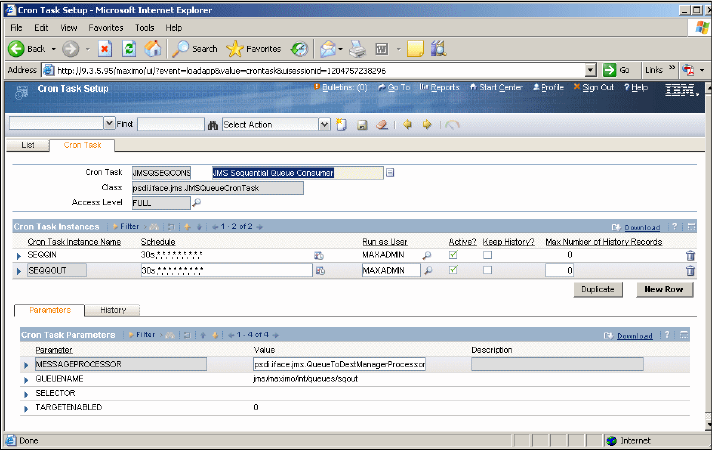
94 Integration Guide for IBM Tivoli Service Request Manager V7.1
Figure 2-39 Enabling JMS queues
Object Structures
Create an object structure that consists of one business object that makes up the
content of the XML message.
You can access the Object Structure application by selecting Go →
Integration → Object Structures.
After launching the Object Structures application, follow these steps:
1. Click New. Figure 2-40 on page 95 appears.
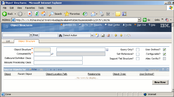
Chapter 2. Integration components 95
Figure 2-40 Object Structure application
2. In the object structure field, type OBJSTR_SAMPLE.
3. Select INTEGRATION from the component field.
4. Click New Row in the Source Objects subtab. Select INCIDENT in the Object
field.
5. Accept all defaults and click Save.
Enterprise Services
After creating the object structure, create the enterprise service for querying
system data and importing data into the system from an external system.
Access the Enterprise Services application by selecting Go → Integration →
Enterprise Services.
After launching the Enterprise Services application, follow these steps:
1. Click New. Figure 2-41 on page 96 appears.
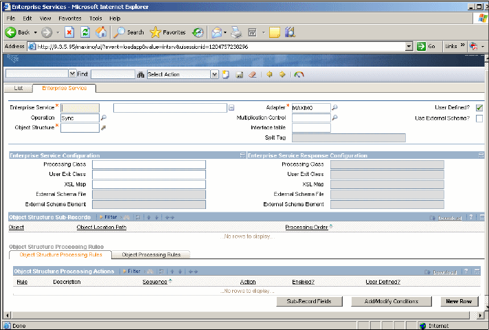
96 Integration Guide for IBM Tivoli Service Request Manager V7.1
Figure 2-41 Creating a new Enterprise Services record
2. In the Enterprise Services field, type ENTSER_SAMPLE.
3. Select Create in the Operation field.
4. In the Object Structure field, select OBJSTR_SAMPLE. This is the object that
you created before.
5. Accept all defaults and click Save.
External system
Create an external system to receive data from an external business application.
Access the External Systems application by selecting Go → Integration →
External Systems.
After launching the External System application, follow these steps:
1. Click New.
2. Type EXTSYS_SAMPLE in the System field.
3. In the Enterprise Services tab, click Select Service and select the enterprise
services that we created in the step before. Search for ENTSER_SAMPLE
and select it.
4. Click OK.
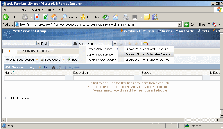
Chapter 2. Integration components 97
5. Enable the enterprise services by clicking the Enabled? check box.
6. Enable the external system by clicking the Enabled? check box.
Creating and exposing a Web service
In this section, we create a Web service from an enterprise service and expose
it. As soon as we expose the Web service, a external application can call this
service, post an XML, and create a new incident.
You can access the Web Services Library application by selecting Go →
Integration → Web Services Library. Follow these steps:
1. Create a new Web service by clicking Select Action → Create Web
Service → Create WS from Enterprise Service as shown in Figure 2-42.
Figure 2-42 Creating a Web service
2. Select the enterprise service called EXTSYS_SAMPLE_ENTSER_SAMPLE
and click Create as shown in Figure 2-43 on page 98.
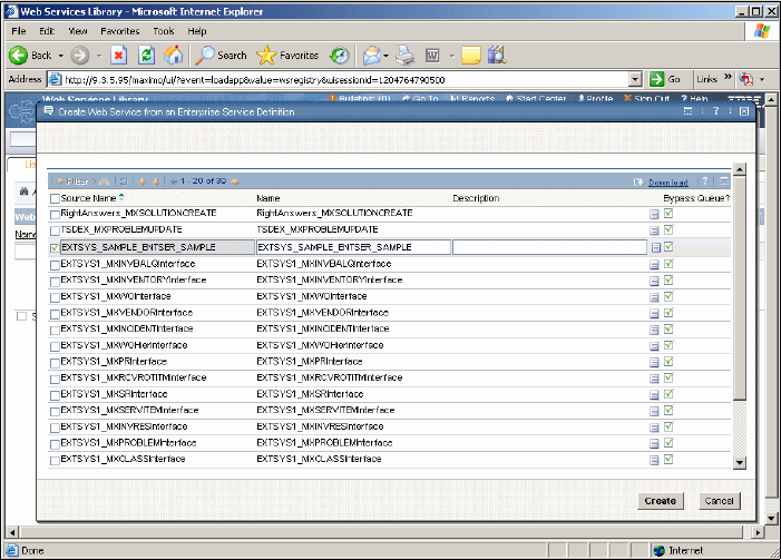
98 Integration Guide for IBM Tivoli Service Request Manager V7.1
Figure 2-43 Selecting the enterprise service
3. The Web Service is now created. The next step is deploying the Web service
by selecting the EXTSYS_SAMPLE_ENTSER_SAMPLE record.
4. Click Select Action → Deploy Web Service. A system message appears as
shown in Figure 2-44 on page 99.
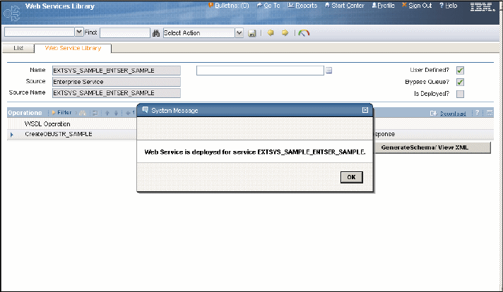
Chapter 2. Integration components 99
Figure 2-44 Web Service deployed
5. Click OK. The Web service EXTSYS_SAMPLE_ENTSER_SAMPLE is now
created and deployed.
View WSDL
In order to view the wsdl file, open a browser and type the following URL:
http://host/meaweb/wsdl/EXTSYS_SAMPLE_ENTSER_SAMPLE.wsdl
Figure 2-45 on page 100 shows the wsdl definition.
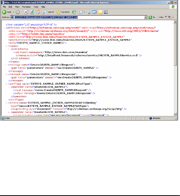
100 Integration Guide for IBM Tivoli Service Request Manager V7.1
Figure 2-45 Wsdl definition
XML file
At this point, the Web service is created and deployed.
You can now test the Web service by using an external application to interact with
the Web service and post an XML file.
Example 2-4 shows two XML files for test purposes. One file is for request and
another file is for response.
Example 2-4 Request xml
<?xml version="1.0" encoding="UTF-8"?>
<CreateOBJSTR_SAMPLE xmlns="http://www.ibm.com/maximo"
xmlns:xsi="http://www.w3.org/2001/XMLSchema-instance"
creationDateTime="2008-03-04T14:00:57-08:00" transLanguage="EN"
baseLanguage="EN" messageID="12046680576872200" maximoVersion="7 1 112
V7110-450" event="1">
<OBJSTR_SAMPLE>
<INCIDENT action="Add">
<ACTLABCOST>0.0</ACTLABCOST>
<ACTLABHRS>0.0</ACTLABHRS>
<ACTUALCONTACTDATE xsi:nil="true" />
Chapter 2. Integration components 101
<ACTUALFINISH xsi:nil="true" />
<ACTUALSTART xsi:nil="true" />
<AFFECTEDDATE>2008-03-04T14:00:00-08:00</AFFECTEDDATE>
<AFFECTEDEMAIL />
<AFFECTEDPERSON>MAXADMIN</AFFECTEDPERSON>
<AFFECTEDPHONE />
<ASSETNUM />
<ASSETORGID />
<ASSETSITEID />
<CHANGEBY>MAXADMIN</CHANGEBY>
<CHANGEDATE>2008-03-04T14:00:37-08:00</CHANGEDATE>
<CINUM />
<CLASS maxvalue="INCIDENT">INCIDENT</CLASS>
<CLASSIFICATIONID />
<CLASSSTRUCTUREID />
<COMMODITY />
<COMMODITYGROUP />
<CREATEDBY>MAXADMIN</CREATEDBY>
<CREATEWOMULTI maxvalue="MULTI">MULTI</CREATEWOMULTI>
<CREATIONDATE>2008-03-04T14:00:38-08:00</CREATIONDATE>
<DESCRIPTION />
<DESCSRVID />
<EXTERNALRECID />
<EXTERNALSYSTEM />
<EXTERNALSYSTEM_TICKETID />
<FAILURECODE />
<FR1CODE />
<FR2CODE />
<GLACCOUNT />
<GLOBALTICKETCLASS />
<GLOBALTICKETID />
<HASACTIVITY>0</HASACTIVITY>
<HISTORYFLAG>0</HISTORYFLAG>
<IMPACT xsi:nil="true" />
<INDICATEDPRIORITY xsi:nil="true" />
<INHERITSTATUS>0</INHERITSTATUS>
<INTERNALPRIORITY xsi:nil="true" />
<ISGLOBAL>0</ISGLOBAL>
<ISKNOWNERROR>0</ISKNOWNERROR>
<ISKNOWNERRORDATE xsi:nil="true" />
<LOCATION />
<ORGID />
<ORIGRECORDCLASS />
<ORIGRECORDID />
<ORIGRECORGID />

102 Integration Guide for IBM Tivoli Service Request Manager V7.1
<ORIGRECSITEID />
<OWNER />
<OWNERGROUP />
<PMCOMRESOLUTION />
<PMCOMTYPE />
<PROBLEMCODE />
<RELATEDTOGLOBAL>0</RELATEDTOGLOBAL>
<REPORTDATE>2008-03-04T14:00:37-08:00</REPORTDATE>
<REPORTEDBY>MAXADMIN</REPORTEDBY>
<REPORTEDEMAIL />
<REPORTEDPHONE />
<REPORTEDPRIORITY xsi:nil="true" />
<SITEID />
<SITEVISIT>0</SITEVISIT>
<SOLUTION />
<SOURCE />
<STATUS maxvalue="NEW">NEW</STATUS>
<STATUSDATE>2008-03-04T14:00:37-08:00</STATUSDATE>
<SUPERVISOR />
<TARGETCONTACTDATE xsi:nil="true" />
<TARGETDESC />
<TARGETFINISH xsi:nil="true" />
<TARGETSTART xsi:nil="true" />
<TEMPLATE>0</TEMPLATE>
<TEMPLATEID />
<TICKETID>1008</TICKETID>
<TICKETUID>9</TICKETUID>
<URGENCY xsi:nil="true" />
<VENDOR />
</INCIDENT>
</OBJSTR_SAMPLE>
</CreateOBJSTR_SAMPLE>
Refer to Example 2-5 for the response XML file.
Example 2-5 Response xml
<?xml version="1.0" encoding="UTF-8"?>
<CreateOBJSTR_SAMPLEResponse xmlns="http://www.ibm.com/maximo"
xmlns:xsi="http://www.w3.org/2001/XMLSchema-instance"
creationDateTime="2008-03-05T17:50:49-08:00" transLanguage="EN"
baseLanguage="EN" messageID="12047682499375535">
<INCIDENTMboKeySet>
<INCIDENT>
<CLASS maxvalue="INCIDENT">INCIDENT</CLASS>

Chapter 2. Integration components 103
<TICKETID>1008</TICKETID>
</INCIDENT>
</INCIDENTMboKeySet>
</CreateOBJSTR_SAMPLEResponse>
104 Integration Guide for IBM Tivoli Service Request Manager V7.1

© Copyright IBM Corp. 2008. All rights reserved. 105
Chapter 3. Event management
integration
This chapter discusses event management integration products, such as Tivoli
Enterprise Console (TEC) and Tivoli Netcool/Omnibus, which are available
within the Tivoli portfolio.
This chapter discusses the following topics:
Event management on page 106
IBM TEC integration on page 106
IBM Tivoli Netcool/Omnibus integration (preview) on page 130
3
106 Integration Guide for IBM Tivoli Service Request Manager V7.1
3.1 Event management
The way that an organization handles an event is known as event management.
It can include the organization’s objectives for managing events, assigned roles
and responsibilities, ownership of tools and processes, critical success factors,
standards, and event-handling procedures. The link between the various
departments within the organization that are required to handle events and the
flow of this information among them is the focus of event management. Tools are
mentioned in reference to how they fit into the flow of event information through
the organization and to the standards that are applied to the flow.
Events are used to report problems, and event management is sometimes
considered a sub-discipline of problem management. However, it can really be
considered a discipline of its own, because it interfaces directly with several other
systems management disciplines. For example, system upgrades and new
installations can result in new event types that must be handled. Maintaining
systems both through regularly scheduled and emergency maintenance can
result in temporary outages that trigger events. There is clearly a relationship
between event management and change management.
In small organizations, it is possible to handle events through informal means.
However, as organizations’ IT support staffs and the number of resources that
they manage grow, it becomes crucial to have a formal documented event
management process. Formalizing the process ensures consistent responses to
events, eliminates duplication of effort, and simplifies the configuration and
maintenance of tools that are used for event management.
Based on the business process, most of the events generated in the environment
become an incident in the Information Technology Infrastructure Library (ITIL)
process, which is maintained and supported by the Tivoli Service Request
Manager (SRM) application.
3.2 IBM TEC integration
The Tivoli Enterprise Console (TEC) integration for Service Desk provides
bidirectional communication between TEC and the Service Desk component of
Tivoli SRM V7.1. TEC is an event management software system that collects,
consolidates, and correlates events from a variety of event sources across the
managed network. It initiates automated corrective action in order to reduce the
number of events that require human intervention to a manageable size.
Chapter 3. Event management integration 107
Events are consolidated or correlated by filtering redundant or low priority
events, discarding duplicate events, discarding secondary events (events
caused by other events) where appropriate, automatically closing a problem
event when the related recovery event occurs, and other techniques. Rules
define how events are processed.
TEC events are assigned a severity level that indicates the seriousness of the
underlying problem. The default classifications, in order of increasing severity,
are: UNKNOWN, HARMLESS, WARNING, MINOR, CRITICAL, and FATAL.
The Service Desk applications most directly related to TEC integration are the
following ticket applications:
Use the Service Requests application to create records of client calls or e-mail
messages that request service.
Use the Incidents application to create records of incidents that interrupt
service or reduce the quality of a service.
Use the Problems application to create records of the underlying problems
that cause incidents and service requests.
Service Request, Incident, and Problem records are referred to as ticket records
or ticket types. Ticket records can be created by a service desk agent and
automatically use data from e-mail messages, system monitoring tools, or
external software applications, such as IBM TEC. After a ticket record is created,
a person or group can take ownership of the ticket and see the issue through to
resolution.
After you install and configure TEC integration for Service Desk, TEC events that
meet defined criteria are used as triggers to automatically open ticket records in
the Service Desk ticket applications. For example, by default, FATAL events
trigger the opening of an Incident ticket, and CRITICAL events trigger a Service
Request ticket. You can change the event criteria for opening Service Desk
tickets and the types of tickets that are opened in response to events.
After a ticket is opened in Service Desk, subsequent updates to the ticket
automatically result in corresponding updates to the originating TEC event and
all correlated events, provided that the events still exist in the TEC event cache.
When the ticket is closed, all TEC events associated with the ticket are also
closed.

108 Integration Guide for IBM Tivoli Service Request Manager V7.1
The integration of TEC with Service Desk addresses an IT management need
that Service Desk alone is not designed to meet. While a service desk agent
might become aware of system outages and access failures reported by
employees or customers, the Service Desk software is not intended as a solution
for isolating and resolving performance and availability problems across
computer networks. TEC, however, is specifically designed to help ensure the
availability of IT resources. The integration of TEC with Service Desk enables
service desk agents to become aware of problems that need attention. The
automated opening of Service Desk tickets in response to events accelerates the
resolution process, reducing mean time to repair, and in certain cases, solving a
problem before it is reported by customers or becomes worse.
3.2.1 Prerequisites
The prerequisite software for TEC integration for Service Desk includes:
Service Desk component of Tivoli SRM V7.1 on Windows
TEC V3.9 or higher on Windows, Linux, or Unix
3.2.2 Architecture
When you install TEC integration for Service Desk software on a TEC server, the
installer creates a rule base that defines the default event criteria for opening
Service Desk tickets. You can change the default criteria by modifying the rule
base.
Figure 3-1 on page 109 shows the components that take part in the integration.
Note: IBM WebSphere V6.0.2.17 is required for IBM Tivoli SRM and can
be installed on Windows, Linux, or UNIX. However, Tivoli SRM must be
installed on the Windows platform for this integration.
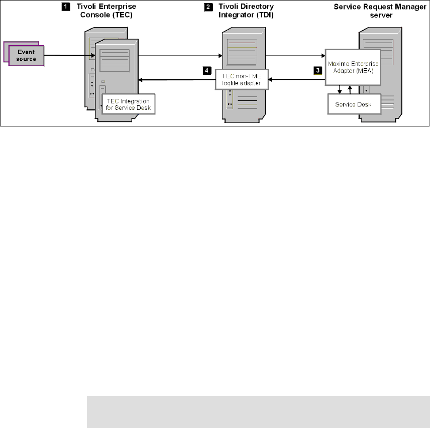
Chapter 3. Event management integration 109
Figure 3-1 The components that take part in the integration
Moving from left to right in Figure 3-1:
1. After a TEC server receives an event from an event source, it evaluates the
event according to the rule base. If the event meets the established criteria,
the TEC server forwards the event information to the Tivoli Directory
Integrator (TDI) server.
2. TDI serves as the interface between TEC and Service Desk. When the TDI
server receives the event information, it evaluates the event to determine the
type of Service Desk ticket to open and evaluates other ticket attributes based
on default settings or based on mappings that you configure using the TDI
Configuration Editor. This information is passed on to the SRM server,
specifically to the MEA component.
3. The MEA provides the interface for communication between SRM and
external applications, in this case, the TDI server.
4. When the ticket description is updated or the ticket is closed, the TEC event
or events that are associated with the ticket are updated.
5. The updated ticket information is communicated through the MEA to the
non-TME logfile adapter on the TDI server.
The non-TME logfile adapter is a TEC product component that you install on
the TDI server. The logfile adapter is used to transmit information from Tivoli
SRM back to the TEC event server.
Note: TDI queries Maximo/MEA every minute (configurable timer) for
updates. Maximo/MEA does not need to be aware of any TDI servers.

110 Integration Guide for IBM Tivoli Service Request Manager V7.1
Your TEC integration for the Service Desk environment can include multiple TEC
servers, multiple TDI servers, and multiple Tivoli SRM servers. Although a single
TDI server can accommodate the data flow from multiple TEC and Tivoli SRM
servers, it is a best practice to install multiple TDI servers to maintain availability
in case of server failure.
Event automation means that actions can be performed when processing events.
For the purposes of this book, we refer to the process of taking action on system
resources without human intervention in response to an event. The actual
actions executed are referred to as automated actions. Automated actions in
Service Desk generates an Incident in Tivoli SRM based on certain predefined
rules.
Figure 3-2 on page 111 shows the communication between various components
involved in TEC integration for Service Desk software.
Note: For incoming events from TEC (port 6767), a logfile adapter is
unnecessary, because a TDI server connector listens for requests and
forwards them to the Maximo connector, which sends the ticket
Create/Update request to Tivoli SRM. Logfile adapter is only used to transmit
information from Tivoli SRM back to the TEC.
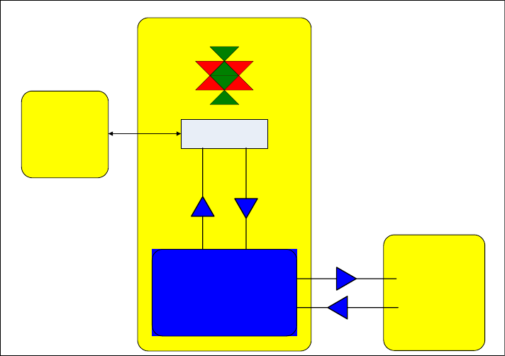
Chapter 3. Event management integration 111
Figure 3-2 Communication methods
The AssemblyLine with the Unified Connector is configured to listen on port
6767, which is the default communication port for event server. When an event
corresponds to the AssemblyLine condition, an Incident within Tivoli SRM is
created automatically.
Figure 3-3 on page 112 demonstrates how the event generates an Incident
record within Tivoli SRM and also how the event is generated within the TEC by
calling the postzmsg.
Tivoli
Enterprise
Agent
Server
Server A
Tivoli Directory Integrator
Unified CONNECTOR
Tivoli Enterprise Console
Assembly Line
Create/Update
Ticket
Update
Ticket
postzmsg
Port : 6767
Server B
Tivoli
Directory
Integrator
(UI)
Workstation
Non-Tivoli
Logfile
Adapter
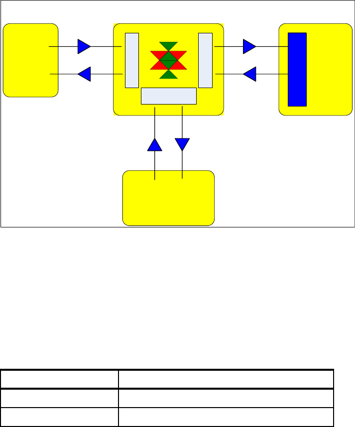
112 Integration Guide for IBM Tivoli Service Request Manager V7.1
Figure 3-3 TDI architecture
The user is able to open an incident record within the TEC Console by using the
Ticket Creation function.
3.2.3 Predefined scenarios
Table 3-1 lists the event status and corresponding actions for every event that is
created or generated in TEC.
Table 3-1 Action performed for a particular event status
Tivoli
Enterprise
Console
Tivoli
Service
Request
Manager
External
Service
Desk
NODE
Tivoli Directory Integrator
External External
Integration Object
(M E A)
Create/Update
TEC Event
Port : 6767
Update
TEC Event
postzmsg
Create/Update
Ticket
Update
Ticket
Unified Connector
TEC
Unified Connector
Service Request Manager
INTERPRETER
Assembly Line
Unified Connector
HP-Peregrine
ServiceCenter 6.1
Create/Update
Ticket
Update
Ticket
Web Services Integration
HTTP
Web Services Integration
HTTP
Event status Action in Tivoli SRM
Fatal An incident record is opened.
Critical or other status A service request record is opened.

Chapter 3. Event management integration 113
TDI has a rule inside the assembly lines to guide the creation of various ticket
types according to the event status sent by TEC (Example 3-1).
Example 3-1 TECInReadQueue assembly line
Open TECInReadQueue assembly line
Select ClassifyTECTicket script and take a look on the code.
if ("FATAL".equals(severity)) {
work.setAttribute("T_TICKET_TYPE", "INCIDENT");
task.logmsg("Ticket class is INCIDENT or PROBLEM.");
} else if (!"FATAL".equals(severity) && severity != null) {
work.setAttribute("T_TICKET_TYPE", "SR");
task.logmsg("Ticket class is SERVICE REQUEST.");
When the following actions (Table 3-2) are performed on the event, which opens
a record in Tivoli SRM, the corresponding actions are automatically reflected in
the service request or incident record.
Table 3-2 Action resolving the service request or the incident record
If the record created by an event is resolved or closed within the SRM
Application, the event record is automatically closed (Table 3-3 on page 114).
Note: You can change the event criteria for opening Service Desk tickets by
editing the mro_troubleticket ruleset.
The mro_troubleticket ruleset file (mro_troubleticket.rls) is located in the
following directory on the TEC server:
rbpath/TEC_Rules/mro_troubleticket.rls, where rbpath is the rulebase
directory.
You can obtain the exact location by running the following command from
within the Tivoli BASH Shell environment:
wrb –lsrb –path
Event status Action on the event Action performed in
Tivoli SRM
Fatal Closed Changes the incident
status to resolved
Critical or other status Closed Changes the service
request status to resolved

114 Integration Guide for IBM Tivoli Service Request Manager V7.1
Table 3-3 Action closing the event record
3.2.4 Steps for implementing TEC integration
You must follow the instructions in this section to implement TEC integration.
The steps are:
1. Install non-TME logfile adapter.
2. Install TDI.
3. Edit the mxe.properties file (optional).
4. Install the new SRM ruleset.
5. Start TDI.
6. Configure the TEC connector.
3.2.5 Installing the non-TME logfile adapter
The non-TME logfile adapter is the adapter that provides the communication
between the system where the logfile is installed and the TEC. The
communication between these components is not secure and uses port 5529.
The installation of this connector is required so that the system can post
messages (using the postzmsg application) and communicate with TEC.
Depending on the operating system of the TDI server, install either the UNIX or
Windows non-TME logfile adapter. The non-TME logfile adapter binary files are
located on the TEC CD. Be sure to install the non-TME version of the logfile
adapter. The TME® version is not supported.
SRM record SRM action Action performed in TEC
Service request Resolved Close the event
Incident Resolved Close the event
Note: Our scenario assumes that you are using one TDI server. If for
performance or high availability reasons you decide to use more than one TDI
server, additional steps are required. Refer to “TDI considerations” on
page 248 for more information.
Note: The Windows non-TME logfile adapter is also known as the Windows
event log adapter.

Chapter 3. Event management integration 115
Perform the following steps to install the Windows non-TME LogFile adapter:
1. The setup.exe file is located at Non-TME LogFile adapter
3.9\W32-IX86\InstallWIN.
2. Click setup.exe if you are using the file browser, or if you are using the
command line, execute the setup.exe.
3. Click Next at the Welcome box.
4. Click Next to accept the destination directory, C:\tec\win.
5. Click Next to accept the destination directory.
6. Click Next to accept the type of adapter.
The progress status bar shows the installation progress.
7. Click Next at the server configuration. The server configuration is done within
the AssemblyLine.
8. Click Next at the port number configuration.
9. The configuration is completed automatically, and the following command line
window appears (Figure 3-4 on page 116).
Important: For Windows, do not change the default value for the path where
you install the non-logfile adapter, because TDI uses this directory. For UNIX,
there is no default location, so you can install at any location on UNIX.
Note: You can use the default values. These values do not matter,
because TDI provides the required values in real time to communicate with
TEC.
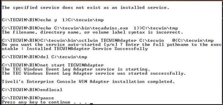
116 Integration Guide for IBM Tivoli Service Request Manager V7.1
Figure 3-4 Automated logfile adapter configuration window
10.Click any key on your keyboard to complete the installation.
11.Click OK to complete the installation after answering the readme file question.
12.A reboot is required to activate the non-Logfile adapter.
3.2.6 Installing TDI
You can use the TDI installation program that is provided with Tivoli SRM to
install a TDI environment that supports the integration of TEC (and other
products) with Tivoli SRM Service Desk.
To install one or more TDI servers, use the procedure described in “Installation
procedure” on page 31.
3.2.7 Editing the mxe.properties file (optional)
The TDI installation program prompts you for the location of the TEC non-TME
logfile adapter. The value that you specify is entered into a properties file named
mxe.properties. If you do not specify a location for the logfile adapter during
installation, you can manually update the mxe.properties file after installation.
Edit the mxe.properties file on each computer that hosts a TDI server to specify
the following values:
The full directory path where the TEC non-TME logfile adapter is installed.
If you specified the correct location of the logfile adapter when you installed
TDI, the mxe.properties file already contains this value.

Chapter 3. Event management integration 117
A SRM user ID and password that the TDI server can use to log on to SRM.
The SRM user that you specify must have the authority to create Service
Desk tickets. You can specify either a Lightweight Directory Access Protocol
(LDAP) or a non-LDAP user, depending on the type of authorization that is
required by SRM.
Complete the following steps to edit the mxe.properties file on each computer
where TDI is installed:
1. Change to the TDI work directory (solution directory). You specified a work
directory when you installed TDI.
2. Open the mxe.properties file.
3. Use the tecLogAdapterFilePath property to specify or verify the location of the
TEC non-TME logfile adapter:
– For Windows: tecLogAdapterFilePath=c:\tecwin
– For Linux or UNIX: tecLogAdapterFilePath=/opt/IBM/Tivoli/tec/nonTME
To enable the TDI server to access SRM, specify values for the following
properties:
–default.maximo.authentication.required=true
– default.maximo.user=user_ID
– default.maximo.url=http://172.27.34.45
–default.maximo.password={encr}
where user ID and password specify a user that is authorized to log on to
SRM and who has the authority to create Service Desk tickets
3.2.8 Installing the SRM rulebase
The prerequisites for installing the SRM rulebase are:
Access to root on a UNIX box and access to Administrator or any other user
on Windows with the Administrator privileges.
Locate the following zip files containing the new ruleset for Tivoli SRM:
– tec_integration_deployment.zip
– integrate\install\tec\winstall_mro_tec
– integrate\install\tec\mro_install\mro_troubleticket.baroc
Note: Typing {protect}- in front of a property name instructs TDI to encrypt
the property value the next time that it reads the file. In this case, the
encrypted password is shown if you open the mxe.properties file after the TDI
server is started.

118 Integration Guide for IBM Tivoli Service Request Manager V7.1
– integrate\install\tec\mro_install\mro_troubleticket.sh
– integrate\install\tec\mro_install\mro_post.pl
– integrate\install\tec\mro_install\mro_troubleticket.rls
Installation procedure
The installation procedure is:
1. Unzip or untar the tec_integration_deployment.zip file. Example 3-2 is based
on an Intel® architecture.
Example 3-2 Files required to add the ruleset
$bindir\tec\winstall_mro_tec
$bindir\tec\mro_install\mro_troubleticket.baroc
$bindir\tec\mro_install\mro_troubleticket.sh
$bindir\tec\mro_install\mro_post.pl
$bindir\tec\mro_install\mro_troubleticket.rls
2. Execute the Tivoli Environment variable, which is the setup_env.sh script file
located in the /winnt/system32/drivers/etc/tivoli directory.
3. Start the bash shell script:
a. Start a new Windows command line.
b. Type bash.
c. Press Enter.
Bash$
4. Set the Tivoli variable environment for your Bash Shell environment:
cd /winnt/system32/drivers/etc/tivoli
setup_env.cmd
bash
.. ./setup_env.sh
5. Follow these steps for the ruleset configuration:
a. Change the directory within the bash shell window to initiate the Perl script
for the configuration:
bash$ cd /appls/tivoli/bin/w32-ix86/tme/tec
bash$ perl winstall_mro_tec
b. Make your selection to the next question.
Important: If you do not run this script, you will not be able to run Tivoli
commands.

Chapter 3. Event management integration 119
c. In your implementation, add this rulebase to an existing and active
rulebase in your environment.
6. Choose a rulebase to modify:
–ITM61rulebase
–Omnibus
– ITM71toTEC
– Create new rulebase
7. Choose Create New Rulebase.
You get the message “You have chosen to create a new Rulebase.”
For “Press Y to confirm, Q to quit, or any other key to reselect:”
enter Y.
8. The following question prompts you to provide a name for the new rulebase.
We used the following name: TECtoSRVv10. The window shows:
Enter a valid Rulebase name.
Example: tsdrb or myrulebase: TECtoSRVv10
You entered: TECtoSRVv10.
For “Press Y to confirm, Q to quit, or any other key to reselect:”
enter Y.
9. The following question asks you to provide a path to store the new rulebase
and all the related files.
The window shows:
Enter a valid path for new Rulebase "TECtoSRVv10".
Example: "c:\TEC\tsdrb" or "/data/Tivoli/TEC/myrulebase":
c:\appls\tivoli\bin\w32-ix86\tme\tec\SRM_RBase
You entered "c:\appls\tivoli\bin\w32-ix86\tme\tec\SRM_RBase".
Note: The following predefined rulebase might not show in your
environment.
Important: In the Windows environment, it is important not to confuse the
backslash (\) with the forward slash (/). If the forward slash is appended,
you receive an error from the script.
For this example, we use the fully qualified path:
c:\appls\tivoli\bin\w32-ix86\tme\tec\SRM_RBase

120 Integration Guide for IBM Tivoli Service Request Manager V7.1
For “Press Y to confirm, Q to quit, or any other key to reselect:”
enter Y.
The following question asks on which rulebase the new rulebase is based.
10.Choose which Rulebase to inherit your functions:
a. Default
b. ITM61rulebase
c. Omnibus
d. ITM71toTEC
Choose ITM71toTEC.
You have chosen Rulebase Default.
For “Press Y to confirm, Q to quit, or any other key to reselect:”
enter Y.
11.For the next question, select the EventServer by entering 1. The window
shows:
Choose the Rulebase target(usually "EventServer"):
EventServer
Choice: 1
You have chosen Rulebase target "EventServer"
For “Press Y to confirm, Q to quit, or any other key to reselect:”
enter Y.
12.The next question is about the TDI Server, where you have to identify it by its
host name or by its IP address:
Enter the hostname or IP address of your TDI Server: 9.3.5.56
You have chosen TDI Server "9.3.5.56"
For “Press Y to confirm, Q to quit, or any other key to reselect:”
enter Y.
13.The next question is about the HTTP port and TDI communication:
Enter the HTTP Port for your TDI Server (usually "6767"): 6767
You have chosen TDI Server Port "6767"
For “Press Y to confirm, Q to quit, or any other key to reselect:”
enter Y.
Note: The following predefined rulebase might not show in your
environment. Substitute the name of a predefined rulebase from your
environment.

Chapter 3. Event management integration 121
14.For high availability reasons, you can specify another TDI server. Refer to
Chapter 9, “High availability best practices” on page 245 for more discussion
about this topic.
Do you want to specify an additional TDI Server? (Y/N): N
15.You can add the host name or the IP address related to the TEC server:
Enter the fully qualified hostname or IP address of your TEC Server.
Note: This is the fully qualified hostname of *THIS* machine:
9.3.4.139
You have chosen TEC Server "9.3.4.139"
For “Press Y to confirm, Q to quit, or any other key to reselect:”
enter Y.
16.The next question is about activating the rulebase after the script is run
successfully. Answer Y (Yes) to this question.
Do you wish to load and activate the new ruleset? [Y/N]:
This requires an EventServer restart: Y
You have chosen to load and activate the new ruleset.
For “Press Y to confirm, Q to quit, or any other key to reselect:”
enter Y.
17.This question is about UTF-8, which makes reference to the new standard for
the multi-language system. Confirm it by pressing the Enter key:
Enter the character set you wish to use. Enter "list" for choices.
Simply press Enter for the default choice of UTF-8.
You have chosen character set "UTF-8"
For “Press Y to confirm, Q to quit, or any other key to reselect:”
enter Y.
Example 3-3 lists a summary of the options that you chose.
Example 3-3 Summary
**********************************
Summary
**********************************
Rulebase Name: TECtoSRVv10*
Rulebase Directory:
c:\appls\tivoli\bin\w32-ix86\tme\tec\SRM_RBase*
Rulebase Target: EventServer
Tip: We highly recommend that you stop and start the TEC at the end of
this process to make sure that the rulebase is activated.

122 Integration Guide for IBM Tivoli Service Request Manager V7.1
Rulebase Parent: ITM61rulebase
TDI Server: 9.3.5.56
TDI Server HTTP Port: 6767
TEC Server Hostname: 9.3.4.139
TEC Server Port: 5529
Load and Active Rulebase Yes
Character Set: UTF-8
**********************************
*-is created
Press "Y" to continue, or "Q" to quit: y
Checking dependencies.
Creating new Rulebase "ITMtoTEC".
New Rulebase successfully created.
Inheriting functions from "Default"...this might take a
minute.
Successfully inherited functions.
Generating TDI properties file.
Successfully installed "tdi_server.props" file.
Successfully installed "mro_troubleticket.rls" file.
Successfully installed "mro_troubleticket.baroc" file.
Successfully installed "mro_Troubleticket.sh" file.
Successfully installed "mro_post.pl" file.
Importing mro_troubleticket.baroc into the "ITMtoTEC"
Rulebase.
Class import is successful.
Importing mro_troubleticket ruleset into the "ITMtoTEC"
Rulebase.
Ruleset import is successful.
Importing mro_troubleticket ruleset into the "EventServer"
Rulebase target.
Ruleset import to Rulebase target is successful.
Compiling the Rulebase "ITMtoTEC".
Ruleset compile operation is successful.
Loading and activating the modified Rulebase "ITMtoTEC".
Ruleset successfully loaded.
Restarting the EventServer.
EventServer restart operation is successful.
bash$
After the Assembly Line is configured, an incident record is generated within
Tivoli SRM for every event with status equal to “FATAL”.
Perform the following steps to make sure that the new rule base is properly
created and activated:
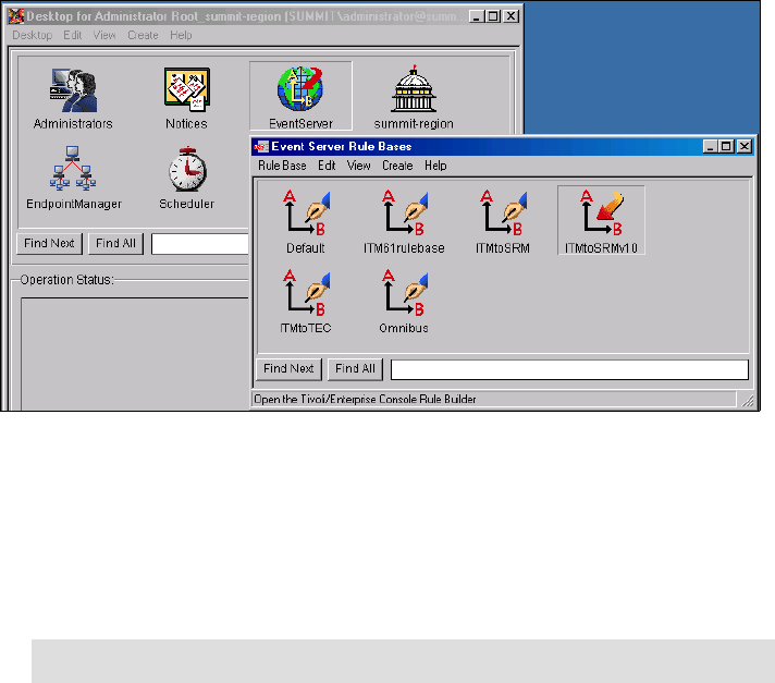
Chapter 3. Event management integration 123
1. Start the Tivoli Desktop.
2. Authenticate with the Administrator ID or root if you use UNIX.
3. Open the EventServer icon, as shown in Figure 3-5 on page 123. The new
rule base appears.
Figure 3-5 New rule set created and activate
3.2.9 Starting the TDI server
Complete the following steps to start the TDI server. Do not start the server if you
have not completed configuration of the SRM server:
1. Change to the TDI working directory.
2. Run the following command:
–On Windows:
mxetdi.cmd
– On Linux or UNIX:
mxetdi.sh
Note: You specified the TDI working directory when you installed TDI.
124 Integration Guide for IBM Tivoli Service Request Manager V7.1
3.2.10 Ticket synchronization
Based on the rules defined in “Predefined scenarios” on page 112, the following
AssemblyLine allows you to create an incident record within Tivoli SRM with
minimum configuration:
1. To establish communication between TDI and Tivoli SRM, the following
configuration in the TDI (described in Figure 3-6 on page 125 and Figure 3-7
on page 126) is required.
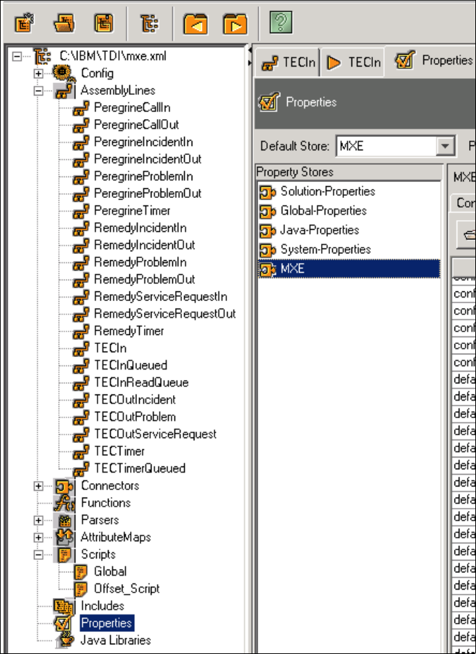
Chapter 3. Event management integration 125
Figure 3-6 Configuration required to establish the communication (1 of 2)
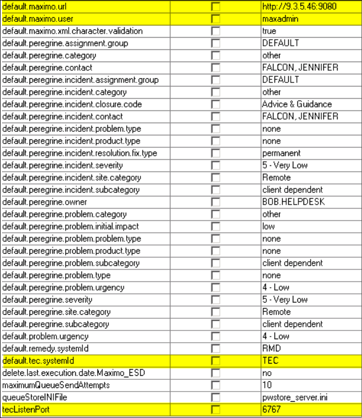
126 Integration Guide for IBM Tivoli Service Request Manager V7.1
Figure 3-7 Configuration required to establish the communication (2 of 2)
2. To test the scenario manually, generate an event with the severity “FATAL”,
using the following command:
wpostemsg -r FATAL -m "This Event is generated to create an Incident
within SRM v7.x" fqhostname="SRV_Server_404" TEC_Error Events
3. Log on to TEC, and validate the creation of the event specified in the previous
step, as shown in Figure 3-8 on page 127.
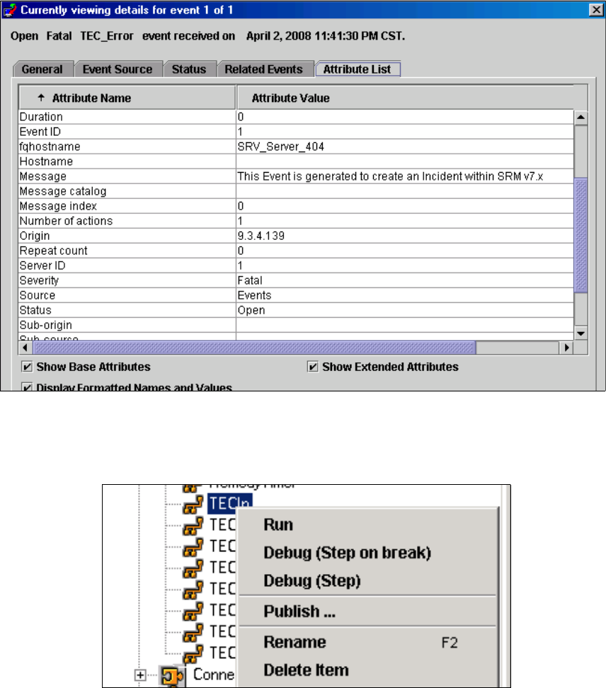

128 Integration Guide for IBM Tivoli Service Request Manager V7.1
Example 3-4 Output of the Run command
is.close();
os.close();
23:11:16 [TECListen] CTGDIS504I *Result of attribute mapping*
23:11:16 [TECListen] CTGDIS505I The 'conn' object
23:11:16 [TECListen] CTGDIS003I *** Start dumping Entry
23:11:16 Operation: generic
23:11:16 Entry attributes:
23:11:16 TECADAPTERHOST (replace):''
23:11:16 TECDURATION (replace):'--'
23:11:16 http.From (replace):'tecadmin@us.ibm.com'
23:11:16 TECLONGMSG (replace):'A trouble ticket has been opened on
reception of this event from host SRV_Server_407'
23:11:16 TECADMINISTRATOR (replace):''
23:11:16 TECMSGINDEX (replace):'--'
23:11:16 TECMSG (replace):'This Event is generated to create an
Incident within SRM v7.x'
23:11:16 http.qs.TECOPERATION (replace):
'OPEN_TT;TECTTID=tt111207203074;TECLONGMSG=A trouble ticket has been
opened on reception of this event from host SRV_Server_407;TECMSG='This
Event is generated to create an Incident within SRM
v7.x';TECSEVERITY=FATAL;TECFQHOSTNAME=SRV_Server_407;TECCLASS=TEC_Error
;TECSERVER_HANDLE=1;TECEVENT_HANDLE=1;TECDATE_RECEPTION=1207203074;TEC_
SERVER=9.3.4.139;TECHOSTPORT=5529;TECACL='[admin]';TECADAPTERHOST='';TE
CADMINISTRATOR='';TECCAUSEDATEEVENT=--;TECCREDIBILITY=1;TECDATEEVENT=--
;TECDURATION=--;TECHOSTNAME='';TECLASTMODIFIEDTIME=--;TECMSGCATALOG='';
TECMSGINDEX=--;TECNUMACTIONS=1;TECORIGIN=origin;TECREPEATCOUNT=--;TECSE
RVERPATH='[]';TECSOURCE=Events;TECSTATUS=OPEN;TECSUBORIGIN='';TECSUBSOU
RCE='';'
23:11:16 TECDATEEVENT (replace):'--'
23:11:16 TECCAUSEDATEEVENT (replace):'--'
23:11:16 TECMSGCATALOG (replace):''
23:11:16 TECHOSTPORT (replace):'5529'
23:11:16 http.base (replace):'/TME/TEC/mro_post.pl'
23:11:16 TECOPERATION (replace):'OPEN_TT'
23:11:16 http.body (replace):
'TECOPERATION=OPEN_TT;TECTTID=tt111207203074;TECLONGMSG=A trouble
ticket has been opened on reception of this event from host
SRV_Server_407;TECMSG='This Event is generated to create an Incident
within SRM
v7.x';TECSEVERITY=FATAL;TECFQHOSTNAME=SRV_Server_407;TECCLASS=TEC_Error
;TECSERVER_HANDLE=1;TECEVENT_HANDLE=1;TECDATE_RECEPTION=1207203074;TEC_
SERVER=9.3.4.139;TECHOSTPORT=5529;TECACL='[admin]';TECADAPTERHOST='';TE
CADMINISTRATOR='';TECCAUSEDATEEVENT=--;TECCREDIBILITY=1;TECDATEEVENT=--

Chapter 3. Event management integration 129
;TECDURATION=--;TECHOSTNAME='';TECLASTMODIFIEDTIME=--;TECMSGCATALOG='';
TECMSGINDEX=--;TECNUMACTIONS=1;TECORIGIN=origin;TECREPEATCOUNT=--;TECSE
RVERPATH='[]';TECSOURCE=Events;TECSTATUS=OPEN;TECSUBORIGIN='';TECSUBSOU
RCE='';'
23:11:16 TECSOURCE (replace):'Events'
23:11:16 TECCREDIBILITY (replace):'1'
23:11:16 TECDATE_RECEPTION (replace):'1207203074'
23:11:16 TECSUBSOURCE (replace):''
23:11:16 http.Content-Length (replace):'709'
23:11:16 TECSTATUS (replace):'OPEN'
23:11:16 TECSEVERITY (replace):'FATAL'
23:11:16 TEC_SERVER (replace):'9.3.4.139'
23:11:16 TECFQHOSTNAME (replace):'SRV_Server_407'
23:11:16 TECCLASS (replace):'TEC_Error'
23:11:16 TECTTID (replace):'tt111207203074'
23:11:16 http.User-Agent (replace):'HTTPTool/1.0'
23:11:16 http.method (replace):'POST'
23:11:16 TECLASTMODIFIEDTIME (replace):'--'
23:11:16 TECEVENT_HANDLE (replace):'1'
23:11:16 TECREPEATCOUNT (replace):'--'
23:11:16 http.Content-Type (replace):
'application/x-www-form-urlencoded'
23:11:16 TECACL (replace):'[admin]'
5. Log on to Tivoli SRM to validate the creation of the incident record
(Figure 3-10 on page 130).
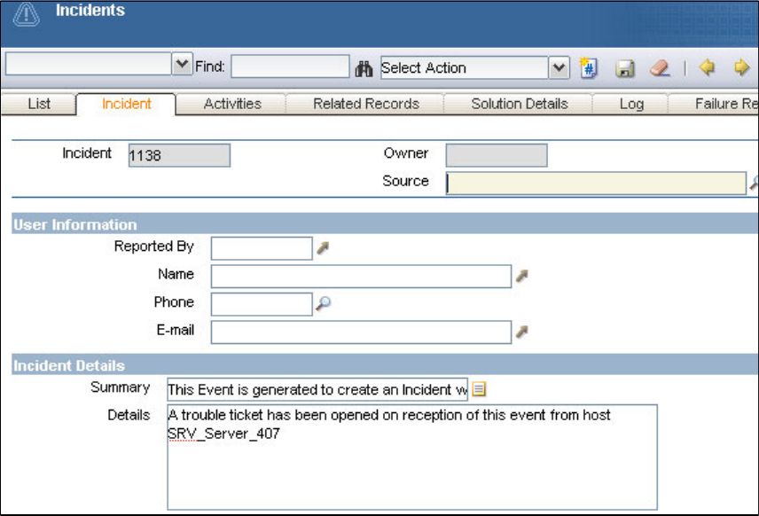
130 Integration Guide for IBM Tivoli Service Request Manager V7.1
Figure 3-10 The incident is generated within Tivoli SRM
3.3 IBM Tivoli Netcool/Omnibus integration (preview)
Tivoli Netcool/Omnibus functions are similar to TEC in terms of event
management. Tivoli Netcool/Omnibus delivers real-time, centralized monitoring
of complex networks and IT domains.
At the time of writing this book, Tivoli Netcool/Omnibus integration with Tivoli
SRM V7.1 is not available. Tivoli SRM V6.2 (or Maximo V6.2) integration is
available and documented at:
http://publib.boulder.ibm.com/infocenter/tivihelp/v8r1/topic/com.ibm.ne
tcool_OMNIbus.doc/gateways/tsrm_integration/concept/tsrm_introduction.h
tml
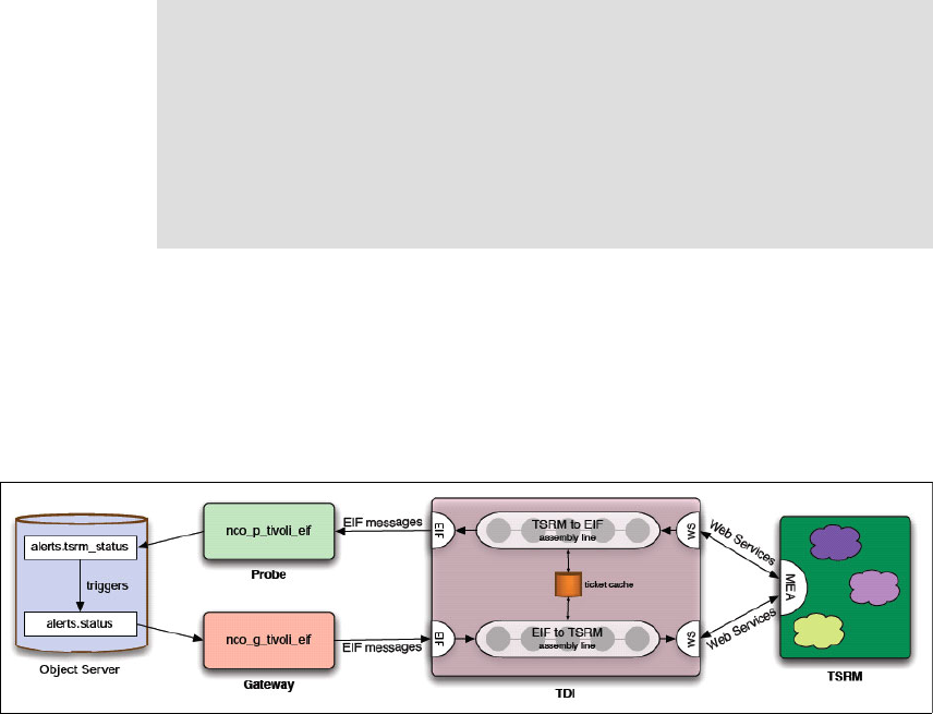
Chapter 3. Event management integration 131
The bidirectional integration of Tivoli Netcool/Omnibus with Tivoli SRM helps
create the new Incident ticket within Tivoli SRM, keeping the incident
synchronized with the event in Netcool/Omnibus. Similar to the TEC, Tivoli
Netcool/Omnibus integration uses TDI. The Netcool/Omnibus Probe and
Gateway are also required to manage the event management workflow.
We provide a high level overview of the Tivoli SRM V6.2 integration, which is
similar to the Tivoli SRM V7.1 integration, when available.
3.3.1 Event workflow (outbound)
Figure 3-11 shows the event workflow to make the outbound integration possible.
Figure 3-11 Outbound event
The event workflow is:
1. The activity in alerts.status is picked up by the Tivoli EIF gateway.
2. The gateway sends EIF messages to TDI.
3. The contents of the EIF messages are passed through the EIF to the SRM
assembly line, being modified (for example, severity mapping) along the way.
4. The data is passed to the Tivoli SRM MEA interface using Web services.
Note: The Gateway for Tivoli Event Integration Facility (EIF) forwards events
from IBM Tivoli Netcool/OMNIbus™ to applications that accept events in EIF
format. The gateway consists of a reader/writer and a writer. The reader/writer
extracts alerts from a source ObjectServer, and the writer forwards the alert
data to applications.
A range of Tivoli products generates EIF messages. The Netcool/OMNIbus
Probe for Tivoli EIF receives EIF events sent from the Tivoli devices and
sends them to the ObjectServer.
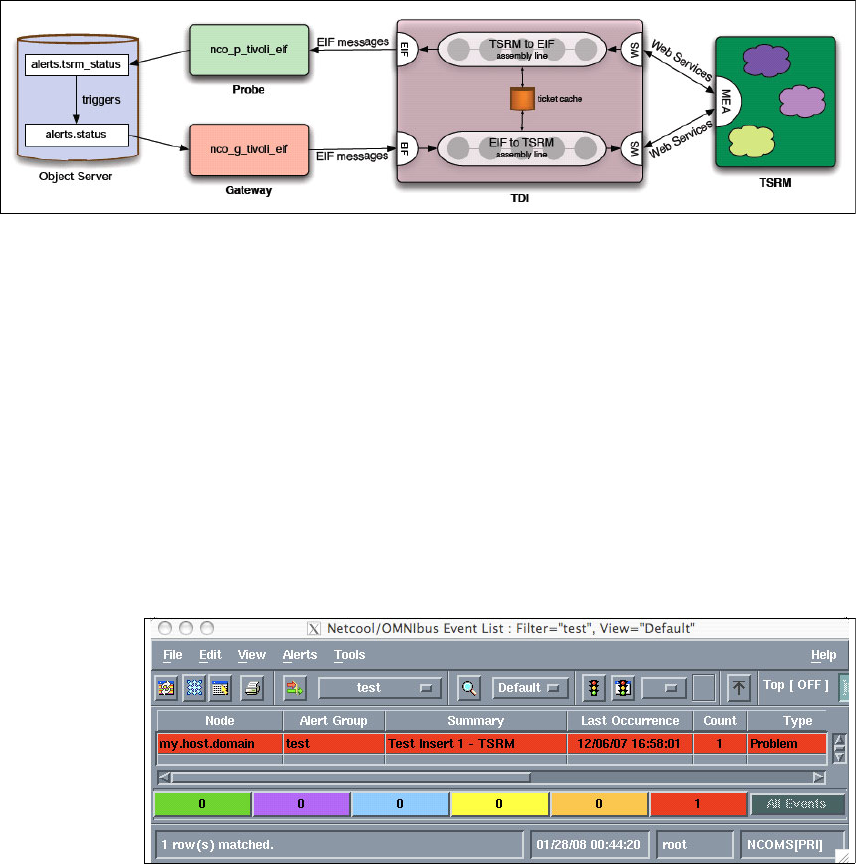
132 Integration Guide for IBM Tivoli Service Request Manager V7.1
3.3.2 Event workflow (inbound)
Figure 3-12 shows the event workflow for inbound integration (the incoming event
from the service desk tools).
Figure 3-12 Inbound event
The event workflow is:
1. TDI polls Tivoli SRM by using Web services every 60 seconds.
2. Updates are passed through the TSRM to EIF assembly line again with
modifications.
3. The data is sent as EIF messages to the EIF probe.
4. The probe puts the data in alerts.tsrm_status.
5. Pre-insert triggers on this table match records with the original records in
alerts.status and perform the appropriate updates.
6. Other triggers clear out the tsrm_status table.
Figure 3-13 shows an event within Netcool/Omnibus.
Figure 3-13 Netcool/Omnibus event
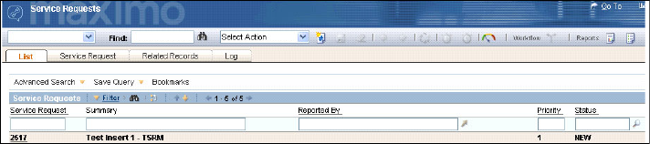
134 Integration Guide for IBM Tivoli Service Request Manager V7.1

© Copyright IBM Corp. 2008. All rights reserved. 135
Chapter 4. Service Desk Tool
integration
This chapter describes the Hewlett-Packard (HP) Service Desk and Tivoli
Service Request Manager (SRM) V7.1, various business aspects of the need for
integration, and in-depth technical configurations for approaching the integration.
This chapter contains the following sections:
Introduction to integration landscape on page 136
Integration scenario on page 137
Service Desk integration planning and installation on page 139
Scenario window flow on page 156
4
136 Integration Guide for IBM Tivoli Service Request Manager V7.1
4.1 Introduction to integration landscape
Service Desk applications are responsible for streamlining IT operations and
improving operational efficiency in an organization. These tools can work in
tandem for monitoring service availability within an organization and identifying
and resolving any interruptions of service that might occur. Many large
enterprises depend on Service Desk to deliver timely customer service.
Most clients already have a type of Service Management solution in place. In
many cases, clients use multiple Service Desk tools for various operations within
the same organization. Many times, these constellations of Help desk tools are a
result of company acquisitions and mergers.
In an IT environment that has multiple Help desks, operating in silos for multiple
operations (such as networking, application support, and so forth) is the most
common cause of delay in responding to service disruption. In most cases, the
multiple Help desks use these tools, and these tools, working in silos, do not
share operational data and do not support carrying forward or sharing the
transaction with other tools. In this scenario, it is essential to have a single
repository for all the Service Desk operations about critical configuration items
(CIs) in order to make the Service Desk operation proactive and responsive to a
customer’s critical business. This repository can carry forward transactions from
the existing Help desk tools, which allows seamless transaction data sharing that
enables the central Help desk to make responsive decisions.
Tivoli SRM is equipped with integration technology that is designed to coexist
with other Help desk tools in the environment. Typically, a new Service
Management product requires replacing the existing or legacy Help desk
product, which might be a costly proposition. Implementing Tivoli SRM saves the
cost of re-implementing the existing Help desk processes in the new tool. At the
same time, this coexisting integration model helps build a central Service Desk
system, which operates in the full view and awareness of all the operations
performed at various Help desk tools on the particular Service Ticket.
The Service Desk Integration Offering for Tivoli SRM provides the necessary
tooling to support migration from existing Help desk products and the
interpretability of Tivoli SRM solutions with other Service Desk products.
The collection of integration scenarios is essentially a software development kit
for the integration of Tivoli SRM V7.1 with HP ServiceCenter and BMC
Remedy-AR IT Service Management suites. In this chapter, we focus on HP
ServiceCenter integration, but BMC Remedy Service Desk is similar and uses
the same tools and concepts.
Chapter 4. Service Desk Tool integration 137
HP ServiceCenter is a comprehensive software product that automates service
management processes based on the Information Technology Infrastructure
Library (ITIL) framework. HP ServiceCenter is used by many clients to manage
Helpdesk IT operations. The Tivoli SRM V7.1 integration with HP ServiceCenter
scenarios collaborates directly with the Web service, which allows Tivoli SRM
V7.1 to interface directly with HP ServiceCenter data.
4.2 Integration scenario
Service Desk personnel are required to make numerous decisions based upon a
limited set of data delivered through Service Desk applications. The evaluation
process involves answering a series of questions and making judgements.
Which group is assigned to manage an event? What priority is the event
assigned? How does this event impact the business? The amount of data and its
accessibility during an event assessment directly impact the quality, efficiency,
and cost-effectiveness of the event resolution. Integrating Service Desk
applications with the rich data, analytics, workflows, policies, and relationships
provided in the Tivoli SRM enables them to provide all the information necessary
to make rapid and well-informed decisions for IT management processes. This
consolidation of resources also:
Lowers the cost of resolving incidents and deploying changes by reducing the
amount of time that is required to execute these processes by making
information readily available and ensuring it is accurate and consistent.
Automates process steps whenever possible.
Assigns work to the appropriate personnel.
Performs tasks in a sequence that maximizes their effectiveness while
minimizing financial impact.
Figure 4-1 on page 138 shows well-defined categories available for integration
between external Service Desk applications and Tivoli SRM V7.1.
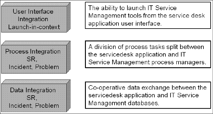
138 Integration Guide for IBM Tivoli Service Request Manager V7.1
Figure 4-1 Integration types
Data integration
Setting up an integration environment enables data to be exchanged between
the HP ServiceCenter application and Tivoli SRM. This data includes Calls,
Incidents, and Problems information as of now.
Process integration
Tivoli SRM can be integrated with HP ServiceCenter at the process level. The
tasks that comprise the Service Request, Incident Management, and Problem
management processes can be divided between the HP ServiceCenter
application and Tivoli SRM transactions. A management process typically begins
in the HP ServiceCenter application and, at an appropriate point in the process, a
corresponding process begins on Tivoli SRM. The two applications work together
where only one application executes a process at a given time with appropriate
notifications that keep the overall process working.
The following process integration scenarios are provided for the HP
ServiceCenter and Tivoli SRM:
Incident creation and updates originating in the HP ServiceCenter invoke
Incident ticket creation and updates in Tivoli SRM.
Incident creation and updates originating in Tivoli SRM invoke Incident
creation, updates in the Service Desk application, which, in practice, take
Incidents created in the Service Desk application, and closure.

Chapter 4. Service Desk Tool integration 139
User interface integration
Service Desk applications can be integrated with Tivoli SRM at a user interface
level in order to obtain the information necessary to complete a task in the
Service Desk application. Tivoli SRM can be launched in context with the current
HP ServiceDesk application task. For example, during an incident evaluation,
you can launch the Tivoli SRM Incident Management window view from the HP
Service Desk, which provides a detailed view of incident Ticket details from
Maximo.
4.3 Service Desk integration planning and installation
Prior to the installation and configuration of the HP ServiceCenter connector,
prerequisites must be met prior to starting the installation and configuration.
Predefined scenario
The predefined scenario that we provide with the product is simple. Every
incident record in the HP ServiceCenter with a data that is greater than the
particular date specified in the AssemblyLine is created in Tivoli SRM.
Service Desk integration component availability
Service Desk application integration scenarios are available by default along with
the TDI installation from the Tivoli SRM installation launchpad.
Prerequisites for installation and configuration
The integration and installation have prerequisite environmental requirements as
shown in Figure 4-2 on page 140.
The prerequisites are:
An HP ServiceCenter server V6.1 installed and running in your environment.
An HP ServiceCenter Web Services installed and configured properly, using
the same version as the HP ServiceCenter server V6.1.
Note: Service Desk application integration scenarios are also available as a
single zip file archive (.zip) from the IBM Tivoli Open Process Automation
Library (OPAL) Web site at:
http://catalog.lotus.com/wps/portal/topal
Visit this Web site prior to deploying Service Desk integration scenarios to
ensure that you have the latest version. The zip is not available on the Web
site at this time.
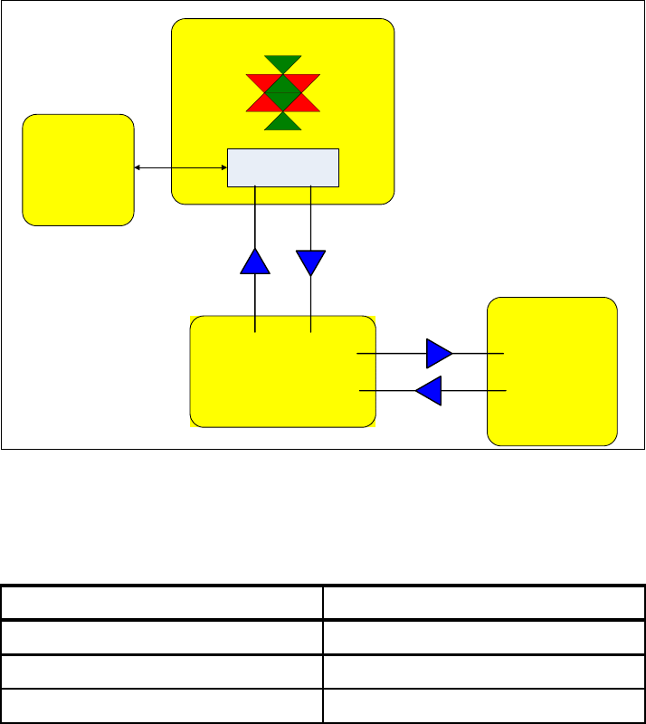
140 Integration Guide for IBM Tivoli Service Request Manager V7.1
An HP ServiceCenter V6.1 Thick Client installed to connect to the server.
Perform the configuration and other changes to the system.
Figure 4-2 shows the integration environment and components.
Figure 4-2 Tivoli SRM V7.1 and HP ServiceCenter integration environment
Table 4-1 lists the applications that are supported by the Service Desk integration
scenarios.
Table 4-1 Supported versions
Application Supported version
Tivoli SRM 7.1
HP Service Desk 6.1
TDI 6.1.1
HP
ServiceCenter
Server
v6.1
HP-ServiceCenter
Web Services
Server A
Tivoli Directory Integrator
CONNECTOR
HP-Peregrine
Assembly Line
Create/Update
Ticket
Update
Ticket
Web Services Integration
Server B
Create/Update
Ticket
Update
Ticket
Server C
Tivoli
Directory
Integrator
(UI)
Workstation

Chapter 4. Service Desk Tool integration 141
4.3.1 Installation instructions for the HP ServiceCenter connector
The following steps install the HP ServiceCenter connector in the TDI
environment:
1. Rename the MaximoConnector.jar file to <tdi home>/jars/connectors to
MaximoConnector.jar_.
2. Obtain the file tdi_integration_deployment.zip from the TDI build directory.
3. Unzip the file, and copy all jars from integrate/install/tdi/jars/connectors to
<tdi home>/jars/connectors directory. Example 4-1 shows an example of the
jar files.
Example 4-1 Jar files required for the HP ServiceCenter connector
C:\IBM\TDI\jars\connectors>dir
Volume in drive C has no label.
Volume Serial Number is 6806-ABBD
Directory of C:\IBM\TDI\jars\connectors
02/28/2008 05:58 PM <DIR> .
02/28/2008 05:58 PM <DIR> ..
02/12/2008 04:20 PM 6,991 build_stubs.xml
02/12/2008 04:20 PM 13,285 IBMSRMPeregrineBaseConnector.jar
02/12/2008 04:20 PM 1,219,526 IBMSRMPeregrineBaseStubs.jar
02/12/2008 04:20 PM 5,420 IBMSRMPeregrineChangeConnector.jar
02/12/2008 04:20 PM 5,090 IBMSRMPeregrineComputerConnector.jar
02/12/2008 04:20 PM 704 IBMSRMPeregrineConnectors-docs.zip
02/12/2008 04:20 PM 5,426 IBMSRMPeregrineIncidentConnector.jar
02/12/2008 04:20 PM 3,644 IBMSRMPeregrineOperatorConnector.jar
02/12/2008 04:20 PM 5,704 IBMSRMPeregrineProblemConnector.jar
02/12/2008 04:20 PM 4,501 IBMSRMPeregrineRelationshipConnector.jar
02/12/2008 04:20 PM 4,928 IBMSRMPeregrineSoftwareConnector.jar
02/05/2008 04:42 PM 16,882 MaximoConnector.jar_
4. Copy the mxe.xml file from \tdi path in tdi_integration_deployment.zip to
<tdi working dir>.
5. Modify the <tdi working dir>/mxe.properties file (Example 4-2 on page 142),
and add the following lines:
peregrinePassword<peregrine password> (default is blank)
peregrineCMTOffset=<CMT offset> (timezone offset from CMT, -5 is Central)
peregrineHost=<your peregrine host URL> (ex. http://localhost)
peregrinePort=<peregrine port> (ex. 12670)
peregrineUser=<peregine userid> (ex. falcon)
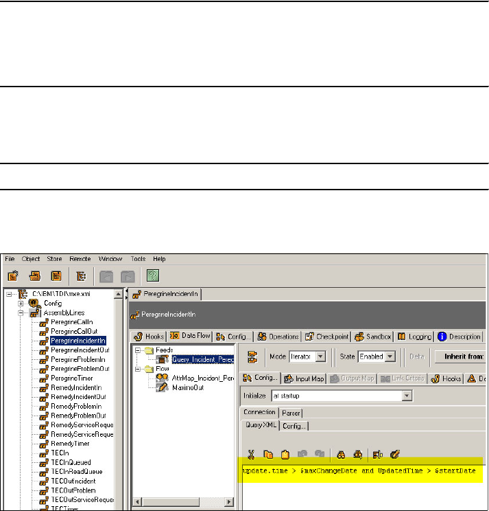
142 Integration Guide for IBM Tivoli Service Request Manager V7.1
Example 4-2 mxe.properties file
peregrinePassword={encr}
peregrineCMTOffset=-5
peregrineHost=http://localhost
peregrinePort=12670
peregrineUser=falcon
6. Edit <tdi working dir>/mxetdi.cmd (or.sh for Linux/UNIX), and modify the
values (Example 4-3) for the -r option.
Example 4-3 mxetdi.cmd file
"<tdi home>\ibmdisrv" -s . -c mxe.xml -r TECIn TECTimer PeregrineTimer
7. By default, AssemblyLine queries the HP ServiceCenter database
(Figure 4-3).
Figure 4-3 AssemblyLine configuration: Querying HP ServiceCenter database
8. To bypass this feature, you must disable the MaximoOut Flow connector
temporarily in the following assemblies: PeregrineIncidentIn,
PeregrineProblemIn, and PeregrineCallIn:
a. Start TDI config editor, and open the mxe.xml file.
b. Select PeregrineIncidentIn assembly from the upper left panel.
c. Right-click the MaximoOut connector in the Flow section, and choose the
Enable option to toggle it to disabled as shown Figure 4-4 on page 143.
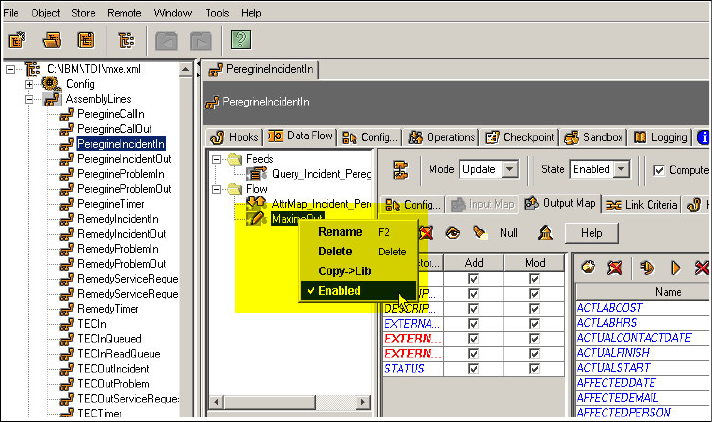
Chapter 4. Service Desk Tool integration 143
Figure 4-4 AssemblyLine configuration: Disabling the SRM ticket generation
4.3.2 HP Service Desk configuration
To make the integration possible and to prevent duplicates of the same record
being created in HP ServiceCenter or Tivoli SRM, there must be a field in both
ServiceCenter and Tivoli SRM to hold the external ID value of the ticket in the
SRM application. In Tivoli SRM, this field is created when the Process Solution
installation is running. In HP ServiceCenter, we manually create them.
Setting up the Web services server
Complete the following steps:
1. Open the file sc.cfg located in <PEREGRINE_INSTALL_HOME>\
ServiceCenter Server\RUN and open it.
2. Add the following line in the file:
scenter -apiserver:< PEREGRINE_WEBSERVICES_PORT> -log:../logs/ws.log
and substitute <PEREGRINE_WEBSERVICES_PORT> for a port number to
use as the Web services listener. The default port in the Assembly Line is
12700.
3. Restart the HP ServiceCenter console.
144 Integration Guide for IBM Tivoli Service Request Manager V7.1
Creating new fields
To create new fields, complete the following steps:
1. Open the Peregrine ServiceCenter client and connect to the server.
2. Navigate to System Definition → Tables → probsummary.
3. Go to the Field and Keys tab.
4. In the Field section, click New Field → type name external.id
5. Click OK.
6. With Field selected, in General Properties, select type Text → caption
ExternalID.
7. In Peregrine Web Services API Properties, select Include in API.
8. Type ExternalID in the Field Name in the API field.
9. In the Field section, click New Field → type name external.uid
10.Click OK.
11.With Field selected, in General Properties, select type Text → caption
ExternalUID.
12.In Peregrine Web Services API Properties, select Include in API.
13.Type ExternalUID in the Field Name in the API field.
14.Click Save.
15.Navigate to System Definition → Tables → rootcause.
16.Go to the tab Field and Keys.
17.In the Field section, click New Field → type name external.id
18.Click OK.
19.With field selected, in General Properties, select type Text → caption
ExternalID.
20.In Peregrine Web Services API Properties, select Include in API.
21.Leave the Field Name in API field blank.
22.In the Field section, click New Field → type name external.uid
23.Click OK.
24.Select Field in General Properties, select Text → caption ExternalUID.
25.In Peregrine Web Services API Properties, select Include in API.
26.Leave the Field Name in API field blank.
27.Click Save.
28.Navigate to System Definition → Tables → cm3r.
Chapter 4. Service Desk Tool integration 145
29.Go to the tab Field and Keys.
30.In the Field section, click New Field → type name external.id
31.Click OK.
32.With field selected, in General Properties, select Text → caption
ExternalUID.
33.In Peregrine Web Services API Properties, select Include in API.
34.Type ExternalID in the Field Name in the API field.
35.In the Field section, click New Field, and type name external.uid
36.Click OK.
37.With Field selected, in General Properties, select Text → caption
ExternalUID.
38.In Peregrine Web Services API Properties, select Include in API.
39.Type ExternalUID in the Field Name in API field.
40.Click Save.
Adding Web Services API database attributes
The HP OpenView ServiceCenter Web services API does not include all required
database attributes by default. The Service Desk integration AssemblyLines are
dependent upon attributes that are not included. These attributes can be
included as described next (when the column Field Data Type in API is empty,
leave it empty in the Administration Client also, so that the application defaults to
StringType).
For Peregrine to publish the tables and fields that are going to be queried or
updated by the AssemblyLines, it has to be configured:
1. Open Peregrine ServiceCenter Client and connect to the server.
2. Go to System Definition → Tables → probsummary.
3. Go to the tab Fields and Keys and locate them as shown in Table 4-2 on
page 146.
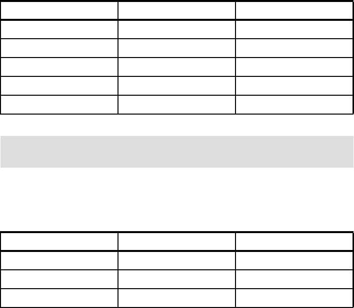
146 Integration Guide for IBM Tivoli Service Request Manager V7.1
Table 4-2 Adding the API database attributes to fields
4. Go to System Definition → Tables → cm3r.
5. Go to the Fields and Keys tab and locate the fields shown in Table 4-3.
Table 4-3 Adding the API database attribute fields
6. Go to System Definition → Tables → rootcause.
7. Click the Include in API check box for all fields:
a. Leave the Field Name in API blank.
b. For each field type: Date/Time in the General Properties section, choose
StringType.
8. Go to System Definition → Tables → operator.
9. Go to the Fields and Keys tab, and locate the following fields in Table 4-4 on
page 147.
Field name Field name in API Field data type in API
contact.email ContactEmail N/A
contact.phone ContactPhone N/A
contact.time ContactTime DateTimeType
extension ContactPhoneExtension N/A
user.priority UserPriority N/A
Note: For each of these fields, click the Include in API check box, Field
Name in API, and Field Data Type in API.
Field name Field name in API Field data type in API
header, orig.date.entered DateOpened DataTimeType
header,request.phone RequestorPhone N/A
sysmodtime SysModTime DataTimeType

Chapter 4. Service Desk Tool integration 147
Table 4-4 Adding the API database attributes to fields
10.Go to System Definition → Tables → screlation.
11.Click the Include in API check box for all fields:
a. Leave the Field Name in API blank.
b. For each field that is Date/Time Type (look in the General Properties
section), choose DateTimeType in the Field Data Type in API field.
c. For each field that is Boolean Type, choose Type Boolean in the Field
Data Type in API field.
12.Go to System Definition → Tables → Device.
13.Go to the Fields and Keys tab and locate the fields that are shown in
Table 4-5 .
Table 4-5 Adding the API database attributes to fields
14.Go to System Definition → Tables → Computer.
15.Go to the Fields and Keys tab and locate the fields that are shown in
Table 4-6 .
Table 4-6 Adding the API database attributes to fields
Field name Field name in API Field data type in API
email email N/A
namenameN/A
phone phone N/A
Field name Field name in API Field data type in API
sysmodtime SysmodTime DateTimeType
Note: For each of these fields, click the Include in API check box, and fill in
the Field Name in API and the Field Data Type in API.
Field name Field name in API Field data type in API
machine.name MachineName N/A
sysmodtime SysModTime DateTymeType

148 Integration Guide for IBM Tivoli Service Request Manager V7.1
16.Go to System Definition → Tables → pcsoftware.
17.Go to the Fields and Keys tab and locate the fields that are shown in
Table 4-7.
Table 4-7 Adding the API database attributes to fields
18.Go to Menu Navigation → Toolkit → DatabaseManager → Table:
extaccess.
19.Select Search.
20.Add a new service with the following parameters:
a. Service Name: OperatorManagement
b. Name: Operator
c. Object: Operator
21.Select Add.
22.Select OK.
23.Add a new service with the following parameters:
a. Service Name: RelationshipManagement
b. Name: screlation
c. Object: Relationship
d. Go the Allowed Actions tab, add the following lines:
i. Save/Update
ii. Delete/Delete
iii. Add/Create
24.Select Add.
25.Exit the Database Manager application.
Note: For each of the fields, click the Include in API check box, and fill in the
Field Name in API and the Field Data Type in API.
Field name Field name in API Field data type in API
sysmodtime SysmodTime DateTimeType
Note: For each field, click the Include in API check box, and fill in the Field
name in API and the Field data type in API.
Chapter 4. Service Desk Tool integration 149
Implementing launch in context
The first time that a launch in context is established from an HP ServiceCenter
server application, log in to the Change and Configuration Management
Database (CCMDB) environment. After that, you do not have to log in to the
CCMDB environment unless the session expires, you choose the Sign out
option, or you close the window. To customize the HP ServiceCenter to launch
the CCMDB in context, complete the following steps:
1. Identify the HP ServiceCenter form. The first step to launching CCMDB from
the HP OpenView ServiceCenter interface is to identify the HP OpenView
ServiceCenter form where the launch button is placed:
a. Select the Services tab in the HP ServiceCenter panel.
b. Click Incident Management, and then, click Search IM Tickets.
c. Press Enter with the window open without entering any values. A new
window appears with a list at the top and a form at the bottom.
d. Click or position the focus on the form. Check the name of the form in the
bottom right corner (for example, IM.template.open.g).
e. Write down the name of the form.
2. Associate an action to the button. After you have successfully added the new
button to the form, you must associate an action with its use. Complete the
following steps to associate an action with the new button:
a. Select the Utilities tab from the HP ServiceCenter window.
b. Select Tools from the Utilities panel.
c. Click Display Options.
d. In the display application option definition, fill the following fields with these
values:
i. Window ID: scm.advanced
ii. Default Label: By Owner
iii. Balloon Help: Calls by Owner
e. Select Search.
f. Modify the following fields:
i. Window ID: apm.edit.problem
ii. Action: do nothing
iii. Unique ID: lic.incident.CCMDB (as an example)
iv. GUI option: 6000
v. Balloon Help: This is a text field not mandatory.
This text appears when you move the mouse pointer on the button.

150 Integration Guide for IBM Tivoli Service Request Manager V7.1
vi. Default Label: This is a text field not mandatory.
Type a default label for the application.
Condition: “not null(external.uid in $L.filed)” Setting Condition
to that value forces the launch button to be enabled only for integrated
records. If you want the launch button to be conditionally enabled,
consult the HP ServiceCenter documentation.
g. Select the RAD tab.
h. Select the Pre Rad® Expressions tab in the sub-tab and fill the
expression with the following value:
$lo.command="http://<hostname or IP
address>:<portnumber>/maximo/ui/?event=loadapp&value=incident&uis
essionid=”+external.uid in $L.filed
The link that was added within the HP ServiceCenter record is shown in
Example 4-4.
Example 4-4 Link added within the HP ServiceCenter record
“http://9.3.5.46:9080/maximo/ui/?event=loadapp&value=incident&uisession
id=”+external.uid
i. Select the Rad tab in the sub-tab, and fill the fields as described:
i. RAD Application: us.launch.external
ii. Separate Thread: false
iii. Name: $lo.command
j. Click Add.
k. Click OK.
3. Now that the form is identified, you can add a button.
a. Select the Toolkit tab from the HP ServiceCenter window.
b. Select Forms Designer from the Toolkit panel.
c. Type IM.template.update.g in the Form field of the Forms Designer
window.
d. Click the Search icon.
e. Highlight the IM.template.update.g form listed in the search results list.
f. Click Design.
4. Create a New button on the form by first selecting the button icon from the
tools bar.
5. Move the button anywhere on the form.
Chapter 4. Service Desk Tool integration 151
6. Change the properties when the button is created on the form:
a. Select New.
b. Change the following Properties from within the Properties window:
i. Change the Caption value: Provide the appropriate identification.
ii. Change the Button ID: 6000.
This value is defined in the Button definition “as Display Option”.
Viewing data in context
After you have completed the steps for implementing launch in context for the
incident modules, it must be synchronized through the AssemblyLines. To view
the data in context, complete the following steps:
1. Launch HP OpenView ServiceCenter and log in.
2. View any of the Open tickets that are incident types.
3. Click Launch CCMDB.
After you complete the steps, the CCMDB Product Console is launched in
context.
Verifying the creation and publication of new fields
Use this topic to verify that new fields are created in HP ServiceCenter and the
correct fields are published.
Verify that the new fields are created and published by completing the following
steps:
1. Open the Peregrine ServiceCenter Client and connect to the server.
2. Go to Menu Navigation → Toolkit → DatabaseManager.
3. Click File.
4. Type extaccess.
5. Press Enter.
6. For the following services, click the Data policy tab and make sure that the
external.id and external.uid fields are created and that all the correct fields are
published:
a. IncidentManagement.wsdl
b. ProblemMangemente.wsdl
c. ChangeManagement.wsdl
7. For the following services, click the Data policy tab and make sure that the
correct fields are published:
a. ConfigurationManagement.wsdl
152 Integration Guide for IBM Tivoli Service Request Manager V7.1
b. RelationshipManagement.wsdl
c. OperatorManagement.wsdl
4.3.3 TDI properties configuration
The TDI Properties file contains the parameters that you need for the
AssemblyLines to work. The values must be defined for the properties according
to your system’s configuration. Using the values that you entered in the
worksheet, complete the following steps to install Service Desk integration
scenarios:
1. Start the TDI.
2. Open the TDI AssemblyLine:
a. Select File → Open.
a. Choose the <TDI solution directory>\peregrine\mxe.xml file.
a. Click OK.
3. Set the properties for your environment by completing the following steps:
a. In the navigation menu, click Properties.
a. Select MXE from the Property Stores list.
b. Edit the MXE properties by double-clicking the Value field for each of the
properties that is listed in Table 4-8 on page 153.

Chapter 4. Service Desk Tool integration 153
Table 4-8 MXE properties store in TDI
Property Default value Properties per
integration
environment
Record your
values
config.peregrine.passw
ord
N/A Provide HP Service
Desk user password for
authentication
config.peregrine.server.
port
12700 Provide HP Service
Desk port number
config.peregrine.server.
url
http://<server
IP>
Provide Peregrine
URL, for example:
http://9.3.5.56
config.peregrine.user,
value
falcon Provide HP Service
Desk user name for
authentication
default.last.execution.d
ate.Maximo_ESD
2008-01-01T06
:00:00+00:00
Auto-populated
default.maximo.authent
ication.required
TRUE DEFAULT
default.maximo.callSyst
emId, value
PCALL DEFAULT
default.maximo.error.ex
cedent.size
FALSE DEFAULT
default.maximo.incident
SystemId
PINC Provide value Maximo
Incident System ID
default.maximo.owner EXT_SD Provide value of Owner
ID which is a valid ID in
Tivoli SRM person
records
default.maximo.owner.
group
G_EXT_SD Provide value of Owner
Group ID, which is a
valid ID in Tivoli SRM
Person Group records
default.maximo.passwo
rd
N/A Provide Tivoli SRM
user password for
authentication
default.maximo.proble
mSystemId
PPRO DEFAULT

154 Integration Guide for IBM Tivoli Service Request Manager V7.1
default.maximo.siteid BEDFORD Provide Tivoli SRM
Site ID for the tickets
default.maximo.url http://<Server
name or
ID>:<port
number>
Provide Tivoli SRM
application URL with
port number. For
example:
http://9.3.5.46:9080
default.maximo.user maxadmin Use maxadmin as
default or provide an
integration user that is
used for the activity
default.maximo.xml.cha
racter.validation
TRUE DEFAULT
default.peregrine.assig
nment.group
DEFAULT DEFAULT
default.peregrine.categ
ory
other DEFAULT
default.peregrine.conta
ct
FALCON,
JENNIFER
Provide Peregrine user
for the contact
default.peregrine.incide
nt.assignment.group
DEFAULT Provide Peregrine
Incident assignment
group
default.peregrine.incide
nt.category
other DEFAULT
default.peregrine.incide
nt.closure.code
Advice &
Guidance
Provide Peregrine
Incident closure code
default.peregrine.incide
nt.contact
FALCON,
JENNIFER
Provide Peregrine
Incident contact name
default.peregrine.incide
nt.problem.type
none DEFAULT
default.peregrine.incide
nt.product.type
none DEFAULT
default.peregrine.incide
nt.resolution.fix.type
permanent DEFAULT
Property Default value Properties per
integration
environment
Record your
values

Chapter 4. Service Desk Tool integration 155
default.peregrine.incide
nt.severity
5 - Very Low Provide Peregrine
Incident severity
default.peregrine.incide
nt.site.category
Remote Provide Peregrine
Incident category
default.peregrine.incide
nt.subcategory
client
dependent
Provide Peregrine
Incident subcategory
default.peregrine.owner BOB.HELPDE
SK
Provide Peregrine
process owner, which
is a valid Peregrine
user
default.peregrine.probl
em.category
other Provide Peregrine
Problem category
default.peregrine.probl
em.initial.impact
low Provide Peregrine
Problem initial impact
default.peregrine.probl
em.problem.type
none Provide Peregrine
Problem type
default.peregrine.probl
em.product.type
none Provide Peregrine
Problem Product type
default.peregrine.probl
em.subcategory
client
dependent
Provide Peregrine
problem subcategory
default.peregrine.probl
em.type
none Provide Peregrine
Problem type
default.peregrine.probl
em.urgency
4 - Low Provide Peregrine
Problem Urgency
default.peregrine.severi
ty
5 - Very Low Provide Peregrine
Problem Severity
default.peregrine.site.
category
Remote Provide Peregrine
Problem Site category
default.peregrine.subca
tegory
client
dependent
Provide Peregrine
Problem subcategory
default.problem.urgenc
y
4 - Low Provide Peregrine
Problem Severity
Property Default value Properties per
integration
environment
Record your
values

156 Integration Guide for IBM Tivoli Service Request Manager V7.1
4.4 Scenario window flow
In this section, we demonstrate how Tivoli SRM and HP ServiceCenter
integration is accomplished in a real-life scenario:
1. Open HP ServiceCenter and navigate to the Incident Management module.
2. Select the Open New incident window and fill all the required fields to create
a new incident record.
3. Click Submit.
4. Open the TDI scenario:
a. Start the TDI application.
b. Open the mxe.xml (the configuration file for the scenarios). Refer to
Figure 4-5 on page 157.
delete.last.execution.da
te.Maximo_ESD
no DEFAULT
maximumQueueSendA
ttempts
10 DEFAULT
queueStoreINIFile pwstore_server
.ini
DEFAULT
Property Default value Properties per
integration
environment
Record your
values
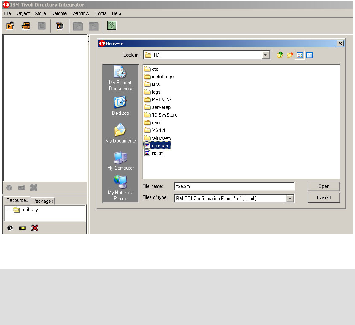
Chapter 4. Service Desk Tool integration 157
Figure 4-5 Opening of the integration scenarios, known as an AssemblyLine
5. Run PeregrineIncident in the AssemblyLine to perform integration
(Figure 4-6 on page 158).
Note: By default, TDI has a timer scheduling mechanism, which runs all
AssemblyLine transactions periodically. You can alter the timing schedule by
setting the TDI Timer. You can also execute the AssemblyLines manually from
TDI.
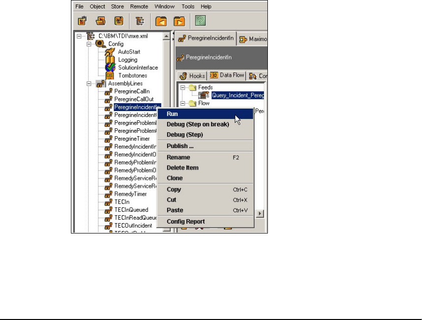
158 Integration Guide for IBM Tivoli Service Request Manager V7.1
Figure 4-6 Running AssemblyLine manually
6. After PeregrineIncident in AssemblyLine runs successfully, the following
output appears on the right pane, which shows the messages. We identify the
important messages (Example 4-5) in this output in bold.
Example 4-5 PeregrineIncident in AssemblyLine output
Command Line Parameters:
[javaw.exe, -classpath, C:\IBM\TDI\V6.1.1\IDILoader.jar,
-Dlog4j.configuration=file:///C:\IBM\TDI\V6.1.1/etc/executetask.properties, -Dos.name=Windows
Server 2003,
-Djava.library.path=C:\IBM\TDI\V6.1.1\jvm\jre\bin;.;C:\IBM\TDI\V6.1.1\jvm\jre\bin;C:\IBM\TDI\V6
.1.1\libs;C:\cygwin\bin;C:\WINDOWS\system32;C:\WINDOWS;C:\WINDOWS\System32\Wbem;C:\Program
Files\IBM\WebSphere\AppServer\java\bin;C:\Program Files\IBM\Java50\jre\bin;C:\Apache Software
Foundation\Tomcat 4.1, -jar, C:\IBM\TDI\V6.1.1\IDILoader.jar, com.ibm.di.server.RS,
-rAssemblyLines/PeregrineIncidentIn, -SC:\IBM\TDI\mxe.xml,
-Ycom.ibm.di.config.xml.MetamergeConfigXML, -D, -R]
16:16:49 CTGDIS232I Server is running in standard mode.
16:16:50 CTGDIS236I The stash file has been successfully read.
16:16:50 CTGDIS237I The key password is not in the stash file. The keystore password is used.
16:16:50 CTGDIS238I Server security has been successfully initialized.
16:16:50 CTGDKD445I Custom method invocation is set to false.
16:16:51 CTGDKD460I Generated configuration id 'C__IBM_TDI_mxe.xml' for a configuration
instance loaded from file 'C:\IBM\TDI\mxe.xml'.

Chapter 4. Service Desk Tool integration 159
16:16:51 CTGDIS229I Register server: C:\IBM\TDI\mxe.xml.
16:16:51 Version : 6.1.1 - 2007-02-07
16:16:51 OS Name : Windows Server 2003
16:16:51 Java Runtime : IBM Corporation, 2.3
16:16:51 Java Library : C:\IBM\TDI\V6.1.1\jvm\jre\bin
16:16:51 Java Extensions : C:\IBM\TDI\V6.1.1\jvm\jre\lib\ext
16:16:51 Working directory : C:\IBM\TDI\V6.1.1
16:16:51 Configuration File: <stdin>
16:16:51 CTGDIS785I ---
16:16:51 CTGDIS040I Loading configuration from stdin.
16:16:52 CTGDIS028I Starting AssemblyLine AssemblyLines/PeregrineIncidentIn.
16:16:52 CTGDIS255I AssemblyLine AssemblyLines/PeregrineIncidentIn is started.
16:16:52 CTGDIS669I [ScriptEngine] RegEx library: java regex library.
16:16:52 CTGDIS670I [ScriptEngine] Engine last modified date: Tue Jan 23 13:08:12 CST 2007
(C:\IBM\TDI\V6.1.1\jars\3rdparty\IBM\ibmjs.jar).
16:16:53 CTGDIR101I The properties file 'C:\IBM\TDI\V6.1.1\solution.properties' does not exist
and is ignored.
16:16:54 CTGDIS087I Iterating.
16:16:56 extToHash: PINC IM10006=PINC-1680533229
16:16:56 [MaximoOut] Executing search...
16:17:12 [MaximoOut] Search has been executed.
16:17:12 [MaximoOut] Creating entry...
16:17:12 [MaximoOut] Entry has been created.
16:17:12 extToHash: PINC IM10007=PINC-1680533228
16:17:12 [MaximoOut] Executing search...
16:17:12 [MaximoOut] Search has been executed.
16:17:12 [MaximoOut] Creating entry...
16:17:12 [MaximoOut] Entry has been created.
16:17:12 CTGDIS088I Finished iterating.
16:17:12 CTGDIS100I Printing the Connector statistics.
16:17:12 [Query_Incident_Peregrine] Get:2
16:17:12 [AttrMap_Incident_Peregrine_Maximo] CTGDIS103I No statistics.
16:17:12 [MaximoOut] Lookup:2, Add:2
16:17:12 CTGDIS104I Total: Get:2, Lookup:2, Add:2.
16:17:12 CTGDIS101I Finished printing the Connector statistics.
16:17:12 CTGDIS080I Terminated successfully (0 errors).
16:17:12 CTGDIS079I AssemblyLine AssemblyLines/PeregrineIncidentIn terminated successfully.
16:17:14 CTGDIS241I All threads have been stopped.
16:17:14 CTGDIS174I Config Instance C:\IBM\TDI\mxe.xml exited with status 0.
16:17:14 CTGDIS228I Unregister server: C:\IBM\TDI\mxe.xml.
16:17:14 CTGDIS627I TDI Shutdown.
16:17:14 CTGDIS376I Shutting down database: TDISysStore.
************************
Process exit code = 0
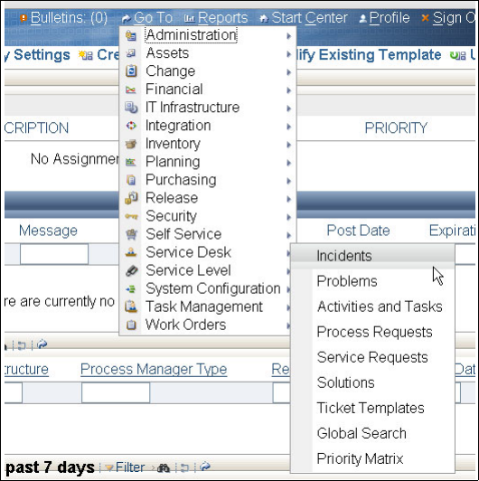
160 Integration Guide for IBM Tivoli Service Request Manager V7.1
7. Open Incident Management from the Start Center, as shown in Figure 4-7.
Figure 4-7 Opening the incident application within SRM
8. Verify the Incident ticket that was created by HP ServiceCenter. Take action
on the ticket and save the Incident ticket. You can move this ticket into the
workflow and take an action by using the Tivoli SRM features.
9. Update the Incident that was created in Tivoli SRM by changing the Contact
Name or any other field that exists in HP ServiceCenter. Refer to Figure 4-8
on page 161.
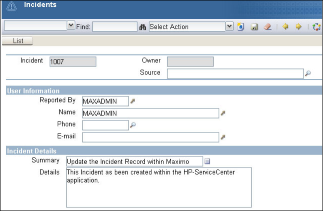

162 Integration Guide for IBM Tivoli Service Request Manager V7.1
Example 4-6 Peregrine IncidentOUT AssemblyLine output
Command Line Parameters:
[javaw.exe, -classpath, C:\IBM\TDI\V6.1.1\IDILoader.jar,
-Dlog4j.configuration=file:///C:\IBM\TDI\V6.1.1/etc/executetask.properties, -Dos.name=Windows
Server 2003,
-Djava.library.path=C:\IBM\TDI\V6.1.1\jvm\jre\bin;.;C:\IBM\TDI\V6.1.1\jvm\jre\bin;C:\IBM\TDI\V6
.1.1\libs;C:\cygwin\bin;C:\WINDOWS\system32;C:\WINDOWS;C:\WINDOWS\System32\Wbem;C:\Program
Files\IBM\WebSphere\AppServer\java\bin;C:\Program Files\IBM\Java50\jre\bin;C:\Apache Software
Foundation\Tomcat 4.1, -jar, C:\IBM\TDI\V6.1.1\IDILoader.jar, com.ibm.di.server.RS,
-rAssemblyLines/PeregrineIncidentOut, -SC:\IBM\TDI\mxe.xml,
-Ycom.ibm.di.config.xml.MetamergeConfigXML, -D, -R]
16:24:28 CTGDIS232I Server is running in standard mode.
16:24:29 CTGDIS236I The stash file has been successfully read.
16:24:29 CTGDIS237I The key password is not in the stash file. The keystore password is used.
16:24:29 CTGDIS238I Server security has been successfully initialized.
16:24:29 CTGDKD445I Custom method invocation is set to false.
16:24:30 CTGDKD460I Generated configuration id 'C__IBM_TDI_mxe.xml' for a configuration
instance loaded from file 'C:\IBM\TDI\mxe.xml'.
16:24:30 CTGDIS229I Register server: C:\IBM\TDI\mxe.xml.
16:24:30 Version : 6.1.1 - 2007-02-07
16:24:30 OS Name : Windows Server 2003
16:24:30 Java Runtime : IBM Corporation, 2.3
16:24:30 Java Library : C:\IBM\TDI\V6.1.1\jvm\jre\bin
16:24:30 Java Extensions : C:\IBM\TDI\V6.1.1\jvm\jre\lib\ext
16:24:30 Working directory : C:\IBM\TDI\V6.1.1
16:24:30 Configuration File: <stdin>
16:24:30 CTGDIS785I ---
16:24:30 CTGDIS040I Loading configuration from stdin.
16:24:31 CTGDIS028I Starting AssemblyLine AssemblyLines/PeregrineIncidentOut.
16:24:31 CTGDIS255I AssemblyLine AssemblyLines/PeregrineIncidentOut is started.
16:24:31 CTGDIS669I [ScriptEngine] RegEx library: java regex library.
16:24:31 CTGDIS670I [ScriptEngine] Engine last modified date: Tue Jan 23 13:08:12 CST 2007
(C:\IBM\TDI\V6.1.1\jars\3rdparty\IBM\ibmjs.jar).
16:24:31 [MaximoIn] CTGDIS058I Connector com.ibm.di.maximo.core.GenericMaximoConnector
inherits from [parent].
16:24:31 [MaximoIn] CTGDIS187I Loaded com.ibm.di.maximo.core.GenericMaximoConnector, 1.0.0
[2008-03-03 00:31:09].
16:24:31 [MaximoIn] CTGDIS064I Loading Attribute Map.
16:24:31 [MaximoIn] CTGDIS065I Load Hooks.
16:24:31 [Update_Incident_Peregrine] CTGDIS058I Connector
com.tivoli.di.peregrine.incident.PeregrineIncidentConnector inherits from [parent].
16:24:31 [Update_Incident_Peregrine] CTGDIS187I Loaded
com.tivoli.di.peregrine.incident.PeregrineIncidentConnector, 1.0.
16:24:31 [Update_Incident_Peregrine] CTGDIS064I Loading Attribute Map.
16:24:31 [Update_Incident_Peregrine] CTGDIS065I Load Hooks.
16:24:31 [MaximoIn] CTGDIS350I Trigger before_initialize [1]
Chapter 4. Service Desk Tool integration 163
com.ibm.di.maximo.util.AbstractConfigurationParameters{enterpriseServiceDelete=MXIncidentDelete
; enterpriseServiceUpdate=MXIncidentUpdate; password=(password not shown);
externalSystem=EXTSYSTDI; mbo=INCIDENT; authenticationRequired=true;
maximoBaseURL=http://9.3.5.46:9080; enterpriseServiceQuery=MXIncidentQuery;
objectStructure=MXOSINCIDENT; maximoVersion=7 1 Harrier 072 7100-001; pageSize=100;
enterpriseServiceCreate=MXIncidentCreate; xmlCharacterValidation=true; queryCriteria=<INCIDENT>
<CHANGEDATE operator=">">2008-03-05T18:25:56-06:00</CHANGEDATE>
<EXTERNALRECID>PINC</EXTERNALRECID>
</INCIDENT>; userId=maxadmin; errorOnExcedentSize=false; maxobjObjectStructure=MXOBJECTCFG;
maxobjEnterpriseService=MXMaxObjectQuery; }
16:24:49 [Update_Incident_Peregrine] CTGDIS484I Connector
com.tivoli.di.peregrine.incident.PeregrineIncidentConnector: 1.0.
16:24:49 [Update_Incident_Peregrine] CTGDIS046I Initialization finished.
16:24:49 CTGDIS087I Iterating.
16:24:49 [MaximoIn] CTGDIS504I *Result of attribute mapping*
16:24:49 [MaximoIn] CTGDIS505I The 'conn' object
16:24:49 [MaximoIn] CTGDIS003I *** Start dumping Entry
16:24:50 [Update_Incident_Peregrine] CTGDIS004I *** Finished dumping Entry
16:24:50 [Update_Incident_Peregrine] CTGDIS506I The 'work' object
16:24:52 [MaximoIn] CTGDIS504I *Result of attribute mapping*
16:24:52 [MaximoIn] CTGDIS505I The 'conn' object
16:24:52 [MaximoIn] CTGDIS003I *** Start dumping Entry
16:24:52 Operation: generic
16:24:52 Entry attributes:
16:24:52 REPORTEDPHONE (replace):''
16:24:52 STATUS#maxvalue (replace):'NEW'
16:24:52 VENDOR (replace):''
16:24:52 COMMODITY (replace):''
16:24:52 ACTLABHRS (replace):'0.0'
16:24:52 ISGLOBAL (replace):'false'
16:24:52 SOLUTION (replace):''
16:24:52 PMCOMRESOLUTION (replace):''
16:24:52 RELATEDTOGLOBAL (replace):'false'
16:24:52 ACTUALFINISH (replace):''
16:24:52 AFFECTEDPERSON (replace):''
16:24:52 CREATEWOMULTI#maxvalue (replace):'MULTI'
16:24:52 CREATEDBY (replace):'MAXADMIN'
16:24:52 ACTUALSTART (replace):''
16:24:52 INHERITSTATUS (replace):'false'
16:24:52 FR2CODE_LONGDESCRIPTION (replace):''
16:24:52 TARGETDESC (replace):''
16:24:52 LOCATION (replace):''
16:24:52 FAILURECODE (replace):''
16:24:52 EXTERNALSYSTEM (replace):''
16:24:52 ISKNOWNERROR (replace):'false'
16:24:52 HASACTIVITY (replace):'false'
164 Integration Guide for IBM Tivoli Service Request Manager V7.1
16:24:52 COMMODITYGROUP (replace):''
16:24:52 OWNER (replace):''
16:24:52 GLOBALTICKETID (replace):''
16:24:52 CHANGEBY (replace):'MAXADMIN'
16:24:52 PROBLEMCODE_LONGDESCRIPTION (replace):''
16:24:52 ORIGRECSITEID (replace):''
16:24:52 REPORTEDBY (replace):''
16:24:53 ISKNOWNERRORDATE (replace):''
16:24:53 GLOBALTICKETCLASS (replace):''
16:24:53 DESCRIPTION_LONGDESCRIPTION (replace):'Blue Window appeared on Win 2000 Server
hosting my Data
Description Updated as per discussion with ticket creator'
16:24:53 EXTERNALRECID (replace):'PINC-1680533229'
16:24:53 DESCSRVID (replace):''
16:24:53 CHANGEDATE (replace):'2008-03-20T16:06:25-07:00'
16:24:53 SUPERVISOR (replace):''
16:24:53 ACTUALCONTACTDATE (replace):''
16:24:53 PMCOMTYPE (replace):''
16:24:53 CLASS (replace):'INCIDENT'
16:24:53 PROBLEMCODE (replace):''
16:24:53 AFFECTEDEMAIL (replace):''
16:24:53 ORIGRECORGID (replace):''
16:24:53 REPORTEDEMAIL (replace):''
16:24:53 SOURCE (replace):''
16:24:53 TICKETID (replace):'1102'
16:24:53 ACTLABCOST (replace):'0.0'
16:24:53 TICKETUID (replace):'115'
16:24:53 FR1CODE_LONGDESCRIPTION (replace):''
16:24:53 ORIGRECORDCLASS (replace):''
16:24:53 ORIGRECORDID (replace):''
16:24:53 OWNERGROUP (replace):''
16:24:53 SITEVISIT (replace):'false'
16:24:53 CLASSSTRUCTUREID (replace):''
16:24:53 HISTORYFLAG (replace):'false'
16:24:53 AFFECTEDDATE (replace):''
16:24:53 ASSETORGID (replace):''
16:24:53 REPORTDATE (replace):'2008-03-20T16:02:31-07:00'
16:24:53 TARGETSTART (replace):''
16:24:53 CREATEWOMULTI (replace):'MULTI'
16:24:53 CINUM (replace):''
16:24:53 TARGETFINISH (replace):''
16:24:53 ASSETSITEID (replace):''
16:24:53 EXTERNALSYSTEM_TICKETID (replace):''
16:24:53 FR2CODE (replace):''
16:24:53 CLASSIFICATIONID (replace):''
Chapter 4. Service Desk Tool integration 165
16:24:53 TEMPLATE (replace):'false'
16:24:53 ORGID (replace):''
16:24:53 TARGETCONTACTDATE (replace):''
16:24:53 DESCRIPTION (replace):'Blue Window appeared on Win 2000 Server hosting my Data'
16:24:53 CLASS#maxvalue (replace):'INCIDENT'
16:24:53 REMARKDESC_LONGDESCRIPTION (replace):''
16:24:53 FR1CODE (replace):''
16:24:53 TEMPLATEID (replace):''
16:24:53 STATUS (replace):'NEW'
16:24:53 CREATIONDATE (replace):'2008-03-20T16:02:31-07:00'
16:24:53 STATUSDATE (replace):'2008-03-20T16:02:31-07:00'
16:24:53 SITEID (replace):''
16:24:53 ASSETNUM (replace):''
16:24:53 AFFECTEDPHONE (replace):''
16:24:53 [MaximoIn] CTGDIS004I *** Finished dumping Entry
16:24:53 [MaximoIn] CTGDIS506I The 'work' object
16:24:53 [MaximoIn] CTGDIS003I *** Start dumping Entry
16:24:53 Operation: generic
16:24:53 Entry attributes:
16:24:53 STATUS (replace):'NEW'
16:24:53 DESCRIPTION (replace):'Blue Window appeared on Win 2000 Server hosting my Data'
16:24:53 CHANGEDATE (replace):'2008-03-20T16:06:25-07:00'
16:24:53 EXTERNALRECID (replace):'PINC-1680533229'
16:24:53 TICKETID (replace):'1102'
16:24:53 DESCRIPTION_LONGDESCRIPTION (replace):'Blue Window appeared on Win 2000 Server
hosting my Data
Description Updated as per discussion with ticket creator'
16:24:53 TICKETUID (replace):'115'
16:24:53 SOLUTION (replace):''
16:24:53 [MaximoIn] CTGDIS004I *** Finished dumping Entry
16:24:53 [MaximoIn] CTGDIS350I Trigger get_ok [3]
16:24:53 hashToExt: PINC-1680533229=IM10006
16:24:53 [Update_Incident_Peregrine] findEntry(SearchCriteria):
SearchCriteria=com.ibm.di.server.SearchCriteria@10da10da
16:24:53 [Update_Incident_Peregrine] findEntry(SearchCriteria):
search.getFirstCriteriaMatch()=61
16:24:53 [Update_Incident_Peregrine] findEntry(SearchCriteria):
search.getFirstCriteriaName()=number
16:24:53 [Update_Incident_Peregrine] findEntry(SearchCriteria):
search.getFirstCriteriaValue()=IM10006
16:24:53 [Update_Incident_Peregrine] findEntry(SearchCriteria): criteria xml=number ="IM10006"
16:24:53 [Update_Incident_Peregrine] resp keys is
com.peregrine.webservice.incident.IncidentKeysType@300f6546
16:24:53 [Update_Incident_Peregrine] resp key is IM10006
16:24:53 [Update_Incident_Peregrine] status = SUCCESS

166 Integration Guide for IBM Tivoli Service Request Manager V7.1
16:24:53 contactPhone (replace):'(619) 455-7645'
16:24:53 [Update_Incident_Peregrine] CTGDIS004I *** Finished dumping Entry
16:24:53 [Update_Incident_Peregrine] CTGDIS350I Trigger before_modify [3]
16:24:54 CTGDIS088I Finished iterating.
16:24:54 [MaximoIn] CTGDIS350I Trigger before_close [1]
16:24:54 [MaximoIn] CTGDIS353I Script is: //Try to store the last execution date
storeNewLastExecutionDate( maxDate, "LASTEXECUTION_INCIDENT_MAXIMO_PEREGRINE", "", "",
"Maximo_ESD" );
16:24:54 SAVING THE LAST EXECUTION DATE = 2008-03-20T17:06:25-06:00
16:24:54 [Update_Incident_Peregrine] terminate()
16:24:54 CTGDIS100I Printing the Connector statistics.
16:24:54 [MaximoIn] Get:4
16:24:54 [AttrMap_Incident_Maximo_Peregrine] CTGDIS103I No statistics.
16:24:54 [Update_Incident_Peregrine] Lookup:4, Modify:4
16:24:54 CTGDIS104I Total: Get:4, Lookup:4, Modify:4.
16:24:54 CTGDIS101I Finished printing the Connector statistics.
16:24:54 CTGDIS080I Terminated successfully (0 errors).
16:24:54 CTGDIS079I AssemblyLine AssemblyLines/PeregrineIncidentOut terminated successfully.
16:24:55 CTGDIS241I All threads have been stopped.
16:24:55 CTGDIS174I Config Instance C:\IBM\TDI\mxe.xml exited with status 0.
16:24:55 CTGDIS228I Unregister server: C:\IBM\TDI\mxe.xml.
16:24:55 CTGDIS627I TDI Shutdown.
16:24:55 CTGDIS376I Shutting down database: TDISysStore.
************************
Process exit code = 0
11.Log back in to HP ServiceCenter to verify the synchronization.

© Copyright IBM Corp. 2008. All rights reserved. 167
Chapter 5. IBM Tivoli Identity Manager
integration
In this chapter, we provide step-by-step procedures for integrating Tivoli Service
Request Manager (SRM) V7.1 with TIM V5.0. Using this integration, you can
manage Tivoli SRM application users through Tivoli Identity Manager (TIM).
This chapter has the following sections:
TIM introduction on page 168
Installation and configuration procedure on page 170
5
168 Integration Guide for IBM Tivoli Service Request Manager V7.1
5.1 TIM introduction
The purpose of this integration is to manage Tivoli SRM application users
through TIM 5.0. The integration provides the ability to automatically generate
Service Request tickets to be generated in Tivoli SRM for any password that is
changed in TIM. In any industry, the majority of Service Request tickets are often
password changes. Automating this activity or task allows users to change their
password in real time, which results in a dramatic reduction of tickets being
raised formally through the Service Desk agents and lowers overall operational
cost. The integration between TIM and Tivoli SRM allows for increased flexibility
between the products, and it speeds up the process of user management in
SRM.
Tivoli Identity Manager
Identity management is a comprehensive, process-oriented, and policy-driven
security approach that helps organizations consolidate identity data and
automate enterprise deployment.
TIM provides a secure, automated, and policy-based user management solution
that helps manage user identities across both existing and e-business
environments throughout their life cycle. TIM provides centralized user access to
disparate resources in organizations by using policies and features that
streamline operations associated with user resource access. As a result, your
organization realizes numerous benefits, including:
Web self-service
Password reset
Synchronization
Users can self-administer their passwords using the rules of a password
management policy that controls access to multiple applications. Password
synchronization enables a user to use one password for all accounts that TIM
manages. Other advantages are:
Quick response to audits and regulatory mandates
Automation of business processes related to changes in user identities by
using life cycle management
Centralized control and local autonomy
Enhanced integration with the use of extensive APIs
Choice to manage target systems with an agent or agent-less approach
Reduced help desk costs
Increased access security through the reduction of orphaned accounts
Chapter 5. IBM Tivoli Identity Manager integration 169
Reduced administrative costs through user provisioning and software
automation
Reduced costs and delays associated with approving resource access to new
and changed users
Tivoli SRM
Tivoli SRM is a core component of IBM Service Management (ISM) offerings that
are built on open standards-based technologies. It is a highly flexible
service-desk solution that allows you to support Information Technology
Infrastructure Library (ITIL) processes that benefit your overall business
objectives. The solution allows you to move from incident management, to
Problem management, to Change management, and to Release management all
on a single platform.
The Service Desk module includes applications to manage customer requests
for:
Help
Information
Service
The principal user of the Service Desk module is a service desk agent. The agent
uses the software to record requests from internal or external customers and
takes steps to resolve the issue. The resolution of an issue often requires a
workflow of activities involving several people. Users can record solutions in a
knowledge base so that the solution can be retrieved and applied to other issues
of a similar nature.
The Tivoli SRM applications directly related to the TIM integration are the ticket
applications:
Service Request application
The Service Requests application is used to create records of customer calls
or e-mail messages that request service.
Incidents application
The Incidents application is used to create records of incidents that result in
an interruption to or reduction in the quality of a service.
Problems application
The Problems application is used to create records of the underlying
problems that cause incidents and service requests.
170 Integration Guide for IBM Tivoli Service Request Manager V7.1
Service Request, Incident, and Problem records are referred to as ticket records
or ticket types. Ticket records can be created by a service desk agent or
automatically by using data from e-mail messages, system monitoring tools, or
external software applications, such as TIM. After a ticket record is created, a
person or group can take ownership of the ticket and see the issue through to
resolution.
The TIM integration for Tivoli SRM has the ability to create Service Request type
tickets for all changePassword operations that occur. The Service Request is
given the status of either Closed or New, depending on whether the
changePassword operation is successful in TIM.
5.2 Installation and configuration procedure
In this section, we discuss installation and customization procedures.
5.2.1 Software prerequisites
In this section, we describe the prerequisite software products that are required
for the TIM Integration with Tivoli SRM.
Before you install the TIM Integration for SRM, the following products must be
installed and running on one of the specified operating systems:
TIM V5.0 on Windows, AIX, Hewlett-Packard UNIX (HP-UX), or Solaris
Tivoli SRM V7.1 on Windows, AIX, or Linux
The IBM SRM requires a Web application server, such as IBM WebSphere
Application Server or BEA Weblogic, and a database server, such as IBM DB2,
Oracle, or Microsoft SQL Server. The supported database servers vary
according to which application server is used and the operating system of the
application server.
For information about software and hardware prerequisites and the detailed
installation procedure for IBM SRM V7.1, refer to IBM Tivoli SRM V7.1 Service
Desk, SG24-7579.
For TIM V5.0, refer to the following Web site:
http://publib.boulder.ibm.com/infocenter/tivihelp/v2r1/index.jsp?topic=
/com.ibm.itim.doc/welcome.htm

Chapter 5. IBM Tivoli Identity Manager integration 171
5.2.2 Installation and configuration procedure for integration
In this section, we provide an overview of the tasks that are required to set up
communication between TIM and Tivoli SRM.
After installing the prerequisite software, perform the following steps to integrate
SRM V7.1 and IBM TIM V5.0:
1. You can locate the TIM Integration for Tivoli SRM 7.1 installation package on
the IBM Tivoli Open Process Automation Library Web site:
http://catalog.lotus.com/wps/portal/topal
2. Download the tim_sd_integration.zip file to your administrator machine for
Tivoli Process Automation Platform (TPAP), which is also known as Maximo
Base Services. Extract the file onto your TPAP installation directory.
3. Table 5-1 lists the subdirectories and files that exist in your TPAP installation
directory. Maximo_Install refers to the TPAP installation directory, for
example, C:\IBM\Maximo or C:\Maximo.
Table 5-1 Installation and configuration procedure for integration
Note: The package is posted at the general availability of Tivoli SRM V7.1. It
is not posted at the time of writing this book.
Top level directory Files Description
Maximo_Install\doc tim_integration.pdf The doc subdirectory
contains the TIM
Integration Installation
Instructions.
Maximo_Install\tim_50 maximo.jar
maximoserviceprofile.jar
The files in the tim_50
subdirectory are used to
configure TIM 5.0 to
support integration with
Tivoli SRM.

172 Integration Guide for IBM Tivoli Service Request Manager V7.1
Steps to perform on Tivoli SRM
Table 5-2 shows you the top level activities for integrating TIM with Tivoli SRM.
Table 5-2 Steps to perform on Tivoli SRM
Configuring MEA
In this section, we describe how to configure the MEA to support TIM.
The procedure for configuring the MEA consists of two parts:
Run the updatedb.bat script that is provided with Tivoli SRM. This script
automatically installs the Tivoli SRM integration interfaces that are required
for communication between the Tivoli SRM application server and the IBM
TDI server.
Complete the MEA configuration by activating the integration interfaces from
within the integration module of Tivoli SRM.
Steps Tasks Description
1 Download and expand the
IBM TIM Integration as
described in 5.2.2,
“Installation and
configuration procedure
for integration” on
page 171.
After you expand the package, the Maximo_Install\optional
subdirectory contains the MaxUser class, which is an optional
component of the TIM Integration.
2 Ensure that your
maximo.properties file
is configured correctly and
that it is pointing to the
correct database server.
The maximo.properties file is located in the following folder:
Maximo_Install\applications\maximo\properties. Verify that the
jdbc connection string specifies the correct location of the
database server that supports this Tivoli SRM installation.
3 Configure the Maximo
Enterprise Adapter
(MEA). Follow the
instructions in Configuring
MEA on page 172.
The MEA is the framework for integrating external applications
with Tivoli SRM. When you configure the MEA, you install and
activate the Tivoli SRM interfaces that are required to establish
communication between Tivoli SRM and TIM.
4 Rebuild and deploy the
maximo.ear file to IBM
WebSphere. Follow the
instructions for
Configuring
WebSphere on page 181.
When you install Tivoli SRM, a maximo.ear file is built and
installed on the Tivoli SRM server and then deployed to
WebSphere, which supports your Tivoli SRM installation. (The
Web application server might reside on the same or a different
host computer as Tivoli SRM.) For the TIM Integration with Tivoli
SRM to function properly, you must rebuild the maximo.ear file on
the Tivoli SRM server. After rebuilding, the maximo.ear file must
be redeployed on WebSphere.
Chapter 5. IBM Tivoli Identity Manager integration 173
Running updatedb.bat
Perform the following procedure to obtain and run the updatedb.bat script.
In these instructions, Maximo_Install refers to the directory where TPAP or
Maximo Base Services V7.1 is installed on the Administrator Machine. The steps
are:
1. Open a Windows command prompt.
2. Change to the Maximo_Install\tools\maximo directory.
3. Run the updatedb.bat script.
After the script finishes processing, complete the procedure to activate the Tivoli
SRM interfaces.
Activating the Tivoli SRM interfaces
Complete the following procedure to deploy Web services that activate the
interfaces that are required for communication between Tivoli SRM and TIM. The
steps are:
1. Log on to the Tivoli SRM Server with Administrative permission.
2. In the Start Center window, click Go To → System Configuration →
Platform Configuration → System Properties, as shown in Figure 5-1 on
page 174.
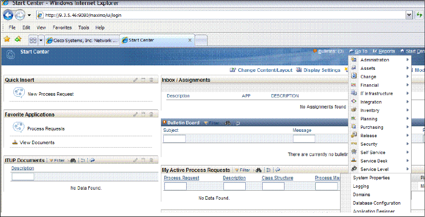
174 Integration Guide for IBM Tivoli Service Request Manager V7.1
Figure 5-1 Start center window
3. Configure the Web Application URL to match the address of your Tivoli SRM
application server. Refer to Figure 5-2 on page 175. The steps are:
a. In the Property Name filter box, type webappurl.
b. Press Enter.
c. Expand mxe.int.webappurl.
d. In the Global Value field, type the address of the Tivoli SRM server. For
example:
http://maximoserver.ibm.com:9080/meaweb
e. Select the value by checking the box next to mxe.int.webappurl.
f. Save the property.
4. Click Go To → Integration → Web Services Library. The steps are:
a. In the Source field, type Object Structure Service.
b. Press Enter.
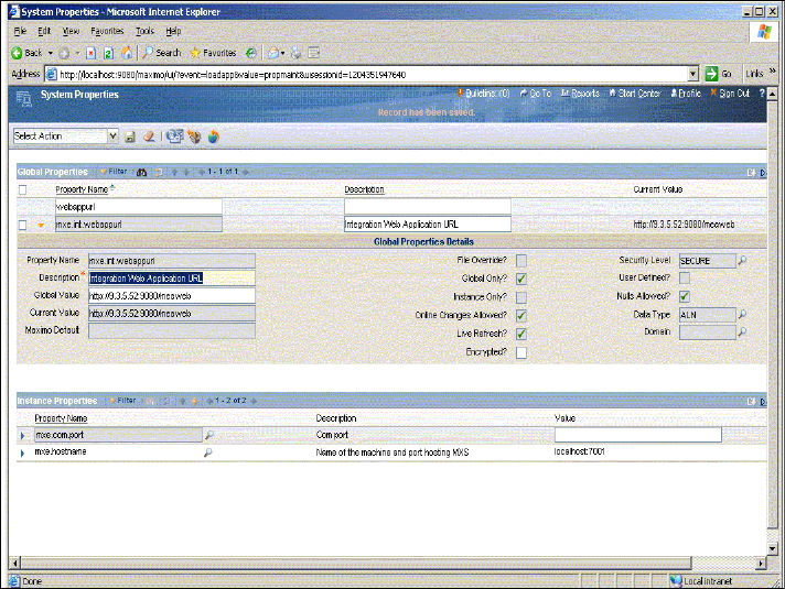
Chapter 5. IBM Tivoli Identity Manager integration 175
Figure 5-2 System properties window
5. Activate the GRPASSIGN interface:
a. Click GRPASSIGN.
b. Select Deploy Web Service from the Select Action menu.
c. Click OK on the confirmation window.
d. Click List to go back to the list of services.
6. Activate the MAXATTRIBUTE interface:
a. Click MAXATTRIBUTE.
b. Select Deploy Web Service from the Select Action menu.
c. Click OK on the confirmation window.
d. Click List to go back to the list of services.
176 Integration Guide for IBM Tivoli Service Request Manager V7.1
7. Activate the PERSON interface:
a. Click PERSON.
b. Select Deploy Web Service from the Select Action menu.
c. Click OK on the confirmation window.
d. Click List to go back to the list of services.
8. Activate the SITE interface:
a. Click SITE.
b. Select Deploy Web Service from the Select Action menu.
c. Click OK on the confirmation window.
d. Click List to go back to the list of services.
9. Activate the Service Request (SR) interface:
a. Click SR.
b. Select Deploy Web Service from the Select Action menu.
c. Click OK on the confirmation window.
d. Click List to go back to the list of services.
10.Activate the SYNONYMDOMAIN interface:
a. Click SYNONYMDOMAIN.
b. Select Deploy Web Service from the Select Action menu.
c. Click OK on the confirmation window.
d. Click List to go back to the list of services.
11.Activate the USER interface:
a. Click USER.
b. Select Deploy Web Service from the Select Action menu.
c. Click OK on the confirmation window.
d. Click List to go back to the list of services.
12.Activate the USERQ interface:
a. Click USERQ.
b. Select Deploy Web Service from the Select Action menu.
c. Click OK on the confirmation window.
d. Click List to go back to the list of services.
13.Click Sign Out.

Chapter 5. IBM Tivoli Identity Manager integration 177
Configuration changes on WebSphere
For TIM integration to function properly, several classes that are provided with
the TIM Integration must be built into the maximo.ear file. If your Tivoli SRM
installation is supported by an IBM WebSphere Application Server, complete the
following procedure to build the MaxUserProcess.class and the MaxUser.class
(optional) files into the maximo.ear file on the Tivoli SRM server. Then, deploy
the maximo.ear file on your WebSphere server.
Activating user deletion in Tivoli SRM
Tivoli SRM does not allow users to be deleted when the LOGINTRACKING
variable is enabled. If you want to delete Tivoli SRM users, this variable must be
disabled. You can disable this variable by performing the following steps:
1. Log on to the Tivoli SRM server with administrative permissions.
2. Click Go To → Security → Users → System Properties.
3. From the action drop-down menu, select Security Controls.
4. Remove the check from Enable Login Tracking? if it is checked.
Building the Tivoli SRM main component
In this section, we discuss building the Tivoli SRM main component. The steps
are:
1. Open a Windows command prompt on the machine where the TPAP is
installed.
2. Change to the following directory: Maximo_Install\deployment.
Note: When the tim_sd_integration.zip file is unzipped into the Maximo_Install
directory, it automatically adds the MaxUserProcess.class to the correct
directory. No further configuration for this class is needed.
Note: If LOGINTRACKING is not checked, select the Maximo User Deletion
Enabled? check box on the Tivoli SRM service form. This check box in TIM is
required in order to delete Tivoli SRM users.
Note: You can install the TPAP on the same or a different computer from
the WebSphere server.
178 Integration Guide for IBM Tivoli Service Request Manager V7.1
3. Enter the following command to rebuild the maximo.ear file:
buildmaximoear.cmd
The buildmaximoear.cmd rebuilds the maximo.ear file while automatically
pulling in the modified class files to replace the class files that were originally
included in the maximo.ear file.
Allow this process to complete.
4. Copy the new maximo.ear file from the TPAP machine to any location on the
WebSphere server.
5. The new maximo.ear file is located in the Maximo_Install\deployment\default
directory on the Tivoli SRM server.
Deploying on WebSphere Application Server
Perform the following steps to deploy the maximo.ear file on the WebSphere
Application Server:
1. Log on to the WebSphere Administrative Console.
2. Click Applications in the navigation pane.
3. Select Enterprise Applications.
4. The Enterprise Applications window is displayed. Refer to Figure 5-3 on
page 179.
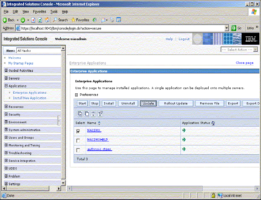
Chapter 5. IBM Tivoli Identity Manager integration 179
Figure 5-3 Enterprise Applications window
5. Select the check box next to MAXIMO.
6. Click Update.
7. Click Replace the entire application.
8. Click Remote File System.
9. Click Browse.
10.Select the node of your WebSphere server.
11.Browse to the location of the maximo.ear file that you copied.
12.Select the file.
13.Click OK.
14.Click Next.
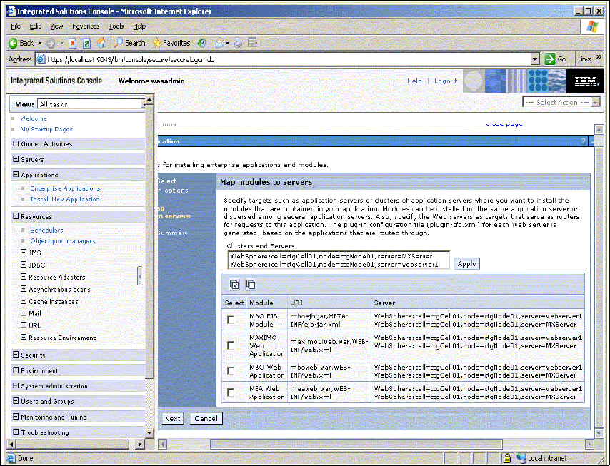
180 Integration Guide for IBM Tivoli Service Request Manager V7.1
15.Click Next on the Select installation options window.
16.Click Next on the Map modules to servers window.
Figure 5-4 Map modules to servers window
17.Click Finish on the Summary page. The maximo.ear file is redeployed. This
process can take several minutes.
18.Click Save to Master Configuration.
19.Click Applications in the navigation pane.
20.Select Enterprise Applications.
21.Select the check box next to MAXIMO.
22.Click Start. Allow this process to complete.
23.Log off of the WebSphere Administrative Console.

Chapter 5. IBM Tivoli Identity Manager integration 181
Configuring TIM
Table 5-3 shows the steps for configuring TIM.
Table 5-3 Configuring TIM
Configuring WebSphere
You must perform the following steps in order for the integration between TIM
and Tivoli SRM to work properly:
1. Navigate to the Maximo_Install\tim_50 directory
2. Copy the maximo.jar file.
3. Navigate to ITIM_HOME\lib\.
4. Paste the maximo.jar file to the lib directory.
5. Log in to the WebSphere Administrative Console for the ITIM install.
6. Click Environment → Shared Libraries → ITIM_LIB.
7. Modify the Classpath by adding: ${ITIM_HOME}/lib/maximo.jar.
Figure 5-5 on page 182 shows an example of the Classpath entry.
Note: In the following sections, ITIM_HOME refers to the directory where
IBM TIM is installed.
Steps Tasks Description
1 Add maximo.jar to the TIM lib
directory
The maximo.jar archive contains the code that drives
the integration between TIM andTivoli SRM.
2 Add maximo.jar to the WebSphere
Application Server Shared
Library Entries
TIM needs to know about maximo.jar in order to use it.
3 Modify enRole.properties The Tivoli SRM connection information for the
password extension needs to be set in the properties
file.
Modify scriptframework.properties The changePassword extension is a script extension,
and the properties file needs to be modified to reflect
this script extension.
Restart WebSphere Application
Server
The Application Server needs to be restarted for the
changes to take effect.
Configure Workflow Extension The changePassword extension needs to be set up in
the TIM configuration.
4 Configure Maximo Service Profile The service profile must be configured in order to
manage Tivoli SRM users.
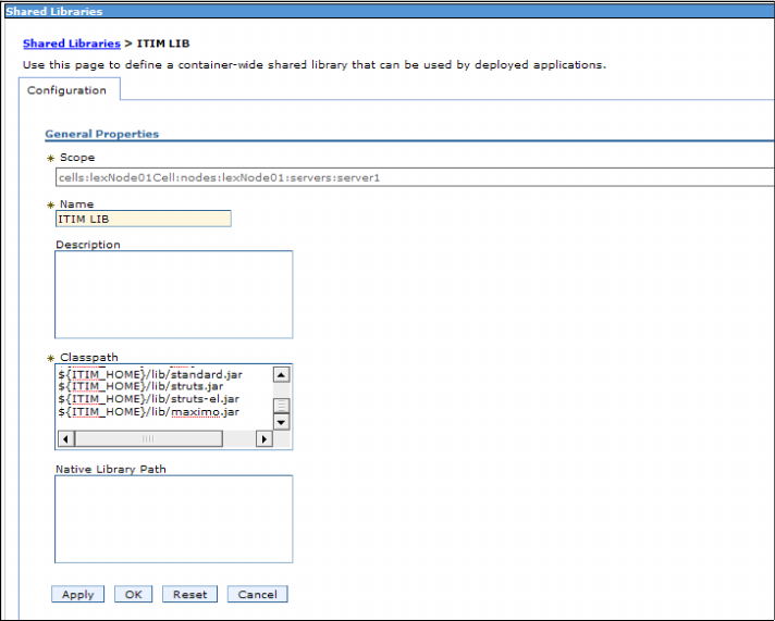
182 Integration Guide for IBM Tivoli Service Request Manager V7.1
Figure 5-5 Classpath entry
Configuring TIM 5.0
You must perform the following steps in order for the integration between TIM
and Tivoli SRM to work properly.
Modify enRole.properties
The steps to modify the enRole.properties are:
1. Navigate to the ITIM_HOME\data directory.
2. Open the enRole.properties, add the text that is shown in Example 5-1 on
page 183, and replace hostname and port with the values that correspond
with the Tivoli SRM environment. Also, set the maximo.security value to true
or false, depending on whether the Application Server Security is enabled. If
the value is set to true, the maximo.user and maximo.password fields are
required, which enables the Service Request creation for Maximo when the
Application Server Security is enabled.

Chapter 5. IBM Tivoli Identity Manager integration 183
Example 5-1 Maximo Workflow Extension Properties
#####################################
## Maximo Workflow Extension Properties
#####################################
maximo.url=http://hostname:port
maximo.security=true
maximo.user=maxadmin
maximo.password=maxadmin
3. Save and close enRole.properties.
Modify scriptframework.properties
The steps to modify scriptframework.properties are:
1. Navigate to the ITIM_HOME\data directory.
2. Open scriptframework.properties and add the command line that is shown in
Example 5-2.
Example 5-2 Scriptframework.properties: Add a line
ITIM.extension.Workflow.Maximo=com.ibm.itim.maximo.MaximoExtension
3. Save and close scriptframework.properties.
4. Restart the WebSphere Application Server.
Configure changePassword workflow extension
The following steps are required for the changePassword extension to function
properly (Example 5-3):
1. Log in to TIM as an administrator.
2. Click Configure System → Manage Operations.
3. Select Entity type level.
4. Click changePassword.
5. Double-click the CHANGEPASSWORD extension box. Add this text.
Example 5-3 Text to be added
Maximo.addTicket(Entity.get(), activity);
6. Click OK.
7. Click Apply.
8. Click OK to verify the changes. Refer to Figure 5-6 on page 184.
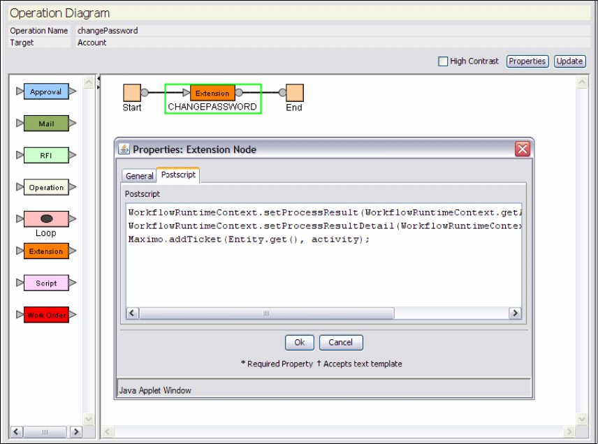
184 Integration Guide for IBM Tivoli Service Request Manager V7.1
Figure 5-6 ChangePassword Workflow Extension modified to create Maximo tickets
Configure the Tivoli SRM Service Provider
The following steps are required to enable support for Tivoli SRM user
management:
1. Log in to TIM.
2. Click Manage Service Types.
3. Click Import.
4. Click Browse and navigate to Maximo_Install\tim_50.
5. Select maximoserviceprofile.jar.
6. Click OK and allow a few minutes for the operation to complete.
7. Click Manage Services.
8. Click Create.

Chapter 5. IBM Tivoli Identity Manager integration 185
9. Select Maximo Service from the radio menu.
10.Click Next.
11.Type a unique service name, and provide the maximo URL:
http://hostname:port
12.Select Maximo User Deletion Enabled? if LOGINTRACKING is false and if
you want Tivoli SRM users deleted.
13.Click Test Connection and verify that the test is successful.
14.Click Finish.
The TIM configuration is complete.
Note: It might be necessary to modify the default provisioning policy that is
created when new service is created in order to make sure that all necessary
attributes are set.
186 Integration Guide for IBM Tivoli Service Request Manager V7.1

© Copyright IBM Corp. 2008. All rights reserved. 187
Chapter 6. CCMDB integration
In this chapter, we describe the integration of Tivoli Service Release Manager
(SRM) V7.1 with Change and Configuration Management Database (CCMDB)
V7.1.
In this chapter, we discuss the value of integrating CCMDB with a Tivoli SRM
implementation and leveraging this integration to achieve services level
management.
CCMDB overview on page 188
Change Management integration on page 190
Working with SRM and CCMDB on page 197
6
188 Integration Guide for IBM Tivoli Service Request Manager V7.1
6.1 CCMDB overview
The CCMDB is the foundation for the IBM Service Management (ISM) strategy. It
is the foundation for core Information Technology Infrastructure Library (ITIL)
process solution deliverables, such as Configuration, Change, or Release
Management. These process solutions provide the best practices
implementations of core ITIL processes.
The CCMDB provides a shared infrastructure, as well as a set of foundation
services that are used by ISM process solutions, such as Configuration, Change,
or Release Management, and includes the Configuration and Change
Management processes that provide the core management capabilities that are
needed in an IT environment.
In addition, the CCMDB incorporates a consistent data model and data layer
implementation and includes a framework for the discovery of resources and its
relationships.
A Configuration Management Database (CMDB) according to ITIL is a database
that is used to manage Configuration Records throughout their life cycle. The
CMDB records the attributes of each CI (Configuration Item) and its relationships
with other CIs and provides the underpinnings for IT Service Management
processes.
A CI has several characteristics, a classification or type, attributes that describe
the CI depending on its classification, and relationships that describe how a CI is
related to other CIs.
In ITIL, a CI is defined as “Any component that needs to be managed in order to
deliver an IT Service.” Information about each CI is recorded in a Configuration
Record within the CMDB and is maintained throughout its life cycle by
Configuration Management. CIs are under change control by Change
Management.
The IBM CCMDB solution provides an ITIL-aligned implementation of a
Configuration Management Database. For more information about CCMDB, refer
to Deployment Guide Series: IBM Tivoli CCMDB Overview and Deployment
Planning, SG24-7565.
Before we get into the specifics of the IBM CCMDB product and related
solutions, we provide an overview of the ISM strategy, ITIL, and the IBM Tivoli
Unified Process that provides a linkage between the ISM strategy and ITIL.
Chapter 6. CCMDB integration 189
6.1.1 Tivoli SRM and CCMDB integration
The first question that come up when installing both products is, “Why do I need
both products?” Tivoli SRM has a database in which asset and CI information
can be stored. CCMDB collects and manages CIs and their relationships.
Installing the CCMDB adds functions to Tivoli SRM, such as:
Impact analysis
CI lifecycle management
Configuration process
Change implementation schedule
Ability to promote process requests to change management and configuration
management requests
Let us consider an example to demonstrate the benefits of introducing CCMDB
to an existing Tivoli SRM environment. CCMDB provides information to help the
Service Desk team isolate the source of the problem quickly. Suppose that a
switch that is used for production goes down and affected users are calling the
help desk. By looking at the applications and servers that are down (affected CIs
in CCMDB terminology), a Service Desk person or a Specialist can determine
that the applications and servers that are down are all related to a certain switch
(through the CI relationship information that is provided by CCMDB). A Service
Desk person or a Specialist can also see that this switch has caused problems
before, and after a closer analysis, the support person can understand that the
firmware software on this switch is back level. All this information is provided by
CCMDB. At this point, the support person can start a change request to upgrade
the switch firmware software. This change request is reviewed by the Change
Manager or the change review board to analyze the impact of the change (again
using the CCMDB, looking at the affected CIs), and when the change is
authorized, it gets implemented.
Similarly, using CCMDB alone allows you to manage CIs and view CCMDB
change history. For instance, if a memory card is added to a server, you notice
that this is a change in CCMDB, but you do not know why this change has
occurred, or what incidents or problems are associated with this change. This
information is usually contained in Tivoli SRM.
This integration is possible when Tivoli SRM V7.1 is present. Every problem or
incident is related to the affected CI.

190 Integration Guide for IBM Tivoli Service Request Manager V7.1
6.2 Change Management integration
To integrate Tivoli SRM with CCMDB, you must upgrade your CCMDB Tivoli
Process Automation Platform (TPAP), which used to be known as Base
Services, to the appropriate level. You must upgrade your CCMDB TPAP before
installing Tivoli SRM on the same infrastructure.
Also, remember that CCMDB requires that a Tivoli Application Dependency
Discovery Manager (TADDM) server is installed in your environment. The
TADDM server does not need to be installed in the same physical server as
CCMDB or Tivoli SRM.
6.2.1 Installing CCMDB on top of SRM scenario
In this scenario, we describe the installation of CCMDB in the same server where
Tivoli SRM V7.1.1 is deployed, which is a valid scenario if you are deploying both
solutions at the same time.
When installing CCMDB, it is mandatory to install TADDM, which is the
technology that is used to discover CIs and CCMDB relationships. We do not
describe CCMDB or TADDM installation in detail, only the necessary steps to
install CCMDB integrated with Tivoli SRM. Refer to the TADDM or CCMDB
documentation, such as Deployment Guide Series: IBM Tivoli CCMDB Overview
and Deployment Planning, SG24-7565, for more information about how to install
and configure TADDM.
We provide the installation steps that you need to install CCMDB on top of an
existing Tivoli SRM V7.1.1 installation:
1. The installation procedure starts from the launchpad, similar to the Tivoli SRM
launchpad, as shown in Figure 6-1 on page 191.
Important: Tivoli SRM and CCMDB integration requires both products to be
at the V7.1.1 level. At the time of writing this book, CCMDB V7.1.1 is not
available, so we use an early version of CCMDB V7.1.1.
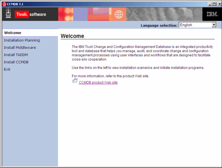
192 Integration Guide for IBM Tivoli Service Request Manager V7.1
Figure 6-2 Language selection
2. Click OK.
3. In the next window, click Next to view the license agreement.
4. After accepting the license agreement, the upgrade window appears. This
window appears when the installation detects that the TPAP is already
installed on this server. Refer to Figure 6-3 on page 193.
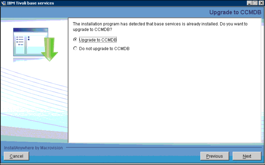
Chapter 6. CCMDB integration 193
Figure 6-3 Upgrade window
5. To implement CCMDB along with Tivoli SRM, it is mandatory that you
upgrade the base services, because the base services must be at the same
level for both applications.
6. Click Next.
7. As part of CCMDB implementation, TADDM server information is requested.
You can point to a local TADDM server if you deployed one locally, or point to
your current TADDM server. Refer to Figure 6-4 on page 194.
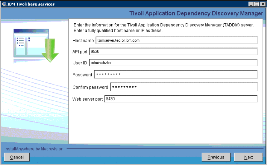
194 Integration Guide for IBM Tivoli Service Request Manager V7.1
Figure 6-4 TADDM
8. Provide the information specific to your environment for the following fields:
–Host name: This is the host name for the TADDM Server; it might be the
same server where Tivoli SRM and CCMDB are installed.
–API port: Default port number for TADDM Server. Change this number
only if you have changed the port number during the TADDM Server
installation.
–User ID: TADDM administrator. Default is administrator, if it is not
changed by the TADDM administrator.
–Password: Default password is collation.
–Web server port: Default is 9430.
9. After entering the information in these fields, click Next to view the run
configuration step window. Refer to Figure 6-5 on page 195.
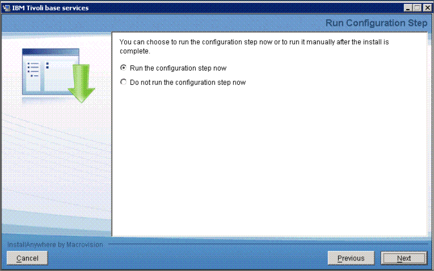
Chapter 6. CCMDB integration 195
Figure 6-5 Run Configuration Step window
10.In this step, you can let the installation run the appropriate steps, or you can
defer this step to be executed manually after the installation is finished. We
recommend that you run this step during the installation process.
11.Click Next.
12.Figure 6-6 on page 196 shows you the information that was entered during
the previous steps. Review the information and click Next.
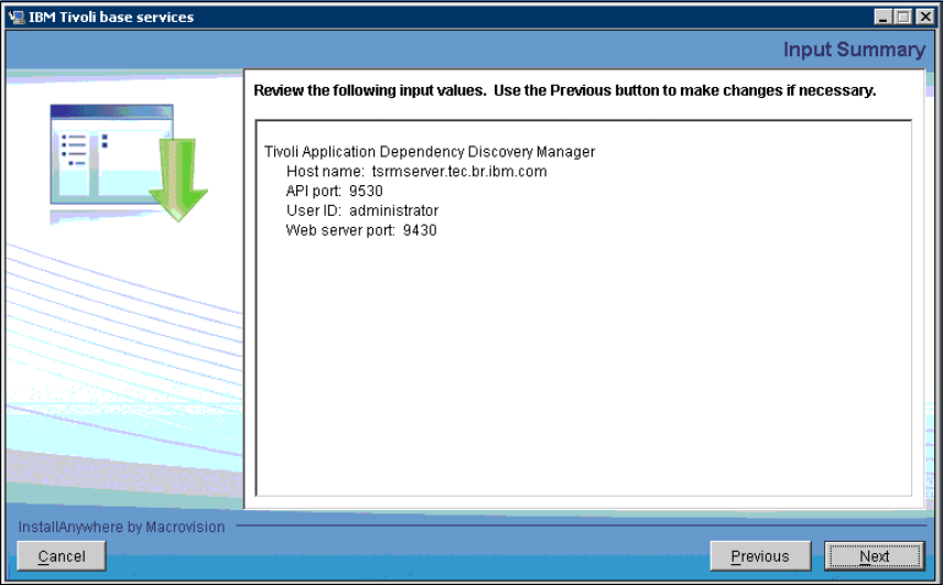
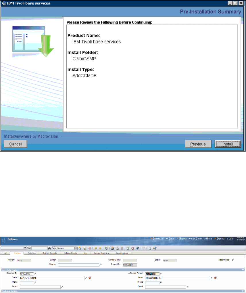
Chapter 6. CCMDB integration 197
Figure 6-7 Pre-Installation Summary
6.3 Working with SRM and CCMDB
After integrating CCMDB and Tivoli SRM, you are able to associate CIs to
incidents and problems.
Follow these required steps to associate a CI to a problem or a incident:
1. Open an Incident or Problem. Refer to Figure 6-8.
Figure 6-8 Problem window
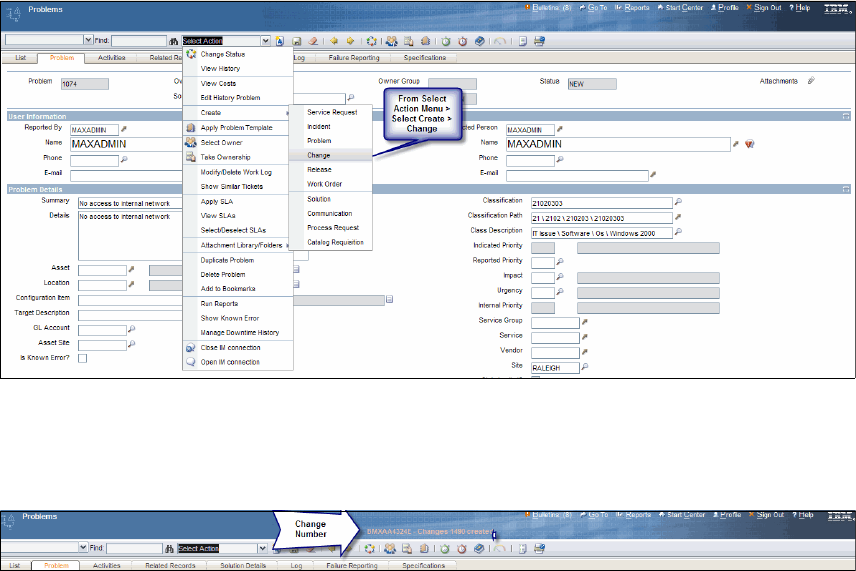
198 Integration Guide for IBM Tivoli Service Request Manager V7.1
2. Type the information in the fields based on your process.
3. If a change is required to fix the problem, you can open a change from the
Select Action menu, as shown in Figure 6-9.
Figure 6-9 Open change option
4. After selecting this option, a message appears in the top menu bar with the
change ticket number that was created for this problem. Refer to Figure 6-10.
Figure 6-10 Change ticket number
5. From this point forward, the Change Manager takes over the ticket.
Navigating through the change window, go to the Related Records tab. You
are able to see all related tickets, which are the tickets that originated from or
are related to this change, as shown in Figure 6-11 on page 199. Relating
incidents with change records provides significant value for both the Incident
Management and Change Management disciplines.
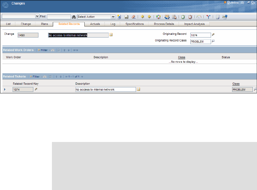
Chapter 6. CCMDB integration 199
Figure 6-11 Related Tickets panel
6. After the change is completed, the problem management team checks
whether the solution that was applied solved the problem. If the solution is
successfully implemented, they record the solution as a valid solution in the
database for further use.
Tivoli SRM helps you to implement or improve services management. When
implemented with CCMDB, the solution is even more powerful. In this chapter,
we have provided examples of these benefits.
Note: According to ITIL, any change to the environment flows through the
Change Management process, so service desk personnel or technicians
do not send updates directly to the CMDB as they resolve incidents. Even
if work is already done (in the case of urgent or high priority incidents), the
CMDB is still updated by the Change Management process (not Incident
Management).
200 Integration Guide for IBM Tivoli Service Request Manager V7.1

© Copyright IBM Corp. 2008. All rights reserved. 201
Chapter 7. Lotus Sametime integration
In this chapter, we provide general information about Sametime Connect instant
messenger, and we focus on integrating the instant messaging application with
IBM Tivoli Service Request Manager (SRM) 7.1.
We discuss the features, installation, and integration of the application in the
following sections:
Sametime overview on page 202
Sametime in the context of Tivoli SRM on page 202
Sametime installation and configuration on page 202
Service desk scenario on page 210
7

202 Integration Guide for IBM Tivoli Service Request Manager V7.1
7.1 Sametime overview
Lotus Sametime software offers integrated, enterprise instant messaging,
point-to-point video, and integration with desktop productivity applications, such
as Microsoft Office, file transfer, integrated chat histories, and optional
integration with supported audio, video, and telephony systems.
In the context of this book, we focus on the integration of Sametime instant
messaging with the Tivoli SRM V7.1.
7.2 Sametime in the context of Tivoli SRM
Tivoli SRM instant messaging offers the following functions:
Allows the service desk analyst to begin a conversation session in real time
with any person related to a ticket
Allows the person who requested the service request to talk to a service desk
analyst in real time by using an instant messenger application
7.3 Sametime installation and configuration
You need to ensure that the application has been installed in order to use the
instant messaging functions.
7.3.1 Installation
To perform the Tivoli SRM V7.1 integration installation with the Sametime server,
follow these steps:
1. Start the launchpad utility by clicking on the launchpad icon located on your
Tivoli SRM V7.1 installation CD.
2. Select Product integration software.
3. Select Service Desk-Sametime Connect Integration (Figure 7-1 on
page 203).
Note: Refer to the Chapter 2, “Integration components” on page 17 of this
book for detailed information about the SRM installation.
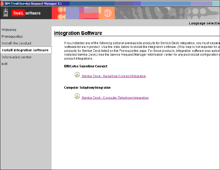
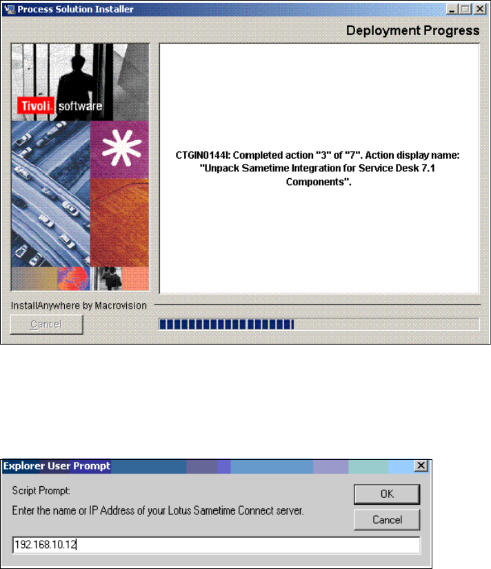
204 Integration Guide for IBM Tivoli Service Request Manager V7.1
Figure 7-2 Installing Sametime integration
5. A request from the installer for the Sametime Connect server IP address
appears.
6. Type the IP address of your Lotus Sametime Connect server (Figure 7-3).
Figure 7-3 Installing Sametime integration
7. After the installation successful completes, click Done.
You are now ready to interact with your Sametime Connect application from
within the Tivoli SRM interface.

Chapter 7. Lotus Sametime integration 205
7.3.2 SRM configuration
The following two properties are created by default; however, you provide values,
such as the Sametime instant messaging server and time-out values, manually:
mxe.im.connectiontimeout
This option defines how many milliseconds the instant messaging application
tries to connect to the instant messaging server. If this timeout expires, the
analysts receives a notification stating that it is not possible to connect to the
instant messaging server.
mxe.im.sametimeserver
This is the instant messaging server host name.
From the SRM interface:
1. Select Go To → System Configuration → Platform Configuration →
System Properties, as shown in Figure 7-4 on page 206.
Tip: While the mxe.im.sametimeserver property is mandatory, the
mxe.im.connectiontimeout property is optional.
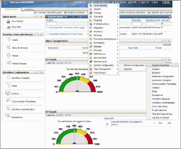
206 Integration Guide for IBM Tivoli Service Request Manager V7.1
Figure 7-4 Properties configuration
2. To view the mxe.im.sametimeserver and mxe.im.connectiontimeout
properties, use the filter to find the property. Type mxe.im and press Enter,
which brings up the two instant messaging properties. Refer to Figure 7-5 on
page 207.
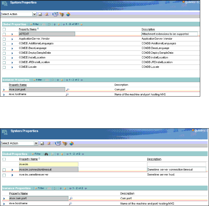
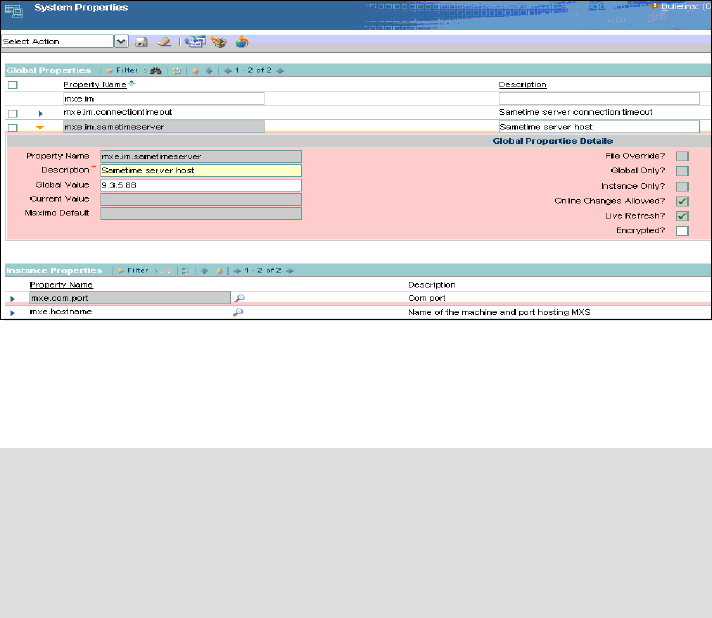
208 Integration Guide for IBM Tivoli Service Request Manager V7.1
Figure 7-7 System Properties (3 of 3)
3. In order to finish the integration, you need to restart the server, which sets the
Current Value to the same value as the Global Value.
7.3.3 Sametime server configuration
On the Sametime server, ensure that users have their profiles properly
configured with the Internet password (refer to Figure 7-8 on page 209).
For more details regarding how to administer users on the Sametime server,
refer to the Sametime server documentation at:
http://www.ibm.com/developerworks/lotus/documentation/sametime/
Tip: You can refresh the Current Value without restarting the server by
following these steps:
1. Save the changes.
2. Select the check box next to the mxe.im.sametimeserver property.
3. Click Live Refresh.
4. Click OK.
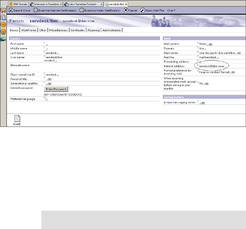
Chapter 7. Lotus Sametime integration 209
Figure 7-8 Sametime server
7.3.4 Sametime instant messaging with Tivoli SRM
You can use the instant messaging function in the following scenarios.
Conversation started by the service desk analyst
The instant messenger integration allows the service desk analyst to begin a
conversation session with the affected user or a person acting on behalf of the
affected user (reported by a person in service desk terminology).
Using this feature, the analyst can quickly verify details with users who are
related to the ticket and interact dynamically with these users for classifications,
descriptions, and similar purposes.
Note: The service desk analyst cannot chat with the configuration item (CI)
owner.
210 Integration Guide for IBM Tivoli Service Request Manager V7.1
The conversation can be started from the Tivoli SRM application, such as service
request, incident, and problem. You can initiate a conversation any time while the
other user is active in the Sametime instant messaging application.
There is an icon beneath a user’s information that indicates the person’s state,
such as:
Available
Offline
Away
Do not disturb
In meeting
Unknown
When the conversation ends, the analyst can make an assessment about the
ticket status. The transcript of the conversation is saved in the communication
log under the Log application tab. This transcript is accessed when required.
7.4 Service desk scenario
In this section, we describe a situation where the service desk analyst interacts
with a user by using Sametime instant messaging.
In our scenario, the user has raised an incident. The incident number is 1001.
The service desk analyst opens the incident to check the status and tries to
initiate a conversation with the user (refer to Figure 7-9 on page 211).
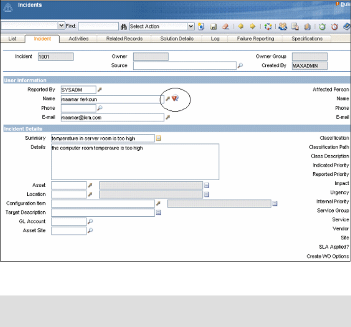
Chapter 7. Lotus Sametime integration 211
Figure 7-9 Incident raised
To initiate an instant messaging session, perform the following steps:
1. Select the Action pull-down menu.
2. Select Open IM connection (refer to Figure 7-10 on page 212).
Note: In Figure 7-9 on page 211, the circled icon displays that an instant
messaging connection is not open.
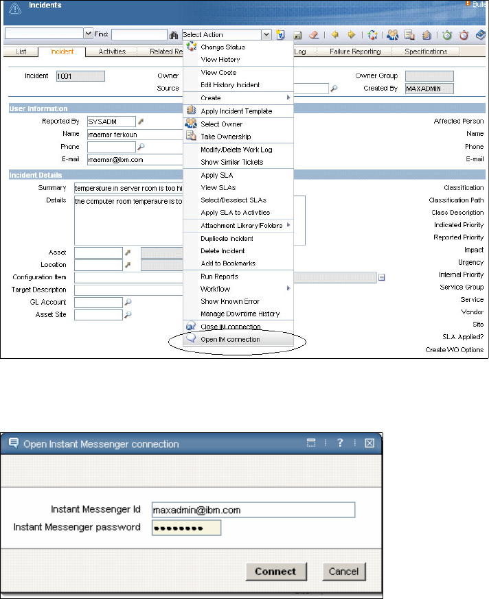
212 Integration Guide for IBM Tivoli Service Request Manager V7.1
Figure 7-10 Open IM connection
3. Enter the password for the IM application, as shown in Figure 7-11.
Figure 7-11 Enter the password for the IM application
4. You now have an open session with the Sametime application, as shown in
Figure 7-12 on page 213.
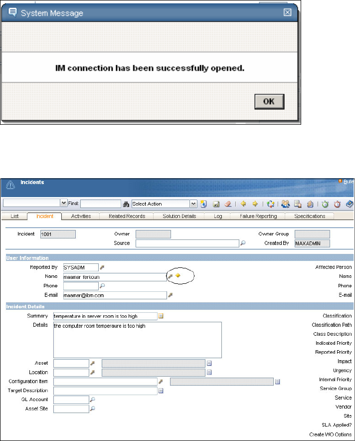
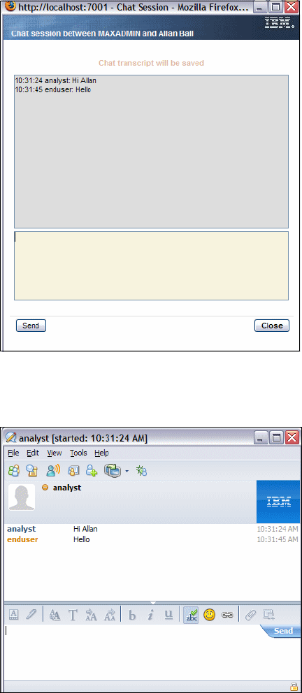
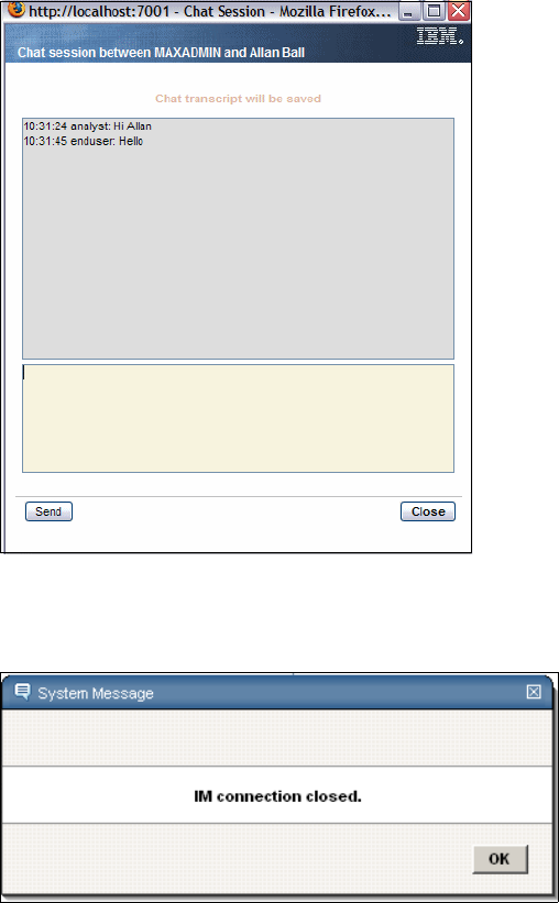
216 Integration Guide for IBM Tivoli Service Request Manager V7.1

© Copyright IBM Corp. 2008. All rights reserved. 217
Chapter 8. Computer Telephony
integration
In this chapter, we describe the available Computer Telephony integrations
(CTIs) for Tivoli Service Request Manager (SRM) V7.1. We describe how to
install and configure the integrating software, as well as an example of how CTI
functions, and basic troubleshooting.
In this chapter, we discuss:
CTI functions on page 218
CTI installation on page 219
CTI configuration on page 231
Using your CTI implementation on page 234
Troubleshooting on page 241
8
218 Integration Guide for IBM Tivoli Service Request Manager V7.1
8.1 CTI functions
CTI is a new Tivoli SRM integration that provides features that allow your
telephony system to interact with Tivoli SRM. CTI solutions are often used in call
center environments, but they can also be used in a Service Desk environment.
Integrating the CTI solution with your service desk solution reduces the number
of manual steps for operators and increases the handling speed, which reduces
the average call time.
CTI allows you to populate Tivoli SRM records and fields with mapped
information based on lookup information that is provided by the CTI system. You
can also control your CTI solution from the Tivoli SRM user interface, creating a
single application for all service desk-related work.
Using CTI, you can implement the following functions:
Call information display (caller number (ANI), number dialed (DNIS), and
screen population on answer (without using calling line data)
Automatic and computer-controlled dialing (fast dial, preview, and predictive
dial)
Phone control (answer, hang up, hold, conference, and so forth)
Coordinated phone and data transfers between two parties (for example,
pass on the screen pop with the call)
Call center phone control (logging on after-call work notification)
Advanced functions, such as call routing, reporting functions, automation of
desktop activities, and multi-channel blending of phone, e-mail, and Web
requests
Agent state control (for example, after-call work for a set duration, then
automatic change to the ready state)
Call control for Quality Monitoring and call recording software
A typical CTI application manages an event flow that is generated by a telephony
switch during the life cycle of a call. The following list is the sequence of events in
the event flow:
1. Set up
2. Deliver (ringing)
3. Establish (answer)
4. Clear (hang up)
5. End
Chapter 8. Computer Telephony integration 219
Other events that can be handled by a typical CTI solution include:
Hold
Retrieve from hold
Conference
Transfer
Forward
CTI applications handle events that are related to automated call distribution
(ACD), such as:
Agent logged in
Agent available
Agent not available
Agent ready
Agent not ready
On general availability of Tivoli SRM V7.1, Genesis is the only integration
supported. Future integrations with other CTI systems are planned, such as
Avaya, CISCO, Siemens, and Envox.
8.2 CTI installation
Follow these steps, and you will find your Tivoli Service Request Manager
environment equipped with an additional Java Applet and CTI functionality:
1. Download the CTI Installation package from:
http://catalog.lotus.com/wps/portal/topal/details?catalog.label=1TW1
0SR01
2. Launch the process solution installation program by navigating to the
<CCMDB_HOME>\bin directory of your CCMDB installation and executing
solutionInstallerGUI.bat.
3. From the Choose PSI Package panel, click Choose and navigate to the CTI
package that you have downloaded.
4. Proceed with the prompts. The dialog box shown in Figure 8-1 on page 220
appears.
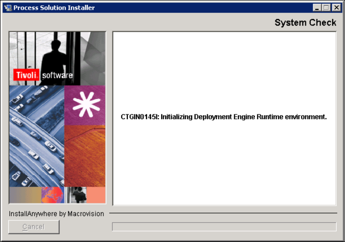
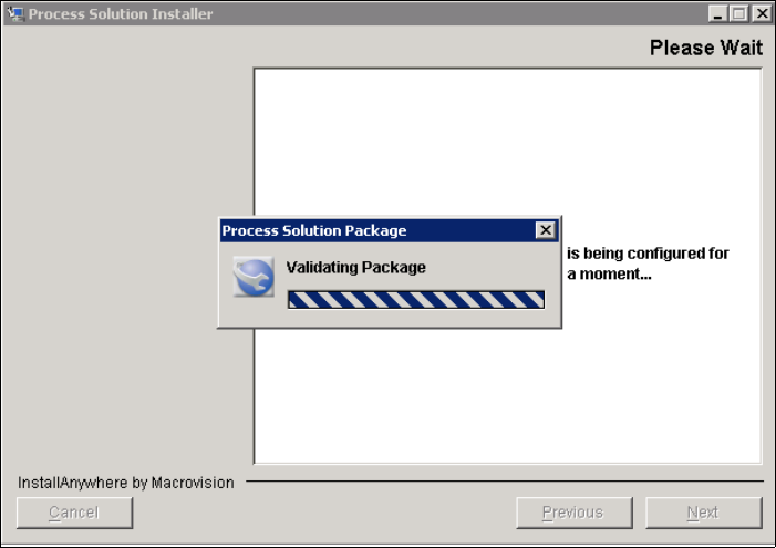
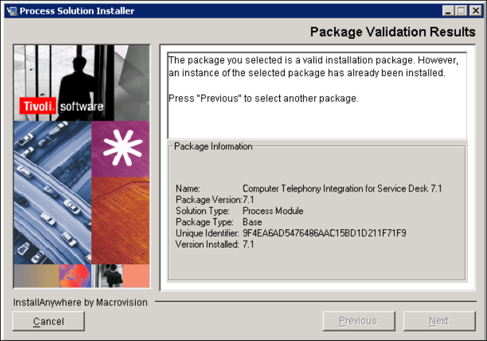
222 Integration Guide for IBM Tivoli Service Request Manager V7.1
Figure 8-3 Package validation results when already installed
7. Uninstall the package using the appropriate Windows tools before you can
install the package again.
8. If the package has not been previously installed and successfully validated,
Figure 8-4 on page 223 appears.
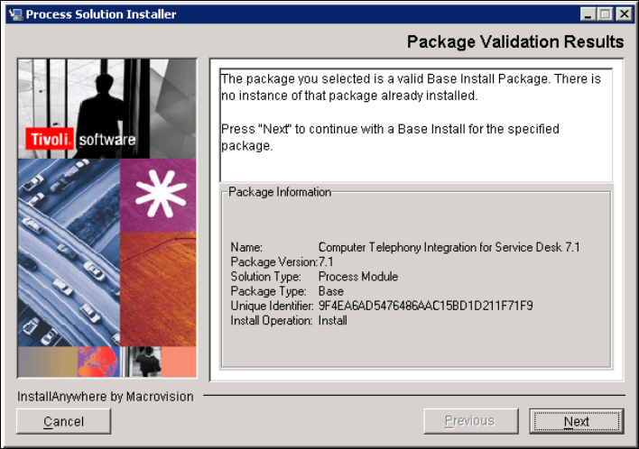
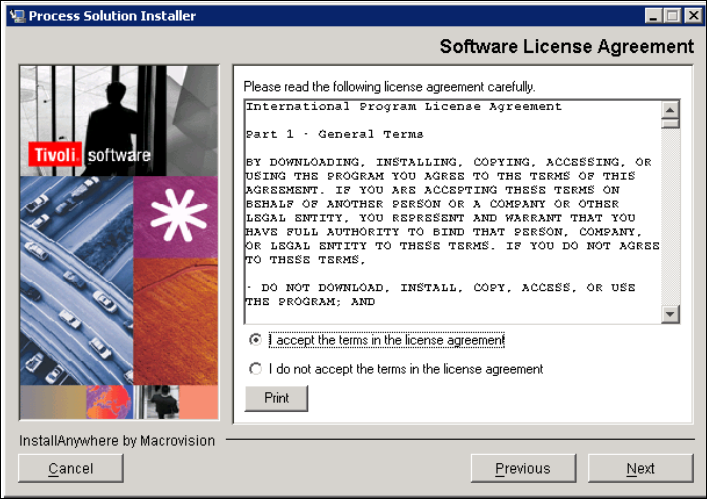

Chapter 8. Computer Telephony integration 225
Figure 8-6 Required credentials
14.Enter the database credentials in the Middleware Login Information dialog
box, as shown in Figure 8-7 on page 226. You are required to enter these
credentials in order to continue. They are used to access the database and
update the maximo schema with CTI-related objects.
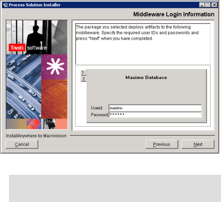
226 Integration Guide for IBM Tivoli Service Request Manager V7.1
Figure 8-7 Maximo Database credentials
15.Enter the WebSphere credentials in the Middleware Login Information dialog
box, as shown in Figure 8-8 on page 227. You are required to enter these
credentials in order to continue. They are used to access WebSphere, and
they are used to rebuild and redeploy the EAR files.
Note: You must enter the user name and password to access the
database that you created during the Tivoli SRM installation. By default,
the user name is maximo.
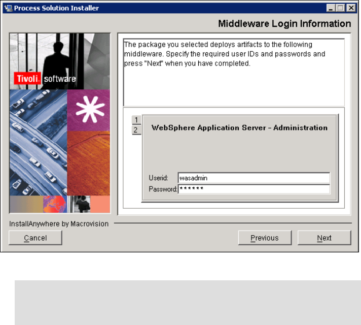
Chapter 8. Computer Telephony integration 227
Figure 8-8 WebSphere credentials
16.Click Next to continue. The middleware credentials are validated, which is
shown in Figure 8-9 on page 228.
Note: You must enter the user name and password to access the
database that you created during the Tivoli SRM installation. By default,
the user name is wasadmin.
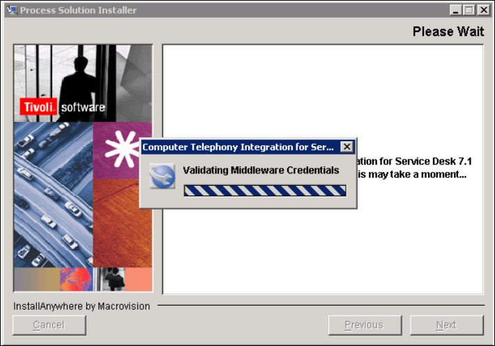
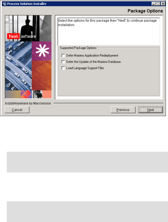
Chapter 8. Computer Telephony integration 229
Figure 8-10 Package options
18.The option, Defer Maximo Application Redeployment, skips rebuilding and
redeployment of the EAR files. You must manually execute this step to enable
the CTI functions in the application.
19.The option, Defer the Update of the Maximo Database, skips all database
updates. You must manually execute this step to update the database with
the necessary objects for CTI.
20.Select your package options, and click Next to continue. The deployment
engine is initialized to verify that all installation requirements are met.
Note: Without the database updates and with only this step executed, you
receive database errors when trying to retrieve unavailable objects from
the database.
Note: If you only execute the database update, but you have not rebuilt
and redeployed the EAR files, you are not able to access the full
application functions.
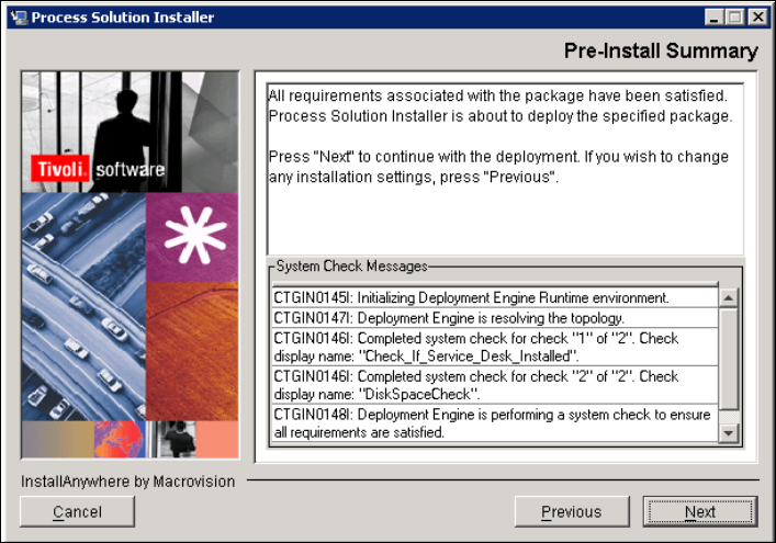
230 Integration Guide for IBM Tivoli Service Request Manager V7.1
21.If all package requirements are satisfied, you can continue the actual
deployment of the package (see Figure 8-11).
22.Click Next to continue.
Figure 8-11 Pre-Install Summary
23.The deployment engine is initialized to start the actual deployment, as shown
in Figure 8-12 on page 231.
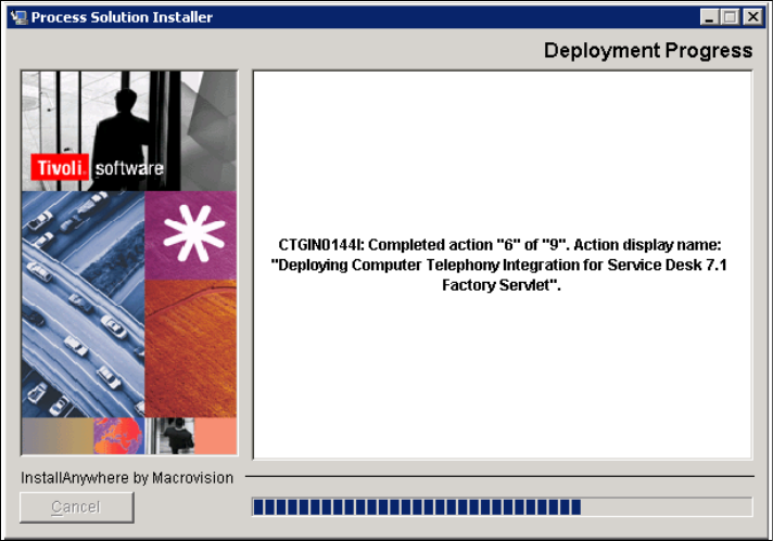
Chapter 8. Computer Telephony integration 231
Figure 8-12 Deployment progress
24.If successful, the deployment status report is complete. You are now able to
access Tivoli SRM and use the CTI solution.
8.3 CTI configuration
1. Log in to Tivoli SRM as the administrator or any user with authorization to
change Tivoli SRM System Properties.
2. From the Go To menu, select System Configuration → Platform
Configurations → System Properties.
3. Filter Property Names on CTI.
4. Change the Global Value field for each of the Property Names specified in
Table 8-1 on page 232. Ask your Genesis administrator for the values that you
have to provide in the Global Value field.

232 Integration Guide for IBM Tivoli Service Request Manager V7.1
Table 8-1 System Properties changes
We provide examples of the integration that we created for this book in ’Using
your CTI implementation” on page 234.
Figure 8-13 on page 233 shows an example of the System Properties window
with the options and values that you change.
Property name Property description
cti.ail.appname Specifies the application name of the CTI system.
cti.config.host Specifies the host name on which the CTI configuration server
is running.
cti.config.port Specifies the port that is used for communication between
Tivoli SRM and the CTI configuration server.
cti.config.backup.host Specifies the hostname on which a potential backup CTI
configuration server is running (in case the primary host is not
responding).
cti.config.backup.port Specifies the port that is used for communication between
Tivoli SRM and a potential backup CTI configuration server.
cti.username Specifies the user name that can access the CTI configuration
server.
cti.password Specifies the password for the user name to access the CTI
configuration server.
cti.ail.license Specifies the URL where the CTI license server can be
located.
cti.ail.period Specifies the keep alive time for the connection to the CTI
server.
cti.ail.queue Specifies the queue name for Tivoli SRM on the CTI server.
cti.ail.timeout Specifies the connection timeout.
cti.lookup.type Specifies the type of lookup that is used to identify callers,
which by default is phone, but it can be changed to a custom
lookup.
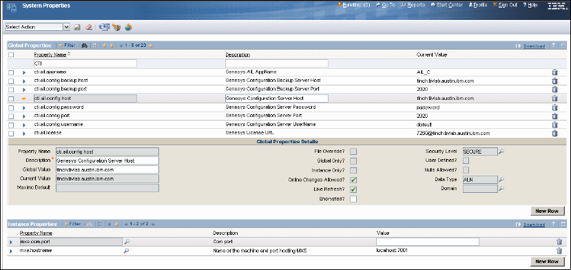
Chapter 8. Computer Telephony integration 233
Figure 8-13 System Properties configuration example
5. Make sure that the Java.rmi.server.hostname is set. If not, change the Global
Value for Property Name mxe.registry.host to the host name of the Tivoli
SRM server. This property is used to define the Remote Method Invocation
(RMI) binding.
8.3.1 Custom lookup configuration
CTI is provided with a default lookup, which is called phone. It enables the Tivoli
SRM system to search the person’s records for caller details based on the phone
number that is provided by the CTI system. The phone number provided by the
CTI system must match the phone number in a person’s record exactly to be
able to identify the caller and transfer data to a new Service Request (SR)
record.
To use a custom lookup, instead of the default phone number, you have to
change the cti.lookup.type Property to custom. The following properties are
necessary and need to be changed:
cti.lookup.key contains the value that you want to look up, which is provided
by the CTI system.
cti.lookup.mxkeymap contains the Tivoli SRM object and attribute to which
you want to match the CTI data.
cti.mappings contain all of the fields that you want mapped in the SR that is
being opened. This property is in the format,
cti.mappings=phoneKey:srColumn, and comma-delimited.

234 Integration Guide for IBM Tivoli Service Request Manager V7.1
Refer to Example 8-1.
Example 8-1 Custom lookup example
If you want to map the data under the key EMPSERIAL in the phone call's
attached data to look up under PERSONID in the PERSON table in SRM,
specify:
cti.lookup.key=EMPSERIAL
cti.lookup.mxkeymap=PERSON:PERSONID
If you want to further map the ASSET and CLASSIFICATION in attached
data to the ASSET and CLASSIFICATION in the SR being opened by the
phone call, specify as well:
cti.mappings=ASSET:ASSET,CLASSIFICATION:CLASSIFICATION
8.4 Using your CTI implementation
After you have successfully installed the integration, you can use the integration.
You still have a few steps to take as well as getting acquainted with the specific
CTI functions.
8.4.1 Changing the URL
You must manually change the Tivoli SRM URL in order to access the Start
Center with CTI Java Applet, access Tivoli SRM, and be able to use the CTI
solution.
The Tivoli SRM URL after login is:
http://[hostname]:[port]/maximo/ui/login
To be able to use your CTI system, manually change the URL to:
http://[hostname]:[port]/maximo/webclient/cti/index.jsp
This URL renews the Start Center, enabling a Java Applet with the required
symbols (buttons and icons) to operate the CTI system (refer to Figure 8-14 on
page 235).
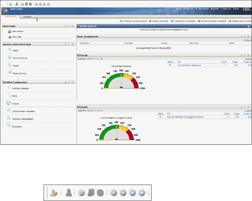
Chapter 8. Computer Telephony integration 235
Figure 8-14 Start Center with CTI solution active
The CTI symbols appear in the upper left corner over the regular Start Center. If
you did not log in to the CTI system, the buttons are shown in Figure 8-15.
Figure 8-15 CTI status before login
8.4.2 CTI buttons
Next, we explain each of these symbols, starting from left to right:
Login/logout button:
The button to either log in to or log out from the CTI system. An orange arrow
to the right means that you are not logged in. A green arrow to the left means
that you are logged in.
Status icon:
This icon shows your status, for example, if you are available to take calls or
busy. A green icon indicates that you are ready (available to answer calls). A
green icon with a stop sign means that you are busy (not on the phone, but
236 Integration Guide for IBM Tivoli Service Request Manager V7.1
not available to answer calls). A red icon with a phone indicates that you have
accepted a call and are still talking.
Accept/end call button:
This button answers or ends the call (hang up).
Start/end after-call work button:
You use this button to set the agent status to start or end after-call work.
Ready/busy button:
You use this button to change your status in the CTI system.
Mute current call button:
You can use this button to mute an active conversation. The call is put on
hold for as long as you do not transfer or resume the call. The button is
active/visible if you have an active conversation.
Resume current call button:
If you put a call on hold, you can use this button to resume the conversation.
The button is active if the current conversation is put on hold.
Transfer button:
You can use this button to transfer the accepted call to another agent.
Two-step transfer button:
You can use this button to transfer an accepted call from your first transfer to
another agent.
8.4.3 An example
The following example describes a call flow, using the buttons just described. We
describe the following flow:
Log in to the CTI system
We make ourselves available to accept calls
We accept and answer an incoming call
We put the call on hold
We resume the call
We disconnect the call
We perform after-call work
We stop performing after-call work
We put our status back to ready
Log out of the CTI system
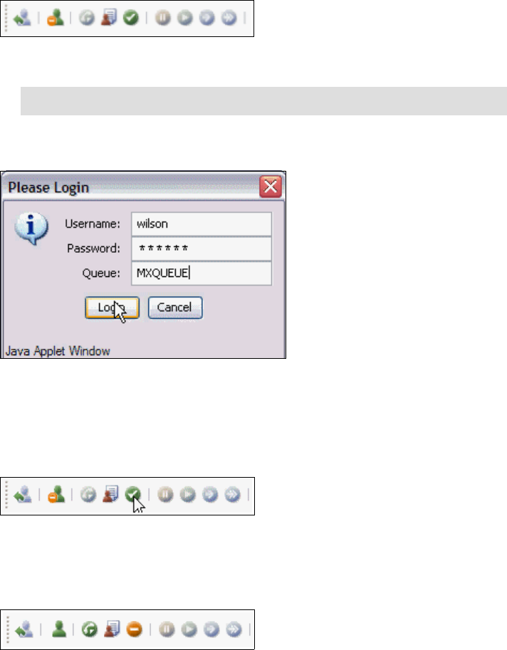
Chapter 8. Computer Telephony integration 237
The steps in this example are:
1. Log in to the CTI system, using the login button.
Notice that the CTI buttons change. Figure 8-16 shows the buttons that
appear.
Figure 8-16 CTI status after login
2. Provide your login credentials (Figure 8-17).
Figure 8-17 CTI login credentials
3. Enter your CTI user name, password, and queue (this the queuename that is
created in your CTI solution for incoming Tivoli SRM calls), and click Login.
4. Set your status to ready by using the ready button, as shown in Figure 8-18.
Figure 8-18 CTI set user status to ready
Notice the change of the CTI buttons again. The buttons shown in Figure 8-19
on page 237 appear.
Figure 8-19 CTI status set to ready
Note: You are logged in, but the status button shows you are not available.
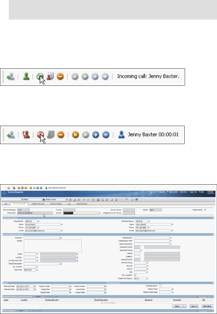
238 Integration Guide for IBM Tivoli Service Request Manager V7.1
5. When an incoming call is registered, accept the call using the accept call
button.
Notice the change of the CTI Java Applet, while it shows the incoming call.
The applet shown in Figure 8-20 appear.
Figure 8-20 Incoming call
After the call is accepted, the buttons shown in Figure 8-21 appear. The
status icon shows that you accept the call.
Figure 8-21 Incoming call accepted
Upon accepting the call, a new Service Request (SR) is created and
displayed, as shown in Figure 8-22 on page 238.
Figure 8-22 New Service Request (SR) using CTI
Note: Although you are logged in, you are not able to accept incoming
calls until you change your status to ready.
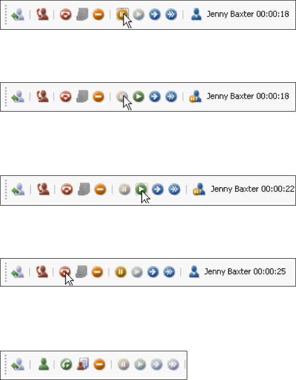
Chapter 8. Computer Telephony integration 239
The External ID field is now populated with a reference ID that is used by
Genesis. The Source field shows PHONECALL (the default) as the origin of the
new record.
6. Put the call on hold, using the mute current call button, as shown in
Figure 8-23.
Figure 8-23 Mute call
The applet shown in Figure 8-24 appears.
Figure 8-24 Muted call
7. Resume the call by using the resume current call button, as shown in
Figure 8-25 on page 239.
Figure 8-25 Resume call
8. Disconnect the call by using the end call button, as shown in Figure 8-26.
Figure 8-26 End call
9. Change your status to perform after-call work by using the start after-call work
button, as shown in Figure 8-27.
Figure 8-27 Perform after-call work
The applet shown in Figure 8-28 appears.
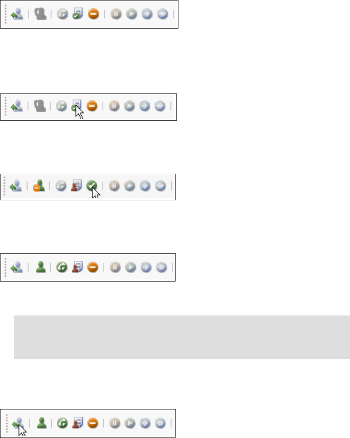
240 Integration Guide for IBM Tivoli Service Request Manager V7.1
Figure 8-28 Performing after-call work
10.Change your status to stop performing after-call work by using the stop
after-call work button, as shown in Figure 8-29.
Figure 8-29 Stop performing after-call work
11.Set your status to ready by using the ready button, as shown in Figure 8-30.
Figure 8-30 CTI set user status to ready
The buttons shown in Figure 8-19 on page 237 appear.
Figure 8-31 CTI status set to ready
12.Log out to the CTI system by using the logout button, as shown in
Figure 8-32.
Figure 8-32 CTI logout
You are asked if you are sure, as shown in Figure 8-33.
Note: Although you are logged in and have stopped performing after-call
work, you are not able to accept incoming calls until you change your
status to ready.
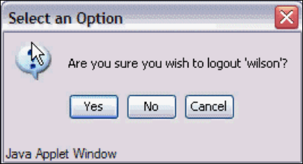
Chapter 8. Computer Telephony integration 241
Figure 8-33 CTI logout options
8.5 Troubleshooting
We always hope that you experience no problems with the installation,
configuration, or usage of Tivoli SRM and the CTI integration, but we are aware
that you can experience difficulties during any of the steps described. This
section is meant to give you a starting point for troubleshooting in case you might
end up in an unexpected state where the interaction with your CTI system is not
working.
8.5.1 Log files and debug information
During either installation, configuration, or when accessing and using your CTI
integration from within Tivoli SRM, you might experience different problems. The
best places to look for errors or exceptions are the Java Console in your Web
browser and the SystemOut.log log file that you can find on your Tivoli SRM
application server.
8.5.2 CTI Java applet did not load
If you access the specific URL to use of the CTI functions, and there are no
visible changes (no applet is visible at all), something might have gone wrong
during installation. Most likely, the Enterprise Archive (EAR) files are the
problem, because they might not be built or deployed successfully.
In that case, rebuild and redeploy the EAR files yourself by using the procedure
described in the product System Administration Guide. After successfully
rebuilding and redeploying the EAR files, perform your previous actions again to
check if the problem still exists. Contact IBM support in case the integration still
does not work after you successfully install, rebuild, and redeploy the EAR files.
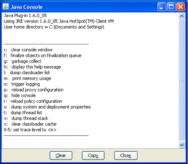
242 Integration Guide for IBM Tivoli Service Request Manager V7.1
8.5.3 CTI Java applet failed to load successfully
If the CTI installation completes successfully, and a gray applet appears on top
of the Start Center, but you cannot see the CTI buttons, check the Java console
of your Web browser for errors or exceptions. For example, in Microsoft Internet
Explorer®, the Sun Java™ Console is in the tools menu (see Figure 8-34 on
page 242).
Figure 8-34 Java Console
The Tivoli SRM window shows a gray rectangle where the CTI buttons usually
display. To be sure that you are looking at the latest errors or exceptions in the
Java Console, you can clear the Console by using the Clear button and open the
CTI URL again. Now, you can find any new error or exception in the Java
Console.
RMI binding unsuccessful
If the Remote Method Invocation (RMI) binding failed during startup, you might
have an issue with a system property that is not set (properly). The Java Console
shows an error message, such as “Class Not Found Exception”.

Chapter 8. Computer Telephony integration 243
Take the following steps to make sure that the prerequisites for the RMI binding
are correct and completed:
Make sure that the system property Java.rmi.server.hostname is set.
Change the Global Value for Property Name mxe.registry.host to the host
name of the Tivoli SRM Application Server.
Missing or incorrect system properties
It is always possible that one of the other system properties is not correctly set
during configuration. Log in to Tivoli SRM as MAXADMIN or an equivalent user
and open the system properties application. Check and correct all CTI properties
as described in ’CTI configuration” on page 231, clear the Java Console and
access the CTI URL again. If no errors or exceptions are recorded in the Java
Console, your CTI solution is now operational.
Missing or incorrect class path
Make sure that you include the Java archives (JAR files) for the Genesis
Platform Software Developer Kit (SDK) Agent Interaction Library in the server
classpath.
There is one application server classpath for each application server in the IBM
WebSphere Application Server environment. Each application server
corresponds to a Java virtual machine (JVM™).
Set the classpath in one of two ways:
Use an administrative client to set the Command Line Arguments field of the
application server. Specify the classpath with the flag-classpath.
Use an administrative client to set the application server Environment
property to include a CLASSPATH variable and value.
Note: Classes put in the classpath must not reference other classes that
cannot be found in this classpath.
244 Integration Guide for IBM Tivoli Service Request Manager V7.1

© Copyright IBM Corp. 2008. All rights reserved. 245
Chapter 9. High availability best
practices
In this chapter, we discuss high availability considerations for integrating IBM
Tivoli Service Request Manager (SRM) with other systems, such as third-party
Service Desks or Event Management systems, such as Tivoli Enterprise Console
(TEC).
We discuss the following topics:
Accuracy and availability on page 246
Event Management integration on page 246
9
246 Integration Guide for IBM Tivoli Service Request Manager V7.1
9.1 Accuracy and availability
Two considerations are especially important when you implement the integration
between two components:
Accuracy of the information
Availability of the information
The accuracy of the information means that the information exchanged through
the integration is accurate between the two systems. For example, if a ticket is
opened due to an automated event, but the source of the event is not shown
correctly in the service desk and the information that is exchanged is not
accurate, there is probably a defect in the integration software.
The availability of the information means that the information that is exchanged
through the integration is available.
Using Event Management and Service Desk integration (assuming that the
integration supports synchronization of the events) when the ticket description is
updated or the ticket is closed in the service desk, but the event or events
associated with the ticket are not updated within a reasonable time means that
the two systems are not synchronized and information is not available.
The failure of one or more components in the integration is usually the problem.
This failure can be a hardware, software, or a performance problem. The
integration components cannot cope with the increased data flow.
The goal of integration is to make sure that both the accuracy and the availability
of information that is exchanged is ensured. In this chapter, we focus on the
availability aspect of the integration and provide guidelines about how to
accomplish high availability for Tivoli SRM integration with Event Management
and third-party Service Desk systems.
9.2 Event Management integration
To ensure the high availability of an integrated end-to-end environment, all
components (including the integration components) must support (or be
configured for) high availability.
Figure 9-1 on page 247 shows a high-level overview of which components must
be evaluated for Event Management integration high availability.
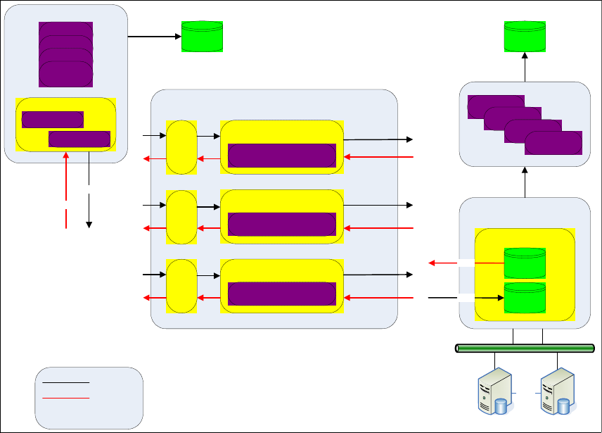
Chapter 9. High availability best practices 247
Figure 9-1 TEC integrated with Tivoli SRM for high availability
9.2.1 TEC considerations
When installing the new ruleset to support the Tivoli SRM integration, there is
one parameter that allows you to define more than one Tivoli Directory Integrator
(TDI) server:
Do you want to specify an additional TDI Server? (Y/N):
If you use more than one TDI server, answer Y. This type of configuration
enables TEC to redirect the event if the active TDI server (# 1 in Figure 9-1) does
not respond; therefore, the ruleset redirects the request to the next active server.
If no TDI servers respond to the TEC, the request is re-initiated later.
Server FARM
Redondant TDI Server
SAN
Storage Area Network
HACMP
Database Server #1 Database Server #2
SRM Database
Outbound
Queue
Inboud
Queue
SRM (DI)TEC (DI)
HTTP
TEC Out
TEC In
DI : Database Intance
Tivoli Event Server
Event
Event
Event
Event
Tivoli Directory Integrator
#2
Assembly Line
HTTP
Integration Cluster
Application
Server
Application
Server
Application
Server
Application
Server
Tivoli Directory Integrator
#1
Assembly Line
Tivoli Directory Integrator
#...
Assembly Line
HTTP 6767
postzmsg
Non-TME
Logfile
Adapter
Non-TME
Logfile
Adapter
Non-TME
Logfile
Adapter
RuleSet - TSRM
Event - FATAL
Event - CRITICAL

248 Integration Guide for IBM Tivoli Service Request Manager V7.1
As shipped, the ruleset defines which type of events are sent to the TDI server
and what type of records are generated within the Tivoli SRM (although this is
customizable). Refer to Chapter 3, “Event management integration” on page 105
for more details.
When one of the TDI servers is chosen, the configuration is kept until the Tivoli
Enterprise Server is re-initialized.
9.2.2 TDI considerations
To ensure high availability of the TDI application, you must create x number of
TDI instances to make the configuration applied at the TEC useful.
To help you understand how to implement TDI in UNIX/AIX - Windows:
In a fully redundant virtualized environment, it easy to create multiple server
instances where TDI runs multiple assembly lines to provide high availability.
In a non-virtualized environment, you can install separate instances of TDI on
separate physical boxes.
The last option is to install multiple instances of TDI on the same server. This
solution has one disadvantage. If there is a hardware problem on the server,
you might lose integration capability.
In addition to the steps described in “Steps for implementing TEC integration” on
page 114, if you use more than one TDI server, you need to perform the following
steps after “Editing the mxe.properties file (optional)” on page 116.
Configuring a common TDI System Queue
Perform this procedure to configure a common TDI System Queue for a TEC
integration environment with multiple TDI servers.
The TDI System Queue is a TDI Java Messaging Service (JMS) messaging
subsystem that facilitates storing and forwarding messages between TDI
Servers and AssemblyLines. When your integration environment includes
multiple TDI servers, each TDI server has its own system queue. Perform the
following procedure to set up the system queue on one of the TDI servers as a
common queue to be shared by all of the TDI servers.
TEC high availability: Apart from high availability of the integration, you must
also consider TEC high availability. We do not cover the installation of TEC in
this book, we assume that the high availability criteria is taken into
consideration when the TEC is introduced into your infrastructure.

Chapter 9. High availability best practices 249
Before you perform this procedure, ensure that you have completed these tasks:
You installed all TDI servers with the queue option set to Y (yes).
You specified the same path to the TDI home and the TDI work (solution)
directory in all TDI installations.
Repeat the following steps on each TDI server that does not host the common
queue:
1. Set the environment variable TDI_SOLDIR to reference the location of the
TDI work directory (solution directory) on this computer. For example:
set TDI_SOLDIR=c:\ibm\tdi1031d\work
2. Remove the file PWStoreServer +TEC.MqeReg from the following directory:
\work\\Registry\PWStoreServer\Queue
Work is the TDI work directory (solution directory) on this computer. The work
directory is typically a subdirectory under the TDI home directory.
3. Map a drive to the TDI server that hosts the common queue.
4. Change to your work directory and enter the following command on one line:
CreateLocalQueue TEC null null null nolimit nolimit PWStoreServer
"%TDI_SOLDIR%\pwstore_server.ini"
"com.ibm.mqe.adapters.MQeDiskFieldsAdapter:D:\work\Queues"
where:
–%TDI_SOLDIR% represents the path name of the work directory on this
computer.
–D specifies the drive letter that you mapped to the TDI server that hosts
the common queue.
–work is the path name of the work directory on the TDI server that hosts
the common queue. This directory path must be the same on all TDI
servers.
5. Verify that the new PWStoreServer+TEC.MqeReg file is created in the
directory \work\\Queues\PWStoreServer\TEC where work is the TDI work
directory on this computer.
Note: The CreateLocalQueue command creates a new
PWStoreServer+TEC.MqeReg file that specifies the location of the
common queue to be shared by this TDI server.

250 Integration Guide for IBM Tivoli Service Request Manager V7.1
Configuring a common TDI system store
Perform this procedure to configure a common TDI system store for a TEC
integration environment with multiple TDI servers.
The TDI system store is a relational database that enables persistent storage
(storage of objects that survive across JVM restarts). The product that
implements the system store is IBM DB2 for Java, which is also known as
Cloudscape®.
When your integration environment includes multiple TDI servers, each TDI
server has its own system store. Perform the following procedure to set up the
system store on one of the TDI servers as a common store to be shared by all of
the TDI servers.
Complete the following steps on all TDI servers, including the TDI server that
hosts the common system store:
1. Change to the work directory and open the solution.properties file.
2. In the SYSTEM STORE section of the file, add comment markers (#) to the
lines that configure Cloudscape to run in embedded mode so that the result is
similar to Example 9-1.
Example 9-1 SYSTEM STORE section one
## Location of the database (embedded mode) - Cloudscape 10
#com.ibm.di.store.database=TDISysStore
#com.ibm.di.store.jdbc.driver=org.apache.derby.jdbc.EmbeddedDriver
#com.ibm.di.store.jdbc.urlprefix=jdbc:derby:
#com.ibm.di.store.jdbc.user=APP
#{protect}-com.ibm.di.store.jdbc.password=APP
3. Remove the comment markers (#) from the lines that configure Cloudscape
to run in networked mode so that the result is similar Example 9-2.
Example 9-2 SYSTEM STORE section two
## Location of the database to connect (networked mode) - Cloudscape 10
- DerbyClient driver
com.ibm.di.store.database=jdbc:derby://localhost:1527/C:\TDI\TDISysStor
e;create=true
com.ibm.di.store.jdbc.driver=org.apache.derby.jdbc.ClientDriver
com.ibm.di.store.jdbc.urlprefix=jdbc:derby:
Note: A Cloudscape server is included with the IBM Tivoli SRM integration
Toolkit and is automatically installed when you install TDI from the toolkit by
using the procedure described in “Installation procedure” on page 31.

Chapter 9. High availability best practices 251
com.ibm.di.store.jdbc.user=APP
{protect}-com.ibm.di.store.jdbc.password=APP
#
## Details for starting Cloudscape in network mode.
## Note: If the com.ibm.di.store.hostname is set to localhost then
remote connections are not allowed.
## If it is set to the IP address of the local machine - then remote
clients can access this Cloudscape
## instance by mentioning the IP address. The network server can only
be started for the local machine.
#
com.ibm.di.store.start.mode=automatic
com.ibm.di.store.hostname=localhost
com.ibm.di.store.port=1527
com.ibm.di.store.sysibm=true
4. Replace all instances of localhost in the preceding segment with the IP
address or fully qualified host name of the computer that hosts the common
system store. replace all instances of the port number (1527 in the above
example) with the actual port number that is used by the computer that hosts
the common system store.
5. Replace the specified location of the TDISysStore directory
(C:\TDI\TDISysStore in the preceding segment) as follows:
– On the computer that hosts the common system store, specify the exact
path to the TDISysStore directory, as in the following example:
com.ibm.di.store.database=jdbc:derby://9.48.163.207:1527/C:\tdi_h
ome\work\TDISysStore;create=true
– On the other TDI servers, you can use the following shorthand notation to
specify the location of the common system store:
com.ibm.di.store.database=jdbc:derby://9.48.163.207:1527/TDISysSt
ore;create=true
6. Locate the following segment in the solution.properties file that is shown in
Example 9-3.
Example 9-3 Solution.properties file
### MQe JMS driver initialization properties
## Specifies the location of the MQe initialization file.
## This file is used to initialize MQe on TDI server startup.
systemqueue.jmsdriver.param.mqe.file.ini=C:\TDI\MQePWStore\pwstore_serv
er.ini

252 Integration Guide for IBM Tivoli Service Request Manager V7.1
7. Modify the preceding statement to specify the actual location of the
pwstore_server.ini file. The pwstore_server.ini file is located in the work
directory. For example:
systemqueue.jmsdriver.param.mqe.file.ini=C:\ibm\tdi1025D\work\pwstor
e_server.ini
Starting the Cloudscape server
First, start the TDI Config Editor:
On Windows, select Start → Programs → IBM Tivoli Directory Integrator
V6.1.1 → TDI Config Editor.
On Linux or UNIX, run the following command: TDI_home_directory/ibmditk
Then, to start the Cloudscape server:
1. From the Store menu, select Network Server Settings.
2. Enter the fully qualified hostname or IP address of this computer in the
Hostname field. (Do not enter localhost.) Enter the port that is used by the
Cloudscape server in the Port field.
3. Click Start to start the Cloudscape server.
4. Click OK on the message pop-up window that tells you the Cloudscape
server is running.
Tivoli SRM considerations
For high availability of the Tivoli SRM, you can refer to the Strategic Reuse with
Asset-Based Development, SG24-7529, IBM Redbooks publication.
9.2.3 Multiple service desks
To ensure high availability with multiple desk integrations, you need to consider
extra work at the architectural design stage. In this section, we describe how to
meet this requirement when this business need is identified.
Most of the time, when the IT department identifies the need to connect two
service desks, there is significant planning. The most important considerations in
this integration are the accuracy and the availability of the information. Several
reasons for this integration are:
Note: This value must match the port that is specified in the
solution.properties file when you set up the common system store.

Chapter 9. High availability best practices 253
Most clients already have a type of Service Management solution in place. In
many cases, clients use Service Desk tools for multiple operations in the
same organization. Many times, these help desk tools are a result of
company acquisitions and mergers.
Perhaps part of your IT Infrastructure is outsourced to another company, and
they have their own service desk systems that they use to support your
organization.
The way to perform this integration is to integrate these systems by
exchanging the Incident records and keeping them in sync.
There are several important considerations when planning for this integration:
How is the status synchronized between these systems?
What happens when the incident is resolved or closed from one side?
What type of notification is sent?
How is the service level agreement (SLA) managed?
Which data can the IBM Business Partner see?
Are there new business roles and rules around this integration?
That list can be long or short depending on your business need.
Figure 9-2 on page 254 shows an example of Tivoli SRM and HP ServiceCenter
integration configured for high availability.
Note: These types of integrations are not limited to incident management.
You can integrate other business processes, such as the service request
record, the problem management record, and the change management
record.
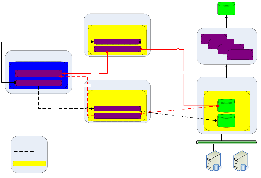
254 Integration Guide for IBM Tivoli Service Request Manager V7.1
Figure 9-2 TDI high availability
TDI considerations
In Figure 9-2, to ensure the high availability of the overall integration
environment, the TDI server is hosted in an AIX-based cluster, which is High
Availability Cluster Multi-Processing (HACMP™), and the storage area network
(SAN) is used to store the data that is exchanged between Service Desk
systems. You can use other high availability mechanisms, such as Tivoli System
Automation for Multiplatforms.
If your organization does not own a SAN system, it is still possible to store the
data on a shared drive under an high availability system, such as HACMP.
Unix – AIX
TDI Server
SAN
Storage Area Network
HACMP
Database Server #1 Database Server #2
SRM Database
Outbound
Queue
Inboud
Queue
SRM (DI)
Legend
Master
Backup
DI : Database Intance
Integration Cluster
Application
Server
Application
Server
Application
Server
Application
Server
Tivoli Directory Integrator
#2
Data volume
Assembly Line IN
Unix - AIX
TDI Server
Tivoli Directory Integrator
#1
Data volume
HACMP
HP ServiceCenter
HP SM Database
Event IN
Event OUT
Assembly Line OUT
Assembly Line IN
Assembly Line OUT
HTTP
HTTP
HTTP
HTTP
HTTP
HTTP
HTTP
Data on SAN
Chapter 9. High availability best practices 255
To configure this environment, two more physical or logical Tivoli Directory
Servers are required and must be configured with clustering software (HACMP in
Figure 9-2 on page 254) for Hot Swap redundancy. By storing the Tivoli Directory
Data on a shared or SAN drive, the integration data (or the data that is
exchanged between the two Service Desk systems) is automatically updated
when the second Tivoli Directory Server is up and running.
At this point, we do not lose any data in any of the systems. The dotted line in the
schema in Figure 9-2 on page 254 represents the backup link that can be
established between the two systems, and the full line is the active link.
256 Integration Guide for IBM Tivoli Service Request Manager V7.1
© Copyright IBM Corp. 2008. All rights reserved. 257
ACD automated call distribution
BPEL Business Process Execution
Language
CCMDB Change and Configuration
Management Database
CMDB Configuration Management
Database
CSV comma-separated values
CTI Computer Telephony
Integration
DII Dynamic Invocation Interface
DNIS dialed
DSML Directory Services Markup
Language
EIF Event Integration Facility
EJB Enterprise Java Bean
ESB Enterprise Service Bus
HTTP Hypertext Transfer Protocol
IBM International Business
Machines Corporation
IM Integration Module
ISM IBM Service Management
ITIL Information Technology
Infrastructure Library
ITSO International Technical
Support Organization
JDBC Java Database Connectivity
JMS Java Messaging Service
JNDI Java Naming and Directory
Interface
LDAP Lightweight Directory Access
Protocol
LIC Launch in context
LMO Logical Management
Operation
Abbreviations and acronyms
MBO Maximo Business Object
MEA Maximo Enterprise Adapter
Maximo Manager
OMP Operational Management
Product
OPAL Open Process Automation
Library
OS object structure
PMP Process Manager Product
SAN storage area network
SLA service level agreement
SOA service-oriented architecture
SOAP Simple Object Access
Protocol
SRM Service Request Manager
SSL Secure Sockets Layer
TADDM Tivoli Application
Dependency Discovery
TADDM Tivoli Application
Dependency Discovery
Manager
TCM Tivoli Configuration Manager
TDI Tivoli Directory Integrator
TEC Tivoli Enterprise Console
TIM Tivoli Identity Manager
TPAP Tivoli Process Automation
Platform
TPM Tivoli Provisioning Manager
UDDI Universal Description,
Discovery and Integration
UI user interface
WSDL Web Service Definition
Language
258 Integration Guide for IBM Tivoli Service Request Manager V7.1
© Copyright IBM Corp. 2008. All rights reserved. 259
Related publications
The publications listed in this section are considered particularly suitable for a
more detailed discussion of the topics covered in this book.
IBM Redbooks publications
For information about ordering these publications, refer to “How to get IBM
Redbooks publications” on page 259. Note that several of the documents
referenced here might be available in softcopy only:
Deployment Guide Series: IBM Tivoli CCMDB Overview and Deployment
Planning, SG24-7565
Implementing IBM Tivoli Service Request Manager V7.1 Service Desk,
SG24-7579
Online resources
These Web sites are also relevant as further information sources:
Lotus Sametime documentation:
http://www.ibm.com/developerworks/lotus/documentation/sametime/
How to get IBM Redbooks publications
You can search for, view, or download IBM Redbooks publications, Redpapers,
Technotes, draft publications, and additional materials, as well as order hardcopy
Redbooks, at this Web site:
ibm.com/redbooks
Index 261
Index
A
access database 19
ActiveDirectory 20
affected CIs 189
application server 39, 57, 170, 172, 174, 177–178,
181–183, 241, 243
application server classpath 243
classpath 243
Command Line Arguments field 243
Environment property 243
Java Naming 57
operating system 170
Assembly Line 22, 31, 111, 113, 115, 122, 124,
127, 131–132, 139, 143, 152, 157–158, 161
Assembly Lines
default port 143
AssemblyLines 21–22
automated call distribution (ACD) 219
B
Base Services 5
benefits of integration 5
Business Process Execution Language (BPEL) 52
C
Change Management
discipline 198
process 188
Change Manager 198
changePassword extension 181, 183
class path 243
CLASSPATH variable 243
Click List 175–176
clock-based timer 21
Cloudscape 250
Cloudscape server 252
CMDLINE handler 67
common TDI System Queue 248
common TDI System Store 250
Computer Telephony Integration (CTI) 217
Configuration Item (CI) 43, 73–74, 92–93,
188–189, 197
CSV Parser 26
CTI implementation 234
CTI Java Applet 234, 241–242
CTI solution 218
Start Center 234
CTI status 240
CTI system 218, 232–236, 240–241
application name 232
Future integrations 219
Custom lookup
configuration 233
example 234
customer relationship management (CRM) 19
D
Data Interchange Format (LDIF) 20
Data source 19–20, 24, 26
Directory Services Markup Language (DSML) 25
E
eDirectory 20
EIF message 131–132
e-mail message 107, 170
End of Queue Processing 80
End Points 54
Enterprise Java Bean (EJB) 57
Enterprise Service 43, 50–51, 53, 75, 77–78, 81,
86–87, 89, 92–93, 95–97
Enterprise Service Bus (ESB) 52
Error in Message Processing 80
Event Integration Facility (EIF) 9, 131
Event management 30–31, 105–106, 130,
245–246
Tivoli Service Request Manager 31
EventHandler 21
EventHandlers 21, 26
Extensible Markup Language (XML) 81
external application 27, 38–39, 109
context-based launching 37
launch 73
specific part number 43
system UI 43
262 Integration Guide for IBM Tivoli Service Request Manager V7.1
UI 39, 43
External Message
Id 76
ID field 77
External System 40, 44, 46, 69–70, 96
following properties 69
F
File System Connector 26
FLATFILE handler 58
G
Gateway for Tivoli EIF 131
Genesys Platform SDKs Agent Interaction Library
243
H
High availability best practices
accuracy and availability 246
event management integration 246
multiple Service Desks 252
High Availability Cluster Multi-Processing (HACMP)
254
HP OpenView ServiceCenter Web services API
145
HP-ServiceCenter 137
I
IBM Service Management (ISM)
strategy 188
IBM Service Management offerings 169
IBM Tivoli Directory Integrator
6.1.1 25, 34
6.1.1 menu 34
AssemblyLine 23
AssemblyLines work 22
component 25–26
core 21
library feature 24
server 172
IBM Tivoli Directory Server 20
IBM Tivoli Netcool/OMNIbus 131
Identity management 168
IM connection 211–213
IMAP 21
inbound message 37, 44, 75–76, 84, 92
Incident Management (IM) 138–139, 149, 156, 160,
169, 198, 253
Information Technology Infrastructure Library (ITIL)
xvii, 4, 137, 169, 188, 199
Installation and configuration
CCMDB integration 190
Computer Telephony (CTI) integration 219
HP ServiceDesk integration 139
Sametime integration 202
Third party Service Desk integration 139
Tivoli Directory integration 30
Tivoli Enterprise Console (TEC) Integration 114
Tivoli Indentity Manager integration 170
Web Services server 143
installation command 32
Instant Messenger (IM) 201–202, 209
integration application 35, 44
integration component 17, 27–28, 30, 76, 86, 93,
246
Integration Composer 36
Integration enhancement 35, 86
Integration Framework 35–36, 38–44, 46, 48–49,
51, 53, 69, 75–76, 78, 80–81, 85–86, 92
application 43
building block 44
component 39, 42–43
enterprise services process 69
exchange data 69
key features 36
overview 35, 38
processing 38, 44
v7.1 92
Integration Framework components 43
End points 54
Enterprise Services 50
External systems 69
Handlers 56
JMS 61
XMLFILE 66
Invocation Channels 47
Logical management operations 70
Object Structure (OS) 44
Publish Channels 46
Web Services Library 52
integration landscape 136
integration module 41–42, 44, 71–72, 92
integration requirements 2
integration scenarios 7
Invocation Channel 43, 47, 58, 87
detailed information 87
Index 263
IP address 204, 251–252
preceding segment 251
iPlanet 20
ITIL process 106
J
Java class 46, 49, 51, 57, 59, 63–64, 72
fully qualified name 59, 63
Java Message Service (JMS) 25, 27, 37, 39, 48,
53–54, 61, 69, 93–94
Java Naming and Directory Interface (JNDI) 57, 62
Java.rmi.server.hostname 243
JavaScript 18, 25, 27
JMS resource 63
L
Launch in context 73
LDAP EventHandler 27
Lightweight Directory Access Protocol (LDAP) 20
LMO definition 70
logfile adapter 33, 109, 114
correct location 116
non-TME version 114
Logical Management Operation (LMO) 36, 41–42,
44, 70–71, 92
Lotus Domino 20
M
Maximo Business Object (MBO) 89
Maximo Enterprise Adapter (MEA) 86, 109, 172
maximo.ear file 172, 177–179
maximo.properties 172
MaximoOut connector 142
MAXINTERROR table 84
MAXINTMSGTRK table 76, 78–79
MaxUser.class 177
MaxUserProcess.class 177
message exchange pattern (MEP) 65
Message Reprocessing application 92
Message Tracking 44, 75, 77–81, 92
detailed information 92
Message Written to Queue 80
multiple Service Desks 252
mxe.im.connectiontimeout 205
mxe.im.sametimeserver 205–206
mxe.prop erties 33, 114, 116, 141
mxetdi command 123
N
ntegration Framework components
Integration modules 71
O
Object Structure
top MBO 88
Object Structure (OS) 40, 43–45, 86, 92, 94
Object Structure Service 52
OMP application
UI 43
URL 74
OMP product 72
Open Process Automation Library (OPAL) 139
Operational Management Product (OMP) 39, 41,
44, 92
outbound messages 92
P
path name 26, 249
PEREGRINE_WEBSERVICES_PORT 143
PerlScript 25
point-to-point video 202
POP3 21
postzmsg 111
predefined rulebase 119
Process Manager Product (PMP) 4–5, 41
publish channels 92
R
Redbooks Web site 259
Contact us xx
Remote Method Invocation (RMI) 233, 242
rule base 108–109, 119, 122
rulebase
valid path 119
ruleset 117, 121, 247
ruleset configuration 118
S
sametime instant messenger
general information 201
Secure Sockets Layer (SSL) 25
Select Action menu 56, 73, 77–78, 198
dialog box 77
server failure 110
Service Desk
264 Integration Guide for IBM Tivoli Service Request Manager V7.1
Automated actions 110
configure TEC Integration 107
service desk 107–108, 135–140, 143, 145,
152–153, 168–170, 202, 218, 252, 254
single application 218
Service Desk tickets 8
Service Oriented Architecture (SOA) 47
service request 106, 108–113, 116–117, 122–123,
129–133, 135–140, 142–143, 153, 156, 160,
167–172, 174, 177, 181–182, 184, 201–202,
204–205, 209–210, 238
SQL database 21
srm 32
storage area network (SAN) 254
T
TDI home 141–142, 249
TDI Server
HTTP Port 122
Port 120
TDI server 123, 248–249, 251
connecter 110
following steps 249
non-TME logfile adapter 109
operating system 114
TEC Server
Hostname 122
Port 122
tim_sd_integration.zip 171
Tivoli Application Dependency Discovery Manager
(TADDM) 36, 193–194
Tivoli Configuration Manager (TCM) 36
Tivoli Directory Integrator
multiple instances 248
separate instances 248
Tivoli Directory Integrator (TDI) 18–19, 31, 33, 109,
112–116, 123, 131, 133, 140–141, 152, 156, 248,
250, 252, 254
architecture 19
Connectors 23
EventHandlers 26
architectureAssemblyLines 22
components 27
installation procedure 31
supported platforms 28
Tivoli Directory Integrator (TDI) server
logfile adapter 33
Tivoli Enterprise 105–106, 108, 247–248
bidirectional communication 106
incoming events 110
Tivoli Enterprise Console (TEC) 30, 33, 245
events 107
Tivoli Service Request Manager 33
Tivoli Identity Manager 167–170, 172–173, 177,
181–185
configuration 181
integration 170, 172, 177
Tivoli Service Request Manager application us-
ers 167
V5.0 170
Tivoli Process Automation Platform 5
Tivoli Process Automation Platform (TPAP) 93, 171
Tivoli Provisioning Manager (TPM) 36, 71, 92
Tivoli Service Request Manager 17–18, 30–33, 35,
93, 106, 108–113, 116–117, 122, 124, 129–133,
135–140, 142–143, 153, 156, 160, 167, 169–174,
177, 181–182, 187, 189–190, 193–194, 197, 199,
201–202, 204, 209–210, 217–219, 226–227,
231–234, 237, 241–243, 245–248, 250, 252–253
9 150
application URL 154
environment 182
external applications 172
high availability 252
incident record 111, 124
installation 170
installation Launchpad 139
instant messaging 202
integration 31, 136, 247
integration interface 172
interface 172–173
launchpad 190
main component 177
new Incident ticket 131
new ruleset 117
object 233
queue name 232
record 218
server 110, 173–174, 177–178
Service Desk Integration Offering 136
Site Id 154
solution 136
system 231, 233
Tivoli Identity Manager 172
Tivoli Identity Manager integration 170–171
transaction 138
URL 234
Index 265
user 181
user deletion 177
user interface 218
user management 184
V6.2 130
V6.2 integration 131
V7.1 106, 130–131, 136–137, 170, 189, 202
V7.1.1 190
TME version 114
U
Universal Description, Discovery and Integration
(UDDI) 52
updatedb.bat script 172
V
VBScript 25
W
web service (WS) 131–132
Web Services (WS) 27, 37–41, 43, 52, 54, 87, 91,
93, 97
message exchange pattern 65
Web Services API 145
Web Services Definition Language (WSDL) 38
Web Services Library 91, 174
application 53, 97
architecture 91
WEBSERVICE handler 64
X
XML change 82, 84
XML document 26, 59, 67–68
XML message 44, 46–49, 51, 94
xml version 83, 100, 102
XMLFILE 55
XPATH expression 77
unique ID value 77
266 Integration Guide for IBM Tivoli Service Request Manager V7.1

(0.5” spine)
0.475”<->0.875”
250 <-> 459 pages
Integration Guide for IBM Tivoli Service Request Manager V7.1

®
SG24-7580-00 ISBN 0738431184
INTERNATIONAL
TECHNICAL
SUPPORT
ORGANIZATION
BUILDING TECHNICAL
INFORMATION BASED ON
PRACTICAL EXPERIENCE
IBM Redbooks are developed by
the IBM International Technical
Support Organization. Experts
from IBM, Customers and
Partners from around the world
create timely technical
information based on realistic
scenarios. Specific
recommendations are provided
to help you implement IT
solutions more effectively in
your environment.
For more information:
ibm.com/redbooks
®
Integration Guide for IBM
Tivoli Service Request
Manager V7.1
Insider’s guide for
Tivoli Service
Request Manager
integrations
Covers integration
best practices and
architecture
Includes
demonstration
scenarios
IBM Tivoli Service Request Manager V7.1 provides a unified
and integrated approach for handling all aspects of service
requests to enable a one-touch IT service experience,
backed up by an optimized delivery and support process.
It is a powerful solution that closely aligns business and IT
operations, which improves IT service support and delivery
performance.
This IBM Redbooks publication is an integration guide for IBM
Tivoli Service Request Manager V7.1. We describe all major
integration scenarios:
Event Management
IBM Lotus Sametime Connect
Change and Configuration Management Database
Third-party programs, such as HP ServiceCenter
Computer Telephony Interface
IBM Tivoli Identity Manager
This book helps you design and create a solution to integrate
IBM Tivoli Service Request Manager V7.1 with other products
to provide an ITIL-based integrated solution for your client’s
environment.
The target audience for this book includes individuals who
are looking for an integrated Service Desk solution.
Back cover
