Chapter 3 Shigley's 9 Edition Solutions Manual
User Manual:
Open the PDF directly: View PDF ![]() .
.
Page Count: 712 [warning: Documents this large are best viewed by clicking the View PDF Link!]

Chapter 1
Problems 1-1 through 1-6 are for student research. No standard solutions are provided.
1-7 From Fig. 1-2, cost of grinding to 0.0005 in is 270%. Cost of turning to 0.003 in is
60%.
Relative cost of grinding vs. turning = 270/60 = 4.5 times Ans.
______________________________________________________________________________
1-8 CA = CB,
10 + 0.8 P = 60 + 0.8 P 0.005 P 2
P 2 = 50/0.005 P = 100 parts Ans.
______________________________________________________________________________
1-9 Max. load = 1.10 P
Min. area = (0.95)2A
Min. strength = 0.85 S
To offset the absolute uncertainties, the design factor, from Eq. (1-1) should be
2
1.10 1.43 .
0.85 0.95
d
nA ns
______________________________________________________________________________
1-10 (a) X1 + X2:
12 11 22
12 1 2
12
error
.
xx XeX e
exx XX
ee Ans
(b) X1 X2:
12 11 22
12 1 2 12
.
xx Xe X e
exx XX ee Ans
(
c) X1 X2:
12 1 1 2 2
12 1 2 12 21 12
12
12 21 1 2
12
.
xx X e X e
exxXX XeXeee
ee
X
eXeXX Ans
XX
Chapter 1 Solutions - Rev. B, Page 1/6
(
d) X1/X2:
1111 11
2222 22
1
22 11121
22 22121
11 112
22 212
1
1
1
1 1 then 1 1 1
1
Thus, .
xXeX eX
xXeX eX
ee eXeee
2
2
e
X
XeXXXX
xX Xe e
eAns
xX XXX
X
______________________________________________________________________________
1-11 (a) x1 = 7 = 2.645 751 311 1
X1 = 2.64 (3 correct digits)
x2 = 8 = 2.828 427 124 7
X2 = 2.82 (3 correct digits)
x1 + x2 = 5.474 178 435 8
e
1 = x1 X1 = 0.005 751 311 1
e2 = x2 X2 = 0.008 427 124 7
e = e1 + e2 = 0.014 178 435 8
Sum = x1 + x2 = X1 + X2 + e
= 2.64 + 2.82 + 0.014 178 435 8 = 5.474 178 435 8 Checks
(
b) X1 = 2.65, X2 = 2.83 (3 digit significant numbers)
e1 = x1 X1 = 0.004 248 688 9
e
2 = x2 X2 = 0.001 572 875 3
e = e1 + e2 = 0.005 821 564 2
Sum = x1 + x2 = X1 + X2 + e
= 2.65 +2.83 0.001 572 875 3 = 5.474 178 435 8 Checks
______________________________________________________________________________
1-12
3
3
25 10
16 1000 0.799 in .
2.5
d
SdA
nd
ns
Table A-17: d = 7
8in Ans.
Factor of safety:
3
3
7
8
25 10 3.29 .
16 1000
S
nA
ns
______________________________________________________________________________
1-13 Eq. (1-5): R =
1
n
i
i
R
= 0.98(0.96)0.94 = 0.88
Overall reliability = 88 percent Ans.
______________________________________________________________________________
Chapter 1 Solutions - Rev. B, Page 2/6
1-14 a = 1.500 0.001 in
b = 2.000 0.003 in
c = 3.000 0.004 in
d = 6.520 0.010 in
(
a) dabcw= 6.520 1.5 2 3 = 0.020 in
= 0.001 + 0.003 + 0.004 +0.010 = 0.018
all
t
wt
w = 0.020 0.018 in Ans.
(b) From part (a), wmin = 0.002 in. Thus, must add 0.008 in to d. Therefore,
d= 6.520 + 0.008 = 6.528 in Ans.
______________________________________________________________________________
1-15 V = xyz, and x = a a, y = b b, z = c c,
V abc
Vaabbcc
abc bc a ac b ab c a b c b c a c a b a b c
The higher order terms in are negligible. Thus,
Vbcaacbabc
and, .
Vbcaacbabc a b c a b c
Ans
V abc a b c a b c
For the numerical values given,
3
1.500 1.875 3.000 8.4375 inV
3
0.002 0.003 0.004 0.00427 0.00427 8.4375 0.036 in
1.500 1.875 3.000
VV
V
V = 8.438 0.036 in3 Ans.
______________________________________________________________________________
Chapter 1 Solutions - Rev. B, Page 3/6
1-16
wmax = 0.05 in, wmin = 0.004 in
0.05 0.004 0.027 in
2
w=
Thus, w = 0.05 0.027 = 0.023 in, and then, w = 0.027 0.023 in.
0.027 0.042 1.5
1.569 in
abc
a
a
w=
tw = 0.023 = t
all
t
a + 0.002 + 0.005 ta = 0.016 in
Thus,
a = 1.569 0.016 in Ans.
______________________________________________________________________________
1-17
2 3.734 2 0.139 4.012 in
oi
DD d
all 0.028 2 0.004 0.036 in
o
D
tt
Do = 4.012 0.036 in Ans.
______________________________________________________________________________
1-18 From O-Rings, Inc. (oringsusa.com), Di = 9.19 0.13 mm, d = 2.62 0.08 mm
2 9.19 2 2.62 14.43 mm
oi
DD d
all 0.13 2 0.08 0.29 mm
o
D
tt
Do = 14.43 0.29 mm Ans.
______________________________________________________________________________
1-19 From O-Rings, Inc. (oringsusa.com), Di = 34.52 0.30 mm, d = 3.53 0.10 mm
2 34.52 2 3.53 41.58 mm
oi
DD d
all 0.30 2 0.10 0.50 mm
o
D
tt
Do = 41.58 0.50 mm Ans.
______________________________________________________________________________
Chapter 1 Solutions - Rev. B, Page 4/6
1-20 From O-Rings, Inc. (oringsusa.com), Di = 5.237 0.035 in, d = 0.103 0.003 in
2 5.237 2 0.103 5.443 in
oi
DD d
all 0.035 2 0.003 0.041 in
o
D
tt
Do = 5.443 0.041 in Ans.
______________________________________________________________________________
1-21 From O-Rings, Inc. (oringsusa.com), Di = 1.100 0.012 in, d = 0.210 0.005 in
2 1.100 2 0.210 1.520 in
oi
DD d
all 0.012 2 0.005 0.022 in
o
D
tt
Do = 1.520 0.022 in Ans.
______________________________________________________________________________
1-22 From Table A-2,
(
a)
= 150/6.89 = 21.8 kpsi Ans.
(
b) F = 2 /4.45 = 0.449 kip = 449 lbf Ans.
(
c) M = 150/0.113 = 1330 lbf in = 1.33 kip in Ans.
(
d) A = 1500/ 25.42 = 2.33 in2 Ans.
(
e) I = 750/2.544 = 18.0 in4 Ans.
(
f) E = 145/6.89 = 21.0 Mpsi Ans.
(
g) v = 75/1.61 = 46.6 mi/h Ans.
(
h) V = 1000/946 = 1.06 qt Ans.
______________________________________________________________________________
1-23 From Table A-2,
(a) l = 5(0.305) = 1.53 m Ans.
(
b)
= 90(6.89) = 620 MPa Ans.
(
c) p = 25(6.89) = 172 kPa Ans.
Chapter 1 Solutions - Rev. B, Page 5/6
Chapter 1 Solutions - Rev. B, Page 6/6
(
d) Z =12(16.4) = 197 cm3 Ans.
(
e) w = 0.208(175) = 36.4 N/m Ans.
(
f)
= 0.001 89(25.4) = 0.0480 mm Ans.
(
g) v = 1200(0.0051) = 6.12 m/s Ans.
(
h) = 0.002 15(1) = 0.002 15 mm/mm Ans.
(
i) V = 1830(25.43) = 30.0 (106) mm3 Ans.
______________________________________________________________________________
1-24
(
a)
= M /Z = 1770/0.934 = 1895 psi = 1.90 kpsi Ans.
(
b)
= F /A = 9440/23.8 = 397 psi Ans.
(
c) y =Fl3/3EI = 270(31.5)3/[3(30)106(0.154)] = 0.609 in Ans.
(
d)
= Tl /GJ = 9740(9.85)/[11.3(106)(
/32)1.004] = 8.648(102) rad = 4.95 Ans.
______________________________________________________________________________
1-25
(
a)
=F / wt = 1000/[25(5)] = 8 MPa Ans.
(
b) I = bh3 /12 = 10(25)3/12 = 13.0(103) mm4 Ans.
(
c) I =
d4/64 =
(25.4)4/64 = 20.4(103) mm4 Ans.
(
d)
=16T /
d 3 = 16(25)103/[
(12.7)3] = 62.2 MPa Ans.
______________________________________________________________________________
1-26
(
a)
=F /A = 2 700/[
(0.750)2/4] = 6110 psi = 6.11 kpsi Ans.
(
b)
= 32Fa/
d 3 = 32(180)31.5/[
(1.25)3] = 29 570 psi = 29.6 kpsi Ans.
(
c) Z =
(do4 di4)/(32 do) =
(1.504 1.004)/[32(1.50)] = 0.266 in3 Ans.
(
d) k = (d 4G)/(8D 3 N) = 0.06254(11.3)106/[8(0.760)3 32] = 1.53 lbf/in Ans.
______________________________________________________________________________
Chapter 2
2-1 From Tables A-20, A-21, A-22, and A-24c,
(a) UNS G10200 HR: Sut = 380 (55) MPa (kpsi), Syt = 210 (30) Mpa (kpsi) Ans.
(b) SAE 1050 CD: Sut = 690 (100) MPa (kpsi), Syt = 580 (84) Mpa (kpsi) Ans.
(c) AISI 1141 Q&T at 540C (1000F): Sut = 896 (130) MPa (kpsi), Syt = 765 (111)
Mpa (kpsi) Ans.
(d) 2024-T4: Sut = 446 (64.8) MPa (kpsi), Syt = 296 (43.0) Mpa (kpsi) Ans.
(e) Ti-6Al-4V annealed: Sut = 900 (130) MPa (kpsi), Syt = 830 (120) Mpa (kpsi) Ans.
______________________________________________________________________________
2-2 (a) Maximize yield strength: Q&T at 425C (800F) Ans.
(b)Maximize elongation: Q&T at 650C (1200F) Ans.
______________________________________________________________________________
2-3 Conversion of kN/m3 to kg/ m3 multiply by 1(103) / 9.81 = 102
AISI 1018 CD steel: Tables A-20 and A-5
3
370 10 47.4 kN m/kg .
76.5 102
y
S
A
ns
2011-T6 aluminum: Tables A-22 and A-5
3
169 10 62.3 kN m/kg .
26.6 102
y
S
A
ns
Ti-6Al-4V titanium: Tables A-24c and A-5
3
830 10 187 kN m/kg .
43.4 102
y
S
A
ns
ASTM No. 40 cast iron: Tables A-24a and A-5.Does not have a yield strength. Using the
ultimate strength in tension
3
42.5 6.89 10 40.7 kN m/kg
70.6 102
ut
S
A
ns
______________________________________________________________________________
2-4
AISI 1018 CD steel: Table A-5
6
6
30.0 10 106 10 in .
0.282
EAns
2011-T6 aluminum: Table A-5
6
6
10.4 10 106 10 in .
0.098
EAns
Ti-6Al-6V titanium: Table A-5
Chapter 2 - Rev. D, Page 1/19
6
6
16.5 10 103 10 in .
0.160
EAns
No. 40 cast iron: Table A-5
6
6
14.5 10 55.8 10 in .
0.260
EAns
______________________________________________________________________________
2-5 2
2(1 ) 2
E
G
GvE v G
From Table A-5
Steel:
30.0 2 11.5 0.304 .
2 11.5
vA
ns
Aluminum:
10.4 2 3.90 0.333 .
2 3.90
vA
ns
Beryllium copper:
18.0 2 7.0 0.286 .
27.0
vA
ns
Gray cast iron:
14.5 2 6.0 0.208 .
26.0
vA
ns
______________________________________________________________________________
2-6 (a) A0 =
(0.503)2/4,
= Pi / A0
For data in elastic range,
= l / l0 = l / 2
For data in plastic range, 00
000
11
ll A
ll
lll A
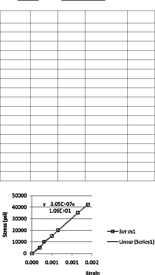
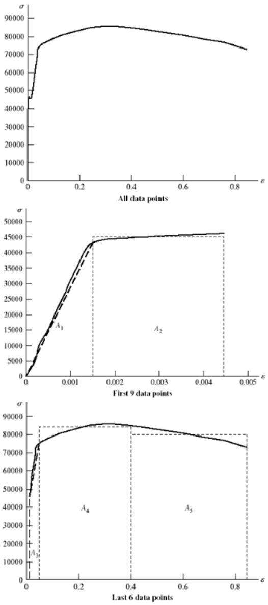
On the next two pages, the data and plots are presented. Figure (a) shows the linear part of
the curve from data points 1-7. Figure (b) shows data points 1-12. Figure (c) shows the
complete range. Note: The exact value of A0 is used without rounding off.
(b) From Fig. (a) the slope of the line from a linear regression is E = 30.5 Mpsi Ans.
From Fig. (b) the equation for the dotted offset line is found to be
= 30.5(106)
61 000 (1)
The equation for the line between data points 8 and 9 is
= 7.60(105)
+ 42 900 (2)
Chapter 2 - Rev. D, Page 2/19
Solving Eqs. (1) and (2) simultaneously yields
= 45.6 kpsi which is the 0.2 percent
offset yield strength. Thus, Sy = 45.6 kpsi Ans.
The ultimate strength from Figure (c) is Su = 85.6 kpsi Ans.
The reduction in area is given by Eq. (2-12) is
0
0
0.1987 0.1077
100 100 45.8 % .
0.1987
f
AA
R
Ans
A
Data Point Pi l, Ai
1 0 0 0 0
2 1000 0.0004 0.00020 5032
3 2000 0.0006 0.00030 10065
4 3000 0.001 0.00050 15097
5 4000 0.0013 0.00065 20130
6 7000 0.0023 0.00115 35227
7 8400 0.0028 0.00140 42272
8 8800 0.0036 0.00180 44285
9 9200 0.0089 0.00445 46298
10 8800 0.1984 0.00158 44285
11 9200 0.1978 0.00461 46298
12 9100 0.1963 0.01229 45795
13 13200 0.1924 0.03281 66428
14 15200 0.1875 0.05980 76492
15 17000 0.1563 0.27136 85551
16 16400 0.1307 0.52037 82531
17 14800 0.1077 0.84506 74479
(a) Linear range
Chapter 2 - Rev. D, Page 3/19
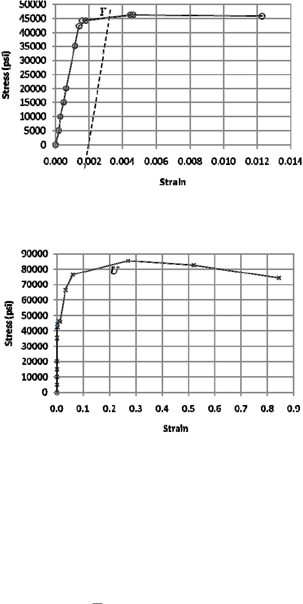
(b) Offset yield
(c) Complete range
(c) The material is ductile since there is a large amount of deformation beyond yield.
(d) The closest material to the values of Sy, Sut, and R is SAE 1045 HR with Sy = 45 kpsi,
Sut = 82 kpsi, and R = 40 %. Ans.
______________________________________________________________________________
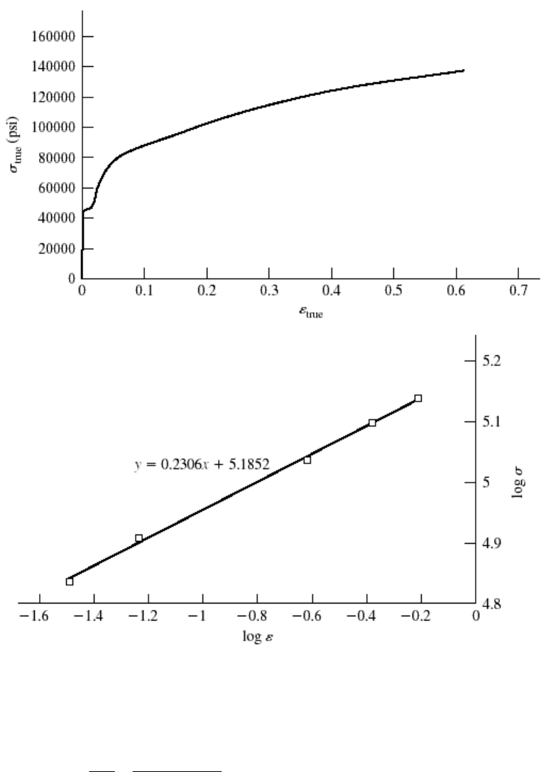
2-7 To plot
true vs.
, the following equations are applied to the data.
true
P
A
Eq. (2-4)
Chapter 2 - Rev. D, Page 4/19
0
0
ln for 0 0.0028 in
ln for 0.0028 in
ll
l
Al
A
where 22
0
(0.503) 0.1987 in
4
A
The results are summarized in the table below and plotted on the next page. The last 5
points of data are used to plot log
vs log
The curve fit gives m = 0.2306
log
0 = 5.1852
0 = 153.2 kpsi Ans.
For 20% cold work, Eq. (2-14) and Eq. (2-17) give,
A = A0 (1 – W) = 0.1987 (1 – 0.2) = 0.1590 in2
0
0.2306
0
0.1987
ln ln 0.2231
0.1590
Eq. (2-18): 153.2(0.2231) 108.4 kpsi .
Eq. (2-19), with 85.6 from Prob. 2-6,
85.6 107 kpsi .
110.2
m
y
u
u
u
A
A
SA
S
S
SAns
W
ns
P
L A
true log
log
true
0 0 0.198 713 0 0
1000 0.0004 0.198 713 0.000 2 5032.388 -3.699 01 3.701 774
2000 0.0006 0.198 713 0.000 3 10 064.78 -3.522 94 4.002 804
3000 0.001 0.198 713 0.000 5 15 097.17 -3.301 14 4.178 895
4000 0.0013 0.198 713 0.000 65 20 129.55 -3.187 23 4.303 834
7000 0.0023 0.198 713 0.001 149 35 226.72 -2.939 55 4.546 872
8400 0.0028 0.198 713 0.001 399 42 272.06 -2.854 18 4.626 053
8800 0.0036 0.198 4 0.001 575 44 354.84 -2.802 61 4.646 941
9200 0.0089 0.197 8 0.004 604 46 511.63 -2.336 85 4.667 562
9100 0.196 3 0.012 216 46 357.62 -1.913 05 4.666 121
13200 0.192 4 0.032 284 68 607.07 -1.491 01 4.836 369
15200 0.187 5 0.058 082 81 066.67 -1.235 96 4.908 842
17000 0.156 3 0.240 083 108 765.20 -0.619 64 5.036 49
16400 0.130 7 0.418 956 125 478.20 -0.377 83 5.098 568
14800 0.107 7 0.612 511 137 418.80 -0.212 89 5.138 046
Chapter 2 - Rev. D, Page 5/19
______________________________________________________________________________
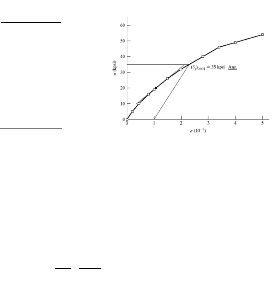
2-8 Tangent modulus at
= 0 is
6
3
5000 0 25 10 psi
0.2 10 0
E
Ans.
At
= 20 kpsi
Chapter 2 - Rev. D, Page 6/19
3
6
20 3
26 19 10 14.0 10 psi
1.5 1 10
E
Ans.
(10-3)
(kpsi)
0 0
0.20 5
0.44 10
0.80 16
1.0 19
1.5 26
2.0 32
2.8 40
3.4 46
4.0 49
5.0 54
______________________________________________________________________________
2-9 W = 0.20,
(a) Before cold working: Annealed AISI 1018 steel. Table A-22, Sy = 32 kpsi, Su = 49.5
kpsi,
0 = 90.0 kpsi, m = 0.25,
f = 1.05
After cold working: Eq. (2-16),
u = m = 0.25
Eq. (2-14), 011
1.25
1 1 0.20
i
A
AW
Eq. (2-17), 0
ln ln1.25 0.223
iu
i
A
A
Eq. (2-18),
S 93% increase Ans.
0.25
090 0.223 61.8 kpsi .
m
yi
Ans
Eq. (2-19), 49.5 61.9 kpsi .
1 1 0.20
u
u
S
SA
W
ns
25% increase Ans.
(b) Before: 49.5 1.55
32
u
y
S
S
After: 61.9 1.00
61.8
u
y
S
S
Ans.
Lost most of its ductility
______________________________________________________________________________
2-10 W = 0.20,
(a) Before cold working: AISI 1212 HR steel. Table A-22, Sy = 28 kpsi, Su = 61.5 kpsi,
0 = 110 kpsi, m = 0.24,
f = 0.85
After cold working: Eq. (2-16),
u = m = 0.24
Chapter 2 - Rev. D, Page 7/19

Eq. (2-14), 011
1.25
1 1 0.20
i
A
AW
Eq. (2-17), 0
ln ln1.25 0.223
iu
i
A
A
Eq. (2-18), 174% increase Ans.
0.24
0110 0.223 76.7 kpsi .
m
yi
SA
ns
Eq. (2-19), 61.5 76.9 kpsi .
1 1 0.20
u
u
S
SA
W
ns
25% increase Ans.
(b) Before: 61.5 2.20
28
u
y
S
S
After: 76.9 1.00
76.7
u
y
S
S
Ans.
Lost most of its ductility
______________________________________________________________________________
2-11 W = 0.20,
(a) Before cold working: 2024-T4 aluminum alloy. Table A-22, Sy = 43.0 kpsi, Su =
64.8 kpsi,
0 = 100 kpsi, m = 0.15,
f = 0.18
After cold working: Eq. (2-16),
u = m = 0.15
Eq. (2-14), 011
1.25
1 1 0.20
i
A
AW
Eq. (2-17), 0
ln ln1.25 0.223
i
i
A
Af
Material fractures. Ans.
______________________________________________________________________________
2-12 For HB = 275, Eq. (2-21), Su = 3.4(275) = 935 MPa Ans.
______________________________________________________________________________
2-13 Gray cast iron, HB = 200.
Eq. (2-22), Su = 0.23(200) 12.5 = 33.5 kpsi Ans.
From Table A-24, this is probably ASTM No. 30 Gray cast iron Ans.
______________________________________________________________________________
2-14 Eq. (2-21), 0.5HB = 100 HB = 200 Ans.
______________________________________________________________________________
Chapter 2 - Rev. D, Page 8/19
2-15 For the data given, converting HB to Su using Eq. (2-21)
HB Su (kpsi) Su2 (kpsi)
230 115 13225
232 116 13456
232 116 13456
234 117 13689
235 117.5 13806.25
235 117.5 13806.25
235 117.5 13806.25
236 118 13924
236 118 13924
239 119.5 14280.25
Su =
1172 Su2 =
137373
1172 117.2 117 kpsi .
10
u
u
S
SA
N
ns
Eq. (20-8),
10 22 2
1137373 10 117.2 1.27 kpsi .
19
u
uu
i
S
SNS
sA
N
ns
______________________________________________________________________________
2-16 For the data given, converting HB to Su using Eq. (2-22)
HB Su (kpsi) Su2 (kpsi)
230 40.4 1632.16
232 40.86 1669.54
232 40.86 1669.54
234 41.32 1707.342
235 41.55 1726.403
235 41.55 1726.403
235 41.55 1726.403
236 41.78 1745.568
236 41.78 1745.568
239 42.47 1803.701
Su =
414.12 Su2 =
17152.63
Chapter 2 - Rev. D, Page 9/19
414.12 41.4 kpsi .
10
u
u
S
SA
N
ns
Eq. (20-8),
10 22 2
117152.63 10 41.4 1.20 .
19
u
uu
i
S
SNS
sA
N
ns
______________________________________________________________________________
2-17 (a) 23
45.5 34.5 in lbf / in .
2(30)
R
uAns
(b)
P L A A0 / A – 1
= P/A0
0 0 0 0
1000 0.0004 0.0002 5 032.39
2000 0.0006 0.0003 10 064.78
3000 0.0010 0.0005 15 097.17
4000 0.0013 0.000 65 20 129.55
7000 0.0023 0.001 15 35 226.72
8400 0.0028 0.0014 42 272.06
8800 0.0036 0.0018 44 285.02
9200 0.0089 0.004 45 46 297.97
9100 0.1963 0.012 291 0.012 291 45 794.73
13200 0.1924 0.032 811 0.032 811 66 427.53
15200 0.1875 0.059 802 0.059 802 76 492.30
17000 0.1563 0.271 355 0.271 355 85 550.60
16400 0.1307 0.520 373 0.520 373 82 531.17
14800 0.1077 0.845 059 0.845 059 74 479.35
From the figures on the next page,
5
1
33
1(43 000)(0.001 5) 45 000(0.004 45 0.001 5)
2
145 000 76 500 (0.059 8 0.004 45)
2
81 000 0.4 0.059 8 80 000 0.845 0.4
66.7 10 in lbf/in .
Ti
i
uA
Ans
Chapter 2 - Rev. D, Page 10/19
Chapter 2 - Rev. D, Page 11/19
2-18, 2-19 These problems are for student research. No standard solutions are provided.
______________________________________________________________________________
2-20 Appropriate tables: Young’s modulus and Density (Table A-5)1020 HR and CD (Table A-
20), 1040 and 4140 (Table A-21), Aluminum (Table A-24), Titanium (Table A-24c)
Appropriate equations:
For diameter,
2
4
/4 y
y
FFSd
F
A
dS
Weight/length =
A, Cost/length = $/in = ($/lbf) Weight/length,
Deflection/length =
/L = F/(AE)
With F = 100 kips = 100(103) lbf,
Material
Young's
ModulusDensity
Yield
StrengthCost/lbf Diameter
Weight/
length
Cost/
length
Deflection/
length
unitsMpsilbf/in^3kpsi$/lbfinlbf/in$/inin/in
1020HR300.28230 $0.27 2.060 0.9400 $0.251.000E‐03
1020CD300.28257 $0.30 1.495 0.4947 $0.151.900E‐03
1040300.28280 $0.35 1.262 0.3525 $0.122.667E‐03
4140300.282165 $0.80 0.878 0.1709 $0.145.500E‐03
Al10.40.09850 $1.10 1.596 0.1960 $0.224.808E‐03
Ti16.50.16120 $7.00 1.030 0.1333 $0.937.273E‐03
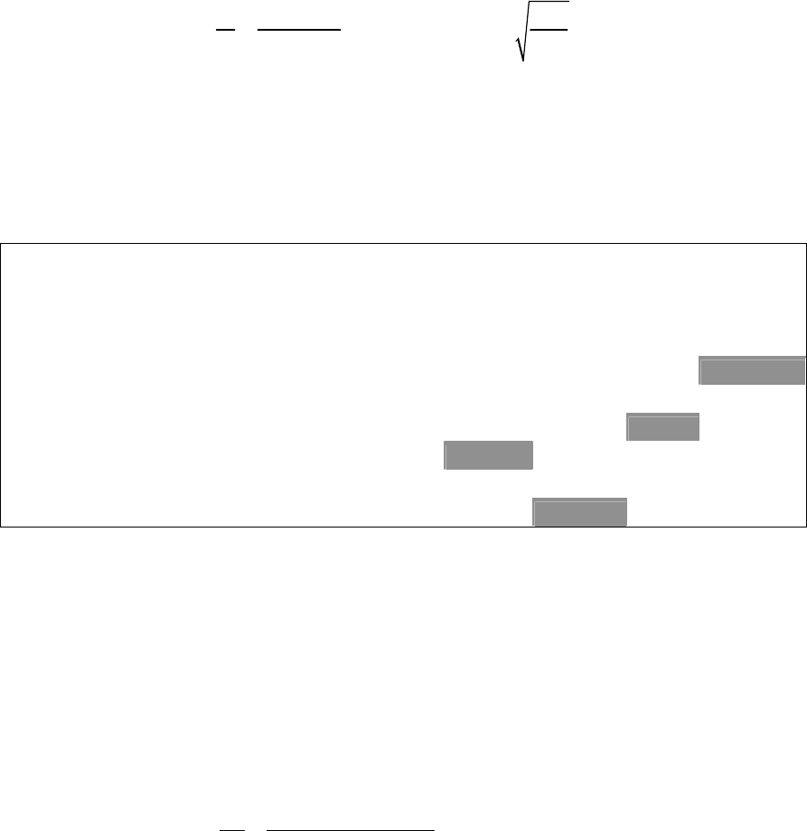
The selected materials with minimum values are shaded in the table above. Ans.
______________________________________________________________________________
2-21 First, try to find the broad category of material (such as in Table A-5). Visual, magnetic,
and scratch tests are fast and inexpensive, so should all be done. Results from these three
would favor steel, cast iron, or maybe a less common ferrous material. The expectation
would likely be hot-rolled steel. If it is desired to confirm this, either a weight or bending
test could be done to check density or modulus of elasticity. The weight test is faster.
From the measured weight of 7.95 lbf, the unit weight is determined to be
33
2
7.95 lbf 0.281 lbf/in 0.28 lbf/in
[ (1 in) / 4](36 in)
W
Al
w
which agrees well with the unit weight of 0.282 lbf/in3 reported in Table A-5 for carbon
steel. Nickel steel and stainless steel have similar unit weights, but surface finish and
darker coloring do not favor their selection. To select a likely specification from Table
Chapter 2 - Rev. D, Page 12/19
A-20, perform a Brinell hardness test, then use Eq. (2-21) to estimate an ultimate strength
of . Assuming the material is hot-rolled due to the
rough surface finish, appropriate choices from Table A-20 would be one of the higher
carbon steels, such as hot-rolled AISI 1050, 1060, or 1080. Ans.
0.5 0.5(200) 100 kpsi
uB
SH
______________________________________________________________________________
2-22 First, try to find the broad category of material (such as in Table A-5). Visual, magnetic,
and scratch tests are fast and inexpensive, so should all be done. Results from these three
favor a softer, non-ferrous material like aluminum. If it is desired to confirm this, either a
weight or bending test could be done to check density or modulus of elasticity. The
weight test is faster. From the measured weight of 2.90 lbf, the unit weight is determined
to be
33
2
2.9 lbf 0.103 lbf/in 0.10 lbf/in
[ (1 in) / 4](36 in)
W
Al
w
which agrees reasonably well with the unit weight of 0.098 lbf/in3 reported in Table A-5
for aluminum. No other materials come close to this unit weight, so the material is likely
aluminum. Ans.
______________________________________________________________________________
2-23 First, try to find the broad category of material (such as in Table A-5). Visual, magnetic,
and scratch tests are fast and inexpensive, so should all be done. Results from these three
favor a softer, non-ferrous copper-based material such as copper, brass, or bronze. To
further distinguish the material, either a weight or bending test could be done to check
density or modulus of elasticity. The weight test is faster. From the measured weight of
9 lbf, the unit weight is determined to be
33
2
9.0 lbf 0.318 lbf/in 0.32 lbf/in
[ (1 in) / 4](36 in)
W
Al
w
which agrees reasonably well with the unit weight of 0.322 lbf/in3 reported in Table A-5
for copper. Brass is not far off (0.309 lbf/in3), so the deflection test could be used to gain
additional insight. From the measured deflection and utilizing the deflection equation for
an end-loaded cantilever beam from Table A-9, Young’s modulus is determined to be
3
3
4
100 24 17.7 Mpsi
33 (1) 64 (17 / 32)
Fl
EIy
which agrees better with the modulus for copper (17.2 Mpsi) than with brass (15.4 Mpsi).
The conclusion is that the material is likely copper. Ans.
______________________________________________________________________________
2-24 and 2-25 These problems are for student research. No standard solutions are provided.
______________________________________________________________________________
Chapter 2 - Rev. D, Page 13/19
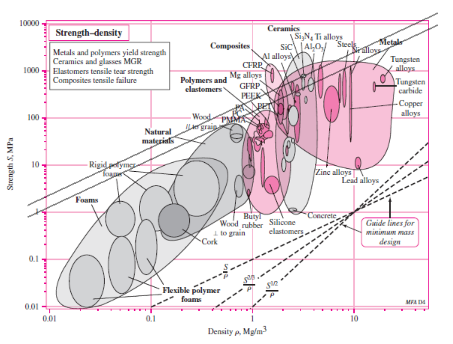
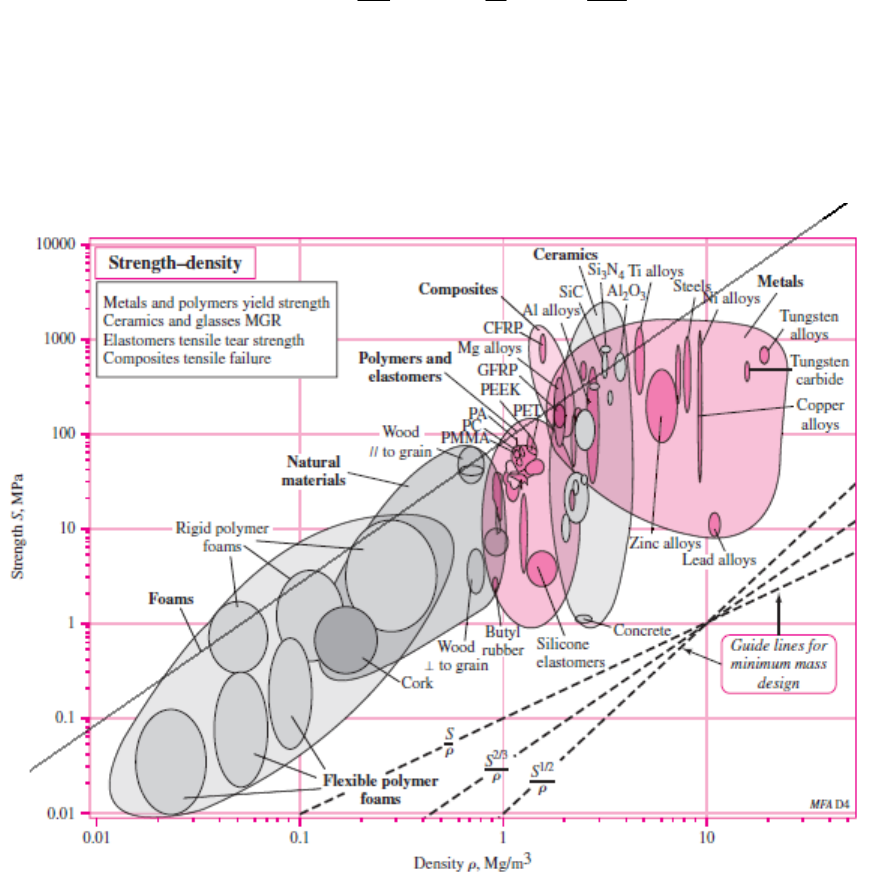
2-26 For strength,
= F/A = S A = F/S
For mass, m = Al
= (F/S) l
Thus, f 3(M ) =
/S , and maximize S/
(
= 1)
In Fig. (2-19), draw lines parallel to S/
From the list of materials given, both aluminum alloy and high carbon heat treated
steel are good candidates, having greater potential than tungsten carbide or polycarbonate.
The higher strength aluminum alloys have a slightly greater potential. Other factors, such
as cost or availability, may dictate which to choose. Ans.
______________________________________________________________________________
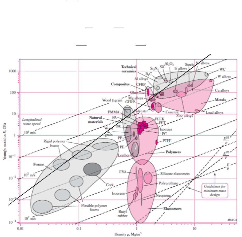
2-27 For stiffness, k = AE/l A = kl/E
For mass, m = Al
= (kl/E) l
=kl2
/E
Thus, f 3(M) =
/E , and maximize E/
(
= 1)
In Fig. (2-16), draw lines parallel to E/
Chapter 2 - Rev. D, Page 14/19
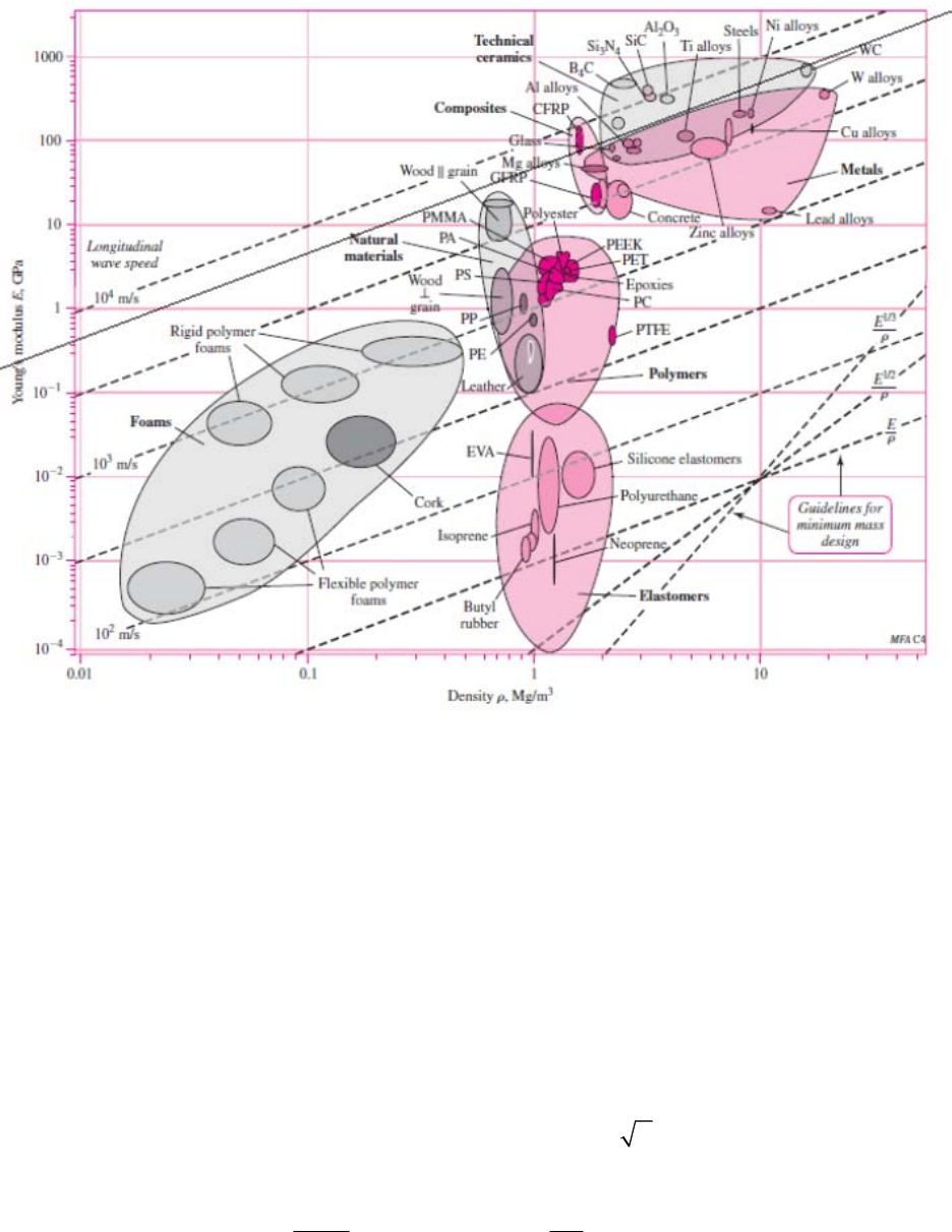
From the list of materials given, tungsten carbide (WC) is best, closely followed by
aluminum alloys, and then followed by high carbon heat-treated steel. They are close
enough that other factors, like cost or availability, would likely dictate the best choice.
Polycarbonate polymer is clearly not a good choice compared to the other candidate
materials. Ans.
______________________________________________________________________________
2-28 For strength,
= Fl/Z = S (1)
where Fl is the bending moment and Z is the section modulus [see Eq. (3-26b), p. 90 ].
The section modulus is strictly a function of the dimensions of the cross section and has
the units in3 (ips) or m3 (SI). Thus, for a given cross section, Z =C (A)3/2, where C is a
number. For example, for a circular cross section, C =
1
4
. Then, for strength, Eq.
(1) is
2/3
3/2
Fl Fl
SA
CA CS
(2)
Chapter 2 - Rev. D, Page 15/19
For mass,
2/3 2/3
5/3
2/3
Fl F
mAl l l
CS C S
Thus, f 3(M) =
/S 2/3, and maximize S 2/3/
(
= 2/3)
In Fig. (2-19), draw lines parallel to S 2/3/
From the list of materials given, a higher strength aluminum alloy has the greatest
potential, followed closely by high carbon heat-treated steel. Tungsten carbide is clearly
not a good choice compared to the other candidate materials. .Ans.
______________________________________________________________________________
2-29 Eq. (2-26), p. 65, applies to a circular cross section. However, for any cross section shape
it can be shown that I = CA 2, where C is a constant. For example, consider a rectangular
section of height h and width b, where for a given scaled shape, h = cb, where c is a
Chapter 2 - Rev. D, Page 16/19
constant. The moment of inertia is I = bh 3/12, and the area is A = bh. Then I = h(bh2)/12
= cb (bh2)/12 = (c/12)(bh)2 = CA 2, where C = c/12 (a constant).
Thus, Eq. (2-27) becomes
1/2
3
3
kl
ACE
and Eq. (2-29) becomes
1/2
5/2
1/2
3
k
mAl l
CE
Thus, minimize
31/2
fM
E
, or maximize 1/2
E
M
. From Fig. (2-16)
From the list of materials given, aluminum alloys are clearly the best followed by steels
and tungsten carbide. Polycarbonate polymer is not a good choice compared to the other
candidate materials. Ans.
______________________________________________________________________________
2-30 For stiffness, k = AE/l A = kl/E
For mass, m = Al
= (kl/E) l
=kl2
/E
Chapter 2 - Rev. D, Page 17/19
So, f 3(M) =
/E, and maximize E/
. Thus,
= 1. Ans.
______________________________________________________________________________
2-31 For strength,
= F/A = S A = F/S
For mass, m = Al
= (F/S) l
So, f 3(M ) =
/S, and maximize S/
. Thus,
= 1. Ans.
______________________________________________________________________________
2-32 Eq. (2-26), p. 65, applies to a circular cross section. However, for any cross section shape
it can be shown that I = CA 2, where C is a constant. For example, consider a rectangular
section of height h and width b, where for a given scaled shape, h = cb, where c is a
constant. The moment of inertia is I = bh 3/12, and the area is A = bh. Then I = h(bh2)/12
= cb (bh2)/12 = (c/12)(bh)2 = CA 2, where C = c/12.
Thus, Eq. (2-27) becomes
1/2
3
3
kl
ACE
and Eq. (2-29) becomes
1/2
5/2
1/2
3
k
mAl l
CE
So, minimize
31/2
fM
E
, or maximize 1/2
E
M
. Thus,
= 1/2. Ans.
______________________________________________________________________________
2-33 For strength,
= Fl/Z = S (1)
where Fl is the bending moment and Z is the section modulus [see Eq. (3-26b), p. 90 ].
The section modulus is strictly a function of the dimensions of the cross section and has
the units in3 (ips) or m3 (SI). Thus, for a given cross section, Z =C (A)3/2, where C is a
number. For example, for a circular cross section, C =
1
4
. Then, for strength, Eq. (1)
is
2/3
3/2
Fl Fl
SA
CA CS
(2)
For mass,
2/3 2/3
5/3
2/3
Fl F
mAl l l
CS C S
So, f 3(M) =
/S 2/3, and maximize S 2/3/
. Thus,
= 2/3. Ans.
______________________________________________________________________________
2-34 For stiffness, k=AE/l, or, A = kl/E.
Chapter 2 - Rev. D, Page 18/19

Chapter 2 - Rev. D, Page 19/19
Thus, m =
Al =
(kl/E )l = kl 2
/E. Then, M = E /
and
= 1.
From Fig. 2-16, lines parallel to E /
for ductile materials include steel, titanium,
molybdenum, aluminum alloys, and composites.
For strength, S = F/A, or, A = F/S.
Thus, m =
Al =
F/Sl = Fl
/S. Then, M = S/
and
= 1.
From Fig. 2-19, lines parallel to S/
give for ductile materials, steel, aluminum alloys,
nickel alloys, titanium, and composites.
Common to both stiffness and strength are steel, titanium, aluminum alloys, and
composites. Ans.
Chapter 3
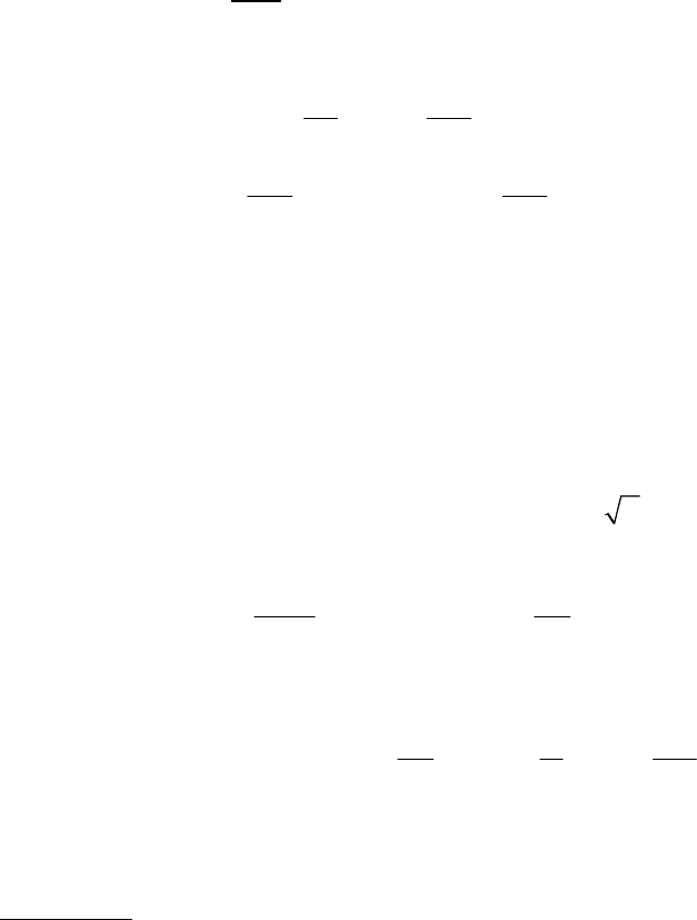
3-1
0
o
M
18 6(100) 0
B
R
33.3 lbf .
B
R
Ans
0
y
F
100 0
oB
RR
66.7 lbf .
o
R
Ans
33.3 lbf .
CB
R
RA ns
______________________________________________________________________________
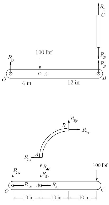
3-2
Body AB:
0
x
F
A
xBx
R
R
0
y
F
A
yBy
R
R
0
B
M (10) (10) 0
Ay Ax
RR
A
xAy
R
R
Body OAC:
0
O
M (10) 100(30) 0
Ay
R
300 lbf .
Ay
R
Ans
0
x
F 300 lbf .
Ox Ax
R
RA ns
0
y
F 100 0
Oy Ay
RR
200 lbf .
Oy
R
Ans
______________________________________________________________________________
Chapter 3 - Rev. A, Page 1/100
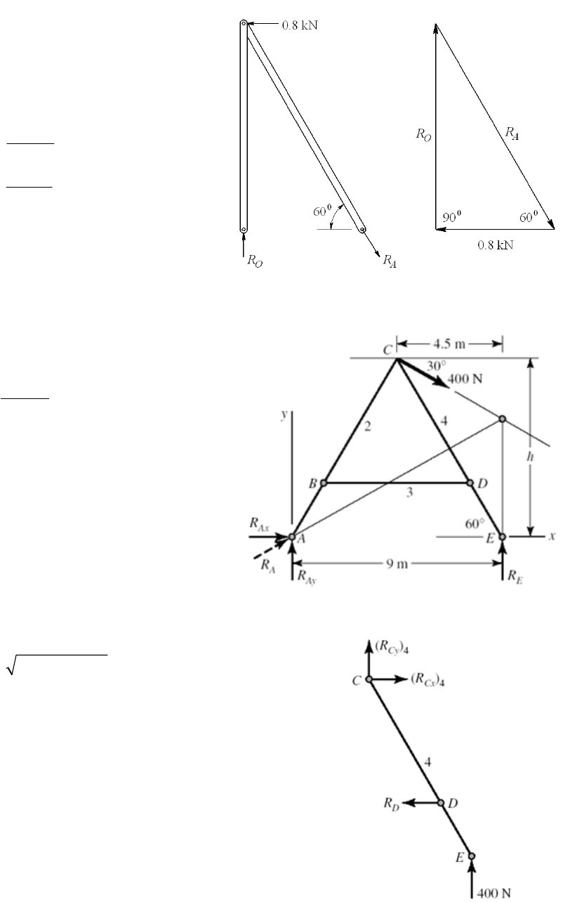
3-3
0.8 1.39 kN .
tan 30
O
R
Ans
0.8 1.6 kN .
sin 30
A
R
Ans
______________________________________________________________________________
3-4
Step 1: Find RA & RE
4.5 7.794 m
tan 30
0
9 7.794(400 cos30 )
4.5(400sin 30 ) 0
400 N .
A
E
E
h
M
R
RAns
22
0 400cos30 0
346.4 N
0 400 400sin 30 0
200 N
346.4 200 400 N .
xAx
Ax
yAy
Ay
A
FR
R
FR
R
R
Ans
Step 2: Find components of RC on link 4 and RD
4
4
0
400(4.5) 7.794 1.9 0
305.4 N .
0 305.4 N
0 ( ) 400 N
C
D
D
xCx
yCy
M
R
RAns
FR
FR
Chapter 3 - Rev. A, Page 2/100
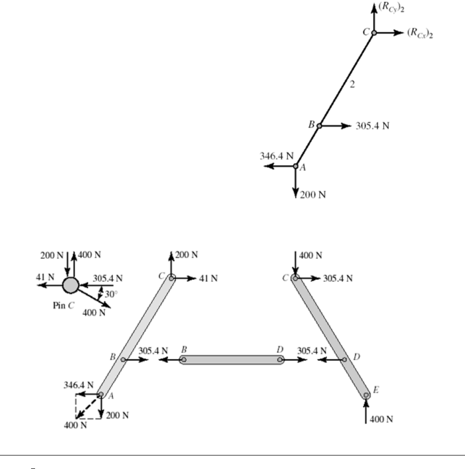
Step 3: Find components of RC on link 2
2
2
2
0
305.4 346.4 0
41 N
0
200 N
x
Cx
Cx
y
Cy
F
R
R
F
R
____________________________________________________________________________________________________________________
_
Chapter 3 - Rev. A, Page 3/100
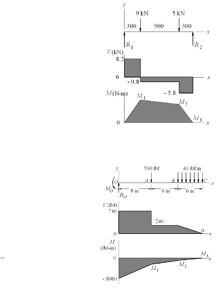
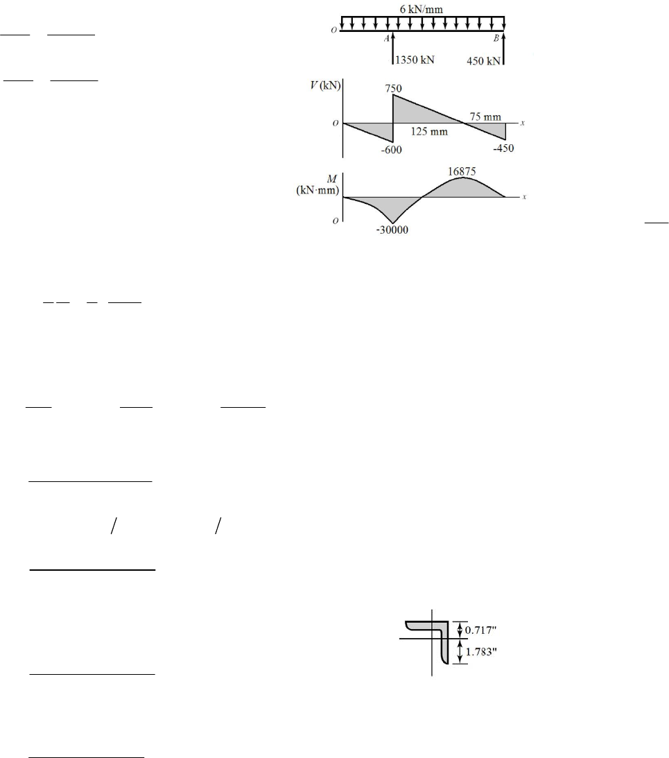
3-5
0
C
M
1
1500 300(5) 1200(9) 0R
18.2 kN .
R
Ans
0
y
F
2
8.2 9 5 0R 25.8 kN .
R
Ans
18.2(300) 2460 N m .
M
Ans
22460 0.8(900) 1740 N m .
M
Ans
31740 5.8(300) 0 checks!M
_____________________________________________________________________________
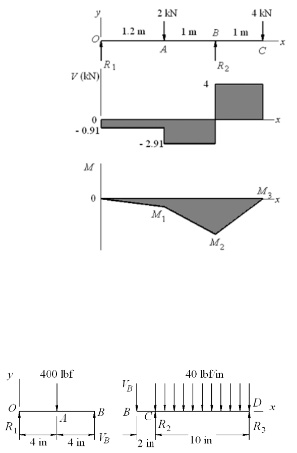
3-6
0
y
F
0500 40(6) 740 lbf .
R
Ans
00M
0500(8) 40(6)(17) 8080 lbf in .
M
Ans
18080 740(8) 2160 lbf in .
M
Ans
22160 240(6) 720 lbf in .
M
Ans
3
1
720 (240)(6) 0 checks!
2
M
______________________________________________________________________________
Chapter 3 - Rev. A, Page 4/100
3-7
0
B
M
1
2.2 1(2) 1(4) 0R
10.91 kN .
R
Ans
0
y
F
2
0.91 2 4 0R
26.91 kN .
R
Ans
10.91(1.2) 1.09 kN m .
M
Ans
21.09 2.91(1) 4 kN m .
M
Ans
34 4(1) 0 checks!M
______________________________________________________________________________
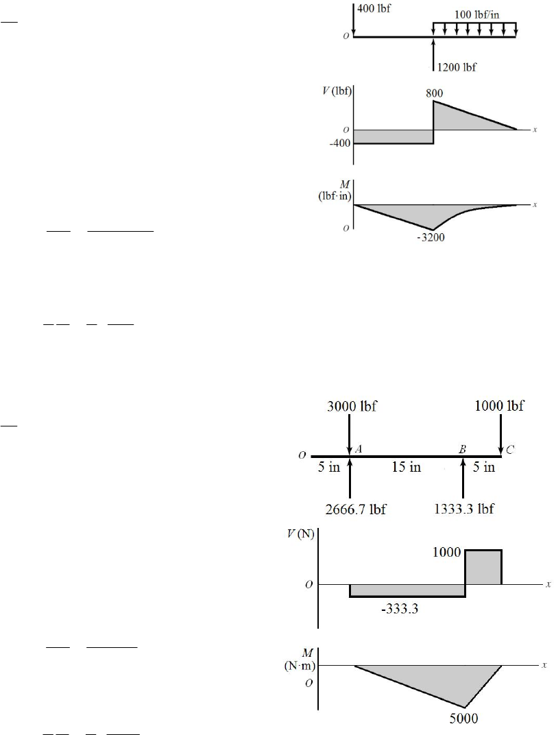
3-8
Break at the hinge at B
Beam OB:
From symmetry,
1200 lbf .
B
R
VAns
Beam BD:
0
D
M
2
200(12) (10) 40(10)(5) 0R
2440 lbf .
R
Ans
0
y
F
3
200 440 40(10) 0R
3160 lbf .
R
Ans
Chapter 3 - Rev. A, Page 5/100
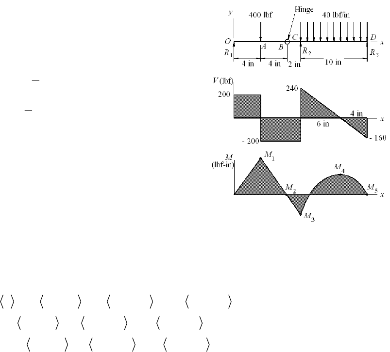
1200(4) 800 lbf in .
M
Ans
2800 200(4) 0 checks at hingeM
3800 200(6) 400 lbf in .
M
Ans
4
1
400 (240)(6) 320 lbf in .
2
M
Ans
5
1
320 (160)(4) 0 checks!
2
M
______________________________________________________________________________
3-9
11 1
12
00 0
12
11 1
12
9 300 5 1200 1500
9 300 5 1200 1500 (1)
9 300 5 1200 1500 (2)
qRx x x Rx
VR x x Rx
MRx x x Rx
1
At x = 1500+ V = M = 0. Applying Eqs. (1) and (2),
12 12
95 0 14RR RR
1 1
1500 9(1500 300) 5(1500 1200) 0 8.2 kN .
R
RA
214 8.2 5.8 kN .
ns
R
Ans
0 300 : 8.2 kN, 8.2 N m
300 1200 : 8.2 9 0.8 kN
8.2 9( 300) 0.8 2700 N m
1200 1500 : 8.2 9 5 5.8 kN
8.2 9( 300
xVMx
xV
Mxx x
xV
Mxx
) 5( 1200) 5.8 8700 N mxx
Plots of V and M are the same as in Prob. 3-5.
______________________________________________________________________________
Chapter 3 - Rev. A, Page 6/100
3-10
12 1 0 0
00
101 1
00
12 2
00
500 8 40 14 40 20
500 8 40 14 40 20 (1)
500 8 20 14 20 20 (2)
at 20 in, 0, Eqs. (1) and (2) give
qRx Mx x x x
VRMx x x x
MRxM x x x
xVM
R
0 0
2
00 0
500 40 20 14 0 740 lbf .
(20) 500(20 8) 20(20 14) 0 8080 l
b
f in .
R
Ans
R
MM
Ans
0 8 : 740 lbf, 740 8080 lbf in
8 14 : 740 500 240 lbf
740 8080 500( 8) 240 4080 lbf in
14 20 : 740 500 40( 14) 40 800 lbf
740 8080
xV Mx
xV
Mx x x
xV x x
Mx
22
500( 8) 20( 14) 20 800 8000 lbf inxx xx
Plots of V and M are the same as in Prob. 3-6.
______________________________________________________________________________
3-11
11 1 1
12
000
12
111
12
2 1.2 2.2 4 3.2
2 1.2 2.2 4 3.2 (1)
2 1.2 2.2 4 3.2 (2)
qRx x Rx x
VR x Rx x
MRx x Rx x
at x = 3.2+, V = M = 0. Applying Eqs. (1) and (2),
Solving Eqs. (3) and (4) simultaneously,
12 12
12 12
2 4 0 6 (3)
3.2 2(2) (1) 0 3.2 4 (4)
RR RR
RR RR
R1 = -0.91 kN, R2 = 6.91 kN Ans.
0 1.2 : 0.91 kN, 0.91 kN m
1.2 2.2 : 0.91 2 2.91 kN
0.91 2( 1.2) 2.91 2.4 kN m
2.2 3.2 : 0.91 2 6.91 4 kN
0.91 2(
xV Mx
xV
Mxx x
xV
Mxx
1.2) 6.91( 2.2) 4 12.8 kN mxx
Plots of V and M are the same as in Prob. 3-7.
______________________________________________________________________________
Chapter 3 - Rev. A, Page 7/100

3-12
111001
12 3
00110
12 3
112 2 1
12 3
1
400 4 10 40 10 40 20 20
400 4 10 40 10 40 20 20 (1)
400 4 10 20 10 20 20 20 (2)
0 at 8 in 8 400(
qRx x Rx x x Rx
VR x Rx x x Rx
MRx x Rx x x Rx
Mx R
1
8 4) 0 200 lbf .RAns
at x = 20+, V =M = 0. Applying Eqs. (1) and (2),
23 23
2
22
200 400 40(10) 0 600
200(20) 400(16) (10) 20(10) 0 440 lbf .
RR RR
R
RA
3600 440 160 lbf .
ns
R
Ans
0 4 : 200 lbf, 200 lbf in
4 10 : 200 400 200 lbf,
200 400( 4) 200 1600 lbf in
10 20 : 200 400 440 40( 10) 640 40 lbf
200 400( 4)
xV Mx
xV
Mxx x
xV x x
Mxx
22
440( 10) 20 10 20 640xx x
4800 lbf inx
Plots of V and M are the same as in Prob. 3-8.
______________________________________________________________________________
3-13 Solution depends upon the beam selected.
______________________________________________________________________________
3-14 (a) Moment at center,
2
2
2
2
22 2 2 4
c
c
la
x
lll
M
la a
wwl
At reaction, 22
r
Maw
a = 2.25, l = 10 in, w = 100 lbf/in
2
100(10) 10 2.25 125 lbf in
24
100 2.25 253 lbf in .
2
c
r
M
M
Ans
(b) Optimal occurs when cr
M
M
Chapter 3 - Rev. A, Page 8/100
2
22
0.25 0
24 2
ll a
aaall
ww
Taking the positive root
22
14 0.25 2 1 0.207 .
22
l
all l lA
ns
for l = 10 in, w = 100 lbf, a = 0.207(10) = 2.07 in
2
min 100 2 2.07 214 lbf inM
______________________________________________________________________________
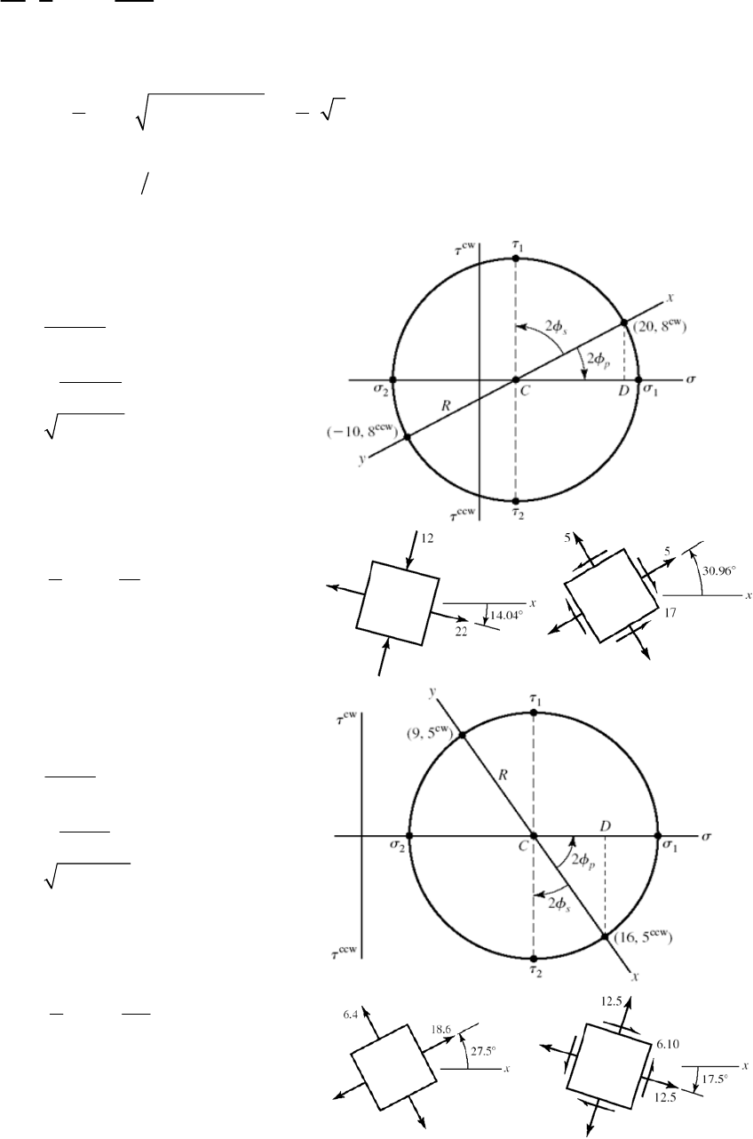
3-15 (a)
20 10 5 kpsi
2
C
20 10 15 kpsi
2
CD
22
15 8 17 kpsiR
15 17 22 kpsi
25 17 12 kpsi
1
18
tan 14.04 cw
215
p
117 kpsi
45 14.04 30.96 ccw
s
R
(b)
916 12.5 kpsi
2
C
16 9 3.5 kpsi
2
CD
22
5 3.5 6.10 kpsiR
112.5 6.1 18.6 kpsi
212.5 6.1 6.4 kpsi
1
15
tan 27.5 ccw
23.5
p
16.10 kpsi
45 27.5 17.5 cw
s
R
Chapter 3 - Rev. A, Page 9/100
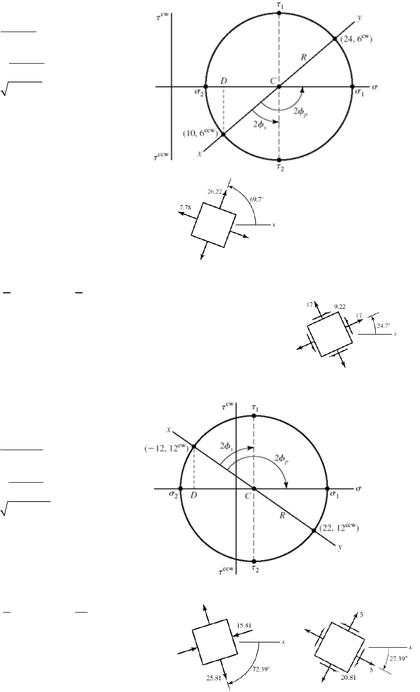
(c)
22
1
2
24 10 17 kpsi
2
24 10 7 kpsi
2
7 6 9.22 kpsi
17 9.22 26.22 kpsi
17 9.22 7.78 kpsi
C
CD
R
1
17
90 tan 69.7 ccw
26
p
19.22 kpsi
69.7 45 24.7 ccw
s
R
(d)
22
1
2
12 22 5 kpsi
2
12 22 17 kpsi
2
17 12 20.81 kpsi
5 20.81 25.81 kpsi
5 20.81 15.81 kpsi
C
CD
R
1
117
90 tan 72.39 cw
212
p
Chapter 3 - Rev. A, Page 10/100
120.81 kpsi
72.39 45 27.39 cw
s
R
______________________________________________________________________________
Chapter 3 - Rev. A, Page 11/100
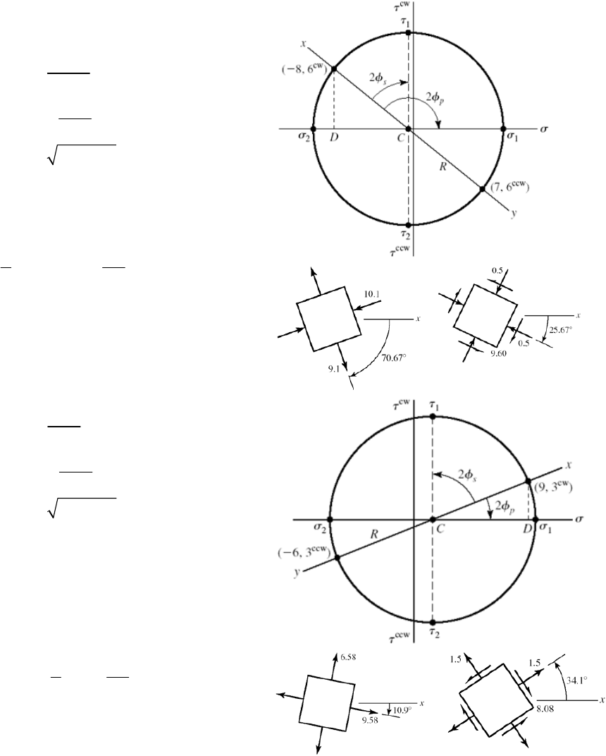
3-16 (a)
22
1
2
87 0.5 MPa
2
87 7.5 MPa
2
7.5 6 9.60 MPa
9.60 0.5 9.10 MPa
0.5 9.6 10.1 Mpa
C
CD
R
1
1 7.5
90 tan 70.67 cw
26
p
19.60 MPa
70.67 45 25.67 cw
s
R
(b)
22
1
2
961.5 MPa
2
96 7.5 MPa
2
7.5 3 8.078 MPa
1.5 8.078 9.58 MPa
1.5 8.078 6.58 MPa
C
CD
R
1
13
tan 10.9 cw
27.5
p
18.078 MPa
45 10.9 34.1 ccw
s
R
Chapter 3 - Rev. A, Page 12/100
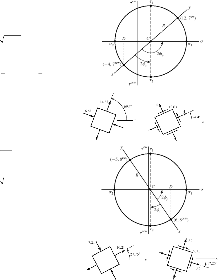
(c)
22
1
2
12 4 4 MPa
2
12 4 8 MPa
2
8 7 10.63 MPa
4 10.63 14.63 MPa
4 10.63 6.63 MPa
C
CD
R
1
18
90 tan 69.4 ccw
27
p
110.63 MPa
69.4 45 24.4 ccw
s
R
(d)
22
1
2
65 0.5 MPa
2
65 5.5 MPa
2
5.5 8 9.71 MPa
0.5 9.71 10.21 MPa
0.5 9.71 9.21 MPa
C
CD
R
1
18
tan 27.75 ccw
25.5
p
19.71 MPa
45 27.75 17.25 cw
s
R
______________________________________________________________________________
Chapter 3 - Rev. A, Page 13/100
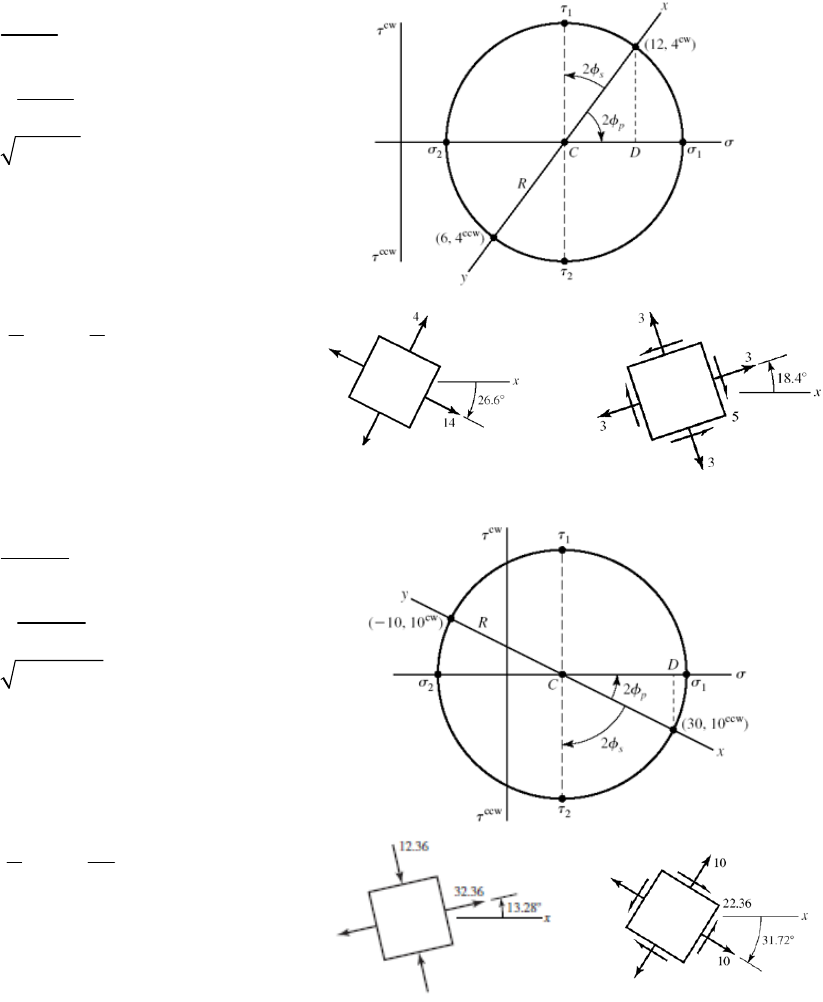
3-17 (a)
22
1
2
12 6 9 kpsi
2
12 6 3 kpsi
2
3 4 5 kpsi
5 9 14 kpsi
9 5 4 kpsi
C
CD
R
1
14
tan 26.6 ccw
23
p
15 kpsi
45 26.6 18.4 ccw
s
R
(b)
22
1
2
30 10 10 kpsi
2
30 10 20 kpsi
2
20 10 22.36 kpsi
10 22.36 32.36 kpsi
10 22.36 12.36 kpsi
C
CD
R
1
110
tan 13.28 ccw
220
p
122.36 kpsi
45 13.28 31.72 cw
s
R
Chapter 3 - Rev. A, Page 14/100
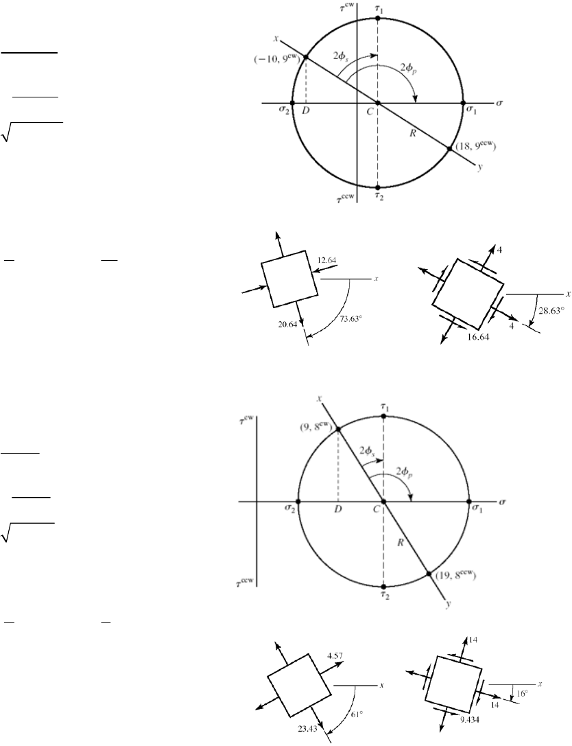
(c)
22
1
2
10 18 4 kpsi
2
10 18 14 kpsi
2
14 9 16.64 kpsi
4 16.64 20.64 kpsi
4 16.64 12.64 kpsi
C
CD
R
1
114
90 tan 73.63 cw
29
p
116.64 kpsi
73.63 45 28.63 cw
s
R
(d)
22
1
2
919 14 kpsi
2
19 9 5 kpsi
2
5 8 9.434 kpsi
14 9.43 23.43 kpsi
14 9.43 4.57 kpsi
C
CD
R
1
15
90 tan 61.0 cw
28
p
19.34 kpsi
61 45 16 cw
s
R
______________________________________________________________________________
Chapter 3 - Rev. A, Page 15/100
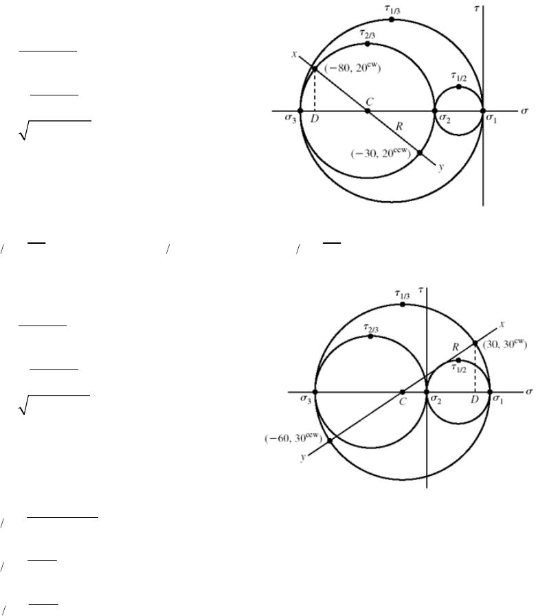
3-18 (a)
22
1
2
3
80 30 55 MPa
2
80 30 25 MPa
2
25 20 32.02 MPa
0 MPa
55 32.02 22.98 23.0 MPa
55 32.0 87.0 MPa
C
CD
R
12 23 13
23 87
11.5 MPa, 32.0 MPa, 43.5 MPa
22
(b)
22
1
2
3
30 60 15 MPa
2
60 30 45 MPa
2
45 30 54.1 MPa
15 54.1 39.1 MPa
0 MPa
15 54.1 69.1 MPa
C
CD
R
13
12
23
39.1 69.1 54.1 MPa
2
39.1 19.6 MPa
2
69.1 34.6 MPa
2
Chapter 3 - Rev. A, Page 16/100
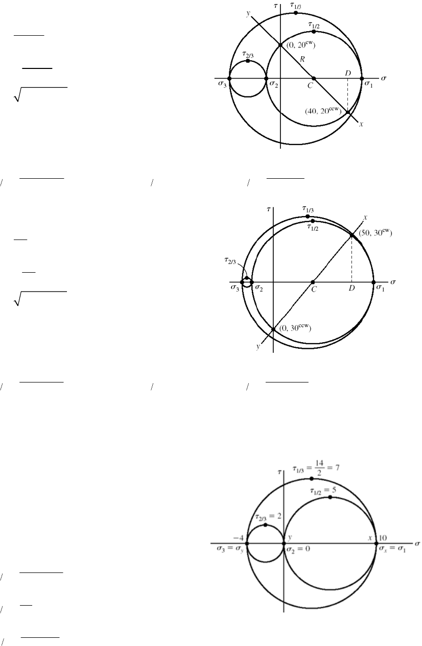
(c)
22
1
2
3
40 0 20 MPa
2
40 0 20 MPa
2
20 20 28.3 MPa
20 28.3 48.3 MPa
20 28.3 8.3 MPa
30 MPa
z
C
CD
R
13 12 23
48.3 30 30 8.3
39.1 MPa, 28.3 MPa, 10.9 MPa
22
(d)
22
1
2
3
50 25 MPa
2
50 25 MPa
2
25 30 39.1 MPa
25 39.1 64.1 MPa
25 39.1 14.1 MPa
20 MPa
z
C
CD
R
13 12 23
64.1 20 20 14.1
42.1 MPa, 39.1 MPa, 2.95 MPa
22
______________________________________________________________________________
3-19 (a)
Since there are no shear stresses on the
stress element, the stress element
already represents principal stresses.
1
2
3
10 kpsi
0 kpsi
4 kpsi
x
y
13
12
23
10 ( 4) 7 kpsi
2
10 5 kpsi
2
0(4) 2 kpsi
2
Chapter 3 - Rev. A, Page 17/100
(b)
22
1
23
010 5 kpsi
2
10 0 5 kpsi
2
5 4 6.40 kpsi
5 6.40 11.40 kpsi
0 kpsi, 5 6.40 1.40 kpsi
C
CD
R
13 12 3
11.40 1.40
6.40 kpsi, 5.70 kpsi, 0.70 kpsi
22
R
(c)
22
12
3
28 5 kpsi
2
82 3 kpsi
2
3 4 5 kpsi
5 5 0 kpsi, 0 kpsi
5 5 10 kpsi
C
CD
R
13 12 23
10 5 kpsi, 0 kpsi, 5 kpsi
2
(d)
22
1
2
3
10 30 10 kpsi
2
10 30 20 kpsi
2
20 10 22.36 kpsi
10 22.36 12.36 kpsi
0 kpsi
10 22.36 32.36 kpsi
C
CD
R
13 12 23
12.36 32.36
22.36 kpsi, 6.18 kpsi, 16.18 kpsi
22
______________________________________________________________________________
Chapter 3 - Rev. A, Page 18/100
3-20 From Eq. (3-15),
32 22
22 2
3
( 6 18 12) 6(18) ( 6)( 12) 18( 12) 9 6 ( 15)
6(18)( 12) 2(9)(6)( 15) ( 6)(6) 18( 15) ( 12)(9) 0
594 3186 0
2
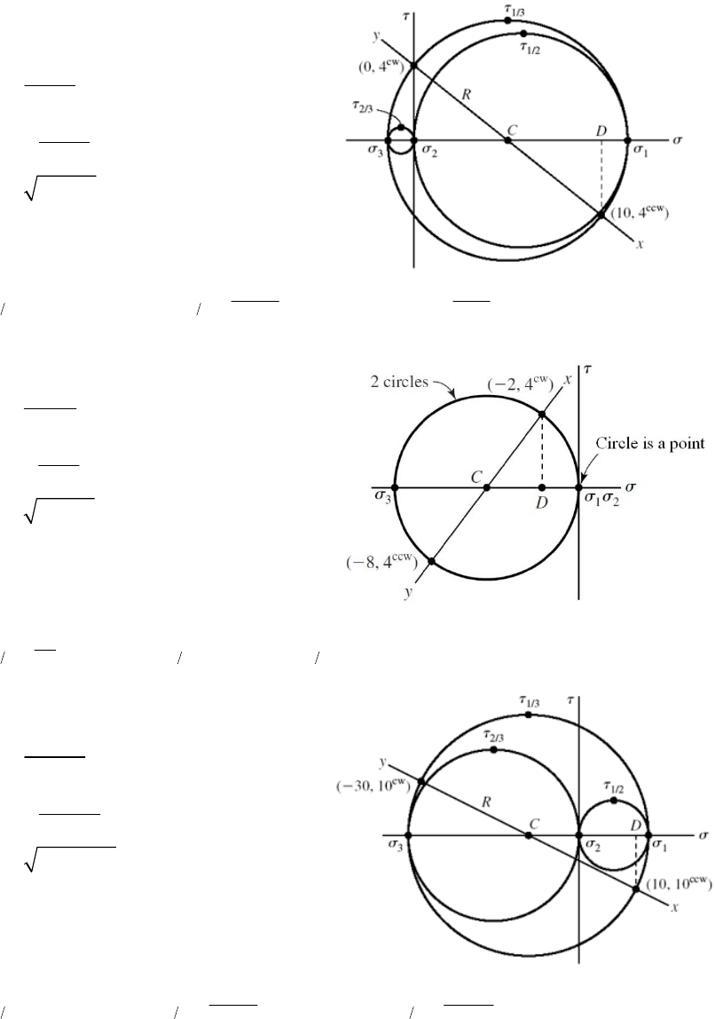
Roots are: 21.04, 5.67, –26.71 kpsi Ans.
12
23
max 1 3
21.04 5.67 7.69 kpsi
2
5.67 26.71 16.19 kpsi
2
21.04 26.71 23.88 kpsi .
2Ans
_____________________________________________________________________________
3-21
From Eq. (3-15)
2
32 2
222
32
(20 0 20) 20(0) 20(20) 0(20) 40 20 2 0
20(0)(20) 2(40) 20 2 (0) 20 20 2 0(0) 20(40) 0
40 2 000 48 000 0
2
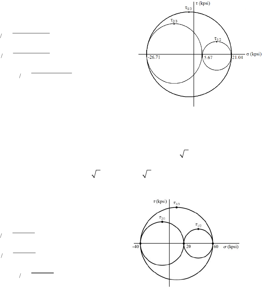
Roots are: 60, 20, –40 kpsi Ans.
12
23
max 1 3
60 20 20 kpsi
2
20 40 30 kpsi
2
60 40 50 kpsi .
2Ans
_____________________________________________________________________________
Chapter 3 - Rev. A, Page 19/100
3-22
From Eq. (3-15)
22
32 2
222
32
(10 40 40) 10(40) 10(40) 40(40) 20 40 20
10(40)(40) 2(20)( 40)( 20) 10( 40) 40( 20) 40(20) 0
90 0
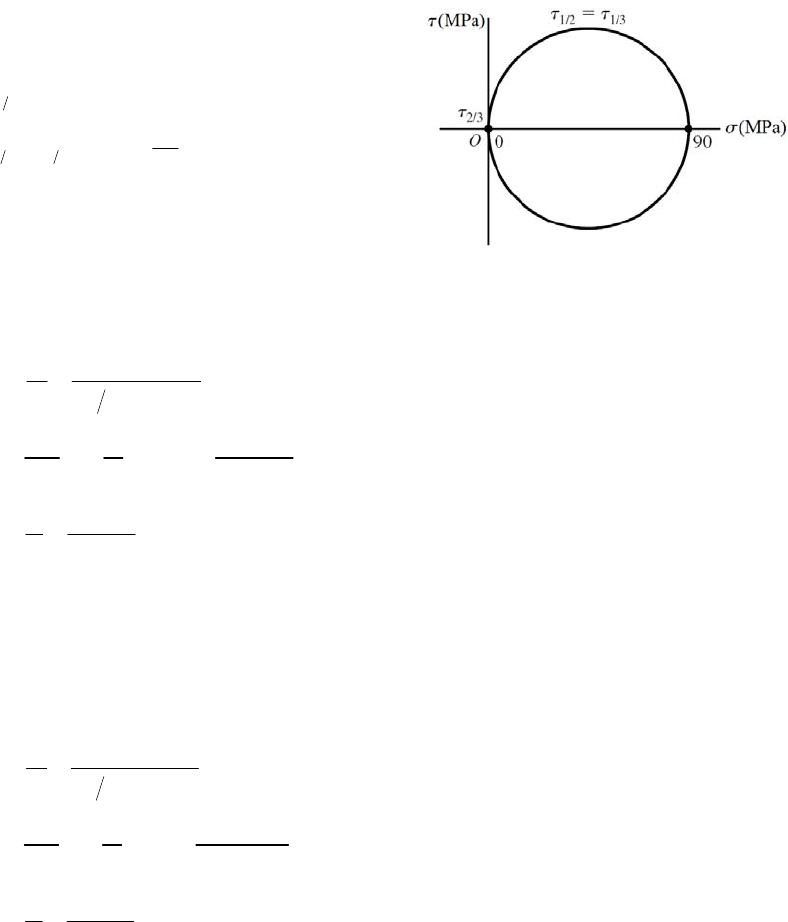
Roots are: 90, 0, 0 MPa Ans.
23
12 13 max
0
90 45 MPa .
2
A
ns
_____________________________________________________________________________
3-23
2
6
6
1
15000 33 950 psi 34.0 kpsi .
40.75
60
33 950 0.0679 in .
30 10
0.0679 1130 10 1130 .
60
F
A
ns
A
FL L
A
ns
AE E
Ans
L
From Table A-5, v = 0.292
21
66
2
0.292(1130) 330 .
330 10 (0.75) 248 10 in .
vA
dd An
ns
s
_____________________________________________________________________________
3-24
2
6
6
1
3000 6790 psi 6.79 kpsi .
40.75
60
6790 0.0392 in .
10.4 10
0.0392 653 10 653 .
60
F
A
ns
A
FL L
A
ns
AE E
Ans
L
From Table A-5, v = 0.333
21
66
2
0.333(653) 217 .
217 10 (0.75) 163 10 in .
vAns
dd Ans
Chapter 3 - Rev. A, Page 20/100
_____________________________________________________________________________
3-25
2
0.0001 0.0001
dd
dd
From Table A-5, v = 0.326, E = 119 GPa
6
2
1
69
1
2
6
0.0001 306.7 10
0.326
and , so
= 306.7 10 (119) 10 36.5 MPa
0.03
36.5 10 25 800 N 25.8 kN .
4
v
FL F
AE A
EE
L
FA An
s
Sy = 70 MPa >
, so elastic deformation assumption is valid.
_____________________________________________________________________________
3-26
6
8(12)
20 000 0.185 in .
10.4 10
FL L
A
ns
AE E
_____________________________________________________________________________
3-27
6
9
3
140 10 0.00586 m 5.86 mm .
71.7 10
FL L
A
ns
AE E
_____________________________________________________________________________
3-28
6
10(12)
15 000 0.173 in .
10.4 10
FL L
A
ns
AE E
_____________________________________________________________________________
3-29
With 0,
z
solve the first two equations of Eq. (3-19) simulatenously. Place E on the
left-hand side of both equations, and using Cramer’s rule,
22
1
111
1
x
yx
xy
x
Ev
EE
EvE
vvv
v
y
v
Likewise,
Chapter 3 - Rev. A, Page 21/100
2
1
yx
y
E
v
From Table A-5, E = 207 GPa and ν = 0.292. Thus,
9
6
22
9
6
2
207 10 0.0019 0.292 0.000 72 10 382 MPa .
1 1 0.292
207 10 0.000 72 0.292 0.0019 10 37.4 MPa .
1 0.292
xy
x
y
Ev Ans
v
Ans
_____________________________________________________________________________
3-30
With 0,
z
solve the first two equations of Eq. (3-19) simulatenously. Place E on the
left-hand side of both equations, and using Cramer’s rule,
22
1
111
1
x
yx
xy
x
Ev
EE
EvE
vvv
v
y
v
Likewise,
2
1
yx
y
E
v
From Table A-5, E = 71.7 GPa and ν = 0.333. Thus,
9
6
22
9
6
2
71.7 10 0.0019 0.333 0.000 72 10 134 MPa .
1 1 0.333
71.7 10 0.000 72 0.333 0.0019 10 7.04 MPa .
1 0.333
xy
x
y
Ev Ans
v
Ans
_____________________________________________________________________________
3-31
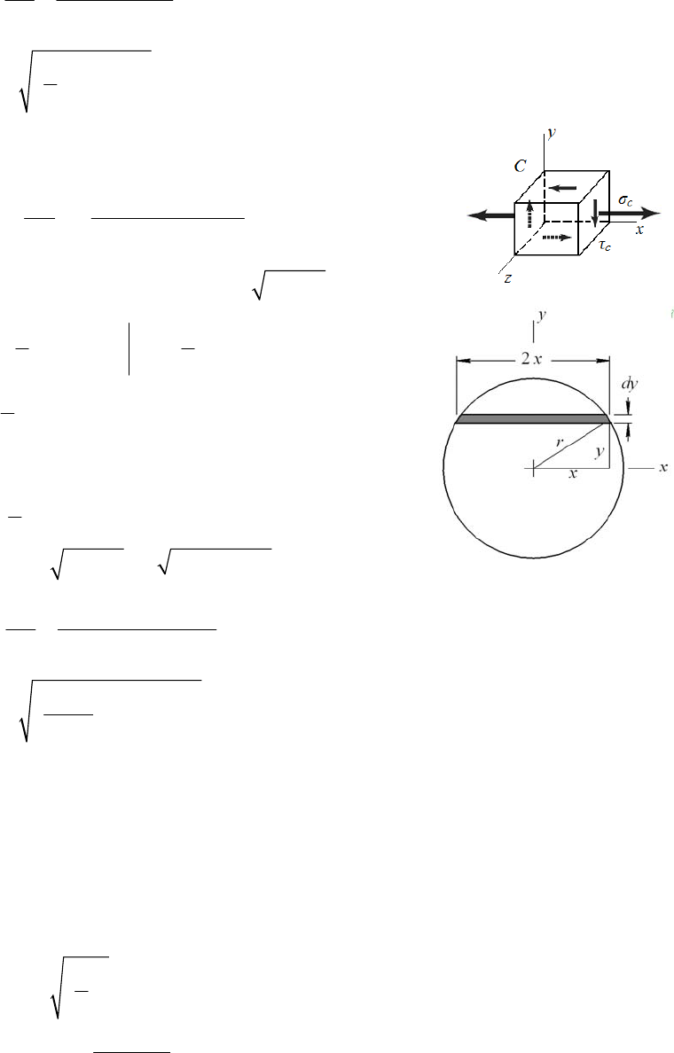
(a) 1max1
cac
R
FM Ra F
ll
2
22
66
6
M
ac bh l
FF
bh bh l ac
Ans.
(b)
22
12
1( )( ) ( ) .
()()
mmm m
m
mm
bbhh ll
Fss s sAns
Faacc ss
3-32
For equal stress, the model load varies by the square of the scale factor.
_____________________________________________________________________________
Chapter 3 - Rev. A, Page 22/100
2
1max
/2
,
2222
xl
lll
RM l
ww
8
l
ww
(a)
22
22 2
66 3 4
.
84 3
MlWl bh
WA
bh bh bh l
w ns
(b)
22
2
(/)(/)(/) 1( )( ) .
/
mm m m
m
Wbbhh
ss sAn
Wll s
s
2
2 .
mm m
ls
ss
ls
ww
ww
Ans
For equal stress, the model load w varies linearly with the scale factor.
_____ _____________
-33 (a) Can solve by iteration or derive
_ __________________________________________________________
3
equations for the general case. Find
maximum moment under wheel 3
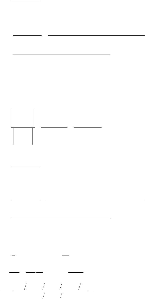
W.
WW at centroid of W’s
T
33
d
AT
lx
R
W
l
Under wheel 3,
33
3 3 1 13 2 23 3 1 13 2 23AT
lx d
M
R xWa W a W x Wa Wa
l
For maximum,
33
33 3
3
02 2
T
dM l d
W
ld x x
dx l
Substitute into
2
3
311
4T
ld
3223
M
MWWa
l
Wa
intersects the midpoint of the beam.
For wheel i,
This means the midpoint of 3
d
21i
ld
ld
1
,
24
i
i
Tjji
j
ii
x
MWWa
l
Note for wheel 1:
0
jji
Wa
1234
104.4
104.4, 26.1 kips
4
T
WWWWW
Wheel 1:
2
11
476 (1200 238)
238 in, (104.4) 20 128 kip in
2 4(1200)
dM
Wheel 2: 238 84 154 ind
2
Chapter 3 - Rev. A, Page 23/100
2
2max
(1200 154) (104.4) 26.1(84) 21 605 kip in .
4(1200)
M
MA
ns
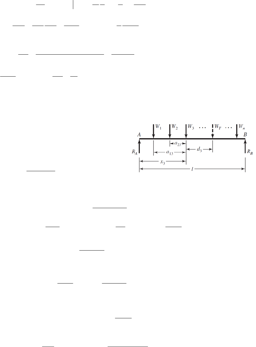
Check if all of the wheels are on the rail.
(b) max 600 77 523 in .
x
Ans
(c) See above sketch.
(d) Inner axles
_____________________________________________________________________________
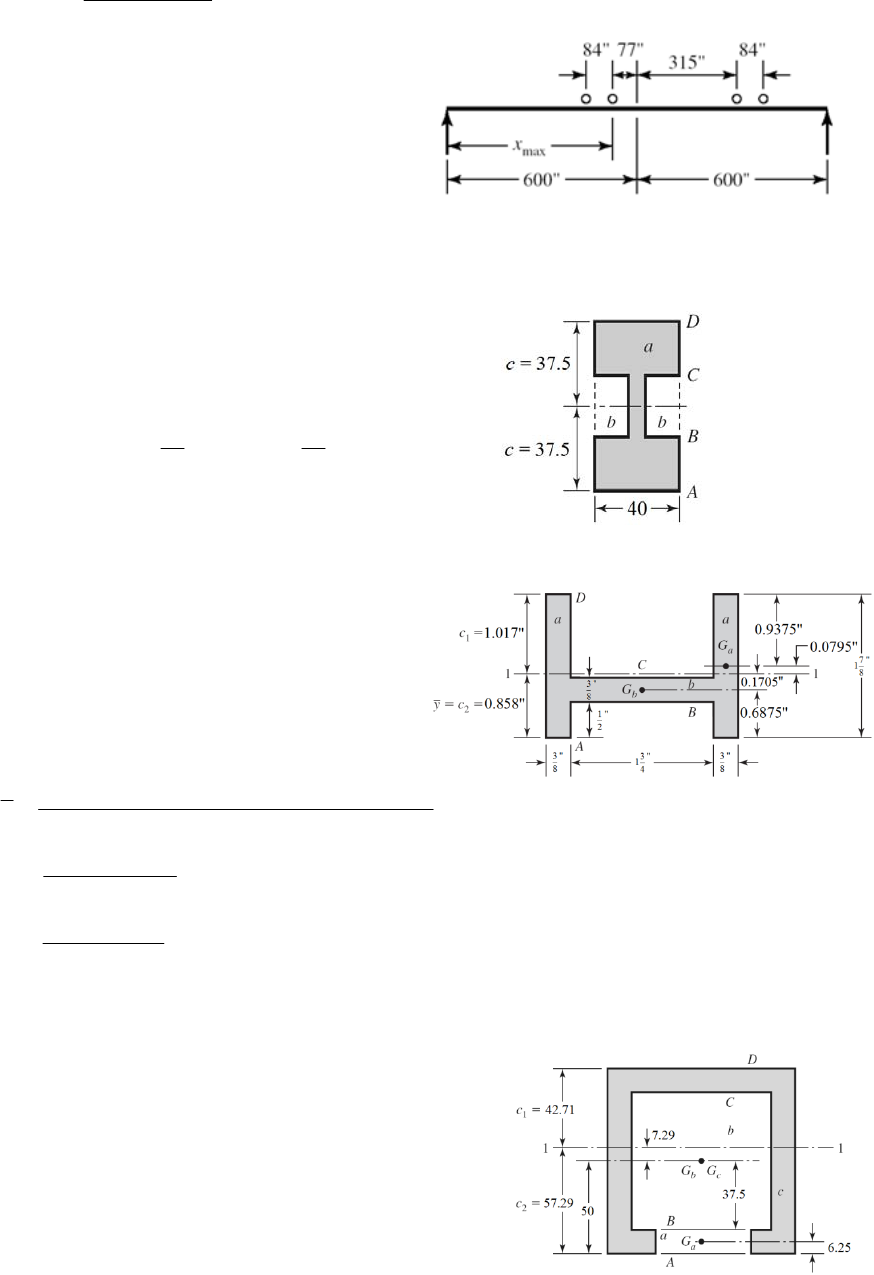
3-34
(a) Let a = total area of entire envelope
Let b = area of side notch
2
33
64
2 40(3)(25) 25 34 2150 mm
11
240753425
12 12
1.36 10 mm .
ab
Aa b
II I
IAns
Dimensions in mm.
(b)
2
2
2
0.375(1.875) 0.703 125 in
0.375(1.75) 0.656 25 in
2(0.703125) 0.656 25 2.0625 in
a
b
A
A
A
3
4
3
4
22
1
2(0.703 125)(0.9375) 0.656 25(0.6875) 0.858 in .
2.0625
0.375(1.875) 0.206 in
12
1.75(0.375) 0.007 69 in
12
2 0.206 0.703 125(0.0795) 0.00769 0.656 25(0.1705) 0.448 in .
a
b
yA
I
I
4
ns
I
Ans
(c)
Use two negative areas.
22
2
625 mm , 5625 mm , 10 000 mm
10 000 5625 625 3750 mm ;
ab c
AA A
A
2
Chapter 3 - Rev. A, Page 24/100
1
3
4
3
64
3
64
6.25 mm, 50 mm, 50 mm
10 000(50) 5625(50) 625(6.25) 57.29 mm .
3750
100 57.29 42.71 mm .
50(12.5) 8138 mm
12
75(75) 2.637 10 mm
12
100(100) 8.333 10 in
12
abc
a
b
c
yyy
y
Ans
cAns
I
I
I
22
626
1
64
1
8.333 10 10000(7.29) 2.637 10 5625 7.29 8138 625 57.29 6.25
4.29 10 in .
I
IAns
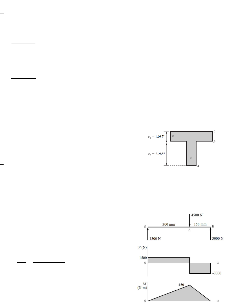
(d)
2
2
2
4 0.875 3.5 in
2.5 0.875 2.1875 in
5.6875 in
2.9375 3.5 1.25(2.1875) 2.288 in .
5.6875
a
b
ab
A
A
AA A
y
Ans
323
4
11
(4) 0.875 3.5 2.9375 2.288 0.875 2.5 2.1875 2.288 1.25
12 12
5.20 in .
I
IAns
2
_____________________________________________________________________________
3-35
35
2
1(20)(40) 1.067 10 mm
12
20(40) 800 mm
I
A
4
Mmax is at A. At the bottom of the section,
max 5
450 000(20) 84.3 MPa .
1.067 10
Mc
A
ns
I
Due to V,
max is between A and B at y = 0.
max
3 3 3000 5.63 MPa .
2 2 800
V
A
ns
A
_____________________________________________________________________________
Chapter 3 - Rev. A, Page 25/100
3-36
34
1(1)(2) 0.6667 in
12
I
2
1(2) 2 inA
0
o
M
8 100(8)(12) 0
A
R
1200 lbf
A
R
1200 100(8) 400 lbf
o
R
is at A. At the top of the beam,
max
M
max
3200(0.5) 2400 psi .
0.6667
Mc
A
ns
I
Due to V, max
is at A, at y = 0.
max
3 3 800 600 psi .
222
V
A
ns
A
_____________________________________________________________________________
3-37
34
1(0.75)(2) 0.5 in
12
I
2
(0.75)(2) 1.5 inA
0
A
M
15 1000(20) 0
B
R
1333.3 lbf
B
R
3000 1333.3 1000 2666.7 lbf
A
R
is at B. At the top of the beam,
max
M
max
5000(1) 10000 psi .
0.5
Mc
A
ns
I
Due to V, max
is between B and C at y = 0.
max
3 3 1000 1000 psi .
221.5
V
A
ns
A
_____________________________________________________________________________
Chapter 3 - Rev. A, Page 26/100
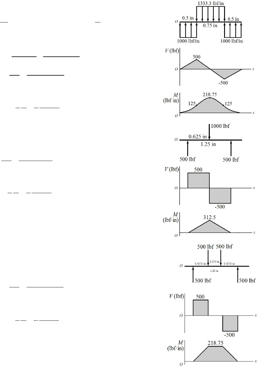
3-38
44
34
(50) 306.796 10 mm
64 64
d
I
22
2
(50) 1963 mm
44
d
A
0
B
M
6(300)(150) 200 0
A
R
1350 kN
A
R
6(300) 1350 450 kN
B
R
max
Mis at A. At the top, max
M
c
I
Due to V, max
is at A, at y = 0.
2
max
4 4 750 0.509 kN/mm 509 MPa .
3 3 1963
V
A
ns
A
_____________________________________________________________________________
3-39
22
max
max max 2
8
88
I
llc
M
I
cl
ww
w
(a)
4
48 in; Table A-8, 0.537 inlI
3
2
8 12 10 0.537 22.38 lbf/in .
148 Answ
(b)
33
60 in, 1 12 2 3 1 12 1.625 2.625 2.051 inlI4
3
2
8 12 10 2.051 36.5 lbf/in .
1.5 60 Answ
(c)
4
60 in; Table A-6, 2 0.703 1.406 inlI
y = 0.717 in, cmax = 1.783 in
3
2
8 12 10 1.406 21.0 lbf/in .
1.783 60 Answ
(d)
4
60 in, Table A-7, 2.07 inlI
3
2
812 10 2.07 36.8 lbf/in .
1.5 60 Answ
_____________________________________________________________________________
Chapter 3 - Rev. A, Page 27/100
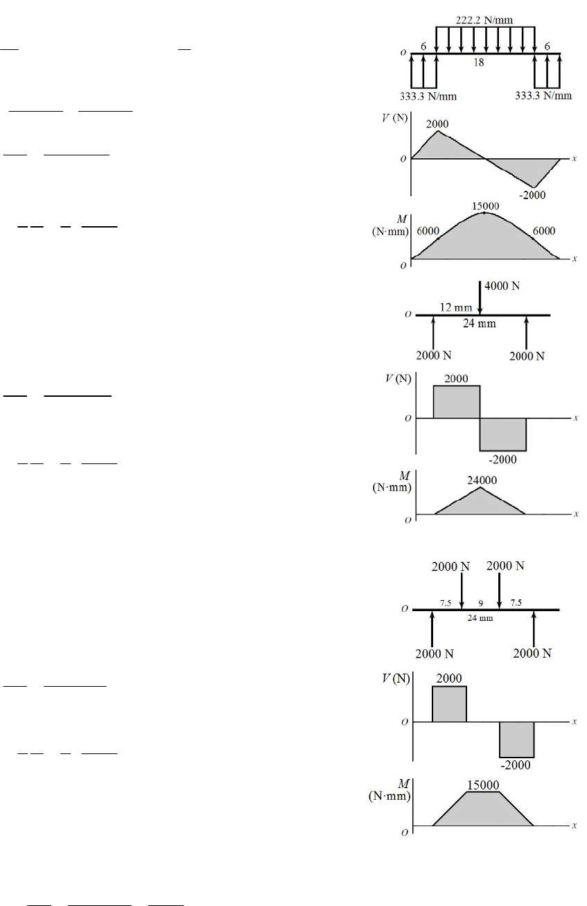
3-40
43422
0.5 3.068 10 in , 0.5 0.1963 in
64 4
IA
Model
(c)
3
max
500(0.5) 500(0.75 / 2) 218.75 lbf in
22
218.75(0.25)
3.068 10
17 825 psi 17.8 kpsi .
4 4 500 3400 psi 3.4 kpsi .
3 3 0.1963
M
Mc
I
Ans
V
A
ns
A
Model (d)
3
500(0.625) 312.5 lbf in
312.5(0.25)
3.068 10
25 464 psi 25.5 kpsi .
M
Mc
I
Ans
max
4 4 500 3400 psi 3.4 kpsi .
3 3 0.1963
V
A
ns
A
Model
(e)
3
max
500(0.4375) 218.75 lbf in
218.75(0.25)
3.068 10
17 825 psi 17.8 kpsi .
4 4 500 3400 psi 3.4 kpsi .
3 3 0.1963
M
Mc
I
Ans
VAns
A
_____________________________________________________________________________
3-41
Chapter 3 - Rev. A, Page 28/100
442
12 1018 mm , 12 113.1 mm
64 4
IA
2
Model (c)
2
2
max
2000(6) 2000(9) 15 000 N mm
22
15 000(6)
1018
88.4 N/mm 88.4 MPa .
4 4 2000 23.6 N/mm 23.6 MPa .
3 3 113.1
M
Mc
I
Ans
V
A
ns
A
Model (d)
2
2000(12) 24 000 N mm
24 000(6)
1018
141.5 N/mm 141.5 MPa .
M
Mc
I
Ans
2
max
4 4 2000 23.6 N/mm 23.6 MPa .
3 3 113.1
V
A
ns
A
Model (e)
2
2000(7.5) 15000 N mm
15000(6)
1018
88.4 N/mm 88.4 MPa .
M
Mc
I
Ans
2
max
4 4 2000 23.6 N/mm 23.6 MPa .
3 3 113.1
V
A
ns
A
_____________________________________________________________________________
43
/2 32
/64
Md
M
cM
I
dd
3-42 (a)
Chapter 3 - Rev. A, Page 29/100
33
32 32(218.75) 0.420 in .
(30 000)
M
dA
ns
(b)
2/4
VV
A
d
4 4(
500) 0.206 in .
(15000)
V
dAns
(c)
2
44
33 /4
VV
Ad
4 4 4 4(500) 0.238 in .
3 3 (15000)
V
dA
ns
______________ __________________ ______________________________
_____________ _
_
3-43
10 1
12
1
12
12
1
23
112
terms for
terms for
2
terms for
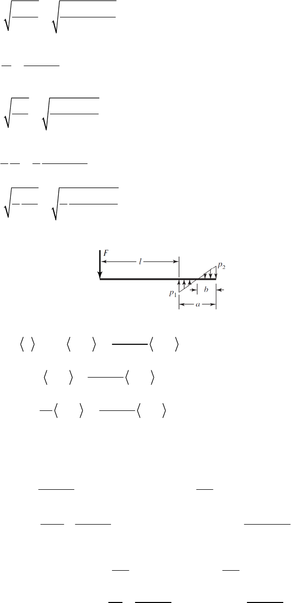
26
pp
q Fx pxl xl x la
a
pp
VFpxl xl xla
a
ppp
M
Fx xl xl x la
a
terms for x > l + a = 0 At x() , 0,la VM
2
12
112
2
F
p p
2
3
11
2
12 2
0 (1)
2
6( )
( ) 0 2 (2)
26
pp
Fpa a
aa
pa p p F l a
Fl a a p p
aa
From (1) and (2) 12
22
22
(3 2 ), (3 ) (3)
FF
plapla
aa
From similar triang les 2
212 12
(4)
ap
ba b
ppp pp
Chapter 3 - Rev. A, Page 30/100
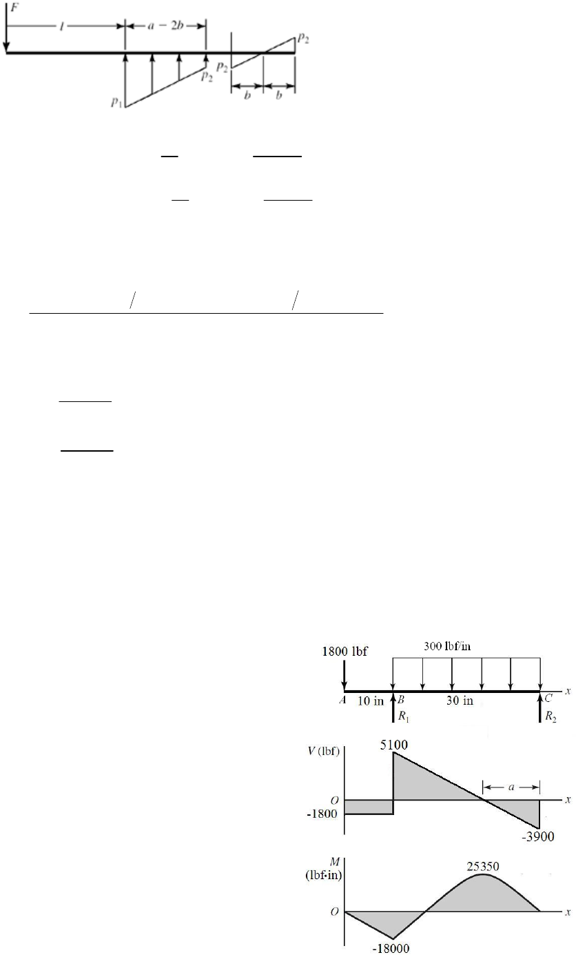
Mmax occurs where V = 0
max 2
x
la b
23
112
max
23
112
(2)(2) (2)
26
(2) (2) (2)
26
ppp
M
Flab ab ab
a
ppp
Fl F a b a b a b
a
Normally Mmax = Fl
The fractional increase in the magnitude is
23
12
2(2) 6(2)
(5)
a b p p a a b
For example, consider F = 1500 lbf, a = 1.2 in, l = 1.5 in
(3)
1
(2)Fa b p
Fl
12
2(1500) 3 1.5 2(1.2) 14 375 lbf/in
1.2
p
22
2(1500) 3 1.5 1.2 11 875 lbf/in
1.2
p
(4) b = 1.2(11 875)/(14 375 + 11 875) = 0.5429 in
Substituting into (5) yields
_____________________________________________________________________________
-44
= 0.036 89 or 3.7% higher than -Fl
3
Chapter 3 - Rev. A, Page 31/100
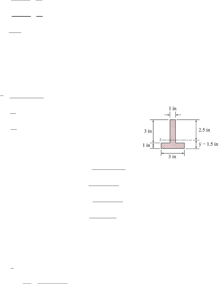
1
2
300(30)
R401800 6900 lbf
230
300(30) 10 1800 3900 lbf
230
3900 13 in
300
R
a
MB = 1800(10) = 18 000 lbfin
x = 27 in = (1/2)3900(13) = 25 350 lbfin
MB = 1800(10) = 18 000 lbfin
x = 27 in = (1/2)3900(13) = 25 350 lbfin
MM
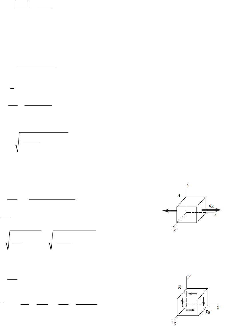
34
1
34
2
0.5(3) 2.5(3) 1.5 in
6
1(3)(1 ) 0.25 in
12
1(1)(3 ) 2.25 in
12
y
I
I
Applying the parallel-axis theorem,
(a)
2
0.25 3(1.5 0.5) 2.25 3
z
I
24
(2.5 1.5) 8.5 in
18000( 1.5)
At 10 in, 1.5 in, 3176 psi
8.5
18000(2.5)
At 10 in, 2.5 in, 5294 psi
8.5
25350( 1.5)
At 27 in, 1.5 in, 4474 psi
8.5
At 27 in, 2.5 in,
x
x
x
x
xy
xy
xy
xy
25350(2.5) 7456 psi
8.5
Max tension 5294 psi .
Max compression 7456 psi .
Ans
A
ns
aximum shear stress due to V is at B, at the neutral axis.
(b) The m
max 5100 lbfV
3
max
1.25(2.5)(1) 3.125 in
5100(3.125) 1875 psi .
8.5(1)
V
QyA
VQ
A
ns
Ib
(c) There are three potentially critical locations for the maximum shear stress, all at x
= 27 in: (i) at the top where the bending stress is maximum, (ii) at the neutral axis where
Chapter 3 - Rev. A, Page 32/100
the transverse shear is maximum, or (iii) in the web just above the flange where bending
stress and shear stress are in their largest combination.
For (i):
The maximum bending stress was previously found to be
7456 psi, and the shear
stress is zero. From Mohr’s circle,
max
max
7456 3728 psi
22
For (ii):
The bending stress is zero, and the transverse shear stress was found previously to be
1875 psi. Thus,
max = 1875 psi.
For (iii):
The bending stress at y = – 0.5 in is
18000( 0.5) 1059 psi
8.5
x
The transverse shear stress is
3
(1)(3)(1) 3.0 in
5100(3.0) 1800 psi
8.5(1)
QyA
VQ
Ib
From Mohr’s circle,
2
2
max
1059 1800 1876 psi
2
The critical location is at x = 27 in, at the top surface, where
max = 3728 psi. Ans.
_____________________________________________________________________________
3-45 (a) L = 10 in. Element A:
3
4
(1000)(10)(0.5) 10 101.9 kpsi
( / 64)(1)
A
My
I
,0
AA
VQ Q0
I
b
22
22
max
101.9 (0) 50.9 kpsi .
22
A
A
A
ns
Element B:
, 0 0
BB
My y
I
3
23
3
40.5
44 1/12 in
32 6 6
rr r
QyA
Chapter 3 - Rev. A, Page 33/100
3
4
(1000)(1/12) 10 1.698 kpsi
( / 64)(1) (1)
B
VQ
Ib
2
2
max
01.698 1.698 kpsi .
2
A
ns
Element C:
3
4
(1000)(10)(0.25) 10 50.93 kpsi
( / 64)(1)
C
My
I
22
11 1
3/2 3/2 3/2
22 22 22
1
1
3/2
22
1
(2 ) 2
22
33
2
3
rr r
yy y
r
y
Q ydA y x dy y r y dy
ry rr ry
ry
For C, y1 = r /2 =0.25 in
3/2
22
20.5 0.25 0.05413
3
Q in3
22 2 2
1
2 2 2 0.5 0.25 0.866 inbx ry
3
4
(1000)(0.05413) 10 1.273 kpsi
( / 64)(1) (0.866)
C
VQ
Ib
2
2
max
50.93 (1.273) 25.50 kpsi .
2
A
ns
(b) Neglecting transverse shear stress:
Element A: Since the transverse shear stress at point A is zero, there is no change.
max 50.9 kpsi .Ans
% error 0% .
A
ns
Element B: Since the only stress at point B is transverse shear stress, neglecting
the transverse shear stress ignores the entire stress.
2
max
00 psi .
2
A
ns
1.698 0
% error *(100) 100% .
1.698
A
ns
Chapter 3 - Rev. A, Page 34/100
Element C:
2
max
50.93 25.47 kpsi .
2
A
ns
25.50 25.47
% error *(100) 0.12% .
25.50 Ans
(c) Repeating the process with different beam lengths produces the results in the table.
Bending
stress,
kpsi)
Transverse
shear stress,
kpsi)
Max shear
stress,
max kpsi)
Max shear
stress,
neglecting
max
kpsi)
% error
L = 10 in
A 102 0 50.9 50.9 0
B 0 1.70 1.70 0 100
C 50.9 1.27 25.50 25.47 0.12
L = 4 in
A 40.7 0 20.4 20.4 0
B 0 1.70 1.70 0 100
C 20.4 1.27 10.26 10.19 0.77
L = 1 in
A 10.2 0 5.09 5.09 0
B 0 1.70 1.70 0 100
C 5.09 1.27 2.85 2.55 10.6
L = 0.1in
A 1.02 0 0.509 0.509 0
B 0 1.70 1.70 0 100
C 0.509 1.27 1.30 0.255 80.4
Discussion:
The transverse shear stress is only significant in determining the critical stress element as
the length of the cantilever beam becomes smaller. As this length decreases, bending
stress reduces greatly and transverse shear stress stays the same. This causes the critical
element location to go from being at point A, on the surface, to point B, in the center. The
maximum shear stress is on the outer surface at point A for all cases except L = 0.1 in,
where it is at point B at the center. When the critical stress element is at point A, there is
no error from neglecting transverse shear stress, since it is zero at that location.
Neglecting the transverse shear stress has extreme significance at the stress element at the
center at point B, but that location is probably only of practical significance for very short
beam lengths.
_____________________________________________________________________________
Chapter 3 - Rev. A, Page 35/100
3-46
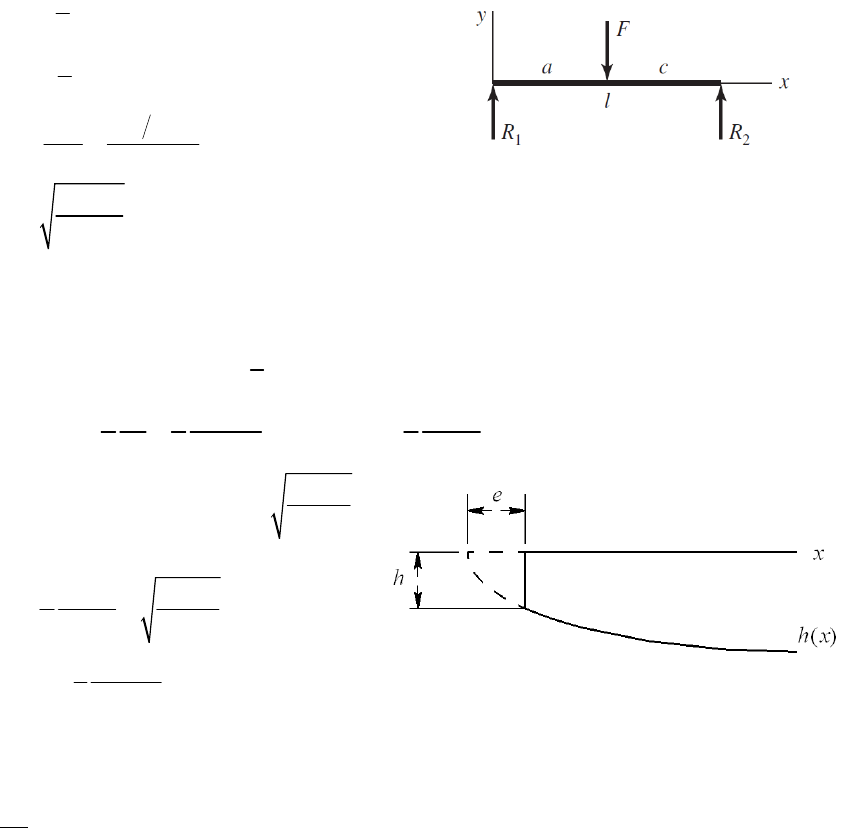
1
0
c
RF
l
c
M
Fx x a
l
22
max
6
6
6 0 .
cl Fx
M
bh bh
Fcx
hx
lb
aAns
_____________________________________________________________________________
3-47
From Problem 3-46, 1, 0
c
R
FV xa
l
max
max
33(/) 3
.
22 2
VclF Fc
hA
bh bh lb
ns
From Problem 3-46,
max
6
() Fcx
hx .
lb
Sub in x = e and equate to h above.
max max
max
2
max
36
2
3 .
8
Fc Fce
lb lb
Fc
eA
lb
ns
_____________________________________________________________________________
3-48 (a)
x-z plane
2
0 1.5(0.5) 2(1.5)sin(30 )(2.25) (3)
Oz
MR
21.375 kN .
z
R
Ans
1
0 1.5 2(1.5)sin(30 ) 1.375
zz
FR
11.625 kN .
z
R
Ans
x-y plane
2
0 2(1.5) cos(30 )(2.25) (3)
Oy
MR
21.949 kN .
y
R
Ans
1
0 2(1.5) cos(30 ) 1.949
yy
FR
10.6491 kN .
y
R
Ans
Chapter 3 - Rev. A, Page 36/100
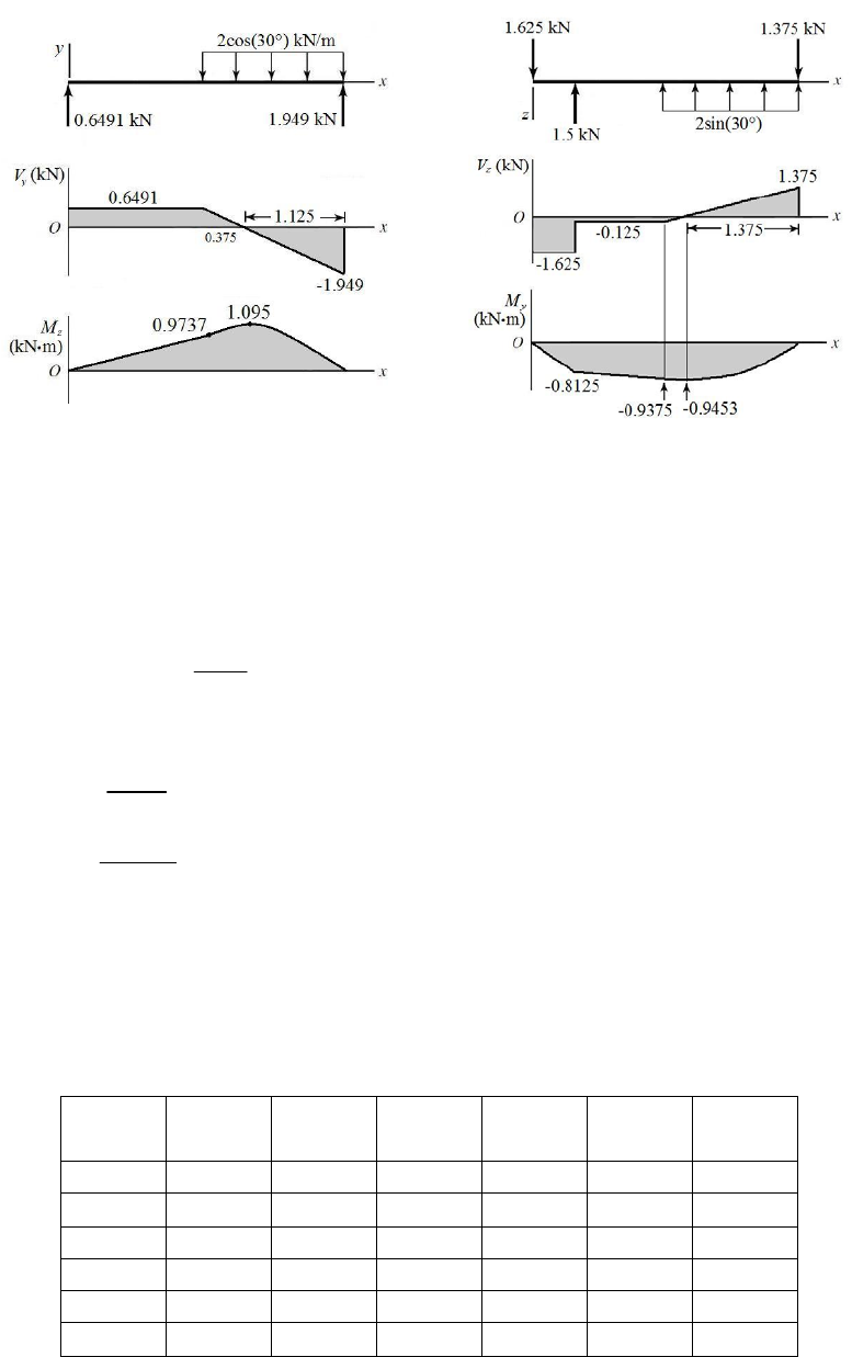
(b)
(c) The transverse shear and bending moments for most points of interest can readily be
taken straight from the diagrams. For 1.5 < x < 3, the bending moment equations are
parabolic, and are obtained by integrating the linear expressions for shear. For
convenience, use a coordinate shift of x = x – 1.5. Then, for 0 < x < 1.5,
2
2
0.125
0.125
2
At 0, 0.9375 0.5 0.125 0.9375
z
yz
yy
Vx
x
MVdx xC
xMC M x x
2
2
1.949 0.6491 1.732 0.6491
1.125
1.732 0.6491
2
At 0, 0.9737 0.8662 0.125 0.9375
y
z
zz
Vx x
MxxC
xMC M x x
By programming these bending moment equations, we can find My, Mz, and their vector
combination at any point along the beam. The maximum combined bending moment is
found to be at x = 1.79 m, where M = 1.433 kN·m. The table below shows values at key
locations on the shear and bending moment diagrams.
x (m) Vz (kN) Vy (kN) V (kN)
My
(kNm)
Mz
(kNm)
M
(kNm)
0 –1.625 0.6491 1.750 0 0 0
0.5 –1.625 0.6491 1.750 –0.8125 0.3246 0.8749
1.5 –0.1250 0.6491 0.6610 0.9375 0.9737 1.352
1.625 0 0.4327 0.4327 –0.9453 1.041 1.406
1.875 0.2500 0 0.2500 –0.9141 1.095 1.427
3 1.375 –1.949 2.385 0 0 0
Chapter 3 - Rev. A, Page 37/100
(d) The bending stress is obtained from Eq. (3-27),
yA
zA
x
zy
M
z
My
I
I
The maximum tensile bending stress will be at point A in the cross section of Prob. 3-34
(a), where distances from the neutral axes for both bending moments will be maximum.
At A, for Mz, yA = –37.5 mm, and for My, zA = –20 mm.
33
64 6
40(75) 34(25) 1.36(10 ) mm 1.36(10 ) m
12 12
z
I
4
33
54 7
25(40) 25(6)
2 2.67(10 ) mm 2.67(10 ) m
12 12
y
I
4
It is apparent the maximum bending moment, and thus the maximum stress, will be in the
parabolic section of the bending moment diagrams. Programming Eq. (3-27) with the
bending moment equations previously derived, the maximum tensile bending stress is
found at x = 1.77 m, where My = – 0.9408 kN·m, Mz = 1.075 kN·m, and
x = 100.1 MPa.
Ans.
_____________________________________________________________________________
3-49
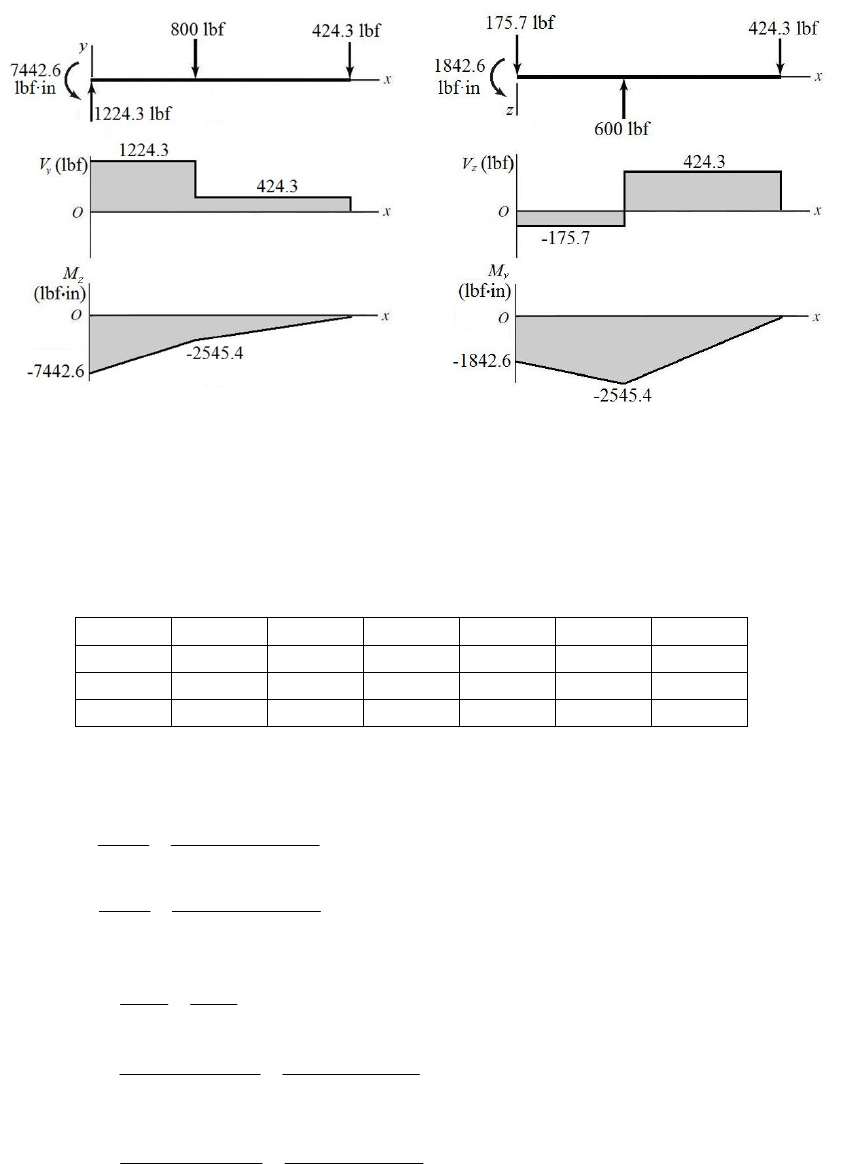
(a) x-z plane
3 600
0 (1000)(4) (10)
52
OOy
M
M
1842.6 lbf in .
Oy
M
Ans
36
0 (1000)
52
zOz
FR
00
175.7 lbf .
Oz
R
Ans
x-y plane
4 600
0 (1000)(4) (10)
52
OOz
M
M
7442.5 lbf in .
Oz
M
Ans
46
0 (1000)
52
yOy
FR
00
1224.3 lbf .
Oy
R
Ans
Chapter 3 - Rev. A, Page 38/100
(b)
(
(c)
1/2
22
() () ()
yz
Vx V x V x
1/ 2
22
() () ()
yz
Mx M x M x
x (m) Vz (kN) Vy (kN) V (kN) My (kNm) Mz (kNm) M (kNm)
0 –175.7 1224.3 1237 –1842.6 –7442.6 7667
4 –175.7 1224.3 1237 –2545.4 –2545.4 3600
10 424.3 424.3 600 0 0 0
(d) The maximum tensile bending stress will be at the outer corner of the cross section in
the positive y, negative z quadrant, where y = 1.5 in and z = –1 in.
33
4
2(3) (1.625)(2.625) 2.051 in
12 12
z
I
33
4
3(2) (2.625)(1.625) 1.601 in
12 12
y
I
At x = 0, using Eq. (3-27),
y
z
x
zy
M
z
My
I
I
( 7442.6)(1.5) ( 1842.6)( 1) 6594 psi
2.051 1.601
x
Check at x = 4 in,
( 2545.4)(1.5) ( 2545.4)( 1) 2706 psi
2.051 1.601
x
The critical location is at x = 0, where
x = 6594 psi. Ans.
_____________________________________________________________________________
Chapter 3 - Rev. A, Page 39/100
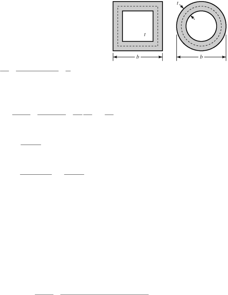
3-50 The area within the wall median line, Am, is
Square: 2
()
m
A
bt . From Eq. (3-45)
2
sq all all
22()
m
TAt btt
Round:
2
()/
m
Abt
4
2
rd all
2( ) /4Tbtt
Ratio of Torques
2
sq all
2
rd all
2( ) 41.27
() /2
Tbtt
Tbtt
Twist per unit length from Eq. (3-46) is
all all
122
2
442
mmm m
mm m
TL A t L L L
C
GA t GA t G A A
m
m
Square:
sq 2
4( )
()
bt
Cbt
Round:
rd 22
() 4(
()/4 ()
bt bt
CC
bt bt
)
Ratio equals 1. Twists are the same.
_____________________________________________________________________________
3-51
(a) The area enclosed by the section median line is Am = (1 0.0625)2 = 0.8789 in2 and
the length of the section median line is Lm = 4(1 0.0625) = 3.75 in. From Eq. (3-45),
2 2(0.8789)(0.0625)(12 000) 1318 lbf in .
m
TAt Ans
From Eq. (3-46),
1262
(1318)(3.75) 36 0.0801 rad 4.59 .
44 11.5 10 (0.8789) 0.0625
m
m
TL l
lA
GA t
ns
(b) The radius at the median line is rm = 0.125 + (0.5)(0.0625) = 0.15625 in. The area enclosed
by the section median line is Am = (1 0.0625)2 – 4(0.15625)2 + 4(π /4)(0.15625)2 = 0.8579
in2. The length of the section median line is Lm = 4[1 – 0.0625 – 2(0.15625)] + 2π(0.15625) =
3.482 in.
Chapter 3 - Rev. A, Page 40/100

From Eq. (3-45),
2 2(0.8579)(0.0625)(12 000) 1287 lbf in .
m
TAt Ans
From Eq. (3-46),
1262
(1287)(3.482) 36 0.0762 rad 4.37 .
44 11.5 10 (0.8579) 0.0625
m
m
TL l
lA
GA t
ns
_____________________________________________________________________________
3-52
3
1
13
3 3
ii
i
ii
TG
T
GL c
i
Lc
33
1
123
1
.
3ii
i
G
TTT T Lc Ans
From Eq. (3-47),
G
1c
G and
1 are constant, therefore the largest shear stress occurs when c is a maximum.
max 1 max .Gc Ans
_____________________________________________________________________________
3-53
(b) Solve part (b) first since the twist is needed for part (a).
max allow 12 6.89 82.7 MPa
6
max
19
max
82.7 10
0.348 rad/m .
79.3 10 (0.003)
Ans
Gc
(a)
93
3
111
1
0.348(79.3) 10 (0.020)(0.002 ) 1.47 N m .
33
GL c
TA
ns
93
3
222
2
93
3
333
3
123
0.348(79.3) 10 (0.030)(0.003 ) 7.45 N m .
33
0.348(79.3) 10 (0)(0 ) 0 .
33
1.47 7.45 0 8.92 N m .
GL c
TA
GL c
TA
TTTT Ans
ns
ns
_____________________________________________________________________________
Chapter 3 - Rev. A, Page 41/100

3-54
(b) Solve part (b) first since the twist is needed for part (a).
3
max
16
max
12000 8.35 10 rad/in .
11.5 10 (0.125)
A
ns
Gc
(a)
36 3
3
111
1
363
3
222
2
36 3
3
333
3
123
8.35 10 11.5 10 0.75 0.0625 5.86 lbf in .
33
8.35 10 11.5 10 1 0.125 62.52 lbf in .
33
8.35 10 11.5 10 0.625 0.0625 4.88 lbf in .
33
5.86 62.52 4
GL c
TA
GL c
TA
GL c
TA
TTTT
.88 73.3 lbf in .Ans
ns
ns
ns
_____________________________________________________________________________
3-55
(b) Solve part (b) first since the twist is needed for part (a).
max allow 12 6.89 82.7 MPa
6
max
19
max
82.7 10
0.348 rad/m .
79.3 10 (0.003)
Ans
Gc
(a)
93
3
111
1
0.348(79.3) 10 (0.020)(0.002 ) 1.47 N m .
33
GL c
TA
ns
93
3
222
2
93
3
333
3
123
0.348(79.3) 10 (0.030)(0.003 ) 7.45 N m .
33
0.348(79.3) 10 (0.025)(0.002 ) 1.84 N m .
33
1.47 7.45 1.84 10.8 N m .
GL c
TA
GL c
TA
TTTT Ans
ns
ns
_____________________________________________________________________________
3-56
(a) From Eq. (3-40), with two 2-mm strips,
62
2
max
max
80 10 0.030 0.002
3.08 N m
3 1.8 / ( / ) 3 1.8 / 0.030 / 0.002
2(3.08) 6.16 N m .
bc
Tbc
TAns
Chapter 3 - Rev. A, Page 42/100
From the table on p. 102, with b/c = 30/2 = 15,
and has a value between 0.313 and 0.333.
From Eq. (3-40),
10.321
31.8/(30/2)
From Eq. (3-41),
339
3.08(0.3) 0.151 rad .
0.321 0.030 0.002 79.3 10
6.16 40.8 N m .
0.151
t
Tl Ans
bc G
T
kAns
From Eq. (3-40), with a single 4-mm strip,
62
2
max
max
80 10 0.030 0.004
11.9 N m .
3 1.8 / ( / ) 3 1.8 / 0.030 / 0.004
bc
TA
bc
ns
Interpolating from the table on p. 102, with b/c = 30/4 = 7.5,
7.5 6 (0.307 0.299) 0.299 0.305
86
From Eq. (3-41)
339
11.9(0.3) 0.0769 rad .
0.305 0.030 0.004 79.3 10
11.9 155 N m .
0.0769
t
Tl Ans
bc G
T
kAns
(b) From Eq. (3-47), with two 2-mm strips,
26
2
max
0.030 0.002 80 10
3.20 N m
33
2(3.20) 6.40 N m .
Lc
T
TAns
339
3 3(3.20)(0.3) 0.151 rad .
0.030 0.002 79.3 10
6.40 0.151 42.4 N m .
t
Tl
A
ns
Lc G
kT Ans
From Eq. (3-47), with a single 4-mm strip,
26
2
max
0.030 0.004 80 10
12.8 N m .
33
Lc
TA
ns
Chapter 3 - Rev. A, Page 43/100
339
3 3(12.8)(0.3) 0.0757 rad .
0.030 0.004 79.3 10
12.8 0.0757 169 N m .
t
Tl
A
ns
Lc G
kT Ans
The results for the spring constants when using Eq. (3-47) are slightly larger than when using
Eq. (3-40) and Eq. (3-41) because the strips are not infinitesimally thin (i.e. b/c does not equal
infinity). The spring constants when considering one solid strip are significantly larger (almost
four times larger) than when considering two thin strips because two thin strips would be able
to slip along the center plane.
_____________________________________________________________________________
3-57
(a) Obtain the torque from the given power and speed using Eq. (3-44).
(40 000)
9.55 9.55 152.8 N m
2500
H
Tn
max 3
16Tr T
Jd
13
13
6
max
16 152.8
16 0.0223 m 22.3 mm .
70 10
T
dA
ns
(b) (40 000)
9.55 9.55 1528 N m
250
H
Tn
13
6
16(1528) 0.0481 m 48.1 mm .
70 10
dA
ns
_____________________________________________________________________________
3-58
(a) Obtain the torque from the given power and speed using Eq. (3-42).
63025 63025(50) 1261 lbf in
2500
H
Tn
max 3
16Tr T
Jd
13
13
max
16 1261
16 0.685 in .
(20 000)
T
dA
ns
(b) 63025 63025(50) 12610 lbf in
250
H
Tn
13
16(12 610) 1.48 in .
(20000)
dA
ns
_____________________________________________________________________________
Chapter 3 - Rev. A, Page 44/100
3-59
63
3
max
max 3
50 10 0.03
16 265 N m
16 16
d
TT
d
Eq. (3-44),
3
265(2000) 55.5 10 W 55.5 kW .
9.55 9.55
Tn
HA ns
_____________________________________________________________________________
3-60
363
3
49
4
16 110 10 0.020 173 N m
16 16
0.020 79.3 10 15180
32 32(173)
1.89 m .
TTd
d
Tl d G
l
JG T
lAns
_____________________________________________________________________________
3-61
33
3
446
16 30 000 0.75 2485 lbf in
16 16
32 32(2485)(24) 0.167 rad 9.57 .
0.75 11.5 10
TTd
d
Tl Tl Ans
JG dG
_____________________________________________________________________________
3-62
(a) 44
max max max max
solid hollow
()
16 16
oo
oo
Jd J dd
TT
rd r d
4
i
4
4
solid hollow
44
solid
36
% (100%) (100%) (100%) 65.6% .
40
i
o
TT d
TA
Td
ns
(b)
22
solid hollow
,
oo
Wkd W kdd
2
i
2
2
solid hollow
22
solid
36
% (100%) (100%) (100%) 81.0% .
40
i
o
WW d
WA
Wd
ns
_____________________________________________________________________________
3-63
(a)
4
4
4max
max max max
solid hollow
16 16
dxd
Jd J
TT
rd r d
44
solid hollow
4
soli
()
% (100%) (100%) (100%) .
d
TT xd
Tx
Td
Ans
Chapter 3 - Rev. A, Page 45/100
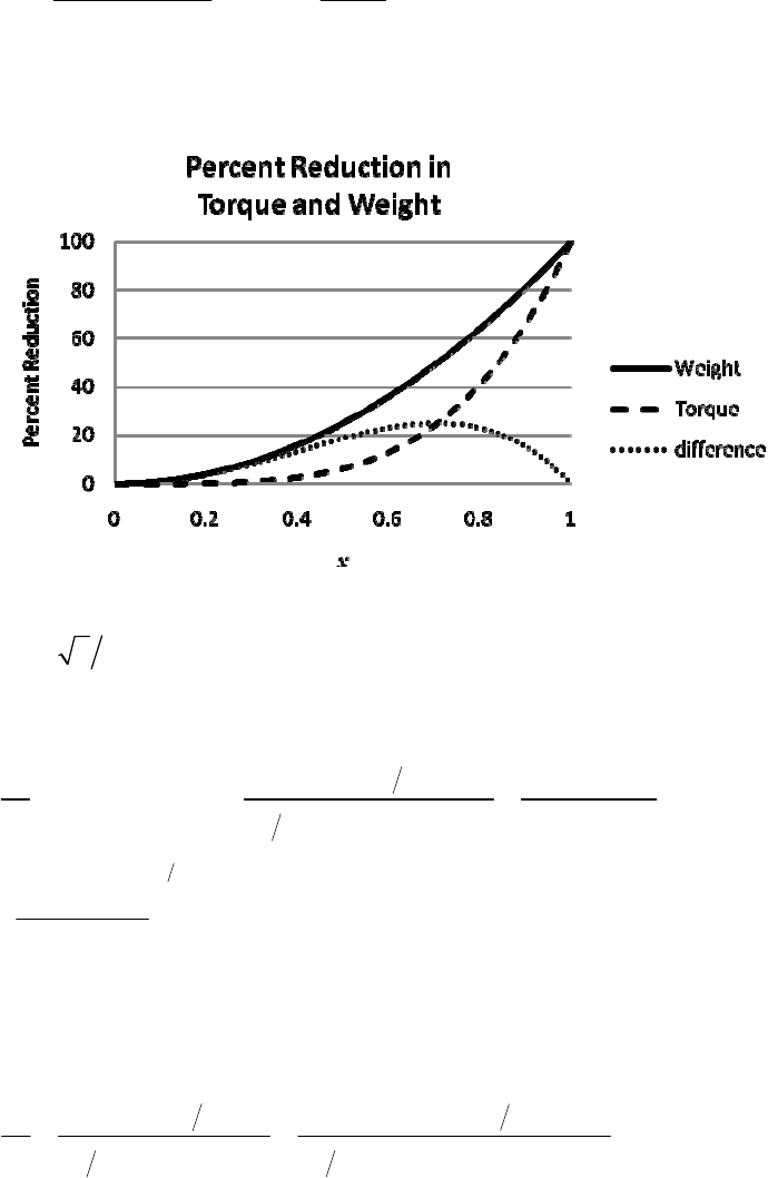
(b)
2
22
solid hollow
Wkd W kdxd
2
2
solid hollow
2
solid
% (100%) (100%) (100%) .
xd
WW
Wx
Wd
Ans
Plot %T and %W versus x.
The value of greatest difference in percent reduction of weight and torque is 25% and
occurs at 22x.
_____________________________________________________________________________
3-64
(a)
4
6
3
4
4
2.8149 10
4200 2
120 10
32 0.70
d
Tc
Jd
dd
13
4
2
6
2.8149 10
6.17 10 m 61.7 mm
120(10 )
d
d
From Table A-17, the next preferred size is d = 80 mm. Ans.
i = 0.7d = 56 mm. The next preferred size smaller is di = 50 mm Ans.
(b)
444
4
4200 2 4200 0.050 2 30.8 MPa .
32 0.080 0.050
32
i
i
d
Tc
A
ns
Jdd
_____________________________________________________________________________
Chapter 3 - Rev. A, Page 46/100
3-65
(1500)
9.55 9.55 1433 N m
10
H
Tn
13
13
36
16 1433
16 16
= 0.045 m 45 mm
80 10
C
C
TT
d
d
From Table A-17, select 50 mm. Ans.
(a)
6
start 3
16 2 1433 117 10 Pa 117 MPa .
0.050 Ans
(b) Design activity
_____________________________________________________________________________
3-66
13
13
3
63 025 63 025(1) 7880 lbf in
8
16 7880
16 16
= 1.39 in
15 000
C
C
H
Tn
TT
d
d
From Table A-17, select 1.40 in. Ans.
_____________________________________________________________________________
3-67 For a square cross section with side length b, and a circular section with diameter d,
22
square circular
42
A
Abdbd
From Eq. (3-40) with b = c,
3
max 233
square
1.8 1.8 2
3 3 (4.8) 6.896
/1
TTT
bc b c b d d
3
T
For the circular cross section,
max 33
circular
16 5.093
TT
dd
3
max square
max circular 3
6.896
1.354
5.093
T
d
T
d
The shear stress in the square cross section is 35.4% greater. Ans.
(b) For the square cross section, from the table on p. 102, β = 0.141. From Eq. (3-41),
Chapter 3 - Rev. A, Page 47/100
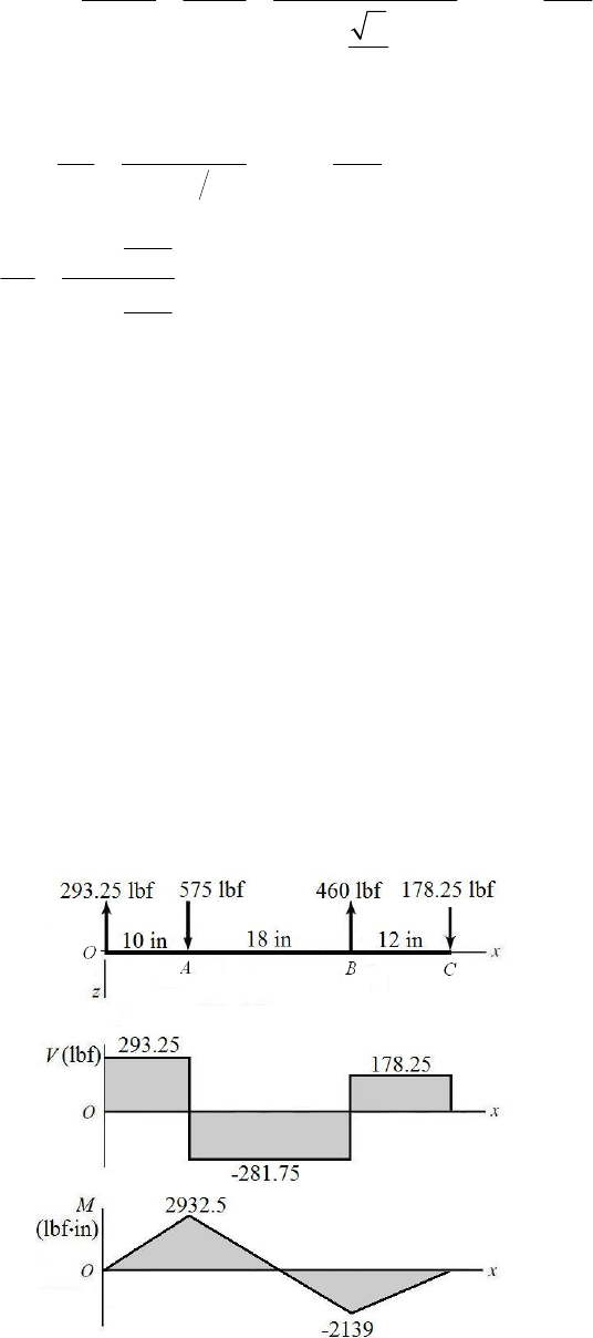
square 4
34 11.50
0.141 2
Tl Tl Tl Tl
bc G b G d G
dG
4
For the circular cross section,
4
410.19
32
rd
Tl Tl Tl
GJ d G
Gd
4
4
11.50
1.129
10.19
sq
rd
Tl
dG
Tl
dG
The angle of twist in the square cross section is 12.9% greater. Ans.
_____________________________________________________________________________
3-68 (a)
12
21 2 2
22
1
0.15
0 (500 75)(4) 5 1700 0.15 5
1700 4.25 0 400 lbf .
0.15 400 60 lbf .
TT
TTTT
TTAns
TAns
T
s
(b)
0 575(10) 460(28) (40)
178.25 178 lbf .
0 575 460 178.25
293.25 lbf .
OC
C
O
O
MR
RAn
FR
RAns
(c)
Chapter 3 - Rev. A, Page 48/100
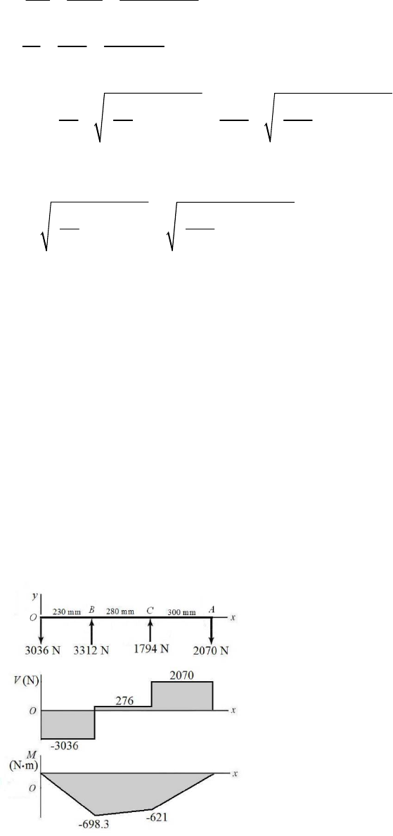
(d) The maximum bending moment is at x = 10 in, and is M = 2932.5 lbf·in. Since the
shaft rotates, each stress element will experience both positive and negative bending
stress as it moves from tension to compression. The torque transmitted through the shaft
from A to B is T = (500 75)(4) = 1700 lbf·in. For a stress element on the outer surface
where the bending stress and the torsional stress are both maximum,
33
32 2932.5
32 15 294 psi = 15.3 kpsi .
(1.25)
Mc M
A
ns
Id
33
16 16(1700) 4433 psi = 4.43 kpsi .
(1.25)
Tr T Ans
Jd
(e)
22
22
12
1
2
22
22
max
15.3 15.3
, 4.43
22 2 2
16.5 kpsi .
1.19 kpsi .
15.3 4.43 8.84 kpsi .
22
xx
xy
x
xy
Ans
Ans
A
ns
_____________________________________________________________________________
3-69 (a)
21
3
21 11
3
11
2
0.15
0 1800 270 (200) (125) 306 10 125 0.15
306 10 106.25 0 2880 N .
0.15 2880 432 N .
TT
TTT
TTAns
TAns
TT
(b)
0 3312(230) (510) 2070(810)
1794 N .
0 3312 1794 2070
3036 N .
OC
C
yO
O
MR
RAns
FR
RAns
(c)
Chapter 3 - Rev. A, Page 49/100
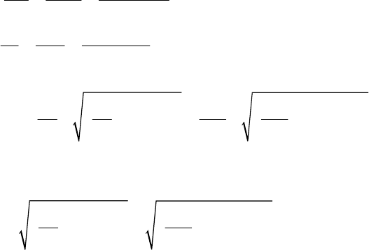
(d) The maximum bending moment is at x = 230 mm, and is M = –698.3 N·m. Since the
shaft rotates, each stress element will experience both positive and negative bending
stress as it moves from tension to compression. The torque transmitted through the shaft
from A to B is T = (1800 270)(0.200) = 306 N·m. For a stress element on the outer
surface where the bending stress and the torsional stress are both maximum,
3
33
32 698.3
32 263 10 Pa 263 MPa .
(0.030)
Mc M
A
ns
Id
6
33
16 16(306) 57.7 10 Pa 57.7MPa .
(0.030)
Tr T Ans
Jd
(e)
22
22
12
1
2
22
22
max
263 263
, 57.7
22 2 2
275 MPa .
12.1 MPa .
263 57.7 144 MPa .
22
xx
xy
x
xy
Ans
Ans
A
ns
_____________________________________________________________________________
3-70
(a)
21
21 11
11
2
0.15
0 300 50 (4) (3) 1000 0.15 (3)
1000 2.55 0 392.16 lbf .
0.15 392.16 58.82 lbf .
TT
TTT
TTAns
TAns
TT
(b)
Chapter 3 - Rev. A, Page 50/100
0 450.98(16) (22)
327.99 lbf .
0 450.98 327.99
122.99 lbf .
0 350(8) (22)
127.27 lbf .
0 350 127.27
222.73 lbf .
Oy Cz
Cz
zOz
Oz
Oz Cy
Cy
yOy
Oy
MR
RAns
FR
RAns
MR
RAns
FR
RAns
Chapter 3 - Rev. A, Page 51/100
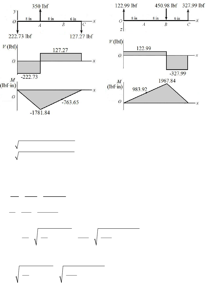
(c)
(d) Combine the bending moments from both planes at A and B to find the critical
location.
22
22
(983.92) ( 1781.84) 2035 lbf in
(1967.84) ( 763.65) 2111 lbf in
A
B
M
M
The critical location is at B. The torque transmitted through the shaft from A to B is T =
(300 50)(4) = 1000 lbf·in. For a stress element on the outer surface where the bending
stress and the torsional stress are both maximum,
33
32 2111
32 21502 psi = 21.5 kpsi .
(1)
Mc M
A
ns
Id
33
16 16(1000) 5093 psi = 5.09 kpsi .
(1)
Tr T Ans
Jd
(e)
22
22
12
1
2
22
22
max
21.5 21.5
, 5.09
22 2 2
22.6 kpsi .
1.14 kpsi .
21.5 5.09 11.9 kpsi .
22
xx
xy
x
xy
Ans
Ans
A
ns
_____________________________________________________________________________
Chapter 3 - Rev. A, Page 52/100
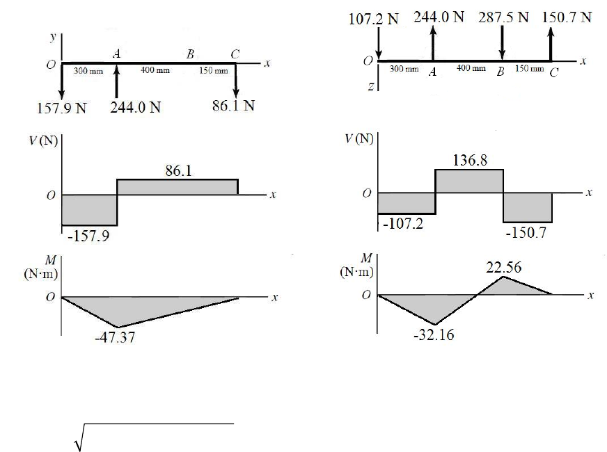
3-71 (a)
21
21 11
11
2
0.15
0 300 45 (125) (150) 31 875 0.15 (150)
31 875 127.5 0 250 N mm .
0.15 250 37.5 N mm .
TT
TTTT
TTAns
TAns
T
(b)
o
o
o
o
0 345sin 45 (300) 287.5(700) (850)
150.7 N .
0 345 cos 45 287.5 150.7
107.2 N .
0 345sin 45 (300) (850)
86.10 N .
0 345cos 45 86.10
Oy Cz
Cz
zOz
Oz
Oz Cy
Cy
yOy
Oy
MR
RAns
FR
RAns
MR
RAns
FR
R
157.9 N .Ans
(c)
(
d
)
F
r
o
m
t
h
e
b
e
n
ding moment diagrams, it is clear that the critical location is at A where both planes have
the maximum bending moment. Combining the bending moments from the two planes,
22
47.37 32.16 57.26 N mM
Chapter 3 - Rev. A, Page 53/100
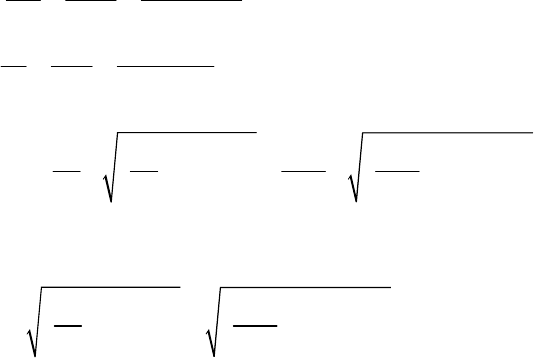
The torque transmitted through the shaft from A to B is T = (300 45)(0.125) = 31.88
N·m. For a stress element on the outer surface where the bending stress and the torsional
stress are both maximum,
6
33
32 57.26
32 72.9 10 Pa 72.9 MPa .
(0.020)
Mc M
A
ns
Id
6
33
16 16(31.88) 20.3 10 Pa 20.3 MPa .
(0.020)
Tr T Ans
Jd
(e)
22
22
12
1
2
22
22
max
72.9 72.9
, 20.3
22 2 2
78.2 MPa .
5.27 MPa .
72.9 20.3 41.7 MPa .
22
xx
xy
x
xy
Ans
Ans
A
ns
_____________________________________________________________________________
3-72 (a)
0 300(cos 20º )(10) (cos 20º )(4)
750 lbf .
B
B
TF
FAns
(b)
0 300(cos 20º )(16) 750(sin 20º )(39) (30)
183 lbf .
0 300(cos 20º ) 183 750(sin 20º )
208 lbf .
0 300(sin 20º )(16) (30) 750(cos 20º )(39)
861 lbf .
0 300
Oz Cy
Cy
yOy
Oy
Oy Cz
Cz
zOz
MR
RAns
FR
RAns
MR
RAns
FR
(sin 20º ) 861 750(cos 20º )
259 lbf .
Oz
RAns
Chapter 3 - Rev. A, Page 54/100
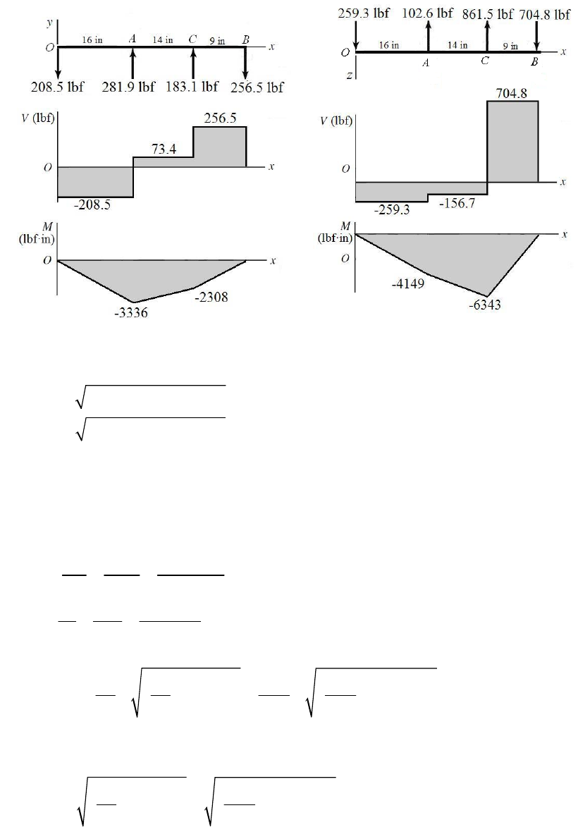
(c)
(d) Combine the bending moments from both planes at A and C to find the critical
location.
22
22
( 3336) ( 4149) 5324 lbf in
( 2308) ( 6343) 6750 lbf in
A
C
M
M
The critical location is at C. The torque transmitted through the shaft from A to B is
. For a stress element on the outer surface where the
bending stress and the torsional stress are both maximum,
300cos 20º 10 2819 lbf inT
33
32 6750
32 35 203 psi = 35.2 kpsi .
(1.25)
Mc M
A
ns
Id
33
16 16(2819) 7351 psi = 7.35 kpsi .
(1.25)
Tr T Ans
Jd
(e)
22
22
12
1
2
22
22
max
35.2 35.2
, 7.35
22 2 2
36.7 kpsi .
1.47 kpsi .
35.2 7.35 19.1 kpsi .
22
xx
xy
x
xy
Ans
Ans
A
ns
_____________________________________________________________________________
Chapter 3 - Rev. A, Page 55/100
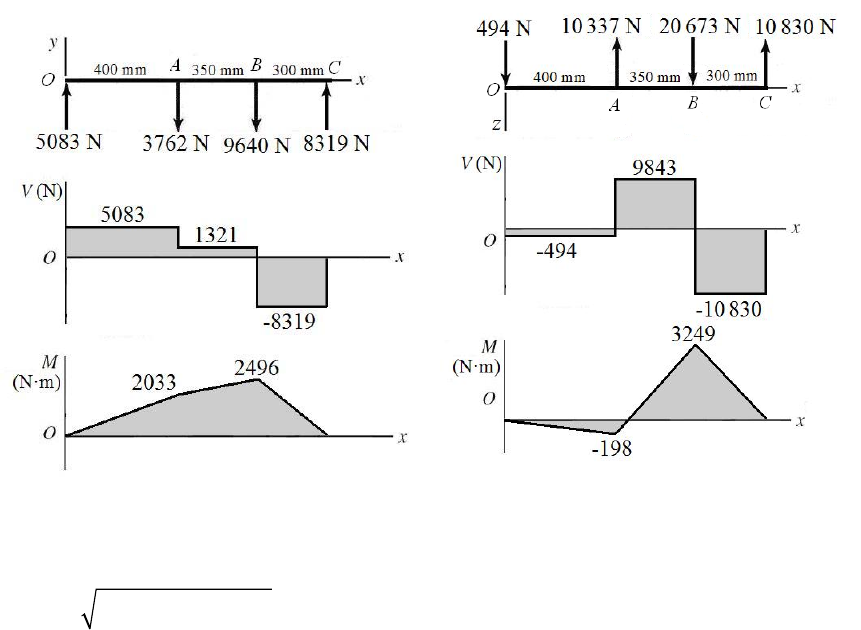
3-73 (a)
0 11 000(cos 20º )(300) (cos 25º )(150)
22 810 N .
B
B
TF
FAns
(b)
0 11000(sin 20º )(400) 22 810(sin 25º )(750) (1050)
8319 N .
Oz Cy
Cy
MR
RAns
0 11000(sin 20º ) 22 810sin(25º ) 8319
5083 N .
0 11 000(cos 20º )(400) 22 810(cos 25º )(750) (1050)
10 830 N .
0 11000(cos 20º ) 22 810(cos 25º ) 10 830
494 N .
yOy
Oy
Oy Cz
Cz
zOz
Oz
FR
RAns
MR
RAns
FR
RAns
(c)
(d) From the bending moment diagrams, it is clear that the critical location is at B where
both planes have the maximum bending moment. Combining the bending moments from
the two planes,
22
2496 3249 4097 N mM
The torque transmitted through the shaft from A to B is
.
11 000cos 20º 0.3 3101 N mT
For a stress element on the outer surface where the bending stress and the torsional stress
are both maximum,
Chapter 3 - Rev. A, Page 56/100
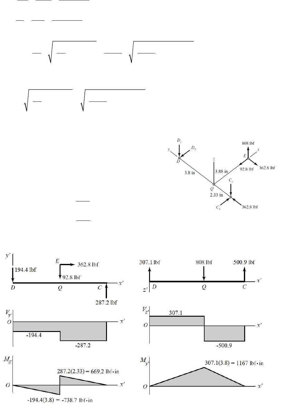
6
33
32 4097
32 333.9 10 Pa 333.9 MPa .
(0.050)
Mc M
A
ns
Id
6
33
16 16(3101) 126.3 10 Pa 126.3 MPa .
(0.050)
Tr T Ans
Jd
(e)
22
22
12
1
2
22
22
max
333.9 333.9
, 126.3
22 2 2
376 MPa .
42.4 MPa .
333.9 126.3 209 MPa .
22
xx
xy
x
xy
Ans
Ans
A
ns
_____________________________________________________________________________
3-74
(a)
6.13 3.8(92.8) 3.88(362.8) 0
Dx
z
MC
287.2 lbf .
x
CAns
ns
6.13 2.33(92.8) 3.88(362.8) 0
Cx
z
MD
194.4 lbf .
x
DA
3.8
0 (808) 500.9 lbf .
6.13
Dz
x
M
CAns
2.33
0 (808) 307.1 lbf .
6.13
Cz
x
M
DA ns
(b) For DQC, let x
, y
, z
correspond to the original y, x, z axes.
Chapter 3 - Rev. A, Page 57/100

(c) The critical stress element is just to the right of Q, where the bending moment in both
planes is maximum, and where the torsional and axial loads exist.
808(3.88) 3135 lbf inT
22
669.2 1167 1345 lbf inM
33
16 16(3135) 11 070 psi .
1.13
TAns
d
33
32 32(1345) 9495 psi .
1.13
b
MAns
d
2
362.8 362 psi .
( / 4) 1.13
a
FAns
A
(d) The critical stress element will be where the bending stress and axial stress are both in
compression.
max 9495 362 9857 psi
2
2
max
9857 11 070 12 118 psi 12.1 kpsi .
2
A
ns
2
2
12
9857 9857
, 11 070
22
17189 psi 7.19 kpsi .Ans
217 046 psi 17.0 kpsi .Ans
_____________________________________________________________________________
3-75
(a)
0
6.13 3.8(46.6) 3.88(140) 0
Dz
x
M
C
ns
ns
117.5 lbf .
x
CA
0
6.13 2.33(46.6) 3.88(140) 0
Cz
x
M
D
70.9 lbf .
x
DA
3.8
0 (406) 251.7 lbf .
6.13
Dz
x
M
CA
ns
2.33
0 (406) 154.3 lbf .
6.13
Cz
x
M
DA ns
Chapter 3 - Rev. A, Page 58/100
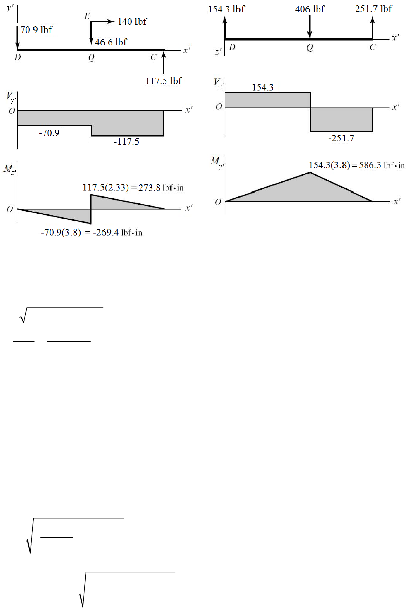
(b) For DQC, let x
, y
, z
correspond to the original y, x, z axes.
(c) The critical stress element is just to the right of Q, where the bending moment in both
planes is maximum, and where the torsional and axial loads exist.
406(3.88) 1575 lbf inT
22
273.8 586.3 647.1 lbf inM
33
16 16(1575) 8021 psi .
1
TAns
d
33
32 32(647.1) 6591 psi .
1
b
MAns
d
2
140 178.3 psi .
(/4)1
a
FAns
A
(d) The critical stress element will be where the bending stress and axial stress are both in
compression.
max 6591 178.3 6769 psi
2
2
max
6769 8021 8706 psi 8.71 kpsi .
2
A
ns
2
2
12
6769 6769
, 8021
22
Chapter 3 - Rev. A, Page 59/100
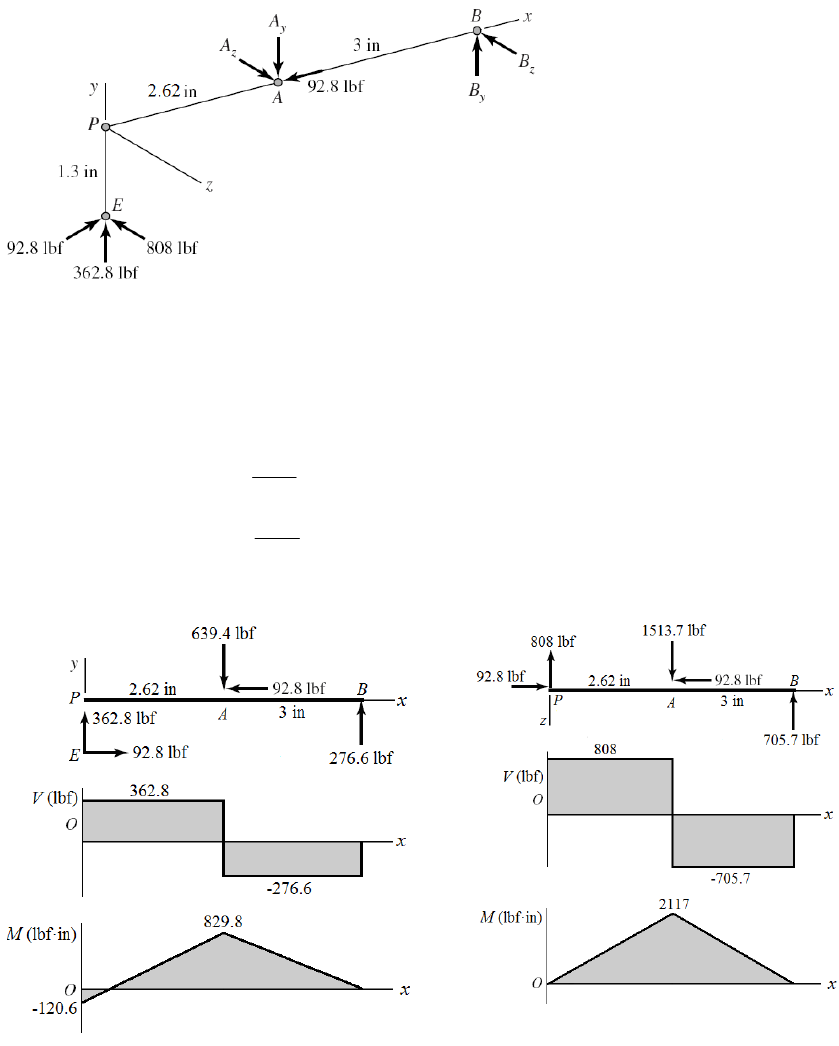
15321 psi 5.32 kpsi .Ans
212090 psi 12.1 kpsi .Ans
_____________________________________________________________________________
3-76
5.62(362.8) 1.3(92.8) 3 0
By
z
MA
639.4 lbf
y
A Ans.
2.62(362.8) 1.3(92.8) 3 0
Ay
z
MB
276.6 lbf
y
B Ans.
5.62
0 (808) 1513.7 lbf
3
Bz
y
MA Ans.
2.62
0 (808) 705.7 lbf
3
Az
y
MB Ans.
(b)
(c) The critical stress element is just to the left of A, where the bending moment in both
planes is maximum, and where the torsional and axial loads exist.
Chapter 3 - Rev. A, Page 60/100
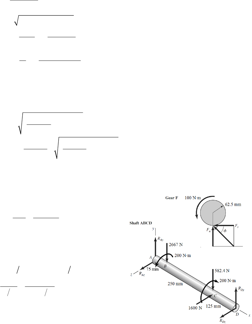
808(1.3) 1050 lbf inT
3
16(1050) 7847 psi .
0.88 Ans
22
(829.8) (2117) 2274 lbf inM
33
32 32(2274) 33 990 psi .
0.88
b
MAns
d
2
92.8 153 psi .
( / 4) 0.88
a
FAns
A
(d) The critical stress will occur when the bending stress and axial stress are both in
compression.
max 33 990 153 34 143 psi
2
2
max
34143 7847 18 789 psi 18.8 kpsi .
2
A
ns
2
2
12
34143 34143
, 7847
22
11717 psi 1.72 kpsi .Ans
235 860 psi 35.9 kpsi .Ans
_____________________________________________________________________________
3-77
100 1600 N
/ 2 0.125 / 2
t
T
Fc
1600 tan 20 582.4 N
2 1600 0.250 2 200 N m
200 2667 N
2 0.150 2
n
Ct
C
F
TFb
T
Pa
0
450 582.4(325) 2667(75) 0
865.1 N
Az
Dy
Dy
M
R
R
0 450 1600(325)
ADz
y
MR
0 865.1 582.4 2667
yAy
FR
0 1156 1600
zAz
FR
1156 N
Dz
R
2384 N
Ay
R
444 N
Az
R
Chapter 3 - Rev. A, Page 61/100
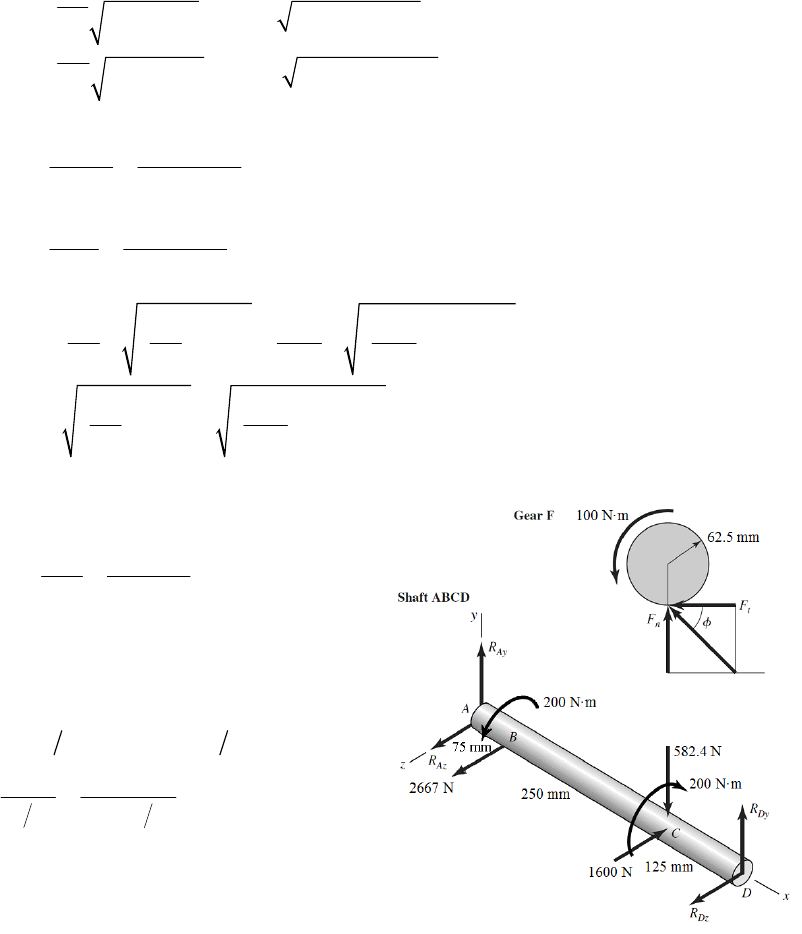
A
BThe maximum bending moment will either be at B or C. If this is not obvious, sketch
the shear and bending moment diagrams. We will directly obtain the combined moments
from each plane.
22 2 2
22 2 2
0.075 2384 444 181.9 N m
0.125 865.1 1156 180.5 N m
yz
yz
BAA
CDD
MABRR
MCDR R
The stresses at B and C are almost identical, but the maximum stresses occur at B. Ans.
6
33
6
33
32 32(181.9) 68.6 10 Pa 68.6 MPa
0.030
16 16(200) 37.7 10 Pa 37.7 MPa
0.030
B
B
B
B
M
d
T
d
22
22
max
68.6 68.6 37.7 85.3 MPa .
22 2 2
BB
BAns
22
22
max
68.6 37.7 51.0 MPa .
22
B
BAns
_____________________________________________________________________________
3-78
100 1600 N
/ 2 0.125 / 2
t
T
Fc
1600 tan 20 582.4 N
2 1600 0.250 2 200 N m
200 2667 N
2 0.150 2
n
Ct
C
F
TFb
T
Pa
0 450 582.4(325) 420.6 N
0 450 1600(325) 2667(75) 711.1 N
0 420.6 582.4 161.8 N
0 711.1 1600 2667
ADy Dy
z
ADz Dz
y
yAy Ay
zAz
MR R
MR R
FR R
FR
1778 N
Az
R
Chapter 3 - Rev. A, Page 62/100
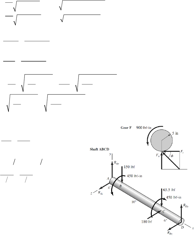
The maximum bending moment will either be at B or C. If this is not obvious, sketch
shear and bending moment diagrams. We will directly obtain the combined moments
from each plane.
2
22 2
22 2 2
0.075 161.8 1778 133.9 N m
0.125 420.6 711.1 103.3 N m
yz
yz
BAA
CDD
MABRR
MCDR R
The maximum stresses occur at B. Ans.
6
33
6
33
32 32(133.9) 50.5 10 Pa 50.5 MPa
0.030
16 16(200) 37.7 10 Pa 37.7 MPa
0.030
B
B
B
B
M
d
T
d
22
22
max
50.5 50.5 37.7 70.6 MPa .
22 2 2
BB
BAns
22
22
max
50.5 37.7 45.4 MPa .
22
BBAns
_____________________________________________________________________________
3-79
900 180 lbf
/2 10/2
t
T
Fc
180 tan 20 65.5 lbf
2 180 5 2 450 lbf in
450 150 lbf
262
n
Ct
C
F
TFb
T
Pa
0 20 65.5(14) 150(4) 75.9 lbf
0 20 180(14) 126 lbf
0 75.9 65.5 150 140 lbf
0 126 180
ADy Dy
z
ADz Dz
y
yAy Ay
zAz
MR R
MR R
FR R
FR
54.0 lbf
Az
R
Chapter 3 - Rev. A, Page 63/100
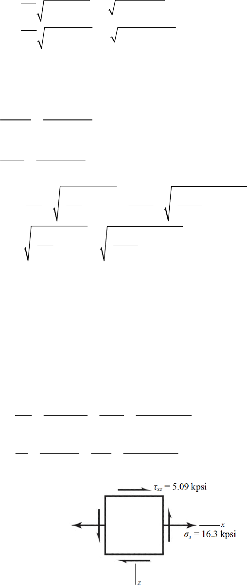
The maximum bending moment will either be at B or C. If this is not obvious, sketch
shear and bending moment diagrams. We will directly obtain the combined moments
from each plane.
22 22
22 2 2
4 140 54 600 lbf in
6 75.9 126 883 lbf in
yz
yz
BAA
CDD
MABRR
MCDR R
The maximum stresses occur at C. Ans.
33
33
32 32(883) 3460 psi
1.375
16 16(450) 882 psi
1.375
C
C
C
C
M
d
T
d
22
22
max
3460 3460 882 3670 psi .
22 2 2
CC
CAns
22
22
max
3460 882 1940 psi .
22
C
CAns
_____________________________________________________________________________
3-80 (a) Rod AB experiences constant torsion throughout its length, and maximum bending
moment at the wall. Both torsional shear stress and bending stress will be maximum on
the outer surface. The transverse shear will be very small compared to bending and
torsion, due to the reasonably high length to diameter ratio, so it will not dominate the
determination of the critical location. The critical stress element will be at the wall, at
either the top (compression) or the bottom (tension) on the y axis. We will select the
bottom element for this analysis.
(b) Transverse shear is zero at the critical stress elements on the top and bottom surfaces.
3
43
/ 2 32 8 200
32 16 297 psi 16.3 kpsi
/64 1
x
Md
Mc M
Id d
3
43
/ 2 16 5 200
16 5093 psi 5.09 kpsi
/32 1
xz
Td
Tr T
Jd d
Chapter 3 - Rev. A, Page 64/100
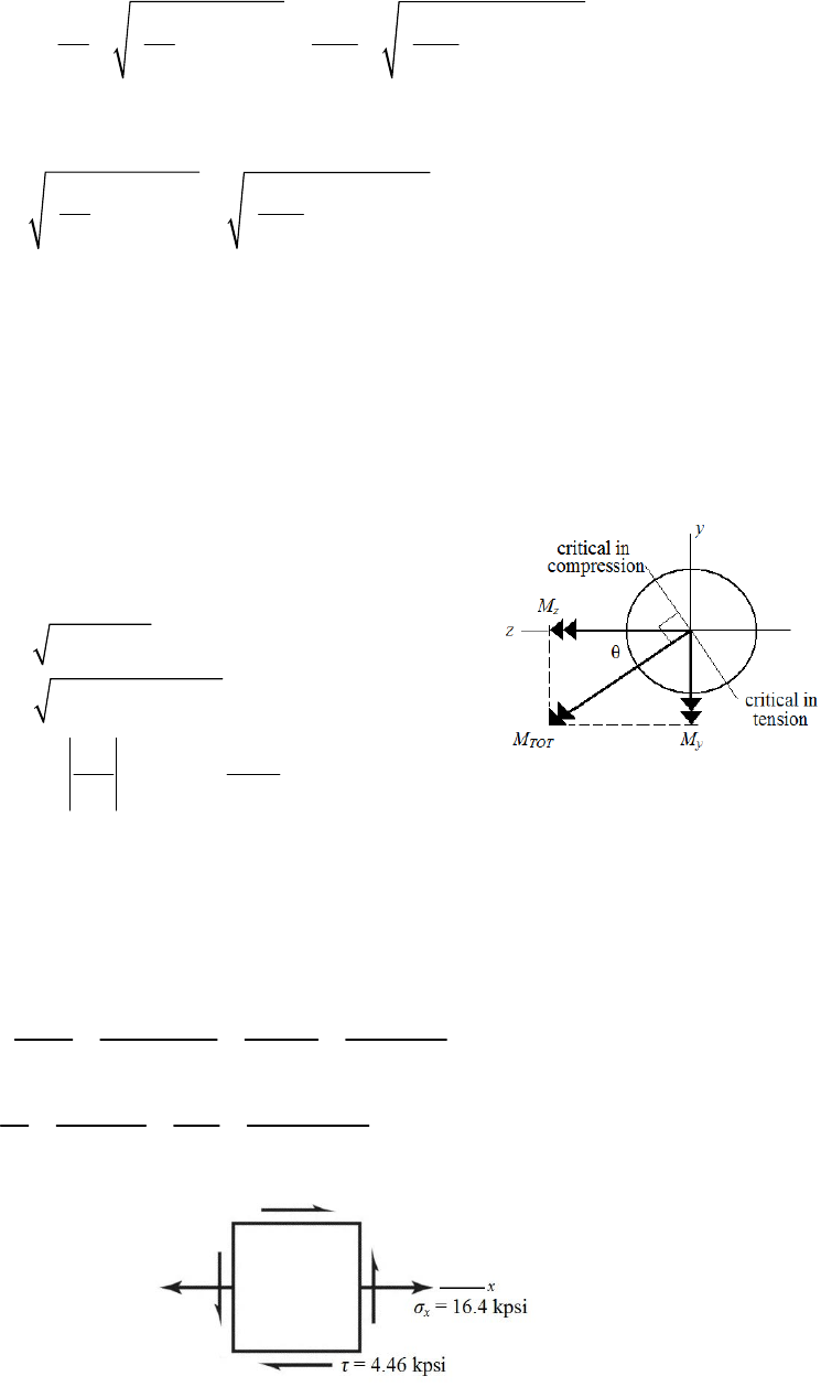
(c)
22
22
12
1
2
22
22
max
16.3 16.3
, 5.09
22 2 2
17.8 kpsi .
1.46 kpsi .
16.3 5.09 9.61 kpsi .
22
xx
xz
x
xz
Ans
Ans
A
ns
_____________________________________________________________________________
3-81 (a) Rod AB experiences constant torsion throughout its length, and maximum bending
moments at the wall in both planes of bending. Both torsional shear stress and bending
stress will be maximum on the outer surface. The transverse shear will be very small
compared to bending and torsion, due to the reasonably high length to diameter ratio, so
it will not dominate the determination of the critical location. The critical stress element
will be on the outer surface at the wall, with its critical location determined by the plane
of the combined bending moments.
My = – (100)(8) = – 800 lbf·in
Mz = (175)(8) = 1400 lbf·in
22
tot
22
11
800 1400 1612 lbf in
800
= tan tan 29.7º
1400
yz
y
z
MMM
M
M
The combined bending moment vector is at an angle of 29.7º CCW from the z axis. The
critical bending stress location, and thus the critical stress element, will be ±90º from this
vector, as shown. There are two equally critical stress elements, one in tension (119.7º
CCW from the z axis) and the other in compression (60.3º CW from the z axis). We’ll
continue the analysis with the element in tension.
(b) Transverse shear is zero at the critical stress elements on the outer surfaces.
tot
tot tot
3
43
/ 2 32 1612
32 16 420 psi 16.4 kpsi
/64 1
x
Md
Mc M
Id d
3
43
/ 2 16 5 175
16 4456 psi 4.46 kpsi
/32 1
Td
Tr T
Jd d
Chapter 3 - Rev. A, Page 65/100
(c)
22
2
2
12
1
2
22
2
2
max
16.4 16.4
, 4.46
22 2 2
17.5 kpsi .
1.13 kpsi .
16.4 4.46 9.33 kpsi .
22
xx
x
Ans
Ans
A
ns
_____________________________________________________________________________
3-82 (a) Rod AB experiences constant torsion and constant axial tension throughout its length,
and maximum bending moments at the wall from both planes of bending. Both torsional
shear stress and bending stress will be maximum on the outer surface. The transverse
shear will be very small compared to bending and torsion, due to the reasonably high
length to diameter ratio, so it will not dominate the determination of the critical location.
The critical stress element will be on the outer surface at the wall, with its critical
location determined by the plane of the combined bending moments.
My = – (100)(8) – (75)(5) = – 1175 lbf·in
Mz = (–200)(8) = –1600 lbf·in
22
tot
22
11
1175 1600 1985 lbf in
1175
= tan tan 36.3º
1600
yz
y
z
MMM
M
M
The combined bending moment vector is at an angle of 36.3º CW from the negative z
axis. The critical bending stress location will be ±90º from this vector, as shown. Since
there is an axial stress in tension, the critical stress element will be where the bending is
also in tension. The critical stress element is therefore on the outer surface at the wall, at
an angle of 36.3º CW from the y axis.
(b) Transverse shear is zero at the critical stress element on the outer surface.
tot
tot tot
,bend 3
43
/ 2 32 1985
32 20 220 psi 20.2 kpsi
/64 1
x
Md
Mc M
Id d
,axial 2
2
75 95.5 psi 0.1 kpsi
/4 1/4
xx
x
FF
Ad
, which is essentially negligible
,axial ,bend 20 220 95.5 20 316 psi 20.3 kpsi
xx x
3
3
16 5 200
16 5093 psi 5.09 kpsi
1
Tr T
Jd
Chapter 3 - Rev. A, Page 66/100
(c)
22
2
2
12
1
2
22
2
2
max
20.3 20.3
, 5.09
22 2 2
21.5 kpsi .
1.20 kpsi .
20.3 5.09 11.4 kpsi .
22
xx
x
Ans
Ans
A
ns
_____________________________________________________________________________
3-83
T = (2)(200) = 400 lbf·in
The maximum shear stress due to torsion occurs in the middle of the longest side of the
rectangular cross section. From the table on p. 102, with b/c = 1.5/0.25 = 6,
= 0.299.
From Eq. (3-40),
max 2
2
400 14 270 psi 14.3 kpsi .
0.299 1.5 0.25
T
A
ns
bc
____________________________________________________________________________
3-84 (a) The cross section at A will experience bending, torsion, and transverse shear. Both
torsional shear stress and bending stress will be maximum on the outer surface. The
transverse shear will be very small compared to bending and torsion, due to the
reasonably high length to diameter ratio, so it will not dominate the determination of the
critical location. The critical stress element will be at either the top (compression) or the
bottom (tension) on the y axis. We’ll select the bottom element for this analysis.
(b) Transverse shear is zero at the critical stress elements on the top and bottom surfaces.
3
43
/ 2 32 11 250
32 28 011 psi 28.0 kpsi
/64 1
x
Md
Mc M
Id d
3
43
/ 2 16 12 250
16 15 279 psi 15.3 kpsi
/32 1
xz
Td
Tr T
Jd d
Chapter 3 - Rev. A, Page 67/100
(c)
22
22
12
1
2
22
22
max
28.0 28.0
, 15.3
22 2 2
34.7 kpsi .
6.7 kpsi .
28.0 15.3 20.7 kpsi .
22
xx
xz
x
xz
Ans
Ans
A
ns
____________________________________________________________________________
3-85 (a) The cross section at A will experience bending, torsion, axial, and transverse shear.
Both torsional shear stress and bending stress will be maximum on the outer surface. The
transverse shear will be very small compared to bending and torsion, due to the
reasonably high length to diameter ratio, so it will not dominate the determination of the
critical location. The critical stress element will be on the outer surface, with its critical
location determined by the plane of the combined bending moments.
My = (300)(12) = 3600 lbf·in
Mz = (250)(11) = 2750 lbf·in
22
tot
22
11
3600 2750 4530 lbf in
2750
= tan tan 37.4º
3600
yz
z
y
MMM
M
M
The combined bending moment vector is at an angle of 37.4º CCW from the y axis. The
critical bending stress location will be 90º CCW from this vector, where the tensile
bending stress is additive with the tensile axial stress. The critical stress element is
therefore on the outer surface, at an angle of 37.4º CCW from the z axis.
(b)
tot
tot tot
,bend 3
43
/ 2 32 4530
32 46142 psi 46.1 kpsi
/64 1
x
Md
Mc M
Id d
,axial 2
2
300 382 psi 0.382 kpsi
/4 1/4
xx
x
FF
Ad
,axial ,bend 46 142 382 46 524 psi 46.5 kpsi
xx x
3
3
16 12 250
16 15 279 psi 15.3 kpsi
1
Tr T
Jd
Chapter 3 - Rev. A, Page 68/100
(c)
22
2
2
12
1
2
22
2
2
max
46.5 46.5
, 15.3
22 2 2
51.1 kpsi .
4.58 kpsi .
46.5 15.3 27.8 kpsi .
22
xx
x
Ans
Ans
A
ns
____________________________________________________________________________
3-86 (a) The cross section at A will experience bending, torsion, axial, and transverse shear.
Both torsional shear stress and bending stress will be maximum on the outer surface. The
transverse shear will be very small compared to bending and torsion, due to the
reasonably high length to diameter ratio, so it will not dominate the determination of the
critical location. The critical stress element will be on the outer surface, with its critical
location determined by the plane of the combined bending moments.
My = (300)(12) – (–100)(11) = 4700 lbf·in
Mz = (250)(11) = 2750 lbf·in
22
tot
22
11
4700 2750 5445 lbf in
2750
= tan tan 30.3º
4700
yz
z
y
MMM
M
M
The combined bending moment vector is at an angle of 30.3º CCW from the y axis. The
critical bending stress location will be 90º CCW from this vector, where the tensile
bending stress is additive with the tensile axial stress. The critical stress element is
therefore on the outer surface, at an angle of 30.3º CCW from the z axis.
(b)
tot
tot tot
,bend 3
43
/ 2 32 5445
32 55 462 psi 55.5 kpsi
/64 1
x
Md
Mc M
Id d
Chapter 3 - Rev. A, Page 69/100
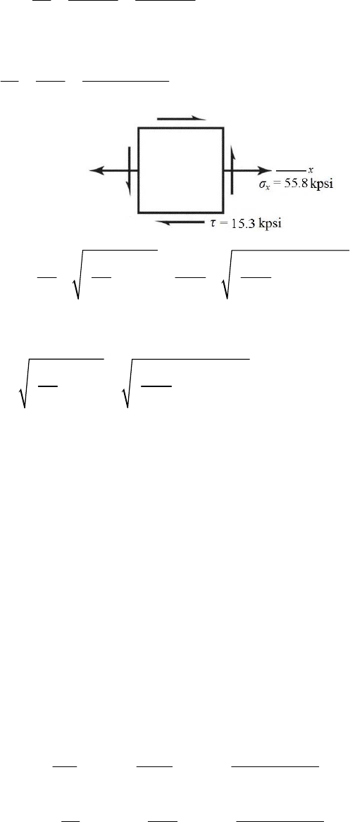
,axial 2
2
300 382 psi 0.382 kpsi
/4 1/4
xx
x
FF
Ad
,axial ,bend 55 462 382 55 844 psi 55.8 kpsi
xx x
3
3
16 12 250
16 15 279 psi 15.3 kpsi
1
Tr T
Jd
(c)
22
2
2
12
1
2
22
2
2
max
55.8 55.8
, 15.3
22 2 2
59.7 kpsi .
3.92 kpsi .
55.8 15.3 31.8 kpsi .
22
xx
x
Ans
Ans
A
ns
____________________________________________________________________________
3-87 (a) The cross section at A will experience bending, torsion, and transverse shear. Both
torsional shear stress and bending stress will be maximum on the outer surface, where the
stress concentration will also be applicable. The transverse shear will be very small
compared to bending and torsion, due to the reasonably high length to diameter ratio, so
it will not dominate the determination of the critical location. The critical stress element
will be at either the top (compression) or the bottom (tension) on the y axis. We’ll select
the bottom element for this analysis.
(b) Transverse shear is zero at the critical stress elements on the top and bottom surfaces.
/ 0.125 /1 0.125
/1.5/11.5
rd
Dd
Fig. A-15-8
,torsion 1.39
t
K
Fig. A-15-9
,bend 1.59
t
K
,bend ,bend 3
3
32 11 250
32 (1.59) 44 538 psi 44.5 kpsi
1
xt t
Mc M
KK
Id
,torsion ,torsion 3
3
16 12 250
16 (1.39) 21 238 psi 21.2 kpsi
1
xz t t
Tr T
KK
Jd
Chapter 3 - Rev. A, Page 70/100
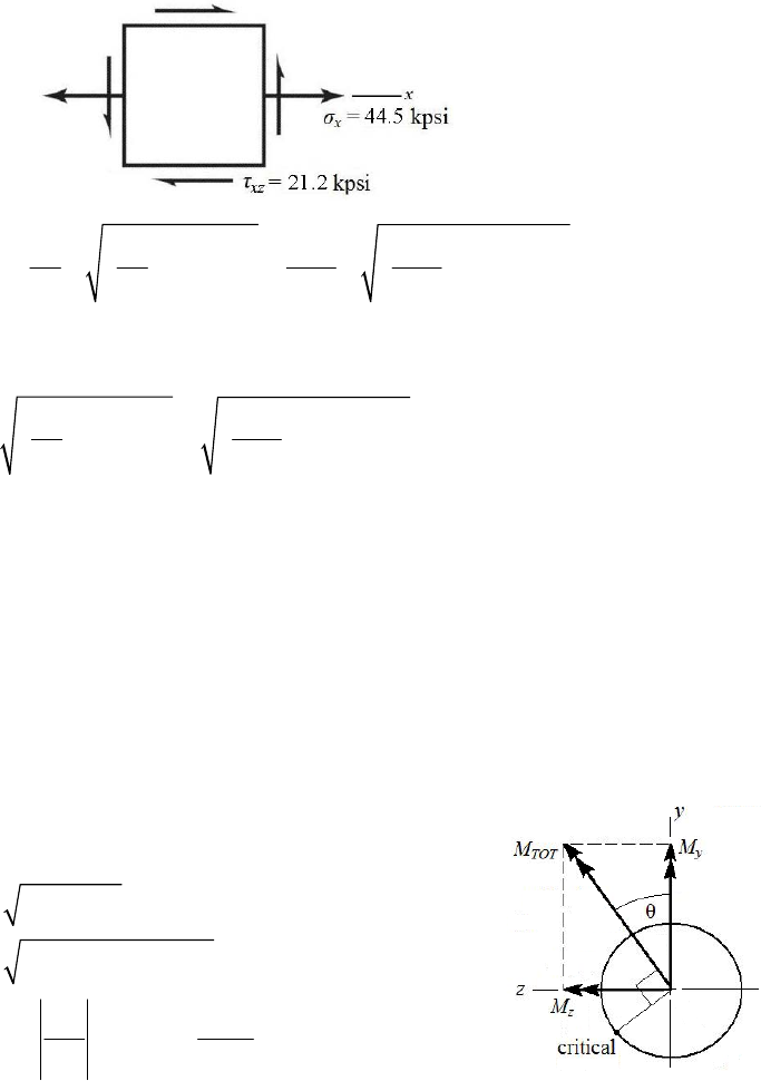
(c)
22
22
12
1
2
22
22
max
44.5 44.5
, 21.2
22 2 2
53.0 kpsi .
8.48 kpsi .
44.5 21.2 30.7 kpsi .
22
xx
xz
x
xz
Ans
Ans
A
ns
____________________________________________________________________________
3-88 (a) The cross section at A will experience bending, torsion, axial, and transverse shear.
Both torsional shear stress and bending stress will be maximum on the outer surface,
where the stress concentration will also be applicable. The transverse shear will be very
small compared to bending and torsion, due to the reasonably high length to diameter
ratio, so it will not dominate the determination of the critical location. The critical stress
element will be on the outer surface, with its critical location determined by the plane of
the combined bending moments.
My = (300)(12) = 3600 lbf·in
Mz = (250)(11) = 2750 lbf·in
22
tot
22
11
3600 2750 4530 lbf in
2750
= tan tan 37.4º
3600
yz
z
y
MMM
M
M
The combined bending moment vector is at an angle of 37.4º CCW from the y axis. The
critical bending stress location will be 90º CCW from this vector, where the tensile
bending stress is additive with the tensile axial stress. The critical stress element is
therefore on the outer surface, at an angle of 37.4º CCW from the z axis.
(b)
/ 0.125 /1 0.125
/1.5/11.5
rd
Dd
Fig. A-15-7
,1.75
taxial
K
Fig. A-15-8
,torsion 1.39
t
K
Fig. A-15-9
,bend 1.59
t
K
Chapter 3 - Rev. A, Page 71/100
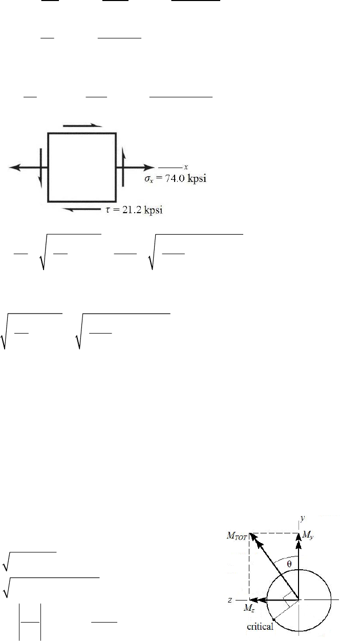
,bend ,bend ,bend 3
3
32 4530
32 (1.59) 73 366 psi 73.4 kpsi
1
xt t
Mc M
KK
Id
,axial ,axial 2
300
1.75 668 psi 0.668 kpsi
1/4
x
xt
F
KA
,axial ,bend 73 366 668 74 034 psi 74.0 kpsi
xx x
,torsion ,torsion 3
3
16 12 250
16 (1.39) 21 238 psi 21.2 kpsi
1
tt
Tr T
KK
Jd
(c)
22
2
2
12
1
2
22
2
2
max
74.0 74.0
, 21.2
22 2 2
79.6 kpsi .
5.64 kpsi .
74.0 21.2 42.6 kpsi .
22
xx
x
Ans
Ans
A
ns
____________________________________________________________________________
3-89 (a) The cross section at A will experience bending, torsion, axial, and transverse shear.
Both torsional shear stress and bending stress will be maximum on the outer surface,
where the stress concentration is also applicable. The transverse shear will be very small
compared to bending and torsion, due to the reasonably high length to diameter ratio, so
it will not dominate the determination of the critical location. The critical stress element
will be on the outer surface, with its critical location determined by the plane of the
combined bending moments.
My = (300)(12) – (–100)(11) = 4700 lbf·in
Mz = (250)(11) = 2750 lbf·in
22
tot
22
4700 2750 5445 lbf in
yz
MMM
11
2750
= tan tan 30.3º
4700
z
y
M
M
Chapter 3 - Rev. A, Page 72/100
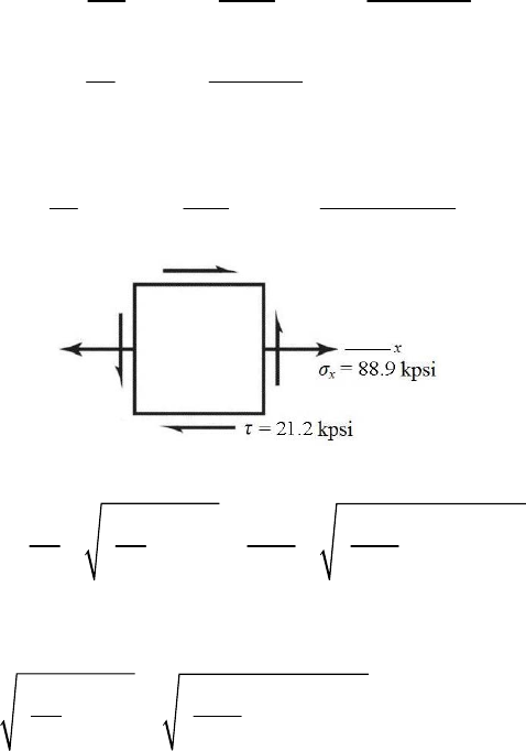
The combined bending moment vector is at an angle of 30.3º CCW from the y axis. The
critical bending stress location will be 90º CCW from this vector, where the tensile
bending stress is additive with the tensile axial stress. The critical stress element is
therefore on the outer surface, at an angle of 30.3º CCW from the z axis.
(b)
/ 0.125 /1 0.125
/1.5/11.5
rd
Dd
Fig. A-15-7
,1.75
taxial
K
Fig. A-15-8
,torsion 1.39
t
K
Fig. A-15-9
,bend 1.59
t
K
,bend ,bend ,bend 3
3
32 5445
32 (1.59) 88185 psi 88.2 kpsi
1
xt t
Mc M
KK
Id
,axial ,axial 2
300
1.75 668 psi 0.668 kpsi
1/4
x
xt
F
KA
,axial ,bend 88185 668 88 853 psi 88.9 kpsi
xx x
,torsion ,torsion 3
3
16 12 250
16 (1.39) 21 238 psi 21.2 kpsi
1
tt
Tr T
KK
Jd
(c)
22
2
2
12
1
2
22
2
2
max
88.9 88.9
, 21.2
22 2 2
93.7 kpsi .
4.80 kpsi .
88.9 21.2 49.2 kpsi .
22
xx
x
Ans
Ans
A
ns
____________________________________________________________________________
3-90
(a) M = F(p / 4), c = p / 4, I = bh3 / 12, b =
dr nt, h = p / 2
Chapter 3 - Rev. A, Page 73/100
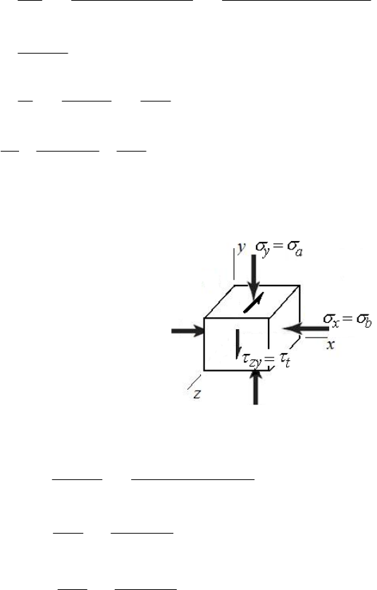
2
3
3
/4 /4
/12 16 / 2 /12
6 .
b
rt
b
rt
Fp p
Mc Fp
Ibh dn p
FAns
dnp
(b) 22
4
/4
a
rr
FF F
Ans.
Ad d
43
/2 16 .
/32
r
t
rr
Td
Tr T Ans
Jd d
(c) The bending stress causes compression in the x direction. The axial stress causes
compression in the y direction. The torsional stress shears across the y face in the negative z
direction.
(d) Analyze the stress element from part (c) using the equations developed in parts (a) and (b).
22
33
1.5 0.25 1.25 in
6 1500
64584 psi = 4.584 kpsi
1.25 2 0.25
4 1500
4= = 1222 psi = 1.222 kpsi
1.25
16 235
16 = = 612.8 psi = 0.6128 kpsi
1.25
r
xb
rt
ya
r
yz t
r
ddp
F
dnp
F
d
T
d
Use Eq. (3-15) for the three-dimensional stress element.
22
32
32
4.584 1.222 4.584 1.222 0.6128 4.584 0.6128 0
5.806 5.226 1.721 0
The roots are at 0.2543, – 4.584, and –1.476. Thus, the ordered principal stresses are
1 = 0.2543 kpsi,
2 = –1.476 kpsi, and
3 = – 4.584 kpsi. Ans.
From Eq. (3-16), the principal shear stresses are
Chapter 3 - Rev. A, Page 74/100
12
1/2
23
2/3
13
1/3
0.2543 1.476 0.8652 kpsi .
22
1.476 4.584 1.554 kpsi .
22
0.2543 4.584 2.419 kpsi .
22
Ans
Ans
Ans
____________________________________________________________________________
3-91 As shown in Fig. 3-32, the maximum stresses occur at the inside fiber where r = ri.
Therefore, from Eq. (3-50)
22
,max 22 2
22
22
22
,max 22 2
1
.
1 .
ii o
t
oi i
oi
i
oi
ii o
ri
oi i
rp r
rr r
rr
pAns
rr
rp r
p
Ans
rr r
______________________________________________________________________________
3-92 If pi = 0, Eq. (3-49) becomes
222 2
22
22
22 2
/
1
oo i o o
t
oi
oo i
oi
p
rrrpr
rr
pr r
rr r
The maximum tangential stress occurs at r = ri. So
2
,max 22
2 .
oo
t
oi
pr Ans
rr
For σr, we have
222 2
22
22
222
/
1
oo i o o
r
oi
oo i
oi
p
rrrpr
rr
pr r
rrr
So σr = 0 at r = ri. Thus at r = ro
222
,max 22 2 .
oo i o
ro
oi o
pr r r
p
Ans
rr r
______________________________________________________________________________
Chapter 3 - Rev. A, Page 75/100
3-93 The force due to the pressure on half of the sphere is resisted by the stress that is
distributed around the center plane of the sphere. All planes are the same, so
2
av 1 2
/4
( ) .
4
ii
t
i
pd
pd
A
ns
dt t
The radial stress on the inner surface of the shell is,
3 = p Ans.
______________________________________________________________________________
3-94 σt > σl > σr
τmax = (σt − σr)/2 at r = ri
22222
max 22 2 22 2 22
22 22
max
22
111
2
32.75
(10 000) 1597 psi .
3
ii o ii o oi
oi i oi i oi
oi
i
o
rp r rp r rp
rr r rr r rr
rr
p Ans
r
______________________________________________________________________________
3-95 σt > σl > σr
τmax = (σt − σr)/2 at r = ri
2222222
max 22 2 22 2 222 22
6
max
6
max
111
2
()(25 4)10
100 91.7 mm
25 10
100 91.7 8.3 mm .
ii o ii o ii o oi
oi i oi i oii oi
i
io
oi
rp r rp r rp r rp
rr r rr r rrr rr
p
rr
trr Ans
______________________________________________________________________________
3-96 σt > σl > σr
τmax = (σt − σr)/2 at r = ri
2222222
max 22 2 22 2 222 22
111
2
ii o ii o ii o oi
oi i oi i oii oi
rp r rp r rp r rp
rr r rr r rrr rr
2
22
4 (500) 4129 psi .
43.75 Ans
______________________________________________________________________________
3-97 From Eq. (3-49) with pi = 0,
Chapter 3 - Rev. A, Page 76/100
22
22 2
22
22 2
1
1
oo i
t
oi
oo i
r
oi
rp r
rr r
rp r
rr r
σt > σl > σr, and since σt and σr are negative,
τmax = (σr − σt)/2 at r = ro
2222222
max 22 2 22 2 222 2
22 22
max
22
111
2
32.75
(10 000) 1900 psi .
2.75
oo i oo i oo i i o
oi o oi o oio oi
oi
o
i
rp r rp r rp r rp
rr r rr r rrr rr
rr
p Ans
r
2
______________________________________________________________________________
3-98 From Eq. (3-49) with pi = 0,
22
22 2
22
22 2
1
1
oo i
t
oi
oo i
r
oi
rp r
rr r
rp r
rr r
σt > σl > σr, and since σt and σr are negative,
τmax = (σr − σt)/2 at r = ro
2222222
max 22 2 22 2 222 2
6
max
6
max
111
2
25 10
100 92.8 mm
() 25410
100 92.8 7.2 mm .
oo i oo i oo i i o
oi o oi o oio oi
io
o
oi
rp r rp r rp r rp
rr r rr r rrr rr
rr p
t r r Ans
2
______________________________________________________________________________
3-99 From Eq. (3-49) with pi = 0,
22
22 2
22
22 2
1
1
oo i
t
oi
oo i
r
oi
rp r
rr r
rp r
rr r
σt > σl > σr, and since σt and σr are negative,
τmax = (σr − σt)/2 at r = ro
Chapter 3 - Rev. A, Page 77/100
2222222
max 22 2 22 2 222 2
2
22
111
2
3.75 (500) 3629 psi .
43.75
oo i oo i oo i i o
oi o oi o oio oi
rp r rp r rp r rp
rr r rr r rrr rr
Ans
2
______________________________________________________________________________
3-100 From Table A-20, Sy=490 MPa
From Eq. (3-49) with pi = 0,
22
22 2
1
oo i
t
oi
rp r
rr r
Maximum will occur at r = ri
22
22
2
,max
,max 22 2 2
0.8( 490) 25 19
()
282.8 MPa .
22(25)
toi
oo
to
oi o
rr
rp
p
Ans
rr r
______________________________________________________________________________
3-101 From Table A-20, Sy = 71 kpsi
From Eq. (3-49) with pi = 0,
22
22 2
1
oo i
t
oi
rp r
rr r
Maximum will occur at r = ri
22 2 2
2,max
,max 22 2 2
0.8( 71) 1 0.75
212.4 kpsi .
22(1)
toi
oo
to
oi o
rr
rp
p
Ans
rr r
______________________________________________________________________________
3-102 From Table A-20, Sy=490 MPa
From Eq. (3-50)
22
22 2
1
ii o
t
oi
rp r
rr r
Maximum will occur at r = ri
22
22
,max 22 2 22
22 22
,max
22 2 2
1
()
0.8(490) (25 19 ) 105 MPa .
(25 19 )
io i
ii o
t
oi i oi
toi
i
oi
pr r
rp r
rr r rr
rr
p
Ans
rr
______________________________________________________________________________
Chapter 3 - Rev. A, Page 78/100
3-103 From Table A-20, Sy =71 MPa
From Eq. (3-50)
22
22 2
1
ii o
t
oi
rp r
rr r
Maximum will occur at r = ri
2222
,max 22 2 22
22 22
,max
22 2 2
()
1
()
0.8(71) (1 0.75 ) 15.9 ksi .
(1 0.75 )
ii o io i
t
oi i oi
toi
i
oi
rp r pr r
rr r rr
rr
p Ans
rr
______________________________________________________________________________
3-104 The longitudinal stress will be due to the weight of the vessel above the maximum stress
point. From Table A-5, the unit weight of steel is
s = 0.282 lbf/in3. The area of the wall
is
Awall = (
/4)(3602 358.52) = 846. 5 in2
The volume of the wall and dome are
Vwall = Awall h = 846.5 (720) = 609.5 (103) in3
Vdome = (2
/3)(1803 179.253) = 152.0 (103) in3
The weight of the structure on the wall area at the tank bottom is
W =
s Vtotal = 0.282(609.5 +152.0) (103) = 214.7(103) lbf
3
wall
214.7 10 254 psi
846.5
l
W
A
The maximum pressure will occur at the bottom of the tank, pi =
water h. From Eq. (3-50)
with
i
rr
2222
22 2 22
222
22 2
1
1 ft 180 179.25
62.4(55) 5708 5710 psi .
144 in 180 179.25
ii o o i
ti
oi i oi
rp r r r
p
rr r rr
Ans
22 2
22 2 2
1 ft
1 62.4(55) 23.8 psi .
144 in
ii o
ri
oi i
rp r
p
Ans
rr r
Note: These stresses are very idealized as the floor of the tank will restrict the values
calculated.
Chapter 3 - Rev. A, Page 79/100
Since
1
2
3,
1 =
t = 5708 psi,
2 =
r = 24 psi and
3 =
l = 254 psi.
From Eq. (3-16),
13
12
23
5708 254 2981 2980 psi
2
5708 24 2866 2870 psi .
2
24 254 115 psi
2
Ans
______________________________________________________________________________
3-105 Stresses from additional pressure are,
Eq. (3-51),
2
22
50psi
50 179.25 5963 psi
180 179.25
l
(
r)50 psi = 50 psi
Eq. (3-50)
22
22
50psi
180 179.25
50 11 975 psi
180 179.25
t
Adding these to the stresses found in Prob. 3-104 gives
t = 5708 + 11 975 = 17683 psi = 17.7 kpsi Ans.
r = 23.8 50 = 73.8 psi Ans.
l = 254 + 5963 = 5709 psi Ans.
Note: These stresses are very idealized as the floor of the tank will restrict the values
calculated.
From Eq. (3-16)
13
12
23
17 683 73.8 8879 psi
2
17 683 5709 5987 psi .
2
5709 23.8 2866 psi
2
Ans
______________________________________________________________________________
3-106 Since σt and σr are both positive and σt > σr
max max 2
t
From Eq. (3-55),
t is maximum at r = ri = 0.3125 in. The term
Chapter 3 - Rev. A, Page 80/100
2
22 5000
3 0.282 3 0.292 82.42 lbf/in
8 386 60 8
22
22 2
2
max
0.3125 2.75 1 3(0.292)
82.42 0.3125 2.75 0.3125
30.292
0.3125
1260 psi
t
max
1260 630 psi .
2
A
ns
Radial stress:
22
22 2
2
io
rio
rr
kr r r
r
Maxima:
22
3
2 2 0 0.3125(2.75) 0.927 in
io
r
io
rr
dkrrrr
dr r
22
22
2
max
0.3125 2.75
82.42 0.3125 2.75 0.927
0.927
490 psi .
r
Ans
2
______________________________________________________________________________
3-107
= 2
(2000)/60 = 209.4 rad/s,
= 3320 20 kg/m3,
= 0.24, ri = 0.01 m, ro = 0.125 m
Using Eq. (3-55)
22
222
3 0.24 1 3(0.24)
3320(209.4) 0.01 (0.125) (0.125) 0.01 (10)
8 3 0.24
1.85 MPa .
t
Ans
6
______________________________________________________________________________
3-108
= 2
(12 000)/60 = 1256.6 rad/s,
42
22
5/16 6.749 10 lbf s / in
386 1 16 4 5 0.75
4
The maximum shear stress occurs at bore where
max =
t /2. From Eq. (3-55)
2
4 222 2
max
3 0.20 1 3(0.20)
( ) 6.749(10 ) 1256.6 0.375 2.5 2.5 (0.375)
8 3 0.20
5360 psi
t
Chapter 3 - Rev. A, Page 81/100
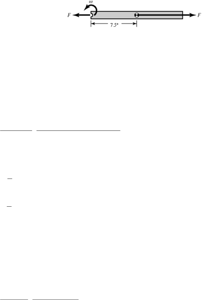
max = 5360 / 2 = 2680 psi Ans.
______________________________________________________________________________
3-109
= 2
(3500)/60 = 366.5 rad/s,
mass of blade = m =
V = (0.282 / 386) [1.25(30)(0.125)] = 3.425(103) lbfs2/in
F = (m/2)
2r
= [3.425(103)/2]( 366.52)(7.5)
= 1725 lbf
Anom = (1.25 0.5)(1/8) = 0.093 75 in2
nom = F/ Anom = 1725/0.093 75 = 18 400 psi Ans.
Note: Stress concentration Fig. A-15-1 gives Kt = 2.25 which increases σmax and fatigue.
______________________________________________________________________________
3-110
= 0.292, E = 207 GPa, ri = 0, R = 25 mm, ro = 50 mm
Eq. (3-57),
9222
93
32
207(10 ) (0.05 0.025 )(0.025 0) 10 3.105(10 ) (1)
2(0.025) (0.05 0)
p
where p is in MPa and
is in mm.
Maximum interference,
max
1[50.042 50.000] 0.021 mm .
2
A
ns
Minimum interference,
min
1[50.026 50.025] 0.0005 mm .
2
A
ns
From Eq. (1)
pmax = 3.105(103)(0.021) = 65.2 MPa Ans.
pmin = 3.105(103)(0.0005) = 1.55 MPa Ans.
______________________________________________________________________________
3-111
= 0.292, E = 30 Mpsi, ri = 0, R = 1 in, ro = 2 in
Eq. (3-57),
6222
7
32
30(10 ) (2 1 )(1 0) 1.125(10 ) (1)
2(1 ) (2 0)
p
where p is in psi and
is in inches.
Maximum interference,
Chapter 3 - Rev. A, Page 82/100

max
1[2.0016 2.0000] 0.0008 in .
2
A
ns
Minimum interference,
min
1[2.0010 2.0010] 0 .
2
A
ns
From Eq. (1),
pmax = 1.125(107)(0.0008) = 9 000 psi Ans.
pmin = 1.125(107)(0) = 0 Ans.
______________________________________________________________________________
3-112
= 0.292, E = 207 GPa, ri = 0, R = 25 mm, ro = 50 mm
Eq. (3-57),
9222
93
32
207(10 ) (0.05 0.025 )(0.025 0) 10 3.105(10 ) (1)
2(0.025) (0.05 0)
p
where p is in MPa and
is in mm.
Maximum interference,
max
1[50.059 50.000] 0.0295 mm .
2
A
ns
Minimum interference,
min
1[50.043 50.025] 0.009 mm .
2
A
ns
From Eq. (1)
pmax = 3.105(103)(0.0295) = 91.6 MPa Ans.
pmin = 3.105(103)(0.009) = 27.9 MPa Ans.
______________________________________________________________________________
3-113
= 0.292, E = 30 Mpsi, ri = 0, R = 1 in, ro = 2 in
Eq. (3-57),
6222
7
32
30(10 ) (2 1 )(1 0) 1.125(10 ) (1)
2(1 ) (2 0)
p
where p is in psi and
is in inches.
Maximum interference,
max
1[2.0023 2.0000] 0.00115 in .
2
A
ns
Minimum interference,
Chapter 3 - Rev. A, Page 83/100

min
1[2.0017 2.0010] 0.00035 .
2
A
ns
From Eq. (1),
pmax = 1.125(107)(0.00115) = 12 940 psi Ans.
pmin = 1.125(107)(0.00035) = 3 938 Ans.
______________________________________________________________________________
3-114
= 0.292, E = 207 GPa, ri = 0, R = 25 mm, ro = 50 mm
Eq. (3-57),
9222
93
32
207(10 ) (0.05 0.025 )(0.025 0) 10 3.105(10 ) (1)
2(0.025) (0.05 0)
p
where p is in MPa and
is in mm.
Maximum interference,
max
1[50.086 50.000] 0.043 mm .
2
A
ns
Minimum interference,
min
1[50.070 50.025] 0.0225 mm .
2
A
ns
From Eq. (1)
pmax = 3.105(103)(0.043) = 134 MPa Ans.
pmin = 3.105(103)(0.0225) = 69.9 MPa Ans.
______________________________________________________________________________
3-115
= 0.292, E = 30 Mpsi, ri = 0, R = 1 in, ro = 2 in
Eq. (3-57),
6222
7
32
30(10 ) (2 1 )(1 0) 1.125(10 ) (1)
2(1 ) (2 0)
p
where p is in psi and
is in inches.
Maximum interference,
max
1[2.0034 2.0000] 0.0017 in .
2
A
ns
Minimum interference,
min
1[2.0028 2.0010] 0.0009 .
2
A
ns
From Eq. (1),
Chapter 3 - Rev. A, Page 84/100
pmax = 1.125(107)(0.0017) = 19 130 psi Ans.
pmin = 1.125(107)(0.0009) = 10 130 Ans.
______________________________________________________________________________
3-116 From Table A-5, Ei = Eo = 30 Mpsi,
i
o ri = 0, R = 1 in, ro = 1.5 in
The radial interference is
12.002 2.000 0.001 in .
2
A
ns
Eq. (3-57),
2222 6 222
322 32
30 10 0.001 1.5 1 1 0
221 1.5 0
8333 psi 83.3 kpsi .
oi
oi
rRRr
E
pRrr
Ans
The tangential stresses at the interface for the inner and outer members are given by Eqs.
(3-58) and (3-59), respectively.
22 22
22 22
10
( ) (8333) 8333 psi 8.33 kpsi .
10
i
ti
rR
i
Rr
p
Ans
Rr
22 22
22 22
1.5 1
( ) (8333) 21 670 psi 21.7 kpsi .
1.5 1
o
to
rR
o
rR
p
Ans
rR
______________________________________________________________________________
3-117 From Table A-5, Ei = 30 Mpsi, Eo =14.5 Mpsi,
i
o
ri = 0, R = 1 in, ro = 1.5 in
The radial interference is
12.002 2.000 0.001 in .
2
A
ns
Eq. (3-56),
22 22
22 22
22 2 2
22 2 2
66
11
0.001 4599 psi .
11.51 110
1 0.211 0.292
1.5 1 1 0
14.5 10 30 10
oi
oi
oo i i
p
rR Rr
REr R ER r
p
Ans
The tangential stresses at the interface for the inner and outer members are given by Eqs.
(3-58) and (3-59), respectively.
22 22
22 22
10
( ) (4599) 4599 psi .
10
i
ti
rR
i
Rr
p
Ans
Rr
Chapter 3 - Rev. A, Page 85/100
22 22
22 22
1.5 1
( ) (4599) 11 960 psi .
1.5 1
o
to
rR
o
rR
p
Ans
rR
______________________________________________________________________________
3-118 From Table A-5, Ei = Eo = 30 Mpsi,
i
o ri = 0, R = 0.5 in, ro = 1 in
The minimum and maximum radial interferences are
min
11.002 1.002 0.000 in .
2
A
ns
max
11.003 1.001 0.001 in .
2
A
ns
Since the minimum interference is zero, the minimum pressure and tangential stresses are
zero. Ans.
The maximum pressure is obtained from Eq. (3-57).
2222
322
6222
32
2
30 10 0.001 1 0.5 0.5 0 22 500 psi
20.5 1 0
oi
oi
rRRr
E
pRrr
p
Ans
The maximum tangential stresses at the interface for the inner and outer members are
given by Eqs. (3-58) and (3-59), respectively.
22 22
22 22
0.5 0
( ) (22 500) 22 500 psi .
0.5 0
i
ti
rR
i
Rr
p
Ans
Rr
22 22
22 2 2
10.5
( ) (22 500) 37 500 psi .
10.5
o
to
rR
o
rR
p
Ans
rR
______________________________________________________________________________
3-119 From Table A-5, Ei = 10.4 Mpsi, Eo =30 Mpsi,
i
o
ri = 0, R = 1 in, ro = 1.5 in
The minimum and maximum radial interferences are
min
1[2.003 2.002] 0.0005 in .
2
A
ns
max
1[2.006 2.000] 0.003 in .
2
A
ns
Eq. (3-56),
Chapter 3 - Rev. A, Page 86/100
22 22
22 22
22 2 2
22 2 2
66
6
11
11.51 1 10
1 0.292 0.333
1.5 1 1 0
30 10 10.4 10
6.229 10 psi .
oi
oi
oo i i
p
rR Rr
REr R ER r
p
pAns
66
min min
6.229 10 6.229 10 0.0005 3114.6 psi 3.11 kpsi .
p
Ans
66
max max
6.229 10 6.229 10 0.003 18 687 psi 18.7 kpsi .
p
Ans
The tangential stresses at the interface for the inner and outer members are given by Eqs.
(3-58) and (3-59), respectively.
Minimum interference:
22 22
min 22 22
min
10
( ) (3.11) 3.11 kpsi .
10
i
ti
i
Rr
p
Ans
Rr
22 22
min 22 22
min
1.5 1
( ) (3.11) 8.09 kpsi .
1.5 1
o
to
o
rR
p
Ans
rR
Maximum interference:
22 22
max 22 22
max
10
( ) (18.7) 18.7 kpsi .
10
i
ti
i
Rr
p
Ans
Rr
22 22
max 22 22
max
1.5 1
( ) (18.7) 48.6 kpsi .
1.5 1
o
to
o
rR
p
Ans
rR
______________________________________________________________________________
3-120 20 mm, 37.5 mm, 57.5 mm
io
dr r
From Table 3-4, for R = 10 mm,
37.5 10 47.5 mm
c
r
2
22
10 46.96772 mm
2 47.5 47.5 10
n
r
47.5 46.96772 0.53228 mm
cn
er r
46.9677 37.5 9.4677 mm
ini
crr
57.5 46.9677 10.5323 mm
oon
crr
22
/ 4 (20) / 4 314.16 mmAd
2
4000(47.5) 190 000 N mm
c
MFr
Using Eq. (3-65) for the bending stress, and combining with the axial stress,
Chapter 3 - Rev. A, Page 87/100
4000 190 000(9.4677) 300 MPa .
314.16 314.16(0.53228)(37.5)
4000 190 000(10.5323) 195 MPa .
314.16 314.16(0.53228)(57.5)
i
i
i
o
o
o
Mc
F
A
ns
AAer
Mc
F
A
ns
AAer
______________________________________________________________________________
3-121 0.75 in, 1.25 in, 2.0 in
io
drr
From Table 3-4, for R = 0.375 in,
1.25 0.375 1.625 in
c
r
2
22
0.375 1.60307 in
2 1.625 1.625 0.375
n
r
1.625 1.60307 0.02193 in
cn
er r
1.60307 1.25 0.35307 in
ini
crr
2.0 1.60307 0.39693 in
oon
crr
22
/ 4 (0.75) / 4 0.44179 inAd
2
750(1.625) 1218.8 lbf in
c
MFr
Using Eq. (3-65) for the bending stress, and combining with the axial stress,
750 1218.8(0.35307) 37 230 psi 37.2 kpsi .
0.44179 0.44179(0.02193)(1.25)
750 1218.8(0.39693) 23 269 psi 23.3 kpsi .
0.44179 0.44179(0.02193)(2.0)
i
i
i
o
o
o
Mc
F
A
ns
AAer
Mc
F
A
ns
AAer
______________________________________________________________________________
3-122 6 mm, 10 mm, 16 mm
io
dr r
From Table 3-4, for R = 3 mm,
10 3 13 mm
c
r
2
22
312.82456 mm
213 13 3
n
r
13 12.82456 0.17544 mm
cn
er r
12.82456 10 2.82456 mm
ini
crr
16 12.82456 3.17544 mm
oon
crr
22
/ 4 (6) / 4 28.2743 mmAd
2
300(13) 3900 N mm
c
MFr
Using Eq. (3-65) for the bending stress, and combining with the axial stress,
Chapter 3 - Rev. A, Page 88/100
300 3900(2.82456) 233 MPa .
28.2743 28.2743(0.17544)(10)
300 3900(3.17544) 145 MPa .
28.2743 28.2743(0.17544)(16)
i
i
i
o
o
o
Mc
F
A
ns
AAer
Mc
F
A
ns
AAer
______________________________________________________________________________
3-123 6 mm, 10 mm, 16 mm
io
dr r
From Table 3-4, for R = 3 mm,
10 3 13 mm
c
r
2
22
312.82456 mm
213 13 3
n
r
13 12.82456 0.17544 mm
cn
er r
12.82456 10 2.82456 mm
ini
crr
16 12.82456 3.17544 mm
oon
crr
22
/ 4 (6) / 4 28.2743 mmAd
2
The angle
of the line of radius centers is
11
/2 10 6/2
sin sin 30
10 6 10
/ 2 sin 300 10 6 / 2 sin 30 1950 N mm
Rd
RdR
MFRd
Using Eq. (3-65) for the bending stress, and combining with the axial stress,
sin 300sin 30 1950(2.82456) 116 MPa .
28.2743 28.2743(0.17544)(10)
sin 300sin 30 1950(3.17544) 72.7 MPa .
28.2743 28.2743(0.17544)(16)
i
i
i
o
o
o
Mc
F
A
ns
AAer
Mc
F
A
ns
AAer
Note that the shear stress due to the shear force is zero at the surface.
______________________________________________________________________________
3-124 0.25 in, 0.5 in, 0.75 in
io
drr
From Table 3-4, for R = 0.125 in,
0.5 0.125 0.625 in
c
r
2
22
0.125 0.618686 in
2 0.625 0.625 0.125
n
r
0.625 0.618686 0.006314 in
cn
er r
0.618686 0.5 0.118686 in
ini
crr
0.75 0.618686 0.131314 in
oon
crr
Chapter 3 - Rev. A, Page 89/100
22
/ 4 (0.25) / 4 0.049087 inAd
2
75(0.625) 46.875 lbf in
c
MFr
Using Eq. (3-65) for the bending stress, and combining with the axial stress,
75 46.875(0.118686) 37 428 psi 37.4 kpsi .
0.049087 0.049087(0.006314)(0.5)
75 46.875(0.131314) 24 952 psi 25.0 kpsi .
0.049087 0.049087(0.006314)(0.75)
i
i
i
o
o
o
Mc
FAns
AAer
Mc
F
A
ns
AAer
______________________________________________________________________________
3-125 0.25 in, 0.5 in, 0.75 in
io
drr
From Table 3-4, for R = 0.125 in,
0.5 0.125 0.625 in
c
r
2
22
0.125 0.618686 in
2 0.625 0.625 0.125
n
r
0.625 0.618686 0.006314 in
cn
er r
0.618686 0.5 0.118686 in
ini
crr
0.75 0.618686 0.131314 in
oon
crr
22
/ 4 (0.25) / 4 0.049087 inAd
2
The angle
of the line of radius centers is
11
/2 0.5 0.25/2
sin sin 30
0.50.250.5
/ 2 sin 75 0.5 0.25 / 2 sin 30 23.44 lbf in
Rd
RdR
MFRd
Using Eq. (3-65) for the bending stress, and combining with the axial stress,
sin 75sin 30 23.44(0.118686) 18 716 psi 18.7 kpsi .
0.049087 0.049087(0.006314)(0.5)
sin 75sin 30 23.44(0.131314) 12 478 psi 12.5 kpsi
0.049087 0.049087(0.006314)(0.75)
i
i
i
o
o
o
Mc
FAns
AAer
Mc
F
AAer
.
A
ns
Note that the shear stress due to the shear force is zero at the surface.
______________________________________________________________________________
3-126
(a)
3
3(4) 0.5(0.1094) 8021 psi 8.02 kpsi .
(0.75) 0.1094 /12
Mc Ans
I
(b) ri = 0.125 in, ro = ri + h = 0.125 + 0.1094 = 0.2344 in
From Table 3-4,
Chapter 3 - Rev. A, Page 90/100
0.125 (0.5)(0.1094) 0.1797 in
0.1094 0.174006 in
ln(0.2344 / 0.125)
0.1797 0.174006 0.005694 in
0.174006 0.125 0.049006 in
0.2344 0.174006 0.060394 in
0.75(0.1094) 0.08205
c
n
cn
ini
oon
r
r
er r
crr
crr
Abh
2
in
3(4) 12 lbf inM
The negative sign on the bending moment is due to the sign convention shown in Fig. 3-34. Using
Eq. (3-65),
12(0.049006) 10 070 psi 10.1 kpsi .
0.08205(0.005694)(0.125)
12(0.060394) 6618 psi 6.62 kpsi .
0.08205(0.005694)(0.2344)
i
i
i
o
o
o
Mc
A
ns
Aer
Mc
A
ns
Aer
(c) 10.1 1.26 .
8.02
i
i
K
Ans
6.62 0.825 .
8.02
o
o
K
Ans
______________________________________________________________________________
3-127
(a)
3
3(4) 0.5(0.1406) 4856 psi 4.86 kpsi .
(0.75) 0.1406 /12
Mc Ans
I
(b) ri = 0.125 in, ro = ri + h = 0.125 + 0.1406 = 0.2656 in
From Table 3-4,
0.125 (0.5)(0.1406) 0.1953 in
0.1406 0.186552 in
ln(0.2656 / 0.125)
0.1953 0.186552 0.008748 in
0.186552 0.125 0.061552 in
0.2656 0.186552 0.079048 in
0.75(0.1406) 0.10545
c
n
cn
ini
oon
r
r
er r
crr
crr
Abh
2
in
3(4) 12 lbf inM
The negative sign on the bending moment is due to the sign convention shown in Fig. 3-34. Using
Eq. (3-65),
Chapter 3 - Rev. A, Page 91/100
12(0.061552) 6406 psi 6.41 kpsi .
0.10545(0.008748)(0.125)
12(0.079048) 3872 psi 3.87 kpsi .
0.10545(0.008748)(0.2656)
i
i
i
o
o
o
Mc
A
ns
Aer
Mc
A
ns
Aer
(c) 6.41 1.32 .
4.86
i
i
K
Ans
3.87 0.80 .
4.86
o
o
K
Ans
______________________________________________________________________________
3-128
(a)
3
3(4) 0.5(0.1094) 8021 psi 8.02 kpsi .
(0.75) 0.1094 /12
Mc Ans
I
(b) ri = 0.25 in, ro = ri + h = 0.25 + 0.1094 = 0.3594 in
From Table 3-4,
0.25 (0.5)(0.1094) 0.3047 in
0.1094 0.301398 in
ln(0.3594 / 0.25)
0.3047 0.301398 0.003302 in
0.301398 0.25 0.051398 in
0.3594 0.301398 0.058002 in
0.75(0.1094) 0.08205 in
c
n
cn
ini
oon
r
r
er r
crr
crr
Abh
2
3(4) 12 lbf inM
The negative sign on the bending moment is due to the sign convention shown in Fig. 3-34. Using
Eq. (3-65),
12(0.051398) 9106 psi 9.11 kpsi .
0.08205(0.003302)(0.25)
12(0.058002) 7148 psi 7.15 kpsi .
0.08205(0.003302)(0.3594)
i
i
i
o
o
o
Mc Ans
Aer
Mc
A
ns
Aer
(c) 9.11 1.14 .
8.02
i
i
K
Ans
7.15 0.89 .
8.02
o
o
K
Ans
______________________________________________________________________________
3-129 ri = 25 mm, ro = ri + h = 25 + 87 = 112 mm, rc = 25 + 87/2 = 68.5 mm
The radius of the neutral axis is found from Eq. (3-63), given below.
Chapter 3 - Rev. A, Page 92/100
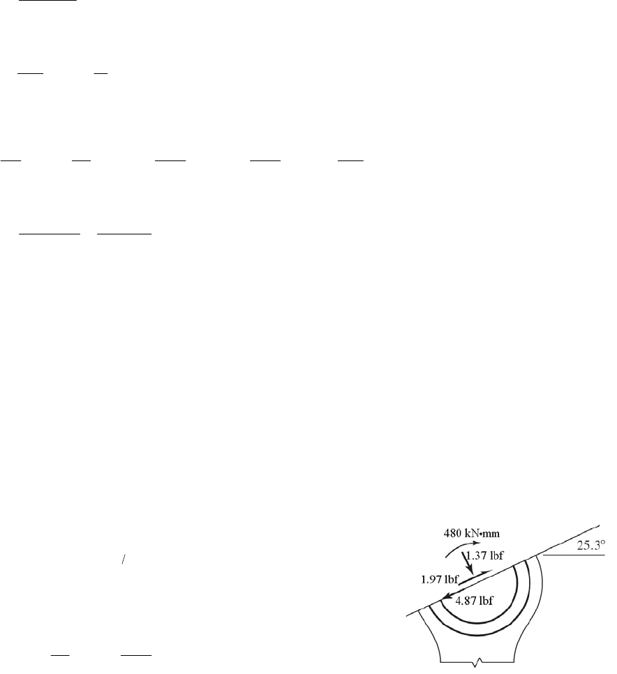
/
n
A
rdA r
For a rectangular area with constant width b, the denominator is
ln
o
i
ro
ri
r
bdr b
rr
Applying this equation over each of the four rectangular areas,
45 54.5 92 112
9 ln 31 ln 31 ln 9 ln 16.3769
25 45 82.5 92
dA
r
2
2 20(9) 31(9.5) 949 mmA
949 57.9475 mm
16.3769
/
n
A
rdA r
68.5 57.9475 10.5525 mm
cn
er r
57.9475 25 32.9475 mm
ini
crr
112 57.9475 54.0525 mm
oon
crr
M = 150F2 = 150(3.2) = 480 kN·mm
We need to find the forces transmitted through the section in order to determine the axial
stress. It is not immediately obvious which plane should be used for resolving the axial
versus shear directions. It is convenient to use the plane containing the reaction force at
the bushing, which assumes its contribution resolves entirely into shear force. To find the
angle of this plane, find the resultant of F1 and F2.
12
12
12
22
2.4cos60 3.2 cos 0 4.40 kN
2.4sin 60 3.2sin 0 2.08 kN
4.40 2.08 4.87 kN
xxx
yyy
FF F
FFF
F
This is the pin force on the lever which acts in a direction
11
2.08
tan tan 25.3
4.40
y
x
F
F
On the surface 25.3° from the horizontal, find the internal forces in the tangential and
normal directions. Resolving F1 into components,
2.4cos 60 25.3 1.97 kN
2.4sin 60 25.3 1.37 kN
t
n
F
F
The transverse shear stress is zero at the inner and outer surfaces. Using Eq. (3-65) for
the bending stress, and combining with the axial stress due to Fn,
Chapter 3 - Rev. A, Page 93/100
3200 150 (32.9475)
1370 64.6 MPa .
949 949(10.5525)(25)
3200 150 (54.0525)
1370 21.7 MPa .
949 949(10.5525)(112)
ni
i
i
no
o
o
FMc
A
ns
AAer
FMc
A
ns
AAer
______________________________________________________________________________
3-130 ri = 2 in, ro = ri + h = 2 + 4 = 6 in, 2 0.5(4) 4 in
c
r
2
(6 2 0.75)(0.75) 2.4375 inA
Similar to Prob. 3-129,
3.625 6
0.75ln 0.75ln 0.682 920 in
2 4.375
dA
r
2.4375 3.56923 in
0.682 920
(/)
n
A
rdA r
4 3.56923 0.43077 in
cn
er r
3.56923 2 1.56923 in
ini
crr
6 3.56923 2.43077 in
oon
crr
6000(4) 24 000 lbf in
c
MFr
Using Eq. (3-65) for the bending stress, and combining with the axial stress,
6000 24 000(1.56923) 20 396 psi 20.4 kpsi .
2.4375 2.4375(0.43077)(2)
6000 24 000(2.43077) 6 799 psi 6.80 kpsi .
2.4375 2.4375(0.43077)(6)
i
i
i
o
o
o
Mc
F
A
ns
AAer
Mc
F
A
ns
AAer
______________________________________________________________________________
3-131 ri = 12 in, ro = ri + h = 12 + 3 = 15 in, rc = 12 + 3/2 = 13.5 in
33
(1.5 )(0.75) 1.988 in
44
(1.5)(0.75) 3.534
Iab
Aab
4
20(3 1.5) 90 kip inM
Since the radius is large compared to the cross section, assume Eq. 3-67 is applicable for
the bending stress. Combining the bending stress and the axial stress,
20 90(1.5)(13.5) 82.1 kpsi .
3.534 (1.988)(12)
ic
i
i
Mc r
F
A
ns
AIr
20 90(1.5)(13.5) 55.5 kpsi .
3.534 1.988(15)
oc
o
o
Mc r
F
A
ns
AIr
______________________________________________________________________________
Chapter 3 - Rev. A, Page 94/100
3-132 ri = 1.25 in, ro = ri + h = 1.25 + 0.5 + 1 + 0.5 = 3.25 in
r
c = (ri + ro) / 2 = (1.25 + 3.25)/2 = 2.25 in Ans.
For outer rectangle, ln o
i
r
dA b
rr
For circle,
2
2
O
22
OO
,
2cc
Ar
A
r
dA r rrr
22
O
2( )
cc
dA rrr
r
Combine the integrals subtracting the circle from the rectangle
22
3.25
1.25ln 2 2.25 2.25 0.5 0.840 904 in
1.25
dA
r
22
1.25(2) (0.5 ) 1.714 60 in .AA
ns
1.71460 2.0390 in .
0.840904
(/)
n
A
rA
dA r
ns
2.25 2.0390 0.2110 in .
cn
er r Ans
2.0390 1.25 0.7890 in
ini
crr
3.25 2.0390 1.2110 in
oon
crr
2000(4.5 1.25 0.5 0.5) 13 500 lbf inM
2000 13 500(0.7890) 20 720 psi = 20.7 kpsi .
1.7146 1.7146(0.2110)(1.25)
i
i
i
Mc
F
A
ns
AAer
2000 13 500(1.2110) 12 738 psi 12.7 kpsi .
1.7146 1.7146(0.2110)(3.25)
o
o
o
Mc
F
A
ns
AAer
______________________________________________________________________________
3-133 From Eq. (3-68),
13
2
13 13 21
3
821
E
aKF F d
Use 0.292,
F in newtons, E in N/mm2 and d in mm, then
1/3
2
3 [(1 0.292 ) / 207 000] 0.03685
81/30
K
From Eq. (3-69),
1/3 1/3
1/3
max 21/322 2
333 3 352 MPa
2 2 ( ) 2 2 (0.03685)
FFF F
pF
aKF K
Chapter 3 - Rev. A, Page 95/100
From Eq. (3-71), the maximum principal stress occurs on the surface where z = 0, and is
equal to – pmax.
1/3
max max 352 MPa .
z
p
FA
ns
From Fig. 3-37,
1/3
max max
0.3 106 MPa .
p
FA
ns
______________________________________________________________________________
3-134 From Eq. (3-68),
22
11 22
3
12
22
3
11
3
811
1 0.292 207 000 1 0.333 71 700
310 0.0990 mm
8125140
EE
F
add
a
From Eq. (3-69),
max 22
310
3487.2 MPa
22 0.0990
F
pa
From Fig. 3-37, the maximum shear stress occurs at a depth of z = 0.48 a.
0.48 0.48 0.0990 0.0475 mm .
z
aA ns
The principal stresses are obtained from Eqs. (3-70) and (3-71) at a depth of z/a = 0.48.
1
12 2
1
487.2 1 0.48 tan 1/ 0.48 1 0.333 101.3 MPa
2 1 0.48
32
487.2 396.0 MPa
10.48
From Eq. (3-72),
13
max
101.3 396.0 147.4 MPa .
22 Ans
Note that if a closer examination of the applicability of the depth assumption from Fig. 3-
37 is desired, implementing Eqs. (3-70), (3-71), and (3-72) on a spreadsheet will allow
for calculating and plotting the stresses versus the depth for specific values of . For =
0.333 for aluminum, the maximum shear stress occurs at a depth of z = 0.492a with
max
= 0.3025 pmax.
Chapter 3 - Rev. A, Page 96/100
This gives
max = 0.3025 pmax = (0.3025)(487.2) = 147.38 MPa. Even though the depth
assumption was a little off, it did not have significant effect on the the maximum shear
stress.
______________________________________________________________________________
3-135 From the solution to Prob. 3-134, a = 0.0990 mm and pmax = 487.2 MPa. Assuming
applicability of Fig. 3-37, the maximum shear stress occurs at a depth of z = 0.48 a =
0.0475 mm. Ans.
The principal stresses are obtained from Eqs. (3-70) and (3-71) at a depth of z/a = 0.48.
1
12 2
1
487.2 1 0.48 tan 1/ 0.48 1 0.292 92.09 MPa
2 1 0.48
32
487.2 396.0 MPa
10.48
From Eq. (3-72),
13
max
92.09 396.0 152.0 MPa .
22 Ans
Note that if a closer examination of the applicability of the depth assumption from Fig. 3-
37 is desired, implementing Eqs. (3-70), (3-71), and (3-72) on a spreadsheet will allow
for calculating and plotting the stresses versus the depth for specific values of . For =
0.292 for steel, the maximum shear stress occurs at a depth of z = 0.478a with
max =
0.3119 pmax.
______________________________________________________________________________
3-136 From Eq. (3-68),
2
3
12
2
3
21
3
81 1
2 1 0.292 207 000
320 0.1258 mm
81301
E
F
add
a
From Eq. (3-69),
max 22
320
3603.4 MPa
22 0.1258
F
pa
From Fig. 3-37, the maximum shear stress occurs at a depth of
0.48 0.48 0.1258 0.0604 mm .
z
aA ns
Also from Fig. 3-37, the maximum shear stress is
max max
0.3 0.3(603.4) 181 MPa .
p
Ans
Chapter 3 - Rev. A, Page 97/100
_____________ ____________________________________ _____________________________
-137 Aluminum Plate-Ball interface: From Eq. (3-68), 3
3
12
26 2 6
31/3
3
81
1
1 0.292 30 10 1 0.333 10.4 10
33.517 10 in
8111
add
F
aF
rom Eq. (3-69),
22
11 22
11
3EE
F
F
41/3
max 2
231/3
3F
p 3
3.860 10 psi
22 3.517 10
FF
aF
By examination of Eqs. (3-70), (3-71), and (3-72), it can be seen that the only difference
in the maximum shear stress for the plate and the ball will be due to poisson’s ratio in Eq.
(3-70). The larger poisson’s ratio will create the greater maximum shear stress, so the
aluminum plate will be the critical element in this interface. Applying the equations for
the aluminum plate,
41/3 1 1/3
12
1
3.86 10 1 0.48 tan 1/ 0.48 1 0.333 8025 psi
2 1 0.48
FF
41/3
41/3
32
3.86 10 3.137 10 psi
10.48
FF
From Eq. (3-72),
1/3 4 1/3
41/3
13
max
8025 3.137 10
1.167 10 psi
22
FF
F
omparing this stress to the allowable stress, and solving for F,
C
3
20 000
45.03 lbf
1.167 10
F
able-Ball interface: From Eq. (3-68),
T
26 2 6
31/3
3
1 0.292 30 10 1 0.211 14.5 10
33.306 10 in
8111
F
aF
From Eq. (3-69),
Chapter 3 - Rev. A, Page 98/100
41/3
max 2
231/3
33
4.369 10 psi
22 3.306 10
FF
pF
aF
The steel ball has a higher poisson’s ratio than the cast iron table, so it will dominate.
41/3 1 1/3
12
1
4.369 10 1 0.48 tan 1/ 0.48 1 0.292 8258 psi
2 1 0.48
FF
41/3
41/3
32
4.369 10 3.551 10 psi
10.48
FF
From Eq. (3-72),
1/3 4 1/ 3
41/3
13
max
8258 3.551 10
1.363 10 psi
22
FF
F
Comparing this stress to the allowable stress, and solving for F,
3
4
20 000 3.16 lbf
1.363 10
F
The steel ball is critical, with F = 3.16 lbf. Ans.
______________________________________________________________________________
3-138 v1 = 0.333, E1 = 10.4 Mpsi, l = 2 in, d1 = 1.25 in, v2 = 0.211, E2 = 14.5 Mpsi, d2 = –12
in.
With b = KcF1/2
12
26 26
4
1 0.333 10.4 10 1 0.211 14.5 10
2
(2) 1/1.25 1/12
2.336 10
c
K
By examination of Eqs. (3-75), (3-76), and (3-77, it can be seen that the only difference
in the maximum shear stress for the two materials will be due to poisson’s ratio in Eq. (3-
75). The larger poisson’s ratio will create the greater maximum shear stress, so the
aluminum roller will be the critical element in this interface. Instead of applying these
equations, we will assume the poisson’s ratio for aluminum of 0.333 is close enough to
0.3 to make Fig. 3-39 applicable.
max max
max
0.3
4000 13 300 psi
p
p0.3
From Eq. (3-74), pmax = 2F / (bl ), so we have
Chapter 3 - Rev. A, Page 99/100
12
max 12
22
cc
FF
plK F lK
So,
2
max
2
4
2
(2)(2.336) 10 (13 300)
2
95.3 lbf .
c
lK p
F
Ans
______________________________________________________________________________
3-139
v = 0.292, E = 30 Mpsi, l = 0.75 in, d1 = 2(0.47) = 0.94 in, d2 = 2(0.62) = 1.24 in.
Eq. (3-73):
12
26
3
2 1 0.292 30 10
2(40) 1.052 10 in
(0.75) 1/ 0.94 1/ 1.24
b
Eq. (3-74):
max 3
240
232 275 psi 32.3 kpsi .
1.052 10 0.75
F
p
Ans
bl
From Fig. 3-39,
max max
0.3 0.3(32 275)=9682.5 psi 9.68 kpsi .
p
Ans
______________________________________________________________________________
3-140 Use Eqs. (3-73) through (3-77).
1/ 2
22
11 22
12
(1 ) / (1 ) /2
(1 / ) (1 / )
EvEF
bldd
1/2
26 26
2(600) (1 0.292 ) / (30(10 )) (1 0.292 ) / (30(10 ))
(2) 1/ 5 1/
0.007 631 inb
max
2 2(600) 25 028 psi
(0.007 631)(2)
F
pbl
Chapter 3 - Rev. A, Page 100/100
2
2
max 2
2 1 2 0.292 25 028 1 0.786
7102 psi 7.10 kpsi .
x
zz
pbb
Ans
0.786
2
max22
2
225 028 2 0.786
1 0.786
1
4 646 psi 4.65 kpsi .
y
z
b
pb
z
b
Ans
2
2
12 1 2 0.786
z
max
22
25 028 19 677 psi 19.7 kpsi .
1 0.786
z
pAns
z
2
1b
max
4 646 19 677 7 516 psi 7.52 kpsi .
yz Ans
22
______________________________________________________________________________
3-141 Use Eqs. (3-73) through (3-77).
12
22
11 22
12
11
2
1/ 1/
EE
F
ldd
b
12
23
0.211 100 10
/
23
1 0.292 207 10 1
2(2000)
(40) 1/150 1
0.2583 mmb
max
2 2(2000) 123.2 MPa
(0.2583)(40)
F
pbl
2
2
max 2
2 1 2 0.292 123.2 1 0.786
35.0 MPa .
x
zz
pbb
Ans
0.786
2
2
12
0.786
z
2
max 22
2
1 2 0.786
2 123.2 2
1 0.786
1
22.9 MPa .
y
z
b
pb
z
b
Ans
max
22
123.2 96.9 MPa .
1 0.786
z
pAns
z
2
1b
Chapter 3 - Rev. A, Page 101/100
Chapter 3 - Rev. A, Page 102/100
max
22.9 96.9 37.0 MPa .
22
yz Ans
______________________________________________________________________________
3-142 Note to the Instructor: The first printing incorrectly had a width w = 1.25 mm instead of
w = 1.25 in. The solution presented here reflects the correction which will be made in
subsequent printings.
Use Eqs. (3-73) through (3-77).
12
22
11 22
12
11
2
1/ 1/
EE
F
ldd
b
12
26
0.211 14.5 10
26
1 0.211 14.5 10 1
2(250)
(1.25) 1 / 3 1 /
0.007 095 inb
max
2 2(250) 17 946 psi
(0.007 095)(1.25)
F
pbl
2
2
max 2
2 1 2 0.211 17 946 1 0.786 0.
3 680 psi 3.68 kpsi .
x
zz
pbb
Ans
786
2
max22
2
12 0.786
2 17 946 2 0.786
1 0.786
1
3 332 psi 3.33 kpsi .
y
z
b
pb
z
b
Ans
2
2
12
z
max
22
17 946 14109 psi 14.1 kpsi .
z
pAns
2
10.786
1z
b
max
3 332 14 109 5 389 psi 5.39 kpsi .
22
yz Ans
______________________________________________________________________________
Chapter 4
4-1 For a torsion bar, kT = T/
= Fl/
, and so
= Fl/kT. For a cantilever, kl = F/
,
= F/kl. For
the assembly, k = F/y, or, y = F/k = l
+
Thus
2
Tl
FFl F
ykk k
Solving for k
22
1.
1
lT
lT
Tl
kk
kA
lkl k
kk
ns
______________________________________________________________________________
4-2 For a torsion bar, kT = T/
= Fl/
, and so
= Fl/kT. For each cantilever, kl = F/
l,
l =
F/kl, and,
L = F/kL. For the assembly, k = F/y, or, y = F/k = l
+
l +
L.
Thus
2
Tl
FFl FF
ykk kk
L
Solving for k
22
1.
11
LlT
lL TL Tl
TlL
kkk
kA
lkkl k k k k
kkk
ns
______________________________________________________________________________
4-3 (a) For a torsion bar, k =T/
=GJ/l.
Two springs in parallel, with J =
di 4/32,
and d1 = d1 = d,
44
12 12
4
32
11 .(1)
32
JG JG d d
kG
x
lx x lx
Gd Ans
xlx
Deflection equation,
2
1
2
1
results in (2)
Tl x
Tx
JG JG
Tl x
Tx
From statics, T1 + T2 = T = 1500. Substitute Eq. (2)
Chapter 4 - Rev B, Page 1/81
22 2
1500 1500 . (3)
lx x
TT T Ans
xl
Substitute into Eq. (2) resulting in 11500 . (4)
lx
TAn
ls
(b) From Eq. (1),
46 3
11
0.5 11.5 10 28.2 10 lbf in/rad .
32 5 10 5
kA
ns
From Eq. (4),
1
10 5
1500 750 lbf in .
10
T Ans
From Eq. (3),
2
5
1500 750 lbf in .
10
T Ans
From either section,
3
33
16 1500
16 30.6 10 psi 30.6 kpsi .
0.5
i
i
TAns
d
______________________________________________________________________________
4-4 Deflection to be the same as Prob. 4-3 where T1 = 750 lbfin, l1 = l / 2 = 5 in, and d1 = 0.5
in
1 =
2 =
12 3
12
44
44 4 12
12
4 6 750 5 4660 10 (1)
0.5
32 32 32
TT TT
dd
dG dG G
Or,
34
11
15 10 (2)Td
34
22
10 10 (3)Td
Equal stress, 12 12
12 33 33
12 12
16 16 (4)
TT TT
dd dd
Divide Eq. (4) by the first two equations of Eq.(1) results in
12
33
12
21
12
44
12
1.5 (5)
44
TT
dd dd
TT
dd
Statics, T1 + T2 = 1500 (6)
Substitute in Eqs. (2) and (3), with Eq. (5) gives
4
34 3
11
15 10 10 10 1.5 1500dd
Solving for d1 and substituting it back into Eq. (5) gives
d1 = 0.388 8 in, d2 = 0.583 2 in Ans.
Chapter 4 - Rev B, Page 2/81
From Eqs. (2) and (3),
T1 = 15(103)(0.388 8)4 = 343 lbfin Ans.
T2 = 10(103)(0.583 2)4 = 1 157 lbfin Ans.
Deflection of T is
11
146
1
343 4 0.053 18 rad
/ 32 0.388 8 11.5 10
Tl
JG
Spring constant is
3
1
1500 28.2 10 lbf in .
0.053 18
T
k Ans
The stress in d1 is
3
1
13
3
1
16 343
16 29.7 10 psi 29.7 kpsi .
0.388 8
TAns
d
The stress in d1 is
3
2
23
3
2
16 1 157
16 29.7 10 psi 29.7 kpsi .
0.583 2
TAns
d
______________________________________________________________________________
4-5 (a) Let the radii of the straight sections be r1 = d1 /2 and r2 = d2 /2. Let the angle of the
taper be
where tan
= (r2 r1)/2. Thus, the radius in the taper as a function of x is
r = r1 + x tan
, and the area is A =
(r1 + x tan
)2. The deflection of the tapered portion
is
2
1
00
10
11 1
21
12 12 12
12
1
tan tan
tan
11 1
tan tan tan tan
tan
tan tan
4.
l
ll
FF dx F
dx
AE E E r x
rx
FF
Er r l E r r
rrFFlFl
E rr E rr rrE
Fl Ans
ddE
2
1
(b) For section 1,
4
1226
1
4 4(1000)(2) 3.40(10 ) in .
(0.5 )(30)(10 )
Fl Fl
A
ns
AE d E
For the tapered section,
4
6
12
4 4 1000(2) 2.26(10 ) in .
(0.5)(0.75)(30)(10 )
Fl
A
ns
ddE
For section 2,
Chapter 4 - Rev B, Page 3/81
4
2226
1
4 4(1000)(2) 1.51(10 ) in .
(0.75 )(30)(10 )
Fl Fl
A
ns
AE d E
______________________________________________________________________________
4-6 (a) Let the radii of the straight sections be r1 = d1 /2 and r2 = d2 /2. Let the angle of the
taper be
where tan
= (r2 r1)/2. Thus, the radius in the taper as a function of x is
r = r1 + x tan
, and the polar second area moment is J = (
/2) (r1 + x tan
)4. The
angular deflection of the tapered portion is
43
00
11
0
3
33
11
1
22
33 33 1122
21 21
33 33 33
12 2 1 12 12
2121
3
tan tan tan
21 1 2 11
3tan 3tan
tan tan
22 2
3tan 3 3
32
3
l
ll
TT dx T
dx
GJ G G
rx rx
TT
Gr G r r
rl
rrrr
rr rr
TTlTl
Grr Grrrr Grr
T
3
2
22
1122
33
12
.
dddd
lAns
Gdd
(
b) The deflections, in degrees, are
For section 1,
1446
1
180 32 180 32(1500)(2) 180 2.44 deg .
(0.5 )11.5(10 )
Tl Tl
A
ns
GJ d G
For the tapered section,
22
1122
33
12
22
633
()
32 180
3
(1500)(2) 0.5 (0.5)(0.75) 0.75
32 180 1.14 deg .
3 11.5(10 )(0.5 )(.75 )
Tl d d d d
Gd d
A
ns
For section 2,
2446
2
180 32 180 32(1500)(2) 180 0.481 deg .
(0.75 )11.5(10 )
Tl Tl
A
ns
GJ d G
______________________________________________________________________________
4-7 The area and the elastic modulus remain constant, however the force changes with respect
to x. From Table A-5 the unit weight of steel is
= 0.282 lbf/in3, and the elastic modulus is
E = 30 Mpsi. Starting from the top of the cable (i.e. x = 0, at the top).
F =
(A)(l
x)
Chapter 4 - Rev B, Page 4/81
2
2
2
6
0
0
0.282 500(12)
1
( ) 0.169 in
2 2 2(30)10
l
ll
co
Fdx l
lxdx lx x
AE E E E
w
From the weight at the bottom of the cable,
226
4(5000) 500(12)
45.093 in
(0.5 )30(10 )
W
Wl Wl
AE d E
0.169 5.093 5.262 in .
cW Ans
The percentage of total elongation due to the cable’s own weight
0.169 (100) 3.21% .
5.262
A
ns
______________________________________________________________________________
4-8 Fy = 0 = R 1 F R 1 = F
MA = 0 = M1 Fa M1 = Fa
VAB = F, MAB =F (x
a ), VBC = MBC = 0
Section AB:
2
1
1
2
AB
Fx
Fx adx ax C
EI EI
(1)
AB = 0 at x = 0 C1 = 0
23
2
26
AB
Fx Fx x
yaxdxa
EI EI
2
2
C
(2)
yAB = 0 at x = 0 C2 = 0
2
3.
6
AB
Fx
y
xa Ans
EI
Section BC:
3
100
BC dx C
E
I
From Eq. (1), at x = a (with C1 = 0),
22
()
2
Fa Fa
aa
EI EI
2
= C3. Thus,
2
2
BC
Fa
EI
22
4
22
BC
Fa Fa
y
dx x C
EI EI
(3)
Chapter 4 - Rev B, Page 5/81

From Eq. (2), at x = a (with C2 = 0),
32
Fa a 3
62 3
Fa
ya
EI EI
. Thus, from Eq. (3)
23
Fa Fa 3
44
23 6
Fa
aC C
EI EI EI
Substitute into Eq. (3)
232
3.
266
BC
Fa Fa Fa
y
xax
EI EI EI
Ans
maximum deflection occurs at x= l,
The
2
max 3.
Fa
6
y
al Ans
EI
MAB = R 1 x = Fx /2
:
= F /2, MBC = R 1 x F ( x l / 2) = F (l
x) /2
______________________________________________________________________________
4-9 MC = 0 = F (l /2) R1 l R1 = F /2
Fy= 0 = F /2 + R 2 F R 2 = F /2
Break at 0 x l /2:
VAB = R 1 = F /2,
Break
at l /2 x l
VBC = R 1 F = R 2
Section AB:
2
1
1
AB
Fx
24
F x
dx C
EI EI
From symmetry,
AB = 0 at x = l /2
2
2
11
20
41
l
FFl
CC
EI EI
6
. Thus,
22
22
Fx Fl F
x
4
416 16
AB l
EI EI EI
(1)
3
4x
22 2
2
4
16 16 3
AB
FF
yxldx lxC
EI EI
Chapter 4 - Rev B, Page 6/81
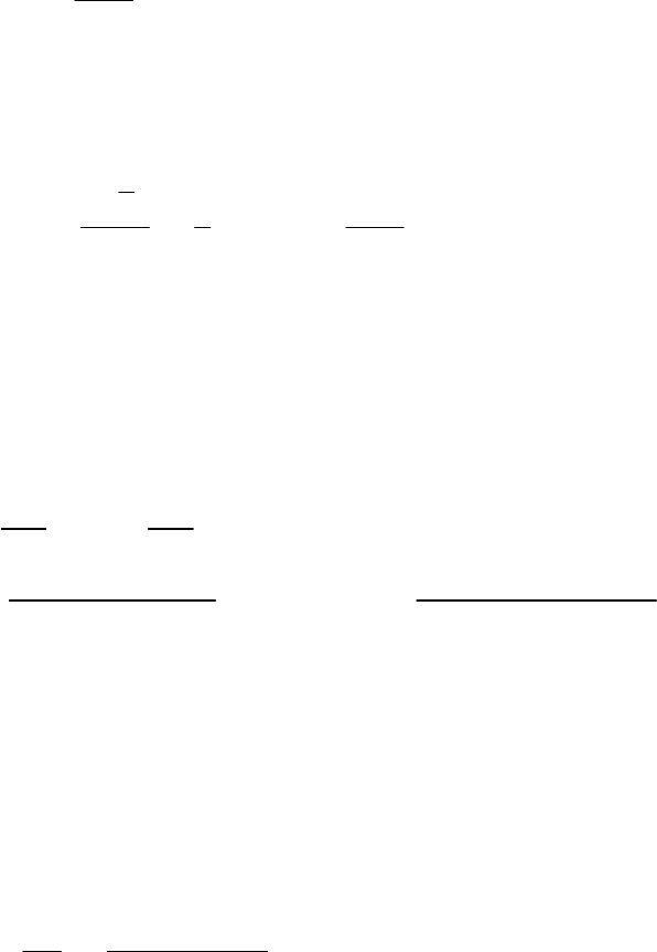
at x = 0 C2 = 0, and, yAB = 0
22
43
48
AB
Fx
yxl
E
I
(2)
is not given, because with symmetry, Eq. (2) can be used in this region. The
maximum deflection occurs at x =l /2,
yBC
2
2
l
Fl3
2
max 43 .
48 2 48
Fl
y
lAns
EI EI
4-10 From Table A-6, for each angle, I = 207 cm4. Thus, I = 2(207) (104) = 4.14(106) mm4
From Table A-9, use beam 2 with F = 2500 N, a = 2000 mm, and l = 3000 mm; and beam
______________________________________________________________________________
1-1
3 with w = 1 N/mm and l = 3000 mm.
24
max (3)
Fa l
yal
w
68EI EI
24
36 3
2500(2000) (1)(3000)
2000 3(3000)
6(207)10 (4.14)10 8(207)(10 )(4.14)(10 )
25.4 mm .Ans
6
)
= 2500(2000) [1(30002)/2] = 9.5(106) Nmm
rom Table A-6, from id to upper surface is y = 29 mm. From centroid to bottom
is compressive at the bottom of
the beam at the wall. This stress is
2
(/2
O
MFal w
F centro
surface is y = 29.0 100= 71 mm. The maximum stress
6
max 6
9.5(10 )( 71) 163 MPa .
4.14(10 )
My Ans
I
______________________________________________________________________________
Chapter 4 - Rev B, Page 7/81
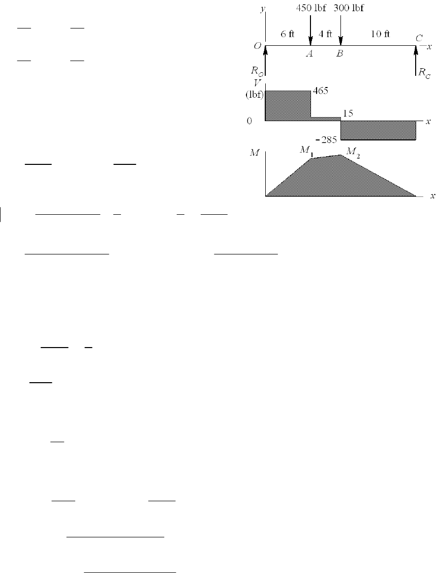
4-11
14 10
(450) (300) 465 lbf
20 20
610
(450) (300) 285 lbf
20 20
O
C
R
R
M
1 = 465(6)12 = 33.48(103) lbfin
M
2 = 33.48(103) +15(4)12
= 34.20(103) lbfin
3
max
max
34.2
15 2.28 in
MZ
Z
Z
For deflections, use beams 5 and 6 of Table A-9
23
2
12
10ft
3
22 2
66
44
[(/2)] 2
62 248
450(72)(120) 300(240 )
0.5 120 72 240
6(30)(10 ) (240) 48(30)(10 )
12.60 in / 2 6.30 in
x
Fal l Fl
ll
yal
EIl EI
I
I
I
I
Select two 5 in-6.7 lbf/ft channels from Table A-7, I = 2(7.49) = 14.98 in4, Z =2(3.00) =
6.00 in3
midspan
max
12.60 1 0.421 in
14.98 2
34.2 5.70 kpsi
6.00
y
______________________________________________________________________________
4-12 44
(1.5 ) 0.2485 in
64
I
From Table A-9 by superposition of beams 6 and 7, at x = a = 15 in, with b = 24 in and
l = 39 in
222 233
[](2
624
Fba a
yabl laa)l
E
Il EI
w
222
6
233
6
340(24)15 15 24 39
6(30)10 (0.2485)39
(150 /12)(15) 2(39)(15 ) 15 39 0.0978 in .
24(30)10 (0.2485)
A
y
Ans
At x = l /2 = 19.5 in
Chapter 4 - Rev B, Page 8/81
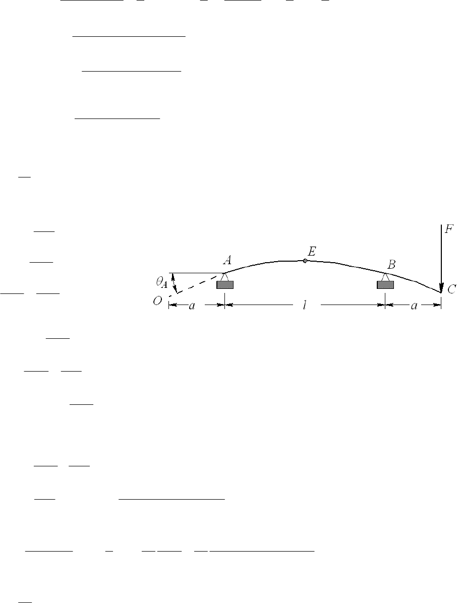
22
23
[(/2)] (/2)
22
62 22422
Fa l l l l l l l
yall
EIl EI
w3
l
22 2
6
233
6
340(15)(19.5) 19.5 15 39
6(30)(10 )(0.2485)(39)
(150 /12)(19.5) 2(39)(19.5 ) 19.5 39 0.1027 in .
24(30)(10 )(0.2485)
y
Ans
0.1027 0.0978
% difference (100) 5.01% .
0.0978
A
ns
______________________________________________________________________________
4-13
33
1(6)(32 ) 16.384 10 mm
12
I 4
From Table A-9-10, beam 10
2
()
3
C
Fa
y
la
EI
22
6
AB
Fax
ylx
E
Il
22
(3
6
AB
dy Fa lx
dx EIl
)
At x = 0, AB A
dy
dx
2
66
A
Fal Fal
EIl EI
2
6
OA
Fa l
ya
EI
With both loads,
22
()
63
O
Fa l Fa
y
la
EI EI
22
33
400(300 )
(3 2 ) 3(500) 2(300) 3.72 mm .
6 6(207)10 (16.384)10
Fa la Ans
EI
At midspan,
222
2
33
2 ( / 2) 3 3 400(300)(500 ) 1.11 mm .
6 2 24 24 207 10 16.384 10
E
Fa l l Fal
yl
EIl EI
Ans
_____________________________________________________________________________
4-14 44
(2 1.5 ) 0.5369 in
64
I4
Chapter 4 - Rev B, Page 9/81
From Table A-5, E = 10.4 Mpsi
From Table A-9, beams 1 and 2, by superposition
32
32
66
200 4(12) 300 2(12)
( 3 ) 2(12) 3(4)(12)
3 6 3(10.4)10 (0.5369) 6(10.4)10 (0.5369)
BA
B
Fl Fa
yal
EI EI
1.94 in .
B
y
Ans
______________________________________________________________________________
4-15 From Table A-7, I = 2(1.85) = 3.70 in4
From Table A-5, E = 30.0 Mpsi
From Table A-9, beams 1 and 3, by superposition
4
4
33
66
5 2(5 /12) (60 )
() 150(60 ) 0.182 in .
3 8 3(30)10 (3.70) 8(30)10 (3.70)
c
A
l
Fl
y
Ans
EI EI
ww
______________________________________________________________________________
4-16 4
64
I
d
From Table A-5,
3
207(10 ) MPaE
From Table A-9, beams 5 and 9, with FC = FA = F, by superposition
3
22 3 22
1
(4 3 ) 2 (4 3 )
48 24 48
B
B B
B
Fl Fa
y
al I FlFaal
EI EI Ey
32
3
34
1550(1000 ) 2 375 (250) 4(250 ) 3(1000 )
48(207)10 2
53.624 10 mm
I2
3
44
64 64 (53.624)10 32.3 mm .dI A
ns
______________________________________________________________________________
4-17 From Table A-9, beams 8 (region BC for this beam with a = 0) and 10 (with a = a), by
superposition
322 22
322 22
32
66
132
6
A
AB
A
MFax
yxlxlxlx
EIl EIl
.
M
xlxlxFaxlx An
EIl
s
322 2
()
32 () [()(3
66
A
BC
xl
M
dFxl
y x lx lx xl xl axl
dx EIl EI
)]
2
()
() [() (3)
66
A
Ml Fx l ]
x
lxlaxl
E
IEI
Chapter 4 - Rev B, Page 10/81
2
() ()(3)
6A
xl .
M
lFxl axl Ans
E
I
______________________________________________________________________________
4-18 Note to the instructor: Beams with discontinuous loading are better solved using
singularity functions. This eliminates matching the slopes and displacements at the
discontinuity as is done in this solution.
11
02
22
C
aa
.
M
Rl a l a R l a Ans
l
w
w
2
22
02
22
y
aa
FlaRaR
ll
ww
w.
Ans
2
122 .VR
22
AB
ala laxa Ans
ll
ww
wx = wx =
2
2.
2
BC
a
VR A
l
wns
2
2
1
2
22
AB AB
x
M
Vdx lax ax C
l
w
2
1
0at 0 0 2 .
2
AB AB
M
xC M alalxA
l
wx ns
22
2
22
BC BC
aa
M
Vdx dx xC
ll
ww
22
2
0 at ( ) .
22
BC BC
aa
M
xl C M lx Ans
l
ww
2222
3
222 3
3
323 4
34
4
111
2
222
111
223
11 1 1
23 6 12
0at 0 0
AB
AB
AB AB
AB
Mx
dx al a lx dx alx a x lx C
EI EI l EI l
y dx alx a x lx C dx
EI l
alx a x lx C x C
EI l
yxC
3
1
3
ww
w
w
22
2
5
23
24 3 2
353
111
()
222
at
111 11 (1)
223 22 6
BC
BC
AB BC
Maa
dx l x dx lx x C
EI EI l EI l
xa
aa
ala a la C la a C C C
EI l EI l
ww
www
5
Chapter 4 - Rev B, Page 11/81
22
223
55
22
65
2
233
5
11 111
22 226
0at 6
1111
()
22 6 3
BC BC
BC
BC
aa
ydx lxxCdx lxxCx
EI l EI l
al
yxlC Cl
a
ylxxlCxl
EI l
ww
w
w
6
C
2
35 4 233
35
2
23
35
at
111 111 ()
23 6 12 2 2 6 3
34 () (2)
24
AB BC
yyxa
a
ala a la C a la a l C a l
ll
a
Ca la l C a l
l
ww
w
Substituting (1) into (2) yields
2
22
54
24
a
Ca
l
w
l. Substituting this back into (2) gives
2
22
344
24
a
Cala
l
wl. Thus,
32343 4 22
42 4 4
24
AB
y alx a x lx a lx a x a l x
E
Il
w
2
232
2(2 ) 2
24
AB
x
yaxlalxala.Ans
E
Il
w
22 23 4 22 4
62 4
24
BC
y alx ax ax alx al Ans.
E
Il
w
This result is sufficient for yBC. However, this can be shown to be equivalent to
323422 3 4
4
42 4 4 (
24 24
( ) .
24
BC
BC AB
y alx a x lx a l x a lx a x x a
EIl EI
yy xa Ans
EI
ww
w
4
)
by expanding this or by solving the problem using singularity functions.
______________________________________________________________________________
4-19 The beam can be broken up into a uniform load w downward from points A to C and a
uniform load upward from points A to B.
22
232 232
22
22 2 2
2(2 ) 2 2(2 ) 2
24 24
2 (2 ) 2 2 (2 ) 2 .
24
AB
xx
ybxlblxblb axlalxal
EIl EIl
xbx l b b l b ax l a a l a Ans
EIl
ww
w
a
2
342
323422 3 4 4
2(2 ) 2
24
42 4 4 ()
BC
ybxlblxbxlb
EIl
alx ax lx alx alxax lxa Ans
w
.
Chapter 4 - Rev B, Page 12/81
323422 3 4 4
323422 3 4 4
44
42 4 4 ()
24
42 4 4 ()
24
()() .
24
CD
AB
y blx b x lx b l x b lx b x l x b
EIl
alx ax lx alx alxaxlxa
EIl
xb xa y Ans
EI
w
w
w
______________________________________________________________________________
4-20 Note to the instructor: See the note in the solution for Problem 4-18.
2
02
22
yB B
aa
FR aR laA
ll
ww
w.
ns
For
region BC, isolate right-hand element of length (l + a
x)
2
,.
2
AB A BC
a
VR V lax An
l
wws
22
,.
22
AB A BC
a
M
Rx x M l a x Ans
l
ww
2
2
1
4
AB AB
a
EI M dx x C
l
w
2
3
12
12
AB
a
EIy x C x C
l
w
yAB = 0 at x = 0 C2 = 0
2
3
1
12
AB
a
EIy x C x
l
w
y
AB = 0 at x = l
2
112
al
Cw
222 2
322 2
.
12 12 12 12
AB AB
aalax ax
EIy x x l x y l x Ans
ll EIl
www w 2
3
3
6
BC BC
E
IMdxlax
wC
4
34
24
BC
E
Iy l a x C x C
w
y
BC = 0 at x = l
44
34 4
0
24 24
aa
Cl C C Cl
ww
3
(1)
AB =
BC at x = l
22 3 2
33
412 6 6
al al a
CC l
ww wa w a
Substitute C3 into Eq. (1) gives
2
2
44
24
a
Calla
w. Substitute back into yBC
242
4
424
1
24 6 24 6
4.
24
BC
l
ylaxxla
EI
lax alxla a Ans
EI
wwawawa
w
la
Chapter 4 - Rev B, Page 13/81
4-21 Table A-9, beam 7,
12
100(10) 500 lbf
22
l
RR
w
233 23 3
6
623
100
2 2(10) 10
24 24 30 10 0.05
2.7778 10 20 1000
AB
xx
ylxxl xx
EI
xxx
w
Slope:
233
64
24
AB
AB
dy lx x l
dx EI
w
At x = l,
3
233
64
24 24
AB xl
l
ll l l
EI EI
ww
3
3
3
6
100 10 10 2.7778 10 10
24 24(30)10 (0.05)
BC AB xl
l
yxlxl x x
EI
w
From Prob. 4-20,
2
2100 4 100 4
80 lbf 2 2(10) 4 480 lbf
2 2(10) 2 2(10)
AB
aa
RRla
ll
ww
2
2
22 22 6 2
6
100 4 10 8.8889 10 100
12 12 30 10 0.05
AB
x
ax
ylx x x
EIl
w
x
424
424
6
4
6
4
24
100 10 4 4 4 10 10 4 4
24 30 10 0.05
2.7778 10 14 896 9216
BC
ylaxalxlaa
EI
xx
xx
w
Superposition,
500 80 420 lbf 500 480 980 lbf .
AB
R
RA ns
623 6 2
2.7778 10 20 1000 8.8889 10 100 .
AB
y
xxx x x Ans
4
36
2.7778 10 10 2.7778 10 14 896 9216 .
BC
yx xx
Ans
The deflection equations can be simplified further. However, they are sufficient for
plotting.
Using a spreadsheet,
x 0 0.5 1 1.5 2 2.5 3 3.5
y 0.000000 -0.000939 -0.001845 -0.002690 -0.003449 -0.004102 -0.004632 -0.005027
x 4 4.5 5 5.5 6 6.5 7 7.5
y -0.005280 -0.005387 -0.005347 -0.005167 -0.004853 -0.004421 -0.003885 -0.003268
Chapter 4 - Rev B, Page 14/81
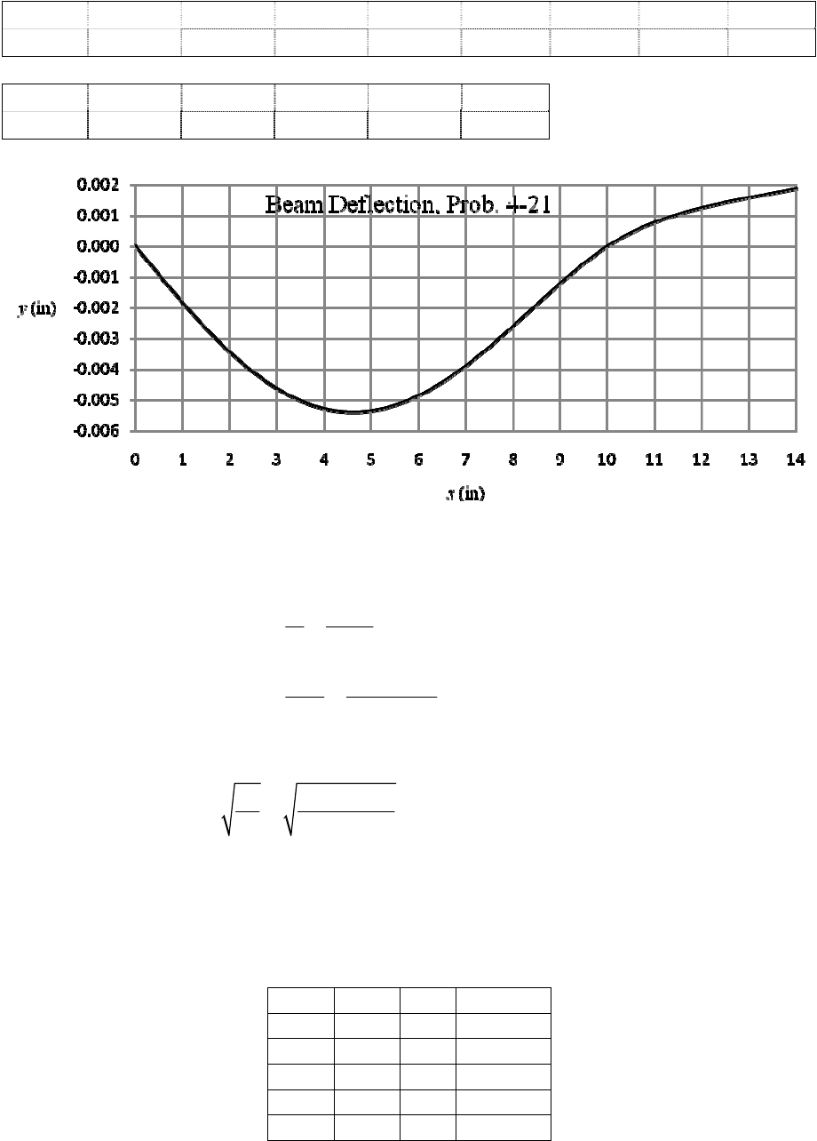
x 8 8.5 9 9.5 10 10.5 11 11.5
y -0.002596 -0.001897 -0.001205 -0.000559 0.000000 0.000439 0.000775 0.001036
x 12 12.5 13 13.5 14
y 0.001244 0.001419 0.001575 0.001722 0.001867
______________________________________________________________________________
4-22 (a) Useful relations
3
3
3
4
6
48
1800 36 0.05832 in
48 48(30)10
FEI
kyl
kl
IE
From I = bh 3/12, and b = 10 h, then I = 5 h 4/6, or,
44
6 6(0.05832) 0.514 in
55
I
h
h is close to 1/2 in and 9/16 in, while b is close to 5.14 in. Changing the height drastically
changes the spring rate, so changing the base will make finding a close solution easier.
Trial and error was applied to find the combination of values from Table A-17 that
yielded the closet desired spring rate.
h (in) b (in) b/h k (lbf/in)
1/2 5 10 1608
1/2 5½ 11 1768
1/2 5¾ 11.5 1849
9/16 5 8.89 2289
9/16 4 7.11 1831
Chapter 4 - Rev B, Page 15/81
h = ½ in, b = 5 ½ in should be selected because it results in a close spring rate and b/h is
still reasonably close to 10.
(
b)
34
5.5(0.5) /12 0.05729 inI
3
3
3
6
( / 4) 4 4(60)10 (0.05729)
1528 lbf
36 (0.25)
(1528) 36 0.864 in .
48 48(30)10 (0.05729)
Mc Fl c I
F
II lc
Fl
yA
EI
ns
______________________________________________________________________________
4-23 From the solutions to Prob. 3-68, 12
60 lbf and 400 lbfTT
44
4
1198 in
(1.25) 0.
64 64
d
I
From Table A-9, beam 6,
222 2 22
11 2 2
12
10in
222
6
22 2
6
()( )
66
( 575)(30)(10) 10 30 40
6(30)10 (0.1198)(40)
460(12)(10) 10 12 40 0.0332 in .
6(30)10 (0.1198)(40)
A
x
Fbx Fb x
zxblxbl
EIl EIl
Ans
222 2 22
11 2 2
12
10in 10in
222 2 22
11 2 2
12
10in
222
6
()( )
66
(3 ) (3 )
66
(575)(30) 310 30 40
6(30)10 (0.1198)(40)
460(12)
6(30
Ayxx
x
Fbx Fb xdz d xbl xb l
dx dx EIl EIl
Fb Fb
xbl xb l
EIl EIl
222
6
4
310 12 40
)10 (0.1198)(40)
6.02(10 ) rad .Ans
______________________________________________________________________________
4-24 From the solutions to Prob. 3-69, 12
2880 N and 432 NTT
44
34
(30) 39.76 10 mm
64 64
d
I
Chapter 4 - Rev B, Page 16/81
The load in between the supports supplies an angle to the overhanging end of the beam.
That angle is found by taking the derivative of the deflection from that load. From Table
A-9, beams 6 (subscript 1) and 10 (subscript 2),
2
b
eam10
beam6
ABC A
C
yay
(1)
11 22 22 2
11
11
22
11
1
263
66
6
BC C2
x
l
xl
Fa l x Fadx a lx lx x a l
dx EIl EIl
Fa la
EIl
Equation (1) is thus
2
22
11 2 2
12 2
2
22
33 33
()
63
3312(230) 2070(300 )
510 230 300 510 300
6(207)10 (39.76)10 (510) 3(207)10 (39.76)10
7.99 mm .
A
Fa Fa
ylaala
EIl EI
Ans
The slope at A, relative to the z axis is
2
2
22 2
11 2
12
22 2
11 2
122
22 2
11 2
122
2
33
()
() ()(3)
66
3( ) 3 ( ) (3 )
66
() 32
66
3312(230) 510 2
6(207)10 (39.76)10 (510)
Az
x
la
x
la
Fa F x l
d
la xl axl
EIl dx EI
Fa F
l a xl axl a xl
EIl EI
Fa F
la a la
EIl EI
2
2
33
30
2070 3(300 ) 2(510)(300)
6(207)10 (39.76)10
0.0304 rad .Ans
______________________________________________________________________________
4-25 From the solutions to Prob. 3-70, 12
392.16 lbf and 58.82 lbfTT
44
4
(1) 0.049 09 in
64 64
d
I
From Table A-9, beam 6,
Chapter 4 - Rev B, Page 17/81
222 2 2 2
11
16
8in
( 350)(14)(8) 8 14 22 0.0452 in .
6 6(30)10 (0.049 09)(22)
A
x
Fbx
y
xbl Ans
EIl
222 22 2
22
26
8in
( 450.98)(6)(8)
( ) 8 6 22 0.0428 in .
6 6(30)10 (0.049 09)(22)
A
x
Fbx
zxbl
EIl
Ans
The displacement magnitude is
22 2 2
0.0452 0.0428 0.0622 in .
AA
yz Ans
1
1
222 222
11 11
11
222
6
(3 )
66
( 350)(14) 3 8 14 22 0.00242 rad .
6(30)10 (0.04909)(22)
Azxa
xa
Fbx Fb
dy d
1
x
bl abl
dx dx EIl EIl
A
ns
1
1
222 222
22 22
21
22 2
6
() 3
66
(450.98)(6) 3 8 6 22 0.00356 rad .
6(30)10 (0.04909)(22)
Ayxa
xa
Fbx Fb
dz d
2
x
bl abl
dx dx EIl EIl
Ans
The slope magnitude is
2
2
0.00242 0.00356 0.00430 rad .
A
A
ns
______________________________________________________________________________
4-26 From the solutions to Prob. 3-71, 12
250 N and 37.5 NTT
44
4
(20) 7 854 mm
64 64
d
I
o
11 222 2 2 2
13
300mm
345sin 45 (550)(300)
( ) 300 550 850
6 6(207)10 (7 854)(850)
1.60 mm .
y
A
x
Fbx
yxbl
EIl
Ans
222 2 22
11 22
12
300mm
()( )
66
z
A
x
Fbx Fbx
zxblxbl
EIl EIl
o
222
3
222
3
345cos 45 (550)(300) 300 550 850
6(207)10 (7 854)(850)
287.5(150)(300) 300 150 850 0.650 mm .
6(207)10 (7 854)(850) Ans
The displacement magnitude is
2
22 2
1.60 0.650 1.73 mm .
AA
yz Ans
Chapter 4 - Rev B, Page 18/81
11
11 11
222 222
11
o
222
3
(3 )
66
345sin 45 (550) 3 300 550 850 0.00243 rad .
6(207)10 (7 854)(850)
yy
Az
xa xa
Fbx Fb
dy d xbl abl
dx dx EIl EIl
Ans
1
1
1
222 2 22
11 22
12
222 222
11 22
11 12
o
222
3
3
66
33
66
345cos 45 (550) 3 300 550 850
6(207)10 (7 854)(850)
287.5(150)
6(207)10 (7 85
z
Ayxa
xa
z
Fbx Fbx
dz d xbl xb l
dx dx EIl EIl
Fb Fb
abl abl
EIl EIl
222 4
3 300 150 850 1.91 10 rad .
4)(850) Ans
The slope magnitude is 22
0.00243 0.000191 0.00244 rad .
A
A
ns
______________________________________________________________________________
4-27 From the solutions to Prob. 3-72, 750 lbf
B
F
44
4
(1.25) 0.1198 in
64 64
d
I
From Table A-9, beams 6 (subscript 1) and 10 (subscript 2)
11 2 2
222 22
1
16in
oo
222 22
66
66
300cos 20 (14)(16) 750sin 20 (9)(16)
16 14 30 30 16
6(30)10 (0.119 8)(30) 6(30)10 (0.119 8)(30)
0.0805 in .
yy
A
x
Fbx Fax
yxbllx
EIl EIl
Ans
222 22
11 2 2
1
16in
oo
222 22
66
66
300sin 20 (14)(16) 750 cos 20 (9)(16)
16 14 30 30 16
6(30)10 (0.119 8)(30) 6(30)10 (0.119 8)(30)
0.1169 in .
zz
A
x
Fbx Fax
zxbllx
EIl EIl
Ans
The displacement magnitude is
2
22 2
0.0805 0.1169 0.142 in .
AA
yz Ans
Chapter 4 - Rev B, Page 19/81
11
11 2 2
222 22
1
11 2 2
222 2 2
11 1
o
222
6
o
6
66
33
66
300cos 20 (14) 316 14 30
6(30)10 (0.119 8)(30)
750sin 20 (9) 3
6(30)10 (0.119 8)(30)
yy
Az
xa xa
yy
Fbx Fax
dy d xbl lx
dx dx EIl EIl
Fb Fa
abl l a
EIl EIl
22 5
0 3 16 8.06 10 rad .Ans
1
1
222 22
11 2 2
1
222 2 2
11 2 2
11 1
oo
222
66
66
33
66
300sin 20 (14) 750cos 20 (9)
316 14 30 3
6(30)10 (0.119 8)(30) 6(30)10 (0.119 8)(30)
zz
Ayxa
xa
zz
Fbx Faxdz d xbl lx
dx dx EIl EIl
Fb Fa
abl l a
EIl EIl
22
0316
0.00115 rad .Ans
The slope magnitude is
2
52
8.06 10 0.00115 0.00115 rad .
AAns
______________________________________________________________________________
4-28 From the solutions to Prob. 3-73, FB = 22.8 (103) N
4
4
34
50 306.8 10 mm
64 64
d
I
From Table A-9, beam 6,
11 2 2
222 2 22
12
400mm
3o
22 2
33
3o
22
33
()()
66
11 10 sin 20 (650)(400)
400 650 1050
6(207)10 (306.8)10 (1050)
22.8 10 sin 25 (300)(400)
400 300 1050
6(207)10 (306.8)10 (1050)
3.735
yy
A
x
Fbx Fbx
yxblxbl
EIl EIl
mm .
2
A
ns
Chapter 4 - Rev B, Page 20/81
222 2 22
11 2 2
12
400mm
3o
22 2
33
3o
22 2
33
()( )
66
11 10 cos 20 (650)(400)
400 650 1050
6(207)10 (306.8)10 (1050)
22.8 10 cos 25 (300)(400)
400 300 1050 1.791
6(207)10 (306.8)10 (1050)
zz
A
x
Fbx Fbx
zxblxbl
EIl EIl
mm .
A
ns
The displacement magnitude is
2
22 2
3.735 1.791 4.14 mm .
AA
yz Ans
1
1
222 2 22
11 2 2
12
11 2 2
222 222
11 1 2
3o
222
33
3o
66
33
66
11 10 sin 20 (650)
3 400 650 1050
6(207)10 (306.8)10 (1050)
22.8 10 sin 25
zz
Az
x
a
xa
yy
Fbx Fbx
dy d xbl xb l
dx dx EIl EIl
Fb Fb
abl abl
EIl EIl
222
33
(300)
3 400 300 1050
6(207)10 (306.8)10 (1050)
0.00507 rad .Ans
1
1
222 2 22
11 2 2
12
222 222
11 2 2
11 12
3o
222
33
3
66
33
66
11 10 cos 20 (650)
3 400 650 1050
6(207)10 (306.8)10 (1050)
22.8 10 co
zz
Ay
x
a
xa
zz
Fbx Fbxdz d xbl xb l
dx dx EIl EIl
Fb Fb
abl abl
EIl EIl
o
222
33
s 25 (300)
3 400 300 1050
6(207)10 (306.8)10 (1050)
0.00489 rad .Ans
The slope magnitude is
22
0.00507 0.00489 0.00704 rad .
A
A
ns
______________________________________________________________________________
4-29 From the solutions to Prob. 3-68, T1 = 60 lbf and T2 = 400 lbf , and Prob. 4-23, I = 0.119 8
in4. From Table A-9, beam 6,
Chapter 4 - Rev B, Page 21/81
222 222
11 2 2
12
0
0
22 22 2 2
11 2 2
12 6
22
6
66
575(30) 30 40
6 6 6(30)10 (0.119 8)(40)
460(12) 12 40 0.00468 rad
6(30)10 (0.119 8)(40)
zz
Oyx
x
zz
Fbx Fbx
dz d xbl xbl
dx dx EIl EIl
Fb Fb
bl bl
EIl EIl
.Ans
11 2 2
22 22
12
222 222
11 2 2
12
22 22
11 2 2
12
22
22
66
623 623
66
66
575(10) 40 10
6(3
zz
Cy
xl
x
l
zz
xl
zz
Falx Falx
dz d x a lx x a lx
dx dx EIl EIl
Fa Fa
lx l x a lx l x a
EIl EIl
Fa Fa
la la
EIl EIl
22
66
460(28) 40 28 0.00219 rad .
0)10 (0.119 8)(40) 6(30)10 (0.119 8)(40) Ans
______________________________________________________________________________
4-30 From the solutions to Prob. 3-69, T1 = 2 880 N and T2 = 432 N, and Prob. 4-24, I = 39.76
(103) mm4. From Table A-9, beams 6 and 10
222 22
11 2 2
1
0
0
222 2 2 22
11 2 2 11 2 2
11
0
22
33
()()
66
(3 ) ( 3 ) ( )
666
3 312(280) 2 070(300)
280 510
6(207)10 (39.76)10 (510)
Ozx
x
x
Fbx Fa x
dy d xbl lx
dx dx EIl EIl
Fb Fa Fb Fa l
xbl l x bl
EIl EIl EIl EI
6
33
(510)
6(207)10 (39.76)10
0.0131 rad .Ans
22 22
11 2 2
1
222 22 22
11 22 11 22
11
2
33
()
(2)()
66
(6 2 3 ) ( 3 ) ( )
666
3 312(230) (510 230
6(207)10 (39.76)10 (510)
Czxl
xl
xl
Fa l x Fa x
dy d xa lx lx
dx dx EIl EIl
3
F
aFaFa
lx l x a l x l a Fal
E
Il EIl EIl EI
2
33
2 070(300)(510)
)3(207)10 (39.76)10
0.0191 rad .Ans
______________________________________________________________________________
4-31 From the solutions to Prob. 3-70, T1 = 392.19 lbf and T2 = 58.82 lbf , and Prob. 4-25, I =
0.0490 9 in4. From Table A-9, beam 6
Chapter 4 - Rev B, Page 22/81
11 11
222 22
11
00
22
6
()
66
350(14) 14 22 0.00726 rad .
6(30)10 (0.04909)(22)
yy
Oz
xx
Fbx Fb
dy d
x
bl bl
dx dx EIl EIl
Ans
222 22
22 22
22
0
0
22
6
66
450.98(6) 622
6(30)10 (0.04909)(22)
0.00624 rad .
zz
Oyx
x
Fbx Fbdz d
x
bl bl
dx dx EIl EIl
Ans
The slope magnitude is
2
2
0.00726 0.00624 0.00957 rad .
O
A
ns
11 22
1
11 11
222 22
11
22
6
() 2
6
623 ( )
66
350(8) 22 8 0.00605 rad .
6(30)10 (0.0491)(22)
y
Cz
xl xl
yy
xl
Fal x
dy d xa lx
dx dx EIl
Fa Fa
lx l x a l a
EIl EIl
Ans
22
22
2
222 22
22 22
22
22
6
() 2
6
623
66
450.98(16) 22 16 0.00846 rad .
6(30)10 (0.0490 9)(22)
z
Cyxl
xl
zz
xl
Fal x
dz d xa lx
dx dx EIl
Fa Fa
lx l x a l a
EIl EIl
A
ns
The slope magnitude is
22
0.00605 0.00846 0.0104 rad .
C
A
ns
______________________________________________________________________________
4-32 From the solutions to Prob. 3-71, T1 =250 N and T1 =37.5 N, and Prob. 4-26, I = 7 854
mm4. From Table A-9, beam 6
11 11
222 22
11
00
o
22
3
()
66
345sin 45 (550) 550 850 0.00680 rad .
6(207)10 (7 854)(850)
yy
Oz
xx
Fbx Fb
dy d
x
bl bl
dx dx EIl EIl
Ans
Chapter 4 - Rev B, Page 23/81
222 222
11 2 2
12
0
0
o
22 22 2 2
11 2 2
12 3
22
3
66
345cos 45 (550) 550 850
6 6 6(207)10 (7 854)(850)
287.5(150) 150 850
6(207)10 (7 854)(850)
zz
Oyx
x
zz
Fbx Fbxdz d xbl xbl
dx dx EIl EIl
Fb Fb
bl bl
EIl EIl
0.00316 rad .Ans
The slope magnitude is 22
0.00680 0.00316 0.00750 rad .
O
A
ns
11 11
22 2 22
11
o
11 22 2 2
13
() 2623
66
345sin 45 (300)
( ) 850 300 0.00558 rad .
6 6(207)10 (7 854)(850)
yy
Cz
xl
x
l
xl
y
Fal x Fa
dy d x a lx lx l x a
dx dx EIl EIl
Fa la Ans
EIl
22 22
11 2 2
12
o
22 22 2 2
11 2 2
12
3
3
() ()
22
66
345cos 45 (300) 850 300
6 6 6(207)10 (7 854)(850)
287.5(700)
6(207)10 (7 854)(850
zz
Cy
x
l
xl
zz
Falx Falxdz d xa lx xa lx
dx dx EIl EIl
Fa Fa
la la
EIl EIl
22 5
850 700 6.04 10 rad .
)Ans
The slope magnitude is
2
25
0.00558 6.04 10 0.00558 rad .
CAns
________________________________________________________________________
4-33 From the solutions to Prob. 3-72, FB = 750 lbf, and Prob. 4-27, I = 0.119 8 in4. From
Table A-9, beams 6 and 10
11 2 2
222 22
1
00
11 2 2 11 2 2
222 2 2 22
11
0
o
22
6
66
33
6666
300cos 20 (14) 750 sin 2
14 30
6(30)10 (0.119 8)(30)
yy
Oz
xx
yyyy
x
Fbx Fax
dy d xbl lx
dx dx EIl EIl
Fb Fa Fb Fal
xbl l x bl
EIl EIl EIl EI
o
6
0 (9)(30) 0.00751 rad .
6(30)10 (0.119 8) Ans
Chapter 4 - Rev B, Page 24/81
222 22
11 2 2
1
0
0
222 2 2 22
11 2 2 11 2 2
11
0
o
22
6
66
33
66 66
300sin 20 (14) 750 cos
14 30
6(30)10 (0.119 8)(30)
zz
Oyx
x
zz zz
x
Fbx Fax
dz d xbl lx
dx dx EIl EIl
Fb Fa Fb Fal
xbl l x bl
EIl EIl EIl EI
o
6
20 (9)(30) 0.0104 rad .
6(30)10 (0.119 8) Ans
The slope magnitude is 22
0.00751 0.0104 0.0128 rad .
O
A
ns
11 2 2
22 22
1
11 22 11 22
222 22 22
11
o
2
6
() 2
66
623 3 ( )
666
300cos 20 (16) 30
6(30)10 (0.119 8)(30)
yy
Cz
xl xl
yyy
xl
Fal x Fax
dy d xa lx lx
dx dx EIl EIl
Fa Fa Fa Fal
lx l x a l x l a
EIl EIl EIl EI
3
y
o
2
6
750sin 20 (9)(30)
16 0.0109 rad .
3(30)10 (0.119 8) Ans
22 22
11 2 2
1
222 22 22
11 2 2 11 2 2
11
o
2
6
() 2
66
623 3
666
300sin 20 (16) 30 1
6(30)10 (0.119 8)(30)
zz
Cyxl
xl
zzz
xl
Fal x Fax
dz d xa lx lx
dx dx EIl EIl
Fa Fa Fa Fal
lx l x a l x l a
EIl EIl EIl EI
3
z
o
2
6
750cos 20 (9)(30)
6 0.0193 rad .
3(30)10 (0.119 8) Ans
The slope magnitude is
22
0.0109 0.0193 0.0222 rad .
C
A
ns
______________________________________________________________________________
4-34 From the solutions to Prob. 3-73, FB = 22.8 kN, and Prob. 4-28, I = 306.8 (103) mm4.
From Table A-9, beam 6
11 2 2
222 222
12
00
3o
11 2 2
22 22 2 2
12 33
3o
3
66
11 10 sin 20 (650)
650 1050
6 6 6(207)10 (306.8)10 (1050)
22.8 10 sin 25 (300)
6(207)10 (
yy
Oz
xx
yy
Fbx Fbx
dy d xbl xbl
dx dx EIl EIl
Fb Fb
bl bl
EIl EIl
22
3300 1050 0.0115 rad .
306.8)10 (1050) Ans
Chapter 4 - Rev B, Page 25/81
222 222
11 2 2
12
0
0
22 22
11 2 2
12
3o
22
33
3o
3
66
66
11 10 cos 20 (650)
650 1050
6(207)10 (306.8)10 (1050)
22.8 10 cos 25 (300)
6(207)10
zz
Oyx
x
zz
Fbx Fbx
dz d xbl xbl
dx dx EIl EIl
Fb Fb
bl bl
EIl EIl
22
3300 1050 0.00427 rad .
(306.8)10 (1050)
A
ns
The slope magnitude is
22
0.0115 0.00427 0.0123 rad .
O
A
ns
11 2 2
22 22
12
11 2 2
222 222
12
3o
11 2 2
22 22
12
() ()
22
66
(623 ) 623
66
11 10 sin 20 (4
66
yy
Cz
xl
x
l
yy
xl
yy
Falx Falx
dy d xa lx xa lx
dx dx EIl EIl
Fa Fa
lx l x a lx l x a
EIl EIl
Fa Fa
la la
EIl EIl
22
33
3o
22
33
00)
1050 400
6(207)10 (306.8)10 (1050)
22.8 10 sin 25 (750)
1050 750 0.0133 rad .
6(207)10 (306.8)10 (1050) Ans
22 22
11 2 2
12
222 222
11 2 2
12
3o
22 22
11 2 2
12
() ()
22
66
623 623
66
11 10 cos 20 (40
66
zz
Cy
x
l
xl
zz
xl
zz
Falx Falxdz d xa lx xa lx
dx dx EIl EIl
Fa Fa
lx l x a lx l x a
EIl EIl
Fa Fa
la la
EIl EIl
22
33
3o
22
33
0)
1050 400
6(207)10 (306.8)10 (1050)
22.8 10 cos 25 (750)
1050 750 0.0112 rad .
6(207)10 (306.8)10 (1050) Ans
The slope magnitude is 22
0.0133 0.0112 0.0174 rad .
C
A
ns
______________________________________________________________________________
4-35 The required new slope in radians is
new = 0.06(
/180) = 0.00105 rad.
In Prob. 4-29, I = 0.119 8 in4, and it was found that the greater angle occurs at the bearing
at O where (
O)y = 0.00468 rad.
Since
is inversely proportional to I,
Chapter 4 - Rev B, Page 26/81
new Inew =
old Iold Inew =
/64 =
4
new
d old Iold /
new
or,
1/4
old
new old
new
64
dI
The absolute sign is used as the old slope may be negative.
1/ 4
new
64 0.00468 0.119 8 1.82 in .
0.00105
dA
ns
______________________________________________________________________________
4-36 The required new slope in radians is
new = 0.06(
/180) = 0.00105 rad.
In Prob. 4-30, I = 39.76 (103) mm4, and it was found that the greater angle occurs at the
bearing at C where (
C)y = 0.0191 rad.
See the solution to Prob. 4-35 for the development of the equation
1/4
old
new old
new
64
dI
1/ 4
3
new
64 0.0191 39.76 10 62.0 mm .
0.00105
dA
ns
______________________________________________________________________________
4-37 The required new slope in radians is
new = 0.06(
/180) = 0.00105 rad.
In Prob. 4-31, I = 0.0491 in4, and the maximum slope is
C = 0.0104 rad.
See the solution to Prob. 4-35 for the development of the equation
1/4
old
new old
new
64
dI
1/4
new
64 0.0104 0.0491 1.77 in .
0.00105
dA
ns
______________________________________________________________________________
4-38 The required new slope in radians is
new = 0.06(
/180) = 0.00105 rad.
In Prob. 4-32, I = 7 854 mm4, and the maximum slope is
O = 0.00750 rad.
See the solution to Prob. 4-35 for the development of the equation
Chapter 4 - Rev B, Page 27/81
1/4
old
new old
new
64
dI
1/4
new
64 0.00750 7 854 32.7 mm .
0.00105
dA
ns
______________________________________________________________________________
4-39 The required new slope in radians is
new = 0.06(
/180) = 0.00105 rad.
In Prob. 4-33, I = 0.119 8 in4, and the maximum slope
= 0.0222 rad.
See the solution to Prob. 4-35 for the development of the equation
1/4
old
new old
new
64
dI
1/ 4
new
64 0.0222 0.119 8 2.68 in .
0.00105
dA
ns
______________________________________________________________________________
4-40 The required new slope in radians is
new = 0.06(
/180) = 0.00105 rad.
In Prob. 4-34, I = 306.8 (103) mm4, and the maximum slope is
C = 0.0174 rad.
See the solution to Prob. 4-35 for the development of the equation
1/4
old
new old
new
64
dI
1/4
3
new
64 0.0174 306.8 10 100.9 mm .
0.00105
dA
ns
______________________________________________________________________________
4-41 IAB =
14/64 = 0.04909 in4, JAB = 2 IAB = 0.09818 in4, IBC = (0.25)(1.5)3/12 = 0.07031 in4,
ICD =
(3/4)4/64 = 0.01553 in4. For Eq. (3-41), p. 102, b/c = 1.5/0.25 = 6
= 0.299.
The deflection can be broken down into several parts
1. The vertical deflection of B due to force and moment acting on B (y1).
2. The vertical deflection due to the slope at B,
B1, due to the force and moment acting on
B (y2 = CD
B1 = 2
B1).
Chapter 4 - Rev B, Page 28/81
3. The vertical deflection due to the rotation at B,
B2, due to the torsion acting at B (y3 =
B
C
B1 = 5
B1).
4. The vertical deflection of C due to the force acting on C (y4).
5. The rotation at C,
C, due to the torsion acting at C (y3 = CD
C = 2
C).
6. The vertical deflection of D due to the force acting on D (y5).
1. From Table A-9, beams 1 and 4 with F = 200 lbf and MB = 2(200) = 400 lbfin
32
166
200 6 400 6 0.01467 in
3 30 10 0.04909 2 30 10 0.04909
y
2. From Table A-9, beams 1 and 4
22
1
6
336
626
6
2 200 6 2 400 0.004074 rad
2 2 30 10 0.04909
BB
B
xl
xl
B
Mx Mx
dFx Fx
xl xl
dx EI EI EI EI
lFl M
EI
y 2 = 2(0.004072) = 0.00815 in
3. The torsion at B is TB = 5(200) = 1000 lbfin. From Eq. (4-5)
26
1000 6 0.005314 rad
0.09818 11.5 10
B
AB
TL
JG
y 3 = 5(0.005314) = 0.02657 in
4. For bending of BC, from Table A-9, beam 1
3
46
200 5 0.00395 in
3 30 10 0.07031
y
5. For twist of BC, from Eq. (3-41), p. 102, with T = 2(200) = 400 lbfin
36
400 5 0.02482 rad
0.299 1.5 0.25 11.5 10
C
y 5 = 2(0.02482) = 0.04964 in
6. For bending of CD, from Table A-9, beam 1
3
66
200 2 0.00114 in
3 30 10 0.01553
y
Chapter 4 - Rev B, Page 29/81

Summing the deflections results in
6
1
0.01467 0.00815 0.02657 0.00395 0.04964 0.00114 0.1041 in .
Di
i
yy A
ns
This problem is solved more easily using Castigliano’s theorem. See Prob. 4-71.
______________________________________________________________________________
4-42 The deflection of D in the x direction due to Fz is from:
1. The deflection due to the slope at B,
B1, due to the force and moment acting on B (x1 =
B
C
B1 = 5
B1).
2. The deflection due to the moment acting on C (x2).
1. For AB, IAB =
14/64 = 0.04909 in4. From Table A-9, beams 1 and 4
22
1
6
336
626
6
2 100 6 2 200 0.002037 rad
2 2 30 10 0.04909
BB
B
xl
xl
B
Mx Mx
dFx Fx
xl xl
dx EI EI EI EI
lFl M
EI
x 1 = 5( 0.002037) = 0.01019 in
2. For BC, IBC = (1.5)(0.25)3/12 = 0.001953 in4. From Table A-9, beam 4
2
26
2 100 5 0.04267 in
2 2 30 10 0.001953
C
Ml
xEI
The deflection of D in the x direction due to Fx is from:
3. The elongation of AB due to the tension. For AB, the area is A =
12/4 = 0.7854 in2
5
36
150 6 3.82 10 in
0.7854 30 10
AB
Fl
xAE
4. The deflection due to the slope at B,
B2, due to the moment acting on B (x1 = BC
B2 =
5
B2). With IAB = 0.04907 in4,
26
5 150 6 0.003056 rad
30 10 0.04909
B
B
Ml
EI
Chapter 4 - Rev B, Page 30/81

x4 = 5( 0.003056) = 0.01528 in
5. The deflection at C due to the bending force acting on C. With IBC = 0.001953 in4
3
3
56
150 5 0.10667 in
3 3 30 10 0.001953
BC
Fl
xEI
6. The elongation of CD due to the tension. For CD, the area is A =
(0.752)/4 = 0.4418
in2
5
66
150 2 2.26 10 in
0.4418 30 10
CD
Fl
xAE
Summing the deflections results in
6
5
1
5
0.01019 0.04267 3.82 10
0.01528 0.10667 2.26 10 0.1749 in .
Di
i
xx
A
ns
______________________________________________________________________________
4-43 JOA = JBC =
(1.54)/32 = 0.4970 in4, JAB =
(14)/32 = 0.09817 in4, IAB =
(14)/64 =
0.04909 in4, and ICD =
(0.754)/64 = 0.01553 in4.
6
250(12) 2 9 2 0.0260 rad .
11.5(10 ) 0.4970 0.09817 0.4970
OA BC
AB
OA AB BC OA AB BC
ll
l
Tl Tl Tl T
GJ GJ GJ G J J J
Ans
Simplified
6
250(12)(13)
11.5 10 0.09817
0.0345 rad .
s
s
Tl
GJ
Ans
Simplified is 0.0345/0.0260 = 1.33 times greater Ans.
33
33
66
250 13 250 12
0.0345(12)
3 3 3(30)10 0.04909 3(30)10 0.01553
0.847 in .
yOC yCD
DsCD
AB CD
D
Fl Fl
yl
EI EI
yAns
______________________________________________________________________________
4-44 Reverse the deflection equation of beam 7 of Table A-9. Using units in lbf, inches
Chapter 4 - Rev B, Page 31/81
3
233 23
6
10 6 2 3
3000 /12
2 2 25 25 12
24 24 30 10 485
7.159 10 27 10 600 .
x
x
ylxxl xx
EI
xxxAns
w
The maximum height occurs at x = 25(12)/2 = 150 in
10 6 2 3
max 7.159 10 150 27 10 600 150 150 1.812 in .
y
Ans
______________________________________________________________________________
4-45 From Table A-9-6,
222
6
L
Fbx
yxbl
E
Il
32 2
6
L
Fb
yxbxlx
E
Il
222
3
6
L
dy Fb
x
bl
dx EIl
22
06
L
x
Fb b l
dy
dx EIl
Let
0
L
x
dy
dx and set
4
64
L
d
I. Thus,
1/ 4
22
32 .
3
L
Fb b l
dA
El
ns
For the other end view, observe beam 6 of Table A-9 from the back of the page, noting
that a and b interchange as do x and –x
1/4
22
32 .
3
R
Fa l a
dA
El
ns
For a uniform diameter shaft the necessary diameter is the larger of and .
LR
dd
______________________________________________________________________________
4-46 The maximum slope will occur at the left bearing. Incorporating a design factor into the
solution for of Prob. 4-45,
L
d
Chapter 4 - Rev B, Page 32/81
1/ 4
22
22
4
3
32
3
32(1.28)(3000)(200) 300 200
3 (207)10 (300)(0.001)
38.1 mm .
nFb l b
dEl
d
dAns
4
34
38.1 103.4 10 mm
64
I
From Table A-9, beam 6, the maximum deflection will occur in BC where dyBC /dx = 0
22 2 2 2
2036 2
6
Fa l x
dxa lx x lxa l
dx EIl
0
2222
3 6 300 100 2 300 0 600 63333 0xx xx
2
1600 600 4(1)63 333 463.3, 136.7 mm
2
x
x = 136.7 mm is acceptable.
22
max
136.7 mm
3
22
33
2
6
3 10 100 300 136.7 136.7 100 2 300 136.7 0.0678 mm .
6 207 10 103.4 10 300
x
Fa l x
yxalx
EIl
A
ns
______________________________________________________________________________
4-47 I =
(1.254)/64 = 0.1198 in4. From Table A-9, beam 6
22
22 222
11 22
12
2
22
6
1/2
2
22 2
6
()
(2) (
66
150(5)(20 8) 8 5 2(20)(8)
6(30)10 0.1198 (20)
250(10)(8) 810 20
6(30)10 0.1198 (20)
0.0120 in .
Fa l x Fb x
xa lx xb l
EIl EIl
Ans
)
______________________________________________________________________________
Chapter 4 - Rev B, Page 33/81
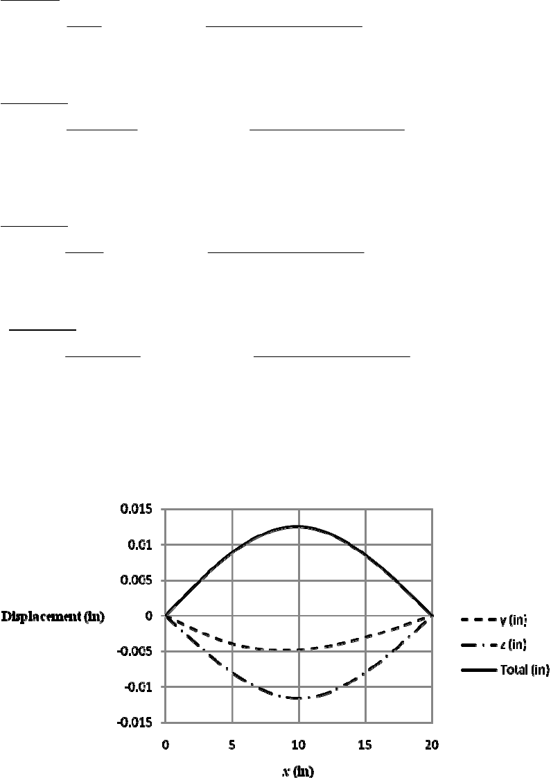
4-48 I =
(1.254)/64 = 0.1198 in4. For both forces use beam 6 of Table A-9.
For F1 = 150 lbf:
0 x 5
222 2 2 2
11
16
62
150 15 15 20
6 6 30 10 0.1198 20
5.217 10 175 (1)
x
Fbx
yxbl x
EIl
xx
5 x 20
11 22 22
16
62
150 5 20
25220
6 6 30 10 0.1198 20
1.739 10 20 40 25 (2)
Fa l x x
xa lx x x
EIl
xx x
y
For F2 = 250 lbf:
0 x 10
222 2 2 2
22
26
62
250 10 10 20
6 6 30 10 0.1198 20
5.797 10 300 (3)
x
Fbx
zxbl x
EIl
xx
10 x 20
22 22 2 2
26
62
250 10 20
210220
6 6 30 10 0.1198 20
5.797 10 20 40 100 (4)
Fa l x x
zxalx xx
EIl
xx x
Plot Eqs. (1) to (4) for each 0.1 in using a spreadsheet. There are 201 data points, too
numerous to tabulate here but the plot is shown below, where the maximum deflection of
= 0.01255 in occurs at x = 9.9 in. Ans.
______________________________________________________________________________
Chapter 4 - Rev B, Page 34/81
4-49 The larger slope will occur at the left end.
From Table A-9, beam 8
22 2
22 2
(362)
6
(3 3 6 2 )
6
B
AB
AB B
Mx
yxaall
EIl
dy M
x
aall
dx EIl
With I
=
d 4/64, the slope at the left bearing is
22
4
0
(3 6 2 )
6/64
AB B
A
x
dy M aall
dx Ed l
Solving for d
22 2
4
46
32 32(1000)
3 6 2 3(4 ) 6(4)(10) 2 10
3 3 (30)10 (0.002)(10)
0.461 in .
B
A
M
daall
El
Ans
2
______________________________________________________________________________
4-50 From Table A-5, E = 10.4 Mpsi
MO = 0 = 18 FBC 6(100) FBC = 33.33 lbf
The cross sectional area of rod BC is A =
(0.52)/4 = 0.1963 in2.
The deflection at point B will be equal to the elongation of the rod BC.
5
6
33.33(12) 6.79 10 in .
0.1963 30 10
B
BC
FL
y
Ans
AE
______________________________________________________________________________
4-51 MO = 0 = 6 FAC 11(100) FAC = 183.3 lbf
The deflection at point A in the negative y direction is equal to the elongation of the rod
AC. From Table A-5, Es = 30 Mpsi.
4
26
183.3 12 3.735 10 in
0.5 / 4 30 10
A
AC
FL
yAE
By similar triangles the deflection at B due to the elongation of the rod AC is
4
1
13 3( 3.735)10 0.00112 in
618
AB BA
yy yy
From Table A-5, Ea = 10.4 Mpsi
The bar can then be treated as a simply supported beam with an overhang AB. From Table
A-9, beam 10
Chapter 4 - Rev B, Page 35/81
2 2
2
2
22
2
63
()
()7 ()(3) (
36 3
7
73()3()(3)| () (23) ()
636
7 100 5
6(10.4)10 0.25(2 ) /
BC
B
xla xla
xla
dy Fa d F x l Fa
yBD la xlaxl l
dx EI dx EI EI
FFaFa
xl axl axl la l a la
EI EI EI EI
)
3
a
Fa
2
63
100 5
2(6) 3(5) (6 5)
12 3(10.4)10 0.25(2 ) / 12
0.01438 in
yB = yB1 + yB2 = 0.00112 0.01438 = 0.0155 in Ans.
______________________________________________________________________________
4-52 From Table A-5, E = 207 GPa, and G = 79.3 GPa.
22
33
44
3
2
44 4
3/32 /32 3 /64
32 2
3
OC AB AC AB
AB AB
BABAB
OC AC AB OC AC
OC AC
AB AB
OC AC AB
Fl l Fl l
Fl Fl
Tl Tl
yll
GJ GJ EI Gd Gd Ed
ll
Fl l
Gd Gd Ed
4
The spring rate is k = F/ yB. Thus
1
2
44 4
1
2
34 34 34
32 2
3
32 200 2 200
200 200
79.3 10 18 79.3 10 12 3 207 10 8
8.10 N/mm .
OC AC
AB AB
OC AC AB
ll
ll
kGd Gd Ed
Ans
_____________________________________________________________________________
4-53 For the beam deflection, use beam 5 of Table A-9.
12
12
12
23
12
1
23
21
112
2
, and
22
(4 3 )
48
1(4 3 ) .
22 48
AB
AB
F
RR
FF
kk
Fx
yxxl
lEI
kk x
y
Fxxl
kkkl EI
Ans
Chapter 4 - Rev B, Page 36/81
For BC, since Table A-9 does not have an equation (because of symmetry) an equation
will need to be developed as the problem is no longer symmetric. This can be done easily
using beam 6 of Table A-9 with a = l /2
2
2
21
112
22
21
112
/2 2
22 4
14 8 .
22 48
BC
Fl l x
Fk Fk
Fl
yxx
kkkl EIl
lx
kk
lx
F
xxllx
kkkl EI
Ans
______________________________________________________________________________
4-54
12
12
12
22
12
1
22
21
2
112
, and ( )
, and ( )
()
6
( ) .
6
AB
AB
Fa F
RRla
ll
Fa F la
lk lk
Fax
yxlx
lEIl
ax ax
y
Fkaklalx
kl kkl EIl
Ans
2
12
1
2
21
2
112
()
()(3)
6
()
( ) (3 ) .
6
BC
BC
Fx l
yxxlaxl
lEI
ax xl
yF kakla xlaxl An
kl kkl EI s
______________________________________________________________________________
4-55 Let the load be at x ≥ l/2. The maximum deflection will be in Section AB
(Table A-9, beam 6)
222
6
AB
Fbx
yxbl
E
Il
222 222
30 3
6
AB
dy Fb xbl xbl
dx EIl
0
22 2
max
, 0.577 .
33
lb l
x
xl
Ans
For x l/2, min 0.577 0.423 .
x
lllA ns
______________________________________________________________________________
Chapter 4 - Rev B, Page 37/81
4-56
6
1(3000)(1500) 2500(2000)
9.5 10 N·mm
1(3000) 2500 5 500 N
O
O
M
R
64
From Prob. 4-10, 4.14(10 ) mm I
21
6
9.5 10 5500 2500 - 2 000
2
x
Mx x
32
62
1
9.5 10 2750 1250 2000
6
dy x
EI x x x C
dx
1
0 at 0 0
dy xC
dx
32
62
43
62 3
2
9.5 10 2 750 1250 2000
6
4.75 10 916.67 416.67 2000
24
dy x
EI x x x
dx
x
EIy x x x C
y, and therefore
2
0 at 0 0x C
3
62 33 4 3
1114 10 22 10 10 10 2000
24
yxxxx
E
I
62 33
36
3
43
1114 10 3000 22 10 3000
24 207 10 4.14 10
3000 10 10 3000 2000
25.4 mm .
B
y
Ans
MO = 9.5 (106) Nm. The maximum stress is compressive at the bottom of the beam where
y = 29.0 100 = 71 mm
6
6
ma
x6
9.5 10 ( 71) 163 10 Pa 163MPa .
4.14(10 )
My Ans
I
The solutions are the same as Prob. 4-10.
______________________________________________________________________________
4-57 See Prob. 4-11 for reactions: RO = 465 lbf and RC = 285 lbf. Using lbf and inch units
Chapter 4 - Rev B, Page 38/81
M = 465 x 450 x 721 300 x 1201
22
2
1
232.5 225 72 150 120
dy
E
Ixx x
dx C
EIy = 77.5 x3 75 x 723 50 x 1203 C1x
y = 0 at x = 0 C2 = 0
y = 0 at x = 240 in
0 = 77.5(2403) 75(240 72)3 50(240 120)3 + C1 x C1 = 2.622(106) lbfin2
and,
EIy = 77.5 x3 75 x 723 50 x 1203 2.622(106) x
Substituting y = 0.5 in at x = 120 in gives
30(106) I ( 0.5) = 77.5 (1203) 75(120 72)3 50(120 120)3 2.622(106)(120)
I = 12.60 in4
Select two 5 in 6.7 lbf/ft channels; from Table A-7, I = 2(7.49) = 14.98 in4
midspan
12.60 1 0.421 in .
14.98 2
yA
ns
The maximum moment occurs at x = 120 in where Mmax = 34.2(103) lbfin
3
max
34.2(10 )(2.5) 5 710 psi
14.98
Mc
I
O.K.
The solutions are the same as Prob. 4-17.
______________________________________________________________________________
4-58 I =
(1.54)/64 = 0.2485 in4, and w = 150/12 = 12.5 lbf/in.
124
12.5 39 (340) 453.0 lbf
239
O
R
1
2
12.5
453.0 340 15
2
Mxxx
2
23
1
12.5
226.5 170 15
6
dy
E
Ixxx
dx C
3
34
12
75.5 0.5208 56.67 15
E
I
y
xxxCx C
2
0at 0 0yx C
Thus,
42
1
0 at 39 in 6.385(10 ) lbf inyx C
3
34 4
175.5 0.5208 56.67 15 6.385 10yxxx x
E
I
Evaluating at x = 15 in,
Chapter 4 - Rev B, Page 39/81
3
34 4
6
175.5 15 0.5208 15 56.67 15 15 6.385 10 (15)
30(10 )(0.2485)
0.0978 in .
A
y
Ans
3
34 4
midspan 6
175.5 19.5 0.5208 19.5 56.67 19.5 15 6.385 10 (19.5)
30(10 )(0.2485)
0.1027 in .
y
Ans
5 % difference Ans.
The solutions are the same as Prob. 4-12.
______________________________________________________________________________
4-59 I = 0.05 in4,
3 14 100 7 14 100
420 lbf and 980 lbf
10 10
AB
RR
M = 420 x 50 x2 + 980 x 10 1
2
23
1
210 16.667 490 10
dy
E
Ixxx
dx C
3
34
12
70 4.167 163.3 10
E
I
y
xx xCx C
y = 0 at x = 0 C2 = 0
y = 0 at x = 10 in C1 = 2 833 lbfin2. Thus,
3
34
6
3
73 4
170 4.167 163.3 10 2833
30 10 0.05
6.667 10 70 4.167 163.3 10 2833 .
yxxxx
x
xx x
Ans
The tabular results and plot are exactly the same as Prob. 4-21.
______________________________________________________________________________
4-60 RA = RB = 400 N, and I = 6(323) /12 = 16 384 mm4.
First half of beam,
M = 400 x + 400 x 300 1
2
2
1
200 200 300
dy
E
Ixx
dx C
From symmetry, dy/dx = 0 at x = 550 mm 0 = 200(5502) + 200(550 – 300) 2 + C1
C1 = 48(106) N·mm2
EIy = 66.67 x3 + 66.67 x 300 3 + 48(106) x + C2
Chapter 4 - Rev B, Page 40/81
y = 0 at x = 300 mm C2 = 12.60(109) N·mm3.
The term (EI)1 = [207(103)16 384] 1 = 2.949 (1010 ) Thus
y = 2.949 (1010) [ 66.67 x3 + 66.67 x 300 3 + 48(106) x 12.60(109)]
yO = 3.72 mm Ans.
yx = 550 mm =2.949 (1010) [ 66.67 (5503) + 66.67 (550 300)3
+ 48(106) 550 12.60(109)] = 1.11 mm Ans.
The solutions are the same as Prob. 4-13.
______________________________________________________________________________
4-61
11
22
1
0
1
0()
BAA
A
AA
MRlFaM RMFa
l
M
MRlFla R FlFaM
l
1
12
A
M
Rx M R x l
2
2
121
3
32
12
11
22
11 1
62 6
A
A
dy
EI R x M x R x l C
dx
12
E
Iy R x M x R x l C x C
y = 0 at x = 0 C2 = 0
y = 0 at x = l 2
11
11
62
A
CRlM l
. Thus,
3
32 2
121
11 1 11
62 6 62
AA
E
Iy R x M x R x l R l M l x
3
32 22
132
6AA A A
y M Fa x M x l Fl Fa M x l Fal M l x Ans.
E
Il
In regions,
3222
2222
132
6
32
6
AB A A A
A
y M Fa x M x l Fal M l x
EIl
x.
M
x lx l Fa l x Ans
EIl
Chapter 4 - Rev B, Page 41/81
3
32 22
33
32 2 3 2
2
2
2
132
6
132
6
13
6
3.
6
BC A A A A
A
A
A
y
MFax MxlFlFaMxl Fal Mlx
EIl
M x x l x l xl F ax l a x l axl
EIl
Mxll Flxl xl axl
EIl
xl Ml F x l a x l Ans
EI
The solutions reduce to the same as Prob. 4-17.
______________________________________________________________________________
4-62
11
1
02
22
D
ba
M
Rl balb ba R lba
l
w
w
22
122
M
Rx x a x b
ww
33
2
11
1
26 6
dy
E
IRxxaxb
dx
ww
C
44
3
11
1
624 24 2
E
Iy R x x a x b C x C
ww
y = 0 at x = 0 C2 = 0
y = 0 at x = l
44
3
11
11
624 24
CRllalb
l
ww
44
3
44
3
44
3
44
2
11 2
6 2 24 24
11 2
6 2 24 24
22
24
22
ba
ylbaxxaxb
EI l
ba
xlballal
ll
ba lbax lxa lxb
EIl
.
b
x
ba lbal la lb Ans
www
www
w
The above answer is sufficient. In regions,
Chapter 4 - Rev B, Page 42/81
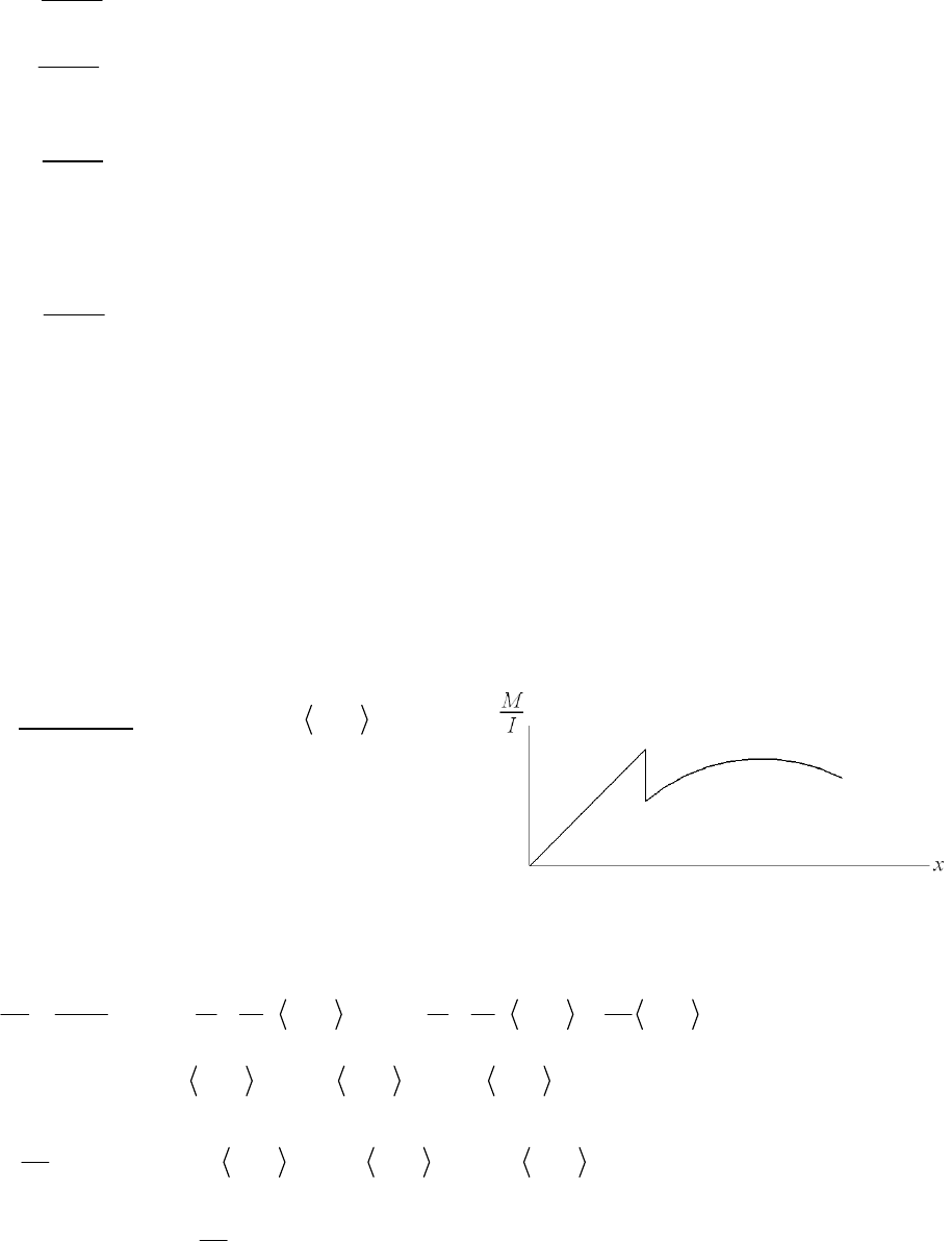
44
32
44
22
22 22
24
22 22
24
AB
y ba lbax x ba lbal la lb
EIl
ba lbax ba lbal la lb
EIl
w
wx
4
3
44
2
22
24
22
BC
ybalbaxlxa
EIl
xbalballa lb
w
44
3
44
2
22
24
22
CD
y
ba lbax lxa lxb
EIl
xbalballa lb
w
These equations can be shown to be equivalent to the results found in Prob. 4-19.
______________________________________________________________________________
4-63 I1 =
(1.3754)/64 = 0.1755 in4, I2 =
(1.754)/64 = 0.4604 in4,
R1 = 0.5(180)(10) = 900 lbf
Since the loading and geometry are symmetric, we will only write the equations for half
the beam
For 0 x 8 in 2
900 90 3Mxx
At x = 3, M = 2700 lbfin
Writing an equation for M / I, as seen in the figure,
the magnitude and slope reduce since I 2 > I 1.
To reduce the magnitude at x = 3 in, we add the
term, 2700(1/I 1 1/ I 2) x 3 0. The slope of 900 at x = 3 in is also reduced. We
account for this with a ramp function, x 31 . Thus,
01
112 12 2
01 2
900 1 1 1 1 90
2700 3 900 3 3
5128 9520 3 3173 3 195.5 3
Mx xx
2
x
II II I
xx x x
II
12
2
1
2564 9520 3 1587 3 65.17 3 3
dy
E
xx x xC
dx
Boundary Condition: 0 at 8 in
dy
x
dx
Chapter 4 - Rev B, Page 43/81
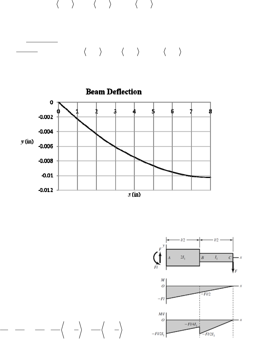
22
1
0 2564 8 9520 8 3 1587 8 3 65.17 8 3 C
3
C1 = 68.67 (103) lbf/in2
23 4
3 3
2
854.7 4760 3 529 3 16.29 3 68.67(10 )
Ey
xx x x x C
y = 0 at x = 0 C2 = 0
Thus, for 0 x 8 in
23 4
3 3
6
1854.7 4760 3 529 3 16.29 3 68.7(10 ) .
30(10 ) xx x x xAns
y
Using a spreadsheet, the following graph represents the deflection equation found above
The maximum is max 0.0102 in at 8 in .
y
xA ns
______________________________________________________________________________
4-64 The force and moment reactions at the left support
are F and Fl respectively. The bending moment
equation is
M = Fx Fl
Plots for M and M /I are shown.
M /I can be expressed using singularity functions
01
111 1
224222
M
FFlFl l F l
xx x
II II I
Chapter 4 - Rev B, Page 44/81
where the step down and increase in slope at x = l /2 are given by the last two terms.
Integrate
12
2
1
111 1
424242
dy F Fl Fl l F l
Exxx x
dx I I I I
C
dy/dx = 0 at x = 0 C1 = 0
23
32
2
111 1
12 4 8 2 12 2
FFlFllFl
Ey x x x x C
III I
y = 0 at x = 0 C2 = 0
23
32
1
26 3 2
24 2 2
Fl
yxlxlxx
EI
l
32 3
/2
11
5
2 6 3 (0) 2(0) .
24 2 2 96
xl
Fl l Fl
yll
EI EI
Ans
23
3
32
1 1
3
26 3 2
24 2 2 16
xl
FllFl
ylllllx
EI EI
.Ans
The answers are identical to Ex. 4-10.
______________________________________________________________________________
4-65 Place a dummy force, Q, at the center. The reaction, R1 = wl / 2 + Q / 2
2
22 2 2
Qx M
Mx Q
wl w x
Integrating for half the beam and doubling the results
/2 /2 2
max
00
0
12
2222
ll
Q
Mx
yMdx x
EI Q EI
wl w x
dx
Note, after differentiating with respect to Q, it can be set to zero
/2
/2 34
2
max
00
5 .
2 2 3 4 384
l
lxl x
y
xlxdx Ans
EI EI EI
ww w
______________________________________________________________________________
4-66 Place a fictitious force Q pointing downwards at the end. Use the variable
x
originating at
the free end at positive to the left
2
2
xM
M
Qx x
Q
w
Chapter 4 - Rev B, Page 45/81
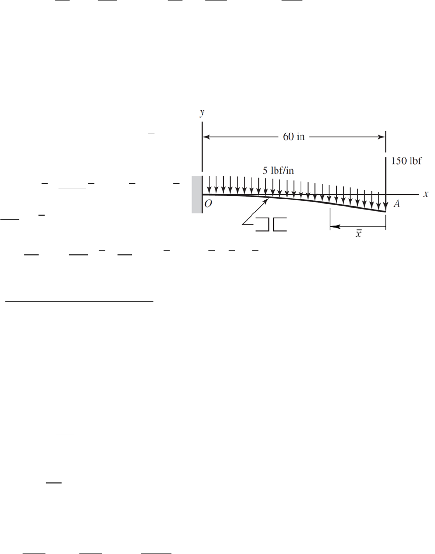
2
3
max
00
0
4
11
22
.
8
ll
Q
M
y M dx x dx x dx
EI Q EI EI
lAns
EI
wx w
w
0
l
______________________________________________________________________________
4-67 From Table A-7, I1-1 = 1.85 in4. Thus, I = 2(1.85) = 3.70 in4
First treat the end force as a variable, F.
Adding weight of channels of 2(5)/12 =
0.833 lbf/in. Using the variable
x
as
shown in the figure
22
5.833 2.917
2
M
Fx x Fx x
Mx
F
60 60 2
00
11
( 2.917 )( )
A
M
M
dx Fx x x dx
E
IFEI
34
6
(150 / 3)(60 ) (2.917 / 4)(60 ) 0.182 in
30(10 )(3.70)
in the direction of the 150 lbf force
0.182 in .
A
y
Ans
______________________________________________________________________________
4-68 The energy includes torsion in AC, torsion in CO, and bending in AB.
Neglecting transverse shear in AB
, M
M
Fx x
F
In AC and CO,
,
AB AB
T
TFl l
F
The total energy is
22 2
0
22 2
AB
l
AB
AC CO
Tl Tl M
Ud
GJ GJ EI
x
The deflection at the tip is
Chapter 4 - Rev B, Page 46/81
2
3
00
1
AB AB
ll
AC CO AC AB CO AB
AC CO AC CO AB
Tl Tl Tl l Tl l
UTTMM
dx Fx dx
F GJ F GJ F EI F GJ GJ EI
22
33
44 4
2
44 4
3/ 32 / 32 3 / 64
32 2
3
AC AB CO AB AC AB CO AB
AB AB
AC CO AB AC CO AB
AC CO
AB AB
AC CO AB
Tl l Tl l Fl l Fl l
Fl Fl
GJ GJ EI Gd Gd Ed
ll
Fl l
Gd Gd Ed
1
24 4 4
1
23434 34
2
32 3
2 200
200 200 8.10 N/mm .
32 200 79.3 10 18 79.3 10 12 3 207 10 8
AC CO AB
AB AC CO AB
ll lF
klGd Gd Ed
A
ns
______________________________________________________________________________
4-69 I1 =
(1.3754)/64 = 0.1755 in4, I2 =
(1.754)/64 = 0.4604 in4
Place a fictitious force Q pointing downwards at the midspan of the beam, x = 8 in
1
11
(10)180 900 0.5
22
R
QQ
For 0 x 3 in
900 0.5 0.5
M
M
Qx x
Q
For 3 x 13 in
2
900 0.5 90( 3) 0.5
M
M
Qx x x
Q
By symmetry it is equivalent to use twice the integral from 0 to 8
838
2
2
12
003
0
38
3
3432
12
03
3
33
66
12
11
2 900 900 90 3
300 1 1 9
300 90( 2 )
42
120.2 10
8100 1 8100
145.5 10 25.31 10 30 10 0.1755 30 10 0.4604
0.0102 in .
Q
MM
dx x dx x x x dx
EI Q EI EI
xxxxx
EI EI
EI EI
Ans
______________________________________________________________________________
Chapter 4 - Rev B, Page 47/81
4-70 I =
(0.54)/64 = 3.068 (103) in4, J = 2 I = 6.136 (103) in4, A =
(0.52)/4 = 0.1963 in2.
Consider x to be in the direction of OA, y vertically upward, and z in the direction of AB.
Resolve the force F into components in the x and y directions obtaining 0.6 F in the
horizontal direction and 0.8 F in the negative vertical direction. The 0.6 F force creates
strain energy in the form of bending in AB and OA, and tension in OA. The 0.8 F force
creates strain energy in the form of bending in AB and OA, and torsion in OA. Use the
dummy variable
x
to originate at the end where the loads are applied on each segment,
0.6 F: AB 0.6 0.6
M
M
Fx x
F
OA 4.2 4.2
M
MF
F
0.6 0.6
a
a
F
FF
F
0.8 F: AB 0.8 0.8
M
M
Fx x
F
OA 0.8 0.8
M
M
Fx x
F
5.6 5.6
T
TF
F
Once the derivatives are taken the value of F = 15 lbf can be substituted in. The deflection
of B in the direction of F is*
636
2
71
2
63 63
00
7
2
63 6
0
1
0.6 15 15 5.6 15 15
0.6 5.6
0.1963 30 10 6.136 10 11.5 10
15 4.2
15 0.6
30 10 3.068 10 30 10 3.068 10
15 15
0.8
30 10 3.068 10 30 10 3.06
aa
BFOA
OA
FL F
UTLTM
Mdx
FAE FJG FEI F
xdx dx
xdx
5
15
2
3
0
53
0.8
810
1.38 10 0.1000 6.71 10 0.0431 0.0119 0.1173
0.279 in .
x
dx
Ans
Chapter 4 - Rev B, Page 48/81
*Note. This is not the actual deflection of point B. For this, dummy forces must be placed
B = 0.0831 i 0.2862 j 0.00770 k in
is
on B in the x, y, and z directions. Determine the energy due to each, take derivatives, and
then substitute the values of Fx = 9 lbf, Fy = 12 lbf, and Fz = 0. This can be done
separately and then use superposition. The actual deflections of B are
From this, the deflection of B in the direction of F
0.6 0.0831 0.8 0.2862 0.279 in
BF
which agrees with our result.
____ ________________________________________________
-71 Strain energy. AB: Bending and torsion, BC: Bending and torsion, CD: Bending.
031 in4,
1) is in the form of
=TL/(JG), where the equivalent of
Use the dummy variable
_ _________________________
4
IAB =
(14)/64 = 0.04909 in4, JAB = 2 IAB = 0.09818 in4, IBC = 0.25(1.53)/12 = 0.07
ICD =
(0.754)/64 = 0.01553 in4.
For the torsion of bar BC, Eq. (3-4
J is Jeq =
bc 3. With b/c = 1.5/0.25 = 6, JBC =
bc 3 = 0.299(1.5)0.253 = 7.008 (103) in4.
x
to originate at the end where the loads are applied on each
ing
segment,
AB: Bend 22
M
MFx F x
F
Torsion 55
T
TF
F
M
M
Fx x
F
BC: Bending
Torsion 22
T
TF
F
CD: Bending M
M
Fx x
F
6
2
636 6
0
52
22
66
00
44456
1
56 25 1
52
0.09818 11.5 10 7.008 10 11.5 10 30 10 0.04909
11
30 10 0.07031 30 10 0.01553
1.329 10 2.482 10 1.141 10 1.98 10 5.72 10
5.207 10
D
UTlT M
Mdx
FJGFEIF
FF 2
F
xd
Fx dx Fx dx
FFFFF
44
5.207 10 200 0.104 in .FAns
x
______________________________________________________________________________
Chapter 4 - Rev B, Page 49/81
4-72 AAB =
(12)/4 = 0.7854 in2, IAB =
(14)/64 = 0.04909 in4, IBC = 1.5 (0.253)/12 = 1.953
(103) in4, ACD =
(0.752)/4 = 0.4418 in2, IAB =
(0.754)/64 = 0.01553 in4. For (
D )x let
F = Fx = 150 lbf and Fz = 100 lbf . Use the dummy variable
x
to originate at the end
where the loads are applied on each segment,
CD: 0
y
yz
M
MFx F
1
a
a
F
FF
F
BC: 2y
yz
M
M
Fx F x
F
0
a
az
F
FF
F
AB: 52 y
yzz
M
MFFFx F5
1
a
a
F
FF
F
5
0
6
0
32
663
2
6
6
7
12
152 5
21
155
0.4418 30 10 3
30 10 1.953 10
6
125 6 10 6 6 5 1
2 0.7854 30 10
30 10 0.04909
1.509 10 7.112 1
a
Dz
xCD BC
a
zz
AB
AB
z
z
z
F
UFL Fx F xdx
FAE FEI
F
FL
FFFx dx
EI AE F
FFF
F
F
FF
F
44 4
4744
0 4.267 10 1.019 10
1.019 10 2.546 10 8.135 10 5.286 10
z
z z
FFF
FFF
F
Substituting F = Fx = 150 lbf and Fz = 100 lbf gives
44
8.135 10 150 5.286 10 100 0.1749 in .
Dx
A
ns
______________________________________________________________________________
4-73 IOA = IBC =
(1.54)/64 = 0.2485 in4, JOA = JBC = 2 IOA = 0.4970 in4, IAB =
(14)/64 =
0.04909 in4, JAB = 2 IAB = 0.09818 in4, ICD =
(0.754)/64 = 0.01553 in4
Let Fy = F, and use the dummy variable
x
to originate at the end where the loads are
applied on each segment,
Chapter 4 - Rev B, Page 50/81

OC: , 12 12
MT
MFx x T F
F
F
DC: M
M
Fx x
F
1
DyOC
UTLT M
M
dx
FJGFEIF
The terms involving the torsion and bending moments in OC must be split up because of
the changing second-area moments.
2
2
66
6
0
11 13 12
22
666
211
437
45 3
12 4 12 9 1
12 12
0.4970 11.5 10 0.09818 11.5 10 30 10 0.2485
111
30 10 0.04909 30 10 0.2485 30 10 0.01553
1.008 10 1.148 10 3.58 10
2.994 10 3.872 10 1.2363 10
Dy
FF Fx dx
2
0
F
xdx Fxdx Fxdx
FFF
FF F
33
2.824 10 2.824 10 250 0.706 in .FAns
For the simplified shaft OC,
13 12
22
666
00
34 333
12 13 11
12
0.09818 11.5 10 30 10 0.04909 30 10 0.01553
1.6580 10 4.973 10 1.2363 10 3.392 10 3.392 10 250
0.848 in .
By
FFx dx Fx dx
FF FF
Ans
Simplified is 0.848/0.706 = 1.20 times greater Ans.
______________________________________________________________________________
4-74 Place a dummy force Q pointing downwards at point B. The reaction at C is
RC = Q + (6/18)100 = Q + 33.33
This is the axial force in member BC. Isolating the beam, we find that the moment is not a
function of Q, and thus does not contribute to the strain energy. Thus, only energy in the
member BC needs to be considered. Let the axial force in BC be F, where
Chapter 4 - Rev B, Page 51/81
33.33 1
F
FQ Q
5
26
00
0 33.33 12 16.7910 in
0.5 / 4 30 10
B
BC
QQ
UFLF Ans
QAEQ
.
______________________________________________________________________________
4-75 IOB = 0.25(23)/12 = 0.1667 in4
AAC =
(0.52)/4 = 0.1963 in2
MO = 0 = 6 RC 11(100) 18 Q
RC = 3Q + 183.3
MA = 0 = 6 RO 5(100) 12 Q RO = 2Q + 83.33
Bending in OB.
BD: Bending in BD is only due to Q which when set to zero after differentiation
gives no contribution.
AD: Using the variable
x
as shown in the figure above
100 7 7
M
M
xQ x x
Q
OA: Using the variable x as shown in the figure above
283.33 2
M
M
Qx
Qx
Axial in AC:
3 183.3 3
F
FQ Q
Chapter 4 - Rev B, Page 52/81
00 0
562
60
0
56
3 2
60
0
37
1
183.3 12 1
3 100 7 2 83.33
0.1963 30 10
1
1.121 10 100 7 166.7
10.4 10 0.1667
1.121 10 5.768 10 100 129.2 166.
B
QQ Q
UFLF M
Mdx
QAEQEIQ
xxdx xdx
EI
xxdx xdx
7 72 0.0155 in .Ans
______________________________________________________________________________
4-76 There is no bending in AB. Using the variable
, rotating counterclockwise from B
sin sin
M
MPR R
P
cos cos
r
r
F
FP P
2
sin sin
2sin
F
FP P
MF PR
P
211
22
6(4) 24 mm , 40 (6) 43 mm, 40 (6) 37 mm,
oi
Ar r
From Table 3-4, p.121, for a rectangular cross section
639.92489 mm
ln(43 / 37)
n
r
From Eq. (4-33), the eccentricity is e = R
rn =40 39.92489 = 0.07511 mm
From Table A-5, E = 207(103) MPa, G = 79.3(103) MPa
From Table 4-1, C = 1.2
From Eq. (4-38)
222 2
000 0
1rr
MF
FR F CF R F
MM
dd d
AeE P AE P AE P AG P
d
2222
22
2
0000
sin sin cos
2sin
PR PR CPR
PR
ddd
AeE AE AE AG
2
d
3
33
(10)(40) 40 (207 10 )(1.2)
12 12
4 4(24)(207 10 ) 0.07511 79.3 10
PR R EC
AE e G
0.0338 mm .Ans
______________________________________________________________________________
Chapter 4 - Rev B, Page 53/81
4-77 Place a dummy force Q pointing downwards at point A. Bending in AB is only due to Q
which when set to zero after differentiation gives no contribution. For section BC use the
variable
, rotating counterclockwise from B
sin sin 1 sin
M
MPR QRR R
Q
cos cos
r
r
F
FPQ Q
sin sin
F
FPQ Q
sin 1 sin sinMF PR QR P Q
2
sin sin 1 sin 2 sin 1 sin
MF PR PR QR
Q
But after differentiation, we can set Q = 0. Thus,
sin 1 2sin
MF PR
Q
211
22
6(4) 24 mm , 40 (6) 43 mm, 40 (6) 37 mm,
oi
Ar r
From Table 3-4, p.121, for a rectangular cross section
639.92489 mm
ln(43 / 37)
n
r
From Eq. (4-33), the eccentricity is e = R
rn =40 39.92489 = 0.07511 mm
From Table A-5, E = 207(103) MPa, G = 79.3(103) MPa
From Table 4-1, C = 1.2
From Eq. (4-38)
222 2
222
2
000 0
2
2
000
2
0
2
1
sin 1 sin sin sin 1 2sin
cos
12
444
rr
MF
FR F CF R F
MM
dd d
AeE Q AE Q AE Q AG Q
PR PR PR
dd d
AeE AE AE
CPR d
AG
PR PR PR
AeE AE
d
3
33
12
444
10 40 1.2 207 10
40
12
24 207 10 4 0.07511 4 79.3 10
0.0766 mm .
CPR PR R CE
AE AG AE e G
Ans
______________________________________________________________________________
Chapter 4 - Rev B, Page 54/81
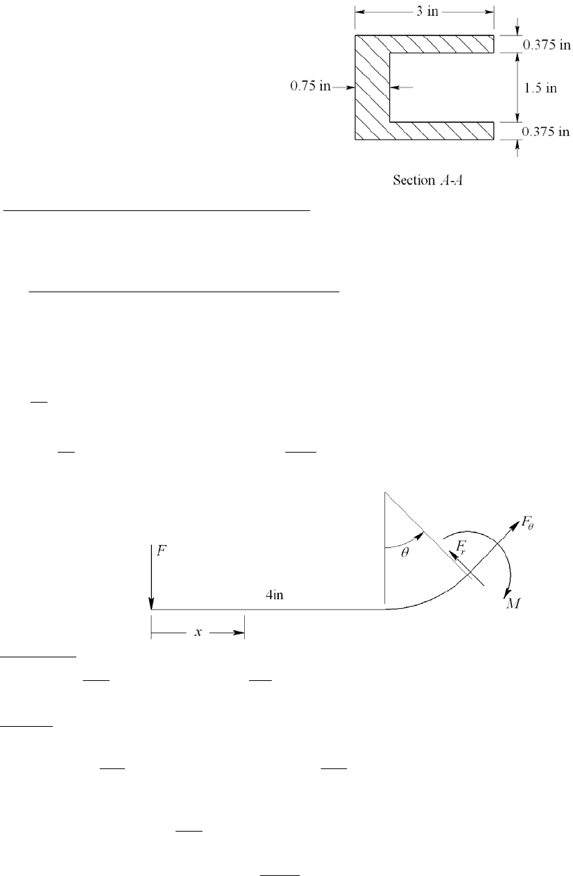
4-78 Note to the Instructor. The cross section
shown in the first printing is incorrect and the
solution presented here reflects the correction
which will be made in subsequent printings.
The corrected cross section should appear as
shown in this figure. We apologize for any
inconvenience.
A = 3(2.25) 2.25(1.5) = 3.375 in2
(1 1.5)(3)(2.25) (1 0.75 1.125)(1.5)(2.25) 2.125 in
3.375
R
Section is equivalent to the “T” section of Table 3-4, p. 121,
2.25(0.75) 0.75(2.25) 1.7960 in
2.25ln[(1 0.75) /1] 0.75ln[(1 3) / (1 0.75)]
n
r
2.125 1.7960 0.329 in
n
eRr
For the straight section
32
2
3
4
1(2.25) 3 2.25(3)(1.5 1.125)
12
1 2.25
(1.5) 2.25 1.5(2.25) 0.75 1.125
12 2
2.689 in
z
I
For 0 x 4 in
, 1
MV
x x VFMF
F
F
For
/2
cos cos , sin sin
r
r
FF
F
FFF
F
F
(4 2.125sin ) (4 2.125sin )
(4 2.125sin ) sin 2 (4 2.365sin )sin
M
MF FMF
MF F F F
F
Chapter 4 - Rev B, Page 55/81
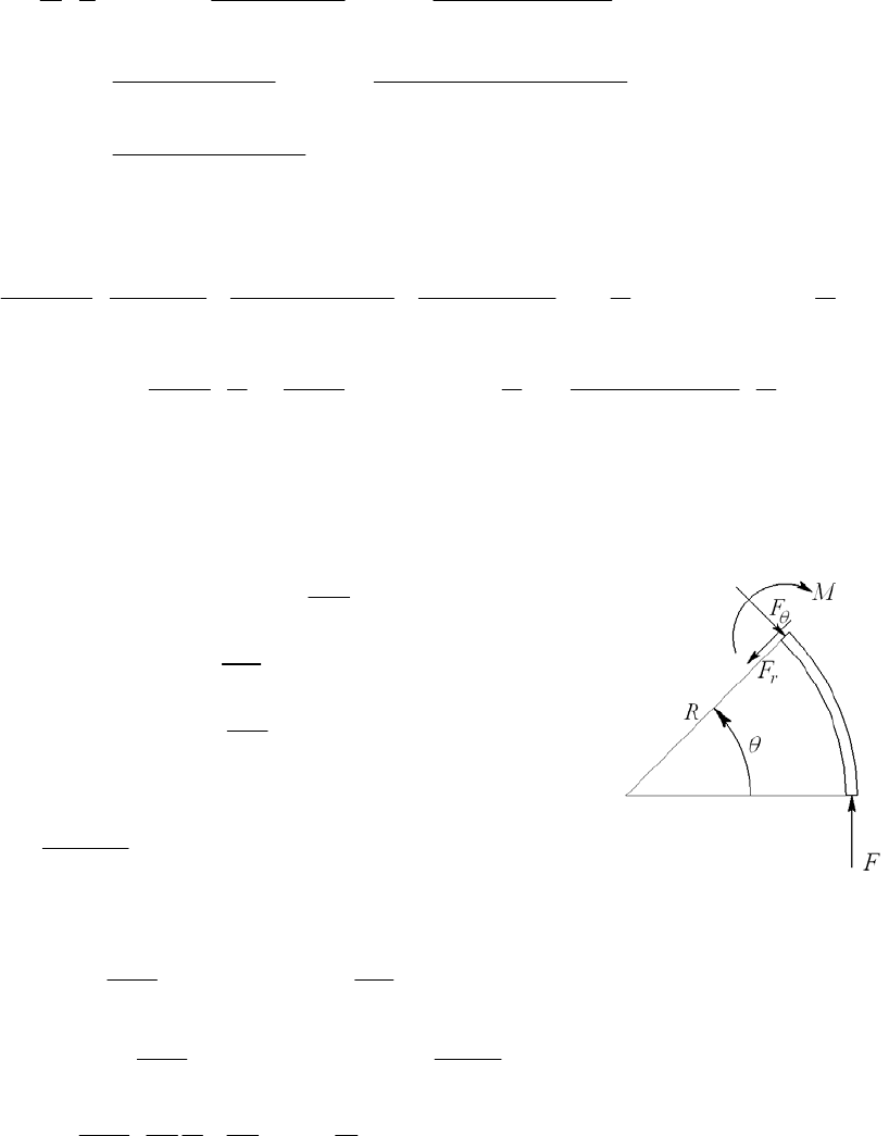
Use Eqs. (4-31) and (4-24) (with C = 1) for the straight part, and Eq. (4-38) for the
curved part, integrating from 0 to π/2, and double the results
2
4/2
2
00
2
/2 /2
00
2
/2
0
2 1 (4)(1) (4 2.125sin )
3.375( / ) 3.375(0.329)
sin (2.125) 2 (4 2.125sin )sin
3.375 3.375
(1) cos (2.125)
3.375( / )
F
Fx dx F d
EI GE
FF
dd
Fd
GE
Substitute I = 2.689 in4, F = 6700 lbf, E = 30 (106) psi, G = 11.5 (106) psi
3
6
2 6700 44 1
16 17(1) 4.516
3 2.689 3.375(11.5 / 30) 3.375(0.329) 2 4
30 10
2.125 2 2.125
4 1 2.125
3.375 4 3.375 4 3.375 11.5 / 30 4
0.0226 in .Ans
______________________________________________________________________________
4-79 Since R/h = 35/4.5 = 7.78 use Eq. (4-38), integrate from 0 to
, and double the results
1 cos 1 cos
M
MFR R
F
sin sin
r
r
F
FF
F
cos cos
F
FF
F
2cos 1 cos
2 cos 1 cos
MF F R
MF FR
F
From Eq. (4-38),
2
22
00
2
00
2 (1 cos ) cos
21.2
cos 1 cos sin
23 3
0.6
22
FR FR
dd
AeE AE
FR FR
dd
AE AG
FR R E
AE e G
A = 4.5(3) = 13.5 mm2, E = 207 (103) N/mm2, G = 79.3 (103) N/mm2, and from Table 3-4,
p. 121,
Chapter 4 - Rev B, Page 56/81
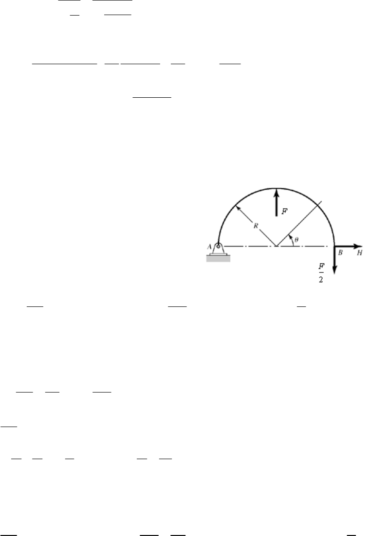
4.5 34.95173 mm
37.25
ln
ln 32.75
no
i
h
rr
r
and e = R
rn = 35 34.95173 = 0.04827 mm. Thus,
3
235 3 35 3 207
0.6 0.08583
13.5 207 10 2 0.04827 2 79.3
F
F
where F is in N. For
= 1 mm, 111.65 N .
0.08583
F
Ans
Note: The first term in the equation for
dominates and this is from the bending moment.
Try Eq. (4-41), and compare the results.
______________________________________________________________________________
4-80 R/h = 20 > 10 so Eq. (4-41) can be used to determine deflections. Consider the horizontal
reaction, to applied at B, subject to the constraint ( ) 0.
BH
(1 cos ) sin sin 0
22
FR M
MHRR
H
By symmetry, we may consider only half of the wire form and use twice the strain energy
Eq. (4-41) then becomes,
/2
0
2
()
0
BH
UM
MRd
HEI H
/2
0(1 cos ) sin ( sin ) 0
2
FR HR R R d
30
0 9.55 N .
24 4
FF F
H
H Ans
Reaction at A is the same where H goes to the left. Substituting H into the moment
equation we get,
(1 cos ) 2sin [ (1 cos ) 2sin ] 0
22
FR M R
2
M
F
Chapter 4 - Rev B, Page 57/81
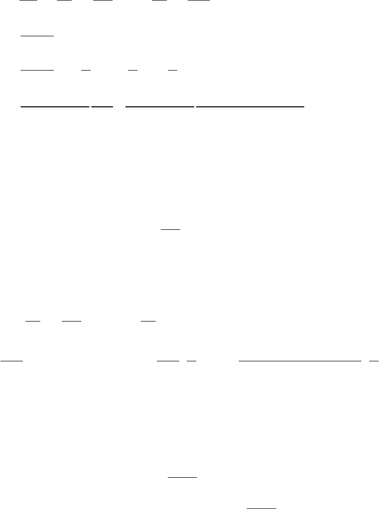
2
/2 2
2
0
3/2 222 2 2
20
3
22 2
2
23
22
[ (1 cos ) 2sin ]
4
( cos 4 sin 2 cos 4 sin 4 sin cos )
2
4242
2244
(3 8 4)
8
P
UM FR
MRd Rd
PEI F EI
FR d
EI
FR
EI
FR
EI
23
34
(3 8 4) (30)(40 ) 0.224 mm .
8207 10 2 / 64
A
ns
______________________________________________________________________________
4-81 The radius is sufficiently large compared to the wire diameter to use Eq. (4-41) for the
curved beam portion. The shear and axial components will be negligible compared to
bending.
Place a fictitious force Q pointing to the left at point A.
sin ( sin ) sin
M
M
PR Q R l R l
Q
Note that the strain energy in the straight portion is zero since there is no real force in that
section.
From Eq. (4-41),
/2 /2
00
0
222
/2 2
64
0
11
sin sin
1(5 )
sin sin (5) 4
44
30 10 0.125 / 64
0.551 in .
Q
M
MRd PR R lRd
EI Q EI
PR PR
Rld Rl
EI EI
A
ns
______________________________________________________________________________
4-82 Both the radius and the length are sufficiently large to use Eq. (4-41) for the curved beam
portion and to neglect transverse shear stress for the straight portion.
Straight portion: AB
AB
M
M
Px x
P
Curved portion:
(1 cos ) (1 cos )
BC
BC
M
M
PR l R l
P
From Eq. (4-41) with the addition of the bending strain energy in the straight portion of
the wire,
Chapter 4 - Rev B, Page 58/81
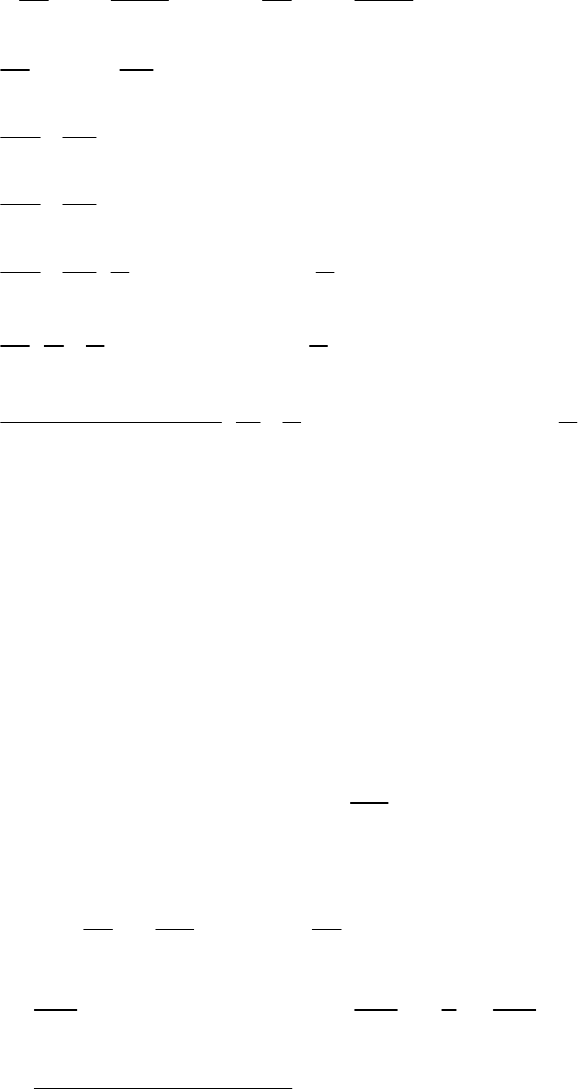
/2
00
/2 2
2
00
3/2 22 2
0
3/2 22 2 2
0
3
11
(1 cos )
(1 2cos cos ) 2 (1 cos )
3
cos 2 2 cos ( )
3
3
lBC
AB
AB BC
l
M
M
Mdx MRd
EI P EI P
PPR
xdx R l d
EI EI
Pl PR RRlld
EI EI
Pl PR RRRlRld
EI EI
Pl P
EI
22 2
3
32 2
32
32
64
22 ()
42
22 ()
34 2
14
(5 ) 5 2(5 ) 2(5)(4) 5 5 4
34 2
30 10 0.125 / 64
0.850 in .
RRRRl Rl
EI
Pl RRR Rl RRl
EI
Ans
______________________________________________________________________________
4-83 Both the radius and the length are sufficiently large to use Eq. (4-41) for the curved beam
portion and to neglect transverse shear stress for the straight portion.
Place a dummy force, Q, at A vertically downward. The only load in the straight section is
the axial force, Q. Since this will be zero, there is no contribution.
In the curved section
sin 1 cos 1 cos
M
MPR QR R
Q
From Eq. (4-41)
/2 /2
00
0
33
/2
0
3
64
11
sin 1 cos
1
sin sin cos 1 22
15 0.174 in .
2 30 10 0.125 / 64
Q
M
3
M
Rd PR R Rd
EI Q EI
PR PR PR
d
EI EI EI
Ans
______________________________________________________________________________
4-84 Both the radius and the length are sufficiently large to use Eq. (4-41) for the curved beam
portion and to neglect transverse shear stress for the straight portion.
Chapter 4 - Rev B, Page 59/81
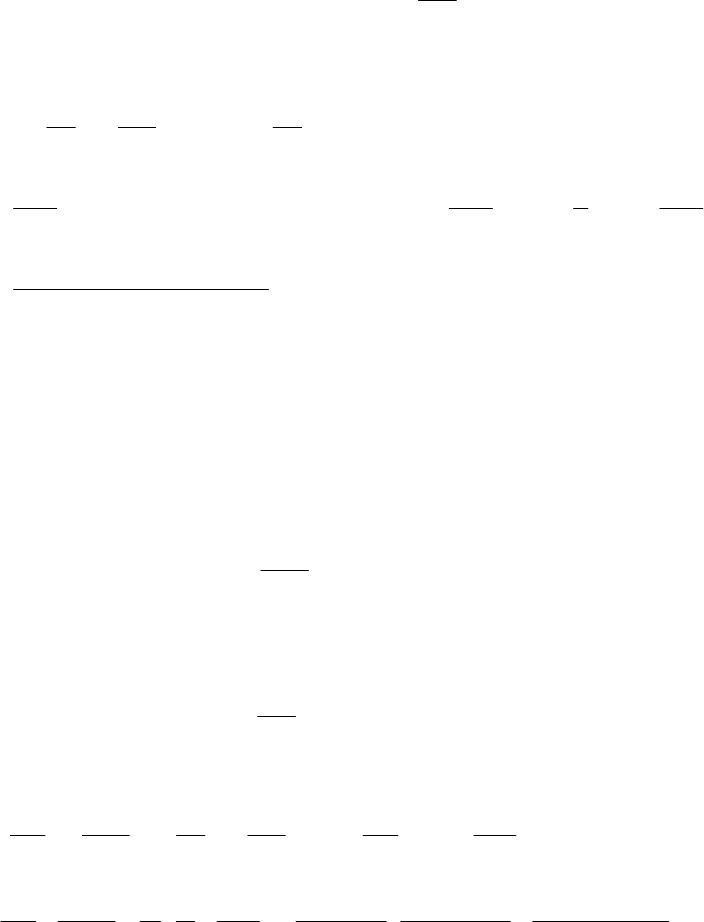
Place a dummy force, Q, at A vertically downward. The load in the straight section is the
axial force, Q, whereas the bending moment is only a function of P and is not a function
of Q. When setting Q = 0, there is no axial or bending contribution.
In the curved section
1cos sin sin
M
MPR l QR R
Q
From Eq. (4-41)
/2 /2
00
0
/2
22
0
2
64
11
1 cos sin
1
sin sin cos sin 2
22
15 5 2 4 0.452 in
2 30 10 0.125 / 64
Q
M
MRd PR lR Rd
EI Q EI
PR PR PR2
R
RldRlRR
EI EI EI
l
Since the deflection is negative,
is in the opposite direction of Q. Thus the deflection is
0.452 in .Ans
______________________________________________________________________________
4-85 Consider the force of the mass to be F, where F = 9.81(1) = 9.81 N. The load in AB is
tension
1
AB
AB
F
FF
F
For the curved section, the radius is sufficiently large to use Eq. (4-41). There is no
bending in section DE. For section BCD, let
be counterclockwise originating at D
sin sin 0
M
MFR R
F
Using Eqs. (4-29) and (4-41)
3
2
00
3
33
324
11sin
40
9.81 80
22
207 10 2/4 2 2/64
6.067 mm .
AB
AB
F
Fl M Fl FR
MRd d
AE F EI F AE EI
Fl FR F l R
AE EI E A I
Ans
______________________________________________________________________________
Chapter 4 - Rev B, Page 60/81
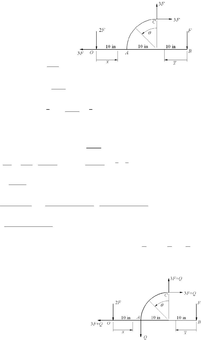
4-86 AOA = 2(0.25) = 0.5 in2,
IOAB = 0.25(23)/12 = 0.1667 in4,
I
AC =
(0.54)/64 = 3.068 (10-3) in4
Applying a force F at point B, using
statics, the reaction forces at O and C
are as shown.
OA: Axial 33
OA
OA
F
FF
F
Bending 22
OA
OA
M
M
Fx x
F
AB: Bending AB
AB
M
M
Fx x
F
AC: Isolating the upper curved section
3 sin cos 1 3 sin cos 1
AC
AC
M
MFR R
F
10 20
22
00
/2
32
0
33
66 6
3/2
22
63
0
11
4
9sin cos 1
410 20
310 3
0.5 10.4 10 3 10.4 10 0.1667 3 10.4 10 0.1667
910 sin 2sin cos 2sin cos 2cos 1
30 10 3.068 10
1
OA
OA OAB OAB
AC
F
Fl Fx dx F x d x
AE F EI EI
FR d
EI
FF
F
Fd
543
.731 10 7.691 10 1.538 10 0.09778 1 2 2
44
0.0162 0.0162 100 1.62 in .
FFFF
FAns
2
_____________________________________________________________________________
4-87 AOA = 2(0.25) = 0.5 in2,
IOAB = 0.25(23)/12 = 0.1667 in4,
I
AC =
(0.54)/64 = 3.068 (10-3) in4
Applying a vertical dummy force, Q, at A,
from statics the reactions are as shown. The
dummy force is transmitted through section
Chapter 4 - Rev B, Page 61/81
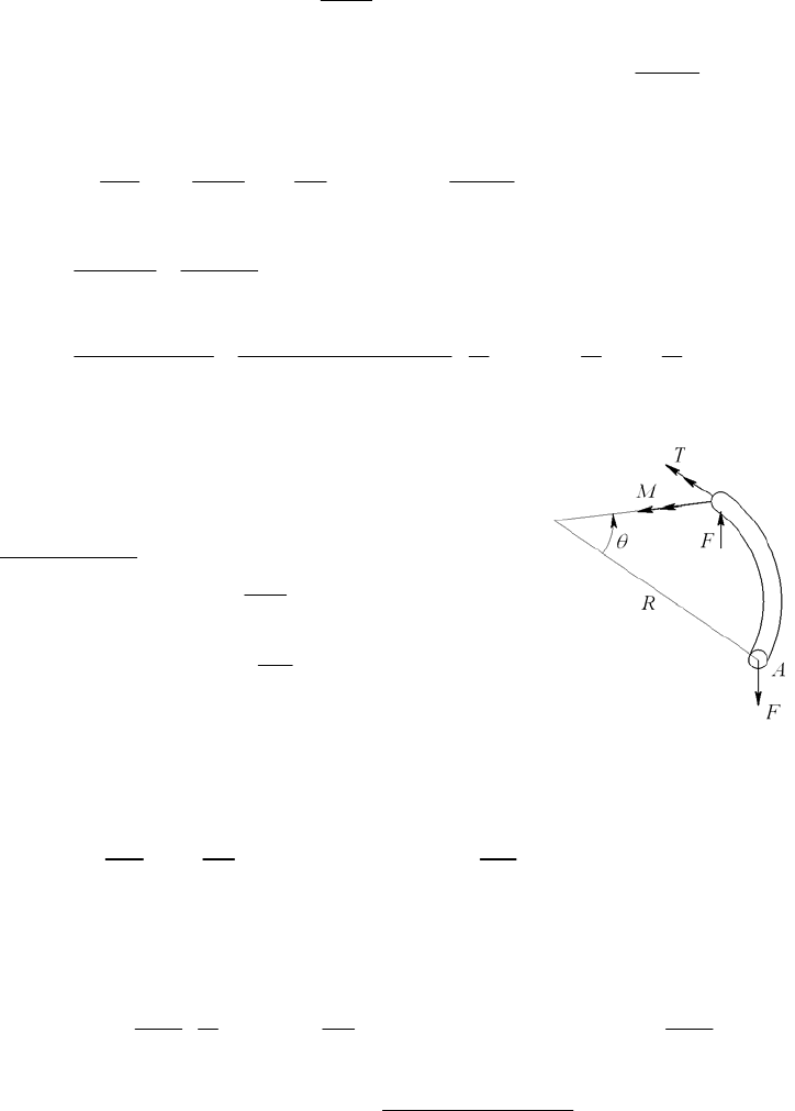
OA and member AC.
OA: 31
OA
OA
F
FFQ Q
AC:
3 sin 3 1 cos sin cos 1
AC
AC
M
MFQR FQR R
Q
/2
00
/2
32
0
3
663
1
33sin cos 1
3 100 10 3 100 10 1 2 2 0.462 in .
442
10.4 10 0.5 30 10 3.068 10
OA AC
AC
OA AC Q
OA
OA AC
FM
Fl MRd
AE Q EI Q
Fl FR d
AE EI
A
ns
______________________________________________________________________________
4-88 I =
(64)/64 = 63.62 mm4
0
/ 2
sin sin
(1 cos ) (1 cos )
M
MFR R
F
T
TFR R
F
According to Castigliano’s theorem, a positive
U/
F will yield a deflection of A in the negative y direction. Thus the deflection in the
positive y direction is
/2 /2
22
00
11
() (sin) [(1cos)]
Ay
U
F
RRd FR Rd
FEI GJ
Integrating and substituting
2 and / 2 1JI GE
3 3
3
3
3
() (1 ) 2 4 8(3 8)
44 4
(250)(80)
[4 8 (3 8)(0.29)] 12.5 mm .
4(200)10 63.62
Ay
FR FR
EI EI
Ans
______________________________________________________________________________
4-89 The force applied to the copper and steel wire assembly is
(1) 400 lbf
cs
FF
Since the deflections are equal, cs
Chapter 4 - Rev B, Page 62/81
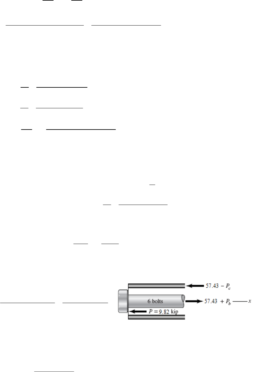
cs
Fl Fl
AE AE
26 2
3( / 4)(0.1019) (17.2)10 ( / 4)(0.1055) (30)10
cs
Fl Fl
6
s
F
Yields, . Substituting this into Eq. (1) gives
1.6046
c
F
1.604 2.6046 400 153.6 lbf
1.6046 246.5 lbf
ss s s
cs
FF F F
FF
2
246.5 10 075 psi 10.1 kpsi .
3( / 4)(0.1019)
c
c
c
F
A
ns
A
2
153.6 17 571 psi 17.6 kpsi .
( / 4)(0.1055 )
s
s
s
F
A
ns
A
26
153.6(100)(12) 0.703 in .
( / 4)(0.1055) (30)10
s
Fl Ans
AE
______________________________________________________________________________
4-90 (a) Bolt stress 0.75(65) 48.8 kpsi .
bAns
Total bolt force 2
6 6(48.8) (0.5 ) 57.5 kips
4
bbb
FA
Cylinder stress 22
57.43 13.9 kpsi .
( / 4)(5.5 5 )
b
c
c
F
A
ns
A
(b) Force from pressure
22
(5 ) (500) 9817 lbf 9.82 kip
44
D
Pp
Fx = 0
Pb + Pc = 9.82 (1)
Since ,
cb
22 2
( / 4)(5.5 5 ) 6( / 4)(0.5 )
cb
Pl Pl
EE
Pc = 3.5 Pb (2)
Substituting this into Eq. (1)
Pb + 3.5 Pb = 4.5 Pb = 9.82 Pb = 2.182 kip. From Eq. (2), Pc = 7.638 kip
Using the results of (a) above, the total bolt and cylinder stresses are
2
2.182
48.8 50.7 kpsi .
6( / 4)(0.5 )
b
Ans
Chapter 4 - Rev B, Page 63/81
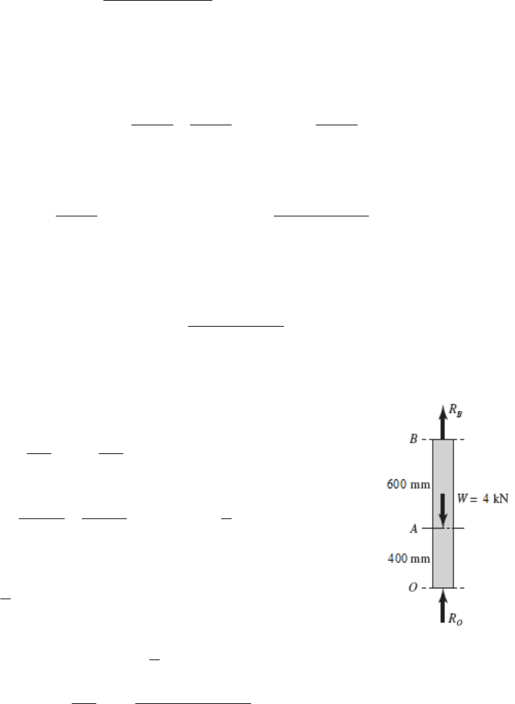
22
7.638
13.9 12.0 kpsi .
( / 4)(5.5 5 )
cAns
______________________________________________________________________________
4-91 Tc + Ts = T (1)
c =
s
(2)
cs c
cs
cs s
JG
Tl Tl TT
JG JG JG
Substitute this into Eq. (1)
cs
ss s
ss
JG JG
TTT T T
JG JG JG
c
The percentage of the total torque carried by the shell is
100
% Torque .
s
sc
JG Ans
JG JG
______________________________________________________________________________
4-92 RO + RB = W (1)
OA =
AB
OA AB
Fl Fl
AE AE
400 600 3(2)
2
OBOB
RRRR
A
EAE
Substitute this unto Eq. (1)
34 1.6 kN .
2BB B
R
RR Ans
From Eq. (2) 31.6 2.4 kN .
2
O
R
Ans
3
2 400(400) 0.0223 mm .
10(60)(71.7)(10 )
A
OA
Fl Ans
AE
______________________________________________________________________________
4-93 See figure in Prob. 4-92 solution.
Procedure 1:
1. Let RB be the redundant reaction.
Chapter 4 - Rev B, Page 64/81
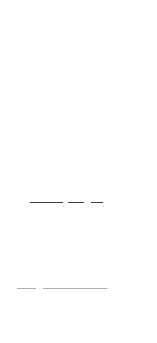
2. Statics. RO + RB = 4 000 N RO = 4 000 RB (1)
3. Deflection of point B.
600 4000 400 0(2
BB
B
RR
AE AE
)
4. From Eq. (2), AE cancels and RB = 1 600 N Ans.
and from Eq. (1), RO = 4 000 1 600 = 2 400 N Ans.
3
2 400(400) 0.0223 mm .
10(60)(71.7)(10 )
A
OA
Fl Ans
AE
______________________________________________________________________________
4-94 (a) Without the right-hand wall the deflection of point C would be
33
26 26
510 8 210 5
/ 4 0.75 10.4 10 / 4 0.5 10.4 10
0.01360 in 0.005 in Hits wall .
C
Fl
AE
Ans
(
b) Let RC be the reaction of the wall at C acting to the left (). Thus, the deflection of
point C is now
33
26 2
622
510 8 210 5
/ 4 0.75 10.4 10 / 4 0.5 10.4 10
485
0.01360 0.005
10.4 10 0.75 0.5
CC
C
C
RR
R
6
or,
6
0.01360 4.190 10 0.005 2053 lbf 2.05 kip .
CC
R
RA
ns
Statics. Considering +, 5 000 RA 2 053 = 0 RA = 2 947 lbf = 2.95 kip Ans.
Deflection. AB is 2 947 lbf in tension. Thus
3
26
8 2947 8 5.13 10 in .
/ 4 0.75 10.4 10
A
BAB
AB
R
A
ns
AE
______________________________________________________________________________
4-95 Since
OA =
AB,
(4) (6) 3(1)
2
OA AB OA AB
TTTT
J
GJG
Chapter 4 - Rev B, Page 65/81
Statics. TOA + TAB = 200 (2)
Substitute Eq. (1) into Eq. (2),
35
200 80 lbf in .
22
AB AB AB AB
TT T T An s
From Eq. (1) 33
80 120 lbf in .
22
OA AB
TT An s
0
46
80 6 180 0.390 .
/ 32 0.5 11.5 10
A
A
ns
max 33
16 120
16 4890 psi 4.89 kpsi .
0.5
OA
TAns
d
3
16 80 3260 psi 3.26 kpsi .
0.5
AB Ans
______________________________________________________________________________
4-96 Since
OA =
AB,
44
(4) (6) 0.2963 (1)
/ 32 0.5 / 32 0.75
OA AB OA AB
TTTT
GG
Statics. TOA + TAB = 200 (2)
Substitute Eq. (1) into Eq. (2),
0.2963 1.2963 200 154.3 lbf in .
AB AB AB AB
TT T T An s
From Eq. (1)
0.2963 0.2963 154.3 45.7 lbf in .
OA AB
TT Ans
0
46
154.3 6 180 0.148 .
/ 32 0.75 11.5 10
A
A
ns
max 33
16 45.7
16 1862 psi 1.86 kpsi .
0.5
OA
TAns
d
3
16 154.3 1862 psi 1.86 kpsi .
0.75
AB Ans
______________________________________________________________________________
Chapter 4 - Rev B, Page 66/81
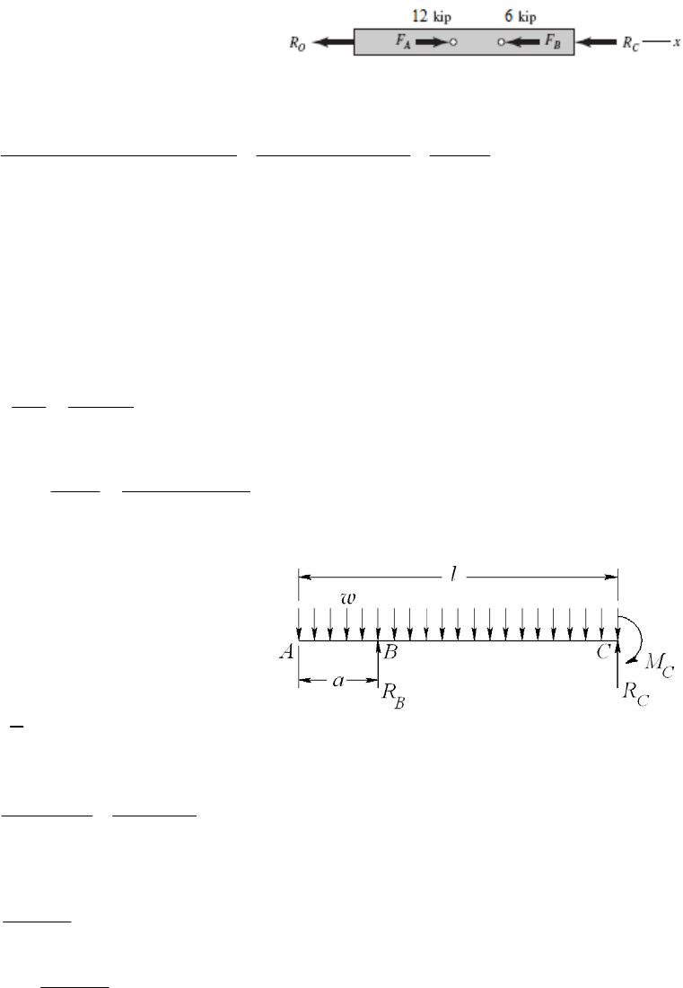
4-97 Procedure 1.
1. Arbitrarily, choose RC as a redundant reaction.
2. Statics. Fx = 0,
12(103) 6(103) RO RC = 0
RO = 6(103) RC (1)
3. The deflection of point C.
33 3
12(10 ) 6(10 ) (20) 6(10 ) (10) (15) 0
CC
C
C
RR
R
AE AE AE
4. The deflection equation simplifies to
45 RC + 60(103) = 0 RC = 1 333 lbf 1.33 kip Ans.
From Eq. (1), RO = 6(103) 1 333 = 4 667 lbf 4.67 kip Ans.
FAB = FB + RC = 6 +1.333 = 7.333 kips compression
7.333 14.7 kpsi .
(0.5)(1)
AB
AB
FAns
A
Deflection of A. Since OA is in tension,
6
4667(20) 0.00622 in .
(0.5)(1)(30)10
OOA
AOA
Rl Ans
AE
______________________________________________________________________________
4-98 Procedure 1.
1. Choose RB as redundant reaction.
2. Statics. RC = wl RB (1)
2
1(2)
2
CB
Ml
Rlaw
3. Deflection equation for point B. Superposition of beams 2 and 3 of Table A-9,
32
22
46
324
B
B
Rla la 0lla la l
EI EI
w
y
4. Solving for RB.
2
2
22
64
8
32
8
B
Rlllala
la
lala An
la
w
w.s
Substituting this into Eqs. (1) and (2) gives
Chapter 4 - Rev B, Page 67/81
22
510
8
CB .
R
lR l ala Ans
la
w
w
222
12.
28
CB
M
lRla l ala Ans
w
w
______________________________________________________________________________
4-99 See figure in Prob. 4-98 solution.
Procedure 1.
1. Choose RB as redundant reaction.
2. Statics. RC = wl RB (1)
2
1(2)
2
CB
MlRlaw
3. Deflection equation for point B. Let the variable x start at point A and to the right. Using
singularity functions, the bending moment as a function of x is
11
2
1
2B
B
M
M
x Rxa xa
R
w
0
22
0
1
11 1 1
00
22
l
B
BB
ll
B
a
UM
yMdx
REI R
xdx xRxaxadx
EI EI
ww
or,
33
44 33
11 0
24 3 3
B
Ra
la la la aa
w
Solving for RB gives
44 33 2 2
334 32
8
8
B.
R
l a a l a l al a Ans
la
la
ww
From Eqs. (1) and (2)
22
510
8
CB .
R
lR l ala Ans
la
w
w
222
12.
28
CB
M
lRla l ala Ans
w
w
Chapter 4 - Rev B, Page 68/81
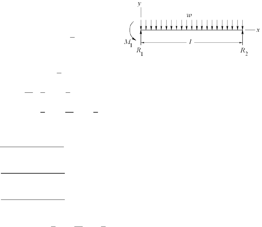
______________________________________________________________________________
4-100 Note: When setting up the equations for this problem, no rounding of numbers was
made. It turns out that the deflection equation is very sensitive to rounding.
Procedure 2.
1.
Statics. R1 + R2 = wl (1)
2
21
1(2)
2
Rl M l
w
2. Bending moment equation.
2
11
23
111
342
111
1
2
11 (3)
26
111 (4)
6242
MRx xM
dy
2
R x x M x C
dx
EIy R x x M x C x C
w
w
w
EI
EI = 30(106)(0.85) = 25.5(106) lbfin2.
3. Boundary condition 1. At x = 0, y = R1/k1 = R1/[1.5(106)]. Substitute into Eq. (4)
with value of EI yields C2 = 17 R1.
Boundary condition 2. At x = 0, dy /dx = M1/k2 = M1/[2.5(106)]. Substitute into
Eq. (3) with value of EI yields C1 = 10.2 M1.
Boundary condition 3. At x = l, y = R2/k3 = R1/[2.0(106)]. Substitute into Eq. (4)
with value of EI yields
342
21 1 1 1
111
12.75 10.2 17 (5)
6242
RRl lMl MlR
w
For the deflection at x = l /2 = 12 in, Eq. (4) gives
Equations (1), (2), and (5), written in matrix form with w = 500/12 lbf/in and l = 24 in,
are
1
3
2
1
11 0 1
0 24 1 12 10
2287 12.75 532.8 576
R
R
M
Solving, the simultaneous equations yields
R1 = 554.59 lbf, R2 = 445.41.59 lbf, M1 = 1310.1 lbfin Ans.
Chapter 4 - Rev B, Page 69/81

34
12in 6
3
1 1 1 500 1
554.59 12 12 1310.1 12
624122
25.5 10
10.2 1310.1 12 17 554.59
5.51 10 in .
x
y
Ans
2
______________________________________________________________________________
-101 Cable area,
422
(0.5 ) 0.1963 in
4
A
Procedure 2.
1. Statics. RA + FBE + FDF = 5(103) (1)
3 FDF + FBE = 10(10 ) (2)
.
3
2 Bending moment equation.
11
16 5000 32
ABE
MRxFx x
22
2
1
33
3
12
11 16 2500 32 (3)
22
1 1 2500
16 32 (4)
66 3
ABE
ABE
dy
EI R x F x x C
dx
EIy R x F x x C x C
B.C. 1 3. : At x = 0, y = 0 C2 = 0
B.C. 2
: At x = 16 in,
6
6
(38) 6.453(10 )
0.1963(30)10
BE
BBE
BE
FFl
y
F
AE
Substituting into Eq. (4) and evaluating at x = 16 in
66
1
30(10 )(1.2)( 6.453)(10 ) 16EIy F R
3
1(16)
6
BBEA
C
lifying gives 682.7 RA + 232.3 FBE + 16 C1 = 0 (5)
B.C. 2
Simp
: At x = 48 in,
6
6
(38) 6.453(10 )
0.1963(30)10
DF
D
DF
DF
FFl
y
F
AE
Substituting into Eq. (4) and evaluating at x = 48 in,
33
1
3
2500
232.3 48 (48 16) (48 32) 48
66 3
FA BE
1 1
E
DD
Iy F R F C
plifying gives 18 432 RA + 5 461 FBE + 232.3 FDF + 48 C1 = 3.413(10 ) (6) Sim 6
Chapter 4 - Rev B, Page 70/81

Equations (1), (2), (5) and (6) in matrix form are
6
1
5000
1110
10000
0130
0
682.7 232.3 0 16
3.413 10
18432 5 461 232.3 48
A
BE
DF
R
F
F
C
Solve simultaneously or use software. The results are
RA = 970.5 lbf, FBE = 3956 lbf, FDF = 2015 lbf, and C1 = 16 020 lbfin2.
3956 2015
20.2 kpsi, 10.3 kpsi .
0.1963 0.1963
BE DF
A
ns
EI = 30(106)(1.2) = 36(106) lbfin2
33
3
6
33
3
6
1 970.5 3956 2500
16 32 16 020
66 3
36 10
1161.8 659.3 16 833.3 32 16 020
36 10
y
xx x x
x
xx
x
B: x = 16 in,
3
6
1161.8 16 16 020 16 0.0255 in .
36 10
B
yA
ns
C: x = 32 in,
3
3
6
1161.8 32 659.3 32 16 16 020 32
36 10
0.0865 in .
C
y
A
ns
D: x = 48 in,
33
3
6
1161.8 48 659.3 48 16 833.3 48 32 16 020 48
36 10
0.0131 in .
D
Ans
______________________________________________________________________________
-102 Beam: EI = 207(10 )21(10 )
2.
A
Procedure
2.
1. Statics.
y
3 3
4
= 4.347(109) Nmm
Rods: = (
/4)82 = 50.27 mm2.
Chapter 4 - Rev B, Page 71/81
RC + FBE FDF = 2 000 (1)
RC + 2FBE = 6 000 (2)
2. Bending moment equation.
M = 2 000 x + FBE x 75 1 + RC x 150 1
22
2
1
33
3
12
11
1000 75 150 (3)
22
1000 1 1
75 150 (4)
36 6
BE C
BE C
dy
EI x F x R x C
dx
EIy x F x R x C x C
3. B.C 1 . At x = 75 mm,
6
3
50 4.805 10
50.27 207 10
BE
BBE
BE
F
Fl
yF
AE
Substituting into Eq. (4) at x = 75 mm,
96 3
12
1000
4.347 10 4.805 10 75 75
3
BE
F
CC
Simplifying gives
36
12
20.89 10 75 140.6 10 (5)
BE
FCC
B.C 2. At x = 150 mm, y = 0. From Eq. (4),
3
3
12
1000 1
150 150 75 150 0
36
BE
FC
C
or,
39
12
31 10 150 1.125 10 (6)
BE
FCC
70.
B.C 3. At x = 225 mm,
6
3
65 6.246 10
50.27 207 10
DF
D
DF
DF
F
Fl
yF
AE
Substituting into Eq. (4) at x = 225 mm,
Chapter 4 - Rev B, Page 72/81
3
96 3
3
12
1000 1
4.347 10 6.246 10 225 225 75
36
1225 150 225
6
DF BE
C
FF
R
CC
Simplifying gives
33 3 9
12
70.31 10 562.5 10 27.15 10 225 3.797 10 (7)
CBEDF
RF FCC
Equations (1), (2), (5), (6), and (7) in matrix form are
3
3
36
39
1
33 3 29
210
11 100
12 000 610
0 20.89 10 0 75 1 140.6 10
0 70.31 10 0 150 1 1.125 10
70.31 10 562.5 10 27.15 10 225 1 3.797 10
C
BE
DF
R
F
F
C
C
Solve simultaneously or use software. The results are
RC = 2378 N, FBE = 4189 N, FDF = 189.2 N Ans.
and C1 = 1.036 (107) Nmm2, C2 = 7.243 (108) Nmm3.
The bolt stresses are
BE = 4189/50.27 = 83.3 MPa,
DF = 189/50.27= 3.8 MPa Ans.
The deflections are
From Eq. (4)
8
9
17.243 10 0.167 mm .
4.347 10
A
yA
ns
For points B and D use the axial deflection equations*.
3
4189 50 0.0201 mm .
50.27 207 10
B
BE
Fl
yA
AE
ns
3
3
189 65 1.18 10 mm .
50.27 207 10
D
DF
Fl
yA
AE
ns
*Note. The terms in Eq. (4) are quite large, and due to rounding are not very accurate for
calculating the very small deflections, especially for point D.
______________________________________________________________________________
4-103 (a) The cross section at A does not rotate. Thus, for a single quadrant we have
Chapter 4 - Rev B, Page 73/81
0
A
U
M
The bending moment at an angle
to the x axis is
1cos 1
2
A
A
FR M
MM M
The rotation at A is
/2
0
10
A
AA
UM
MRd
MEI M
Thus,
/2
0
11cos 1 0 0
22
AA
FR FR FR
MRdM
EI
22
or,
2
1
2
A
FR
M
Substituting this into the equation for M gives
2
cos
2
FR
M
(1)
The maximum occurs at B where
=
/2
max .
B
FR
M
MAns
(
b) Assume B is supported on a knife edge. The deflection of point D is
U/
F. We will
deal with the quarter-ring segment and multiply the results by 4. From Eq. (1)
2
cos
2
MR
F
Thus,
2
/2 /2
33
00
3
2
42
cos 4
8.
4
D
UMFR FR
MRd d
FEI F EI EI
FR Ans
EI
2
______________________________________________________________________________
4-104
2
cr 2
4
44 4
1where
64 64
CEI
Pl
Dd
IDd K K
D
24
4
cr 21
64
CE D
PK
l
Chapter 4 - Rev B, Page 74/81
1/ 4
2
cr
34
64 .
1
Pl
DA
CE K
ns
______________________________________________________________________________
4-105
22 44 42 2
1, 1 1 1
46464
ADK I DK DK K
,
where K = d / D.
The radius of gyration, k, is given by
2
22
1
16
ID
kK
A
From Eq. (4-46)
22 22
cr
22
22 22 2
4
/4 1 4 /16 1
yy
yy
Sl Sl
PSS
kCE
DK D KC
E
22 2 2
22
cr 22 2
41
41 1
y
y
Sl D K
PDKS DKC
E
22 2
22
cr 2
41
14
1
y
y
Sl K
DKSP KCE
1/2
22 2
cr
22 2
1/2
2
cr
22 2
41
4
11 1
2.
11
y
yy
y
y
Sl K
P
DSK KCE KS
Sl
P
A
ns
SK CEK
______________________________________________________________________________
4-106 (a) 22
0.9
0, (0.75)(800) (0.5) 0 1373 N
0.9 0.5
ABO
MF
BO
F
Using nd = 4, design for Fcr = nd FBO = 4(1373) = 5492 N
22
0.9 0.5 1.03 m, 165 MPa
y
lS
In-plane:
1/ 2
1/ 2 3/12 0.2887 0.2887(0.025) 0.007 218 m, 1.0
Ibh
kh
Abh
C
1.03 142.7
0.007218
l
k
1/ 2
29
6
1
2 (207)(10 ) 157.4
165(10 )
l
k
Chapter 4 - Rev B, Page 75/81

Since use Johnson formula.
1
(/ ) (/ )lk lk
Try 25 mm x 12 mm,
2
6
6
cr 9
165 10 1
0.025(0.012) 165 10 (142.7) 29.1 kN
2 1(207)10
P
This is significantly greater than the design load of 5492 N found earlier. Check out-of-
plane.
Out-of-plane:
0.2887(0.012) 0.003 464 in, 1.2kC
1.03 297.3
0.003 464
l
k
Since use Euler equation.
1
(/ ) (/ )lk lk
29
cr 2
1.2 207 10
0.025(0.012) 8321 N
297.3
P
This is greater than the design load of 5492 N found earlier. It is also significantly less
than the in-plane Pcr found earlier, so the out-of-plane condition will dominate. Iterate
the process to find the minimum h that gives Pcr greater than the design load.
With h = 0.010, Pcr = 4815 N (too small)
h = 0.011, Pcr = 6409 N (acceptable)
Use 25 mm x 11 mm. If standard size is preferred, use 25 mm x 12 mm. Ans.
(
b)
6
1373 10.4 10 Pa 10.4 MPa
0.012(0.011)
b
P
dh
No, bearing stress is not significant. Ans.
______________________________________________________________________________
4-107 This is an open-ended design problem with no one distinct solution.
______________________________________________________________________________
4-108 F = 1500(
/4)22 = 4712 lbf. From Table A-20, Sy = 37.5 kpsi
Pcr = nd F = 2.5(4712) = 11 780 lbf
(
a) Assume Euler with C = 1
1/ 4
1/4 2
22
4cr cr
23
36
64 11790 50
64 1.193 in
64 13010
Pl Pl
Id d
CE CE
Use d = 1.25 in. The radius of gyration, k = ( I / A)1/2 = d /4 = 0.3125 in
Chapter 4 - Rev B, Page 76/81
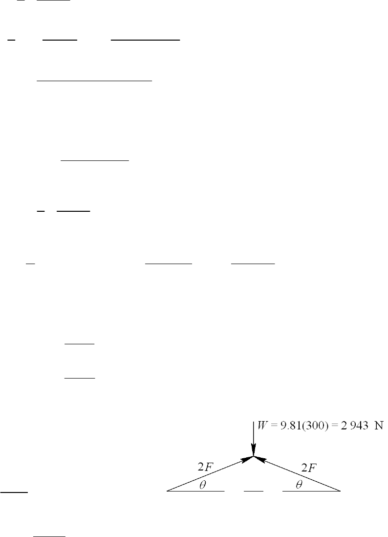
1/2
1/2 26
2
3
1
26 4
cr 2
50 160
0.3125
2 (1)30 10
2126 use Euler
37.5 10
30 10 / 64 1.25 14194 lbf
50
y
l
k
lCE
kS
P
Since 14 194 lbf > 11 780 lbf, d = 1.25 in is satisfactory. Ans.
(
b)
1/ 4
2
36
64 11780 16 0.675 in,
13010
d
so use d = 0.750 in
k = 0.750/4 = 0.1875 in
16 85.33 use Johnson
0.1875
l
k
2
3
23
cr 6
37.5 10 1
0.750 37.5 10 85.33 12 748 lbf
4 2 13010
P
Use d = 0.75 in.
(
c)
()
()
14194 3.01 .
4712
12748 2.71 .
4712
a
b
nA
nA
ns
ns
______________________________________________________________________________
4-109 From Table A-20, Sy = 180 MPa
4F sin
= 2 943
735.8
sin
F
In range of operation, F is maximum when
= 15
max o
735.8 2843 N per bar
sin15
F
Pcr = ndFmax = 3.50 (2 843) = 9 951 N
l = 350 mm, h = 30 mm
Chapter 4 - Rev B, Page 77/81
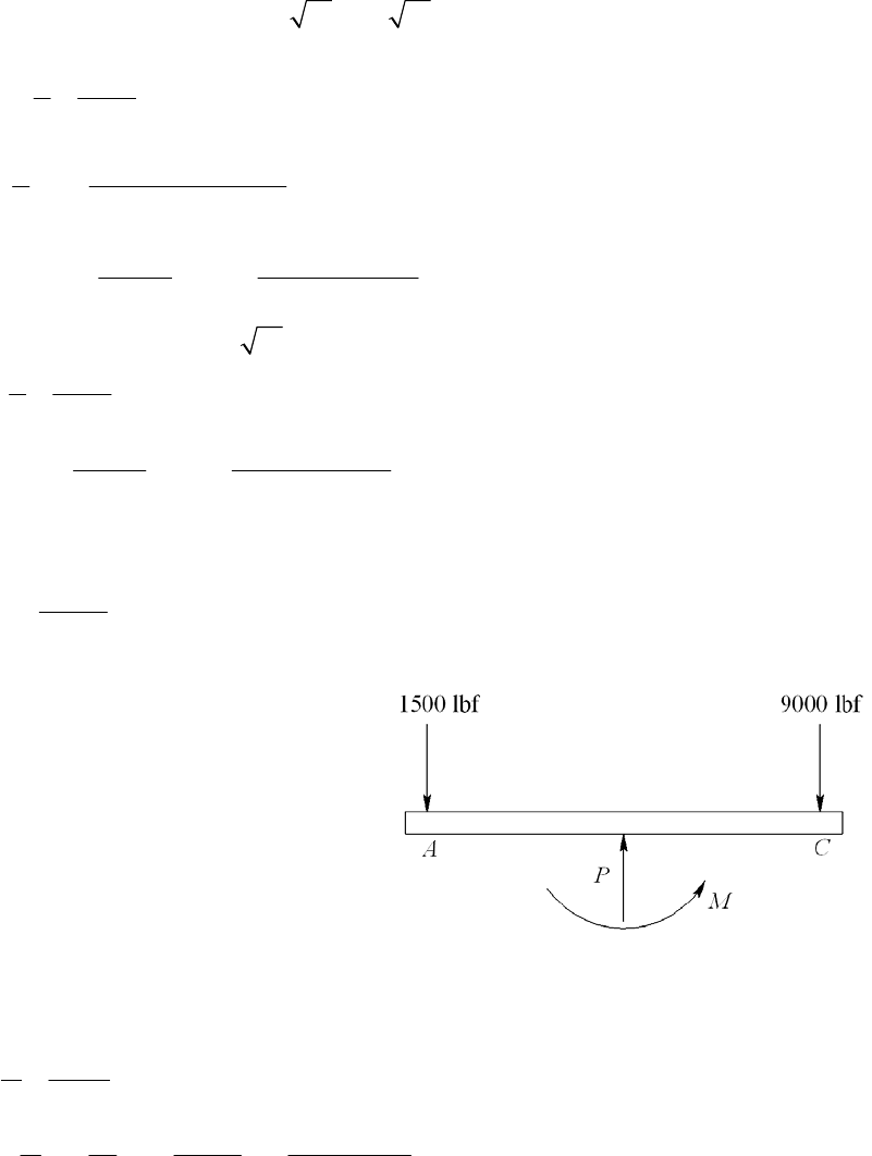
Try b = 5 mm. Out of plane, k = b / 12 = 5/ 12 = 1.443 mm
1/ 2
29
6
1
23
2
cr 22
350 242.6
1.443
2 1.4 207 10 178.3 use Euler
180 10
1.4 207 10
5(30) 7 290 N
/ 242.6
l
k
l
k
CE
PA
lk
Too low. Try b = 6 mm. k = 6/ 12 = 1.732 mm
23
2
cr 22
350 202.1
1.732
1.4 207 10
6(30) 12 605 N
/ 202.1
l
k
CE
PA
lk
O.K. Use 25 6 mm bars Ans. The factor of safety is
12605 4.43 .
2843
nA
ns
______________________________________________________________________________
4-110 P = 1 500 + 9 000 = 10 500 lbf Ans.
MA = 10 500 (4.5/2) 9 000 (4.5) +M = 0
M = 16 874 lbfin
e = M / P = 16 874/10 500 = 1.607 in Ans.
From Table A-8, A = 2.160 in2, and I = 2.059 in4. The stresses are determined using Eq.
(4-55)
22
2
2.059 0.953 in
2.160
1.607 3 / 2
10500
1 1 17157 psi 17.16 kpsi .
2.160 0.953
c
I
kA
Pec
A
ns
Ak
______________________________________________________________________________
4-111 This is a design problem which has no single distinct solution.
______________________________________________________________________________
Chapter 4 - Rev B, Page 78/81
4-112 Loss of potential energy of weight = W (h +
)
Increase in potential energy of spring = 2
1
2k
W (h +
) = 2
1
2k
or,
2220
WW
h
kk
. W = 30 lbf, k = 100 lbf/in, h = 2 in yields
2 0.6
1.2 = 0
Taking the positive root (see discussion on p. 192)
2
max
10.6 ( 0.6) 4(1.2) 1.436 in .
2
A
ns
Fmax = k
max = 100 (1.436) = 143.6 lbf Ans.
______________________________________________________________________________
4-113 The drop of weight W1 converts potential energy, W1 h, to kinetic energy 2
1
1
1
2
W
gv.
Equating these provides the velocity of W1 at impact with W2.
2
1
11 1
12
2
W
Wh gh
g
vv (1)
Since the collision is inelastic, momentum is conserved. That is, (m1 + m2) v2 = m1 v1,
where v2 is the velocity of W1 + W2 after impact. Thus
12 1 1 1
21 2 1
12 12
2
WW W W W gh
gg WWWW
vv v v (2)
The kinetic and potential energies of W1 + W2 are then converted to potential energy of
the spring. Thus,
22
12
212
11
22
WW WW k
g
v
Substituting in Eq. (1) and rearranging results in
2
212 1
12
22
WW W h
kWWk
0 (3)
Solving for the positive root (see discussion on p. 192)
22
12 12 1
12
124 8
2
WW WW W h
kkW
Wk
(4)
Chapter 4 - Rev B, Page 79/81
W1 = 40 N, W2 = 400 N, h = 200 mm, k = 32 kN/m = 32 N/mm.
22
1 40 400 40 400 40 200
2 4 8 29.06 mm .
2 32 32 40 400 32
A
ns
Fmax = k
= 32(29.06) = 930 N Ans.
______________________________________________________________________________
4-114 The initial potential energy of the k1 spring is Vi = 2
1
1
2ka . The movement of the weight
W the distance y gives a final potential of Vf =
22
1
1
22
ka y ky
2
1
. Equating the two
energies give
2
22
11
11 1
22 2
ka k a y k y
2
Simplifying gives
2
12 1
20kky aky
This has two roots, y = 0, 1
12
2ka
kk
. Without damping the weight will vibrate between
these two limits. The maximum displacement is thus y max = 1
12
2ka
kk
Ans.
With W = 5 lbf, k1 = 10 lbf/in, k2 = 20 lbf/in, and a = 0.25 in
max
2 0.25 10 0.1667 in .
10 20
y
Ans
______________________________________________________________________________
Chapter 4 - Rev B, Page 80/81
Chapter 6
6-1 Eq. (2-21): 3.4 3.4(300) 1020 MPa
ut B
SH
Eq. (6-8): 0.5 0.5(1020) 510 MPa
eut
SS
Table 6-2:
1.58, 0.085ab
Eq. (6-19):
0.085
1.58(1020) 0.877
b
aut
kaS
Eq. (6-20):
0.107 0.107
1.24 1.24(10) 0.969
b
kd
Eq. (6-18): (0.877)(0.969)(510) 433 MPa .
eabe
SkkS Ans
______________________________________________________________________________
6-2 (a) Table A-20: Sut = 80 kpsi
Eq. (6-8): 0.5(80) 40 kpsi .
e
SA
ns
ns
ns
(b) Table A-20: Sut = 90 kpsi
Eq. (6-8): 0.5(90) 45 kpsi .
e
SA
(c) Aluminum has no endurance limit. Ans.
(d) Eq. (6-8): Sut > 200 kpsi, 100 kpsi .
e
SA
______________________________________________________________________________
6-3 rev
120 kpsi, 70 kpsi
ut
S
Fig. 6-18:
0.82f
Eq. (6-8): 0.5(120) 60 kpsi
ee
SS
Eq. (6-14):
2
20.82(120)
() 161.4 kpsi
60
ut
e
fS
aS
Eq. (6-15): 1 1 0.82(120)
log log 0.0716
3360
ut
e
fS
bS
Eq. (6-16):
1
1/ 0.0716
rev 70 116 700 cycles .
161.4
b
NA
a
ns
______________________________________________________________________________
6-4 rev
1600 MPa, 900 MPa
ut
S
Fig. 6-18: Sut = 1600 MPa = 232 kpsi. Off the graph, so estimate f = 0.77.
Eq. (6-8): Sut > 1400 MPa, so Se = 700 MPa
Eq. (6-14):
2
20.77(1600)
() 2168.3 MPa
700
ut
e
fS
aS
Chapter 6 - Rev. A, Page 1/66

Eq. (6-15): 1 1 0.77(1600)
log log 0.081838
3 3 700
ut
e
fS
bS
Eq. (6-16):
1
1/ 0.081838
rev 900 46 400 cycles .
2168.3
b
NA
a
ns
______________________________________________________________________________
6-5 230 kpsi, 150 000 cycles
ut
SN
Fig. 6-18, point is off the graph, so estimate: f = 0.77
Eq. (6-8): Sut > 200 kpsi, so 100 kpsi
ee
SS
Eq. (6-14):
2
20.77(230)
() 313.6 kpsi
100
ut
e
fS
aS
Eq. (6-15): 1 1 0.77(230)
log log 0.08274
3 3 100
ut
e
fS
bS
Eq. (6-13):
0.08274
313.6(150 000) 117.0 kpsi .
b
f
SaN Ans
______________________________________________________________________________
6-6 = 160 kpsi 1100 MPa
ut
S
Fig. 6-18: f = 0.79
Eq. (6-8): 0.5(1100) 550 MPa
ee
SS
Eq. (6-14):
2
20.79(1100)
() 1373 MPa
550
ut
e
fS
aS
Eq. (6-15): 1 1 0.79(1100)
log log 0.06622
3 3 550
ut
e
fS
bS
Eq. (6-13):
0.06622
1373(150 000) 624 MPa .
b
f
SaN Ans
______________________________________________________________________________
6-7
150 kpsi, 135 kpsi, 500 cycles
ut yt
SSN
Fig. 6-18: f = 0.798
From Fig. 6-10, we note that below 103 cycles on the S-N diagram constitutes the low-
cycle region, in which Eq. (6-17) is applicable.
Chapter 6 - Rev. A, Page 2/66

Eq. (6-17):
log 0.798 /3
log /3 150 500 122 kpsi .
f
fut
SSN Ans
The testing should be done at a completely reversed stress of 122 kpsi, which is below
the yield strength, so it is possible. Ans.
______________________________________________________________________________
6-8 The general equation for a line on a log Sf - log N scale is Sf = aNb, which is Eq. (6-13).
By taking the log of both sides, we can get the equation of the line in slope-intercept
form.
log log log
f
SbNa
a
Substitute the two known points to solve for unknowns a and b. Substituting point (1,
Sut),
log log(1) log
ut
Sb
From which . Substituting point
ut
aS3
(10 , ) and
ut ut
f
SaS
3
log log10 log
ut ut
f
Sb S
From which
1/3 logbf
(log )/3 3
1 10
f
fut
SSN N
N
N
______________________________________________________________________________
6-9 Read from graph: From
36
10 ,90 and (10 ,50). b
SaN
11
22
log log log
log log log
Sab
Sab
From which
12 2
21
log log log log
log log /
SN SN
aNN
1
63
63
log 90log10 log 50log10
log10 / 10
2.2095
log 2.2095
0.0851 3 6
10 10 162.0 kpsi
log 50 / 90 0.0851
3
( ) 162 10 10 in kpsi .
a
fax
a
b
SN N
Ans
Chapter 6 - Rev. A, Page 3/66

Check:
3
6
3 0.0851
10
6 0.0851
10
( ) 162(10 ) 90 kpsi
( ) 162(10 ) 50 kpsi
fax
fax
S
S
The end points agree.
______________________________________________________________________________
6-10 d = 1.5 in, Sut = 110 kpsi
Eq. (6-8): 0.5(110) 55 kpsi
e
S
Table 6-2: a = 2.70, b = 0.265
Eq. (6-19):
0.265
2.70(110) 0.777
b
aut
kaS
Since the loading situation is not specified, we’ll assume rotating bending or torsion so
Eq. (6-20) is applicable. This would be the worst case.
0.107 0.107
0.879 0.879(1.5) 0.842
Eq. (6-18): 0.777(0.842)(55) 36.0 kpsi .
b
eabe
kd
SkkS Ans
______________________________________________________________________________
6-11 For AISI 4340 as-forged steel,
Eq. (6-8): Se = 100 kpsi
Table 6-2: a = 39.9, b = 0.995
Eq. (6-19): ka = 39.9(260)0.995 = 0.158
Eq. (6-20):
0.107
0.75 0.907
0.30
b
k
Each of the other modifying factors is unity.
Se = 0.158(0.907)(100) = 14.3 kpsi
For AISI 1040:
0.995
0.5(113) 56.5 kpsi
39.9(113) 0.362
0.907 (same as 4340)
e
a
b
S
k
k
Each of the other modifying factors is unity
0.362(0.907)(56.5) 18.6 kpsi
e
S
Not only is AISI 1040 steel a contender, it has a superior endurance strength.
______________________________________________________________________________
Chapter 6 - Rev. A, Page 4/66
6-12 D = 1 in, d = 0.8 in, T = 1800 lbfin, f = 0.9, and from Table A-20 for AISI 1020 CD,
Sut = 68 kpsi, and Sy = 57 kpsi.
(a) 0.1 1
Fig. A-15-15: 0.125, 1.25, 1.40
0.8 0.8 ts
rD
K
dd
Get the notch sensitivity either from Fig. 6-21, or from the curve-fit Eqs. (6-34) and
(6-35b). We’ll use the equations.
2
35 83
0.190 2.51 10 68 1.35 10 68 2.67 10 68 0.07335a
11
0.812
0.07335
1
10.1
s
qa
r
Eq. (6-32): Kfs = 1 + qs (Kts 1) = 1 + 0.812(1.40 1) = 1.32
For a purely reversing torque of T = 1800 lbfin,
33
16 1.32(16)(1800) 23 635 psi 23.6 kpsi
(0.8)
fs
afs
KT
Tr
KJd
Eq. (6-8): 0.5(68) 34 kpsi
e
S
Eq. (6-19): ka = 2.70(68)0.265 = 0.883
Eq. (6-20): kb = 0.879(0.8)0.107 = 0.900
Eq. (6-26): kc = 0.59
Eq. (6-18) (labeling for shear): Sse = 0.883(0.900)(0.59)(34) = 15.9 kpsi
For purely reversing torsion, use Eq. (6-54) for the ultimate strength in shear.
Eq. (6-54): Ssu = 0.67 Sut = 0.67(68) = 45.6 kpsi
Adjusting the fatigue strength equations for shear,
Eq. (6-14):
22
0.9(45.6) 105.9 kpsi
15.9
su
se
fS
aS
Eq. (6-15): 1 1 0.9(45.6)
log log 0.137 27
3 3 15.9
su
se
fS
bS
Eq. (6-16):
11
0.137 27 3
23.3 61.7 10 cycles .
105.9
b
a
NA
a
ns
Chapter 6 - Rev. A, Page 5/66
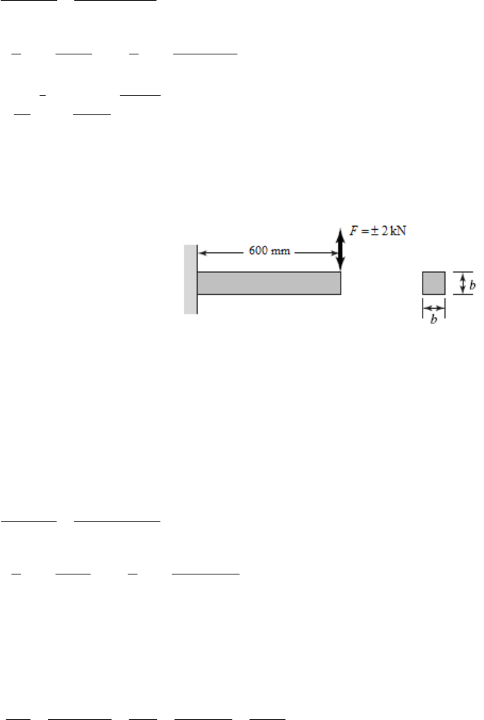
(b) For an operating temperature of 750 the temperature modification factor, F,
from Table 6-4 is kd = 0.90.
Sse = 0.883(0.900)(0.59)(0.9)(34) = 14.3 kpsi
22
0.9(45.6) 117.8 kpsi
14.3
1 1 0.9(45.6)
log log 0.152 62
3 3 14.3
su
se
su
se
fS
aS
fS
bS
11
0.152 62 3
23.3 40.9 10 cycles .
117.8
b
a
NA
a
ns
y
______________________________________________________________________________
6-13 (Table A-20)
4
0.6 m, 2 kN, 1.5, 10 cycles, 770 MPa, 420 MPa
aut
LFnN S S
First evaluate the fatigue strength.
0.5(770) 385 MPa
e
S
0.718
57.7(770) 0.488
a
k
Since the size is not yet known, assume a
typical value of kb = 0.85 and check later.
All other modifiers are equal to one.
Eq. (6-18): Se = 0.488(0.85)(385) = 160 MPa
In kpsi, Sut = 770/6.89 = 112 kpsi
Fig. 6-18: f = 0.83
Eq. (6-14):
22
0.83(770) 2553 MPa
160
ut
e
fS
a
S
Eq. (6-15): 1 1 0.83(770)
log log 0.2005
3 3 160
ut
e
fS
bS
Eq. (6-13):
4 0.2005
2553(10 ) 403 MPa
b
f
SaN
Now evaluate the stress.
max (2000 N)(0.6 m) 1200 N mM
max 333
/ 2 6 1200
6 7200
()/12
a
Mb
Mc M
3
I
bb b b b
Pa, with b in m.
Compare strength to stress and solve for the necessary b.
Chapter 6 - Rev. A, Page 6/66
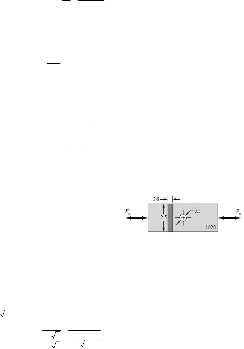
6
403 10
f
S
31.5
7200 /
a
nb
b = 0.0299 m Select b = 30 mm.
Since the size factor was guessed, go back and check it now.
Eq. (6-25):
1/2
0.808 0.808 0.808 30 24.24
e
dhb b mm
Eq. (6-20):
0.107
24.2 0.88
7.62
b
k
Our guess of 0.85 was slightly conservative, so we will accept the result of
b = 30 mm. Ans.
Checking yield,
6
max 3
7200 10 267 MPa
0.030
max
420 1.57
267
y
y
S
n
______________________________________________________________________________
-14 Given: w =2.5 in, t = 3/8 in, d = 0.5 in, nd = 2. From Table A-20, for AISI 1020 CD,
Eq. (6-8):
b= 1 (axial loading)
Eq. (6-18): Se = 0.88(1)(0.85)(34) = 25.4 kpsi
notch sensitivity either from Fig. 6-20, or from the curve-fit Eqs. (6-34) and
h
6
Sut = 68 kpsi and Sy = 57 kpsi.
0.5(68) 34 kpsi
e
S
Table 6-2: 88k0.265
2.70(68) 0.
a
Eq. (6-21): k
Eq. (6-26): kc = 0.85
Table A-15-1: / 0.5 / 2.5 0.2, 2.5
t
dKw
Get the
(6-35a). The relatively large radius is off the graph of Fig. 6-20, so we’ll assume the
curves continue according to the same trend and use the equations to estimate the notc
sensitivity.
2
35 83
0.246 3.08 10 68 1.51 10 68 2.67 10 68 0.09799a
11
0.836
0.09799
1
10.25
qa
r
Eq. (6-32): 1 ( 1) 1 0.836(2.5 1) 2.25
ft
KqK
Chapter 6 - Rev. A, Page 7/66
2.25
=3
(3 / 8)(2.5 0.5)
aa
af
FF
KF
A
a
e life was not mentioned, we’ll assume infinite life is desired, so the
Since a finit
completely reversed stress must stay below the endurance limit.
25.4 2
3
e
f
aa
S
nF
ns4.23 kips .
a
FA
____ __________ ___ ____________________ _________________________________________
ble A-20, for AISI 1095 HR, Sut = 120 kpsi and Sy = 66 kpsi.
-15 Given:6 max min
2 in, 1.8 in, 0.1 in, 25 000 lbf in, 0.Dd r M M
From Ta
(6-8):
0.5 0.5 120 60 kpsiSS
Eq. eut
Eq. (6-19):
0.265
2.70(120) 0.76
b
aut
kaS
Eq. (6-24): i
e0.370 0.370(1.8) 0.666 ndd
Eq. (6-20): 70.107 0.10
0.879 0.879(0.666) 0.92
be
kd
Fig. A-15-14:
Eq. (6-26): 1
c
k
Eq. (6-18): (0.76)(0.92)(1)(60) 42.0 kpsi
eabce
SkkkS
/ 2 /1.8 1.11, / 0.1/ 1.8 0.056Dd rd 2.1
t
K
Get the notch sensitivity either from Fig. 6-20, or from the curve-fit Eqs. (6-34) and
(6-35a). We’ll use the equations.
2
35 83
0.246 3.08 10 120 1.51 10 120 2.67 10 120 0.04770a
11
0.87
0.04770
1
10.1
qa
r
Eq. (6-32):
1 ( 1) 1 0.87(2.1 1) 1.96
ft
KqK
4
44
( / 64) ( / 64)(1.8) 0.5153 inId
max
min
25 000(1.8 / 2) 43 664 psi 43.7 kpsi
0.5153
0
Mc
I
Chapter 6 - Rev. A, Page 8/66
Eq. (6-36):
max min 43.7 0
1.96 42.8 kpsi
22
mf
K
max min 43.7 0
1.96 42.8 kpsi
22
af
K
Eq. (6-46): 1 42.8 42.8
42.0 120
am
feut
nSS
0.73 .
f
nAns
A factor of safety less than unity indicates a finite life.
Check for yielding. It is not necessary to include the stress concentration for static
yielding of a ductile material.
max
66 1.51 .
43.7
y
y
S
nA
ns
______________________________________________________________________________
6-16 From a free-body diagram analysis, the bearing reaction forces are found to be 2.1 kN at
the left bearing and 3.9 kN at the right bearing. The critical location will be at the
shoulder fillet between the 35 mm and the 50 mm diameters, where the bending moment
is large, the diameter is smaller, and the stress concentration exists. The bending moment
at this point is M = 2.1(200) = 420 kN·mm. With a rotating shaft, the bending stress will
be completely reversed.
2
rev 4
420 (35 / 2) 0.09978 kN/mm 99.8 MPa
( / 64)(35)
Mc
I
This stress is far below the yield strength of 390 MPa, so yielding is not predicted. Find
the stress concentration factor for the fatigue analysis.
Fig. A-15-9: r/d = 3/35 = 0.086, D/d = 50/35 = 1.43, Kt =1.7
Get the notch sensitivity either from Fig. 6-20, or from the curve-fit Eqs. (6-34) and
(6-35a). We’ll use the equations, with Sut = 470 MPa = 68.2 kpsi and r = 3 mm = 0.118
in.
23
35 8
0.246 3.08 10 68.2 1.51 10 68.2 2.67 10 68.2 0.09771a
11
0.78
0.09771
1
10.118
qa
r
Eq. (6-32): 1 ( 1) 1 0.78(1.7 1) 1.55
ft
KqK
Chapter 6 - Rev. A, Page 9/66
Eq. (6-8):
'0.5 0.5(470) 235 MPa
eut
SS
Eq. (6-19):
0.265
4.51(470) 0.88
b
aut
kaS
Eq. (6-24):
0.107 0.107
1.24 1.24(35) 0.85
b
kd
Eq. (6-26): 1
c
k
Eq. (6-18):
'(0.88)(0.85)(1)(235) 176 MPa
eabce
SkkkS
rev
176 1.14 Infinite life is predicted. .
1.55 99.8
e
f
f
S
nA
K
ns
______________________________________________________________________________
6-17 From a free-body diagram analysis, the
bearing reaction forces are found to be RA =
2000 lbf and RB = 1500 lbf. The shear-force
and bending-moment diagrams are shown.
The critical location will be at the shoulder
fillet between the 1-5/8 in and the 1-7/8 in
diameters, where the bending moment is
large, the diameter is smaller, and the stress
concentration exists.
M = 16 000 – 500 (2.5) = 14 750 lbf · in
With a rotating shaft, the bending stress will
be completely reversed.
rev 4
14 750(1.625 / 2) 35.0 kpsi
( / 64)(1.625)
Mc
I
This stress is far below the yield strength of 71 kpsi, so yielding is not predicted.
Fig. A-15-9: r/d = 0.0625/1.625 = 0.04, D/d = 1.875/1.625 = 1.15, Kt =1.95
Get the notch sensitivity either from Fig. 6-20, or from the curve-fit Eqs. (6-34) and
(6-35a). We will use the equations.
23
35 8
0.246 3.08 10 85 1.51 10 85 2.67 10 85 0.07690a
11
0.76
0.07690
1
10.0625
qa
r
.
Eq. (6-32):
1 ( 1) 1 0.76(1.95 1) 1.72
ft
KqK
Eq. (6-8):
SS
'0.5 0.5(85) 42.5 kpsi
eut
Chapter 6 - Rev. A, Page 10/66

Eq. (6-19):
0.265
2.70(85) 0.832
b
aut
kaS
Eq. (6-20):
0.107 0.107
0.879 0.879(1.625) 0.835
b
kd
Eq. (6-26): 1
c
k
Eq. (6-18):
'(0.832)(0.835)(1)(42.5) 29.5 kpsi
eabce
SkkkS
rev
29.5 0.49 .
1.72 35.0
e
f
f
S
nA
K
ns
Infinite life is not predicted. Use the S-N diagram to estimate the life.
Fig. 6-18: f = 0.867
22
0.867(85)
Eq. (6-14): 184.1
29.5
1 1 0.867(85)
Eq. (6-15): log log 0.1325
3 3 29.5
ut
e
ut
e
fS
aS
fS
bS
11
0.1325
rev (1.72)(35.0)
Eq. (6-16): 4611 cycles
184.1
b
f
K
Na
N = 4600 cycles Ans.
______________________________________________________________________________
6-18 From a free-body diagram analysis, the
bearing reaction forces are found to be RA =
1600 lbf and RB = 2000 lbf. The shear-force
and bending-moment diagrams are shown.
The critical location will be at the shoulder
fillet between the 1-5/8 in and the 1-7/8 in
diameters, where the bending moment is
large, the diameter is smaller, and the stress
concentration exists.
M = 12 800 + 400 (2.5) = 13 800 lbf · in
With a rotating shaft, the bending stress will
be completely reversed.
rev 4
13 800(1.625 / 2
)32.8 kpsi
( / 64)(1.625)
Mc
I
This stress is far below the yield strength of 71 kpsi, so yielding is not predicted.
Fig. A-15-9: r/d = 0.0625/1.625 = 0.04, D/d = 1.875/1.625 = 1.15, Kt =1.95
Chapter 6 - Rev. A, Page 11/66

Get the notch sensitivity either from Fig. 6-20, or from the curve-fit Eqs. (6-34) and
(6-35a). We will use the equations
23
35 8
0.246 3.08 10 85 1.51 10 85 2.67 10 85 0.07690a
11
0.76
0.07690
1
10.0625
qa
r
Eq. (6-32):
1 ( 1) 1 0.76(1.95 1) 1.72
ft
KqK
Eq. (6-8):
'0.5 0.5(85) 42.5 kpsi
eut
SS
Eq. (6-19):
0.265
2.70(85) 0.832
b
aut
kaS
Eq. (6-20):
0.107 0.107
0.879 0.879(1.625) 0.835
b
kd
Eq. (6-26): 1
c
k
Eq. (6-18):
'(0.832)(0.835)(1)(42.5) 29.5 kpsi
eabce
SkkkS
rev
29.5 0.52 .
1.72 32.8
e
f
f
S
nA
K
ns
Infinite life is not predicted. Use the S-N diagram to estimate the life.
Fig. 6-18: f = 0.867
22
0.867(85)
Eq. (6-14): 184.1
29.5
1 1 0.867(85)
Eq. (6-15): log log 0.1325
3 3 29.5
ut
e
ut
e
fS
aS
fS
bS
11
0.1325
rev (1.72)(32.8)
Eq. (6-16): 7527 cycles
184.1
b
f
K
Na
N = 7500 cycles Ans.
______________________________________________________________________________
6-19 Table A-20:
120 kpsi, 66 kpsi
ut y
SS
N = (950 rev/min)(10 hr)(60 min/hr) = 570 000 cycles
One approach is to guess a diameter and solve the problem as an iterative analysis
problem. Alternatively, we can estimate the few modifying parameters that are dependent
on the diameter and solve the stress equation for the diameter, then iterate to check the
estimates. We’ll use the second approach since it should require only one iteration, since
the estimates on the modifying parameters should be pretty close.
Chapter 6 - Rev. A, Page 12/66

First, we’ll evaluate the stress. From a free-body diagram analysis, the reaction forces at
the bearings are R1 = 2 kips and R2 = 6 kips. The critical stress location is in the middle
of the span at the shoulder, where the bending moment is high, the shaft diameter is
smaller, and a stress concentration factor exists. If the critical location is not obvious,
prepare a complete bending moment diagram and evaluate at any potentially critical
locations. Evaluating at the critical shoulder,
2 kip 10 in 20 kip inM
rev 4333
/ 2 32 20
32 203.7 kpsi
/64
Md
Mc M
Id d d d
Now we’ll get the notch sensitivity and stress concentration factor. The notch sensitivity
depends on the fillet radius, which depends on the unknown diameter. For now, we’ll
estimate a value for q = 0.85 from observation of Fig. 6-20, and check it later.
Fig. A-15-9:
/ 1.4 / 1.4, / 0.1 / 0.1, 1.65
t
Dd dd rd dd K
Eq. (6-32):
1 ( 1) 1 0.85(1.65 1) 1.55
ft
KqK
Now we will evaluate the fatigue strength.
'
0.265
0.5(120) 60 kpsi
2.70(120) 0.76
e
a
S
k
Since the diameter is not yet known, assume a typical value of k
b = 0.85 and check later.
All other modifiers are equal to one.
S
e = (0.76)(0.85)(60) = 38.8 kpsi
Determine the desired fatigue strength from the S-N diagram.
Fig. 6-18: f = 0.82
22
0.82(120)
Eq. (6-14): 249.6
38.8
1 1 0.82(120)
Eq. (6-15): log log 0.1347
3 3 38.8
ut
e
ut
e
fS
aS
fS
bS
0.1347
Eq. (6-13): 249.6(570 000) 41.9 kpsi
b
f
SaN
Compare strength to stress and solve for the necessary d.
Chapter 6 - Rev. A, Page 13/66
3
rev
d = 2.29 in
41.9 1.6
1.55 203.7 /
f
f
f
S
nKd
Since the size factor and notch sensitivity were guessed, go back and check them now.
Eq. (6-20):
0.157
0.157
0.91 0.91 2.29 0.80
b
kd
Our guess of 0.85 was conservative. From Fig. 6-20 with r = d/10 = 0.229 in, we are off
the graph, but it appears our guess for q is low. Assuming the trend of the graph
continues, we’ll choose q = 0.91 and iterate the problem with the new values of kb and q.
Intermediate results are Se = 36.5 kpsi, Sf = 39.6 kpsi, and Kf = 1.59. This gives
3
rev
39.6 1.6
1.59 203.7
d = 2.36 in Ans. /
f
f
f
S
nKd
a
A quick check of kb and q show that our estimates are still reasonable for this diameter.
______________________________________________________________________________
6-20 40 kpsi, 60 kpsi, 80 kpsi, 15 kpsi, 25 kpsi, 0
eyutma m
SSS
Obtain von Mises stresses for the alternating, mid-range, and maximum stresses.
1/2
1/2 2
22 2
1/2
1/2 2
22 2
3 25 3 0 25.00 kpsi
3 0 3 15 25.98 kpsi
aaa
mmm
1/ 2
1/ 2 22
22
max max max
1/ 2
22
33
25 3 15 36.06 kpsi
am am
max
60 1.66 .
36.06
y
y
S
nA
ns
(a) Modified Goodman, Table 6-6
11.05 .
(25.00 / 40) (25.98 / 80)
f
nA
ns
(b) Gerber, Table 6-7
2
2
1 80 25.00 2(25.98)(40)
1 1 1.31 .
2 25.98 40 80(25.00)
f
nA
ns
Chapter 6 - Rev. A, Page 14/66
(c) ASME-Elliptic, Table 6-8
22
11.32 .
(25.00 / 40) (25.98 / 60)
f
nA
ns
a
______________________________________________________________________________
6-21 40 kpsi, 60 kpsi, 80 kpsi, 20 kpsi, 10 kpsi, 0
eyutm a m
SSS
Obtain von Mises stresses for the alternating, mid-range, and maximum stresses.
1/2
1/ 2 2
22 2
1/2
1/2 2
22 2
3 10 3 0 10.00 kpsi
3 0 3 20 34.64 kpsi
aaa
mmm
1/ 2
1/ 2 22
22
max max max
1/2
22
33
10 3 20 36.06 kpsi
am am
max
60 1.66 .
36.06
y
y
S
nA
ns
(a) Modified Goodman, Table 6-6
11.46 .
(10.00 / 40) (34.64 / 80)
f
nA
ns
(b) Gerber, Table 6-7
2
2
1 80 10.00 2(34.64)(40)
1 1 1.74 .
2 34.64 40 80(10.00)
f
nA
ns
(c) ASME-Elliptic, Table 6-8
22
11.59 .
(10.00 / 40) (34.64 / 60)
f
nA
ns
m
______________________________________________________________________________
6-22 40 kpsi, 60 kpsi, 80 kpsi, 10 kpsi, 15 kpsi, 12 kpsi, 0
eyutama
SSS
Obtain von Mises stresses for the alternating, mid-range, and maximum stresses.
1/ 2
1/2 2
22 2
1/ 2
1/2 2
22 2
3 12 3 10 21.07 kpsi
3 0 3 15 25.98 kpsi
aaa
mmm
Chapter 6 - Rev. A, Page 15/66
1/ 2
1/ 2 22
22
max max max
1/ 2
22
33
12 0 3 10 15 44.93 kpsi
am am
max
60 1.34 .
44.93
y
y
S
nA
ns
(a) Modified Goodman, Table 6-6
11.17 .
(21.07 / 40) (25.98 / 80)
f
nA
ns
(b) Gerber, Table 6-7
2
2
1 80 21.07 2(25.98)(40)
1 1 1.47 .
2 25.98 40 80(21.07)
f
nA
ns
(c) ASME-Elliptic, Table 6-8
22
11.47 .
(21.07 / 40) (25.98 / 60)
f
nA
ns
a
______________________________________________________________________________
6-23 40 kpsi, 60 kpsi, 80 kpsi, 30 kpsi, 0
eyuta ma
SSS
Obtain von Mises stresses for the alternating, mid-range, and maximum stresses.
1/2
1/2 2
22 2
1/2
22
3 0 3 30 51.96 kpsi
3 0 kpsi
aaa
mmm
1/ 2
1/ 2 22
22
max max max
1/ 2
2
33
3 30 51.96 kpsi
am am
max
60 1.15 .
51.96
y
y
S
nA
ns
(a) Modified Goodman, Table 6-6
10.77 .
(51.96 / 40)
f
nAns
(b) Gerber criterion of Table 6-7 is only valid for
m > 0; therefore use Eq. (6-47).
Chapter 6 - Rev. A, Page 16/66
40
10
51.96
ae
ff
ea
S
nn
S.77.
Ans
(c) ASME-Elliptic, Table 6-8
2
10.77 .
(51.96 / 40)
f
nAns
Since infinite life is not predicted, estimate a life from the S-N diagram. Since
'm = 0,
the stress state is completely reversed and the S-N diagram is applicable for
'a.
Fig. 6-18: f = 0.875
Eq. (6-14):
2
20.875(80)
() 122.5
40
ut
e
fS
aS
Eq. (6-15): 1 1 0.875(80)
log log 0.08101
3340
ut
e
fS
bS
Eq. (6-16):
1
1/ 0.08101
rev 51.96 39 600 cycles .
122.5
b
NA
a
ns
a
______________________________________________________________________________
6-24 40 kpsi, 60 kpsi, 80 kpsi, 15 kpsi, 15 kpsi, 0
eyutamm
SSS
Obtain von Mises stresses for the alternating, mid-range, and maximum stresses.
1/2
1/2 2
22 2
3 0 3 15 25.98 kpsi
aaa
1/ 2
1/2 2
22 2
3 15 3 0 15.00 kpsi
mmm
1/ 2
1/ 2 22
22
max max max
1/2
22
33
15 3 15 30.00 kpsi
am am
max
60 2.00 .
30
y
y
S
nA
ns
(a) Modified Goodman, Table 6-6
11.19 .
(25.98 / 40) (15.00 / 80)
f
nA
ns
(b) Gerber, Table 6-7
2
2
1 80 25.98 2(15.00)(40)
1 1 1.43 .
2 15.00 40 80(25.98)
f
nA
ns
Chapter 6 - Rev. A, Page 17/66
(c) ASME-Elliptic, Table 6-8
22
11.44 .
(25.98 / 40) (15.00 / 60)
f
nA
ns
______________________________________________________________________________
6-25 Given: . From Table A-20, for AISI 1040
CD,
max min
28 kN, 28 kNFF
590 MPa, 490 MPa,
y
SS
ut
Check for yielding
2
max
max
28 000 147.4 N/mm 147.4 MPa
10(25 6)
F
A
max
490 3.32 .
147.4
y
y
S
nA
ns
Determine the fatigue factor of safety based on infinite life
Eq. (6-8):
'
0.5(590) 295 MPa
e
S
Eq. (6-19):
0.265
4.51(590) 0.832
b
aut
kaS
Eq. (6-21): 1 (axial)
b
k
Eq. (6-26): 0.85
c
k
Eq. (6-18):
'(0.832)(1)(0.85)(295) 208.6 MPa
eabce
SkkkS
Fig. 6-20: q = 0.83
Fig. A-15-1:
t
/ 0.24, 2.44dKw
1 ( 1) 1 0.83(2.44 1) 2.20
ft
KqK
max min
max min
28 000 28 000
2.2 324.2 MPa
2 2(10)(25 6)
0
2
af
mf
FF
KA
FF
KA
1 324.2 0
208.6 590
0.64 .
am
feut
f
nSS
nAns
Since infinite life is not predicted, estimate a life from the S-N diagram. Since
m = 0,
the stress state is completely reversed and the S-N diagram is applicable for
a.
Sut = 590/6.89 = 85.6 kpsi
Fig. 6-18: f = 0.87
Chapter 6 - Rev. A, Page 18/66

Eq. (6-14):
2
20.87(590)
() 1263
208.6
ut
e
fS
aS
Eq. (6-15): 1 1 0.87(590)
log log 0.1304
3 3 208.6
ut
e
fS
bS
Eq. (6-16):
1
1/ 0.1304
rev 324.2 33 812 cycles
1263
b
Na
N = 34 000 cycles Ans.
________________________________________________________________________
6-26
max min
590 MPa, 490 MPa, 28 kN, 12 kN
ut y
SSFF
Check for yielding
2
max
max
28 000 147.4 N/mm 147.4 MPa
10(25 6)
F
A
max
490 3.32 .
147.4
y
y
S
nA
ns
Determine the fatigue factor of safety based on infinite life.
From Prob. 6-25:
208.6 MPa, 2.2
ef
SK
max min 28 000 12 000
2.2 92.63 MPa
2 2(10)(25 6)
af
FF
KA
max min 28 000 12 000
2.2 231.6 MPa
2 2(10)(25 6)
mf
FF
KA
Modified Goodman criteria:
1 92.63 231.6
208.6 590
am
feut
nSS
1.20 .
f
nAns
Gerber criteria:
22
2
111
2
ut a m e
f
me uta
SS
nSS
2
2
1 590 92.63 2(231.6)(208.6)
11
2 231.6 208.6 590(92.63)
1.49 .
f
nAns
Chapter 6 - Rev. A, Page 19/66
ASME-Elliptic criteria:
22 2
11
( / ) ( / ) (92.63 / 208.6) (231.6 / 490)
f
ae my
nSS
2
= 1.54 Ans.
The results are consistent with Fig. 6-27, where for a mean stress that is about half of the
yield strength, the Modified Goodman line should predict failure significantly before the
other two.
______________________________________________________________________________
6-27
590 MPa, 490 MPa
ut y
SS
(a)
max min
28 kN, 0 kNFF
Check for yielding
2
max
max
28 000 147.4 N/mm 147.4 MPa
10(25 6)
F
A
max
490 3.32 .
147.4
y
y
S
nA
ns
From Prob. 6-25:
208.6 MPa, 2.2
ef
SK
max min
max min
28 000 0
2.2 162.1 MPa
2 2(10)(25 6)
28 000 0
2.2 162.1 MPa
2 2(10)(25 6)
af
mf
FF
KA
FF
KA
1 162.1 162.1
208.6 590
am
feut
nSS
0.95 .
f
nAns
Since infinite life is not predicted, estimate a life from the S-N diagram. First, find an
equivalent completely reversed stress (See Ex. 6-12).
rev
162.1 223.5 MPa
1 ( / ) 1 (162.1/ 590)
a
mut
S
Fig. 6-18: f = 0.87
Eq. (6-14):
2
20.87(590)
() 1263
208.6
ut
e
fS
aS
Chapter 6 - Rev. A, Page 20/66
Eq. (6-15): 1 1 0.87(590)
log log 0.1304
3 3 208.6
ut
e
fS
bS
Eq. (6-16):
1
1/ 0.1304
rev 223.5 586 000 cycles .
1263
b
NA
a
ns
(b)
max min
28 kN, 12 kNFF
The maximum load is the same as in part (a), so
max 147.4 MPa
3.32 .
y
nAns
Factor of safety based on infinite life:
max min
max min
28 000 12 000
2.2 92.63 MPa
2 2(10)(25 6)
28 000 12 000
2.2 231.6 MPa
2 2(10)(25 6)
af
mf
FF
KA
FF
KA
1 92.63 231.6
208.6 590
am
feut
nSS
1.20 .
f
nAns
(c)
max min
12 kN, 28 kNFF
The compressive load is the largest, so check it for yielding.
min
min
28 000 147.4 MPa
10(25 6)
F
A
min
490 3.32 .
147.4
yc
y
S
nA
ns
Factor of safety based on infinite life:
max min
max min
12 000 28 000
2.2 231.6 MPa
2 2(10)(25 6)
12 000 28 000
2.2 92.63 MPa
2 2(10)(25 6)
af
mf
FF
KA
FF
KA
For
m < 0, 208.6 0.90 .
231.6
e
f
a
S
nA
ns
Chapter 6 - Rev. A, Page 21/66
Since infinite life is not predicted, estimate a life from the S-N diagram. For a negative
mean stress, we shall assume the equivalent completely reversed stress is the same as the
actual alternating stress. Get a and b from part (a).
Eq. (6-16):
1
1/ 0.1304
rev 231.6 446 000 cycles .
1263
b
NA
a
ns
______________________________________________________________________________
6-28 Eq. (2-21): Sut = 0.5(400) = 200 kpsi
Eq. (6-8):
'
0.5(200) 100 kpsi
e
S
Eq. (6-19):
0.718
14.4(200) 0.321
b
aut
kaS
Eq. (6-25):
e0.37 0.37(0.375) 0.1388 indd
Eq. (6-20):
0.107 0.107
0.879 0.879(0.1388) 1.09
be
kd
Since we have used the equivalent diameter method to get the size factor, and in doing so
introduced greater uncertainties, we will choose not to use a size factor greater than one.
Let kb = 1.
Eq. (6-18): (0.321)(1)(100) 32.1 kpsi
e
S
40 20 40 20
10 lb 30 lb
22
am
FF
33
33
32 32(10)(12) 23.18 kpsi
(0.375)
32 32(30)(12) 69.54 kpsi
(0.375)
a
a
m
m
M
d
M
d
(a) Modified Goodman criterion
1 23.18 69.54
32.1 200
am
feut
nSS
0.94 .
f
nAns
Since infinite life is not predicted, estimate a life from the S-N diagram. First, find an
equivalent completely reversed stress (See Ex. 6-12).
rev
23.18 35.54 kpsi
1 ( / ) 1 (69.54 / 200)
a
mut
S
Fig. 6-18: f = 0.775
Eq. (6-14):
2
20.775(200)
() 748.4
32.1
ut
e
fS
aS
Chapter 6 - Rev. A, Page 22/66
Eq. (6-15): 1 1 0.775(200)
log log 0.228
3 3 32.1
ut
e
fS
bS
Eq. (6-16):
1
1/ 0.228
rev 35.54 637 000 cycles .
748.4
b
N
Ans
a
(b) Gerber criterion, Table 6-7
22
2
2
2
111
2
1 200 23.18 2(69.54)(32.1)
11
2 69.54 32.1 200(23.18)
1.16 Infinite life is predicted .
ut a m e
f
me uta
SS
nSS
Ans
______________________________________________________________________________
6-29
207.0 GPaE
(a) 34
1(20)(4 ) 106.7 mm
12
I
3
3
3
3
Fl EIy
yF
EI l
9123
min 39
3(207)(10 )(106.7)(10 )(2)(10 ) 48.3 N .
140 (10 )
FA
ns
9123
max 39
3(207)(10 )(106.7)(10 )(6)(10 ) 144.9 N .
140 (10 )
FA
ns
(b) Get the fatigue strength information.
Eq. (2-21): Sut = =3.4HB = 3.4(490) = 1666 MPa
From problem statement: Sy = 0.9Sut = 0.9(1666) = 1499 MPa
Eq. (6-8): 700 MPa
e
S
Eq. (6-19): ka = 1.58(1666)-0.085 = 0.84
Eq. (6-25): de = 0.808[20(4)]1/2 = 7.23 mm
Eq. (6-20): kb = 1.24(7.23)-0.107 = 1.00
Eq. (6-18): Se = 0.84(1)(700) = 588 MPa
This is a relatively thick curved beam, so
use the method in Sect. 3-18 to find the
stresses. The maximum bending moment
will be to the centroid of the section as
shown.
Chapter 6 - Rev. A, Page 23/66
M = 142F N·mm, A = 4(20) = 80 mm2, h = 4 mm, ri = 4 mm, ro = ri + h = 8 mm,
r
c = ri + h/2 = 6 mm
Table 3-4: 45.7708 mm
ln( / ) ln(8 / 4)
n
oi
h
rrr
6 5.7708 0.2292 mm
cn
err
5.7708 4 1.7708 mm
ini
crr
8 5.7708 2.2292 mm
oon
crr
Get the stresses at the inner and outer surfaces from Eq. (3-65) with the axial stresses
added. The signs have been set to account for tension and compression as appropriate.
(142 )(1.7708) 3.441 MPa
80(0.2292)(4) 80
(142 )(2.2292) 2.145 MPa
80(0.2292)(8) 80
i
i
i
o
o
o
Mc FF F F
Aer A
Mc FF F F
Aer A
min
max
min
max
( ) 3.441(144.9) 498.6 MPa
( ) 3.441(48.3) 166.2 MPa
( ) 2.145(48.3) 103.6 MPa
( ) 2.145(144.9) 310.8 MPa
i
i
o
o
166.2 498.6
( ) 166.2 MPa
2
ia
166.2 498.6
( ) 332.4 MPa
2
im
310.8 103.6
( ) 103.6 MPa
2
oa
310.8 103.6
( ) 207.2 MPa
2
om
To check for yielding, we note that the largest stress is –498.6 MPa (compression) on the
inner radius. This is considerably less than the estimated yield strength of 1499 MPa, so
yielding is not predicted.
Check for fatigue on both inner and outer radii since one has a compressive mean stress
and the other has a tensile mean stress.
Inner radius:
Since
m < 0, 588 3.54
166.2
e
f
a
S
n
Chapter 6 - Rev. A, Page 24/66

Outer radius:
Since
m > 0, we will use the Modified Goodman line.
103.6 207.2
1/ 588 1666
3.33
am
f
eut
f
nSS
n
Infinite life is predicted at both inner and outer radii. Ans.
______________________________________________________________________________
6-30 From Table A-20, for AISI 1018 CD, 64 kpsi, 54 kpsi
ut y
SS
Eq. (6-8):
'
0.5(64) 32 kpsi
e
S
Eq. (6-19):
0.265
2.70(64) 0.897
a
k
Eq. (6-20): 1 (axial)
b
k
Eq. (6-26): 0.85
c
k
Eq. (6-18): (0.897)(1)(0.85)(32) 24.4 kpsi
e
S
Fillet:
Fig. A-15-5: / 3.5 / 3 1.17, / 0.25 / 3 0.083, 1.85
t
Dd rd K
Use Fig. 6-20 or Eqs. (6-34) and (6-35a) for q. Estimate a little high since it is off the
graph. q = 0.85
1 ( 1) 1 0.85(1.85 1) 1.72
ft
KqK
max
max
2
min
max min
max min
53.33 kpsi
3.0(0.5)
16 10.67 kpsi
3.0(0.5)
3.33 ( 10.67)
1.72 12.0 kpsi
22
3.33 ( 10.67)
1.72 6.31 kpsi
22
af
mf
F
h
K
K
w
min
54 5.06 Does not yield.
10.67
y
y
S
n
Since the midrange stress is negative,
24.4 2.03
12.0
e
f
a
S
n
Chapter 6 - Rev. A, Page 25/66
Hole:
Fig. A-15-1:
1
/ 0.4 / 3.5 0.11 2.68
t
dKw
Use Fig. 6-20 or Eqs. (6-34) and (6-35a) for q. Estimate a little high since it is off the
graph. q = 0.85
1 0.85(2.68 1) 2.43
f
K
max
max
1
min
min
1
53.226 kpsi
0.5(3.5 0.4)
16 10.32 kpsi
0.5(3.5 0.4)
F
hd
F
hd
w
w
max min
max min
3.226 ( 10.32)
2.43 16.5 kpsi
22
3.226 ( 10.32)
2.43 8.62 kpsi
22
af
mf
K
K
min
54 5.23 does not yield
10.32
y
y
S
n
Since the midrange stress is negative,
24.4 1.48
16.5
e
f
a
S
n
Thus the design is controlled by the threat of fatigue at the hole with a minimum factor of
safety of
1.48. .
f
nAns
______________________________________________________________________________
6-31
64 kpsi, 54 kpsi
ut y
SS
Eq. (6-8):
'
0.5(64) 32 kpsi
e
S
Eq. (6-19):
0.265
2.70(64) 0.897
a
k
Eq. (6-20): 1 (axial)
b
k
Eq. (6-26): 0.85
c
k
Eq. (6-18): (0.897)(1)(0.85)(32) 24.4 kpsi
e
S
Fillet:
Fig. A-15-5: / 2.5 / 1.5 1.67, / 0.25 /1.5 0.17, 2.1
t
Dd rd K
Use Fig. 6-20 or Eqs. (6-34) and (6-35a) for q. Estimate a little high since it is off the
graph. q = 0.85
1 ( 1) 1 0.85(2.1 1) 1.94
ft
KqK
Chapter 6 - Rev. A, Page 26/66
max
max
2
min
16 21.3 kpsi
1.5(0.5)
45.33 kpsi
1.5(0.5)
F
h
w
max min
max min
21.3 ( 5.33)
1.94 25.8 kpsi
22
21.3 ( 5.33)
1.94 15.5 kpsi
22
af
mf
K
K
max
54 2.54 Does not yield.
21.3
y
y
S
n
Using Modified Goodman criteria,
1 25.8 15.5
24.4 64
am
feut
nSS
0.77
f
n
Hole:
Fig. A-15-1:
1
/ 0.4 / 2.5 0.16 2.55
t
dKw
Use Fig. 6-20 or Eqs. (6-34) and (6-35a) for q. Estimate a little high since it is off the
graph. q = 0.85
1 0.85(2.55 1) 2.32
f
K
max
max
1
min
min
1
16 15.2 kpsi
0.5(2.5 0.4)
43.81 kpsi
0.5(2.5 0.4)
F
hd
F
hd
w
w
max min
max min
15.2 ( 3.81)
2.32 22.1 kpsi
22
15.2 ( 3.81)
2.32 13.2 kpsi
22
af
mf
K
K
max
54 3.55 Does not yield.
15.2
y
y
S
n
Using Modified Goodman criteria
1 22.1 13.2
24.4 64
am
feut
nSS
0.90
f
n
Chapter 6 - Rev. A, Page 27/66
Thus the design is controlled by the threat of fatigue at the fillet with a minimum factor
of safety of
0.77 .
f
nAns
______________________________________________________________________________
6-32
64 kpsi, 54 kpsi
ut y
SS
From Prob. 6-30, the fatigue factor of safety at the hole is nf = 1.48. To match this at the
fillet,
24.4
16.5 kpsi
1.48
ee
fa
af
SS
nn
where Se is unchanged from Prob. 6-30. The only aspect of
a that is affected by the
fillet radius is the fatigue stress concentration factor. Obtaining
a in terms of Kf,
max min 3.33 ( 10.67) 7.00
22
af f f
K
KK
Equating to the desired stress, and solving for Kf,
7.00 16.5 2.36
af f
KK
Assume since we are expecting to get a smaller fillet radius than the original, that q will
be back on the graph of Fig. 6-20, so we’ll estimate q = 0.8.
1 0.80( 1) 2.36 2.7
ft t
KK K
From Fig. A-15-5, with D / d = 3.5/3 = 1.17 and Kt = 2.6, find r / d. Choosing r / d =
0.03, and with d = w2 = 3.0,
2
0.03 0.03 3.0 0.09 in r w
At this small radius, our estimate for q is too high. From Fig. 6-20, with r = 0.09, q
should be about 0.75. Iterating, we get Kt = 2.8. This is at a difficult range on Fig. A-15-
5 to read the graph with any confidence, but we’ll estimate r / d = 0.02, giving r = 0.06
in. This is a very rough estimate, but it clearly demonstrates that the fillet radius can be
relatively sharp to match the fatigue factor of safety of the hole. Ans.
______________________________________________________________________________
6-33
60 kpsi, 110 kpsi
yut
SS
Inner fiber where 3 / 4 in
c
r
330.84375
4 16(2)
330.65625
432
o
i
r
r
Table 3-4, p. 121,
Chapter 6 - Rev. A, Page 28/66
3/16 0.74608 in
0.84375
ln
ln 0.65625
no
i
h
rr
r
0.75 0.74608 0.00392 in
0.74608 0.65625 0.08983
cn
ini
err
crr
2
330.035156 in
16 16
A
Eq. (3-65), p. 119,
(0.08983) 993.3
(0.035156)(0.00392)(0.65625)
i
i
i
Mc TT
Aer
where T is in lbf·in and i
is in psi.
1( 993.3) 496.7
2
496.7
m
a
TT
T
Eq. (6-8):
'0.5 110 55 kpsi
e
S
Eq. (6-19):
0.265
2.70(110) 0.777
a
k
Eq. (6-25):
1/ 2
e0.808 3 /16 3 / 16 0.1515 ind
Eq. (6-20):
0.107
0.879 0.1515 1.08 (round to 1)
b
k
Eq. (6-19): (0.777)(1)(55) 42.7 kpsi
e
S
For a compressive midrange component, /. Thus,
aef
Sn
42.7
0.4967 3
T
28.7 lbf inT
Outer fiber where 2 .5 in
c
r
3
2.5 2.59375
32
3
2.5 2.40625
32
o
i
r
r
3/16 2.49883
2.59375
ln 2.40625
n
r
2.5 2.49883 0.00117 in
2.59375 2.49883 0.09492 in
o
e
c
Chapter 6 - Rev. A, Page 29/66
(0.09492) 889.7 psi
(0.035156)(0.00117)(2.59375)
1(889.7 ) 444.9 psi
2
o
o
o
ma
Mc TT
Aer
TT
(a) Using Eq. (6-46), for modified Goodman, we have
1
0.4449 0.4449 1
42.7 110 3
am
eut
SS n
TT
23.0 lbf in .TAns
(b) Gerber, Eq. (6-47), at the outer fiber,
2
2
1
3(0.4449 ) 3(0.4449 ) 1
42.7 110
am
eut
nn
SS
TT
28.2 lbf in .TAns
(c) To guard against yield, use T of part (b) and the inner stress.
60 2.14 .
0.9933(28.2)
y
y
i
S
nA
ns
______________________________________________________________________________
6-34 From Prob. 6-33,
42.7 kpsi, 60 kpsi, and 110 kpsi
ey ut
SS S
(a) Assuming the beam is straight,
max 323
/2 66
910.2
/12 (3 /16)
Mh
Mc M T T
Ibh bh
Goodman:
0.4551 0.4551 1
42.7 110 3
TT
22.5 lbf in .TAns
(b) Gerber:
2
3(0.4551 ) 3(0.4551 ) 1
42.7 110
TT
27.6 lbf in .TAns
Chapter 6 - Rev. A, Page 30/66
(c)
max
60 2.39 .
0.9102(27.6)
y
y
S
nA
ns
______________________________________________________________________________
6-35
,bend ,axial ,tors
1.4, 1.1, 2.0, 300 MPa, 400 MPa, 200 MPa
fffy ut e
KKKS S S
Bending: 0, 60 MPa
ma
Axial: 20 MPa, 0
ma
Torsion: 25 MPa, 25 MPa
ma
Eqs. (6-55) and (6-56):
22
22
1.4(60) 0 3 2.0(25) 120.6 MPa
0 1.1(20) 3 2.0(25) 89.35 MPa
a
m
Using Modified Goodman, Eq. (6-46),
1 120.6 89.35
200 400
am
feut
nSS
1.21 .
f
nAns
Check for yielding, using the conservative max am
,
300 1.43 .
120.6 89.35
y
y
am
S
nA
ns
______________________________________________________________________________
6-36
,bend ,tors
1.4, 2.0, 300 MPa, 400 MPa, 200 MPa
ffy ut e
KKS S S
Bending: max min
150 MPa, 40 MPa, 55 MPa, 95 MPa
ma
Torsion: 90 MPa, 9 MPa
ma
Eqs. (6-55) and (6-56):
22
22
1.4(95) 3 2.0(9) 136.6 MPa
1.4(55) 3 2.0(90) 321.1 MPa
a
m
Using Modified Goodman,
1 136.6 321.1
200 400
am
feut
nSS
0.67 .
f
nAns
Check for yielding, using the conservative max am
,
Chapter 6 - Rev. A, Page 31/66
300 0.66 .
136.6 321.1
y
y
am
S
nA
ns
Since the conservative yield check indicates yielding, we will check more carefully with
with max
obtained directly from the maximum stresses, using the distortion energy
failure theory, without stress concentrations. Note that this is exactly the method used for
static failure in Ch. 5.
22 2 2
max max max
max
3 150 3 90 9 227.8 MPa
300 1.32 .
227.8
y
y
S
nAns
Since yielding is not predicted, and infinite life is not predicted, we would like to
estimate a life from the S-N diagram. First, find an equivalent completely reversed stress
(See Ex. 6-12).
rev
136.6 692.5 MPa
1 ( / ) 1 (321.1/ 400)
a
mut
S
This stress is much higher than the ultimate strength, rendering it impractical for the S-N
diagram. We must conclude that the stresses from the combination loading, when
increased by the stress concentration factors, produce such a high midrange stress that the
equivalent completely reversed stress method is not practical to use. Without testing, we
are unable to predict a life.
______________________________________________________________________________
6-37 Table A-20:
ut y
64 kpsi, 54 kpsiSS
From Prob. 3-68, the critical stress element experiences
= 15.3 kpsi and
= 4.43 kpsi.
The bending is completely reversed due to the rotation, and the torsion is steady, giving
a = 15.3 kpsi,
m = 0 kpsi,
a = 0 kpsi,
m = 4.43 kpsi. Obtain von Mises stresses for
the alternating, mid-range, and maximum stresses.
1/2
1/2 2
22 2
1/2
1/2 2
22 2
1/2
1/ 2 2
22 2
max max max
3 15.3 3 0 15.3 kpsi
3 0 3 4.43 7.67 kpsi
3 15.3 3 4.43 17.11 kpsi
aaa
mmm
Check for yielding, using the distortion energy failure theory.
max
54 3.16
17.11
y
y
S
n
Obtain the modifying factors and endurance limit.
Eq. (6-8):
0.5 64 32 kpsi
e
S
Chapter 6 - Rev. A, Page 32/66

Eq. (6-19):
0.265
2.70(64) 0.90
a
k
Eq. (6-20):
0.107
0.879(1.25) 0.86
b
k
Eq. (6-18): 0.90(0.86)(32) 24.8 kpsi
e
S
Using Modified Goodman,
1 15.3 7.67
24.8 64
am
feut
nSS
1.36 .
f
nAns
______________________________________________________________________________
6-38 Table A-20:
ut y
440 MPa, 370 MPaSS
From Prob. 3-69, the critical stress element experiences
= 263 MPa and
= 57.7 MPa.
The bending is completely reversed due to the rotation, and the torsion is steady, giving
a = 263 MPa,
m = 0,
a = 0 MPa,
m = 57.7 MPa. Obtain von Mises stresses for the
alternating, mid-range, and maximum stresses.
1/ 2
1/ 2 2
22 2
1/ 2
1/ 2 2
22 2
1/2
1/ 2 2
22 2
max max max
3 263 3 0 263 MPa
3 0 3 57.7 99.9 MPa
3 263 3 57.7 281 MPa
aaa
mmm
Check for yielding, using the distortion energy failure theory.
max
370 1.32
281
y
y
S
n
Obtain the modifying factors and endurance limit.
Eq. (6-8):
0.5 440 220 MPa
e
S
Eq. (6-19):
0.265
4.51(440) 0.90
a
k
Eq. (6-20):
0.107
1.24(30) 0.86
b
k
Eq. (6-18):
0.90(0.86)(220) 170 MPa
e
S
Using Modified Goodman,
1 263 99.9
170 440
am
feut
nSS
Infinite life is not predicted. Ans.
0.56
f
n
______________________________________________________________________________
Chapter 6 - Rev. A, Page 33/66

6-39 Table A-20:
ut y
64 kpsi, 54 kpsiSS
From Prob. 3-70, the critical stress element experiences
= 21.5 kpsi and
= 5.09 kpsi.
The bending is completely reversed due to the rotation, and the torsion is steady, giving
a = 21.5 kpsi,
m = 0 kpsi,
a = 0 kpsi,
m = 5.09 kpsi. Obtain von Mises stresses for
the alternating, mid-range, and maximum stresses.
1/ 2
1/2 2
22 2
1/ 2
1/2 2
22 2
1/ 2
1/ 2 2
22 2
max max max
3 21.5 3 0 21.5 kpsi
3 0 3 5.09 8.82 kpsi
3 21.5 3 5.09 23.24 kpsi
aaa
mmm
Check for yielding, using the distortion energy failure theory.
max
54 2.32
23.24
y
y
S
n
Obtain the modifying factors and endurance limit.
0.265
2.70(64) 0.90
a
k
0.107
0.879(1) 0.88
b
k
0.90(0.88)(0.5)(64) 25.3 kpsi
e
S
Using Modified Goodman,
1 21.5 8.82
25.3 64
am
feut
nSS
1.01 .
f
nAns
______________________________________________________________________________
6-40 Table A-20:
ut y
440 MPa, 370 MPaSS
From Prob. 3-71, the critical stress element experiences
= 72.9 MPa and
= 20.3 MPa.
The bending is completely reversed due to the rotation, and the torsion is steady, giving
a = 72.9 MPa,
m = 0 MPa,
a = 0 MPa,
m = 20.3 MPa. Obtain von Mises stresses for
the alternating, mid-range, and maximum stresses.
1/2
1/2 2
22 2
1/2
1/2 2
22 2
1/2
1/ 2 2
22 2
max max max
3 72.9 3 0 72.9 MPa
3 0 3 20.3 35.2 MPa
3 72.9 3 20.3 80.9 MPa
aaa
mmm
Check for yielding, using the distortion energy failure theory.
Chapter 6 - Rev. A, Page 34/66

max
370 4.57
80.9
y
y
S
n
Obtain the modifying factors and endurance limit.
Eq. (6-8):
0.5 440 220 MPa
e
S
Eq. (6-19):
0.265
4.51(440) 0.90
a
k
Eq. (6-20):
0.107
1.24(20) 0.90
b
k
Eq. (6-18):
0.90(0.90)(220) 178.2 MPa
e
S
Using Modified Goodman,
1 72.9 35.2
178.2 440
am
feut
nSS
2.04 .
f
nAns
______________________________________________________________________________
6-41 Table A-20:
ut y
64 kpsi, 54 kpsiSS
From Prob. 3-72, the critical stress element experiences
= 35.2 kpsi and
= 7.35 kpsi.
The bending is completely reversed due to the rotation, and the torsion is steady, giving
a = 35.2 kpsi,
m = 0 kpsi,
a = 0 kpsi,
m = 7.35 kpsi. Obtain von Mises stresses for
the alternating, mid-range, and maximum stresses.
1/ 2
1/2 2
22 2
1/2
1/2 2
22 2
1/ 2
1/2 2
22 2
max max max
3 35.2 3 0 35.2 kpsi
3 0 3 7.35 12.7 kpsi
3 35.2 3 7.35 37.4 kpsi
aaa
mmm
Check for yielding, using the distortion energy failure theory.
max
54 1.44
37.4
y
y
S
n
Obtain the modifying factors and endurance limit.
Eq. (6-8): 0.5(64) 32 kpsi
e
S
Eq. (6-19):
0.265
2.70(64) 0.90
a
k
Eq. (6-20):
0.107
0.879(1.25) 0.86
b
k
Eq. (6-18):
0.90(0.86)(32) 24.8 kpsi
e
S
Chapter 6 - Rev. A, Page 35/66

Using Modified Goodman,
1 35.2 12.7
24.8 64
am
feut
nSS
Infinite life is not predicted. Ans.
0.62
f
n
______________________________________________________________________________
6-42 Table A-20:
ut y
440 MPa, 370 MPaSS
From Prob. 3-73, the critical stress element experiences
= 333.9 MPa and
= 126.3
MPa. The bending is completely reversed due to the rotation, and the torsion is steady,
giving
a = 333.9 MPa,
m = 0 MPa,
a = 0 MPa,
m = 126.3 MPa. Obtain von Mises
stresses for the alternating, mid-range, and maximum stresses.
1/ 2
1/2 2
22 2
1/2
1/2 2
22 2
1/ 2
1/ 2 2
22 2
max max max
3 333.9 3 0 333.9 MPa
3 0 3 126.3 218.8 MPa
3 333.9 3 126.3 399.2 MPa
aaa
mmm
Check for yielding, using the distortion energy failure theory.
max
370 0.93
399.2
y
y
S
n
The sample fails by yielding, infinite life is not predicted. Ans.
The fatigue analysis will be continued only to obtain the requested fatigue factor of
safety, though the yielding failure will dictate the life.
Obtain the modifying factors and endurance limit.
Eq. (6-8): 0.5(440) 220 MPa
e
S
Eq. (6-19):
0.265
4.51(440) 0.90
a
k
Eq. (6-20):
0.107
1.24(50) 0.82
b
k
Eq. (6-18):
0.90(0.82)(220) 162.4 MPa
e
S
Using Modified Goodman,
1 333.9 218.8
162.4 440
am
feut
nSS
Infinite life is not predicted. Ans.
0.39
f
n
______________________________________________________________________________
Chapter 6 - Rev. A, Page 36/66

6-43 Table A-20:
64 kpsi, 54 kpsi
ut y
SS
From Prob. 3-74, the critical stress element experiences completely reversed bending
stress due to the rotation, and steady torsional and axial stresses.
,bend ,bend
,axial ,axial
9.495 kpsi, 0 kpsi
0 kpsi, 0.362 kpsi
0 kpsi, 11.07 kpsi
am
am
am
Obtain von Mises stresses for the alternating, mid-range, and maximum stresses.
1/ 2
1/2 22
22
1/ 2
1/2 22
22
1/ 2
1/ 2 22
22
max max max
3 9.495 3 0 9.495 kpsi
3 0.362 3 11.07 19.18 kpsi
3 9.495 0.362 3 11.07 21.56 kpsi
aaa
mmm
Check for yielding, using the distortion energy failure theory.
max
54 2.50
21.56
y
y
S
n
Obtain the modifying factors and endurance limit.
Eq. (6-8): 0.5(64) 32 kpsi
e
S
Eq. (6-19):
0.265
2.70(64) 0.90
a
k
Eq. (6-20):
0.107
0.879(1.13) 0.87
b
k
Eq. (6-18):
0.90(0.87)(32) 25.1 kpsi
e
S
Using Modified Goodman,
1 9.495 19.18
25.1 64
am
feut
nSS
1.47 .
f
nAns
______________________________________________________________________________
6-44 Table A-20:
ut y
64 kpsi, 54 kpsiSS
From Prob. 3-76, the critical stress element experiences completely reversed bending
stress due to the rotation, and steady torsional and axial stresses.
,bend ,bend
,axial ,axial
33.99 kpsi, 0 kpsi
0 kpsi, 0.153 kpsi
0 kpsi, 7.847 kpsi
am
am
am
Chapter 6 - Rev. A, Page 37/66

Obtain von Mises stresses for the alternating, mid-range, and maximum stresses.
1/2
1/2 22
22
1/ 2
1/2 22
22
1/2
1/ 2 22
22
max max max
3 33.99 3 0 33.99 kpsi
3 0.153 3 7.847 13.59 kpsi
3 33.99 0.153 3 7.847 36.75 kpsi
aaa
mmm
Check for yielding, using the distortion energy failure theory.
max
54 1.47
36.75
y
y
S
n
Obtain the modifying factors and endurance limit.
Eq. (6-8): 0.5(64) 32 kpsi
e
S
Eq. (6-19):
0.265
2.70(64) 0.90
a
k
Eq. (6-20):
0.107
0.879(0.88) 0.89
b
k
Eq. (6-18):
0.90(0.89)(32) 25.6 kpsi
e
S
Using Modified Goodman,
1 33.99 13.59
25.6 64
am
feut
nSS
Infinite life is not predicted. Ans.
0.65
f
n
______________________________________________________________________________
6-45 Table A-20:
ut y
440 MPa, 370 MPaSS
From Prob. 3-77, the critical stress element experiences
= 68.6 MPa and
= 37.7 MPa.
The bending is completely reversed due to the rotation, and the torsion is steady, giving
a = 68.6 MPa,
m = 0 MPa,
a = 0 MPa,
m = 37.7 MPa. Obtain von Mises stresses for
the alternating, mid-range, and maximum stresses.
1/ 2
1/2 2
22 2
1/ 2
1/2 2
22 2
1/ 2
1/ 2 2
22 2
max max max
3 68.6 3 0 68.6 MPa
3 0 3 37.7 65.3 MPa
3 68.6 3 37.7 94.7 MPa
aaa
mmm
Check for yielding, using the distortion energy failure theory.
max
370 3.91
94.7
y
y
S
n
Chapter 6 - Rev. A, Page 38/66

Obtain the modifying factors and endurance limit.
Eq. (6-8): 0.5(440) 220 MPa
e
S
Eq. (6-19):
0.265
4.51(440) 0.90
a
k
Eq. (6-20):
0.107
1.24(30) 0.86
b
k
Eq. (6-18): 0.90(0.86)(220) 170 MPa
e
S
Using Modified Goodman,
1 68.6 65.3
170 440
am
feut
nSS
1.81 .
f
nAns
______________________________________________________________________________
6-46 Table A-20:
64 kpsi, 54 kpsi
ut y
SS
From Prob. 3-79, the critical stress element experiences
= 3.46 kpsi and
= 0.882 kpsi.
The bending is completely reversed due to the rotation, and the torsion is steady, giving
a = 3.46 kpsi,
m = 0,
a = 0 kpsi,
m = 0.882 kpsi. Obtain von Mises stresses for the
alternating, mid-range, and maximum stresses.
1/2
1/2 2
22 2
1/2
1/2 2
22 2
1/ 2
1/ 2 2
22 2
max max max
3 3.46 3 0 3.46 kpsi
3 0 3 0.882 1.53 kpsi
3 3.46 3 0.882 3.78 kpsi
aaa
mmm
Check for yielding, using the distortion energy failure theory.
max
54 14.3
3.78
y
y
S
n
Obtain the modifying factors and endurance limit.
Eq. (6-8): 0.5(64) 32 kpsi
e
S
Eq. (6-19):
0.265
2.70(64) 0.90
a
k
Eq. (6-20):
0.107
0.879(1.375) 0.85
b
k
Eq. (6-18):
0.90(0.85)(32) 24.5 kpsi
e
S
Using Modified Goodman,
Chapter 6 - Rev. A, Page 39/66

1 3.46 1.53
24.5 64
am
feut
nSS
Ans.
6.06
f
n
______________________________________________________________________________
6-47 Table A-20:
64 kpsi, 54 kpsi
ut y
SS
From Prob. 3-80, the critical stress element experiences
= 16.3 kpsi and
= 5.09 kpsi.
Since the load is applied and released repeatedly, this gives
max = 16.3 kpsi,
min = 0
kpsi,
max = 5.09 kpsi,
min = 0 kpsi. Consequently,
m =
a = 8.15 kpsi,
m =
a = 2.55
kpsi.
For bending, from Eqs. (6-34) and (6-35a),
23
35 8
0.246 3.08 10 64 1.51 10 64 2.67 10 64 0.10373a
11
0.75
0.10373
1
10.1
qa
r
Eq. (6-32):
1 ( 1) 1 0.75(1.5 1) 1.38
ft
KqK
For torsion, from Eqs. (6-34) and (6-35b),
23
35 8
0.190 2.51 10 64 1.35 10 64 2.67 10 64 0.07800a
11
0.80
0.07800
1
10.1
qa
r
Eq. (6-32):
1 ( 1) 1 0.80(2.1 1) 1.88
fs s ts
KqK
Obtain von Mises stresses for the alternating and mid-range stresses from Eqs. (6-55) and
(6-56).
1/ 2
22
1.38 8.15 3 1.88 2.55 13.98 kpsi
13.98 kpsi
a
ma
Check for yielding, using the conservative max am
,
54 1.93
13.98 13.98
y
y
am
S
n
Obtain the modifying factors and endurance limit.
Eq. (6-8): 0.5(64) 32 kpsi
e
S
Eq. (6-19):
0.265
2.70(64) 0.90
b
aut
kaS
Chapter 6 - Rev. A, Page 40/66
Eq. (6-24):
0.370 0.370 1 0.370 in
e
dd
Eq. (6-20):
0.107 0.107
0.879 0.879(0.370) 0.98
be
kd
Eq. (6-18):
(0.90)(0.98)(32) 28.2 kpsi
e
S
Using Modified Goodman,
1 13.98 13.98
28.2 64
am
feut
nSS
1.40 .
f
nAns
______________________________________________________________________________
6-48 Table A-20:
64 kpsi, 54 kpsi
ut y
SS
From Prob. 3-81, the critical stress element experiences
= 16.4 kpsi and
= 4.46 kpsi.
Since the load is applied and released repeatedly, this gives
max = 16.4 kpsi,
min = 0
kpsi,
max = 4.46 kpsi,
min = 0 kpsi. Consequently,
m =
a = 8.20 kpsi,
m =
a = 2.23
kpsi.
For bending, from Eqs. (6-34) and (6-35a),
23
35 8
0.246 3.08 10 64 1.51 10 64 2.67 10 64 0.10373a
11
0.75
0.10373
1
10.1
qa
r
Eq. (6-32):
1 ( 1) 1 0.75(1.5 1) 1.38
ft
KqK
For torsion, from Eqs. (6-34) and (6-35b),
23
35 8
0.190 2.51 10 64 1.35 10 64 2.67 10 64 0.07800a
11
0.80
0.07800
1
10.1
qa
r
Eq. (6-32):
1 ( 1) 1 0.80(2.1 1) 1.88
fs s ts
KqK
Obtain von Mises stresses for the alternating and mid-range stresses from Eqs. (6-55) and
(6-56).
1/ 2
22
1.38 8.20 3 1.88 2.23 13.45 kpsi
13.45 kpsi
a
ma
Check for yielding, using the conservative max am
,
Chapter 6 - Rev. A, Page 41/66
54 2.01
13.45 13.45
y
y
am
S
n
Obtain the modifying factors and endurance limit.
Eq. (6-8): 0.5(64) 32 kpsi
e
S
Eq. (6-19):
0.265
2.70(64) 0.90
b
aut
kaS
Eq. (6-24): 0.370 0.370(1) 0.370 in
e
dd
Eq. (6-20):
0.107 0.107
0.879 0.879(0.370) 0.98
be
kd
Eq. (6-18):
(0.90)(0.98)(32) 28.2 kpsi
e
S
Using Modified Goodman,
1 13.45 13.45
28.2 64
am
feut
nSS
1.46 .
f
nAns
______________________________________________________________________________
6-49 Table A-20:
64 kpsi, 54 kpsi
ut y
SS
From Prob. 3-82, the critical stress element experiences repeatedly applied bending,
axial, and torsional stresses of
x,bend = 20.2 kpsi,
x,axial = 0.1 kpsi, and
= 5.09 kpsi..
Since the axial stress is practically negligible compared to the bending stress, we will
simply combine the two and not treat the axial stress separately for stress concentration
factor and load factor. This gives
max = 20.3 kpsi,
min = 0 kpsi,
max = 5.09 kpsi,
min =
0 kpsi. Consequently,
m =
a = 10.15 kpsi,
m =
a = 2.55 kpsi.
For bending, from Eqs. (6-34) and (6-35a),
23
35 8
0.246 3.08 10 64 1.51 10 64 2.67 10 64 0.10373a
11
0.75
0.10373
1
10.1
qa
r
Eq. (6-32):
1 ( 1) 1 0.75(1.5 1) 1.38
ft
KqK
For torsion, from Eqs. (6-34) and (6-35b),
23
35 8
0.190 2.51 10 64 1.35 10 64 2.67 10 64 0.07800a
11
0.80
0.07800
1
10.1
qa
r
Chapter 6 - Rev. A, Page 42/66

Eq. (6-32):
1 ( 1) 1 0.80(2.1 1) 1.88
fs s ts
KqK
Obtain von Mises stresses for the alternating and mid-range stresses from Eqs. (6-55) and
(6-56).
1/ 2
22
1.38 10.15 3 1.88 2.55 16.28 kpsi
16.28 kpsi
a
ma
Check for yielding, using the conservative max am
,
54 1.66
16.28 16.28
y
y
am
S
n
Obtain the modifying factors and endurance limit.
Eq. (6-8): 0.5(64) 32 kpsi
e
S
Eq. (6-19):
0.265
2.70(64) 0.90
b
aut
kaS
Eq. (6-24): 0.370 0.370(1) 0.370 in
e
dd
Eq. (6-20):
0.107 0.107
0.879 0.879(0.370) 0.98
be
kd
Eq. (6-18):
(0.90)(0.98)(32) 28.2 kpsi
e
S
Using Modified Goodman,
1 16.28 16.28
28.2 64
am
feut
nSS
1.20 .
f
nAns
____________________________________________________________________________
6-50 Table A-20:
64 kpsi, 54 kpsi
ut y
SS
From Prob. 3-83, the critical stress element on the neutral axis in the middle of the
longest side of the rectangular cross section experiences a repeatedly applied shear stress
of
max = 14.3 kpsi,
min = 0 kpsi. Thus,
m =
a = 7.15 kpsi. Since the stress is entirely
shear, it is convenient to check for yielding using the standard Maximum Shear Stress
theory.
max
/2 54 / 2 1.89
14.3
y
y
S
n
Find the modifiers and endurance limit.
Eq. (6-8): 0.5(64) 32 kpsi
e
S
Eq. (6-19):
0.265
2.70(64) 0.90
b
aut
kaS
Chapter 6 - Rev. A, Page 43/66

The size factor for a torsionally loaded rectangular cross section is not readily available.
Following the procedure on p. 289, we need an equivalent diameter based on the 95
percent stress area. However, the stress situation in this case is nonlinear, as described on
p. 102. Noting that the maximum stress occurs at the middle of the longest side, or with a
radius from the center of the cross section equal to half of the shortest side, we will
simply choose an equivalent diameter equal to the length of the shortest side.
0.25 in
e
d
Eq. (6-20):
0.107 0.107
0.879 0.879(0.25) 1.02
be
kd
We will round down to kb = 1.
Eq. (6-26): 0.59
c
k
Eq. (6-18): 0.9(1)(0.59)(32) 17.0 kpsi
se
S
Since the stress is entirely shear, we choose to use a load factor kc = 0.59, and convert the
ultimate strength to a shear value rather than using the combination loading method of
Sec. 6-14. From Eq. (6-54), Ssu = 0.67Su = 0.67 (64) = 42.9 kpsi.
Using Modified Goodman,
11
1.70 .
( / ) ( / ) (7.15 /17.0) (7.15 / 42.9)
f
ase msu
n Ans
SS
______________________________________________________________________________
6-51 Table A-20:
64 kpsi, 54 kpsi
ut y
SS
From Prob. 3-84, the critical stress element experiences
= 28.0 kpsi and
= 15.3 kpsi.
Since the load is applied and released repeatedly, this gives
max = 28.0 kpsi,
min = 0
kpsi,
max = 15.3 kpsi,
min = 0 kpsi. Consequently,
m =
a = 14.0 kpsi,
m =
a = 7.65
kpsi. From Table A-15-8 and A-15-9,
,bend ,tors
/ 1.5 /1 1.5, / 0.125 /1 0.125
1.60, 1.39
tt
Dd rd
KK
Eqs. (6-34) and (6-35), or Figs. 6-20 and 6-21: qbend = 0.78, qtors = 0.82
Eq. (6-32):
,bend bend ,bend
,tors tors ,tors
1 1 1 0.78 1.60 1 1.47
1 1 1 0.82 1.39 1 1.32
ft
ft
KqK
KqK
Obtain von Mises stresses for the alternating and mid-range stresses from Eqs. (6-55) and
(6-56).
Chapter 6 - Rev. A, Page 44/66

1/2
22
1.47 14.0 3 1.32 7.65 27.0 kpsi
27.0 kpsi
a
ma
Check for yielding, using the conservative max am
,
54 1.00
27.0 27.0
y
y
am
S
n
Since stress concentrations are included in this quick yield check, the low factor of safety
is acceptable.
Eq. (6-8): 0.5(64) 32 kpsi
e
S
Eq. (6-19):
0.265
2.70(64) 0.897
b
aut
kaS
Eq. (6-24):
0.370 0.370 1 0.370 in
e
dd
Eq. (6-20):
0.107 0.107
0.879 0.879(0.370) 0.978
be
kd
Eq. (6-18): (0.897)(0.978)(0.5)(64) 28.1 kpsi
e
S
Using Modified Goodman,
1 27.0 27.0
28.1 64
am
feut
nSS
0.72 .
f
nAns
Since infinite life is not predicted, estimate a life from the S-N diagram. First, find an
equivalent completely reversed stress (See Ex. 6-12).
rev
27.0 46.7 kpsi
1 ( / ) 1 (27.0 / 64)
a
mut
S
Fig. 6-18: f = 0.9
Eq. (6-14):
2
20.9(64)
() 118.07
28.1
ut
e
fS
aS
Eq. (6-15): 1 1 0.9(64)
log log 0.1039
3 3 28.1
ut
e
fS
bS
Eq. (6-16):
1
1/ 0.1039
rev 46.7 7534 cycles 7500 cycles .
118.07
b
NA
a
ns
______________________________________________________________________________
6-52 Table A-20:
64 kpsi, 54 kpsi
ut y
SS
Chapter 6 - Rev. A, Page 45/66
From Prob. 3-85, the critical stress element experiences
x,bend = 46.1 kpsi,
x,axial = 0.382
kpsi and
= 15.3 kpsi. The axial load is practically negligible, but we’ll include it to
demonstrate the process. Since the load is applied and released repeatedly, this gives
max,bend = 46.1 kpsi,
min,bend = 0 kpsi,
max,axial = 0.382 kpsi,
min,axial = 0 kpsi,
max =
15.3 kpsi,
min = 0 kpsi. Consequently,
m,bend =
a,bend = 23.05 kpsi,
m,axial =
a,axial =
0.191 kpsi,
m =
a = 7.65 kpsi. From Table A-15-7, A-15-8 and A-15-9,
,bend ,tors ,axial
/ 1.5 /1 1.5, / 0.125 / 1 0.125
1.60, 1.39, 1.75
ttt
Dd rd
KKK
Eqs. (6-34) and (6-35), or Figs. 6-20 and 6-21: qbend = qaxial =0.78, qtors = 0.82
Eq. (6-32):
,bend bend ,bend
,axial axial ,axial
,tors tors ,tors
1 1 1 0.78 1.60 1 1.47
1 1 1 0.78 1.75 1 1.59
1 1 1 0.82 1.39 1 1.32
ft
ft
ft
KqK
KqK
KqK
Obtain von Mises stresses for the alternating and mid-range stresses from Eqs. (6-55) and
(6-56).
1/ 2
2
2
0.191
1.47 23.05 1.59 3 1.32 7.65 38.45 kpsi
0.85
a
1/ 2
22
1.47 23.05 1.59 0.191 3 1.32 7.65 38.40 kpsi
m
Check for yielding, using the conservative max am
,
54 0.70
38.45 38.40
y
y
am
S
n
Since the conservative yield check indicates yielding, we will check more carefully with
with max
obtained directly from the maximum stresses, using the distortion energy
failure theory, without stress concentrations. Note that this is exactly the method used for
static failure in Ch. 5.
2222
max max,bend max,axial max
max
3 46.1 0.382 3 15.3 53.5 kpsi
54 1.01 .
53.5
y
y
S
nAns
This shows that yielding is imminent, and further analysis of fatigue life should not be
interpreted as a guarantee of more than one cycle of life.
Chapter 6 - Rev. A, Page 46/66

Eq. (6-8): 0.5(64) 32 kpsi
e
S
Eq. (6-19):
0.265
2.70(64) 0.897
b
aut
kaS
Eq.
(6-24):
0.370 0.370 1 0.370 in
e
dd
Eq. (6-20):
0.107 0.107
0.879 0.879(0.370) 0.978
be
kd
Eq. (6-18): (0.897)(0.978)(0.5)(64) 28.1 kpsi
e
S
Using Modified Goodman,
1 38.45 38.40
28.1 64
am
feut
nSS
0.51 .
f
nAns
Since infinite life is not predicted, estimate a life from the S-N diagram. First, find an
equivalent completely reversed stress (See Ex. 6-12).
rev
38.45 96.1 kpsi
1 ( / ) 1 (38.40 / 64)
a
mut
S
This stress is much higher than the ultimate strength, rendering it impractical for the S-N
diagram. We must conclude that the fluctuating stresses from the combination loading,
when increased by the stress concentration factors, are so far from the Goodman line that
the equivalent completely reversed stress method is not practical to use. Without testing,
we are unable to predict a life.
______________________________________________________________________________
6-53 Table A-20:
64 kpsi, 54 kpsi
ut y
SS
From Prob. 3-86, the critical stress element experiences
x,bend = 55.5 kpsi,
x,axial = 0.382
kpsi and
= 15.3 kpsi. The axial load is practically negligible, but we’ll include it to
demonstrate the process. Since the load is applied and released repeatedly, this gives
max,bend = 55.5 kpsi,
min,bend = 0 kpsi,
max,axial = 0.382 kpsi,
min,axial = 0 kpsi,
max =
15.3 kpsi,
min = 0 kpsi. Consequently,
m,bend =
a,bend = 27.75 kpsi,
m,axial =
a,axial =
0.191 kpsi,
m =
a = 7.65 kpsi. From Table A-15-7, A-15-8 and A-15-9,
,bend ,tors ,axial
/ 1.5 /1 1.5, / 0.125 / 1 0.125
1.60, 1.39, 1.75
ttt
Dd rd
KKK
Eqs. (6-34) and (6-35), or Figs. 6-20 and 6-21: qbend = qaxial =0.78, qtors = 0.82
Eq. (6-32):
,bend bend ,bend
,axial axial ,axial
,tors tors ,tors
1 1 1 0.78 1.60 1 1.47
1 1 1 0.78 1.75 1 1.59
1 1 1 0.82 1.39 1 1.32
ft
ft
ft
KqK
KqK
KqK
Chapter 6 - Rev. A, Page 47/66
Obtain von Mises stresses for the alternating and mid-range stresses from Eqs. (6-55) and
(6-56).
1/2
2
2
1/ 2
22
0.191
1.47 27.75 1.59 3 1.32 7.65 44.71 kpsi
0.85
1.47 27.75 1.59 0.191 3 1.32 7.65 44.66 kpsi
a
m
Since these stresses are relatively high compared to the yield strength, we will go ahead
and check for yielding using the distortion energy failure theory.
2222
max max,bend max,axial max
max
3 55.5 0.382 3 15.3 61.8 kpsi
54 0.87 .
61.8
y
y
S
nAns
This shows that yielding is predicted. Further analysis of fatigue life is just to be able to
report the fatigue factor of safety, though the life will be dictated by the static yielding
failure, i.e. N = 1/2 cycle. Ans.
Eq. (6-8):
0.5 64 32 kpsi
e
S
Eq.
(6-19):
0.265
2.70(64) 0.897
b
aut
kaS
Eq.
(6-24):
0.370 0.370 1 0.370 in
e
dd
Eq. (6-20):
0.107 0.107
0.879 0.879(0.370) 0.978
be
kd
Eq. (6-18): (0.897)(0.978)(0.5)(64) 28.1 kpsi
e
S
Using Modified Goodman,
1 44.71 44.66
28.1 64
am
feut
nSS
0.44 .
f
nAns
______________________________________________________________________________
6-54 From Table A-20, for AISI 1040 CD, Sut = 85 kpsi and Sy = 71 kpsi. From the solution to
Prob. 6-17 we find the completely reversed stress at the critical shoulder fillet to be
rev =
35.0 kpsi, producing
a = 35.0 kpsi and
m = 0 kpsi. This problem adds a steady torque
which creates torsional stresses of
4
2500 1.625 / 2 2967 psi 2.97 kpsi, 0 kpsi
1.625 / 32
m a
Tr
J
From Table A-15-8 and A-15-9, r/d = 0.0625/1.625 = 0.04, D/d = 1.875/1.625 = 1.15,
Kt,bend =1.95, Kt,tors =1.60
Chapter 6 - Rev. A, Page 48/66
Eqs. (6-34) and (6-35), or Figs. 6-20 and 6-21: qbend = 0.76, qtors = 0.81
Eq. (6-32):
,bend bend ,bend
,tors tors ,tors
1 1 1 0.76 1.95 1 1.72
1 1 1 0.81 1.60 1 1.49
ft
ft
KqK
KqK
Obtain von Mises stresses for the alternating and mid-range stresses from Eqs. (6-55) and
(6-56).
1/ 2
22
1/ 2
22
1.72 35.0 3 1.49 0 60.2 kpsi
1.72 0 3 1.49 2.97 7.66 kpsi
a
m
Check for yielding, using the conservative max am
,
71 1.05
60.2 7.66
y
y
am
S
n
From the solution to Prob. 6-17, Se = 29.5 kpsi. Using Modified Goodman,
1 60.2 7.66
29.5 85
am
feut
nSS
0.47 .
f
nAns
Since infinite life is not predicted, estimate a life from the S-N diagram. First, find an
equivalent completely reversed stress (See Ex. 6-12).
rev
60.2 66.2 kpsi
1 ( / ) 1 (7.66 / 85)
a
mut
S
Fig. 6-18: f = 0.867
22
0.867(85)
Eq. (6-14): 184.1
29.5
1 1 0.867(85)
Eq. (6-15): log log 0.1325
3 3 29.5
ut
e
ut
e
fS
aS
fS
bS
1
1/ 0.1325
rev 66.2
Eq. (6-16): 2251 cycles
184.1
b
Na
N = 2300 cycles Ans.
______________________________________________________________________________
Chapter 6 - Rev. A, Page 49/66

6-55 From the solution to Prob. 6-18 we find the completely reversed stress at the critical
shoulder fillet to be
rev = 32.8 kpsi, producing
a = 32.8 kpsi and
m = 0 kpsi. This
problem adds a steady torque which creates torsional stresses of
4
2200 1.625 / 2 2611 psi 2.61 kpsi, 0 kpsi
1.625 / 32
m a
Tr
J
From Table A-15-8 and A-15-9, r/d = 0.0625/1.625 = 0.04, D/d = 1.875/1.625 = 1.15,
Kt,bend =1.95, Kt,tors =1.60
Eqs. (6-34) and (6-35), or Figs. 6-20 and 6-21: qbend = 0.76, qtors = 0.81
Eq. (6-32):
,bend bend ,bend
,tors tors ,tors
1 1 1 0.76 1.95 1 1.72
1 1 1 0.81 1.60 1 1.49
ft
ft
KqK
KqK
Obtain von Mises stresses for the alternating and mid-range stresses from Eqs. (6-55) and
(6-56).
1/ 2
22
1.72 32.8 3 1.49 0 56.4 kpsi
a
1/ 2
22
1.72 0 3 1.49 2.61 6.74 kpsi
m
Check for yielding, using the conservative max am
,
71 1.12
56.4 6.74
y
y
am
S
n
From the solution to Prob. 6-18, Se = 29.5 kpsi. Using Modified Goodman,
1 56.4 6.74
29.5 85
am
feut
nSS
0.50 .
f
nAns
Since infinite life is not predicted, estimate a life from the S-N diagram. First, find an
equivalent completely reversed stress (See Ex. 6-12).
rev
56.4 61.3 kpsi
1( / ) 1(6.74/85)
a
mut
S
Fig. 6-18: f = 0.867
Chapter 6 - Rev. A, Page 50/66

22
0.867(85)
Eq. (6-14): 184.1
29.5
1 1 0.867(85)
Eq. (6-15): log log 0.1325
3 3 29.5
ut
e
ut
e
fS
aS
fS
bS
1
1/ 0.1325
rev 61.3
Eq. (6-16): 4022 cycles
184.1
b
Na
N = 4000 cycles Ans.
______________________________________________________________________________
6-56
min max
55 kpsi, 30 kpsi, 1.6, 2 ft, 150 lbf , 500 lbf
ut y ts
SSKLF F
Eqs. (6-34) and (6-35b), or Fig. 6-21: qs = 0.80
Eq. (6-32):
1 1 1 0.80 1.6 1 1.48
fs s ts
KqK
max min
500(2) 1000 lbf in, 150(2) 300 lbf inTT
max
max 33
16 16(1.48)(1000) 11 251 psi 11.25 kpsi
(0.875)
fs
KT
d
min
min 33
16 16(1.48)(300) 3375 psi 3.38 kpsi
(0.875)
fs
KT
d
max min
max min
11.25 3.38 7.32 kpsi
22
11.25 3.38 3.94 kpsi
22
m
a
Since the stress is entirely shear, it is convenient to check for yielding using the standard
Maximum Shear Stress theory.
max
/2 30 / 2 1.33
11.25
y
y
S
n
Find the modifiers and endurance limit.
Eq. (6-8): 0.5(55) 27.5 kpsi
e
S
Eq. (6-19):
0.718
14.4(55) 0.81
a
k
Eq. (6-24): 0.370(0.875) 0.324 in
e
d
Eq. (6-20):
0.107
0.879(0.324) 0.99
b
k
Eq. (6-26):
0.59
c
k
Eq. (6-18): 0.81(0.99)(0.59)(27.5) 13.0 kpsi
se
S
Chapter 6 - Rev. A, Page 51/66
Since the stress is entirely shear, we will use a load factor kc = 0.59, and convert the
f
(a) Modified Goodman, Table 6-6
ultimate strength to a shear value rather than using the combination loading method o
Sec. 6-14. From Eq. (6-54), Ssu = 0.67Su = 0.67 (55) = 36.9 kpsi.
11
1.99 .
( / ) ( / ) (3.94 /13.0) (7.32 / 36.9)
f
ase msu
n Ans
SS
(b) Gerber, Table 6-7
22
2
111
2
su a m se
f
mse sua
SS
nSS
2
2
1 36.9 3.94 2(7.32)(13.0)
11
2 7.32 13.0 36.9(3.94)
ns
__ ________________ ____________________________________________
-57
From Eqs. (6-34) and (6-35a), or Fig. 6-20, with a notch radius of 0.1 in, q = 0.9. Thus,
2.49 .
f
nA
____ __________ __
6145 kpsi, 120 kpsi
ut y
SS
with Kt = 3 from the problem statement,
1 ( 1) 1 0.9(3 1) 2.80
ft
KqK
max 22
4 2.80(4)( ) 2.476
(1.2)
f
PP
KP
d
1( 2.476 ) 1.238
2
ma PP
max
0.3 6 1.2 0.54
44
fP D d P
TP
From Eqs. ( 6-34) and (6-35b), or Fig. 6-21, with a notch radius of 0.1 in, Thus,
0.92.
s
q
with Kts = 1.8 from the problem statement,
1 ( 1) 1 0.92
fs s ts
KqK (1.8 1) 1.74
max 33
16 16(1.74)(0.54 ) 2.769
(1.2)
fs
KT PP
d
max 2.769 1.385
22
am
PP
Eqs. (6-55) and (6-56):
Chapter 6 - Rev. A, Page 52/66
221/2 2 21/2
221/2 2 21/2
[( / 0.85) 3 ] [(1.238 / 0.85) 3(1.385 ) ] 2.81
[ 3 ] [( 1.238 ) 3(1.385 ) ] 2.70
aa a
mm m
PP
PPP
P
Eq. (6-8): 0.5(145) 72.5 kpsi
e
S
Eq. (6-19):
0.265
2.70(145) 0.722
a
k
Eq. (6-20):
0.107
0.879(1.2) 0.862
b
k
Eq. (6-18): (0.722)(0.862)(72.5) 45.12 kpsi
e
S
Modified Goodman: 1 2.81 2.70 1
45.12 145 3
am
feut
PP
nSS
4.12 kips .PAns
Yield (conservative): 120 5.29 .
(2.81)(4.12) (2.70)(4.12)
y
y
am
S
nA
ns
______________________________________________________________________________
6-58 From Prob. 6-57,
2.80, 1.74, 45.12 kpsi
ffse
KK S
max
max 22
44(18)
2.80 44.56 kpsi
(1.2 )
f
P
Kd
min
min 22
44(4.5)
2.80 11.14 kpsi
(1.2)
f
P
Kd
max max
61.2
0.3(18) 9.72 kip in
44
Dd
TfP
min min
61.2
0.3(4.5) 2.43 kip in
44
Dd
TfP
max
max 33
16 16(9.72)
1.74 49.85 kpsi
(1.2)
fs
T
Kd
min
min 33
16 16(2.43)
1.74 12.46 kpsi
(1.2)
fs
T
Kd
44.56 ( 11.14) 16.71 kpsi
2
a
44.56 ( 11.14) 27.85 kpsi
2
m
49.85 12.46 18.70 kpsi
2
a
49.85 12.46 31.16 kpsi
2
m
Chapter 6 - Rev. A, Page 53/66
Eqs. (6-55) and (6-56):
221/2 2 21/2
221/2 2 21/2
[( / 0.85) 3 ] [(16.71/ 0.85) 3(18.70) ] 37.89 kpsi
[ 3 ] [( 27.85) 3(31.16) ] 60.73 kpsi
aa a
mm m
Modified Goodman: 1 37.89 60.73
45.12 145
am
feut
nSS
nf = 0.79
Since infinite life is not predicted, estimate a life from the S-N diagram. First, find an
equivalent completely reversed stress (See Ex. 6-12).
rev
37.89 65.2 kpsi
1 ( / ) 1 (60.73 /145)
a
mut
S
Fig. 6-18: f = 0.8
22
0.8(145)
Eq. (6-14): 298.2
45.12
ut
e
fS
aS
1 1 0.8(145)
Eq. (6-15): log log 0.1367
3 3 45.12
ut
e
fS
bS
1
1/ 0.1367
rev 65.2
Eq. (6-16): 67 607 cycles
298.2
b
Na
N = 67 600 cycles Ans.
______________________________________________________________________________
6-59 For AISI 1020 CD, From Table A-20, Sy = 390 MPa, Sut = 470 MPa. Given: Se = 175
MPa.
First Loading:
11
360 160 360 160
260 MPa, 100 MPa
22
ma
Goodman:
1
1
1
100 223.8 MPa finite life
1 / 1 260 / 470
a
a e
emut
S
S
Chapter 6 - Rev. A, Page 54/66
2
1/0.127 767
0.9 470 1022.5 MPa
175
0.9 470
1log 0.127 767
3 175
223.8 145 920 cycles
1022.5
a
b
N
Second loading:
22
320 200 320 200
60 MPa, 260 MPa
22
ma
2
260 298.0 MPa
1 60 / 470
ae
(
a) Miner’s method:
1/0.127767
2
298.0 15 520 cycles
1022.5
N
12 2
2
12
80 000
1 1 7000 cycles .
145 920 15 520
nn n nA
NN
ns
(
b) Manson’s method: The number of cycles remaining after the first loading
Nremaining =145 920 80 000 = 65 920 cycles
Two data points: 0.9(470) MPa, 103 cycles
223.8 MPa, 65 920 cycles
2
2
2
3
2
2
2
20.151 997
1/ 0.151 997
2
10
0.9 470
223.8 65 920
1.8901 0.015170
log1.8901 0.151 997
log 0.015170
223.8 1208.7 MPa
65 920
298.0 10 000 cycles .
1208.7
b
b
b
a
a
b
a
nA
ns
______________________________________________________________________________
6-60 Given: Se = 50 kpsi, Sut = 140 kpsi, f =0.8. Using Miner’s method,
Chapter 6 - Rev. A, Page 55/66
2
0.8 140 250.88 kpsi
50
0.8 140
1log 0.116 749
350
a
b
1/ 0.116 749
11
1/ 0.116 749
22
1/ 0.116 749
33
95
95 kpsi, 4100 cycles
250.88
80
80 kpsi, 17 850 cycles
250.88
65
65 kpsi, 105 700 cycles
250.88
N
N
N
0.2 0.5 0.3 1 12 600 cycles .
4100 17 850 105 700
NN N N Ans
______________________________________________________________________________
6-61 Given: Sut = 530 MPa, Se = 210 MPa, and f = 0.9.
(a) Miner’s method
2
0.9 530 1083.47 MPa
210
0.9 530
1log 0.118 766
3 210
a
b
1/ 0.118 766
11
350
350 MPa, 13 550 cycles
1083.47
N
1/ 0.118 766
22
1/ 0.118 766
33
260
260 MPa, 165 600 cycles
1083.47
225
225 MPa, 559 400 cycles
1083.47
N
N
3
12
123
1
n
nn
NNN
3
5000 50 000 184 100 cycles .
13 550 165 600 559 400
n
A
ns
(
b) Manson’s method:
The life remaining after the first series of cycling is NR1 = 13 550 5000 = 8550
cycles. The two data points required to define ,1e
S
are [0.9(530), 103] and (350, 8550).
Chapter 6 - Rev. A, Page 56/66
2
2
2
3
2
2
10
0.9 530 1.3629 0.11696
350 8550
b
b
b
a
a
2
20.144 280
1/0.144 280
2
2
log 1.362 9 0.144 280
log 0.116 96
350 1292.3 MPa
8550
260 67 090 cycles
1292.3
67 090 50 000 17 090 cycles
R
b
a
N
N
3
2
3
3
3
3
10
0.9 530 1.834 6 0.058 514
260 17 090
b
b
b
a
a
33
0.213 785
log 1.834 6 260
0.213 785, 2088.7 MPa
log 0.058 514 17 090
ba
1/0.213 785
3
225 33 610 cycles .
2088.7
N Ans
______________________________________________________________________________
6-62 Given: Se = 45 kpsi, Sut = 85 kpsi, f = 0.86, and
a = 35 kpsi and
m = 30 kpsi for 12
(103) cycles.
Gerber equivalent reversing stress:
rev 22
35 39.98 kpsi
1/ 130/85
a
mut
S
(
a) Miner’s method:
rev < Se. According to the method, this means that the endurance
limit has not been reduced and the new endurance limit is e
S
= 45 kpsi. Ans.
(
b) Manson’s method: Again,
rev < Se. According to the method, this means that the
material has not been damaged and the endurance limit has not been reduced. Thus,
the new endurance limit is e
S
= 45 kpsi. Ans.
______________________________________________________________________________
6-63 Given: Se = 45 kpsi, Sut = 85 kpsi, f = 0.86, and
a = 35 kpsi and
m = 30 kpsi for 12
(103) cycles.
Goodman equivalent reversing stress:
rev
35 54.09 kpsi
1/ 130/85
a
mut
S
Initial cycling
Chapter 6 - Rev. A, Page 57/66
2
0.86 85 116.00 kpsi
45
0.86 85
1log 0.070 235
345
a
b
1/ 0.070 235
11
54.09
54.09 kpsi, 52 190 cycles
116.00
N
(a) Miner’s method (see discussion on p. 325): The number of remaining cycles at 54.09
kpsi is Nremaining = 52 190 12 000 = 40 190 cycles. The new coefficients are b
= b,
and a
=Sf /Nb = 54.09/(40 190) 0.070 235 = 113.89 kpsi. The new endurance limit is
0.070 235
6
,1 113.89 10 43.2 kpsi .
b
ee
SaN An
s
(
b) Manson’s method (see discussion on p. 326): The number of remaining cycles at
54.09 kpsi is Nremaining = 52 190 12 000 = 40 190 cycles. At 103 cycles,
Sf = 0.86(85) = 73.1 kpsi. The new coefficients are
b
= [log(73.1/54.09)]/log(103/40 190) = 0.081 540 and a
=
1/ (Nremaining) b
=
54.09/(40 190)
0.081 540 = 128.39 kpsi. The new endurance limit is
0.081 540
6
,1 128.39 10 41.6 kpsi .
b
ee
SaN An
s
______________________________________________________________________________
6-64 Given Sut =1030LN(1, 0.0508) MPa
From Table 6-10: a = 1.58, b = 0.086, C = 0.120
Eq. (6-72) and Table 6-10):
0.086
1.58 1030 1, 0.120 0.870 1, 0.120
a
kLNLN
From Prob. 6-1: kb = 0.97
Eqs. (6-70) and (6-71): Se = [0.870LN(1, 0.120)] (0.97) [0.506(1030)LN(1,
0.138)]
0.870S
e(0.97)(0.506)(1030) = 440 MPa
and, CSe (0.122 + 0.1382)1/2 = 0.183
Se =440LN(1, 0.183) MPa Ans.
______________________________________________________________________________
Chapter 6 - Rev. A, Page 58/66
6-65 A Priori Decisions:
• Material and condition: 1020 CD, Sut = 68 LN(1, 0.28), and
Sy = 57 LN(1, 0.058) kpsi
• Reliability goal: R = 0.99 (z = 2.326, Table A-10)
• Function:
Critical location—hole
• Variabilities:
1/ 2
222 2221/2
221/2
22 22
22
0.058
0.125
0.138
(0.058 0.125 0.138 ) 0.195
0.10
0.20
(0.10 0.20 ) 0.234
0.195 0.234 0.297
1 1 0.234
e
e
ka
kc
S
Se ka kc S
Kf
Fa
a
Se a
n
a
C
C
C
CCCC
C
C
C
CC
CC
Resulting in a design factor nf of,
Eq. (6-59): 22
exp[ ( 2.326) ln(1 0.297 ) ln 1 0.297 ] 2.05
f
n
• Decision: Set nf = 2.05
Now proceed deterministically using the mean values:
Table 6-10:
0.265
2.67 68 0.873
a
k
Eq. (6-21): kb = 1
Table 6-11:
0.0778
1.23 68 0.886
c
k
Eq. (6-70):
0.506 68 34.4 kpsi
e
S
Eq. (6-71):
0.873 1 0.886 34.4 26.6 kpsi
e
S
From Prob. 6-14, Kf = 2.26. Thus,
Chapter 6 - Rev. A, Page 59/66
2.5 0.5 2
2.05 2.26 3.8 0.331 in
2 2 26.6
aaa
af f f e
f
ffa
e
F
FF
KK KS
A
tt
nKF
tS
n
Decision: Use t = 3
8 in Ans.
______________________________________________________________________________
6-66 Rotation is presumed. M and Sut are given as deterministic, but notice that is not;
therefore, a reliability estimation can be made.
From Eq. (6-70):
Se = 0.506(780)LN(1, 0.138) = 394.7 LN(1, 0.138)
Table 6-13:
ka = 4.45(780) 0.265LN(1, 0.058) = 0.762 LN(1, 0.058)
Based on d = 32 6 = 26 mm, Eq. (6-20) gives
0.107
26 0.877
7.62
b
k
Conservatism is not necessary
221/2
0.762 1, 0.058 (0.877)(394.7) (1, 0.138)
263.8 MPa
(0.058 0.138 ) 0.150
263.8 (1, 0.150) MPa
e
e
Se
e
S
C
SLN LN
SLN
Fig. A-15-14: D/d = 32/26 = 1.23, r/d = 3/26 = 0.115. Thus, Kt 1.75, and Eq. (6-78)
and Table 6-15 gives
1.75 1.64
21.75 1
21 104 / 780
1
11.75 3
t
f
t
t
K
KKa
Kr
From Table 6-15, CKf = 0.15. Thus,
K f = 1.64LN(1, 0.15)
The bending stress is
33
6
32 32(160)
1.64 (1, 0.15) (0.026)
152 10 (1, 0.15) Pa 152 (1, 0.15) MPa
f
M
d
KLN
LN LN
From Eq. (5-43), p. 250,
Chapter 6 - Rev. A, Page 60/66
2
2
22
22
22
1
ln 1
ln 1 1
ln 263.8 /152 1 0.15 / 1 0.15
2.61
ln 1 0.15 1 0.15
S
S
S
C
C
zCC
From Table A-10, pf = 0.004 53. Thus, R = 1 0.004 53 = 0.995 Ans.
Note: The correlation method uses only the mean of Sut ; its variability is already
included in the 0.138. When a deterministic load, in this case M, is used in a reliability
estimate, engineers state, “For a Design Load of M, the reliability is 0.995.” They are, in
fact, referring to a Deterministic Design Load.
______________________________________________________________________________
6-67 For completely reversed torsion, ka and kb of Prob. 6-66 apply, but kc must also be
considered. ut
S= 780/6.89 = 113 kpsi
Eq. 6-74:
kc = 0.328(113)0.125LN(1, 0.125) = 0.592LN(1, 0.125)
Note 0.590 is close to 0.577.
2221/2
0.762[ (1, 0.058)](0.877)[0.592 (1, 0.125)][394.7 (1, 0.138)]
0.762(0.877)(0.592)(394.7) 156.2 MPa
(0.058 0.125 0.138 ) 0.195
156.2 (1, 0.195) MPa
eabce
e
Se
e
k
S
C
SkkS
LN LN LN
SLN
Fig. A-15-15: D/d = 1.23, r/d = 0.115, then Kts 1.40. From Eq. (6-78) and
Table 7-8
1.40 1.34
21.40 1
21 104 / 780
1
11.40 3
ts
fs
ts
ts
K
KKa
Kr
From Table 6-15, CKf = 0.15. Thus,
K fs = 1.34LN(1, 0.15)
The torsional stress is
3
3
6
16 160
16 1.34 (1, 0.15)
0.026
62.1 10 (1, 0.15) Pa 62.1 (1, 0.15) MPa
fs
T
d
KLN
LN LN
Chapter 6 - Rev. A, Page 61/66
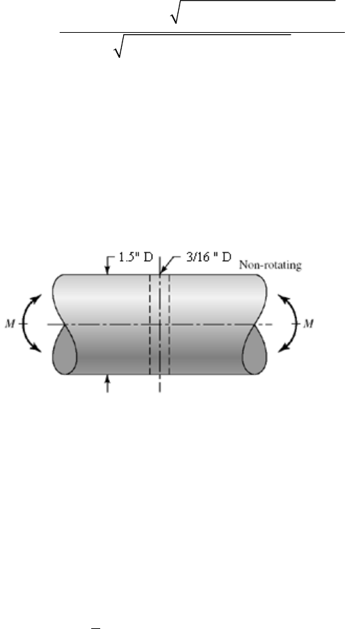
From Eq. (5-43), p. 250,
22
22
ln (156.2 / 62.1) (1 0.15 ) / (1 0.195 )
3.75
ln[(1 0.195 )(1 0.15 )]
z
From Table A-10, pf = 0.000 09
R = 1 pf = 1 0.000 09 = 0.999 91 Ans.
For a design with completely-reversed torsion of 160 N · m, the reliability is 0.999 91.
The improvement over bending comes from a smaller stress-concentration factor in
torsion. See the note at the end of the solution of Prob. 6-66 for the reason for the
phraseology.
______________________________________________________________________________
6-68
Given: Sut = 58 kpsi.
Eq. (6-70): Se = 0.506(76) LN(1, 0.138) = 38.5 LN(1, 0.138) kpsi
Table 6-13: ka = 14.5(76) 0.719 LN(1, 0.11) = 0.644 LN(1, 0.11)
Eq. (6-24): de = 0.370(1.5) = 0.555 in
Eq. (6-20): kb = (0.555/0.3)0.107 = 0.936
Eq. (6-70): Se = [0.644 LN(1, 0.11)](0.936)[38.5 LN(1, 0.138)]
0.644 0.936 38.5 23.2 kpsi
e
S
CSe = (0.112 + 0.1382)1/2 = 0.176
Se =23.2 LN(1, 0.176) kpsi
Table A-16: d/D = 0, a/D = (3/16)/1.5 = 0.125, A = 0.80 Kt = 2.20.
From Eqs. (6-78) and (6-79) and Table 6-15
Chapter 6 - Rev. A, Page 62/66
2.20 (1, 0.10) 1.83 (1, 0.10)
22.20 1 5/76
12.20 0.125
f
K
LN LN
Table A-16:
33
3
net
net
(0.80)(1.5 ) 0.265 in
32 32
1.5
1.83 (1, 0.10) 0.265
10.4 (1, 0.10) kpsi
10.4 kpsi
0.10
f
AD
Z
M
Z
C
KLN
LN
Eq. (5-43), p. 250:
22
22
ln (23.2 / 10.4) (1 0.10 ) / (1 0.176 )
3.94
ln[(1 0.176 )(1 0.10 )]
z
Table A-10: pf = 0.000 041 5 R = 1 pf = 1 0.000 041 5 = 0.999 96 Ans.
______________________________________________________________________________
6-69 From Prob. 6-68: Se = 23.2 LN(1, 0.138) kpsi
ka = 0.644LN(1, 0.11)
kb = 0.936
Eq. (6-74): kc = 0.328(76)0.125LN(1, 0.125) = 0.564 LN(1, 0.125)
Eq. (6-71):
Se = [0.644LN(1, 0.11)](0.936)[ 0.564 LN(1, 0.125)][ 23.2 LN(1, 0.138)]
0.644 0.936 0.564 23.2 7.89 kpsi
e
S
CSe = (0.112 +0.1252 + 0.1383)1/2 = 0.216
Table A-16: d/D = 0, a/D = (3/16)/1.5 = 0.125, A = 0.89, Kts = 1.64
From Eqs. (6-78) and(7-79), and Table 6-15
1.64 (1, 0.10) 1.40 (1, 0.10)
21.64 1 5/76
11.64 3/32
fs
LN
KLN
Chapter 6 - Rev. A, Page 63/66
Table A-16:
44
4
net
net
(0.89)(1.5 ) 0.4423 in
32 32
2(1.5)
1.40[ (1, 0.10)] 4.75 (1, 0.10) kpsi
2 2 0.4423
a
afs
AD
J
TD
J
KLN LN
From Eq. (6-57):
22
22
ln(7.89 / 4.75) (1 0.10 ) / (1 0.216 ) 2.08
ln[(1 0.10 )(1 0.216 )]
z
Table A-10, pf = 0.0188, R = 1 pf = 1 0.0188 = 0.981 Ans.
______________________________________________________________________________
6-70 This is a very important task for the student to attempt before starting Part 3. It illustrates
the drawback of the deterministic factor of safety method. It also identifies the a priori
decisions and their consequences.
The range of force fluctuation in Prob. 6-30 is 16 to + 5 kip, or 21 kip. Let the
repeatedly-applied Fa be 10.5 kip. The stochastic properties of this heat of AISI 1018 CD
are given in the problem statement.
Function Consequences
Axial Fa = 10.5 kip
Fatigue load CFa = 0
Ckc = 0.125
Overall reliability R ≥ 0.998;
with twin fillets
0.998 0.999R
z = 3.09
CKf = 0.11
Cold rolled or machined
surfaces
Cka = 0.058
Ambient temperature Ckd = 0
Use correlation method 0.138C
Stress amplitude CKf = 0.11
C
a = 0.11
Significant strength Se 2221/2
(0.058 0.125 0.138 ) 0.195
Se
C
Choose the mean design factor which will meet the reliability goal. From Eq. (6-88)
22
2
22
0.195 0.11 0.223
1 0.11
exp ( 3.09) ln(1 0.223 ) ln 1 0.223
2.02
n
C
n
n
Chapter 6 - Rev. A, Page 64/66
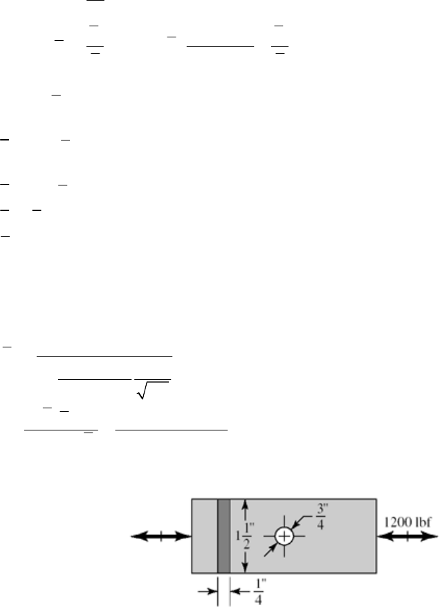
In Prob. 6-30, it was found that the hole was the significant location that controlled the
analysis. Thus,
1
e
a
ea
af
SF
K
nhd
S
n
w
e
S
n
We need to determine e
S
-0.265 -0.265
2.67 2.67(64) 0.887
aut
kS
kb = 1
0.0778 0.0778
1.23 1.23(64) 0.890
cut
kS
1
de
kk
0.887(1)(0.890)(1)(1)(0.506)(64) 25.6 kpsi
e
S
From the solution to Prob. 6-30, the stress concentration factor at the hole is Kt = 2.68.
From Eq. (6-78) and Table 6-15
1
2.68 2.20
22.68 15/64
12.68 0.2
2.20(2.02)(10.5) 0.588 .
3.5 0.4 (25.6)
f
fa
e
K
KnF
h Ans
dS
w
______________________________________________________________________________
6-71
1200 lbf
80 kpsi
a
ut
F
S
(a) Strength
ka = 2.67(80) 0265LN(1, 0.058) = 0.836 LN(1, 0.058)
kb = 1
kc = 1.23(80) 0.0778LN(1, 0.125) = 0.875 LN(1, 0.125)
Chapter 6 - Rev. A, Page 65/66
Chapter 6 - Rev. A, Page 66/66
2221/2
0.506(80) (1, 0.138) 40.5 (1, 0.138) kpsi
0.836 (1, 0.058) (1) 0.875 (1, 0.125) 40.5 (1, 0.138)
0.836(1)(0.875)(40.5) 29.6 kpsi
(0.058 0.125 0.138 ) 0.195
e
e
e
Se
S
C
SLN LN
SLN LN LN
Stress: Fig. A-15-1; d/w = 0.75/1.5 = 0.5, Kt = 2.18. From Eqs. (6-78), (6-79) and
Table 6-15
2.18 (1, 0.10) 1.96 (1, 0.10)
2 2.18 1 5/80
12.18 0.375
f
LN
KLN
22
22
22
22
, 0.10
()
1.96(1.2) 12.54 kpsi
( ) (1.5 0.75)(0.25)
29.6 kpsi
ln ( / ) 1 1
ln 1 1
ln 29.6 /12.48 1 0.10 / 1 0.195
3.9
ln 1 0.10 1 0.195
a
af
fa
a
ae
aa S
S
FC
dt
KF
dt
SS
SCC
zCC
Kw
w
From Table A-20, pf = 4.81(10 5) R = 1 4.81(10 5) = 0.999 955 Ans.
(b) All computer programs will differ in detail.
______________________________________________________________________________
6-72 to 6-78 Computer programs are very useful for automating specific tasks in the design
process. All computer programs will differ in detail.
Chapter 7
7-1 (a) DE-Gerber, Eq. (7-10):
22 22
4 3 4 (2.2)(70) 3 (1.8)(45) 338.4 N m
fa fsa
AKM KT
22 22
4 3 4 (2.2)(55) 3 (1.8)(35) 265.5 N m
fm fsm
BKM KT
1/3
1/ 2
2
6
66
2(265.5) 210 10
8(2)(338.4) 11
210 10 338.4 700 10
d
d = 25.85 (103) m = 25.85 mm Ans.
(b) DE-elliptic, Eq. (7-12) can be shown to be
1/3
1/3 22
22
22
22 66
338.4 265.5
16 16(2)
210 10 560 10
ey
nA B
dSS
d = 25.77 (103) m = 25.77 mm Ans.
(c) DE-Soderberg, Eq. (7-14) can be shown to be
1/3
1/3
66
16 16(2) 338.4 265.5
210 10 560 10
ey
nA B
dSS
d = 27.70 (103) m = 27.70 mm Ans.
(d) DE-Goodman: Eq. (7-8) can be shown to be
1/3
1/3
66
16 16(2) 338.4 265.5
210 10 700 10
eut
nA B
dSS
d = 27.27 (103) m = 27.27 mm Ans.
________________________________________________________________________
Criterion d (mm) Compared to DE-Gerber
DE-Gerber 25.85
DE-Elliptic 25.77 0.31% Lower Less conservative
DE-Soderberg 27.70 7.2% Higher More conservative
DE-Goodman 27.27 5.5% Higher More conservative
______________________________________________________________________________
7-2 This problem has to be done by successive trials, since Se is a function of shaft size. The
material is SAE 2340 for which Sut = 175 kpsi, Sy = 160 kpsi, and HB ≥ 370.
Chapter 7 - Rev. A, Page 1/45
Eq. (6-19), p. 287:
0.265
2.70(175) 0.69
a
k
Trial #1: Choose dr = 0.75 in
Eq. (6-20), p. 288:
0.107
0.879(0.75) 0.91
b
k
Eq. (6-8), p.282:
0.5 0.5 175 87.5 kpsi
eut
SS
Eq. (6-18), p. 287: Se = 0.69 (0.91)(87.5) = 54.9 kpsi
2 0.75 2 / 20 0.65
r
ddr DD D
0.75 1.15 in
0.65 0.65
r
d
D
1.15 0.058 in
20 20
D
r
Fig. A-15-14:
2 0.75 2(0.058) 0.808 in
r
dd r
0.808 1.08
0.75
r
d
d
0.058 0.077
0.75
r
r
d
K
t = 1.9
Fig. 6-20, p. 295: r = 0.058 in, q = 0.90
Eq. (6-32), p. 295: Kf = 1 + 0.90 (1.9 – 1) = 1.81
Fig. A-15-15: Kts = 1.5
Fig. 6-21, p. 296: r = 0.058 in, qs = 0.92
Eq. (6-32), p. 295: Kfs = 1 + 0.92 (1.5 – 1) = 1.46
We select the DE-ASME Elliptic failure criteria, Eq. (7-12), with d as dr, and
Mm = Ta = 0,
1/3
1/2
22
33
16(2.5) 1.81(600) 1.46(400)
43
54.9 10 160 10
r
d
d
r = 0.799 in
Trial #2: Choose dr = 0.799 in.
0.107
0.879(0.799) 0.90
b
k
S
e = 0.69 (0.90)(0.5)(175) = 54.3 kpsi
0.799 1.23 in
0.65 0.65
r
d
D
r = D / 20 = 1.23/20 = 0.062 in
Chapter 7 - Rev. A, Page 2/45

Figs. A-15-14 and A-15-15:
2 0.799 2(0.062) 0.923 in
r
dd r
0.923 1.16
0.799
r
d
d
0.062 0.078
0.799
r
r
d
With these ratios only slightly different from the previous iteration, we are at the limit of
readability of the figures. We will keep the same values as before.
1.9, 1.5, 0.90, 0.92
tts s
KKq q
1.81, 1.46
ffs
KK
Using Eq. (7-12) produces dr = 0.802 in. Further iteration produces no change. With
dr = 0.802 in,
0.802 1.23 in
0.65
0.75(1.23) 0.92 in
D
d
A look at a bearing catalog finds that the next available bore diameter is 0.9375 in. In
nominal sizes, we select d = 0.94 in, D = 1.25 in, r = 0.0625 in Ans.
______________________________________________________________________________
7-3 F cos 20(d / 2) = TA, F = 2 TA / ( d cos 20) = 2(340) / (0.150 cos 20) = 4824 N.
The maximum bending moment will be at point C, with MC = 4824(0.100) = 482.4 N·m.
Due to the rotation, the bending is completely reversed, while the torsion is constant.
Thus, Ma = 482.4 N·m, Tm = 340 N·m, Mm = Ta = 0.
For sharp fillet radii at the shoulders, from Table 7-1, Kt = 2.7, and Kts = 2.2. Examining
Figs. 6-20 and 6-21 (pp. 295 and 296 respectively) with 560 MPa,
ut
S
conservatively
estimate q = 0.8 and These estimates can be checked once a specific fillet radius
is determined.
0.9.
s
q
Eq. (6-32):
1 0.8(2.7 1) 2.4
f
K
1 0.9(2.2 1) 2.1
fs
K
(a) We will choose to include fatigue stress concentration factors even for the static
analysis to avoid localized yielding.
Eq. (7-15):
1/2
22
max 33
32 16
3
fa fsm
KM KT
dd
Chapter 7 - Rev. A, Page 3/45

Eq. (7-16):
31/ 2
22
max
43
16
yy
fa fsm
SdS
nKMK
T
Solving for d,
1/3
1/ 2
22
1/3
1/ 2
22
6
16 4( ) 3( )
16(2.5) 4 (2.4)(482.4) 3 (2.1)(340)
420 10
fa fsa
y
n
dKMKT
S
d = 0.0430 m = 43.0 mm Ans.
(b)
0.265
4.51(560) 0.84
a
k
Assume kb = 0.85 for now. Check later once a diameter is known.
Se = 0.84(0.85)(0.5)(560) = 200 MPa
Selecting the DE-ASME Elliptic criteria, use Eq. (7-12) with 0.
ma
MT
1/3
1/ 2
22
66
16(2.5) 2.4(482.4) 2.1(340)
43
200 10 420 10
0.0534 m 53.4 mm
d
With this diameter, we can refine our estimates for kb and q.
Eq. (6-20):
0.157
0.157
1.51 1.51 53.4 0.81
b
kd
Assuming a sharp fillet radius, from Table 7-1, r = 0.02d = 0.02 (53.4) = 1.07 mm.
Fig. (6-20): q = 0.72
Fig. (6-21): qs = 0.77
Iterating with these new estimates,
Eq. (6-32): Kf = 1 + 0.72 (2.7 – 1) = 2.2
Kfs = 1 + 0.77 (2.2 – 1) = 1.9
Eq. (6-18): Se = 0.84(0.81)(0.5)(560) = 191 MPa
Eq. (7-12): d = 53 mm Ans.
Further iteration does not change the results.
_____________________________________________________________________________
Chapter 7 - Rev. A, Page 4/45
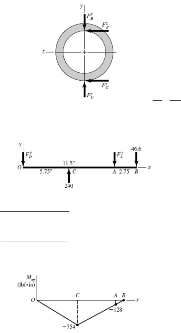
7-4 We have a design task of identifying bending moment and torsion diagrams which are
preliminary to an industrial roller shaft design. Let point C represent the center of the
span of the roller.
30(8) 240 lbf
y
C
F
0.4(240) 96 lbf
z
C
F
(2) 96(2) 192 lbf in
z
C
TF
192 128 lbf
1.5 1.5
z
B
T
F
tan 20 128 tan 20 46.6 lbf
yz
BB
FF
(a) xy-plane
240(5.75) (11.5) 46.6(14.25) 0
y
OA
MF
240(5.75) 46.6(14.25) 62.3 lbf
11.5
y
A
F
(11.5) 46.6(2.75) 240(5.75) 0
y
AO
MF
240(5.75) 46.6(2.75) 131.1 lbf
11.5
y
O
F
Bending moment diagram:
xz-plane
Chapter 7 - Rev. A, Page 5/45

0 96(5.75) (11.5) 128(14.25)
z
OA
MF
96(5.75) 128(14.25) 206.6 lbf
11.5
z
A
F
0 (11.5) 128(2.75) 96(5.75)
z
AO
MF
96(5.75) 128(2.75) 17.4 lbf
11.5
z
O
F
Bending moment diagram:
22
100 ( 754) 761 lbf in
C
M
22
( 128) ( 352) 375 lbf in
A
M
Torque: The torque is constant from C to B, with a magnitude previously obtained of 192
lbf·in.
(b) xy-plane
22
131.1 15 1.75 15 9.75 62.3 11.5
xy
Mxx x x 1
Bending moment diagram:
Chapter 7 - Rev. A, Page 6/45
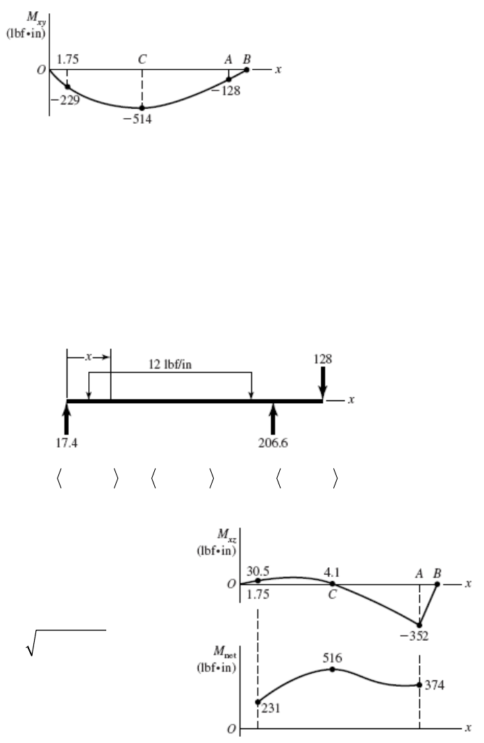
M
max = –516 lbf · in and occurs at 6.12 in.
2
131.1(5.75) 15(5.75 1.75) 514 lbf in
C
M
This is reduced from 754 lbf · in found in part (a). The maximum occurs
at rather than C, but it is close enough.
6.12 inx
xz-plane
22
17.4 6 1.75 6 9.75 206.6 11.5
xz
Mxx x x
1
Bending moment diagram:
Let 22
net
x
yxz
M
MM
Plot Mnet(x), 1.75 ≤ x ≤ 11.5 in
Mmax = 516 lbf · in at x = 6.25 in
Torque: The torque rises from 0 to 192 lbf·in linearly across the roller, then is constant to
B. Ans.
______________________________________________________________________________
7-5 This is a design problem, which can have many acceptable designs. See the solution for
Prob. 7-17 for an example of the design process.
______________________________________________________________________________
Chapter 7 - Rev. A, Page 7/45
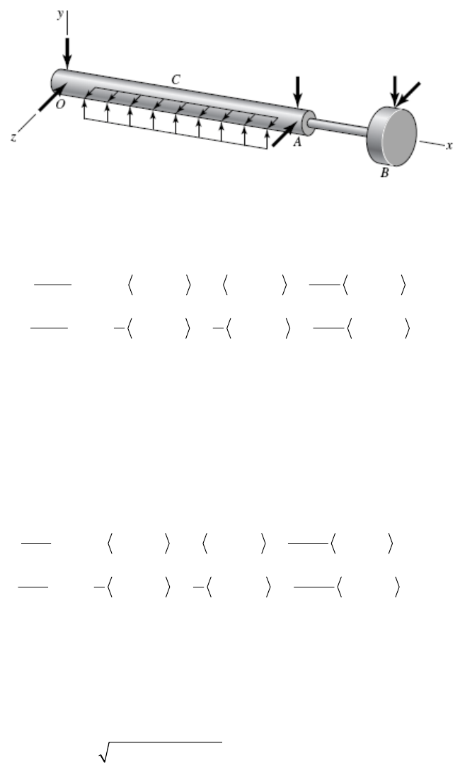
7-6 If students have access to finite element or beam analysis software, have them model the
shaft to check deflections. If not, solve a simpler version of shaft for deflection. The 1 in
diameter sections will not affect the deflection results much, so model the 1 in diameter
as 1.25 in. Also, ignore the step in AB.
From Prob. 7-4, integrate Mxy and Mxz.
xy plane, with dy/dx = y'
33
2
1
131.1 62.3
5 1.75 5 9.75 11.5
22
2
E
Iy x x x x C
(1)
44 3
3
12
131.1 5 5 62.3
1.75 9.75 11.5
64 4 6
E
Iy x x x x C x C
2
0 at 0 0yx C
3
1
0 at 11.5 1908.4 lbf inyx C
From (1), x = 0: EIy' = 1908.4
x = 11.5: EIy' = –2153.1
xz plane (treating )
z
33
2
3
17.4 206.6
2 1.75 2 9.75 11.5
22
2
E
Iz x x x x C
(2)
44 3
3
34
17.4 1 1 206.6
1.75 9.75 11.5
62 2 6
E
Iz x x x x C x C
4
0 at 0 0zx C
3
3
0 at 11.5 8.975 lbf inzx C
From (2), x = 0: EIz' = 8.975
x = 11.5: EIz' = –683.5
At O: 22
1908.4 8.975 1908.4 lbf inEI
3
Chapter 7 - Rev. A, Page 8/45
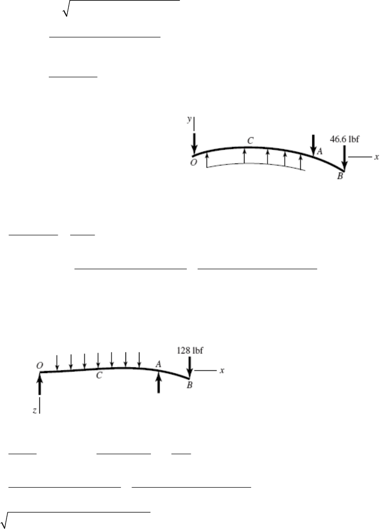
At A: 22
( 2153.1) ( 683.5) 2259.0 lbf inEI
3
(dictates size)
64
2259 0.000 628 rad
30 10 / 64 1.25
0.001 1.59
0.000 628
n
At gear mesh, B
xy plane
With
1
I
I in section OCA,
1
2153.1/
A
y
EI
Since y'B/A is a cantilever, from Table A-9-1, with 2
I
I
in section AB
/ 2
22
( 2 ) 46.6 (2.75)[2.75 2(2.75)] 176.2 /
22
BA
Fx x l
yE
EI EI
I
/646
2153.1 176.2
30 10 / 64 1.25 30 10 / 64 0.875
BABA
yyy
4
= –0.000 803 rad (magnitude greater than 0.0005 rad)
xz plane
2
/
12
128 2.75
683.5 484
,2
ABA
zz
2
E
IEI
EI
646 4
683.5 484 0.000 751 rad
30 10 / 64 1.25 30 10 / 64 0.875
B
z
22
( 0.000 803) ( 0.000 751) 0.00110 rad
B
Crowned teeth must be used.
Finite element results: Error in simplified model
4
5.47(10 ) rad
O
3.0%
4
7.09(10 ) rad
A
11.4%
3
1.10(10 ) rad
B
0.0%
Chapter 7 - Rev. A, Page 9/45

The simplified model yielded reasonable results.
Strength
72 kpsi, 39.5 kpsi
ut y
SS
At the shoulder at A, From Prob. 7-4,
10.75 in.x
209.3 lbf in, 293.0 lbf in, 192 lbf in
xy xz
MMT
22
( 209.3) ( 293) 360.0 lbf inM
0.5(72) 36 kpsi
e
S
0.265
2.70(72) 0.869
a
k
0.107
10.879
0.3
b
k
1
cde f
kkkk
0.869(0.879)(36) 27.5 kpsi
e
S
D / d = 1.25, r / d = 0.03
Fig. A-15-8: Kts = 1.8
Fig. A-15-9: Kt = 2.3
Fig. 6-20: q = 0.65
Fig. 6-21: qs = 0.70
Eq. (6-32):
1 0.65(2.3 1) 1.85
f
K
1 0.70(1.8 1) 1.56
fs
K
Using DE-ASME Elliptic, Eq. (7-11) with 0,
ma
MT
1/2
22
3
1 16 1.85(360) 1.56(192)
43
27 500 39 500
1
n
n = 3.91
Perform a similar analysis at the profile keyway under the gear.
The main problem with the design is the undersized shaft overhang with excessive slope
at the gear. The use of crowned-teeth in the gears will eliminate this problem.
______________________________________________________________________________
7-7 through 7-16
These are design problems, which can have many acceptable designs. See the solution for
Prob. 7-17 for an example of the design process.
______________________________________________________________________________
7-17 (a) One possible shaft layout is shown in part (e). Both bearings and the gear will be
located against shoulders. The gear and the motor will transmit the torque through the
Chapter 7 - Rev. A, Page 10/45
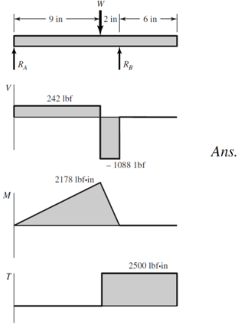
keys. The bearings can be lightly pressed onto the shaft. The left bearing will locate the
shaft in the housing, while the right bearing will float in the housing.
(b) From summing moments around the shaft axis, the tangential transmitted load
through the gear will be
/ ( / 2) 2500 / (4 / 2) 1250 lbf
t
WTd
The radial component of gear force is related by the pressure angle.
tan 1250 tan 20 455 lbf
rt
WW
1/2 1/ 2
22 2 2
455 1250 1330 lbf
rt
WWW
Reactions and ,
A
B
R
Rand the load W are all in the same plane. From force and moment
balance,
1330(2 / 11) 242 lbf
A
R
1330(9 /11) 1088 lbf
B
R
max (9) 242(9) 2178 lbf in
A
MR
Shear force, bending moment, and torque diagrams can now be obtained.
(c) Potential critical locations occur at each stress concentration (shoulders and keyways).
To be thorough, the stress at each potentially critical location should be evaluated. For
Chapter 7 - Rev. A, Page 11/45

now, we will choose the most likely critical location, by observation of the loading
situation, to be in the keyway for the gear. At this point there is a large stress
concentration, a large bending moment, and the torque is present. The other locations
either have small bending moments, or no torque. The stress concentration for the
keyway is highest at the ends. For simplicity, and to be conservative, we will use the
maximum bending moment, even though it will have dropped off a little at the end of the
keyway.
(d) At the gear keyway, approximately 9 in from the left end of the shaft, the bending is
completely reversed and the torque is steady.
2178 lbf in 2500 lbf in 0
am m
MTM
a
T
From Table 7-1, estimate stress concentrations for the end-milled keyseat to be Kt = 2.14
and Kts = 3.0. For the relatively low strength steel specified (AISI 1020 CD), roughly
estimate notch sensitivities of q = 0.75 and qs = 0.80, obtained by observation of Figs. 6-
20 and 6-21, assuming a typical radius at the bottom of the keyseat of r / d = 0.02 (p.
373), and a shaft diameter of up to 3 inches.
Eq. (6-32):
1 0.75(2.14 1) 1.9
f
K
1 0.8(3.0 1) 2.6
fs
K
Eq. (6-19):
0.265
2.70(68) 0.883
a
k
For estimating , guess 2 in.
b
kd
Eq. (6-20)
0.107
(2 / 0.3) 0.816
b
k
Eq. (6-18) 0.883(0.816)(0.5)(68) 24.5 kpsi
e
S
Selecting the DE-Goodman criteria for a conservative first design,
Eq. (7-8):
1/3
1/ 2 1/ 2
22
43
16 fa fsm
eut
KM KT
n
dSS
1/3
1/ 2 1/ 2
22
4 1.9 2178 3 2.6 2500
16(1.5)
24 500 68 000
d
1.57 in .dAns
With this diameter, the estimates for notch sensitivity and size factor were conservative,
but close enough for a first iteration until deflections are checked. Check yielding with
this diameter.
Chapter 7 - Rev. A, Page 12/45
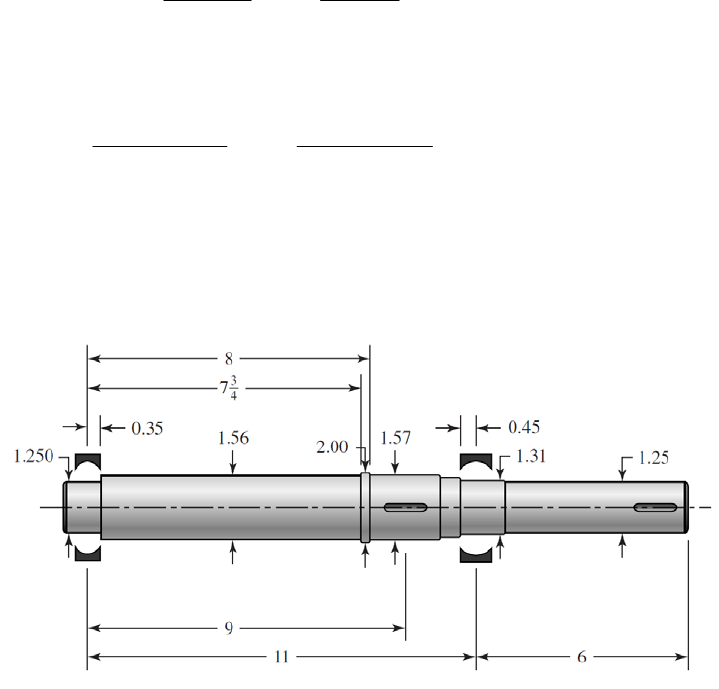
Eq. (7-15):
1/2
22
max 33
32 16
3
fa fsm
KM KT
dd
1/ 2
22
max 33
32(1.9)(2178) 16(2.6)(2500)
3 18389 psi 18.4 kpsi
(1.57) (1.57)
max
/ 57 /18.4 3.1 .
yy
nS Ans
(e) Now estimate other diameters to provide typical shoulder supports for the gear and
bearings (p. 372). Also, estimate the gear and bearing widths.
(f) Entering this shaft geometry into beam analysis software (or Finite Element software),
the following deflections are determined:
Left bearing slope: 0.000 532 rad
Right bearing slope: 0.000 850 rad
Gear slope: 0.000 545 rad
Right end of shaft slope: 0.000 850 rad
Gear deflection: 0.001 45 in
Right end of shaft deflection: 0.005 10 in
Comparing these deflections to the recommendations in Table 7-2, everything is within
typical range except the gear slope is a little high for an uncrowned gear.
(g) To use a non-crowned gear, the gear slope is recommended to be less than 0.0005 rad.
Since all other deflections are acceptable, we will target an increase in diameter only for
the long section between the left bearing and the gear. Increasing this diameter from the
proposed 1.56 in to 1.75 in, produces a gear slope of 0.000 401 rad. All other
deflections are improved as well.
______________________________________________________________________________
Chapter 7 - Rev. A, Page 13/45
7-18 (a) Use the distortion-energy elliptic failure locus. The torque and moment loadings on
the shaft are shown in the solution to Prob. 7-17.
Candidate critical locations for strength:
Left seat keyway
Right bearing shoulder
Right keyway
Table A-20 for 1030 HR: 68 kpsi, 37.5 kpsi, 137
ut y B
SS H
Eq. (6-8): 0.5(68) 34.0 kpsi
e
S
Eq. (6-19):
0.265
2.70(68) 0.883
a
k
1
cde
kkk
Left keyway
See Table 7-1 for keyway stress concentration factors,
2.14 Profile keyway
3.0
t
ts
K
K
For an end-mill profile keyway cutter of 0.010 in radius, estimate notch sensitivities.
Fig. 6-20: 0.51q
Fig. 6-21: 0.57
s
q
Eq. (6-32): 1 ( 1) 1 0.57(3.0 1) 2.1
fs s ts
KqK
1 0.51(2.14 1) 1.6
f
K
Eq. (6-20):
0.107
1.875 0.822
0.30
b
k
Eq. (6-18): 0.883(0.822)(34.0) 24.7 kpsi
e
S
Eq. (7-11):
1
22
2
3
1 16 1.6(2178) 2.1(2500)
43
(1.875 ) 24 700 37 500
f
n
nf = 3.5 Ans.
Right bearing shoulder
The text does not give minimum and maximum shoulder diameters for 03-series bearings
(roller). Use D = 1.75 in.
0.030 1.75
0.019, 1.11
1.574 1.574
rD
dd
Fig. A-15-9: 2.4
t
K
Fig. A-15-8: 1.6
ts
K
Chapter 7 - Rev. A, Page 14/45
Fig. 6-20:
0.65q
Fig. 6-21: 0.70
s
q
Eq. (6-32): 1 0.65(2.4 1) 1.91
f
K
1 0.70(1.6 1) 1.42
fs
K
0.453
2178 493 lbf in
2
M
Eq. (7-11):
1/ 2
22
3
1 16 1.91(493) 1.42(2500)
43
(1.574 ) 24 700 37 500
f
n
nf = 4.2 Ans.
Right keyway
Use the same stress concentration factors as for the left keyway. There is no bending
moment, thus Eq. (7-11) reduces to:
33
16 3
1 16 3(2.1)(2500)
1.5 (37 500)
fs m
fy
KT
ndS
nf = 2.7 Ans.
Yielding
Check for yielding at the left keyway, where the completely reversed bending is
maximum, and the steady torque is present. Using Eq. (7-15), with Mm = Ta = 0,
1/2
22
max 33
1/2
22
33
32 16
3
32 1.6 2178 16 2.1 2500
3
1.875 1.875
8791 psi 8.79 kpsi
fa fsm
KM KT
dd
max
37.5 4.3
8.79
y
y
S
n
Ans.
Check in smaller diameter at right end of shaft where only steady torsion exists.
1/2
2
max 3
1/2
2
3
16
3
16 2.1 2500
3
1.5
13 722 psi 13.7 kpsi
fs m
KT
d
Chapter 7 - Rev. A, Page 15/45

max
37.5 2.7
13.7
y
y
S
n
Ans.
(b) One could take pains to model this shaft exactly, using finite element software.
However, for the bearings and the gear, the shaft is basically of uniform diameter, 1.875
in. The reductions in diameter at the bearings will change the results insignificantly. Use
E = 30 Mpsi for steel.
To the left of the load, from Table A-9, case 6, p. 1015,
22 2
222
64
62
1449(2)(3 2 11 )
(3 )
6 6(30)(10 )( / 64)(1.875 )(11)
2.4124(10 )(3 117)
AB
AB
dy Fb x
xbl
dx EIl
x
At x = 0 in:
4
2.823(10 ) rad
At x = 9 in:
4
3.040(10 ) rad
To the right of the load, from Table A-9, case 6, p. 1015,
22
362
6
BC
BC
dy Fa 2
x
xl l a
dx EIl
At x = l = 11 in:
22
22 4
64
1449(9)(11 9 ) 4.342(10 ) rad
6 6(30)(10 )( / 64)(1.875 )(11)
Fa la
EIl
Obtain allowable slopes from Table 7-2.
Left bearing:
Allowable slope 0.001 3.5 .
Actual slope 0.000 282 3
fs
n Ans
Right bearing:
0.0008 1.8 .
0.000 434 2
fs
n Ans
Gear mesh slope:
Table 7-2 recommends a minimum relative slope of 0.0005 rad. While we don’t know the
slope on the next shaft, we know that it will need to have a larger diameter and be stiffer.
At the moment we can say
0.0005 1.6 .
0.000 304
fs
n Ans
______________________________________________________________________________
Chapter 7 - Rev. A, Page 16/45
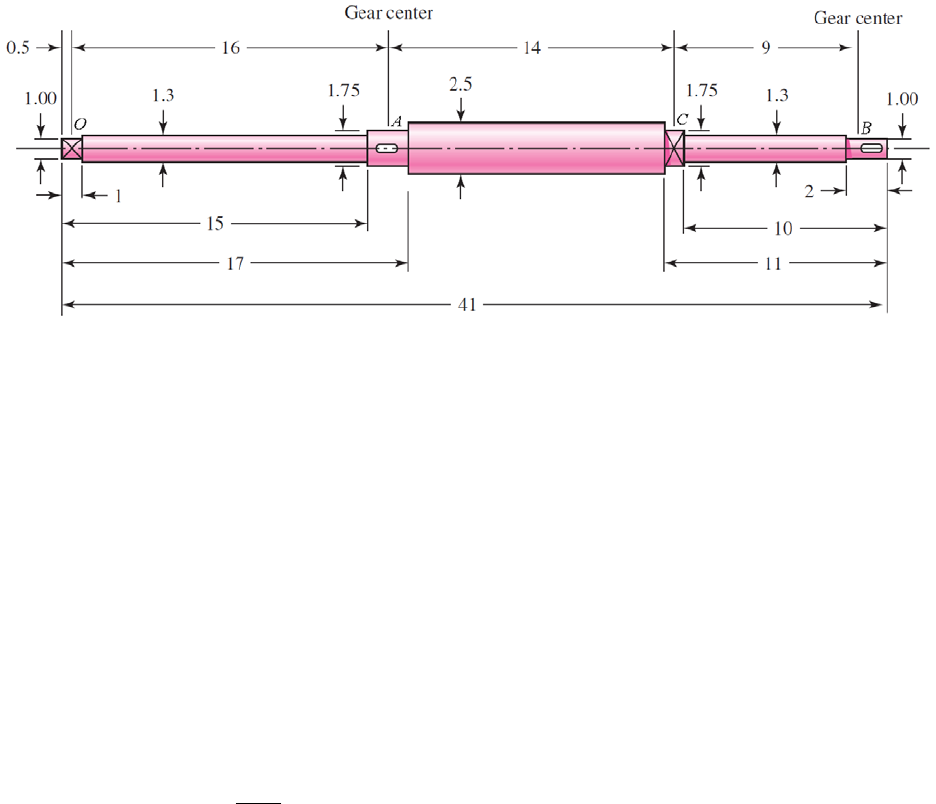
7-19 The most likely critical locations for fatigue are at locations where the bending moment is
high, the cross section is small, stress concentration exists, and torque exists. The two-
plane bending moment diagrams, shown in the solution to Prob. 3-72, indicate decreasing
moments in both planes to the left of A and to the right of C, with combined values at A
and C of MA = 5324 lbf·in and MC = 6750 lbf·in. The torque is constant between A and
B, with T = 2819 lbf·in. The most likely critical locations are at the stress concentrations
near A and C. The two shoulders near A can be eliminated since the shoulders near C
have the same geometry but a higher bending moment. We will consider the following
potentially critical locations:
keyway at A
shoulder to the left of C
shoulder to the right of C
Table A-20: Sut = 64 kpsi, Sy = 54 kpsi
Eq. (6-8): 0.5(64) 32.0 kpsi
e
S
Eq. (6-19):
0.265
2.70(64) 0.897
a
k
1
cde
kkk
Keyway at A
Assuming r / d = 0.02 for typical end-milled keyway cutter (p. 373), with d = 1.75 in,
r = 0.02d = 0.035 in.
Table 7-1: Kt = 2.14, Kts = 3.0
Fig. 6-20: q = 0.65
Fig. 6-21: qs = 0.71
Eq. (6-32):
1 1 1 0.65(2.14 1) 1.7
ft
KqK
1 ( 1) 1 0.71(3.0 1) 2.4
fs s ts
KqK
Eq. (6-20):
0.107
1.75 0.828
0.30
b
k
Eq. (6-18): 0.897(0.828)(32) 23.8 kpsi
e
S
Chapter 7 - Rev. A, Page 17/45
We will choose the DE-Gerber criteria since this is an analysis problem in which we
would like to evaluate typical expectations.
sing Eq. (7-9) with M = T = 0,
Um a
22
22
4 4 1.7 5324 18102 lbf in 18.10 kip in
3 3 2.4 2819 11 718 lbf in 11.72 kip in
fa
fs m
AKM
BKT
1/2
2
3
1/ 2
2
3
2
18 11
8 18.10 2 11.72 23.8
11 18.10 64
75 .8
e
eut
BS
A
ndS AS
1. 23
oulder to the left of C
625 / 1.75 = 0.036, D / d = 2.5 / 1.75 = 1.43
:
: q = 0.71
Fig. 6-21: q = 0.76
q. (6-32):
n = 1.3
Sh
r / d = 0.0
Fig. A-15-9 Kt = 2.2
Fig. A-15-8 Kts = 1.8
Fig. 6-20:
E
s
1 1 1 0.71(2.2 1) 1.9
ft
KqK
1 ( 1) 1 .76(1.8 1) 1.6
fs s ts
KqK
0
0.107
1.75 0.828
0.30
b
k
Eq. (6-20):
Eq. (6-18): 0.897(0.828)(32) 23.8 kpsi
e
S
For convenience, we will use the full value of the bending moment at C, even though it
will be slightly less at the shoulder. Using Eq. (7-9) with Mm = Ta = 0,
22
22
4 4 1.9 6750 25 650 lbf in 25.65 kip in
3 3 1.6 2819 7812 lbf in 7.812 kip in
fa
fs m
AKM
BKT
1/2
2
3
1/2
2
2
18 11
8 25.65 2 7.812 23.8
11 25.65 64
3.8
e
eut
BS
A
ndS AS
3
1.75 2
Chapter 7 - Rev. A, Page 18/45
n = 0.96
oulder to the right of C
625 / 1.3 = 0.048, D / d = 1.75 / 1.3 = 1.35
:
: q = 0.71
Fig. 6-21: qs = 0.76
q. (6-32):
Sh
r / d = 0.0
Fig. A-15-9 Kt = 2.0
Fig. A-15-8 Kts = 1.7
Fig. 6-20:
E
1 1 1 0.71(2.0 1) 1.7
ft
KqK
1 ( 1) 1 .76(1.7 1) 1.5
fs s ts
KqK
0
0.107
1.3 0.855
Eq. (6-20): 0.30
Eq. (6-18): 0.897(0.855)(32) 24.5 kpsi
e
S
b
k
or convenience, we will use the full value of the bending moment at C, even though it
will be slightly less at the shoulder. Using Eq. (7-9) with Mm = Ta = 0,
F
22
22
4 4 1.7 6750 22 950 lbf in 22.95 kip in
3 3 1.5 2819 7324 lbf in 7.324 kip in
fa
fs m
AKM
BKT
1/2
2
3
1/2
2
2
18 11
8 22.95 2 7.324 24.5
11 22.95 64
24.5
e
eut
BS
A
ndS AS
3
1.3
The critical location is at the shoulder to the right of C, where n = 0.45 and finite life is
plicitly called for in the problem statement, a static check for yielding is
especially warranted with such a low fatigue factor of safety. Using Eq. (7-15), with
Mm = Ta = 0,
n = 0.45
predicted. Ans.
Though not ex
1/2
22
max 33
1/ 2
22
33
32 16
3
32 1.7 6750 16 1.5 2819
3 55 845 psi 55.8 kpsi
1.3
fa fsm
KM KT
dd
1.3
Chapter 7 - Rev. A, Page 19/45
max
0.97
55.8
y
n
his indicates localized yielding is predicted at the stress-concentr
54
S
ation, though after
o be
f
static,
7-20
te the deflections. Entering
the geometry from the shaft as defined in - loading as defined in Prob.
3-72, the following defle itude te
D
T
localized cold-working it may not be a problem. The finite fatigue life is still likely t
the failure mode that will dictate whether this shaft is acceptable.
It is interesting to note the impact of stress concentration on the acceptability of the
proposed design. This problem is linked with several previous problems (see Table 1-1,
p. 24) in which the shaft was considered to have a constant diameter of 1.25 in. In each o
the previous problems, the 1.25 in diameter was more than adequate for deflection,
and fatigue considerations. In this problem, even though practically the entire shaft has
diameters larger than 1.25 in, the stress concentrations significantly reduce the
anticipated fatigue life.
______________________________________________________________________________
For a shaft with significantly varying diameters over its length, we will choose to use
shaft analysis software or finite element software to calcula
Prob. 7
e
19, and the
rmined: ction magn s are d
Location Slope
(rad) eflection
(in)
Left bearing O 0.00640 0.00000
Right bearing C 0.00434 0.00000
Left Gear A 0.00260 0.04839
Right Gear B 0.01078 0.07517
Comparing these values to the recommended limits in Table 7-2, we find that they are all
out of the desired range. This is not unexpected since the stress analysis of Prob. 7-19
also indicated the shaft is undersized for infinite life. The sl
ope at the right gear is the
ost excessive, so we will attempt to increase all diameters to bring it into compliance.
sing Eq. (7-18) at the right gear,
m
U
1/4 1/ 4
new old
old all
2.15
slope 0.0005d
/(1)(0.01078)
d
ndydx
d
Multiplying all diameter e ob fo lections:
D
s by 2.15, w tain the llowing def
Location Slope
(rad) eflection
(in)
Left bearing O 0.00030 0.00000
Right bearing C 0.00020 0.00000
Left Gear A 0.00012 0.00225
Right Gear B 0.00050 0.00350
Chapter 7 - Rev. A, Page 20/45
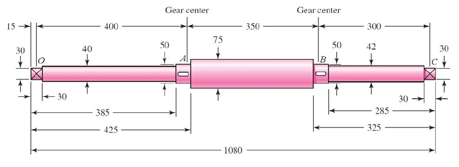
This brings the slope at the right gear just to the limit for an uncrowned gear, and all
other slopes well below the recommended limits. For the gear deflections, the values are
______________________________________________________________________________
7-21 is
o-
with the keyway at B, the
rimary difference between the two is the stress concentration, since they both have
eyway at A
d-milled keyway cutter (p. 373), with d = 50 mm,
Kt = 2.14, Kts = 3.0
Fig. 6-20: q = 0.66
ig. 6-21: qs = 0.72
e
50 = 0.04, D / d = 75 / 50 = 1.5
:
below recommended limits as long as the diametral pitch is less than 20.
The most likely critical locations for fatigue are at locations where the bending moment
high, the cross section is small, stress concentration exists, and torque exists. The tw
plane bending moment diagrams, shown in the solution to Prob. 3-73, indicate both
planes have a maximum bending moment at B. At this location, the combined bending
moment from both planes is M = 4097 N·m, and the torque is T = 3101 N·m. The
shoulder to the right of B will be eliminated since its diameter is only slightly smaller,
and there is no torque. Comparing the shoulder to the left of B
p
essentially the same bending moment, torque, and size. We will check the stress
concentration factors for both to determine which is critical.
Table A-20: Sut = 440 MPa, Sy = 370 MPa
K
Assuming r / d = 0.02 for typical en
r = 0.02d = 1 mm.
Table 7-1:
F
Eq. (6-32): 1
f
Kq
1 1 0.66(2.14 1) 1.8
t
K
1 ( 1) 1 0.72(3.0 1) 2.4
fs s ts
KqK
Shoulder to th left of B
r / d = 2 /
Fig. A-15-9 Kt = 2.2
Chapter 7 - Rev. A, Page 21/45
Fig. A-15-8:
F
Kts = 1.8
Fig. 6-20: q = 0.73
ig. 6-21: q = 0.78
n of the stress concentration f ctors indicates the keyway will be the critical
Eq. (6-19):
s
1 1 1 0.73(2.2 1) 1.9
fs s ts
KqK
Eq. (6-32): ft
KqK
1 ( 1) 1 0.78(1.8 1) 1.6
Examinatio a
location.
0.5(440) 220 MPa
e
S Eq. (6-8):
0.265
4.51(440) 0.899
a
k
0.107
Eq. (6-20): 50 0.818
7.62
b
k
We will choose the DE-Gerber criteria since this is an analysis problem in which we
ould like to evaluate typical expectations. Using Eq. (7-9) with Mm a = 0,
1
cde
kkk
Eq. (6-18): 0.899(0.818)(220) 162 MPa
e
S
w = T
22
22
4 4 1.8 4097 14 750 N m
3 3 2.4 3101 12 890 N m
fa
fs m
AKM
BKT
1/ 2
2
3
1/ 2
2
6
36 6
2
18 11
0
8 14
0.050 162 10 14 750 440 10
e
eut
BS
A
ndS AS
212 890 162 1
750 11
n = 0.25 Infinite life is not predicted. Ans.
Though not explicitly called for in the problem statement, a static check for yielding is
especially warranted with such a low fatigue factor of safety. Using Eq. (7-15), with
Mm = Ta = 0,
1/2
22
max 33
1/2
22
8
33
32 16
3
32 1.8 4097 16 2.4 3101
3 7.98 10 Pa 798 MPa
050 0.050
fa fsm
KM KT
dd
0.
Chapter 7 - Rev. A, Page 22/45
max
370 0.46
798
y
S
n
This indicates localized yielding is predicted at the stress-concentration. Even without
the stress concentration effects, the static factor of safety turns out to be 0.93. Static
failure is predicted, rendering this proposed shaft design unacceptable.
This problem is linked with several previous problems (see Table 1-1, p. 24) in which
shaft was considered to have a constant diameter of 50 mm. The results here ar
the
e
______________________________________________________________________________
-22 th, we will choose to use
shaft analysis software o ment s t e deflections. Entering
the geometry from the shaft as defined in -2 ading as defined in Prob.
3-73, the following itud erm
De n
consistent with the previous problems, in which the 50 mm diameter was found to
slightly undersized for static, and significantly undersized for fatigue. Though in the
current problem much of the shaft has larger than 50 mm diameter, the added
contribution of stress concentration limits the fatigue life.
For a shaft with significantly varying diameters over its leng7
r finite ele oftware
7
o calculate th
1, and the lo
i
Prob.
deflection magn es are det ned:
Location Slope
(rad) flectio
(mm)
Left bearing O 0.01445 0.000
Right bearing C 0.01843 0.000
Left Gear A 0.00358 3.761
Right Gear B 0.00366 3.676
Comparing these values to the recommended limits in Table 7-2, we find that they are all
well out of the desired range. This is not unexpected since the stress analysis in Prob.
-21 also indicated the shaft is undersize7
the lef
d for infinite life. The transverse deflection at
t gear is the most excessive, so we will attempt to increase all diameters to bring it
to compliance. Using Eq. (7-17) at the left gear, assuming from Table 7-2 an allowable
yall = 0.01 in = 0.254 mm,
in
deflection of
1/4 1/ 4
new old (1)(3.761) 1.96
d
dny
old all
dy
Multiplying all diam btai wi :
De n
0.254
eters by 2, we o n the follo ng deflections
Location Slope
(rad) flectio
(mm)
Left bearing O 0.00090 0.000
Right bearing C 0.00115 0.000
Left Gear A 0.00022 0.235
Right Gear B 0.00023 0.230
Chapter 7 - Rev. A, Page 23/45
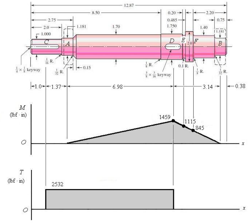
This brings the deflection at the gears just within the limit for a spur gear (assuming P <
______________________________________________________________________________
7-23 ,
stress element will be completely reversed, while the torsional stress will be steady.
Since we do not have any information about the fan, we will ignore any axial load that it
would introduce. It would not likely contribute much compared to the bending anyway.
10 teeth/in), and all other deflections well below the recommended limits.
(a) Label the approximate locations of the effective centers of the bearings as A and B
the fan as C, and the gear as D, with axial dimensions as shown. Since there is only one
gear, we can combine the radial and tangential gear forces into a single resultant force
with an accompanying torque, and handle the statics problem in a single plane. From
statics, the resultant reactions at the bearings can be found to be RA = 209.9 lbf and RB =
464.5 lbf. The bending moment and torque diagrams are shown, with the maximum
bending moment at D of MD = 209.9(6.98) = 1459 lbf·in and a torque transmitted from D
to C of T = 633 (8/2) = 2532 lbf·in. Due to the shaft rotation, the bending stress on any
Potentially critical locations are identified as follows:
Keyway at C, where the torque is high, the diameter is small, and the keyway creates
a stress concentration.
Chapter 7 - Rev. A, Page 24/45

Keyway at D, where the bending moment is maximum, the torque is high, and the
keyway creates a stress concentration.
.
eter is smaller than at D or E, the bending moment is
The shoulder to the left of D can be eliminated since the change in diameter is very
ill undoubtedly be much less than at D.
Sut = 68 kpsi, Sy = 57 kpsi
ince there is only steady torsion here, only a static check needs to be performed. We’ll
aximum shear stress theory.
Groove at E, where the diameter is smaller than at D, the bending moment is still
high, and the groove creates a stress concentration. There is no torque here, though
Shoulder at F, where the diam
still moderate, and the shoulder creates a stress concentration. There is no torque
here, though.
slight, so that the stress concentration w
Table A-20:
q. (6-8): 0.5(68) 34.0 kpsi
e
S E
0.265
2.70(68) 0.883
a
k
Eq. (6-19):
Keyway at C
S
use the m
4
2532 1.00 / 2 12.9 kpsi
1.00 / 32
Tr
J
/2 57 / 2 2.21
12.9
y
y
S
nEq. (5-3):
ssuming r / d = 0.02 for typical end-milled keyway cutter (p. 373), with d = 1.75 in,
Kts = 3.0
q = 0.66
Fig. 6-21: qs = 0.72
q. (6-32):
A
Keyway at D
r = 0.02d = 0.035 in.
Table 7-1: Kt = 2.14,
Fig. 6-20:
E
1 1 1 0.66(2.14 1) 1.8
ft
KqK
1 ( 1) 1 .72(3.0 1) 2.4
fs s ts
KqK
0
0.107
1.75 0.828
0.30
b
k
Eq. (6-20):
Eq. (6-18): 0.883(0.828)(34.0) 24.9 kpsi
e
S
We will choose the DE-Gerber criteria since this is an analysis problem in which we
ould like to evaluate typical expectations.
Using Eq. (7-9) with Mm = Ta = 0,
w
Chapter 7 - Rev. A, Page 25/45
22
22
4 4 1.8 1459 5252 lbf in 5.252 kip in
3 3 2.4 2532 10 525 lbf in 10.53 kip in
fa
fs m
AKM
BKT
1/2
2
3
1/ 2
2
3
2
18 11
8 5.252 2 10.53 24.9
11 5.252 68
1.75 24.9
e
eut
BS
A
ndS AS
n = 3.59 Ans.
roove at E
he right of the
w and will likely not allow the stress flow to fully develop. (See
the concept.)
r / d = 0.1 / 1.55 = 0.065, D / d = 1.75 / 1.55 = 1.13
: Kt = 2.1
Fig. 6-20: q = 0.76
G
We will assume Figs. A-15-14 is applicable since the 2 in diameter to t
groove is relatively narro
Fig.7-9 for stress flow
Fig. A-15-14
Eq. (6-32): )
1 1 1 0.76(2.1 1 1.8
ft
KqK
0.107
1.55 0.839
0.30
b
k
Eq. (6-20):
Using Eq. (7-9) with Mm = Ta = Tm = 0,
0.883(0.839)(34) 25.2 kpsi
e
S Eq. (6-18):
22
4 4 1.8 1115 4122 lbf in 4.122 kip in
fa
AKM
B = 0
1/2
2
3
1/2
2
3
1.55 25.2
2
18 11
8 4.122 110
e
eu
BS
A
A
t
nd
S S
Ans.
F
r / d = 0.125 / 1.40 = 0.089, D / d = 2.0 / 1.40 = 1.43
Kt = 1.7
Fig. 6-20: q = 0.78
n = 4.47
Shoulder at
Fig. A-15-9:
Chapter 7 - Rev. A, Page 26/45
Eq. (6-32): )
1 1 1 0.78(1.7 1 1.5
ft
KqK
0.107
1.40 0.848
0.30
b
k
Eq. (6-20):
Eq. (6-18):
Using Eq. (7-9) with Mm = Ta = Tm = 0,
0.883(0.848)(34) 25.5 kpsi
e
S
22
4 4 1.5 845 2535 lbf in 2.535 kip in
fa
AKM
B = 0
1/2
2
3
2.53 110
1.40 25.5
1/2
2
3
2
18 11 e
eut
BS
A
AS
nd
S
8 5
n = 5.42 Ans.
(b) The deflection will not be much affected by the details of fillet radii, grooves, and
keyways, so these can be A g
narrow 2.0 in diameter section, can be cted. ill model the shaft with the
following three sections:
Section Diameter
(in) Length
(in)
ignored. lso, the sli ht diameter changes, as well as the
negle We w
1 1.00 2.90
2 1.70 7.77
3 1.40 2.20
The deflection problem can readily (though tediously) be solved with singularity
functions. For example -7, p. the solution to Prob. 7-24. Alternatively,
shaft analysis software or finite element software may be used. Using any of the
methods, the results low
ation D
s, see Ex. 4 159, or
should be as fol s:
Loc Slope
(rad) eflection
(in)
Left bearing A 0.000290 0.000000
Right bearing B 0.000400 0.000000
Fan C 0.000290 0.000404
Gear D 0.000146 0.000928
Chapter 7 - Rev. A, Page 27/45

Comparing these values to the recommended limits in Table 7-2, we find that they
within the r
are all
ecommended range.
______________________________________________________________________________
7-24
ill ignore the steps near the bearings where the bending moments
w mm dia. be 35 mm. Secondly, the 55 mm dia. is very thin, 10
Th tresses will not develop at the outer fibers so full stiffness will not
iameter be 45 mm.
tatics: L ort
R r
100 140 210 275 315
Shaft analysis software or finite element software can be utilized if available. Here we
will demonstrate how the problem can be simplified and solved using singularity
functions.
Deflection: First we w
are lo . Thus let the 30
mm. e full bending s
develop either. Thus, ignore this step and let the d
Seft supp : R115 140) / 315 889 7(3 3. kN
ight suppo t: 27(140R) / 315 3.111 kN
Determine the bending moment at each step.
x(mm) 0 40
M(N · m) 0 155.56 388.89 544.44 326.67 124.44 0
I35 = (
/64)(0.0354) = 366(10 ) m4, I0 = 1.257(1 , I45 = 2.-7) m4
Plot M/I nction
) M N/m3) Step
7.-8 40-7) m4013(10
as a fu of x.
x(m /I (109 Slope Slope
0 0 52.8
0.04 2.112
0.04 1.2375 0.8745 21.86
4
1.162 11.617
05 0 15.457 34.78
0.21 1.623
0.21 2.6 0.977 -24.769 -9.312
0.275 0.99
0.275 1.6894 0.6994 -42.235 -17.47
0.315 0
– 30.942 –
0.1 3.09
0.1 1.932 – 19.325 –
0.14 2.705
0.14 2.7 – –
Chapter 7 - Rev. A, Page 28/45
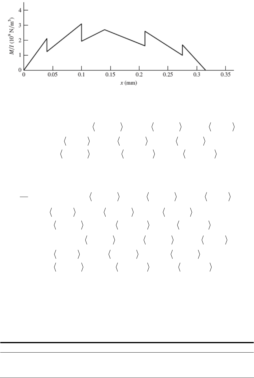
The steps and the change of slopes are evaluated in the table. From these, the function
M/I can be generated:
01
110
10 9
/ 52.8 0.8745 0.04 21.86 0.04 1.162 0.1
11.617 0.1 34.78 0.14 0.977 0.21
9.312 0.21 0.6994 0.275 17.47 0.275 10
MI x x x x
xx x
xxx
0
1
Integrate twice:
12
2
26.4 0.8745 0.04 10.93 0.04 1.162xx x x
1
32
0.1
0.04 0.581 0.1
7
E
dx
x
x
dy
221
212
9
1
2
3
5.81 0.1 17.39 0.14 0.977 0.21
4.655 0.21 0.6994 0.275 8.735 0.275 10 (1)
8.8 0.4373 0.04 3.643
xx x
xxxC
Ey x x x
1.9333 2
3
9
0.1 0.14 0.21
52 0. 0.2 0.275 10
x
xxx
Boundary conditions: y yields C2
y = 0 at x = 0.315 m yields C1 = –0.295 25 N/m2.
3
2
12
CxC
5.797 0.4885 x
1.521 0.3497 75 2.912
= 0 at x = 0 = 0;
Equation (1) with C1 = –0.295 25 provides the slopes at the bearings and gear. The
following table gives the results in the second column. The third column gives the results
from a similar finite element model. The fourth column gives the results of a full model
which models the 35 and 55 mm diameter steps.
x (mm)
(rad) F.E. Model Full F.E. Model
0 –0.001 4260 –0.001 4270 –0.001 4160
140 –0.000 1466 –0.000 1467 –0.000 1646
315 0.001 3120 0.001 3280 0.001 3150
Chapter 7 - Rev. A, Page 29/45
The main discrepancy between the results is at the gear location (x = 140 mm). The larger
value in the full model is caused by the stiffer 55 mm diameter step. As was stated
arlier, this step is not as stiff as modeling implicates, so the exact answer is somewhere
between the full model and the simplified model which in any event is a small value. As
xpected, modeling the 30 mm dia. as 35 mm does not affect the results much.
can be seen that the allowable slopes at the bearings are exceeded. Thus, either the load
ed or the shaft “beefed” up. If the allowable slope is 0.001 rad, then the
aximum load should be Fmax = (0.001/0.001 426)7 = 4.91 kN. With a design factor this
would be reduced further.
To increase the stiffness of th , E 8 f deflection (at
= 0) to determine a multiplier to be used for all diameters.
e
e
It
has to be reduc
m
e shaft apply q. (7-1 ) to the most o fending
x
1/ 4 1/4
new old
old
/(1)(0.0014260) 1.093
ndydx
d
d
orm a table:
all
slope 0.001
d
F
Old d, mm 20.00 30.00 35.00 40.00 45.00 55.00
New ideal d, mm 21.86 32.79 38.26 43.72 49.19 60.12
Rounded up d, mm 22.00 34.00 40.00 44.00 50.00 62.00
Repeating the full finite element mo lts in del resu
x 9
40 : –1 1
5 .
stress concentrations and reduced shaft diameters, there are a number of
at. A table of nominal stresses is given below. Note that torsion is only
f the 7 kN load. Using
= 32 (
d3) and
= 16T/(
d3),
0 275 300 330
= 0:
= – .30 10-4 rad
x = 1 mm
=.09 0-4 rad
-4
x = 31 mm:
= 8 65 10 rad
This is well within our goal. Have the students try a goal of 0.0005 rad at the gears.
Strength: Due to
looklocations to
to the right o M/
x (mm) 15 40 100 110 140 210
(MPa) 0 39.6 17.6 0
0 6 8.5 12.7 20.2 68.1
22.0 37.0 61.9 47.8 60.9 52.0
(MPa) 0 0 0 0
(MPa)
0 22.0 37.0 61.9 47.8 61.8 53.1 45.3 39.2 118.0
for Sy = 390 MPa
Eq. (6-19):
Table A-20 AISI 1020 CD steel: Sut = 470 MPa,
At x = 210 mm:
0.265
4.51(470) 0.883
a
k
Chapter 7 - Rev. A, Page 30/45
Eq. (6-20): 0.107
(40 / 7.62) 0.837
b
k
Eq. (6-18): Se = 0.883 (0.837)(0.5)(470) = 174 MPa
D / d = 45 / 40 = 1.125, r / d = 2 / 40 = 0.05
Fig. A-15-8: Kts = 1.4
Fig. A-15-9: Kt = 1.9
Fig q = 0.75
Fig qs = 0.79
= 1 + 0.75(1.9 –1) = 1.68
ld check, from Eq. (7-11), with
. 6-20:
. 6-21:
Eq. (6-32): Kf
K f s = 1 + 0.79(1.4 – 1) = 1.32
Choosing DE-ASME Elliptic to inherently include the yie
Mm = Ta = 0,
1/2
22
6
1.32(107)
3
390 10
36
1.68(326.67)
4
0.04 174 10
n
1 16
At
The von Mises stress is the highest but it comes from the steady torque only.
Fig. 6-21: qs = 0.79 .42 – 1) = 1.33
1.98n
x = 330 mm:
D / d = 30 / 20 = 1.5, r / d = 2 / 20 = 0.1
Fig. A-15-9: Kts = 1.42
Eq. (6-32): Kf s = 1 + 0.79(1
Eq. (7-11):
1 16 1.33(107)
36
390 10
n
3
n = 2.49
Note that since there is only a steady torque, Eq. (7-11) reduces to essentially the
equivalent of the distortion energy failure theory.
s at x = 210 mm, the changes discussed for the slope criterion will
______________________________________________________________________________
7-2 se design tasks each student will travel different paths and almost all
The student gets a blank piece of paper, a statement of function, and some constraints
Check the other locations.
If worse-case i
improve the strength issue.
5 and 7-26 With the
details will differ. The important points are
– explicit and implied. At this point in the course, this is a good experience.
It is a good preparation for the capstone design course.
Chapter 7 - Rev. A, Page 31/45
The adequacy of their design must be demonstrated and possibly include a designer’s
notebook.
Many of the fundaments of the course, based on this text and this course, are useful.
.
Don’t let the students create a time sink for themselves. Tell them how far you want
______________________________________________________________________________
7-27 oblem. This problem is a learning experience.
ollowing the task statement, the following guidance was added.
ting the temptation of putting pencil to paper, and decide
what the problem really is.
ld implement it.
The students’ initial reaction is that he/she does not know much from the problem
lowly the realization sets in that they do know some important things
that the designer did not. They knew how it failed, where it failed, and that the design
wasn’t good enough; it was close, though.
Also, a fix at the bearing seat lead-in could transfer the problem to the shoulder fillet, and
the problem may not be
tudents’ credit, they chose to keep the shaft geometry, and selected a new
material to realize about
______________________________________________________________________________
-28
The student will find them useful and notice that he/she is doing it
them to go.
This task was once given as a final exam pr
F
Take the first half hour, resis
Take another twenty minutes to list several possible remedies.
Pick one, and show your instructor how you wou
statement. Then, s
solved.
To many s
twice the Brinell hardness.
7In Eq. (7-22) set
42
dd
,
64 4
IA
to obtain
2
4l
dg
E
(1)
or
2
2gE
4l
d
(2)
(a) From Eq. (1) and Table A-5
29
0.025 9.81(207)(10 ) .
A
3883 rad/s
0.6 476.5 10 ns
Chapter 7 - Rev. A, Page 32/45
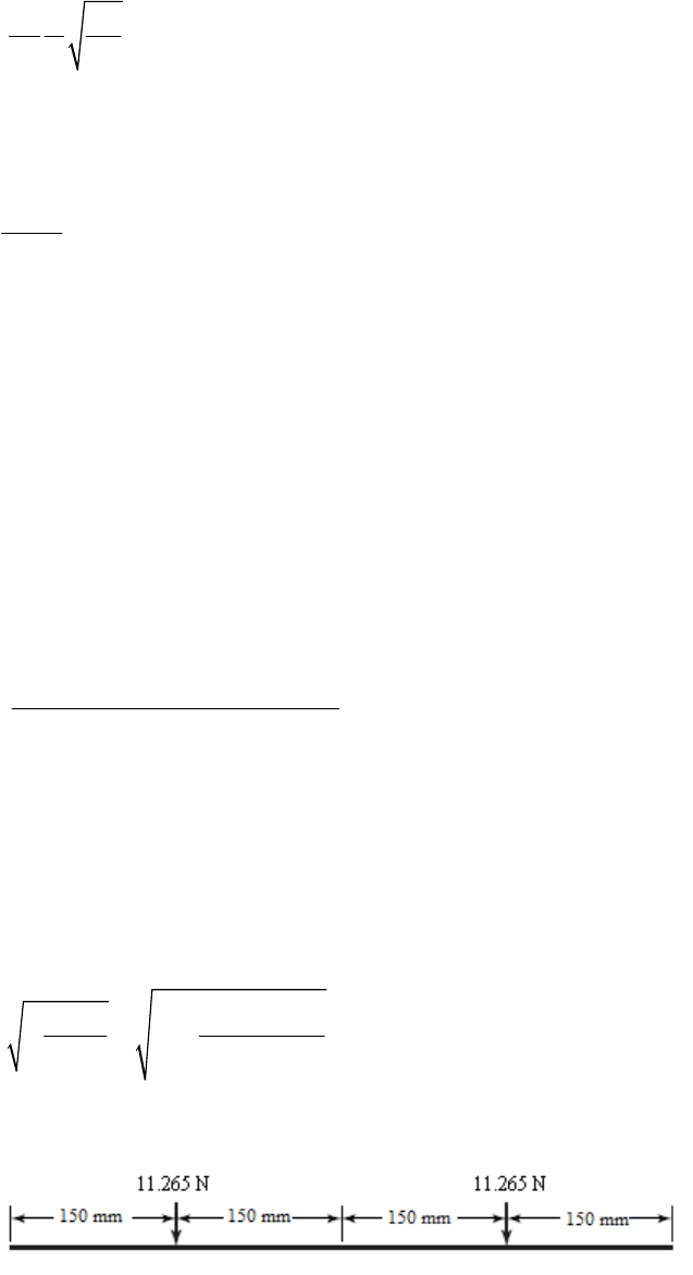
(b) From Eq. (1), we observe that the critical speed is linearly proportional to the
diameter. Thus, to double the critical speed, we should double the diameter to d = 50
mm. Ans.
(c) From Eq. (2),
2dg
l
4
E
l
Since d / l is the same regardless of the scale,
constant 0.6(883) 529.8l
529.8 1766 rad/s .
A
0.3 ns
Thus the first critical speed doubles.
______________________________________________________________________________
7-29 From Prob. 7-28,
883 rad/s
42 84 4
4.909 10 m , 1.917 10 m , 7.65 10 N/mAI
3
944
207(10 ) Pa, 4.909 10 7.65 10 (0.6) 22.53 NEAl
w
One element:
Eq. (7-24):
222
6
11 98
0.3(0.3) 0.6 0.3 0.3 1.134 10 m/N
6(207) 10 (1.917) 10 (0.6)
65
1111
22.53(1.134) 10 2.555 10 my
w
21
16.528 10y
0
54
22.53(2.555) 10 5.756 10y
w
210
22.53(6.528) 10 1.471 10y
w
8
4
128
5.756 10
9.81 620 rad/s
1.471 10
y
gy
w
w (30% low)
Two elements:
Chapter 7 - Rev. A, Page 33/45

222
7
11 22 98
0.45(0.15) 0.6 0.45 0.15 6.379 10 m/N
6(207) 10 (1.917) 10 (0.6)
222
7
12 21 98
0.15(0.15)(0.6 0.15 0.15 ) 4.961 10 m/N
6(207) 10 (1.917) 10 (0.6)
77
12 111 212
11.265(6.379) 10 11.265(4.961) 10 1.277 10 myy
ww
5
22 10
2 10
12
1.63yy
54
2(11.265)(1.277) 10 2.877 10y
w
210
2(11.265)(1.632) 10 3.677 10y
w
9
4
19
2.877 10
9.81 876 rad/s
3.677 10
(0.8% low)
Three elements:
222
7
11 33 98
0.5(0.1) 0.6 0.5 0.1 3.500 10 m/N
6(207) 10 (1.917) 10 (0.6)
222
6
22 98
0.3(0.3) 0.6 0.3 0.3 1.134 10 m/N
6(207) 10 (1.917) 10 (0.6)
222
7
12 32 98
0.3(0.1) 0.6 0.3 0.1 5.460 10 m/N
6(207) 10 (1.917) 10 (0.6)
222
7
13 98
0.1(0.1) 0.6 0.1 0.1 2.380 10 m/N
6(207) 10 (1.917) 10 (0.6)
777
17.51 3.500 10 5.460 10 2.380 10 8.516 10
6
y
76 7
27.51 5.460 10 1.134 10 10 1.672 10y
5
5.460
777
37.51 2.380 10 5.460 10 3.500 10 8.516 10y
6
656 4
7.51 8.516 10 1.672 10 8.516 10 2.535 10y
w
222
26569
7.51 8.516 10 1.672 10 8.516 10 3.189 10y
w
Chapter 7 - Rev. A, Page 34/45
4
2.535 10
9.81 883 ra
19
3.189 10
d/s
7-28. The point was to show that convergence is rapid
using a static deflection beam equation. The method works because:
If a deflection curve is chosen which meets the boundary conditions of moment-
free and deflection-free ends, as in this problem, the strain energy is not very
sensitive to the equation used.
ation is available, and meets the moment-free and
deflection-free ends, it works.
______________________________________________________________________________
7-30 (a) For two bodies, Eq. (7-26) is
The result is the same as in Prob.
Since the static bending equ
2
111
(1/) 0
m
212
2
121 222
(1
/)
m
mm
Expanding the determinant yields,
2
1
111 2 22 1 2 11 22 12 21
22
1
1
() ( )0mm mm
(1)
Eq. (1) has two roots 22
12
1/ and 1/ .
Thus
22 22
12
11 11
0
or,
2
11
2
222 22
12 1 2
1111
0
(2)
Equate the third terms of Eqs. (1) and (2), which must be identical.
2
1 2 11 22 12 21 1 1 2 11 22 12 21
22 2
11 1
() ()mm mm
12 2
and it follows that
Chapter 7 - Rev. A, Page 35/45
2
2
11 112212
.
()
Ans
ww
2 21
1g
(b) In Ex. 7-5, part (b), the first critical speed of the two-disk shaft (w1 = 35 lbf,
w 2 = 55 lbf) is
1 = 124.8 rad/s. From part (a), using influence coefficients,
2
228
1 386 466 rad/s .
124.8 35(55) 2.061(3.534) 2.234 10
A
ns
______________________________________________________________________________
7-31 In Eq. (7-22), for
1, the term /
I
Aappears. For a hollow uniform diameter shaft,
4 2222
22
o oi oi
d dddd
Idd
4
122
22
/64 11
16 4
/4
i
oi
oi
oi
d
Add
dd
This means that when a solid shaft is hollowed out, the critical speed increases beyond
solid shaft of the same size. By how much? that of the
2
22
21
(1 / 4)
oi i
o
od
d
The possible values of are 0 ,
iio
ddd
(1 / 4) dd d
so the range of the critical speeds is
110
to about 111
or from
11
to 2 . .
A
ns
______________________________________________________________________________
7-32 All steps w b g t t pr s et. Programming
both loads will enable the user to first set the left load to 1, the right load to 0 and
calculate
11 and
21. Then set the left load to 0 and the right to 1 to get
12 and
22. The
spreadsheet shows the
11 and
21 calculation. A table for M / I vs. x is easy to make.
First, draw the bending-moment diagram as shown with the data.
x 0 1 2 3 4 5 6 7 8
ill e modeled using sin ulari y func ions with a s ead he
M 0 0.875 1.75 1.625 1.5 1.375 1.25 1.125 1
x 9 10 11 12 13 14 15 16
M 0.875 0.75 0.625 0.5 0.375 0.25 0.125 0
Chapter 7 - Rev. A, Page 36/45
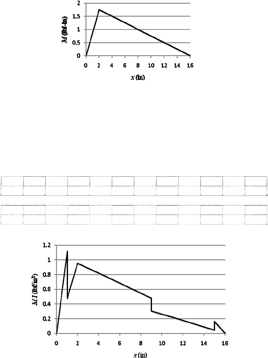
The second-area moments are:
44
1
0 1 in and 15 16 in, 2 / 64 0.7854 inxxI
44
2
44
3
1 9 in , 2.472 / 64 1.833 in
9 15 in , 2.763 / 64 2.861 in
xI
xI
Divide M by I at the key points x = 0, 1, 2, 9, 14, 15, and 16 in and plot
x 0 1 1 2 2 3 4 5 6 7 8
M/I 0 1.1141 0.4774 0.9547 0.9547 0.8865 0.8183 0.7501 0.6819 0.6137 0.5456
x 9 9 10 11 12 13 14 14 15 15 16
M/I 0.4774 0.3058 0.2621 0.2185 0.1748 0.1311 0.0874 0.0874 0.0437 0.1592 0
From this diagram, one can see where changes in value (steps) and slope occur. Using a
spreadsheet, one can form a table of these changes. An example of a step is, at x = 1 in,
M/I goes from 0.875/0.7854 = 1.1141 lbf/in3 to 0.875/1.833 = 0.4774 lbf/in3, a step
change of 0.4774 1.1141 = 0.6367 lbf/in3. A slope change also occurs at at x = 1 in.
Chapter 7 - Rev. A, Page 37/45
The slope for 0 x 1 in is 1.1141/1 = 1.1141 lbf/in2, which changes to (0.9547
0.4774)/1 = 0.4774 lbf/in2, a change of 0.4774 1.1141 = 0.6367 lbf/in2. Following
this approach, a table is made of all the changes. The table shown indicates the column
letters and row numbers for the spreadsheet.
A B C D E F
1 x M M/I
step Slope Slope
2 1a 0.875 1.114085 0.000000 1.114085 0.000000
3 1b 0.875 0.477358 -0.636727 0.477358 -0.636727
4 2 1.75 0.954716 0.000000 0.477358 0.000000
5 2 1.75 0.954716 0.000000 -0.068194 -0.545552
6 9a 0.875 0.477358 0.000000 -0.068194 0.000000
7 9b 0.875 0.305854 -0.171504 -0.043693 0.024501
8 14 0.25 0.087387 0.000000 -0.043693 0.000000
9 14 0.25 0.087387 0.000000 -0.043693 0.000000
10 15a 0.125 0.043693 0.000000 -0.043693 0.000000
11 15b 0.125 0.159155 0.115461 -0.159155 -0.115461
12 16 0 0.000000 0.000000 -0.159155 0.000000
The equation for M / I in terms of the spreadsheet cell locations is:
01 1
01 0
/E2()D3 1F31F5 2
D7 9 F7 9 D11 15 F11 15
MI x x x x
xx x x
1
5
5
Integrating twice gives the equation for Ey. Assume the shaft is steel. Boundary
conditions y = 0 at x = 0 and at x = 16 inches provide integration constants (C1 = 4.906
lbf/in and C2 = 0). Substitution back into the deflection equation at x = 2 and 14 in
provides the
’s. The results are:
11 = 2.917(10–7) and
12 = 1.627(10–7). Repeat for
F1 = 0 and F2 = 1, resulting in
21 = 1.627(10–7) and
22 = 2.231(10–7). This can be
verified by finite element analysis.
77
1
77
2
210210
12
42 9
18(2.917)(10 ) 32(1.627)(10 ) 1.046(10 )
18(1.627)(10 ) 32(2.231)(10 ) 1.007(10 )
1.093(10 ), 1.014(10 )
5.105(10 ), 5.212(10 )
y
y
yy
yy
ww
Neglecting the shaft, Eq. (7-23) gives
4
19
5.105(10 )
386 6149 rad/s or 58 720 rev/min .
5.212(10 ) Ans
Chapter 7 - Rev. A, Page 38/45
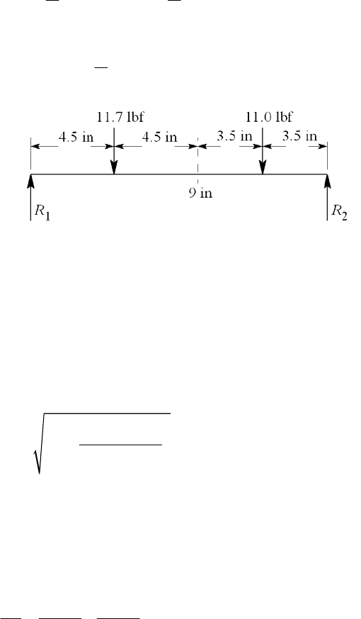
Without the loads, we will model the shaft using 2 elements, one between 0 x 9 in,
and one between 0 x 16 in. As an approximation, we will place their weights at
x = 9/2 = 4.5 in, and x = 9 + (16 9)/2 = 12.5 in. From Table A-5, the weight density of
steel is
= 0.282 lbf/in3. The weight of the left element is
222
10.282 2 1 2.472 8 11.7 lbf
44
dl
w
The right element is
22
20.282 2.763 6 2 1 11.0 lbf
4
w
The spreadsheet can be easily modified to give
77
11 12 21 22
9.605 10 , 5.718 10 , 5.472 10
7
55
12
1.753 10 , 1.271 10yy
2102
12
3.072 10 , 1.615 10yy
10
42
3.449 10 , 5.371 10yy
ww
9
4
19
3.449 10
386 4980 rad/s
5.371 10
A finite element model of the exact shaft gives
1 = 5340 rad/s. The simple model is
6.8% low.
Combination: Using Dunkerley’s equation, Eq. (7-32):
1
222
1
11 1 3870 rad/s .
6149 4980
A
ns
______________________________________________________________________________
7-33 We must not let the basis of the stress concentration factor, as presented, impose a view-
point on the designer. Table A-16 shows Kts as a decreasing monotonic as a function of
a/D. All is not what it seems. Let us change the basis for data presentation to the full
section rather than the net section.
00ts ts
KK
Chapter 7 - Rev. A, Page 39/45
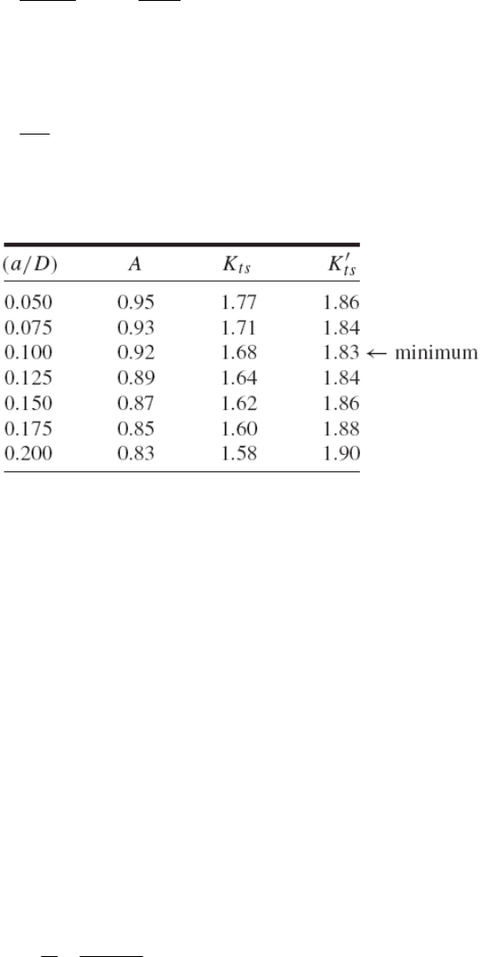
33
32 32
ts ts
TT
KK
A
DD
Therefore
ts
ts
K
K
A
Form a table:
ts
Khas the following attributes:
It exhibits a minimum;
It changes little over a wide range;
Its minimum is a stationary point minimum at a / D 0.100;
Our knowledge of the minima location is
0.075 ( / ) 0.125aD
We can form a design rule: In torsion, the pin diameter should be about 1/10 of the shaft
diameter, for greatest shaft capacity. However, it is not catastrophic if one forgets the
rule.
______________________________________________________________________________
7-34 From the solution to Prob. 3-72, the torque to be transmitted through the key from the
gear to the shaft is T = 2819 lbf·in. From Prob. 7-19, the nominal shaft diameter
supporting the gear is 1.00 in. From Table 7-6, a 0.25 in square key is appropriate for a
1.00 in shaft diameter. The force applied to the key is
2819 5638 lbf
1.00 / 2
T
Fr
Selecting 1020 CD steel for the key, with Sy = 57 kpsi, and using the distortion-energy
theory, Ssy = 0.577 Sy = (0.577)(57) = 32.9 kpsi.
Failure by shear across the key:
Chapter 7 - Rev. A, Page 40/45
1.1 5638
0.754 in
/ 0.25 32 900
sy sy
sy
FF
Atl
SS nF
nl
Ftl tS
Failure by crushing:
/2
FF
At l
3
2 5638 1.1
2
0.870 in
2/ 0.25 57 10
yy
y
SS Fn
nl
Ftl tS
Select ¼-in square key, 7/8 in long, 1020 CD steel. Ans.
______________________________________________________________________________
7-35 From the solution to Prob. 3-73, the torque to be transmitted through the key from the
gear to the shaft is T = 3101 N·m. From Prob. 7-21, the nominal shaft diameter
supporting the gear is 50 mm. To determine an appropriate key size for the shaft
diameter, we can either convert to inches and use Table 7-6, or we can look up standard
metric key sizes from the internet or a machine design handbook. It turns out that the
recommended metric key for a 50 mm shaft is 14 x 9 mm. Since the problem statement
specifies a square key, we will use a 14 x 14 mm key. For comparison, using Table 7-6
as a guide, for d = 50 mm = 1.97 in, a 0.5 in square key is appropriate. This is equivalent
to 12.7 mm. A 14 x 14 mm size is conservative, but reasonable after rounding up to
standard sizes.
The force applied to the key is
3
3101 124 10 N
0.050 / 2
T
Fr
Selecting 1020 CD steel for the key, with Sy = 390 MPa, and using the distortion-energy
theory, Ssy = 0.577 Sy = 0.577(390) = 225 MPa.
Failure by shear across the key:
3
6
1.1 124 10
0.0433 m 43.3 mm
/0.014 225 10
sy sy
sy
FF
Atl
SS nF
nl
Ftl tS
Failure by crushing:
Chapter 7 - Rev. A, Page 41/45

/2
FF
At
l
3
6
2 124 10 1.1
2
0.0500 m 50.0 mm
2/ 0.014 390 10
yy
y
SS Fn
nl
Ftl tS
Select 14 mm square key, 50 mm long, 1020 CD steel. Ans.
______________________________________________________________________________
7-36 Choose basic size D = d = 15 mm. From Table 7-9, a locational clearance fit is
designated as 15H7/h6. From Table A-11, the tolerance grades are D = 0.018 mm and
d = 0.011 mm. From Table A-12, the fundamental deviation is
F = 0 mm.
Hole:
Eq. (7-36): Dmax = D + D = 15 + 0.018 = 15.018 mm Ans.
Dmin = D = 15.000 mm Ans.
Shaft:
Eq. (7-37): dmax = d +
F = 15.000 + 0 = 15.000 mm Ans.
dmin = d +
F – d = 15.000 + 0 – 0.011 = 14.989 mm Ans.
______________________________________________________________________________
7-37 Choose basic size D = d = 1.75 in. From Table 7-9, a medium drive fit is designated as
H7/s6. From Table A-13, the tolerance grades are D = 0.0010 in and d = 0.0006 in.
From Table A-14, the fundamental deviation is
F = 0.0017 in.
Hole:
Eq. (7-36): Dmax = D + D = 1.75 + 0.0010 = 1.7510 in Ans.
Dmin = D = 1.7500 in Ans.
Shaft:
Eq. (7-38): dmin = d +
F = 1.75 + 0.0017 = 1.7517 in Ans.
dmax = d +
F + d = 1.75 + 0.0017 + 0.0006 = 1.7523 in Ans.
______________________________________________________________________________
7-38 Choose basic size D = d = 45 mm. From Table 7-9, a sliding fit is designated as H7/g6.
From Table A-11, the tolerance grades are D = 0.025 mm and d = 0.016 mm. From
Table A-12, the fundamental deviation is
F = –0.009 mm.
Hole:
Eq. (7-36): Dmax = D + D = 45 + 0.025 = 45.025 mm Ans.
Dmin = D = 45.000 mm Ans.
Shaft:
Eq. (7-37): dmax = d +
F = 45.000 + (–0.009) = 44.991 mm Ans.
dmin = d +
F – d = 45.000 + (–0.009) – 0.016 = 44.975 mm Ans.
______________________________________________________________________________
Chapter 7 - Rev. A, Page 42/45
7-39 Choose basic size D = d = 1.250 in. From Table 7-9, a close running fit is designated as
H8/f7. From Table A-13, the tolerance grades are D = 0.0015 in and d = 0.0010 in.
From Table A-14, the fundamental deviation is
F = –0.0010 in.
Hole:
Eq. (7-36): Dmax = D + D = 1.250 + 0.0015 = 1.2515 in Ans.
Dmin = D = 1.2500 in Ans.
Shaft:
Eq. (7-37): dmax = d +
F = 1.250 + (–0.0010) = 1.2490 in Ans.
dmin = d +
F – d = 1.250 + (–0.0010) – 0.0010 = 1.2480 in Ans.
______________________________________________________________________________
7-40 Choose basic size D = d = 35 mm. From Table 7-9, a locational interference fit is
designated as H7/p6. From Table A-11, the tolerance grades are D = 0.025 mm and
d = 0.016 mm. From Table A-12, the fundamental deviation is
F = 0.026 mm.
Hole:
Eq. (7-36): Dmax = D + D = 35 + 0.025 = 35.025 mm
Dmin = D = 35.000 mm
The bearing bore specifications are within the hole specifications for a locational
interference fit. Now find the necessary shaft sizes.
Shaft:
Eq. (7-38): dmin = d +
F = 35 + 0.026 = 35.026 mm Ans.
dmax = d +
F + d = 35 + 0.026 + 0.016 = 35.042 mm Ans.
______________________________________________________________________________
7-41 Choose basic size D = d = 1.5 in. From Table 7-9, a locational interference fit is
designated as H7/p6. From Table A-13, the tolerance grades are D = 0.0010 in and
d = 0.0006 in. From Table A-14, the fundamental deviation is
F = 0.0010 in.
Hole:
Eq. (7-36): Dmax = D + D = 1.5000 + 0.0010 = 1.5010 in
Dmin = D = 1.5000 in
The bearing bore specifications exactly match the requirements for a locational
interference fit. Now check the shaft.
Shaft:
Eq. (7-38): dmin = d +
F = 1.5000 + 0.0010 = 1.5010 in
dmax = d +
F + d = 1.5000 + 0.0010 + 0.0006 = 1.5016 in
Chapter 7 - Rev. A, Page 43/45

The shaft diameter of 1.5020 in is greater than the maximum allowable diameter of
1.5016 in, and therefore does not meet the specifications for the locational interference
fit. Ans.
______________________________________________________________________________
7-42 (a) Basic size is D = d = 35 mm.
Table 7-9: H7/s6 is specified for medium drive fit.
Table A-11: Tolerance grades are D = 0.025 mm and d = 0.016 mm.
Table A-12: Fundamental deviation is 0.043 mm.
F
Eq. (7-36): Dmax = D + D = 35 + 0.025 = 35.025 mm
Dmin = D = 35.000 mm
Eq. (7-38): dmin = d +
F = 35 + 0.043 = 35.043 mm Ans.
dmax = d +
F + d = 35 + 0.043 + 0.016 = 35.059 mm Ans.
(b)
Eq. (7-42): min min max 35.043 35.025 0.018 mmdD
Eq. (7-43): max max min 35.059 35.000 0.059 mmdD
Eq. (7-40):
2222
max
max 322
2
oi
oi
dddd
E
pddd
9222
2
3
207 10 0.059 60 35 35 0 115 MPa .
60 0
235
A
ns
2222
min
min 322
2
oi
oi
dddd
E
pddd
9222
2
3
207 10 0.018 60 35 35 0 35.1 MPa .
60 0
235
A
ns
(c) For the shaft:
Eq. (7-44): ,shaft 115 MPa
tp
Eq. (7-46): ,shaft 115 MPa
rp
Eq. (5-13):
1/ 2
22
1122
1/2
22
( 115) ( 115)( 115) ( 115) 115 MPa
/ 390 /115 3.4 .
y
nS Ans
For the hub:
Eq. (7-45):
22 22
,hub 22 2 2
60 35
115 234 MPa
60 35
o
t
o
dd
pdd
Eq. (7-46): ,hub 115 MPa
rp
Chapter 7 - Rev. A, Page 44/45
Eq. (5-13):
1/ 2
22
1122
1/ 2
22
(234) (234)( 115) ( 115) 308 MPa
/ 600 / 308 1.9 .
y
nS Ans
(d) A value for the static coefficient of friction for steel to steel can be obtained online or
from a physics textbook as approximately f = 0.8.
Eq. (7-49) 2
min
(/2)T
f
pld
62
( / 2)(0.8)(35.1) 10 (0.050)(0.035) 2700 N m .
A
ns
______________________________________________________________________________
Chapter 7 - Rev. A, Page 45/45
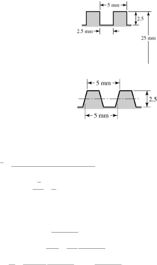
Chapter 8
Note to the Instructor for Probs. 8-41 to 8-44. These problems, as well as many others in this
chapter are best implemented using a spreadsheet.
8-1 (a) Thread depth= 2.5 mm Ans.
Width = 2.5 mm Ans.
d
m = 25 - 1.25 - 1.25 = 22.5 mm
d
r = 25 - 5 = 20 mm
l = p = 5 mm Ans.
(b) Thread depth = 2.5 mm Ans.
Width at pitch line = 2.5 mm Ans.
d
m = 22.5 mm
d
r = 20 mm
l = p = 5 mm Ans.
______________________________________________________________________________
8-2 From Table 8-1,
1.226 869
0.649 519
1.226 869 0.649 519 0.938 194
2
r
m
dd p
dd p
dpdp
dd
p
2
2
( 0.938 194 ) .
44
t
d
Adp
Ans
______________________________________________________________________________
8-3 From Eq. (c) of Sec. 8-2,
tan
1tan
tan
221tan
R
Rm m
R
f
PF f
Pd Fd f
Tf
-
-
-
-
0/ (2 ) 1 tan 1 tan
tan .
/2 tan tan
Rm
TFl f f
eA
TFd f f ns
--
-
--
Chap. 8 Solutions - Rev. A, Page 1/69
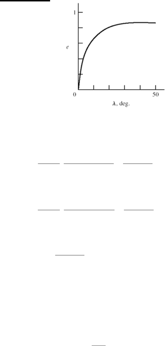
Using f = 0.08, form a table and plot the efficiency curve.
-, deg. e
0 0
0 0.678
20 0.796
30 0.838
40 0.8517
45 0.8519
______________________________________________________________________________
8-4 Given F = 5 kN, l = 5 mm, and dm = d p/2 = 25 5/2 = 22.5 mm, the torque required to
raise the load is found using Eqs. (8-1) and (8-6)
5 22.5 5 0.09 22.5 5 0.06 45 15.85 N m .
2 22.5 0.09 5 2
R
TA
ns
The torque required to lower the load, from Eqs. (8-2) and (8-6) is
5 22.5 0.09 22.5 5 5 0.06 45 7.83 N m .
2 22.5 0.09 5 2
L
TA
ns
Since TL is positive, the thread is self-locking. From Eq.(8-4) the efficiency is
55 0.251 .
2 15.85
e Ans
______________________________________________________________________________
8-5 Collar (thrust) bearings, at the bottom of the screws, must bear on the collars. The bottom
segment of the screws must be in compression. Whereas, tension specimens and their
grips must be in tension. Both screws must be of the same-hand threads.
______________________________________________________________________________
8-6 Screws rotate at an angular rate of
1720 28.67 rev/min
60
n
Chap. 8 Solutions - Rev. A, Page 2/69
(a) The lead is 0.25 in, so the linear speed of the press head is
V = 28.67(0.25) = 7.17 in/min Ans.
(b) F = 2500 lbf/screw
o
2 0.25 / 2 1.875 in
sec 1 / cos(29 / 2) 1.033
m
d
Eq. (8-5):
2500(1.875) 0.25 (0.05)(1.875)(1.033) 221.0 lbf · in
2 (1.875) 0.05(0.25)(1.033)
R
T
Eq. (8-6):
2500(0.08)(3.5 / 2) 350 lbf · in
350 221.0 571 lbf · in/screw
571(2) 20.04 lbf · in
60(0.95)
20.04(1720) 0.547 hp .
63 025 63 025
c
total
motor
T
T
T
Tn
HA
ns
______________________________________________________________________________
8-7 Note to the Instructor: The statement for this problem in the first printing of this edition
was vague regarding the effective handle length. For the printings to follow the statement
“The overall length is 4.25 in.” will be replaced by “ A force will be applied to the handle
at a radius of 1
2
3in from the screw centerline.” We apologize if this has caused any
inconvenience.
33
3.5 in
3.5
33
3.5 3.125
88
41 kpsi
32 32(3.125) 41 000
(0.1875)
8.49 lbf
y
y
L
TF
M
LF F
S
MF
Sd
F
F
ns
3.5(8.49) 29.7 lbf · in .TA
(b) Eq. (8-5), 2
= 60 , l = 1/10 = 0.1 in, f = 0.15, sec
= 1.155, p = 0.1 in
Chap. 8 Solutions - Rev. A, Page 3/69
clamp
clamp
clamp
30.649 519 0.1 0.6850 in
4
(0.6850) 0.1 (0.15)(0.6850)(1.155)
2 (0.6850) 0.15(0.1)(1.155)
0.075 86
29.7 392 lbf .
0.075 86 0.075 86
m
R
R
R
d
F
T
TF
T
FA
ns
(c) The column has one end fixed and the other end pivoted. Base the decision on the
mean diameter column. Input: C = 1.2, D = 0.685 in, A = (0.6852)/4 = 0.369 in2, Sy = 41
kpsi, E = 30(106) psi, L = 6 in, k = D/4 =0.171 25 in, L/k = 35.04. From Eq. (4-45),
1/ 2
1/ 2 26
2
1
2 1.2 30 10
2131.7
41 000
y
lCE
kS
From Eq. (4-46), the limiting clamping force for buckling is
2
clamp cr
2
3
33
6
1
2
41 10 1
0.369 41 10 35.04 14.6 10 lbf
2 1.2 30 10
y
y
Sl
FPAS kCE
Ans
(d) This is a subject for class discussion.
______________________________________________________________________________
8-8 T = 8(3.5) = 28 lbf in
310.6667 in
412
m
d
l = 1
6 = 0.1667 in,
=
0
29
2 = 14.50, sec 14.50 = 1.033
From Eqs. (8-5) and (8-6)
total
0.1667 0.15 0.6667 1.033 0.15 1
0.6667 0.1542
2 0.6667 0.15 0.1667 1.033 2
F
F
TF
28 182 lbf .
0.1542
F
Ans
_____________________________________________________________________________
Chap. 8 Solutions - Rev. A, Page 4/69

8-9 dm = 1.5 0.25/2 = 1.375 in, l = 2(0.25) = 0.5 in
From Eq. (8-1) and Eq. (8-6)
33
2.2 10 (1.375) 2.2 10 (0.15)(2.25)
0.5 (0.10)(1.375)
2 (1.375) 0.10(0.5) 2
330 371 701 lbf · in
R
T
Since n = V/l = 2/0.5 = 4 rev/s = 240 rev/min
so the power is
701 240 2.67 hp .
63 025 63 025
Tn
HA ns
______________________________________________________________________________
8-10 dm = 40 4 = 36 mm, l = p = 8 mm
From Eqs. (8-1) and (8-6)
36 8 (0.14)(36) 0.09(100)
2(36)0.14(8) 2
(3.831 4.5) 8.33 N · m ( in kN)
2 2 (1) 2 rad/s
3000 477 N · m
2
477 57.3 kN .
8.33
FF
T
FF F
n
HT
H
T
FAns
57.3(8) 0.153 .
2 2 (477)
Fl
eA
T
ns
______________________________________________________________________________
8-11 (a) Table A-31, nut height H = 12.8 mm. L ≥ l + H = 2(15) + 12.8 = 42.8 mm. Rounding
up,
L = 45 mm Ans.
(b) From Eq. (8-14), LT = 2d + 6 = 2(14) +6 = 34 mm
From Table 8-7, ld = L
LT = 45
34 = 11 mm, lt = l
ld = 2(15) 11 = 19 mm,
Ad =
(142) / 4 = 153.9 mm2. From Table 8-1, At = 115 mm2. From Eq. (8-17)
Chap. 8 Solutions - Rev. A, Page 5/69
153.9 115 207 874.6 MN/m .
153.9 19 115 11
dt
b
dt td
AAE
kA
Al Al
ns
(c) From Eq. (8-22), with l = 2(15) = 30 mm
0.5774 207 14
0.5774 3 116.5 MN/m .
0.5774 0.5 0.5774 30 0.5 14
2ln 5 2ln 5
0.5774 2.5 0.5774 30 2.5 14
m
k
Ed Ans
ld
ld
8-12 (a) Table A-31, nut height H = 12.8 mm. Table A-33, washer thickness t = 3.5 mm. Thus,
the grip is l = 2(15) + 3.5 = 33.5 mm. L ≥ l + H = 33.5 + 12.8 = 46.3 mm. Rounding up
L = 50 mm Ans.
(b) From Eq. (8-14), LT = 2d + 6 = 2(14) +6 = 34 mm
From Table 8-7, ld = L
LT = 50
34 = 16 mm, lt = l
ld = 33.5 16 = 17.5 mm,
Ad =
(142) / 4 = 153.9 mm2. From Table 8-1, At = 115 mm2. From Eq. (8-17)
153.9 115 207 808.2 MN/m .
153.9 17.5 115 16
dt
b
dt td
AAE
kA
Al Al
ns
(c)
From Eq. (8-22)
0.5774 207 14
0.5774 2 969 MN/m .
0.5774 0.5 0.5774 33.5 0.5 14
2ln 5 2ln 5
0.5774 2.5 0.5774 33.5 2.5 14
m
Ed
kA
ld
ld
ns
______________________________________________________________________________
Chap. 8 Solutions - Rev. A, Page 6/69
8-13 (a) Table 8-7, l = h + d /2 = 15 + 14/2 = 22 mm. L ≥ h + 1.5d = 36 mm. Rounding up
L = 40 mm Ans.
(b) From Eq. (8-14), LT = 2d + 6 = 2(14) +6 = 34 mm
From Table 8-7, ld = L
LT = 40
34 = 6 mm, lt = l
ld = 22 6 = 16 mm
Ad =
(142) / 4 = 153.9 mm2. From Table 8-1, At = 115 mm2. From Eq. (8-17)
153.9 115 207 1 162.2 MN/m .
153.9 16 115 6
dt
b
dt td
AAE
kA
Al Al
ns
(c) From Eq. (8-22), with l = 22 mm
0.5774 207 14
0.5774 3 624.4 MN/m .
0.5774 0.5 0.5774 22 0.5 14
2ln 5 2ln 5
0.5774 2.5 0.5774 22 2.5 14
m
Ed
kAns
ld
ld
______________________________________________________________________________
8-14 (a) From Table A-31, the nut height is H = 7/16 in. L ≥ l + H = 2 + 1 + 7/16 = 3 7/16 in.
Rounding up, L = 3.5 in Ans.
(b) From Eq. (8-13), LT = 2d + 1/4 = 2(0.5) + 0.25 = 1.25 in
From Table 8-7, ld = L
LT = 3.5 1.25 = 2.25 in, lt = l ld = 3 2.25 = 0.75 in
Ad =
(0.52)/4 = 0.1963 in2. From Table 8-2, At = 0.1419 in2. From Eq. (8-17)
0.1963 0.1419 30 1.79 Mlbf/in .
0.1963 0.75 0.1419 2.25
dt
b
dt td
AAE
kA
Al Al
ns
Chap. 8 Solutions - Rev. A, Page 7/69
(c)
Top steel frustum: t = 1.5 in, d = 0.5 in, D = 0.75 in, E = 30 Mpsi. From Eq. (8-20)
1
0.5774 30 0.5 22.65 Mlbf/in
1.155 1.5 0.75 0.5 0.75 0.5
ln 1.155 1.5 0.75 0.5 0.75 0.5
k
Lower steel frustum: t = 0.5 in, d = 0.5 in, D = 0.75 + 2(1) tan 30 = 1.905 in, E = 30
Mpsi. Eq. (8-20) k2 = 210.7 Mlbf/in
Cast iron: t = 1 in, d = 0.5 in, D = 0.75 in, E = 14.5 Mpsi (Table 8-8). Eq. (8-20)
k3 = 12.27 Mlbf/in
From Eq. (8-18)
km = (1/k1 + 1/k2 +1/k3)1 = (1/22.65 + 1/210.7 + 1/12.27)1 = 7.67 Mlbf/in Ans.
8-15 (a) From Table A-32, the washer thickness is 0.095 in. Thus, l = 2 + 1 + 2(0.095) = 3.19
in. From Table A-31, the nut height is H = 7/16 in. L ≥ l + H = 3.19 + 7/16 = 3.63 in.
Rounding up, L = 3.75 in Ans.
(b) From Eq. (8-13), LT = 2d + 1/4 = 2(0.5) + 0.25 = 1.25 in
From Table 8-7, ld = L
LT = 3.75 1.25 = 2.5 in, lt = l ld = 3.19 2.5 = 0.69 in
Ad =
(0.52)/4 = 0.1963 in2. From Table 8-2, At = 0.1419 in2. From Eq. (8-17)
Chap. 8 Solutions - Rev. A, Page 8/69
0.1963 0.1419 30 1.705 Mlbf/in .
0.1963 0.69 0.1419 2.5
dt
b
dt td
AAE
kA
Al Al
ns
(c)
Each steel washer frustum: t = 0.095 in, d = 0.531 in (Table A-32), D = 0.75 in, E = 30
Mpsi. From Eq. (8-20)
1
0.5774 30 0.531 89.20 Mlbf/in
1.155 0.095 0.75 0.531 0.75 0.531
ln 1.155 0.095 0.75 0.531 0.75 0.531
k
Top plate, top steel frustum: t = 1.5 in, d = 0.5 in, D = 0.75 + 2(0.095) tan 30 = 0.860 in,
E = 30 Mpsi. Eq. (8-20) k2 = 28.99 Mlbf/in
Top plate, lower steel frustum: t = 0.5 in, d = 0.5 in, D = 0.860 + 2(1) tan 30 = 2.015 in,
E = 30 Mpsi. Eq. (8-20) k3 = 234.08 Mlbf/in
Cast iron: t = 1 in, d = 0.5 in, D = 0.75 + 2(0.095) tan 30 = 0.860 in, E = 14.5 Mpsi
(Table 8-8). Eq. (8-20) k4 = 15.99 Mlbf/in
From Eq. (8-18)
km = (2/k1 + 1/k2 +1/k3+1/k4)1 = (2/89.20 + 1/28.99 + 1/234.08 + 1/15.99)1
= 8.08 Mlbf/in Ans.
______________________________________________________________________________
8-16 (a) From Table 8-7, l = h + d /2 = 2 + 0.5/2 = 2.25 in.
L ≥ h + 1.5 d = 2 + 1.5(0.5) = 2.75 in Ans.
(b) From Table 8-7, LT = 2d + 1/4 = 2(0.5) + 0.25 = 1.25 in
Chap. 8 Solutions - Rev. A, Page 9/69
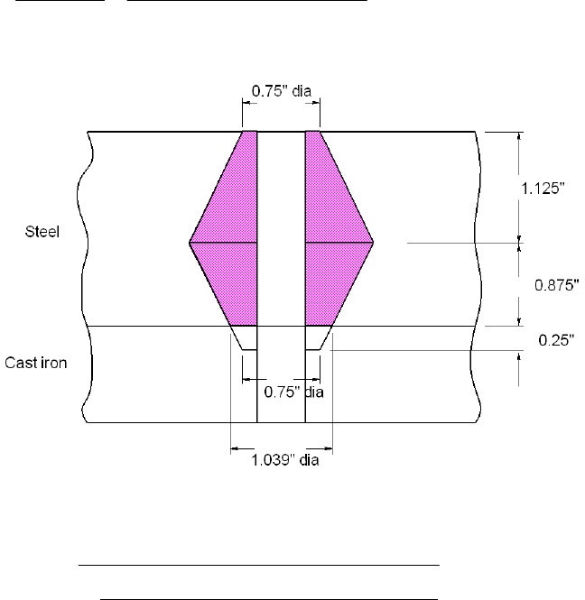
ld = L
LT = 2.75 1.25 = 1.5 in, lt = l ld = 2.25 1.5 = 0.75 in
Ad =
(0.52)/4 = 0.1963 in2. From Table 8-2, At = 0.1419 in2. From Eq. (8-17)
0.1963 0.1419 30 2.321 Mlbf/in .
0.1963 0.75 0.1419 1.5
dt
b
k
Al
dt td
AAE Ans
Al
(c)
Top steel frustum: t = 1.125 in, d = 0.5 in, D = 0.75 in, E = 30 Mpsi. From Eq. (8-20)
1
0.5774 30 0.5 24.48 Mlbf/in
1.155 1.125 0.75 0.5 0.75 0.5
ln 1.155 1.125 0.75 0.5 0.75 0.5
k
Lower steel frustum: t = 0.875 in, d = 0.5 in, D = 0.75 + 2(0.25) tan 30 = 1.039 in, E =
30 Mpsi. Eq. (8-20) k2 = 49.36 Mlbf/in
Cast iron: t = 0.25 in, d = 0.5 in, D = 0.75 in, E = 14.5 Mpsi (Table 8-8). Eq. (8-20)
k3 = 23.49 Mlbf/in
From Eq. (8-18)
km = (1/k1 + 1/k2 +1/k3)1 = (1/24.48 + 1/49.36 + 1/23.49)1 = 9.645 Mlbf/in Ans.
______________________________________________________________________________
8-17 a) Grip, l = 2(2 + 0.095) = 4.19 in. L ≥ 4.19 + 7/16 = 4.628 in.
Rounding up, L = 4.75 in Ans.
Chap. 8 Solutions - Rev. A, Page 10/69
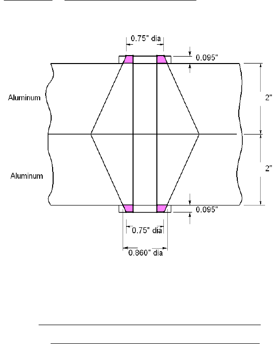
(b) From Eq. (8-13), LT = 2d + 1/4 = 2(0.5) + 0.25 = 1.25 in
From Table 8-7, ld = L
LT = 4.75 1.25 = 3.5 in, lt = l ld = 4.19 3.5 = 0.69 in
Ad =
(0.52)/4 = 0.1963 in2. From Table 8-2, At = 0.1419 in2. From Eq. (8-17)
0.1963 0.1419 30 1.322 Mlbf/in .
0.1963 0.69 0.1419 3.5
dt
b
k
Al
dt td
AAE Ans
Al
(c)
Upper and lower halves are the same. For the upper half,
Steel frustum: t = 0.095 in, d = 0.531 in, D = 0.75 in, and E = 30 Mpsi. From Eq. (8-20)
1
0.5774 30 0.531 89.20 Mlbf/in
1.155 0.095 0.75 0.531 0.75 0.531
ln 1.155 0.095 0.75 0.531 0.75 0.531
k
Aluminum: t = 2 in, d = 0.5 in, D =0.75 + 2(0.095) tan 30 = 0.860 in, and E = 10.3
Mpsi. Eq. (8-20) k2 = 9.24 Mlbf/in
For the top half, = (1/k
m
k1 + 1/k2)1 = (1/89.20 + 1/9.24)1 = 8.373 Mlbf/in
Since the bottom half is the same, the overall stiffness is given by
km = (1/ + 1/ k)
m
km
1 = km
/2 = 8.373/2 = 4.19 Mlbf/in Ans
______________________________________________________________________________
8-18 (a) Grip, l = 2(2 + 0.095) = 4.19 in. L ≥ 4.19 + 7/16 = 4.628 in.
Rounding up, L = 4.75 in Ans.
Chap. 8 Solutions - Rev. A, Page 11/69
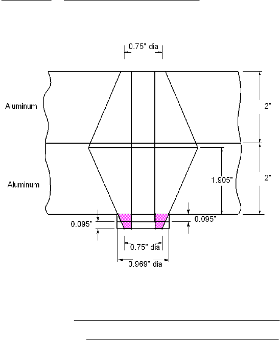
(b) From Eq. (8-13), LT = 2d + 1/4 = 2(0.5) + 0.25 = 1.25 in
From Table 8-7, ld = L
LT = 4.75 1.25 = 3.5 in, lt = l ld = 4.19 3.5 = 0.69 in
Ad =
(0.52)/4 = 0.1963 in2. From Table 8-2, At = 0.1419 in2. From Eq. (8-17)
0.1963 0.1419 30 1.322 Mlbf/in .
0.1963 0.69 0.1419 3.5
dt
b
k
Al
dt td
AAE Ans
Al
(c)
Upper aluminum frustum: t = [4 + 2(0.095)] /2 = 2.095 in, d = 0.5 in, D = 0.75 in, and
E = 10.3 Mpsi. From Eq. (8-20)
1
0.5774 10.3 0.5 7.23 Mlbf/in
1.155 2.095 0.75 0.5 0.75 0.5
ln 1.155 2.095 0.75 0.5 0.75 0.5
k
Lower aluminum frustum: t = 4 2.095 = 1.905 in, d = 0.5 in,
D = 0.75 +4(0.095) tan 30 = 0.969 in, and E = 10.3 Mpsi. Eq. (8-20) k2 = 11.34
Mlbf/in
Steel washers frustum: t = 2(0.095) = 0.190 in, d = 0.531 in, D = 0.75 in, and E = 30 Mpsi.
Eq. (8-20) k3 = 53.91 Mlbf/in
From Eq. (8-18)
km = (1/k1 + 1/k2 +1/k3)1 = (1/7.23 + 1/11.34 + 1/53.91)1 = 4.08 Mlbf/in Ans.
______________________________________________________________________________
8-19 (a) From Table A-31, the nut height is H = 8.4 mm. L > l + H = 50 + 8.4 = 58.4 mm.
Chap. 8 Solutions - Rev. A, Page 12/69
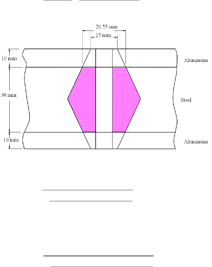
Rounding up, L = 60 mm Ans.
(b) From Eq. (8-14), LT = 2d + 6 = 2(10) + 6 = 26 mm, ld = L LT = 60 26 =
34 mm, lt = l
l = 50 34 = 16 mm. Ad =
(102) / 4 = 78.54 mm2. From Table 8-1,
At = 58 mm2. From Eq. (8-17)
78.54 58.0 207 292.1 MN/m .
78.54 16 58.0 34
dt
b
dt td
AAE
kA
Al Al
ns
(c)
Upper and lower frustums are the same. For the upper half,
Aluminum: t = 10 mm, d = 10 mm, D = 15 mm, and from Table 8-8, E = 71 GPa.
From Eq. (8-20)
1
0.5774 71 10 1576 MN/m
1.155 10 15 10 15 10
ln 1.155 10 15 10 15 10
k
Steel: t = 15 mm, d = 10 mm, D = 15 + 2(10) tan 30 = 26.55 mm, and E = 207
GPa. From Eq. (8-20)
2
0.5774 207 10 11 440 MN/m
1.155 15 26.55 10 26.55 10
ln 1.155 15 26.55 10 26.55 10
k
For the top half, = (1/k
m
k1 + 1/k2)1 = (1/1576 + 1/11 440)1 = 1385 MN/m
Chap. 8 Solutions - Rev. A, Page 13/69
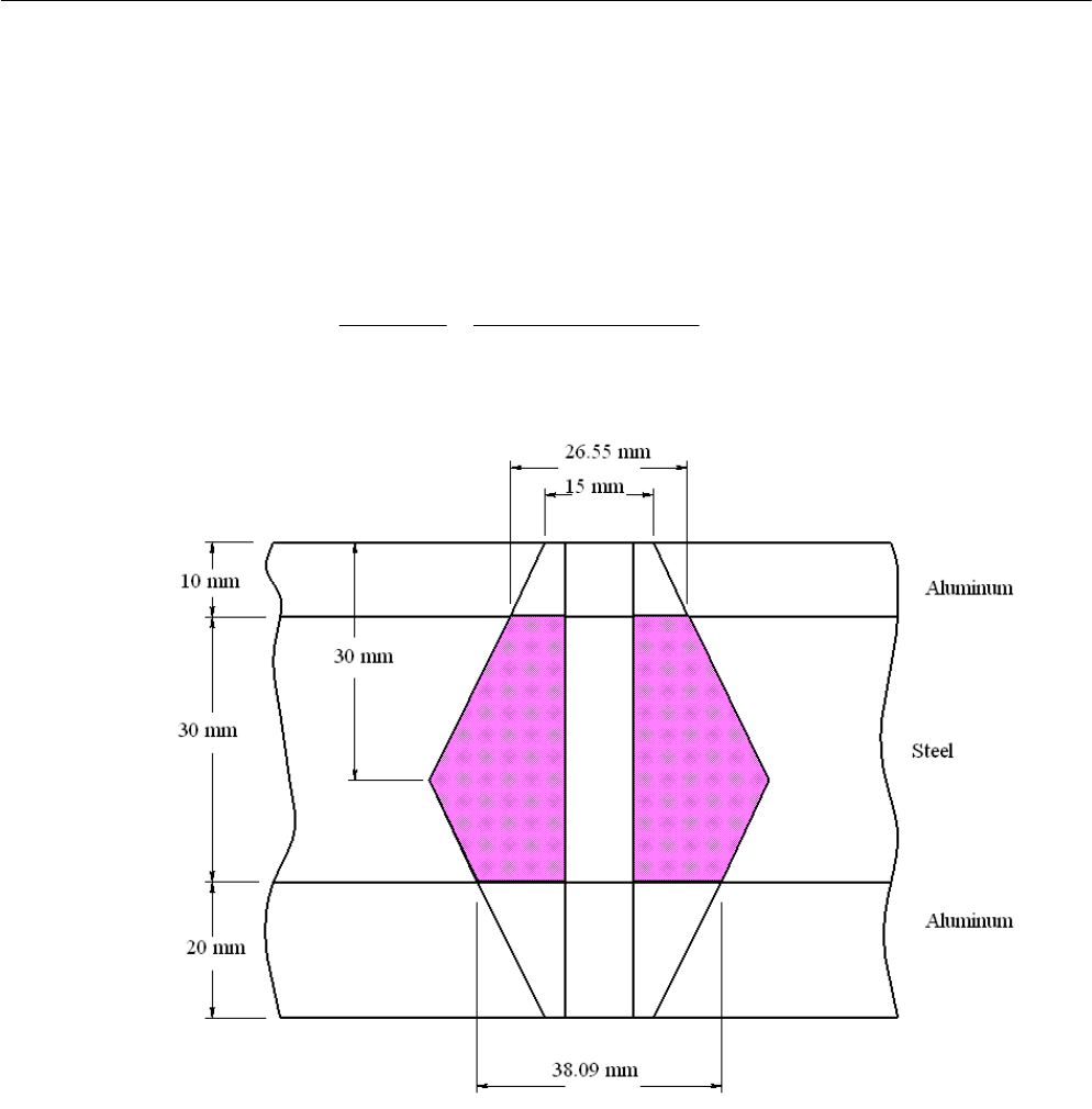
Since the bottom half is the same, the overall stiffness is given by
km = (1/ + 1/ )
m
km
k1 = m
k
/2 = 1385/2 = 692.5 MN/m Ans.
8-20 (a) From Table A-31, the nut height is H = 8.4 mm. L > l + H = 60 + 8.4 = 68.4 mm.
Rounding up, L = 70 mm Ans.
(b) From Eq. (8-14), LT = 2d + 6 = 2(10) + 6 = 26 mm, ld = L LT = 70 26 =
44 mm, lt = l
ld = 60 44 = 16 mm. Ad =
(102) / 4 = 78.54 mm2. From Table 8-1,
At = 58 mm2. From Eq. (8-17)
78.54 58.0 207 247.6 MN/m .
78.54 16 58.0 44
dt
b
dt td
AAE
kA
Al Al
ns
(c)
Upper aluminum frustum: t = 10 mm, d = 10 mm, D = 15 mm, and E = 71 GPa. From Eq.
(8-20)
Chap. 8 Solutions - Rev. A, Page 14/69
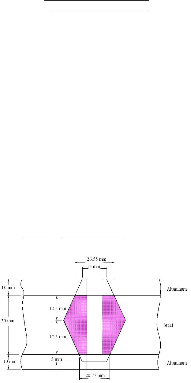
1
0.5774 10.3 71 1576 MN/m
1.155 2.095 15 10 15 10
ln 1.155 2.095 15 10 15 10
k
Lower aluminum frustum: t = 20 mm, d = 10 mm, D = 15 mm, and E = 71 GPa. Eq.
(8-20) k2 = 1 201 MN/m
Top steel frustum: t = 20 mm, d = 10 mm, D = 15 + 2(10) tan 30 = 26.55 mm, and E =
207 GPa. Eq. (8-20) k
3 = 9 781 MN/m
Lower steel frustum: t = 10 mm, d = 10 mm, D = 15 + 2(20) tan 30 = 38.09 mm, and E =
207 GPa. Eq. (8-20) k4 = 29 070 MN/m
From Eq. (8-18)
km = (1/k1 + 1/k2 +1/k3+1/k4)1 = (1/1 576 + 1/1 201 + 1/9 781 +1/29 070)1
= 623.5 MN/m Ans.
______________________________________________________________________________
8-21 (a) From Table 8-7, l = h + d /2 = 10 + 30 + 10/2 = 45 mm. L ≥ h + 1.5 d =
10 + 30 + 1.5(10) = 55 mm Ans.
(b) From Eq. (8-14), LT = 2d + 6 = 2(10) + 6 = 26 mm, ld = L LT = 55 26 =
29 mm, lt = l
ld = 45 29 = 16 mm. Ad =
(102) / 4 = 78.54 mm2. From Table 8-1,
At = 58 mm2. From Eq. (8-17)
78.54 58.0 207 320.9 MN/m .
78.54 16 58.0 29
dt
b
k
dt td
AAE Ans
Al Al
(c)
Chap. 8 Solutions - Rev. A, Page 15/69
Upper aluminum frustum: t = 10 mm, d = 10 mm, D = 15 mm, and E = 71 GPa. From Eq.
(8-20)
1
0.5774 10.3 71 1576 MN/m
1.155 2.095 15 10 15 10
ln 1.155 2.095 15 10 15 10
k
Lower aluminum frustum: t = 5 mm, d = 10 mm, D = 15 mm, and E = 71 GPa. Eq.
(8-20) k2 = 2 300 MN/m
Top steel frustum: t = 12.5 mm, d = 10 mm, D = 15 + 2(10) tan 30 = 26.55 mm, and E =
207 GPa. Eq. (8-20) k
3 = 12 759 MN/m
Lower steel frustum: t = 17.5 mm, d = 10 mm, D = 15 + 2(5) tan 30 = 20.77 mm, and E
= 207 GPa. Eq. (8-20) k4 = 6 806 MN/m
From Eq. (8-18)
km = (1/k1 + 1/k2 +1/k3+1/k4)1 = (1/1 576 + 1/2 300 + 1/12 759 +1/6 806)1
= 772.4 MN/m Ans.
______________________________________________________________________________
8-22 Equation (f ), p. 436: b
bm
k
Ckk
Eq. (8-17): dt
b
dt td
A
AE
k
A
lAl
Eq. (8-22):
0.5774 207
0.5774 40 0.5
2ln 50.5774 40 2.5
m
d
kd
d
See Table 8-7 for other terms used.
Using a spreadsheet, with coarse-pitch bolts (units are mm, mm2, MN/m):
d At A
d H L > L LT
10 58 78.53982 8.4 48.4 50 26
12 84.3 113.0973 10.8 50.8 55 30
14 115 153.938 12.8 52.8 55 34
16 157 201.0619 14.8 54.8 55 38
20 245 314.1593 18 58 60 46
24 353 452.3893 21.5 61.5 65 54
30 561 706.8583 25.6 65.6 70 66
Chap. 8 Solutions - Rev. A, Page 16/69
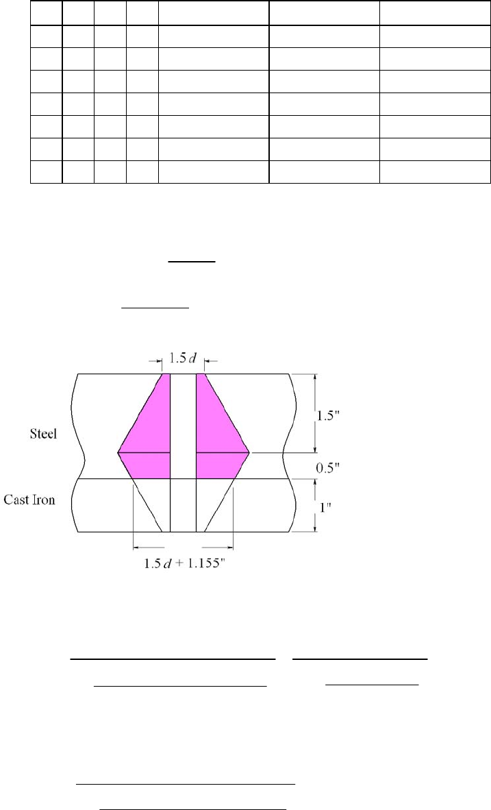
d l ld l
t k
b k
m C
10 40 24 16 356.0129 1751.566 0.16892
12 40 25 15 518.8172 2235.192 0.188386
14 40 21 19 686.2578 2761.721 0.199032
16 40 17 23 895.9182 3330.796 0.211966
20 40 14 26 1373.719 4595.515 0.230133
24 40 11 29 1944.24 6027.684 0.243886
30 40 4 36 2964.343 8487.533 0.258852
The 14 mm would probably be ok, but to satisfy the question, use a 16 mm bolt Ans.
_____________________________________________________________________________
8-23 Equation (f ), p. 436: b
bm
k
Ckk
Eq. (8-17): dt
b
dt td
A
AE
k
A
lAl
For upper frustum, Eq. (8-20), with D = 1.5 d and t = 1.5 in:
1
0.5774 30 0.5774 30
1.733 0.5
1.155 1.5 0.5 2.5 ln 5
ln 1.733 2.5
1.155 1.5 2.5 0.5
dd
kd
dd
d
dd
Lower steel frustum, with D = 1.5d + 2(1) tan 30 = 1.5d + 1.155, and t = 0.5 in:
2
0.5774 30
1.733 0.5 2.5 1.155
ln 1.733 2.5 0.5 1.155
d
kdd
dd
Chap. 8 Solutions - Rev. A, Page 17/69
For cast iron frustum, let E = 14. 5 Mpsi, and D = 1.5 d, and t = 1 in:
3
0.5774 14.5
1.155 0.5
ln 5 1.155 2.5
d
kd
d
Overall, km = (1/k1 +1/k2 +1/k3)1
See Table 8-7 for other terms used.
Using a spreadsheet, with coarse-pitch bolts (units are in, in2, Mlbf/in):
d At A
d H L > L LT l
0.375 0.0775 0.110447 0.328125 3.328125 3.5 1 3
0.4375 0.1063 0.15033 0.375 3.375 3.5 1.125 3
0.5 0.1419 0.19635 0.4375 3.4375 3.5 1.25 3
0.5625 0.182 0.248505 0.484375 3.484375 3.5 1.375 3
0.625 0.226 0.306796 0.546875 3.546875 3.75 1.5 3
0.75 0.334 0.441786 0.640625 3.640625 3.75 1.75 3
0.875 0.462 0.60132 0.75 3.75 3.75 2 3
d ld l
t k
b k1 k
2 k
3 km C
0.375 2.5 0.5 1.031389 15.94599 178.7801 8.461979 5.362481 0.161309
0.4375 2.375 0.625 1.383882 19.21506 194.465 10.30557 6.484256 0.175884
0.5 2.25 0.75 1.791626 22.65332 210.6084 12.26874 7.668728 0.189383
0.5625 2.125 0.875 2.245705 26.25931 227.2109 14.35052 8.915294 0.20121
0.625 2.25 0.75 2.816255 30.03179 244.2728 16.55009 10.22344 0.215976
0.75 2 1 3.988786 38.07191 279.7762 21.29991 13.02271 0.234476
0.875 1.75 1.25 5.341985 46.7663 317.1203 26.51374 16.06359 0.24956
Use a
9
16 12 UNC 3.5 in long bolt Ans.
______________________________________________________________________________
8-24 Equation (f ), p. 436: b
bm
k
Ckk
Eq. (8-17): dt
b
dt td
A
AE
k
A
lAl
Chap. 8 Solutions - Rev. A, Page 18/69
Top frustum, Eq. (8-20), with E = 10.3Mpsi, D = 1.5 d, and t = l /2:
1
0.5774 10.3
1.155 / 2 0.5
ln 51.155 / 2 2.5
d
kld
ld
Middle frustum, with E = 10.3 Mpsi, D = 1.5d + 2(l 0.5) tan 30, and t = 0.5 l /2
200
00
0.5774 10.3
1.155 0.5 0.5 0.5 2 0.5 tan 30 2.5 2 0.5 tan 30
ln 1.155 0.5 0.5 2.5 2 0.5 tan 30 0.5 2 0.5 tan 30
d
k
ldl dl
ldl dl
Lower frustum, with E = 30Mpsi, D = 1.5 d, t = l 0.5
3
0.5774 30
1.155 0.5 0.5
ln 5 1.155 0.5 2.5
d
kld
ld
See Table 8-7 for other terms used.
Using a spreadsheet, with coarse-pitch bolts (units are in, in2, Mlbf/in)
Chap. 8 Solutions - Rev. A, Page 19/69

Size d At Ad L > L LT l ld
1 0.073 0.00263 0.004185 0.6095 0.75 0.396 0.5365 0.354
2 0.086 0.0037 0.005809 0.629 0.75 0.422 0.543 0.328
3 0.099 0.00487 0.007698 0.6485 0.75 0.448 0.5495 0.302
4 0.112 0.00604 0.009852 0.668 0.75 0.474 0.556 0.276
5 0.125 0.00796 0.012272 0.6875 0.75 0.5 0.5625 0.25
6 0.138 0.00909 0.014957 0.707 0.75 0.526 0.569 0.224
8 0.164 0.014 0.021124 0.746 0.75 0.578 0.582 0.172
10 0.19 0.0175 0.028353 0.785 1 0.63 0.595 0.37
Size d lt kb k1 k2 k3 km C
1 0.073 0.1825 0.194841 1.084468 1.954599 7.09432 0.635049 0.23478
2 0.086 0.215 0.261839 1.321595 2.449694 8.357692 0.778497 0.251687
3 0.099 0.2475 0.333134 1.570439 2.993366 9.621064 0.930427 0.263647
4 0.112 0.28 0.403377 1.830494 3.587564 10.88444 1.090613 0.27
5 0.125 0.3125 0.503097 2.101297 4.234381 12.14781 1.258846 0.285535
6 0.138 0.345 0.566787 2.382414 4.936066 13.41118 1.434931 0.28315
8 0.164 0.41 0.801537 2.974009 6.513824 15.93792 1.809923 0.306931
10 0.19 0.225 1.15799 3.602349 8.342138 18.46467 2.214214 0.343393
The lowest coarse series screw is a 164 UNC 0.75 in long up to a 632 UNC 0.75 in
long. Ans.
______________________________________________________________________________
8-25 For half of joint, Eq. (8-20): t = 20 mm, d = 14 mm, D = 21 mm, and E = 207 GPa
1
0.5774 207 14 5523 MN/m
1.155 20 21 14 21 14
ln 1.155 20 21 14 21 14
k
km = (1/k1 + 1/k1)1 = k1/2 = 5523/2 = 2762 MN/m Ans.
From Eq. (8-22) with l = 40 mm
0.5774 207 14 2762 MN/m .
0.5774 40 0.5 14
2ln 50.5774 40 2.5 14
m
kA
ns
which agrees with the earlier calculation.
Chap. 8 Solutions - Rev. A, Page 20/69

For Eq. (8-23), from Table 8-8, A = 0.787 15, B = 0.628 73
km = 207(14)(0.78 715) exp [0.628 73(14)/40] = 2843 MN/m Ans.
This is 2.9% higher than the earlier calculations.
______________________________________________________________________________
8-26 (a) Grip, l = 10 in. Nut height, H = 41/64 in (Table A-31).
L ≥ l + H = 10 + 41/64 = 10.641 in. Let L = 10.75 in.
Table 8-7, LT = 2d + 0.5 = 2(0.75) + 0.5 = 2 in, ld = L LT = 10.75 2 = 8.75 in,
lt = l ld = 10 8.75 = 1.25 in
Ad = (0.752)/4 = 0.4418 in2, At = 0.373 in2 (Table 8-2)
Eq. (8-17),
0.4418 0.373 30 1.296 Mlbf/in .
0.4418 1.25 0.373 8.75
dt
b
dt td
AAE
kA
Al Al
ns
Eq. (4-4), p. 149,
22
/ 4 1.125 0.75 30 1.657 Mlbf/in .
10
mm
m
AE
kA
l
ns
Eq. (f), p. 436, C = kb/(kb + km) = 1.296/(1.296 + 1.657) = 0.439 Ans.
(b)
Let: Nt = no. of turns, p = pitch of thread (in), N = no. of threads per in = 1/p. Then,
=
b +
m = Nt p = Nt / N (1)
But,
b = Fi / kb, and,
m = Fi / km. Substituting these into Eq. (1) and solving for Fi gives
Chap. 8 Solutions - Rev. A, Page 21/69
6
2
1.296 1.657 10 1/3 15 150 lbf .
1.296 1.657 16
bm t
i
bm
kk N
FkkN
A
ns
______________________________________________________________________________
8-27 Proof for the turn-of-nut equation is given in the solution of Prob. 8-26, Eq. (2), where
Nt =
/ 360.
The relationship between the turn-of-nut method and the torque-wrench method is as
follows.
(turn-of-nut)
(torque-wrench)
bm
ti
bm
i
kk
NFN
kk
TKFd
Eliminate Fi
.
360
bm
t
bm
kkNT
NA
kk Kd
ns
______________________________________________________________________________
8-28 (a) From Ex. 8-4, Fi = 14.4 kip, kb = 5.21(106) lbf/in, km = 8.95(106) lbf/in
Eq. (8-27): T = kFid = 0.2(14.4)(103)(5/8) = 1800 lbf · in Ans.
From Prob. 8-27,
3
6
5.21 8.95 (14.4)(10 )11
5.21 8.95 10
0.0481 turns 17.3 .
bm
ti
bm
kk
NFN
kk
Ans
Bolt group is (1.5) / (5/8) = 2.4 diameters. Answer is much lower than RB&W
recommendations.
______________________________________________________________________________
8-29 C = kb / (kb + km) = 3/(3+12) = 0.2, P = Ptotal/ N = 80/6 = 13.33 kips/bolt
Table 8-2, At = 0.141 9 in2; Table 8-9, Sp = 120 kpsi; Eqs. (8-31) and (8-32),
Fi = 0.75 At Sp = 0.75(0.141 9)(120) = 12.77 kips
(a) From Eq. (8-28), the factor of safety for yielding is
120 0.141 9 1.10 .
0.2 13.33 12.77
pt
p
i
SA
nA
CP F
ns
(b) From Eq. (8-29), the overload factor is
Chap. 8 Solutions - Rev. A, Page 22/69
120 0.141 9 12.77 1.60 .
0.2 13.33
pt i
L
SA F
nA
CP
ns
(c) From Eq. (803), the joint separation factor of safety is
0
12.77 1.20 .
1 13.33 1 0.2
i
F
nA
PC
ns
______________________________________________________________________________
8-30 1/2 13 UNC Grade 8 bolt, K = 0.20
(a) Proof strength, Table 8-9, Sp = 120 kpsi
Table 8-2, At = 0.141 9 in2
Maximum, Fi = Sp At = 120(0.141 9) = 17.0 kips Ans.
(b) From Prob. 8-29, C = 0.2, P = 13.33 kips
Joint separation, Eq. (8-30) with n0 = 1
Minimum Fi = P (1 C) = 13.33(1 0.2) = 10.66 kips Ans.
(c) i
F = (17.0 + 10.66)/2 = 13.8 kips
Eq. (8-27), T = KFi d = 0.2(13.8)103(0.5)/12 = 115 lbf ft Ans.
______________________________________________________________________________
8-31 (a) Table 8-1, At = 20.1 mm2. Table 8-11, Sp = 380 MPa.
Eq. (8-31), Fi = 0.75 Fp = 0.75 At Sp = 0.75(20.1)380(103) = 5.73 kN
Eq. (f ), p. 436, 10.278
12.6
b
bm
k
Ckk
Eq. (8-28) with np = 1,
3
0.25 20.1 380 10
0.25 6.869 kN
0.278
pt i pt
SA F SA
PCC
Ptotal = NP = 8(6.869) = 55.0 kN Ans.
(b) Eq. (8-30) with n0 = 1,
5.73 7.94 kN
1 1 0.278
i
F
PC
Ptotal = NP = 8(7.94) = 63.5 kN Ans. Bolt stress would exceed proof strength
______________________________________________________________________________
8-32 (a) Table 8-2, At = 0.141 9 in2. Table 8-9, Sp = 120 kpsi.
Eq. (8-31), Fi = 0.75 Fp = 0.75 At Sp = 0.75(0.141 9)120 = 12.77 kips
Eq. (f ), p. 436, 40.25
412
b
bm
k
Ckk
Chap. 8 Solutions - Rev. A, Page 23/69
Eq. (8-28) with np = 1,
total
total
0.25
80 0.25 4.70
0.25 0.25 120 0.141 9
pt i pt
pt
SA F NSA
PN CC
PC
NSA
Round to N = 5 bolts Ans.
(
b) Eq. (8-30) with n0 = 1,
total
total
1
1 80 1 0.25 4.70
12.77
i
i
F
PNC
PC
NF
Round to N = 5 bolts Ans.
______________________________________________________________________________
8-33 Bolts: From Table A-31, the nut height is H = 10.8 mm. L ≥ l +H = 40 + 10.8 = 50.8
mm. Although Table A-17 indicates to go to 60 mm, 55 mm is readily available
Round up to L = 55 mm Ans.
Eq. (8-14): LT = 2d + 6 = 2(12) + 6 = 30 mm
Table 8-7: ld = L
LT = 55 30 = 25 mm, lt = l ld = 40 25 = 15 mm
Ad =
(122)/4 = 113.1 mm2, Table 8-1: At = 84.3 mm2
Eq. (8-17):
113.1 84.3 207 518.8 MN/m
113.1 15 84.3 25
dt
b
dt td
AAE
kAl Al
Members: Steel cyl. head: t = 20 mm, d = 12 mm, D = 18 mm, E = 207 GPa. Eq. (8-20),
1
0.5774 207 12 4470 MN/m
1.155 20 18 12 18 12
ln 1.155 20 18 12 18 12
k
Cast iron: t = 20 mm, d = 12 mm, D = 18 mm, E = 100 GPa (from
Table 8-8). The only difference from k1 is the material
k2 = (100/207)(4470) = 2159 MN/m
Eq. (8-18): km = (1/4470 + 1/2159)1 = 1456 MN/m
Chap. 8 Solutions - Rev. A, Page 24/69

C = kb / (kb + km) = 518.8/(518.8+1456) = 0.263
Table 8-11: Sp = 650 MPa
Assume non-permanent connection. Eqs. (8-31) and (8-32)
Fi = 0.75 At Sp = 0.75(84.3)(650)103 = 41.1 kN
The total external load is Ptotal = pg Ac, where Ac is the diameter of the cylinder which is
100 mm. The external load per bolt is P = Ptotal /N. Thus
P = [6
(1002)/4](103)/10 = 4.712 kN/bolt
Yielding factor of safety, Eq. (8-28):
3
650 84.3 10 1.29 .
0.263 4.712 41.10
pt
p
i
SA
nA
CP F
ns
Overload factor of safety, Eq. (8-29):
3
650 84.3 10 41.10 11.1 .
0.263 4.712
pt i
L
SA F
nA
CP
ns
Separation factor of safety, Eq. (8-30):
0
41.10 11.8 .
1 4.712 1 0.263
i
F
nA
PC
ns
______________________________________________________________________________
8-34 Bolts: Grip, l = 1/2 + 5/8 = 1.125 in. From Table A-31, the nut height is H = 7/16 in.
L ≥ l + H = 1.125 + 7/16 = 1.563 in.
Round up to L = 1.75 in Ans.
Eq. (8-13): LT = 2d + 0.25 = 2(0.5) + 0.25 = 1.25 in
Table 8-7: ld = L
LT = 1.75 1.25 = 0.5 in, lt = l ld = 1.125 0.5 = 0.625 in
Ad =
(0.52)/4 = 0.196 3 in2, Table 8-2: At = 0.141 9 in2
Eq. (8-17):
0.196 3 0.141 9 30 4.316 Mlbf/in
0.196 3 0.625 0.141 9 0.5
dt
b
dt td
AAE
kAl Al
Chap. 8 Solutions - Rev. A, Page 25/69

Members: Steel cyl. head: t = 0.5 in, d = 0.5 in, D = 0.75 in, E = 30 Mpsi. Eq. (8-20),
1
0.5774 30 0.5 33.30 Mlbf/in
1.155 0.5 0.75 0.5 0.75 0.5
ln 1.155 0.5 0.75 0.5 0.75 0.5
k
Cast iron: Has two frusta. Midpoint of complete joint is at (1/2 + 5/8)/2 =
0.5625 in.
Upper frustum, t = 0.5625 0.5 = 0.0625 in, d = 0.5 in,
D = 0.75 + 2(0.5) tan 30 = 1.327 in, E = 14.5 Mpsi (from Table 8-8)
Eq. (8-20) k2 = 292.7 Mlbf/in
Lower frustum, t = 0.5625 in, d = 0.5 in, D = 0.75 in, E = 14.5 Mpsi
Eq. (8-20) k3 = 15.26 Mlbf/in
Eq. (8-18): km = (1/33.30 + 1/292.7 + 1/15.26)1 = 10.10 Mlbf/in
C = kb / (kb + km) = 4.316/(4.316+10.10) = 0.299
Table 8-9: Sp = 85 kpsi
Assume non-permanent connection. Eqs. (8-31) and (8-32)
Fi = 0.75 At Sp = 0.75(0.141 9)(85) = 9.05 kips
The total external load is Ptotal = pg Ac, where Ac is the diameter of the cylinder which is
3.5 in. The external load per bolt is P = Ptotal /N. Thus
P = [1 500
(3.52)/4](103)/10 = 1.443 kips/bolt
Yielding factor of safety, Eq. (8-28):
85 0.141 9 1.27 .
0.299 1.443 9.05
pt
p
i
SA
nA
CP F
ns
Overload factor of safety, Eq. (8-29):
85 0.141 9 9.05 6.98 .
0.299 1.443
pt i
L
SA F
nA
CP ns
Separation factor of safety, Eq. (8-30):
Chap. 8 Solutions - Rev. A, Page 26/69

0
9.05 8.95 .
1 1.443 1 0.299
i
F
nA
PC
ns
______________________________________________________________________________
-35 Bolts: Grip: l = 20 + 25 = 45 mm. From Table A-31, the nut height is H = 8.4 mm.
m is
Round up to L = 55 mm Ans.
Eq. (8-14): LT = 2d + 6 = 2(10) + 6 = 26 mm
Table 8-7: ld = L
LT = 55 26 = 29 mm, lt = l ld = 45 29 = 16 mm
Ad =
(102)/4 = 78.5 mm2, Table 8-1: At = 58.0 mm2
Eq. (8-17):
8
L ≥ l +H = 45 + 8.4 = 53.4 mm. Although Table A-17 indicates to go to 60 mm, 55 m
readily available
78.5 58.0 207 320.8 MN/m
78.5 16 58.0 29
dt
b
dt td
AAE
kAl Al
Members: Steel cyl. head: t = 20 mm, d = 10 mm, D = 15 mm, E = 207 GPa. Eq. (8-20),
1
0.5774 207 10 3503 MN/m
1.155 20 15 10 15 10
ln 1.155 20 15 10 15 10
k
n: Has two frusta. Midpoint of complete joint is at (20 + 25)/2 = 22.5 mm
m Table 8-8),
Lower frustum, t = 22.5 mm, d = 10 mm, D = 15 mm, E = 100 GPa
Eq. (8-20) k3 = 1632 MN/m
Eq. (8-18): km = (1/3503 + 1/45 880 + 1/1632)1 = 1087 MN/m
C = kb / (kb + km) = 320.8/(320.8+1087) = 0.228
Table 8-11: Sp = 830 MPa
ection. Eqs. (8-31) and (8-32)
Fi = 0.75 At Sp = 0.75(58.0)(830)103 = 36.1 kN
Cast iro
Upper frustum, t = 22.5 20 = 2.5 mm, d = 10 mm,
D = 15 + 2(20) tan 30 = 38.09 mm, E = 100 GPa (fro
Eq. (8-20) k2 = 45 880 MN/m
Assume non-permanent conn
Chap. 8 Solutions - Rev. A, Page 27/69

The total external load is Ptotal = pg Ac, where Ac is the diameter of the cylinder which is
P = [550
(0.82)/4]/36 = 7.679 kN/bolt
Yielding factor of safety, Eq. (8-28):
0.8 m. The external load per bolt is P = Ptotal /N. Thus
3
830 58.0 10 1.27 .
0.228 7.679 36.1
pt
p
i
SA
nA
CP F
ns
Overload factor of safety, Eq. (8-29):
3
830 58.0 10 36.1 6.88 .
0.228 7.679
pt i
L
SA F
nA
CP
ns
Separation factor of safety, Eq. (8-30):
0
36.1 6.09 .
1 7.679 1 0.228
i
F
nA
PC
ns
______________________________________________________________________________
-36 Bolts: Grip, l = 3/8 + 1/2 = 0.875 in. From Table A-31, the nut height is H = 3/8 in.
Let L = 1.25 in Ans.
Eq. (8-13): LT = 2d + 0.25 = 2(7/16) + 0.25 = 1.125 in
Table 8-7: ld = L
LT = 1.25 1.125 = 0.125 in, lt = l ld = 0.875 0.125 =
Ad =
(7/16) /4 = 0.150 3 in2, Table 8-2: At = 0.106 3 in2
Eq. (8-17),
8
L ≥ l + H = 0.875 + 3/8 = 1.25 in.
0.75 in
2
0.150 3 0.106 3 30 3.804 Mlbf/in
0.150 3 0.75 0.106 3 0.125
d
A
k
t
b
dt td
AE
Al Al
Members: Steel cyl. head: t = 0.375 in, d = 0.4375 in, D = 0.65625 in, E = 30 Mpsi. Eq.
(8-20),
Chap. 8 Solutions - Rev. A, Page 28/69

1
0.5774 30 0.4375 31.40 Mlbf/in
1.155 0.375 0.65625 0.4375 0.65625 0.4375
ln 1.155 0.375 0.65625 0.4375 0.65625 0.4375
k
Cast iron: Has two frusta. Midpoint of complete joint is at (3/8 + 1/2)/2 =
0.4375 in.
Upper frustum, t = 0.4375 0.375 = 0.0625 in, d = 0.4375 in,
D = 0.65625 + 2(0.375) tan 30 = 1.089 in, E = 14.5 Mpsi (from Table
8-8)
Eq. (8-20) k2 = 195.5 Mlbf/in
Lower frustum, t = 0.4375 in, d = 0.4375 in, D = 0.65625 in, E = 14.5
Mpsi
Eq. (8-20) k3 = 14.08 Mlbf/in
Eq. (8-18): km = (1/31.40 + 1/195.5 + 1/14.08)1 = 9.261 Mlbf/in
C = kb / (kb + km) = 3.804/(3.804 + 9.261) = 0.291
Table 8-9: Sp = 120 kpsi
Assume non-permanent connection. Eqs. (8-31) and (8-32)
Fi = 0.75 At Sp = 0.75(0.106 3)(120) = 9.57 kips
The total external load is Ptotal = pg Ac, where Ac is the diameter of the cylinder which is
3.25 in. The external load per bolt is P = Ptotal /N. Thus
P = [1 200
(3.252)/4](103)/8 = 1.244 kips/bolt
Yielding factor of safety, Eq. (8-28):
120 0.106 3 1.28 .
0.291 1.244 9.57
pt
p
i
SA
nA
CP F
ns
Overload factor of safety, Eq. (8-29):
120 0.106 3 9.57 8.80 .
0.291 1.244
pt i
L
SA F
nA
CP ns
Separation factor of safety, Eq. (8-30):
Chap. 8 Solutions - Rev. A, Page 29/69

0
9.57 10.9 .
1 1.244 1 0.291
i
F
nA
PC
ns
______________________________________________________________________________
-37 From Table 8-7, h = t1 = 20 mm
/2 = 26 mm
p to L = 40 mm
From Table 8-1, At = 84.3 mm2. Ad =
(122)/4 = 113.1 mm2
8
For t2 > d, l = h + d /2 = 20 + 12
L ≥ h + 1.5 d = 20 + 1.5(12) = 38 mm. Round u
LT = 2d + 6 = 2(12) + 6 = 30 mm
ld = L LT = 40 20 = 10 mm
lt = l ld = 26 10 = 16 mm
Eq.
(8-17),
113.1 84.3 207 744.0 MN/m
113.1 16 84.3 10
dt
b
dt td
AAE
kAl Al
Similar to Fig. 8-21, we have three frusta.
m, D = 18 mm, E = 207 GPa. Eq. (8-20)
Top frusta, steel: t = l / 2 = 13 mm, d = 12 m
1
0.5774 207 12 5 316 MN/m
1.155 13 18 12 18 12
ln 1.155 13 18 12 18 12
k
Middle frusta, steel: t = 20 13 = 7 mm, d = 12 mm, D = 18 + 2(13 7) tan 30 = 24.93
Lower frusta, cast iron: t = 26 20 = 6 mm, d = 12 mm, D = 18 mm, E = 100 GPa (see
Eq. (8-18), km = (1/5 316 + 1/15 660 + 1/3 887)1 = 1 964 MN/m
C = kb / (kb + km) = 744.0/(744.0 + 1 964) = 0.275
Table 8-11: Sp = 650 MPa. From Prob. 8-33, P = 4.712 kN. Assume a non-permanent
Fi = 0.75 At Sp = 0.75(84.3)(650)103 = 41.1 kN
Yielding factor of safety, Eq. (8-28)
mm, E = 207 GPa. Eq. (8-20) k2 = 15 660 MN/m
Table 8-8). Eq. (8-20) k3 = 3 887 MN/m
connection. Eqs. (8-31) and (8-32),
3
650 84.3 10 1.29 .
0.275 4.712 41.1
pt
p
i
SA
nA
CP F
ns
Overload factor of safety, Eq. (8-29)
Chap. 8 Solutions - Rev. A, Page 30/69

3
650 84.3 10 41.1 10.7 .
0.275 4.712
pt i
L
SA F
nA
CP
ns
r of safety, Eq. (8-30)
Separation facto
0
41.1 12.0 .
1 4.712 1 0.275
i
F
nA
PC
ns
___________________________________________ ________________
1
.5/2 = 0.75 in
1.25 in
b = At E / l = 0.141 9(30)/0.75 =
in, D = 0.75 in, E = 30 Mpsi
__________________ _
-38 From Table 8-7, h = t = 0.5 in 8
For t2 > d, l = h + d /2 = 0.5 + 0
L ≥ h + 1.5 d = 0.5 + 1.5(0.5) = 1.25 in. Let L =
LT = 2d + 0.25 = 2(0.5) + 0.25 = 1.25 in. All threaded.
2
From Table 8-1, At = 0.141 9 in . The bolt stiffness is k
5.676 Mlbf/in
Similar to Fig. 8-21, we have three frusta.
Top frusta, steel: t = l / 2 = 0.375 in, d = 0.5
1
0.5774 30 0.5 38.45 Mlk
bf/in
1.155 0.375 0.75 0.5 0.75 0.5
ln 1.155 0.375 0.75 0.5 0.75 0.5
Middle frusta, steel: t = 0.5 0.375 = 0.125 in, d = 0.5 in,
d = 0.5 in, D = 0.75 in, E = 14.5 Mpsi.
m1 = 13.51 Mlbf/in
b b m
pe a non-permanent
it p
D = 0.75 + 2(0.75 0.5) tan 30 = 1.039 in, E = 30 Mpsi.
Eq. (8-20) k2 = 184.3 Mlbf/in
Lower frusta, cast iron: t = 0.75 0.5 = 0.25 in,
Eq. (8-20) k3 = 23.49 Mlbf/in
Eq. (8-18), k = (1/38.45 + 1/184.3 + 1/23.49)
C = k / (k + k ) = 5.676 / (5.676 + 13.51) = 0.296
Table
8-9, S = 85 kpsi. From Prob. 8-34, P = 1.443 kips/bolt. Assum
connection. Eqs. (8-31) and (8-32),
F = 0.75 A S = 0.75(0.141 9)(85) = 9.05 kips
Yielding factor of safety, Eq. (8-28)
85 0.141 9 1.27 .
0.296 1.443 9.05
pt
p
i
SA
nA
CP F
ns
Overload factor of safety, Eq. (8-29)
Chap. 8 Solutions - Rev. A, Page 31/69
85 0.141 9 9.05 7.05 .
0.296 1.443
pt i
L
SA F
nA
CP
ns
r of safety, Eq. (8-30)
Separation facto
0
9.05 8.91 .
1 1.443 1 0.296
i
F
nA
PC
ns
__________________________________________ ________________
1
2 = 25 mm
35 mm
t2. Ad =
(102)/4 = 78.5 mm2
__________________ __
-39 From Table 8-7, h = t = 20 mm 8
For t2 > d, l = h + d /2 = 20 + 10/
L ≥ h + 1.5 d = 20 + 1.5(10) = 35 mm. Let L =
LT = 2d + 6 = 2(10) + 6 = 26 mm
ld = L LT = 35 26 = 9 mm
lt = l ld = 25 9 = 16 mm
From Table 8-1, A = 58.0 mm
Eq.
(8-17),
78.5 58.0 207 530.1 MN/m
78.5 16 58.0 9
dt
b
dt td
AAE
kAl Al
-21, we have three frusta.
mm, D = 15 mm, E = 207 GPa. Eq. (8-20)
Similar to Fig. 8
Top frusta, steel: t = l / 2 = 12.5 mm, d = 10
1
0.5774 207 10 4 163 MN/mk
1.155 12.5 15 10 15 10
ln 1.155 12.5 15 10 15 10
Middle frusta, steel: t = 20 12.5 = 7.5 mm, d = 10 mm, D = 15 + 2(12.5 7.5) tan 30 =
, E = 100 GPa (see
m1 = 1 562 MN/m
b b m
p = 830 MPa. From anent
it p3 = 36.1 kN
20.77 mm, E = 207 GPa. Eq. (8-20) k2 = 10 975 MN/m
Lower frusta, cast iron: t = 25 20 = 5 mm, d = 10 mm, D = 15 mm
Table 8-8). Eq. (8-20) k3 = 3 239 MN/m
Eq. (8-18), k = (1/4 163 + 1/10 975 + 1/3 239)
C = k / (k + k ) = 530.1/(530.1 + 1 562) = 0.253
Table
8-11: S Prob. 8-35, P = 7.679 kN/bolt. Assume a non-perm
connection. Eqs. (8-31) and (8-32),
F = 0.75 A S = 0.75(58.0)(830)10
Yielding factor of safety, Eq. (8-28)
Chap. 8 Solutions - Rev. A, Page 32/69
3
830
pt
SA
58.0 10 1.27 .
0.253 7.679 36.1
p
i
nA
ns
CP F
of safety, Eq. (8-29)
Overload factor
3
58.0 10 36.1 6.20 .
0.253 7.679
pt i
L
nA
ns
CP
Separation factor of safety, Eq. (8-30)
830
SA F
0
36.1 6.29 .
1 7.679 1 0.253
i
F
nA
ns
PC
______________________________________________________________________________
For t2 > d, l = h + d /2 = 0.375 + 0.4375/2 = 0.59375 in
) = 1.031 in. Round up to L = 1.25 in
8-2: At = 0.106 3 in2
8-40 From Table 8-7, h = t1 = 0.375 in
L ≥ h + 1.5 d = 0.375 + 1.5(0.4375
LT = 2d + 0.25 = 2(0.4375) + 0.25 = 1.125 in
ld = L LT = 1.25 1.125 = 0.125
lt = l ld = 0.59375 0.125 = 0.46875 in
Ad =
(7/16)2/4 = 0.150 3 in2, Table
Eq.
(8-17),
0.150 3 0.106 3 30 5.724 Mlbf/in
0.150 3 0.46875 0.106 3 0.125
dt
b
dt td
AAE
kAl Al
-21, we have three frusta.
Top frusta, steel: t = l / 2 = 0.296875 in, d = 0.4375 in, D = 0.65625 in, E = 30 Mpsi
Similar to Fig. 8
1
k
0.5774 30 0.4375 35.52 Mlbf/in
1.155 0.296875 0.656255 0.4375 0.75 0.656255
ln 1.155 0.296875 0.75 0.656255 0.75 0.656255
Middle frusta, steel: t = 0.375 0.296875 = 0.078125 in, d = 0.4375 in,
D = 0.65625 + 2(0.59375 0.375) tan 30 = 0.9088 in, E = 30 Mpsi.
0.375 = 0.21875 in, d = 0.4375 in, D = 0.65625 in,
E = 14.5 Mpsi. Eq. (8-20) k3 = 20.55 Mlbf/in
C = kb / (kb + km) = 5.724/(5.724 + 12.28) = 0.318
Eq. (8-20) k2 = 215.8 Mlbf/in
Lower frusta, cast iron: t = 0.59375
Eq.
(8-18), km = (1/35.52 + 1/215.8 + 1/20.55)1 = 12.28 Mlbf/in
Chap. 8 Solutions - Rev. A, Page 33/69

Table 8-9, Sp = 120 kpsi. From Prob. 8-34, P = 1.244 kips/bolt. Assume a non-permanent
connection. Eqs. (8-31) and (8-32),
5(0.106 3)(120) = 9.57 kips
Fi = 0.75 At Sp = 0.7
Yielding factor of safety, Eq. (8-28)
12
pt
SA
nA
0 0.106 3 1.28 .
0.318 1.244 9.57
p
i
ns
CP F
of safety, Eq. (8-29)
Overload factor
120
pt i
SA F0.106 3 9.57 8.05 .
0.318 1.244
L
nA
ns
CP
Separation factor of safety, Eq. (8-30)
0
9.57 11.3 .
1 1.244 1 0.318
i
F
nA
ns
PC
______________________________________________________________________________
What is presented here is one possible iterative approach. We will demonstrate this with
g using Eq. (8-18), yields km = 1 141 MN/m (see Prob. 8-33 for method of
e nut height in Table A-31. For the example, H = 8.4 mm. From this, L is
rounded up from the calculation of l + H = 40 + 8.4 = 48.4 mm to 50 mm. Next,
4 mm2.
for Db in Eq.
(8-34), the number of bolts are
8-41 This is a design problem and there is no closed-form solution path or a unique solution.
an example.
1. Select the diameter, d. For this example, let d = 10 mm. Using Eq. (8-20) on members,
and combinin
calculation.
2. Look up th
calculations are made for LT = 2(10) + 6 = 26 mm, ld = 50 26 = 24 mm, lt = 40 24 =
16 mm. From step 1, Ad =
(102)/4 = 78.54 mm2. Next, from Table 8-1, At = 78.5
From Eq. (8-17), kb = 356 MN/m. Finally, from Eq. (e), p. 421, C = 0.238.
3. From Prob. 8-33, the bolt circle diameter is E = 200 mm. Substituting this
200
b
D
N
15.7
44
10
d
p gives N = 16.
d on the solution to Prob. 8-33, the strength of ISO 9.8
was so high to give very large factors of safety for overload and separation. Try ISO 4.6
Rounding this u
4. Next, select a grade bolt. Base
Chap. 8 Solutions - Rev. A, Page 34/69
with Sp = 225 MPa. From Eqs. (8-31) and (8-32) for a non-permanent connection, Fi =
9.79 kN.
5. The ex
ternal load requirement per bolt is P = 1.15 pg Ac/N, where from Prob 8-33, pg =
6 MPa, and A =
(1002)/4. This gives P = 3.39 kN/bolt.
nd n0 = 3.79.
for the tables
used from the text. The results for four bolt sizes are shown below. The dimension of each
l
t A
d A
t k
b
c
6. Using Eqs. (8-28) to (8-30) yield np = 1.23, nL = 4.05, a
Steps 1 - 6 can be easily implemented on a spreadsheet with lookup tables
term is consistent with the example given above.
d km H L LT l
d
8 854 6.8 50 22 28 12 50.26 36.6 233.9
10 1 78.54 356 141 8.4 50 26 24 16 58
12 1456 10.8 55 30 25 15 113.1 84.3 518.8
14 1950 12.8 55 34 21 19 153.9 115 686.3
d C N S
pF
iP n
pn
Ln
0
8 0.215 20 225 6.18 2.71 1.22 3.53 2.90
10 0.238 16 225 9.79 3.39 1.23 4.05 3.79
12 0.263 13* 225 14.23 4.17 1.24 4.33 4.63
14 0.276 12 225 19.41 4.52 1.25 5.19 5.94
*Rounded down from 89 g eters.
N cost/bolt, and/or N cost per hole, etc.
____ __
n.
What is presented here is one possible iterative approach. We will demonstrate this with
4 solution), and combining using Eq. (8-19), yields km = 10.10 Mlbf/in.
rounded up from the calculation of l + H = 1.125 + 0.4375 = 1.5625 in to 1.75 in. Next,
34), for the number of bolts
13.0 97, so spacin is slightly greater than four diam
Any one of the solutions is acceptable. A decision-maker might be cost such as
_ _________________________________________________________________
8-42 This is a design problem and there is no closed-form solution path or a unique solutio
an example.
1. Select the diameter, d. For this example, let d = 0.5 in. Using Eq. (8-20) on three frusta
(see Prob. 8-3
2. Look up the nut height in Table A-31. For the example, H = 0.4375 in. From this, L is
calculations are made for LT = 2(0.5) + 0.25 = 1.25 in, ld = 1.75 1.25 = 0.5 in, lt = 1.125
0.5 = 0.625 in. From step 1, Ad =
(0.52)/4 = 0.1963 in2. Next, from Table 8-1, At =
0.141 9 in2. From Eq. (8-17), kb = 4.316 Mlbf/in. Finally, from Eq. (e), p. 421, C = 0.299.
3. From Prob. 8-34, the bolt circle diameter is E = 6 in. Substituting this for Db in Eq. (8-
Chap. 8 Solutions - Rev. A, Page 35/69

69.425
44
b
D
Nd
0.5
Rounding this up gives N = 10.
4. Next, select a grade bolt. Based on the solution to Prob. 8-34, the strength of SAE grade
= 85 kpsi. From Eqs. (8-31) and (8-32) for a non-
permanent connection, Fi = 9.046 kips.
4,
s gives P = 1.660 kips/bolt.
b
5 was adequate. Use this with Sp
5. The external load requirement per bolt is P = 1.15 pg Ac/N, where from Prob 8-3
pg = 1 500 psi, and Ac =
(3.52)/4 . Thi
6. Using Eqs. (8-28) to (8-30) yield np = 1.26, nL = 6.07, and n0 = 7.78.
d km H L LT l
d l
t A
d A
t k
0.375 6.75 0.3281 1.5 1 0.5 0.625 0.1104 0.0775 2.383
0.4375 9.17 0.375 1.5 1.125 0.375 0.75 0.1503 0.1063 3.141
0.5 10.10 0.4375 1.75 1.25 0.1963 0.1419 4.316 0.5 0.625
0.5625 11.98 0.4844 1.75 1.375 0.375 0.75 0.2485 0.182 5.329
d C N Sp F
i P np n
L n
0
0.375 0.261 13 85 4.941 1.277 1.25 4.95 5.24
0.4375 0.273 11 85 6.777 1.509 1.26 5.48 6.18
0.5 0.299 9.046 1.660 1.26 6.07 7.78 10 85
0.5625 0.308 9 85 11.6 1.844 1.27 6.81 9.09
Any on th io ac a d - r b such as
N c r N cos r h t
_______________________________________________________________________
solution path or a unique solution.
ith
an example.
ta
calculations are made for L = 2(10) + 6 = 26 mm, l = 55 26 = 29 mm, l = 45 29 =
e of e solut ns is cept ble. A ecision make might e cost
ost/bolt, and/o t pe ole, e c.
_
8-43 This is a design problem and there is no closed-form
What is presented here is one possible iterative approach. We will demonstrate this w
1. Select the diameter, d. For this example, let d = 10 mm. Using Eq. (8-20) on three frus
(see Prob. 8-35 solution), and combining using Eq. (8-19), yields km = 1 087 MN/m.
2. Look up the nut height in Table A-31. For the example, H = 8.4 mm. From this, L is
rounded up from the calculation of l + H = 45 + 8.4 = 53.4 mm to 55 mm. Next,
T d t
16 mm. From step 1, Ad =
(102)/4 = 78.54 mm2. Next, from Table 8-1, At = 58.0 mm2.
From Eq. (8-17), kb = 320.9 MN/m. Finally, from Eq. (e), p. 421, C = 0.228.
3. From Prob. 8-35, the bolt circle diameter is E = 1000 mm. Substituting this for Db in
Eq. (8-34), for the number of bolts
Chap. 8 Solutions - Rev. A, Page 36/69
1000 78.5
4410
b
D
Nd
Rounding this up gives N = 79. A rather large number, since the bolt circle diameter, E is
ger bolts.
rge factors of safety for overload and separation. Try ISO 5.8
with Sp = 380 MPa. From Eqs. (8-31) and (8-32) for a non-permanent connection, Fi =
a, and Ac =
(8002)/4 . This gives P = 4.024 kN/bolt.
Steps 1 - 6 can be easily implemented on a spreadsheet with lookup tables for the tables
mension of
each term is consistent with the example given above.
so large. Try lar
4. Next, select a grade bolt. Based on the solution to Prob. 8-35, the strength of ISO 9.8
was so high to give very la
16.53 kN.
5. The external load requirement per bolt is P = 1.15 pg Ac/N, where from Prob 8-35, pg
= 0.550 MP
6. Using Eqs. (8-28) to (8-30) yield np = 1.26, nL = 6.01, and n0 = 5.32.
used from the text. The results for three bolt sizes are shown below. The di
d km H L LT l
d l
t A
d A
t k
b
10 1087 8.4 55 26 29 16 78.54 58 320.9
20 3055 18 65 46 19 26 314.2 245 1242
36 6725 31 80 78 2 43 1018 817 3791
d C N Sp F
i P np n
L n0
1 0 0.2 8 2 7 9 380 16.53 4.024 1.26 6. 1 0 5. 2 3
20 0.308 40 380 69.83 7.948 1.29 12.7 9.5
36 0.361 22 380 232.8 14.45 1.3 14.9 25.2
A large range e he n l i ep A decision-maker
might be cost such as co lt o r h tc
_______________________________________________________________________
8-44 r a unique solution.
ith
an example.
.
made for L = 2(0.375) + 0.25 = 1 in, l = 1.25 1 = 0.25 in, l = 0.875 0.25 = 0.625 in.
is pres nted re. A y one of the so utions s acc table.
N st/bo , and/or N c st pe ole, e .
_
This is a design problem and there is no closed-form solution path o
What is presented here is one possible iterative approach. We will demonstrate this w
1. Select the diameter, d. For this example, let d = 0.375 in. Using Eq. (8-20) on three
frusta (see Prob. 8-36 solution), and combining using Eq. (8-19), yields km = 7.42 Mlbf/in
2. Look up the nut height in Table A-31. For the example, H = 0.3281 in. From this,
L ≥ l + H = 0.875 + 0.3281 = 1.2031 in. Rounding up, L = 1.25. Next, calculations are
T d t
Chap. 8 Solutions - Rev. A, Page 37/69
From step 1, Ad =
(0.3752)/4 = 0.1104 in2. Next, from Table 8-1, At = 0.0775 in2. From
Eq. (8-17), k
for Db in Eq. (8-
34), for the number of bolts
b = 2.905 Mlbf/in. Finally, from Eq. (e), p. 421, C = 0.263.
3. From Prob. 8-36, the bolt circle diameter is E = 6 in. Substituting this
612.6
4 4 0.375
b
D
N
d
p gives N = 13.
d on the solution to Prob. 8-36, the strength of SAE grade
8 seemed high for overload and separation. Try SAE grade 5 with Sp = 85 kpsi. From Eqs.
from Prob 8-34,
pg = 1 200 psi, and Ac =
(3.25 )/4. This gives P = 0.881 kips/bolt.
.81.
for the tables
used from the text. For this solution we only looked at one bolt size,
Rounding this u
4. Next, select a grade bolt. Base
(8-31) and (8-32) for a non-permanent connection, Fi = 4.941 kips.
5. The external load requirement per bolt is P = 1.15 pg Ac/N, where
2
6. Using Eqs. (8-28) to (8-30) yield np = 1.27, nL = 6.65, and n0 = 7
Steps 1 - 6 can be easily implemented on a spreadsheet with lookup tables
3
8
changing the bolt grade. The results for four bolt grades are shown below. The dimension
of each term is consistent with the example given above.
16, but evaluated
Note t he t gr onl fe , dn of the
solutio le eci the lowest grade bolt.
hat changing t bol ade y af cts Sp, Fi , npnL, an n0. A y one
ns is acceptab , esp ally
________________________________________________________________________
ment is contributed by the line load in the interval 0 ≤
≤
A
d A
t k
b d km H L LT l
d l
t
0.375 7.42 0.3281 1.25 1 0.25 0.625 0.1104 0.0775 2.905
d C N
grade S F P n n n
SAE
p i p L 0
0.375 0.281 13 1 33 1.918 0.881 1.18 2.58 3.03
0. 5 0. 3.197 0.881 1 4 5.05 37 281 13 2 55 .24 .30
0.375 0.281 13 4 65 3.778 0.881 1.25 5.08 5.97
0.375 0.281 13 5 85 4.941 0.881 1.27 6.65 7.81
8-45 (a) ,max sin
bb
FRF
Half of the external mo
Chap. 8 Solutions - Rev. A, Page 38/69
22
,max
00
2
,max
sin sin
2
22
bb
b
MFR d F R d
MFR
2
from which
,max 2
b
M
F
R
22
11
max 12
2
sin sin (cos - cos )
b
MM
F FRd Rd
RR
Noting
1 = 75,
2 = 105,
max
12 000 (cos 75 - cos105 ) 494 lbf .
(8 / 2)
FA
ns
(b)
max ,max 2
22
()
b
M
M
FFR R
R
NR
N
max
2(12 000) 500 lbf .
(8 / 2)(12)
FA ns
(c) F = Fmax sin
M = 2 Fmax R [(1) sin2 90 + 2 sin2 60 + 2 sin2 30 + (1) sin2 (0)] = 6FmaxR
from which,
max
12 000 500 lbf .
66(8/2)
M
FA
R
ns
The simple general equation resulted from part (b)
max
2
M
F
R
N
________________________________________________________________________
8-46
(a) From Table 8-11, Sp = 600 MPa. From Table 8-1, At = 353 mm2.
Eq. (8-31):
3
0.9 0.9 353 600 10 190.6 kN
itp
FAS
Table 8-15: K = 0.18
Eq. (8-27): T = K Fi d = 0.18(190.6)(24) = 823 Nm Ans.
Chap. 8 Solutions - Rev. A, Page 39/69
(b) Washers: t = 4.6 mm, d = 24 mm, D = 1.5(24) = 36 mm, E = 207 GPa.
Eq. (8-20),
1
0.5774 207 24 31 990 MN/m
1.155 4.6 36 24 36 24
ln 1.155 4.6 36 24 36 24
k
Cast iron: t = 20 mm, d = 24 mm, D = 36 + 2(4.6) tan 30 = 41.31 mm, E = 135 GPa.
Eq. (8-20) k2 = 10 785 MN/m
Steel joist: t = 20 mm, d = 24 mm, D = 41.31 mm, E = 207 GPa. Eq. (8-20) k3 = 16
537 MN/m
Eq. (8-18): km = (2 / 31 990 + 1 / 10 785 +1 / 16 537)1 = 4 636 MN/m
Bolt: l = 2(4.6) + 2(20) = 49.2 mm. Nut, Table A-31, H = 21.5 mm. L > 49.2 + 21.5 = 70.7
mm. From Table A-17, use L = 80 mm. From Eq. (8-14)
LT = 2(24) + 6 = 54 mm, ld = 80 54 = 26 mm, lt = 49.2 26 = 23.2 mm
From Table (8-1), At = 353 mm2, Ad =
(242) / 4 = 452.4 mm2
Eq. (8-17):
452.4 353 207 1680 MN/m
452.4 23.2 353 26
dt
b
dt td
AAE
kAl Al
C = kb / (kb + km) = 1680 / (1680 + 4636) = 0.266, Sp = 600 MPa, Fi = 190.6 kN,
P = Ptotal / N = 18/4 = 4.5 kN
Yield: From Eq. (8-28)
3
600 353 10 1.10 .
0.266 4.5 190.6
pt
p
i
SA
nA
CP F
ns
Load factor: From Eq. (8-29)
3
600 353 10 190.6 17.7 .
0.266 4.5
pt i
L
SA F
nA
CP
ns
Separation: From Eq. (8-30)
Chap. 8 Solutions - Rev. A, Page 40/69
0
190.6 57.7 .
1 4.5 1 0.266
i
F
nA
PC
ns
m
As was stated in the text, bolts are typically preloaded such that the yielding factor of
safety is not much greater than unity which is the case for this problem. However, the
other load factors indicate that the bolts are oversized for the external load.
______________________________________________________________________________
8-47 (a) ISO M 20 2.5 grade 8.8 coarse pitch bolts, lubricated.
Table 8-2, At = 245 mm2
Table 8-11, Sp = 600 MPa
Fi = 0.90 At Sp = 0.90(245)600(103) = 132.3 kN
Table 8-15, K = 0.18
Eq. (8-27), T = KFi d = 0.18(132.3)20 = 476 N m Ans.
(b) Table A-31, H = 18 mm, L ≥ LG + H = 48 + 18 = 66 mm. Round up to L = 80 mm per
Table A-17.
262(20)646 m
-804634 mm
-483414 mm
T
dT
td
Ld
lLL
lll
Ad =
(202) /4 = 314.2 mm2,
314.2(245)(207) 1251.9 MN/m
314.2(14) 245(34)
dt
b
dt td
AAE
kAl Al
Members: Since all members are steel use Eq. (8-22) with E = 207 MPa, l = 48 mm, d =
20mm
0.5774 207 20
0.5774 4236 MN/m
0.5774 0.5 0.5774 48 0.5 20
2ln 5 2ln 5
0.5774 2.5 0.5774 48 2.5 20
m
Ed
kld
ld
1251.9 0.228
1251.9 4236
b
bm
k
Ckk
P = Ptotal / N = 40/2 = 20 kN,
Yield: From Eq. (8-28)
3
600 245 10 1.07 .
0.228 20 132.3
pt
p
i
SA
nA
CP F
ns
Chap. 8 Solutions - Rev. A, Page 41/69
Load factor: From Eq. (8-29)
3
600 245 10 132.3 3.22 .
0.228 20
pt i
L
SA F
nA
CP
ns
Separation: From Eq. (8-30)
0
132.3 8.57 .
1 20 1 0.228
i
F
nA
PC
ns
______________________________________________________________________________
8-48 From Prob. 8-29 solution, Pmax =13.33 kips, C = 0.2, Fi = 12.77 kips, At = 0.141 9 in2
12.77 90.0 kpsi
0.141 9
i
i
t
F
A
Eq. (8-39),
0.2 13.33 9.39 kpsi
2 2 0.141 9
a
t
CP
A
Eq. (8-41), 9.39 90.0 99.39 kpsi
mai
(
a) Goodman Eq. (8-45) for grade 8 bolts, Se = 23.2 kpsi (Table 8-17), Sut = 150 kpsi
(Table 8-9)
23.2 150 90.0 0.856 .
9.39 150 23.2
eut i
f
aut e
SS
nA
SS
ns
(
b) Gerber Eq. (8-46)
22
22
142
2
1150 150 4 23.2 23.2 90.0 150 2 90.0 23.2 1.32 .
2 9.39 23.2
fututeeiutie
ae
nSSSSSS
S
A
ns
(
c) ASME-elliptic Eq. (8-47) with Sp = 120 kpsi (Table 8-9)
222
22
222
22
23.2 120 120 23.2 90 90 23.2 1.30 .
9.39 120 23.2
e
fppeiie
ap e
S
nSSSS
SS
A
ns
______________________________________________________________________________
8-49 Attention to the Instructor. Part (d) requires the determination of the endurance strength,
Se, of a class 5.8 bolt. Table 8-17 does not provide this and the student will be required to
estimate it by other means [see the solution of part (d)].
Per bolt, Pbmax = 60/8 = 7.5 kN, Pbmin = 20/8 = 2.5 kN
Chap. 8 Solutions - Rev. A, Page 42/69
10.278
12.6
b
bm
k
Ckk
(
a) Table 8-1, At = 20.1 mm2; Table 8-11, Sp = 380 MPa
Eqs. (8-31) and (8-32), Fi = 0.75 At Sp = 0.75(20.1)380(103) = 5.73 kN
Yield, Eq. (8-28),
3
380 20.1 10 0.98 .
0.278 7.5 5.73
pt
p
i
SA
nA
CP F
ns
(
b) Overload, Eq. (8-29),
3
380 20.1 10 5.73 0.915 .
0.278 7.5
pt i
L
SA F
nA
CP
ns
(
c) Separation, Eq. (8-30),
0
5.73 1.06 .
1 7.5 1 0.278
i
F
nA
PC
ns
(
d) Goodman, Eq. (8-35),
3
max min 0.278 7.5 2.5 10 34.6 MPa
2 2 20.1
bb
a
t
CP P
A
Eq. (8-36),
3
3
max min 5.73 10
0.278 7.5 2.5 10 354.2 MPa
2 2 20.1 20.1
bb i
m
tt
CP P F
AA
Table 8-11, Sut = 520 MPa,
i = Fi /At = 5.73(103)/20.1 = 285 MPa
We have a problem for Se. Table 8-17 does not list Se for class 5.8 bolts. Here, we will
estimate Se using the methods of Chapter 6. Estimate e
S
from the,
Eq. (6-8), p. 282,
0.5 0.5 520 260 MPa
eut
SS
.
Table 6-2, p. 288, a = 4.51, b = 0.265
Eq. (6-19), p. 287,
0.265
4.51 520 0.860
b
aut
kaS
Eq. (6-21), p. 288, kb = 1
Eq. (6-26), p.290, kc = 0.85
The fatigue stress-concentration factor, from Table 8-16, is Kf = 2.2. For simple axial
loading and infinite-life it is acceptable to reduce the endurance limit by Kf and use the
nominal stresses in the stress/strength/design factor equations. Thus,
Eq. (6-18), p. 287, Se = ka kb kce
S
/ Kf = 0.86(1)0.85(260) / 2.2 = 86.4 MPa
Eq. (8-38),
86.4 520 285 0.847 .
520 34.6 86.4 354.2 285
eut i
f
ut a e m i
SS
nA
SS
ns
It is obvious from the various answers obtained, the bolted assembly is undersized. This
can be rectified by a one or more of the following: more bolts, larger bolts, higher class
bolts.
______________________________________________________________________________
8-50 Per bolt, Pbmax = Pmax /N = 80/10 = 8 kips, Pbmin = Pmin /N = 20/10 = 2 kips
C = kb / (kb + km) = 4/(4 + 12) = 0.25
(
a) Table 8-2, At = 0.141 9 in2, Table 8-9, Sp = 120 kpsi and Sut = 150 kpsi
Chap. 8 Solutions - Rev. A, Page 43/69
Table 8-17, Se = 23.2 kpsi
Eqs. (8-31) and (8-32), Fi = 0.75 At Sp
i = Fi /At = 0.75 Sp = 0.75(120) =90 kpsi
Eq. (8-35),
max min 0.25 8 2 5.29 kpsi
2 2 0.141 9
bb
a
t
CP P
A
Eq. (8-36),
max min 0.25 8 2 90 98.81 kpsi
2 2 0.141 9
bb
mi
t
CP P
A
Eq. (8-38),
23.2 150 90 1.39 .
150 5.29 23.2 98.81 90
eut i
f
ut a e m i
SS
nA
SS
ns
______________________________________________________________________________
8-51 From Prob. 8-33, C = 0.263, Pmax = 4.712 kN / bolt, Fi = 41.1 kN, Sp = 650 MPa, and
At = 84.3 mm2
i = 0.75 Sp = 0.75(650) = 487.5 MPa
Eq. (8-39):
3
0.263 4.712 10 7.350 MPa
2 2 84.3
a
t
CP
A
Eq. (8-40) 7.350 487.5 494.9 MPa
2
i
m
tt
F
CP
AA
(
a) Goodman: From Table 8-11, Sut = 900 MPa, and from Table 8-17, Se = 140 MPa
Eq. (8-45):
140 900 487.5 7.55 .
7.350 900 140
eut i
f
aut e
SS
nA
SS
ns
(
b) Gerber:
Eq. (8-46):
22
22
142
2
1900 900 4 140 140 487.5 900 2 487.5 140
2 7.350 140
11.4 .
fututeeiutie
ae
nSSSSSS
S
Ans
(
c) ASME-elliptic:
Eq. (8-47):
Chap. 8 Solutions - Rev. A, Page 44/69
222
22
22 2
22
140 650 650 140 487.5 487.5 140 9.73 .
7.350 650 140
e
fppeiie
ap e
S
nSSSS
SS
A
ns
______________________________________________________________________________
8-52 From Prob. 8-34, C = 0.299, Pmax = 1.443 kips/bolt,Fi = 9.05 kips, Sp = 85 kpsi, and
At = 0.141 9 in2
0.75 0.75 85 63.75 kpsi
ip
S
Eq. (8-37):
0.299 1.443 1.520 kpsi
2 2 0.141 9
a
t
CP
A
Eq. (8-38) 1.520 63.75 65.27 kpsi
2
mi
t
CP
A
(
a) Goodman: From Table 8-9, Sut = 120 kpsi, and from Table 8-17, Se = 18.8 kpsi
Eq. (8-45):
18.8 120 63.75 5.01 .
1.520 120 18.8
eut i
f
aut e
SS
nA
SS
ns
(
b) Gerber:
Eq. (8-46):
22
22
142
2
1120 120 4 18.6 18.6 63.75 120 2 63.75 18.6
2 1.520 18.6
7.45 .
fututeeiutie
ae
nSSSSSS
S
Ans
(
c) ASME-elliptic:
Eq. (8-47):
222
22
22 2
22
18.6 85 85 18.6 63.75 63.75 18.6 6.22 .
1.520 85 18.6
e
fppeiie
ap e
S
nSSSS
SS
A
ns
______________________________________________________________________________
Chap. 8 Solutions - Rev. A, Page 45/69

8-53 From Prob. 8-35, C = 0.228, Pmax = 7.679 kN/bolt, Fi = 36.1 kN, Sp = 830 MPa, and
At = 58.0 mm2
i = 0.75 Sp = 0.75(830) = 622.5 MPa
Eq. (8-37):
3
0.228 7.679 10 15.09 MPa
2 2 58.0
a
t
CP
A
Eq. (8-38) 15.09 622.5 637.6 MPa
2
mi
t
CP
A
(
a) Goodman: From Table 8-11, Sut = 1040 MPa, and from Table 8-17, Se = 162 MPa
Eq. (8-45):
162 1040 622.5 3.73 .
15.09 1040 162
eut i
f
aut e
SS
nA
SS
ns
(
b) Gerber:
Eq. (8-46):
22
22
142
2
11040 1040 4 162 162 622.5 1040 2 622.5 162
2 15.09 162
5.74 .
fututeeiutie
ae
nSSSSSS
S
Ans
(
c) ASME-elliptic:
Eq. (8-47):
222
22
22 2
22
162 830 830 162 622.5 622.5 162 5.62 .
15.09 830 162
e
fppeiie
ap e
S
nSSSS
SS
A
ns
______________________________________________________________________________
8-54 From Prob. 8-36, C = 0.291, Pmax = 1.244 kips/bolt, Fi = 9.57 kips, Sp = 120 kpsi, and
At = 0.106 3 in2
0.75 0.75 120 90 kpsi
ip
S
Eq. (8-37):
0.291 1.244 1.703 kpsi
2 2 0.106 3
a
t
CP
A
Chap. 8 Solutions - Rev. A, Page 46/69
Eq. (8-38) 1.703 90 91.70 kpsi
2
mi
t
CP
A
(
a) Goodman: From Table 8-9, Sut = 150 kpsi, and from Table 8-17, Se = 23.2 kpsi
Eq. (8-45):
23.2 150 90 4.72 .
1.703 150 23.2
eut i
f
aut e
SS
nA
SS
ns
(
b) Gerber:
Eq. (8-46):
22
22
142
2
1150 150 4 23.2 23.2 90 150 2 90 23.2
2 1.703 23.2
7.28 .
fututeeiutie
ae
nSSSSSS
S
Ans
(
c) ASME-elliptic:
Eq. (8-47):
222
22
222
22
23.2 120 120 23.2 90 90 23.2 7.24 .
1.703 120 18.6
e
fppeiie
ap e
S
nSSSS
SS
A
ns
______________________________________________________________________________
8-55 From Prob. 8-51, C = 0.263, Se = 140 MPa, Sut = 900 MPa, At = 84.4 mm2,
i =
487.5 MPa, and Pmax = 4.712 kN.
Pmin = Pmax / 2 = 4.712/2 = 2.356 kN
Eq. (8-35):
3
max min 0.263 4.712 2.356 10 3.675 MPa
2 2 84.3
a
t
CP P
A
Eq. (8-36):
Chap. 8 Solutions - Rev. A, Page 47/69

max min
3
2
0.263 4.712 2.356 10 487.5 498.5 MPa
2 84.3
mi
t
CP P
A
Eq. (8-38):
140 900 487.5 11.9 .
900 3.675 140 498.5 487.5
eut i
f
ut a e m i
SS
nA
SS
ns
______________________________________________________________________________
8-56 From Prob. 8-52, C = 0.299, Se = 18.8 kpsi, Sut = 120 kpsi, At = 0.141 9 in2,
i = 63.75
kpsi, and Pmax = 1.443 kips
Pmin = Pmax / 2 = 1.443/2 = 0.722 kips
Eq. (8-35):
max min 0.299 1.443 0.722 0.760 kpsi
2 2 0.141 9
a
t
CP P
A
Eq. (8-36):
max min
2
0.299 1.443 0.722 63.75 66.03 kpsi
2 0.141 9
mi
t
CP P
A
Eq. (8-38):
18.8 120 63.75 7.89 .
120 0.760 18.8 66.03 63.75
eut i
f
ut a e m i
SS
nAns
SS
______________________________________________________________________________
8-57 From Prob. 8-53, C = 0.228, Se = 162 MPa, Sut = 1040 MPa, At = 58.0 mm2,
i = 622.5
MPa, and Pmax = 7.679 kN.
Pmin = Pmax / 2 = 7.679/2 = 3.840 kN
Eq. (8-35):
3
max min 0.228 7.679 3.840 10 7.546 MPa
2 2 58.0
a
t
CP P
A
Chap. 8 Solutions - Rev. A, Page 48/69

Eq. (8-36):
max min
3
2
0.228 7.679 3.840 10 622.5 645.1 MPa
2 58.0
mi
t
CP P
A
Eq. (8-38):
162 1040 622.5 5.88 .
1040 7.546 162 645.1 622.5
eut i
f
ut a e m i
SS
nA
SS
ns
______________________________________________________________________________
8-58 From Prob. 8-54, C = 0.291, Se = 23.2 kpsi, Sut = 150 kpsi, At = 0.106 3 in2,
i = 90
kpsi, and Pmax = 1.244 kips
Pmin = Pmax / 2 = 1.244/2 = 0.622 kips
Eq. (8-35):
max min 0.291 1.244 0.622 0.851 kpsi
2 2 0.106 3
a
t
CP P
A
Eq. (8-36):
max min
2
0.291 1.244 0.622 90 92.55 kpsi
2 0.106 3
mi
t
CP P
A
Eq. (8-38):
23.2 150 90 7.45 .
150 0.851 23.2 92.55 90
eut i
f
ut a e m i
SS
nA
SS
ns
______________________________________________________________________________
8-59 Let the repeatedly-applied load be designated as P. From Table A-22, Sut = 93.7 kpsi.
Referring to the Figure of Prob. 3-122, the following notation will be used for the radii of
Section AA.
ri = 1.5 in, ro = 2.5 in, rc = 2.0 in
From Table 3-4, p. 121, with R = 0.5 in
Chap. 8 Solutions - Rev. A, Page 49/69
22
22 2 2
22
0.5 1.968 246 in
2 2 2 2 0.5
2.0 1.968 246 0.031 754 in
- 2.5 1.968 246 0.531 754 in
- 1.968 246 1.5 0.468 246 in
(1 ) / 4 0.7854 in
n
cc
cn
oon
ini
R
r
rrR
er r
crr
crr
A
If P is the maximum load
2
2(0.468)
1 1 26.29
0.785 4 0.031 754(1.5)
26.294 13.15
22
c
ci
i
i
i
am
MPr P
Prc P P
Aer
PP
(a) Eye: Section AA,
Table 6-2, p. 288, a = 14.4 kpsi, b = 0.718
Eq. (6-19), p. 287,
0.718
14.4(93.7) 0.553
a
k
Eq. (6-23), p. 289,
de = 0.370 d
Eq. (6-20), p. 288,
0.107
0.37 0.978
0.30
b
k
Eq. (6-26), p. 290,
kc = 0.85
Eq. (6-8), p. 282,
0.5 0.5 93.7 46.85 kpsi
eut
SS
Eq. (6-18) p. 287,
Se = 0.553(0.978)0.85(46.85) = 21.5 kpsi
From Table 6-7, p. 307, for Gerber
22
2
111
2
ut a m e
f
me uta
SS
nSS
With
m =
a,
22
22
1 2 1 93.7 2(21.5) 1.557
11 11
2 2 13.15 (21.5) 93.7
ut e
f
ae ut
SS
nSS P
P
where P is in kips.
Chap. 8 Solutions - Rev. A, Page 50/69
Thread: Die cut. Table 8-17 gives Se = 18.6 kpsi for rolled threads. Use Table 8-16 to find
Se for die cut threads
Se = 18.6(3.0/3.8) = 14.7 kpsi
Table 8-2, At = 0.663 in2,
= P/At = P /0.663 = 1.51 P,
a =
m =
/2 = 0.755 P
From Table 6-7, Gerber
22
22
1 2 1 93.7 2(14.7) 19.01
11 11
2 2 0.755 (14.7) 93.7
ut e
f
ae ut
SS
nSS P
P
Comparing 1910/P with 19 200/P, we conclude that the eye is weaker in fatigue. Ans.
(
b) Strengthening steps can include heat treatment, cold forming, cross section change (a
round is a poor cross section for a curved bar in bending because the bulk of the material
is located where the stress is small). Ans.
(c) For nf = 2
3
1.557 10 779 lbf, max. load .
2
PA ns
______________________________________________________________________________
8-60 Member, Eq. (8-22) with E =16 Mpsi, d = 0.75 in, and l = 1.5 in
0.5774 16 0.75
0.5774 13.32 Mlbf/in
0.5774 0.5 0.5774 1.5 0.5 0.75
2ln 5 2ln 5
0.5774 2.5 0.5774 1.5 2.5 0.75
m
Ed
kld
ld
Bolt, Eq. (8-13),
LT = 2d + 0.25 = 2(0.75) + 0.25 = 1.75 in
l = 1.5 in
ld = L
LT = 2.5 1.75 = 0.75 in
lt = l ld = 1.5 0.75 = 0.75 in
Table 8-2,
At = 0.373 in2
Ad = (0.752)/4 = 0.442 in2
Eq. (8-17),
Chap. 8 Solutions - Rev. A, Page 51/69
0.442 0.373 30 8.09 Mlbf/in
0.442 0.75 0.373 0.75
dt
b
dt td
AAE
kAl Al
8.09 0.378
8.09 13.32
b
bm
k
Ckk
Eq. (8-35),
max min 0.378 6 4 1.013 kpsi
2 2 0.373
a
t
CP P
A
Eq.(8-36),
max min 0.378 6 4 25 72.09 kpsi
2 2 0.373 0.373
i
m
tt
CP P F
AA
(
a) From Table 8-9, Sp = 85 kpsi, and Eq. (8-51), the yielding factor of safety is
85 1.16 .
72.09 1.013
p
p
ma
S
nA
ns
(
b) From Eq. (8-29), the overload factor of safety is
max
85 0.373 25 2.96 .
0.378 6
pt i
L
SA F
nA
CP
ns
(
c) From Eq. (8-30), the factor of safety based on joint separation is
0
max
25 6.70 .
1 6 1 0.378
i
F
nA
PC
ns
(
d) From Table 8-17, Se = 18.6 kpsi; Table 8-9, Sut = 120 kps; the preload stress is
i = Fi / At = 25/0.373 = 67.0 kpsi; and from Eq. (8-38)
18.6 120 67.0 4.56 .
120 1.013 18.6 72.09 67.0
eut i
f
ut a e m i
SS
nA
SS
ns
______________________________________________________________________________
8-61 (a) Table 8-2, At = 0.1419 in2
Table 8-9, Sp = 120 kpsi, Sut = 150 kpsi
Table 8-17, Se = 23.2 kpsi
Eqs. (8-31) and (8-32),
i = 0.75 Sp = 0.75(120) = 90 kpsi
Chap. 8 Solutions - Rev. A, Page 52/69
40.2
416
0.2 0.705 kpsi
2 2(0.141 9)
b
bm
a
t
k
Ckk
CP P P
A
Eq. (8-45) for the Goodman criterion,
23.2(150 90) 11.4 25.70kips
0.705 (150 23.2)
eut i
f
aut e
SS
nP
SS P P
.
Ans
(
b) Fi = 0.75At Sp = 0.75(0.141 9)120 = 12.77 kips
Yield, Eq. (8-28),
120 0.141 9 1.22 .
0.2 5.70 12.77
pt
p
i
SA
nA
CP F
ns
Load factor, Eq. (8-29),
-120(0.141 9) 12.77 3.74 .
0.2(5.70)
pt i
L
SA F
nA
CP
ns
Separation load factor, Eq. (8-30)
0
12.77 2.80 .
(1 - ) 5.70(1 0.2)
i
F
nA
PC
ns
______________________________________________________________________________
8-62 Table 8-2, At = 0.969 in2 (coarse), At = 1.073 in2 (fine)
Table 8-9, Sp = 74 kpsi, Sut = 105 kpsi
Table 8-17, Se = 16.3 kpsi
Coarse thread,
Fi = 0.75 At Sp = 0.75(0.969)74 = 53.78 kips
i = 0.75 Sp = 0.75(74) = 55.5 kpsi
0.30 0.155 kpsi
2 2(0.969)
a
t
CP P P
A
Gerber, Eq. (8-46),
22
22
142
2
1 64.28
105 105 4 16.3 16.3 55.5 105 2 55.5 16.3
2 0.155 16.3
fututeeiutie
ae
nSSSSSS
S
PP
With nf =2,
Chap. 8 Solutions - Rev. A, Page 53/69

64.28 32.14 kip .
2
PA ns
Fine thread,
Fi = 0.75 At Sp = 0.75(1.073)74 = 59.55kips
i = 0.75 Sp = 0.75(74) = 55.5 kpsi
0.32 0.149 kpsi
2 2(1.073)
a
t
CP P P
A
The only thing that changes in Eq. (8-46) is
a. Thus,
0.155 64.28 66.87 2 33.43 kips .
0.149
f
nP
PP
Ans
Percent improvement,
33.43 32.14 (100) 4% .
32.14
A
ns
______________________________________________________________________________
8-63 For an M 30 × 3.5 ISO 8.8 bolt with P = 65 kN/bolt and C = 0.28
Table 8-1, At = 561 mm2
Table 8-11, Sp = 600 MPa, Sut = 830 MPa
Table 8-17, Se = 129 MPa
Eq. (8-31), Fi = 0.75Fp = 0.75 At Sp
= 0.75(5610600(103) = 252.45 kN
i = 0.75 Sp = 0.75(600) = 450 MPa
Eq. (8-39),
3
0.28 65 10 16.22 MPa
2 2 561
a
t
CP
A
Gerber, Eq. (8-46),
22
22
142
2
1830 830 4 129 129 450 830 2 450 129
2 16.22 129
4.75 .
fututeeiutie
ae
nSSSSSS
S
Ans
The yielding factor of safety, from Eq. (8-28) is
Chap. 8 Solutions - Rev. A, Page 54/69
3
600 561 10 1.24 .
0.28 65 252.45
pt
p
i
SA
nA
CP F
ns
From Eq. (8-29), the load factor is
3
600 561 10 252.45 4.62 .
0.28 65
pt i
L
SA F
nA
CP
ns
The separation factor, from Eq. (8-30) is
0
252.45 5.39 .
1 65 1 0.28
i
F
nA
PC
ns
______________________________________________________________________________
8-64 (a) Table 8-2, At = 0.077 5 in2
Table 8-9, Sp = 85 kpsi, Sut = 120 kpsi
Table 8-17, Se = 18.6 kpsi
Unthreaded grip,
2
22 22 2
(0.375) (30) 0.245 Mlbf/in per bolt .
4(13.5)
[( 2 ) - ] (4.75 - 4 ) 5.154 in
44
5.154(30) 1 2.148 Mlbf/in/bolt. .
12 6
d
b
m
m
m
AE
kA
l
ADtD
AE
kA
l
ns
ns
(
b) Fi = 0.75 At Sp = 0.75(0.0775)(85) = 4.94 kip
2
0.75 0.75(85) 63.75 kpsi
2000 (4) 4189 lbf/bolt
64
0.245 0.102
0.245 2.148
0.102(4.189) 2.77 kpsi
2 2(0.0775)
ip
b
bm
a
t
S
PpA
k
Ckk
CP
A
From Eq. (8-46) for Gerber fatigue criterion,
22
22
142
2
1120 120 4 18.6 18.6 63.75 120 2 63.75 18.6 4.09 .
2 2.77 18.6
fututeeiutie
ae
nSSSSSS
S
A
ns
Chap. 8 Solutions - Rev. A, Page 55/69
(
c) Pressure causing joint separation from Eq. (8-30)
0
2
1
(1 )
4.94 5.50 kip
1 1 0.102
5.50 6 2.63 kpsi .
(4 ) / 4
i
i
F
nPC
F
PC
P
p
Ans
A
______________________________________________________________________________
8-65 From the solution of Prob. 8-64, At = 0.077 5 in2, Sut = 120 kpsi, Se = 18.6 kpsi, C =
0.102,
i = 63.75 kpsi
Pmax = pmaxA = 2
(42)/4 = 25.13 kpsi, Pmin = pminA = 1.2
(42)/4 = 15.08 kpsi,
Eq. (8-35),
max min 0.102 25.13 15.08 6.61 kpsi
2 2 0.077 5
a
t
CP P
A
Eq. (8-36),
max min 0.102 25.13 15.08 63.75 90.21 kpsi
2 2 0.077 5
mi
t
CP P
A
Eq. (8-38),
18.6 120 63.75 0.814 .
120 6.61 18.6 90.21 63.75
eut i
f
ut a e m i
SS
nA
SS
ns
This predicts a fatigue failure.
______________________________________________________________________________
8-66 Members: Sy = 57 kpsi, Ssy = 0.577(57) = 32.89 kpsi.
Bolts: SAE grade 5, Sy = 92 kpsi, Ssy = 0.577(92) = 53.08 kpsi
Shear in bolts,
2
2
(0.25 )
2 0.0982 in
4
s
A
0.0982(53.08) 2.61 kips
2
ssy
s
AS
Fn
Bearing on bolts,
Ab = 2(0.25)0.25 = 0.125 in2
0.125(92) 5.75 kips
2
byc
b
AS
Fn
Bearing on member,
Chap. 8 Solutions - Rev. A, Page 56/69
0.125(57) 3.56 kips
2
b
F
Tension of members,
At = (1.25 0.25)(0.25) = 0.25 in2
0.25(57) 7.13 kip
2
min(2.61, 5.75, 3.56, 7.13) 2.61 kip .
t
F
F
Ans
The shear in the bolts controls the design.
______________________________________________________________________________
8-67 Members, Table A-20, Sy = 42 kpsi
Bolts, Table 8-9, Sy = 130 kpsi, Ssy = 0.577(130) = 75.01 kpsi
Shear of bolts,
2
2
5/16
2 0.1534 in
4
s
A
532.6 kpsi
0.1534
s
s
F
A
75.01 2.30 .
32.6
sy
S
nA
ns
Bearing
on bolts,
Ab = 2(0.25)(5/16) = 0.1563 in2
532.0 kpsi
0.1563
b
130 4.06 .
32.0
y
b
S
nA
ns
Bearing on members,
42 1.31 .
32
y
b
S
nA
ns
Tension of members,
At = [2.375 2(5/16)](1/4) = 0.4375 in2
511.4 kpsi
0.4375
t
Chap. 8 Solutions - Rev. A, Page 57/69
42 3.68 .
11.4
y
t
S
nA
ns
______________________________________________________________________________
8-68 Members: Table A-20, Sy = 490 MPa, Ssy = 0.577(490) = 282.7 MPa
Bolts: Table 8-11, ISO class 5.8, Sy = 420 MPa, Ssy = 0.577(420) = 242.3 MPa
Shear in bolts,
2
2
(20 )
2 628.3 mm
4
s
A
3
628.3(242.3)10 60.9 kN
2.5
ssy
s
AS
Fn
Bearing on bolts,
Ab = 2(20)20 = 800 mm2
3
800(420)10 134 kN
2.5
byc
b
AS
Fn
Bearing on member,
3
800(490)10 157 kN
2.5
b
F
Tension of members,
At = (80 20)(20) = 1 200 mm2
3
1 200(490)10 235 kN
2.5
min(60.9, 134, 157, 235) 60.9 kN .
t
F
FA
ns
The shear in the bolts controls the design.
______________________________________________________________________________
8-69 Members: Table A-20, Sy = 320 MPa
Bolts: Table 8-11, ISO class 5.8, Sy = 420 MPa, Ssy = 0.577(420) = 242.3 MPa
Shear of bolts,
As =
(202)/4 = 314.2 mm2
3
90 10 95.48 MPa
3 314.2
s
242.3 2.54 .
95.48
sy
s
S
nA
ns
Bearing on bolt,
Ab = 3(20)15 = 900 mm2
Chap. 8 Solutions - Rev. A, Page 58/69
3
90 10 100 MPa
900
b
420 4.2 .
100
y
b
S
nA
ns
Bearing
on members,
320 3.2 .
100
y
b
S
nA
ns
Tension
on members,
3
90 10 46.15 MPa
15[190 3 20 ]
320 6.93 .
46.15
t
y
t
F
A
S
nA
ns
______________________________________________________________________________
8-70 Members: Sy = 57 kpsi
Bolts: Sy = 100 kpsi, Ssy = 0.577(100) = 57.7 kpsi
Shear of bolts,
2
2
1/4
3 0.1473 in
4
A
533.94 kpsi
0.1473
s
s
F
A
57.7 1.70 .
33.94
sy
s
S
nA
ns
Bearing
on bolts,
Ab = 3(1/4)(5/16) = 0.2344 in2
521.3 kpsi
0.2344
b
b
F
A
100 4.69 .
21.3
y
b
S
nA
ns
Bearing on members,
Ab = 0.2344 in2 (From bearing on bolts calculation)
b = 21.3 kpsi (From bearing on bolts calculation)
Chap. 8 Solutions - Rev. A, Page 59/69
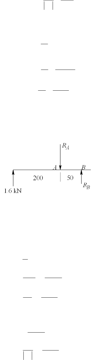
57 2.68 .
21.3
y
b
S
nA
ns
Tension in members, failure across two bolts,
2
52.375 2 1/ 4 0.5859 in
16
t
A
58.534 kpsi
0.5859
t
t
F
A
57 6.68 .
8.534
y
t
S
nA
ns
B
______________________________________________________________________________
8-71 By symmetry, the reactions at each support is 1.6 kN. The free-body diagram for the left
member is
0 1.6(250) 50 0 8 kN
0 200(1.6) 50 0 6.4 kN
BAA
AB
MRR
MRR
Members: Table A-20, Sy = 370 MPa
Bolts: Table 8-11, Sy = 420 MPa, Ssy = 0.577(420) = 242.3 MPa
Bolt shear, 22
(12 ) 113.1 mm
4
s
A
3
max 8(10 ) 70.73 MPa
113.1
242.3 3.43
70.73
s
sy
F
A
S
n
Bearing on member, Ab = td = 10(12) = 120 mm2
3
8(10 ) 66.67 MPa
120
370 5.55
66.67
b
y
b
S
n
Chap. 8 Solutions - Rev. A, Page 60/69
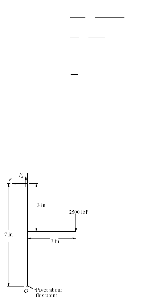
Strength of member. The bending moments at the hole locations are:
in the left member at A, MA = 1.6(200) = 320 N · m. In the right member at B, MB =
8(50) = 400 N · m. The bending moment is greater at B
33 3
3
3
1[10(50 ) 10(12 )] 102.7(10 ) mm
12
400(25) (10 ) 97.37 MPa
102.7(10 )
370 3.80
97.37
B
A
B
A
y
A
I
Mc
I
S
n
4
At the center, call it point C,
MC = 1.6(350) = 560 N · m
334
3
3
1(10)(50 ) 104.2(10 ) mm
12
560(25) (10 ) 134.4 MPa
104.2(10 )
370 2.75 3.80 more critical at
134.4
min(3.04, 3.80, 2.75) 2.72 .
C
C
C
C
y
C
I
Mc
I
S
nC
nA
ns
______________________________________________________________________________
8-72 The free-body diagram of the bracket, assuming the upper bolt takes all the shear and
tensile load is
Fs = 2500 lbf
2500 3 1071 lbf
7
P
Table
A-31, H = 7/16 = 0.4375 in. Grip, l = 2(1/2) = 1 in. L ≥ l + H = 1.4375 in. Use 1.5
in bolts.
Eq. (8-13), LT = 2d + 0.25 = 2(0.5) + 0.25 = 1.25 in
Table 8-7, ld = L
LT = 1.5 1.25 = 0.25 in
Chap. 8 Solutions - Rev. A, Page 61/69
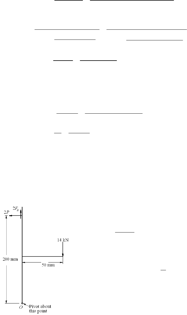
lt = l
ld = 1 0.25 = 0.75 in
Table 8-2, At = 0.141 9 in2
Ad =
(0.52) /4 = 0.196 3 in2
Eq. (8-17),
0.196 3 0.141 9 30 4.574 Mlbf/in
0.196 3 0.75 0.141 9 0.25
dt
b
dt td
AAE
kAl Al
Eq. (8-22),
0.5774 30 0.5
0.5774 16.65 Mlbf/in
0.5774 0.5 0.5774 1 0.5 0.5
2ln 5 2ln 5
0.5774 2.5 0.5774 1 2.5 0.5
m
Ed
kld
ld
4.574 0.216
4.574 16.65
b
bm
k
Ckk
Table 8-9, Sp = 65 kpsi
Eqs. (8-31) and (8-32), Fi = 0.75 At Sp = 0.75(0.141 9)65 = 6.918 kips
i = 0.75 Sp = 0.75(65) = 48.75 kips
Eq. (a), p. 440,
0.216 1.071 6.918 50.38 kpsi
0.141 9
i
b
t
CP F
A
Direct shear, 321.14 kpsi
0.141 9
s
s
t
F
A
von Mises stress, Eq. (5-15), p. 223
1/ 2
1/2
22 2 2
3 50.38 3 21.14 62.3 kpsi
bs
Stress margin, m = Sp
= 65
62.3 = 3.7 kpsi Ans.
______________________________________________________________________________
8-73
22
3
2 (200) 14(50)
14(50) 1.75 kN per bolt
2(200)
7 kN/bolt
380 MPa
245 mm , (20 ) 314.2 mm
4
0.75(245)(380)(10 ) 69.83 kN
0.75 380 285 MPa
s
p
td
i
i
P
P
F
S
AA
F
2
Chap. 8 Solutions - Rev. A, Page 62/69
3
3
221/2
0.25(1.75) 69.83 (10 ) 287 MPa
245
7(10 ) 22.3 MPa
314.2
[287 3(22.3 )] 290 MPa
380 290 90 MPa
i
b
t
s
d
p
CP F
A
F
A
mS
Stress margin, m = Sp
= 380 90 = 90 MPa Ans.
______________________________________________________________________________
8-74 Using the result of Prob. 5-67 for lubricated assembly (replace 0.2 with 0.18 per Table
8-15)
2
0.18
x
f
T
Fd
With a design factor of nd gives
0.18 0.18(3)(1000) 716
2 2 (0.12)
dx
nFd d
Td
f
or T/d = 716. Also,
(0.75 )
0.18(0.75)(85 000)
11 475
pt
t
t
TKSA
d
A
A
Form a table
Size At T/d = 11 475Atn
1
4-28 0.0364 417.70 1.75
5
16 -24 0.058 665.55 2.8
3
824 0.0878 1007.50 4.23
where the factor of safety in the last column of the table comes from
2 ( / ) 2 (0.12)( / ) 0.0042( / )
0.18 0.18(1000)
x
fT d T d
nT
Fd
Select a
"
3
8-24
UNF cap screw. The setting is given by
T = (11 475At )d = 1007.5(0.375) = 378 lbf · in
Given the coarse scale on a torque wrench, specify a torque wrench setting of 400 lbf · in.
Check the factor of safety
Chap. 8 Solutions - Rev. A, Page 63/69
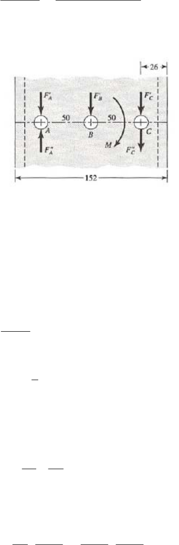
2 2 (0.12)(400) 4.47
0.18 0.18(1000)(0.375)
x
fT
nFd
______________________________________________________________________________
8-75
Bolts, from Table 8-11, Sy = 420 MPa
Channel, From Table A-20, Sy = 170 MPa. From Table A-7, t = 6.4 mm
Cantilever, from Table A-20, Sy = 190 MPa
F
A = F
B = F
C = F / 3
M = (50 + 26 + 125) F = 201 F
201 2.01
250
AC
F
FF F
Max. force, 12.01 2.343
3
CCC
F
FF F F
(1)
Shear on Bolts: The shoulder bolt shear area, As =
(102) / 4 = 78.54 mm2
Ssy = 0.577(420) = 242.3 KPa
max
s
y
C
s
S
F
An
From Eq. (1), FC = 2.343 F. Thus
3
242.3 78.54 10 4.06 kN
2.343 2.0 2.343
sy s
SA
Fn
Bearing on bolt: The bearing area is Ab = td = 6.4(10) = 64 mm2. Similar to shear
Chap. 8 Solutions - Rev. A, Page 64/69
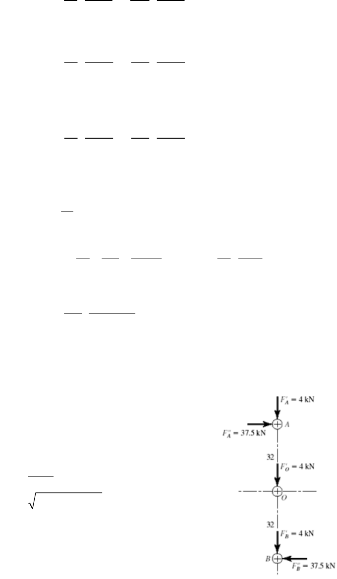
3
420 64 10 5.74 kN
2.343 2.0 2.343
yb
SA
Fn
Bearing on channel: Ab = 64 mm2, Sy = 170 MPa.
3
170 64 10 2.32 kN
2.343 2.0 2.343
yb
SA
Fn
Bearing on cantilever: Ab = 12(10) = 120 mm2, Sy = 190 MPa.
3
190 120 10 4.87 kN
2.343 2.0 2.343
yb
SA
Fn
Bending of cantilever: At C
33 5
112 50 10 1.24 10 mm
12
I 4
max
151
151
yy
SS
M
cFc I
F
nI I n c
5
3
1.24 10
190 10 3.12 kN
2.0 151 25
F
So F = 2.32 kN based on bearing on channel. Ans.
______________________________________________________________________________
8-76 Bolts, from Table 8-11, Sy = 420 MPa
Bracket, from Table A-20, Sy = 210 MPa
22
12 4 kN; 12(200) 2400 N · m
3
2400 37.5 kN
64
(4) (37.5) 37.7 kN
4 kN
AB
AB
O
FM
FF
FF
F
Bolt shear:
The shoulder bolt shear area, As =
(122) / 4 = 113.1 mm2
S
sy = 0.577(420) = 242.3 KPa
Chap. 8 Solutions - Rev. A, Page 65/69

3
37.7(10) 333 MPa
113
242.3 0.728 .
333
sy
S
nA
ns
Bearing on bolts:
2
3
12(8) 96 mm
37.7(10) 393 MPa
96
420 1.07 .
393
b
b
yc
b
A
S
nA
ns
Bearing on member:
393 MPa
210 0.534 .
393
b
yc
b
S
nAns
Bending stress in plate:
33 3
2
33 3
2
64
3
6
2
12 12 12
8(136) 8(12) 8(12)
2(32)(8)(
12 12 12
1.48(10) mm .
2400(68) (10) 110 MPa
1.48(10)
210 1.91 .
110
y
bh bd bd
Iabd
Ans
Mc
I
S
nAns
12)
Failure is predicted for bolt shear and bearing on member.
______________________________________________________________________________
Chap. 8 Solutions - Rev. A, Page 66/69
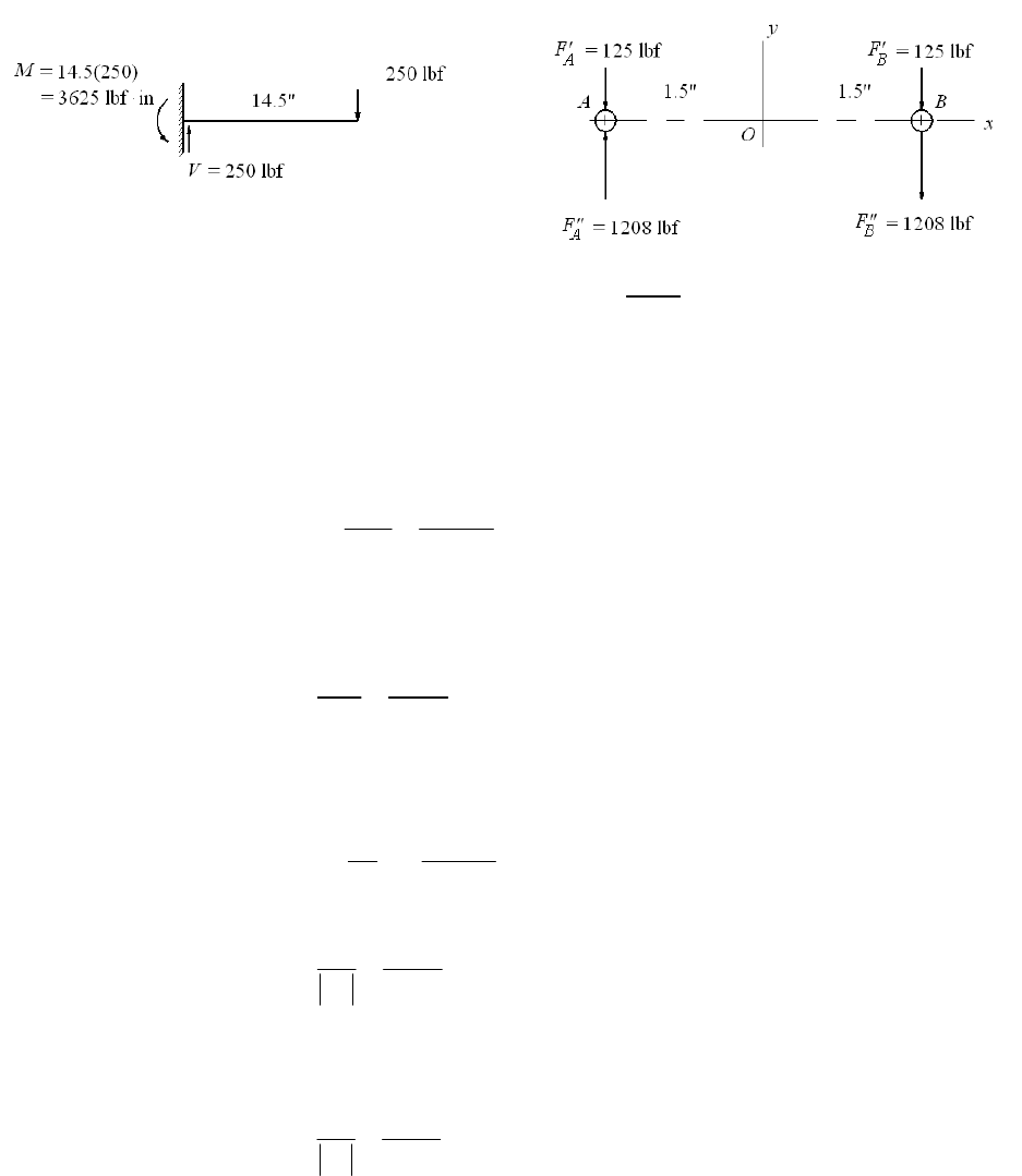
8-77
3625 1208 lbf
3
1208 125 1083 lbf, 1208 125 1333 lbf
AB
AB
FF
FF
Bolt shear:
As = (
/ 4)(0.3752) = 0.1104 in2
max
max
1333 12 070 psi
0.1104
s
F
A
From Table 8-10, Sy = 100 kpsi, Ssy = 0.577(100) = 57.7 kpsi
max
57.7 4.78 .
12.07
sy
S
nA
ns
Bearing on bolt: Bearing area is Ab = td = 0.375 (0.375) = 0.1406 in2.
1333 9 481 psi
0.1406
b
b
F
A
100 10.55 .
9.481
y
b
S
nA
ns
Bearing on member: From Table A-20, Sy = 54 kpsi. Bearing stress same as bolt
54 5.70 .
9.481
y
b
S
nA
ns
Bending of member: At B, M = 250(13) = 3250 lbfin
Chap. 8 Solutions - Rev. A, Page 67/69
3
34
13 3
2 0.2484 in
12 8 8
I
3250 1 13 080 psi
0.2484
Mc
I
54 4.13 .
13.08
y
S
nA
ns
______________________________________________________________________________
8-78 The direct shear load per bolt is F
= 2000/6 = 333.3 lbf. The moment is taken only by the
four outside bolts. This moment is M = 2000(5) = 10 000 lbf · in.
Thus 10 000 1000 lbf
2(5)
F and the resultant bolt load is
22
(333.3) (1000) 1054 lbfF
Bolt strength, Table 8-9, Sy = 100 kpsi; Channel and Plate strength, Sy = 42 kpsi
Shear of bolt: As =
(0.5)2/4 = 0.1963 in2
(0.577)(100) 10.7 .
1.054 / 0.1963
sy
S
nA
ns
Bearing on bolt: Channel thickness is t = 3/16 in, Ab = 0.5(3/16) = 0.09375 in2
100 8.89 .
1.054 / 0.09375
nAns
Bearing on channel: 42 3.74 .
1.054 / 0.09375
nAns
Bearing on plate: Ab = 0.5(0.25) = 0.125 in2
42 4.98 .
1.054 / 0.125
nAns
Strength of plate:
33
3
24
0.25(7.5) 0.25(0.5)
12 12
0.25(0.5)
2 0.25 0.5 (2.5) 7.219 in
12
I
Chap. 8 Solutions - Rev. A, Page 68/69

5000 lbf · in per plate
5000(3.75)
2597 psi
7.219
42
16.2 .
2.597
M
Mc
I
nAns
______________________________________________________________________________
8-79 to 8-81 Specifying bolts, screws, dowels and rivets is the way a student learns about such
components. However, choosing an array a priori is based on experience. Here is a chance
for students to build some experience.
Chap. 8 Solutions - Rev. A, Page 69/69
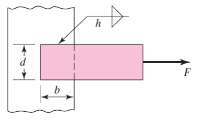
Chapter 9
Figure for Probs.
9-1 to 9-4
9-1 Given, b = 50 mm, d = 50 mm, h = 5 mm,
allow = 140 MPa.
F = 0.707 hl
allow = 0.707(5)[2(50)](140)(103) = 49.5 kN Ans.
______________________________________________________________________________
9-2 Given, b = 2 in, d = 2 in, h = 5/16 in,
allow = 25 kpsi.
F = 0.707 hl
allow = 0.707(5/16)[2(2)](25) = 22.1 kip Ans.
______________________________________________________________________________
9-3 Given, b = 50 mm, d = 30 mm, h = 5 mm,
allow = 140 MPa.
F = 0.707 hl
allow = 0.707(5)[2(50)](140)(103) = 49.5 kN Ans.
______________________________________________________________________________
9-4 Given, b = 4 in, d = 2 in, h = 5/16 in,
allow = 25 kpsi.
F = 0.707 hl
allow = 0.707(5/16)[2(4)](25) = 44.2 kip Ans.
______________________________________________________________________________
9-5 Prob. 9-1 with E7010 Electrode.
Table 9-6: f = 14.85 h kip/in = 14.85 [5 mm/(25.4 mm/in)] = 2.923 kip/in
= 2.923(4.45/25.4) = 0.512 kN/mm
F = f l = 0.512[2(50)] = 51.2 kN Ans.
______________________________________________________________________________
9-6 Prob. 9-2 with E6010 Electrode.
Table 9-6: f = 14.85 h kip/in = 14.85(5/16) = 4.64 kip/in
Chapter 9, Page 1/36
F = f l = 4.64[2(2)] = 18.6 kip Ans.
______________________________________________________________________________
9-7 Prob. 9-3 with E7010 Electrode.
Table 9-6: f = 14.85 h kip/in = 14.85 [5 mm/(25.4 mm/in)] = 2.923 kip/in
= 2.923(4.45/25.4) = 0.512 kN/mm
F = f l = 0.512[2(50)] = 51.2 kN Ans.
______________________________________________________________________________
9-8 Prob. 9-4 with E6010 Electrode.
Table 9-6: f = 14.85 h kip/in = 14.85(5/16) = 4.64 kip/in
F = f l = 4.64[2(4)] = 37.1 kip Ans.
______________________________________________________________________________
9-9 Table A-20:
1018 CD: Sut = 440 MPa, Sy = 370 MPa
1018 HR: Sut = 400 MPa, Sy = 220 MPa
Cold-rolled properties degrade to hot-rolled properties in the neighborhood of the weld.
Table 9-4:
all min(0.30 , 0.40 )
min[0.30(400), 0.40(220)]
min(120, 88) 88 MPa
ut y
SS
for both materials.
Eq. (9-3): F = 0.707hl
all = 0.707(5)[2(50)](88)(103) = 31.1 kN Ans.
______________________________________________________________________________
9-10 Table A-20:
1020 CD: Sut = 68 kpsi, Sy = 57 kpsi
1020 HR: Sut = 55 kpsi, Sy = 30 kpsi
Cold-rolled properties degrade to hot-rolled properties in the neighborhood of the weld.
Table 9-4:
all min(0.30 , 0.40 )
min[0.30(55), 0.40(30)]
min(16.5, 12.0) 12.0 kpsi
ut y
SS
for both materials.
Eq. (9-3): F = 0.707hl
all = 0.707(5/16)[2(2)](12.0) = 10.6 kip Ans.
______________________________________________________________________________
Chapter 9, Page 2/36
9-11 Table A-20:
1035 HR: Sut = 500 MPa, Sy = 270 MPa
1035 CD: Sut = 550 MPa, Sy = 460 MPa
Cold-rolled properties degrade to hot-rolled properties in the neighborhood of the weld.
Table 9-4:
all min(0.30 , 0.40 )
min[0.30(500), 0.40(270)]
min(150, 108) 108 MPa
ut y
SS
for both materials.
Eq. (9-3): F = 0.707hl
all = 0.707(5)[2(50)](108)(103) = 38.2 kN Ans.
______________________________________________________________________________
9-12 Table A-20:
1035 HR: Sut = 72 kpsi, Sy = 39.5 kpsi
1020 CD: Sut = 68 kpsi, Sy = 57 kpsi, 1020 HR: Sut = 55 kpsi, Sy = 30 kpsi
Cold-rolled properties degrade to hot-rolled properties in the neighborhood of the weld.
Table 9-4:
all min(0.30 , 0.40 )
min[0.30(55), 0.40(30)]
min(16.5, 12.0) 12.0 kpsi
ut y
SS
for both materials.
Eq. (9-3): F = 0.707hl
all = 0.707(5/16)[2(4)](12.0) = 21.2 kip Ans.
______________________________________________________________________________
9-13
Eq. (9-3):
3
2 100 10
2141 MPa .
5 2 50 50
FAns
hl
______________________________________________________________________________
9-14
Eq. (9-3):
240
222.6 kpsi .
5/16 2 2 2
F
A
ns
hl
______________________________________________________________________________
9-15 Eq. (9-3):
3
2 100 10
2177 MPa .
5 2 50 30
FAns
hl
______________________________________________________________________________
9-16 Eq. (9-3):
240
215.1 kpsi .
5/16 2 4 2
F
A
ns
hl
______________________________________________________________________________
Chapter 9, Page 3/36

9-17 b = d =50 mm, c = 150 mm, h = 5 mm, and
allow = 140 MPa.
(a) Primary shear, Table 9-1, Case 2 (Note: b and d are interchanged between problem
figure and table figure. Note, also, F in kN and
in MPa):
3
10 2.829
1.414 5 50
y
F
VF
A
Secondary shear, Table 9-1:
22
22
33
50 3 50 50
383.33 10 mm
66
u
db d
J
J = 0.707 h Ju = 0.707(5)(83.33)(103) = 294.6(103) mm4
3
3
175 10 25 14.85
294.6 10
y
xy
F
Mr F
J
22
22
max 14.85 2.829 14.85 23.1
xyy
F
F
(1)
allow 140 6.06 kN .
23.1 23.1
F
Ans
(b) For E7010 from Table 9-6,
allow = 21 kpsi = 21(6.89) = 145 MPa
1020 HR bar: Sut = 380 MPa, Sy = 210 MPa
1015 HR support: Sut = 340 MPa, Sy = 190 MPa
Table 9-3, E7010 Electrode: Sut = 482 MPa, Sy = 393 MPa
The support controls the design.
Table 9-4:
allow = min(0.30Sut, 0.40Sy ) =min[0.30(340), 0.40(190) = min(102, 76)
= 76 MPa
The allowable load, from Eq. (1) is
allow 76 3.29 kN .
23.1 23.1
F
Ans
______________________________________________________________________________
9-18 b = d =2 in, c = 6 in, h = 5/16 in, and
allow = 25 kpsi.
Chapter 9, Page 4/36
(a) Primary shear, Table 9-1(Note: b and d are interchanged between problem figure and
table figure. Note, also, F in kip and
in kpsi):
1.132
1.414 5/16 2
y
VF F
A
Secondary shear, Table 9-1:
22
22
3
232 2
35.333 in
66
u
db d
J
J = 0.707 h Ju = 0.707(5/16)(5.333) = 1.178 in4
71 5.942
1.178
y
xy
Mr FF
J
22
22
max 5.942 1.132 5.942 9.24
xyy
F
F
(1)
allow 25 2.71 kip .
9.24 9.24
F
Ans
(b) For E7010 from Table 9-6,
allow = 21 kpsi
1020 HR bar: Sut = 55 kpsi, Sy = 30 kpsi
1015 HR support: Sut = 50 kpsi, Sy = 27.5 kpsi
Table 9-3, E7010 Electrode: Sut = 70 kpsi, Sy = 57 kpsi
The support controls the design.
Table 9-4:
allow = min(0.30Sut, 0.40Sy ) =min[0.30(50), 0.40(27.5) = min(15, 11)
= 11 kpsi
The allowable load, from Eq. (1) is
allow 11 1.19 kip .
9.24 9.24
F
Ans
______________________________________________________________________________
9-19 b =50 mm, c = 150 mm, d = 30 mm, h = 5 mm, and
allow = 140 MPa.
(a) Primary shear, Table 9-1, Case 2 (Note: b and d are interchanged between problem
figure and table figure. Note, also, F in kN and
in MPa):
Chapter 9, Page 5/36

3
10 2.829
1.414 5 50
y
F
VF
A
Secondary shear, Table 9-1:
22
22
33
50 3 30 50
343.33 10 mm
66
u
db d
J
J = 0.707 h Ju = 0.707(5)(43.33)(103) = 153.2(103) mm4
3
3
175 10 15 17.13
153.2 10
y
x
F
Mr F
J
3
3
175 10 25 28.55
153.2 10
x
y
F
Mr F
J
22
22
max 17.13 2.829 28.55 35.8
xyy
F
F
(1)
allow 140 3.91 kN .
35.8 35.8
F
Ans
(b) For E7010 from Table 9-6,
allow = 21 kpsi = 21(6.89) = 145 MPa
1020 HR bar: Sut = 380 MPa, Sy = 210 MPa
1015 HR support: Sut = 340 MPa, Sy = 190 MPa
Table 9-3, E7010 Electrode: Sut = 482 MPa, Sy = 393 MPa
The support controls the design.
Table 9-4:
allow = min(0.30Sut, 0.40Sy ) =min[0.30(340), 0.40(190) = min(102, 76)
= 76 MPa
The allowable load, from Eq. (1) is
allow 76 2.12 kN .
35.8 35.8
F
Ans
______________________________________________________________________________
9-20 b = 4 in, c = 6 in, d = 2 in, h = 5/16 in, and
allow = 25 kpsi.
Chapter 9, Page 6/36
(a) Primary shear, Table 9-1(Note: b and d are interchanged between problem figure and
table figure. Note, also, F in kip and
in kpsi):
0.5658
1.414 5/16 4
y
VF F
A
Secondary shear, Table 9-1:
22
22
3
432 4
318.67 in
66
u
db d
J
J = 0.707 h Ju = 0.707(5/16)(18.67) = 4.125 in4
811.939
4.125
y
x
Mr FF
J
82 3.879
4.125
x
y
F
Mr F
J
22
22
max 1.939 0.5658 3.879 4.85
xyy
F
F
(1)
allow 25 5.15 kip .
4.85 4.85
F
Ans
(b) For E7010 from Table 9-6,
allow = 21 kpsi
1020 HR bar: Sut = 55 kpsi, Sy = 30 kpsi
1015 HR support: Sut = 50 kpsi, Sy = 27.5 kpsi
Table 9-3, E7010 Electrode: Sut = 70 kpsi, Sy = 57 kpsi
The support controls the design.
Table 9-4:
allow = min(0.30Sut, 0.40Sy ) =min[0.30(50), 0.40(27.5) = min(15, 11)
= 11 kpsi
The allowable load, from Eq. (1) is
allow 11 2.27 kip .
4.85 4.85
F
Ans
______________________________________________________________________________
Chapter 9, Page 7/36
9-21 Given, b = 50 mm, c = 150 mm, d = 50 mm, h = 5 mm,
allow = 140 MPa.
Primary shear (F in kN,
in MPa, A in mm2):
3
10 1.414
1.414 5 50 50
y
F
V
F
A
Secondary shear:
Table 9-1:
33
33
50 50 166.7 10 mm
66
u
bd
J
J = 0.707 h Ju = 0.707(5)166.7(103) = 589.2(103) mm4
3
3
175 10 (25) 7.425
589.2 10
y
xy
F
Mr F
J
Maximum shear:
22
22
max 7.425 1.414 7.425 11.54
xyy
F
F
140 12.1 kN .
11.54 11.54
allow
F
Ans
______________________________________________________________________________
9-22 Given, b = 2 in, c = 6 in, d = 2 in, h = 5/16 in,
allow = 25 kpsi.
Primary shear:
0.5658
1.414 5/16 2 2
y
VF F
A
Secondary shear:
Table 9-1:
33
3
22 10.67 in
66
u
bd
J
J = 0.707 h Ju = 0.707(5/16)10.67 = 2.357 in4
7(1) 2.970
2.357
y
xy
Mr FF
J
Maximum shear:
22
22
max 2.970 0.566 2.970 4.618
xyy
F
F
25 5.41 kip .
4.618 4.618
allow
F
Ans
______________________________________________________________________________
9-23 Given, b = 50 mm, c = 150 mm, d = 30 mm, h = 5 mm,
allow = 140 MPa.
Chapter 9, Page 8/36

Primary shear (F in kN,
in MPa, A in mm2):
3
10 1.768
1.414 5 50 30
y
F
V
F
A
Secondary shear:
Table 9-1:
33
33
50 30 85.33 10 mm
66
u
bd
J
J = 0.707 h Ju = 0.707(5)85.33(103) = 301.6(103) mm4
3
3
175 10 (15) 8.704
301.6 10
y
x
F
Mr F
J
3
3
175 10 (25) 14.51
301.6 10
x
y
F
Mr F
J
Maximum shear:
22
22
max 8.704 1.768 14.51 18.46
xyy
F
F
140 7.58 kN .
18.46 18.46
allow
F
Ans
______________________________________________________________________________
9-24 Given, b = 4 in, c = 6 in, d = 2 in, h = 5/16 in,
allow = 25 kpsi.
Primary shear:
0.3772
1.414 5/16 4 2
y
VF F
A
Secondary shear:
Table 9-1:
33
3
42 36 in
66
u
bd
J
J = 0.707 h Ju = 0.707(5/16)36 = 7.954 in4
8(1) 1.006
7.954
y
x
Mr FF
J
8(2) 2.012
7.954
x
y
Mr F
F
J
Maximum shear:
22
22
max 1.006 0.3772 2.012 2.592
xyy
F
F
Chapter 9, Page 9/36

25 9.65kip .
2.592 2.592
allow
F
Ans
______________________________________________________________________________
9-25 Given, b = 50 mm, d = 50 mm, h = 5 mm, E6010 electrode.
A = 0.707(5)(50 +50 + 50) = 530.3 mm2
Member endurance limit: From Table A-20 for AISI 1010 HR, Sut = 320 MPa.
Eq. 6-19 and Table 6-2, pp. 287, 288: ka = 272(320)0.995 = 0.875
kb = 1 (uniform shear), kc = 0.59 (torsion, shear), kd = 1
Eqs. (6-8) and (6-18): Se = 0.875(1)(0.59)(1)(0.5)(320) = 82.6 MPa
Electrode endurance: E6010, Table 9-3, Sut = 427 MPa
Eq. 6-19 and Table 6-2, pp. 287, 288: ka = 272(427)0.995 = 0.657
As before, kb = 1 (direct shear), kc = 0.59 (torsion, shear), kd = 1
Se = 0.657(1)(0.59)(1)(0.5)(427) = 82.8 MPa
The members and electrode are basically of equal strength. We will use Se = 82.6 MPa.
For a factor of safety of 1, and with Kfs = 2.7 (Table 9-5)
3
allow 82.6 530.3 16.2 10 N 16.2 kN .
2.7
fs
A
F
Ans
K
______________________________________________________________________________
9-26 Given, b = 2 in, d = 2 in, h = 5/16 in, E6010 electrode.
A = 0.707(5/16)(2 +2 + 2) = 1.326 in2
Member endurance limit: From Table A-20 for AISI 1010 HR, Sut = 47 kpsi.
Eq. 6-19 and Table 6-2, pp. 287, 288: ka = 39.9(47)0.995 = 0.865
kb = 1 (uniform shear), kc = 0.59 (torsion, shear), kd = 1
Eqs. (6-8) and (6-18): Se = 0.865(1)(0.59)(1)(0.5)(47) = 12.0 kpsi
Electrode endurance: E6010, Table 9-3, Sut = 62 kpsi
Eq. 6-19 and Table 6-2, pp. 287, 288: ka = 39.9(62)0.995 = 0.657
Chapter 9, Page 10/36

As before, kb = 1 (uniform shear), kc = 0.59 (torsion, shear), kd = 1
Se = 0.657(1)(0.59)(1)(0.5)(62) = 12.0 kpsi
Thus the members and electrode are of equal strength. For a factor of safety of 1, and
with Kfs = 2.7 (Table 9-5)
allow 12.0 1.326 5.89 kip .
2.7
fs
A
F
Ans
K
______________________________________________________________________________
9-27 Given, b = 50 mm, d = 30 mm, h = 5 mm, E7010 electrode.
A = 0.707(5)(50 +50 + 30) = 459.6 mm2
Member endurance limit: From Table A-20 for AISI 1010 HR, Sut = 320 MPa.
Eq. 6-19 and Table 6-2, pp. 287, 288: ka = 272(320)0.995 = 0.875
kb = 1 (direct shear), kc = 0.59 (torsion, shear), kd = 1
Eqs. (6-8) and (6-18): Se = 0.875(1)(0.59)(1)(0.5)(320) = 82.6 MPa
Electrode endurance: E6010, Table 9-3, Sut = 482 MPa
Eq. 6-19 and Table 6-2, pp. 287, 288: ka = 272(482)0.995 = 0.582
As before, kb = 1 (direct shear), kc = 0.59 (torsion, shear), kd = 1
Se = 0.582(1)(0.59)(1)(0.5)(482) = 82.7 MPa
The members and electrode are basically of equal strength. We will use Se =82.6 MPa.
For a factor of safety of 1, and with Kfs = 2.7 (Table 9-5)
3
allow 82.6 459.6 14.1 10 N 14.1 kN .
2.7
fs
A
F
Ans
K
______________________________________________________________________________
9-28 Given, b = 4 in, d = 2 in, h = 5/16 in, E7010 electrode.
A = 0.707(5/16)(4 +4 + 2) = 2.209 in2
Member endurance limit: From Table A-20 for AISI 1010 HR, Sut = 47 kpsi.
Eq. 6-19 and Table 6-2, pp. 287, 288: ka = 39.9(47)0.995 = 0.865
kb = 1 (direct shear), kc = 0.59 (torsion, shear), kd = 1
Chapter 9, Page 11/36
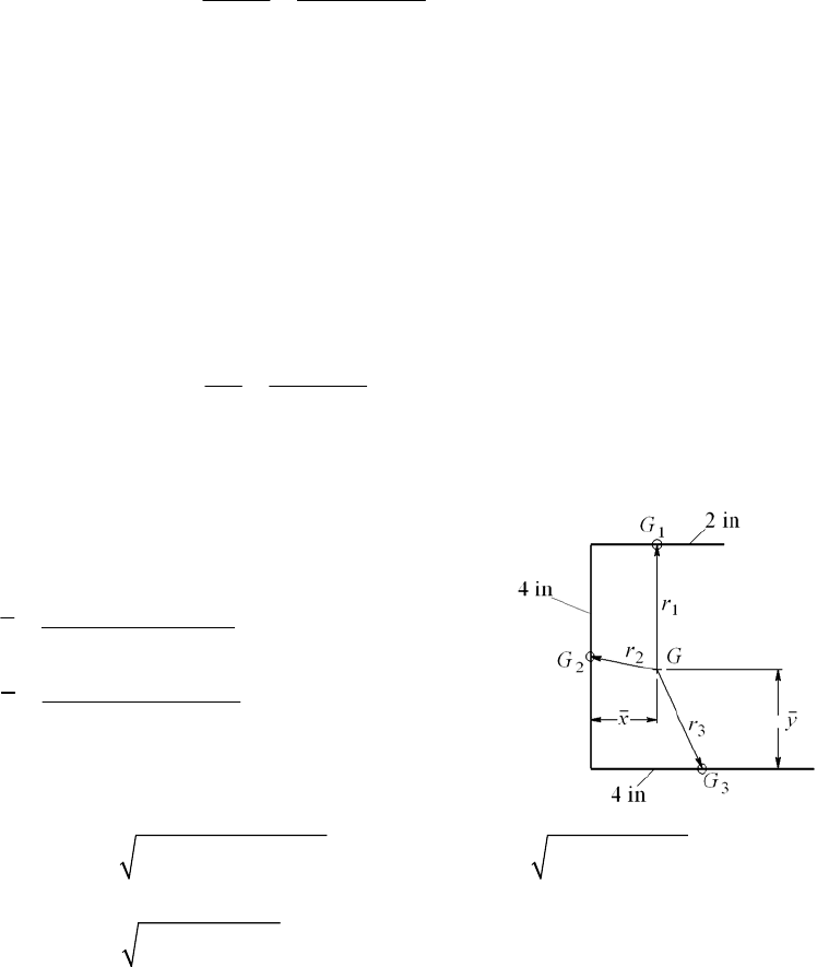
Eqs. (6-8) and (6-18): Se = 0.865(1)(0.59)(1)(0.5)(47) = 12.0 kpsi
Electrode endurance: E7010, Table 9-3, Sut = 70 kpsi
Eq. 6-19 and Table 6-2, pp. 287, 288: ka = 39.9(70)0.995 = 0.582
As before, kb = 1 (direct shear), kc = 0.59 (torsion, shear), kd = 1
Se = 0.582(1)(0.59)(1)(0.5)(70) = 12.0 kpsi
Thus the members and electrode are of equal strength. For a factor of safety of 1, and
with Kfs = 2.7 (Table 9-5)
allow 12.0 2.209 9.82 kip .
2.7
fs
A
F
Ans
K
______________________________________________________________________________
9-29 Primary shear:
= 0 (why?)
Secondary shear:
Table 9-1: Ju = 2
r3 = 2
(1.5)3 = 21.21 in3
J = 0.707 h Ju = 0.707(1/4)(21.21) = 3.749 in4
2 welds:
81.5 1.600
2 2 3.749
F
Mr
F
J
allow 1.600 20 12.5 kip .FF Ans
______________________________________________________________________________
9-30 l = 2 + 4 + 4 = 10 in
21 40 42 1in
10
24 42 40 1.6 in
10
x
y
M = FR = F(10 1) = 9 F
22 2
2
12
1 1 4 1.6 2.4 in, 1 2 1.6 1.077 inrr
22
32 1 1.6 1.887 inr
Chapter 9, Page 12/36
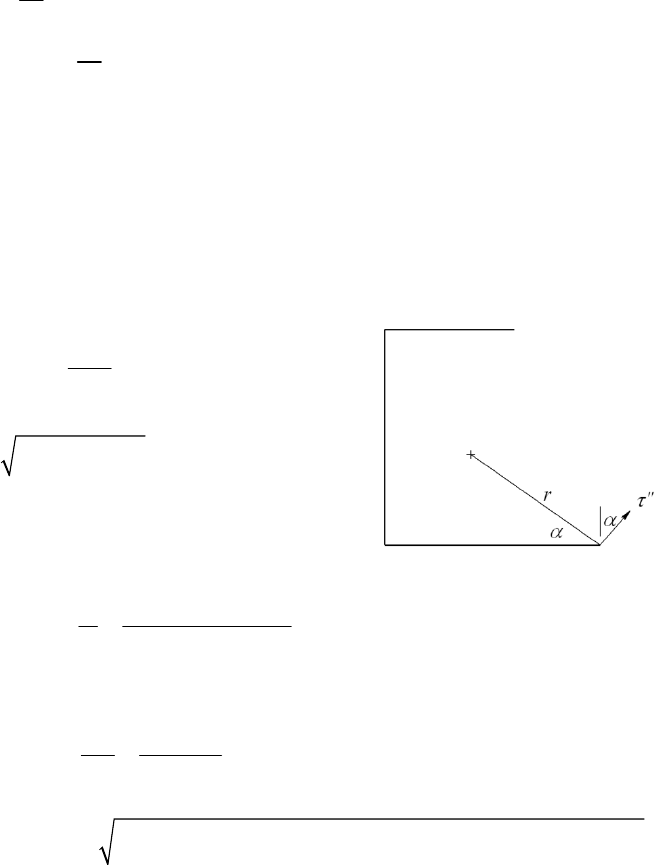
1
34
10.707 5/16 2 0.1473 in
12
G
J
23
34
10.707 5 /16 4 1.178 in
12
GG
JJ
32
1
22
24
0.1473 0.707 5/16 2 2.4 1.178 0.707 5/16 4 1.077
1.178 0.707 5 /16 4 1.887 9.220 in
i
iiG
i
JJAr
1o
1.6
tan 28.07
41
2
2
1.6 4 1 3.4 inr
Primary shear (
in kpsi, F in kip) :
0.4526
0.707 5/16 10
VF F
A
Secondary shear:
93.4 3.319
9.220
F
Mr F
J
22
oo
max 3.319 sin 28.07 3.319 cos28.07 0.4526
3.724
FF
F
F
max =
allow 3.724 F = 25 F = 6.71 kip Ans.
______________________________________________________________________________
Chapter 9, Page 13/36
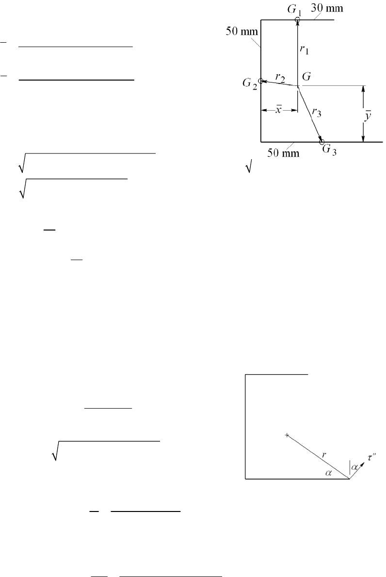
9-31 l = 30 + 50 + 50 = 130 mm
30 15 50 0 50 25 13.08 mm
130
30 50 50 25 50 0 21.15 mm
130
x
y
M = FR = F(200 13.08)
= 186.92 F (M in Nm, F in kN)
22 2
2
1 2
15 13.08 50 21.15 28.92 mm, 13.08 25 21.15 13.63 mmrr
22
325 13.08 21.15 24.28 mmr
1
33
10.707 5 30 7.954 10 mm
12
G
J
4
23
33
10.707 5 50 36.82 10 mm
12
GG
JJ 4
2
32
1
323
3234
7.954 10 0.707 5 30 28.92 36.82 10 0.707 5 50 13.63
36.82 10 0.707 5 50 24.28 307.3 10 mm
i
iiG
i
JJAr
1o
21.15
tan 29.81
50 13.08
2
2
21.15 50 13.08 42.55 mmr
Primary shear (
in MPa, F in kN) :
3
10 2.176
0.707 5 130
F
V
F
A
Secondary shear:
3
3
186.92 10 42.55 25.88
307.3 10
F
Mr F
J
Chapter 9, Page 14/36
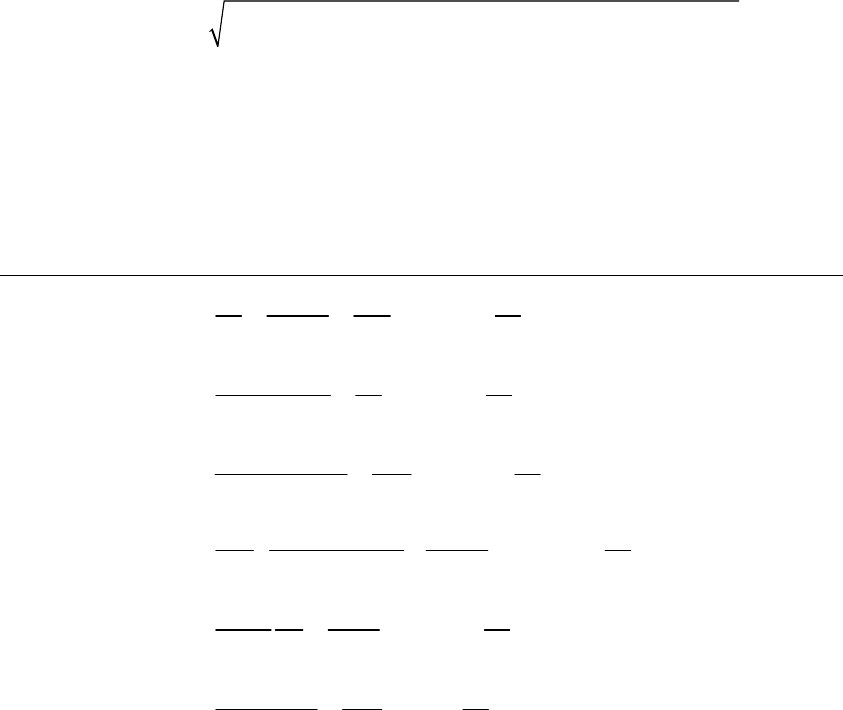
22
oo
max 25.88 sin 29.81 25.88 cos 29.81 2.176
27.79
FF
F
F
max =
allow 27.79 F = 140 F = 5.04 kN Ans.
______________________________________________________________________________
9-32
Weld
Pattern Figure of merit Rank______
1. 32
/12
fom 0.0833
12
u
Jaa a
lh ah h h
2
5
2.
22 22
3
fom 0.3333
62 3
aa a a
ah h h
a
1
3.
422 22
26 5
fom 0.2083
12 2 24
aaaaa
aa ah h h
4
4. 333 4 2
18 6
fom 0.3056
3122
aaa a a
ah a a h
2
5.
332
218
fom 0.3333
64 24
aaa
ha ah h
1
6.
332
2/2
fom 0.25
4
aaa
ah ah h
3
______________________________________________________________________________
Chapter 9, Page 15/36
9-33
Weld
Pattern Figure of merit Rank______
1.
32
/12
fom 0.0833
ua
Ia
lh ah h
6
2.
32
/6
fom 0.0833
2
aa
ah h
6
3.
22
/2
fom 0.25
2
aa a
ah h
1
4.*
222
/12 6 7
fom 0.1944
336
aaa
a
ah h h
a
2
5. & 7. 2
,
22
aa
xy
aa
3
a
2
33
2
222
33 3
u
aa a
Iaaa
3
a
322
/3 1
fom 0.1111
39
ua
Iaa
lh ah h h
5
6. & 8.
222
/6 3 1
fom 0.1667
46
aaaaa
ah h h
3
9.
322
/2
fom 0.125
8
aaa
ah h h
4
*Note. Because this section is not symmetric with the vertical axis, out-of-plane
deflection may occur unless special precautions are taken. See the topic of “shear center”
in books with more advanced treatments of mechanics of materials.
______________________________________________________________________________
9-34 Attachment and member (1018 HR), Sy = 220 MPa and Sut = 400 MPa.
The member and attachment are weak compared to the properties of the lowest electrode.
Decision Specify the E6010 electrode
Controlling property, Table 9-4:
all = min[0.3(400), 0.4(220)] = min(120, 88) = 88 MPa
For a static load, the parallel and transverse fillets are the same. Let the length of a bead
be l = 75 mm, and n be the number of beads.
Chapter 9, Page 16/36
0.707 all
F
nhl
3
all
100 10 21.43
0.707 0.707 75 88
F
nh l
where h is in millimeters. Make a table
Number of beads, n Leg size, h (mm)
1 21.43
2 10.71
3 7.14
4 5.36 6 mm
Decision Specify h = 6 mm on all four sides.
Weldment specification:
Pattern: All-around square, four beads each side, 75 mm long
Electrode: E6010
Leg size: h = 6 mm
______________________________________________________________________________
9-35 Decision: Choose a parallel fillet weldment pattern. By so-doing, we’ve chosen an
optimal pattern (see Prob. 9-32) and have thus reduced a synthesis problem to an analysis
problem:
Table 9-1, case 2, rotated 90: A = 1.414hd = 1.414(h)(75) = 106.05h mm2
Primary shear
3
12 10 113.2
106.05
y
V
Ahh
Secondary shear:
22
22 33
33
(3 )
6
75[3(75 ) 75 ] 281.3 10 mm
6
0.707( )(281.3) 10 198.8 10 mm
u
db d
J
Jh h
4
With
= 45,
Chapter 9, Page 17/36
3
o
3
2
22
max
12 10 (187.5)(37.5)
cos45 424.4
198.8 10
1 684.9
424.4 (113.2 424.4)
y
x y
xyy
Mr
Mr
JJ h
h
hh
2
Attachment and member (1018 HR): Sy = 220 MPa, Sut = 400 MPa
Decision: Use E60XX electrode which is stronger
all
max all
min[0.3(400), 0.4(220)] 88 MPa
684.9 88 MPa
684.9 7.78 mm
88
h
h
Decision: Specify 8 mm leg size
Weldment Specifications:
Pattern: Parallel horizontal fillet welds
Electrode: E6010
Type: Fillet
Length of each bead: 75 mm
Leg size: 8 mm
______________________________________________________________________________
9-36 Problem 9-35 solves the problem using parallel horizontal fillet welds, each 75 mm long
obtaining a leg size rounded up to 8 mm.
For this problem, since the width of the plate is fixed and the length has not been
determined, we will explore reducing the leg size by using two vertical beads 75 mm long
and two horizontal beads such that the beads have a leg size of 6 mm.
Decision: Use a rectangular weld bead pattern with a leg size of 6 mm (case 5 of Table
9-1 with b unknown and d = 75 mm).
Materials:
Attachment and member (1018 HR): Sy = 220 MPa, Sut = 400 MPa
From Table 9-4, AISC welding code,
all = min[0.3(400), 0.4(220)] = min(120, 88) = 88 MPa
Select a stronger electrode material from Table 9-3.
Decision: Specify E6010
Solving for b: In Prob. 9-35, every term was linear in the unknown h. This made solving
for h relatively easy. In this problem, the terms will not be linear in b, and so we will use
an iterative solution with a spreadsheet.
Throat area and other properties from Table 9-1:
A = 1.414(6)(b + 75) = 8.484(b + 75) (1)
Chapter 9, Page 18/36
3
75
6
u
b
J
, J = 0.707 (6) Ju = 0.707(b +75)3 (2)
Primary shear (
in MPa, h in mm):
3
12 10 (3)
y
V
AA
Secondary shear (See Prob. 9-35 solution for the definition of
) :
3
3
3
3
2
2
max
12 10 150 / 2 (37.5)
cos cos (4)
0.707 75
12 10 150 / 2 ( / 2)
sin sin (5)
0.707 75
(6)
y
x
x
y
yxy
Mr
J
b
Mr
Mr
JJ b
bb
Mr Mr
JJ b
Enter Eqs. (1) to (6) into a spreadsheet and iterate for various values of b. A portion of
the spreadsheet is shown below.
b (mm) A (mm2) J (mm4)
'y (Mpa)
"y (Mpa)
"x (Mpa)
max
(Mpa)
41 984.144 1103553.5 12.19334 69.5254 38.00722 90.12492
42 992.628 1132340.4 12.08912 67.9566 38.05569 88.63156
43 1001.112 1161623.6 11.98667 66.43718 38.09065 87.18485 < 88 Mpa
44 1009.596 1191407.4 11.88594 64.96518 38.11291 85.7828
We see that b 43 mm meets the strength goal.
Weldment Specifications:
Pattern: Horizontal parallel weld tracks 43 mm long, vertical parallel weld tracks 75 mm
long
Electrode: E6010
Leg size: 6 mm
______________________________________________________________________________
9-37 Materials:
Member and attachment (1018 HR): 32 kpsi, 58 kpsi
yut
SS
Table 9-4: all min[0.3(58), 0.4(32)] 12.8 kpsi
Chapter 9, Page 19/36
Decision: Use E6010 electrode. From Table 9-3: 50 kpsi, 62 kpsi,
yut
SS
all min[0.3(62), 0.4(50)] 20 kpsi
Decision: Since 1018 HR is weaker than the E6010 electrode, use all 12.8 kpsi
Decision: Use an all-around square weld bead track.
l1 = 6 + a = 6 + 6.25 = 12.25 in
Throat area and other properties from Table 9-1:
1.414 ( ) 1.414( )(6 6) 16.97
A
hb d h h
Primary shear
3
20 10 1179 psi
16.97
y
VF
A
Ahh
Secondary shear
333
()(66)
288 in
66
u
bd
J
4
0.707 (288) 203.6 inJh h
3
20 10 (6.25 3)(3) 2726 psi
203.6
y
xy
Mr
Jh
h
22 2 2
max
1 4762
( ) 2726 (1179 2726) psi
xyy
hh
Relate stress to strength
3
max all 3
4762 4762
12.8 10 0.372 in
12.8 10
h
h
Decision:
Specify in leg size
3/8
Specifications:
Pattern: All-around square weld bead track
Electrode: E6010
Type of weld: Fillet
Weld bead length: 24 in
Leg size: in
3/8
Attachment length: 12.25 in
______________________________________________________________________________
Chapter 9, Page 20/36
9-38 This is a good analysis task to test a student’s understanding.
(1) Solicit information related to a priori decisions.
(2) Solicit design variables b and d.
(3) Find h and round and output all parameters on a single screen. Allow return to Step 1
or Step 2.
(4) When the iteration is complete, the final display can be the bulk of your adequacy
assessment.
Such a program can teach too.
______________________________________________________________________________
9-39 The objective of this design task is to have the students teach themselves that the weld
patterns of Table 9-2 can be added or subtracted to obtain the properties of a
contemplated weld pattern. The instructor can control the level of complication. We have
left the presentation of the drawing to you. Here is one possibility. Study the problem’s
opportunities, and then present this (or your sketch) with the problem assignment.
Use as the design variable. Express properties as a function of From Table 9-3,
1
b1.b
case 3:
1
1.414 ( )Ahbb
22211
()
22 2
u
bd b b d
bd
I
0.707 u
I
hI
1
1.414 ( )
VF
A
hb b
(/2)
0.707 u
Mc Fa d
I
hI
Parametric study
Let 1all
10 in, 8 in, 8 in, 2 in, 12.8 kpsi, 2(8 2) 12 inabdb l
Chapter 9, Page 21/36
2
1.414 (8 2) 8.48 inAh h
23
(8 2)(8 / 2) 192 in
u
I
4
0.707( )(192) 135.7 inIh h
10 000 1179 psi
8.48hh
10 000(10)(8 / 2) 2948 psi
135.7hh
22
max
1 3175
1179 2948 12 800 psi
hh
from which Do not round off the leg size – something to learn.
0.248 in.h
192
fom' 64.5 in
0.248(12)
u
I
hl
2
8.48(0.248) 2.10 inA
4
135.7(0.248) 33.65 inI
22 3
0.248
vol 12 0.369 in
22
hl
33.65
eff 91.2 in
vol 0.369
I
1179 4754 psi
0.248
2948 11 887 psi
0.248
max
3175 12 800 psi
0.248
Now consider the case of uninterrupted welds,
10b
1.414( )(8 0) 11.31
A
hh
23
(8 0)(8 / 2) 256 in
u
I
4
0.707(256) 181 inIhh
10 000 884
11.31hh
10 000(10)(8 / 2) 2210
181hh
22
max all
1 2380
884 2210
hh
max
all
2380 0.186 in
12 800
h
Do not round off h.
Chapter 9, Page 22/36
2
11.31(0.186) 2.10 inA
4
181(0.186) 33.67 inI
23
884 0.186
4753 psi, vol 16 0.277 in
0.186 2
2210 11882 psi
0.186
256
fom' 86.0 in
0.186(16)
u
I
hl
22
33.67
eff 121.7 in
( / 2) (0.186 / 2)16
I
hl
Conclusions: To meet allowable stress limitations, I and A do not change, nor do τ and σ.
To meet the shortened bead length, h is increased proportionately. However, volume of
bead laid down increases as h2. The uninterrupted bead is superior. In this example, we
did not round h and as a result we learned something. Our measures of merit are also
sensitive to rounding. When the design decision is made, rounding to the next larger
standard weld fillet size will decrease the merit.
Had the weld bead gone around the corners, the situation would change. Here is a follow
up task analyzing an alternative weld pattern.
______________________________________________________________________________
9-40 From Table 9-2
For the box 1.414 ( )
A
hb d
Subtracting
11
from and from bbd d
11
1.414
A
hb b d d
32223
11 11
11
(3 )
6622 6
u
dbd
d3
I
bd bbd d d
Length of bead
11
2( )lbbdd
fom /
u
I
hl
______________________________________________________________________________
Chapter 9, Page 23/36
9-41 Computer programs will vary.
______________________________________________________________________________
9-42 Note to the Instructor. In the first printing of the ninth edition, the loading was stated
incorrectly. In the fourth line, “bending moment of 100 kip ⋅ in in” should read, “10 kip
bending load 10 in from”. This will be corrected in the printings that follow. We
apologize if this has caused any inconvenience.
all = 12 kpsi. Use Fig. 9-17(a) for general geometry, but employ beads and then
beads.
Horizontal parallel weld bead pattern
b = 3 in, d = 6 in
Table 9-2:
2
1.414 1.414( )(3) 4.24 inAhb h h
22 3
3(6) 54 in
22
u
bd
I
4
0.707 0.707( )(54) 38.2 in
u
IhI h h
10 2.358 kpsi
4.24hh
10(10)(6 / 2) 7.853 kpsi
38.2
Mc
I
hh
22 2 2
max
1 8.199
2.358 7.853 kpsi
hh
Equate the maximum and allowable shear stresses.
max all
8.199 12
h
from which It follows that
0.683 in.h
4
38.2(0.683) 26.1 inI
The volume of the weld metal is
22 3
(0.683) (3 3)
vol 1.40 in
22
hl
The effectiveness, (eff)H, is
Chapter 9, Page 24/36
H
26.1
(eff) 18.6 in
vol 1.4
I
H
54
(fom') 13.2 in
0.683(3 3)
u
I
hl
Vertical parallel weld beads
3 in
6 in
b
d
From Table 9-2, case 2
2
1.414 1.414( )(6) 8.48 inAhd h h
33 3
672 in
66
u
d
I
0.707 0.707( )(72) 50.9
u
I
hI h h
10 1.179 psi
8.48hh
10(10)(6 / 2) 5.894 psi
50.9
Mc
I
hh
22 2 2
max
1 6.011
1.179 5.894 kpsi
hh
Equating
max
to all
gives 0.501 in.h
It follows that
4
50.9(0.501) 25.5 inI
22 3
0.501
vol (6 6) 1.51 in
22
hl
V
25.5
(eff) 16.7 in
vol 1.51
I
V
72
(fom') 12.0 in
0.501(6 6)
u
I
hl
The ratio of is 16
VH
(eff) / (eff) .7 /18.6 0.898.
The ratio is
This is not surprising since
VH
(fom') / (fom')
12.0 /13.2 0.909.
22
0.707
eff 1.414 1.414fom'
(/2) (/2)
uu
hI I
II
vol h l h l hl
The ratios(e and give the same information.
VH
ff) / (eff) V
(fom') / (fom')H
______________________________________________________________________________
Chapter 9, Page 25/36

9-43 F = 0, T = 15 kipin.
Table 9-1: Ju = 2
r 3 = 2
(1)3 = 6.283 in3, J = 0.707(1/4) 6.283 = 1.111 in4
max
15 1 13.5 kpsi .
1.111
Tr Ans
J
______________________________________________________________________________
9-44 F = 2 kip, T = 0.
Table 9-2: A = 1.414
h r = 1.414
(1/4)(1) = 1.111 in2
Iu =
r 3 =
(1)3 = 3.142 in3, I = 0.707(1/4) 3.142 = 0.5553 in4
21.80 kpsi
1.111
V
A
26 1 21.6 kpsi
0.5553
Mr
I
max = (
2 +
2)1/2 = (1.802 + 21.62)1/2 = 21.7 kpsi Ans.
______________________________________________________________________________
9-45 F = 2 kip, T = 15 kipin.
Bending:
Table 9-2: A = 1.414
h r = 1.414
(1/4)(1) = 1.111 in2
Iu =
r 3 =
(1)3 = 3.142 in3, I = 0.707(1/4) 3.142 = 0.5553 in4
21.80 kpsi
1.111
V
A
26 1 21.6 kpsi
0.5553
M
Mr
I
Torsion:
Table 9-1: Ju = 2
r 3 = 2
(1)3 = 6.283 in3, J = 0.707(1/4) 6.283 = 1.111 in4
15 1 13.5 kpsi
1.111
T
Tr
J
Chapter 9, Page 26/36
22
2222
max 1.80 21.6 13.5 25.5 kpsi .
MT
A
ns
______________________________________________________________________________
9-46 F = 2 kip, T = 15 kipin.
Bending:
Table 9-2: A = 1.414
h r = 1.414
h (1) = 4.442h in2
Iu =
r 3 =
(1)3 = 3.142 in3, I = 0.707 h (3.142) = 2.221h in4
2 0.4502 kpsi
4.442
V
A
hh
26 1 5.403 kpsi
2.221
M
Mr
Ihh
Torsion:
Table 9-1: Ju = 2
r 3 = 2
(1)3 = 6.283 in3, J = 0.707 h (6.283) = 4.442 in4
15 1 3.377 kpsi
4.442
T
Tr
Jhh
222
22
2
max
0.4502 5.403 3.377 6.387 kpsi
MT hhhh
max all
6.387 20 0.319 in .hA
h
ns
Should specify a 3
8in weld. Ans.
______________________________________________________________________________
9-47
9 mm, 200 mm, 25mmhd b
From Table 9-2, case 2:
A = 1.414(9)(200) = 2.545(103) mm2
33 63
200 1.333 10 mm
66
u
d
I
I = 0.707h Iu = 0.707(9)(1.333)(106) = 8.484(106) mm4
Chapter 9, Page 27/36
3
3
25 10 9.82 MPa
2.545(10 )
F
A
M = 25(150) = 3750 Nm
3
6
3750(100) 10 44.20 MPa
8.484(10 )
Mc
I
22 2 2
max 9.82 44.20 45.3 MPa .
A
ns
______________________________________________________________________________
9-48 Note to the Instructor. In the first printing of the ninth edition, the vertical dimension of
5 in should be to the top of the top plate. This will be corrected in the printings that
follow. We apologize if this has caused any inconvenience.
h = 0.25 in, b = 2.5 in, d = 5 in.
Table 9-2, case 5: A = 0.707h (b +2d) = 0.707(0.25)[2.5 + 2(5)] = 2.209 in2
22
52in
22.525
d
ybd
322
3
22
222
3
25 2 5 2 2.5 2 5 2 33.33 in
3
u
d
Idybdy
3
I = 0.707 h Iu = 0.707(1/4)(33.33) = 5.891 in4
Primary shear:
20.905 kpsi
2.209
F
A
Secondary shear (the critical location is at the bottom of the bracket):
y = 5 2 = 3 in
25 3 5.093 kpsi
5.891
My
I
22 2 2
max 0.905 5.093 5.173 kpsi
all
max
18 3.48 .
5.173
nAns
______________________________________________________________________________
Chapter 9, Page 28/36
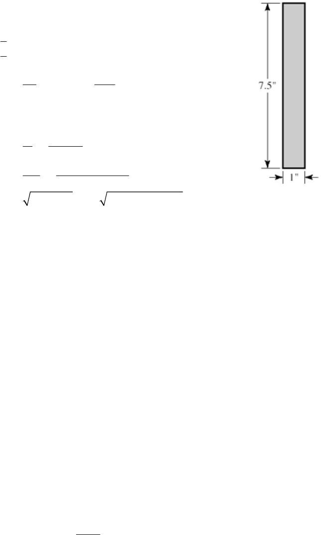
9-49 The largest possible weld size is 1/16 in. This is a small weld and thus difficult to
accomplish. The bracket’s load-carrying capability is not known. There are geometry
problems associated with sheet metal folding, load-placement and location of the center
of twist. This is not available to us. We will identify the strongest possible weldment.
Use a rectangular, weld-all-around pattern – Table 9-2, case 6:
2
22 3
4
1.414 ( ) 1.414(1 / 16)(1 7.5)
0.7512 in
/ 2 0.5 in
/ 2 7.5 / 2 3.75 in
7.5
(3 ) [3(1) 7.5] 98.44 in
66
0.707 0.707(1 / 16)(98.44) 4.350 in
(3.75 0.5) 4.25
1.331
0.7512
4
u
u
Ahbd
xb
yd
d
Ibd
IhI
MWW
VW W
A
Mc
I
22 2 2
max
.25 (7.5 / 2) 3.664
4.350
1.331 3.664 3.90
WW
WW
Materia
l properties: The allowable stress given is low. Let’s demonstrate that.
For the 1020 CD bracket, use HR properties of Sy = 30 kpsi and Sut = 55. The 1030 HR
support, Sy = 37.5 kpsi and Sut = 68. The E6010 electrode has strengths of Sy = 50 and
Sut = 62 kpsi.
Allowable stresses:
1020 HR:
all = min[0.3(55), 0.4(30)] = min(16.5, 12) = 12 kpsi
1020 HR:
all = min[0.3(68), 0.4(37.5)] = min(20.4, 15) = 15 kpsi
E6010:
all = min[0.3(62), 0.4(50)] = min(18.6, 20) = 18.6 kpsi
Since Table 9-6 gives 18.0 kpsi as the allowable shear stress, use this lower value.
Therefore, the allowable shear stress is
all = min(14.4, 12, 18.0) = 12 kpsi
However, the allowable stress in the problem statement is 1.5 kpsi which is low from the
weldment perspective. The load associated with this strength is
max all 3.90 1500
1500 385 lbf
3.90
W
W
Chapter 9, Page 29/36

If the welding can be accomplished (1/16 leg size is a small weld), the weld strength is
12 000 psi and the load associated with this strength is W = 12 000/3.90 = 3077 lbf. Can
the bracket carry such a load?
There are geometry problems associated with sheet metal folding. Load placement is
important and the center of twist has not been identified. Also, the load-carrying
capability of the top bend is unknown.
These uncertainties may require the use of a different weld pattern. Our solution provides
the best weldment and thus insight for comparing a welded joint to one which employs
screw fasteners.
______________________________________________________________________________
9-50
all
100 lbf, 3 kpsi
100(16 / 3) 533.3 lbf
533.3cos60 266.7 lbf
533.3cos30 462 lbf
B
x
B
y
B
F
F
F
F
It follows that and R
562 lbf
y
A
R266.7 lbf,
x
A
RA = 622 lbf
M = 100(16) = 1600 lbf · in
The OD of the tubes is 1 in. From Table 9-1, case 6:
2
33 3
4
2 1.414( ) 2(1.414)( )(1 / 2) 4.442 in
2 2 (1 / 2) 0.7854 in
2(0.707) 1.414(0.7854) 1.111 in
u
u
Ahr h
Jr
JhJ hh
h
Chapter 9, Page 30/36
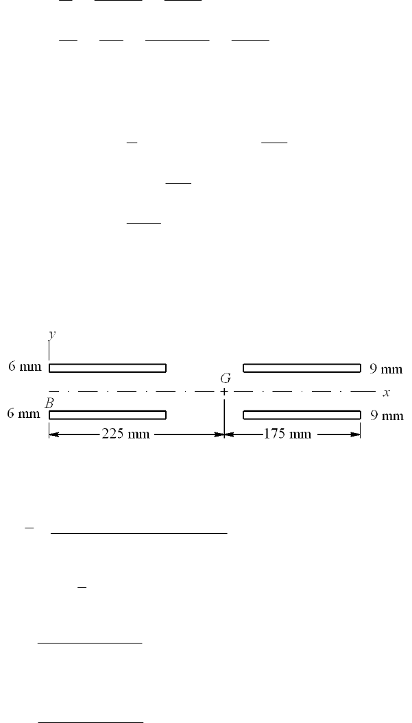
622 140.0
4.442 1600(0.5) 720.1
1.111
V
Ahh
Tc Mc
JJ h h
The shear stresses, and ,
are additive algebraically
max
max all
1 860
(140.0 720.1) psi
860 3000
860 0.287 5 / 16 in
3000
hh
h
h
Decision: Use 5/16 in fillet welds Ans.
______________________________________________________________________________
9-51
For the pattern in bending shown, find the centroid G of the weld group.
75 6 150 325 9 150 225 mm
6 150 9 150
x
2
6mm 6mm
3264
2
0.707 6 150
2 0.707 6 150 225 75 31.02 10 mm
12
G
IIAx
3264
9mm
0.707 9 150
2 0.707 9 150 175 75 22.67 10 mm
12
I
I = I 6 mm + I 9 mm = (31.02 + 22.67)(106) = 53.69(106) mm4
The critical location is at B. With
in MPa, and F in kN
Chapter 9, Page 31/36
3
10 0.3143
2 0.707 6 9 150
F
VF
A
3
6
200 10 225 0.8381
53.69 10
F
Mc F
I
22 2 2
max 0.3143 0.8381 0.8951FF
Materials:
1015 HR (Table A-20): Sy = 190 MPa, E6010 Electrode(Table 9-3): Sy = 345 MPa
Eq. (5-21), p. 225
all = 0.577(190) = 109.6 MPa
all /109.6 / 2 61.2 kN .
0.8951 0.8951
n
F
Ans
______________________________________________________________________________
9-52 In the textbook, Fig. Problem 9-52b is a free-body diagram of the bracket. Forces and
moments that act on the welds are equal, but of opposite sense.
(a) M = 1200(0.366) = 439 lbf · in Ans.
(b) Fy = 1200 sin 30 = 600 lbf Ans.
(c) Fx = 1200 cos 30 = 1039 lbf Ans.
(d) From Table 9-2, case 6:
2
22 3
1.414(0.25)(0.25 2.5) 0.972 in
2.5
(3 ) [3(0.25) 2.5] 3.39 in
66
u
A
d
Ibd
The second area moment about an axis through G and parallel to z is
4
0.707 0.707(0.25)(3.39) 0.599 in .
u
I
hI Ans
(e) Refer to Fig. Problem 9-52b. The shear stress due to Fy is
1
600 617 psi
0.972
y
F
A
The shear stress along the throat due to Fx is
2
1039 1069 psi
0.972
x
F
A
The resultant of
1 and
2 is in the throat plane
Chapter 9, Page 32/36
22 2 2
12 617 1069 1234 psi
The bending of the throat gives
439(1.25) 916 psi
0.599
Mc
I
The maximum shear stress is
22 2 2
max 1234 916 1537 psi .
A
ns
(f) Materials:
1018 HR Member: Sy = 32 kpsi, Sut = 58 kpsi (Table A-20)
E6010 Electrode: Sy = 50 kpsi (Table 9-3)
max max
0.577 0.577(32) 12.0 .
1.537
sy y
SS
nA
ns
(g) Bending in the attachment near the base. The cross-sectional area is approximately
equal to bh. 2
1
122
3
0.25(2.5) 0.625 in
1039 1662 psi
0.625
0.25(2.5) 0.260 in
66
x
xy
Abh
F
A
Ibd
c
At location A,
1/
600 439 2648 psi
0.625 0.260
y
y
y
FM
AIc
The von Mises stress
is
22 2 2
3 2648 3(1662) 3912 psi
yxy
Thus, the factor of safety is,
32 8.18 .
3.912
y
S
nA
ns
The clip on the mooring line bears against the side of the 1/2-in hole. If the clip fills
the hole
Chapter 9, Page 33/36
3
1200 9600 psi
0.25(0.50)
32(10 ) 3.33 .
9600
y
F
td
S
nA
ns
Further investigation of this situation requires more detail than is included in the task
statement.
(h) In shear fatigue, the weakest constituent of the weld melt is 1018 HR with Sut = 58
kpsi, Eq. (6-8), p. 282, gives
0.504 0.504(58) 29.2 kpsi
eut
SS
Eq. (6-19), p. 287: ka = 14.4(58)-0.718 = 0.780
For the size factor estimate, we first employ Eq. (6-25), p. 289, for the equivalent
diameter
0.808 0.707 0.808 0.707(2.5)(0.25) 0.537 in
e
dhb
Eq. (6-20), p. 288, is used next to find kb
-0.107 -0.107
0.537 0.940
0.30 0.30
e
b
d
k
Eq.(6-26), p. 290: kc = 0.59
From Eq. (6-18), p. 287, the endurance strength in shear is
Sse = 0.780(0.940)(0.59)(29.2) = 12.6 kpsi
From Table 9-5, the shear stress-concentration factor is Kf s = 2.7. The loading is
repeatedly-applied
max 1.537
2.7 2.07 kpsi
22
am fs
K
Table 6-7, p. 307: Gerber factor of safety nf, adjusted for shear, with Ssu = 0.67Sut
2
2
2
12
11
2
1 0.67(58) 2.07 2(2.07)(12.6)
1 1 5.55 .
2 2.07 12.6 0.67(58)(2.07)
su a m se
f
mse sua
SS
nSS
A
ns
Attachment metal should be checked for bending fatigue.
______________________________________________________________________________
9-53 (a) Use b = d = 4 in. Since h = 5/8 in, the primary shear is
Chapter 9, Page 34/36
0.2829
1.414(5 / 8)(4)
FF
The secondary shear calculations, for a moment arm of 14 in give
22 3
4
4[3(4) 4] 42.67 in
6
0.707 0.707(5 / 8)42.67 18.85 in
14 (2) 1.485
18.85
u
u
y
xy
J
JhJ
Mr FF
J
Thus, the maximum shear and allowable load are:
22
max
all
1.485 (0.2829 1.485) 2.309
25 10.8 kip .
2.309 2.309
F
F
FA
ns
The load for part (a) has increased by a factor of 10.8/2.71 = 3.99 Ans.
(
b) From Prob. 9-18b,
all = 11 kpsi
all
all
11 4.76 kip
2.309 2.309
F
The allowable load in part (b) has increased by a factor of 4.76/1.19 = 4 Ans.
______________________________________________________________________________
9-54 Purchase the hook having the design shown in Fig. Problem 9-54b. Referring to text Fig.
9-29a, this design reduces peel stresses.
______________________________________________________________________________
9-55 (a)
/2
/2 /2 1
1
/2 /2 /2
11
1
1 cosh( ) cosh( ) sinh( )
4 sinh( / 2)
[sinh( / 2) sinh( / 2)] [sinh( / 2) ( sinh( / 2))]
2 sinh( / 2) [2sinh( / 2)] .
4 sinh( / 2) 2
l
ll
ll l
Px A
dx A x dx x
lb l
AA
ll l
Al P P
lAn
bl l bl
l
s
(b) cosh( / 2)
(/2) .
4 sinh( / 2) 4 tanh( / 2)
Pl P
lA
bl bl ns
Chapter 9, Page 35/36

(c) (/2) 2 /2 .
4 tanh( / 2) tanh( / 2)
lPbll
K
Ans
bl P l
For computer programming, it can be useful to express the hyperbolic tangent in
terms of exponentials: exp( / 2) exp( / 2) .
2 exp( / 2) exp( / 2)
ll l
KA
ll
ns
______________________________________________________________________________
9-56 This is a computer programming exercise. All programs will vary.
Chapter 9, Page 36/36
Chapter 10
10-1 From Eqs. (10-4) and (10-5)
4 1 0.615 4 2
44 4
WB
CC
KK CCC3
Plot 100(KW KB)/ KW vs. C for 4 C 12 obtaining
We see the maximum and minimum occur at C = 4 and 12 respectively where
Maximum = 1.36 % Ans., and Minimum = 0.743 % Ans.
______________________________________________________________________________
10-2 A = Sdm
dim(Auscu) = [dim (S) dim(d m)]uscu = kpsiinm
dim(ASI) = [dim (S) dim(d m)]SI = MPammm
SI uscu uscu uscu
MPa mm 6.894 757 25.4 6.895 25.4 .
kpsi in
mmm
m
AA A AAns
For music wire, from Table 10-4:
Auscu = 201 kpsiinm, m = 0.145; what is ASI?
_____________________________________________________________________________
0-3 Given: Music wire, d = 2.5 mm, OD = 31 mm, plain ground ends, Nt = 14 coils.
ASI = 6.895(25.4)0.145 (201) = 2215 MPammm Ans.
_
1
Chapter 10 - Rev. A, Page 1/41
(a) Table 10-1: Na = N 1 = 14 1 = 13 coils
Ls = d Nt = 2.5(14) = 35 mm
Table 10-4: m = 0.145, A = 2211 MPammm
Eq. (10-14):
t
0.145
2211 1936 MPa
2.5
ut m
A
Sd
Table 10-6: Ssy = 0.45(1936) = 871.2 MPa
D = OD d = 31 2.5 = 28.5 mm
C = D/d = 28.5/2.5 = 11.4
Eq. (10-5):
4 11.4 2
42 1.117
4 3 4 11.4 3
B
C
KC
Eq. (10-7):
3
32.5 871.2 167.9 N
8 8 1.117 28.5
sy
s
B
dS
FKD
Table 10-5): d = 2.5/25.4 = 0.098 in G = 81.0(103) MPa
Eq. (10-9):
43
4
33
2.5 81 10 1.314 N / mm
88 28.5 13
a
dG
kDN
0
167.9 35 162.8 mm .
1.314
s
s
F
L
LA
k
ns
(b) Fs = 167.9 N Ans.
(c) k = 1.314 N/mm Ans.
(d)
0cr 149.9 mm
0.5
L. Spring needs to be supported. Ans.
2.63 28.5
_____________________________________________________________________________
0-4 Given: Design load, F1 = 130 N.
4, N = 13 coils, Ssy = 871.2 MPa, Fs = 167.9 N,
Eq. (10-19): 3 ≤ Na ≤ 15 Na = 13 O.K.
_
1
Referring to Prob. 10-3 solution, C = 11. a
L0 = 162.8 mm and (L0)cr = 149.9 mm.
Eq. (10-18): 4 ≤ C ≤ 12 C = 11.4 O.K.
Chapter 10 - Rev. A, Page 2/41
Eq. (10-17):
1
167.9
1 1 0.29
130
s
F
F
Eq. (10-20): 0.15, 0.29 . .OK
From Eq. (10-7) for static service
1
133
1
8 8(130)(28.5)
1.117 674 MPa
(2.5)
871.2 1.29
674
B
sy
FD
Kd
S
n
Eq. (10-21): ns ≥ 1.2, n = 1.29 O.K.
1
167.9 167.9
674 870.5 MPa
130 130
/ 871.2 / 870.5 1
s
sy s
S
S
sy/
s ≥ (ns )d : Not solid-safe (but was the basis of the design). Not O.K.
L
0 ≤ (L0)cr: 162.8 149.9 Not O.K.
Design is unsatisfactory. Operate over a rod? Ans.
______________________________________________________________________________
10-5 Given: Oil-tempered wire, d = 0.2 in, D = 2 in, Nt = 12 coils, L0 = 5 in, squared ends.
(a) Table 10-1: Ls = d (Nt + 1) = 0.2(12 + 1) = 2.6 in Ans.
(b) Table 10-1: Na = Nt 2 = 12 2 = 10 coils
Table 10-5: G = 11.2 Mpsi
Eq. (10-9):
46
4
33
0.2 11.2 10 28 lbf/in
882 10
dG
kDN
Fs = k ys = k (L0 Ls ) = 28(5 2.6) = 67.2 lbf Ans.
(c) Eq. (10-1): C = D/d = 2/0.2 = 10
Eq. (10-5):
410 2
42 1.135
434103
B
C
KC
Eq. (10-7):
3
33
8 67.2 2
81.135 48.56 10 psi
0.2
sB
FD
Kd
Chapter 10 - Rev. A, Page 3/41

Table 10-4: m = 0.187, A = 147 kpsiinm
Eq. (10-14): 0.187
147 198.6 kpsi
0.2
ut m
A
Sd
Table 10-6: Ssy = 0.50 Sut = 0.50(198.6) = 99.3 kpsi
99.3 2.04 .
48.56
sy
s
s
S
nA
ns
______________________________________________________________________________
10-6 Given: Oil-tempered wire, d = 4 mm, C = 10, plain ends, L0 = 80 mm, and at F = 50 N,
y = 15 mm.
(a) k = F/y = 50/15 = 3.333 N/mm Ans.
(b) D = Cd = 10(4) = 40 mm
OD = D + d = 40 + 4 = 44 mm Ans.
(c) From Table 10-5, G = 77.2 GPa
Eq. (10-9):
43
4
33
4 77.2 10 11.6 coils
8 8 3.333 40
a
dG
NkD
Table 10-1: Nt = Na = 11.6 coils Ans.
(d) Table 10-1: Ls = d (Nt + 1) = 4(11.6 + 1) = 50. 4 mm Ans.
(e) Table 10-4: m = 0.187, A = 1855 MPammm
Eq. (10-14): 0.187
1855 1431 MPa
4
ut m
A
Sd
Table 10-6: Ssy = 0.50 Sut = 0.50(1431) = 715.5 MPa
ys = L0 Ls = 80 50.4 = 29.6 mm
Fs = k ys = 3.333(29.6) = 98.66 N
Eq. (10-5): 4 2 4(10) 2 1.135
434(10)3
B
C
KC
Chapter 10 - Rev. A, Page 4/41
Eq. (10-7):
33
8 98.66 40
81.135 178.2 MPa
4
s
sB
FD
Kd
715.5 4.02 .
178.2
sy
s
s
S
nA
ns
______________________________________________________________________________
10-7 Static service spring with: HD steel wire, d = 0.080 in, OD = 0.880 in, Nt = 8 coils, plain
and ground ends.
Preliminaries
Table 10-5: A = 140 kpsi · inm, m = 0.190
Eq. (10-14): 0.190
140 226.2 kpsi
0.080
ut m
A
Sd
Table 10-6: Ssy = 0.45(226.2) = 101.8 kpsi
Then,
D = OD d = 0.880 0.080 = 0.8 in
Eq. (10-1): C = D/d = 0.8/0.08 = 10
Eq. (10-5): 424(10)2
1.135
434(10)3
B
C
KC
Table 10-1: Na = Nt 1 = 8 1 = 7 coils
Ls = dNt = 0.08(8) = 0.64 in
Eq. (10-7) For solid-safe, ns = 1.2 :
33
30.08 101.8 10 / 1.2
/18.78 lbf
8 8(1.135)(0.8)
sy s
s
B
dS n
FKD
Eq. (10-9):
46
4
33
0.08 11.5 10 16.43 lbf/in
88 0.8 7
a
dG
kDN
18.78 1.14 in
16.43
s
s
F
yk
(a) L0 = ys + Ls = 1.14 + 0.64 = 1.78 in Ans.
(b) Table 10-1: 01.78 0.223 in .
8
t
L
pA
N
ns
(c) From above: Fs = 18.78 lbf Ans.
(d) From above: k = 16.43 lbf/in Ans.
(e) Table 10-2 and Eq. (10-13): 0cr
2.63 2.63(0.8)
( ) 4.21 in
0.5
D
L
Since L0 < (L0)cr, buckling is unlikely Ans.
______________________________________________________________________________
10-8 Given: Design load, F1 = 16.5 lbf.
Referring to Prob. 10-7 solution, C = 10, Na = 7 coils, Ssy = 101.8 kpsi, Fs = 18.78 lbf,
y
s = 1.14 in, L0 = 1.78 in, and (L0)cr = 4.208 in.
Chapter 10 - Rev. A, Page 5/41
Eq. (10-18): 4 ≤ C ≤ 12 C = 10 O.K.
Eq. (10-19): 3 ≤ Na ≤ 15 Na = 7 O.K.
Eq. (10-17):
1
18.78
1 1 0.14
16.5
s
F
F
Eq. (10-20): 0.15, 0.14 . .not O K
, but probably acceptable.
From Eq. (10-7) for static service
3
1
133
1
8 8(16.5)(0.8)
1.135 74.5 10 psi 74.5 kpsi
(0.080)
101.8 1.37
74.5
B
sy
FD
Kd
S
n
Eq. (10-21): ns ≥ 1.2, n = 1.37 O.K.
1
18.78 18.78
74.5 84.8 kpsi
16.5 16.5
/ 101.8 / 84.8 1.20
s
ssys
nS
Eq. (10-21): ns ≥ 1.2, ns = 1.2 It is solid-safe (basis of design). O.K.
Eq. (10-13) and Table 10-2: L0 ≤ (L0)cr 1.78 in 4.208 in O.K.
______________________________________________________________________________
10-9 Given: A228 music wire, sq. and grd. ends, d = 0.007 in, OD = 0.038 in, L0 = 0.58 in,
Nt = 38 coils.
D = OD d = 0.038 0.007 = 0.031 in
Eq. (10-1): C = D/d = 0.031/0.007 = 4.429
Eq. (10-5):
4 4.429 2
42 1.340
4 3 4 4.429 3
B
C
KC
Table (10-1): Na = Nt 2 = 38 2 = 36 coils (high)
Table 10-5: G = 12.0 Mpsi
Eq. (10-9):
46
4
33
0.007 12.0 10 3.358 lbf/in
88 0.031 36
a
dG
kDN
Table (10-1): Ls = dNt = 0.007(38) = 0.266 in
ys = L0 Ls = 0.58 0.266 = 0.314 in
F
s = kys = 3.358(0.314) = 1.054 lbf
Eq. (10-7):
3
33
8 1.054 0.031
81.340 325.1 10 psi
0.007
s
sB
FD
Kd
(1)
Table 10-4: A = 201 kpsiinm, m = 0.145
Chapter 10 - Rev. A, Page 6/41

Eq. (10-14): 0.145
201 412.7 kpsi
0.007
ut m
A
Sd
Table 10-6: Ssy = 0.45 Sut = 0.45(412.7) = 185.7 kpsi
s > Ssy, that is, 325.1 > 185.7 kpsi, the spring is not solid-safe. Return to Eq. (1) with
F
s = kys and
s = Ssy /ns, and solve for ys, giving
33
3185.7 10 /1.2 0.007
/0.149 in
8 8 1.340 3.358 0.031
sy s
s
B
Sn d
yKkD
The free length should be wound to
L0 = Ls + ys = 0.266 + 0.149 = 0.415 in Ans.
This only addresses the solid-safe criteria. There are additional problems.
______________________________________________________________________________
10-10 Given: B159 phosphor-bronze, sq. and grd. ends, d = 0.014 in, OD = 0.128 in, L0 = 0.50
in, Nt = 16 coils.
D = OD d = 0.128 0.014 = 0.114 in
Eq. (10-1): C = D/d = 0.114/0.014 = 8.143
Eq. (10-5):
4 8.143 2
42 1.169
4 3 4 8.143 3
B
C
KC
Table (10-1): Na = Nt 2 = 16 2 = 14 coils
Table 10-5: G = 6 Mpsi
Eq. (10-9):
46
4
33
0.014 6 10 1.389 lbf/in
88 0.114 14
a
dG
kDN
Table (10-1): Ls = dNt = 0.014(16) = 0.224 in
ys = L0 Ls = 0.50 0.224 = 0.276 in
F
s = kys = 1.389(0.276) = 0.3834 lbf
Eq. (10-7):
3
33
8 0.3834 0.114
81.169 47.42 10 psi
0.014
s
sB
FD
Kd
(1)
Table 10-4: A = 145 kpsiinm, m = 0
Eq. (10-14): 0
145 145 kpsi
0.014
ut m
A
Sd
Table 10-6: Ssy = 0.35 Sut = 0.35(135) = 47.25 kpsi
s > Ssy, that is, 47.42 > 47.25 kpsi, the spring is not solid-safe. Return to Eq. (1) with
F
s = kys and
s = Ssy /ns, and solve for ys, giving
33
347.25 10 /1.2 0.014
/0.229 in
8 8 1.169 1.389 0.114
sy s
s
B
Sn d
yKkD
The free length should be wound to
Chapter 10 - Rev. A, Page 7/41

L0 = Ls + ys = 0.224 + 0.229 = 0.453 in Ans.
______________________________________________________________________________
10-11 Given: A313 stainless steel, sq. and grd. ends, d = 0.050 in, OD = 0.250 in, L0 = 0.68 in,
Nt = 11.2 coils.
D = OD d = 0.250 0.050 = 0.200 in
Eq. (10-1): C = D/d = 0.200/0.050 = 4
Eq. (10-5):
44 2
42 1.385
43443
B
C
KC
Table (10-1): Na = Nt 2 = 11.2 2 = 9.2 coils
Table 10-5: G = 10 Mpsi
Eq. (10-9):
46
4
33
0.050 10 10 106.1 lbf/in
88 0.2 9.2
a
dG
kDN
Table (10-1): Ls = dNt = 0.050(11.2) = 0.56 in
ys = L0 Ls = 0.68 0.56 = 0.12 in
F
s = kys = 106.1(0.12) = 12.73 lbf
Eq. (10-7):
3
33
8 12.73 0.2
81.385 71.8 10 psi
0.050
s
sB
FD
Kd
Table 10-4: A = 169 kpsiinm, m = 0.146
Eq. (10-14): 0.146
169 261.7 kpsi
0.050
ut m
A
Sd
Table 10-6: Ssy = 0.35 Sut = 0.35(261.7) = 91.6 kpsi
91.6 1.28
71.8
sy
s
s
S
n
Spring is solid-safe (ns > 1.2) Ans.
______________________________________________________________________________
10-12 Given: A227 hard-drawn wire, sq. and grd. ends, d = 0.148 in, OD = 2.12 in, L0 = 2.5 in,
Nt = 5.75 coils.
D = OD d = 2.12 0.148 = 1.972 in
Eq. (10-1): C = D/d = 1.972/0.148 = 13.32 (high)
Eq. (10-5):
4 13.32 2
42 1.099
4 3 4 13.32 3
B
C
KC
Table (10-1): Na = Nt 2 = 5.75 2 = 3.75 coils
Table 10-5: G = 11.4 Mpsi
Eq. (10-9):
46
4
33
0.148 11.4 10 23.77 lbf/in
88 1.972 3.75
a
dG
kDN
Table (10-1): Ls = dNt = 0.148(5.75) = 0.851 in
ys = L0 Ls = 2.5 0.851 = 1.649 in
Chapter 10 - Rev. A, Page 8/41
F
s = kys = 23.77(1.649) = 39.20 lbf
Eq. (10-7):
3
33
8 39.20 1.972
81.099 66.7 10 psi
0.148
s
sB
FD
Kd
Table 10-4: A = 140 kpsiinm, m = 0.190
Eq. (10-14): 0.190
140 201.3 kpsi
0.148
ut m
A
Sd
Table 10-6: Ssy = 0.35 Sut = 0.45(201.3) = 90.6 kpsi
90.6 1.36
66.7
sy
s
s
S
n
Spring is solid-safe (ns > 1.2) Ans.
______________________________________________________________________________
10-13 Given: A229 OQ&T steel, sq. and grd. ends, d = 0.138 in, OD = 0.92 in, L0 = 2.86 in,
Nt = 12 coils.
D = OD d = 0.92 0.138 = 0.782 in
Eq. (10-1): C = D/d = 0.782/0.138 = 5.667
Eq. (10-5):
4 5.667 2
42 1.254
4 3 4 5.667 3
B
C
KC
Table (10-1): Na = Nt 2 = 12 2 = 10 coils
A229 OQ&T steel is not given in Table 10-5. From Table A-5, for carbon steels,
G = 11.5 Mpsi.
Eq. (10-9):
46
4
33
0.138 11.5 10 109.0 lbf/in
88 0.782 10
a
dG
kDN
Table (10-1): Ls = dNt = 0.138(12) = 1.656 in
ys = L0 Ls = 2.86 1.656 = 1.204 in
F
s = kys = 109.0(1.204) = 131.2 lbf
Eq. (10-7):
3
33
8 131.2 0.782
81.254 124.7 10 psi
0.138
s
sB
FD
Kd
(1)
Table 10-4: A = 147 kpsiinm, m = 0.187
Eq. (10-14): 0.187
147 212.9 kpsi
0.138
ut m
A
Sd
Table 10-6: Ssy = 0.50 Sut = 0.50(212.9) = 106.5 kpsi
s > Ssy, that is, 124.7 > 106.5 kpsi, the spring is not solid-safe. Return to Eq. (1) with
F
s = kys and
s = Ssy /ns, and solve for ys, giving
33
3106.5 10 /1.2 0.138
/0.857 in
8 8 1.254 109.0 0.782
sy s
s
B
Sn d
yKkD
The free length should be wound to
Chapter 10 - Rev. A, Page 9/41
L0 = Ls + ys = 1.656 + 0.857 = 2.51 in Ans.
______________________________________________________________________________
10-14 Given: A232 chrome-vanadium steel, sq. and grd. ends, d = 0.185 in, OD = 2.75 in, L0 =
7.5 in, Nt = 8 coils.
D = OD d = 2.75 0.185 = 2.565 in
Eq. (10-1): C = D/d = 2.565/0.185 = 13.86 (high)
Eq. (10-5):
413.86 2
42 1.095
43413.863
B
C
KC
Table (10-1): Na = Nt 2 = 8 2 = 6 coils
Table 10-5: G = 11.2 Mpsi.
Eq. (10-9):
46
4
33
0.185 11.2 10 16.20 lbf/in
88 2.565 6
a
dG
kDN
Table (10-1): Ls = dNt = 0.185(8) = 1.48 in
ys = L0 Ls = 7.5 1.48 = 6.02 in
F
s = kys = 16.20(6.02) = 97.5 lbf
Eq. (10-7):
3
33
8 97.5 2.565
81.095 110.1 10 psi
0.185
s
sB
FD
Kd
(1)
Table 10-4: A = 169 kpsiinm, m = 0.168
Eq. (10-14): 0.168
169 224.4 kpsi
0.185
ut m
A
Sd
Table 10-6: Ssy = 0.50 Sut = 0.50(224.4) = 112.2 kpsi
112.2 1.02
110.1
sy
s
s
S
n
Spring is not solid-safe (ns < 1.2)
Return to Eq. (1) with Fs = kys and
s = Ssy /ns, and solve for ys, giving
33
3112.2 10 /1.2 0.185
/5.109 in
8 8 1.095 16.20 2.565
sy s
s
B
Sn d
yKkD
The free length should be wound to
L0 = Ls + ys = 1.48 + 5.109 = 6.59 in Ans.
______________________________________________________________________________
10-15 Given: A313 stainless steel, sq. and grd. ends, d = 0.25 mm, OD = 0.95 mm, L0 = 12.1
mm, Nt = 38 coils.
D = OD d = 0.95 0.25 = 0.7 mm
Eq. (10-1): C = D/d = 0.7/0.25 = 2.8 (low)
Eq. (10-5):
42.8 2
42 1.610
4342.83
B
C
KC
Chapter 10 - Rev. A, Page 10/41
Table (10-1): Na = Nt 2 = 38 2 = 36 coils (high)
Table 10-5: G = 69.0(103) MPa.
Eq. (10-9):
43
4
33
0.25 69.0 10 2.728 N/mm
880.7 36
a
dG
kDN
Table (10-1): Ls = dNt = 0.25(38) = 9.5 mm
ys = L0 Ls = 12.1 9.5 = 2.6 mm
F
s = kys = 2.728(2.6) = 7.093 N
Eq. (10-7):
33
8 7.093 0.7
81.610 1303 MPa
0.25
s
sB
FD
Kd
(1)
Table 10-4 (dia. less than table): A = 1867 MPammm, m = 0.146
Eq. (10-14): 0.146
1867 2286 MPa
0.25
ut m
A
Sd
Table 10-6: Ssy = 0.35 Sut = 0.35(2286) = 734 MPa
s > Ssy, that is, 1303 > 734 MPa, the spring is not solid-safe. Return to Eq. (1) with
F
s = kys and
s = Ssy /ns, and solve for ys, giving
3
3734 /1.2 0.25
/1.22 mm
8 8 1.610 2.728 0.7
sy s
s
B
Sn d
yKkD
The free length should be wound to
L0 = Ls + ys = 9.5 + 1.22 = 10.72 mm Ans.
This only addresses the solid-safe criteria. There are additional problems.
______________________________________________________________________________
10-16 Given: A228 music wire, sq. and grd. ends, d = 1.2 mm, OD = 6.5 mm, L0 = 15.7 mm,
Nt = 10.2 coils.
D = OD d = 6.5 1.2 = 5.3 mm
Eq. (10-1): C = D/d = 5.3/1.2 = 4.417
Eq. (10-5):
4 4.417 2
42 1.368
4 3 4 4.417 3
B
C
KC
Table (10-1): Na = Nt 2 = 10.2 2 = 8.2 coils
Table 10-5 (d = 1.2/25.4 = 0.0472 in): G = 81.7(103) MPa.
Eq. (10-9):
43
4
33
1.2 81.7 10 17.35 N/mm
885.3 8.2
a
dG
kDN
Table (10-1): Ls = dNt = 1.2(10.2) = 12.24 mm
ys = L0 Ls = 15.7 12.24 = 3.46 mm
F
s = kys = 17.35(3.46) = 60.03 N
Chapter 10 - Rev. A, Page 11/41
Eq. (10-7):
33
8 60.03 5.3
81.368 641.4 MPa
1.2
s
sB
FD
Kd
(1)
Table 10-4: A = 2211 MPammm, m = 0.145
Eq. (10-14): 0.145
2211 2153 MPa
1.2
ut m
A
Sd
Table 10-6: Ssy = 0.45 Sut = 0.45(2153) = 969 MPa
969 1.51
641.4
sy
s
s
S
n
Spring is solid-safe (ns > 1.2) Ans.
______________________________________________________________________________
10-17 Given: A229 OQ&T steel, sq. and grd. ends, d = 3.5 mm, OD = 50.6 mm, L0 = 75.5 mm,
Nt = 5.5 coils.
D = OD d = 50.6 3.5 = 47.1 mm
Eq. (10-1): C = D/d = 47.1/3.5 = 13.46 (high)
Eq. (10-5):
413.46 2
42 1.098
43413.463
B
C
KC
Table (10-1): Na = Nt 2 = 5.5 2 = 3.5 coils
A229 OQ&T steel is not given in Table 10-5. From Table A-5, for carbon steels,
G = 79.3(103) MPa.
Eq. (10-9):
43
4
33
3.5 79.3 10 4.067 N/mm
88 47.1 3.5
a
dG
kDN
Table (10-1): Ls = dNt = 3.5(5.5) = 19.25 mm
ys = L0 Ls = 75.5 19.25 = 56.25 mm
F
s = kys = 4.067(56.25) = 228.8 N
Eq. (10-7):
33
8 228.8 47.1
81.098 702.8 MPa
3.5
s
sB
FD
Kd
(1)
Table 10-4: A = 1855 MPammm, m = 0.187
Eq. (10-14): 0.187
1855 1468 MPa
3.5
ut m
A
Sd
Table 10-6: Ssy = 0.50 Sut = 0.50(1468) = 734 MPa
734 1.04
702.8
sy
s
s
S
n
Spring is not solid-safe (ns < 1.2)
Return to Eq. (1) with Fs = kys and
s = Ssy /ns, and solve for ys, giving
3
3734 /1.2 3.5
/48.96 mm
8 8 1.098 4.067 47.1
sy s
s
B
Sn d
yKkD
The free length should be wound to
Chapter 10 - Rev. A, Page 12/41

L0 = Ls + ys = 19.25 + 48.96 = 68.2 mm Ans.
______________________________________________________________________________
10-18 Given: B159 phosphor-bronze, sq. and grd. ends, d = 3.8 mm, OD = 31.4 mm, L0 = 71.4
mm, Nt = 12.8 coils.
D = OD d = 31.4 3.8 = 27.6 mm
Eq. (10-1): C = D/d = 27.6/3.8 = 7.263
Eq. (10-5):
4 7.263 2
42 1.192
4 3 4 7.263 3
B
C
KC
Table (10-1): Na = Nt 2 = 12.8 2 = 10.8 coils
Table 10-5: G = 41.4(103) MPa.
Eq. (10-9):
43
4
33
3.8 41.4 10 4.752 N/mm
88 27.6 10.8
a
dG
kDN
Table (10-1): Ls = dNt = 3.8(12.8) = 48.64 mm
ys = L0 Ls = 71.4 48.64 = 22.76 mm
F
s = kys = 4.752(22.76) = 108.2 N
Eq. (10-7):
33
8 108.2 27.6
81.192 165.2 MPa
3.8
s
sB
FD
Kd
(1)
Table 10-4 (d = 3.8/25.4 = 0.150 in): A = 932 MPammm, m = 0.064
Eq. (10-14): 0.064
932 855.7 MPa
3.8
ut m
A
Sd
Table 10-6: Ssy = 0.35 Sut = 0.35(855.7) = 299.5 MPa
299.5 1.81
165.2
sy
s
s
S
n
Spring is solid-safe (ns > 1.2) Ans.
______________________________________________________________________________
10-19 Given: A232 chrome-vanadium steel, sq. and grd. ends, d = 4.5 mm, OD = 69.2 mm,
L0 = 215.6 mm, Nt = 8.2 coils.
D = OD d = 69.2 4.5 = 64.7 mm
Eq. (10-1): C = D/d = 64.7/4.5 = 14.38 (high)
Eq. (10-5):
414.38 2
42 1.092
43414.383
B
C
KC
Table (10-1): Na = Nt 2 = 8.2 2 = 6.2 coils
Table 10-5: G = 77.2(103) MPa.
Eq. (10-9):
43
4
33
4.5 77.2 10 2.357 N/mm
88 64.7 6.2
a
dG
kDN
Table (10-1): Ls = dNt = 4.5(8.2) = 36.9 mm
Chapter 10 - Rev. A, Page 13/41

ys = L0 Ls = 215.6 36.9 = 178.7 mm
F
s = kys = 2.357(178.7) = 421.2 N
Eq. (10-7):
33
8 421.2 64.7
81.092 832 MPa
4.5
s
sB
FD
Kd
(1)
Table 10-4: A = 2005 MPammm, m = 0.168
Eq. (10-14): 0.168
2005 1557 MPa
4.5
ut m
A
Sd
Table 10-6: Ssy = 0.50 Sut = 0.50(1557) = 779 MPa
s > Ssy, that is, 832 > 779 MPa, the spring is not solid-safe. Return to Eq. (1) with
F
s = kys and
s = Ssy /ns, and solve for ys, giving
3
3779 /1.2 4.5
/139.5 mm
8 8 1.092 2.357 64.7
sy s
s
B
Sn d
yKkD
The free length should be wound to
L0 = Ls + ys = 36.9 + 139.5 = 176.4 mm Ans.
This only addresses the solid-safe criteria. There are additional problems.
______________________________________________________________________________
10-20 Given: A227 HD steel.
From the figure: L0 = 4.75 in, OD = 2 in, and d = 0.135 in. Thus
D = OD d = 2 0.135 = 1.865 in
(a) By counting, Nt = 12.5 coils. Since the ends are squared along 1/4 turn on each end,
12.5 0.5 12 turns .
4.75 / 12 0.396 in .
a
NAns
p
Ans
The solid stack is 13 wire diameters
Ls = 13(0.135) = 1.755 in Ans.
(b) From Table 10-5, G = 11.4 Mpsi
46
4
33
0.135 (11.4) 10 6.08 lbf/in .
88 1.865 (12)
a
dG
kA
DN
ns
(c) Fs = k(L0 - Ls ) = 6.08(4.75 1.755)(10-3) = 18.2 lbf Ans.
(d) C = D/d = 1.865/0.135 = 13.81
Chapter 10 - Rev. A, Page 14/41
3
33
4(13.81) 2 1.096
4(13.81) 3
8 8(18.2)(1.865)
1.096 38.5 10 psi 38.5 kpsi .
0.135
B
s
sB
K
FD
KA
d
ns
______________________________________________________________________________
10-21 For the wire diameter analyzed, G = 11.75 Mpsi per Table 10-5. Use squared and ground
ends. The following is a spread-sheet study using Fig. 10-3 for parts (a) and (b). For Na,
k = Fmax /y = 20/2 = 10 lbf/in. For
s, F = Fs = 20(1 +
) = 20(1 + 0.15) = 23 lbf.
(a) Spring over a Rod (b) Spring in a Hole
Source Parameter Values Source Parameter Values
d 0.075 0.080 0.085 d 0.075 0.080 0.085
ID 0.800 0.800 0.800 OD 0.950 0.950 0.950
D 0.875 0.880 0.885 D 0.875 0.870 0.865
Eq. (10-1) C 11.667 11.000 10.412 Eq. (10-1) C 11.667 10.875 10.176
Eq. (10-9) Na 6.937 8.828 11.061 Eq. (10-9) Na 6.937 9.136 11.846
Table 10-1 Nt 8.937 10.828 13.061 Table 10-1 Nt 8.937 11.136 13.846
Table 10-1 Ls 0.670 0.866 1.110 Table 10-1 Ls 0.670 0.891 1.177
1.15y + Ls L0 2.970 3.166 3.410 1.15y + Ls L0 2.970 3.191 3.477
Eq. (10-13) (L0)cr 4.603 4.629 4.655 Eq. (10-
13)
(L0)cr 4.603 4.576 4.550
Table 10-4 A 201.000 201.000 201.000 Table 10-4 A 201.000 201.000 201.000
Table 10-4 m 0.145 0.145 0.145 Table 10-4 m 0.145 0.145 0.145
Eq. (10-14) Sut 292.626 289.900 287.363 Eq. (10-
14)
Sut 292.626 289.900 287.363
Table 10-6 Ssy 131.681 130.455 129.313 Table 10-6 Ssy 131.681 130.455 129.313
Eq. (10-5) KB 1.115 1.122 1.129 Eq. (10-5) KB 1.115 1.123 1.133
Eq. (10-7)
s 135.335 112.948 95.293 Eq. (10-7)
s 135.335 111.787 93.434
Eq. (10-3) ns 0.973 1.155 1.357 Eq. (10-3) ns 0.973 1.167 1.384
Eq. (10-22) fom 0.282 0.391 0.536 Eq. (10-
22)
fom 0.282 0.398 0.555
For ns ≥ 1.2, the optimal size is d = 0.085 in for both cases.
______________________________________________________________________________
10-22 In Prob. 10-21, there is an advantage of first selecting d as one can select from the
available sizes (Table A-28). Selecting C first, requires a calculation of d where then a
size must be selected from Table A-28.
Consider part (a) of the problem. It is required that
ID = D d = 0.800 in. (1)
From Eq. (10-1), D = Cd. Substituting this into the first equation yields
0.800
1
dC
(2)
Chapter 10 - Rev. A, Page 15/41

Starting with C = 10, from Eq. (2) we find that d = 0.089 in. From Table A-28, the closest
diameter is d = 0.090 in. Substituting this back into Eq. (1) gives D = 0.890 in, with C =
0.890/0.090 = 9.889, which are acceptable. From this point the solution is the same as
Prob. 10-21. For part (b), use
OD = D + d = 0.950 in. (3)
and, 0.800
1C
(4)
d
(a) Spring over a rod (b) Spring in a Hole
Source Parameter Values Source Parameter Values
C 10.000 10.5 C 10.000
Eq. (2) d 0.089 0.084 Eq. (4) d 0.086
Table A-28 d 0.090 0.085 Table A-28 d 0.085
Eq. (1) D 0.890 0.885 Eq. (3) D 0.865
Eq. (10-1) C 9.889 10.412 Eq. (10-1) C 10.176
Eq. (10-9) Na 13.669 11.061 Eq. (10-9) Na 11.846
Table 10-1 Nt 15.669 13.061 Table 10-1 Nt 13.846
Table 10-1 Ls 1.410 1.110 Table 10-1 Ls 1.177
1.15y + Ls L0 3.710 3.410 1.15y + Ls L0 3.477
Eq. (10-13) (L0)cr 4.681 4.655 Eq. (10-13) (L0)cr 4.550
Table 10-4 A 201.000 201.000 Table 10-4 A 201.000
Table 10-4 m 0.145 0.145 Table 10-4 m 0.145
Eq. (10-14) Sut 284.991 287.363 Eq. (10-14) Sut 287.363
Table 10-6 Ssy 128.246 129.313 Table 10-6 Ssy 129.313
Eq. (10-5) KB 1.135 1.128 Eq. (10-5) KB 1.135
Eq. (10-7)
s 81.167 95.223 Eq. (10-7)
s 93.643
ns = Ssy/
s ns 1.580 1.358
ns = Ssy/
s ns 1.381
Eq. (10-22) fom -0.725 -0.536 Eq. (10-22) fom -0.555
Again, for ns 1.2, the optimal size is = 0.085 in.
Although this approach used less iterations than in Prob. 10-21, this was due to the initial
values picked and not the approach.
______________________________________________________________________________
10-23 One approach is to select A227 HD steel for its low cost. Try L0 = 48 mm, then for
y = 48 37.5 = 10.5 mm when F = 45 N. The spring rate is k = F/y = 45/10.5 = 4.286
N/mm.
For a clearance of 1.25 mm with screw, ID = 10 + 1.25 = 11.25 mm. Starting with
d = 2 mm,
D = ID + d = 11.25 + 2 = 13.25 mm
C = D/d = 13.25/2 = 6.625 (acceptable)
Table 10-5 (d = 2/25.4 = 0.0787 in): G = 79.3 GPa
Chapter 10 - Rev. A, Page 16/41
Eq. (10-9):
44 3
33
2 (79.3)10 15.9 coils
8 8(4.286)13.25
a
dG
kD
N
Assume squared and closed.
Table 10-1: Nt = Na + 2 = 15.9 + 2 = 17.9 coils
Ls = dNt = 2(17.9) =35.8 mm
ys = L0 Ls = 48 35.8 = 12.2 mm
Fs = kys = 4.286(12.2) = 52.29 N
Eq. (10-5):
4 6.625 2
42 1.213
B
C
K
43 4 6.625 3C
Eq. (10-7):
3
8 8(52.29
1.213
s
sB
FD
K
3
)13.25 267.5 MPa
2
d
Table 10-4: A = 1783 MPa · mmm, m = 0.190
Eq. (10-14): 0.190
1783 1563 MPa
2
ut m
A
Sd
Table 10-6: Ssy = 0.45Sut = 0.45(1563) = 703.3 MPa
703.3 2.63 1.2 . .
267.5
sy
s
s
S
nOK
No other diameters in the given range work. So specify
A227-47 HD steel, d = 2 mm, D = 13.25 mm, ID = 11.25 mm, OD = 15.25 mm, squared
and closed, Nt = 17.9 coils, Na = 15.9 coils, k = 4.286 N/mm, Ls = 35.8 mm, and L0 = 48
mm. Ans.
______________________________________________________________________________
10-24 Select A227 HD steel for its low cost. Try L0 = 48 mm, then for y = 48 37.5 = 10.5 mm
when F = 45 N. The spring rate is k = F/y = 45/10.5 = 4.286 N/mm.
For a clearance of 1.25 mm with screw, ID = 10 + 1.25 = 11.25 mm.
D d = 11.25 (1)
and, D =Cd (2)
Starting with C = 8, gives D = 8d. Substitute into Eq. (1) resulting in d = 1.607 mm.
Selecting the nearest diameter in the given range, d = 1.6 mm. From this point, the
calculations are shown in the third column of the spreadsheet output shown. We see that
for d = 1.6 mm, the spring is not solid safe. Iterating on C we find that C = 6.5 provides
acceptable results with the specifications
A227-47 HD steel, d = 2 mm, D = 13.25 mm, ID = 11.25 mm, OD = 15.25 mm, squared
Chapter 10 - Rev. A, Page 17/41
and closed, Nt = 17.9 coils, Na = 15.9 coils, k = 4.286 N/mm, Ls = 35.8 mm, and L0 = 48
mm. Ans.
Chapter 10 - Rev. A, Page 18/41

Source Parameter Values
C 8.000 7 6.500
Eq. (2) d 1.607 1.875 2.045
Table A-28 d 1.600 1.800 2.000
Eq. (1) D 12.850 13.050 13.250
Eq. (10-1) C 8.031 7.250 6.625
Eq. (10-9) Na 7.206 10.924 15.908
Table 10-1 Nt 9.206 12.924 17.908
Table 10-1 Ls 14.730 23.264 35.815
L0 Ls ys 33.270 24.736 12.185
Fs = kys F
s 142.594 106.020 52.224
Table 10-4 A 1783.000 1783.000 1783.000
Table 10-4 m 0.190 0.190 0.190
Eq. (10-14) Sut 1630.679 1594.592 1562.988
Table 10-6 Ssy 733.806 717.566 703.345
Eq. (10-5) KB 1.172 1.200 1.217
Eq. (10-7)
s 1335.568 724.943 268.145
ns = Ssy/
s ns 0.549 0.990 2.623
The only difference between selecting C first rather than d as was done in Prob. 10-23, is
that once d is calculated, the closest wire size must be selected. Iterating on d uses
available wire sizes from the beginning.
______________________________________________________________________________
10-25 A stock spring catalog may have over two hundred pages of compression springs with up
to 80 springs per page listed.
• Students should be made aware that such catalogs exist.
• Many springs are selected from catalogs rather than designed.
• The wire size you want may not be listed.
• Catalogs may also be available on disk or the web through search routines. For
example, disks are available from Century Spring at
1 - (800) - 237 - 5225
www.centuryspring.com
• It is better to familiarize yourself with vendor resources rather than invent them
yourself.
• Sample catalog pages can be given to students for study.
______________________________________________________________________________
10-26 Given: ID = 0.6 in, C = 10, L0 = 5 in, Ls = 5 3 = 2 in, sq. & grd ends, unpeened, HD
A227 wire.
(a) With ID = D d = 0.6 in and C = D/d = 10 10 d d = 0.6 d = 0.0667 in Ans.,
and D = 0.667 in.
(b) Table 10-1: Ls = dNt = 2 in Nt = 2/0.0667 30 coils Ans.
Chapter 10 - Rev. A, Page 19/41
(c) Table 10-1: Na = Nt 2 = 30 2 = 28 coils
Table 10-5: G = 11.5 Mpsi
Eq. (10-9):
46
4
33
0.0667 11.5 10 3.424 lbf/in .
88 0.667 28
a
dG
k Ans
DN
(d) Table 10-4: A = 140 kpsiinm, m = 0.190
Eq. (10-14): 0.190 234.2 kpsi
0.0667
ut m
Sd
140A
Table 10-6: Ssy = 0.45 Sut = 0.45 (234.2) = 105.4 kpsi
Fs = kys = 3.424(3) = 10.27 lbf
410 2
42 1.135
434103
B
C
KC
Eq. (10-5):
Eq. (10-7):
3
66.72 10 psi 66.72 kpsi
K
33
8 10.27 0.667
81.135 0.0667
s
sB
FD
d
105.4 1.58 .
66.72
sy
s
nA
s
Sns
(e)
a =
m = 0.5
s = 0.5(66.72) = 33.36 kpsi, r =
a /
m = 1. Using the Gerber fatigue
failure criterion with Zimmerli data,
Eq. (10-30): Ssu = 0.67 Sut = 0.67(234.2) = 156.9 kpsi
The Gerber ordinate intercept for the Zimmerli data is
22
35 39.9 kpsi
1 / 1 55 /156.9
sa
e
sm su
S
S
SS
Table 6-7, p. 307,
2
22 2
11
2
i
su se
sa
se su
rS S
SSrS
2
22
1 156.9 2 39.9
1 1 37.61 kps
2 39.9 1 156.9
37.61 1.13 .
33.36
sa
f
a
S
n Ans
______________________________________________________________________________
10-27 Given: OD 0.9 in, C = 8, L0 = 3 in, Ls = 1 in, ys = 3 1 = 2 in, sq. ends, unpeened,
music wire.
(a) Try OD = D + d = 0.9 in, C = D/d = 8 D = 8d 9d = 0.9 d = 0.1 Ans.
Chapter 10 - Rev. A, Page 20/41
D = 8(0.1) = 0.8 in
(b) Table 10-1: Ls = d (Nt + 1) Nt = Ls / d 1 = 1/0.1 1 = 9 coils Ans.
Table 10-1: Na = Nt 2 = 9 2 = 7 coils
(c) Table 10-5: G = 11.75 Mpsi
Eq. (10-9):
46
4
33
0.1 11.75 10 40.98 lbf/in .
880.8 7
a
dG
kAns
DN
(d) Fs = kys = 40.98(2) = 81.96 lbf
Eq. (10-5): 48 2
42 1.172
43483
B
C
KC
Eq. (10-7):
3
33
8 81.96 0.8
81.172 195.7 10 psi 195.7 kpsi
0.1
s
sB
FD
Kd
Table 10-4: A = 201 kpsiinm, m = 0.145
Eq. (10-14): 0.145
201 280.7 kpsi
0.1
ut m
A
d
S
Table 10-6: Ssy = 0.45 Sut = 0.45(280.7) = 126.3 kpsi
126.3 0.645 .
sy
s
S
nA
195.7
s
ns
(e)
a =
m =
s /2 = 195.7/2 = 97.85 kpsi. Using the Gerber fatigue failure criterion with
Zimmerli data,
Eq. (10-30): Ssu = 0.67 Sut = 0.67(280.7) = 188.1 kpsi
The Gerber ordinate intercept for the Zimmerli data is
22
/ 1 55 / 188.1
sm su
SS
35 36.83 kpsi
1
sa
e
S
S
Table 6-7, p. 307,
2
22
2
22
2
11
2
1 188.1 2 38.3
1 1 36.83 kpsi
2 38.3 1 188.1
su se
sa
se su
rS S
SSrS
Chapter 10 - Rev. A, Page 21/41
36.83 0.376
97.85
sa
a
.
f
S
n Ans
Obviously, the spring is severely under designed and will fail statically and in fatigue.
Increasing C would improve matters. Try C = 12. This yields ns = 1.83 and nf = 1.00.
______________________________________________________________________________
10-28 Note to the Instructor: In the first printing of the text, the wire material was incorrectly
identified as music wire instead of oil-tempered wire. This will be corrected in
subsequent printings. We are sorry for any inconvenience.
Given: Fmax = 300 lbf, Fmin = 150 lbf, y = 1 in, OD = 2.1 0.2 = 1.9 in, C = 7,
unpeened, sq. & grd., oil-tempered wire.
(a) D = OD d = 1.9 d (1)
C = D/d = 7 D = 7d (2)
Substitute Eq. (2) into (1)
7d = 1.9 d d = 1.9/8 = 0.2375 in Ans.
(b) From Eq. (2): D = 7d = 7(0.2375) = 1.663 in Ans.
300 150 150 lbf/in .
1
F
kA
y
(c) ns
(d) Table 10-5: G = 11.6 Mpsi
Eq. (10-9):
46
4
33
0.2375 11.6 10 6.69 coils
88 1.663 150
a
dG
NDk
Table 10-1: Nt = Na + 2 = 8.69 coils Ans.
(e) Table 10-4: A = 147 kpsiinm, m = 0.187
Eq. (10-14): 0.187
147 192.3 kpsi
0.2375
ut m
A
d
S
Table 10-6: Ssy = 0.5 Sut = 0.5(192.3) = 96.15 kpsi
Eq. (10-5): 47 2
42 1.2
43473
B
C
KC
Chapter 10 - Rev. A, Page 22/41
Eq. (10-7): 3
8s
s
Bsy
FD
K
S
d
33
30.2375 96.15 10 253.5 lbf
sy
s
dS
F
88 1.2 1.663
B
KD
ys = Fs / k = 253.5/150 = 1.69 in
Table 10-1: Ls = Nt d = 8.46(0.2375) = 2.01 in
L0 = Ls + ys = 2.01 + 1.69 = 3.70 in Ans.
______________________________________________________________________________
10-29 For a coil radius given by:
21
1
-
2
R
R
RR N
The torsion of a section is T = PR where dL = R d
23
0
3
221
1
0
2
4
21
1
21 0
44 22
21 121 2
21
422
121 2
4
11
2
12
42
()
2( ) 2
16
( )
32
N
P
N
N
p
UT
TdL PRd
PGJ P GJ
PRR
Rd
GJ N
PNRR
R
GJ R R N
PN PN
R
RRRRR
GJ R R GJ
PN
Jd RRRR
Gd
4
22
121 2
.
16 ( )
P
PdG
kAns
NR R R R
______________________________________________________________________________
10-30 Given: Fmin = 4 lbf, Fmax = 18 lbf, k = 9.5 lbf/in, OD 2.5 in, nf = 1.5.
For a food service machinery application select A313 Stainless wire.
Table 10-5: G = 10(106) psi
Note that for 0.013 ≤ d ≤ 0.10 in A = 169, m = 0.146
0.10 < d ≤ 0.20 in A = 128, m = 0.263
18 4 18 4
7 lbf , 11 lbf , 7 / 11
22
am
r
FF
Chapter 10 - Rev. A, Page 23/41
Try, 0.146
169
0.080 in, 244.4 kpsi
(0.08)
ut
dS
S
su = 0.67Sut = 163.7 kpsi, Ssy = 0.35Sut = 85.5 kpsi
Try unpeened using Zimmerli’s endurance data: Ssa = 35 kpsi, Ssm = 55 kpsi
Gerber: 22
35 39.5 kpsi
1 ( / ) 1 (55 / 163.7)
sa
se
sm su
S
SS
S
2
22
33
22
(7 / 11) (163.7) 2(39.5)
1 1 35.0 kpsi
2(39.5) (7 / 11)(163.7)
/ 35.0 / 1.5 23.3 kpsi
88(7)
(10 ) (10 ) 2.785 kpsi
(0.08 )
2(23.3) 2.785 2(23.3) 2.785
4(2.785) 4(2.785)
sa
sa f
a
S
Sn
F
d
C
2
3
33
46
3
3(23.3) 6.97
4(2.785)
6.97(0.08) 0.558 in
424(6.97)2
1.201
4 3 4(6.97) 3
8 8(7)(0.558)
1.201 (10 ) 23.3 kpsi
(0.08 )
35 / 23.3 1.50 checks
10(10 )(0.0
8
B
a
aB
f
a
DCd
C
KC
FD
Kd
n
Gd
NkD
4
3
max max
max
0
0
8) 31.02 coils
8(9.5)(0.558)
31.02 2 33 coils, 0.08(33) 2.64 in
/ 18 / 9.5 1.895 in
(1 ) (1 0.15)(1.895) 2.179 in
2.64 2.179 4.819 in
2.63(0.558)
( ) 2.63 2.935 in
0.5
tst
s
cr
s
NLdN
yFk
yy
L
D
L
22 2 2
1.15(18 / 7) 1.15(18 / 7)(23.3) 68.9 kpsi
/ 85.5 / 68.9 1.24
9.5(386) 109 Hz
(0.08 )(0.558)(31.02)(0.283)
a
ssys
a
kg
fdD
N
nS
These steps are easily implemented on a spreadsheet, as shown below, for different
diameters.
Chapter 10 - Rev. A, Page 24/41
d1 d2 d3 d4
d 0.080 0.0915 0.1055 0.1205
m 0.146 0.146 0.263 0.263
A 169.000 169.000 128 128
Sut 244.363 239.618 231.257 223.311
Ssu 163.723 160.544 154.942 149.618
Ssy 85.527 83.866 80.940 78.159
Sse 39.452 39.654 40.046 40.469
Ssa 35.000 35.000 35.000 35.000
23.333 23.333 23.333 23.333
2.785 2.129 1.602 1.228
C 6.977 9.603 13.244 17.702
D 0.558 0.879 1.397 2.133
KB 1.201 1.141 1.100 1.074
a 23.333 23.333 23.333 23.333
nf 1.500 1.500 1.500 1.500
Na 30.993 13.594 5.975 2.858
Nt 32.993 15.594 7.975 4.858
LS 2.639 1.427 0.841 0.585
ys 2.179 2.179 2.179 2.179
L0 4.818 3.606 3.020 2.764
(L0)cr 2.936 4.622 7.350 11.220
s 69.000 69.000 69.000 69.000
ns 1.240 1.215 1.173 1.133
f
,(Hz) 108.895 114.578 118.863 121.775
The shaded areas depict conditions outside the recommended design conditions. Thus,
one spring is satisfactory. The specifications are: A313 stainless wire, unpeened, squared
and ground, d = 0.0915 in, OD = 0.879 + 0.092 = 0.971 in, L0 = 3.606 in, and Nt = 15.59
turns Ans.
______________________________________________________________________________
10-31 The steps are the same as in Prob. 10-23 except that the Gerber-Zimmerli criterion is
replaced with Goodman-Zimmerli:
1
sa
se
s
msu
S
SSS
Chapter 10 - Rev. A, Page 25/41

The problem then proceeds as in Prob. 10-23. The results for the wire sizes are shown
below (see solution to Prob. 10-23 for additional details).
Iteration of d for the first trial
d1 d2 d3 d4 d1 d2 d3 d4
d 0.080 0.0915 0.1055 0.1205 d 0.080 0.0915 0.1055 0.1205
m 0.146 0.146 0.263 0.263 KB 1.151 1.108 1.078 1.058
A 169.000 169.000 128.000 128.000
a 29.008 29.040 29.090 29.127
Sut 244.363 239.618 231.257 223.311 nf 1.500 1.500 1.500 1.500
Ssu 163.723 160.544 154.942 149.618 Na 14.191 6.456 2.899 1.404
Ssy 85.527 83.866 80.940 78.159 Nt 16.191 8.456 4.899 3.404
Sse 52.706 53.239 54.261 55.345 Ls 1.295 0.774 0.517 0.410
Ssa 43.513 43.560 43.634 43.691 ymax 2.875 2.875 2.875 2.875
29.008 29.040 29.090 29.127 L0 4.170 3.649 3.392 3.285
2.785 2.129 1.602 1.228 (L0)cr 3.809 5.924 9.354 14.219
C 9.052 12.309 16.856 22.433
s 85.782 85.876 86.022 86.133
D 0.724 1.126 1.778 2.703 ns 0.997 0.977 0.941 0.907
f (Hz) 140.040 145.559 149.938 152.966
Without checking all of the design conditions, it is obvious that none of the wire sizes
satisfy ns ≥ 1.2. Also, the Gerber line is closer to the yield line than the Goodman. Setting
nf = 1.5 for Goodman makes it impossible to reach the yield line (ns < 1) . The table
below uses nf = 2.
Iteration of d for the second trial
d1 d2 d3 d4 d1 d2 d3 d4
d 0.080 0.0915 0.1055 0.1205 d 0.080 0.0915 0.1055 0.1205
m 0.146 0.146 0.263 0.263 KB 1.221 1.154 1.108 1.079
A 169.000 169.000 128.000 128.000
a 21.756 21.780 21.817 21.845
Sut 244.363 239.618 231.257 223.311 nf 2.000 2.000 2.000 2.000
Ssu 163.723 160.544 154.942 149.618 Na 40.243 17.286 7.475 3.539
Ssy 85.527 83.866 80.940 78.159 Nt 42.243 19.286 9.475 5.539
Sse 52.706 53.239 54.261 55.345 Ls 3.379 1.765 1.000 0.667
Ssa 43.513 43.560 43.634 43.691 ymax 2.875 2.875 2.875 2.875
21.756 21.780 21.817 21.845 L0 6.254 4.640 3.875 3.542
2.785 2.129 1.602 1.228 (L0)cr 2.691 4.266 6.821 10.449
C 6.395 8.864 12.292 16.485
s 64.336 64.407 64.517 64.600
D 0.512 0.811 1.297 1.986 ns 1.329 1.302 1.255 1.210
f (Hz) 98.936 104.827 109.340 112.409
The satisfactory spring has design specifications of: A313 stainless wire, unpeened,
squared and ground, d = 0.0915 in, OD = 0.811 + 0.092 = 0.903 in, L0 = 4.266 in, and
.Nt = 19.6 turns. Ans.
______________________________________________________________________________
10-32 This is the same as Prob. 10-30 since Ssa = 35 kpsi. Therefore, the specifications are:
Chapter 10 - Rev. A, Page 26/41
A313 stainless wire, unpeened, squared and ground, d = 0.0915 in, OD = 0.879 + 0.092 =
0.971 in, L0 = 3.606 in, and Nt = 15.84 turns Ans.
______________________________________________________________________________
10-33 For the Gerber fatigue-failure criterion, Ssu = 0.67Sut ,
2
22
2
2
, 1 1
1( / ) 2
sa su se
se sa
sm su se su
SrSS
SS
SS S rS
The equation for Ssa is the basic difference. The last 2 columns of diameters of Ex. 10-5
are presented below with additional calculations.
d 0.105 0.112 d 0.105 0.112
Sut 278.691 276.096 Na 8.915 6.190
Ssu 186.723 184.984 Ls 1.146 0.917
Sse 38.325 38.394 L0 3.446 3.217
Ssy 125.411 124.243 (L0)cr 6.630 8.160
Ssa 34.658 34.652 KB 1.111 1.095
23.105 23.101
a 23.105 23.101
1.732 1.523 nf 1.500 1.500
C 12.004 13.851
s 70.855 70.844
D 1.260 1.551 ns 1.770 1.754
ID 1.155 1.439 fn 105.433 106.922
OD 1.365 1.663 fom 0.973 1.022
There are only slight changes in the results.
______________________________________________________________________________
10-34 As in Prob. 10-35, the basic change is Ssa.
For Goodman, 1-( / )
sa
se
s
msu
SSS
S
Recalculate Ssa with
se su
sa
s
use
rS S
SrS S
Calculations for the last 2 diameters of Ex. 10-5 are given below.
Chapter 10 - Rev. A, Page 27/41
d 0.105 0.112 d 0.105 0.112
Sut 278.691 276.096 Na 9.153 6.353
Ssu 186.723 184.984 Ls 1.171 0.936
Sse 49.614 49.810 L0 3.471 3.236
Ssy 125.411 124.243 (L0)cr 6.572 8.090
Ssa 34.386 34.380 KB 1.112 1.096
22.924 22.920
a 22.924 22.920
1.732 1.523 nf 1.500 1.500
C 11.899 13.732
s 70.301 70.289
D 1.249 1.538 ns 1.784 1.768
ID 1.144 1.426 fn 104.509 106.000
OD 1.354 1.650 fom 0.986 1.034
There are only slight differences in the results.
______________________________________________________________________________
10-35 Use: E = 28.6 Mpsi, G = 11.5 Mpsi, A = 140 kpsi · inm , m = 0.190, rel cost = 1.
Try 0.190
140
0.067 , 234.0 kpsi
(0.067)
ut
dinS
Table 10-6: Ssy = 0.45Sut = 105.3 kpsi
Table 10-7: Sy = 0.75Sut = 175.5 kpsi
Eq. (10-34) with D/d = C and C1 = C
max y
S
F
2
2
2
max
2
2
max
[( ) (16 ) 4]
41
(16 ) 4
4( 1)
41(1) 1
4
AA
y
y
y
y
y
KC
dn
dS
CC C
CC nF
dS
CC C nF
22
2
max max
11
11 20
44 44
yy
yy
dS dS
CC
nF nF
2
222
max max max
23
2
23 23
12 take positive root
216 16 4
1 (0.067 )(175.5)(10 )
216(1.5)(18)
(0.067) (175.5)(10 ) (0.067) (175.5)(10 )
16(1.5)(18) 4(
yyy
yyy
dS dS dS
CnF nF nF
2 4.590
1.5)(18)
Chapter 10 - Rev. A, Page 28/41
33
4.59 0.067 0.3075 in
33 500 3
1000 4
8 8 exp(0.105 ) 6.5
i
i
DCd
dd C
FDD C
Use the lowest Fi in the preferred range. This results in the best fom.
3
(0.067) 33 500 4.590 3
1000 4 6.505 lbf
8(0.3075) exp[0.105(4.590)] 6.5
i
F
For simplicity, we will round up to the next integer or half integer. Therefore, use Fi = 7
lbf
446
33
0
18 lbf
18 7 22 lbf/in
0.5
(0.067) (11.5)(10 ) 45.28 turns
8 8(22)(0.3075)
11.5
45.28 44.88 turns
28.6
(2 1 ) [2(4.590) 1 44.88](0.067) 3.555 in
3.555 0.5 4.055 in
a
ba
b
k
dG
NkD
G
NNE
LC Nd
L
Body: 4 2 4(4.590) 2 1.326
4 3 4(4.590) 3
B
C
C
K
3
max
max 33
body
max
2
22
2
2
8 8(1.326)(18)(0.3075) (10 ) 62.1 kpsi
(0.067)
105.3
( ) 1.70
62.1
2 2(0.134)
2 2(0.067) 0.134 in, 4
0.067
4 1 4(4) 1
( ) 1.25
4
()
B
sy
y
B
KF D
d
S
n
r
rd Cd
C
KC
FD
K
max
3
4 4(4) 4
8
BB
d
3
8(18)(0.3075)
1.25 (10 ) 58.58 kpsi
( )
fom (1 0.160
44
sy
yB
B
S
n
3
22 2 2
(0.067)
105.3 1.80
58.58
( 2) (0.067) (44.88 2)(0.3075)
)b
dN D
Several diameters, evaluated using a spreadsheet, are shown below.
Chapter 10 - Rev. A, Page 29/41

d 0.067 0.072 0.076 0.081 0.085 0.09 0.095 0.104
Sut 233.977 230.799 228.441 225.692 223.634 221.219 218.958 215.224
Ssy 105.290 103.860 102.798 101.561 100.635 99.548 98.531 96.851
Sy 175.483 173.100 171.331 169.269 167.726 165.914 164.218 161.418
C 4.589 5.412 6.099 6.993 7.738 8.708 9.721 11.650
D 0.307 0.390 0.463 0.566 0.658 0.784 0.923 1.212
Fi (calc) 6.505 5.773 5.257 4.675 4.251 3.764 3.320 2.621
Fi (rd) 7.0 6.0 5.5 5.0 4.5 4.0 3.5 3.0
k 22.000 24.000 25.000 26.000 27.000 28.000 29.000 30.000
Na 45.29 27.20 19.27 13.10 9.77 7.00 5.13 3.15
Nb 44.89 26.80 18.86 12.69 9.36 6.59 4.72 2.75
L0 3.556 2.637 2.285 2.080 2.026 2.071 2.201 2.605
L18 lbf 4.056 3.137 2.785 2.580 2.526 2.571 2.701 3.105
KB 1.326 1.268 1.234 1.200 1.179 1.157 1.139 1.115
max 62.118 60.686 59.707 58.636 57.875 57.019 56.249 55.031
(ny)body 1.695 1.711 1.722 1.732 1.739 1.746 1.752 1.760
B 58.576 59.820 60.495 61.067 61.367 61.598 61.712 61.712
(ny)B 1.797 1.736 1.699 1.663 1.640 1.616 1.597 1.569
(ny)A 1.500 1.500 1.500 1.500 1.500 1.500 1.500 1.500
fom 0.160 0.144 -0.138 0.135 0.133 0.135 0.138 0.154
Except for the 0.067 in wire, all springs satisfy the requirements of length and number of
coils. The 0.085 in wire has the highest fom.
______________________________________________________________________________
10-36 Given: Nb = 84 coils, Fi = 16 lbf, OQ&T steel, OD = 1.5 in, d = 0.162 in.
D = OD d = 1.5 0.162 = 1.338 in
(a) Eq. (10-39):
L
0 = 2(D d) + (Nb + 1)d
= 2(1.338 0.162) + (84 + 1)(0.162) = 16.12 in Ans.
or 2d + L0 = 2(0.162) + 16.12 = 16.45 in overall
1.338 8.26
0.162
D
Cd
(b)
33
4 2 4(8.26) 2 1.166
4 3 4(8.26) 3
8 8(16)(1.338)
1.166 14 950 psi .
(0.162)
B
i
iB
C
KC
FD
KAns
d
(c) From Table 10-5 use: G = 11.4(106) psi and E = 28.5(106) psi
Chapter 10 - Rev. A, Page 30/41
446
33
28.5
(0.162) (11.4)(10 ) 4.855 lb
8 8(1.338) (84.4)
a
E
dG
DN
11.4
84 84.4 turns
f/in .
ab
G
NN
kAns
(d) Table 10-4: A = 147 psi · inm , m = 0.187
0.187
147 207.1 kpsi
(0.162)
ut
S
0.75(207.1) 155.3 kpsi
0.50(207.1) 103.5 kpsi
y
sy
S
S
Body
3
33
(0.162) (103.5)(10 )
sy
B
dS
FKD
110.8 lbf
8(1.166)(1.338)
Torsional stress on hook point B
2
2
2
2 2(0.25 0.162 / 2) 4.086
0.162
4 1 4(4.086) 1
( ) 1.243
B
r
Cd
C
K
2
33
44 4(4.086) 4
(0.162) (103.5)(10 ) 103.9 lbf
8(1.243)(1.338)
C
F
Normal stress on hook point A
1
1
22
11
11
2 1.338 8.26
0.162
4 1 4(8.26) 8.26 1
)4 ( 1) 4(8.26)(8.26 1)
16( ) 4
A
A
r
Cd
CC
KCC
KD
SF
32
3
32
(1.099
155.3(10 ) 85.8 lbf
16(1.099)(1.338) / (0.162) 4 / (0.162)
min(110.8, 103.9, 85.
yt dd
F
8) 85.8 lbf .Ans
(e) Eq. (10-48):
85.8 16 14.4 in .
4.855
i
FF
y Ans
k
______________________________________________________________________________
Chapter 10 - Rev. A, Page 31/41
10-37 Fmin = 9 lbf, Fmax = 18 lbf
18 9 18 9
4.5 lbf, 13.5 lbf
22
am
FF
A313 stainless: 0.013 ≤ d ≤ 0.1 A = 169 kpsi · inm , m = 0.146
0.1 ≤ d ≤ 0.2 A = 128 kpsi · inm , m = 0.263
E = 28 Mpsi, G = 10 Gpsi
Try d = 0.081 in and refer to the discussion following Ex. 10-7
0.146
169 243.9 kpsi
(0.081)
0.67 163.4 kpsi
0.35 85.4 kpsi
ut
su ut
sy ut
S
SS
SS
0.55 134.2 kpsi
yu
t
SS
Table 10-8: Sr = 0.45Sut = 109.8 kpsi
22
/ 2 109.8 / 2 57.8 kpsi
1 [ / (2 )] 1 [(109.8 / 2) / 243.9]
/ 4.5 / 13.5 0.333
r
e
rut
S
SS
rFF
am
S
2
22 2
11
2
ut e
a
eut
rS S
SSrS
Table 7-10:
2
22
(0.333) (243.9 ) 2(57.8)
1 1 42.2 kpsi
2(57.8) 0.333(243.9)
a
S
Hook bending
22
2
2
16 4
() () () 2
4.5 (4 - - 1)16 4
4( -1) 2
aa
aA a A
fA
a
CSS
FK dd n
CC C S
dCC
This equation reduces to a quadratic in C (see Prob. 10-35). The useable root for C is
Chapter 10 - Rev. A, Page 32/41
2
222
2
23 23
2
144 36
(0.081) (42.2)(10 ) (0.081) (42.2)(10 )
aaa
dS dS
23
0.5 144
(0.081) (42.2)(10 )
0.5 2
144 144 36
4.91
dS
C
33
33 500 1000 4
8 8 exp(0.105 ) 6
i
dd
DD C
0.398 in
3
.5
i
DCd
C
F
Use the lowest Fi in the preferred range.
3
(0.081) 33 500 4.91 3
1000 4
8(0.398) exp[0.105(4.91)] 6.5
8.55 lbf
i
F
For simplicity we will round up to next 1/4 integer.
446
8.75 lbf
18 9 36 lbf/in
0.25
(0.081) (10)(10 )
i
F
k
dG
33
0
max 0 max
23.7 turns
8 8(36)(0.398)
10
23.7 23.3 turns
28
(2 1 ) [2(4.91) 1 23.3](0.081) 2.602 in
( ) / 2.602 (18 8.75) / 36 2.
a
ba
b
i
NkD
G
NNE
LC Nd
LLFFk
2
2
859 in
4.5(4) 4 1
() 1
1
aA
CC
dC
-3 2
2
18(10 ) 4(4.91 ) 4.91 1 1 21.1 kpsi
(0.081 ) 4.91 1
42.2
() 2 checks
( ) 21.1
a
fA
aA
S
n
Body: 4 2 4(4.91) 2 1.300
4 3 4(4.91) 3
B
C
KC
Chapter 10 - Rev. A, Page 33/41
3
3
8(1.300)(4.5)(0.398) (10 ) 11.16 kpsi
(0.081)
13.5 (11.16) 33.47 kpsi
4.5
a
m
ma
a
F
F
The repeating allowable stress from Table 7-8 is
Ssr = 0.30Sut = 0.30(243.9) = 73.17 kpsi
The Gerber intercept is
2
73.17 / 2 38.5 kpsi
1 [(73.17 / 2) / 163.4]
se
S
From Table 6-7,
2
2
body
1 163.4 11.16 2(33.47)(38.5)
( ) 1 1 2.53
f
n
2 33.47 38.5 163.4(11.16)
Let r2 = 2d = 2(0.081) = 0.162
2
2
24(4)1
4, ( ) 1.25
4(4) 4
( ) 1.25
( ) (11.16) 10.73 kpsi
1.30
( ) 1.25
( ) (33.47) 32.18 kpsi
1.30
B
B
aB a
B
B
mB m
B
r
CK
d
K
K
K
K
Table 10-8: (Ssr )B = 0.28Sut = 0.28(243.9) = 68.3 kpsi
2
2
2
68.3 / 2
( ) 35.7 kpsi
1 [(68.3 / 2) / 163.4]
1 163.4 10.73 2(32.18)(35.7)
( ) 1 1 2.51
2 32.18 35.7 163.4(10.73)
se B
fB
S
n
Yield
Bending:
2
max
max 2
2
-3
2
4(4 1)
() 1
1
4(18) 4(4.91) 4.91 1 1 (10 ) 84.4 kpsi
(0.081 ) 4.91 1
134.2
( ) 1.59
84.4
A
yA
FCC
dC
n
Body:
Chapter 10 - Rev. A, Page 34/41

body
( / ) (8.75 / 4.5)(11.16) 21.7 kpsi
/( ) 11.16 / (33.47 21.7) 0.948
0.948
( ) ( ) (85.4 21.7) 31.0 kpsi
1 0.948 1
() 31.0
( ) 2.78
11.16
iiaa
am i
sa y sy i
sa y
y
a
FF
r
r
SS
r
S
n
Hook shear: Hook shear:
max
0.3 0.3(243.9) 73.2 kpsi
( ) ( ) 10.73 32.18 42.9 kpsi
73.2
( ) 1.71
42.9
sy ut
aB mB
yB
SS
n
22 2 2
7.6 ( 2) 7.6 (0.081) (23.3 2)(0.398)
fom 1.239
44
b
dN D
A tabulation of several wire sizes follow
d 0.081 0.085 0.092 0.098 0.105 0.12
Sut 243.920 242.210 239.427 237.229 234.851 230.317
Ssu 163.427 162.281 160.416 158.943 157.350 154.312
Sr 109.764 108.994 107.742 106.753 105.683 103.643
Se 57.809 57.403 56.744 56.223 55.659 54.585
Sa 42.136 41.841 41.360 40.980 40.570 39.786
C 4.903 5.484 6.547 7.510 8.693 11.451
D 0.397 0.466 0.602 0.736 0.913 1.374
OD 0.478 0.551 0.694 0.834 1.018 1.494
Fi (calc) 8.572 7.874 6.798 5.987 5.141 3.637
Fi (rd) 8.75 9.75 10.75 11.75 12.75 13.75
k 36.000 36.000 36.000 36.000 36.000 36.000
Na 23.86 17.90 11.38 8.03 5.55 2.77
Nb 23.50 17.54 11.02 7.68 5.19 2.42
L0 2.617 2.338 2.127 2.126 2.266 2.918
L18 lbf 2.874 2.567 2.328 2.300 2.412 3.036
(
a)A 21.068 20.920 20.680 20.490 20.285 19.893
(nf)A 2.000 2.000 2.000 2.000 2.000 2.000
KB 1.301 1.264 1.216 1.185 1.157 1.117
(
a)body 11.141 10.994 10.775 10.617 10.457 10.177
(
m)body 33.424 32.982 32.326 31.852 31.372 30.532
Ssr 73.176 72.663 71.828 71.169 70.455 69.095
Sse 38.519 38.249 37.809 37.462 37.087 36.371
(nf)body 2.531 2.547 2.569 2.583 2.596 2.616
(K)B 1.250 1.250 1.250 1.250 1.250 1.250
(
a)B 10.705 10.872 11.080 11.200 11.294 11.391
(
m)B 32.114 32.615 33.240 33.601 33.883 34.173
(Ssr)B 68.298 67.819 67.040 66.424 65.758 64.489
(Sse)B 35.708 35.458 35.050 34.728 34.380 33.717
Chapter 10 - Rev. A, Page 35/41
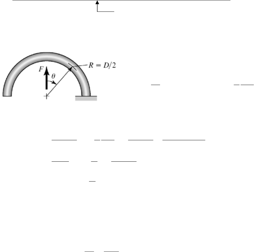
(nf)B 2.519 2.463 2.388 2.341 2.298 2.235
Sy 134.156 133.215 131.685 130.476 129.168 126.674
(
A)max 84.273 83.682 82.720 81.961 81.139 79.573
(ny)A 1.592 1.592 1.592 1.592 1.592 1.592
i 21.663 23.820 25.741 27.723 29.629 31.097
r 0.945 1.157 1.444 1.942 2.906 4.703
(Ssy)body 85.372 84.773 83.800 83.030 82.198 80.611
(Ssa)y 30.958 32.688 34.302 36.507 39.109 40.832
(ny)body 2.779 2.973 3.183 3.438 3.740 4.012
(Ssy)B 73.176 72.663 71.828 71.169 70.455 69.095
(
B)max 42.819 43.486 44.321 44.801 45.177 45.564
(ny)B 1.709 1.671 1.621 1.589 1.560 1.516
fom 1.246 1.234 1.245 1.283 1.357 1.639
optimal fom
The shaded areas show the conditions not satisfied.
______________________________________________________________________________
10-38 For the hook,
M = FR sin
, ∂M/∂F = R sin
3
/2 2
0
1sin 2
FR
FR Rd
EI EI
F
The total deflection of the body and the two hooks
333 3
444
33
44
88(/2)
22(/64)()
88
bb
a
b
FD N FR FD N F D
dG EI dG E d
FD G FD N
N
dG E dG
G
NN
Q.E.D.
ab
E
______________________________________________________________________________
10-39 Table 10-5 (d = 4 mm = 0.1575 in): E = 196.5 GPa
Table 10-4 for A227:
A = 1783 MPa · mmm, m = 0.190
Eq. (10-14): 0.190
1783 1370 MPa
4
ut m
A
Sd
Eq. (10-57): Sy =
all = 0.78 Sut = 0.78(1370) = 1069 MPa
Chapter 10 - Rev. A, Page 36/41
D = OD d = 32 4 = 28 mm
C = D/d = 28/4 = 7
Eq.
(10-43):
2
247 7 1
41 1.119
4 ( 1) 4(7)(7 1)
i
CC
KCC
Eq. (10-44): 3
32
i
F
r
Kd
At
yield, Fr = My ,
= Sy. Thus,
33
34 1069 10
y
y
dS
6.00 N · m
32 32(1.119)
i
MK
Count the turns when M = 0
2.5 y
M
N
k
4
10.8
dE
kDN
where from Eq. (10-51):
Thus,
4
2.5 / (10.8 )
y
M
NdE DN
Solving for N gives
4
2.5
1 [10.8 / ( )]
2.5
y
NDM d E
42.413 turns
1 10.8(28)(6.00) / 4 (196.5)
This means (2.5 - 2.413)(360) or 31.3 from closed. Ans.
Treating the hand force as in the middle of the grip,
3
max
87.5
112.5 87.5 68.75 mm
2
6.00 10 87.3 N .
68.75
y
r
M
FAns
r
______________________________________________________________________________
10-40 The spring material and condition are unknown. Given d = 0.081 in and OD = 0.500,
(a) D = 0.500 0.081 = 0.419 in
Using E = 28.6 Mpsi for an estimate
Chapter 10 - Rev. A, Page 37/41
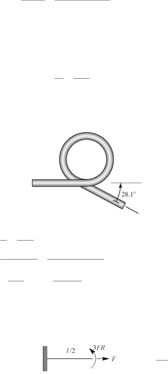
446
(0.081) (28.6)(10 ) 24.7 lbf · in/turn
10.8 10.8(0.419)(11)
dE
kDN
for each spring. The moment corresponding to a force of 8 lbf
Fr = (8/2)(3.3125) = 13.25 lbf · in/spring
The fraction windup turn is
13.25 ns
Fr
nk
0.536 tur
24.7
The arm swings through an arc of slightly less than 180, say 165. This uses up
165/360 or 0.458 turns. So n = 0.536 0.458 = 0.078 turns are left (or
0.078(360) = 28.1 ). The original configuration of the spring was
Ans.
(b)
3
33
1.168
41 4(5.17)(5.17 1)
32 32(13.25)
1.168 297 10 psi 297 kpsi .
i
i
CC
M
KA
22
0.419 5.17
0.081
4 1 4(5.17) 5.17 1
(0.081)
D
Cd
CC
K
ns
d
To achieve this stress level, the spring had to have set removed.
______________________________________________________________________________
10-41 (a) Consider half and double results
Straight section:
M = 3FR, 3
M
R
P
Chapter 10 - Rev. A, Page 38/41
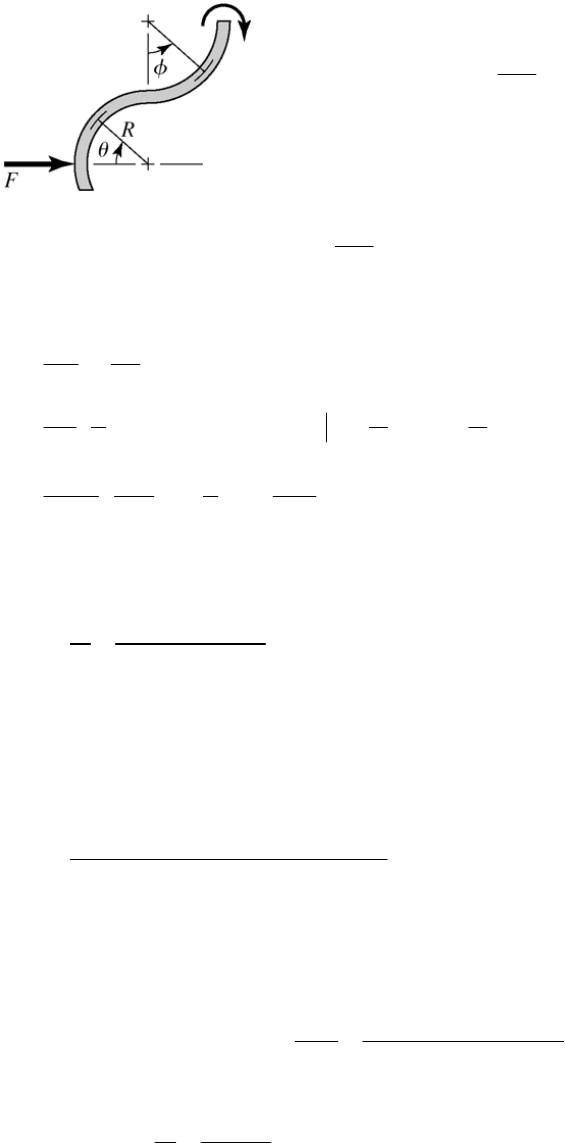
Upper 180 section:
[(1cos)]
s )
MFRR
(2 cos ), (2 co
M
FR R
F
Lower section: M = FR sin
, sin
MR
F
Considering bending only:
/2 /2
222 2
0
22
29 (2cos) (sin)
29
4
219 9 (19 18 )
422
l
UFR dx FR R d F R R d
FEI
FRl
EI
FR FR
Rl Rl
EI EI
00
23 3
0
44
sin
22
R R
The spring rate is
2(19ns
RRl
2.
18 )
FEI
kA
(
b) Given: A227 HD wire, d = 2 mm, R = 6 mm, and l = 25 mm.
Table 10-5 (d = 2 mm = 0.0787 in): E = 197.2 MPa
3
10 N/m 10.65 N/mm .ns
94
2
2 197.2 10 0.002 / 64 10.65
0.006 19 0.006 18 0.025
kA
(
c) The maximum stress will occur at the bottom of the top hook where the bending-
moment is 3FR and the axial fore is F. Using curved beam theory for bending,
Eq. (3-65), p. 119:
2
3
/4 /2
ii
i
i
Mc FRc
Aer deRd
Axial:
F
F
2/4
a
A
d
Chapter 10 - Rev. A, Page 39/41
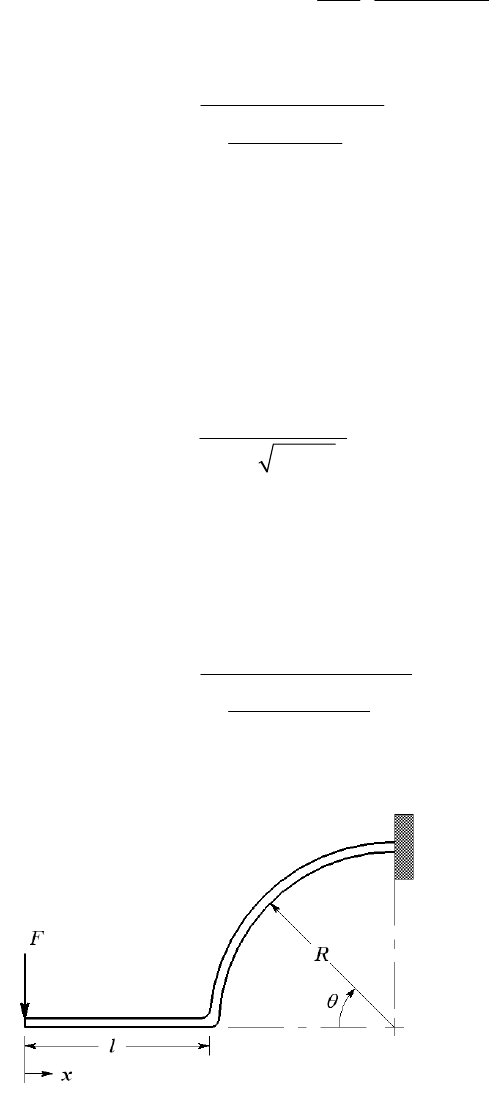
Combining,
max 2
3
41
/2
i
ia
Rc
FS
deRd
y
2
(1) .
3
41
/2
y
i
dS
FAns
Rc
eR d
For the clip in part (b),
Eq. (10-14) and Table 10-4: Sut = A/dm = 1783/20.190 = 1563 MPa
Eq. (10-57): Sy = 0.78 Sut = 0.78(1563) = 1219 MPa
Table 3-4, p. 121:
2
22
15.95804 mm
26 6 1
n
r
e = rc
rn = 6 5.95804 = 0.04196 mm
ci = rn
(R
d /2) = 5.95804 (6 2/2) = 0.95804 mm
Eq. (1):
26
0.002 1219 10 46.0 N .
3 6 0.95804
41
0.04196 6 1
FA
ns
______________________________________________________________________________
10-42 (a)
Chapter 10 - Rev. A, Page 40/41
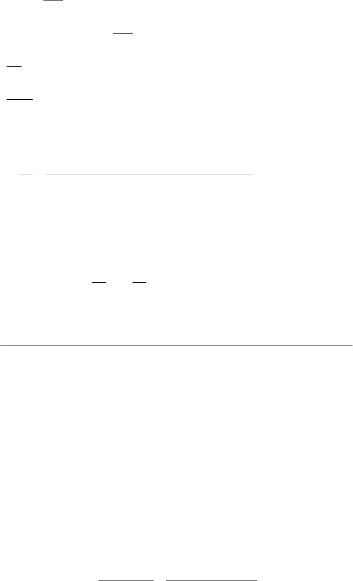
Chapter 10 - Rev. A, Page 41/41
/2 2
00
32 2
,
1 cos , 1 cos 0
1() 1cos
432 4 2 38
12
l
F
M
MFx F 0x xl
M
M
Fl FR l R l
F
Fx x dx F l R Rd
EI
FlRl lR R
EI
The spring rate is
32
43
2
F
2
12 .
4 2 38
FEI ns
lRl lR R
kA
(
b) Given: A313 stainless wire, d = 0.063 in, R = 0.625 in, and l = 0.5 in.
Table 10-5: E = 28 Mpsi
44
0.063 7.733
64 64
Id
74
10 in
67
32 2
12 28 10 7.733 10
0.625
k
40.5 3 0.625 2 0.5 4 2 0.5 0.625 3 8
36.3 lbf/in .Ans
(
c) Table 10-4: A = 169 kpsiinm, m = 0.146
Eq. (10-14): Sut = A/ d m = 169/0.0630.146 = 253.0 kpsi
Eq. (10-57): Sy = 0.61 Sut = 0.61(253.0) = 154.4 kpsi
One can use curved beam theory as in the solution for Prob. 10-41. However, the
equations developed in Sec. 10-12 are equally valid.
C = D/d = 2(0.625 + 0.063/2)/0.063 = 20.8
Eq. (10-43):
2
24 20.8 20.8 1
41 1.037
4 1 4 20.8 20.8 1
i
CC
CC
K
Eq. (10-44), setting
= Sy:
Chapter 10 - Rev. A, Page 42/41
3
33
32 0.5 0.625
32 1.037 154.4 10
0.063
iy
F
Fr
KS
d
Solving for F yields F = 3.25 lbf Ans.
Try solving part (c) of this problem using curved beam theory. You should obtain the
same answer.
______________________________________________________________________________
10-43 (a) M =
Fx
2
// /6
M
Fx Fx
Ic Ic bh
Constant stress,
26(1) .
6
Fx Fx
hAns
b
bh
At x = l,
6/.
oo
Fl hxlAns
b
hh
(
b) M =
Fx,
M /
F =
x
3/2
1/ 2
3/2 3
13
00 0
12
3/2 3
3/2
33
/112
/
212 8
3
ll l
o
o
oo
MM F Fxx Fl
ydx dxxdx
EI E bh E
bh x l
Fl Fl
l
bh E bh E
3
3.
8
o
bh E
Fns
yl
kA
______________________________________________________________________________
10-44 Computer programs will vary.
______________________________________________________________________________
10-45 Computer programs will vary.

Chapter 11
11-1 For the deep-groove 02-series ball bearing with R = 0.90, the design life xD, in multiples
of rating life, is
6
10
60 25000 350
60 525 .
10
DDD
D
R
Ln
x
Ans
LL
The design radial load is
1.2 2.5 3.0 kN
D
F
Eq. (11-6):
1/3
10 1/1.483
525
3.0 0.02 4.459 0.02 ln 1/ 0.9
C
C10 = 24.3 kN Ans.
Table 11-2: Choose an 02-35 mm bearing with C10 = 25.5 kN. Ans.
Eq. (11-18):
1.483
3
525 3/ 25.5 0.02
exp 0.920 .
4.459 0.02
R
Ans
______________________________________________________________________________
11-2 For the angular-contact 02-series ball bearing as described, the rating life multiple is
6
10
60 40000 520
60 1248
10
DDD
D
R
Ln
xLL
The design radial load is
1.4 725 1015 lbf 4.52 kN
D
F
Eq. (11-6):
1/3
10 1/1.483
1248
1015 0.02 4.459 0.02 ln 1/ 0.9
10 930 lbf 48.6 kN
C
Table 11-2: Select an 02-60 mm bearing with C10 = 55.9 kN. Ans.
Eq. (11-18):
1.483
3
1248 4.52 / 55.9 0.02
exp 0.945 .
4.439
R
Ans
______________________________________________________________________________
Chapter 11, Page 1/28
11-3 For the straight-roller 03-series bearing selection, xD = 1248 rating lives from Prob. 11-2
solution.
1.4 2235 3129 lbf 13.92 kN
D
F
3/10
10
1248
13.92 118 kN
1
C
Table 11-3: Select an 03-60 mm bearing with C10 = 123 kN. Ans.
Eq. (11-18):
1.483
10/3
1248 13.92 /123 0.02
exp 0.917 .
4.459 0.02
R
Ans
______________________________________________________________________________
11-4 The combined reliability of the two bearings selected in Probs. 11-2 and 11-3 is
0.945 0.917 0.867 .
R
Ans
We can choose a reliability goal of 0.90 0.95for each bearing. We make the
selections, find the existing reliabilities, multiply them together, and observe that the
reliability goal is exceeded due to the roundup of capacity upon table entry.
Another possibility is to use the reliability of one bearing, say R1. Then set the reliability
goal of the second as
2
1
0.90
R
R
or vice versa. This gives three pairs of selections to compare in terms of cost, geometry
implications, etc.
______________________________________________________________________________
11-5 Establish a reliability goal of 0.90 0.95for each bearing. For an 02-series angular
contact ball bearing,
1/3
10 1/1.483
1248
1015 0.02 4.439 ln 1/ 0.95
12822 lbf 57.1 kN
C
Select an 02-65 mm angular-contact bearing with C10 = 63.7 kN.
1.483
3
1248 4.52 / 63.7 0.02
exp 0.962
4.439
A
R
Chapter 11, Page 2/28

For an 03-series straight roller bearing,
3/10
10 1/1.483
1248
13.92 136.5 kN
0.02 4.439 ln 1/ 0.95
C
Select an 03-65 mm straight-roller bearing with C10 = 138 kN.
1.483
10/3
1248 13.92 /138 0.02
exp 0.953
4.439
B
R
The overall reliability is R = (0.962)(0.953) = 0.917, which exceeds the goal.
______________________________________________________________________________
11-6 For the straight cylindrical roller bearing specified with a service factor of 1, R = 0.95 and
FR = 20 kN.
6
10
60 8000 950
60 456
10
DDD
D
R
Ln
xLL
3/10
10 1/1.483
456
20 145 kN .
0.02 4.439 ln 1/ 0.95
CA
ns
______________________________________________________________________________
11-7 Both bearings need to be rated in terms of the same catalog rating system in order to
compare them. Using a rating life of one million revolutions, both bearings can be rated
in terms of a Basic Load Rating.
Eq. (11-3):
1/3
1/ 1/
6
3000 500 60
60 2.0 10
8.96 kN
aa
AAA
AA A
RR
Ln
CF F
LL
Bearing B already is rated at one million revolutions, so CB = 7.0 kN. Since CA > CB,
bearing A can carry the larger load. Ans.
______________________________________________________________________________
11-8 FD = 2 kN, LD = 109 rev, R = 0.90
Eq. (11-3):
1/ 1/3
9
10 6
10
2 20 kN .
10
a
D
D
R
L
CF An
L
s
______________________________________________________________________________
Chapter 11, Page 3/28
11-9 FD = 800 lbf,
D = 12 000 hours, nD = 350 rev/min, R = 0.90
Eq. (11-3):
1/3
1/
10 6
12 000 350 60
60 800 5050 lbf
10
a
DD
D
R
n
CF An
L
s
______________________________________________________________________________
11-10 FD = 4 kN,
D = 8 000 hours, nD = 500 rev/min, R = 0.90
Eq. (11-3):
1/3
1/
10 6
8 000 500 60
60 4 24.9 kN
10
a
DD
D
R
n
CF An
L
s
______________________________________________________________________________
11-11 FD = 650 lbf, nD = 400 rev/min, R = 0.95
D = (5 years)(40 h/week)(52 week/year) = 10 400 hours
Assume an application factor of one. The multiple of rating life is
6
10 400 400 60 249.6
10
D
D
R
L
xL
Eq. (11-6):
1/3
10 1/1.483
249.6
1 650 0.02 4.439 ln 1/ 0.95
C
4800 lbf .Ans
______________________________________________________________________________
11-12 FD = 9 kN, LD = 108 rev, R = 0.99
Assume an application factor of one. The multiple of rating life is
8
6
10 100
10
D
D
R
L
xL
Eq. (11-6):
1/3
10 1/1.483
100
19 0.02 4.439 ln 1/ 0.99
C
69.2 kN .Ans
______________________________________________________________________________
11-13 FD = 11 kips,
D = 20 000 hours, nD = 200 rev/min, R = 0.99
Assume an application factor of one. Use the Weibull parameters for Manufacturer 2 on
p. 608.
Chapter 11, Page 4/28

The multiple of rating life is
6
20 000 200 60 240
10
D
D
R
L
xL
Eq. (11-6):
1/3
10 1/1.483
240
111 0.02 4.439 ln 1/ 0.99
C
113 kips .
A
ns
______________________________________________________________________________
11-14 From the solution to Prob. 3-68, the ground reaction force carried by the bearing at C is
RC = FD = 178 lbf. Use the Weibull parameters for Manufacturer 2 on p. 608.
6
15000 1200 60 1080
10
D
D
R
L
xL
Eq. (11-7):
1/
10 1/
00
1
a
D
fD b
D
x
CaF
xxR
1/3
10 1/1.483
1080
1.2 178 0.02 4.459 0.02 1 0.95
2590 lbf .
C
Ans
______________________________________________________________________________
11-15 From the solution to Prob. 3-69, the ground reaction force carried by the bearing at C is
RC = FD = 1.794 kN. Use the Weibull parameters for Manufacturer 2 on p. 608.
6
15000 1200 60 1080
10
D
D
R
L
xL
Eq. (11-7):
1/
10 1/
00
1
a
D
fD b
D
x
CaF
xxR
1/3
10 1/1.483
1080
1.2 1.794 0.02 4.459 0.02 1 0.95
26.1 kN .
C
Ans
______________________________________________________________________________
11-16 From the solution to Prob. 3-70, RCz = –327.99 lbf, RCy = –127.27 lbf
1/2
22
327.99 127.27 351.8 lbf
CD
RF
Use the Weibull parameters for Manufacturer 2 on p. 608.
Chapter 11, Page 5/28

6
15000 1200 60 1080
10
D
D
R
L
xL
Eq. (11-7):
1/
10 1/
1
a
D
fD b
ooD
x
CaF
xxR
1/3
10 1/1.483
1080
1.2 351.8 0.02 4.459 0.02 1 0.95
5110 lbf .
C
Ans
______________________________________________________________________________
11-17 From the solution to Prob. 3-71, RCz = –150.7 N, RCy = –86.10 N
1/2
22
150.7 86.10 173.6 N
CD
RF
Use the Weibull parameters for Manufacturer 2 on p. 608.
6
15000 1200 60 1080
10
D
D
R
L
xL
Eq. (11-7):
1/
10 1/
00
1
a
D
fD b
D
x
CaF
xxR
1/3
10 1/1.483
1080
1.2 173.6 0.02 4.459 0.02 1 0.95
2520 N .
C
Ans
______________________________________________________________________________
11-18 From the solution to Prob. 3-77, RAz = 444 N, RAy = 2384 N
1/2
22
444 2384 2425 N 2.425 kN
AD
RF
Use the Weibull parameters for Manufacturer 2 on p. 608. The design speed is equal to
the speed of shaft AD,
125 191 95.5 rev/min
250
F
Di
C
d
nn
d
6
12000 95.5 60 68.76
10
D
D
R
L
xL
Eq. (11-7):
1/
10 1/
00
1
a
D
fD b
D
x
CaF
xxR
Chapter 11, Page 6/28
1/3
10 1/1.483
68.76
12.425 0.02 4.459 0.02 1 0.95
11.7 kN .
C
Ans
______________________________________________________________________________
11-19 From the solution to Prob. 3-79, RAz = 54.0 lbf, RAy = 140 lbf
1/2
22
54.0 140 150.1 lbf
AD
RF
Use the Weibull parameters for Manufacturer 2 on p. 608. The design speed is equal to
the speed of shaft AD,
10 280 560 rev/min
5
F
Di
C
d
nn
d
6
14000 560 60 470.4
10
D
D
R
L
xL
Eq. (11-7):
1/
10 1/
00
1
a
D
fD b
D
x
CaF
xxR
3/10
10 1/1.483
470.4
1 150.1 0.02 4.459 0.02 1 0.98
1320 lbf .
C
Ans
______________________________________________________________________________
11-20 (a)
3 kN, 7 kN, 500 rev/min, 1.2
arD
FFn V
From Table 11-2, with a 65 mm bore, C0 = 34.0 kN.
Fa / C0 = 3 / 34 = 0.088
From Table 11-1, 0.28 e 3.0.
30.357
1.2 7
a
r
F
VF
Since this is greater than e, interpolating Table 11-1 with Fa / C0 = 0.088, we obtain
X2 = 0.56 and Y2 = 1.53.
Eq. (11-9):
0.56 1.2 7 1.53 3 9.29 kN
eiria
FXVFYF Ans.
Fe > Fr so use Fe.
(b) Use Eq. (11-7) to determine the necessary rated load the bearing should have to carry
the equivalent radial load for the desired life and reliability. Use the Weibull
parameters for Manufacturer 2 on p. 608.
Chapter 11, Page 7/28
6
10000 500 60 300
10
D
D
R
L
xL
Eq. (11-7):
1/
10 1/
00
1
a
D
fD b
D
x
CaF
xxR
1/3
10 1/1.483
300
19.29 0.02 4.459 0.02 1 0.95
73.4 kN
C
From Table 11-2, the 65 mm bearing is rated for 55.9 kN, which is less than the
necessary rating to meet the specifications. This bearing should not be expected to meet
the load, life, and reliability goals. Ans.
______________________________________________________________________________
11-21 (a) 2 kN, 5 kN, 400 rev/min, 1
arD
FFn V
From Table 11-2, 30 mm bore, C10 = 19.5 kN, C0 = 10.0 kN
Fa / C0 = 2 / 10 = 0.2
From Table 11-1, 0.34 e 0.38.
20.4
15
a
r
F
VF
Since this is greater than e, interpolating Table 11-1, with Fa / C0 = 0.2, we obtain X2 =
0.56 and Y2 = 1.27.
Eq. (11-9):
0.56 1 5 1.27 2 5.34 kN
eiria
FXVFYF Ans.
Fe > Fr so use Fe.
(b) Solve Eq. (11-7) for xD.
1/
10 00
1
a
b
DD
fD
C
xxxR
aF
3
1/1.483
19.5 0.02 4.459 0.02 1 0.99
15.34
D
x
10.66
D
x
6
60
10
DD
D
D
R
n
L
xL
Chapter 11, Page 8/28
66
10 10.66 10 444 h .
60 400 60
D
D
D
xAns
n
______________________________________________________________________________
11-22
9
8 kN, 0.9, 10 rev
rD
FRL
Eq. (11-3):
1/ 1/3
9
10 6
10
880
10
a
D
D
R
L
CF
L
kN
From Table 11-2, select the 85 mm bore. Ans.
______________________________________________________________________________
11-23
8 kN, 2 kN, 1, 0.99
ra
FFVR
Use the Weibull parameters for Manufacturer 2 on p. 608.
6
10000 400 60 240
10
D
D
R
L
xL
First guess: Choose from middle of Table 11-1, X = 0.56, Y = 1.63
Eq. (11-9):
0.56 1 8 1.63 2 7.74 kN
e
F
Fe < Fr, so just use Fr as the design load.
Eq. (11-7):
1/
10 1/
1
a
D
fD b
ooD
x
CaF
xxR
1/3
10 1/1.483
240
1 8 82.5 kN
0.02 4.459 0.02 1 0.99
C
From Table 11-2, try 85 mm bore with C10 = 83.2 kN, C0 = 53.0 kN
Iterate the previous process:
Fa / C0 = 2 / 53 = 0.038
Table 11-1: 0.22 e 0.24
20.25
18
a
r
Fe
VF
Interpolate Table 11-1 with Fa / C0 = 0.038 to obtain X2 = 0.56 and Y2 = 1.89.
Eq. (11-9): 0.56(1)8 1.89(2) 8.26 >
er
FF
Eq. (11-7):
1/3
10 1/1.483
240
1 8.26 85.2 kN
0.02 4.459 0.02 1 0.99
C
Chapter 11, Page 9/28

Table 11-2: Move up to the 90 mm bore with C10 = 95.6 kN, C0 = 62.0 kN.
Iterate again:
Fa / C0 = 2 / 62 = 0.032
Table 11-1: Again, 0.22 e 0.24
20.25
18
a
r
Fe
VF
Interpolate Table 11-1 with Fa / C0 = 0.032 to obtain X2 = 0.56 and Y2 = 1.95.
Eq. (11-9):
0.56(1)8 1.95(2) 8.38 >
er
FF
Eq. (11-7):
1/3
10 1/1.483
240
1 8.38 86.4 kN
0.02 4.459 0.02 1 0.99
C
The 90 mm bore is acceptable. Ans.
______________________________________________________________________________
11-24
8
8 kN, 3 kN, 1.2, 0.9, 10 rev
ra D
FFVRL
First guess: Choose from middle of Table 11-1, X = 0.56, Y = 1.63
Eq. (11-9):
0.56 1.2 8 1.63 3 10.3 kN
e
F
er
FF
Eq. (11-3):
1/ 1/3
8
10 6
10
10.3 47.8 kN
10
a
D
e
R
L
CF
L
From Table 11-2, try 60 mm with C10 = 47.5 kN, C0 = 28.0 kN
Iterate the previous process:
Fa / C0 = 3 / 28 = 0.107
Table 11-1: 0.28 e 0.30
30.313
1.2 8
a
r
Fe
VF
Interpolate Table 11-1 with Fa / C0 = 0.107 to obtain X2 = 0.56 and Y2 = 1.46
Eq. (11-9):
0.56 1.2 8 1.46 3 9.76 kN >
er
FF
Eq. (11-3):
1/3
8
10 6
10
9.76 45.3 kN
10
C
From Table 11-2, we have converged on the 60 mm bearing. Ans.
______________________________________________________________________________
Chapter 11, Page 10/28

11-25
10 kN, 5 kN, 1, 0.95
ra
FFVR
Use the Weibull parameters for Manufacturer 2 on p. 608.
6
12000 300 60 216
10
D
D
R
L
xL
First guess: Choose from middle of Table 11-1, X = 0.56, Y = 1.63
Eq. (11-9):
0.56 1 10 1.63 5 13.75 kN
e
F
Fe > Fr, so use Fe as the design load.
Eq. (11-7):
1/
10 1/
00
1
a
D
fD b
D
x
CaF
xxR
1/3
10 1/1.483
216
1 13.75 97.4 kN
0.02 4.459 0.02 1 0.95
C
From Table 11-2, try 95 mm bore with C10 = 108 kN, C0 = 69.5 kN
Iterate the previous process:
Fa / C0 = 5 / 69.5 = 0.072
Table 11-1: 0.27 e 0.28
50.5
110
a
r
Fe
VF
Interpolate Table 11-1 with Fa / C0 = 0.072 to obtain X2 = 0.56 and Y2 = 1.62 1.63
Since this is where we started, we will converge back to the same bearing. The 95 mm
bore meets the requirements. Ans.
______________________________________________________________________________
11-26 Note to the Instructor. In the first printing of the 9th edition, the design life was
incorrectly given to be 109 rev and will be corrected to 108 rev in subsequent printings.
We apologize for the inconvenience.
9 kN, 3 kN, 1.2, 0.99
ra
FFVR
Use the Weibull parameters for Manufacturer 2 on p. 608.
8
6
10 100
10
D
D
R
L
xL
First guess: Choose from middle of Table 11-1, X = 0.56, Y = 1.63
Chapter 11, Page 11/28
Eq. (11-9):
0.56 1.2 9 1.63 3 10.9 kN
e
F
Fe > Fr, so use Fe as the design load.
Eq. (11-7):
1/
10 1/
00
1
a
D
fD b
D
x
CaF
xxR
1/3
10 1/1.483
100
1 10.9 83.9 kN
0.02 4.459 0.02 1 0.99
C
From Table 11-2, try 90 mm bore with C10 = 95.6 kN, C0 = 62.0 kN. Try this bearing.
Iterate the previous process:
Fa / C0 = 3 / 62 = 0.048
Table 11-1: 0.24 e 0.26
30.278
1.2 9
a
r
Fe
VF
Interpolate Table 11-1 with Fa / C0 = 0.048 to obtain X2 = 0.56 and Y2 = 1.79
Eq. (11-9):
0.56 1.2 9 1.79 3 11.4 kN
er
FF
10
11.483.9 87.7 kN
10.9
C
From Table 11-2, this converges back to the same bearing. The 90 mm bore meets the
requirements. Ans.
______________________________________________________________________________
11-27 (a)
1200 rev/min, 15 kh, 0.95, 1.2
DD
nLR
f
a
From Prob. 3-72, RCy = 183.1 lbf, RCz = –861.5 lbf.
1/2
2
2
183.1 861.5 881 lbf
CD
RF
6
15000 1200 60 1080
10
D
D
R
L
xL
Eq. (11-7):
1/3
10 1/1.483
1080
1.2 881 0.02 4.439 1 0.95
C
12800 lbf 12.8 kips .
A
ns
(b) Results will vary depending on the specific bearing manufacturer selected. A general
engineering components search site such as www.globalspec.com might be useful as
a starting point.
______________________________________________________________________________
Chapter 11, Page 12/28

11-28 (a)
1200 rev/min, 15 kh, 0.95, 1.2
DD
nLR
f
a
From Prob. 3-72, ROy = –208.5 lbf, ROz = 259.3 lbf.
1/2
2
2
259.3 208.5 333 lbf
CD
RF
6
15000 1200 60 1080
10
D
D
R
L
xL
Eq. (11-7):
1/3
10 1/1.483
1080
1.2 333 0.02 4.439 1 0.95
C
4837 lbf 4.84 kips .
A
ns
(b) Results will vary depending on the specific bearing manufacturer selected. A general
engineering components search site such as www.globalspec.com might be useful as
a starting point.
______________________________________________________________________________
11-29 (a)
900 rev/min, 12 kh, 0.98, 1.2
DD
nLR
f
a
From Prob. 3-73, RCy = 8.319 kN, RCz = –10.830 kN.
1/2
2
2
8.319 10.830 13.7 kN
CD
RF
6
12000 900 60 648
10
D
D
R
L
xL
Eq. (11-7):
1/3
10 1/1.483
648
1.2 13.7 204 kN .
0.02 4.439 1 0.98
CA
ns
f
a
(b) Results will vary depending on the specific bearing manufacturer selected. A general
engineering components search site such as www.globalspec.com might be useful as
a starting point.
______________________________________________________________________________
11-30 (a)
900 rev/min, 12 kh, 0.98, 1.2
DD
nLR
From Prob. 3-73, ROy = 5083 N, ROz = 494 N.
1/2
22
5083 494 5106 N 5.1 kN
CD
RF
6
12000 900 60 648
10
D
D
R
L
xL
Eq. (11-7):
1/3
10 1/1.483
648
1.2 5.1 76.1 kN .
0.02 4.439 1 0.98
CA
ns
(b) Results will vary depending on the specific bearing manufacturer selected. A general
engineering components search site such as www.globalspec.com might be useful as
a starting point.
______________________________________________________________________________
Chapter 11, Page 13/28
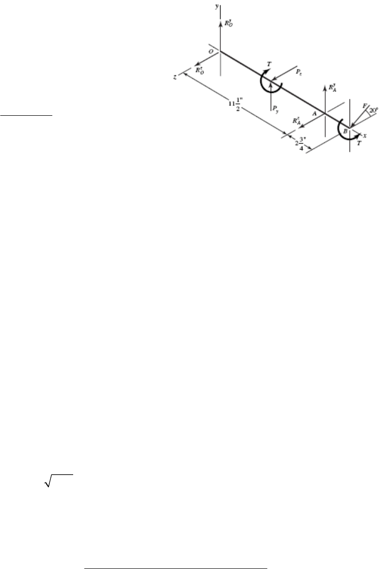
11-31 Assume concentrated forces as shown.
8 28 224 lbf
z
P
835 280 lbf
y
P
224 2 448 lbf inT
448 1.5 cos20 0
x
TF
448 318 lbf
1.5 0.940
F
5.75 11.5 14.25 sin 20 0
zy
OyA
MPR F
5.75 280 11.5 14.25 318 0.342 0
y
A
R
5.24 lbf
y
A
R
5.75 11.5 14.25 cos20 0
yz
OzA
MPRF
5.75 224 11.5 14.25 318 0.940 0
z
A
R
1/2
22
482 lbf; 482 5.24 482 lbf
z
AA
RR
cos20 0
zz z
Oz A
FRPRF
224 482 318 0.940 0
z
O
R
40.9 lbf
z
O
R
sin 20 0
yy y
Oy A
FRPRF
280 5.24 318 0.342 0
y
O
R
166 lbf
y
O
R
1/2
22
40.9 166 171 lbf
O
R
So the reaction at A governs.
Reliability Goal: 0.92 0.96
1.2 482 578 lbf
D
F
6
35000 350 60 /10 735
D
x
1/3
10 1/1.483
735
578 0.02 4.459 0.02 ln 1/ 0.96
6431 lbf 28.6 kN
C
From Table 11-2, a 40 mm bore angular contact bearing is sufficient with a rating of
Chapter 11, Page 14/28
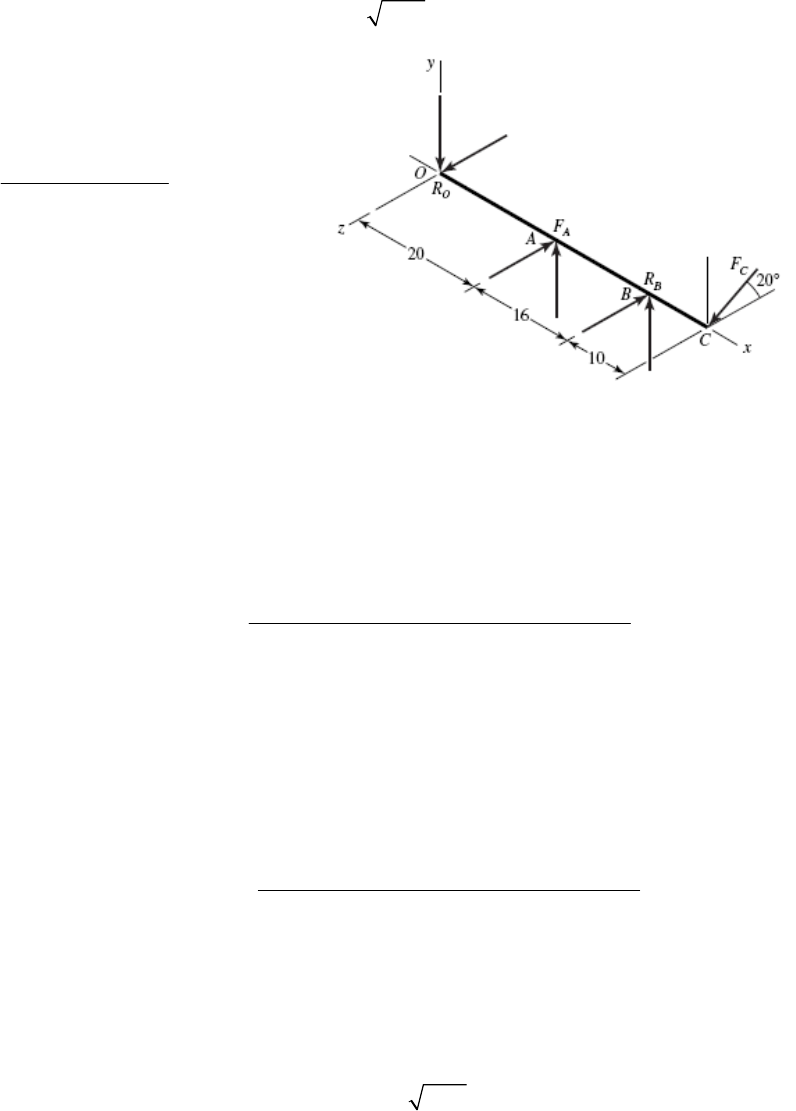
31.9 kN. Ans.
______________________________________________________________________________
1-32 For a combined reliability goal of 0.95, use
10.95 0.975for the individual bearings.
6
40000 420 60 1008
10
D
x
The resultant of the given forces are
R
O = [(–387) + 467 ] = 607 lbf
At O:
Eq. (11-6):
2 2 1/2
R
B = [3162 + (–1615)2]1/2 = 1646 lbf
1/3
10 1/1.483
1008
1.2 607 0.02 4.459 0.02 ln 1/ 0.975
C
9978 lbf 44.4 kN
From Table 11-2, select an 02-55 mm angular-contact ball bearing with a basic load
At B:
Eq. (11-6):
rating of 46.2 kN. Ans.
3/10
10 1/1.483
1008
1.2 1646 0.02 4.459 0.02 ln 1/ 0.975
C
20827 lbf 92.7 kN
From Table 11-3, select an 02-75 mm or 03-55 mm cylindrical roller. Ans.
_____ _________
1-33 The reliability of the individual bearings is
_ _______________________________________________________________
10.98 0.9899R
Chapter 11, Page 15/28
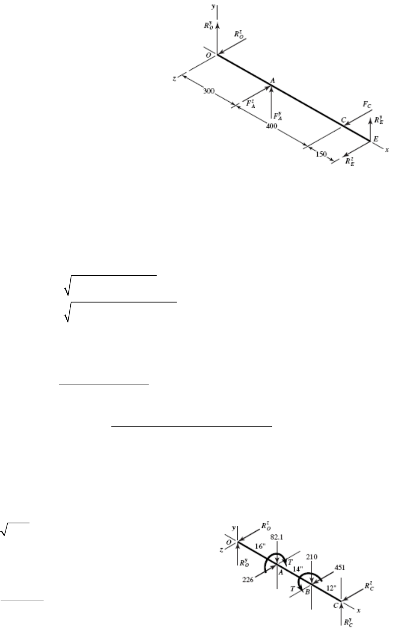
From statics,
T = (270 50) = (P1 P2)125
= (P1 0.15 P1)125
P1 = 310.6 N,
P
2 = 0.15 (310.6) = 46.6 N
P1 + P2 = 357.2 N
357.2sin 45 252.6 N
y
z
A
A
FF
z
R
850 300(252.6) 0 89.2 N
zy y
OE E
MR R
252.6 89.2 0 163.4 N
yyy
OO
FRR
850 700(320) 300(252.6) 0 174.4 N
yz z
OE E
MR R
174.4 320 252.6 0 107 N
zz
OO
FR
22
22
163.4 107 195 N
89.2 174.4 196 N
O
E
R
R
The radial loads are nearly the same at O and E. We can use the same bearing at both
locations.
6
60000 1500 60 5400
10
D
x
Eq. (11-6):
1/3
10 1/1.483
5400
1 0.196 5.7 kN
0.02 4.439 ln 1/ 0.9899
C
From Table 11-2, select an 02-12 mm deep-groove ball bearing with a basic load rating
of 6.89 kN. Ans.
______________________________________________________________________________
11-34 0.96 0.980R
12(240cos20 ) 2706 lbf inT
2706 498 lbf
6cos 25
F
In xy-plane:
16(82.1) 30(210) 42 0
zy
OC
MR
Chapter 11, Page 16/28
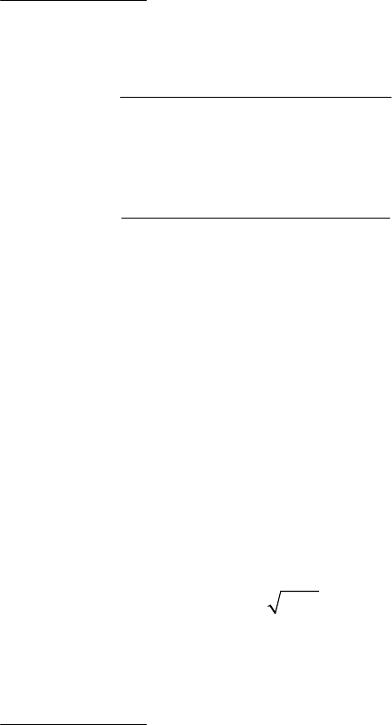
181 lbf
y
C
R
82.1 210 181 111.1 lbf
y
O
R
In xz-plane:
16(226) 30(451) 42 0
yz
OC
MR
236 lbf
z
C
R
226 451 236 11 lbf
z
O
R
1/2
22
111.1 11 112 lbf .
O
R
Ans
1/2
22
181 236 297 lbf .
C
R
Ans
6
50000 300 60 900
10
D
x
1/3
10 1/1.483
900
1.2 112 0.02 4.439 ln 1/ 0.980
1860 lbf 8.28 kN
O
C
1/3
10 1/1.483
900
1.2 297 0.02 4.439 ln 1/ 0.980
4932 lbf 21.9 kN
C
C
Bearing at O: Choose a deep-groove 02-17 mm. Ans.
Bearing at C: Choose a deep-groove 02-35 mm. Ans.
______________________________________________________________________________
11-35 Shafts subjected to thrust can be constrained by bearings, one of which supports the
thrust. The shaft floats within the endplay of the second (roller) bearing. Since the thrust
force here is larger than any radial load, the bearing absorbing the thrust (bearing A) is
heavily loaded compared to bearing B. Bearing B is thus likely to be oversized and may
not contribute measurably to the chance of failure. If this is the case, we may be able to
obtain the desired combined reliability with bearing A having a reliability near 0.99 and
bearing B having a reliability near 1. This would allow for bearing A to have a lower
capacity than if it needed to achieve a reliability of 0.99 . To determine if this is the
case, we will start with bearing B.
Bearing B (straight roller bearing)
6
30000 500 60 900
10
D
x
1/2
22
36 67 76.1 lbf 0.339 kN
r
F
Try a reliability of 1 to see if it is readily obtainable with the available bearings.
Chapter 11, Page 17/28

Eq. (11-6):
3/10
10 1/1.483
900
1.2 0.339 10.1 kN
0.02 4.439 ln 1/1.0
C
The smallest capacity bearing from Table 11-3 has a rated capacity of 16.8 kN.
Therefore, we select the 02-25 mm straight cylindrical roller bearing. Ans.
Bearing at A (angular-contact ball)
With a reliability of 1 for bearing B, we can achieve the combined reliability goal of 0.99
if bearing A has a reliability of 0.99.
1/2
22
36 212 215 lbf 0.957 kN
r
F
555 lbf 2.47 kN
a
F
Trial #1:
Tentatively select an 02-85 mm angular-contact with C10 = 90.4 kN and C0 = 63.0 kN.
0
2.47 0.0392
63.0
a
F
C
6
30000 500 60 900
10
D
x
Table 11-1: Interpolating, X2 = 0.56, Y2 = 1.88
Eq. (11-9):
0.56 0.957 1.88 2.47 5.18 kN
e
F
Eq. (11-6):
1/3
10 1/1.483
900
1.2 5.18 0.02 4.439 ln 1/ 0.99
C
99.54 kN 90.4 kN
Trial #2:
Tentatively select a 02-90 mm angular-contact ball with C10 = 106 kN and C0 = 73.5 kN.
0
2.47 0.0336
73.5
a
F
C
Table 11-1: Interpolating, X2 = 0.56, Y2 = 1.93
0.56 0.957 1.93 2.47 5.30 kN
e
F
1/3
10 1/1.483
900
1.2 5.30 102 kN < 106 kN O.K.
0.02 4.439 ln 1/ 0.99
C
Chapter 11, Page 18/28
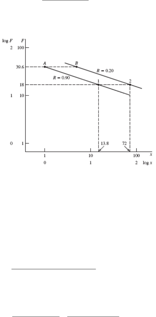
Select an 02-90 mm angular-contact ball bearing. Ans.
______________________________________________________________________________
11-36 We have some data. Let’s estimate parameters b and θ from it. In Fig. 11-5, we will use
line AB. In this case, B is to the right of A.
For F = 18 kN,
6
1
115 2000 60 13.8
10
x
This establishes point 1 on the R = 0.90 line.
The R = 0.20 locus is above and parallel to the R = 0.90 locus. For the two-parameter
Weibull distribution, x0 = 0 and points A and B are related by [see Eq. (20-25)]:
(1)
1/
ln 1/ 0.90 b
A
x
1/
ln 1/ 0.20 b
B
x
and xB/xA is in the same ratio as 600/115. Eliminating θ,
ln ln 1/ 0.20 / ln 1/ 0.90 1.65 .
ln 600 /115
bA
ns
Solving for θ in Eq. (1),
1/1.65 1/1.65
13.91 .
ln 1/ ln 1/ 0.90
A
A
xAns
R
Chapter 11, Page 19/28
Therefore, for the data at hand,
1.65
exp 3.91
x
R
Check R at point B: xB = (600/115) = 5.217
1.65
5.217
exp 0.20
3.91
R
Note also, for point 2 on the R = 0.20 line,
2
log 5.217 log 1 log log 13.8
m
x
272
m
x
______________________________________________________________________________
11-37 This problem is rich in useful variations. Here is one.
Decision: Make straight roller bearings identical on a given shaft. Use a reliability goal of
(0.99)1/6 = 0.9983.
Shaft a
1/2
22
239 111 264 lbf 1.175 kN
r
A
F
1/2
22
502 1075 1186 lbf 5.28 kN
r
B
F
Thus the bearing at B controls.
6
10000 1200 60 720
10
D
x
1/1.483
0.02 4.439 ln 1/ 0.9983 0.08026
0.3
10
720
1.2 5.28 97.2 kN
0.08026
C
Select either an 02-80 mm with C10 = 106 kN or an 03-55 mm with C10 = 102 kN. Ans.
Shaft b
1/2
22
874 2274 2436 lbf or 10.84 kN
r
C
F
1/2
22
393 657 766 lbf or 3.41 kN
r
D
F
The bearing at C controls.
Chapter 11, Page 20/28
6
10000 240 60 144
10
D
x
0.3
10
144
1.2 10.84 123 kN
0.080 26
C
Select either an 02-90 mm with C10 = 142 kN or an 03-60 mm with C10 = 123 kN. Ans.
Shaft c
1/2
22
1113 2385 2632 lbf or 11.71 kN
r
E
F
1/2
22
417 895 987 lbf or 4.39 kN
r
F
F
The bearing at E controls.
6
10000 80 60 48
10
D
x
0.3
10
48
1.2 11.71 95.7 kN
0.08026
C
Select an 02-80 mm with C10 = 106 kN or an 03-60 mm with C10 = 123 kN. Ans.
______________________________________________________________________________
11-38 Express Eq. (11-1) as
1 1 10 10
aa
FL CL K
For a ball bearing, a = 3 and for an 02-30 mm angular contact bearing, C10 = 20.3 kN.
369
20.3 10 8.365 10K
At a load of 18 kN, life L1 is given by:
9
6
13
1
8.365 10 1.434 10 rev
18
a
K
LF
For a load of 30 kN, life L2 is:
9
6
23
8.365 10 0.310 10 rev
30
L
In this case, Eq. (6-57) – the Palmgren-Miner cycle-ratio summation rule – can be
expressed as
Chapter 11, Page 21/28

12
12
1
ll
LL
Substituting,
2
66
200 000 1
1.434 10 0.310 10
l
6
20.267 10 rev .lAns
______________________________________________________________________________
11-39 Total life in revolutions
Let:
l = total turns
f1 = fraction of turns at F1
f2 = fraction of turns at F2
From the solution of Prob. 11-38, L1 = 1.434(106) rev and L2 = 0.310(106) rev.
Palmgren-Miner rule:
12 1 2
12 1 2
1
ll flfl
LL L L
from which
11 2 2
1
//
l
f
LfL
66
1
0.40 / 1.434 10 0.60 / 0.310 10
451 585 rev .
l
Ans
Total life in loading cycles
4 min at 2000 rev/min = 8000 rev/cycle
6 min at 2000 rev/min = 12 000 rev/cycle
Total rev/cycle = 8000 + 12 000 = 20 000
451585rev 22.58 cycles .
20000 rev/cycle
A
ns
Chapter 11, Page 22/28

Total life in hours
min 22.58 cycles
10 3.76 h .
cycle 60 min/h Ans
______________________________________________________________________________
11-40 560 lbf
rA
F
1095 lbf
rB
F
200 lbf
ae
F
6
40 000 400 60 10.67
90 10
D
D
R
L
xL
0.90 0.949R
Eq. (11-15):
0.47 560
0.47 175.5 lbf
1.5
rA
iA
A
F
FK
Eq. (11-15):
0.47 1095
0.47 343.1 lbf
1.5
rB
iB
B
F
FK
?
iA iB ae
FFF
175.5 lbf 343.1 200 543.1 lbf, so Eq. (11-16) applies.
We will size bearing B first since its induced load will affect bearing A, but is not itself
affected by the induced load from bearing A [see Eq. (11-16)].
From Eq. (11-16b), FeB = FrB = 1095 lbf.
Eq. (11-7):
3/10
1/1.5
10.67
1.4 1095 3607 lbf
4.48 1 0.949
RB
F
Ans.
Select cone 32305, cup 32305, with 0.9843 in bore, and rated at 3910 lbf with K = 1.95.
Ans.
With bearing B selected, we re-evaluate the induced load from bearing B using the actual
value for K.
Eq. (11-15):
0.47 1095
0.47 263.9 lbf
1.95
rB
iB
B
F
FK
Find the equivalent radial load for bearing A from Eq. (11-16), which still applies.
Eq. (11-16a):
0.4
eA rA A iB ae
FFKFF
0.4 560 1.5 263.9 200 920 lbf
eA
F
Chapter 11, Page 23/28
eA rA
FF
Eq. (11-7):
3/10
1/1.5
10.67
1.4 920 3030 lbf
4.48 1 0.949
RA
F
Tentatively select cone M86643, cup M86610, with 1 in bore, and rated at 3250 lbf with
K = 1.07. Iterating with the new value for K, we get FeA = 702 lbf and FrA = 2312 lbf.
Ans.
By using a bearing with a lower K, the rated load decreased significantly, providing a
higher than requested reliability. Further examination with different combinations of
bearing choices could yield additional acceptable solutions.
______________________________________________________________________________
11-41 The thrust load on shaft CD is from the axial component of the force transmitted through
the bevel gear, and is directed toward bearing C. By observation of Fig. 11-14, direct
mounted bearings would allow bearing C to carry the thrust load. Ans.
From the solution to Prob. 3-74, the axial thrust load is Fae = 362.8 lbf, and the bearing
radial forces are FCx = 287.2 lbf, FCz = 500.9 lbf, FDx = 194.4 lbf, and FDz = 307.1 lbf.
Thus, the radial forces are
22
287.2 500.9 577 lbf
rC
F
22
194.4 307.1 363 lbf
rD
F
The induced loads are
Eq. (11-15):
0.47 577
0.47 181 lbf
1.5
rC
iC
C
F
FK
Eq. (11-15):
0.47 363
0.47 114 lbf
1.5
rD
iD
D
F
FK
Check the condition on whether to apply Eq. (11-16) or Eq. (11-17), where bearings C
and D are substituted, respectively, for labels A and B in the equations.
?
iC iD ae
FF F
181 lbf 114 362.8 476.8 lbf, so Eq.(11-16) applies
Eq. (11-16a):
0.4
eC rC C iD ae
FFKFF
,
0.4 577 1.5 114 362.8 946 lbf so use
rC eC
FF
Assume for tapered roller bearings that the specifications for Manufacturer 1 on p. 608
are applicable.
Chapter 11, Page 24/28
8
6
10 1.11
90 10
D
D
R
L
xL
0.90 0.949R
Eq. (11-7):
3/10
1/1.5
1.11
1 946 1130 lbf .
4.48 1 0.949
RC
F
Ans
Eq. (11-16b): 363 lbf
eD rD
FF
Eq. (11-7):
3/10
1/1.5
1.11
1 363 433 lbf .
4.48 1 0.949
RD
F
Ans
______________________________________________________________________________
11-42 The thrust load on shaft AB is from the axial component of the force transmitted through
the bevel gear, and is directed to the right. By observation of Fig. 11-14, indirect
mounted bearings would allow bearing A to carry the thrust load. Ans.
From the solution to Prob. 3-76, the axial thrust load is Fae = 92.8 lbf, and the bearing
radial forces are FAy = 639.4 lbf, FAz = 1513.7 lbf, FBy = 276.6 lbf, and FBz = 705.7 lbf.
Thus, the radial forces are
22
639.4 1513.7 1643 lbf
rA
F
22
276.6 705.7 758 lbf
rB
F
The induced loads are
Eq. (11-15):
0.47 1643
0.47 515 lbf
1.5
rA
iA
A
F
FK
Eq. (11-15):
0.47 758
0.47 238 lbf
1.5
rB
iB
B
F
FK
Check the condition on whether to apply Eq. (11-16) or Eq. (11-17).
?
iA iB ae
FF F
515 lbf 238 92.8 330.8 lbf, so Eq.(11-17) applies
Notice that the induced load from bearing A is sufficiently large to cause a net axial force
to the left, which must be supported by bearing B.
Eq. (11-17a):
0.4
eB rB B iA ae
FFKFF
,
0.4 758 1.5 515 92.8 937 lbf so use
rB eB
FF
Assume for tapered roller bearings that the specifications for Manufacturer 1 on p. 608
are applicable.
Chapter 11, Page 25/28
6
6
500 10 5.56
90 10
D
D
R
L
xL
0.90 0.949R
Eq. (11-7):
3/10
1/1.5
5.56
1 937 1810 lbf .
4.48 1 0.949
RB
F
Ans
Eq. (11-16b): 1643 lbf
eA rA
FF
Eq. (11-7):
3/10
1/1.5
5.56
1 1643 3180 lbf .
4.48 1 0.949
RA
F
Ans
______________________________________________________________________________
11-43 The lower bearing is compressed by the axial load, so it is designated as bearing A.
25 kN
rA
F
12 kN
rB
F
5 kN
ae
F
Eq. (11-15):
0.47 25
0.47 7.83 kN
1.5
rA
iA
A
F
FK
Eq. (11-15):
0.47 12
0.47 3.76 kN
1.5
rB
iB
B
F
FK
Check the condition on whether to apply Eq. (11-16) or Eq. (11-17)
?
iA iB ae
FF F
7.83 kN 3.76 5 8.76 kN, so Eq.(11-16) applies
Eq. (11-16a):
0.4
eA rA A iB ae
FFKFF
,
0.4 25 1.5 3.76 5 23.1 kN so use
rA rA
FF
6
60 min 8 hr 5 day 52 weeks
250 rev/min 5 yrs
hr day week yr
156 10 rev
D
L
Assume for tapered roller bearings that the specifications for Manufacturer 1 on p. 608
are applicable.
Eq. (11-3):
3/10
3/10 6
6
156 10
1.2 25 35.4 kN .
90 10
D
RA f D
R
L
FaF An
L
s
Eq. (11-16b): 12 kN
eB rB
FF
Chapter 11, Page 26/28

Eq. (11-3):
3/10
156
1.2 12 17.0 kN .
90
RB
F
Ans
______________________________________________________________________________
11-44 The left bearing is compressed by the axial load, so it is properly designated as bearing A.
875 lbf
rA
F
625 lbf
rB
F
250 lbf
ae
F
Assume K = 1.5 for each bearing for the first iteration. Obtain the induced loads.
Eq. (11-15):
0.47 875
0.47 274 lbf
1.5
rA
iA
A
F
FK
Eq. (11-15):
0.47 625
0.47 196 lbf
1.5
rB
iB
B
F
FK
Check the condition on whether to apply Eq. (11-16) or Eq. (11-17).
?
iA iB ae
FF F
274 lbf 196 250 lbf, so Eq.(11-16) applies
We will size bearing B first since its induced load will affect bearing A, but it is not
affected by the induced load from bearing A [see Eq. (11-16)].
From Eq. (11-16b), FeB = FrB = 625 lbf.
Eq. (11-3):
3/10
3/10
6
90 000 150 60
1 625 90 10
D
RB f D
R
L
FaF
L
1208 lbf
RB
F
Select cone 07100, cup 07196, with 1 in bore, and rated at 1570 lbf with K = 1.45. Ans.
With bearing B selected, we re-evaluate the induced load from bearing B using the actual
value for K.
Eq. (11-15):
0.47 625
0.47 203 lbf
1.45
rB
iB
B
F
FK
Find the equivalent radial load for bearing A from Eq. (11-16), which still applies.
Chapter 11, Page 27/28

Eq. (11-16a):
0.4
eA rA A iB ae
FFKFF
0.4 875 1.5 203 250 1030 lbf
eA rA
FF
Eq. (11-3):
3/10
3/10
6
90 000 150 60
1 1030 90 10
D
RA f D
R
L
FaF
L
1990 lbf
RA
F
Any of the bearings with 1-1/8 in bore are more than adequate. Select cone 15590, cup
15520, rated at 2480 lbf with K = 1.69. Iterating with the new value for K, we get FeA =
1120 lbf and FrA = 2160 lbf. The selected bearing is still adequate. Ans.
______________________________________________________________________________
Chapter 11, Page 28/28

Chapter 12
12-1 Given: dmax = 25 mm, bmin = 25.03 mm, l/d = 1/2, W = 1.2 kN,
= 55 mPas, and N =
1100 rev/min.
min max
min
25.03 25 0.015 mm
22
bd
c
r 25/2 = 12.5 mm
r/c = 12.5/0.015 = 833.3
N = 1100/60 = 18.33 rev/s
P = W/ (ld) = 1200/ [12.5(25)] = 3.84 N/mm2 = 3.84 MPa
Eq. (12-7):
3
2
2
6
55 10 18.33
833.3 0.182
3.84 10
rN
ScP
Fig. 12-16: h0 /c = 0.3 h0 = 0.3(0.015) = 0.0045 mm Ans.
Fig. 12-18: f r/c = 5.4 f = 5.4/833.3 = 0.006 48
T =f Wr = 0.006 48(1200)12.5(103) = 0.0972 Nm
Hloss = 2
TN = 2
(0.0972)18.33 = 11.2 W Ans.
Fig. 12-19: Q/(rcNl) = 5.1 Q = 5.1(12.5)0.015(18.33)12.5 = 219 mm3/s
Fig. 12-20: Qs /Q = 0.81 Qs = 0.81(219) = 177 mm3/s Ans.
______________________________________________________________________________
12-2 Given: dmax = 32 mm, bmin = 32.05 mm, l = 64 mm, W = 1.75 kN,
= 55 mPas, and N =
900 rev/min.
min max
min
32.05 32 0.025 mm
22
bd
c
r 32/2 = 16 mm
r/c = 16/0.025 = 640
N = 900/60 = 15 rev/s
Chapter 12, Page 1/26
Draft
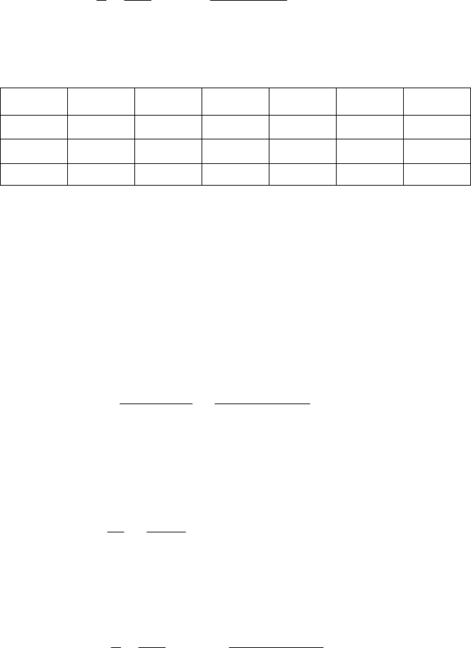
P = W/ (ld) = 1750/ [32(64)] = 0.854 MPa
l/d = 64/32 = 2
Eq. (12-7):
3
2
255 10 15
640 0.797
0.854
rN
ScP
Eq. (12-16), Figs. 12-16, 12-19, and 12-21
l/d yy1y1/2y1/4yl/d
h0/c 2 0.98 0.83 0.61 0.36 0.92
P/pmax 2 0.84 0.54 0.45 0.31 0.65
Q/rcNl 2 3.1 3.45 4.2 5.08 3.20
h0 = 0.92 c = 0.92(0.025) = 0.023 mm Ans.
pmax = P / 0.065 = 0.854/0.65 = 1.31 MPa Ans.
Q = 3.20 rcNl = 3.20(16)0.025(15)64 = 1.23 (103) mm3/s Ans.
______________________________________________________________________________
12-3 Given: dmax = 3.000 in, bmin = 3.005 in, l = 1.5 in, W = 800 lbf, N = 600 rev/min, and
SAE 10 and SAE 40 at 150F.
min max
min
3.005 3.000 0.0025 in
22
3.000 / 2 1.500 in
/ 1.5 / 3 0.5
/ 1.5 / 0.0025 600
600 / 60 10 rev/s
800 177.78 psi
1.5(3)
bd
c
r
ld
rc
N
W
Pld
Fig. 12-12: SAE 10 at 150F, 1.75 reynµµ
26
21.75(10 )(10)
600 0.0354
177.78
rN
ScP
Figs. 12-16 and 12-21: h0/c = 0.11 and P/pmax = 0.21
0
max
0.11(0.0025) 0.000 275 in .
177.78 / 0.21 847 psi .
hA
p Ans
ns
Fig. 12-12: SAE 40 at 150F, 4.5 reynµµ
Chapter 12, Page 2/26
Draft
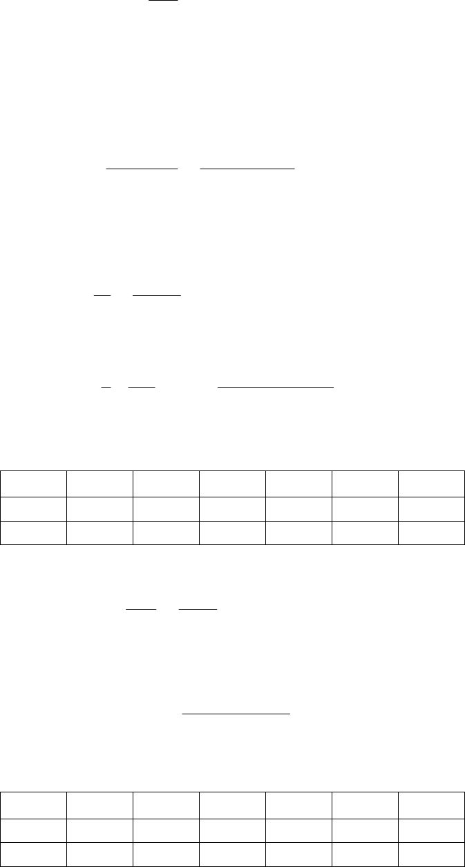
0max
0
max
4.5
0.0354 0.0910
1.75
/ 0.19, / 0.275
0.19(0.0025) 0.000 475 in .
177.78 / 0.275 646 psi .
S
hc Pp
hA
pA
ns
ns
______________________________________________________________________________
12-4 Given: dmax = 3.250 in, bmin = 3.256 in, l = 3.25 in, W = 800 lbf, and N = 1000 rev/min.
min max
min
3.256 3.250 0.003
22
3.250 / 2 1.625 in
/ 3 / 3.250 0.923
/ 1.625 / 0.003 542
1000 / 60 16.67 rev/s
800 82.05 psi
3(3.25)
bd
c
r
ld
rc
N
W
Pld
Fig. 12-14: SAE 20W at 150F,
= 2.85
reyn
26
22.85(10 )(16.67)
542 0.1701
82.05
rN
ScP
From Eq. (12-16), and Figs. 12-16 and 12-21:
l/d yy1y1/2y1/4yl/d
ho/c 0.923 0.85 0.48 0.28 0.15 0.46
P/pmax 0.923 0.83 0.45 0.32 0.22 0.43
max
0.46 0.46(0.003) 0.001 38 in .
82.05 191 psi .
0.43 0.43
o
hc A
P
pA
ns
ns
Fig. 12-14: SAE 20W-40 at 150F,
= 4.4
reyn
6
24.4(10 )(16.67)
542 0.263
82.05
S
From Eq. (12-16), and Figs. 12-16 and 12-21:
l/d yy1y1/2y1/4yl/d
ho/c 0.923 0.91 0.6 0.38 0.2 0.58
P/pmax 0.923 0.83 0.48 0.35 0.24 0.46
Chapter 12, Page 3/26
Draft

0
max
0.58 0.58(0.003) 0.001 74 in .
8205 82.05 178 psi .
0.46 0.46
hc A
pA
ns
ns
______________________________________________________________________________
12-5 Given: dmax = 2.000 in, bmin = 2.0024 in, l = 1 in, W = 600 lbf, N = 800 rev/min, and SAE
20 at 130F.
min max
min
2.0024 2 0.0012 in
22
21 in, / 1 / 2 0.50
22
/ 1 / 0.0012 833
800 / 60 13.33 rev/s
600 300 psi
2(1)
bd
c
d
rld
rc
N
W
Pld
Fig. 12-12: SAE 20 at 130F, 3.75 reynµµ
26
23.75(10 )(13.3)
833 0.115
300
rN
ScP
From Figs. 12-16, 12-18 and 12-19:
0
0
/ 0.23, / 3.8, / ( ) 5.3
0.23(0.0012) 0.000 276 in .
3.8 0.004 56
833
hc rfc QrcNl
hA
f
ns
The power loss due to friction is
3
2 2 (0.004 56)(600)(1)(13.33)
778(12) 778(12)
0.0245 Btu/s .
5.3
5.3(1)(0.0012)(13.33)(1)
0.0848 in / s .
fWrN
H
Ans
QrcNl
Ans
______________________________________________________________________________
12-6 Given: dmax = 25 mm, bmin = 25.04 mm, l/d = 1, W = 1.25 kN,
= 50 mPas, and N =
1200 rev/min.
Chapter 12, Page 4/26
Draft
min max
min
2
25.04 25 0.02 mm
22
/ 2 25 / 2 12.5 mm, / 1
/ 12.5 / 0.02 625
1200 / 60 20 rev/s
1250 2 MPa
25
bd
c
rd ld
rc
N
W
Pld
For µ = 50 MPa · s,
23
2
6
50(10 )(20)
625 0.195
2(10 )
rN
ScP
From Figs. 12-16, 12-18 and 12-20:
0
0
/ 0.52, / 4.5, / 0.57
0.52(0.02) 0.0104 mm .
4.5 0.0072
625
0.0072(1.25)(12.5) 0.1125 N · m
s
hc frc QQ
hA
f
TfWr
ns
The power loss due to friction is
H = 2πT N = 2π (0.1125)(20) = 14.14 W Ans.
Q
s = 0.57Q The side flow is 57% of Q Ans.
______________________________________________________________________________
12-7 Given: dmax = 1.25 in, bmin = 1.252 in, l = 2 in, W = 620 lbf,
= 8.5
reyn, and N =
1120 rev/min.
min max
min
26
2
1.252 1.25 0.001 in
22
/ 2 1.25 / 2 0.625 in
/ 0.625 / 0.001 625
1120 / 60 18.67 rev/s
620 248 psi
1.25(2)
8.5(10 )(18.67)
625 0.250
248
/ 2 / 1.25 1.6
bd
c
rd
rc
N
W
Pld
rN
ScP
ld
From Eq. (12-16), and Figs. 12-16, 12-18, and 12-19
Chapter 12, Page 5/26
Draft
l/d yy1y1/2y1/4yl/d
h0/c 1.6 0.9 0.58 0.36 0.185 0.69
fr/c 1.6 4.5 5.3 6.5 8 4.92
Q/rcNl 1.6 3 3.98 4.97 5.6 3.59
h0 = 0.69 c = 0.69(0.001) =0.000 69 in Ans.
f = 4.92/(r/c) = 4.92/625 = 0.007 87 Ans.
Q = 1.6 rcNl = 1.6(0.625) 0.001(18.57) 2 = 0.0833 in3/s Ans.
______________________________________________________________________________
12-8 Given: dmax = 75.00 mm, bmin = 75.10 mm, l = 36 mm, W = 2 kN, N = 720 rev/min, and
SAE 20 and SAE 40 at 60C.
min max
min
75.10 75 0.05 mm
22
/ 36 / 75 0.48 0.5 (close enough)
/ 2 75 / 2 37.5 mm
/ 37.5 / 0.05 750
720 / 60 12 rev/s
2000 0.741 MPa
75(36)
bd
c
ld
rd
rc
N
W
Pld
Fig. 12-13: SAE 20 at 60C, µ = 18.5 MPa · s
23
2
6
18.5(10 )(12)
750 0.169
0.741(10 )
rN
ScP
From Figures 12-16, 12-18 and 12-21:
0m
0
/ 0.29, / 5.1, / 0.315
0.29(0.05) 0.0145 mm .
5.1 / 750 0.0068
0.0068(2)(37.5) 0.51 N · m
hc frc Pp
hAn
f
TfWr
ax
s
The heat loss rate equals the rate of work on the film
H
loss = 2πT N = 2π(0.51)(12) = 38.5 W Ans.
p
max = 0.741/0.315 = 2.35 MPa Ans.
Fig. 12-13: SAE 40 at 60C, µ = 37 MPa · s
Chapter 12, Page 6/26
Draft

S = 0.169(37)/18.5 = 0.338
From Figures 12-16, 12-18 and 12-21:
0m
0
loss
max
/ 0.42, / 8.5, / 0.38
0.42(0.05) 0.021 mm .
8.5 / 750 0.0113
0.0113(2)(37.5) 0.85 N · m
2 2 (0.85)(12) 64 W .
0.741 / 0.38 1.95 MPa .
hc frc Pp
hAns
f
TfWr
HTN Ans
pA
ax
ns
_____________________________________________________________________________
12-9 Given: dmax = 56.00 mm, bmin = 56.05 mm, l = 28 mm, W = 2.4 kN, N = 900 rev/min, and
SAE 40 at 65C.
min max
min
56.05 56 0.025 mm
22
/ 2 56 / 2 28 mm
/ 28 / 0.025 1120
/ 28 / 56 0.5, 900 / 60 15 rev/s
2400 1.53 MPa
28(56)
bd
c
rd
rc
ld N
P
Fig. 12-13: SAE 40 at 65C, µ = 30 MPa · s
23
2
6
30(10 )(15)
1120 0.369
1.53(10 )
rN
ScP
From Figures 12-16, 12-18, 12-19 and 12-20:
0
0
/ 0.44, / 8.5, / 0.71, / ( ) 4.85
0.44(0.025) 0.011 mm .
8.5 / 1000 0.007 59
0.007 59(2.4)(28) 0.51 N · m
2 2 (0.51)(15) 48.1 W .
4.85 4.85(28)(0.0
s
hc frc QQ QrcNl
hAns
f
TfWr
HTN Ans
QrcNl
3
3
25)(15)(28) 1426 mm /s
0.71(1426) 1012 mm /s .
s
QAns
_____________________________________________________________________________
12-10 Consider the bearings as specified by
minimum f : 0
0
, b
d
t
t
db
maximum W: 0
0
, b
d
t
t
db
Chapter 12, Page 7/26
Draft
d
and differing only in d and .
ig. µ = 1.38(106) reyn
/448) = 0.185(106)
Preliminaries:
2
/1
/ ( ) 700 / (1.25 ) 448 psi
3600 / 60 60 rev/s
ld
PW ld
N
Fig. 12-16:
minimum f :
S0.08
maximum W: 0.20S
F 12-12:
µN/P = 1.38(106)(60
Eq. (12-7):
/
rS
cµN
P
m
For minimu f :
6
0.08 658
0.185(10 )
0.625 / 658 0.000 950 0.001 in
r
c
c
If this is c min ,
b d = 2(0.001) = 0.002 in
The median clearance is
0.001
22
db db
tt tt
min
cc
ran nge for this bearing is
and the clea ce ra
2
d
t
cb
t
which is a function only of the tolerances.
For maximum W:
6
0.2 1040
0.185(10 )
0.625 / 1040 0.000 600 0.0005 in
r
c
c
If this is cmin
Chapter 12, Page 8/26
Draft
min
min
2 2(0.0005) 0.001 in
0.0005
22
2
db db
db
bd c
tt tt
cc
tt
c
The difference (mean) in clearance between the two clearance ranges, crange, is
range 0.001 0.0005
22
0.0005 in
db db
tt tt
c
For the minimum f bearing
b d = 0.002 in
d = b 0.002 in
d
= b 0.001 in
For the same b, tb and td, we need to change the journal diameter by 0.001 in.
Increasing d of the minimum friction bearing by 0.001 in, defines of the maximum
_____________________________________________________________________________
2-11 Given: SAE 40, N = 10 rev/s, Ts = 140F, l/d = 1, d = 3.000 in, b = 3.003 in, W = 675
or
For the maximum W bearing
0.001 ( 0.002)
0.001 in
ddb b
d
load bearing. Thus, the clearance range provides for bearing dimensions which are
attainable in manufacturing. Ans.
1
lbf.
min max
min
3.003 3 0.0015 in
22
/ 2 3 / 2 1.5 in
/ 1.5 / 0.0015 1000
675 75 psi
3(3)
bd
c
rd
rc
W
Pld
Trial #1: Fr om Figure 12-12 for T = 160°F, µ = 3.5 µ reyn,
26
2
2(160 140) 40
3.5(10 )(10)
1000 0.4667
75
TF
rN
ScP
From Fig. 12-24,
Chapter 12, Page 9/26
Draft
2
9.70 0.349 109 6.009 40(0.4667) 0.047 467(0.4667) 3.16
75
3.16 3.16 24.4 F
9.70 9.70
T
P
P
T
Discrepancy = 40 24.4 = 15.6°F
Trial #2: T = 150°F, µ = 4.5 µ reyn,
6
2
2(150 140) 20
4.5 10 10
1000 0.6
75
TF
S
From Fig. 12-24,
2
9.70 0.349 109 6.009 40(0.6) 0.047 467(0.6) 3.97
75
3.97 3.97 30.7 F
9.70 9.70
T
P
P
T
Discrepancy = 20 30.7 = 10.7°F
Trial #3: T = 154°F, µ = 4 µ reyn,
6
2
2(154 140) 28
410 10
1000 0.533
75
TF
S
From Fig. 12-24,
2
9.70 0.349 109 6.009 40(0.533) 0.047 467(0.533) 3.57
75
3.57 3.57 27.6 F
9.70 9.70
T
P
P
T
Discrepancy = 28 27.6 = 0.4°F O.K.
T = 140 +28/2 = 154°F Ans.
s 12-16, 12-18, to 12-20:
av
2av
) 140
/ 2 154 (28 / 2) 168
0.4
F
TT T F
S
1av / 2 154 (28 / 2TT T
From Figure
Chapter 12, Page 10/26
Draft
0
0
loss
0.75, 11, 3.6, 0.33
0.75(0.0015) 0.001 13 in .
11 0.011
1000
0.0075(3)(40) 0.9 N · m
2 0.011 675 1.5 10
20.075 Btu/s .
778 12 778 12
3.6 3.
s
hfrQQ
ccrcNlQ
hAns
f
TfWr
fWrN
HA
QrcNl
3
3
6(1.5)0.0015(10)3 0.243 in /s .
0.33(0.243) 0.0802 in /s .
s
Ans
QAns
ns
_____________________________________________________________________________
2-12 Given: d = 2.5 in, b = 2.504 in, cmin = 0.002 in, W = 1200 lbf, SAE = 20, Ts = 110°F,
P = W/(ld) = 1200/(2.5) = 192 psi, N = 1120/60 = 18.67 rev/s
For a trial film temperature, let Tf = 150°F
Table 12-1:
= 0.0136 exp[1271.6/(150 + 95)] = 2.441
reyn
Eq. (12-7):
1
N = 1120 rev/min, and l = 2.5 in.
2
6
22
2.441 10 18.67
2.5 / 2 0.927
0.002 192
rN
ScP
Fig. 12-24:
2
192 0.349 109 6.009 40 0.0927 0.047 467 0.0927
9.70
17.9 F
T
av
av
17.9
110 119.0 F
22
150 119.0 31.0 F
s
f
T
TT
TT
which is not 0.1 or less, therefore try averaging for the new trial film temperature, let
new
150 119.0
( ) 134.5 F
2
f
T
ing a spreadsheet (table also shows the first trial)
Proceed with additional trials us
Chapter 12, Page 11/26
Draft
Trial
Tf
' S T Tav Tf Tav
New
Tf
150.0 2.441 0.0927 17.9 119.0 31.0 134.5
134.5 3.466 0.1317 22.6 121.3 13.2 127.9
127.9 4.084 0.1551 25.4 122.7 5.2 125.3
125.3 4.369 0.1659 26.7 123.3 2.0 124.3
124.3 4.485 0.1704 27.2 123.6 0.7 124.0
124.0 4.521 0.1717 27.4 123.7 0.3 123.8
123.8 4.545 0.1726 27.5 123.7 0.1 123.8
Note that the convergence begins rapidly. There are ways to speed this, but at this point
they would only add complexity.
(a)
6
4.545(10 ), 0.1726µS
From Fig. 12-16: 0
0
0.482, 0.482(0.002) 0.000 964 in
hh
c
From Fig. 12-17:
= 56° Ans.
(b) e = c h0 = 0.002 0.000 964 = 0.001 04 in Ans.
(c) From Fig. 12-18: 4.10, 4.10(0.002 /1.25) 0.006 56 .
fr
f
Ans
c
(d) T = f Wr = 0.006 56(1200)(1.25) = 9.84 lbf · in
2 2 (9.84)(1120 / 60) 0.124 Btu/s .
778(12) 778(12)
TN
HAns
(e) From Fig. 12-19: 4.16
Q
rcNl
3
1120
4.16(1.25)(0.002) (2.5) 0.485 in /s .
60
QA
ns
From Fig. 12-20: 3
0.6, 0.6(0.485) 0.291 in /s .
s
s
QQA
Q ns
(f) From Fig. 12-21:
2
max
max
/1200 / 2.5
0.45, 427 psi .
0.45 0.45
Wld
P
p
Ans
p
From Fig. 12-22:
max 16 .
p
A
ns
Chapter 12, Page 12/26
Draft
(g) From Fig. 12-22: 082 .
p
A
ns
(h) From the trial tabl Ans. e, Tf = 123.8°F
T = 110 + 27.5 = 137.5°F Ans.
_____
2-13 Given: d = 1.250 in, td = 0.001 in, b = 1.252 in, tb = 0.003 in, l = 1.25 in, W = 250 lbf,
P = W/(ld) = 250/1.25 = 160 psi, N = 1750/60 = 29.17 rev/s
For the clearance, c = 0.002 0.001 in. Thus, cmin = 0.001 in, cmedian = 0.002 in, and
For cmin = 0.001 in, start with a trial film temperature of Tf = 135°F
Table 12-1:
= 0.0158 exp[1157.5/(135 + 95)] = 2.423
reyn
Eq. (12-7):
(i) With T = 27.5°F from the trial table, Ts +
________________________________________________________________________
1
N = 1750 rev/min, SAE 10 lubricant, sump temperature Ts = 120°F.
2
cmax = 0.003 in.
6
22
2.423 10 29.17
1.25 / 2 0.1725
0.001 160
rN
ScP
Fig. 12-24:
2
160 0.349 109 6.009 40 0.1725 0.047 467 0.1725
9.70
22.9 F
T
av
av
22.9
120 131.4 F
22
135 131.4 3.6 F
s
f
T
TT
TT
which is not 0.1 or less, therefore try averaging for the new trial film temperature, let
new
135 131.4
( ) 133.2 F
2
f
T
h additional trials using a spreadsheet (table also shows the first trial)
Trial
' S T Tav TfTav
New
Proceed wit
Tf Tf
1 2. 0.1 5 1 135.0 423 72 22.9 31.4 3.6 33.2
133.2 2.521 0.1795 23.6 131.8 1.4 132.5
132.5 2.560 0.1823 23.9 131.9 0.6 132.2
132.2 2.578 0.1836 24.0 132.0 0.2 132.1
132.1 2.583 0.1840 24.0 132.0 0.1 132.1
Chapter 12, Page 13/26
Draft

With Tf = 132.1°F, T = 24.0°F,
= 2.583
reyn, S = 0.1840,
Tmax = Ts + T = 120 + 24.0 = 144.0°F
Fig. 12-16: h0/c = 0.50, h0 = 0.50(0.001) = 0.000 50 in
= 1 h0/c = 1 0.50 = 0.05 in
Fig. 12-18: r f /c = 4.25, f = 4.25/(0.625/0.001) = 0.006 8
Fig. 12-19: Q/(rcNl) = 4.13, Q = 4.13(0.625)0.001(29.17)1.25 = 0.0941 in3/s
Fig. 12-20: Qs/Q = 0.58, Qs = 0.58(0.0941) = 0.0546 in /s
The above can be repeated for cmedian = 0.002 in, and cmax = 0.003 in. The results are
cmin 0.001 cmedian
0.002 in
cmax 0.003
3
shown below.
in in
T132.1 125.6 124.1
1
0.00050 0.00069 0.00038
f
0.0068 0.0058 0.0059
Q/( )
0.0941 0.207 0.321
Q
0.0546 0.170
f
2.583 3.002 3.112
S 0.184 0.0534 0.0246
24.0 11.1 8.2
Tmax 144.0 131.1 28.2
h0/c 0.5 0.23 0.125
h0
0.50 0.77 0.88
r/c 4.25 1.8 1.22
f
rcNl 4.13 4.55 4.7
Q
s /Q 0.58 0.82 0.90
Qs 0.289
____________________________________________________________________________
2-14 Computer programs will vary.
______________________________________________
2-15 Note to the Instructor: In the first printing of the 9th edition, the l/d ratio and the
ill be
_
1
_______________________________
1
lubrication constant
were omitted. The values to use are l/d = 1, and
= 1. This w
updated in the next printing. We apologize for any inconvenience this may have caused.
Chapter 12, Page 14/26
Draft
ring
nowledge the environmental temperature’s role in establishing the sump
Given: dmax = 2.500 in, bmin = 2.504 in, l/d = 1, N = 1120 rev/min, SAE 20 lubricant, W =
600 lbf load with minimal clearance: We will start by using W = 600 lbf (nd = 2). The
lo
In a step-by-step fashion, we are building a skill for natural circulation bearings.
• Given the average film temperature, establish the bearing properties.
• Given a sump temperature, find the average film temperature, then establish the bea
properties.
• Now we ack
temperature. Sec. 12-9 and Ex. 12-5 address this problem.
300 lbf, A = 60 in2, T = 70F, and
= 1.
task is to iteratively find the average film temperature, Tf , which makes Hgen and
Hss equal.
min max
min
2.504 2.500 0.002 in
22
bd
c
N = 1120/60 = 18.67 rev/s
2
600 96 psi
2.5
W
Pld
6
22
10 18.67
1.25 0.0760
0.002 96
rN
ScP
Table 12-1:
= 0.0136 exp[1271.6/(Tf + 95)]
gen
2545 2545 600 18.67 0.002
1050 1050
54.3
f
rf
HWNc
cc
fr
c
r
CR
loss
2.7 60 / 144 70
111
0.5625 70
ff
f
A
HTT T
T
Start with trial values of Tf of 220 and 240F.
Trial Tf
S f r/c
Hgen Hloss
220 0.770 0. 9 05 1.9 103.2 84.4
240 0.605 0.046 1.7 92.3 95.6
As a linear approximation, let Hgen = mTf + b. Substituting the two sets of values of
f
Tand Hgen we find that Hgen = 0.545 Tf +223.1. Setting this equal to Hloss and
solving for Tf gives Tf = 237F.
Chapter 12, Page 15/26
Draft
Tr
S
ial Tf f r/c
Hgen Hloss
237 0.627 0. 8 04 1.73 93.9 94.0
which is satisfactory.
Table 12-16: h0/c = 0.21, h0 = 0.21 (0.002) = 000 42 in
Fig. 12-24:
2
96 0.349 109 6.009 4 0.048 0.047 467 0.048
9.7
6.31 F
T
T1 = Ts = Tf T = 237 6.31/2 = 233.8F
Tmax = T1 + T = 233.8 + 6.31 = 240.1F
Trumpler’s design criteria:
0.002 + 0.000 04d = 0.002 + 0.000 04(2.5) = 0.000 30 in < h0 O.K.
Tmax = 240.1F < 250F O.K.
2
300 48 psi 300 psi . .
2.5
st
WOK
ld
nd = 2 (assessed at W = 600 lbf) O.K.
We see that the design passes Trumpler’s criteria and is deemed acceptable.
For an operating load of W = 300 lbf, it can be shown that Tf = 219.3F,
= 0.78, S =
_____________________________________________________________________________
2-16 Given: , SAE 30, Ts = 120F, ps = 50 psi,
0/60 = 33.33 rev/s, W = 4600 lbf, b 0.250 in,
0.118, f r/c = 3.09, Hgen = Hloss = 84 Btu/h, h0 = , T = 10.5F, T1 = 224.6F, and Tmax =
235.1F.
10.000 0.005
0.001 0.000
3.500 in, 3.505 indb
N = 200 earing length = 2 in, groove width =
and Hloss 5000 Btu/hr.
min
b
c
max
min
3.505 3.500 0.0025 in
22
d
r = d/ 2 = 3.500/2 = 1.750 in
r / c = 1.750/0.0025 = 700
l
= (2 0.25)/2 = 0.875 in
Chapter 12, Page 16/26
Draft
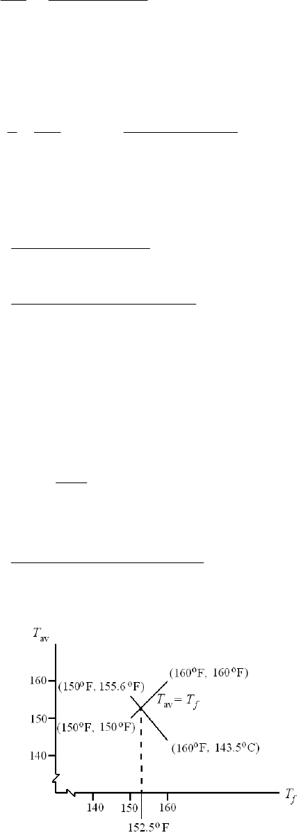
l
/ d = 0.875/3.500 = 0.25
4600W
P 751 psi
4 4 1.750 0.875rl
Trial #1: Choose (Tf )1 = 150°F. From Table 12-1,
= 0.0141 exp[1360.0/(150 + 95)] = 3.63 µ reyn
26
23.63(10 )(33.33)
700 0.0789
751
rN
ScP
From Figs. 12-16 and 12-18: = 0.9, f r/ c = 3.6
From Eq. (12-24),
2
24
2
24
0.012
T 3( / )
1 1.5
0.0123 3.6 0.0789 4600 71.2 F
1 1.5(0.9) 50 1.750
s
fr cSW
pr
Tav = Ts + T / 2 = 120 + 71.2/2 = 155.6F
Trial #2: Choose (Tf )2 = 160°F. From Table 12-1
= 0.0141 exp[1360.0/(160 + 95)] = 2.92 µ reyn
2.92
0.0789 0.0635
3.63
S
From Figs. 12-16 and 12-18: = 0.915, f r/ c =3
2
0.0123 3 0.0635 4600
24
46.9 F
11.5 0.915 50 1.750
T
Tav = 120 + 46.9/2 = 143.5F
Chapter 12, Page 17/26
Draft
Trial #3: Thus, the plot gives (Tf )3 = 152.5°F. From Table 12-1
= 0.0141 exp[1360.0/(152.5 + 95)] = 3.43 µ reyn
3.43
0.0789 0.0746
3.63
S
gs. 12-16 and 12-18: = 0.905, f r/ c =3.4
From Fi
2
24
0.0123 3.4 0.0746 4600 63.2 F
1 1.5 0.905 50 1.750
T
Tav = 120 + 63.2/2 = 151.6F
152.5 151.6 152.1 F Try 152 F
2
f
T
Result is close. Choose
Table 12-1:
= 0.0141 exp[1360.0/(152 + 95)] = 3.47 µ reyn
0
2
24
av
3.47
0.0789 0.0754S
3.63
3.4, 0.902, 0.098
0.0123 3.4 0.0754 4600 64.1 F
1 1.5 0.902 50 1.750
120 64.1 / 2 152.1 F O.K.
fr h
cc
T
T
h0 = 0.098(0.0025) = 0.000 245 in
T
max = Ts + T = 120 + 64.1 = 184.1F
Eq. (12-22):
6
3
1 1.5 1 1.5 0.902
3 3 3.47 10 0.875
1.047 in /s
s
Ql
3
3
22
50 1.750 0.0025
s
prc
Hloss =
CpQs T = 0.0311(0.42)1.047(64.1) = 0.877 Btu/s
0.0002 + 0.000 04(3.5) = 0.000 34 in > 0.000 245 Not O.K.
.
__ __ ____________________________________
= 0.877(602) = 3160 Btu/h O.K.
Trumpler’s design criteria:
T
max = 184.1°F < 250°F O.K.
P
st = 751 psi > 300 psi Not O.K
n = 1, as done Not O.K.
____ __________ _______________________
Chapter 12, Page 18/26
Draft
12-17 Given: 0.00 0.010
0.05 0.000
50.00 mm, 50.084 mmdb
, SAE 30, Ts = 55C, ps = 200 kPa,
N = 288 gth = 55 mm, groove width = 5 mm, 0/60 = 48 rev/s, W = 10 kN, bearing len and
Hloss 300 W.
min max
min
50.084 50 0.042 mm
22
bd
c
r = d/ 2 = 50/2 = 25 mm
r / c = 25/0.042 = 595
l
= (55 5)/2 = 25 mm
l
/ d = 25/50 = 0.5
3
10 10
W4 MPa
4 4 25 25
Prl
Trial #1: Choose (Tf )1 = 79°C. From Fig. 12-13, µ = 13 MPa · s.
23
2
6
13(10 )(48)
595 0.0552
4(10 )
rN
ScP
From Figs. 12-16 and 12-18: = 0.85, f r/ c = 2.3
From Eq. (12-25),
62
24
62
24
978(1
T 0 ) ( / )
1 1.5
978(10 ) 2.3(0.0552)(10 ) 76.3 C
1 1.5(0.85) 200(25)
s
fr cSW
pr
Tav = Ts + T / 2 = 55 + 76.3/2 = 93.2C
Trial #2: Choose (Tf )2 = 100°C. From Fig. 12-13, µ = 7 MPa · s.
7
0.0552 0.0297
13
S
From Figs. 12-16 and 12-18: = 0.90, f r/ c =1.6
62
978(10 ) 1.6(0.0297)(10 )
24
26.9 C
11.5(0.9) 200(25)
T
Tav = 55 + 26.9/2 = 68.5C
Chapter 12, Page 19/26
Draft
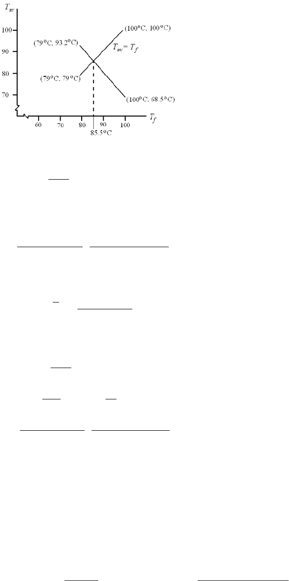
Trial #3: Thus, the plot gives (Tf )3 = 85.5°C. From Fig. 12-13, µ = 10.5 MPa · s.
10.5
0.0552 0.0446
13
S
From Figs. 12-16 and 12-18: = 0.87, f r/ c =2.2
62
24
978(10 ) 2.2(0.0457)(10 ) 58.9 C
1 1.5(0.87 ) 200(25)
T
Tav = 55 + 58.9/2 = 84.5C
Result is close. Choose
85.5 84.5 85 C
2
f
T
Fig. 12-13: µ = 10.5 MPa · s
0
62
24
av
10.5
0.0552 0.0446
13
0.87, 2.2, 0.13
978(10 ) 2.2(0.0457)(10 ) 58.9 C or 138 F
1 1.5(0.87 ) 200(25 )
55 58.9 / 2 84.5 C O.K.
S
fr h
cc
T
T
From Eq. (12-22)
h0 = 0.13(0.042) = 0.005 46 mm or 0.000 215 in
T
max = Ts + T = 55 + 58.9 = 113.9C or 237°F
3
3
22
6
333
200 25 0.042
(1 1.5 ) 1 1.5 0.87
3 3 10.5 10 25
3156 mm /s 3156 25.4 0.193 in /s
s
s
prc
Qµl
Hloss =
CpQs T = 0.0311(0.42)0.193(138) = 0.348 Btu/s
= 1.05(0.348) = 0.365 kW = 365 W not O.K.
Chapter 12, Page 20/26
Draft
Trumpler’s design criteria:
0.0002 + 0.000 04(50/25.4) = 0.000 279 in > h0 Not O.K.
T
max = 237°F O.K.
P
st = 4000 kPa or 581 psi > 300 psi Not O.K.
n = 1, as done Not O.K.
_____________________________________________________________________________
12-18 So far, we’ve performed elements of the design task. Now let’s do it more completely.
The values of the unilateral tolerances, tb and td , reflect the routine capabilities of the
bushing vendor and the in-house capabilities. While the designer has to live with these,
his approach should not depend on them. They can be incorporated later.
First we shall find the minimum size of the journal which satisfies Trumpler’s constraint
of Pst ≤ 300 psi.
2
min
300
2
300
2 / 600( / )
900 1.73 in
2(300)(0.5)
st
W
Pdl
WW
d
dl d l d
d
In this problem we will take journal diameter as the nominal value and the bushing bore
as a variable. In the next problem, we will take the bushing bore as nominal and the
journal diameter as free.
To determine where the constraints are, we will set tb = td = 0, and thereby shrink the
design window to a point.
We set d = 2.000 in
b = d + 2cmin = d + 2c
nd = 2 (This makes Trumpler’s nd ≤ 2 tight)
and construct a table.
Chapter 12, Page 21/26
Draft
c b d *
f
T Tmax hoPst Tmax nfom
0.0010 2.0020 2 215.50 312.0 -5.74
0.0011 2.0022 2 206.75 293.0 -6.06
0.0012 2.0024 2 198.50 277.0 -6.37
0.0013 2.0026 2 191.40 262.8 -6.66
0.0014 2.0028 2 185.23 250.4 -6.94
0.0015 2.0030 2 179.80 239.6 -7.20
0.0016 2.0032 2 175.00 230.1 -7.45
0.0017 2.0034 2 171.13 220.3 -7.65
0.0018 2.0036 2 166.92 213.9 -7.91
0.0019 2.0038 2 163.50 206.9 -8.12
0.0020 2.0040 2 160.40 200.6 -8.32
*Sample calculation for the first entry of this column.
Iteration yields: 215.5 F
f
T
With
215.5 F
f
T
, from Table 12-1
66
26
0.0136(10 ) exp[1271.6 / (215.5 95)] 0.817(10 ) reyn
900
3000 / 60 50 rev/s, 225 psi
4
1 0.817(10 )(50) 0.182
0.001 225
µ
NP
S
From Figs. 12-16 and 12-18: e = 0.7, f r/c = 5.5
Eq. (12–24):
2
24
av
0.0123(5.5)(0.182)(900 ) 191.6 F
[1 1.5(0.7 )](30)(1 )
191.6 F
120 F 215.8 F 215.5 F
2
F
T
T
For the nominal 2-in bearing, the various clearances show that we have been in contact
with the recurving of (ho)min . The figure of merit (the parasitic friction torque plus the
pumping torque negated) is best at c = 0.0018 in. For the nominal 2-in bearing, we will
place the top of the design window at cmin = 0.002 in, and b = d + 2(0.002) = 2.004 in. At
this point, add the b and d unilateral tolerances:
0.000 0.003
0.001 0.000
2.000 in, 2.004 indb
Now we can check the performance at cmin , c, and cmax . Of immediate interest is the
fom of the median clearance assembly, 9.82, as compared to any other satisfactory
bearing ensemble.
Chapter 12, Page 22/26
Draft

If a nominal 1.875 in bearing is possible, construct another table with tb = 0 and td = 0.
c b d
f
T Tmax hoPst Tmax nfom
0.0020 1.879 1.875 157.2 194.30 7.36
0.0030 1.881 1.875 138.6 157.10 8.64
0.0035 1.882 1.875 133.5 147.10 9.05
0.0040 1.883 1.875 130.0 140.10 9.32
0.0050 1.885 1.875 125.7 131.45 9.59
0.0055 1.886 1.875 124.4 128.80 9.63
0.0060 1.887 1.875 123.4 126.80 9.64
The range of clearance is 0.0030 < c < 0.0055 in. That is enough room to fit in our
design window.
0.000 0.003
0.001 0.000
1.875 in, 1.881 indb
The ensemble median assembly has a fom = 9.31.
We just had room to fit in a design window based upon the (h0)min constraint. Further
reduction in nominal diameter will preclude any smaller bearings. A table constructed for
a d = 1.750 in journal will prove this.
We choose the nominal 1.875-in bearing ensemble because it has the largest figure of
merit. Ans.
_____________________________________________________________________________
12-19 This is the same as Prob. 12-18 but uses design variables of nominal bushing bore b and
radial clearance c.
The approach is similar to that of Prob. 12-18 and the tables will change slightly. In the
table for a nominal b = 1.875 in, note that at c = 0.003 in the constraints are “loose.” Set
b = 1.875 in
d = 1.875 2(0.003) = 1.869 in
For the ensemble
0.003 0.000
0.001 0.001
1.875 in, 1.869 inbd
Analyze at cmin = 0.003, c = 0.004 in and cmax = 0.005 in
At
min loss
0.003 in: 138.4, 3.160, 0.0297, 1035 Btu/h
f
cTµSH
and the
Trumpler conditions are met.
At
0.004 in: 130 F,
f
cT
= 3.872, S = 0.0205, Hloss = 1106 Btu/h, fom = 9.246
Chapter 12, Page 23/26
Draft
and the Trumpler conditions are O.K.
At
max 0.005 in: 125.68 F,
f
cT
= 4.325, S = 0.014 66, Hloss = 1129 Btu/h and the
Trumpler conditions are O.K.
The ensemble figure of merit is slightly better; this bearing is slightly smaller. The
lubricant cooler has sufficient capacity.
_____________________________________________________________________________
12-20 Table 12-1:
(
reyn) =
0 (106) exp [b / (T + 95)] b and T in F
The conversion from
reyn to mPas is given on p. 620. For a temperature of C degrees
Celsius, T = 1.8 C + 32. Substituting into the above equation gives
(mPas) = 6.89
0 (106) exp [b / (1.8 C + 32+ 95)]
= 6.89
0 (106) exp [b / (1.8 C + 127)] Ans.
For SAE 50 oil at 70C, from Table 12-1,
0 = 0.0170 (106) reyn, and b = 1509.6F.
From the equation,
= 6.89(0.0170) 106(106) exp {1509.6/[1.8(70) + 127]}
= 45.7 mPas Ans.
From Fig. 12-13,
= 39 mPas Ans.
The figure gives a value of about 15 % lower than the equation.
_____________________________________________________________________________
12-21 Originally
0.000 0.003
0.001 0.000
2.000 in, 2.005 indb
Doubled,
0.000 0.006
0.002 0.000
4.000 in, 4.010 indb
The radial load quadrupled to 3600 lbf when the analyses for parts (a) and (b) were
carried out. Some of the results are:
Part c
S Tf f r/c Qs h
0 /c e Hloss h
0
Trumpler
h0 f
(a) 0.007 3.416 0.0310 135.1 0.1612 6.56 0.1032 0.897 9898 0.000 722 0.000 360 0.005 67
(b) 0.0035 3.416 0.0310 135.1 0.1612 0.870 0.1032 0.897 1237 0.000 361 0.000 280 0.005 67
The side flow Qs differs because there is a c3 term and consequently an 8-fold increase.
H
loss is related by a 9898/1237 or an 8-fold increase. The existing h0 is related by a 2-fold
increase. Trumpler’s (h0)min is related by a 1.286-fold increase.
Chapter 12, Page 24/26
Draft
_____________________________________________________________________________
12-22 Given: Oiles SP 500 alloy brass bushing, L = 0.75 in, D = 0.75 in, T = 70F, F = 400
lbf, N = 250 rev/min, and w = 0.004 in.
Table 12-8: K = 0.6(1010) in3min/(lbffth)
P = F/ (DL) = 400/ [0.75(0.75)] = 711 psi
V =
DN/ 12 =
(0.75)250/12 = 49.1 ft/min
Tables 12-10 and 12-11: f 1 = 1.8, f 2 = 1.0
Table 12-12: PVmax = 46 700 psift/min, Pmax = 3560 psi, Vmax = 100 ft/min
max 2
4 4 400 905 psi 3560 psi . .
0.75
F
PO
DL K
PV = 711 (49.1) = 34 910 psift/min < 46 700 psift/min O.K.
Eq. (12-32) can be written as
12
4F
f
fK Vt
DL
w
Solving for t,
10
12
0.75 0.75 0.004
4 4 1.8 1.0 0.6 10 49.1 400
833.1 h 833.1 60 49 900 min
DL
tffKVF
w
Cycles = Nt = 250 (49 900) = 12.5 (106) cycles Ans.
_____________________________________________________________________________
12-23 Given: Oiles SP 500 alloy brass bushing, wmax = 0.002 in for 1000 h, N = 400 rev/min, F
= 100 lbf, CR = 2.7 Btu/ (hft2F), Tmax = 300F, f s = 0.03, and nd = 2.
Estimate bushing length with f1 = f2 = 1, and K = 0.6(10-10) in3 · min/(lbf · ft · h)
Using Eq. (12-32) with ndF for F,
10
12 1(1)(0.6)(10 )(2)(100)(400)(1000) 0.80 in
3 3(0.002)
d
ffKnFNt
L
w
From Eq. (12-38), with fs = 0.03 from Table 12-9 applying nd = 2 to F
Chapter 12, Page 25/26
Draft
and
2
CR 2.7 Btu/(h · ft · °F)
720 720(0.03)(2)(100)(400) 3.58 in
778(2.7)(300 70)
0.80 3.58 in
sd
CR f
fnFN
LJTT
L
Trial 1: Let L = 1 in, D = 1 in
max
4 4(2)(100) 255 psi 3560 psi . .
(1)(1)
2(100) 200 psi
1(1)
(1)(400) 104.7 ft/min 100 ft/min . .
12 12
d
d
nF
PO
DL
nF
PDL
DN
VN
K
otOK
Trial 2: Try D = 7/8 in = 0.875 in, L = 1 in
max
4(2)(100) 291 psi 3560 psi . .
(0.875)(1)
2(100) 229 psi
0.875(1)
(0.875)(400) 91.6 ft/min 100 ft/min . .
12
PO
P
VO
K
K
PV = 229(91.6) = 20 976 psi · ft/min < 46 700 psi · ft/min O.K.
V f1
33 1.3
91.6 f1
100 1.8
1
new 1
91.6 33
1.3 (1.8 1.3) 1.74
100 33
1.74 0.80 1.39 in
old
f
LfL
Trial 3: Try D = 7/8 in = 0.875 in, L = 1.5 in
max
4(2)(100) 194 psi 3560 psi . .
(0.875)(1.5)
2(100) 152 psi, 91.6 ft/min
0.875(1.5)
152(91.6) 13 923 psi · ft/min 46 700 psi · ft/min . .
7 / 8 in, 1.5 in is acceptable .
PO
PV
PV O K
DL Ans
K
Chapter 12, Page 26/26
Draft
Chapter 12, Page 27/26
Suggestion: Try smaller sizes.
Draft
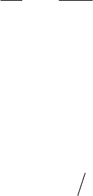
Chapter 13
13-1 17 / 8 2.125 in
P
d
2
3
1120 2.125 4.375 in
544
GP
N
dd
N
8 4.375 35 teeth .
GG
NPd An s
ns
ns
s
2.125 4.375 / 2 3.25 in .CA
______________________________________________________________________________
13-2
1600 15 / 60 400 rev/min .
G
nA
3 mm .pm An
3 15 60 2 112.5 mm .CA
ns
ns
______________________________________________________________________________
13-3
16 4 64 teeth .
G
NA
64 6 384 mm .
GG
dNm An s
16 6 96 mm .
PP
dNm An s
ns
s
ns
s
384 96 / 2 240 mm .CA
______________________________________________________________________________
13-4 Mesh:
1/ 1/ 3 0.3333 in .aP An
1.25 / 1.25 / 3 0.4167 in .bP A
0.0834 in .cba Ans
/ / 3 1.047 in .pP An
/ 2 1.047 / 2 0.523 in .tp Ans
Pinion Base-Circle: 11
/21/37 idNP n
17 cos 20 6.578 in .
b
dA
ns
Gear Base-Circle: 22
/ 28 / 3 9.333 indNP
29.333cos 20 8.770 in .
b
dA
ns
Base pitch:
cos / 3 cos 20 0.984 in .
bc
p
pA
ns
Contact Ratio: / 1.53 / 0.984 1.55 .
cabb
mLp Ans
See the following figure for a drawing of the gears and the arc lengths.
Chapter 13, Page 1/35
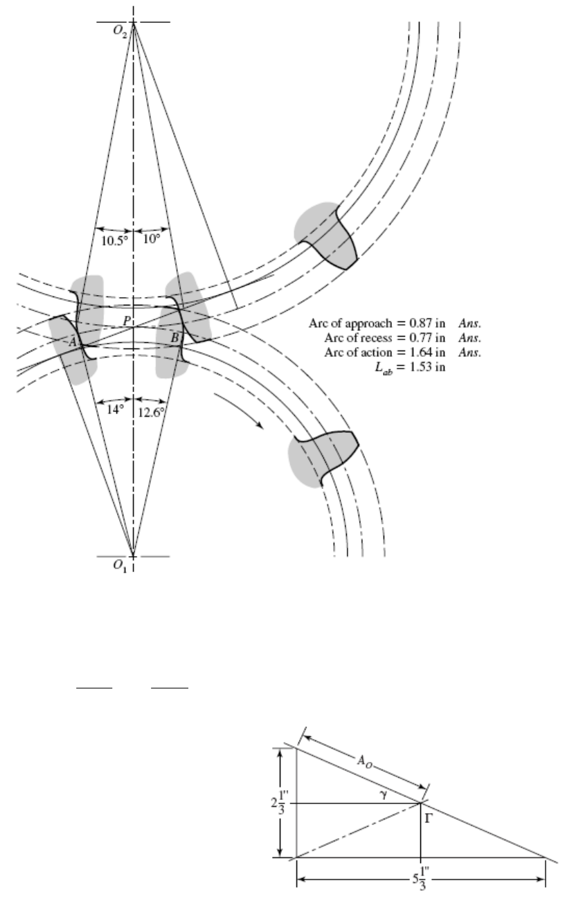
______________________________________________________________________________
13-5
(a)
1/ 2
22
0
14 / 6 32 / 6 2.910 in .
22
A A
ns
(b)
1
tan 14 / 32 23.63 .
A
ns
1
tan 32 /14 66.37 .
A
ns
(c)
Ans. 14 / 6 2.333 in
P
d
32 / 6 5.333 in .
G
dA ns
Chapter 13, Page 2/35
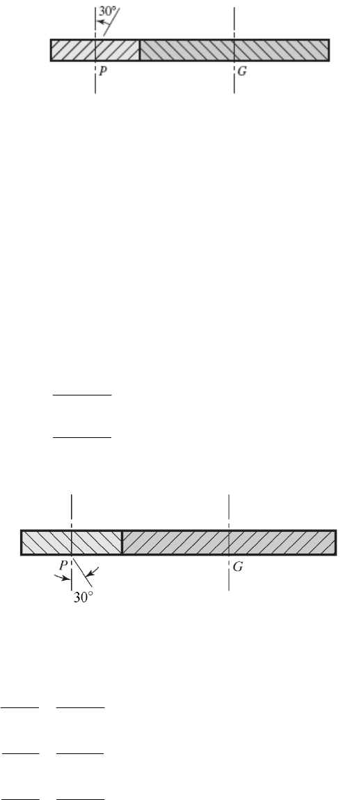
(d) From Table 13-3, 0.3A0 = 0.3(2.910) = 0.873 in and 10/P = 10/6 = 1.67
0.873 < 1.67 0.873 in .FAns
______________________________________________________________________________
13-6
(a) / / 4 0.7854 in
nn
pP
/ cos 0.7854 / cos 30 0.9069 in
tn
pp
/ tan 0.9069 / tan 30 1.571 in
xt
pp
(b) Eq. (13-7): cos 0.7854cos 25 0.7380 in .
nb n n
p
pA
ns
(c)
cos 4 cos30 3.464 teeth/in
tn
pP
11
tan tan / cos tan (tan 25 / cos30 ) 28.3 .
tn
A
ns
(d) Table 13-4:
1/ 4 0.250 in .aA ns
ns
1.25 / 4 0.3125 in .bA
20 5.774 in .
4cos30
P
dA
ns
36 10.39 in .
4cos 30
G
dA
ns
______________________________________________________________________________
13-7
19 teeth, 57 teeth, 20 , 2.5 mm
PGnn
NN m
(a)
2.5 7.854 mm .
nn
p
mA
ns
7.854 9.069 mm .
cos cos30
n
t
p
p
Ans
9.069 15.71 mm .
tan tan 30
t
x
p
p
Ans
(b) 2.5 2.887 mm .
cos cos30
n
t
m
mA
ns
Chapter 13, Page 3/35
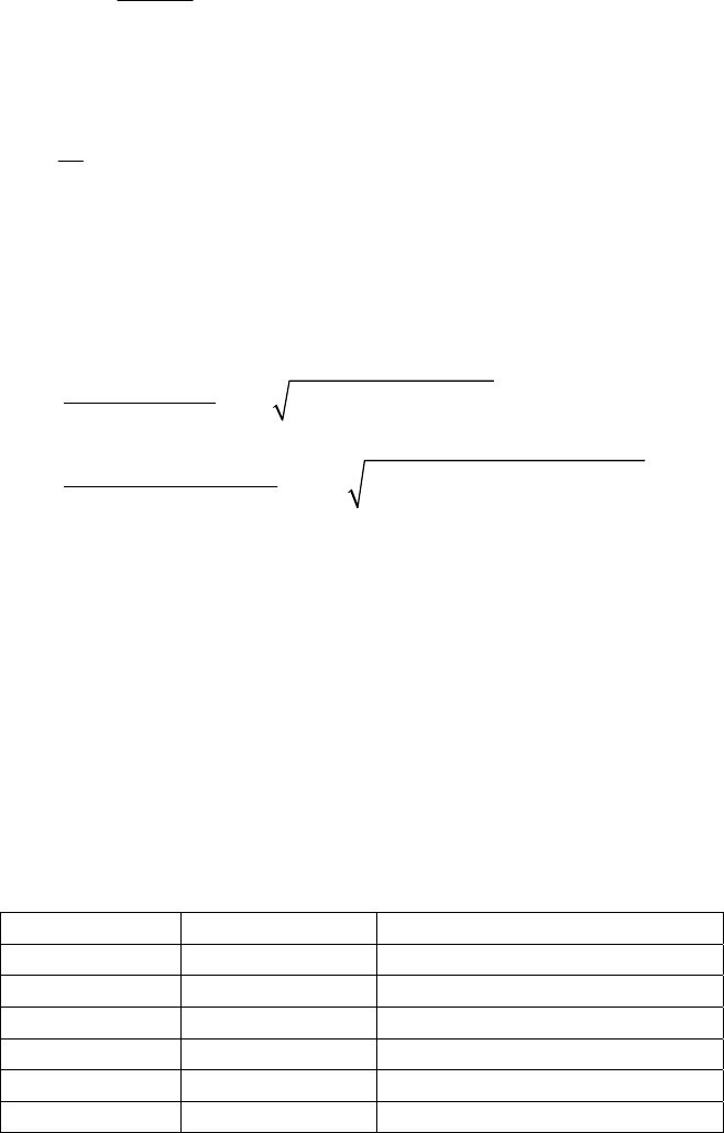
1tan 20
tan 22.80 .
cos 30
tAns
(c) 2.5 mm .
n
am Ans
1.25 1.25 2.5 3.125 mm .
n
bm A ns
19 2.887 =54.85 mm .
Pt
t
N
dNm
P
Ans
57 2.887 164.6 mm .
G
dA ns
______________________________________________________________________________
13-8 (a) Using Eq. (13-11) with k = 1,
= 20º, and m = 2,
22
2
22
2
212 sin
12 sin
21 2 2 1 2 2 sin 20 14.16 teeth
122 sin 20
P
k
Nmmm
m
Round up for the minimum integer number of teeth.
NP = 15 teeth Ans.
(b) Repeating (a) with m = 3, NP = 14.98 teeth. Rounding up, NP = 15 teeth. Ans.
(c) Repeating (a) with m = 4, NP = 15.44 teeth. Rounding up, NP = 16 teeth. Ans.
(d) Repeating (a) with m = 5, NP = 15.74 teeth. Rounding up, NP = 16 teeth. Ans.
Alternatively, a useful table can be generated to determine the largest gear that can mesh
with a specified pinion, and thus also the maximum gear ratio with a specified pinion.
The Max NG column was generated using Eq. (13-12) with k = 1,
= 20º, and rounding
up to the next integer.
Min NP Max NG Max m = Max NG / Min NP
13 16 1.23
14 26 1.86
15 45 3.00
16 101 6.31
17 1309 77.00
18 unlimited unlimited
With this table, we can readily see that gear ratios up to 3 can be obtained with a
minimum NP of 15 teeth, and gear ratios up to 6.31 can be obtained with a minimum NP
of 16 teeth. This is consistent with the results previously obtained.
______________________________________________________________________________
Chapter 13, Page 4/35
13-9 Repeating the process shown in the solution to Prob. 13-8, except with
= 25º, we obtain
the following results.
(a) For m = 2, NP = 9.43 teeth. Rounding up, NP = 10 teeth. Ans.
(b) For m = 3, NP = 9.92 teeth. Rounding up, NP = 10 teeth. Ans.
(c) For m = 4, NP = 10.20 teeth. Rounding up, NP = 11 teeth. Ans.
(d) For m = 5, NP = 10.38 teeth. Rounding up, NP = 11 teeth. Ans.
For convenient reference, we will also generate the table from Eq. (13-12) for
= 25º.
Min NP Max NG Max m = Max NG / Min NP
9 13 1.44
10 32 3.20
11 249 22.64
12 unlimited unlimited
______________________________________________________________________________
13-10 (a) The smallest pinion tooth count that will run with itself is found from Eq. (13-10).
2
2
2
2
2113sin
3sin
21 113sin20
3sin 20
12.32 13 teeth .
P
k
N
Ans
(b) The smallest pinion that will mesh with a gear ratio of mG = 2.5, from Eq. (13-11)
is
22
2
22
2
212 sin
12 sin
21 2.5 2.5 1 2 2.5 sin 20
1 2 2.5 sin 20
14.64 15 teeth .
P
k
Nmmm
m
Ans
The largest gear-tooth count possible to mesh with this pinion, from Eq. (13-12) is
22 2
2
2
22
2
sin 4
42sin
15 sin 20 4 1
41 215sin 20
45.49 45 teeth .
P
G
P
Nk
NkN
Ans
Chapter 13, Page 5/35
(c) The smallest pinion that will mesh with a rack, from Eq. (13-13),
22
21
2
sin sin 20
17.097 18 teeth .
P
k
N
Ans
______________________________________________________________________________
13-11
20 , 30
n
From Eq. (13-19),
1
tan tan 20 / cos 30 22.80
t
(a) The smallest pinion tooth count that will run with itself, from Eq. (13-21) is
2
2
2
2
2cos 113sin
3sin
21cos30 1 1 3sin 22.80
3sin 22.80
8.48 9 teeth .
Pt
t
k
N
Ans
(b) The smallest pinion that will mesh with a gear ratio of m = 2.5, from Eq. (13-22)
is
22
2
21cos30 2.5 2.5 1 2 2.5 sin 22.80
1 2 2.5 sin 22.80
9.95 10 teeth .
P
N
Ans
The largest gear-tooth count possible to mesh with this pinion, from Eq. (13-23) is
22 2 2
2
22 2
22
sin 4 cos
4cos 2 sin
10 sin 22.80 4 1 cos 30
4 1 cos 30 2 20 sin 22.80
26.08 26 teeth .
Pt
G
Pt
Nk
NkN
Ans
(c) The smallest pinion that will mesh with a rack, from Eq. (13-24) is
22
21cos30
2cos
sin sin 22.80
11.53 12 teeth .
P
t
k
N
A
ns
______________________________________________________________________________
Chapter 13, Page 6/35
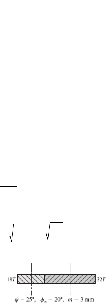
13-12 From Eq. (13-19), 11
tan tan 20
tan tan 22.796
cos cos30
n
t
Program Eq. (13-23) on a computer using a spreadsheet or code, and increment NP. The
first value of NP that can be doubled is NP = 10 teeth, where NG ≤ 26.01 teeth. So NG =
20 teeth will work. Higher tooth counts will work also, for example 11:22, 12:24, etc.
Use NP = 10 teeth, NG = 20 teeth Ans.
Note that the given diametral pitch (tooth size) is not relevant to the interference problem.
______________________________________________________________________________
13-13 From Eq. (13-19), 11
tan tan 20
tan tan 27.236
cos cos 45
n
t
Program Eq. (13-23) on a computer using a spreadsheet or code, and increment NP. The
first value of NP that can be doubled is NP = 6 teeth, where NG ≤ 17.6 teeth. So NG = 12
teeth will work. Higher tooth counts will work also, for example 7:14, 8:16, etc.
Use NP = 6 teeth, NG = 12 teeth Ans.
______________________________________________________________________________
13-14 The smallest pinion that will operate with a rack without interference is given by Eq. (13-
13).
2
2
sin
P
k
N
Setting k = 1 for full depth teeth, NP = 9 teeth, and solving for
,
11
21
2
sin sin 28.126 .
9
P
k
A
ns
N
______________________________________________________________________________
13-15
(a) Eq. (13-3): 3 mm .
nn
p
mAns
Eq. (13-16): / cos 3 / cos 25 10.40 mm .
tn
p
pA
ns
Eq. (13-17): / tan 10.40 / tan 25 22.30 mm .
xt
p
pA
ns
(b) Eq. (13-3): / 10.40 / 3.310 mm .
tt
mp Ans
Chapter 13, Page 7/35
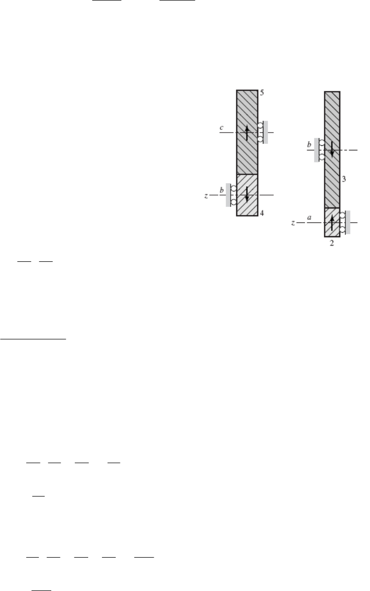
Eq. (13-19): 11
tan tan 20
tan tan 21.88 .
cos cos 25
n
tAns
(c) Eq. (13-2): dp = mt Np = 3.310 (18) = 59.58 mm Ans.
Eq. (13-2): dG = mt NG = 3.310 (32) = 105.92 mm Ans.
______________________________________________________________________________
13-16 (a) Sketches of the figures are shown to
determine the axial forces by inspection.
The axial force of gear 2 on shaft a is in the
negative z-direction. The axial force of gear 3 on
shaft b is in the positive z-direction. Ans.
The axial force of gear 4 on shaft b is in the
positive z-direction. The axial force of gear 5 on
shaft c is in the negative z-direction. Ans.
(b)
5
12 16 700 77.78 rev/min ccw .
48 36
c
nn Ans
(c)
212 / 12cos 30 1.155 in
P
d
348 / 12cos 30 4.619 in
G
d
1.155 4.619 2.887 in .
2
ab
CA
ns
ns
416 / 8cos 25 2.207 in
P
d
536 / 8cos 25 4.965 in
G
d
3.586 in .
bc
CA
______________________________________________________________________________
13-17 20 8 20 4
40 17 60 51
e
400 47.06 rev/min cw .
51
d
nA ns
______________________________________________________________________________
13-18 618 20 3 3
10 38 48 36 304
e
9
31200 11.84 rev/min cw .
304
nA ns
______________________________________________________________________________
Chapter 13, Page 8/35
13-19 (a)
12 1 540 162 rev/min cw about . .
40 1
c
nx Ans
(b)
12 / 8cos 23 1.630 in
P
d
40 / 8cos 23 5.432 in
G
d
3.531 in .
2
PG
dd
A
ns
(c) 32 8 in at the large end of the teeth. .
4
dA ns
______________________________________________________________________________
13-20 Applying Eq. (13-30), e = (N2 / N3) (N4 / N5) = 45. For an exact ratio, we will choose to
factor the train value into integers, such that
N2 / N3 = 9 (1)
N4 / N5 = 5 (2)
Assuming a constant diametral pitch in both stages, the geometry condition to satisfy the
in-line requirement of the compound reverted configuration is
N2 + N3 = N4 + N5 (3)
With three equations and four unknowns, one free choice is available. It is necessary that
all of the unknowns be integers. We will use a normalized approach to find the minimum
free choice to guarantee integers; that is, set the smallest gear of the largest stage to unity,
thus N3 = 1. From (1), N2 = 9. From (3),
N2 + N3 = 9 + 1 = 10 = N4 + N5
Substituting N4 = 5 N5 from (2) gives
10 = 5 N5 + N5 = 6 N5
N5 = 10 / 6 = 5 / 3
To eliminate this fraction, we need to multiply the original free choice by a multiple of 3.
In addition, the smallest gear needs to have sufficient teeth to avoid interference. From
Eq. (13-11) with k = 1,
= 20°, and m = 9, the minimum number of teeth on the pinion to
avoid interference is 17. Therefore, the smallest multiple of 3 greater than 17 is 18.
Setting N3 = 18 and repeating the solution of equations (1), (2), and (3) yields
N2 = 162 teeth
N
3 = 18 teeth
N
4 = 150 teeth
N
5 = 30 teeth Ans.
______________________________________________________________________________
Chapter 13, Page 9/35
13-21 The solution to Prob. 13-20 applies up to the point of determining the minimum number
of teeth to avoid interference. From Eq. (13-11), with k = 1,
= 25°, and m = 9, the
minimum number of teeth on the pinion to avoid interference is 11. Therefore, the
smallest multiple of 3 greater than 11 is 12. Setting N3 = 12 and repeating the solution of
equations (1), (2), and (3) yields
N2 = 108 teeth
N
3 = 12 teeth
N
4 = 100 teeth
N
5 = 20 teeth Ans.
______________________________________________________________________________
13-22 Applying Eq. (13-30), e = (N2 / N3) (N4 / N5) = 30. For an exact ratio, we will choose to
factor the train value into integers, such that
N2 / N3 = 6 (1)
N4 / N5 = 5 (2)
Assuming a constant diametral pitch in both stages, the geometry condition to satisfy the
in-line requirement of the compound reverted configuration is
N2 + N3 = N4 + N5 (3)
With three equations and four unknowns, one free choice is available. It is necessary that
all of the unknowns be integers. We will use a normalized approach to find the minimum
free choice to guarantee integers; that is, set the smallest gear of the largest stage to unity,
thus N3 = 1. From (1), N2 = 6. From (3),
N2 + N3 = 6 + 1 = 7 = N4 + N5
Substituting N4 = 5 N5 from (2) gives
7 = 5 N5 + N5 = 6 N5
N5 = 7 / 6
To eliminate this fraction, we need to multiply the original free choice by a multiple of 6.
In addition, the smallest gear needs to have sufficient teeth to avoid interference. From
Eq. (13-11) with k = 1,
= 20°, and m = 6, the minimum number of teeth on the pinion to
avoid interference is 16. Therefore, the smallest multiple of 3 greater than 16 is 18.
Setting N3 = 18 and repeating the solution of equations (1), (2), and (3) yields
N2 = 108 teeth
N
3 = 18 teeth
N
4 = 105 teeth
N
5 = 21 teeth Ans.
______________________________________________________________________________
Chapter 13, Page 10/35
13-23 Applying Eq. (13-30), e = (N2 / N3) (N4 / N5) = 45. For an approximate ratio, we will
choose to factor the train value into two equal stages, such that
23 45
//NN NN45
If we choose identical pinions such that interference is avoided, both stages will be
identical and the in-line geometry condition will automatically be satisfied. From Eq.
(13-11) with k = 1,
= 20°, and 45m, the minimum number of teeth on the pinions
to avoid interference is 17. Setting N3 = N5 = 17, we get
24
17 45 114.04 teethNN
Rounding to the nearest integer, we obtain
N2 = N4 = 114 teeth
N
3 = N5 = 17 teeth Ans.
Checking, the overall train value is e = (114 / 17) (114 / 17) = 44.97.
______________________________________________________________________________
13-24 H = 25 hp,
i = 2500 rev/min
Let ωo = 300 rev/min for minimal gear ratio to minimize gear size.
300 1
2500 8.333
o
i
24
35
1
8.333
o
i
NN
NN
Let 24
35
11
8.333 2.887
NN
NN
From Eq. (13-11) with k = 1,
= 20°, and m = 2.887, the minimum number of teeth on
the pinions to avoid interference is 15.
Let N2 = N4 = 15 teeth
N3 = N5 = 2.887(15) = 43.31 teeth
Try N3 = N5 = 43 teeth.
15 15 2500 304.2
43 43
o
Too big. Try N3 = N5 = 44.
Chapter 13, Page 11/35

15 15 2500 290.55 rev/min
44 44
o
N2 = N4 = 15 teeth, N3 = N5 = 44 teeth Ans.
______________________________________________________________________________
13-25 (a) The planet gears act as keys and the wheel speeds are the same as that of the ring
gear. Thus,
3900 16 / 48 300 rev/min .
A
nn Ans
(b)
56
0, , 1
FL
nn nne
6300
10 300
n
6
300 300n
6600 rev/min .nAns
(c) The wheel spins freely on icy surfaces, leaving no traction for the other wheel.
The car is stalled. Ans.
______________________________________________________________________________
13-26 (a) The motive power is divided equally among four wheels instead of two.
(b) Locking the center differential causes 50 percent of the power to be applied to the
rear wheels and 50 percent to the front wheels. If one of the rear wheels rests on a
slippery surface such as ice, the other rear wheel has no traction. But the front
wheels still provide traction, and so you have two-wheel drive. However, if the
rear differential is locked, you have 3-wheel drive because the rear-wheel power
is now distributed 50-50.
______________________________________________________________________________
13-27 Let gear 2 be first, then nF = n2 = 0. Let gear 6 be last, then nL = n6 = –12 rev/min.
20 16 16
30 34 51
LA
FA
nn
enn
16
01
51
AA
nn
2
12 17.49 rev/min (negative indicates cw) .
35 / 51
A
nA
ns
______________________________________________________________________________
13-28 Let gear 2 be first, then nF = n2 = 0 rev/min. Let gear 6 be last, then nL = n6 = 85
rev/min.
Chapter 13, Page 12/35
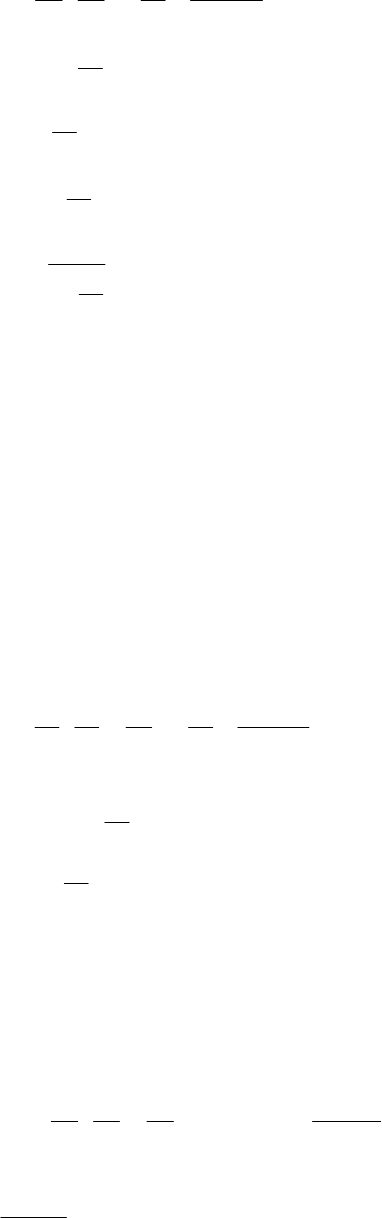
20 16 16
30 34 51
LA
FA
nn
enn
16
085
51
AA
nn
16 85
51
AA
nn
16
18
51
A
n
5
85 123.9 rev/min
16
151
A
n
The positive sign indicates the same direction as n6. 123.9 rev/min ccw .
A
nAns
______________________________________________________________________________
13-29 The geometry condition is 523
/2 /2ddd
4
d
. Since all the gears are meshed, they
will all have the same diametral pitch. Applying d = N / P,
523
/(2 ) /(2 ) / /NPNPNPN
4
P
52 3 4
2 2 12 2 16 2 12 68 teeth .NN N N Ans
Let gear 2 be first, nF = n2 = 320 rev/min. Let gear 5 be last, nL = n5 = 0 rev/min.
12 16 12 3
16 12 68 17
LA
FA
nn
enn
17
320 0
3
AA
nn
3320 68.57 rev/min
14
A
n
The negative sign indicates opposite of n2. 68.57 rev/min cw .
A
nAns
______________________________________________________________________________
13-30 Let nF = n2, then nL = n7 = 0.
5
5
20 16 36 0.5217
16 30 46
L
F
nn
enn
5
5
00.5217
10
n
n
Chapter 13, Page 13/35
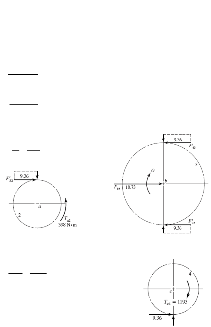
55
0.5217 10 nn
55
5.217 0.5217 0nn
51 0.5217 5.217n
5
5.217
1.5217
n
53.428 turns in same direction
b
nn
______________________________________________________________________________
13-31 (a) 2/60n
2 / 60 ( in N m, in W)HT Tn T H
So
3
60 10
2
9550 / ( in kW, in rev/min)
H
Tn
HnH n
9550 75 398 N m
1800
a
T
2
2
517 42.5 mm
22
mN
r
So 32
2
398 9.36 kN
42.5
ta
T
Fr
33
2 9.36 18.73 kN in the positive -direction. .
bb
FF x An s
(b)
4
4
551 127.5 mm
22
mN
r
49.36 127.5 1193 N m ccw
c
T
41193 N m cw .
c
TAns
Note: The solution is independent of the pressure angle.
______________________________________________________________________________
Chapter 13, Page 14/35
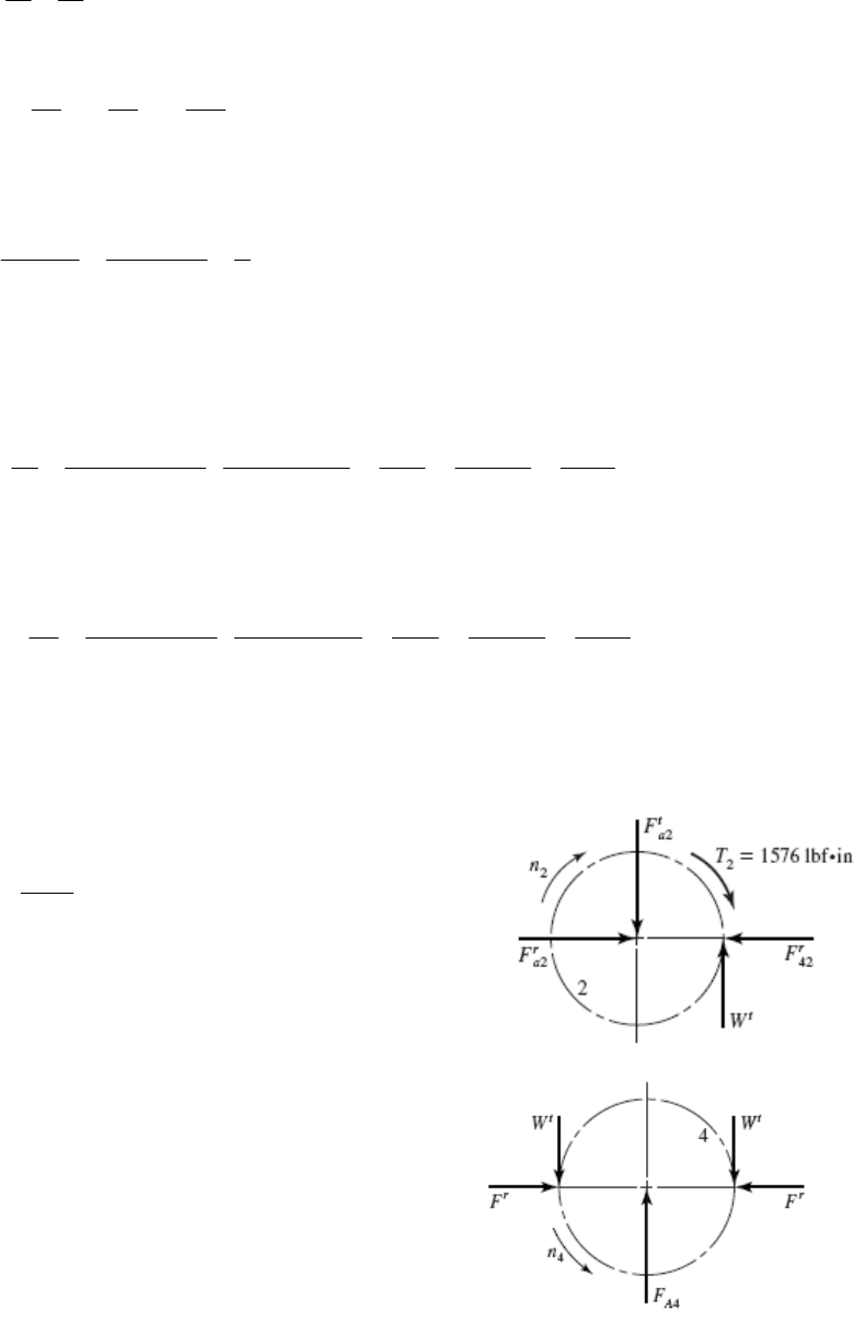
13-32 6
NN
dP
2456
4 in, 4 in, 6 in, 24 indddd
24 24 36 1/ 6
24 36 144
e
21000 rev/min
F
nn
60
L
nn
01
1000 6
LA A
FA A
nn n
enn n
200 rev/min
A
n
Noting that power equals torque times angular velocity, the input torque is
2
2
25 hp 550 lbf ft/s 60 s 1 rev 12 in 1576 lbf in
1000 rev/min hp min 2 rad ft
H
Tn
For 100 percent gear efficiency, the output power equals the input power, so
25 hp 550 lbf ft/s 60 s 1 rev 12 in 7878 lbf in
200 rev/min hp min 2 rad ft
arm
A
H
Tn
Next, we’ll confirm the output torque as we work through the force analysis and
complete the free body diagrams.
Gear 2
1576 788 lbf
2
t
W
32 788 tan 20 287 lbf
r
F
Gear 4
42 2 788 1576 lbf
t
A
FW
Chapter 13, Page 15/35
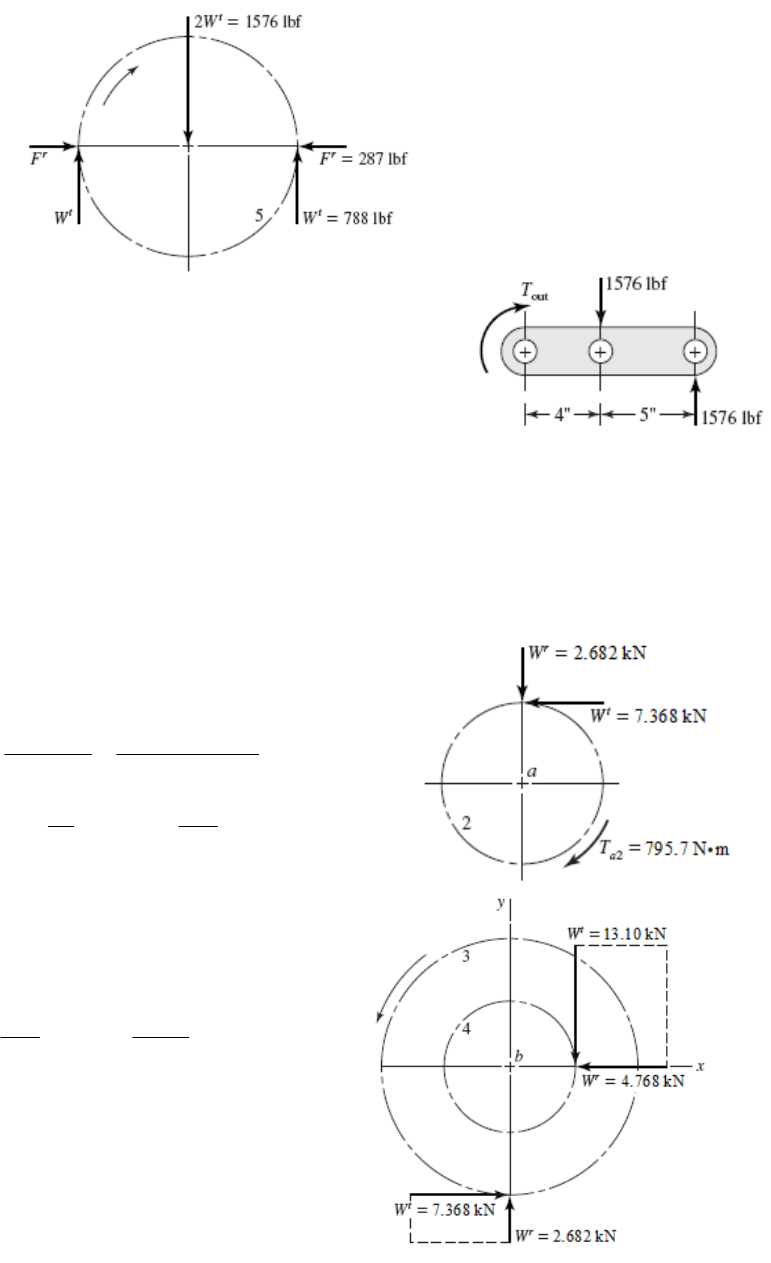
Gear 5
Arm
out 1576 9 1576 4 7880 lbf in .TA ns
______________________________________________________________________________
13-33 Given: m = 12 mm, nP = 1800 rev/min cw,
N2 = 18T, N3 = 32T, N4 = 18T, N5 = 48T
Pitch Diameters: d2 = 18(12) = 216 mm, d3 = 32(12) = 384 mm,
d4 = 18(12) = 216 mm, d5 = 48(12) = 576 mm
Gear 2
From Eq. (13-36),
60000 150
60000 7.368 kN
216 1800
t
H
Wdn
2
2
216
7.368 795.7 N m
22
at
d
TW
7.368 tan 20 2.682 kN
r
W
Gears 3 and 4
384
216 7.368
22
t
W
13.10 kN
t
W
W
13.10 tan 20 4.768 kN
r
Ans.
______________________________________________________________________________
Chapter 13, Page 16/35
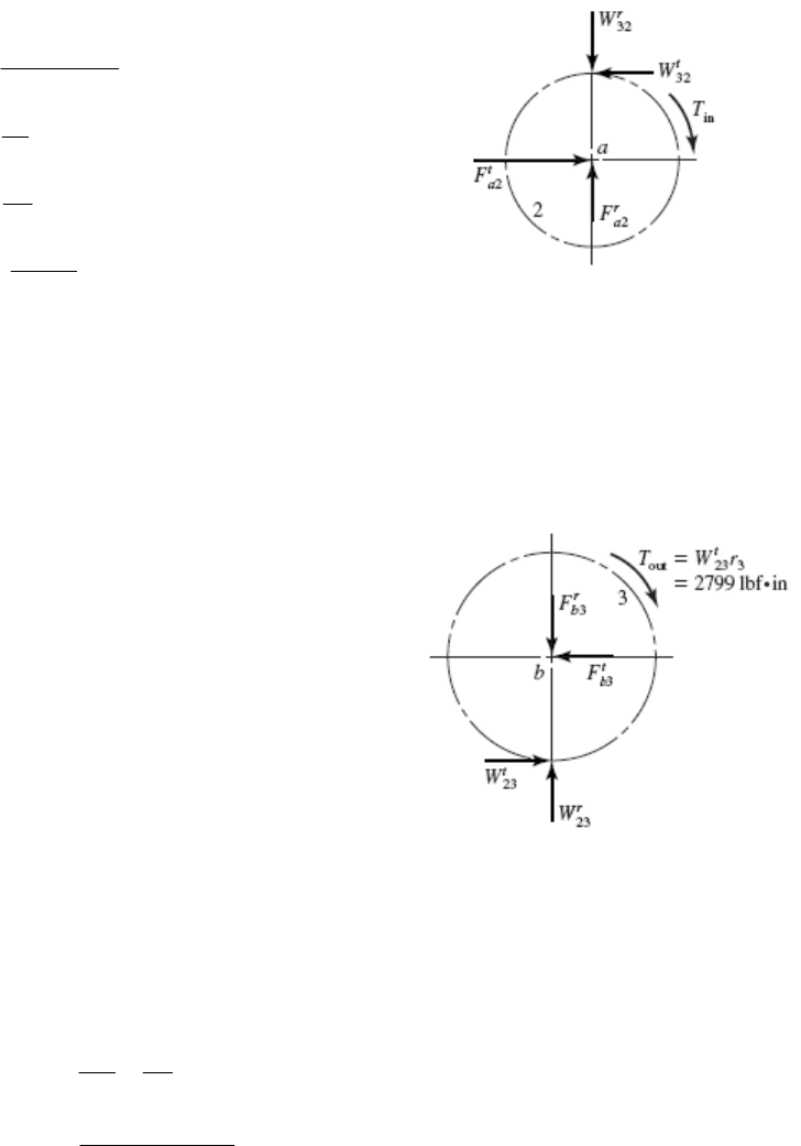
13-34 Given: P = 5 teeth/in, N2 = 18T, N3 = 45T,
20 ,
n
H = 32 hp, n2 = 1800 rev/min
Gear 2
in
63025 32 1120 lbf in
1800
T
18 3.600 in
5
P
d
45 9.000 in
5
G
d
32
1120 622 lbf
3.6 / 2
t
W
32 622 tan 20 226 lbf
r
W
232 232
622 lbf, 226 lbf
tt rr
aa
FW FW
1/2
22
2622 226 662 lbf
a
F
Each bearing on shaft a has the same radial load of RA = RB = 662/2 = 331 lbf.
Gear 3
23 32 622 lbf
tt
WW
23 32 226 lbf
rr
WW
32
662 lbf
bb
FF
662 / 2 331 lbf
CD
RR
Each bearing on shaft b has the same radial load which is equal to the radial load of
bearings A and B. Thus, all four bearings have the same radial load of 331 lbf. Ans.
______________________________________________________________________________
13-35 Given: P = 4 teeth/in, N
20 ,
n
P = 20T, n2 = 900 rev/min
2
20 5.000 in
4
P
N
dP
in
63025 30 2 4202 lbf in
900
T
32 in 2
/ / 2 4202 / 5 / 2 1681 lbf
td WT
W
32 1681 tan 20 612 lbf
r
Chapter 13, Page 17/35
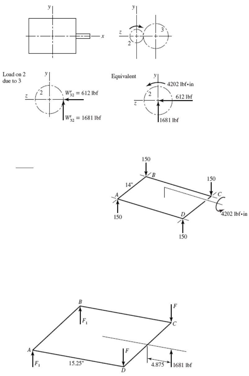
The motor mount resists the equivalent forces and torque.
The radial force due to torque is
4202 150 lbf
14 2
r
F
Forces reverse with rotational sense as
torque reverses.
The compressive loads at A and D are absorbed by the base plate, not the bolts. For
the tensions in C and D are
32 ,
t
W
0 1681 4.875 15.25 2 15.25 0 1109 lbf
AB
MF F
Chapter 13, Page 18/35
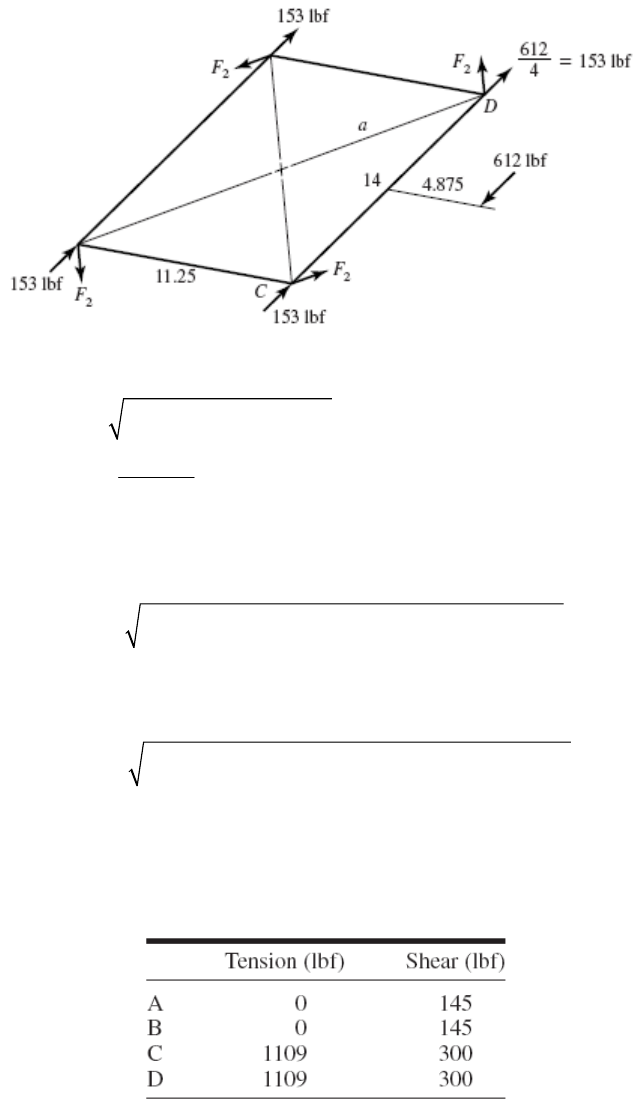
If reverses, 15.25 in changes to 13.25 in, 4.815 in changes to 2.875 in, and the forces
change direction. For A and B,
32
t
W
11
1681 2.875 2 13.25 0 182.4 lbfFF
For ,
32
r
W
612 4.875 11.25 / 2 6426 lbf inM
22
14 / 2 11.25 / 2 8.98 ina
2
6426 179 lbf
48.98
F
At C and D, the shear forces are:
22
1153 179 5.625 / 8.98 179 7 / 8.98
S
F
At A and B, the shear forces are:
22
2153 179 5.625 / 8.98 179 7 / 8.98
145 lbf
S
F
The shear forces are independent of the rotational sense.
The bolt tensions and the shear forces for cw rotation are,
Chapter 13, Page 19/35

For ccw rotation,
______________________________________________________________________________
13-36 (a) N2 = N4 = 15 teeth, N3 = N5 = 44 teeth
NN
Pd
dP
24
15 2.5 in .
6
dd Ans
35
44 7.33 in .
6
dd Ans
(b)
22
23
2.5 2500 1636 ft/min .
12 12
i
dn
VV V Ans
44
45
2.5 2500 15 / 44 558 ft/min .
12 12
o
dn
VVV Ans
(c) Input gears:
33000 25
33000 504.3 lbf 504 lbf .
1636
ti
i
H
WA
V
ns
tan 504.3 tan 20 184 lbf .
ri ti
WW Ans
504.3 537 lbf .
cos cos 20
ti
i
W
WA
ns
Output gears:
33000 25
33000 1478 lbf .
558
to
o
H
WA
V
ns
tan 1478 tan 20 538 lbf .
ro to
WW Ans
1478 1573 lbf .
cos 20 cos 20
to
o
W
WA
ns
(d) 22.5
504.3 630 lbf in .
22
iti
d
TW Ans
Chapter 13, Page 20/35

(e)
22
44 44
630 5420 lbf in .
15 15
oi
TT Ans
______________________________________________________________________________
13-37
35 hp, 1200 rev/min, =20
i
Hn
24 35
16 teeth, 48 teeth, 10 teeth/inNN NN P
(a)
2
intermediate 3 4
3
16 1200 400 rev/min
48
i
N
nnnn
N
Ans.
24
35
16 16 1200 133.3 rev/min
48 48
oi
NN
nn
NN
Ans.
(b) NN
Pd
dP
24
16 1.6 in .
10
dd Ans
35
48 4.8 in .
10
dd Ans
22
23
1.6 1200 502.7 ft/min .
12 12
i
dn
VV V Ans
44
45
1.6 400 167.6 ft/min .
12 12
o
dn
VVV Ans
(c)
33000 35
33000 2298 lbf lbf .
502.7
ti
i
H
WA
V
ns
tan 2298 tan 20 836.4 lbf .
ri ti
WW Ans
2298 2445 lbf .
cos cos 20
ti
i
W
WA
ns
33000 35
33000 6891 lbf .
167.6
to
o
H
WA
V
ns
tan 6891tan 20 2508 lbf .
ro to
WW Ans
6891 7333 lbf .
cos 20 cos 20
to
o
W
WA
ns
(d) 21.6
2298 1838 lbf in .
22
iti
d
TW Ans
(e)
22
48 48
1838 16 540 lbf in .
16 16
oi
TT Ans
______________________________________________________________________________
Chapter 13, Page 21/35
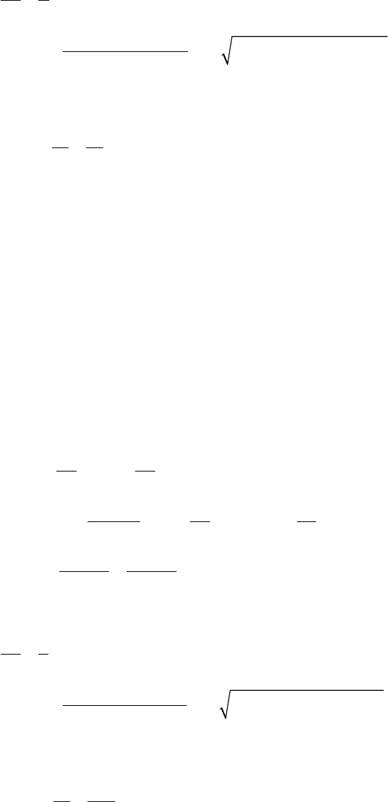
13-38 (a) For 2,
1
o
i
from Eq. (13-11), with m = 2, k = 1, 20
22
2
21 2 2 1 2 2 sin 20 14.16
122 sin20
P
N
ns
So
min 15 .
P
NA
(b) 15 1.875 teeth/in .
8
N
P Ans
d
(c) To transmit the same power with no change in pitch diameters, the speed and
transmitted force must remain the same.
For A, with
= 20°,
WtA = FA cos20° = 300 cos20° = 281.9 lbf
For A, with
= 25°, same transmitted load,
FA = WtA/cos25° = 281.9/cos25° = 311.0 lbf Ans.
Summing the torque about the shaft axis,
22
AB
tA tB
dd
WW
/2 20
281.9 704.75 lbf
/2 8
AA
tB tA tA
BB
dd
WW W
dd
704.75 777.6 lbf .
cos 25 cos 25
tB
B
W
F
Ans
______________________________________________________________________________
13-39 (a) For 5,
1
o
i
from Eq. (13-11), with m = 5, k = 1, 20
22
2
21 5 5 1 2 5 sin 25 10.4
125sin25
P
N
ns
So
min 11 .
P
NA
(b) 300 27.3 mm/tooth .
11
d
m Ans
N
(d) To transmit the same power with no change in pitch diameters, the speed and
transmitted force must remain the same.
Chapter 13, Page 22/35
For A, with
= 20°,
WtA = FA cos20° = 11 cos20° = 10.33 kN
For A, with
= 25°, same transmitted load,
FA = WtA/cos25° = 10.33 / cos 25° = 11.40 kN Ans.
Summing the torque about the shaft axis,
22
AB
tA tB
dd
WW
/2 600
11.40 22.80 kN
/ 2 300
AA
tB tA tA
BB
dd
WW W
dd
22.80 25.16 kN .
cos 25 cos 25
tB
B
W
F
Ans
______________________________________________________________________________
13-40 (a) Using Eq. (13-11) with k = 1,
= 20º, and m = 2,
22
2
22
2
212 sin
12 sin
21 2 2 1 2 2 sin 20 14.16 teeth
122 sin 20
P
k
Nmmm
m
Round up for the minimum integer number of teeth.
NF = 15 teeth, NC = 30 teeth Ans.
(b) 125 8.33 mm/tooth .
15
d
m Ans
N
(c) 2 kW 1000 W rev 60 s 100 N m
191 rev/min kW 2 rad min
H
T
(d) From Eq. (13-36),
60 000 2
60 000 1.60 kN 1600 N
125 191
t
H
Wdn
Ans.
Or, we could have obtained Wt directly from the torque and radius,
Chapter 13, Page 23/35
100 1600 N
/ 2 0.125 / 2
t
T
Wd
tan 1600 tan 20 583 N .
rt
WW Ans
1600 1700 N .
cos cos 20
t
W
WA
ns
______________________________________________________________________________
13-41 (a) Using Eq. (13-11) with k = 1,
= 20º, and m = 2,
22
2
22
2
212 sin
12 sin
21 2 2 1 2 2 sin 20 14.16 teeth
122 sin 20
P
k
Nmmm
m
Round up for the minimum integer number of teeth.
NC = 15 teeth, NF = 30 teeth Ans.
(b) 30 3 teeth/in .
10
N
P Ans
d
(c) 1 hp 550 lbf ft/s 12 in rev 60 s
70 rev/min hp ft 2 rad min
H
T
Ans.
900 lbf inT
(d) From Eqs. (13-34) and (13-35),
10 70 183.3 ft/min
12 12
dn
V
33000 1
33000 180 lbf
183.3
t
H
WV
Ans.
tan 180 tan 20 65.5 lbf .
rt
WW Ans
180 192 lbf .
cos cos 20
t
W
WA
ns
______________________________________________________________________________
13-42 (a) Eq. (13-14): 111
1.30
tan tan tan 18.5
3.88
PP
GG
Nd
Nd
Ans.
(b) Eq. (13-34):
2 1.30 600 408.4 ft/min
12 12
dn
V
Ans.
Chapter 13, Page 24/35
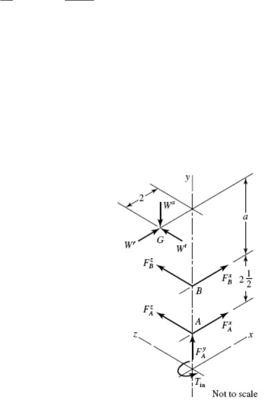
(c) Eq. (13-35): 10
33 000 33 000 808 lbf
408.4
t
H
WV
Ans.
Eq. (13-38): Ans.
tan cos 808 tan 20 cos18.5 279 lbf
rt
WW
Eq. (13-38): Ans.
tan sin 808tan 20 sin18.5 93.3 lbf
at
WW
The tangential and axial forces agree with Prob. 3-74, but the radial force given in Prob.
3-74 is shown here to be incorrect. Ans.
______________________________________________________________________________
13-43
in 63 025 / 63025 2.5 / 240 656.5 lbf inTHn
0
k
/ 656.5 / 2 328.3 lbf
t
WTr
1
tan 2 / 4 26.565
1
tan 4 / 2 63.435
2 1.5cos 26.565 / 2 2.67 ina
328.3tan 20 cos 26.565 106.9 lbf
r
W
328.3tan 20 sin 26.565 53.4 lbf
a
W
W = 106.9i – 53.4j + 328.3k lbf
RAG = –2i + 5.17j, RAB = 2.5j
4+
AG AB B
MR WR FT
Solving gives
2.5 2.5
zx
AB B B B
FF RF i
1697 656.6 445.9
AG RW i
j
k
So
1697 656.6 445.9 2.5 2.5
zx
BB
FFT i
j
kik
j
0
1697 / 2.5 678.8 lbf
z
B
F
656.6 lbf inT
445.9 / 2.5 178.4 lbf
x
B
F
So
1/ 2
22
678.8 178.4 702 lbf .
B
F
Ans
FA = – (FB + W)
= – (–178.8i – 678.8k + 106.9i – 53.4j + 328.3k)
= 71.5i + 53.4j + 350.5k
Chapter 13, Page 25/35
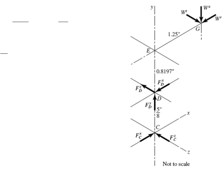
1/ 2
22
(radial) 71.5 350.5 358 lbf .
A
F
Ans
(thrust) 53.4 lbf .
A
FAns
______________________________________________________________________________
13-44
23
18 /10 1.8 in, 30 /10 3.0 indd
11
2
3
/2 0.9
tan tan 30.96
/2 1.5
d
d
180 59.04
90.5cos59.04 0.8197 in
16
DE
W
25 lbf
t
W
25 tan 20 cos 59.04 4.681 lbf
r
W
25 tan 20 sin 59.04 7.803 lbf
a
W = –4.681i – 7.803j +25k
R
DG = 0.8197j + 1.25i
R
DC = –0.625j
DDG DCC
MR WR FT0
20.49 31.25 5.917
DG RW i
j
k
RF
0.625 0.625
zx
DC C C C
FF i k
20.49 31.25 5.917 0.625 0.625
zx
CC
FFT i
j
kik
j
0
31.25 lbf in .TAns
Fi 9.47 32.8 lbf .
CAnsk
1/2
22
9.47 32.8 34.1 lbf .
C
F
Ans
0 4.79 7.80 57.8 lbf
D FF ijk
1/ 2
22
(radial) 4.79 57.8 58.0 lbf .
D
FA
ns
Ans
(thrust) 7.80 lbf .
a
D
FW
______________________________________________________________________________
Chapter 13, Page 26/35
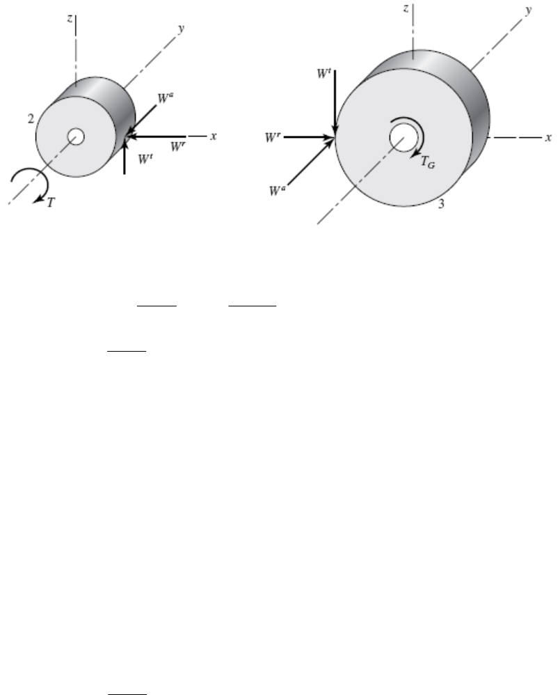
13-45
cos 4cos 30 3.464 teeth/in
tn
PP
11
tan tan 20
tan tan 22.80
cos cos30
n
t
18 5.196 in
3.464
P
d
The forces on the shafts will be equal and opposite of the forces transmitted to the
gears through the meshing teeth.
Pinion (Gear 2)
tan 800 tan 22.80 336 lbf
rt
t
WW
tan 800 tan 30 462 lbf
at
WW
336 462 800 lbf .
A
ns Wijk
1/2
22
2
336 462 800 983 lbf .WA
ns
Gear 3
336 462 800 lbf .
A
nsWijk
983 lbf .WAns
32 9.238 in
3.464
G
d
800 9.238 7390 lbf in
t
G
TWr
______________________________________________________________________________
Chapter 13, Page 27/35
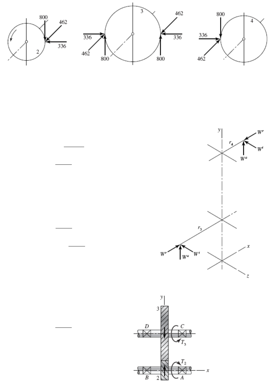
13-46 From Prob. 13-45 solution,
Notice that the idler shaft reaction contains a couple tending to turn the shaft end-over-
end. Also the idler teeth are bent both ways. Idlers are more severely loaded than other
gears, belying their name. Thus, be cautious.
______________________________________________________________________________
13-47 Gear 3:
cos 7 cos 30 6.062 teeth/in
tn
PP
tan 20
tan 0.4203, 22.8
cos 30
tt
3
54 8.908 in
6.062
d
500 lbf
t
W
500 tan 30 288.7 lbf
a
W
500 tan 22.8 210.2 lbf
r
W
3210.2 288.7 500 lbf .AnsWijk
Gear 4:
4
14 2.309 in
6.062
d
8.908
500 1929 lbf
2.309
t
W
1929 tan 30 1114 lbf
a
W
1929 tan 22.8 811 lbf
r
W
4811 1114 1929 lbf .Ans Wijk
______________________________________________________________________________
13-48
6cos 30 5.196 teeth/in
t
P
3
42 8.083 in
5.196
d
22.8
t
Chapter 13, Page 28/35
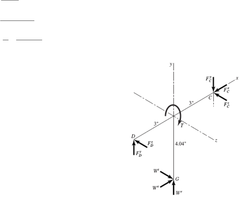
2
16 3.079 in
5.196
d
2
63025 25 916 lbf in
1720
T
916 595 lbf
3.079 / 2
tT
Wr
595 tan 30 344 lbf
a
W
595 tan 22.8 250 lbf
r
W
344 250 595 lbfWijk
6 , 3 4.04
DC DG
RiRi
j
(1)
DDCCDG
MR FR WT0
2404 1785 2140
DG RW i
j
k
66
zy
DC C C C
FF RF
j
k
Substituting and solving Eq. (1) gives
2404 lbf inTi
297.5 lbf
z
C
F
365.7 lbf
y
C
F
DC
FF F W0
Substituting and solving gives
344 lbf
x
C
F
106.7 lbf
y
D
F
297.5 lbf
z
D
F
344 356.7 297.5 lbf .
CAns Fijk
106.7 297.5 lbf .
DAnsFjk
______________________________________________________________________________
Chapter 13, Page 29/35
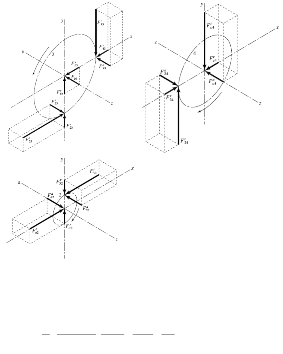
13-49
Since the transverse pressure angle is specified, we will assume the given module is also
in terms of the transverse orientation.
22
416 64 mmdmN
33
4 36 144 mmdmN
44
4 28 112 mmdmN
6 kW 1000 W rev 60 s 35.81 N m
1600 rev/min kW 2 rad min
H
T
2
35.81 1119 N
/ 2 0.064 / 2
tT
Wd
Chapter 13, Page 30/35
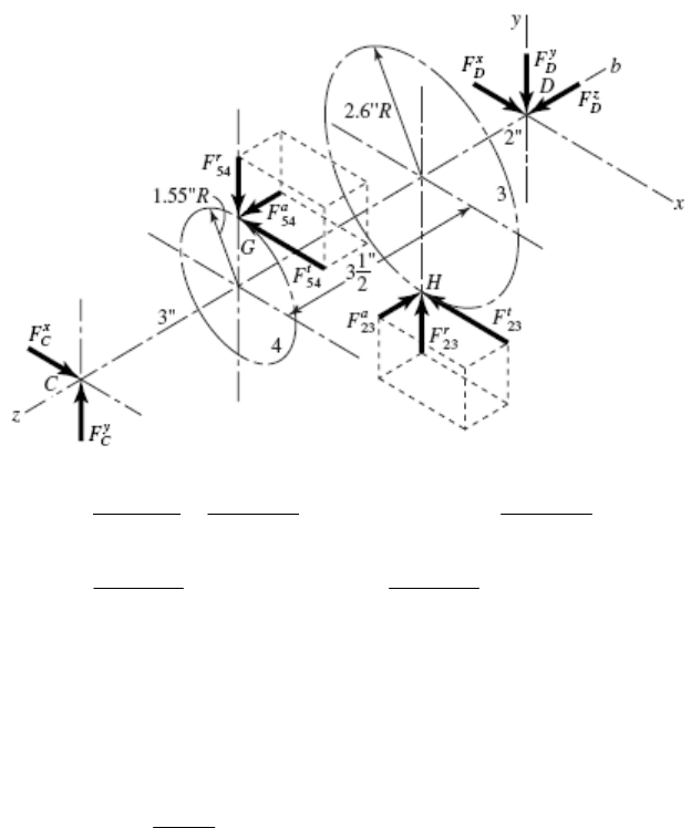
tan 1119 tan 20 407.3 N
rt
t
WW
tan 1119 tan15 299.8 N
at
WW
21119 407.3 299.8 N .
aAns Fijk
31119 407.3 1119 407.3
711.7 711.7 N .
b
Ans
Fi
j
ij
4407.3 1119 299.8 N .
cAnsFijk
______________________________________________________________________________
13-50
23
14 36
2.021 in, 5.196 in
cos 8 cos 30 8 cos 30
n
N
dd
P
45
15 45
3.106 in, 9.317 in
5cos15 5cos15
dd
For gears 2 and 3:
11
tan tan / cos tan tan 20 / cos30 22.8
tn
For gears 4 and 5:
1
tan tan 20 / cos15 20.6
t
23 2 2
/ 1200 / 2.021/ 2 1188 lbf
t
FTr
54
5.196
1188 1987 lbf
3.106
t
F
23 23 tan 1188 tan 22.8 499 lbf
rt
t
FF
54 1986 tan 20.6 746 lbf
r
F
23 23 tan 1188 tan 30 686 lbf
at
FF
a
54 1986 tan15 532 lbfF
Next, designate the points of action on gears 4 and 3, respectively, as points G and H, as
shown. Position vectors are
Chapter 13, Page 31/35

1.553 3
CG R
j
k
2.598R 6.5
CH
j
k
8.5
CD Rk
e Force vectors ar
54 1986 748 532 Fi
j
k
F
23 1188 500 686 i
j
k
x
y
CC C
FFFi
j
x
yz
DD D D
FFFFi
j
k
Now, a summation of moments about bearing C gives
0
The terms for this equation are found to be
54 23CCG CH CDD
MR FR FR F
54 1412 5961
CG RF i
j
3086k
23 5026 7722 3086
CH RF i
j
k
8.5 8.5
y
x
CD D D D
FF RF i
j
When these terms are placed back into the moment equation, the k terms, representing
the shaft torque, cancel. The i and j terms give
3614 425 lbf .
y
8.5
D
F
Ans
13683 1610 lbf .
8.5
x
D
F
Ans
Next, we sum the forces to zero.
54 23C
FFFF D
0
es
F
Substituting, giv
1987 746 532 1188 499 686
y
C
F
x
C
Fi
j
i
j
ki
j
k
1610 425 z
D
Fi
j
k0
Solving gives
1987 1188 1610 1565 lbf .
x
C
FA ns
ns
ns
______________________________ ____________________________
746 499 425 672 lbf .
y
C
FA
___________________ _
532 686 154 lbf .
z
D
FA
Chapter 13, Page 32/35
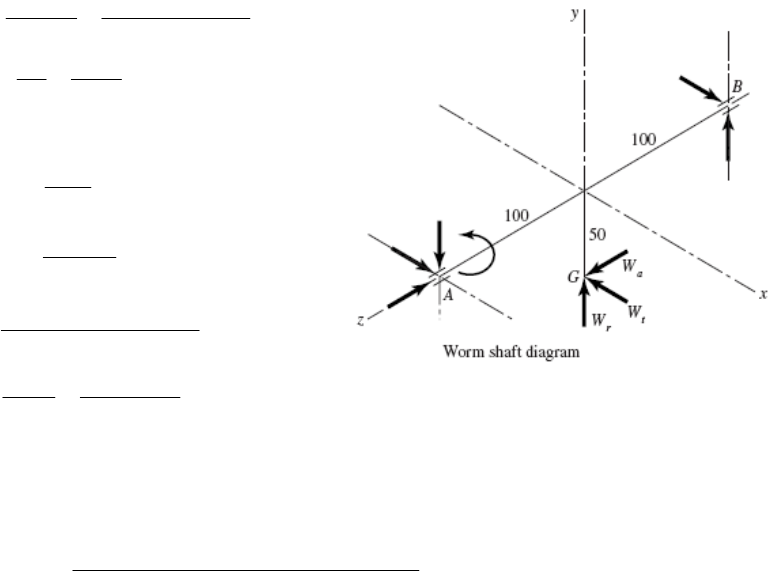
13-51
0.100 600 m/s
WW
dn
V
60 60
W
2000 637 N
Wt
W
H
WV
25 1 25 mm
xW
LpN
1
1
tan
25
tan 4.550 lead angle
100
W
L
d
-
cos sin cos
Wt
n
W
Wf
--
3V.152 m/s
cos cos 4.550
W
S
V
-
VS = 3.28(3.152) = 10.33 ft/s = 620 ft/min
Use f = 0.043 from curve A of Fig. 13-42. Then, from the first of Eq. (13-43)
In ft/min:
637 5323 NW
cos14.5 sin 4.55 0.043cos 4.55
WWsin 5323sin14.5 1333 N
y
n
5323 cos14.5 cos 4.55 0.043 in 4.55 5119 N
z
sW
against the worm is
rust bearing. Ans.
The force acting
637 1333 51 Wij19 Nk
Thus, A is the th
0.05 0.10 ,
AG R
j
k0.20
AB R k
0 AAG ABB
MR WR FT
122.6 63.7 31.85
AG RW i
j
k
0.2 0.2
y
x
A
BB B B
FF RF i
j
Substituting and solving gives
Ans
31.85 N m T .
318.5 N, 613 N
xy
BB
FF
So
318.5 613 N .
BAnsFij
Chapter 13, Page 33/35
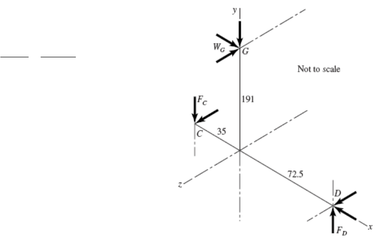
Or
1/ 2
22
613 318.5 691 N radial
B
F
AB
FF WR 0
37 1333 5119 318.5 613
318.5 1946 5119 .
AB
Ans
FWF i6
j
ki
j
ijk
Radial 318.5 1946 N
r
AFi
j
1/ 2
22
318.5 1946 1972 N
r
A
F
Thrust 5119 N
a
A
F
___________________ ____________ _______________________________________________
3-52 From Prob. 13-51, 1
637
GWi1333 5119 N
j
k
tx
p
p
So
48 25 382 mm
G
dx
G
Np
D takes the thrust load.
0
Bearing
MR WR
DDGGDCC
FT
0.0725 0.191
DG Ri
j
Ri0.1075
DC
The position vectors are in meters.
977.7 371.1 RW i 25.02
DG G
j
k
0.1075 0.1075
zy
DC C C C
FF RF
j
k
Putting it together and solving,
ns
977.7 N m .TAns
233 3450 N, 3460 N .
CC
FA Fjk
CGD
FF W F 0
637 1566 1669 N .
DCG
A
ns W i j k
FF
Radial 1566 1669 N
r
DF
j
k
Or 2
1/
22
1566 1669 2289 N (total radial)
r
D
F
t
Fi637 N (thrust)
D
Chapter 13, Page 34/35
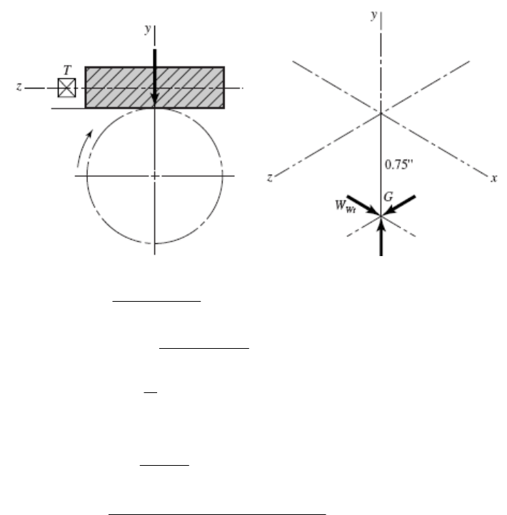
Chapter 13, Page 35/35
___________________ _____________________________________________ _____________ _
13-53
1.5 600 235.7 ft/min
12
W
V
33000 0.75 105.0 lbf
235.7
x
Wt
WW
0.3927 in
8
tx
pp
0.3927 2 0.7854 inL
10.7854
tan 9.46
1.5
-
105.0 515.3 lbf
cos 20 sin 9.46 0.05cos9.46
W
515.3sin 20 176.2 lbf
y
W
515.3 cos 20 cos9.46 0.05sin 9.46 473.4 lbf
z
W
So 105 176 473 lbf .
A
nsWijk
105 0.75 78.8 lbf in .TAns
___________________________ ______________________________ ___________________ __
3-54 Computer programs will vary. 1

Chapter 14
14-1 22 3.667 in
6
N
dP
Table 14-2: Y = 0.331
Eq. (13-34): (3.667)(1200) 1152 ft/min
12 12
dn
V
Eq. (14-4b): 1200 1152 1.96
1200
K
v
Eq. (13-35) : 15
33 000 33 000 429.7 lbf
1152
tH
WV
Eq. (14-7): 1.96(429.7)(6) 7633 psi 7.63 kpsi .
2(0.331)
t
KWP Ans
FY
v
________________________________________________________________________
14-2 18 1.8 in
10
N
dP
Table 14-2: Y = 0.309
Eq. (13-34): (1.8)(600) 282.7 ft/min
12 12
dn
V
Eq. (14-4b): 1200 282.7 1.236
1200
K
v
Eq. (13-35) : 2
33 000 33 000 233.5 lbf
282.7
tH
WV
Eq. (14-7): 1.236(233.5)(10) 9340 psi 9.34 kpsi .
1.0(0.309)
t
KWP Ans
FY
v
________________________________________________________________________
14-3
1.25(18) 22.5 mmdmN
Table 14-2: Y = 0.309
3
(22.5)(10 )(1800) 2.121 m/s
60 60
dn
V
Eq. (14-6b): 6.1 2.121 1.348
6.1
K
v
Eq. (13-36): 60 000 60 000(0.5) 0.2358 kN 235.8 N
(22.5)(1800)
tH
Wdn
Eq. (14-8): 1.348(235.8) 68.6 MPa .
12(1.25)(0.309)
t
KW Ans
FmY
v
________________________________________________________________________
Chapter 14, Page 1/39

14-4
Y = 0.296
8(16) 128 mmdmN
Table 14-2:
3
(128)(10 )(150) 1.0053 m/s
60 60
dn
V
6.1 1.0053 1.165
6.1
K
v Eq. (14-6b):
60 000 60 000(6) 5.968 kN 5968 N
(128)(150)
tH
Wdn
Eq. (13-36):
Eq. (14-8): 1.165(5968) 32.6 MPa .
90(8)(0.296)
t
KW Ans
FmY
v
________________________________________________________________________
4-5
Y = 0.296
11(16) 16 mmdmN
Table 14-2:
3
(16)(10 )(40 0) 0.335 m/s
60 60
dn
V
6.1 0.335 1.055
6.1
K
v Eq. (14-6b):
60 000 60 000(0.15) 0.4476 kN 447.6 N
(16)(400)
tH
Wdn
Eq. (13-36):
Eq. (14-8): 1.055(447.6) 10.6 mm
150(1)(0.296)
t
KW
FmY
v
From Table 13-2, use F = 11 mm or 12 mm, depending on availability. Ans.
_____ ___
4-6
Y = 0.322
_ _______________________________________________________________
12(20) 40 mmdmN
Table 14-2:
3
(40)(10 )(200) 0.419 m/s
60 60
dn
V
6.1 0.419 1.069
6.1
K
v Eq. (14-6b):
Eq. (13-36): 60 000 60 000(0.5) 1.194 kN 1194 N
(40)(200)
tH
Wdn
Eq. (14-8): 1.069(1194) 26.4 mm
75(2.0)(0.322)
t
KW
FmY
v
From Table 13-2, use F = 28 mm. Ans.
_____ ________________________________
_ __________________________________
Chapter 14, Page 2/39
14-7 24 4.8 in
5
N
dP
Table 14-2: Y = 0.337
(4.8)(50) 62.83 ft/min
12 12
dn
V
Eq. (13-34):
Eq. (14-4b):
1200 62.83 1.052
1200
K
v
Eq. (13-35) : 6
33 000 33 000 3151 lbf
62.83
tH
WV
Eq. (14-7): 3
1.052(3151)(5) 2.46 in
20(10 )(0.337)
t
KWP
FY
v
Use F = 2.5 in Ans.
_______________________________________________
4-8
_________________________
116 4.0 in
4
N
dP
Table 14-2: Y = 0.296
(4.0)(400) 418.9 ft/min
12 12
dn
V
Eq. (13-34):
Eq. (14-4b):
1200 418.9 1.349
1200
K
v
Eq. (13-35) : 20
33 000 33 000 1575.6 lbf
418.9
tH
WV
Eq. (14-7): 3
1.349(1575.6)(4) 2.39 in
12(10 )(0.296)
t
KWP
FY
v
Use F = 2.5 in Ans.
_______________________________________________
4-9 Try P = 8 which gives d = 18/8 = 2.25 in and Y = 0.309.
Eq. (13-34):
_________________________
1
(2.25)(600) 353.4 ft/min
12 12
dn
V
1200 353.4 1.295
1200
K
v Eq. (14-4b):
Eq. (13-35): 2.5
33 000 33 000 233.4 lbf
353.4
tH
WV
Eq. (14-7): 3
1.295(233.4)(8) 0.783 in
10(10 )(0.309)
t
KWP
FY
v
Using coarse integer pitches from Table 13-2, the following table is formed.
Chapter 14, Page 3/39

P d V Kv Wt F
2 9.000 1413.717 2.178 58.356 0.082
3 6. 0 942.478 1.785 87.535 0.152
1
1
10 1.800
12 1.500
00
4 4.500 706.858 1.589 16.713 0.240
6 3.000 471.239 1.393 75.069 0.473
8 2.250 353.429 1.295 233.426 0.782
282.743 1.236 291.782 1.167
235.619 1.196 350.139 1.627
16 1.125 176.715 1.147 466.852 2.773
Other considerat ta e G i re P = 8
(F = 7/8 in) and P =10 (F = 1.25 in). Ans.
_____ _____
ions may dic te the sel ction. ood cand dates a
_ _____________________________________________________________
14-10 Try m = 2 mm which gives d = 2(18) = 36 mm and Y = 0.309.
3
(36)(10 )(900) 1.696 m/s
dn
V
60 60
Eq. (14-6b): 6.1 1.696 1.278
6.1
K
v
Eq. (13-36): 60 000 60 000(1.5) 0.884 kN 884 N
(36)(900)
tH
Wdn
Eq. (14-8): 1.278(884) 24.4 mm
75(2)(0.309)
F
Using the prefer edr module sizes from Table 13-2:
W
t F m d V Kv
1.00 18.0 0.848 1.139 1768.388 86.917
1.25 22.5 1.060 1.174 1414.711 57.324
1
1
1
1 1
1
1.50 27.0 1.272 1.209 1178.926 40.987
2.00 36.0 1.696 1.278 884.194 24.382
3.00 54.0 2.545 1.417 589.463 12.015
4.00 72.0 3.393 1.556 442.097 7.422
5.00 90.0 4.241 1.695 353.678 5.174
6.00 08.0 5.089 1.834 294.731 3.888
8.00 44.0 6.786 2.112 221.049 2.519
0.00 180.0 8.482 2.391 176.839 1.824
2.00 216.0 0.179 2.669 147.366 1.414
16.00 288.0 3.572 3.225 110.524 0.961
20.00 360.0 16.965 3.781 88.419 0.721
25.00 450.0 21.206 4.476 70.736 0.547
32.00 576.0 27.143 5.450 55.262 0.406
40.00 720.0 33.929 6.562 44.210 0.313
50.00 900.0 42.412 7.953 35.368 0.243
Chapter 14, Page 4/39
1/ 2
3
2
3
1.204(202.6) 1 1
2
C
100 100(10 )
cos 20 0.228 0.684
2100 1.204(202.6) 1 1 0.669 in
100(10 ) cos 20 0.228 0.684
F
F
Use F = 0.75 in Ans.
________________________________________________________________________
14-13 5(24
p
d) 120 mm, 5(48) 240 mm
G
d
3
(120)(10 )(50)
0.3142 m/s
60
V
Eq. (14-6a): 3.05 0.3142 1.103
3.05
K
v
3
60 000 60(10 ) 3.183
(120)(50)
tHH
WH
dn
t
where H is in kW and W is in kN
Table 14-8:
163 MPa
p
C
C
[Note: Using Eq. (14-13) can result in wide variation in
n properties].
p due to wide variation in cast iro
Eq. (14-12):
12
20.52 mm, 41.04 mm
2
r
120sin 20 240sin 20
2
r
1/ 2
3
1.103(3.183) 10 H
o
11
690 163 60cos 20 20.52 41.04
Eq. (14-14):
3.94 kW .
H
Ans
________________________________________________________________________
4
14-1
3
4(20) 80 mm, 4(32) 128 mm
PG
dd
(80)(10 )(1000) 4.189 m/s
60
V
Eq.
(14-6a): 3.05 4.189 2.373
3.05
K
v
3
60(10)(10 ) 2.387 kN 2387 N
(80)(1000)
t
W
Table
14-8: 163 MPa
p
C [Note: Using Eq. (14-13) can result in wide variation in
Cp due to wide variation in cast iron properties.]
(14-12):
12
80sin 20 128sin 20
13.68 mm, 21.89 mm
22
rr
Eq.
Chapter 14, Page 6/39
Eq. (14-14):
1/ 2
73(2387) 1 1
163 617 MPa .
50cos 20 13.68
C
2.3
21.89
A
ns
________________________________________________ ____
14-15 The pinion controls the design.
___________________ _
Bending
YP = 0.303, YG = 0.359
17 30
1.417
12
P
d
in, 2.500 in
12
1 ) 194.8 ft/min
G
d
Eq. (14-4b):
(.417)(525
12 12
P
dn
V
1200 194.8 1.162
1200
K
v
Eq. (6-8), p. 282:
Eq. (6-19), p. 287: k = 2.70(76) = 0.857
0.5(76) 38.0 kpsi
e
S
–0.265
a
2.25 2.25 0.1875 i
n
12
d
lP
33(0.303)
0.0379 in
2
Eq.
(14-3): 2
(12)
P
Y
P
37:
x
4 4(0.1875)(0.0379) 0.1686 intlx Eq. (b), p. 7
0.808 0.808 0.875(0.1686) 0.310 in
e
dhb
Eq. (6-25), p. 289:
0.107
0.310 0.996
0.3
b
k
Eq. (6-20), p. 288:
kc = kd = ke = 1
y bending with kf = 1.66. (See Ex. 14-2.)
Se = 0.857(0.996)(1)(1)(1)(1.66)(38.0) = 53.84 kpsi
i
Account for one-wa
Eq. (6-18), p. 287:
For stress co entration, find thnc e rad us of the root fillet (See Ex. 14-2).
0.300 0.300 0.025 in
12
f
rP
From Fig. A-15-6,
0.025 0.148
0.1686
f
r
r
dt
D/d = 3; from Fig. A-15-6, Kt = 1.68.
ut 76 kpsi and r = 0.025 in, q = 0.62.
Eq. (6-32): Kf = 1 + 0.62 (1.68 – 1) = 1.42
Approximate D/d = ∞ with
From Fig. 6-20, with S =
Chapter 14, Page 7/39
53.84
e
S16.85 psi
1.42(2.25)
all
fd
Kn
0.875(0.303)(16
(12
tPa
ll
FY
WKP
850) 320.4 lbf
1.162 )
320.4(194.8) 1.89 hp .
33 000 33 000
d
t
WV
HA
ns
v
Wear
1 =
2 = 0.292, E1 = E2 = 30(106) psi
1/ 2
2
6
Eq.
(14-13): 1
C
2285 psi
1 0.292
230 10
p
Eq. (14-12):
1
1.417
sin sin 20 0.242 in
22
P
d
r
2
2.500
sin sin 20 0.428 in
22
G
d
r
1
12
11 1 1 6.469 in
0.242 0.428rr
Eq. (6-68), p. 329:
From the discussion and equation developed on the bottom of p. 329,
8
3
10
( ) 0.4 10 kpsi [0.4(149) 10](10 ) 49 600 psi
CB
SH
8
10
,allC
49 600 33 067 psi
2.25
C
S
n
Eq. (14-14):
2
33 067 0.875cos 20 22.6 lbf
t
W
2285 1.162(6.469)
22.6(194.8) 0.133 hp .
33 000 33 000
t
WV
HA
ns
i n controls):
H1 = 1.89 hp
H
2 = 0.133 hp
H
all = (min 1.89, 0.133) = 0.133 hp Ans.
___ __ __ _____ __________________________________________
4-16 See Prob. 14-15 solution for equation numbers.
Rating power (p nio
___ _ _ _ ____________
1
Chapter 14, Page 8/39
Pinion controls: YP = 0.322, YG = 0.447
Bending d = 20/3 = 6.667 in, d = 100/3 = 33.333 in
P G
/ 12 (6.667)(870)Vdn
0.265
0.5(113) 56.5 kpsi
2.70(113) 0.771
S
k
/ 12 1519 ft/min
/ 6
2.25 / 2.25 / 3 0.75 in
3(0.322) / [2(3)] 0.161 in
4(0.75)(0.161) 0.695 in
0.808 2.5(0.69
e
a
d
e
lP
x
t
d
(1200 1519) 1200 2.26
P
K
v
0.107
5) 1.065 in
(1.065 / 0.30) 0.873
1
b
cde
k
kkk
kf = 1.66 (See Ex. 14-2.)
0.771(0.873)(1)(1)(1)(1.66)(56.5) 63.1 kpsi
e
S
0.300 / 3 0.100 in
0.100 0.144
f
r
r
0.695
f
r
dt
Kt = 1.75, q = 0.85, Kf = 1.64
63.1 25.7 kpsi
1.64(1.5)
e
all
fd
S
Kn
all 2.5(0.322)(25
(3)
tP
FY
WKP
700) 3043 lbf
2.266
/ 33 000 3043(1519) / 3 000 140 hp .
d
t
H
3 WV Ans
v
Wear
Eq. (14-13):
1/ 2
2
6
12285 psi
1 0.292
230 10
p
C
Eq. (14-12): r1 = (6.667/2) sin 20° = 1.140 in
r
2 = (33.333/2) sin 20° = 5.700 in
Eq. (6-68), p. 329: SC = [0.4(262) – 10](103) = 94 800 psi
,allCCd
/ 94 800 /Sn
1.5 77 400 psi
Chapter 14, Page 9/39
2
,all
12
2
cos 1
1/ 1/
77 400 2.5cos 20 1
2285 2.266 1 / 1.140 1 / 5.700
1130 lbf
C
t
p
F
WCK rr
v
1130(1519) 52.0 hp .
33 000 33 000
t
WV
HA ns
les (revolutions of the pinion), the power based on wear is 52.0 hp.
ns
________________________________________________________________________
75 mm, NP = 16 milled teeth,
For
108 cyc
Rating power (pinion controls):
140 hpH
1
2
rated
52.0 hp
min(140, 52.0) 52.0 hp .
H
HA
4-17 See Prob. 14-15 solution for equation numbers. 1
Given:
= 20°, n = 1145 rev/min, m = 6 mm, F =
N
G = 30T, Sut = 900 MPa, HB = 260, nd = 3, YP = 0.296, and YG = 0.359.
Pinion bending
3
6(16) 96 mm
6(30) 180 mm
(96)(10 )(1145) 5.76 m/s
60 (60)
P
dmN
P
G
P
d
dn
V
6.1 5.76 1.944
6.1
K
v
0.265
0.107
0.5(900) 450 MPa
4.51(900) 0.744
2.25 2.25(6) 13.5 mm
3 / 2 3(0.296)6 / 2 2.664 mm
4 4(13.5)(2.664) 12.0 mm
0.808 75(12.0) 24.23 mm
24.23 0.884
7.62
1
e
a
e
b
cde
S
k
lm
xYm
tlx
d
k
kkk
f
(1.66)(450) 491.3 MPa
k = 1.66 (See Ex. 14-2)
r/d = rf /t = 1.8/12 = 0.15, Kt = 1.68, q = 0.86, Kf = 1.58
0.744(0.884)(1)(1)(1)
e
S
0.300 0.300(6) 1.8 mm
f
rm
Chapter 14, Page 10/39
all
491.3 239.2 MPa
1.58 1.3
e
fd
S
Kn
Eq. (14-8): all 75(0.296)(6)(239.2) 16 390 N
1.944
tFYm
WK
v
Eq. (13-36): 16.39 (96)(1145) 94.3 kW .
60 000 60 000
t
Wdn
HA
ns
Wear: Pinion and gear
Eq. (14-12): r1 = (96/2) sin 20 = 16.42 mm
r
2 = (180/2) sin 20 = 30.78 mm
Eq. (14-13):
1/2
2
3
1190 MPa
1 0.292
2207 10
p
C
Eq. (6-68), p. 329: SC = 6.89[0.4(260) – 10] = 647.7 MPa
,all
647.7
/ 568 MPa
1.3
CCd
Sn
Eq. (14-14):
2
,all
12
cos 1
1/ 1/
C
t
p
F
WCKr
vr
2o
568 75cos 20 1 3469 N
190 1.944 1 / 16.42 1 / 30.78
Eq. (13-36): 3.469 (96)(1145) 20.0 kW
60 000 60 000
t
Wdn
H
Thus, wear controls the gearset power rating; H = 20.0 kW. Ans.
________________________________________________________________________
14-18 NP = 17 teeth, NG = 51 teeth
17 2.833 in
6
51 8.500 in
6
P
G
N
dP
d
/ 12 (2.833)(1120) / 12 830.7 ft/min
P
Vdn
Eq. (14-4b): Kv = (1200 + 830.7)/1200 = 1.692
Chapter 14, Page 11/39
all
90 000 45 000 psi
2
y
d
S
n
Table 14-2: YP = 0.303, YG = 0.410
Eq. (14-7): all 2(0.303)(45 000) 2686 lbf
1.692(6)
tP
FY
WKP
v
Eq. (13-35): 2686(830.7) 67.6 hp
33 000 33 000
t
WV
H
Based on yielding in bending, the power is 67.6 hp.
(a) Pinion fatigue
Bending
Eq. (2-121), p. 41: Sut = 0.5 HB = 0.5(232) = 116 kpsi
Eq. (6-8), p. 282: 0.5 0.5(116) 58 kpsi
eut
SS
Eq. (6-19), p. 287:
0.265
2.70(116) 0.766
a
k
Table 13-1, p. 696: 1 1.25 2.25 2.25 0.375 in
6
dd d
lPP P
Eq. (14-3):
3 3(0.303) 0.0758 in
22(6)
P
Y
xP
Eq. (b), p. 737: 4 4(0.375)(0.0758) 0.337 intlx
Eq. (6-25), p. 289: 0.808 0.808 2(0.337) 0.663 in
e
dFt
Eq. (6-20), p. 288:
0.107
0.663 0.919
0.30
b
k
k
c = kd = ke = 1
Account for one-way bending with kf = 1.66. (See Ex. 14-2.)
Eq. (6-18):
0.766(0.919)(1)(1)(1)(1.66)(58) 67.8 kpsi
e
S
For stress concentration, find the radius of the root fillet (See Ex. 14-2).
0.300 0.300 0.050 in
6
f
rP
Fig. A-15-6: 0.05 0.148
0.338
f
r
r
dt
Estimate D/d = ∞ by setting D/d = 3, Kt = 1.68.
Chapter 14, Page 12/39
Fig. 6-20, p. 295: q = 0.86
Eq. (6-32), p. 295: 1 (0.86)(1.68 1) 1.58
f
K
all
67.8 21.5 kpsi
1.58(2)
e
fd
S
Kn
all 2(0.303)(21 500) 1283 lbf
1.692(6)
tP
d
FY
WKP
v
1283(830.7) 32.3 hp .
33 000 33 000
t
WV
HA ns
(b) Pinion fatigue
Wear
Eq. (14-13):
1/ 2
26
12285 psi
2 [(1 - 0.292 ) / 30(10 )]
p
C
Eq. (14-12): o
1
2.833
sin sin 20 0.485 in
22
P
d
r
o
2
8.500
sin sin 20 1.454 in
22
G
d
r
12
11 1 1 2.750 in
0.485 1.454rr
Eq. (6-68): 8
10
( ) 0.4 10 kpsi
CB
SH
In terms of gear notation
C = [0.4(232) – 10]103 = 82 800 psi
We will introduce the design factor of nd = 2 and because it is a contact stress apply it
to the load Wt by dividing by 2 . (See p. 329.)
,all
82 800 58 548 psi
22
c
C
Solve Eq. (14-14) for Wt:
2o
all
58 548 2 cos 20 265 lbf
2285 1.692(2.750)
265(830.7) 6.67 hp .
33 000 33 000
t
t
W
WV
HA
ns
(c) Gear fatigue due to bending and wear
For 108 cycles (turns of pinion), the allowable power is 6.67 hp.
Chapter 14, Page 13/39
Bending
3 3(0.4103) 0.1026 in
22(6)
G
Y
xP
Eq. (14-3):
4 4(0.375)(0.1026) 0.392 intlx
Eq. (b), p. 737:
Eq. (6-25):
0.808 0.808 2(0.392) 0.715 in
e
dFt
Eq. (6-20):
0.107
0.715 0.911
0.30
b
k
k = kd = ke = 1
. 14-2.)
c
kf = 1.66. (See Ex
Eq. (6-18):
0.766(0.911)(1)(1)(1)(1
e
S.66)(58) 67.2 kpsi
0.050 0.128
0.392
f
r
r
dt
Fig. 6-20: q = 0.82
Approximate D/d = ∞ by setting D/d = 3 for Fig. A-15-6; Kt = 1.80.
Eq. (6-32): 1 (K0.82)(1.80 1) 1.66
f
all
67.2 20.2 kpsi
1.66(2)
e
fd
S
Kn
all 2(0.4103)(20 200) 1633 lbf
1.692(6)
tP
d
FY
WKP
v
all
1633(830.7) 41.1 hp .
33 000 33 000
t
WV
HA ns
Wear
Since the material of the pinion and the gear are the same, and the contact stresses are
(d)
nion bending: H1 = 32.3 hp
1.1, 6.67) = 6.67 hp Ans.
__ __ ___________
4-19 dP = 16/6 = 2.667 in, dG = 48/6 = 8 in
The gear is thus stronger than the pinion in bending.
the same, the allowable power transmission of both is the same. Thus, Hall = 6.67 hp
for 108 revolutions of each. As yet, we have no way to establish SC for 108/3
revolutions.
Pi
Pinion wear: H2 = 6.67 hp
Gear bending: H3 = 41.1 hp
Gear wear: H4 = 6.67 hp
Power rating of the gear set is thus
H
rated = min(32.3, 6.67, 4
____ __________ ___________________________________________
1
Chapter 14, Page 14/39
(2.667)(300) 209.4 ft/minV12
33 000(5) 787.8 lbf
209.4
t
W
Assuming uniform loading, K = 1.
o
2/3
6) 0.8255 Eq.
(14-28): 6, 0.25(12QB
v
50 56(1 0.8255) 59.77A
Eq. (14-27):
0.8255
59.77 209.4 1.196
59.77
K
v
Table 14-2:
ec. 14-10 with F = 2 in
0.296, 0.4056
PG
YY
From Eq. (a), S
0.0535
0.0535
2 0.296
( ) 1.192 1.088
6
2 0.4056
( ) 1.192 1.097
6
sP
sG
K
K
4-30) with C = 1
From Eq. (1 mc
2
C0.0375 0.0125(2) 0.0625
10(2.667)
1, 0.093 (Fig. 14 - 11), 1
1 1[0.0625(1) 0.093(1)] 1.156
pf
pm ma e
m
CC C
K
Assuming constant thickness of the gears → KB = 1
m
G = NG/NP = 48/16 = 3
With N (pinion) = 10 cycles and N (gear) = 108/3, Fig. 14-14 provides the relations:
Fig.
14-6:
R = 0.85
(14-23):
8
8 0.0178
( ) 1.3558(10 ) 0.977
NP
Y
80.0178
() 1.3558(10 / 3) 0.996
NG
Y
0.27, 0.38
PG
JJ
Table 14-10: K
KT = Cf = 1
oo
cos 20 sin 20 3 0.1205
2(1) 3 1
I
Eq.
Table 14-8: 2300 psi
p
C
Strength: Grade 1 steel with HBP = HBG = 200
Chapter 14, Page 15/39
Fig. 14-2: (St)P = (St)G = 77.3(200) + 12 800 = 28 260 psi
Fig. 14-5: (Sc)P = (Sc)G = 322(200) + 29 100 = 93 500 psi
Fig. 14-15: (ZN )P = 1.4488(10 ) = 0.948
3
Sec.
14-12: HBP/HBG = 1 CH = 1
Pinion tooth bending
8–0.023
(ZN )G = 1.4488(108/3)–0.023 = 0.97
Eq.
(14-15):
()
tdmB
Pos
PKK
WKKK FJ
v
6 (1.156)(1)
787.8(1)(1.196)(1.088) 20.27
13 170 psi .Ans
Eq. (14-41): /( )
() tN T R
FP
SY K K
S
28 260(0.977) / [(1)(0.85)] 2.47 .
13 170
A
ns
Gear tooth bending
6 (1.156)(1)
Eq.
(14-15):
() 787.8(1)(1.196)(1.097) 9433 psi .
20.38
G
A
ns
Eq. (14-41):
28 260(0.996) / [(1)(0.85)]
( ) 3.51 .
9433
FG
SA
ns
Pinion tooth wear
Eq. (14-16):
1/ 2
() f
tm
cP p o s
PP
C
K
CWKKK
dF I
v
1/2
1.156 1
2300 787.8(1)(1.196)(1.088) 2.667(2) 0.1205
98 760 psi .Ans
: Eq. (14-42)
/( ) 93 500(0.948) /[(1)(0.85)]
( ) 1.06 .
98 760
cN
S
SA
T R
HP
cP
Z KK ns
Gear tooth wear
Chapter 14, Page 16/39
1/ 2 1/ 2
( )
( ) ( )
sG
cG
K1.097
( ) (98 760) 99 170 psi .
1.088
93 500(0.973)(1) /[(1)(0.85)]
) 1.08 .
99 170
cP
sP
G
(H
A
ns
ns
The hardness of the pinion and the gear should be increased.
_______________________________________________________________________
K
SA
_
14-20 dP = 2.5(20) = 50 mm, dG = 2.5(36) = 90 mm
3
3
(50)(10 )(100) 0.2618 m/s
60 60
PP
V
60(120) 458.4 N
(50)(10 )(100)
t
dn
W
With no specific information given to indicate otherwise, assume
: = 0.8255
A = 50 + 56(1 – 0.8255) = 59.77
K
B = Ko = Y
= ZR = 1
Eq. (14-28) Qv = 6, B = 0.25(12 – 6)2/3
0.8255
Eq.
(14-27): 59.77 200(0.2618)
59.77
K
v1.099
P 0.322, YG = 0.3775
units:
Table
14-2: Y =
Similar to Eq. (a) of Sec. 14-10 but for SI
0.0535
10.8433KmFY
s
b
k
0.0535
( ) 0.8433 2.5(18) 0.322 1.003 use 1
sP
K
0.0535
( ) 0.8433 2.5(18) 0.3775 =1.007 use 1
sG
K
1
18
18 / 25.4 0.709 in, 0.025 0.011
10(50)
mc e pm
pf
CCC
FC
(YN )P = 1.3558(108)–0.0178 = 0.977
(Y )G = 1.3558(108/1.8)–0.0178 = 0.987
38): YZ = 0.658 – 0.0759 ln(1 – 0.95) = 0.885
42
0.247 0.0167(0.709) 0.765(10 )(0.709 ) 0.259
ma
C
1 1[0.011(1) 0.259(1)] 1.27
H
K
Fig. 14-14:
N
Fig. 14-6: (YJ )P = 0.33, (YJ )G = 0.38
Eq. (14-
Chapter 14, Page 17/39
Eq. (14-23):
oo
cos 20 sin 20 1.8
0.103
2(1) 1.8 1
I
Z
Table 14-8: 191 MPa
E
Z
Strength Grade 1 steel, BP
H = HBG = 200
.9 MPa
Fig.
14-5: (Sc)P = (Sc)G = 2.22(200) + 200 = 644 MPa
ding
Fig.
14-2: (St)P = (St)G = 0.533(200) + 88.3 = 194
Fig.
14-15: (ZN )P = 1.4488(108)–0.023 = 0.948
NG
Fig.
14-12: / 1 HH C
80.023
( ) 1.4488(10 / 1.8) 0.961Z
1
BP BG W H
Z
Pinion tooth ben
1
Eq.
(14-15):
()
P
tHB
os
tJ
P
KK
WKKKbm Y
v
1 1.27(1)
458.4(1)(1.099)(1) 43.08 MPa .
18(2.5) 0.33
A
ns
194.9 0.977
( ) 4.99 .
43.08 1(0.885)
tN
FP
ZP
SY
SA
YY
Eq. (14-41) for SI: ns
Gear tooth bending
1 1.27(1)
( )G
458.4(1)(1.099)(1) 37.42 MPa .
18(2.5) 0.38
194.9 0.987
( ) 5.81 .
37.42 1(0.885)
FG
Ans
SAns
wear Pinion tooth
1
Eq.
(14-16):
()
c
tHR
P E o s
IP
KZ
ZWKKK
dbZ
v
w
1.27 1
191 458.4(1)(1.099)(1) 501.8 MPa .
50(18) 0.103 Ans
644 0.948(1)
( ) 1.37 .
501.8 1(0.885)
cNW
HP
cZ
P
SZZ
SA
YY
Eq. (14-42) for SI:
ns
Gear
tooth wear
1/2 1/ 2
() 1
( ) ( ) (501.8) 501.8 MPa .
() 1
sG
cG cP
K
sP
A
ns
K
Chapter 14, Page 18/39
644 0.961(1)
( ) 1.39 .
501.8 1(0.885)
HG
SA
ns
________________________________________________________________________
14-21
cos 6cos30 5.196 teeth/in
tn
PP
0.8255
16 48
3.079 in, (3.079) 9.238 in
5.196 16
(3.079)(300) 241.8 ft/min
12
33 000(5) 59.77 241.8
682.3 lbf , 1.210
241.8 59.77
PG
t
dd
V
WK
v
From Prob. 14-19:
0.296, 0.4056
8, ( ) 1.097, 1
3, ( ) 0.977, ( ) 0.996, 0.85
( ) ( ) 28 260 psi, 1, ( ) ( ) 93 500 psi
( ) 0.948, ( ) 0.973
G
sP sG B
GNP NG R
tP tG H cP cG
NP NG
YY
KK
mY Y K
SS C SS
ZZ
() 1.08
P
K
, 2300 psi
p
C
The pressure angle is:
1tan 20
tan 22.80
cos 30
t
3.079
( ) cos 22.8 1.419 in, ( ) 3( ) 4.258 in
2
bP bG bP
rr
r
Eq.
(14-25):
1/ 1/6 0.167 in
n
aP
1/ 2 1/ 2
22
22
3.079 9.238
0.167 1.419 0.167 4.258
2
3.079 9.238 sin 22.8
22
0.9479 2.1852 2.3865 0.7466 Conditions . . for useOK
2
Z
cos cos 20 0.4920 in
6
N
pnn
p
0.492 0.6937
0.95 0.95(0.7466)
N
N
p
mZ
Eq. (14-21):
Chapter 14, Page 19/39
Eq. (14-23): sin 22.8 cos 22.8 3 0.193
2(0.6937) 3 1
I
Fig. 14-7: 0.45, 0.54
PG
JJ
Fig. 14-8: Corre . ctions are 0.94 and 0.98
0.45(0.94) 0.423,
P
J 0.54(0.98) 0.529
2
1, 0.0375 0.0125(2) 0.0525
10(3.079)
1, 0.093, 1
1 (1)[0.0525(1) 0.093(1)] 1.146
G
mc pf
pm ma e
m
J
CC
CC C
K
bending
Pinion tooth
5.196 1.146(1)
( ) 682.3(1)(1.21)(1.088) 6323 psi .
2 0.423
28 260(0.977) / [1(0.85)]
( ) 5.14 .
6323
A
P
FP
ns
SAns
ending
Gear tooth b
5.196 1.146(1)
( ) 682.3(1)(1.21)(1.097) 5097 psi .
2 0.529
28 260(0.996) / [1(0.85)]
( ) 6.50 .
5097
A
G
FG
ns
SAns
Pinion tooth wear
1/ 2
1.146 1
( ) 230
cP
0 682.3(1)(1.21)(1.088) 67 700 psi .
3.078(2) 0.193
93 500(0.948) / [(1)(0.85)]
( ) 1.54 .
67 700
HP
Ans
SAns
eoth wear
G ar to
1/ 2
1.097
( )
(67 700) 67 980 psi .
1.088
93 500(0.973) /[(1)(0.85)]
( ) 1.57 .
67 980
cG
HG
Ans
SAns
________________________________________________________________________
both
P G
14-2: YP = 0.303, YG = 0.4103
14-22 Given: R = 0.99 at 108 cycles, HB = 232 through-hardening Grade 1, core and case,
gears. N = 17T, N = 51T,
Table
Chapter 14, Page 20/39
Fig. 14-6: JP = 0.292, JG = 0.396
d 17 / 6 = 2.833 in, dG = 51 / 6 = 8.500 in.
Fig.
14-14: YN = 1.6831(108)–0.0323 = 0.928
P = NP / P =
Pinion
bending
From Fig. 14-2:
7
0.99 ( ) 77.3 12 800
77.3(232) 12 800 30 734 psi
tB
SH
10
P/ 12 (2.833)(1120 / 12) 830.7 ft/minVdn
all
1, 2, KK S S 2
30 734(0.928) 14 261 psi
2(1)(1)
TR F H
2/3
5, 0.25(12 5) 0.9148QB
v
50 56(1 0.9148) 54.77A
0.9148
54.77 830.7 1.472
54.77
K
v
0.0535
2 0.303
1.192 1.089 use 1
6
s
K
)
e
1(
mmf mcpfpmma
KC CCC CC
1
0.0375 0.0125
10
20.0375 0.0125(2) 0.0581
10(2.833)
mc
pf
C
F
CF
d
42
1
0.127 0.0158(2) 0.093(10 )(2 ) 0.1586
pm
ma
C
C
Eq.
(14-15):
1
e
C
1 1[0.0581(1) 0.1586(1)] 1.217
1
m
B
K
K
all
tP
osdm
FJ
W
B
K
KKPKK
v
2(0.292)(14 261) 775 lbf
1(1.472)(1)(6)(1.217)(1)
775(830.7) 19.5 hp
33 000 33 000
t
WV
H
Pinion wear
Chapter 14, Page 21/39
Fig. 14-15: ZN = 2.466N–0.056 = 2.466(108)–0.056 = 0.879
Eq.
(14-23):
G
m51 / 17 3
oo
cos 20 sin 20 3 1.205, 1
231 H
IC
Fig.
14-5: (S
7
0.99 10
) 322 29 100
cB
H
322 103 804 psi
(232) 29 100
,all
103 804(0.879) 64 519 psi
2(1)(1)
c
Eq.
(14-16):
2
,all
c
tP
posm
Fd I
WCKKKKC
v
f
2
64 519 2(2.833)(0.1205)
2300 1(1.472)(1)(1.2167)(1
)
300 lbf
300(830.7) 7.55 hp
33 000 33 000
t
WV
H
The pinion controls, therefore Hrated = 7.55 hp Ans.
________________________________________________________________________
l = 2.25/ Pd, x = 3Y / 2Pd
14-23
0.107 0.0535
0.0535
2.25 3 3.674
44 2
tlx PP P
3.674
dd d
0.808 0.808
e1.5487
1.5487 / 0.8389
0.30
11.192 .
dd
d
b
d
s
bd
YY
F
Y
dFtFY
PP
FY P FY
kP
FY
KAns
kP
________________________________________________________________________
14-24 YP = 0.331, YG = 0.422, JP = 0.345, JG = 0.410, Ko = 1.25. The service conditions are
adequately described by Ko. Set SF = SH = 1.
dP = 22 / 4 = 5.500 in
d
G = 60 / 4 = 15.000 in
Chapter 14, Page 22/39
(5.5)(1145) 1649 ft/min
12
V
Pinion
bending
3
2 800 77.3(250) 12 800 32 125 psi
1.6831[3(10 )] 0.832
N
7
0.99 10
9 0.032
1
tB
Y
( ) 77.3SH
Eq.
(14-17):
all
32 125(0.832) 26728 psi
1(1)(1)
P
A
2/3
0.25(12 6) 0.8255B
50 56(1 0.8255) 59.77
0.8255
59.77 1649 1.534
59.77
K
v
1, 1
sm
KC
0.0375 0.0125
10
mc
F
CF
d
3.25 0.0375 0.0125(3.25) 0.0622
10(5.5)
42
0.127 0.0158(3.25) 0.093(10 )(3.25 ) 0.178
ma
C
1
e
C
m
K 1 (1)[0.0622(1) 0.178(1)] 1.240
mf
C
1, 1
BT
KK
1
26 728(3.25)(0.345) 3151 lbf
1.25(1.534)(1)(4)(1.240)
t
W Eq. (14-15):
1
3151(1649) 157.5 hp
33 000
H
Gear bending
22
3861 lbf and 192.9 hp
t
WH
By similar reasoning,
Pinion
wear
60 / 22 2.727
G
m
oo
cos 20 sin 20 2
I
.727 0.1176
2 1 2.727
0.99 (S7
10
) 322(250) 29 100 109 600 psi
c
90.056
( ) 2.466[3(10 )] 0.727
NP
Z
9 0.056
( ) 2.466[3(10 ) / 2.727] 0.769
NG
Z
,all
109 600(0.727)
( ) 79 679 psi
1(1)(1)
cP
Chapter 14, Page 23/39
2
,all
3
c
tP
posm
Fd I
WCKKKKC
v
f
2
79 679 3.25(5.5)(0.1176) 1061 lbf
2300 1.25(1.534)(1)(1.24)(1)
3
1061(1649) 53.0 hp
33 000
H
G r eaea w r
Similarly,
?
______________________________________________________
14-24:
44
1182 lbf , 59.0 hp
t
WH
Rating
rated 1 2 3 4
min( , , , )
min(157.5, 192.9, 53, 59) 53 hp .
HHHHH
Ans
Note differing capacities. Can these be equalized
__________________
14-25 From Prob.
12
3151 lbf, 3861 lbf ,
tt
WW
34
1061 lbf , 1182 lbf
tt
WW
33 000 33 000(1.25)(40) 1000 lbf
1649
o
KH
V
Pinion
bending: The factor of safety, based on load and stress, is
t
W
13151
( ) 3.15
1000 1000
t
FP
W
S
Gear bending based on load and stress
23861
( ) 3.86
1000 1000
t
FG
W
S
Pinion
wear
based on load: 3
3
106
t
W11.06
1000 1000
n
( ) 1.06 1.03
HP
S
based on stress:
Gear
wear
4
4
1182 1.18
1000 1000
t
W
n based on load:
Chapter 14, Page 24/39
( ) 1.18 1.09
HG
S
based on stress:
Factors of safety are used to assess the relative threat of loss of function 3.15, 3.86, 1.06,
1.18 where the threat is from pinion wear. By comparison, the AGMA safety factors
(SF)P, (SF)G, (SH)P, ( H)G
.86, 1.03, 1.09 or 3.15, 3.86, 1.061/2, 1.181/2
on
concerning threat. Therefore
______________________________________ ____ ___________
4-26 Solution summary from Prob. 14-24: n = 1145 rev/min, K = 1.25, Grade 1 materials,
=
min, K = 1.534, (K ) = (K ) = 1, (Y )P =
S
are
3.15, 3
and the threat is again from pinion wear. Depending on the magnitude of the numbers,
using SF and SH as defined by AGMA, does not necessarily lead to the same conclusi
be cautious.
_______________ __ __
1o
NP = 22T, NG = 60T, mG = 2.727, YP = 0.331,YG = 0.422, JP = 0.345, JG = 0.410, Pd
4T /in, F = 3.25 in, Qv = 6, (Nc)P = 3(109), R = 0.99, Km = 1.240, KT = 1, KB = 1,
dP = 5.500 in, dG = 15.000 in, V = 1649 ft/ vs P s G N
0.832, (YN )G = 0.859, KR = 1
Pinion HB: 250 core, 390 case
Gear HB: 250 core, 390 case
Bending
all
( ) 26 728 p
P
all
l
G
t
1
3151
t
W1
22
si ( ) 32 125 psi
( ) 27 546 psi ( ) 32 125 psi
bf , 157.5 hp
3861 lbf, 192.9 hp
tP
tG
S
S
H
WH
Wear
o
20 , 0.1176, ( ) 0.727
NP
IZ
( ) 0.769, 2300 psi
NG P
ZC
( ) 322(390) 29 100 154 680 psi
cP c
SS
,all
154 680(0.727)
( ) 112 450 psi
1(1)(1)
cP
,all
154 680(0.769)
( ) 118 950 psi
1(1)(1)
cG
2
33
112 450 2113(1649)
(1061) 2113 lbf, 105.6 hp
79 679 33 000
H
t
W
2
4 4
118 950 2354(1649)
(1182) 2354 lbf , 117.6 hp
109 600(0.769) 33 000
t
WH
Rated power
Chapter 14, Page 25/39

H
rated = min(157.5, 192.9, 105.6, 117.6) = 105.6 hp Ans.
Prob. 14-24:
H
rated = min(157.5, 192.9, 53.0, 59.0) = 53 hp
roximately doubled.
________________ ________________________________
4-27 The gea obtain Brinell
580–600 case.
The rated power app
_______________________ _
1r and the pinion are 9310 grade 1, carburized and case-hardened to
285 core and Brinell
Table
14-3:
7
0.99 10
( ) 55 000 psi
t
S
Modification of St by (YN )P = 0.832 produces
all
( ) 45 657 psi,
P
Similarly for (Y ) = 0.859 N G
all
( ) 47 161 psi, and
G
11
4569 lbf , 228 hp
t
WH
22
5668 lbf, 283 hp
t
WH
From Table 14-8,
2300
p
Cpsi. Also, from Table 14-6:
Modification
of Sc by YN produces
7
0.99 10
( ) 180 000 psi
c
S
() si
cG
,all
,all
( ) 130 525 psi
138 069 p
cP
and
Rating Hrated = min(228, 283, 124, 138) = 124 hp Ans.
________________________________________________________
Grade 2, 9310 carburized and case-hardened to 285 core and 580 case in Prob. 14-27.
44
2767 lbf ,
t
WH
33
2489 lbf , 124.3 hp
138.2 hp
t
WH
____ ____________
14-28
Chapter 14, Page 26/39

Summary:
Table
14-3: 7
0.99 10
( ) 65 000 psi
t
S
all
all
( ) 53 959 psi
( ) 55 736 psi
P
G
and it follows that
t
1
t
W1
22
5400 lbf , 270 hp
6699 lbf , 335 hp
H
WH
From Table 14-8,
2300 psi.
p
C Also, from Table 14-6:
c
S225 000 psi
,all
( ) 181 285 psi
cP
,all
( ) 191 762 psi
cG
Consequently,
480 240 hp
t
WH
33
t
44
1 lbf ,
5337 lbf , 267 hpWH
Rating
___ __________
H
rated = min(270, 335, 240, 267) = 240 hp. Ans.
__ ________________________________________________________
in, Ko = 1.25, NP = 22T, NG = 60T, mG = 2.727, dP = 2.75 in, dG =
7.5 in, YP = 0.331,YG = 0.422, JP = 0.335, JG = 0.405, P = 8T /in, F = 1.625 in, HB = 250,
e, both gears. Cm = 1, F/dP = 0.0591, Cf = 0.0419, Cpm = 1, Cma = 0.152,
C = 1, K = 1.1942, KT = 1, KB = 1, Ks = 1,V = 824 ft/min, (YN )P = 0.8318, (YN )G =
I = 0.117 58
_
14-29 Given: n = 1145 rev/m
case and cor
e m
0.859, KR = 1,
all
all
() 26 668 psi
( ) 27 546 psi
P
G
and it follows that
7
0.99 10
( ) 32 125 psi
t
S
11
22
879.3 lbf, 21.97 hp
1098 lbf, 27.4 hp
t
t
WH
WH
For wear
Chapter 14, Page 27/39
Rating H
rated = min(21.97, 27.4, 7.59, 8.50) = 7.59 hp
rated = 53 hp. Thus,
3
t
W
3
44
304 lbf , 7.59 hp
340 lbf , 8.50 hp
t
WH
H
In Prob. 14-24, H
7.59 1 1
0.1432 , not .
53.0 6.98 8
A
ns
The transmitted load rating is
In Prob. 14-24
Thus
t
W
rated min(879.3, 1098, 304, 340) 304 lbf
rated 1061 lbf
t
W
304 0.2865 1 1
, not .
1061 3.49 4
A
ns
__ _______________________________________ _______________
4-30 d = 4, JP = 0.345, JG = 0.410, Ko = 1.25
____ __________ __
1SP = SH = 1, P
Bending
7
0.99 10
( ) 13 000 psi
t
S Table 14-4:
all all
13 000(1)
( ) ( ) 13 000 psi
1(1)(1)
PG
all 13 000(3.25)(0.345)
tP
FJ
11533 lbf
1)
W1.25(1.534)(1)(4)(1.24)(
os
dmB
KKKPKK
v
1
1533(1649) 76.6 hp
33 000
H
21
21
/ 1533(0.410) / 0.345 1822 lbf
/ 76.6(0.410) / 0.345 91.0 hp
tt
GP
GP
WWJJ
HHJJ
Wear
Table
14-8:
1960 psi
p
C
7
0.99 ,all ,all
10
( ) 75 000 psi ( ) ( )
ccP
ScG
Table 14-7:
Chapter 14, Page 28/39
2
,all
3
2
3
43
43
()
75 000 3.25(5.5)(0.1176) 1295 lbf
1960 1.25(1.534)(1)(1.24)(1)
1295 lbf
1295(1649) 64.7 hp
33 000
p
cP
t
posmf
t
tt
Fd I
WCKKKKC
W
WW
HH
v
Rating
H
rated = min(76.7, 94.4, 64.7, 64.7) = 64.7 hp Ans.
Notice that the balance between bending and wear power is improved due to CI’s more
favorable Sc/St ratio. Also note that the life is 107 pinion revolutions which is (1/300) of
3(109). Longer life goals require power de-rating.
______________________________________________________
1 and B
__________________
14-3 From Table A-24a, Eav = 11.8(106) Mpsi
For
= 14.5H = 156
6
1.4(81) 51 693 psi
2sin14.5 / [11.8(10 )]
C
S
For
= 20
6
1
.4(112) 52S
008 psi
.8(10 )]
0.32(156) 49.9 kpsi
C
S
The first two calculations were approximately 4 percent higher.
__ ______________________________________ _________________
ll vary.
________________________________________________________________________
14-33
2sin 20 / [11
C
____ __________ _
14-32 Programs wi
( ) 0.977, ( ) 0.996
NP NG
YY
( ) ( ) 82.3(250) 12 150 32 725 psi
tP tG
SS
all
32 725(0.977)
() 37 615 psi
1(0.85)
P
1
37 615(1.5)(0.423) 1558 lbf
t
W
1(1.404)(1.043)(8.66)(1.208)(1)
1
1558(925) 43.7 hp
33 000
H
Chapter 14, Page 29/39

all
32 725(0.996)
( ) 38 346 psi
1(0.85)
G
2
38 346(1.5)(0.5346) 2007 lbf
1(1.404)(1.043)(8.66)(1.208)(1)
t
W
2
2007(925) 56.3 hp
33 000
H
( ) 0.948, ( ) 0.973
NP NG
ZZ
Table 14-6: 7
0.99 10
( ) 150 000 psi
c
S
,allow
0.948(1)
( ) 150 000 167 294 psi
1(0.85)
cP
2
3
167 294 1.963(1.5)(0.195) 2074 lbf
2300 1(1.404)(1.043)
t
W
3
2074(925) 58.1 hp
33 000
H
,allow
0.973
( ) (167 294) 171 706 psi
0.948
cG
2
4
171 706 1.963(1.5)(0.195) 2167 lbf
2300 1(1.404)(1.052)
t
W
4
2167(925) 60.7 hp
33 000
H
ns
Pinion bending is controlling.
________________________________________________________________________
14-34
rated min(43.7, 56.3, 58.1, 60.7) 43.7 p .HA
h
80.0323
( ) 1.6831(10 ) .928
NP
Y
0
8 0.0323
( ) 1.6831(10 / 3.059) 0.962
NG
Y
Table 14-3: St = 55 000 psi
all
55 000(0.928)
( ) 60 047 psi
P
1(0.85)
1
60 047(1.5)(0.423) 2487 lbf
1(1.404)(1.043)(8.66)(1.208)(1)
t
W
133 000
2487(925) 69.7 hpH
all
0.962
( ) (60 047) 62 247 psi
0.928
G
Chapter 14, Page 30/39
2
62 247 0.5346 (2487) 3258 lbf
60 047 0.423
t
W
2
3258 (69.7) 91.3 hp
2487
H
S = 180 000 psi
Table 14-6:
c
80.056
( ) 2.466(10 ) 0.8790
NP
Z
8 0.056
( ) 2.466(10 / 3.059) 0.9358
NG
Z
,all
180 000(0.8790)
( ) 186 141 psi
1(0.85)
cP
2
3
186 141
t
W
1.963(1.5)(0.195) 2568 lbf
2300 1(1.404)(1.043
)
3
2568(925) 72.0 hp
33 000
H
,all
0.9358
( ) (186 141) 198 169 psi
0.8790
cG
2
4
198 169 1.043 (2568) 2886 lbf
186 141 1.052
t
W
4
2886(925) 80.9 hp
33 000
H
h
rated min(69.7, 91.3, 72, 80.9) 69.7 p .HA
ns
Pinion bending controlling
__ _______________________________________ ________________
14-35 (YN)P = 0.928, (YN )G = 0.
St = 65 000 psi
____ __________ _
962 (See Prob. 14-34)
Table
14-3:
all
()P
65 000(0.928) 70 965 psi
1(0.85)
1
70 965(1.5)(0.423) 2939 lbf
t
W
1(1.404)(1.043)(8.66)(1.208)
133 000
H
2939(925) 82.4 hp
all
65 000(0.962)
( ) 73 565 psi
1(0.85)
G
2
73 565 0.5346 (2939) 3850 lbf
70 965 0.423
t
W
2
3850 (82.4) 108 hp
2939
H
Chapter 14, Page 31/39
Table 14-6: Sc = 225 000 psi
( ) 0.8790, ( ) 0.9358
NP NG
ZZ
,all
225 000(0.879)
( ) 232 676 psi
1(0.85)
cP
2
3
232 676 1.963(1.5)(0.195) 4013 lbf
2300 1(1.404)(1.043)
t
W
3
4013(925) 112.5 hp
33 000
H
,all
0.9358
( ) (232 676) 247 711 psi
0.8790
cG
2
4
247 711 1.043 (4013) 4509 lbf
232 676 1.052
t
W
4
4509(925) 126 hp
33 000
H
ns
The bending of the pinion is the controlling factor.
________________________________________________________________________
14-36 P = 2 teeth/in, d = 8 in, NdP = 8 (2) = 16 teeth
rated min(82.4, 108, 112.5, 126) 82.4 p .HA
h
=
44 4 2
2
Fp P
0 10(300) cos 20 4 co
xB
MF
s20
FB = 750 lbf
cos 20 750 cos 20 705 lbf
tB
WF
n = 2400 / 2 = 1200 rev/min
(8)(1200) 2513 ft/min
12 12
dn
V
ain ed factors, roughly in the o der presented in the textbook.
St = 102(300) + 16 400 = 47 000 psi
Sc = 349(300) + 34 300 = 139 000 psi
J = 0.27
r We will obt all of the need
Fig. 14-2:
Fig.
14-5:
Fig.
14-6:
oo
cos 20 sin 20 2 0.107
2(1) 2 1
I
Eq. (14-23):
Table
14-8: 2300 psi
p
C
Assume a typical quality number of 6.
Eq. (14-28): 2/3 2/3
0.25(12 ) 0.25(12 6)BQ
v0.8255
Chapter 14, Page 32/39
50 56(1 ) 50 56(1 0.8255) 59.77AB
Eq. (14-27):
0.8255
59.77 2513 1.65
59.77
B
AV
KA
ze factor, get the Lewis Form Factor from Table 14-2, Y = 0.296.
v
To estimate a si
From Eq. (a), Sec. 14-10,
0.0535 0.0535
2 0.296
1.192 1.192 1.23
2
s
FY
KP
The load distribution factor is applicable for straddle-mounted gears, which is not the
tter,
Eq. (14-31): C = 1 (uncrowned teeth)
case here since the gear is mounted outboard of the bearings. Lacking anything be
ution factor as a rough estimate. we will use the load distrib
mc
20.0375 0.0125(2 ) 0.1196
C Eq.
(14-32): 10(8)
pf
Eq.
(14-35): Ce = 1
cle factors, we need the desired number of load cycles.
(109) rev
0.8
Eq.
14-38:
Eq.
(14-33): Cpm = 1.1
Fig. 14-11: Cma = 0.23 (commercial enclosed gear unit)
Eq.
(14-30): 1 1[0.1196(1.1) 0.23
m
K (1)] 1.36
For the stress-cy
N = 15 000 h (1200 rev/min)(60 min/h) = 1.1
9 Fig.
14-14: YN = 0.
Fig. 14-15: ZN
=
0.658 0.0759ln 1 0.658 0.0759 ln 1 0.95 0.885
R
KR
With no specific information given to indicate otherwise, assume Ko = KB = KT = Cf = 1
Tooth bending
Eq. (14-15): tK
WK
dm
B
os
PK
KK FJ
v
2 (1.36)(1)
705(1)(1.65)(1.23) 2294 psi
20.27
/( )
tN T R
Eq.
(14-41):
F
SY K K
S
47 000(0.9) / [(1)(0.885)] 20.8 .
2294
A
ns
Tooth wear
Chapter 14, Page 33/39
Eq. (14-16):
1/ 2
f
tm
cp os
P
C
K
CWKKK
dF I
v
1/ 2
1.36 1
2300 705(1)(1.65)(1.23) 8(2 ) 0.107
43 750 psi
Since
gear B is a pinion, CH is not used in Eq. (14-42) (see p. 761), where
/( )
cN T R
H
c
SZ KK
S
139 000(0.8) / [(1)(0.885)] 2.9
43 750 Ans
_ _____
4-37 m = 18.75 mm/tooth, d = 300 mm
N = d/m = 300 / 18.75 = 16 teeth
____________________________ ______________________________________
1
4 4 4 18.75 236 mmFb p m
F = 22.81 kN
0 300(11) cos 20 150 cos25
xB
MF
B
cos 25 22.81cos 25 20.67 kN
tB
WF
n = 1800 / 2 = 900 rev/min
(0.300)(900) 14.
dn
V14 m/s
60 60
roughly in the order presented in the textbook.
+ 113 = 324 MPa
Sc = 2.41(300) + 237 = 960 MPa
We will obtain all of the needed factors,
Fig. 14-2: St = 0.703(300)
Fig. 14-5:
Fig.
14-6: J = YJ = 0.27
oo
cos 20 sin 20 5 0.134
2(1) 5 1
I
IZ
Eq. (14-23):
Table
14-8: 191 MPa
E
Z
Assume a typical quality number of 6.
2/3
Eq.
(14-28): 0.25(12B 2/3
) 0.25(12 6) 0.8255Q
v
50 56(1 ) 50 56(1 0.8255) 59.77AB
Eq.
(14-27):
0.8255
59.77 200(14.14)
200 1.69
59.77
B
AV
KA
Form Factor from Table 14-2, Y = 0.296.
Similar to Eq. (a) of Sec. 14-10 but for SI units:
v
To estimate a size factor, get the Lewis
Chapter 14, Page 34/39
0.0535
10.8433
s
b
KmF
k
Y
0.0535
0.8433 18.75(236) 0.296 1.28
s
K
Convert the diameter and facewidth to inches for use in the load-distribution facto
r
= 9.29 in
: Cmc = 1 (uncrowned teeth)
Eq. (14-32):
equations. d = 300/25.4 = 11.81 in, F = 236/25.4
Eq.
(14-31)
9.29 0.0375 0.0125(9.29) 0.1573
10(11.81)
pf
C
Eq. (14-33): Cpm = 1.1
Fig. 14-11: Cma = 0.27 (commercial enclosed gear unit)
sired number of load cycles.
h ( 0 rev/min)(60 min/h) = 6.48 (108) rev
5
Eq.
(14-35): Ce = 1
Eq. (14-30): 1 1[0.1573(1.1) 0.27(1)] 1.4
mH
KK 4
For the stress-cycle factors, we need the de
N = 12 000 90
Fig.
14-14: YN = 0.9
Fig. 14-15: ZN = 0.8
Eq. 14-38:
0.658 0.0759ln 1 0.658 0.0759 ln 1 0.98 0.955
R
KR
With no specific information given to indicate otherwise, assume Ko = KB = KT = ZR = 1.
Tooth bending
1
t
H
B
os
tJ
K
K
Eq.
(14-15): WK
KKbm Y
v
1 (1.44)(1)
20 670(1)(1.69)(1.28) 53.9 MPa
236(18.75) 0.27
/( )
tN T R
Eq.
(14-41):
F
SY K K
S
324(0.9) / [(1)(0.955)] 5.66 .
53.9
A
ns
Tooth wear
Eq. (14-16):
1/2
1
tHR
cE os
I
KZ
ZWKKK
dbZ
v
w
Chapter 14, Page 35/39
1/2
1.44 1
191 20 670(1)(1.69)(1.28) 300(236) 0.134
498 MPa
Since gear B is a pinion, CH is not used in Eq. (14-42) (see p. 761), where
/( )
cN T R
H
c
SZ KK
S
960(0.85) / [(1)(0.955)] 1.72
498
A
ns
____________________________ _______________________________________ _____
4-38 From the solution to Prob. 13-40, n = 191 rev/min, Wt = 1600 N, d = 125 mm,
, m = 8.33 mm/tooth.
1N = 15 teeth
4 4 4 8.33 105 mmFb p m
(0.125)(191) 1.25 m/s
60 60
dn
V
tbook.
t
Sc = 225 kpsi = 1550 MPa
J = YJ = 0.25
Eq. (14-23):
We will obtain all of the needed factors, roughly in the order presented in the tex
Table 14-3: S = 65 kpsi = 448 MPa
Table 14-6:
Fig.
14-6:
oo
cos 20 sin 20 2 0.107
2(1) 2 1
I
IZ
Table
14-8: 191 MPaZ
E
Assume a typical quality number of 6.
Eq. (14-28): 0.25(12B
2/3 2/3
) 0.25(12 6) 0.8255Q
v
)AB50 56(1 ) 50 56(1 0.8255 59.77
0.8255
59.77 200(1.25)
20
Eq.
(14-27): 0
1.21
59.77
B
AV
KA
v
To estimate a size factor, get the Lewis Form Factor from Table 14-2, Y = 0.290.
) of Sec. 14-10 but for SI units:
Similar to Eq. (a
0.0535
10.8433
s
Km
b
FY
k
0.0535
0.8433 8.33(105) 0.290 1.17
s
K
r Convert the diameter and facewidth to inches for use in the load-distribution facto
Chapter 14, Page 36/39
equations. d = 125/25.4 = 4.92 in, F = 105/25.4 = 4.13 in
1): C = 1 (uncrowned teeth) Eq. (14-3 mc
4.13 0.0375 0.0125(4.13) 0.0981
10(4.92)
pf
C Eq.
(14-32):
Eq.
(14-33): Cpm = 1
Cma = 0.32 (open gearing)
factors, we need the desired number of load cycles.
in)(60 min/h) = 1.4 (108) rev
5
Fig.
14-11:
Eq. (14-35): Ce = 1
Eq. (14-30): 1 1[0.0981(1) 0.32(1)] 1.4KK 2
mH
For the stress-cycle
N = 12 000 h (191 rev/m
Fig.
14-14: YN = 0.9
Fig. 14-15: ZN = 0.88
658 0.0759ln 1 0.658 0.0759 ln 1 0.95 0.885R Eq.
14-38: 0.
R
K
With no specific information given to indicate otherwise, assume K= KB = KT = ZR = 1. o
Tooth bending
1
Eq.
(14-15): t
H
B
s
tJ
o
K
K
bm
v
WKKK Y
1 (1.42)(1)
1600(1)(1.21)(1.17) 14.7 MPa
105(8.33) 0.25
H
Since gear is a pinion, C is not used in Eq. (14-42) (see p. 761), where
/( )
tN T R
F
SSY K K
448(0.95) / [(1)(0.885)] 32.7 .
14.7
A
ns
Tooth wear
Eq. (14-16):
1/2
KZ
1
tHR
cE os
I
ZW
KKK
dbZ
v
w
1/2
1.42 1
191 1600(1)(1.21)(1.17) 125(105) 0.107
289 MPa
Eq. (14-42): /( )
cN T R
H
c
SZ KK
S
1550(0.88) / [(1)(0.885)] 5.33
289
A
ns
________________________________________________________________________
Chapter 14, Page 37/39
14-39 From the solution to Prob. 13-41, n = 2(70) = 140 rev/min, Wt = 180 lbf, d = 5 in
/in.
N = 15 teeth, P = 3 teeth
4 4 4 4.2 in
3
Fp P
(5)(140) 183.3 ft/min
12 12
dn
V
ook.
St = 65 kpsi
Table 14-6: Sc = 225 kpsi
J = 0.25
Eq. (14-23):
We will obtain all of the needed factors, roughly in the order presented in the textb
Table 14-3:
Fig. 14-6:
oo
cos 20 sin 20 2 0.107
2(1) 2 1
I
Table 14-8: 2300 psiC
p
ber of 6. Assume a typical quality num
Eq. (14-28): 0.25B2/3 2/3
(12 ) 0.25(12 6) 0.8255Q
v
.8AB50 56(1 ) 50 56(1 0 255) 59.77
Eq. (14-27):
0.8255
59.77 183.3 1.18
59.77
B
AV
KA
v
To estimate a size factor, get the Lewis Form Factor from Table 14-2, Y = 0.290.
c. 14-10,
From Eq. (a), Se
0.0535 0.0535
4.2 0.290
1.192 1.192 1.17
3
s
FY
KP
Eq. (14-31): Cmc = 1 (uncrowned teeth)
4.2
Eq.
(14-32): 0.0375 0.0125(4.2) 0.099
10(5)
pf
C
Eq. (14-33): Cpm = 1
Fig. 14-11: Cma = 0.32 (Open gearing)
Eq. (14-35): Ce = 1
factors, we need the desired number of load cycles.
N = 14 000 h (140 rev/min)(60 min/h) = 1.2 (108) rev
5
Eq.
(14-30): 1 1[0.099(1) 0.32(
m
K
1)] 1.42
For the stress-cycle
Fig.
14-14: YN = 0.9
Fig. 14-15: ZN = 0.88
658 0.0759ln 1 0.658 0.0759 ln 1 0.98 0.955R Eq.
14-38: 0.K
R
With no specific nf i ormation given to indicate otherwise, assume Ko = KB = KT = Cf = 1.
Chapter 14, Page 38/39
Tooth bending
Chapter 14, Page 39/39
Eq.
(14-15): tdmB
PKK
KK
o
WK
s
FJ
v
3 (1.42)(1)
180(1)(1.18)(1.17) 1010 psi
4.2 0.25
/( )
tN T R
Eq.
(14-41):
F
SSY K K
65 000(0.95) / [(1)(0.955)] 64.0 .
1010
A
ns
Tooth wear
Eq. (14-16):
1/ 2
f
tm
cp os
P
C
K
CWKKK
dF I
v
1/ 2
1.42 1
2300 180(1)(1.18)(1.17) 5(4.2) 0.107
28 800 psi
Since
gear B is a pinion, CH is not used in Eq. (14-42) (see p. 761), where
/( )
cN T R
H
c
SZ KK
S
225 000(0.88) / [(1)(0.955)] 7.28
28 800
Ans
_______________________________________________________________________ _
Chapter 15
15-1 Given: Uncrowned, through-hardened 300 Brinell core and case, Grade 1, NC =
109 rev of pinion at R = 0.999, NP = 20 teeth, NG = 60 teeth, Qv = 6, Pd = 6
teeth/in, shaft angle = 90°, np = 900 rev/min, JP = 0.249 and JG = 0.216 (Fig.
15-7), F = 1.25 in, SF = SH = 1, Ko = 1.
Mesh dP = 20/6 = 3.333 in, dG = 60/6 = 10.000 in
Eq. (15-7): vt =
(3.333)(900/12) = 785.3 ft/min
Eq. (15-6): B = 0.25(12 – 6)2/3 = 0.8255
A = 50 + 56(1 – 0.8255) = 59.77
Eq. (15-5):
0.8255
59.77 785.3 1.374
59.77
K
v
Eq. (15-8): vt,max = [59.77 + (6 – 3)]2 = 3940 ft/min
Since 785.3 < 3904, Kv = 1.374 is valid. The size factor for bending is:
Eq. (15-10): Ks = 0.4867 + 0.2132 / 6 = 0.5222
For one gear straddle-mounted, the load-distribution factor is:
Eq. (15-11): Km = 1.10 + 0.0036 (1.25)2 = 1.106
Eq. (15-15): (KL)P = 1.6831(109)–0.0323 = 0.862
(KL)G = 1.6831(109 / 3)–0.0323 = 0.893
Eq. (15-14): (CL)P = 3.4822(109)–0.0602 = 1
(CL)G = 3.4822(109 / 3)–0.0602 = 1.069
Eq. (15-19): KR = 0.50 – 0.25 log(1 – 0.999) = 1.25 (or Table 15-3)
1.25 1.118
RR
CK
Bending
Fig. 15-13:
0.9
944(300) 2100 15 300 psi
tat
Ss
Eq. (15-4):
all
15 300(0.862)
( ) 10 551 psi
1(1)(1.25)
at L
Pt
FTR
sK
sSKK
w
Chapter 15, Page 1/20
Eq. (15-3): all
()
tPxP
P
do sm
F
KJ
WPK K KK
v
1
10 551(1.25)(1)(0.249) 690 lbf
6(1)(1.374)(0.5222)(1.106)
690(785.3) 16.4 hp
33 000
H
Eq. (15-4):
all
15 300(0.893)
( ) 10 930 psi
1(1)(1.25)
G
2
10 930(1.25)(1)(0.216) 620 lbf
6(1)(1.374)(0.5222)(1.106)
620(785.3) 14.8 hp .
33 000
t
G
W
HA
ns
The gear controls the bending rating.
________________________________________________________________________
15-2 Refer to Prob. 15-1 for the gearset specifications.
Wear
Fig. 15-12: sac = 341(300) + 23 620 = 125 920 psi
For the pinion, CH = 1. From Prob. 15-1, CR = 1.118. Thus, from Eq. (15-2):
,all
,all
()
()
125 920(1)(1)
( ) 112 630 psi
1(1)(1.118)
ac L P H
cP
HTR
cP
sC C
SKC
For the gear, from Eq. (15-16),
10.008 98(300 / 300) 0.008 29 0.000 69
1 0.000 69(3 1) 1.001 38
H
B
C
From Prob. 15-1, (CL)G = 1.0685. Equation (15-2) thus gives
,all
,all
()
()
125 920(1.0685)(1.001 38)
( ) 120 511 psi
1(1)(1.118)
ac L G H
cG
HTR
cG
sC C
SKC
For steel: 2290 psi
p
C
Chapter 15, Page 2/20
Eq. (15-9): 0.125(1.25) 0.4375 0.593 75
s
C
Fig. 15-6: I = 0.083
Eq. (15-12): Cxc = 2
Eq. (15-1):
2
,all
()
cP
tP
P
poms
Fd I
WCKKKCC
vxc
2
3
2
4
112 630 1.25(3.333)(0.083)
2290 1(1.374)(1.106)(0.5937)(2)
464 lbf
464(785.3) 11.0 hp
33 000
120 511 1.25(3.333)(0.083)
2290 1(1.374)(1.106)(0.593 75)(2)
531 lbf
531(785.3)
3
t
G
H
W
H
12.6 hp
3 000
The pinion controls wear: H = 11.0 hp Ans.
The power rating of the mesh, considering the power ratings found in Prob. 15-1,
is
H = min(16.4, 14.8, 11.0, 12.6) = 11.0 hp Ans.
________________________________________________________________________
15-3 AGMA 2003-B97 does not fully address cast iron gears. However, approximate
comparisons can be useful. This problem is similar to Prob. 15-1, but not
identical. We will organize the method. A follow-up could consist of completing
Probs. 15-1 and 15-2 with identical pinions, and cast iron gears.
Given: Uncrowned, straight teeth, Pd = 6 teeth/in, NP = 30 teeth, NG = 60 teeth,
ASTM 30 cast iron, material Grade 1, shaft angle 90°, F = 1.25, nP = 900
rev/min,
n = 20, one gear straddle-mounted, Ko = 1, JP = 0.268, JG = 0.228, SF
= 2, 2.
H
S
Mesh dP = 30/6 = 5.000 in, dG = 60/6 = 10.000 in
vt =
(5)(900 / 12) = 1178 ft/min
Set NL = 107 cycles for the pinion. For R = 0.99,
Table 15-7: sat = 4500 psi
Chapter 15, Page 3/20
Table 15-5: sac = 50 000 psi
Eq. (15-4): 4500(1) 2250 psi
2(1)(1)
at L
t
FTR
sK
sSKK
w
The velocity factor Kv represents stress augmentation due to mislocation of tooth
profiles along the pitch surface and the resulting “falling” of teeth into
engagement. Equation (5-67) shows that the induced bending moment in a
cantilever (tooth) varies directly with E of the tooth material. If only the
material varies (cast iron vs. steel) in the same geometry, I is the same. From the
Lewis equation of Section 14-1,
/
t
M
KWP
I
cFY
v
We expect the ratio
CI/
steel to be
CI
steel steel steel
()
()
CI CI
KE
KE
v
v
In the case of ASTM class 30, from Table A-24(a)
(ECI)av = (13 + 16.2)/2 = 14.7 kpsi
Then, CI steel steel
14.7
() () 0.7()
30
KK
vv
K
v
Our modeling is rough, but it convinces us that (Kv)CI < (Kv)steel, but we are not
sure of the value of (Kv)CI. We will use Kv for steel as a basis for a conservative
rating.
Eq. (15-6): B = 0.25(12 – 6)2/3 = 0.8255
A = 50 + 56(1 – 0.8255) = 59.77
Eq. (15-5):
0.8255
59.77 1178 1.454
59.77
K
v
Pinion bending (
all)P = swt = 2250 psi
From Prob. 15-1, Kx = 1, Km = 1.106, Ks = 0.5222
Eq. (15-3): all
()
tPxP
P
do sm
F
KJ
WPK K KK
v
2250(1.25)(1)(0.268) 149.6 lbf
6(1)(1.454)(0.5222)(1.106)
Chapter 15, Page 4/20
1
149.6(1178) 5.34 hp
33 000
H
Gear bending
2
0.228
149.6 127.3 lbf
0.268
127.3(1178) 4.54 hp
33 000
tt
G
GP
P
J
WW
J
H
The gear controls in bending fatigue. H = 4.54 hp Ans.
________________________________________________________________________
15-4 Continuing Prob. 15-3,
Table 15-5: sac = 50 000 psi
,all
50 000 35 355 psi
2
tc
s
w
Eq. (15-1):
2
,all
c
tP
poms
Fd I
WCKKKCC
vxc
Fig. 15-6: I = 0.86
From Probs. 15-1 and 15-2: Cs = 0.593 75, Ks = 0.5222, Km = 1.106, Cxc = 2
From Table 14-8: 1960 psi
p
C
Thus,
2
35 355 1.25(5.000)(0.086) 91.6 lbf
1960 1(1.454)(1.106)(0.59375)(2)
t
W
34
91.6(1178) 3.27 hp
33 000
HH
Rating
Based on results of Probs. 15-3 and 15-4,
H = min(5.34, 4.54, 3.27, 3.27) = 3.27 hp Ans.
The mesh is weakest in wear fatigue.
________________________________________________________________________
15-5 Uncrowned, through-hardened to 180 Brinell (core and case), Grade 1, 109 rev of
pinion at R = 0.999, NP = z1 = 22 teeth, NG = z2 = 24 teeth, Qv = 5, met = 4 mm,
shaft angle 90°, n1 = 1800 rev/min, SF = 1, 1,
HF
SS
= KT = K
= 1 and
JP = YJ1 = 0.23,
JG = YJ2 = 0.205, F = b = 25 mm, Ko = KA 190 MPa .
p
C
Chapter 15, Page 5/20
Mesh d , = 4(24) = 96 mm
Eq. (15-7): vet = 5.236(10–5)(88)(1800) = 8.29 m/s
Eq. (15-6): B = 0.25(12 – 5) = 0.9148
P = de1 = mz1 = 4(22) = 88 mm dG = met z2
2/3
A = 50 + 56(1 – 0.9148) = 54.77
0.9148
54.77 200(8.29)
Eq. (15-5): 1.663
Eq. (15-10): Ks = Yx = 0.4867 + 0.008 339(4) = 0.520
Eq. (15-11): with Kmb = 1 (both straddle-mounted),
Eq. (15-12): Cxc = Zxc = 2 (uncrowned)
Eq. (15-19): K = Y = 0.50 – 0.25 log (1 – 0.999) = 1.25
54.77
K
v
Km = KH
= 1 + 5.6(10–6)(252) = 1.0035
From Fig. 15-8,
LG
CZ
9 0.0602
( ) ( ) 3.4822(10 ) 1.0
LP NTP
CZ
90
.0602
0
( ) ( ) 3.4822[10 (22 / 24)] 1.0054
NTG
R Z
1.25 1.118
RZ Z
CZ Y
Eq. (15-9): Zx = 0.004 92(25) + 0.4375 = 0.560
Wear of Pinion
Fig. 15-12:
H lim = 2.35HB + 162.89
= 2.35(180) + 162.89 = 585.9 MPa
Eq. (15-2):
From Fig. 15-10, CH = Zw = 1
Fig. 15-6: I = ZI = 0.066
lim
()()
()
H
PNTPW
Z
Z
HP
HZ
SK
Z
585.9(1)(1) 524.1 MPa
1(1)(1.118)
Eq. (15-1):
2
1
1000
tHeI
P
pAH
bd Z
WCKKKZ
v
xxc
Z
t 1 xpresses Wt in kN. The constan 000 e
Chapter 15, Page 6/20
2
524.1 25(88)(0.066) 0.591 kN
190 1000(1)(1.663)(1.0035)(0.56)(2)
t
P
W
Eq. (13-36): 1
3
(88)(1
t
dnW
H
800)(0.591) 4.90 kW
60 000 60 000
Wear of Gear
H lim = 585.9 MPa
585.9(1.0054)
( ) 526.9 MPa
1(1)(1.118)
HG
4
( ) 526.9
0.591 0.594 kN
( )
GP
HP
W
524.1
(88)(1800)(0.594) 4.93 kW
60 000
tt
HG
H
Thus in wear, the pinion controls the power rating; H = 4.90 kW Ans.
We will rate the gear set after solving Prob. 15-6.
__ ________________________________________________________
5-6
0HB + 14.48
= 0.30(180) + 14.48 = 68.5 MPa
Kx = Y
= 1
8.29 m/s,
W
____ __________
1Refer to Prob. 15-5 for terms not defined below.
Bending of Pinion
9 0.0323
( ) ( ) 1.6831(10 ) 0.862KY
90
( ) ( ) 1.6831[10 (22 /
LG NTG
KY .0323
24)] 0.864
LP NTP
Fig. 15-13:
F lim = 0.3
Eq. (15-13):
From Prob. 15-5: YZ = 1.25, vet =
x
1
0.52, 1.0035, Y 0.23
HJ
YK
1, 1.663, 1,
A
KK K
v
Eq. (5-4): lim 68.5(0.862)
( ) 1(1)(1.25)
FNT
FP
Y
SKY 47.2 MPa
FZ
Eq. (5-3): 1
()
1000
FP et J
t
P
AxH
bm Y Y
WKKYK
v
47.2(25)(4)(1)(0.23) 1.25 kN
1000(1)(1.663)(0.52)(1.0035)
Chapter 15, Page 7/20
1
88 1800 1.25
10.37 kW
60 000
H
of Gear
Bending
lim 68.5 MPa
F
68.5(0.864)
( ) 47.3 MPa
1(1)(1.25)
FG
47.3(25)(4)(1)(0.205) 1.12 kN
1000(1)(1.663)(0.52)(1.0035)
t
G
W
2
88 1800 1.12 9.29 kW
60 000
H
Rating of mesh is
Hrating = min(10.37, 9.29, 4.90, 4.93) = 4.90 kW Ans.
wear controlling.
________________________________________________________________________
5-7
with pinion
1
(a) all
() (
FP F all
)
G
P
G
SS
(/ ) (/ )sK KK sK KK
(/
)(/)
atLTRP atLTRG
tt
do sm x P do sm x G
WP
KKKK FKJ WPKKKK FKJ
vv
s cancel except for sat , KL , and J,
(sat)P(KL)P JP = (sat )G(KL)G JG
All term
From which
()( )
() (
at P L P P
sKJ
ss)
() P
at G at P G
G G
J
m
KJ J
LG
or
= – 0.0323 as appropriate. This equation is the same as
ng
where
= – 0.0178
Eq. (14-44). Ans.
(b) In bendi
all xatLx
FK J s K FK J
11 11
Fdo sm F TRdo sm
SPKKKK SKKPKKKK
vv
(1)
t
W
In wear 1/2
22 22
t
ac L U o m s xc
p
HTR P
sCC WKKKCC
C
SKC FdI
v
Chapter 15, Page 8/20
Squaring and solving for Wt gives
222
2222
22 22
tac L H P
HTRP o msxc
sCC FdI
WSKCC KKKCC
v
(2)
Equating the right-hand sides of Eqs. (1) and (2) and canceling terms, and
RR
CK and PddP = NP, we obtain recognizing that
211 11 11
22 2
22
() ()
()( )
p
H
at L x T s xc
ac
LF HPs
sCS CNKI
CSs KKJKCC
For equal Wt in bending and wear
2
21
F
H
FF
S
S
SS
So we get
()( )
( ) .
()
pat P L P P x T s xc
ac G
LG H P s
CsKJKKCC
sA
CC NIK
ns
(c)
,all ,all
() () cc
HP HG
cc
P
G
SS
g Substitutin in the right-hand equality gives
[/()] [ /()]
/( ) /( )
ac L R T P ac L
po
C
CW
H R T G
tt
msxcP pomsxcP
PG
sC CK sC CK
KKKCC FdI CWKKKCC FdI
vv
Denominators cancel, leaving
(sac)P(CL)P = (sac)G(CL)GCH
Solving for (s) gives,
ac P()
( )s
( ) (1)
LG
ac P ac G H
C
s C
C
From Eq. (15-14),
()
LP
0.0602
0.0602
3.4822 and 3.4822 / .
LLL LG
PG
CNC Nm
Thus,
0.0602 0.0602
1
ac ac G H ac G H
PG G
s
sm Csm
C
Ans.
transpose of Eq. (14-45).
This equation is the
Chapter 15, Page 9/20
________________________________________________________________________
Given (HB)11 = 30 Brinell
Eq. (15-23): (sat ( 1 300 psi
15-8
0
)P = 44 300 +) 2 00 = 15
0.0323 0.0323
0.249
( ) ( )
at G at P
ss15 300 3 17 023 psi
0.216
PG
G
Jm
J
21
17 023 2100
( ) 339 Brinell .
44
B
H
Ans
2290 15 300(0.862)(0.249)(1)(0.593 25)(2)
() 1.0685(1) 20(0.086)(0.5222)
141 160 psi
ac G
s
22
141 160 23 600
( ) 345 Brinell .
341
B
H
Ans
0.0602 0.0602
( ) ( ) 141 160(3 ) 1 150 811 psi
ac P ac G G H
ssmC
12
150 811 23 600
( ) 373 Brinell .
341
B
H
Ans
Core Case
Pinion 300 373 Ans.
Gear 339 345
______________________ ______ _ _ ______________________________
15-9 core
_ _____ _____ _
Pinion
( ) 44(300) 2100 15 300 psi
at P
s
all
15 300(0.862)
( ) 10 551 psi
1(1)(1.25)
P
10 551(1.25)(0.249) 689.7 lbf
6(1)(1.374)(0.5222)(1.106)
t
W
Gear core
( ) 44(352) 2100 17 588 psi
at G
s
all
17 588(0.893)
( ) 12 565 psi
1(1)(1.25)
G
12 565(1.25)(0.216) 712.5 lbf
6(1)(1.374)(0.5222)(1.106)
Core Case
Pinion (HB)11 (HB)12
Gear (H) (H)
B
21
B
22
t
W
Chapter 15, Page 10/20

Pinion case
472( ) 341(372) 23 620 150 psi
ac P
s
,all
150 472(1)
( ) 134 590 psi
1(1)(1.118)
cP
2
134 590 1.25(3.333)(0.086) 685.8 lbf
2290 1(1.374)(1.106)(0.593 75)(2)
t
W
Gear case
( ) 341(344) 23 620 140 924 psi
ac G
s
,all
140 924(1.0685)(1)
( ) 134 685 psi
1(1)(1.118)
cG
2
134 685 1.25(3.333)(0.086) 686.8 lbf
2290 1(1.374)(1.106)(0.593 75
)(2)
W
oad would be
Pinion core
t
The rating l
rated min(689.7, 712.5, 685.8, 686.8) 685.8 lbf
t
W
which is slightly less than intended.
( ) 15 300 psi (as before)
at P
s
all
( ) 10 551 psi
P (as before)
Gear core
689.7 lbf (as before)
t
W
( ) 44(339) 2100 17 016 psi
at G
s
all
17 016(0.893)
( ) 12 156 psi
1(1)(1.25)
G
12 156(1.25)(0.216) 689.3 lbf
6(1)(1.374)(0.5222)(1.106)
t
W
Pinion case
( ) 341(373) 23 620 150 813 psi
ac P
s
,all
150 813(1)
( ) 134 895 psi
1(1)(1.118)
cP
2
134 895 1.25(3.333)(0.086) 689.0 lbf
2290 1(1.374)(1.106)(0.593 75)(2)
t
W
Gear case
( ) 341(345) 23 620 141 265 psi
ac G
s
,all
141 265(1.0685)(1)
( ) 135 010 psi
1(1)(1.118)
cG
Chapter 15, Page 11/20
2
135 010 1.25(3.333)(0.086) 690.1 lbf
2290 1(1.1374)(1.106)(0.593 75)(2)
t
W
ns developed within Prob. 15-7 are effective.
________________________________________________________________________
0 rating is 5.2 hp at 1200 re /min for a straight bevel gearset. Also
JP = 0.241, JG = 0.201,
The equatio
15-1 The catalog v
given: NP = 20 teeth, NG = 40 teeth, n = 20, F = 0.71 in,
P = 10 teeth/in, through-hardened to 300 Brinell-General
dIndustrial Service, and
Q
v = 5 uncrowned.
Mesh
20 / 10 2.000 in, 40 / 10 4.000 in
PG
dd
(2)(1200) 628.3 ft/min
12 12
PP
dn
tv
B = 0.25(12 – 5)2/3 = 0.9148
A = 50 + 56(1 – 0.9148) = 54.77
1, 1, 1
oFH
KSS
Eq. (15-6):
0.9148
Eq. (15-5): 54.77 628.3 1.412
= 1.25 + 0.0036(0.71)2 = 1.252, where Kmb = 1.25
9–0.0323
1
9–0.0602
10 reli
54.77
K
v
Eq. (15-10): Ks = 0.4867 + 0.2132/10 = 0.508
Eq. (15-11): Km
Eq. (15-15): (KL)P = 1.6831(10 ) = 0.862
(KL)G = 1.6831(109/2)–0.0323 = 0.88
Eq. (15-14): (CL)P = 3.4822(109)–0.0602 = 1.000
(CL)G = 3.4822(10 /2) = 1.043
Analyze for
9 pinion cycles at 0.999 ability.
Eq. (15-19): K = 0.50 – 0.25 log(1 – 0.999) = 1
R.25
1.25 8CK
1.11
RR
Pinion:
(sat )P = 44(300) + 2100 = 15 300 psi
Bending
Eq. (15-23):
Chapter 15, Page 12/20

15 300(0.862)
Eq. (15-4): (s) 10 551 psi
tP
w
Eq. (15-3):
1(1)(1.25)
()sFKJ
tP x P
t
do sm
WPK K KK
w
v
1
10 551(0.71)(1)(0.241) 201 lbf
10(1)(1.412)(0.508)(1.252)
201(628.3) 3.8 hp
33 000
H
Gear: (s ) = 15 300 psi
at G
Eq. (15-4): 15 300(0.881)
( ) 10 783 psi
1(1)(1.25)
tG
s
w
Eq. (15-3): 10 783(0.71)
10(
t
W
(1)(0.201) 171.4 lbf
1)(1.412)(0.508)(1.252)
2
171.4(628.3) 3.3 hp
33 000
H
Wear
Pinion:
( ) 1, 0.078, 2290 psi, 2
0.125(0.71) 0.4375 0.526 25
HG
p xc
s
CI C C
C
(sac)P = 341(300) + 23 620 = 125 920 psi
Eq. (15-22):
,all
125 920(1)(1)
( ) 112 630 psi
1(1)(1.118)
cP
E ( -1q. 15 ):
2
,all
()
cP
tP
pomsxc
Fd I
WCKKKCC
v
2
112 630 0.71(2.000)(0.078)
2290 1(1.412)(1.252)(0.526 25)(2)
144.0 lbf
3
144(628.3) 2.7 hp
33 000
H
Gear:
( ) 125 920 psi
ac G
s
,all
125 920(1.043)(1)
( ) 117 473 psi
1(1)(1.118)
c
2
117 473 0.71(2.000)(0.078) 156.6 lbf
2290 1(1.412)(1.252)(0.526 25)(2)
t
W
Chapter 15, Page 13/20
4
156.6(628.3) 3.0 hp
33 000
H
Rating: H = min(3.8, 3.3, 2.7, 3.0) = 2.7 hp
controls the power rating. While the basis of the catalog rating is
istic (by a factor of 1.9).
_____ __________________________________________________________
5-11 From Ex. 15-1, the core hardness of both the pinion and gear is 180 Brinell. So
n Prob.
15-7, is
Pinion wear
unknown, it is overly optim
_ ________
1(HB)11 and (HB)21 are 180 Brinell and the bending stress numbers are:
at G
The contact strength of the gear case, based upon the equation derived i
( ) 44(180) 2100 10 020 psi
at P
s
( ) 10 020 psis
2()( )
() ()
p
H
at P L P x P T s xc
ac G
LG H F P s
CSs KKJKCC
sCC S NIK
Substituting (s) from above and the values of the remaining terms from
15-1,
at P
Ex.
2
22
2290 1.5 10 020(1)(1)(0.216)(1)(0.575)(2)
() 1.32(1) 1.5 25(0.065)(0.529)
114 331 psi
114 331 23 620
) 266 Brinell
341
ac G
B
s
The pinion contact strength is found using the relation from Prob. 15-7:
(H
0.0602 0.0602
12
( ) ( ) 114 331(1) (1) 114 331 psi
114 331 23 600
( ) 266 Brinell
341
ac P ac G G H
B
ssmC
H
Core Case
Pinion 180 266
Gear 180 266
Realization of hardnesses
The response of students to his par e ion would be a function of the
extent to which heat-treatm c aterials and
manufacturing prerequisites, and ho an ve it was. The most important
t t of th quest
ent pro edures were covered in their m
w qu titati
Chapter 15, Page 14/20

Chapter 15, Page 15/20
bout it.
will meet or exceed core hardness in
the hot-rolled condition, then heat-treating to gain the additional 86 points of in
ay be too costly. In this case the material selection will be different.
ore hardness to 33–38
Rockwell C-scale (about 300–350 Brinell), which is too much.
_____
5-12 Computer programs will vary.
________________________________________________________________________
in Sec. 15-5, p. 806, of the text. The decision set can be organized as follows:
• Function: H, Ko, rpm, mG, temp., NL, R
thing is to have the student think a
The instructor can comment in class when students’ curiosity is heightened.
Options that will surface may include:
(a) Select a through-hardening steel which
Brinell hardness by bath-quenching, then tempering, then generating the teeth
the blank.
(b) Flame or induction hardening are possibilities.
(c) The hardness goal for the case is sufficiently modest that carburizing and case
hardening m
(d)The initial step in a nitriding process brings the c
_ __________________________________________________________________
1
15-13 A design program would ask the user to make the a priori decisions, as indicated
A priori decisions:
• Design factor: nd (SF = nd ,
H
d
Sn)
• Tooth system: Involute, Straight Teeth, Crowning,
n
v
• Gear hardness: (H) , (HB)4
uations one needs, then arrange them before coding. Find
s, express the consequences of the chosen hardnesses, and
.
• Straddling: Kmb
• Tooth count: NP (NG = mGNP)
Design decisions:
• Pitch and Face: Pd , F
• Quality number: Q
• Pinion hardness: (HB)1, (HB)3
B2
First, gather all of the eq
the required hardnesse
allow for revisions as appropriate
Pinion Bending Gear Bending Pinion Wear Gear Wear
Load-induced
stress (Allowable
stress)
11
toms
t
WPKKKK
ss
FK J
v
xP
21
toms
t
WPKKKK
ss
FK J
v
xG
1/2
12
tosxc
cp
P
WKKCC
Cs
Fd I
v
s22 = s12
Tabulated
strength 11
() ()
FTR
at P
LP
sSKK
sK
21
() ()
FTR
at G
LG
sSKK
sK
12
() ()( )
H
TR
ac P
L
PHP
sSKC
sCC
22
() ()( )
H
TR
ac G
L
GHG
sSKC
sCC
Associated
hardness
( ) 2100
44
Bhn ( ) 5980
48
at P
at P
s
s
( ) 2100
44
Bhn ( ) 5980
48
at G
at G
s
s
( ) 23 620
341
Bhn ( ) 29 560
363.6
ac P
ac P
s
s
( ) 23 620
341
Bhn ( ) 29 560
363.6
ac P
ac P
s
s
Chosen
hardness (HB)11 ( ((HB)21 HB)12 HB)22
22
1
22
341( ) 23 620
() 363.6( ) 29 560
B
ac G
B
H
sH
New tabulated
strength 11
111
44( ) 2100
() 48( ) 5980
B
at P B
H
sH
21
121
44( ) 2100
() 48( ) 5980
B
at G B
H
sH
12
112
341( ) 23 620
() 363.6( ) 29 560
B
ac P B
H
sH
Factor of
safety all 1
11
11
()()
at P L P
TR
sK
nsKK
1
21
21
()()
at G L G
TR
sK
nsKK
2
1
12
12
()()()
acPLPHP
TR
sCC
nsKC
2
1
22
22
()()()
acGLGHG
TR
sCC
nsKC
Note: ,
FdH F
SnS S
Chapter 15, Page 16/20
15-14 NW = 1, NG = 56, Pt = 8 teeth/in, d = 1.5 in, Ho = 1hp,
n = 20, ta = 70F,
K
a = 1.25, nd = 1, Fe = 2 in, A = 850 in2
(a) mG = NG/NW = 56, dG = NG/Pt = 56/8 = 7.0 in
p
x =
/ 8 = 0.3927 in, C = 1.5 + 7 = 8.5 in
Eq. (15-39): a = px /
= 0.3927 /
= 0.125 in
Eq. (15-40): b = 0.3683 px = 0.1446 in
Eq. (15-41): ht = 0.6866 px = 0.2696 in
Eq. (15-42): do = 1.5 + 2(0.125) = 1.75 in
Eq. (15-43): dr = 3 – 2(0.1446) = 2.711 in
Eq. (15-44): Dt = 7 + 2(0.125) = 7.25 in
Eq. (15-45): Dr = 7 – 2(0.1446) = 6.711 in
Eq. (15-46): c = 0.1446 – 0.125 = 0.0196 in
Eq. (15-47):
max
( ) 2 2 7 0.125 2.646 in
W
F
(1.5)(1725/12) 677.4 ft/min
(7)(1725/ 56) 56.45 ft/min
12
W
G
V
V
Eq. (13-27): 0.3927 in
xW
LpN
Eq. (13-28): 1o
0.3927
tan 4.764
(1.5)
-
88.028
cos cos4.764
0.3913 in
t
n
n
n
P
P
pP
-
Eq. (15-62): (1.5)(1725) 679.8 ft/min
12cos 4.764
s
V
(b)
Eq. (15-38):
0.450
0.103exp 0.110(679.8) 0.012 0.0250f
Eq. (15-54):
cos tan cos 20 0.0250tan 4.764 0.7563 .
cos cot cos 20 0.0250cot 4.764
n
n
f
eA
fns
-
-
Chapter 15, Page 17/20

Eq. (15-58): 33 000 33 000(1)(1)(1.25) 966 lbf .
56.45(0.7563)
tdoa
G
G
nHK
W Ans
Ve
Eq. (15-57): cos sin cos
cos cos sin
tt
n
WG
n
f
WW f
--
--
cos20 sin 4.764 0.025cos4.764
966 cos20 cos4.764 0.025sin 4.764
106.4 lbf .Ans
(c) 5-33): Cs = 1190 – 477 log 7.0 = 787
Eq. (15-36):
Eq. (1
2
0.0107 56 56(56) 5145 0.767
m
C
Eq. (15-37):
Eq. (15-38): (Wt)all = 787(7)0.8(2)(0.767)(0.312) = 1787 lbf
Since the mesh will survive at least 25 000 h.
Eq. (15-61):
0.659exp[ 0.0011(679.8)] 0.312C
v
all
(),
tt
G
WW
0.025(966) 29.5 lbf
0.025sin 4.764 cos20 cos4.764
f
W
Eq. (15-63): 29.5(679.8) 0.608 hp
33 000
f
H
106.4(677.4) 2.18 hp
33 000
966(56.45) 1.65 hp
33 000
W
G
H
H
The mesh is sufficient Ans.
o
/ cos 8 / cos4.764 8.028
nt
PP
-
/ 8.028 0.3913 in
n
p
966 39 500 psi
0.3913(0.5)(0.125)
G
The stress is high. At the rated horsepower,
139 500 23 940 psi acceptable
1.65
G
(d)
Chapter 15, Page 18/20

Eq. (15-52): Amin = 43.2(8.5)1.7 = 1642 in2 < 1700 in2
Eq. (15-49): Hloss = 33 000(1 – 0.7563)(2.18) = 17 530 ft · lbf/min
Assuming a fan exists on the worm shaft,
Eq. (15-50):
2o
1725 0.13 0.568 ft · lbf/(min · in · F)
3939
CR
Eq. (15-51): o
17 530
70 88.2 F .
0.568(1700)
s
tA ns
________________________________________________________________________
Chapter 15, Page 19/20

15-15 Problem statement values of 25 hp, 1125 rev/min, mG = 10, Ka = 1.25, nd = 1.1,
n = 20°, ta = 70°F are not referenced in the table. The first four parameters listed
in the table were selected as design decisions.
15-15 15-16 15-17 15-18 15-19 15-20 15-21 15-22
px 1.75 1.75 1.75 1.75 1.75 1.75 1.75 1.75
dW 3.60 3.60 3.60 3.60 3.60 4.10 3.60 3.60
FG 2.40 1.68 1.43 1.69 2.40 2.25 2.4 2.4
A 2000 2000 2000 2000 2000 2000 2500 2600
FAN FAN
HW 38.2 38.2 38.2 38.2 38.2 38.0 41.2 41.2
HG 36.2 36.2 36.2 36.2 36.2 36.1 37.7 37.7
Hf 1.87 1.47 1.97 1.97 1.97 1.85 3.59 3.59
NW 3 3 3 3 3 3 3 3
NG 30 30 30 30 30 30 30 30
KW 125 80 50 115 185
Cs 607 854 1000
Cm 0.759 0.759 0.759
Cv 0.236 0.236 0.236
VG 492 492 492 492 492 563 492 492
t
G
W 2430 2430 2430 2430 2430 2120 2524 2524
t
W
W 1189 1189 1189 1189 1189 1038 1284 1284
f 0.0193 0.0193 0.0193 0.0193 0.0193 0.0183 0.034 0.034
e 0.948 0.948 0.948 0.948 0.948 0.951 0.913 0.913
(Pt)G 1.795 1.795 1.795 1.795 1.795 1.571 1.795 1.795
Pn 1.979 1.979 1.979 1.979 1.979 1.732 1.979 1.979
C-to-C 10.156 10.156 10.156 10.156 10.156 11.6 10.156 10.156
ts 177 177 177 177 177 171 179.6 179.6
L 5.25 5.25 5.25 5.25 5.25 6.0 5.25 5.25
-
24.9 24.9 24.9 24.9 24.9 24.98 24.9 24.9
G 5103 7290 8565 7247 5103 4158 5301 5301
dG 16.71 16.71 16.71 16.71 16.71 19.099 16.7 16.71
Chapter 15, Page 20/20

Chapter 16
16-1 Given: r = 300/2 = 150 mm, a = R = 125 mm, b = 40 mm, f = 0.28, F = 2.2 kN,
1 = 0,
2 = 120, and
a = 90. From which, sin
a = sin90 = 1.
Eq. (16-2):
120
0
4
0.28 (0.040)(0.150) sin (0.150 0.125cos )
1
2.993 10 N · m
a
f
a
p
M
d
p
Eq. (16-3):
120 24
0
(0.040)(0.150)(0.125) sin 9.478 10 N · m
1
a
N a
p
Md
p
c = 2(0.125 cos 30) = 0.2165 m
Eq. (16-4):
44
3
9.478 10 2.993 10 2.995 10
0.2165
aa
a
pp
Fp
p
a = F/ [2.995(103)] = 2200/ [2.995(103)]
= 734.5(103) Pa for cw rotation
Eq. (16-7):
44
9.478 10 2.993 10
2200 0.2165
aa
p
p
pa = 381.9(103) Pa for ccw rotation
A maximum pressure of 734.5 kPa occurs on the RH shoe for cw rotation. Ans.
(b) RH shoe:
Eq. (16-6):
32oo
0.28(734.5)10 (0.040)0.150 (cos 0 cos120 ) 277.6 N · m .
1
R
TA
ns
LH shoe:
381.9
277.6 144.4 N · m .
734.5
L
TA ns
T
total = 277.6 + 144.4 = 422 N · m Ans.
Chapter 16, Page 1/27
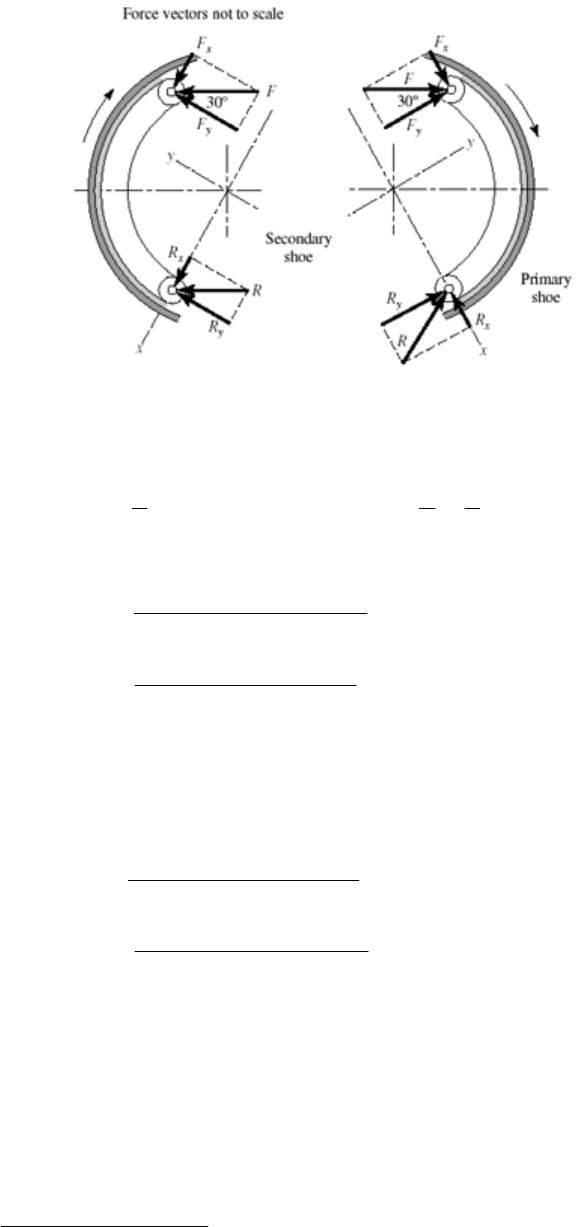
(c)
RH shoe: Fx = 2200 sin 30° = 1100 N, Fy = 2200 cos 30° = 1905 N
Eqs. (16-8):
o
o
120 2 / 3 rad
2
00
11
sin 0.375, sin 2 1.264
224
AB
Eqs. (16-9):
3
734.5 10 0.040(0.150) [0.375 0.28(1.264)] 1100 1007 N
1
x
R
3
221/2
734.5 10 0.04(0.150) [1.264 0.28(0.375)] 1905 4128 N
1
[ 1007 4128 ] 4249 N .
y
R
RAns
LH shoe: Fx = 1100 N, Fy = 1905 N
Eqs. (16-10):
3
381.9 10 0.040(0.150) [0.375 0.28(1.264)] 1100 570 N
1
x
R
3
1/2
22
381.9 10 0.040(0.150) [1.264 0.28(0.375)] 1905 751 N
1
597 751 959 N .
y
R
RAns
______________________________________________________________________________
16-2 Given: r = 300/2 = 150 mm, a = R = 125 mm, b = 40 mm, f = 0.28, F = 2.2 kN,
1 = 15,
2 = 105, and
a = 90. From which, sin
a = sin90 = 1.
Eq. (16-2):
105 4
15
0.28 (0.040)(0.150) sin (0.150 0.125cos ) 2.177 10
1
a
f
a
p
M
dp
Chapter 16, Page 2/27

Eq. (16-3):
105 24
15
(0.040)(0.150)(0.125) sin 7.765 10
1
a
N a
p
M
dp
c = 2(0.125) cos 30° = 0.2165 m
Eq. (16-4):
44
3
7.765 10 2.177 10 2.581 10
0.2165
aa
a
pp
Fp
RH shoe: pa = 2200/ [2.581(10 3)] = 852.4 (103) Pa
= 852.4 kPa on RH shoe for cw rotation Ans.
Eq. (16-6):
32
0.28(852.4)10 (0.040)(0.150 )(cos15 cos105 ) 263 N · m
1
R
T
LH shoe:
44
3
7.765 10 2.177 10
2200 0.2165
479.1 10 Pa 479.1 kPa on LH shoe for ccw rotation .
aa
a
pp
pA
ns
32
total
0.28(479.1)10 (0.040)(0.150 )(cos15 cos105 ) 148 N · m
1
263 148 411 N · m .
L
T
TAns
Comparing this result with that of Prob. 16-1, a 2.6% reduction in torque is obtained by
using 25% less braking material.
______________________________________________________________________________
16-3 Given:
1 = 0°,
2 = 120°,
a = 90°, sin
a = 1, a = R = 3.5 in, b = 1.25 in, f = 0.30,
F = 225 lbf, r = 11/2 = 5.5 in, counter-clockwise rotation.
LH shoe:
Eq. (16-2), with
1 = 0:
2
1
2
22
o2
sin cos (1 cos ) sin
sin sin 2
0.30 (1.25)5.5 3.5
5.5(1 cos120 ) sin 120
12
14.31 lbf · in
aa
f
aa
a
a
fpbr fpbr a
Mradr
p
p
Eq. (16-3), with
1 = 0:
2
1
22
2
1
sin sin 2
sin sin 2 4
(1.25)5.5(3.5) 120 1 sin 2(120 )
1 2 180 4
30.41 lbf · in
aa
N
aa
a
a
p bra p bra
Md
p
p
Chapter 16, Page 3/27
o
o
2
180
2 cos 2(5.5) cos30 9.526 in
2
30.41 14.31
225 1.690
9.526
225 / 1.690 133.1 psi
aa a
a
cr
pp
Fp
p
Eq. (16-6):
22
12
(cos cos ) 0.30(133.1)1.25(5.5 ) [1 ( 0.5)]
sin 1
2265 lbf · in 2.265 kip · in .
a
L
a
fpbr
T
Ans
RH shoe:
30.41 14.31
225 4.694
9.526
225 / 4.694 47.93 psi
aa a
a
pp
Fp
p
47.93 2265 816 lbf ·in 0.816 kip·in
133.1
R
T
Ttotal = 2.27 + 0.82 = 3.09 kip in Ans.
______________________________________________________________________________
16-4 (a) Given:
1 = 10°,
2 = 75°,
a = 75°, pa = 106 Pa, f = 0.24, b = 0.075 m (shoe width),
a = 0.150 m, r = 0.200 m, d = 0.050 m, c = 0.165 m.
Some of the terms needed are evaluated here:
2
22 2
1
11
1
2
1
2
1
2
75
75 2
10
10
75 /180 rad
2
10 /180 rad
1
sin sin cos cos sin
2
1
200 cos 150 sin 77.5 mm
2
1
sin sin 2 0.528
24
sin cos 0.4514
Ar da d r a
Bd
Cd
Now converting to Pascals and meters, we have from Eq. (16-2),
6
0.24 10 (0.075)(0.200) (0.0775) 289 N · m
sin sin 75
a
f
a
fpbr
MA
Chapter 16, Page 4/27

From Eq. (16-3),
6
10 (0.075)(0.200)(0.150) (0.528) 1230 N · m
sin sin 75
a
N
a
pbra
MB
Finally, using Eq. (16-4), we have
1230 289 5.70 kN .
165
Nf
MM
FA
c
ns
(b) Use Eq. (16-6) for the primary shoe.
2
12
62
(cos cos )
sin
0.24 10 (0.075)(0.200) (cos 10 cos 75 ) 541 N · m
sin 75
a
a
fp br
T
For the secondary shoe, we must first find pa. Substituting
66
66
3
1230 289
and into Eq. (16 - 7),
10 10
(1230 / 10 ) (289 / 10 )
5.70 , solving gives 619 10 Pa
165
Nafa
aa a
MpMp
pp p
Then
32
0.24 619 10 0.075 0.200 cos 10 cos 75 335 N · m
sin 75
T
so the braking capacity is Ttotal = 2(541) + 2(335) = 1750 N · m Ans.
(c) Primary shoes:
6
3
6
3
sin
10 (0.075)0.200 [0.4514 0.24(0.528)](10 ) 5.70 0.658 kN
sin 75
()
sin
10 (0.075)0.200 [0.528 0.24(0.4514)] 10 0 9.88 kN
sin 75
a
xx
a
a
yy
a
pbr
RCfBF
pbr
RBfCF
Chapter 16, Page 5/27
Secondary shoes:
6
3
6
3
()
sin
0.619 10 0.075(0.200) [0.4514 0.24(0.528)] 10 5.70
sin 75
0.143 kN
()
sin
0.619 10 0.075(0.200) [0.528 0.24(0.4514)] 10 0
sin 75
4.03 kN
a
xx
a
a
yy
a
pbr
RCfBF
pbr
RBfCF
Note from figure that +y for secondary shoe is opposite to
+y for primary shoe.
Combining horizontal and vertical components,
22
0.658 0.143 0.801 kN
9.88 4.03 5.85 kN
( 0.801) 5.85
5.90 kN .
H
V
R
R
R
Ans
______________________________________________________________________________
16-5 Given: Face width b = 1.25 in, F = 90 lbf, f = 0.25.
Preliminaries:
1 = 45° tan1(6/8) = 8.13°,
2 = 98.13°,
a = 90°,
a = (62 + 82)1/2 = 10 in
Eq. (16-2):
2
1
98.13
8.13
0.25 (1.25)6
sin cos sin 6 10cos
sin 1
3.728 lbf · in
aa
f
a
a
fpbr p
M
ra d d
p
Eq. (16-3):
2
1
98.13
22
8.13
(1.25)6(10)
sin sin
sin 1
69.405 lbf · in
aa
N
a
a
pbra p
M
dd
p
Eq. (16-4): Using Fc = MN Mf , we obtain
90(20) (69.405 3.728) 27.4 psi .
aa
p
pA ns
Chapter 16, Page 6/27
Eq. (16-6):
2
2
12
0.25(27.4)1.25 6 cos8.13 cos98.13
cos cos
sin 1
348.7 lbf · in .
a
a
fp br
T
Ans
______________________________________________________________________________
16-6 For ˆ
3:
f
ˆ
3 0.25 3(0.025) 0.325
f
ff
From Prob. 16-5, with f = 0.25, M f = 3.728 pa. Thus, M f = (0.325/0.25) 3.728 pa =
4.846 pa. From Prob. 16-5, M N = 69.405 pa.
Eq. (16-4): Using Fc = MN Mf , we obtain
90(20) (69.405 4.846) 27.88 psi .
aa
p
pA ns
From Prob. 16-5, pa = 27.4 psi and T = 348.7 lbf⋅in. Thus,
0.325 27.88 348.7 461.3 lbf ·in .
0.25 27.4
TA
ns
Similarly, for
ˆ
3:
f
ˆ
3 0.25 3(0.025) 0.175
(0.175 / 0.25) 3.728 2.610
f
f
aa
ff
M
pp
90(20) = (69.405 2.610) pa pa = 26.95 psi
0.175 26.95 348.7 240.1 lbf · in .
0.25 27.4
TA
ns
______________________________________________________________________________
16-7 Preliminaries:
2 = 180° 30° tan1(3/12) = 136°,
1 = 20° tan1(3/12) = 6°,
a = 90, sin
a = 1, a = (32 + 122)1/2 = 12.37 in, r = 10 in, f = 0.30, b = 2 in, pa = 150 psi.
Eq. (16-2):
o
136
6
0.30(150)(2)(10) sin (10 12.37 cos ) 12 800 lbf · in
sin 90
f
Md
Eq. (16-3): 136 2
6
150(2)(10)(12.37) sin 53 300 lbf · in
sin 90
N
Md
LH shoe:
c
L = 12 + 12 + 4 = 28 in
Chapter 16, Page 7/27
Now note that Mf is cw and MN is ccw. Thus,
53 300 12 800 1446 lbf
28
L
F
Eq. (16-6):
2
0.30(150)(2)(10) (cos 6 cos136 ) 15 420 lbf · in
sin 90
L
T
RH shoe:
53 300 355.3 , 12 800 85.3
150 150
aa
Naf
pp
a
M
pM p
On this shoe, both MN and Mf are ccw. Also,
c
R = (24 2 tan 14°) cos 14° = 22.8 in
act sin14 361 lbf .
/ cos14 1491 lbf
L
RL
F
F Ans
FF
Thus, 355.3 85.3
1491 77.2 psi
22.8 aa
pp
Then,
2
0.30(77.2)(2)(10) (cos 6 cos136 ) 7940 lbf · in
sin 90
R
T
Ttotal = 15 420 + 7940 = 23 400 lbf · in Ans.
______________________________________________________________________________
16-8
2
2
0
0
2 ( )( cos ) where
2(cos) 0
f
M
fdN a r dN pbr d
fpbr a r d
From which
22
00
2
2
cos
(60 )( / 180) 1.209 .
sin sin 60
adrd
rr
ar
Ans
Chapter 16, Page 8/27
Eq. (16-15):
4sin60 1.170 .
2(60)( / 180) sin[2(60)]
r
ar
Ans
a differs with a ¢ by 100(1.170 1.209)/1.209 = 3.23 % Ans.
______________________________________________________________________________
16-9 (a) Counter-clockwise rotation,
2 =
/ 4 rad, r = 13.5/2 = 6.75 in
Eq. (16-15):
2
22
4 sin 4(6.75) sin( / 4) 7.426 in
2sin2 2/4sin(2/4)
2 2(7.426) 14.85 in .
r
a
ea Ans
(b)
= tan1(3/14.85) = 11.4°
0 3 6.375 2.125
02
xx
R
xx x x
x.125
M
FPF
FFRRF
P
P
P
o
tan11.4 0.428
0.428 1.428
yx
yy
y
y
FF
FPFR
R
PP
P
Left shoe lever.
0 7.78 15.28
15.28 (2.125 ) 4.174
7.78
0.30(4.174 ) 1.252
0
0.428 1.252 1.68
0
4.174 2.125 2.049
xx
R
x
yx
yy y
y
yyy
xx x
x
xxx
MSF
SPP
SfS P P
FRSF
R
FS P P
FRSF
P
R
SF P P P
Chapter 16, Page 9/27
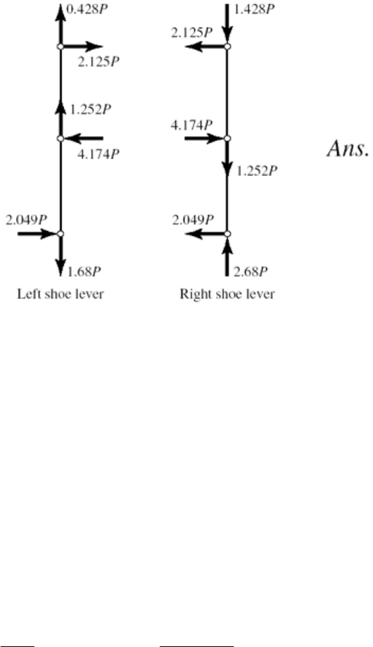
(c) The direction of brake pulley rotation affects the sense of Sy, which has no effect on
The brake shoe levers carry identical bending moments but the left lever carries a
ers).
______________________________________________________________________________
6-10 r = 13.5/2 = 6.75 in, b = 6 in,
2 = 45° =
/ 4 rad.
From Table 16-3 for a rigid, molded non-asbestos lining use a conservative estimate of
Equation (16-16) gives the horizontal brake hinge pin reaction which corresponds to Sx in
the brake shoe lever moment and hence, no effect on Sx or the brake torque.
tension while the right carries compression (column loading). The right lever is
designed and used as a left lever, producing interchangeable levers (identical lev
But do not infer from these identical loadings.
1
p
a = 100 psi, f = 0.33.
Prob. 16-9. Thus,
22
100(6)6.75
2sin2 2/4sin245
22
5206 lbf
xa
p
NS
br
which, from Prob. 6-9 is 4.174 P. Therefore,
4.174 P = 5206 P = 1250 lbf = 1.25 kip Ans.
Applying Eq. (16-18) for two shoes, where from Prob. 16-9, a = 7.426 in
______________________________________________________________________________
6-11 Given: D = 350 mm, b = 100 mm, pa = 620 kPa, f = 0.30,
= 270.
2 2(7.426)0.33(5206)
25 520 lbf · in 25.52 kip · in .
TafN
Ans
1
Chapter 16, Page 10/27
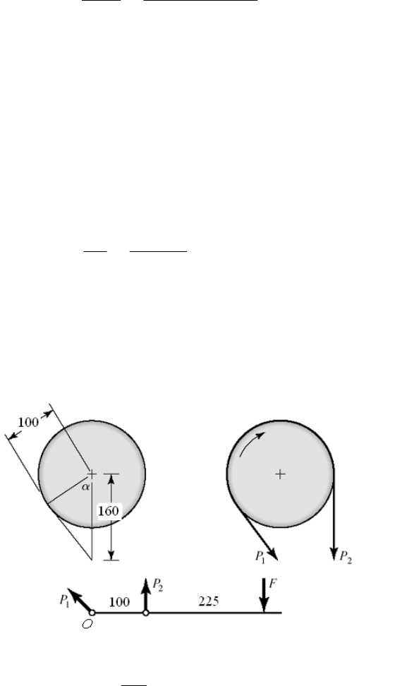
Eq. (16-22):
1
620(0.100)0.350 10.85 kN .
22
0.30(270 )( / 180 ) 1.414
a
pbD
PAns
f
Eq. (16-19): P2 = P1 exp( f
) = 10.85 exp( 1.414) = 2.64 kN Ans.
s
_____ _ _____ _________________________________________________________
6-12 Given: D = 12 in, f = 0.28, b = 3.25 in,
= 270°, P1 = 1800 lbf.
Eq. (16-22):
12
( )( / 2) (10.85 2.64)(0.350 / 2) 1.437 kN · m .TPPD An
_ _____ _ __ _
1
1
2 2(1800) 92.3 psi .
3.25(12)
a
P
p
Ans
bD
______________________________________________________________________________
3
Ans.
oo
21
12
0.28(270 )( / 180 ) 1.319
exp( ) 1800 exp( 1.319) 481 lbf
( )( / 2) (1800 481)(12 / 2)
7910 lbf · in 7.91 kip · in .
f
PP f
TPPD
Ans
16-1
MO = 0 = 100 P2 325 F P2 = 325(300)/100 = 975 N
1100
cos 51.32
12
12
3
160
270 51.32 218.7
0.30(218.7) / 180 1.145
exp( ) 975 exp(1.145) 3064 N .
( / 2) (3064 975)(200 / 2)
209 10 N · mm 209 N · m .
f
PP f Ans
TPPD
Ans
______________________________________________________________________________
Chapter 16, Page 11/27

16-14 (a) D = 16 in, b = 3 in
n = 200 rev/min
f = 0.20, pa = 70 psi
Eq. (16-22):
11680 lbf
22
a
P
70(3)(16)pbD
f0.20(3 / 2) 0.942
Eq. (16-14): P
21
exp( ) 1680 exp( 0.942) 655 lbfP f
12
1504 lbf .
10 10
16
( ) (1680 655)
22
8200 lbf · in .
8200(200) 26.0 hp .
63 025 63 025
3 3(1680)
D
TPP
Ans
Tn
H
Ans
P
(b) Force of belt on the drum:
R = (16802 + 6552)1/2 = 1803 lbf
shaft on the drum: 1680 and 655 lbf
Net torque on drum due to brake band:
r is 1803 lbf. If th
the drum at center span, the bearing radial load is 1803
PA
ns
Force of
1
2
1680(8) 13 440 lbf · in
655(8) 5240 lbf · in
P
P
T
T
8200 lbf · in
12
13 440 5240
PP
TT T
The radial load on the bearing pai e bearing is straddle mounted with
/2 = 901 lbf.
Chapter 16, Page 12/27
(c) Eq. (16-21):
1
0
2
22(1680)
70 psi .
3(16) 3(16)
P
pbD
P
p Ans
2
270 27.3 psi .
3(16) 3(16)
2 2(655)P
p
Ans
______________________________________________________________________________
16-15 Given:
= 270°, b = 2.125 in, f = 0.20, T =150 lbf · ft, D = 8.25 in, c2 = 2.25 in (see
figure). Notice that the pivoting rocker is not located on the vertical centerline of the
drum.
(a) To have the band tighten for ccw rotation, it is necessary to have c1 < c2 . When
friction is fully developed,
12
/ exp( ) exp[0.2(3 / 2)] 2.566PP f
If friction is not fully developed,
P
1/P2 ≤ exp( f
)
To help visualize what is going on let’s add a force W parallel to P1, at a lever arm of
c
3. Now sum moments about the rocker pivot.
23112
0
M
cW cP c P
From which
22 11
3
cP cP
Wc
The device is self locking for ccw rotation if W is no longer needed, that is, W ≤ 0.
It follows from the equation above
12
21
Pc
Pc
When friction is fully developed
1
1
2.566 2.25 /
2.25 0.877 in
2.566
c
c
When P1/P2 is less than 2.566, friction is not fully developed. Suppose P1/P2 = 2.25,
Chapter 16, Page 13/27
then
1
2.25 1 in
2.25
c
We don’t want to be at the point of slip, and we need the band to tighten.
2
12
12
/
ccc
PP
When the developed friction is very small, P1/P2 → 1 and c1 → c2 Ans.
(b) Rocker has c1 = 1 in
12
21 1
ln(
Pc
f
12
2.25
/ ) ln 2.25 0.172
3/2
PP
is ully developed, no slip.
2.25Pc
Friction not f
1
12
()
DP
TPP
21
2
D
P
2
2P
Solve for P2
2
12
12
1
2 2(150)(12) 349 lbf
[( / ) 1] (2.25 1)(8.25)
2.25 2.25(349) 785 lbf
2 2(785) 89.6 psi .
2.125(8.25)
T
PPP D
PP
P
p Ans
bD
-fold.
(c) The torque ratio is 150(12)/100 or 18
2
12
349 19.4 lbf
18
2.25 2.25(19.4) 43.6 lbf
89.6 4.98 psi .
18
P
PP
pAns
Comment:
As the torque opposed by the locked brake increases, P2 and P1 increase (although
ratio is still 2.25), then p follows. The brake can self-destruct. Protection could be
provided by a shear key.
__ __ ________________________________________________________
____ __________ ____
16-16 Given: OD = 250 mm, ID = 175 mm, f = 0.30, F = 4 kN.
Chapter 16, Page 14/27
(a) From Eq. (16-23),
2
2 4000
2
a0.194 N/mm 194 kPa .
( ) (175)(250 175)
F
p
Ans
dD d
Eq. (16-25):
3
4000(0.30)
( ) (250 175)10 127.5 N · m .
44
Ff
T D d Ans
(b) From Eq. (16-26),
2
22
()
a2 2
4 4(4000) 0.159 N/mm 159 kPa .
(250 175 )
F
p
Ans
Eq. (16-27):
Dd
3
33 3 3 3 3
( ) (0.30)159 10 250 175 10
12 12
128 N · m .
a
TfpDd
Ans
__ _________ ___
___ ___ _________________________________________________________
6-17 Given: OD = 6.5 in, ID = 4 in, f = 0.24, pa = 120 psi.
(a) Eq. (16-23):
_
1
(120)(4)
( ) (6.5 4) 1885 lbf .
22
a
pd
F
D d Ans
N sliding planes:
Eq. (16-24) with
22 22
(0.24)(120)(4)
() (6.54)
88
7125 lbf · in .
a
fp d
TDdN
Ans
(6)
22
(0.24)(120 ) (6.5 )(6)
8
d
(b)
T
d
d, in T, lbf · in
2 5191
3 6769
4 7125
Ans.
5 5853
6 2545
(c) The torque-diameter curve exhibits a stationary point maximum in the range of
s nearly optimal proportions. diameter d. The clutch ha
______________________________________________________________________________
16-18 (a) Eq. (16-24) with N sliding planes:
Chapter 16, Page 15/27
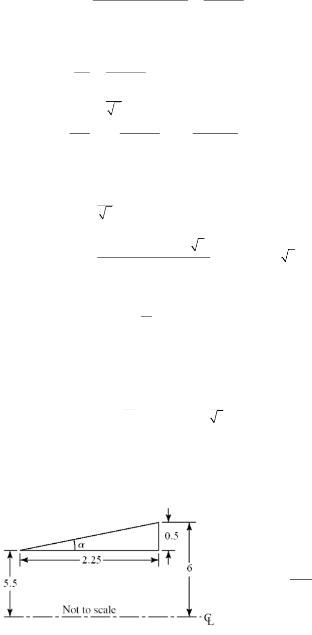
22
23
()
88
aa
f
TD
pdD d N fpN dd
respect to d and equating to zero gives
Differentiating with
22
2
2
30
8
*d .
3
3
684
a
aa
dT f p N Dd
dd DAns
dT fpN fpN
dd
dd
egative for all positive d. We have a stationary point maximum.
(b)
which is n
6.5
* 3.75 in .
3
dA
ns
Eq. (16-24):
2
(0.24)(120) 6.5 / 3
* 6.5T
2
6.5 / 3 (6) 7173 lbf · in
8
(c) The table indicates a maximum within the range: 3 ≤ d ≤ 5 in
r:
0.45 0.80
d
(d) Conside D
Multiply through by D,
*
0.45 0.80
0.45(6.5) 0.80(6.5)
2.925 5.2 in
1
* / 0.577
3
Dd D
d
d
ddD
D
which lies within the common range of clutches.
Yes. Ans.
______________________________________________________________________________
16-19 Given: d = 11 in, l = 2.25 in, = 1800 lbf · i D = 12 in, f = 0.28.
Tn,
10.5
tan 12.53
2.25
Chapter 16, Page 16/27
Uniform wear
45):
Eq. (16-
22
8sin
a
fpd
TDd
22
(0.28) (11)
1800 12 11 128.2
8sin12.53
1800 14.04 psi .
128.2
aa
a
p
p
pAns
Eq. (16-44):
(14.04)11
( ) (12 11) 243 lbf .
22
a
pd
F
Dd Ans
pressure
Uniform
Eq. (16-48):
33
1 s
fp
T
2 in
aD
d
33
(0.28)
1800 12 11 134.1
12sin12.53
1800
aa
p
13.42 psi .
134.1
a
p
pAns
Eq. (16-47):
22 2 2
(13.42)
(
a
p) 12 11 242 lbf .
44
F
D d Ans
______________________________________________________________________________
16-20 Uniform wear
Eq. (16-34):
22
21
1()
2
F = (
ai o i
Tfprrr
2
1) pari (ro ri) Eq.
(16-33):
Thus,
22
21
(1 / 2)( ) ai o i
fpr r r
T
21
()()()
/2 /2 1 1 . . .
224
ai o i
oi
fF
D f prr r D
rr D d d OK Ans
DD D
Uniform pressure
Eq. (16-38):
33
21
1()
3ao i
Tfpr
r
Chapter 16, Page 17/27
22
21
1()
2ao i
Eq. (16-37):
F
pr r
Thus,
33 33
21
22
22
21
33 3
2
22
(1 / 3)( ) 2 ( /2) ( /2)
3
( / 2) ( / 2)(1 / 2) ( )
2( / 2) 1 ( / ) 11 ( / ) . . .
31 ( / )
3( / 2) 1 ( / )
ao i
ao i
fp r r
TD
fFD DdDfprrD
DdD dD OK Ans
dD
DdDD
d
___ __________
__ ______________________________________________________________
_
6-211
3
2 / 60 2 500 / 60 52.4 rad/s
2(10 ) 38.2 N· m
52.4
n
H
T
Key:
38.2 3.18 kN
12
T
Fr
Average shear stress in key is
3
3.18(10 ) 13.2 MPa .
6(40) Ans
Average bearing stress is
3
3.18(10 ) 26.5 MPa .
3(40)
bA
b
FAns
tire load. Let one jaw carry the en
126 45 17.75 mm
22 2
38.2 2.15 kN
17.75
av
av
r
T
Fr
The bearing and shear stress estimates are
3
3
2
2.15 10 22.6 MPa .
10(22.5 13)
2.15(10 ) 0.869 MPa .
10 0.25 (17.75)
b
Ans
Ans
___________________________________________________ ___________________________
Chapter 16, Page 18/27
16-22
From Eq. (16-51),
1
2
2 / 60 2 (1600) / 60 167.6 rad/s
0
n
2
12 1
12 1 2
2800(8) 133.7 lbf · in · s
167.6 0
II Tt
II
Eq. (16-52):
226
12
12
12
133.7II
(167.6 0) 1.877 10 lbf in
22
EII
In Btu, Eq. (16-53): H = E / 9336 = 1.877(106) / 9336 = 201 Btu
:
6-54) Eq. (1
201 41.9 F .
0.12(40)
p
H
TA
CW
ns
__ ________________________ _____________________________________
16-23
____ __________ _
12
260 240 250 rev/min
2
Eq.
(16-62): C
2
nn
n
2
1) /
= (n2 n1) / n = (260 240) / 250 = 0.08 Ans.
= 2
(250) / 60 = 26.18 rad/s
From Eq. (16-64):
s = (
3
2
21
22
6.75 10 123.1 N · m · s
0.08(26.18)
s
EE
IC
22
22 2 2
8 8(123.1) 233.9 kg
81.5
oi
oi
mI
Idd m
dd
1.4
Table A-5, cast iron unit weight = 70.6 kN/m3
= 70.6(103) / 9.81 = 7197 kg / m3.
Volume: V = m /
= 233.9 / 7197 = 0.0325 m3
22 2 2
/ 4 1.5 1.4 / 4 0.2278
oi
Vtdd t
t
Equating the expressions for volume and solving for t,
0.0325 0.143 m 143 mm .
0.2278
tA
ns
Chapter 16, Page 19/27
______________________________________________________________________________
) The useful work performed in one revolution of the crank shaft is
U = 320 (103) 200 (103) 0.15 = 9.6 (10
ict e total work done in one revolution is
U = 9.6(103) / (1 0.20) = 12.0(103) J
nk shaft stroke accounts for 7.5% of a crank shaft revolution, the
energy fluctuation is
E
2 E1 = 9.6(103) 12.0(103)(0.075) = 8.70(103) J Ans.
(b) For the flywheel,
16-24 (a
3) J
Accounting for fr ion, th
Since 15% of the cra
6(90) 540 rev/min
2 2 (540) 56.5 rad/s
60 60
n
n
Since C = 0.10 s
q.
(16-64):
3
2
21
22
8.70(10 ) 27.25 N · m · s
0.10(56.5)
s
EE
IC
E
Assuming all the mass is concentrated at the effective diameter, d,
2
2md
Im
r
22
4
4 4(27.25) 75.7 kg .
1.2
Ins
d
__ _________________________________________ ____________________
6-25 Use Ex. 16-6 and Table 16-6 data for one cylinder of a 3-cylinder engine.
mA
____ __________ _
1
21
2
21
22
0.30
2400 rev/min or 251 rad/s
3(3368) 804 lbf · in .
10 590 0.560 in · lbf · s .
0.30(251 )
s
m
s
C
n
TAns
EE
4
3(3531) 10 590 in · lbfEE
I
Ans
C
_____ ___________________________
_ _____________________________________________
Chapter 16, Page 20/27
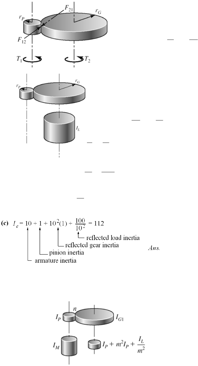
16-26 (a)
(1)
22
21 21
( ) P
G
TFr
r
.
P
TT
r Ans
n
Equivalent energy
Equivalent energy
(2) (2)
22
22 21 1
2
22
21 2
22
1
(1 / 2) (1 / 2)( )
( ) .
II
I
I
IAns
n
(3)
22
4
2
G
PPP PP
rn
r
From (2)
GGG G
Irm r
Irm r
4
2
21 22 P
( ) .
GP
InI
I
nI Ans
(b)
nn
2
2 .
L
eMP P
I
I
IInI An
n
s
______________________________________________________________________________
16-27 (a) Reflect IL, IG2 to the center shaft
Chapter 16, Page 21/27
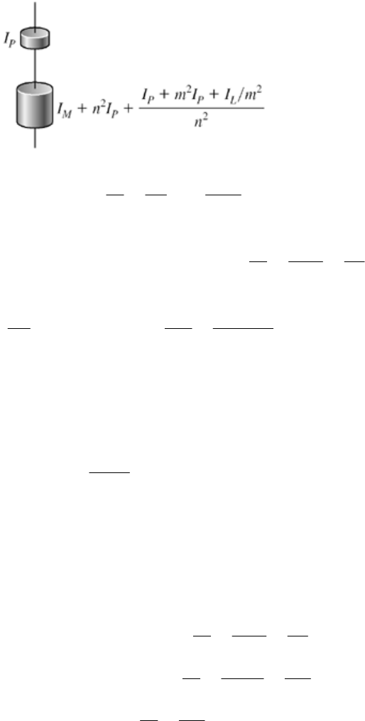
Reflect the center shaft to the motor shaft
2
2PL
Im I
22 22
.
eMP P P
I
IInI I Ans
nn mn
(b) For R = constant = nm,
2
2
24 2
.
PPL
eMP P
IRII
I
IInI An
nn
s
= 10,
R
2
35
2(1) 4(10 )(1)
002(1) 0 0
e
In
nnn
(c) For R
n
6 n2 200 = 0
From which
* 2.430 .
10
* 4.115 .
2.430
nAns
mA
ns
at n*and m* are independent of IL.
_____________________________________________________________________________
6-28 From Prob. 16-27,
Notice
th
_
1
2
2
24 2
24 2
24
10
1100
12
21 100(1) 100
10 1 (1)
2
P
PL
eMP P
I
RI I
II InInnR
nn
nnn
n
Chapter 16, Page 22/27
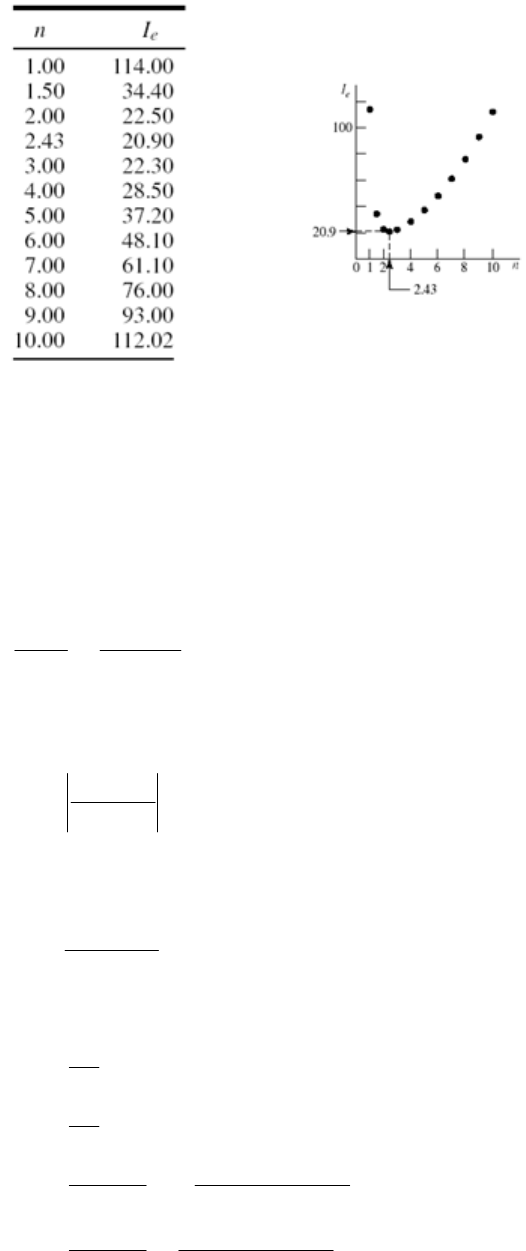
Optimizing the partitioning of a double reduction lowered the gear-train inertia to
of that of a single reduction. This includes the two additional
gears.
_____________________________________________________________________________
lies,
20.9/112 = 0.187, or to 19%
_
16-29 Figure 16-29 app
21
10 , 0.5 tst s
21
-tt
1
1
00.5
19
0.5t
The load torque, as seen by the motor shaft (Rule 1, Prob. 16-26), is
1300(12) 1560 lbf · in
10
L
T
ue Tr is
The rated motor torq
63 025(3) 168.07 lbf · in
1125
r
T
For Eqs. (16-65):
2(1125) 117.81 rad/s
60
2(1200) 125.66 rad/s
60
168.07 21.41 lbf in s/rad
125.66 117.81
168.07(125.66) 2690.4 lbf · in
125.66 117.81
r
s
r
sr
rs
sr
T
a
T
b
Chapter 16, Page 23/27
The linear portion of the squirrel-cage motor characteristic can now be expressed as
T
M = 21.41
+ 2690.4 lbf · in
Eq. (16-68):
19
2
2
1560 168.07
168.07 1560
TT
One root is 168.07 which is for infinite time. The root for 10 s is desired. Use a
successive substitution method
T2 New T2
0.00 19.30
19.30 4.40
26.50 26.67
2
24.40 26.00
26.00 26.50
Continue until convergence to
T
2 = 26.771 lbf ⋅ in
Eq. (16-69):
21 2
2
2
max
min
max min
max
21.41(10 0.5) 110.72 lbf · in · s
ln / ln(26.771 / 168.07)
26.771 2690.4 124.41 rad/s .
21.41
117.81 rad/s .
124.41 117.81 121.11 rad/s
2
(
r
s
at t
ITT
Tb Ans
aAns
C
Tb
a
min
22
22
22
21
124.41 117.81 0.0545 .
) / 2 (124.4 117.81) / 2
11
(110.72)(117.81) 768 352 in · lbf
22
11
(110.72)(124.41) 856 854 in · lbf
22
856 854 768 352 88 502 in · lbf
r
A
1
1
ns
EI
EI
EE E
Eq. (16-64):
22
0.0545(110.72)(121.11)
88 508 in · lbf, close enough .
s
ECI
A
ns
Chapter 16, Page 24/27
During the punch
63 025H
(60 / 2 ) 1560(121.11)(60 / 2 ) 28.6 hp
63 025 63 25
L
n
T
H
eel is on
T
0
The gear train has to be sized for 28.6 hp under shock conditions since the flywh
the motor shaft. From Table A-18,
22 22
oi
22
88
8 1
oi
oi
mW
2
o
2
i
8(386)( 10.72)
I
dd
gI
Wdd
If a mean diameter of the flywheel rim of 30 in is acceptable, try a rim thickness of 4 in
dd
g
dd
22
30 (4 / 2) 28 in
30 (4 / 2) 32 in
o
8(386)(110.72) 189.1 lbf
32 28
i
d
d
Rim volume V is given by
W
22 2 2
(32 28 ) 188.5
44
oi
ll
Vdd l
where l is the rim width as shown in Table A-18. The specific weight of cast iron is
= 0.260 lbf / in3, therefore the volume of cast iron is
3
189.1 727.3 in
0.260
W
V
Equating the volumes,
188.5 727.3
727.3 3.86 in wide
188.5
l
l
Proportions can be varied.
_____________________________________________________________________________
0 solution has I for the motor shaft flywheel as
_
16-3 Prob. 16-29
Chapter 16, Page 25/27
I = 110.72 lbf · in · s2
A flywheel located on the crank shaft needs an inertia of 102 I (Prob. 16-26, rule 2)
I = 102(110.72) = 11 072 lbf · in · s2
inertia increase. On the other hand, the gear train has to transmit 3 hp under
A 100-fold
shock conditions.
Stating the problem is most of the solution. Satisfy yourself that on the crankshaft:
1300(12) 15 600 lbf · in
10(168.07) 1680.7 lbf · in
117.81 / 10 11.781 rad/s
125.66 / 10 12.566 rad/s
L
r
r
s
T
T
19
2
2
21.41(100) 2141 lbf · in · s/rad
2690.35(10) 26903.5 lbf · in
2141 26 903.5 lbf · in
b
T
15 600 1680.5
1680.6 15 600
Mc
a
TT
0(26.67) = 266.7 lbf · in The root is 1
121.11
max
min
/ 10 12.111 rad/s
0.0549 (same)
121.11 / 10 12.111 rad/s .
117.81 / 10 11.781 rad/s .
s
C
A
ns
A
ns
-18 E
1, E2,
E and peak power are the same. From Table A
6
22 22 22
34.19 10
8 8(386)(11 072)
oi oi oi
gI
Wdd dd dd
d di , but the gear ratio changed I. Scale up the flywheel in the
Prob. 16-29 solution by a factor of 2.5. Thickness becomes 4(2.5) = 10 in.
Scaling
will affect do an
30(2.5) 75 in
75 (10 / 2) 80 in
75 (10 / 2) 70 in
o
i
d
d
d
Chapter 16, Page 26/27
6
34.19 10
22
80 70
3026W
Chapter 16, Page 27/27
3
22
3026 lbf
11 638 in
11 638
W
V
Proportions can be varied. The weight has increased 3026/189.1 or about 16-fold while
the moment of inertia I increased 100-fold. The gear train transmits a steady 3 hp. But the
motor armature has its inertia magnified 100-fold, and during the punch there are
deceleration stresses in the train. With no motor armature information, we cannot
comment.
______________________________________________________________________________
1 the basis for a class discussion.
0.260
(80 70 ) 1178
4
Vl l
9.88 in
1178
l
16-3 This can be
Chapter 17
17-1 Given: F-1 Polyamide, b = 6 in, d = 2 in with n = 1750 rev/min, Hnom = 2 hp, C = 9(12) =
108 in, velocity ratio = 0.5, Ks = 1.25, nd = 1
V =
d n / 12 =
(2)(1750) / 12 = 916.3 ft/min
D = d / vel ratio = 2 / 0.5 = 4 in
Eq. (17-1): 11
42
2sin 2sin 3.123 rad
2 2(108)
d
Dd
C
Table 17-2: t = 0.05 in, dmin = 1.0 in, Fa = 35 lbf/in,
= 0.035 lbf/in3, f = 0.5
w = 12
bt = 12(0.035)6(0.05) = 0.126 lbf/ft
(a) Eq. (e), p. 885:
22
0.126 916.3 0.913 lbf .
60 32.17 60
c
V
F
Ans
g
w
12
63 025 63 025(2)(1.25)(1) 90.0 lbf · in
1750
2 2(90.0) 90.0 lbf
2
nom s d
a
HKn
TnT
FF Fd
Table 17-4: Cp = 0.70
Eq. (17-12): (F1)a = bFaCpCv = 6(35)(0.70)(1) = 147 lbf Ans.
F
2 = (F1)a [(F1)a F2] = 147 90 = 57 lbf Ans.
Do not use Eq. (17-9) because we do not yet know
f
Eq. (i), p. 886:
12 147 57 0.913 101.1 lbf .
22
a
ic
FF
F
FA
ns
Using Eq. (17-7) solved for f ¢ (see step 8, p.888),
1
2
1 ( ) 1 147 0.913
ln ln 0.307
3.123 57 0.913
ac
dc
FF
fFF
The friction is thus underdeveloped.
(b) The transmitted horsepower is, with F = (F1)a F2 = 90 lbf,
Chapter 17, Page 1/39

Eq. (j), p. 887: ( ) 90(916.3) 2.5 hp .
33 000 33 000
FV
H
Ans
nom
2.5 1
2(1.25)
fs
s
H
nHK
Eq. (17-1): 11
42
2sin 2sin 3.160 rad
2 2(108)
D
Dd
C
Eq. (17-2): L = [4C2 (D d)2]1/2 + (D
D + d
d)/2
= [4(108)2 (4 2)2]1/2 + [4(3.160) + 2(3.123)]/2 = 225.4 in Ans.
(c) Eq. (17-13):
22
3 3(108 / 12) (0.126)
dip 0.151 in .
2 2(101.1)
i
CAns
F
w
Comment: The solution of the problem is finished; however, a note concerning the design
is presented here.
The friction is under-developed. Narrowing the belt width to 5 in (if size is available) will
increase
f
. The limit of narrowing is bmin = 4.680 in, whence
1
2
12
0.0983 lbf/ft ( ) 114.7 lbf
0.713 lbf 24.7 lbf
90 lbf · in (same) 0.50
( ) 90 lbf
a
c
a
F
FF
Tf
FF F
w
dip 0.173 in
68.9 lbf
i
F
f
Longer life can be obtained with a 6-inch wide belt by reducing Fi to attain
Prob. 17-8 develops an equation we can use here
0.50.f
1
21
12
1
2
2
( ) exp( )
exp( ) 1
2
1ln
3
dip 2
cc
ic
c
dc
i
FF f F
Ff
FF F
FF
FF
FF
fFF
C
F
w
which in this case,
d = 3.123 rad, exp(f
) = exp[0.5(3.123)] = 4.766, w = 0.126 lbf/ft,
F = 90.0 lbf, Fc = 0.913 lbf, and gives
Chapter 17, Page 2/39
1
0.913 90 4.766 0.913 114.8 lbf
4.766 1
F
F2 = 114.8 90 = 24.8 lbf
Fi = (114.8 + 24.8)/ 2 0.913 = 68.9 lbf
1 114.8 0.913
ln 0.50
3.123 24.8 0.913
f
2
3 108 / 12 0.126
dip 0.222 in
2(68.9)
So, reducing F
i from 101.1 lbf to 68.9 lbf will bring the undeveloped friction up to 0.50,
with a corresponding dip of 0.222 in. Having reduced F1 and F2, the endurance of the
belt is improved. Power, service factor and design factor have remained intact.
______________________________________________________________________________
17-2 Double the dimensions of Prob. 17-1.
In Prob. 17-1, F-1 Polyamide was used with a thickness of 0.05 in. With what is available
in Table 17-2 we will select the Polyamide A-2 belt with a thickness of 0.11 in. Also, let
b = 12 in, d = 4 in with n = 1750 rev/min, Hnom = 2 hp, C = 18(12) = 216 in, velocity
ratio = 0.5, Ks = 1.25, nd = 1.
V =
d n / 12 =
(4)(1750) / 12 = 1833 ft/min
D = d / vel ratio = 4 / 0.5 = 8 in
Eq. (17-1): 11
84
2sin 2sin 3.123 rad
2 2(216)
d
Dd
C
Table 17-2: t = 0.11 in, dmin = 2.4 in, Fa = 60 lbf/in,
= 0.037 lbf/in3, f = 0.8
w = 12
bt = 12(0.037)12(0.11) = 0.586 lbf/ft
(a) Eq. (e), p. 885:
22
0.586 1833 17.0 lbf .
60 32.17 60
c
V
F
Ans
g
w
12
63 025 63 025(2)(1.25)(1) 90.0 lbf · in
1750
2 2(90.0) 45.0 lbf
4
nom s d
a
HKn
TnT
FF Fd
Table 17-4: Cp = 0.73
Chapter 17, Page 3/39
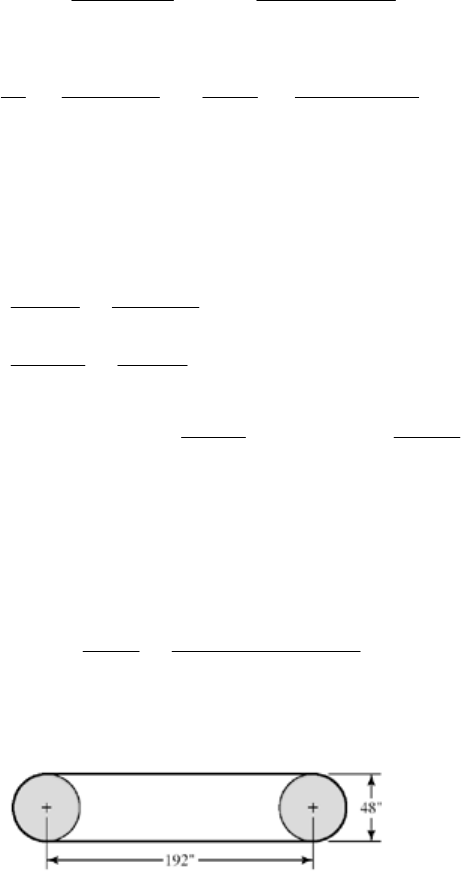
Eq. (17-12): (F1)a = bFaCpCv = 12(60)(0.73)(1) = 525.6 lbf Ans.
F
2 = (F1)a [(F1)a F2] = 525.6 45 = 480.6 lbf Ans.
Eq. (i), p. 886:
12 525.6 480.6 17.0 486.1 lbf .
22
a
ic
FF
F
FA
ns
Eq. (17-9):
1
2
1 ( ) 1 525.6 17.0
ln ln 0.0297
3.123 480.6 17.0
ac
dc
FF
fFF
The friction is thus underdeveloped.
(b) The transmitted horsepower is, with F = (F1)a F2 = 45 lbf,
nom
( ) 45(1833) 2.5 hp .
33 000 33 000
2.5 1
2(1.25)
fs
s
FV
H
Ans
H
nHK
Eq. (17-1): 11
84
2sin 2 sin 3.160 rad
2 2(216)
D
Dd
C
Eq. (17-2): L = [4C2 (D d)2]1/2 + (D
D + d
d)/2
= [4(216)2 (8 4)2]1/2 + [8(3.160) + 4(3.123)]/2 = 450.9 in Ans.
(c) Eq. (17-13):
22
3 3(216 / 12) (0.586)
dip 0.586 in .
2 2(486.1)
i
CAns
F
w
______________________________________________________________________________
17-3
As a design task, the decision set on p. 893 is useful.
A priori decisions:
• Function: Hnom = 60 hp, n = 380 rev/min, C = 192 in, Ks = 1.1
• Design factor: nd = 1
• Initial tension: Catenary
• Belt material. Table 17-2: Polyamide A-3, Fa = 100 lbf/in,
= 0.042 lbf/in3, f = 0.8
• Drive geometry: d = D = 48 in
• Belt thickness: t = 0.13 in
Chapter 17, Page 4/39
Design variable: Belt width.
Use a method of trials. Initially, choose b = 6 in
22
nom
11
(48)(380) 4775 ft/min
12 12
12 12(0.042)(6)(0.13) 0.393 lbf/ft
0.393(4775 / 60) 77.4 lbf
32.17
63 025 63 025(60)(1.1)(1) 10 946 lbf · in
380
2 2(10 946) 456.1 lbf
48
()
c
sd
a
dn
V
bt
V
FgHKn
Tn
T
Fd
FF
w
w
21
6(100)(1)(1) 600 lbf
600 456.1 143.9 lbf
ap
bF C C
FF F
v
Transmitted power H
12
1
2
( ) 456.1(4775) 66 hp
33 000 33 000
600 143.9 77.4 294.6 lbf
22
1 1 600 77.4
ln ln 0.656
143.9 77.4
ic
c
dc
FV
H
FF
FF
FF
fFF
Eq. (17-2): L = [4(192)2 (48 48)2]1/2 + [48(
) + 48(
)] / 2 = 534.8 in
Friction is not fully developed, so bmin is just a little smaller than 6 in (5.7 in). Not having
a figure of merit, we choose the most narrow belt available (6 in). We can improve the
design by reducing the initial tension, which reduces F1 and F2, thereby increasing belt
life (see the result of Prob. 17-8). This will bring
f
to 0.80
1
exp
exp 1
exp exp(0.80 ) 12.345
cc
FF f F
Ff
f
Therefore
1
21
12
(456.1 77.4)(12.345) 77.4 573.7 lbf
12.345 1
573.7 456.1 117.6 lbf
573.7 117.6 77.4 268.3 lbf
22
ic
F
FF F
FF
FF
These are small reductions since
f
is close to f , but improvements nevertheless.
Chapter 17, Page 5/39
1
2
1 1 573.7 77.4
ln ln 0.80
117.6 77.4
c
dc
FF
fFF
22
3 3(192 / 12) (0.393)
dip 0.562 in
2 2(268.3)
i
C
F
w
______________________________________________________________________________
17-4 From the last equation given in the problem statement,
02
02
02
02
1
exp 12/[( )]
2
1exp1
()
2exp exp 1
()
exp
12
exp 1
fTda ab
Tf
da a b
Tff
da a b
f
T
baad f
But 2T/d = 33 000Hd/V. Thus,
02
exp
1 33 000 ...
exp 1
df
H
bQ
aa V f
ED
______________________________________________________________________________
17-5 Refer to Ex. 17-1 on p. 890 for the values used below.
(a) The maximum torque prior to slip is,
nom
63 025 63 025(15)(1.25)(1.1) 742.8 lbf · in .
1750
sd
HKn
TA
n
ns
The corresponding initial tension, from Eq. (17-9), is,
exp( ) 1 742.8 11.17 1 148.1 lbf .
exp( ) 1 6 11.17 1
i
Tf
FA
df
ns
(b) See Prob. 17-4 statement. The final relation can be written
Chapter 17, Page 6/39
min 2
2
33 000 exp
1
(12 / 32.174)( / 60) [exp 1]
1 33 000(20.6)(11.17)
100(0.7)(1) [12(0.042)(0.13)] / 32.174 (2749 / 60) 2749(11.17 1)
4.13 in .
a
ap
Hf
bFCC t V V f
Ans
v
This is the minimum belt width since the belt is at the point of slip. The design must
round up to an available width.
Eq. (17-1):
11
11
18 6
2sin 2sin
22
3.016 511 rad
18 6
2sin 2sin
22
3.266 674 rad
d
D
Dd
C
Dd
C
(96)
(96)
Eq. (17-2):
221/2
1
[4(96) (18 6) ] [18(3.266 674) 6(3.016 511)]
2
230.074 in .
L
Ans
(c) 2 2(742.8) 247.6 lbf
6
T
Fd
11
21
22
12
( ) 4.13(100)(0.70)(1) 289.1 lbf
289.1 247.6 41.5 lbf
12 12(0.042)4.13(0.130) 0.271 lbf/ft
0.271 2749 17.7 lbf
60 32.17 60
289.1 41.5 17.7 147.6 lb
22
aap
c
ic
FbFCCF
FF F
bt
V
Fg
FF
FF
v
w
w
f
Transmitted belt power H
nom
( ) 247.6(2749) 20.6 hp
33 000 33 000
20.6 1.1
15(1.25)
fs
s
FV
H
H
nHK
Chapter 17, Page 7/39

Dip:
2
23(96 / 12) 0.271
30.176 in
2 2(147.6)
i
C
dip F
w
(
d) If you only change the belt width, the parameters in the following table change as
shown.
Ex. 17-1 This Problem
b 6.00 4.13
w 0.393 0.271
Fc 25.6 17.7
(F1)a420 289
F2 172.4 41.5
Fi 270.6 147.6
f
0.33* 0.80**
dip 0.139 0.176
*Friction underdeveloped
**Friction fully developed
______________________________________________________________________________
17-6 The transmitted power is the same.
b = 6 in b = 12 in
n-Fold
Change
Fc 25.65 51.3 2
Fi 270.35 664.9 2.46
(F1)a 420 840 2
F2 172.4 592.4 3.44
Ha 20.62 20.62 1
nfs 1.1 1.1 1
f
0.139 0.125 0.90
dip 0.328 0.114 0.34
If we relax Fi to develop full friction (f = 0.80) and obtain longer life, then
b = 6 in b = 12 in
n-Fold
Change
Fc 25.6 51.3 2
Fi 148.1 148.1 1
F1 297.6 323.2 1.09
F2 50 75.6 1.51
f
0.80 0.80 1
dip 0.255 0.503 2
______________________________________________________________________________
Chapter 17, Page 8/39
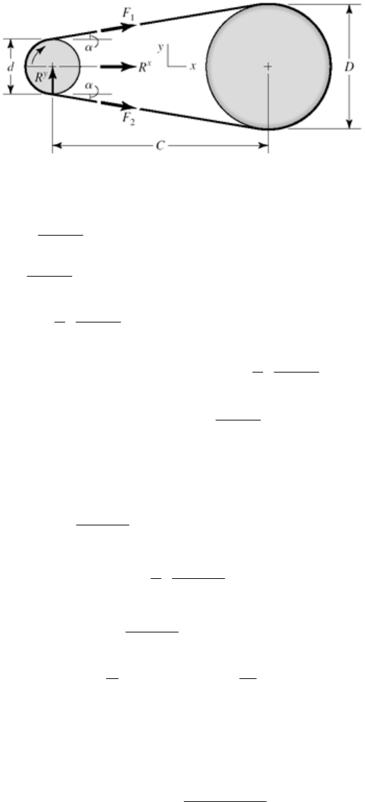
17-7
Find the resultant of F1 and F2:
1
2
2
12 12
12 12
sin 2
sin 2
1
cos 1 22
1
cos cos ( ) 1 .
22
sin sin ( ) .
2
x
y
Dd
C
Dd
C
Dd
C
Dd
R
FF FF C
Dd
RF F FF Ans
C
Ans
From Ex. 17-2, d = 16 in, D = 36 in, C = 16(12) = 192 in, F1 = 940 lbf, F2 = 276 lbf
1o
2
12
36 16
sin 2.9855
2(192)
136 16
(940 276) 1 1214.4 lbf
2 2(192)
36 16
(940 276) 34.6 lbf
2(192)
16
( ) (940 276) 5312 lbf · in
22
x
y
R
R
d
TFF
______________________________________________________________________________
17-8 Begin with Eq. (17-10),
1
2exp( )
exp( ) 1
ci
f
FFF f
Introduce Eq. (17-9):
Chapter 17, Page 9/39
1
1
exp( ) 1 2 exp( ) 2 exp( )
exp( ) 1 exp( ) 1 exp( ) 1
exp( )
exp( ) 1
cc
c
ffT
FFd F
ff df
f
FF F f
f
Now add and subtract exp( )
exp( ) 1
c
f
Ff
1
exp( ) exp( ) exp( )
exp( ) 1 exp( ) 1 exp( ) 1
exp( ) exp( )
()
exp( ) 1 exp( ) 1
exp( )
()
exp( ) 1 exp( ) 1
( ) exp( )
ex
cc c
ccc
c
c
cc
ff
FFF F F
ff
ff
FF FF
ff
fF
FF ff
FF f F
f
f
...
p( ) 1 QED
f
From Ex. 17-2:
d = 3.037 rad,
F = 664 lbf, exp( f
) = exp[0.80(3.037)] = 11.35, and
Fc = 73.4 lbf.
1
21
1
2
(73.4 664)11.35 73.4 802 lbf
(11.35 1)
802 664 138 lbf
802 138 73.4 396.6 lbf
2
1 1 802 73.4
ln ln 0.80 .
3.037 138 73.4
i
c
dc
F
FF F
F
FF
f
Ans
FF
______________________________________________________________________________
17-9 This is a good class project. Form four groups, each with a belt to design. Once each
group agrees internally, all four should report their designs including the forces and
torques on the line shaft. If you give them the pulley locations, they could design the line
shaft.
______________________________________________________________________________
17-10 If you have the students implement a computer program, the design problem selections
may differ, and the students will be able to explore them. For Ks = 1.25, nd = 1.1, d = 14
in and D = 28 in, a polyamide A-5 belt, 8 inches wide, will do (bmin = 6.58 in)
______________________________________________________________________________
17-11 An efficiency of less than unity lowers the output for a given input. Since the object of
Chapter 17, Page 10/39

the drive is the output, the efficiency must be incorporated such that the belt’s capacity is
increased. The design power would thus be expressed as
nom .
eff
sd
d
HKn
H
Ans
______________________________________________________________________________
17-12 Some perspective on the size of Fc can be obtained from
22
12
60 60
c
Vbt
Fgg
wV
An approximate comparison of non-metal and metal belts is presented in the table below.
Non-metal Metal
, lbf/in30.04 0.280
b, in 5.00 1.000
t, in 0.20 0.005
The
ratio
w / wm is
12(0.04)(5)(0.2) 29
12(0.28)(1)(0.005)
m
w
w
The second contribution to Fc is the belt peripheral velocity which tends to be low in
metal belts used in instrument, printer, plotter and similar drives. The velocity ratio
squared influences any Fc / (Fc)m ratio.
It is common for engineers to treat Fc as negligible compared to other tensions in the
belting problem. However, when developing a computer code, one should include Fc.
______________________________________________________________________________
17-13 Eq. (17-8):
12 1 1
exp( ) 1 exp( ) 1
()
exp( ) exp( )
c
ff
FFF FF F
ff
Assuming negligible centrifugal force and setting F1 = ab from step 3, p. 897,
min
exp( ) (1)
exp( ) 1
Ff
baf
Also, nom
()
33 000
dsd
F
V
HHKn
nom
33 000
s
d
H
Kn
FV
Chapter 17, Page 11/39

Substituting into Eq. (1), min
1 33 000 exp( ) .
exp( ) 1
d
Hf
bA
aV f
ns
______________________________________________________________________________
17-14 The decision set for the friction metal flat-belt drive is:
A priori decisions
• Function: Hnom = 1 hp, n = 1750 rev/min, VR = 2 , K
15 in,Cs = 1.2 ,
Np = 106 belt passes.
• Design factor: nd = 1.05
• Belt material and properties: 301/302 stainless steel
Table 17-8: Sy = 175 kpsi, E = 28 Mpsi,
= 0.285
• Drive geometry: d = 2 in, D = 4 in
• Belt thickness: t = 0.003 in
Design variables:
• Belt width, b
• Belt loop periphery
Preliminaries
nom 1(1.2)(1.05) 1.26 hp
63 025(1.26) 45.38 lbf · in
1750
dsd
HHKn
T
A 15 in center-to-center distance corresponds to a belt loop periphery of 39.5 in. The
40 in loop available corresponds to a 15.254 in center distance.
1
1
42
2sin 3.010 rad
2(15.254)
42
2sin 3.273 rad
2(15.274)
d
D
For full friction development
exp( ) exp[0.35(3.010)] 2.868
(2)(1750) 916.3 ft/s
12 12
175 kpsi
d
y
f
dn
V
S
Eq. (17-15):
0.407
6 0.407 6 6 3
14.17 10 14.17 10 10 51.212 10 psi
yp
SN
Chapter 17, Page 12/39
From selection step 3, p. 897,
6
3
22
1
28(10 )(0.003)
51.212(10 ) (0.003)
(1 ) (1 0.285 )(2)
16.50 lbf/in of belt width
( ) 16.50
f
a
Et
aS t
d
Fab b
For full friction development, from Prob. 17-13,
min
exp( )
exp( ) 1
2 2(45.38) 45.38 lbf
2
d
d
Ff
baf
T
Fd
So
min
45.38 2.868 4.23 in
16.50 2.868 1
b
Decision #1: b = 4.5 in
11
21
12
( ) 16.5(4.5) 74.25 lbf
74.25 45.38 28.87 lbf
74.25 28.87 51.56 lbf
22
a
i
FF ab
FF F
FF
F
Existing friction
1
2
nom
1 1 74.25
ln ln 0.314
3.010 28.87
( ) 45.38(916.3) 1.26 hp
33 000 33 000
1.26 1.05
1(1.2)
d
t
t
fs
s
F
fF
FV
H
H
nHK
This is a non-trivial point. The methodology preserved the factor of safety corresponding
to nd = 1.1 even as we rounded bmin up to b.
Decision #2 was taken care of with the adjustment of the center-to-center distance to
accommodate the belt loop. Use Eq. (17-2) as is and solve for C to assist in this.
Remember to subsequently recalculate
d and
D .
______________________________________________________________________________
Chapter 17, Page 13/39
17-15 Decision set:
A priori decisions
• Function: Hnom = 5 hp, N = 1125 rev/min, VR = 3, K
20 in,Cs = 1.25,
Np = 106 belt passes
• Design factor: nd = 1.1
• Belt material: BeCu, Sy = 170 kpsi, E = 17 Mpsi,
= 0.220
• Belt geometry: d = 3 in, D = 9 in
• Belt thickness: t = 0.003 in
Design decisions
• Belt loop periphery
• Belt width b
Preliminaries:
nom 5(1.25)(1.1) 6.875 hp
63 025(6.875) 385.2 lbf · in
1125
dsd
HHKn
T
Decision #1: Choose a 60-in belt loop with a center-to-center distance of 20.3 in.
1
1
93
2sin 2.845 rad
2(20.3)
93
2sin 3.438 rad
2(20.3)
d
D
For full friction development:
exp( ) exp[0.32(2.845)] 2.485
(3)(1125) 883.6 ft/min
12 12
56.67 kpsi
d
f
f
dn
V
S
From selection step 3, p. 897,
Chapter 17, Page 14/39
6
3
22
min
17(10 )(0.003)
56.67(10 ) (0.003) 116.4 lbf/in
(1 ) (1 0 .22 )(3)
2 2(385.2) 256.8 lbf
3
exp( ) 256.8 2.485 3.69 in
exp( ) 1 116.4 2.485 1
t
f
d
d
E
aS t
d
T
Fd
Ff
baf
Decision #2: b = 4 in
11
21
12
( ) 116.4(4) 465.6 lbf
465.6 256.8 208.8 lbf
465.6 208.8 337.3 lbf
22
a
i
FF ab
FF F
FF
F
Existing friction
1
2
1 1 465.6
ln ln 0.282
2.845 208.8
( ) 256.8(883.6) 6.88 hp
33 000 33 000
6.88 1.1
5(1.25) 5(1.25)
d
fs
F
fF
FV
H
H
n
F
i can be reduced only to the point at which 0.32.ff
From Eq. (17-9)
exp( ) 1 385.2 2.485 1 301.3 lbf
exp( ) 1 3 2.485 1
d
i
d
Tf
Fdf
Eq. (17-10):
1
21
2exp( ) 2(2.485)
301.3 429.7 lbf
exp( ) 1 2.485 1
429.7 256.8 172.9 lbf
d
i
d
f
FF f
FF F
and
0.32ff
______________________________________________________________________________
17-16 This solution is the result of a series of five design tasks involving different belt
thicknesses. The results are to be compared as a matter of perspective. These design tasks
are accomplished in the same manner as in Probs. 17-14 and 17-15 solutions.
The details will not be presented here, but the table is provided as a means of learning.
Five groups of students could each be assigned a belt thickness. You can form a table
Chapter 17, Page 15/39
from their results or use the table given here.
Chapter 17, Page 16/39
t, in
0.002 0.003 0.005 0.008 0.010
b 4.000 3.500 4.000 1.500 1.500
CD 20.300 20.300 20.300 18.700 20.200
a 109.700 131.900 110.900 194.900 221.800
d 3.000 3.000 3.000 5.000 6.000
D 9.000 9.000 9.000 15.000 18.000
Fi 310.600 333.300 315.200 215.300 268.500
F1 439.000 461.700 443.600 292.300 332.700
F2 182.200 209.000 186.800 138.200 204.300
nf s 1.100 1.100 1.100 1.100 1.100
L 60.000 60.000 60.000 70.000 80.000
f
0.309 0.285 0.304 0.288 0.192
Fi 301.200 301.200 301.200 195.700 166.600
F1 429.600 429.600 429.600 272.700 230.800
F2 172.800 172.800 172.800 118.700 102.400
f 0.320 0.320 0.320 0.320 0.320
The first three thicknesses result in the same adjusted Fi, F1 and F2 (why?). We have no
figure of merit, but the costs of the belt and pulleys are about the same for these three
thicknesses. Since the same power is transmitted and the belts are widening, belt forces
are lessening.
______________________________________________________________________________
17-17 This is a design task. The decision variables would be belt length and belt section, which
could be combined into one, such as B90. The number of belts is not an issue.
We have no figure of merit, which is not practical in a text for this application. It is
suggested that you gather sheave dimensions and costs and V-belt costs from a principal
vendor and construct a figure of merit based on the costs. Here is one trial.
Preliminaries: For a single V-belt drive with Hnom = 3 hp, n = 3100 rev/min, D = 12 in,
and d = 6.2 in, choose a B90 belt, Ks = 1.3 and nd = 1. From Table 17-10, select a
circumference of 90 in. From Table 17-11, add 1.8 in giving
L
p = 90 + 1.8 = 91.8 in
Eq. (17-16b):
2
2
0.25 91.8 (12 6.2) 91.8 (12 6.2) 2(12 6.2)
22
31.47 in
C
Chapter 17, Page 17/39
-1 12 6.2
2sin 2.9570 rad
2(31.47)
d
exp( ) exp[0.5123(2.9570)] 4.5489
(6.2)(3100) 5031.8 ft/min
12 12
d
f
dn
V
Table 17-13:
180 180
Angle (2.957 rad) 169.42
d
The footnote regression equation of Table 17-13 gives K1 without interpolation:
K1 = 0.143 543 + 0.007 468(169.42°) 0.000 015 052(169.42°)2 = 0.9767
The design power is Hd = HnomKsnd = 3(1.3)(1) = 3.9 hp
From Table 17-14 for B90, K2 = 1. From Table 17-12 take a marginal entry of Htab = 4,
although extrapolation would give a slightly lower Htab.
Eq. (17-17): Ha = K1K2Htab = 0.9767(1)(4) = 3.91 hp
The allowable
Fa is given by
63 025 63 025(3.91) 25.6 lbf
( / 2) 3100(6.2 / 2)
a
a
H
Fnd
The allowable torque Ta is
25.6(6.2) 79.4 lbf · in
22
a
a
Fd
T
From Table 17-16, Kc = 0.965. Thus, Eq. (17-21) gives,
22
5031.8
0.965 24.4 lbf
1000 1000
cc
V
FK
At incipient slip, Eq. (17-9) provides:
exp( ) 1 79.4 4.5489 1 20.0 lbf
exp( ) 1 6.2 4.5489 1
i
Tf
Fdf
Eq. (17-10):
Chapter 17, Page 18/39
1
2exp( ) 2(4.5489)
24.4 20 57.2 lbf
exp( ) 1 4.5489 1
ci
f
FFF f
Thus, F2 = F1 Fa = 57.2 25.6 = 31.6 lbf
Eq. (17-26): (3.91)(1) 1.003 .
3.9
ab
fs
d
HN
nA
H
ns
If we had extrapolated for Htab, the factor of safety would have been slightly less than
one.
Life Use Table 17-16 to find equivalent tensions T1 and T2 .
11 11
21 21
576
( ) 57.2 150.1 lbf
6.2
576
( ) 57.2 105.2 lbf
12
b
b
b
b
K
TF F F d
K
TFF FD
From Table 17-17, K = 1193, b = 10.926, and from Eq. (17-27), the number of belt passes
is:
1
12
1
10.926 10.926
9
1193 1193 6.72(10 ) passes
150.1 105.2
bb
P
KK
NTT
From Eq. (17-28) for NP > 109,
9
10 (91.8)
720 720(5031.8)
25 340 h .
Pp
NL
tV
tA
ns
Suppose nf s was too small. Compare these results with a 2-belt solution.
tab
nom
4 hp/belt, 39.6 lbf · in/belt,
12.8 lbf/belt, 3.91 hp/belt
2(3.91) 2.0
3(1.3)
a
aa
ba ba
fs
ds
HT
FH
NH NH
nHHK
Also, F1 = 40.8 lbf/belt, F2 = 28.0 lbf/belt
Chapter 17, Page 19/39
12
12
10
9.99 lbf/belt, 24.4 lbf/belt
( ) 92.9 lbf/belt, ( ) 48 lbf/belt
133.7 lbf/belt, 88.8 lbf/belt
2.39(10 ) passes, 605 600 h
ic
bb
P
FF
FF
TT
Nt
Initial tension of the drive:
(Fi)drive = NbFi = 2(9.99) = 20 lbf
______________________________________________________________________________
17-18 Given: two B85 V-belts with d = 5.4 in, D = 16 in, n = 1200 rev/min, and Ks = 1.25
Table 17-11: Lp = 85 + 1.8 = 86.8 in
Eq. (17-17b):
2
2
0.25 86.8 (16 5.4) 86.8 (16 5.4) 2(16 5.4)
22
26.05 in .
C
Ans
Eq. (17-1):
-1 16 5.4
180 2sin 156.5
2(26.05)
d
From table 17-13 footnote:
K
1 = 0.143 543 + 0.007 468(156.5°) 0.000 015 052(156.5°)2 = 0.944
Table 17-14: K2 = 1
Belt speed: (5.4)(1200) 1696 ft/min
12
V
Use Table 17-12 to interpolate for Htab.
tab
2.62 1.59
1.59 (1696 1000) 2.31 hp/belt
2000 1000
H
Eq. (17-17) for two belts: 12 tab 0.944(1)(2)(2.31) 4.36 hp
ab
HKKNH
Assuming nd = 1, Hd = KsHnomnd = 1.25(1)Hnom
For a factor of safety of one,
Chapter 17, Page 20/39
nom
nom
4.36 1.25
4.36 3.49 hp .
1.25
ad
HH
H
HA
ns
______________________________________________________________________________
17-19 Given: Hnom = 60 hp, n = 400 rev/min, Ks = 1.4, d = D = 26 in on 12 ft centers.
Design task: specify V-belt and number of strands (belts). Tentative decision: Use D360
belts.
Table 17-11: Lp = 360 + 3.3 = 363.3 in
Eq. (17-16b):
2
2
0.25 363.3 (26 26) 363.3 (26 26) 2(26 26)
22
140.8 in (nearly 144 in)
C
, , exp[0.5123 ] 5.0,
(26)(400) 2722.7 ft/min
12 12
dD
dn
V
Table 17-13: For
= 180°, K1 = 1
Table 17-14: For D360, K2 = 1.10
Table 17-12: Htab = 16.94 hp by interpolation
Thus, Ha = K1K2Htab = 1(1.1)(16.94) = 18.63 hp / belt
Eq. (17-19): Hd = HnomKs nd = 60(1.4)(1) = 84 hp
Number of belts, Nb
84 4.51
18.63
d
b
a
H
NH
Round up to five belts. It is left to the reader to repeat the above for belts such as C360
and E360.
Chapter 17, Page 21/39

63 025 63 025(18.63) 225.8 lbf/belt
( / 2) 400(26 / 2)
( ) 225.8(26) 2935 lbf · in/belt
22
a
a
a
a
H
Fnd
Fd
T
Eq. (17-21):
22
2722.7
3.498 3.498 25.9 lbf/belt
1000 1000
c
V
F
At fully developed friction, Eq. (17-9) gives
exp( ) 1 2935 5 1 169.3 lbf/belt
exp( ) 1 26 5 1
i
Tf
Fdf
Eq. (17-10): 1
2exp( ) 2(5)
25.9 169.3 308.1 lbf/belt
exp( ) 1 5 1
ci
f
FFF f
21
308.1 225.8 82.3 lbf/belt
18.63 5 1.109 .
84
a
ab
fs
d
FF F
HN
nA
H
ns
Life From Table 17-16,
12 1
5 680
308.1 526.6 lbf
26
b
K
TT F d
Eq. (17-27):
1
9
12
5.28 10 passes
bb
P
KK
NTT
Thus, NP > 109 passes Ans.
Eq. (17-28):
9
10 (363.3)
720 720(2722.7)
Pp
NL
tV
Thus, t > 185 320 h Ans.
______________________________________________________________________________
17-20 Preliminaries: 14-in wide rim, H
60 in,Dnom = 50 hp, n = 875 rev/min, Ks = 1.2,
n
d = 1.1, mG = 875/170 = 5.147, 60 / 5.147 11.65 ind
(a) From Table 17-9, an 11-in sheave exceeds C-section minimum diameter and
precludes D- and E-section V-belts.
Decision: Use d = 11 in, C270 belts
Chapter 17, Page 22/39
Table 17-11: Lp = 270 + 2.9 = 272.9 in
Eq. (17-16b):
2
2
0.25 272.9 (60 11) 272.9 (60 11) 2(60 11)
22
76.78 in
C
This fits in the range
3( ) 60 3(60 11) 60 in 213 inDC Dd C C
160 11
2sin 2.492 rad 142.8
2(76.78)
d
160 11
2sin 3.791 rad
2(76.78)
D
exp(f
d) = exp[0.5123(2.492)] = 3.5846
For the flat on flywheel, f = 0.13 (see p. 900), exp(f
D) = exp[0.13(3.791)] = 1.637.
The belt speed is
(11)(875) 2520 ft/min
12 12
dn
V
Table 17-13:
K
1 = 0.143 543 + 0.007 468(142.8°) 0.000 015 052(142.8°)2 = 0.903
Table 17-14: K2 = 1.15
For interpolation of Table 17-12, let x be entry for d = 11.65 in and n = 2000 ft/min, and y
be entry for d = 11.65 in and n = 3000 ft/min. Then,
6.74 7.17 6.74 7.01 hp at 2000 ft/min
11.65 11 12 11
xx
and
8.11 8.84 8.11 8.58 hp at 3000 ft/min
11.65 11 12 11
yy
Interpolating these for 2520 ft/min gives
tab
tab
8.58 3000 2520 7.83 hp/belt
8.58 7.01 3000 2000
HH
Eq. (17-17): Ha = K1K2Htab = 0.903(1.15)(7.83) = 8.13 hp
Chapter 17, Page 23/39
Eq. (17-19): Hd = HnomKsnd = 50(1.2)(1.1) = 66 hp
Eq. (17-20): 66 8.1 belts
8.13
d
b
a
H
NH
Decision: Use 9 belts. On a per belt basis,
63 025 63 025(8.13) 106.5 lbf/belt
( / 2) 875(11 / 2)
a
a
H
Fnd
106.5(11) 586.8 lbf · in per belt
22
a
a
Fd
T
Table 17-16: Kc = 1.716
Eq.
(17-21):
22
2520
1.716 1.716 10.9 lbf/belt
1000 1000
c
V
F
At fully developed friction, Eq. (17-9) gives
exp( ) 1 586.9 3.5846 1 94.6 lbf/belt
exp( ) 1 11 3.5846 1
d
i
d
Tf
Fdf
Eq. (17-10):
1
2exp( ) 2(3.5846)
10.9 94.6 158.8 lbf/belt
exp( ) 1 3.5846 1
d
ci
d
f
FFF f
21
158.8 106.7 52.1 lbf/belt
9(8.13) 1.11 . . .
66
a
ba
fs
d
FF F
NH
nO
H
KAns
Durability:
1
2
11 1
21 2
/ 1600 / 11 145.5 lbf/belt
/ 1600 / 60 26.7 lbf/belt
158.8 145.5 304.3 lbf/belt
158.8 26.7 185.5 lbf/belt
bb
bb
b
b
FKd
FKD
TF F
TFF
Eq. (17-27) with Table 17-17:
11
11.173 11.173
12
99
2038 2038
304.3 185.5
1.68 10 passes 10 passes .
bb
P
KK
NTT
Ans
Since NP is greater than 109 passes and is out of the range of Table 17-17, life from Eq.
(17-27) is
Chapter 17, Page 24/39
9
3
10 (272.9) 150 10 h
720 720(2520)
Pp
NL
tV
Remember: (Fi)drive = 9(94.6) = 851.4 lbf
Table 17-9: C-section belts are 7/8 in wide. Check sheave groove spacing to see if 14 in
width is accommodating.
(b) The fully developed friction torque on the flywheel using the flats of the V-belts,
from Eq. (17-9), is
flat
exp( ) 1 1.637 1
94.6(60) 1371 lbf · in per belt
exp( ) 1 1.637 1
i
f
TFD f
The flywheel torque should be
T
fly = mGTa = 5.147(586.9) = 3021 lbf · in per belt
but it is not. There are applications, however, in which it will work. For example,
make the flywheel controlling. Yes. Ans.
______________________________________________________________________________
17-21
(a)
S is the spliced-in string segment length
D
e is the equatorial diameter
D
is the spliced string diameter
is the radial clearance
S +
De =
D
=
(De + 2
) =
De + 2
From which
2
S
The radial clearance is thus independent of De.
12(6) 11.5 in .
2
A
ns
This is true whether the sphere is the earth, the moon or a marble. Thinking in terms of a
radial or diametral increment removes the basic size from the problem.
(b) and (c)
Chapter 17, Page 25/39
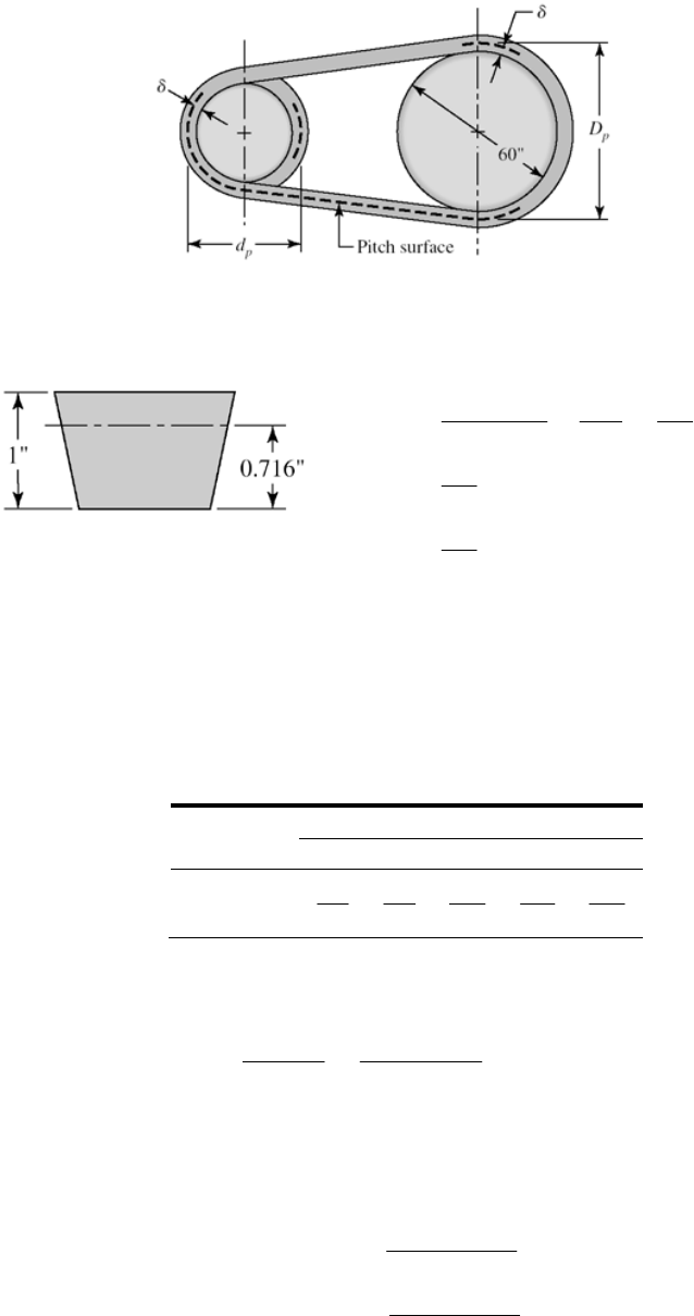
Table 17-9: For an E210 belt, the thickness is 1 in.
210 4.5 210 4.5
4.5
2
4.5 0.716 in
2
Pi
dd
The pitch diameter of the flywheel is
2 2 60 2(0.716) 61.43 in
PP
DDDD
We could make a table:
Section
Diametral
Growth A B C D E
2
1.3
1.8
2.9
3.3
4.5
The velocity ratio for the D-section belt of Prob. 17-20 is
2603.3/ 5.55 .
11
G
D
mA
dns
for the V-flat drive as compared to ma = 60/11 = 5.455 for the VV drive.
The pitch diameter of the pulley is still d = 11 in, so the new angle of wrap,
d, is
1
1
2
2sin .
2
2
2sin .
2
d
D
Dd
Ans
C
Dd
Ans
C
Chapter 17, Page 26/39
Equations (17-16a) and (17-16b) are modified as follows
2
2
2
()
2 ( 2 ) .
24
0.25 ( 2 )
2
( 2 ) 2( 2 ) .
2
p
pp
p
Dd
LC D d Ans
C
CLDd
L
DdDd
Ans
The changes are small, but if you are writing a computer code for a V-flat drive,
remember that
d and
D changes are exponential.
______________________________________________________________________________
17-22 This design task involves specifying a drive to couple an electric motor running at 1720
rev/min to a blower running at 240 rev/min, transmitting two horsepower with a center
distance of at least 22 inches. Instead of focusing on the steps, we will display two
different designs side-by-side for study. Parameters are in a “per belt” basis with per
drive quantities shown along side, where helpful.
Parameter Four A-90 Belts Two A-120 Belts
mG 7.33 7.142
Ks 1.1 1.1
nd 1.1 1.1
K1 0.877 0.869
K2 1.05 1.15
d, in 3.0 4.2
D, in 22 30
d, rad 2.333 2.287
V, ft/min 1350.9 1891
exp(f
d ) 3.304 3.2266
Lp, in 91.3 101.3
C, in 24.1 31
Htab, uncorr. 0.783 1.662
NbHtab, uncorr. 3.13 3.326
Ta, lbf · in 26.45(105.8) 60.87(121.7)
Fa, lbf 17.6(70.4) 29.0(58)
Ha, hp 0.721(2.88) 1.667(3.33)
nf s 1.192 1.372
F1, lbf 26.28(105.2) 44(88)
F2, lbf 8.67(34.7) 15(30)
(Fb)1, lbf 73.3(293.2) 52.4(109.8)
(Fb)2, lbf 10(40) 7.33(14.7)
Fc, lbf 1.024 2.0
Fi, lbf 16.45(65.8) 27.5(55)
T1, lbf · in 99.2 96.4
Chapter 17, Page 27/39

T2, lbf · in 36.3 57.4
, passesN 1.61(109) 2.3(109)
t > h 93 869 89 080
Conclusions:
• Smaller sheaves lead to more belts.
• Larger sheaves lead to larger D and larger V.
• Larger sheaves lead to larger tabulated power.
• The discrete numbers of belts obscures some of the variation. The factors of safety
exceed the design factor by differing amounts.
______________________________________________________________________________
17-23 In Ex. 17-5 the selected chain was 140-3, making the pitch of this 140 chain14/8 = 1.75
in. Table 17-19 confirms.
______________________________________________________________________________
17-24 (a) Eq. (17-32):
1.08 0.9 (3 0.07 )
111
0.004 p
HNnp
Eq. (17-33):
1.5 0.8
1
21.5
1
1000 r
KN p
Hn
Equating and solving for n1 gives
1/2.4
60.42
1
1(2.2 0.07 )
0.25(10 ) .
rp
KN
nA
p
ns
(b) For a No. 60 chain, p = 6/8 = 0.75 in, N1 = 17, Kr = 17
1/ 2.4
60.42
1[2.2 0.07(0.75)]
0.25(10 )(17)(17) 1227 rev/min .
0.75
nA
ns
Table 17-20 confirms that this point occurs at 1200 ± 200 rev/min.
(c) Life predictions using Eq. (17-40) are possible at speeds greater than 1227 rev/min.
Ans.
______________________________________________________________________________
17-25 Given: a double strand No. 60 roller chain with p = 0.75 in, N1 = 13 teeth at 300 rev/min,
N2 = 52 teeth.
(a) Table 17-20: Htab = 6.20 hp
Table 17-22: K1 = 0.75
Table 17-23: K2 = 1.7
Use Ks = 1
Eq. (17-37):
H
a = K1K2Htab = 0.75(1.7)(6.20) = 7.91 hp Ans.
Chapter 17, Page 28/39
(b) Eqs. (17-35) and (17-36) with L/p = 82
2
2
13 52 82 49.5
2
52 13
49.5 49.5 8 23.95
42
23.95(0.75) 17.96 in, round up to 18 in .
A
p
Cp
CA
ns
(c) For 30 percent less power transmission,
0.7(7.91) 5.54 hp
63 025(5.54) 1164 lbf · in .
300
H
TA
ns
Eq. (17-29):
o
0.75 3.13 in
sin(180 /13)
1164 744 lbf .
3.13/ 2
D
T
F
Ans
r
______________________________________________________________________________
17-26 Given: No. 40-4 chain, N1 = 21 teeth for n = 2000 rev/min, N2 = 84 teeth, h = 20 000
hours.
(a) Chain pitch is p = 4/8 = 0.500 in and
20 in.C
Eq. (17-34):
2
12
12
2
2
2
2
24/
2(20) 21 84 (84 21) 135 pitches (or links)
0.5 2 4 (20 / 0.5)
NN
LCNN
pp Cp
L = 135(0.500) = 67.5 in Ans.
(b) Table 17-20: Htab = 7.72 hp (post-extreme power)
Eq. (17-40): Since K1 is required, the term is omitted (see p. 914).
3.75
1
N
2.5
1/2.5
tab
7.72 (15 000)
constant 18 399
135
18 399(135) 6.88 hp .
20 000
H
Ans
Chapter 17, Page 29/39

(c) Table 17-22:
1.5
1
21 1.37
17
K
Table 17-23: K2 = 3.3
12 tab 1.37(3.3)(6.88) 31.1 hp .
a
HKKH An
s
(d) 121(0.5)(2000) 1750 ft/min
12 12
Npn
V
1
33 000(31.1) 586 lbf .
1750
F
Ans
______________________________________________________________________________
17-27 This is our first design/selection task for chain drives. A possible decision set:
A priori decisions
• Function: Hnom, n1, space, life, Ks
• Design factor: nd
• Sprockets: Tooth counts N1 and N2, factors K1 and K2
Decision variables
• Chain number
• Strand count
• Lubrication type
• Chain length in pitches
Function: Motor with Hnom = 25 hp at n = 700 rev/min; pump at n = 140 rev/min;
mG = 700/140 = 5
Design Factor: nd = 1.1
Sprockets: Tooth count N2 = mGN1 = 5(17) = 85 teeth–odd and unavailable. Choose
84 teeth. Decision: N1 = 17, N2 = 84
Evaluate K1 and K2
Eq. (17-38): Hd = HnomKsnd
Eq. (17-37): Ha = K1K2Htab
Equate Hd to Ha and solve for Htab :
nom
tab
12
sd
KnH
HKK
Table 17-22: K1 = 1
Table 17-23: K2 = 1, 1.7, 2.5, 3.3 for 1 through 4 strands
Chapter 17, Page 30/39
tab
22
1.5(1.1)(25) 41.25
(1)
H
K
K
Prepare a table to help with the design decisions:
Strands K2 tab
H
Chain
No. Htab nf s
Lub.
Type
1 1.0 41.3 100 59.4 1.58 B
2 1.7 24.3 80 31.0 1.40 B
3 2.5 16.5 80 31.0 2.07 B
4 3.3 12.5 60 13.3 1.17 B
Design Decisions
We need a figure of merit to help with the choice. If the best was 4 strands of No. 60
chain, then
Decision #1 and #2: Choose four strand No. 60 roller chain with nf s = 1.17.
12 tab
nom
1(3.3)(13.3) 1.17
1.5(25)
fs
s
KKH
nKH
Decision #3: Choose Type B lubrication
Analysis:
Table 17-20: Htab = 13.3 hp
Table 17-19: p = 0.75 in
Try C = 30 in in Eq. (17-34):
2
12 21
2
2
2
2()
24/
17 84 (84 17)
2(30 / 0.75) 2 4 (30 / 0.75)
133.3
LCNN NN
pp Cp
L = 0.75(133.3) = 100 in (no need to round)
Eq. (17-36) with p = 0.75 in: 12 17 84 100 82.83
2 2 0.75
NN L
Ap
Eq. (17-35):
2
221
2
2
8
42
0.75 84 17
82.83 82.83 8 30.0 in
42
pNN
CAA
Chapter 17, Page 31/39
Decision #4: Choose C = 30.0 in.
______________________________________________________________________________
17-28 Follow the decision set outlined in Prob. 17-27 solution. We will form two tables, the
first for a 15 000 h life goal, and a second for a 50 000 h life goal. The comparison is
useful.
Function: Hnom = 50 hp at n = 1800 rev/min, npump = 900 rev/min, mG = 1800/900 = 2,
Ks = 1.2, life = 15 000 h, then repeat with life = 50 000 h
Design factor: nd = 1.1
Sprockets: N1 = 19 teeth, N2 = 38 teeth
Table 17-22 (post extreme):
1.5 1.5
1
1
19 1.18
17 17
N
K
Table 17-23: K2 = 1, 1.7, 2.5, 3.3, 3.9, 4.6, 6.0
Decision variables for 15 000 h life goal:
nom
tab
12 2 2
1 2 tab 2 tab
2tab
nom
1.2(1.1)(50) 55.9 (1)
1.18
1.18 0.0197
1.2(50)
sd
fs
s
KnH
HKK K K
KKH KH
nK
KH
H
Form a table for a 15 000 h life goal using these equations.
K2 H'tab Chain # Htab nf s Lub
1 55.90 120 21.6 0.423 C'
1.7 32.90 120 21.6 0.923 C'
2.5 22.40 120 21.6 1.064 C'
3.3 16.90 120 21.6 1.404 C'
3.9 14.30 80 15.6 1.106 C'
4.6 12.20 60 12.4 1.126 C'
6 9.32 60 12.4 1.416 C'
There are 4 possibilities where nf s ≥ 1.1
Decision variables for 50 000 h life goal
From Eq. (17-40), the power-life tradeoff is:
Chapter 17, Page 32/39
2.5 2.5
tab tab
1/ 2.5
2.5
tab tab tab
( ) 15 000 ( ) 50 000
15 000 ( ) 0.618
50 000
HH
HH
H
Substituting from (1),
tab
22
55.9 34.5
0.618HKK
The
H
notation is only necessary because we constructed the first table, which we
normally would not do.
12 tab 12 tab
2tab
nom nom
2tab
(0.618 ) 0.618[(0.0197) ]
0.0122
fs
ss
KKH KK H
nK
KH KH
KH
H
Form a table for a 50 000 h life goal.
K2 H''tab Chain # Htab nf s Lub
1 34.50 120 21.6
0.264 C'
1.7 20.30 120 21.6
0.448 C'
2.5 13.80 120 21.6
0.656 C'
3.3 10.50 120 21.6
0.870 C'
3.9 8.85 120 21.6
1.028 C'
4.6 7.60 120 21.6
1.210 C'
6 5.80 80 15.6
1.140 C'
There are two possibilities in the second table with nf s ≥ 1.1. (The tables allow for the
identification of a longer life of the outcomes.) We need a figure of merit to help with
the choice; costs of sprockets and chains are thus needed, but is more information than
we have.
Decision #1: #80 Chain (smaller installation) Ans.
n
f s = 0.0122K2Htab = 0.0122(8.0)(15.6) = 1.14 O.K.
Decision #2: 8-Strand, No. 80 Ans.
Decision #3: Type C Lubrication Ans.
Decision #4: p = 1.0 in, C is in midrange of 40 pitches
Chapter 17, Page 33/39
2
12 21
2
2
2
2(
24/
19 38 (38 19)
2(40) 24(40)
108.7 110 even integer .
LCNN NN
pp Cp
Ans
)
Eq. (17-36):
12 19 38 110 81.5
221
NN L
Ap
Eq. (17-35):
2
2
1381
( 81.5) ( 81.5) 8 40.64
42
C
p
9
C = p(C/p) = 1.0(40.64/1.0) = 40.64 in (for reference) Ans.
______________________________________________________________________________
17-29 The objective of the problem is to explore factors of safety in wire rope. We will express
strengths as tensions.
(a) Monitor steel 2-in 6 19 rope, 480 ft long.
Table 17-2: Minimum diameter of a sheave is 30d = 30(2) = 60 in, preferably
45(2) = 90 in. The hoist abuses the wire when it is bent around a sheave. Table 17-24
gives the nominal tensile strength as 106 kpsi. The ultimate load is
2
nom nom
(2)
( ) 106 333 kip .
4
uu
F
S A Ans
The tensile loading of the wire is given by Eq. (17-46)
1
4(2) 8 kip, 1
t
Wa
Fl
mg
Wm
w
Table (17-24):
wl = 1.60d 2 l = 1.60(22)(480) = 3072 lbf = 3.072 kip
Therefore,
2
(8 3.072) 1 11.76 kip .
32.2
t
F
Ans
Eq. (17-48):
rm
b
E
dA
FD
w
Chapter 17, Page 34/39

and for the 72-in drum
6
12(10 )
F
23
(2 / 13)(0.38)(2 )(10 ) 39 kip .
72
bAns
in Eq. (17-44), from Fig. 17-21 For use
( / ) 0.0014
u
pS
240 kpsi, p. 920
0.0014(240)(2)(72) 24.2 kip .
2
u
f
S
FA
ns
(b) Factors of safety
Static, no bending:
333 28.3 .
11.76
u
t
F
nA
F
ns
Static,
with bending:
333 39 25.0 .
11.76
ub
s
t
FF
nA
F
Eq. (17-49): ns
Fatigue without bending:
24.2 2.06 .
11.
f
t
n
F
76
f
FAns
, with bending: For a life of 0.1(106) cycles, from Fig. 17-21
Fatigue
( / ) 4 / 1000 0.004
u
pS
0.004(240)(2)(72) 69.1 kip
2
f
F
50): 69.1 39 2.56 .
11.76
f
nA
Eq. (17- ns
If we were to use the endurance strength at 106 cycles (Ff = 24.2 kip) the factor of
safety would be less than 1 indicating 106 cycle life impossible.
ber of factors of safety used in wire rope analysis. They are different,
ent meanings. There is no substitute for knowing exactly which factor
opes, with multiple ropes
Comments:
• There are a num
with differ
of safety is written or spoken.
• Static performance of a rope in tension is impressive.
have a finite life. • In this problem, at the drum, we
• The remedy for fatigue is the use of smaller diameter r
Chapter 17, Page 35/39

supporting the load. See Ex. 17-6 for the effectiveness of this approach. It will also
ar and breaks; such ropes should be retired. Periodic
______________________________________________________________________________
ight, acceleration, velocity, life goal
r of strands, number of wires per strand
pporting wires: m
rob. 17-29, a 1-in diameter rope is not likely to have much of a
and m decisions open.
ity = 2 ft/s, life
goal = 10 cycles
a ri
plow-steel 6 19 hoisting
hoose 30-in Dn. Table 17-27: w = 1.60d lbf/ft
= 1.60d 2l = 1.60d 2(90) = 144d 2 lbf, each
:
be used in Prob. 17-30.
• Remind students that wire ropes do not fail suddenly due to fatigue. The outer
wires gradually show we
inspections prevent fatigue failures by parting of the rope.
17-30 Since this is a design task, a decision set is useful.
A priori decisions
• Function: load, he
• Design Factor: nd
• Material: IPS, PS, MPS or other
• Rope: Lay, numbe
Decision variables:
• Nominal wire size: d
• Number of load-su
From experience with P
life, so approach the problem with the d
Function: 5000 lbf load, 90 foot lift, acceleration = 4 ft/s2, veloc
5
Design Factor: nd = 2
M te al: IPS
Rope: Regular lay, 1-in
Design variables 2
Cmi
wl
Eq. (17-46)
2
2
5000 4
1 144 1 32.2
5620 162 lbf, each wire
t
Wa
Fl d
mgm
d
m
w
Eq. (17-47):
( / )
2
uu
f
pSSDd
F
7-21 for 105 cycles, p/Su = 0.004. From p. 920, Su = 240 kpsi, based on
metal area.
From Fig. 1
0.004(240 000)(30 ) 14 400 lbf each wire
d
Fd
2
f
and Table 17-27: Eq. (17-48)
Chapter 17, Page 36/39
62
3
12 10 0.067 0.4 10 720 lbf, each wire
30
m
b
dd
EdA
ww
Fd
D
Eq. (17-45):
3
2
14 400 10 720
(5620 / ) 162
fb
f
t
FF dd
nFm
d
se a computer program to build a table similar to that of Ex. 17-6.
lternatively, we could recognize that 162 d 2 is small compared to 5620 / m, and
We could u
A
therefore eliminate the 162d 2 term.
3
3
14 400 10 d
nd
720 (14 400 10 720 )
5620 / 5620
f
dm d
m
Maximize nf ,
2
0 [14 400 3(10 720) ]
5620
f
nmd
d
From which
14 400
* 0.669 in
3(10 720)
d
Back-substituting
3
[14 400(0.669) 10 720(0.669 )] 1.14 m
5620
f
m
n
Thus nf = 1.14, 2.28, 3.42, 4.56 for m=1, 2, 3, 4 respectively. If we choose d = 0.50 in,
then m = 2.
3
14 400(0.5) 10 720(0.5 ) 2.06n
2
(5620 / 2) 162(0.5)
f
This exceeds nd = 2
in
s supporting load. Rope should be inspected weekly for any
gns of fatigue (broken outer wires).
ght elevators in terms of velocity.
Decision #1: d = 1/2
Decision #2: m = 2 rope
si
Comment: Table 17-25 gives n for frei
2
2
( ) 106 000 83 252 lbf, each wire
d
FSA d
nom nom
2
2
4
83 452(0.5) 7.32
(5620 / 2) 162(0.5)
uu
u
t
F
nF
Chapter 17, Page 37/39
By comparison, interpolation for 120 ft/min gives 7.08 - close. The category of
construction hoists is not addressed in Table 17-25. We should investigate this before
proceeding further.
______________________________________________________________________________
17-31 2 ft/s2.
nom = 106 kpsi; Su = 240 kpsi (p. 920); Fig. 17-21: (p/Su)10 =
Given: 2000 ft lift, 72 in drum, 6 19 MS rope, cage and load 8000 lbf, accel. =
(a) Table 17-24: (Su)6
0.0014
Eq.
(17-44):
/0.0014(240) (72)
12.1 kip
22
uu
f
Fd
pSSdD d
wl = 1.6d 2 2000(103) = 3.2d 2 kip
46):
Table
17-24:
()1
t
a
FW l g
w Eq. (17-
22
(8 3.2 ) 1d
2
32.2
8.5 3.4 kipd
Note that bending is not included.
2
12.1
8.5 3.4
f
Fd
t
Fd
n
d, in n
0.500 0.650
1.000 1.020
1.500 1.124
1 5 ← maximum n Ans.1.625
1.750
.12
.12
1 0
2.000 1.095
(b) Try m = s4 strand
Chapter 17, Page 38/39
2
2
2
82
3.2 1
4 32.2
2.12 3.4 kip
12.1 kip
12.1
2.12 3.4
t
f
Fd
d
Fd
d
nd
d, in n
0.5000 2.037
0.5625 2.130
0.6520 2.193
0.7500 2.250 ← maximum n Ans.
0.8750 2.242
1.0000 2.192
Comparing tables, multiple ropes supporting the load increases the factor of safety,
and reduces the corresponding wire rope diameter, a useful perspective.
______________________________________________________________________________
Chapter 17, Page 39/39
17-32
2
2
22
/
(/ ) (2 ) 0
(/ )
ad
nbm cd
dn b m cd a ad cd
dd b m cd
From which
* .
/( )
*
(/ ) [/( )] 2
b
dAns
mc
ab mc am
nA
bm cb mc bc
.ns
These results agree closely with the Prob. 17-31 solution. The small differences are due
to rounding in Prob. 17-31.
______________________________________________________________________________
17-33 From Prob. 17-32 solution:
12
/
ad
nbm cd
Solve the above equation for m
2
1
2
11
2
2
1
(1)
/
/(0)/
0
/
b
mad n cd
ad n ad b a n cd
dm
dd ad n cd
2
From which
1
* .
2
a
dA
cn
ns
Substituting this result for d into Eq. (1) gives
1
2
4
* .
bcn
mA
a
ns
______________________________________________________________________________
17-34 Note to the Instructor. In the first printing of the ninth edition, the wording of this
problem is incorrect. It should read “ For Prob. 17-29 estimate the elongation of the rope
if a 7000 lbf loaded mine cart is placed in the cage which weighs 1000 lbf. The results of
Prob. 4-7 may be useful”. This will be corrected in subsequent printings. We apologize
for any inconvenience encountered.
Chapter 17, Page 40/39

Table 17-27:
222
22
3
0.40 0.40(2 ) 1.6 in
12 Mpsi, 1.6 1.6(2 ) 6.4 lbf/ft
6.4(480) 3072 lbf
/ 3072 / 1.6(480)12 0.333 lbf/in
m
r
m
Ad
Ed
l
lAl
w
w
w
Treat the rest of the system as rigid, so that all of the stretch is due to the load of 7000 lbf,
the cage weighing 1000 lbf, and the wire’s weight. From the solution of Prob. 4-7,
2
1
22
66
2
(1000 7000)(480)(12) 0.333(480 )12
1.6(12)(10 ) 2(12)(10 )
2.4 0.460 2.860 in .
Wl l
AE E
A
ns
______________________________________________________________________________
17-35 to 17-38 Computer programs will vary.
Chapter 17, Page 41/39
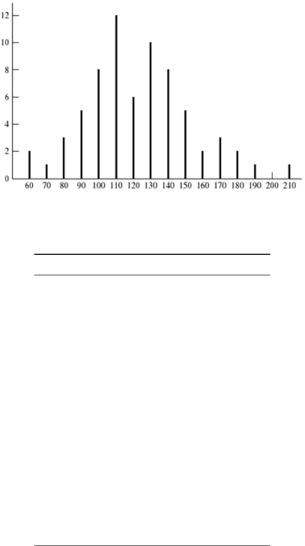
Chapter 20
20-1 (a)
(b) f / (Nx) = f / [69(10)] = f / 690
x
f
f x f x2f / (Nx)
60 2 120 7200 0.0029
70 1 70 4900 0.0015
80 3 240 19200 0.0043
90 5 450 40500 0.0072
100 8 800 80000 0.0116
110 12 1320 145200 0.0174
120 6 720 86400 0.0087
130 10 1300 169000 0.0145
140 8 1120 156800 0.0116
150 5 750 112500 0.0174
160 2 320 51200 0.0029
170 3 510 86700 0.0043
180 2 360 64800 0.0029
190 1 130 36100 0.0015
200 0 0 0 0
210 1 210 44100 0.0015
69 8480 1 104 600
Chapter 20, Page 1/29
Eq. (20-9): 8480 122.9 kcycles
69
x
Eq. (20-10):
12
2
1 104 600 8480 / 69 30.3 kcycles .
69 1
x
sA
ns
______________________________________________________________________________
20-2 Data represents a 7-class histogram with N = 197.
x f f x f x2
174 6 1044 181 656
182 9 1638 298 116
190 44 8360 1 588 400
198 67 13 266 2 626 688
206 53 10 918 2 249 108
214 12 2568 549 552
220 6 1320 290 400
197 39 114 7 789 900
39 114 198.55 kpsi .
197
x
Ans
12
2
7 783 900 39 114 / 197 9.55 kpsi .
197 1
sA
ns
______________________________________________________________________________
20-3 Form a Table:
x f fx fx2
64 2 128 8192
68 6 408 27 744
72 6 432 31 104
76 9 684 51 984
80 19 1520 121 600
84 10 840 70 560
88 4 352 30 976
92 2 184 16 928
58 4548 359 088
Chapter 20, Page 2/29
4548 78.4 kpsi .
58
x
Ans
12
2
359 088 4548 / 58 6.57 kpsi .
58 1
x
sA
ns
From Eq. 20-14
2
1 1 78.4
exp .
26.57
6.57 2
x
f
xA
ns
______________________________________________________________________________
20-4 (a)
x f f y f y2 y f / (Nw) f (y) g(y)
5.625 1 5.625 31.64063 5.625 0.072 727 0.001 262 0.000 295
5.875 0 0 0 5.875 0 0.008 586 0.004 088
6.125 0 0 0 6.125 0 0.042 038 0.031 194
6.375 3 19.125 121.9219 6.375 0.218 182 0.148 106 0.140 262
6.625 3 19.875 131.6719 6.625 0.218 182 0.375 493 0.393 667
6.875 6 41.25 283.5938 6.875 0.436 364 0.685 057 0.725 002
7.125 14 99.75 710.7188 7.125 1.018 182 0.899 389 0.915 128
7.375 15 110.625 815.8594 7.375 1.090 909 0.849 697 0.822 462
7.625 10 76.25 581.4063 7.625 0.727 273 0.577 665 0.544 251
7.875 2 15.75 124.0313 7.875 0.145 455 0.282 608 0.273 138
8.125 1 8.125 66.015 63 8.125 0.072 727 0.099 492 0.106 720
55 396.375 2866.859
For a normal distribution,
12
2
2866.859 396.375 / 55
396.375 / 55 7.207, 0.4358
55 1
y
ys
2
1 1 7.207
exp 2 0.4358
0.4358 2
x
fy
For a lognormal distribution,
22
ln 7.206 818 ln 1 0.060 474 1.9732, ln 1 0.060 474 0.0604
x
xs
2
1 1 ln 1.9732
exp 2 0.0604
0.0604 2
x
gy x
Chapter 20, Page 3/29
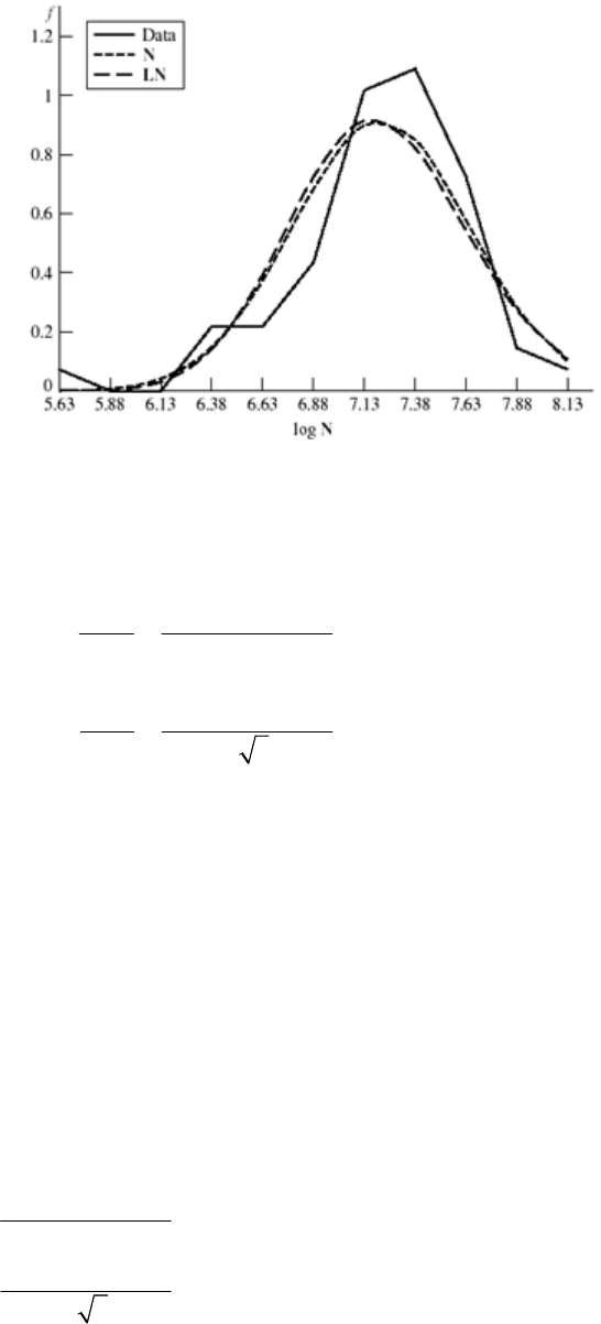
(b) Histogram
______________________________________________________________________________
20-5 Distribution is uniform in interval 0.5000 to 0.5008 in, range numbers are a = 0.5000 in,
b = 0.5008 in.
(a) Eq. (20-22) 0.5000 0.5008 0.5004
22
x
ab
Eq. (20-23) 0.5008 0.5000 0.000 231
223
x
ba
(b) PDF, Eq. (20-20)
1250 0.5000 x 0.5008 in
() 0 otherwise
fx
(c) CDF, Eq. (20-21)
0 0.5000 in
( ) ( 0.5) / 0.0008 0.5000 0.5008 in
1 0.5008 in
x
Fx x x
x
If all smaller diameters are removed by inspection, a = 0.5002 in, b = 0.5008 in,
0.5002 0.5008 0.5005 in
2
0.5008 0.5002
ˆ0.000 173 in
23
x
x
1666.7 0.5002 0.5008 in
() 0 otherwise
x
fx
Chapter 20, Page 4/29
0 0.5002 in
( ) 1666.7( 0.5002) 0.5002 0.5008 in
1 0.5008 in
x
Fx x x
x
______________________________________________________________________________
20-6 Dimensions produced are due to tool dulling and wear. When parts are mixed, the
distribution is uniform. From Eqs. (20-22) and (20-23),
3 0.6241 3 0.000 581 0.6231 in
3 0.6241 3 0.000 581 0.6251 in
x
x
as
bs
We suspect the dimension was 0.623 in .
0.625
A
ns
______________________________________________________________________________
20-7 F(x) = 0.555x – 33 mm.
(a) Since F(x) is linear, distribution is uniform at x = a
F(a) = 0 = 0.555(a) – 33
a = 59.46 mm. Therefore at x = b
F(b) = 1= 0.555b – 33
b = 61.26 mm. Therefore,
0 59.46 mm
( ) 0.555 33 59.46 61.26 mm
1 61.26 mm
x
Fx x x
x
The PDF is dF/dx, thus the range numbers are:
0.555 59.46 61.26 mm
( ) .
0 otherwise
x
f
xA
ns
From the range numbers,
59.46 61.26 60.36 mm .
2
61.26 59.46
ˆ0.520 mm .
23
x
x
Ans
Ans
Chapter 20, Page 5/29
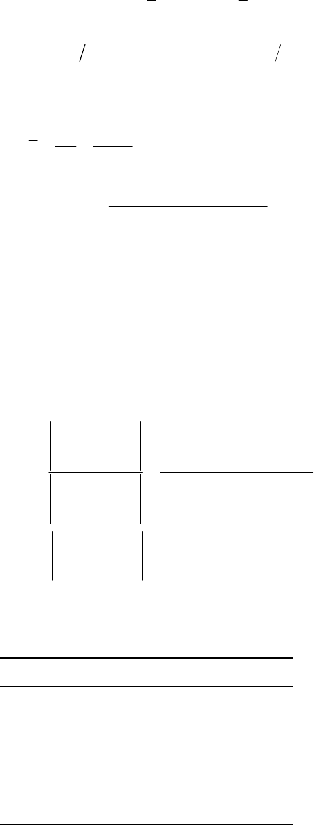
(b)
is an uncorrelated quotient 2
3600 lbf, 0.112 inFA
300 3600 0.083 33, 0.001 0.112 0.008 929
FA
CC
From Table 20-6, For
1/2
22
2
3600 32 143 psi .
0.112
0.08333 0.008929
ˆ32 143 2694 psi .
1 0.008929
2694 / 32 143 0.0838 .
F
A
Ans
Ans
CAns
Since F and A are lognormal, division is closed and
is lognormal too.
= LN(32 143, 2694) psi Ans.
______________________________________________________________________________
20-8 Cramer’s rule
2
332
12
232
23
22
22
232
23
.
.
yx
xy x yx xyx
aA
xx xx x
xx
xy
xxyyxy yx
aA
xx xx x
xx
ns
ns
x y x2 x3 xy
0 0.01 0 0 0
0 0.15 0.04 0.008 0.030
0 0.25 0.16 0.064 0.100
1 0.25 0.36 0.216 0.150
1 0.17 0.64 0.512 0.136
1 0.01 1.00 1.000 0.010
3 0.82 2.20 1.800 0.406
a
1 = 1.040 714 a2 = 1.046 43 Ans.
Chapter 20, Page 6/29
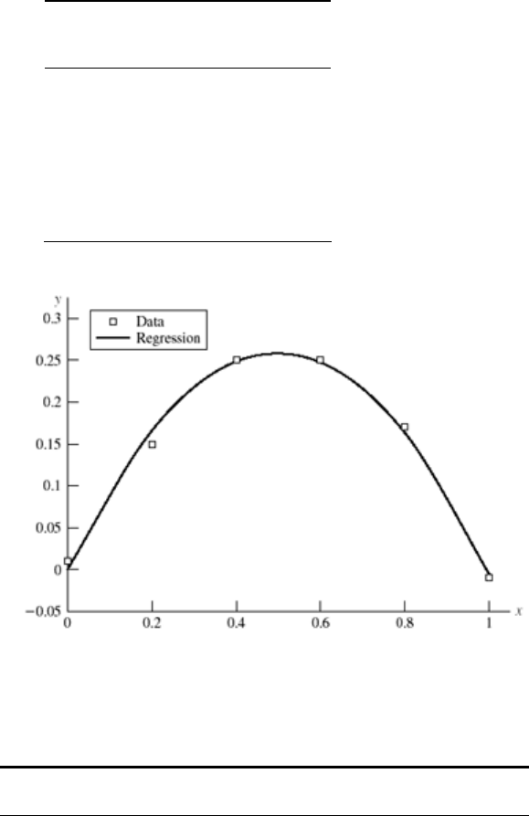
Data Regression
x y y
0 0.01 0
0.2 0.15 0.166 286
0.4 0.25 0.248 857
0.6 0.25 0.247 714
0.8 0.17 0.162 857
1.0 -0.01 -0.005 710
______________________________________________________________________________
20-9
Data Regression
Su
Su2
0 20.356 75
60 30 39.080 78 3 600 1 800
64 48 40.329 05 4 096 3 072
65 29.5 40.641 12 4 225 1 917.5
82 45 45.946 26 6 724 3 690
101 51 51.875 54 10 201 5 151
119 50 57.492 75 14 161 5 950
120 48 57.804 81 14 400 5 760
130 67 60.925 48 16 900 8 710
134 60 62.173 75 17 956 8 040
145 64 65.606 49 21 025 9 280
180 84 76.528 84 32 400 15 120
e
S
ue
SS
e
S
Chapter 20, Page 7/29
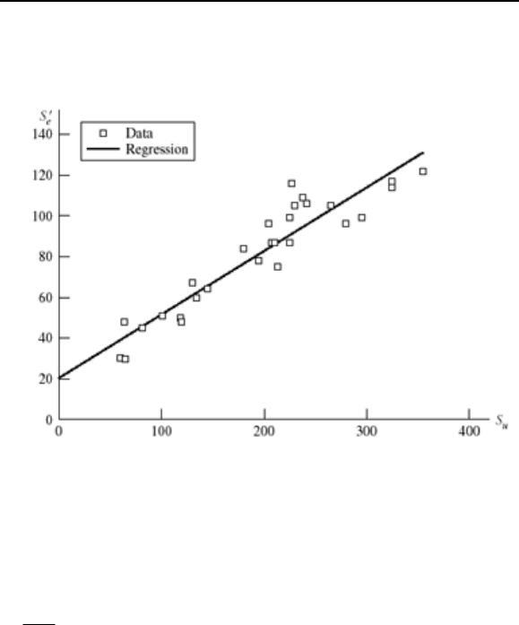
195 78 81.209 85 38 025 15 210
205 96 84.330 52 42 025 19 680
207 87 84.954 66 42 849 18 009
210 87 85.890 86 44 100 18 270
213 75 86.827 06 45 369 15 975
225 99 90.571 87 50 625 22 275
225 87 90.571 87 50 625 19 575
227 116 91.196 00 51 529 26 332
230 105 92.132 20 52 900 24 150
238 109 94.628 74 56 644 25 942
242 106 95.877 01 58 564 25 652
265 105 103.054 60 70 225 27 825
280 96 107.735 60 78 400 26 880
295 99 112.416 60 87 025 29 205
325 114 121.778 60 105 625 37 050
325 117 121.778 60 105 625 38 025
355 122 131.140 60 126 025 43 310
5462 2274.5 1 251 868 501 855.5
m = 0.312 067, b = 20.356 75 Ans.
______________________________________________________________________________
20-10
2
2
02
2
02
20
o
ya ax
ya ax
a
Chapter 20, Page 8/29
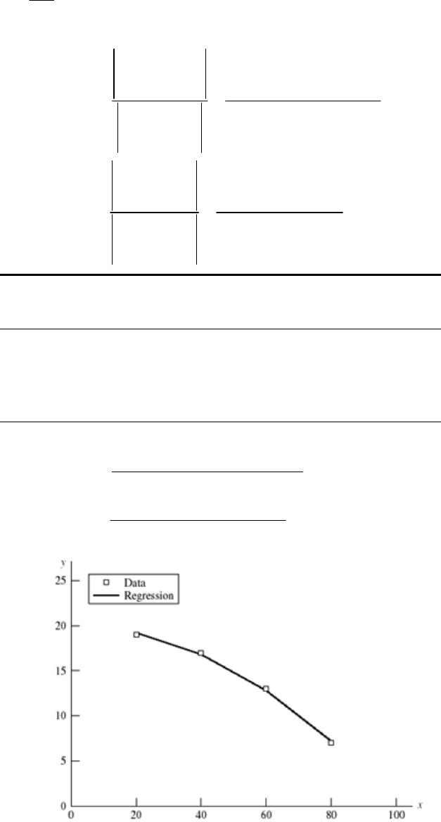
22
02 02
23
02 0 2
2
0
220
yna a x yna a x
y
aax x xya xa x
a
Ans.
Cramer’s rule
2
332
32
2
3
132
2
3
o
yx
xy x
x
yxx
anx xx
nx
xx
ny
xxy
nxy xy
anx xx
nx
xx
y
Data Regression
x y y x2 x3 xy
20 19 19.2 400 8 000 380
40 17 16.8 1600 64 000 680
60 13 12.8 3600 216 000 780
80 7 7.2 6400 512 000 560
200 56 12 000 800 000 2400
0
1
800 000(56) 12 000(2400) 20
4(800 000) 200(12 000)
4(2400) 200(56) 0.002
4(800 000) 200(12 000)
a
a
______________________________________________________________________________
Chapter 20, Page 9/29
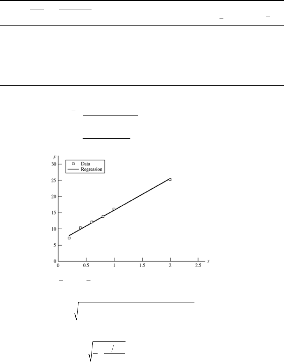
20-11
Data Regression
x y y x2 y2 xy
x
x
2
x
x
0.2 7.1 7.931 803 0.04 50.41 1.42 -0.633 333 0.401 111 111
0.4 10.3 9.884 918 0.16 106.09 4.12 -0.433 333 0.187 777 778
0.6 12.1 11.838 032 0.36 146.41 7.26 -0.233 333 0.054 444 444
0.8 13.8 13.791 147 0.64 190.44 11.04 -0.033 333 0.001 111 111
1 16.2 15.744 262 1 262.44 16.2 0.166 666 0.027 777 778
2 25.2 25.509 836 4 635.04 50.4 1.166 666 1.361 111 111
5 84.7 6.2 1390.83 90.44 0 2.033 333 333
2
6 90.44 5 84.7
ˆ9.7656
6 6.2 5
84.7 9.7656(5)
ˆ5.9787
6
i
mk
bF
(a) 5 84.7
; 14.117
66
xy
Eq. (20-37):
1390.83 5.9787(84.7) 9.7656(90.44)
62
0.556
yx
s
Eq. (20-36):
2
ˆ
56
1
0.556 0.3964 lbf
6 2.0333
5.9787,0.3964 lbf .
b
i
s
FA
ns
Chapter 20, Page 10/29
(b) Eq. (20-35):
ˆ
0.556 0.3899 lbf/in
2.0333
(9.7656,0.3899) lbf/in .
m
s
kA
ns
______________________________________________________________________________
20-12 The expression = / l is of the form x / y. Now = (0.0015, 0.000 092) in, unspecified
distribution; and unspecified distribution;
(2,000, 0.008 1) in,l=
Cx = 0.000 092 / 0.0015 = 0.0613
C
y = 0.0081 / 2.000 = 0.004 05
Table 20-6: 0.0015 / 2.000 0.000 75
1/2
22
2
5
0.0613 0.004 05
ˆ0.000 75 1 0.004 05
4.607 10 0.000 046
We can predict and ˆ
but not the distribution of .
______________________________________________________________________________
20-13 = E
= (0.0005, 0.000 034), distribution unspecified; E = (29.5, 0.885) Mpsi, distribution
unspecified;
Cx = 0.000 034 / 0.0005 = 0.068
C
y = 0.0885 / 29.5 = 0.03
is of the form xy
Table 20-6: 6
0.0005(29.5)10 14 750 psiE
1/ 2
2222
ˆ14 750 0.068 0.030 0.068 0.030
1096.7 psi
1096.7 /14 750 0.074 35C
______________________________________________________________________________
20-14
Fl
AE
where F = (14.7, 1.3) kip, A = (0.226, 0.003) in2, l = (1.5, 0.004) in, and
E = (29.5, 0.885) Mpsi, distributions unspecified.
Chapter 20, Page 11/29
C
F = 1.3 / 14.7 = 0.0884; CA = 0.003 / 0.226 = 0.0133; Cl = 0.004 / 1.5 = 0.00267;
C
E =0.885 / 29.5 = 0.03
11
Fl Fl
AE A E
Table 20-6:
6
11/ 11
11
14 700(1.5) 0.003 31 in. .
0.226 29.5 10
Fl A E Fl A E
Ans
For the standard deviation, using the first-order terms in Table 20-6,
12 12
2222 2222
12
2222
ˆ
ˆ0.003 31 0.0844 0.002 67 0.0133 0.03
0.000 313 in .
Fl AE Fl AE
Fl CCCC CCCC
AE
A
ns
COV: ˆ/ 0.000 313/ 0.003 31 0.0945 .CA
ns
Force COV dominates. There is no distributional information on .
______________________________________________________________________________
20-15 M = (15 000, 1350) lbf ⋅ in, distribution unspecified; d = (2.00, 0.005) in, distribution
unspecified.
3
32
M
d
CM = 1350 / 15 000 = 0.09, Cd = 0.005 / 2.00 = 0.0025
is of the form x/y3, Table 20-6.
Mean: 15 000 lbf inM
22
33 3
11 1
1 6 1 6 0.0025 0.125 in *
2
x
C
dd
3
* Note: 33
11
dd
Chapter 20, Page 12/29
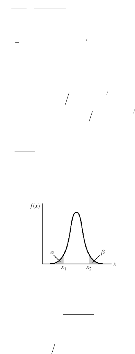
3
32 32(15 000) (0.125)
19 099 psi .
M
dAns
Standard Deviation:
33
12
22 2
ˆ/1
Mdd
CC C
Table 20-6:
3
12
22
2
12
22 2
3 3(0.0025) 0.0075
ˆ313
19 099 0.09 0.0075 1 0.0075
1725 psi .
d
d
Md d
CC
CC C
Ans
COV:
1725 0.0903 .
19 099
CA
ns
Stress COV dominates. No information of distribution of .
______________________________________________________________________________
20-16
Fraction discarded is
+
. The area under the PDF was unity. Having discarded
+
fraction, the ordinates to the truncated PDF are multiplied by a.
1
1
a
New PDF, g(x), is given by
12
() 1
()
0 otherwise
f
xx
gx
xx
A more formal proof: g(x) has the property
Chapter 20, Page 13/29
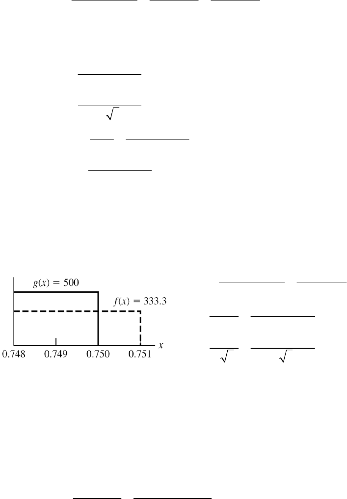
22
11
1
2
0
12
21
1
1
11()1()
11
() () 1 1
xx
xx
x
x
g x dx a f x dx
a f xdx f xdx f xdx
aFx Fx
aFx Fx
1
______________________________________________________________________________
20-17 (a) d = U(0.748, 0.751)
1
0.751 0.748 0.7495 in
2
0.751 0.748
ˆ0.000 866 in
23
11
333.3 in
0.751 0.748
0.748
( ) 333.3( 0.748)
0.751 0.748
d
d
fx ba
x
Fx x
(b) F(x1) = F(0.748) = 0
F(x2) = (0.750 – 0.748) 333.3 = 0.6667
If g(x) is truncated, PDF becomes
1
21
( ) 333.3
( ) 500 in
( ) ( ) 0.6667 0
0.748 0.750 0.749 in
22
0.750 0.748
ˆ0.000 577 in
23 23
x
x
fx
gx Fx Fx
ab
ba
______________________________________________________________________________
20-18 From Table A-10, 8.1% corresponds to z1 = 1.4 and 5.5% corresponds to z2 = +1.6.
11
22
ˆ
ˆ
kz
kz
From which
21 12
21
1.6(9) ( 1.4)11
1.6 ( 1.4)
9.933
zk zk
zz
Chapter 20, Page 14/29
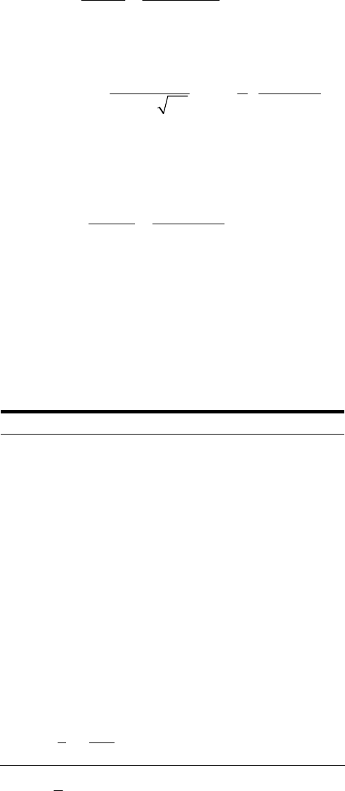
21
21
11 9
ˆ0.6667
1.6 ( 1.4)
kk
zz
The original density function is
2
1 1 9.933
() exp .
2 0.6667
0.6667 2
k
f
kA
ns
______________________________________________________________________________
20-19 From Prob. 20-1,
= 122.9 kcycles and ˆ
= 30.3 kcycles.
10 10
10
10 10
122.9
ˆ30.3
122.9 30.3
xx
z
xz
From Table A-10, for 10 percent failure, z10 = 1.282
x10 = 122.9 + 30.3(1.282)
= 84.1 kcycles Ans.
______________________________________________________________________________
20-20
x f f x f x2 f / (Nw) f (x)
60 2 120 7200 0.002899 0.000399
70 1 70 4900 0.001449 0.001206
80 3 240 19200 0.004348 0.003009
90 5 450 40500 0.007246 0.006204
100 8 800 80000 0.011594 0.010567
110 12 1320 145200 0.017391 0.014871
120 6 720 86400 0.008696 0.017292
130 10 1300 169000 0.014493 0.016612
140 8 1120 156800 0.011594 0.013185
150 5 750 112500 0.007246 0.008647
160 2 320 51200 0.002899 0.004685
170 3 510 86700 0.004348 0.002097
180 2 360 64800 0.002899 0.000776
190 1 190 36100 0.001449 0.000237
200 0 0 0 0 5.98E-05
210 1 210 44100 0.001449 1.25E-05
69 8480
x
= 122.8986 sx = 22.887 19
Chapter 20, Page 15/29

Eq. (20-14):
2
2
11
() exp ˆ
ˆ2
2
1 1 122.8986
exp 2 22.88719
22.88719 2
x
x
x
x
fx
x
x f / (Nw) f (x) x f / (Nw) f (x)
55 0 0.000 214 145 0.011 594 0.010 935
55 0.002 899 0.000 214 145 0.007 246 0.010 935
65 0.002 899 0.000 711 155 0.007 246 0.006 518
65 0.001 449 0.000 711 155 0.002 899 0.006 518
75 0.001 449 0.001 951 165 0.002 899 0.002 21
75 0.004 348 0.001 951 165 0.004 348 0.003 21
85 0.004 348 0.004 425 175 0.004 348 0.001 306
85 0.007 246 0.004 425 175 0.002 899 0.001 306
95 0.007 246 0.008 292 185 0.002 899 0.000 439
95 0.011 594 0.008 292 185 0.001 449 0.000 439
105 0.011 594 0.012 839 195 0.001 449 0.000 122
105 0.017 391 0.012 839 195 0 0.000 122
115 0.017 391 0.016 423 205 0 2.8E-05
115 0.008 696 0.016 423 205 0.001 499 2.8E-05
125 0.008 696 0.017 357 215 0.001 499 5.31E-06
125 0.014 493 0.017 357 215 0 5.31E-06
135 0.014 493 0.015 157
135 0.011 594 0.015 157
______________________________________________________________________________
Chapter 20, Page 16/29
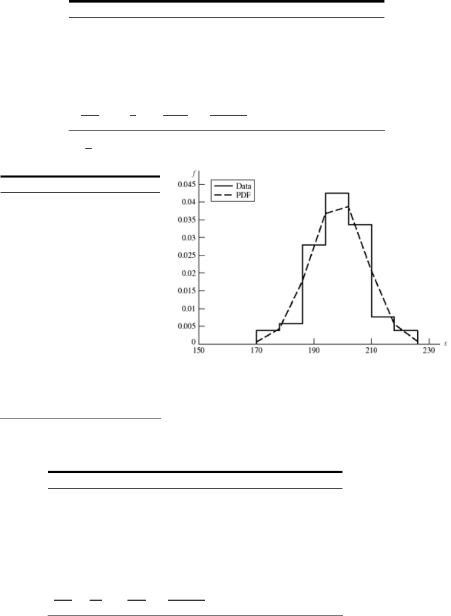
20-21
x f f x f x 2 f / (Nw) f (x)
174 6 1044 181656 0.003807 0.001642
182 9 1638 298116 0.005711 0.009485
190 44 8360 1588400 0.027919 0.027742
198 67 13266 2626668 0.042513 0.041068
206 53 10918 2249108 0.033629 0.030773
214 12 2568 549552 0.007614 0.011671
222 6 1332 295704 0.003807 0.002241
1386 197 39126 7789204
x
= 198.6091 sx = 9.695 071
x f / (Nw) f (x)
170 0 0.000529
170 0.003807 0.000529
178 0.003807 0.004297
178 0.005711 0.004297
186 0.005711 0.017663
186 0.027919 0.017663
194 0.027919 0.036752
194 0.042513 0.036752
202 0.042513 0.038708
202 0.033629 0.038708
210 0.033629 0.020635
210 0.007614 0.020635
218 0.007614 0.005568
218 0.003807 0.005568
226 0.003807 0.00076
226 0 0.00076
______________________________________________________________________________
20-22
x f f x f x2 f / (Nw) f (x)
64 2 128 8192 0.008621 0.00548
68 6 408 27744 0.025862 0.017299
72 6 432 31104 0.025862 0.037705
76 9 684 51984 0.038793 0.056742
80 19 1520 121600 0.081897 0.058959
84 10 840 70560 0.043103 0.042298
88 4 352 30976 0.017241 0.020952
92 2 184 16928 0.008621 0.007165
624 58 4548 359088
Chapter 20, Page 17/29
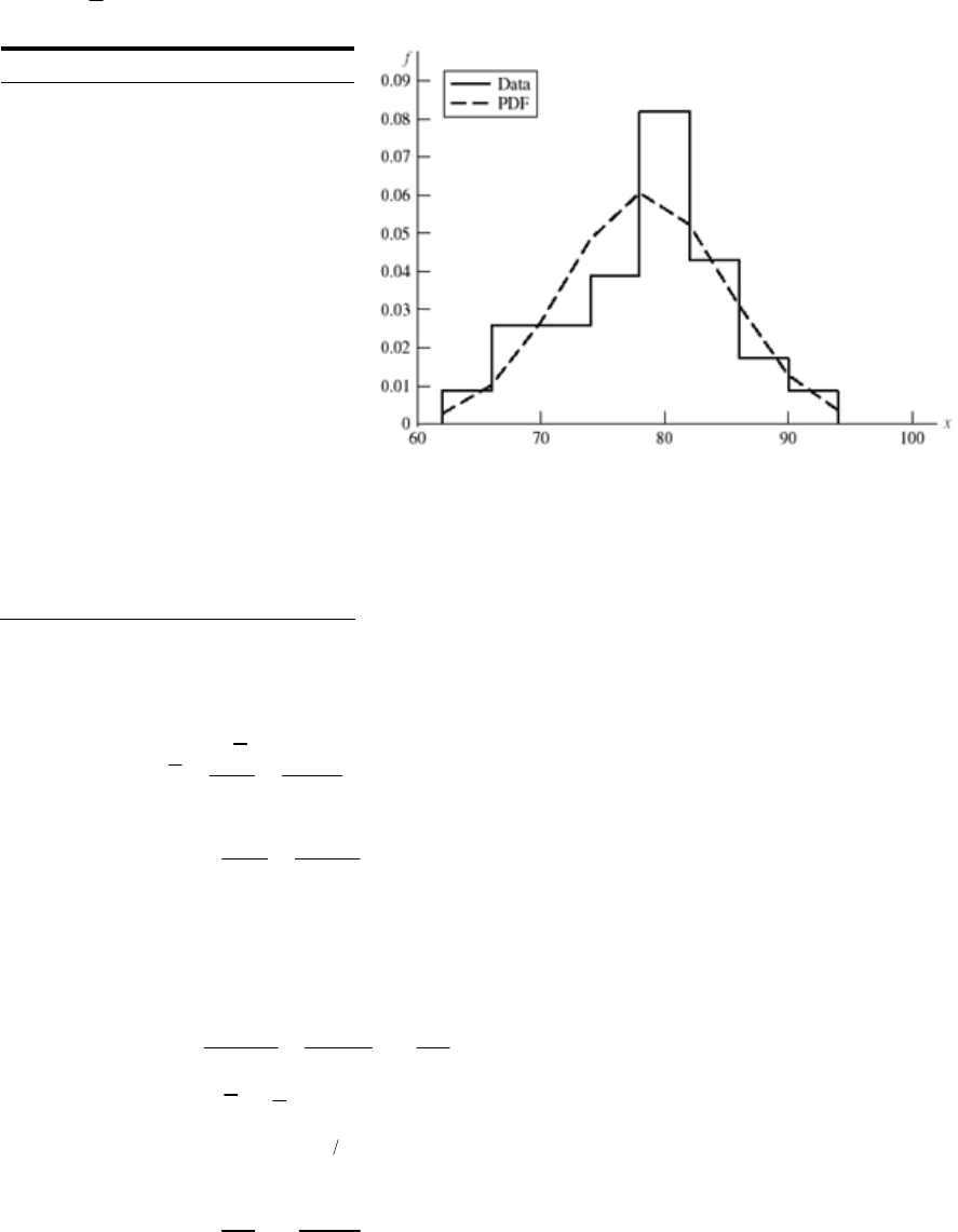
x
= 78.041379 sx = 6.572 229
x f / (Nw) f (x)
62 0 0.002684
62 0.008621 0.002684
66 0.008621 0.010197
66 0.025862 0.010197
70 0.025862 0.026749
70 0.025862 0.026749
74 0.025862 0.048446
74 0.038793 0.048446
78 0.038793 0.060581
78 0.0381897 0.060581
82 0.081897 0.052305
82 0.043103 0.052305
86 0.043103 0.03118
86 0.017241 0.03118
90 0.017241 0.012833
90 0.008621 0.012833
94 0.008621 0.003647
94 0 0.003647
______________________________________________________________________________
20-23
22
22
4 4(40) 50.93 kpsi
1
ˆ
44(8.5)
ˆ10.82 kpsi
1
ˆ5.9 kpsi
y
P
S
P
d
d
For no yield, m = Sy
0
12 2
22 2 2
0
ˆˆˆ
78.4 50.93 27.47 kpsi
ˆˆ 10.82 5.9 12.32 kpsi
27.47 2.230
ˆ12.32
y
mmm
mmm
my
mS
m
m
m
z
S
z
Table A-10, pf = 0.0129
R = 1 – pf = 1 – 0.0129 = 0.987 Ans.
______________________________________________________________________________
Chapter 20, Page 18/29
20-24 For a lognormal distribution,
2
2
Eq. (20-18) ln ln 1
ˆ
Eq. (20-19) ln 1
y
xx
yx
C
C
From Prob. (20-23)
22
2
2
12
22
22
2
2
22
22
2
ln ln 1 ln ln 1
1
ln 1
ˆln 1 ln 1
ln 1 1
1
ln 1
ˆln 1 1
4 4(30) 38.197 kpsi
1
ˆ
44(5.
ˆ
y
y
y
y
y
y
my x
yy S
y
S
yS
S
y
S
S
P
S
SC C
SC
C
CC
CC
SC
C
zCC
P
d
d
2
2
2
22
1) 6.494 kpsi
1
6.494 0.1700
38.197
3.81 0.076 81
49.6
49.6 1 0.170
ln 38.197 1 0.07681 1.470
ln 1 0.076 81 1 0.170
y
S
C
C
z
Table A-10
pf = 0.0708
R = 1 – pf = 0.929 Ans.
______________________________________________________________________________
Chapter 20, Page 19/29

20-25
x n nx nx2
93 19 1767 164 311
95 25 2375 225 625
97 38 3686 357 542
99 17 1683 166 617
101 12 1212 122 412
103 10 1030 106 090
105 5 525 55 125
107 4 428 45 796
109 4 436 47 524
111 2 222 24 642
136 13 364 1 315 704
x
= 13 364/136 = 98.26 kpsi
12
2
1 315 704 13 364 /136 4.30 kpsi
136 1
x
s
Under normal hypothesis,
0.01 0.01
0.01 0.01
98.26 / 4.30
98.26 4.30
98.26 4.30 2.3267
88.26 88.3 kpsi .
zx
xz
A
ns
______________________________________________________________________________
20-26 From Prob. 20.25,
x = 98.26 kpsi, and ˆ4.30 kpsi.
x
ˆ/ 4.30 / 98.26 0.043 76
xxx
C
From Eqs. (20-18) and (20-19),
2
2
ln 98.26 0.043 76 / 2 4.587
ˆln 1 0.043 76 0.043 74
y
y
For a yield strength exceeded by 99% of the population,
0.01 0.01 0.01 0.01
ˆˆ
ln / ln
yy yy
z
xx
z
From Table A-10, for 1% failure, z0.01 = 2.326. Thus,
Chapter 20, Page 20/29
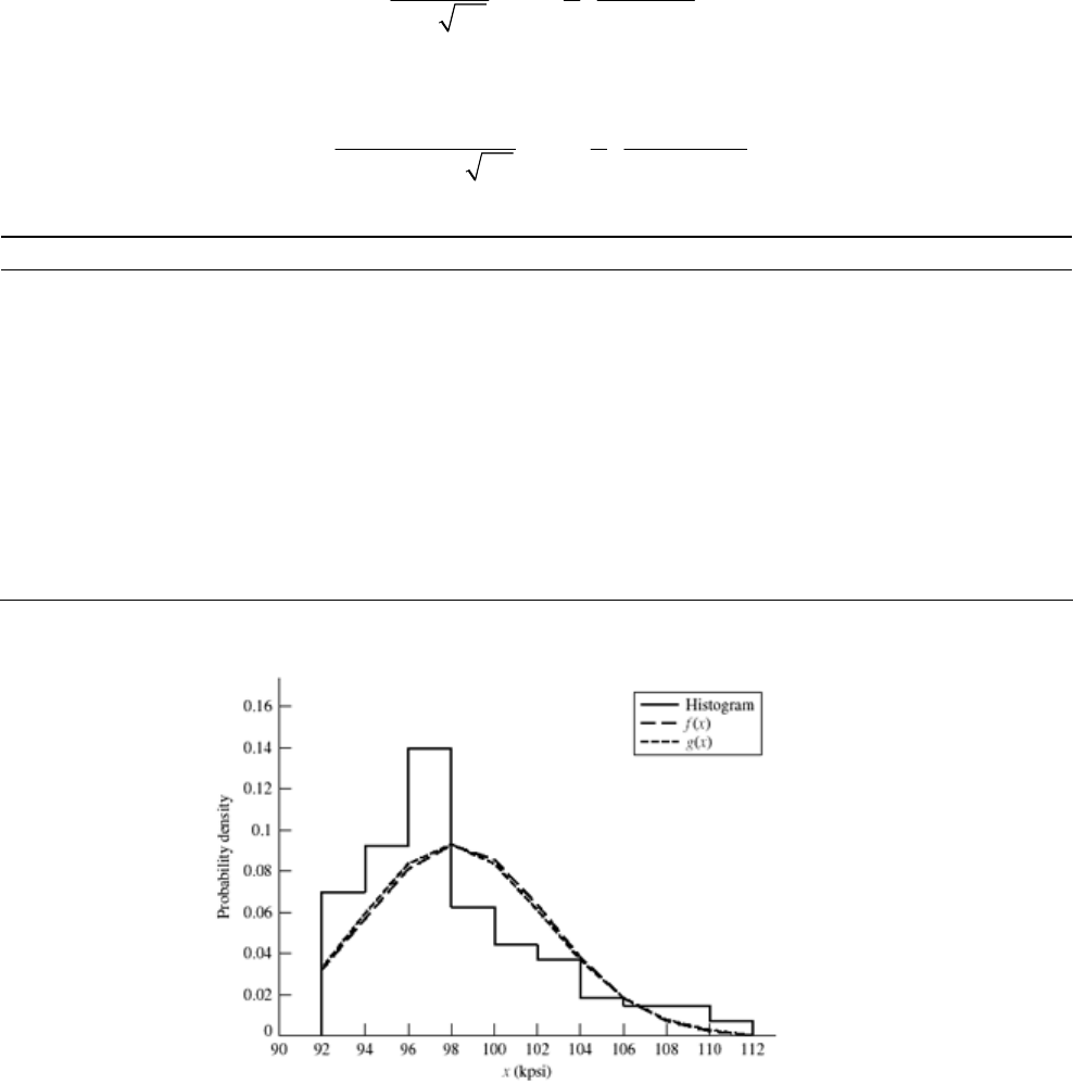
0.01
0.01
ln 4.587 0.043 74 2.326 4.485
88.7 kpsi .
x
xAns
The normal PDF is given by Eq. (20-14) as
2
1 1 98.26
exp 2 4.30
4.30 2
x
fx
For the lognormal distribution, from Eq. (20-17), defining g(x),
2
1 1 ln 4.587
exp 2 0.043 74
0.043 74 2
x
gx x
x(kpsi) f / (Nw) f (x) g(x) x(kpsi) f / (Nw) f (x) g(x)
92 0.000 00 0.032 15 0.032 63 102 0.036 76 0.063 56 0.061 34
92 0.069 85 0.032 15 0.032 63 104 0.036 76 0.038 06 0.037 08
94 0.069 85 0.056 80 0.058 90 104 0.018 38 0.038 06 0.037 08
94 0.091 91 0.056 80 0.058 90 106 0.018 38 0.018 36 0.018 69
96 0.091 91 0.080 81 0.083 08 106 0.014 71 0.018 36 0.018 69
96 0.139 71 0.080 81 0.083 08 108 0.014 71 0.007 13 0.007 93
98 0.139 71 0.092 61 0.092 97 108 0.014 71 0.007 13 0.007 93
98 0.062 50 0.092 61 0.092 97 110 0.014 71 0.002 23 0.002 86
100 0.062 50 0.085 48 0.083 67 110 0.007 35 0.002 23 0.002 86
100 0.044 12 0.085 48 0.083 67 112 0.007 35 0.000 56 0.000 89
102 0.044 12 0.063 56 0.061 34 112 0.000 00 0.000 56 0.000 89
Note: rows are repeated to draw histogram
The normal and lognormal are almost the same. However, the data is quite skewed and
perhaps a Weibull distribution should be explored. For a method of establishing the
Chapter 20, Page 21/29
Weibull parameters see Shigley, J. E., and C. R. Mishke, Mechanical Engineering
Design, McGraw-Hill, 5th ed., 1989, Sec. 4-12.
_____________________________________________________________________________
20-27 x
4
10
fe
xS 0 = 79 kpsi,
= 86.2 kpsi, b = 2.6
Eq. (20-28):
00
(1 1 )
79 (86.2 79) (1 1 2.6)
79 7.2 (1.38)
xx x b
From Table A-34,
Γ(1.38) = 0.888 54
79 7.2(0.888 54) 85.4 kpsi .
x
Ans
Eq. (20-29)
12
2
0
12
2
12
2
ˆ12 11
86.2 79 1 2 2.6 1 1 2.6
7.2 0.923 76 0.888 54
2.64 kpsi .
ˆ2.64 0.031 .
85.4
x
x
x
xb b
Ans
CAns
x
_____________________________________________________________________________
20-28 x = Sut x0 = 27.7 kpsi,
= 46.2 kpsi, b = 4.38
12
2
12
2
12
2
27.7 46.2 27.7 1 1 4.38
27.7 18.5 (1.23)
27.7 18.5(0.910 75)
44.55 kpsi .
ˆ46.2 27.7 1 2 4.38 1 1 4.38
18.5 (1.46) (1.23)
18.5 0.8856 0.920 75
4.38 kpsi .
4.38
4
x
x
x
Ans
Ans
C
0.098 .
4.55 Ans
From the Weibull survival equation
Chapter 20, Page 22/29
0
0
exp 1
b
xx
R
p
x
40 0
40 40
0
4.38
40 40
exp 1
40 27.7
exp 0.846
46.2 27.7
1 1 0.846 0.154 15.4% .
b
xx
Rp
x
p
RA
ns
_____________________________________________________________________________
20-29 x = Sut, x0 = 151.9 kpsi,
= 193.6 kpsi, b = 8
12
2
12
2
12
2
151.9 193.6 151.9 1 1 8
151.9 41.7 (1.125)
151.9 41.7(0.941 76)
191.2 kpsi .
ˆ193.6 151.9 1 2 8 1 1 8
41.7 (1.25) (1.125)
41.7 0.906 40 0.941 76
5.82 kpsi .
5.8
x
x
x
Ans
Ans
C
20.030
191.2
_____________________________________________________________________________
20-30 x = Sut, x0 = 47.6 kpsi,
= 125.6 kpsi, b = 11.4
12
2
12
2
12
2
47.6 125.6 47.6 1 1 11.84
47.6 78 1.08
47.6 78 0.959 73 122.5 kpsi
ˆ125.6 47.6 1 2 11.84 1 1 11.84
78 (1.08) (1.17)
78 0.959 73 0.936 70 22.4 kpsi
x
x
From Prob. 20-28,
11.84
0
0
100 47.6
1 exp 1 exp 0.0090 .
125.6 47.6
b
xx
p
Ans
Chapter 20, Page 23/29
y = Sy, y0 = 64.1 kpsi,
= 81.0 kpsi, b = 3.77
12
12
2
3.77
0
0
64.1 (81.0 64.1) 1 1 3.77
64.1 16.9 (1.27)
64.1 16.9(0.902 50) 79.35 kpsi
(81 64.1) (1 2 3.77) 1 1 3.77
16.9 0.887 57 0.902 50 4.57 kpsi
1exp
70 64.1
1exp 81
y
y
yy
py
3.77
0.019 .
64.1 Ans
_____________________________________________________________________________
20-31 x = Sut = W[122.3, 134.6, 3.64] kpsi, p(x > 120) = 1 = 100% since x0 > 120 kpsi
3.64
133 122.3
( 133) exp 134.6 122.3
0.548 54.8% .
px
Ans
_____________________________________________________________________________
20-32 Using Eqs. (20-28) and (20-29) and Table A-34,
00
2
0
1 1 36.9 133.6 36.9 1 1 2.66
=122.85 kcycles
ˆ1 2 1 1 34.79 kcycles
n
n
nn b
nb b
For the Weibull density function, Eq. (20-27),
2.66 1 2.66
2.66 36.9 36.9
() exp
133.6 36.9 133.6 36.9 133.6 36.9
W
nn
fn
For the lognormal distribution, Eqs. (20-18) and (20-19) give,
2
2
ln 122.85 34.79 122.85 2 4.771
ˆ1 34.79 122.85 0.2778
y
y
From Eq. (20-17), the lognormal PDF is
Chapter 20, Page 24/29
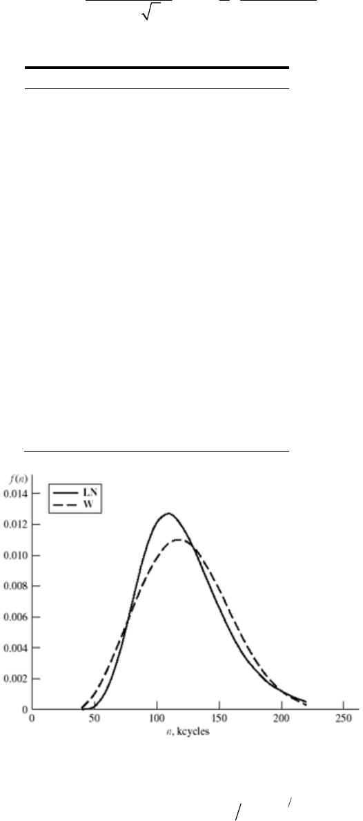
2
LN
1 1 ln 4.771
exp 2 0.2778
0.2778 2
n
fn n
We form a table of densities f W (n) and f LN (n) and plot.
n(kcycles) f W (n) f LN (n)
40 9.1E-05 1.82E-05
50 0.000 991 0.000 241
60 0.002 498 0.001 233
70 0.004 380 0.003 501
80 0.006 401 0.006 739
90 0.008 301 0.009 913
100 0.009 822 0.012 022
110 0.010 750 0.012 644
120 0.010 965 0.011 947
130 0.010 459 0.010 399
140 0.009 346 0.008 492
150 0.007 827 0.006 597
160 0.006 139 0.004 926
170 0.004 507 0.003 564
180 0.003 092 0.002 515
190 0.001 979 0.001 739
200 0.001 180 0.001 184
210 0.000 654 0.000 795
220 0.000 336 0.000 529
The Weibull L10 life comes from Eq. (20-26) with reliability of R = 0.90. Thus,
12.66
0.10 36.9 133.6 36.9 ln 1 0.90 78.4 kcycles .nA
ns
The lognormal L10 life comes from the definition of the z variable. That is,
Chapter 20, Page 25/29
00
ˆˆ
ln or exp
yy yy
nzn
z
From Table A-10, for R = 0.90, z = 1.282. Thus,
0exp 4.771 0.2778 1.282 82.7 kcycles .nA
ns
_____________________________________________________________________________
20-33 Form a table
i x
(105)L fi fi x⋅(105)fi x2⋅(1010) g(x)⋅(105)
1 3.05 39.15 27.9075 0.0557
2 3.55 724.85 88.2175 0.1474
3 4.05 11 44.55 180.4275 0.2514
4 4.55 16 72.80 331.24 0.3168
5 5.05 21 106.05 535.5525 0.3216
6 5.55 13 72.15 400.4325 0.2789
7 6.05 13 78.65 475.8325 0.2151
8 6.55 639.30 257.415 0.1517
9 7.05 214.10 99.405 0.1000
10 7.55 0 0 0 0.0625
11 8.05 432.20 259.21 0.0375
12 8.55 325.65 219.3075 0.0218
13 9.05 0 0 0 0.0124
14 9.55 0 0 0 0.0069
15 10.05 1 10.05 101.0025 0.0038
100 529.50 2975.95
Chapter 20, Page 26/29
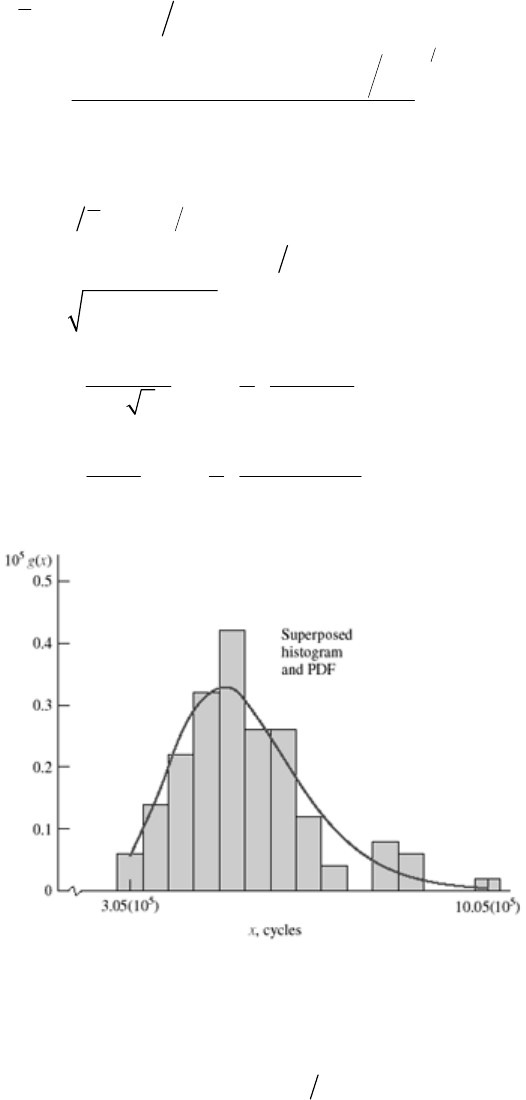
55
12
2
10 5
5
52
2
529.5 10 100 5.295 10 cycles .
2975.95 10 529.5 10 100
100 1
1.319 10 cycles .
1.319 5.295 0.249
ln 5.295 10 0.249 2 13.149
ˆln 1 0.249 0.245
l
11
() exp 2
ˆ2
x
x
y
y
y
x
Ans
s
Ans
Csx
gx x
2
2
n
ˆ
1.628 1 ln 13.149
exp 2 0.245
y
y
x
x
x
_____________________________________________________________________________
20-34 X = Su = W[70.3, 84.4, 2.01]
Eq. (2-28):
70.3 84.4 70.3 1 1 2.01
70.3 (84.4 70.3) 1.498
82.8kpsi .
x
Ans
Chapter 20, Page 27/29
Eq. (2-29):
12
2
12
2
ˆ(84.4 70.3) (1 2 2.01) (1 1 2.01)
ˆ14.1 0.997 91 0.886 17
6.502 kpsi
6.502 0.079 .
82.8
x
x
x
CAns
_____________________________________________________________________________
20-35 Take the Weibull equation for the standard deviation
12
2
0
ˆ(1 2 ) (1 1 )
xxbb
and the mean equation solved for 0
x
x
00
11
x
xx
b
and divide the first by the second,
12
2
0
12 11
ˆ
11
xbb
xx b
2
12
4.2 1 0.2763
49 33.8 1 1
bR
b
Make a table and solve for b iteratively
0
0
4.068 Using MathCad .
49 33.8
33.8
(1 1/ ) 1 1/ 4.068
49.8 kpsi .
bA
xx
xb
Ans
b 1 + 2/b 1 + 1/b
12b
11b
R
3 1.67 1.33 0.903 30 0.893 38 0.363
4 1.5 1.25 0.886 23 0.906 40 0.280
4.1 1.49 1.24 0.885 95 0.908 52 0.271
ns
_____________________________________________________________________________
20-36 x = Sy = W[34.7, 39, 2.93] kpsi
Chapter 20, Page 28/29
12
2
12
2
12
2
34.7 39 34.7 1 1 2.93 34.7 4.3 1.34
34.7 4.3 0.892 22 38.5 kpsi
ˆ39 34.7 1 2 2.93 1 1 2.93
4.3 1.68 1.34
4.3 0.905 00 0.892 22 1.42 kpsi .
1.42 38.5 0.037 .
x
x
x
Ans
CAns
_____________________________________________________________________________
x (Mrev) f f x f x2
1 11 11 11
2 22 44 88
3 38 114 342
4 57 228 912
5 31 155 775
6 19 114 684
7 15 105 735
8 12 96 768
9 11 99 891
10 9 90 900
11 7 77 847
12 5 60 720
Sum 78 237 1193 7673
20-37
66
2
12 6
6
1193 10 / 237 5.034 10 cycles
7673 10 1193 10 / 237
ˆ2.658 10 cycles
237 1
2.658 / 5.034 0.528
x
x
x
C
From Eqs. (20-18) and (20-19),
62
2
ln 5.034 10 0.528 / 2 15.292
ˆln 1 0.528 0.496
y
y
From Eq. (20-17), defining g(x),
2
1 1 ln 15.292
() exp 2 0.496
0.496 2
x
gx x
x (Mrev) f / (Nw) g(x)(106)
0.5 0.000 00 0.000 11
Chapter 20, Page 29/29
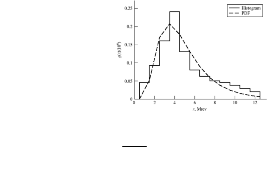
Chapter 20, Page 30/29
ln ˆ
ln 15.292 0.496
ˆ
y
yy
y
x
zxzz
L10 life, where 10% of bearings fail, from Table A-10,
z = 1.282. Thus,
0.5 0.046414 0.000 11
1.5 0.046414
0.052 03
1.5 0.092827 0.052 03
2.5 0.092827 0.169 92
2.5 0.160338 0.169 92
3.5 0.160338 0.207 54
3.5 0.240506 0.207 54
4.5 0.240506 0.178 47
4.5 0.130802 0.178 47
5.5 0.130802 0.131 58
5.5 0.080 17 0.13158
6.5 0.080 17 0.090 11
6.5 0.063 29 0.090 11
7.5 0.063 29 0.059 53
7.5 0.050 63 0.059 53
8.5 0.050 63 0.038 69
8.5 0.046 41 0.038 69
9.5 0.046 41 0.025 01
9.5 0.037 97 0.025 01
10.5 0.037 97 0.016 18
10.5 0.029 54 0.016 18
11.5 0.029 54 0.010 51
11.5 0.021 10 0.010 51
12.5 0.021 10 0.006 87
12.5 0.000 00 0.006 87
ln x = 15.292 + 0.496(1.282) = 14.66
x = 2.33 (106) rev Ans.
