Cisco ATA 186 And 188 Analog Telephone Adaptor Administrator?s Guide For SIP (version 3.0) Sip30ad
User Manual: ATA 188
Open the PDF directly: View PDF ![]() .
.
Page Count: 294 [warning: Documents this large are best viewed by clicking the View PDF Link!]
- Cisco ATA 186 and Cisco ATA 188 Analog Telephone Adaptor Administrator’s Guide for SIP (version 3.0)
- Contents
- Preface
- Cisco Analog Telephone Adaptor Overview
- Installing the Cisco ATA
- Configuring the Cisco ATA for SIP
- Default Boot Load Behavior
- Specifying a Preconfigured VLAN ID or Disabling VLAN IP Encapsulation
- Steps Needed to Configure the Cisco ATA
- Configuring the Cisco ATA Using a TFTP Server
- Voice Configuration Menu
- Cisco ATA Web Configuration Page
- Refreshing or Resetting the Cisco ATA
- Obtaining Cisco ATA Configuration File After Failed Attempt
- Upgrading the SIP Signaling Image
- Basic and Additional SIP Services
- Important Basic SIP Services
- Additional SIP Services
- Advanced Audio Configuration
- Billable Features
- Call Forwarding Setting Removal Using HTTP
- Call-Waiting Hang-Up Alert
- Comfort Noise During Silence Period When Using G.711
- Configurable Hook Flash Timing
- Configurable Mixing of Call Waiting Tone and Audio
- Configurable On-hook delay
- Configurable Reboot of Cisco ATA
- Diagnostics for Debugging
- Dial Plan
- Disabling Access To The Web Interface
- Display-Name Support for Caller ID
- Distinctive Ringing
- DNS SRV Support
- Hardware Information Display
- NAT Gateway
- NAT/PAT Translation
- Network Timing
- Obtaining Network Status Before and After Getting IP Connectivity
- Privacy Options
- Progress Tones
- Real-Time Transport Protocol (RTP) Statistics Reporting
- Receiver-tagged VIA header
- Redundant Proxy Support for BYE/CANCEL Request
- Repeat Dialing on Busy Signal
- Retransmitting SIP requests and SIP Responses
- Setting Up and Placing a Call Without Using a SIP Proxy
- SipOutBoundProxy Support
- SIP Proxy Server Redundancy
- SIP Session-Timer Support
- Status of Phone Service Using HTTP
- STUN Support
- Stuttering Dial Tone on Unconditional Call Forward
- Toll Restrictions for Call Forwarding and Outgoing Calls
- User Configurable Call Waiting Permanent Default Setting
- User Configurable Timeout On No Answer for Call Forwarding
- Voice Prompt Confirmation for Call Waiting and Call Forwarding
- XML Pages of Cisco ATA Information
- Complete Reference Table of all Cisco ATA SIP Services
- Parameters and Defaults
- Configuration Text File Template
- User Interface (UI) Security Parameter
- Parameters for Configuration Method and Encryption
- Network Configuration Parameters
- SIP Configuration Parameters
- Audio Configuration Parameters
- Operational Parameters
- Telephone Configuration Parameters
- Tone Configuration Parameters
- Dial Plan Parameters
- Diagnostic Parameters
- CFGID-Version Parameter for Cisco ATA Configuration File
- Call Commands
- Configuring and Debugging Fax Services
- Upgrading the Cisco ATA Signaling Image
- Troubleshooting
- General Troubleshooting Tips
- Symptoms and Actions
- Installation and Upgrade Issues
- Debugging
- Using System Diagnostics
- Local Tone Playout Reporting
- Obtaining Network Status Prior to Getting IP Connectivity
- Obtaining Network Status After Getting IP Connectivity
- DHCP Status HTML Page
- Real-Time Transport Protocol (RTP) Statistics Reporting
- Frequently Asked Questions
- Contacting TAC
- Using SIP Supplementary Services
- Changing Call Commands
- Cancelling a Supplementary Service
- Common Supplementary Services
- Caller ID
- Call-Waiting Caller ID
- Voice Mail Indication
- Unattended Transfer
- Attended Transfer
- Making a Conference Call in the United States
- Making a Conference Call in Sweden
- Call Waiting in the United States
- Call Waiting in Sweden
- About Call Forwarding
- Call Forwarding in the United States
- Call Forwarding in Sweden
- Call Return in the United States
- Call Return in Sweden
- Calling Line Identification Presentation
- About Calling Line Identification Restriction
- Calling Line Identification Restriction in the United States
- Calling Line Identification Restriction in Sweden
- Voice Menu Codes
- Cisco ATA Specifications
- SIP Call Flows
- Recommended Cisco ATA Tone Parameter Values by Country
- Glossary
- Index

THE SPECIFICATIONS AND INFORMATION REGARDING THE PRODUCTS IN THIS MANUAL ARE SUBJECT TO CHANGE WITHOUT NOTICE. ALL
STATEMENTS, INFORMATION, AND RECOMMENDATIONS IN THIS MANUAL ARE BELIEVED TO BE ACCURATE BUT ARE PRESENTED WITHOUT
WARRANTY OF ANY KIND, EXPRESS OR IMPLIED. USERS MUST TAKE FULL RESPONSIBILITY FOR THEIR APPLICATION OF ANY PRODUCTS.
THE SOFTWARE LICENSE AND LIMITED WARRANTY FOR THE ACCOMPANYING PRODUCT ARE SET FORTH IN THE INFORMATION PACKET THAT
SHIPPED WITH THE PRODUCT AND ARE INCORPORATED HEREIN BY THIS REFERENCE. IF YOU ARE UNABLE TO LOCATE THE SOFTWARE LICENSE
OR LIMITED WARRANTY, CONTACT YOUR CISCO REPRESENTATIVE FOR A COPY.
The following information is for FCC compliance of Class A devices: This equipment has been tested and found to comply with the limits for a Class A digital device, pursuant
to part 15 of the FCC rules. These limits are designed to provide reasonable protection against harmful interference when the equipment is operated in a commercial
environment. This equipment generates, uses, and can radiate radio-frequency energy and, if not installed and used in accordance with the instruction manual, may cause
harmful interference to radio communications. Operation of this equipment in a residential area is likely to cause harmful interference, in which case users will be required
to correct the interference at their own expense.
The following information is for FCC compliance of Class B devices: The equipment described in this manual generates and may radiate radio-frequency energy. If it is not
installed in accordance with Cisco’s installation instructions, it may cause interference with radio and television reception. This equipment has been tested and found to
comply with the limits for a Class B digital device in accordance with the specifications in part 15 of the FCC rules. These specifications are designed to provide reasonable
protection against such interference in a residential installation. However, there is no guarantee that interference will not occur in a particular installation.
Modifying the equipment without Cisco’s written authorization may result in the equipment no longer complying with FCC requirements for Class A or Class B digital
devices. In that event, your right to use the equipment may be limited by FCC regulations, and you may be required to correct any interference to radio or television
communications at your own expense.
You can determine whether your equipment is causing interference by turning it off. If the interference stops, it was probably caused by the Cisco equipment or one of its
peripheral devices. If the equipment causes interference to radio or television reception, try to correct the interference by using one or more of the following measures:
• Turn the television or radio antenna until the interference stops.
• Move the equipment to one side or the other of the television or radio.
• Move the equipment farther away from the television or radio.
• Plug the equipment into an outlet that is on a different circuit from the television or radio. (That is, make certain the equipment and the television or radio are on circuits
controlled by different circuit breakers or fuses.)
Modifications to this product not authorized by Cisco Systems, Inc. could void the FCC approval and negate your authority to operate the product.
NOTWITHSTANDING ANY OTHER WARRANTY HEREIN, ALL DOCUMENT FILES AND SOFTWARE OF THESE SUPPLIERS ARE PROVIDED “AS IS” WITH
ALL FAULTS. CISCO AND THE ABOVE-NAMED SUPPLIERS DISCLAIM ALL WARRANTIES, EXPRESSED OR IMPLIED, INCLUDING, WITHOUT
LIMITATION, THOSE OF MERCHANTABILITY, FITNESS FOR A PARTICULAR PURPOSE AND NONINFRINGEMENT OR ARISING FROM A COURSE OF
DEALING, USAGE, OR TRADE PRACTICE.
IN NO EVENT SHALL CISCO OR ITS SUPPLIERS BE LIABLE FOR ANY INDIRECT, SPECIAL, CONSEQUENTIAL, OR INCIDENTAL DAMAGES, INCLUDING,
WITHOUT LIMITATION, LOST PROFITS OR LOSS OR DAMAGE TO DATA ARISING OUT OF THE USE OR INABILITY TO USE THIS MANUAL, EVEN IF CISCO
OR ITS SUPPLIERS HAVE BEEN ADVISED OF THE POSSIBILITY OF SUCH DAMAGES.
CCIP, CCSP, the Cisco Arrow logo, the Cisco Powered Network mark, Cisco Unity, Follow Me Browsing, FormShare, and StackWise are trademarks of Cisco Systems, Inc.;
Changing the Way We Work, Live, Play, and Learn, and iQuick Study are service marks of Cisco Systems, Inc.; and Aironet, ASIST, BPX, Catalyst, CCDA, CCDP, CCIE,
CCNA, CCNP, Cisco, the Cisco Certified Internetwork Expert logo, Cisco IOS, the Cisco IOS logo, Cisco Press, Cisco Systems, Cisco Systems Capital, the Cisco Systems
logo, Empowering the Internet Generation, Enterprise/Solver, EtherChannel, EtherSwitch, Fast Step, GigaStack, Internet Quotient, IOS, IP/TV, iQ Expertise, the iQ logo, iQ
Net Readiness Scorecard, LightStream, MGX, MICA, the Networkers logo, Networking Academy, Network Registrar, Packet, PIX, Post-Routing, Pre-Routing, RateMUX,
Registrar, ScriptShare, SlideCast, SMARTnet, StrataView Plus, Stratm, SwitchProbe, TeleRouter, The Fastest Way to Increase Your Internet Quotient, TransPath, and VCO
are registered trademarks of Cisco Systems, Inc. and/or its affiliates in the U.S. and certain other countries.
All other trademarks mentioned in this document or Web site are the property of their respective owners. The use of the word partner does not imply a partnership relationship
between Cisco and any other company. (0304R)
Cisco ATA 186 and Cisco ATA 188 Analog Telephone Adaptor Administrator’s Guide for SIP (version 3.0)
Copyright © 2003, Cisco Systems, Inc.
All rights reserved.

3
Cisco ATA 186 and Cisco ATA 188 Analog Telephone Adaptor Administrator’s Guide for SIP (version 3.0)
OL-4654-01
CONTENTS
Preface 13
Overview 13
Audience 13
Organization 14
Conventions 14
Related Documentation 18
Obtaining Documentation 18
World Wide Web 18
Documentation CD-ROM 19
Ordering Documentation 19
Documentation Feedback 19
Obtaining Technical Assistance 19
Cisco.com 20
Technical Assistance Center 20
Cisco TAC Web Site 20
Cisco TAC Escalation Center 21
Cisco Analog Telephone Adaptor Overview 1
Session Initiation Protocol (SIP) Overview 2
SIP Capabilities 3
Components of SIP 3
SIP Clients 4
SIP Servers 4
Hardware Overview 5
Software Features 7
Voice Codecs Supported 7
Additional Supported Signaling Protocols 8
Other Supported Protocols 8
Cisco ATA SIP Services 8
Fax Services 9
Methods Supported 9
Supplementary Services 10
Installation and Configuration Overview 10

Contents
4
Cisco ATA 186 and Cisco ATA 188 Analog Telephone Adaptor Administrator’s Guide for SIP (version 3.0)
OL-4654-01
Installing the Cisco ATA 1
Network Requirements 2
Safety Recommendations 2
What the Cisco ATA Package Includes 2
What You Need 3
Installation Procedure 3
Power-Down Procedure 6
Configuring the Cisco ATA for SIP 1
Default Boot Load Behavior 2
Specifying a Preconfigured VLAN ID or Disabling VLAN IP Encapsulation 3
Steps Needed to Configure the Cisco ATA 5
Basic Configuration Steps in a TFTP Server Environment 5
Basic Configuration Steps in a Non-TFTP Server Environment 7
Configuring the Cisco ATA Using a TFTP Server 8
Setting Up the TFTP Server with Cisco ATA Software 8
Configurable Features and Related Parameters 8
Creating Unique and Common Cisco ATA Configuration Files 9
Using atapname.exe Tool to Obtain MAC Address 11
Using Encryption With the cfgfmt Tool 12
Examples of Upgrading to Stronger Encryption Key 15
atadefault.cfg Configuration File 17
Configuring the Cisco ATA to Obtain its Configuration File from the TFTP Server 18
Using a DHCP Server 18
Without Using a DHCP Server 20
Voice Configuration Menu 20
Using the Voice Configuration Menu 21
Entering Alphanumeric Values 22
Resetting the Cisco ATA to Factory Default Values 23
Cisco ATA Web Configuration Page 23
Refreshing or Resetting the Cisco ATA 26
Procedure to Refresh the Cisco ATA 27
Procedure to Reset the Cisco ATA 27
Obtaining Cisco ATA Configuration File After Failed Attempt 27
Upgrading the SIP Signaling Image 27

Contents
5
Cisco ATA 186 and Cisco ATA 188 Analog Telephone Adaptor Administrator’s Guide for SIP (version 3.0)
OL-4654-01
Basic and Additional SIP Services 1
Important Basic SIP Services 1
Required Parameters 1
Establishing Authentication 2
Setting the Codec 3
Configuring Refresh Interval 3
Additional SIP Services 3
Advanced Audio Configuration 4
Billable Features 4
Call Forwarding Setting Removal Using HTTP 5
Call-Waiting Hang-Up Alert 5
Enabling the Call-Waiting Hang-Up Alert Feature 6
Default Behavior of Call-Waiting Calls 6
Comfort Noise During Silence Period When Using G.711 6
Configurable Hook Flash Timing 7
Configurable Mixing of Call Waiting Tone and Audio 7
Configurable On-hook delay 7
Configurable Reboot of Cisco ATA 7
Diagnostics for Debugging 7
Dial Plan 7
Disabling Access To The Web Interface 8
Display-Name Support for Caller ID 8
Distinctive Ringing 8
DNS SRV Support 9
Hardware Information Display 9
NAT Gateway 9
NAT/PAT Translation 10
Network Timing 10
Obtaining Network Status Before and After Getting IP Connectivity 10
Privacy Options 10
Network Infrastructure Requirements 11
Anonymity for Called Party 11
Anonymous User Name Support for SIP INVITE Requests 11
Privacy Token Support for SIP Diversion Header 12
Progress Tones 13
Real-Time Transport Protocol (RTP) Statistics Reporting 13
Receiver-tagged VIA header 13
Redundant Proxy Support for BYE/CANCEL Request 13

Contents
6
Cisco ATA 186 and Cisco ATA 188 Analog Telephone Adaptor Administrator’s Guide for SIP (version 3.0)
OL-4654-01
Repeat Dialing on Busy Signal 14
Retransmitting SIP requests and SIP Responses 15
Setting Up and Placing a Call Without Using a SIP Proxy 15
Configuration 15
Placing an IP Call 16
SipOutBoundProxy Support 16
SIP Proxy Server Redundancy 16
SIP Session-Timer Support 17
Status of Phone Service Using HTTP 17
STUN Support 18
Types of NATs 18
NAT Traversal 18
STUN Configuration Parameters 19
Stuttering Dial Tone on Unconditional Call Forward 19
Toll Restrictions for Call Forwarding and Outgoing Calls 19
User Configurable Call Waiting Permanent Default Setting 20
User Configurable Timeout On No Answer for Call Forwarding 20
Voice Prompt Confirmation for Call Waiting and Call Forwarding 20
Base Number 21
Relevant Bit of OpFlags Parameter 21
XML Pages of Cisco ATA Information 22
Current configuration 22
Current statistics 22
Current service values 22
Complete Reference Table of all Cisco ATA SIP Services 23
Parameters and Defaults 1
Configuration Text File Template 2
User Interface (UI) Security Parameter 4
UIPassword 4
Parameters for Configuration Method and Encryption 4
UseTFTP 5
TftpURL 5
CfgInterval 6
EncryptKey 6
EncryptKeyEx 7
Network Configuration Parameters 8
DHCP 8
StaticIp 9

Contents
7
Cisco ATA 186 and Cisco ATA 188 Analog Telephone Adaptor Administrator’s Guide for SIP (version 3.0)
OL-4654-01
StaticRoute 9
StaticNetMask 10
DNS1IP 10
DNS2IP 11
NTPIP 11
AltNTPIP 12
VLANSetting 12
SIP Configuration Parameters 13
GkOrProxy 13
AltGk 14
AltGkTimeOut 15
UID0 15
PWD0 16
UID1 16
PWD1 17
LoginID0 17
LoginID1 18
UseLoginID 18
SIPPort 19
SIPRegInterval 19
SIPRegOn 20
MAXRedirect 20
SipOutBoundProxy 21
NATIP 21
NatServer 22
NatTimer 22
MsgRetryLimits 24
SessionTimer 26
SessionInterval 28
MinSessionInterval 28
DisplayName0 29
DisplayName1 29
Audio Configuration Parameters 30
MediaPort 30
RxCodec 31
TxCodec 31
LBRCodec 32
AudioMode 32
NumTxFrames 34
TOS 34

Contents
8
Cisco ATA 186 and Cisco ATA 188 Analog Telephone Adaptor Administrator’s Guide for SIP (version 3.0)
OL-4654-01
Operational Parameters 35
CallFeatures 35
PaidFeatures 36
CallCmd 37
FeatureTimer 38
FeatureTimer2 39
SigTimer 40
ConnectMode 41
OpFlags 45
TimeZone 48
Telephone Configuration Parameters 49
CallerIdMethod 49
Polarity 51
FXSInputLevel 52
FXSOutputLevel 52
Tone Configuration Parameters 53
Tone Parameter Syntax—Basic Format 53
Tone Parameter Syntax—Extended Formats 54
Extended Format A 55
Extended Format B 56
Recommended Values 59
Specific Tone Parameter Information 60
DialTone 60
BusyTone 61
ReorderTone 61
RingbackTone 62
CallWaitTone 62
AlertTone 63
SITone 63
RingOnOffTime 64
Dial Plan Parameters 64
DialPlan 64
Dial Plan Commands 65
Dial Plan Rules 66
Dial Plan Examples 70
DialPlanEx 72
IPDialPlan 72
Diagnostic Parameters 73

Contents
9
Cisco ATA 186 and Cisco ATA 188 Analog Telephone Adaptor Administrator’s Guide for SIP (version 3.0)
OL-4654-01
NPrintf 73
TraceFlags 73
SyslogIP 74
SyslogCtrl 75
CFGID—Version Parameter for Cisco ATA Configuration File 76
Call Commands 1
Call Command Structure 1
Syntax 2
Context-Identifiers 3
Input Sequence Identifiers 4
Action Identifiers 4
Call Command Example 5
Call Command Behavior 7
Configuring and Debugging Fax Services 1
Using Fax Pass-through Mode 1
Configuring the Cisco ATA for Fax Pass-through mode 2
AudioMode 2
ConnectMode 3
Configuring Cisco IOS Gateways to Enable Fax Pass-through 3
Enable Fax Pass-through Mode 4
Disable Fax Relay Feature 5
Using FAX Mode 6
Configuring the Cisco ATA for Fax Mode 6
Configuring the Cisco ATA for Fax Mode on a Per-Call Basis 7
Configuring the Cisco IOS Gateway for Fax Mode 7
Debugging the Cisco ATA 186/188 Fax Services 7
Common Problems When Using IOS Gateways 7
Using prserv for Diagnosing Fax Problems 9
prserv Overview 9
Analyzing prserv Output for Fax Sessions 10
Using rtpcatch for Diagnosing Fax Problems 12
rtpcatch Overview 12
Example of rtpcatch 14
Analyzing rtpcatch Output for Fax Sessions 16
Using rtpcatch to Analyze Common Causes of Failure 18

Contents
10
Cisco ATA 186 and Cisco ATA 188 Analog Telephone Adaptor Administrator’s Guide for SIP (version 3.0)
OL-4654-01
rtpcatch Limitations 20
Upgrading the Cisco ATA Signaling Image 1
Upgrading the Signaling Image from a TFTP Server 1
Upgrading the Signaling Image Manually 2
Preliminary Steps 3
Running the Executable File 3
Upgrade Requirements 3
Syntax 3
Upgrade Procedure 4
Confirming a Successful Signaling Image Upgrade 5
Using a Web Browser 5
Using the Voice Configuration Menu 5
Troubleshooting 1
General Troubleshooting Tips 1
Symptoms and Actions 2
Installation and Upgrade Issues 3
Debugging 4
Using System Diagnostics 6
Local Tone Playout Reporting 10
Obtaining Network Status Prior to Getting IP Connectivity 11
Obtaining Network Status After Getting IP Connectivity 12
DHCP Status HTML Page 13
Real-Time Transport Protocol (RTP) Statistics Reporting 13
Frequently Asked Questions 14
Contacting TAC 15
Using SIP Supplementary Services 1
Changing Call Commands 1
Cancelling a Supplementary Service 1
Common Supplementary Services 1
Caller ID 2
Call-Waiting Caller ID 2
Voice Mail Indication 2
Unattended Transfer 3

Contents
11
Cisco ATA 186 and Cisco ATA 188 Analog Telephone Adaptor Administrator’s Guide for SIP (version 3.0)
OL-4654-01
Semi-unattended Transfer 3
Fully Unattended Transfer 3
Attended Transfer 4
Making a Conference Call in the United States 4
Making a Conference Call in Sweden 4
Call Waiting in the United States 5
Call Waiting in Sweden 5
About Call Forwarding 5
Call Forwarding in the United States 5
Call Forwarding in Sweden 6
Call Return in the United States 6
Call Return in Sweden 6
Calling Line Identification Presentation 6
About Calling Line Identification Restriction 6
Calling Line Identification Restriction in the United States 7
Calling Line Identification Restriction in Sweden 7
Voice Menu Codes 1
Cisco ATA Specifications 1
Physical Specifications 1
Electrical Specifications 2
Environmental Specifications 2
Physical Interfaces 2
Ringing Characteristics 3
Software Specifications 3
SIP Compliance Reference Information 5
SIP Call Flows 1
Supported SIP Request Methods 1
Call Flow Scenarios for Successful Calls 2
Cisco ATA-to-SIP Server—Registration without Authentication 2
Cisco ATA-to-SIP Server—Registration with Authentication 3
Cisco ATA-to-Cisco ATA—Basic SIP to SIP Call without Authentication 6
Cisco ATA-to-Cisco ATA—Basic SIP to SIP Call with Authentication 12
Recommended Cisco ATA Tone Parameter Values by Country 1
G
LOSSARY
I
NDEX

Contents
12
Cisco ATA 186 and Cisco ATA 188 Analog Telephone Adaptor Administrator’s Guide for SIP (version 3.0)
OL-4654-01

13
Cisco ATA 186 and Cisco ATA 188 Analog Telephone Adaptor Administrator’s Guide for SIP (version 3.0)
OL-4654-01
Preface
This preface includes the following sections:
• Overview, page 13
• Audience, page 13
• Organization, page 14
• Conventions, page 14
• Related Documentation, page 18
• Obtaining Documentation, page 18
• Obtaining Technical Assistance, page 19
Overview
The Cisco ATA 186 and Cisco ATA 188 Analog Telephone Adaptor Administrator’s Guide (SIP)
provides the information you need to install, configure and manage the Cisco ATA 186 and
Cisco ATA 188 on a Session Initiation Protocol (SIP) network.
Note The term Cisco ATA is used throughout this manual to refer to both the Cisco ATA 186 and the
Cisco ATA 188, unless differences between the Cisco ATA 186 and Cisco ATA 188 are explicitly
stated.
Audience
This guide is intended for service providers and network administrators who administer Voice over IP
(VoIP) services using the Cisco ATA. Most of the tasks described in this guide are not intended for end
users of the Cisco ATA. Many of these tasks impact the ability of the Cisco ATA to function on the
network, and require an understanding of IP networking and telephony concepts.

14
Cisco ATA 186 and Cisco ATA 188 Analog Telephone Adaptor Administrator’s Guide for SIP (version 3.0)
OL-4654-01
Preface
Organization
Organization
Table 1 provides an overview of the organization of this guide.
Conventions
This document uses the following conventions:
• Alternative keywords are grouped in braces and separated by vertical bars (for example, {x | y | z}).
• Arguments for which you supply values are in italic font.
• Commands and keywords are in boldface font.
• Elements in square brackets ([ ]) are optional.
• Information you must enter is in boldface screen font.
Ta b l e 1 Cisco ATA 186 and Cisco ATA 188 Analog Telephone Adaptor Administrator’s Guide (SIP) Organization
Chapter Description
Chapter 1, “Cisco Analog Telephone Adaptor Overview” Provides descriptions of hardware and software features of
the Cisco ATA Analog Telephone Adaptor along with a brief
overview of the Session Initiation Protocol (SIP).
Chapter 2, “Installing the Cisco ATA ” Provides information about installing the Cisco ATA .
Chapter 3, “Configuring the Cisco ATA for SIP” Provides information about configuring the Cisco ATA and
the various methods for configuration.
Chapter 4, “Basic and Additional SIP Services” Provides information about SIP services that the Cisco ATA
supports.
Chapter 5, “Parameters and Defaults,” Provides information on all parameters and defaults that you
can use to configure the Cisco ATA .
Chapter 6, “Call Commands” Provides the Cisco ATA call commands for SIP.
Chapter 7, “Configuring and Debugging Fax Services” Provides instructions for configuring both ports of the
Cisco ATA to support fax transmission.
Chapter 8, “Upgrading the Cisco ATA Signaling Image” Provides instructions for remotely upgrading Cisco ATA
software.
Chapter 9, “Troubleshooting” Provides basic testing and troubleshooting procedures for the
Cisco ATA.
Appendix A, “Using SIP Supplementary Services” Provides end-user information about pre-call and mid-call
services.
Appendix B, “Voice Menu Codes” Provides a quick-reference list of the voice configuration
menu options for the Cisco ATA.
Appendix C, “Cisco ATA Specifications” Provides physical specifications for the Cisco ATA .
Appendix D, “SIP Call Flows” Provides Cisco ATA call flows for SIP scenarios.
Appendix E, “Recommended Cisco ATA Tone Parameter
Values by Country”
Provides tone parameters for various countries.
Glossary Provides definitions of commonly used terms.
Index Provides reference information.

15
Cisco ATA 186 and Cisco ATA 188 Analog Telephone Adaptor Administrator’s Guide for SIP (version 3.0)
OL-4654-01
Preface
Conventions
• Optional alternative keywords are grouped in brackets and separated by vertical bars (for example,
[x | y | z]).
• Terminal sessions and information the system displays are in screen font.
Note Means reader take note. Notes contain helpful suggestions or references to material not covered in the
publication.
Timesaver Means the described action saves time. You can save time by performing the action described in the
paragraph.
Tip Means the following information will help you solve a problem. The tips information might not be
troubleshooting or even an action, but could be useful information, similar to a Timesaver.
Caution Means reader be careful. In this situation, you might do something that could result in equipment
damage or loss of data.
Warning
IMPORTANT SAFETY INSTRUCTIONS
This warning symbol means danger. You are in a situation that could cause bodily injury. Before you
work on any equipment, be aware of the hazards involved with electrical circuitry and be familiar
with standard practices for preventing accidents. Use the statement number provided at the end of
each warning to locate its translation in the translated safety warnings that accompanied this
device.
Statement 1071
SAVE THESE INSTRUCTIONS
Waarschuwing
BELANGRIJKE VEILIGHEIDSINSTRUCTIES
Dit waarschuwingssymbool betekent gevaar. U verkeert in een situatie die lichamelijk letsel kan
veroorzaken. Voordat u aan enige apparatuur gaat werken, dient u zich bewust te zijn van de bij
elektrische schakelingen betrokken risico's en dient u op de hoogte te zijn van de standaard
praktijken om ongelukken te voorkomen. Gebruik het nummer van de verklaring onderaan de
waarschuwing als u een vertaling van de waarschuwing die bij het apparaat wordt geleverd, wilt
raadplegen.
BEWAAR DEZE INSTRUCTIES

16
Cisco ATA 186 and Cisco ATA 188 Analog Telephone Adaptor Administrator’s Guide for SIP (version 3.0)
OL-4654-01
Preface
Conventions
Varoitus
TÄRKEITÄ TURVALLISUUSOHJEITA
Tämä varoitusmerkki merkitsee vaaraa. Tilanne voi aiheuttaa ruumiillisia vammoja. Ennen kuin
käsittelet laitteistoa, huomioi sähköpiirien käsittelemiseen liittyvät riskit ja tutustu
onnettomuuksien yleisiin ehkäisytapoihin. Turvallisuusvaroitusten käännökset löytyvät laitteen
mukana toimitettujen käännettyjen turvallisuusvaroitusten joukosta varoitusten lopussa näkyvien
lausuntonumeroiden avulla.
SÄILYTÄ NÄMÄ OHJEET
Attention
IMPORTANTES INFORMATIONS DE SÉCURITÉ
Ce symbole d'avertissement indique un danger. Vous vous trouvez dans une situation pouvant
entraîner des blessures ou des dommages corporels. Avant de travailler sur un équipement, soyez
conscient des dangers liés aux circuits électriques et familiarisez-vous avec les procédures
couramment utilisées pour éviter les accidents. Pour prendre connaissance des traductions des
avertissements figurant dans les consignes de sécurité traduites qui accompagnent cet appareil,
référez-vous au numéro de l'instruction situé à la fin de chaque avertissement.
CONSERVEZ CES INFORMATIONS
Warnung
WICHTIGE SICHERHEITSHINWEISE
Dieses Warnsymbol bedeutet Gefahr. Sie befinden sich in einer Situation, die zu Verletzungen führen
kann. Machen Sie sich vor der Arbeit mit Geräten mit den Gefahren elektrischer Schaltungen und
den üblichen Verfahren zur Vorbeugung vor Unfällen vertraut. Suchen Sie mit der am Ende jeder
Warnung angegebenen Anweisungsnummer nach der jeweiligen Übersetzung in den übersetzten
Sicherheitshinweisen, die zusammen mit diesem Gerät ausgeliefert wurden.
BEWAHREN SIE DIESE HINWEISE GUT AUF.
Avvertenza
IMPORTANTI ISTRUZIONI SULLA SICUREZZA
Questo simbolo di avvertenza indica un pericolo. La situazione potrebbe causare infortuni alle
persone. Prima di intervenire su qualsiasi apparecchiatura, occorre essere al corrente dei pericoli
relativi ai circuiti elettrici e conoscere le procedure standard per la prevenzione di incidenti.
Utilizzare il numero di istruzione presente alla fine di ciascuna avvertenza per individuare le
traduzioni delle avvertenze riportate in questo documento.
CONSERVARE QUESTE ISTRUZIONI
Advarsel
VIKTIGE SIKKERHETSINSTRUKSJONER
Dette advarselssymbolet betyr fare. Du er i en situasjon som kan føre til skade på person. Før du
begynner å arbeide med noe av utstyret, må du være oppmerksom på farene forbundet med
elektriske kretser, og kjenne til standardprosedyrer for å forhindre ulykker. Bruk nummeret i slutten
av hver advarsel for å finne oversettelsen i de oversatte sikkerhetsadvarslene som fulgte med denne
enheten.
TA VARE PÅ DISSE INSTRUKSJONENE
17
Cisco ATA 186 and Cisco ATA 188 Analog Telephone Adaptor Administrator’s Guide for SIP (version 3.0)
OL-4654-01
Preface
Conventions
Aviso
INSTRUÇÕES IMPORTANTES DE SEGURANÇA
Este símbolo de aviso significa perigo. Você está em uma situação que poderá ser causadora de
lesões corporais. Antes de iniciar a utilização de qualquer equipamento, tenha conhecimento dos
perigos envolvidos no manuseio de circuitos elétricos e familiarize-se com as práticas habituais de
prevenção de acidentes. Utilize o número da instrução fornecido ao final de cada aviso para
localizar sua tradução nos avisos de segurança traduzidos que acompanham este dispositivo.
GUARDE ESTAS INSTRUÇÕES
¡Advertencia!
INSTRUCCIONES IMPORTANTES DE SEGURIDAD
Este símbolo de aviso indica peligro. Existe riesgo para su integridad física. Antes de manipular
cualquier equipo, considere los riesgos de la corriente eléctrica y familiarícese con los
procedimientos estándar de prevención de accidentes. Al final de cada advertencia encontrará el
número que le ayudará a encontrar el texto traducido en el apartado de traducciones que acompaña
a este dispositivo.
GUARDE ESTAS INSTRUCCIONES
Varning!
VIKTIGA SÄKERHETSANVISNINGAR
Denna varningssignal signalerar fara. Du befinner dig i en situation som kan leda till personskada.
Innan du utför arbete på någon utrustning måste du vara medveten om farorna med elkretsar och
känna till vanliga förfaranden för att förebygga olyckor. Använd det nummer som finns i slutet av
varje varning för att hitta dess översättning i de översatta säkerhetsvarningar som medföljer denna
anordning.
SPARA DESSA ANVISNINGAR
18
Cisco ATA 186 and Cisco ATA 188 Analog Telephone Adaptor Administrator’s Guide for SIP (version 3.0)
OL-4654-01
Preface
Related Documentation
Related Documentation
• RFC3261 (SIP: Session Initiation Protocol)
• RFC2543 (SIP: Session Initiation Protocol)
• Cisco ATA SIP Compliance Reference Information
http://www-vnt.cisco.com/SPUniv/SIP/documents/CiscoATASIPComplianceRef.pdf
• RFC768 (User Datagram Protocol)
• RFC2198 (RTP Payload for Redundant Audio Data)
• RFC2833 (RTP Payload for DTMF Digits, Telephony Phones and Telephony Signals)
• RFC2327 (SDP: Session Description Protocol)
• RFC3266 (Support for IPv6 in Session Description Protocol (SDP))
• Read Me First - ATA Boot Load Information
• Cisco ATA 186 and Cisco 188 Analog Telephone Adaptor At a Glance
• Regulatory Compliance and Safety Information for the Cisco ATA 186 and Cisco 188
• Cisco ATA Release Notes
Obtaining Documentation
These sections explain how to obtain documentation from Cisco Systems.
World Wide Web
You can access the most current Cisco documentation on the World Wide Web at this URL:
http://www.cisco.com

19
Cisco ATA 186 and Cisco ATA 188 Analog Telephone Adaptor Administrator’s Guide for SIP (version 3.0)
OL-4654-01
Preface
Obtaining Technical Assistance
Translated documentation is available at this URL:
http://www.cisco.com/public/countries_languages.shtml
Documentation CD-ROM
Cisco documentation and additional literature are available in a Cisco Documentation CD-ROM
package, which is shipped with your product. The Documentation CD-ROM is updated monthly and may
be more current than printed documentation. The CD-ROM package is available as a single unit or
through an annual subscription.
Ordering Documentation
You can order Cisco documentation in these ways:
• Registered Cisco.com users (Cisco direct customers) can order Cisco product documentation from
the Networking Products MarketPlace:
http://www.cisco.com/cgi-bin/order/order_root.pl
• Registered Cisco.com users can order the Documentation CD-ROM through the online Subscription
Store:
http://www.cisco.com/go/subscription
• Nonregistered Cisco.com users can order documentation through a local account representative by
calling Cisco Systems Corporate Headquarters (California, U.S.A.) at 408 526-7208 or, elsewhere
in North America, by calling 800 553-NETS (6387).
Documentation Feedback
You can submit comments electronically on Cisco.com. In the Cisco Documentation home page, click
the Fax or Email option in the “Leave Feedback” section at the bottom of the page.
You can e-mail your comments to bug-doc@cisco.com.
You can submit your comments by mail by using the response card behind the front cover of your
document or by writing to the following address:
Cisco Systems
Attn: Document Resource Connection
170 West Tasman Drive
San Jose, CA 95134-9883
We appreciate your comments.
Obtaining Technical Assistance
Cisco provides Cisco.com as a starting point for all technical assistance. Customers and partners can
obtain online documentation, troubleshooting tips, and sample configurations from online tools by using
the Cisco Technical Assistance Center (TAC) Web Site. Cisco.com registered users have complete
access to the technical support resources on the Cisco TAC Web Site.

20
Cisco ATA 186 and Cisco ATA 188 Analog Telephone Adaptor Administrator’s Guide for SIP (version 3.0)
OL-4654-01
Preface
Obtaining Technical Assistance
Cisco.com
Cisco.com is the foundation of a suite of interactive, networked services that provides immediate, open
access to Cisco information, networking solutions, services, programs, and resources at any time, from
anywhere in the world.
Cisco.com is a highly integrated Internet application and a powerful, easy-to-use tool that provides a
broad range of features and services to help you with these tasks:
• Streamline business processes and improve productivity
• Resolve technical issues with online support
• Download and test software packages
• Order Cisco learning materials and merchandise
• Register for online skill assessment, training, and certification programs
If you want to obtain customized information and service, you can self-register on Cisco.com. To access
Cisco.com, go to this URL:
http://www.cisco.com
Technical Assistance Center
The Cisco Technical Assistance Center (TAC) is available to all customers who need technical
assistance with a Cisco product, technology, or solution. Two levels of support are available: the Cisco
TAC Web Site and the Cisco TAC Escalation Center.
Cisco TAC inquiries are categorized according to the urgency of the issue:
• Priority level 4 (P4)—You need information or assistance concerning Cisco product capabilities,
product installation, or basic product configuration.
• Priority level 3 (P3)—Your network performance is degraded. Network functionality is noticeably
impaired, but most business operations continue.
• Priority level 2 (P2)—Your production network is severely degraded, affecting significant aspects
of business operations. No workaround is available.
• Priority level 1 (P1)—Your production network is down, and a critical impact to business operations
will occur if service is not restored quickly. No workaround is available.
The Cisco TAC resource that you choose is based on the priority of the problem and the conditions of
service contracts, when applicable.
Cisco TAC Web Site
You can use the Cisco TAC Web Site to resolve P3 and P4 issues yourself, saving both cost and time.
The site provides around-the-clock access to online tools, knowledge bases, and software. To access the
Cisco TAC Web Site, go to this URL:
http://www.cisco.com/tac
All customers, partners, and resellers who have a valid Cisco service contract have complete access to
the technical support resources on the Cisco TAC Web Site. The Cisco TAC Web Site requires a
Cisco.com login ID and password. If you have a valid service contract but do not have a login ID or
password, go to this URL to register:
http://www.cisco.com/register/

21
Cisco ATA 186 and Cisco ATA 188 Analog Telephone Adaptor Administrator’s Guide for SIP (version 3.0)
OL-4654-01
Preface
Obtaining Technical Assistance
If you are a Cisco.com registered user, and you cannot resolve your technical issues by using the Cisco
TAC Web Site, you can open a case online by using the TAC Case Open tool at this URL:
http://www.cisco.com/tac/caseopen
If you have Internet access, we recommend that you open P3 and P4 cases through the Cisco TAC
Web Site.
Cisco TAC Escalation Center
The Cisco TAC Escalation Center addresses priority level 1 or priority level 2 issues. These
classifications are assigned when severe network degradation significantly impacts business operations.
When you contact the TAC Escalation Center with a P1 or P2 problem, a Cisco TAC engineer
automatically opens a case.
To obtain a directory of toll-free Cisco TAC telephone numbers for your country, go to this URL:
http://www.cisco.com/warp/public/687/Directory/DirTAC.shtml
Before calling, please check with your network operations center to determine the level of Cisco support
services to which your company is entitled: for example, SMARTnet, SMARTnet Onsite, or Network
Supported Accounts (NSA). When you call the center, please have available your service agreement
number and your product serial number.

22
Cisco ATA 186 and Cisco ATA 188 Analog Telephone Adaptor Administrator’s Guide for SIP (version 3.0)
OL-4654-01
Preface
Obtaining Technical Assistance
CHAPTER
1-1
Cisco ATA 186 and Cisco ATA 188 Analog Telephone Adaptor Administrator’s Guide for SIP (version 3.0)
OL-4654-01
1
Cisco Analog Telephone Adaptor Overview
This section describes the hardware and software features of the Cisco Analog Telephone Adaptor
(Cisco ATA) and includes a brief overview of the Session Initiation Protocol (SIP).
The Cisco ATA analog telephone adaptors are handset-to-Ethernet adaptors that allow regular analog
telephones to operate on IP-based telephony networks. Cisco ATAs support two voice ports, each with
an independent telephone number. The Cisco ATA 188 also has an RJ-45 10/100BASE-T data port.
This section covers the following topics:
• Session Initiation Protocol (SIP) Overview, page 1-2
• Hardware Overview, page 1-5
• Software Features, page 1-7
• Installation and Configuration Overview, page 1-10
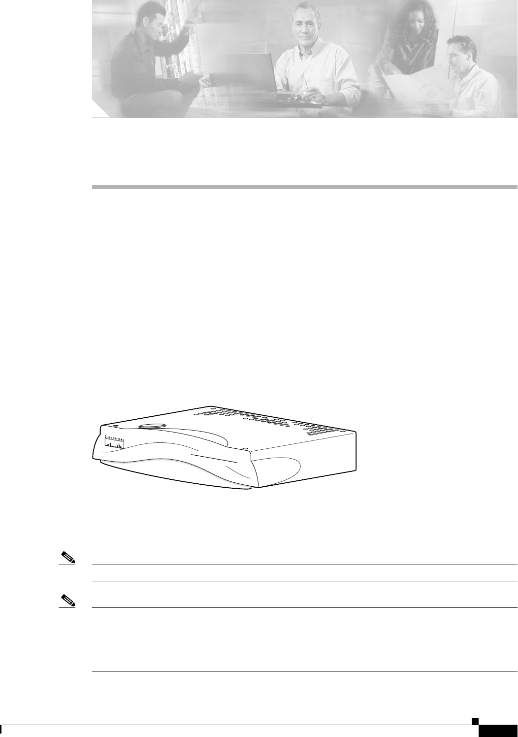
Figure 1-1 Cisco ATA Analog Telephone Adaptor
The Cisco ATA, which operates with Cisco voice-packet gateways, makes use of broadband pipes that
are deployed through a digital subscriber line (DSL), fixed wireless-cable modem, and other Ethernet
connections.
Note The term Cisco ATA refers to both the Cisco ATA 186 and the Cisco ATA 188, unless otherwise stated.
Note This guide provides information about the SIP image for the Cisco ATA. The features and functionality
described in this guide do not necessarily pertain to the features and functionality provided by the other
protocol loads available for the Cisco ATA. Each protocol load has its own administrator’s guide. If you are
looking for information about the behavior of the Cisco ATA for a protocol other than SIP, please refer to the
administration guide specific to that protocol.
72209
ANALOG TELEPHONE ADAPTOR
CISCO ATA 186
1-2
Cisco ATA 186 and Cisco ATA 188 Analog Telephone Adaptor Administrator’s Guide for SIP (version 3.0)
OL-4654-01
Chapter 1 Cisco Analog Telephone Adaptor Overview
Session Initiation Protocol (SIP) Overview
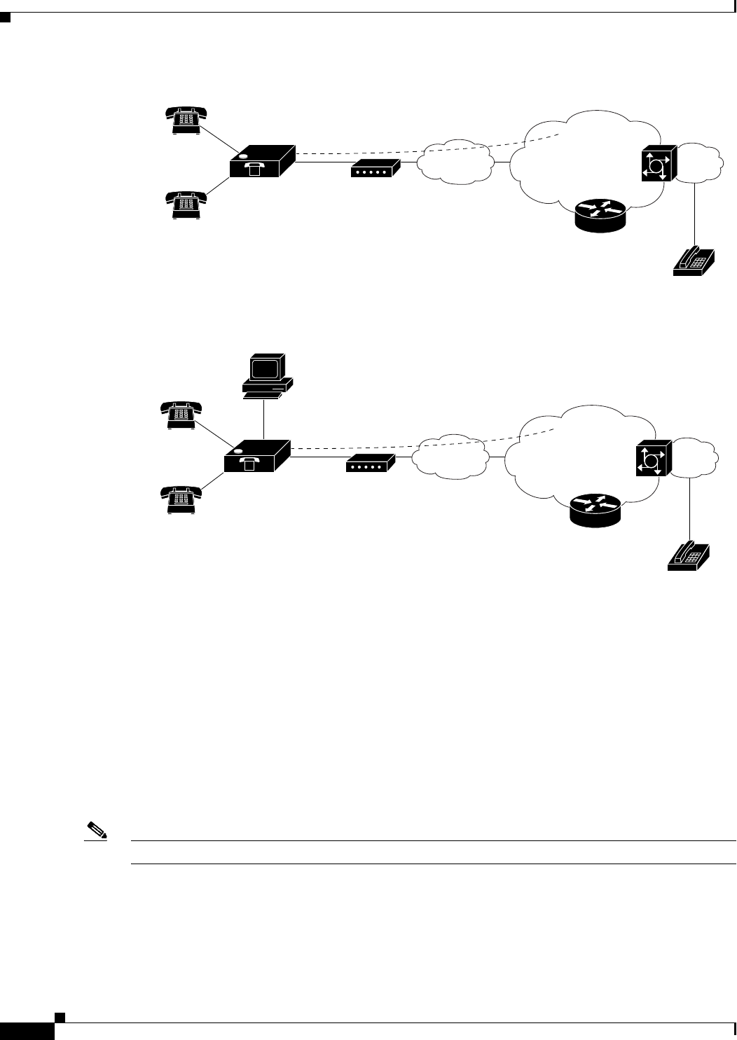
Figure 1-2 Cisco ATA 186 as Endpoint in SIP Network
Figure 1-3 Cisco ATA 188 as Endpoint in SIP Network
Session Initiation Protocol (SIP) Overview
Session Initiation Protocol (SIP) is the Internet Engineering Task Force (IETF) standard for real-time
calls and conferencing over Internet Protocol (IP). SIP is an ASCII-based, application-layer control
protocol (defined in RFC3261) that can be used to establish, maintain, and terminate multimedia
sessions or calls between two or more endpoints.
Like other Voice over IP (VoIP) protocols, SIP is designed to address the functions of signaling and
session management within a packet telephony network. Signaling allows call information to be carried
across network boundaries. Session management provides the ability to control the attributes of an
end-to-end call.
Note SIP for the Cisco ATA is compliant with RFC2543.
This section contains the following topics:
• SIP Capabilities, page 1-3
• Components of SIP, page 1-3
V
Cisco ATA 186
Telephone/fax Ethernet
Broadband CPE
(DSL, cable,
fixed wireless)
Broadband
SIP proxy
Layer 3
IP infrastructure PSTN
Voice
gateway
72088
V
V
Cisco ATA 188
Telephone/fax Ethernet
Broadband CPE
(DSL, cable,
fixed wireless)
Broadband
SIP proxy
Layer 3
IP infrastructure PSTN
Voice
gateway
72444
V

1-3
Cisco ATA 186 and Cisco ATA 188 Analog Telephone Adaptor Administrator’s Guide for SIP (version 3.0)
OL-4654-01
Chapter 1 Cisco Analog Telephone Adaptor Overview
Session Initiation Protocol (SIP) Overview
SIP Capabilities
SIP provides the following capabilities:
• Determines the availability of the target endpoint. If a call cannot be completed because the target
endpoint is unavailable, SIP determines whether the called party is already on the phone or did not
answer in the allotted number of rings. SIP then returns a message indicating why the target endpoint
was unavailable.
• Determines the location of the target endpoint. SIP supports address resolution, name mapping, and
call redirection.
• Determines the media capabilities of the target endpoint. Using the Session Description Protocol
(SDP), SIP determines the lowest level of common services between endpoints. Conferences are
established using only the media capabilities that are supported by all endpoints.
• Establishes a session between the originating and target endpoint. If the call can be completed, SIP
establishes a session between the endpoints. SIP also supports mid-call changes, such as adding
another endpoint to the conference or changing the media characteristic or codec.
• Handles the transfer and termination of calls. SIP supports the transfer of calls from one endpoint
to another. During a call transfer, SIP establishes a session between the transferee and a new
endpoint (specified by the transferring party) and terminates the session between the transferee and
the transferring party. At the end of a call, SIP terminates the sessions between all parties.
Conferences can consist of two or more users and can be established using multicast or multiple
unicast sessions.
Components of SIP
SIP is a peer-to-peer protocol. The peers in a session are called User Agents (UAs). A user agent can
function in one of the following roles:
• User agent client (UAC)—A client application that initiates the SIP request.
• User agent server (UAS)—A server application that contacts the user when a SIP request is received
and returns a response on behalf of the user.
Typically, a SIP endpoint is capable of functioning as both a UAC and a UAS, but functions only as one
or the other per transaction. Whether the endpoint functions as a UAC or a UAS depends on the UA that
initiated the request.
From an architectural standpoint, the physical components of a SIP network can also be grouped into
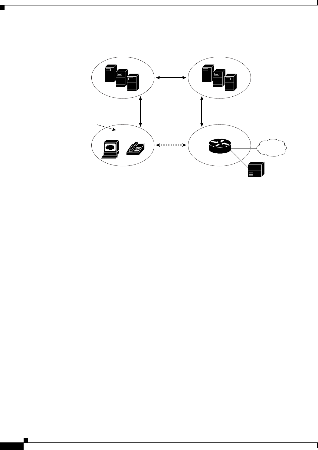
two categories—Clients and servers. Figure 1-4 illustrates the architecture of a SIP network.
Note SIP servers can interact with other application services, such as Lightweight Directory Access Protocol
(LDAP) servers, a database application, or an extensible markup language (XML) application. These
application services provide back-end services such as directory, authentication, and billable services.
1-4
Cisco ATA 186 and Cisco ATA 188 Analog Telephone Adaptor Administrator’s Guide for SIP (version 3.0)
OL-4654-01
Chapter 1 Cisco Analog Telephone Adaptor Overview
Session Initiation Protocol (SIP) Overview
Figure 1-4 SIP Architecture
SIP Clients
SIP clients include:
• Gateways—Provide call control. Gateways provide many services, the most common being a
translation function between SIP conferencing endpoints and other terminal types. This function
includes translation between transmission formats and between communications procedures. In
addition, the gateway also translates between audio and video codecs and performs call setup and
clearing on both the LAN side and the switched-circuit network side.
• Telephones—Can act as either a UAS or UAC. The Cisco ATA can initiate SIP requests and respond
to requests.
SIP Servers
SIP servers include:
• Proxy server—The proxy server is an intermediate device that receives SIP requests from a client
and then forwards the requests on the client’s behalf. Proxy servers receive SIP messages and
forward them to the next SIP server in the network. Proxy servers can provide functions such as
authentication, authorization, network access control, routing, reliable request retransmission, and
security.
• Redirect server—Receives SIP requests, strips out the address in the request, checks its address
tables for any other addresses that may be mapped to the address in the request, and then returns the
results of the address mapping to the client. Redirect servers provide the client with information
about the next hop or hops that a message should take, then the client contacts the next hop server
or UAS directly.
• Registrar server—Processes requests from UACs for registration of their current location. Registrar
servers are often co-located with a redirect or proxy server.
SIP user agents
RTP
SIP
SIP proxy and
redirect servers
SIP gateway
PSTN
Legacy PBX
SIP SIP
72342
1-5
Cisco ATA 186 and Cisco ATA 188 Analog Telephone Adaptor Administrator’s Guide for SIP (version 3.0)
OL-4654-01
Chapter 1 Cisco Analog Telephone Adaptor Overview
Hardware Overview
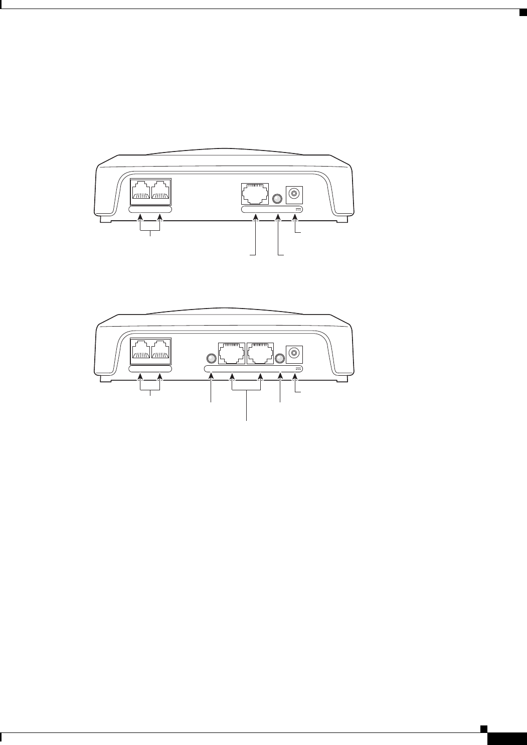
Hardware Overview
The Cisco ATA 186 and Cisco ATA 188 are compact, easy to install devices. Figure 1-5 shows the rear
panel of the Cisco ATA 186. Figure 1-6 shows the rear panel of the Cisco ATA 188.
Figure 1-5 Cisco ATA 186—Rear View
Figure 1-6 Cisco ATA 188—Rear View
10BaseT ACT 5VPHONE 1 PHONE 2
72210
RJ-11 FXS ports
RJ-45 10BaseT ACT LED
Power
connector
10/100 UPLINK10/100 PC LINKLINK 5VPHONE 1 PHONE 2
72211
RJ-11 FXS ports LINK LED
Power
connector
LINK LED
RJ-45 10/100BaseT ports

1-6
Cisco ATA 186 and Cisco ATA 188 Analog Telephone Adaptor Administrator’s Guide for SIP (version 3.0)
OL-4654-01
Chapter 1 Cisco Analog Telephone Adaptor Overview
Hardware Overview
The unit provides the following connectors and indicators:
• 5V power connector.
• Two RJ-11 FXS (Foreign Exchange Station) ports—The Cisco ATA supports two independent
RJ-11 telephone ports that can connect to any standard analog telephone device. Each port supports
either voice calls or fax sessions, and both ports can be used simultaneously.
Note The Cisco ATA186-I1 and Cisco ATA188-I1 provide 600-ohm resistive impedance. The
Cisco ATA186-I2 and Cisco ATA188-I2 provide 270 ohm + 750 ohm // 150-nF complex impedance.
The impedance option is requested when you place your order and should match your specific
application. If you are not sure of the applicable configuration, check your country or regional telephone
impedance requirements.
• Ethernet ports
–
The Cisco ATA 186 has one RJ-45 10BASE-T uplink Ethernet port to connect the
Cisco ATA 186 to a 10/100BASE-T hub or another Ethernet device.
–
The Cisco ATA 188 has two Ethernet ports: an RJ-45 10/100BASE-T uplink port to connect the
Cisco ATA 188 to a 10/100BASE-T hub or another Ethernet device and an RJ-45
10/100BASE-T data port to connect an Ethernet-capable device, such as a computer, to the
network.
Note The Cisco ATA 188 performs auto-negotiation for duplexity and speed and is capable of 10/100 Mbps,
full-duplex operation. The Cisco ATA 186 is fixed at 10 Mbps, half-duplex operation.
• The Cisco ATA 188 RJ-45 LED shows network link and activity. The LED blinks twice when the
Cisco ATA is first powered on, then turns off if there is no link or activity. The LED blinks to show
network activity and is solid when there is a link.
• The Cisco ATA 186 RJ-45 LED is solid when the Cisco ATA is powered on and blinks to show
network activity.
• Function button—The function button is located on the top panel of the unit (see Figure 1-7).
Figure 1-7 Function Button
The function button lights when you pick up the handset of a telephone attached to the Cisco ATA.
The button blinks quickly when the Cisco ATA is upgrading its configuration.
ANALOG TELEPHONE ADAPTOR
CISCO ATA 186
72214
Function
button

1-7
Cisco ATA 186 and Cisco ATA 188 Analog Telephone Adaptor Administrator’s Guide for SIP (version 3.0)
OL-4654-01
Chapter 1 Cisco Analog Telephone Adaptor Overview
Software Features
Note If the function button blinks slowly, the Cisco ATA cannot find the DHCP server. Check your
Ethernet connections and make sure the DHCP server is available.
Pressing the function button allows you to access to the voice configuration menu. For additional
information about the voice configuration menu, see the “Voice Configuration Menu” section on
page 3-20.
Caution Never press the function button during an upgrade process. Doing so may interfere with the process.
Software Features
The Cisco ATA supports the following protocols, services and methods:
• Voice Codecs Supported, page 1-7
• Additional Supported Signaling Protocols, page 1-8
• Other Supported Protocols, page 1-8
• Cisco ATA SIP Services, page 1-8
• Fax Services, page 1-9
• Methods Supported, page 1-9
• Supplementary Services, page 1-10
Voice Codecs Supported
The Cisco ATA supports the following voice codecs (check your other network devices for the codecs
they support):
• G.711µ-law
• G.711A-law
• G.723.1
• G.726
• G.729
• G.729A
• G.729B
• G.729AB

1-8
Cisco ATA 186 and Cisco ATA 188 Analog Telephone Adaptor Administrator’s Guide for SIP (version 3.0)
OL-4654-01
Chapter 1 Cisco Analog Telephone Adaptor Overview
Software Features
Additional Supported Signaling Protocols
In addition to SIP, the Cisco ATA supports the following signaling protocols:
• H.323
• Skinny Client Control Protocol (SCCP)
• Media Gateway Control Protocol (MGCP)
If you wish to perform a cross-protocol upgrade from SIP to another signaling image, see the “Upgrading
the Signaling Image from a TFTP Server” section on page 8-1.
Other Supported Protocols
Other protocols that the Cisco ATA supports include the following:
• 802.1Q VLAN tagging
• Cisco Discovery Protocol (CDP)
• Domain Name System (DNS)
• Dynamic Host Configuration Protocol (DHCP)
• Internet Control Message Protocol (ICMP)
• Internet Protocol (IP)
• Real-Time Transport Protocol (RTP)
• Transmission Control Protocol (TCP)
• Trivial File Transfer Protocol (TFTP)
• User Datagram Protocol (UDP)
Cisco ATA SIP Services
For a list of required SIP parameters as well as descriptions of all supported Cisco ATA SIP services and
cross references to the parameters for configuring these services, see Chapter 4, “Basic and Additional
SIP Services.”
These services include the following features:
• IP address assignment—DHCP-provided or statically configured
• Cisco ATA configuration by means of a TFTP server, web browser, or voice configuration menu
• VLAN configuration
• Cisco Discovery Protocol (CDP)
• Low-bit-rate codec selection
• User authentication
• Configurable tones (dial tone, busy tone, alert tone, reorder tone, call waiting tone)
• Dial plans
• Network Address Translation (NAT) Gateway
• NAT/Port Address Translation (PAT) translation

1-9
Cisco ATA 186 and Cisco ATA 188 Analog Telephone Adaptor Administrator’s Guide for SIP (version 3.0)
OL-4654-01
Chapter 1 Cisco Analog Telephone Adaptor Overview
Software Features
• SIP proxy server redundancy
• Outbound-proxy support
• SIP session-timer support
• Privacy features
• DNS SRV support
• User-configurable, call-waiting, permanent default setting
• Comfort noise during silence period when using G.711
• Advanced audio
• Billable features
• Caller ID format
• Ring cadence format
• Silence suppression
• Hook-flash detection timing configuration
• Configurable on-hook delay
• Type of Service (ToS) configuration for audio and signaling ethernet packets
• Debugging and diagnostic tools
Fax Services
The Cisco ATA supports two modes of fax services, in which fax signals are transmitted using the G.711
codec:
• Fax pass-through mode—Receiver-side Called Station Identification (CED) tone detection with
automatic G.711A-law or G.711µ-law switching.
• Fax mode—The Cisco ATA is configured as a G.711-only device.
How you set Cisco ATA fax parameters depends on what network gateways are being used. You may
need to modify the default fax parameter values (see Chapter 7, “Configuring and Debugging Fax
Services”).
Note Success of fax transmission depends on network conditions and fax modem response to these conditions.
The network must have reasonably low network jitter, network delay, and packet loss rate.
Methods Supported
The Cisco ATA supports the methods listed below. For more information, refer to RFC3261 (SIP:
Session Initiation Protocol).
• REGISTER
• REFER
• INVITE
• BYE
• CANCEL

1-10
Cisco ATA 186 and Cisco ATA 188 Analog Telephone Adaptor Administrator’s Guide for SIP (version 3.0)
OL-4654-01
Chapter 1 Cisco Analog Telephone Adaptor Overview
Installation and Configuration Overview
• NOTIFY
• OPTIONS
• ACK
Supplementary Services
SIP supplementary services are services that you can use to enhance your telephone service. For
information on how to enable and subscribe to these services, see the “CallFeatures” section on
page 5-35 and the “PaidFeatures” section on page 5-36.
For information on how to use these services, see Appendix A, “Using SIP Supplementary Services.”
The following list contains the SIP supplementary services that the Cisco ATA supports:
• Caller ID
• Call-waiting caller ID
• Voice mail indication
• Making a conference call
• Call waiting
• Call forwarding
• Call return
• Calling-line identification
• Unattended transfer
• Attended transfer
Installation and Configuration Overview
Table 1-1 provides the basic steps required to install and configure the Cisco ATA to make it operational
in a typical SIP environment where a large number of Cisco ATAs must be deployed.
Ta b l e 1-1 Overview of the Steps Required to Install and Configure the Cisco ATA and Make it Operational
Action Reference
1. Plan the network and Cisco ATA configuration.
2. Install the Ethernet connection.
3. Install and configure the other network devices.
4. Install the Cisco ATA but do not power up the Cisco ATA y e t . What the Cisco ATA Package Includes, page 2-2
5. Download the desired Cisco ATA release software zip file from
the Cisco web site, then configure the Cisco ATA.
Chapter 3, “Configuring the Cisco ATA fo r SI P”
6. Power up the Cisco ATA.
7. Periodically, you can upgrade the Cisco ATA t o a n ew
signaling image by using the TFTP server-upgrade method or
the manual-upgrade method.
Chapter 8, “Upgrading the Cisco ATA Signaling
Image”

CHAPTER
2-1
Cisco ATA 186 and Cisco ATA 188 Analog Telephone Adaptor Administrator’s Guide for SIP (version 3.0)
OL-4654-01
2
Installing the Cisco ATA
This section provides instructions for installing the Cisco ATA 186 and Cisco ATA 188. Before you
perform the installation, be sure you have met the following prerequisites:
• Planned the network and Cisco ATA configuration.
• Installed the Ethernet connection.
• Installed and configured the other network devices.
This section contains the following topics:
• Network Requirements, page 2-2
• Safety Recommendations, page 2-2
• What the Cisco ATA Package Includes, page 2-2
• What You Need, page 2-3
• Installation Procedure, page 2-3
• Power-Down Procedure, page 2-6
Note The term Cisco ATA is used throughout this manual to refer to both the Cisco ATA 186 and the
Cisco ATA 188, unless differences between the Cisco ATA 186 and Cisco ATA 188 are explicitly
stated.

2-2
Cisco ATA 186 and Cisco ATA 188 Analog Telephone Adaptor Administrator’s Guide for SIP (version 3.0)
OL-4654-01
Chapter 2 Installing the Cisco ATA
Network Requirements
Network Requirements
The Cisco ATA acts as an endpoint on an IP telephony network. The following equipment is required:
• Call Control system
• Voice packet gateway—Required if you are connecting to the Public Switched Telephone Network
(PSTN). A gateway is not required if an analog key system is in effect.
• Ethernet connection
Safety Recommendations
To ensure general safety, follow these guidelines:
• Do not get this product wet or pour liquids into this device.
• Do not open or disassemble this product.
• Do not perform any action that creates a potential hazard to people or makes the equipment unsafe.
• Use only the power supply that comes with the Cisco ATA.
Warning
Ultimate disposal of this product should be handled according to all national laws and regulations.
Warning
Read the installation instructions before you connect the system to its power source.
Warning
The plug-socket combination must be accessible at all times because it serves as the main
disconnecting device.
Warning
Do not work on the system or connect or disconnect cables during periods of lightning activity.
Warning
To avoid electric shock, do not connect safety extra-low voltage (SELV) circuits to telephone-network
voltage (TNV) circuits. LAN ports contain SELV circuits, and WAN ports contain TNV circuits. Some
LAN and WAN ports both use RJ-45 connectors. Use caution when connecting cables.
For translated warnings, see the Regulatory Compliance and Safety Information for the Cisco ATA 186
and Cisco ATA 188 manual.
What the Cisco ATA Package Includes
The Cisco ATA package contains the following items:
• Cisco ATA 186 or Cisco ATA 188 Analog Telephone Adaptor
• Cisco ATA 186 and Cisco ATA 188 Analog Telephone Adaptor at a Glance

2-3
Cisco ATA 186 and Cisco ATA 188 Analog Telephone Adaptor Administrator’s Guide for SIP (version 3.0)
OL-4654-01
Chapter 2 Installing the Cisco ATA
What You Need
• Regulatory Compliance and Safety Information for the Cisco ATA 186 and Cisco ATA 188
• 5V power adaptor
• Power cord
Note The Cisco ATA is intended for use only with the 5V DC power adaptor that comes with the unit.
What You Need
You also need the following items:
• Category-3 10BASE-T or 100BASE-T or better Ethernet cable. One cable is needed for each
Ethernet connection.
A Category-3 Ethernet cable supports 10BASE-T for up to 100 meters without quality degradation,
and a Category-3 Ethernet cable supports 100BASE-T for up to 10 meters without quality
degradation.
For uplink connections, use a crossover Ethernet cable to connect the Cisco ATA to a n o t h er
Ethernet device (such as a router or PC) without using a hub. Otherwise, use straight-through
Ethernet cables for both uplink and data port connections.
• Access to an IP network
• One or two analog Touch-Tone telephones or fax machines, or one of each
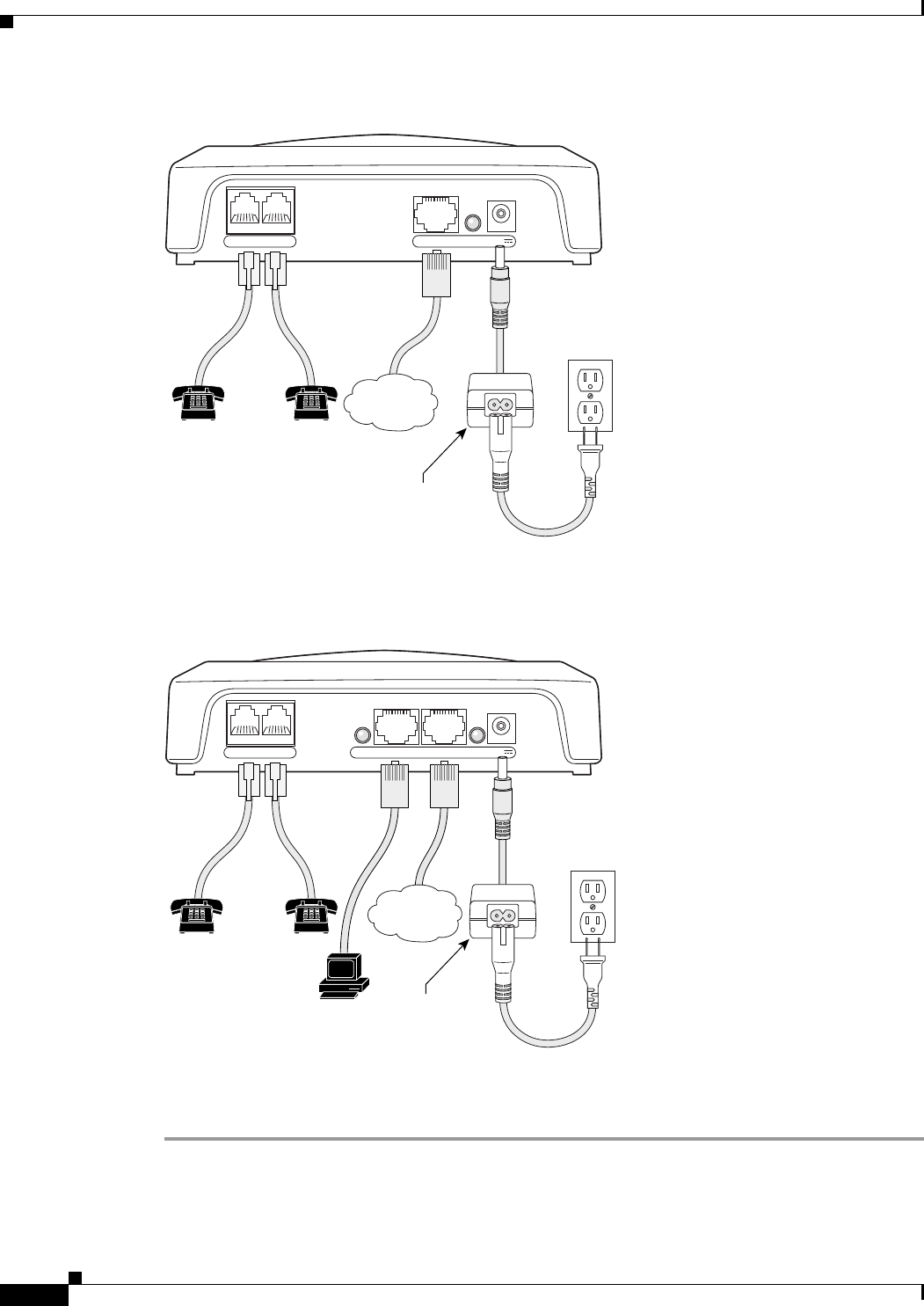
Installation Procedure
After the equipment is in place, see Figure 2-1 (for Cisco ATA 186) or Figure 2-2 (for Cisco ATA 188)
and follow the next procedure to install the Cisco ATA.
2-4
Cisco ATA 186 and Cisco ATA 188 Analog Telephone Adaptor Administrator’s Guide for SIP (version 3.0)
OL-4654-01
Chapter 2 Installing the Cisco ATA
Installation Procedure
Figure 2-1 Cisco ATA 186 Rear Panel Connections
Figure 2-2 Cisco ATA 188 Rear Panel Connections
Procedure
Step 1 Place the Cisco ATA near an electrical power outlet.
Step 2 Connect one end of a telephone line cord to the Phone 1 input on the rear panel of the Cisco ATA.
Connect the other end to an analog telephone set.
Power outlet
10BaseT ACT 5VPHONE 1 PHONE 2
72212
Analog telephones
(or fax)
5V power
adaptor
Power cord
IP network
10/100 UPLINK10/100 PC LINKLINK 5VPHONE 1 PHONE 2
Power outlet
72213
Analog telephones
(or fax)
5V power
adaptor
Power cord
PC
IP network

2-5
Cisco ATA 186 and Cisco ATA 188 Analog Telephone Adaptor Administrator’s Guide for SIP (version 3.0)
OL-4654-01
Chapter 2 Installing the Cisco ATA
Installation Procedure
If you are connecting a telephone set that was previously connected to an active telephone line, unplug
the telephone line cord from the wall jack and plug it into the Phone 1 input.
Warning
To reduce the risk of fire, use only No. 26 AWG or larger telecommunication line cord.
Caution Do not connect the Phone input ports to a telephone wall jack. To avoid damaging the Cisco ATA o r
telephone wiring in the building, do not connect the Cisco ATA to the telecommunications network.
Connect the Phone port to a telephone only, never to a telephone wall jack.
Note The telephone must be switched to tone setting (not pulse) for the Cisco ATA to operate properly.
Step 3 (Optional) Connect the telephone line cord of a second telephone to the Phone 2 input port.
Note If you are connecting only one telephone to the Cisco ATA, you must use the Phone 1 input port.
Step 4 Connect an Ethernet cable to the uplink RJ-45 connector on the Cisco ATA . Fo r t h e Ci sc o ATA 186,
this is the 10BASE-T connector; for the Cisco ATA 188, this is the 10/100UPLINK connector.
Note Use a crossover Ethernet cable to connect the Cisco ATA to another Ethernet device (such as a router or
PC) without using a hub. Otherwise, use a straight-through Ethernet cable.
Step 5 (Cisco ATA 188 only—optional) Connect a straight-through Ethernet cable from your PC to the 10/100
PC RJ-45 connector on the Cisco ATA .
Step 6 Connect the socket end of the power cord to the Cisco-supplied 5V DC power adaptor.
Step 7 Insert the power adaptor cable into the power connector on the Cisco ATA .
Caution Use only the Cisco-supplied power adaptor.
Warning
This product relies on the building’s installation for short-circuit (overcurrent) protection. Ensure that
a fuse or circuit breaker no larger than 120 VAC, 15A U.S. (240VAC, 10A international) is used on the
phase conductors (all current-carrying conductors).

2-6
Cisco ATA 186 and Cisco ATA 188 Analog Telephone Adaptor Administrator’s Guide for SIP (version 3.0)
OL-4654-01
Chapter 2 Installing the Cisco ATA
Power-Down Procedure
Step 8 Connect the plug end of the 5V DC power adaptor cord into an electrical power outlet.
When the Cisco ATA is properly connected and powered up, the green activity LED flashes to indicate
network activity. This LED is labeled ACT on the rear panel of the Cisco ATA 186 and is labeled LINK
on the rear panel of the Cisco ATA 188.
Caution Do not cover or block the air vents on either the top or the bottom surface of the Cisco ATA. Overheating
can cause permanent damage to the unit.
For more information about LEDs and the function button, see the “Hardware Overview” section on
page 1-5.
Power-Down Procedure
Caution If you need to power down Cisco ATA 186 or Cisco 188 at any time, use the following power-down
procedure to prevent damage to the unit.
Procedure
Step 1 Unplug the RJ45 Ethernet cable
Step 2 Wait for 20 seconds.
Step 3 Unplug the power cable.
Warning
This equipment contains a ring signal generator (ringer), which is a source of hazardous voltage. Do
not touch the RJ-11 (phone) port wires (conductors), the conductors of a cable connected to the RJ-11
port, or the associated circuit-board when the ringer is active. The ringer is activated by an incoming
call.

CHAPTER
3-1
Cisco ATA 186 and Cisco ATA 188 Analog Telephone Adaptor Administrator’s Guide for SIP (version 3.0)
OL-4654-01
3
Configuring the Cisco ATA for SIP
This section describes how to configure the Cisco ATA to operate with the Session Initiation Protocol
(SIP) signaling image and how the Cisco ATA obtains the latest signaling image.
You can configure the Cisco ATA for use with SIP with any of the following methods:
• By using a TFTP server—This is the Cisco-recommended method for deploying a large number of
Cisco ATAs. This method allows you to set up a unique Cisco ATA configuration file or a
configuration file that is common to all Cisco ATAs . T h e C is c o ATA can automatically download its
latest configuration file from the TFTP server when the Cisco ATA powers up, is refreshed or reset,
or when the specified TFTP query interval expires.
• By using manual configuration:
–
Voice configuration menu—This is the method you must use if the process of establishing IP
connectivity for the Cisco ATA requires changing the default network configuration settings. These
settings are CDP, VLAN, and DHCP. You also can use the voice configuration menu to review all IP
connectivity settings. The voice configuration menu can also be used when Web access is not
available.
–
Web-based configuration—This method is convenient if you plan to deploy a small number of
Cisco ATAs in your network. To use this method, the Cisco ATA must first obtain IP connectivity,
either through the use of a DHCP server or by using the voice configuration menu to statically
configure IP addresses.
This section contains the following topics:
• Default Boot Load Behavior, page 3-2—This section describes the process that the Cisco ATA
follows by default when it boots up. It is very important to understand this process because, if your
network environment is not set up to follow this default behavior, you need to make the applicable
configuration changes. For example, by default, the Cisco ATA attempts to contact a DHCP server
for the necessary IP addresses to achieve network connectivity. However, if your network does not
use a DHCP server, you must manually configure various IP settings as described in this section.
• Specifying a Preconfigured VLAN ID or Disabling VLAN IP Encapsulation, page 3-3—This
section includes a table of the parameters you can configure for VLAN and CDP settings.
• Steps Needed to Configure the Cisco ATA, page 3-5—This section provides tables that summarize
the general configuration steps you must follow to configure the Cisco ATA .
• Configuring the Cisco ATA Using a TFTP Server, page 3-8—This section describes procedures for
configuring the Cisco ATA by using a TFTP server, which is the recommended configuration
method for the deployment of a large number of Cisco ATAs.
• Voice Configuration Menu, page 3-20—This section includes information on how to obtain basic
network connectivity for the Cisco ATA and how to perform a factory reset if necessary.

3-2
Cisco ATA 186 and Cisco ATA 188 Analog Telephone Adaptor Administrator’s Guide for SIP (version 3.0)
OL-4654-01
Chapter 3 Configuring the Cisco ATA for SIP
Default Boot Load Behavior
• Cisco ATA Web Configuration Page, page 3-23—This section shows the Cisco ATA Web
configuration page and contains a procedure for how to configure Cisco ATA parameters using this
interface.
• Refreshing or Resetting the Cisco ATA, page 3-26—This section gives the procedure (via the Web
configuration page) for refreshing or resetting the Cisco ATA so that your most recent configuration
changes take effect immediately.
• Obtaining Cisco ATA Configuration File After Failed Attempt, page 3-27—This section gives the
formula for how soon the Cisco ATA attempts to fetch its configuration file from the TFTP server
after a failed attempt.
• Upgrading the SIP Signaling Image, page 3-27—This section provides references to the various
means of upgrading your Cisco ATA signaling image.
Note The term Cisco ATA is used throughout this manual to refer to both the Cisco ATA 186 and the
Cisco ATA 188, unless differences between the Cisco ATA 186 and Cisco ATA 188 are explicitly stated.
Default Boot Load Behavior
Before configuring the Cisco ATA, you need to know how the default Cisco ATA boot load process
works. Once you understand this process, you will be able to configure the Cisco ATA by following the
instructions provided in this section and in the sections that follow.
All Cisco ATAs are shipped with a bootload signaling-protocol image. However, because this image is
not a fully functional signaling image, the image must be upgraded. The image is designed to be
automatically upgraded by a properly configured TFTP server. To configure the Cisco ATA to
automatically upgrade to the latest signaling image, see the “Upgrading the Signaling Image from a
TFTP Server” section on page 8-1.
In addition, the Cisco ATA obtains its configuration file during the bootload process.
The following list summarizes the default Cisco ATA behavior during its boot-up process:
1. The Cisco ATA uses the Cisco Discovery Protocol (CDP) to discover which VLAN to enter. If the
Cisco ATA receives a VLAN ID response from the network switch, the Cisco ATA enters that VLAN
and adds 802.1Q VLAN tags to its IP packets. If the Cisco ATA does not receive a response with a
VLAN ID from the network switch, then the Cisco ATA assumes it is not operating in a VLAN
environment and does not perform VLAN tagging on its packets.
Note If your network environment is not set up to handle this default behavior, make the necessary
configuration changes by referring to the “Specifying a Preconfigured VLAN ID or Disabling
VLAN IP Encapsulation” section on page 3-3.
2. The Cisco ATA contacts the DHCP server to request its own IP address.
Note If your network environment does not contain a DHCP server, you need to statically configure
various IP addresses so that the Cisco ATA can obtain network connectivity. For a list of
parameters that you must configure to obtain network connectivity, see Table 3-6 on page 3-21.
For instructions on how to use the voice configuration menu, which you must use to perform this
configuration, see the “Voice Configuration Menu” section on page 3-20.

3-3
Cisco ATA 186 and Cisco ATA 188 Analog Telephone Adaptor Administrator’s Guide for SIP (version 3.0)
OL-4654-01
Chapter 3 Configuring the Cisco ATA for SIP
Specifying a Preconfigured VLAN ID or Disabling VLAN IP Encapsulation
3. Also from the DHCP server, the Cisco ATA requests the IP address of the TFTP server.
4. The Cisco ATA contacts the TFTP server and downloads the Cisco ATA release software that
contains the correct signaling image for the Cisco ATA to function properly.
Note If you are not using a TFTP server, you need to manually upgrade the Cisco ATA to the correct
signaling image. For information on this procedure, see the “Upgrading the Signaling Image
Manually” section on page 8-2.
5. The Cisco ATA looks for a Cisco ATA-specific configuration file (designated by the MAC address
of the Cisco ATA and named ata<macaddress> with a possible file extension) on the TFTP server
and downloads this file if it exists. For information about configuration file names, see the
“Configuration Files that the cfgfmt Tool Creates” section on page 3-13.
6. If the Cisco ATA does not find an ata<macaddress> configuration file, it looks for an atadefault.cfg
configuration file and downloads this file if it exists. This file can contain default values for the
Cisco ATA to us e .
Note When the Cisco ATA is downloading its DHCP configuration, the function button on the top panel
blinks.
Specifying a Preconfigured VLAN ID or Disabling VLAN IP
Encapsulation
If you want the Cisco ATA to use a preconfigured VLAN ID instead of using the Cisco Discovery
Protocol to locate a VLAN, or if you want to disable VLAN IP encapsulation, refer to Table 3-1 for a
reference to the parameters and bits you may need to configure. Use the voice configuration menu to
configure these parameters. (See the “Voice Configuration Menu” section on page 3-20 for instructions
on using this menu.) Also, refer to Table 3-2 for a matrix that indicates which VLAN-related parameters
and bits to configure depending on your network environment.
Note Bits are numbered from right to left, starting with bit 0.

3-4
Cisco ATA 186 and Cisco ATA 188 Analog Telephone Adaptor Administrator’s Guide for SIP (version 3.0)
OL-4654-01
Chapter 3 Configuring the Cisco ATA for SIP
Specifying a Preconfigured VLAN ID or Disabling VLAN IP Encapsulation
N/A indicates that the variable is not applicable to the feature and the setting of this varaible does not affect the feature.
Example
The following procedure shows you how to configure the OpFlags and VLANSetting parameters to allow
the Cisco ATA to use a user-specified VLAN ID. In this example, the voice VLAN ID is 115 (in decimal
format).
Step 1 Set bits 4-6 of the OpFlags parameter to 1, 0, and 1, respectively. This setting translates to the following
bitmap:
xxxx xxxx xxxx xxxx xxxx xxxx x101 xxxx
The remaining bits of the OpFlags parameter, using all default values, make up the following bitmap
representation:
0000 0000 0000 0000 0000 0000 0xxx 0010
Therefore, the resulting value of the OpFlags parameter becomes the following bitmap representation:
0000 0000 0000 0000 0000 0000 0101 0010
Ta b l e 3-1 Parameters and Bits for Preconfiguring a VLAN ID
Parameter and Bits Reference
OpFlags:
• Bit 4—Enable the use of user-specified voice VLAN ID.
• Bit 5—Disable VLAN encapsulation
• Bit 6—Disable CDP discovery.
OpFlags, page 5-45
VLANSetting:
• Bits 0-2—Specify VLAN CoS bit value (802.1P priority) for TCP
packets.
• Bits 3-5—Specify VLAN CoS bit value (802.1P priority) for
Voice IP packets
• Bits 18-29—User-specified 802.1Q VLAN ID
VLANSetting, page 5-12
Ta b l e 3-2 VLAN-Related Features and Corresponding Configuration Parameters
OpFlags Bit 4 OpFlags Bit 5 OpFlags Bit 6
VLANSetting
Bits 18-29
Feature
Static VLAN 101VLAN ID
CDP-acquired
VLAN
000N/A
No VLAN N/A 1N/A N/A
No CDP N/A N/A 1N/A
No CDP and no
VLAN
011N/A

3-5
Cisco ATA 186 and Cisco ATA 188 Analog Telephone Adaptor Administrator’s Guide for SIP (version 3.0)
OL-4654-01
Chapter 3 Configuring the Cisco ATA for SIP
Steps Needed to Configure the Cisco ATA
In hexadecimal format, this value is 0x00000052.
Step 2 Set bits 18-29 of the VLANSetting parameter to to voice VLAN ID 115. This setting translates to the
following bitmap
xx00 0001 1100 11xx xxxx xxxx xxxx xxxx
where 000001110011 is the binary representation of the demical value 115.
The remaining bits of the VLANSetting parameter, using all default values, make up the following
representation:
00xx xxxx xxxx xx00 0000 0000 0010 1011
Therefore, the resulting value of the VLANSetting parameter becomes the following bitmap
representation:
0000 0001 1100 1100 0000 0000 0010 1011
In hexadecimal format, this value is 0x01cc002b.
Note If you are using the voice configuration menu to set the parameters, you must convert hexadecimal values
to decimal values. For example, the OpFlags setting of 0x00000052 is equivalent to 82 in decimal
format, and the VLANSetting of 0x01cc002b is equivalent to 30146603 in decimal format.
Steps Needed to Configure the Cisco ATA
This section contains the following topics:
• Basic Configuration Steps in a TFTP Server Environment, page 3-5
• Basic Configuration Steps in a Non-TFTP Server Environment, page 3-7
Basic Configuration Steps in a TFTP Server Environment
Table 3-3 shows the basic steps for configuring the Cisco ATA and making it operational in a typical
SIP environment, which includes a TFTP server.

3-6
Cisco ATA 186 and Cisco ATA 188 Analog Telephone Adaptor Administrator’s Guide for SIP (version 3.0)
OL-4654-01
Chapter 3 Configuring the Cisco ATA for SIP
Steps Needed to Configure the Cisco ATA
Ta b l e 3-3 Basic Steps to Configure the Cisco ATA in a TFTP Environment
Action Reference
1. Download the desired Cisco ATA release software zip file from
the Cisco web site and store it on the TFTP server.
“Setting Up the TFTP Server with Cisco ATA
Software” section on page 3-8
2. Follow these basic steps to create a unique Cisco ATA
configuration file, which actually entails creating two files:
a. Create a Cisco ATA configuration text file that contains
parameters that are common to all Cisco ATAs in your
network.
b. Create a unique Cisco ATA configuration text file that
contains parameters that are specific to a Cisco ATA .
Make sure to use an include command in the unique
configuration file to pull in values from the common
configuration file.
c. Convert the unique configuration file to binary format.
d. Place the unique binary configuration file on the TFTP server.
“Creating Unique and Common Cisco ATA
Configuration Files” section on page 3-9
3. Optionally, create a default configuration file called
atadefault.cfg, which the Cisco ATA will download from the
TFTP server only if the unique Cisco ATA file called
ata<macaddress> (with a possible file extension) does not exist
on the TFTP server. For information about possible configuration
file names, see the “Configuration Files that the cfgfmt Tool
Creates” section on page 3-13.
“atadefault.cfg Configuration File” section on
page 3-17
4. Configure the upgradecode parameter so that the Cisco ATA will
obtain the correct signaling image from the TFTP server when the
Cisco ATA powers up.
“Upgrading the Signaling Image from a TFTP
Server” section on page 8-1
5. Configure the desired interval for the Cisco ATA to contact the
TFTP server to check for a configuration-file update or an
upgrade of the signaling image file.
“Configuring Refresh Interval” section on page 4-3
6. Configure the method with which the Cisco ATA will locate the
TFTP server at boot up time.
“Configuring the Cisco ATA to Obtain its
Configuration File from the TFTP Server” section
on page 3-18
7. Power up the Cisco ATA .
8. If you make configuration changes to the Cisco ATA or upgrade
the signaling image on the TFTP server, you can refresh the
Cisco ATA so that these changes take effect immediately.
Otherwise, these changes will take effect when the specified
interval (CfgInterval parameter value) for the TFTP query
expires.
“Refreshing or Resetting the Cisco ATA” section on
page 3-26

3-7
Cisco ATA 186 and Cisco ATA 188 Analog Telephone Adaptor Administrator’s Guide for SIP (version 3.0)
OL-4654-01
Chapter 3 Configuring the Cisco ATA for SIP
Steps Needed to Configure the Cisco ATA
Basic Configuration Steps in a Non-TFTP Server Environment
Table 3-4 shows the basic steps for configuring the Cisco ATA without using the TFTP server method.
Ta b l e 3-4 Basic Steps to Configure the Cisco ATA Without Using the TFTP Server Method
Action Reference
1. Download the desired Cisco ATA release software zip file from the Cisco web site:
a. If you are a registered CCO user. go to the following URL:
http://www.cisco.com/cgi-bin/tablebuild.pl/ata186
b. Download the zip file that contains the software for the applicable release and signaling
image you are using. The contents of each file are described next to the file name.
c. Extract the files to the desired location on your PC.
Note The file that contains the protocol signaling image has an extension of .zup.
2. Manually upgrade the Cisco ATA to the correct signaling image. Upgrading the Signaling
Image Manually, page 8-2
3. Configure the Cisco ATA by using either one of the manual-configuration methods. • Voice Configuration
Menu, page 3-20
• Cisco ATA Web
Configuration Page,
page 3-23
4. Power up the Cisco ATA.

3-8
Cisco ATA 186 and Cisco ATA 188 Analog Telephone Adaptor Administrator’s Guide for SIP (version 3.0)
OL-4654-01
Chapter 3 Configuring the Cisco ATA for SIP
Configuring the Cisco ATA Using a TFTP Server
Configuring the Cisco ATA Using a TFTP Server
The TFTP method of configuration is useful when you have many Cisco ATA because you can use a
TFTP server for remote, batch configuration of Cisco ATAs. A TFTP server can host one unique
configuration file for each Cisco ATA .
This section contains the following topics:
• Setting Up the TFTP Server with Cisco ATA Software, page 3-8
• Configurable Features and Related Parameters, page 3-8
• Creating Unique and Common Cisco ATA Configuration Files, page 3-9
• atadefault.cfg Configuration File, page 3-17
• Configuring the Cisco ATA to Obtain its Configuration File from the TFTP Server, page 3-18
Setting Up the TFTP Server with Cisco ATA Software
This section provides the procedure for the Cisco ATA administrator to obtain the correct Cisco ATA
software and set up the TFTP server with this software.
Procedure
Step 1 If you are a registered CCO user. go to the following URL:
http://www.cisco.com/cgi-bin/tablebuild.pl/ata186
Step 2 Download the zip file that contains the software for the applicable release and signaling image you are
using. The contents of each file are described next to the file name. Save the zip file onto a floppy disc.
Note The file that contains the protocol signaling image has an extension of .zup.
Step 3 Extract the signaling files onto the TFTP server. This should be the same TFTP server that will contain
the binary Cisco ATA configuration file that you create (either ata<macaddress> with a possible file
extension or atadefault.cfg). For information about possible configuration file names, see the
“Configuration Files that the cfgfmt Tool Creates” section on page 3-13.
Configurable Features and Related Parameters
Table 4-1 on page 4-2 contains a list of all required SIP parameters. These parameters must be properly
configured for the Cisco ATA t o w o rk .
For descriptions of important Cisco ATA SIP services that you can configure, and references to their
configuration parameters, see the “Important Basic SIP Services” section on page 4-1 and the
“Additional SIP Services” section on page 4-3.
Table 4-4 on page 4-23 lists, in alphabetical order, various features that you can configure for the
Cisco ATA . Table 4-4 on page 4-23 also includes links to the related parameter that allows you to
configure each of these features. Each link takes you to a detailed description of the parameter that
includes its default values.

3-9
Cisco ATA 186 and Cisco ATA 188 Analog Telephone Adaptor Administrator’s Guide for SIP (version 3.0)
OL-4654-01
Chapter 3 Configuring the Cisco ATA for SIP
Configuring the Cisco ATA Using a TFTP Server
For an example of how to configure parameters for the TFTP Server configuration method, see the
“Creating Unique and Common Cisco ATA Configuration Files” section on page 3-9.
Creating Unique and Common Cisco ATA Configuration Files
If you have many Cisco ATAs to configure, a good approach is to create two configuration files:
• One file that will contain only parameter values unique to a specific Cisco ATA.
• One file for parameters that will be configured with values common to a group of Cisco ATAs. If
this file is updated, all Cisco ATA devices in this common group can obtain the new configuration
data in a batch-mode environment.
The following procedure demonstrates the steps needed to create these configuration files.
Note The parameters used in this section help illustrate the process of creating a unique Cisco ATA
configuration file, and do not include all required SIP parameters in the examples. See Chapter 4, “Basic
and Additional SIP Services,” for complete listings and descriptions of required parameters and
additional configurable features. Also, refer back to Table 3-3 on page 3-6 for all main configuration
steps.
Procedure
Step 1 Use the sip_example.txt file as a template for creating a text file of values that are common to one group
of Cisco ATAs. The sip_example.txt file is included in the software-release zip file and contains all
default values. This file is shown without its annotations in the “Configuration Text File Template”
section on page 5-2.
Copy the sip_example.txt file and save it with a meaningful name, such as common.txt.
Step 2 Configure all common parameters by editing the text file as desired. For example, you might configure
the following parameters:
UseTftp:1
DHCP:1
TFtpURL:10.10.10.1
The settings in this example indicate that a group of Cisco ATAs is using the TFTP server with an IP
address of 10.10.10.1 to obtain their configuration files. These Cisco ATAs will use a DHCP server to
obtain their own IP addresses but not to obtain the TFTP server IP address (because the TftpURL
parameter has a configured value).
Step 3 Save your changes.

3-10
Cisco ATA 186 and Cisco ATA 188 Analog Telephone Adaptor Administrator’s Guide for SIP (version 3.0)
OL-4654-01
Chapter 3 Configuring the Cisco ATA for SIP
Configuring the Cisco ATA Using a TFTP Server
Step 4 Use the sip_example.txt file again, this time as a template for creating a text file of values that are
specific to one Cisco ATA. For example, you might configure the following parameters:
UserID:8530709
GkorProxy:192.168.1.1
Save this file of Cisco ATA-specific parameters as:
ata<macaddress>.txt
where macaddress is the non-dotted hexadecimal version of the MAC address of the Cisco ATA you are
configuring. This non-dotted hexadecimal MAC address is labeled on the bottom of most Cisco ATAs
next to the word “MAC.” The file name must be exactly 15 characters long. (However, if this filename
is supplied by the DHCP server, the name can be as long as 31 characters and can be any name with
printable ASCII characters.)
If necessary, you can obtain the non-dotted hexadecimal MAC address by using the atapname.exe
command. For information on using the atapname.exe command, see the “Using atapname.exe Tool to
Obtain MAC Address” section on page 3-11. That section includes an example of a dotted decimal MAC
address and its corresponding non-dotted hexadecimal address.
Note The ata<macaddress>.txt file should contain only those parameters whose values are different
from the file of common parameters. Parameter values in the ata<macaddress> configuration
file will overwrite any manually configured values (values configured through the web or voice
configuration menu) when the Cisco ATA powers up or refreshes.
Step 5 On the top line of the ata<macaddress>.txt file, add an include command to include the name of the
common-parameters file, and save the file.
include:common.txt
UserID:8530709
GkorProxy:192.168.1.1
Step 6 Run the cfgfmt.exe tool, which is bundled with the Cisco ATA software, on the ata<macaddress>.txt
text file to generate the binary configuration file. If you wish to encrypt the binary file, see the “Using
Encryption With the cfgfmt Tool” section on page 3-12.
The syntax of the cfgfmt program follows:
Syntax
cfgfmt [Encryption options] -sip -tptag.dat input-text-file output-binary-file
–
Encryption options are described in the “Using Encryption With the cfgfmt Tool” section on
page 3-12.
–
sip is the protocol you are using, which you must specify so that the cfgfmt tool will include
only the applicable protocol in the converted output binary file.
–
The ptag.dat file, provided with the Cisco ATA software version you are running, is used by
cfgfmt.exe to format a text input representation of the parameter/value pairs to its output binary
representation. Be sure this file resides in the same directory from which you are running the
cfgfmt program.
–
input-text-file is the input text file representation of the Cisco ATA configuration file.
–
output-binary-file is the final output binary file that Cisco ATA uses as the TFTP
configuration file.

3-11
Cisco ATA 186 and Cisco ATA 188 Analog Telephone Adaptor Administrator’s Guide for SIP (version 3.0)
OL-4654-01
Chapter 3 Configuring the Cisco ATA for SIP
Configuring the Cisco ATA Using a TFTP Server
Example
cfgfmt -sip -tptag.dat ata0a141e28323c.txt ata0a141e28323c
This example is based on a Cisco ATA MAC address of 10.20.30.40.50.60, which converts to the
two-digit, lower-case hexadecimal representation of each integer as 0a141e28323c.
When you convert the ata<macaddress>.txt file to a binary file, the binary file will merge the two text
files to form one Cisco ATA-specific binary configuration file for your Cisco ATA .
If the same parameter is configured with different values in these two files, the value in the
ata<macaddress>.txt file takes precedence over the value in the common.txt file.
Step 7 Store all binary configuration file(s) in the TFTP server root directory. For information about possible
configuration file names, see the “Configuration Files that the cfgfmt Tool Creates” section on
page 3-13.
When the Cisco ATA powers up, it will retrieve its configuration file(s) from the TFTP server.
Step 8 If you want to make configuration changes after boot up, repeat the process of creating or editing the
text files containing the desired parameters, then converting the ata<macaddress>.txt text file to the
binary file(s) and storing the binary file(s) on the TFTP server. For the configuration changes to take
effect immediately, refresh the Cisco ATA. (See the “Refreshing or Resetting the Cisco ATA” section
on page 3-26.)
After being refreshed, the Cisco ATA will download the updated ata<macaddress> configuration
file(s).
Note If you do not perform a refresh procedure, the Cisco ATA will update its configuration the next
time it contacts the TFTP server, which is based on the configured value of the CfgInterval
parameter.
Using atapname.exe Tool to Obtain MAC Address
This bundled tool is useful for converting the dotted decimal version of the Cisco ATA MAC address
(available on the Cisco ATA Web configuration page or from the voice configuration menu code 24#)
to its default Cisco ATA profile name. This name has the following format:
ataxxxxxxxxxxxx
where each xx is the two-digit, lower-case hexadecimal representation of each integer in the dotted,
decimal version of the Cisco ATA MAC address. This is the name you use for the unique Cisco ATA
binary configuration file.

3-12
Cisco ATA 186 and Cisco ATA 188 Analog Telephone Adaptor Administrator’s Guide for SIP (version 3.0)
OL-4654-01
Chapter 3 Configuring the Cisco ATA for SIP
Configuring the Cisco ATA Using a TFTP Server
The following command and output show an example of this command.
Command Example
atapname.exe 10.20.30.40.50.60
Command Output
ata0a141e28323c
Note The same functionality is available from the voice configuration menu (voice menu code 84#), which
will announce the Cisco ATA profile name.
Using Encryption With the cfgfmt Tool
The EncryptKey or EncryptKeyEx parameter can be used to encrypt binary files that are transferred over
TFTP. You can change encryption keys for each Cisco ATA so that only one specific Cisco ATA can
decode the information.
Cisco strongly recommends using the EncryptKeyEx parameter for encryption because this parameter
provides a stronger encryption than the EncryptKey parameter that was used in Cisco ATA software
releases prior to release 2.16.
You must use version 2.3 of the cfgfmt configuration-file generation tool to use the new EncryptKeyEx
parameter. This tools comes bundled with Cisco ATA software version 3.0. To verify that you have
version 2.3 of the cfgfmt tool type the following command:
cfgfmt
The version number of the cfgfmt tool will be returned.
You can configure the EncryptKeyEx parameter by using the Cisco ATA Web configuration page or by
using the TFTP configuration method. (For more information, see the “EncryptKeyEx” section on
page 5-7.)
You can configure the EncryptKey parameter by using the Cisco ATA Web configuration page, the
voice configuration menu, or by using the TFTP configuration method. (For more information, see the
“EncryptKey” section on page 5-6.)
By default, the Cisco ATA-specific ata<macaddress> configuration file(s) are not encrypted. If
encryption is required, however, you must manually configure the EncryptKeyEx or EncryptKey
parameter before you boot up the Cisco ATA so that the TFTP method is secure. The Cisco ATA us e s
the RC4 cipher algorithm for encryption.
Note Because the factory-fresh ATA cannot accept encrypted configuration files, the first unencrypted file, if
intercepted, can easily be read. (You would still have to know the data structure format in order to
decode the binary information from the unencrypted file.) Therefore, the new encryption key in the
unencrypted file can be compromised.
Note For security reasons, Cisco recommends that you set the UIPassword parameter (if desired) in the
configuration file and not by using one of the manual configuration methods.

3-13
Cisco ATA 186 and Cisco ATA 188 Analog Telephone Adaptor Administrator’s Guide for SIP (version 3.0)
OL-4654-01
Chapter 3 Configuring the Cisco ATA for SIP
Configuring the Cisco ATA Using a TFTP Server
This section contains the following topics:
• Configuration Files that the cfgfmt Tool Creates, page 3-13
• cfgfmt Tool Syntax and Examples, page 3-14
Configuration Files that the cfgfmt Tool Creates
The number of output binary configuration files that the Cisco ATA produces is dependent on two
factors:
• Which encryption key parameter is used—EncryptKey or EncryptKeyEx
• The total size of the binary output
Table 3-5 shows the names of the binary files that can be generated. One, two or four files can be
generated.
Note <macaddress> in Table 3-5 is the MAC address of the Cisco ATA .
Note If you are creating an atadefault configuration file, the generated binary file name will be
atadefault.cfg.x if you encrypt the text file with the EncryptKeyEx parameter; the binary file name will
be atadefault.cfg if you do not use the EncryptKeyEx parameter to encrypt the text file. For information
on creating an atadefault configuration file, see the “atadefault.cfg Configuration File” section on
page 3-17.
Note Place all generated binary configuration files onto the TFTP server.
Ta b l e 3-5 Configuration Files that the Cisco ATA May G enera te
Total Binary Output Size Less
Than or Equal to 2,000 Bytes
Total Binary Output Size
Greater Than 2,000 Bytes
Value of
EncryptKeyEx
Parameter
0ata<macaddress>ata<macaddress>
ata<macaddress>.ex
Non-zero ata<macaddress>
ata<macaddress>.x
ata<macaddress>
ata<macaddress>.ex
ata<macaddress>.x
ata<macaddress>.xex

3-14
Cisco ATA 186 and Cisco ATA 188 Analog Telephone Adaptor Administrator’s Guide for SIP (version 3.0)
OL-4654-01
Chapter 3 Configuring the Cisco ATA for SIP
Configuring the Cisco ATA Using a TFTP Server
cfgfmt Tool Syntax and Examples
The syntax of the cfgfmt tool follows:
Syntax
cfgfmt [options] input output
Syntax Definitions—Options
• -eRc4Passwd—This option directs the Cisco ATA t o us e Rc4Passwd as the key (up to eight
hexadecimal characters) to encrypt or decrypt the input text file. However, if the Cisco ATA
EncryptKey parameter in the input text file is not 0, then the value of that parameter is used to
encrypt the output binary file, and Rc4Passwd is ignored. The -e portion of this option means that
the Cisco ATA will use the weaker encryption method.
• -E—This option directs the Cisco ATA t o not use the value of the EncryptKey parameter, as set in
the input text file, to encrypt the output binary configuration file.
• -xRc4Passwd—This option directs the Cisco ATA t o u s e Rc4Passwd, which must be a hexadecimal
string of as many as 64 characters, as the key to encrypt or decrypt the input text file. However, if
the Cisco ATA EncryptKeyEx parameter in the input text file is not 0, then the value of that
parameter is used to encrypt the output binary file, and Rc4Passwd is ignored. The -x portion of this
option means that the Cisco ATA will use the stronger encryption method.
• -X—This option directs the Cisco ATA t o not use the value of the EncryptKeyEx parameter, as set
in the input text file, to encrypt the output binary configuration file.
• -tPtag.dat—This file, provided with the Cisco ATA software version you are running, is used by the
cfgfmt tool to format a text input representation of the parameter/value pairs to its output binary
representation. Be sure this file resides in the same directory from which you are running the cfgfmt
program.
• -sip—Specify this tag if you are using the SIP protocol so that the cfgfmt tool will include only the
SIP protocol parameters in the converted output binary file.
• -h323—Specify this tag if you are using the H.323 protocol so that the cfgfmt tool will include only
the H.323 protocol parameters in the converted output binary file.
• -mgcp—Specify this tag if you are using the MGCP protocol so that the cfgfmt tool will include
only the MGCP protocol parameters in the converted output binary file.
• -sccp—Specify this tag if you are using the SCCP protocol so that the cfgfmt tool will include only
the SCCP protocol parameters in the converted output binary file.
• -g—This tag omits sensitive parameters in an ata<macaddress> file that was created with a version
of the cfgfmt tool prior to version 2.3.
Some parameters, specified in the ptag.dat file used by the cfgfmt tool, are marked as sensitive
information (these parameters could include UIPassword, UID, PWD0). These parameters are not
included in the output binary file if the -g switch is specified in the cfgfmt syntax.
Syntax Definitions—Required Parameters
• Input—This is the input text file representation of the Cisco ATA configuration file.
• Output—This is the final output binary file that Cisco ATA uses as the TFTP configuration file.

3-15
Cisco ATA 186 and Cisco ATA 188 Analog Telephone Adaptor Administrator’s Guide for SIP (version 3.0)
OL-4654-01
Chapter 3 Configuring the Cisco ATA for SIP
Configuring the Cisco ATA Using a TFTP Server
Syntax examples
The cfgfmt.exe syntax affects how the EncryptKeyEx or EncryptKey parameters are used, as shown in
the following examples. In these examples, input-text-file is the ata<macaddress>.txt file that you will
convert to binary to create the ata<macaddress> configuration file(s) for the Cisco ATA;
output-binary-file is that binary ata<macaddress> file, and Secret is the encryption key.
• cfgfmt -sip -tptag.dat input-text-file output-binary-file
If input-text-file sets the Cisco ATA EncryptKey parameter to 0, then output-binary-file is not
encrypted. If the input-text-file sets EncryptKey to a non-zero value, then output-binary-file is
encrypted with that value.
• cfgfmt -X -sip -tptag.dat input-text-file output-binary-file
This is an example of how you might perform encryption on a first-time Cisco ATA.
The -X (uppercase) option means that any value specified for the Cisco ATA EncryptKeyEx
parameter in input-text-file is ignored. However, because Secret is not specified in this example,
output-binary-file is not encrypted. Nevertheless, the EncryptKeyEx parameter and its value, if
specified in input-file-text, will be included in output-binary-file for possible encryption at a later
time. The next time the Cisco ATA fetches the configuration file from the TFTP server, the file will
be encrypted with Secret.
• cfgfmt -X -xSecret -sip -tptag.dat input-text-file output-binary-file
This is an example of changing the encryption key from one key to another key.
The -X (uppercase) option means that any value specified for the Cisco ATA EncryptKeyEx
parameter in input-text-file is ignored and the output-binary-file is encrypted with the Secret key.
However, the EncryptKeyEx parameter and its value, if specified in input-text-file, will be included
in output-binary-file.
Examples of Upgrading to Stronger Encryption Key
This section contains two examples of how you would upgrade your Cisco ATA configuration to use the
stronger encyrption method if the current Cisco ATA firmware version was a version earlier than version
2.16.2. Versions earlier than 2.16.2 do not support the stronger EncryptKeyEx parameter.
Example 1
In this example, the Cisco ATA has not yet been deployed, but its firmware version is earlier than 2.16.2.
Therefore, the Cisco ATA will upgrade to to firmware version 3.0 to use the EncryptKeyEx parameter
as its encryption key.
The Cisco ATA in this example has a MAC address of 102030405060.
Perform the following steps:
Procedure
Step 1 Create a file called ata102030405060.txt by using the applicable example.txt file provided with the
Cisco ATA software. (For example, for SIP, the example.txt file is called sip_example.txt.)
Step 2 Modify the ata102030405060.txt file with desired parameter values. The value of the EncryptKey
parameter should be 0.

3-16
Cisco ATA 186 and Cisco ATA 188 Analog Telephone Adaptor Administrator’s Guide for SIP (version 3.0)
OL-4654-01
Chapter 3 Configuring the Cisco ATA for SIP
Configuring the Cisco ATA Using a TFTP Server
Step 3 Set the value of the EncryptKeyEx parameter to the chosen encryption key with which you want the
output binary file to be encrypted. In the EncryptKeyEx parameter specified in the configuration file,
you can also restrict the EncryptKeyEx value to apply only to the Cisco ATA with a particular MAC
address. For example, if the chosen key value is 231e2a7f10bd7fe, you can specify EncryptKeyEx as:
EncryptKeyEx:231e2a7f10bd7fe/102030405060
This means that only the Cisco ATA with the MAC address 102030405060 will be allowed to apply this
EncryptKeyEx value to its internal configuration.
Step 4 Update the upgradecode parameter to instruct the Cisco ATA to upgrade to firmware version 3.0 by
means of TFTP configuration. The upgradecode parameter is described in Chapter 8, “Upgrading the
Cisco ATA Signaling Image.”
Step 5 Run the cfgfmt tool as follows:
cfgfmt -g ata102030405060.txt ata102030405060
This will generate the following two binary configuration files:
• ata102030405060
• ata102030405060.x
ata102030405060 is unencrypted.
ata102030405060.x is encrypted with EncryptKeyEx value.
Step 6 Place these two files on the TFTP server that the Cisco ATA will contact for its configuration files.
When the Cisco ATA powers up, it will obtain its IP address from the DHCP server. If the DHCP server
specifies the TFTP server address, the Cisco ATA will contact the TFTP server obtained from DHCP
because the Cisco ATA is not preconfigured with a TFTP server address. The boot process is as follows:
a. The Cisco ATA downloads the configuration file ata102030405060 from the TFTP server.
b. The Cisco ATA applies parameter values in the file ata102030405060 to its internal
configuration while ignoring the EncryptKeyEx parameter (because the older version of the
Cisco ATA does not yet recognize the EncryptKeyEx parameter).
c. The Cisco ATA upgrades to the 3.0 firmware load.
d. The Cisco ATA reboots.
e. The Cisco ATA again downloads the configuration file ata102030405060.
f. The Cisco ATA applies the value of the EncryptKeyEx parameter to its internal configuration.
g. The Cisco ATA reboots.
h. The Cisco ATA EncryptKeyEx value is in effect, so from this point forward the Cisco ATA will
download the ata102030405060.x file at each reboot and each time the value configured in the
CfgInterval parameter expires.
Note Although EncryptKeyEx is encrypted in the ata<macaddress> file, and the ata<macaddress> file
does not contain other sensitive information, Cisco recommends that for absolute security you
pre-configure the Cisco ATA as described in this example for a private network. Alternatively, you
should remove ata<macaddress> once EncryptKeyEx takes effect.

3-17
Cisco ATA 186 and Cisco ATA 188 Analog Telephone Adaptor Administrator’s Guide for SIP (version 3.0)
OL-4654-01
Chapter 3 Configuring the Cisco ATA for SIP
Configuring the Cisco ATA Using a TFTP Server
Example 2
In this example, a new Cisco ATA has already been deployed (with the EncryptKey value set) with a
firmware version earlier than 2.16.2. The Cisco ATA needs to be upgraded to version 2.16.2 firmware
or greater to use EncryptKeyEx parameter to encrypt its configuration file.
In this scenario, you would follow the same procedure as in Example 1, except that you would need to
set the EncryptKey value to the previously configured EncryptKey value. The difference is that the
ata<macaddress> file is now encrypted with EncryptKey because the Cisco ATA expects the
ata<macaddress> file to be encrypted with EncryptKey.The Cisco ATA can then begin using the
ata<macaddress>.x file that is encrypted with the EncryptKeyEx parameter.
atadefault.cfg Configuration File
You can create a configuration file, called atadefault.cfg, that is common to all Cisco ATAs. This
configuration file is applied to a Cisco ATA only if a unique configuration file (such as ata<macaddress>)
does not exist for the Cisco ATA on the TFTP server during the Cisco ATA power-up procedure.
You can use the atadefault.cfg file to provide limited functionality for when you first install the
Cisco ATA. For example, if your service provider provides the ethernet connection and VoIP telephony
service, you may need to call customer service to activate the service. If the atadefault.cfg file is
configured to provide a direct connection to the customer service center, you can simply pick up the
telephone and wait to be connected without using your regular phone.
The following procedure illustrates how to create the Cisco ATA default configuration file, convert it to
the required binary format that the Cisco ATA can read, and store it on the TFTP server so that the
Cisco ATA will download it during the boot-up process:
Procedure
Step 1 Make a copy of the sip_example.txt file and rename it atadefault.txt.
Step 2 Make the desired configuration changes by editing the atadefault.txt file, then save the file.
Step 3 Convert the atadefault.txt file to a binary file by running the cfgfmt.exe tool, which is bundled with the
Cisco ATA software.
Note If you wish to encrypt the binary file for security reasons, see the “Using Encryption With the
cfgfmt Tool” section on page 3-12. If you encrypt the file using the EncryptKeyEx parameter,
the resulting binary file will be called atadefault.cfg.x; if not encrypted with the EncryptKeyEx
parameter the resulting binary file name will be atadefault.cfg.
Step 4 Store the binary atadefault.cfg (or atadefault.cfg.x) configuration file in the TFTP server root directory.
During the boot-up process, the Cisco ATA will download this file as its configuration file unless it first
finds a Cisco ATA-specific configuration file named for the MAC address of the Cisco ATA.

3-18
Cisco ATA 186 and Cisco ATA 188 Analog Telephone Adaptor Administrator’s Guide for SIP (version 3.0)
OL-4654-01
Chapter 3 Configuring the Cisco ATA for SIP
Configuring the Cisco ATA Using a TFTP Server
Configuring the Cisco ATA to Obtain its Configuration File from the TFTP Server
This section describes three methods for how the Cisco ATA contacts the TFTP server to obtain its
configuration file:
• Using a DHCP Server, page 3-18
–
The Cisco ATA contacts the DHCP server, which provides the IP address of the TFTP server
–
The Cisco ATA uses the DHCP server but the DHCP server does not know about the TFTP
server
• Without Using a DHCP Server, page 3-20
Using a DHCP Server
When using a DHCP server, configuration settings vary depending on whether or not the DHCP server
is under the control of the Cisco ATA system administrator or the service provider. The simplest
configuration is when the DHCP server is under the control of the Cisco ATA administrator, in which
case the DHCP server provides the IP address of the TFTP server. Depending on who controls the DHCP
server, follow the applicable configuration procedure:
• Procedure if DHCP Server is Under Control of Cisco ATA Administrator, page 3-18
• Procedure if DHCP Server is not Under Control of Cisco ATA Administrator, page 3-19
This section also includes the topic:
• Other DHCP Options You Can Set, page 3-19
Note If no DHCP server is found and the Cisco ATA is programmed to find one, the function button
continues to blink.
Procedure if DHCP Server is Under Control of Cisco ATA Administrator
Procedure
Step 1 On the DHCP server, set one of the following two options:
• DHCP option 150 (TFTP server IP address)
• Standard DHCP option 66 (TFTP server name)
If you use DHCP option 150, the Cisco ATA will ignore DHCP option 66. However, if you use DHCP
option 66, you must turn off DHCP option 150 or set its value to 0.
Note You can turn off the DHCP option 150 request by using the Cisco ATA OpFlags parameter (see
the “OpFlags” section on page 5-45).
Step 2 Make sure to use default values for the following Cisco ATA p a r am et e rs :
• TftpURL=0
• UseTftp=1
• DHCP=1

3-19
Cisco ATA 186 and Cisco ATA 188 Analog Telephone Adaptor Administrator’s Guide for SIP (version 3.0)
OL-4654-01
Chapter 3 Configuring the Cisco ATA for SIP
Configuring the Cisco ATA Using a TFTP Server
This completes the parameter settings and DHCP options you need to configure for this procedure. The
Cisco ATA will contact the DHCP server for the IP address of the TFTP server that contains the
Cisco ATA configuration file.
Procedure if DHCP Server is not Under Control of Cisco ATA Administrator
This is the procedure to use if the DHCP server is not under the control of the Cisco ATA administrator,
which means that the URL of the TFTP server must be manually configured.
Procedure
Step 1 Using the voice configuration menu, set the parameter TftpURL to the IP address or URL of the TFTP
server. For more information on setting the TftpURL parameter, see the “TftpURL” section on page 5-5.
For information about using the Cisco ATA voice configuration menu, see the “Voice Configuration
Menu” section on page 3-20.
Note If you are not using a DHCP server to provide the TFTP server location, you must manually
configure the TftfURL. You can do this by using the voice configuration menu without first
obtaining network connectivity for the Cisco ATA. If you want to configure this value using the
Web configuration page, you first must obtain network connectivity by using the voice
configuration menu to statically configure IP address information (see the “Voice Configuration
Menu” section on page 3-20).
Step 2 Use the default value of 1 for the Cisco ATA parameter DHCP.
Step 3 Use the default value of 1 for the Cisco ATA parameter UseTftp.
This completes the parameter settings you need to configure for this procedure. The Cisco ATA w i ll
contact the manually configured TFTP server that contains the Cisco ATA configuration file.
Other DHCP Options You Can Set
The following parameters can also be configured with DHCP:
• Boot file name of DHCP header—The ata<macaddress> binary Cisco ATA configuration file,
which can have a maximum of 31 characters and can be any name with printable ASCII characters
• Client PC address
• DHCP option 1—Client Subnet Mask
• DHCP option 3—Routers on the client’s subnet
• DHCP option 6—One or two Domain Name servers
• DHCP option 42—One or two Network Time Protocol servers
Note DHCP options 43 and 60 are set by the Cisco ATA. Option 43 specifies the protocol and option 60
identifies the vendor class of the Cisco ATA box.

3-20
Cisco ATA 186 and Cisco ATA 188 Analog Telephone Adaptor Administrator’s Guide for SIP (version 3.0)
OL-4654-01
Chapter 3 Configuring the Cisco ATA for SIP
Voice Configuration Menu
Without Using a DHCP Server
Use the following procedure if you are not using a DHCP server in your environment but are still using
a TFTP server to obtain the Cisco ATA configuration file:
Procedure
Step 1 Set the DHCP parameter to 0.
Step 2 Set the UseTFTP parameter to 1.
Step 3 Set the Cisco ATA parameter TftpURL to the IP address or URL of the TFTP server. For more
information on setting the TftpURL parameter, see the “TftpURL” section on page 5-5.
Note If you are not using a DHCP server to provide the TFTP server location, you must manually enter
the TftpUrl using either the voice configuration menu or the Web configuration page.
Step 4 If you have done already done so, statically configure the following parameters using the voice
configuration menu (see the “Voice Configuration Menu” section on page 3-20). These are the
parameters you need to configure for the Cisco ATA to obtain network connectivity:
• StaticIP
• StaticRoute
• StaticNetMask
Other parameters that are normally supplied by DHCP may be provided statically by configuring their
values. These parameters are:
• DNS1IP
• DNS2IP
• NTPIP
• AltNTPIP
• Domain
This completes the parameter settings you need to configure in order for the Cisco ATA to contact the
TFTP server (without using DHCP) that will contain the configuration file for the Cisco ATA.
Voice Configuration Menu
The main reasons to use the voice configuration menu are to establish IP connectivity for the Cisco ATA
if a DHCP server is not being used in your network environment, and to reset the Cisco ATA to its
factory values if necessary. You can also use the voice configuration menu if you need to configure a
small number of parameters or if the web interface and TFTP configuration are not available.

3-21
Cisco ATA 186 and Cisco ATA 188 Analog Telephone Adaptor Administrator’s Guide for SIP (version 3.0)
OL-4654-01
Chapter 3 Configuring the Cisco ATA for SIP
Voice Configuration Menu
Note Do not use the voice configuration menu to attempt to change any values that you configured by means
of the TFTP configuration file method. Whenever the Cisco ATA refreshes, it downloads its
ata<macaddress> configuration file or atadefault.cfg default configuration file from the TFTP server,
and the values in either of these files will overwrite the values of any corresponding parameters
configured with the voice configuration menu.
See Chapter 5, “Parameters and Defaults,” for a complete list of parameters and their definitions. Also
see Table 4-4 on page 4-23 for an alphabetical listing of configurable features and references to their
corresponding parameters.
This section contains the following topics:
• Using the Voice Configuration Menu, page 3-21
• Entering Alphanumeric Values, page 3-22
• Resetting the Cisco ATA to Factory Default Values, page 3-23
Using the Voice Configuration Menu
To manually configure the Cisco ATA by using the voice configuration menu and the telephone keypad,
perform the following steps:
Procedure
Step 1 Connect an analog touch-tone phone to the port labeled Phone 1 on the back of the Cisco ATA .
Step 2 Lift the handset and press the function button located on the top of the Cisco ATA. You should receive
the initial voice configuration menu voice prompt.
Step 3 Using the telephone keypad, enter the voice menu code for the parameter that you want to configure or
the command that you want to execute, then press #. For a list of voice menu codes, see Appendix B,
“Voice Menu Codes.”
Table 3-6 lists the menu options that you need to configure basic IP connectivity for the Cisco ATA ,
after which you can use the Cisco ATA web configuration page to configure additional parameters.
Note If you are using the voice configuration menu to statically configure the Cisco ATA IP address,
you must disable DHCP by setting its value to 0.
Ta b l e 3-6 Parameters that Provide Basic IP Connectivity for the Cisco ATA
Voice Menu
Number Features
1StaticIP—IP address of the Cisco ATA.
2StaticRoute—Default gateway for the Cisco ATA t o us e.
10 StaticNetMask—Subnet mask of the Cisco ATA .
20 DHCP—Set value to 0 to disable the use of a DHCP server; set value to 1 to enable
DHCP.
21 Review the IP address of the Cisco ATA .

3-22
Cisco ATA 186 and Cisco ATA 188 Analog Telephone Adaptor Administrator’s Guide for SIP (version 3.0)
OL-4654-01
Chapter 3 Configuring the Cisco ATA for SIP
Voice Configuration Menu
Step 4 Follow the voice prompts and enter the appropriate values, then press the # key.
Note Use the * key to indicate a delimiter (dot). For example, to enter an IP address of 192.168.3.1,
you would enter 192*168*3*1 on your telephone keypad.
Note When entering values for a field that contains a hexadecimal value, you must convert the
hexadecimal value to a decimal value in order to enter it into the voice configuration menu
system. For example, to enter the hexadecimal value 0x6A, you would enter the number 106 on
the telephone keypad.
The voice configuration menu repeats the value you entered, then prompts you to press one of the
following keys:
• 1=Change your entered value
• 2=Review your entered value
• 3=Save your entered value
• 4=Review the current saved value
Step 5 Cisco strongly recommends that you set a password. Use the voice menu code 7387277 (SETPASS) to
configure a password through the voice configuration menu, after which you are prompted for the
password whenever you attempt to change a parameter value.
Step 6 After completing the configuration through the voice configuration menu, press the # key to exit.
Step 7 Hang up the telephone. The Cisco ATA configuration refreshes. The function button fast-blinks when
the refresh completes.
Entering Alphanumeric Values
Some voice configuration menu options require you to enter alphanumeric characters. Alphanumeric
entry differs from numeric entry because you must press # after each character selected.
If you need to enter an alphanumeric value, the voice prompt tells you to enter an alphanumeric value;
otherwise, enter a numeric value (0 to 9).
Table 3-7 lists the keys on a telephone keypad and their respective alphanumeric characters.
22 Review the default router for the Cisco ATA to use.
23 Review subnet mask of the Cisco ATA .
Table 3-6 Parameters that Provide Basic IP Connectivity for the Cisco ATA (continued)
Voice Menu
Number Features

3-23
Cisco ATA 186 and Cisco ATA 188 Analog Telephone Adaptor Administrator’s Guide for SIP (version 3.0)
OL-4654-01
Chapter 3 Configuring the Cisco ATA for SIP
Cisco ATA Web Configuration Page
Using Table 3-7 as a guide, enter the appropriate number key on the telephone keypad as many times as
needed to select the number, letter, or symbol required. For example, to enter 58sQ, you would enter:
5 # 8 # 7 7 7 7 7 # 7 7 7 7 7 7 7 # #
Resetting the Cisco ATA to Factory Default Values
It is possible that you may, under some circumstances, want to reset the Cisco ATA to its factory default
values. For example, this is the only way to recover a forgotten password without contacting your Cisco
representative.
To perform a factory reset, you must use the voice configuration menu and follow these steps:
Procedure
Step 1 Press the function button on the Cisco ATA .
Step 2 Press the digits 322873738 (FACTRESET) then press # on your telephone keypad.
Step 3 Press * on your telephone keypad to confirm that you want to reset the Cisco ATA, then hang up the phone.
Cisco ATA Web Configuration Page
You can use the Cisco ATA web configuration page in a non-TFTP configuration environment, or in a
TFTP configuration environment as a read-only record of individual customer parameters.
You can display the most recent Cisco ATA configuration file from the TFTP server by opening your
web browser and typing the following:
http://<ipaddress>/refresh
where ipaddress is the IP address of the Cisco ATA.
Figure 3-1 shows and example of the Cisco ATA web configuration page, which displays all
configurable parameters.
Ta b l e 3-7 Alphanumeric Characters
Key Alphanumeric Characters
11 ./_\ @*space return +-!,?|~^#=$”‘’%<>[] :;{}()&
22 a b c A B C
33 d e f D E F
44 g h i G H I
55 j k l J K L
66 m n o M N O
77 p q r s P Q R S
88 t u v T U V
9 9 w x y z W X Y Z
0 0

3-24
Cisco ATA 186 and Cisco ATA 188 Analog Telephone Adaptor Administrator’s Guide for SIP (version 3.0)
OL-4654-01
Chapter 3 Configuring the Cisco ATA for SIP
Cisco ATA Web Configuration Page
Note Do not use the web configuration page to attempt to change any values that you configured by means of
the TFTP configuration file method. Whenever the Cisco ATA refreshes, it downloads its
ata<macaddress> configuration file(s) or atadefault.cfg default configuration file from the TFTP server,
and the values in either of these files will overwrite the values of any corresponding parameters
configured with the web configuration method.
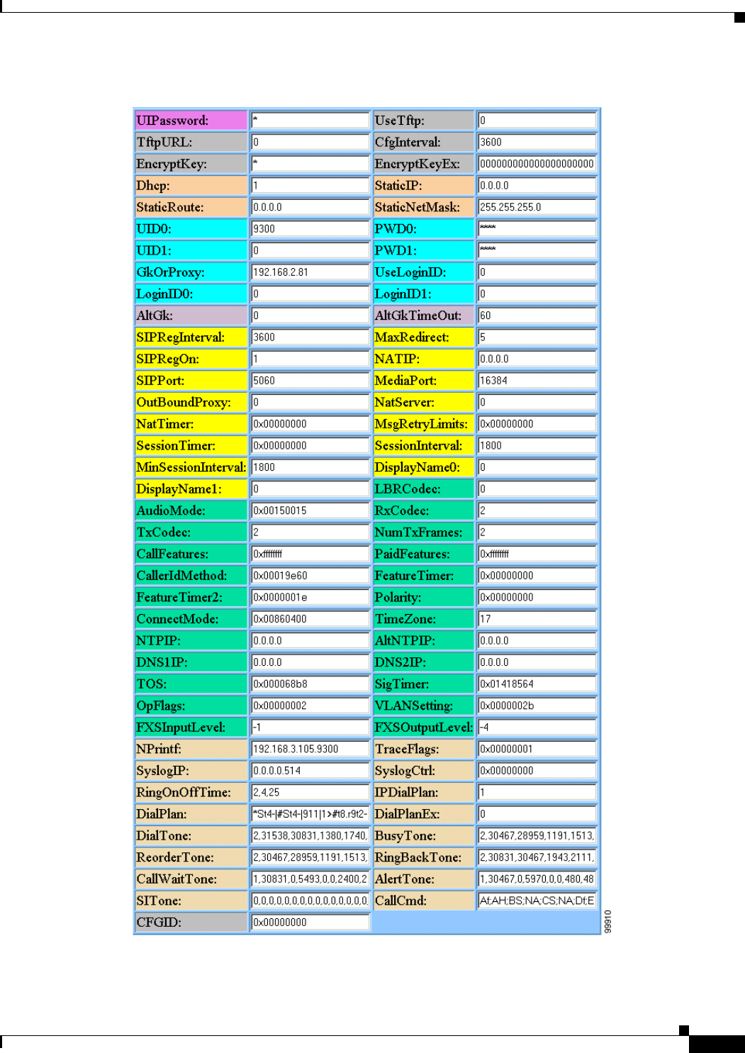
3-25
Cisco ATA 186 and Cisco ATA 188 Analog Telephone Adaptor Administrator’s Guide for SIP (version 3.0)
OL-4654-01
Chapter 3 Configuring the Cisco ATA for SIP
Cisco ATA Web Configuration Page
Figure 3-1 Cisco ATA Web Configuration Page

3-26
Cisco ATA 186 and Cisco ATA 188 Analog Telephone Adaptor Administrator’s Guide for SIP (version 3.0)
OL-4654-01
Chapter 3 Configuring the Cisco ATA for SIP
Refreshing or Resetting the Cisco ATA
You can access the web configuration page from any graphics-capable browser, such as
Microsoft Internet Explorer or Netscape. This provides easy initial access to the Cisco ATA
configuration within the administrator’s private network.
Follow these steps to set parameters using the web configuration page:
Procedure
Step 1 Make sure that your PC and the Cisco ATA are already networked and visible to each another.
Step 2 Open your web browser.
Step 3 Enter the URL for your configuration page. The default URL for the web server is:
http://IP Address/dev
For example, the configuration page for a Cisco ATA with the IP address 192.168.3.225 is:
http://192.168.3.225/dev
Step 4 Select the values for the items that you want to configure. See Chapter 5, “Parameters and Defaults,” for
a complete list of parameters and their definitions. Also see Table 4-4 on page 4-23 for an alphabetical
listing of configurable features and references to their corresponding parameters.
Note Cisco strongly recommends that you set a password. Use the UIPassword parameter to configure a
password, after which you are prompted for the password whenever you attempt to change a parameter
value. Configuration parameters cannot be accessed through the voice configuration menu if the
password contains one or more letters and can be changed only by using the web interface or the TFTP
configuration method.
Step 5 Click apply to save your changes.
The Cisco ATA automatically refreshes its configuration.
Step 6 Close your web browser.
Refreshing or Resetting the Cisco ATA
Whenever you make configuration changes to your Cisco ATA configuration file, you can refresh or
reset the Cisco ATA for these configuration changes to immediately take effect. If you do not refresh or
reset the Cisco ATA, the configuration changes will take effect the next time the Cisco ATA contacts
the TFTP server, which occurs based on the configured value of the CfgInterval parameter.
Note A refresh procedure will update the Cisco ATA configuration file. A reset procedure will also update the
Cisco ATA configuration file, and will additionally power-down and power-up the Cisco ATA. A re se t
should not be necessary if your only goal is to update the configuration file.

3-27
Cisco ATA 186 and Cisco ATA 188 Analog Telephone Adaptor Administrator’s Guide for SIP (version 3.0)
OL-4654-01
Chapter 3 Configuring the Cisco ATA for SIP
Obtaining Cisco ATA Configuration File After Failed Attempt
Procedure to Refresh the Cisco ATA
To refresh the Cisco ATA, enter the following command from your web browser:
http://<ipaddress>/refresh
where ipaddress is the IP address of the Cisco ATA that you are refreshing.
Procedure to Reset the Cisco ATA
To reset the Cisco ATA, enter the following command from your web browser:
http://<ipaddress>/reset
where ipaddress is the IP address of the Cisco ATA that you are resetting.
Obtaining Cisco ATA Configuration File After Failed Attempt
The Cisco ATA uses the following formula for determining how soon to contact the TFTP server for the
Cisco ATA configuration file after a failed attempt at getting the file. The result of the formula is called
the random back-off amount.
random back-off amount = CfgInterval + random(min(1800, CfgInterval))
where
• CfgInterval is the value of the CfgInterval configuration parameter (in seconds). For more
information about this parameter, see the “CfgInterval” section on page 5-6.
• random(x) function yields a value between 0 and x-1.
• min(x,y) function yields the smaller value of x and y.
Upgrading the SIP Signaling Image
For instructions on how to upgrade the Cisco ATA to the most recent SIP signaling image, refer to the
following list:
• To use the recommended TFTP method of upgrading the Cisco ATA, see the “Upgrading the
Signaling Image from a TFTP Server” section on page 8-1.
• In the rare instance that you are not using the TFTP server to configure the Cisco ATA and to obtain
software upgrades, you must manually upgrade to the latest signaling image immediately after the
Cisco ATA boots up. In this case, see the “Upgrading the Signaling Image Manually” section on
page 8-2.

3-28
Cisco ATA 186 and Cisco ATA 188 Analog Telephone Adaptor Administrator’s Guide for SIP (version 3.0)
OL-4654-01
Chapter 3 Configuring the Cisco ATA for SIP
Upgrading the SIP Signaling Image

CHAPTER
4-1
Cisco ATA 186 and Cisco ATA 188 Analog Telephone Adaptor Administrator’s Guide for SIP (version 3.0)
OL-4654-01
4
Basic and Additional SIP Services
This section provides information about key basic and additional SIP services that the Cisco ATA
supports:
• Important Basic SIP Services, page 4-1—This section includes a list of parameters that you must
configure in order for the Cisco ATA to function in a SIP environment.
• Additional SIP Services, page 4-3—This section contains information about additional, commonly
used SIP features, with references to the parameters for configuring these services.
• Complete Reference Table of all Cisco ATA SIP Services, page 4-23—This section contains a
complete listing of Cisco ATA services supported for SIP, and includes cross references to the
parameters for configuring these services. This section includes services not described in the
sections about the key basic SIP services and the commonly used additional SIP services.
Note The term Cisco ATA refers to both the Cisco ATA 186 and the Cisco ATA 188, unless otherwise stated.
Important Basic SIP Services
This section provides descriptions and cross references for configuring required SIP parameters and also
for configuring other important basic SIP services:
• Required Parameters, page 4-1
• Establishing Authentication, page 4-2
• Setting the Codec, page 4-3
• Configuring Refresh Interval, page 4-3
Required Parameters
If you are using the SIP protocol, you need to supply values for the required SIP parameters shown in
Table 4-1. The Parameter column provides the name of the parameter and a cross reference which
provides a more-detailed description of the parameter.
Note See Chapter 5, “Parameters and Defaults,” for information about additional Cisco ATA parameters.

4-2
Cisco ATA 186 and Cisco ATA 188 Analog Telephone Adaptor Administrator’s Guide for SIP (version 3.0)
OL-4654-01
Chapter 4 Basic and Additional SIP Services
Important Basic SIP Services
Establishing Authentication
The Cisco ATA supports two levels of authentication, depending on the setting of the UseLoginID
parameter:
• If UseLoginID is set to 0, the user ID (UID0 or UID1) is used with a user-supplied password (PWD0
or PWD1) for authentication.
• If UseLoginID is set to 1, you must supply a login ID (LoginID0 or LoginID1) and a password
(PWD0 or PWD1) for authentication.
Related Configuration Parameters
• UseLoginID, page 5-18
• UID0, page 5-15
• UID1, page 5-16
• LoginID0, page 5-17
• LoginID1, page 5-18
• PWD0, page 5-16
• PWD1, page 5-17
Ta b l e 4-1 Required SIP Parameters and Defaults
Parameter Value Type Description
Voice
Menu
Access
Code
Minimum
Value
Maximum
Value Default
SIPRegInterval, page
5-19
Integer Seconds between registration renewal 203 186400 3600
MAXRedirect, page
5-20
Integer Maximum number of times to try
redirection
202 010 5
SIPRegOn, page 5-20 Integer Enable SIP registration 204 0 1 0
NATIP, page 5-21 IP address WAN address of the attached
router/NAT; currently only used to
support SIP behind a NAT.
200 0255 0.0.0.0
SIPPort, page 5-19 Integer Port to listen for incoming SIP requests 201 165535 5060
MediaPort, page 5-30 Integer Base port to receive RTP media; only
used to support SIP behind a NAT
202 165535 16384
SipOutBoundProxy,
page 5-21
Alphanumeric
string
Proxy server for all outbound SIP
requests.
All SIP requests are sent to
SipOutBoundProxy, when configured,
instead of to the configured GkOrProxy.
206 — — 0
GkOrProxy, page
5-13
Alphanumeric
string
SIP proxy server address or registrar
address.
5 — — 0

4-3
Cisco ATA 186 and Cisco ATA 188 Analog Telephone Adaptor Administrator’s Guide for SIP (version 3.0)
OL-4654-01
Chapter 4 Basic and Additional SIP Services
Additional SIP Services
Setting the Codec
The LBRCodec (low-bit-rate codec) parameter determines whether the G.723, G.726 or G.729A codec,
in addition to G.711A-law and G.711µ-law, can be used for receiving and transmitting. For configuration
information, see the “LBRCodec” section on page 5-32.
Configuring Refresh Interval
When the value specified in the CfgInterval parameter is reached, the Cisco ATA attempts to refresh its
configuration file from the TFTP server. By opening a web page for the Cisco ATA, you can perform a
refresh before the scheduled refresh. Set the CfgInterval parameter to an interval value (in seconds) for
refreshing the Cisco ATA configuration file. Cisco recommends that the interval be semi-random to
prevent many simultaneous contacts with the TFTP server. For more information, see the “CfgInterval”
section on page 5-6.
When the Cisco ATA contacts the TFTP server, it also checks to see if an upgrade signaling image has
been placed on the TFTP server. If such an image exists, the Cisco ATA will download this image.
Additional SIP Services
This section describes additional SIP services and, where applicable, provides configuration information
and cross references to the parameters for configuring these services. These services are listed
alphabetically.
• Advanced Audio Configuration, page 4-4
• Billable Features, page 4-4
• Call Forwarding Setting Removal Using HTTP, page 4-5
• Call-Waiting Hang-Up Alert, page 4-5
• Comfort Noise During Silence Period When Using G.711, page 4-6
• Configurable Hook Flash Timing, page 4-7
• Configurable Mixing of Call Waiting Tone and Audio, page 4-7
• Configurable On-hook delay, page 4-7
• Configurable Reboot of Cisco ATA, page 4-7
• Diagnostics for Debugging, page 4-7
• Dial Plan, page 4-7
• Disabling Access To The Web Interface, page 4-8
• Display-Name Support for Caller ID, page 4-8
• Distinctive Ringing, page 4-8
• DNS SRV Support, page 4-9
• Hardware Information Display, page 4-9
• NAT Gateway, page 4-9
• NAT/PAT Translation, page 4-10
• Network Timing, page 4-10

4-4
Cisco ATA 186 and Cisco ATA 188 Analog Telephone Adaptor Administrator’s Guide for SIP (version 3.0)
OL-4654-01
Chapter 4 Basic and Additional SIP Services
Additional SIP Services
• Obtaining Network Status Before and After Getting IP Connectivity, page 4-10
• Progress Tones, page 4-13
• Real-Time Transport Protocol (RTP) Statistics Reporting, page 4-13
• Receiver-tagged VIA header, page 4-13
• Redundant Proxy Support for BYE/CANCEL Request, page 4-13
• Repeat Dialing on Busy Signal, page 4-14
• Retransmitting SIP requests and SIP Responses, page 4-15
• Setting Up and Placing a Call Without Using a SIP Proxy, page 4-15
• SipOutBoundProxy Support, page 4-16
• SIP Proxy Server Redundancy, page 4-16
• SIP Session-Timer Support, page 4-17
• Status of Phone Service Using HTTP, page 4-17
• STUN Support, page 4-18
• Stuttering Dial Tone on Unconditional Call Forward, page 4-19
• Toll Restrictions for Call Forwarding and Outgoing Calls, page 4-19
• User Configurable Call Waiting Permanent Default Setting, page 4-20
• User Configurable Timeout On No Answer for Call Forwarding, page 4-20
• Voice Prompt Confirmation for Call Waiting and Call Forwarding, page 4-20
• XML Pages of Cisco ATA Information, page 4-22
Advanced Audio Configuration
The TOS (specifies the precedence and delay of audio and signaling IP packets) and AudioMode (audio
operating mode) parameters allow you to tune audio configuration.
Related Parameters
TOS, page 5-34
AudioMode, page 5-32
Billable Features
You can customize specific features on a subscription basis by changing the values of specific bits in
several different parameters. Table 4-2 contains a list of billable features and their related parameters:
Ta b l e 4-2 Billable Features and Related Parameters
Feature Related Parameters
Call Conferencing PaidFeatures, page 5-36, CallFeatures, page 5-35
Call Forwarding PaidFeatures, page 5-36, CallFeatures, page 5-35, ConnectMode, page 5-41,
SigTimer, page 5-40
Call Transfer PaidFeatures, page 5-36, CallFeatures, page 5-35

4-5
Cisco ATA 186 and Cisco ATA 188 Analog Telephone Adaptor Administrator’s Guide for SIP (version 3.0)
OL-4654-01
Chapter 4 Basic and Additional SIP Services
Additional SIP Services
Note CallWaitCallerID is an obsolete parameter. Do not use it.
Call Forwarding Setting Removal Using HTTP
The service provider can remotely reset a call forwarding setting for which a subscriber configured an
incorrect phone number to receive fowarded calls.
The service provider issues the following command, which removes call forwarding settings for both
Cisco ATA phone lines:
http://ipaddress/resetcfwd/
where ipaddress is the IP address of the Cisco ATA whose call forwarding numbers are being removed.
This Web page is password protected. Once the service provider issues this command, this Web page
shows that the current call-waiting and call-forwarding settings are N/A.
Call-Waiting Hang-Up Alert
This feature provides an audible alert (ringtone) whenever the user inadvertently hangs up from a
call-waiting call while an active call is still on hold.
This section contains the following topics:
• Enabling the Call-Waiting Hang-Up Alert Feature, page 4-6
• Default Behavior of Call-Waiting Calls, page 4-6
Call Waiting PaidFeatures, page 5-36, CallFeatures, page 5-35, SigTimer, page 5-40
Caller ID PaidFeatures, page 5-36, CallFeatures, page 5-35, CallerIdMethod, page 5-49
Call Return ConnectMode, page 5-41, PaidFeatures, page 5-36, CallFeatures, page 5-35
Polarity Polarity, page 5-51
Voice Mail Indicator PaidFeatures, page 5-36, CallFeatures, page 5-35
Table 4-2 Billable Features and Related Parameters (continued)
Feature Related Parameters

4-6
Cisco ATA 186 and Cisco ATA 188 Analog Telephone Adaptor Administrator’s Guide for SIP (version 3.0)
OL-4654-01
Chapter 4 Basic and Additional SIP Services
Additional SIP Services
Enabling the Call-Waiting Hang-Up Alert Feature
To enable the call-waiting hang-up alert feature, perform the following steps:
Procedure
Step 1 Enable bit 25 of the Cisco ATA ConnectMode parameter. (For more information, see the
“ConnectMode” section on page 5-41.
Step 2 Make sure the call-waiting call command is set to one of the following values:
• Kf;EFh;HF; (for U.S. users)
• Kh;HFf;EF; (for U.S. users)
• Kf1;HFf2;EFf3;AFf4;HQh;HF; (for Sweden users)
Note The F Action-Identifier specifies the retrieval of the held call after the active call is disconnected
when the user hangs up. For more information about call commands, see Chapter 6, “Call
Commands.”
Default Behavior of Call-Waiting Calls
Without the call-waiting hang-up alert feature enabled, both the call-waiting call and active call are
disconnected as soon as the user hangs up the phone.
To check whether this default behavior is in effect, search for the appearance of the string h;HH within
the sequence of call-waiting call commands. The context-identifier K denotes the beginning of the
call-waiting call commands.
With this default behavior, the call-waiting call command string could be one of the following examples:
• Kf;EFh;HH; (for U.S. users)
• Kh;HHf;EF; (for U.S. users)
• Kf1;HFf2;EFf3;AFf4;HQh;HH; (for Swedish users)
• Kf1;HFf2;EFf3;AFf4;HQ; (for Swedish users with no specific on-hook treatment defined)
For more information about call commands, see Chapter 6, “Call Commands.”
Comfort Noise During Silence Period When Using G.711
When silence suppression is turned on in ITU G.711, the Cisco ATA calculates and transmits its noise
level to the far end to enable the remote endpoint to generate the appropriate amount of comfort noise.
This provides the remote user with a similar experience to that of a PSTN call and prevents silent gaps
when neither party is talking.
Related Parameter
AudioMode, page 5-32—Bit 0 disables/enables silence suppression.

4-7
Cisco ATA 186 and Cisco ATA 188 Analog Telephone Adaptor Administrator’s Guide for SIP (version 3.0)
OL-4654-01
Chapter 4 Basic and Additional SIP Services
Additional SIP Services
Configurable Hook Flash Timing
This feature provides the ability to adjust the hook-flash timing to meet local requirements.
Related Parameter
SigTimer, page 5-40—Bits 26 and 27 are for configuring the minimum on-hook time required for a hook
flash event, and bits 28 through 31 are for configuring maximum on-hook time.
Configurable Mixing of Call Waiting Tone and Audio
This feature allows the call-waiting tone to be mixed with the audio in an active call. Therefore, the
call-waiting tone will sound without a pause in the audio.
Related Parameter
ConnectMode, page 5-41—Bit 24
Configurable On-hook delay
This feature is available only for the recipient (callee) of a call. If the callee picks up the phone and then
later hangs up to retrieve another call, the hang-up is not considered on-hook until the specified delay
expires.
Related Parameter
FeatureTimer, page 5-38—Bits 8 to 12
Configurable Reboot of Cisco ATA
The Cisco ATA continuously monitors its Ethernet connection to the switch or hub. If this connection
is broken, the Cisco ATA starts an internal timer that runs until a configurable timeout period expires.
Once the timeout value is reached, the Cisco ATA automatically reboots. This timeout value is
configured by using the FeatureTimer2 configuration parameter. For more information, see the
“FeatureTimer2” section on page 5-39.
Diagnostics for Debugging
You can use the following parameters to troubleshoot operation issues:
• NPrintf, page 5-73—Specify the IP address and port where debug information is sent.
• TraceFlags, page 5-73—Use to turn on specific trace features.
Dial Plan
You can set specific dial plan rules and timeout values. Many of these values are determined on a
country-by-country basis.

4-8
Cisco ATA 186 and Cisco ATA 188 Analog Telephone Adaptor Administrator’s Guide for SIP (version 3.0)
OL-4654-01
Chapter 4 Basic and Additional SIP Services
Additional SIP Services
Related Parameters
• DialPlan, page 5-64
• DialPlanEx, page 5-72
Disabling Access To The Web Interface
To prevent tampering and unauthorized access to the Cisco ATA configuration, the Cisco ATA built-in
web server can be disabled.
Related Parameter
OpFlags, page 5-45—Bit 7
Display-Name Support for Caller ID
For caller ID purposes, you can configure a name to correspond to the phone number of the Cisco ATA
input ports. This name will be displayed at the remote endpoint when a call originates from this
Cisco ATA .
Related Parameters
• DisplayName0, page 5-29—for the Phone 1 port
• DisplayName1, page 5-29—for the Phone 2 port
Distinctive Ringing
This feature allows a user to identify a caller based on the ringing pattern the user selects for the
incoming number.
This feature is dependent on the proxy or remote UA, including the Alert-Info header with the
appropriate value in the INVITE message. The Cisco ATA supports standard distinctive ringing pattern
1 to 5 as defined in the standard GR-506-CORE.
The following Alert-Info header values are allowed:
• Bellcore-dr1
• Bellcore-dr2
• Bellcore-dr3
• Bellcore-dr4
• Bellcore-dr5
If the Alert-Info header value is not recognized, the Cisco ATA plays the regular ring tone, Bellcore-dr1.
Note The Bellcore-dr5 ringing pattern is the same as the Bellcore-dr1 ringing pattern.

4-9
Cisco ATA 186 and Cisco ATA 188 Analog Telephone Adaptor Administrator’s Guide for SIP (version 3.0)
OL-4654-01
Chapter 4 Basic and Additional SIP Services
Additional SIP Services
DNS SRV Support
The Cisco ATA supports DNS SRV lookup for the SIP proxy server. If the GkOrProxy parameter value
begins with _sip._udp. or sip.udp., the Cisco ATA performs a DNS SRV lookup for the SIP proxy server.
A DNS SRV lookup results in one of the following conditions:
• Zero host is returned or DNS SRV lookup failed. The Cisco ATA then performs a regular DNS
A-record lookup for the given name.
• One host is returned. The single host is used as the primary proxy and AltGk is the backup proxy,
if specified.
• Two or more hosts are returned. The two hosts with the highest priorities are used as the primary
and backup proxy servers (AltGk is ignored in this case).
Related Parameters
• GkOrProxy, page 5-13
• AltGk, page 5-14
Hardware Information Display
Cisco ATA hardware information is displayed in the lower-left corner of the Cisco ATA Web
configuration page.
NAT Gateway
Network Address Translation (NAT) supports port mapping and forwarding to standard default SIP
signaling port 5060 and media base port 16384, or other ports as configured in the Cisco ATA. M ed ia
ports are evenly numbered from the base port. NAT must support multiple port mappings. The
Cisco ATA can use up to four media ports to handle conference calls on both lines. For example, if media
base port 16384 is used for one call, the next call uses port 16386 and other calls will use ports 16388
and 16390.
Note Routers such as D-Link, WinRoute, and WinProxy may not route correctly if both caller and callee are
behind the same NAT.
To configure the Cisco ATA to work in a NAT environment, modify the following parameters:
• StaticRoute, page 5-9—Enter the LAN IP address of the NAT through which the Cisco ATA will
communicate.
• NATIP, page 5-21—Enter the WAN IP address of the NAT through which all external SIP user
agents will communicate.
• SIPPort, page 5-19—Enter a new port for SIP messages (optional).
• MediaPort, page 5-30—Enter a new base port for RTP media (optional).

4-10
Cisco ATA 186 and Cisco ATA 188 Analog Telephone Adaptor Administrator’s Guide for SIP (version 3.0)
OL-4654-01
Chapter 4 Basic and Additional SIP Services
Additional SIP Services
NAT/PAT Translation
To maintain Network Address Translation/Port Address Translation (NAT/PAT) for a session, the
Cisco ATA can be configured to periodically send a dummy UDP packet to a server (the Cisco ATA
does not expect any response from the server).
Related Parameters
• NatTimer, page 5-22—Bits 0 to 11 are for specifying the retransmission period.
• NatServer, page 5-22—Specify the server to which the dummy packet is sent.
Network Timing
You can fine tune your network timing with the following parameters:
• TimeZone, page 5-48—Use for time-stamping incoming calls (offset from Greenwich Mean Time)
with local time.
• NTPIP, page 5-11—Use for configuring the IP address of the Network Time Protocol server. NTP
is a protocol built on top of TCP that ensures accurate local time-keeping with reference to radio
and atomic clocks located on the Internet.
• AltNTPIP, page 5-12—Use to configure an alternate NTP server IP address.
• ConnectMode, page 5-41—Used to control the connection mode of the SIP protocol.
Obtaining Network Status Before and After Getting IP Connectivity
Using voice configuration menu code 3123#, you can obtain basic network status to use for diagnostic
purposes prior to getting IP connectivity. For detailed information, see the “Obtaining Network Status
Prior to Getting IP Connectivity” section on page 9-11.
Use the Cisco ATA Stats Web page (http://<Cisco ATA IP address>/stats) to display network status
information after obtaining IP connectivity. For detailed information, see the “Obtaining Network Status
After Getting IP Connectivity” section on page 9-12.
Privacy Options
The privacy options described in this section provide users with stricter control over the appearance of
their caller line identification at the SIP message level. These options not only protect the user’s
anonymity at the caller site but also prevent network-level sniffer-type applications from gaining access
to restricted information that is in transit.
This section contains the following topics:
• Network Infrastructure Requirements, page 4-11
• Anonymity for Called Party, page 4-11
• Anonymous User Name Support for SIP INVITE Requests, page 4-11
• Privacy Token Support for SIP Diversion Header, page 4-12

4-11
Cisco ATA 186 and Cisco ATA 188 Analog Telephone Adaptor Administrator’s Guide for SIP (version 3.0)
OL-4654-01
Chapter 4 Basic and Additional SIP Services
Additional SIP Services
Network Infrastructure Requirements
For user privacy to work effectively on the Cisco ATA, the proxy or proxies deployed in the IP network
must be capable of the following:
• Privacy token support.
• Determining whether a third party involved in a diversion case is trusted so that the proxy can
forward private Diversion headers to that site.
• Determing that a site is not trusted and being able to change the user names to Anonymous in
Diversion headers before including these headers in resulting INVITE requests.
Gateways deployed in the IP Network must be capable of the following:
• Privacy token support
• Redirecting a number by correctly setting the presentation bits in the Redirecting Number field of
the Initial Address Message (IAM) message, based on the level of privacy requested in the Diversion
header.
Anonymity for Called Party
The Cisco ATA provides an option to use the Anonymous user name in the TO header in all outgoing
SIP INVITE requests when the Cisco ATA is the calling party.
To enable this option, set bit 30 of the Cisco ATA ConnectMode parameter to 1. For more information,
see the “ConnectMode” section on page 5-41.
This feature guarantees the anonymity of the called party (in the To header) on every call that the
Cisco ATA initiates. However, the main intent of this feature is to hide the identity of the called party
in the event that the call is diverted to a not-trusted address and caller-ID-restricted is configured on the
diverting Cisco ATA. In this case, the proxy has the responsibility of removing user-sensitive data
before the call is sent to the not-trusted address.
The Cisco ATA handles the TO header because proxies are not allowed to change the TO header.
Anonymous User Name Support for SIP INVITE Requests
The Cisco ATA provides an option to use the Anonymous user name in the FROM and CONTACT
headers and in the o= line (also called the origin line) of the Session Description Protocol (SDP) header
in SIP INVITE requests to the far end. The Anonymous user name is used when the following three
conditions are met:
• The Cisco ATA is acting as the caller.
• The Cisco ATA Caller Line Identification Restriction (CLIR) feature is enabled, which can be
performed in one of two ways:
–
By setting bit 3 of both the CallFeatures and PaidFeatures parameters to 0. (For the Phone2 port
of the Cisco ATA, you would set bit 19 to 0 for each parameter.) For more information on these
parameters, see the “CallFeatures” section on page 5-35 and the “PaidFeatures” section on
page 5-36.
–
By enabling the CLIR on a per-call basis by using the call command dial string. Enabling the
CLIR on a per-call basis requires that the dial string sequence (typically *69) that users enter
on their dialpad prior to dialing the phone number match the specified CLIR string defined in
the call command. For more information, see Chapter 6, “Call Commands.”

4-12
Cisco ATA 186 and Cisco ATA 188 Analog Telephone Adaptor Administrator’s Guide for SIP (version 3.0)
OL-4654-01
Chapter 4 Basic and Additional SIP Services
Additional SIP Services
• Bit 27 of the Cisco ATA ConnectMode parameter is set to 1. For more information, see the
“ConnectMode” section on page 5-41.
Example Cisco ATA INVITE Messages
The following example SIP INVITE messages show how the Anonymous user name would appear in the
context of these messages:
INVITE sip:9401@192.168.2.146:5060;user=phone SIP/2.0
Via: SIP/2.0/UDP 192.168.2.96:5060;branch=7cca152b-232af34f-3f0b0c31-3cea3a52-1
Via: SIP/2.0/UDP 192.168.3.117:5060;received=192.168.3.117
Supported: timer
From: "Anonymous" <sip:Anonymous@192.168.2.96;user=phone>;tag=173234376
To: <sip:9401@192.168.2.96;user=phone>
Call-ID: 1157628352@192.168.3.117
CSeq: 1 INVITE
Contact: "Anonymous" <sip:Anonymous@192.168.3.117:5060;user=phone;transport=udp>
User-Agent: Cisco ATA 186 v3.0.0 atasip (030619A)
Allow: ACK, BYE, CANCEL, INVITE, NOTIFY, OPTIONS, REFER, REGISTER
Expires: 300
Content-Length: 252
Content-Type: application/sdp
v=0
o=Anonymous 6269 6269 IN IP4 192.168.3.117
Privacy Token Support for SIP Diversion Header
Proxies typically use the privacy token value contained in the Diversion header of SIP INVITE messages
and 3xx Redirection responses to determine whether any of the diverting party's user names should be
changed before forwarding the message to untrusted addresses.
This feature applies only when the following two conditions are met:
• The Cisco ATA is the callee and is forwarding or diverting a call.
• Bit 27 of the ConnectMode parameter is set to 1. For more information, see the “ConnectMode”
section on page 5-41.
Before forwarding the call, the Cisco ATA appends a privacy=[full|off] field to the end of the Diversion
header in a 302 Moved Temporarily message.
The value of the privacy=[full|off] field depends on the setting of bit 3 of the CallFeatures and
PaidFeatures parameters. (Bit 19 is the applicable bit for the Phone2 port of the Cisco ATA.) This bit is
for configuring either the Caller Line Identification Restriction (CLIR) or Caller Line Identification
Presentation (CLIP) feature.
• If CLIR is the configured feature, then privacy=full is appended to the Diversion header.
• If CLIP is the configured feature, then privacy=off is appended to the Diversion header.
For more information on CLIR and CLIP, see the “CallFeatures” section on page 5-35 and the
“PaidFeatures” section on page 5-36.

4-13
Cisco ATA 186 and Cisco ATA 188 Analog Telephone Adaptor Administrator’s Guide for SIP (version 3.0)
OL-4654-01
Chapter 4 Basic and Additional SIP Services
Additional SIP Services
Progress Tones
Values for the following parameters (all defined in the “Tone Configuration Parameters” section on
page 5-53) must be determined based on the country in which the Cisco ATA is located:
• DialTone
• BusyTone
• ReorderTone
• RingBackTone
• CallWaitTone
• AltertTone
Real-Time Transport Protocol (RTP) Statistics Reporting
To monitor the quality of service for the media stream, you can access RTP packet statistics of the two
voice ports and their channels by opening the following page on the Cisco ATA We b s er ve r:
<Cisco ATA IP address>/rtps
For detailed information about RTP statistics reporting, see the “Real-Time Transport Protocol (RTP)
Statistics Reporting” section on page 9-13.
Receiver-tagged VIA header
You can disable or enable the processing the received = parameter in the Via header. This feature is
disabled by default.
Related Parameter
ConnectMode, page 5-41—Bit 22
Redundant Proxy Support for BYE/CANCEL Request
The Cisco ATA retries a BYE or CANCEL request using an alternate SIP proxy if the GkOrProxy
parameter value is configured with a domain name. The BYE request requires special consideration
because the destination can be either the SIP endpoint client or proxy server.
For a SIP user agent client, if a SIP proxy server does not include a Record-Route header in its 200 OK
response to an INVITE request, the destination of a BYE request is the SIP URL specified in the Contact
header of the response. This URL is usually an IP address; therefore, redundancy is not possible.
For a SIP user agent server, if a SIP proxy server does not include a Record-Route header in the original
INVITE request, the destination of a BYE request is the SIP URL specified in the Contact header of the
request. This URL is also usually an IP address; therefore, redundancy is not possible.

4-14
Cisco ATA 186 and Cisco ATA 188 Analog Telephone Adaptor Administrator’s Guide for SIP (version 3.0)
OL-4654-01
Chapter 4 Basic and Additional SIP Services
Additional SIP Services
If a Record-Route header is present in the SIP proxy server 200 OK response to an INVITE request or
in an original INVITE request, the BYE request is sent to the first SIP URL specified in the
Record-Route header. If the SIP URL is a proxy domain name, then proxy redundancy is possible.
Therefore, for SIP proxy redundancy to work for a BYE request, the RequestURL must be a domain
name.
Related Parameter
GkOrProxy, page 5-13
Repeat Dialing on Busy Signal
This feature allows the Cisco ATA to repeatedly call a busy number at a periodic interval for a specific
length of time. Both the interval and total time can be specified by the user.
To use this feature, configure FeatureTimer bits 0-7 and add the new command/action values "#37#;kA"
to the existing “H” context and “5;jA” to the existing “S” context in the CallCmd parameter.
This feature is invoked by pressing 5 after the busy tone sounds. The caller then gets a beep confirmation
followed by silence. When the subscriber hangs up, the Cisco ATA starts to redial at the interval
specified in FeatureTimer bits 4-7. When the called party rings, the caller is notified with a special ring.
If the called party picks up the call first, the called party receives a ringback. If the caller picks up the
call first, the caller receives the ringback. This feature is automatically cancelled when the called party
rings.
Note For this feature to work properly, the remote user agent server must return a 486 (Busy Here) response
to an INVITE request if it detects that the remote party (IP or PSTN) is busy. If the server returns a 183
(Session Progress) response with an SDP before a 486, the Cisco ATA considers the call successful and
automatically cancels repeat dialing.
Related Parameters
• FeatureTimer, page 5-38—Bits 0 to 3 control the maximum time the Cisco ATA redials a number.
• FeatureTimer, page 5-38—Bits 4 to 7 control the interval between each redial that the Cisco ATA
performs.A value of zero (0) sets the default redial interval to 15 seconds.
• CallCmd, page 5-37—The following context commands are used as follows:
Parameter: CallCmd
Context: S (may also include 'a' or 'b')
Command/action: 5;jA
Description: This context command adds the service activation code to enable
repeat dialing.
Parameter: CallCmd
Context: H
Command/action: #37#;kA
Description: This context command adds the service deactivation code to disable
repeat dialing
Note For complete information about call commands, see Chapter 6, “Call Commands.”

4-15
Cisco ATA 186 and Cisco ATA 188 Analog Telephone Adaptor Administrator’s Guide for SIP (version 3.0)
OL-4654-01
Chapter 4 Basic and Additional SIP Services
Additional SIP Services
Retransmitting SIP requests and SIP Responses
You can configure the number of Cisco ATA transmission attempts for some SIP requests and responses
to requests from the SIP user agent. For details on which requests and responses are configurable, see
the “MsgRetryLimits” section on page 5-24.
Setting Up and Placing a Call Without Using a SIP Proxy
The Cisco ATA supports direct IP-to-IP calls without using a SIP proxy. When a call is placed, the Cisco
ATA sends the INVITE request directly to the remote user agent and exepcts the usual 100/180/200
responses from the user agent.
This section contains the following topics:
• Configuration, page 4-15
• Placing an IP Call, page 4-16
Configuration
To perform the necessary configuration of the Cisco ATA, follow this procedure:
Procedure
Step 1 Open your Web browser.
Step 2 Enter the URL: http://<Cisco_ATA_IP_address>/dev
where Cisco_ATA_IP_address is the IP address of your Cisco ATA. This takes you to the Cisco ATA
Web configuration page.
Step 3 Configure the following parameters as shown:
• GkOrProxy, page 5-13—Set to the value of 0 (zero).
• UID0, page 5-15—Set to the unique telephone number of the Phone 1 port of the Cisco ATA.
• UID1, page 5-16—Set to the unique telephone number of the Phone 2 port of the Cisco ATA.
• SIPRegOn, page 5-20—Set to 0 to disable SIP registration with a SIP proxy server.
Step 4 Click the Apply button to save these changes.

4-16
Cisco ATA 186 and Cisco ATA 188 Analog Telephone Adaptor Administrator’s Guide for SIP (version 3.0)
OL-4654-01
Chapter 4 Basic and Additional SIP Services
Additional SIP Services
Placing an IP Call
To place an IP call, dial the telephone number and the IP address of the remote user agent. The dial
format is shown below:
Dial Format
<phone number>**<ipaddress>#
Use the star (*) key on the telephone keypad to represent the dot (.) in an IP address. Use the pound (#)
key on the telephone keypad to terminate the dial string and place the call.
Note URL dialing is not supported.
Example
To place a call to a user agent with an ID of 408-555-1212 at IP address 192.168.1.100, you would enter
the following string on your telephone keypad:
4085551212**192*168*1*100#
SipOutBoundProxy Support
If the SipOutBoundProxy parameter is a fully qualified domain name (FQDN), and DNS returns
multiple IP addresses, the first IP address is used as the primary outbound proxy and the second IP
address as the secondary outbound proxy. If SipOutBoundProxy is an IP address or if DNS returns only
one IP address, then a backup outbound proxy is not available. The AltGkTimeOut parameter determines
the backup proxy timeout value for the outbound proxy.
If the backup proxy fails, the Cisco ATA automatically switches back to the primary proxy if the unit
has been using the backup proxy for at least 30 seconds. This effectively prevents the Cisco ATA from
switching indefinitely between failing primary and failing backup proxies for the same transactions.
Switching between primary and secondary proxies can occur only for initial INVITE and REGISTER
requests. Other requests, such as CANCEL, BYE, ACK, and re-INVITE, do not retry the backup proxy
but give up if the current proxy fails.
When SipOutBoundProxy is enabled, the Cisco ATA determines whether to retry to connect with the
backup SipOutBoundProxy or backup SIP proxy if the INVITE or REGISTER requests fail. If the reason
for failure is an ICMP error (such as an unreachable host), the Cisco ATA retries with the backup
outbound proxy. If failure is due to timeout while waiting for a response or a 5xx response, the
Cisco ATA retries the backup SIP proxy.
Related Parameter
• SipOutBoundProxy, page 5-21
• AltGkTimeOut, page 5-15
SIP Proxy Server Redundancy
SIP proxy server redundancy can be enabled by entering a fully qualified domain name (FQDN) or IP
address (and optional port number) in the GkOrProxy and AltGk parameters, and by configuring the
AltGkTimeOut parameter. If you provide hostnames for GkOrProxy or AltGk, the names are resolved
by the configured DNS. DNS results are hard-coded in cache memory for 10 minutes.

4-17
Cisco ATA 186 and Cisco ATA 188 Analog Telephone Adaptor Administrator’s Guide for SIP (version 3.0)
OL-4654-01
Chapter 4 Basic and Additional SIP Services
Additional SIP Services
If DNS returns multiple IP addresses, the Cisco ATA uses only the first IP address. If AltGk is set to 0
(disabled) and DNS returns two or more IP addresses for GkOrProxy, then the Cisco ATA uses the first
IP address as the primary proxy and the second IP address as the secondary proxy. If GkOrProxy is an
IP address or DNS returns one IP address, then the backup SIP proxy is not available. A special case
exists if GkOrProxy and AltGk are the same values and are not IP addresses. In this case, the AltGk
parameter is assumed to have the value 0.
Related parameters
• GkOrProxy, page 5-13
• AltGk, page 5-14
• AltGkTimeOut, page 5-15
SIP Session-Timer Support
The SIP Session Timer is a keepalive mechanism for a SIP session, and is used to determine whether a
call is still active when one of the following conditions occurs:
• The user agent fails to send a BYE message to the Cisco ATA at the end of a SIP session.
• The BYE message that the user agent sends to the Cisco ATA is lost because of network problems.
To avoid a a situation where a user agent waits indefinitely for a BYE message, the user agent sends
periodic re-INVITE requests (or session refresh requests) to the Cisco ATA to keep the session alive.
The interval betwen these session-refresh requests is negotiated with the use of Session-Expires/Min-SE
headers and 422 (Session Interval Too Small) messages. If the Cisco ATA does not receive a
session-refresh request before the negotiated interval expires, the session is considered terminated. Both
user agents then send BYE messages and disconnect the session.
The Cisco ATA supports session timing only when both the caller and callee support this feature. Also,
the Cisco ATA does not support the UPDATE method; therefore, all session-refresh requests are
performed by means of the re-INVITE method.
Note The Cisco ATA implementation of the SIP Session Timer is based on the document
draft-ietf-sip-session-timer-11.txt, which can be found on the Internet.
Related Parameters
The following three parameters are used to configure SIP session timing:
• SessionTimer, page 5-26—Example settings are included and described.
• SessionInterval, page 5-28
• MinSessionInterval, page 5-28
Status of Phone Service Using HTTP
You can use the following command to provide the status of various call features:
http://ipaddress/service/
where ipaddress is the IP address of the Cisco ATA whose status you are checking.
The Web page invoked from this command provides information about the following features:

4-18
Cisco ATA 186 and Cisco ATA 188 Analog Telephone Adaptor Administrator’s Guide for SIP (version 3.0)
OL-4654-01
Chapter 4 Basic and Additional SIP Services
Additional SIP Services
• CWait (call waiting)—The status is shown as either on or off.
• CFwdU (call forwarding unconditional)
• CFwdNA (call forwarding no answer)
• CFwdB (call forward busy)
• CRtn (call return number)
For all features except call waiting, the information on the Web page either provides the applicable
phone number, which also means that the feature has been activated, or N/A is shown if the feature has
not been activated.
STUN Support
The Cisco ATA supports a Simple Traversal of UDP through NAT (STUN) client, as described in RFC
3489. The Cisco ATA obtains the IP address and port mappings of the NAT and uses them accordingly
in a SIP message.
This section contains the following topics:
• Types of NATs, page 4-18
• NAT Traversal, page 4-18
• STUN Configuration Parameters, page 4-19
Types of NATs
Four types of NATs can be used:
• Full Cone NAT—This type of NAT maps all requests from the same internal IP address and port to
the same external IP address and port. Any external host can send a packet to the internal host only
if the internal host had previously sent a packet through the NAT.
• Restricted Cone NAT—This type of NAT maps all requests from the same internal IP address and
port to the same external IP address and port. An external host (with IP address X) can send a packet
to the internal host only if the internal host had previously sent a packet to IP address X.
• Port Restricted Cone NAT—This type of NAT maps all requests from the same internal IP address
and port to the same external IP address and port. An external host (with IP address X and source
port P) can send a packet to the internal host only if the internal host had previously sent a packet
to IP address X and port P.
• Symmetric NAT—In a symmetric NAT, all requests from the same internal IP address and port to
a specific destination IP address and port are mapped to the same external IP address and port. If the
same host sends a packet with the same source address and port, but to a different destination, a
different mapping is used. Furthermore, only the external host that receives a packet can send a UDP
packet back to the internal host.
A STUN server can help facilitate traversing through most NATs, except for symmetric NATs.
NAT Traversal
To help facilitate traversal through a NAT, the Cisco ATA uses the same signaling port for transmitting
and receiving SIP messages and the same media port for transmitting and receiving media. Before an
external host can send a packet to the Cisco ATA behind a NAT, the Cisco ATA must already have sent
a packet through the NAT.

4-19
Cisco ATA 186 and Cisco ATA 188 Analog Telephone Adaptor Administrator’s Guide for SIP (version 3.0)
OL-4654-01
Chapter 4 Basic and Additional SIP Services
Additional SIP Services
An external host can communicate with a Cisco ATA behind a full cone NAT by sending packets to the
mapped port. If the Cisco ATA is behind a restricted cone NAT, an external host would have to send
packets from the same IP address that it used to receive packets from the Cisco ATA.
If the Cisco ATA is behind a port-restricted cone NAT, an external host would have to send packets from
the same IP address and port it used to receive packets from the Cisco ATA. Because a symmetric NAT
creates different mapping for every packet with a different destination IP address and/or port, the
Cisco ATA cannot traverse through this type of NAT.
If properly configured, the Cisco ATA on power up contacts the specified STUN server to obtain the IP
address and port mappings of the NAT before registering with the registration server. The Cisco ATA
substitutes this mapping information into the Via and Contact headers. Each time the Cisco ATA s e n d s
an INVITE message, the Cisco ATA obtains IP address and port mappings from the STUN server and
substitutes this mapping information into the Via, Contact, and SDP c= and m= headers. This allows
the SIP proxy server and remote user agents to to communicate with the Cisco ATA through most NATs.
STUN Configuration Parameters
Two parameters control the operation of the Cisco ATA with a STUN server:
• NatTimer—This parameter allows the following configuration:
–
Interval of keep-alive packets
–
STUN mode to use
–
Destination of keep-alive packets
For more information, see the “NatTimer” section on page 5-22.
• NatServer—This parameter is used to specify a server to which keep-alive packets are sent. If the
NatServer is a STUN server and STUN mode is selected, the Cisco ATA obtains IP address and port
mapping information from this server.
For more information, see the “NatServer” section on page 5-22.
Stuttering Dial Tone on Unconditional Call Forward
If unconditional call forwarding is enabled, the Cisco ATA plays a continuous stuttering dial tone when
the telephone handset is picked up. This reminds the user that all incoming calls are forwarded to another
number. For more information, see the “Call Forwarding in the United States” section on page A-5 and
the “Call Forwarding in Sweden” section on page A-6.
Toll Restrictions for Call Forwarding and Outgoing Calls
You can configure the Cisco ATA to block certain numbers from call forwarding and to display certain
numbers for caller ID.
Related Dial Plan Rules
• ‘F’ Rule for Call Forwarding Blocking, page 5-69
• ‘D’ Rule for Displaying Caller ID, page 5-70

4-20
Cisco ATA 186 and Cisco ATA 188 Analog Telephone Adaptor Administrator’s Guide for SIP (version 3.0)
OL-4654-01
Chapter 4 Basic and Additional SIP Services
Additional SIP Services
User Configurable Call Waiting Permanent Default Setting
This feature allows you to specify the default call-waiting setting for every call on a permanent basis by
means of the service activation and deactivation codes.
Related Parameter
ConnectMode, page 5-41—Bit 23
User Configurable Timeout On No Answer for Call Forwarding
This feature allows you to specify the timeout before a call is forwarded to another number on no answer.
This feature is activated by entering the service activation code followed by the phone number and delay.
The entry sequence is as follows:
<Service Activation Code> <Phone Number> * <Delay> #
Delay can be from 1 to 255 seconds. If the delay is zero (0) or not provided by the user, the delay
specified in the SigTimer parameter (bits 20-25), which has a default value of 20 seconds, is in effect.
Example
Using the U.S. Call Command parameter string, the U.S. service activation code is #75 and the
deactivation code is #73.
To forward calls to the number 555-1212 after a no-answer for 15 seconds, enter the following:
#755551212*15#
To deactivate this feature, enter the following:
#73
Related Parameter
SigTimer, page 5-40—Bits 20 to 25
Voice Prompt Confirmation for Call Waiting and Call Forwarding
You can configure the Cisco ATA to automatically call a voice announcement server whenever the
status of call-waiting or call-forwarding services changes. The telephone number of the server to which
the Cisco ATA will send an INVITE request is specified by a configurable base number and several
pre-assigned extension numbers. The extension numbers correspond to the service and the state change
of the service.
You must configure the following information:
• Base Number, page 4-21
• Relevant Bit of OpFlags Parameter, page 4-21

4-21
Cisco ATA 186 and Cisco ATA 188 Analog Telephone Adaptor Administrator’s Guide for SIP (version 3.0)
OL-4654-01
Chapter 4 Basic and Additional SIP Services
Additional SIP Services
Base Number
The base number is the first part of a number that the Cisco ATA calls, as specified in the dial plan using
rule ‘B.’ To set this base number using rule plan ‘B’, you would use ‘B’ followed by the desired base
number. If, for example, the desired base number is 1234, you would add the rule ‘B1234’ to your dial
plan.
Note Each dial plan rule must be partitioned from other rules with a vertical bar ( | ).
The telephone number that the Cisco ATA will call will always consist of the base number followed by
a two-digit extension. The extensions corresponding to the service type and service transition, as shown
below. These extensions are not configurable. If the administrator has configured a base number of 1234
and call forward on busy is enabled, the called number is 123403.
Cisco ATA Service/Transition Extensions
• Call Waiting Enable—Extension 00
• Call Waiting Disabled—Extension 01
• Call Forward All Enabled—Extension 02
• Call Forward All Disabled—Extension 05
• Call Forward Busy Enabled—Extension 03
• Call Forward Busy Disabled—Extension 05
• Call Forward No Answer Enabled—Extension 04
• Call Forward No Answer Disabled—Extension 05
Relevant Bit of OpFlags Parameter
The relevant OpFlags parameter bit is determined by the service that is enabled or disabled, and the
identity of the transition. The service types that will prompt a call to the announcement server are call
waiting and call forward. Both of these services can undergo an enable transition or a disable transition.
For the Cisco ATA to call the server, the applicable OpFlags bit must be set. Table 4-3 provides a
mapping of each relevant OpFlags bit to its corresponding service/transition state or states.
Ta b l e 4-3 Service/Transition and Corresponding OpFlags Bit
Service/Transition OpFlags Bit
Call Waiting Enabled Bit 18 (mask = 0x40000)
Call Waiting Disabled Bit 19 (mask = 0x80000)
Call Forward All Enabled Bit 16 (mask = 0x10000)
Call Forward All Disabled Bit 17 (mask = 0x20000)
Call Forward Busy Enabled Bit 16 (mask = 0x10000)
Call Forward Busy Disabled Bit 17 (mask = 0x20000)
Call Forward No Answer Enabled Bit 16 (mask = 0x10000)
Call Forward No Answer Disabled Bit 17 (mask = 0x20000)

4-22
Cisco ATA 186 and Cisco ATA 188 Analog Telephone Adaptor Administrator’s Guide for SIP (version 3.0)
OL-4654-01
Chapter 4 Basic and Additional SIP Services
Additional SIP Services
XML Pages of Cisco ATA Information
The Cisco ATA provides XML pages that contain the following Cisco ATA information:
• Current configuration, page 4-22
• Current statistics, page 4-22
• Current service values, page 4-22
Current configuration
To obtain the XML configuration page, issue the following command:
http://ipaddress/dev.xml
where ipaddress is the IP address of the Cisco ATA whose configuration you wish to access.
This XML page is only for retrieving the configuration of a Cisco ATA; you cannot change
configuration values on this page.
This XML page is password protected. You can enter the password by means of your Web browser,
or you can issue the following command:
curl -d "ChangeUIPasswd=<passwd>&ChangeUIPasswd=&ChangeUIPasswd=
&apply=apply"<ip addr>/dev.xml
where <passwd> is the Cisco ATA password and <ip addr> is the IP address of the Cisco ATA .
Current statistics
To obtain this statistics page, issue the following command:
http://ipaddress/stats.xml
where ipaddress is the IP address of the Cisco ATA whose statistics you wish to access.
This XML page is password protected. You can enter the password by means of your Web browser,
or you can issue the following command:
curl -d "ChangeUIPasswd=<passwd>&ChangeUIPasswd=&ChangeUIPasswd=
&apply=apply"<ip addr>/stats.xml
where <passwd> is the Cisco ATA password and <ip addr> is the IP address of the Cisco ATA .
Current service values
To obtain this service page, issue the following command:
http://ipaddress/service.xml
where ipaddress is the IP address of the Cisco ATA whose service values you wish to access.
This XML page is password protected. You can enter the password by means of your Web browser,
or you can issue the following command:
curl -d "ChangeUIPasswd=<passwd>&ChangeUIPasswd=&ChangeUIPasswd=
&apply=apply"<ip addr>/service.xml
where <passwd> is the Cisco ATA password and <ip addr> is the IP address of the Cisco ATA .

4-23
Cisco ATA 186 and Cisco ATA 188 Analog Telephone Adaptor Administrator’s Guide for SIP (version 3.0)
OL-4654-01
Chapter 4 Basic and Additional SIP Services
Complete Reference Table of all Cisco ATA SIP Services
Complete Reference Table of all Cisco ATA SIP Services
Table 4-4 is a reference table that lists all configurable features for the Cisco ATA (using SIP), and
includes links to the detailed descriptions of the parameters used for configuring these features.
Ta b l e 4-4 Configurable Features and Related Parameters
Configurable Feature Related Parameter
802.1Q packet tagging VLANSetting, page 5-12
Anonymity for called third party ConnectMode, page 5-41—Bit 30
Anonymous user name support ConnectMode, page 5-41—Bit 27
Audio compression and decompression LBRCodec, page 5-32
Audio level of FXS ports FXSInputLevel, page 5-52, FXSOutputLevel,
page 5-52
Backup proxy configuration AltGk, page 5-14
Backup proxy timeout AltGkTimeOut, page 5-15
Call forward enable/disable ConnectMode, page 5-41—Bit 17
Call forwarding—Maximum times allowed MAXRedirect, page 5-20
Call commands CallCmd, page 5-37, Chapter 6, “Call
Commands”
Call features CallFeatures, page 5-35
Caller ID format CallerIdMethod, page 5-49
Call waiting SigTimer, page 5-40
Call-waiting call ring timeout FeatureTimer, page 5-38
Call-waiting hang-up alert ConnectMode, page 5-41—Bit 25
Call-waiting state specified ConnectMode, page 5-41
Cisco Discovery Protocol OpFlags, page 5-45
CNG tone detection AudioMode, page 5-32
Configuration update interval CfgInterval, page 5-6
Debugging and diagnostics NPrintf, page 5-73, TraceFlags, page 5-73,
SyslogIP, page 5-74, SyslogCtrl, page 5-75
Dial plan commands DialPlan, page 5-64
Domain name server DNS1IP, page 5-10
DNS hostname lookup ConnectMode, page 5-41
DTMF method AudioMode, page 5-32
Encryption EncryptKey, page 5-6, EncryptKeyEx, page 5-7
Fax CED tone AudioMode, page 5-32
Fax mode on a per-call basis CallFeatures, page 5-35,
PaidFeatures, page 5-36
Fax pass-through AudioMode, page 5-32,
ConnectMode, page 5-41

4-24
Cisco ATA 186 and Cisco ATA 188 Analog Telephone Adaptor Administrator’s Guide for SIP (version 3.0)
OL-4654-01
Chapter 4 Basic and Additional SIP Services
Complete Reference Table of all Cisco ATA SIP Services
G.711 codec AudioMode, page 5-32
Hook flash AudioMode, page 5-32, SigTimer, page 5-40
IDs for phone lines UID0, page 5-15,
UID1, page 5-16
IP audio and signaling packets—precedence and
delay
TOS, page 5-34
IP-like address in dial plan IPDialPlan, page 5-72
Login ID LoginID0, page 5-17,
LoginID1, page 5-18
Low bit-rate codec LBRCodec, page 5-32
Mixing of tones ConnectMode, page 5-41
Network Address Translation (NAT)
server—Maintain during session
NatServer, page 5-22
NSE payload number ConnectMode, page 5-41
NTP IP address NATIP, page 5-21
On-hook delay FeatureTimer, page 5-38
Outbound proxy SipOutBoundProxy, page 5-21
Paid features PaidFeatures, page 5-36
Passwords for phone lines PWD0, page 5-16,
PWD1, page 5-17
Polarity Polarity, page 5-51
Polarity reversal before and after caller ID signal CallerIdMethod, page 5-49
Privacy token support for SIP diversion header ConnectMode, page 5-41—Bit 27
Received = tag enable/disable ConnectMode, page 5-41
Receiving-audio codec preference RxCodec, page 5-31
Redial time if line is busy FeatureTimer, page 5-38
Refresh Cisco ATA using Web server OpFlags, page 5-45
REGISTER messages ConnectMode, page 5-41
Registration removal ConnectMode, page 5-41
Reset Cisco ATA using Web server OpFlags, page 5-45
Retransmission interval for NAT server NatTimer, page 5-22
Retry interval if line is busy FeatureTimer, page 5-38
Ringback tone—send to caller ConnectMode, page 5-41
Ring-cadence pattern RingOnOffTime, page 5-64
RTP media port MediaPort, page 5-30
RTP packet size NumTxFrames, page 5-34
RTP statistics TraceFlags, page 5-73
Table 4-4 Configurable Features and Related Parameters (continued)
Configurable Feature Related Parameter

4-25
Cisco ATA 186 and Cisco ATA 188 Analog Telephone Adaptor Administrator’s Guide for SIP (version 3.0)
OL-4654-01
Chapter 4 Basic and Additional SIP Services
Complete Reference Table of all Cisco ATA SIP Services
Secondary domain name server DNS2IP, page 5-11
Silence suppression setting AudioMode, page 5-32
SIP call return ConnectMode, page 5-41
SIP proxy registrar address GkOrProxy, page 5-13
SIP retransmission attempts for requests or
responses
MsgRetryLimits, page 5-24
SIP proxy registration renewal SIPRegInterval, page 5-19
SIP registration enable/disable SIPRegOn, page 5-20
SIP-request listening port SIPPort, page 5-19
SIP session-timer settings SessionTimer, page 5-26, SessionInterval, page
5-28, MinSessionInterval, page 5-28
Static network router probe OpFlags, page 5-45
STUN support NatTimer, page 5-22, NatServer, page 5-22
TFTP file—not using internally generated name OpFlags, page 5-45
Timing values SigTimer, page 5-40, FeatureTimer, page 5-38,
FeatureTimer2, page 5-39
Time zone offset TimeZone, page 5-48
Tones: BusyTone, CallWaitTone
AlertTone, DialTone, ReorderTone, and
RingBackTone parameters
Tone Configuration Parameters, page 5-53
Tracing TraceFlags, page 5-73
Transmitting-audio codec preference TxCodec, page 5-31
VLAN encapsulation OpFlags, page 5-45
VLAN mode OpFlags, page 5-45
WAN address of NAT NATIP, page 5-21
Web configuration—disallowing OpFlags, page 5-45
Table 4-4 Configurable Features and Related Parameters (continued)
Configurable Feature Related Parameter

4-26
Cisco ATA 186 and Cisco ATA 188 Analog Telephone Adaptor Administrator’s Guide for SIP (version 3.0)
OL-4654-01
Chapter 4 Basic and Additional SIP Services
Complete Reference Table of all Cisco ATA SIP Services

CHAPTER
5-1
Cisco ATA 186 and Cisco ATA 188 Analog Telephone Adaptor Administrator’s Guide for SIP (version 3.0)
OL-4654-01
5
Parameters and Defaults
This section provides information on the parameters and defaults that you can use to create your own
Cisco ATA configuration file. This section also includes the voice configuration menu code for each
parameter that has such a code.
Parameters are divided into categories based on their functionality. The following categories of
parameters are covered in this section:
• User Interface (UI) Security Parameter, page 5-4
• Parameters for Configuration Method and Encryption, page 5-4
• Network Configuration Parameters, page 5-8
• SIP Configuration Parameters, page 5-13
• Audio Configuration Parameters, page 5-30
• Operational Parameters, page 5-35
• Telephone Configuration Parameters, page 5-49
• Tone Configuration Parameters, page 5-53
• Dial Plan Parameters, page 5-64
• Diagnostic Parameters, page 5-73
• CFGID—Version Parameter for Cisco ATA Configuration File, page 5-76
The following list contains general configuration information:
• Your configuration file must begin with #txt.
• The Cisco ATA uses the following parameter types:
–
Alphanumeric string
–
Array of short integers
–
Boolean (1 or 0)

5-2
Cisco ATA 186 and Cisco ATA 188 Analog Telephone Adaptor Administrator’s Guide for SIP (version 3.0)
OL-4654-01
Chapter 5 Parameters and Defaults
Configuration Text File Template
–
Bitmap value—unsigned hexadecimal integer (for specifying bits in a 32-bit integer)
Note Bits are numbered from right to left, starting with bit 0.
Note A tool called bitaid.exe is bundled with your Cisco ATA software. You can use this tool
to help you configure values of Cisco ATA bitmap parameters. The tool prompts you
for the necessary information.
–
Extended IP address—IP address followed by port number (for example, 192.168.2.170.9001)
–
IP address (e.g. 192.168.2.170)
–
Integer (32-bit integer)
–
Numeric digit string
Note The term Cisco ATA is used throughout this manual to refer to both the Cisco ATA 186 and the
Cisco ATA 188, unless differences between the Cisco ATA 186 and Cisco ATA 188 are explicitly
stated.
Note This section contains recommended values for the United States and other countries as configuration
examples for certain parameters. For detailed recommendations of tone-parameter values by country, see
Appendix E, “Recommended Cisco ATA Tone Parameter Values by Country.”
Configuration Text File Template
This is a listing of the sip_example.txt text file, without its annotations, that comes bundled with the
Cisco ATA so ft w a re .
You can make a copy of this file and use it as a template for creating your own default configuration file
or Cisco ATA-specific configuration file. For instructions on how to create these configuration files, see
the “Creating Unique and Common Cisco ATA Configuration Files” section on page 3-9.
The sip_example.txt file contains all the Cisco ATA default values. The sections that follow this listing
describe all the parameters in this file.
#txt
UIPassword:0
UseTftp:1
TftpURL:0
cfgInterval:3600
EncryptKey:0
EncryptKeyEx:0
upgradecode:0,0x301,0x0400,0x0200,0.0.0.0,69,0,none
upgradelang:0,0x301,0x0400,0x0200,0.0.0.0,69,0,none
Dhcp:1
StaticIp:0
StaticRoute:0
StaticNetMask:0
DNS1IP:0.0.0.0
DNS2IP:0.0.0.0
NTPIP:0.0.0.0

5-3
Cisco ATA 186 and Cisco ATA 188 Analog Telephone Adaptor Administrator’s Guide for SIP (version 3.0)
OL-4654-01
Chapter 5 Parameters and Defaults
Configuration Text File Template
AltNTPIP:0.0.0.0
VLANSetting:0x0000002b
GkOrProxy:0
AltGk:0
AltGkTimeOut:0
UID0:0
UID1:0
PWD0:0
PWD1:0
LoginID0:0
LoginID1:0
UseLoginID:0
SIPPort:5060
SIPRegOn:0
SIPRegInterval:120
MaxRedirect:5
SipOutBoundProxy:0
NATIP:0
NatServer:0
NatTimer:0
MsgRetryLimits:0x00000000
SessionTimer:0x00000000
SessionInterval:1800
MinSessionInterval:1800
DisplayName0:0
DisplayName1:0
MediaPort:16384
RxCodec:1
TxCodec:1
LBRCodec:0
AudioMode:0x00150015
NumTxFrames:2
TOS:0x0000A8B8
CallFeatures:0xffffffff
PaidFeatures:0xffffffff
CallCmd:Af;AH;BS;NA;CS;NA;Df;EB;Ff;EP;Kf;EFh;HH;Jf;AFh;HQ;I*67;gA*82;fA#90v#;OI;H#72v#;
bA#74v#;cA#75v#;dA#73;eA*67;gA*82;fA*70;iA*69;DA*99;xA;Uh;GQ;
FeatureTimer:0x00000000
FeatureTimer2:0x0000001e
SigTimer:0x01418564
ConnectMode:0x00060000
OpFlags:0x2
TimeZone:17
CallerIdMethod:0x00019e60
Polarity: 0
FXSInputLevel:-1
FXSOutputLevel:-4
DialTone:2,31538,30831,1380,1740,1,0,0,1000
BusyTone:2,30467,28959,1191,1513,0,4000,4000,0
ReorderTone:2,30467,28959,1191,1513,0,2000,2000,0
RingBackTone:2,30831,30467,1943,2111,0,16000,32000,0
CallWaitTone:1,30831,0,5493,0,0,2400,2400,4800
AlertTone:1,30467,0,5970,0,0,480,480,1920
SITone:2,30467,28959,1191,1513,0,2000,2000,0
RingOnOffTime:2,4,25
DialPlan:*St4-|#St4-|911|1>#t8.r9t2-|0>#t811.rat4-|^1t4>#.-
IPDialPlan: 1
NPrintf:0
TraceFlags:0x00000000
SyslogIP:0.0.0.0.514
SyslogCtrl:0x00000000
The sections that follow describe these parameters.

5-4
Cisco ATA 186 and Cisco ATA 188 Analog Telephone Adaptor Administrator’s Guide for SIP (version 3.0)
OL-4654-01
Chapter 5 Parameters and Defaults
User Interface (UI) Security Parameter
User Interface (UI) Security Parameter
This parameter type contains one parameter—UIPassword.
UIPassword
Description
This parameter controls access to web page or voice configuration menu interface. To set a password,
enter a value other than zero. To prompt the user for this password when the user attempts to perform a
factory reset or upgrade using the voice configuration menu, see the “OpFlags” section on page 5-45.
To clear a password, change the value to 0.
You cannot recover a forgotten password unless you reset the entire configuration of the Cisco ATA ( se e
the “Resetting the Cisco ATA to Factory Default Values” section on page 3-23).
Note When UIPassword contains letters, you cannot enter the password from the telephone keypad.
Value Type
Alphanumeric string
Range
Maximum nine characters
Default
0
Voice Configuration Menu Access Code
7387277
Related Parameter
OpFlags, page 5-45
Parameters for Configuration Method and Encryption
This section describes parameters for instructing the Cisco ATA how to locate its TFTP server and how
to encrypt its configuration file. These parameters are:
• UseTFTP, page 5-5
• TftpURL, page 5-5
• CfgInterval, page 5-6
• EncryptKey, page 5-6
• EncryptKeyEx, page 5-7

5-5
Cisco ATA 186 and Cisco ATA 188 Analog Telephone Adaptor Administrator’s Guide for SIP (version 3.0)
OL-4654-01
Chapter 5 Parameters and Defaults
Parameters for Configuration Method and Encryption
UseTFTP
Settings
1—Use the TFTP server for Cisco ATA configuration.
0—Do not use the TFTP server for Cisco ATA configuration.
Value Type
Boolean
Range
0 or 1
Default
1
Voice Configuration Menu Access Code
305
Related Parameters
• TftpURL, page 5-5
• EncryptKey, page 5-6
• OpFlags, page 5-45 (bits 0 and 3)
TftpURL
Description
Use this parameter to specify the IP address or URL of the TFTP server. This string is needed if the DHCP
server does not provide the TFTP server IP address. When the TftpURL parameter is set to a non-zero value,
this parameter has priority over the TFTP server IP address supplied by the DHCP server.
Optionally, you can include the path prefix to the TFTP file to download.
For example, if the TFTP server IP address is 192.168.2.170 or www.cisco.com, and the path to
download the TFTP file is in /ata186, you can specify the URL as 192.168.2.170/ata186 or
www.cisco.com/ata186.
Note From the voice configuration menu, you can only enter the IP address; from the web server, you can
enter the actual URL.
Value Type
Alphanumeric string
Range
Maximum number of characters: 31
Default
0

5-6
Cisco ATA 186 and Cisco ATA 188 Analog Telephone Adaptor Administrator’s Guide for SIP (version 3.0)
OL-4654-01
Chapter 5 Parameters and Defaults
Parameters for Configuration Method and Encryption
Voice Configuration Menu Access Code
905
Related Parameters
• UseTFTP, page 5-5
• CfgInterval, page 5-6
CfgInterval
Description
Use this parameter to specify the number of seconds between each configuration update. The Cisco ATA
will also upgrade its signaling image if it detects that the TFTP server contains an upgraded image.
For example, when using TFTP for configuration, the Cisco ATA contacts TFTP each time the interval
expires to get its configuration file.
You can set CfgInterval to a random value to achieve random contact intervals from the Cisco ATA t o
the TFTP server.
Value Type
Decimal
Range
60 to 4294967295
Default
3600
Voice Configuration Menu Access Code
80002
EncryptKey
Description
This parameter specifies the encryption key that is used to encrypt the Cisco ATA configuration file on
the TFTP server.
The cfgfmt tool, which is used to create a Cisco ATA binary configuration file (see the “Using
Encryption With the cfgfmt Tool” section on page 3-12), automatically encrypts the binary file when the
EncryptKey parameter has a value other than 0. The cfgfmt tool uses the rc4 encryption algorithm.
If this parameter value is set to 0, the Cisco ATA configuration file on the TFTP server is not encrypted.
Note Cisco recommends using the stronger Cisco ATA encryption method, which requires the use of the
EncryptKeyEx parameter. For more information, see the “EncryptKeyEx” section on page 5-7.
For examples on how to upgrade from the EncryptKey parameter to the stronger encryption method that
uses the EncryptKeyEx parameter, see the “Examples of Upgrading to Stronger Encryption Key” section
on page 3-15.

5-7
Cisco ATA 186 and Cisco ATA 188 Analog Telephone Adaptor Administrator’s Guide for SIP (version 3.0)
OL-4654-01
Chapter 5 Parameters and Defaults
Parameters for Configuration Method and Encryption
Value Type
Hexadecimal string
Range
Maximum number of characters: 8
Default
0
Voice Configuration Menu Access Code
320
Related Parameters
• UseTFTP, page 5-5
• TftpURL, page 5-5
• EncryptKeyEx, page 5-7
EncryptKeyEx
Description
This parameter specifies an encryption key that is stronger than the key specified with the EncryptKey
parameter. This stronger key is used to encrypt the Cisco ATA configuration file on the TFTP server.
Note Cisco recommends using the EncrpytKeyEx parameter instead of the EncryptKey parameter for the
strongest possible encryption of the Cisco ATA configuration file.
When the EncryptKeyEx parameter is set to a non-zero value, the Cisco ATA uses this value as the
encryption key and ignores any value that has been set for the EncryptKey parameter. The cfgfmt tool,
which is used to create a Cisco ATA binary configuration file (see the “Using Encryption With the
cfgfmt Tool” section on page 3-12), automatically encrypts the binary file using the stronger rc4
encryption algorithm.
When EncryptKeyEx is used for encryption, the Cisco ATA searches for the configuration file with the
format ata<macaddress>.x. on the TFTP server.
If the value of the EncryptKeyEx parameter is 0, then the Cisco ATA uses the value of the EncryptKey
parameter for encryption.
Note The cfgfmt tool (version 2.3) program generate an ata<macaddress>.x file in addition to an
ata<macaddress> file if the EncryptKeyEx parameter is specified. You should place both such
configuration files on the TFTP server.
For examples on how to upgrade from the EncryptKey parameter to the stronger encryption method that
uses the EncryptKeyEx parameter, see the “Examples of Upgrading to Stronger Encryption Key” section
on page 3-15.

5-8
Cisco ATA 186 and Cisco ATA 188 Analog Telephone Adaptor Administrator’s Guide for SIP (version 3.0)
OL-4654-01
Chapter 5 Parameters and Defaults
Network Configuration Parameters
Value Type
Hexadecimal string of the form:
Rc4PasswdInHex/macinHex_12
• rc4KeyInHex_n is a hexadecimal string of one to 64 characters.
• /macInHex_12 is the optional extension consisting of a forward slash ( / ) followed by the six-byte
MAC address of the Cisco ATA to which the configuration file will be downloaded.
Range
Maximum number of characters: 64
Default
0
Voice Configuration Menu Access Code
Not applicable for this parameter.
Related Parameters
• UseTFTP, page 5-5
• TftpURL, page 5-5
• EncryptKey, page 5-6
Network Configuration Parameters
This section includes the parameters for enabling or disabling the use of a DHCP server to obtain IP
address information, and parameters that you need to statically configure if you disable DHCP:
• DHCP, page 5-8
• StaticIp, page 5-9
• StaticRoute, page 5-9
• StaticNetMask, page 5-10
• DNS1IP, page 5-10
• DNS2IP, page 5-11
• NTPIP, page 5-11
• AltNTPIP, page 5-12
• VLANSetting, page 5-12
DHCP
Description
A DHCP server can be used to automatically set the Cisco ATA IP address, the network route IP address,
the subnet mask, DNS, NTP, TFTP, and other parameters.
• 1—Enable DHCP
• 0—Disable DHCP

5-9
Cisco ATA 186 and Cisco ATA 188 Analog Telephone Adaptor Administrator’s Guide for SIP (version 3.0)
OL-4654-01
Chapter 5 Parameters and Defaults
Network Configuration Parameters
Value Type
Boolean
Range
0 or 1
Default
1
Voice Configuration Menu Access Code
20
Related Parameters
• StaticIp, page 5-9
• StaticRoute, page 5-9
• StaticNetMask, page 5-10
• OpFlags, page 5-45 (bits 3 and 11)
StaticIp
Description
Use this parameter to statically assign the Cisco ATA IP address if the DHCP parameter is set to 0.
Value Type
IP address
Default
0.0.0.0
Voice Configuration Menu Access Code
1
Related Parameters
• DHCP, page 5-8
• StaticRoute, page 5-9
• StaticNetMask, page 5-10
StaticRoute
Description
Use this parameter to statically assign the Cisco ATA route if the DHCP parameter is set to 0.
Value Type
IP address

5-10
Cisco ATA 186 and Cisco ATA 188 Analog Telephone Adaptor Administrator’s Guide for SIP (version 3.0)
OL-4654-01
Chapter 5 Parameters and Defaults
Network Configuration Parameters
Default
0.0.0.0
Voice Configuration Menu Access Code
2
Related Parameters
• DHCP, page 5-8
• StaticIp, page 5-9
• StaticNetMask, page 5-10
StaticNetMask
Description
Use this parameter to statically assign the Cisco ATA subnet mask if the DHCP parameter is set to 0
Value Type
IP address
Default
255.255.255.0
Voice Configuration Menu Access Code
10
Related Parameters
• DHCP, page 5-8
• StaticIp, page 5-9
• StaticRoute, page 5-9
DNS1IP
Description
This parameter is for setting the primary domain name server (DNS) IP address, if the DHCP server does
not provide one. If DHCP provides DNS1IP (and if it is non-zero), this parameter overwrites the
DHCP-supplied value. You cannot specify a port parameter. The Cisco ATA uses the default DNS port
only.
Value Type
IP address
Default
0.0.0.0

5-11
Cisco ATA 186 and Cisco ATA 188 Analog Telephone Adaptor Administrator’s Guide for SIP (version 3.0)
OL-4654-01
Chapter 5 Parameters and Defaults
Network Configuration Parameters
Voice Configuration Menu Access Code
916
Related Parameter
DHCP, page 5-8
DNS2IP
Description
This parameter is for setting the secondary domain name server (DNS) IP address, if the DHCP server
does not provide one. If DHCP provides DNS2IP (if it is non-zero), this parameter overwrites the
DHCP-supplied value. You cannot specify a port parameter. The Cisco ATA uses the default DNS port
only.
Value Type
IP address
Default
0.0.0.0
Voice Configuration Menu Access Code
917
Related Parameter
DHCP, page 5-8
NTPIP
Description
This parameter is the NTP IP address, required if DHCP server does not provide one.
The Cisco ATA requires an NTP Server from which to obtain Coordinated Universal Time (UTC) to
time-stamp incoming calls (H.323 and SIP) to drive an external Caller-ID device.
DHCP may also supply a NTP server. If NTPIP is specified, it overwrites the value supplied by DHCP.
NTPIP is ignored if its value is 0 or 0.0.0.0.
The user must not specify a port parameter. The Cisco ATA uses the default NTP port only.
Value Type
IP address
Default
0.0.0.0
Voice Configuration Menu Access Code
141

5-12
Cisco ATA 186 and Cisco ATA 188 Analog Telephone Adaptor Administrator’s Guide for SIP (version 3.0)
OL-4654-01
Chapter 5 Parameters and Defaults
Network Configuration Parameters
AltNTPIP
Description
This parameter is the alternate NTP IP address, if you want redundancy. You can set this parameter to 0
or point to the same NTPIP if only one NTP server exists.
Value Type
IP address
Default
0.0.0.0
Voice Configuration Menu Access Code
142
VLANSetting
Description
This parameter is for specifying VLAN-related settings.
Bitmap definitions are as follows for the VLANSetting parameter:
• Bits 0-2—Specify VLAN Class of Service (CoS) bit value (802.1P priority) for signaling IP packets.
• Bits 3-5—Specify VLAN CoS bit value (802.1P priority) for voice IP packets.
• Bits 6-17—Reserved.
• Bits 18-29—User-specified 802.1Q VLAN ID.
• Bits 30-31—Reserved.
Value Type
Bitmap
Default
0x0000002b
Voice Configuration Menu Access Code
324
Related Parameter
OpFlags, page 5-45

5-13
Cisco ATA 186 and Cisco ATA 188 Analog Telephone Adaptor Administrator’s Guide for SIP (version 3.0)
OL-4654-01
Chapter 5 Parameters and Defaults
SIP Configuration Parameters
SIP Configuration Parameters
This section describes the following parameters, which include SIP port and SIP proxy configuration
parameters:
• GkOrProxy, page 5-13
• AltGk, page 5-14
• AltGkTimeOut, page 5-15
• UID0, page 5-15
• PWD0, page 5-16
• UID1, page 5-16
• PWD1, page 5-17
• LoginID0, page 5-17
• LoginID1, page 5-18
• UseLoginID, page 5-18
• SIPPort, page 5-19
• SIPRegInterval, page 5-19
• SIPRegOn, page 5-20
• MAXRedirect, page 5-20
• SipOutBoundProxy, page 5-21
• NATIP, page 5-21
• NatServer, page 5-22
• NatTimer, page 5-22
• MsgRetryLimits, page 5-24
• SessionTimer, page 5-26
• SessionInterval, page 5-28
• MinSessionInterval, page 5-28
• DisplayName0, page 5-29
• DisplayName1, page 5-29
GkOrProxy
Description
This parameter is the proxy address or registrar address.
For a SIP proxy server, this can be an IP address with or without a port parameter such as
123.123.110.45, 123.123.110.45.5060, or 123.123.110.45:5061, or a URL such as sip.cisco.com, or
sip.ata.cisco.com:5061. For an IP address, a '.' or ':' can be used to delimit a port parameter. For a URL,
a ':' must be used to indicate a port.
The default port is port number 5060.

5-14
Cisco ATA 186 and Cisco ATA 188 Analog Telephone Adaptor Administrator’s Guide for SIP (version 3.0)
OL-4654-01
Chapter 5 Parameters and Defaults
SIP Configuration Parameters
Note If the SIP proxy server and registration server reside on separate hardware, enter the SIP registration
server address in this field.
If the hostname specified in GkOrProxy is not an IP address (but is, for example, a domain name), the
Cisco ATA performs a DNS A-record query on the domain name. To force the Cisco ATA to p er f o r m a
DNS SRV query first, you must set ConnectMode parameter bit 29 to a value of 1. (See the
“ConnectMode” section on page 5-41.) If the query results in a zero DNS SRV entry, then the
Cisco ATA performs a DNS A-record query on the hostname.
If the SRV lookup returns two hosts, they become primary and backup proxies according to their priority
(as specified in the DNS SRV RFC), and the hostname specified in the AltGk parameter is ignored.
If the SRV lookup returns only one host, this host is the primary proxy, and the hostname specified in
the AltGk parameter is the backup proxy.
Value Type
Alphanumeric string
Range
Maximum number of characters: 31
Default
0—Disables proxy registration and proxy-routed calls.
In this case, you can make direct IP calls by dialing the user-id@IP:port of the callee, where user-id must
be a numeric value, '@' is dialed as "**", and '.' and ':' are dialed as a '*'.
The following list shows some examples of direct SIP IP dialing:
• 1234**192*168*1*10*5060
• 102*210*9*101*5061
• 4084281002**100*123*89*10
Voice Configuration Menu Access Code
5
AltGk
Description
You have the option of using this parameter to specify a backup proxy. However, if a DNS SRV
performed on the GkOrProxy parameter returns more than one host, the AltGk parameter is ignored. For
more information, refer to the description and syntax examples in the “GkOrProxy” section on
page 5-13.
Value Type
Alphanumeric string
Range
Maximum number of characters: 31

5-15
Cisco ATA 186 and Cisco ATA 188 Analog Telephone Adaptor Administrator’s Guide for SIP (version 3.0)
OL-4654-01
Chapter 5 Parameters and Defaults
SIP Configuration Parameters
Default
0
Voice Configuration Menu Access Code
6
AltGkTimeOut
Description
You can use this parameter to specify the timeout in seconds before the Cisco ATA fails back to the
primary proxy server from the backup proxy server. Re-registration does not occur until the current
registration period expires.
Value Type
Integer
Default
0—The Cisco ATA continues to use the backup proxy server until it fails before attempting to fail back
to the primary proxy server.
Range
30 to 4294967295 seconds
Voice Configuration Menu Access Code
251
UID0
Description
This parameter is the User ID (for example, the phone number) for the Phone 1 port. If the value is set
to zero, the port will be disabled and no dial tone will sound.
Use this parameter for registration and authentication. If a proxy server requires separate registration
and authentication IDs, use this parameter to specify the registration ID only. You can use the LoginID0
parameter specify the authentication ID.
Value Type
Alphanumeric string
Range
Maximum number of characters: 31
Default
0

5-16
Cisco ATA 186 and Cisco ATA 188 Analog Telephone Adaptor Administrator’s Guide for SIP (version 3.0)
OL-4654-01
Chapter 5 Parameters and Defaults
SIP Configuration Parameters
Voice Configuration Menu Access Code
3
Related Parameter
LoginID0, page 5-17
PWD0
Description
This parameter is the password for the Phone 1 port.
Value Type
Alphanumeric string
Range
Maximum number of characters: 31
Default
0
Voice Configuration Menu Access Code
4
UID1
Description
This parameter is the User ID (for example, the phone number) for the Phone 2 port. If the value is set
to zero, the port will be disabled and no dial tone will sound.
Use this parameter for registration and authentication. If a proxy server requires separate registration
and authentication IDs, use this parameter to specify the registration ID only. You can use the LoginID1
parameter specify the authentication ID.
Value Type
Alphanumeric string
Range
Maximum number of characters: 31
Default
0
Voice Configuration Menu Access Code
13
Related Parameter
LoginID1, page 5-18

5-17
Cisco ATA 186 and Cisco ATA 188 Analog Telephone Adaptor Administrator’s Guide for SIP (version 3.0)
OL-4654-01
Chapter 5 Parameters and Defaults
SIP Configuration Parameters
PWD1
Description
This parameter is the password for the Phone 2 port.
Value Type
Alphanumeric string
Range
Maximum number of characters: 31
Default
0
Voice Configuration Menu Access Code
14
LoginID0
Description
If a proxy server requires separate registration and authentication IDs, use this parameter to specify the
authentication ID for the Phone1 port of the Cisco ATA .
Note UID0 is used for authentication if UseLoginID is 0.
Value Type
Alphanumeric string
Range
Maximum number of characters: 51
Default
0
Voice Configuration Menu Access Code
46
Related Parameters
• UID0, page 5-15
• UseLoginID, page 5-18

5-18
Cisco ATA 186 and Cisco ATA 188 Analog Telephone Adaptor Administrator’s Guide for SIP (version 3.0)
OL-4654-01
Chapter 5 Parameters and Defaults
SIP Configuration Parameters
LoginID1
Description
If a proxy server requires separate registration and authentication IDs, use this parameter to specify the
authentication ID for the Phone2 port of the Cisco ATA .
Note UID1 is used for authentication if UseLoginID is 0.
Value Type
Alphanumeric string
Range
Maximum number of characters: 51
Default
0
Voice Configuration Menu Access Code
47
Related Parameters
• UID1, page 5-16
• UseLoginID, page 5-18
UseLoginID
Description
0—Use UID0 and UID1 as the authentication ID.
1—Use LoginID0 and LoginID1 as the authentication ID.
Value Type
Boolean
Range
0 or 1
Default
0
Voice Configuration Menu Access Code
93

5-19
Cisco ATA 186 and Cisco ATA 188 Analog Telephone Adaptor Administrator’s Guide for SIP (version 3.0)
OL-4654-01
Chapter 5 Parameters and Defaults
SIP Configuration Parameters
SIPPort
Description
This parameter is used to configure the port through which the Cisco ATA listens for incoming SIP
requests and sends outgoing SIP requests.
Value Type
Integer
Range
1 to 65535
Default
5060
Voice Configuration Menu Access Code
201
SIPRegInterval
Description
Use this parameter to configure the number of seconds between Cisco ATA registration renewal with
the SIP proxy server. The Cisco ATA renews the registration at some percentage of time earlier than the
specified interval to prevent a registration from expiring.
Value Type
Integer
Range
1 to 86400
Default
3600
Voice Configuration Menu Access Code
203

5-20
Cisco ATA 186 and Cisco ATA 188 Analog Telephone Adaptor Administrator’s Guide for SIP (version 3.0)
OL-4654-01
Chapter 5 Parameters and Defaults
SIP Configuration Parameters
SIPRegOn
Description
0—Disable SIP registration.
1—Enable SIP registration. When this flag is enabled, the Cisco ATA registers with the SIP Proxy
Server that is specified in the GkorProxy parameter. The Cisco ATA also registers with the interval that
is specified in the SIPRegInterval parameter.
Value Type
Boolean
Range
0 or 1
Default
0
Voice Configuration Menu Access Code
204
MAXRedirect
Description
This parameter specifies the maximum number of times that a called number is allowed to forward the
call to another number.
Value Type
Integer
Range
0 to 10
Default
5
Voice Configuration Menu Access Code
205

5-21
Cisco ATA 186 and Cisco ATA 188 Analog Telephone Adaptor Administrator’s Guide for SIP (version 3.0)
OL-4654-01
Chapter 5 Parameters and Defaults
SIP Configuration Parameters
SipOutBoundProxy
Description
The SIP Outbound Proxy Server is a SIP proxy server which can be different from the Registration Proxy
Server (specified in the GkOrProxy parameter) and to which all outgoing SIP requests are sent. Outgoing
SIP responses are not affected by this out-bound-proxy and are still sent according to the VIA header
and source address of the incoming SIP requests.
If the outgoing SIP request has a ROUTE header, the first route in the header is removed if it resolves
to the same IP address as the out-bound-proxy. This process guards against the case when the
out-bound-proxy also inserts its IP address into the RECORD-ROUTE header.
The OutBoundProxy parameter can be an IP address with or without a port parameter, such as
123.123.110.45, 123.123.110.45.5060, or 123.123.110.45:5061, or a URL such as sip.cisco.com,
sip.ata.cisco.com:5061. For IP addresses, a period (.) or colon (:) can be used to delimit a port parameter.
For a URL, a colon (:) must be used to indicate a port. If no port parameter is specified, the port 5060 is
assumed.
Value Type
Alphanumeric string
Range
Maximum number of characters: 31
Default
0
Voice Configuration Menu Access Code
206
NATIP
Description
This is the WAN address of the attached router/NAT; currently only used to support SIP behind a NAT.
Value Type
IP address
Default
0.0.0.0
Voice Configuration Menu Access Code
200

5-22
Cisco ATA 186 and Cisco ATA 188 Analog Telephone Adaptor Administrator’s Guide for SIP (version 3.0)
OL-4654-01
Chapter 5 Parameters and Defaults
SIP Configuration Parameters
NatServer
Description
This parameter allows you to specify the server to which dummy, single-byte UDP packets are sent to
maintain a NAT translation for a session.
The parameter value can be an IP address with or without a port parameter (such as 123.123.110.45 or
123.123.110.45:5060), or a URL(such as nat.cisco.com or dummy.cisco.com:5061).
Syntax
<IP_address>[<.|:><Port>] | <URL>[:<Port>]
The following syntax rules apply:
• For an IP address, a dot (.) or colon (:) can be used to delimit a port parameter.
• For a URL, a colon (:) must be used as a delimiter.
• If the port parameter is not specified, the default port 5060 is assumed.
• A value of 0 indicates that a server is not available.
Value Type
IP address or FQDN format
Range
Maximum number of characters: 47
Default
5060 is the default port if no port is specified.
Voice Configuration Menu Access Code
207
NatTimer
Description
The NatTimer parameter provides the following configuration:
• Interval of Keep-Alive packets
• STUN mode to use
• Destination of keep-alive packets.
See Table 5-1 for definitions of each bit.
Value Type
Bitmap
Default
0x00000000

5-23
Cisco ATA 186 and Cisco ATA 188 Analog Telephone Adaptor Administrator’s Guide for SIP (version 3.0)
OL-4654-01
Chapter 5 Parameters and Defaults
SIP Configuration Parameters
Voice Configuration Menu Access Code
208
Ta b l e 5-1 NatTimer Parameter Bit Definitions
Bit Number Definition
0-11 Use these bits to specify the interval in seconds for sending keep-alive packets from the SIP port and
RTP port.
Keep-alive packets are sent in the following manner:
• The packets are sent constantly for the SIP port once the keep-alive interval is reached.
• The packets are sent only during a call for the media ports once the keep-alive interval is reached.
Range: 0 to 2047 seconds
Default: 0 (no keep-alive packets are sent).
12-15 Reserved. These bits must be set to 0.
16-17 Use these bits with one of the following values to specify NAT traversal mode:
• 0—Send keep-alive packets only
The Cisco ATA sends keep-alive packets only and does not perform any discovery or substitution
of the NAT WAN IP address or port in SIP messages.
• 1—STUN
The Cisco ATA obtains IP address and port mappings from the STUN server specified in the
NatServer parameter and substitutes these mappings into SIP messages. The Cisco ATA
automatically obtains port mappings, as needed, for the following parameters:
–
SIPPort
–
MediaPort
–
MediaPort + 2
–
MediaPort + 4
• 2—NATIP auto-mapping
The Cisco ATA obtains only the IP address mapping from the STUN server specified in the
NatServer parameter and substitutes the mapping into SIP messages. With this mode, you must
manually map the Cisco ATA port to an external port.
• 3—Reserved. Do not use this value.
18 Use this bit to set the destination of keep-alive UDP packets that are sent from the SIP port:
• 0—Keep-alive UDP packets are sent to the server specified in the NatServer parameter. This
setting is normally used when only keep-alive packets are sent (see bits 16-17).
• 1—Keep-alive UDP packets are sent to the server specified in the GkOrProxy parameter. This
setting is normally used when STUN mode is selected (see bits 16-17).
Related Parameters
• NatServer, page 5-22
• GkOrProxy, page 5-13
19 Reserved.

5-24
Cisco ATA 186 and Cisco ATA 188 Analog Telephone Adaptor Administrator’s Guide for SIP (version 3.0)
OL-4654-01
Chapter 5 Parameters and Defaults
SIP Configuration Parameters
MsgRetryLimits
Description
This parameter is a bitmap that allows you to specify the number of times that the Cisco ATA retransmits
various SIP requests to the current proxy as well as the number of times that the Cisco ATA sends
responses to specific requests from the SIP user agent.
When the Cisco ATA sends a SIP message to the remote SIP user agent, the message does not always
reach its destination for various reasons. When this occurs, the Cisco ATA re-sends the same message a
specified number of times before timing out.
The number of retries is configurable for the following Cisco ATA SI P r eque s ts:
• REGISTER
• INVITE
• BYE
20 0—This setting keeps the Cisco ATA signaling port (SIPPort parameter value) bound to the
NAT-assigned external port during a call. This prevents the binding from expiring during a period of
inactivity when no UDP packets pass through the mapped port.
1—If this setting is selected, a NAT router may remove the signaling port binding after a period of
inactivity.
Related Parameter
SIPPort, page 5-19
21 0—This setting keeps the first Cisco ATA media port (MediaPort parameter value) bound to the
NAT-assigned external port during a call. This prevents the binding from expiring during a period of
silence when no UDP packets pass through the mapped port.
1—If this setting is selected, a NAT router may remove the media port binding after a period of
inactivity.
Related Parameter
MediaPort, page 5-30
22 0—This setting keeps the second Cisco ATA media port (MediaPort parameter value + 4) bound to
the NAT-assigned external port during a call. This prevents the binding from expiring during a period
of silence when no UDP packets pass through the mapped port.
1—If this setting is selected, a NAT router may remove the media port binding after a period of
inactivity.
Related Parameter
MediaPort, page 5-30
23-31 Reserved; must be set to 0.
Table 5-1 NatTimer Parameter Bit Definitions
Bit Number Definition

5-25
Cisco ATA 186 and Cisco ATA 188 Analog Telephone Adaptor Administrator’s Guide for SIP (version 3.0)
OL-4654-01
Chapter 5 Parameters and Defaults
SIP Configuration Parameters
• CANCEL
• REFER
• NOTIFY
The number of retries is also configurable for the following Cisco ATA responses to requests from the
SIP user agent:
• Cisco ATA responses to an INVITE request
• Cisco ATA final responses (200-to-600 class responses) to an OPTIONS request
See Table 5-2 for definitions of each bit.
Value Type
Bitmap
Default
0x00000000
Voice Configuration Menu Access Code
360
Ta b l e 5-2 MsgRetryLimits Parameter Bit Definitions
Bit Number Definition
0-3 Number of times to retransmit the following Cisco ATA SIP requests or responses to the SIP user
agent:
• NOTIFY request
• Response to an OPTIONS request
• Final response to an INVITE request
Range: 0-15
Default: 0. This means the following numbers of retransmission attempts are used:
• NOTIFY request: 6
• OPTIONS response: 10
• INVITE final response: 7
4-7 Number of times to retransmit REGISTER request.
Default: 0 (Number of attempts is 10.)
8-11 Number of times to retransmit INVITE request.
Default: 0 (Number of attempts is five.)
12-15 Number of times to retransmit BYE request.
Default: 0 (Number of attempts is four.)
16-19 Number of times to retransmit CANCEL request.
Default: 0 (Number of attempts is four.)
20-23 Number of times to retransmit REFER request.
Default: 0 (Number of attempts is five.)
24-31 Reserved. The value of these bits must be 0.

5-26
Cisco ATA 186 and Cisco ATA 188 Analog Telephone Adaptor Administrator’s Guide for SIP (version 3.0)
OL-4654-01
Chapter 5 Parameters and Defaults
SIP Configuration Parameters
SessionTimer
Description
Use this parameter to configure various options of the SIP session timer. See Table 5-3 for bit
definitions.
Value Type
Bitmap
Default
0x00000000
Voice Configuration Menu Access Code
362
Examples
• SessionTimer: 0x00000001
With this setting, the Cisco ATA accepts requests from the far end for a session timer but never
initiates requests for a session timer.
By default, the Cisco ATA will not be the session refresher except if one of the following conditions
is true:
–
If the caller has already specified the Cisco ATA as the refresher in the initial call setup request.
–
If the party that the Cisco ATA called has specified that the Cisco ATA be the refresher.
• SessionTimer: 0x00000003
With this setting, the Cisco ATA is always the requester of a session timer, providing the following
condition is true:
–
Session timing is supported by the far end regardless of whether the far end or the Cisco ATA
is the call initiator.
By default, the Cisco ATA will not be the session refresher except if one of the following conditions
is true:
–
If the caller has already specified the Cisco ATA as the refresher in the initial call setup request.
–
If the party that the Cisco ATA called has specified that the Cisco ATA be the refresher.
• SessionTimer: 0x00000005
With this setting, the Cisco ATA only accept requests from the far end for a session timer but never
initiates requests for a session timer.
By default, the Cisco ATA will not be the session refresher except if one of the following conditions
is true:
–
The caller has already specified itself to as the session refresher in the initial call setup request.
–
The party that the Cisco ATA called has specified itself as the session refresher.

5-27
Cisco ATA 186 and Cisco ATA 188 Analog Telephone Adaptor Administrator’s Guide for SIP (version 3.0)
OL-4654-01
Chapter 5 Parameters and Defaults
SIP Configuration Parameters
• SessionTimer: 0x00000007
With this setting, the Cisco ATA is always the requester of a session timer, providing the following
condition is true:
–
Session timing is supported by the far end regardless of whether the far end or the Cisco ATA
is the call initiator.
In this mode, the Cisco ATA is designated as the session refresher except if one of the following
conditions is true:
–
The caller has already specified itself as the session refresher in the initial call-setup request.
–
The party that the Cisco ATA called has specified itself as the session refresher.
Related Parameters
• SessionInterval, page 5-28
• MinSessionInterval, page 5-28
Ta b l e 5-3 SessionTimer Parameter Bit Definitions
Bit Number Definition
0Set this bit to 1 to enable the SIP session-timer feature.
1Set this bit to 1 to request that a SIP session timer be in effect on every call if the far endpoint also
supports this feature.
2Use this bit to select the party responsible for initiating session refreshes if the caller has not specified
the party.
This field is applicable only when the Cisco ATA is the callee.
Set the bit value as follows:
• 0—The caller will perform session refreshes.
• 1—The callee will perform session refreshes.
Note If the caller specifies which party will perform session refreshes (by means of the SIP
Session-Expires field of the initial INVITE request), that selection takes precedence over the
configured value of this bit.
3Reserved.
4Set this bit to 1 to enable the collection of session debug messages.
5-31 Reserved.

5-28
Cisco ATA 186 and Cisco ATA 188 Analog Telephone Adaptor Administrator’s Guide for SIP (version 3.0)
OL-4654-01
Chapter 5 Parameters and Defaults
SIP Configuration Parameters
SessionInterval
Description
Use this parameter to configure the interval, in number of seconds, between SIP session refreshes.
Conditions for Usage
One of the following conditions must exist for this parameter to be used:
• The Cisco ATA is the caller requesting the use of a session timer.
In this case, bits 0 and 1 of the SessionTimer parameter must be enabled.
• The Cisco ATA is the callee requesting the use of a session timer when none has been requested by
the calling side.
–
The initial SIP INVITE request did not contain a Session-Expires header or a Min-SE header
(for minimum session interval); however the INVITE request did include the Supported:timer
line to indicate that this feature is supported.
–
Bits 0 and 1 of the SessionTimer parameter must be enabled.
Value Type
Integer
Range
60 to 86400 seconds
Default
1800 seconds (one half hour)
Voice Configuration Menu Access Code
363
Related Parameters
• SessionTimer, page 5-26
• MinSessionInterval, page 5-28
MinSessionInterval
Description
This parameter is used only if the Cisco ATA is the callee and if the caller has requested the use of a
session timer. The Cisco ATA then uses this parameter to validate the requested refresh interval.
Use this parameter to configure the minimum required interval, in number of seconds, between session
refreshes.
If the Session-Expires value in the INVITE request sent to the Cisco ATA is smaller than the value of
the MinSessionInterval parameter, the Cisco ATA will reject the INVITE request and return a 422
Session Interval Too Small message to the caller.

5-29
Cisco ATA 186 and Cisco ATA 188 Analog Telephone Adaptor Administrator’s Guide for SIP (version 3.0)
OL-4654-01
Chapter 5 Parameters and Defaults
SIP Configuration Parameters
If the Session-Expires value in the received INVITE request is greater than or equal to the Cisco ATA
MinSessionInterval, the Cisco ATA will accept this interval by sending a 200 OK message to the caller
with the refresh interval listed in the Session-Expires field and the Required:timer line included in the
Cisco ATA response.
Value Type
Integer
Range
60 to 86400 seconds
Default
1800
Voice Configuration Menu Access Code
364
Related Parameters
• SessionTimer, page 5-26
• SessionInterval, page 5-28
DisplayName0
Description
For caller ID purposes, you can configure a name to correspond to the phone number of the Cisco ATA
Phone 1 input port. This name will be displayed at the remote endpoint when a call originates from this
Cisco ATA .
Value Type
Alphanumeric string
Range
Maximum 31 characters
Default
0. This means that a display name will not be included in any SIP messages.
Voice Configuration Menu Access Code
5002
DisplayName1
Description
For caller ID purposes, you can configure a name to correspond to the phone number of the Cisco ATA
Phone 2 input port. This name will be displayed at the remote endpoint when a call originates from this
Cisco ATA .

5-30
Cisco ATA 186 and Cisco ATA 188 Analog Telephone Adaptor Administrator’s Guide for SIP (version 3.0)
OL-4654-01
Chapter 5 Parameters and Defaults
Audio Configuration Parameters
Value Type
Alphanumeric string
Range
Maximum 31 characters
Default
0. This means that a display name will not be included in any SIP messages.
Voice Configuration Menu Access Code
5003
Audio Configuration Parameters
This section describes the following audio parameters, which allow you to configure such items as
codecs and silence suppression:
• MediaPort, page 5-30
• RxCodec, page 5-31
• TxCodec, page 5-31
• LBRCodec, page 5-32
• AudioMode, page 5-32
• NumTxFrames, page 5-34
• TOS, page 5-34
MediaPort
Description
Use this parameter to specify the base port where the Cisco ATA transmits and receives RTP media. This
parameter must be an even number. Each connection uses the next available even-numbered port for
RTP.
Value Type
Integer
Range
1 to 65535
Default
16384

5-31
Cisco ATA 186 and Cisco ATA 188 Analog Telephone Adaptor Administrator’s Guide for SIP (version 3.0)
OL-4654-01
Chapter 5 Parameters and Defaults
Audio Configuration Parameters
Voice Configuration Menu Access Code
202
Related Parameters
• TOS, page 5-34
• VLANSetting, page 5-12
RxCodec
Description
Use this parameter to specify receiving-audio codec preference. The following values are valid:
• 0—G.723 (can be selected only if LBRCodec is set to 0)
• 1—G.711A-law
• 2—G.711µ-law
• 3—G.729a (can be selected only if LBRCodec is set to 3)
• 6—G.726-32kbps
Value Type
Integer
Range
0-3, 6
Default
2
Voice Configuration Menu Access Code
36
TxCodec
Description
Use this parameter to specify the transmitting-audio codec preference. The following values are valid:
• 0—G.723 (can be selected only if LBRCodec is set to 0)
• 1—G.711A-law
• 2—G.711µ-law
• 3—G.729A (can be selected only if LBRCodec is set to 3
• 6—G.726-32kbps
Value Type
Integer

5-32
Cisco ATA 186 and Cisco ATA 188 Analog Telephone Adaptor Administrator’s Guide for SIP (version 3.0)
OL-4654-01
Chapter 5 Parameters and Defaults
Audio Configuration Parameters
Range
0-3, 6
Default
2
Voice Configuration Menu Access Code
37
LBRCodec
Description
This parameter allows you to specify which low-bit-rate codecs are available. The Cisco ATA is capable
of supporting two G.723.1 connections, two G.726 connections, or one G.729 connection.
When G.723.1 is selected as the low-bit-rate codec, each FXS port is allocated with one G.723.1 connection.
When G.729 is selected, only one FXS port is capable of operating with the G.729 codec. The allocation of
the G.729 resource to the FXS port is dynamic. The G.729 resource, if available, is allocated to an FXS port
when a call is initiated or received; the resource is released when a call is completed.
When G.726 is selected, the Cisco ATA can support as many as two active simultaneous G.726 connections.
The allocation of the G.726 codec is dynamic. Two G.726 connections can be used by one Cisco ATA voic e
port for conferencing or shared by two Cisco ATA voice ports.
The following values are valid:
• 0—Select G.723.1 as the low-bit-rate codec.
• 3—Select either G.729 as the low-bit-rate codec.
• 6—Select G.726-32kbps as the low-bit-rate codec.
Value Type
Integer
Range
0, 3 or 6
Default
0
Voice Configuration Menu Access Code
300
AudioMode
Description
This parameter represents the audio operating mode. The lower 16 bits are for the Phone 1 port, and the
upper 16 bits are for the Phone 2 port. Table 5-4 on page 5-33 provides definitions for each bit.

5-33
Cisco ATA 186 and Cisco ATA 188 Analog Telephone Adaptor Administrator’s Guide for SIP (version 3.0)
OL-4654-01
Chapter 5 Parameters and Defaults
Audio Configuration Parameters
Value Type
Bitmap
Default
0x00150015
Voice Configuration Menu Access Code
312
Related Parameter
ConnectMode, page 5-41
Ta b l e 5-4 AudioMode Parameter Bit Definitions
Bit Number Definition
0 and 16 0/1—Disable/enable G.711 silence suppression.
Default: 1
1 and 17 0—Enable selected low-bit-rate codec in addition to G.711.
1—Enable G.711 only.
Default: 0
2 and 18 0/1—Disable/enable fax CED tone detection.
Default: 1
3 and 19 Reserved.
4-5 and
20-21:DtmfMethod
0—Always in-band (send and receive, do not send SDP info)
1—By negotiation (send SDP info, enable receive, decode others’ SDP information, send
depends on others’ SDP information)
2—Always out-of-band (send SDP info, enable receive, decode others’ SDP information, always
send).
3—Reserved.
6-15 and 22-31 Reserved.

5-34
Cisco ATA 186 and Cisco ATA 188 Analog Telephone Adaptor Administrator’s Guide for SIP (version 3.0)
OL-4654-01
Chapter 5 Parameters and Defaults
Audio Configuration Parameters
NumTxFrames
Description
Use this parameter to select the default RTP packet side in number of frames per packet. The Cisco ATA
default frame sizes are as follows:
• G.711 and G.729—10 ms
• G.723.1—30 ms
For example, to receive 20 ms of G.729 packets, set the parameter to 2.
Value Type
Integer
Range
1-6
Default
2
Voice Configuration Menu Access Code
35
TOS
Description
This parameter allows you to configure Type of Service (ToS) bits by specifying the precedence and
delay of audio and signaling IP packets, as follows:
• Bits 0-7—These bits are for the ToS value for voice data packets.
Range: 0-255
Default: 184
• Bits 8-15—These bits are for the ToS value for signaling-data packets
Range: 0-255
Default: 168
• Bits 16-31—Reserved.
Value Type
Bitmap
Default
0x0000A8B8
Voice Configuration Menu Access Code
255

5-35
Cisco ATA 186 and Cisco ATA 188 Analog Telephone Adaptor Administrator’s Guide for SIP (version 3.0)
OL-4654-01
Chapter 5 Parameters and Defaults
Operational Parameters
Note This parameter is called UDPTOS in previous Cisco ATA releases. If you are performing a Cisco ATA
upgrade, the previous value of the UDPTOS parameter is carried forward to the TOS parameter.
Operational Parameters
This section describes the following parameters, which allow you to configure such items as call features
and various timeout values:
• CallFeatures, page 5-35
• PaidFeatures, page 5-36
• CallCmd, page 5-37
• FeatureTimer, page 5-38
• FeatureTimer2, page 5-39
• SigTimer, page 5-40
• ConnectMode, page 5-41
• OpFlags, page 5-45
• TimeZone, page 5-48
CallFeatures
Description
Disable/enable CallFeatures by setting each corresponding bit to 0 or 1.
The lower 16 bits are for the Phone 1 port, and the upper 16 bits are for the Phone 2 port. Table 5-5
provides definitions of each bit.
Note The subscribed features that can be permanently disabled by the user are Caller Line Identification
Restriction_Caller Line Identification Presentation (CLIP_CLIR), call waiting and Fax mode. A
subscribed service enable/disabled by the user can be disabled/enabled dynamically on a per-call basis.
Value Type
Bitmap
Default
0xffffffff
Voice Configuration Menu Access Code
314

5-36
Cisco ATA 186 and Cisco ATA 188 Analog Telephone Adaptor Administrator’s Guide for SIP (version 3.0)
OL-4654-01
Chapter 5 Parameters and Defaults
Operational Parameters
PaidFeatures
Description
Unsubscribe/subscribe to CallFeatures by setting each corresponding bit to either 0 or 1. The lower 16
bits are for the Phone 1 port, and the upper 16 bits are for the Phone 2 port. Table 5-6 provides
definitions of each bit.
Value Type
Bitmap
Default
0xffffffff
Voice Configuration Menu Access Code
315
Ta b l e 5-5 CallFeatures Parameter Bit Definitions
Bit
Number Definition
0 and 16 Forward unconditionally
1 and 17 Forward on busy
2 and 18 Forward on no answer
3 and 19 Caller Line Identification Restriction (CLIR)—0; Caller Line Identification Presentation (CLIP)—1
4 and 20 Call waiting
5 and 21 three-way calling
6 and 22 Blind transfer
7 and 23 Transfer with consultation. This service allows the user to transfer the remote party to a different number by first
calling that number and consulting with the callee.
8 and 24 Caller ID. This service enables the Cisco ATA 186 to generate a Caller ID signal to drive a Caller ID display
device attached to the FXS line.
9 and 25 Call return
10 and 26 Message waiting indication
11 and 27 Call Waiting Caller ID. This is available only if the Method bit in CallerIdMethod is set to Bellcore (FSK).
12-14
and
28-30
Reserved.
15 and 31 Fax mode. This service allows the user to set the Cisco ATA to Fax mode on a per-call basis. For Fax mode, use
the following settings:
• G711 codec only
• No silence suppression
• No FAX tone detection

5-37
Cisco ATA 186 and Cisco ATA 188 Analog Telephone Adaptor Administrator’s Guide for SIP (version 3.0)
OL-4654-01
Chapter 5 Parameters and Defaults
Operational Parameters
CallCmd
Description
Command table that controls call commands such as turning on/off caller ID.
For detailed information on the CallCmd parameter, see Chapter 6, “Call Commands.”
Value Type
Alphanumeric string
Range
Maximum of 248 characters
Ta b l e 5-6 PaidFeatures Parameter Bit Definitions
Bit Number Definition
0 and 16 Forward unconditionally
1 and 17 Forward on busy
2 and 18 Forward on no answer
3 and 19 Caller Line Identification Restriction_Caller Line Identification Presentation (CLIP_CLIR)
4 and 20 Call waiting
5 and 21 three-way calling
6 and 22 Blind transfer
7 and 23 Transfer with consultation. This service allows the user to transfer the remote party to a different number by
first calling that number and consulting with the callee.
8 and 24 Caller ID. This service enables the Cisco ATA 186 to generate a Caller ID signal to drive a Caller ID display
device attached to the FXS line.
9 and 25 Call return
10 and 26 Message waiting indication
11 and 27 Call Waiting Caller ID. This is available only if the Method bit in CallerIdMethod is set to Bellcore (FSK).
12-14 and
28-30
Reserved.
15 Fax mode. This service allows the user to set the Cisco ATA to Fax mode on a per-call basis. For Fax mode, use
the following settings:
• G.711 codec only
• No silence suppression
• No FAX tone detection

5-38
Cisco ATA 186 and Cisco ATA 188 Analog Telephone Adaptor Administrator’s Guide for SIP (version 3.0)
OL-4654-01
Chapter 5 Parameters and Defaults
Operational Parameters
Default
US command table:
CallCmd:Af;AH;BS;NA;CS;NA;Df;EB;Ff;EP;Kf;EFh;HH;Jf;AFh;HQ;I*67;gA*82;fA#90v#;OI;H#72
v#;bA#74v#;cA#75v#;dA#73;eA*67;gA*82;fA*70;iA*69;DA*99;xA;Uh;GQ;
Voice Configuration Menu Access Code
930
FeatureTimer
Description
This parameter provides configurable timing values for various telephone features, as described below:
• Bits 0-3—Maximum time to spend redialing if line is busy
–
Range: 0 - 15
–
Factor: five-minute increments
–
Values: 0 - 75 minutes
–
Default: 0 (equals 30 minutes)
• Bits 4-7—Retry interval if line is busy
–
Range: 0 - 15
–
Factor: 15-second increments
–
Values: 0 - 225 seconds
–
Default: 0 (equals 15 seconds)
• Bits 8-12—On-hook delay before a call is disconnected. This feature works only when the
Cisco ATA is the terminating endpoint of the call. The user can hang up the phone in one room and
pick up the phone in another room without disconnecting the line.
–
Range: 0 - 31
–
Factor: five-second increments
–
Values: 0 - 155 seconds
–
Default: 0 (no delay)
• Bits 13-15—Amount of time the Cisco ATA waits for a "486 Busy Here" response from a PSTN
gateway after receiving a "183 Session Progress" response.
–
Range: 0 - 7
–
Factor: one-second increments
–
Values: 0 to 7 seconds
–
Default: 0 (no waiting)
• Bits 16-18—Configurable call waiting ring timeout. When a call arrives for a Cisco ATA po r t t ha t
is in use and has call-waiting enabled, the Cisco ATA plays a call-waiting tone. If the incoming call
is not answered within a specified period of time, the Cisco ATA can reject the call by returning a
"486 Busy" response to the remote user agent.
You can configure FeatureTimer parameter bits 16-18 to specify the ringing period for incoming
call-waiting calls.

5-39
Cisco ATA 186 and Cisco ATA 188 Analog Telephone Adaptor Administrator’s Guide for SIP (version 3.0)
OL-4654-01
Chapter 5 Parameters and Defaults
Operational Parameters
This feature can be disabled by either using the default value 0 or by setting bits 16-18 to a value
greater than the standard timeout for an incoming call as specified in SigTimer parameter bits 14-19.
When this feature is disabled, a "480 Temporarily Not Available" response is returned to the remote
user agent when the standard ring times out.
–
Range: 0 - 7
–
Factor: 10-second increments
–
Values: 0 to 70 seconds
–
Default: 0 (never timeout)
• Bits 19-31—Reserved.
Value Type
Bitmap
Default
0x00000000
Voice Configuration Menu Access Code
317
FeatureTimer2
Description
This parameter provides configurable timing values for various Cisco ATA features, as described below:
• Bits 0-7—Maximum time that the Ethernet connection can be disconnected before the Cisco ATA
automatically reboots.
–
Range: 0 - 255
–
Factor: one-second increments
–
Values: 0 - 255 seconds
–
Default: 30 (equals 30 seconds)
Note To disable this feature, set the value of bits 0-7 to 0.
Value Type
Bitmap

5-40
Cisco ATA 186 and Cisco ATA 188 Analog Telephone Adaptor Administrator’s Guide for SIP (version 3.0)
OL-4654-01
Chapter 5 Parameters and Defaults
Operational Parameters
Default
0x0000001e
Voice Configuration Menu Access Code
361
SigTimer
Description
This parameter controls various timeout values. Table 5-7 contains bit definitions of this parameter.
Value Type
Bitmap
Default
0x01418564
Voice Configuration Menu Access Code
318
Related Parameter
CallWaitTone, page 5-62
Ta b l e 5-7 SigTimer Parameter Bit Definitions
Bit Number Definition
0-7 Call waiting period—The period between each burst of call-waiting tone.
Range: 0 to 255 in 0.1 seconds
Default: 100 (0x64=100 seconds)
8-13 Reorder delay—The delay in playing the reorder (fast busy) tone after the far-end caller hangs up.
Range: 0 to 62 in seconds
Default—5 (seconds)
63—Never play the reorder tone.
14-19 Ring timeout—When a call is not answered, this is the amount of time after which Cisco ATA rejects the
incoming call.
Range—0 to 63 in 10 seconds
Default—6 (60 seconds)
0—Never times out
20-25 No-answer timeout—The time to declare no answer and initiate call forwarding on no answer (used in SIP
only
Range—0 to 63 in seconds
Default—20 (0x14=20 seconds)

5-41
Cisco ATA 186 and Cisco ATA 188 Analog Telephone Adaptor Administrator’s Guide for SIP (version 3.0)
OL-4654-01
Chapter 5 Parameters and Defaults
Operational Parameters
ConnectMode
Description
This parameter is a 32-bit bitmap used to control the connection mode of the selected call signaling
protocol. Table 5-8 provides bit definitions for this parameter.
Value Type
Bitmap
Default
0x00060400
Voice Configuration Menu Access Code
311
26-27 Minimum hook flash time—The minimum on-hook time required for hook flash event.
Range: 0 to 3
Default: 0 (60 ms)
Other possible values: 1=100 ms, 2=200 ms, 3=300 ms.
28-31 Maximum hook flash time—The maximum on-hook time allowed for hook flash event.
Range: 0 to 15
Default: 0 (1000 ms)
Other possible values: 1=100 ms, 2=200 ms, 3=300 ms, 4=400 ms, 5=500 ms, 6=600 ms, 7=700 ms, 8=800
ms, 9=900 ms, 10=1000 ms, 11=1100 ms, 12=1200 ms, 13=1300 ms, 14=1400 ms, 15=1500 ms.
Table 5-7 SigTimer Parameter Bit Definitions (continued)
Bit Number Definition
Ta b l e 5-8 ConnectMode Parameter Bit Definitions
Bit Number Definition
0—H.323 only 0—Enable normal start.
1—Enable fast start.
1—H.323 only 0/1—Disable/enable h245 tunneling.
20—Use the dynamic payload type 126/127 as the RTP payload type (fax pass-through mode) for G.711
µ-law/G.711 A-law.
1—Use the standard payload type 0/8 as the RTP payload type (fax pass-through mode) for G.711
µ-law/G.711 A-law.
Default: 0
3—H.323 only 0/1—Disable/enable the requirement for the alternate gatekeeper to register.
4—H.323 only 0—Denotes a non-Cisco CallManager environment.
1—Enable the Cisco ATA to operate in a Cisco CallManager environment.
5—H.323 only 0/1—Enable/disable two-way cut-through of voice path before receiving CONNECT message.

5-42
Cisco ATA 186 and Cisco ATA 188 Analog Telephone Adaptor Administrator’s Guide for SIP (version 3.0)
OL-4654-01
Chapter 5 Parameters and Defaults
Operational Parameters
6—H.323 only 0/1—Disable/enable using the Progress Indicator to determine if ringback is supplied by the far end with
RTP.
70/1—Disable/enable fax pass-through redundancy.
Default: 0
8-12 Specifies the fax pass-through NSE payload type. The value is the offset to the NSE payload base number
of 96. The valid range is 0-23; the default is 4.
For example, if the offset is 4, the NSE payload type is 100.
13 0—Use G.711µ-law for fax pass-through codec.
1—Use G.711A-law for fax pass-through codec.
Default: 0
14-15 0—Use fax pass-through. This setting is the default.
1—Use codec negotiation in sending fax.
2—Reserved.
3—Reserved.
16 0/1—Disable/enable SIP to remove previous registrations before adding a new registration.
Default: 0
Note On power up, all registrations are removed. Also, after some soft reboot/resets, only the latest
registration is removed.
17—SIP only 0/1—Disable/enable call forwarding performed by the Cisco ATA. In SIP, call forwarding can be
performed locally by the Cisco ATA or it can be performed by the SIP proxy. If this bit is disabled, the
Cisco ATA forwards the entire dial string, including service activation code, to the SIP proxy for
processing.
Default: 1
18—SIP only 0/1—Disable/enable SIP call return performed by the Cisco ATA .
Default: 1
19 0/1—Disable/enable the Cisco ATA to send a ringback tone to the caller.
Default: 0
20—SIP only 0/1—Disable/enable SIP to perform action=proxy in a REGISTER message.
You cannot simultaneously set bits 20 and 21 to 1. Also, if you set both these bits 0, the action parameter
is not included in the REGISTER message, forcing the proxy server to perform the next step in the call
process.
Default: 0
21—SIP only 0/1—Disable/enable SIP to perform action=redirect in a REGISTER message.
Default: 0
Table 5-8 ConnectMode Parameter Bit Definitions (continued)
Bit Number Definition

5-43
Cisco ATA 186 and Cisco ATA 188 Analog Telephone Adaptor Administrator’s Guide for SIP (version 3.0)
OL-4654-01
Chapter 5 Parameters and Defaults
Operational Parameters
22—SIP only 0/1—Disable/enable SIP to process a received= tag in the VIA header to extract the exernal IP addresses
used by the Network Address Translation (NAT) router.
When the Cisco ATA is operating behind a NAT, the NATIP parameter must be set to the external IP
address of the NAT router. This allows the correct IP address to be placed in the Contact and SDP
headers.
In release 2.14 or later, you may leave the NAT IP address at the default value of "0" or "0.0.0.0" and let
the ATA automatically scan the Via header for a "received=" parameter. The parameter, if present, would
indicate that the Cisco ATA is operating behind a firewall.
The Cisco ATA proceeds as follows:
1. If the "received=" parameter is in an INVITE response, the current INVITE is canceled and a new
INVITE is sent with the new IP address extracted from the "received=<NAT IP address>" parameter
in the Contact and SDP headers.
In addition, the Cisco ATA will cancel all previous registrations and re-register with the new IP
address in the Contact header. This step is performed only if registration is currently in an idle state.
2. If the "received=" parameter is in a REGISTER response as a result of a REGISTER command, the
Cisco ATA will cancel all previous registrations and re-register with the new IP address extracted
from the "received=<NAT IP address>" parameter in the Contact header.
Default: 0
Note For the Cisco ATA to automatically detect its presence behind a NAT, the SIP proxy server
or remote user agent server must include the "received=" parameter in the Via header in the
responses to the Cisco ATA if the proxy detects that the source address and port do not match
those in the Via header.
23 0/1—Disable/enable user-configurable setting for call-waiting default.
If this value is 0 (default), the end user cannot configure the permanent default call-waiting setting for
every call. Instead, the service provider's default call-waiting setting is used for every call.
If this value is 1, the end-user can configure the permanent default call-waiting setting for every call, thus
overriding the value set by the service provider.
Default: 0
24 0/1—Disable/enable the mixing of audio and call waiting tone during a call.
Default: 0
Table 5-8 ConnectMode Parameter Bit Definitions (continued)
Bit Number Definition

5-44
Cisco ATA 186 and Cisco ATA 188 Analog Telephone Adaptor Administrator’s Guide for SIP (version 3.0)
OL-4654-01
Chapter 5 Parameters and Defaults
Operational Parameters
25 0—Both the call-waiting call and active call will be dropped the instant the call-waiting user hangs up
the phone.
1—This setting enables the call-waiting hang-up alert feature, which alerts call-waiting users that an
active call is still on hold once the user has hung up from another call. The phone will continue to ring
until the party on hold has hung up.
Note For the call-waiting hang-up feature to work, the call-waiting call command sequence must be
set appropriately. For more information on how to set this sequence, see the “Enabling the
Call-Waiting Hang-Up Alert Feature” section on page 4-6.
Default: 0
26 Reserved.
27 0—The Cisco ATA does not change the user name to Anonymous in the SIP URL of the FROM and
CONTACT headers in any INVITE requests even when the display name is sent as Anonymous. Also,
the Cisco ATA does not change the user name to Anonymous in the o= line (also called the origin line)
of the Session Description Protocol (SDP) header in SIP INVITE requests.
1—The Cisco ATA exhibits the following behavior, provided that the Caller Line Identification
Restriction (CLIR) feature is enabled:
• The Cisco ATA uses a user name of Anonymous in the following SIP headers and requests:
–
FROM header
–
CONTACT header
–
The o= line of the SDP header in SIP INVITE requests
For more information and example requests showing the usage of the Anonymous user name, see the
“Anonymous User Name Support for SIP INVITE Requests” section on page 4-11.
• The Diversion header in the INVITE request contains the privacy=[full|off] field, and this field will
have the value of full. For more information, see the “Privacy Token Support for SIP Diversion
Header” section on page 4-12.
Default: 0
Enabling the CLIR feature
CLIR is enabled in one of two ways:
• By setting bit 3 of both the CallFeatures and PaidFeatures parameters to 0. (For the Phone2 port of
the Cisco ATA, you would set bit 19 to 0 for each parameter.) For more information on these
parameters, see the “CallFeatures” section on page 5-35 and the “PaidFeatures” section on
page 5-36.
• By enabling CLIR on a per-call basis using the call command dial string. For more information, see
Chapter 6, “Call Commands.” If CLIR is enabled in the call command string, this takes precedence
over the setting of bits 3 or 19 of the CallFeatures and PaidFeatures parameters.
Table 5-8 ConnectMode Parameter Bit Definitions (continued)
Bit Number Definition

5-45
Cisco ATA 186 and Cisco ATA 188 Analog Telephone Adaptor Administrator’s Guide for SIP (version 3.0)
OL-4654-01
Chapter 5 Parameters and Defaults
Operational Parameters
OpFlags
Description
This parameter enables/disables various operational features.
See Table 5-9 on page 5-46 for bit definitions of this parameter.
Value Type
Bitmap
Default
0x2
Voice Configuration Menu Access Code
323
28 0/1—Disable/enable conference warning-tone setting.
If you set this value to 1, the Cisco ATA, when acting as a conference bridge, sends a
three-party-conference warning tone to all parties in the conference call.
Default: 0
Specifications of the Warning Tone:
• Cadence: 0.33 seconds in duration; played every 15 seconds
• Duration: The full duration of the conference call
• Frequency: 1400 Hz
• Level: -33 dBm to –53 dBm
29 0—The Cisco ATA performs only a DNS A-record query on the domain name.
1—The Cisco ATA first performs a DNS SRV query on the domain name. If the response is empty, the
Cisco ATA then performs a DNS A-record query on the domain name.
Default: 0
Related Parameters
• GkOrProxy, page 5-13
• AltGk, page 5-14
30 0—The Cisco ATA does not change the user name to Anonymous in the TO header of any INVITE
requests.
1—The Cisco ATA replaces all occurrences of a user ID in the TO header in all INVITE requests with
Anonymous, regardless of whether the calling party has enabled or disabled the Caller Line Identification
Restriction (CLIR) feature.
Default: 0
31 Reserved
Table 5-8 ConnectMode Parameter Bit Definitions (continued)
Bit Number Definition

5-46
Cisco ATA 186 and Cisco ATA 188 Analog Telephone Adaptor Administrator’s Guide for SIP (version 3.0)
OL-4654-01
Chapter 5 Parameters and Defaults
Operational Parameters
Related Parameters
• TftpURL, page 5-5
• DHCP, page 5-8
• VLANSetting, page 5-12
Ta b l e 5-9 OpFlags Parameter Operational Features to Turn On or Off
Bit Number Definition
0If Bit 0 = 0, the TFTP configuration filename supplied by the DHCP server overwrites the default filename for
each Cisco ATA .
If Bit 0 = 1, the default Cisco ATA filename is always used.
Default: 0
1If Bit 1 = 0, the Cisco ATA probes the static network router during the power-up process.
If Bit 1 = 1, static network router probing is disabled.
Default: 1
2Reserved.
3If Bit 3=1, the Cisco ATA does not request DHCP option 150 in the DHCP discovery message; some DHCP
server do not respond if option 150 is requested.
Default: 0
4If Bit 4 = 1, the Cisco ATA uses the VLAN ID specified in the VLANSetting parameter for VLAN IP encapsulation
(see the “VLANSetting” section on page 5-12).
Default: 0
5If Bit 5=1, the Cisco ATA does not use VLAN IP encapsulation.
Default: 0
6If Bit 6=1, the Cisco ATA does not perform CDP discovery.
Default: 0
7If Bit 7=1, the Cisco ATA does not allow web configuration. Once the web server is disabled, you must
configure the Cisco ATA with the TFTP or voice configuration menu methods.
Default: 0
Examples
1. If the existing OpFlags value is 0x2, select menu option 323 from the voice configuration menu and enter
the value 130 (0x82). This disables web configuration.
If you later attempt to access the Cisco ATA web configuration page, the following error messages will be
displayed.
–
Netscape: The document contained no data. Try again later, or contact the
server's administrator.
–
Internet Explorer: The page cannot be displayed.
2. If the existing OpFlags value is 0x82, select menu option 323 from the voice configuration menu and enter
the value 2 (0x2). This disables web configuration.
8If Bit 8=1, the Cisco ATA does not allow HTTP refresh access with the http://ip/refresh command.
Default: 0

5-47
Cisco ATA 186 and Cisco ATA 188 Analog Telephone Adaptor Administrator’s Guide for SIP (version 3.0)
OL-4654-01
Chapter 5 Parameters and Defaults
Operational Parameters
9If Bit 9=1, the Cisco ATA does not allow HTTP reset access with the http://ip/reset command.
Default: 0
10 Reserved.
11 If Bit 11=0,the Cisco ATA requests the device hostname from the DHCP server.
If Bit 11=1, the Cisco ATA uses the device hostname that is specified in DHCP option 12.
Default: 0
12 Reserved.
13 DNS Servers For Name Resolution
If Bit 13=0 (default), use statically configured DNS IP addresses, if available, for name resolution. If statically
configured DNS servers are not available, use DHCP-provided DNS IP addresses for name resolution.
If Bit 13=1, use both statically configured DNS IP addresses and as many as two DHCP-provided DNS IP
addresses. Therefore, the Cisco ATA can query as many as four DNS IP addresses in one DNS query.
Default: 0
For more information about statically configured DNS IP addresses, see the “DNS1IP” section on page 5-10
and the “DNS2IP” section on page 5-11.
14 DNS Servers For Name Resolution 2
If Bit 14=0 (default), use statically configured DNS IP addresses (DNS1IP and DNS2IP), if available, for name
resolution; otherwise, use DHCP-provided DNS IP addresses.
If Bit 14=1, use both statically configured (DNS1IP and DNS2IP) and DHCP-provided DNS IP addresses
(maximum of two) for name resolution.
Note This configuration bit gives precedence to statically provided DNS IP addresses over DHCP-provided
DNS IP addresses. This bit also overrides the value of OpFlags parameter bit 13.
15 Disable UDP Checksum Generation
If Bit 13=0, generate UDP checksum in outgoing UDP packets.
If Bit 13=1, disable generation of of UDP checksum in outgoing UDP packets.
Default: 0
16 Set this bit to 1 for voice prompt confirmation for the following services:
• Call Forward All Enable
• Call Forward Busy Enable
• Call Forward No Answer Enable
For more information, see the “Voice Prompt Confirmation for Call Waiting and Call Forwarding” section on
page 4-20.
Table 5-9 OpFlags Parameter Operational Features to Turn On or Off (continued)
Bit Number Definition

5-48
Cisco ATA 186 and Cisco ATA 188 Analog Telephone Adaptor Administrator’s Guide for SIP (version 3.0)
OL-4654-01
Chapter 5 Parameters and Defaults
Operational Parameters
TimeZone
Description
This parameter is the timezone offset (in hours) from Greenwich Mean Time (GMT) for time-stamping
incoming calls with local time (to use for Caller ID display, for example). See the “Additional
Description” heading later in the description of this parameter for selecting time offsets for timezones
that have 30-minute-factor or 45-minute-factor offset from GMT.
Local time is generated by the following formula:
• Local Time=GMT + TimeZone, if TimeZone <= 12
• Local Time=GMT + TimeZone - 25, if TimeZone > 12
Value Type
Integer
Range
0-24
Default
17
17 Set this bit to 1 for voice prompt confirmation for the following services:
• Call Forward All Disable
• Call Forward Busy Disable
• Call Forward No Answer Disable
For more information, see the “Voice Prompt Confirmation for Call Waiting and Call Forwarding” section on
page 4-20.
18 Set this bit to 1 for voice prompt confirmation for the following service:
• Call Waiting Enable
For more information, see the “Voice Prompt Confirmation for Call Waiting and Call Forwarding” section on
page 4-20.
19 Set this bit to 1 for voice prompt confirmation for the following service:
• Call Waiting Disable
For more information, see the “Voice Prompt Confirmation for Call Waiting and Call Forwarding” section on
page 4-20.
20-27 Reserved.
28-31 To configure the Cisco ATA to prompt the user for the UIPassword when the user attempts to perform a factory
reset or upgrade using the voice configuration menu, configure bits 28 to 31 with the value of 6. Any other value
for these bits means that the Cisco ATA will not prompt the user for the UIPassword in these cases.
The default value for these bits is 0.
Table 5-9 OpFlags Parameter Operational Features to Turn On or Off (continued)
Bit Number Definition

5-49
Cisco ATA 186 and Cisco ATA 188 Analog Telephone Adaptor Administrator’s Guide for SIP (version 3.0)
OL-4654-01
Chapter 5 Parameters and Defaults
Telephone Configuration Parameters
Voice Configuration Menu Access Code
302
Additional Description
Use the following list to select Timezone offset (in minutes) from GMT for the following cities and
countries that have 30-minute-factor and 45-minute-factor time zone offsets. These values are integers
and can range from -720 through -60, and from 60 through 780.
• Tehran—210 = GMT + 3:30
• Kabul— 270 = GMT + 4:30
• Calcutta, Chennai, Mumbai, and New Delhi—330 = GMT + 5:30
• Kathmandu—345 = GMT + 5:45
• Rangoon—390 = GMT + 6:30
• Darwin and Adelaide—570 = GMT + 9:30
• Newfoundland— -210 = GMT - 3:30
Note Negative timezone values must be configured through the Cisco ATA Web configuration page and
cannot be configured with the voice configuration menu.
Telephone Configuration Parameters
This section includes the following parameters, which allow you to configure items such as generating
caller ID format and controlling line polarity:
• CallerIdMethod, page 5-49
• Polarity, page 5-51
• FXSInputLevel, page 5-52
• FXSOutputLevel, page 5-52
CallerIdMethod
Description
This 32-bit parameter specifies the signal format to use for both FXS ports for generating Caller ID
format. Possible values are:
• Bits 0-1 (method)—0=Bellcore (FSK), 1=DTMF, 2=ETSI, and 3 is reserved.
If method=0 (default), set the following bits:
• Bit 2—Reserved.
• Bit 3 to 8—Maximum number of digits in phone number (valid values are 1 to 20; default is 12).
• Bit 9 to 14—Maximum number of characters in name (valid values are 1 to 20; default is 15).
• Bit 15—If this bit is enabled (it is enabled by default), send special character O (out of area) to CID
device if the phone number is unknown.

5-50
Cisco ATA 186 and Cisco ATA 188 Analog Telephone Adaptor Administrator’s Guide for SIP (version 3.0)
OL-4654-01
Chapter 5 Parameters and Defaults
Telephone Configuration Parameters
• Bit 16—If this bit is enabled (it is enabled by default), send special character P (private) to CID
device if the phone number is restricted.
• Bits 17 to 27—Reserved.
Note The Cisco ATA supports the Bellcore FSK method to turn on/off the visual message waiting indicator
(VMWI) on a phone when the Cisco ATA receives MWI messages from a server. The Bellcore FSK
VMWI is enabled automatically if the CallerIdMethod parameter is configured to use the Bellcore
method and if the PaidFeatures and CallFeatures parameters (bits 11 and 27) are configured to enable
message waiting indication. (See the “PaidFeatures” section on page 5-36 and the “CallFeatures” section
on page 5-35.)
If method=1, set the following bits:
• Bit 2—Reserved.
• Bits 3-6—Start digit for known numbers (valid values are 12 for “A,” 13 for “B,” 14 for “C,” and
15 for “D.”)
• Bits 7-10—End digit for known numbers (valid values are 11 for “#,” 12 for “A,” 13 for “B,” 14 for
“C,” and 15 for “D.”)
• Bits 11—Polarity reversal before and after Caller ID signal (value of 0/1 disables/enables polarity
reversal)
• Bits 12-16—Maximum number of digits in phone number (valid values are 1 to 20; default is 15).
• Bits 17 to 19—Start digit for unknown or restricted numbers (valid values are 4 for “A,” 5 for “B,”
6 for “C,” and 7 for “D.”)
• Bits 20 to 22—End digit for unknown or restricted numbers (valid values are 3 for “#,” 4 for “A,”
5 for “B,” 6 for “C,” and 7 for “D.”)
• Bits 23 to 24—Code to send to the CID device if the number is unknown (valid values are 0 for “00,”
1 for “0000000000,” and 2 for “3.” 3 is reserved and should not be used.
• Bits 25 to 26—Code to send to the CID device if the number is restricted (valid values are 0 for “10,”
and 1 for “1.” 2 and 3 are reserved and should not be used.
• Bits 27 to 31—Reserved.
If method=2, set the following bits:
• Bit 2—Set to 0 to have the Cisco ATA transmit data prior to ringing by using the Ring-Pulse
Alerting Signal (RP-AS); set to 1 to have the Cisco ATA transmit data after the firsr ring.
• Bits 3-8—Maximum number of digits in a phone number (valid values are 1 to 20; default is 12).
• Bits 9-14—Maximum number of characters in a name (valid values are 1 to 20; default is 15).
• Bit 15—If this bit is enabled (it is enabled by default), send special character O (out of area) to CID
device if telephone number is unknown.
• Bit 16—If this bit is enabled (it is enabled by default), send special character P (private) to CID
device if telephone number is restricted.
• Bits 17-27 are reserved.

5-51
Cisco ATA 186 and Cisco ATA 188 Analog Telephone Adaptor Administrator’s Guide for SIP (version 3.0)
OL-4654-01
Chapter 5 Parameters and Defaults
Telephone Configuration Parameters
Examples
The following examples are recommended values for the CallerID Method parameter:
• USA = 0x00019e60
• Sweden = 0x006aff79 or 0x006aff61
• Denmark = 0x0000fde1 or 0x033efde1
• Germany = 0x00019e62
• Austria = 0x00019e66
Value Type
Bitmap
Default
0x00019e60
Voice Configuration Menu Access Code
316
Polarity
Description
You can control line polarity of the Cisco ATA FXS ports when a call is connected or disconnected by
configuring the Polarity bitmap parameter as follows:
• Bit 0: CALLER_CONNECT_POLARITY. Polarity to use when the Cisco ATA is the caller and the
call is connected.
–
0 =Use forward polarity (Default)
–
1 =Use reverse polarity
• Bit 1: CALLER_DISCONNECT_POLARITY. Polarity to use when the Cisco ATA is the caller and
the call is disconnected.
–
0 =Use forward polarity (Default)
–
1 =Use reverse polarity
• Bit 2: CALLEE_CONNECT_POLARITY. Polarity to use when the Cisco ATA is the callee and the
call is connected.
–
0 =Use forward polarity (Default)
–
1 =Use reverse polarity
• Bit 3: CALLEE_DISCONNECT_POLARITY. Polarity to use when the Cisco ATA is the callee and
the call is disconnected.
–
0 =Use forward polarity (Default)
–
1 =Use reverse polarity
Note Bits 4-31 are reserved.

5-52
Cisco ATA 186 and Cisco ATA 188 Analog Telephone Adaptor Administrator’s Guide for SIP (version 3.0)
OL-4654-01
Chapter 5 Parameters and Defaults
Telephone Configuration Parameters
Value Type
Bitmap
Default
0x00000000
Voice Configuration Menu Access Code
304
FXSInputLevel
Description
Use this parameter to specify the input level control (analog-to-digital path) of the Cisco ATA FXS
ports.
Value Type
Integer
Range
-9 to 2 dB
Default
-1
Voice Configuration Menu Access Code
370
Related Parameter
FXSOutputLevel, page 5-52
FXSOutputLevel
Description
Use this parameter to specify the output level control (digital-to-analog path) of the Cisco ATA FXS
ports.
Value Type
Integer
Range
-9 to 2 dB
Default
-4

5-53
Cisco ATA 186 and Cisco ATA 188 Analog Telephone Adaptor Administrator’s Guide for SIP (version 3.0)
OL-4654-01
Chapter 5 Parameters and Defaults
Tone Configuration Parameters
Voice Configuration Menu Access Code
371
Related Parameter
FXSInputLevel, page 5-52
Tone Configuration Parameters
The Cisco ATA supports the following tone parameters:
• DialTone
• BusyTone
• ReorderTone
• RingBackTone
• CallWaitTone
• AlertTone
• SITone
The Cisco ATA supports two types of tone-parameter syntax—basic format and extended format. Basic
format is used in most countries; use the extended format only if the country in which the Cisco ATA i s
used requires this format.
This section covers all the call-progress tones that the Cisco ATA supports, and contains the following
topics:
• Tone Parameter Syntax—Basic Format, page 5-53
• Tone Parameter Syntax—Extended Formats, page 5-54
• Recommended Values, page 5-59
• Specific Tone Parameter Information, page 5-60
This section also covers the following parameter, which is for configuring phone-ringing characteristics:
• RingOnOffTime, page 5-64
Note For detailed recommendations of tone-parameter values by country, see Appendix E, “Recommended
Cisco ATA Tone Parameter Values by Country.”
Tone Parameter Syntax—Basic Format
Each tone is specified by nine integers, as follows:
parametername: NumOfFreqs,Tfreq1,Tfreq2,Tamp1,Tamp2,Steady,OnTime,OffTime, TotalToneTime
• parametername is the name of the tone.
• NumOfFreqs is the number of frequency components (0, 1 or 2).
• Tfreq1 and Tfreq2 are the transformed frequencies of the first and second frequencies, respectively.
Their values are calculated with the following formula:
32767 * cos (2*pi*F/8000)

5-54
Cisco ATA 186 and Cisco ATA 188 Analog Telephone Adaptor Administrator’s Guide for SIP (version 3.0)
OL-4654-01
Chapter 5 Parameters and Defaults
Tone Configuration Parameters
where F is the desired frequency in Hz. Set this value to 0 if the frequency does not exist.
The range of each value is –32768 to 32767.
For negative values, use the 16-bit 2’s complement value. For example, enter –1 as 65535 or as
0xffff.
• Tamp1 and Tamp2 are the transformed amplitudes of the first and second frequencies, respectively.
Their values are calculated with the following formulas:
32767 * A * sin(2*pi*F/8000)
A (amplitude factor) = 0.5 * 10^((k+10-(n-1)*3)/20)
where F is the desired frequency in Hz, k is the desired volume in dBm, and n is the number of
frequencies. The ^ symbol means to the order of.
• Steady controls whether the tone is constant or intermittent. A value of 1 indicates a steady tone and
causes the Cisco ATA to ignore the on-time and off-time parameters. A value of 0 indicates an
on/off tone pattern and causes the Cisco ATA to use the on-time and off-time parameters.
• OnTime controls the length of time the tone is played in milliseconds (ms).
Specify each value as a number of samples with a sampling rate of 8 kHz. The range of each value
is 0 to 0xffff. For example, for a length of 0.3 seconds, set the value to 2400.
• OffTime controls the length of time between audible tones in milliseconds (ms).
Specify each value as a number of samples with a sampling rate of 8 kHz. The range of each value
is 0 to 0xffff. For example, for a length of 0.3 seconds, set the value to 2400.
• TotalToneTime controls the length of time the tone is played. If this value is set to 0, the tone will play
until another call event stops the tone. For DialTone, DialTone2, BusyTone, ReorderTone, and
RingBackTone, the configurable value is the number of 10 ms (100 = 1 second) units.
For the remaining tones, the configurable value is the number of samples with a sampling rate of 8
kHz.
Note All tones are persistent (until the Cisco ATA changes state) except for the call-waiting tone and the
confirm tone. The call-waiting tone, however, repeats automatically once every 10 seconds while the
call-waiting condition exists.
Tone Parameter Syntax—Extended Formats
Two types of extended format exist for the Cisco ATA tone parameters:
• Extended Format A, page 5-55—This format can be used for the following tone parameters:
–
DialTone
–
BusyTone
–
RingbackTone
–
CallWaitTone
–
AlertTone
• Extended Format B, page 5-56—This format can be used for the following tone parameters:
–
ReorderTone
–
SITone

5-55
Cisco ATA 186 and Cisco ATA 188 Analog Telephone Adaptor Administrator’s Guide for SIP (version 3.0)
OL-4654-01
Chapter 5 Parameters and Defaults
Tone Configuration Parameters
Extended Format A
Each tone is specified by 11 integers, as follows:
parametername:NumOfFreqs,Tfreq1,Tamp1,Tfreq2,Tamp2,NumOfOnOffPairs,OnTime1,
OffTime1,OnTime2,OffTime2,TotalToneTime
• parametername is the name of the tone.
• NumOfFreqs = 100 + the number of frequencies in the tone. (Therefore, NumOfFreqs = 101 for one
frequency, and 102 for two frequencies.)
• Tfreq1 and Tfreq2 are the transformed frequencies of the first and second frequencies, respectively.
Their values are calculated with the following formula:
32767 * cos (2*pi*F/8000)
where F is the desired frequency in Hz. Set this value to 0 if the frequency does not exist.
The range of each value is –32768 to 32767.
For negative values, use the 16-bit 2’s complement value. For example, enter –1 as 65535 or as
0xffff.
• Tamp1 and Tamp2 are the transformed amplitudes of the first and second frequencies, respectively.
Their values are calculated with the following formula:
32767 * A * sin(2*pi*F/8000)
A (amplitude factor) = 0.5 * 10^((k+10-(n-1)*3)/20)
where F is the desired frequency in Hz, k is the desired volume in dBm, and n is the number of
frequencies. The ^ symbol means to the order of.
• NumOfOnOffPairs is the number of on-off pairs in the cadence of the tone.
Valid values are 0, 1 and 2. Use 0 if the tone is steady.
• OnTime1 and OnTime2 values are the lengths of time the tone is played for the first and second
on-off pairs of a cadence, respectively. (See Figure 5-1 for a graphical representation.)
Specify each value as a number of samples with a sampling rate of 8 kHz. The range of each value
is 0 to 0xffff. For example, for a length of 0.3 seconds, set the value to 2400.
• OffTime1 and OffTime2 values are the lengths of time that silence is played for the first and second
on-off pairs of a cadence, respectively. (See Figure 5-1 for a graphical representation.)
Specify each value as a number of samples with a sampling rate of 8 kHz. The range of each value
is 0 to 0xffff. For example, for a length of 0.3 seconds, set the value to 2400.
Figure 5-1 Cadence With Two On-Off Pairs
• TotalToneTime controls the length of time the tone is played. If this value is set to 0, the tone will play
until another call event stops the tone. For DialTone, DialTone2, BusyTone, ReorderTone, and
RingBackTone, the configurable value is the number of 10 ms (100 = 1 second) units.
For the remaining tones, the configurable value is the number of samples with a sampling rate of 8
kHz.
OnTime_1
OffTime_1
OnTime_2
OffTime_2
Sound
Silence
99267

5-56
Cisco ATA 186 and Cisco ATA 188 Analog Telephone Adaptor Administrator’s Guide for SIP (version 3.0)
OL-4654-01
Chapter 5 Parameters and Defaults
Tone Configuration Parameters
Note All tones are persistent (until the Cisco ATA changes state) except for the call-waiting tone and the
confirm tone. The call-waiting tone, however, repeats automatically once every 10 seconds while the
call-waiting condition exists.
Extended Format B
The ReorderTone parameter specifies the tone that the Cisco ATA plays when the called number is not
available or the external circuit is busy. The SItone parameter specifies the special-information tone that
the Cisco ATA plays when the called party is not found on the network. These tones can consist of:
• Up to three frequencies played simultaneously and a cadence of up to three on-off pairs. The first
on-off pair can repeat multiple times before the second on-off pair plays.
For example, a 400 Hz frequency plays four times for 0.75 second followed by 0.1 second of silence
after each play and then plays one time for 0.75 second followed by 0.4 second of silence. This
pattern can be set to repeat until another call event stops the pattern.
• Up to three frequencies played sequentially with a cadence of up to three on-off pairs
For example, the frequencies 900 Hz, 1400 Hz, and 1800 Hz play sequentially for 0.33 seconds each
with no silence after the first and second frequencies but one second of silence after the third
frequency.
The syntax for Extended Format B is specified by 17 integers, as follows:
parameter:Sequential,NumOfFreqs,TFreq1,Tamp1,TFreq2,
Tamp2,TFreq3,Tamp3,NumOfOnOffPairs,OnTime1,OffTime1,
OnTime2,OffTime2,OnTime3,OffTime3,NumOfRepeats,TotalToneTime
where:
• parameter is either ReorderTone or SITone.
• Sequential specifies whether multiple frequencies in a tone play simultaneously (100) or
sequentially (101). Set to 100 for a tone with one frequency. If Sequential is 101, the number of
frequencies (NumOfFreqs) has to be the same value as the number of on-off pairs in a cadence
(NumOfOnOffPairs).
• NumOfFreqs is the number of frequencies in the tone (1, 2, or 3). The frequencies can play
simultaneously or sequentially, depending on the Sequential setting.
• TFreq1, TFreq2, and TFreq3 are the transformed frequencies of the first, second, and third
frequencies, respectively. Calculate each value with the following formula:
32767 * cos (2 * pi * F/8000)
where F is the desired frequency in Hz. Set this value to 0 if the frequency does not exist.
The range of each value is –32768 to 32767.
For negative values, use the 16-bit 2’s complement value. For example, enter –1 as 65535 or as
0xffff.
• Tamp1, Tamp2 and Tamp3 are the transformed amplitudes of the first, second and third frequencies,
respectively. Their values are calculated with the following formula:
32767 * A * sin(2*pi*F/8000)
A (amplitude factor) = 0.5 * 10^((k+10-(n-1)*3)/20)
where F is the desired frequency in Hz, k is the desired volume in dBm, and n is the number of
frequencies (If Sequential is set to 101, n is equal to 1). The ^ symbol means to the order of.

5-57
Cisco ATA 186 and Cisco ATA 188 Analog Telephone Adaptor Administrator’s Guide for SIP (version 3.0)
OL-4654-01
Chapter 5 Parameters and Defaults
Tone Configuration Parameters
• NumOfOnOffPairs is the number of on-off pairs in the cadences of the tone (0, 1, 2, or 3). For a
steady tone, use 0.
If this value is 0, the OnTime1, OnTime2, OnTime 3, OffTime1, OffTime2, and OffTime3 values must
also be 0.
• OnTime1, OnTime2, and OnTime3 are the lengths of time that the first, second, and third on-off pairs
of a cadence play a sound, respectively. (See Figure 5-2 for a graphical representation.)
Specify each value as a number of samples with the sampling rate of 8 kHz. The range of each value
is 0 to 0xffff.
For example, for a length of 0.3 seconds, set a value to 2400.
• OffTime1, OffTime2, and OffTime3 are the lengths of silence after the sound of the first, second, and
third on-off pairs of a cadence, respectively.
Specify each value as a number of samples with the sampling rate of 8 kHz. The range of each value
is 0 to 0xffff.
For example, for a length of 0.3 seconds, set a value to 2400. (See Figure 5-2 for a graphical
representation.)
Figure 5-2 Cadence with Three On-Off Pairs
• NumOfRepeats is the number of times that the first on-off pair of the cadence (specified by
OnTime1, OffTime1) repeats before the second on-off pair (specified by OnTime2, OffTime2) plays.
For example, if NumOfRepeats is 2, the first on-off pair will play three times (it will play once and
then repeat two times), then the second on-off pair will play.
• TotalToneTime is the total length of time that the tone plays. If this value is 0, the tone will play
until another call event stops the tone.
This value is in 10 ms units (100 ms = 1 second).
Two examples of Extended Format B, both using the Reorder tone, follow.
ReorderTone Parameter Example1
Assume that you want a reorder tone in which:
• The frequencies 900 Hz, 1400 Hz, and 1800 Hz play sequentially.
• Each frequency plays once for 0.33 seconds.
• There is no silence after the first and the second frequencies.
• There is 1 second of silence after the third frequency (before the first frequency starts again)
• The volume of each frequency is –19 dBm.
• The tone plays until another call event stops the tone.
For this reorder tone, make the following setting. See Table 5-10 for a detailed explanation.
ReorderTone:101,3,24917,3405,14876,4671,5126,5178,3,2640,0,2640,0,
2640,8000,0,0
OnTime_3
OffTime_3
99267
OnTime_1
OffTime_1
OnTime_2
OffTime_2
Sound
Silence

5-58
Cisco ATA 186 and Cisco ATA 188 Analog Telephone Adaptor Administrator’s Guide for SIP (version 3.0)
OL-4654-01
Chapter 5 Parameters and Defaults
Tone Configuration Parameters
ReorderTone Parameter Example 2
Assume that you want a reorder tone in which:
• The only frequency is 400 Hz.
• The frequency plays six times, each time for 0.1 second followed by 0.9 second of silence.
• The frequency then plays once for 0.3 second followed by 0.7 second of silence.
• The volume of the frequency is –19 dBm.
• The tone plays until another call event stops the tone.
For this reorder tone, make the following setting. See Table 5-11 for a detailed explanation.
ReorderTone:100,1,31164,1620,0,0,0,0,2,800,7200,2400,5600, 0,0,5,0
Ta b l e 5-10 Reorder Tone Parameter Example 1 Explanation
Component Setting Explanation
Sequential 101 Frequencies play sequentially
NumOfFreqs 3Three frequencies in the tone
TFreq1 24917 First frequency is 900 Hz
TAmpl1 3405 First frequency volume is –19 dBm
TFreq2 14876 Second frequency is 1400 Hz
TAmp2 4671 Second frequency volume is –19 dBm
TFreq3 5126 Third frequency is 1800 Hz
TAmp3 5178 Third frequency volume is –19 dBm
NumOfOnOffPairs 3Three on-off pairs in the cadence of the tone
OnTime1 2640 Sound in first on-off pair plays for 0.33
seconds
OffTime 0No silence after the first sound (the second
sound plays immediately)
OnTime2 2640 Sound in second on-off pair plays for 0.33
seconds
OffTime2 0No silence after the second sound (the third
sound plays immediately)
OnTime3 2640 Sound in third on-off pair plays for 0.33
seconds
OffTime3 8000 1 second of silence after the sound in the third
on-off pair (before the pattern repeats,
beginning with the first on-off pair)
NumOfRepeats 0First on-off pair of the cadence plays once
(does not repeat), then the second on-off pair
plays
TotalToneTime 0Tone plays continuously (set of three on-off
pairs of the cadence repeat continuously) until
another call event stops the tone

5-59
Cisco ATA 186 and Cisco ATA 188 Analog Telephone Adaptor Administrator’s Guide for SIP (version 3.0)
OL-4654-01
Chapter 5 Parameters and Defaults
Tone Configuration Parameters
Recommended Values
The following settings are recommended for the US:
• DialTone = "2,31538,30831,1380,1740,1,0,0,1000" (approximately -17 dBm)
• BusyTone = "2,30467,28959,1191,1513,0,4000,4000,0" (approximately -21 dBm)
• ReorderTone = "2,30467,28959,1191,1513,0,2000,2000,0" (approximately -21 dBm)
• RingBackTone = "2,30831,30467,1943,2111,0,16000,32000,0" (approximately -16 dBm)
• CallWaitTone = "1,30831,0,5493,0,0,2400,2400,4800" (approximately -10 dBm)
• AlertTone = “1,30467,0,5970,0,0,480,480,1920”
• SITone = "2,30467,28959,1191,1513,0,2000,2000,0" (approximately -21 dBm)
Note For detailed recommendations of tone-parameter values by country, see Appendix E, “Recommended
Cisco ATA Tone Parameter Values by Country.”
Ta b l e 5-11 Reorder Tone Parameter Example 2 Explanation
Component Setting Explanation
Sequential 100 Required setting for a tone with one frequency
NumOfFreqs 1One frequency in the tone
TFreq1 31164 First frequency is 400 Hz
TAmp1 1620 First frequency volume is –19 dBm
TFreq2 0No second frequency
TAmp2 0No second frequency
TFreq3 0No third frequency
TAmp3 0No third frequency
NumOfOnOffPairs 2Two on-off pairs in the cadence of the tone
OnTime1 800 Sound in first on-off pair plays for 0.1 second
OffTime1 7200 Sound in first on-off pair is followed by 0.9
second of silence
OnTime2 2400 Sound in second on-off pair plays for 0.3
seconds
OffTime2 5600 Sound in second on-off pair is followed by 0.7
second of silence
OnTime3 0No third on-off pair in the cadence
OffTime3 0No third on-off pair in the cadence
NumOfRepeats 5First on-off pair of the cadence plays six times
(plays once and then repeats five times), then
the second on-off pair plays
TotalToneTime 0Tone plays continuously (set of two on-off
pairs of the cadence repeat continuously) until
another call event stops the tone

5-60
Cisco ATA 186 and Cisco ATA 188 Analog Telephone Adaptor Administrator’s Guide for SIP (version 3.0)
OL-4654-01
Chapter 5 Parameters and Defaults
Tone Configuration Parameters
Specific Tone Parameter Information
Brief descriptions, and lists of default values and the voice configuration menu code for each Cisco ATA
tone parameter, appear in the following sections:
• DialTone, page 5-60
• BusyTone, page 5-61
• ReorderTone, page 5-61
• RingbackTone, page 5-62
• CallWaitTone, page 5-62
• AlertTone, page 5-63
• SITone, page 5-63
DialTone
Description
The Cisco ATA plays the dial tone when it is ready to accept the first digit of a remote address to make
an outgoing call.
Default values (using the Basic format)
• NumOfFreqs—2
• Tfreq1—31538
• Tfreq2—30831
• Tamp1—1380
• Tamp2—1740
• Steady—1
• OnTime—0
• OffTime—0
• TotalToneTime—1000
Voice Configuration Menu Access Code
920

5-61
Cisco ATA 186 and Cisco ATA 188 Analog Telephone Adaptor Administrator’s Guide for SIP (version 3.0)
OL-4654-01
Chapter 5 Parameters and Defaults
Tone Configuration Parameters
BusyTone
Description
The Cisco ATA plays the busy tone when the callee is busy.
Default values (using the Basic format)
• NumOfFreqs—2
• Treq1—30467
• Tfreq2—28959
• Tamp1—1191
• Tamp2—1513
• Steady—0
• OnTime—4000
• OffTime—4000
• TotalToneTime—0
Voice Configuration Menu Access Code
921
ReorderTone
Description
The Cisco ATA plays the reorder tone (also known as congestion tone) if the outgoing call failed for
reasons other than busy. This is a fast-busy tone.
Default values (using the Basic format)
• NumOfFreqs—2
• Treq1—30467
• Treq2—28959
• Tamp1—1191
• Tamp2—1513
• Steady—0
• OnTime—2000
• OffTime—2000
• TotalToneTime—0
Voice Configuration Menu Access Code
922

5-62
Cisco ATA 186 and Cisco ATA 188 Analog Telephone Adaptor Administrator’s Guide for SIP (version 3.0)
OL-4654-01
Chapter 5 Parameters and Defaults
Tone Configuration Parameters
RingbackTone
Description
The Cisco ATA plays the ring-back tone when the callee is being alerted by the called device.
Default values (using the Basic format)
• NumOfFreqs—2
• Tfreq1—30831
• Tfreq2—30467
• Tamp1—1943
• Tamp2—2111
• Steady—0
• OnTime—16000
• OffTime—32000
• TotalToneTime—0
Voice Configuration Menu Access Code
923
CallWaitTone
Description
The Cisco ATA plays the call-waiting tone when an incoming call arrives while the user is connected to
another party.
Default values (using the Basic format)
• NumOfFreqs—1
• Tfreq1—30831
• Tfreq2—0
• Tamp1—5493
• Tamp2—0
• Steady—0
• OnTime—2400
• OffTime—2400
• TotalToneTime—4800
Voice Configuration Menu Access Code
924

5-63
Cisco ATA 186 and Cisco ATA 188 Analog Telephone Adaptor Administrator’s Guide for SIP (version 3.0)
OL-4654-01
Chapter 5 Parameters and Defaults
Tone Configuration Parameters
AlertTone
Description
The Cisco ATA plays the alert tone as a confirmation tone that a special event, such as call forwarding,
is in effect.
Default values (using the Basic format)
• NumOfFreqs—1
• Tfreq1—30467
• Treq2—0
• Tamp1—5970
• Tamp2—0
• Steady—0
• OnTime—480
• OffTime—480
• TotalToneTime—1920
Voice Configuration Menu Access Code
925
SITone
Description
The Cisco ATA plays the SITone (special information tone) if the Cisco ATA receives a 404 (Not
Found) response, which indicates that the called party cannot be located on the network.
Default values (using the Basic format)
• NumOfFreqs—2
• Tfreq1—30467
• Tfreq2—28959
• Tamp1—1191
• Tamp2—1513
• Steady—0
• OnTime—2000
• OffTime—2000
• TotalToneTime—0
Voice Configuration Menu Access Code
926

5-64
Cisco ATA 186 and Cisco ATA 188 Analog Telephone Adaptor Administrator’s Guide for SIP (version 3.0)
OL-4654-01
Chapter 5 Parameters and Defaults
Dial Plan Parameters
RingOnOffTime
Description
This parameter specifies the ringer cadence pattern, expressed as a triplet of integers “a,b, and c”.
• a—Number of seconds to turn the ring ON.
• b—Number of seconds to turn the ring OFF.
• c—The ring frequency, fixed at 25.
Value Type
List of three integer values, separated by commas
Range
1-65535
Default
2, 4, 25
Recommended Values:
• United States —2,4,25
• Sweden — 1,5,25
Voice Configuration Menu Access Code
929
Dial Plan Parameters
This section describes the configurable parameters related to dial plans:
• DialPlan, page 5-64
• DialPlanEx, page 5-72
• IPDialPlan, page 5-72
DialPlan
Description
The programmable dial plan is designed for the service provider to customize the behavior of the
Cisco ATA for collecting and sending dialed digits. The dial plan allows the Cisco ATA user to specify
the events that trigger the sending of dialed digits. These events include the following:
• The termination character has been entered.
• The specified dial string pattern has been accumulated.
• The specified number of dialed digits has been accumulated.
• The specified inter-digit timer has expired.

5-65
Cisco ATA 186 and Cisco ATA 188 Analog Telephone Adaptor Administrator’s Guide for SIP (version 3.0)
OL-4654-01
Chapter 5 Parameters and Defaults
Dial Plan Parameters
Value Type
Alphanumeric string
Range
Maximum number of characters is 199.
Note If the dial plan exceeds 199 characters, use the DialPlanEx parameter instead of the DialPlan parameter.
For more information, see the “DialPlanEx” section on page 5-72.
Default
*St4-|#St4-|911|1>#t8.r9t2-|0>#t811.rat4-|^1t4>#.-
Voice Configuration Menu Access Code
926
Additional DialPlan Information
The DialPlan section contains the following additional topics that describe commands and rules for
creating your own dial plan, and includes many examples:
• Dial Plan Commands, page 5-65
• Dial Plan Rules, page 5-66
• Dial Plan Examples, page 5-70
Dial Plan Commands
The following list contains commands that can be used to create you own dial plans:
• . —Wildcard, match any digit entered.
• - —Additional digits can be entered. This command can be used only at the end of a dial plan rule
(for example, 1408t5- is legal usage of the - command, but 1408t5-3... is illegal).
• [ ]—Range, which means to match any single digit in the list. Use an underscore ( _ ) to indicate a
range of digits. For example, [135] matches the digits 1, 3, and 5. Also, [1_5] matches the digits 1,
2, 3, 4 and 5. The pound key (#) and asterisk (*) are not allowed in the Range command. Also, the
Repeat (rn) command does not apply to range, and range cannot include the Subrule matching
command.
• (subrule0| subrule1| ...|subruleN)—Subrule matching. Using the ( ) and | operators allows you to specify
multiple subrules within a dial plan rule so that a subrule match is reached if the entered digits fit one of
the subrules. This can be used to reduce the length of the desired dial plan rule by concatenating the group
of the subrules with the common rule.
For example, a dial plan rule of (1900|1800|17..)555.r3 or three dial plan rules of
1900555.r3|1800555.r3|17..555.r3 are equivalent. A match is reached if 11 digits are entered and the first
three digits are either 1900, 1800, or 17..., and the fifth, sixth, and seventh digits are all 5.
• >#—Defines the # character as a termination character. When the termination character is entered,
the dial string is automatically sent. The termination character can be entered only after at least one
user-entered digit matches a dial plan rule. Alternatively, the command >* can be used to define *
as the termination character.
• tn— Defines the timeout value n, in the unit of seconds, for the interdigit timer. Valid values are 0-9
and a-z, where a-z indicates a range of 10 to 35.

5-66
Cisco ATA 186 and Cisco ATA 188 Analog Telephone Adaptor Administrator’s Guide for SIP (version 3.0)
OL-4654-01
Chapter 5 Parameters and Defaults
Dial Plan Parameters
• rn—Repeat the last pattern n times, where n is 0-9 or a-z. The values a-z indicate a range of 10 to
26. Use the repeat modifier to specify more rules in less space.
Note The commands ># and tn are modifiers, not patterns, and are ignored by the rn command.
• |—Used to separate multiple dial plan rules.
• ^—Logical not. Match any character except the character immediately following the ^ command.
The ^ command can also be used as a negation instruction before the range or subrule matching
commands.
• S—Seize rule matching. If a dial plan rule matches the sequence of digits entered by the user to this
point, and the modifier S is the next command in the dial plan rule, all other rules are negated for
the remainder of the call (for example, a dial plan beginning with *S will be the only one in effect
if the user first enters the * key).
Note All rules apply in the order listed (whichever rule is completely matched first will immediately send the
dial string).
Note No syntax check is performed by the actual implementation. The administrator has the responsibility of
making sure that the dial plan is syntactically valid.
Dial Plan Rules
The Cisco ATA supports the following dial plan rules:
• (In Rule) for Dial Plan Blocking, page 5-66
• ‘H’ Rule to Support Hot/Warm Line, page 5-67
• ‘P’ Rule to Support Dial Prefix, page 5-67
• ‘B’ Rule for Base Number, page 5-68
• ‘R’ Rule for Enhanced Prefix, page 5-68
• ‘C’ Rule for Call Blocking, page 5-69
• ‘F’ Rule for Call Forwarding Blocking, page 5-69
• ‘X’ Rule for Call Blocking and Call Forwarding Blocking, page 5-70
• ‘D’ Rule for Displaying Caller ID, page 5-70
(In Rule) for Dial Plan Blocking
Dial plan blocking can be used to reduce the occurrences of invalid dialed digits being sent and can
prevent the dialed string of a specified pattern from being sent. By adding dial plan blocking, dialed
digits are discarded after the interdigit timer expires unless one of the specified matching rules is met.
In addition, the default nine-second global interdigit timeout value is also modified with the value specified
in the dial plan blocking command:
Syntax
In

5-67
Cisco ATA 186 and Cisco ATA 188 Analog Telephone Adaptor Administrator’s Guide for SIP (version 3.0)
OL-4654-01
Chapter 5 Parameters and Defaults
Dial Plan Parameters
where n specifies the global interdigit timeout and the valid values are 1-9 and a-z (10-35).
Example
Ic| 911
This command specifies an interdigit timeout of 12 seconds, and will discard dialed digits unless 911 is
entered.
Specifying your own interdigit timeout also changes the behavior of the dial plan so that the entire dial
string, rather than being sent at timeout, is sent only as a result of a matching rule or time intended by a
matching rule.
‘H’ Rule to Support Hot/Warm Line
Hotline/Warmline, also known as Private Line Automatic Ringdown (PLAR), is a line used for priority
telephone service. If the Hotline feature is configured, the Cisco ATA immediately dials a pre-configured
number as soon as the handset goes off hook. If the Warmline feature is configured, the Cisco ATA dials a
pre-configured number if no digits were entered before the specified timer value expired when the handset
went offhook.
Syntax
Hdnnnn
where d is a delay-in-seconds parameter 0-9,a-z (to support 0 to 35 seconds delay), and nnnn is the
variable-length phone number to call when no digits are entered for d seconds after offhook.
Example 1
H05551212
This is a hotline configuration; the Cisco ATA immediately dials 555-1212 when the handset goes off
hook.
Example 2
H55551212
This is a warmline configuration; the Cisco ATA waits for five seconds and dials 555-1212 if no digits
were entered when the handset went off hook.
‘P’ Rule to Support Dial Prefix
This rule is for automatic pre-pending the dial string as entered by the user with a specified prefix.
Syntax
Ptnnnn
where t is a single leading trigger character; if t is the first entered digit when making a new call, it
triggers the prepending of a variable-length prefix (as specified by nnnn) in the dial string. The t
character can take one of the following values:
0-9,*,#, 'n' (= any of 1-9), 'N' (any of 'n' and 0), 'a' (any of 'n',* and #), or 'A' (any of 'a' and 0);
Example
Pn12345

5-68
Cisco ATA 186 and Cisco ATA 188 Analog Telephone Adaptor Administrator’s Guide for SIP (version 3.0)
OL-4654-01
Chapter 5 Parameters and Defaults
Dial Plan Parameters
This rule prepends 12345 to the dial string when the first entered digit is any of 1-9. The triggered digit
is not removed from the dial string.
‘B’ Rule for Base Number
A base number the first part of a phone number that the Cisco ATA dials when Rule ‘B’ is used in a dial
plan. The telephone number that the Cisco ATA calls consists of the base number followed by a
two-digit extension.
Rule ‘B’ is used for voice prompt confirmation for the call-waiting and call-forwarding features. For more
information, see the “Voice Prompt Confirmation for Call Waiting and Call Forwarding” section on page 4-20.
To set a base number, use ‘B’ followed by the desired base number. For example, if the desired base
number is 1234, you would add the rule ‘B1234’ to your dial plan.
Syntax
Bnnnn
where nnnn is the base number.
Example
If the administrator has configured a base number of 1234 and call forward on busy (extension 03) is
enabled, the called number is 123403.
‘R’ Rule for Enhanced Prefix
This enhanced prefix rule matches entire strings, whereas the ‘P’ rules matches only a single digit. The
‘R’ rule is for automaticly prepending a specified prefix to the dialed string. The string must be an exact
match to trigger the rule. If more than one ‘R’ rule matches, the first matched ‘R’ rule is triggered.
The ‘R’ rule also uses negation to exclude one or more leading digits before prepending the defined
prefix string.
The number of dashes (-) after the R represents the number of leading digits that will be removed
preceding the prefix.
Syntax
Rnnnn(tttt)
where tttt is a trigger string. If the dialed numbers match this string, this match triggers the prepending
of a variable-length prefix (as specified by nnnn) to the dial string. The triggered string is not removed
from the dial string. The negation, subrule matching and range patterns can be applied to the trigger
strings.
Example 1
R1212([2_9]-)
This rule prepends 1212 to dial strings that have a leading digit of 2 to 9.
Note Note: ‘R’ rules can replace most ‘P’ rules; for example, Pn12345 is the same as R12345([1_9]-).
Example 2
R-0033(0[1-9].r7)

5-69
Cisco ATA 186 and Cisco ATA 188 Analog Telephone Adaptor Administrator’s Guide for SIP (version 3.0)
OL-4654-01
Chapter 5 Parameters and Defaults
Dial Plan Parameters
This removes the first dialed digit, then prepends 0033 to the dialed string. For example, if the number
0148336134 is dialed, the resulting string becomes 0033148336134.
Example 3
R----0(0033[1-9].r7)
This removes the first four dialed digits, then prepends 0 to the dialed string. For example, if the number
0033148336134 is dialed, the resulting string becomes 0148336134.
Log Information
The Call Prefix <prefix>+<num> is shown in the prserv log.
‘C’ Rule for Call Blocking
This rule is for blocking call numbers.
Syntax
Cnnnn
where nnnn is the leading set of digits of the blocked call number; nnnn can be composed with subrule
matching and range. The rule is triggered when the leading digits of a dialed string match the string nnnn.
The ‘C’ rule does not work with negation.
Example:
C1900|C1888 or C(1900|1888)
This rule blocks call numbers beginning with 1900 or 1888.
Log Information
The Call Block <num> is shown in the prserv log, and a busy tone is being played.
‘F’ Rule for Call Forwarding Blocking
This rule is for blocking call forwarding numbers.
Syntax
Fnnnn
where nnnn is the leading set of digits of the blocked call forwarding number; nnnn can be composed
with subrule matching and range. The rule is triggered when the leading digits of a dialed forwarding
number match the string nnnn. The ‘F’ rule does not work with negation.
Example:
F1900|F1888 or F(1900|1888)
These rules block call forwarding numbers beginning with 1900 or 1888.
Log Information
The CFWD Block:<num> is shown in the prserv log, and a busy tone is being played.

5-70
Cisco ATA 186 and Cisco ATA 188 Analog Telephone Adaptor Administrator’s Guide for SIP (version 3.0)
OL-4654-01
Chapter 5 Parameters and Defaults
Dial Plan Parameters
‘X’ Rule for Call Blocking and Call Forwarding Blocking
This rule is for blocking call numbers and call forwarding numbers.
Syntax
Xnnnn
where nnnn is the leading set of digits of the blocked call number and blocked call forwarding number;
nnnn can be composed with subrule matching and range. The rule is triggered when the leading set of
digits of a dialed call number or forwarding number match the string nnnn. The ‘F’ rule does not work
with negation.
Example
X1900|X1888 or X(1900|1888)
This rule blocks the call numbers and call forwarding numbers beginning with 1900 or 1888.
‘D’ Rule for Displaying Caller ID
This rule is for displaying caller ID at the remote site. The number must be an exact match to trigger the
rule.
Syntax
Dnnnn
where nnnn is the callee number. The caller ID will show to the callee; nnnn automatically becomes a
valid calling number. Also, nnnn can be composed with negation, subrule matching and range. The ‘D’
rule is checked before the ‘R’ and ‘P’ rules.
Example
D911
This rule shows the caller ID at the remote side when if the call number is 911.
Log Information
SCC Cmd[]:CLIP or CLIP:<num> are shown in the prserv log.
Dial Plan Examples
This section contains three dial plan examples that use many different rules and commands.
Dial Plan Example 1 (Default Dial Plan)
The following dial plan:
*St4-|#St4-|911|1>#t8.r9t2-|0>#t811.rat4-|^1t4>#.-
consists of the following rules:
• *St4-—If the first digit entered is *, all other dial plan rules are voided. Additional digits can be
entered after the initial * digit, and the timeout before automatic dial string send is four seconds.
• #St4—Same as above, except with # as the initial digit entered.
• 911—If the dial string 911 is entered, send it immediately.

5-71
Cisco ATA 186 and Cisco ATA 188 Analog Telephone Adaptor Administrator’s Guide for SIP (version 3.0)
OL-4654-01
Chapter 5 Parameters and Defaults
Dial Plan Parameters
• 1>#t8.r9t2—If the first digit entered is 1, the timeout before automatic send is eight seconds. The
terminating character # can be entered at any time to manually send the dial string. After the 11th
digit is entered, the timeout before an automatic send changes to two seconds. The user can enter
more digits until the dial string is sent by the timeout or by the user entering the # character.
• 0>#t811.rat4—If the first digit entered is 0, the timeout before automatic send is eight seconds, and
the terminating character # can be entered at any time to manually send the dial string. If the first
three digits entered are 011, then, after an additional 11 digits are entered, the timeout before an
automatic send changes to four seconds. The user can enter more digits until the dial string is sent
by the timeout or by the user entering the # character.
• ^1t4>#.—If the first digit entered is anything other than 1, the timeout before an automatic send is
four seconds. The terminating character # can be entered at any time to manually send the dial string.
The user can enter more digits until the dial string is sent by the timeout or by the user entering the
# character.
Dial Plan Example 2
The following dial plans:
.t7>#......t4-|911|1t7>#..........t1-|0t4>#.t7-
or
.t7>#r6t4-|911|1t7>#.r9t1-|0t4>#.t7-
consist of the following rules:
• .t7>#r6t4-—You must enter at least one digit. After the first digit is entered and matched by the dial
plan, the timeout before an automatic send is seven seconds, and the terminating character # can be
entered at any time to manually send the dial string. After seven digits are entered, the timeout
before an automatic send changes to two seconds. The - symbol at the end of the rule allows further
digits to be entered until the dial string is sent by the timeout or the user entering the # character.
• 911—If the dial string 911 is entered, send this string immediately.
• 1t7>#.r9t1—If the first digit entered is 1, the timeout before an automatic send is seven seconds,
and the terminating character # can be entered at any time to manually send the dial string. After the
11th digit is entered, the timeout before an automatic send changes to one second. The user can enter
more digits until the dial string is sent by the timeout or by the user entering the # character.
• 0t4>#.t7—If the first digit entered is 0, the timeout before an automatic send is four seconds, and
the terminating character # can be entered at any time to manually send the dial string. After the
second digit is entered, the timeout before an automatic send changes to seven seconds. The user
can enter more digits until the dial string is sent by the timeout or by the user entering the #
character.
Dial Plan Example 3
The following dial plan:
R1408([2_9].r5|[2_9].r6)|R9^(911|.r4)|X(1900|1888)|F011
consists of the following rules:
• R1408([2_9].r5|[2_9].r6)—The prefix 1408 will be added to any call numbers with seven or eight
digits where the leading digit is in the range of 2 to 9. For example, 5551234 will become
14085551234, but 555123 does not match this rule.
• R9^(911|.r4)— The prefix 9 will added to any numbers except 911 and five-digit numbers. For
example, 911 will still be 911, and 51234 will still be 51234.

5-72
Cisco ATA 186 and Cisco ATA 188 Analog Telephone Adaptor Administrator’s Guide for SIP (version 3.0)
OL-4654-01
Chapter 5 Parameters and Defaults
Dial Plan Parameters
• X(1900|1888)— There will be no calls or call forwarding to numbers beginning with 1900 or 1888.
• F011—There will be no call forwarding to numbers beginning with 011.
In Dial Plan Example 3, there are two ‘R’ rules, so the first matched rule is triggered. Therefore, 5551234
becomes 14085551234. However, 555123 will then become 9555123 because it matches the second rule.
DialPlanEx
If your dial plan exceeds 199 characters, then use must use the DialPlanEx parameter to configure your
dial plans. The DialPlanEx parameter supports dial plans up to 499 characters in length. This range in
the number of characters is the only difference between the DialPlanEx and DialPlan parameters.
Therefore, all the information about the DialPlan parameter applies to the DialPlanEx parameter. For
more information, see the “DialPlan” section on page 5-64.
Note If you are not using this parameter for dial plan configuration, be sure this parameter is set to 0.
IPDialPlan
Description
This Iparameter allows for detection of IP-like destination address in DialPlan. Three values are valid:
• 0—String is dialed as is and not treated as an IP address.
• 1—When the Cisco ATA detects two asterisks (**), IPDialPlan takes over. The user enters the
pound (#) key to terminate the digit collection, and the interdigit timeout default is not used.
• 2—When IPDialPlan is set to 2, three asterisks (***) are required for IPDialPlan to take effect.
All other values are currently undefined.
Value Type
Integer
Range
0, 1 or 2
Default
1
Voice Configuration Menu Access Code
310

5-73
Cisco ATA 186 and Cisco ATA 188 Analog Telephone Adaptor Administrator’s Guide for SIP (version 3.0)
OL-4654-01
Chapter 5 Parameters and Defaults
Diagnostic Parameters
Diagnostic Parameters
This section describes the following parameters, which are used for diagnostic purposes:
• NPrintf, page 5-73
• TraceFlags, page 5-73
• SyslogIP, page 5-74
• SyslogCtrl, page 5-75
NPrintf
Description
Use this parameter to specify the IP address and port of a host to which all Cisco ATA debug messages
are sent. The program prserv.exe, which comes bundled with the Cisco ATA software, is needed to
capture the debug information.
Syntax
<HOST_IP>,<HOST_PORT>
Example
If the program prserv.exe is running on a host with IP address 192.168.2.170 and listening port 9001, set
NPrintf to 192.168.2.170.9001. This causes the Cisco ATA to send all debug traces to that IP address.
Value Type
Extended IP address
Default
0
Voice Configuration Menu Access Code
81
TraceFlags
Description
Use this parameter to turn on specific trace features for diagnostic use. Bit values are as follows:
• Bits 0 to 1:
–
0 (default) is for simple debug messages.
–
1 is for detailed debug messages.
–
2 and 3 are reserved.
• Bits 2-7—Reserved
• Bit 8—RTP statistics log (values 0/1 to disable/enable with default of 0) has the following format:
Recv[channel number]: <call duration in seconds> <number of recv packets>
<number of recv octets> <number of late packets>

5-74
Cisco ATA 186 and Cisco ATA 188 Analog Telephone Adaptor Administrator’s Guide for SIP (version 3.0)
OL-4654-01
Chapter 5 Parameters and Defaults
Diagnostic Parameters
<number of lost packets> <average network jitter in 1/8 ms>
<counts in speeding up local clock (adjustment for 10 ms each time)>
<counts in slowing down local clock (adjustment for 10 ms each time)>
Note Bit 8 is not used at this time.
• Bits 9 to 31—Reserved.
Value Type
Bitmap
Default
0x00000000
Voice Configuration Menu Access Code
313
SyslogIP
Description
Use this parameter for diagnostic purposes; specify the IP address and port number to which the
Cisco ATA should send its syslog output information.
The program prserv.exe, which is included in all Cisco ATA software upgrade packages, can be used to
capture syslog information if you do not have a syslog server.
Syntax
<HOST_IPaddress>.<HOST_PORT>
Example
If you want to send syslog information to the host at IP address 192.168.2.170 and port number 514, do
the following:
• Configure the value of this parameter as 192.168.2.170.514
• On your PC, run the command:
prserv 514
Value Type
Extended IP address

5-75
Cisco ATA 186 and Cisco ATA 188 Analog Telephone Adaptor Administrator’s Guide for SIP (version 3.0)
OL-4654-01
Chapter 5 Parameters and Defaults
Diagnostic Parameters
Default
0.0.0.0.514
Voice Configuration Menu Access Code
7975640
Related Parameter
SyslogCtrl, page 5-75
SyslogCtrl
Description
Use this parameter to turn on specific syslog traces. All traces are sent to the syslog server specified in
the SyslogIP parameter.
See Table 5-12 for bit values and the corresponding types of messages to turn on for tracing.
Value Type
Bitmap
Default
0x00000000
Voice Configuration Menu Access Code
7975641
Related Parameter
SyslogIP, page 5-74
Ta b l e 5-12 SyslogCtrl Parameter Definitions
Bit Number Type of Messages to Trace
0ARP messages.
1DHCP messages
2TFTP messages
3Cisco ATA configuration-update messages.
4System reboot messages
5-7 Reserved.
8SIP messages
9Cisco ATA event messages.
10 FAX messages.
11-15 Reserved.
16 RTP statistics messages.
17-31 Reserved.

5-76
Cisco ATA 186 and Cisco ATA 188 Analog Telephone Adaptor Administrator’s Guide for SIP (version 3.0)
OL-4654-01
Chapter 5 Parameters and Defaults
CFGID—Version Parameter for Cisco ATA Configuration File
CFGID—Version Parameter for Cisco ATA Configuration File
Description
CFGID is a 32-bit unsigned-value parameter whose purpose is to allow the local administrator to track
the version of the Cisco ATA configuration file. This parameter-value assignment is entirely the
responsibility of the local administrator, and has no significance to the operation of the Cisco ATA .
Value Type
Bitmap
Default
0x00000000

CHAPTER
6-1
Cisco ATA 186 and Cisco ATA 188 Analog Telephone Adaptor Administrator’s Guide for SIP (version 3.0)
OL-4654-01
6
Call Commands
This section provides detailed information on call commands for the Cisco ATA:
• Call Command Structure, page 6-1
• Syntax, page 6-2
• Call Command Example, page 6-5
• Call Command Behavior, page 6-7
Service providers can offer many supplementary services, which can be activated, configured, or
deactivated in more than one way. The CallCmd parameter allows you to define the behavior of
supplementary services that the Cisco ATA supports.
Note The term Cisco ATA refers to both the Cisco ATA 186 and the Cisco ATA 188, unless otherwise stated.
Note This section contains call command information for the United States and Sweden. For information
about other countries, contact the Cisco equipment provider for a specific country.
Call Command Structure
The entry in the CallCmd field is a character string composed of a sequence of instructions, which
consist of a combination of three elements:
• Context—The Cisco ATA supplementary service operation is dependent upon a state and transition
process. For example, the most common state is IDLE, in which the Cisco ATA is on-hook, waiting
for an incoming call. Picking up the telephone handset causes the Cisco ATA to transition to the
PREDIAL state, in which the user hears a dial tone and the Cisco ATA is waiting to detect DTMF
digits. The Context portion of a Call Command string specifies the state for which the commands
are defined.
• Input-Sequence—The input sequence is simply the input from the user, a combination of hook-flash
and DTMF digits.
• Action—This specifies the action taken by the Cisco ATA. The action depends on the
Input-Sequence that the user enters and the Context in which it is entered.

6-2
Cisco ATA 186 and Cisco ATA 188 Analog Telephone Adaptor Administrator’s Guide for SIP (version 3.0)
OL-4654-01
Chapter 6 Call Commands
Syntax
Syntax
The CallCmd string has the following structure:
Context-Identifier Command . . . Command; . . . Context-Identifier Command;
• Table 6-1 provides a list of Context-Identifiers, which show the state of the Cisco ATA .
• Command consists of the following items:
Input-Sequence; Action-Identifier-1 Action-Identifier-2 [Input-Sequence]
–
Input Sequence consists of one or more characters from the set shown in Table 6-2.
–
Table 6-3 provides a list of Action Identifiers. Action-Identifier-1 is for the first thread of a
call; Action-Identifier-2 is for the second thread of a call. Each Action Identifier is one
character.
Each Context-Identifier is followed by one or more commands to allow a variable number of actions to
be triggered by relevant user input commands for any state. Each command is composed of an
Input-Sequence that the user enters when the Cisco ATA is in a given state and two Action-Identifier
characters which define the action that the Cisco ATA performs in response to the Context-Identifier and
Input-Sequence. If the Cisco ATA takes only one action, one of the two Action-Identifier characters is
a null action.
Example 6-1 Syntax Example Using One Command
Af;AH;
In this simple example, the first “A” is the Context-Identifier, which means the Cisco ATA is in the
CONFERENCE state, as shown in Table 6-1. The “f” is the input sequence, which is hook-flash, as
shown in Table 6-2. Following the semicolon, the two action identifiers are “A” and “H”. These
identifiers mean “NONE” and “Disconnect the call,” respectively, as shown in Table 6-3. Based on these
action identifiers, the Cisco ATA disconnects the most recent callee, and remains connected to the first
party. The state of the Cisco ATA becomes CONNECTED. Table 6-4 explains more about the various
states of the Cisco ATA.
Example 6-2 Syntax Example Using Two Commands
CN;CAf;OF;
In this example, the first “C” is the Context Identifier, which means the Cisco ATA is in the
PREDIAL_HOLDING state, as shown in Table 6-1. The “N” is the first input sequence, which is any
part of the set of digits 0|1|2|3|4|5|6|7|8|9, as shown in Table 6-2. Following the first semicolon, the two
action identifiers are “C” and “A”, which mean “Continue to Dial” and “NONE,” respectively, as shown
in Table 6-3.
Following this pair of action identifiers is another input sequence, “f”, which means hook-flash, as
shown in Table 6-2. Next is the semicolon, always required after the input sequence, followed by the
corresponding action pair, “O” and “F”. These identifiers mean “Release the Call” and “Retrieve the
Call,” respectively, as shown in Table 6-3.

6-3
Cisco ATA 186 and Cisco ATA 188 Analog Telephone Adaptor Administrator’s Guide for SIP (version 3.0)
OL-4654-01
Chapter 6 Call Commands
Syntax
Context-Identifiers
Ta b l e 6-1 Context-Identifiers
Identifier Context (State of Cisco ATA)
ACONFERENCE
BPREDIAL
CPREDIAL_HOLDING
DCONNECTED
ECONNECTED_HOLDING
FCONNECTED_ALERTING
GHOLDING
HCONFIGURING
ICONFIGURING_HOLDING
J3WAYCALLING
KCALLWAITING
LIDLE
MRINGING
NDIALING
OCALLING
PReserved (ANSWERING)
QReserved (CANCELING)
RReserved (DISCONNECTING)
SWAITHOOK
TDIALING_HOLDING
UCALLING_HOLDING
VReserved (ANSWERING_HOLDING)
WReserved (HOLDING_HOLDING)
XReserved (CANCELING_HOLDING)
YReserved (DISCONNECTING_HOLDING)
ZReserved (HOLDING_ALERTING)
aWAITHOOK_ALERTING
bWAITHOOK_HOLDING

6-4
Cisco ATA 186 and Cisco ATA 188 Analog Telephone Adaptor Administrator’s Guide for SIP (version 3.0)
OL-4654-01
Chapter 6 Call Commands
Syntax
Input Sequence Identifiers
Action Identifiers
Ta b l e 6-2 Input Sequence Identifiers
Identifier Input Sequence
0-9,#* DTMF digits
fhook flash
ooff-hook
@anytime; for example, @f means anytime
hook- flash occurs
hon-hook
S#|*
N0|1|2|3|4|5|6|7|8|9
DN|S
va variable number (1 or more) of characters
from the above list. It must be followed by a
character which acts as the terminator of this
variable part.
Ta b l e 6-3 Action Identifiers
Identifier Action
ANONE
BSeizure (User intends to dial or configure)
CContinue to dial
DCall Return
EHold the active call
FRetrieve the waiting call
GCancel the call attempt
HDisconnect the call
IBlind transfer the call to the number
NGo to configuration mode
ORelease the call
PAnswer the incoming call
QTransfer with consultation
RSay busy to the caller
aNone
bForward all calls to the given number

6-5
Cisco ATA 186 and Cisco ATA 188 Analog Telephone Adaptor Administrator’s Guide for SIP (version 3.0)
OL-4654-01
Chapter 6 Call Commands
Call Command Example
Call Command Example
In addition to call commands that you configure, the Cisco ATA has a default list of call commands to
handle common call scenarios. Configured call commands overwrite default call commands. If any
Context-Identifier or Input-Sequence elements appear in both the default Call Command string and the
manually entered string, the manually entered value takes precedence.
The following string shows a sample Call Command:
Bf;BAN;CA;CN;CAf;OF;Df;EB;I@f;OF;H@f;OA;Lo;BAf;BA;Mo;PA;ND;CAf;OA;Of;GA;Pf;HA;Qf;OA;Rf;OA;
Sf;OA;TD;CAf;OF;Uf;GF;Vf;HF;Wf;FF;Xf;AF;Yf;AF;Zf;AP;bf;OF;af;OP;
In this section, the Call Command string is broken down into its components as follows:
Call Command Fragment;
Context-Identifier
Input-Sequence1; Action1 Action2;
(optional) Input-Sequence2; Action1 Action2;
Note If you use a second input sequence, this sequence follows the Action Identifier pair without a
separating semicolon.
Refer to the preceding tables to determine the meanings of the identifiers.
Example 6-3 Call Command String
Bf;BAN;CA;
Predial
hook-flash; Seizure NONE
0|1|...|9; Continue-to-dial NONE;
CN;CAf;OF;
Predial_Holding
0|1|...|9; Continue-to-dial NONE
hook-flash; Release-the-call Retrieve-the-waiting-call;
Df;EB;
Connected
hook-flash; Hold-the-active-call Seizure;
I@f;OF;
Configuring_Holding
hook-flash (at any time); Release-the-call Retrieve-the-waiting-call;
H@f;OA;
cForward on busy to the given number
dForward on no answer to the given number
eCancel call forward
fCLIP for the next call
gCLIR for the next call
hEnable Call Waiting for the next call
iDisable Call Waiting for the next call
xEnable Fax Mode for the next call
yDisable Fax Mode for the next call
Table 6-3 Action Identifiers (continued)

6-6
Cisco ATA 186 and Cisco ATA 188 Analog Telephone Adaptor Administrator’s Guide for SIP (version 3.0)
OL-4654-01
Chapter 6 Call Commands
Call Command Example
Configuring
hook-flash (at any time); Release-the-call NONE;
Lo;BAf;BA;
Idle
off-hook; Seizure NONE;
hook-flash; Seizure NONE;
Mo;PA;
Ringing
off-hook; Answer-the-incoming-call NONE;
ND;CAf;OA
Dialing
0|1|...|9|#|*; Continue-to-dial NONE
hook-flash; Release-the-call NONE;
Of;GA;
Calling
hook-flash; Cancel-the-call-attempt NONE;
Pf;HA;
Answering
hook-flash; Disconnect-the-call NONE;
Qf;OA;
Canceling
hook-flash; Release-the-call NONE;
Rf;OA;
Disconnecting
hook-flash; Release-the-call NONE;
Sf;OA;
Waithook
hook-flash; Release-the-call NONE;
TD;CAf;OF;
Dialing_Holding
0|1|...|9|#|*; Continue-to-dial NONE;
hook-flash; Release-the-call NONE;
Uf;GF;
Calling_Holding
hook-flash; Cancel-the-call-attempt Retrieve-the-waiting-call;
Vf;HF;
Answering_Holding
hook-flash; Disconnect-the-call Retrieve-the-waiting-call;
Wf;FF;
Holding_Holding
hook-flash; Retrieve-the-waiting-call Retrieve-the-waiting-call;
Xf;AF;
Canceling_Holding
hook-flash; NONE Retrieve-the-waiting-call;
Yf;AF;
Disconnecting_Holding
hook-flash; NONE Retrieve-the-waiting-call;
Zf;AP;
Holding_Alerting
hook-flash; NONE Answering;
bf;OF;
Waithook_Holding
hook-flash; Release-the-call Retrieve-the-waiting-call;
af;OP;
Waithook_Holding
hook-flash; Release-the-call Answer-the-incoming-call;

6-7
Cisco ATA 186 and Cisco ATA 188 Analog Telephone Adaptor Administrator’s Guide for SIP (version 3.0)
OL-4654-01
Chapter 6 Call Commands
Call Command Behavior
Call Command Behavior
Table 6-4 summarizes differing Call Command behavior based on the U.S. and Sweden default call
commands.
U.S. Call Command Default
Af;AH;BS;NA;CS;NA;Df;EB;Ff;EP;Kf;EFh;HH;Jf;AFh;HQ;I*67;gA*82;fA#90v#;OI;H#72v#;bA#74
v#;cA#75v#;dA#73;eA*67;gA*82;fA*70;iA*69;DA*99;xA;Uh;GQ;
Sweden Call Command Default
BS;NA;CS;NA;Df;EB;Ff0;ARf1;HPf2;EPf3;AP;Kf1;HFf2;EFf3;AFf4;HQh;HH;Jf1;HFf2;EFf3;AFf4;
HQ;Af4;HQ;I*31#;gA#31#;gA*90*v#;OI;H*21*v#;bA*61*v#;dA*67*v#;cA#21#;eA#61#;eA#67#;e
A*31#;gA#31#;gA*43#;hA#43#;iA*69#;DA*99#;xA;Uh;GQ;
Table Notations
The following notations are used in Table 6-4:
• FE—Far end
• AFE—Active Far End, which is a connected far end that is not placed on hold
• WFE—Waiting Far End, which is a connected far end being placed on hold, or an incoming caller
waiting to be answered
• R—Hook Flash
• ONH—On Hook
• OFH—Off Hook
• 0-9,*,#—DTMF digits
• v—a variable length string, usually a phone number, and does not include #
• CWT—call-waiting tone
Note The notations in Table 6-4 include abbreviations for input sequence behavior. Refer to the tables and
syntax examples shown earlier in this section. The Summary of Commands column in Table 6-4 is based
on the actual command syntax used in the default Call Command strings for the United States and
Sweden.
Ta b l e 6-4 Call Command Behavior
Cisco ATA State and its Definition Summary of Commands (Input Sequence and Actions)
IDLE: Phone is on-hook; Cisco ATA is
waiting for incoming call
• OFH—Start dial tone and go to PREDIAL state.
• New incoming call or a waiting call (started before it enters IDLE)—Start
ringing the phone and go to the RINGING state.
PREDIAL: Phone just went off-hook but
no DTMF has been entered yet;
Cisco ATA plays dial-tone
United States and Sweden:
• # , *—Stop dial-tone, go to the CONFIG state, and prepare to accept a
complete configuration sequence.
• 0-9: Stop dial tone, start invoking dial-plan rules, and go to the DIALING
state to accept a complete phone number.

6-8
Cisco ATA 186 and Cisco ATA 188 Analog Telephone Adaptor Administrator’s Guide for SIP (version 3.0)
OL-4654-01
Chapter 6 Call Commands
Call Command Behavior
DIALING: User is entering phone
number, which is parsed with the given
dial-plan rules
• R—Abort dialing, restart dial tone, and revert to PREDIAL state.
• Invalid phone number—Abort dialing, plays fast-busy, and go to
WAITHOOK state.
CONFIG: User configuring a
supplementary service in the United
States
• *69—Call Return
• #72v#—Forward unconditional to number specified in 'v'l (PacBell use
72#).
• #73—Cancel any call forwarding (PacBell use 73#).
• #74v#—Forward on busy to number specified in 'v' (PacBell does not enable
this service from the phone).
• #75v#—Forward on no answer to number specified in 'v' (Pac Bell does not
enable this service from the phone).
• *67—CLIR in the next call (if global profile is CLIP)
• *82—CLIP for the next call (if global user profile is CLIR)
• *70—Disable call waiting in the next call.
• *99—Enable Fax Mode in the next call (non-standard).
• Dial-tone—Revert to PREDIAL state.
• Any complete configuration sequence—Carry out the configuration
command, restart dial-tone, and revert to PREDIAL state.
CONFIG: User configuring a
supplementary service in Sweden
• *21*v#—Forward unconditionally to number specified in 'v'.
• *67*v#—Forward on busy to number specified in 'v'.
• *61*v#—Forward on no answer to number specified in 'v'.
• #21#—Cancel any call forwarding.
• #67#—Cancel any call forwarding.
• #61#—Cancel any call forwarding.
• #31#—CLIR in the next call.
• *31#—CLIR in the next call.
• *43#—Enable call waiting in the next call (Sweden allows globally disable
call waiting).
• #43#—Disable call waiting in the next call.
• *69#—Call Return
• (non-standard)*99#—Enable Fax Mode in the next call (non-standard).
All Regions:
• R or any unrecognized sequence—Abort configuration, restart dial tone and
revert to PREDIAL state.
• Any complete configuration sequence—Carry out the configuration
command, restart dial tone, and revert to PREDIAL state.
Table 6-4 Call Command Behavior (continued)
Cisco ATA State and its Definition Summary of Commands (Input Sequence and Actions)

6-9
Cisco ATA 186 and Cisco ATA 188 Analog Telephone Adaptor Administrator’s Guide for SIP (version 3.0)
OL-4654-01
Chapter 6 Call Commands
Call Command Behavior
CALLING: Phone number is sent;
Cisco ATA is waiting for response from
the far end
• R—Cancel the outgoing call, restarts dial-tone, and revert to PREDIAL
state.
RINGING: Cisco ATA is ringing the
phone to alert user of an incoming call
• OFH—Stop ringing, answer the call, and go to CONNECTED state.
CONNECTED: The Cisco ATA is
connected with one far end party;
Cisco ATA may be the caller or the callee
United States and Sweden:
• R—Hold current call, play dial-tone to dial second number, and go to
PREDIAL_HOLDING state.
WAITHOOK: Far end hangs up while in
CONNECTED state; Cisco ATA p l ays
fast-busy after five seconds in this state
• R—Stop fast-busy, start dial-tone, and go to PREDIAL state.
CONNECTED_ALERTING: Cisco ATA
receives another call while in
CONNECTED state; Cisco ATA p l ays
Call Waiting tone periodically (every 10
seconds for US; every second for
Sweden)
United States:
• R—Place current call on-hold, answer the waiting call, and go to
CALLWAITING state.
Sweden:
• R0—Continue current call, reject the waiting call, and revert to
CONNECTED state.
• R1—Disconnect current call, answer the waiting call, and go to
CONNECTED state.
• R2—Place current call on-hold, answer waiting call, and go to
CALLWAITING state.
• R3—Continue with current call, answer the waiting call and go to
CONFERENCE state.
All Regions:
• ONH—Disconnect current call and go to IDLE state (the Cisco ATA th e n
automatically starts ringing the phone, and goes to RINGING state).
• AFE hangs up—Go to WAITHOOK_ALERTING state, continue to play
CWT.
• WFE cancels the call—Stop CWT and revert to CONNECTED state.
Table 6-4 Call Command Behavior (continued)
Cisco ATA State and its Definition Summary of Commands (Input Sequence and Actions)

6-10
Cisco ATA 186 and Cisco ATA 188 Analog Telephone Adaptor Administrator’s Guide for SIP (version 3.0)
OL-4654-01
Chapter 6 Call Commands
Call Command Behavior
CALL WAITING: Cisco ATA is
connected to two far end users on the
same line; one is in active conversation
(the active far end or AFE) while the
other is on-hold (the waiting far end or
WFE). This state is initially entered when
the Cisco ATA is connected to one of the
far ends while the other far end calls into
the Cisco ATA .
United States:
• R—Place the AFE on-hold and retrieve the WFE.
• ONH—The default behavior is to disconnect both the current call and the
held call, then go to the PREDIAL state.
The enhanced behavior (with the call-waiting hang-up alert feature enabled)
is to disconnect the current call, retrieve the held call, go to the
CONNECTED state, then alert the user of the call on hold by ringing the
phone.
Sweden:
• R1—Disconnect current call, answer the waiting call, and go to
CONNECTED state.
• R2—Place the AFE on-hold and retrieve the WFE.
• R3—Retrieve the WFE, and go to CONFERENCE state.
• R4—Transfer the WFE to the AFE, drop out of the call, and go to PREDIAL
state.
3WAYCALLING: Cisco ATA i s
connected to two far end users on the
same line; one of them is in active
conversation (the active far end or AFE)
while the other is on-hold (the waiting far
end or WFE). This state is initially
entered when the Cisco ATA is
connected to one of the far ends, then
places this far end on hold and calls the
second far end.
United States:
• R—Retrieve the WFE and go to CONFERENCE state.
• ONH—Transfer the WFE to the AFE, drop out of the call, and go to
PREDIAL state.
Sweden:
• Same as for CALLWAITING state
CONFERENCE: Cisco ATA is
connected to two active far ends
simultaneously; Cisco ATA pe rf o r m s
audio mixing such that every party can
hear the other two parties but not
themselves.
United States:
• R—Disconnect the last callee and stay connected with the first party, and
revert to CONNECTED state.
Sweden:
• R4—Transfer one FE to the other, drop out of the call, and go to PREDIAL
state.
PREDIAL_HOLDING: Cisco ATA u s er
places a connected call on-hold and
prepares to dial a second number;
Cisco ATA plays dial-tone.
United States and Sweden:
• *,#—Stop dial-tone, go to CONFIG_HOLDING state, and prepare to collect
a configuration command.
• 0-9—Stop dial-tone, go to DIALING_HOLDING state, and prepare to
complete dialing a second phone number.
All Regions:
• Stop dial-tone, retrieve the WFE, and revert to CONNECTED state.
Table 6-4 Call Command Behavior (continued)
Cisco ATA State and its Definition Summary of Commands (Input Sequence and Actions)

6-11
Cisco ATA 186 and Cisco ATA 188 Analog Telephone Adaptor Administrator’s Guide for SIP (version 3.0)
OL-4654-01
Chapter 6 Call Commands
Call Command Behavior
CONFIG_HOLDING: A connected FE is
placed on hold, while the Cisco ATA i s
entering a configuration command.
United States:
• *67—CLIR for the next call
• *82—CLIP for the next call
• #90v#—Blind transfer to the number specified in 'v'; disconnect the call and
go to PREDIAL state.
Sweden:
• #31# or *31#—CLIR in the next call
• *90*v#—Blind transfer to the number specified in 'v'; disconnect the call
and go to PREDIAL (non-standard) state.
All Regions:
• R or any unrecognized sequence—Abort configuration, restart dial tone, and
go to PREDIAL_HOLDING state.
• A complete configuration sequence—Carry out the command, and go to
PREDIAL_HOLDING state.
DIALING_HOLDING: Cisco ATA us er
is entering a second phone number to call
while placing a connected call on hold
• Collected digits match a dial-plan rule—Call the new number, and go to
CALLING_HOLDING state
• R—Abort dialing and revert to PREDIAL_HOLDING state.
CALLING_HOLDING: Cisco ATA i s
waiting for a second far end to respond
while placing a connected call on hold
• R—Cancel the call and revert to PREDIAL_HOLDING state.
• ONH—Cancel the call and transfer the waiting party to the callee, and revert
back to PREDIAL state.
WAITHOOK_HOLDING: The AFE
hangs-up to disconnect the current call
while there is a WFE being put on hold
• R—Retrieve the WFE and go to CONNECTED state.
AITHOOK_ALERTING: The AFE hangs
up while a waiting call alerts
• R—Stop CWT, answer the waiting call, and go to CONNECTED state.
• WFE: Cancel the call; stop CWT, go to WAITHOOK state.
• ONH—Go to IDLE state (in which Cisco ATA automatically starts ringing
the phone, and goes to RINGING state).
Table 6-4 Call Command Behavior (continued)
Cisco ATA State and its Definition Summary of Commands (Input Sequence and Actions)

6-12
Cisco ATA 186 and Cisco ATA 188 Analog Telephone Adaptor Administrator’s Guide for SIP (version 3.0)
OL-4654-01
Chapter 6 Call Commands
Call Command Behavior

CHAPTER
7-1
Cisco ATA 186 and Cisco ATA 188 Analog Telephone Adaptor Administrator’s Guide for SIP (version 3.0)
OL-4654-01
7
Configuring and Debugging Fax Services
The Cisco ATA provides two modes of fax services that are capable of internetworking with Cisco IOS
gateways over IP networks. These modes are called fax pass-through mode and fax mode.
With fax pass-through mode, the Cisco ATA encodes fax traffic within the G.711 voice codec and passes
it through the Voice Over IP (VoIP) network as though the fax were a voice call. This mode uses the
Cisco proprietary fax upspeed method.
With fax mode, the Cisco ATA presents itself as a device capable of using only G.711 codecs; therefore,
no codec renegotiation or switchover is required. This places minimum functionality and configuration
requirements on remote gateways. Fax mode is recommended for environments in which G.711 fax
upspeed is not available for the supporting Cisco gateways.
This section contains the following topics:
• Using Fax Pass-through Mode, page 7-1
• Using FAX Mode, page 7-6
• Debugging the Cisco ATA 186/188 Fax Services, page 7-7
Note The term Cisco ATA is used throughout this manual to refer to both the Cisco ATA 186 and the
Cisco ATA 188, unless differences between the Cisco ATA 186 and Cisco ATA 188 are explicitly
stated.
Using Fax Pass-through Mode
Fax pass-through mode allows for maximum codec flexibility because users may set up a voice call
using any voice codec, then renegotiate to a G.711 codec for the fax session. To use fax pass-through
mode, first configure the Cisco ATA and supporting Cisco gateways to support the Cisco-proprietary
G.711fax upspeed method. Then, disable fax relay on the far-end gateway—either for the entire gateway
or for the dial peer engaged in the fax call with the Cisco ATA .
The fax upspeed method allows you to use low bit-rate codecs such as G.723 and G.729 for voice calls,
and G.711 codecs for fax calls. With a fax call, the Cisco ATA detects a 2100-Hz CED tone or V.21
preamble flag, then informs the remote gateway of its intent to switchover to G.711 via a peer-to-peer
message. This type of message, carried as a Named Signaling Event (NSE) within the RTP stream, is
used for all fax event signaling. The Cisco ATA can initiate and respond to NSEs and can function as
either an originating or terminating gateway.

7-2
Cisco ATA 186 and Cisco ATA 188 Analog Telephone Adaptor Administrator’s Guide for SIP (version 3.0)
OL-4654-01
Chapter 7 Configuring and Debugging Fax Services
Using Fax Pass-through Mode
Note The Cisco ATA can also accept standard-based protocol-level codec switch requests, but cannot send
such requests. Therefore, to interoperate with a Cisco gateway, use the Cisco-proprietary codec switch.
This section contains the following topics:
• Configuring the Cisco ATA for Fax Pass-through mode, page 7-2
• Configuring Cisco IOS Gateways to Enable Fax Pass-through, page 7-3
Configuring the Cisco ATA for Fax Pass-through mode
Fax Pass-through mode requires configuring two configuration parameters:
AudioMode, page 7-2
ConnectMode, page 7-3
AudioMode
Description
The AudioMode parameter is a 32-bit value. The lower 16 bits apply to the Phone 1 port of the
Cisco ATA and the upper 16 bits apply to the Phone 2 port of the Cisco ATA .
Example
The following is an example of configuring the Phone 1 port of the Cisco ATA for fax pass-through
mode:
0xXXXX0015
Translation
This setting translates to the following bitmap:
xxxx xxxx xxxx xxxx 0000 0000 0001 0101
• Bit 0 = 1—Enables G.711 silence suppression (VAD)
• Bit 2 = 1—Enables Fax CED tone detection and switchover upon detection
• Bit 4 = 1, Bit 5 = 0—DTMF transmission method = out-of-band through negotiation
• Bit 6 = Bit 7 = 0—Hookflash transmission method = disable sending out hookflash
Note The values XXXX in the example apply to the Phone 2 port of the Cisco ATA.
To configure the same value for the Phone 2 port of the Cisco ATA, the value would be 0x0015XXXX.
The configuration of one port is independent from the configuration of the other port.

7-3
Cisco ATA 186 and Cisco ATA 188 Analog Telephone Adaptor Administrator’s Guide for SIP (version 3.0)
OL-4654-01
Chapter 7 Configuring and Debugging Fax Services
Using Fax Pass-through Mode
ConnectMode
Description
The ConnectMode parameter is a 32-bit value. The parameter settings apply to both lines of the
Cisco ATA. Configure ConnectMode after configuring AudioMode for fax pass-through mode. Cisco
recommends you use the following ConnectMode setting to interoperate with a Cisco IOS gateway.
Recommended Setting
0x90000400
Translation
This setting translates to the bitmap:
1001 0000 0000 0000 0000 0100 0000 0000
Bit 2 and bits 7 through 15 are the only relevant bits for fax pass-through mode. These bits from the
example are isolated below:
xxxx xxxx xxxx xxxx 0000 0100 0xxx x0xx
• Bit 2 = 0—Uses RTP payload number 126/127 for fax upspeed to G.711μ−law/G.711A-law. Set this
value to 1 if you want to use RTP payload number 0/8 for fax upspeed.
• Bit 7 = 0—Disables fax pass-through redundancy. Set this bit to 1 to enable redundancy. With
redundancy enabled, the Cisco ATA sends each packet twice. Because of bandwidth and
transmission time costs, use this option only if network quality is poor and all other gateways used
in the network support this feature.
• Bits {12, 11, 10, 9, 8} = {0, 0, 1, 0, 0}—Sets the offset to NSE payload-type number 96 to 4. Setting
the offset to 4 results in the Cisco ATA sending an NSE payload-type value of 100 by default. Valid
offset values range from 2 to 23 (NSE payload type value of 98 to 119). Set this value to match the
value for your Cisco gateways.
Most Cisco MGCP-based gateways, such as Cisco 6608, use NSE payload type 101 by default. Most
Cisco H.323/SIP-based gateways use NSE payload type 100 by default.
• Bit 13 = 0—Uses G.711μ−law for fax pass-through upspeed. Set this bit to 1 to use G.711A for fax
pass-through upspeed.
• Bit 14 = Bit 15 = 0—Enables fax pass-through mode using the Cisco proprietary method
(recommended). Set both of these bits to 1 to disable fax pass-through mode.
Configuring Cisco IOS Gateways to Enable Fax Pass-through
To configure your IOS gateways to network with Cisco ATA, do the following:
Procedure
Step 1 Enable Fax Pass-through Mode, page 7-4
Step 2 Disable Fax Relay Feature, page 7-5

7-4
Cisco ATA 186 and Cisco ATA 188 Analog Telephone Adaptor Administrator’s Guide for SIP (version 3.0)
OL-4654-01
Chapter 7 Configuring and Debugging Fax Services
Using Fax Pass-through Mode
Note For detailed information on setting up your IOS gateways and on feature availability, refer to the
document Cisco Fax Services over IP.
Enable Fax Pass-through Mode
The supporting Cisco gateway can enable fax pass-through mode using system-level or dial-peer-level
commands.
System Level commands
Enable the fax pass-through feature using the following system-level commands:
Procedure
Step 1 Run the following command:
voice service voip
Step 2 Run the following command:
modem passthrough NSE [payload-type number] codec {g711μ/law | g711alaw} [redundancy]
[maximum-sessions value]
The definitions of the command parameters are as follows:
• The payload-type parameter default is 100. Valid values are from 98 to 119.
The NSE payload number must be the same on both the Cisco ATA and the Cisco gateway.
• The codec parameter must be G.711μ−law for faxes sent over a T1 trunk or G.711A-law for faxes
sent over an E1 trunk.
• The redundancy parameter enables RFC 2198 packet redundancy. It is disabled by default.
• The maximum sessions parameter defines the number of simultaneous fax pass-through calls with
redundancy. The default is 16. Valid values are 1 to 26.
Step 3 For the Cisco ATA ConnectMode parameter, turn off bits 14 and 15. This enables the sending of fax
pass-through signals and the detection of incoming fax pass-through signals using the Cisco proprietary
method.
Note The NSE payload-type number, fax pass-through codec (G.711μ-law or G.711A-law) and redundancy
parameters must have the same settings for the Cisco ATA that they have for supporting Cisco gateways.

7-5
Cisco ATA 186 and Cisco ATA 188 Analog Telephone Adaptor Administrator’s Guide for SIP (version 3.0)
OL-4654-01
Chapter 7 Configuring and Debugging Fax Services
Using Fax Pass-through Mode
Dial-Peer Level Commands
You can enable fax pass-through mode for communication between a Cisco IOS gateway and the
specified Cisco ATA using the following dial-peer level commands:
Procedure
Step 1 Perform the command:
dial-peer voice tag voip
Step 2 Perform the command:
modem passthrough {NSE [payload-type number] codec {g711μlaw | g711alaw} [redundancy] |
system}
a. The default of this command is:
modem passthrough system
When using the default configuration, the dial-peer fax pass-through configuration is defined by the
voice service voip command. When the system option is used, no other parameters are available.
When the NSE is configured in the fax pass-through command at the dial-peer level, the fax
pass-through definition in the dial-peer command takes priority over the definition in the voice
service voip command.
b. The payload-type number, codec, and redundancy parameters can also be used.
For example, the command:
modem passthrough NSE codec g711μlaw
means that the Cisco ATA will use the NSE payload-type number 100, G.711μ-law codec, and no
redundancy in fax pass-through mode.
Step 3 When setting up dial-peer for fax pass-through, it is necessary to set up a pair of dial-peers for inbound
and outbound calls between the Cisco ATA and Cisco IOS gateways. You do this by specifying the
destination-pattern and incoming-called number. The destination-pattern should point to the
Cisco ATA, while the incoming-called number should apply to all numbers that the Cisco ATA i s
allowed to dial.
Disable Fax Relay Feature
Fax relay may be enabled by default for some IOS gateways. If you do not disable the fax relay feature,
it may override the precedence of fax/modem pass-through and cause the fax transmission to fail. It is
necessary to disable fax relay at the dial-peer or system level with the following command:
fax rate disable

7-6
Cisco ATA 186 and Cisco ATA 188 Analog Telephone Adaptor Administrator’s Guide for SIP (version 3.0)
OL-4654-01
Chapter 7 Configuring and Debugging Fax Services
Using FAX Mode
Using FAX Mode
Use fax mode when the gateways in the network do not support fax pass-through mode or dial-peer
configuration.
You can set one or both lines of the Cisco ATA to G.711-only fax mode. This mode allows the fax
machine connected to the Cisco ATA to communicate directly with the far endpoint with no fax
signaling event occurring between the two gateways.
This section contains the following topics:
• Configuring the Cisco ATA for Fax Mode, page 7-6
• Configuring the Cisco ATA for Fax Mode on a Per-Call Basis, page 7-7
• Configuring the Cisco IOS Gateway for Fax Mode, page 7-7
Configuring the Cisco ATA for Fax Mode
G.711-only fax mode operation requires configuration of one parameter—AudioMode.
Description
The AudioMode parameter is a 32-bit value. The lower 16 bits apply to the Phone 1 port of the
Cisco ATA, and the upper 16 bits to the Phone 2 port. The following is an example of the Phone 1 port
of the Cisco ATA configured for G.711-only fax mode:
Example
0xXXXX0012
Translation
This setting translates to the bitmap:
xxxx xxxx xxxx xxxx 0000 0000 0001 0010
• Bit 0 = 0—Disables G.711 silence suppression (VAD).
• Bit 1 = 1—Uses G.711 only, does not user the low bit-rate codec.
• Bit 2 = 0—Disables Fax CED tone detection.
• Bit 4 = 1, Bit 5 = 0—DTMF transmission method: out-of-band through negotiation
• Bit 6 = Bit 7 = 0—Hookflash transmission method: disables sending out hookflash
Note The values XXXX in the example do not apply to the Phone 1 port of the Cisco ATA .
To configure the same value for the Phone 2 port of the Cisco ATA, the value would be 0x0012XXXX.
The configuration of one port is independent from the configuration of the other port.
Note The AudioMode configuration overrides the values of the following three parameters: RxCodec,
TxCodec, and LBRCodec. For example, if these three parameters are each set to 0 (for G.723), the
Cisco ATA would still use G.711 if AudioMode is set to 0x00120012. With this configuration, the
Cisco ATA sends both G.711μ-law and G.711A-law as preferred codecs to a peer voice gateway.

7-7
Cisco ATA 186 and Cisco ATA 188 Analog Telephone Adaptor Administrator’s Guide for SIP (version 3.0)
OL-4654-01
Chapter 7 Configuring and Debugging Fax Services
Debugging the Cisco ATA 186/188 Fax Services
Configuring the Cisco ATA for Fax Mode on a Per-Call Basis
Note The per-call-basis fax mode feature is only available for the H.323 and SIP protocols.
If you want to activate fax mode on a per-call basis, configure the following parameters:
Procedure
Step 1 CallFeatures and PaidFeatures Bit 15 (for line1—mask 0x8000) and Bit 31 (for line2—mask
0x80000000) = 1: This sets the default to enable fax mode on a per-call basis.
Step 2 AudioMode Bit 2 = 0: This disables fax CED tone detection.
Step 3 CallCmd includes *99;xA (99 is the default; the value can be changed to any prefix code.)
To activate a call from your fax machine, enter *99 (default), then enter the telephone number to which
you want to send the fax. The next call will automatically revert to normal mode.
Configuring the Cisco IOS Gateway for Fax Mode
On the Cisco gateway, disable both fax relay and fax pass-through at the dial-peer level or system level
with the following commands:
Procedure
Step 1 Run the command:
fax rate disable
Step 2 Run the command:
no modem passthrough
Debugging the Cisco ATA 186/188 Fax Services
This section includes the following debugging topics for fax services:
• Common Problems When Using IOS Gateways, page 7-7
• Using prserv for Diagnosing Fax Problems, page 7-9
• Using rtpcatch for Diagnosing Fax Problems, page 7-12
Common Problems When Using IOS Gateways
Table 7-1 lists typical problems and actions that might solve these problems for situations in which the
Cisco ATA is using fax over a Cisco IOS gateway.

7-8
Cisco ATA 186 and Cisco ATA 188 Analog Telephone Adaptor Administrator’s Guide for SIP (version 3.0)
OL-4654-01
Chapter 7 Configuring and Debugging Fax Services
Debugging the Cisco ATA 186/188 Fax Services
Ta b l e 7-1 Solving Common Fax Problems
Problem Action
The far-end gateway is not
loaded with correct
software image.
Cisco recommends IOS version 12.2 (11)T or higher for the Cisco 2600
and Cisco 3600, and IOS version 12.1 (3)T or higher for Cisco AS5300.
The Cisco 6608 supports both the NSE and NTE methods of fax
pass-through mode, beginning with software version
D004030145S16608. To use fax pass-through mode with the Cisco 6608,
the user must select 6608 NSE mode, and the NSE payload type must be
reconfigured to match the Cisco ATA.
The Cisco IOS gateway is
not configured using the
external T1 clock.
Perform these steps:
1. Enter the following CLI commands:
Controller T1 0
clock source line
2. On the Cisco CallManager Gateway Configuration page, choose the
T1 line connection port. Set the clock as “external primary.”
The Cisco ATA is not
loaded with the proper
software.
Cisco recommends using software version 2.14 or higher.
User is operating
Cisco ATA software on an
outdated model.
Cisco recommends using Cisco ATA models 186-I1, 186-I2, 188-I1, or
188-I2 (hardware platforms).
The Cisco ATA is not
configured for fax mode or
fax pass-through mode.
For fax mode, the AudioMode configuration parameter should be set to
0xXXXX0012 (X = value not applicable) for the Phone 1 port of the
Cisco ATA, and 0x0012XXXX for the Phone 2 port.
For fax pass-through mode, AudioMode should be set to 0xXXXX0015
for the Phone 1 port of the Cisco ATA, and 0x0015XXXX for the Phone
2 port.
The remote gateway is not
configured for modem/fax
pass-through mode.
When the Cisco ATA is configured for fax pass-through mode, all remote
gateways must be configured with modem/fax pass-through mode either
on a dial-peer level or system level.
Fax relay is not disabled
on the remote gateway.
Fax relay is enabled by default on some Cisco gateways. When fax relay
is enabled, it can override fax pass-through mode and cause fax failure.
Examples of the CLI commands to disable fax relay for IOS gateways are
as follows:
• fax rate disable for H.323/SIP gateways
• mgcp fax t38 inhibit for MGCP gateways

7-9
Cisco ATA 186 and Cisco ATA 188 Analog Telephone Adaptor Administrator’s Guide for SIP (version 3.0)
OL-4654-01
Chapter 7 Configuring and Debugging Fax Services
Debugging the Cisco ATA 186/188 Fax Services
Using prserv for Diagnosing Fax Problems
This section contains the following topics:
• prserv Overview, page 7-9
• Analyzing prserv Output for Fax Sessions, page 7-10
prserv Overview
prserv is a tool that runs on a Microsoft Windows-based PC and serves as a log server that captures
debug information that the Cisco ATA sends to your PC IP address/port. The debug information is saved
into a readable text file.
To enable your Cisco ATA to send debug information, you need to set the NPrintf configuration
parameter to your PC IP address and an available port, as shown in the following procedure:
Procedure
Step 1 <IP address>.<port>
<IP address> is the IP address of your PC.
<port> is any unused port (any number from 1024 to 65535) on your PC.
Note You can the Nprintf parameter on the Cisco ATA configuration web page or with the
TFTP-based configuration method.
Step 2 To operate the debug capture program prserv.exe, place the prserv program in a folder on your PC. At
the DOS prompt, enter:
C:>prserv <port>
<port> is the port number you have selected. If <port> is omitted, the default port number is 9001.
Fax/modem pass-through
method on the remote
gateway is not compatible
with the Cisco NSE-based
method.
Some Cisco gateways (such as Cisco VG248, and Cisco 6608) may use
signaling messages based on RFC2833 for G.711 upspeed when loaded
with older software images. This method is incompatible with the Cisco
NSE-based method.
You must check to make sure that the image on your gateway supports the
Cisco NSE-based fax/modem pass-through. Otherwise, you must
configure the Cisco ATA t o u se fax mode.
NSE payload types differ
between gateways.
The Cisco ATA has a configurable NSE packet payload-type value whose
default is 100. This value is compatible with the implementations of most
Cisco gateways. However, some Cisco gateways use 101 as the NSE
payload type.
Ensure that all gateways in your environment use the same NSE payload
type if you wish to successfully use fax pass-through mode.
Table 7-1 Solving Common Fax Problems (continued)
Problem Action

7-10
Cisco ATA 186 and Cisco ATA 188 Analog Telephone Adaptor Administrator’s Guide for SIP (version 3.0)
OL-4654-01
Chapter 7 Configuring and Debugging Fax Services
Debugging the Cisco ATA 186/188 Fax Services
As prserv receives debug information from the Cisco ATA, it displays the information on the DOS screen
and saves it to the output file <port>.log.
Once you are finished capturing debug information, you can stop prserv by entering Ctrl-C at the DOS
prompt. If you restart the process without changing the name of the log file, any new debug information
is appended to the end of the original file.
Analyzing prserv Output for Fax Sessions
The debug log obtained from prserv is for detecting simple configuration problems.
Note A comprehensive understanding of the fax events requires the use of the rtpcatch tool (see the “Using
rtpcatch for Diagnosing Fax Problems” section on page 7-12).
Table 7-2 lists log events relevant to analyzing a fax session.
Ta b l e 7-2 Debug Log Examples
Log event Description
[ch] Enable encoder <pt> Voice encoder type pt is enabled for the channel ch, where pt can be 0
for G.711µ-law, 4 for G.723.1, 8 for G.711A-law, and 18 for G.729.
For example, [0]Enable encoder 4 indicates that the Cisco ATA
transmitted G.723.1-encoded voice packets.
[ch] DPKT 1st:
<timestamp1>
<timestamp2>, pt <pt>
The first voice packet that the Cisco ATA received was of RTP payload
type pt for the channel ch with timestamp of timestamp1, and the local
decoding timestamp was set to timestamp2.
For example, [0]DPKT 1st: 1491513359 1491512639, pt 4 indicates
that the first RTP packet that the Cisco ATA received was
G.723.1-encoded for channel 0.
[ch] codec: <pt1> => <pt2>Voice codec switchover occurred. The voice encoder type switched
from pt1 to pt2 for the channel ch.
For example, [0]codec: 4 => 0 indicates that the local voice encoder
on the Cisco ATA switched from G.723.1 to G.711µ-law.
[ch] Rx MPT PT=<NSEpt>
NSE pkt <event>
Channel ch received an NSE packet of event with payload type of
NSEpt. For event, c0XXXXXX indicates a CED tone event, and
c1XXXXXX indicates a phase reversal event.
For example, [0]Rx MPT PT=100 NSE pkt c0000000 indicates that the
Cisco ATA received a CED tone event NSE packet with payload type of
100.
[ch] Tx MPT PT=<pt> NSE
pkt <event>
Channel ch transmitted an NSE packet of event with payload type of
NSEpt. For event, c0XXXXXX indicates a CED tone event, and
c1XXXXXX indicates a phase reversal event.
For example, [0]Tx MPT PT=100 NSE pkt c0000000 indicates that the
ATA transmitted a CED tone event NSE packet with payload type of
100.

7-11
Cisco ATA 186 and Cisco ATA 188 Analog Telephone Adaptor Administrator’s Guide for SIP (version 3.0)
OL-4654-01
Chapter 7 Configuring and Debugging Fax Services
Debugging the Cisco ATA 186/188 Fax Services
Debugging FAX Pass-through Mode
When the Cisco ATA is configured to use fax pass-through mode, the fax call session can be established
with an arbitrary voice codec. Once the voice call has been established, fax machines can signal their
presence by means of a CED tone or V.21 preamble flag, after which the gateways send NSE packets to
initiate switchover.
Note For fax pass-through mode, check the Cisco ATA debug log to verify that it is acting as an originating
gateway as well as a terminating gateway.
Terminating-Gateway Example
When the Cisco ATA is used as a terminating gateway for a fax session, make sure the following
conditions are true:
• The Cisco ATA transmits CED-tone-event NSE packets.
• The encoder switchover to G.711 occurs during the NSE-packet transaction.
An example debug log for a terminating gateway scenario is show below:
[0]Tx MPT PT=100 NSE pkt c0000000
[0]codec: 4 => 0
[0]Rx MPT PT=100 NSE pkt c0000000
Note The NSE response to the CED tone event is not mandatory; some gateways may not send back an NSE
response.
Originating-Gateway Example
When the Cisco ATA is used as an originating gateway for a fax session, make sure that the following
conditions are true:
• The Cisco ATA receives and responds to CED-tone-event NSE packets.
• The NSE payload type is the same for the received and transmitted NSE packets.
• The encoder switchover to G.711 occurs during NSE-packet transaction.
An example debug log for an originating gateway scenario is shown below:
[0]Rx MPT PT=100 NSE pkt c0000000
[0]Tx MPT PT=100 NSE pkt c0000000
[0]codec: 4 => 0
[0]Rx MPT PT=100 NSE pkt c0000000
[0]Rx MPT PT=100 NSE pkt c0000000
Note If your gateway is using a legacy IOS software image, it may not send NSE packets but instead may rely
on a straightforward codec switchover mechanism. In this case, a codec switchover event occurs rather
than an NSE packet transaction.

7-12
Cisco ATA 186 and Cisco ATA 188 Analog Telephone Adaptor Administrator’s Guide for SIP (version 3.0)
OL-4654-01
Chapter 7 Configuring and Debugging Fax Services
Debugging the Cisco ATA 186/188 Fax Services
Possible Reasons for Failure
If your Cisco ATA does not receive CED-tone-event NSE packets and codec switchover does not occur,
the failure may be due to the following reasons:
• The terminating gateway is not configured with fax/modem pass-through.
• The fax pass-through mode used by the terminating gateway may not be compatible with the Cisco
NSE method.
If the log shows proper NSE packet transaction and G.711 upspeed for your fax session but the session
still fails, check that the following conditions are true:
• The Cisco ATA software image version is 2.14 or above.
• The Cisco ATA model number is ATA186-I1, ATA186-I2, ATA188-I1, or ATA188-I2.
• The fax relay option for the remote gateways has been disabled.
Debugging FAX Mode
When the Cisco ATA is configured with fax mode, only G.711 codecs are used. You must confirm that
only 0 (for G.711µ-law) or 8 (for G.711A-law) appear in the Enable encoder and DPKT 1st debug lines.
The following example of a debug log shows that G.711µ-law is used:
[0]Enable encoder 0
[0]DPKT 1st: 1491513359 1491512639, pt 0
If the numeric codes for the G.711 codecs do not appear in the log, you need to check your AudioMode
parameter setting on the Cisco ATA.
If the correct G.711 codecs appear in the log but your fax sessions still fail, check that the following
conditions are true:
• The Cisco ATA software image version is 2.14 or above.
• The Cisco ATA model number is ATA186-I1, ATA186-I2, ATA 188-I1, or ATA188-I2.
• The fax relay option for the remote gateways has been disabled.
Using rtpcatch for Diagnosing Fax Problems
This section contains the following topics:
• rtpcatch Overview, page 7-12
• Example of rtpcatch, page 7-14
• Analyzing rtpcatch Output for Fax Sessions, page 7-16
• Using rtpcatch to Analyze Common Causes of Failure, page 7-18
• rtpcatch Limitations, page 7-20
rtpcatch Overview
rtpcatch is a tool that provides comprehensive information for a VoIP connection. The tool runs on a
Microsoft Windows-based PC and is capable of parsing an output capture file from Network Associates
(NAI) Sniffer Pro and identifies significant fax pass-through and fax relay events.

7-13
Cisco ATA 186 and Cisco ATA 188 Analog Telephone Adaptor Administrator’s Guide for SIP (version 3.0)
OL-4654-01
Chapter 7 Configuring and Debugging Fax Services
Debugging the Cisco ATA 186/188 Fax Services
Major functions
rtpcatch includes the following major functions:
• Reads session data from Sniffer Pro capture files.
• Analyzes media streams.
• Stores media streams to files.
• Reports RTP statistics such as the number of RTP packets, the number of RTP frames, the number
of lost packets, the number of filler packets during silence suppression periods, and the number of
erased packets.
How to Use
To use rtpcatch, follow these steps:
Procedure
Step 1 Create a working directory for rtpcatch and place the executable file rtpcatch.exe in this directory.
Step 2 Copy your Network Associates Sniffer Pro capture files into this directory.
Step 3 At the DOS prompt of this directory, enter the following command:
:>rtpcatch <cap_file> [<prefix>] [options]
–
<cap_file> is the NAI Sniffer capture file.
–
<prefix> is the prefix prepended to the output filenames.
Output Files
The output files of rtpcatch include a summary file and audio stream files.
The summary file is <prefix>.sum if <prefix> is specified, otherwise it is file.sum.
Stream files are labeled with an integer tag beginning with 00. Stream files are also tagged with the
extension pcm for G.711A/G.711µ-law, 723 for G723.1, 729 for G729, t38 for T.38, and cfr for Cisco
Fax Relay.
Options
rtpcatch options include:
• -fax—to output the fax events for a connection.
The output includes "FAX summary 1" as the interleaved event list for all directions, and "FAX
summary 2" as the event list for each direction. The reported events include voice codec change,
NSE signalling, and fax relay events.
• -port <port0> <port1>—to discard any packets sent from/to this port.
If the NAI Sniffer capture file includes Cisco ATA prserv packets, these packets can interfere with
rtpcatch analysis. Some prserv packets might be interpreted as NTE or NSE events. To prevent
such interference, you can either disable debugging output on the Cisco ATA (do this by setting the
Nprintf configuration parameter to 0), configure your NAI Sniffer to filter out the prserv packets,
or run rtpcatch with the -port options.

7-14
Cisco ATA 186 and Cisco ATA 188 Analog Telephone Adaptor Administrator’s Guide for SIP (version 3.0)
OL-4654-01
Chapter 7 Configuring and Debugging Fax Services
Debugging the Cisco ATA 186/188 Fax Services
Note rtpcatch works best for analyzing a single VoIP session. Command-line options can be entered in any
order.
Example of rtpcatch
The section contains an example of using rtpcatch and includes an explanation of its output:
Output
C:\>rtpcatch faxpassthru -fax
[ 25]open file: 00.723, (G723) 2.213:10000 => 2.116:10002
[ 26]open file: 01.723, (G723) 2.116:10002 => 2.213:10000
[ 29] <00> 1 silence pkts from TS 1760 (seq# 3)
[ 42] <00> 2 silence pkts from TS 4400 (seq# 9)
[ 47] <00> 2 silence pkts from TS 5600 (seq# 11)
[ 55] <00> 2 silence pkts from TS 7760 (seq# 15)
[ 101]open file: 02.pcm, (G711u) 2.116:10002 => 2.213:10000
[ 106] <02> 2 lost pkts from seq# 39
[ 107]open file: 03.pcm, (G711u) 2.213:10000 => 2.116:10002
[ 110] <03> 1 silence pkts from TS 19440 (seq# 41)
------------ Summary --------------
Input file: faxpassthru.cap
<00.723>: (G723) 2.213:10000 => 2.116:10002
total 38 pkts(70 frames), lost 0 pkts, fill 7 silence pkts
<01.723>: (G723) 2.116:10002 => 2.213:10000
total 38 pkts(76 frames), lost 0 pkts, fill 0 silence pkts
<02.pcm>: (G711u) 2.116:10002 => 2.213:10000
total 2181 pkts(2181 frames), lost 2 pkts, fill 0 silence pkts
<03.pcm>: (G711u) 2.213:10000 => 2.116:10002
total 2179 pkts(2179 frames), lost 0 pkts, fill 1 silence pkts
---------- FAX Summary 1 ----------
[ 25]<2.213=>2.116> Codec G723
[ 26]<2.116=>2.213> Codec G723
[ 101]<2.116=>2.213> Codec G711u/D
[ 102]<2.116=>2.213> NSE PT 100, EVT 192: Up-Speed, CED tone Detected
[ 103]<2.116=>2.213> NSE PT 100, EVT 193: ECAN OFF, Phase Reversal Detected
[ 105]<2.213=>2.116> NSE PT 100, EVT 192: Up-Speed, CED tone Detected
[ 107]<2.213=>2.116> Codec G711u/D
---------- FAX Summary 2 ----------
PATH: 2.213:10000 => 2.116:10002
[ 25]Codec G723
[ 105]NSE PT 100, EVT 192: Up-Speed, CED tone Detected
[ 107]Codec G711u/D
PATH: 2.116:10002 => 2.213:10000

7-15
Cisco ATA 186 and Cisco ATA 188 Analog Telephone Adaptor Administrator’s Guide for SIP (version 3.0)
OL-4654-01
Chapter 7 Configuring and Debugging Fax Services
Debugging the Cisco ATA 186/188 Fax Services
[ 26]Codec G723
[ 101]Codec G711u/D
[ 102]NSE PT 100, EVT 192: Up-Speed, CED tone Detected
[ 103]NSE PT 100, EVT 193: ECAN OFF, Phase Reversal Detected
Explanation
The output is printed on screen and saved in the file file.sum.
The following lines are described:
• [ 25]open file: 00.723, (G723) 2.213:10000 => 2.116:10002
This indicates that rtpcatch reached NAI Sniffer packet number 25 and opened a new file named
00.723 to store an audio stream consisting of G.723-compressed data. The audio path originates
from the IP address ending with 2.213 and port 10000 (written as <2.213:1000>) and terminates at
the IP address ending with 2.116 and port 10002.
• [ 29] <00> 1 silence pkts from TS 1760 (seq# 3)
This indicates that rtpcatch detected one silence RTP packet in the audio path <00> and the silence
packet began at timestamp 1760. This occurred at packet number 29 with the RTP sequence number
3.
• [ 106] <02> 2 lost pkts from seq# 39
This indicates that rtpcatch detected two lost RTP packets in the audio path <02>. The missing
packets began with sequence number 39. This occurred at packet number 106.
• ------------ Summary --------------
Input file: faxpassthru.cap
<00.723>: (G723) 2.213:10000 => 2.116:10002
total 38 pkts(70 frames), lost 0 pkts, fill 7 silence pkts
This indicates that the input filename is faxpassthru.cap. The output file 00.723 contains the
G.723-compressed stream from <2.123:10000> to <2.116:10002>; 38 packets (70 frames) were
processed by rtpcatch. No lost packets were detected and seven silence packets were found.
• ---------- FAX Summary 1 ----------
[ 25]<2.213=>2.116> Codec G723
[ 26]<2.116=>2.213> Codec G723
[ 101]<2.116=>2.213> Codec G711u/D
[ 102]<2.116=>2.213> NSE PT 100, EVT 192: Up-Speed, CED tone Detected
[ 103]<2.116=>2.213> NSE PT 100, EVT 193: ECAN OFF, Phase Reversal Detected
[ 105]<2.213=>2.116> NSE PT 100, EVT 192: Up-Speed, CED tone Detected
[ 107]<2.213=>2.116> Codec G711u/D
This indicates that the audio streams originating at <2.213> and <2.216> are G.723-compressed.
The audio stream from <2.116> was then up-sped to G.711µ-law at packet number 101. The NSE
signaling packets were sent at packet number 102, 103 and 105. Finally, the audio stream from
<2.113> was up-sped to G.711µ-law.
• ---------- FAX Summary 2 ----------
PATH: 2.213:10000 => 2.116:10002
[ 25]Codec G723
[ 105]NSE PT 100, EVT 192: Up-Speed, CED tone Detected
[ 107]Codec G711u/D

7-16
Cisco ATA 186 and Cisco ATA 188 Analog Telephone Adaptor Administrator’s Guide for SIP (version 3.0)
OL-4654-01
Chapter 7 Configuring and Debugging Fax Services
Debugging the Cisco ATA 186/188 Fax Services
PATH: 2.116:10002 => 2.213:10000
[ 26]Codec G723
[ 101]Codec G711u/D
[ 102]NSE PT 100, EVT 192: Up-Speed, CED tone Detected
[ 103]NSE PT 100, EVT 193: ECAN OFF, Phase Reversal Detected
This summarizes the fax events for each path.
The audio stream events reported by rtpcatch include:
–
beginning of new audio codec
–
silence packets
–
lost packets
–
erased packets (as in G.729)
The NSE events reported by rtpcatch include:
–
event 32, Fax Mode, CED tone Detected (RFC2833)
–
event 34, Modem Mode, ANSam tone Detected (RFC2833)
–
event 192, Up-Speed, CED tone Detected
–
event 193, ECAN OFF, Phase Reversal Detected
–
event 194, ECAN ON, Silence Detected
–
event 200, T38 Fax Mode, V.21 Detected
–
event 201, T38 Fax Mode ACK
–
event 202, T38 Fax Mode NACK
–
event 203, Modem Relay Mode, CM Tone Detected
–
event Cisco Fax Relay (with RTP payload type 96)
–
event Cisco Fax Relay ACK (with RTP payload type 97)
Analyzing rtpcatch Output for Fax Sessions
The following examples show the proper fax events when gateways are configured to operate in the
following modes:
• Cisco ATA fax mode
• Cisco ATA fax pass-through mode
• T.38 fax relay mode
• Cisco fax relay mode
Example 7-1 Fax Mode
---------- FAX Summary 1 ----------
[ 25]<2.131=>3.200> Codec G711u
[ 26]<3.200=>2.131> Codec G711u
Analysis
Both sides use G.711 for the entire fax session.

7-17
Cisco ATA 186 and Cisco ATA 188 Analog Telephone Adaptor Administrator’s Guide for SIP (version 3.0)
OL-4654-01
Chapter 7 Configuring and Debugging Fax Services
Debugging the Cisco ATA 186/188 Fax Services
Example 7-2 Fax Pass-through Mode
---------- FAX Summary 1 ----------
[ 25]<2.213=>2.116> Codec G723
[ 26]<2.116=>2.213> Codec G723
[ 101]<2.116=>2.213> Codec G711u/D
[ 102]<2.116=>2.213> NSE PT 100, EVT 192: Up-Speed, CED tone Detected
[ 103]<2.116=>2.213> NSE PT 100, EVT 193: ECAN OFF, Phase Reversal Detected
[ 105]<2.213=>2.116> NSE PT 100, EVT 192: Up-Speed, CED tone Detected
[ 107]<2.213=>2.116> Codec G711u/D
Analysis
• Both sides initially use G.723.
• <2.116> switches to G.711µ-law using a dynamic payload type.
• NSE signaling packets are sent from <2.116>.
• An optional NE signaling packet is sent from <2.213>.
• <2.113> switches to G.711µ-law using a dynamic payload type.
Note EVT 193 may not appear for some fax transmission.
Example 7-3 Fax Pass-through Mode
---------- FAX Summary 1 ----------
[ 37]<3.200=>2.53> Codec G723
[ 41]<2.53=>3.200> Codec G723
[ 136]<3.200=>2.53> Codec G711u/D
[ 137]<3.200=>2.53> NSE PT 100, EVT 192: Up-Speed, CED tone Detected
[ 140]<2.53=>3.200> Codec G711u/D
Analysis
• Both sides initially use G.723.
• <3.200> switches to G.711µ-law using a dynamic payload type.
• NSE signaling packets are sent from <3.200>.
• <2.53> switches to G.711µ-law using a dynamic payload type.
Example 7-4 T38 Fax Relay Mode
---------- FAX Summary 1 ----------
[ 15]<2.53=>3.99> Codec G711u
[ 486]<3.99=>2.53> Codec G711u
[ 1277]<3.99=>2.53> Codec T38
[ 1278]<2.53=>3.99> Codec T38
Analysis
• Both sides initially use G.711µ-law.
• Both sides switch to T.38

7-18
Cisco ATA 186 and Cisco ATA 188 Analog Telephone Adaptor Administrator’s Guide for SIP (version 3.0)
OL-4654-01
Chapter 7 Configuring and Debugging Fax Services
Debugging the Cisco ATA 186/188 Fax Services
Example 7-5 Cisco Fax Relay
---------- FAX Summary 1 ----------
[ 8]<2.53=>3.99> Codec G711u
[ 248]<3.99=>2.53> Codec G711u
[ 798]<2.53=>3.99> NSE PT 96, Cisco Fax Relay
[ 799]<3.99=>2.53> NSE PT 97, EVT 192: Up-Speed, CED tone Detected
[ 800]<2.53=>3.99> NSE PT 97, Cisco Fax Relay ACK
[ 801]<2.53=>3.99> Codec C_FxRly
[ 803]<3.99=>2.53> NSE PT 96, EVT 192: Up-Speed, CED tone Detected
[ 804]<2.53=>3.99> NSE PT 97, Cisco Fax Relay ACK
[ 805]<3.99=>2.53> Codec C_FxRly
Analysis
• Both sides initially use G.711µ-law.
• NSE signaling packets are sent between <2.53> and <3.99>.
• Both sides switch to Cisco fax relay.
Using rtpcatch to Analyze Common Causes of Failure
The following examples show the rtpcatch output of failed fax sessions. <3.200> is ATA; <2.53> is a
Cisco gateway.
Example 7-6 Cisco ATA Configuration Failure
---------- FAX Summary 1 ----------
[ 37]<2.53=>3.200> Codec G723
[ 39]<3.200=>2.53> Codec G723
Analysis
• <2.53> is the originating gateway and <3.200> is the terminating Cisco ATA .
• The Cisco ATA and the <2.53> gateway use G.723 codec.
Possible Causes for Failure
• The Cisco ATA is not configured with fax mode or fax pass-through mode.
• If the Cisco ATA is the gateway for a fax sender, the remote gateway is not configured with fax
pass-through mode.
Example 7-7 Fax Mode Failure
---------- FAX Summary 1 ----------
[ 37]<2.53=>3.200> Codec G711
[ 39]<3.200=>2.53> Codec G711
[ 1820]<2.53=>3.200> NSE PT 96, Cisco Fax Relay
[ 1966]<2.53=>3.200> NSE PT 96, Cisco Fax Relay
Analysis
• <2.53> is the originating gateway and <3.200> is the terminating Cisco ATA .
• The Cisco ATA and the <2.53> gateway begin with G.711 codec.

7-19
Cisco ATA 186 and Cisco ATA 188 Analog Telephone Adaptor Administrator’s Guide for SIP (version 3.0)
OL-4654-01
Chapter 7 Configuring and Debugging Fax Services
Debugging the Cisco ATA 186/188 Fax Services
• The <2.53> gateway sends Cisco fax relay event packets.
Possible Cause for Failure
• Cisco fax relay option is not disabled on the gateway.
Example 7-8 Fax Pass-through Mode Failure
---------- FAX Summary 1 ----------
[ 2]<2.53=>3.200> Codec G723
[ 4]<3.200=>2.53> Codec G723
[ 106]<3.200=>2.53> Codec G711u/D
[ 107]<3.200=>2.53> NSE PT 100, EVT 192: Up-Speed, CED tone Detected
[ 1436]<3.200=>2.53> NSE PT 100, EVT 192: Up-Speed, CED tone Detected
Analysis
• <2.53> is the originating gateway, and <3.200> is the terminating Cisco ATA .
• The Cisco ATA upspeeds to G.711µ-law and sends G.711 upspeed NSE signaling packets.
• The <2.53> gateway does not respond to the NSE signaling packets.
Possible Causes for Failure
• Fax/modem pass-through option is not enabled on the gateway.
• Fax/modem pass-through NSE payload type are configured differently on the Cisco ATA and the
gateway.
Example 7-9 Fax Pass-through Mode Failure
---------- FAX Summary 1 ----------
[ 37]<2.53=>3.200> Codec G723
[ 39]<3.200=>2.53> Codec G723
[ 143]<3.200=>2.53> Codec G711u/D
[ 144]<3.200=>2.53> NSE PT 100, EVT 192: Up-Speed, CED tone Detected
[ 1602]<3.200=>2.53> NSE PT 100, EVT 192: Up-Speed, CED tone Detected
[ 1604]<2.53=>3.200> Codec G711u/D
[ 1820]<2.53=>3.200> NSE PT 96, Cisco Fax Relay
[ 1966]<2.53=>3.200> NSE PT 96, Cisco Fax Relay
Analysis
• <2.53> is the originating gateway, and <3.200> is the terminating Cisco ATA .
• The Cisco ATA upspeeds to G.711µ-law and sends G.711 upspeed NSE signaling packets.
• The <2.53> gateway upspeeds to G.711µ-law and then sends Cisco fax relay event packets.
Possible Cause for Failure
• Cisco fax relay option is not disabled on the gateway.
Example 7-10 Fax Pass-through Mode Failure
---------- FAX Summary 1 ----------
[ 33]<3.200=>2.53> Codec G729
[ 39]<2.53=>3.200> Codec G729
[ 562]<2.53=>3.200> NTE PT 101, EVT 34: Modem Mode, ANSam tone Detected (RFC2833)

7-20
Cisco ATA 186 and Cisco ATA 188 Analog Telephone Adaptor Administrator’s Guide for SIP (version 3.0)
OL-4654-01
Chapter 7 Configuring and Debugging Fax Services
Debugging the Cisco ATA 186/188 Fax Services
[ 563]<2.53=>3.200> NTE PT 101, EVT 34: Modem Mode, ANSam tone Detected (RFC2833)
[ 565]<2.53=>3.200> NTE PT 101, EVT 34: Modem Mode, ANSam tone Detected (RFC2833)
[ 566]<2.53=>3.200> Codec G711u/D
[ 568]<2.53=>3.200> NTE PT 101, EVT 34: Modem Mode, ANSam tone Detected (RFC2833)
[ 580]<3.200=>2.53> Codec G711u/D
Analysis
• <3.200> is the originating Cisco ATA, and <2.53> is the terminating gateway.
• Both sides initially use G.729.
• <2.53> gateway sends NTE signaling packets, then upspeeds to G.711µ-law.
• <3.200>The Cisco ATA switches to G.711µ-law also, but never sends NTE signaling packets.
• Fax transmission fails because <2.53> gateway does not receive any NTE packets, and it drops the
fax call.
Possible Cause for Failure
• The Cisco ATA does not support the NTE signaling method and requires that the gateways use the
NSE signaling method.
rtpcatch Limitations
• rtpcatch performs optimally when analyzing capture files containing only one VoIP session.
• rtpcatch detects only G.711A, G.711µ-law, G.723, G.729, T.38, Cisco fax relay, modem
pass-through with or without redundancy packets, RTCP packets and NSE packets.
• rtpcatch can handle a maximum of 20 prserv ports using the -port option.
• rtpcatch may not detect T.38 packets correctly.

CHAPTER
8-1
Cisco ATA 186 and Cisco ATA 188 Analog Telephone Adaptor Administrator’s Guide for SIP (version 3.0)
OL-4654-01
8
Upgrading the Cisco ATA Signaling Image
This section describes two methods for upgrading the Cisco ATA software for the SIP protocol:
• Upgrading the Signaling Image from a TFTP Server, page 8-1—This is the Cisco-recommended
method for the SIP protocol. This method is the most efficient method and requires only a one-time
configuration change.
• Upgrading the Signaling Image Manually, page 8-2—This method can be used if you must manually
upgrade the image of one Cisco ATA. However, this method is not the recommended upgrade
method because it is not as simple as the TFTP method.
This section also describes procedures for verifying a successful image upgrade:
• Confirming a Successful Signaling Image Upgrade, page 8-5—Procedures for using your Web
browser or the voice configuration menu are included.
Caution Do not unplug the Cisco ATA while the function button is blinking. Doing so can cause permanent
damage to the device. The function button blinks during an upgrade.
Note The term Cisco ATA is used throughout this manual to refer to both the Cisco ATA 186 and the
Cisco ATA 188, unless differences between the Cisco ATA 186 and Cisco ATA 188 are explicitly
stated.
Upgrading the Signaling Image from a TFTP Server
You can configure the Cisco ATA to automatically download the latest signaling image from the TFTP
server. You do this configuring the parameter upgradecode in your Cisco ATA configuration file. (You
also would use this procedure if you wanted to perform a cross-protocol signaling image upgrade.) For
more information about setting up the configuration file, see the “Creating Unique and Common
Cisco ATA Configuration Files” section on page 3-9.
Syntax of upgradecode Parameter
upgradecode:3,0x301,0x0400,0x0200,tftp_server_ip,69,image_id,image_file_name
Definitions
• The hexadecimal values that precede the tftp_server_ip variable must always be the values shown
in the syntax.

8-2
Cisco ATA 186 and Cisco ATA 188 Analog Telephone Adaptor Administrator’s Guide for SIP (version 3.0)
OL-4654-01
Chapter 8 Upgrading the Cisco ATA Signaling Image
Upgrading the Signaling Image Manually
• tftp_server_ip is the TFTP server that contains the latest signaling image file.
• image_id is a unique 32-bit integer that differs with each upgrade. You can determine this 32-bit
integer value by using the build date on the image file name and prepending it with "0x". For
example, if the image_file_name is ata186-v2-14-020514a.kxz, then the build date is 020508a, and
the image_id is 0x020508a).
• image_file_name is the firmware upgrade-image file name. The image_file_name format is:
ata186-v{M}-{N}-{yymmdd}{a-f}{ext}
–
- M is the major version number
–
- N is the minor version number (always two digits)
–
- yymmdd is a two-digit year, two-digit month, and two-digit day
–
- a-f is the build letter (- yymmdd and a-f together form the build date of the image)
–
- ext must be ".kxz" for upgrading from version 2.11 and below, and can be ".zup" for
upgrading from version 2.12 and up for the Cisco ATA186, but it must be ".zup" for upgrading
the Cisco ATA188.
Process
Whenever the Cisco ATA administrator stores a new signaling image (denoted by a change to the
image_id), the Cisco ATA upgrades its firmware with the new image_file. To contact the TFTP server,
the Cisco ATA uses the TFTP server IP address that is contained within the value of the upgradecode
parameter.
Example
The upgradecode parameter value could be:
upgradecode:3,0x301,0x0400,0x0200,192.168.2.170,69,0x020723a,ata186-v2-15-020
723a.zup
This instructs the Cisco ATA to upgrade its firmware to ata186-v2-15-020723a.zup by downloading the
ata186-v2-15-020723a.zup file from the TFTP server IP address of 192.168.2.170. This download
occurs after the Cisco ATA downloads its configuration file that contains the directive from the
upgradecode parameter. Also, the upgrade occurs only if the internally cached image_id in Cisco ATA
is different from the value 0x020723a.
Upgrading the Signaling Image Manually
This section describes how to manually upgrade the Cisco ATA with the most recent signaling image.
The executable file that you need is called sata186us.exe, and is bundled in the Cisco ATA
release-software zip file.
This section contains the following topics:
• Preliminary Steps, page 8-3
• Running the Executable File, page 8-3

8-3
Cisco ATA 186 and Cisco ATA 188 Analog Telephone Adaptor Administrator’s Guide for SIP (version 3.0)
OL-4654-01
Chapter 8 Upgrading the Cisco ATA Signaling Image
Upgrading the Signaling Image Manually
Preliminary Steps
Before you run the executable file, be sure to complete the following procedure:
Procedure
Step 1 If you are a registered CCO user. go to the following URL:
http://www.cisco.com/cgi-bin/tablebuild.pl/ata186
Step 2 Locate the zip file that contains the software for the applicable release and signaling image you are
using. The contents of each file are described next to the file name. Extract the signaling image file (this
file has an extension of .zup—For example, ata186-v2-15-020723a.zup) and store it on the PC that has
connectivity with the Cisco ATA .
Step 3 Set the Cisco ATA parameter UseTftp to 0.
Note Remember to set this parameter back to 1 before you use the TFTP upgrade method at a later
time.
Step 4 Follow the instructions in the “Running the Executable File” section on page 8-3.
Running the Executable File
This section includes the procedure for running the executable file and using the voice configuration
menu to complete the upgrade process. First check to make sure the upgrade requirements are met and
determine the syntax to use when running the program.
This section contains the following topics:
• “Upgrade Requirements” section on page 8-3
• “Syntax” section on page 8-3
• “Upgrade Procedure” section on page 8-4
Upgrade Requirements
The following list contains the requirements for using the sata186us.exe file and the voice configuration
menu to upgrade the Cisco ATA to the latest signaling image:
• A network connection between the PC from which you will invoke the executable file and the
Cisco ATA
• A PC running Microsoft Windows 9X/ME/NT/2000
Syntax
sata186us [-any] {-h[host_ip]} {-p[port]} {-quiet} [-d1 -d2 -d3] <image file>

8-4
Cisco ATA 186 and Cisco ATA 188 Analog Telephone Adaptor Administrator’s Guide for SIP (version 3.0)
OL-4654-01
Chapter 8 Upgrading the Cisco ATA Signaling Image
Upgrading the Signaling Image Manually
Definitions
• -any—Allow upgrade regardless of software and build versions (recommended).
• -h[host_ip]—Set the upgrade server to a specific IP address in cases where there may be more
than one IP address for the host. The default behavior is that the program will use the first IP address
it obtains when it runs the gethostbyname command.
• -p[port]—Set the server port to a specific port number (the default port number is 8000; use a
different port number only if you are setting up an upgrade server other than the default).
• -quiet—Quiet mode; send all output to log file named as [port].log (useful when running the
upgrade server as a daemon).
• -d1,-d2,-d3—Choose a verbosity level for debugging, with -d3 being the most verbose.
• image file—This is the name of the signaling image file to which the Cisco ATA will upgrade.
Example
To upgrade the Cisco ATA to the signaling image ata186-v2-15-020723a.zup, you can use the following
syntax:
sata186us -any -d1 ata186-v2-15-020723a.zup
Upgrade Procedure
To perform the upgrade, follow these steps:
Procedure
Step 1 Run the executable file (see the “Syntax” section on page 8-3) from the Microsoft Windows DOS or
command prompt. You will receive instructions on how to upgrade.
Step 2 On the Cisco ATA, press the function button to invoke the voice configuration menu.
Step 3 Using the telephone keypad, enter the following:
100# ip_address_of_PC * port #
This is the IP address of the PC and the port number at the DOS prompt where you invoked the
sata186us.exe file.
For example, if the IP address is 192.168.1.10, and the port number is 8000 (the default), then enter:
100#192*168*1*10*8000#
When the upgrade is complete, the "Upgrade Successful" prompt will sound.
Note When upgrading many Cisco ATAs manually, you can save the software-upgrade dial-pad sequence in
your telephone's speed-dial, and use this sequence repeatedly.

8-5
Cisco ATA 186 and Cisco ATA 188 Analog Telephone Adaptor Administrator’s Guide for SIP (version 3.0)
OL-4654-01
Chapter 8 Upgrading the Cisco ATA Signaling Image
Confirming a Successful Signaling Image Upgrade
Confirming a Successful Signaling Image Upgrade
You can verify that you have successfully upgraded the Cisco ATA signaling image by using one of the
following methods:
• Using a Web Browser, page 8-5
• Using the Voice Configuration Menu, page 8-5
Using a Web Browser
To use your web browser to verify a successful image upgrade, perform the following steps:
Procedure
Step 1 Open your web browser.
Step 2 Enter the IP address of your Cisco ATA Web configuration page:
http://<IP address>/dev
Step 3 Refresh the page to clear the cache.
The image version number and its build date should appear at the bottom-left corner of the Cisco ATA
Web configuration page.
Using the Voice Configuration Menu
To use the voice configuration menu to verify a successful image upgrade, perform the following steps:
Procedure
Step 1 Pick up the telephone handset attached to the Phone1 port of the Cisco ATA.
Step 2 Press the function button on the Cisco ATA .
Step 3 Press 123# on the telephone keypad to play out the image version number.
Step 4 Press 123123# on the telephone keypad to play out the image build date.

8-6
Cisco ATA 186 and Cisco ATA 188 Analog Telephone Adaptor Administrator’s Guide for SIP (version 3.0)
OL-4654-01
Chapter 8 Upgrading the Cisco ATA Signaling Image
Confirming a Successful Signaling Image Upgrade

CHAPTER
9-1
Cisco ATA 186 and Cisco ATA 188 Analog Telephone Adaptor Administrator’s Guide for SIP (version 3.0)
OL-4654-01
9
Troubleshooting
This section describes troubleshooting procedures for the Cisco ATA :
• General Troubleshooting Tips, page 9-1
• Symptoms and Actions, page 9-2
• Installation and Upgrade Issues, page 9-3
• Debugging, page 9-4
• Using System Diagnostics, page 9-6
• Local Tone Playout Reporting, page 9-10
• Obtaining Network Status Prior to Getting IP Connectivity, page 9-11
• Obtaining Network Status After Getting IP Connectivity, page 9-12
• DHCP Status HTML Page, page 9-13
• Real-Time Transport Protocol (RTP) Statistics Reporting, page 9-13
• Frequently Asked Questions, page 9-14
• Contacting TAC, page 9-15
Note The term Cisco ATA is used throughout this manual to refer to both the Cisco ATA 186 and the
Cisco ATA 188, unless differences between the Cisco ATA 186 and Cisco ATA 188 are explicitly
stated.
General Troubleshooting Tips
The suggestions in this section are general troubleshooting tips.
• Make sure that the DHCP server is operating correctly. Note that the function button blinks slowly
when the Cisco ATA attempts to acquire the DHCP configuration.
• If the green activity LED is not flashing after you connect the Ethernet cable, make sure that both
the power cord and the Ethernet connection are secure.
• If there is no dial tone, make sure that the telephone line cord from the telephone is plugged into the
appropriate port on the Cisco ATA. Make sure that your Cisco ATA is properly registered on your
Call Control system. Test another phone; if this phone does not work either, there may be a problem
with the current configuration or with the Cisco ATA.

9-2
Cisco ATA 186 and Cisco ATA 188 Analog Telephone Adaptor Administrator’s Guide for SIP (version 3.0)
OL-4654-01
Chapter 9 Troubleshooting
Symptoms and Actions
• A busy tone indicates that the party you called is not available. Try your call again later. A fast-busy
tone indicates that you dialed an invalid number.
• After power up, if the function button continues to blink slowly, the Cisco ATA cannot locate the
DHCP server. Check the Ethernet connection and the availability of the DHCP server.
• The DHCP server should show an incoming request from the MAC address listed on the product
label or given by the voice prompt.
• If you place a call to another IP telephone, detect ringing, and the called party answers but you
cannot detect the speaker’s voice, verify that the Cisco ATA and the other IP telephone support at
least one common audio codec: G.711A-law, G.711µ-law, G.723.1, or G.729A.
Symptoms and Actions
Symptom Parameters with values set by using the web server interface or voice configuration menu
revert to their original settings.
Possible Cause You are using TFTP for configuration (the UseTFTP parameter is set to 1). The
Cisco ATA has a cached version of its configuration file stored in its flash memory; this is what
displayed or played through the web server interface or voice configuration menu. If UseTFTP is
set to 1, then the cached value of the Cisco ATA configuration file is synchronized with its
configuration file located at the TFTP server. This synchronization update of the cached value
occurs at approximate intervals determined by the CFGInterval parameter value as well as when the
Cisco ATA powers up or resets.
Recommended Action If you are using TFTP for configuration, do not use the web server interface or
voice configuration menu to modify the value of the Cisco ATA configuration file. Use the web
server interface or voice configuration menu only to initially configure the Cisco ATA to contact
the TFTP server for the Cisco ATA configuration file.
Symptom Unable to access the web configuration page.
Possible Cause Software versions earlier than 2.0 require the web configuration page to be enabled
using option 80# on the voice configuration menu.
Recommended Action Upgrade the software.
Symptom The Cisco ATA does not seem to be configured using the TFTP server.
Possible Cause The TFTP server address is not properly set.
Recommended Action Ensure that the TftpURL is correctly set to the URL or IP address of the TFTP
server that is hosting the configuration file for the Cisco ATA. If you are using DHCP to supply the
TFTP server IP address, make sure that the TftpURL is set to 0. Also, unless the TftpURL is an IP
address, be sure that the DNS1IP and DNS2IP values are properly set to resolve the TftpURL
supplied by DHCP.

9-3
Cisco ATA 186 and Cisco ATA 188 Analog Telephone Adaptor Administrator’s Guide for SIP (version 3.0)
OL-4654-01
Chapter 9 Troubleshooting
Installation and Upgrade Issues
Symptom The Cisco ATA contacts the TFTP server more often than specified in the CfgInterval
parameter.
Possible Cause The ToConfig parameter is not set to 0.
Recommended Action After the Cisco ATA has a valid configuration file, the ToConfig parameter
must be set to 0. If it is not set to 0, the Cisco ATA will attempt to contact the TFTP server too
frequently.
Symptom Cannot place call.
Possible Cause Equipment failure on the network.
Recommended Action Replace defective network equipment.
Possible Cause Recipient has not registered the IP phone.
Recommended Action Register the IP phone.
Possible Cause Ethernet cable is not connected.
Recommended Action Make sure that all cables are connected.
Symptom Fast busy tone.
Possible Cause Authentication credential is incorrect.
Recommended Action Verify authentication credential, and revise if necessary.
Possible Cause Recipient has not registered the IP phone.
Recommended Action Register the IP phone.
Possible Cause No common codec between the Cisco ATA and remote end.
Recommended Action Change codec to one that is common with the Cisco ATA and the remote end.
Possible Cause Recipient is in a call with call waiting disabled.
Recommended Action Attempt to place the call at a later time.
Installation and Upgrade Issues
Note The following issues apply to the manual image-upgrade process only. Image upgrades must be
performed separately.

9-4
Cisco ATA 186 and Cisco ATA 188 Analog Telephone Adaptor Administrator’s Guide for SIP (version 3.0)
OL-4654-01
Chapter 9 Troubleshooting
Debugging
Symptom The red LED is flashing slowly on the function button.
Possible Cause The Cisco ATA is trying to obtain the DHCP address or the software image is being
upgraded.
Possible Cause The Ethernet cable is unplugged.
Recommended Action Plug in the Ethernet cable.
Symptom Voice prompt returns Upgrade not available message. This can only occur if you are using the
executable-file upgrade method.
Possible Cause You are attempting to upgrade to the existing version.
Recommended Action You do not need to upgrade.
Symptom Voice prompt returns Upgrade failed message. This can only occur if you are using the
executable-file upgrade method.
Possible Cause You have entered an incorrect IP address.
Recommended Action Enter the correct IP address.
Possible Cause Software image is corrupted.
Recommended Action Upgrade software image.
Symptom No dial tone.
Possible Cause No user ID was entered.
Recommended Action Enter the correct user ID.
Symptom Incorrect dial tone.
Possible Cause Check the web interface for your DialTone setting. The default is U.S.
Recommended Action Set the correct country DialTone value.
Debugging
The MS-DOS Windows-based debugging program tool, preserv.exe, is included in every software
upgrade package. The tool is also available from Cisco TAC. The prserv program is used in conjunction
with the NPrintf configuration parameter. This file serves as an upgrade server that captures debug
information sent by the Cisco ATA software to your PC’s IP address and port number. This debug file
(prserv.exe) compiles the information from the Cisco ATA into a readable log file. To capture this
"NPRINTF" information, you must know the IP address of the PC using the prserv program, illustrated
as follows:
IP address.port

9-5
Cisco ATA 186 and Cisco ATA 188 Analog Telephone Adaptor Administrator’s Guide for SIP (version 3.0)
OL-4654-01
Chapter 9 Troubleshooting
Debugging
where IP address is the IP address of your PC, and port is 9001. If another process on your PC already
uses port 9001, you may use some other value (legal values are from 1024 to 65535). If no port value is
entered, the default value is 9001.
To enter the IP address and port number, use voice menu option 81#. You must enter the IP address and
port number in alphanumeric format, which requires entering the * key after every character entered. To
enter the "." character, you must enter the sequence 1 1#.
For example, for a computer with the IP address 172.28.78.90 and port number 9001
(172.28.78.90.9001), you would enter the following on your telephone handset:
1* 7* 2* 1 1* 2* 8* 1 1* 7* 8* 1 1* 9* 0* 1 1* 9* 0* 0* 1* *
To operate the debug capture program prserv.exe, place the prserv program in a folder on your PC; then
at the DOS prompt of the folder where you have placed it, enter:
C:> prserv [-t] port.log
where port is the port number you have selected, and -t, which is optional, means that a time stamp will
be included with each message in the form yy:mm:dd:hh (two-digit years, two-digit months, two-digit
days, two-digit hours). If you do not enter port.log, debug information still appears on your screen, but
it is not saved to a log file.
After you finish capturing debug information, you can stop the log program by entering Ctrl-C at the
DOS prompt. The log file created is named port.log. If you restart the process without changing the name
of the log file, any new debug information is appended to the end of the original file.
Contact Cisco TAC for more information. See the “Obtaining Technical Assistance” section on page 19
for instructions.
You should also have access to a sniffer or LAN analyzer.
Caution For security reasons, Cisco recommends that you do not use the web interface over the public network.
Disable the web interface, using the UIPassword parameter, before the Cisco ATA is moved from the
service provider site.

9-6
Cisco ATA 186 and Cisco ATA 188 Analog Telephone Adaptor Administrator’s Guide for SIP (version 3.0)
OL-4654-01
Chapter 9 Troubleshooting
Using System Diagnostics
Using System Diagnostics
The Cisco ATA uses functionality of the syslog protocol for system diagnostics. For detailed
information on syslog, see RFC-3164.
Note Because the Cisco ATA does not have an internal clock, syslog messages provide the time offset from
the most recent Cisco ATA reset. The system administrator should make sure that the syslog relay or
syslog server adds the local timestamps upon receiving syslog messages.
Message Syntax
<Priority>Time_Offset ATA_IP [tag] : [ch]Message
Syntax Definitions
• Priority means the facility and severity values for a specific syslog message.
Priority = (facility value) * 8 + (severity value). Facility and severity definitions and values are
supplied in RFC-3164; these values can be calculated if you know the priority value.
• Time_offset means the time elapsed since the most recent Cisco ATA r e se t.
If the time offset is less than 24 hours, this value is shown as:
hh:mm:ss
If the time offset is more than 24 hours, this value is shown as:
dd hh:mm:ss
where the first d is the number of days elapsed since the most recent reset, and the second d is the letter
d.
• ATA_IP means the IP address of ATA.
• tag means the tag number of the syslog message. Each tag number corresponds to a particular type
of message, such as an ARP message. You can turn on tracing for each type of message you want
captured by configuring the Cisco ATA parameter syslogCtrl. For more information about the
syslogCtrl parameter and for a complete listing of tag numbers and their corresponding message
types, see the “SyslogCtrl” section on page 5-75.
Syslog information is sent to the syslog server that you configure by means of the Cisco ATA
syslogIP parameter. For more information, see the “SyslogIP” section on page 5-74.
• ch means the active line of the Cisco ATA .
System-level messages do not contain a ch field.
• Message means the syslog message. (See RFC-3164 for message formats and how to interpret the
meaning of each syslog message.)
The following examples show some of the different types of messages that syslog reports.

9-7
Cisco ATA 186 and Cisco ATA 188 Analog Telephone Adaptor Administrator’s Guide for SIP (version 3.0)
OL-4654-01
Chapter 9 Troubleshooting
Using System Diagnostics
Example—ARP Message
<62>00:00:51 192.168.3.169 [00]:ARP Update: MAC:080017014e00, IP:192.168.2.81
This message includes the following information:
• Priority=62, which means that the facility value is 7 (network new subsystem) and the severity value
is 6 ( informational messages). You can derive this information from RFC-3164.
• The time offset is 00:00:51, which means that the most recent Cisco ATA reset was 51 seconds
earlier.
• The IP address of the Cisco ATA is 192.168.3.169
• The tag value is 00, which corresponds to ARP messages. This is derived from Table 5-12 on
page 5-75.
• The message itself begins with ARP Update and can be interpreted by means of RFC-3164.
Example—DHCP Messages
<62>00:04:00 192.168.3.140 [01]:DHCP Reg: Srv:192.168.2.1 lease:120
<62>00:02:31 192.168.2.253 [01]:DHCP's sm: 255.255.254.0
<62>00:02:31 192.168.2.253 [01]:DHCP's rt: 192.168.3.254
These messages include the following information:
• Priority=62, which means that the facility value is 7 (network new subsystem) and the severity value
is 6 ( informational messages). You can derive this information from RFC-3164.
• The time offset of the first message is 00:04:00, which means that the most recent Cisco ATA re se t
was four minutes earlier.
• The tag value is 01, which corresponds to DHCP messages. This is derived from Table 5-12 on
page 5-75.
• The messages include the DHCP server IP, lease time, subnet mask and router.
Example—TFTP messages
<94>00:04:35 192.168.3.237 [02]:Rx TFTP file:ata00012d010828(684) ok
<94>00:00:02 192.168.3.237 [02]:Rx TFTP file:ata00012d010828(-10) fail
These messages include the following information:
• Priority=94, which means that the facility value is 11 (FTP daemon) and the severity value is 6 (
informational messages). You can derive this information from RFC-3164.
• The time offset of the first message is 00:04:35, which means that the most recent Cisco ATA re se t
was four minutes and 35 seconds earlier.
• The tag value is 02, which corresponds to TFTP messages. This is derived from Table 5-12 on
page 5-75.
• The messages include TFTP filename, file size and transmission result.

9-8
Cisco ATA 186 and Cisco ATA 188 Analog Telephone Adaptor Administrator’s Guide for SIP (version 3.0)
OL-4654-01
Chapter 9 Troubleshooting
Using System Diagnostics
Example—Cisco ATA Configuration Update Message
<30>00:00:01 192.168.3.237 [03]:ATA Config Update OK
This message includes the following information:
• Priority=30, which means that the facility value is 3 (system daemon) and the severity value is 6
(informational messages). You can derive this information from RFC-3164.
• The time offset of the message is 00:00:01, which means that the most recent Cisco ATA re se t wa s
one second earlier.
• The tag value is 03, which corresponds to Cisco ATA configuration-update messages. This is
derived from Table 5-12 on page 5-75.
• This message shows indicates the status of the Cisco ATA configuration-file update.
Example—System Reboot Message
<31>00:00:00 192.168.3.220 [04]:Reboot from ata00012d010829(HWVersion1)
@192.168.3.220 (warmStart:0)
This message includes the following information:
• Priority=31, which means that the facility value is 3 (system daemon) and the severity value is 7
(debug-level messages). You can derive this information from RFC-3164.
• The time offset of the message is 0.
• The tag value is 04, which corresponds to system-reboot messages. This is derived from Table 5-12
on page 5-75.
• This message includes the MAC address, hardware version and IP address of the Cisco ATA , a n d
the reason for the reboot.
Example—SIP Messages
<134>00:01:51 192.168.3.169 [08]:[0]Response=100; Trying
<134>00:01:51 192.168.3.169 [08]:[0]Response=407; Proxy Authentication Required
<134>00:01:51 192.168.3.169 [08]:[0]Response=100; Trying
<134>00:01:51 192.168.3.169 [08]:[0]Response=180; Ringing
<134>00:01:53 192.168.3.169 [08]:[0]Response=200; OK
<134>02:20:33 192.168.3.199 [08]:[0]Reg Resp 100; Trying
<134>02:20:33 192.168.3.199 [08]:[0]Reg Resp 401; Unauthorized
<134>02:20:33 192.168.3.199 [08]:[1]Reg Resp 100; Trying
<134>02:20:33 192.168.3.199 [08]:[1]Reg Resp 401; Unauthorized
These messages include the following information:
• Priority=134, which means that the facility value is 16 (local use 0) and the severity value is 6
(informational messages). You can derive this information from RFC-3164.
• The time offset of the first four messages is one minute and 51 seconds.
• The tag value is 08, which corresponds to Cisco ATA SIP messages. This is derived from Table 5-12
on page 5-75.
• The ch (active line of the Cisco ATA) for the first several messages is line 0, which is the Phone 1
port of the Cisco ATA. The active line for the last two messages is line 1, which is the Phone 2 port
of the Cisco ATA.
• These SIP messages are displayed in the short format. To obtain more detailed SIP messages, see
the “TraceFlags” section on page 5-73, and use the prserv tool to capture logging information.

9-9
Cisco ATA 186 and Cisco ATA 188 Analog Telephone Adaptor Administrator’s Guide for SIP (version 3.0)
OL-4654-01
Chapter 9 Troubleshooting
Using System Diagnostics
Example—Cisco ATA Event Messages
<142>00:00:40 192.168.3.169 [09]:[0]OFFHOOK
<142>00:00:43 192.168.3.169 [09]:[0]ONHOOK
<142>00:01:35 192.168.3.169 [09]:[0]OFFHOOK
<142>00:01:50 192.168.3.169 [09]:[0]DTMF 2 , insum:830200
<142>00:01:50 192.168.3.169 [09]:[0]DTMF 2 , insum:854313
<142>00:01:50 192.168.3.169 [09]:[0]DTMF 1 , insum:868411
<142>00:01:50 192.168.3.169 [09]:[0]DTMF 2 , insum:861215
<142>00:01:50 192.168.3.169 [09]:[0]DTMF 0 , insum:858638
<142>00:01:51 192.168.3.169 [09]:[0]DTMF # , insum:845590
<142>00:01:51 192.168.3.169 [09]:[0]CLIP 22120
These messages include the following information:
• Priority=142, which means that the facility value is 17 (local use 1) and the severity value is 6
(informational messages). You can derive this information from RFC-3164.
• The time offset of the first message is 40 seconds.
• The tag value is 09, which corresponds to Cisco ATA event messages. This is derived from
Table 5-12 on page 5-75.
• The ch (active line of the Cisco ATA) is line 0, which is the Phone 1 port of the Cisco ATA.
• The messages include DTMF debugging (showing the key and the insum number), on/off hook,
Caller ID (CLIP/CLIR) and the callee number.
Example—Fax Event Messages
<150>00:00:11 192.168.3.169 [10]:[1]MPT mode 0
<150>01:07:27 192.168.3.169 [10]:[1:0]Rx FAX
<150>01:07:27 192.168.3.169 [10]:[1]Tx MPT PT=100 NSE pkt c0000000
<150>01:07:27 192.168.3.169 [10]:[1]MPT mode 2
<150>01:07:27 192.168.3.169 [10]:[1]codec: 0 => 0
<150>01:07:27 192.168.3.169 [10]:[1]MPT mode 3
<150>01:07:27 192.168.3.169 [10]:[1]Rx MPT PT=100 NSE pkt c0000000
These messages include the following information:
• Priority=150, which means that the facility value is 18 (local use 2) and the severity value is 6
(informational messages). You can derive this information from RFC-3164.
• The time offset of the first message is 11 seconds.
• The tag value is 10, which corresponds to Cisco ATA event messages. This is derived from
Table 5-12 on page 5-75.
• The ch (active line of the Cisco ATA) is line 1, which is the Phone 2 port of the Cisco ATA..
• The messages include fax detection, transmit/receive NSE packet status and Fax codec switch
information.
Example—RTP Statistic Messages
<182>00:01:58 192.168.3.169 [16]:[0]RTP Tx dur:5, pkt:275, byte:44000
<182>00:01:58 192.168.3.169 [16]:[0]RTP Rx dur:7, pkt:226, byte:35921, latePkt:0 lostPkt:0
avgJitter:0
These messages include the following information:
• Priority=182, which means that the facility value is 22 (local use 6) and the severity value is 6
(informational messages). You can derive this information from RFC-3164.
• The time offset of the first message is one minute and 58 seconds.

9-10
Cisco ATA 186 and Cisco ATA 188 Analog Telephone Adaptor Administrator’s Guide for SIP (version 3.0)
OL-4654-01
Chapter 9 Troubleshooting
Local Tone Playout Reporting
• The tag value is 16, which corresponds to RTP statistics messages. This is derived from Table 5-12
on page 5-75.
• The ch (active line of the Cisco ATA) is line 0, which is the Phone 1 port of the Cisco ATA .
• The transmission statistics include the duration, packet count and byte count. The receiving
statistics include the duration, packet count, byte count, last packet count, lost packet count and
average jitter.
Local Tone Playout Reporting
Local tones are tones that the Cisco ATA plays to its FXS port. Each of these tones corresponds to an
identifier, and these tone type identifiers are placed into the prserv debug log. These identifiers supply
information that administrators can use to help analyze call flows for debugging purposes.
Local tones are different from other tones because local tones are not carried within the inband audio.
Instead, the Cisco ATA is prompted by a network event to play the tone, and the Cisco ATA g e ne ra t e s
the tone for the exclusive purpose of playing it to the attached telephone handset. For example, during
a call between the Cisco ATA and a far-end phone, the far-end user might press a digit on the dial pad,
thus sending an AVT Named Signaling Event to the Cisco ATA. This event prompts the Cisco ATA t o
generate a DTMF tone and to play the tone locally to the Cisco ATA phone.
Table 9-1 lists the tone type identifier and its description for local tone reporting.
Ta b l e 9-1 Tone Type Identifiers
Tone Type ID Description
0Dial tone
1Reorder tone
2Ringback tone
3Call-waiting tone
4Warning tone
5Special information tone (SIT)
6Secondary dial tone
7DTMF digit 0
8DTMF digit 1
9DTMF digit 2
10 DTMF digit 3
11 DTMF digit 4
12 DTMF digit 5
13 DTMF digit 6
14 DTMF digit 7
15 DTMF digit 8
16 DTMF digit 9
17 DTMF digit A
18 DTMF digit B

9-11
Cisco ATA 186 and Cisco ATA 188 Analog Telephone Adaptor Administrator’s Guide for SIP (version 3.0)
OL-4654-01
Chapter 9 Troubleshooting
Obtaining Network Status Prior to Getting IP Connectivity
Obtaining Network Status Prior to Getting IP Connectivity
Using voice configuration menu code 3123#, you can obtain basic network status to use for diagnostic
purposes. After you enter this code, the Cisco ATA announces a message in the following format:
e123.D.0xX
where:
• D is the VLAN ID (this is a non-zero value if the Cisco ATA has entered a VLAN)
• 0xX is a bitmap value in hexadecimal format. The definition of each bit is shown in Table 9-2.
Example
If the hexadecimal value provided by the voice configuration menu is 0x1d, the network status of the
Cisco ATA is shown in Table 9-3.
19 DTMF digit C
20 DTMF digit D
21 DTMF digit *
22 #
23 CPE alerting tone (CAS)
24 Prompt tone/Conference warning tone
25 Beep tone
Table 9-1 Tone Type Identifiers (continued)
Tone Type ID Description
Ta b l e 9-2 Voice Configuration Menu Network Status Bitmap
Bit Number Description
0Cisco ATA sent CDP request
1VLAN ID acquired via CDP
2Cisco ATA sent DHCP request
3DHCP server offered IP address
4Cisco ATA obtained IP address from DHCP server
5Cisco ATA web server is ready
Ta b l e 9-3 Voice Configuration Menu Example Network Status
Bit Number Description Boolean Value
0Cisco ATA sent CDP request True
1VLAN ID acquired via CDP False
2Cisco ATA sent DHCP request True
3DHCP server offered IP address True

9-12
Cisco ATA 186 and Cisco ATA 188 Analog Telephone Adaptor Administrator’s Guide for SIP (version 3.0)
OL-4654-01
Chapter 9 Troubleshooting
Obtaining Network Status After Getting IP Connectivity
Obtaining Network Status After Getting IP Connectivity
Use the Cisco ATA Stats Web page (http://<Cisco ATA IP address>/stats)to display the following
information:
• VLAN ID: D0
• tftpFile: S
• NTP: D1,D2,D3
• tftp: 0xX
where:
–
D0 is the VLAN ID. It should be non-zero if the Cisco ATA has entered a VLAN.
–
S is the tftp filename, which can be either ata<macaddress> or the filename supplied by the
DHCP server.
–
D1 is the local time on the Cisco ATA .
–
D2 is the last NTP contact time.
–
D3 is the last successful NTP contact time.
D1, D2, D3 values are shown in number of seconds since 00:00:00 UTC, 1970-01-01. If no NTP
response has been received from the NTP server, the values of D1, D2, and D3 are 0.
–
0xX is a bitmap value in hexadecimal format. The definition of each bit is shown in Table 9-4.
Example
If the hexadecimal value provided by the web configuration menu is 0x1011, the network status of the
Cisco ATA is shown in Table 9-5.
4Cisco ATA obtained IP address from DHCP server True
5Cisco ATA web server is ready False
Table 9-3 Voice Configuration Menu Example Network Status (continued)
Bit Number Description Boolean Value
Ta b l e 9-4 Web Configuration Menu Network Status Bitmap
Bit Number Description
0Cisco ATA sent request for configuration file, ata<macaddress>, to TFTP server
1Cisco ATA sent request for configuration file, atadefault.cfg, to TFTP server
4Cisco ATA sent request for image file to TFTP server
5Cisco ATA failed to upgrade to the downloaded image file
8Configuration file is not found
9Bad configuration file
10 Checksum error for configuration file
11 Decode error for configuration file (encryption related)
12 Configuration file is processed successfully

9-13
Cisco ATA 186 and Cisco ATA 188 Analog Telephone Adaptor Administrator’s Guide for SIP (version 3.0)
OL-4654-01
Chapter 9 Troubleshooting
DHCP Status HTML Page
DHCP Status HTML Page
You can use the following command to check the status DHCP-related information:
http://ipaddress/stats/
where ipaddress is the IP address of the Cisco ATA.
The information you receive includes the following:
• Elapsed time since most recent renewal of Cisco ATA IP address.
• Elapsed time since most recent successful Cisco ATA registration.
• IP address of the proxy to which the Cisco ATA is registered.
Real-Time Transport Protocol (RTP) Statistics Reporting
To monitor the quality of service for the media stream, you can access RTP packet statistics of the two
voice ports and their channels by opening the following page on the Cisco ATA We b s er ve r:
<Cisco ATA IP address>/rtps
The following RTP packet statistics are reported:
• rxDuration—the number of seconds since the beginning of reception
• rxPktCnt—the total number of RTP packets received
• rxOctet—the total number of RTP payload octets received (not including RTP header)
• latePktCnt—the total number of late RTP packets received
• totalLostPktCnt—the total number of lost RTP packets received (not including late RTP packets)
• avgJitter—an estimate of statistical variance of the RTP packet inter-arrival time, measured in
timestamp unit. (Calculation is based on the formula in RFC1889.)
• txDuration—the number of seconds since the beginning of transmission
Ta b l e 9-5 Web Configuration Menu Example Network Status
Bit Number Description Boolean Value
0Cisco ATA sent request for configuration file, ata<macaddress>, to
TFTP server
True
1Cisco ATA sent request for configuration file, atadefault.cfg, to
TFTP server
False
4Cisco ATA sent request for image file to TFTP server True
5Cisco ATA failed to upgrade to the downloaded image file False
8Configuration file is not found False
9Bad configuration file False
10 Checksum error for configuration file False
11 Decode error for configuration file (encryption related) False
12 Configuration file is processed successfully True

9-14
Cisco ATA 186 and Cisco ATA 188 Analog Telephone Adaptor Administrator’s Guide for SIP (version 3.0)
OL-4654-01
Chapter 9 Troubleshooting
Frequently Asked Questions
• txPktCnt—the total number of RTP packets transmitted
• txOctet—the total number of RTP payload octets transmitted
Using the refresh feature on the RTP Statistics page, you can obtain updated, real-time RTP statistics
during a call.
Resetting Cisco ATA counters
To reset the Cisco ATA counters, do the following:
• Click the [Refresh] link to refresh the current counter values.
• Click the [Line 0] link to reset line 0 counter values.
• Click the [Line 1] link to reset line 1 counter values.
Note Inactive lines will be indicated as such.
Frequently Asked Questions
Q.
How can I recover the box if I forgot the password?
A.
There are two important passwords. One is the UIPassword, which protects access to the Cisco ATA
Web Server interface; the other is the EncryptKey, which protects access to the TFTP configuration
file. If you forget the value for the UIPassword but still have access to TFTP-stored configuration
file, you can modify the UIPassword via TFTP. However, if you are not configuring the Cisco ATA
via TFTP, or if you forget both passwords, the only way you can recover the box is to have physical
access to the box and do a factory reset on the box via the box voice configuration menu interface
(Access Code: FACTRESET#).
Q.
What is the maximum distance from which I can drive an analog device with a Cisco ATA?
A.
Table 9-6 provides maximum distances for this question.
Ta b l e 9-6 Ring Loads and Distances
The Cisco ATA, however, is not designed for long distance. The simple test is to determine if the phone
or phones that are connected to the Cisco ATA work properly in their environment.
Pay attention to the following questions:
1. Can the Cisco ATA detect on/off hook from the analog phone?
2. Can the Cisco ATA detect the DTMF signal?
3. Can you dial the remote side?
Ring Load (per RJ-11 FXS Port) Maximum Distance
5 REN 200 feet (61 m)
4 REN 1000 feet (305 m)
3 REN 1700 feet (518 m)
2 REN 2500 feet (762 m)
1 REN 3200 feet (975 m)

9-15
Cisco ATA 186 and Cisco ATA 188 Analog Telephone Adaptor Administrator’s Guide for SIP (version 3.0)
OL-4654-01
Chapter 9 Troubleshooting
Contacting TAC
4. Can the Cisco ATA ring the phone?
5. Is voice quality satisfactory?
If you answer no to any of the above questions, you may have a loop impedance greater than 400 ohm.
In this case, perform the following procedure.
Procedure
Step 1 Increase the wire gauge to reduce the impedance until the Cisco ATA can detect on/off hook and DTMF
signal.
Step 2 If the Cisco ATA cannot ring the phone, find a phone that can ring at a lower ringing voltage. Also, try
to use only one phone instead of multiple phones in parallel.
Q.
Does the Cisco ATA support an overhead paging system, and, if so, does the Cisco ATA support
power denial?
A.
The Cisco ATA supports an overhead paging system only if that system does not require power
denial (battery removal) when a call is disconnected. However, the Cisco ATA can be configured to
reverse the voltage polarity when a call is connected or disconnected. For more information, see the
“Polarity” section on page 5-51.
Contacting TAC
Qualified customers who need to contact the Cisco Technical Assistance Center (TAC) must provide the
following information:
• Product codes.
• Software version number—To identify the software revision number, use the configuration menu
number 123.
• Hardware version number—To identify the hardware revision number, use the serial number and
MAC address found on the label on the bottom of the Cisco ATA. The MAC address can also be
obtained using voice menu option 24.
• Software build information—To identify the software build information, use the voice menu option
123123.
• Cisco ATA serial number.
See the “Obtaining Technical Assistance” section on page 19 for instructions on contacting TAC.
Note Customers who obtained their equipment through service providers, independent dealers and other third
parties must contact their equipment provider for technical assistance.

9-16
Cisco ATA 186 and Cisco ATA 188 Analog Telephone Adaptor Administrator’s Guide for SIP (version 3.0)
OL-4654-01
Chapter 9 Troubleshooting
Contacting TAC

A-1
Cisco ATA 186 and Cisco ATA 188 Analog Telephone Adaptor Administrator’s Guide for SIP (version 3.0)
OL-4654-01
APPENDIX
A
Using SIP Supplementary Services
SIP supplementary services are services that you can use to enhance your telephone service. These
services include call forward, call return, call forwarding and conference calling. Use the following
parameters to enable and subscribe to supplementary services:
• CallFeatures, page 5-35—Use this parameter to enable desired features.
• PaidFeatures, page 5-36—Use this parameter to subscribe or unsubscribe to enabled features.
• This section contains the following topics:
• Changing Call Commands, page A-1
• Cancelling a Supplementary Service, page A-1
• Common Supplementary Services, page A-1
Changing Call Commands
To change the command for a supplementary service (for example, to change *69 to *100), change the
context identifiers in the Call Command field on the Web configuration page. For more information, see
Chapter 6, “Call Commands.”
Note You cannot change supplementary services by means of the voice configuration menu.
Cancelling a Supplementary Service
You can deactivate some supplementary services by pressing *70 before making a call. You can also
configure your system to have services disabled by default and enabled on a call-by-call basis. Use the
32-bit Call Features plan to handle your services in this manner. For more information, see the
“CallFeatures” section on page 5-35.
Common Supplementary Services
The supplementary services described in this section, and their configuration and implementation,
depend on the system of the country in which the service is activated. For information about your
country’s implementation of services, contact your local Cisco equipment provider.

A-2
Cisco ATA 186 and Cisco ATA 188 Analog Telephone Adaptor Administrator’s Guide for SIP (version 3.0)
OL-4654-01
Appendix A Using SIP Supplementary Services
Common Supplementary Services
This section contains the following topics:
• Caller ID, page A-2
• Call-Waiting Caller ID, page A-2
• Voice Mail Indication, page A-2
• Unattended Transfer, page A-3
• Attended Transfer, page A-4
• Making a Conference Call in the United States, page A-4
• Making a Conference Call in Sweden, page A-4
• Call Waiting in the United States, page A-5
• Call Waiting in Sweden, page A-5
• About Call Forwarding, page A-5
• Call Forwarding in the United States, page A-5
• Call Forwarding in Sweden, page A-6
• Call Return in the United States, page A-6
• Call Return in Sweden, page A-6
• Calling Line Identification Presentation, page A-6
• About Calling Line Identification Restriction, page A-6
• Calling Line Identification Restriction in the United States, page A-7
• Calling Line Identification Restriction in Sweden, page A-7
Caller ID
When the telephone rings, the Cisco ATA sends a Caller ID signal to the telephone between the first and
second ring (with name, telephone number, time, and date information, if these are available).
Call-Waiting Caller ID
The Cisco ATA plays a call waiting tone, then sends an off-hook Caller ID signal to the telephone
immediately after the first tone burst.
The Cisco ATA sends the name, telephone number, time, and date information, if these are available.
Voice Mail Indication
This feature allows the Cisco ATA to play an intermittent dial tone if there is a message in the user's
voice mail box.

A-3
Cisco ATA 186 and Cisco ATA 188 Analog Telephone Adaptor Administrator’s Guide for SIP (version 3.0)
OL-4654-01
Appendix A Using SIP Supplementary Services
Common Supplementary Services
Unattended Transfer
This feature allows a user to transfer an existing call to another telephone number without waiting for
the dialed party to answer before the user hangs up. Two methods exist for performing an unattended
transfer:
• Semi-unattended Transfer, page A-3
• Fully Unattended Transfer, page A-3
Semi-unattended Transfer
Perform the following steps to complete a semi-unattended transfer:
Procedure
Step 1 Press the flash button on the telephone handset to put the other party on hold and get a dial tone.
Step 2 Dial the telephone number to which you would like to transfer the other party.
Step 3 Wait for at least one ring and then hang up your phone to transfer the other party.
Fully Unattended Transfer
Perform the following steps to complete a fully unattended transfer:
Procedure
Step 1 Press the flash button on the telephone handset to put the other party on hold and get a dial tone.
Step 2 Press #90 (the transfer service activation code) on your telephone keypad, then enter the phone number
to which you want to transfer the other party, then press #.
Step 3 Hang up your phone.

A-4
Cisco ATA 186 and Cisco ATA 188 Analog Telephone Adaptor Administrator’s Guide for SIP (version 3.0)
OL-4654-01
Appendix A Using SIP Supplementary Services
Common Supplementary Services
Attended Transfer
This feature allows a user to transfer an existing call to another telephone number after first consulting
with the dialed party before the user hangs up. Perform the following steps to complete an attended
transfer:
Procedure
Step 1 Press the flash button on the telephone handset to put the existing party on hold and get a dial tone.
Step 2 Dial the telephone number to which the existing party is being transferred.
Step 3 When the callee answers the phone, you may consult with the callee and then transfer the existing party
by hanging up your telephone handset.
Making a Conference Call in the United States
Procedure
Step 1 Dial the first number.
Step 2 When the person you called answers, press the flash or receiver button on the telephone handset. This
will put the first person you called on hold and you will receive a dial tone.
Step 3 Dial the second person and speak normally when that person answers.
Step 4 To conference with both callers at the same time, perform a hook flash.
Step 5 To drop the second call, perform a hook flash.
Step 6 (Optional) To conference in additional callers, the last person called with a Cisco ATA can call an
additional person, that new person can then call someone else, and so on. This is known as
daisy-chaining.
Making a Conference Call in Sweden
Procedure
Step 1 Dial the first number.
Step 2 When the person you called answers, press the flash or receiver button on the telephone handset. This
will put the first person you called on hold and a dial tone will sound.
Step 3 Dial the second person and speak normally when that person answers.
Step 4 Perform a hook flash, then press 2 on your telephone keypad to return to the first person. You can
continue to switch back and forth between the two callers.

A-5
Cisco ATA 186 and Cisco ATA 188 Analog Telephone Adaptor Administrator’s Guide for SIP (version 3.0)
OL-4654-01
Appendix A Using SIP Supplementary Services
Common Supplementary Services
Step 5 To conference with both callers at the same time, perform a hook flash, then press 3 on the telephone
keypad. Once you conference all three callers, the only way to drop a caller is for that caller to hang up.
Step 6 (Optional) To conference in additional callers, the last person called with a Cisco ATA can call an
additional person, that new person can call someone else, and so on. This is known as “daisy-chaining.”
Call Waiting in the United States
If someone calls you while you are speaking on the telephone, you can answer by performing a hook
flash. You cannot conference in all three callers, but the first person you called could call someone else
and daisy-chain them into the conference.
When the Cisco ATA is configured to use Call Waiting by default, press *70 on your telephone keypad
to disable Call Waiting for the duration of the next call.
Call Waiting in Sweden
If someone calls you while you are speaking on the telephone, you can answer by performing a hook
flash then pressing 2 on your telephone keypad, or you can conference them with the person to whom
you are already speaking by performing a hook flash then pressing 3. You can also perform a hook flash
then press 3 later during the call to create a conference call.
Performing a hook flash then pressing 1 hangs up the first caller and answers the second call. If there is
no answer after one minute, the caller receives three beeps and a busy signal.
To enable call waiting for Sweden, press *43#. When the Cisco ATA is configured to use Call Waiting
by default, press #43# to disable Call Waiting for the duration of the next call.
About Call Forwarding
In SIP, the Cisco ATA can control call forwarding and call return.
There are three types of call forwarding:
• Forward Unconditional—Forwards every call that comes in.
• Forward When Busy—Forwards calls when the line is busy.
• Forward on No Answer—Forwards calls when the telephone is not answered after the configured
period of 0-63 seconds.
You can activate only one of these services at a time.
Call Forwarding in the United States
Forward Unconditional
Press #72 on your telephone keypad; enter the number you want to forward call to; then press # again.
Forward When Busy
Press #74 on your telephone keypad; enter the number to forward the calls to; then press # again.

A-6
Cisco ATA 186 and Cisco ATA 188 Analog Telephone Adaptor Administrator’s Guide for SIP (version 3.0)
OL-4654-01
Appendix A Using SIP Supplementary Services
Common Supplementary Services
Forward On No Answer
Press #75 on your telephone keypad; enter the number you want to forward the calls to; then press #
again.
Cancelling Call Forwarding
To cancel call forwarding, press #73 on your telephone keypad
Call Forwarding in Sweden
Forward Unconditional
Press *21* on your telephone keypad; enter the number you want to forward calls to; then press #. To cancel,
press #21#.
Forward When Busy
Press *67* on your telephone keypad; enter the number to forward the calls to; then press #. To cancel, press
#67#.
Forward On No Answer
Press *61* on your telephone keypad; enter the number you want to forward the calls to; then press #.
To cancel, press #61#.
Forward On No Answer with a Specified Call Forward Delay
Press *61*on your telephone keypad; enter the number you want to forward the calls to; then press * and the
number of seconds for the call forward delay; then press # again. To cancel, press #61# on your telephone
keypad.
Call Return in the United States
Press *69 on your telephone keypad to activate call return in the United States.
Call Return in Sweden
Press *69# on your telephone keypad to activate call return in Sweden.
Calling Line Identification Presentation
Calling Line Identification Presentation (CLIP) shows your identity to callers with Caller ID.
Press *82 on your telephone keypad to activate CLIP.
About Calling Line Identification Restriction
Calling Line Identification Restriction (CLIR) hides your identity from callers with Caller ID.

A-7
Cisco ATA 186 and Cisco ATA 188 Analog Telephone Adaptor Administrator’s Guide for SIP (version 3.0)
OL-4654-01
Appendix A Using SIP Supplementary Services
Common Supplementary Services
Calling Line Identification Restriction in the United States
Press *67 on your telephone keypad to activate CLIR. This feature is disabled when you hang up.
Calling Line Identification Restriction in Sweden
Press *31# on your telephone keypad to activate CLIR. This feature is disabled when you hang up.

A-8
Cisco ATA 186 and Cisco ATA 188 Analog Telephone Adaptor Administrator’s Guide for SIP (version 3.0)
OL-4654-01
Appendix A Using SIP Supplementary Services
Common Supplementary Services

B-1
Cisco ATA 186 and Cisco ATA 188 Analog Telephone Adaptor Administrator’s Guide for SIP (version 3.0)
OL-4654-01
APPENDIX
B
Voice Menu Codes
This section contains a quick-reference list of the voice configuration menu options for the Cisco ATA.
This section contains the following tables about voice menu codes:
• Table B-1—Information Options
• Table B-2—Configuration Parameters
• Table B-3—Software Upgrade Codes
Note Follow each voice menu code with #.
Note The term Cisco ATA refers to both the Cisco ATA 186 and the Cisco ATA 188, unless otherwise stated.
Table B-1 lists codes to return basic Cisco ATA information.
Ta b l e B-1 Cisco ATA Voice Menu Codes—Information Options
Option
Voice Menu
Code Description
Build information 123123 Build date of the Cisco ATA s o ftware
Review IP address 21 Returns IP address of the Cisco ATA
Review MAC address 24 Returns media access control (MAC) address of the
Cisco ATA
Review network route IP address 22 Returns IP address of the network route
Review subnet mask 23 Returns subnet mask of the network route
Version number 123 Returns version number of the Cisco ATA
software

B-2
Cisco ATA 186 and Cisco ATA 188 Analog Telephone Adaptor Administrator’s Guide for SIP (version 3.0)
OL-4654-01
Appendix B Voice Menu Codes
Table B-2 lists configuration codes.
Ta b l e B-2 Cisco ATA Voice Menu Codes—Configuration Parameters
Option
Voice Menu
Code Description
Alternate NTP IP address 78 IP address of the alternate NTP server
Audio mode 312 Allows finer control of the audio component to suit
certain user applications
Call features 314 Subscribed features statically enabled by the user
Caller ID method 316 Specifies the signal format when generating the
Caller ID format to use
TFTP Configuration Interval 80002 Interval (in seconds) between configuration
updates when TFTP configuration is used,
Connection mode 311 Controls the connection mode of the call signaling
protocol
Dynamic Host Configuration
Protocol (DHCP)
20 Controls whether the Cisco ATA can automatically
obtain configuration parameters from a server over
the network
DNS 1 IP 916 IP address of the primary DNS server
DNS 2 IP 917 IP address of the secondary DNS server
Encrypt key 320 Encrypts the configuration file on the TFTP server
Num Tx frames 35 Number of frames transmitted per packet
Gatekeeper/proxy server IP
address
5SIP registration proxy server IP address
IP address 1IP address of the Cisco ATA
LBR codec 300 Low bit rate codec selection
Login ID 0 46 Alternate user ID used for authentication
Login ID 1 47 Alternate user ID used for authentication
Media port 202 Specifies which base port the Cisco ATA u s es to
receive RTP media streams
Network route address 2Network router address
NPrintf address 81 IP address of a host to which all Cisco ATA debug
messages are sent
NTP server address 141 IP address of the NTP server
Paid features 315 Features subscribed to by the user
Polarity 304 Controls connect and disconnect polarity
PWD 0 4Password associated with the primary phone line
(UID0 or LoginID0)
PWD 1 14 Password associated with the secondary phone line
(UID1 or LoginID1)

B-3
Cisco ATA 186 and Cisco ATA 188 Analog Telephone Adaptor Administrator’s Guide for SIP (version 3.0)
OL-4654-01
Appendix B Voice Menu Codes
Rx codec 36 Selects the audio codec type to use to decode
received data. The call-receiving station
automatically adjusts to the call-initiating station's
audio codec type if the call-receiving station
supports that audio codec.
Set password 7387277 Configuration interface password
Signal timers 318 Timeout values controlling the starting or stopping
of a signaling event
SIP max number of redirects 205 Maximum number of redirections the Cisco ATA
will attempt to reach a callee when making a call
SIP NAT IP address 200 WA N I P o f t h e NAT
SIP outbound proxy 206 IP address of the outbound proxy server to which
all outgoing SIP requests are sent
SIP port 201 Specifies which port the Cisco ATA listens to for
incoming SIP messages
SIP protocol 38 Selects the signaling protocol
SIP registration On 204 Enables SIP registration
SIP registration period 203 Interval (in seconds) between each registration
renewal to the SIP registration server
Subnet mask 10 Specifies the subnet mask for the Cisco ATA
TFTP URL 905 IP address of the TFTP server when TFTP
configuration is used
Timezone 302 Specifies offset to GMT—used to time-stamp
incoming calls for caller ID
ToConfig 80001 Identifies unconfigured or already-configured
Cisco ATAs
Trace Fflags 313 Enables logging of debug information
Tx Codec 37 Selects transmitting audio codec preference
UDP TOS bits 255 Determines the precedence and delay of UDP IP
packets
UID 0 3User ID (telephone number) for the PHONE 1 port
UID 1 13 User ID (telephone number) for the PHONE 2 port
Use login ID 93 Determines which pair (UIDx, PWDx or LoginIDx,
PWDx) to use for authentication
Use TFTP 305 Enables TFTP as configuration method
Table B-2 Cisco ATA Voice Menu Codes—Configuration Parameters (continued)
Option
Voice Menu
Code Description

B-4
Cisco ATA 186 and Cisco ATA 188 Analog Telephone Adaptor Administrator’s Guide for SIP (version 3.0)
OL-4654-01
Appendix B Voice Menu Codes
Table B-3 lists codes used in the software upgrade process. For information about these codes, see
Appendix , “Upgrading the Cisco ATA Signaling Image.”
Ta b l e B-3 Cisco ATA Voice Menu Codes—Software Upgrade
Option
Voice Menu
Code Description
Upgrade software 100 Used in the software process to enter the IP address of
the PC
Upgrade language to English 101 When upgrading software, changes or upgrades the
voice prompt language to English

C-1
Cisco ATA 186 and Cisco ATA 188 Analog Telephone Adaptor Administrator’s Guide for SIP (version 3.0)
OL-4654-01
APPENDIX
C
Cisco ATA Specifications
This section describes Cisco ATA specifications:
• Physical Specifications, page C-1
• Electrical Specifications, page C-2
• Environmental Specifications, page C-2
• Physical Interfaces, page C-2
• Ringing Characteristics, page C-3
• Software Specifications, page C-3
• SIP Compliance Reference Information, page C-5
Note The term Cisco ATA refers to both the Cisco ATA 186 and the Cisco ATA 188, unless otherwise stated.
Physical Specifications
Ta b l e C-1 Physical Specifications
Description Specification
Dimensions 1.5 x 6.5 x 5.75 in. (3.8 x 16.5 x 14.6 cm) (H x W x D)
Weight 15 oz (425 g)

C-2
Cisco ATA 186 and Cisco ATA 188 Analog Telephone Adaptor Administrator’s Guide for SIP (version 3.0)
OL-4654-01
Appendix C Cisco ATA Specifications
Electrical Specifications
Electrical Specifications
Environmental Specifications
Physical Interfaces
Ta b l e C-2 Electrical Specifications
Description Specification
Power 0.25 to 7.5W (idle to peak)
DC input voltage +5.0 VDC at 1.5A maximum
Power adaptor Universal AC/DC
~3.3 x 2.0 x 1.3 in. (~8.5 x 5.0 x 3.2 cm)
~4.8 oz (135 g) for the AC-input external power adaptor
~4 ft (1.2 m) DC cord
6 ft (1.8 m) cord
UL/CUL, CE approved
Class II transformer
Ta b l e C-3 Environmental Specifications
Description Specification
Operating temperature 41 to 104°F (5 to 40°C)
Storage temperature –4 to 140°F (–20 to 65°C)
Relative humidity 10 to 90% noncondensing, operating, and nonoperating/storage
Ta b l e C-4 Physical Interfaces
Description Specification
Ethernet Two RJ-45 connectors, IEEE 802.3 10BaseT standard
Analog telephone Two RJ-11 FXS voice ports
Power 5 VDC power connector
Indicators Function button with integrated status indicator
Activity LED indicating network activity

C-3
Cisco ATA 186 and Cisco ATA 188 Analog Telephone Adaptor Administrator’s Guide for SIP (version 3.0)
OL-4654-01
Appendix C Cisco ATA Specifications
Ringing Characteristics
Ringing Characteristics
Software Specifications
Ta b l e C-5 Ringing Characteristics
Description Specification
Tip/ring interfaces for each RJ-11 FXS port (SLIC)
Ring voltage 40VRMS (typical, balanced ringing only)
Ring frequency 25 Hz
Ring waveform Trapezoidal with 1.2 to 1.6 crest factor
Ring load 1400 ohm + 40μF
Ringer equivalence number (REN) Up to 5 REN per RJ-11 FXS port
Loop impedance Up to 200 ohms (plus 430-ohm maximum telephone
DC resistance)
On-hook/off-hook characteristics
On-hook voltage (tip/ring) –50V
Off-hook current 27 mA (nominal)
RJ-11 FXS port terminating impedance option The Cisco ATA186-I1 and Cisco ATA188-I1
provide 600-ohm resistive impedance. The Cisco
ATA186-I2 and Cisco ATA188-I2 provide 270 ohm
+ 750 ohm // 150-nF complex impedance.
Ta b l e C-6 Software Specifications (All Protocols)
Description Specification
Call progress tones Configurable for two sets of frequencies and single set of on/off
cadence
Dual-tone multifrequency (DTMF) DTMF tone detection and generation
Fax G.711 fax pass-through and G.711 fax mode.
Enhanced fax pass-through is supported on the Cisco ATA.
Success of fax transmissions up to 14.4 kbps depends on
network conditions, and fax modem/fax machine tolerance to
those conditions. The network must have reasonably low
network jitter, network delay, and packet-loss rate.

C-4
Cisco ATA 186 and Cisco ATA 188 Analog Telephone Adaptor Administrator’s Guide for SIP (version 3.0)
OL-4654-01
Appendix C Cisco ATA Specifications
Software Specifications
Line-echo cancellation • Echo canceller for each port
• 8 ms echo length
• Nonlinear echo suppression (ERL > 28 dB for frequency
= 300 to 2400 Hz)
• Convergence time = 250 ms
• ERLE = 10 to 20 dB
• Double-talk detection
Out-of-band DTMF • H.245 out-of-band DTMF for H.323
• RFC 2833 AVT tones for SIP, MGCP, SCCP
Configuration • DHCP (RFC 2131)
• Web configuration via built-in Web server
• Touch-tone telephone keypad configuration with voice
prompt
• Basic boot configuration (RFC 1350 TFTP Profiling)
• Dial plan configuration
• Cisco Discovery Protocol
Quality of Service • Class-of-service (CoS) bit-tagging (802.1P)
• Type-of-service (ToS) bit-tagging
Security • H.235 for H.323
• RC4 encryption for TFTP configuration files
Voice coder-decoders (codecs)
Note In simultaneous dual-port operation, the second port is
limited to G.711 when using G.729.
• G.723.1
• G.729, G.729A, G.729AB
• G.723.1
• G.711A-law
• G.711µ-law
Table C-6 Software Specifications (All Protocols) (continued)
Description Specification

C-5
Cisco ATA 186 and Cisco ATA 188 Analog Telephone Adaptor Administrator’s Guide for SIP (version 3.0)
OL-4654-01
Appendix C Cisco ATA Specifications
SIP Compliance Reference Information
SIP Compliance Reference Information
Information on how the Cisco ATA complies with the IETF definition of SIP as described in RFC 2543
is found at the following URL:
http://www-vnt.cisco.com/SPUniv/SIP/documents/CiscoATASIPComplianceRef.pdf
Voice features • Voice activity detection (VAD)
• Comfort noise generation (CNG)
• Dynamic jitter buffer (adaptive)
Voice-over-IP (VoIP) protocols • H.323 v2
• SIP (RFC 2543 bis)
• MGCP 1.0 (RFC 2705)
• MGCP 1.0/network-based call signalling (NCS) 1.0 profile
• MGCP 0.1
• SCCP
Table C-6 Software Specifications (All Protocols) (continued)
Description Specification

C-6
Cisco ATA 186 and Cisco ATA 188 Analog Telephone Adaptor Administrator’s Guide for SIP (version 3.0)
OL-4654-01
Appendix C Cisco ATA Specifications
SIP Compliance Reference Information

D-1
Cisco ATA 186 and Cisco ATA 188 Analog Telephone Adaptor Administrator’s Guide for SIP (version 3.0)
OL-4654-01
APPENDIX
D
SIP Call Flows
This section describes some basic call flows for the Cisco ATA :
• Supported SIP Request Methods, page D-1
• Call Flow Scenarios for Successful Calls, page D-2
Note The term Cisco ATA refers to both the Cisco ATA 186 and the Cisco ATA 188, unless otherwise stated.
Supported SIP Request Methods
The Cisco ATA supports the following SIP request methods:
• INVITE—Indicates a user or service is being invited to participate in a call session.
• ACK—Confirms that the client has received a final response to an INVITE request.
• BYE—Terminates a call and can be sent by either the caller or the callee.
• CANCEL—Cancels any pending searches but does not terminate a call that has already been
accepted.
• REGISTER—Registers the address listed in the To header field with a SIP proxy.
• NOTIFY—Notifies the user of the status of a transfer using REFER. Also used for remote reset.
• OPTIONS
The following types of responses are used by SIP and generated by the Cisco SIP gateway:
• SIP 1xx—Informational responses
• SIP 2xx—Successful responses
• SIP 3xx—Redirection responses
• SIP 4xx—Client Failure responses
• SIP 5xx—Server Failure responses
• SIP 6xx—Global Failure responses
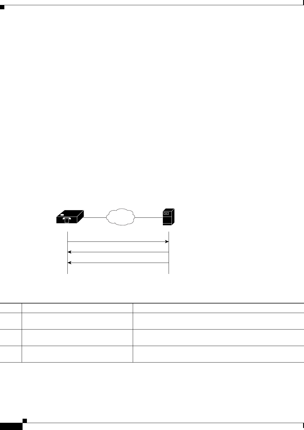
D-2
Cisco ATA 186 and Cisco ATA 188 Analog Telephone Adaptor Administrator’s Guide for SIP (version 3.0)
OL-4654-01
Appendix D SIP Call Flows
Call Flow Scenarios for Successful Calls
Call Flow Scenarios for Successful Calls
This section describes call flows for the following scenarios:
• Cisco ATA-to-SIP Server—Registration without Authentication, page D-2
• Cisco ATA-to-SIP Server—Registration with Authentication, page D-3
• Cisco ATA -t o- C is co ATA—Basic SIP to SIP Call without Authentication, page D-6
• Cisco ATA -t o- C is co ATA—Basic SIP to SIP Call with Authentication, page D-12
Each of the call flows includes a call diagram, action descriptions table, and a sample log file.
Cisco ATA-to-SIP Server—Registration without Authentication
Figure D-1 illustrates the Cisco ATA registering with the SIP server. Authentication is not required for
registration.
The call flow is as follows:
1. Cisco ATA requests registration.
2. Registration is completed.
Figure D-1 Cisco ATA-to-SIP Server—Registration without Authentication
Ta b l e D-1 Action Descriptions
Step Action Description
Step 1 REGISTER—Cisco ATA to SIP server Cisco ATA sends a REGISTER message to the SIP server to register
the address in the To header field.
Step 2 100 Trying—SIP Server to Cisco ATA SIP server returns a 100 Trying message, indicating that the
REGISTER request has been received.
Step 3 200 OK—SIP server to Cisco ATA SIP server returns a final 200 OK response, confirming that
registration is complete.
1. REGISTER
2. 100 Trying
3. 200 OK
72117
V
Cisco ATA 186 IP network SIP server

D-3
Cisco ATA 186 and Cisco ATA 188 Analog Telephone Adaptor Administrator’s Guide for SIP (version 3.0)
OL-4654-01
Appendix D SIP Call Flows
Call Flow Scenarios for Successful Calls
Cisco ATA-to-SIP Server—Registration with Authentication
Figure D-2 illustrates the Cisco ATA registering with the SIP server. Authentication is required for
registration.
The call flow is as follows:
1. Cisco ATA requests registration.
2. SIP server requests authentication credential.
3. Authentication is received and registration is completed.
Ta b l e D-2 Log Listings
1. REGISTER sip:192.168.2.97 SIP/2.0
Via: SIP/2.0/UDP 192.168.2.194
From: <sip:9301@192.168.2.97;user=phone>
To: <sip:9301@192.168.2.97;user=phone>
Call-ID: 88397253@192.168.2.194
CSeq: 1 REGISTER
Contact: <sip:9301@192.168.2.194;user=phone;transport=udp>;expires=3600
User-Agent; Cisco ATA v2.10 ata186 (0705a)
Content-Length: 0
2. SIP/2.0 100 Trying
Via: SIP/2.0/UDP 192.168.2.194
Call-ID: 88397253@192.168.2.194
From: <sip:9301@192.168.2.97;user=phone>
To: <sip:9301@192.168.2.97;user=phone>
CSeq: 1 REGISTER
Content-Length: 0
3. SIP/2.0 200 OK
Via: SIP/2.0/UDP 192.168.2.194
Call-ID: 88397253@192.168.2.194
From: <sip:9301@192.168.2.97;user=phone>
To: <sip:9301@192.168.2.97;user=phone>
CSeq: 1 REGISTER
Contact: <sip:9301@192.168.2.194;user=phone;transport=udp>;expires=“tue, 23 Oct 2001 14:24:57 GMT”
Expires: 3600
Content-Length: 0
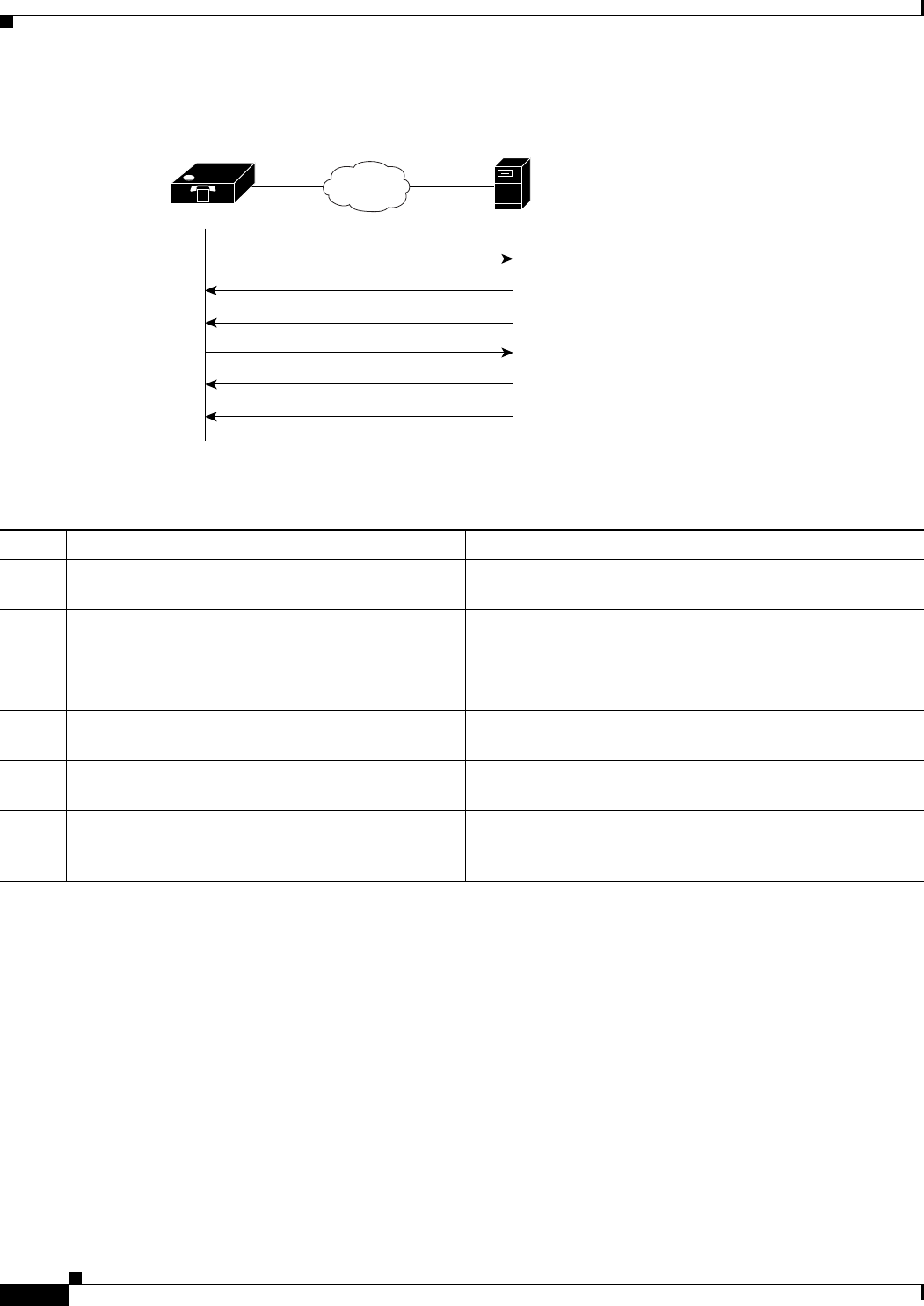
D-4
Cisco ATA 186 and Cisco ATA 188 Analog Telephone Adaptor Administrator’s Guide for SIP (version 3.0)
OL-4654-01
Appendix D SIP Call Flows
Call Flow Scenarios for Successful Calls
Figure D-2 Cisco ATA-to-SIP Server—Registration with Authentication
Ta b l e D-3 Action Descriptions
Step Action Description
Step 1 REGISTER—Cisco ATA to SIP server Cisco ATA sends a REGISTER message to the SIP server to
register the address in the To header field.
Step 2 100 Trying—SIP server to Cisco ATA SIP server returns a 100 trying message, indicating that the
REGISTER request has been received.
Step 3 407 Proxy authentication required— SIP server to
Cisco ATA
SIP server returns a request for authentication.
Step 4 REGISTER—Cisco ATA to SIP server Cisco ATA attempts to register using its authentication
credential.
Step 5 100 Trying—SIP server to Cisco ATA SIP server returns a 100 trying message, indicating that the
new REGISTER request has been received.
Step 6 200 OK—SIP server to Cisco ATA SIP server returns a final 200 OK response, confirming that
the authentication credential has been verified and
registration is complete.
V
1. REGISTER
Cisco ATA 186 IP network SIP server
2. 100 Trying
3. 407 Proxy Authentication Required
4. REGISTER
5. 100 Trying
6. 200 OK
72118

D-5
Cisco ATA 186 and Cisco ATA 188 Analog Telephone Adaptor Administrator’s Guide for SIP (version 3.0)
OL-4654-01
Appendix D SIP Call Flows
Call Flow Scenarios for Successful Calls
Ta b l e D-4 Log Listings
1. REGISTER sip:192.168.2.81 SIP/2.0
Via: SIP/2.0/UDP 192.168.2.194
From: <sip:9301@192.168.2.81;user=phone>
To: <sip:9301@192.168.2.81;user=phone>
Call-ID: 311316842@192.168.2.194
CSeq: 1 REGISTER
Contact: <sip:9301@192.168.2.194;user=phone;transport=udp>;expires=3600
User-Agent; Cisco ATA v2.10 ata186 (0705a)
Content-Length: 0
2. SIP/2.0 100 Trying
Via: SIP/2.0/UDP 192.168.2.194
Call-ID: 311316842@192.168.2.194
From: <sip:9301@192.168.2.81;user=phone>
To: <sip:9301@192.168.2.81;user=phone>
CSeq: 1 REGISTER
Content-Length: 0
3. SIP/2.0 407 Proxy Authentication Required
Via: SIP/2.0/UDP 192.168.2.194
Call-ID:311316842@192.168.2.194
From: <sip:9301@192.168.2.81;user=phone>
To: <sip:9301@192.168.2.81;user=phone>
CSeq: 1 REGISTER
Proxy-Authenticate: DIGEST realm=“CISCO”, nonce=“3bd5e334”
Content-Length: 0
4. REGISTER sip:192.168.2.81 SIP/2.0
Via: SIP/2.0/UDP 192.168.2.194
From: <sip:9301@192.168.2.81;user=phone>
To: <sip:9301@192.168.2.81;user=phone>
Call-ID: 311316842@192.168.2.194
CSeq: 2 REGISTER
Contact: <sip:9301@192.168.2.194;user=phone;transport=udp>;expires=3600
User-Agent: Cisco ATA v2.10 ata186 (0705a)
Proxy-Authorization: Digest
username=“9301”,realm=“CISCO”,nonce=“3bd5e334”,uri=“sip:192.168.2.81”,response=“87ac0afeb08222af706
f9e8b5c566ce2”
Content-Length: 0
5. SIP/2.0 100 Trying
Via: SIP/2.0/UDP 192.168.2.194
Call-ID: 311316842@192.168.2.194
From: <sip:9301@192.168.2.81;user=phone>
To: <sip:9301@192.168.2.81;user=phone>
CSeq: 2 REGISTER
Content-Length: 0
6. SIP/2.0 200 OK
Via: SIP/2.0/UDP 192.168.2.194
Call-ID: 311316842@192.168.2.194
From: <sip:9301@192.168.2.81;user=phone>
To: <sip:9301@192.168.2.81;user=phone>
CSeq: 2 REGISTER
Contact: <sip:9301@192.168.2.194;user=phone;transport=udp>;expires=“tue, 23 Oct 2001 22:37:56 GMT”
Expires: 3600
Content-Length: 0
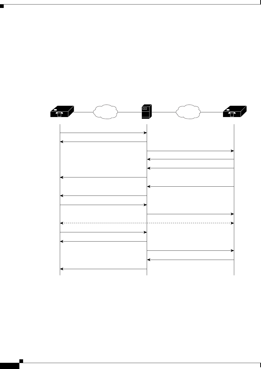
D-6
Cisco ATA 186 and Cisco ATA 188 Analog Telephone Adaptor Administrator’s Guide for SIP (version 3.0)
OL-4654-01
Appendix D SIP Call Flows
Call Flow Scenarios for Successful Calls
Cisco ATA-to-Cisco ATA—Basic SIP to SIP Call without Authentication
Figure D-3 illustrates a call from one Cisco ATA to another. Authentication by the SIP server is not
required.
The call flow is as follows:
1. Call is established between Cisco ATA A an d C i sc o ATA B.
2. Call is terminated.
Figure D-3 Cisco ATA-to-Cisco ATA—Basic SIP to SIP Call without Authentication
V V
1. INVITE
Cisco ATA 186 A Cisco ATA 186 BIP network IP networkSIP server
2. 100 Trying
3. INVITE
4. 100 Trying
5. 180 Ringing
6. 180 Ringing
7. 200 OK
8. 200 OK
9. ACK
10. ACK
11. BYE
12. 100 Trying
15. 200 OK
13. BYE
14. 200 OK
72119
2-way voice path

D-7
Cisco ATA 186 and Cisco ATA 188 Analog Telephone Adaptor Administrator’s Guide for SIP (version 3.0)
OL-4654-01
Appendix D SIP Call Flows
Call Flow Scenarios for Successful Calls
Ta b l e D-5 Action Descriptions
Step Action Description
Step 1 INVITE—Cisco ATA A to SIP server Cisco ATA A sends a call session INVITE request to the SIP
server to pass on to Cisco ATA B .
Step 2 100 Trying—SIP server to Cisco ATA A SIP server returns a 100 trying message, indicating that the
INVITE request has been received.
Step 3 INVITE—SIP server to Cisco ATA B SIP server sends the call session INVITE request to Cisco ATA
B.
Step 4 100 Trying—Cisco ATA B to SIP server Cisco ATA B returns a 100 trying message indicating that the
INVITE request has been received.
Step 5 180 Ringing—Cisco ATA B to SIP server Cisco ATA B sends a 180 ringing response to the SIP server to
pass on to Cisco ATA A.
Step 6 180 Ringing—SIP server to Cisco ATA A SIP server sends the 180 ringing response to Cisco ATA A.
Step 7 200 OK—Cisco ATA B to SIP server Cisco ATA B sends a 200 OK message to the SIP server
indicating that a connection has been established.
Step 8 200 OK—SIP server to Cisco ATA A SIP server passes the 200 OK message to Cisco ATA A.
Step 9 ACK—Cisco ATA A to SIP server Cisco ATA A sends acknowledgement of the 200 OK response to
the SIP server to pass on to Cisco ATA B .
Step 10 ACK—SIP server to Cisco ATA B SIP server passes ACK response to Cisco ATA B.
A two-way voice path is established between Cisco ATA A an d C i s c o ATA B.
Step 11 BYE—Cisco ATA A to SIP server Cisco ATA A terminates the call session and sends a BYE request
to the SIP server indicating that Cisco ATA A wants to terminate
the call.
Step 12 100 Trying—SIP server to Cisco ATA A SIP server returns a 100 trying message indicating that the BYE
request has been received.
Step 13 BYE—SIP server to Cisco ATA B SIP server passes the BYE request to Cisco ATA B .
Step 14 200 OK—Cisco ATA B to SIP server Cisco ATA B sends a 200 OK message to the SIP server
indicating that Cisco ATA B has received the BYE request.
Step 15 200 OK—SIP server to Cisco ATA A SIP server passes the BYE request to Cisco ATA A.

D-8
Cisco ATA 186 and Cisco ATA 188 Analog Telephone Adaptor Administrator’s Guide for SIP (version 3.0)
OL-4654-01
Appendix D SIP Call Flows
Call Flow Scenarios for Successful Calls
Ta b l e D-6 Log Listings
1. INVITE sip:9000@192.168.2.97;user=phone SIP/2.0
Via: SIP/2.0/UDP 192.168.3.175
From: <sip:8000@192.168.2.97;user=phone>;tag=2819471139
To: <sip:9000@192.168.2.97;user=phone>
Call-ID: 488337201@192.168.3.175
CSeq: 1 INVITE
Contact: <sip:8000@192.168.3.175;user=phone;transport=udp>
User-Agent: Cisco ATA v2.12 ata186 (0928a)
Expires: 300
Content-Length: 253
Content-Type: application/sdp
v=0
o=8000 206154 206154 IN IP4 192.168.3.175
s=ATA186 Call
c=IN IP4 192.168.3.175
t=0 0
m=audio 10000 RTP/AVP 0 18 8 101
a=rtpmap:0 PCMU/8000/1
a=rtpmap:18 G729/8000/1
a=rtpmap:8 PCMA/8000/1
a=rtpmap:101 telephone-event/8000
a=fmtp:101 0-15
2. SIP/2.0 100 Trying
Via: SIP/2.0/UDP 192.168.3.175
Call-ID: 488337201@192.168.3.175
From: <sip:8000@192.168.2.97;user=phone>;tag=2819471139
To: <sip:9000@192.168.2.97;user=phone>
CSeq: 1 INVITE
Content-Length: 0
3. INVITE sip:9000@192.168.2.194;user=phone SIP/2.0
Record-Route: <sip:9000@192.168.2.97:5060;user=phone;maddr=192.168.2.97>
Via: SIP/2.0/UDP 192.168.2.97:5060;branch=140fed6e-f61cbd1a-52f223b1-9beb149a-1
Via: SIP/2.0/UDP 192.168.3.175
From: <sip:8000@192.168.2.97;user=phone>;tag=2819471139
To: <sip:9000@192.168.2.97;user=phone>
Call-ID: 488337201@192.168.3.175
CSeq: 1 INVITE
Contact: <sip:8000@192.168.3.175;user=phone;transport=udp>
User-Agent: Cisco ATA v2.12 ata186 (0928a)
Expires: 300
Content-Length: 253
Content-Type: application/sdp
v=0
o=8000 206154 206154 IN IP4 192.168.3.175
s=ATA186 Call
c=IN IP4 192.168.3.175
t=0 0
m=audio 10000 RTP/AVP 0 18 8 101
a=rtpmap:0 PCMU/8000/1
a=rtpmap:18 G729/8000/1
a=rtpmap:8 PCMA/8000/1
a=rtpmap:101 telephone-event/8000
a=fmtp:101 0-15

D-9
Cisco ATA 186 and Cisco ATA 188 Analog Telephone Adaptor Administrator’s Guide for SIP (version 3.0)
OL-4654-01
Appendix D SIP Call Flows
Call Flow Scenarios for Successful Calls
4. SIP/2.0 100 Trying
Via: SIP/2.0/UDP 192.168.2.97:5060;branch=140fed6e-f61cbd1a-52f223b1-9beb149a-1
Via: SIP/2.0/UDP 192.168.3.175
Record-Route: <sip:9000@192.168.2.97:5060;user=phone;maddr=192.168.2.97>
From: <sip:8000@192.168.2.97;user=phone>;tag=2819471139
To: <sip:9000@192.168.2.97;user=phone>;tag=909616993
Call-ID: 488337201@192.168.3.175
CSeq: 1 INVITE
Server: Cisco ATA v2.12 ata186 (0928a)
Content-Length: 0
5. SIP/2.0 180 Ringing
Via: SIP/2.0/UDP 192.168.2.97:5060;branch=140fed6e-f61cbd1a-52f223b1-9beb149a-1
Via: SIP/2.0/UDP 192.168.3.175
Record-Route: <sip:9000@192.168.2.97:5060;user=phone;maddr=192.168.2.97>
From: <sip:8000@192.168.2.97;user=phone>;tag=2819471139
To: <sip:9000@192.168.2.97;user=phone>;tag=909616993
Call-ID: 488337201@192.168.3.175
CSeq: 1 INVITE
Server: Cisco ATA v2.12 ata186 (0928a)
Content-Length: 0
6. SIP/2.0 180 Ringing
Via: SIP/2.0/UDP 192.168.3.175
Record-Route: <sip:9000@192.168.2.97:5060;user=phone;maddr=192.168.2.97>
From: <sip:8000@192.168.2.97;user=phone>;tag=2819471139
To: <sip:9000@192.168.2.97;user=phone>;tag=909616993
Call-ID: 488337201@192.168.3.175
CSeq: 1 INVITE
Server: Cisco ATA v2.12 ata186 (0928a)
Content-Length: 0
7. SIP/2.0 200 OK
Via: SIP/2.0/UDP 192.168.2.97:5060;branch=140fed6e-f61cbd1a-52f223b1-9beb149a-1
Via: SIP/2.0/UDP 192.168.3.175
Record-Route: <sip:9000@192.168.2.97:5060;user=phone;maddr=192.168.2.97
From: <sip:8000@192.168.2.97;user=phone>;tag=2819471139
To: <sip:9000@192.168.2.97;user=phone;tag=909616993
Call-ID: 488337201@192.168.3.175
CSeq: 1 INVITE
Contact: <sip:9000@192.168.2.194;user=phone;transport=udp>
Server: Cisco ATA v2.12 ata186 (0928a)
Content-Length: 199
Content-Type: application/sdp
v=0
o=9000 206275 206275 IN IP4 192.168.2.194
s=ATA186 Call
c=IN IP4 192.168.2.194
t=0 0
m=audio 10000 RTP/AVP 0 101
a=rtpmap:0 PCMU/8000/1
a=rtpmap:101 telephone-event/8000
a=fmtp:101 0-15
Table D-6 Log Listings (continued)

D-10
Cisco ATA 186 and Cisco ATA 188 Analog Telephone Adaptor Administrator’s Guide for SIP (version 3.0)
OL-4654-01
Appendix D SIP Call Flows
Call Flow Scenarios for Successful Calls
8. SIP/2.0 200 OK
Via: SIP/2.0/UDP 192.168.3.175
Record-Route: <sip:9000@192.168.2.97:5060;user=phone;maddr=192.168.2.97
From: <sip:8000@192.168.2.97;user=phone>;tag=2819471139
To: <sip:9000@192.168.2.97;user=phone;tag=909616993
Call-ID: 488337201@192.168.3.175
CSeq: 1 INVITE
Contact: <sip:9000@192.168.2.194;user=phone;transport=udp>
Server: Cisco ATA v2.12 ata186 (0928a)
Content-Length: 199
Content-Type: application/sdp
v=0
o=9000 206275 206275 IN IP4 192.168.2.194
s=ATA186 Call
c=IN IP4 192.168.2.194
t=0 0
m=audio 10000 RTP/AVP 0 101
a=rtpmap:0 PCMU/8000/1
a=rtpmap:101 telephone-event/8000
a=fmtp:101 0-15
9. ACK sip:9000@192.168.2.97;user=phone SIP/2.0
Route: <sip:9000@192.168.2.194:5060;user=phone;transport=udp>
Via: SIP/2.0/UDP 192.168.3.175
From: <sip:8000@192.168.2.97;user=phone>;tag=2819471139
To: <sip:9000@192.168.2.97;user=phone>;tag=909616993
Call-ID: 488337201@192.168.3.175
CSeq: 1 ACK
User-Agent: Cisco ATA v2.12 ata186 (0928a)
Content-Length: 0
10. ACK sip:9000@192.168.2.194;user=phone SIP/2.0
Via: SIP/2.0/UDP 192.168.2.97:5060;branch=140fed6e-f61cbd1a-52f223b1-9beb149a-
Via: SIP/2.0/UDP 192.168.3.175
From: <sip:8000@192.168.2.97;user=phone>;tag=2819471139
To: <sip:9000@192.168.2.97;user=phone>;tag=909616993
Call-ID: 488337201@192.168.3.175
CSeq: 1 ACK
User-Agent: Cisco ATA v2.12 ata186 (0928a)
Content-Length: 0
11. BYE sip:9000@192.168.2.97;user=phone SIP/2.0
Route: <sip:9000@192.168.2.194:5060;user=phone;transport=udp>
Via: SIP/2.0/UDP 192.168.3.175
From: <sip:8000@192.168.2.97;user=phone>;tag=2819471139
To: <sip:9000@192.168.2.97;user=phone>;tag=909616993
Call-ID: 488337201@192.168.3.175
CSeq: 2 BYE
User-Agent: Cisco ATA v2.12 ata186 (0928a)
Content-Length: 0
12. SIP/2.0 100 Trying
Via: SIP/2.0/UDP 19.168.3.175
Call-ID: 488337201@192.168.3.175
From: <sip:8000@192.168.2.97;user=phone>;tag=2819471139
To: <sip:9000@192.168.2.97;user=phone>;tag=909616993
CSeq: 2 BYE
Content-Length: 0
Table D-6 Log Listings (continued)

D-11
Cisco ATA 186 and Cisco ATA 188 Analog Telephone Adaptor Administrator’s Guide for SIP (version 3.0)
OL-4654-01
Appendix D SIP Call Flows
Call Flow Scenarios for Successful Calls
13. BYE sip:9000@192.168.2.194;user=phone SIP/2.0
Via: SIP/2.0/UDP 192.168.2.97:5060;branch=b499b4be-d7995db7-980cd8af-e5ba35f5-1
Via: SIP/2.0/UDP 192.168.3.175
From: <sip:8000@192.168.2.97;user=phone>;tag=2819471139
To: <sip:9000@192.168.2.97;user=phone>;tag=909616993
Call-ID: 488337201@192.168.3.175
CSeq: 2 BYE
User-Agent: Cisco ATA v2.12 ata186 (0928a)
Content-Length: 0
14. SIP/2.0 200 OK
Via: SIP/2.0/UDP 192.168.2.97:5060;branch=b499b4be-d7995db7-980cd8af-e5ba35f5-1
Via: SIP/2.0/UDP 192.168.3.175
From: <sip:8000@192.168.2.97;user=phone>;tag=2819471139
To: <sip:9000@192.168.2.97;user=phone>;tag=909616993
Call-ID: 488337201@192.168.3.175
CSeq: 2 BYE
Server: Cisco ATA v2.12 ata186 (0928a)
Content-Length: 0
15. SIP/2.0 200 OK
Via: SIP/2.0/UDP 192.168.3.175
From: <sip:8000@192.168.2.97;user=phone>;tag=2819471139
To: <sip:9000@192.168.2.97;user=phone>;tag=909616993
Call-ID: 488337201@192.168.3.175
CSeq: 2 BYE
Server: Cisco ATA v2.12 ata186 (0928a)
Content-Length: 0
Table D-6 Log Listings (continued)
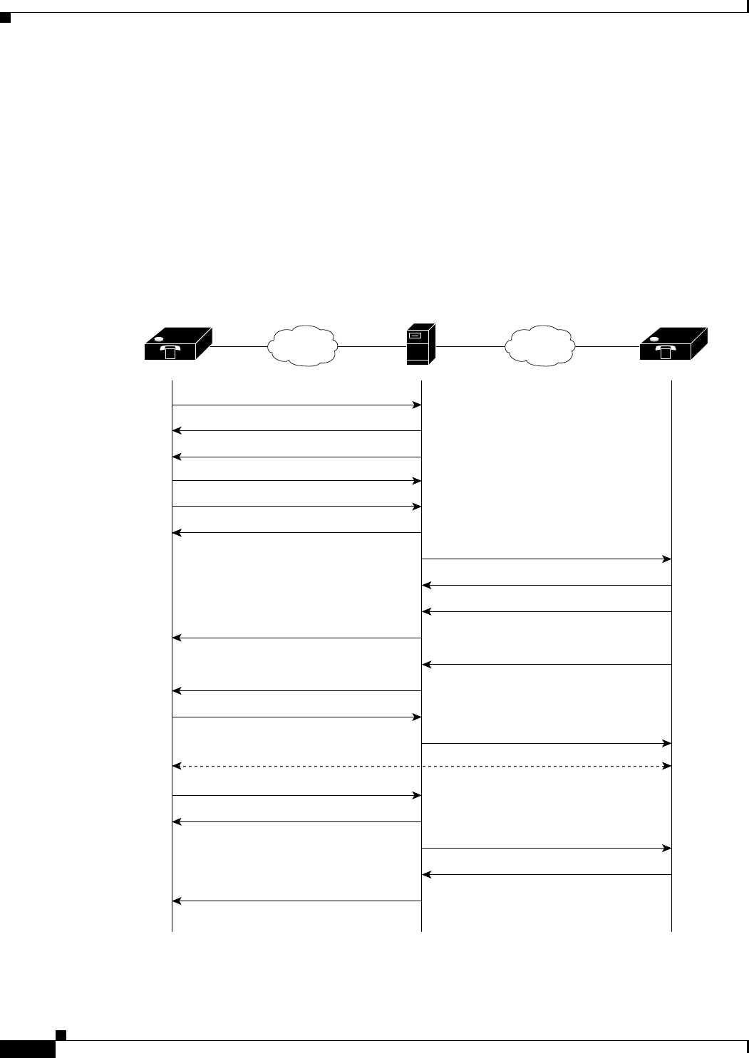
D-12
Cisco ATA 186 and Cisco ATA 188 Analog Telephone Adaptor Administrator’s Guide for SIP (version 3.0)
OL-4654-01
Appendix D SIP Call Flows
Call Flow Scenarios for Successful Calls
Cisco ATA-to-Cisco ATA—Basic SIP to SIP Call with Authentication
Figure D-4 illustrates a call from one Cisco ATA to another. Authentication by the SIP server is
required.
The call flow is as follows:
1. Authentication is requested for call initiated by Cisco ATA A.
2. Call is established between Cisco ATA A an d C i sc o ATA B.
3. Call is terminated.
Figure D-4 Cisco ATA-to-Cisco ATA—Basic SIP to SIP Call with Authentication
V V
1. INVITE
Cisco ATA 186 A Cisco ATA 186 BIP network IP networkSIP server
2. 100 Trying
3. 407 Proxy Authentication Required
4. ACK
5. INVITE
6. 100 Trying
7. INVITE
8.100 Trying
9. 180 Ringing
10. 180 Ringing
2-way voice path
11. 200 OK
12. 200 OK
15. BYE
13. ACK
14. ACK
16. 100 Trying
17. BYE
18. 200 OK
19. 200 OK
72120

D-13
Cisco ATA 186 and Cisco ATA 188 Analog Telephone Adaptor Administrator’s Guide for SIP (version 3.0)
OL-4654-01
Appendix D SIP Call Flows
Call Flow Scenarios for Successful Calls
Ta b l e D-7 Action Descriptions
Step Action Description
Step 1 INVITE—Cisco ATA A to SIP server Cisco ATA A sends a call session INVITE request to the SIP
server to pass on to Cisco ATA B .
Step 2 100 Trying—SIP server to Cisco ATA A SIP server returns a 100 Trying message, indicating that the
INVITE request has been received.
Step 3 407 Proxy Authentication Required— SIP server
to Cisco ATA A
SIP server returns a request for authentication to Cisco ATA A .
Step 4 ACK—Cisco ATA A to SIP server Cisco ATA A acknowledges the request for authentication.
Step 5 INVITE—Cisco ATA A to SIP server Cisco ATA A sends a call session INVITE request along with
authentication credential to the SIP server to pass on to
Cisco ATA B.
Step 6 100 Trying—SIP server to Cisco ATA A SIP server returns a 100 Trying message, indicating that the
INVITE request has been received.
Step 7 INVITE—SIP server to Cisco ATA B SIP server sends the call session INVITE request to Cisco ATA
B.
Step 8 100 Trying—Cisco ATA B to SIP server Cisco ATA B returns a 100 trying message indicating that the
INVITE request has been received.
Step 9 180 Ringing—Cisco ATA B to SIP server Cisco ATA B sends a 180 ringing response to the SIP server to
pass on to Cisco ATA A .
Step 10 180 Ringing—SIP server to Cisco ATA A SIP server sends the 180 ringing response to Cisco ATA A.
Step 11 200 OK—Cisco ATA B to SIP server Cisco ATA B sends a 200 OK message to the SIP server
indicating that a connection has been established.
Step 12 200 OK—SIP server to Cisco ATA A SIP server passes the 200 OK message to Cisco ATA A .
Step 13 ACK—Cisco ATA A to SIP server Cisco ATA A sends acknowledgment of the 200 OK response to
the SIP server to pass on to Cisco ATA B .
Step 14 ACK—SIP server to Cisco ATA B SIP server passes ACK response to Cisco ATA B .
A two-way voice path is established between Cisco ATA A an d C i s c o ATA B.
Step 15 BYE—Cisco ATA A to SIP server Cisco ATA A terminates the call session and sends a BYE
request to the SIP server indicating that Cisco ATA A wants to
terminate the call.
Step 16 100 Trying—SIP server to Cisco ATA A SIP server returns a 100 trying message indicating that the BYE
request has been received.
Step 17 BYE—SIP server to Cisco ATA B SIP server passes the BYE request to Cisco ATA B.
Step 18 200 OK—Cisco ATA B to SIP server Cisco ATA 186 B sends a 200 OK message to the SIP server
indicating that Cisco ATA 186 B has received the BYE request.
Step 19 200 OK—SIP server to Cisco ATA A SIP server passes the BYE request to Cisco ATA A.

D-14
Cisco ATA 186 and Cisco ATA 188 Analog Telephone Adaptor Administrator’s Guide for SIP (version 3.0)
OL-4654-01
Appendix D SIP Call Flows
Call Flow Scenarios for Successful Calls
Ta b l e D-8 Log Listings
1. INVITE sip:9000@192.168.2.81;user=phone SIP/2.0
Via: SIP/2.0/UDP 192.168.3.175
From: <sip:8000@192.168.2.81;user=phone>;tag=3515135869
To: <sip:9000@192.168.2.81;user=phone>
Call-ID: 557188650@192.168.3.175
CSeq: 1 INVITE
Contact: <sip:8000@192.168.3.175;user=phone;transport=udp>
User-Agent: Cisco ATA v2.12 ata186 (0928a)
Expires: 300
Content-Length: 253
Content-Type: application/sdp
v=0
o=8000 177731 177731 IN IP4 192.168.3.175
s=ATA186 Call
c=IN IP4 192.168.3.175
t=0 0
m=audio 10000 RTP/AVP 0 18 8 101
a=rtpmap:0 PCMU/8000/1
a=rtpmap:18 G729/8000/1
a=rtpmap:8 PCMA/8000/1
a=rtpmap:101 telephone-event/8000
a=fmtp:101 0-15
2. SIP/2.0 100 Trying
Via: SIP/2.0/UDP 192.168.3.175
Call-ID: 557188650@192.168.3.175
From: <sip:8000@192.168.2.81;user=phone>;tag=3515135869
To: <sip:9000@192.168.2.81;user=phone>
CSeq: 1 INVITE
Content-Length: 0
3. SIP/2.0 407 Proxy Authentication Required
Via: SIP/2.0/UDP 192.168.3.175
Call-ID: 557188650@192.168.3.175
From: <sip:8000@192.168.2.81;user=phone>;tag=3515135869
To:<sip:9000@192.168.2.81;user=phone>;tag=600eaef7-7c3a549a
CSeq: 1 INVITE
Proxy-Authenticate: DIGEST realm=“CISCO”, nonce=“3bd76584”
Content-Length: 0
4. ACK sip:9000@192.168.2.81:5060 SIP/2.0
Via: SIP/2.0/UDP 192.168.3.175
From: <sip:8000@192.168.2.81;user=phone>;tag=3515135869
To:<sip:9000@192.168.2.81;user=phone>;tag=600eaef7-7c3a549a
Call-ID: 557188650@192.168.3.175
CSeq: 1 ACK
User-Agent: Cisco ATA v2.12 ata186 (0928a)
Content-Length: 0

D-15
Cisco ATA 186 and Cisco ATA 188 Analog Telephone Adaptor Administrator’s Guide for SIP (version 3.0)
OL-4654-01
Appendix D SIP Call Flows
Call Flow Scenarios for Successful Calls
5. INVITE sip:9000@192.168.2.81;user=phone SIP/2.0
Via: SIP/2.0/UDP 192.168.3.175
From: <sip:8000@192.168.2.81;user=phone>;tag=3515135869
To: <sip:9000@192.168.2.81;user=phone>
Call-ID: 557188650@192.168.3.175
CSeq: 2 INVITE
Contact: <sip:8000@192.168.3.175;user=phone;transport=udp>
User-Agent: Cisco ATA v2.12 ata186 (0928a)
Proxy-Authorization: Digest username=“8000”,realm=“CISCO”,nonce=“3bd76584”,
uri=“sip:9000@192.168.2.81”,response=“6e91de67ad976997ffac76f0398ef224”
Expires: 300
Content-Length: 253
Content-Type: application/sdp
v=0
o=8000 177738 177738 IN IP4 192.168.3.175
s=ATA186 Call
c=IN IP4 192.168.3.175
t=0 0
m=audio 10000 RTP/AVP 0 18 8 101
a=rtpmap:0 PCMU/8000/1
a=rtpmap:18 G729/8000/1
a=rtpmap:8 PCMA/8000/1
a=rtpmap:101 telephone-event/8000
a=fmtp:101 0-15
6. SIP/2.0 100 Trying
Via: SIP/2.0/UDP 192.168.3.175
Call-ID: 557188650@192.168.3.175
From: <sip:8000@192.168.2.81;user=phone>;tag=3515135869
To: <sip:9000@192.168.2.81;user=phone>
CSeq: 2 INVITE
Content-Length: 0
7. INVITE sip:9000@192.168.2.194;user=phone SIP/2.0
Record-Route: <sip:9000@192.168.2.81:5060;user=phone;maddr=192.168.2.81
Via: SIP/2.0/UDP 192.168.2.81:5060;branch=c0b3510a-819f9d1a-ea43c345-9604747f-1
Via: SIP/2.0/UDP 192.168.3.175
From: <sip:8000@192.168.2.81;user=phone>;tag=3515135869
To: <sip:9000@192.168.2.81;user=phone>
Call-ID: 557188650@192.168.3.175
CSeq: 2 INVITE
Contact: <sip:8000@192.168.3.175;user=phone;transport=udp>
User-Agent: Cisco ATA v2.12 ata186 (0928a)
Proxy-Authorization: Digest username=“8000”,realm=“CISCO”,nonce=“3bd76584”,
uri=“sip:9000@192.168.2.81”,response=“6e91de67ad976997ffac76f0398ef224”
Expires: 300
Content-Length: 253
Content-Type: application/sdp
v=0
o=8000 177738 177738 IN IP4 192.168.3.175
s=ATA186 Call
c=IN IP4 192.168.3.175
t=0 0
m=audio 10000 RTP/AVP 0 18 8 101
a=rtpmap:0 PCMU/8000/1
a=rtpmap:18 G729/8000/1
a=rtpmap:8 PCMA/8000/1
a=rtpmap:101 telephone-event/8000
a=fmtp:101 0-15
Table D-8 Log Listings (continued)

D-16
Cisco ATA 186 and Cisco ATA 188 Analog Telephone Adaptor Administrator’s Guide for SIP (version 3.0)
OL-4654-01
Appendix D SIP Call Flows
Call Flow Scenarios for Successful Calls
8. SIP/2.0 100 Trying
Via: SIP/2.0/UDP 192.168.2.81:5060;branch=c0b3510a-819f9d1a-ea43c345-9604747f-1
Via: SIP/2.0/UDP 192.168.3.175
Record-Route: <sip:9000@192.168.2.81:5060;user=phone;maddr=192.168.2.81>
From: <sip:8000@192.168.2.81;user=phone>;tag=3515135869
To: <sip:9000@192.168.2.81;user=phone>;tag=100585329
Call-ID: 557188650@192.168.3.175
CSeq: 2 INVITE
Server: Cisco ATA v2.12 ata186 (0928a)
Content-Length: 0
9. SIP/2.0 180 Ringing
Via: SIP/2.0/UDP 192.168.2.81:5060;branch=c0b3510a-819f9d1a-ea43c345-9604747f-1
Via: SIP/2.0/UDP 192.168.3.175
Record-Route: <sip:9000@192.168.2.81:5060;user=phone;maddr=192.168.2.81>
From: <sip:8000@192.168.2.81;user=phone>;tag=3515135869
To: <sip:9000@192.168.2.81;user=phone>;tag=100585329
Call-ID: 557188650@192.168.3.175
CSeq: 2 INVITE
Server: Cisco ATA v2.12 ata186 (0928a)
Content-Length: 0
10. SIP/2.0 180 Ringing
Via: SIP/2.0/UDP 192.168.3.175
Record-Route: <sip:9000@192.168.2.81:5060;user=phone;maddr=192.168.2.81>
From: <sip:8000@192.168.2.81;user=phone>;tag=3515135869
To: <sip:9000@192.168.2.81;user=phone>;tag=100585329
Call-ID: 557188650@192.168.3.175
CSeq: 2 INVITE
Server: Cisco ATA v2.12 ata186 (0928a)
Content-Length: 0
11. SIP/2.0 200 OK
Via: SIP/2.0/UDP 192.168.2.81:5060;branch=c0b3510a-819f9d1a-ea43c345-9604747f-1
Via: SIP/2.0/UDP 192.168.3.175
Record-Route: <sip:9000@192.168.2.81:5060;user=phone;maddr=192.168.2.81
From: <sip:8000@192.168.2.81;user=phone>;tag=3515135869
To: <sip:9000@192.168.2.81;user=phone;tag=100585329
Call-ID: 557188650@192.168.3.175
CSeq: 2 INVITE
Contact: <sip:9000@192.168.3.194;user=phone;transport=udp>
Server: Cisco ATA v2.12 ata186 (0928a)
Content-Length: 199
Content-Type: application/sdp
v=0
o=9000 179263 179263 IN IP4 192.168.2.194
s=ATA186 Call
c=IN IP4 192.168.2.194
t=0 0
m=audio 10000 RTP/AVP 0 101
a=rtpmap:0 PCMU/8000/1
a=rtpmap:101 telephone-event/8000
a=fmtp:101 0-15
Table D-8 Log Listings (continued)

D-17
Cisco ATA 186 and Cisco ATA 188 Analog Telephone Adaptor Administrator’s Guide for SIP (version 3.0)
OL-4654-01
Appendix D SIP Call Flows
Call Flow Scenarios for Successful Calls
12. SIP/2.0 200 OK
Via: SIP/2.0/UDP 192.168.3.175
Record-Route: <sip:9000@192.168.2.81:5060;user=phone;maddr=192.168.2.81
From: <sip:8000@192.168.2.81;user=phone>;tag=3515135869
To: <sip:9000@192.168.2.81;user=phone;tag=100585329
Call-ID: 557188650@192.168.3.175
CSeq: 2 INVITE
Contact: <sip:9000@192.168.2.194;user=phone;transport=udp>
Server: Cisco ATA v2.12 ata186 (0928a)
Content-Length: 199
Content-Type: application/sdp
v=0
o=9000 179263 179263 IN IP4 192.168.2.194
s=ATA186 Call
c=IN IP4 192.168.2.194
t=0 0
m=audio 10000 RTP/AVP 0 101
a=rtpmap:0 PCMU/8000/1
a=rtpmap:101 telephone-event/8000
a=fmtp:101 0-15
13. ACK sip:9000@192.168.2.81;user=phone SIP/2.0
Route: <sip:9000@192.168.2.194:5060;user=phone;transport=udp>
Via: SIP/2.0/UDP 192.168.3.175
From: <sip:8000@192.168.2.81;user=phone>;tag=3515135869
To: <sip:9000@192.168.2.81;user=phone>;tag=100585329
Call-ID: 557188650@192.168.3.175
CSeq: 2 ACK
User-Agent: Cisco ATA v2.12 ata186 (0928a)
Content-Length: 0
14. ACK sip:9000@192.168.2.194;user=phone SIP/2.0
Via: SIP/2.0/UDP 192.168.2.81:5060;branch=c0b3510a-819f9d1a-ea43c345-9604747f-1
Via: SIP/2.0/UDP 192.168.3.175
From: <sip:8000@192.168.2.81;user=phone>;tag=3515135869
To: <sip:9000@192.168.2.81;user=phone>;tag=100585329
Call-ID: 557188650@192.168.3.175
CSeq: 2 ACK
User-Agent: Cisco ATA v2.12 ata186 (0928a)
Content-Length: 0
15. BYE sip:9000@192.168.2.81;user=phone SIP/2.0
Route: <sip:9000@192.168.2.194:5060;user=phone;transport=udp>
Via: SIP/2.0/UDP 192.168.3.175
From: <sip:8000@192.168.2.81;user=phone>;tag=3515135869
To: <sip:9000@192.168.2.81;user=phone>;tag=100585329
Call-ID: 557188650@192.168.3.175
CSeq: 3 BYE
User-Agent: Cisco ATA v2.12 ata186 (0928a)
Content-Length: 0
16. SIP/2.0 100 Trying
Via: SIP/2.0/UDP 19.168.3.175
Call-ID: 557188650@192.168.3.175
From: <sip:8000@192.168.2.81;user=phone>;tag=3515135869
To: <sip:9000@192.168.2.81;user=phone>;tag=100585329
CSeq: 3 BYE
Content-Length: 0
Table D-8 Log Listings (continued)

D-18
Cisco ATA 186 and Cisco ATA 188 Analog Telephone Adaptor Administrator’s Guide for SIP (version 3.0)
OL-4654-01
Appendix D SIP Call Flows
Call Flow Scenarios for Successful Calls
17. BYE sip:9000@192.168.2.194;user=phone SIP/2.0
Via: SIP/2.0/UDP 192.168.2.81:5060;branch=424f3898-9ef87cec-82179ac3-50eeb1d3-1
Via: SIP/2.0/UDP 192.168.3.175
From: <sip:8000@192.168.2.81;user=phone>;tag=3515135869
To: <sip:9000@192.168.2.81;user=phone>;tag=100585329
Call-ID: 557188650@192.168.3.175
CSeq: 3 BYE
User-Agent: Cisco ATA v2.12 ata186 (0928a)
Content-Length: 0
18. SIP/2.0 200 OK
Via: SIP/2.0/UDP 192.168.2.81:5060;branch=424f3898-9ef87cec-82179ac3-50eeb1d3-1
Via: SIP/2.0/UDP 192.168.3.175
From: <sip:8000@192.168.2.81;user=phone>;tag=3515135869
To: <sip:9000@192.168.2.81;user=phone>;tag=100585329
Call-ID: 557188650@192.168.3.175
CSeq: 3 BYE
Server: Cisco ATA v2.12 ata186 (0928a)
Content-Length: 0
19. SIP/2.0 200 OK
Via: SIP/2.0/UDP 192.168.3.175
From: <sip:8000@192.168.2.81;user=phone>;tag=3515135869
To: <sip:9000@192.168.2.81;user=phone>;tag=100585329
Call-ID: 557188650@192.168.3.175
CSeq: 3 BYE
Server: Cisco ATA v2.12 ata186 (0928a)
Content-Length: 0
Table D-8 Log Listings (continued)

E-1
Cisco ATA 186 and Cisco ATA 188 Analog Telephone Adaptor Administrator’s Guide for SIP (version 3.0)
OL-4654-01
APPENDIX
E
Recommended Cisco ATA Tone Parameter
Values by Country
This section provides tables of recommended tone parameters for the followings countries, listed
alphabetically:
Note The extended tone format used by some countries is available only with Cisco ATA software version 3.0
or later. For more information about tone parameter syntax and formats, see the “Tone Configuration
Parameters” section on page 5-53.
• Argentina
• Australia
• Austria
• Belgium
• Brazil
• Canada
• China
• Columbia
• Czech Republic
• Denmark
• Egypt
• Finland
• France
• Germany
• Greece
• Hong Kong
• Hungary
• Iceland
• India
• Indonesia
• Ireland

E-2
Cisco ATA 186 and Cisco ATA 188 Analog Telephone Adaptor Administrator’s Guide for SIP (version 3.0)
OL-4654-01
Appendix E Recommended Cisco ATA Tone Parameter Values by Country
• Israel
• Italy
• Japan
• Korea
• Luxembourg
• Malaysia
• Mexico
• Netherlands
• New Zealand
• Norway
• Pakistan
• Panama
• Peru
• Phillippines
• Poland
• Portugal
• Russia
• Saudi Arabia
• Singapore
• Slovakia
• Slovenia
• South Africa
• Spain
• Sweden
• Switzerland
• Taiwan
• Thailand
• Turkey
• United Kingdom
• United States
• Venezuela

E-3
Cisco ATA 186 and Cisco ATA 188 Analog Telephone Adaptor Administrator’s Guide for SIP (version 3.0)
OL-4654-01
Appendix E Recommended Cisco ATA Tone Parameter Values by Country
Ta b l e E-1 Argentina
Parameter Recommended Values
DialTone 1,30958,0,3125,0,1,0,0,0
BusyTone 1,30958,0,1757,0,0,2400,1600,0
ReorderTone 1,30958,0,1757,0,0,2400,3200,0
RingbackTone 1,30958,0,1971,0,0,8000,32000,0
SITTone 1,30958,0,1757,0,0,2400,1600,0
Ta b l e E-2 Australia
Parameter Recommended Values
DialTone 2,31163,30958,1477,1566,1,0,0,0
BusyTone 1,30958,0,2212,0,0,3000,3000,0
ReorderTone 1,31163,0,2086,0,0,3000,3000,0
RingbackTone 102,31163,1477,30742,1654,2,3200,1600,3200,16000,0
SITTone 1,30958,0,2212,0,0,20000,4000,0
Ta b l e E-3 Austria
Parameter Recommended Values
DialTone 1,31000,0,3089,0,1,0,0,0
BusyTone 1,31000,0,1737,0,0,3200,3200,0
ReorderTone 1,31000,0,1737,0,0,1600,1600,0
RingbackTone 1,31000,0,1949,0,0,8000,40000,0
SITTone 101,3,24062,3640,14876,4778,5126,5297,3,2664,0,2664,0,2664,8000,0,0
Ta b l e E-4 Belgium
Parameter Recommended Values
DialTone 1,30958,0,4952,0,1,0,0,0
BusyTone 1,30958,0,1757,0,0,4000,4000,0
ReorderTone 1,30958,0,1757,0,0,1336,1336,0
RingbackTone 1,30958,0,1971,0,0,8000,24000,0
SITTone 1,30958,0,1757,0,0,1336,1336,0

E-4
Cisco ATA 186 and Cisco ATA 188 Analog Telephone Adaptor Administrator’s Guide for SIP (version 3.0)
OL-4654-01
Appendix E Recommended Cisco ATA Tone Parameter Values by Country
Ta b l e E-5 Brazil
Parameter Recommended Values
DialTone 1,30958,0,3125,0,1,0,0,0
BusyTone 1,30958,0,1757,0,0,2000,2000,0
ReorderTone 1,30958,0,1757,0,0,2000,2000,0
RingbackTone 1,30958,0,1971,0,0,8000,32000,0
SITTone 100,1,30958,1757,0,0,0,0,2,6000,2000,2000,2000,0,0,0,0
Ta b l e E-6 Canada
Parameter Recommended Values
DialTone 2,31537,30830,1490,1859,1,0,0,0
BusyTone 2,30466,28958,1246,1583,0,4000,4000,0
ReorderTone 2,30466,28958,1246,1583,0,2000,2000,0
RingbackTone 2,30830,30466,793,862,0,8000,24000,0
SITTone 2,30466,28958,1246,1583,0,2000,2000,0
Ta b l e E-7 China
Parameter Recommended Values
DialTone 1,30742,0,5870,0,1,0,0,0
BusyTone 1,30742,0,5870,0,0,2800,2800,0
ReorderTone 1,30742,0,5870,0,0,5600,5600,0
RingbackTone 1,30742,0,5870,0,0,8000,32000,0
SITTone 100,1,30742,1856,0,0,0,0,2,800,800,3200,3200,0,0,2,0
Ta b l e E-8 Columbia
Parameter Recommended Values
DialTone 1,30958,0,3125,0,1,0,0,0
BusyTone 1,30958,0,1757,0,0,2000,2000,0
ReorderTone 1,30958,0,1757,0,0,2000,2000,0
RingbackTone 1,30958,0,1971,0,0,8000,32000,0
SITTone 1,30958,0,1757,0,0,2000,2000,0

E-5
Cisco ATA 186 and Cisco ATA 188 Analog Telephone Adaptor Administrator’s Guide for SIP (version 3.0)
OL-4654-01
Appendix E Recommended Cisco ATA Tone Parameter Values by Country
Ta b l e E-9 Czech Republic
Parametter Recommended Values
DialTone 1,30958,0,3125,0,1,0,0,0
BusyTone 1,30958,0,1757,0,0,2664,2664,0
ReorderTone 1,30958,0,1757,0,0,1336,1336,0
RingbackTone 1,30958,0,1971,0,0,8000,32000,0
SITTone 1,30958,0,1757,0,0,1336,1336,0
Ta b l e E-10 Denmark
Parameter Recommended Values
DialTone 1,30958,0,3125,0,1,0,0,0
BusyTone 1,30958,0,1757,0,0,2000,2000,0
ReorderTone 1,30958,0,1757,0,0,2000,2000,0
RingbackTone 1,30958,0,1757,0,0,8000,32000,0
SITTone 101,3,24062,3640,14876,4778,5126,5297,3,2664,0,2664,0,2664,8000,0,0
Ta b l e E-11 Egypt
Parameter Recommended Values
DialTone 1,30958,0,3125,0,1,0,0,0
BusyTone 2,31356,30513,1102,1384,0,8000,32000,0
ReorderTone 1,30742,0,1856,0,0,4000,4000,0
RingbackTone 2,31356,31356,1237,1237,0,16000,8000,0
SITTone 1,30742,0,1856,0,0,4000,4000,0
Ta b l e E-12 Finland
Parameter Recommended Values
DialTone 1,30958,0,4952,0,1,0,0,0
BusyTone 1,30958,0,4952,0,0,2400,2400,0
ReorderTone 1,30958,0,5556,0,0,1600,2000,0
RingbackTone 1,30958,0,9545,0,0,8000,32000,0
SITTone 1,30958,0,1757,0,0,1600,1600,0

E-6
Cisco ATA 186 and Cisco ATA 188 Analog Telephone Adaptor Administrator’s Guide for SIP (version 3.0)
OL-4654-01
Appendix E Recommended Cisco ATA Tone Parameter Values by Country
Ta b l e E-13 France
Parameter Recommended Values
DialTone 1,30830,0,3231,0,1,0,0,0
BusyTone 1,30830,0,1817,0,0,4000,4000,0
ReorderTone 1,30830,0,1817,0,0,4000,4000,0
RingbackTone 1,30830,0,2038,0,0,12000,28000,0
SITTone 1,30830,0,1817,0,0,4000,4000,0
Ta b l e E-14 Germany
Parameter Recommended Values
DialTone 1,30958,0,3125,0,1,0,0,0
BusyTone 1,30958,0,1757,0,0,3840,3840,0
ReorderTone 1,30958,0,1757,0,0,1920,1920,0
RingbackTone 1,30958,0,1971,0,0,8000,32000,0
SITTone 1,30958,0,1757,0,0,1920,1920,0
Ta b l e E-15 Greece
Parameter Recommended Values
DialTone 101,30958,3587,0,0,2,1600,2400,5600,6400,0
BusyTone 1,30958,0,1757,0,0,2400,2400,0
ReorderTone 1,30958,0,1757,0,0,2400,2400,0
RingbackTone 1,30958,0,3426,0,0,8000,32000,0
SITTone 1,30958,0,1757,0,0,2400,2400,0
Ta b l e E-16 Hong Kong
Parameter Recommended Values
DialTone 2,31537,30830,1833,2287,1,0,0,0
BusyTone 2,30466,28958,2215,2816,0,4000,4000,0
ReorderTone 2,30466,28958,2215,2816,0,2000,2000,0
RingbackTone 102,30830,2038,30466,2215,2,3200,1600,3200,24000,0
SITTone 2,30466,28958,1398,1777,1,0,0,0

E-7
Cisco ATA 186 and Cisco ATA 188 Analog Telephone Adaptor Administrator’s Guide for SIP (version 3.0)
OL-4654-01
Appendix E Recommended Cisco ATA Tone Parameter Values by Country
Ta b l e E-17 Hungary
Parameter Recommended Values
DialTone 1,30958,0,3197,0,1,0,0,0
BusyTone 1,30958,0,1737,0,0,2400,2400,0
ReorderTone 1,30958,0,1737,0,0,2400,2400,0
RingbackTone 1,30958,0,1927,0,0,9600,29600,0
SITTone 1,30958,0,1737,0,0,2400,2400,0
Ta b l e E-18 Iceland
Parameter Recommended Values
DialTone 1,30958,0,3125,0,1,0,0,0
BusyTone 1,30958,0,1757,0,0,2000,2000,0
ReorderTone 1,30958,0,1757,0,0,2000,2000,0
RingbackTone 1,30958,0,1971,0,0,9600,37600,0
SITTone 1,30958,0,1757,0,0,2000,2000,0
Ta b l e E-19 India
Parameter Recommended Values
DialTone 2,31356,30958,5336,6023,1,0,0,0
BusyTone 1,31163,0,9003,0,0,6000,6000,0
ReorderTone 1,31163,0,1657,0,0,2000,4000,0
RingbackTone 102,31356,3485,30958,3934,2,3200,1600,3200,16000,0
SITTone 1,31163,0,1657,0,0,20000,4000,0
Ta b l e E-20 Indonesia
Parameter Recommended Values
DialTone 1,30958,0,3125,0,1,0,0,0
BusyTone 1,30958,0,1757,0,0,4000,4000,0
ReorderTone 1,30958,0,1757,0,0,2000,2000,0
RingbackTone 1,30958,0,1971,0,0,8000,32000,0
SITTone 1,30958,0,1757,0,0,20000,4000,0

E-8
Cisco ATA 186 and Cisco ATA 188 Analog Telephone Adaptor Administrator’s Guide for SIP (version 3.0)
OL-4654-01
Appendix E Recommended Cisco ATA Tone Parameter Values by Country
Ta b l e E-21 Ireland
Parameter Recommended Values
DialTone 1,30958,0,7582,0,1,0,0,0
BusyTone 1,30958,0,6758,0,0,4000,4000,0
ReorderTone 1,30958,0,1757,0,0,48000,8000,0
RingbackTone 102,31163,3194,30742,3578,2,3200,1600,3200,16000,0
SITTone 1,30958,0,1757,0,0,48000,8000,0
Ta b l e E-22 Israel
Parameter Recommended Values
DialTone 1,30958,0,3125,0,1,0,0,0
BusyTone 1,30958,0,1757,0,0,4000,4000,0
ReorderTone 1,30958,0,1757,0,0,2000,2000,0
RingbackTone 1,31163,0,1859,0,0,8000,24000,0
SITTone 101,3,23620,3717,14876,4778,5126,5297,3,2664,0,2664,0,2664,8000,0,0
Ta b l e E-23 Italy
Parameter Recommended Values
DialTone 101,30958,3125,0,0,2,1600,1600,4800,8000,0
BusyTone 1,30958,0,1757,0,0,4000,4000,0
ReorderTone 1,30958,0,1757,0,0,1600,1600,0
RingbackTone 1,30958,0,1971,0,0,8000,32000,0
SITTone 1,30958,0,1757,0,0,4000,4000,0
Ta b l e E-24 Japan
Parameter Recommended Values
DialTone 1,31163,0,1657,0,1,0,0,0
BusyTone 1,31163,0,1859,0,0,4000,4000,0
ReorderTone 1,31163,0,1859,0,0,4000,4000,0
RingbackTone 2,31318,31000,1769,1949,0,8000,16000,0
SITTone 1,31163,0,1859,0,0,4000,4000,0

E-9
Cisco ATA 186 and Cisco ATA 188 Analog Telephone Adaptor Administrator’s Guide for SIP (version 3.0)
OL-4654-01
Appendix E Recommended Cisco ATA Tone Parameter Values by Country
Ta b l e E-25 Korea
Parameter Recommended Values
DialTone 2,31537,30830,1833,2287,1,0,0,0
BusyTone 2,30466,28958,1398,1777,0,4000,4000,0
ReorderTone 2,30466,28958,1398,1777,0,2400,1600,0
RingbackTone 2,30830,30466,1443,1568,0,8000,16000,0
SITTone 100,1,30742,1856,0,0,0,0,2,1600,800,1600,12000,0,0,0,0
Ta b l e E-26 Luxembourg
Parameter Recommended Values
DialTone 1,30958,0,3125,0,1,0,0,0
BusyTone 1,30958,0,1757,0,0,4000,4000,0
ReorderTone 1,30958,0,1757,0,0,2000,2000,0
RingbackTone 1,30958,0,1971,0,0,8000,32000,0
SITTone 1,30958,0,1757,0,0,2000,2000,0
Ta b l e E-27 Malaysia
Parameter Recommended Values
DialTone 1,30958,0,3125,0,1,0,0,0
BusyTone 1,30958,0,1757,0,0,3840,3840,0
ReorderTone 1,30958,0,1757,0,0,2000,2000,0
RingbackTone 101,30958,1971,0,0,2,3200,1600,3200,16000,0
SITTone 1,30958,0,1757,0,0,20000,4000,0
Ta b l e E-28 Mexico
Parameter Recommended Values
DialTone 1,30958,0,3125,0,1,0,0,0
BusyTone 1,30958,0,1757,0,0,2000,2000,0
ReorderTone 1,30958,0,1757,0,0,2000,2000,0
RingbackTone 1,30958,0,1971,0,0,8000,32000,0
SITTone 1,30958,0,1757,0,0,2000,2000,0

E-10
Cisco ATA 186 and Cisco ATA 188 Analog Telephone Adaptor Administrator’s Guide for SIP (version 3.0)
OL-4654-01
Appendix E Recommended Cisco ATA Tone Parameter Values by Country
Ta b l e E-29 Netherlands
Parameter Recommended Values
DialTone 1,30958,0,3125,0,1,0,0,0
BusyTone 1,30958,0,1757,0,0,4000,4000,0
ReorderTone 1,30958,0,1757,0,0,2000,2000,0
RingbackTone 1,30958,0,4839,0,0,8000,32000,0
SITTone 1,30958,0,1757,0,0,2000,2000,0
Ta b l e E-30 New Zealand
Parameter Recommended Values
DialTone 1,31163,0,3307,0,1,0,0,0
BusyTone 1,31163,0,1657,0,0,4000,4000,0
ReorderTone 1,24916,0,3483,0,0,4000,4000,0
RingbackTone 102,31163,1316,30742,1474,2,3200,1600,3200,16000,0
SITTone 100,1,31163,1657,0,0,0,0,2,6000,800,6000,3200,0,0,2,0
Ta b l e E-31 Norway
Parameter Recommended Values
DialTone 1,30958,0,3125,0,1,0,0,0
BusyTone 1,30958,0,1757,0,0,4000,4000,0
ReorderTone 1,30958,0,1757,0,0,2000,2000,0
RingbackTone 1,30958,0,3053,0,0,8000,32000,0
SITTone 1,30958,0,1757,0,0,2000,2000,0
Ta b l e E-32 Pakistan
Parameter Recommended Values
DialTone 1,31163,0,2947,0,1,0,0,0
BusyTone 1,31163,0,1657,0,0,6000,6000,0
ReorderTone 1,31163,0,1657,0,0,6000,6000,0
RingbackTone 1,30742,0,2083,0,0,8000,32000,0
SITTone 1,31163,0,1657,0,0,6000,6000,0

E-11
Cisco ATA 186 and Cisco ATA 188 Analog Telephone Adaptor Administrator’s Guide for SIP (version 3.0)
OL-4654-01
Appendix E Recommended Cisco ATA Tone Parameter Values by Country
Ta b l e E-33 Panama
Parameter Recommended Values
DialTone 1,30958,0,3125,0,1,0,0,0
BusyTone 1,30958,0,1757,0,0,2560,37200,0
ReorderTone 1,30958,0,1757,0,0,2560,37200,0
RingbackTone 1,30958,0,1971,0,0,8000,37200,0
SITTone 100,1,30958,3125,0,0,0,0,2,1440,1440,4000,1440,0,0,0,0
Ta b l e E-34 Peru
Parameter Recommended Values
DialTone 1,30958,0,3125,0,1,0,0,0
BusyTone 1,30958,0,1757,0,0,2000,2000,0
ReorderTone 1,30958,0,1757,0,0,2000,2000,0
RingbackTone 1,30958,0,1971,0,0,8000,32000,0
SITTone 1,30958,0,1757,0,0,2000,2000,0
Ta b l e E-35 Phillippines
Parameter Recommended Values
DialTone 1,30958,0,3125,0,1,0,0,0
BusyTone 1,30958,0,1757,0,0,4000,4000,0
ReorderTone 2,30466,28958,1398,1777,0,2000,2000,0
RingbackTone 1,30742,0,2083,0,0,8000,32000,0
SITTone 2,30466,27666,1398,2034,0,2000,2000,0
Ta b l e E-36 Poland
Parameter Recommended Values
DialTone 1,30958,0,3889,0,1,0,0,0
BusyTone 1,30958,0,5368,0,0,4000,4000,0
ReorderTone 1,30958,0,1697,0,0,4000,4000,0
RingbackTone 1,30742,0,8010,0,0,8000,32000,0
SITTone 1,30958,0,1697,0,0,4000,4000,0

E-12
Cisco ATA 186 and Cisco ATA 188 Analog Telephone Adaptor Administrator’s Guide for SIP (version 3.0)
OL-4654-01
Appendix E Recommended Cisco ATA Tone Parameter Values by Country
Ta b l e E-37 Portugal
Parameter Recommended Values
DialTone 1,30958,0,3889,0,1,0,0,0
BusyTone 1,30958,0,1757,0,0,4000,4000,0
ReorderTone 1,30958,0,1757,0,0,1600,1600,0
RingbackTone 1,30742,0,2083,0,0,8000,40000,0
SITTone 1,30958,0,1757,0,0,1600,1600,0
Ta b l e E-38 Russia
Parameter Recommended Values
DialTone 1,30958,0,3889,0,1,0,0,0
BusyTone 1,30958,0,1757,0,0,3200,3200,0
ReorderTone 1,30958,0,1757,0,0,1600,1600,0
RingbackTone 1,30742,0,2083,0,0,6400,25600,0
SITTone 1,30958,0,1757,0,0,1600,1600,0
Ta b l e E-39 Saudi Arabia
Parameter Recommended Values
DialTone 1,30958,0,3889,0,1,0,0,0
BusyTone 1,30958,0,1757,0,0,4000,4000,0
ReorderTone 1,30958,0,1757,0,0,4000,4000,0
RingbackTone 1,30958,0,1971,0,0,9600,36800,0
SITTone 1,30958,0,1757,0,0,4000,4000,0
Ta b l e E-40 Singapore
Parameter Recommended Values
DialTone 1,30958,0,3506,0,1,0,0,0
BusyTone 1,30958,0,1757,0,0,6000,6000,0
ReorderTone 1,30958,0,1757,0,0,2000,2000,0
RingbackTone 102,31163,3710,30742,4156,2,3200,1600,3200,16000,0
SITTone 1,30958,0,1757,0,0,20000,4000,0

E-13
Cisco ATA 186 and Cisco ATA 188 Analog Telephone Adaptor Administrator’s Guide for SIP (version 3.0)
OL-4654-01
Appendix E Recommended Cisco ATA Tone Parameter Values by Country
Ta b l e E-41 Slovakia
Parameter Recommended Values
DialTone 1,30958,0,3889,0,1,0,0,0
BusyTone 1,30958,0,1757,0,0,2640,2640,0
ReorderTone 1,30958,0,1757,0,0,1320,1320,0
RingbackTone 1,30958,0,1971,0,0,8000,32000,0
SITTone 1,30958,0,1757,0,0,1320,1320,0
Ta b l e E-42 Slovenia
Parameter Recommended Values
DialTone 101,30958,3125,0,0,2,1600,2400,5600,6400,0
BusyTone 1,30958,0,1757,0,0,4000,4000,0
ReorderTone 1,30958,0,1757,0,0,1600,1600,0
RingbackTone 1,30958,0,1971,0,0,8000,32000,0
SITTone 1,30958,0,1757,0,0,1600,1600,0
Ta b l e E-43 South Africa
Parameter Recommended Values
DialTone 2,31415,30890,1919,2252,1,0,0,0
BusyTone 1,31163,0,1657,0,0,4000,4000,0
ReorderTone 1,31163,0,1657,0,0,2000,2000,0
RingbackTone 102,31415,1079,30890,1266,2,3200,1600,3200,16000,0
SITTone 1,31163,0,1657,0,0,20000,4000,0
Ta b l e E-44 Spain
Parameter Recommended Values
DialTone 1,30958,0,4895,0,1,0,0,0
BusyTone 1,30958,0,1757,0,0,1600,1600,0
ReorderTone 100,1,30958,1757,0,0,0,0,2,1600,1600,1600,4800,0,0,1,0
RingbackTone 1,30958,0,1757,0,0,12000,24000,0
SITTone 100,1,30958,1757,0,0,0,0,2,1600,1600,1600,4800,0,0,0,0

E-14
Cisco ATA 186 and Cisco ATA 188 Analog Telephone Adaptor Administrator’s Guide for SIP (version 3.0)
OL-4654-01
Appendix E Recommended Cisco ATA Tone Parameter Values by Country
Ta b l e E-45 Sweden
Parameter Recommended Values
DialTone 1,30958,0,3889,0,1,0,0,0
BusyTone 1,30958,0,1757,0,0,2000,2000,0
ReorderTone 1,30958,0,1757,0,0,2000,6000,0
RingbackTone 1,30958,0,1927,0,0,8000,40000,0
SITTone 101,3,24062,3640,14876,4778,5126,5297,3,2664,0,2664,0,2664,8000,0,0
CallWaitTone 1,30958,0,1757,0,0,1600,4000,11200
AlertTone 1,30467,0,4385,0,0,480,480,1920
Ta b l e E-46 Switzerland
Parameter Recommended Values
DialTone 1,30958,0,3506,0,1,0,0,0
BusyTone 1,30958,0,1757,0,0,4000,4000,0
ReorderTone 1,30958,0,1757,0,0,1600,1600,0
RingbackTone 1,30958,0,1927,0,0,8000,32000,0
SITTone 1,30958,0,1757,0,0,1600,1600,0
Ta b l e E-47 Taiwan
Parameter Recommended Values
DialTone 2,31537,30830,1833,2287,1,0,0,0
BusyTone 2,30466,28958,1398,1777,0,4000,4000,0
ReorderTone 2,30466,28958,1398,1777,0,2000,2000,0
RingbackTone 102,30830,1443,30466,1568,2,3200,1600,3200,16000,0
SITTone 2,30466,28958,1398,1777,0,2000,2000,0
Ta b l e E-48 Thailand
Parameter Recommended Values
DialTone 1,31163,0,2947,0,1,0,0,0
BusyTone 1,31163,0,1657,0,0,4000,4000,0
ReorderTone 1,30742,0,1856,0,0,2640,2640,0
RingbackTone 1,31163,0,1657,0,0,8000,32000,0
SITTone 100,1,31163,1657,0,0,0,0,2,800,7200,2400,5600,0,0,5,0

E-15
Cisco ATA 186 and Cisco ATA 188 Analog Telephone Adaptor Administrator’s Guide for SIP (version 3.0)
OL-4654-01
Appendix E Recommended Cisco ATA Tone Parameter Values by Country
Ta b l e E-49 Turkey
Parameter Recommended Values
DialTone 1,30742,0,3301,0,1,0,0,0
BusyTone 1,30742,0,1856,0,0,4000,4000,0
ReorderTone 100,1,30742,1856,0,0,0,0,2,1600,1600,4800,1600,0,0,2,0
RingbackTone 1,30742,0,2083,0,0,16000,32000,0
SITTone 1,30742,0,1856,0,0,1600,1600,0
Ta b l e E-50 United Kingdom
Parameter Recommended Values
DialTone 2,31537,30830,1833,2287,1,0,0,0
BusyTone 1,31163,0,1657,0,0,3000,3000,0
ReorderTone 100,1,31163,1657,0,0,0,0,2,3200,2800,1800,4200,0,0,0,0
RingbackTone 102,31163,1173,30742,1314,2,3200,1600,3200,16000,0
SITTone 1,31163,0,2947,0,1,0,0,0
Ta b l e E-51 United States
Parameter Recommended Values
DialTone 2,31537,30830,1490,1859,1,0,0,0
BusyTone 2,30466,28958,1246,1583,0,4000,4000,0
ReorderTone 2,30466,28958,1246,1583,0,2000,2000,0
RingbackTone 2,30830,30466,793,862,0,8000,24000,0
SITTone 2,30466,28958,1246,1583,0,2000,2000,0
Ta b l e E-52 Venezuela
Parameter Recommended Values
DialTone 1,30958,0,3506,0,1,0,0,0
BusyTone 1,30958,0,1757,0,0,2000,2000,0
ReorderTone 1,30958,0,1757,0,0,2000,2000,0
RingbackTone 1,30958,0,1757,0,0,8000,32000,0
SITTone 1,30958,0,1757,0,0,2000,2000,0

E-16
Cisco ATA 186 and Cisco ATA 188 Analog Telephone Adaptor Administrator’s Guide for SIP (version 3.0)
OL-4654-01
Appendix E Recommended Cisco ATA Tone Parameter Values by Country

GL-1
Cisco ATA 186 and Cisco ATA 188 Analog Telephone Adaptor Administrator’s Guide for SIP (version 3.0)
OL-4654-01
GLOSSARY
Numerics
10BaseT 10-Mbps baseband Ethernet specification using two pairs of twisted-pair cabling (Categories 3, 4, or
5): one pair for transmitting data and the other for receiving data. 10BASET, which is part of the
IEEE 802.3 specification, has a distance limit of approximately 328 feet (100 meters) per segment.
A
A-law ITU-T companding standard used in the conversion between analog and digital signals in PCM
systems. A-law is used primarily in European telephone networks and is similar to the North American
µ-law standard. See also companding and µ-law.
AVT tones Out-of-bound signaling as defined in RFC 2833.
C
category-3 cable One of five grades of UTP cabling described in the EIA/TIA-586 standard. Category 3 cabling is used
in 10BaseT networks and can transmit data at speeds up to 10 Mbps.
CED tone detection Called station identification. A three-second, 2100 Hz tone generated by a fax machine answering a
call, which is used in the hand-shaking used to set the call; the response from a called fax machine to
a CNG tone.
CELP code excited linear prediction compression. Compression algorithm used in low bit-rate voice
encoding. Used in ITU-T Recommendations G.728, G.729, G.723.1.
CLIP Calling Line Identification Presentation. Shows your identity to callers with Caller ID.
CLIR Calling Line Identification Restriction. Hides your identity from callers with Caller ID.
CNG Comfort Noise Generation.
codec coder decoder. In Voice over IP, Voice over Frame Relay, and Voice over ATM, a DSP software
algorithm used to compress/decompress speech or audio signals.
companding Contraction derived from the opposite processes of compression and expansion. Part of the PCM
process whereby analog signal values are rounded logically to discrete scale-step values on a nonlinear
scale. The decimal step number then is coded in its binary equivalent prior to transmission. The process
is reversed at the receiving terminal using the same nonlinear scale. Compare with compression and
expansion. See also a-law and µ-law.

Glossary
GL-2
Cisco ATA 186 and Cisco ATA 188 Analog Telephone Adaptor Administrator’s Guide for SIP (version 3.0)
OL-4654-01
compression The running of a data set through an algorithm that reduces the space required to store or the bandwidth
required to transmit the data set. Compare with companding and expansion.
CoS Class of service. An indication of how an upper-layer protocol requires a lower-layer protocol to treat
its messages. In SNA subarea routing, CoS definitions are used by subarea nodes to determine the
optimal route to establish a given session. A CoS definition comprises a virtual route number and a
transmission priority field.
D
DHCP Dynamic Host Configuration Protocol. Provides a mechanism for allocating IP addresses dynamically
so that addresses can be reused when hosts no longer need them.
dial peer An addressable call endpoint. In Voice over IP (VoIP), there are two types of dial peers: POTS and
Vo I P.
DNS Domain Name System. System used on the Internet for translating names of network nodes into
addresses.
DSP digital signal processor. A DSP segments the voice signal into frames and stores them in voice
packets.
DTMF dual tone multifrequency. Tones generated when a button is pressed on a telephone, primarily used in
the U.S. and Canada.
E
E.164 The international public telecommunications numbering plan. A standard set by the ITU-T which
addresses telephone numbers.
endpoint A SIP terminal or gateway. An endpoint can call and be called. It generates and/or terminates the
information stream.
expansion The process of running a compressed data set through an algorithm that restores the data set to its
original size. Compare with companding and compression.
F
firewall Router or access server, or several routers or access servers, designated as a buffer between any
connected public networks and a private network. A firewall router uses access lists and other methods
to ensure the security of the private network.
FoIP Fax over IP
FQDN Fully Qualified Domain (FQDN) format “mydomain.com” or “company.mydomain.com.”
FSK Frequency shift key.

Glossary
GL-3
Cisco ATA 186 and Cisco ATA 188 Analog Telephone Adaptor Administrator’s Guide for SIP (version 3.0)
OL-4654-01
FXO Foreign Exchange Office. An FXO interface connects to the public switched telephone network
(PSTN) central office and is the interface offered on a standard telephone. Cisco FXO interface is an
RJ-11 connector that allows an analog connection at the PSTN central office or to a station interface
on a PBX.
FXS Foreign Exchange Station. An FXS interface connects directly to a standard telephone and supplies
ring, voltage, and dial tone. Cisco's FXS interface is an RJ-11 connector that allows connections to
basic telephone service equipment, keysets, and PBXs.
G
G.711 Describes the 64-kbps PCM voice coding technique. In G.711, encoded voice is already in the correct
format for digital voice delivery in the PSTN or through PBXs. Described in the ITU-T standard in
its G-series recommendations.
G.723.1 Describes a compression technique that can be used for compressing speech or audio signal
components at a very low bit rate as part of the H.324 family of standards. This Codec has two bit
rates associated with it: 5.3 and 6.3 kbps. The higher bit rate is based on ML-MLQ technology and
provides a somewhat higher quality of sound. The lower bit rate is based on CELP and provides
system designers with additional flexibility. Described in the ITU-T standard in its G-series
recommendations.
G.729A Describes CELP compression where voice is coded into 8-kbps streams. There are two variations of
this standard (G.729 and G.729 Annex A) that differ mainly in computational complexity; both
provide speech quality similar to 32-kbps ADPCM. Described in the ITU-T standard in its G-series
recommendations.
gateway A gateway allows SIP or H.323 terminals to communicate with terminals configured to other
protocols by converting protocols. A gateway is the point where a circuit-switched call is encoded and
repackaged into IP packets.
H
H.245 An ITU standard that governs H.245 endpoint control.
H.323 H.323 allows dissimilar communication devices to communicate with each other by using a standard
communication protocol. H.323 defines a common set of CODECs, call setup and negotiating
procedures, and basic data transport methods.
I
ICMP Internet Control Message Protocol

Glossary
GL-4
Cisco ATA 186 and Cisco ATA 188 Analog Telephone Adaptor Administrator’s Guide for SIP (version 3.0)
OL-4654-01
IP Internet Protocol. Network layer protocol in the TCP/IP stack offering a connectionless internetwork
service. IP provides features for addressing, type-of-service specification, fragmentation and
reassembly, and security. Defined in RFC 791.
IVR Interactive voice response. Term used to describe systems that provide information in the form of
recorded messages over telephone lines in response to user input in the form of spoken words or, more
commonly, DTMF signaling.
L
LDAP Lightweight DirectoryAccess Protocol
LEC local exchange carrier.
Location Server A SIP redirect or proxy server uses a location server to get information about a caller’s location.
Location services are offered by location servers.
M
MGCP Media Gateway Control Protocol.
MWI message waiting indication.
µ-law North American companding standard used in conversion between analog and digital signals in PCM
systems. Similar to the European a-law. See also a-law and companding.
N
NAT Network Address Translation. Mechanism for reducing the need for globally unique IP addresses.
NAT allows an organization with addresses that are not globally unique to connect to the Internet by
translating those addresses into globally routable address spaces. Also known as Network Address
Translator.
NSE packets Real-Time Transport Protocol (RTP) digit events are encoded using the Named Signaling Event
(NSE) format specified in RFC 2833, Section 3.0.
NAT Server Network Address Translation. an Internet standard that enables a local-area network (LAN) to use one
set of IP addresses for internal traffic and a second set of addresses for external traffic.
NTP Network Time Protocol. Protocol built on top of TCP that assures accurate local time-keeping with
reference to radio and atomic clocks located on the Internet. This protocol is capable of synchronizing
distributed clocks within milliseconds over long time periods.

Glossary
GL-5
Cisco ATA 186 and Cisco ATA 188 Analog Telephone Adaptor Administrator’s Guide for SIP (version 3.0)
OL-4654-01
P
POTS Plain old telephone service. Basic telephone service supplying standard single-line telephones,
telephone lines, and access to the PSTN.
Proxy Server An intermediary program that acts as both a server and a client for the purpose of making requests on
behalf of other clients. Requests are serviced internally or by passing them on, possibly after
translation, to other servers. A proxy interprets, and, if necessary, rewrites a request message before
forwarding it.
PSTN Public switched telephone network.
Q
QoS Quality of Service. The capability of a network to provide better service to selected network traffic
over various technologies, including Frame Relay, Asynchronous Transfer Mode (ATM), Ethernet
and 802.1 networks, SONET, and IP-routed networks that may use any or all of these underlying
technologies. The primary goal of QoS is to provide priority including dedicated bandwidth,
controlled jitter and latency (required by some real-time and interactive traffic), and improved loss
characteristics.
R
Redirect Server A redirect server is a server that accepts a SIP request, maps the address into zero or more new
addresses, and returns these addresses to the client. It does not initiate its own SIP request nor accept
calls.
Registrar Server A registrar server is a server that accepts Register requests. A registrar is typically co-located with a
proxy or redirect server and may offer location services.
router Network layer device that uses one or more metrics to determine the optimal path along which
network traffic should be forwarded. Routers forward packets from one network to another based on
network layer information. Occasionally called a gateway (although this definition of gateway is
becoming increasingly outdated). Compare with gateway.
RTP Real-Time Transport Protocol. One of the IPv6 protocols. RTP is designed to provide end-to-end
network transport functions for applications transmitting real-time data, such as audio, video, or
simulation data, over multicast or unicast network services. RTP provides services such as payload
type identification, sequence numbering, timestamping, and delivery monitoring to real-time
applications.
S
SCCP Signaling connection control part.
SDP Session Definition Protocol. An IETF protocol for the definition of Multimedia Services. SDP
messages can be part of SGCP and MGCP messages.

Glossary
GL-6
Cisco ATA 186 and Cisco ATA 188 Analog Telephone Adaptor Administrator’s Guide for SIP (version 3.0)
OL-4654-01
SIP Session Initiation Protocol. Protocol developed by the IETF MMUSIC Working Group as an
alternative to H.323. SIP features are compliant with IETF RFC 2543, published in March 1999. SIP
equips platforms to signal the setup of voice and multimedia calls over IP networks.
SIP endpoint A terminal or gateway that acts as a source or sink of Session Initiation Protocol (SIP) voice data. An
endpoint can call or be called, and it generates or terminates the information stream.
SLIC Subscriber Line Interface Circuit. An integrated circuit (IC) providing central office-like telephone
interface functionality.
SOHO Small office, home office. Networking solutions and access technologies for offices that are not
directly connected to large corporate networks.
T
TCP Transmission Control Protocol. Connection-oriented transport layer protocol that provides reliable
full-duplex data transmission. TCP is part of the TCP/IP protocol stack.
TFTP Trivial File Transfer Protocol. Simplified version of FTP that allows files to be transferred from one
computer to another over a network, usually without the use of client authentication (for example,
username and password).
TN power systems A TN power system is a power distribution system with one point connected directly to earth (ground).
The exposed conductive parts of the installation are connected to that point by protective earth
conductors.
TOS Type of service. See CoS.
U
UAC User agent client. A client application that initiates the SIP request.
UAS User agent server (or user agent). A server application that contacts the user when a SIP request is
received, and then returns a response on behalf of the user. The response accepts, rejects, or redirects
the request.
UDP User Datagram Protocol. Connectionless transport layer protocol in the TCP/IP protocol stack. UDP
is a simple protocol that exchanges datagrams without acknowledgments or guaranteed delivery,
requiring that error processing and retransmission be handled by other protocols. UDP is defined in
RFC 768.
user agent See UAS.
V
VAD Voice activity detection. When enabled on a voice port or a dial peer, silence is not transmitted over
the network, only audible speech. When VAD is enabled, the sound quality is slightly degraded but
the connection monopolizes much less bandwidth.

Glossary
GL-7
Cisco ATA 186 and Cisco ATA 188 Analog Telephone Adaptor Administrator’s Guide for SIP (version 3.0)
OL-4654-01
voice packet
gateway
Gateway platforms that enable Internet telephony service providers to offer residential and
business-class services for Internet telephony.
VoIP Voice over IP. The capability to carry normal telephony-style voice over an IP-based Internet with
POTS-like functionality, reliability, and voice quality. VoIP enables a router to carry voice traffic (for
example, telephone calls and faxes) over an IP network. In VoIP, the DSP segments the voice signal
into frames, which then are coupled in groups of two and stored in voice packets. VoIP is a blanket
term, which generally refers to Cisco’s standard-based (for example H.323) approach to IP voice
traffic.
X
XML eXtensible Markup Language. Designed to enable the use of SGML on the World-Wide Web. XML
allow you to define your own customized markup language.

Glossary
GL-8
Cisco ATA 186 and Cisco ATA 188 Analog Telephone Adaptor Administrator’s Guide for SIP (version 3.0)
OL-4654-01

IN-1
Cisco ATA 186 and Cisco ATA 188 Analog Telephone Adaptor Administrator’s Guide for SIP (version 3.0)
OL-4654-01
INDEX
Numerics
486 Busy Here response-timeout configuration 38
802.1Q VLAN ID 4, 12
A
Action Identifiers 4
advanced audio configuration 4
alphanumeric values 22
alternate gatekeeper requirement configuration setting 41
alternate NTP IP address configuration 12
AltGk parameter 16, 14
AltNTPIP parameter 12
anonymity for called third party 11
Anonymous user name 11, 12
ata.txt file 10
atadefault.cfg configuration file 17
atapname.exe Tool 11
ata unique configuration file 3, 17
audio and call waiting tone mixing 7
audio and call-waiting tone mixing 43
audio configuration 4
audio configuration parameters 30
AudioMode parameter 32, 2, 6
audio operating mode 32
authentication 2, 17, 18
authentication ID 18
B
backup proxy configuration parameter 14
Bellcore (FSK) method 36
Bellcore method for called ID 49
billable features 4
billable features configuration 4
binary configuration file creation 10
blind-transfer configuration setting 36, 37
bootload
process 2
boot load behavior 2
BusyTone 61
BYE request 13
C
CallCmd parameter 37
Call Command behavior 7
call commands
changing 1
caller ID 29, 2
caller ID configuration setting 36
caller-ID-configuration setting 37
caller ID format 49
CallerIdMethod parameter 49
CallFeatures 35
call features 35
CallFeatures parameter 35
call forwarding
in Sweden 6
in United States 5
types 5
call forwarding configuration setting 42
call forwarding setting removal 5
Calling Line Identification Presentation 35
calling line identification presentation (CLIP) 6

Index
IN-2
Cisco ATA 186 and Cisco ATA 188 Analog Telephone Adaptor Administrator’s Guide for SIP (version 3.0)
OL-4654-01
Calling Line Identification Restriction 35
calling line identification restriction
definition 6
in Sweden 7
in United States 7
Calling Line Identification Restriction(CLIR) 11
call-progress toes 53
Call-Progress tone parameters 53, 59
Call-progress tones 13
call-progress tones 53
call return
in Sweden 6
in United States 6
call return configuration setting 36
call-return configuration setting 37
call waiting 20
in Sweden 5
in United States 5
call-waiting caller ID 2
call-waiting-caller ID configuration setting 37
call-waiting caller ID setting 36
call-waiting configuration setting 36, 37
call-waiting hang-up alert 5, 44
call-waiting period 40
call waiting ring timeout 38
call waiting tone 7
call-waiting tone 62
call waiting tone and audio mixing 7
CallWaitTone 62
CANCEL request 13
CDP discovery setting 46
cfgfmt.exe tool 10, 15
CFGID 76
CfgInterval parameter 6
Cisco ATA route static configuration 9
Cisco ATA-specific configuration file 3
Cisco CallManager environment configuration setting 41
Cisco Discovery Protocol (CDP) 2
CLIP_CLIR 35
CLIP_CLIR setting 36, 37
CLIR 11
codec negotiation in sending fax 42
codecs 3
codec setting 3
Comfort 6
common parameters
configuration 9
conference call
in Sweden 4
in United States 4
conference warning-tone setting 45
configurable reboot of Cisco ATA 7
configurable reboot time 39
configurable time Ethernet is down before reboot 39
configuration
advanced audio 4
alphabetical listing of features with related
parameters 23
atadefault.cfg file 12
audio 4
authentication 2
billable features 4
call-progress tones 53
cfgfmt.exe tool 10, 15
codec 3
dial plan 7
features and related parameters 23
hook flash timing 7
methods
using TFTP and DHCP servers 8, 9
Web-based 23, 25
Wed-based 26
mixing of call waiting tone and audio 7
NAT/PAT translation 10
NAT gateway 9
network timing 10
on-hook delay 7
parameters

Index
IN-3
Cisco ATA 186 and Cisco ATA 188 Analog Telephone Adaptor Administrator’s Guide for SIP (version 3.0)
OL-4654-01
AltGk 16, 14
AltNTPIP 12
AudioMode 32, 2, 6
CallCmd 37
CallerIdMethod 49
CallFeatures 35
CfgInterval 6
ConnectMode 41, 3
DHCP 8
DialPlan 64
DNS1IP 10
DNS2IP 11
EncryptKey 6, 14
FeatureTimer 38
GkOrProxy 2, 16, 13
LoginID0 17
LoginID1 18
MAXRedirect 2
MediaPort 9, 30
MediaPort parameter 2
NATIP 2, 9, 21, 43
NatServer 22
NatTimer 22
network timing 10
NPrintF 73
NTPIP 11
NumTxFrames 34
OpFlags 45
Polarity 51
PWD0 16
PWD1 17
RxCodec 31
SigTimer 40
SipOutBoundProxy 2, 16, 21
SIPPort 9, 19
SIPPort parameter 2
SIPRegInterval 2, 19
SIPRegOn 2, 20
StaticIp 9
StaticNetMask 10
StaticRoute 9
TftpURL 5
TimeZone 48
TraceFlags 73
TxCodec 31
UID0 15
UID1 16
UIPassword 4, 14
UseLoginID 18
UseTFTP 5
VLAN Setting 12
refresh interval 3
repeat dialing on busy signal 14
required parameters 1
services and related parameters 23
silence suppression 6
SipOutBoundProxy support 16
SIP proxy server redundancy 16
timeout on no answer for call forwarding 20
timing 10
tones 53
VIA header 13
configuration changes taking effect 6
configuration files generated 13
configuration in a non-TFTP server environment 7
configuration in a TFTP server environment 5
configuration-method parameters 4
configuration update interval 6
configuring seconds between registration renewal 2
congestion tone 61
ConnectMode parameter 41, 3
Context-Identifiers 3, 4
converting MAC address to hexadecimal format 11
convert unique configuration file to binary format 6
creating a text configuration file 9

Index
IN-4
Cisco ATA 186 and Cisco ATA 188 Analog Telephone Adaptor Administrator’s Guide for SIP (version 3.0)
OL-4654-01
D
debugging 4
debugging, preserv.exe program 4
debugging diagnostics
TraceFlags 7
Default 2
default boot load behavior 2
default configuration file 17
default values 9, 2
device hostname 47
DHCP
disabling 8
enabling 8
DHCP discovery message 46
DHCP option 12 47
DHCP option 150 18, 46
DHCP option 66 18
DHCP options 19
DHCP parameter 8
DHCP server
configuration without using DHCP 20
if not under control of Cisco ATA administrator 19
DHCP server-supplied TFTP configuration filename used
configuration setting 46
DHCP server usage 18
Diagnostic 73
diagnostics 7
SyslogCtrl 75
SyslogIP 74
types of messages to trace 75
diagnostics for debugging 7
DialPlan 7
dial plan blocking 66
Dial Plan Commands 65
dial plan configuration 7
dial plan examples 70
dial plan exceeding 199 characters 72
DialPlanEx parameter 72
DialPlan parameter 64
dial plans 64
dial plan syntax 65
DialTone 60
direct IP-to-IP calls 15
disabling access to Web interface 8
disabling CDP discovery 4
disabling use of DHCP server 21
disabling VLAN encapsulation 4
disabling VLAN IP encapsulation 3
DisPlayName0 29
DisplayName1 29
display name for caller ID 8
display name parameters 29
display of hardware information 9
Diversion header 12, 44
DNS1IP parameter 10
DNS2IP parameter 11
DNS A-record query performed 14
DNS SRV 45
DNS SRV lookup 9
DNS SRV performed 14
DNS SRV support 9
downloading Cisco ATA software from CCO 7, 8
DTMF Method
always out-of-band setting 33
by negotiation 33
in band setting 33
DtmfMethod configuration settings 33
DTMF method for caller ID 49
dynamic payload type 41
E
electrical specifications 2
enabling SIP registration 2
enabling user-specified voice VLAN ID 4
EncrpytKeyEx parameter 7
encryption 12

Index
IN-5
Cisco ATA 186 and Cisco ATA 188 Analog Telephone Adaptor Administrator’s Guide for SIP (version 3.0)
OL-4654-01
encryption examples 15
encryption key 6
encryption parameter 4
EncryptKey parameter 6, 14
entering alphanumeric values 22
environmental specifications 2
establishing IP connectivity 20
Ethernet ports 6
ETSI method for caller ID 49
example configuration text file 2
F
factory default reset 23
failback to primary proxy 15
fax CED tone detection configuration setting 33
fax mode 1, 6
configuration
per-call basis 7
G.711 codec only setting 36, 37
no fax tone detection setting 36, 37
no silence suppression setting 36, 37
fax mode configuration 6, 7
fax mode configuration settings 36
fax-mode configuration settings 37
fax pass-through 42
G.711µ-law 42
G.711 A-law 42
fax pass-through mode 1
fax pass-through mode, enabling 4, 5
fax Pass-through mode configuration 2
fax pass-through redundancy configuration setting 42
fax relay, disabling 5
fax services 1
fax services, debugging 7, 9
features and related parameters 23
FeatureTimer2 parameter 39
FeatureTimer parameter 38
forgotten password 4
forward-on-busy setting 36, 37
forward-on-no-answer setting 36, 37
forward-unconditionally setting 36, 37
frames per packet configuration 34
frequently asked questions 14
Full cone NAT 18
Function button 1, 2
function button 6, 3
FXSInputLevel 52
FXSOutputLevel 52
FXS ports 6
G
G.711 silence suppression configuration 33
G.723.1 32
G.726-32kbps 32
G.729 32
generated configuration files 13
generating binary configuration file 10
GkOrProxy parameter 2, 16, 13
Greenwich Mean Time offset 48
H
h245 tunneling configuration setting 41
hardware information display 9
hook flash time 41
hook-flash timing 7
hook flash timing configuration 7
Hotline/Warmline 67
HTTP refresh 46
HTTP reset 47
I
include command 10
input level of FXS ports 52

Index
IN-6
Cisco ATA 186 and Cisco ATA 188 Analog Telephone Adaptor Administrator’s Guide for SIP (version 3.0)
OL-4654-01
installation
procedure 3
INVITE request 44
IP address static configuration 9
IP dial plan configuration 72
ITU G.711 6
K
keepalive mechanism for a SIP session 17
keep-alive packets 23
L
Lightweight Directory Access Protocol (LDAP) 3
line polarity 51
local tone playout reporting 10
LoginID0 parameter 17
LoginID1 parameter 18
log listings 3, 5, 8, 14
low-bit-rate codec 33
low-bit-rate codecs 32
M
MAC address 11
making configuration changes after boot up 11
maximum number of digits in phone number 50
maximum number of times to try redirection 2
maximum redirects to another number 20
MAXRedirect parameter 2
MediaPort 9
MediaPort parameter 2, 30
message-waiting-indication setting 36, 37
message waiting indicator 50
methods supported 9
minimum required interval for SIP session timer 28
mixing of call waiting tone and audio 7
MsgRetryLimits parameter 24
N
NAT/PAT translation 10
NAT/PAT translation configuration 10
NAT gateway configuration 9
NATIP 9, 21
NATIP auto-mapping 23
NATIP parameter 2, 21, 43
NATs 18
NatServer 19
NatServer parameter 22
NatTimer 19
NatTimer parameter 22
Network Address Translation (NAT) 9
network configuration parameters 8
network requirements 2
network status 11, 12
network timing 10
network timing configuration 10
no-answer timeout 40
non-dotted hexadecimal MAC address location 10
normal start connection mode setting 41
NPrintf 7
NPrintF parameter 73
NTP IP address configuration 11
NTPIP parameter 11
NumTxFrames parameter 34
O
obtaining network status 11, 12
obtaining non-dotted hexadecimal MAC address of Cisco
ATA 10
on-hook delay 7
on-hook delay before call is disconnected 38
on-hook delay configuration 7
operating parameters 35

Index
IN-7
Cisco ATA 186 and Cisco ATA 188 Analog Telephone Adaptor Administrator’s Guide for SIP (version 3.0)
OL-4654-01
Operational 35
OpFlags parameter 45
outbound proxy server 21
output level of FXS ports 52
P
paid features 36
parameters
audio configuration 30
FeatureTimer2 39
MsgRetryLimits 24
SIP session timer 26
SITone 63
parameters and defaults 14, 1
parameters for configuration method 4
parameter types 1
password 4
password for Phone 1 port 16
password for Phone 2 port 17
phone service status using HTTP 17
physical interfaces 2
physical specifications 1
placing call without using SIP proxy 15
Polarity 51
polarity 51
Polarity parameter 51
polarity reversal before and after Caller ID signal 50
polarity reversal before and after caller ID signal 50
port
incoming SIP requests 19
outgoing SIP requests 19
RTP media 30
port for debug messages
configuration 73
port for incoming SIP requests 2
port restricted cone NAT 18
primary domain name server 10
priority value 6
privacy field of Diversion header 44
privacy options 10
privacy token support for Diversion header 12
Private Line Automatic Ringdown (PLAR) 67
Progress Indicator configuration setting 42
progress tones 13
proxy server 4
proxy server for all outbound SIP requests 2
prserv 9, 10
PWD0 parameter 16
PWD1 parameter 17
R
reboot 7
reboot time configuration 39
received= tag in VIA header 43
receiving-audio codec settings 31
redialing timeout 38
redirection attempts 2
redirect server 4
redirects to another number 20
redundancy 12
redundant proxy support for BYE/CANCEL Request 13
refreshing the Cisco ATA 27
refresh interval 3, 6
refresh-interval configuration 6
refresh procedure 11
REGISTER message configuration 42
registrar address 2
registrar server 4
registration-renewal configuration setting 42
registration renewal increment 19
registration server 14
registration with authentication 3
registration without authentication 2
re-INVITE method 17
reorder delay 40
Reorder Tone 61

Index
IN-8
Cisco ATA 186 and Cisco ATA 188 Analog Telephone Adaptor Administrator’s Guide for SIP (version 3.0)
OL-4654-01
reorder tone 56, 61
ReorderTone parameter 56
reorder tone parameter example 57, 58
repeat dialing on busy signal 14
reporting
local tone playout 10
RTP statistics 13
required parameters 1
resetting the Cisco ATA 27
resetting the Cisco ATA to factory defaults 23
restricted cone NAT 18
retry timeout 38
reviewing default router for Cisco ATA to use 22
reviewing subnet mask of Cisco ATA 22
review IP address of Cisco ATA 21
Ringback Tone 62
ringback tone configuration setting 42
ringer cadence pattern configuration 64
ringing characteristics 3
ring loads 14
ring timeout 40
RJ-45 LED
Cisco ATA 186 6
Cisco ATA 188 6
rtpcatch 12, 13, 14, 16, 18, 20
RTP frames 13
RTP media port 2, 30
RTP packets 13
RTP payload type 41
RTP statistics 13
RTP statistics reporting 13
RxCodec parameter 31
S
safety recommendations 2
sample configuration text file 9
secondary domain name server 11
sending SIP requests 24
sending SIP responses 24
send special character O 49
send special character P 50
services
basic 8
supplemental 10
services and related parameters 23
Session-Expires value 29
session timing 17
setting a password 4
setting the codec 3
signaling data packets 34
signaling image upgrade 27
SigTimer 40
SigTimer parameter 40
silence suppression 6
Simple Traversal of UDP through NAT (STUN)
support 18
SIP 2, 3
advanced features 3
call flow scenarios 2
clients 4
request methods 1
servers 4
sip_example.txt file 10
sip_example.txt sample configuration file 9
sip_example.txt text file 2
SIP call return configuration setting 42
SIP INVITE messages 12
SipOutBoundProxy parameter 2, 16, 21
SipOutBoundProxy support configuration 16
SIPPort 9
SIPPort parameter 2, 19
SIP proxy not used for call 15
SIP proxy server address 2
SIP proxy server configuration parameter 13
SIP Proxy Server redundancy 16
SIPRegInterval 19
SIPRegInterval parameter 2, 19

Index
IN-9
Cisco ATA 186 and Cisco ATA 188 Analog Telephone Adaptor Administrator’s Guide for SIP (version 3.0)
OL-4654-01
SIP registration 2
SIP registration enabled 20
SIPRegOn parameter 2, 20
SIP requests 24
SIP responses 24
SIP session interval 28
SIP session refreshes 28
SIP Session Timer 17
SIP session timer 26
minimum required interval 28
SIP session timer parameters 26
SIP to SIP call with authentication 12
SIP to SIP call without authentication 6
SITone parameter 56
SITtone parameter 63
software download from CCO 7, 8
software specifications (all protocols) 3
special information tone 56, 63
specifying a preconfigured VLAN ID 3
specifying number of attempts at sending SIP requests 24
specifying VLAN CoS bit value (802.1P priority) for UDP
packets 4
specifying VLAN CoS bit value for TCP packets 4
standard payload type 41
statically configuring various IP addresses 2
StaticIP 20
StaticIP parameter 9
StaticNetMask 20
StaticNetMask parameter 10
static network-router-probing configuration setting 46
StaticRoute 20, 9
StaticRoute parameter 9
status of phone services 17
strongest encryption key 7
STUN 23
stuttering dial tone 19
subnet mask static configuration 10
supplementary services
cancelling 1
common 1
symmetric NAT 18
syslog 6
IP address 6
priority value 6
tag 6
time_offset 6
SyslogCtrl 75
SyslogIP 74
system diagnostics 6
T
TFTP server IP address 18
TFTP server IP address or URL specification 5
TFTP server name 18
TFTP server usage 5
TftpURL parameter 5
three-way calling configuration setting 36
three-way-calling configuration setting 37
timeout configuration for failback 15
timeout on no answer for call forwarding 20
timeouts
redialing 38
retry 38
time-stamping incoming calls 48
time zone configuration 48
TimeZone parameter 48
timing configuration 10
tone
reorder 56
tone parameters 53, 54
tone parameter syntax
basic format 53
extended formats 54
tones 13, 53
syntax 53
trace-features configuration 73
TraceFlags parameter 73

Index
IN-10
Cisco ATA 186 and Cisco ATA 188 Analog Telephone Adaptor Administrator’s Guide for SIP (version 3.0)
OL-4654-01
transfer with consultation 36
transfer-with-consultation configuration setting 37
transmitting-audio codec settings 31
troubleshooting
general tips 1
installation 3
upgrade issues 3
two-way cut-through configuration setting 41
TxCodec 31
TxCodec parameter 31
Type of Service (ToS) bits 34
U
UID0 parameter 15
UID1 parameter 16
UIPassword parameter 4, 14
UIPassword promt configuration setting 48
unconditional call forwarding 19
unique configuration file 10, 17
upgrading firmware from TFTP server 1
upgrading software
using executable file 2
upgrading software from TFTP server 1
upgrading the signaling image 27
UseLoginID 18
UseLoginID parameter 18
User agent client (UAC) 3
User agent server (UAS) 3
user configurable timeout 20
User ID 15, 16
User Interface (UI) Parameters 4
UseTFTP parameter 5
Using 12
V
version parameter 76
version parameter for configuration file 76
VIA header 13
visual message waiting indicator 50
VLAN CoS bit value (802.1P priority) for TCP
packets 12
VLAN CoS bit value (802.1P priority) for UDP
packets 12
VLAN ID 12
VLAN ID example 4
VLAN IP encapsulation setting 46
VLAN-related parameters 3
VLAN Setting parameter 12
VLAN tagging 2
voice configuration menu 21
voice data packets 34
Voice Menu Codes
configuration parameters 2
information options 1
software upgrade 4
voice prompt confirmation bit settings 47, 48
Voice prompt confirmation for call waiting and call
forwarding 20
W
WAN address of attached router/NAT 2, 21
warnings
circuit breaker (15A) 5
installation 2
lightning activity 2
main disconnecting device 2
No. 26 AWG 5
product disposal 2
web configuration disabling 46
Web interface access disabled 8
X
XML configuration page 22


Index
IN-12
Cisco ATA 186 and Cisco ATA 188 Analog Telephone Adaptor Administrator’s Guide for SIP (version 3.0)
OL-4654-01
