MSP430F5529 LaunchPad Development Kit (MSP EXP430F5529LP) User's Guide (Rev. D) Slau533d Launch Pad
User Manual:
Open the PDF directly: View PDF ![]() .
.
Page Count: 59
- MSP430F5529 LaunchPad™ Development Kit (MSP‑EXP430F5529LP)
- 1 Getting Started
- 2 Hardware
- 2.1 Block Diagram
- 2.2 Hardware Features
- 2.2.1 MSP430F5529
- 2.2.2 eZ-FET lite Onboard Emulator
- 2.2.3 Integrated Full-Speed USB Hub
- 2.2.4 Power
- 2.2.5 Clocking
- 2.2.6 Application (or "Backchannel") UART
- 2.2.7 Emulator and Target Isolation Jumper Block
- 2.2.8 Isolation Jumper Block: 3.3-V and 5-V Jumpers
- 2.2.9 Isolation Jumper Block: Emulator Connection and Application UART
- 2.3 Measure Current Draw of MSP430 MCU
- 2.4 Using an External Power Source
- 2.5 Using the eZ-FET lite Emulator With a Different Target
- 2.6 USB BSL Button
- 2.7 BoosterPack Plug-in Module Pinout
- 2.8 Design Files
- 2.9 Hardware Change Log
- 3 Software Examples
- 3.1 MSP430 Software Libraries: driverlib and the USB API
- 3.2 Viewing the Code
- 3.3 Example Project Software Organization
- 3.4 USB Configuration Files
- 3.5 Out-of-Box Experience: emulStorageKeyboard
- 3.6 Example: simpleUsbBackchannel
- 3.7 Starting Device Manager
- 4 Additional Resources
- 5 FAQs
- 6 Schematics
- Revision History
- Important Notice
1
SLAU533D–September 2013–Revised April 2017
Submit Documentation Feedback Copyright © 2013–2017, Texas Instruments Incorporated
MSP430F5529 LaunchPad™ Development Kit (MSP
‑
EXP430F5529LP)
User's Guide
SLAU533D–September 2013–Revised April 2017
MSP430F5529 LaunchPad™ Development Kit
(MSP
‑‑
EXP430F5529LP)
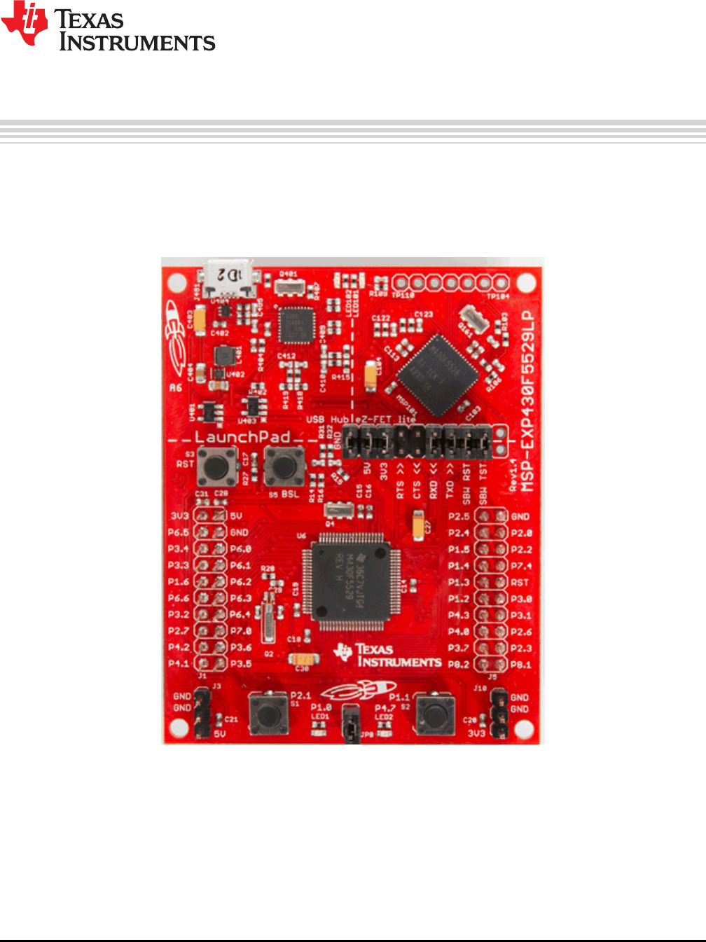
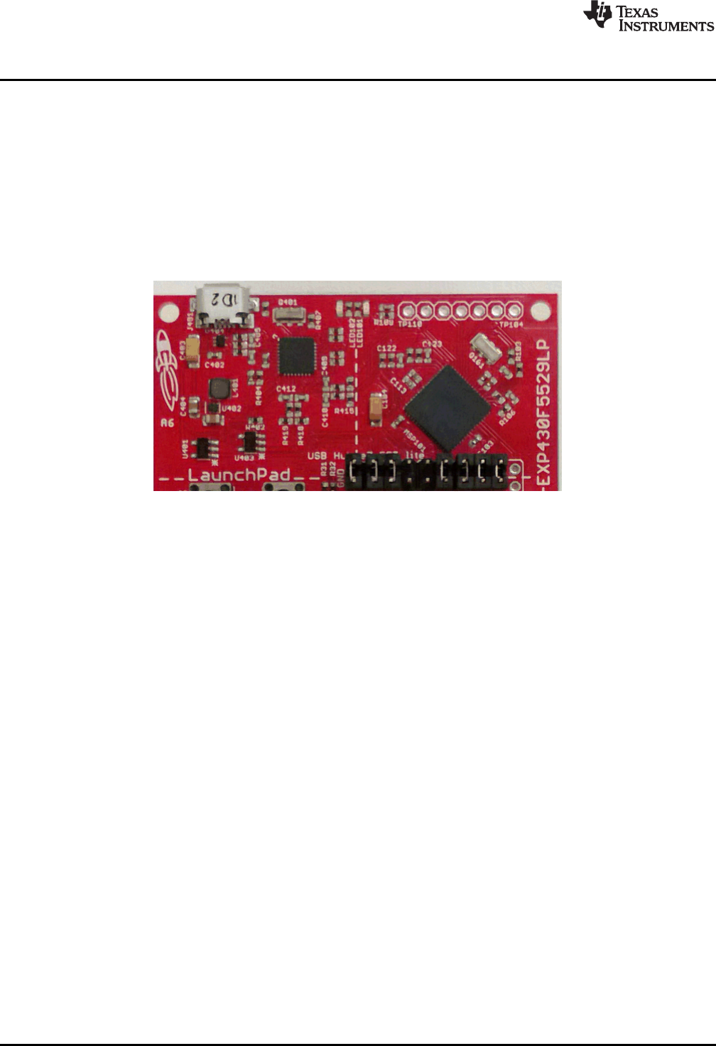
The MSP430™ LaunchPad™ development kit now has USB. The MSP-EXP430F5529LP is an
inexpensive and simple development kit for the MSP430F5529 USB microcontroller. It offers an easy way
to start developing on the MSP430 MCU, with onboard emulation for programming and debugging as well
as buttons and LEDs for a simple user interface.
Figure 1. MSP430F5529 LaunchPad Development Kit

www.ti.com
2SLAU533D–September 2013–Revised April 2017
Submit Documentation Feedback
Copyright © 2013–2017, Texas Instruments Incorporated
MSP430F5529 LaunchPad™ Development Kit (MSP
‑
EXP430F5529LP)
Contents
1 Getting Started ............................................................................................................... 4
2 Hardware...................................................................................................................... 9
3 Software Examples ........................................................................................................ 28
4 Additional Resources ...................................................................................................... 48
5 FAQs......................................................................................................................... 52
6 Schematics.................................................................................................................. 54
List of Figures
1 MSP430F5529 LaunchPad Development Kit ............................................................................ 1
2 Jumper Requirements Necessary for Software Demo.................................................................. 5
3 Storage Volume, Mounted from the MSC Interface..................................................................... 6
4 Files on the Storage Volume............................................................................................... 6
5 Default Text Typed From Button S1 ...................................................................................... 7
6 ASCII-Art Rocket, Typed from Button S2................................................................................. 8
7 EVM Features and Controls................................................................................................ 9
8 Block Diagram .............................................................................................................. 10
9 MSP430F5529 Pinout ..................................................................................................... 11
10 eZ-FET lite Emulator....................................................................................................... 12
11 Onboard USB Bus Path ................................................................................................... 13
12 F5529 LaunchPad Development Kit USB Interfaces.................................................................. 14
13 F5529 LaunchPad Development Kit Power Supply ................................................................... 14
14 Backchannel UART Pathway ............................................................................................. 16
15 Application Backchannel UART in Device Manager................................................................... 16
16 Isolation Jumper Block .................................................................................................... 17
17 Power Block Diagram for Default Configuration With USB Power Only ............................................ 19
18 Power Block Diagram for External 3.3-V Power Source.............................................................. 20
19 Power Block Diagram for External 5-V Power Source Without USB Connection ................................. 21
20 Power Block Diagram for External 5-V Power Source With USB Connection ..................................... 22
21 USB BSL Button............................................................................................................ 23
22 Identifying the USB BSL HID Interface in Device Manager .......................................................... 24
23 F5529 LaunchPad Development Kit to BoosterPack Plug-in Module Connector Pinout ......................... 26
24 Browse to Demo Project for Import Function........................................................................... 29
25 When CCS Has Found the Project ...................................................................................... 29
26 F5529 LaunchPad Development Kit Demo Software Organization ................................................. 30
27 MSP430 USB Descriptor Tool............................................................................................ 31
28 Demo Program Flow....................................................................................................... 32
29 Disable the Watchdog in Pre-Initialization .............................................................................. 33
30 Waking From LPM0........................................................................................................ 35
31 Movement of Data in simpleUsbBackchannel: CDC .................................................................. 39
32 simpleUsbBackchannel USB Virtual COM Port, Needing a Driver .................................................. 40
33 Device Manager After Both Ports are Enumerated.................................................................... 41
34 Movement of Data in simpleUsbBackchannel: HID-Datapipe ........................................................ 46
35 Start Device Manager ..................................................................................................... 46
36 Device Manager ............................................................................................................ 47
37 F5529 LaunchPad Development Kit With DLP-7970ABP NFC BoosterPack Plug-in Module ................... 48
38 USB Examples in the USB Developers Package...................................................................... 50
39 TI Resource Explorer: Create a New USB Project Wizard ........................................................... 51
40 Schematics (1 of 4) ........................................................................................................ 54

www.ti.com
3
SLAU533D–September 2013–Revised April 2017
Submit Documentation Feedback Copyright © 2013–2017, Texas Instruments Incorporated
MSP430F5529 LaunchPad™ Development Kit (MSP
‑
EXP430F5529LP)
41 Schematics (2 of 4) ........................................................................................................ 55
42 Schematics (3 of 4) ........................................................................................................ 56
43 Schematics (4 of 4) ........................................................................................................ 57
List of Tables
1 Files on the Storage Volume............................................................................................... 6
2 eZ-FET lite LED Feedback Behavior .................................................................................... 13
3 Isolation Block Connections .............................................................................................. 17
4 Hardware Change Log .................................................................................................... 27
5 Software Examples ........................................................................................................ 28
6 Demo Project File and Directory Descriptions.......................................................................... 30
7 Backchannel Library: Constants to Configure.......................................................................... 42
8 Backchannel Library: Functions .......................................................................................... 42
9 Clock Settings .............................................................................................................. 43
10 How MSP430 Device Documentation is Organized ................................................................... 48
Trademarks
MSP430, LaunchPad, BoosterPack, Code Composer Studio are trademarks of Texas Instruments.
IAR Embedded Workbench is a trademark of IAR Systems.
All other trademarks are the property of their respective owners.

Getting Started
www.ti.com
4SLAU533D–September 2013–Revised April 2017
Submit Documentation Feedback
Copyright © 2013–2017, Texas Instruments Incorporated
MSP430F5529 LaunchPad™ Development Kit (MSP
‑
EXP430F5529LP)
1 Getting Started
Rapid prototyping is simplified by the 40-pin BoosterPack™ plug-in module headers, which support a wide
range of available BoosterPack plug-in modules. You can quickly add features like wireless connectivity,
graphical displays, environmental sensing, and much more. You can either design your own BoosterPack
plug-in module or choose among many already available from TI and third-party developers.
The MSP430F5529 16-bit MCU has 128KB of flash memory, 8KB of RAM, 25-MHz CPU speed,
integrated USB, and many peripherals – plenty to get you started in your development.
Custom USB functionality can be quickly added using the free open-source USB tools and examples
available in the MSP430 USB Developers Package. This includes the MSP430 USB Descriptor Tool,
which quickly customizes any combination of USB interfaces and automatically generates your USB
descriptors for those interfaces.
Free software development tools are also available: TI's Eclipse-based Code Composer Studio™ IDE
(CCS) and IAR Embedded Workbench™ IDE (IAR), and the community-driven Energia open-source code
editor. More information about the LaunchPad development kit including documentation and design files
can be found on the tool page at www.ti.com/tool/msp-exp430f5529lp.
1.1 Key Features
• USB-enabled MSP430F5529 16-bit MCU
– Up to 25-MHz System Clock
– 1.8-V to 3.6-V operation
– 128KB of flash, 8KB of RAM
– Five timers
– Up to four serial interfaces (SPI, UART, I2C)
– 12-bit analog-to-digital converter
– Analog comparator
– Integrated USB, with a complete set of USB tools, libraries, examples, and reference guides
• The eZ-FET lite emulator, with the application ("backchannel") UART. (Now open-source!)
• Ability to emulate and develop USB applications with a single USB cable, made possible with an
onboard USB hub
• Power sourced from the USB host. The 5-V bus power is reduced to 3.3 V, using an onboard dc-dc
converter.
• Both male and female 40-pin BoosterPack plug-in module headers, configured for stacking. 20-pin
BoosterPack plug-in modules can also be attached.
• Compatible with the 40-pin BoosterPack plug-in module development tool standard.
1.2 Kit Contents
(1) MSP-EXP430F5529LP LaunchPad development kit
(1) USB cable with "micro" connectors
(1) Quick start guide
If you intend to write code for the F5529 LaunchPad development kit, you can complete the kit by
downloading the MSP-EXP430F5529LP Hardware Design Files and the MSP-EXP430F5529LP Software
Examples from the MSP-EXP430F5529LP tool page.
1.3 Out-of-Box Experience
The F5529 LaunchPad development kit comes programmed with an out-of-box demonstration example.
Let's get started!
This section only describes how to use the demo. More details about the F5529 LaunchPad development
kit are given later.
www.ti.com
Getting Started
5
SLAU533D–September 2013–Revised April 2017
Submit Documentation Feedback Copyright © 2013–2017, Texas Instruments Incorporated
MSP430F5529 LaunchPad™ Development Kit (MSP
‑
EXP430F5529LP)
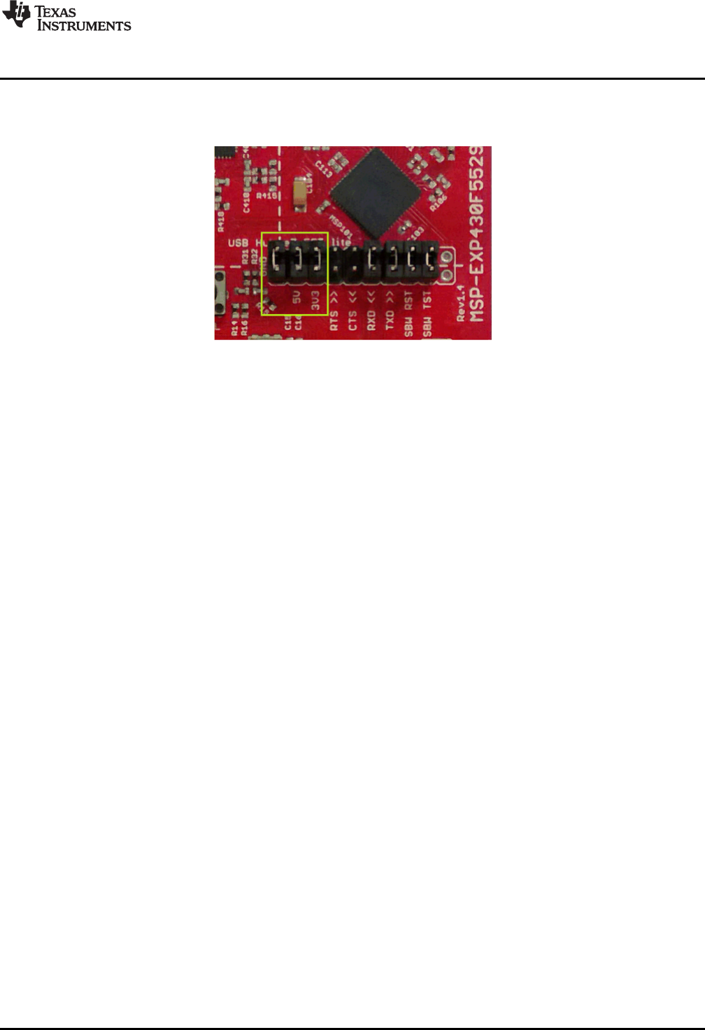
The demo works on a Windows PC, Linux PC, or Mac. It requires that (at minimum) the power jumpers
(3.3 V and 5 V) on the isolation jumper block be connected. These supply power to the target F5529
device. As shipped from TI, these jumpers are connected.
Figure 2. Jumper Requirements Necessary for Software Demo
1.3.1 Step 1: Install a Software Development Platform
The development platform can be Code Composer Studio IDE (CCS), IAR Embedded Workbench IDE
(IAR), mspgcc, or Energia open-source platform. See Section 3.2 for help choosing a platform.
The out-of-box demo works without this step, but the host reports that the integrated eZ-FET lite emulator
did not enumerate.
(Be aware that the USB API does not yet fully support mspgcc development, but mspgcc does contain the
eZ-FET drivers.)
1.3.2 Step 2: Connect the Hardware
Connect the LaunchPad development kit to a host PC using the USB cable included with the LaunchPad
development kit. The demo should work on any recent version of these operating systems. If prompted, let
the PC automatically install software. The install is "silent", which means that the PC's operating system
already has the drivers it needs.
When you connect a USB device to your computer, the computer goes through the enumeration process.
During enumeration, the host asks for the device's USB descriptors to learn the device's identity,
capabilities, and more. Using the descriptors, the device presents one or more USB interfaces to the host,
where each interface is associated with either a pre-defined device class, or a custom driver. The major
operating systems already ship with drivers for most common device classes, which is why you do not
need to provide them during installation.
The F5529 LaunchPad development kit software demo presents two USB interfaces to the host:
• A Mass Storage Class (MSC) interface, which results in a storage volume
• A Human Interface Device (HID) interface, which is configured as a keyboard
All major host operating systems already have drivers for these classes.
Note: The eZ-FET emulator, application UART, and USB hub also enumerate when the LaunchPad
development kit is attached. These are part of the LaunchPad development kit emulator, and so they
always enumerate on Windows and Linux PCs, no matter what software is loaded into the MSP430F5529
device. In contrast, the MSC and HID interfaces described in this section are generated by the software
demo application that is loaded onto the LaunchPad development kit as shipped from TI. See
Section 2.2.3 for more information.
Getting Started
www.ti.com
6SLAU533D–September 2013–Revised April 2017
Submit Documentation Feedback
Copyright © 2013–2017, Texas Instruments Incorporated
MSP430F5529 LaunchPad™ Development Kit (MSP
‑
EXP430F5529LP)
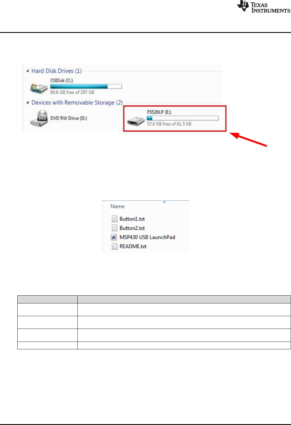
1.3.3 Step 3: Verify the storage volume has been loaded
When you attach the LaunchPad development kit to the PC, a storage volume is mounted on the host.
This volume can be seen in "My Computer", with the name "F5529LP":
Figure 3. Storage Volume, Mounted from the MSC Interface
This storage volume is stored within the MSP430F5529's on-chip flash. It is small compared to most flash
drives, but it is large enough for the demo's needs. The MSP430 software presents it to the host through
the MSC interface.
If you open the volume, you see these files:
Figure 4. Files on the Storage Volume
Table 1 describes the function of these files.
Table 1. Files on the Storage Volume
File Description
Button1.txt Contains the text that will be "typed" by the keyboard interface when button S1 is pressed. By default,
its contents are "Hello World".
Button2.txt Contains the text that will be "typed" by the keyboard interface when button S2 is pressed. By default,
it contains "ASCII art" of the LaunchPad development kit "rocket" logo.
MSP430 USB
LaunchPad.url Opening this file causes your web browser to launch the MSP-EXP430F5529LP LaunchPad
development kit web page
README.txt A "readme" file that helps explain how to use these files.
If you place other files inside the volume, they are stored inside flash of the MSP430 MCU. The volume is
only approximately 60KB in size. If you later download the software demo (or any software) to the F5529
target, any data that you have placed in the volume will be lost.
If you change the name of the Button1.txt or Button2.txt file, the pushbutton functionality no longer works.
This is because the MSP430 demo software looks for these files by name.
www.ti.com
Getting Started
7
SLAU533D–September 2013–Revised April 2017
Submit Documentation Feedback Copyright © 2013–2017, Texas Instruments Incorporated
MSP430F5529 LaunchPad™ Development Kit (MSP
‑
EXP430F5529LP)
1.3.4 Step 4: Open a text editor, and press the buttons
In addition to the MSC interface, the other USB interface that is enumerated by the demo is an HID
interface, which is used to emulate a keyboard. When you press the S1 or S2 button, the text stored in the
Button1.txt or Button2.txt file, respectively, is sent to your computer as typed keystrokes.
To see the keyboard in action, open a text editor. If using Windows, the standard Notepad application is a
good choice. (To open Notepad, click the Start button, then click Run…, type "notepad" in the Open text
box, and click OK.)
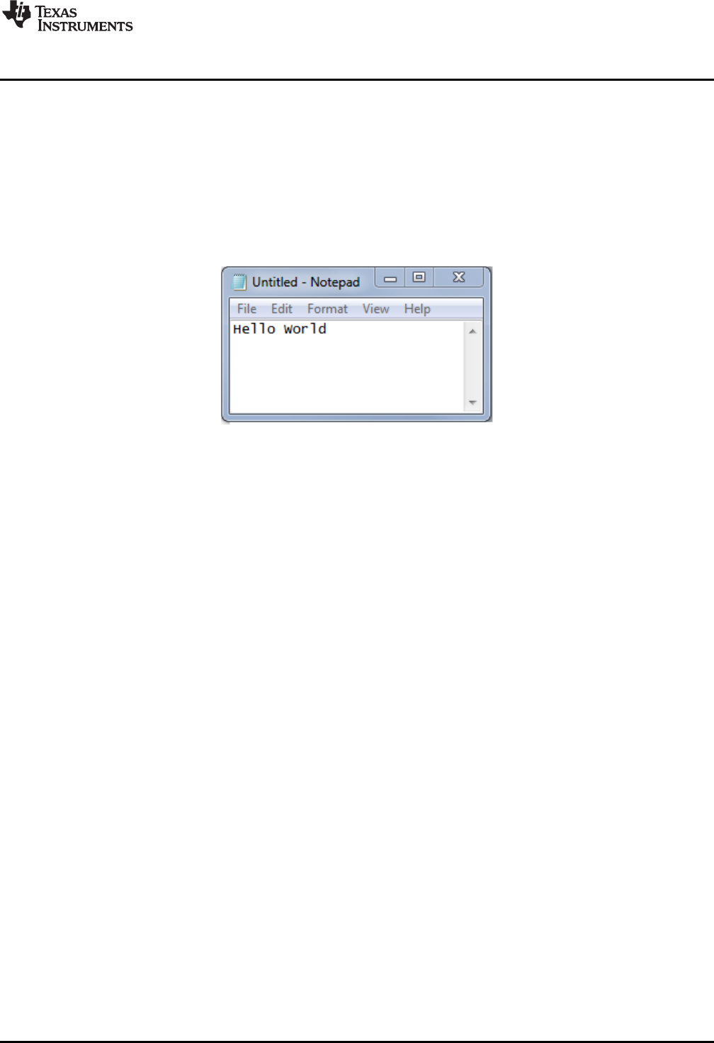
Make sure the window focus is on the text editor and not on another application running on the PC. Then
press the S1 button on the LaunchPad development kit to send the text in Figure 5 to Notepad.
Figure 5. Default Text Typed From Button S1
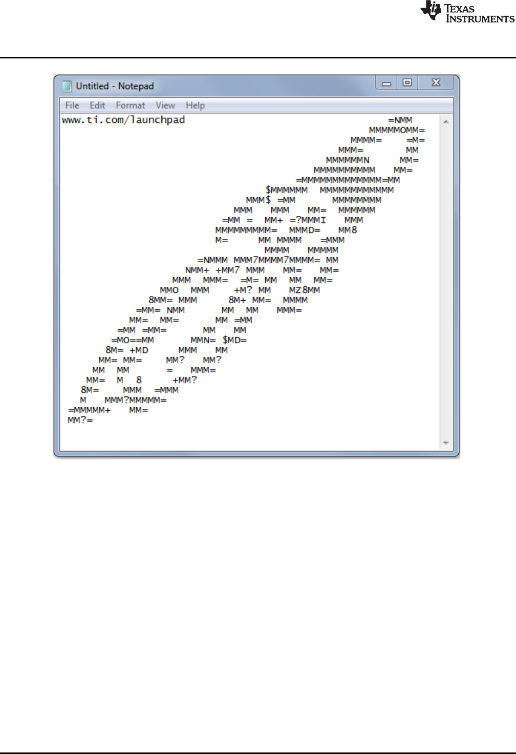
Then delete this text, and press the S2 button on the Launchpad to send the text in Figure 6 to Notepad.
Getting Started
www.ti.com
8SLAU533D–September 2013–Revised April 2017
Submit Documentation Feedback
Copyright © 2013–2017, Texas Instruments Incorporated
MSP430F5529 LaunchPad™ Development Kit (MSP
‑
EXP430F5529LP)
Figure 6. ASCII-Art Rocket, Typed from Button S2
The rocket can take a few seconds to type out. While the MCU is typing this out, be sure not to change
the PC window focus outside of Notepad. If you change the focus, keystrokes will be sent to whatever
application has focus, and strange things might happen on your PC.
1.3.5 Step 5: Customize the strings
Because the strings typed out by the S1 and S2 buttons originate from the Button1.txt and Button2.txt
files, respectively, you can change these strings. Open these files in a text editor, modify their contents,
and save the files. Then press the corresponding button; your new string is typed out.
There is a 2048-character limit on each string, a limit set within the software. The limit is necessary
because the software reads the files' strings into a RAM buffer before typing, and the size of this RAM
buffer is 2048 bytes.
Develop your own USB
applications and emulate,
using a single USB cable!
Integrated USB hub and
USB-based power supply
RESET button, for
the target device
Button that invokes the
USB bootstrap loader,
for firmware updates
Pushbuttons and LEDs,
for user interface
eZ-FET emulator
·Open-source
·Works with almost any
MSP430 target
40-pin BoosterPack header
·Compatible with 20-pin and
40-pin BoosterPacks
·Now allows BoosterPacks
with more functionality
Isolation Jumper Block
·Connect to other targets
·Allow more accurate power
measurement
MSP430F5529 USB Microcontroller
·128KB flash, 8KB RAM
·Full-speed USB
·ADC
·5 timers
·4 serial interfaces (SPI, UART, I C)
2
·Analog comparator
·Much more !
www.ti.com
Hardware
9
SLAU533D–September 2013–Revised April 2017
Submit Documentation Feedback Copyright © 2013–2017, Texas Instruments Incorporated
MSP430F5529 LaunchPad™ Development Kit (MSP
‑
EXP430F5529LP)
2 Hardware
This section describes the F5529 LaunchPad development kit hardware.
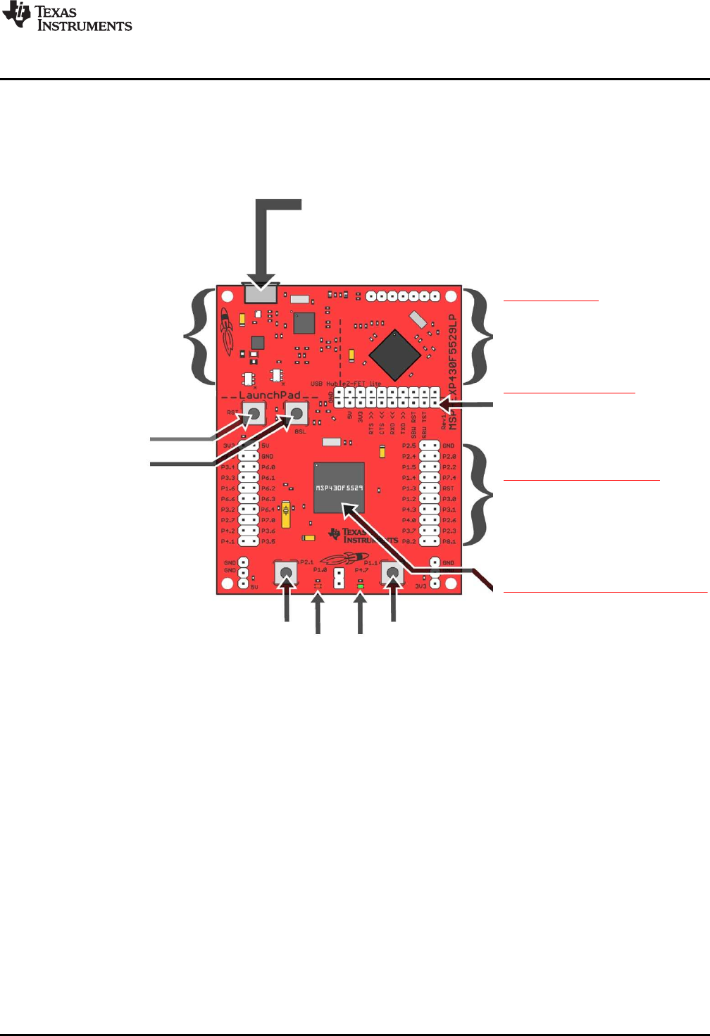
Figure 7 shows the LaunchPad development kit, with its important features and configuration controls.
These controls are described in this section.
Figure 7. EVM Features and Controls
32kHz
4MHz
Target Device
MSP430F5529
40-pin (4x10) Boosterpack Interface
4MHz
ESD
Protection
TUSB2046
Full-Speed
USB Hub
6MHz
USB Connector
eZ-FET lite
Emulator
MCU
TPS62237
5V-3.3V
DC-DC Converter
User LEDs and Switches
ResetUSB BSL
Isolation
Jumper Block
Spy-Bi-Wire (SBW)
Emulation
Application UART
Application USB
40-pin (4x10) Boosterpack Interface
USB Hub / Power
eZ-FET lite Emulator
3.3V Power
5V VBUS
3.3V
Power
Header
Jumper
Power
Header
USB
USB Data 5V VBUS
Emulator USB
5V VBUS
Hardware
www.ti.com
10 SLAU533D–September 2013–Revised April 2017
Submit Documentation Feedback
Copyright © 2013–2017, Texas Instruments Incorporated
MSP430F5529 LaunchPad™ Development Kit (MSP
‑
EXP430F5529LP)
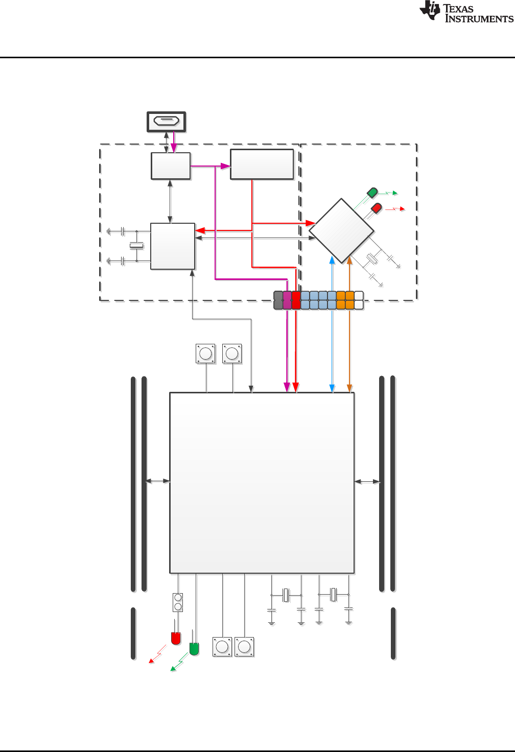
2.1 Block Diagram
Figure 8 shows a functional block diagram of the board.
Figure 8. Block Diagram
1
2
3
4
5
6
7
8
9
10
11
12
13
14
15
16
17
18
19
20
61
62
63
64
65
66
67
68
69
70
71
72
73
74
75
76
77
78
79
80
60
59
58
57
56
55
54
53
52
51
50
49
48
47
46
45
44
43
42
41
40
39
38
37
36
35
34
33
32
31
30
29
28
27
26
25
24
23
22
21
P6.4/CB4/A4
P6.5/CB5/A5
P6.6/CB6/A6
P6.7/CB7/A7
P7.0/CB8/A12
P7.1/CB9/A13
P7.2/CB10/A14
P7.3/CB11/A15
P5.0/A8/VREF+/VeREF+
P5.1/A9/VREF−/VeREF−
AVCC1
AVSS1
P5.4/XIN
P5.5/XOUT
P1.0/TA0CLK/ACLK
P1.1/TA0.0
P1.2/TA0.1
P1.3/TA0.2
DVCC2
DVSS2
VCORE
RST/NMI/SBWTDIO
PJ.3/TCK
PJ.2/TMS
PJ.1/TDI/TCLK
PJ.0/TDO
TEST/SBWTCK
P5.3/XT2OUT
P5.2/XT2IN
AVSS2
V18
VUSB
VBUS
PU.1/DM
PUR
PU.0/DP
VSSU
P1.6/TA1CLK/CBOUT
P1.5/TA0.4
P1.7/TA1.0
P2.2/TA2CLK/SMCLK
P2.0/TA1.1
P2.3/TA2.0
P2.4/TA2.1
P2.5/TA2.2
P2.6/RTCCLK/DMAE0
P2.7/UCB0STE/UCA0CLK
P3.0/UCB0SIMO/UCB0SDA
P3.1/UCB0SOMI/UCB0SCL
P3.2/UCB0CLK/UCA0STE
P3.3/UCA0TXD/UCA0SIMO
P3.4/UCA0RXD/UCA0SOMI
P7.4/TB0.2
P7.5/TB0.3
DVSS1
DVCC1
P1.4/TA0.3
P2.1/TA1.2
P3.6/TB0.6
P3.7/TB0OUTH/SVMOUT
P4.2/PM_UCB1SOMI/PM_UCB1SCL
P4.1/PM_UCB1SIMO/PM_UCB1SDA
P4.0/PM_UCB1STE/PM_UCA1CLK
P4.5/PM_UCA1RXD/PM_UCA1SOMI
P4.4/PM_UCA1TXD/PM_UCA1SIMO
P4.3/PM_UCB1CLK/PM_UCA1STE
P4.6/PM_NONE
P4.7/PM_NONE
P5.6/TB0.0
P5.7/TB0.1
P7.6/TB0.4
P7.7/TB0CLK/MCLK
P6.3/CB3/A3
P6.2/CB2/A2
P6.1/CB1/A1
P6.0/CB0/A0
P3.5/TB0.5
P8.0
P8.1
P8.2
www.ti.com
Hardware
11
SLAU533D–September 2013–Revised April 2017
Submit Documentation Feedback Copyright © 2013–2017, Texas Instruments Incorporated
MSP430F5529 LaunchPad™ Development Kit (MSP
‑
EXP430F5529LP)
2.2 Hardware Features
2.2.1 MSP430F5529
The MSP430F552x is one of several USB-equipped MSP430 MCU families. It offers:
• 1.8-V to 3.6-V operation
• Up to 25-MHz system clock
• 128KB flash memory, 8KB RAM (in addition to 2KB shared RAM with the USB module)
• Ultra-low-power operation
• Full-speed USB with 14 endpoints – enough for almost any USB application
• Five timers, up to four serial interfaces (SPI, UART, or I2C), 12-bit analog-to-digital converter, analog
comparator, hardware multiplier, DMA, and more
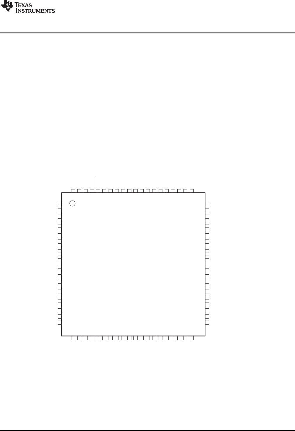
Figure 9 shows the pinout of the MSP430F5529 in the PN package (LQFP).
Figure 9. MSP430F5529 Pinout
Hardware
www.ti.com
12 SLAU533D–September 2013–Revised April 2017
Submit Documentation Feedback
Copyright © 2013–2017, Texas Instruments Incorporated
MSP430F5529 LaunchPad™ Development Kit (MSP
‑
EXP430F5529LP)
Other USB-equipped MSP430 MCU families include the smaller F550x family and the larger F563x,
F663x, F565x, and F665x families.
To compare the various MSP430 MCUs, download the MSP430 Product Brochure, which is also available
from http://www.ti.com/msp430. The brochure has a table that lets you see at a glance how the families
compare and their pricing. This document is frequently updated as new MSP430 MCUs become available.
2.2.2 eZ-FET lite Onboard Emulator
To simplify development and keep the user's costs low, TI's LaunchPad development kit development
tools integrate an emulator for programming and debugging. The F5529 LaunchPad development kit has
the new eZ-FET lite emulator (see Figure 10).
Figure 10. eZ-FET lite Emulator
The dotted line along the bottom of the image divides the emulator area from the target area. (On the
board, the power and hub area that is shown in Figure 8 is grouped with the emulator.)
The eZ-FET lite is simple and low cost. Like the emulator on the G2 LaunchPad development kit (MSP-
EXP430G2), it provides a "backchannel" UART-over-USB connection with the host, which can be very
useful during debugging. But unlike the G2 emulator, it:
• supports almost all MSP430 MCUs
• has a configurable backchannel UART baudrate
• is completely open source!
The hardware and firmware designs are both available for you to customize. Further details and source
can be found on http://processors.wiki.ti.com/index.php/EZ-FET_lite.
The eZ-FET lite needs a host-side interface. TI provides the "MSP430 DLL", through which PC
applications can access the eZ-FET lite. Such applications include IAR or CCS software environments,
MSP430Flasher, Elprotronic's FET-Pro430, mspgcc, and Energia. These solutions generally bundle the
DLL.
On Windows, the MSP430 DLL is a DLL file, while on Linux it is a *.so file. Like the rest of the eZ-FET lite
solution, the DLL is open source.
Mac OS X has a limitation that prevents it from enumerating composite USB devices that include a CDC
interface. For this reason, the eZ-FET lite currently does not work with the default OS X.
The eZ-FET lite works with almost all MSP430 target devices. If you want to work with a different target
than the F5529 device on the F5529 LaunchPad development kit, you can disconnect the F5529 using the
isolation jumper block and wire your hardware to the emulator through this block.
TUSB2046
Full-Speed USB Hub
USB Connector
Target
F5529
eZ-FET lite
Emulator
www.ti.com
Hardware
13
SLAU533D–September 2013–Revised April 2017
Submit Documentation Feedback Copyright © 2013–2017, Texas Instruments Incorporated
MSP430F5529 LaunchPad™ Development Kit (MSP
‑
EXP430F5529LP)
Features of the eZ-FET lite:
• USB debugging and programming interface
• No need to install a driver on the host Windows or Linux PC – it loads silently
• Application ("backchannel UART") virtual COM port connection with the host, over USB, up to 1 Mbaud
• LEDs for visual feedback
• Field-updatable firmware
• Supports almost all MSP430 MCUs
Hardware and software requirements
• PC with Windows or Linux
• MSP430.DLL 3.3.0.6 or higher
The eZ-FET lite LEDs provide feedback to the user about the emulator status (see Table 2). This behavior
is similar to that of the MSP-FET430UIF emulator.
Table 2. eZ-FET lite LED Feedback Behavior
Green LED
(Power) Red LED
(Mode) Description
OFF OFF eZ-FET lite is not connected to the PC. eZ-FET lite is not ready (for example, after an
update). Disconnect the LaunchPad development kit from the PC and reconnect it.
ON OFF eZ-FET lite is connected and ready, but the. eZ-FET lite interface has not been opened by
IDE.
ON ON eZ-FET lite interface is used by IDE, but no data transfer is taking place.
ON Blinking eZ-FET lite is in action: data transfer between eZ-FET lite and IDE is taking place.
OFF ON A severe ERROR has occurred; disconnect and reconnect the eZ-FET lite. If this does not
resolve the error, send for repair.
Alternating green and red blinking A critical update is running on the eZ-FET lite. Do not interfere with it during this time.
Wait until it is finished.
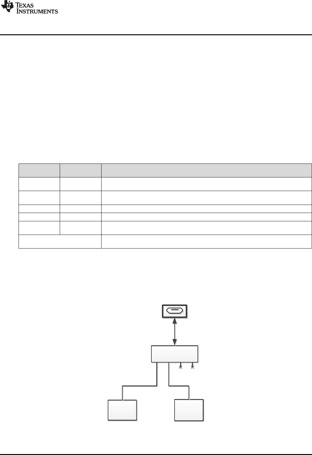
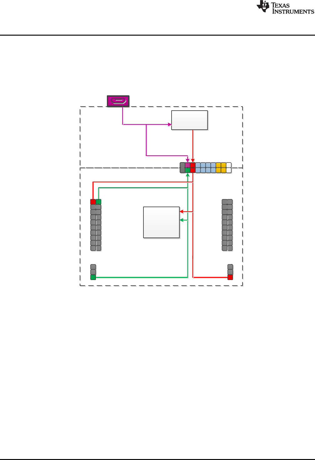
2.2.3 Integrated Full-Speed USB Hub
The F5529 LaunchPad development kit requires only one USB connection to the host, thanks to an
integrated USB hub (see Figure 11). The emulator and the target device share one USB cable and can be
used simultaneously. This simplifies the development setup.
Figure 11. Onboard USB Bus Path
USB Connector
TPS62237
DC-DC Converter
Isolation
Jumper Block
eZ-FET lite
eZ-FET lite 5V
eZ-FET lite 3.3V
5V in
3.3V out
MSP430F5529 Target
5529 Target + BoosterPack 5V
5529 Target + BoosterPack 3.3V
MSP430F5529
Target Device
* 5V and 3V3
Isolation Block
Jumpers Control
Power Connection
Hardware
www.ti.com
14 SLAU533D–September 2013–Revised April 2017
Submit Documentation Feedback
Copyright © 2013–2017, Texas Instruments Incorporated
MSP430F5529 LaunchPad™ Development Kit (MSP
‑
EXP430F5529LP)
The eZ-FET lite emulator itself is a composite USB device, which means that it contains two USB
interfaces:
• A CDC interface (virtual COM port) for the emulation function
• A CDC interface (virtual COM port) for the application UART
(For an explanation of USB interfaces, see the discussion in Step 2 of Section 1.3)
These interfaces can be found on the host PC. As an example, Device Manager can be used for this
purpose on a Windows PC. (See Section 3.7 for instructions on starting Device Manager.) Look for the
emulator interfaces under the "Ports" section (see Figure 12).
Figure 12. F5529 LaunchPad Development Kit USB Interfaces
If you are using a Mac, see Section 2.2.2 for an explanation why these interfaces do not enumerate.
Although the MSP Debug Interface virtual COM port is accessible to any host application, do not try to
interface with it; it is only intended for use with supported emulation tools, like CCS and IAR.
If you load a USB-equipped software application into the target MSP430F5529 device, then additional
USB interfaces, defined by that software, will be enumerated on the host.
The TUSB2046 is a four-port hub, and two ports are unused. The unused ports are properly terminated
and inaccessible.
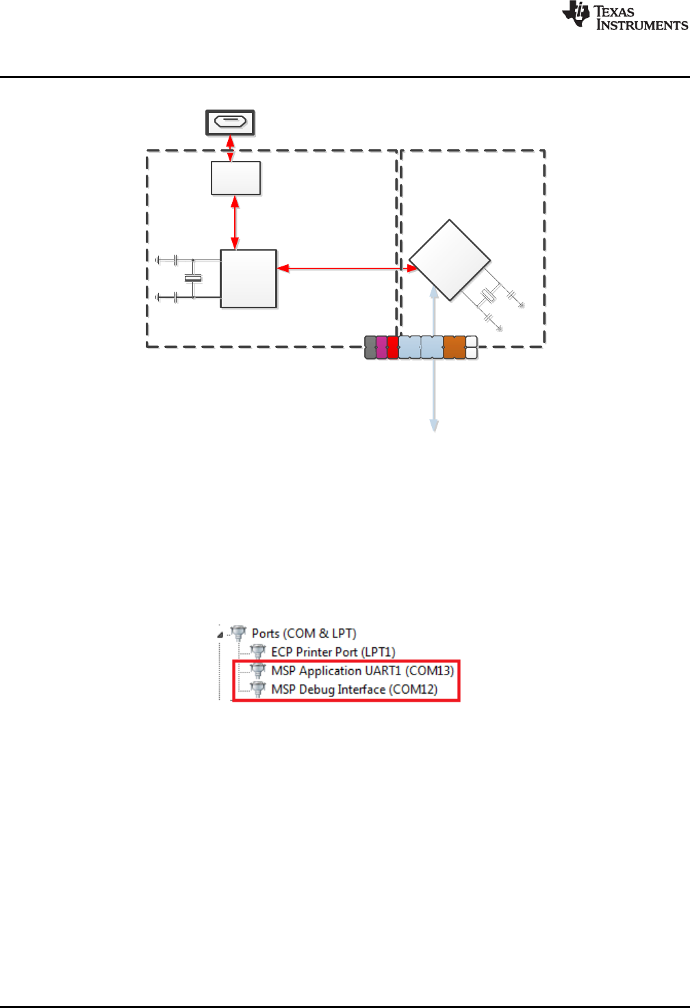
2.2.4 Power
Figure 13 shows the power segment of the block diagram.
Figure 13. F5529 LaunchPad Development Kit Power Supply

www.ti.com
Hardware
15
SLAU533D–September 2013–Revised April 2017
Submit Documentation Feedback Copyright © 2013–2017, Texas Instruments Incorporated
MSP430F5529 LaunchPad™ Development Kit (MSP
‑
EXP430F5529LP)
USB hosts supply a 5-V power rail to USB devices, called "VBUS". This is convenient for USB devices; if
they only need to function while attached to a host (for example, mice or keyboards) then they may not
need their own power source. Even if they need to function apart from the USB host and, thus, need their
own power source, being attached to the host places power demands on that device which may not be
present when the device is not attached; the availability of VBUS can help offset these demands.
The F5529 LaunchPad development kit has a high-efficiency dc-dc converter, a TPS62237, that derives a
new power rail of 3.3 V from VBUS. This 3.3-V rail sources the eZ-FET lite, hub, target F5529 device, and
the 3.3-V pin on the BoosterPack plug-in module header.
VBUS is still made available to the target F5529 device for two reasons. One reason is that the presence
of VBUS is how a USB device determines the presence of a USB host. The other reason is that VBUS
also supplies power to the target F5529 USB module.
USB-equipped MSP430 MCUs have an integrated 5-V to 3.3-V LDO. On the F5529 LaunchPad
development kit, this LDO is only used for the MSP430F5529 USB operation. However, the integrated
LDO also has an output pin that can source a modest amount of power to external circuitry. See the
device data sheet for more details. Sometimes, this output pin can eliminate the need for external power
management. But because the current limit may be too low for some applications, the F5529 LaunchPad
development kit uses the external dc-dc converter.
If desired, 3.3 V can be supplied from an external source to the power header pin. But to do this, the 3.3-V
jumper on the isolation jumper block must be disconnected. See Section 2.4 for more information.
2.2.5 Clocking
The F5529 LaunchPad development kit provides two resonators on the target F5529:
• XT1: a 32-kHz crystal
• XT2: a 4-MHz ceramic resonator, within ±2500-ppm precision
The 32-kHz crystal allows for lower LPM3 sleep currents than do the other low-frequency clock sources.
Therefore, the presence of the crystal allows the full range of low-power modes to be used.
USB operation on the MSP430F5529 requires a high-frequency reference clock for the USB PLL. To meet
this need, the F5529 LaunchPad development kit has a 4-MHz ceramic resonator on the XT2 oscillator.
This particular ceramic resonator operates within ±2500 ppm, which is important for USB operation. If the
F5529 application needs a high-frequency precision clock for purposes other than USB, then this clock is
available for this as well.
For information on how clocks are configured by the software examples, see Section 3.6.5.3.
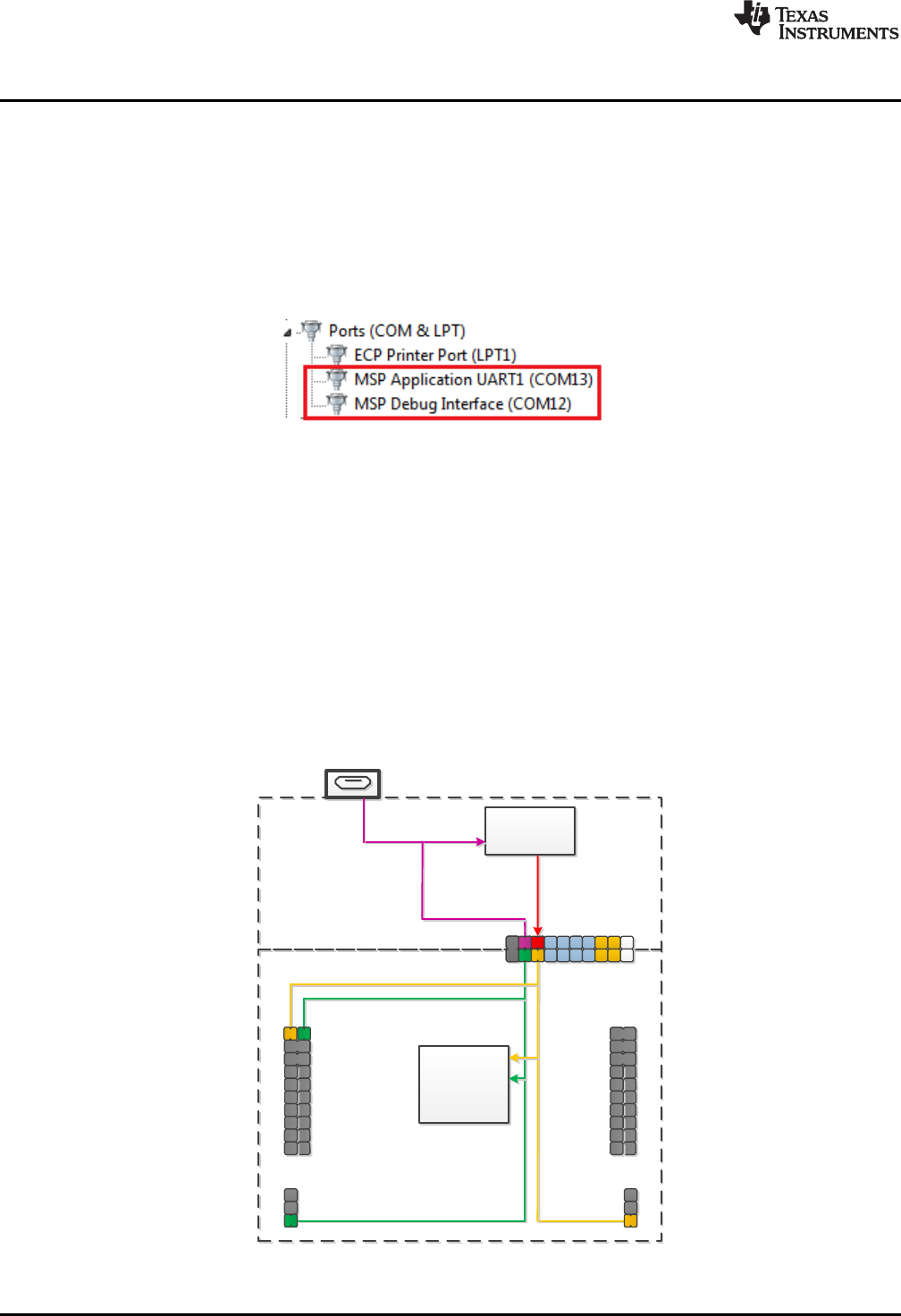
2.2.6 Application (or "Backchannel") UART
The backchannel UART allows communication with the USB host that is not part of the target application
main functionality. This is very useful during development. For example, if, while developing a USB
interface, you want to send debug information to the host without using the USB interfaces under
development to do so.
Figure 14 shows the pathway of the backchannel UART. The backchannel UART (USCI_A1) is
independent of the UART on the 40-pin BoosterPack plug-in module connector (USCI_A0).
ESD
Protection
TUSB2046
Full-Speed
USB Hub
6MHz
USB Connector
UART
USB Hub and Power
eZ-FET lite Emulator
USB
USB
F5529 dŒPš[•
USCI_A1 Interface
4MHz
eZ-FET lite
Emulator
MCU
Isolation
Jumper Block
Hardware
www.ti.com
16 SLAU533D–September 2013–Revised April 2017
Submit Documentation Feedback
Copyright © 2013–2017, Texas Instruments Incorporated
MSP430F5529 LaunchPad™ Development Kit (MSP
‑
EXP430F5529LP)
Figure 14. Backchannel UART Pathway
On the host side, a virtual COM port for the application backchannel UART is generated when the F5529
LaunchPad development kit enumerates on the host. You can use any PC application that interfaces with
COM ports, including terminal applications like Hyperterminal or Docklight, to open this port and
communicate with the target application.
You need to identify the COM port for the backchannel. On Windows PCs, Device Manager can assist
(see Figure 15). (See Section 3.7 for instructions on starting Device Manager.)
Figure 15. Application Backchannel UART in Device Manager
The backchannel UART is the port named "MSP Application UART1". In this example, the figure shows
COM13, but the port number varies from one host PC to the next.
After you identify the correct COM port, configure it in your host application according to its
documentation. You can then open the port and begin talking to it from the host.
On the target F5529 side, the backchannel is connected to the USCI_A1 module.
Unlike the eZ-FET on the G2 LaunchPad development kit, this eZ-FET lite has a configurable baudrate.
Therefore, it is important that the PC application configures the baudrate to be the same as what is
configured on the USCI_A1.
www.ti.com
Hardware
17
SLAU533D–September 2013–Revised April 2017
Submit Documentation Feedback Copyright © 2013–2017, Texas Instruments Incorporated
MSP430F5529 LaunchPad™ Development Kit (MSP
‑
EXP430F5529LP)
Also unlike the eZ-FET on the G2 LaunchPad development kit, this eZ-FET lite supports hardware flow
control, if desired. Hardware flow control (CTS and RTS handshaking) allows the target F5529 and the
emulator to tell each other to wait before sending more data. At slow baud rates and with simple target
applications, flow control may not be necessary. An application with faster baud rates and more interrupts
to service has a higher likelihood that it cannot read the USCI_A1 RXBUF register in time, before the next
byte arrives. If this happens, the USCI_A1 UCA1STAT register will report an overrun error.
To implement the backchannel on the target F5529, a simple library is provided within the
simpleUsbBackchannel example. It supports communication with and without hardware flow control. See
Section 3.6.4 for more information.
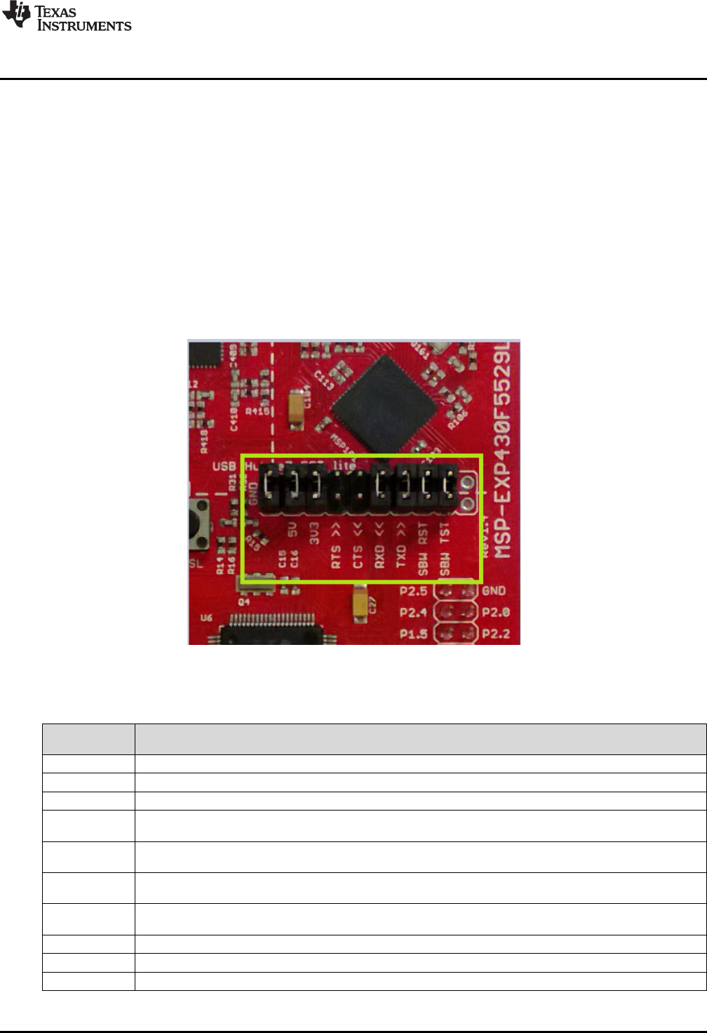
2.2.7 Emulator and Target Isolation Jumper Block
A set of ten jumpers is placed between the emulator and the F5529 target device. This is the isolation
jumper block (see Figure 16 and Table 3). Individual functions on the isolation block are described in the
following sections.
Figure 16. Isolation Jumper Block
Table 3. Isolation Block Connections
Jumper (from
left to right) Description
GND Ground
5V 5-V VBUS, sourced from the USB host. The F5529 target needs this if attempting a USB connection with it.
3V3 3.3-V rail, derived from VBUS with a dc-dc converter
RTS >> Backchannel UART: Ready-To-Send, for hardware flow control. The target can use this to indicate whether it is
ready to receive data from the host PC. The arrows indicate the direction of the signal.
CTS << Backchannel UART: Clear-To-Send, for hardware flow control. The host PC (through the emulator) uses this to
indicate whether it is ready to receive data. The arrows indicate the direction of the signal.
RXD << Backchannel UART: the target F5529 receives data through this signal. The arrows indicate the direction of the
signal.
TXD >> Backchannel UART: the target F5529 sends data through this signal. The arrows indicate the direction of the
signal.
SBW RST Spy-Bi-Wire emulation: SBWTDIO data signal. This pin also functions as the RST signal (active low).
SBW TST Spy-Bi-Wire emulation: SBWTCK clock signal. This pin also functions as the TST signal.
N/C Not connected. Reserved.

Hardware
www.ti.com
18 SLAU533D–September 2013–Revised April 2017
Submit Documentation Feedback
Copyright © 2013–2017, Texas Instruments Incorporated
MSP430F5529 LaunchPad™ Development Kit (MSP
‑
EXP430F5529LP)
2.2.8 Isolation Jumper Block: 3.3-V and 5-V Jumpers
The 5-V VBUS and 3.3-V power rails, which are sourced to the target from the emulator, travel through
the isolation jumper block. This routing serves these functions:
• Measurement of the target power consumption
• Removing the emulator from the circuit when an external (non-USB) power source is used
• Removing the F5529 target from the circuit when a different external target board is attached to the
emulator
Measuring the target power draw is as simple as removing the 3.3-V jumper and connecting an ammeter
across it. The USB hub, emulator and dc-dc converter currents are then excluded from this measurement.
However, anything that is connected on the F5529 LaunchPad development kit headers or power pins on
the target domain below the dotted silkscreen line are included. If precise current measurement is needed,
it is important to disconnect the backchannel UART and SBW lines in the jumper block as well.
See Section 2.3 for more information about measuring power using these jumpers.
Sometimes you may want to use an external 3.3-V power source connected to the target power header
pins. In this case, the 3.3-V jumper must be disconnected to avoid back-powering the emulator. See
Section 2.4 for more information on this procedure.
Otherwise, in normal operation, both these jumpers should be attached.
2.2.9 Isolation Jumper Block: Emulator Connection and Application UART
MSP430F5xx devices support both standard four-wire JTAG and the two-wire Spy-Bi-Wire (SBW)
standard. The eZ-FET lite emulator on the F5529 LaunchPad development kit supports SBW only. These
two signals travel through jumpers in the isolation block, and can be disconnected if desired. They are
labeled on the block as "SBW RST" and "SBW TEST".
The backchannel UART consists of four signals: the data signals TXD and RXD, and the hardware flow
control signals RTS and CTS. All four of these signals travel through the jumper block as well and can be
disconnected.
Reasons to open these connections:
• When measuring current consumption, devices attached to I/O pins can consume power, influencing
the measurement. Removing the jumpers prevents this.
• The backchannel UART pins can be configured for other functionality instead of the backchannel
UART. If this is desired, it might be good to remove these jumpers, so that the emulator is not affected
by any activity that your application presents on these signals. If only two general I/Os are needed and
if hardware flow control is not needed, you might choose to remove only the hardware flow control
(RTS and CTS) jumpers and leave the TXD and RXD jumpers in place.
• If you want to use the onboard eZ-FET lite emulator with a different target, you can remove the
jumpers and connect your target hardware to the jumper block.
2.3 Measure Current Draw of MSP430 MCU
The following steps assume that the target F5529 is to be powered from the USB host, not from an
external power source.
1. Remove the 3V3 jumper in the isolation jumper block. Attach an ammeter across this jumper.
2. Consider the effect that the backchannel UART and any circuitry attached to the F5529 may have on
current draw. Maybe these should be disconnected, or their current sinking and sourcing capability at
least considered in the final measurement.
3. Make sure there are no floating input I/Os. These cause unnecessary extra current draw. Every I/O
should either be driven out or, if an input, should be pulled or driven to a high or low level.
4. Begin target F5529 execution.
5. Measure the current. (Keep in mind that if the current levels are fluctuating, it may be difficult to get a
stable measurement. It is easier to measure quiescent states.)
USB Connector
TPS62237
DC-DC Converter
Isolation
Jumper Block
eZ-FET lite 5V
eZ-FET lite 3.3V
5V in
3.3V out
MSP430F5529 Target
5529 Target + BoosterPack 5V
5529 Target + BoosterPack 3.3V
MSP430F5529
Target Device
* 5V and 3V3
Isolation Block
Jumpers
Connected
eZ-FET lite
www.ti.com
Hardware
19
SLAU533D–September 2013–Revised April 2017
Submit Documentation Feedback Copyright © 2013–2017, Texas Instruments Incorporated
MSP430F5529 LaunchPad™ Development Kit (MSP
‑
EXP430F5529LP)
This measurement does not include USB current, which is sourced through the 5V jumper instead. USB
current levels can vary widely, depending on whether the connection is active or suspended, how much
bus activity is happening, how long the cable is, and other factors.
If you are trying to achieve the LPM3 values shown in the F5529 data sheet and are having trouble,
download the F5529 code examples and see MSP430F552x_LPM3_01.c, adjusting the I/O settings for
your application.
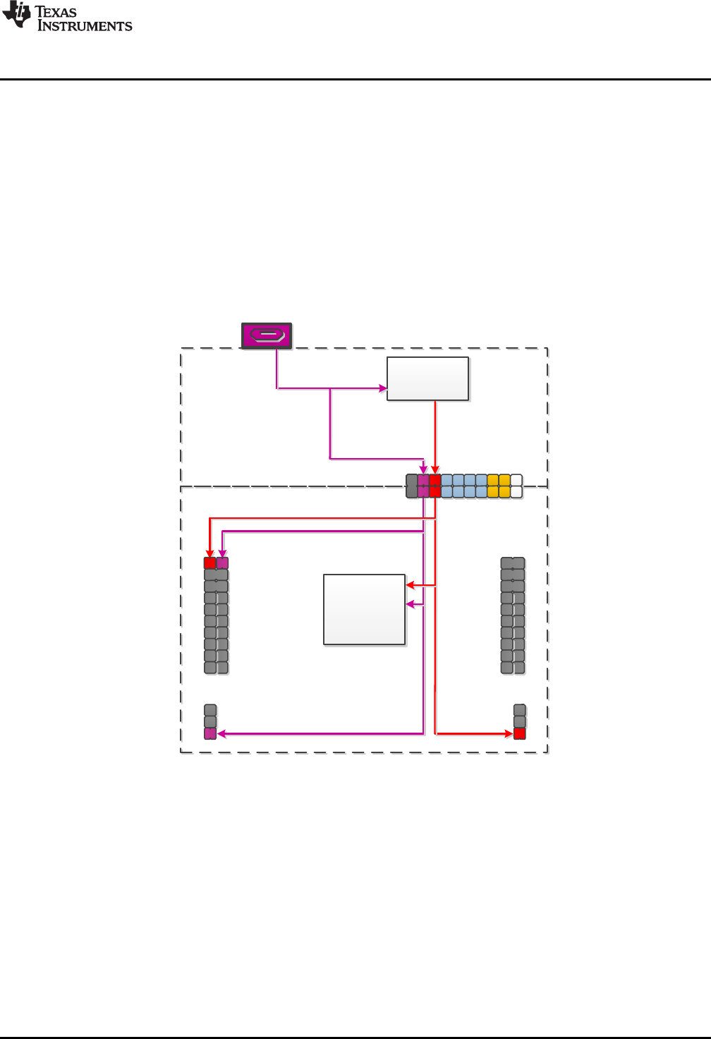
2.4 Using an External Power Source
The F5529 LaunchPad development kit target device can be used with a power source other than USB.
However, this should be done carefully to ensure proper system behavior. External power can be supplied
by many sources, most commonly a direct power supply, or through a battery BoosterPack plug-in
module.
Figure 17. Power Block Diagram for Default Configuration With USB Power Only
USB Connector
TPS62237
DC-DC Converter
Isolation
Jumper Block
eZ-FET lite 5V
eZ-FET lite 3.3V
5V in
3.3V out
MSP430F5529 Target
5529 Target + BoosterPack 5V
5529 Target + BoosterPack 3.3V
MSP430F5529
Target Device
eZ-FET lite
* 3V3 Isolation
Block Jumper
Disconnected
Hardware
www.ti.com
20 SLAU533D–September 2013–Revised April 2017
Submit Documentation Feedback
Copyright © 2013–2017, Texas Instruments Incorporated
MSP430F5529 LaunchPad™ Development Kit (MSP
‑
EXP430F5529LP)
2.4.1 External 3.3-V Power Source
It is often beneficial to evaluate the LaunchPad development kit with an external power source (see
Figure 18). To see accurate system power when performing this action, it is best to disconnect all jumpers
in the isolation block, so that additional power is not consumed by back-powering the emulation MCU
through its I/Os. The 5-V jumper can be left populated for proper USB operation and to allow for 5 V to the
target side.
Figure 18. Power Block Diagram for External 3.3-V Power Source
1. Disconnect the 3V3 jumper in the isolation jumper block. This should be done regardless of 5-V source
(external or USB), to avoid conflict with the eZ-FET lite 3.3-V rail.
2. If the target voltage to be applied is anything other than exactly 3.3 V, remove the SBW and SBW TST
jumpers. The emulator always runs at 3.3 V, and allowing the emulator to communicate with the target
when their voltages are significantly different results in back-powering and possible unexpected
behavior.
3. Apply the external power source to any appropriate location. This includes the 3V3 pin on the right-side
power header or directly to the 3V3 BoosterPack plug-in module header pin.
Step 2 requires that emulation is not possible if you are using an external power source at a voltage other
than 3.3 V. But USB can be used under these conditions, because there is no connection between the
USB module VBUS and VUSB rails and the DVCC and AVCC rails used by the rest of the F5529.
USB Connector
TPS62237
DC-DC Converter
Isolation
Jumper Block
eZ-FET lite 5V
eZ-FET lite 3.3V
5V in
3.3V out
MSP430F5529 Target
5529 Target + BoosterPack 5V
5529 Target + BoosterPack 3.3V
MSP430F5529
Target Device
* 5V and 3V3
Isolation Block
Jumpers
Connected
eZ-FET lite
www.ti.com
Hardware
21
SLAU533D–September 2013–Revised April 2017
Submit Documentation Feedback Copyright © 2013–2017, Texas Instruments Incorporated
MSP430F5529 LaunchPad™ Development Kit (MSP
‑
EXP430F5529LP)
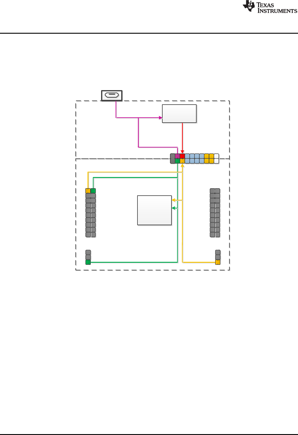
2.4.2 External 5-V Power Source Without USB Connection
If USB connection is not required, the 5V jumper in the isolation jumper block may be left populated (see
Figure 19). In this case, 3.3 V is derived through the dc-dc converter and, depending on the 3V3 jumper
setting in the isolation jumper block, can power the target device as well. If using external power source
for both 3.3 V and 5 V, consider recommendations for each.
Figure 19. Power Block Diagram for External 5-V Power Source Without USB Connection
USB Connector
TPS62237
DC-DC Converter
Isolation
Jumper Block
eZ-FET lite 5V
eZ-FET lite 3.3V
5V in
3.3V out
MSP430F5529 Target
5529 Target + BoosterPack 5V
5529 Target + BoosterPack 3.3V
MSP430F5529
Target Device
* 5V Isolation
Block Jumper
Disconnected
eZ-FET lite
Hardware
www.ti.com
22 SLAU533D–September 2013–Revised April 2017
Submit Documentation Feedback
Copyright © 2013–2017, Texas Instruments Incorporated
MSP430F5529 LaunchPad™ Development Kit (MSP
‑
EXP430F5529LP)
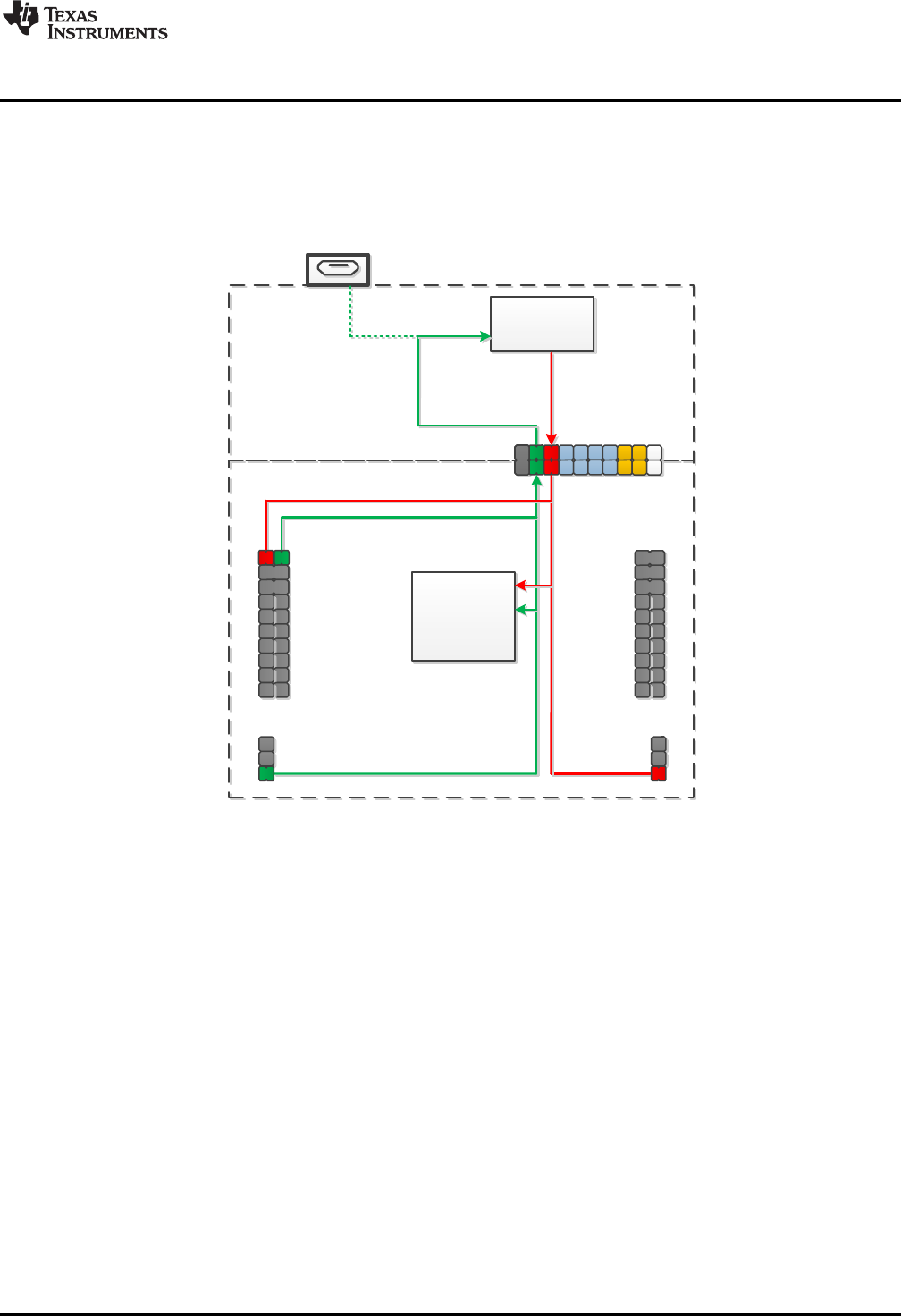
2.4.3 External 5-V Power Source With USB Connection
In certain situations, it is advantageous to have an external 5-V source and USB connected
simultaneously (see Figure 20). The USB connection may be needed for direct USB communication, back-
channel UART, or to allow for programming through emulation. In this scenario, the 5V jumper in the
isolation block must be disconnected to allow for the two separate 5-V sources. If using external power
source for both 3.3 V and 5 V, consider recommendations for each.
Figure 20. Power Block Diagram for External 5-V Power Source With USB Connection
www.ti.com
Hardware
23
SLAU533D–September 2013–Revised April 2017
Submit Documentation Feedback Copyright © 2013–2017, Texas Instruments Incorporated
MSP430F5529 LaunchPad™ Development Kit (MSP
‑
EXP430F5529LP)
2.5 Using the eZ-FET lite Emulator With a Different Target
The eZ-FET lite emulator on the F5529 LaunchPad development kit can interface to most MSP430 MCUs,
not just the onboard F5529 target device.
To do this, disconnect every jumper in the isolation jumper block. This is necessary because the emulator
cannot connect to more than one target at a time over the Spy-Bi-Wire (SBW) connection.
Next, make sure the target board has proper connections for Spy-Bi-Wire. To be compatible with SBW,
the capacitor on RST/SBWTDIO cannot be greater than 2.2 nF. The documentation for designing MSP430
JTAG interface circuitry is the MSP430 Hardware Tools User's Guide.
Finally, wire together these signals from the emulator side of the isolation jumper block to the target
hardware:
• 3.3 V
• GND
• 5 V (if needed)
• SBWTDIO
• SBWTCK
• TXD (if the UART backchannel is to be used)
• RXD (if the UART backchannel is to be used)
• CTS (if hardware flow control is to be used)
• RTS (if hardware flow control is to be used)
This wiring can be done either with jumper wires or by designing the board with a connector that plugs into
the isolation jumper block.
2.6 USB BSL Button
Like the vast majority of MSP430 MCUs, the F5529 has an on-chip bootloader (BSL). The BSL is a
program that resides in a special protected location in the MCU flash memory and facilitates
communication with an external host. Like tools with JTAG access, it can read and write the MCU flash
memory. But unlike JTAG tools, it cannot be used to emulate code.
The interface to the BSL is often a UART or sometimes I2C. On USB-equipped derivatives, the BSL
interface is USB.
In situations where JTAG access is not available, the BSL plays an important role in accessing the device.
For example, it can be used to recover the device when something has corrupted internal flash. It is often
used for products in the field, when there is no JTAG access. Because of the use in the field, the BSL is
password-protected, which prevents unwanted access to proprietary application software. To serve its role
in updating MSP430 flash memory, the BSL must be invoked, meaning that execution must be transferred
to it. This can happen a few different ways, but on the USB BSL, one way is to pull the PUR pin high
immediately after a BOR reset.
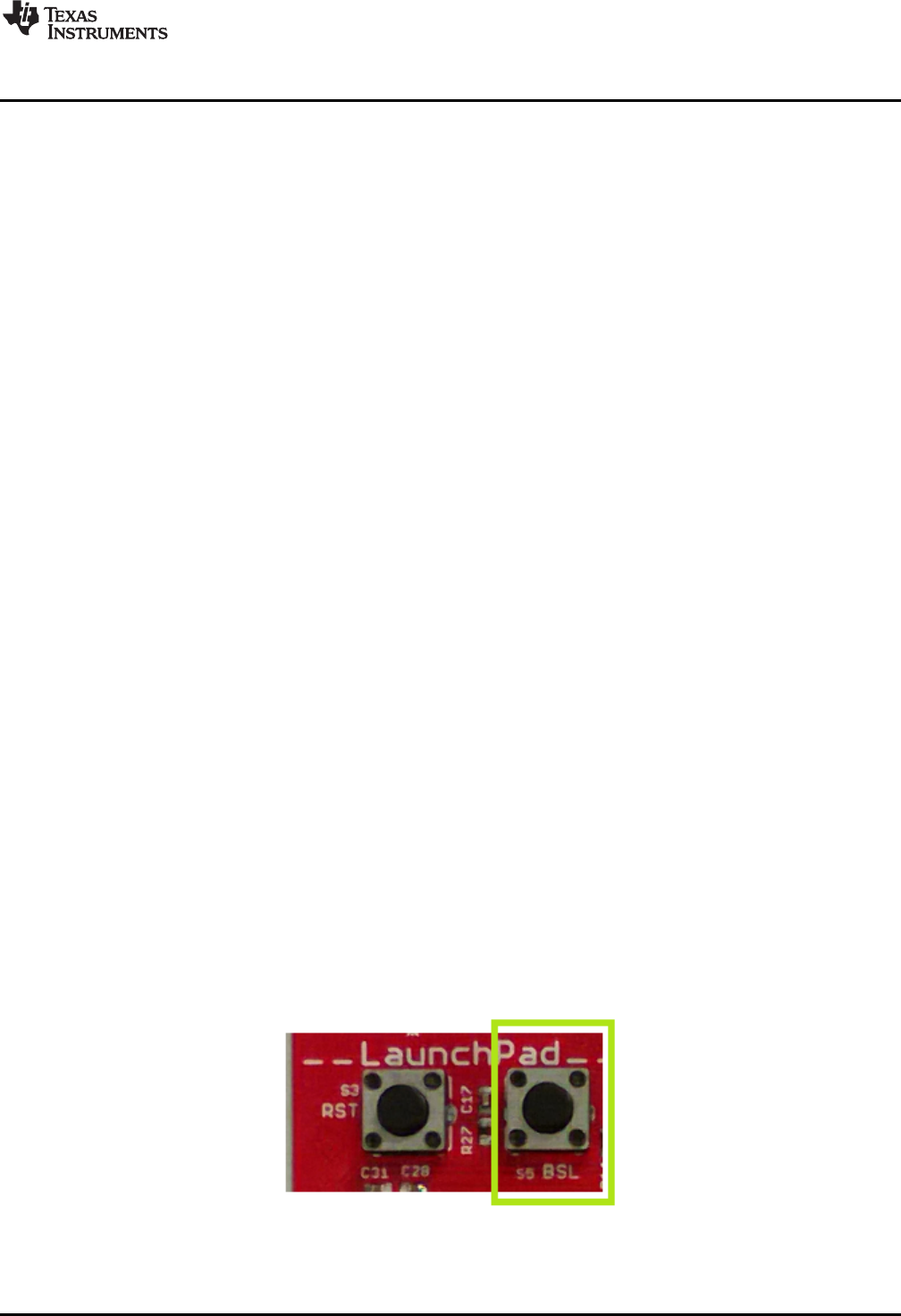
The USB BSL button on the F5529 LaunchPad development kit (see Figure 21) serves this purpose.
Figure 21. USB BSL Button
Hardware
www.ti.com
24 SLAU533D–September 2013–Revised April 2017
Submit Documentation Feedback
Copyright © 2013–2017, Texas Instruments Incorporated
MSP430F5529 LaunchPad™ Development Kit (MSP
‑
EXP430F5529LP)
Hold the button down while attaching the F5529 LaunchPad development kit to the USB host, continue to
hold it for approximately one second after attaching, and then release. (This assumes the F5529
LaunchPad development kit was unpowered prior to attaching, which allows a power-up event to occur.)
The target F5529 should enumerate under USB BSL control as a HID interface. The USB BSL has its own
vendor ID (VID) and product ID (PID), the codes used in USB to separate one USB product from another.
The BSL VID and PID pair is 0x2047 and 0x0200.
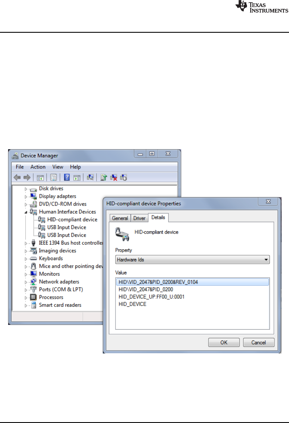
In Device Manager, the HID interface can be found under the "Human Interface Devices" group. (See
Section 3.7 for instructions on starting Device Manager.) If you open Device Manager prior to attaching
the LaunchPad development kit as described above, you will see it refresh, and then two new entries
appear: "HID-compliant device" and "USB Input Device". Both refer to the one HID interface presented by
the USB BSL.
These are generic names that can also appear for other HID devices. To be completely sure these entries
derive from the USB BSL, you can look for the VID and PID associated with them, and make sure they
are 0x2047 and 0x0200. For every such entry under the "Human Interface Devices" group, right-click on
the entry, then click Properties, then go to the "Details" tab, and select "Hardware IDs" from the pulldown
menu (see Figure 22).
Figure 22. Identifying the USB BSL HID Interface in Device Manager
For every other HID interface entry, the IDs in the "Value" field are different. For the USB BSL, they
include the strings "VID_2047" and "PID_0200".
If these interface entries do not appear, then something went wrong in the procedure to press the USB
BSL button to invoke the BSL. Retry the procedure.

www.ti.com
Hardware
25
SLAU533D–September 2013–Revised April 2017
Submit Documentation Feedback Copyright © 2013–2017, Texas Instruments Incorporated
MSP430F5529 LaunchPad™ Development Kit (MSP
‑
EXP430F5529LP)
After this interface enumerates, a host application is needed to interface with it and issue BSL commands
to access the firmware on the MSP430 MCU. The MSP430 USB Developers Package includes a firmware
updater application that uses the USB BSL to download programs. For its input, it uses TI-TXT object-
code files. TI-TXT is a simple text-based object-code format that used with MSP430 MCUs to store and
distribute compiled code. These files can be generated by CCS or IAR. TI-TXT files for the software
examples are included in the zip file (\bin\simpleBackchannel.txt and \bin\emulStorageKeyboard.txt).
See the application report USB Field Firmware Updates on MSP430 MCUs for information about
designing firmware update into your USB application. Additional information about the MSP430 BSL can
be found in the MSP430 Programming With the Bootloader (BSL).
2.7 BoosterPack Plug-in Module Pinout
The F5529 LaunchPad development kit adheres to the 40-pin LaunchPad development kit pinout
standard. A standard was created to aid compatibility between LaunchPad development kit and
BoosterPack plug-in module tools across the TI ecosystem.
The 40-pin standard is backward-compatible with the 20-pin one used by other LaunchPad development
kits like the MSP-EXP430G2. This allows 20-pin BoosterPack plug-in modules to be used with 40-pin
LaunchPad development kits.
This having been said, while most BoosterPack plug-in modules are compliant with the standard, some
are not. The F5529 LaunchPad development kit is compatible with all 20-pin (and 40-pin) BoosterPack
plug-in modules that are compliant with the standard. If the reseller or owner of the BoosterPack plug-in
module does not explicitly indicate compatibility with the F5529 LaunchPad development kit, you might
want to compare the schematic of the candidate BoosterPack plug-in module with the LaunchPad
development kit to ensure compatibility. Keep in mind that sometimes conflicts can be resolved by
changing the F5529 device pin function configuration in software. More information about compatibility
might also be found at http://www.ti.com/launchpad.
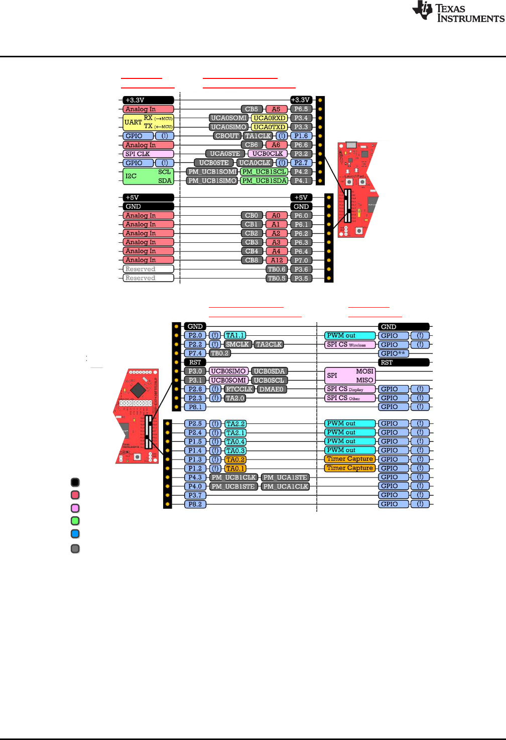
Figure 23 shows the 40-pin pinout of the F5529 LaunchPad development kit.
Software configuration of the pin functions plays a role in compatibility. The F5529 LaunchPad
development kit side of the dashed line shows all of the functions for which the F5529 device pins can be
configured. This can also be seen in the MSP430F5529 data sheet. The BoosterPack plug-in module side
of the dashed line shows the standard. The F5529 function whose color matches the BoosterPack plug-in
module function shows the specific software-configurable function by which the F5529 LaunchPad
development kit adheres to the standard.
BoosterPack
Pinout Standard
Software-Configurable
MSP430F5529 Pin Functions
F5529 LaunchPad
F5529 LaunchPad
Power
Analog
SPI
I2C
General I/O
Unused function
(!) Denotes an interrupt-capable I/O
BoosterPack
Pinout Standard
Software-Configurable
MSP430F5529 Pin Functions
Hardware
www.ti.com
26 SLAU533D–September 2013–Revised April 2017
Submit Documentation Feedback
Copyright © 2013–2017, Texas Instruments Incorporated
MSP430F5529 LaunchPad™ Development Kit (MSP
‑
EXP430F5529LP)
Figure 23. F5529 LaunchPad Development Kit to BoosterPack Plug-in Module Connector Pinout
www.ti.com
Hardware
27
SLAU533D–September 2013–Revised April 2017
Submit Documentation Feedback Copyright © 2013–2017, Texas Instruments Incorporated
MSP430F5529 LaunchPad™ Development Kit (MSP
‑
EXP430F5529LP)
2.8 Design Files
A complete schematic is available in Section 6. All hardware design files including schematics, layout, bill
of materials (BOM), and Gerber files are in the MSP-EXP430F5529LP Hardware Design Files. The
software examples are available in the MSP-EXP430F5529LP Software Examples. More information
about the software is available in Section 3.
The schematic PDF is searchable to make it easier to follow signals across the multipage schematic.
2.9 Hardware Change Log
Table 4 lists the changes to the MSP-EXP430F5529LP hardware.
Table 4. Hardware Change Log
PCB Revision Description
Rev 1.4 Initial release
Rev 1.5 Removed TPS2041B power switches.
Changed to sturdier BoosterPack plug-in module male header pins
Rev 1.6 Updated some pad dimensions for manufacturing.
Changed mounting holes to 125 mil.
Rev 1.7 Changed Q2 crystal to X1A0001410014.
Updated rear silkscreen to current LaunchPad development kit standards.
Added CE marking to silkscreen.

Software Examples
www.ti.com
28 SLAU533D–September 2013–Revised April 2017
Submit Documentation Feedback
Copyright © 2013–2017, Texas Instruments Incorporated
MSP430F5529 LaunchPad™ Development Kit (MSP
‑
EXP430F5529LP)
3 Software Examples
The software examples, including TI-TXT object-code firmware images, are available in the MSP-
EXP430F5529LP Software Examples. There are two software examples included with the F5529
LaunchPad development kit, as shown in Table 5.
Table 5. Software Examples
Demo Name USB Interface Type Description Described
In…
emulStorageKeyboard MSC: in-flash storage volume
HID: emulated keyboard
The out-of-box demo that is programmed on the F5529
LaunchPad development kit from the factory. Its
function is described in Section 1.3. Demonstrates a
more advanced USB device than
simpleUsbBackchannel.
Section 3.5
simpleUsbBackchannel CDC: Virtual COM Port (or,
optionally, HID-Datapipe)
A very simple example showing how to send and
receive data on both a virtual COM port USB
connection and the backchannel UART Section 3.6
The backchannel code in simpleUsbBackchannel is implemented as a simple library that can be copied
into any code project in which backchannel access is needed.
3.1 MSP430 Software Libraries: driverlib and the USB API
The examples are built upon two MSP430 libraries available from TI:
• driverlib: A foundational MSP430 software library that is useful for interfacing with all MSP430 core
functions and peripherals, especially clocks and power. driverlib is part of MSP430Ware. The
examples contain a subset of full driverlib.
• MSP430 USB API: Useful for quickly creating USB applications. The API is part of the MSP430 USB
Developers Package. The full USB API is included.
When you begin your own development, you will need more information about these libraries than can be
included in this user's guide. All of the information that you need is in the downloads linked above. Each
has its own documentation, and the USB Developers Package contains additional tools, 20+ more USB
examples, and detailed documentation.
The emulStorageKeyboard example also uses an MSP430 port of the open-source FatFs file system
software, which interacts with FAT storage volumes. It has been modified to work with internal MSP430
flash memory.
3.2 Viewing the Code
Although the files can be viewed with any text editor, more can be done with the projects if they are
opened with CCS or IAR. (Although support for mspgcc is increasing, the USB API does not yet fully
support mspgcc. See the FAQs in Section 5.)
CCS and IAR are each available in a full version and a free code-size-limited version. Although the
software demo can be built with the free version of CCS, the code is too large to be built with the free
version of IAR (IAR KickStart). This is primarily because the software demo has an MSC interface in it,
and MSC interfaces and storage volumes require more memory. Most USB examples built on the
MSP430 USB API (in the MSP430 USB Developers Package) that do not have an MSC Interface can be
built with IAR KickStart, and IAR Embedded Workbench is fully supported.
See the MSP430 software tools page to download these IDEs and for instructions on installation.
www.ti.com
Software Examples
29
SLAU533D–September 2013–Revised April 2017
Submit Documentation Feedback Copyright © 2013–2017, Texas Instruments Incorporated
MSP430F5529 LaunchPad™ Development Kit (MSP
‑
EXP430F5529LP)
3.2.1 CCS
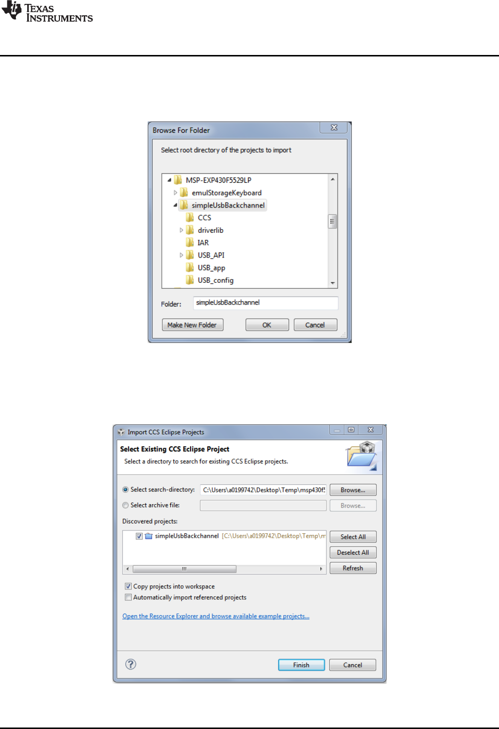
CCS v5.4 or higher is required. When CCS has been launched, and a workspace directory chosen, click
Project and then Import Existing CCS Eclipse Project. Browse to the desired demo project directory
containing main.c. This is either simpleUsbBackchannel or emulStorageKeyboard (see Figure 24).
Figure 24. Browse to Demo Project for Import Function
Selecting the \CCS subdirectory also works. (The CCS-specific files are located there.)
Click OK, and CCS should recognize the project and allow you to import it. The indication that CCS has
found it is that the project appears as shown in Figure 25, and it has a checkmark to the left of it.
Figure 25. When CCS Has Found the Project
Software Examples
www.ti.com
30 SLAU533D–September 2013–Revised April 2017
Submit Documentation Feedback
Copyright © 2013–2017, Texas Instruments Incorporated
MSP430F5529 LaunchPad™ Development Kit (MSP
‑
EXP430F5529LP)
Sometimes CCS finds the project but does not have a checkmark; this might mean that a project by that
name is already in the workspace. Rename or delete the existing project to resolve this conflict. (If you do
not see the existing project in the CCS workspace, check the workspace directory on the file system.)
Finally, click Finish. Even if you check the "Copy projects into workspace" checkbox, most of the
resources are linked and remain in their original location.
If using CCS v5.4, you may see a "#303-D typedef" warning. This warning should not cause problems, but
see Section 5 for more information and instructions to resolve it.
3.2.2 IAR
IAR v5.50 or higher is required. To open the demo in IAR, click File, then click Open, then click
Workspace…, and browse to the *.eww workspace file inside the \IAR directory of the desired demo. All
workspace information is contained within this file.
The directory also has an *.ewp project file. To open this file into an existing workspace, click Project, and
then click Add-Existing-Project….
Although the software examples have all of the code required to run them, IAR users may want to
download and install MSP430Ware, which contains the full USB Developers Package, driverlib, and the TI
Resource Explorer. These are already included in a CCS installation (unless the user selected otherwise).
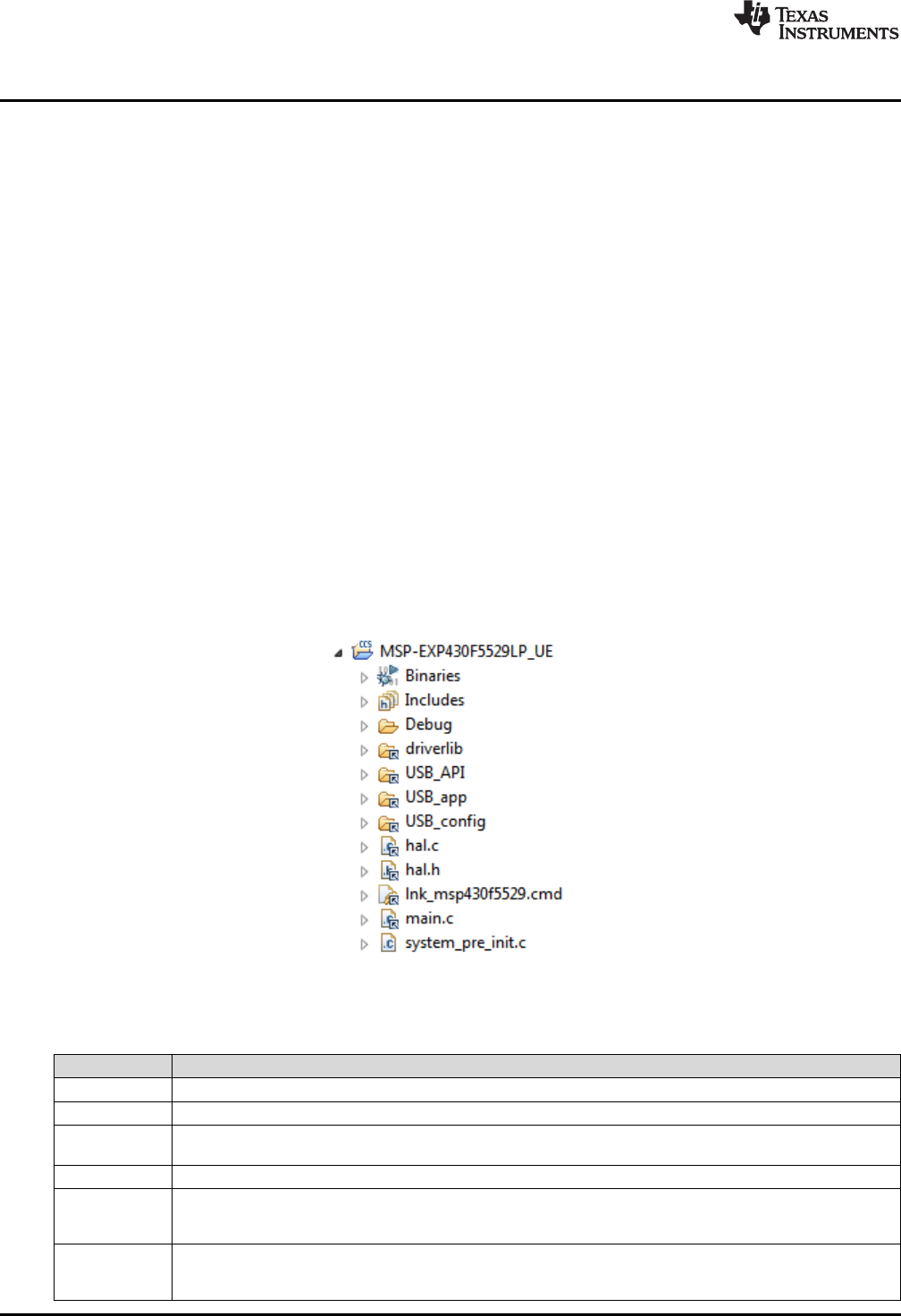
3.3 Example Project Software Organization
The simpleUsbBackchannel example and the emulStorageKeyboard example share a similar project
organization. Figure 26 shows the CCS version of emulStorageKeyboard, and Table 6 describes the
functions of these files and directories.
Figure 26. F5529 LaunchPad Development Kit Demo Software Organization
Table 6. Demo Project File and Directory Descriptions
Name Description
main.c The main() function
hal.c, hal.h Hardware abstraction layer for the MSP430F5529 LaunchPad development kit
driverlib MSP430 foundational software library, for accessing core MSP430 functions and peripherals. The USB API and
examples use it to manage clocks, power, and the DMA module. driverlib is part of MSP430Ware.
USB_API The MSP430 USB API, part of the MSP430 USB Developers Package.
USB_config Contains three files that configure the USB API for the application needs. In particular, they define the USB
interfaces that are used for the respective demo application. These files were generated by the USB Descriptor
Tool, located in the MSP430 USB Developers Package.
USB_app Files related to USB functionality, but which are part of the application and not the USB API itself. These files
handle the keyboard emulation, and implement the virtual storage volume mounted by the device. The directory
also contains the USB "event handlers".

www.ti.com
Software Examples
31
SLAU533D–September 2013–Revised April 2017
Submit Documentation Feedback Copyright © 2013–2017, Texas Instruments Incorporated
MSP430F5529 LaunchPad™ Development Kit (MSP
‑
EXP430F5529LP)
3.4 USB Configuration Files
The USB configuration files, in the \USB_config directory, determine what USB interfaces the USB API
presents to the USB host. These files are generated by the MSP430 USB Descriptor Tool.
The Descriptor Tool customizes the API USB interfaces and generates all of its USB descriptors (see
Figure 27). (For a discussion on USB descriptors, see Step 2 of Section 1.3.) For example, with just a few
clicks, the Tool can create a composite USB device with three virtual COM ports and an emulated mouse.
Figure 27. MSP430 USB Descriptor Tool
For the simpleUsbBackchannel demo, these files cause the API to present a single CDC interface. An
application can then be written to simply send and receive data over that interface.
For the emulStorageKeyboard example, these files cause the API to have an MSC interface and an HID
interface. They also cause that HID interface to be a keyboard. The application is then responsible for
accessing the storage volume for the MSC interface and for sending HID "reports" that contain key press
data.
*.dat input files for the Descriptor Tool are located inside each example project directory. This allows easy
regeneration of the output.
Device Reset
Initialize I /Os, clocks, and power
Initialize USB-related functions
Trigger the MSC interface to poll
for new SCSI commands from the
host, using USBMSC_poll()
Enter LPM0
Call mscProcessBuffer () to
process any pending READ or
WRITE operations
Has button S 1 been
pressed?
Has button S 2 been
pressed?
Is
bUsbSendCompleted
TRUE, and is
charLeftToSend
non-zero?
Is next key
direction down or
up?
Send USB report containing the
previous character, as an up -press,
using USBHID_sendReport (). Set
bUsbSendCompleted to FALSE
USB interrupt results in a
USBHID_handleSendCompleted () event,
indicating the HID report has now been sent
bUsbSendCompleted flag is set to TRUE
Initiate string output , using prepSendingStr (). Set
charLeftToSend to the length of the string .
Initiate string output , using prepSendingStr (). Set
charLeftToSend to the length of the string .
Send USB report containing the
next character, as a down-press,
using USBHID_sendReport ().
Set bUsbSendCompleted to FALSE
Main while(1) loop
USB event handlers
From within the USB API
USB interrupt results in new
MSC SCSI command received
Wake from LPM
The handler returns TRUE, waking the
device from LPM0 (if it was sleeping)
Port I/O ISR
Pushbutton is pressed
Was a READ or WRITE SCSI
command received?
No
Yes
No
No
Yes
Yes
No
Yes Down
Up
charLeftToSend=0?
Yes
No
Any button presses?
No
Yes
Pre-initialization : disable
watchdog
bButton1Pressed or
bButton1Pressed
flag is set to TRUE
Software Examples
www.ti.com
32 SLAU533D–September 2013–Revised April 2017
Submit Documentation Feedback
Copyright © 2013–2017, Texas Instruments Incorporated
MSP430F5529 LaunchPad™ Development Kit (MSP
‑
EXP430F5529LP)
3.5 Out-of-Box Experience: emulStorageKeyboard
This is the demo that is loaded into the F5529 LaunchPad development kit at the factory. It is described in
Section 1.3. This demo is slightly more advanced than the simpleUsbBackchannel demo.
The code is prolifically commented, and the following sections provide additional detail.
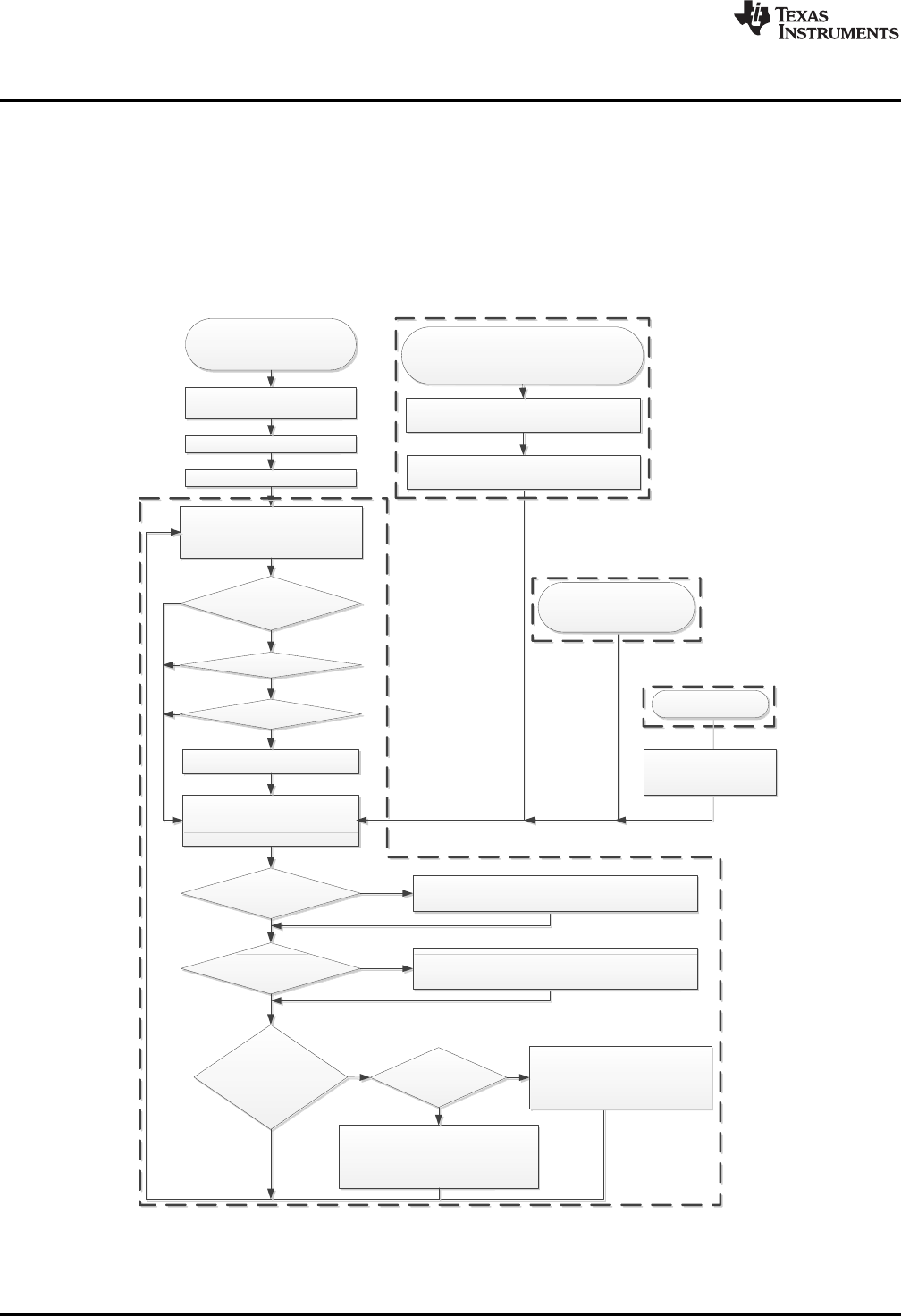
3.5.1 Flowchart
Figure 28 shows the program flow. The following sections reference this flow.
Figure 28. Demo Program Flow
www.ti.com
Software Examples
33
SLAU533D–September 2013–Revised April 2017
Submit Documentation Feedback Copyright © 2013–2017, Texas Instruments Incorporated
MSP430F5529 LaunchPad™ Development Kit (MSP
‑
EXP430F5529LP)
3.5.2 Pre-Initialization
Pre-initialization refers to the activity that happens before the first line of main().
As described for the simpleUsbBackchannel example (see Section 3.6.5.1), it is often convenient during
development to disable the watchdog at the beginning of execution. But for some application programs,
including this demo, there's a twist. Programs that contain a large amount of allocated RAM may never
reach the first line of main(). This is because the first line of execution of a C program is not actually the
first line of main(); instead, the compiler inserts code prior to main that handles preparatory functions, like
initializing variables.
So if the amount of allocated RAM is large enough, the time required to initialize it may exceed the
watchdog's expiration time. To the developer, this appears as execution never quite arriving to the first line
of main().
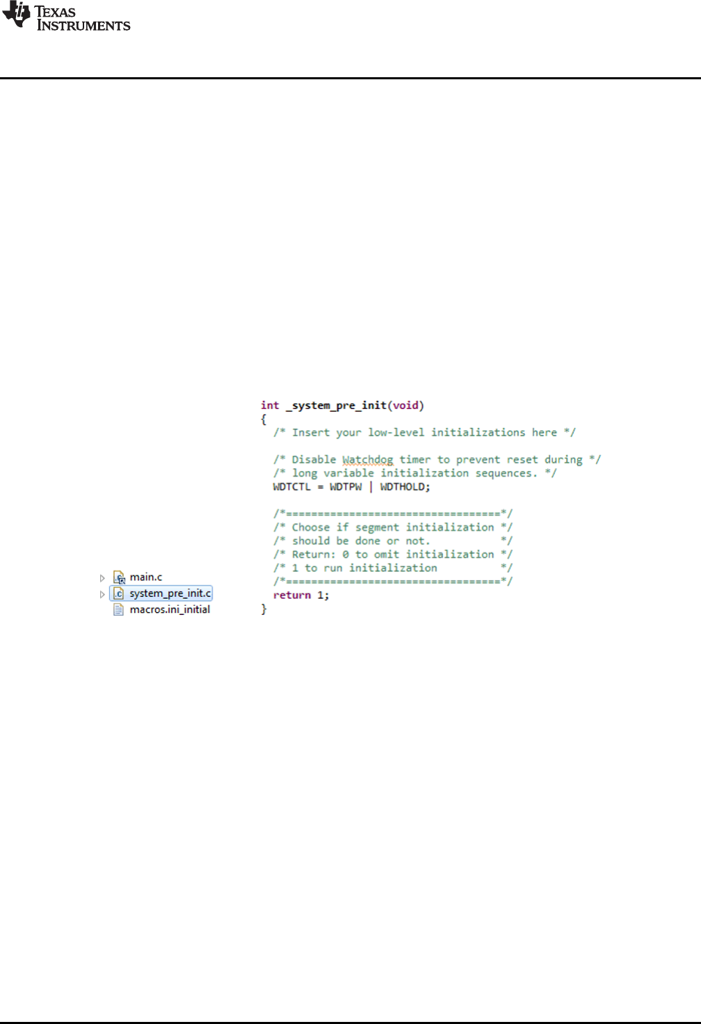
A solution to this is to define a pre-init function. In CCS, this is the function _system_pre_init(); in IAR, it is
the function __low_level_init(). The developer can write code here that executes immediately after a reset,
before RAM is initialized. When large amounts of RAM are allocated, it can be necessary to hold the
watchdog here.
The F5529 LaunchPad development kit software demo does this. Figure 29 shows the implementation of
both the system_pre_init.c file in the project and the function inside it.
Figure 29. Disable the Watchdog in Pre-Initialization
3.5.3 Initialization
This demo uses driverlib somewhat more heavily than the simpleUsbBackchannel example does. driverlib
is used for the initialization of clocks, power, and ports. The use of driverlib makes the code appear
different in the two examples, but the same actions are being taken. See Section 3.6.5 for more
information on how to initialize these functions and initialize USB.
The following sections describe initialization that is unique to this example.
3.5.3.1 Configuring the Keyboard
The keyboard function must be initialized before operation. Keyboard.c maintains a report structure that
will later be sent by the USB API.
3.5.3.2 Configuring the MSC Interface
The MSC interface also must be initialized. First, initMscIntf() obtains from the USB API a pointer to a
structure that will later be used to exchange information about SCSI READ and WRITE commands. It also
registers with the API the location of a RAM buffer that the application has allocated for the exchange of
block data during READ and WRITE commands.

Software Examples
www.ti.com
34 SLAU533D–September 2013–Revised April 2017
Submit Documentation Feedback
Copyright © 2013–2017, Texas Instruments Incorporated
MSP430F5529 LaunchPad™ Development Kit (MSP
‑
EXP430F5529LP)
The application must also tell the USB API about the mass storage volume's media; for example, how big
it is, if it is write protected, and if it is been changed recently (if removable). It does this with
USBMSC_updateMediaInfo().
3.5.4 Handling SCSI Commands
The first item in the main loop is a call to USBMSC_poll().
__disable_interrupt();
if ((USBMSC_poll() == kUSBMSC_okToSleep) && !charLeftToSend &&
!bButton1Pressed && !bButton2Pressed)
{
__bis_SR_register(LPM0_bits + GIE);
}
__enable_interrupt();
Notice all of the code surrounding USBMSC_poll(); this is discussed in Section 3.5.5.
Every USB application with an MSC interface must call this function regularly to check for any SCSI
commands received from the host. The USB MSC interface is essentially a carrier for the same SCSI
commands used with many non-USB storage devices that are commonly used with computers. In other
words, the interface is essentially "SCSI-over-USB".
USBMSC_poll() automatically handles all SCSI commands except READ and WRITE. These two require
media access. The developer might choose among a wide variety of media types, and there are many
different file system "middleware" offerings on the market. To preserve these options for the developer, the
MSC API lets the application access the media. mscProcessBuffer() is the function that serves this
function for the software demo; it receives a block buffer from the API and exchanges data between this
buffer and the media (see Section 3.5.7 for more information).
Most MSC applications need this exact same block within the main loop, except that the checking of the
charLeftToSend and button-pressed flags are specific to this demo application.
3.5.5 LPM0 Entry
Developing low-power applications is not just about finding the MCU with the lowest-current low-power
modes, although that is an important step. The software also must be written to effectively control the
circuitry and make good use of the low-power modes that are available.
In an application based on a main loop, one way to do this is to have a single location in the loop where a
low-power mode is conditionally entered. Various events can wake it from this sleep and allow the main
loop to resume execution, check flags, and handle any waiting events, and then eventually loop back and
sleep again.
The primary low-power modes are for MSP430 MCUs are LPM0, LPM3, and LPM4 (see Table 9 for a
brief description of these modes). Lower numbers represent "lighter" sleep, while higher numbers
generally mean "heavier" sleep. When the MCU is not in an LPM mode, it is considered to be in "active
mode", which means that all clocks are enabled and the CPU is executing code. (See the MSP430 family
user's guides for complete descriptions of these modes.)
The developer's choice of low-power mode is based on what functionality the MCU needs to keep alive
while sleeping. In the case of USB, the MSP430 can enter LPM0 while the USB connection is active (not
suspended by the USB host), but this is the deepest possible sleep state. When suspended, it can go into
LPM3, which is significantly lower power than LPM0.
With this in mind, refer back to the flowchart in Figure 28. The main loop begins by trying to enter LPM0,
but to do so it evaluates several conditions: the return value of USBMSC_poll(), the number of characters
waiting to be typed to the host, and whether a LaunchPad development kit pushbutton has been pressed.
This code was shown in the previous section.
If USBMSC_poll() returns kUSBMSC_processbuffer, it means the API is waiting for the application to
finish the READ or WRITE operation, and thus it is important to skip LPM0 and proceed to
mscProcessBuffer().
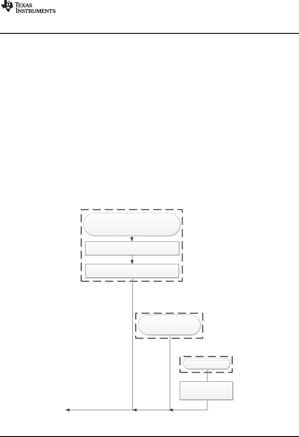
USB interrupt results in a
USBHID_handleSendCompleted () event,
indicating the HID report has now been sent
bUsbSendCompleted flag is set to TRUE
USB event handlers
From within the USB API
USB interrupt results in new
MSC SCSI command received
Wake from LPM
The handler returns TRUE, waking the
device from LPM0 (if it was sleeping)
Port I/O ISR
Pushbutton is pressed
bButton1Pressed or
bButton1Pressed
flag is set to TRUE
www.ti.com
Software Examples
35
SLAU533D–September 2013–Revised April 2017
Submit Documentation Feedback Copyright © 2013–2017, Texas Instruments Incorporated
MSP430F5529 LaunchPad™ Development Kit (MSP
‑
EXP430F5529LP)
Similarly, code checks for these other interrupt-driven events that may have occurred after the main loop
checked their flags. If execution enters sleep while these flags are set, they are not handled until yet
another interrupt occurs. This could cause the device to be unresponsive.
For similar reasons, interrupts are disabled prior to evaluating any of these flags. It takes several cycles to
evaluate these conditions, and because these events can occur at any time, the status of the early flags
could potentially change before LPM0 is actually entered. If LPM0 were then entered, they would get
missed. Disabling interrupts prevents that from happening; the events are simply queued up. When
interrupts are reenabled, any interrupts that came in take effect immediately.
Therefore, the code simultaneously enters LPM0 and reenables interrupts by setting the GIE bit:
_bis_SR_register(LPM0_bits + GIE);
If an interrupt had come in while interrupts were disabled, the CPU will wake again in the very next cycle
after entry.
3.5.6 LPM0 Exit
When emulating the code, if the device is sleeping, main() execution is seen resting at the LPM0 entry.
The demo application can then exit LPM0 and resume execution in response to three different events:
• A SCSI READ/WRITE command has been received. (This happens from a USB interrupt, which can
happen at any time.)
• A USB event has occurred. (This happens from the USB event handlers, which are triggered by USB
interrupts, which again can happen at any time.)
• One of the LaunchPad development kit pushbuttons has been pressed.
Figure 30. Waking From LPM0

Software Examples
www.ti.com
36 SLAU533D–September 2013–Revised April 2017
Submit Documentation Feedback
Copyright © 2013–2017, Texas Instruments Incorporated
MSP430F5529 LaunchPad™ Development Kit (MSP
‑
EXP430F5529LP)
USB events are like software callbacks, functions called by the USB interrupt service routine (ISR) that the
application can choose to service. These handlers are in the file usbEventHandling.c. If the event handler
returns TRUE, the CPU remains awake after the USB ISR returns; this causes execution to resume from
the point of LPM0 entry, if it had been sleeping there. (If it had not been sleeping, then the resumption has
no effect.)
The last event that can wake the CPU out of LPM0 is a pushbutton press. This generates an I/O port
interrupt, and the port ISR in hal.c is executed. It includes an intrinsic function
__bic_SR_register_on_exit(LPM3_bits); this causes execution to resume from the point of LPM0 entry, if it
had been sleeping there. Again, if it had not been sleeping, this resumption has no effect.
3.5.7 Emulated Storage Volume
mscProcessBuffer() is the first function to run after waking from LPM0. It checks the "operation" field of the
RWbuf_info structure to see if the USB API is waiting for the application to handle any READ or WRITE
buffer operations from the USB host.
If a READ or WRITE is pending, mscProcessBuffer accesses the media to perform the read or write. It
does this by issuing low-level commands to the FatFs file system library, disk_read() and disk_write().
The block of code within mscProcessBuffer() for performing reads is:
while (RWbuf_info->operation == kUSBMSC_READ)
{
RWbuf_info->returnCode = disk_read(0,
RWbuf_info->bufferAddr,
RWbuf_info->lba,
RWbuf_info->lbCount); // Fetch a block from the medium
USBMSC_bufferProcessed(); // Close the buffer operation
}
In a more typical mass storage application, the media would probably be an SD-card or external SPI flash.
In this application, the media is located inside the MSP430 internal flash memory. This is only
approximately 60KB, but it is big enough for what this demo needs, and saves the cost and complexity of
external media.
FatFs is commonly used to interface with FAT-formatted memory cards, but for this example it is been
customized for internal MSP430 flash. Most of this was done in disk_read() and disk_write().
Whereas the high-level FatFs calls ask FatFs to open or read files, and leave it to FatFs to parse the
volume and locate the files itself, the low-level calls bypass this, asking FatFs to read/write specific
locations in the volume. These locations are measured in blocks or sectors. The address of a block is
called a logical block address, or LBA, which is a parameter passed to disk_read().
The demo application implements the volume as an array called storageVol[]. The C-code contents of
storageVol[] contain the files that were seen in Step 3 of Section 1.3. storageVol[] occupies all of the
F5529 upper on-chip flash memory, from address 0x10000 to the end of the map, 0x243FF. To ensure the
linker does not place any code or other data there, a special linker segment has been set up: MYDRIVE.
This segment is defined in the auxiliary linker file \USB_app\F5529LP_UE.cmd. storageVolume.c then
contains code to locate storageVol[] there.
The volume within storageVol[] is formatted as FAT. It was generated using a procedure that is described
in the comments in storageVol.c. You can use this same procedure to create your own storage volumes
represented in C code, with your own file/directory sets.
If you are interested in using FatFs for SD cards, download the USB Developers Package and look in the
USB examples for MSC interfaces. One of the examples is a USB SD-card reader, written to run on the
F5529 Experimenter's Board (MSP-EXP430F5529) which has an SD-card socket on it. This example has
a version of FatFs set up for this purpose.
3.5.8 Sending Data as a USB Keyboard
In USB, keyboards are implemented as Human Interface Device (HID) interfaces. Within the USB
descriptors reported to the host during enumeration, the application declares itself to contain a keyboard
HID interface. It then sends specially formatted HID reports to the host, to tell it about key presses. While
no key presses occur, no reports are sent.

www.ti.com
Software Examples
37
SLAU533D–September 2013–Revised April 2017
Submit Documentation Feedback Copyright © 2013–2017, Texas Instruments Incorporated
MSP430F5529 LaunchPad™ Development Kit (MSP
‑
EXP430F5529LP)
Although the word "send" is an easy way to describe it, it is not quite correct. In USB, everything is
initiated by the host. What actually happens with HID interfaces is that the USB device prepares a report
and makes it available to the host. Then, on a regular interval, the host polls the device to see if it has any
reports ready. In the Descriptor Tool, this particular interface was set to have the fastest possible polling
interval: 1 ms.
After receiving a report indicating a keystroke, the host assumes the key is held down until a report is later
sent to indicate its release. Because of this, the demo application quickly follows every key-press report
with a key-release report.
So when a LaunchPad development kit pushbutton press occurs, it sets a flag and wakes main(), had it
been sleeping in LPM0. Execution eventually checks the flags associated with the buttons. If the button
had been pressed, it calls prepSendingStr() to fetch the target string from the file associated with that
button.
// Handle a press of button 1, if it happened
if (bButton1Pressed && !charLeftToSend)
{
prepSendingStr("0:Button1.txt");
bButton1Pressed = FALSE;
}
It uses high-level FatFs calls to do this – to mount the volume, open it, read it, and close it. When the
string has been obtained, main() assigns the length of that string to charLeftToSend. While this variable is
non-zero, it means there are still characters left to transmit to the host.
Later in main(), code evaluates charLeftToSend, and also checks whether a USB report is still waiting to
be fetched from the host. If characters still need to be sent, and if the USB HID interface is available, the
report is prepared, and USBHID_sendReport() is called to "send" it. A flag bKeyDirIsDown is used to
alternate between down-presses and up-presses, to ensure every down-press is followed by an up-press.
if (bUsbSendComplete && charLeftToSend)
{
if(bKeyDirIsDown) // Will this be a down-press?
{
KB_addKeypressToReport(btnStr[btnStrLen-charLeftToSend]);
bKeyDirIsDown = FALSE;
}
else // Or will it be an up-press?
{
KB_addKeyReleaseToReport(btnStr[btnStrLen-charLeftToSend]);
bKeyDirIsDown = TRUE;
charLeftToSend--;
}
bUsbSendComplete = FALSE;
USBHID_sendReport(KB_getReportPtr(), HID0_INTFNUM);
}
USBHID_sendReport() copies the report to the USB endpoint buffer, making it available to the host.
HID0_INTFNUM is a value that references this particular HID interface; if additional HID interfaces had
been created within this device, this parameter is how code could access them separately. The Descriptor
Tool defines an INTFNUM constant for every interface it creates, stored in descriptors.h.
When the host gets around to fetching the report, a USBHID_handleSendCompleted() event is generated.
BYTE USBHID_handleSendCompleted (BYTE intfNum)
{
bUsbSendComplete = TRUE;
return (TRUE); // Returning TRUE wakes the main loop, if it had been
} // sleeping.
This is one of the USB event handlers in usbEventHandling.c. These handlers are defined by the API, and
the developer can insert code that should execute when those events occur. In this application, the
bUsbSendComplete flag is set to TRUE in the handler, and the handler returns TRUE, which wakes
main() if it had been sleeping at the LPM0 entry. This allows main() to send the next character, if one is
waiting to be sent.

Software Examples
www.ti.com
38 SLAU533D–September 2013–Revised April 2017
Submit Documentation Feedback
Copyright © 2013–2017, Texas Instruments Incorporated
MSP430F5529 LaunchPad™ Development Kit (MSP
‑
EXP430F5529LP)
3.5.9 Properly Handling USB Unplug Events
In USB, it is important to consider that the bus may suddenly become unavailable. For example, the USB
cable can be removed by the user at any time. If the developer does not keep this in mind, it is easy to
write code that can hang up indefinitely when it happens.
For example, suppose the bUsbSendComplete flag had been polled until it was set to TRUE. If the cable
was then removed between the call to USBHID_sendReport() and the time the host fetches the report, the
flag would never become TRUE, and execution would freeze. Granted, with a 1-ms polling interval, this is
a very small window. But if this code went into a product, with thousands of users in the field, eventually it
would occur. (The default LaunchPad development kit configuration is bus-powered, losing power when
detached from the host. So this error won't occur unless external power is used. However, the code was
written this way to show good USB coding practices.)
Another thing that can go wrong is if the host becomes unresponsive. This is more problematic for MSC
and CDC interfaces than for HID interfaces, because the former use USB bulk transfers, which are more
subject to host and bus conditions. In contrast, HID is guaranteed to be polled at the polling interval, as
long as the host is functioning properly. But even so, if the host crashes, it is undesirable for the USB
device to hang. Therefore, good coding practice requires considering what happens if the
USBHID_handleSendCompleted() event never occurs, or if USBHID_sendReport() returns
kUSBHID_intfBusyError.
The application deals with these problems by never depending on the bUsbSendComplete flag for
execution fluidity. Whatever USBHID_sendReport() returns, the next line of code is always
USB_connectionState(). So if the cable has been detached, execution shifts to the switch() case that
shuts down all string sending and enters LPM3. If instead USB remains connected, but the host has
crashed, then the application functions as it always had, with fluid execution; the only difference is that
USBHID_sendReport() always returns kUSBHID_intfBusyError and no characters are actually sent.
3.5.10 Non-Maskable Interrupt (NMI) Vector
The MSP430 contains one vector that cannot be disabled by the general interrupt enable (GIE) bit: the
NMI vector. Several different events are directed into the NMI vector, most of which involve critical
functions. Oscillator failure is one example.
There is one NMI unique to USB operation: the "bus error", which is indicated when the SYSUNIV
interrupt vector register contains the value SYSUNIV_BUSIFG. This involves the fact that the MSP430
USB module shares a block of RAM with the CPU, called "USB RAM". When the host suspends the USB
module, it becomes clocked by a slow clock. If the CPU then tries to access USB RAM, the difference in
clock speeds between this slow clock and the MCU clock creates a conflict, and recovery from the error is
not possible without shutting down the USB module.
Fortunately this event is completely within control of software, by not accessing USB RAM during
suspend. The USB API is written to not do this, and most applications do not have a reason to access
USB RAM. Therefore, this error should never occur. But in the event that it does, the NMI is provided, and
code is provided to handle the failure.
3.6 Example: simpleUsbBackchannel
The simpleUsbBackchannel example runs on Windows and Linux PCs. However, it does not run on Macs,
because the OS X does not support composite CDC devices. This means that OS X does not support the
eZ-FET lite emulator or its backchannel UART.
3.6.1 What It Does
The simpleUsbBackchannel example receives data over the backchannel UART and sends it back to the
host PC over USB (see Figure 31). By default, the USB connection uses a CDC interface, which results in
a virtual COM port on the host. Thus both sides of the communication loop terminate in virtual COM ports
on the host. Through these COM ports, two instances of a terminal application can exchange data.
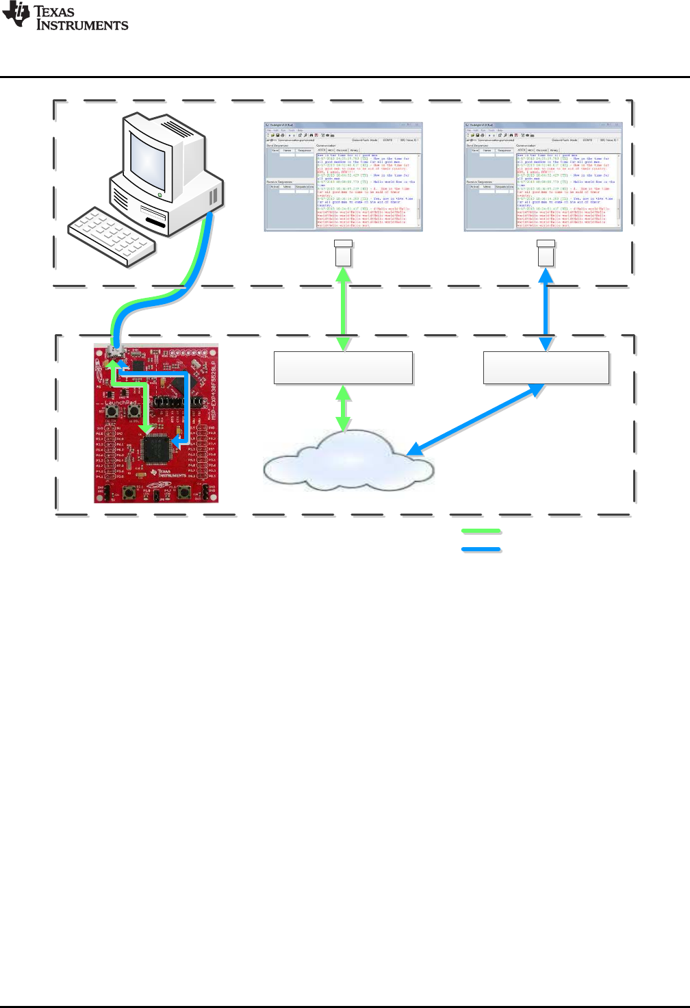
•]u‰olZvvoZ}[•
CDC Interface
Backchannel UART, via
eZ-FET lite emulator
simpleBackchannelEcho
Example
F5529 LaunchPad
USB Host PC
Terminal App Terminal App
‰‰o]š]}v[•h^
Backchannel UART
www.ti.com
Software Examples
39
SLAU533D–September 2013–Revised April 2017
Submit Documentation Feedback Copyright © 2013–2017, Texas Instruments Incorporated
MSP430F5529 LaunchPad™ Development Kit (MSP
‑
EXP430F5529LP)
Figure 31. Movement of Data in simpleUsbBackchannel: CDC
3.6.2 Installing the CDC Interface
Now, build and run the example.
When you do this for the first time on a Windows PC, Windows asks for an INF file
(simpleUsbBackchannel.inf) to associate with this device. This INF file is located in the
simpleUsbBackchannel directory.
Windows XP starts an installation wizard when you attach the device; direct it to this INF file.
Windows 7 does not show a dialog box but, rather, indicates an installation failure in a bubble in the
system tray. To install the device, open Device Manager (see Section 3.7). Locate the device (see
Figure 32). Right-click on it, and click Update Driver Software.
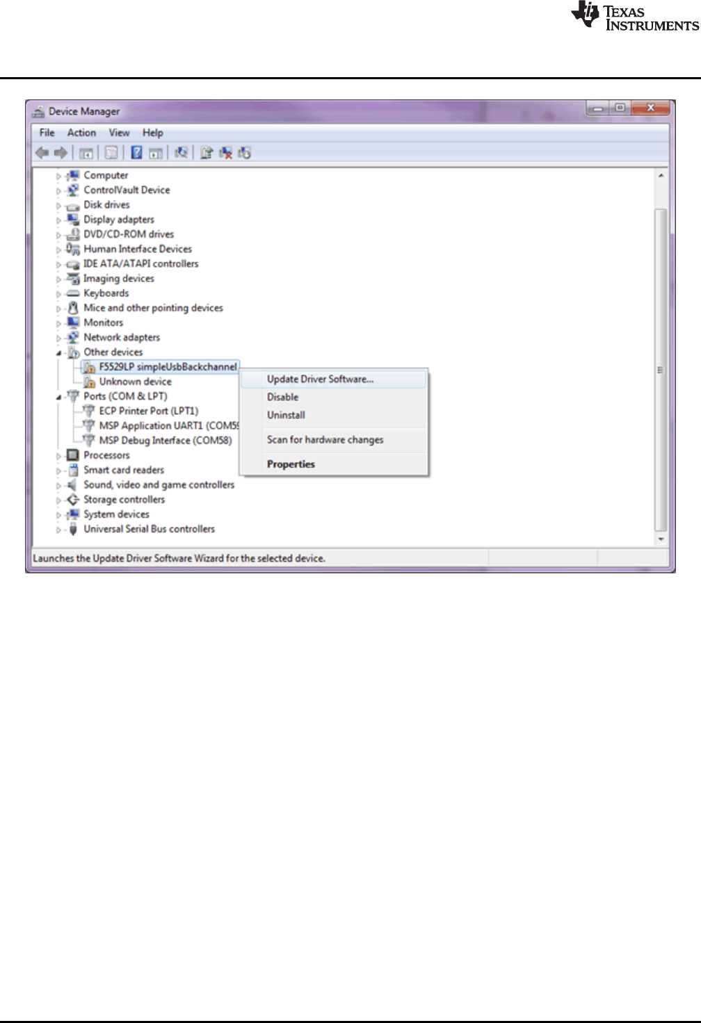
Software Examples
www.ti.com
40 SLAU533D–September 2013–Revised April 2017
Submit Documentation Feedback
Copyright © 2013–2017, Texas Instruments Incorporated
MSP430F5529 LaunchPad™ Development Kit (MSP
‑
EXP430F5529LP)
Figure 32. simpleUsbBackchannel USB Virtual COM Port, Needing a Driver
In the dialog box, browse to the INF file in the simpleUsbBackchannel directory.
If more help is needed to install the CDC interface, see the Examples Guide in the MSP430 USB
Developers Package, which contains a more complete description.
Linux PCs do not have this requirement. CDC interfaces enumerate silently as TTY devices in the \dev
directory.
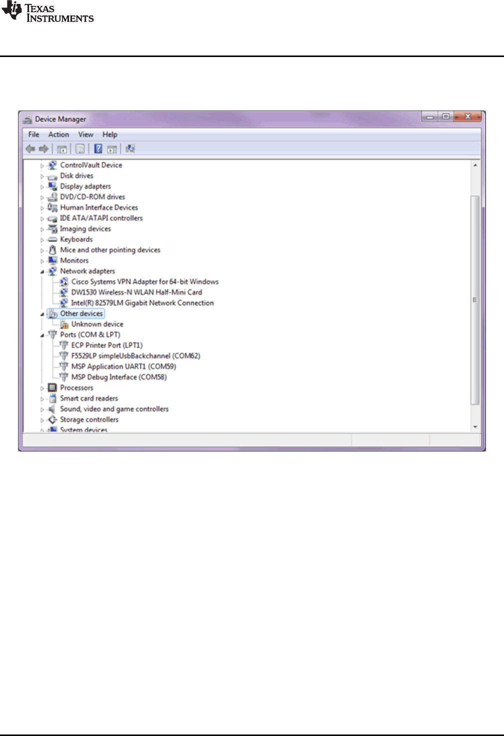
www.ti.com
Software Examples
41
SLAU533D–September 2013–Revised April 2017
Submit Documentation Feedback Copyright © 2013–2017, Texas Instruments Incorporated
MSP430F5529 LaunchPad™ Development Kit (MSP
‑
EXP430F5529LP)
3.6.3 Operating the Example
When installation is complete, both COM ports are available. On a Windows PC, Device Manager runs
(see Figure 33) (see Section 3.7 for how to open Device Manager).
Figure 33. Device Manager After Both Ports are Enumerated
The UART backchannel port name is "MSP Application UART1". The USB CDC interface for the
simpleUsbBackchannel application is "F5529LP simpleUsbBackchannel". The CDC interface port only
appears when the simpleUsbBackchannel application is running, whereas the backchannel port is present
anytime the F5529 LaunchPad development kit is physically connected.
The COM port numbers associated with each are shown in the Device Manager. Open two instances of a
terminal application, like Hyperterminal or Docklight, and associate one with the backchannel and the
other with the CDC interface. Make sure that the terminal settings in each terminal application disable flow
control and have baud rate set to 28.8 kbps.
When both ports are open, enter data into one of the terminal applications. The data should appear in the
other terminal application. The same should work in reverse.
3.6.4 Backchannel UART Library: bcUart.c, bcUart.h
This example includes a simple library for the backchannel UART, which can be copied into any project to
use the backchannel. It can also be modified as needed. Copy bcUart.c and bcUart.h into the target
project, and include the bcUart.h file from any files that access it.
The library is preconfigured to use SMCLK as the clock source, and for the speed of SMCLK to be 8 MHz.
The baudrate is preconfigured for 28.8 kbps with no hardware flow control.
SMCLK is generally a good choice for the backchannel UART in a given application, but the clock speeds
may change. Instructions for this are located in bcUart.h.
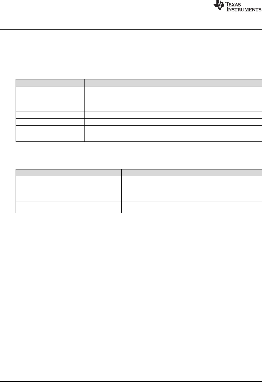
Software Examples
www.ti.com
42 SLAU533D–September 2013–Revised April 2017
Submit Documentation Feedback
Copyright © 2013–2017, Texas Instruments Incorporated
MSP430F5529 LaunchPad™ Development Kit (MSP
‑
EXP430F5529LP)
On the F5529 LaunchPad development kit, the backchannel UART is implemented with the USCI_A1
module. The RTS and CTS flow control signals are implemented on the P6.7 and P1.7 I/O pins,
respectively. All of these locations are hardwired on the F5529 LaunchPad development kit and are
independent from the 40-pin BoosterPack plug-in module header.
Table 7 shows some constants in bcUart.h that define the library behavior.
Table 7. Backchannel Library: Constants to Configure
Constant Description
UCA1_OS
UCA1_BR0
UCA1_BR1
UCA1_BRS
UCA1_BRF
Set the baudrate. Must be adjusted if SMCLK speed or baudrate are configured to anything
other than 8 MHz and 28.8 kbps, respectively. See bcUart.h for instructions.
BC_USE_HW_FLOW_CONTROL If hardware flow control is desired, un-comment this #define
BC_RXBUF_SIZE Set the size of the buffer that receives data over the backchannel UART.
BC_RX_WAKE_THRESH When this number of bytes have been received into the receive buffer, the
bcUartRxThresholdReached flag is set to TRUE, and the main application is awakened from
any LPM it might be in.
Table 8 shows the library function calls.
Table 8. Backchannel Library: Functions
Function Description
void bcUartInit(void) Call once during program initialization
void bcUartSend(uint8_t * buf, uint8_t len) Send len bytes stored at buf over the UART.
uint16_t bcUartReceiveBytesInBuffer(uint8_t* buf) Copy any bytes received into the library UART receive buffer into buf and
return the number of bytes copied.
USCI_A1 Interrupt Vector The library includes a definition of the USCI_A1 ISR, which copies
incoming UART bytes into a receive buffer.
If the application uses the USCI_A1 ISR for another purpose in addition to the backchannel, it is
necessary to merge that operation with the backchannel library ISR.
3.6.5 Code Description: Initialization
First, the device must be initialized. Although called from main(), much of this initialization is defined within
hal.c and hal.h. Most of the examples in the USB API v4.0 and later include this hardware abstraction
layer (HAL) file to assist in running on multiple USB-equipped boards available from TI. Clocks, power,
and port settings can be hardware-specific and, thus, are handled by the HAL. This demo follows that
convention.
3.6.5.1 Stopping the Watchdog
The MSP430 contains a watchdog timer that is enabled by default. After a reset, an MSP430 application
has approximately 32 ms to either reconfigure the watchdog or put it on hold. Otherwise, the watchdog
resets the MSP430 device.
Watchdogs are an important part of writing robust production-level code, but if you are only experimenting
with the MCU, it is not helpful and can be obstructive. For this reason, the first line of code on many bench
applications is to simply disable the watchdog by setting the WDTHOLD bit.
3.6.5.2 Configuring VCORE
Next, main() sets the PMMCOREV register field to 2. PMMCOREV controls the VCORE voltage, which is the
voltage at which the MCU core circuitry operates. VCORE is generated from a low-dropout (LDO) regulator
inside the MCU Power Management Module (PMM). Higher CPU operating speeds require higher VCORE
levels, and higher VCORE levels result in higher quiescent current on the LDO. For this reason, VCORE is
programmable.

www.ti.com
Software Examples
43
SLAU533D–September 2013–Revised April 2017
Submit Documentation Feedback Copyright © 2013–2017, Texas Instruments Incorporated
MSP430F5529 LaunchPad™ Development Kit (MSP
‑
EXP430F5529LP)
Although primarily related to CPU speed, the device data sheet also shows that during operation of the
USB PLL (that is, during an active USB connection), VCORE must be set to 2 or 3, the highest two levels.
Because the demo's use of an 8-MHz clock does not require a setting of 3, the PMMCOREV register is
set to 2.
3.6.5.3 Configuring Clocks
MSP430 applications typically use a fast clock and a slow clock. The fast clock (called MCLK) sources the
CPU and peripherals in some cases, while the slow one keeps timers and peripherals operating during
low-power modes. This approach reduces power: slow clocks consume less power, so the more often the
fast clock can be disabled, the less power the application may consume.
Typically this fast clock is the digitally controlled oscillator (DCO) integrated in the MCU. The DCO itself is
an important low-power tool, because unlike a crystal, it has a very fast start-up time, and thus can be
quickly shut down and re-enabled. The DCO can be activated by an interrupt and stabilize fast enough to
respond to it. An MCU's low-power modes are only useful if they can be used often.
Many MSP430 devices, including the F5529, couple the DCO with an frequency-locked loop (FLL) module
that keeps the DCO locked to a precise slower-frequency reference. This gives good control over the DCO
frequency.
The F5529 has three slow clocks available:
• REFO: This is a modestly precise low-power on-chip oscillator that does not require a crystal. It
operates at 32 kHz.
• LFXT1: This is a crystal oscillator. It is very precise and lower power than the REFO, but it requires a
crystal. It, too, operates at 32 kHz.
• VLO: This oscillator is not very precise but does not require a crystal and has the lowest power of the
three. It usually operates somewhere between 12 kHz and 20 kHz.
To keep things simple, the simpleUsbBackchannel example does not use any low-power modes; the CPU
stays active at all times. As a result, all of these clocks are constantly active, and all functions are sourced
from the DCO FLL. The emulStorageKeyboard example (see Section 3.5) does make use of low-power
modes.
USB operation on the F5529 requires a high-frequency reference clock for the USB PLL. As mentioned in
Section 2.2.5, this is sourced on the XT2 oscillator, and the F5529 LaunchPad development kit has a
resonator on XT2. XT2 is managed directly by the USB API.
Table 9 shows the simpleUsbBackchannel example's clock configuration.
Table 9. Clock Settings
System
Clock Source Speed Description
MCLK DCO, FLL 8 MHz MCLK is the MSP430 CPU clock. It is disabled in all low-power modes. There is no
predefined MCLK lower limit for USB communication, but 8 MHz and higher are
commonly used.
SMCLK DCO, FLL 8 MHz SMCLK drives high-speed peripherals. It is kept alive during LPM0 but disabled in
LPM3, LPM4, and LPM5. LPM0 is the lowest power mode permissible during an active
USB connection.
ACLK REFO 32 kHz ACLK is a low-speed clock that drives timers and slower peripherals. It is a very low-
power way to keep the MCU alive during low-power modes. It is kept alive during
LPM3 but disabled in LPM4 and LPM5.
USBCLK XT2 4 MHz USB operation on the F5529 requires a ±2500-ppm clock source on XT2. This
application uses a precise crystal resonator. The USB module receives this clock
directly from XT2.
For a full explanation of the MSP430 clock system, see the Unified Clock System (UCS) chapter in the
MSP430x5xx and MSP430x6xx Family User's Guide.

Software Examples
www.ti.com
44 SLAU533D–September 2013–Revised April 2017
Submit Documentation Feedback
Copyright © 2013–2017, Texas Instruments Incorporated
MSP430F5529 LaunchPad™ Development Kit (MSP
‑
EXP430F5529LP)
3.6.5.4 Configuring Ports
In the function initPorts(), all of the I/Os are configured to drive out-low. Later, in bcUartInit(), the USCI_A1
module's UART pins will be configured for the backchannel UART.
The purpose of initPorts() is to eliminate floating inputs. These are a source of unexpected power draw, so
it is a good practice to either drive all I/Os out or make sure any inputs are being pulled high or low from
the outside. If you drive an I/O out, make sure this does not negatively affect some other component on
the board.
3.6.5.5 Initializing the Backchannel UART
bcUartInit() initializes the backchannel UART. See Section 3.6.4 for more information about configuring
the backchannel UART library.
3.6.5.6 Configuring USB
USB_setup() is called next. This initializes the USB API and enables all of the USB events. It then checks
to see if a USB host is already attached, which it determines by the presence of 5 V on the VBUS pin. If
attached, it pulls the D+ signal high, telling the host it is there. The host responds by enumerating the
device.
Finally, global interrupts are enabled, and execution enters the main loop.
3.6.6 Code Description: Main Loop
The following code sample shows the main loop.
while(1)
{
// Receive backchannel UART bytes, send over USB
rxByteCount = bcUartReceiveBytesInBuffer(buf_bcuartToUsb);
if(rxByteCount)
{
cdcSendDataInBackground(buf_bcuartToUsb, rxByteCount, CDC0_INTFNUM, 1000);
//hidSendDataInBackground(buf_bcuartToUsb, rxByteCount, HID0_INTFNUM, 1000);
}
// Receive USB bytes, send over backchannel UART
rxByteCount = cdcReceiveDataInBuffer(buf_usbToBcuart,
sizeof(buf_usbToBcuart),
CDC0_INTFNUM);
/*rxByteCount = hidReceiveDataInBuffer(buf_usbToBcuart,
sizeof(buf_usbToBcuart),
HID0_INTFNUM); */
if(rxByteCount)
{
bcUartSend(buf_usbToBcuart, rxByteCount);
}
}
The main loop does the following actions for both the backchannel UART and USB CDC interface:
• Copies data from their respective input buffers.
• If any data was present, retransmits the data over the other interface.
When data arrives at the USCI_A1 backchannel UART, it is immediately copied to the receive buffer,
bcUartRcvBuf. Then, because this main loop never sleeps, it frequently checks if any bytes are waiting in
the receive buffer using bcUartReceiveBytesInBuffer(). If bytes are waiting, the bytes are copied into
buf_bcuartToUsb. Then cdcSendDataInBackground() sends them over the application's CDC interface to
the host PC.
The same happens in the other direction. When data arrives over the USB CDC interface, the USB
hardware module places them into the USB endpoint buffers. The main loop calls
cdcReceiveDataInBuffer(), which checks if any bytes have been received; if so, they are copied into
buf_usbtoBcuart. Then, bcUartSend() sends them over the backchannel UART.

www.ti.com
Software Examples
45
SLAU533D–September 2013–Revised April 2017
Submit Documentation Feedback Copyright © 2013–2017, Texas Instruments Incorporated
MSP430F5529 LaunchPad™ Development Kit (MSP
‑
EXP430F5529LP)
When data is sent over a UART, communication generally happens quickly, because it is low-level and
has essentially no overhead. After a byte is written to the TXBUF register, the time is very brief before
TXBUF is ready to send the next byte. Therefore, bcUartSend() does not return until all bytes are sent.
Hardware flow control could theoretically keep execution here indefinitely, but it is usually a safe
assumption that the eZ-FET lite's MSP430, which is at the other end of this hardware UART connection,
will quickly de-assert flow control and be ready to receive data.
Sending data over a USB interface is very different. Multiple communication layers, both hardware and
software, exist between the MSP430 application and the bus. There is a higher potential for the host and
bus to respond slowly. So, sending data over USB is an interrupt-driven process, involving multiple
interrupts over time. Polling in one place until all data is sent is possible but carries some risk of blocking
execution.
The USB API provides two construct functions for CDC interfaces. cdcSendDataWaitTilDone() waits until
the sending is complete before proceeding to the next line of code. cdcSendDataInBackground() only
initiates the sending operation and returns immediately while data is sent in the background behind
subsequent lines of code. However, cdcSendDataInBackground() always checks to ensure there is not a
previous send operation still open and polls until that operation is complete. Both functions have a retry
parameter, so they can only block for a limited amount of time.
This example of USB sending and receiving is sufficient for simple situations, but its handling of events
like surprise removal of the USB cable is simplistic. If USB is present, it sends data. If not, then it simply
returns an error (which is not even checked) and moves forward. More sophisticated applications may
need to pay attention to return codes and consider USB surprise removals. The emulStorageKeyboard
example in Section 3.5 demonstrates this.
3.6.7 Modifying to Use an HID-Datapipe Interface
This demo can be easily converted to use an HID-Datapipe interface instead of CDC (see Figure 34). The
advantage of the HID-Datapipe interface is that HID does not require the INF installation process on
Windows PCs that CDC does. In exchange for this, it operates with a 64-KB/s bandwidth limit.
HID also does not have the same host-side coding simplicity provided by virtual COM ports. For this
reason, TI provides the Java HID Demo App as an example. This demo app and its source code are
included in the MSP430 USB Developers Package.
HID-Datapipe is a special version of HID and is part of the MSP430 USB API. It allows communication
that is point-to-point, bidirectional, and unformatted, much like a virtual COM port. In contrast, traditional
HID relies on highly-formatted reports. HID-Datapipe abstracts the application from these reports and
presents an interface that is very much like the one used for CDC.
To convert the simpleUsbBackchannel example to use HID-Datapipe:
• Use the Descriptor Tool to generate new output in the example's \USB_config directory. A Descriptor
Tool input file called simpleUsbBackchannel_HID.dat is provided in the project directory. Open this file
with the Tool, and then generate new output files into \USB_config. (For reverting to CDC, another file
that is named simpleUsbBackchannel_CDC.dat is provided.)
• The code shown in Section 3.6.6 includes alternate calls for HID, which are symmetrical to the ones for
CDC. Comment out the CDC calls, and uncomment the ones for HID.
Now, build and run. Download the MSP430 USB Developers Package, and run the Java HID Demo App.
The app needs to know the VID and PID reported by the F5529; for the HID version of this example, these
are 0x2047 and 0x0404, respectively.
Instructions for using the Java HID Demo App are located in the Examples Guide PDF file in the MSP430
USB Developers Package.
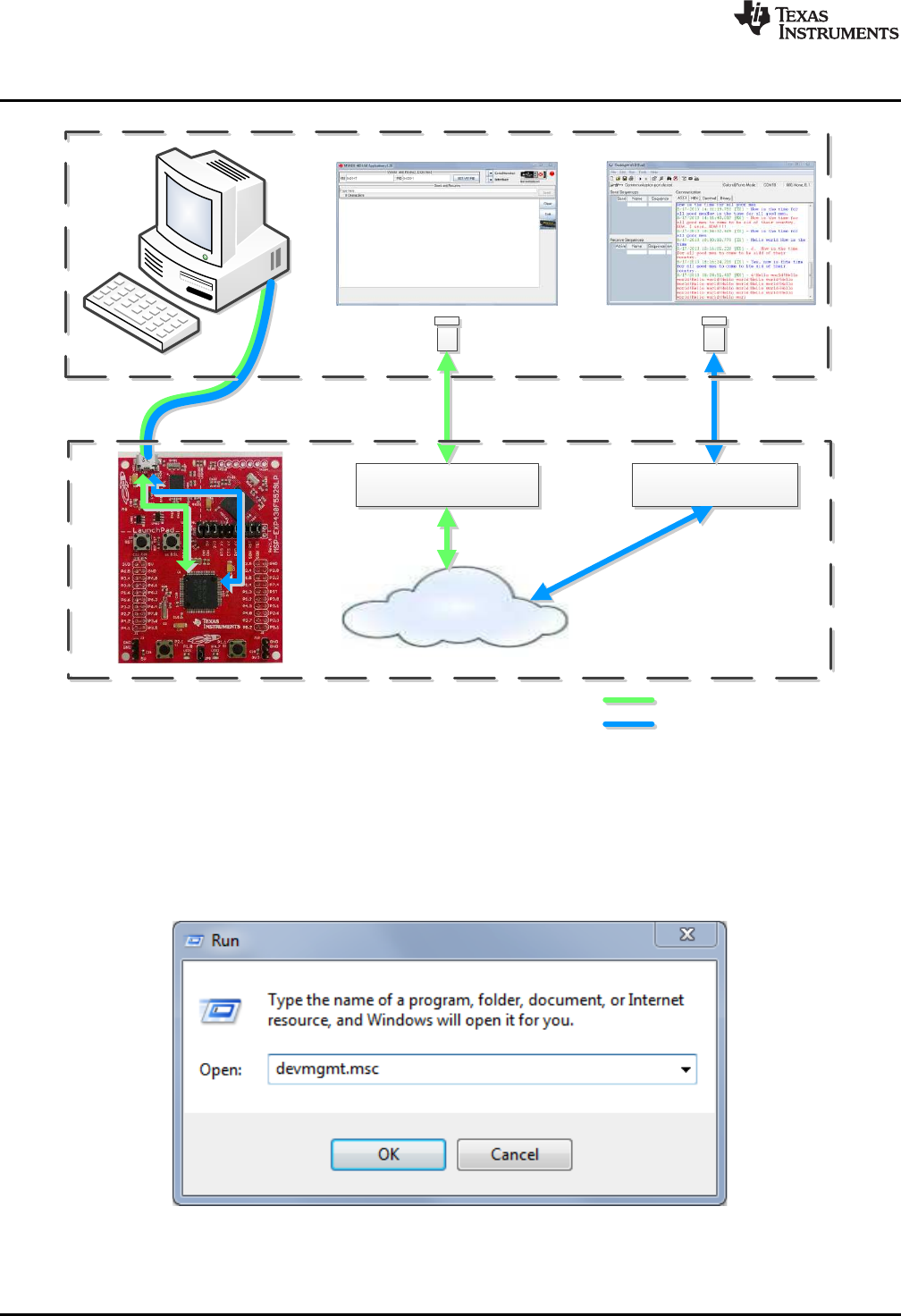
•]u‰olZvvoZ}[•
HID-Datapipe Interface
Backchannel UART, via
eZ-FET lite emulator
simpleBackchannelEcho
Example
F5529 LaunchPad
USB Host PC
HID Demo App Terminal App
‰‰o]š]}v[•h^
Backchannel UART
Software Examples
www.ti.com
46 SLAU533D–September 2013–Revised April 2017
Submit Documentation Feedback
Copyright © 2013–2017, Texas Instruments Incorporated
MSP430F5529 LaunchPad™ Development Kit (MSP
‑
EXP430F5529LP)
Figure 34. Movement of Data in simpleUsbBackchannel: HID-Datapipe
3.7 Starting Device Manager
Device Manager is very useful for determining what USB interfaces have enumerated on the host.
To open Device Manager, click the Start button, click Run…, type "devmgmt.msc" in the Open field, and
click OK (see Figure 35).
Figure 35. Start Device Manager
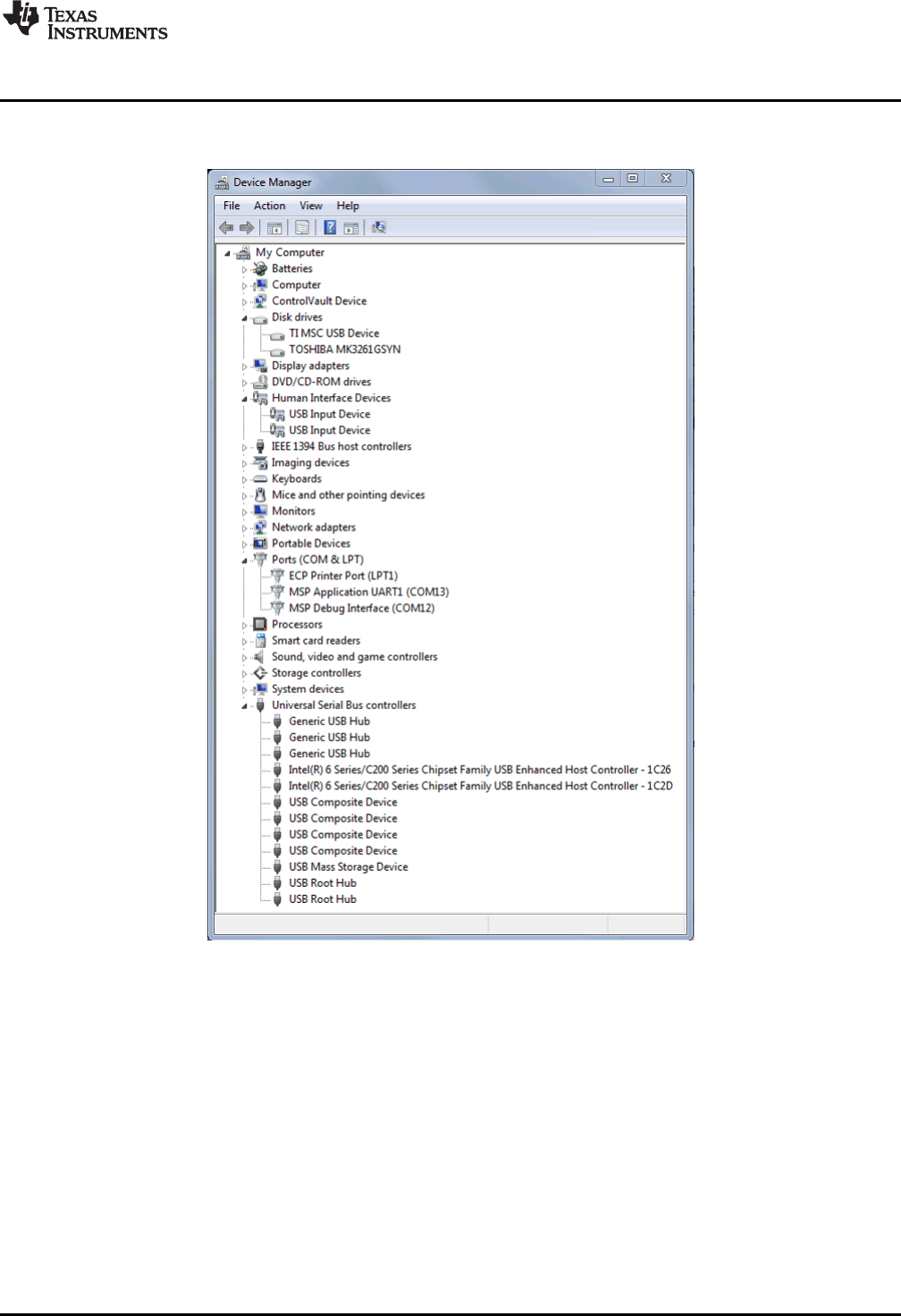
www.ti.com
Software Examples
47
SLAU533D–September 2013–Revised April 2017
Submit Documentation Feedback Copyright © 2013–2017, Texas Instruments Incorporated
MSP430F5529 LaunchPad™ Development Kit (MSP
‑
EXP430F5529LP)
If Windows asks if you want to allow the program to make changes to your computer, click Yes; however,
Device Manager is very useful for viewing purposes without having to change anything (see Figure 36).
Figure 36. Device Manager
The groups in Device Manager that are relevant to MSP430 USB work include:
• Ports (for virtual COM ports)
• Human Interface Devices (for HID interfaces).
• Disk Drives (for any drives that have been mounted with an MSC interface)
• Universal Serial Bus controllers (Hubs and MSC interfaces appear here, as do root entries for
composite USB devices.)
Device Manager is also very useful during debug of a USB application. The MSP430 USB API
Programmer's Guide in the MSP430 USB Developers Package contains a section on how to debug your
USB application. See this document for more information on using Device Manager.
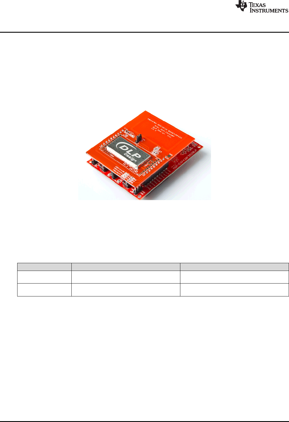
Additional Resources
www.ti.com
48 SLAU533D–September 2013–Revised April 2017
Submit Documentation Feedback
Copyright © 2013–2017, Texas Instruments Incorporated
MSP430F5529 LaunchPad™ Development Kit (MSP
‑
EXP430F5529LP)
4 Additional Resources
4.1 LaunchPad Development Kit Websites
More information about the F5529 LaunchPad development kit, supported BoosterPack plug-in modules,
and available resources can be found at:
•F5529 LaunchPad development kit tool page: resources specific to this particular LaunchPad
development kit
•TI's LaunchPad development kit portal: information about all LaunchPad development kits from TI for
all MCUs
Figure 37. F5529 LaunchPad Development Kit With DLP-7970ABP NFC BoosterPack Plug-in Module
4.2 Information on the MSP430F5529
At some point, you will probably want more information about the F5529 device. For every MSP430
device, the documentation is organized as shown in Table 10.
Table 10. How MSP430 Device Documentation is Organized
Document For MSP430F5529 Description
Device family
user's guide MSP430x5xx and MSP430x6xx Family User's
Guide Architectural information about the device,
including clocks, timers, ADC, and so on.
Device-specific
data sheet MSP430F551x, MSP430F552x Mixed Signal
Microcontroller Device-specific information and all parametric
information for this device
4.3 Download CCS, IAR, mspgcc, or Energia
When you want to write your own programs, you will need one of these development environments.
Currently, the USB API does not support mspgcc. However, you can still use mspgcc to write non-USB
software on the F5529 LaunchPad development kit, because the eZ-FET lite supports mspgcc.
As described in Section 3.2, the free version of IAR KickStart has a code-size limit of 8KB, which limits the
ability to compile some USB projects.
Energia is an easy-to-use open-source platform. It is a great place to get started if you are new to
LaunchPad development kits or are in need of rapid prototyping.
4.4 USB Developers Package
The software examples included with the F5529 LaunchPad development kit are built on the materials in
the MSP430 USB Developers Package. The developers package includes the USB API, USB Descriptor
Tool, 20+ USB examples, the Java HID Demo App, and a detailed programmer's guide to help you get
started on writing your own USB applications.

www.ti.com
Additional Resources
49
SLAU533D–September 2013–Revised April 2017
Submit Documentation Feedback Copyright © 2013–2017, Texas Instruments Incorporated
MSP430F5529 LaunchPad™ Development Kit (MSP
‑
EXP430F5529LP)
You can obtain the MSP430 USB Developers Package in these ways:
• Download and install CCS, which contains MSP430Ware if the appropriate box is checked during
installation.
• Download it as part of MSP430Ware
• Download it as a separate download
If you have already installed CCS, you probably already have the USB Developers Package. Click the
View menu, click TI Resource Explorer, and go to the USB Developers Package under Libraries.
If using IAR, either MSP430Ware or the USB developers package can be downloaded. The latter is a
smaller download but does not include the TI Resource Explorer (see Section 4.5), the full version of
driverlib, and other tools and libraries.
The current revision of the MSP430 USB Developers Package requires CCS v5.5 or IAR v5.51. These are
newer versions than are required to run the examples included with the F5529 LaunchPad development
kit.
4.5 MSP430Ware and TI Resource Explorer
MSP430Ware is a complete collection of libraries and tools. It includes driverlib and the USB Developers
Package used in the software demo. By default, MSP430Ware is included in a CCS installation. IAR and
mspgcc users must download it separately.
MSP430Ware includes the TI Resource Explorer for easily browsing the tools. For example, Figure 38
shows all of the USB examples in the MSP430 USB Developers Package.
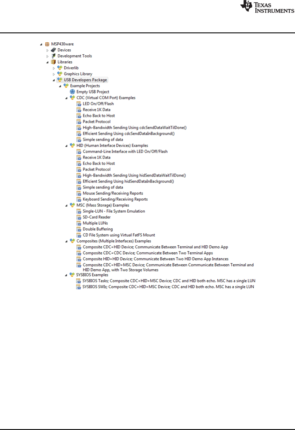
Additional Resources
www.ti.com
50 SLAU533D–September 2013–Revised April 2017
Submit Documentation Feedback
Copyright © 2013–2017, Texas Instruments Incorporated
MSP430F5529 LaunchPad™ Development Kit (MSP
‑
EXP430F5529LP)
Figure 38. USB Examples in the USB Developers Package
The Resource Explorer also has a wizard for creating your own empty USB project (see Figure 39). It
automatically invokes the Descriptor Tool, the tool's help text walks you through all of the decisions you
need to make, and finally the tool saves its output files into your new empty USB project!
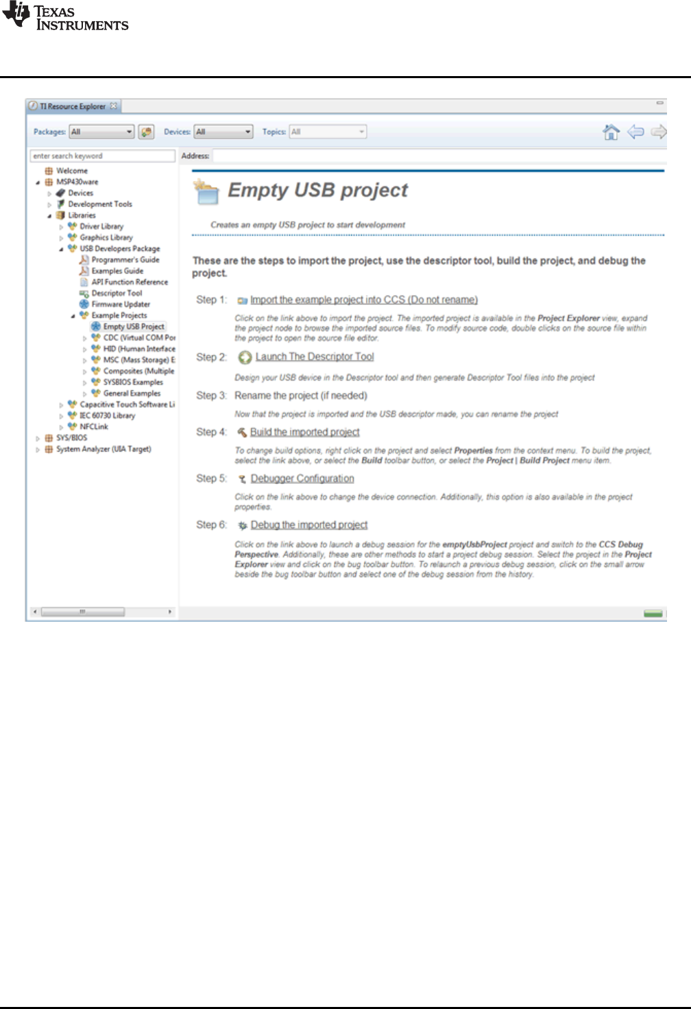
www.ti.com
Additional Resources
51
SLAU533D–September 2013–Revised April 2017
Submit Documentation Feedback Copyright © 2013–2017, Texas Instruments Incorporated
MSP430F5529 LaunchPad™ Development Kit (MSP
‑
EXP430F5529LP)
Figure 39. TI Resource Explorer: Create a New USB Project Wizard
Inside TI Resource Explorer, click Libraries, then click USB Developers Package, and finally click Example
Projects. Click Empty USB Project.
This feature is only found in MSP430Ware v1.40.01.44 and later, which is distributed in CCS v5.5.
4.6 F5529 Code Examples
This is a set of very simple code examples that demonstrate how to use the entire set of peripherals on
the MSP430 MCU: ADC12, Timer_A, Timer_B, and so on. These do not use driverlib; rather, they access
the MSP430 registers directly.
Every MSP430 MCU has a set of these code examples. When you write code that uses a peripheral,
these examples can often serve as a starting point.
4.7 MSP430 Application Notes
There are many application notes at www.ti.com/msp430 with practical design examples and topics.
4.8 TI E2E Community
Search the forums at http://e2e.ti.com. If you cannot find your answer, post your question to the
community.
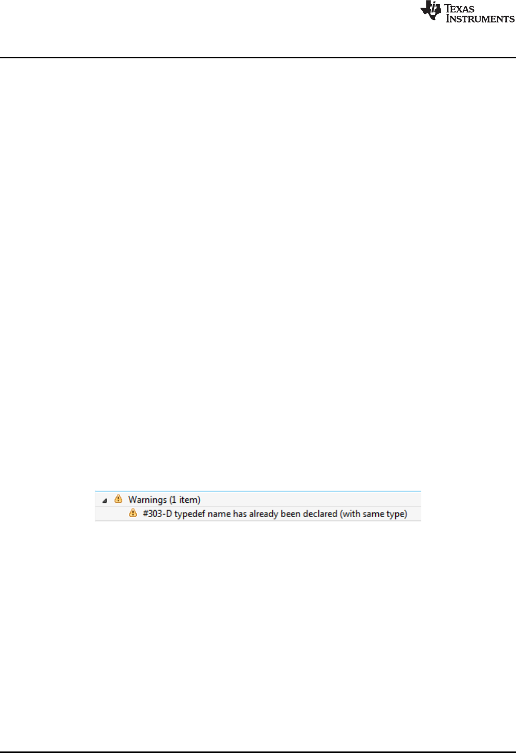
Additional Resources
www.ti.com
52 SLAU533D–September 2013–Revised April 2017
Submit Documentation Feedback
Copyright © 2013–2017, Texas Instruments Incorporated
MSP430F5529 LaunchPad™ Development Kit (MSP
‑
EXP430F5529LP)
4.9 Community at Large
Many online communities focus on the MSP430 – for example, http://www.43oh.com. You can find
additional tools, resources, and support from these communities.
5 FAQs
Q: I can't get the backchannel UART to connect. What's wrong?
A: Check the following:
• Do the baudrate in the host's terminal application and the USCI_A1 settings match?
• Are the appropriate jumpers in place, on the isolation jumper block?
• Probe on RXD and send data from the host; if you don't see data, it might be a problem on the host
side.
• Probe on TXD while sending data from the MSP430. If you don't see data, it might be a configuration
problem on the USCI_A1 module.
• Consider the use of the hardware flow control lines (especially for higher baud rates)
Q: So the onboard emulator is really open source? And I can build my own onboard emulator?
A: Yes! We encourage you to do so. The design files are on ti.com.
Q: Why are the character strings printed to the screen incorrect when using the keyboard demo?
A: If you are using a different regional keyboard, certain characters may appear differently. This can be
fixed by opening the *.txt files and entering new strings.
Q: My ASCII art rocket does not look right?
A: A couple possibilities…
• If typing the rocket into Notepad++, the image can become skewed due to a setting that automatically
tabs into the next line after a carriage return. You can fix this by changing these settings or by using
the standard Notepad application or another text editor. (To open Notepad, click the Start button, then
click Run…, type "notepad" in the Open text box, and click OK.)
• If you are using a word processor like Microsoft Word, be sure to use a fixed-width font like Courier
New.
Q: I tried building my own project with driverlib and got a warning: "#303-D typedef name has
already been declared (with same type)." How do I resolve this?
A: This warning can occur with CCS v5.4. The version of driverlib in the F5529 LaunchPad development
kit software examples is from MSP430Ware v1.40.01.44, which is targeted at CCS v5.5. CCS v5.5 has a
new and improved set of MSP430 header files in it (for example, msp430f5529.h), and the driverlib in
these examples is dependent on that new header file. To resolve this problem in the demo, TI put the new
and improved header file (from CCS v5.5) into this project, allowing the project to be compatible with v5.4.
However, if you are now working with a different project, this new header file may be missing. You can
copy the msp430f5529.h file out of the demo project into your project, or you can upgrade to CCS v5.5.
Q: The MSP430 G2 LaunchPad development kit had a socket, allowing me change the target
device. Why doesn't the F5529 LaunchPad development kit use one?
A: The F5529 LaunchPad development kit provides more functionality, and this requires it to use a device
with more pins. Sockets for devices with this many pins are too expensive for the tool's target price.

www.ti.com
FAQs
53
SLAU533D–September 2013–Revised April 2017
Submit Documentation Feedback Copyright © 2013–2017, Texas Instruments Incorporated
MSP430F5529 LaunchPad™ Development Kit (MSP
‑
EXP430F5529LP)
Q: I'm trying to power the LaunchPad development kit from a USB power supply (not an actual
USB host), and it is not working. Does the LaunchPad development kit not support this?
This problem is fixed in Rev1.5 and later LaunchPad development kits. Unfortunately Rev1.4 does not.
USB hubs typically shouldn't enable power to their downstream devices until the hubs themselves
enumerate on the host, and that's what the TUSB2046 on the Rev1.4 F5529 LaunchPad development kit
does through the TPS2041B power switches. If the hub never enumerates, power is not provided to the
target F5529. Because the downstream device is permanently attached in this application, the TPS2041B
switches are not required by the USB specification. Rev1.5 and newer F5529 LaunchPad development
kits have these switches removed, to avoid this problem.
Again, the benefit of the hub is single-cable development. Other power supplies can still be applied
through the power header.
Q: With the female headers on the bottom, the board does not sit flat on the table, and I can't
unsolder them. Why did TI do this?
A: For several reasons. A major feedback item on previous LaunchPad development kits was the desire
for female headers instead of male ones. But simply using female instead is problematic, because
compatibility with existing BoosterPack plug-in modules would be lost, and some people prefer male
headers. So, adding female headers without removing male ones satisfies both preferences. It also allows
more flexibility in stacking BoosterPack plug-in modules and other LaunchPad development kits.
The downside to this approach is perhaps that the board does not sit flat. But while a USB cable is
attached (the usual development model), it tends to not sit flat anyway.
For those wishing the board to sit flat, holes are drilled in the corners so that standoffs can be fastened.
Rubber bumper feet also should work.
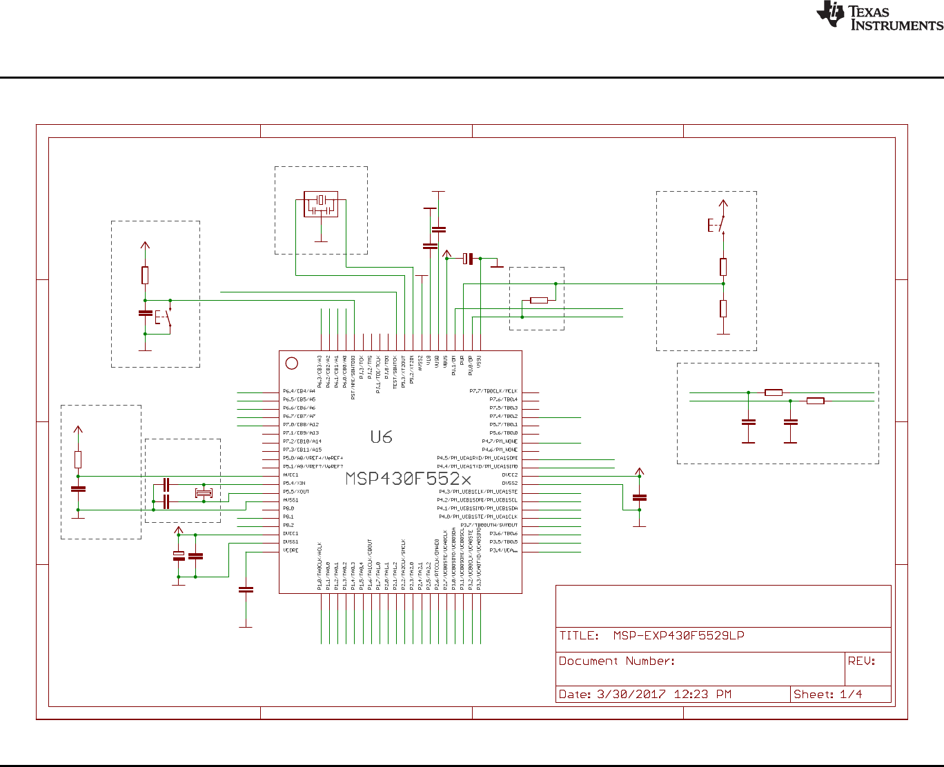
Remove R28 and inject AVCC directly if needed
Design Notes:
Free IO pins: 4.6, 5.0, 5.1, 5.6, 5.7, 7.1, 7.2, 7.3, 7.5, 7.6, 7.7, 8.0, PJ.x (4)
100n
220n
220n
47k
1n
470n
100n
0R
22p
22p
RST
100n
10u
GND
GND GND
GND
GND
GND
100R
BSL
GND
1k4 1M
GND
CSTCR4M00G15L99
GND
+3V3
+3V3
GND
+3V3
+5V
+3V3
4u7
GND +3V3
27R
27R
10p
GND
10p
GND
LF_CRYSTAL
RESET
LFXTCLK
XT2
Main MSP430F5529 w Power, Clock and USB
1.7
BSL
Speed
Analog VCC
C14
C15
C16
R27
C17
C18
C19
R28
C25
C26
12
S3
C29
C30
1
2
3
4
5
6
7
8
9
10
11
12
13
14
15
16
17
18
19
20
21
22
23
24
25
26
27
28
29
30
31
32
33
34
35
36
37
38
39
40
41
42
43
44
45
46
47
48
49
50
51
52
53
54
55
56
57
58
59
60
61
62
63
64
65
66
67
68
69
70
71
72
73
74
75
76
77
78
79
80
R14
1
2
S5
R15
R16
1
2
3
Q4
C27
R31
R32
C23
C24
Q2
P1.4
P2.6
P1.3
P3.2
P1.2
P1.5
P1.7
TARGET_PUR
TEST/SBWTCK
RST/SBWTDIO
P1.0
P1.1 P6.2
P1.6
P6.4
P6.3
P6.1
P6.6
P6.7
P2.0
P4.7
P3.4
P2.5
P3.3
P2.7
P6.0
P2.4
P2.3
P2.1
P2.2
P3.7
P4.0
P6.5
P4.4/UCA1TXD
P4.5/UCA1RXD
P3.6
P4.1
P3.0
P3.1
P3.5
P4.2
P4.3
TARGET_DP
TARGET_DP
TARGET_DM
TARGET_DM HUB_DM1
HUB_DP1
P7.4
P7.0
P8.1
P8.2
+
A
B
C
D
1 2 3 4
A
B
C
D
1 2 3 4
+
Copyright © 2017, Texas Instruments Incorporated
Schematics
www.ti.com
54 SLAU533D–September 2013–Revised April 2017
Submit Documentation Feedback
Copyright © 2013–2017, Texas Instruments Incorporated
MSP430F5529 LaunchPad™ Development Kit (MSP
‑
EXP430F5529LP)
6 Schematics
Figure 40. Schematics (1 of 4)
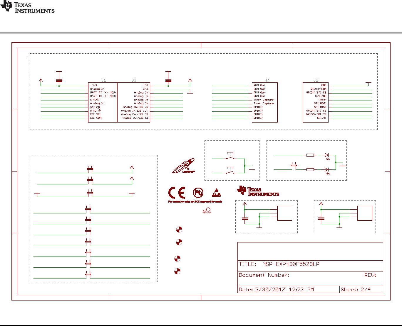
>>
>>
<<
<<
>>
<<
<<
>>
11
2040
31
1
10
21
30
GND
GND
GND
470R
470R
GND
GND
LED1_PWR
+5V
+3V3
GND
+5V
+3V3
+3V3
+3V3 +5V
+5V
100n100n
100n100n
GNDGND
RTS
CTS
SBW_TST
SBW_RST
TXD
RXD
SBW_NC
GND
GNDGND
MOUNTHOLE_125MIL
MOUNTHOLE_125MIL
MOUNTHOLE_125MIL
MOUNTHOLE_125MIL
HEADER1X03-J5INSIDE_LABEL
40 pin BoosterPack Headers
Connections
1.7
User LEDs
User Buttons
ezFET <<---->> LaunchPad
1 2
S2
1 2
S1
R29
R30
1
2
JP8
1
2
JP1
1
2
JP2
C20C21
C28C31
1
2
JP6.4
1
2
JP6.3
1
2
JP4.1
1
2
JP4.2
1
2
JP6.1
1
2
JP6.2
1
2
JP4.3
1
2
JP3
LED1
LED2
U$7
U$8
U$9
U$10
1
2
3
J10
1
2
3
J7
P1.4
P1.3
P3.2
P1.2
P1.5
P1.7
TEST/SBWTCK
RST/SBWTDIO
RST/SBWTDIO
P1.0
P1.1
P6.2
P6.4
P6.3
P6.1
P2.0
P3.4
P3.3
P6.0
P2.1
P2.2
P6.5 GND
GND
P3.0
P3.1
P4.2
P4.7
EZFET_UARTRTS
EZFET_VBUS
EZFET_VCC
EZFET_UARTCTS
EZFET_UARTRXD
EZFET_UARTTXD
EZFET_SBW_RST
EZFET_SBW_TST
P4.5/UCA1RXD
P6.7
P4.4/UCA1TXD
EZFET_SBW_NC
P6.6
P2.7
P4.1
P2.5
P2.4
P1.6
P3.7
P7.4
P2.6
P2.3
P7.0 P4.0
P4.3
P8.1
P3.6
P3.5 P8.2
A
B
C
D
1 2 3 4
A
B
C
D
1 2 3 4
+3V3
GND
GND
+5V
GND
GND
Copyright © 2017, Texas Instruments Incorporated
www.ti.com
Schematics
55
SLAU533D–September 2013–Revised April 2017
Submit Documentation Feedback
Copyright © 2013–2017, Texas Instruments Incorporated
MSP430F5529 LaunchPad™ Development Kit (MSP
‑
EXP430F5529LP)
Figure 41. Schematics (2 of 4)
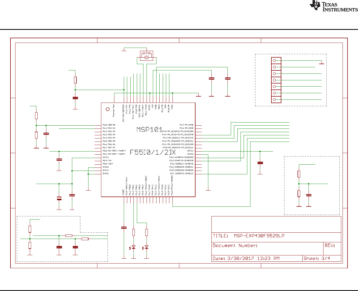
eZ-FET lite Emulator
>>
>>
<<
<<
TARGET VCC SENSE
DEBUG
MSP430F5528IRGC
GND
GND
GND
470 390
red green
GND GND
1n
47k
GND
470n
GND
220n
GND
220n
GND
GND
PIEZO_CSTCR4M00G15L99
100n
GND
10u
GND
100n
GND
100n
GND
240k
150k 33p
GND GND
220k
220k 33p
GND GND
GND
27R
10p
GND
1k4
1M
GND
27R
10p
GND
eZ-FET Lite Rev1.0
1.7
1
2
3
4
5
6
7
8
9
10
11
12
13
14
15
16
17
18
19
20
21
22
23
24
25
26
27
28
29
30
31
32
33
34
35
36
37
38
39
40
41
42
43
44
45
46
47
48
49
50
51
52
53
54
55
56
57
58
59
60
61
62
63
64
TP
R101 R102
LED101 LED102
C112
R109
C101
C102 C107
1
2
3
Q101
C103
C104
C113
C121
R124
R125 C123
R121
R122 C122
1
TP105
1
TP110
1
TP106
1
TP107
1
TP108
1
TP109
1
TP104
R104
C111
R105
R106
R103
C110
EZFET_LED0
EZFET_LED1
EZFET_AVBUS
EZFET_RST
EZFET_RST
EZFET_TCK
EZFET_TCK
EZFET_TMS
EZFET_TMS
EZFET_TDI
EZFET_TDI
EZFET_TDO
EZFET_TDO
EZFET_TEST
EZFET_TEST
EZFET_XT2OUT
EZFET_XT2IN
EZFET_V18
EZFET_VUSB
EZFET_PUR
EZFET_PUR
EZFET_VREF
EZFET_AVCCOUT2ADC
EZFET_AVCCOUT2ADC
EZFET_UARTRTS
EZFET_UARTRTS
EZFET_VBUS
EZFET_VBUS
EZFET_VCC
EZFET_VCC
EZFET_VCC
EZFET_VCC
EZFET_UARTTXD
EZFET_UARTTXD
EZFET_UARTRXD
EZFET_UARTRXD
EZFET_SBW_RST
EZFET_SBW_TST
EZFET_UARTCTS
EZFET_UARTCTS
EZFET_PU.1/DM
EZFET_PU.1/DM
EZFET_PU.0/DP
EZFET_PU.0/DP HUB_DP2
HUB_DM2
EZFET_SBW_NC
+
A
B
C
D
1 2 3 4
A
B
C
D
1 2 3 4
Copyright © 2017, Texas Instruments Incorporated
Schematics
www.ti.com
56 SLAU533D–September 2013–Revised April 2017
Submit Documentation Feedback
Copyright © 2013–2017, Texas Instruments Incorporated
MSP430F5529 LaunchPad™ Development Kit (MSP
‑
EXP430F5529LP)
Figure 42. Schematics (3 of 4)
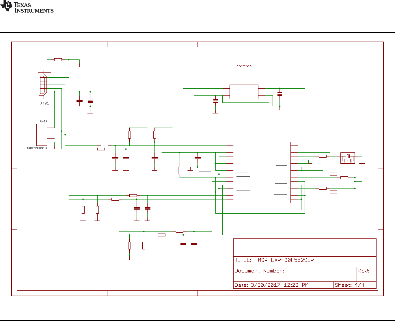
TUSB2046BIRHBIRHB
GND
GND
TPS62237DRY
1u
1u
GND
GND
GND
CSTCR6M00G15L99
GND
GND
GND
GND
GND
GND
GND
GND
100n
22p 22p
22R
22R
1k5
22R
22R
22R
22R
15k 15k
15k 15k
22p 22p
22p 22p
10k
33R
4u7
1k5
47k
100n
GND
100n
GND GND
GNDGND
GNDGNDGND
15k
15k
15k
15k GND
USB Hub and Power
1.7
EXTMEM 26
OVRCUR1
10
OVRCUR2
14
OVRCUR3 18
OVRCUR4 22
PWRON1
9
PWRON2
13
PWRON3 17
PWRON4 21
RESET
4
BUSPWR
8
DM0
2
DM1
11
DM2
15 DM3 19
DM4 23
DP0
1
DP1
12
DP2
16
DP3 20
DP4 24
EECLK
5
EEDATA/GANGED
6
GND
7
GND 28
SUSPND 32
TSTMODE 31
TSTPLL/48MCLK 27
VCC
3
VCC 25
XTAL1 30
XTAL2 29
IC401
MODE
1
SW
2
VIN
3GND 4
EN 5
FB 6
U402
D+
D-
GND
NC
VBUS
C404
C401
1
2
3
Q401
IO1 3
VCC 1
IO2 5
GND 4
NC 2
L401
2.2uH (NR3010T2R2M)
C402
C405 C406
R405
R406
R403
R410
R411
R416
R417
R414 R415
R418 R419
C409 C410
C411 C412
R402
R401
C403
R407
R404
C408 C407
R409
R408
R413
R412
PWRON
OC
HUB_DP2
HUB_DM2
HUB_DM1
HUB_DP1
EZFET_VCC
EZFET_VCC EZFET_VCC
EZFET_VCC
EZFET_VCC
EZFET_VBUS
EZFET_VBUS
A
B
C
D
1 2 3 4
A
B
C
D
1 2 3 4
+
Copyright © 2017, Texas Instruments Incorporated
www.ti.com
Schematics
57
SLAU533D–September 2013–Revised April 2017
Submit Documentation Feedback
Copyright © 2013–2017, Texas Instruments Incorporated
MSP430F5529 LaunchPad™ Development Kit (MSP
‑
EXP430F5529LP)
Figure 43. Schematics (4 of 4)

Revision History
www.ti.com
58 SLAU533D–September 2013–Revised April 2017
Submit Documentation Feedback
Copyright © 2013–2017, Texas Instruments Incorporated
Revision History
Revision History
NOTE: Page numbers for previous revisions may differ from page numbers in the current version.
Changes from July 22, 2015 to April 7, 2017 ................................................................................................................... Page
• Added Rev 1.6 and Rev 1.7 to Table 4,Hardware Change Log .................................................................. 27
• Updated all of the figures in Section 6,Schematics ................................................................................ 54

IMPORTANT NOTICE FOR TI DESIGN INFORMATION AND RESOURCES
Texas Instruments Incorporated (‘TI”) technical, application or other design advice, services or information, including, but not limited to,
reference designs and materials relating to evaluation modules, (collectively, “TI Resources”) are intended to assist designers who are
developing applications that incorporate TI products; by downloading, accessing or using any particular TI Resource in any way, you
(individually or, if you are acting on behalf of a company, your company) agree to use it solely for this purpose and subject to the terms of
this Notice.
TI’s provision of TI Resources does not expand or otherwise alter TI’s applicable published warranties or warranty disclaimers for TI
products, and no additional obligations or liabilities arise from TI providing such TI Resources. TI reserves the right to make corrections,
enhancements, improvements and other changes to its TI Resources.
You understand and agree that you remain responsible for using your independent analysis, evaluation and judgment in designing your
applications and that you have full and exclusive responsibility to assure the safety of your applications and compliance of your applications
(and of all TI products used in or for your applications) with all applicable regulations, laws and other applicable requirements. You
represent that, with respect to your applications, you have all the necessary expertise to create and implement safeguards that (1)
anticipate dangerous consequences of failures, (2) monitor failures and their consequences, and (3) lessen the likelihood of failures that
might cause harm and take appropriate actions. You agree that prior to using or distributing any applications that include TI products, you
will thoroughly test such applications and the functionality of such TI products as used in such applications. TI has not conducted any
testing other than that specifically described in the published documentation for a particular TI Resource.
You are authorized to use, copy and modify any individual TI Resource only in connection with the development of applications that include
the TI product(s) identified in such TI Resource. NO OTHER LICENSE, EXPRESS OR IMPLIED, BY ESTOPPEL OR OTHERWISE TO
ANY OTHER TI INTELLECTUAL PROPERTY RIGHT, AND NO LICENSE TO ANY TECHNOLOGY OR INTELLECTUAL PROPERTY
RIGHT OF TI OR ANY THIRD PARTY IS GRANTED HEREIN, including but not limited to any patent right, copyright, mask work right, or
other intellectual property right relating to any combination, machine, or process in which TI products or services are used. Information
regarding or referencing third-party products or services does not constitute a license to use such products or services, or a warranty or
endorsement thereof. Use of TI Resources may require a license from a third party under the patents or other intellectual property of the
third party, or a license from TI under the patents or other intellectual property of TI.
TI RESOURCES ARE PROVIDED “AS IS” AND WITH ALL FAULTS. TI DISCLAIMS ALL OTHER WARRANTIES OR
REPRESENTATIONS, EXPRESS OR IMPLIED, REGARDING TI RESOURCES OR USE THEREOF, INCLUDING BUT NOT LIMITED TO
ACCURACY OR COMPLETENESS, TITLE, ANY EPIDEMIC FAILURE WARRANTY AND ANY IMPLIED WARRANTIES OF
MERCHANTABILITY, FITNESS FOR A PARTICULAR PURPOSE, AND NON-INFRINGEMENT OF ANY THIRD PARTY INTELLECTUAL
PROPERTY RIGHTS.
TI SHALL NOT BE LIABLE FOR AND SHALL NOT DEFEND OR INDEMNIFY YOU AGAINST ANY CLAIM, INCLUDING BUT NOT
LIMITED TO ANY INFRINGEMENT CLAIM THAT RELATES TO OR IS BASED ON ANY COMBINATION OF PRODUCTS EVEN IF
DESCRIBED IN TI RESOURCES OR OTHERWISE. IN NO EVENT SHALL TI BE LIABLE FOR ANY ACTUAL, DIRECT, SPECIAL,
COLLATERAL, INDIRECT, PUNITIVE, INCIDENTAL, CONSEQUENTIAL OR EXEMPLARY DAMAGES IN CONNECTION WITH OR
ARISING OUT OF TI RESOURCES OR USE THEREOF, AND REGARDLESS OF WHETHER TI HAS BEEN ADVISED OF THE
POSSIBILITY OF SUCH DAMAGES.
You agree to fully indemnify TI and its representatives against any damages, costs, losses, and/or liabilities arising out of your non-
compliance with the terms and provisions of this Notice.
This Notice applies to TI Resources. Additional terms apply to the use and purchase of certain types of materials, TI products and services.
These include; without limitation, TI’s standard terms for semiconductor products http://www.ti.com/sc/docs/stdterms.htm), evaluation
modules, and samples (http://www.ti.com/sc/docs/sampterms.htm).
Mailing Address: Texas Instruments, Post Office Box 655303, Dallas, Texas 75265
Copyright © 2018, Texas Instruments Incorporated
