SmartRF™ Packet Sniffer User's Manual (Rev. G) Smartrf User
User Manual:
Open the PDF directly: View PDF ![]() .
.
Page Count: 30
SmartRF™ Packet Sniffer
User’s Manual
SWRU187G

SWRU187G
2/29
Table of contents
1 INTRODUCTION ........................................................................................................................................3
1.1 PROTOCOLS .....................................................................................................................................................4
1.2 HARDWARE PLATFORM...................................................................................................................................5
1.3 DATA FLOW ....................................................................................................................................................7
1.4 SOFTWARE ......................................................................................................................................................7
2 USER INTERFACE .....................................................................................................................................8
2.1 LAUNCH WINDOW ..........................................................................................................................................8
2.2 PACKET SNIFFER WINDOW OF AN ACTIVE SESSION ..........................................................................................8
2.3 MENUS AND TOOLBARS ................................................................................................................................ 10
2.4 PACKET BROADCAST .................................................................................................................................... 11
2.5 CAPTURING DEVICE ...................................................................................................................................... 12
2.6 RADIO CONFIGURATION ................................................................................................................................ 13
2.7 SELECT FIELDS .............................................................................................................................................. 16
2.8 PACKET DETAILS ........................................................................................................................................... 17
2.9 ADDRESS BOOK ............................................................................................................................................. 18
2.10 DISPLAY FILTER ............................................................................................................................................ 19
2.11 TIME LINE ..................................................................................................................................................... 20
3 KNOW ISSUES .......................................................................................................................................... 22
3.1 BLUETOOTH LOW ENERGY ........................................................................................................................... 22
4 FORMAT OF PACKETS SAVED TO FILE .......................................................................................... 23
5 EXPORTING REGISTER SETTINGS FROM SMARTRF™ STUDIO ............................................. 25
6 HELP ........................................................................................................................................................... 26
7 TROUBLESHOOTING ............................................................................................................................. 27
8 GENERAL INFORMATION ................................................................................................................... 29
8.1 DOCUMENT HISTORY .................................................................................................................................... 29

SWRU187G
3/29
1 Introduction
The SmartRF™ Packet Sniffer is a PC software application used to display and store RF packets
captured with a listening RF HW node. Multiple RF protocols are supported. The Packet Sniffer filters
and decodes packets and displays them in a convenient way, with options for filtering and storage to a
binary file format.
The Packet Sniffer is installed separately from SmartRF® Studio 7, and must be downloaded from the
Texas Instruments web site.

SWRU187G
4/29
1.1 Protocols
The supported protocols can be seen in the Launch window when starting the packet sniffer. The
following combinations of protocols and capture devices are supported:
Protocol
Version
Capture device
Can be used to
capture packets from
Bluetooth®
low energy
Bluetooth
core spec 4.0
CC2540 USB Dongle
CC2540EM + SmartRF05EB
CC2540
Bluetooth® low
energy devices
ZigBee
2007/PRO
2006
2003
CC2531 USB Dongle
CC2533EM + SmartRF05EB
CC2530EM + SmartRF05EB
CC2520EM + SmartRF05EB
CC2420
CC2430, CC2431
CC2480
CC2520
CC2530, CC2531
CC2538
RF4CE
ZigBee RF4CE 1.0.1
CC2531 USB Dongle
CC2533EM + SmartRF05EB
CC2530EM + SmartRF05EB
CC2520EM + SmartRF05EB
CC2520
CC2530, CC2531
CC2533
SimpliciTI
1.2.0
1.1.1
1.1.0
1.0.6
1.0.4
1.0.0
CC1111 USB Dongle
CC1110EM + SmartRF04EB/SmartRF05EB
CC1101EM + SmartRFTrxEB
CC110LEM + SmartRFTrxEB
CC113LEM + SmartRFTrxEB
CC1100, CC1100E
CC1101, CC110L
CC1110, CC1111
CC430
CC1120EM + SmartRFTrxEB
CC1121EM + SmartRFTrxEB
CC1125EM + SmartRFTrxEB
CC1120
CC1121
CC1125
CC2510EM + SmartRF04EB/SmartRF05EB
CC2511 USB Dongle
CC2500
CC2510
CC2511
Generic
Any
CC2531 USB Dongle
CC2533EM + SmartRF05EB
CC2530EM + SmartRF05EB
CC2520EM + SmartRF05EB
CC2420
CC2430, CC2431
CC2480
CC2520
CC2530, CC2531
CC2533
CC2544 USB Dongle
CC2511 USB Dongle
CC2510EM + SmartRF04EB/SmartRF05EB
CC2500, CC2550
CC2510, CC2511
CC2544
CC1111 USB Dongle
CC1110EM + SmartRF04EB/SmartRF05EB
CC1101EM + SmartRFTrxEB
CC110LEM + SmartRFTrxEB
CC113LEM + SmartRFTrxEB
CC1200EM + SmartRFTrxEB
CC1100, CC1100E
CC1101, CC1150
CC110L, CC115L
CC1110, CC1111
CC430
CC1200
CC1120EM + SmartRFTrxEB
CC1121EM + SmartRFTrxEB
CC1125EM + SmartRFTrxEB
CC1120
CC1121
CC1125
Table 1: Supported protocols
Note that when sniffing in the sub-1 GHz frequency bands, you need to use a capture device that
supports the frequency used by the devise you are sniffing. For instance, CC1110 and CC1111 have
limited support for some frequencies supported by CC1100E.
Also note that for all of the proprietary operating modes, the capture device will only be able to capture
packets as long as it can be set up with the same data rate and modulation. For instance, CC1120 may
not support the high data rates supported by CC1200.
SWRU187G
5/29
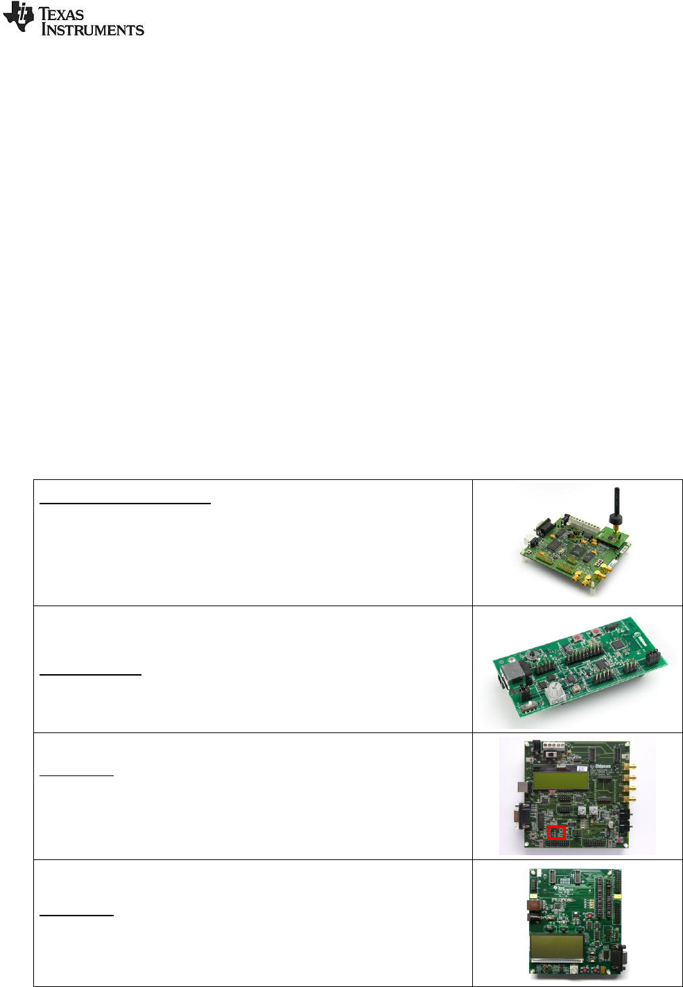
1.2 Hardware Platform
The packet sniffer can be used with different HW platforms. The following HW can be used:
CC2540 USB Dongle
CC2544 USB Dongle
CC2531 USB Dongle
CC2511 USB Dongle
CC1111 USB Dongle
SmartRF04EB
o CC1110EM, CC2510EM
SmartRF05EB
o CC2520EM, CC2530EM, CC2533EM, CC2540EM, CC1110EM, CC2510EM
SmartRFTrxEB
o CC1101EM, CC110LEM, CC113LEM, CC1120EM, CC1121EM, CC1125EM,
CC1200EM, CC2520EM
CC Debugger + SmartRFCCxx10TB
The below legacy capture devices may still work with the tool, but are no longer recommended.
CC2400EB + CC2420EM
CC2430DB
SmartRF04EB + CC2430EM
The applicable board must be connected to the PC through USB.
CC2400EB + CC2420EM (legacy)
Note: The Packet Sniffer started when selecting “IEEE802.15.4/ZigBee (CC2420)” will
be different from the others. A different GUI application will be started. The most
important difference is that the packets will only be stored in a RAM buffer. That means
the GUI application will not be able to handle more packets when the buffer is full. See
the user manual for “Packet Sniffer CC2420” for more details. The manual can be
found under the “documentation” option of the start menu: start->Texas Instruments-
>Packet Sniffer->Documentation->Packet Sniffer CC2420 user manual
CC2430DB (legacy)
SmartRF04EB
Note: Observe the jumpers on header P3. For revision A and B of CC2430 (register
CHVER ≤ 0x02), the jumpers must be set in the horizontal direction (in parallel with the
display) like in Figure 2. For newer revisions of CC2430, the jumpers should be set in
the vertical direction (this is the default position).
SmartRF05EB
Note: Supports selected 8051-based RF SoC (CC254x, CC253x, CC254x) evaluation
modules. Board revision 1.8.0 or higher is recommended for best performance.
SWRU187G
6/29
SmartRFTrxEB
Note: Supports all transceiver evaluation modules. The USB MCU on the TrxEB board
must be programmed with FW revision “0014” or newer. The revision can be seen in
the SmartRF Flash Programmer or SmartRF Studio when the board is connected to
the PC with a USB cable. The firmware is normally updated automatically by the
SmartRF tools.
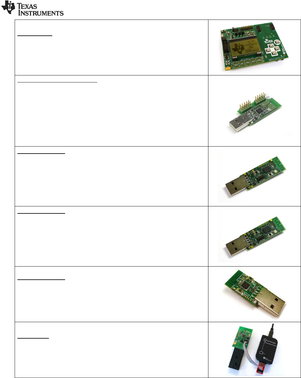
CC2511 and CC1111 USB Dongles
Note: The CC2511 and the CC1111 USB dongles may both be used as capturing
devices with the packet sniffer. Dongles in the CC2511EMK and CC1111EMK868-915
kits are pre-programmed with the packet sniffer firmware and can be used for packet
sniffing straight away. However, since the firmware on the dongle is not automatically
updated, it is recommended to program it with the latest firmware. The same dongles
included in other kits may have to be programmed. The packet sniffer hex file is
located at <install dir>\bin\general\firmware\sniffer_fw_ccxx11.hex
The firmware can be programmed with the SmartRF Flash Programmer tool. To
program the firmware on the dongle, it must be connected to either a SmartRF05EB or
a CC Debugger via the debug connector. See user manual for the flash programmer
for details on how to use the flash programmer.
CC2531 USB Dongle
Note: The CC2531 USB dongles in the CC2531EMK kit are pre-programmed with the
packet sniffer firmware and can be used for packet sniffing straight away. However,
since the firmware on the dongle is not automatically updated, it is recommended to
program it with the latest firmware. Dongles included in other kits may have to be
programmed. The packet sniffer hex file is located at
<install dir>\bin\general\firmware\sniffer_fw_cc2531.hex
The firmware can be programmed with the SmartRF Flash Programmer tool. To
program the firmware on the dongle, it must be connected to either a SmartRF05EB or
a CC Debugger via the debug connector.
CC2540 USB Dongle
Note: The CC2540 USB dongles in the CC2540EMK-USB kit are pre-programmed
with the packet sniffer firmware and can be used for packet sniffing straight away.
However, since the firmware on the dongle is not automatically updated, it is
recommended to program it with the latest firmware. Dongles included in other kits
may have to be programmed. The packet sniffer hex file is located at
<install dir>\bin\general\firmware\sniffer_fw_cc2540_usb.hex
The firmware can be programmed with the SmartRF Flash Programmer tool. To
program the firmware on the dongle, it must be connected to either a SmartRF05EB or
a CC Debugger via the debug connector.
CC2544 USB Dongle
Note: The CC2544 USB dongle must be programmed with the packet sniffer firmware.
The packet sniffer hex file is located at
<install dir>\bin\general\firmware\sniffer_fw_cc2544.hex
The firmware can be programmed with the SmartRF Flash Programmer tool. To
program the firmware on the dongle, it must be connected to either a SmartRF05EB or
a CC Debugger via the debug connector.
CC Debugger
Note: The CC Debugger can be used for packet sniffing just like the SmartRF
evaluation boards. It supports the same devices as SmartRF05EB and
SmartRFTrxEB. Follow the instructions in the CC Debugger’s User Manual to see how
to connect the debugger to your own target board. The picture shows the debugger
connected to the SmartRFCC2510 board included in the CC2510 mini kit.
SWRU187G
7/29
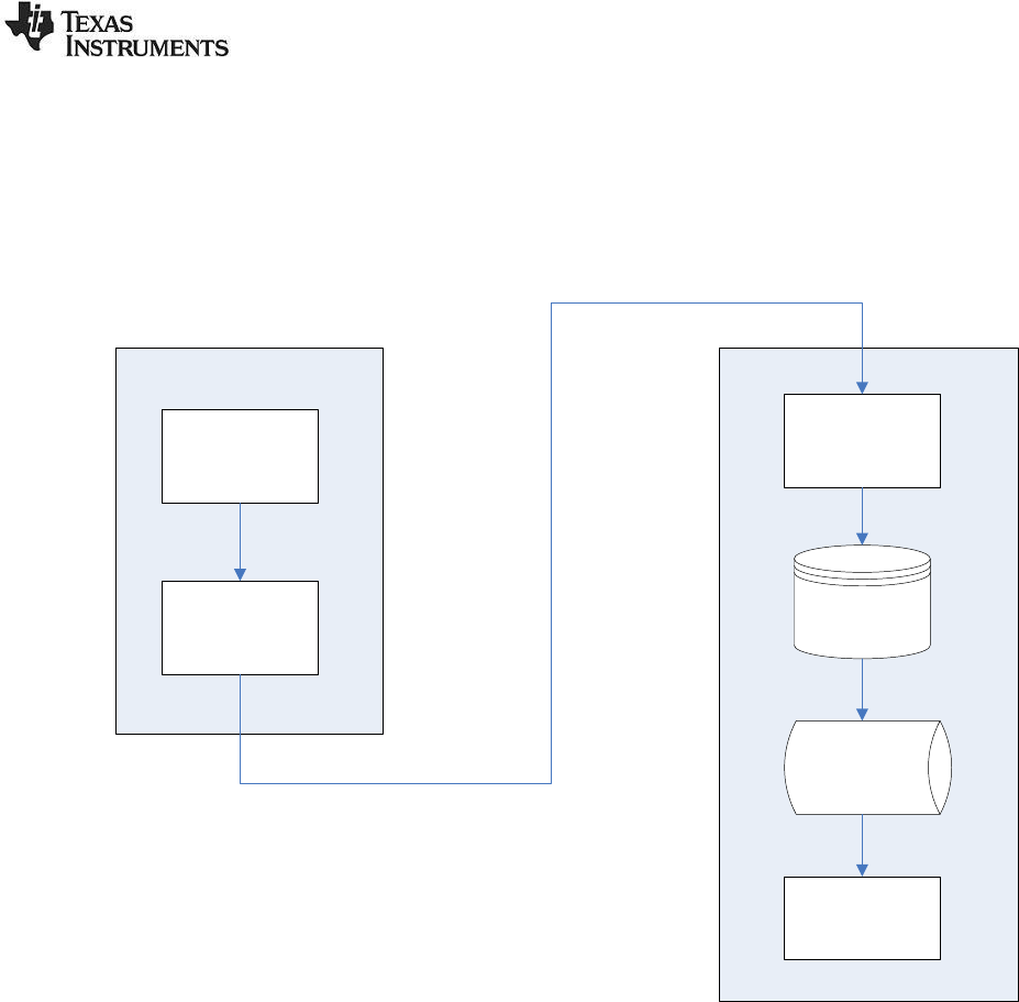
1.3 Data flow
On the PC side the packets will be stored in a disk buffer. The total amount of packets that can be
stored depends on the packet size and the size of the hard disk. During operation the packets will be
cached in a RAM buffer to improve the access time when a packet is to be displayed in the GUI.
Figure 1: Dataflow for the packet sniffer (SoC) below shows the data flow for the packet sniffer.
Connected Device PC
SoC/Transceiver
Data Buffer*
USB controller
Data Buffer
Abstraction layer
8 kB buffer
Screen/GUI
Temporary
Disk file
Cache buffer
In RAM
Figure 1: Dataflow for the packet sniffer (SoC)
* The buffer is only applicable for the System on Chip devices (SoC).
If the PC application is not able to read the packets from the connected devices data buffer fast enough,
an “Overflow” error will be given by the device and the packet sniffer will show the error on screen.
1.4 Software
The firmware on the SoC’s required to run the sniffer will be checked and loaded automatically, if
needed, when the sniffer is started. This can be seen on the status bar in the lower left corner.
The same apply for the USB controller, but the user will be asked to do the update and the user has the
possibility to reject the update. In that case it might be that the sniffer is not working properly.
The following operating systems are supported:
Windows XP/Pro (32 bit)
Windows Vista (32 bit)
Windows Vista (64 bit)
Windows 7 (32 bit)
Windows 7 (64 bit)
Windows 8 (64 bit)
SWRU187G
8/29
2 User Interface
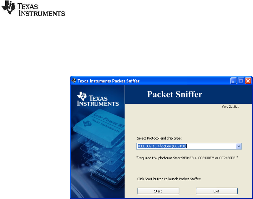
2.1 Launch Window
To select between the different options for protocol and HW configuration, a launch window will be
shown when starting the sniffer.
Figure 2: Screen shot of the packet sniffer launch window
To start the packet sniffer a combination of protocol and chip type should be selected. Then the start
button should be clicked. If a packet sniffer session has been started and the launch window is closed,
the sniffer session will still remain active and must be closed explicit if required.
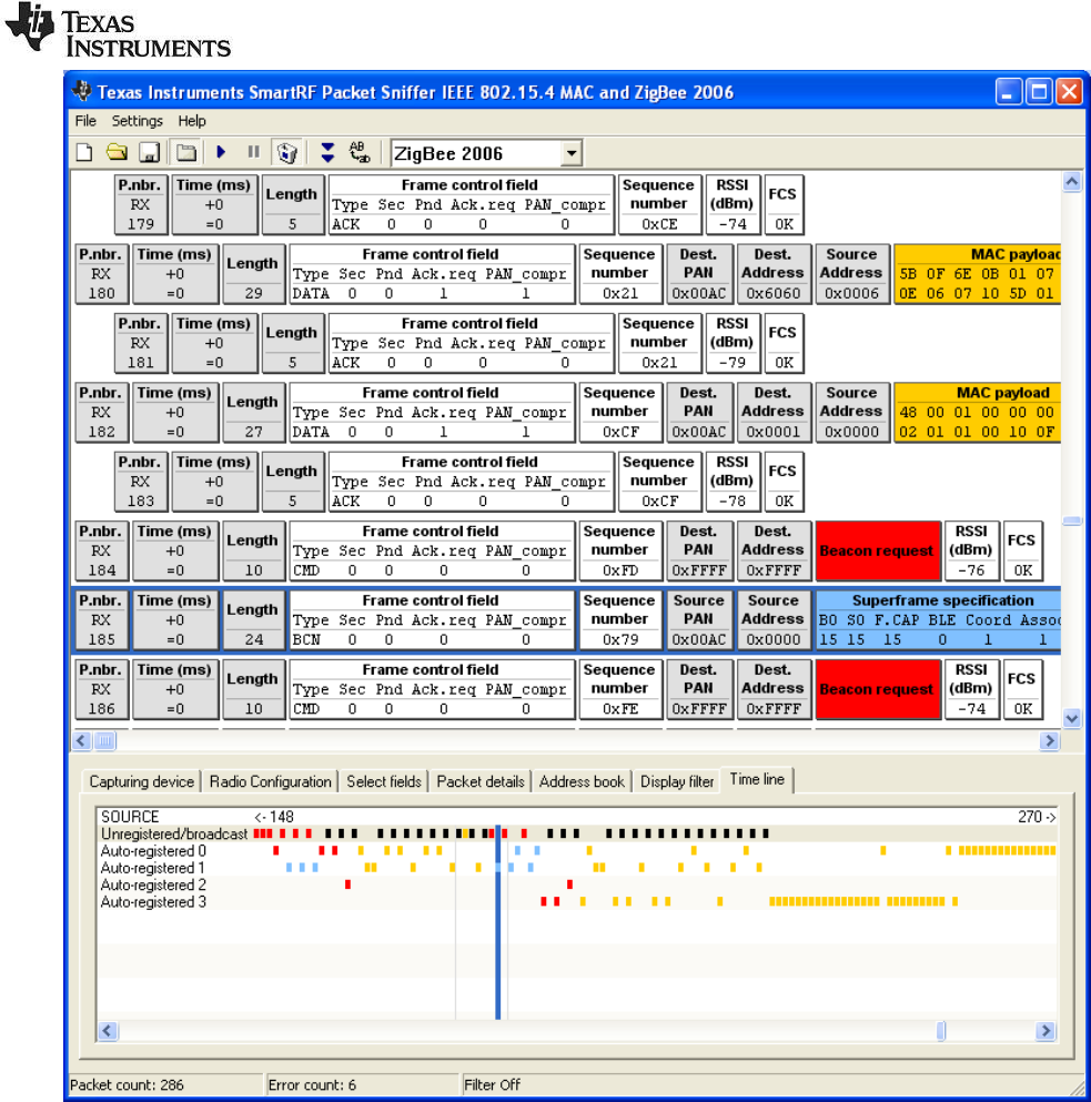
2.2 Packet Sniffer window of an active session
The main window of the packet sniffer can be divided into two sections:
At the top: A packet list, which displays the various fields of the decoded packets.
At the bottom: The following seven tabs:
o Capturing device: Selects which capturing device to use.
o Radio Configuration: Input data to configure the radio of the capturing device. E.g.
Channel number for IEEE 802.15.4 devices.
o Select fields: Select which fields to display in the packet list.
o Packet details: Displays additional packet details (e.g. raw data).
o Address book: Contains all known nodes from the current session. Addresses can be
registered automatically or manually, and they can be changed or deleted.
o Display filter: Packet filtering with user defined filter conditions. A list of all fields which
can be used to define the filter condition is given. From this list a filter condition can be
defined by combining these fields with AND and OR operators.
o Time line: Displays a large sequence of packets, about 20 times as many as in the
packet list, and sorted by either source or destination addresses.
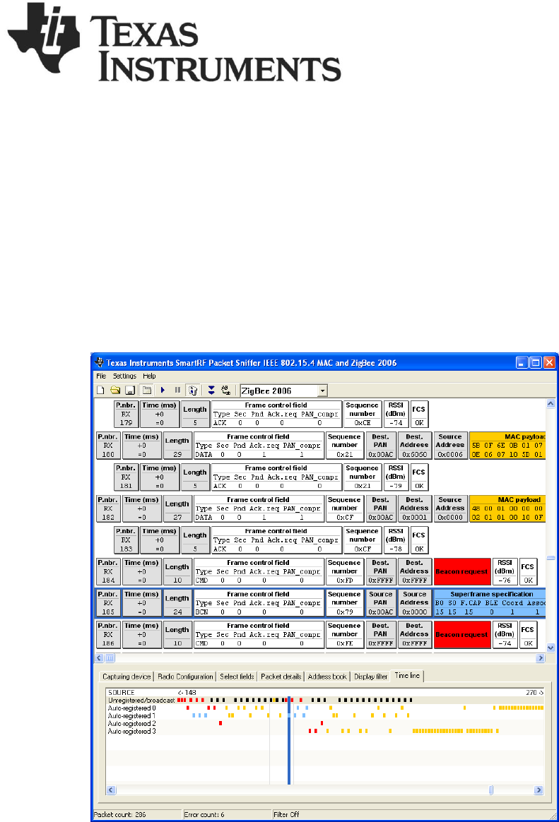
The packet sniffer screenshot in Figure 3 shows an example from the IEEE802.15.4/ZigBee protocol.
The status bar displays the total (unfiltered) number of captured packets, the number of packets with
errors (checksum error and the number of occurrences of buffer overflow) and the status of the filter
function. If filter is on, it will show the number of packets which have passed current filter conditions.
SWRU187G
9/29
Figure 3: Packet sniffer screenshot from the IEEE8022.15.4/ZigBee protocols
SWRU187G
10/29
2.3 Menus and Toolbars
Menu
Button
Key
Description
FileReset...
Empties the packet buffer and the packet list.
FileOpen data...
Load packet buffer from file
FileSave data...
Save packet buffer to file
* Display the tabs at the bottom of the window.
F5
Start the packet sniffer (does not empty the
buffer)
F6
Pause the packet sniffer
* Delete all captured packets when starting
Switch automatic scrolling on/off
Switch between normal font or small font in the
packet view window.
Settings
Cash buffer size…
* The size of the packet RAM buffer in
megabytes.
Settings
Clock multiplier…
* A clock multiplier, which allows you to
compensate for clock speed differences on the
connected device and the hardware running the
network application
Settings
Packet broadcast ...
* Configuration of packet broadcast.
Enable/disable the feature, select broadcast
address and UDP port number, select broadcast
only
Help
About the PSD file format
Help on the file format used to save data.
HelpUser Manual
Opens this document in your PDF file viewer
HelpRev. History
Revision history (bug fixes, new features, etc.)
The application is closed by double-clicking in the top left corner, or single-clicking on the X-symbol in
the top right corner.
Items marked with a star (*) are saved to Windows registry between each session.
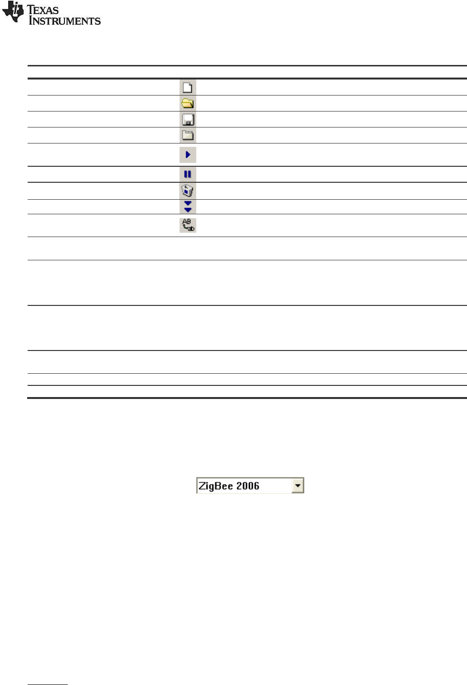
For the ZigBee and SimpliciTI protocol there are options to select the protocol version. This can be
seen in the toolbar as a drop down list: . The selected version will be saved
between each session.
Cash buffer size:
The cash buffer is a RAM buffer that is allocated to contain packets that is displayed by the packet
sniffer. It is used to optimize the access time when the GUI asks for information to display a packet.
The cash buffer function tries to anticipate which packets that will be requested next and will try to load
the buffer with these packets in the background.
Clock multiplier:
A clock multiplier, which allows you to compensate for clock speed differences on the connected device
and the hardware running the network application (Synchronizing the clock on the sniffer device with
the clock on the network devices).
Example:
Ensure that the time stamps are given in microseconds to get accurate numbers (default). Measure a
known time interval (e.g. the distance between a few beacons for the IEEE 802.15.4 protocol). Divide
the desired value by the real value, and enter this floating-point factor into this field. Clock multiplier:
SWRU187G
11/29
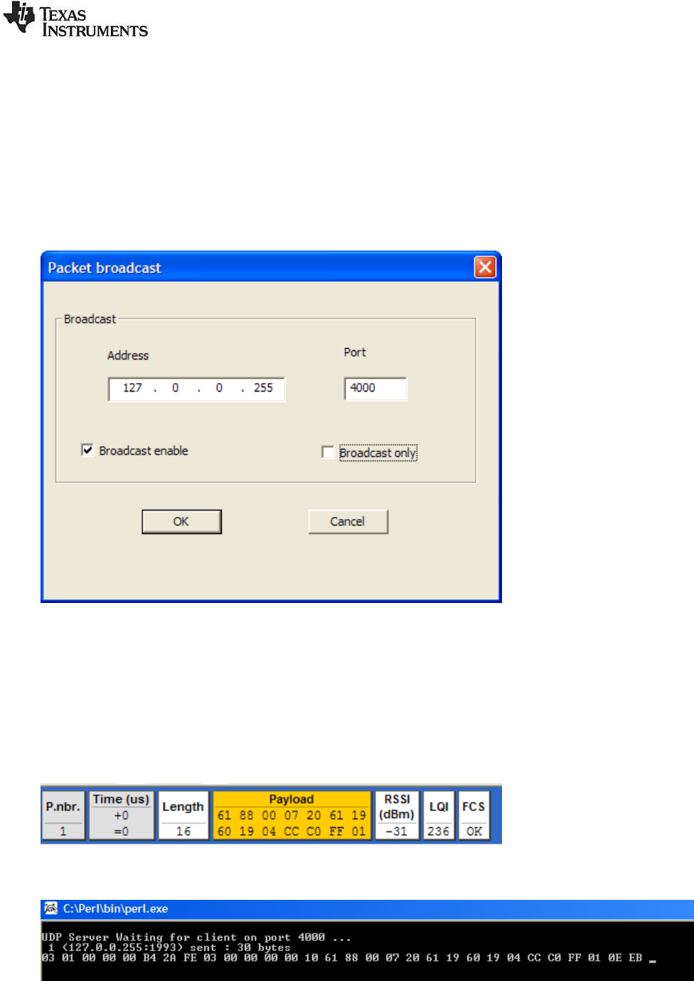
2.4 Packet Broadcast
From version 2.14 of the General Packet Sniffer it is possible to stream packet data to other
applications via a UDP-port. This feature can be configured from the Settings -> Packet broadcast
menu. The feature can be disabled altogether, and it is possible to select broadcast IP-address and
UDP port. The IP-address is restricted to the ‘local’ interface to avoid inadvertently flooding the network
with packets. Optionally the operator may choose to broadcast data only. This is useful when capturing
data over time for storage as it avoid the problem of the buffers of the Packet Sniffer GUI application
filling up.
Figure 4: Packet broadcast setup
A PERL-script is provided as an example of how to use the broadcast data. It is located in <installation
directory>\scripts\udp_receive.pl. It received data on port 4000 and displays the packets in
hexadecimal format. Please note that the packet format is the same as the PSD-format described in
chapter 4 Format of packets saved to file . To save a PSD-file, the application will have to pad the
payload so it makes up the total number of bytes given in the <protocol>.plt file (Located in the plugin
folder). The file contain “Packet_length_raw_data=n” where n is the buffer size excluding the packet
info byte. E.g.: “Packet_length_raw_data=150” means that the total number of bytes for each packet
should be 151.
Figure 5: Sample packet in Packet Sniffer GUI
Figure 6: Sample packet as shown by udp_receive.pl
SWRU187G
12/29
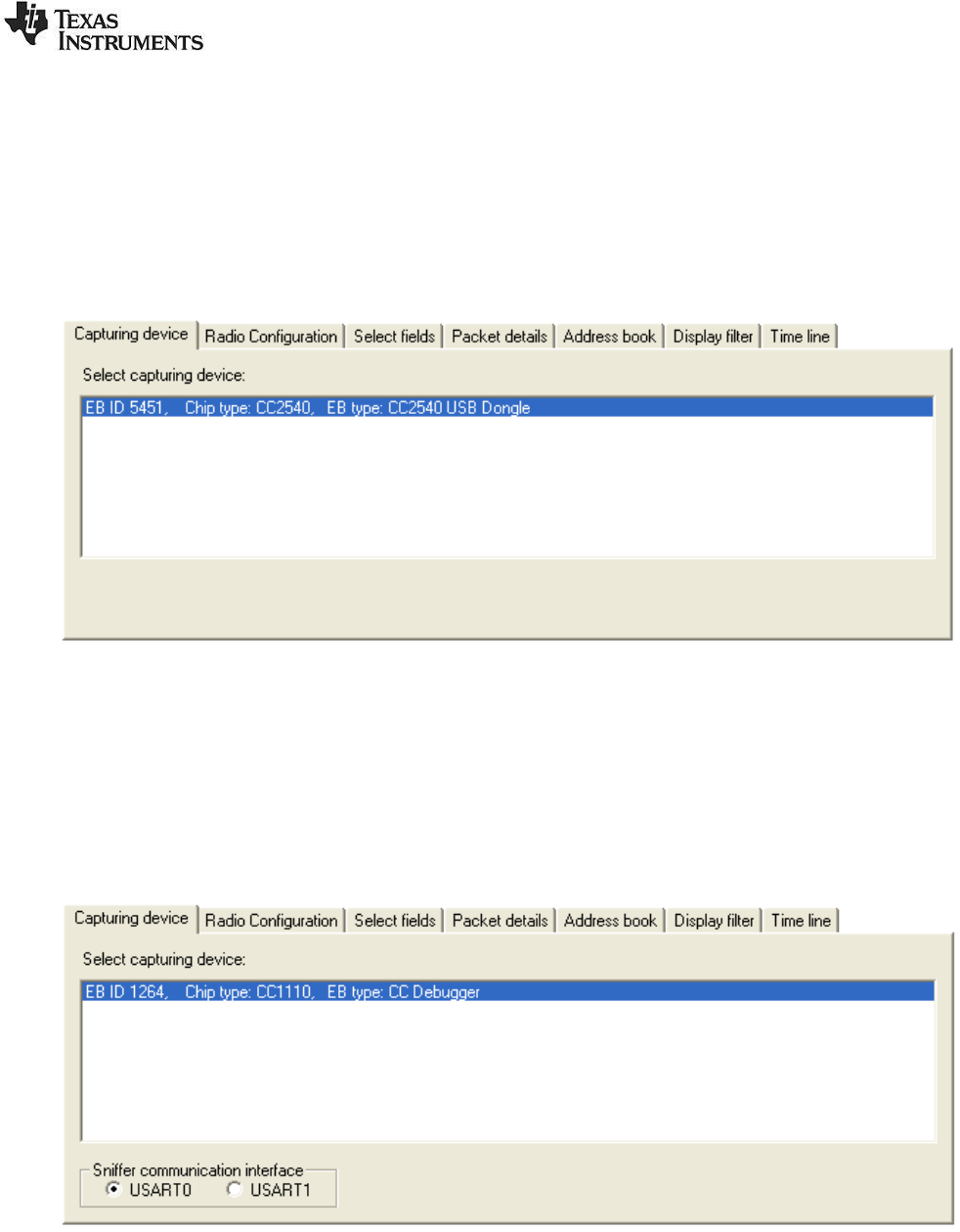
2.5 Capturing device
The Capturing device tab is used to select the required device.
Depending on the selected protocol, the applicable devices will be shown in the list. The list will
automatically be updated when an applicable device is connected to a USB connector.
The Capturing device must be selected before the packet sniffer can be started (which is done by
clicking the tool bar button, or hitting the F5 key).
Figure 7: Capturing device
Sniffer communication interface:
If the EB type is CC Debugger and the chip type is CC1110 or CC2510, an additional option will be
visible in the Capturing device panel. The sniffer communication interface must be selected.
The default value is USART0 and is applicable when CC Debugger is used together with the
SmartRFCCxx10TB board. See figure below.
USART1 should be used for all other combinations with CC1110EM or CC2510EM.
SWRU187G
13/29
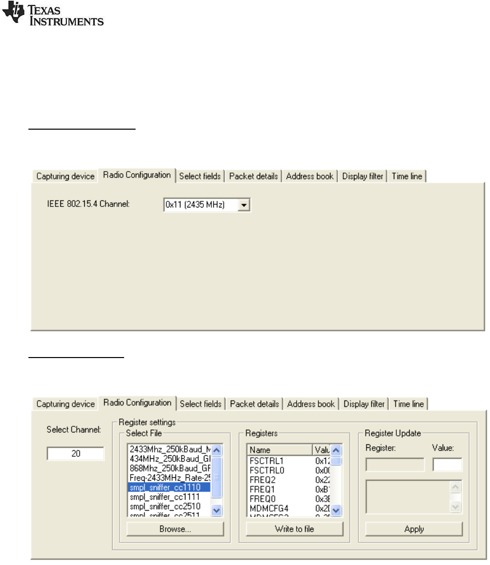
2.6 Radio Configuration
The Radio Configuration tab is used to select the parameter values required to configure the radio of
the capturing device.
The parameters depend on the selected capturing device.
IEEE 802.15.4 devices:
For IEEE 802.15.4 devices, the required channel must be selected.
Proprietary devices:
These radios support a lot of programmable RF parameters.
The radio settings should be given in a text file. The file can be created by SmartRF® Studio. This
makes it easy to get all the correct register settings calculated by SmartRF® Studio. See chapter 5 for
further details.
After installation of the SmartRF™ packet sniffer, a default file will be available in the subdirectory of the
applicable plugin.
The format of the file is shown in the example below:
SWRU187G
14/29
#Name |Addr. |Val.|Description
#--------+------+----+-----------------------------------------------------------
PKTLEN |0xDF02|0xFD|Packet length.
PKTCTRL1 |0xDF03|0x04|Packet automation control.
PKTCTRL0 |0xDF04|0x05|Packet automation control.
FSCTRL1 |0xDF07|0x07|Frequency synthesizer control.
FREQ2 |0xDF09|0x1C|Frequency control word, high byte.
FREQ1 |0xDF0A|0x80|Frequency control word, middle byte.
FREQ0 |0xDF0B|0x00|Frequency control word, low byte.
MDMCFG4 |0xDF0C|0x2D|Modem configuration.
MDMCFG3 |0xDF0D|0x3B|Modem configuration.
MDMCFG2 |0xDF0E|0x73|Modem configuration.
MDMCFG1 |0xDF0F|0x22|Modem configuration.
MDMCFG0 |0xDF10|0xF8|Modem configuration.
DEVIATN |0xDF11|0x00|Modem deviation setting (when FSK modulation is enabled).
MCSM1 |0xDF13|0x0C|Main Radio Control State Machine configuration.
MCSM0 |0xDF14|0x10|Main Radio Control State Machine configuration.
FOCCFG |0xDF15|0x1D|Frequency Offset Compensation Configuration.
BSCFG |0xDF16|0x1C|Bit synchronization Configuration.
AGCCTRL2 |0xDF17|0xC7|AGC control.
AGCCTRL1 |0xDF18|0x00|AGC control.
AGCCTRL0 |0xDF19|0xB2|AGC control.
FREND1 |0xDF1A|0x56|Front end RX configuration.
FREND0 |0xDF1B|0x10|Front end RX configuration.
FSCAL3 |0xDF1C|0xA9|Frequency synthesizer calibration.
FSCAL2 |0xDF1D|0x0A|Frequency synthesizer calibration.
FSCAL1 |0xDF1E|0x00|Frequency synthesizer calibration.
FSCAL0 |0xDF1F|0x11|Frequency synthesizer calibration.
PA_TABLE0|0xDF2E|0xFF|PA Output Power Setting.
When the file is selected, the register values will be shown in the “Registers” frame.
To modify the register value, double click the register name. The register name will appear in the
“Register update” frame. The value can be changed in the “Value” field. Click on “Apply” to use the new
value. The changes can be seen in the “Register” frame. The new values can be written to file with a
click on the “Write to file” button.
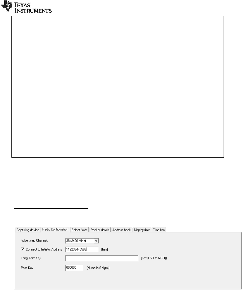
Bluetooth Low Energy devices:
For Bluetooth Low Energy devices, the Advertising channel must be selected.
The capture device can be configured to follow a data connection between a specific Bluetooth low
energy master (initiator) and slave device. In the "Radio Configuration tab", click the checkbox next to
the "Connect to Initiator Address" and write the address of the initiator (master) device. If this option is
not selected, the capture device will start following the first data connection that appears on the current
advertising channel
Decryption of encrypted data is only supported by the Bluetooth low energy packet parser.
How to use the decryption feature
1. The Long Term Key must be given as a string of hex characters starting with the Least
Significant Octet. E.g.: “00112233445566778899AABBCCDDEEFF”

SWRU187G
15/29
2. Run the sniffer like normal. Encrypted packets will be decrypted and flagged as "Encryption
Enabled". Payload and MIC will be displayed on the GUI.
Limitations
Decryption is supported with the following limitations:
1. The decryption will fail if one or more packets are sent but failed to be captured by the capturing
device. The decryption algorithm depends on the timing, packet counters (one for each side)
and the direction of the packet. There are algorithms in the parser to determine these
parameters but they can’t capture all the scenarios where one or more packets missing.
SWRU187G
16/29
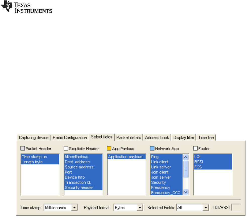
2.7 Select fields
The field selection tab can be used to select which fields to display and which to hide in the packet list.
This feature is particularly useful for low-resolution screens (less than 1024x768). The fields are
grouped in several colour coded categories.
The time stamp can be displayed in microseconds or milliseconds. The payload data can be displayed
as hex-bytes or as plain-text. In plain-text format all non-printable characters will be replaced by a "*".
The Selected Fields list box gives the possibility to select predefined field groups. It is also possible to
select “all” or “none”.
Each frame can be shown either with its LQI (Link Quality Indication, ranging from 0x00 to 0xFF) or
RSSI (Received Signal Strength Indicator with an approximation to the actual RF level, in dBm). The
LQI parameter is derived from the IEEE802.15.4/ZigBee protocol specification. The exact definition will
depend on the used protocol.
The example below shows the fields defined for the SimpliciTI protocol.
Figure 8: Select Fields panel
Tips:
Extended selection is used to operate the controls:
To select a range of fields:
o Click and drag over the fields that should be selected, or....
o ... select the first field, hold down the "Shift" key, and select the last field.
To select/unselect a single field:
o Hold down the "Ctrl" key and click on the field to be toggled.
SWRU187G
17/29
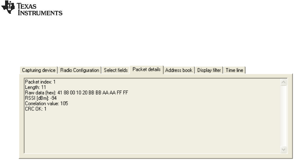
2.8 Packet details
By double-clicking on a packet in the packet list, additional details, as shown below, will be displayed.
This example show details from the SimpliciTI protocol.
Figure 9: Packet details panel
The packet index shows the index for each captured packet, starting with index 1 for the first packet.
The RSSI value is read from the connected device and adjusted with a given offset value to get an
approximate value in dBm. The correlation value is equal to the value read from the connected device.
See the datasheet of the connected device for detailed information on the RSSI and correlation values.
SWRU187G
18/29
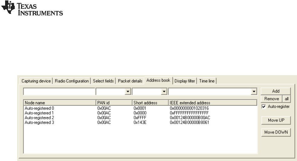
2.9 Address book
The address book contains all known Node addresses from the most recent session. By selecting
"Auto-register" (on by default), the packet sniffer will register all addresses automatically and add
entries into the address book. The example below show the fields defined for the IEEE 802.15.4/ZigBee
protocols.
Figure 10: Address book panel
Nodes are added/replaced manually by clicking the "Add" button, or by pressing the "Enter" key while
standing in one of the top fields.
Nodes can be removed by clicking the "Remove" button, or by pressing the "Delete" key while a node is
selected in the address list.
Nodes can be moved up/down by using the rightmost buttons, or the "Alt + U" and "Alt + D" key
combinations.
Depending on the protocol it may be required with manual editing of the fields in the address book to
correct for address conflicts.
Below are examples where manual editing for the IEEE 802.15.4 protocol are given.
There has been a PAN ID conflict.
A device has left the network, and another device has been given an already used short
address (the extended address will be replaced).
Association response commands have not been detected.
Tips:
Fast editing of node names can be done using the following procedure:
1. Select the first auto-registered item in the address list
2. Hit "Enter" to copy the data and move to the node name field
3. Enter the new name
4. Hit "Enter" to replace the old entry and move back to the address list
5. Move one line down by using the down arrow.
6. Go to step 2
SWRU187G
19/29
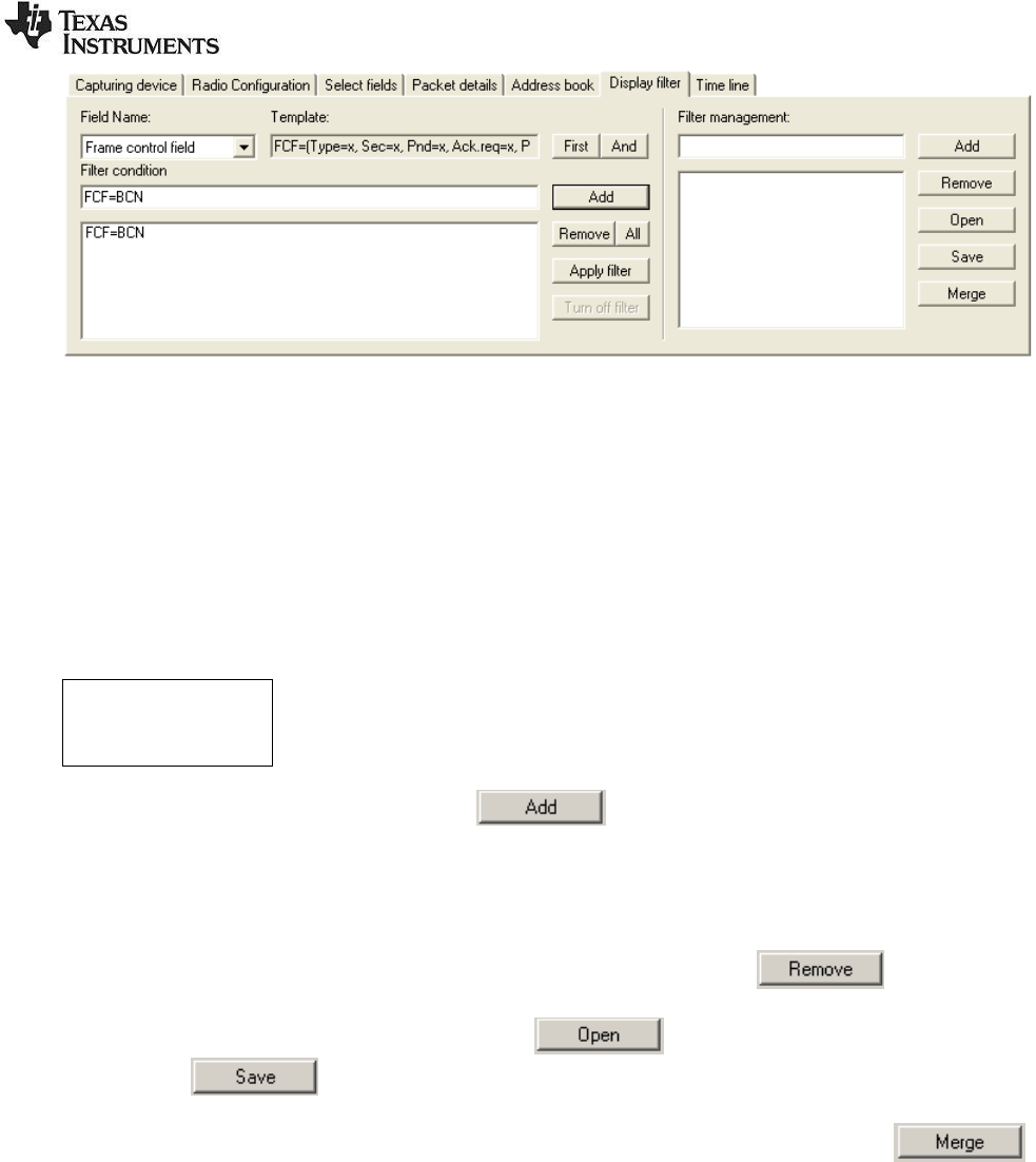
2.10 Display filter
The Display filter tab allows for filtering on all fields defined in the Field Name window.
A template is provided to ease the definition of the filter condition. The template will show the short
name for each field. If the field has sub fields, the definition of all sub fields will be shown within
brackets. Some fields will be dependent of other fields. This will also be shown in the template.
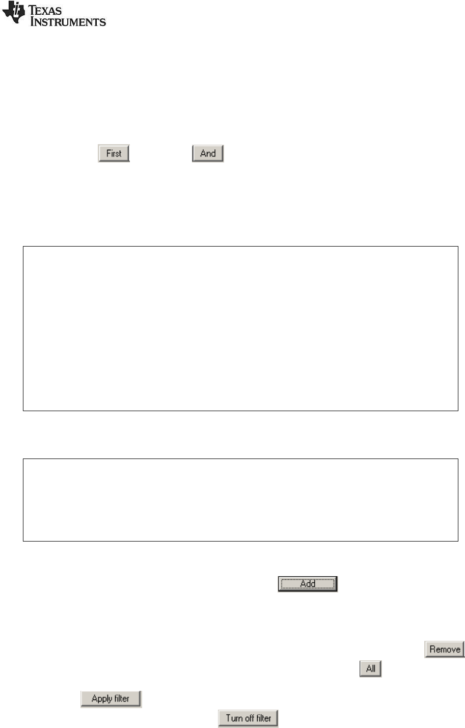
When the required field is selected, the template can be moved to the single line Filter condition window
by pushing the button or the button. The “First” button will remove all existing conditions
and set current template as the first condition. The “And” button will add current template to the existing
conditions and the conditions will be evaluated with the AND operator. When the template has been
moved to the single line Filter condition window, it must be modified to give the real values of the
requested fields. The value is indicated with an “x” in the template. If the filter condition of a field with
sub fields only requires evaluating the first sub field value, the sub field value can be given without
brackets.
Example:
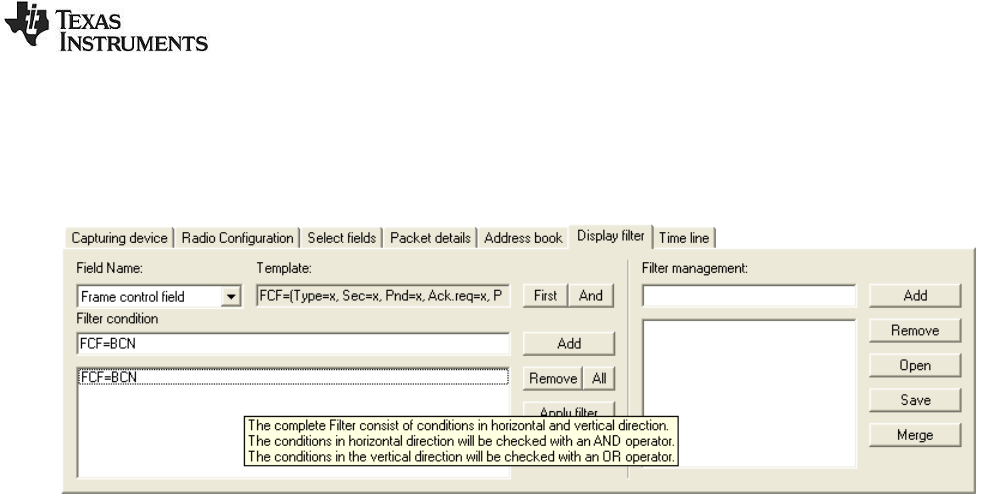
Figure 11 below shows an example from the IEEE 802.15.4/ZigBee protocols. The template
of the Frame control field is:
FCF=(Type=x, Sec=x, Pnd=x, Ack_req=x, Intra_PAN=x)
If it is only required to test on the “Type” sub field, the condition can be simplified the following
way:
FCF=BCN
Note: This is only possible for the first field in the definition of sub fields.
It is not required to fill in the values of all fields. If the filter condition only requires checking some of the
sub fields, only those fields should be given.
Example:
Same as previous example, but this time it includes checking the “Type” and “Ack_req”
values. This condition should be given as follows:
FCF=(Type=BCN, Ack_req=1)
When all conditions that should be evaluated with the AND operator are defined, the condition can be
moved to the multi line Filter condition window with the button (“Enter” will give the same
result). In this window several filter conditions can be added and all the conditions in “vertical” direction
will be evaluated with the OR operator. To summarize: Conditions in the horizontal direction are
evaluated with the AND operator. Conditions in vertical direction are evaluated with the OR operator.
To remove a line from the multi line filter condition, select the required line and click the
button. To remove all the lines from the multi line filter condition, click the button.
The button will activate the filter and the packet window will be redrawn with packets that
comply with the given filter condition. The button should be used to disable the filter
function. The packet window will be redrawn again and all packets will be visible. The filter function can
be enabled and disabled while the sniffer is running.
SWRU187G
20/29
Figure 11: Display filter panel
Filter management:
On the right side of the panel, a Filter management function is provided. The filter management
contains a database of defined filters. The database can be saved to a file and read from a file. The file
is formatted as a plain text file and can be manually updated if required.
Below is an example of a filter database file. The filter name is given within square brackets [ ] and the
filter conditions are given on the following lines. In this example the filter condition is: Dest. Address =
0x2430 OR 0x1749
[address]
DAD=0x2430
DAD=0x1749
To add a filter definition to the database, the button should be used. In order to add the
filter to the database, a filter name must be given in the window to the left of the button. When the name
is given and the “Add” button is pushed, the current filter definition (the multi line window of the filter
condition) will be added to the filter database. The name of the filter will appear in the list of filters
(Window below the filter name).
To remove a filter, select the required filter in the list of filters and push the button.
The filter database can be read from a file with the button. To save the filter database to
a file, use the button.
To add filter definitions from a file, without deleting the existing filters in the database, the
button should be used. This will open the given file and add the filters to the existing filter database. If
the given filter name already exist in the filter database, the name will be modified with an additional
digit at the end of the name.
To use a filter from the filter database, double click on the filter name and the filter condition will appear
in the multi line filter condition window at the left side.
Note:
When packets are filtered out, the delta times shown in the Time fields still show the delta time to the
previous packet captured, not the previous packet shown.
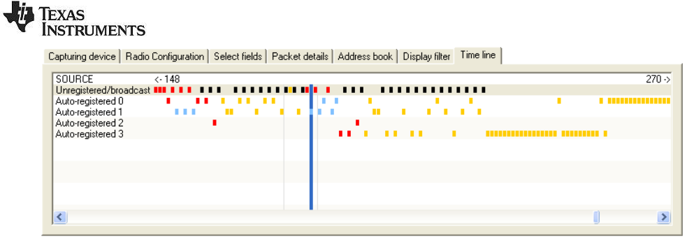
2.11 Time line
The time line displays all received packets, ordered horizontally by the time of reception and vertically
by source or destination address. Selecting a packet from the time line will instantly be reflected in the
packet list, and vice versa, thus allowing for efficient navigation in large collections of packets.
SWRU187G
21/29
Figure 12: Time line panel
Double-click in the left section of the time line to switch between destination and source.
Packets are selected by clicking and/or holding down the left mouse button.
The time line can be scrolled clicking and holding down the right mouse button (drag).

SWRU187G
22/29
3 Know Issues
3.1 Bluetooth Low Energy
The CC2540 BLE sniffer will not update the connection parameters if a connection parameter update
request (or similar requests) is sent over an encrypted connection. As a consequence, the sniffer will
either disconnect or lose a lot of packets.
SWRU187G
23/29
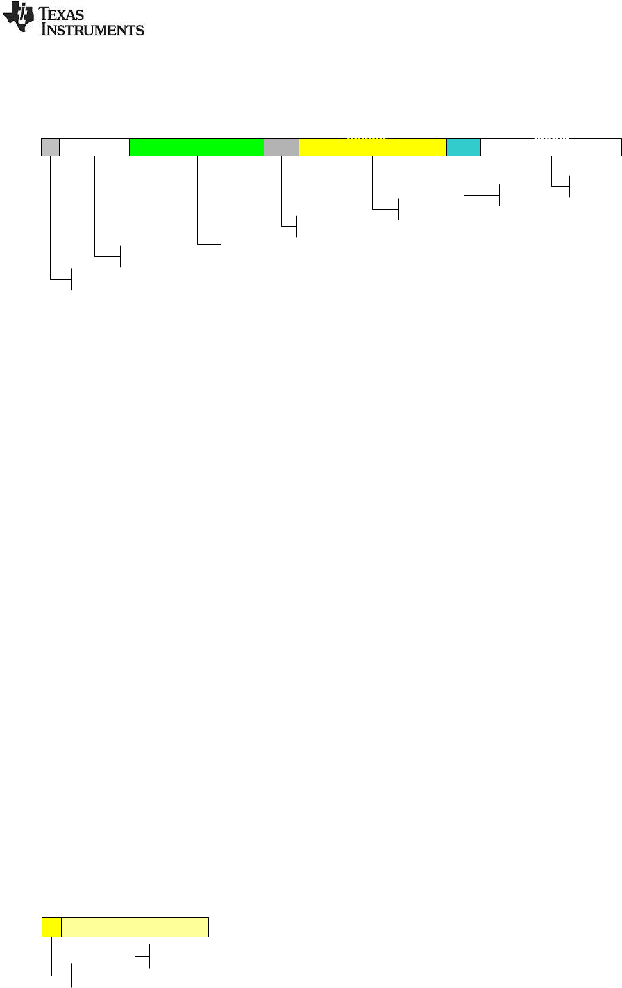
4 Format of packets saved to file
The figure below describes the packet format for packets saved to a Packet Sniffer Data (PSD) file. The
number of bytes is given for each field.
1 4 8 2 sx
2
Length
Timestamp
Packet number
Packet Information
Payload
Status bytes Spare
Figure 13: Packet format in PSD file
Packet Information:
New field introduced from version 2.3.0. Contains information used by the packet sniffer to read the
data correctly.
Bit 0: Length includes FCS.
Bit 1: Correlation used.
Bit 2: Incomplete packet.
Bit 3: Buffer overflow.
Bit 4: Generic protocol.
Bit 5-7: Not used.
Timestamp:
64 bit counter value. To calculate the time in microseconds this value must be divided by a number
depending on the clock speed used to drive the counter tics on the target. (E.g. CC243xEM, CC253x ->
32, CCxx10EM -> 26, SmartRF05EB + CC2520EM -> 24). The timestamp on the first packet will be
used as offset value for all packets. That means that packet number 1 will be shown in the packet
sniffer with time = 0.
A special algorithm is used for BLE devices:
uint64_t timeLo = rawTimestamp & 0xFFFF;
uint64_t timeHi = (rawTimestamp >> 16);
uint64_t timeStamp = timeHi*5000 + timeLo;
uint64_t timeStampUs = timeStamp/32;
Length:
The length will include the Payload and the two status bytes.
Note: This is the length defined in the packet sniffer data format. For packets of variable length, the
payload will also start with a length byte.
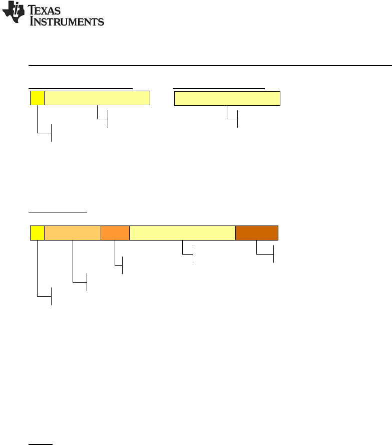
Payload:
Payload of packet as defined in the packet sniffer data format. The payload will depend on the RF
Device used as transmitter.
IEEE 802.15.4 devices (e.g. CC253x, CC2520, CC243x)
1
Length
n
Payload
As per the IEEE 802.15.4 standard, the length filed included in the packet will include the length of the
payload and the two trailing FCS bytes. The capture device will strip the FCS bytes from the packet and
replace them with the two status bytes described below.
SWRU187G
24/29
Proprietary devices (e.g. CC110x, CC112x, CC111x, CC2500, CC251x, CC2544):
Variable length packets Fixed length packets
1
Length
n
Payload
n
Payload
Note that there is no length byte included in the payload when the device operates in fixed packet
length mode.
BLE devices:
1
Length
n
Payload
4
Access Address
2
BLE Header
3
CRC
The complete packet as sent over the air. For more details see the BLE protocol specification.
Status bytes:
The Status bytes are generated by the RF Device used as capturing device. See the user guide of the
capturing device for more details.
BYTE 1: RSSI.
BYTE 2: Bit 7: Indicate CRC OK or not.
Bit 0-6: Depending on the RF Device and the configuration of these.
Note: For BLE devices bit 0-6 in byte 2 is set to the channel number by the packet sniffer FW.
Spare:
The number of spare bytes depends on the total amount of bytes used by the packet sniffer to save the
packet. The number of bytes depends on the protocol and can be seen from the description of the
packet format under the help menu.
SWRU187G
25/29
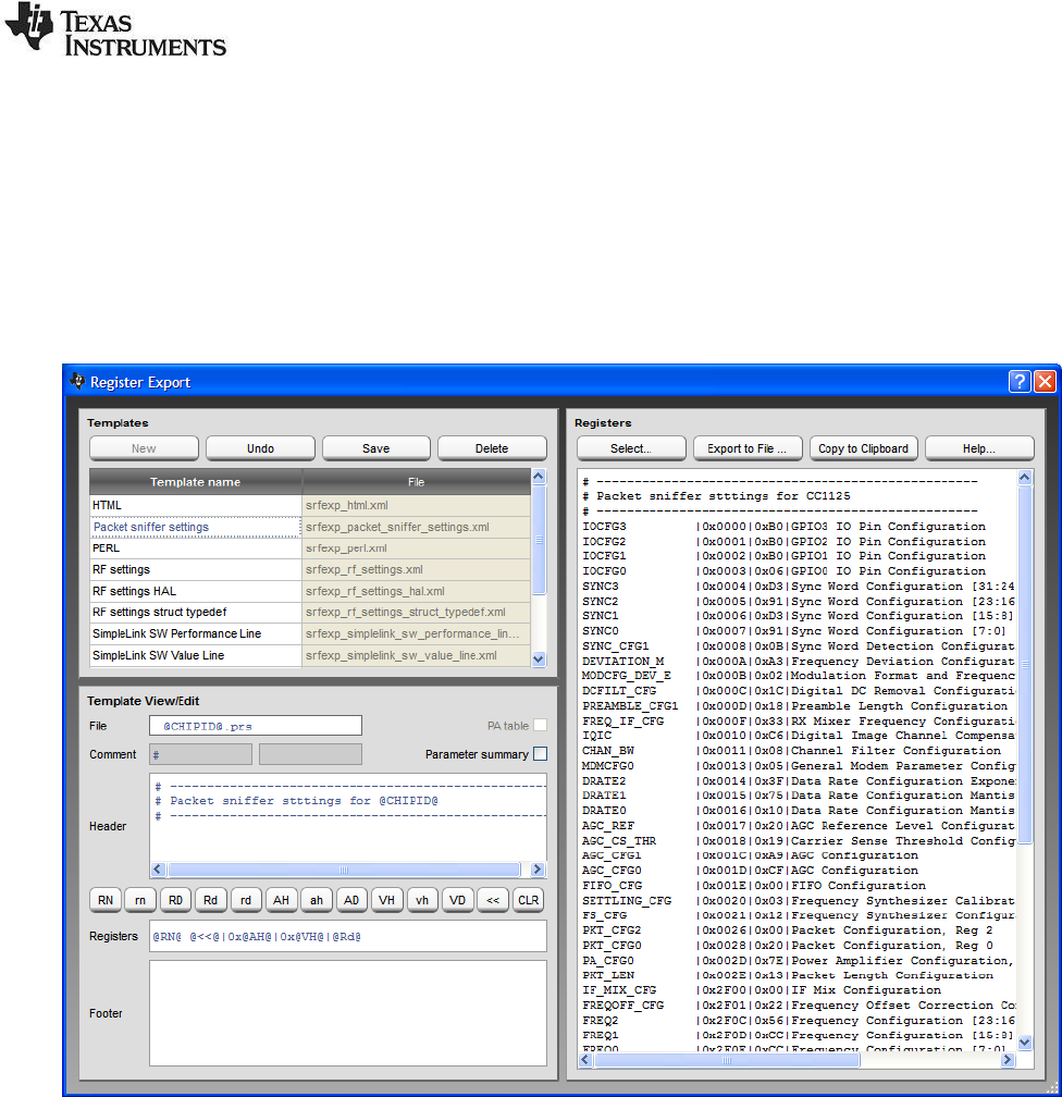
5 Exporting register settings from SmartRF™ Studio
SmartRF™ Studio 7 can be downloaded from the Texas Instruments web site. See the SmartRF™
Studio 7 integrated help for more information.
After opening a “Device Control Panel” for the selected RF device, a list of preferred register settings
will appear in the “Easy Mode” and “Expert mode” tabs respectively. After selecting the register settings
and optionally changing some of the register values, click on the “Register Export” button in the
“Register View”, Alternatively choose “File->Register Export …” from the menu. This will open the
following window:
Figure 14: SmartRF Studio 7 Register Export
SWRU187G
26/29
6 Help
The packet sniffer provides help through so-called tool-tips. By moving the cursor over a field (e.g. a
button or a text field) and holding it in the same position for about half a second, the text will appear in a
yellow box slightly below the cursor:
Figure 15: Display filter panel with the tool-tip shown
Keyboard and mouse button events will cause the tool-tip to disappear, or not be displayed at all.
SWRU187G
27/29
7 Troubleshooting
This section contains some troubleshooting tips that should be used if the packet sniffer does not
function as expected. Execute the steps one by one until the problem is solved.
A) The evaluation board is not detected (it does not appear in the list box in the Setup tab)
Using smartRF04EB + CC2430EM
Make sure that the USB cable is connected and that a CC2430EM is mounted.
Check that the jumper between I_OUT and I_IN is connected.
Check that the jumpers on P3 are mounted correctly (see the CC2430DK user manual).
Press the "Reset" button.
Using 2430DB
Make sure that the USB cable is connected and power switch is in USB position.
Check that the jumper on P3 pin 1-2 is mounted
Check that all tree jumpers on P5 are mounted
Press the "Reset" button.
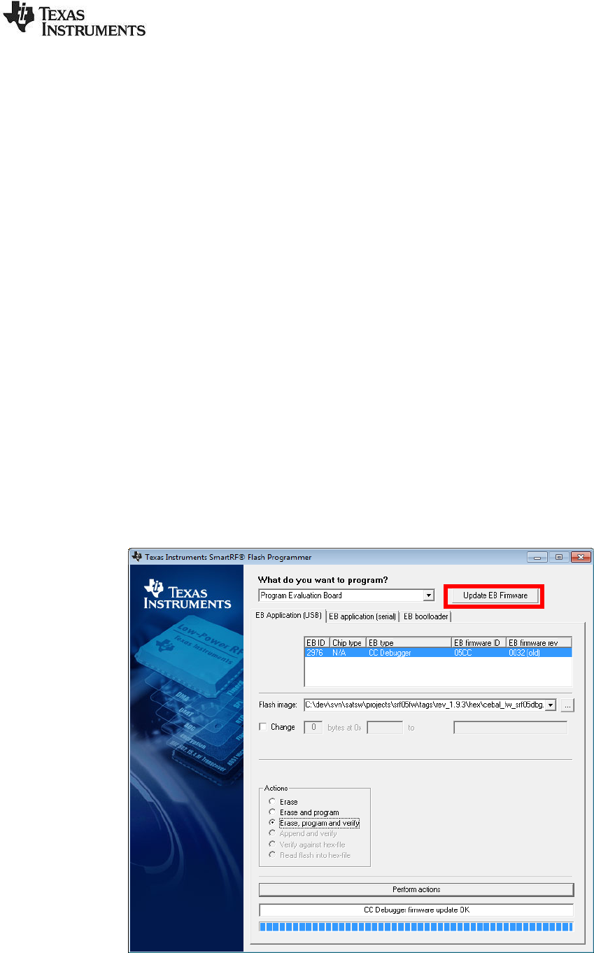
B) When pressing the “start button”, the following message is given:
"Not able to Start Sniffer. Try upgrade of USB firmware".
Check if latest Firmware version of the USB controller is used. This should be version 0037 or
later. This can be seen by using the SmartRF Flash Programmer from Texas Instruments. The
figure below show an example from the flash programmer. The column “EB firmware rev” will
show the version. The Flash Programmer can be downloaded from the Texas Instruments web
site.
Figure 16: SmartRF Flash Programmer
SWRU187G
28/29
C) When pressing the "start button", the sniffer stops immediately (the start button is not grayed
out)
Disconnect the USB cable from the capture device, and plug it back in.
Press the "Reset" button on the board.
Disconnect the power cable from the capture device and install the latest version of the packet
sniffer.
Reboot the computer.
D) The program does not respond
Press the "Reset" button on the connected Evaluation Board (EB).
E) The packets are not decoded correctly
Packets with an FCS failure will probably not be parsed correctly (FCS = ERR).
Make sure that the packet really is correctly formatted (compare the fields with the raw data in
the packet details tab).
F) Weird packets appear in the packet sniffer when not transmitting anything
The capture device will try receiving packets down to the RF noise floor. Sometimes it will also
decode packets which are decoded from noise only. These will appear in the packet sniffer. To
avoid displaying these packets, enable FCS filtering in the toolbar.
G) The packet sniffer stays “idle” and does not receive any packets after “start button” has been
pressed.
Check that correct channel is used in the setup panel.
Check the jumpers on the evaluation boards. In particular, note the jumpers on SmartRF04EB
when it is used with older versions of the CC2430EM (see section 1.2 in this document).
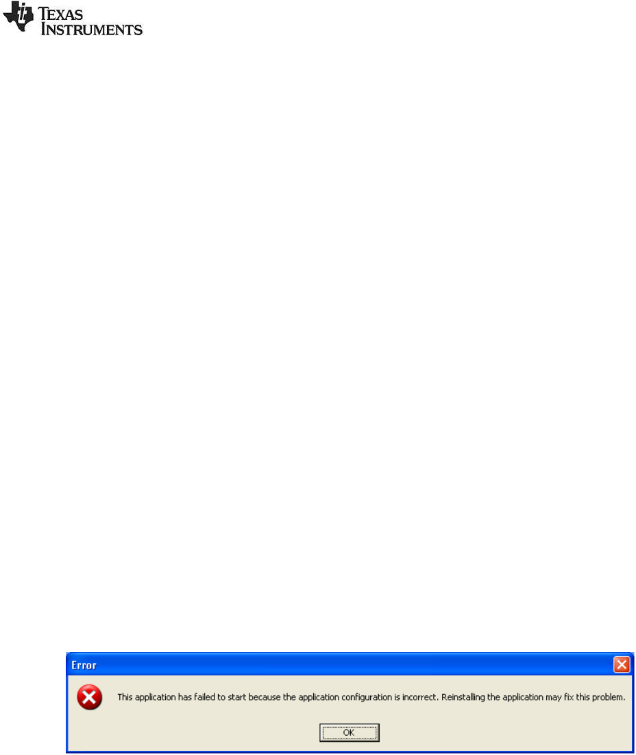
H) Error message when trying to start the packet sniffer.
If an error message about missing msvcp80.dll appears, or the error message shown below
appears when attempting to start the application, you may be required to install an additional
package from Microsoft.
The package contains some additional runtime components needed by applications developed with
Visual C++. To resolve this problem, download the file vcredist_x86.exe from the URL below and
install the package.
http://www.microsoft.com/Downloads/details.aspx?FamilyID=32bc1bee-a3f9-4c13-9c99-
220b62a191ee&displaylang=en
SWRU187G
29/29
8 General Information
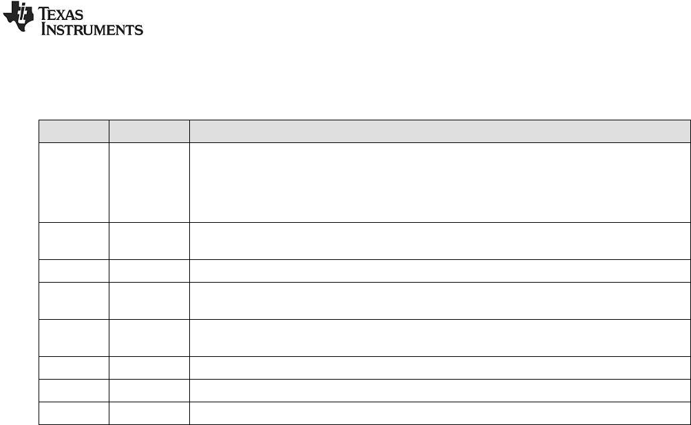
8.1 Document History
Revision
Date
Description/Changes
G
20/06/2014
Description of PSD format and time stamp processing updated.
Added new HW platforms:
- TrxEB + CC1125EM
- TrxEB + CC120Xem
- CC2544 USB Dongle
F
07/07/2011
Added new HW platforms:
- TrxEB + one of the following EM’s: CC1101, CC110L, CC113L, CC1120 or CC1121
E
14/03/2011
Description of Packet Broadcast added.
D
22/10/2010
The table with combinations of protocols+HW has been updated.
A picture of the HW platform for CC2420 is added.
C
25/08/2010
Document updated with information about capturing device used for the Bluetooth Low
Energy protocol. Screen shots have been updated.
B
03/11/2009
SmartRFCCxx10TB added as possible capturing device.
A
19/02/2009
Description for SmartRF05EB added.
-
03/09/2008
First revision.

IMPORTANT NOTICE
Texas Instruments Incorporated and its subsidiaries (TI) reserve the right to make corrections, enhancements, improvements and other
changes to its semiconductor products and services per JESD46, latest issue, and to discontinue any product or service per JESD48, latest
issue. Buyers should obtain the latest relevant information before placing orders and should verify that such information is current and
complete. All semiconductor products (also referred to herein as “components”) are sold subject to TI’s terms and conditions of sale
supplied at the time of order acknowledgment.
TI warrants performance of its components to the specifications applicable at the time of sale, in accordance with the warranty in TI’s terms
and conditions of sale of semiconductor products. Testing and other quality control techniques are used to the extent TI deems necessary
to support this warranty. Except where mandated by applicable law, testing of all parameters of each component is not necessarily
performed.
TI assumes no liability for applications assistance or the design of Buyers’ products. Buyers are responsible for their products and
applications using TI components. To minimize the risks associated with Buyers’ products and applications, Buyers should provide
adequate design and operating safeguards.
TI does not warrant or represent that any license, either express or implied, is granted under any patent right, copyright, mask work right, or
other intellectual property right relating to any combination, machine, or process in which TI components or services are used. Information
published by TI regarding third-party products or services does not constitute a license to use such products or services or a warranty or
endorsement thereof. Use of such information may require a license from a third party under the patents or other intellectual property of the
third party, or a license from TI under the patents or other intellectual property of TI.
Reproduction of significant portions of TI information in TI data books or data sheets is permissible only if reproduction is without alteration
and is accompanied by all associated warranties, conditions, limitations, and notices. TI is not responsible or liable for such altered
documentation. Information of third parties may be subject to additional restrictions.
Resale of TI components or services with statements different from or beyond the parameters stated by TI for that component or service
voids all express and any implied warranties for the associated TI component or service and is an unfair and deceptive business practice.
TI is not responsible or liable for any such statements.
Buyer acknowledges and agrees that it is solely responsible for compliance with all legal, regulatory and safety-related requirements
concerning its products, and any use of TI components in its applications, notwithstanding any applications-related information or support
that may be provided by TI. Buyer represents and agrees that it has all the necessary expertise to create and implement safeguards which
anticipate dangerous consequences of failures, monitor failures and their consequences, lessen the likelihood of failures that might cause
harm and take appropriate remedial actions. Buyer will fully indemnify TI and its representatives against any damages arising out of the use
of any TI components in safety-critical applications.
In some cases, TI components may be promoted specifically to facilitate safety-related applications. With such components, TI’s goal is to
help enable customers to design and create their own end-product solutions that meet applicable functional safety standards and
requirements. Nonetheless, such components are subject to these terms.
No TI components are authorized for use in FDA Class III (or similar life-critical medical equipment) unless authorized officers of the parties
have executed a special agreement specifically governing such use.
Only those TI components which TI has specifically designated as military grade or “enhanced plastic” are designed and intended for use in
military/aerospace applications or environments. Buyer acknowledges and agrees that any military or aerospace use of TI components
which have not been so designated is solely at the Buyer's risk, and that Buyer is solely responsible for compliance with all legal and
regulatory requirements in connection with such use.
TI has specifically designated certain components as meeting ISO/TS16949 requirements, mainly for automotive use. In any case of use of
non-designated products, TI will not be responsible for any failure to meet ISO/TS16949.
Products Applications
Audio www.ti.com/audio Automotive and Transportation www.ti.com/automotive
Amplifiers amplifier.ti.com Communications and Telecom www.ti.com/communications
Data Converters dataconverter.ti.com Computers and Peripherals www.ti.com/computers
DLP® Products www.dlp.com Consumer Electronics www.ti.com/consumer-apps
DSP dsp.ti.com Energy and Lighting www.ti.com/energy
Clocks and Timers www.ti.com/clocks Industrial www.ti.com/industrial
Interface interface.ti.com Medical www.ti.com/medical
Logic logic.ti.com Security www.ti.com/security
Power Mgmt power.ti.com Space, Avionics and Defense www.ti.com/space-avionics-defense
Microcontrollers microcontroller.ti.com Video and Imaging www.ti.com/video
RFID www.ti-rfid.com
OMAP Applications Processors www.ti.com/omap TI E2E Community e2e.ti.com
Wireless Connectivity www.ti.com/wirelessconnectivity
Mailing Address: Texas Instruments, Post Office Box 655303, Dallas, Texas 75265
Copyright © 2014, Texas Instruments Incorporated
