Sony Ericsson W910 Working Instruction, Mechanical. Www.s Manuals.com. Mechanical
User Manual: Phone Sony Ericsson W910 - Service manuals and Schematics, Disassembly / Assembly. Free.
Open the PDF directly: View PDF ![]() .
.
Page Count: 35

Working Instruction, Mechanical
3/000 21-1/FEA 209 544/129 A
Company Internal
©
Sony Ericsson Mobile Communications AB
1(34)
Working Instruction, Mechanical
Applicable for W910
CONTENTS
1
Introduction .............................................................................. 3
1.1
Equipment.................................................................................4
1.2
General cautions ......................................................................5
1.3
Adhesives .................................................................................5
2
Disassembly ............................................................................. 6
2.1
Overview ...................................................................................6
2.1.1 M2, Battery Cover and Battery ..............................................7
2.1.2 Rear Back Cover ................................................................... 8
2.1.3 Main PCB ............................................................................ 10
2.1.4 Front Cover Assembly......................................................... 11
2.1.5 Navi Key PBA...................................................................... 13
2.1.6 Display ................................................................................ 13
3
Replacements......................................................................... 14
3.1
Battery Cover..........................................................................15
3.2
Battery .....................................................................................15
3.3
RF Cap.....................................................................................15
3.4
Label Co-Brand Inlay .............................................................15
3.5
Keyboard Main........................................................................15
3.6
Liquid Intrusion Indicator ......................................................16
3.7
Panel Antenna ........................................................................16
3.8
Rear Back Cover.....................................................................16
3.9
Key, On/Off..............................................................................16
3.10
Key, Volume............................................................................16
3.11
Key, Camera............................................................................16
3.12
Key, Music...............................................................................17
3.13
Cap, MemoryStick ..................................................................17
3.14
Camera 2.0 MPixel CMOS ......................................................17
3.15
BT Antenna Assy....................................................................17
3.16
Front Cover Assembly ...........................................................18
3.17
Key, Game...............................................................................18
3.18
Key, Navi .................................................................................18
3.19
Navi Key PBA..........................................................................18
3.20
Display.....................................................................................18
3.21
Slider Flex Module..................................................................18
3.22
Slider Sub Assembly..............................................................18
3.23
Main Antenna..........................................................................19

Working Instruction, Mechanical
3/000 21-1/FEA 209 544/129 A
Company Internal
©
Sony Ericsson Mobile Communications AB
2(34)
3.24
Speaker Flex Module..............................................................22
3.25
Key Foil Assy..........................................................................24
3.26
Camera QCIF MPixel CMOS ..................................................26
3.27
Receiver Flex Module.............................................................26
3.28
Label ......................................................................................27
4
Reassembly ............................................................................ 28
4.1
Overview .................................................................................28
4.1.1 Display ................................................................................ 29
4.1.2 Navi Key PBA...................................................................... 29
4.1.3 Front Cover Assembly......................................................... 30
4.1.4 Main PCB ............................................................................ 30
4.1.5 Rear Back Cover ................................................................. 31
4.1.6 Battery, Battery Cover and M2 ............................................ 33
5
Revision history ..................................................................... 34
Working Instruction, Mechanical
3/000 21-1/FEA 209 544/129 A
Company Internal
©
Sony Ericsson Mobile Communications AB
3(34)
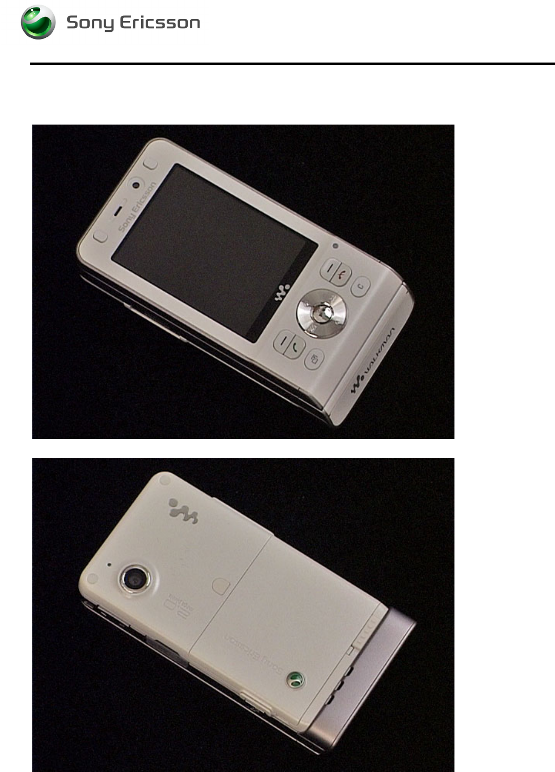
1 Introduction
W910
Working Instruction, Mechanical
3/000 21-1/FEA 209 544/129 A
Company Internal
©
Sony Ericsson Mobile Communications AB
4(34)
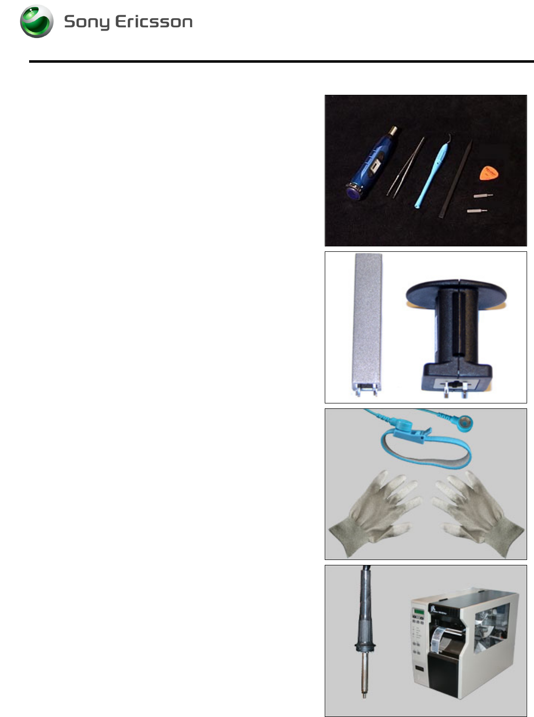
1.1 Equipment
STANDARD TOOLS
• NTZ 112 459 – Torque Screwdriver
• Style 2A Tweezers
• Dental Hook
• Nylon Pointer
• NTZ 112 590 – Guitar Pick
• NTZ 112 288 – Torx Bit No. 6
• NTZ 112 1052 – JCIS No. 0 Screw Bit
SPECIAL TOOLS
• NTZ 112 1067– Camera Removal Tool
• NTZ 112 1077 – VGA Camera Tool
ESD EQUIPMENT
Protect the phone from ESD damages whenever it has
been opened by using:
• ESD-wristband
• ESD-gloves
LABEL EQUIPMENT
The following special equipment is required when replacing
or installing a new label:
• Hot air flow solder station
• Zebra printer connected to computer

Working Instruction, Mechanical
3/000 21-1/FEA 209 544/129 A
Company Internal
©
Sony Ericsson Mobile Communications AB
5(34)
1.2 General cautions
The following cautions are considered to be generic for all phone models and will not be repeated in
the Disassembly, Replacements and Reassembly sections:
• S
WITCH OFF THE PHONE AND REMOVE ANY MEMORY STICK BEFORE THE START OF THE DISASSEMBLY
!
• K
EEP ALL CONTACT SURFACES CLEAN
!
• B
E CAREFUL WHEN USING TOOLS LIKE THE
D
ENTAL HOOK
,
TWEEZERS
,
OPENING TOOLS
,
GUITAR PICK
ETC
.
TO AVOID SCRATCHES OR DAMAGES TO THE EXTERIOR AND INTERIOR PARTS OF THE PHONE
!
• B
E CAREFUL NOT TO DAMAGE ANY CONTACT SPRINGS
!
• R
EMEMBER TO REMOVE THE PROTECTION FOILS ON NEW PARTS SUCH AS THE FRONT COVER AND LCD
!
• N
EVER TOUCH THE DISPLAY GLASS
!
• U
SE AIR BLOW EQUIPMENT TO KEEP THE FRONT WINDOW AND DISPLAY MODULE DUST FREE
!
1.3 Adhesives
Use a Dental hook and/or the tweezers to remove old adhesives.
Clean the surface with isopropyl alcohol before attaching new adhesives.
Working Instruction, Mechanical
3/000 21-1/FEA 209 544/129 A
Company Internal
©
Sony Ericsson Mobile Communications AB
6(34)
2 Disassembly
When you are going to replace a part being listed in Replacements, the instruction of that section
usually begins by directing you to this Disassembly section with a specification of the instructions you
have to carry out in order to disassemble the phone as far as needed before returning to
Replacements for the actual replacement.
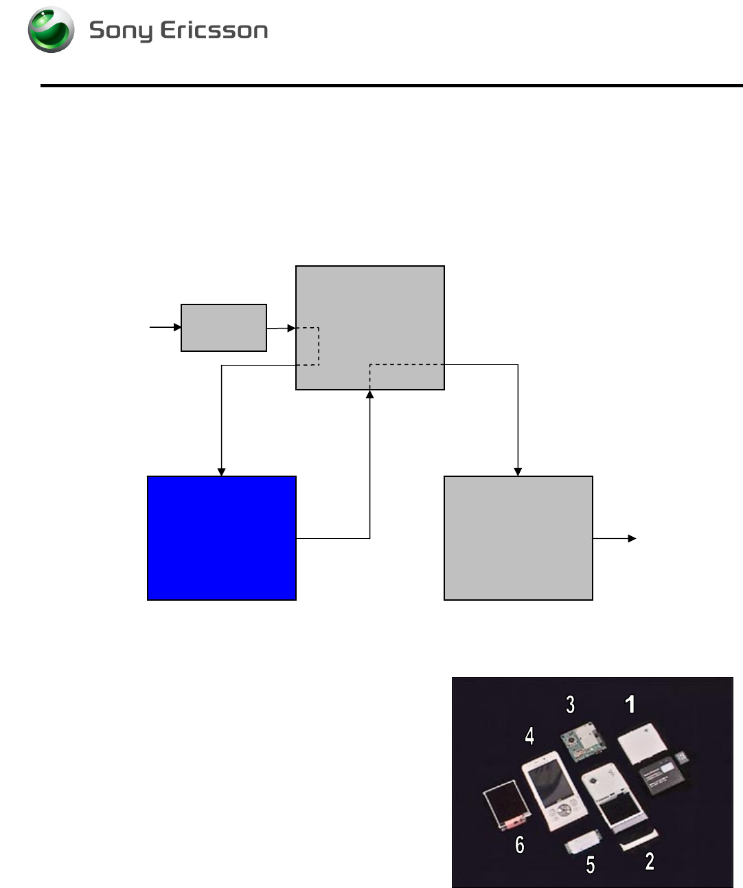
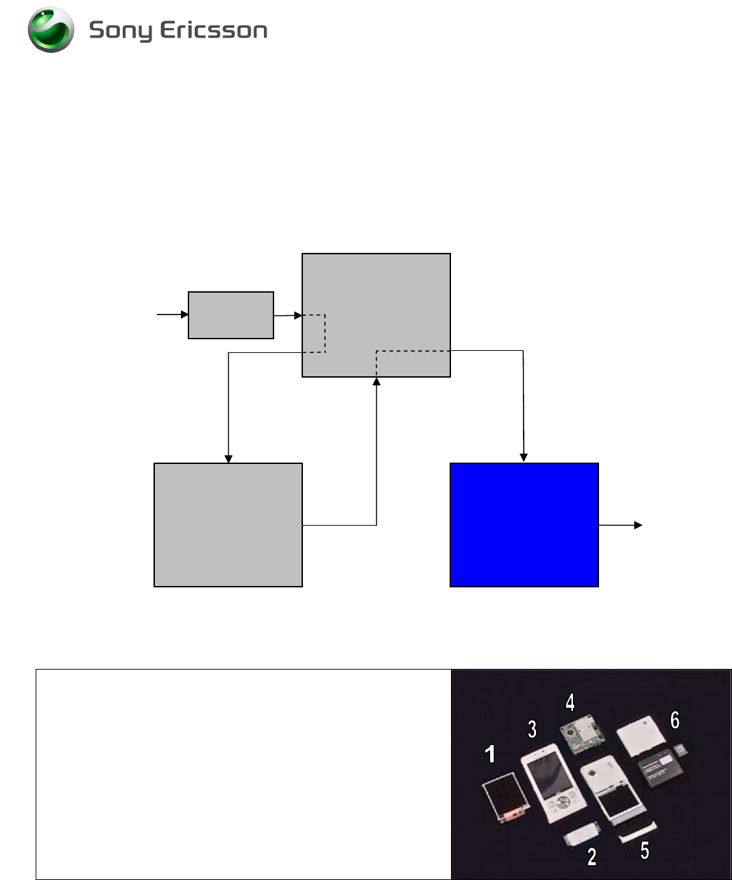
2.1 Overview
The disassembly is done in the following sequence:
1. M2, Battery Cover and Battery
2. Rear Back Cover
3. Main PCB
4. Front Cover Assembly
5. Navi Key PBA
6. Display
Start
Done
REPLACEMENTS
DISASSEMBLY REASSEMBLY
Contents
page
Working Instruction, Mechanical
3/000 21-1/FEA 209 544/129 A
Company Internal
©
Sony Ericsson Mobile Communications AB
7(34)
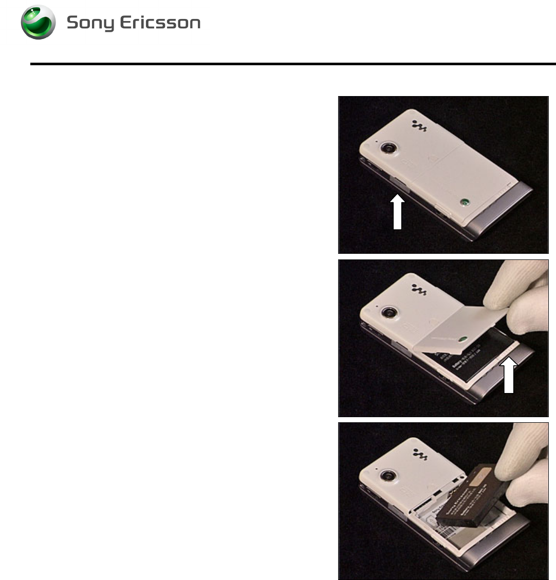
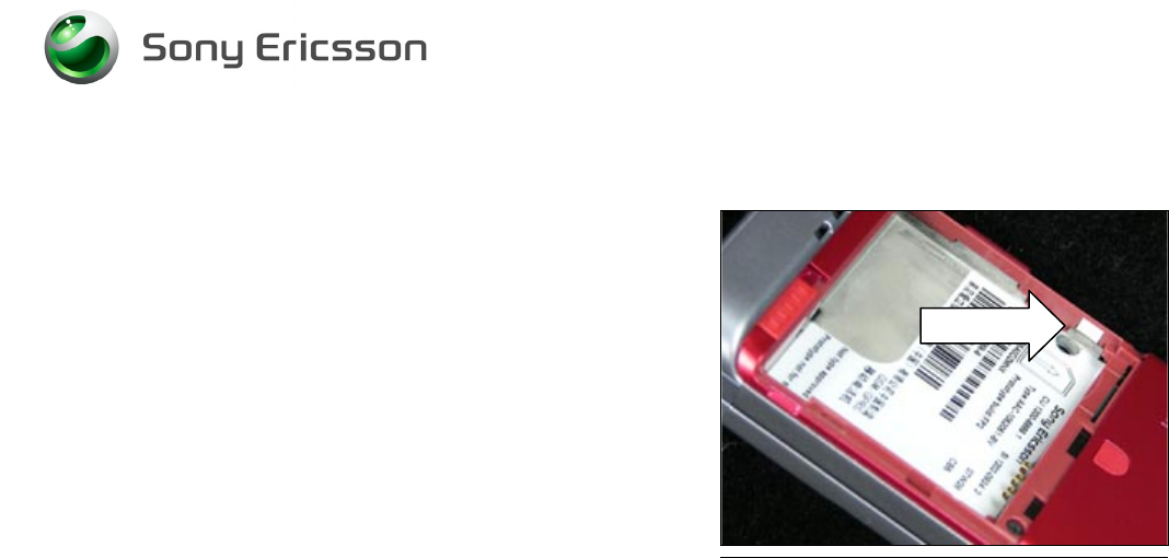
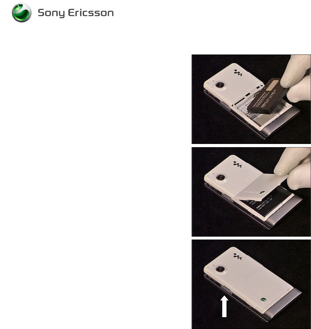
2.1.1 M2, Battery Cover and Battery
Open the MemoryStick Cap and remove the M2
MemoryStick.
Unlock the Battery Cover and remove it.
Remove the Battery.
Working Instruction, Mechanical
3/000 21-1/FEA 209 544/129 A
Company Internal
©
Sony Ericsson Mobile Communications AB
8(34)
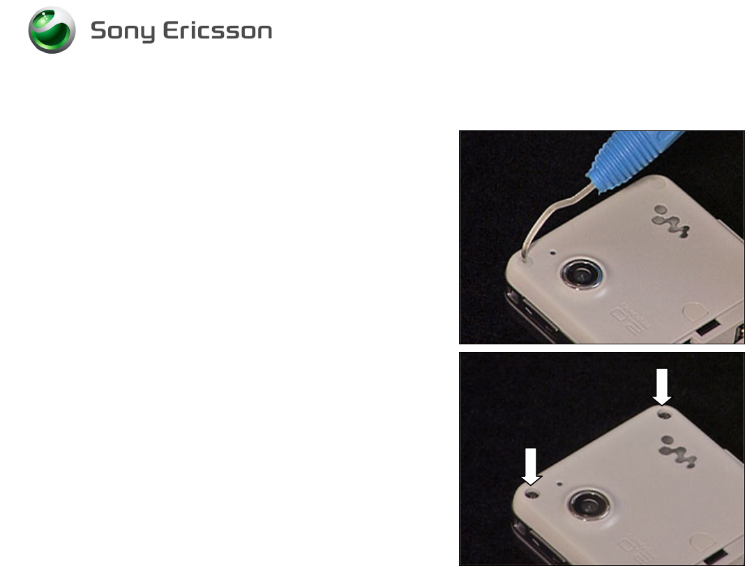
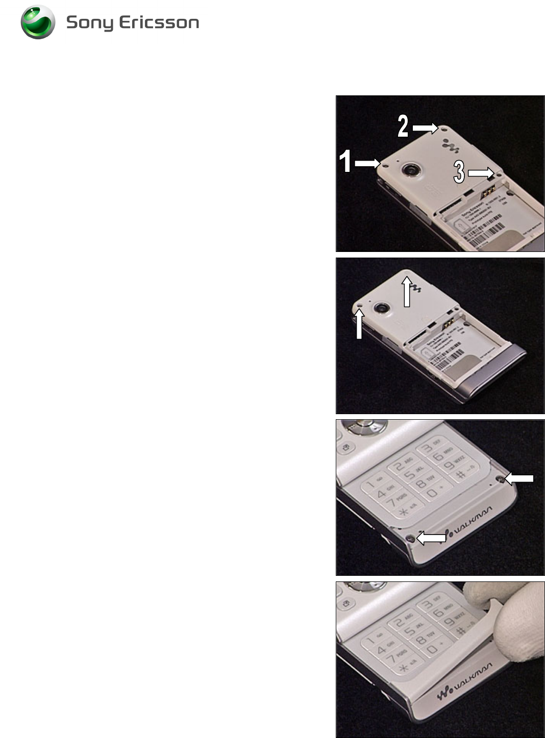
2.1.2 Rear Back Cover
Remove the screw Caps using a Dental hook.
Remove the two screws (Torx T6).
Working Instruction, Mechanical
3/000 21-1/FEA 209 544/129 A
Company Internal
©
Sony Ericsson Mobile Communications AB
9(34)
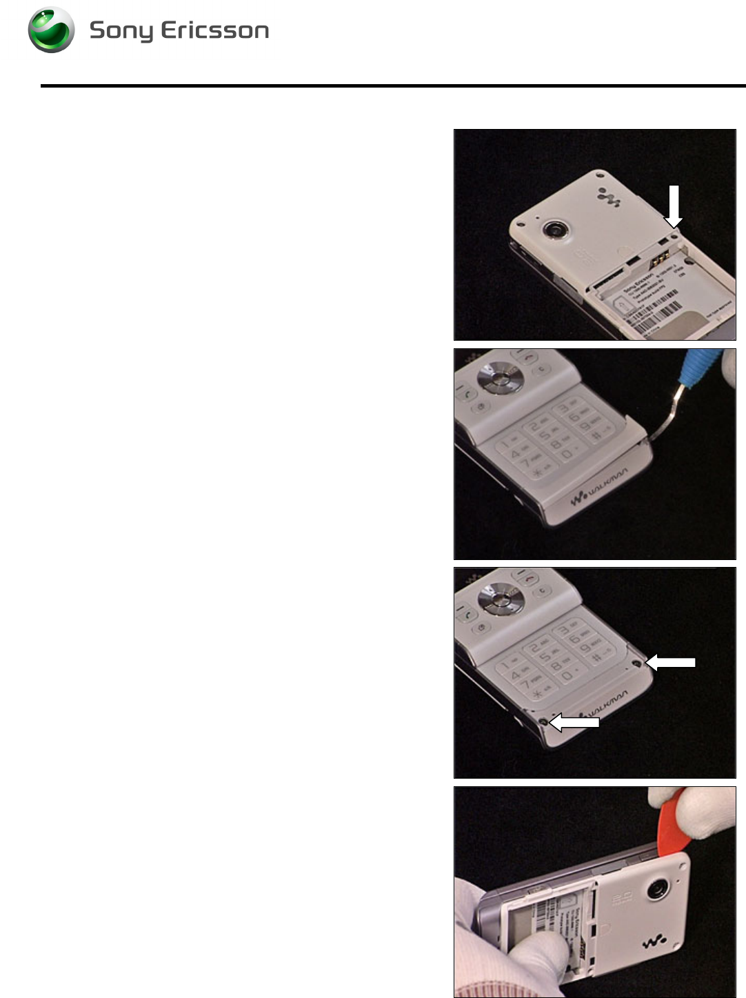
Rear back Cover continued
Remove the screw.
Remove the Panel Antenna using a Dental hook.
Remove the two screws (Torx T6).
Release the Rear Back Cover using a guitar pick, carefully
sliding it along the side of the Cover Lower Rear.
Working Instruction, Mechanical
3/000 21-1/FEA 209 544/129 A
Company Internal
©
Sony Ericsson Mobile Communications AB
10(34)
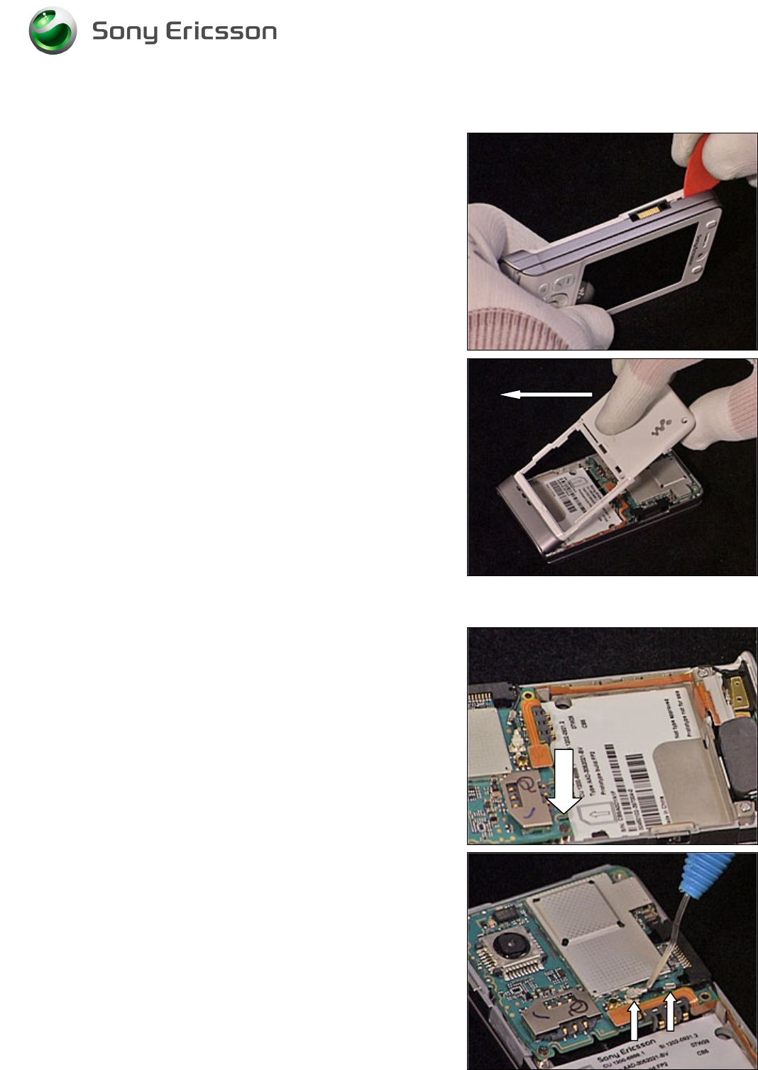
Rear Back Cover continued
Repeat the previous step on the other side of the phone.
Carefully remove the Rear Back Cover by lifting it 90
degrees from the unit as shown in picture.
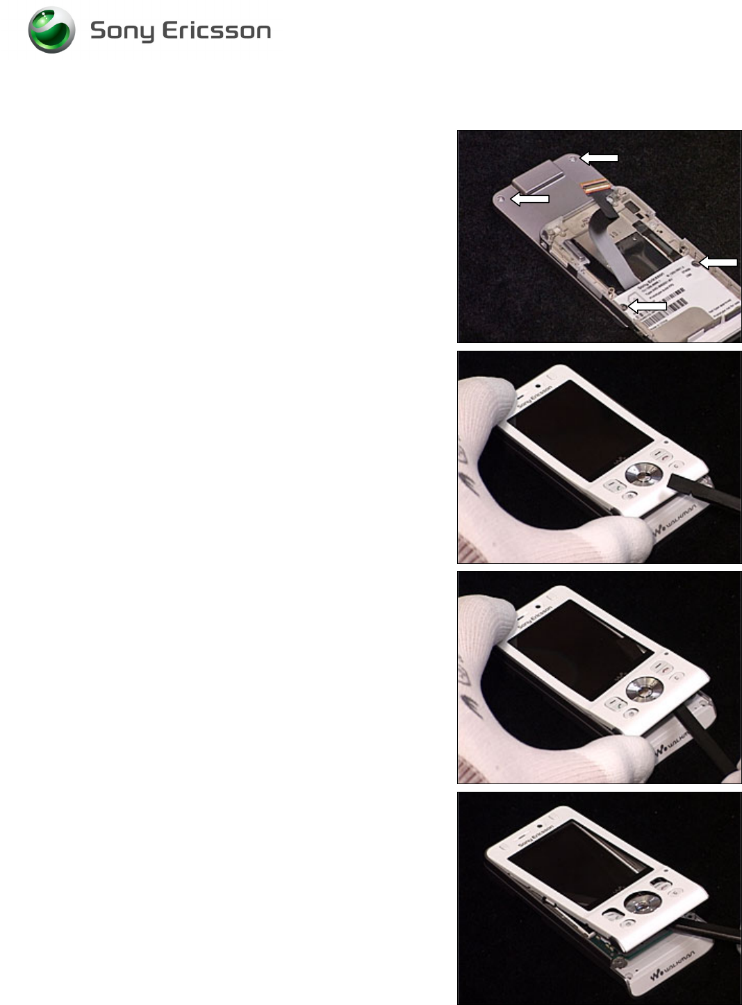
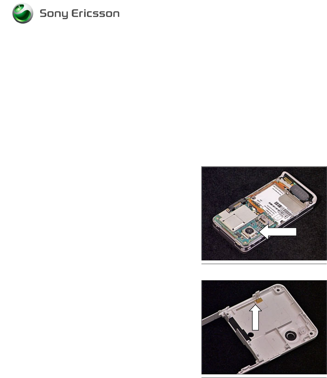
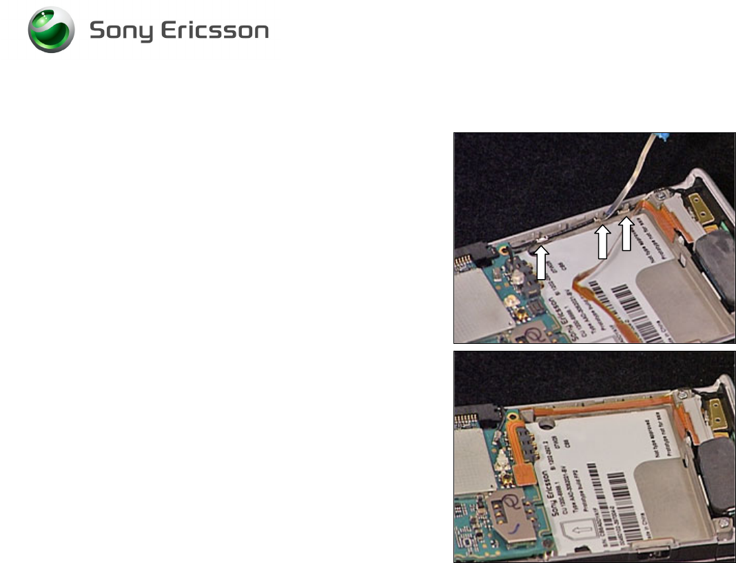
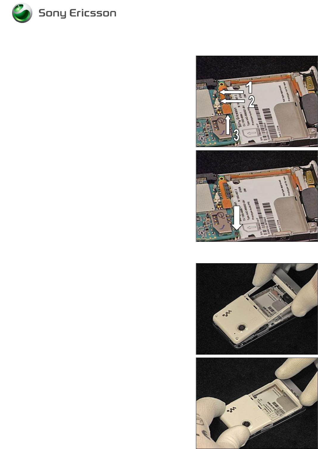
2.1.3 Main PCB
Remove the screw.
Carefully release the Antenna Coax using a Dental hook.
Working Instruction, Mechanical
3/000 21-1/FEA 209 544/129 A
Company Internal
©
Sony Ericsson Mobile Communications AB
11(34)
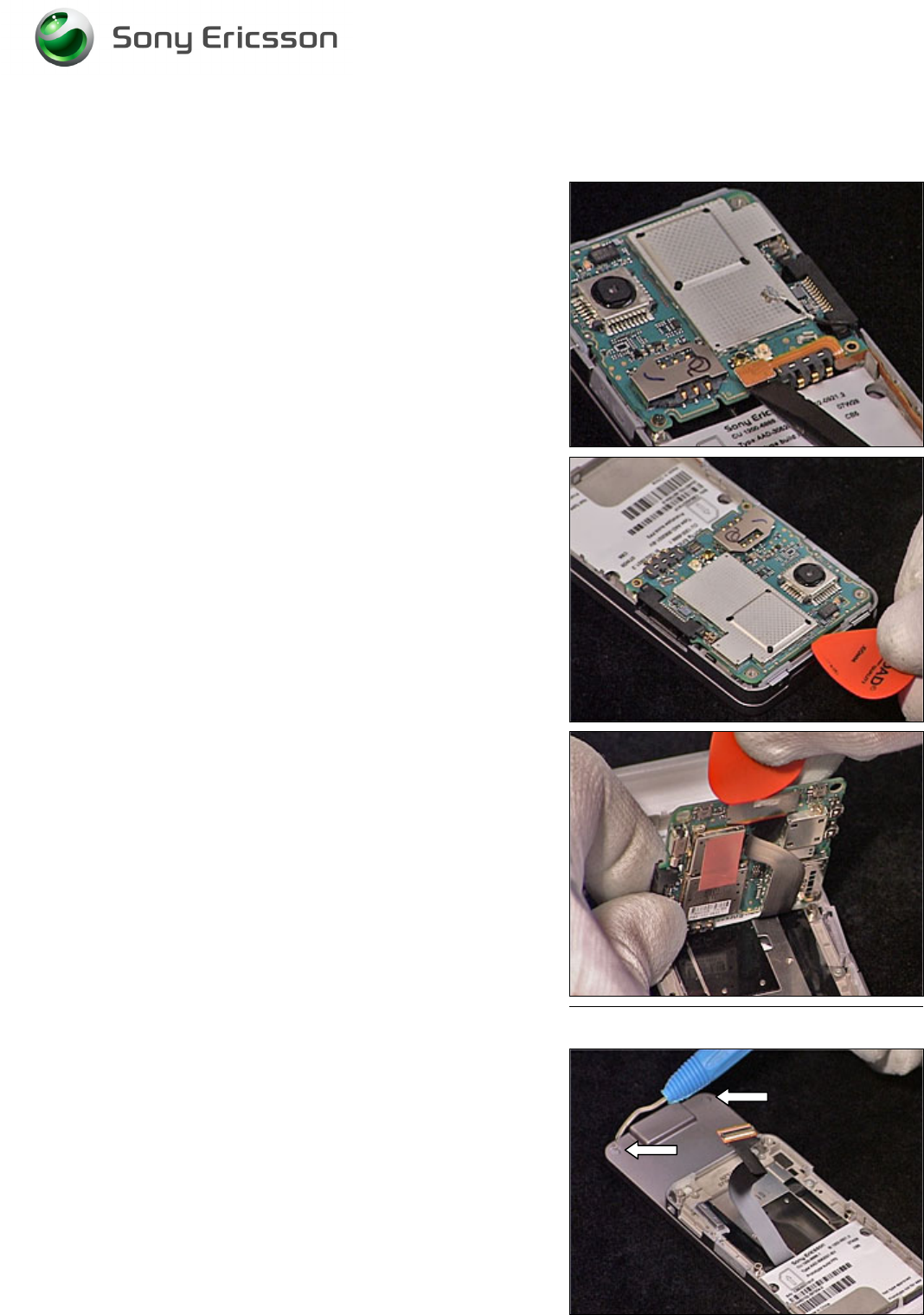
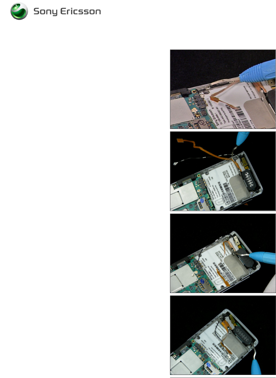
Main PCB continued
Carefully release the Speaker Flex Board to Board
Connector using an orange stick.
Carefully release the Main PCB from the frame using a
guitar pick.
Carefully release the Front Flex Board to Board connector
from the Main PCB using a guitar pick.
Remove the Main PCB.
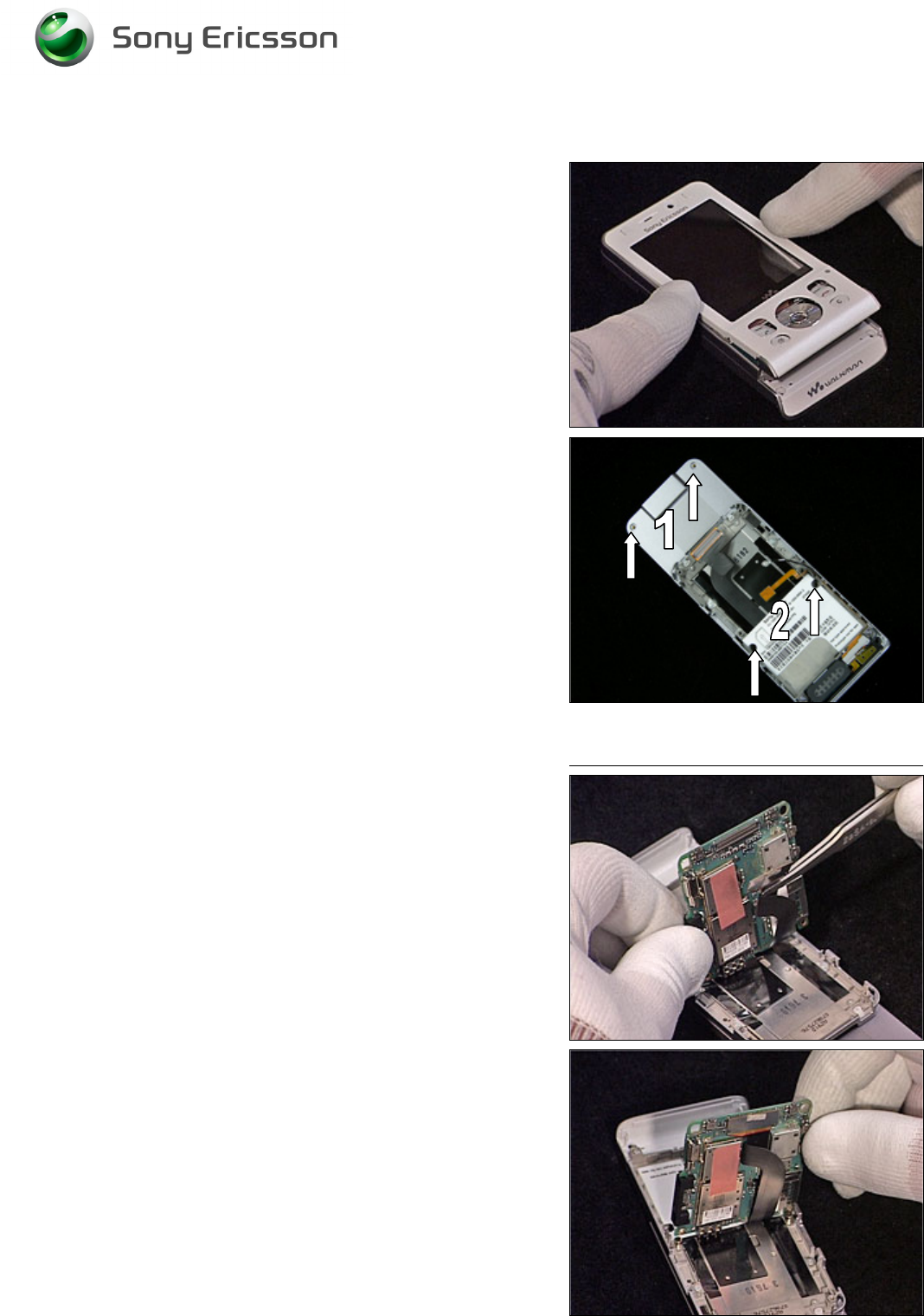
2.1.4 Front Cover Assembly
Remove the two screw Caps using a Dental hook.
Working Instruction, Mechanical
3/000 21-1/FEA 209 544/129 A
Company Internal
©
Sony Ericsson Mobile Communications AB
12(34)
Front Cover Assembly continued
Remove the two upper screws and the two lower screws
(Torx T6).
B
E CAREFUL NOT TO SCRATCH THE
LCD
OR DAMAGE THE
N
AVIGATION
K
EY
FPC
Carefully lift the lower end of the Front Cover Assembly.
B
E CAREFUL NOT TO SCRATCH THE
LCD
OR DAMAGE THE
N
AVIGATION
K
EY
FPC
Carefully insert the orange stick between the Front Cover
Assembly and the Navigation Key FPC. By carefully
pushing the orange stick towards the right side and the top
of the phone, the Front Cover will release.
B
E CAREFUL NOT TO SCRATCH THE
LCD
OR DAMAGE THE
N
AVIGATION
K
EY
FPC
Repeat previous step to release the left side of the Front
Cover as well.
Working Instruction, Mechanical
3/000 21-1/FEA 209 544/129 A
Company Internal
©
Sony Ericsson Mobile Communications AB
13(34)
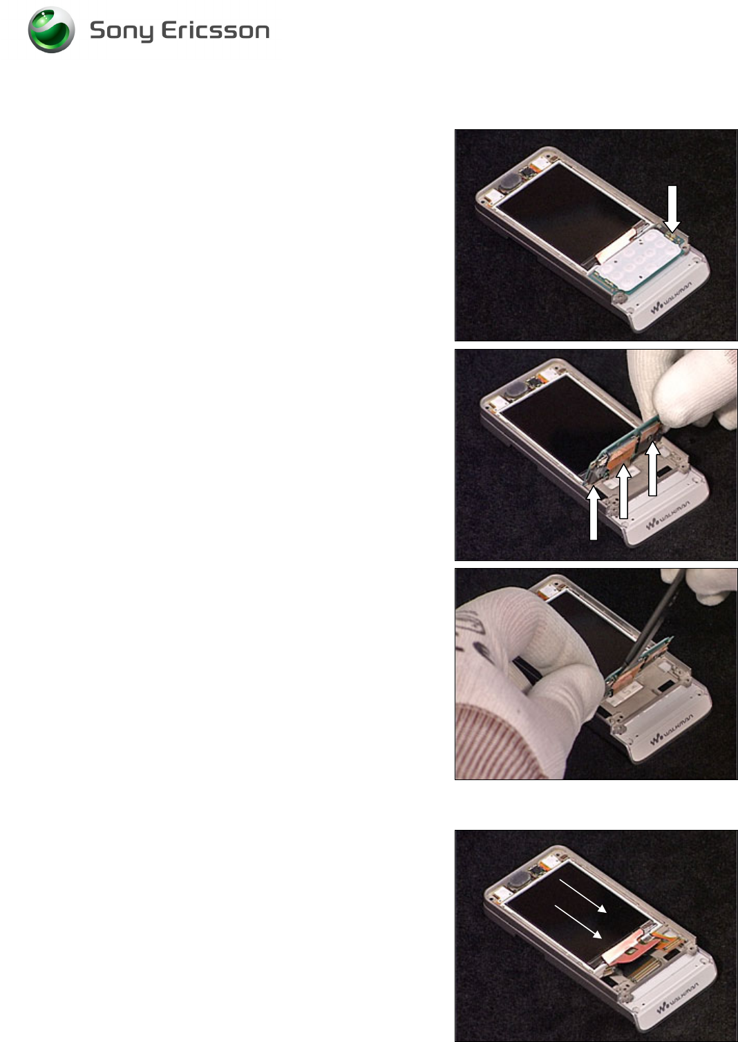
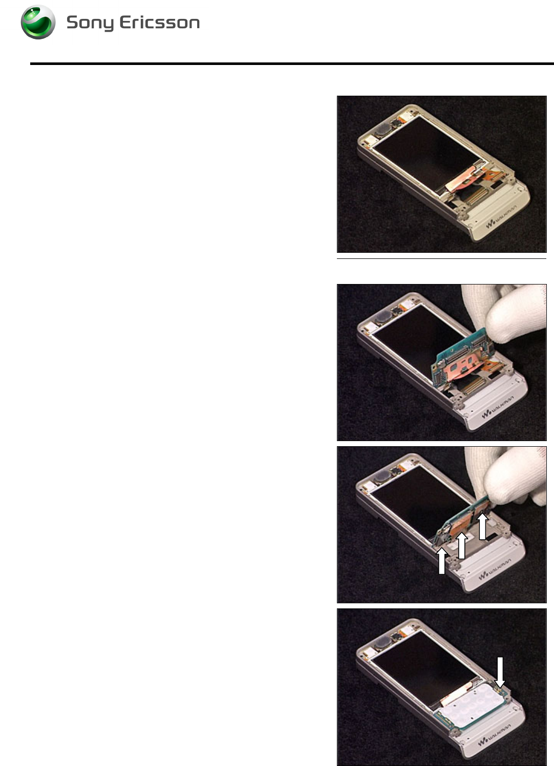
2.1.5 Navi Key PBA
Release the screw.
B
E CAREFUL NOT TO DAMAGE THE
B
T
B
CONNECTORS
Carefully disconnect the three Board to Board connectors
from the Navi Key PBA using the orange stick.
When all BtB connectors have been released, remove the
Navi Key PBA.
2.1.6 Display
B
E CAREFUL NOT TO DAMAGE THE
D
ISPLAY
Carefully slide the Display towards the bottom of the phone.
Remove the Display.
Working Instruction, Mechanical
3/000 21-1/FEA 209 544/129 A
Company Internal
©
Sony Ericsson Mobile Communications AB
14(34)
3 Replacements
Search for the part to be replaced on the Contents page and go to that instruction to be found in this
Replacements section.
The instruction usually begins by directing you to the Disassembly section with a specification of the
instructions you have to carry out in order to disassemble the phone as far as needed before the
actual replacement.
Go back to this Replacements section and carry out the instruction.
The instruction usually ends by directing you to the Reassembly section with a specification of the
instructions you have to carry out in order to reassemble the phone.
Start
Done
REPLACEMENTS
DISASSEMBLY REASSEMBLY
Contents
page
Working Instruction, Mechanical
3/000 21-1/FEA 209 544/129 A
Company Internal
©
Sony Ericsson Mobile Communications AB
15(34)
3.1 Battery Cover
Follow the 2.1.1 Disassembly instructions!
Prepare the new Battery Cover.
Follow the 4.1.6 Reassembly instructions!
3.2 Battery
Follow the 2.1.1 Disassembly instructions!
Prepare the new Battery.
Follow the 4.1.6 Reassembly instructions!
3.3 RF Cap
Remove the RF Cap with a pair of tweezers or a Dental hook.
Prepare the new RF Cap.
3.4 Label Co-Brand Inlay
B
E CAREFUL NOT TO DAMAGE THE PLASTICS
Remove the old Label using a Dental hook. Prepare the
new Label.
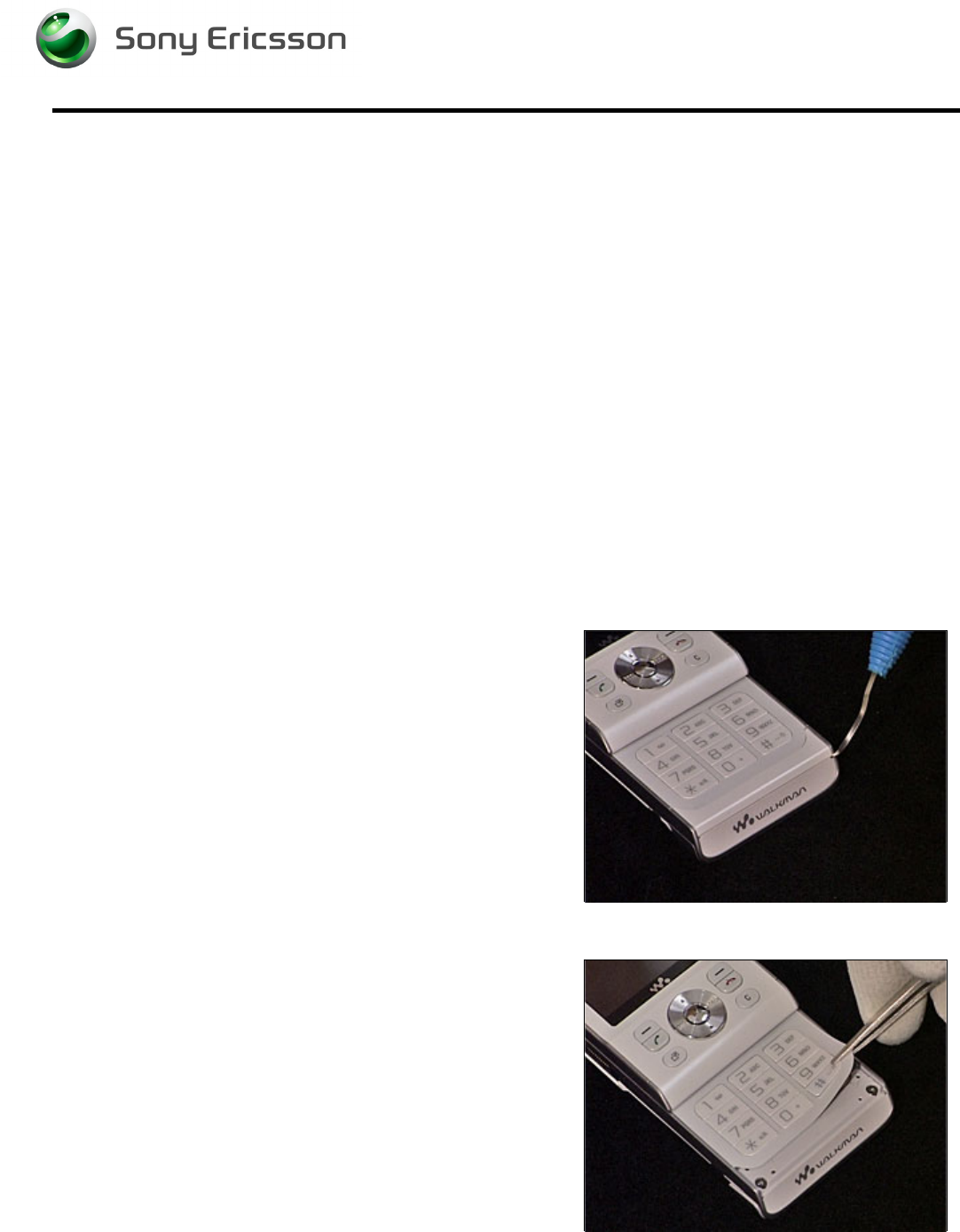
3.5 Keyboard Main
Follow the 2.1.1 - 2.1.2 Disassembly instructions to remove
the Antenna Panel!
B
E CAREFUL NOT TO DAMAGE THE PLASTICS
Remove the old Keyboard using a pair of tweezers. Prepare
the new Keyboard.
Follow the 4.1.5 - 4.1.6 Reassembly instructions!
Working Instruction, Mechanical
3/000 21-1/FEA 209 544/129 A
Company Internal
©
Sony Ericsson Mobile Communications AB
16(34)
3.6 Liquid Intrusion Indicator
Follow the 2.1.1 Disassembly instructions!
Remove the activated Indicator using a Dental hook and a
pair of tweezers. Prepare the new Liquid Intrusion Indicator.
Follow the 4.1.6 Reassembly instructions!
3.7 Panel Antenna
Follow the 2.1.1 – 2.1.2 Disassembly instructions!
Prepare the new Panel Antenna.
Follow the 4.1.5 – 4.1.6 Reassembly instructions!!
3.8 Rear Back Cover
Follow the 2.1.1 – 2.1.2 Disassembly instructions!
Prepare the new Rear Back Cover.
Follow the 4.1.5 – 4.1.6 Reassembly instructions!
3.9 Key, On/Off
Follow the 2.1.1 – 2.1.2 Disassembly instructions!
Prepare the new Key.
Follow the 4.15 – 4.1.6 Reassembly instructions!
3.10 Key, Volume
Follow the 2.1.1 – 2.1.2 Disassembly instructions!
Prepare the new Key.
Follow the 4.1.5 – 4.1.6 Reassembly instructions!
3.11 Key, Camera
Follow the 2.1.1 – 2.1.2 Disassembly instructions!
Prepare the new Key.
Follow the 4.1.5 – 4.1.6 Reassembly instructions!
Working Instruction, Mechanical
3/000 21-1/FEA 209 544/129 A
Company Internal
©
Sony Ericsson Mobile Communications AB
17(34)
3.12 Key, Music
Follow the 2.1.1 – 2.1.2 Disassembly instructions!
Prepare the new Key.
Follow the 4.1.5 – 4.1.6 Reassembly instructions!
3.13 Cap, MemoryStick
Follow the 2.1.1 – 2.1.2 Disassembly instructions!
Prepare the new Cap.
Follow the 4.1.5 – 4.1.6 Reassembly instructions!
3.14 Camera 2.0 MPixel CMOS
Follow the 2.1.1 – 2.1.2 Disassembly instructions!
1. Remove the Shield Can Lid from the Camera using
a Dental hook and a pair of tweezers.
2. Remove the camera using the Camera Removal
Tool.
3. Prepare the new Camera and Shield Can Lid.
4. Insert the new Camera into its socket.
5. Mount a new Shield Can Lid on top of the Camera.
Follow the 4.1.5 – 4.1.6 Reassembly instructions!
3.15 BT Antenna Assy
Follow the 2.1.1 – 2.1.2 Disassembly instructions!
Remove the BT Antenna using a Dental hook and a pair of
tweezers. Prepare the new BT Antenna Assy.
Follow the 4.1.5 – 4.1.6 Reassembly instructions!

Working Instruction, Mechanical
3/000 21-1/FEA 209 544/129 A
Company Internal
©
Sony Ericsson Mobile Communications AB
18(34)
3.16 Front Cover Assembly
Follow the 2.1.1 – 2.1.4 Disassembly instructions!
Prepare the new Front Cover Assembly
Follow the 4.1.3 – 4.1.6 Reassembly instructions!
3.17 Key, Game
Follow the 2.1.1 – 2.1.4 Disassembly instructions!
Prepare the new Key.
Follow the 4.1.3 – 4.1.6 Reassembly instructions!
3.18 Key, Navi
Follow the 2.1.1 – 2.1.4 Disassembly instructions!
Prepare the new Key.
Follow the 4.1.3 – 4.1.6 Reassembly instructions!
3.19 Navi Key PBA
Follow the 2.1.1 – 2.1.5 Disassembly instructions!
Prepare the new Navi Key PBA.
Follow the 4.1.2 – 4.1.6 Reassembly instructions!
3.20 Display
Follow the 2.1.1 – 2.1.6 Disassembly instructions!
Prepare the new Display.
Follow the 4.1.1 – 4.1.6 Reassembly instructions!
3.21 Slider Flex Module
Follow the 2.1.1 – 2.1.6 Disassembly instructions!
Prepare the new Slider Flex Module
Follow the 4.1.1 – 4.1.6 Reassembly instructions!
3.22 Slider Sub Assembly
Follow the 2.1.1 – 2.1.6 Disassembly instructions!
Prepare the new Slider Sub Assembly
Follow the 4.1.1 – 4.1.6 Reassembly instructions!
Working Instruction, Mechanical
3/000 21-1/FEA 209 544/129 A
Company Internal
©
Sony Ericsson Mobile Communications AB
19(34)
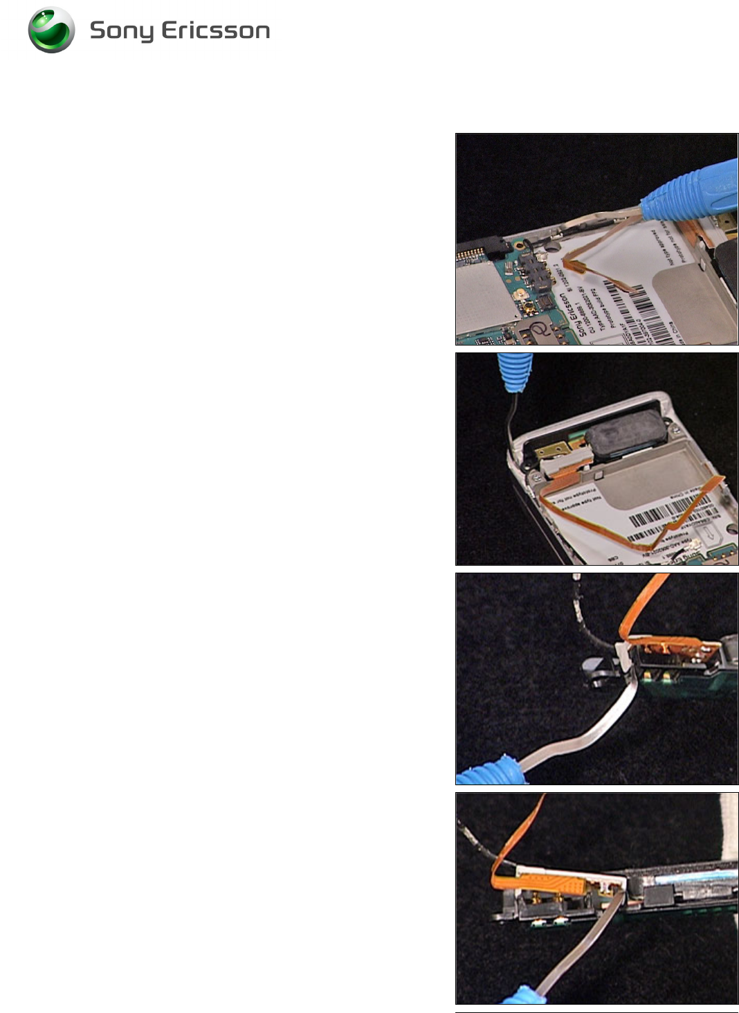
3.23 Main Antenna
REMOVAL
Follow the 2.1.1 – 2.1.3 Disassembly instructions!
B
E CAREFULL NOT TO DAMAGE THE COAX CABLE AND
SPEAKER FLEX
1. Carefully release the speaker flex using a Dental
hook.
2. Carefully release the coax cable from the frame
using a Dental hook.
3. Carefully remove the Main Antenna from the cavity
in the Antenna Cover using a Dental hook.
4. Carefully release the Holder Antenna from the Main
Antenna.
5. Repeat the previous step on the other side of the
Holder Antenna.
Working Instruction, Mechanical
3/000 21-1/FEA 209 544/129 A
Company Internal
©
Sony Ericsson Mobile Communications AB
20(34)
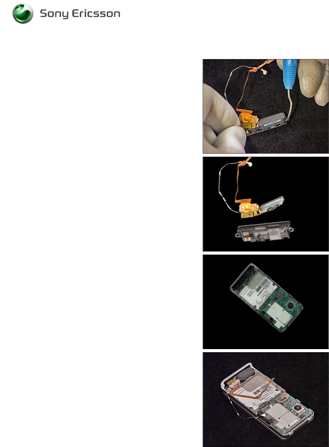
Main Antenna continued
6. Carefully release the speaker from the Main
Antenna using a Dental hook.
INSTALLATION
1. Insert the new Main Antenna into the Antenna
Cover.
2. Position the Speaker Flex Module inside the Main
Antenna.
3. Carefully press the Speaker Flex Module into
position. Make sure the Holder Antenna Sub Assy
clicks into position and the adhesive fixates to the
Main Antenna and the frame.
Working Instruction, Mechanical
3/000 21-1/FEA 209 544/129 A
Company Internal
©
Sony Ericsson Mobile Communications AB
21(34)
Main Antenna continued
4. Attach the coax cable from the Speaker Flex Module
underneath the 3 hooks in the frame using a Dental
hook.
5. Mount the Speaker Flex onto the frame. Make sure
the adhesive sticks to the frame.
Follow the 4.1.4 – 4.1.6 Reassembly instructions!
Working Instruction, Mechanical
3/000 21-1/FEA 209 544/129 A
Company Internal
©
Sony Ericsson Mobile Communications AB
22(34)
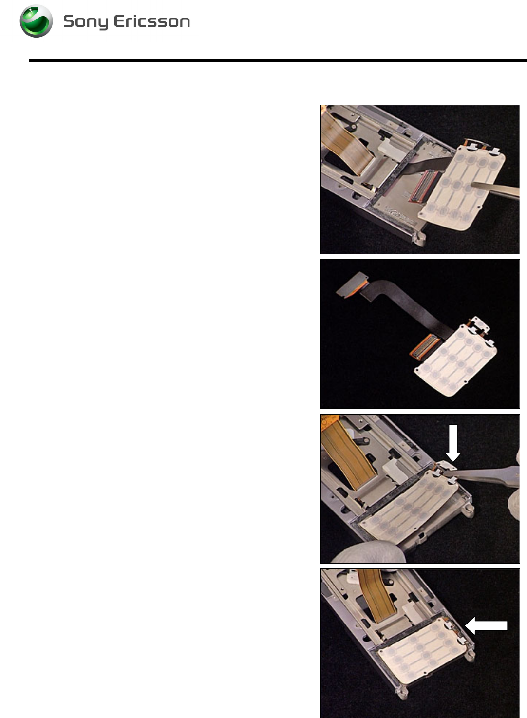
3.24 Speaker Flex Module
REMOVAL
Follow the 2.1.1 – 2.1.3 Disassembly instructions!
B
E CAREFULL NOT TO DAMAGE THE COAX CABLE AND
SPEAKER FLEX
1. Carefully release the speaker flex using a Dental
hook.
2. Carefully release the coax cable from the frame
using a Dental hook.
3. Carefully release the Holder Antenna from the Main
Antenna.
4. Repeat the previous step on the other side of the
Holder Antenna.
5. Carefully release the speaker from the Main
Antenna using a Dental hook.
Working Instruction, Mechanical
3/000 21-1/FEA 209 544/129 A
Company Internal
©
Sony Ericsson Mobile Communications AB
23(34)
Speaker Flex Module continued
INSTALLATION
1. Position the Speaker Flex Module inside the Main
Antenna.
2. Carefully press the Speaker Flex Module into
position. Make sure the Holder Antenna Sub Assy
clicks into position and the adhesive fixates to the
Main Antenna and the frame.
3. Attach the coax cable from the Speaker Flex Module
underneath the 3 hooks in the frame using a Dental
hook.
4. Mount the Speaker Flex onto the frame. Make sure
the adhesive sticks to the frame.
Follow the 4.1.4 – 4.1.6 Reassembly instructions!
Working Instruction, Mechanical
3/000 21-1/FEA 209 544/129 A
Company Internal
©
Sony Ericsson Mobile Communications AB
24(34)
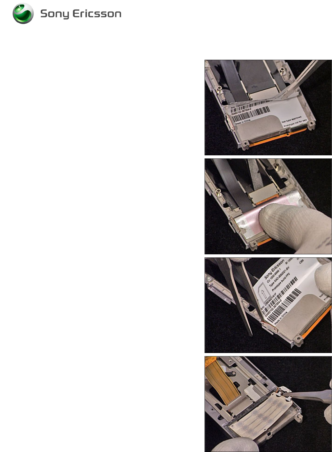
3.25 Key Foil Assy
REMOVAL
Follow the 2.1.1 – 2.1.3 Disassembly instructions!
1. Carefully lift the Label using a pair of tweezers, to be
able to access the Key Foil Assy Board to Board
connector.
2. Release the Key Foil Assy Board to Board
connector using the orange stick.
3. Release the Camera Switch from the Slider
Assembly using a pair of tweezers.
4. Release the Key Foil Assy from the Slider Assembly
using a pair of tweezers.
Working Instruction, Mechanical
3/000 21-1/FEA 209 544/129 A
Company Internal
©
Sony Ericsson Mobile Communications AB
25(34)
Key Foil Assy continued
5. Remove the Key Foil Assy using a pair of tweezers.
INSTALLATION
1. Prepare the new Key Foil Assy.
2. Insert the new Key Foil Assy into the Slider Sub
Assembly using a pair of tweezers. Make sure you
position the Camera Key correct into the Slider Sub
Assembly.
3. Make sure you position the Camera Key correct into
the Slider Sub Assembly.
Follow the 4.1.4 – 4.1.6 Reassembly instructions!
Working Instruction, Mechanical
3/000 21-1/FEA 209 544/129 A
Company Internal
©
Sony Ericsson Mobile Communications AB
26(34)
3.26 Camera QCIF MPixel CMOS
Follow the 2.1.1 – 2.1.6 Disassembly instructions!
Remove the Video Camera using the Camera Removal Tool. Prepare the new Camera.
Follow the 4.1.1 – 4.1.6 Reassembly instructions!
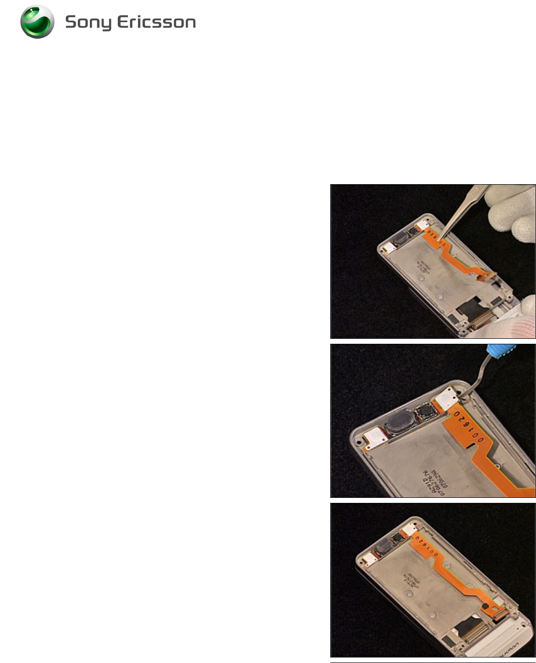
3.27 Receiver Flex Module
REMOVAL
Follow the 2.1.1 – 2.1.6 Disassembly instructions!
Release the Receiver flex from the Slider Assembly using a
pair of tweezers.
Release the upper part of the Receiver flex using a Dental
hook.
INSTALLATION
Position the new Receiver Flex Module into the cavity of the
Slider Assembly. Carefully press it into place and make
sure the adhesive sticks to the Slider Assembly.
Follow the 4.1.1 – 4.1.6 Reassembly instructions!
Working Instruction, Mechanical
3/000 21-1/FEA 209 544/129 A
Company Internal
©
Sony Ericsson Mobile Communications AB
27(34)
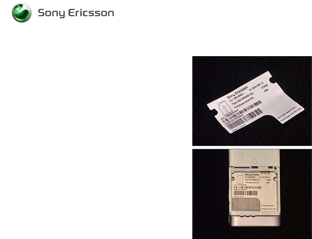
3.28 Label
Follow the 2.1.1 Disassembly instructions!
Read the old label and/or write the information into the
“Label make” program before removal.
Note the position of the label before removal
Heat up the label by using hot air, if needed.
Carefully remove the label without causing scratches
If there still are residues, clean the surface with isopropyl
alcohol
Check that the proper label format is loaded in the Zebra
printer.
Write a new label by using the program “Label make” and
check that the printing is OK.
Take the new label and place it onto the frame as in the
adjacent picture.
O
NE LABEL ONLY IS ALLOWED
!
Follow the 4.1.6 Reassembly instructions!
Working Instruction, Mechanical
3/000 21-1/FEA 209 544/129 A
Company Internal
©
Sony Ericsson Mobile Communications AB
28(34)
4 Reassembly
After replacing a part being listed in Replacements, the instruction of that section usually ends by
directing you to this Reassembly section with a specification of the instructions you have to carry out
in order to reassemble the phone.
4.1 Overview
The reassembly is done in the following sequence:
1. Display
2. Navi key PBA
3. Front Cover Assembly
4. Main PCB
5. Rear Back Cover
6. Battery, Battery Cover and M2
Start
Done
REPLACEMENTS
DISASSEMBLY REASSEMBLY
Contents
page
Working Instruction, Mechanical
3/000 21-1/FEA 209 544/129 A
Company Internal
©
Sony Ericsson Mobile Communications AB
29(34)
4.1.1 Display
Position the Display into the Cover Upper Rear and slide it
into position.
4.1.2 Navi Key PBA
Position the Navi Key PBA as shown in picture.
Carefully connect the 3 Board to Board connectors.
M
AKE SURE THE
D
ISPLAY IS IN CORRECT POSITION
Carefully fold down the Navi Key PBA into position.
Insert and tighten the screw (JCIS 10Ncm).
Working Instruction, Mechanical
3/000 21-1/FEA 209 544/129 A
Company Internal
©
Sony Ericsson Mobile Communications AB
30(34)
4.1.3 Front Cover Assembly
Position the Front Cover Assembly on top of the Display as
shown in picture. Carefully press down and make sure it
snaps into position.
Insert and tighten the 4 screws. Insert two new Screw Caps
(Upper).
1 – JCIS 10Ncm
2 – Torx T6 10Ncm
4.1.4 Main PCB
Connect the Slider Flex to the Main PCB using a pair of
tweezers.
Fold down the Main PCB into position.
Working Instruction, Mechanical
3/000 21-1/FEA 209 544/129 A
Company Internal
©
Sony Ericsson Mobile Communications AB
31(34)
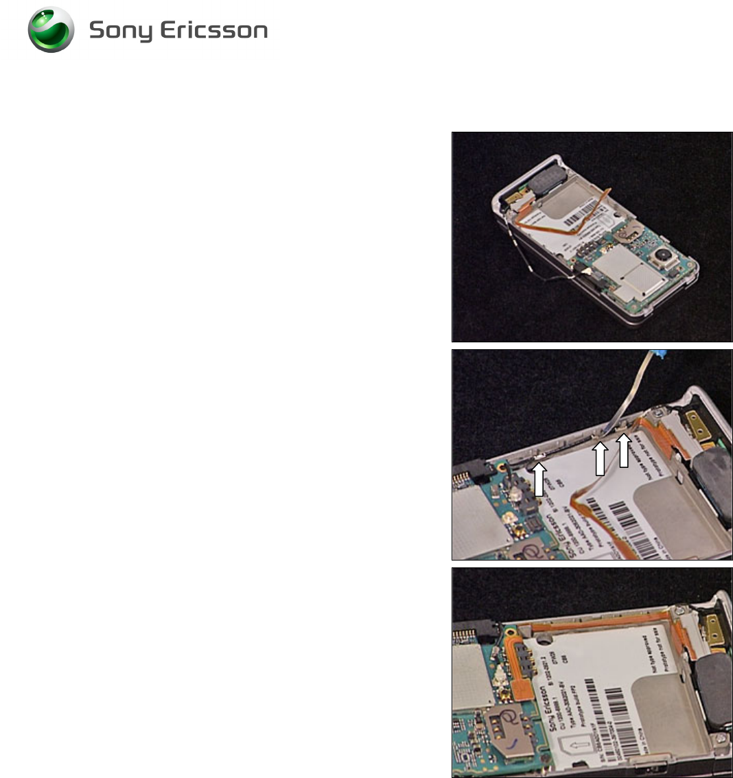
Main PCB continued
Connect the Antenna Coax (1 & 2) and the Speaker Flex
BtB (3) to the Main PCB.
Insert and tighten the screw (JCIS 10Ncm).
4.1.5 Rear Back Cover
Position the Rear Back Cover as shown in picture. Fold it
down into position.
Carefully press all four sides of the Rear Back Cover and
make sure it snaps into position.
Working Instruction, Mechanical
3/000 21-1/FEA 209 544/129 A
Company Internal
©
Sony Ericsson Mobile Communications AB
32(34)
Rear Back Cover continued
Insert and tighten the three screws.
1, 2 – Torx T6 14Ncm
3 – JCIS 10Ncm
Insert the two screw Caps.
Insert and tighten the two screws (Torx T6 14Ncm).
Position and put the Panel Antenna in place.
Working Instruction, Mechanical
3/000 21-1/FEA 209 544/129 A
Company Internal
©
Sony Ericsson Mobile Communications AB
33(34)
4.1.6 Battery, Battery Cover and M2
Insert the Battery.
Place the Battery Cover into position and lock it.
Insert the M2 MemoryStick.

Working Instruction, Mechanical
3/000 21-1/FEA 209 544/129 A
Company Internal
©
Sony Ericsson Mobile Communications AB
34(34)
5 Revision history
Rev. Date Changes / Comments
A 2007-10-09 Initial release