XR 1300R Sony C2300r
User Manual: XR-1300R
Open the PDF directly: View PDF ![]() .
.
Page Count: 37
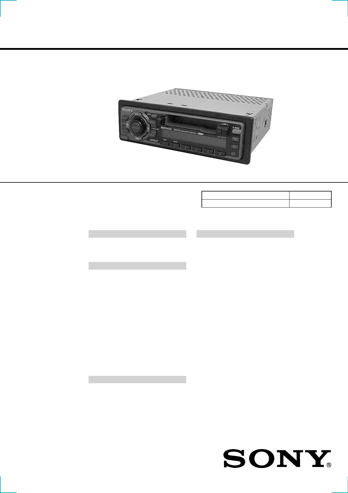
SERVICE MANUAL
FM/MW/LW CASSETTE CAR STEREO
AEP Model
UK Model
SPECIFICATIONS
XR-1300R/C2300R
Photo: XR-C2300R
Model Name Using Similar Mechanism NEW
Tape Transport Mechanism Type MG-36SZ10-32
Cassette player section
Tape track 4-track 2-channel stereo
Wow and flutter 0.13 % (WRMS)
Frequency response 30 – 15,000 Hz
Signal-to-noise ratio 55 dB
Tuner section
FM
Tuning range 87.5 – 108.0 MHz
Aerial terminal External aerial connector
Intermediate frequency 10.7 MHz
Usable sensitivity 9 dBf
Selectivity 75 dB at 400 kHz
Signal-to-noise ratio 65 dB (stereo),
68 dB (mono)
Harmonic distortion at 1 kHz
0.7 % (stereo),
0.4 % (mono)
Separation 35 dB at 1 kHz
Frequency response 30 – 15,000 Hz
MW/LW
Tuning range MW: 531 – 1,602 kHz
LW: 153 – 279 kHz
Aerial terminal External aerial connector
Intermediate frequency 10.7 MHz/450 kHz
Sensitivity MW: 30 µV
LW: 50 µV
Power amplifier section
Outputs Speaker outputs
(sure seal connectors)
Speaker impedance 4 – 8 ohms
Maximum power output 45 W × 4 (at 4 ohms)
General
Outputs
Power aerial relay control
lead
Power amplifier control
lead
Tone controls Bass ±8 dB at 100 Hz
Treble ±8 dB at 10 kHz
Power requirements 12 V DC car battery
(negative earth)
Dimensions Approx. 188 × 58 × 182 mm
(w/h/d)
Mounting dimensions Approx. 182 × 53 × 163 mm
(w/h/d)
Mass Approx. 1.2 kg
Supplied accessories Parts for installation and
connections (1 set)
Front panel case (1)
Design and specifications are subject to change
without notice.
Audio output (XR-C2300R)
Ver 1.1 2001.02
9-870-024-12 Sony Corporation
2001B0500-1 Audio Entertainment Group
C 2001.2 General Engineering Dept.

2
TABLE OF CONTENTS
1. GENERAL
Location of Controls (XR-1300R).................................. 3
Setting the Clock ............................................................. 3
Locations of Controls (XR-C2300R) ............................. 4
Setting the Clock ............................................................. 4
Installation ....................................................................... 5
Connections ..................................................................... 6
2. DISASSEMBLY ......................................................... 9
3. MECHANICAL ADJUSTMENTS ....................... 12
4. ELECTRICAL ADJUSTMENTS
Tape Deck Section .......................................................... 13
Tuner Section .................................................................. 14
5. DIAGRAMS
5-1. Note for Printed Wiring Boards and
Schematic Diagrams ....................................................... 17
5-2. Printed Wiring Board
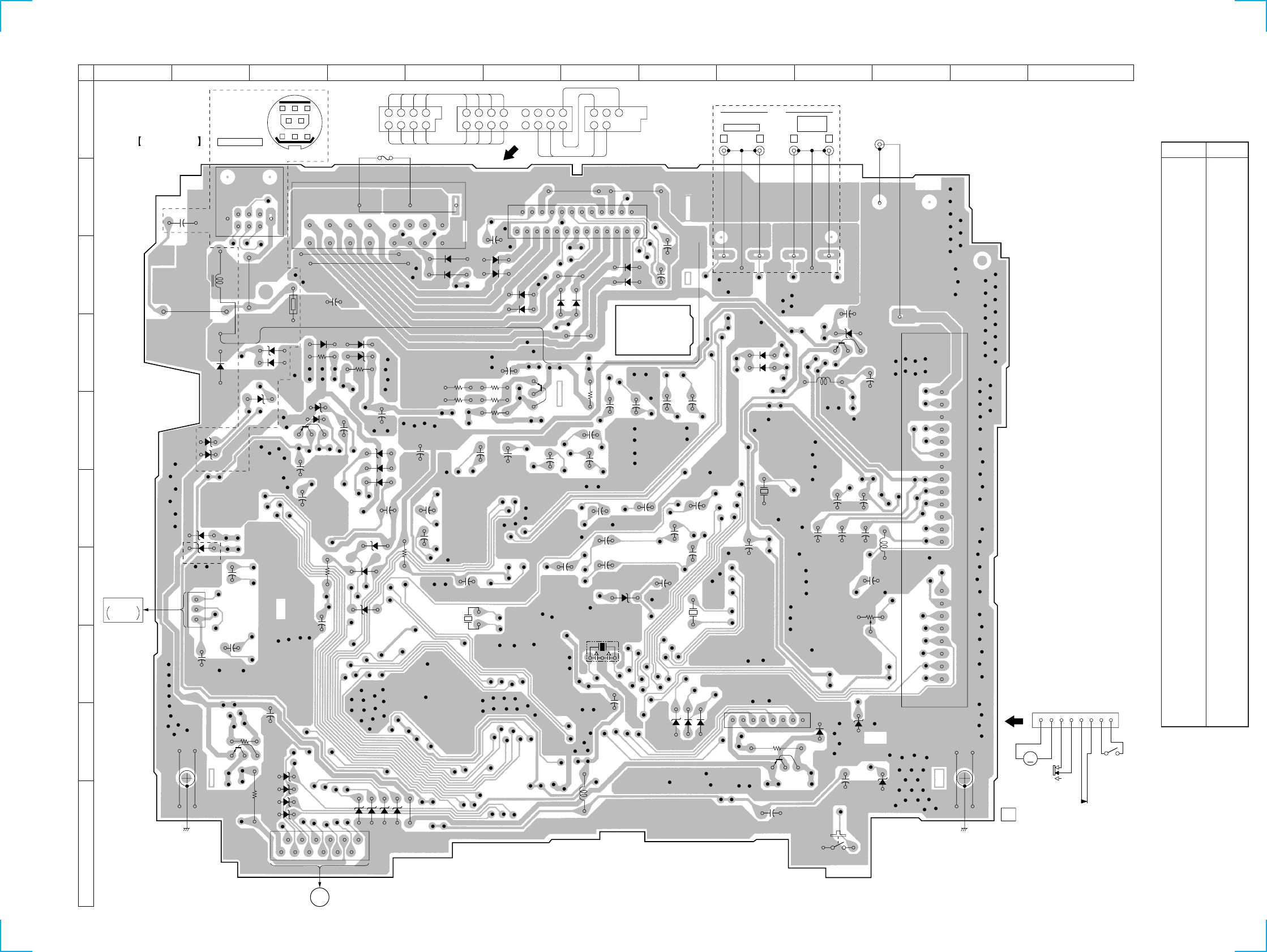
– MAIN Board (Component Side) – .............................. 18
5-3. Printed Wiring Board
– MAIN Board (Conductor Side) – ................................ 19
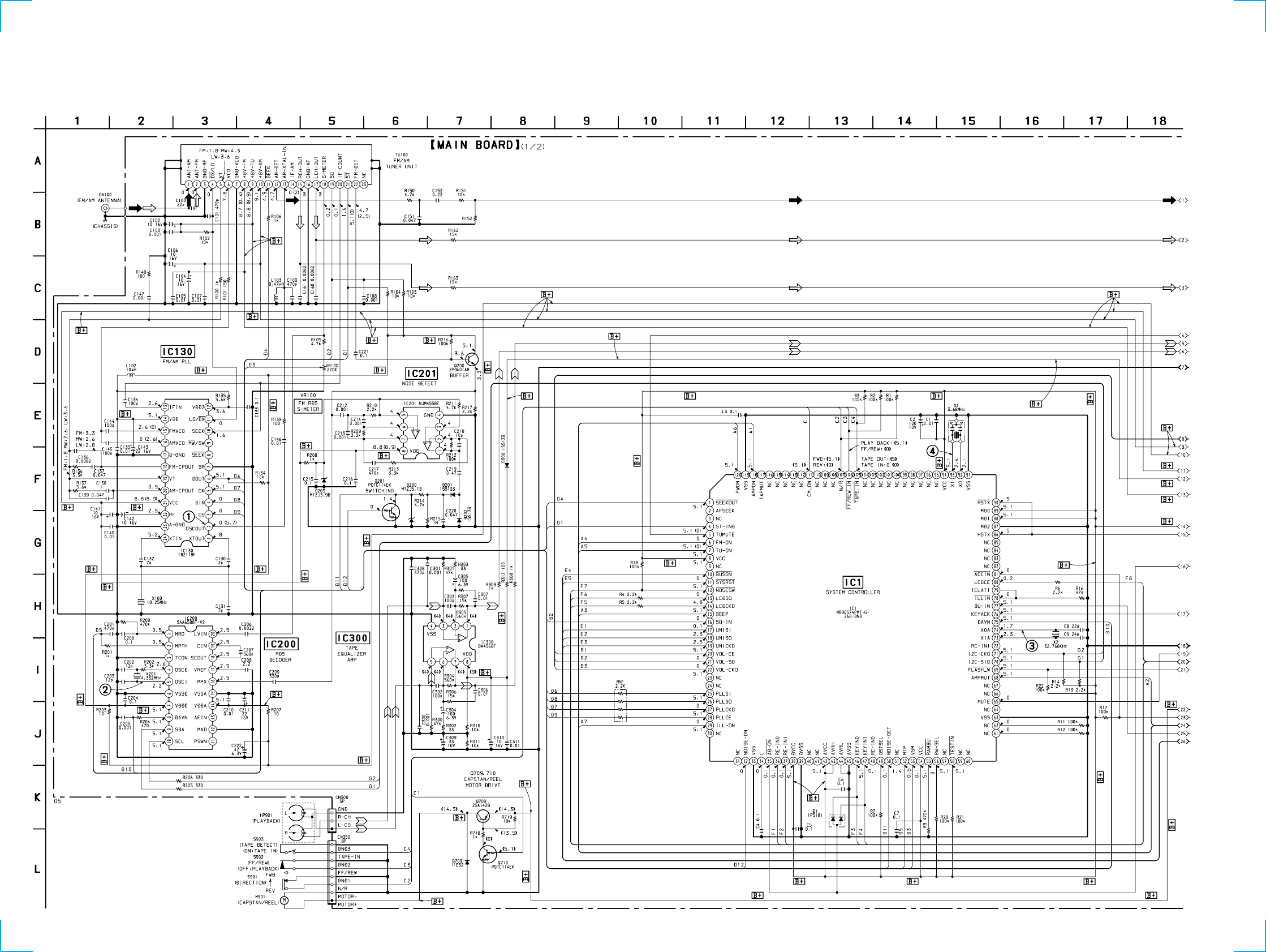
5-4. Schematic Diagram – MAIN Board (1/2) – .................. 20
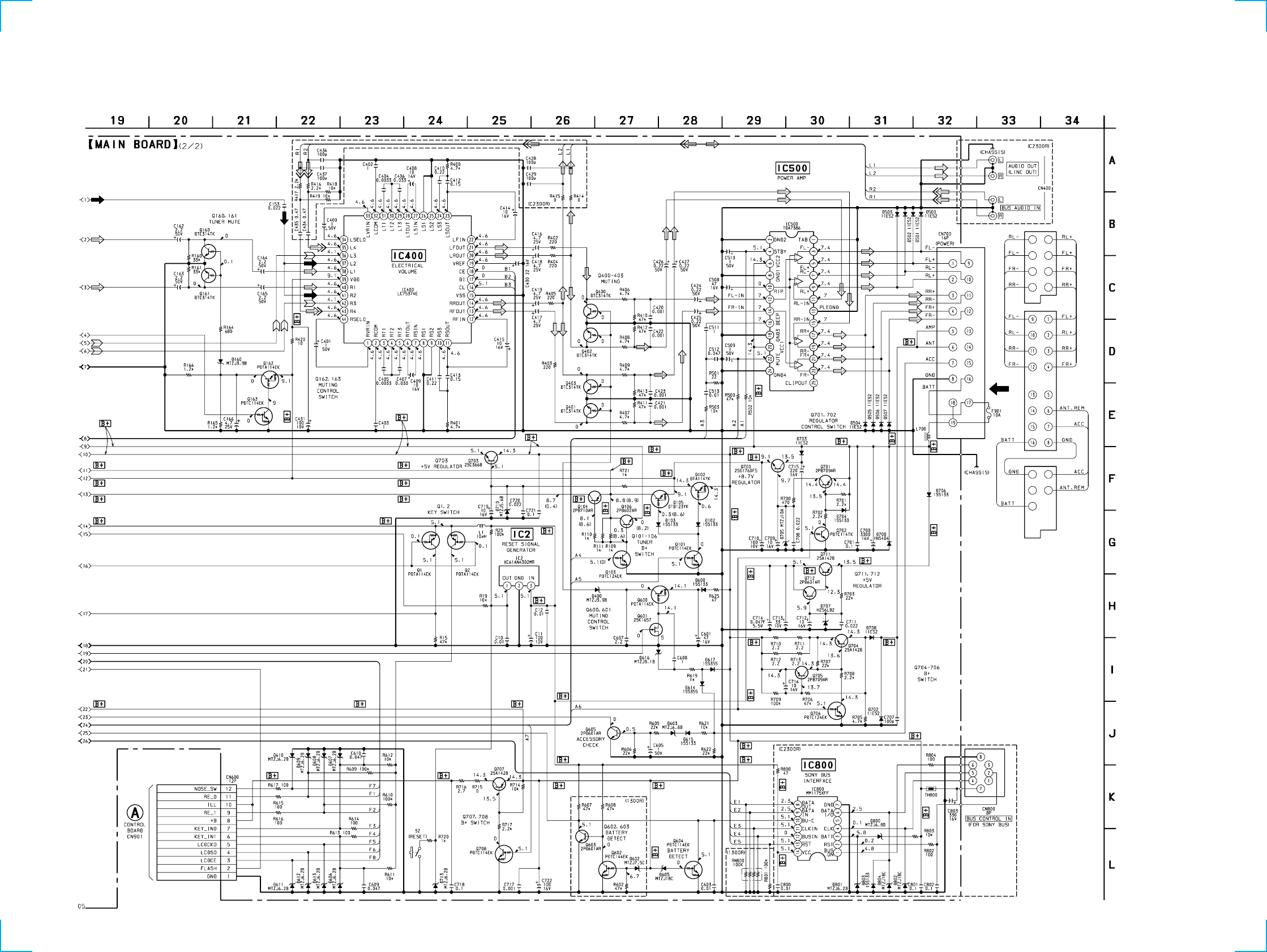
5-5. Schematic Diagram – MAIN Board (2/2) – .................. 21
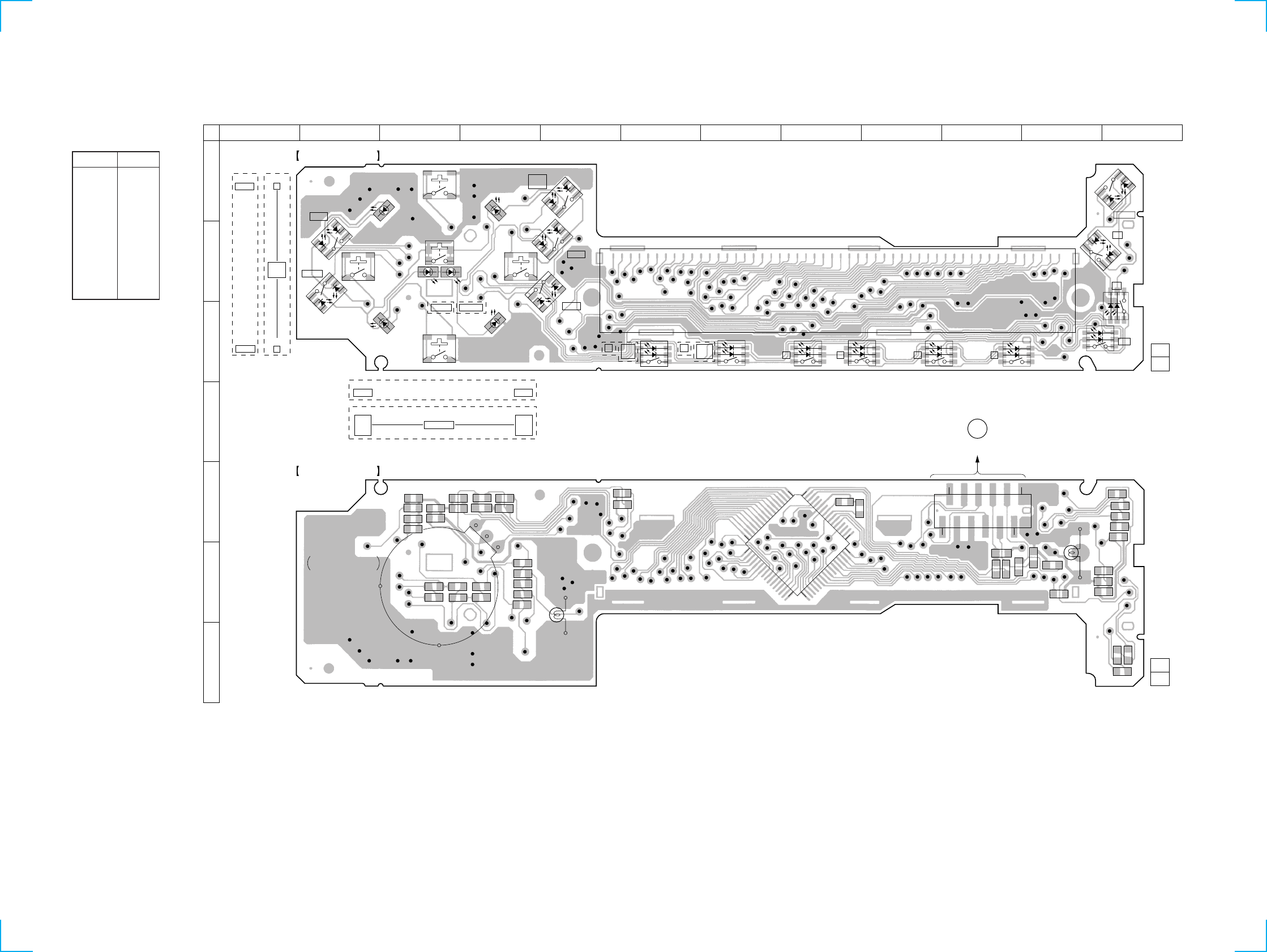
5-6. Printed Wiring Board – CONTROL Board – ................ 22
5-7. Schematic Diagram – CONTROL Board – ................... 23
5-8. IC Pin Function Description ........................................... 25
6. EXPLODED VIEWS ................................................ 28
7. ELECTRICAL PARTS LIST ............................... 31
Flexible Circuit Board Repairing
• Keep the temperature of the soldering iron around 270 ˚C dur-
ing repairing.
• Do not touch the soldering iron on the same conductor of the
circuit board (within 3 times).
• Be careful not to apply force on the conductor when soldering
or unsoldering.
Notes on chip component replacement
• Never reuse a disconnected chip component.
• Notice that the minus side of a tantalum capacitor may be dam-
aged by heat.
3
55
Location of controls
Refer to the pages listed for details.
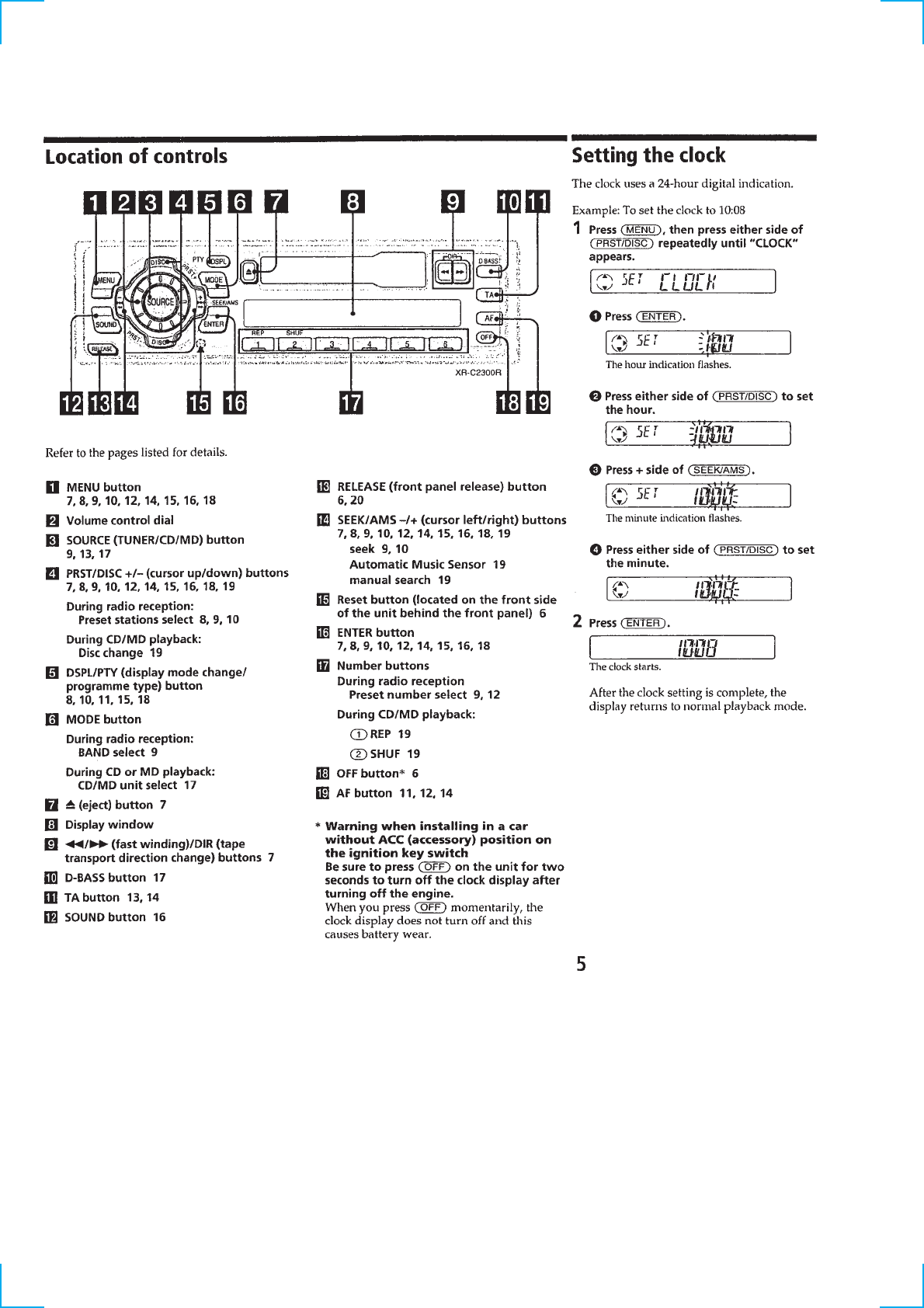
1MENU button
7, 8, 9, 11, 13, 14, 15
2Volume control dial
3TUNER button 8, 9, 12
4PRST +/– (cursor up/down) buttons
7, 8, 9, 11, 13, 14, 15
During radio reception:
Preset stations select 8, 9
5DSPL/PTY (display mode change/
programme type) button 14
6MODE button
During radio reception:
BAND select 8, 9
7Z (eject) button 7
8Display window
9m/M (fast winding)/DIR (tape
transport direction change) buttons 7
q; D-BASS button 16
qa TA button 12, 13
qs SOUND button 15
qd RELEASE (front panel release) button
6, 17
qf SEEK –/+ (cursor left/right) buttons
7, 8, 9, 11, 13, 14, 15
seek 9
qg Reset button (located on the front side
of the unit behind the front panel) 6
qh ENTER button 7, 8, 9, 11, 13, 14, 15
qj Preset number buttons 9, 11
qk OFF button* 6
ql AF button 10, 11, 13
*Warning when installing in a car
without ACC (accessory) position on
the ignition key switch
Be sure to press (OFF) on the unit for two
seconds to turn off the clock display after
turning off the engine.
When you press (OFF) momentarily, the
clock display does not turn off and this
causes battery wear.
XR-1300R
P
R
S
T
+
S
E
E
K
–
S
E
E
K
+
P
R
S
T
–
MODE
OFF
DIR D-BASS
ENTER
MENU
SOUND
RELEASE
1 2 3 4 56
TA
AF
TUNER
DSPL
PTY
SECTION 1
GENERAL This section is extracted from
instruction manual.
(XR-1300R)
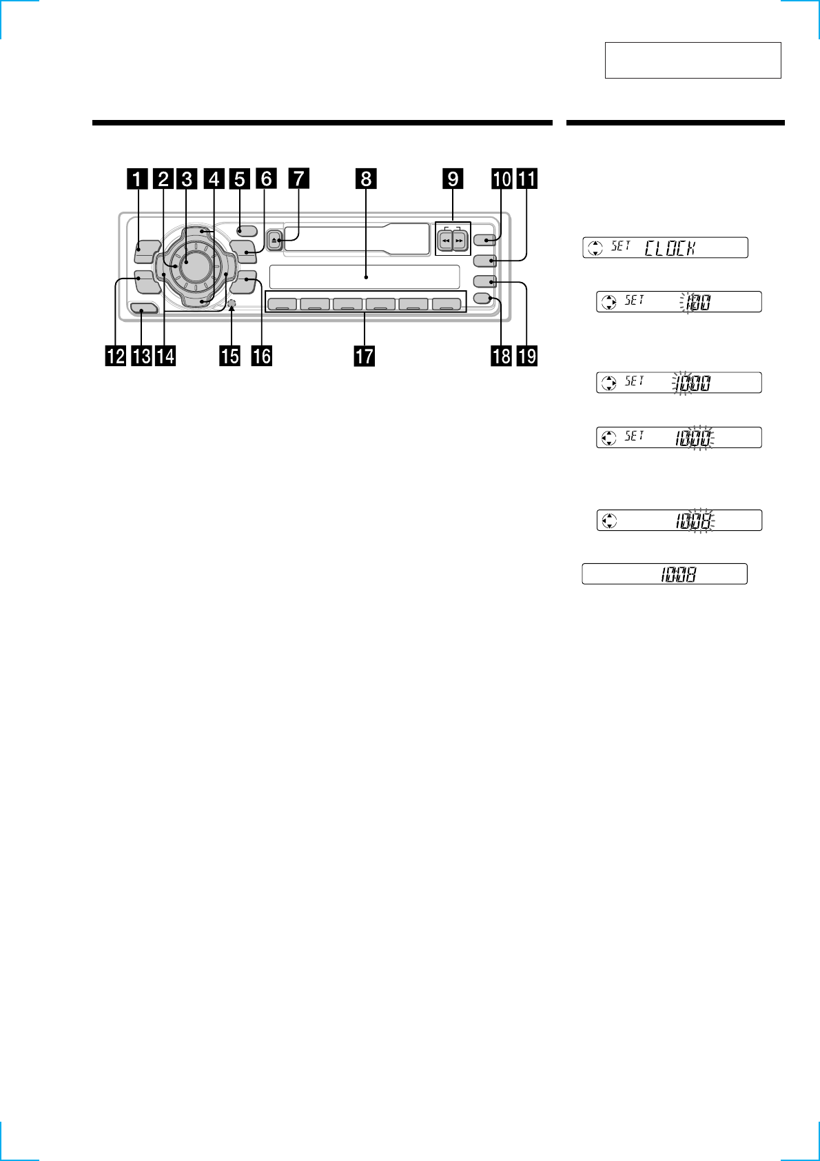
Setting the clock
The clock uses a 24-hour digital indication.
Example: To set the clock to 10:08
1
Press (MENU), then press either side of
(PRST) repeatedly until “CLOCK”
appears.
1 Press (ENTER).
The hour indication flashes.
2 Press either side of (PRST) to set the
hour.
3Press + side of (SEEK).
The minute indication flashes.
4Press either side of (PRST) to set the
minute.
2
Press (ENTER).
The clock starts.
After the clock setting is complete, the
display returns to normal playback mode.
4
(XR-C2300R)
5
182 mm
53 mm
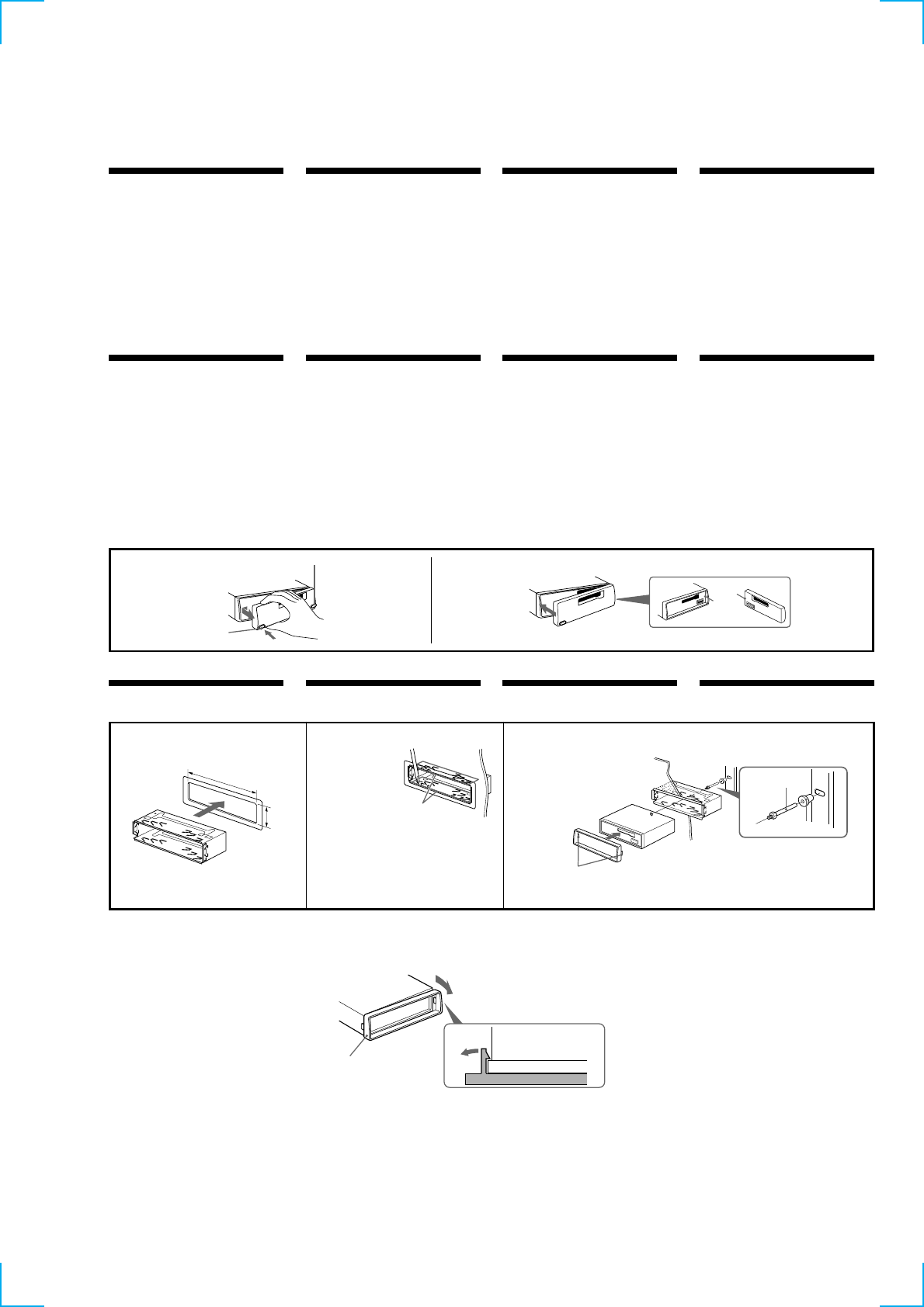
Installation
Precautions
•Choose the installation location carefully so that
the unit will not interfere with normal driving
operations.
•Avoid installing the unit in areas subject to dust,
dirt, excessive vibration, or high temperatures,
such as in direct sunlight or near heater ducts.
•Use only the supplied mounting hardware for a
safe and secure installation.
Mounting angle adjustment
Adjust the mounting angle to less than 20°.
How to detach and attach the
front panel
Before installing the unit, detach the front
panel.
ATo detach
Before detaching the front panel, be sure to press
(OFF). Press (RELEASE), then slide the front
panel a little to the left, and pull it off towards
you.
BTo attach
Attach part A of the front panel to part B of the
unit as illustrated and push the left side into
position until it clicks.
Installation in the dashboard
2
Bend these claws outward for a tight
fit, if necessary.
Si es necesario, doble estas uñas hacia
fuera para que encaje firmemente.
För att få en tät passning böj dessa
flikar vid behov.
Se necessário, dobre as unhas para
prender melhor.
3
Dashboard
Salpicadero
Instrumentinfattning
Tablier
Fire wall
Panel contafuegos
Brandsäker mellanvägg
Parede anti-fogo
3
2
Instalación InstalaçãoMontering
Precauciones
•Elija cuidadosamente el lugar de montaje de
forma que la unidad no interfiera las funciones
normales de conducción.
•Evite instalar la unidad donde pueda quedar
sometida a altas temperaturas, como a la luz
solar directa o al aire de calefacción, o a polvo,
suciedad o vibraciones excesivas.
•Para realizar una instalación segura y firme,
emplee solamente la ferretería de montaje
suministrada.
Ajuste del ángulo de montaje
Ajuste el ángulo de montaje a menos de 20°.
Hur framsidan tas loss/fästs
Ta loss framsidan före bilstereons montering.
AHur framsidan tas loss
Se till att enheten är avstängd innan du tar bort
Frontpanelen. Tryck på (OFF). Tryck sedan på
(RELEASE) och skjut frontpanelen lite åt vänster
medan du drar den emot dig.
BHur framsidan fästs i bilstereon
Sätt fast del A på frontpanelen på del B på
enheten enligt bilden och tryck på den vänstra
sidan tills det klickar till.
Para retirar e colocar o painel
frontal
Antes de inciar a insta;ação do aparelho,
remova o painel frontal.
APara remover
Antes de retirar o painel frontal, tem de carregar
em (OFF). Carregue em (RELEASE), faça deslizar
o painel um pouco para a esquerda e puxe-o para
si.
BPara colocar
Encaixe a parte A do painel frontal na parte B do
aparelho, como se mostra na figura, fazendo
pressão sobre o painel até ouvir um estalido.
Forma de extraer e instalar el
panel frontal
Antes de instalar la unidad, extraiga el panel
frontal.
APara extraerlo
Antes de extraer el panel frontal, asegúrese de
pulsar (OFF). Pulse (RELEASE), deslice el panel
ligeramente hacia la izquierda y tire de él hacia
fuera.
BPara instalarlo
Fije la parte A del panel frontal a la parte B de la
unidad tal como muestra la ilustración y ejerza
presión sobre el lado izquierdo hasta oír un
chasquido.
Precauções
•Escolha com cuidado um local apropriado para
a montagem do aparelho, para que este não
interfira com as manobras necessárias à
condução do veículo.
•Evite instalar o aparelho onde possa estar sujeito
a altas temperaturas, como em locais expostos
directamente à luz do sol, ao ar quente dos
aquecimentos, ou sujeitos a pó, sujidade ou
vibração excessiva.
•Utilize somente o jogo de montagem fornecido
para efectuar uma instalação segura.
Ajuste do ângulo de montagem
Ajuste o ângulo de montagem a menos de 20°.
Att observera
•Var noga när du väljer var i bilen du monterar
bilstereon, så att den inte sitter i vägen när du
kör.
•Montera inte bilstereon där den utsätts för
värme, t ex solsken eller varmluft, eller där den
utsätts för damm, smuts och/eller vibrationer.
•Använd endast de medföljande
monteringstillbehören för att vara säker på att
bilstereon monteras på säkert och korrekt sätt.
Tillåten monteringsvinkel
Monteringsvinkeln måste vara under 20 grader.
Instalación en el salpicadero Montering i
instrumentinfattning Instalação no tablier
Caution
Remove the protection collar 6 before installing.
Release the catch lock as illustrated.
Desbloquee el retén como se ilustra.
Lossa spärren på det sätt som bilden visar.
Abra o fecho como se mostra na figura.
6
B
6
1
First attach 6 to the unit, then insert the unit into 1.
En primer lugar, fije 6 a la unidad y, a continuación, inserte ésta en 1.
Sätt först fast 6 på enheten och skjut sedan in bilstereon i 1.
Primeiro, fixe 6 no aparelho e depois introduza-o em 1.
1
1
A
Precaución
Extraiga el collar de protección 6 antes de
realizar la instalación.
Varning
Avlägsna skyddsringen 6 innan du installerar
enheten.
Cuidado
Antes de fazer a instalação retire a moldura
protectora 6.
(OFF)
(RELEASE)
A
B
With the UP marking up
Con la marca UP hacia arriba
Med märkningen UP vänd uppåt
Com a marca UP para cima

6
Connections
Att observera
•Denna bilstereo är endast avsedd för anslutning
till ett negativt jordat, 12 V bilbatteri.
•Var noga med att inga kablar kläms mellan
någon skruv eller att de blir klämda mellan
rörliga delar som t.ex. bilsätet.
•Anslut strömkabeln 5 till enheten och
högtalarna innan du ansluter den till den yttre
strömanslutningen.
•Dra samtliga jordledningar till en och samma
jordningspunkt.
•Anslut den gula kabeln till en ledig bilkrets med
en högre ampere än enhetens. Om du
seriekopplar enheten till andra
stereokomponenter måste den bilkrets de
kopplas till ha en högre ampere än summan av
de enskilda delarnas amperestyrka. Om det inte
finns några bilkretsar med en så hög
amperestyrka som enhetens ska du ansluta
enheten direkt till batteriet. Om inga bilkretsar
finns för anslutning till enheten ska du ansluta
enheten till en bilkrets med en högre ampere än
enhetens styrka så att inga andra säkringar går
om enhetens säkring smälter.
Cautions
•This unit is designed for negative earth 12 V DC
operation only.
•Be careful not to pinch any wires between a
screw and the body of the car or this unit or
between any moving parts such as the seat
railing, etc.
•Connect the power connecting cord 5 to the
unit and speakers before connecting it to the
auxiliary power connector.
•Run all earth wires to a common earth point.
•Connect the yellow cord to a free car circuit
rated higher than the unit’s fuse rating. If you
connect this unit in series with other stereo
components, the car circuit they are connected to
must be rated higher than the sum of the
individual components’ fuse rating. If there are
no car circuits rated as high as the unit’s fuse
rating, connect the unit directly to the battery. If
no car circuits are available for connecting this
unit, connect the unit to a car circuit rated higher
than the unit’s fuse rating in such a way that if
the unit blows its fuse, no other circuits will be
cut off.
Conexiones Anslutning Ligações
Advertência
•Este aparelho foi projectado para funcionar
somente com 12 V CC, terra negativa.
•Tenha cuidado para que os fios não fiquem
entalados entre os parafusos e a carroçaria do
automóvel ou a caixa do aparelho nem entre as
peças móveis, por exemplo, as calhas dos
bancos, etc.
•Ligue o cabo de alimentação de corrente 5 ao
aparelho e aos alifalantes antes de o ligar ao
conector de corrente auxiliar.
•Ligue todos os fios terra num ponto comum
na carroçaria.
•Ligue o cabo amarelo a um circuito eléctrico
livre do automóvel, cuja tensão seja superior à
dos fusíveis do aparelho. Se ligar este aparelho
em série com outros componentes estéreo, a
tensão do circuito eléctrico do automóvel onde
os ligar tem de ser superior à soma das tensões
dos fusíveis de todos os componentes
individuais. Se não houver nenhum circuito
eléctrico do automóvel com uma tensão tão
elevada como a dos fusíveis do aparelho, ligue-o
directamente à bateria. Se não estiver disponível
nenhum circuito eléctrico do automóvel para
ligar aparelho, ligue-o a um circuito eléctrico do
automóvel com uma tensão superior à dos
fusíveis do aparelho, de tal modo que, se o
aparelho rebentar os fusíveis respectivos,
nenhum outro circuito seja cortado.
Precauciones
•Esta unidad ha sido diseñada para alimentarse
con 12 V CC, negativo a masa, solamente.
•Tenga cuidado de no atrapar ningún cable entre
algún tornillo y la carrocería del automóvil o
esta unidad, o entre las partes móviles, como por
ejemplo los raíles del asiento, etc.
•Conecte el cable de conexión de alimentación 5
a la unidad y los altavoces antes de conectarlo al
conector de alimentación auxiliar.
•Conecte todos los conductores de puesta a
masa a un punto común.
•Conecte el cable amarillo a un circuito libre del
automóvil de potencia nominal superior a la del
fusible de la unidad. Si conecta esta unidad en
serie con otros componentes estéreo, la potencia
nominal del circuito del automóvil a los que
dichos componentes estén conectados debe ser
superior a la suma de la potencia nominal del
fusible de los componentes. Si no existen
circuitos del automóvil de potencia nominal
igual a la del fusible de la unidad, conecte ésta
directamente a la batería. Si no hay circuitos del
automóvil disponibles para conectar esta
unidad, conecte la misma a un circuito del
automóvil de potencia nominal superior a la del
fusible de la unidad de forma que no se
desactiven otros circuitos si el fusible de dicha
unidad se funde.
Warning when installing in a car
without ACC (accessory) position
on the ignition key switch
Be sure to press (OFF) on the unit for two
seconds to turn off the clock display after
turned off the engine.
When you press (OFF) momentarily, the clock
display does not turn off and this causes battery
wear.
Advertencia sobre la instalación
en un automóvil que no
disponga de posición ACC
(accesorios) en el interruptor de
la llave de encendido
Asegúrese de pulsar (OFF) en la unidad
durante dos segundos para desactivar la
indicación del reloj una vez apagado el motor.
Si pulsa (OFF) momentáneamente, la indicación
del reloj no se desactivará y esto causará el
desgaste de la batería.
Aviso sobre a instalação num
automóvel sem posição ACC
(acessórios) na chave de ignição
Verifique se carregou em (OFF) no aparelho
durante dois segundos para desactivar o visor
do relógio depois de ter desligado o motor.
Se carregar durante alguns momentos em (OFF),
não desactiva o visor do relógio o que provoca o
desgaste da bateria.
Var försiktig när du gör
installationen i en bil där
tändningslåset saknar
tillbehörsläge (ACC)
Glöm inte att trycka på (OFF) på enheten
under två sekunder för att stänga av klockans
teckenfönster efter det att du har stängt av
motorn.
Om du bara trycker på (OFF) ett kort ögonblick
slocknar inte klockans teckenfönster vilket kan
leda till att batteriet laddas ur.
Notes of connection example
Notes on the control leads
• The power aerial control lead (blue) supplies +12 V
DC when you turn on the unit.
• When your car has a built-in FM/MW/LW aerial in
the rear/side glass, it is necessary to connect the
power aerial control lead (blue) or the accessory
power input lead (red) to the power terminal of the
existing aerial booster. For details, consult your
dealer.
• A power aerial without a relay box cannot be used
with this unit.
Warning
If you have a power aerial without a relay box,
connecting this unit with the supplied power
connecting cord 5 may damage the aerial.
Memory hold connection
When the yellow power input lead is connected,
power will always be supplied to the memory circuit
even when the ignition switch is turned off.
Notes on speaker connection
•Before connecting the speakers, turn the unit off.
•Use speakers with an impedance of 4 to 8 ohms, and
with adequate power handling capacities.
Otherwise, the speakers may be damaged.
•Do not connect the terminals of the speaker system
to the car chassis, and do not connect the terminals
of the right speaker with those of the left speaker.
•Do not attempt to connect the speakers in parallel.
•Do not connect any active speakers (with built-in
amplifiers) to the speaker terminals of the unit.
Doing so may damage the active speakers. Be sure
to connect passive speakers to these terminals.
*1Note for the aerial connecting
If your car aerial is an ISO (International
Organization for Standardization) type, use the
supplied adapter 7 to connect it.
First connect the car aerial to the supplied adapter,
then connect it to the aerial jack of the master unit.
*2To AMP REMOTE IN of the optional power
amplifier
This connection is only for amplifiers. Connecting
any other system may damage the unit.
Notas de ejemplo de conexiones
Notas sobre conductores de control
• El conductor de control de la antena motorizada
(azul) suministra +12 V CC al encender la unidad.
• Si el automóvil dispone de antena de FM/MW/LW
incorporada en el cristal trasero/lateral, será
necesario conectar el cable de control de antena
motorizada (azul) o el cable de entrada de
alimentación accesoria (rojo) al terminal de potencia
del amplificador de antena existente. Para más
información, consulte con el proveedor.
• Con esta unidad no podrá utilizarse una antena
motorizada sin caja de relés.
Advertencia
Si dispone de una antena motorizada sin dispositivo
de relé, la conexión de esta unidad con el cable de
conexión de alimentación 5 suministrado puede
dañar la antena.
Conexión para protección de la memoria
Si conecta el conductor de entrada de alimentación
amarillo, el circuito de la memoria recibirá siempre
alimentación, incluso aunque ponga la llave de
encendido en la posición de apagado.
Notas sobre la conexión de los altavoces
•Antes de conectar los altavoces, desconecte la
alimentación de la unidad.
•Utilice altavoces con una impedancia de 4 a 8
ohmios, y con la potencia máxima admisible
adecuada, ya que de lo contrario podría dañarlos.
•No conecte los terminales del sistema de altavoces al
chasis del automóvil, ni los del altavoz izquierdo a
los del derecho.
•No intente conectar los altavoces en paralelo.
•No conecte altavoces activos (con amplificadores
incorporados) a los terminales de altavoces de la
unidad. Si lo hiciese, podría dañar tales altavoces.
Por lo tanto, cerciórese de conectar altavoces pasivos
a estos terminales.
*1Nota sobre la conexión de la antena
Si la antena del automóvil es del tipo ISO
(International Organization for Standardization),
emplee el adaptador suministrado 7 para
conectarla.
En primer lugar, conecte la antena del automóvil al
adaptador suministrado y, a continuación, a la toma
de antena de la unidad principal.
*2Para conectar a AMP REMOTE IN del amplificador
de potencia opcional
Esta conexión es sólo para amplificadores. La
conexión de cualquier otro sistema puede dañar la
unidad.
Att observera angående
anslutningsexemplen
Att observera angående de olika styrkablarna
• Kontrolledningen fˆr antennen (blÂ) leder +12 V
n‰r du slÂr p enheten.
• Om bilen har en FM/MW/LW-antenn som är inbyggd
i sido- eller bakrutan, måste du ansluta
motorantennens styrkabel (blå) eller
tilbehörsströmkabeln (röd) till strömterminalen på
antennförstärkaren. Din återförsäljare kan ge dig
mer information.
• En motorantenn utan styrrelädosa kan inte anslutas
till denna bilstereo.
Varning
Om du har en motorantenn utan relädosa kan
antennen skadas om du ansluter enheten med den
medföljande strömkabeln 5.
Anslutning för minnesstöd
När du anslutit den gula, ingående strömkabeln
försörjs minneskretsen med ström hela tiden, även när
tändlåset slås ifrån.
Att observera angående högtalarnas anslutning
• Slå av bilstereon innan du ansluter högtalarna.
• Anslut endast högtalare, vars impedans varierar från
4 till 8 ohm och som har tillräcklig
effekthanteringskapacitet för att skydda högtalarna
mot skador.
• Anslut inte något av högtalaruttagen till bilens
chassi. Anslut inte heller uttagen på höger högtalare
till uttagen på vänster högtalare.
• Anslut inte högtalarna parallellt.
• Anslut inte aktiva högtalare (med inbyggda slutsteg)
till bilstereons högtalaruttag, eftersom de kan skada
de aktiva högtalarna. Var noga med att bara ansluta
passiva högtalare till dessa uttag.
*1Angående antennanslutning
Om bilantennen är av ISO-typ (International
Organization for Standardization), använder du
medföljande adapter 7 för att ansluta den.
Anslut först bilantennen till medföljande adapter
och därefter till antennuttaget på huvudenheten.
*2Ansluta till AMP REMOTE IN på den valfria
effektförstärkaren
Denna anslutning gäller endast för högtalare. Om
du ansluter något annat system kan enheten
skadas.
Notas sobre o exemplo de
ligação
Notas sobre os fios de controlo
• O fio de controlo da antena elÈctrica (azul) fornece
+12 V CC quando liga o aparelho.
• Se o seu automóvel tiver uma antena de FM/MW/LW
montada no vidro traseiro/lateral, tem de ligar o fio
de controlo da antena eléctrica (azul) ou o fio de
entrada de alimentação para os acessórios
(vermelho) ao terminal de alimentação do
intensificador do sinal da antena existente.
• Não pode utilizar uma antena eléctrica sem caixa de
relé com este aparelho.
Advertência
Se a antena eléctrica não tiver uma caixa de relé, o
facto de ligar este aparelho com o cabo de
alimentação 5 fornecido, pode provocar danos na
antena.
Ligação para alimentação contínua da memória
Quando o fio amarelo de entrada de alimentação for
ligado, os circuitos de memória ficarão com
alimentação continua, mesmo se a chave de ignição
estiver desligada.
Notas sobre a ligação dos altifalantes
•Antes de ligar os altifalantes, desligue o aparelho.
•Utilize altifalantes com impedância de 4 a 8 ohm, e
com capacidade admissível de potência adequada.
Caso contrário, os altifalantes poderão sofrer
avarias.
•Não ligue os terminais do sistema de altifalantes ao
chassis do automóvel, e não ligue os terminais do
altifalante direito aos terminais do altifalante
esquerdo.
•Não tente ligar os altifalantes em paralelo.
•Não ligue nenhum sistema de altifalantes activos
(com amplificadores incorporados) aos terminais dos
altifalantes do aparelho. Caso o faça, poderá avariar
o sistema de altifalantes activos. Portanto, não se
esqueça de ligar altifalantes passivos a estes
terminais.
*1Nota referente à ligação da antena
Se a antena do automóvel for uma antena de tipo
ISO (International Organization for
Standardization), utilize o adaptador fornecido 7
para fazer a ligação respectiva.
Ligue primeiro a antena do automóvel ao
adaptador fornecido e depois à ficha tipo jack de
antena do sistema principal.
*2Para ligação a AMP REMOTE IN do amplificador de
potência adicional
Esta ligação destina-se apenas aos amplificadores. A
ligação de qualquer outro sistema pode provocar
avarias no aparelho.
7
1357
2468
7135
8246
7135
8246
1357
2468
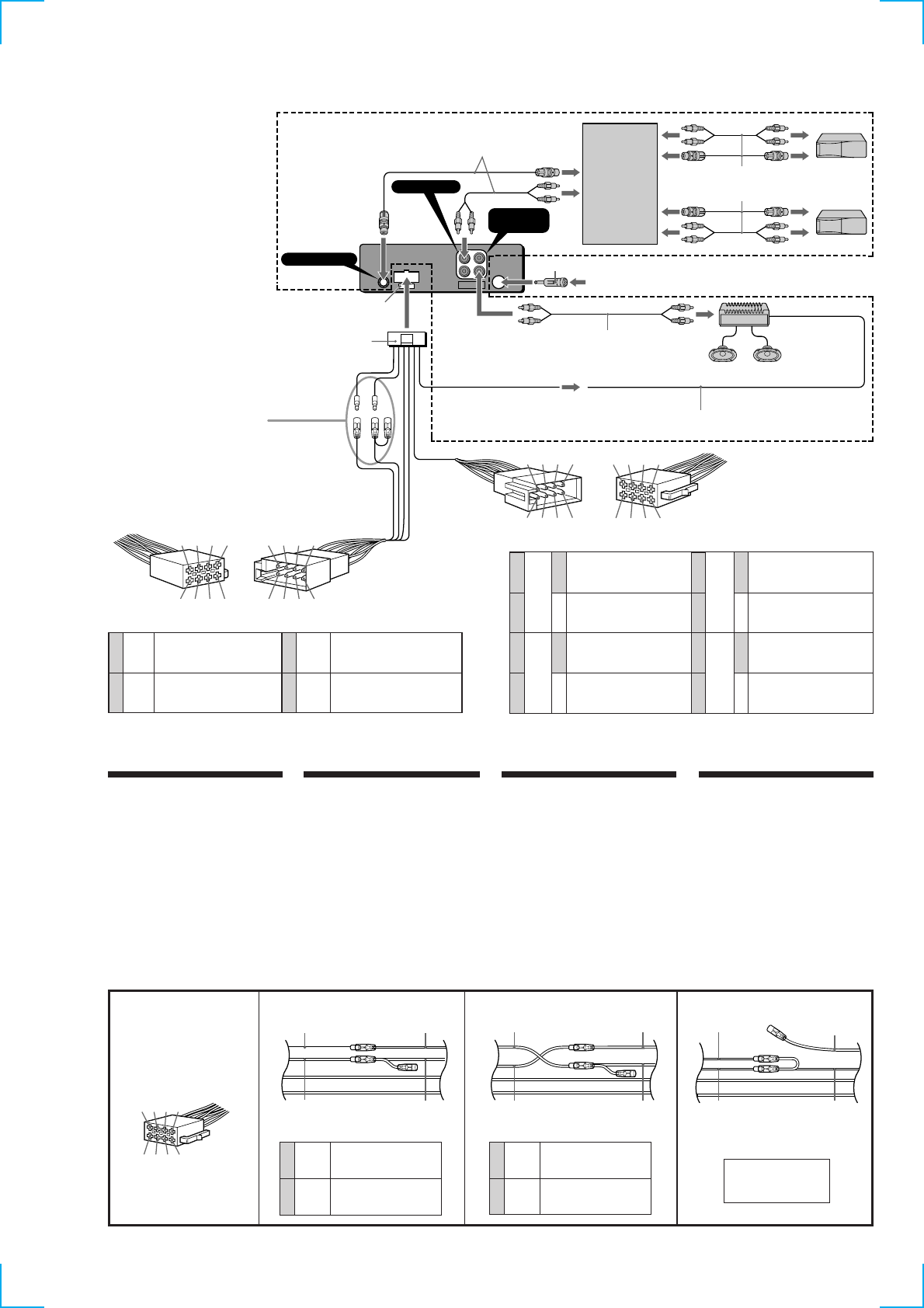
Connection example
Conexiones de ejemplo
Exempel på Kopplingsschema
Ligações de exemplo
from a car aerial
*
1
de la antena del automóvil
*
1
fran bilantenn
*
1
da antena do automóvel
*
1
Fuse (10A)
Fusible (10A)
Säkaring (10A)
Fusível (10A)
5
7
8
switched power supply
suministro de alimentación conmutado
switchad strömförsörjning
alimentação de corrente comutada
earth
toma de tierra
jord
Terra
4
5
Yellow
Amarillo
Gul
Amarelo
Blue
Azul
Blå
Azul
Red
Rojo
Röd
Vermelho
Black
Negro
Svart
Preto
continuous power supply
suministro de alimentación continua
kontinuerlig strömförsörjning
alimentação de corrente contínua
power aerial control
control de antena motorizada
elektrisk antenn
antena eléctrica
Negative polarity positions 2, 4, 6, and 8 have striped cords.
Las posiciones de polaridad negativa 2, 4, 6 y 8 tienen cables con raya.
As posições 2, 4, 6 e 8 (polaridade negativa) têm cabos às riscas.
De negativa polpositionerna 2, 4, 6 och 8 har randiga kablar.
1
2
3
4
Speaker, Rear, Right
Altavoz, trasero, derecho
Högtalare, bakre, höger
Altifalante, Parte de trás, Direito
Speaker, Rear, Right
Altavoz, trasero, derecho
Högtalare, bakre, höger
Altifalante, Parte de trás, Direito
Speaker, Front, Right
Altavoz, delantero, derecho
Högtalare, främre, höger
Altifalante, Parte da frente, Direito
Speaker, Front, Right
Altavoz, delantero, derecho
Högtalare, främre, höger
Altifalante, Parte da frente, Direito
5
6
7
8
Purple
Púrpura
Violett
Violeta
Grey
Gris
Grå
Cinzento
+
–
+
–
Positions 1, 2 ,3 and 6 do not have pins.
Las posiciones 1, 2 ,3 y 6 no disponen de pines.
As posições 1, 2, 3 e 6 não têm pinos.
Positionerna 1, 2, 3 och 6 saknar stift.
to a car‘s auxiliary power connector
a un conector de alimentación auxiliar del automóvil
till bilens yttre strömanslutning
a um conector de alimentação auxiliar do automóvel
Speaker, Front, Left
Altavoz, delantero, izquierdo
Högtalare, främre, vänster
Altifalante, Parte da frente, Esquerdo
Speaker, Front, Left
Altavoz, delantero, izquierdo
Högtalare, främre, vänster
Altifalante, Parte da frente, Esquerdo
Speaker, Rear, Left
Altavoz, trasero, izquierdo
Högtalare, bakre, vänster
Altifalante, Parte de trás, Esquerdo
Speaker, Rear, Left
Altavoz, trasero, izquierdo
Högtalare, bakre, vänster
Altifalante, Parte de trás, Esquerdo
Green
Verde
Grön
Verde
White
Blanco
Vit
Branco
+
–
+
–
to a car‘s speaker connector
a un conector de altavoces del automóvil
till bilens högtalaranslutning
a um conector de altifalante do automóvel
Power connection diagram
Auxiliary power connector may vary depending
on the car. Check your car’s auxiliary power
connector diagram to make sure the connections
match correctly. There are three basic types
(illustrated below). You may need to switch the
positions of the red and yellow leads in the car
stereo’s power connecting cord.
After matching the connections and switched
power supply leads correctly, connect the unit to
the car’s power supply. If you have any questions
and problems connecting your unit that are not
covered in this manual, please consult the car
dealer.
Diagrama de conexión de
alimentación
El conector de alimentación auxiliar puede variar
en función del automóvil. Compruebe el diagrama
del conector de alimentación auxiliar del
automóvil para asegurarse de que las conexiones
coinciden correctamente. Existen tres tipos
básicos, ilustrados a continuación. Es posible que
sea preciso cambiar las posiciones de los cables
rojo y amarillo del cable de conexión de
alimentación del sistema estéreo del automóvil.
Después de hacer coincidir correctamente las
conexiones y los cables de alimentación
conmutada, conecte la unidad al suministro de
alimentación del automóvil. Si desea realizar
alguna consulta o solucionar algún problema
referentes a la conexión de la unidad que no
aparezcan en este manual, consulte con el
concesionario automovilístico.
Strömanslutningsschema
Typen av yttre strömanslutning varierar från bil
till bil. Kontrollera schemat till strömanslutningen
så att du ansluter på rätt sätt. Det finns tre
grundläggande anslutningstyper (visas nedan).
Eventuellt kan du behöva byta plats på de röda
och gula ledarna i bilstereons
strömanslutningskabel.
Koppla kablarna för kontinuerlig respektive
switchad strömförsörjning på rätt sätt och anslut
sedan enheten till bilens strömanslutning. Om du
får problem eller har frågor som inte besvaras i
den här bruksanvisningen kan du kontakta
bilåterförsäljaren.
Diagrama de ligação de corrente
O conector auxiliar de corrente pode variar de
carro para carro. Verifique o diagrama do
conector auxiliar de corrente do seu automóvel
para se certificar de que as ligações estão bem
feitas. Existem três tipos de conectores (ilustrados
abaixo). Pode ter que mudar as posições dos fios
vermelho e amarelo do cabo de ligação da
alimentação do sistema estéreo do automóvel.
Depois de fazer a correspondência entre as
ligações e os fios de alimentação de corrente
comutada, ligue o aparelho à fonte de alimentação
do carro. Se tiver alguma dúvida ou problema
relacionado com o aparelho que não esteja
incluído neste manual, consulte o concessionário.
Auxiliary power connector
Conector de alimentación auxiliar
Yttre strömanslutning
Conector auxiliar de corrente
4
7
Yellow
Amarillo
Gul
Amarelo
Red
Rojo
Röd
Vermelho
continuous power supply
suministro de alimentación continua
kontinuerlig strömförsörjning
alimentação de corrente contínua
switched power supply
suministro de alimentación conmutado
switchad strömförsörjning
alimentação de corrente comutada
A
Red
Rojo
Röd
Vermelho
Red
Rojo
Röd
Vermelho
Yellow
Amarillo
Gul
Amarelo
Yellow
Amarillo
Gul
Amarelo
the car without ACC position
automóvil sin posición ACC
bil utan ACC-läge
o carro sem posição ACC
4
7
Yellow
Amarillo
Gul
Amarelo
Red
Rojo
Röd
Vermelho
switched power supply
suministro conmutado de alimentación
switchad strömförsörjning
alimentação de corrente comutada
continuous power supply
suministro de alimentación continua
kontinuerlig strömförsörjning
alimentação de corrente contínua
BC
Yellow
Amarillo
Gul
Amarelo
Red
Rojo
Röd
Vermelho
Red
Rojo
Röd
Vermelho
Yellow
Amarillo
Gul
Amarelo
Red
Rojo
Röd
Vermelho
Yellow
Amarillo
Gul
Amarelo
Red
Rojo
Röd
Vermelho
Yellow
Amarillo
Gul
Amarelo
7135
82
4
6
7
BUS AUDIO IN
AUDIO OUT
(LINE OUT)
BUS CONTROL IN
Source selector
Selector de fuente
Väljare för ljudkälla
Selector de fonte
Supplied with the CD/MD changer
Suministrado con el cambiador CD/MD
Medföljer CD/MD-växlaren
Fornecido com o permutador de CD/MD
Supplied with the XA-C30
Suministrado con el XA-C30
Medföljer XA-C30
Fornecido com o XA-C30
RCA pin cord (not supplied)
Cable con clavijas RCA (no suministrado)
Kabel med RCA-kontakter (medföljer inte)
Cabo de terminais RCA (não fornecido)
XR-C2300R only
Sólo para XR-C2300R
endast XR-C2300R
Apenas para o modelo XR-C2300R
AMP REM
Max. supply current 0.3 A
Corriente máx. de alimentación de 0,3 A
Maximal strömtillförsel 0,3 A
Corrente máxima de alimentação de 0,3 A
Blue/white striped
Con raya azul/blanca
Blå/vit-randig
Com riscas azuis/brancas
See ”Power connection diagram” for details.
Para obtener información detallada, consulte
“Diagrama de conexión de alimentación”.
Se “Strömanslutningsschema”, där finns mer
information.
Para mais informaçoes, consulte o “Diagrama de
ligaçao de corrente”.
*
2
8
Caution
Cautionary notice for handling the bracket 1.
Handle the bracket carefully to avoid injuring your fingers.
Precaución
Advertencia sobre la manipulación del soporte 1.
Tenga mucho cuidado al manipular el soporte para evitar posibles
lesiones en los dedos.
Varning
Att observera angående konsolen 1.
Hantera konsolen med största aktsamhet så att du inte skadar
fingrarna.
Cuidado
Aviso sobre as precauções a tomar no manuseamento do suporte 1.
Pegue no suporte com cuidado para não magoar os dedos.
Nollställningsknappen
Kom ihåg att använda en penna eller något
annat spetsigt föremål för att trycka på
nollställningsknappen när anslutningen och
monteringen är klar.
Botão de reinicialização
Quando terminar a instalação e as ligações, não
se esqueça de carregar no botão de
reinicialização com a ponta de uma caneta, etc.
Reset button
When the installation and connections are
complete, be sure to press the reset button with
a ballpoint pen, etc.
Botón de reposición
Cuando finalice la instalación y las conexiones,
cerciórese de presionar el botón de reposición
con un bolígrafo, etc.
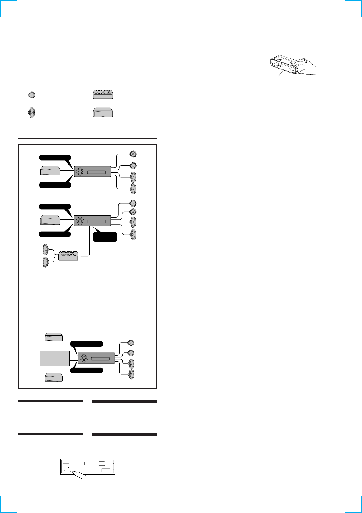
Conection diagram (XR-C2300R only)
Diagrama de conexiones (sólo para XR-C2300R)
Kopplingsschema (endast XR-C2300R)
Diagrama de ligações (Apenas para o modelo XR-C2300R)
Equipment used in illustrations (not supplied)
Equipo utilizado en las ilustraciones (no suministrado)
Utrustning som visas i illustrationer (medföljer inte)
Equipamento utilizado nas ilustrações (não fornecido)
CD/MD changer
Cambiador de CD/MD
CD/MD-skivväxlare
Permutador CD/MD
Power amplifier
Amplificador de potencia
Effektförstärkare
Amplificador de potência
Front speaker
Altavoz delantero
Främre högtalare
Altifalante dianteiro
Rear speaker
Altavoz trasero
Bakre högtalare
Altifalante traseiro
For connecting two or more changers, the source selector XA-C30 (optional) is necessary.
Si desea conectar dos o más cambiadores, necesitará el selector de fuente XA-C30 (opcional).
För anslutning av två eller flera växlare krävs väljaren XA-C30 (tillval).
Para ligar dois ou mais permutadores, é necessário o selector de fonte XA-C30 (opcional).
B
A
C
Notes
• Be sure to connect the earth cord before connecting the amplifier.
• If you connect an optional power amplifier and do not use the built-in amplifier, the beep sound will be
deactivated.
Notas
• Asegúrese de conectar primero el cable de puesta a masa antes de realizar la conexión al amplificador.
• Si conecta un amplificador de potencia opcional y no utiliza el incorporado, los pitidos se desactivarán.
Obsevera
• Var noga med att först ansluta jorden, innan du ansluter förstärkaren.
• Om du väljer att använda en annan förstärkare i stället för den inbyggda, kommer ljudsignalen att
avaktiveras.
Notas
• Antes de fazer a ligação ao amplificador tem de ligar primeiro o cabo de ligação à terra.
• Se ligar um amplificador de potência opcional e não utilizar o amplificador integrado, desactiva o sinal
sonoro.
BUS AUDIO IN
BUS CONTROL IN
BUS AUDIO IN
BUS CONTROL IN AUDIO OUT
(LINE OUT)
BUS AUDIO IN
BUS CONTROL IN
Source selector
Selector de fuente
Väljare för ljudkälla
Selector de fonte
1
9
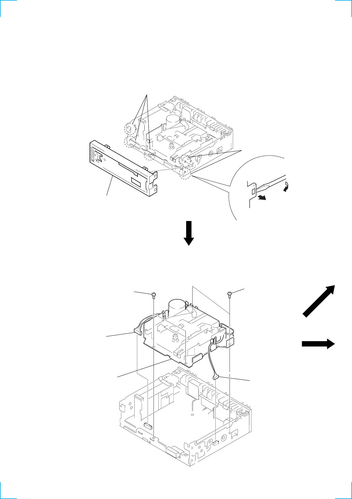
SUB PANEL
MECHANISM DECK (MG-36SZ10-32)
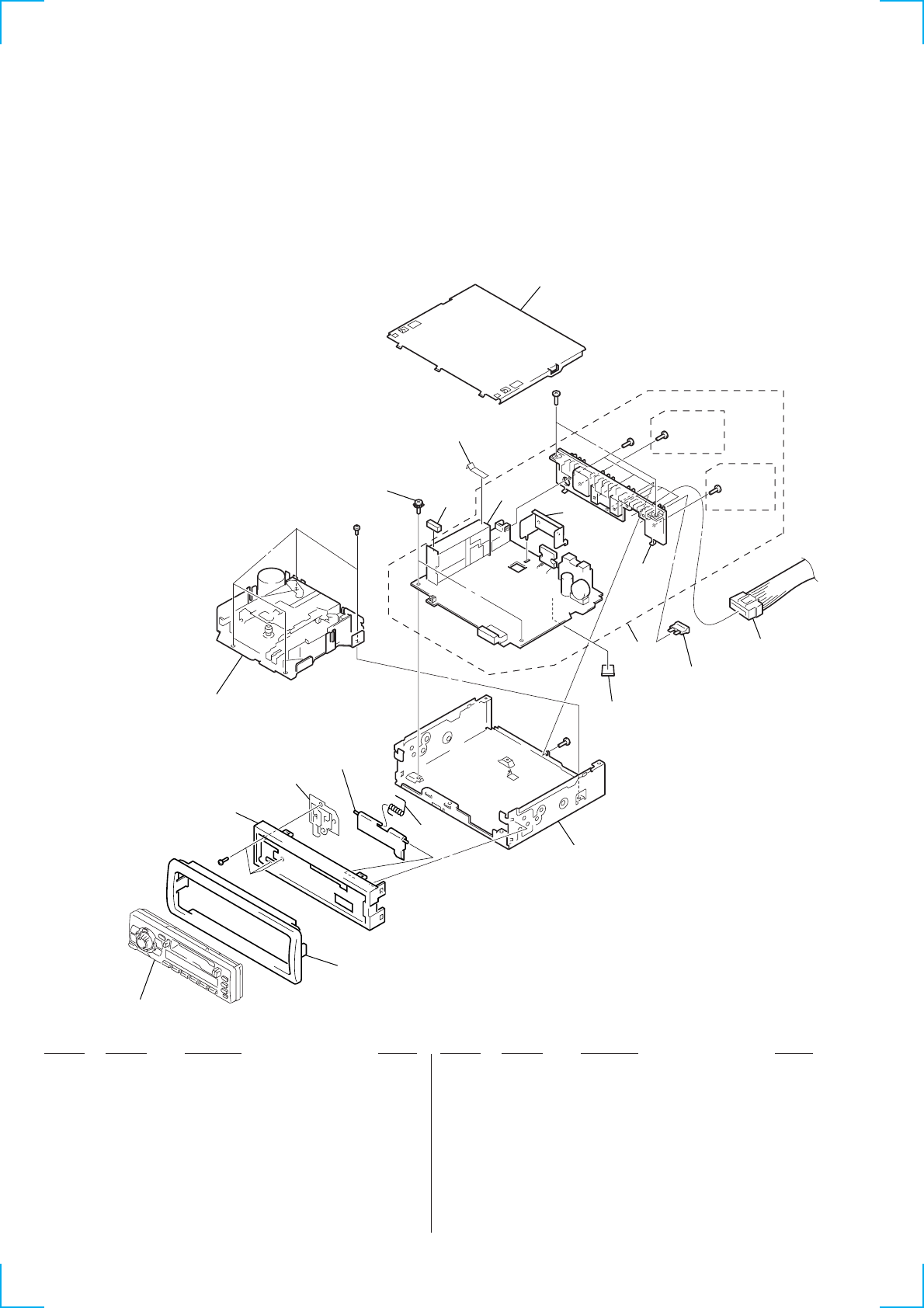
Note: Follow the disassembly procedure in the numerical order given.
SECTION 2
DISASSEMBLY
1
three claws
1
two claws
2
sub panel
2
two screws
(PTT2.6
×
6)
1
connector
(CN350)
1
connecto
r
(CN300)
3
mechanism deck
(MG-36SZ10-32)
2
two screws
(PTT2.6
×
6)
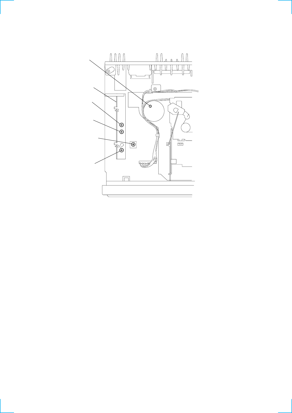
10
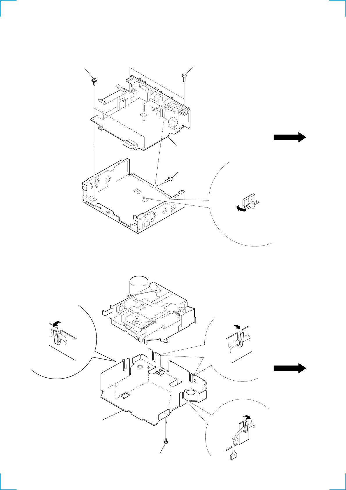
MAIN BOARD
BRACKET (MD)
2
two ground point screws
3
two screws
(PTT2.6
×
6)
3
screw
(PTT2.6
×
6)
4
main board
1
claw
1
claw
1
claw
1
claw
2
four screws
(B2.6
×
4)
3
bracket (MD)
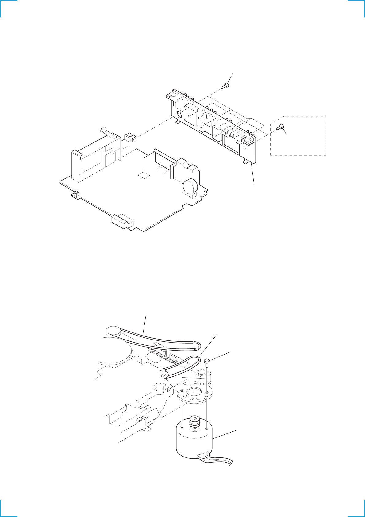
11
MOTOR ASS’Y (CAPSTAN/REEL) (M901)
HEAT SINK
1
five screws
(PTT2.6
×
10)
1
two screws
(PTT2.6
×
10)
(XR-C2300R)
2
heat sink
1
two screws
(P2
×
2.5)
4
motor ass’y (capstan/reel)
(M901)
3
belt
2
belt
Note : When installing motor,
adjust the screw and
screw hole of motor.
12
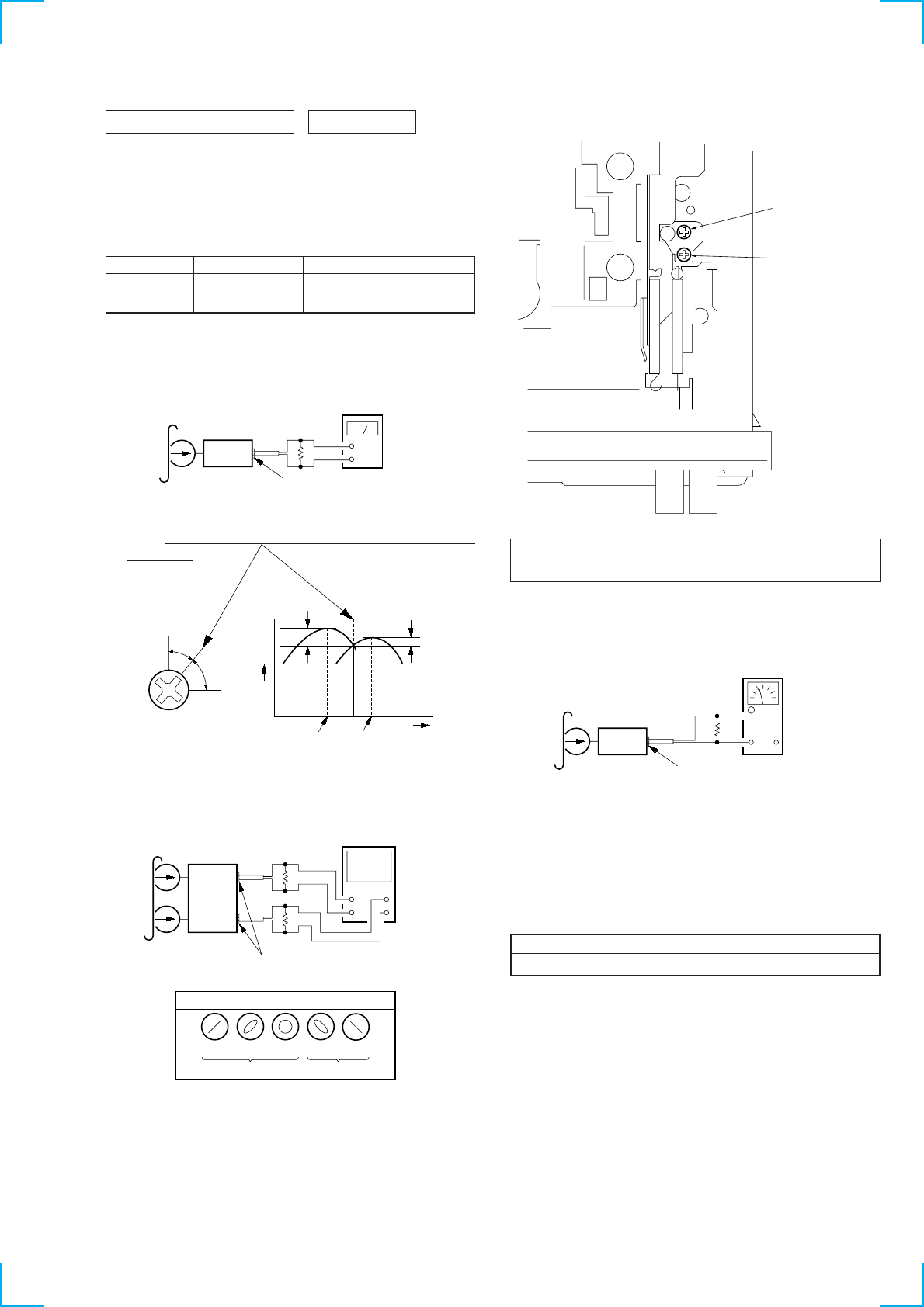
SECTION 3
MECHANICAL ADJUSTMENTS SECTION 4
ELECTRICAL ADJUSTMENTS
Mode Tension Meter Meter Reading
Forward CQ-403A more than 5.89 mN•m
(more than 60 g)
Reverse CQ-403R (more than 2.12 oz)
• Tape Tension Measurement
1. Clean the following parts with a denatured-alcohol-moistened
swab:
playback head pinch roller
rubber belt capstan
idler
2. Demagnetize the playback head with a head demagnetizer.
3. Do not use a magnetized screwdriver for the adjustments.
4. The adjustments should be performed with the power supply
voltage (14.4 V) unless otherwise noted.
• Torque Measurement
Mode Torque Meter Meter Reading
2.46 – 5.39 mN•m
Forward CQ-102C (25 – 55 g•cm)
(0.35 – 0.76 oz•inch)
Forward 0.15 – 0.39 mN•m
CQ-102C (1.5 – 4 g•cm)
Back Tension (0.02 – 0.06 oz•inch)
2.46 – 5.39 mN•m
Reverse CQ-102RC (25 – 55 g•cm)
(0.35 – 0.76 oz•inch)
Reverse 0.15– 0.39 mN•m
CQ-102RC (1.5 – 4 g•cm)
Back Tension (0.02 – 0.06 oz•inch)
4.91 – 14.70 mN•m
FF, REW CQ-201B (50 – 150 g•cm)
(0.69 – 2.08 oz•inch)
TEST MODE
This set have the test mode function. In the test mode, FM Auto
Seek/Stop Level, FM RDS S-Meter adjustments and MW Auto
Seek/Stop Level check can be performed easier than it in ordinary
procedure.
<Set the Test Mode>
1. Turn ON the regulated power supply. (All LEDs on the set
lights up, and the clock is displayed.)
Note: Press the [OFF] button, if the clock is not displayed.
2. Push the preset [4] button.
3. Push the preset [5] button.
4. Press the preset [1] button for more than two seconds.
5. Then the display indicates all lights, the test mode is set.
<Release the Test mode>
1. Push the [OFF] button.
13
TAPE DECK SECTION 0 dB= 0.775 V
1. The adjustments should be performed in the order given in
this service manual.
2. The adjustments should be performed for both L-CH and
R-CH.
Test Tape
PB Head Azimuth Adjustment
Procedure:
1. Put the set into the FWD PB mode.
2. Turn the screw and check the output peak value. Adjust the
screw so that the peak value in channels L and R coincides
within 2 dB.
3. Check the phase in the FWD PB mode.
4. Repeat the above adjustment for the REV PB mode.
5. Check that output level difference between FWD PB mode
and REV PB mode is within 4 dB.
Type Signal Used for
P-4-A063 6.3 kHz, –10 dB head azimuth adjustment
WS-48A 3 kHz, 0 dB tape speed adjustment
Adjustment Location: PB head
Tape Speed Adjustment
Setting:
Procedure:
1. Put the set into the FWD PB mode.
2. Adjust adjustment resistor for inside capstan motor so that the
reading on the speed checker or frequency counter becomes in
specification.
Specification: Constant speed
Adjustment Location: See page 16.
See the adjustment location from on page 16 for the ad-
justment.
Speed checker Frequency counter
–2 to +3% 2,940 to 3,090 Hz
level
meter
test tape
P-4-A063
(6.3 kHz, –10 dB)
set
speaker out terminal (1300R) or
AUDIO OUT jack (CN400) (C2300R)
4
Ω
+
–
screw
position
L-CH
peak
within
2 dB
output
level
L-CH
peak R-CH
peak
within
2 dB
angl
e
R-CH
peak
test tape
P-4-A063
(6.3 kHz, –10 dB)
L-CH
R-CH
speaker out terminal (1300R) or
AUDIO OUT jack (CN400) (C2300R)
oscilloscope
VH
++
––
Screen pattern
in phase
good wrong
45
°
90
°
135
°
180
°
4
Ω
4
Ω
set
FWD
REV
adjustment
screws
+–
speed checker
or
frequency counter
test tape
WS-48A
(3 kHz, 0 dB)
speaker out terminal (1300R) or
AUDIO OUT jack (CN400) (C2300R)
set
4
Ω
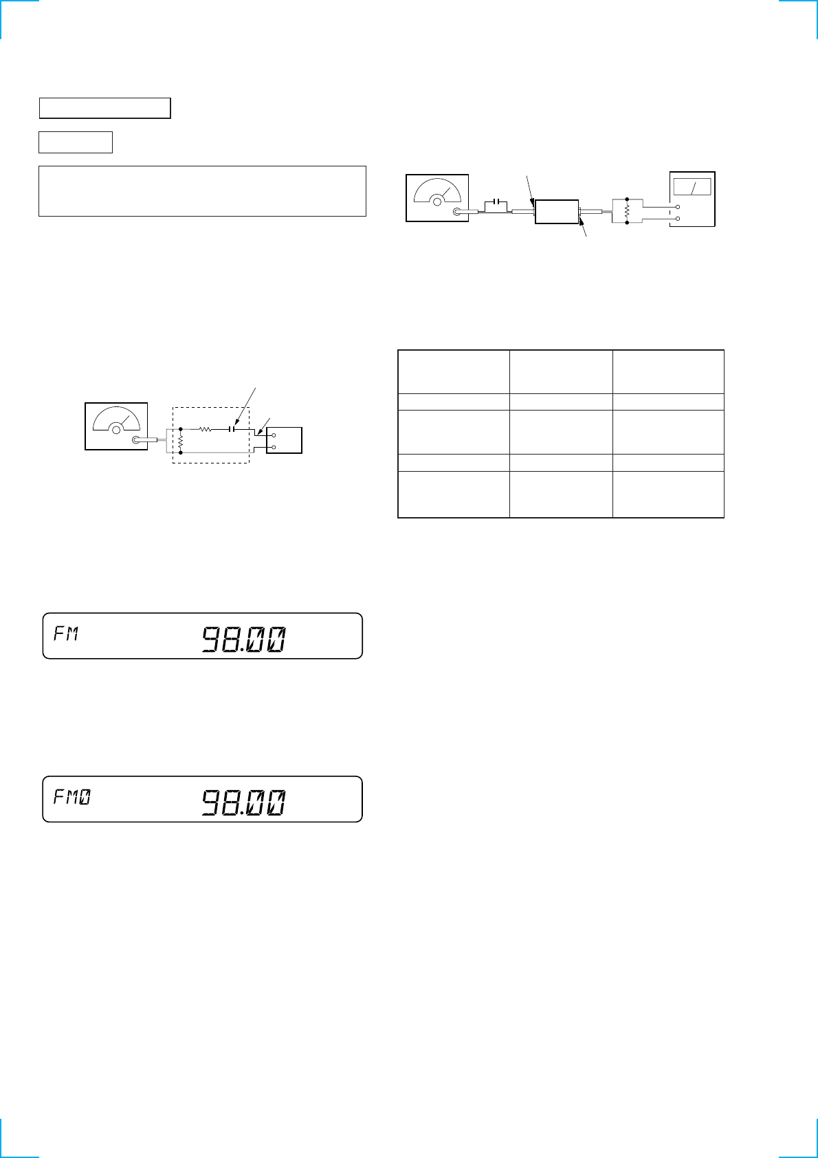
14
TUNER SECTION
0 dB=1 µV
Cautions during repair
When the tuner unit is defective, replace it by a new one be-
cause its internal block is difficult to repair.
Note: Adjust the tuner section in the sequence shown below.
1. FM Auto Seek/Stop Level Adjustment
2. FM Stereo Separation Adjustment
3. FM RDS S-Meter Adjustment
4. MW Auto Seek/Stop Level Adjustment
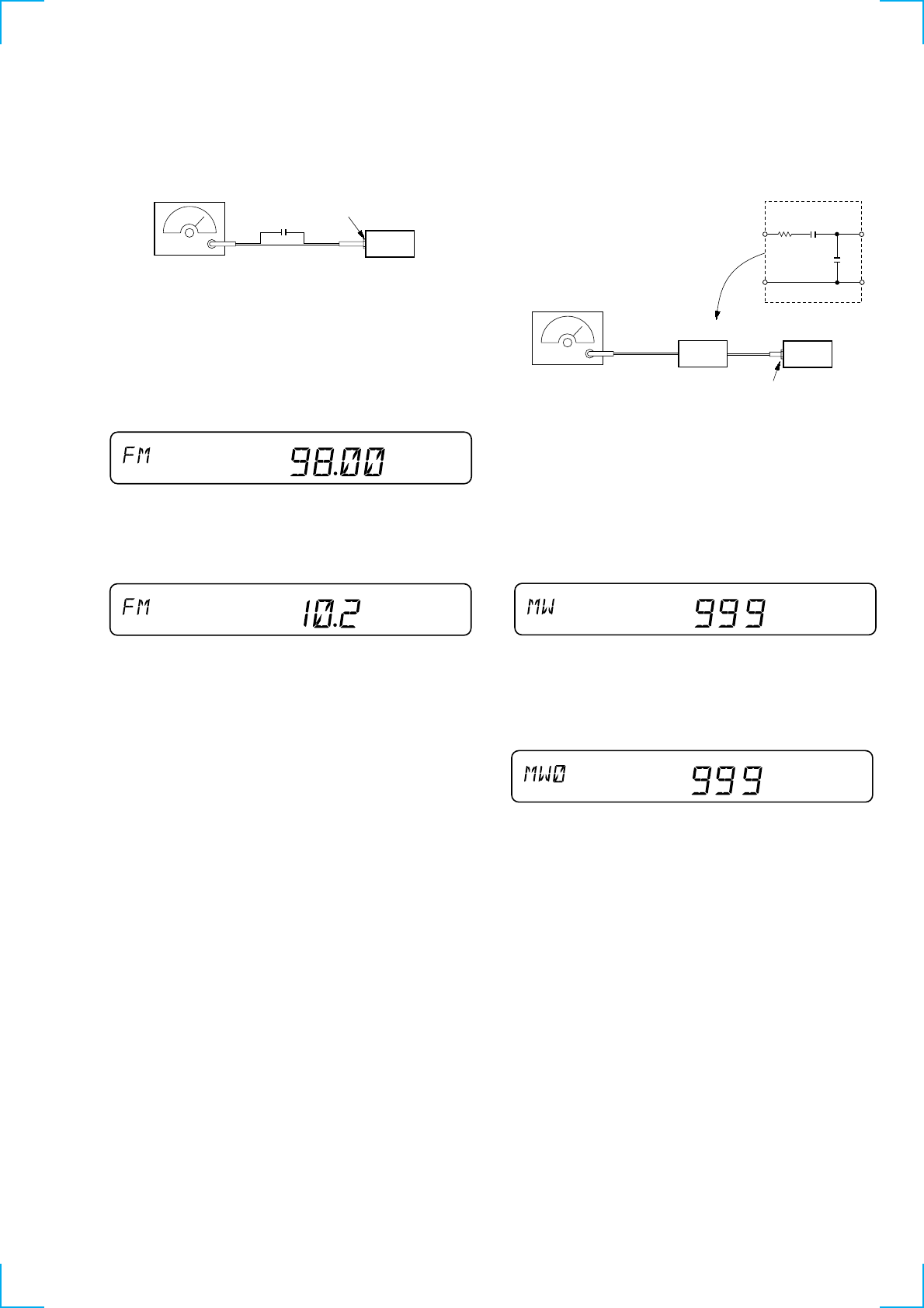
FM Auto Seek/Stop Level Adjustment
Setting:
[TUNER] (1300R) or [SOURCE] (C2300R) button: FM
Procedure:
1. Set to the test mode. (See page 12)
2. Push the [TUNER] (1300R) or [SOURCE] (C2300R) button
and set to FM. Display
3. Adjust with the volume RV2 on TU100 so that the “FM” indi-
cation turns to “FM0” indication on the display window.
But, in case of already indicated “FM0”, turn the RV2 so that
put out light “0” indication and adjustment.
Display
Adjustment Location: See page 16.
FM RF signal
generator dummy
antenna
Carrier frequency : 98.0 MHz
Output level : 22 dB (12.6
µ
V)
Mode : mono
Modulation : 1 kHz, 22.5 kHz deviation (30%
)
antenna
jack (CN100
)
set
50
Ω
50
Ω
0.1pF
SHUF
SHUF
FM Stereo Separation Adjustment
Setting:
[TUNER] (1300R) or [SOURCE] (C2300R) button: FM
Procedure:
L-CH Stereo separation: A-B
R-CH Stereo separation: C-D
The separations of both channels should be equal.
Specification: Separation more than 30 dB
Adjustment Location: See page 16.
FM Stereo Level meter Level meter
signal generator connection reading (dB)
output channel
L-CH L-CH A
B
R-CH L-CH Adjust RV4 on TU100
for minimum reading.
R-CH R-CH C
D
L-CH R-CH Adjust RV4 on TU100
for minimum reading.
FM RF signal
generator
Carrier frequency : 98.0 MHz
Output level : 70 dB (3.2 mV)
Mode : stereo
Modulation : main: 1 kHz, 20 kHz deviation (26.7%)
sub: 1 kHz, 20 kHz deviation (26.7%)
: 19 kHz pilot: 7.5 kHz deviation (10%)
0.01
µ
F
set
antenna jack (CN100)
+
–
speaker out terminal (1300R) or
AUDIO OUT jack (CN400) (C2300R)
level meter
10 k
Ω
15
MW Auto Seek/Stop Level Adjustmant
Make this adjustment after “FM Auto Seek/Stop Level Adjust-
ment”.
Setting:
[TUNER] (1300R) or [SOURCE] (C2300R) button: MW
Procedure:
1. Set to the test mode. (See page 12)
2. Push the [TUNER] (1300R) or [SOURCE] (C2300R) button
and set to FM.
3. Push the [MODE] button and set to MW.
Display
4. Adjust with the volume RV1 on TU100 so that the “MW” in-
dication turns to “MW0” indication on the display window.
But, in case of already indicated “MW0”, turn the RV1 so that
put out light “0” indication and adjustment.
Display
Adjustment Location: See page 16.
FM RDS S-Meter Adjustment
Setting:
[TUNER] (1300R) or [SOURCE] (C2300R) button: FM
Procedure:
1. Set to the test mode. (See page 12)
2. Push the [TUNER] (1300R) or [SOURCE] (C2300R) button
and set to FM.
Display
3. Push the [6] button.
4. Adjust VR100 on main board so that the display indication is
“10.2”. Display
Specification: Display indication: 10.0 to 10.4
Adjustment Location: See page 16.
TP SHUF
FM RF signal
generator
Carrier frequency : 98.00 MHz
Output level : 35 dB (56.2
µ
V)
Mode : mono
Modulation : no modulation
0.01
µ
F
set
antenna jack (CN100)
SHUF
SHUF
AM RF signal
generator
Carrier frequency : 999 kHz
30% amplitude
modulation by
1 kHz signal
Output level : 33 dB (44.7
µ
V)
(50
Ω
)set
AM dummy antenna
30
Ω
15 pF
65 pF
antenna jack (CN100)
TP SHUF
16
Adjustment Location:
CN901
TU100
RV2 FM Auto Seek/Stop Level Adjustment
RV1 MW Auto Seek/Stop Level Adjustment
Tape Speed Adjustment
VR100 FM RDS S-Meter Adjustment
RV4 FM Stereo Separation Adjustment
1717
SECTION 5
DIAGRAMS
5-1. NOTE FOR PRINTED WIRING BOARDS AND SCHEMATIC DIAGRAMS
Note on Printed Wiring Board:
•X: parts extracted from the component side.
•Y: parts extracted from the conductor side.
•b: Pattern from the side which enables seeing.
(The other layers' patterns are not indicated.)
Caution:
Pattern face side: Parts on the pattern face side seen from
(Conductor Side) the pattern face are indicated.
Parts face side: Parts on the parts face side seen from
(Component Side) the parts face are indicated.
Note on Schematic Diagram:
• All capacitors are in µF unless otherwise noted. pF: µµF
50 WV or less are not indicated except for electrolytics
and tantalums.
• All resistors are in Ω and 1/4 W or less unless otherwise
specified.
•f: internal component.
•C: panel designation.
•U: B+ Line.
•H: adjustment for repair.
• Power voltage is dc 14.4V and fed with regulated dc power
supply from ACC and BATT cords.
• Voltages and waveforms are dc with respect to ground
under no-signal (detuned) conditions.
no mark : FM
( ) : MW(LW)
〈〈 〉〉 : TAPE PLAYBACK
• Voltages are taken with a VOM (Input impedance 10 MΩ).
Voltage variations may be noted due to normal produc-
tion tolerances.
• Waveforms are taken with a oscilloscope.
Voltage variations may be noted due to normal produc-
tion tolerances.
• Circled numbers refer to waveforms.
• Signal path.
F: FM
f: MW(LW)
L: BUS AUDIO IN
E: TAPE PLAYBACK
• Abbreviation
AMBER : Amber illumination type
GREEN : Green illumination type
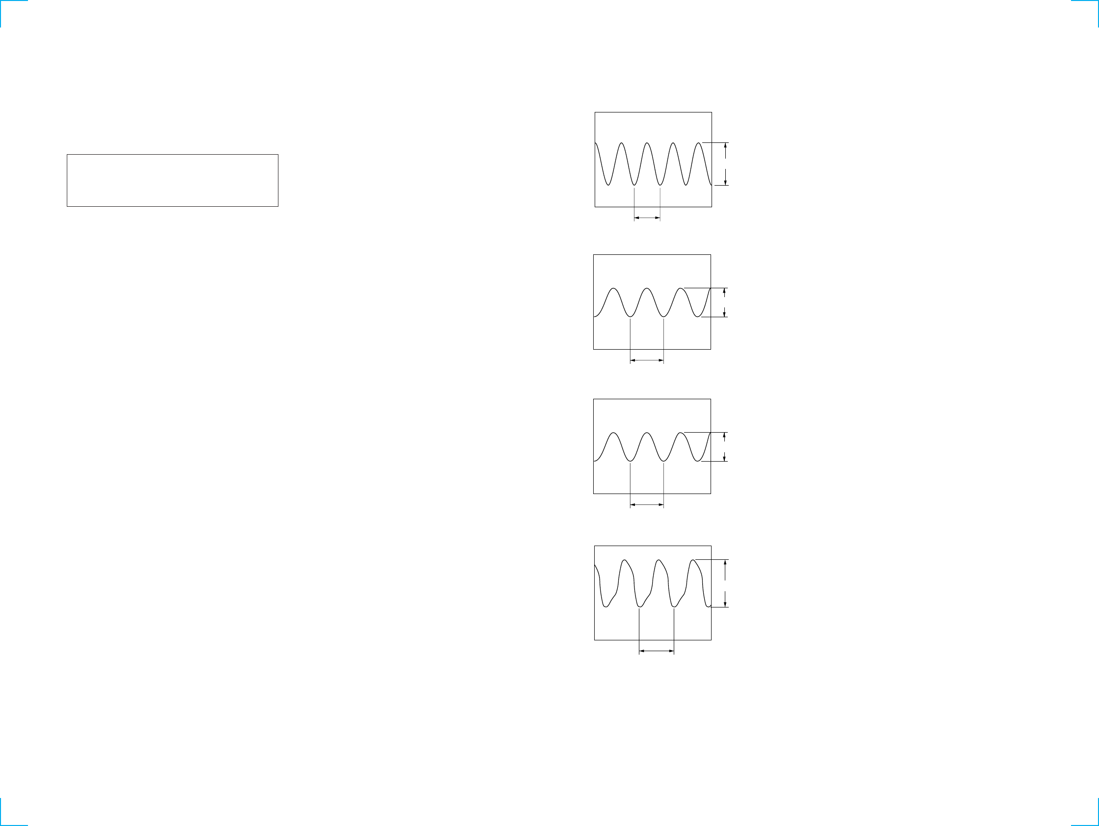
• Waveforms
– MAIN Board –
1IC130 2 (OSCOUT) (MW/LW)
2IC200 5 (OSCI)
3IC1 uf (X0A)
4IC1 od (X1)
820 mVp-p
98 ns
2.4 Vp-p
231 ns
3.6 Vp-p
30.5
µ
s
5.7 Vp-p
272 ns
1818
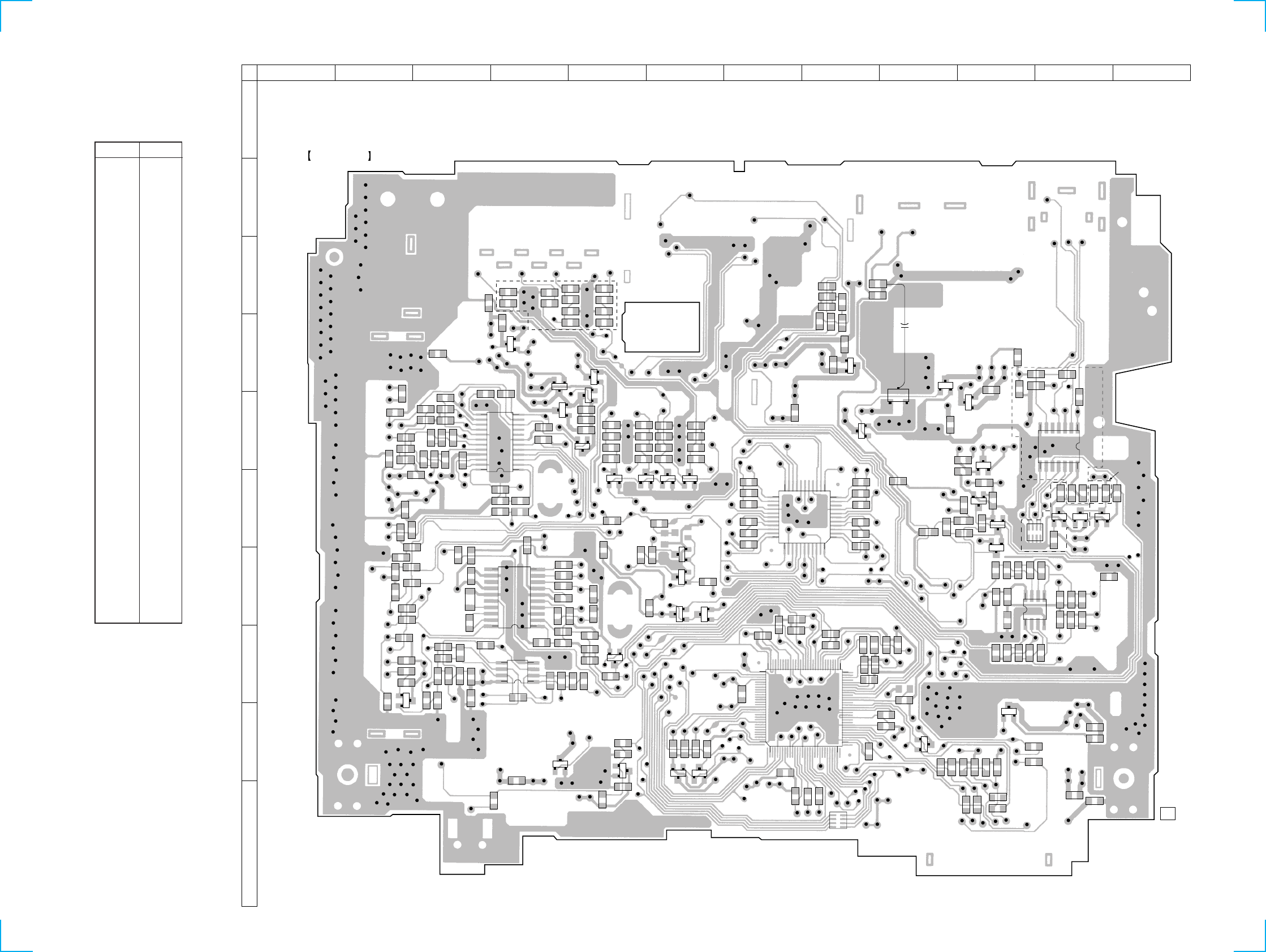
XR-1300R/C2300R
C721
C135
C144
C145
R102
R101
C101
C100
R100
C147
R136
C137
C136
C103
R137
C139
R138
C140
R140
C105
C107
R150
C109
R106
R207
C152
C151
R163
C161
C160
C210
R162
R105
C206
C207 C208
R103
R104
C221
C214
C213
R209
C212
R210
C215
R208
R216
C108
R217
C216
C209
ECB
Q200
C217
1
4
8
5
IC201
R211 R200
R213
1
10
20
11
IC200
R203
R139
C131
C132
C130
C148
1
12
24
13
IC130
C134 R135
C133
R134
C429
R415
C720
R721
Q102
BCE
C428
R414
C437
R417
R419
C435
C436
R416
R418
C434
BCE
BCE
BCE
Q105
Q101
Q106
Q104
R109
R110 C420
R410
R406
R402
ECB
Q103
Q400
BCE
R151
R166
R206
R205
R204
C204
C201
C205C202
C203
R202
C201
C200
R215
C220
C214
R212
C218
C219
R719
R720
Q710
BCE
R25
R19
C10
C12
R3
R2
3
2
1
IC2
ECB
Q201
R165
Q162
BCE
Q161
BCE
Q160
BCE
R161
R160
R153
Q401
BCE
Q403
BCE
R403
R407
R411
R405
R409
R413
C421 C423
R404
R408
R412
C422
Q402
BCE C412
C410
R400
C406
C404
C402
R164
Q163
BCE
R1
R15
ECB
Q2 Q1
BCE
R18
R4
R5
C3
RN1
C4
C1
IC1
R17
R16
C8
C9
IC400
R707
R709
R502
R500
R501
C512
C511 C707
R622
C513R502
R706
ECB
Q705
Q706
BCE
C413 R621
C411
R401
C407
C405
C403
R14
R13
R12
R11
R21
R22
R9
C7
R20
R7
C6
C5
R615
R616
R610
R609
R612
R611
AK
D614
R619
C608
AK
D617
R625
C711
R703
C708
Q702
BCE
Q700
E
C
B
C701
C801
R701
C802
R803
Q701
BCE
Q712
BCE
R605
R606
C607
ECB
Q605
SDG
Q601
ECB
Q600
RN800
R308
C306
R306
R304
C302
C311
R310R311
14
85
IC300
R309
C307
R307
R305
C303
Q708
BCE
C610
C609
R6
R617
R613
R614
R715
C718
C717
R714
R303
R301
R302
R300
C300
C301
C308
R602
R801
C800
R800
R608
R607
C603
Q602
BCE
Q603
BCE
Q604
BCE
1
7
148
IC800
R804
R802
A
K
AD1
MAIN BOARD (COMPONENT SIDE)
1-676-260- 11
05
1 2 3 4 5 6 7 8 9 10 11 12
A
B
C
D
E
F
G
H
I
J
(C2300R)
ECB
1
11
12
22
23
33
34 44
6190
91
120
130
31
60
(1300R)
(C2300R)
(1300R)
R111
C715
+
5-2. PRINTED WIRING BOARD – MAIN Board (Component Side) –
• Semiconductor
Location
Ref. No. Location
D1 I-9
D614 F-9
D617 F-10
IC1 I-7
IC2 I-5
IC130 E-4
IC200 G-4
IC201 H-4
IC300 G-10
IC400 F-8
IC800 E-11
Q1 I-6
Q2 I-6
Q101 D-5
Q102 D-4
Q103 E-5
Q104 E-4
Q105 D-4
Q106 E-5
Q160 G-6
Q161 G-6
Q162 G-6
Q163 G-6
Q200 H-2
Q201 H-5
Q400 F-5
Q401 F-5
Q402 F-6
Q403 F-6
Q600 G-10
Q601 F-10
Q602 F-11
Q603 F-11
Q604 F-11
Q605 F-10
Q700 E-9
Q701 E-10
Q702 D-9
Q705 D-8
Q706 E-8
Q708 I-10
Q710 I-4
Q712 E-10
1919
XR-1300R/C2300R
C803
+
CN800
1
2
3
4
5
6
7
8
L700
D700
D801
D802
D800
D605
D602
CN300
1
3
C309
+
C305
+
C722
+
R717
Q707
1
2
11
12
CN600
R716
D610
D611
D612
D613
D608
D609
D607
D606
C304
+
C310
+
D400
D300
R312
D616
R420
C401
+
C409
+
C601
+
D600
D615
D603
C712
+
Q711
D706
D707
D804
D803
1
2
15
16
TH800
C700
+
D704
R702
D703
D705
R700
X2
C431
+
C415
+
C430
+
R708
R711
R713
R710
R712
C716
+
C509
+
D507
D506 D505
D504
D503
D502
Q704
C414
+
C418
+
+
C419
IC500
1
2
25
24
D501
D500
R705 C426
+
C427
+
C425
+
C424
+
+
C408
+
C164
+
C165
+
C400
+
C417
+
C166
X1
D160
C2
+
L1
D202
D201
D200
Q709
C714
+
R718
D709
X201
C163
+
C162
+
C416
+
C222
+
X100
D102
D103
C510
+
C508
+
Q703
D710
C719
+
C143
+
L102
C141
+
C142
+
C104
+
C102
+
C106
+
L103
C211
+
VR100
D203
D713
C11
+
S2
(RESET)
TU100
(FM/AM TUNER UNIT)
CN100
(FM/AM ANTENNA)
CN700
(POWER)
D708
D702
C713
+
C605
+
C709
+
18
CN350
54
87
6
2 13
(FRONT VIEW)
(FOR SONY BUS)
BUS CONTROL IN
CN800 L RL R
AUDIO OUT
(LINE OUT)
BUS AUIDO IN
CN400
HP901
PLAYBACK
HEAD
A
KEY BOARD
CN901
(CHASSIS) (CHASSIS)
MAIN BOARD
(CONDUCTOR SIDE)
1-676-260-
11
F901
18
17
19
05
1 2 3 4 5 6 7 8 9 10 11 12 13
A
B
C
D
E
F
G
H
I
J
18
M901
(CAPSTAN/REEL)
M
RED
BLU
S901
(DIRECTION)
REV
m
FWD
BRN
BRN
ORG
ORG
S902
(FF/REW)
(OFF : PLAYBACK)
S903
(TAPE DETECT)
(ON : TAPE IN)
YEL
YEL
9 10 11 12 13 14 15 16
1 2 3 4 5 6 7 8
RL–
FL–
FR–
RL–
FR–
BATT
GND
BATT
RR–
RL–
FL–
RL+
FL+
FR+
RR+
FL+
RL+
RR+
FR+
ANT REM
ACC
ACC
ANT REM
GND
C710
+
(C2300R)
(1300R)
(C2300R)
1
13
15
22
TO
CN350
5-3. PRINTED WIRING BOARD – MAIN Board (Conductor Side) –
• Semiconductor
Location
Ref. No. Location
D102 D-9
D103 D-9
D160 G-7
D200 I-8
D201 I-8
D202 I-8
D203 I-10
D300 G-4
D400 G-4
D500 C-7
D501 C-7
D502 C-7
D503 C-6
D504 C-6
D505 C-6
D506 C-6
D507 C-6
D600 F-4
D602 F-2
D603 E-4
D605 F-2
D606 J-4
D607 J-4
D608 J-4
D609 J-4
D610 I-3
D611 J-3
D612 J-3
D613 J-3
D615 E-4
D616 F-4
D700 D-2
D702 C-5
D703 D-4
D704 D-3
D705 D-4
D706 E-3
D707 E-3
D708 C-5
D709 I-10
D710 D-10
D713 J-11
D800 E-3
D801 E-2
D802 E-2
D803 D-3
D804 D-3
IC500 B-7
Q703 D-10
Q704 E-6
Q707 I-2
Q709 I-9
Q711 E-3
(Page 22)
2020
XR-1300R/C2300R
5-4. SCHEMATIC DIAGRAM – MAIN Board (1/2) – • See page 17 for Waveforms. • See page 24 for IC Block Diagrams.
2121
XR-1300R/C2300R
5-5. SCHEMATIC DIAGRAM – MAIN Board (2/2) – • See page 24 for IC Block Diagrams.
(Page
23)
2222
XR-1300R/C2300R
D904 D905
D908
D903
D906
D907
LCD900
LIQUID CRYSTAL DISPLAY
CONTROL BOARD
(COMPONENT SIDE)
1-676-261-
11
(11)
R912
R913
R914
R915
R931
R930
R938
R939
R911
R908
A
K
K
A
D900
D901
R916
R917
R918
K
A
D902
R906
R907
C901
C902
C903
C904
R909
R910
C900
K
A
D910
R933
R932
R935
R934
R904
R903
R937
R936
R928
R929
R927
R926
R924
R925
R919
R920
R921
R922
R923
1
IC900
1
2
11
12
CN901
MAIN BOARD
CN600
CONTROL BOARD
(CONDUCTOR SIDE)
1-676-261-
11
(11)
A
1 2 3 4 5 6 7 8 9 10 11 12
A
B
C
D
E
F
G
05
S920
MENU
S919
SOUND
S918
–
.
m
S914
+
>
M
SEEK/AMS
S916
S918 S914
S913
PTY
DISPL
S912
MODE
S911
ENTER
S917
S915
S910
REP
1
1
S909
SHUF
2
S902
3
S903
4
S904
5
S905
6
S901
OFF
S907
AF
S908
TA
S906
D-BASS
3
2
1
PL901
(LCD BACK LIGHT)
PL900
(LCD BACK LIGHT)
S900
VOLUME/BASS/TREBLE/
BALANCE/FADER CONTROL
(C2300R)
S918
SEEK–
S914
SEEK+ (1300R)
DISC
PRST
–
S915
+
S917
PRST–
S915
PRST+
S917
(C2300R)(C1300R)
(C2300R) (C2300R)
(1300R)
1
(1300R)
52
1
D904, 905, S916
SOURCE
TUNER
(C2300R)
(1300R)
D903, 906-908
(ILLUMINATION)
16
17
32 33
48
49
64
5-6. PRINTED WIRING BOARD – CONTROL Board –
• Semiconductor
Location
Ref. No. Location
D900 F-11
D901 F-11
D902 F-10
D903 C-3
D904 B-3
D905 B-3
D906 C-4
D907 A-4
D908 A-3
D910 E-4
IC900 E-8
(Page 19)
2323
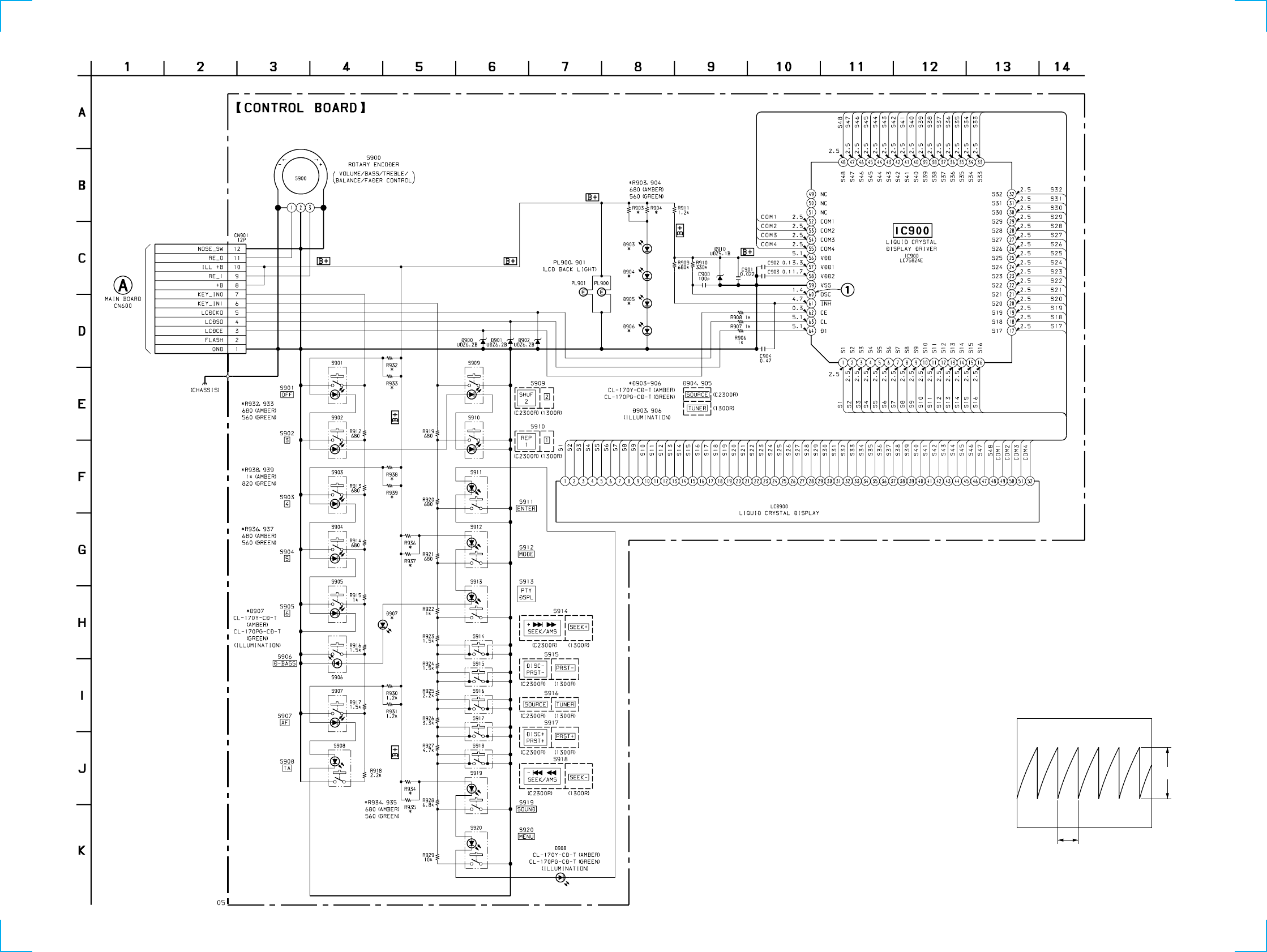
XR-1300R/C2300R
5-7. SCHEMATIC DIAGRAM – CONTROL Board –
2.5 Vp-p
28
µ
s
• Waveform
1IC900 y; OSC
(Page 21)
2424
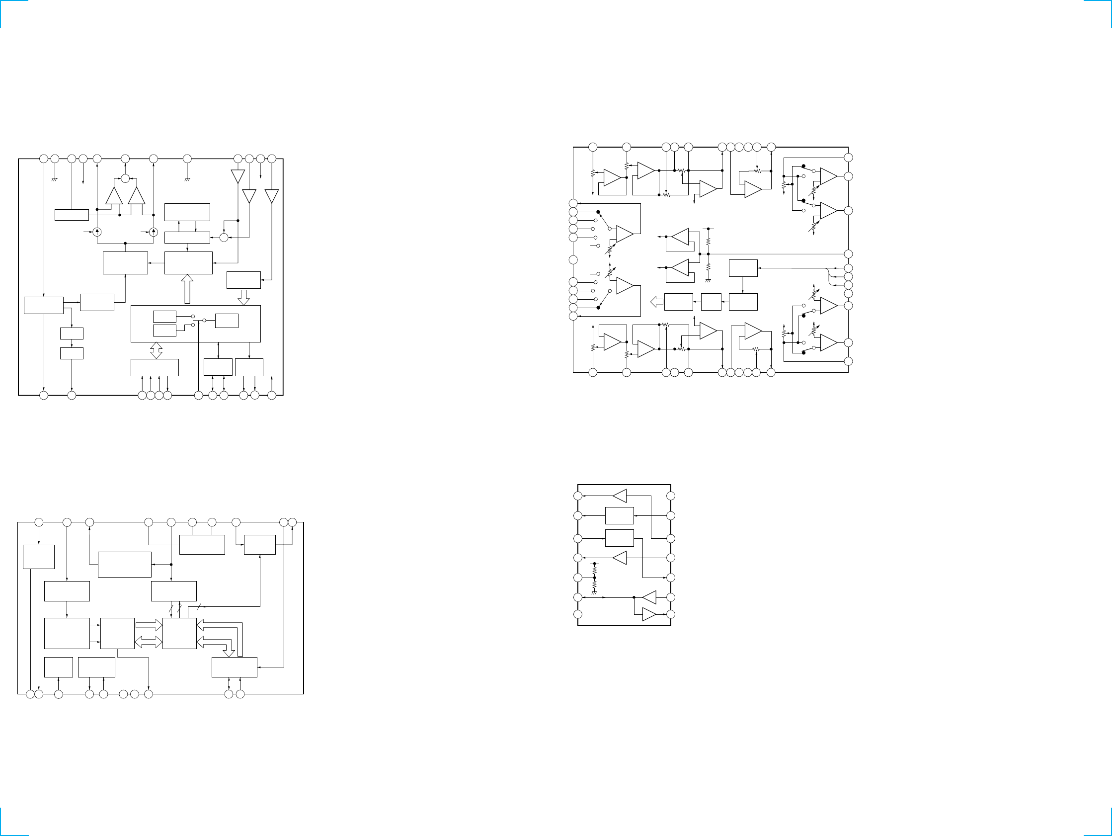
• IC Block Diagrams
– MAIN Board –
IC130 TB2118F-EL-S
VDD
AMP
AMP
AMP
VDD2
12 3 45 6 7 8 9 10
24 23 22 21 20 19 18 17 16 15
11 12
14 13
XO
OSC
CE
DIN
CK
DOUT
SR
I/O-1
I/O-2
OUT-1
OUT-2
VDD2 IFC
VDD
FM IN
AM IN
D-GND
FM CP OUT
VT
AM CP OUT
VCC
REG
A-GND
XI
SERIAL
INTERFACE
I/O
PORT
OSCILLATOR
ON/OFF
BUFFER
REFERENCE
DIVIDER
PHASE
COMPARATOR
20BIT
IF COUNTER
PRESCALLER
12BIT
PROGRAMMABLE
COUNTER
+
–
REGULATOR
18BIT
18BIT 22BIT
40BIT SHIFT
REGISTER
REF
VCC
SEEK/RECP SEEK/RECP
+
–
SIG
4BIT SWALLOW
COUNTER
OUTPUT
PORT
+
+
IC200 SAA6588T/V2-118
SCOUT
MRO
MPTH
TCON
OSCO
OSCI
VSSD
VDDD
DAVN
SDA
VREF
MPX
VSSA
VDDA
AFIN
MAD
PSWN
SCL
2
16
15 11
1316 14 12
INTERFACE
REGISTER
SIGNAL QUALITY
DECODER
CLOCKED
COMPARATOR
POWER SUPPLY
& RESET
TEST
CONTROL
OSCILLATOR
& CLOCK
PAUSE
DETECTOR
MULTI
PATH
DETECTOR
57kHz
8th ORDER
BAND-PASS FILTER
RDS/RDBS
DECODER
RDS/RDBS
DEMODULATOR
IIC BUS SLAVE
TRANSCEIVER
17
18
CIN
19
LVIN
20
87
DATA
CLOCK
DATA
CLOCK
44
5
9 10
34 5
IC400 LC75374E
+
–
+
–
+
–
+
–
+
–
+
–
+
–
+
–
+
–
+
–
+
–
+
–
+
–
+
–
DECODER LATCH SHIFT
REGISTER
CONTROL
–
+
+
–
12 3 45 6 7 8 9 10
20
19
18
17
16
15
14
13
12
11
21
22
2324
25
2627282930313233
34
35
36
37
38
39
40
41
42
43
44
LSELO
L4
L3
L2
L1
VDD
R1
R2
R3
R4
RSELO
RVRIN
RCOM
RT1
RT2
RT3
RTOUT
RSIN
NC
NC
RSB1
RSB2
RFIN
RFOUT
RROUT
VSS
CL
DI
CE
VREF
LROUT
LFOUT
LFIN
LSB2
LSB1
NC
NC
LSIN
LTOUT
LT3
LT2
LT1
LCOM
LVRIN
IC800 MM1175XFF
RESET
SWITCH
BATT
SWITCH
1
2
3
4
5
6
7 8
9
10
14
13
12
11
BUS ON
OUT
RESET
OUT
BATT
CLK
OUT
VREF
DATA
IN/OUT
GND
BATT
CHECK
CLK
IN
BUS ON
IN
RESET
IN
VCC
DATA IN
DATA OUT

25
5-8. IC PIN FUNCTION DESCRIPTION
• MAIN BOARD IC1 MB90574PMT-G-268-BND (SYSTEM CONTROLLER)
Pin No. Pin Name I/O Description
1 SEEKOUT O
Seek control signal output to the FM/AM tuner unit (TU100)
AM mode: Used for IF count output/SD output request/AGC cut at SEEK or BTM
FM mode: Used for SD speed up at SEEK, BTM, or AF
“L” is output at tuner off
2 AFSEEK O PLL low-pass filter time constant selection signal output at AF SEEK
“H” is output when AF SEEK Not used (open)
3NC ONot used (open)
4 ST-IND I/O
FM stereo broadcasting detection signal input from the FM/AM tuner unit (TU100), or forced
monaural control signal output to the FM/AM tuner unit (TU100)
“L” is input in the FM stereo mode, or “L” is output in the forced monaural mode
5 TUMUTE O Muting on/off control signal output of the FM and AM tuner signal “H”: muting on
6FM-ON O FM system power supply on/off control signal output terminal
“L”: AM power on, “H”: FM power on
7TU-ON O Tuner system power supply on/off control signal output terminal “H”: tuner power on
8 VCC — Power supply terminal (+5V)
9NC ONot used (open)
10 BUSON OBus on/off control signal output to the SONY bus interface (IC800) “L”: bus on
Used for the XR-C2300R only
11 SYSRST O Reset signal output to the SONY bus interface (IC800) “L”: reset
Used for the XR-C2300R only
12 NOSESW I Front panel block remove/attach detection signal input terminal
“L”: front panel is attached
13 LCDSO O Serial data output to the liquid crystal display driver (IC900)
14 LCD CKO O Serial data transfer clock signal output to the liquid crystal display driver (IC900)
15 BEEP O Beep sound drive signal output terminal
16 SD-IN ISignal detector input from the FM/AM tuner unit (TU100)
Stop level for SEEK, SCAN, etc. is determined SD is present at input of “H”
17 UNISI I Serial data input from the SONY bus interface (IC800) Used for the XR-C2300R only
18 UNISO O Serial data output to the SONY bus interface (IC800) Used for the XR-C2300R only
19 UNICKO OSerial data transfer clock signal output to the SONY bus interface (IC800)
Used for the XR-C2300R only
20 VOL-CE O Chip enable signal output to the electrical volume (IC400)
21 VOL-SO O Serial data output to the electrical volume (IC400)
22 VOL-CKO O Serial data transfer clock signal output to the electrical volume (IC400)
23, 24 NC ONot used (open)
25 PLLSI I PLL serial data input from the FM/AM PLL (IC130)
26 PLLSO O PLL serial data output to the FM/AM PLL (IC130)
27 PLLCKO O PLL serial data transfer clock signal output to the FM/AM PLL (IC130)
28 PLLCE O PLL chip enable signal output to the FM/AM PLL (IC130) “H” active
29 ILL-ON O Power on/off control signal output of the illumination LED and liquid crystal display driver
(IC900) “H”: power on
30, 31 NC ONot used (open)
32 NOISE-ON O Discharge control signal output for the noise detection circuit “H”: discharge
33 VSS —Ground terminal
34 C — Connected to coupling capacitor for the power supply
35 AD-ON O
A/D converter power control signal output terminal
When the KEYACK (pin uh) that controls reference voltage power for key A/D conversion input
is active, “L” is output from this terminal to enable the input

26
Pin No. Pin Name I/O Description
36 RE-IN0 I
37 RE-IN1 I
38 DVCC — Power supply terminal (+5V) (for D/A converter)
39 DVSS — Ground terminal (for D/A converter)
40, 41 NC ONot used (open)
42 AVCC — Power supply terminal (+5V) (for A/D converter)
43 AVRH I Reference voltage (+5V) input terminal (for A/D converter)
44 AVRL I Reference voltage (0V) input terminal (for A/D converter)
45 AVSS — Ground terminal (for A/D converter)
46 KEYIN0 IKey input terminal (A/D input) (S901 to S908)
OFF, 3, 4, 5, 6, D-BASS, AF, TA keys input
47 KEYIN1 I
48 RC-IN0 O Not used (open) Rotary remote commander key input terminal (A/D input)
49 DSTSEL I Destination setting terminal (fixed at “H”)
50 NOISE-DET I Noise level detection signal input at SEEK mode (A/D input)
51 NC O Not used (open)
52 MTP I Multi-path detection signal input from the RDS decoder (IC200)
53 VSM I FM and AM signal meter voltage detection input from the FM/AM tuner unit (TU100)
(A/D input)
54 VCC — Power supply terminal (+5V)
55 RAMBU I
Internal RAM reset detection signal input terminal
Input terminal to check that RAM data are not destroyed due to low voltage
This checking is made within 100 msec after reset Fixed at “L” in this set
56 POW-SEL I Power select input terminal Fixed at “H” in this set
57 NC O Not used (open)
58 TESTIN I Setting terminal for the test mode “L”: test mode, Normally: fixed at “H”
59, 60 NC O Not used (open)
61, 62 NC O Not used
63 VSS — Ground terminal
64 NC O Not used (open)
65 MUTE O Audio line muting on/off control signal output terminal “H”: muting on
66, 67 NC O Not used (open)
68 AMPMUTE O Muting on/off control signal output to the power amplifier (IC500) “L”: muting on
69 FLASH-W IInternal flash memory data write mode detection signal input terminal “L”: data write mode
Not used (fixed at “H” in this set)
70 I2C-SIO I/O Two-way data bus with the RDS decoder (IC200)
71 I2C-CKO O Bus clock signal output to the RDS decoder (IC200)
72 RC-IN1 O Not used (open) Rotary remote commander shift key input terminal
73 X1A O Sub system clock output terminal (32.768 kHz)
74 X0A I Sub system clock input terminal (32.768 kHz)
75 DAVN I Data transmit completed detect signal input from the RDS decoder (IC200) “H” active
76 KEYACK IInput of acknowledge signal for the key entry Acknowledge signal is input to accept function
and eject keys in the power off status On at input of “H”
Dial pulse input of the rotary encoder (RE900)
(for VOLUME/BASS/TREBLE/BALANCE/FADER control)
Key input terminal (A/D input) (S909 to S920)
2 (XR-1300R), 2 SHUF (XR-C2300R), 1 (XR-1300R), 1 REP (XR-C2300R), ENTER, MODE,
DSPL PTY, SEEK +/– (XR-1300R), SEEK/AMS + > M – . m (XR-C2300R),
PRST +/– (XR-1300R), PRST DISC +/– (XR-C2300R), TUNER (XR-1300R),
SOURCE
(
XR-C2300R
),
SOUND
,
MENU ke
y
s in
p
ut

27
Pin No. Pin Name I/O Description
77 BU-IN IBattery detect signal input from the SONY bus interface (IC800) and battery detect circuit
“L” is input at low voltage IC800: Used for the XR-C2300R only
78 ILL IN O Not used
79 TELATT I Telephone muting signal input terminal At input of “H”, the signal is attenuated by –20 dB
Not used
80 LCDCE I Chip enable signal output to the liquid crystal display driver (IC900) “H” active
81 ACC IN I Accessory detect signal input terminal “L”: accessory on
82 to 85 NC O Not used (open)
86 HSTX I Hardware standby input terminal “L”: hardware standby mode Reset signal input in this set
87 MD2 I Setting terminal for the CPU operational mode (fixed at “L” in this set)
88, 89 MD1, MD0 I Setting terminal for the CPU operational mode (fixed at “H” in this set)
90 RSTX I System reset signal input from the reset signal generator (IC2) and reset switch (S2)
“L”: reset “L” is input for several 100 msec after power on, then it changes to “H”
91 VSS — Ground terminal
92 X0 I Main system clock input terminal (3.68 MHz)
93 X1 O Main system clock output terminal (3.68 MHz)
94 VCC — Power supply terminal (+5V)
95 to 104 NC O Not used (open)
105 TAPE IN I Tape in detection switch (S903) input terminal “L”: tape in
106 FF-REW IN I FF/REW detection switch (S902) input terminal “L”: FF/REW mode
107 N/R I Tape direction switch (S903) input terminal “L”: reverse direction “H”: forward direction
108 to 11
0
NC O Not used (open)
111 CM ON O Capstan/reel motor (M901) drive signal output terminal “H”: motor on
112 to 116 NC O Not used (open)
117 TAPMUTE O Tape muting on/off control signal output terminal “H”: muting on
Active at ATA, FF/REW mode Not used (open)
118 AMPON O Standby on/off control signal output to the power amplifier (IC500)
“L”: standby mode, “H”: amp on
119 VSS —Ground terminal
120 PWON O Main system power supply on/off control signal output terminal “H”: power on
28
(1) GENERAL SECTION
SECTION 6
EXPLODED VIEWS
• Items marked “*” are not stocked since they
are seldom required for routine service. Some
delay should be anticipated when ordering
these items.
• The mechanical parts with no reference num-
ber in the exploded views are not supplied.
• Hardware (# mark) list and accessories and
packing materials are given in the last of the
electrical parts list.
NOTE:
• -XX and -X mean standardized parts, so they
may have some difference from the original
one.
• Color Indication of Appearance Parts
Example:
KNOB, BALANCE (WHITE) . . . (RED)
↑↑
Parts Color Cabinet's Color
Ref. No. Part No. Description Remark Ref. No. Part No. Description Remark
1 3-041-580-01 PANEL, SUB
2 X-3367-636-1 LOCK ASSY
3 3-041-581-01 DOOR, CASSETTE
4 3-044-125-01 SPRING, TORSION
5 3-376-464-11 SCREW (+PTT 2.6X6), GROUND POINT
6 3-029-047-01 PLATE (C), GROUND
*7 X-3378-167-1 COVER ASSY
*8 3-041-577-01 HEAT SINK (1300R)
*8 3-041-577-11 HEAT SINK (C2300R)
9 1-776-527-31 CORD (WITH CONNECTOR) (ISO) (POWER)
*10 3-041-578-01 BRACKET (IC)
*11 3-046-339-01 CUSHION (U)
*12 A-3326-108-A MAIN BOARD, COMPLETE (C2300R)
*12 A-3326-391-A MAIN BOARD, COMPLETE (1300R)
*13 3-041-575-01 CHASSIS
14 3-041-576-01 SHEET, INSULATING
15 3-041-599-01 COLLAR
F601 1-532-877-11 FUSE (BLADE TYPE) (AUTO FUSE) (10A)
TU100 1-693-440-12 TUNER UNIT (FM/AM)
7
#2
#3 #3
#3
(C2300R)
(C2300R)
F601
#2
#2
TU100
#1
Front panel section
6
10
11
8
9
14
12
13
15
4
3
5
2
1
MG-36SZ10-32
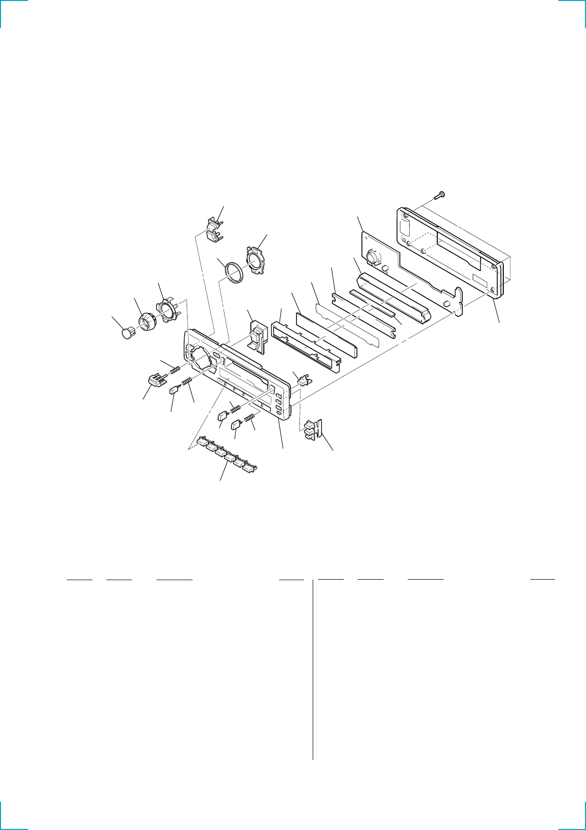
29
Ref. No. Part No. Description Remark Ref. No. Part No. Description Remark
(2) FRONT PANEL SECTION
51 3-041-597-01 BUTTON (1-6) (1. 2. 3. 4. 5. 6)
52 3-041-582-01 BUTTON (EJECT) (Z)
53 3-029-327-01 SPRING (EJECT)
54 3-041-605-01 BUTTON (RELEASE)
55 3-932-475-01 SPRING (RELEASE)
56 3-041-596-01 BUTTON (SOURCE) (C2300R)
56 3-041-602-01 BUTTON (TUNER) (1300R)
57 3-041-604-01 BUTTON (VOL)
58 3-041-603-01 BUTTON (CROSS)
(DISC +. DISC –. + > M. – . m)
(C2300R)
58 3-041-603-11 BUTTON (CROSS)
(PRST +. PRST –. SEEK +. SEEK –) (1300R)
59 3-041-595-01 BUTTON (S/M) (MENU. SOUND)
*60 3-043-247-01 CUSHION (CROSS)
61 3-041-593-01 PLATE (RING), LIGHT GUIDE
62 3-041-594-01 BUTTON (D/M/E) (DSPL. MODE. ENTER)
*63 3-041-591-01 PLATE (LCD), GROUND
*64 3-041-589-01 PLATE, LIGHT GUIDE
*65 3-041-592-01 ILLUMINATOR
66 1-694-696-11 CONDUCTOR BOARD, CONNENTION
*67 3-041-590-01 HOLDER (LCD)
68 3-041-588-01 PANEL, FRONT BACK
69 3-041-598-01 BUTTON (D-BASS)
70 3-041-601-01 BUTTON (T/A/O) (TA. AF. OFF)
71 3-375-372-01 SPRING (F/R)
72 3-041-583-01 BUTTON (FF) (M)
73 3-041-584-01 BUTTON (REW) (m)
74 X-3378-615-1 PANEL SUB ASSY (C2300R)
74 X-3378-655-1 PANEL SUB ASSY (1300R)
LCD900 1-803-841-11 DISPLAY PANEL, LIQUID CRYSTAL
51
52 53 71
71
72 74 70
69
73
55
54
56
57
58
59
60
61
62 63
64 65
67
66
LCD900
not supplied
(CONTROL board)
#4
68
Ver 1.1 2001.02
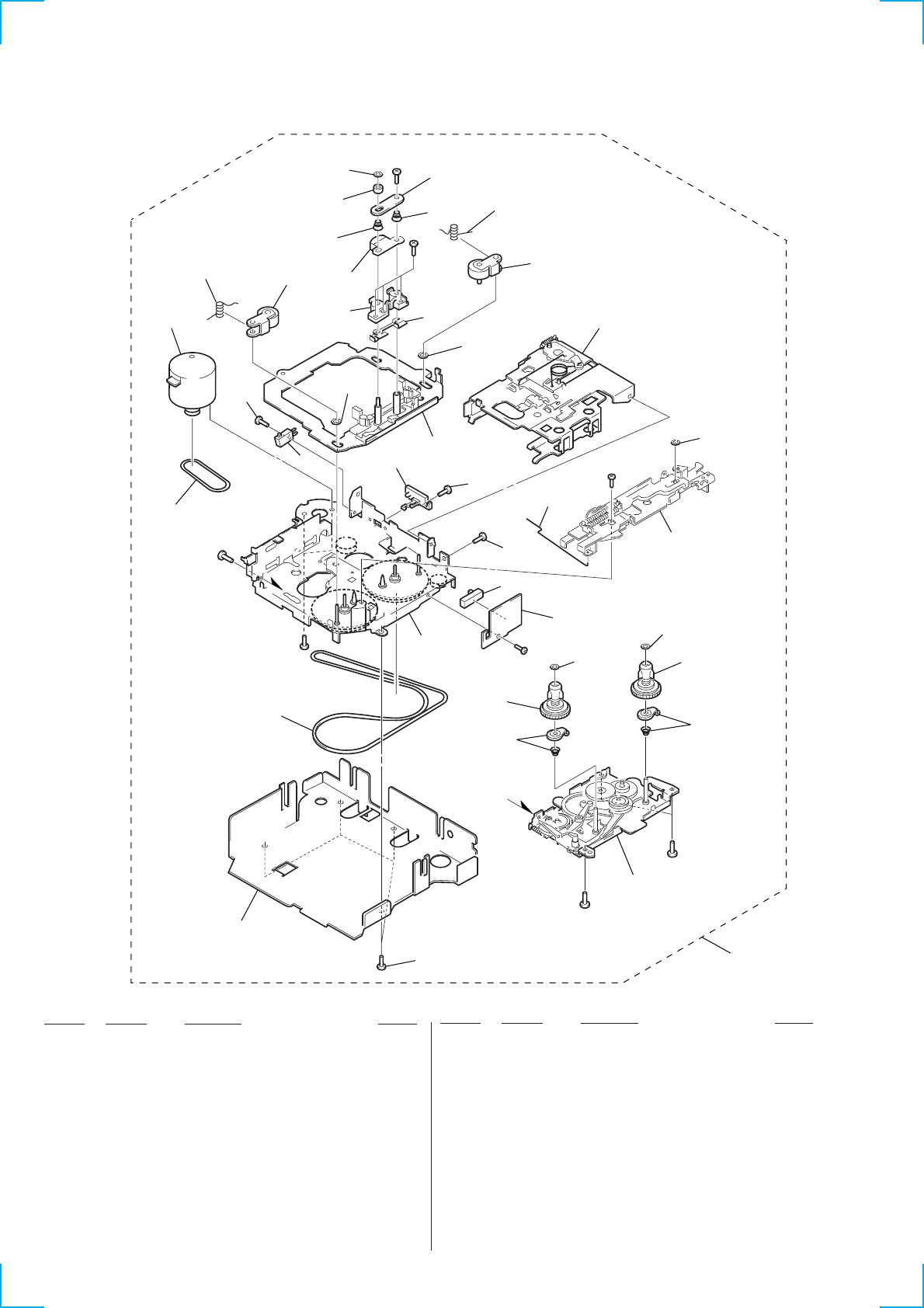
30
(3) MECHANISM DECK SECTION
(MG-36SZ10-32)
Ref. No. Part No. Description Remark Ref. No. Part No. Description Remark
*101 3-041-579-01 BRACKET (MD)
102 3-045-943-01 MAIN BELT
103 3-045-945-01 SUB BELT (C)
104 3-045-953-01 +MACHINE SCREW M1.7X6
105 3-045-940-01 PINCH ARM SPG (R)
106 3-045-950-01 E-RING (DIA. 2)
107 3-045-890-01 PINCH ARM (R)
108 3-045-933-01 ADJUSTER ARM SPG (B)
109 3-045-949-01 PSW (REEL) B
110 3-045-932-01 ADJUSTER ARM SPG (A)
111 3-045-939-01 PINCH ARM SPG (F)
112 3-045-891-01 PINCH ARM (F)
113 3-045-906-01 ADJUSTER SHIM (X)
114 3-045-952-01 +MACHINE SCREW M1.7X4
115 3-713-786-51 SCREW +P 2X3
117 3-045-893-01 REEL SPINDLE
118 3-046-138-01 SCREW (2.6X4) (STYLE) (CZN) +B
119 A-3220-753-A MECHANISM DECK ASSY (MG-36SZ10-32)
HP901 1-500-661-11 HEAD (PLAYBACK)
M901 1-763-507-11 MOTOR (CAPSTAN/REEL)
S901 1-771-928-11 SWITCH (SLIDE) (DIRECTION)
S902 1-771-926-11 SWITCH (LEAF) (FF/REW)
S903 1-771-927-11 SWITCH (LEAF) (TAPE DETECT)
118
101
102
103
104
105
106
107
108
110
#6 not
supplied
#7
M901
S902
not
supplied
not
supplied
not
supplied
#9
#8
HP901
109
not
supplied
not
supplied
not
supplied
not
supplied
not supplied
not supplied
not
supplied
not supplied
S901
#10
#7
#7
#7
S903
111
112
113
114
115
109
109
119
117
117
106
106

31
SECTION 7
ELECTRICAL PARTS LIST CONTROL
Ref. No. Part No. Description Remark Ref. No. Part No. Description Remark
CONTROL BOARD
***************
1-694-696-11 CONDUCTOR BOARD, CONNENTION
*3-041-589-01 PLATE, LIGHT GUIDE
*3-041-590-01 HOLDER (LCD)
*3-041-591-01 PLATE (LCD), GROUND
*3-041-592-01 ILLUMINATOR
< CAPACITOR >
C900 1-163-251-11 CERAMIC CHIP 100PF 5% 50V
C901 1-163-037-11 CERAMIC CHIP 0.022uF 10% 25V
C902 1-164-004-11 CERAMIC CHIP 0.1uF 10% 25V
C903 1-164-004-11 CERAMIC CHIP 0.1uF 10% 25V
C904 1-107-823-11 CERAMIC CHIP 0.47uF 10% 16V
< CONNECTOR >
CN901 1-794-312-11 PIN CONNECTOR 12P
< DIODE >
D900 8-719-056-82 DIODE UDZ-TE-17-6.2B
D901 8-719-056-82 DIODE UDZ-TE-17-6.2B
D902 8-719-056-82 DIODE UDZ-TE-17-6.2B
D903 8-719-033-13 LED CL-170Y-CD-T (ILLUMINATION)
(AMBER)
D903 8-719-033-14 LED CL-170PG-CD-T (ILLUMINATION)
(GREEN)
D904 8-719-033-13 LED CL-170Y-CD-T
(1300R: TUNER/C2300R: SOURCE) (AMBER)
D904 8-719-033-14 LED CL-170PG-CD-T
(1300R: TUNER/C2300R: SOURCE) (GREEN)
D905 8-719-033-13 LED CL-170Y-CD-T
(1300R: TUNER/C2300R: SOURCE) (AMBER)
D905 8-719-033-14 LED CL-170PG-CD-T
(1300R: TUNER/C2300R: SOURCE) (GREEN)
D906 8-719-033-13 LED CL-170Y-CD-T (ILLUMINATION)
(AMBER)
D906 8-719-033-14 LED CL-170PG-CD-T
(ILLUMINATION) (GREEN)
D907 8-719-033-13 LED CL-170Y-CD-T (ILLUMINATION)
(AMBER)
D907 8-719-033-14 LED CL-170PG-CD-T
(ILLUMINATION) (GREEN)
D908 8-719-033-13 LED CL-170Y-CD-T (ILLUMINATION)
(AMBER)
D908 8-719-033-14 LED CL-170PG-CD-T
(ILLUMINATION) (GREEN)
D910 8-719-976-89 DIODE UDZ-TE-17-5.1B
< IC >
IC900 8-759-366-34 IC LC75824E
< LIQUID CRYSTAL DISPLAY >
LCD900 1-803-841-11 DISPLAY PANEL, LIQUID CRYSTAL
< PILOT LAMP >
PL900 1-517-534-11 LAMP, PILOT (LCD BACK LIGHT) (GREEN)
PL900 1-517-535-11 LAMP, PILOT (LCD BACK LIGHT) (AMBER)
PL901 1-517-534-11 LAMP, PILOT (LCD BACK LIGHT) (GREEN)
PL901 1-517-535-11 LAMP, PILOT (LCD BACK LIGHT) (AMBER)
< RESISTOR >
R903 1-216-043-00 RES, CHIP 560 5% 1/10W
(GREEN)
R903 1-216-045-00 RES, CHIP 680 5% 1/10W
(AMBER)
R904 1-216-043-00 RES, CHIP 560 5% 1/10W
(GREEN)
R904 1-216-045-00 RES, CHIP 680 5% 1/10W
(AMBER)
R906 1-216-049-11 RES, CHIP 1K 5% 1/10W
R907 1-216-049-11 RES, CHIP 1K 5% 1/10W
R908 1-216-049-11 RES, CHIP 1K 5% 1/10W
R909 1-216-045-00 METAL CHIP 680 5% 1/10W
R910 1-216-186-00 RES, CHIP 330 5% 1/8W
R911 1-216-051-00 METAL CHIP 1.2K 5% 1/10W
R912 1-216-647-11 METAL CHIP 680 0.5% 1/10W
R913 1-216-647-11 METAL CHIP 680 0.5% 1/10W
R914 1-216-647-11 METAL CHIP 680 0.5% 1/10W
R915 1-208-437-61 RES, CHIP 1K 2% 1/10W
R916 1-208-441-61 RES, CHIP 1.5K 2% 1/10W
R917 1-208-441-61 RES, CHIP 1.5K 2% 1/10W
R918 1-216-659-11 METAL CHIP 2.2K 0.5% 1/10W
R919 1-216-647-11 METAL CHIP 680 0.5% 1/10W
R920 1-216-647-11 METAL CHIP 680 0.5% 1/10W
R921 1-216-647-11 METAL CHIP 680 0.5% 1/10W
R922 1-208-437-61 RES, CHIP 1K 2% 1/10W
R923 1-208-441-61 RES, CHIP 1.5K 2% 1/10W
R924 1-208-441-61 RES, CHIP 1.5K 2% 1/10W
R925 1-216-659-11 METAL CHIP 2.2K 0.5% 1/10W
NOTE:
• Due to standardization, replacements in the
parts list may be different from the parts speci-
fied in the diagrams or the components used
on the set.
• -XX and -X mean standardized parts, so they
may have some difference from the original
one.
• RESISTORS
All resistors are in ohms.
METAL: Metal-film resistor.
METAL OXIDE: Metal oxide-film resistor.
F: nonflammable
• Items marked “*” are not stocked since they
are seldom required for routine service.
Some delay should be anticipated when order-
ing these items.
• SEMICONDUCTORS
In each case, u: µ, for example:
uA. . : µA. . uPA. . : µPA. .
uPB. . : µPB. . uPC. . : µPC. .
uPD. . : µPD. .
• CAPACITORS
uF: µF
• COILS
uH: µH
When indicating parts by reference
number, please include the board.
• Abbreviation
AMBER : Amber illumination type
GREEN : Green illumination type

32
Ref. No. Part No. Description Remark Ref. No. Part No. Description Remark
CONTROL MAIN
R926 1-208-449-61 RES, CHIP 3.3K 2% 1/10W
R927 1-208-453-61 RES, CHIP 4.7K 2% 1/10W
R928 1-216-671-11 METAL CHIP 6.8K 0.5% 1/10W
R929 1-208-462-61 RES, CHIP 10K 2% 1/10W
R930 1-216-051-00 METAL CHIP 1.2K 5% 1/10W
R931 1-216-051-00 METAL CHIP 1.2K 5% 1/10W
R932 1-216-043-00 RES, CHIP 560 5% 1/10W
(GREEN)
R932 1-216-045-00 RES, CHIP 680 5% 1/10W
(AMBER)
R933 1-216-043-00 RES, CHIP 560 5% 1/10W
(GREEN)
R933 1-216-045-00 RES, CHIP 680 5% 1/10W
(AMBER)
R934 1-216-043-00 RES, CHIP 560 5% 1/10W
(GREEN)
R934 1-216-045-00 RES, CHIP 680 5% 1/10W
(AMBER)
R935 1-216-043-00 RES, CHIP 560 5% 1/10W
(GREEN)
R935 1-216-045-00 RES, CHIP 680 5% 1/10W
(AMBER)
R936 1-216-043-00 RES, CHIP 560 5% 1/10W
(GREEN)
R936 1-216-045-00 RES, CHIP 680 5% 1/10W
(AMBER)
R937 1-216-043-00 RES, CHIP 560 5% 1/10W
(GREEN)
R937 1-216-045-00 RES, CHIP 680 5% 1/10W
(AMBER)
R938 1-216-047-00 RES, CHIP 820 5% 1/10W
(GREEN)
R938 1-216-049-11 RES, CHIP 1K 5% 1/10W
(AMBER)
R939 1-216-047-00 RES, CHIP 820 5% 1/10W
(GREEN)
R939 1-216-049-11 RES, CHIP 1K 5% 1/10W
(AMBER)
< SWITCH >
S900 1-475-014-11 ENCODER, ROTARY (VOLUME/BASS/TREBLE/
BALANCE/FADER CONTROL)
S901 1-771-882-21 SWITCH, TACTILE (WITH LED) (OFF) (AMBER)
S901 1-771-609-11 SWITCH, TACT (WITH LED) (OFF) (GREEN)
S902 1-771-882-21 SWITCH, TACTILE (WITH LED) (3) (AMBER)
S902 1-771-609-11 SWITCH, TACT (WITH LED) (3) (GREEN)
S903 1-771-882-21 SWITCH, TACTILE (WITH LED) (4) (AMBER)
S903 1-771-609-11 SWITCH, TACT (WITH LED) (4) (GREEN)
S904 1-771-882-21 SWITCH, TACTILE (WITH LED) (5) (AMBER)
S904 1-771-609-11 SWITCH, TACT (WITH LED) (5) (GREEN)
S905 1-771-882-21 SWITCH, TACTILE (WITH LED) (6) (AMBER)
S905 1-771-609-11 SWITCH, TACT (WITH LED) (6) (GREEN)
S906 1-762-737-21 SWITCH, KEY BOARD (LED) (D-BASS)
S907 1-771-882-21 SWITCH, TACTILE (WITH LED) (AF) (AMBER)
S907 1-771-609-11 SWITCH, TACT (WITH LED) (AF) (GREEN)
S908 1-762-617-21 SWITCH, KEY BOARD (WITH LED) (TA)
(AMBER)
S908 1-762-619-21 SWITCH, KEY BOARD (WITH LED) (TA)
(GREEN)
S909 1-771-882-21 SWITCH, TACTILE (WITH LED)
(1300R: 2/C2300R: 2 SHUF) (AMBER)
S909 1-771-609-11 SWITCH, TACT (WITH LED)
(1300R:2/C2300R:2 SHUF) (GREEN)
S910 1-771-882-21 SWITCH, TACTILE (WITH LED)
(1300R: 1/C2300R: 1 REP) (AMBER)
S910 1-771-609-11 SWITCH, TACT (WITH LED)
(1300R:1/C2300R REP) (GREEN)
S911 1-762-617-21 SWITCH, KEY BOARD (WITH LED) (ENTER)
(AMBER)
S911 1-762-619-21 SWITCH, KEY BOARD (WITH LED) (ENTER)
(GREEN)
S912 1-762-617-21 SWITCH, KEY BOARD (WITH LED) (MODE)
(AMBER)
S912 1-762-619-21 SWITCH, KEY BOARD (WITH LED) (MODE)
(GREEN)
S913 1-762-617-21 SWITCH, KEY BOARD (WITH LED)
(DSPL, PTY) (AMBER)
S913 1-762-619-21 SWITCH, KEY BOARD (WITH LED)
(DSPL, PTY) (GREEN)
S914 1-771-027-21 SWITCH, KEYBOARD (WITH LED)
(1300R: SEEK +/C2300R: + > M, SEEK/AMS)
S915 1-771-027-21 SWITCH, KEYBOARD (WITH LED)
(1300R: PRST –/C2300R: DISC –, PRST –)
S916 1-771-884-21 SWITCH, TACTILE (WITH LED)
(1300R: TUNER/C2300R: SOURCE)
S917 1-771-027-21 SWITCH, KEYBOARD (WITH LED)
(1300R: PRST +/C2300R: DISC +, PRST +)
S918 1-771-027-21 SWITCH, KEYBOARD (WITH LED)
(1300R: SEEK -/C2300R: – . m, SEEK/AMS)
S919 1-762-617-21 SWITCH, KEY BOARD (WITH LED) (SOUND)
(AMBER)
S919 1-762-619-21 SWITCH, KEY BOARD (WITH LED) (SOUND)
(GREEN)
S920 1-762-617-21 SWITCH, KEY BOARD (WITH LED) (MENU)
(AMBER)
S920 1-762-619-21 SWITCH, KEY BOARD (WITH LED) (MENU)
(GREEN)
**************************************************************
*A-3326-108-A MAIN BOARD, COMPLETE (C2300R)
*A-3326-391-A MAIN BOARD, COMPLETE (1300R)
*********************
*3-041-577-01 HEAT SINK (1300R)
*3-041-577-11 HEAT SINK (C2300R)
*3-041-578-01 BRACKET (IC)
7-685-794-09 SCREW +PTT 2.6X10 (S)
< CAPACITOR >
C1 1-163-021-11 CERAMIC CHIP 0.01uF 10% 50V
C2 1-124-584-00 ELECT 100uF 20% 10V
C3 1-164-004-11 CERAMIC CHIP 0.1uF 10% 25V
C4 1-164-004-11 CERAMIC CHIP 0.1uF 10% 25V
C5 1-164-004-11 CERAMIC CHIP 0.1uF 10% 25V
C6 1-164-004-11 CERAMIC CHIP 0.1uF 10% 25V
C7 1-164-004-11 CERAMIC CHIP 0.1uF 10% 25V
C8 1-163-235-11 CERAMIC CHIP 22PF 5% 50V
C9 1-163-102-00 CERAMIC CHIP 24PF 5% 50V
C10 1-163-021-11 CERAMIC CHIP 0.01uF 10% 50V
C11 1-124-584-00 ELECT 100uF 20% 10V
C12 1-163-021-11 CERAMIC CHIP 0.01uF 10% 50V
C100 1-163-235-11 CERAMIC CHIP 22PF 5% 50V

33
Ref. No. Part No. Description Remark Ref. No. Part No. Description Remark
MAIN
C101 1-163-133-00 CERAMIC CHIP 470PF 5% 50V
C102 1-126-157-11 ELECT 10uF 20% 16V
C103 1-163-009-11 CERAMIC CHIP 0.001uF 10% 50V
C104 1-126-157-11 ELECT 10uF 20% 16V
C105 1-163-021-11 CERAMIC CHIP 0.01uF 10% 50V
C106 1-126-157-11 ELECT 10uF 20% 16V
C107 1-163-021-11 CERAMIC CHIP 0.01uF 10% 50V
C108 1-163-009-11 CERAMIC CHIP 0.001uF 10% 50V
C109 1-163-005-11 CERAMIC CHIP 470PF 10% 50V
C130 1-163-085-00 CERAMIC CHIP 2PF 0.25PF 50V
C131 1-163-224-11 CERAMIC CHIP 7PF 0.5PF 50V
C132 1-163-224-11 CERAMIC CHIP 7PF 0.5PF 50V
C133 1-164-004-11 CERAMIC CHIP 0.1uF 10% 25V
C134 1-163-251-11 CERAMIC CHIP 100PF 5% 50V
C135 1-163-021-11 CERAMIC CHIP 0.01uF 10% 50V
C136 1-163-020-00 CERAMIC CHIP 0.0082uF 10% 50V
C137 1-104-760-11 CERAMIC CHIP 0.047uF 10% 50V
C138 1-109-982-11 CERAMIC CHIP 1uF 10% 10V
C139 1-104-760-11 CERAMIC CHIP 0.047uF 10% 50V
C140 1-163-021-11 CERAMIC CHIP 0.01uF 10% 50V
C141 1-126-157-11 ELECT 10uF 20% 16V
C142 1-126-157-11 ELECT 10uF 20% 16V
C143 1-124-234-00 ELECT 22uF 20% 16V
C144 1-163-251-11 CERAMIC CHIP 100PF 5% 50V
C145 1-163-251-11 CERAMIC CHIP 100PF 5% 50V
C146 1-163-021-11 CERAMIC CHIP 0.01uF 10% 50V
C147 1-163-009-11 CERAMIC CHIP 0.001uF 10% 50V
C151 1-104-760-11 CERAMIC CHIP 0.047uF 10% 50V
C152 1-164-489-11 CERAMIC CHIP 0.22uF 10% 16V
C153 1-163-037-11 CERAMIC CHIP 0.022uF 10% 25V
C160 1-163-020-00 CERAMIC CHIP 0.0082uF 10% 50V
C161 1-163-020-00 CERAMIC CHIP 0.0082uF 10% 50V
C162 1-124-257-00 ELECT 2.2uF 20% 50V
C163 1-124-257-00 ELECT 2.2uF 20% 50V
C164 1-124-257-00 ELECT 2.2uF 20% 50V
C165 1-124-257-00 ELECT 2.2uF 20% 50V
C166 1-126-163-11 ELECT 4.7uF 20% 50V
C200 1-164-004-11 CERAMIC CHIP 0.1uF 10% 25V
C201 1-163-133-00 CERAMIC CHIP 470PF 5% 50V
C202 1-163-229-11 CERAMIC CHIP 12PF 5% 50V
C203 1-163-229-11 CERAMIC CHIP 12PF 5% 50V
C204 1-164-004-11 CERAMIC CHIP 0.1uF 10% 25V
C205 1-163-009-11 CERAMIC CHIP 0.001uF 10% 50V
C206 1-164-161-11 CERAMIC CHIP 0.0022uF 10% 100V
C207 1-163-135-00 CERAMIC CHIP 560PF 5% 50V
C208 1-115-565-11 CERAMIC CHIP 2.2uF 10% 10V
C209 1-163-263-11 CERAMIC CHIP 330PF 5% 50V
C210 1-163-021-11 CERAMIC CHIP 0.01uF 10% 50V
C211 1-124-234-00 ELECT 22uF 20% 16V
C212 1-163-009-11 CERAMIC CHIP 0.001uF 10% 50V
C213 1-163-009-11 CERAMIC CHIP 0.001uF 10% 50V
C214 1-163-009-11 CERAMIC CHIP 0.001uF 10% 50V
C215 1-164-004-11 CERAMIC CHIP 0.1uF 10% 25V
C216 1-164-004-11 CERAMIC CHIP 0.1uF 10% 25V
C217 1-163-133-00 CERAMIC CHIP 470PF 5% 50V
C218 1-163-227-11 CERAMIC CHIP 10PF 0.5PF 50V
C219 1-107-823-11 CERAMIC CHIP 0.47uF 10% 16V
C220 1-104-760-11 CERAMIC CHIP 0.047uF 10% 50V
C221 1-164-004-11 CERAMIC CHIP 0.1uF 10% 25V
C222 1-126-154-11 ELECT 47uF 20% 6.3V
C300 1-163-009-11 CERAMIC CHIP 0.001uF 10% 50V
C301 1-163-009-11 CERAMIC CHIP 0.001uF 10% 50V
C302 1-163-251-11 CERAMIC CHIP 100PF 5% 50V
C303 1-163-251-11 CERAMIC CHIP 100PF 5% 50V
C304 1-124-584-00 ELECT 100uF 20% 10V
C305 1-124-584-00 ELECT 100uF 20% 10V
C306 1-163-021-11 CERAMIC CHIP 0.01uF 10% 50V
C307 1-163-021-11 CERAMIC CHIP 0.01uF 10% 50V
C308 1-163-133-00 CERAMIC CHIP 470PF 5% 50V
C309 1-124-229-00 ELECT 33uF 20% 10V
C310 1-126-157-11 ELECT 10uF 20% 16V
C311 1-163-021-11 CERAMIC CHIP 0.01uF 10% 50V
C400 1-104-942-11 ELECT 1uF 20% 50V
C401 1-104-942-11 ELECT 1uF 20% 50V
C402 1-109-982-11 CERAMIC CHIP 1uF 10% 10V
C403 1-109-982-11 CERAMIC CHIP 1uF 10% 10V
C404 1-164-182-11 CERAMIC CHIP 0.0033uF 10% 50V
C405 1-164-182-11 CERAMIC CHIP 0.0033uF 10% 50V
C406 1-163-989-11 CERAMIC CHIP 0.033uF 10% 25V
C407 1-163-989-11 CERAMIC CHIP 0.033uF 10% 25V
C408 1-126-157-11 ELECT 10uF 20% 16V
C409 1-126-157-11 ELECT 10uF 20% 16V
C410 1-164-489-11 CERAMIC CHIP 0.22uF 10% 16V
C411 1-164-489-11 CERAMIC CHIP 0.22uF 10% 16V
C412 1-164-492-11 CERAMIC CHIP 0.15uF 10% 16V
C413 1-164-492-11 CERAMIC CHIP 0.15uF 10% 16V
C414 1-126-157-11 ELECT 10uF 20% 16V
C415 1-126-157-11 ELECT 10uF 20% 16V
C416 1-126-572-11 ELECT 4.7uF 20% 35V
C417 1-126-572-11 ELECT 4.7uF 20% 35V
C418 1-126-572-11 ELECT 4.7uF 20% 35V
C419 1-126-572-11 ELECT 4.7uF 20% 35V
C420 1-163-009-11 CERAMIC CHIP 0.001uF 10% 50V
C421 1-163-009-11 CERAMIC CHIP 0.001uF 10% 50V
C422 1-163-009-11 CERAMIC CHIP 0.001uF 10% 50V
C423 1-163-009-11 CERAMIC CHIP 0.001uF 10% 50V
C424 1-124-464-11 ELECT 0.22uF 20% 50V
C425 1-124-464-11 ELECT 0.22uF 20% 50V
C426 1-124-464-11 ELECT 0.22uF 20% 50V
C427 1-124-464-11 ELECT 0.22uF 20% 50V
C428 1-163-251-11 CERAMIC CHIP 100PF 5% 50V
(C2300R)
C429 1-163-251-11 CERAMIC CHIP 100PF 5% 50V
(C2300R)
C430 1-124-234-00 ELECT 22uF 20% 16V
C431 1-124-584-00 ELECT 100uF 20% 10V
C434 1-107-823-11 CERAMIC CHIP 0.47uF 10% 16V
(C2300R)
C435 1-107-823-11 CERAMIC CHIP 0.47uF 10% 16V
(C2300R)
C436 1-163-251-11 CERAMIC CHIP 100PF 5% 50V
(C2300R)
C437 1-163-251-11 CERAMIC CHIP 100PF 5% 50V
(C2300R)
C508 1-124-589-11 ELECT 47uF 20% 16V
C509 1-104-942-11 ELECT 1uF 20% 50V

34
Ref. No. Part No. Description Remark Ref. No. Part No. Description Remark
MAIN
C510 1-104-942-11 ELECT 1uF 20% 50V
C511 1-109-982-11 CERAMIC CHIP 1uF 10% 10V
C512 1-104-760-11 CERAMIC CHIP 0.047uF 10% 50V
C513 1-163-021-11 CERAMIC CHIP 0.01uF 10% 50V
C601 1-124-589-11 ELECT 47uF 20% 16V
C603 1-163-021-11 CERAMIC CHIP 0.01uF 10% 50V
C605 1-104-942-11 ELECT 1uF 20% 50V
C607 1-164-505-11 CERAMIC CHIP 2.2uF 16V
C608 1-109-982-11 CERAMIC CHIP 1uF 10% 10V
C609 1-104-760-11 CERAMIC CHIP 0.047uF 10% 50V
C610 1-104-760-11 CERAMIC CHIP 0.047uF 10% 50V
C700 1-126-936-11 ELECT 3300uF 20% 16V
C701 1-164-004-11 CERAMIC CHIP 0.1uF 10% 25V
C707 1-163-251-11 CERAMIC CHIP 100PF 5% 50V
C708 1-163-037-11 CERAMIC CHIP 0.022uF 10% 25V
C709 1-126-157-11 ELECT 10uF 20% 16V
C710 1-124-584-00 ELECT 100uF 20% 10V
C711 1-163-037-11 CERAMIC CHIP 0.022uF 10% 25V
C712 1-126-157-11 ELECT 10uF 20% 16V
C713 1-124-229-00 ELECT 33uF 20% 10V
C714 1-125-701-11 DOUBLE LAYER 0.047F 5.5V
C715 1-128-499-11 ELECT 220uF 20% 16V
C716 1-126-157-11 ELECT 10uF 20% 16V
C717 1-163-009-11 CERAMIC CHIP 0.001uF 10% 50V
C718 1-164-004-11 CERAMIC CHIP 0.1uF 10% 25V
C719 1-126-157-11 ELECT 10uF 20% 16V
C720 1-163-037-11 CERAMIC CHIP 0.022uF 10% 25V
C721 1-164-004-11 CERAMIC CHIP 0.1uF 10% 25V
C722 1-119-774-11 ELECT 100uF 20% 16V
C800 1-163-021-11 CERAMIC CHIP 0.01uF 10% 50V
C801 1-164-004-11 CERAMIC CHIP 0.1uF 10% 25V
C802 1-164-004-11 CERAMIC CHIP 0.1uF 10% 25V
C803 1-126-940-11 ELECT 330uF 20% 25V
< CONNECTOR >
CN100 1-764-808-21 JACK (ANT) (FM/AM ANTENNA)
*CN300 1-564-705-11 PIN, CONNECTOR (PC BOARD) 3P
*CN350 1-573-486-11 PIN, CONNECTOR (PC BOARD) 8P
CN400 1-774-699-12 JACK, PIN 4P (BUS AUDIO IN, AUDIO OUT)
(C2300R)
CN600 1-764-423-11 PIN, CONNECTOR 12P
CN700 1-774-701-11 PIN, CONNECTOR 16P (POWER)
CN800 1-580-907-31 PLUG, CONNECTOR (BUS CONTROL IN)
(C2300R)
< DIODE >
D1 8-719-066-10 DIODE 1PS181-115
D102 8-719-991-33 DIODE 1SS133T-77
D103 8-719-991-33 DIODE 1SS133T-77
D160 8-719-109-72 DIODE MTZJ-T-77-3.9B
D200 8-719-109-85 DIODE MTZJ-T-77-5.1B
D201 8-719-991-33 DIODE 1SS133T-77
D202 8-719-991-33 DIODE 1SS133T-77
D203 8-719-109-72 DIODE MTZJ-T-77-3.9B
D300 8-719-991-33 DIODE 1SS133T-77
D400 8-719-109-72 DIODE MTZJ-T-77-3.9B
D500 8-719-200-82 DIODE 11ES2-TA1B
D501 8-719-200-82 DIODE 11ES2-TA1B
D502 8-719-200-82 DIODE 11ES2-TA1B
D503 8-719-200-82 DIODE 11ES2-TA1B
D504 8-719-200-82 DIODE 11ES2-TA1B
D505 8-719-200-82 DIODE 11ES2-TA1B
D506 8-719-200-82 DIODE 11ES2-TA1B
D507 8-719-200-82 DIODE 11ES2-TA1B
D600 8-719-991-33 DIODE 1SS133T-77
D602 8-719-110-03 DIODE MTZJ-T-77-7.5C (C1300R)
D603 8-719-109-97 DIODE MTZJ-T-77-6.8B
D605 8-719-922-03 DIODE MTZJ-T-77-18C
D606 8-719-109-93 DIODE MTZJ-T-77-6.2B
D607 8-719-109-93 DIODE MTZJ-T-77-6.2B
D608 8-719-109-93 DIODE MTZJ-T-77-6.2B
D609 8-719-109-93 DIODE MTZJ-T-77-6.2B
D610 8-719-109-93 DIODE MTZJ-T-77-6.2B
D611 8-719-109-93 DIODE MTZJ-T-77-6.2B
D612 8-719-109-93 DIODE MTZJ-T-77-6.2B
D613 8-719-109-93 DIODE MTZJ-T-77-6.2B
D614 8-719-988-61 DIODE 1SS355TE-17
D615 8-719-991-33 DIODE 1SS133T-77
D616 8-719-929-15 DIODE HZS9.1NB2
D617 8-719-988-61 DIODE 1SS355TE-17
D700 8-719-049-38 DIODE 1N5404TU
D702 8-719-200-82 DIODE 11ES2-TA1B
D703 8-719-200-82 DIODE 11ES2-TA1B
D704 8-719-991-33 DIODE 1SS133T-77
D705 8-719-048-54 DIODE MTZJ-T-77-10A
D706 8-719-991-33 DIODE 1SS133T-77
D707 8-719-935-40 DIODE HZS6B2LTD
D708 8-719-200-82 DIODE 11ES2-TA1B
D709 8-719-200-82 DIODE 11ES2-TA1B
D710 8-719-109-89 DIODE MTZJ-T-77-5.6B
D713 8-719-109-93 DIODE MTZJ-T-77-6.2B
D800 8-719-109-97 DIODE MTZJ-T-77-6.8B (C2300R)
D801 8-719-109-93 DIODE MTZJ-T-77-6.2B (C2300R)
D802 8-719-922-03 DIODE MTZJ-T-77-18C (C2300R)
D803 8-719-991-33 DIODE 1SS133T-77 (C2300R)
D804 8-719-922-03 DIODE MTZJ-T-77-18C (C2300R)
< IC >
IC1 8-759-654-48 IC MB90574PMT-G-268-BND
IC2 8-759-574-61 IC XC61AN4302MR
IC130 8-759-586-59 IC TB2118F-EL-S
IC200 8-759-650-68 IC SAA6588T/V2-118
IC201 8-759-331-72 IC NJM4558E-D (TE2)
IC300 8-759-924-46 IC BA4560F-T1
IC400 8-759-487-82 IC LC75374E
IC500 8-759-486-44 IC TDA7386
IC800 8-759-096-16 IC MM1175XFF (C2300R)
< COIL >
L1 1-410-509-11 INDUCTOR 10uH
L102 1-410-509-11 INDUCTOR 10uH
L103 1-410-750-41 INDUCTOR 0.47uH
L700 1-419-476-11 COIL, CHOKE

35
Ref. No. Part No. Description Remark Ref. No. Part No. Description Remark
MAIN
< TRANSISTOR >
Q1 8-729-043-32 TRANSISTOR PDTA114EK-115
Q2 8-729-043-32 TRANSISTOR PDTA114EK-115
Q101 8-729-043-27 TRANSISTOR PDTC114EK-115
Q102 8-729-901-46 TRANSISTOR DTA114YK-T146
Q103 8-729-043-28 TRANSISTOR PDTC124EK-115
Q104 8-729-049-85 TRANSISTOR 2PB710AR-115
Q105 8-729-904-63 TRANSISTOR DTB123YK-T-146
Q106 8-729-049-86 TRANSISTOR 2PD602AR-115
Q160 8-729-920-21 TRANSISTOR DTC314TK-T-146
Q161 8-729-920-21 TRANSISTOR DTC314TK-T-146
Q162 8-729-043-32 TRANSISTOR PDTA114EK-115
Q163 8-729-043-27 TRANSISTOR PDTC114EK-115
Q200 8-729-422-33 TRANSISTOR 2PD601AR-115
Q201 8-729-043-27 TRANSISTOR PDTC114EK-115
Q400 8-729-920-21 TRANSISTOR DTC314TK-T-146
Q401 8-729-920-21 TRANSISTOR DTC314TK-T-146
Q402 8-729-920-21 TRANSISTOR DTC314TK-T-146
Q403 8-729-920-21 TRANSISTOR DTC314TK-T-146
Q600 8-729-043-32 TRANSISTOR PDTA114EK-115
Q601 8-729-021-94 FET 2SK1657-T1B
Q602 8-729-043-29 TRANSISTOR PDTC144EK-115 (1300R)
Q603 8-729-422-33 TRANSISTOR 2PD601AR-115 (1300R)
Q604 8-729-043-27 TRANSISTOR PDTC114EK-115
Q605 8-729-422-33 TRANSISTOR 2PD601AR-115
Q700 8-729-921-48 TRANSISTOR 2SD1760F5-TRPQR
Q701 8-729-216-22 TRANSISTOR 2PB709AR-115
Q702 8-729-043-30 TRANSISTOR PDTC114TK-115
Q703 8-729-205-96 TRANSISTOR 2SC3668-OY-TPE2
Q704 8-729-205-95 TRANSISTOR 2SA1428-OY-TPF2
Q705 8-729-216-22 TRANSISTOR 2PB709AR-115
Q706 8-729-043-28 TRANSISTOR PDTC124EK-115
Q707 8-729-205-95 TRANSISTOR 2SA1428-OY-TPF2
Q708 8-729-043-27 TRANSISTOR PDTC114EK-115
Q709 8-729-205-95 TRANSISTOR 2SA1428-OY-TPF2
Q710 8-729-043-27 TRANSISTOR PDTC114EK-115
Q711 8-729-205-95 TRANSISTOR 2SA1428-OY-TPF2
Q712 8-729-422-33 TRANSISTOR 2PD601AR-115
< RESISTOR >
R1 1-216-097-00 RES, CHIP 100K 5% 1/10W
R2 1-216-097-00 RES, CHIP 100K 5% 1/10W
R3 1-216-097-00 RES, CHIP 100K 5% 1/10W
R4 1-216-057-00 METAL CHIP 2.2K 5% 1/10W
R5 1-216-057-00 METAL CHIP 2.2K 5% 1/10W
R6 1-216-057-00 METAL CHIP 2.2K 5% 1/10W
R7 1-216-097-00 RES, CHIP 100K 5% 1/10W
R9 1-216-113-00 METAL CHIP 470K 5% 1/10W
R11 1-216-097-00 RES, CHIP 100K 5% 1/10W
R12 1-216-097-00 RES, CHIP 100K 5% 1/10W
R13 1-216-057-00 METAL CHIP 2.2K 5% 1/10W
R14 1-216-057-00 METAL CHIP 2.2K 5% 1/10W
R15 1-216-089-00 RES, CHIP 47K 5% 1/10W
R16 1-216-089-00 RES, CHIP 47K 5% 1/10W
R17 1-216-097-00 RES, CHIP 100K 5% 1/10W
R18 1-216-097-00 RES, CHIP 100K 5% 1/10W
R19 1-216-073-00 METAL CHIP 10K 5% 1/10W
R20 1-216-097-00 RES, CHIP 100K 5% 1/10W
R21 1-216-097-00 RES, CHIP 100K 5% 1/10W
R22 1-216-097-00 RES, CHIP 100K 5% 1/10W
R25 1-216-097-00 RES, CHIP 100K 5% 1/10W
R100 1-216-049-11 RES, CHIP 1K 5% 1/10W
R101 1-216-029-00 METAL CHIP 150 5% 1/10W
R102 1-216-073-00 METAL CHIP 10K 5% 1/10W
R103 1-216-073-00 METAL CHIP 10K 5% 1/10W
R104 1-216-073-00 METAL CHIP 10K 5% 1/10W
R105 1-216-065-00 RES, CHIP 4.7K 5% 1/10W
R106 1-216-049-11 RES, CHIP 1K 5% 1/10W
R109 1-216-049-11 RES, CHIP 1K 5% 1/10W
R110 1-216-049-11 RES, CHIP 1K 5% 1/10W
R111 1-216-049-11 RES,CHIP 1K 5% 1/10W
R134 1-216-073-00 METAL CHIP 10K 5% 1/10W
R135 1-216-067-00 METAL CHIP 5.6K 5% 1/10W
R136 1-216-061-00 METAL CHIP 3.3K 5% 1/10W
R137 1-216-067-00 METAL CHIP 5.6K 5% 1/10W
R139 1-216-025-00 RES, CHIP 100 5% 1/10W
R140 1-216-025-00 RES, CHIP 100 5% 1/10W
R150 1-216-065-00 RES, CHIP 4.7K 5% 1/10W
R151 1-216-073-00 METAL CHIP 10K 5% 1/10W
R160 1-216-085-00 METAL CHIP 33K 5% 1/10W
R161 1-216-085-00 METAL CHIP 33K 5% 1/10W
R162 1-216-077-00 RES, CHIP 15K 5% 1/10W
R163 1-216-077-00 RES, CHIP 15K 5% 1/10W
R164 1-216-045-00 METAL CHIP 680 5% 1/10W
R165 1-216-051-00 METAL CHIP 1.2K 5% 1/10W
R166 1-216-051-00 METAL CHIP 1.2K 5% 1/10W
R200 1-216-113-00 METAL CHIP 470K 5% 1/10W
R201 1-216-049-11 RES, CHIP 1K 5% 1/10W
R202 1-216-061-00 METAL CHIP 3.3K 5% 1/10W
R203 1-216-001-00 METAL CHIP 10 5% 1/10W
R204 1-216-041-00 METAL CHIP 470 5% 1/10W
R205 1-216-037-00 METAL CHIP 330 5% 1/10W
R206 1-216-037-00 METAL CHIP 330 5% 1/10W
R207 1-216-001-00 METAL CHIP 10 5% 1/10W
R208 1-216-049-11 RES, CHIP 1K 5% 1/10W
R209 1-216-057-00 METAL CHIP 2.2K 5% 1/10W
R210 1-216-057-00 METAL CHIP 2.2K 5% 1/10W
R211 1-216-065-00 RES, CHIP 4.7K 5% 1/10W
R212 1-216-097-00 RES, CHIP 100K 5% 1/10W
R213 1-216-061-00 METAL CHIP 3.3K 5% 1/10W
R214 1-216-065-00 RES, CHIP 4.7K 5% 1/10W
R215 1-216-121-00 RES, CHIP 1M 5% 1/10W
R216 1-216-097-00 RES, CHIP 100K 5% 1/10W
R217 1-216-057-00 METAL CHIP 2.2K 5% 1/10W
R300 1-216-089-00 RES, CHIP 47K 5% 1/10W
R301 1-216-089-00 RES, CHIP 47K 5% 1/10W
R302 1-216-013-00 METAL CHIP 33 5% 1/10W
R303 1-216-013-00 METAL CHIP 33 5% 1/10W
R304 1-216-115-00 METAL CHIP 560K 5% 1/10W
R305 1-216-115-00 METAL CHIP 560K 5% 1/10W
R306 1-216-077-00 RES, CHIP 15K 5% 1/10W
R307 1-216-077-00 RES, CHIP 15K 5% 1/10W
R308 1-216-049-11 RES, CHIP 1K 5% 1/10W
R309 1-216-049-11 RES, CHIP 1K 5% 1/10W
R310 1-216-073-00 METAL CHIP 10K 5% 1/10W

36
Ref. No. Part No. Description Remark Ref. No. Part No. Description Remark
R311 1-216-073-00 METAL CHIP 10K 5% 1/10W
R312 1-247-807-31 CARBON 100 5% 1/4W
R400 1-216-065-00 RES, CHIP 4.7K 5% 1/10W
R401 1-216-065-00 RES, CHIP 4.7K 5% 1/10W
R402 1-216-033-00 METAL CHIP 220 5% 1/10W
R403 1-216-033-00 METAL CHIP 220 5% 1/10W
R404 1-216-033-00 METAL CHIP 220 5% 1/10W
R405 1-216-033-00 METAL CHIP 220 5% 1/10W
R406 1-216-065-00 RES, CHIP 4.7K 5% 1/10W
R407 1-216-065-00 RES, CHIP 4.7K 5% 1/10W
R408 1-216-065-00 RES, CHIP 4.7K 5% 1/10W
R409 1-216-065-00 RES, CHIP 4.7K 5% 1/10W
R410 1-216-089-00 RES, CHIP 47K 5% 1/10W
R411 1-216-089-00 RES, CHIP 47K 5% 1/10W
R412 1-216-089-00 RES, CHIP 47K 5% 1/10W
R413 1-216-089-00 RES, CHIP 47K 5% 1/10W
R414 1-216-295-00 SHORT 0 (C2300R)
R415 1-216-295-00 SHORT 0 (C2300R)
R416 1-216-057-00 METAL CHIP 2.2K 5% 1/10W
(C2300R)
R417 1-216-057-00 METAL CHIP 2.2K 5% 1/10W
(C2300R)
R418 1-216-073-00 METAL CHIP 10K 5% 1/10W
(C2300R)
R419 1-216-073-00 METAL CHIP 10K 5% 1/10W
(C2300R)
R420 1-249-393-11 CARBON 10 5% 1/4W
R500 1-216-089-00 RES, CHIP 47K 5% 1/10W
R501 1-216-069-00 METAL CHIP 6.8K 5% 1/10W
R502 1-216-073-00 METAL CHIP 10K 5% 1/10W
R503 1-216-073-00 METAL CHIP 10K 5% 1/10W
R602 1-216-089-00 RES, CHIP 47K 5% 1/10W
(1300R)
R605 1-216-081-00 METAL CHIP 22K 5% 1/10W
R606 1-216-081-00 METAL CHIP 22K 5% 1/10W
R607 1-216-089-00 RES, CHIP 47K 5% 1/10W
(1300R)
R608 1-216-089-00 RES, CHIP 47K 5% 1/10W
(1300R)
R609 1-216-097-00 RES, CHIP 100K 5% 1/10W
R610 1-216-097-00 RES, CHIP 100K 5% 1/10W
R611 1-216-073-00 METAL CHIP 10K 5% 1/10W
R612 1-216-073-00 METAL CHIP 10K 5% 1/10W
R613 1-216-025-00 RES, CHIP 100 5% 1/10W
R614 1-216-025-00 RES, CHIP 100 5% 1/10W
R615 1-216-025-00 RES, CHIP 100 5% 1/10W
R616 1-216-025-00 RES, CHIP 100 5% 1/10W
R617 1-216-025-00 RES, CHIP 100 5% 1/10W
R618 1-216-105-00 RES, CHIP 220K 5% 1/10W
R619 1-216-049-11 RES, CHIP 1K 5% 1/10W
R621 1-216-073-00 METAL CHIP 10K 5% 1/10W
R622 1-216-081-00 METAL CHIP 22K 5% 1/10W
R700 1-249-413-11 CARBON 470 5% 1/4W
R701 1-216-057-00 METAL CHIP 2.2K 5% 1/10W
R702 1-249-421-11 CARBON 2.2K 5% 1/4W
R703 1-216-081-00 METAL CHIP 22K 5% 1/10W
R705 1-249-425-11 CARBON 4.7K 5% 1/4W
R706 1-216-089-00 RES, CHIP 47K 5% 1/10W
R707 1-216-081-00 METAL CHIP 22K 5% 1/10W
R708 1-249-421-11 CARBON 2.2K 5% 1/4W
R709 1-216-097-00 RES, CHIP 100K 5% 1/10W
R710 1-249-385-11 CARBON 2.2 5% 1/6W
R711 1-249-385-11 CARBON 2.2 5% 1/6W
R712 1-249-385-11 CARBON 2.2 5% 1/6W
R713 1-249-385-11 CARBON 2.2 5% 1/6W
R714 1-216-073-00 METAL CHIP 10K 5% 1/10W
R715 1-216-295-00 SHORT 0
R716 1-247-185-11 CARBON 2.7 5% 1/2W
R717 1-249-421-11 CARBON 2.2K 5% 1/4W
R718 1-247-752-11 CARBON 1K 5% 1/2W
(C2300R)
R719 1-216-073-00 METAL CHIP 10K 5% 1/10W
R720 1-216-049-11 RES, CHIP 1K 5% 1/10W
R721 1-216-049-11 RES, CHIP 1K 5% 1/10W
R800 1-216-017-00 RES, CHIP 47 5% 1/10W
(C2300R)
R801 1-216-097-00 RES, CHIP 100K 5% 1/10W
(1300R)
R802 1-216-025-00 RES, CHIP 100 5% 1/10W
(C2300R)
R803 1-216-073-00 METAL CHIP 10K 5% 1/10W
(C2300R)
R804 1-216-025-00 RES, CHIP 100 5% 1/10W
(C2300R)
< COMPOSITION CIRCUIT BLOCK >
RN1 1-216-825-11 METAL CHIP 2.2K 5% 1/16W
RN800 1-216-845-11 METAL CHIP 100K 5% 1/16W
(1300R)
< SWITCH >
S2 1-692-431-21 SWITCH, TACTILE (RESET)
< TUNER >
TU100 1-693-440-12 TUNER UNIT (FM/AM)
< VARIABLE RESISTOR >
VR100 1-241-768-11 RES, ADJ, CARBON 220K
< VIBRATOR >
X1 1-767-833-21 VIBRATOR, CERAMIC (3.68MHz)
X2 1-567-098-41 VIBRATOR, CRYSTAL (32.768kHz)
X100 1-781-246-21 VIBRATOR, CRYSTAL (10.25MHz)
X201 1-579-242-11 VIBRATOR, CRYSTAL (4.332MHz)
**************************************************************
MISCELLANEOUS
**************
9 1-776-527-31 CORD (WITH CONNECTOR) (ISO) (POWER)
66 1-694-696-11 CONDUCTOR BOARD, CONNECTION
F601 1-532-877-11 FUSE (BLADE TYPE) (AUTO FUSE) (10A)
HP901 1-500-661-11 HEAD (PLAYBACK)
LCD900 1-803-841-11 DISPLAY PANEL, LIQUID CRYSTAL
M901 1-763-507-11 MOTOR (CAPSTAN/REEL)
S901 1-771-928-11 SWITCH (SLIDE) (DIRECTION)
S902 1-771-926-11 SWITCH (LEAF) (FF/REW)
MAIN
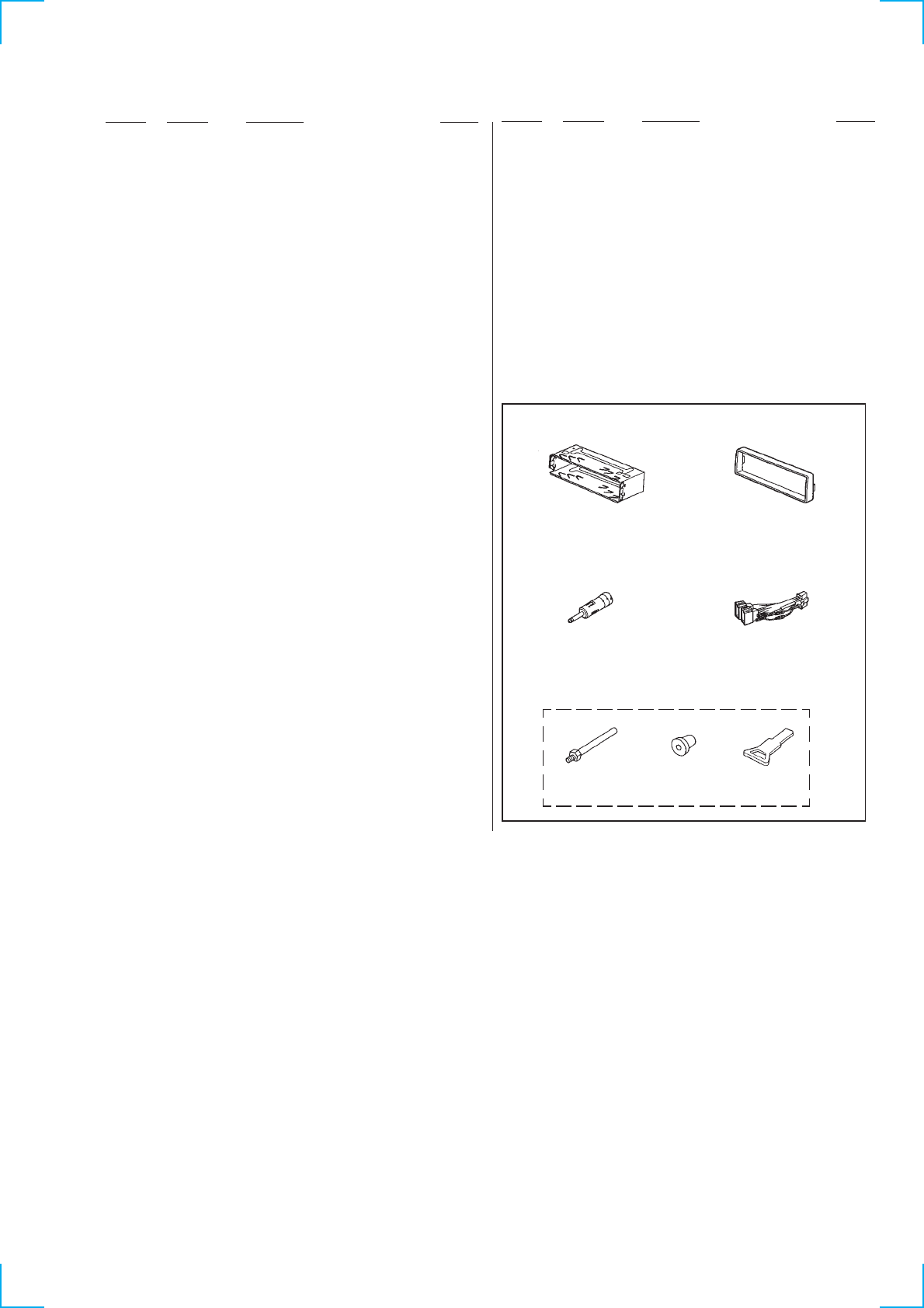
37
Ref. No. Part No. Description Remark Ref. No. Part No. Description Remark
S903 1-771-927-11 SWITCH (LEAF) (TAPE DETECT)
************************************************************
**************
HARDWARE LIST
**************
#1 7-685-782-09 SCREW +PTT 2X5 (S)
#2 7-685-792-09 SCREW +PTT 2.6X6 (S)
#3 7-685-794-09 SCREW +PTT 2.6X10 (S)
#4 7-685-105-19 TPG +P 2X8, TYPE 2, NON-SLIT
#6 7-627-553-27 PRECISION SCREW +P 2X2.5 TYPE3
#7 7-685-101-11 SCREW +PTP 2X3 NON-SLIT
#8 7-621-255-35 SCREW +P 2X5
#9 7-621-255-25 SCREW +P 2X4
#10 7-685-781-09 SCREW +PTT 2X4 (S)
************************************************************
ACCCESSORIES & PACKING MATERIALS
*********************************
3-044-698-11 MANUAL, INSTRUCTION (ENGLISH, SPANISH,
SWEDISH, PORTUGUESE) (1300R: AEP, UK)
3-044-698-21 MANUAL, INSTRUCTION (FRENCH, GERMAN,
DUTCH, ITALIIAN, GREEK) (1300R: AEP)
3-044-698-31 MANUAL, INSTRUCTION (GERMAN)
(1300R: German)
3-044-698-41 MANUAL, INSTRUCTION (ENGLISH, CZECH,
POLISH, TURKISH, RUSSIAN)
(1300R: South European)
3-868-292-11 CONNECTION, FITTING (ENGLISH, SPANISH,
SWEDISH, PORTUGUESE) (AEP, UK)
3-868-292-21 CONNECTION, FITTING (FRENCH, GERMAN,
DUTCH, ITALIIAN, GREEK)
(AEP/C2300R: South European)
3-868-292-31 CONNECTION, FITTING (ENGLISH, CZECH,
POLISH, TURKISH, RUSSIAN)
(1300R: South European)
3-868-293-11 MANUAL, INSTRUCTION (ENGLISH, SPANISH,
SWEDISH, PORTUGUESE)
(C2300R: AEP, UK)
3-868-293-21 MANUAL, INSTRUCTION (FRENCH, GERMAN,
DUTCH, ITALIIAN, GREEK) (C2300R: AEP)
501 502
503 504
505
FRAME ASSY
× 1 COLLAR
× 1
ADAPTER, ANTENNA
× 1 CORD
(WITH CONNECTOR)
× 1
FITTING SCREW
× 1 BUSHING
× 1 KEY
× 1
3-868-293-31 MANUAL, INSTRUCTION (GERMAN)
(C2300R: German)
3-868-293-41 MANUAL, INSTRUCTION (ENGLISH, CZECH,
POLISH, TURKISH, RUSSIAN)
(C2300R: South European)
X-3378-453-1 CASE (PANEL) ASSY (for FRONT PANEL)
************************************************************
PARTS FOR INTALLATION AND CONNECTIONS
*************************************
501 X-3376-298-1 FRAME ASSY, FITTING
502 3-041-599-01 COLLAR
503 1-465-459-21 ADAPTER, ANTENNA
504 1-776-527-31 CORD (WITH CONNECTOR) (ISO) (POWER)
505 X-3370-077-1 SCREW ASSY (AE. KEY), FITTING
