SP Racing F3 FC Board(Deluxe) Internal OSD Manual
User Manual: sp-racing-f3-osd-manual
Open the PDF directly: View PDF ![]() .
.
Page Count: 5
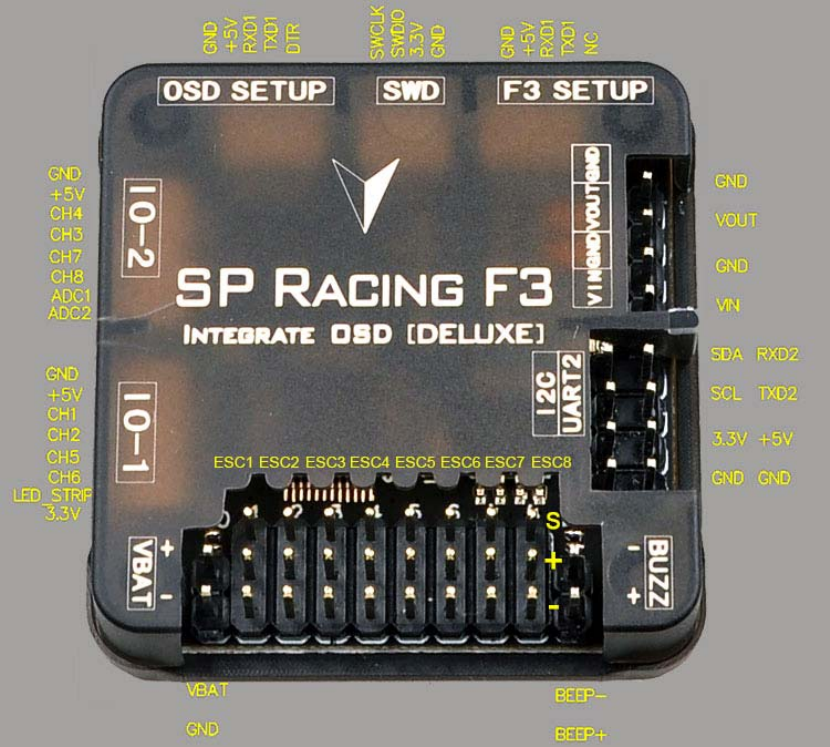
SP Racing F3 FC Board(Deluxe) internal OSD
Specification:
Interface definition
IO_1 connector - PWM RX / PPM RX / GPIO / LED Strip
When using a PWM receiver connect CH1/2/5/6 to PWM RX.
LED Strip data signal can be used to change individual colors of each LEDs on a strip of
WS2812 RGB leds - Perfect for battery warning lights, orientation lights, indicators, failsafe,
display flight modes, etc.
CH1/2/5/6 can be used as a general purpose IOs when not used for PPM/PWM RX.
A 3.3v output is also available.
IO_2 connector - Serial RX / PWM RX / GPIO / UART3
When using a PWM receiver connect CH3/4/7/8 to PWM RX.
When using a 3.3v Serial RX receiver (S.Bus, SUMD/H, etc.) use GND/VCC/CH3 (UART3
RX).
CH3/4/7/8 can be used as general purpose IO when not used for Serial/PWM RX.
CH7/8 can be used for a 3.3v Sonar sensor when not used for PWM RX.
ADC_1/2 can be used to connect Battery Current Monitoring and RSSI signals. (3.3v MAX).
OUTPUT headers - Connect up to 8 motors and/or servos
Currently supports PWM ESCs (400hz default), Oneshot 125 ESCs and PWM servos (50hz
default).
WARNING: Configure outputs before connecting power to servos and ESCs.
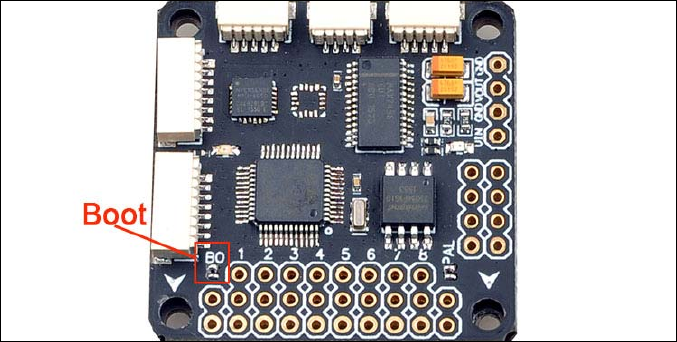
Boot Headers - Used for recovering firmware
No connection = Boot Normally
Bridged = STM32 Bootloader
VBAT headers - Connect flight battery for voltage monitoring, logging and warnings
WARNING: DOUBLE CHECK POLARITY!
Buzzer headers - Connect to a buzzer for warnings and notifications
Use a low-power ~50mA 5.0v buzzer that only requires power to produce sound, e.g.
Sonicrest HCM1205X. See Cleanflight manual for links. Can also be used to find your aircraft
after a crash.
I2C connector - Used for external sensors and OLED displays.
The SCL and SDA are 3.3v signals.
5.0v is always supplied via the on-board voltage regulators, even when powering via USB.
WARNING: logic level converters are REQUIRED if your sensors require 5.0v signals
UART2 connector - Used for 5.0v Serial IO. (GPS, etc.)
MUST NOT be used when SWD port is in use
VIN/VOUT connector - Used for Camera and wireless video transmitter
VIN/GND connect to the video signal and GND of the camera
VOUT/GND connect to the video signal and GND of the video transmitter
No voltage output, please ensure the extra voltage input for you camera and transmitter
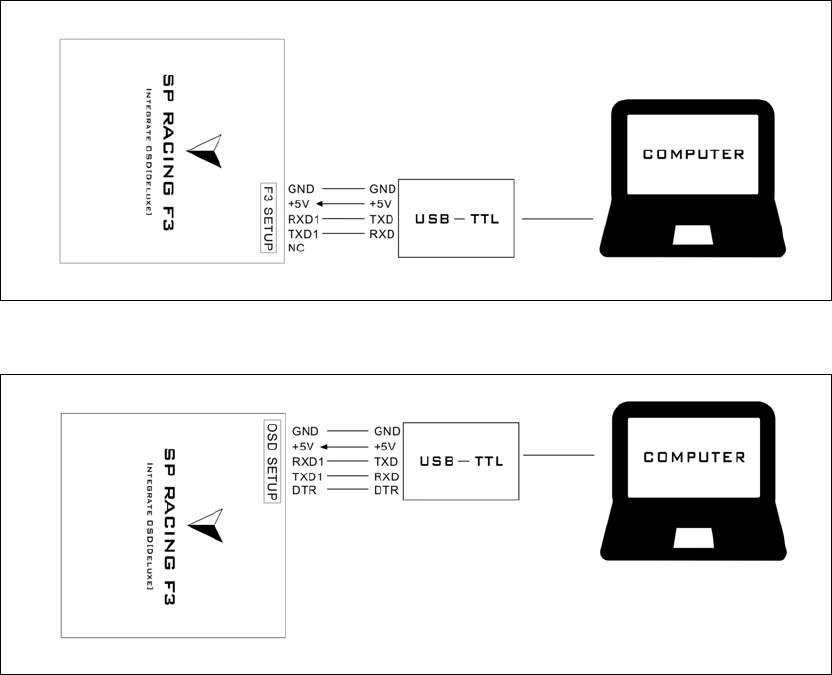
F3 SETUP connector – Used for Flashing firmware and configuring the Flight controller by
computer with connected to the USB-TTL Serial Converter
OSD SETUP connector – Used for Flashing OSD firmware and configuring the OSD
SWD/DEBUG connector - Used for software development or flashing via SWD
Cannot be used when UART2 is enabled. Use an ST-Link debugger with OpenOCD or a
J-Link debugger.
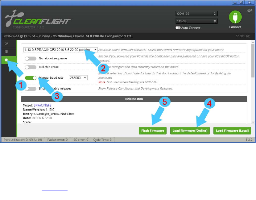
Flight controller Firmware Upgrade
It is highly recommended that you immediately upgrade the firmware of the flight controller so
that you have the latest features and bug fixes. DO NOT FLY until you have used the latest
firmware.
Click the Firmware Flasher tab.
Select the latest SPRacingF3 stable release.
Set the flashing baud rate to 256000.
Click ‘Load firmware [Online]’ and wait for firmware to download and read release notes.
Click ‘Flash Firmware’.
How to install MW OSD firmware to your OSD hardware
Preparation
•Download the MW OSD software pack of your choice.
•Download the Arduino flavor that matches your system.
Testing Firmware communication flashing
•Connect the OSD to the FTDI adapter, and that to the PC.
•Start Arduino IDE.
•Choose the appropriate board. For most MinimOSDs etc go to menu Tools > Board > Arduino
Pro or Pro Mini 5V, 16MHz, w/ ATmega328.
•Select the proper serial port in menu Tools > Serial Port.
•Click on the "Upload" button and observe the serial console at the bottom of arduino. Success
is noted as white text on black background stating just the binary sketch size. If messages in
red letters appear, something went wrong.
Firmware flashing
•Connect the OSD to the FTDI adapter, and that to the PC.
•Start Arduino IDE.
•Select File > Open. Browse to the MW_OSD folder and select 'MW_OSD.ino'
•A new Arduino IDE will appear. Close the other window as it it no longer needed.
•If you have not already done so, make sure to do the following: From the MW_OSD Arduino
window, choose the appropriate board. For most MinimOSDs etc go to menu Tools > Board >
Arduino Pro or Pro Mini 5V, 16MHz, w/ ATmega328. Select the proper serial port in menu
Tools > Serial Port.
•Edit the config.h tab to select the correct OSD hardware, Flight controller and aircraft type.
•Click on the "Upload" button and observe the serial console at the bottom of arduino. Success
is noted as white text on black background stating just the binary sketch size. If messages in
red letters appear, something went wrong.
To test the setup, close Arduino and start MW OSD GUI. It should connect and work normally
with the newly flashed OSD.
Updating fonts
•Connect to the OSD using the GUI.
•Select the font you require otherwise the default one will be used
•The font chosen will be seen in the simulator window
•Select upload from the GUI
•NOTE - check the FAQ - requires the OSD to be powered correctly or teh fonts will not save
(upload looks OK)
