SR55 Soft Starters User Manual (SR55_UMW 1ed,RevA) View / The Sr55manual
User Manual: View / the Manual Stellar SR55 Soft Starter User Manual
Open the PDF directly: View PDF ![]() .
.
Page Count: 210 [warning: Documents this large are best viewed by clicking the View PDF Link!]
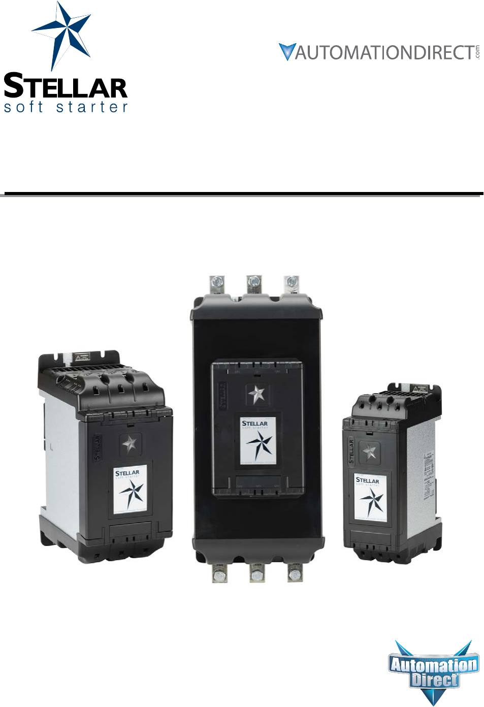
- Stellar® SR55 Soft Starter User Manual
- Errata Sheet
- SR 55 User Manual
- Warnings and Trademarks
- User Manual Revision History
- User Manual Table of Contents
- Chapter 1: Mechanical Installation
- Chapter 2: Electrical Installation
- Chapter 3: Configuration and Parameters
- Chapter 4: Principles of iERS (intelligent Energy Recovery System)
- Chapter 5: Communications
- Chapter 6: Accessories
- Appendix A: Updating Firmware
- Appendix B: Soft Starter Application Considerations
- B.1 – Motor Suitability and Associated Considerations
- B.1.1 – Suitability
- B.1.2 – Induction Motor Characteristics
- B.1.3 – Rating
- B.1.4 – Maximum Motor Cable Length
- B.1.5 – Power Factor Correction Capacitors
- B.1.6 – Lightly Loaded Small Motors
- B.1.7 – Motors Installed with Integral Brakes
- B.1.8 – Older Motors
- B.1.9 – Wound-rotor or Slip-ring Motors
- B.1.10 – Enclosures
- B.1.11 – Efficiency
- B.1.12 – High-Efficiency Motors
- B.1.13 – EU Compliance with the EMC Directive
- B.1.14 – Fuses
- B.2 – Rules for Specific Applications
- B.3 – Concepts and Principles of Fixed-Speed Induction Motor Starting and Control
- Appendix B Glossary of Terms
- B.1 – Motor Suitability and Associated Considerations
- Appendix C: Electromagnetic Compatibility
- C.0 – Electromagnetic Compatibility (EMC)
- C.1 – Introduction
- C.2 – Applicable Standard Within the EU
- C.3 – Mandatory Requirements Within the EU
- C.4 – Guidance for Installation Personnel and System Designers
- C.5 – EMC Basic Criteria
- C.6 – Purchasing Implications of Meeting an EMC Standard
- C.7 – Basic EMC Considerations
- Appendix D: Sizing an SR55 Soft Starter

Errata Sheet
Page 1
Product Family: SR55 Soft Starter
Manual Number SR55_UMW
Revision and Date 1st Edition, Rev. B; February 2017
Date: June 28, 2017
This Errata Sheet contains changes made to Chapter 3
after the publication of this manual.
Changes to Chapter 3. Configuration and Parameters
After the latest publication of this manual, the manufacturer released a firmware update which added four new
parameters, and a new set of block transfer parameters. Refer to this Errata Sheet for details on these new parameters.
Also, there was a Range value change for existing parameter P5.0.
Appendix A in this manual has instructions for updating the firmware.
Change to Parameter P5.0 - Motor Current Range Value
The Range for this parameter changed from “50% to 100% of SR55 rated Amperage” to “10% to 100% of SR55 rated
Amperage”.
This change affects two entries in the manual:
On page 3-6, in the Summary of Parameters for Auto Setup table, under the Range column in the P5.0 - Motor Current
line, change the “50% to 100%” range value to “10% to 50%”.
On page 3-27, in the Parameter Details box towards the bottom of the page for the P5.0 - Motor Current parameter (with
the Advanced “Motor Protection” Parameters heading), change the 50% range value to 10%.
Continued on next page.

Errata Sheet
Page 2
New Parameter Added: P0.11 - I/O Status Register
This new parameter, P0.11, was added.
This change affects two areas in the manual:
On page 3-6, in the first table insert the following summary description line for this new parameter right after the last line
for parameter P0.10:
Summary - Parameters Not Configurable Through Touchscreen
I
Group Parameter Units Range Read /
Write
Modbus Default
Setting
User
Setting
Address Hex
Status Indications
(detailed info
starts)
[page 3-15]
No changes in table for existing
parameters P0.0 through P0.10
P0.10 – iERS Active -OFF / ON Read 38080 94C0 OFF -
P0.11 – I/O Status Register -0 to 255 Read 62016 F240 OFF -
On page 3-17, insert the following Parameters Details box for the new parameter right after the existing box for
parameter P0.10 - iERS Active:
P0.11 – I/O Status Register Hold. Reg. Type:
Description:
Read
Displays the current status of the hardware inputs and outputs.
b0 ( Input DI-1I) b1 (Input D1-2I) b2 (input D2-I1) b3 (undefined)
b4 ( Output 12) b5 ( Output 24) b6 (Output 34) b7 (Output 44)
Range: Modbus Decimal Value: Default (decimal):
• 0 to 255 • 0
• 1
• OFF (0)
Modbus Address: Modbus Format:
62016 (F240 hex ) 16-bit unsigned
Continued on next page.

Errata Sheet
Page 3
SR55 Parameters Summary – Serial Communication Parameters – Block Transfer Parameter Map
Address
Description
Block Transfer Address Pointers Block Transfer Data
Default
Setting
Para-
meter Range Read/
Write
Modbus
Address Default
Setting Address Description Para-
meter Range
Read/
Write
Modbus
Address
Address Hex Address Hex
Block Transfer 1 P0.20
0~65535 R/W
17600 44C0 OFF Block Data Address 1 P0.40
0–65535 R/W
17664 44C0 OFF
Block Transfer 2 P0.21 17601 44C1 OFF Block Data Address 2 P0.41 17666 44C1 OFF
Block Transfer 3 P0.22 17602 44C2 OFF Block Data Address 3 P0.42 17668 44C2 OFF
Block Transfer 4 P0.23 17603 44C3 OFF Block Data Address 4 P0.43 17670 44C3 OFF
Block Transfer 5 P0.24 17604 44C4 OFF Block Data Address 5 P0.44 17672 44C4 OFF
Block Transfer 6 P0.25 17605 44C5 OFF Block Data Address 6 P0.45 17674 44C5 OFF
Block Transfer 7 P0.26 17606 44C6 OFF Block Data Address 7 P0.46 17676 44C6 OFF
Block Transfer 8 P0.27 17607 44C7 OFF Block Data Address 8 P0.47 17678 44C7 OFF
Block Transfer 9 P0.28 17608 44C8 OFF Block Data Address 9 P0.48 17680 44C8 OFF
Block Transfer 10 P0.29 17609 44C9 OFF Block Data Address 10 P0.49 17682 44C9 OFF
Block Transfer 11 P0.30 17610 44CA OFF Block Data Address 11 P0.50 17684 44CA OFF
Block Transfer 12 P0.31 17611 44CB OFF Block Data Address 12 P0.51 17686 44CB OFF
Block Transfer 13 P0.32 17612 44CC OFF Block Data Address 13 P0.52 17688 44CC OFF
Block Transfer 14 P0.33 17613 44CD OFF Block Data Address 14 P0.53 17690 44CD OFF
Block Transfer 15 P0.34 17614 44CE OFF Block Data Address 15 P0.54 17692 44CE OFF
Block Transfer 16 P0.35 17615 44CF OFF Block Data Address 16 P0.55 17694 44CF OFF
Block Transfer Explanation
Parameters P0.20~P0.35 and P0.40~P0.55
Block Transfer allows parameters from many different Parameter Groups to be consolidated into one Modbus
communication message. This can greatly simplify PLC programming and reduce network traffic. A maximum of 16
parameters can be grouped together. The 16 Block Transfer Address Pointer registers have 16 correlating, four-byte,
Block Transfer Data registers that correspond with the Pointer registers and act as the data conduits for each select
address. Once set the addresses can be saved in none volatile memory if required. The Block Transfer parameters can
only be accessed through Modbus, not through the Touchscreen Menu.
• New Pointer Parameters P0.20~P0.35 (where you enter the addresses that you want to consolidate)
• Data Location Parameters P0.40~P0.55 (where you push data into, or pull data out of)
Continued on next page.
New Block Transfer Parameters Added
Insert the following Block Transfer information after the new Parameter P0.11 - I/O Status Register added on the previous
page.

Errata Sheet
Page 4
Block Transfer Example
The table below shows the relationship between the alias Registers and the data Registers. The data can take any data
type that can fit into 4 bytes. So, any address that yields 6 bytes of data, such as time, will be incomplete. To access data
that is more than 6 bytes then reading or writing directly to that register should be implemented and not accessed using
the Block Transfer method. Below is an example of what will happen with different sizes.
Alias
Address
Addresses Parameter Data
Address Data Shown in 4 Bytes
17600 P3.3 – Start Current Limit Level 17664 0x00 0x00 0xe8 0x6c
17601 P3.4 – Start Current Limit Time 17666 0x00 0x00 0x01 0x0e
17602 P3.1 – Start Pedestal 17668 0x00 0x00 0x0c 0xcd
17603 P6.0 – iERS Enable 17670 0x00 0x00 0x00 0x00
17604 P6.2 – iERS Rate 17672 0x00 0x00 0x00 0x00
17605 P15.17 – Start Saving Level 17674 0x00 0x00 0x00 0x00
Continued on next page.
Errata Sheet
Page 5
New Parameters Added: P9.2 - Main Contactor Control, and P9.3 - Hand-Auto Control
These two new parameters, P9.2 and P9.3, were added for touch-screen setup.
This change affects two areas in the manual:
On page 3-9, replace the table shown at the top of the page with the one below, which has the summary descriptions for
the two new parameters. No changes were made to existing parameters P9.0 or P9.1.
Summary - Parameters for Touchscreen Setup - “Advanced” Category (continued)
I
Group Parameter Units Range Read /
Write
Modbus Default
Setting
User
Setting
Address Hex
Advanced
(P9)
[page 3-33
P9.0 – Firing Mode toggle In-Delta / In-line R/W 128 0080 In-Line
P9.1 – Legacy Delta Mode toggle OFF / ON R/W 192 00C0 OFF
P9.2 – Main Contactor Control toggle OFF / ON R/W 14144 3740 OFF
P9.3 – Hand-Auto Control toggle OFF / ON R/W 28160 6E00 OFF
On page 3-40, right after the existing Parameter Details box for parameter P9.1 - Legacy Delta Mode, add the following
two Parameters Details boxes for the new parameters:
Advanced “Main Contactor Control” Parameter
P9.2 – Main Contactor Control Hold. Reg. Type:
Description:
Read/Write
Used when the motor is required to start when the Main Contactor closes, and stop when it
opens. An auxiliary contact from the main contactor is used as a Start / Stop signal. The ‘ Stop
Time’ must be set to zero.
Range: Modbus Decimal Value: Default (decimal):
• Off : When the contactor opens and the stop signal is given at the
same time the unit may trip on “Phase Loss” (Default).
• On : When the contactor opens and the stop signal is given at the
same time the unit will not trip on “Phase Loss”.
• 0
• 1
• OFF (0)
Modbus Address: Modbus Format:
14144 (3740 hex ) 16-bit unsigned
Touchscreen Menu Path:
Home → Advanced → Main Contactor Control
Continued on next page.

Errata Sheet
Page 6
Advanced “Hand-Auto Control” Parameter (continued)
P9.3 – Hand-Auto Control Hold. Reg. Type:
Description:
Read/Write
A Hand-Auto selection switch can be connected to Digital Input D1-2I to change the ‘Control
Method’. This can be used to change the Start / Stop to ‘Hand’ if the Communications fails. The
user must ensure D1-2I = 1 and D1-2I = 0 which are the default settings for those inputs before
turning on Hand-Auto Control.
• D1-2I = 1: Control Method is set to “2 -Wire” (Hand).
• D1-2I = 0: Control Method is set to “Modbus Network” (Auto).
• Hand : Input D1-1I = Start / Stop , Input D2-1I = Reset
• Auto : ADDRESS 17920 = Start / Stop , ADDRESS 18368 = Reset
Range: Modbus Decimal Value: Default (decimal):
• Off : Control method can be selected to any method needed.
Digital input functions can be changed.
• On : Control Method is fixed to “User Programable”. Digital inputs
are fixed to as shown in the description above.
• 0
• 1
• OFF (0)
Modbus Address: Modbus Format:
28160 (6E00 hex ) 16-bit unsigned
Touchscreen Menu Path:
Home → Advanced → Hand-Auto Control
Continued on next page.

Errata Sheet
Page 7
P26.6 – Communications Shutdown Hold. Reg. Type:
Description:
Read/Write
This works in conjunction with the ‘Communications Trip’.
Range: Modbus Decimal Value: Default (decimal):
• Off : If the ‘Communication Trip’ is turned ‘On’ the unit will trip if
the communications fail.
• On : If the ‘Communication Trip’ is turned ‘On’ the unit will shut
down instead of tripping if the communications fail.
• 0
• 1
• ON (1)
Modbus Address: Modbus Format:
53802 (D22A hex ) 16-bit unsigned
Touchscreen Menu Path:
Home → Advanced → Communications Shutdown
On page 3-78, insert the following Parameters Details box for the new parameter right after the existing box for
parameter P26.5 - Timout mS:
New Parameter Added: P26.6 - Communications Shutdown
This new parameters, P26.6, was added for touch-screen setup.
This change affects two areas in the manual:
On page 3-13, in the table insert the following summary description line for this new parameter right after the
existing line for parameter P26.5 - Timeout:
Summary - Parameters for Touchscreen Setup - “Device” Category
I
Group Parameter Units Range Read /
Write
Modbus Default
Setting
User
Setting
Address Hex
Device
(P26)
Networks
[page 377]
P26.5 – Timeout ms 0 to 60,000 R/W 15808 3DC0 5,000
P26.6 – Communications Shutdown toggle OFF / ON R/W 53802 D22A ON
®
Stellar® SR55 Soft Starter User Manual
SR55_UMW
First Edition, Revision B

Stellar® SR55 Series Soft Starter User Manual – 1st Ed. Rev.B – 02/02/2017
BLANK
PAG E

Page W–1Stellar® SR55 Series Soft Starter User Manual – 1st Ed. Rev.B – 02/02/2017
Warnings and Trademarks
~ WARNING ~
Thank you for purchasing automation equipment from Automationdirect.com®, doing business as
AutomationDirect. We want your new automation equipment to operate safely. Anyone who installs or
uses this equipment should read this publication (and any other relevant publications) before installing or
operating the equipment.
To minimize the risk of potential safety problems, you should follow all applicable local and national
codes that regulate the installation and operation of your equipment. These codes vary from area to area
and usually change with time. It is your responsibility to determine which codes should be followed, and
to verify that the equipment, installation, and operation is in compliance with the latest revision of these
codes.
At a minimum, you should follow all applicable sections of the National Fire Code, National Electrical
Code, and the codes of the National Electrical Manufacturer’s Association (NEMA). There may be local
regulatory or government offices that can also help determine which codes and standards are necessary
for safe installation and operation.
Equipment damage or serious injury to personnel can result from the failure to follow all applicable
codes and standards. We do not guarantee the products described in this publication are suitable for
your particular application, nor do we assume any responsibility for your product design, installation, or
operation.
Our products are not fault-tolerant and are not designed, manufactured or intended for use or resale as
on-line control equipment in hazardous environments requiring fail-safe performance, such as in the
operation of nuclear facilities, aircraft navigation or communication systems, air traffic control, direct life
support machines, or weapons systems, in which the failure of the product could lead directly to death,
personal injury, or severe physical or environmental damage (“High Risk Activities”). AutomationDirect
specifically disclaims any expressed or implied warranty of fitness for High Risk Activities.
For additional warranty and safety information, see the Terms and Conditions section of our catalog.
If you have any questions concerning the installation or operation of this equipment, or if you need
additional information, please call us at 770-844-4200.
This publication is based on information that was available at the time it was printed. At
AutomationDirect we constantly strive to improve our products and services, so we reserve the right to
make changes to the products and/or publications at any time without notice and without any obligation.
This publication may also discuss features that may not be available in certain revisions of the product.
Trademarks
This publication may contain references to products produced and/or offered by other companies. The
product and company names may be trademarked and are the sole property of their respective owners.
AutomationDirect disclaims any proprietary interest in the marks and names of others.
Copyright 2015, 2017 Automationdirect.com® Incorporated
All Rights Reserved
No part of this manual shall be copied, reproduced, or transmitted in any way without the prior, written
consent of Automationdirect.com® Incorporated. AutomationDirect retains the exclusive rights to all
information included in this document.

Page W–2 Stellar® SR55 Series Soft Starter User Manual – 1st Ed. Rev.B – 02/02/2017
~ AVERTISSEMENT ~
Nous vous remercions d’avoir acheté l’équipement d’automatisation de Automationdirect.com®,
en faisant des affaires comme AutomationDirect. Nous tenons à ce que votre nouvel équipement
d’automatisation fonctionne en toute sécurité. Toute personne qui installe ou utilise cet équipement
doit lire la présente publication (et toutes les autres publications pertinentes) avant de l’installer ou de
l’utiliser.
Afin de réduire au minimum le risque d’éventuels problèmes de sécurité, vous devez respecter tous les
codes locaux et nationaux applicables régissant l’installation et le fonctionnement de votre équipement.
Ces codes diffèrent d’une région à l’autre et, habituellement, évoluent au fil du temps. Il vous incombe de
déterminer les codes à respecter et de vous assurer que l’équipement, l’installation et le fonctionnement
sont conformes aux exigences de la version la plus récente de ces codes.
Vous devez, à tout le moins, respecter toutes les sections applicables du Code national de prévention
des incendies, du Code national de l’électricité et des codes de la National Electrical Manufacturer’s
Association (NEMA). Des organismes de réglementation ou des services gouvernementaux locaux
peuvent également vous aider à déterminer les codes ainsi que les normes à respecter pour assurer une
installation et un fonctionnement sûrs.
L’omission de respecter la totalité des codes et des normes applicables peut entraîner des dommages
à l’équipement ou causer de graves blessures au personnel. Nous ne garantissons pas que les produits
décrits dans cette publication conviennent à votre application particulière et nous n’assumons aucune
responsabilité à l’égard de la conception, de l’installation ou du fonctionnement de votre produit.
Nos produits ne sont pas insensibles aux défaillances et ne sont ni conçus ni fabriqués pour l’utilisation ou
la revente en tant qu’équipement de commande en ligne dans des environnements dangereux nécessitant
une sécurité absolue, par exemple, l’exploitation d’installations nucléaires, les systèmes de navigation
aérienne ou de communication, le contrôle de la circulation aérienne, les équipements de survie ou
les systèmes d’armes, pour lesquels la défaillance du produit peut provoquer la mort, des blessures
corporelles ou de graves dommages matériels ou environnementaux («activités à risque élevé»). La
société AutomationDirect nie toute garantie expresse ou implicite d’aptitude à l’emploi en ce qui a trait
aux activités à risque élevé.
Pour des renseignements additionnels touchant la garantie et la sécurité, veuillez consulter la section
Modalités et conditions de notre documentation. Si vous avez des questions au sujet de l’installation ou
du fonctionnement de cet équipement, ou encore si vous avez besoin de renseignements supplémentaires,
n’hésitez pas à nous téléphoner au 770-844-4200.
Cette publication s’appuie sur l’information qui était disponible au moment de l’impression. À la
société AutomationDirect, nous nous efforçons constamment d’améliorer nos produits et services. C’est
pourquoi nous nous réservons le droit d’apporter des modifications aux produits ou aux publications en
tout temps, sans préavis ni quelque obligation que ce soit. La présente publication peut aussi porter sur
des caractéristiques susceptibles de ne pas être offertes dans certaines versions révisées du produit.
Marques de commerce
La présente publication peut contenir des références à des produits fabriqués ou offerts par d’autres
entreprises. Les désignations des produits et des entreprises peuvent être des marques de commerce et
appartiennent exclusivement à leurs propriétaires respectifs. AutomationDirect nie tout intérêt dans les
autres marques et désignations.
Copyright 2015, 2017 Automationdirect.com® Incorporated
Tous droits réservés
Nulle partie de ce manuel ne doit être copiée, reproduite ou transmise de quelque façon que ce soit sans
le consentement préalable écrit de la société Automationdirect.com® Incorporated. AutomationDirect
conserve les droits exclusifs à l’égard de tous les renseignements contenus dans le présent document.
Page W–3Stellar® SR55 Series Soft Starter User Manual – 1st Ed. Rev.B – 02/02/2017
Warnings
The owner, insTaller, and user are responsible for The correcT insTallaTion and use of The
sTellar® sr55, for ensuring ThaT only qualified personnel insTall The sr55, and for ensuring
ThaT The operaTion and mainTenance of The uniT complies wiTh The relevanT codes of pracTice,
regulaTions, and sTaTuTory requiremenTs. The manufacTurer or his agenT do noT assume any
expressed or implied liabiliTy for any consequences resulTing from inappropriaTe, negligenT,
or incorrecT insTallaTion, applicaTion, use, or adjusTmenT of The producT or circuiT design, or
from The mismaTch of The uniT To a moTor. To prevenT an elecTrical shock hazard, The sr55
musT be properly grounded. The sr55 is noT designed for use in hazardous areas. use in such
an area may invalidaTe The hazardous area cerTificaTion.
warning: read This manual Thoroughly before using sTellar® sr55 series sofT sTarTers.
warning: The sr55 uses semiconducTor devices in The main (power) circuiT, and is noT designed
To provide isolaTion. for This reason, isolaTion device(s) musT be insTalled in The power supply
circuiT in accordance wiTh The applicable wiring and safeTy regulaTions.
warning: ac inpuT power musT be disconnecTed before performing any mainTenance. do
noT connecT or disconnecT wires or connecTors while power is applied To The circuiT.
mainTenance musT be performed only by a qualified Technician.
warning: There are highly sensiTive elecTronic componenTs on The prinTed circuiT boards,
and These componenTs are especially sensiTive To sTaTic elecTriciTy. To avoid damage To These
componenTs, do noT Touch These componenTs or The circuiT boards wiTh meTal objecTs or your
bare hands.
warning: always replace The cover panel on The uniT afTer gaining access To The elecTrical
connecTions.
warning: The sr55 may be desTroyed beyond repair if incorrecT cables are connecTed To The
inpuT/ouTpuT Terminals. never connecT The sr55 ouTpuT Terminals T1, T2, and T3 direcTly To
The ac main circuiT power supply.
warning: ground The sr55 sofT sTarTer using The ground Terminal. The grounding meThod
musT comply wiTh The laws of The counTry where The sr55 is To be insTalled. refer To chapTer
2, “elecTrical insTallaTion”.

Page W–4 Stellar® SR55 Series Soft Starter User Manual – 1st Ed. Rev.B – 02/02/2017
BLANK
PAG E
Page H–1Stellar® SR55 Series Soft Starter User Manual – 1st Ed. Rev.B – 02/02/2017
Stellar®
SR55 Soft Starter
User Manual
User manUal revision HisTory
Please include this Manual Number and the Manual Issue, both shown below, when communicating with
AutomationDirect Technical Support regarding this publication.
Manual Number: SR55_UMW
Manual Issue: First Edition, Revision B
Issue Date: 02/02/2017
Publication History
Issue Date Description of Changes
First Edition 06/17/2015 Original Issue
1st Ed., Rev.A 08/17/2015
C h.2: Control power consumption specs, Bypass contactor info,
Ch.3: Parameter holding register notations; Parameter descriptions (P8.7, P9.1, P13.1, P14.0,
P15.19); Parameter examples (P12.1, P13.1); Trip codes 601, 1501; Fail Safe codes.
C h.5: Modbus RTU comm note.
C h.6: RJ45–R12 adapter pin-out; Cooling fan running conditions.
A ppx.A: Recommend save configuration before updating firmware.
A ppx.D: New Appendix.
1st Ed., Rev.B 02/02/2017
User Manual Number (file name) change; was SR55-M-WO.
Ch.1: Dimensions for frame size 3 soft starters.
Appx.D: Trip Class rating for Tumblers.

Page H–2 Stellar® SR55 Series Soft Starter User Manual – 1st Ed. Rev.B – 02/02/2017
BLANK
PAG E

TOC–1Stellar® SR55 Series Soft Starter User Manual – 1st Ed. Rev.B – 02/02/2017
SR55 USeR ManUal
Table of ConTenTS ConTenTS
ConTenTS
ConTenTS
Warnings and Trademarks . . . . . . . . . . . . . . . . . . . . . . . . . . . . . . . . . . . . . . W–1
~ WARNING ~ . . . . . . . . . . . . . . . . . . . . . . . . . . . . . . . . . . . . . . . . . . . . W–1
Trademarks . . . . . . . . . . . . . . . . . . . . . . . . . . . . . . . . . . . . . . . . . . . . . . W–1
~ AVERTISSEMENT ~ . . . . . . . . . . . . . . . . . . . . . . . . . . . . . . . . . . . . . . . . . W–2
Marques de commerce . . . . . . . . . . . . . . . . . . . . . . . . . . . . . . . . . . . . . . . . W–2
Warnings . . . . . . . . . . . . . . . . . . . . . . . . . . . . . . . . . . . . . . . . . . . . . . . W–3
User Manual Revision History . . . . . . . . . . . . . . . . . . . . . . . . . . . . . . . . . . . . H–1
Chapter 1: Mechanical Installation . . . . . . . . . . . . . . . . . . . . . . . . . . . . . . . . . 1–1
User Manual Overview . . . . . . . . . . . . . . . . . . . . . . . . . . . . . . . . . . . . . . . . . 1–2
Overview of this Publication . . . . . . . . . . . . . . . . . . . . . . . . . . . . . . . . . 1–2
Who Should Read This Manual . . . . . . . . . . . . . . . . . . . . . . . . . . . . . . . 1–2
Supplemental Publications . . . . . . . . . . . . . . . . . . . . . . . . . . . . . . . . . . 1–2
Technical Support . . . . . . . . . . . . . . . . . . . . . . . . . . . . . . . . . . . . . . . 1–2
Special Symbols . . . . . . . . . . . . . . . . . . . . . . . . . . . . . . . . . . . . . . . . 1–2
Mechanical Installation. . . . . . . . . . . . . . . . . . . . . . . . . . . . . . . . . . . . . . . . . 1–3
Mounting . . . . . . . . . . . . . . . . . . . . . . . . . . . . . . . . . . . . . . . . . . . 1–3
Requirements for an Enclosure. . . . . . . . . . . . . . . . . . . . . . . . . . . . . . . . 1–3
Enclosure Ventilation . . . . . . . . . . . . . . . . . . . . . . . . . . . . . . . . . . . . . 1–3
Mechanical Specifications . . . . . . . . . . . . . . . . . . . . . . . . . . . . . . . . . . 1–4
Dimensions . . . . . . . . . . . . . . . . . . . . . . . . . . . . . . . . . . . . . . . . . . 1–4
Chapter 2: Electrical Installation. . . . . . . . . . . . . . . . . . . . . . . . . . . . . . . . . . . 2–1
Safety Warning . . . . . . . . . . . . . . . . . . . . . . . . . . . . . . . . . . . . . . . . . . . . . 2–2
Agency Approvals. . . . . . . . . . . . . . . . . . . . . . . . . . . . . . . . . . . . . . . . . . . . 2–2
Technical Information and Standards . . . . . . . . . . . . . . . . . . . . . . . . . . . . . . . . . 2–2
Electrical Specifications. . . . . . . . . . . . . . . . . . . . . . . . . . . . . . . . . . . . . . . . . 2–3
Circuit Protection . . . . . . . . . . . . . . . . . . . . . . . . . . . . . . . . . . . . . . . . . . . . 2–4
Short-Circuit Protection . . . . . . . . . . . . . . . . . . . . . . . . . . . . . . . . . . . 2–4
Motor overload Protection . . . . . . . . . . . . . . . . . . . . . . . . . . . . . . . . . . 2–5
Wire Sizes and Torques . . . . . . . . . . . . . . . . . . . . . . . . . . . . . . . . . . . . . . . . . 2–5
Electrical Connections . . . . . . . . . . . . . . . . . . . . . . . . . . . . . . . . . . . . . . . . . 2–6
Electrical Wiring . . . . . . . . . . . . . . . . . . . . . . . . . . . . . . . . . . . . . . . . . . . . 2–7
Power Circuit Wiring . . . . . . . . . . . . . . . . . . . . . . . . . . . . . . . . . . . . . 2–7
Control Circuit Wiring . . . . . . . . . . . . . . . . . . . . . . . . . . . . . . . . . . . . 2–8

TOC–2 Stellar® SR55 Series Soft Starter User Manual – 1st Ed. Rev.B – 02/02/2017
Table of Contents
Chapter 3: Configuration and Parameters . . . . . . . . . . . . . . . . . . . . . . . . . . . . . 3–1
“Heartbeat” LED . . . . . . . . . . . . . . . . . . . . . . . . . . . . . . . . . . . . . . . . . . . . 3–2
Configuration Overview . . . . . . . . . . . . . . . . . . . . . . . . . . . . . . . . . . . . . . . . 3–2
Auto Setup Procedure . . . . . . . . . . . . . . . . . . . . . . . . . . . . . . . . . . . . 3–2
Setup by Individual Parameter Settings . . . . . . . . . . . . . . . . . . . . . . . . . . . 3–2
Configuration From Touchscreen . . . . . . . . . . . . . . . . . . . . . . . . . . . . . . . . . . . 3–2
Auto Setup Procedure from Touchscreen . . . . . . . . . . . . . . . . . . . . . . . . . . 3–2
Individual Parameter Settings from Touchscreen . . . . . . . . . . . . . . . . . . . . . . 3–2
Touchscreen Pictorial Example – Auto Setup . . . . . . . . . . . . . . . . . . . . . . . . 3–3
Auto Setup Procedure – Parameter Settings . . . . . . . . . . . . . . . . . . . . . . . . . . . . . 3–4
Parameter Summary . . . . . . . . . . . . . . . . . . . . . . . . . . . . . . . . . . . . . . . . . . 3–6
Summary of Parameters Not Configurable Through Touchscreen Menu . . . . . . . . . 3–6
Summary of Parameters for Auto Setup. . . . . . . . . . . . . . . . . . . . . . . . . . . 3–6
Summary of Parameters for Individual Parameter Setup . . . . . . . . . . . . . . . . . 3–7
Parameter Details. . . . . . . . . . . . . . . . . . . . . . . . . . . . . . . . . . . . . . . . . . . 3–14
Parameters Not Configurable Through Touchscreen Menu . . . . . . . . . . . . . . . .3–14
Parameters in Sequence and Grouped by Touchscreen Navigation . . . . . . . . . . . .3–18
“Auto Setup” Menu of Parameters . . . . . . . . . . . . . . . . . . . . . . . . . . . . . .3–18
“Advanced” Menu of Parameters. . . . . . . . . . . . . . . . . . . . . . . . . . . . . . .3–20
“I/O” Menu of Parameters . . . . . . . . . . . . . . . . . . . . . . . . . . . . . . . . . .3–41
“Monitor” Menu of Parameters . . . . . . . . . . . . . . . . . . . . . . . . . . . . . . .3–50
“Log” Menu of Parameters . . . . . . . . . . . . . . . . . . . . . . . . . . . . . . . . . .3–56
“Device” Menu of Parameters . . . . . . . . . . . . . . . . . . . . . . . . . . . . . . . .3–75
Trip Code Descriptions . . . . . . . . . . . . . . . . . . . . . . . . . . . . . . . . . . . . . . . . 3–80
Fail Safe Codes . . . . . . . . . . . . . . . . . . . . . . . . . . . . . . . . . . . . . . . . . . . . 3–83
Main Board Trip (2402 – 2436) . . . . . . . . . . . . . . . . . . . . . . . . . . . . . . .3–83
Touchscreen Trip (2501 – 2581) . . . . . . . . . . . . . . . . . . . . . . . . . . . . . . .3–83
Logging Trip (2601 – 2603). . . . . . . . . . . . . . . . . . . . . . . . . . . . . . . . . .3–84
Fail Safe Trip Codes. . . . . . . . . . . . . . . . . . . . . . . . . . . . . . . . . . . . . .3–84
Saving and Loading an SR55 Configuration File . . . . . . . . . . . . . . . . . . . . . . . . . . 3–85
Chapter 4: Principles of iERS (intelligent Energy Recovery System) . . . . . . . . . . . . . . . . 4–1
Principles of the iERS . . . . . . . . . . . . . . . . . . . . . . . . . . . . . . . . . . . . . . . . . . 4–2
Principles . . . . . . . . . . . . . . . . . . . . . . . . . . . . . . . . . . . . . . . . . . . 4–2
Advantages of iERS . . . . . . . . . . . . . . . . . . . . . . . . . . . . . . . . . . . . . . 4–3
How Much Energy? . . . . . . . . . . . . . . . . . . . . . . . . . . . . . . . . . . . . . . 4–4
Estimating Energy Savings . . . . . . . . . . . . . . . . . . . . . . . . . . . . . . . . . . 4–5
iERS with the SR55 System . . . . . . . . . . . . . . . . . . . . . . . . . . . . . . . . . . 4–6
Chapter 4 Glossary of Terms . . . . . . . . . . . . . . . . . . . . . . . . . . . . . . . . . . . . . . 4–7

Table of Contents
TOC–3Stellar® SR55 Series Soft Starter User Manual – 1st Ed. Rev.B – 02/02/2017
Chapter 5: Communications . . . . . . . . . . . . . . . . . . . . . . . . . . . . . . . . . . . . . 5–1
SR55 Communications Overview . . . . . . . . . . . . . . . . . . . . . . . . . . . . . . . . . . . 5–2
Modbus Serial Communications . . . . . . . . . . . . . . . . . . . . . . . . . . . . . . . . . . . . 5–3
Modbus RTU Communications Interface . . . . . . . . . . . . . . . . . . . . . . . . . . 5–3
Modbus RTU Connections . . . . . . . . . . . . . . . . . . . . . . . . . . . . . . . . . . 5–3
Modbus Communications Configuration . . . . . . . . . . . . . . . . . . . . . . . . . . 5–4
Transmission Modes . . . . . . . . . . . . . . . . . . . . . . . . . . . . . . . . . . . . . 5–4
Message Structure For RTU Mode . . . . . . . . . . . . . . . . . . . . . . . . . . . . . . 5–4
Supported Functions . . . . . . . . . . . . . . . . . . . . . . . . . . . . . . . . . . . . . 5–5
Memory Map . . . . . . . . . . . . . . . . . . . . . . . . . . . . . . . . . . . . . . . . . 5–6
Message Timing. . . . . . . . . . . . . . . . . . . . . . . . . . . . . . . . . . . . . . . . 5–6
Network Communications – EtherNet/IP and Modbus TCP . . . . . . . . . . . . . . . . . . . . . 5–7
Communication Module Overview . . . . . . . . . . . . . . . . . . . . . . . . . . . . . 5–7
Module Installation – SR55-CM-ENETIP and SR55-CM-MODTCP . . . . . . . . . . . . . 5–7
SR55 Configuration. . . . . . . . . . . . . . . . . . . . . . . . . . . . . . . . . . . . . . 5–7
IP Address Configuration. . . . . . . . . . . . . . . . . . . . . . . . . . . . . . . . . . . 5–7
Communication Module Front Panel Indicator Lights . . . . . . . . . . . . . . . . . . . 5–8
Modbus TCP Network Communications. . . . . . . . . . . . . . . . . . . . . . . . . . . . . . . . 5–8
EtherNet/IP Network Communications . . . . . . . . . . . . . . . . . . . . . . . . . . . . . . . . 5–8
EtherNet/IP Control. . . . . . . . . . . . . . . . . . . . . . . . . . . . . . . . . . . . . . 5–9
EDS File . . . . . . . . . . . . . . . . . . . . . . . . . . . . . . . . . . . . . . . . . . . . 5–9
Using the IP Configuration Tool (IPconfig) . . . . . . . . . . . . . . . . . . . . . . . . .5–10
Connecting to the SR55-CM-ENET Module through I/O (Implicit Messaging) . . . . . .5–14
Connecting to the SR55-CM-ENET Module through Explicit Message: . . . . . . . . . .5–17
Explicit Message Instruction Examples (from Productivity Series CPU) . . . . . . . . . .5–18
Chapter 6: Accessories . . . . . . . . . . . . . . . . . . . . . . . . . . . . . . . . . . . . . . . . 6–1
Optional Accessories . . . . . . . . . . . . . . . . . . . . . . . . . . . . . . . . . . . . . . . . . . 6–2
Finger Guards . . . . . . . . . . . . . . . . . . . . . . . . . . . . . . . . . . . . . . . . . 6–2
Remote Touchscreen . . . . . . . . . . . . . . . . . . . . . . . . . . . . . . . . . . . . . 6–3
RJ45 to RJ12 Adapter . . . . . . . . . . . . . . . . . . . . . . . . . . . . . . . . . . . . . 6–5
Serial Modbus Communication Splitter . . . . . . . . . . . . . . . . . . . . . . . . . . . 6–5
Communication Modules. . . . . . . . . . . . . . . . . . . . . . . . . . . . . . . . . . . 6–7
Replacement/Spare Parts. . . . . . . . . . . . . . . . . . . . . . . . . . . . . . . . . . . . . . . 6–10
Replacement Cooling Fans . . . . . . . . . . . . . . . . . . . . . . . . . . . . . . . . . .6–11
Replacement Touchscreen . . . . . . . . . . . . . . . . . . . . . . . . . . . . . . . . . .6–13
Appendix A: Updating Firmware. . . . . . . . . . . . . . . . . . . . . . . . . . . . . . . . . . . A–1
Updating SR55 Firmware. . . . . . . . . . . . . . . . . . . . . . . . . . . . . . . . . . . . . . . . A–2

TOC–4 Stellar® SR55 Series Soft Starter User Manual – 1st Ed. Rev.B – 02/02/2017
Table of Contents
Appendix B: Soft Starter Application Considerations . . . . . . . . . . . . . . . . . . . . . . . . B–1
B.1 – Motor Suitability and Associated Considerations . . . . . . . . . . . . . . . . . . . . . . . . B–2
B.1.1 – Suitability . . . . . . . . . . . . . . . . . . . . . . . . . . . . . . . . . . . . . . . B–2
B.1.2 – Induction Motor Characteristics . . . . . . . . . . . . . . . . . . . . . . . . . . . B–2
B.1.3 – Rating . . . . . . . . . . . . . . . . . . . . . . . . . . . . . . . . . . . . . . . . . B–2
B.1.4 – Maximum Motor Cable Length . . . . . . . . . . . . . . . . . . . . . . . . . . . B–3
B.1.5 – Power Factor Correction Capacitors . . . . . . . . . . . . . . . . . . . . . . . . . B–3
B.1.6 – Lightly Loaded Small Motors. . . . . . . . . . . . . . . . . . . . . . . . . . . . . B–3
B.1.7 – Motors Installed with Integral Brakes . . . . . . . . . . . . . . . . . . . . . . . . B–3
B.1.8 – Older Motors . . . . . . . . . . . . . . . . . . . . . . . . . . . . . . . . . . . . . B–3
B.1.9 – Wound-rotor or Slip-ring Motors . . . . . . . . . . . . . . . . . . . . . . . . . . B–3
B.1.10 – Enclosures . . . . . . . . . . . . . . . . . . . . . . . . . . . . . . . . . . . . . . B–3
B.1.11 – Efficiency. . . . . . . . . . . . . . . . . . . . . . . . . . . . . . . . . . . . . . . B–4
B.1.12 – High-Efficiency Motors . . . . . . . . . . . . . . . . . . . . . . . . . . . . . . . B–4
B.1.13 – EU Compliance with the EMC Directive . . . . . . . . . . . . . . . . . . . . . . B–4
B.1.14 – Fuses . . . . . . . . . . . . . . . . . . . . . . . . . . . . . . . . . . . . . . . . . B–4
B.2 – Rules for Specific Applications . . . . . . . . . . . . . . . . . . . . . . . . . . . . . . . . . . B–5
B.2.1 – In-Delta Operation . . . . . . . . . . . . . . . . . . . . . . . . . . . . . . . . . . B–5
B.2.2 – High-Inertia Loads . . . . . . . . . . . . . . . . . . . . . . . . . . . . . . . . . . B–5
B.2.4 – Resistive Loads . . . . . . . . . . . . . . . . . . . . . . . . . . . . . . . . . . . . B–5
B.2.5 – Frequent Starting . . . . . . . . . . . . . . . . . . . . . . . . . . . . . . . . . . . B–5
B.2.6 – Optimizing . . . . . . . . . . . . . . . . . . . . . . . . . . . . . . . . . . . . . . B–5
B.2.7 – Soft Stopping . . . . . . . . . . . . . . . . . . . . . . . . . . . . . . . . . . . . . B–6
B.2.9 – Replacement of Fluid Couplings . . . . . . . . . . . . . . . . . . . . . . . . . . . B–6
B.2.12 – Overhauling Loads . . . . . . . . . . . . . . . . . . . . . . . . . . . . . . . . . B–6
B.2.13 – Application Table . . . . . . . . . . . . . . . . . . . . . . . . . . . . . . . . . . B–6
B.3 – Concepts and Principles of Fixed-Speed Induction Motor Starting and Control. . . . . . . . B–8
B.3.1 – Introduction. . . . . . . . . . . . . . . . . . . . . . . . . . . . . . . . . . . . . . B–8
B.3.2 – The Induction Motor . . . . . . . . . . . . . . . . . . . . . . . . . . . . . . . . . B–8
B.3.3 – Starting Induction Motors . . . . . . . . . . . . . . . . . . . . . . . . . . . . . B–10
B.3.4 – Electro-Mechanical Methods Of Starting . . . . . . . . . . . . . . . . . . . . . B–11
B.3.5 – The Semiconductor Motor Controller . . . . . . . . . . . . . . . . . . . . . . . B–12
B.3.6 – Running Induction Motors . . . . . . . . . . . . . . . . . . . . . . . . . . . . . B–13
B.3.7 – Reliability Considerations . . . . . . . . . . . . . . . . . . . . . . . . . . . . . B–14
Appendix B Glossary of Terms . . . . . . . . . . . . . . . . . . . . . . . . . . . . . . . . . . . . B–15

Table of Contents
TOC–5Stellar® SR55 Series Soft Starter User Manual – 1st Ed. Rev.B – 02/02/2017
Appendix C: Electromagnetic Compatibility. . . . . . . . . . . . . . . . . . . . . . . . . . . . . C–1
C.0 – Electromagnetic Compatibility (EMC) . . . . . . . . . . . . . . . . . . . . . . . . . . . . . . C–2
C.1 – Introduction. . . . . . . . . . . . . . . . . . . . . . . . . . . . . . . . . . . . . . . . . . . . C–2
C.2 – Applicable Standard Within the EU . . . . . . . . . . . . . . . . . . . . . . . . . . . . . . . C–2
C.3 – Mandatory Requirements Within the EU . . . . . . . . . . . . . . . . . . . . . . . . . . . . C–2
C.4 – Guidance for Installation Personnel and System Designers . . . . . . . . . . . . . . . . . . C–2
C.5 – EMC Basic Criteria . . . . . . . . . . . . . . . . . . . . . . . . . . . . . . . . . . . . . . . . C–3
C.6 – Purchasing Implications of Meeting an EMC Standard. . . . . . . . . . . . . . . . . . . . . C–3
C.7 – Basic EMC Considerations . . . . . . . . . . . . . . . . . . . . . . . . . . . . . . . . . . . . C–4
C.7.1 – Immunity . . . . . . . . . . . . . . . . . . . . . . . . . . . . . . . . . . . . . . . C–4
C.7.2 – Emissions . . . . . . . . . . . . . . . . . . . . . . . . . . . . . . . . . . . . . . . C–4
C.7.3 – Emissions - Harmonics . . . . . . . . . . . . . . . . . . . . . . . . . . . . . . . . C–4
C.7.4 – Emissions - Radio Frequency (RF) . . . . . . . . . . . . . . . . . . . . . . . . . . C–4
C.7.5 – Emissions - Conducted . . . . . . . . . . . . . . . . . . . . . . . . . . . . . . . . C–5
C.7.6 – Important Systems Information . . . . . . . . . . . . . . . . . . . . . . . . . . . C–5
C.7.7 – Strategies for Attaining and Maintaining EMC Compliance . . . . . . . . . . . . C–6
Appendix D: Sizing an SR55 Soft Starter . . . . . . . . . . . . . . . . . . . . . . . . . . . . . . D–1
SR55 Soft Starter Selection Steps. . . . . . . . . . . . . . . . . . . . . . . . . . . . . . . . . . . .D–2
SR55 Soft Starter Overload Trip . . . . . . . . . . . . . . . . . . . . . . . . . . . . . . . . . . . .D–3
SR55 Index Ratings . . . . . . . . . . . . . . . . . . . . . . . . . . . . . . . . . . . . . . . . . . .D–3
Standard Overload Current Profile and Duty Cycle. . . . . . . . . . . . . . . . . . . . . . . . . .D–4
Increased Starts per Hour – Derating . . . . . . . . . . . . . . . . . . . . . . . . . . . . . . . . .D–5
Derating Examples . . . . . . . . . . . . . . . . . . . . . . . . . . . . . . . . . . . . . . D–6

TOC–6 Stellar® SR55 Series Soft Starter User Manual – 1st Ed. Rev.B – 02/02/2017
Table of Contents
BLANK
PAG E

Page 1–1Stellar® SR55 Series Soft Starter User Manual – 1st Ed. Rev.B – 02/02/2017
Mechanical installation 1
1
1
chapter
chapter
chapter
Table of ConTenTs
User Manual Overview . . . . . . . . . . . . . . . . . . . . . . . . . . . . . . 1–2
Overview of this Publication . . . . . . . . . . . . . . . . . . . . . . . . . . . . .1–2
Who Should Read This Manual . . . . . . . . . . . . . . . . . . . . . . . . . . . .1–2
Supplemental Publications . . . . . . . . . . . . . . . . . . . . . . . . . . . . . .1–2
Technical Support . . . . . . . . . . . . . . . . . . . . . . . . . . . . . . . . . . .1–2
Special Symbols . . . . . . . . . . . . . . . . . . . . . . . . . . . . . . . . . . . .1–2
Mechanical Installation . . . . . . . . . . . . . . . . . . . . . . . . . . . . . . 1–3
Mounting. . . . . . . . . . . . . . . . . . . . . . . . . . . . . . . . . . . . . . . .1–3
Requirements for an Enclosure . . . . . . . . . . . . . . . . . . . . . . . . . . . .1–3
Enclosure Ventilation . . . . . . . . . . . . . . . . . . . . . . . . . . . . . . . . .1–3
Mechanical Specifications. . . . . . . . . . . . . . . . . . . . . . . . . . . . . . .1–4
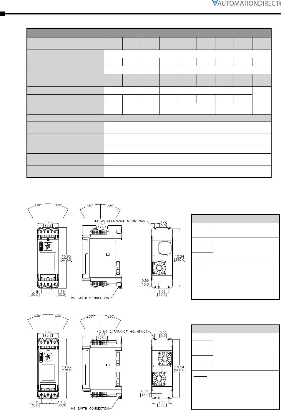
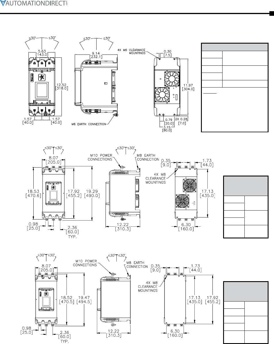
Dimensions . . . . . . . . . . . . . . . . . . . . . . . . . . . . . . . . . . . . . .1–4

Page 1–2 Stellar® SR55 Series Soft Starter User Manual – 1st Ed. Rev.B – 02/02/2017
Chapter 1: Mechanical Installation
User Manual Overview
The SR55 Soft Starter User Manual describes the installation, configuration, and methods of
operation of the SR55 Soft Starter.
This manual contains important information for those who will install, maintain, and/or operate
any of the SR55 Soft Starters.
The National Electrical Manufacturers Association (NEMA) publishes many different documents
that discuss standards for industrial control equipment. Global Engineering Documents handles
the sale of NEMA documents. For more information, you can contact Global Engineering
Documents at:
15 Inverness Way East
Englewood, CO 80112-5776
1-800-854-7179 (within the U.S.)
303-397-7956 (international)
www.global.ihs.com
By Telephone: 770-844-4200
(Mon.–Fri., 9:00 a.m.–6:00 p.m. E.T.)
On the Web: www.automationdirect.com
Our technical support group is glad to work with you in answering your questions. If you cannot
find the solution to your particular application, or, if for any reason you need additional technical
assistance, please call technical support at 770-844-4200. We are available weekdays from 9:00
a.m. to 6:00 p.m. Eastern Time.
We also encourage you to visit our web site where you can find technical and non-technical
information about our products and our company. Visit us at www.automationdirect.com.
When you see the “notepad” icon in the left-hand margin, the paragraph
to its immediate right will be a special note.
when you see The “exclamaTion mark” icon in The lefT-hand margin, The paragraph To iTs
immediaTe righT will be a warning. This informaTion could prevenT injury, loss of properTy, or
even deaTh (in exTreme cases).
Chapter 1: Mechanical Installation
Page 1–3Stellar® SR55 Series Soft Starter User Manual – 1st Ed. Rev.B – 02/02/2017
Mechanical Installation
Mount the soft starter to a flat, vertical surface using the mounting holes (or slots) on its base
plate. The dimension drawings, shown in the “Dimensions” subsection of this chapter, give
mounting hole positions and overall dimensions for each SR55 model. Ensure that:
• The orientation of the unit has the “TOP” uppermost, and within the vertical range shown
on the dimension drawings. (Mount the unit within 30° of vertical, for both side-to-side and
front-to-back dimensions.)
• The location allows adequate front access.
• You can view and access the touchscreen.
SR55 soft starters are not intended for mounting in environments
containing corrosive gases.
For a typical industrial environment, an enclosure should provide the following:
• A single location for the unit and its protection/isolation switch gear.
• The safe termination of cabling and/or bus bars.
• Allow minimum clearance distances around soft starters as specified in the tables shown
with the dimension drawings.
• Means to effect proper air flow through the enclosure and maintain temperature and
humidity within the ranges specified in the Mechanical Specifications table.
Enclosure Ventilation
When fitting SR55 into an enclosure, ventilation must be provided
if the heat output of the unit is greater than the enclosure will
dissipate. Use the following formula to determine the enclosure
fan requirement. An allowance has been incorporated into the
formula so that the figure for Q is the air delivery in the fan
suppliers data.
The power dissipation of the thyristors are at their peak when the
SR55 is in energy-saving mode (iERS), therefore causing the most
heat generated from the starter.
Heat dissipated can be approximated with the formula:
Watts (SR55) = 1/2 x (SR55 current rating) x 3
Q = (4xWt) / (Tmax - Tamb)
Q = Volume of air (cubic meters per hour - m3/h)
Wt = Heat produced by the unit and all other heat sources within the enclosure (Watts)
Tmax = Maximum permissible temperature within the enclosure
(50°C for a fully rated SR55)
Tamb = Temperature of the air entering the enclosure (°C)
(If you prefer to work in CFM, substitute °F for °C. Q is now in CFM)
Page 1–4 Stellar® SR55 Series Soft Starter User Manual – 1st Ed. Rev.B – 02/02/2017
Chapter 1: Mechanical Installation
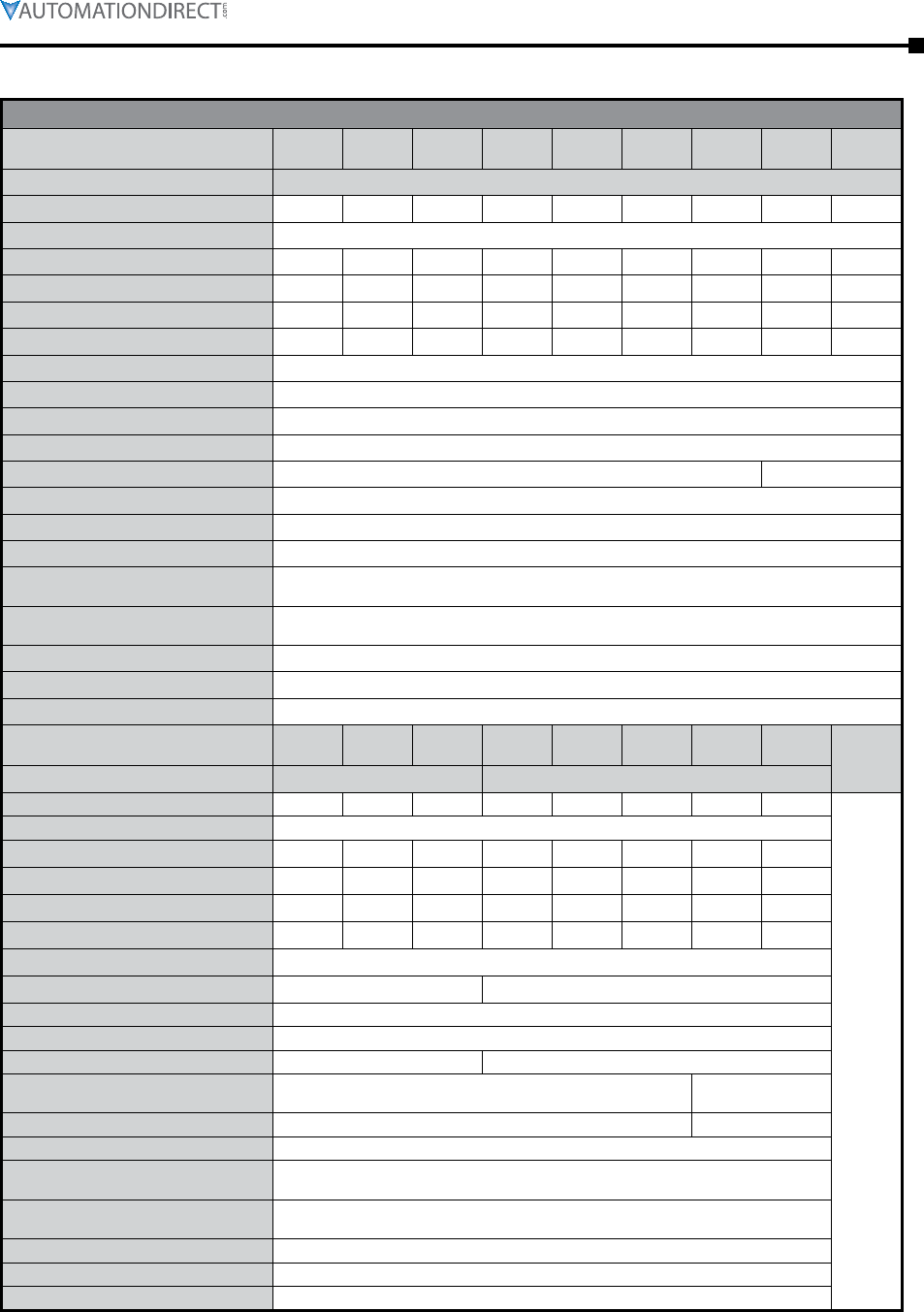
MECHANICAL SPECIFICATIONS – SR55 Series Full-Featured Soft Starters
-017
-021
-027
-034
-040
-077
-096
1
25.5 31.5 40.5 51.0 60.0 78.0 97.5 116 144
6.6 [3.0] 7.7 [3.5]
-124
-180
-242
-302
-361
-414
-477 –
2 3
–
186 234 270 363 453 542 621 716
12.1
[5.5] 14.3 [6.5] 35.3 [16.0] 46.7 [21.2]
-20°C [-4°F] to 50°C [122°F] ; above 50°C derate linearly by 4% of SR55 Ie per °C
to a maximum of 60°C (140°F)
-20°C to 60°C [-4°F to 140°F] continuous
max 85% non-condensing, not exceeding 50% @ 40°C [104°F]
1,000m [3281ft] ; above 1000m derate by 1% of SR55 Ie per 100m (328ft)
to a maximum altitude of 2,000m (6562ft)
Main Circuit: IP00 (IP20 with optional finger guards for sizes 1&2 only);
Control Circuit: IP20; No corrosive gases permitted
Mount soft starter within 30° of vertical
Top 3in
[75mm]
Bottom
Left
1in
[25mm]
Right
Front
NOTE: The addition of optional finger
guards to size 1 and size 2 SR55 soft
starters adds approximately 14mm
[0.5in] to the vertical dimension,
but does NOT change the clearance
distance.
Mount soft starter within 30° of vertical
Top 3in
[75mm]
Bottom
Left
1in
[25mm]
Right
Front
NOTE: The addition of optional finger
guards to size 1 and size 2 SR55 soft
starters adds approximately 14mm
[0.5in] to the vertical dimension,
but does NOT change the clearance
distance.
Chapter 1: Mechanical Installation
Page 1–5Stellar® SR55 Series Soft Starter User Manual – 1st Ed. Rev.B – 02/02/2017
Mount soft starter within 30° of vertical
Top 3.9 in
[100mm]
Bottom
Left 1.6 in
[40mm]
Right
Front 1in [25mm]
NOTE: The addition of
optional finger guards to
size 1 and size 2 SR55 soft
starters adds approximately
14mm [0.5in] to the vertical
dimension, but does NOT
change the clearance distance.
Top 4.9 in
[125mm]
Bottom
Left 2.4 in
[60mm]
Right
Front 1in
[25mm]
Top 4.9 in
[125mm]
Bottom
Left 2.4 in
[60mm]
Right
Front 1in
[25mm]

Page 1–6 Stellar® SR55 Series Soft Starter User Manual – 1st Ed. Rev.B – 02/02/2017
Chapter 1: Mechanical Installation
BLANK
PAG E

Page 2–1Stellar® SR55 Series Soft Starter User Manual – 1st Ed. Rev.B – 02/02/2017
ElEctrical installation 2
2
2
chaptEr
chaptEr
chaptEr
Table of ConTenTs
Safety Warning . . . . . . . . . . . . . . . . . . . . . . . . . . . . . . . . . . 2–2
Agency Approvals . . . . . . . . . . . . . . . . . . . . . . . . . . . . . . . . . 2–2
Technical Information and Standards . . . . . . . . . . . . . . . . . . . . . . 2–2
Electrical Specifications . . . . . . . . . . . . . . . . . . . . . . . . . . . . . . 2–3
Circuit Protection . . . . . . . . . . . . . . . . . . . . . . . . . . . . . . . . . 2–4
Short-Circuit Protection . . . . . . . . . . . . . . . . . . . . . . . . . . . . . . . .2–4
Motor overload Protection . . . . . . . . . . . . . . . . . . . . . . . . . . . . . .2–5
Wire Sizes and Torques . . . . . . . . . . . . . . . . . . . . . . . . . . . . . . 2–5
Electrical Connections . . . . . . . . . . . . . . . . . . . . . . . . . . . . . . . 2–6
Electrical Wiring . . . . . . . . . . . . . . . . . . . . . . . . . . . . . . . . . . 2–7
Power Circuit Wiring . . . . . . . . . . . . . . . . . . . . . . . . . . . . . . . . .2–7
Control Circuit Wiring. . . . . . . . . . . . . . . . . . . . . . . . . . . . . . . . .2–8
Page 2–2 Stellar® SR55 Series Soft Starter User Manual – 1st Ed. Rev.B – 02/02/2017
Chapter 2: Electrical Installation
Safety Warning
sr55 sofT sTarTers conTain dangerous volTages when connecTed To The elecTrical power supply.
only qualified personnel who have been compleTely Trained and auThorized should carry ouT
insTallaTion, operaTion and mainTenance of This equipmenT. refer To and carefully follow all
of The warnings in The “warnings” secTion aT The sTarT of This user manual, as well as oTher
warnings and noTes ThroughouT The manual
Agency Approvals
All SR55 models are CE, REACH, and RoHS compliant. SR55 models -017 through -361
bear the ETL listing mark and are UL508 and CSA C22.2 No. 14, per ETL, listed to U.S. and
Canadian safety standards respectively.
SR55 Soft Starter Agency Approvals
SR55 Models Applicable Agency Approvals *
SR55-017 through SR55-361 CE, CSA C22.2 No.14 (ETL tested), ETL 4004274, REACH, RoHS, UL508 (ETL tested)
SR55-414 through SR55-477 CE, REACH, RoHS
* To obtain the most current agency approval information, see the Agency Approval Checklist section on the
specific part number’s web page.
Technical Information and Standards
SR55 Technical Information and Standards
Rated Operational Voltages Ue200VAC to 480VAC
Rated Operational Current IeSee Electrical Specifications table
Rating Index SR55-017 to -180 Ie: AC-53a: 3.5-17: 90-5
SR55-242 to -477 Ie: AC-53a: 3.5-17: 90-3
Rated Frequency 50 to 60Hz
Rated Duty Uninterrupted
IEC 60947-4-2 Form Designation Form 1 internally bypassed
Rated Insulation Voltage Ui480V
Rated Impulse Withstand
Voltage Uimp
Main circuit 4kV
Control supply circuit 2.5 kV
IP Code
Main AC
line/load circuit
IP00 (IP20 with optional finger
guards SR55-FG-x)
Supply and control circuit IP20
Pollution Degree 2
Rated conditional short-circuit current and
type of coordination with associated short-
circuit protective device (SCPD).
Type 1 coordination. See short-circuit protection table for rated
conditional short-circuit current and required current rating and
characteristics of the associated SCPD.
Rated Control Circuit Voltage
(programmable) UC24VDC, 110VAC or 230VAC
Protect with 4A UL Listed fuse
Rated Control Supply Voltage USSee Electrical Specifications table
Relay Specification AC-15 230VAC, 1A
DC-13 30VDC, 0.7A
EMC Emission Levels EN 55011 Class A
EMC Immunity Levels
IEC 61000-4-2 8kV/air discharge or 4kV/contact discharge
IEC 61000-4-3 10 V/m
IEC 61000-4-4 2kV/5kHz (main power and ports)
1kV/5kHz (signal ports)
IEC 61000-4-5 2kV line-to-ground
1kV line-to-line
IEC 61000-4-6 10V
Chapter 2: Electrical Installation
Page 2–3Stellar® SR55 Series Soft Starter User Manual – 1st Ed. Rev.B – 02/02/2017
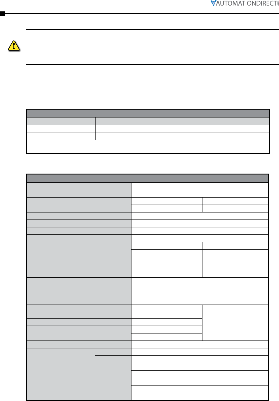
Electrical Specifications
ELECTRICAL SPECIFICATIONS – SR55 Series Full-Featured Soft Starters
Model SR55
-017
SR55
-021
SR55
-027
SR55
-034
SR55
-040
SR55
-052
SR55
-065
SR55
-077
SR55
-096
Frame Size 1
Rated Current [UL FLC] (A) 17 21 27 34 40 52 65 77 96
Rated Operational Voltage 200VAC to 480VAC
Motor Rating @ 200V (hp) 3 5 7.5 10 10 15 20 20 30
Motor Rating @ 208V (hp) 5 5 7.5 10 10 15 20 25 30
Motor Rating @ 230V (hp) 5 5 7.5 10 10 15 20 25 30
Motor Rating @ 460V (hp) 10 15 20 25 30 40 50 60 75
Trip Class programmable 10 to 30
Index Rating [per IEC 60947-4-2] Ie: AC-53a: 3.5–17: 90–5
Impulse Withstand Voltage 4kV
Insulation Voltage Rating 480V
Short-Circuit Current Rating (type 1) 5kA 10kA
Control Power Consumption 60W inrush to latch internal bypass relays; 4W steady state
Control Voltage Range 24VDC +10%-15% or 110–230 VAC +10%-15%
Control Fuse (external) 4A
Control Inputs (3) DI @ 24VDC, 110VAC, or 230 VAC; (1) PTC Thermistor;
(1) AI @ 0–10VDC 10mA max or 4–20mA
Control Outputs (3) N/O relay and (1) N/C relay @ 30VDC 0.5A / 230VAC 1A resistive;
(1) AO @ 0–10VDC 10mA max or 4–20mA
Start Time Setting Range 1 to 300 seconds
Start Voltage Setting Range 10% to 100%
Stop Time Setting Range 0 to 300 seconds
Model SR55
-124
SR55
-156
SR55
-180
SR55
-242
SR55
-302
SR55
-361
SR55
-414
SR55
-477 –
Frame Size 2 3
Rated Current [UL FLC] (A) 124 156 180 242 302 361 414 477
–
Rated Operational Voltage 200VAC to 480VAC
Motor Rating @ 200V (hp) 40 50 60 75 100 125 150 150
Motor Rating @ 208V (hp) 40 50 60 75 100 125 150 150
Motor Rating @ 230V (hp) 40 60 60 75 100 150 150 150
Motor Rating @ 460V (hp) 100 125 150 200 250 300 350 400
Trip Class programmable 10 to 30
Index Rating [per IEC 60947-4-2] Ie: AC-53a: 3.5–17: 90–5 Ie: AC-53a: 3.5–17: 90–3
Impulse Withstand Voltage 4kV
Insulation Voltage Rating 480V
Short-Circuit Current Rating (type 1) 10kA 18kA
Control Power Consumption 60W inrush to latch internal bypass relays; 4W steady state 120W inrush;
4W steady state
Control Voltage Range 24VDC +10%-15% or 110–230 VAC +10%-15% 110VAC +10%-15%
Control Fuse (external) 4A
Control Inputs (3) DI @ 24VDC, 110VAC, or 230 VAC; (1) PTC Thermistor;
(1) AI @ 0–10VDC 10mA max or 4–20mA
Control Outputs (3) N/O relay and (1) N/C relay @ 30VDC 0.5A / 230VAC 1A resistive;
(1) AO @ 0–10VDC 10mA max or 4–20mA
Start Time Setting Range 1 to 300 seconds
Start Voltage Setting Range 10% to 100%
Stop Time Setting Range 0 to 300 seconds
Page 2–4 Stellar® SR55 Series Soft Starter User Manual – 1st Ed. Rev.B – 02/02/2017
Chapter 2: Electrical Installation
Circuit Protection
Short-Circuit Protection
External Short-Circuit Protection Required for SR55
SR55 Model Number SR55
-017
SR55
-021
SR55
-027
SR55
-034
SR55
-040
SR55
-052
SR55
-065
SR55
-077
SR55
-096
Rated Operational Current UL FLC (A) 17 21 27 34 40 52 65 77 96
IEC Ie(A) 17 22 29 35 41 55 66 80 100
Semiconductor Fuse
(class aR) #1
Type
Mersen 6,9 URD 30xx
Bussmann 170M30xx
Bussmann 170M31xx
Bussmann 170M32xx
SIBA 20 61xx
Rating (A) 100 100 160 160 160 200 200 250 315
Class J High-Speed Current-
Limiting Fuse #2 Rating Z1(A) 30 45 60 70 90 110 125 150 175
Class J Time-Delay Fuse #3 Rating Z2(A) 30 40 50 60 70 100 125 150 175
UL Listed Inverse Time-
Delay Circuit Breaker #3 Rating Z3(A) 60 60 60 60 60 150 150 250 300
Rated Conditional Short-
Circuit Current Iq(kA) 5 10
SR55 Model Number SR55
-124
SR55
-156
SR55
-180
SR55
-242
SR55
-302
SR55
-361
SR55
-414
SR55
-477 –
Rated Operational Current UL FLC (A) 124 156 180 242 302 361 414 477
–
IEC Ie(A) 132 160 195 242 302 361 430 500
Semiconductor Fuse
(class aR) #1
Type
Mersen 6,9 URD 31xx
Bussmann 170M40xx
Bussmann 170M41xx
Bussmann 170M42xx
SIBA 20 61xx
Mersen 6,9 URD 33xx
Bussmann 170M60xx
Bussmann 170M61xx
Bussmann 170M62xx
SIBA 20 63xx
Rating (A) 400 550 550 700 800 900 1000 1100
Class J High-Speed Current-
Limiting Fuse #2 Rating Z1250 350 400 500 600 600 n/a
Class J Time-Delay Fuse #3 Rating Z2(A) 225 300 350 450 500 500 600 600
UL Listed Inverse Time-
Delay Circuit Breaker #3 Rating Z3(A) 350 450 500 700 800 1000 1000 1000
Rated Conditional Short-
Circuit Current Iq(kA) 10 18
#1 Correctly selected semiconductor fuses can provide additional protection against damage to the SR55 unit (this
is sometimes referred to as type 2 coordination). These semiconductor fuses are recommended to provide this
increased protection.
#2 Suitable for use in a circuit capable of delivering not more than Iq rms Symmetrical Amperes, when protected by
Class J high-speed current-limiting 600V rated fuses with a maximum trip rating of Z1 (IEC Type 1 coordination
short-circuit protection).
#3 Suitable for use in a circuit capable of delivering not more than Iq rms Symmetrical Amperes, 480 Volts maximum,
when protected by Class J time-delay fuses with a maximum rating of Z2, or by a circuit breaker with an
interrupting rating not less than Z3 rms Symmetrical Amperes, 480 Volts maximum as in table.
Chapter 2: Electrical Installation
Page 2–5Stellar® SR55 Series Soft Starter User Manual – 1st Ed. Rev.B – 02/02/2017
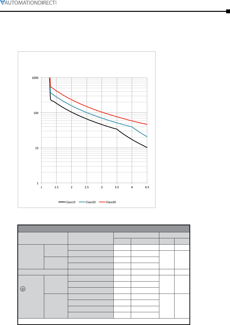
Motor overload Protection
The SR55 soft starter provides full motor overload protection, which can be configured through
the touch screen. Overload trip settings are determined by the Motor Current setting and the Trip
Class setting. Trip class choices are Class 10, Class 20, and Class 30. The SR55 soft starters are
protected using full I2T motor overload with memory.
Trip time ( seconds )
Multiple of Motor FLA
Motor overload 'cold' trip curves
(20°C ambient)
Wire Sizes and Torques
SR55 Wire Sizes and Torques
Terminal Models Wire Size Torque
mm2AWG N·m lb·in
Main
Terminals
Cu STR
75°C Only
Terminal SR55-017 to SR55-096 2.5–70 12–2/0 9 80
SR55-124 to SR55-180 4–185 12–350 MCM
14 123
M10 bolt SR55-242 to SR55-361 2 x 95 2 x 2/0
SR55-414 to SR55-477 2 x 150 2 x 350 MCM
Control Terminals all models 0.2–1.5 24–16 0.5 4.5
Protective
Ground *
Cu Only
M6 stud
SR55-017 ≥ 4 ≥ 12
8 70
SR55-021 to SR55-052 ≥ 6 ≥ 10
SR55-065 to SR55-096 ≥ 10 ≥ 8
M8 stud
SR55-124 to SR55-180 ≥ 16 ≥ 6
12 105
SR55-242 ≥ 25 ≥ 4
SR55-302 to SR55-361 ≥ 35 ≥ 3
SR55-414 to SR55-477 ≥ 35 ≥ 2
* Protective Ground wire size based on bonding conductor requirements of UL508 and UL508A
Page 2–6 Stellar® SR55 Series Soft Starter User Manual – 1st Ed. Rev.B – 02/02/2017
Chapter 2: Electrical Installation
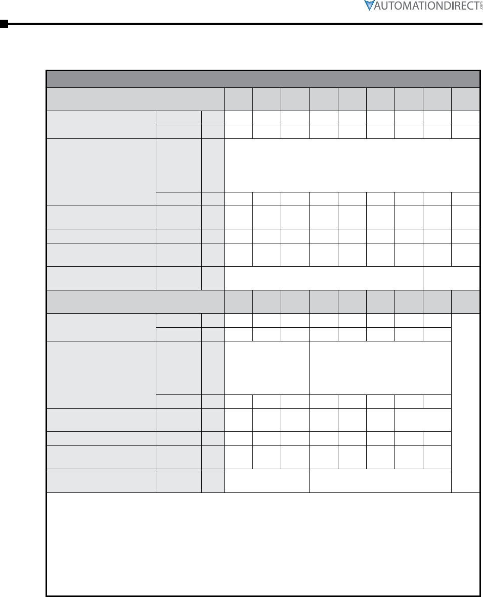
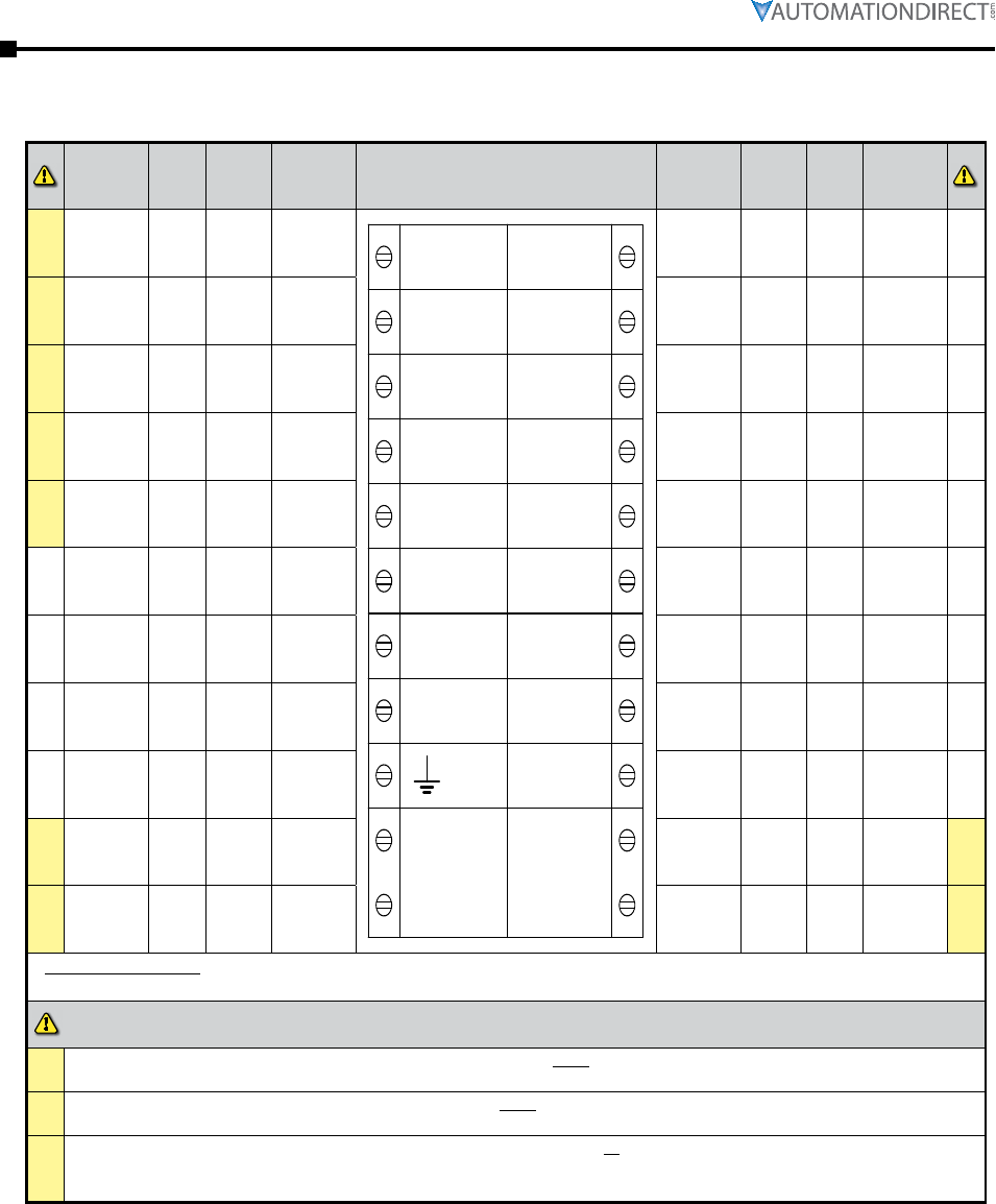
Electrical Connections
Required
Rating
Pro-
gram-
mable
Default Description Control Terminals Description Default
Pro-
gram-
mable
Required
Rating
#1 – – –
Group
1 input
common
D1COM
D1-1I
D1-2I
D2COM
D2-1I
PTC+
PTC–
N
L
11
12
24
33
34
44
AO
ACOM
AI
110–230
VAC
0VDC
24VDC
group 1
relay
common
– – – –
#1
24VDC or
110VAC or
230VAC
+10% -15%
yes start /
stop
opto-
coupled
input
relay N/C fault yes
230VAC 1A
AC15;
30VDC 0.5A
Resistive
–
#1
24VDC or
110VAC or
230VAC
+10% -15%
yes none
opto-
coupled
input
relay N/O fault yes
230VAC 1A
AC15;
30VDC 0.5A
Resistive
–
#2 – – –
Group
2 input
common
group 2
relay
common
– – – –
#2
24VDC or
110VAC or
230VAC
+10% -15%
yes reset
opto-
coupled
input
relay N/O running yes
230VAC 1A
AC15;
30VDC 0.5A
Resistive
–
– – – – not used relay N/O end of
start yes
230VAC 1A
AC15;
30VDC 0.5A
Resistive
–
–
3 x PTC in
series
(130°C)
– OFF thermistor analog
output 0–10V yes
0 to 10V
10mA /
4-20mA
–
–
3 x PTC in
series
(130°C)
– OFF thermistor analog 0V – – 0V –
– – – – signal
ground
analog
input 0–10V yes
0 to 10V
10mA /
4-20mA
–
#3
110VAC–
230VAC
+10% -15%
– – control
supply 0V input – – 0V #3
#3
110VAC–
230VAC
+10% -15%
– – control
supply 24V input – – 24VDC
+10% -15% #3
* 24VDC Specification: 24VDC 60W; Residual ripple 100mV; Spikes/switching Peaks 240mV; Turn On/Off response; No
overshoot of V out; Overvoltage voltage protection output voltage must be clamped to <30Vdc
#1 The programmed digital input setting on D1COM, D1-1I, D1-2I must correspond to the voltage applied to these terminals
to avoid risk of damage to the equipment.
#2 The programmed digital input setting on D2COM, D2-1I must correspond to the voltage applied to these terminals to
avoid risk of damage to the equipment.
#3
The control supply can be 110 to 230VAC applied to the N, L terminals or 24VDC applied to the 0VDC, 24V input
terminals. The correct voltage as specified must only be applied to one of these supply inputs to avoid risk of damage to
the equipment.

Chapter 2: Electrical Installation
Page 2–7Stellar® SR55 Series Soft Starter User Manual – 1st Ed. Rev.B – 02/02/2017
Electrical Wiring
Power Circuit Wiring
In Line
Induction
Motor
In Delta
Induction
Motor
U1
U2
V2 W2
V1 W1
Term Fwd Rev
2/T1 U1 U1
4/T2 V1 W1
6/T3 W1 V1
1/L1 W2 V2
3/L2 U2 U2
5/L3 V2 W2
So starter
must be
grounded
K1 – Main contactor or
circuit breaker isolation
and protection switch gear
(provided by the customer)
K1 – Main contactor
and protection switch gear
(provided by the customer)
Circuit breaker isolation
alone is not allowed for
In-Delta operation.
K1 (Main contactor)
controlled by the Run
relay on the SR55 MUST
be used for isolation.
NOTE:
RJ12 serial
comm port
Control wiring
terminals behind
hinged front cover
Optional
EtherNet/IP
comm module
slot
RJ45 port
(future use)
For wire size and torque requirements, refer to the “Wire Sizes and
Torques” section of this chapter.
for suiTable shorT-circuiT proTecTion devices (scpds), refer To The “circuiT proTecTion”
secTion of This chapTer.
In Delta WIrIng: for This configuraTion, applying The following equaTion allows The use of a
lower currenT-raTed sr55 Than The moTor flc: sr55 ie = ie (moTor) / √3.
when in-delTa configuraTion is used, a line conTacTor conTrolled by The sr55 musT be used
wiTh The in-delTa firing mode selecTed in The advanced menu.
The sr55 sTarTer does noT offer iers opTimizaTion when connecTed in-delTa.
do noT place bypass conTacTors around The sTarTer. The sTarTer has builT in bypass conTacTors.
if an exTernal bypass conTacTor is desired in order To allow emergency across The line sTarTing
in case of an sr55 failure, Then The load side of The sTarTer wiring musT be disconnecTed in
order To proTecT The sTarTer.
Page 2–8 Stellar® SR55 Series Soft Starter User Manual – 1st Ed. Rev.B – 02/02/2017
Chapter 2: Electrical Installation
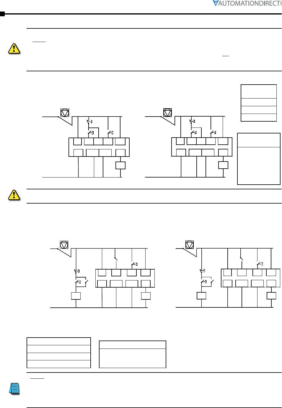
Control Circuit Wiring
1) The programmed digiTal inpuT seTTings for d1com, d1-1i, d1-2i, and d2com, d2-1i
musT correspond To The volTage applied To These Terminals To avoid risk of damage To The
equipmenT.
2) The conTrol supply can be 110 To 230vac applied To The n, l Terminals or 24vdc applied To
The 0vdc, 24v inpuT Terminals. The correcT volTage as specified musT only be applied To one
of These supply inpuTs To avoid risk of damage To The equipmenT.
Three-Wire Control
24VDC control supply and
digital input programming
24
VDC D1-2ID1-1I D2-1I 33
0VDC D2COMD1COM 34
K1
!
3-Wire Control Diagram
110/230VAC control supply
and digital input programming
L D1-2ID1-1I D2-1I 33
N D2COMD1COM 34
K1
!
110/230VAC
N
24VDC
0VDC
Emergency StopEmergency Stop
Digital Output
Configuration
34 = DO3 set to
“Running”
(This pulls in the
line contactor, K1,
before the ramp
starts)
Digital Input
Configuration
D1-1I = Start
D1-2I = Stop
D2-1I = Reset
power facTor correcTion capaciTors* musT noT be posiTioned beTween The sofT sTarTer and The
moTor, or There is a risk of damaging The ThyrisTors due To currenT peaks.
User-Programmable Control
User Programmable Control Diagram
LD1-1I
Stop
Start
D2-1I 33
ND2COMD1COM 34
K1K2
K2.1
K2.2
1)
!
24
VDC
0VDC
D1-1I
Stop
Start
D2-1I 33
D2COMD1COM 34
K1K2
K2.1
K2.2 1)
!
110/230VAC 24VDC
0VDC
N
Emergency StopEmergency Stop
1) Optional high reset. If this reset is required, ensure that “User Programmable” is selected as the control method menu
found in the Digital Inputs menu. If you would prefer the reset to work by removing and reapplying the Start Signal on
D1-1I then select “Two wire control” in the control method menu.
Digital Input Configuration
D1-1I = High Start / Low Stop
D1-2I = None
D2-1I = High Reset
Digital Output Configuration
34 = DO3 set to “Running”
(This pulls in the line contactor,
K1, before the ramp starts)
* Note: Power factor correction capacitors (PFCs) can reduce a facility’s
kVAR charges in some cases. Determining the need for, and location of,
PFCs should be performed by a qualified engineer (from your utility
company or a power quality engineering firm). PFCs cannot be located
between the SR55 and the motor.
Chapter 2: Electrical Installation
Page 2–9Stellar® SR55 Series Soft Starter User Manual – 1st Ed. Rev.B – 02/02/2017
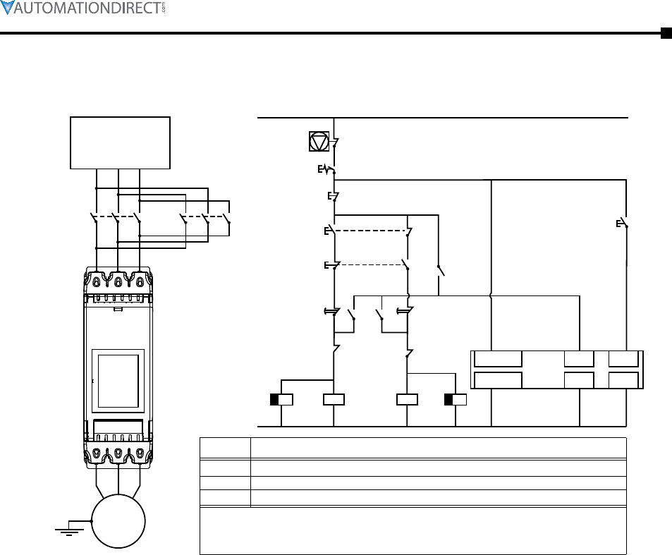
Electrical Wiring (continued)
Reversing Wiring Diagram
!
Note: Forward and reverse buttons must remain pressed for longer than timer change over period.
K1 K2
Protection switch
gear (provided by
the customer)
Emergency Stop
Enable
Stop
Forward
Reverse
K2A
Induction
Motor
Control supply 110/230VAC or 24VDC
depending on application
K1 K2 K1A
K1
K1A K1 K2 K2A
Reset
33
SR55
34
SR55
D2-1ID1-1I
L or 24VDC
D2COMD1COM
N or 0VDC
K2
2/T1 4/T2 6/T3
1L1 3/L2 5/L3
Reversing Wiring Diagram
Item
K1, K2
K1A, K1B
SR55
These are the major components of the system. Local wiring regulations should be
observed. Note the use of timers to ensure that a reversed voltage is not applied to
the starter/motor before the motor eld has had some chance to die away.
Description
AC3 rated forward/reverse contactors
1-second o-delay timing relays (delay time must be ≥ the stop ramp time)
SR55-xxx soft starter
• “Stop” must be pressed before direction reversal can be initiated.
• Digital Output 3 must be congured to “Running.”
• Digital Input 1 must be congured to “High Start / Low Stop.”
• Digital Input 2 must be congured to “Reset.”

Page 2–10 Stellar® SR55 Series Soft Starter User Manual – 1st Ed. Rev.B – 02/02/2017
Chapter 2: Electrical Installation
BLANK
PAG E

Errata Sheet
Page 1
Product Family: SR55 Soft Starter
Manual Number SR55_UMW
Revision and Date 1st Edition, Rev. B; February 2017
Date: June 28, 2017
This Errata Sheet contains changes made to Chapter 3
after the publication of this manual.
Changes to Chapter 3. Configuration and Parameters
After the latest publication of this manual, the manufacturer released a firmware update which added four new
parameters, and a new set of block transfer parameters. Refer to this Errata Sheet for details on these new parameters.
Also, there was a Range value change for existing parameter P5.0.
Appendix A in this manual has instructions for updating the firmware.
Change to Parameter P5.0 - Motor Current Range Value
The Range for this parameter changed from “50% to 100% of SR55 rated Amperage” to “10% to 100% of SR55 rated
Amperage”.
This change affects two entries in the manual:
On page 3-6, in the Summary of Parameters for Auto Setup table, under the Range column in the P5.0 - Motor Current
line, change the “50% to 100%” range value to “10% to 50%”.
On page 3-27, in the Parameter Details box towards the bottom of the page for the P5.0 - Motor Current parameter (with
the Advanced “Motor Protection” Parameters heading), change the 50% range value to 10%.
Continued on next page.
Errata Sheet
Page 2
New Parameter Added: P0.11 - I/O Status Register
This new parameter, P0.11, was added.
This change affects two areas in the manual:
On page 3-6, in the first table insert the following summary description line for this new parameter right after the last line
for parameter P0.10:
Summary - Parameters Not Configurable Through Touchscreen
I
Group Parameter Units Range Read /
Write
Modbus Default
Setting
User
Setting
Address Hex
Status Indications
(detailed info
starts)
[page 3-15]
No changes in table for existing
parameters P0.0 through P0.10
P0.10 – iERS Active -OFF / ON Read 38080 94C0 OFF -
P0.11 – I/O Status Register -0 to 255 Read 62016 F240 OFF -
On page 3-17, insert the following Parameters Details box for the new parameter right after the existing box for
parameter P0.10 - iERS Active:
P0.11 – I/O Status Register Hold. Reg. Type:
Description:
Read
Displays the current status of the hardware inputs and outputs.
b0 ( Input DI-1I) b1 (Input D1-2I) b2 (input D2-I1) b3 (undefined)
b4 ( Output 12) b5 ( Output 24) b6 (Output 34) b7 (Output 44)
Range: Modbus Decimal Value: Default (decimal):
• 0 to 255 • 0
• 1
• OFF (0)
Modbus Address: Modbus Format:
62016 (F240 hex ) 16-bit unsigned
Continued on next page.
Errata Sheet
Page 3
SR55 Parameters Summary – Serial Communication Parameters – Block Transfer Parameter Map
Address
Description
Block Transfer Address Pointers Block Transfer Data
Default
Setting
Para-
meter Range Read/
Write
Modbus
Address Default
Setting Address Description Para-
meter Range
Read/
Write
Modbus
Address
Address Hex Address Hex
Block Transfer 1 P0.20
0~65535 R/W
17600 44C0 OFF Block Data Address 1 P0.40
0–65535 R/W
17664 44C0 OFF
Block Transfer 2 P0.21 17601 44C1 OFF Block Data Address 2 P0.41 17666 44C1 OFF
Block Transfer 3 P0.22 17602 44C2 OFF Block Data Address 3 P0.42 17668 44C2 OFF
Block Transfer 4 P0.23 17603 44C3 OFF Block Data Address 4 P0.43 17670 44C3 OFF
Block Transfer 5 P0.24 17604 44C4 OFF Block Data Address 5 P0.44 17672 44C4 OFF
Block Transfer 6 P0.25 17605 44C5 OFF Block Data Address 6 P0.45 17674 44C5 OFF
Block Transfer 7 P0.26 17606 44C6 OFF Block Data Address 7 P0.46 17676 44C6 OFF
Block Transfer 8 P0.27 17607 44C7 OFF Block Data Address 8 P0.47 17678 44C7 OFF
Block Transfer 9 P0.28 17608 44C8 OFF Block Data Address 9 P0.48 17680 44C8 OFF
Block Transfer 10 P0.29 17609 44C9 OFF Block Data Address 10 P0.49 17682 44C9 OFF
Block Transfer 11 P0.30 17610 44CA OFF Block Data Address 11 P0.50 17684 44CA OFF
Block Transfer 12 P0.31 17611 44CB OFF Block Data Address 12 P0.51 17686 44CB OFF
Block Transfer 13 P0.32 17612 44CC OFF Block Data Address 13 P0.52 17688 44CC OFF
Block Transfer 14 P0.33 17613 44CD OFF Block Data Address 14 P0.53 17690 44CD OFF
Block Transfer 15 P0.34 17614 44CE OFF Block Data Address 15 P0.54 17692 44CE OFF
Block Transfer 16 P0.35 17615 44CF OFF Block Data Address 16 P0.55 17694 44CF OFF
Block Transfer Explanation
Parameters P0.20~P0.35 and P0.40~P0.55
Block Transfer allows parameters from many different Parameter Groups to be consolidated into one Modbus
communication message. This can greatly simplify PLC programming and reduce network traffic. A maximum of 16
parameters can be grouped together. The 16 Block Transfer Address Pointer registers have 16 correlating, four-byte,
Block Transfer Data registers that correspond with the Pointer registers and act as the data conduits for each select
address. Once set the addresses can be saved in none volatile memory if required. The Block Transfer parameters can
only be accessed through Modbus, not through the Touchscreen Menu.
• New Pointer Parameters P0.20~P0.35 (where you enter the addresses that you want to consolidate)
• Data Location Parameters P0.40~P0.55 (where you push data into, or pull data out of)
Continued on next page.
New Block Transfer Parameters Added
Insert the following Block Transfer information after the new Parameter P0.11 - I/O Status Register added on the previous
page.
Errata Sheet
Page 4
Block Transfer Example
The table below shows the relationship between the alias Registers and the data Registers. The data can take any data
type that can fit into 4 bytes. So, any address that yields 6 bytes of data, such as time, will be incomplete. To access data
that is more than 6 bytes then reading or writing directly to that register should be implemented and not accessed using
the Block Transfer method. Below is an example of what will happen with different sizes.
Alias
Address
Addresses Parameter Data
Address Data Shown in 4 Bytes
17600 P3.3 – Start Current Limit Level 17664 0x00 0x00 0xe8 0x6c
17601 P3.4 – Start Current Limit Time 17666 0x00 0x00 0x01 0x0e
17602 P3.1 – Start Pedestal 17668 0x00 0x00 0x0c 0xcd
17603 P6.0 – iERS Enable 17670 0x00 0x00 0x00 0x00
17604 P6.2 – iERS Rate 17672 0x00 0x00 0x00 0x00
17605 P15.17 – Start Saving Level 17674 0x00 0x00 0x00 0x00
Continued on next page.

Errata Sheet
Page 5
New Parameters Added: P9.2 - Main Contactor Control, and P9.3 - Hand-Auto Control
These two new parameters, P9.2 and P9.3, were added for touch-screen setup.
This change affects two areas in the manual:
On page 3-9, replace the table shown at the top of the page with the one below, which has the summary descriptions for
the two new parameters. No changes were made to existing parameters P9.0 or P9.1.
Summary - Parameters for Touchscreen Setup - “Advanced” Category (continued)
I
Group Parameter Units Range Read /
Write
Modbus Default
Setting
User
Setting
Address Hex
Advanced
(P9)
[page 3-33
P9.0 – Firing Mode toggle In-Delta / In-line R/W 128 0080 In-Line
P9.1 – Legacy Delta Mode toggle OFF / ON R/W 192 00C0 OFF
P9.2 – Main Contactor Control toggle OFF / ON R/W 14144 3740 OFF
P9.3 – Hand-Auto Control toggle OFF / ON R/W 28160 6E00 OFF
On page 3-40, right after the existing Parameter Details box for parameter P9.1 - Legacy Delta Mode, add the following
two Parameters Details boxes for the new parameters:
Advanced “Main Contactor Control” Parameter
P9.2 – Main Contactor Control Hold. Reg. Type:
Description:
Read/Write
Used when the motor is required to start when the Main Contactor closes, and stop when it
opens. An auxiliary contact from the main contactor is used as a Start / Stop signal. The ‘ Stop
Time’ must be set to zero.
Range: Modbus Decimal Value: Default (decimal):
• Off : When the contactor opens and the stop signal is given at the
same time the unit may trip on “Phase Loss” (Default).
• On : When the contactor opens and the stop signal is given at the
same time the unit will not trip on “Phase Loss”.
• 0
• 1
• OFF (0)
Modbus Address: Modbus Format:
14144 (3740 hex ) 16-bit unsigned
Touchscreen Menu Path:
Home → Advanced → Main Contactor Control
Continued on next page.

Errata Sheet
Page 6
Advanced “Hand-Auto Control” Parameter (continued)
P9.3 – Hand-Auto Control Hold. Reg. Type:
Description:
Read/Write
A Hand-Auto selection switch can be connected to Digital Input D1-2I to change the ‘Control
Method’. This can be used to change the Start / Stop to ‘Hand’ if the Communications fails. The
user must ensure D1-2I = 1 and D1-2I = 0 which are the default settings for those inputs before
turning on Hand-Auto Control.
• D1-2I = 1: Control Method is set to “2 -Wire” (Hand).
• D1-2I = 0: Control Method is set to “Modbus Network” (Auto).
• Hand : Input D1-1I = Start / Stop , Input D2-1I = Reset
• Auto : ADDRESS 17920 = Start / Stop , ADDRESS 18368 = Reset
Range: Modbus Decimal Value: Default (decimal):
• Off : Control method can be selected to any method needed.
Digital input functions can be changed.
• On : Control Method is fixed to “User Programable”. Digital inputs
are fixed to as shown in the description above.
• 0
• 1
• OFF (0)
Modbus Address: Modbus Format:
28160 (6E00 hex ) 16-bit unsigned
Touchscreen Menu Path:
Home → Advanced → Hand-Auto Control
Continued on next page.
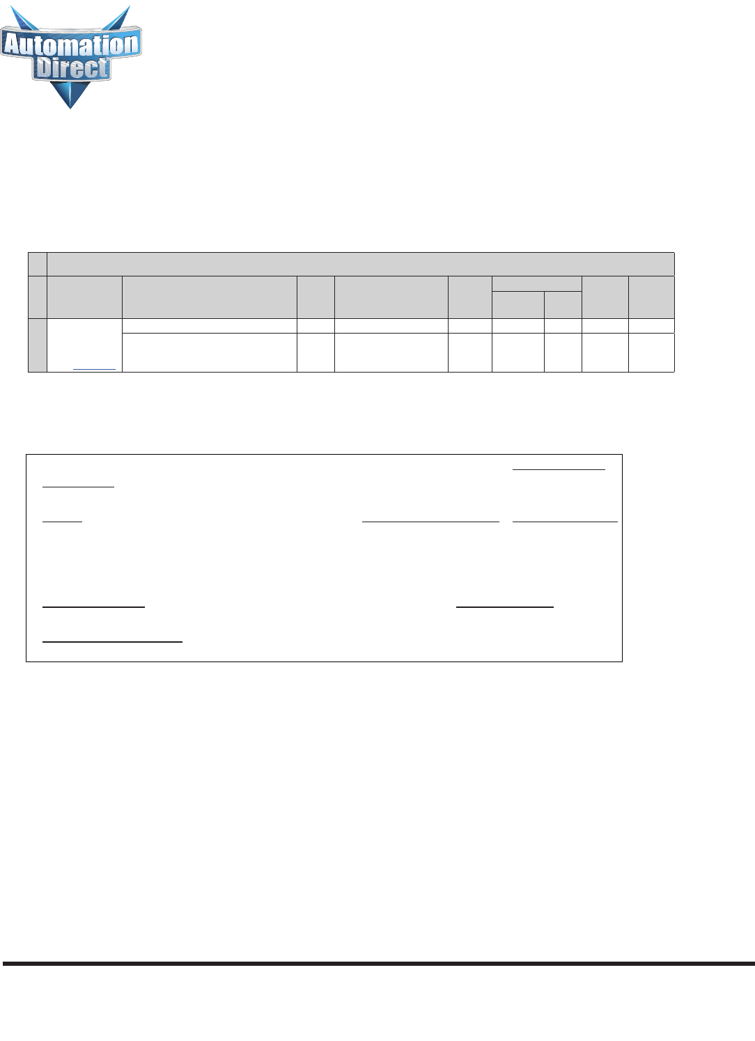
Errata Sheet
Page 7
P26.6 – Communications Shutdown Hold. Reg. Type:
Description:
Read/Write
This works in conjunction with the ‘Communications Trip’.
Range: Modbus Decimal Value: Default (decimal):
• Off : If the ‘Communication Trip’ is turned ‘On’ the unit will trip if
the communications fail.
• On : If the ‘Communication Trip’ is turned ‘On’ the unit will shut
down instead of tripping if the communications fail.
• 0
• 1
• ON (1)
Modbus Address: Modbus Format:
53802 (D22A hex ) 16-bit unsigned
Touchscreen Menu Path:
Home → Advanced → Communications Shutdown
On page 3-78, insert the following Parameters Details box for the new parameter right after the existing box for
parameter P26.5 - Timout mS:
New Parameter Added: P26.6 - Communications Shutdown
This new parameters, P26.6, was added for touch-screen setup.
This change affects two areas in the manual:
On page 3-13, in the table insert the following summary description line for this new parameter right after the
existing line for parameter P26.5 - Timeout:
Summary - Parameters for Touchscreen Setup - “Device” Category
I
Group Parameter Units Range Read /
Write
Modbus Default
Setting
User
Setting
Address Hex
Device
(P26)
Networks
[page 377]
P26.5 – Timeout ms 0 to 60,000 R/W 15808 3DC0 5,000
P26.6 – Communications Shutdown toggle OFF / ON R/W 53802 D22A ON
Page 3–1Stellar® SR55 Series Soft Starter User Manual – 1st Ed. Rev.B – 02/02/2017
Configuration
and Parameters 3
3
3
ChaPter
ChaPter
ChaPter
Table of ConTenTs
“Heartbeat” LED . . . . . . . . . . . . . . . . . . . . . . . . . . . . . . . . . . 3–2
Configuration Overview . . . . . . . . . . . . . . . . . . . . . . . . . . . . . . 3–2
Auto Setup Procedure . . . . . . . . . . . . . . . . . . . . . . . . . . . . . . . . .3–2
Setup by Individual Parameter Settings . . . . . . . . . . . . . . . . . . . . . . .3–2
Configuration From Touchscreen . . . . . . . . . . . . . . . . . . . . . . . . . 3–2
Auto Setup Procedure from Touchscreen. . . . . . . . . . . . . . . . . . . . . . .3–2
Individual Parameter Settings from Touchscreen . . . . . . . . . . . . . . . . . .3–2
Touchscreen Pictorial Example – Auto Setup. . . . . . . . . . . . . . . . . . . . .3–3
Auto Setup Procedure – Parameter Settings . . . . . . . . . . . . . . . . . . . 3–4
Parameter Summary . . . . . . . . . . . . . . . . . . . . . . . . . . . . . . . 3–6
Summary of Parameters Not Configurable Through Touchscreen Menu. . . . . .3–6
Summary of Parameters for Auto Setup . . . . . . . . . . . . . . . . . . . . . . .3–6
Summary of Parameters for Individual Parameter Setup . . . . . . . . . . . . . .3–7
Parameter Details . . . . . . . . . . . . . . . . . . . . . . . . . . . . . . . . 3–14
Parameters Not Configurable Through Touchscreen Menu. . . . . . . . . . . . 3–14
Parameters in Sequence and Grouped by Touchscreen Navigation . . . . . . . 3–18
“Auto Setup” Menu of Parameters . . . . . . . . . . . . . . . . . . . . . . . . . 3–18
“Advanced” Menu of Parameters . . . . . . . . . . . . . . . . . . . . . . . . . . 3–20
“I/O” Menu of Parameters . . . . . . . . . . . . . . . . . . . . . . . . . . . . . 3–41
“Monitor” Menu of Parameters . . . . . . . . . . . . . . . . . . . . . . . . . . . 3–50
“Log” Menu of Parameters . . . . . . . . . . . . . . . . . . . . . . . . . . . . . 3–56
“Device” Menu of Parameters. . . . . . . . . . . . . . . . . . . . . . . . . . . . 3–75
Trip Code Descriptions. . . . . . . . . . . . . . . . . . . . . . . . . . . . . . 3–80
Fail Safe Codes. . . . . . . . . . . . . . . . . . . . . . . . . . . . . . . . . . 3–83
Main Board Trip (2402 – 2436) . . . . . . . . . . . . . . . . . . . . . . . . . . . 3–83
Touchscreen Trip (2501 – 2581). . . . . . . . . . . . . . . . . . . . . . . . . . . 3–83
Logging Trip (2601 – 2603) . . . . . . . . . . . . . . . . . . . . . . . . . . . . . 3–84
Fail Safe Trip Codes . . . . . . . . . . . . . . . . . . . . . . . . . . . . . . . . . 3–84
Saving and Loading an SR55 Configuration File. . . . . . . . . . . . . . . . 3–85

Page 3–2 Stellar® SR55 Series Soft Starter User Manual – 1st Ed. Rev.B – 02/02/2017
Chapter 3: Configuration and Parameters
“Heartbeat” LED
The Stellar logo LED on the SR55 front panel will blink once every 10 seconds to let the user
know that all microprocessors in the soft starter are operating properly.
Configuration Overview
Configuring the SR55 soft starters for use is as simple as setting the parameters to match your
motor, application, power source, etc.
You can configure the SR55 from its touchscreen, from an optional remote touchscreen, or from a
PLC using Modbus RTU via the onboard RJ12 port or connected through an optional EtherNet/IP
or Modbus TCP communication module.
Choose this setup method if you want to quickly change all of the parameters at once to settings
that are typical for your general application. You can then adjust some parameters as necessary to
fine tune the settings for your specific application.
Choose this setup method if you want to change the parameter settings yourself one at a time.
The individual parameters are grouped by categories as you scroll through the touchscreen menu.
Configuration From Touchscreen
Simply touch the on-screen buttons to enter data or to scroll through the SR55 setup menu, using
the intuitive “Up,” Dn,” “BACK,” and “NEXT” buttons as necessary. From the home “Menu”
screen, select either “Auto Setup” or “Advanced.”
The resistive touchscreen requires localized pressure to activate a
button and works best if you gently use a blunt stylus-type object to
make on-screen selections.
Warning: Do not use a sharp object anD/or excessive force to make touchscreen selections, or you may Damage
the touchscreen.
The “Setup Wizard” menu is displayed only the first time the SR55 is powered up. If you are
ready to set parameters on the first power-up, select “Auto” from the on-screen Setup Wizard
menu, and then follow the on-screen prompts. Refer to the Auto Setup Touchscreen Pictorial
Example on the following page.
To set up your parameters following a subsequent start-up of your SR55, select the “Home” menu
from the “Status” screen on the touchscreen, choose “Auto Setup,” and then follow the on-screen
prompts. Refer to the Auto Setup Touchscreen Pictorial Example on the following page.
From the initial “Setup Wizard” or from the Home Menu, choose the “Advanced” parameters and
other parameter categories as required for your particular application. Refer to the “Parameter
Summary” and “Parameter Details” sections of this chapter for more details.
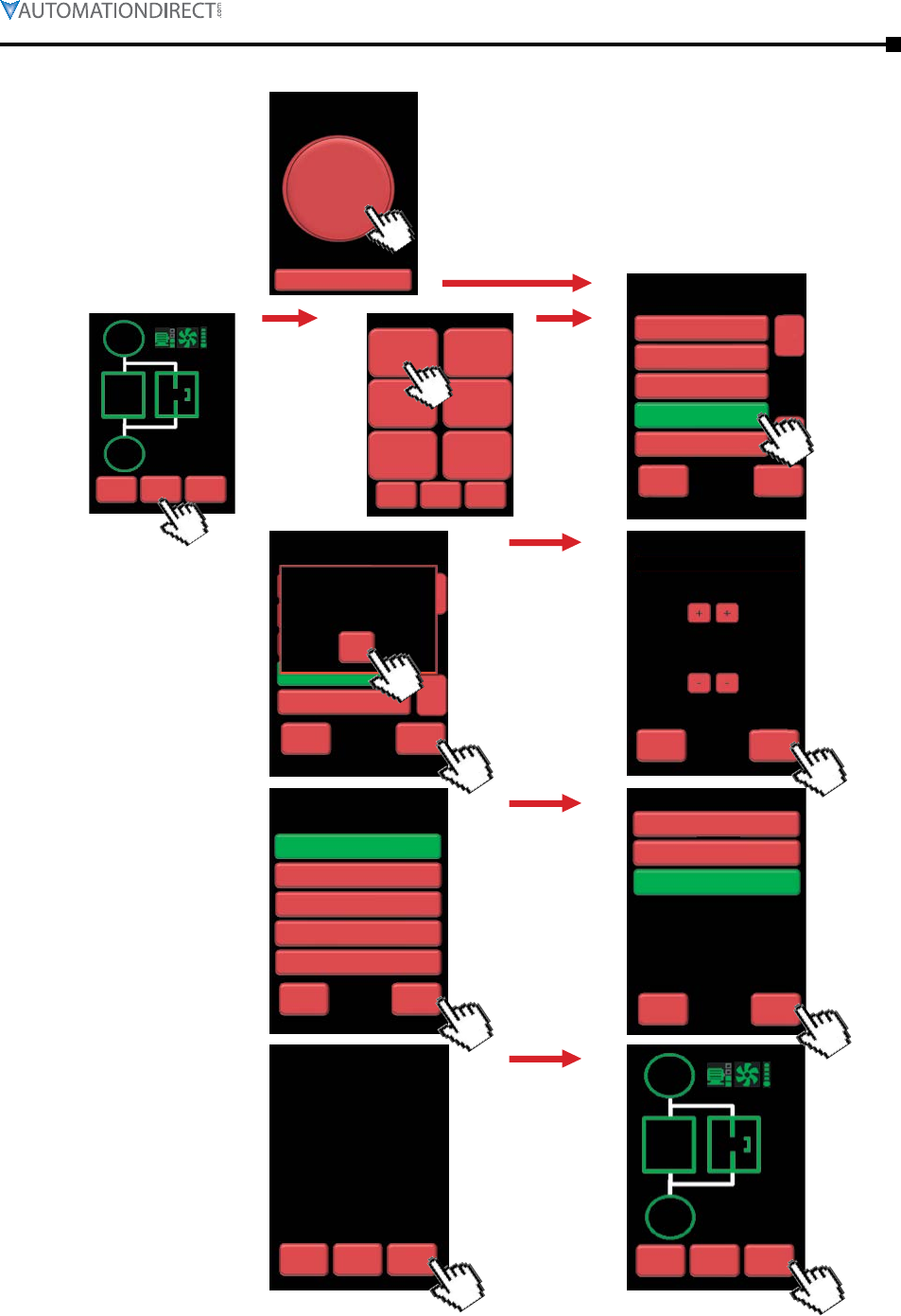
Chapter 3: Configuration and Parameters
Page 3–3Stellar® SR55 Series Soft Starter User Manual – 1st Ed. Rev.B – 02/02/2017
1.
3.
5.
7.
6.
8.
2.
4.
1b.1a.
Please note:
This “Setup Wizard” screen appears only once;
on the initial power-up of the SR55 soft starter.
For subsequent start-ups, screen 1a will be the
first screen displayed.
HomeBack Start
Stopped
OL =
I =
P =
0%
0A
0kW
–
Auto Setup
I / O
Log
Back
Advanced
Monitor
Device
Status Start
Menu
Auto
Advanced
Setup Wizard
ଯ
Back Next
ଭ
Default
Compressor
Centrifugal
Agitator
Heavy
Compressor
Reciprocating
Select Your Application
OK
ଯ
Back Next
Compressor
Reciprocating
Centrifugal
Select Your Application
Warning!
Selected Application Will
Enable Trip Class 20
A
Back Next
17
++
Set Motor Current Rating
--
NoBack Yes
Motor Current:
Application:
Control Logic:
Digital Input Voltage:
Trip Class:
17A
Compressor
Local Touch Screen
24Vdc
20
Auto Setup Summary
Save?
HomeBack Start
Stopped
OL =
I =
P =
0%
0A
0kW
–
Back Next
Select Control Method
Local Touch Screen
Two Wire Control
User Programmable
Modbus Network
Three Wire Control
Back Next
230V
24VDC
110V
Select Digital Input Voltage
Please note:
Only appears if
application with
a trip class higher
than 10 is selected
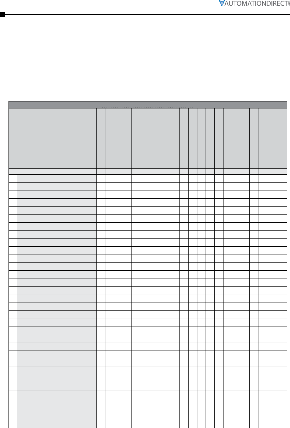
Page 3–4 Stellar® SR55 Series Soft Starter User Manual – 1st Ed. Rev.B – 02/02/2017
Chapter 3: Configuration and Parameters
Auto Setup Procedure – Parameter Settings
Choose “Auto” setup from the “Setup Wizard” or from the “Home” menu, and set the following
parameter groups:
1) Application
2) Motor Current Rating
3) Control Method
4) Digital Input Voltage
The SR55 will automatically set the rest of the parameters as shown in the following table:
Auto Setup Parameter Settings
# Application
Unit % %
0 20 10 10 0 10 3.5 30 5 0 0 0 1 1 0 0 0 0 0 0 8 2
1 40 10 10 0 20 4 40 5 1 0 1 1 1 0 0 0 0 0 0 8 2
2 30 10 10 0 10 3.5 25 5 1 0 1 1 1 0 0 0 0 0 0 8 2
3 35 10 15 0 20 3.5 25 5 1 0 1 1 1 0 0 0 0 0 0 8 2
4 45 10 15 0 20 3.5 25 15 1 0 1 1 1 0 0 0 0 0 0 8 2
5 40 10 15 0 20 3.5 25 5 1 0 1 1 1 0 0 0 0 0 0 8 2
6 35 10 7 0 10 3.5 25 5 1 0 1 0 1 0 0 0 0 0 0 8 2
7 35 10 7 0 10 3.5 25 15 1 0 1 0 1 0 0 0 0 0 0 8 2
8 40 10 10 0 20 5.5 25 5 1 0 1 0 1 0 0 0 0 0 0 8 2
9 40 10 10 0 30 2.5 300 5 1 0 1 0 1 0 0 0 0 0 0 8 2
10 10 10 10 0 10 2.5 25 5 1 1 0 1 1 0 0 0 0 0 0 8 2
11 10 10 10 0 20 4 25 5 1 1 0 1 1 0 0 1 0 0 0 8 2
12 10 10 10 7 10 3.5 30 5 1 0 1 0 1 1 1 1 0 1 0 2 10
13 10 10 10 7 20 5.5 30 5 1 0 1 0 1 1 1 0 0 1 0 2 10
14 40 10 10 0 30 3.5 60 5 1 0 1 0 1 0 0 0 0 0 0 8 2
15 30 10 15 0 10 3.5 30 5 1 0 1 0 1 0 1 0 0 0 0 8 2
16 40 10 10 0 30 3.5 60 5 1 0 1 0 1 0 0 0 0 0 0 8 2
17 20 10 10 0 10 3.5 25 5 1 0 1 0 1 0 0 0 0 0 0 8 2
18 40 10 10 0 20 3.5 40 5 1 0 1 0 1 0 0 0 0 0 0 8 2
19 40 10 10 0 20 3.5 40 5 1 0 1 0 1 0 0 0 0 0 0 8 2
20 10 10 15 0 10 3.5 25 5 1 0 1 0 1 0 0 0 0 0 0 8 2
21 40 10 10 0 20 3.5 40 5 1 0 1 0 1 0 0 0 0 0 0 8 2
22 10 10 10 0 10 3.5 25 5 1 0 1 0 1 0 0 0 0 0 0 8 2
23 10 10 10 0 20 4 25 5 1 0 1 0 1 0 0 0 0 0 0 8 2
24 10 10 10 0 10 4.5 25 5 1 0 1 0 1 0 0 0 0 0 1 8 2
25 40 10 10 0 20 5.5 25 5 1 0 1 0 1 0 0 0 0 0 0 8 2
26 10 10 10 0 10 4.5 25 5 1 0 1 0 1 0 0 1 0 0 1 8 2
27 40 10 10 0 20 3.5 40 5 1 0 1 0 1 0 0 1 0 0 1 8 2
28 10 10 10 60 10 3.5 25 5 1 0 0 0 1 1 1 1 0 1 0 2 25
29 10 10 10 60 10 3.5 25 5 1 0 0 0 1 1 1 1 0 1 0 2 25
30
10 10 10 60 20 3.5 25 15 1 0 0 0 1 1 1 0 0 1 0 2 25
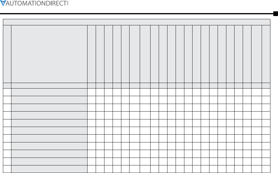
Chapter 3: Configuration and Parameters
Page 3–5Stellar® SR55 Series Soft Starter User Manual – 1st Ed. Rev.B – 02/02/2017
# Application
Unit % %
31 10 10 10 60 20 3.5 25 15 1 0 0 0 1 1 1 0 0 1 0 2 25
32 40 10 10 0 20 3.5 40 5 1 0 1 0 1 0 0 0 0 0 1 8 2
33 40 10 10 0 20 3.5 40 5 1 0 1 0 1 0 0 0 0 0 0 8 2
34 30 10 10 0 20 4.5 25 5 1 0 1 0 1 0 0 0 0 0 0 8 2
35 10 10 10 0 10 3.5 25 5 1 0 1 0 1 0 0 0 0 0 0 8 2
36 40 10 10 0 20 3.5 40 5 1 0 1 0 1 0 0 0 0 0 0 8 2
37 40 10 10 0 20 4.5 40 5 1 0 1 0 1 0 0 0 0 0 0 8 2
38 40 10 10 0 30 3.5 60 5 1 0 1 0 1 0 0 0 0 0 0 8 2
39 10 10 5 0 10 3.5 25 5 0 0 0 0 1 0 0 0 0 0 0 8 2
40 20 10 10 0 20 4 25 5 1 0 1 0 0 0 0 0 0 0 0 8 2
41 40 10 10 0 30 3.5 60 5 1 0 1 0 0 0 0 0 0 0 0 8 2
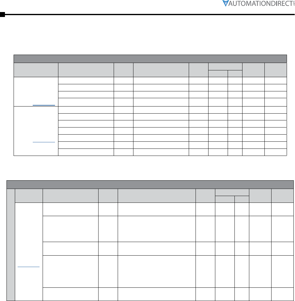
Page 3–6 Stellar® SR55 Series Soft Starter User Manual – 1st Ed. Rev.B – 02/02/2017
Chapter 3: Configuration and Parameters
Parameter Summary
These parameters are configurable through network communications.
Summary – Parameters Not Configurable Through Touchscreen
(for Digital Inputs)
[detailed info starts
page 3–14]
P0.0 – Start/Stop toggle OFF (Stop) / ON (Start) R/W 17920 4600 OFF
P0.1 – Freeze Ramp toggle OFF / ON R/W 18240 4740 OFF
P0.2 – Reset toggle OFF / ON R/W 18368 47C0 OFF
P0.3 – External Trip toggle OFF / ON R/W 18880 49C0 OFF
[detailed info starts
page 3–15]
P0.4 – Ready – OFF / ON Read 37184 9140 OFF –
P0.5 – Enabled – OFF / ON Read 37248 9180 OFF –
P0.6 – Error – OFF / ON Read 37312 91C0 OFF –
P0.7 – Running – OFF / ON Read 37632 9300 OFF –
P0.8 – End Of Start – OFF / ON Read 37760 9380 OFF –
P0.9 – Current Limit – OFF / ON Read 37824 93C0 OFF –
P0.10 – iERS Active – OFF / ON Read 38080 94C0 OFF –
Summary – Parameters for Touchscreen Setup – “Auto Setup” Category
[detailed
info starts
page 3–18]
P0.11 – Application n/a See the previous “Auto Setup
Parameter Settings” table R/W 19200 4B00 Default
P5.1 –
Trip Class (Automatically
selected from
Application selection)
n/a 10, 20, 30 R/W 25664 6440 10
P5.0 – Motor Current A 50% to 100% of SR55 rated
current R/W 25728 6480 100%
P7.0 – Control Method n/a
Local Touch Screen
User Programmable
Two Wire Control
Three Wire Control
Modbus Network
R/W 59392 E800
Local
Touch
Screen
P10.0 –
Digital Input Voltage V 230VAC, 110VAC, 24VDC R/W 10880 2A80 230VAC
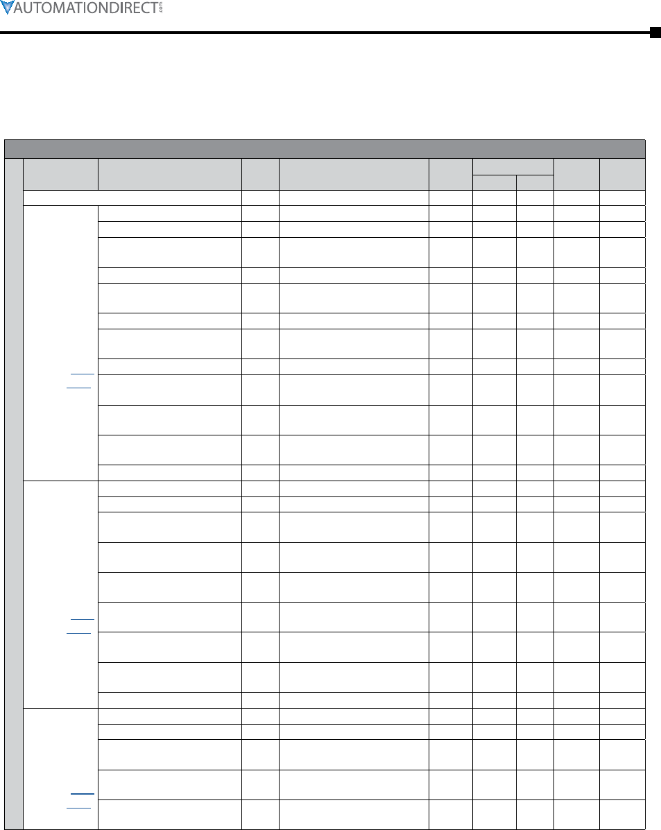
Chapter 3: Configuration and Parameters
Page 3–7Stellar® SR55 Series Soft Starter User Manual – 1st Ed. Rev.B – 02/02/2017
Summary – Parameters for Touchscreen Setup – “Advanced” Category
P1.0 – Save Parameters toggle NO / YES R/W 62144 F2C0 NO
[detailed info
starts page
3–20]
P2.0 – Automatic Pedestal toggle OFF / ON R/W 19840 4D80 OFF
P2.1 – Automatic Ramp toggle OFF / ON R/W 20352 4F80 OFF
P2.2 –
Automatic End Start (1) toggle OFF / ON R/W 19968 4E00 OFF
P2.3 – Automatic Stop toggle OFF / ON R/W 20160 4EC0 OFF
P2.4 –
Automatic Stop Profile % 0 to 100 R/W 20608 5080 50
P2.5 – Automatic End Stop toggle OFF / ON R/W 20416 4FC0 OFF
P2.6 –
Automatic Impact Load toggle OFF / ON R/W 20480 5000 OFF
P2.7 – Auto Smooth Stop toggle OFF / ON R/W 20224 4F00 OFF
P2.8 –
Auto Smoothing Level % 10 to 100 R/W 20672 50C0 50
P2.9 –
Automatic End Start (2) toggle OFF / ON R/W 19904 4DC0 OFF
P2.10 –
Automatic End Start (3) toggle OFF / ON R/W 20032 4E40 OFF
P2.11 – Rate End Start (3) % 0 to 100 R/W 768 0300 50
[detailed info
starts page
3–23]
P3.0 – Start Time s 1 to 300 R/W 7104 1BC0 10
P3.1 – Start Pedestal % 10 to 100 R/W 704 02C0 20
P3.2 – Start Current Limit →
Start Current Limit Trip toggle OFF / ON R/W 53790 D21E ON
P3.3 – Start Current Limit →
Start Current Limit Level A100% mtr FLA to
450% SR55 rated A R/W 26880 6900 350%
mtr FLA
P3.4 – Start Current Limit →
Start Current Limit Time s 1 to 300 R/W 26944 6940 30
P3.5 –
Kick Start → Kick Start toggle OFF / ON R/W 320 0140 OFF
P3.6 –
Kick Start → Kick Start Time ms 10 to 2,000 R/W 7040 1B80 100
P3.7 – Kick Start →
Kick Start Pedestal % 30 to 80 R/W 640 0280 75
P3.8 – Contactor Delay ms 20 to 800 R/W 8320 2080 160
[detailed info
starts page
3–26]
P4.0 – Stop Time s 0 to 300 R/W 7296 1C80 0
P4.1 – Stop Pedestal % 10 to 40 R/W 896 0380 10
P4.2 – Stop Current Limit →
Stop Current Limit Trip toggle OFF / ON R/W 53791 D21F OFF
P4.3 – Stop Current Limit →
Stop Current Limit Level A100% mtr FLA to
450% SR55 rated A R/W 28800 7080 350%
mtr FLA
P4.4 – Stop Current Limit →
Stop Current Limit Time s 1 to 300 R/W 28864 70C0 10
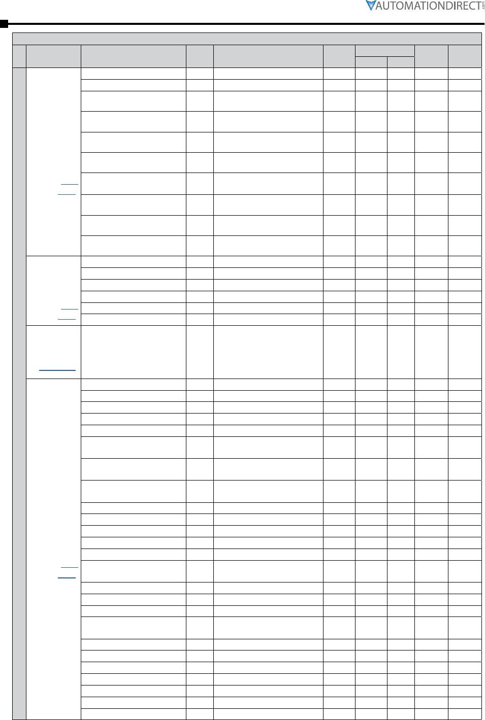
Page 3–8 Stellar® SR55 Series Soft Starter User Manual – 1st Ed. Rev.B – 02/02/2017
Chapter 3: Configuration and Parameters
[detailed info
starts page
3–27]
P5.0 – Motor Current A 50% to 100% of SR55 rated A R/W 25728 6480 100%
P5.1 – Trip Class class 10, 20, 30 R/W 25664 6440 10
Low Current Settings →
P5.2 – Low Current Trip toggle OFF / ON R/W 53787 D21B OFF
Low Current Settings →
P5.3 – Low Current Trip Level A 25% to 100% of motor FLA R/W 26304 66C0 25%
Low Current Settings →
P5.4 – Low Current Trip Time ms 100 to 9,000 R/W 26368 6700 100
Shearpin Settings →
P5.5 – Shearpin Trip toggle OFF / ON R/W 53793 D221 ON
Shearpin Settings →
P5.6 – Shearpin Trip Current A100% mtr FLA to
450% SR55 rated A R/W 27584 6BC0 450%
SR55 A
Shearpin Settings →
P5.7 – Shearpin Trip Time ms 100 to 9,000 R/W 27648 6C00 100
Overload Settings →
P5.8 – Overload Trip toggle OFF / ON R/W 53792 D220 ON
Overload Settings →
P5.9 – Overload Level A 50% to 125% of motor FLA R/W 28224 6E40 115%
[detailed info
starts page
3–30]
P6.0 – iERS toggle OFF / ON R/W 21120 5280 ON
P6.1 – Dwell Time s 1 to 300 R/W 7360 1CC0 5
P6.2 – iERS Rate % 0 to 100 R/W 21184 52C0 25
P6.3 – iERS Level % 0 to 100 R/W 21376 5380 100
P6.4 – Fixed Voltage (Level) V 100 to 500 R/W 35200 8980 500
P6.5 – Fixed Voltage toggle OFF / ON R/W 35264 89C0 OFF
[detailed info
page 3–19]
P7.0 – Control Method –
Local Touch Screen
User Programmable
Two Wire Control
Three Wire Control
Modbus Network
R/W 59392 E800
Local
Touch
Screen
[detailed info
starts page
3–33]
P8.0 – Trip Sensitivity % 0 to 100 R/W 44864 AF40 0
P8.1 – Cover Open Trip toggle OFF / ON R/W 53803 D22B OFF
P8.2 – Shearpin Trip toggle OFF / ON R/W 53793 D221 ON
P8.3 – Overload Trip toggle OFF / ON R/W 53792 D220 ON
P8.4 – Low Current Trip toggle OFF / ON R/W 53787 D21B OFF
P8.5 –
Start Current Limit Trip toggle OFF / ON R/W 53790 D21E ON
P8.6 –
Stop Current Limit Trip toggle OFF / ON R/W 53791 D21F OFF
P8.7 –
PTC Motor Thermistor Trip toggle OFF / ON R/W 53794 D222 OFF
P8.8 – L1-L2-L3 Trip toggle OFF / ON R/W 53808 D230 OFF
P8.9 – L1-L3-L2 Trip toggle OFF / ON R/W 53807 D22F OFF
P8.10 – Remote Start Trip toggle OFF / ON R/W 53804 D22C ON
P8.11 – Current Sensor Trip toggle OFF / ON R/W 53775 D20F OFF
P8.12 – Fan Trip toggle OFF / ON R/W 53782 D216 ON
P8.13 –
Communications Trip toggle OFF / ON R/W 53796 D224 ON
P8.14 – Shut Down (1) toggle OFF / ON R/W 53769 D209 ON
P8.15 – Shut Down (2) toggle OFF / ON R/W 53770 D20A ON
P8.16 – Thyristor Firing Trip toggle OFF / ON R/W 53774 D20E ON
P8.17 –
Motor Side Phase Loss toggle OFF / ON R/W 53777 D211 ON
P8.18 – Sensing Fault Trip toggle OFF / ON R/W 53781 D215 ON
P8.19 – Thermal Sensor Trip toggle OFF / ON R/W 53768 D208 ON
P8.20 – External Trip Enable toggle OFF / ON R/W 53795 D223 OFF
P8.21 – Main Board Trip toggle OFF / ON R/W 53800 D228 ON
P8.22 – Keypad Trip toggle OFF / ON R/W 53798 D226 OFF
P8.23 – Logging Trip toggle OFF / ON R/W 53799 D227 OFF
P8.24 – Input Side Phase Loss toggle OFF / ON R/W 53762 D202 ON
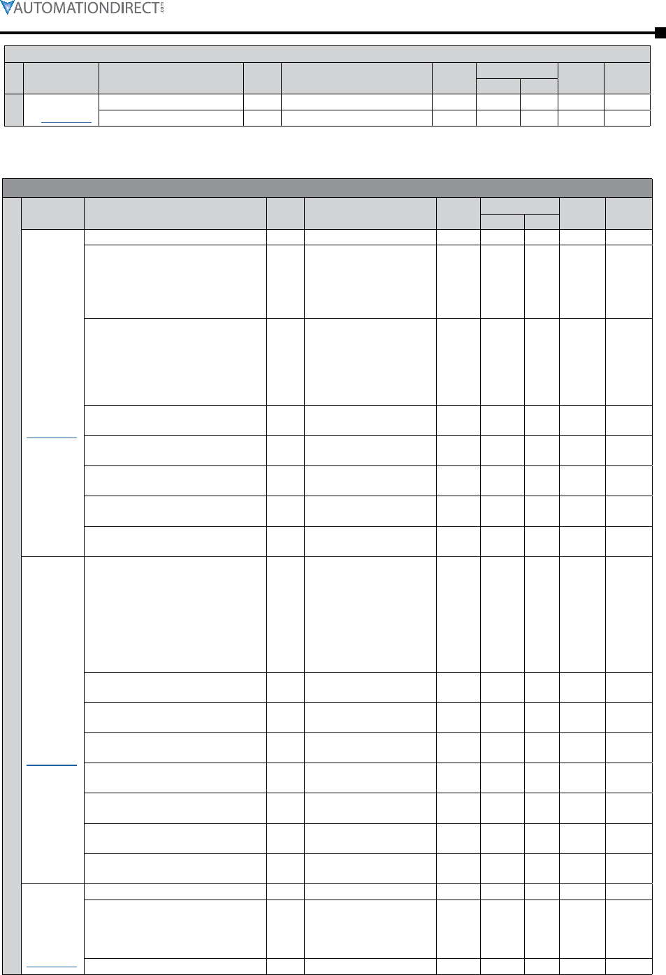
Chapter 3: Configuration and Parameters
Page 3–9Stellar® SR55 Series Soft Starter User Manual – 1st Ed. Rev.B – 02/02/2017
[page 3–33]
P9.0 – Firing Mode toggle In-Delta / In-Line R/W 128 0080 In-Line
P9.1 – Legacy Delta Mode toggle OFF / ON R/W 192 00C0 OFF
Summary – Parameters for Touchscreen Setup – “I/O” Category
[detailed
info starts
page 3–41]
P10.0 – Digital Input Voltage V 230VAC, 110VAC, 24VDC R/W 10880 2A80 230VAC
P7.0 – Control Method –
Local Touch Screen
User Programmable
Two Wire Control
Three Wire Control
Modbus Network
R/W 59392 E800
Local
Touch
Screen
P10.1 – Digital Input 1 (D1-1I) →
Select Function –
Off
Start / Stop
Freeze Ramp
Reset
iERS
External Trip
R/W 10944 2AC0 Start /
Stop
P10.2 – Digital Input 1 (D1-1I) →
High Input =1 Sets Value toggle OFF / ON R/W 11264 2C00 ON
P10.3 – Digital Input 2 (D1-2I) →
Select Function –same as DI1
function selections R/W 10945 2AC1 OFF
P10.4 – Digital Input 2 (D1-2I) →
High Input =1 Sets Value toggle OFF / ON R/W 11266 2C02 ON
P10.5 – Digital Input 3 (D2-1I) →
Select Function –same as DI1
function selections R/W 10946 2AC2 Reset
P10.6 – Digital Input 3 (D2-1I) →
High Input =1 Sets Value toggle OFF / ON R/W 11268 2C04 ON
[detailed
info starts
page 3–44]
P11.0 – Digital Output 1 N/C (12) →
Select Function –
Off
Ready
Enabled
Error
Running
End Of Start
Current Limit
iERS Active
R/W 11584 2D40 Error
P11.1 – Digital Output 1 N/C (12) →
High Output =1 When Value toggle OFF / ON R/W 11904 2E80 ON
P11.2 – Digital Output 2 N/O (24) →
Select Function –same as DO1
function selections R/W 11585 2D41 Error
P11.3 – Digital Output 2 N/O (24) →
High Output =1 When Value toggle OFF / ON R/W 11906 2E82 ON
P11.4 – Digital Output 3 N/O (34) →
Select Function –same as DO1
function selections R/W 11586 2D42 Run-
ning
P11.5 – Digital Output 3 N/O (34) →
High Output =1 When Value toggle OFF / ON R/W 11908 2E84 ON
P11.6 – Digital Output 4 N/O (44) →
Select Function –same as DO1
function selections R/W 11587 2D43 End Of
Start
P11.7 – Digital Output 4 N/O (44) →
High Output =1 When Value toggle OFF / ON R/W 11910 2E86 ON
[detailed
info starts
page 3–47]
P12.0 – Analog Input Type toggle 0–10V / 4–20mA R/W 9600 2580 0–10V
P12.1 – Select Function –
Off
Current Limit Start
Current Shearpin
Current Overload
R/W 9664 25C0 OFF
P12.2 – Scaling Level – 0 to 16,384 R/W 9728 2600 16,384
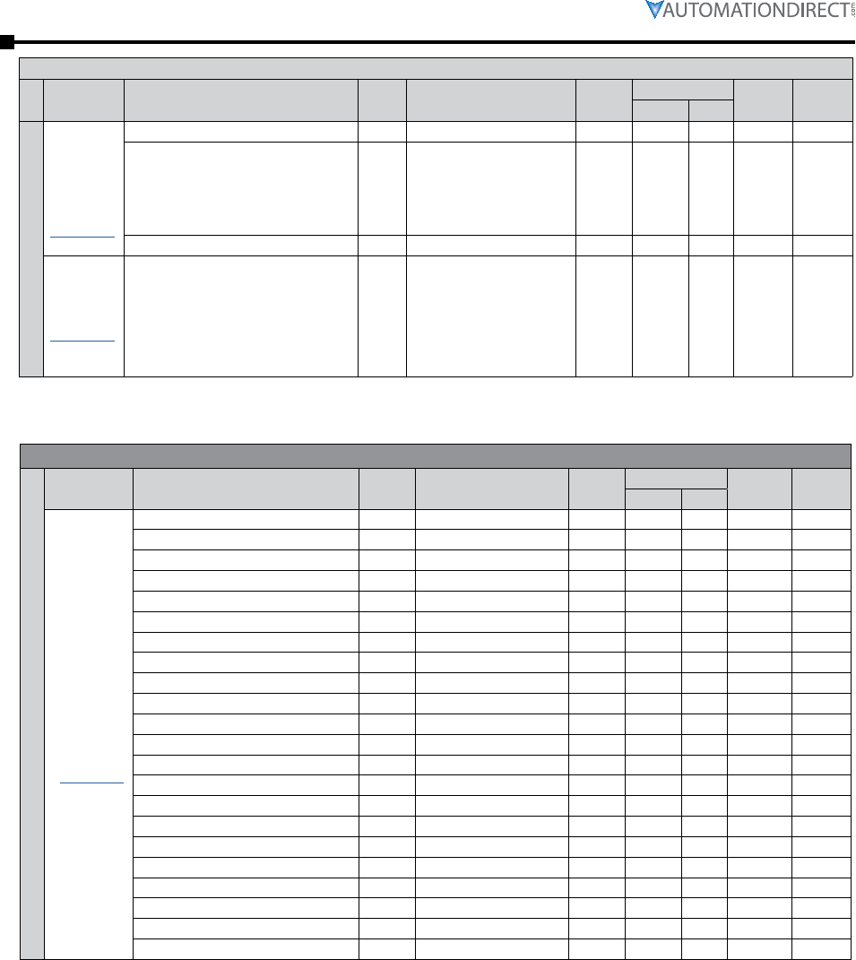
Page 3–10 Stellar® SR55 Series Soft Starter User Manual – 1st Ed. Rev.B – 02/02/2017
Chapter 3: Configuration and Parameters
[detailed
info starts
page 3–48]
P13.0 – Analog Output Type toggle 0–10V / 4–20mA R/W 8960 2300 0–10V
P13.1 – Select Function –
Off
Current Measured
Overload
Overload SCR
P-Total
R/W 9024 2340 OFF
P13.2 – Scaling Level – 0 to 16,384 R/W 9088 2380 0
[details
page 3–49]
P14.0 – PTC Motor Thermistor Trip toggle OFF / ON R/W 53794 D222 OFF
Summary – Parameters for Touchscreen Setup – “Monitor” Category
[detailed
info starts
page 3–50]
P15.0 – Line Frequency Hz 45 to 65 Read 32000 7D00 n/a –
P15.1 – Phase Rotation – L1-L2-L3 or L1-L3-L2 Read 32064 7D40 L1-L2-L3 –
P15.2 – I1 A 0 to 10,000 Read 33536 8300 0 –
P15.3 – I2 A 0 to 10,000 Read 33538 8302 0 –
P15.4 – I3 A 0 to 10,000 Read 33540 8304 0 –
P15.5 – Current I rms A 0 to 10,000 Read 32896 8080 0 –
P15.6 – V rms (Approx) V 0 to 500 Read 32960 80C0 0 –
P15.7 – Real Power Factor – 0 to 1 Read 33024 8100 0 –
P15.8 – True Power P kW 0 to 10,000 Read 34688 8780 0 –
P15.9 – Apparent Power S kVA 0 to 10,000 Read 34816 8800 0 –
P15.10 – Reactive Power Q kVAR 0 to 10,000 Read 34944 8880 0 –
P15.11 – iERS Saving Level % 0 to 100 Read 35008 88C0 0 –
P15.12 – Delay Angle degree 0° to 55° Read 22400 5780 0 –
P15.13 – Backstop degree 0° to 55° Read 23040 5A00 0 –
P15.14 – Delay Max degree 0° to 55° Read 22464 57C0 0 –
P15.15 – Pres PF Degrees degree 0° to 90° Read 21824 5540 0 –
P15.16 – Ref PF Degrees degree 0° to 90° Read 21760 5500 0 –
P15.17 – Start Saving Level % 50% to 80% of mtr FLA Read 21320 5348 80% –
P18.0 – Last Peak (Start) Current A 0 to 10,000 Read 38400 9600 0 –
P15.18 – HeatSink Temp °C -20°C to 80°C Read 36544 8EC0 ambient –
P15.19 – Motor Thermistor – 0 to 1024 Read 10432 28C0 0 –
P15.20 – Overload % 0 to 100 Read 33408 8280 0 –
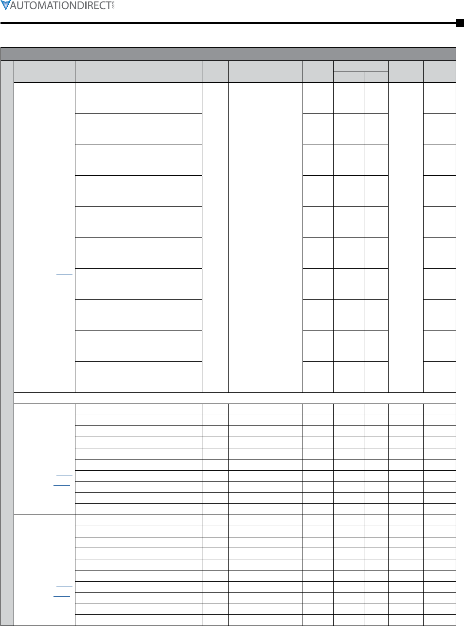
Chapter 3: Configuration and Parameters
Page 3–11Stellar® SR55 Series Soft Starter User Manual – 1st Ed. Rev.B – 02/02/2017
Summary – Parameters for Touchscreen Setup – “Log” Category
Event Times for
Last Peak Start
Currents, Last
Temperatures,
Last Overloads
[detailed info
starts page
3–56]
P16.0 – (Event Time)
Last Peak Start Current / Last
Temperature / Last Overload
hh :
mm :
ss
Time since midnight;
Days since
01/01/1984
Read 38464 9640
GMT
–
P16.1 – (Event Time)
Last Peak Start Current / Last
Temperature / Last Overload -1
Read 38467 9643 –
P16.2 – (Event Time)
Last Peak Start Current / Last
Temperature / Last Overload -2
Read 38470 9646 –
P16.3 – (Event Time)
Last Peak Start Current / Last
Temperature / Last Overload -3
Read 38473 9649 –
P16.4 – (Event Time)
Last Peak Start Current / Last
Temperature / Last Overload -4
Read 38476 964C –
P16.5 – (Event Time)
Last Peak Start Current / Last
Temperature / Last Overload -5
Read 38479 964F –
P16.6 – (Event Time)
Last Peak Start Current / Last
Temperature / Last Overload -6
Read 38482 9652 –
P16.7 – (Event Time)
Last Peak Start Current / Last
Temperature / Last Overload -7
Read 38485 9655 –
P16.8 – (Event Time)
Last Peak Start Current / Last
Temperature / Last Overload -8
Read 38488 9658 –
P16.9 – (Event Time)
Last Peak Start Current / Last
Temperature / Last Overload -9
Read 38491 965B –
* P16 event times are associated with parameters P18, P20, and P21, and the times are displayed on each of those logs.
[detailed info
starts page
3–59]
P17.0 – Last Trip – 0 to 65,535 Read 60608 ECC0 0 –
P17.1 – Last Trip -1 – 0 to 65,535 Read 60609 ECC1 0 –
P17.2 – Last Trip -2 – 0 to 65,535 Read 60610 ECC2 0 –
P17.3 – Last Trip -3 – 0 to 65,535 Read 60611 ECC3 0 –
P17.4 – Last Trip -4 – 0 to 65,535 Read 60612 ECC4 0 –
P17.5 – Last Trip -5 – 0 to 65,535 Read 60613 ECC5 0 –
P17.6 – Last Trip -6 – 0 to 65,535 Read 60614 ECC6 0 –
P17.7 – Last Trip -7 – 0 to 65,535 Read 60615 ECC7 0 –
P17.8 – Last Trip -8 – 0 to 65,535 Read 60616 ECC8 0 –
P17.9 – Last Trip -9 – 0 to 65,535 Read 60617 ECC9 0 –
[detailed info
starts page
3–62]
P18.0 – Last Peak (Start) Current A 0 to 10,000 Read 38400 9600 0 –
P18.1 – Last Peak Start Current -1 A 0 to 10,000 Read 38402 9602 0 –
P18.2 – Last Peak Start Current -2 A 0 to 10,000 Read 38404 9604 0 –
P18.3 – Last Peak Start Current -3 A 0 to 10,000 Read 38406 9606 0 –
P18.4 – Last Peak Start Current -4 A 0 to 10,000 Read 38408 9608 0 –
P18.5 – Last Peak Start Current -5 A 0 to 10,000 Read 38410 960A 0 –
P18.6 – Last Peak Start Current -6 A 0 to 10,000 Read 38412 960C 0 –
P18.7 – Last Peak Start Current -7 A 0 to 10,000 Read 38414 960E 0 –
P18.8 – Last Peak Start Current -8 A 0 to 10,000 Read 38416 9610 0 –
P18.9 – Last Peak Start Current -9 A 0 to 10,000 Read 38418 9612 0 –
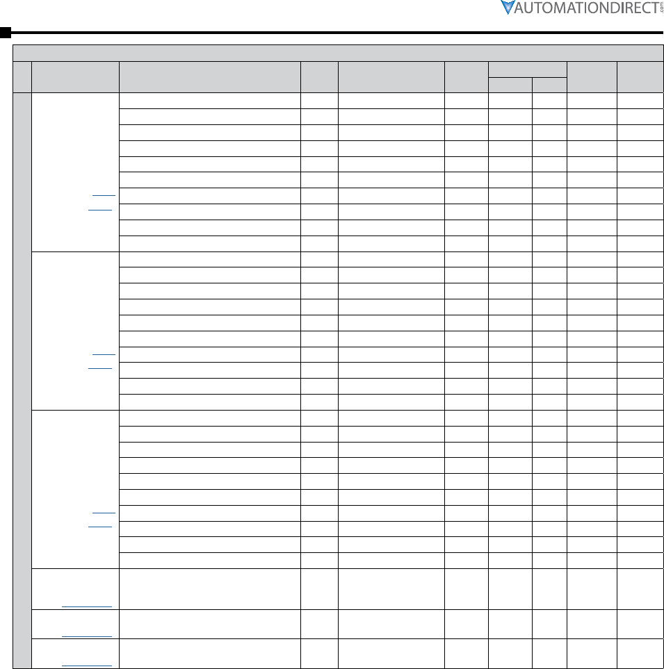
Page 3–12 Stellar® SR55 Series Soft Starter User Manual – 1st Ed. Rev.B – 02/02/2017
Chapter 3: Configuration and Parameters
[detailed info
starts page
3–65]
P19.0 – Last Peak Stop Current A 0 to 10,000 Read 39040 9880 0 –
P19.1 – Last Peak Stop Current -1 A 0 to 10,000 Read 39042 9882 0 –
P19.2 – Last Peak Stop Current -2 A 0 to 10,000 Read 39044 9884 0 –
P19.3 – Last Peak Stop Current -3 A 0 to 10,000 Read 39046 9886 0 –
P19.4 – Last Peak Stop Current -4 A 0 to 10,000 Read 39048 9888 0 –
P19.5 – Last Peak Stop Current -5 A 0 to 10,000 Read 39050 988A 0 –
P19.6 – Last Peak Stop Current -6 A 0 to 10,000 Read 39052 988C 0 –
P19.7 – Last Peak Stop Current -7 A 0 to 10,000 Read 39054 988E 0 –
P19.8 – Last Peak Stop Current -8 A 0 to 10,000 Read 39056 9890 0 –
P19.9 – Last Peak Stop Current -9 A 0 to 10,000 Read 39058 9892 0 –
[detailed info
starts page
3–68]
P20.0 – Last Temperature °C -20°C to 80°C Read 39680 9B00 ambient –
P20.1 – Last Temperature -1 °C -20°C to 80°C Read 39681 9B01 ambient –
P20.2 – Last Temperature -2 °C -20°C to 80°C Read 39682 9B02 ambient –
P20.3 – Last Temperature -3 °C -20°C to 80°C Read 39683 9B03 ambient –
P20.4 – Last Temperature -4 °C -20°C to 80°C Read 39684 9B04 ambient –
P20.5 – Last Temperature -5 °C -20°C to 80°C Read 39685 9B05 ambient –
P20.6 – Last Temperature -6 °C -20°C to 80°C Read 39686 9B06 ambient –
P20.7 – Last Temperature -7 °C -20°C to 80°C Read 39687 9B07 ambient –
P20.8 – Last Temperature -8 °C -20°C to 80°C Read 39688 9B08 ambient –
P20.9 – Last Temperature -9 °C -20°C to 80°C Read 39689 9B09 ambient –
[detailed info
starts page
3–72]
P21.0 – Last Overload % 0 to 100 Read 40320 9D80 0 –
P21.1 – Last Overload -1 % 0 to 100 Read 40321 9D81 0 –
P21.2 – Last Overload -2 % 0 to 100 Read 40322 9D82 0 –
P21.3 – Last Overload -3 % 0 to 100 Read 40323 9D83 0 –
P21.4 – Last Overload -4 % 0 to 100 Read 40324 9D84 0 –
P21.5 – Last Overload -5 % 0 to 100 Read 40325 9D85 0 –
P21.6 – Last Overload -6 % 0 to 100 Read 40326 9D86 0 –
P21.7 – Last Overload -7 % 0 to 100 Read 40327 9D87 0 –
P21.8 – Last Overload -8 % 0 to 100 Read 40328 9D88 0 –
P21.9 – Last Overload -9 % 0 to 100 Read 40329 9D89 0 –
[page 3–74]
P22.0 – Number of Starts – 0 to 4,294,836,225 Read 35840 8C00 0 –
[page 3–74]P23.0 – Download Log File – – R/W n/a n/a –
[page 3–74]P24.0 – Clear Trip Log – – R/W n/a n/a –
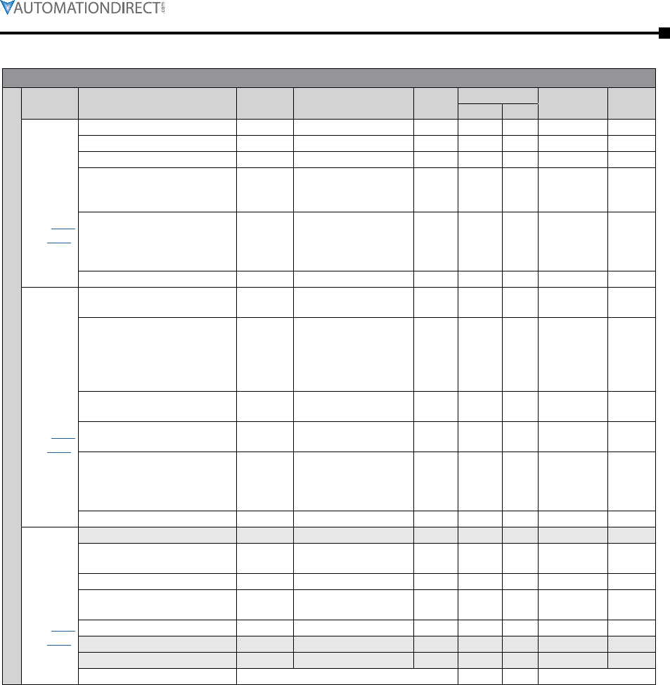
Chapter 3: Configuration and Parameters
Page 3–13Stellar® SR55 Series Soft Starter User Manual – 1st Ed. Rev.B – 02/02/2017
Summary – Parameters for Touchscreen Setup – “Device” Category
[detailed
info starts
page
3–78]
P25.0 – Update Firmware – – R/W – – –
P25.1 – Date – current date R/W – – –
P25.2 – Time hh:mm:ss GMT / local R/W 14720 3980 GMT
P25.3 – Language –
refer to the “Parameter
Details” section for list
of available languages
R/W 13376 3440 English
P25.4 – Passcode – 0 to 255 per Byte R/W
12864
12865
12866
12867
3240
3241
3242
3243
n/a
P25.5 – Backlight Timeout s 0 to 3,600 R/W 14208 3780 60
[detailed
info starts
page
3–77]
P26.0 –
Modbus Network Address – 1 to 32 R/W 16000 3E80 1
P26.1 –
Modbus Network Baud Rate Baud
9,600
19,200
38,400
57,600
115,200
R/W 16064 3EC0 19,200
P26.2 –
Modbus Network Parity – none / odd / even R/W 16128 3F00 even
P26.3 –
Modbus Network Traffic LEDs toggle OFF / ON R/W 14080 3700 OFF
P26.4 –
Anybus / ModbusTCP /
EtherNetIP
–
Address
Serial Number
Firmware Version
Connection
Read – – – –
P26.5 – Timeout ms 0 to 60,000 R/W 15808 3DC0 5,000
[detailed
info starts
page
3–78]
P27.0 –
P27.1 – About – SR55 model #, serial #,
software versions Read – – – –
P27.2 – Screen Lock toggle OFF / ON R/W 12992 32C0 OFF
P27.3 – Date Format – dd/mm/yyyy
mm/dd/yyyy R/W 13248 33C0 dd/mm/yyyy
P27.4 – Temperature Format degrees °C / °F R/W 13312 3400 °C
P27.5 –
P27.6 –
P27.7 – Service Code for manufacturer’s use only 13120 3340
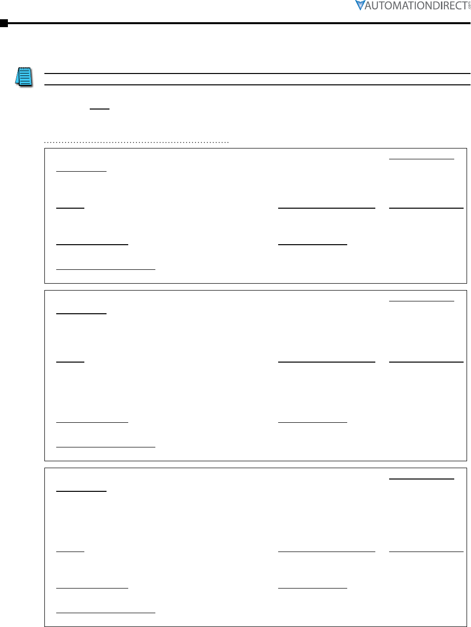
Page 3–14 Stellar® SR55 Series Soft Starter User Manual – 1st Ed. Rev.B – 02/02/2017
Chapter 3: Configuration and Parameters
Parameter Details
This section describes the individual parameters and the functions that they perform.
SR55 parameters are defined as holding type registers.
These parameters are configurable through network communications.
P0.0 – (Digital Input Control Command Function) Hold. Reg. Type:
Description:
Read/Write
Starts or Stops the SR55.
• To map to digital input, refer to P10.2, P10.4, P10.6.
Range: Modbus Decimal Value: Default (decimal):
• Off : Stops or Soft Stops the SR55.
• On : Starts the SR55.
• 0
• 1
• Off (0)
Modbus Address: Modbus Format:
17920 ( 4600 hex ) 16-bit unsigned
Touchscreen Menu Path:
none
P0.1 – (Digital Input Control Command Function) Hold. Reg. Type:
Description:
Read/Write
If set to On, this parameter will hold the Start Ramp even if “Current Irms” is less than the “Current
Limit Level.”
• To map to digital input, refer to P10.2, P10.4, P10.6.
Range: Modbus Decimal Value: Default (decimal):
• Off : The Soft Start Ramp is not held and the SR55 will start in
the time set.
• On : The Soft Start Ramp is held and the SR55 will take longer
than the time set to start.
• 0
• 1
• Off (0)
Modbus Address: Modbus Format:
18240 ( 4740 hex ) 16-bit unsigned
Touchscreen Menu Path:
none
P0.2 – (Digital Input Control Command Function) Hold. Reg. Type:
Description:
Read/Write
To reset pulse high and then low when resetting using communications.
• If using the touchscreen, the Start button will change to a Reset button during a fault condition.
• Clear the fault and press Reset.
• To map to digital input, refer to P10.2, P10.4, P10.6.
Range: Modbus Decimal Value: Default (decimal):
• Off : The final state required for a reset.
• On : The initial state required for a reset.
• 0
• 1
• Off (0)
Modbus Address: Modbus Format:
18368 ( 47C0 hex ) 16-bit unsigned
Touchscreen Menu Path:
none
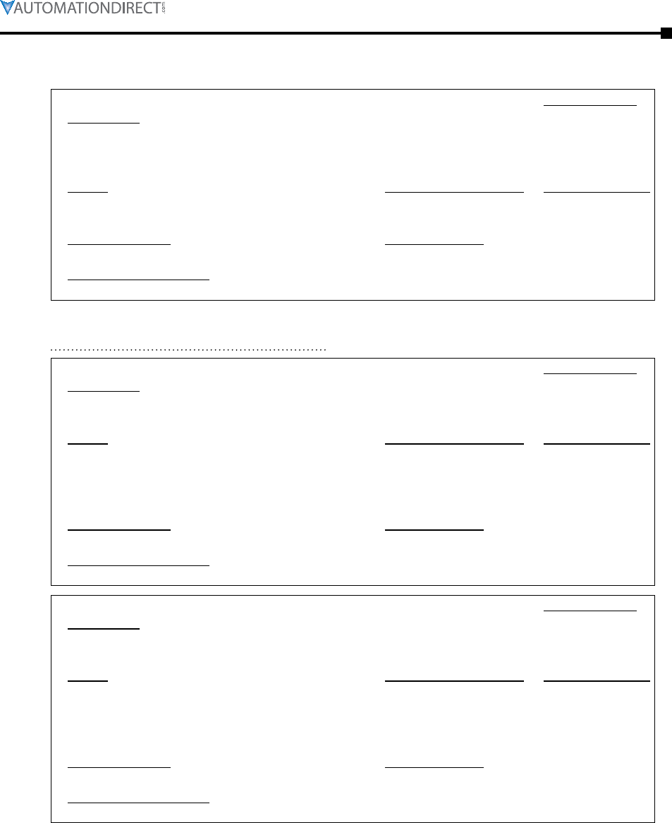
Chapter 3: Configuration and Parameters
Page 3–15Stellar® SR55 Series Soft Starter User Manual – 1st Ed. Rev.B – 02/02/2017
P0.3 – (Digital Input Control Command Function) Hold. Reg. Type:
Description:
Read/Write
Control command for Digital Input: External Trip.
• Ensure start signal is low before reset.
• To map to digital input, refer to P10.2, P10.4, P10.6.
Range: Modbus Decimal Value: Default (decimal):
• Off : The SR55 will not trip.
• On : If “External Trip” is enabled, the SR55 trips.
• 0
• 1
• Off (0)
Modbus Address: Modbus Format:
18880 ( 49C0 hex ) 16-bit unsigned
Touchscreen Menu Path:
none
P0.4 – Hold. Reg. Type:
Description:
Read Only
STATUS INDICATION : Ready
• To map to Digital Output, refer to P11.0, P11.2, P11.4, P11.6.
Range: Modbus Decimal Value: Default (decimal):
• Off : The SR55 has not powered up successfully, or failed to
reset from a trip.
• On : Indicates that the SR55 is healthy and ready for a start.
Remains on when Running.
• 0
• 1
• Off (0)
Modbus Address: Modbus Format:
37184 ( 9140 hex ) 16-bit unsigned
Touchscreen Menu Path:
none
P0.5 – Hold. Reg. Type:
Description:
Read Only
STATUS INDICATION : Enabled
• To map to Digital Output, refer to P11.0, P11.2, P11.4, P11.6.
Range: Modbus Decimal Value: Default (decimal):
• Off : The SR55 has not powered up successfully, or failed to
reset from a trip.
• On : Indicates that the SR55 is enabled and ready for a start.
Remains on when Running.
• 0
• 1
• Off (0)
Modbus Address: Modbus Format:
37248 ( 9180 hex ) 16-bit unsigned
Touchscreen Menu Path:
none
Page 3–16 Stellar® SR55 Series Soft Starter User Manual – 1st Ed. Rev.B – 02/02/2017
Chapter 3: Configuration and Parameters
P0.6 – Hold. Reg. Type:
Description:
Read Only
STATUS INDICATION : Error. The fault must be cleared before a reset.
• To map to Digital Output, refer to P11.0, P11.2, P11.4, P11.6.
Range: Modbus Decimal Value: Default (decimal):
• Off : The SR55 is fault free.
• On : Indicates that SR55 has detected a fault and has shut
down.
• 0
• 1
• Off (0)
Modbus Address: Modbus Format:
37312 ( 91C0 hex ) 16-bit unsigned
Touchscreen Menu Path:
none
P0.7 – Hold. Reg. Type:
Description:
Read Only
STATUS INDICATION : Running
• To map to Digital Output, refer to P11.0, P11.2, P11.4, P11.6.
Range: Modbus Decimal Value: Default (decimal):
• Off : The SR55 has detected a fault and tripped, or has been
stopped.
• On : Indicates that the motor is running and is being actively
controlled by the SR55.
• 0
• 1
• Off (0)
Modbus Address: Modbus Format:
37632 ( 9300 hex ) 16-bit unsigned
Touchscreen Menu Path:
none
P0.8 – Hold. Reg. Type:
Description:
Read Only
STATUS INDICATION : End Of Start
• To map to Digital Output, refer to P11.0, P11.2, P11.4, P11.6.
Range: Modbus Decimal Value: Default (decimal):
• Off : The SR55 is disabled or ramping down.
• On : Indicates that the Soft Start ramp has been completed.
• 0
• 1
• Off (0)
Modbus Address: Modbus Format:
37760 ( 9380 hex ) 16-bit unsigned
Touchscreen Menu Path:
none
P0.9 – Hold. Reg. Type:
Description:
Read Only
STATUS INDICATION : Current Limit
• To map to Digital Output, refer to P11.0, P11.2, P11.4, P11.6.
Range: Modbus Decimal Value: Default (decimal):
• Off : The ramp is not being held because “ Current Irms “ is
less than “Current Limit Level.”
• On : The ramp is being held because “Current Irms” is greater
or equal to “Current Limit Level.”
• 0
• 1
• Off (0)
Modbus Address: Modbus Format:
37824 ( 93C0 hex ) 16-bit unsigned
Touchscreen Menu Path:
none
Chapter 3: Configuration and Parameters
Page 3–17Stellar® SR55 Series Soft Starter User Manual – 1st Ed. Rev.B – 02/02/2017
P0.10 – Hold. Reg. Type:
Description:
Read Only
STATUS INDICATION : iERS Active
• To map to Digital Output, refer to P11.0, P11.2, P11.4, P11.6.
Range: Modbus Decimal Value: Default (decimal):
• Off : The iERS saving mode has been disabled either internally
or via “iERS.”
• On : Indicates that the SR55 is operating in the iERS energy
saving Mode.
• 0
• 1
• Off (0)
Modbus Address: Modbus Format:
38080 ( 94C0 hex ) 16-bit unsigned
Touchscreen Menu Path:
none
Page 3–18 Stellar® SR55 Series Soft Starter User Manual – 1st Ed. Rev.B – 02/02/2017
Chapter 3: Configuration and Parameters
SR55 parameters are defined as holding type registers.
P0.11 – Holding Register Type:
Description:
Read/Write
• The SR55 has numerous built-in preset applications. Select the application best suited to your
load. The selected application will automatically change several parameters and functions.
Depending on the application loaded, the “Trip Class” may also change.
• Refer to the previous “Auto Setup Parameter Settings” table for more details (page 3–4).
Range: Modbus Decimal Value: Default (decimal):
See the previous “Auto Setup Parameter
Settings” table (page 3–4).
n/a Default (0)
Modbus Address: Modbus Format:
19200 ( 4B00 hex) 16-bit unsigned
Touchscreen Menu Path:
Home → Auto Setup → Application
P5.1 – Holding Register Type:
Description:
Read/Write
• The trip class is a numeric value that correlates the trip time with overload level. Select Trip
class according to application requirements.
• The trip time depends on the selected Trip Class, the duration of the overload and the level of
the overcurrent. Refer to the Motor Overload ‘cold’ trip curves given in the Quick-Start Guide.
• When “Class 20” or “Class30” are selected, the SR55 current rating will be reduced to a lower
value.
Range: Modbus Decimal Value: Default (decimal):
• 10
• 20
• 30
• 10
• 20
• 30
• 10 (10)
Modbus Address: Modbus Format:
25664 ( 6440 hex ) 16-bit unsigned
Touchscreen Menu Path:
Home → Auto Setup → Application → Trip Class
(also Home → Advanced → Motor Protection → Trip Class)
(also automatically set in “Auto Setup” mode, depending on the application selected)
P5.0 – Hold. Reg. Type:
Description:
Read/Write
• This should be set to the Full Load Current shown on the motor plate.
• The overload works with multiples of the set “Motor Current” (also referred to as Motor FLA).
Range: Modbus Decimal Value: Default:
50% to 100% of SR55 rated current
(displayed in amps)
linear scale: 1 = 1mA 100%
Modbus Address: Modbus Format:
25728/2529 ( 6480/6481 hex ) 32-bit unsigned
Touchscreen Menu Path:
Home → Auto Setup → Motor Current
(also Home → Advanced → Motor Protection → Motor Current)
Chapter 3: Configuration and Parameters
Page 3–19Stellar® SR55 Series Soft Starter User Manual – 1st Ed. Rev.B – 02/02/2017
P7.0 – Holding Register Type:
Description:
Read/Write
• Local Touch Screen : Control using the buttons on the keypad.
• User Programmable : Control using the terminals, function defined in “I/O” menu.
• Two Wire Control : Control using terminals; functions fixed as shown on screen.
D1-1I = High: Reset & Start / Low: Stop
• Three Wire Control : Control using terminals; functions fixed as shown on screen.
D1-1I = High Start
D1-2I = Low Stop
D2-1I = High Reset
• Modbus Network : Control via remote Modbus network or remote touchscreen.
Range: Modbus Decimal Value: Default (decimal):
• Local Touch Screen
• User Programmable
• Two Wire Control
• Three Wire Control
• Modbus Network
• 0
• 1
• 2
• 3
• 4
• Local (0)
Modbus Address: Modbus Format:
59392 ( E800 hex ) 16-bit unsigned
Touchscreen Menu Path:
Home → Auto Setup → Control Method
(also Home → Advanced → Control Method) (also Home → I/O → Digital Inputs → Control Method)
P10.0 – Hold. Reg. Type:
Description:
Read/Write
The digital inputs D1-1I, D1-2I, D2-1I are designed to work with a range of control supplies.
• It is important to ensure the “Digital Input Voltage” corresponds to the voltage applied to the
input. Failure to do so may result in damage.
Range: Modbus Decimal Value: Default (decimal):
• 230VAC : ‘Active high level’ Input voltage must be in
the range 195.5V–253V.
• 110VAC : ‘Active high level’ Input voltage must be in
the range 93.5V–121V.
• 24VDC : ‘Active high level’ input voltage must be in the
range 20.4V–26.4V.
• 0
• 1
• 2
• 230VAC (0)
Modbus Address: Modbus Format:
10880 ( 2A80 hex ) 16-bit unsigned
Touchscreen Menu Path:
Home → Auto Setup → Digital Input Voltage
(also Home → I/O → Digital Inputs → Digital Input Voltage)
Page 3–20 Stellar® SR55 Series Soft Starter User Manual – 1st Ed. Rev.B – 02/02/2017
Chapter 3: Configuration and Parameters
P1.0 – Hold. Reg. Type:
Description:
Read/Write
Saves all Read/Write parameters to non-volatile memory.
Note: This does not save the parameters to an external USB drive.
Range: Modbus Decimal Value: Default (decimal):
• No : Parameters remain unchanged.
• Yes : Parameters are written.
• 0
• 1
• No (0)
Modbus Address: Modbus Format:
Touchscreen Menu Path:
P2.0 – Hold. Reg. Type:
Description:
Read/Write
Automatically controls the starting torque by adjusting the start voltage.
Range: Modbus Decimal Value: Default (decimal):
• Off : The initial torque is defined by the “Start Pedestal.”
• On : The initial torque is increased until the motor starts to
rotate at a moderate speed.
• 0
• 1
• Off (0)
Modbus Address: Modbus Format:
19840 ( 4D80 hex ) 16-bit unsigned
Touchscreen Menu Path:
Home → Advanced → Automatic Settings → Automatic Pedestal
P2.1 – Hold. Reg. Type:
Description:
Read/Write
Automatically controls the torque applied to the motor during the soft start by automatically
adjusting “Start Time” and “Current Limit.”
Range: Modbus Decimal Value: Default (decimal):
• Off : The ramp time depends on the “Start Time” and “Current
Limit.”
• On : The torque is adjusted to suit the load.
• 0
• 1
• Off (0)
Modbus Address: Modbus Format:
20352 ( 4F80 hex ) 16-bit unsigned
Touchscreen Menu Path:
Home → Advanced → Automatic Settings → Automatic Ramp
P2.2 – Hold. Reg. Type:
Description:
Read/Write
Automatically controls the time taken for the motor to start.
Range: Modbus Decimal Value: Default (decimal):
• Off : The ramp time depends on the “Start Time” and “Current
Limit.”
• On : The ramp time is shortened if the motor is at speed before
the end of the “Start Time.”
• 0
• 1
• Off (0)
Modbus Address: Modbus Format:
19968 ( 4E00 hex ) 16-bit unsigned
Touchscreen Menu Path:
Home → Advanced → Automatic Settings → Automatic End Start (1)
Chapter 3: Configuration and Parameters
Page 3–21Stellar® SR55 Series Soft Starter User Manual – 1st Ed. Rev.B – 02/02/2017
P2.3 – Hold. Reg. Type:
Description:
Read/Write
Automatically controls the soft stop to suit the application.
This feature is particularly useful with pumping applications
Range: Modbus Decimal Value: Default (decimal):
• Off : The deceleration to the point where the soft stop becomes
useful will be slower.
• On : If the motor is lightly loaded it decelerates rapidly to the
point where the soft stop becomes useful.
• 0
• 1
• Off (0)
Modbus Address: Modbus Format:
20160 ( 4EC0 hex ) 16-bit unsigned
Touchscreen Menu Path:
Home → Advanced → Automatic Settings → Automatic Stop
P2.4 – Type:
Description:
Read/Write
Adjusts the response of the “Automatic Stop.”
• Increase if the motor speed doesn’t drop quickly enough.
• When the value is set to zero, the “Automatic Stop” is effectively disabled.
Range: Modbus Decimal Value: Default:
0% – 100% linear scale ( 1 = 0.006104 % )
0% – 100% = (0 – 16384)
x% / 0.006104% = Modbus dec. value
EX: Modbus value of 2900 = 17.7016%
50%
Modbus Address: Modbus Format:
20608 ( 5080 hex ) 16-bit unsigned
Touchscreen Menu Path:
Home → Advanced → Automatic Settings → Automatic Stop Profile
P2.5 – Hold. Reg. Type:
Description:
Read/Write
Automatically controls the “Stop Time.”
Range: Modbus Decimal Value: Default (decimal):
• Off : The ramp time depends on the “Stop Time” and “Current
Limit.”
• On : The ramp time is shortened if the motor reaches a very low
speed before the end of the “Stop Time.”
• 0
• 1
• Off (0)
Modbus Address: Modbus Format:
20416 ( 4FC0 hex ) 16-bit unsigned
Touchscreen Menu Path:
Home → Advanced → Automatic Settings → Automatic End Stop
P2.6 – Hold. Reg. Type:
Description:
Read/Write
Automatically controls the maximum iERS saving level.
Range: Modbus Decimal Value: Default (decimal):
• Off : The saving potential may be reduced on applications with
heavy load cycles , such as injection molding machines.
• On : The maximum iERS saving level (“BackStop” ) is reset to
maximum during each load cycle.
• 0
• 1
• Off (0)
Modbus Address: Modbus Format:
20480 ( 5000 hex ) 16-bit unsigned
Touchscreen Menu Path:
Home → Advanced → Automatic Settings → Automatic Impact Load
Page 3–22 Stellar® SR55 Series Soft Starter User Manual – 1st Ed. Rev.B – 02/02/2017
Chapter 3: Configuration and Parameters
P2.7 – Hold. Reg. Type:
Description:
Read/Write
Automatically controls the soft stop to eliminate oscillations that can occur towards the end of
the ramp.
Range: Modbus Decimal Value: Default (decimal):
• Off : The soft stop is not adjusted, and torque fluctuations
may cause instability. This can often occur in pumping
applications.
• On : The soft stop is adjusted when oscillations are detected.
Refer to “Auto smoothing Level.”
• 0
• 1
• Off (0)
Modbus Address: Modbus Format:
20224 ( 4F00 hex ) 16-bit unsigned
Touchscreen Menu Path:
Home → Advanced → Automatic Settings → Auto Smooth Stop
P2.8 – Type:
Description:
Read/Write
Adjusts the response of the “Automatic smoothing.”
• Increase to provide a greater smoothing effect if there are torque fluctuations that occur during
the soft stop.
• When set to zero, the smoothing is effectively disabled.
Range: Modbus Decimal Value: Default:
10% – 100% linear scale ( 1 = 0.006104 % )
10% – 100% = (1638 – 16384)
x% / 0.006104% = Modbus dec. value
EX: Modbus value of 2900 = 17.7016%
50%
Modbus Address: Modbus Format:
20672 ( 50C0 hex ) 16-bit unsigned
Touchscreen Menu Path:
Home → Advanced → Automatic Settings → Auto Smoothing Level
P2.9 – Hold. Reg. Type:
Description:
Read/Write
Automatically controls the time taken for the motor to start.
Range: Modbus Decimal Value: Default (decimal):
• Off : The ramp time depends on the “Start Time” and “Current
Limit.”
• On : The ramp time is shortened if the motor current falls below
the current limit level before the end of the “Start Time.”
• 0
• 1
• Off (0)
Modbus Address: Modbus Format:
19904 ( 4DC0 hex ) 16-bit unsigned
Touchscreen Menu Path:
Home → Advanced → Automatic Settings → Automatic End Start (2)
Chapter 3: Configuration and Parameters
Page 3–23Stellar® SR55 Series Soft Starter User Manual – 1st Ed. Rev.B – 02/02/2017
P2.10 – Hold. Reg. Type:
Description:
Read/Write
Automatically controls the time taken for the motor to start.
Range: Modbus Decimal Value: Default (decimal):
• Off : The ramp time depends on the “Start Time” and “Current
Limit.”
• On : The ramp time is shortened if torque fluctuations occur
before the end of the “Start Time.”
• 0
• 1
• Off (0)
Modbus Address: Modbus Format:
20032 ( 4E40 hex ) 16-bit unsigned
Touchscreen Menu Path:
Home → Advanced → Automatic Settings → Automatic End Start (3)
P2.11 – Type:
Description:
Read/Write
Adjusts the response of the “Automatic End Start(3).”
• Increase to provide a greater smoothing effect if torque fluctuations occur during the soft start.
• When set to zero, the smoothing is effectively disabled.
Range: Modbus Decimal Value: Default:
0% – 100% linear scale ( 1 = 0.006104 % )
0% – 100% = (0 – 16384)
x% / 0.006104% = Modbus dec. value
EX: Modbus value of 2900 = 17.7016%
50%
Modbus Address: Modbus Format:
768 ( 300 hex ) 16-bit unsigned
Touchscreen Menu Path:
Home → Advanced → Automatic Settings → Rate End Start (3)
P3.0 – Type:
Description:
Read/Write
Time taken to soft start from the “Start Pedestal” to the end of the start.
• Normally set between 5 and 30 seconds.
• Actual time to get to full voltage depends on the “Start Current Limit Level.”
• If set too long the motor can be at speed before the end of the time set; refer to “Automatic End
Start.”
Range: Modbus Decimal Value: Default:
1s – 300s Linear Scaling ( 1 = 1s ) 10s
Modbus Address: Modbus Format:
7104 ( 1BC0 hex ) 16-bit unsigned
Touchscreen Menu Path:
Advanced - Start Settings - Start Time
Page 3–24 Stellar® SR55 Series Soft Starter User Manual – 1st Ed. Rev.B – 02/02/2017
Chapter 3: Configuration and Parameters
P3.1 – Hold. Reg. Type:
Description:
Read/Write
• Percentage of the supply voltage applied to motor at the beginning of the soft start.
• Increase to provide more torque If the load fails to break away.
• Decrease if the motor accelerates too quickly.
Range: Modbus Decimal Value: Default:
10% – 100% linear scale ( 1 = 0.006104 % )
10% – 100% = (1638 – 16384)
x% / 0.006104% = Modbus dec. value
EX: Modbus value of 2900 = 17.7016%
20%
Modbus Address: Modbus Format:
704 ( 2C0 hex ) 16-bit unsigned
Touchscreen Menu Path:
Home → Advanced → Start Settings → Start Pedestal
P3.2 – Hold. Reg. Type:
Description:
Read/Write
Selects between trip or continue if the current limit has been active for too long.
Range: Modbus Decimal Value: Default (decimal):
• Off : The start will continue regardless of the motor current
level.
• On : The SR55 will trip. This trip is constrained by the Start
Current Limit Level and the Start Current Limit Time.
• 0
• 1 • On (1)
Modbus Address: Modbus Format:
53790 ( D21E hex ) 16-bit unsigned
Touchscreen Menu Path:
Home → Advanced → Start Settings → Start Current Limit Trip
(also Home → Advanced → Trip Settings → Start Current Limit Trip)
P3.3 – Holding Register Type:
Description:
Read/Write
The current in Amps which the soft start ramp is not allowed to go above.
• Normally set to 350% of motor FLA.
• Increase if motor fails to accelerate at required rate.
• The “Current Limit Level” will effect actual time to start. If set too low the motor may not
accelerate to full speed.
Range: Modbus Decimal Value: Default:
100% motor FLA – 450% SR55 rated A Linear Scale ( 1 = 1mA ) 350% motor FLA
Modbus Address: Modbus Format:
26880 ( 6900 hex ) 16-bit unsigned
Touchscreen Menu Path:
Home → Advanced → Start Settings → Start Current Limit → Start Current Limit Level
P3.4 – Holding Register Type:
Description:
Read/Write
The maximum time allowed for the current limit.
• If the current limit is still active at the end of this period the SR55 will either ‘trip’ or ‘continue.’
Range: Modbus Decimal Value: Default:
• 1s – 300s Linear Scale ( 1 = 1s ) 30s
Modbus Address: Modbus Format:
26944 ( 6940 hex ) 16-bit unsigned
Touchscreen Menu Path:
Home → Advanced → Start Settings → Start Current Limit → Start Current Limit Time
Chapter 3: Configuration and Parameters
Page 3–25Stellar® SR55 Series Soft Starter User Manual – 1st Ed. Rev.B – 02/02/2017
P3.5 – Hold. Reg. Type:
Description:
Read/Write
Applies a short duration torque pulse to dislodge ‘sticky’ loads.
Range: Modbus Decimal Value: Default (decimal):
• Off : The initial starting torque is defined by the “Start Pedestal.”
• On : The torque pulse is applied at start-up, when complete the
torque drops to the “Start Pedestal.”
• 0
• 1
• Off (0)
Modbus Address: Modbus Format:
320 ( 140 hex ) 16-bit unsigned
Touchscreen Menu Path:
Home → Advanced → Start Settings → Kick Start
(also Home → Advanced → Start Settings → Kick Start → Kick Start)
P3.6 – Type:
Description:
Read/Write
Time that the torque pulse is applied to load.
• Increase to provide more torque If the load fails to break away.
• Decrease if the motor accelerates too quickly.
Range: Modbus Decimal Value: Default:
10ms – 2000ms linear scale ( 1 = 1 ms ) 100ms
Modbus Address: Modbus Format:
7040 ( 1B80 hex ) 16-bit unsigned
Touchscreen Menu Path:
Home → Advanced → Start Settings → Kick Start Time
(also Home → Advanced → Start Settings → Kick Start → Kick Start Time)
P3.7 – Type:
Description:
Read/Write
Percentage of the supply voltage applied to the motor during the ‘kick’ period.
• Increase to provide more torque If the load fails to break away.
• Decrease if the motor accelerates too quickly.
Range: Modbus Decimal Value: Default:
30% – 80% linear scale ( 1 = 0.006104 % )
30% – 80% = (4915 – 13106)
x% / 0.006104% = Modbus dec. value
EX: Modbus value of 10500 = 64.09%
75%
Modbus Address: Modbus Format:
640 ( 280 hex ) 16-bit unsigned
Touchscreen Menu Path:
Home → Advanced → Start Settings → Kick Start → Kick Start Pedestal
P3.8 – Type:
Description:
Read/Write
Time allowed for external line-side contactors to close before soft start begins.
• Increase if contactors are driven by buffer relays or motor trips on phase loss when start signal
applied.
• Decrease if response to start signal needs to be improved.
Range: Modbus Decimal Value: Default:
20ms – 800ms linear scale ( 1 = 1 ms ) 160ms
Modbus Address: Modbus Format:
8320 ( 2080 hex ) 16-bit unsigned
Touchscreen Menu Path:
Home → Advanced → Start Settings → Contactor Delay
Page 3–26 Stellar® SR55 Series Soft Starter User Manual – 1st Ed. Rev.B – 02/02/2017
Chapter 3: Configuration and Parameters
P4.0 – Type:
Description:
Read/Write
Normally set between 15 and 60 seconds.
• Actual time to get to ‘Stop Pedestal’ depends on the “”Stop Current Limit Level.”
• If set too long motor may reach zero speed before the end of the time set; refer to “Automatic
End Stop.”
Range: Modbus Decimal Value: Default:
0s – 300s linear scale ( 1 = 1 s ) 0s
Modbus Address: Modbus Format:
7296 ( 1C80 hex ) 16-bit unsigned
Touchscreen Menu Path:
Home → Advanced → Stop Settings → Stop Time
P4.1 – Type:
Description:
Read/Write
Percentage of the supply voltage applied to the motor at the end of the soft stop.
• Increase if the motor crawls at the end of the soft stop.
• Decrease if greater soft-stop effect is required at end of ramp.
Range: Modbus Decimal Value: Default:
10% – 40% linear scale ( 1 = 0.006104 % )
10% – 40% = (1638 – 6553)
x% / 0.006104% = Modbus dec. value
EX: Modbus value of 5250 = 32.05%
10%
Modbus Address: Modbus Format:
896 ( 380 hex ) 16-bit unsigned
Touchscreen Menu Path:
Home → Advanced → Stop Settings → Stop Pedestal
P4.2 – Hold. Reg. Type:
Description:
Read/Write
Selects between ‘trip’ or ‘continue’ if the current limit has been active for too long.
Range: Modbus Decimal Value: Default (decimal):
Off : The stop will continue regardless of the motor current level.
On : The SR55 will trip. This trip is constrained by the Stop
Current Limit Level and the Stop Current Limit Time. Motor
will coast to stop when tripped.
• 0
• 1
• Off (0)
Modbus Address: Modbus Format:
53791 ( D21F hex ) 16-bit unsigned
Touchscreen Menu Path:
Home → Advanced → Stop Settings → Stop Current Limit → Stop Current Limit Trip
(also Home → Advanced → Trip Settings → Stop Current Limit Trip)
Chapter 3: Configuration and Parameters
Page 3–27Stellar® SR55 Series Soft Starter User Manual – 1st Ed. Rev.B – 02/02/2017
P4.3 – Type:
Description:
Read/Write
The current in amps at which the soft stop ramp is not allowed to go above.
• Normally set to 350% motor FLA. Increase if motor decelerates too rapidly. Increasing this
setting allows the motor to take longer to decelerate.
• The current limit level will effect actual time to stop the motor.
Range: Modbus Decimal Value: Default:
100% I-motor – 450% I-SR55 linear scale ( 1 = 1mA ) 350%
I-motor
Modbus Address: Modbus Format:
28800 ( 7080 hex ) 16-bit unsigned
Touchscreen Menu Path:
Home → Advanced → Stop Settings → Stop Current Limit → Stop Current Limit Level
P4.4 – Type:
Description:
Read/Write
The maximum time allowed for the current limit.
• If the current limit is still active at the end of this period the SR55 will either ‘trip’ or ‘continue.’
Range: Modbus Decimal Value: Default:
1s – 300s linear scale ( 1 = 1 s ) 10s
Modbus Address: Modbus Format:
28864 ( 70C0 hex ) 16-bit unsigned
Touchscreen Menu Path:
Home → Advanced → Stop Settings → Stop Current Limit → Stop Current Limit Time
P5.0 – Type:
Description:
Read/Write
This should be set to the Full Load Current shown on the motor plate.
• The overload works with multiples of the set “Motor Current” (i-motor).
• Also referred to as Motor FLA.
Range: Modbus Decimal Value: Default:
50% I-rated – 100% I-rated linear scale ( 1 = 1mA ) 100%
I-rated
Modbus Address: Modbus Format:
25728/25729 ( 6480/6481 hex ) 32-bit unsigned
Touchscreen Menu Path:
Home → Advanced → Motor Protection → Motor Current
Page 3–28 Stellar® SR55 Series Soft Starter User Manual – 1st Ed. Rev.B – 02/02/2017
Chapter 3: Configuration and Parameters
P5.1 – Hold. Reg. Type:
Description:
Read/Write
• The trip class is a numeric value that correlates the trip time with overload level. Select “Trip
Class” according to application requirements.
• The trip time depends on the selected Trip Class, the duration of the overload and the level of
the overcurrent. Refer to the Motor Overload ‘cold’ trip curves given in the Quick-Start Guide.
• When “Class 20” or “Class30” are selected, the SR55 current rating will be reduced to a lower
value.
Range: Modbus Decimal Value: Default (decimal):
• 10
• 20
• 30
• 10
• 20
• 30
• 10 (10)
Modbus Address: Modbus Format:
25664 ( 6440 hex ) 16-bit unsigned
Touchscreen Menu Path:
Home → Advanced → Motor Protection → Trip Class
P5.2 – Hold. Reg. Type:
Description:
Read/Write
This can be used to detect if the motor is running lightly loaded.
Range: Modbus Decimal Value: Default (decimal):
• Off : The SR55 will continue to operate regardless of motor
current.
• On : The SR55 will trip when lower than expected current draw
occurs. This trip is constrained by the Low Current Trip
Level and the Low Current Trip Time. This feature is not
active during soft start and soft stop.
• 0
• 1
• Off (0)
Modbus Address: Modbus Format:
53787 ( D21B hex ) 16-bit unsigned
Touchscreen Menu Path:
Home → Advanced → Motor Protection → Low Current Settings → Low Current Trip
(also Home → Advanced → Trip Settings → Low Current Trip)
P5.3 – Type:
Description:
Read/Write
The current in Amps that will cause a trip.
• A trip will occur if the motor current is less than the “Trip Level” for the “Trip Time.”
Range: Modbus Decimal Value: Default:
25% I-motor – 100% I-motor linear scale ( 1 = 1mA ) 25%
I-motor
Modbus Address: Modbus Format:
26304 ( 66C0 hex ) 16-bit unsigned
Touchscreen Menu Path:
Home → Advanced → Motor Protection → Low Current Settings → Low Current Trip Level
P5.4 – Type:
Description:
Read/Write
The trip time for the Low current trip.
• A trip will occur if the motor current is less than the “Trip Level” for the “Trip Time.”
Range: Modbus Decimal Value: Default:
100ms – 9000ms linear scale ( 1 = 1 ms ) 100ms
Modbus Address: Modbus Format:
26368 ( 6700 hex ) 16-bit unsigned
Touchscreen Menu Path:
Home → Advanced → Motor Protection → Low Current Settings → Low Current Trip Time
Chapter 3: Configuration and Parameters
Page 3–29Stellar® SR55 Series Soft Starter User Manual – 1st Ed. Rev.B – 02/02/2017
P5.5 – Hold. Reg. Type:
Description:
Read/Write
The shearpin is an electronic equivalent of a mechanical shearpin.
• This feature is not active during soft start and soft stop.
Range: Modbus Decimal Value: Default (decimal):
• Off : The SR55 will continue to operate regardless of motor
current level.
• On : The SR55 will trip. This trip is constrained by the Shearpin
Trip Current and the Shearpin Trip Time.
• 0
• 1 • On (1)
Modbus Address: Modbus Format:
53793 ( D221 hex ) 16-bit unsigned
Touchscreen Menu Path:
Home → Advanced → Motor Protection → Shearpin Settings → Shearpin Trip
(also Home → Advanced → Trip Settings → Shearpin Trip)
P5.6 – Type:
Description:
Read/Write
The current in Amps that will cause a “Shearpin Trip.”
• A trip will occur if the motor current is greater than the “Trip Level” for the “Trip Time.”
Range: Modbus Decimal Value: Default:
100% I-motor – 450% I-SR55 linear scale ( 1 = 1mA ) 450%
I-SR55
Modbus Address: Modbus Format:
27584 ( 6BC0 hex ) 16-bit unsigned
Touchscreen Menu Path:
Home → Advanced → Motor Protection → Shearpin Settings → Shearpin Trip Current
P5.7 – Type:
Description:
Read/Write
The trip time for the Shearpin trip.
• A trip will occur if the motor current is greater than the “Trip Level” for the “Trip Time.”
Range: Modbus Decimal Value: Default:
100ms – 9000ms linear scale ( 1 = 1 ms ) 100ms
Modbus Address: Modbus Format:
27648 ( 6C00 hex ) 16-bit unsigned
Touchscreen Menu Path:
Home → Advanced → Motor Protection → Shearpin Settings → Shearpin Trip Time
P5.8 – Hold. Reg. Type:
Description:
Read/Write
The overload is an electronic equivalent to a thermal overload.
(See Overload parameter address 33408 for more information about Overload.)
Range: Modbus Decimal Value: Default (decimal):
• Off : The SR55 will continue to operate regardless of motor
current level.
• On : The SR55 will trip when the “Overload” capacity exceeds
the motor current level chosen in Overload Level and Trip
Class parameters.
• 0
• 1 • On (1)
Modbus Address: Modbus Format:
53792 ( D220 hex ) 16-bit unsigned
Touchscreen Menu Path:
Home → Advanced → Motor Protection → Overload Settings → Overload Trip
(also Home → Advanced → Trip Settings → Overload Trip)
Page 3–30 Stellar® SR55 Series Soft Starter User Manual – 1st Ed. Rev.B – 02/02/2017
Chapter 3: Configuration and Parameters
P5.9 – Type:
Description:
Read/Write
Determines the level in Amps at which the overload will start.
• Normally set to 115% of the set motor current (i-motor).
• Reduce to speed up trip response.
Range: Modbus Decimal Value: Default:
50% I-motor – 125% I-motor linear scale ( 1 = 1mA ) 115%
I-motor
Modbus Address: Modbus Format:
28224 ( 6E40 hex ) 16-bit unsigned
Touchscreen Menu Path:
Home → Advanced → Motor Protection → Overload Settings → Overload Level
P6.0 – Hold. Reg. Type:
Description:
Read/Write
Enables and disables the intelligent Energy Recovery System feature (iERS).
Range: Modbus Decimal Value: Default (decimal):
Off : The feature is disabled and the motor operates at full
voltage.
On : The voltage to the motor will be regulated to ensure
optimum efficiency.
• 0
• 1 • On (1)
Modbus Address: Modbus Format:
21120 ( 5280 hex ) 16-bit unsigned
Touchscreen Menu Path:
Home → Advanced → iERS → iERS
P6.1 – Type:
Description:
Read/Write
The time from the end of the start to the point where the iERS saving mode becomes active.
• Normally set to 5 seconds to ensure that the motor is at full speed before the iERS saving
becomes active.
• Increase to allow time for the motor to stabilize.
Range: Modbus Decimal Value: Default:
1s – 300s linear scale ( 1 = 1 s ) 5s
Modbus Address: Modbus Format:
7360 ( 1CC0 hex ) 16-bit unsigned
Touchscreen Menu Path:
Home → Advanced → iERS → Dwell Time
Chapter 3: Configuration and Parameters
Page 3–31Stellar® SR55 Series Soft Starter User Manual – 1st Ed. Rev.B – 02/02/2017
P6.2 – Type:
Description:
Read/Write
Determines the rate at which the load is regulated during the energy saving mode.
• Increase if the applications shows signs of instability.
• Reduce to increase the speed of response.
Range: Modbus Decimal Value: Default:
0% – 100% linear scale ( 1 = 0.006104 % )
0% – 100% = (0 – 16384)
x% / 0.006104% = Modbus dec. value
EX: Modbus value of 5250 = 32.05%
25%
Modbus Address: Modbus Format:
21184 ( 52C0 hex ) 16-bit unsigned
Touchscreen Menu Path:
Home → Advanced → iERS → iERS Rate
P6.3 – Type:
Description:
Read/Write
Determines the maximum energy saving potential.
• Reduce if the application shows signs of instability.
• The amount of energy that can be saved may fall as the “iERS Level” is reduced.
Range: Modbus Decimal Value: Default:
0% – 100% linear scale ( 1 = 0.006104 % ) 100%
Modbus Address: Modbus Format:
21376 ( 5380 hex ) 16-bit unsigned
Touchscreen Menu Path:
Home → Advanced → iERS → iERS Level
P6.4 – Type:
Description:
Read/Write
User settable voltage level for power calculations.
• If required, can be used to improve accuracy of power calculations.
• This voltage level will be displayed on the “Monitor” screen as Vrms (Approx) if Fixed Voltage is
turned on.
Range: Modbus Decimal Value: Default:
100V – 500V linear scale ( 1 = 1 V ) 100V
Modbus Address: Modbus Format:
35200 ( 8980 hex ) 16-bit unsigned
Touchscreen Menu Path:
Home → Advanced → iERS → Fixed Voltage (Level)
Page 3–32 Stellar® SR55 Series Soft Starter User Manual – 1st Ed. Rev.B – 02/02/2017
Chapter 3: Configuration and Parameters
P6.5 – Hold. Reg. Type:
Description:
Read/Write
Selects the source for the voltage value used in the power calculations.
Range: Modbus Decimal Value: Default (decimal):
• Off : kW, kVAR, and kVA are calculated using the internally
measured voltage. This internally measured voltage is not
an accurate method of obtaining a voltage reading, and
can have an error up to 35% if the starter and motor are
unloaded or lightly loaded.
• On : kW, kVAR, and kVA are calculated using the “Fixed Voltage.”
This voltage level will be displayed on the “Monitor” screen
as Vrms (Approx).
• 0
• 1
• Off (0)
Modbus Address: Modbus Format:
35264 ( 89C0 hex ) 16-bit unsigned
Touchscreen Menu Path:
Home → Advanced → iERS → Fixed Voltage
P7.0 – Hold. Reg. Type:
Description:
Read/Write
• Local Touch Screen : Control using the button on the keypad.
(Digital Inputs are disabled; Digital Outputs still function as configured.)
• User Programmable : Control using the terminals; function defined in “I/O” menu.
• Two Wire Control : Control using terminals; functions fixed as shown on screen.
• Three Wire Control : Control using terminals; functions fixed as shown on screen.
• Modbus Network : Control via remote Modbus network, remote touchscreen, or Modbus TCP /
EtherNet/IP. (Digital Inputs are disabled; Digital Outputs still function as configured.)
Range: Modbus Decimal Value: Default (decimal):
• Local Touch Screen
• User Programmable
• Two Wire Control
• Three Wire Control
• Modbus Network
• 0
• 1
• 2
• 3
• 4
• Local (0)
Modbus Address: Modbus Format:
59392 ( E800 hex ) 16-bit unsigned
Touchscreen Menu Path:
Home → Advanced → Control Method
(also Home → Auto Setup → Control Method) (also Home → I/O → Digital Inputs → Control Method)
Chapter 3: Configuration and Parameters
Page 3–33Stellar® SR55 Series Soft Starter User Manual – 1st Ed. Rev.B – 02/02/2017
P8.0 – Type:
Description:
Read/Write
Adjusts the reaction time to fault trips.
• Increase “Trip Sensitivity” to slow the response to fault trips.
• Sometimes useful on sites were electrical noise is causing nuisance tripping.
• This is a global setting; increasing “Trip Sensitivity” will slow the response of all the trips.
(0% = most sensitive trip setting)
Range: Modbus Decimal Value: Default:
0% – 100% linear scale ( 1 = 0.006104% )
0% – 100% = (0 – 16384)
x% / 0.006104% = Modbus dec. value
EX: Modbus value of 5250 = 32.05%
0%
Modbus Address: Modbus Format:
44864 ( AF40 hex ) 16-bit unsigned
Touchscreen Menu Path:
Home → Advanced → Trip Settings → Trip Sensitivity
P8.1 – Hold. Reg. Type:
Description:
Read/Write
For safety purposes, the SR55 has the ability to trip if the front cover is open.
Range: Modbus Decimal Value: Default (decimal):
• Off : The SR55 will continue to operate with the cover open.
• On : The SR55 will trip if the front cover is open. This trip is
active at all times.
• 0
• 1
• Off (0)
Modbus Address: Modbus Format:
53803 ( D22B hex ) 16-bit unsigned
Touchscreen Menu Path:
Home → Advanced → Trip Settings → Cover Open Trip
P8.2 – Hold. Reg. Type:
Description:
Read/Write
The shearpin is an electronic equivalent of a mechanical shearpin.
Range: Modbus Decimal Value: Default (decimal):
• Off : The SR55 will trip. This trip is constrained by the Shearpin
Trip Current and the Shearpin Trip Time.
• On : The SR55 will trip. This feature is not active during soft
start and soft stop.
• 0
• 1 • On (1)
Modbus Address: Modbus Format:
53793 ( D221 hex ) 16-bit unsigned
Touchscreen Menu Path:
Home → Advanced → Trip Settings → Shearpin Trip
(also Home → Advanced → Motor Protection → Shearpin Settings → Shearpin Trip)
Page 3–34 Stellar® SR55 Series Soft Starter User Manual – 1st Ed. Rev.B – 02/02/2017
Chapter 3: Configuration and Parameters
P8.3 – Hold. Reg. Type:
Description:
Read/Write
The overload is an electronic equivalent to a thermal overload.
(See Overload parameter address 33408 for more information about Overload.)
Range: Modbus Decimal Value: Default (decimal):
• Off : The SR55 will continue to operate regardless of motor
current level.
• On : The SR55 will trip when the “Overload” capacity exceeds
the motor current level chosen in Overload Level and Trip
Class parameters.
• 0
• 1 • On (1)
Modbus Address: Modbus Format:
53792 ( D220 hex ) 16-bit unsigned
Touchscreen Menu Path:
Home → Advanced → Trip Settings → Overload Trip
(also Home → Advanced → Motor Protection → Overload Settings → Overload Trip)
P8.4 – Hold. Reg. Type:
Description:
Read/Write
This can be used to detect if the motor is running lightly loaded.
Range: Modbus Decimal Value: Default (decimal):
• Off : The SR55 will continue to operate regardless of motor
current.
• On : The SR55 will trip. This feature is not active during soft
start and soft stop.
• 0
• 1
• Off (0)
Modbus Address: Modbus Format:
53787 ( D21B hex ) 16-bit unsigned
Touchscreen Menu Path:
Home → Advanced → Trip Settings → Low Current Trip
(also Home → Advanced → Motor Protection → Low Current Settings → Low Current Trip)
P8.5 – Hold. Reg. Type:
Description:
Read/Write
Selects between trip or continue if the start current limit has been active for too long.
Range: Modbus Decimal Value: Default (decimal):
• Off : The start will continue regardless of the motor current
level.
• On : The SR55 will trip. This trip is constrained by the Start
Current Limit Level and the Start Current Limit Time.
• 0
• 1 • On (1)
Modbus Address: Modbus Format:
53790 ( D21E hex ) 16-bit unsigned
Touchscreen Menu Path:
Home → Advanced → Trip Settings → Start Current Limit Trip
(Home → Advanced → Start Settings → Start Current Limit → Start Current Limit Trip)
Chapter 3: Configuration and Parameters
Page 3–35Stellar® SR55 Series Soft Starter User Manual – 1st Ed. Rev.B – 02/02/2017
P8.6 – Hold. Reg. Type:
Description:
Read/Write
Selects between trip or continue if the stop current limit has been active for too long.
Range: Modbus Decimal Value: Default (decimal):
• Off : The stop will continue regardless of the motor current
level.
• On : The SR55 will trip. This trip is constrained by the Stop
Current Limit Level and the Stop Current Limit Time.
• 0
• 1
• Off (0)
Modbus Address: Modbus Format:
53791 ( D21F hex ) 16-bit unsigned
Touchscreen Menu Path:
Home → Advanced → Trip Settings → Stop Current Limit Trip
(also Home → Advanced → Stop Settings → Stop Current Limit → Stop Current Limit Trip)
P8.7 – Hold. Reg. Type:
Description:
Read/Write
A single PTC motor thermistor or set of PTC motor thermistors can be connected to the PTC
terminals.
Range: Modbus Decimal Value: Default (decimal):
• Off : The SR55 will continue to operate.
• On : The SR55 will trip if the motor thermistor exceeds its
response temperature, or the PTC input is open circuit (> 4kΩ).
• 0
• 1
• Off (0)
Modbus Address: Modbus Format:
53794 ( D222 hex ) 16-bit unsigned
Touchscreen Menu Path:
Home → Advanced → Trip Settings → PTC Motor Thermistor Trip
(also Home → I/O → PTC Motor Thermistor Trip)
P8.8 – Hold. Reg. Type:
Description:
Read/Write
Determines if supply phase sequence is incorrect for motor rotation.
Range: Modbus Decimal Value: Default (decimal):
• Off : The SR55 will continue to operate normally.
• On : Trips if the phase sequence is L1, L2, L3.
• 0
• 1
• Off (0)
Modbus Address: Modbus Format:
53808 ( D230 hex ) 16-bit unsigned
Touchscreen Menu Path:
Home → Advanced → Trip Settings → L1-L2-L3 Trip
P8.9 – Hold. Reg. Type:
Description:
Read/Write
Determines if supply phase sequence is incorrect for motor rotation.
Range: Modbus Decimal Value: Default (decimal):
• Off : The SR55 will continue to operate normally.
• On : Trips if the phase sequence is L1, L3, L2.
• 0
• 1
• Off (0)
Modbus Address: Modbus Format:
53807 ( D22F hex ) 16-bit unsigned
Touchscreen Menu Path:
Home → Advanced → Trip Settings → L1-L3-L2 Trip
Page 3–36 Stellar® SR55 Series Soft Starter User Manual – 1st Ed. Rev.B – 02/02/2017
Chapter 3: Configuration and Parameters
P8.10 – Hold. Reg. Type:
Description:
Read/Write
For safety reasons the SR55 will trip during some operations if the “Start/Stop” signal is active.
Range: Modbus Decimal Value: Default (decimal):
• Off : The SR55 will not trip and may start unexpectedly if the
start signal is accidently left active.
• On : Trips if the “Start/Stop” signal is active when the SR55 is
first powered up or a reset is applied.
• 0
• 1 • On (1)
Modbus Address: Modbus Format:
53804 ( D22C hex ) 16-bit unsigned
Touchscreen Menu Path:
Home → Advanced → Trip Settings → Remote Start Trip
P8.11 – Hold. Reg. Type:
Description:
Read/Write
Detects if the internal current sensors have failed or reading a very low level.
Range: Modbus Decimal Value: Default (decimal):
• Off : Will continue to operate even if the sensor has failed.
Measurements and overload protection may be effected.
• On : The SR55 will trip if the internal current sensors fail, or the
current measured falls to a very low level.
• 0
• 1
• Off (0)
Modbus Address: Modbus Format:
53775 ( D20F hex ) 16-bit unsigned
Touchscreen Menu Path:
Home → Advanced → Trip Settings → Current Sensor Trip
P8.12 – Hold. Reg. Type:
Description:
Read/Write
Detects if the on-board cooling fans have failed.
Range: Modbus Decimal Value: Default (decimal):
• Off : Will continue to operate and is likely to trip on a thermal
trip as the heatsink will not be sufficiently cooled.
• On : The SR55 trips if the cooling fans fitted to the SR55 fail.
• 0
• 1 • On (1)
Modbus Address: Modbus Format:
53782 ( D216 hex ) 16-bit unsigned
Touchscreen Menu Path:
Home → Advanced → Trip Settings → Fan Trip
P8.13 – Hold. Reg. Type:
Description:
Read/Write
Detects if the communications bus has failed or become inactive. To keep the bus active there
must be at least one Modbus read or write (any address) during the “Timeout ms” period
(Modbus 15808).
Range: Modbus Decimal Value: Default (decimal):
• Off : Communication trip disabled.
• On : Communication trip enabled.
• 0
• 1 • On (1)
Modbus Address: Modbus Format:
53796 ( D224 hex ) 16-bit unsigned
Touchscreen Menu Path:
Home → Advanced → Trip Settings → Communications Trip
Chapter 3: Configuration and Parameters
Page 3–37Stellar® SR55 Series Soft Starter User Manual – 1st Ed. Rev.B – 02/02/2017
P8.14 – Hold. Reg. Type:
Description:
Read/Write
This features controls the soft stop to improve stability.
• Shut Down Trip 1 is an overlap trip. If firing patterns get overlapped at the beginning of stop
ramp this trip will occur.
Range: Modbus Decimal Value: Default (decimal):
• Off : The motor will stop in the set time.
• On : The stop time is truncated if the motor experiences severe
torque fluctuations during the soft stop.
• 0
• 1 • On (1)
Modbus Address: Modbus Format:
53769 ( D209 hex ) 16-bit unsigned
Touchscreen Menu Path:
Home → Advanced → Trip Settings → Shut Down (1)
P8.15 – Hold. Reg. Type:
Description:
Read/Write
This features controls the soft stop to improve stability.
• Shut Down Trip 2 is an oscillation trip. If oscillations in the power factor are too great during a
soft stop, then this trip will occur.
Range: Modbus Decimal Value: Default (decimal):
• Off : The motor will stop in the set time.
• On : The stop time is truncated if the motor experiences severe
torque fluctuations during the soft stop.
• 0
• 1 • On (1)
Modbus Address: Modbus Format:
53770 ( D20A hex ) 16-bit unsigned
Touchscreen Menu Path:
Home → Advanced → Trip Settings → Shut Down (2)
* The Shut Down Trips are in operation during the soft stop ramp.
At the end of the soft stop ramp, occasionally the motor can become unstable due to torque fluctuations.
If the torque fluctuations get too bad then the SR55 may trip, this could cause issues with the restart. With Shut Down
Trips turned on, if the torque fluctuations are experienced the SR55 will automatically stop the soft stop ramp and let the
motor coast to a full stop. This stops the SR55 tripping and allows for a restart without resetting a trip. This is normally
only for a very small time due to torque fluctuations occurring at the end of a soft stop ramp. If a Shut Down occurs,
then it is logged in the log file but will not affect the operation of the SR55. Both shut down trips have to do with rapid
changes in power factor. Soft stop smoothing will keep shut down trips from happening.
P8.16 – Hold. Reg. Type:
Description:
Read/Write
Detects if there is a fault with one or more of the internal thyristors or bypass relays.
Range: Modbus Decimal Value: Default (decimal):
• Off : The SR55 will attempt to start and run although the
operation may be erratic. Operating in this mode for
prolonged periods may result in SCR failure.
• On : Trips if one or more of the Thyristors / bypass relays
has failed short circuit (<10Ω). Check by measuring the
resistance between L1 -T1, L2 -T2, L3 -T3. (Never check
resistance when power is applied. Resistance should
measre <10Ω. Greater resistance indicates a bad thyristor.)
• 0
• 1 • On (1)
Modbus Address: Modbus Format:
53774 ( D20E hex ) 16-bit unsigned
Touchscreen Menu Path:
Home → Advanced → Trip Settings → Thyristor Firing Trip
Warning: never check resistance When poWer is applieD.
Page 3–38 Stellar® SR55 Series Soft Starter User Manual – 1st Ed. Rev.B – 02/02/2017
Chapter 3: Configuration and Parameters
P8.17 – Hold. Reg. Type:
Description:
Read/Write
Detects if there is a disconnection between the SR55 output and the motor.
Range: Modbus Decimal Value: Default (decimal):
• Off : The SR55 will attempt to start and run although the
operation may be erratic. Operating in this mode for
prolonged periods may result in SCR failure.
• On : Trips if there is a disconnection between the output side of
the SR55 and the motor.
• 0
• 1 • On (1)
Modbus Address: Modbus Format:
53777 ( D211 hex ) 16-bit unsigned
Touchscreen Menu Path:
Home → Advanced → Trip Settings → Motor Side Phase Loss
P8.18 – Hold. Reg. Type:
Description:
Read/Write
Detects if there is a fault with operation of one or more of the internal thyristors.
Range: Modbus Decimal Value: Default (decimal):
• Off : The SR55 will attempt to start and run although the
operation may be erratic. Operating in this mode for
prolonged periods may result in SCR failure.
• On : Trips if one or more of the Thyristors fails to turn on properly.
• 0
• 1 • On (1)
Modbus Address: Modbus Format:
53781 ( D215 hex ) 16-bit unsigned
Touchscreen Menu Path:
Home → Advanced → Trip Settings → Sensing Fault Trip
P8.19 – Hold. Reg. Type:
Description:
Read/Write
Detects if the internal temperature sensors have failed.
Range: Modbus Decimal Value: Default (decimal):
• Off : The SR55 will continue to operate even if the temperature
sensor has failed. Operating in this mode for prolonged
periods may result in SCR failure.
• On : The SR55 will trip if the internal temperature sensors fail.
• 0
• 1 • On (1)
Modbus Address: Modbus Format:
53768 ( D208 hex ) 16-bit unsigned
Touchscreen Menu Path:
Home → Advanced → Trip Settings → Thermal Sensor Trip
P8.20 – Hold. Reg. Type:
Description:
Read/Write
Turning this parameter on will allow an External Trip Command to trip the SR55. A trip can
be forced using one of the digital inputs or using a Modbus command. The “Control Method”
parameter must be set to “User Programmable” when using a digital input or “Modbus Network”
when using Modbus in order to configure the SR55 for an external trip.
Range: Modbus Decimal Value: Default (decimal):
• Off : External Trip is disabled.
• On : Trips when the programmed input is active.
• 0
• 1 • On (1)
Modbus Address: Modbus Format:
53795 ( D223 hex ) 16-bit unsigned
Touchscreen Menu Path:
Home → Advanced → Trip Settings → External Trip
Chapter 3: Configuration and Parameters
Page 3–39Stellar® SR55 Series Soft Starter User Manual – 1st Ed. Rev.B – 02/02/2017
P8.21 – Hold. Reg. Type:
Description:
Read/Write
Detects if an unexpected event has occurred during the Main Board operation.
Range: Modbus Decimal Value: Default (decimal):
• Off : Main Board trip disabled.
• On : Main Board trip enabled.
• 0
• 1 • On (1)
Modbus Address: Modbus Format:
53800 ( D228 hex ) 16-bit unsigned
Touchscreen Menu Path:
Home → Advanced → Trip Settings → Main Board Trip
P8.22 – Hold. Reg. Type:
Description:
Read/Write
Detects if an unexpected event has occurred during the Touchscreen operation.
Range: Modbus Decimal Value: Default (decimal):
• Off : Keypad Trip disabled.
• On : Keypad Trip enabled.
• 0
• 1
• OFF (0)
Modbus Address: Modbus Format:
53798 ( D226 hex ) 16-bit unsigned
Touchscreen Menu Path:
Home → Advanced → Trip Settings → Keypad Trip
P8.23– Hold. Reg. Type:
Description:
Read/Write
Detects if the logging to the internal SD card has failed to operate normally.
Range: Modbus Decimal Value: Default (decimal):
• Off : Logging trip disabled.
• On : Logging trip enabled.
• 0
• 1
• OFF (0)
Modbus Address: Modbus Format:
53799 ( D227 hex ) 16-bit unsigned
Touchscreen Menu Path:
Home → Advanced → Trip Settings → Logging Trip
P8.24 – Hold. Reg. Type:
Description:
Read/Write
Detects if there is a disconnection between the SR55 input and supply when motor is running.
Range: Modbus Decimal Value: Default (decimal):
• Off : The SR55 will attempt to run, although the operation may
be erratic. Operating in this mode for prolonged periods may
result in SCR failure.
• On : Trips if there is a disconnection between the input side of the
SR55 and the supply when the motor is running.
• 0
• 1
• On (1)
Modbus Address: Modbus Format:
53762 ( D202 hex ) 16-bit unsigned
Touchscreen Menu Path:
Home → Advanced → Trip Settings → Input Side Phase Loss
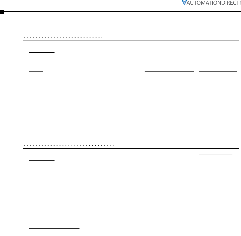
Page 3–40 Stellar® SR55 Series Soft Starter User Manual – 1st Ed. Rev.B – 02/02/2017
Chapter 3: Configuration and Parameters
P9.0 – Hold. Reg. Type:
Description:
Read/Write
Set to correspond with SR55 connection to the Motor. Refer to connection diagrams in the Quick
Start Guide, or in the “Electrical Installation” Chapter 2 of this user manual.
Range: Modbus Decimal Value: Default (decimal):
• In- Line : The SR55 is connected in-line with a delta or star
connected motor.
• In- Delta : The SR55 is connected inside the delta of the motor. The
iERS function is disabled. In-Delta must be selected if “Legacy
Delta Mode” parameter is desired.
• 0
• 1
• In-Line (0)
Modbus Address: Modbus Format:
128 ( 80 hex ) 16-bit unsigned
Touchscreen Menu Path:
Home → Advanced → Firing Mode
P9.1 – Hold. Reg. Type:
Description:
Read/Write
Allows the SR55 to be retro-fitted into “Delta” applications that previously used an SR44 in-delta
configuration. (Changes phase rotation L1-L2-L3 to L1-L3-L2.)
For “Legacy Delta Mode” to be activated, “Firing Mode” must be set to “In-Delta”.
Range: Modbus Decimal Value: Default (decimal):
• Off : Operates normally. Refer to SR55 delta connection diagram
in “Electrical Installation” Chapter 2 or the Quick Start Guide.
• On : Operates in SR44 delta compatibility mode.
(Changes phase rotation L1-L2-L3 to L1-L3-L2.)
• 0
• 1
• Off (0)
Modbus Address: Modbus Format:
192 ( C0 hex ) 16-bit unsigned
Touchscreen Menu Path:
Home → Advanced → Legacy Delta Mode
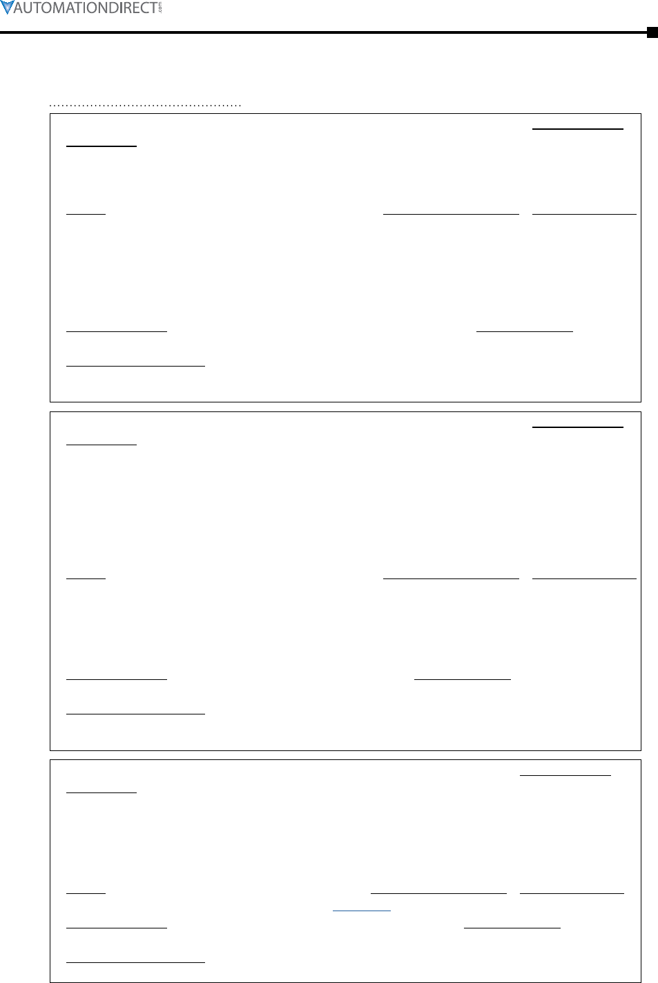
Chapter 3: Configuration and Parameters
Page 3–41Stellar® SR55 Series Soft Starter User Manual – 1st Ed. Rev.B – 02/02/2017
P10.0 – Hold. Reg. Type:
Description:
Read/Write
The digital inputs D1-1I, D1-2I, D2-1I are designed to work with a range of control supplies.
• It is important to ensure the “Digital Input Voltage” corresponds to the voltage applied to the
input. Failure to do so may result in damage.
Range: Modbus Decimal Value: Default (decimal):
• 230VAC : ‘Active high level’ Input voltage must be in the range
195.5V–253V.
• 110VAC : ‘Active high level’ Input voltage must be in the range
93.5V–121V.
• 24VDC : ‘Active high level ‘ input voltage must be in the range
20.4V–26.4V.
• 0
• 1
• 2
• 230VAC (0)
Modbus Address: Modbus Format:
10880 ( 2A80 hex ) 16-bit unsigned
Touchscreen Menu Path:
Home → I/O → Digital Inputs → Digital Input Voltage
(also Home → Auto Setup → Digital Input Voltage)
P7.0 – Hold. Reg. Type:
Description:
Read/Write
• Local Touch Screen : Control using the button on the keypad.
(Digital Inputs are disabled. Digital Outputs still function as configured.)
• User Programmable : Control using the terminals; function defined in “I/O” menu.
• Two Wire Control : Control using terminals; functions fixed as shown on screen.
• Three Wire Control : Control using terminals; functions fixed as shown on screen.
• Modbus Network : Control via remote Modbus network, remote touchscreen, or Modbus TCP /
EtherNet/IP. (Digital Inputs are disabled. Digital Outputs still function as configured.)
Range: Modbus Decimal Value: Default (decimal):
• Local Touch Screen
• User Programmable
• Two Wire Control
• Three Wire Control
• Modbus Network
• 0
• 1
• 2
• 3
• 4
• Local (0)
Modbus Address: Modbus Format:
59392 ( E800 hex ) 16-bit unsigned
Touchscreen Menu Path:
Home → I/O → Digital Inputs → Control Method
(also Home → Auto Setup → Control Method) (also Home → Advanced → Control Method)
P10.1 – Hold. Reg. Type:
Description:
Read/Write
Allows the Digital Input to be mapped to different functions.
• The selected function will change in proportion with the input.
• Digital Inputs can only be user configured if “Control Method” is set to “User Programmable.”
• All Digital Inputs are disabled if “Control Method” is set to “Local Touch Screen” or “Modbus
Network.”
Range: Modbus Decimal Value: Default (decimal):
Refer to “Digital Input Function Settings” on page 3–43. Start/Stop (280)
Modbus Address: Modbus Format:
10944 ( 2AC0 hex ) 16-bit unsigned
Touchscreen Menu Path:
Home → I/O → Digital Inputs → Digital Input 1 (D1-1I) → Select Function
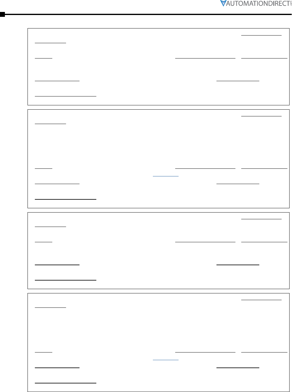
Page 3–42 Stellar® SR55 Series Soft Starter User Manual – 1st Ed. Rev.B – 02/02/2017
Chapter 3: Configuration and Parameters
P10.2 – Hold. Reg. Type:
Description:
Read/Write
Allows the polarity of the input to be reversed.
Range: Modbus Decimal Value: Default (decimal):
• Off : When the input is off, the selected function will be on.
• On : When the input is on, the selected function will be on.
• 0
• 1 • On (1)
Modbus Address: Modbus Format:
11264 ( 2C00 hex ) 16-bit unsigned
Touchscreen Menu Path:
Home → I/O → Digital Inputs → Digital Input 1 (D1-1I) → High Input = 1 Sets Value
P10.3 – Hold. Reg. Type:
Description:
Read/Write
Allows the Digital Input to be mapped to different functions.
• The selected function will change in proportion with the input.
• Digital Inputs can only be user configured if “Control Method” is set to “User Programmable.”
• All Digital Inputs are disabled if “Control Method” is set to “Local Touch Screen” or “Modbus
Network.”
Range: Modbus Decimal Value: Default (decimal):
Refer to “Digital Input Function Settings” on page 3–43. Off (0)
Modbus Address: Modbus Format:
10945 ( 2AC1 hex ) 16-bit unsigned
Touchscreen Menu Path:
Home → I/O → Digital Inputs → Digital Input 2 (D1-2I) → Select Function
P10.4 – Hold. Reg. Type:
Description:
Read/Write
Allows the polarity of the input to be reversed.
Range: Modbus Decimal Value: Default (decimal):
• Off : When the input is off, the selected function will be on.
• On : When the input is on, the selected function will be on.
• 0
• 1 • On (1)
Modbus Address: Modbus Format:
11266 ( 2C02 hex ) 16-bit unsigned
Touchscreen Menu Path:
Home → I/O → Digital Inputs → Digital Input 2 (D1-2I) → High Input = 1 Sets Value
P10.5 – Hold. Reg. Type:
Description:
Read/Write
Allows the Digital Input to be mapped to different functions.
• The selected function will change in proportion with the input.
• Digital Inputs can only be user configured if “Control Method” is set to “User Programmable.”
• All Digital Inputs are disabled if “Control Method” is set to “Local Touch Screen” or “Modbus
Network.”
Range: Modbus Decimal Value: Default (decimal):
Refer to “Digital Input Function Settings” on page 3–43. Reset (287)
Modbus Address: Modbus Format:
10946 ( 2AC2 hex ) 16-bit unsigned
Touchscreen Menu Path:
Home → I/O → Digital Inputs → Digital Input 3 (D2-1I) → Select Function
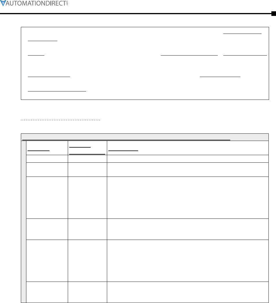
Chapter 3: Configuration and Parameters
Page 3–43Stellar® SR55 Series Soft Starter User Manual – 1st Ed. Rev.B – 02/02/2017
P10.6 – Hold. Reg. Type:
Description:
Read/Write
Allows the polarity of the input to be reversed.
Range: Modbus Decimal Value: Default (decimal):
• Off : When the input is off, the selected function will be on.
• On : When the input is on, the selected function will be on.
• 0
• 1 • On (1)
Modbus Address: Modbus Format:
11268 ( 2C04 hex ) 16-bit unsigned
Touchscreen Menu Path:
Home → I/O → Digital Inputs → Digital Input 3 (D2-1I) → High Input = 1 Sets Value
The following settings are for the “Digital Input x (x): Select Function” I/O parameters.
settings for the “Digital Input x (x): Select Function” I/O parameters 10944–10946
Settings: Modbus
Decimal Value: Description:
Off 0 No function selected
Start/Stop 280 • Off : Stops or Soft Stops the SR55.
• On : Starts the SR55.
Freeze Ramp 285
If set to On this parameter will hold the Start Ramp even if
“Current Irms” is less than the “Current Limit Level.”
• Off : The Soft Start Ramp is not held and the SR55 will start in
the time set.
• On : The Soft Start Ramp is held and the SR55 will take longer
than the time set to start .
Reset 287
To reset pulse high and then low.
• Off : The final state required for a reset.
• On : The initial state required for a reset.
iERS on/off 330
Enables and disables the intelligent Energy Recovery System
feature (iERS).
• Off : The feature is disabled and the motor operates at full
voltage.
• On : The voltage to the motor will be regulated to ensure
optimum efficiency.
External Trip
Command 295
Ensure start signal is low before reset.
• Off : The SR55 will not trip.
• On : If “External Trip” is enabled the SR55 trips.
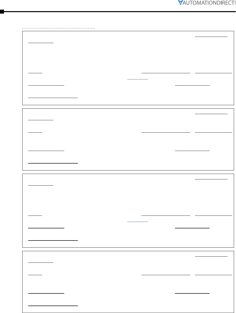
Page 3–44 Stellar® SR55 Series Soft Starter User Manual – 1st Ed. Rev.B – 02/02/2017
Chapter 3: Configuration and Parameters
P11.0 – Hold. Reg. Type:
Description:
Read/Write
Allows the Digital Output to be mapped to different functions.
• The output will change in proportion with the selected function.
• Digital Outputs can only be user configured if the “Control Method” is set to “User
Programmable.”
Range: Modbus Decimal Value: Default (decimal):
Refer to “Digital Output Function Settings” on page 3–46. Error (583)
Modbus Address: Modbus Format:
11584 ( 2D40 hex ) 16-bit unsigned
Touchscreen Menu Path:
Home → I/O → Digital Outputs → Digital Output 1 N/C(12)) → Select Function
P11.1 – Hold. Reg. Type:
Description:
Read/Write
Allows the polarity of the output to be reversed.
Range: Modbus Decimal Value: Default (decimal):
• Off : When the selected function is activated, the output is closed.
• On : When the selected function is activated, the output is open.
• 0
• 1 • On (1)
Modbus Address: Modbus Format:
11904 ( 2E80 hex ) 16-bit unsigned
Touchscreen Menu Path:
Home → I/O → Digital Outputs → Digital Output 1 N/C(12) → High Output = 1 When Value
P11.2 – Hold. Reg. Type:
Description:
Read/Write
Allows the Digital Output to be mapped to different functions.
• The output will change in proportion with the selected function.
• Digital Outputs can only be user configured if the “Control Method” is set to “User
Programmable.”
Range: Modbus Decimal Value: Default (decimal):
Refer to “Digital Output Function Settings” on page 3–46. Error (583)
Modbus Address: Modbus Format:
11585 ( 2D41 hex ) 16-bit unsigned
Touchscreen Menu Path:
Home → I/O → Digital Outputs → Digital Output 2 N/O(24) → Select Function
P11.3 – Hold. Reg. Type:
Description:
Read/Write
Allows the polarity of the output to be reversed.
Range: Modbus Decimal Value: Default (decimal):
• Off : When the selected function is activated, the output is open.
• On : When the selected function is activated, the output is closed.
• 0
• 1 • On (1)
Modbus Address: Modbus Format:
11906 ( 2E82 hex ) 16-bit unsigned
Touchscreen Menu Path:
Home → I/O → Digital Outputs → Digital Output 2 N/O(24) → High Output = 1 When Value
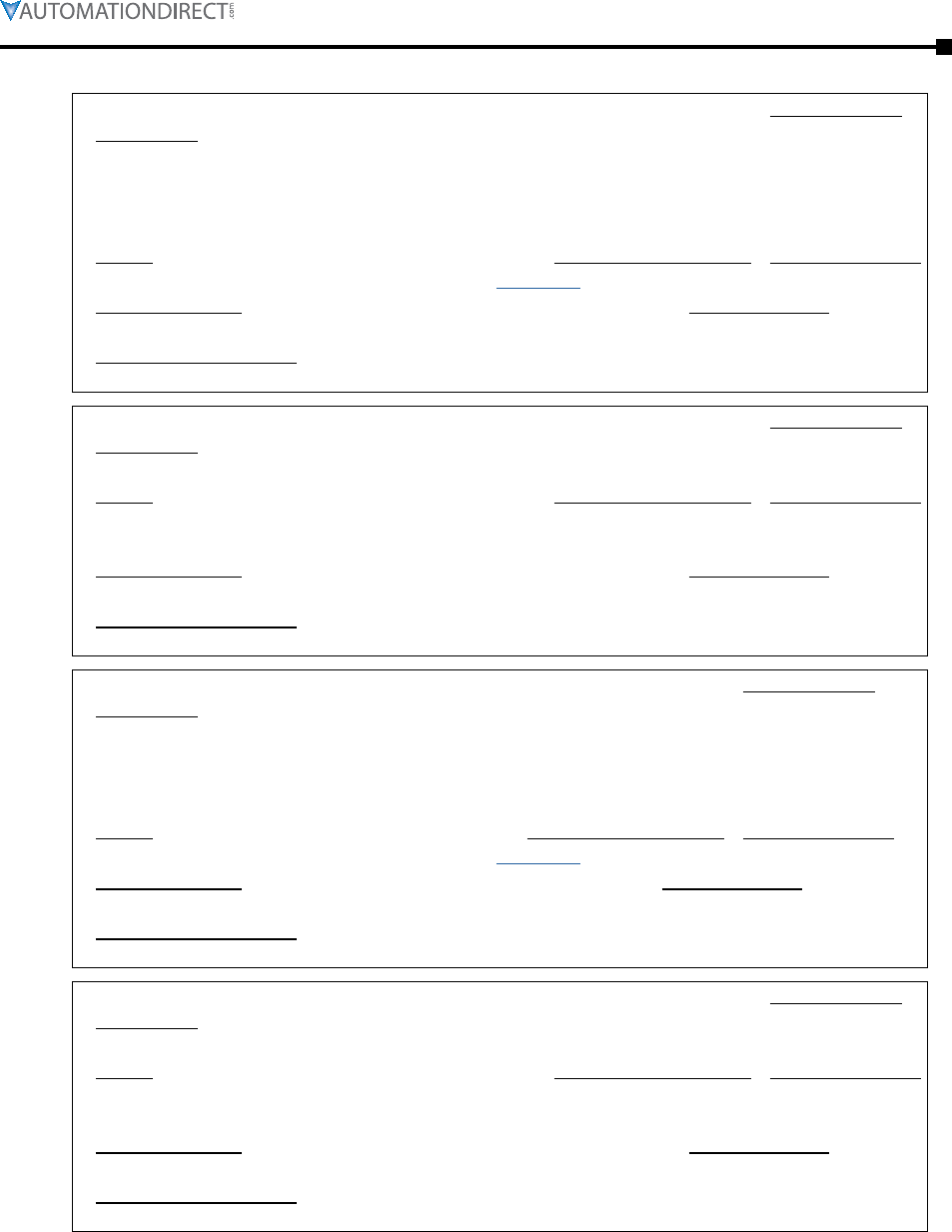
Chapter 3: Configuration and Parameters
Page 3–45Stellar® SR55 Series Soft Starter User Manual – 1st Ed. Rev.B – 02/02/2017
P11.4 – Hold. Reg. Type:
Description:
Read/Write
Allows the Digital output to be mapped to different functions.
• The output will change in proportion with the selected function.
• Digital Outputs can only be user configured if the “Control Method” is set to “User
Programmable.”
Range: Modbus Decimal Value: Default (decimal):
Refer to “Digital Output Function Settings” on page 3–46. Running (588)
Modbus Address: Modbus Format:
11586 ( 2D42 hex ) 16-bit unsigned
Touchscreen Menu Path:
Home → I/O → Digital Outputs → Digital Output 3 N/O(34) → High Output = 1 When Value
P11.5 – Hold. Reg. Type:
Description:
Read/Write
Allows the polarity of the output to be reversed.
Range: Modbus Decimal Value: Default (decimal):
• Off : When the selected function is activated, the output is open.
• On : When the selected function is activated, the output is closed.
• 0
• 1 • On (1)
Modbus Address: Modbus Format:
11908 ( 2E84 hex ) 16-bit unsigned
Touchscreen Menu Path:
Home → I/O → Digital Outputs → Digital Output 3 N/O(34) → High Output = 1 When Value
P11.6 – Hold. Reg. Type:
Description:
Read/Write
Allows the Digital output to be mapped to different functions.
• The output will change in proportion with the selected function.
• Digital Outputs can only be user configured if the “Control Method” is set to “User
Programmable.”
Range: Modbus Decimal Value: Default (decimal):
Refer to “Digital Output Function Settings” on page 3–46. End of Start (590)
Modbus Address: Modbus Format:
11587 ( 2D43 hex ) 16-bit unsigned
Touchscreen Menu Path:
Home → I/O → Digital Outputs → Digital Output 4 N/O(44) → Select Function
P11.7 – Hold. Reg. Type:
Description:
Read/Write
Allows the polarity of the output to be reversed.
Range: Modbus Decimal Value: Default (decimal):
• Off : When the selected function is activated, the output is open.
• On : When the selected function is activated, the output is closed.
• 0
• 1 • On (1)
Modbus Address: Modbus Format:
11910 ( 2E86 hex ) 16-bit unsigned
Touchscreen Menu Path:
Home → I/O → Digital Outputs → Digital Output 4 N/O(44) → High Output = 1 When Value
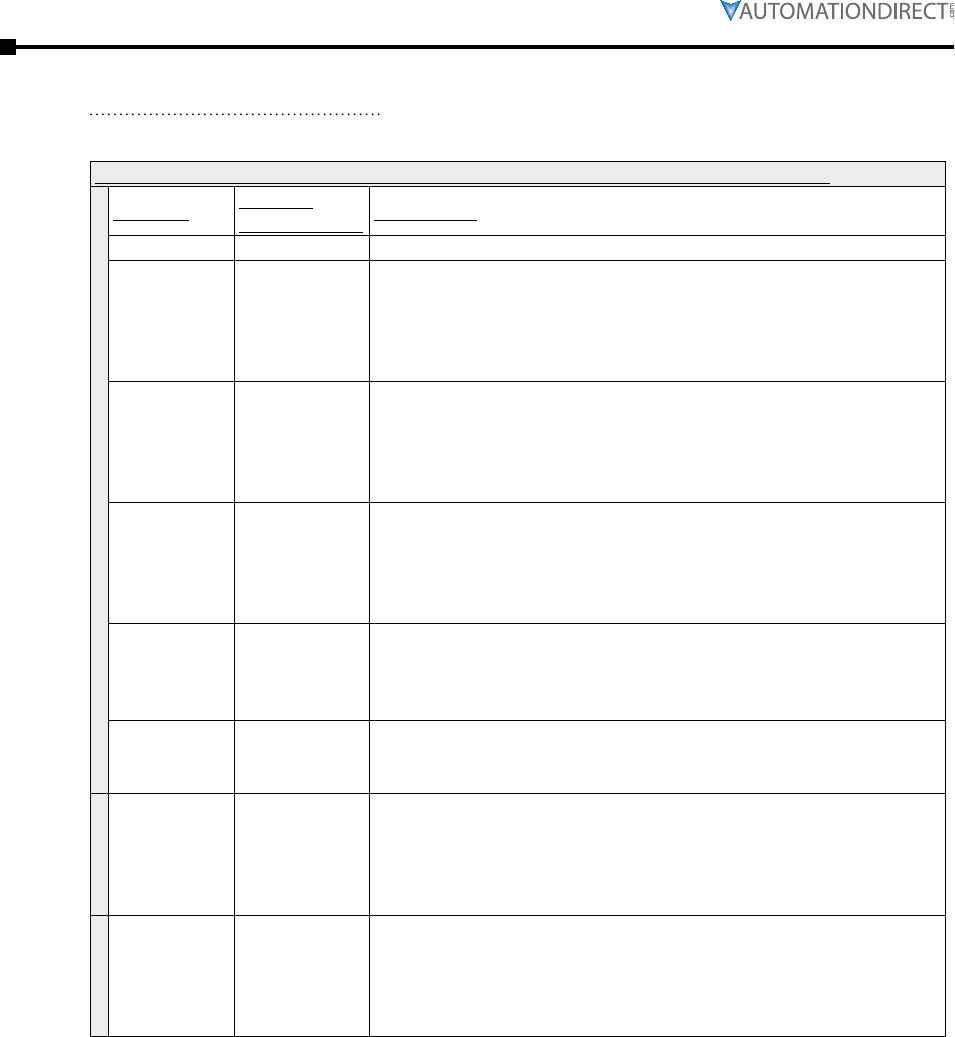
Page 3–46 Stellar® SR55 Series Soft Starter User Manual – 1st Ed. Rev.B – 02/02/2017
Chapter 3: Configuration and Parameters
The following settings are for the “Digital Output x (x): Select Function” I/O parameters.
settings for the “Digital Output x (x): Select Function” I/O parameters 11584–11587
Settings: Modbus
Decimal Value: Description:
Off 0 No function selected
Ready 581
STATUS INDICATION : Ready
Off : The SR55 has not powered up successfully or failed to reset
from a trip.
On : Indicates that the SR55 is healthy and ready for a start.
Remains on when Running.
Enabled 582
STATUS INDICATION : Enabled
• Off : The SR55 has not powered up successfully or failed to reset
from a trip
• On : Indicates that the SR55 is enabled and ready for a start.
Remains on when Running.
Error 583
STATUS INDICATION : Error
• Off : The SR55 is fault free.
• On : Indicates that SR55 has detected a fault and has shut
down.
The fault must be cleared before a reset.
Running 588
STATUS INDICATION : Running
• Off : The SR55 has detected a fault and tripped.
• On : Indicates that the motor is running and is being actively
controlled by the SR55.
End Of
Start 590
STATUS INDICATION : End Of Start
• Off : The SR55 is disabled or ramping down.
• On : Indicates that the Soft Start ramp has been completed.
Current
Limit 591
STATUS INDICATION : Current Limit
• Off : The ramp is not being held because “Current Irms” is less
than “Current Limit Level.”
• On : The ramp is being held because “Current Irms” is greater or
equal to “Current Limit Level.”
iERS Active 595
STATUS INDICATION : iERS Active
• Off : The iERS saving mode has been disabled either internally
or via “iERS.”
• On : Indicates that the SR55 is operating in the iERS energy
saving Mode.
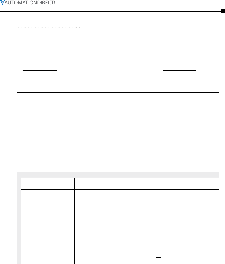
Chapter 3: Configuration and Parameters
Page 3–47Stellar® SR55 Series Soft Starter User Manual – 1st Ed. Rev.B – 02/02/2017
P12.0 – Hold. Reg. Type:
Description:
Read/Write
Defines the function of the Analog Input (AI).
Range: Modbus Decimal Value: Default (decimal):
• 0–10V : The input voltage varies from 0 to 10V.
• 4–20mA : The input varies from 4 to 20mA.
• 0
• 1
• 0–10V (0)
Modbus Address: Modbus Format:
Touchscreen Menu Path:
P12.1 – Hold. Reg. Type:
Description:
Read/Write
Allows the Analog Input to be mapped to different functions. The selected function will change in
proportion with the input.
Range: Modbus Decimal Value: Default (decimal):
• Off
• Current Limit Start
• Current Shearpin
• Current Overload
• 0
• 420
• 431
• 441
• Off (0)
Modbus Address: Modbus Format:
9664 ( 25C0 hex ) 16-bit unsigned
Touchscreen Menu Path:
Home → I/O → Analog Inputs → Select Function (Analog Input)
Examples of P12.1 Analog Input Fuction Selections
AI Function
Settings:
Modbus
Dec. Value: Example:
Current
Limit Start 420
AI signal controls P3.3 Start Current Limit Level. Ex: Water pumping
system with high head; nearly vertical lift. AI signal keeps P3.3 low
at start to slowly rotate motor to control flow until height is reached,
then AI signal increases P3.3 to allow motor to accelerate to full speed.
Usually PLC control.
Current
Shearpin 431
AI signal controls P5.6 Shearpin Trip Current. Ex: Applications such
as opening and closing sluice gates or doors, which require different
running current limits for opening vs. closing. AI signal changes P5.6
as needed, usually via PLC control. P5.5 Shearpin Trip is turned OFF
when P5.6 level is reached; however an output should be used to stop
the motor via a relay in the motor stop circuit.
Current
Overload 441 AI signal controls P5.9 Overload Level. Ex: Motor testing. AI signal
changes P5.8 as needed to test different motors.
Page 3–48 Stellar® SR55 Series Soft Starter User Manual – 1st Ed. Rev.B – 02/02/2017
Chapter 3: Configuration and Parameters
P12.2 – Type:
Description:
Read/Write
Allows the selected function to be scaled. The selected function will change in proportion with
the input.
• The function will be at its “Scaling Level” when the input is at its maximum.
Range: Modbus Decimal Value: Default:
0 – 16384 linear scale ( 1 = 0.006104 % )
0% – 100% = (0 – 16384)
x% / 0.006104% = Modbus dec. value
EX: Modbus value of 5250 = 32.05%
16384
Modbus Address: Modbus Format:
9728 ( 2600 hex ) 16-bit unsigned
Touchscreen Menu Path:
Home → I/O → Analog Inputs → Scaling Level
P13.0 – Hold. Reg. Type:
Description:
Read/Write
Defines the function of the Analog Output (AO).
Range: Modbus Decimal Value: Default (decimal):
• 0–10V : The output voltage varies from 0 to 10V.
• 4–20mA : The output varies from 4 to 20mA.
• 0
• 1
• 0–10V (0)
Modbus Address: Modbus Format:
8960 ( 2300 hex ) 16-bit unsigned
Touchscreen Menu Path:
Home → I/O → Analog Outputs → Analog Output Type
P13.1 – Hold. Reg. Type:
Description:
Read/Write
Allows the Analog Output to be mapped to different functions. The output will change in
proportion with the selected function.
• By default the output will be at a maximum when the selected function equals its max value.
Range: Modbus Decimal Value: Default (decimal):
• Off
• Current Measured
• Overload
• Overload SCR
• P-Total
• 0
• 514
• 522
• 161
• 542
• Off (0)
Modbus Address: Modbus Format:
9024 ( 2340 hex ) 16-bit unsigned
Touchscreen Menu Path:
Home → I/O → Analog Outputs → Select Function (Analog Output)
Examples of P13.1 Analog Output Fuction Selections
AO Function
Settings:
Modbus
Dec. Value: Example:
Current
Measured 514
AO shows P15.5 Current Irms. Ex: This value can be fed out to a panel
ammeter for panel designs, or can be used as feedback to a PLC
system for monitoring or management system such as SCADA, etc.
Overload 522 AO shows P15.20 Overload. Ex: This value can be fed back to a PLC
system for monitoring or management system such as SCADA, etc.
P-Total 542
AO shows P15.8 True Power P. Ex: This value can be fed out to a panel
power meter for panel designs, or can be used as feedback to a PLC
system for monitoring or management system such as SCADA, etc.
Chapter 3: Configuration and Parameters
Page 3–49Stellar® SR55 Series Soft Starter User Manual – 1st Ed. Rev.B – 02/02/2017
P13.2 – Type:
Description:
Read/Write
Allows the selected function to be scaled. The output will change in proportion with the selected
function.
• The output will be at a maximum when the selected function equals the “Scaling Level.”
Range: Modbus Decimal Value: Default:
0 – 16384 linear scale ( 1 = 0.006104 % )
0% – 100% = (0 – 16384)
x% / 0.006104% = Modbus dec. value
EX: Modbus value of 5250 = 32.05%
0
Modbus Address: Modbus Format:
9088 ( 2380 hex ) 16-bit unsigned
Touchscreen Menu Path:
Home → I/O → Analog Outputs → Scaling Level
P14.0 – Hold. Reg. Type:
Description:
Read/Write
A single PTC motor thermistor or set of PTC motor thermistors can be connected to the PTC
terminals.
Range: Modbus Decimal Value: Default (decimal):
• Off : The SR55 will continue to operate.
• On : The SR55 will trip if the motor thermistor exceeds its
response temperature, or the PTC input is open circuit (> 4kΩ).
• 0
• 1
• Off (0)
Modbus Address: Modbus Format:
53794 ( D222 hex ) 16-bit unsigned
Touchscreen Menu Path:
Home → I/O → PTC Motor Thermistor Trip
(also Home → Advanced → Trip Settings → PTC Motor Thermistor Trip)
Page 3–50 Stellar® SR55 Series Soft Starter User Manual – 1st Ed. Rev.B – 02/02/2017
Chapter 3: Configuration and Parameters
P15.0 – Type:
Description:
Read Only
The frequency of the 3-phase supply.
Range: Modbus Decimal Value: Default:
45Hz – 65Hz linear scale (1 = 0.001 Hz)
Freq(Hz) = (Value / 1000)
n/a
Modbus Address: Modbus Format:
32000 ( 7D00 hex ) 16-bit unsigned
Touchscreen Menu Path:
Home → Monitor → Line Frequency
P15.1 – Hold. Reg. Type:
Description:
Read Only
Indicates the phase sequence of the incoming supply.
Range: Modbus Decimal Value: Default (decimal):
• RYB = L1, L2, L3
• RBY = L1, L3, L2
• 0
• 1
• L1-L2-L3 (0)
Modbus Address: Modbus Format:
32064 ( 7D40 hex ) 16-bit unsigned
Touchscreen Menu Path:
Home → Monitor → Phase Rotation
P15.2 – Type:
Description:
Read Only
The RMS current on phase L1.
Range: Modbus Decimal Value: Default:
0A – 10,000A linear scale (1 = 1mA)
Current (A) = (Value / 1000)
0A
Modbus Address: Modbus Format:
33536/33537 ( 8300/8301 hex ) 32-bit unsigned
Touchscreen Menu Path:
Home → Monitor → I1
P15.3 – Type:
Description:
Read Only
The RMS current on phase L2.
Range: Modbus Decimal Value: Default:
0A – 10,000A linear scale (1 = 1mA)
Current (A) = (Value / 1000)
0A
Modbus Address: Modbus Format:
33538/33539 ( 8302/8303 hex ) 32-bit unsigned
Touchscreen Menu Path:
Home → Monitor → I2
Chapter 3: Configuration and Parameters
Page 3–51Stellar® SR55 Series Soft Starter User Manual – 1st Ed. Rev.B – 02/02/2017
P15.4 – Type:
Description:
Read Only
The RMS current on phase L3.
Range: Modbus Decimal Value: Default:
0A – 10,000A linear scale (1 = 1mA)
Current (A) = (Value / 1000)
0A
Modbus Address: Modbus Format:
33540/33541 ( 8304/8305 hex ) 32-bit unsigned
Touchscreen Menu Path:
Home → Monitor → I3
P15.5 – Type:
Description:
Read Only
The RMS motor current.
• This is the maximum of the 3 phases.
• This value is used for the overload and power calculations.
Range: Modbus Decimal Value: Default:
0A – 10,000A linear scale (1 = 1mA)
Current (A) = (Value / 1000)
0A
Modbus Address: Modbus Format:
32896/32897 ( 8080/8081 hex ) 32-bit unsigned
Touchscreen Menu Path:
Home → Monitor → Current Irms
P15.6 – Type:
Description:
Read Only
The RMS 3-phase supply voltage.
• This is the average of the 3 phases.
• This value is used for power calculations.
• This value is derived internally. If a higher level of accuracy is required, a “Fixed Voltage” value
can be used.
• The internally measured voltage is not an accurate method of obtaining a voltage reading. This
voltage reading can have and error up to 35% if the starter and motor is unloaded or lightly
loaded.
Range: Modbus Decimal Value: Default:
0V – 500V linear scale ( 1 = 1 V ) 0V
Modbus Address: Modbus Format:
32960 ( 80C0 hex ) 16-bit unsigned
Touchscreen Menu Path:
Home → Monitor → Vrms (Approx)
P15.7 – Type:
Description:
Read Only
The actual power factor.
Range: Modbus Decimal Value: Default:
0 – 1 linear scale ( 1 = 0.001 ) 0
Modbus Address: Modbus Format:
33024 ( 8100 hex ) 16-bit unsigned
Touchscreen Menu Path:
Home → Monitor → Real Power Factor
Page 3–52 Stellar® SR55 Series Soft Starter User Manual – 1st Ed. Rev.B – 02/02/2017
Chapter 3: Configuration and Parameters
P15.8 – Type:
Description:
Read Only
Total True Power. This is a sum of the 3 phases.
Range: Modbus Decimal Value: Default:
0kW – 10,000 kW linear scale (1 = 1W)
True Power (kW) = (Value / 1000)
0kW
Modbus Address: Modbus Format:
34688/34689 ( 8780/8781 hex ) 32-bit unsigned
Touchscreen Menu Path:
Home → Monitor → True Power P
P15.9 – Type:
Description:
Read Only
Total Apparent Power. This is a sum of the 3 phases.
Range: Modbus Decimal Value: Default:
0kVA – 10,000 kVA linear scale (1 = 1VA)
Apparent Power
(kVA) = (Value/1000)
0 kVA
Modbus Address: Modbus Format:
34816/34817 ( 8800/8801 hex ) 32-bit unsigned
Touchscreen Menu Path:
Home → Monitor → Apparent Power S
P15.10 – Type:
Description:
Read Only
Range: Modbus Decimal Value: Default:
0 kVAR – 10,000 kVAR linear scale (1 = 1VAR)
Reactive Power
(kVAR) = (Value / 1000)
0 kVAR
Modbus Address: Modbus Format:
34944/34945 ( 8880/8881 hex ) 32-bit unsigned
Touchscreen Menu Path:
Home → Monitor → Reactive Power Q
P15.11 – Type:
Description:
Read Only
Indicates the level of potential saving. 100% indicates that SR55 is saving at its maximum level.
Range: Modbus Decimal Value: Default:
0% – 100% linear scale ( 1 = 0.006104 % )
0% – 100% = (0 – 16384)
x% / 0.006104% = Modbus dec. value
EX: Modbus value of 5250 = 32.05%
0%
Modbus Address: Modbus Format:
35008 ( 88C0 hex ) 16-bit unsigned
Touchscreen Menu Path:
Home → Monitor → iERS Saving Level
Chapter 3: Configuration and Parameters
Page 3–53Stellar® SR55 Series Soft Starter User Manual – 1st Ed. Rev.B – 02/02/2017
P15.12 – Type:
Description:
Read Only
Internal firing delay angle. Displayed for diagnostic purposes.
Range: Modbus Decimal Value: Default:
0° – 55° linear scale
(1 = 1° of mains cycle)
Time(ms)=(Value/LineFreq)*(25/9)
0°
Modbus Address: Modbus Format:
22400 ( 5780 hex ) 16-bit unsigned
Touchscreen Menu Path:
Home → Monitor → Delay Angle
P15.13 – Type:
Description:
Read Only
The maximum possible Delay Angle for the current iERS saving phase.
(Backstop starts at 55°, and can be reduced by iERS.)
• Displayed for diagnostic purposes.
• May decrease during heavy load periods or instability.
• The BackStop is the maximum iERS saving level allowed.
Range: Modbus Decimal Value: Default:
0° – 55° linear scale
(1 = 1° of mains cycle)
Time(ms)=(Value/LineFreq)*(25/9)
0°
Modbus Address: Modbus Format:
23040 ( 5A00 hex ) 16-bit unsigned
Touchscreen Menu Path:
Home → Monitor → BackStop
P15.14 – Type:
Description:
Read Only
The maximum possible delay for iERS saving. Displayed for diagnostic purposes.
(Delay Max is internally fixed at 55°.)
Range: Modbus Decimal Value: Default:
0° – 55° linear scale
(1 = 1° of mains cycle)
Time(ms)=(Value/LineFreq)*(25/9)
0°
Modbus Address: Modbus Format:
22464 ( 57C0 hex ) 16-bit unsigned
Touchscreen Menu Path:
Home → Monitor → Delay Max
P15.15 – Type:
Description:
Read Only
The Present Power Factor used by the iERS saving function. This is the actual Power Factor for
the iERS saving function. The “Delay” is constantly adjusted to minimize the control loop error
between “Pres PF Degrees” and “Ref PF Degrees.” The parameter displays the displacement part
of the True Power Factor, and is used for diagnostic purposes.
Range: Modbus Decimal Value: Default:
0° – 90° linear scale
(1 = 1° of mains cycle)
Time(ms)=(Value/LineFreq)*(25/9)
0°
Modbus Address: Modbus Format:
21824 ( 5540 hex ) 16-bit unsigned
Touchscreen Menu Path:
Home → Monitor → Pres PF Degrees

Page 3–54 Stellar® SR55 Series Soft Starter User Manual – 1st Ed. Rev.B – 02/02/2017
Chapter 3: Configuration and Parameters
P15.16 – Type:
Description:
Read Only
The Reference Power Factor used by the iERS saving function. This is the target Power Factor
for the iERS saving function. The parameter will change dynamically depending on motor
operation. The parameter displays the displacement part of the True Power Factor, and is used
for diagnostic purposes.
Range: Modbus Decimal Value: Default:
0° – 90° linear scale (1 = 1° of mains cycle)
Time(ms)=(Value/LineFreq)*(25/9)
0°
Modbus Address: Modbus Format:
21760 ( 5500 hex ) 16-bit unsigned
Touchscreen Menu Path:
Home → Monitor → Ref PF Degrees
P15.17 – Type:
Description:
Read Only
• The current in Amps at which the iERS is enabled or disabled.
The iERS function is active when the motor current is less than the “Start Saving Level.”
• When the iERS function is disabled, internal bypass relays close to improve efficiency.
Range: Modbus Decimal Value: Default:
50% I-motor – 80% I-motor linear scale ( 1 = 0.006104 % )
50% – 80% = (8191 – 13106)
x% / 0.006104% = Modbus dec. value
EX: Modbus value of 9000 = 54.936%
80%
I-motor
Modbus Address: Modbus Format:
21320 ( 5348 hex ) 16-bit unsigned
Touchscreen Menu Path:
Home → Monitor → Start Saving Level
Each SR55 is tested at the factory. The Last Peak (Start)
Current default may vary depending on the load that was tested.
P18.0 – Type:
Description:
Read Only
Displays the peak current of the last successful start.
Range: Modbus Decimal Value: Default:
0A – 10,000A linear scale (1 = 1mA) 0A
Modbus Address: Modbus Format:
38400/38401 ( 9600/9601 hex ) 32-bit unsigned
Touchscreen Menu Path:
Home → Monitor → Last Peak Current
(also Home → Log → Start Current Log → Last Peak Current)
Chapter 3: Configuration and Parameters
Page 3–55Stellar® SR55 Series Soft Starter User Manual – 1st Ed. Rev.B – 02/02/2017
P15.18 – Type:
Description:
Read Only
The temperature of the internal SR55 heatsink.
• The SR55 will trip when the heatsink temperature exceeds 80°C.
• The internal cooling fans will turn on if this temperature exceeds 40°C.
Range: Modbus Decimal Value: Default:
-20°C – 80°C Address Format 16-bit (Highbyte=b11-b8,
LowByte=b7-b0) Ta ≥ 0 b12=0 Ta < 0 b12=1
Address Note bit12=0 [HighByte*16 +
LowByte/16]bit12=1 256-[HighByte*16 +
LowByte/16]
ambient °C
Modbus Address: Modbus Format:
36544 ( 8EC0 hex ) 16-bit unsigned
Touchscreen Menu Path:
Home → Monitor → HeatSink Temp
P15.19 – Type:
Description:
Read Only
Indicates the state of the SR55 PTC input; designed for single, double or triple PTC in series.
• PTC thermistor standards DIN44081 / EN60738-1 apply.
( < 300Ω @ 25°C, typically 4kΩ @ nominal temperature )
• The value indicated is a not in degrees Celsius, but is an internal representation.
• At 25°C the value displayed should be less than 100, and the SR55 trips when value > 400 (4kΩ).
(open circuit = 1023)
• The value will increase rapidly when the motor thermistors approach their nominal
temperature.
• If thermistors are connected, the “Thermistor trip” should be turned “on.”
Range: Modbus Decimal Value: Default:
0 – 1024 linear scale ( 1 = 1) 1024
Modbus Address: Modbus Format:
10432 ( 28C0 hex ) 16-bit unsigned
Touchscreen Menu Path:
Home → Monitor → Motor Thermistor
P15.20 – Type:
Description:
Read Only
The SR55 has an “Overload” function that is an electronic equivalent to a thermal overload.
• “Overload” displays the overload capacity, which is a measure of how close the SR55
“Overload Trip” is to tripping.
• When “Current Irms” is greater than the “Overload Level,” the “Overload” increases in
accordance with the “Trip Class.”
• When “Current Irms” is less than the “Overload Level,” the “Overload” decreases exponentially
(if greater than 50%).
• When the “Overload” reaches 100% the SR55 will trip.
• During situations when (I-motor) is equal to (I-SR55) the overload will indicate 50%.
Range: Modbus Decimal Value: Default:
0% – 100% linear scale ( 1 = 0.006104 % )
0% – 100% = (0 – 16384)
x% / 0.006104% = Modbus dec. value
EX: Modbus value of 5250 = 32.05%
0%
Modbus Address: Modbus Format:
33408 ( 8280 hex ) 16-bit unsigned
Touchscreen Menu Path:
Home → Monitor → Overload

Page 3–56 Stellar® SR55 Series Soft Starter User Manual – 1st Ed. Rev.B – 02/02/2017
Chapter 3: Configuration and Parameters
Each SR55 is tested at the factory, and each unit may have a
brief log history from this testing.
The event time shows up on the “Start Current,” “temperature,”
and “Overload” Logs. These events are logged at the same time,
which are reflected by the 10 “Event Time” parameters.
P16.0 –
Holding
Register Type:
Description:
Read Only
Displays the event time.
Range: Modbus Decimal Value: Default:
hh:mm:ss Time (ms) since midnight
(bytes5,4,3,2) and Days since
01/01/1984 (bytes1,0)
GMT
Modbus Address: Modbus Format:
38464 ( 9640 hex ) 6 Bytes
Touchscreen Menu Path:
Home → Log → Start Current / Temperature / Overload →
Last Peak Start Current / Last Temperature / Last Overload
P16.1 –
Holding
Register Type:
Description:
Read Only
Displays the event time -1.
Range: Modbus Decimal Value: Default:
hh:mm:ss Time (ms) since midnight
(bytes5,4,3,2) and Days since
01/01/1984 (bytes1,0)
GMT
Modbus Address: Modbus Format:
38467 ( 9643 hex ) 6 Bytes
Touchscreen Menu Path:
Home → Log → Start Current / Temperature / Overload →
Last Peak Start Current / Last Temperature / Last Overload -1
P16.2 –
Holding
Register Type:
Description:
Read Only
Displays the event time -2.
Range: Modbus Decimal Value: Default:
hh:mm:ss Time (ms) since midnight
(bytes5,4,3,2) and Days since
01/01/1984 (bytes1,0)
GMT
Modbus Address: Modbus Format:
38470 ( 9646 hex ) 6 Bytes
Touchscreen Menu Path:
Home → Log → Start Current / Temperature / Overload →
Last Peak Start Current / Last Temperature / Last Overload -2
Chapter 3: Configuration and Parameters
Page 3–57Stellar® SR55 Series Soft Starter User Manual – 1st Ed. Rev.B – 02/02/2017
Each SR55 is tested at the factory, and each unit may have a
brief log history from this testing.
P16.3 –
Holding
Register Type:
Description:
Read Only
Displays the event time -3.
Range: Modbus Decimal Value: Default:
hh:mm:ss Time (ms) since midnight
(bytes5,4,3,2) and Days since
01/01/1984 (bytes1,0)
GMT
Modbus Address: Modbus Format:
38473 ( 9649 hex ) 6 Bytes
Touchscreen Menu Path:
Home → Log → Start Current / Temperature / Overload →
Last Peak Start Current / Last Temperature / Last Overload -3
P16.4 –
Holding
Register Type:
Description:
Read Only
Displays the event time -4.
Range: Modbus Decimal Value: Default:
hh:mm:ss Time (ms) since midnight
(bytes5,4,3,2) and Days since
01/01/1984 (bytes1,0)
GMT
Modbus Address: Modbus Format:
38476 ( 964C hex ) 6 Bytes
Touchscreen Menu Path:
Home → Log → Start Current / Temperature / Overload →
Last Peak Start Current / Last Temperature / Last Overload -4
P16.5 –
Holding
Register Type:
Description:
Read Only
Displays the event time -5.
Range: Modbus Decimal Value: Default:
hh:mm:ss Time (ms) since midnight
(bytes5,4,3,2) and Days since
01/01/1984 (bytes1,0)
GMT
Modbus Address: Modbus Format:
38479 ( 964F hex ) 6 Bytes
Touchscreen Menu Path:
Home → Log → Start Current / Temperature / Overload →
Last Peak Start Current / Last Temperature / Last Overload -5
Page 3–58 Stellar® SR55 Series Soft Starter User Manual – 1st Ed. Rev.B – 02/02/2017
Chapter 3: Configuration and Parameters
Each SR55 is tested at the factory, and each unit may have a
brief log history from this testing.
P16.6 –
Holding
Register Type:
Description:
Read Only
Displays the event time -6.
Range: Modbus Decimal Value: Default:
hh:mm:ss Time (ms) since midnight
(bytes5,4,3,2) and Days since
01/01/1984 (bytes1,0)
GMT
Modbus Address: Modbus Format:
38482 ( 9652 hex ) 6 Bytes
Touchscreen Menu Path:
Home → Log → Start Current / Temperature / Overload →
Last Peak Start Current / Last Temperature / Last Overload -6
P16.7 –
Holding
Register Type:
Description:
Read Only
Displays the event time -7.
Range: Modbus Decimal Value: Default:
hh:mm:ss Time (ms) since midnight
(bytes5,4,3,2) and Days since
01/01/1984 (bytes1,0)
GMT
Modbus Address: Modbus Format:
38485 ( 9655 hex ) 6 Bytes
Touchscreen Menu Path:
Home → Log → Start Current / Temperature / Overload →
Last Peak Start Current / Last Temperature / Last Overload -7
P16.8 –
Holding
Register Type:
Description:
Read Only
Displays the event time -8.
Range: Modbus Decimal Value: Default:
hh:mm:ss Time (ms) since midnight
(bytes5,4,3,2) and Days since
01/01/1984 (bytes1,0)
GMT
Modbus Address: Modbus Format:
38488 ( 9658 hex ) 6 Bytes
Touchscreen Menu Path:
Home → Log → Start Current / Temperature / Overload →
Last Peak Start Current / Last Temperature / Last Overload -8
Chapter 3: Configuration and Parameters
Page 3–59Stellar® SR55 Series Soft Starter User Manual – 1st Ed. Rev.B – 02/02/2017
Each SR55 is tested at the factory, and each unit may have a
brief log history from this testing.
P16.9 –
Holding
Register Type:
Description:
Read Only
Displays the event time -9.
Range: Modbus Decimal Value: Default:
hh:mm:ss Time (ms) since midnight
(bytes5,4,3,2) and Days since
01/01/1984 (bytes1,0)
GMT
Modbus Address: Modbus Format:
38491 ( 965B hex ) 6 Bytes
Touchscreen Menu Path:
Home → Log → Start Current / Temperature / Overload →
Last Peak Start Current / Last Temperature / Last Overload -9
P17.0 – Type:
Description:
Read Only
Displays the last Fault trip.
• Refer to “Trip Code Descriptions” in this chapter.
Range: Modbus Decimal Value: Default:
• Trip: 0 – 65,535
• Trip Time: hh:mm:ss
• linear scale ( 1 = 1 )
• Time (ms) since midnight
(bytes5,4,3,2) and Days since
01/01/1984 (bytes1,0)
• 0
• GMT
Modbus Address: Modbus Format:
• Trip: 60608 ( ECC0 hex )
• Trip Time: 60672 ( ED00 hex )
• 16-bit unsigned
• 6 Bytes
Touchscreen Menu Path:
Home → Log → Trip Log → Last Trip
P17.1 – Type:
Description:
Read Only
Displays the last Fault trip -1.
• Refer to “Trip Code Descriptions” in this chapter.
Range: Modbus Decimal Value: Default:
• Trip: 0 – 65,535
• Trip Time: hh:mm:ss
• linear scale ( 1 = 1 )
• Time (ms) since midnight
(bytes5,4,3,2) and Days since
01/01/1984 (bytes1,0)
• 0
• GMT
Modbus Address: Modbus Format:
• 60609 ( ECC1 hex )
• 60675 ( ED03 hex )
• 16-bit unsigned
• 6 Bytes
Touchscreen Menu Path:
Home → Log → Trip Log → Last Trip -1
Page 3–60 Stellar® SR55 Series Soft Starter User Manual – 1st Ed. Rev.B – 02/02/2017
Chapter 3: Configuration and Parameters
Each SR55 is tested at the factory, and each unit may have a
brief log history from this testing.
P17.2 – Type:
Description:
Read Only
Displays the last Fault trip -2.
• Refer to “Trip Code Descriptions” in this chapter.
Range: Modbus Decimal Value: Default:
• Trip: 0 – 65,535
• Trip Time: hh:mm:ss
• linear scale ( 1 = 1 )
• Time (ms) since midnight
(bytes5,4,3,2) and Days since
01/01/1984 (bytes1,0)
• 0
• GMT
Modbus Address: Modbus Format:
• 60610 ( ECC2 hex )
• 60678 ( ED06 hex )
• 16-bit unsigned
• 6 Bytes
Touchscreen Menu Path:
Home → Log → Trip Log → Last Trip -2
P17.3 – Type:
Description:
Read Only
Displays the last Fault trip -3.
• Refer to “Trip Code Descriptions” in this chapter.
Range: Modbus Decimal Value: Default:
• Trip: 0 – 65,535
• Trip Time: hh:mm:ss
• linear scale ( 1 = 1 )
• Time (ms) since midnight
(bytes5,4,3,2) and Days since
01/01/1984 (bytes1,0)
• 0
• GMT
Modbus Address: Modbus Format:
• 60611 ( ECC3 hex )
• 60681 ( ED09 hex )
• 16-bit unsigned
• 6 Bytes
Touchscreen Menu Path:
Home → Log → Trip Log → Last Trip -3
P17.4 – Type:
Description:
Read Only
Displays the last Fault trip -4.
• Refer to “Trip Code Descriptions” in this chapter.
Range: Modbus Decimal Value: Default:
• Trip: 0 – 65,535
• Trip Time: hh:mm:ss
• linear scale ( 1 = 1 )
• Time (ms) since midnight
(bytes5,4,3,2) and Days since
01/01/1984 (bytes1,0)
• 0
• GMT
Modbus Address: Modbus Format:
• 60612 ( ECC4 hex )
• 60684 ( ED0C hex )
• 16-bit unsigned
• 6 Bytes
Touchscreen Menu Path:
Home → Log → Trip Log → Last Trip -4
Chapter 3: Configuration and Parameters
Page 3–61Stellar® SR55 Series Soft Starter User Manual – 1st Ed. Rev.B – 02/02/2017
Each SR55 is tested at the factory, and each unit may have a
brief log history from this testing.
P17.5 – Type:
Description:
Read Only
Displays the last Fault trip -5.
• Refer to “Trip Code Descriptions” in this chapter.
Range: Modbus Decimal Value: Default:
• Trip: 0 – 65,535
• Trip Time: hh:mm:ss
• linear scale ( 1 = 1 )
• Time (ms) since midnight
(bytes5,4,3,2) and Days since
01/01/1984 (bytes1,0)
• 0
• GMT
Modbus Address: Modbus Format:
• 60613 ( ECC5 hex )
• 60687 ( ED0F hex )
• 16-bit unsigned
• 6 Bytes
Touchscreen Menu Path:
Home → Log → Trip Log → Last Trip -5
P17.6 – Type:
Description:
Read Only
Displays the last Fault trip -6.
• Refer to “Trip Code Descriptions” in this chapter.
Range: Modbus Decimal Value: Default:
• Trip: 0 – 65,535
• Trip Time: hh:mm:ss
• linear scale ( 1 = 1 )
• Time (ms) since midnight
(bytes5,4,3,2) and Days since
01/01/1984 (bytes1,0)
• 0
• GMT
Modbus Address: Modbus Format:
• 60614 ( ECC6 hex )
• 60690 ( ED12 hex )
• 16-bit unsigned
• 6 Bytes
Touchscreen Menu Path:
Home → Log → Trip Log → Last Trip -6
P17.7 – Type:
Description:
Read Only
Displays the last Fault trip -7.
• Refer to “Trip Code Descriptions” in this chapter.
Range: Modbus Decimal Value: Default:
• Trip: 0 – 65,535
• Trip Time: hh:mm:ss
• linear scale ( 1 = 1 )
• Time (ms) since midnight
(bytes5,4,3,2) and Days since
01/01/1984 (bytes1,0)
• 0
• GMT
Modbus Address: Modbus Format:
• 60615 ( ECC7 hex )
• 60693 ( ED15 hex )
• 16-bit unsigned
• 6 Bytes
Touchscreen Menu Path:
Home → Log → Trip Log → Last Trip -7
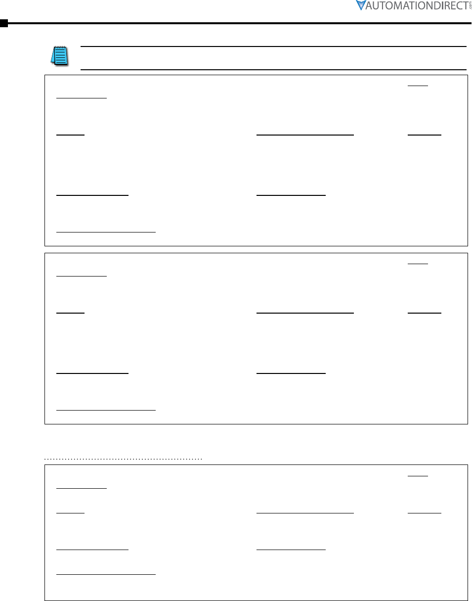
Page 3–62 Stellar® SR55 Series Soft Starter User Manual – 1st Ed. Rev.B – 02/02/2017
Chapter 3: Configuration and Parameters
Each SR55 is tested at the factory, and each unit may have a
brief log history from this testing.
P17.8 – Type:
Description:
Read Only
Displays the last Fault trip -8.
• Refer to “Trip Code Descriptions” in this chapter.
Range: Modbus Decimal Value: Default:
• Trip: 0 – 65,535
• Trip Time: hh:mm:ss
• linear scale ( 1 = 1 )
• Time (ms) since midnight
(bytes5,4,3,2) and Days since
01/01/1984 (bytes1,0)
• 0
• GMT
Modbus Address: Modbus Format:
• 60616 ( ECC8 hex )
• 60696 ( ED18 hex )
• 16-bit unsigned
• 6 Bytes
Touchscreen Menu Path:
Home → Log → Trip Log → Last Trip -8
P17.9 – Type:
Description:
Read Only
Displays the last Fault trip -9.
• Refer to “Trip Code Descriptions” in this chapter.
Range: Modbus Decimal Value: Default:
• Trip: 0 – 65,535
• Trip Time: hh:mm:ss
• linear scale ( 1 = 1 )
• Time (ms) since midnight
(bytes5,4,3,2) and Days since
01/01/1984 (bytes1,0)
• 0
• GMT
Modbus Address: Modbus Format:
• 60617 ( ECC9 hex )
• 60699 ( ED1B hex )
• 16-bit unsigned
• 6 Bytes
Touchscreen Menu Path:
Home → Log → Trip Log → Last Trip -9
P18.0 – Type:
Description:
Read Only
Displays the peak current of the last successful start.
Range: Modbus Decimal Value: Default:
0A – 10,000A linear scale (1 = 1mA)
Current (A) = (Value / 1000)
0A
Modbus Address: Modbus Format:
38400/38401 ( 9600/9601 hex ) 32-bit unsigned
Touchscreen Menu Path:
Home → Log → Start Current Log → Last Peak Current
(Home → Monitor → Last Peak Current)
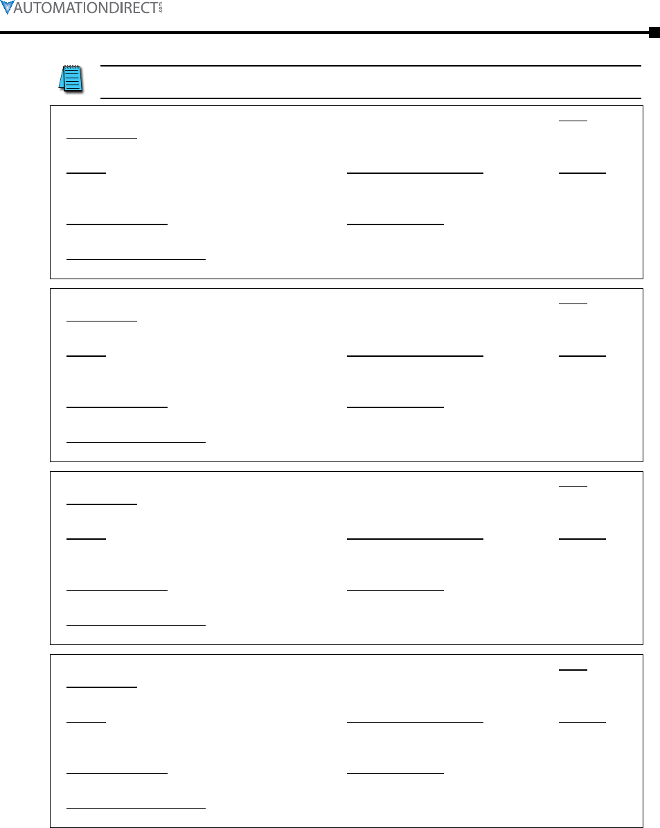
Chapter 3: Configuration and Parameters
Page 3–63Stellar® SR55 Series Soft Starter User Manual – 1st Ed. Rev.B – 02/02/2017
Each SR55 is tested at the factory, and each unit may have a
brief log history from this testing.
P18.1 – Type:
Description:
Read Only
Displays the peak current of the last successful start -1.
Range: Modbus Decimal Value: Default:
0A – 10,000A linear scale (1 = 1mA)
Current (A) = (Value / 1000)
0A
Modbus Address: Modbus Format:
38402/38403 ( 9602/9603 hex ) 32-bit unsigned
Touchscreen Menu Path:
Home → Log → Start Current Log → Last Peak Start Current -1
P18.2 – Type:
Description:
Read Only
Displays the peak current of the last successful start -2.
Range: Modbus Decimal Value: Default:
0A – 10,000A linear scale (1 = 1mA)
Current (A) = (Value / 1000)
0A
Modbus Address: Modbus Format:
38404/38405 ( 9604/9605 hex ) 32-bit unsigned
Touchscreen Menu Path:
Home → Log → Start Current Log → Last Peak Start Current -2
P18.3 – Type:
Description:
Read Only
Displays the peak current of the last successful start -3.
Range: Modbus Decimal Value: Default:
0A – 10,000A linear scale (1 = 1mA)
Current (A) = (Value / 1000)
0A
Modbus Address: Modbus Format:
38406/38407 ( 9606/9607 hex ) 32-bit unsigned
Touchscreen Menu Path:
Home → Log → Start Current Log → Last Peak Start Current -3
P18.4 – Type:
Description:
Read Only
Displays the peak current of the last successful start -4.
Range: Modbus Decimal Value: Default:
0A – 10,000A linear scale (1 = 1mA)
Current (A) = (Value / 1000)
0A
Modbus Address: Modbus Format:
38408/38409 ( 9608/9609 hex ) 32-bit unsigned
Touchscreen Menu Path:
Home → Log → Start Current Log → Last Peak Start Current -4
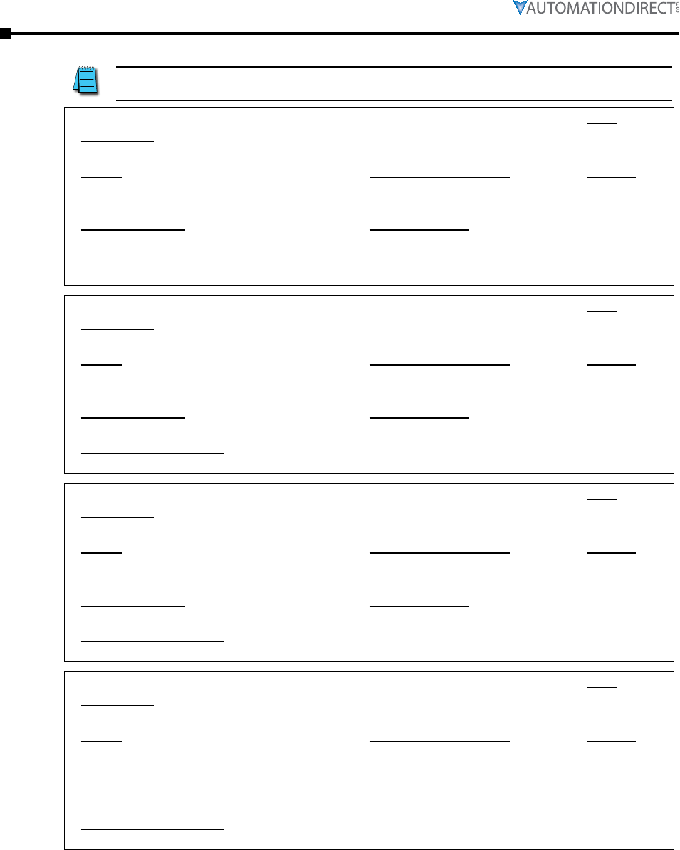
Page 3–64 Stellar® SR55 Series Soft Starter User Manual – 1st Ed. Rev.B – 02/02/2017
Chapter 3: Configuration and Parameters
Each SR55 is tested at the factory, and each unit may have a
brief log history from this testing.
P18.5 – Type:
Description:
Read Only
Displays the peak current of the last successful start -5.
Range: Modbus Decimal Value: Default:
0A – 10,000A linear scale (1 = 1mA)
Current (A) = (Value / 1000)
0A
Modbus Address: Modbus Format:
38410/38411 ( 960A/960B hex ) 32-bit unsigned
Touchscreen Menu Path:
Home → Log → Start Current Log → Last Peak Start Current -5
P18.6 – Type:
Description:
Read Only
Displays the peak current of the last successful start -6.
Range: Modbus Decimal Value: Default:
0A – 10,000A linear scale (1 = 1mA)
Current (A) = (Value / 1000)
0A
Modbus Address: Modbus Format:
38412/38413 ( 960C/960D hex ) 32-bit unsigned
Touchscreen Menu Path:
Home → Log → Start Current Log → Last Peak Start Current -6
P18.7 – Type:
Description:
Read Only
Displays the peak current of the last successful start -7.
Range: Modbus Decimal Value: Default:
0A – 10,000A linear scale (1 = 1mA)
Current (A) = (Value / 1000)
0A
Modbus Address: Modbus Format:
38414/38415 ( 960E/960F hex ) 32-bit unsigned
Touchscreen Menu Path:
Home → Log → Start Current Log → Last Peak Start Current -7
P18.8 – Type:
Description:
Read Only
Displays the peak current of the last successful start -8.
Range: Modbus Decimal Value: Default:
0A – 10,000A linear scale (1 = 1mA)
Current (A) = (Value / 1000)
0A
Modbus Address: Modbus Format:
38416/38417 ( 9610/9611 hex ) 32-bit unsigned
Touchscreen Menu Path:
Home → Log → Start Current Log → Last Peak Start Current -8
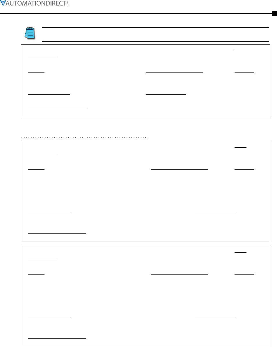
Chapter 3: Configuration and Parameters
Page 3–65Stellar® SR55 Series Soft Starter User Manual – 1st Ed. Rev.B – 02/02/2017
Each SR55 is tested at the factory, and each unit may have a
brief log history from this testing.
P18.9 – Type:
Description:
Read Only
Displays the peak current of the last successful start -9.
Range: Modbus Decimal Value: Default:
0A – 10,000A linear scale (1 = 1mA)
Current (A) = (Value / 1000)
0A
Modbus Address: Modbus Format:
38418/38419 ( 9612/9613 hex ) 32-bit unsigned
Touchscreen Menu Path:
Home → Log → Start Current Log → Last Peak Start Current -9
P19.0 – Type:
Description:
Read Only
Displays the peak current of the last successful stop.
Range: Modbus Decimal Value: Default:
• Peak Current: 0A – 10,000A
• Peak Current Time: hh:mm:ss
• linear scale (1 = 1mA)
Current (A) = (Value / 1000)
• Time (ms) since midnight
(bytes5,4,3,2) and Days since
01/01/1984 (bytes1,0)
• 0A
• GMT
Modbus Address: Modbus Format:
• Peak Current: 39040/39041 ( 9880/9881 hex )
• Peak Current Time: 39104/39105/39106 ( 98C0/98C1/98C2 hex )
• 32-bit unsigned
• 6 Bytes
Touchscreen Menu Path:
Home → Log → Stop Current Log → Last Peak Stop Current
P19.1 – Type:
Description:
Read Only
Displays the peak current of the last successful stop -1.
Range: Modbus Decimal Value: Default:
• Peak Current: 0A – 10,000A
• Peak Current Time: hh:mm:ss
• linear scale (1 = 1mA)
Current (A) = (Value / 1000)
• Time (ms) since midnight
(bytes5,4,3,2) and Days since
01/01/1984 (bytes1,0)
• 0A
• GMT
Modbus Address: Modbus Format:
• Peak Current: 39042/39043 ( 9882/9883 hex )
• Peak Current Time: 39107/39108/39109 ( 98C3/98C4/98C5 hex )
• 32-bit unsigned
• 6 Bytes
Touchscreen Menu Path:
Home → Log → Stop Current Log → Last Peak Stop Current -1
Page 3–66 Stellar® SR55 Series Soft Starter User Manual – 1st Ed. Rev.B – 02/02/2017
Chapter 3: Configuration and Parameters
Each SR55 is tested at the factory, and each unit may have a
brief log history from this testing.
P19.2 – Type:
Description:
Read Only
Displays the peak current of the last successful stop -2.
Range: Modbus Decimal Value: Default:
• Peak Current: 0A – 10,000A
• Peak Current Time: hh:mm:ss
• linear scale (1 = 1mA)
Current (A) = (Value / 1000)
• Time (ms) since midnight
(bytes5,4,3,2) and Days since
01/01/1984 (bytes1,0)
• 0A
• GMT
Modbus Address: Modbus Format:
• Peak Current: 39044/39045 ( 9884/9885 hex )
• Peak Current Time: 39110/39111/39112 ( 98C6/98C7/98C8 hex )
• 32-bit unsigned
• 6 Bytes
Touchscreen Menu Path:
Home → Log → Stop Current Log → Last Peak Stop Current -2
P19.3 – Type:
Description:
Read Only
Displays the peak current of the last successful stop -3.
Range: Modbus Decimal Value: Default:
• Peak Current: 0A – 10,000A
• Peak Current Time: hh:mm:ss
• linear scale (1 = 1mA)
Current (A) = (Value / 1000)
• Time (ms) since midnight
(bytes5,4,3,2) and Days since
01/01/1984 (bytes1,0)
• 0A
• GMT
Modbus Address: Modbus Format:
• Peak Current: 39046/39047 ( 9886/9887 hex )
• Peak Current Time: 39113/39114/39115 ( 98C9/98CA/98CB hex )
• 32-bit unsigned
• 6 Bytes
Touchscreen Menu Path:
Home → Log → Stop Current Log → Last Peak Stop Current -3
P19.4 – Type:
Description:
Read Only
Displays the peak current of the last successful stop -4.
Range: Modbus Decimal Value: Default:
• Peak Current: 0A – 10,000A
• Peak Current Time: hh:mm:ss
• linear scale (1 = 1mA)
Current (A) = (Value / 1000)
• Time (ms) since midnight
(bytes5,4,3,2) and Days since
01/01/1984 (bytes1,0)
• 0A
• GMT
Modbus Address: Modbus Format:
• Peak Current: 39048/39049 ( 9888/9889 hex )
• Peak Current Time: 39116/39117/39118 ( 98CC/98CD/98CE hex )
• 32-bit unsigned
• 6 Bytes
Touchscreen Menu Path:
Home → Log → Stop Current Log → Last Peak Stop Current -4
Chapter 3: Configuration and Parameters
Page 3–67Stellar® SR55 Series Soft Starter User Manual – 1st Ed. Rev.B – 02/02/2017
Each SR55 is tested at the factory, and each unit may have a
brief log history from this testing.
P19.5 – Type:
Description:
Read Only
Displays the peak current of the last successful stop -5.
Range: Modbus Decimal Value: Default:
• Peak Current: 0A – 10,000A
• Peak Current Time: hh:mm:ss
• linear scale (1 = 1mA)
Current (A) = (Value / 1000)
• Time (ms) since midnight
(bytes5,4,3,2) and Days since
01/01/1984 (bytes1,0)
• 0A
• GMT
Modbus Address: Modbus Format:
• Peak Current: 39050/39051 ( 988A/988B hex )
• Peak Current Time: 39119/39120/39121 ( 98CF/98D0/98D1 hex )
• 32-bit unsigned
• 6 Bytes
Touchscreen Menu Path:
Home → Log → Stop Current Log → Last Peak Stop Current -5
P19.6 – Type:
Description:
Read Only
Displays the peak current of the last successful stop -6.
Range: Modbus Decimal Value: Default:
• Peak Current: 0A – 10,000A
• Peak Current Time: hh:mm:ss
• linear scale (1 = 1mA)
Current (A) = (Value / 1000)
• Time (ms) since midnight
(bytes5,4,3,2) and Days since
01/01/1984 (bytes1,0)
• 0A
• GMT
Modbus Address: Modbus Format:
• Peak Current: 39052/39053 ( 988C/988D hex )
• Peak Current Time: 39122/39123/39124 ( 98D2/98D3/98D4 hex )
• 32-bit unsigned
• 6 Bytes
Touchscreen Menu Path:
Home → Log → Stop Current Log → Last Peak Stop Current -6
P19.7 – Type:
Description:
Read Only
Displays the peak current of the last successful stop -7.
Range: Modbus Decimal Value: Default:
• Peak Current: 0A – 10,000A
• Peak Current Time: hh:mm:ss
• linear scale (1 = 1mA)
Current (A) = (Value / 1000)
• Time (ms) since midnight
(bytes5,4,3,2) and Days since
01/01/1984 (bytes1,0)
• 0A
• GMT
Modbus Address: Modbus Format:
• Peak Current: 39054/39055 ( 988E/988F hex )
• Peak Current Time: 39125/39126/39127 ( 98D5/98D6/98D7 hex )
• 32-bit unsigned
• 6 Bytes
Touchscreen Menu Path:
Home → Log → Stop Current Log → Last Peak Stop Current -7
Page 3–68 Stellar® SR55 Series Soft Starter User Manual – 1st Ed. Rev.B – 02/02/2017
Chapter 3: Configuration and Parameters
Each SR55 is tested at the factory, and each unit may have a
brief log history from this testing.
P19.8 – Type:
Description:
Read Only
Displays the peak current of the last successful stop -8.
Range: Modbus Decimal Value: Default:
• Peak Current: 0A – 10,000A
• Peak Current Time: hh:mm:ss
• linear scale (1 = 1mA)
Current (A) = (Value / 1000)
• Time (ms) since midnight
(bytes5,4,3,2) and Days since
01/01/1984 (bytes1,0)
• 0A
• GMT
Modbus Address: Modbus Format:
• Peak Current: 39056/39057 ( 9890/9891 hex )
• Peak Current Time: 39128/39129/39130 ( 98D8/98D9/98DA hex )
• 32-bit unsigned
• 6 Bytes
Touchscreen Menu Path:
Home → Log → Stop Current Log → Last Peak Stop Current -8
P19.9 – Type:
Description:
Read Only
Displays the peak current of the last successful stop -9.
Range: Modbus Decimal Value: Default:
• Peak Current: 0A – 10,000A
• Peak Current Time: hh:mm:ss
• linear scale (1 = 1mA)
Current (A) = (Value / 1000)
• Time (ms) since midnight
(bytes5,4,3,2) and Days since
01/01/1984 (bytes1,0)
• 0A
• GMT
Modbus Address: Modbus Format:
• Peak Current: 39058/39059 ( 9892/9893 hex )
• Peak Current Time: 39131/39132/39133 ( 98DB/98DC/98DD hex )
• 32-bit unsigned
• 6 Bytes
Touchscreen Menu Path:
Home → Log → Stop Current Log → Last Peak Stop Current -9
P20.0 – Type:
Description:
Read Only
Displays the heatsink temperature at the end of the last successful start.
Range: Modbus Decimal Value: Default:
-20°C to 80°C bit12=0 [HighByte*16
+ LowByte/16]bit12=1
256-[HighByte*16 + LowByte/16]
ambient °C
Modbus Address: Modbus Format:
39680 ( 9B00 hex ) 16 bit (Highbyte=b11-b8,
LowByte=b7-b0) Ta >= 0 b12=0 Ta
< 0 b12=1
Touchscreen Menu Path:
Home → Log → Temperature Log → Last Temperature

Chapter 3: Configuration and Parameters
Page 3–69Stellar® SR55 Series Soft Starter User Manual – 1st Ed. Rev.B – 02/02/2017
Each SR55 is tested at the factory, and each unit may have a
brief log history from this testing.
P20.1 – Type:
Description:
Read Only
Displays the heatsink temperature at the end of the last successful start -1.
Range: Modbus Decimal Value: Default:
-20°C to 80°C bit12=0 [HighByte*16
+ LowByte/16]bit12=1
256-[HighByte*16 + LowByte/16]
ambient °C
Modbus Address: Modbus Format:
39681 ( 9B01 hex ) 16 bit (Highbyte=b11-b8,
LowByte=b7-b0) Ta >= 0 b12=0 Ta
< 0 b12=1
Touchscreen Menu Path:
Home → Log → Temperature Log → Last Temperature -1
P20.2 – Type:
Description:
Read Only
Displays the heatsink temperature at the end of the last successful start -2.
Range: Modbus Decimal Value: Default:
-20°C to 80°C bit12=0 [HighByte*16
+ LowByte/16]bit12=1
256-[HighByte*16 + LowByte/16]
ambient °C
Modbus Address: Modbus Format:
39682 ( 9B02 hex ) 16 bit (Highbyte=b11-b8,
LowByte=b7-b0) Ta >= 0 b12=0 Ta
< 0 b12=1
Touchscreen Menu Path:
Home → Log → Temperature Log → Last Temperature -2
P20.3 – Type:
Description:
Read Only
Displays the heatsink temperature at the end of the last successful start -3.
Range: Modbus Decimal Value: Default:
-20°C to 80°C bit12=0 [HighByte*16
+ LowByte/16]bit12=1
256-[HighByte*16 + LowByte/16]
ambient °C
Modbus Address: Modbus Format:
39683 ( 9B03 hex ) 16 bit (Highbyte=b11-b8,
LowByte=b7-b0) Ta >= 0 b12=0 Ta
< 0 b12=1
Touchscreen Menu Path:
Home → Log → Temperature Log → Last Temperature -3
Page 3–70 Stellar® SR55 Series Soft Starter User Manual – 1st Ed. Rev.B – 02/02/2017
Chapter 3: Configuration and Parameters
Each SR55 is tested at the factory, and each unit may have a
brief log history from this testing.
P20.4 – Type:
Description:
Read Only
Displays the heatsink temperature at the end of the last successful start -4.
Range: Modbus Decimal Value: Default:
-20°C to 80°C bit12=0 [HighByte*16
+ LowByte/16]bit12=1
256-[HighByte*16 + LowByte/16]
ambient °C
Modbus Address: Modbus Format:
39684 ( 9B04 hex ) 16 bit (Highbyte=b11-b8,
LowByte=b7-b0) Ta >= 0 b12=0 Ta
< 0 b12=1
Touchscreen Menu Path:
Home → Log → Temperature Log → Last Temperature -4
P20.5 – Type:
Description:
Read Only
Displays the heatsink temperature at the end of the last successful start -5.
Range: Modbus Decimal Value: Default:
-20°C to 80°C bit12=0 [HighByte*16
+ LowByte/16]bit12=1
256-[HighByte*16 + LowByte/16]
ambient °C
Modbus Address: Modbus Format:
39685 ( 9B05 hex ) 16 bit (Highbyte=b11-b8,
LowByte=b7-b0) Ta >= 0 b12=0 Ta
< 0 b12=1
Touchscreen Menu Path:
Home → Log → Temperature Log → Last Temperature -5
P20.6 – Type:
Description:
Read Only
Displays the heatsink temperature at the end of the last successful start -6.
Range: Modbus Decimal Value: Default:
-20°C to 80°C bit12=0 [HighByte*16
+ LowByte/16]bit12=1
256-[HighByte*16 + LowByte/16]
ambient °C
Modbus Address: Modbus Format:
39686 ( 9B06 hex ) 16 bit (Highbyte=b11-b8,
LowByte=b7-b0) Ta >= 0 b12=0 Ta
< 0 b12=1
Touchscreen Menu Path:
Home → Log → Temperature Log → Last Temperature -6

Chapter 3: Configuration and Parameters
Page 3–71Stellar® SR55 Series Soft Starter User Manual – 1st Ed. Rev.B – 02/02/2017
Each SR55 is tested at the factory, and each unit may have a
brief log history from this testing.
P20.7 – Type:
Description:
Read Only
Displays the heatsink temperature at the end of the last successful start -7.
Range: Modbus Decimal Value: Default:
-20°C to 80°C bit12=0 [HighByte*16
+ LowByte/16]bit12=1
256-[HighByte*16 + LowByte/16]
ambient °C
Modbus Address: Modbus Format:
39687 ( 9B07 hex ) 16 bit (Highbyte=b11-b8,
LowByte=b7-b0) Ta >= 0 b12=0 Ta
< 0 b12=1
Touchscreen Menu Path:
Home → Log → Temperature Log → Last Temperature -7
P20.8 – Type:
Description:
Read Only
Displays the heatsink temperature at the end of the last successful start -8.
Range: Modbus Decimal Value: Default:
-20°C to 80°C bit12=0 [HighByte*16
+ LowByte/16]bit12=1
256-[HighByte*16 + LowByte/16]
ambient °C
Modbus Address: Modbus Format:
39688 ( 9B08 hex ) 16 bit (Highbyte=b11-b8,
LowByte=b7-b0) Ta >= 0 b12=0 Ta
< 0 b12=1
Touchscreen Menu Path:
Home → Log → Temperature Log → Last Temperature -8
P20.9 – Type:
Description:
Read Only
Displays the heatsink temperature at the end of the last successful start -9.
Range: Modbus Decimal Value: Default:
-20°C to 80°C bit12=0 [HighByte*16
+ LowByte/16]bit12=1
256-[HighByte*16 + LowByte/16]
ambient °C
Modbus Address: Modbus Format:
39689 ( 9B09 hex ) 16 bit (Highbyte=b11-b8,
LowByte=b7-b0) Ta >= 0 b12=0 Ta
< 0 b12=1
Touchscreen Menu Path:
Home → Log → Temperature Log → Last Temperature -9
Page 3–72 Stellar® SR55 Series Soft Starter User Manual – 1st Ed. Rev.B – 02/02/2017
Chapter 3: Configuration and Parameters
Each SR55 is tested at the factory, and each unit may have a
brief log history from this testing.
P21.0 – Type:
Description:
Read Only
Displays the overload level at the end of the last successful start.
Range: Modbus Decimal Value: Default:
0% to 100% linear scale ( 1 = 0.006104 % ) 0%
Modbus Address: Modbus Format:
40320 ( 9D80 hex ) 16 bit unsigned
Touchscreen Menu Path:
Home → Log → Overload Log → Last Overload
P21.1 – Type:
Description:
Read Only
Displays the overload level at the end of the last successful start -1.
Range: Modbus Decimal Value: Default:
0% to 100% linear scale ( 1 = 0.006104 % ) 0%
Modbus Address: Modbus Format:
40321 ( 9D81 hex ) 16 bit unsigned
Touchscreen Menu Path:
Home → Log → Overload Log → Last Overload -1
P21.2 – Type:
Description:
Read Only
Displays the overload level at the end of the last successful start -2.
Range: Modbus Decimal Value: Default:
0% to 100% linear scale ( 1 = 0.006104 % ) 0%
Modbus Address: Modbus Format:
40322 ( 9D82 hex ) 16 bit unsigned
Touchscreen Menu Path:
Home → Log → Overload Log → Last Overload -2
P21.3 – Type:
Description:
Read Only
Displays the overload level at the end of the last successful start -3.
Range: Modbus Decimal Value: Default:
0% to 100% linear scale ( 1 = 0.006104 % ) 0%
Modbus Address: Modbus Format:
40323 ( 9D83 hex ) 16 bit unsigned
Touchscreen Menu Path:
Home → Log → Overload Log → Last Overload -3
P21.4 – Type:
Description:
Read Only
Displays the overload level at the end of the last successful start -4.
Range: Modbus Decimal Value: Default:
0% to 100% linear scale ( 1 = 0.006104 % ) 0%
Modbus Address: Modbus Format:
40324 ( 9D84 hex ) 16 bit unsigned
Touchscreen Menu Path:
Home → Log → Overload Log → Last Overload -4
Chapter 3: Configuration and Parameters
Page 3–73Stellar® SR55 Series Soft Starter User Manual – 1st Ed. Rev.B – 02/02/2017
Each SR55 is tested at the factory, and each unit may have a
brief log history from this testing.
P21.5 – Type:
Description:
Read Only
Displays the overload level at the end of the last successful start -5.
Range: Modbus Decimal Value: Default:
0% to 100% linear scale ( 1 = 0.006104 % ) 0%
Modbus Address: Modbus Format:
40325 ( 9D85 hex ) 16 bit unsigned
Touchscreen Menu Path:
Home → Log → Overload Log → Last Overload -5
P21.6 – Type:
Description:
Read Only
Displays the overload level at the end of the last successful start -6.
Range: Modbus Decimal Value: Default:
0% to 100% linear scale ( 1 = 0.006104 % ) 0%
Modbus Address: Modbus Format:
40326 ( 9D86 hex ) 16 bit unsigned
Touchscreen Menu Path:
Home → Log → Overload Log → Last Overload -6
P21.7 – Type:
Description:
Read Only
Displays the overload level at the end of the last successful start -7.
Range: Modbus Decimal Value: Default:
0% to 100% linear scale ( 1 = 0.006104 % ) 0%
Modbus Address: Modbus Format:
40327 ( 9D87 hex ) 16 bit unsigned
Touchscreen Menu Path:
Home → Log → Overload Log → Last Overload -7
P21.8 – Type:
Description:
Read Only
Displays the overload level at the end of the last successful start -8.
Range: Modbus Decimal Value: Default:
0% to 100% linear scale ( 1 = 0.006104 % ) 0%
Modbus Address: Modbus Format:
40328 ( 9D88 hex ) 16 bit unsigned
Touchscreen Menu Path:
Home → Log → Overload Log → Last Overload -8
P21.9 – Type:
Description:
Read Only
Displays the overload level at the end of the last successful start -9.
Range: Modbus Decimal Value: Default:
0% to 100% linear scale ( 1 = 0.006104 % ) 0%
Modbus Address: Modbus Format:
40329 ( 9D89 hex ) 16-bit unsigned
Touchscreen Menu Path:
Home → Log → Overload Log → Last Overload -9
Page 3–74 Stellar® SR55 Series Soft Starter User Manual – 1st Ed. Rev.B – 02/02/2017
Chapter 3: Configuration and Parameters
Each SR55 is tested at the factory, and each unit may have a
brief log history from this testing.
P22.0 – Type:
Description:
Read Only
The total number of successful starts.
Range: Modbus Decimal Value: Default:
0 to 4,294,836,225 linear scale ( 1 = 1 ) 0
Modbus Address: Modbus Format:
35840/3841 ( 8C00/8C01 hex ) 32-bit unsigned
Touchscreen Menu Path:
Home → Log → Totals Log → Number of Starts
P23.0 – Type:
Description:
Read/Write
Download the full log file onto the USB flash drive.
• The SR55 logs several parameters during normal and fault conditions.
• Data is stored in CSV format.
• Log file cannot be downloaded using the remote touchscreen. Please use the on-board
touchscreen only.
Range: Modbus Decimal Value: Default:
n/a n/a n/a
Modbus Address: Modbus Format:
n/a n/a
Touchscreen Menu Path:
Home → Log → Download Log File
P24.0 – Type:
Description:
Read/Write
Deletes all of the history in the Trip Log.
Range: Modbus Decimal Value: Default:
Yes / No n/a n/a
Modbus Address: Modbus Format:
n/a n/a
Touchscreen Menu Path:
Home → Log → Clear Trip Log
Chapter 3: Configuration and Parameters
Page 3–75Stellar® SR55 Series Soft Starter User Manual – 1st Ed. Rev.B – 02/02/2017
P25.0 – Type:
Description:
Read/Write
Used to upgrade to the latest version of firmware using a USB
ash drive
.
Range: Modbus Decimal Value: Default:
n/a n/a n/a
Modbus Address: Modbus Format:
n/a n/a
Touchscreen Menu Path:
Home → Device → Update Firmware
P25.1 – Type:
Description:
Read/Write
Enter current date.
• Date format can be set to either dd/mm/yyyy or mm/dd/yyyy; refer to “Date format” parameter.
Range: Modbus Decimal Value: Default:
• dd/mm/yyyy
• mm/dd/yyyy
n/a n/a
Modbus Address: Modbus Format:
See “Time” parameter for date address. n/a
Touchscreen Menu Path:
Home → Device → Date
P25.2 – Type:
Description:
Read/Write
Allows the time to be changed to ‘local’ time.
Range: Modbus Decimal Value: Default:
hh:mm:ss Time(ms) since midnight
(bytes5,4,3,2) and Days since
01/01/1984 (bytes1,0)
GMT
Modbus Address: Modbus Format:
14720 ( 3980 hex ) 6 Bytes
Touchscreen Menu Path:
Home → Device → Time
Time is derived from the number of milliseconds since midnight.
Date can be derived from the number of days since midnight 1st Jan 1984.
If Modbus addresses 14720 thru 14724 (6 bytes) and the time is 09:50 and the date is 9th March
2015, then the SR55 will return: 021C49782C7E.
Where: 021C4978 = # milliseconds since midnight, and 2C7E = # days since 01/01/84.
Since there are 60 seconds in a minute, 3600 seconds in an hour, and 86400 seconds in a day, the
time can be derived as follows:
• 021C4978h = 35407992d (ms) = 35407 (s)
• Hour = 35407 mod 86400/3600 = 09
• Min = 35407 mod 3600/60 = 50
• Sec = 35407 mod 60 = 07
So the time is 09:50:07.
For the date the SR55 will only return the number of days since 01/01/84.
So: 2C7Eh = 11390d.
Page 3–76 Stellar® SR55 Series Soft Starter User Manual – 1st Ed. Rev.B – 02/02/2017
Chapter 3: Configuration and Parameters
P25.3 – Hold. Reg. Type:
Description:
Read/Write
Selects the display language for the touchscreen.
Enter the required language from the displayed list.
Range: Modbus Decimal Value: Default (decimal):
• ENG
• DEU
• FRA
• ITA
• CHN
• TUR
• POR
• JPN
• SRB
• RUS
• VIE
• KOR
• 1
• 2
• 3
• 4
• 5
• 6
• 7
• 8
• 9
• 10
• 11
• 12
• English (1)
Modbus Address: Modbus Format:
13376 ( 3440 hex ) 16-bit unsigned
Touchscreen Menu Path:
Home → Device → Language
P25.4 – Type:
Description:
Read/Write
Stops unauthorized access to read/write parameters.
• The “Screen lock” must be turned on for the passcode be active.
• With passcode protection on, the SR55 can still be started and stopped. The Log and Monitor
screens can also still be accessed.
Range: Modbus Decimal Value: Default:
0 – 9 per Byte (ASCII character) 48–57 (48 = “0” ... 57 = “9”) n/a
Modbus Address: Modbus Format:
• 12864 ( 3240 hex ) – Byte 3 (MSB)
• 12865 ( 3241 hex ) – Byte 2
• 12866 ( 3242 hex ) – Byte 1
• 12867 ( 3243 hex ) – Byte 0
• 16-bit unsigned
• 16-bit unsigned
• 16-bit unsigned
• 16-bit unsigned
Touchscreen Menu Path:
Home → Device → Passcode
P25.5 – Type:
Description:
Read/Write
Time for backlight on display.
• After the period set, the back light on the screen will turn off.
• To reactivate, touch screen anywhere.
• To disable, set to 0.
Range: Modbus Decimal Value: Default:
0s – 3600s linear scale ( 1 = 1 s ) 60s
Modbus Address: Modbus Format:
14208 ( 3780 hex ) 16-bit unsigned
Touchscreen Menu Path:
Home → Device → Backlight Timeout
Chapter 3: Configuration and Parameters
Page 3–77Stellar® SR55 Series Soft Starter User Manual – 1st Ed. Rev.B – 02/02/2017
P26.0 – Type:
Description:
Read/Write
Sets the Modbus station number.
Range: Modbus Decimal Value: Default:
1 – 32 linear scale ( 1 = 1 ) 1
Modbus Address: Modbus Format:
16000 ( 3E80 hex ) 16-bit unsigned
Touchscreen Menu Path:
Home → Device → Networks → Modbus Network Settings → Address
P26.1 – Hold. Reg. Type:
Description:
Read/Write
Sets the serial communications baud rate.
Range: Modbus Decimal Value: Default (decimal):
• 9600
• 19200
• 38400
• 57600
• 115200
• 0
• 1
• 2
• 3
• 4
• 19200 (1)
Modbus Address: Modbus Format:
16064 ( 3EC0 hex ) 16-bit unsigned
Touchscreen Menu Path:
Home → Device → Networks → Modbus Network Settings → Baud Rate
P26.2 – Hold. Reg. Type:
Description:
Read/Write
Sets the serial communications parity bit. Also sets the stop bits.
• No parity uses 2 stop bits.
• Odd/even parity uses 1 stop bit.
Range: Modbus Decimal Value: Default (decimal):
• None
• Even
• Odd
• 0
• 1
• 2
• Even (1)
Modbus Address: Modbus Format:
16128 ( 3F00 hex ) 16-bit unsigned
Touchscreen Menu Path:
Home → Device → Networks → Modbus Network Settings → Parity
P26.3 – Hold. Reg. Type:
Description:
Read/Write
Allows the user to check the state of the modbus communication network.
• Red LED = Receive. • Green LED = Transmit.
Range: Modbus Decimal Value: Default (decimal):
• Off : The Red and Green LEDs display the SR55 status
information. Turning traffic LEDs on will not allow normal
operating LED states to indicate.
Ex: Flashing red LED for a fault present.
• On : The Red and Green LEDS display the traffic on the Modbus
communications network.
• 0
• 1
• Off (0)
Modbus Address: Modbus Format:
14080 ( 3700 hex ) 16-bit unsigned
Touchscreen Menu Path:
Home → Device → Networks → Modbus Network Settings → Traffic LEDs
Page 3–78 Stellar® SR55 Series Soft Starter User Manual – 1st Ed. Rev.B – 02/02/2017
Chapter 3: Configuration and Parameters
P26.4 – Type:
Description:
Read Only
Modbus TCP Communication Module.
Active only with Anybus / ModbusTCP / EtherNetIP Communication Module installed.
Range: Modbus Decimal Value: Default:
• Address
• Serial Number
• Firmware Version
• Connection
– –
Modbus Address: Modbus Format:
– –
Touchscreen Menu Path:
Home → Device → Networks → Anybus / Modbus TCP / EtherNet/IP
P26.5 – Type:
Description:
Read/Write
Communications trip Timeout period. To prevent a ‘Communications Trip’ (If enabled), a
parameter must be written to or read within this time period.
Range: Modbus Decimal Value: Default:
0ms – 60,000ms linear scale ( 1 = 1 ms ) 5000ms
Modbus Address: Modbus Format:
15808 ( 3DC0 hex ) 16-bit unsigned
Touchscreen Menu Path:
Home → Device → Networks → Timeout mS
P27.0 – Hold. Reg. Type:
Description:
Read/Write
Restores the SR55 to the factory defaults.
• Reset to factory defaults does not reset configurations that were set up in the Anybus modules,
because the configuration is stored in the communication module; not the starter.
Range: Modbus Decimal Value: Default (decimal):
• No
• Yes
• 0
• 1
• No (0)
Modbus Address: Modbus Format:
62080 ( F280 hex ) 16-bit unsigned
Touchscreen Menu Path:
Home → Device → Reset Defaults
P27.1 – Type:
Description:
Read Only
Gives the SR55 model number, serial number, and current firmware versions.
Range: Modbus Decimal Value: Default:
• Model number
• Serial Number
• Firmware versions
– –
Modbus Address: Modbus Format:
– –
Touchscreen Menu Path:
Home → Device → About
Chapter 3: Configuration and Parameters
Page 3–79Stellar® SR55 Series Soft Starter User Manual – 1st Ed. Rev.B – 02/02/2017
P27.2 – Hold. Reg. Type:
Description:
Read/Write
Stops unauthorized access to read/write parameters.
Range: Modbus Decimal Value: Default (decimal):
• Off
• On
• 0
• 1
• Off (0)
Modbus Address: Modbus Format:
12992 ( 32C0 hex ) 16-bit unsigned
Touchscreen Menu Path:
Home → Device → Screen Lock
P27.3 – Hold. Reg. Type:
Description:
Read/Write
Allows the date format to be changed to American.
Range: Modbus Decimal Value: Default:
• dd/mm/yyyy
• mm/dd/yyyy
• 0
• 1
• dd/mm/yyyy
Modbus Address: Modbus Format:
13248 ( 33C0 hex ) 16-bit unsigned
Touchscreen Menu Path:
Home → Device → Date Format
P27.4 – Type:
Description:
Read/Write
Selects °C or °F for displayed temperatures.
Range: Modbus Decimal Value: Default:
• °C
• °F
• 0
• 1
• °C
Modbus Address: Modbus Format:
13312 ( 3400 hex ) 16-bit unsigned
Touchscreen Menu Path:
Home → Device → Temperature Format
P27.5 – Hold. Reg. Type:
Description:
Read/Write
Allows the user to save parameters.
• Downloads the parameters from the SR55 to the USB drive.
• Data is stored in CSV format.
• Parameters cannot be saved to a USB using the remote touchscreen. Please use the on-board
touchscreen only.
Range: Modbus Decimal Value: Default (decimal):
• No
• Yes
• 0
• 1
• No (0)
Modbus Address: Modbus Format:
62272 ( F340 ) –
Touchscreen Menu Path:
Home → Device → Parameters to USB
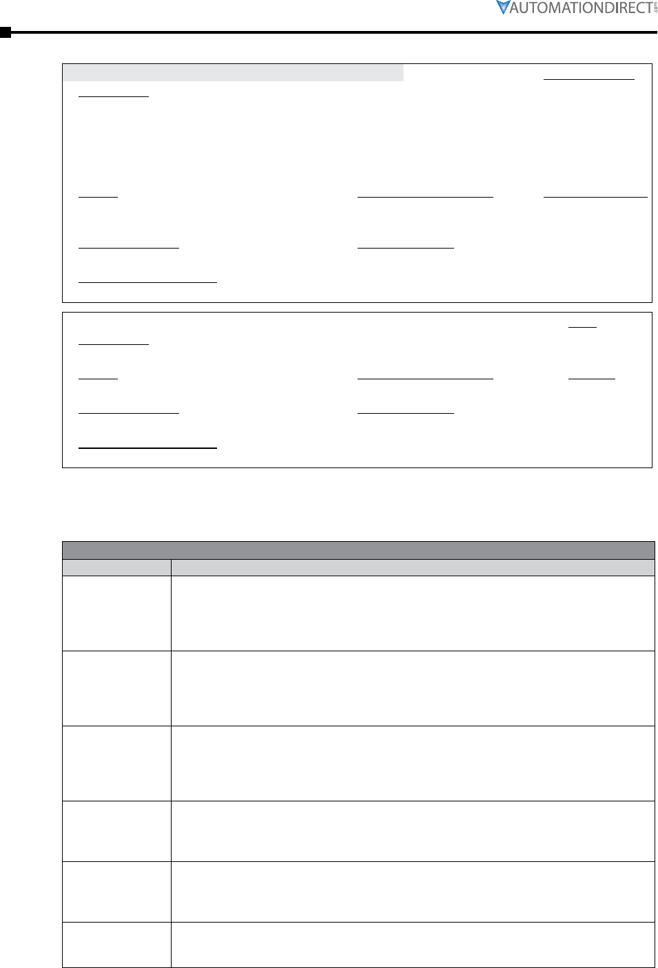
Page 3–80 Stellar® SR55 Series Soft Starter User Manual – 1st Ed. Rev.B – 02/02/2017
Chapter 3: Configuration and Parameters
P27.6 – Hold. Reg. Type:
Description:
Read/Write
Allows the user to load parameters stored on a USB flash drive.
• Uploads the parameters from the USB drive to the SR55.
• Data is stored in CSV format.
• Parameters cannot be uploaded from a USB using the remote touchscreen. Please use the on-
board touchscreen only.
Range: Modbus Decimal Value: Default (decimal):
• No
• Yes
• 0
• 1
• No (0)
Modbus Address: Modbus Format:
62336 ( F380 ) –
Touchscreen Menu Path:
Home → Device → Parameters from USB
P27.7 – Type:
Description:
n/a
Diagnostic parameter; for manufacturer’s use only.
Range: Modbus Decimal Value: Default:
n/a n/a n/a
Modbus Address: Modbus Format:
13120 ( 3340 hex ) n/a
Touchscreen Menu Path:
Home → Device → Service Code
Trip Code Descriptions
Trip Codes (from Trip Log)
101
Input Side Phase Loss
Phase L1 missing at the instant of start up.
• The L1 phase is either missing or at a very low level.
• Check all incoming connecons.
• If a main contactor is being controlled by a digital output set to “Running,”
check that “Contactor Delay” (under “Start Sengs”) is sucient.
102
Input Side Phase Loss
Phase L2 missing at the instant of start up.
• The L2 phase is either missing or at a very low level.
• Check all incoming connecons.
• If a main contactor is being controlled by a digital output set to “Running,”
check that “Contactor Delay” (under “Start Sengs”) is sucient.
103
Input Side Phase Loss
Phase L3 missing at the instant of start up.
• The L3 phase is either missing or at a very low level.
• Check all incoming connecons.
• If a main contactor is being controlled by a digital output set to “Running,”
check that “Contactor Delay” (under “Start Sengs”) is sucient.
104 - 117
Input Side Phase Loss
Any or all phases missing when the motor is being controlled (running).
• L1, L2, or L3 are missing or at a very low level.
• Check all incoming connecons.
• Check any fuses/breakers incorporated in the power circuit.
201
Maximum
Temperature
Exceeded
Internal heatsink temperature has exceeded 80°C.
• It is possible the SR55 is operang outside specied limits.
• Check enclosure venlaon and airow around the SR55.
• If the unit trips immediately, the internal temperature sensor could be faulty.
208
Thermal Sensor Trip
Thermal sensor failure.
• The internal temperature sensor has failed.
• Contact AutomaonDirect.

Chapter 3: Configuration and Parameters
Page 3–81Stellar® SR55 Series Soft Starter User Manual – 1st Ed. Rev.B – 02/02/2017
300-307
Thyristor Firing Trip
One or more of the internal control thyristors (SCRs) have failed to turn on properly (In-Line “Firing
Mode”)
• The SR55 has detected that the SCRs are not operang as expected.
• Check all incoming and outgoing connecons.
350-357
Thyristor Firing Trip
One or more of the internal control thyristors (SCRs) have failed to turn on properly (Delta “Firing
Mode”).
• The SR55 has detected that the SCRs are not operang as expected.
• Check all incoming and outgoing connecons.
401
Motor Side Phase
Loss
One or all of the phases are missing on the motor side during the instant of start up
• T1, T2, or T3 are missing or at a very low level.
• Check that the motor is connected to T1, T2 and T3.
• Ensure any disconnecng device between the SR55 and
the motor is closed at the instant of start up.
402-403
Motor Side Phase
Loss
One or all of the phases are missing on the motor side during the instant of start up when the motor
is being controlled.
• T1, T2 or T3 are missing or at a very low level.
• Check all incoming and outgoing connecons.
601
Control Voltage Too
Low
The internal control supply of the SR55 level has fallen to a low level.
• Can be caused by a weak 24VDC/115VAC/230VAC control supply.
• Ensure 24VDC/115VAC/230VAC supply meets the requirements specied
in “Electrical Installaon” Chapter 2 or the Quick Start Guide.
701-710
Sensing Fault Trip
One or more of the internal control thyristors (SCRs) have failed to turn on properly.
• The SR55 has detected that the SCRs are not operang as expected.
• Check connecons all incoming and outgoing connecons.
801-802
Fan Problem
One or more of the internal cooling fans has failed.
• To ensure the heatsink is cooled suciently, the SR55 will trip if the fans fail to operate.
• Check SR55 fans for signs of damage or contaminaon.
1001
Short Circuit
Thyristor
One or more of the internal control thyristors (SCRs) have failed short circuit.
• The SR55 has detected that the SCRs are not operang as expected.
• Check all incoming and outgoing connecons.
1101
Low Current Trip
The motor current has been lower than the “Low Trip Level” for the “Low Trip Time” (under “Motor
Protection”).
• This trip is not acve during so start and so stop and is “o” by default.
• If the Low Current Trip is not required, turn “o” in “Trip Sengs.”
1201
Current Limit
Timeout Trip
The motor has been held in current limit longer than the “Start Current Limit Time.”
• It is likely that the current limit level has been set too low for the applicaon.
• Increase the current limit level or meout period.
1202
Current Limit
Timeout Trip
The motor has been held in current limit longer than the “Stop Current Limit Time.”
• It is likely that the current limit level has been set too low for the applicaon.
• Increase the current limit level or meout period.
1301
Overload Trip
The “Overload” has exceeded 100%.
• The SR55 is aempng to start an applicaon that is
outside its capacity or it is starng too oen.
• Refer to the overload trip curves to determine whether the SR55 has been sized correctly.
1302
Overload Trip
The motor current has exceeded 475% (i-SR55) for a time greater than 250ms.
• The SR55 is aempng to start an applicaon that is outside
its capacity with a “high current limit level” set.
• Refer to the overload trip curves to determine whether the SR55
has been sized correctly, and check current limit level.
1401
Shearpin Trip
The motor current has been higher than the “Shearpin Trip Level” for the “Shearpin Trip Time.”
• This trip is not acve during so start and so stop, and is “o” by default.
• If “Shearpin Trip” is not required, turn “o” in “Trip Sengs.”
1501
PTC Thermistor Trip
The PTC thermistor value has exceed the trip level (4kΩ).
• The PTC thermistor connected to the PTC input has exceeded its
response temperature, or the PTC input is open circuit.
• If the PTC Trip is not required, turn “o” in “Trip Sengs.”
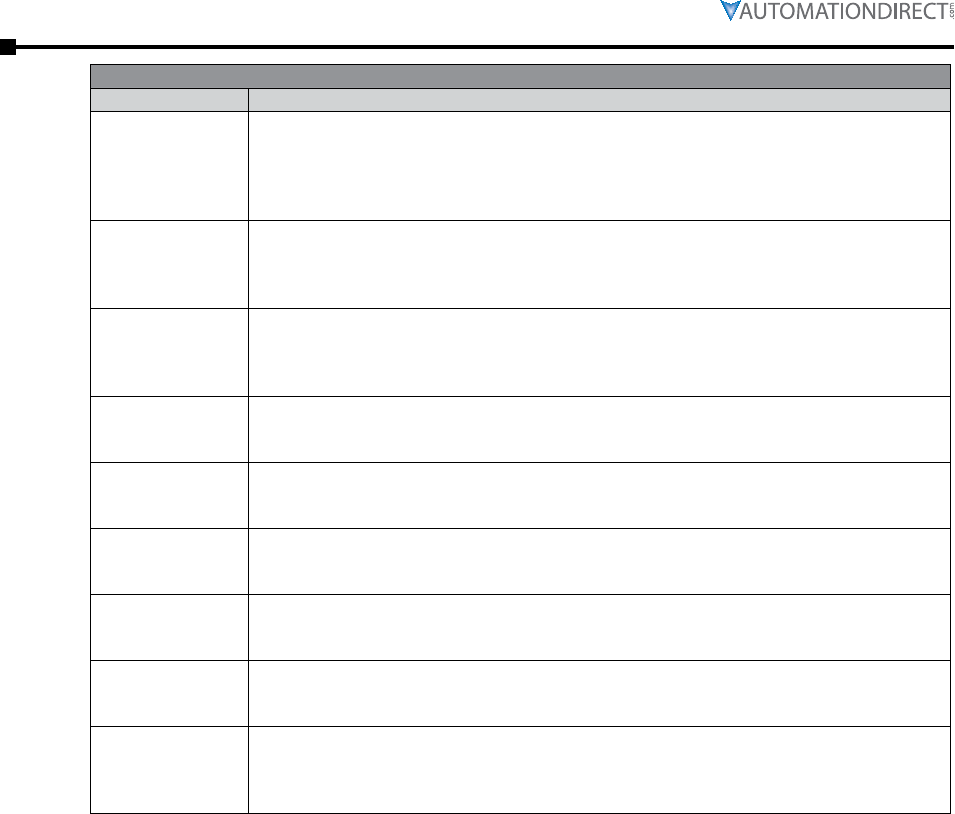
Page 3–82 Stellar® SR55 Series Soft Starter User Manual – 1st Ed. Rev.B – 02/02/2017
Chapter 3: Configuration and Parameters
1701
Communications Trip
Communications failure.
• A parameter has not been wrien to or polled in the me set in
the “Timeout” period (under “Device Networks”).
• If the “Communicaons Trip” is disabled, the SR55 will not
be stopped by the communicaons failure.
1801-1802
Bypass Relay Trip
One or more of the internal bypass relays has failed to close.
• The internal bypass relay has failed or the control supply is to weak.
• Ensure 24VDC supply meets the requirements specied in “Electrical
Installaon” Chapter 2 or the Quick Start Guide.
1803
Bypass Relay Trip
One or more of the internal bypass relays has failed to open.
• The internal bypass relay has failed or the control supply is too weak.
• Ensure 24VDC supply meets the requirements specied in “Electrical
Installaon” Chapter 2 or the Quick Start Guide.
1901
Cover Open, Close to
Enable Motor Start
The SR55 cover is open.
• The cover is open or not closed properly.
• Close cover, or if Cover Trip is not required, turn o in “Trip Sengs.”
2001
Remote Start is
Enabled
The Remote Start signal is active.
• The “Start/Stop” signal was acve during power up or Reset.
• Turn o “Start/Stop,” or if Remote Start trip is not required, turn “o” in “Trip Sengs.”
2101
Rotation L1 L2 L3 Trip
The input phase rotation is RYB (L1, L2,L3).
• The phase rotaon is opposite to that required.
• Change phase rotaon, or if “RYB” trip is not required, turn “o” in “Trip Sengs.”
2102
Rotation L1 L3 L2 Trip
The input phase rotation is RBY (L1, L3,L2).
• The phase rotaon is opposite to that required.
• Change phase rotaon, or if “RBY” trip is not required turn “o” in “Trip Sengs.”
2013
Rotation
Undetermined Trip
The phase rotation is undetermined.
• The SR55 is unable to determine whether the input phase rotaon is L1, L2, L3 or L1, L3, L2.
• Check all incoming and outgoing connecons.
2201-2209
MPU Trip
Internal SR55 Failure of the main processing unit.
• The SR55 has failed internally and is unable to recover automacally.
• Cycle the control supply.
• If the fault is not cleared, then contact AutomaonDirect.
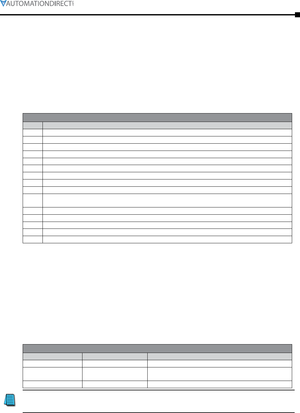
Chapter 3: Configuration and Parameters
Page 3–83Stellar® SR55 Series Soft Starter User Manual – 1st Ed. Rev.B – 02/02/2017
Fail Safe Codes
A trip number in the range of 2402 to 2436 indicates that a process on the main board has been
affected in some way and is unable to recover automatically.
• The trip is turned ON and OFF via the “Main Board Trip” (Advanced / Trips).
• The default for this trip is ON.
• The trip MUST be reset using the either the digital input, touchscreen, or bus command
depending on the control method set.
• As this is a special case, it is NOT possible to reset this trip by cycling the control supply.
Fail Safe Codes Associated with the Main Board
2402 Initialization process has been unsuccessful.
2404 Initialization of the Parameters has been unsuccessful.
2406 Initialization of the Overload has been unsuccessful.
2408 Initialization of the Parameter Read has been unsuccessful.
2410 Initialization of the Overload Read has been unsuccessful.
2412 Initialization of the Current measurement has been unsuccessful.
2420 A main process on the Main Board has been affected and is unable to recover automatically.
2422 A main process on the Main Board has been affected and is unable to recover automatically.
2424 A main process on the Main Board has been affected and is unable to recover automatically.
2426 Communication between the Main Board and Touchscreen Board has been affected and is unable to recover
automatically.
2428 The modbus communication has been affected and is unable to recover automatically.
2430 The parameter save has been unsuccessful.
2432 The logging function has been unsuccessful.
2434 A main process on the Main Board has been affected and is unable to recover automatically.
2436 The Anybus communication has been affected and is unable to recover automatically.
A trip number in the range of 2501 to 2581 indicates that a process on the touchscreen board has
been affected in some way and is unable to recover automatically.
• The trip is turned ON and OFF via the “Touchscreen Trip” (Advanced / Trips).
• The default for this trip is OFF.
• With the trip OFF the touchscreen display may display the ‘start up’ screen momentarily as it
recovers automatically.
• When the trip is turned ON it is reset using the either the digital input or touchscreen or bus
command, depending on the control method set.
• It is possible to reset this trip by cycling the control supply.
Fail Safe Codes Associated with the Touchscreen Board
2501 – 2529 2551 – 2579 A main process on the Touchscreen Board has been affected.
2530 2580 Communication between the Main board and Touchscreen
Board has been affected.
2531 2581 The touchscreen has become unresponsive.
When a remote touchscreen is used the same trips can be generated.
However, to discriminate between the remote and local (built in) 50 is
added to each code.
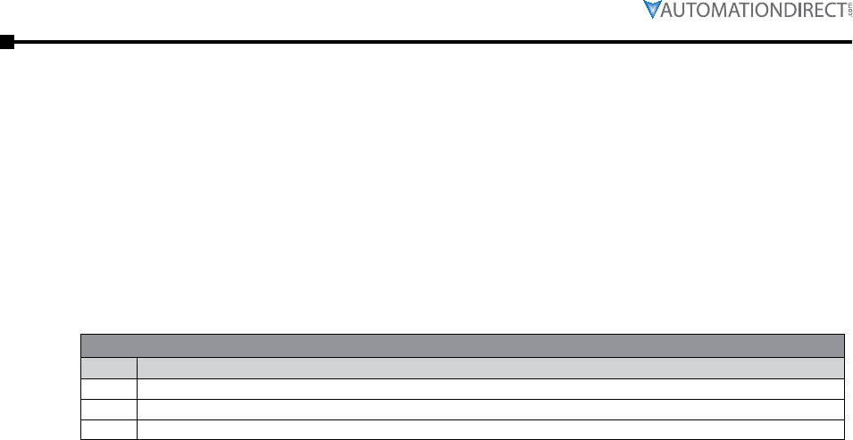
Page 3–84 Stellar® SR55 Series Soft Starter User Manual – 1st Ed. Rev.B – 02/02/2017
Chapter 3: Configuration and Parameters
Trip numbers that are in the range of 2601 to 2603 indicate that a process associated with the
logging has been affected in some way and has been unable to recover automatically.
• The trip is turned ON and OFF via the “Logging Trip” (Advanced / Trips).
• The default for this trip is OFF.
• With the trip OFF, the logging function will temporarily be disabled if a continual failure is
detected.
• When the trip is turned ON, it is reset using the either the digital input or keypad or bus
command, depending on the control method set.
• It is possible to reset this trip by cycling the control supply.
Fail Safe Codes Associated with the Logging Function
2601 The initialization of the event logging function has been unsuccessful for 20 consecutive attempts.
2602 The event logging function has been unsuccessful for 20 consecutive attempts.
2603 The SD card could not be accessed 20 consecutive attempts.
As part of the firmware upgrade procedure or if you experience a Fail Safe Trip we recommend
the following steps:
Parameters have not been set or do not need to be retained.
• Upgrade firmware ( Device / Upgrade Firmware ). See Appendix A for more details.
• Set the defaults ( Device / Reset Default ).
Parameters have been set and need to be retained.
• Upgrade firmware ( Device / Upgrade Firmware ). See Appendix A for more details.
• Upload parameters to USB stick (Device / Parameters to USB). Ensure that the SR55 is
NOT displaying ANY trip code. If a trip code is displayed then reset via the digital input,
touchscreen, or bus command depending on the control method set.
• Set the defaults ( Device / Reset Default ).
• Down load the parameters from the USB stick to the SR55 ( Device/ Parameters from USB ).
• Turn ‘Touchscreen Trip’ OFF ( Advanced / Trips).
• Turn ‘Logging Trip’ OFF (Advanced / Trips).
• Save Parameters ( Advanced / Save Parameters).

Chapter 3: Configuration and Parameters
Page 3–85Stellar® SR55 Series Soft Starter User Manual – 1st Ed. Rev.B – 02/02/2017
Saving and Loading an SR55 Configuration File
Operating parameters of the unit can be copied onto a USB flash drive. To do this, attach the
USB flash drive into the USB port under the front cover just above the touchscreen.
ADC part number USB-FLASH is a 4GB SanDisk USB flash drive that has been
verified to work with the SR55. Other flash drives may be too wide to
fit, or may not perform correctly.
From the Device Setting menu on the SR55 Home screen, scroll down to the third menu and
select “Parameters to USB.” This will construct a file called PARAMS.CSV, and copy it to a
PARAM folder on the stick. There is no way to rename the file during the save process. If you
have another PARAMS.CSV file on the flash drive, it will be overwritten. It is suggested that
parameter files be archived in a separate folder with a unique name other than PARAM. A new
parameter configuration must be configured on the SR55 and saved using the method described
above. It is not recommended to open the .CSV file and edit parameters on a PC and resave the
PARAMS file.
There is also the option to copy “Parameters From USB,” which gives the ability to restore or set
parameters to a known state. This function will only work on a file called PARAMS.CSV in the
PARAM folder of the stick. Any other files in that folder will be ignored.
A log file is for AutomationDirect to help solve performance issues that may arise. From the
Log menu on the Home screen, scroll down to the second menu and select “Download Log File.”
The LOG folder is created when the user connects a flash drive and selects “Download Log file”
from the LOG menu. As an aid to help analyses, the log file(s) PARAMS.CSV is also created and
copied into the LOG folder.

Page 3–86 Stellar® SR55 Series Soft Starter User Manual – 1st Ed. Rev.B – 02/02/2017
Chapter 3: Configuration and Parameters
BLANK
PAG E

Page 4–1Stellar® SR55 Series Soft Starter User Manual – 1st Ed. Rev.B – 02/02/2017
PrinciPles of iers
(intelligent energy
recovery system)4
4
4
chaPter
chaPter
chaPter
Table of ConTenTs
Principles of the iERS . . . . . . . . . . . . . . . . . . . . . . . . . . . . . . . 4–2
Principles. . . . . . . . . . . . . . . . . . . . . . . . . . . . . . . . . . . . . . . .4–2
Advantages of iERS . . . . . . . . . . . . . . . . . . . . . . . . . . . . . . . . . .4–3
How Much Energy? . . . . . . . . . . . . . . . . . . . . . . . . . . . . . . . . . .4–4
Estimating Energy Savings . . . . . . . . . . . . . . . . . . . . . . . . . . . . . .4–5
iERS with the SR55 System . . . . . . . . . . . . . . . . . . . . . . . . . . . . . .4–6
Chapter 4 Glossary of Terms . . . . . . . . . . . . . . . . . . . . . . . . . . . 4–7
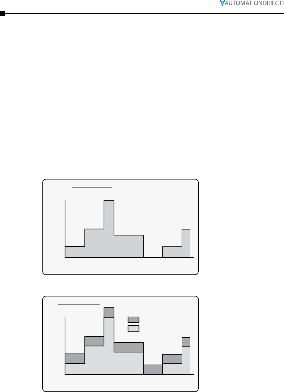
Page 4–2 Stellar® SR55 Series Soft Starter User Manual – 1st Ed. Rev.B – 02/02/2017
Chapter 4: Principles of iERS (intelligent Energy Recovery System)
Principles of the iERS
Every wound-field electric motor must consume some minimum amount of energy to provide a
magnetic field which enables it to work at all. With DC motors the field is under separate control,
so that the amount of magnetizing energy can be adjusted to be sufficient to overcome losses and
provide an armature reaction appropriate to the load. The squirrel cage AC induction motor has
no such provision, with the result that energy is wasted at any load less than its rated full load
(at full speed). When a squirrel-cage motor is supplied at a constant terminal voltage, as when
it is connected directly to the supply without a controller of any kind, the strength of the field
flux is fixed by the supply voltage. At normal running speed the field will take a fixed quantity
of energy regardless of the torque demanded by the mechanical load. The energy required to
support the load torque is determined by the torque demand. As load torque increases, the rotor
slows down a little (i.e. ’slip’ increases), causing induced rotor currents to also increase in order
to increase the torque. These additional currents in the rotor are balanced by additional current
in the stator coils. Conversely, if load torque demand falls, the slip decreases, the rotor currents
decrease, and the current in the stator decreases accordingly. But at constant terminal voltage, the
current providing the stator field flux remains unchanged at any level of load torque demand. As
a consequence, the efficiency of an induction motor decreases as the load decreases.
Load Torque Demand at working speed
40 60 80 100 120 140 160
seconds
M
demand
%
100
50
0
Current Demand due to torque and flux
40 60 80 100 120 140 160
seconds
Magnetizing current
Torque current
%
FLC
100
50
0

Page 4–3Stellar® SR55 Series Soft Starter User Manual – 1st Ed. Rev.B – 02/02/2017
Chapter 4: Principles of iERS (intelligent Energy Recovery System)
A soft starter with an iERS energy-optimizing feature alters the motor operation. The iERS
function reduces the terminal voltage applied to the motor so that the energy needed to supply the
field is more closely proportioned to the torque demand. The effect is shown in the Figure below.
A
Full load Torque
at rated voltage
Reduced
Torque
demand
Speed Synch
Torque at
rated voltage
Torque at
reduced voltage
Torque
100% M
80% M B
Voltage/Torque balance The present considerations do not affect
soft-starting options or strategies.
Point A on the current curve is the operating
point of the motor when the motor terminal
voltage is at its ‘nominal’ or rated value, and
when the load is the maximum for which the
motor is rated.
If the load decreases, a motor supplied
at a fixed voltage will speed up slightly,
the current demand will reduce, and the
operating point moves along the curve to
point “B”. Because the torque developed
by a motor is proportional to the square of
the applied voltage, lowering the terminal
voltage reduces the torque. If the reduced voltage is correctly chosen, the working point at the
reduced torque demand becomes the point “A”. By reducing the terminal voltage, the motor has
in effect been ‘exchanged’ for one which has a lower rated power output. A reduced terminal
voltage also means a reduced field energy requirement, and this simple relationship enables the
iERS function to maintain the efficiency of the motor over nearly the entire load range from
‘no load’ upwards. In practical terms, ‘no load’ means no external load. There are still internal
mechanical and electrical losses to overcome – friction and windage of the rotor at speed, and the
electrical heating and hysteresis losses. The ideal response to the ‘no load’ condition would be
to supply precisely the amount of magnetizing current needed to provide the armature reaction to
balance the losses. This is what the iERS seeks to do automatically and continuously.
It is normal to select a standard motor with a rating somewhat higher than the maximum
demand of the driven load. The motor selected for any given application will almost certainly
be over-rated for this reason alone, and therefore energy could be saved even at full load when
supplied at rated voltage. Furthermore, there are those applications where the size of motor has
to be chosen to provide for high loadings which occur only intermittently, or for an arduous start,
even though the load demand at most times is much lower.
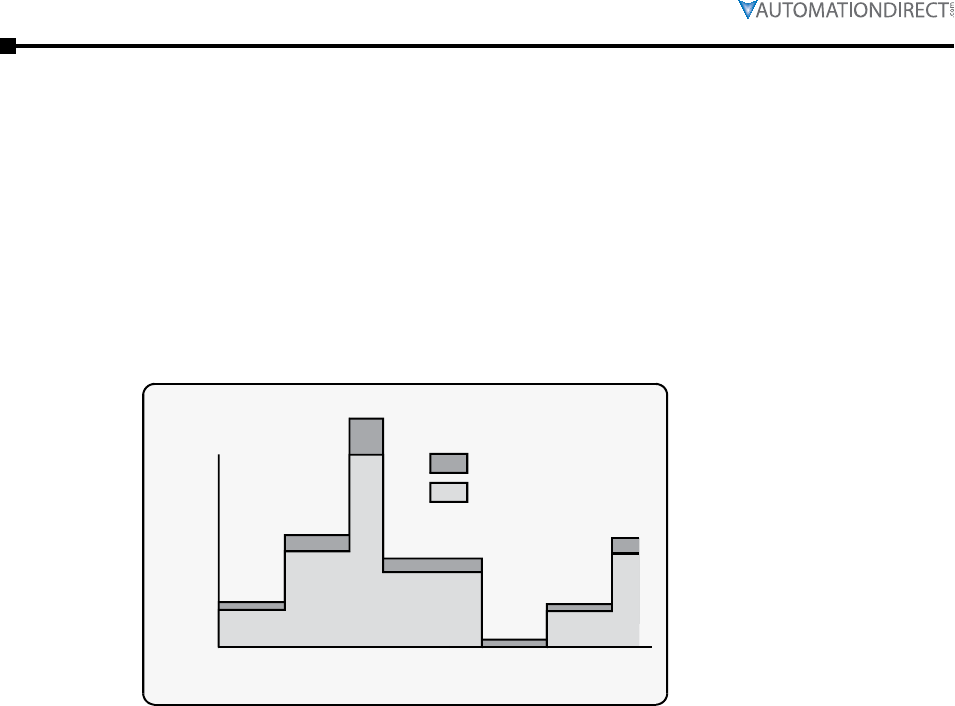
Page 4–4 Stellar® SR55 Series Soft Starter User Manual – 1st Ed. Rev.B – 02/02/2017
Chapter 4: Principles of iERS (intelligent Energy Recovery System)
The amount of energy used by a squirrel-cage induction motor operating with a soft starter in
energy-optimizing (iERS) mode is shown in the following figure (Figure 4.5.1), for the same
duty cycle as Figure 4.1.2. By reducing the voltage when torque demand is below maximum, the
magnetizing current is proportioned to the torque current.
Compare Figure 4.5.1 (energy-optimizing) with Figure 4.1.2 (non-optimizing). (These graphical
representations are illustrative only and not to scale.) Arriving at any exact figure for the energy
cost saved requires each individual case to be examined in detail, taking into account the motor
rating, type, and any special characteristics such as load, load characteristics, duty cycle, supply
voltage, and the cost of electricity.
40 60 80 100 120 140 160
seconds
%
FLC
100
50
0
Current demand with Energy Saving in operation
Magnetizing current
Torque current
The calculations to cover all the likely or possible conditions would be laborious. An empirical
method for arriving at a usefully realistic estimate has been devised. Used with a proper sense
of engineering circumspection, the tables in the “Estimating Energy Savings” sub-section allow
a user to gain a reasonably close estimate of the savings to be achieved within the motor by
using the SR55 optimizing soft starter. The method does not include any additional savings and
benefits conferred by other sources, such as:
• reduction of heating losses in cabling because of the lower voltages;
• potential reduction of maximum demand charges;
• further energy savings and other benefits deriving from the soft-starting process itself;
• reduced total energy demand;
• reduced wear and tear;
• reduced maintenance and replacement costs.
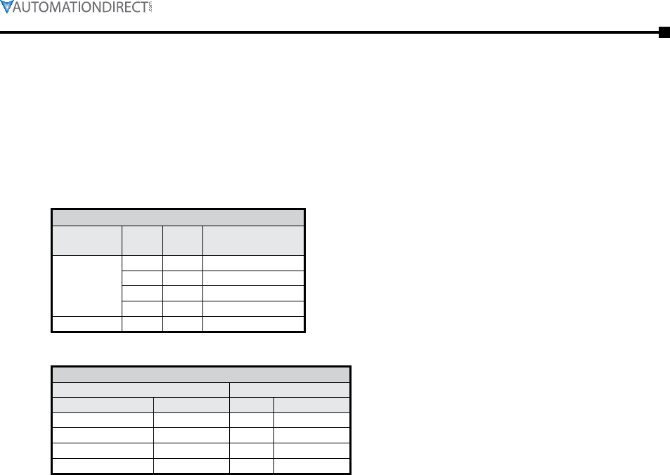
Page 4–5Stellar® SR55 Series Soft Starter User Manual – 1st Ed. Rev.B – 02/02/2017
Chapter 4: Principles of iERS (intelligent Energy Recovery System)
Basis for estimations:
• 3-phase squirrel cage induction motor, standard type.
• Supply: 380 to 440V, 50Hz.
• Supply voltage > minimum working voltage on motor rating plate.
• Operation 30% rated nameplate full load.
kW HP
Less than
5 7.5 10
22.5 30 6.5
55 75 3.5
110 150 2.5
More than 110 150 1.5
2 -0.5 0.5 -0.5
4 0 2 0
6 0.5 3.3 0.5
8 1 5 1
Examples of estimated energy savings:
1) 37.5 kW 4-pole motor
From Table 1, use the estimated savings figure for the next higher rating, i.e. 55 kW.
The savings would be approximately 3.5% x 37.5 kW = 1.3125 kW.
For the 30% loaded motor, the savings are 1.3125 kW / (30% x 37.5 kW) = 11.6% savings.
2) 37.5 kW 2-pole motor
From Table 1, use the estimated savings figure for the next higher rating, i.e. 55 kW.
From Table 2, apply the pole-number factor of -0.5 %.
The savings would be approximately (3.5 % - 0.5 %) x 37.5 kW = 1.125 kW.
For the 30% loaded motor, the savings are 1.125 kW / (30% x 37.5 kW) = 10% savings.
3) 37.5 kW 2-pole ‘low slip’ motor
From Table 1, use the estimated savings figure for the next higher rating, i.e. 55 kW.
From Table 2, apply the pole-number factor of -0.5 % and the %-slip factor of -0.5%.
The savings would be approximately (3.5 % - 0.5 % - 0.5 %) x 37.5 kW = 0.938 kW.
For the 30% loaded motor, the savings are 0.938 kW / (30% x 37.5 kW) = 8.3% savings.

Page 4–6 Stellar® SR55 Series Soft Starter User Manual – 1st Ed. Rev.B – 02/02/2017
Chapter 4: Principles of iERS (intelligent Energy Recovery System)
During start-up, the SR55 software uses a patented method to compute and store a reference
value for the power factor. When the motor has reached full speed and is driving the load at the
demanded torque, the SR55 enters the ‘motor running’ stage. At this stage, if required, the motor
may also operate in ‘iERS Mode’. Entering this mode can be pre-set from the SR55 touchscreen
and stored for automatic operation, which will suit the majority of applications where it is
required. This is the default operating mode for the SR55. It can also be toggled on and off while
running by using either the iERS button in the Advanced Settings of the touchscreen, or through
external circuitry connected to one of the programmable inputs and controlled by the driven
process.
‘iERS’ Intelligent Energy Recovery System will sense when at a level where we will gain no
benefits from Energy Saving, the SR55 will energize the bypass relays, and there will be no losses
from the motor controller.
Energy Saving will try to be active at all times and is fully automatic. The bypass relays will only
energize depending upon the measured thermal capabilities of the unit, percentage loading of the
motor, and the power factor, etc.
The bypass relays will open at 80% loading of the motor current set and enter the energy saving
mode. The relays will not re-energize until at least we are a level of 90% of the motor current set,
or we have surpassed the measured thermal capabilities of the unit, or the power factor is close to
full loading.
There should be even higher levels of energy saving, as when the motor is fully loaded the relays
will be energized and we will have no losses in the thyristors. We will therefore gain maximum
saving which is especially beneficial on typical cyclic loading applications such as pump jacks,
injection molding machines, mixers, saws, etc.
In iERS mode the reference power factor is continuously compared with the running power
factor. The software continuously uses this comparison to compute and adjust the firing point
of the thyristors in order to maintain the best power factor. This method of continuous control
minimizes wasted energy caused by overfluxing the motor. It also maintains the power factor at
the most appropriate value for every condition of load demand. This can produce a significant
reduction in the kVA demand.
This is an operating condition that may, at light or partial load conditions, provide the benefit
of energy saving and if selected, is continuous from the dwell period until a STOP command is
initiated or the mode is disabled. It should be noted that this function is inhibited by the software
if the current being drawn by the motor exceeds 80% of the set current of the SR55 (at full
voltage when the motor enters its running stage with the iERS mode selected).
The method of power factor management described does not affect motor performance, nor
does it detract from the motor’s capability to respond to changes in load demand. This feature
of the SR55 Soft Starter is a purely electrical function which has the effect of ensuring that the
motor delivers the torque demanded at all times, but allows it to draw only the precise amount of
magnetizing current required to support that torque output. Without this feature, the motor would
draw the maximum magnetizing current regardless of load. The iERS function cannot improve
the power factor beyond what it would ordinarily be at full load, but it does make the optimum
improvement possible at any partial load.

Page 4–7Stellar® SR55 Series Soft Starter User Manual – 1st Ed. Rev.B – 02/02/2017
Chapter 4: Principles of iERS (intelligent Energy Recovery System)
Chapter 4 Glossary of Terms
Bre akaway Torque: The minimum torque required to achieve rotor movement for the motor with
its load.
Cur rent Limit: The current at which the ramp is held. For the SR55, current limit is only active
during start-up where it contributes to the motor control function. This feature is particularly
useful when starting high-inertia loads that require an extended start-up period. (See also
Overload Level.)
Dir ect-On-Line (DOL): The direct connection and disconnection of a motor from the AC main
supply by means of a contactor or switch. Acceleration and operation is at full mains voltage
only.
iER S: Intelligent Energy Recovery System. An advanced motor control technology proven
to reduce the energy consumed in fixed speed motor applications. It matches the power
consumption to the load required by intelligently monitoring and regulating energy
consumption, voltage, current, and power factor during the motor starting and running
stages. iERS automatically bypasses itself when it is not needed, and continues monitoring to
re-engage itself as needed.
Inr ush Current or Locked Rotor Current: The current that flows at the instant of connection of a
motor to the power source. It is limited by the impedance presented by a de-energized motor
and the applied voltage. Usually expressed as a multiple of motor full-load current.
Kic k-start Voltage: The percentage of supply voltage applied before commencing ramp-up when
a load has a high breakaway torque and the standard settings of pedestal voltage may not
allow sufficient torque to be developed by the motor to cause acceleration.
Loc ked Rotor Current: Same as Inrush Current (defined above).
Ove rload Level: The level of current at which the controller overload begins to integrate. For
the SR55, the overload detector is always active and provides protection against prolonged
over-current operation.
Ped estal Voltage: The voltage that the unit applies to the motor at start-up. It is expressed as a
percentage of the rated supply voltage.
Po w er Factor: The ratio, expressed as a trigonometric cosine, of the real power consumption to
the apparent power consumption.
Top of Ramp (TOR): The unit achieves Top of Ramp (TOR) when it completes the start-up stage
of motor control. (This occurs when the voltage applied to the motor first equals the main
supply voltage.)
Sof t -start: The regulation, by electronic means, of the supply voltage from an initial low value to
full voltage during the starting process. This overcomes the inherent drawbacks of a switched
supply. The motor torque is modified in proportion to the square of the voltage applied.
Trip : A trip occurs when the unit removes power to the motor because its operation equals the
limit imposed by one of its self-protection features.

Page 4–8 Stellar® SR55 Series Soft Starter User Manual – 1st Ed. Rev.B – 02/02/2017
Chapter 4: Principles of iERS (intelligent Energy Recovery System)
BLANK
PAG E

Page 5–1Stellar® SR55 Series Soft Starter User Manual – 1st Ed. Rev.B – 02/02/2017
CommuniCations 5
5
5
Chapter
Chapter
Chapter
Table of ConTenTs
SR55 Communications Overview . . . . . . . . . . . . . . . . . . . . . . . . . 5–2
Modbus Serial Communications . . . . . . . . . . . . . . . . . . . . . . . . . 5–3
Modbus RTU Communications Interface . . . . . . . . . . . . . . . . . . . . . . .5–3
Modbus RTU Connections. . . . . . . . . . . . . . . . . . . . . . . . . . . . . . .5–3
Modbus Communications Configuration. . . . . . . . . . . . . . . . . . . . . . .5–4
Transmission Modes . . . . . . . . . . . . . . . . . . . . . . . . . . . . . . . . . .5–4
Message Structure For RTU Mode . . . . . . . . . . . . . . . . . . . . . . . . . .5–4
Supported Functions. . . . . . . . . . . . . . . . . . . . . . . . . . . . . . . . . .5–5
Memory Map . . . . . . . . . . . . . . . . . . . . . . . . . . . . . . . . . . . . .5–6
Message Timing . . . . . . . . . . . . . . . . . . . . . . . . . . . . . . . . . . . .5–6
Network Communications – EtherNet/IP and Modbus TCP. . . . . . . . . . . 5–7
Communication Module Overview . . . . . . . . . . . . . . . . . . . . . . . . . .5–7
Module Installation – SR55-CM-ENETIP and SR55-CM-MODTCP . . . . . . . . .5–7
SR55 Configuration . . . . . . . . . . . . . . . . . . . . . . . . . . . . . . . . . .5–7
IP Address Configuration . . . . . . . . . . . . . . . . . . . . . . . . . . . . . . .5–7
Communication Module Front Panel Indicator Lights. . . . . . . . . . . . . . . .5–8
Modbus TCP Network Communications . . . . . . . . . . . . . . . . . . . . . 5–8
EtherNet/IP Network Communications. . . . . . . . . . . . . . . . . . . . . . 5–8
EtherNet/IP Control . . . . . . . . . . . . . . . . . . . . . . . . . . . . . . . . . .5–9
EDS File . . . . . . . . . . . . . . . . . . . . . . . . . . . . . . . . . . . . . . . .5–9
Using the IP Configuration Tool (IPconfig) . . . . . . . . . . . . . . . . . . . . . 5–10
Connecting to the SR55-CM-ENET Module through I/O (Implicit Messaging) . . 5–14
Connecting to the SR55-CM-ENET Module through Explicit Message: . . . . . . 5–17
Explicit Message Instruction Examples (from Productivity Series CPU). . . . . . 5–18
Page 5–2 Stellar® SR55 Series Soft Starter User Manual – 1st Ed. Rev.B – 02/02/2017
Chapter 5: Communications
SR55 Communications Overview
All SR55 soft starters have a built-in RJ12 serial port that can be used to configure and to control
one SR55 from one RS-485 master controller, with no additional communications components
required (other than RS-485 cabling). Multiple SR55 soft starters can be controlled from a single
RS-485 master controller with the use of one optional serial Modbus communication splitter
(SR55-SPLT) per soft starter. An RJ45 female to RJ12 male cable adapter (SR55-RJ45-RJ12) is
available for easier cable connection. Examples of Modbus masters are SR55-KPD-REM, PLC,
or HMI.
Multiple SR55 soft starters can be networked for configuration and control from a single
Modbus TCP master controller. This type of network control requires one optional Modbus TCP
communication module (SR55-CM-MODTCP) per SR55 soft starter.
Multiple SR55 soft starters can be networked for configuration and control from a single
EtherNet/IP master controller. This type of network control requires one optional EtherNet/IP
communication module (SR55-CM-ENETIP) per SR55 soft starter.
For communications, ensure that the SR55 “Timeout” parameter setting
is > o. Otherwise, the SR55 will fault as soon as communication is
enabled. (Home → Device → Networks → Timeout ms)
If using Modbus RTU / Modbus TCP / EtherNet/IP communication for
control, the Digital Inputs are disabled. The Digital Outputs will
still function as configured.
If using Modbus RTU / Modbus TCP / EtherNet/IP communication for
monitoring only, then the Digital Inputs and Outputs will function as
configured if the Control Method is set to User Programmable, Two Wire,
or Three Wire control.
If using Modbus RTU (RJ12 port) for communications, an SR55-CM-xxxx
module must NOT be installed in the bottom communication port. The
presence of a communications module will cause interference with the
Modbus RTU communications.
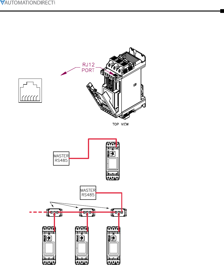
Chapter 5: Communications
Page 5–3Stellar® SR55 Series Soft Starter User Manual – 1st Ed. Rev.B – 02/02/2017
Modbus Serial Communications
All SR55 soft starters support serial Modbus RTU protocol (slave) communications. The serial
RS-485 communications are accessible from the built-in RJ12 port, as shown below.
16
1: GND
2: Reserved*
3: Not connected
4: Not connected
5: TXD0-A-OUT
6: TXD1-B-OUT
* Warning: To avoid damage to
the SR55 or to the RS-485 master,
do NOT connect to this pin!
SR55-xxx
SR55-SPLT
SR55-xxx SR55-xxxSR55-xxx
Single SR55 RS-485 network
(SR55-SPLT optional)
Multiple SR55 RS-485 network
(one SR55-SPLT per starter
recommended)
Information for the optional SR55-SPLT serial Modbus communication splitter is found in
“Accessories” Chapter 6. (An SR55-RJ45-RJ12 adapter can be used to simplify cabling between
the splitter’s RJ45 ports and the SR55’s RJ12 port.)
Page 5–4 Stellar® SR55 Series Soft Starter User Manual – 1st Ed. Rev.B – 02/02/2017
Chapter 5: Communications
The Modbus communication settings are accessible from the Device menu:
• Device >> Networks >> Modbus Network Settings >> Address (1 – 32)
• Device >> Networks >> Modbus Network Settings >> Baud (9600 – 115200)
• Device >> Networks >> Modbus Network Settings >> Parity (Odd / Even)
• (Data bits = 8, Stop bits = 1)
The communication parameters should be set before connecting the Modbus master.
ASCII and RTU transmission modes are defined in the Modbus protocol specification. SR55
uses only the RTU mode for the message transmission.
The Modbus RTU structure uses a master-slave system for message exchange. In the case of
the SR55 system, it allows up to 32 slaves, and one master. Every message begins with the
master making a request to a slave, which responds to the master in a defined structure. In both
messages (request and answer), the used structure is the same:
• Address, Function Code, Data and CRC.
Address
(1 byte)
Function
(1 byte)
Request Data
(n bytes)
CRC
(2 bytes)
Address
(1 byte)
Function
(1 byte)
Response Data
(n bytes)
CRC
(2 bytes)
The master initiates the communication by sending a byte with the address of the destination
slave. When responding, the slave also initiates the message with its own address. Broadcast to
address 0 (zero) is not supported.
This field contains a single byte, where the master specifies the type of service or function
requested to the slave (reading, writing, etc.). According to the protocol, each function is used to
access a specific type of data.
The format and contents of this field depend on the function used and the transmitted value.
The used method is the CRC-16 (Cyclic Redundancy Check). This field is formed by two bytes;
where first the least significant byte is transmitted (CRC-), and then the most significant (CRC+).
The CRC calculation form is described in the Modbus RTU protocol specification.
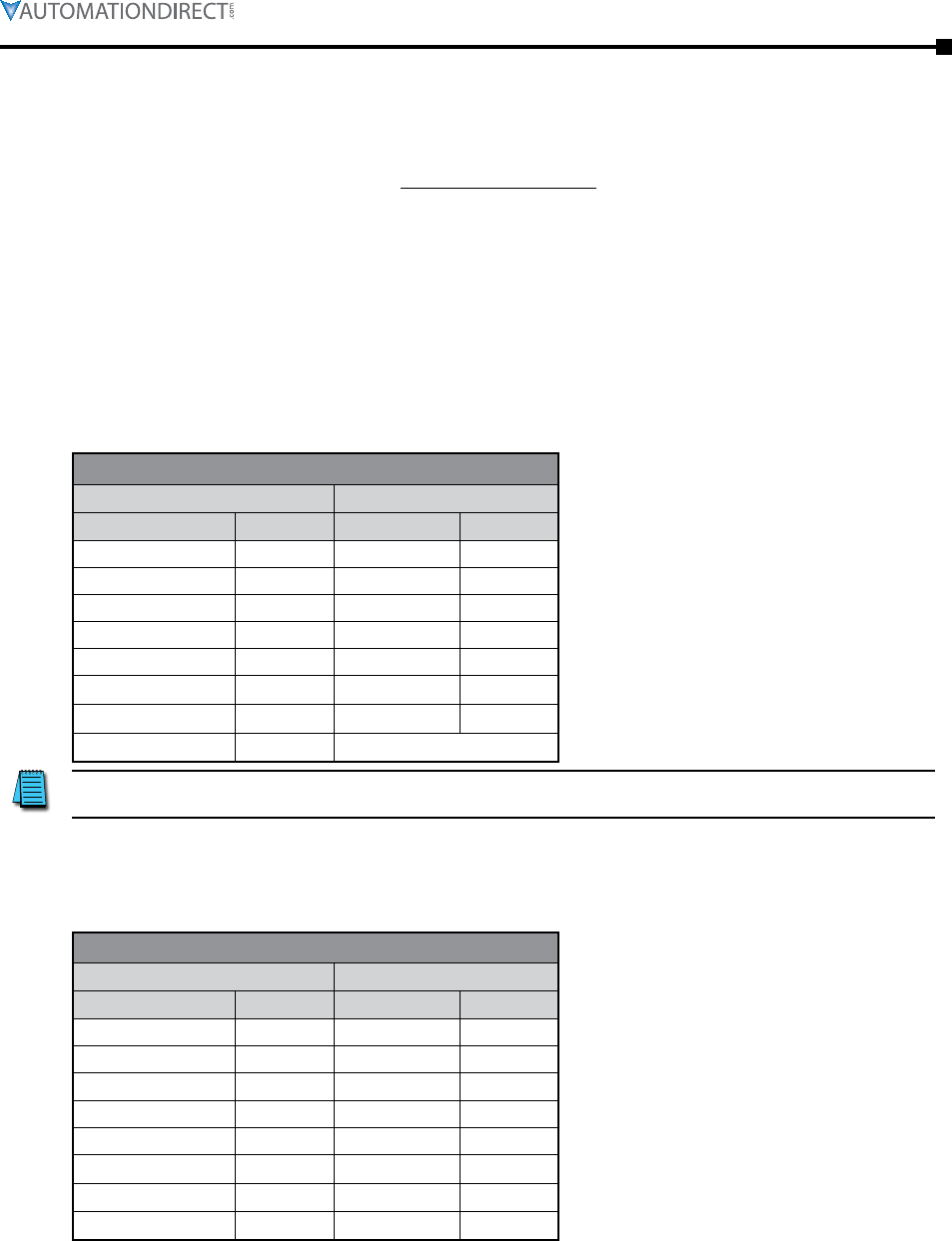
Chapter 5: Communications
Page 5–5Stellar® SR55 Series Soft Starter User Manual – 1st Ed. Rev.B – 02/02/2017
Modbus RTU specification defines the functions used to access different types of data.
• SR55 parameters are defined as holding type registers.
• For Modbus RTU/TCP Client devices that use Modicon style addressing, place a 4 as the
high digit followed by the Modbus address defined in the parameter mapping table. Note
that SR55 Modbus addressing starts at zero; not 1 as some devices do.
• SR55 32-bit parameters are High Word / Low Word in Modbus format.
The following services are available:
Description: reading register blocks of holding register type (block R/W limited to 8 registers).
• Function code: 03
Modbus Function 03 Transaction Table
Query
Slave address 01 Slave address 01
Function 03 Function 03
Start address Hi 00 Byte count 02
Start address Lo 01 Data Hi 01
No of registers Hi 00 Data Lo 2C
No of registers Lo 01 CRC Lo B8
CRC Lo D5 CRC Hi 09
CRC Hi CA
Before writing to the SR55, initiate several Modbus Reads to ensure that
the master’s addressing and configuration are correct.
Description: writing in a single register of the holding type.
• Function code: 06
Modbus Function 06 Transaction Table
Query
Slave address 01 Slave address 01
Function 06 Function 06
Address Hi 00 Address Hi 02
Address Lo 0C Address Lo 0C
Force data Hi 00 Force data Hi 00
Force data Lo 09 Force data Lo 09
CRC Lo 48 CRC Lo 88
CRC Hi 0C CRC Hi 77
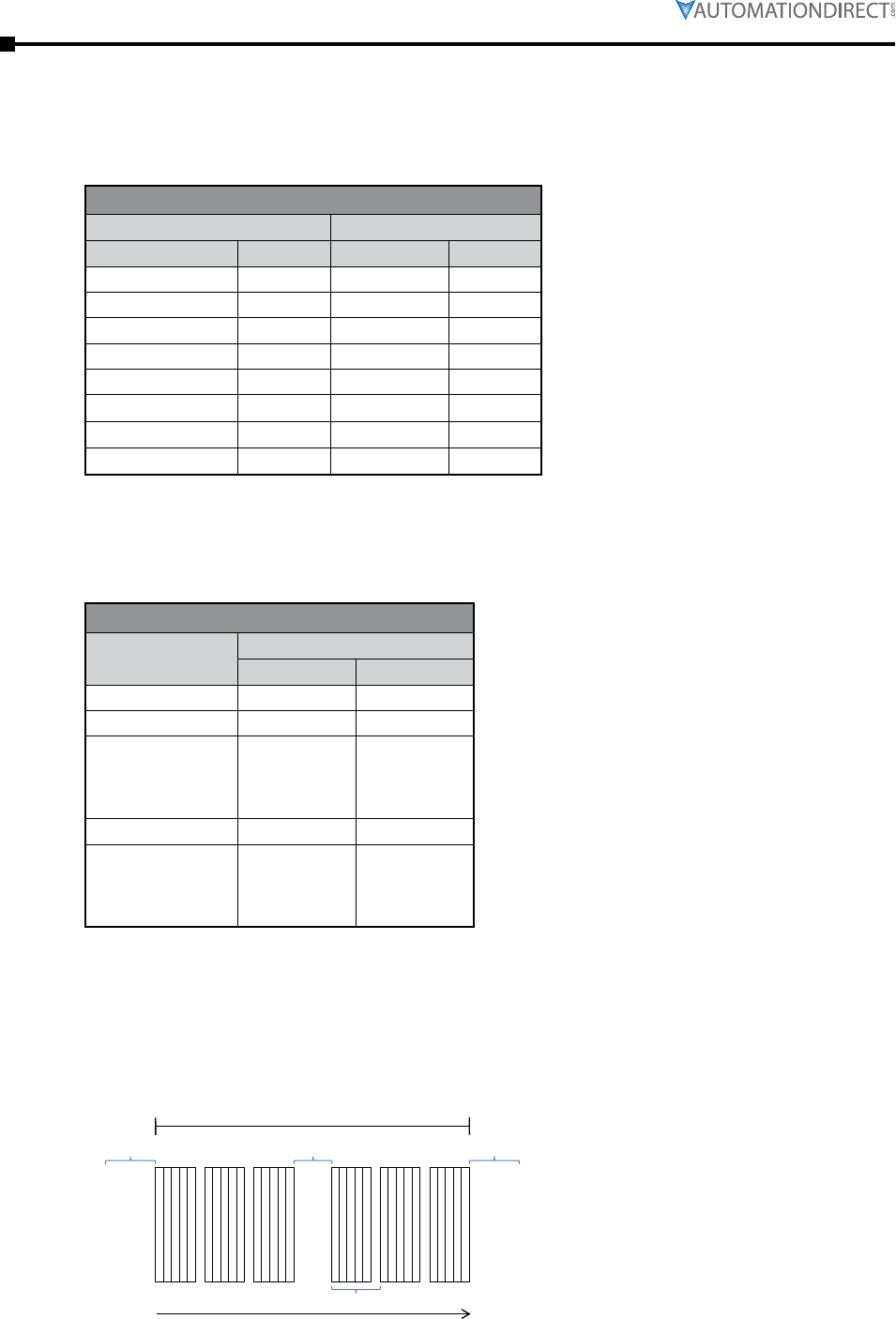
Page 5–6 Stellar® SR55 Series Soft Starter User Manual – 1st Ed. Rev.B – 02/02/2017
Chapter 5: Communications
Description: writing register blocks of holding register type (block R/W limited to 8 registers).
• Function code: 16
Modbus Function 16 Transaction Table
Query
Slave address 01 Slave address 01
Function 16 Function 16
Address Hi 00 Address Hi 02
Address Lo 0C Address Lo 0C
Force data Hi 00 Force data Hi 00
Force data Lo 09 Force data Lo 09
CRC Lo 48 CRC Lo 49
CRC Hi 0C CRC Hi B4
SR55 Modbus communication is based on reading or writing equipment parameters from or to
the holding registers. The data addressing is zero offset, such that the parameter Modbus address
corresponds to the register number.
Modbus Address Memory Map
0000 0 0000h
0001 1 0001h
•
•
•
•
•
•
•
•
•
•
•
•
0128 128 0080h
•
•
•
•
•
•
•
•
•
•
•
•
In the RTU mode there is no specific start or stop byte that marks the beginning or the end of a
message. Indication of when a new message begins or when it ends is achieved by the absence of
data transmission for a minimum period of 3.5 times the transmission time of a data byte. Thus,
in case a message is transmitted after this minimum time has elapsed; the network elements will
assume that the first received character represents the beginning of a new message.
Message
T3.5x
T3.5x Tinterval
T11 bits
Time
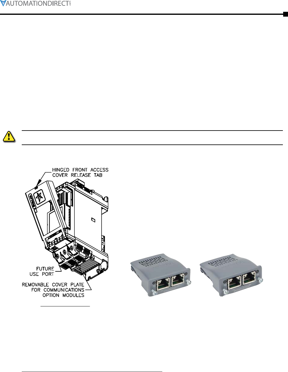
Chapter 5: Communications
Page 5–7Stellar® SR55 Series Soft Starter User Manual – 1st Ed. Rev.B – 02/02/2017
Network Communications – EtherNet/IP and Modbus TCP
Two communication modules are available which allow network communication and control for
the SR55 soft starter.
• SR55-CM-ENETIP for EtherNet/IP network communication.
• SR55-CM-MODTCP for Modbus network communication.
Both modules have two RJ45 ports for daisy chaining to multiple starters. These ports act as a
switch. It does not matter which port you connect to.
Install the applicable communication module in the SR55 option module slot per the hardware
installation instructions in the “Accessories” chapter of this user manual.
refer To The insTallaTion insTrucTions in The “accessories” chapTer of This user manual before
aTTempTing To insTall The communicaTion modules.
SR55-xxx Bottom View
Great care must be taken to properly seat the
communication modules into the SR55 soft starter
without damaging the connection pins. Refer
to the detailed instructions in the “Accessories”
chapter of this user manual.
SR55-CM-ENETIP SR55-CM-MODTCP
The SR55 will automatically configure when the option module is installed.
Use the IP address configuration tool available from:
http://support.automationdirect.com/downloads.html
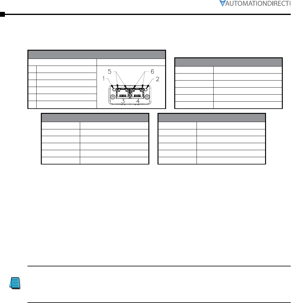
Page 5–8 Stellar® SR55 Series Soft Starter User Manual – 1st Ed. Rev.B – 02/02/2017
Chapter 5: Communications
Location of Front Panel Indicators
1 Network Status LED
2 Module Status LED
3 Network Interface, Port 1
4 Network Interface, Port 2
5 Link/Activity Port 1
6 Link/Activity Port 2
Network Interface LED
Off No link, no activity
Green Link established (100 Mbit/s)
Green, flickering Activity (100 Mbit/s)
Yellow Link established (10 Mbit/s)
Yellow, flickering Activity (10 Mbit/s)
Network Status LED
Off No power or no IP address
Green Online, connections active
Green, flashing Online, no connections active
Red Duplicate IP, fatal error
Red, flashing Connection timeout
Module Status LED
Off No power
Green Controlled, Run state
Green, flashing Not configured or idle state
Red Major fault
Red, flashing Recoverable error(s)
Modbus TCP Network Communications
The SR55-CM-MODTCP Modbus communication module offers the following functionality:
• Dual switched RJ45 communication ports
• 256 bytes of I/O data in each direction
• 100 Mbps full duplex
• Supports 4 simultaneous (master) connections
All Modbus functions and addresses that are available in the preceeding “Modbus Serial
Communications” section of this chapter are also available via modus TCP.
SR55 uses Protocol Addressing (Base 0); not PLC Addressing (Base 1). If
you are not using the correct selection, all the addresses will be off
by 1. Recommended test: monitor a non-critical parameter such as Start
Time (address 7104), then manually change the value on the touchscreen
and verify that Modbus master actually sees the correct changes.
EtherNet/IP Network Communications
The SR55-CM-ENETIP EtherNet/IP communication module offers the following functionality:
• CIP Parameter Object Support
• Implicit and Explicit messaging
• Dual switched RJ45 communication ports
• 10/100 Mbps full duplex
• 2 Input Words from the network master to the SR55
• 2 Output Words from the SR55 to the network master
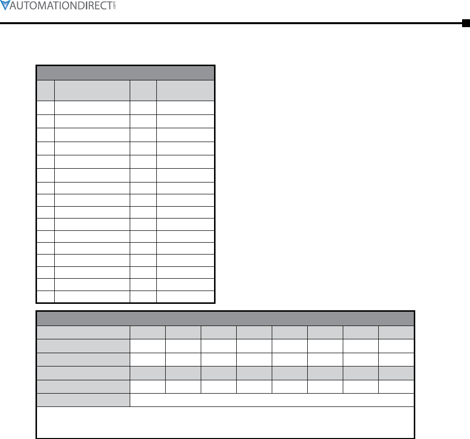
Chapter 5: Communications
Page 5–9Stellar® SR55 Series Soft Starter User Manual – 1st Ed. Rev.B – 02/02/2017
Supported Parameters
#
1 Run Forward N Y
2 Run Reverse N N
3 Fault Rest N Y
4 Net Control N Y
5 Net Reference N N
6 Speed Reference N N
7 Torque Reference N N
8 Faulted Y Y
9 Warning Y Y
10 Running Forward Y Y
11 Running Reverse Y N
12 Ready Y Y
13 Ctrl From Net Y Y
14 Ref From Net Y N
15 At Reference Y N
16 Drive State Y Y
The drive profile used by the interface
is currently that provided by the
SR55-CM-ENETIP Module and is dictated
by the EDS file provided by HMS Industrial
Networks.
The EDS describes parameters that can be
accessed explicitly in an Acyclic manner. Not
all of these parameters are implemented in the
SR55 soft starter. See the following table. CIP
paths from these parameters are described in the
EDS.
The EDS also describes the 25 Implicit Cyclic
connections, each of which will set and/or
get a combination of the above parameters.
The following examples are for connection 6
(Extended Control).
CIP Packet functionality – Extended Control
– – #4 – #3 – – #1
––––––––
– – #13 #12 – #10 #9 #8
#16
Note: When a cyclic connection is established and Bit4 (Net Control) is set, the network has control of the
SR55 soft starter and any other control from the SR55 front touchscreen, switches, or Modbus interface
will be overridden.
An EDS file for the interface is available from the AutomationDirect website:
http://support.automationdirect.com/downloads.html
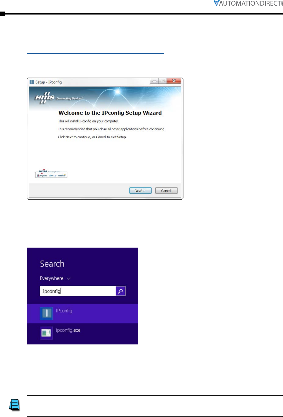
Page 5–10 Stellar® SR55 Series Soft Starter User Manual – 1st Ed. Rev.B – 02/02/2017
Chapter 5: Communications
The IP address of the SR55 is set using the Anybus IPconfig utility available from:
http://support.automationdirect.com/downloads.html.
This section explains how to install the IPconfig utility and how to set the SR55’s IP address.
Unzip the file to a temporary folder and run the executable.
Follow the steps through the installation.
Once the installation is complete, run application from the folder that it was installed to (usually
the HMS folder in the Start menu). In Windows 8, from the home tile screen, simply type in
“ipconfig.” Typing any text on this screen will open the Search dialog. The program IPconfig is
the configuration tool from HMS.
If you use the Desktop most of the time in Windows 8, right click on this file and select “Pin to
Taskbar” to always have quick access to the file from the desktop.
The SR55 with the installed SR55-CM-ENETIP module needs to be installed on the same
network as the PC running the Ipconfig application.
The messaging uses broadcast and will not go through routers.
It is highly recommended to disconnect the PC from any network and have
only the SR55 and the PC connected via an Ethernet switch (not a router)
or an Ethernet cross-over cable.
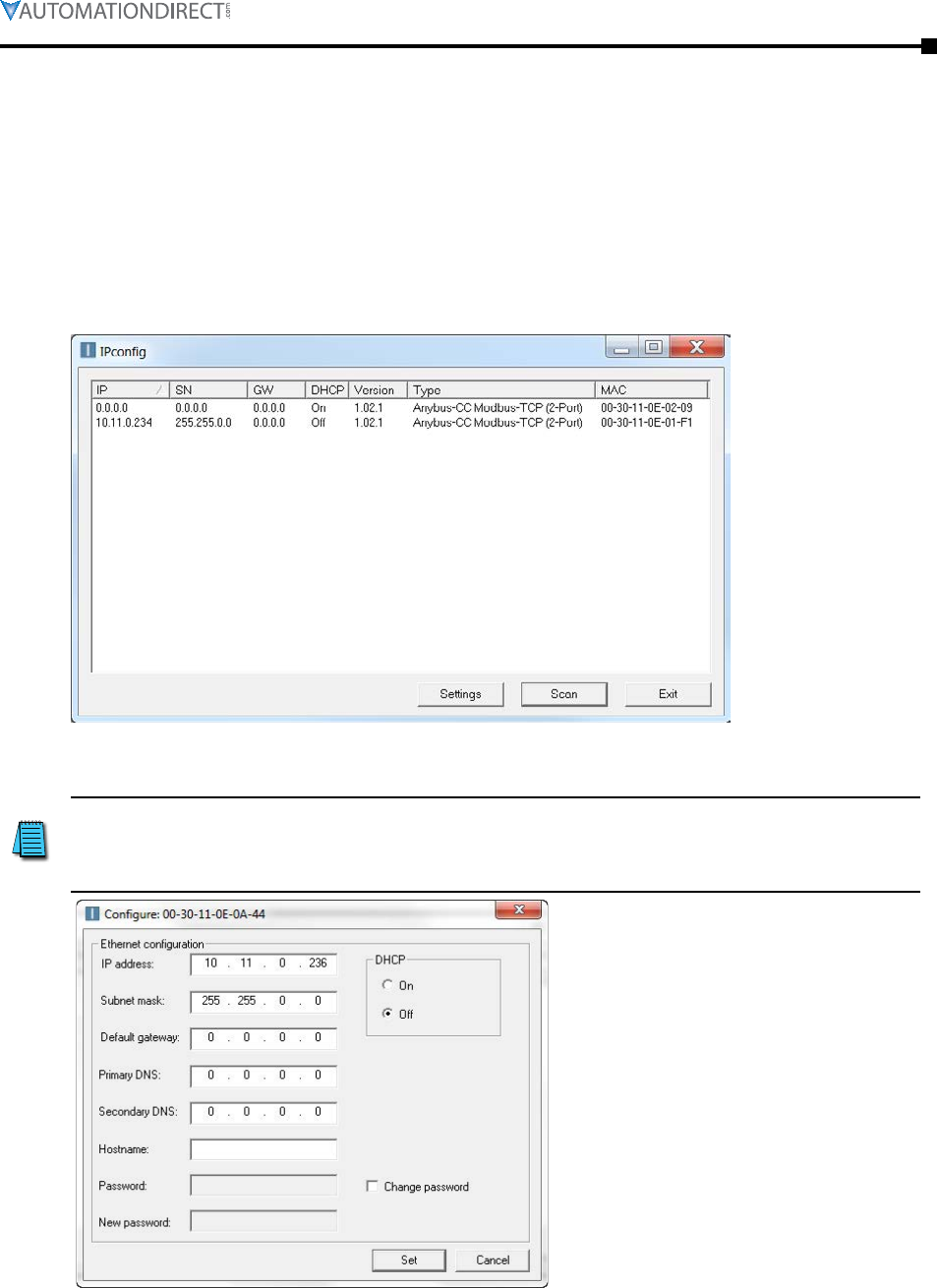
Chapter 5: Communications
Page 5–11Stellar® SR55 Series Soft Starter User Manual – 1st Ed. Rev.B – 02/02/2017
Use a switch or crossover cable to connect the starter to the SR55.
Start the Ipconfig software. Press the Scan button to have the PC scan for an SR55. The IPconfig
utility will automatically find the SR55 units on the network.
If the SR55 is not found, click on the Settings button, then choose “Broadcast from a specific
Network Interface Controller.” This could be required if there are multiple network cards on the
PC. Click OK, then Scan for SR55 units again.
Below shows a screen capture of an SR55-077 and an SR55-242 daisy chained from one to
another.
Select the Anybus module in the window and double click on it. This will bring up a window to
set the network settings to values appropriate to the network that it will be running on.
It is very highly recommended to set DHCP to OFF. Otherwise, the
Ethernet address of the SR55 could be changed by a DHCP server at a
future time. Setting DHCP to OFF will ensure that the SR55 maintains
the same IP address.
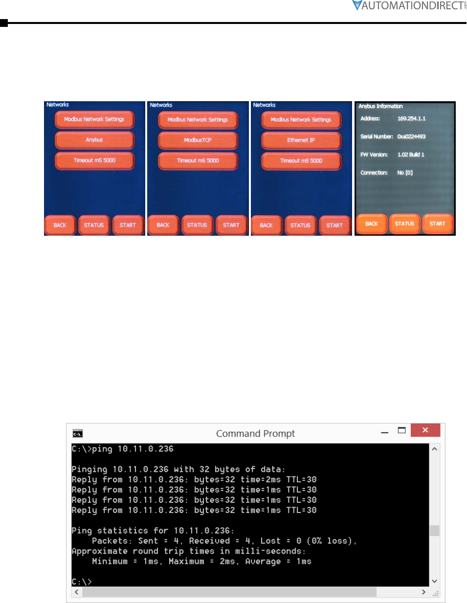
Page 5–12 Stellar® SR55 Series Soft Starter User Manual – 1st Ed. Rev.B – 02/02/2017
Chapter 5: Communications
Once the settings have been entered, click on the “Set” button and the Anybus module is now
configured and ready to be used. It is not recommended to use DHCP, as the address could be
changed. The starter’s control power will have to be cycled for the correct settings to show up on
the touchscreen.
If you do not see modules showing up in the IPconfig screen check the following:
• That the SR55-MODTCP or SR55-ENETIP module is inserted correctly, and MS LED is on or
flashing green. See module installation instructions in this SR55 user manual.
• That the module appears in the Networks menu under Home >> Device >> Networks. If the
module is not recognized the center selection text will read “Anybus” instead of “ModbusTCP
or “Ethernet IP.”
• On the PC, run “cmd” from the Start Menu (or type “cmd” from the Windows 8 Home tile
screen) to get a command prompt. Test the physical connection between the PC and the
starter. Type “ping” and the address the SR55 should be set to. Press Enter.
• If the PC can see the starter, valid data will be returned:
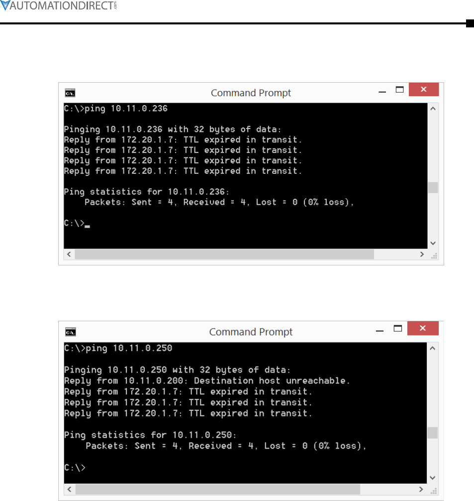
Chapter 5: Communications
Page 5–13Stellar® SR55 Series Soft Starter User Manual – 1st Ed. Rev.B – 02/02/2017
• If the PC is set to a different IPv4 network than the SR55, ie., both PC and SR55 are not set to
the same first two octets (10.11.xxx.xxx in this example), the following error will be returned:
• If the IPv4 Ethernet address is incorrect, the following error will be returned (notice that
unlike the previous error, this error returns “Destination host unreachable”):
• If Ping from the PC to the SR55 does not work, please recheck that a cross-over cable or an
Ethernet switch (NOT a router) is being used to connect the PC to the SR55.
• Also check that the header pins between the comm module and the SR55 were not bent
(extreme care must be taken when inserting the module into the starter).
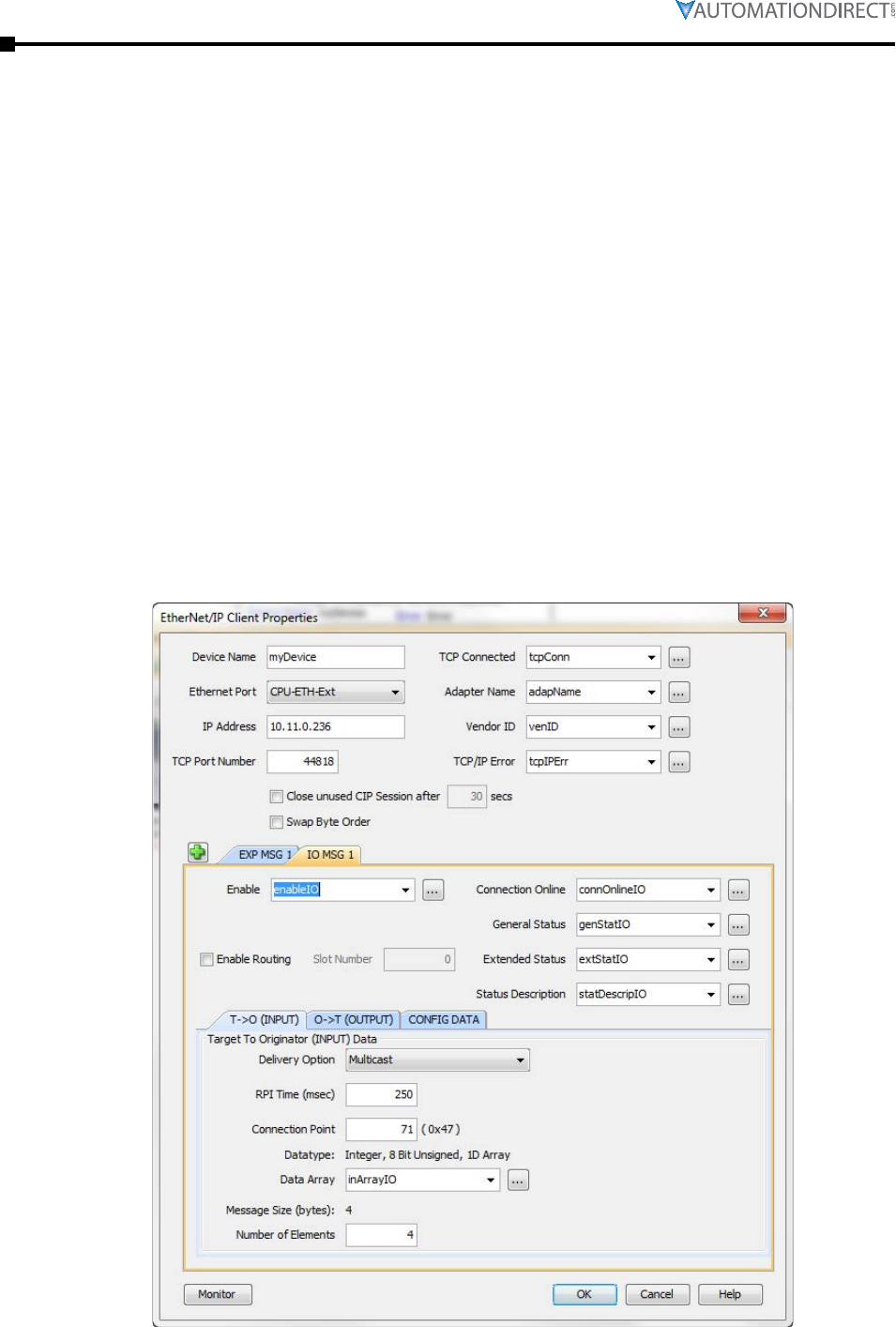
Page 5–14 Stellar® SR55 Series Soft Starter User Manual – 1st Ed. Rev.B – 02/02/2017
Chapter 5: Communications
The connection parameters for Connection 6 (Extended Control) are as follows:
• T->O (Input Data) Connection Point Assembly Instance value is 71.
• T->O (Input Data) Size is 4 bytes.
• The Data format for Status is shown in the “Input Data Setup” screen capture.
• O->T (Output Data) Connection Point Assembly Instance value is 21.
• O->T (Output Data) Size is 4 bytes.
• The Data format for Control is shown in the “Output Data Setup” screen capture.
• No Configuration data is required.
To start the SR55, a value of 33 should be placed into Byte 0 of the Control data.
33 equates to Bit 0 (Run Forward) On and Bit 5 (Net Control) On.
To stop the SR55, a value of 32 should be placed into Byte 0 of the Control data.
32 equates to Bit 0 Off and Bit 5 On.
To reset faults on the SR55, a value of 36 should be placed into Byte 0 of the Control data.
36 equates to Bit 2 (Fault Reset) On and Bit 5 (Net Control) On.
The following images are an example setup of I/O (Implicit Messaging) to the SR55 EtherNet/IP
adapter from a Productivity Series CPU.
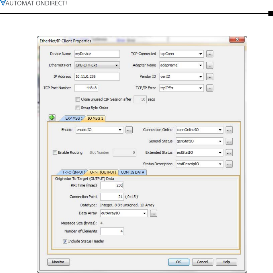
Chapter 5: Communications
Page 5–15Stellar® SR55 Series Soft Starter User Manual – 1st Ed. Rev.B – 02/02/2017
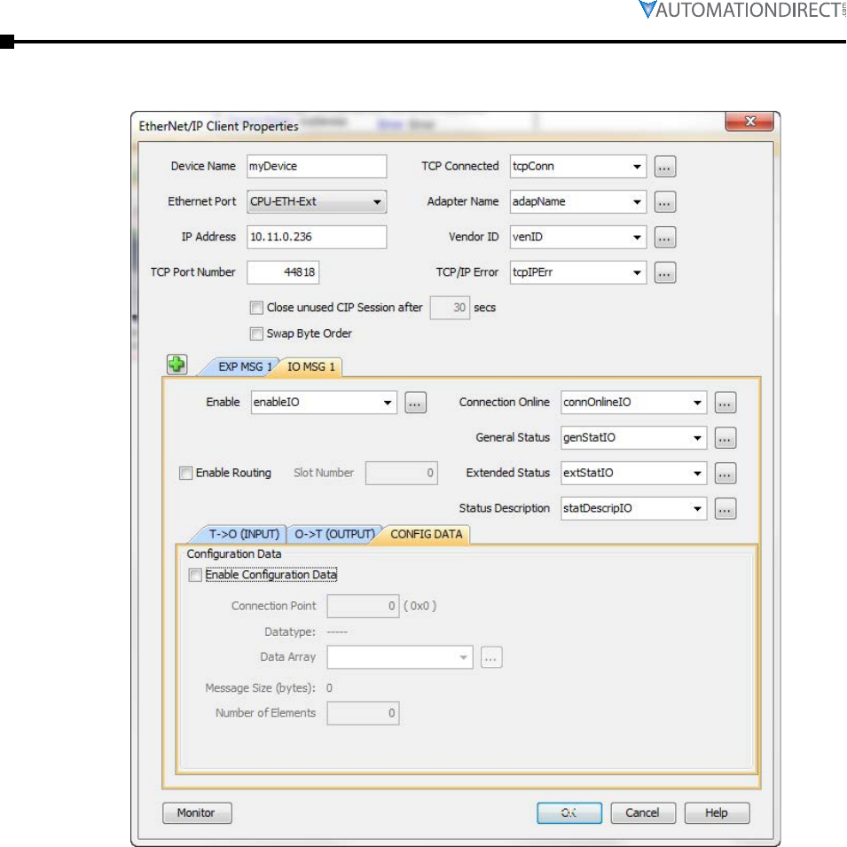
Page 5–16 Stellar® SR55 Series Soft Starter User Manual – 1st Ed. Rev.B – 02/02/2017
Chapter 5: Communications
Chapter 5: Communications
Page 5–17Stellar® SR55 Series Soft Starter User Manual – 1st Ed. Rev.B – 02/02/2017
There are a few different objects that can be read or be written to via Explicit Messaging:
Objects Supported By Explicit Messaging
Run No 16 (0x10) 41 (0x29) 1 3
Fault Reset No 16 (0x10) 41 (0x29) 1 12 (0x0c)
Network Control No 16 (0x10) 41 (0x29) 1 5
Faulted Yes 14 (0x0e) 41 (0x29) 1 10 (0x0a)
Warning Yes 14 (0x0e) 41 (0x29) 1 11 (0x0b)
Running Forward Yes 14 (0x0e) 41 (0x29) 1 7
Ready Yes 14 (0x0e) 41 (0x29) 1 9
Control from Network Yes 14 (0x0e) 41 (0x29) 1 15 (0x0f)
Drive State Yes 14 (0x0e) 41 (0x29) 1 6
With the exception of the “Drive State” parameter, all of the other parameters either require a
value of 1 or 0 for SET (16), and will return a value of 0 or 1 on the GET (14) parameters.
To run the starter, a value of 1 must be set in the “Network Control” parameter first and then
a value of 1 can be sent to the “Run” parameter to start the motor and a value of 0 to the same
parameter to stop the motor.
If the Communications Trip parameter is enabled, a message must be sent to the starter at a faster
rate than what is configured for the Timeout parameter. It is typical in this situation to poll the
“Faulted” parameter to view the state of the starter along with keeping the Communications Trip
from enabling and stopping the motor.
If communications are interrupted for a long enough period to invoke the Communications Trip
fault, the following sequence is required to restart the motor:
• Send a 0 to the “Run” parameter.
• Send a 1 to the “Fault Reset” parameter.
• Send a 0 to the “Fault Reset” parameter.
• Now you can restart the motor by sending a 1 to the “Run” parameter.
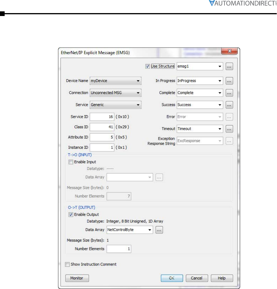
Page 5–18 Stellar® SR55 Series Soft Starter User Manual – 1st Ed. Rev.B – 02/02/2017
Chapter 5: Communications
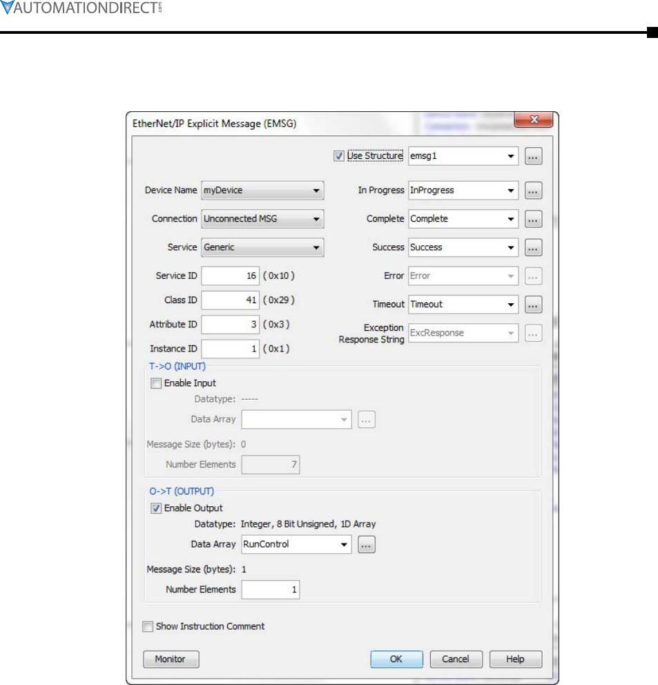
Chapter 5: Communications
Page 5–19Stellar® SR55 Series Soft Starter User Manual – 1st Ed. Rev.B – 02/02/2017
(value of 1 to start and 0 to stop)
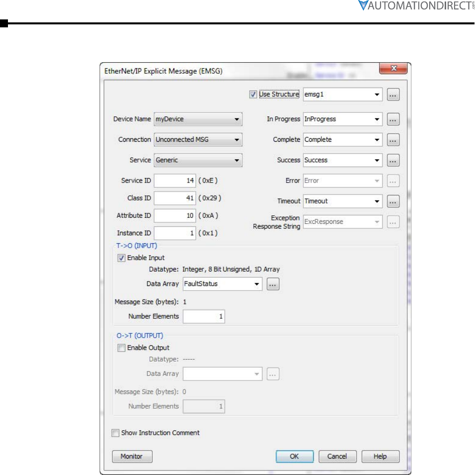
Page 5–20 Stellar® SR55 Series Soft Starter User Manual – 1st Ed. Rev.B – 02/02/2017
Chapter 5: Communications
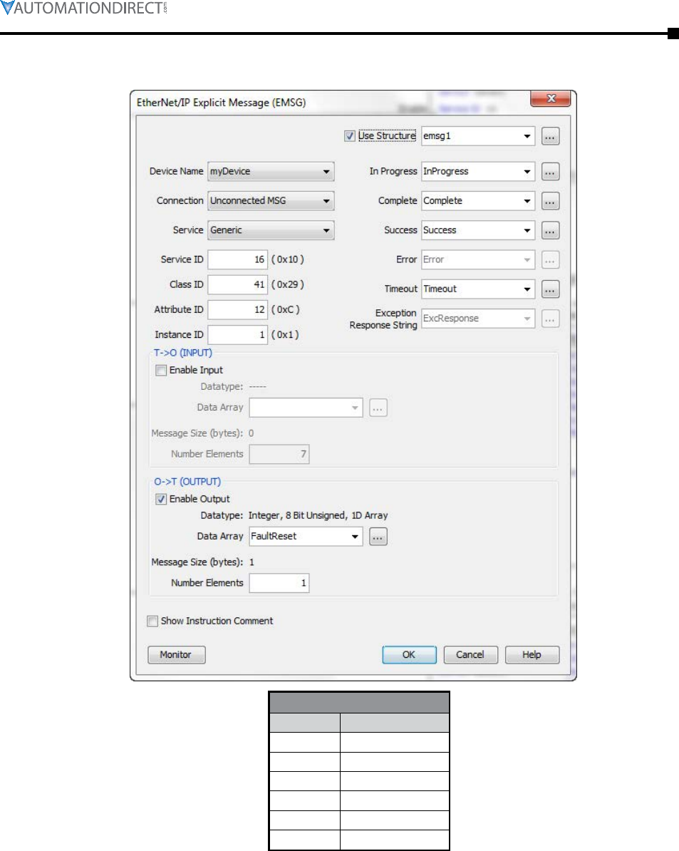
Chapter 5: Communications
Page 5–21Stellar® SR55 Series Soft Starter User Manual – 1st Ed. Rev.B – 02/02/2017
Drive State
1 Startup
2 Ready & Stopped
4 Running
5 Stopping
6 Fault Stop
7 Faulted

Page 5–22 Stellar® SR55 Series Soft Starter User Manual – 1st Ed. Rev.B – 02/02/2017
Chapter 5: Communications
BLANK
PAG E

Page 6–1Stellar® SR55 Series Soft Starter User Manual – 1st Ed. Rev.B – 02/02/2017
Accessories 6
6
6
chApter
chApter
chApter
Table of ConTenTs
Optional Accessories. . . . . . . . . . . . . . . . . . . . . . . . . . . . . . . . 6–2
Finger Guards . . . . . . . . . . . . . . . . . . . . . . . . . . . . . . . . . . . . .6–2
Remote Touchscreen. . . . . . . . . . . . . . . . . . . . . . . . . . . . . . . . . .6–3
RJ45 to RJ12 Adapter . . . . . . . . . . . . . . . . . . . . . . . . . . . . . . . . .6–5
Serial Modbus Communication Splitter . . . . . . . . . . . . . . . . . . . . . . .6–5
Communication Modules . . . . . . . . . . . . . . . . . . . . . . . . . . . . . . .6–7
Replacement/Spare Parts . . . . . . . . . . . . . . . . . . . . . . . . . . . . 6–10
Replacement Cooling Fans . . . . . . . . . . . . . . . . . . . . . . . . . . . . . 6–11
Replacement Touchscreen. . . . . . . . . . . . . . . . . . . . . . . . . . . . . . 6–13
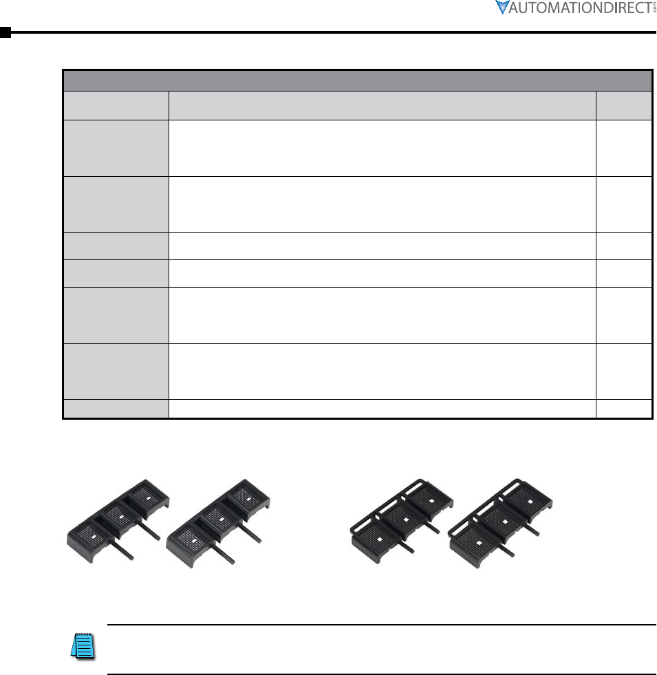
Page 6–2 Stellar® SR55 Series Soft Starter User Manual – 1st Ed. Rev.B – 02/02/2017
Chapter 6: Accessories
Optional Accessories
SR55 Optional Accessories
Part Number Description For SR555
Models
SR55-CM-ENETIP
EtherNet/IP communication module, optional, for Stellar SR55 series soft starters, dual
RJ45 communication ports, complete EtherNet/IP adapter, TCP/IP socket interface,
CIP parameter object support, explicit and implicit messaging (2 input words, 2 output
words), transformer isolated Ethernet interface, 10/100 Mbps full duplex.
all
SR55-CM-MODTCP
Modbus TCP communication module, optional, for Stellar SR55 series soft starters, dual
RJ45 communication ports, complete Modbus TCP server, up to 256 bytes of I/O data
in each direction, transformer isolated interface, 100 Mbps full duplex, TCP/IP socket
interface, capable of supporting 4 simultaneous (master) connections.
all
SR55-FG-1 Finger guards, optional, for size 1 Stellar SR55 series soft starter power terminals.
Provides IP20 protection rating. Package of 2.
-017 thru
-096
SR55-FG-2 Finger guards, optional, for size 2 Stellar SR55 series soft starter power terminals,
Provides IP20 protection rating. Package of 2.
-124 thru
-180
SR55-KPD-REM
Touchscreen, optional remote, for Stellar SR55 series soft starters. Used to remotely
monitor, configure, and control SR55 series units without opening enclosures. Rated for
IP55 enclosures, no external power wiring required. Includes 3m (9.8 ft.) Cat5e cable
and SR55-RJ45-RJ12 adapter.
all
SR55-SPLT
Serial Modbus communication splitter, optional, for Stellar SR55 series soft starters.
Used for creating a Modbus network with multiple SR55 series soft starters. Uses 3
serial RJ45 connectors for upstream/downstream connectivity and for connection to the
starter. Includes 3m (9.8 ft.) Cat5e cable and SR55-RJ45-RJ12 adapter.
all
SR55-RJ45-RJ12 RJ45 female to RJ12 male adapter, optional, for Stellar SR55 series soft starters. all
Finger Guards
SR55-FG-1 SR55-FG-2
Install these optional finger guards on the power-circuit line and load side power terminals to
provide IP20 protection for soft starter sizes SR55-180 and below (frame sizes 1 and 2).
The addition of optional finger guards to size 1 and size 2 SR55
soft starters adds approximately 14mm [0.5in] to the vertical
dimension, but does NOT change the clearance distance.
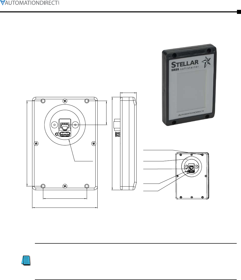
Chapter 6: Accessories
Page 6–3Stellar® SR55 Series Soft Starter User Manual – 1st Ed. Rev.B – 02/02/2017
Optional Accessories (continued)
Remote Touchscreen
SR55-KPD-REM
1.36
[34.5]
5.30
[134.0]
0.90
[23.5]
Neoprene Gasket
RJ45 Socket
(for connecting to
starter)
Reset Switch
USB Socket
(for firmware
updates only)
4x Mounting Holes
No.6 self tapping screws
or M3.5 Machine screws
Ø1.69
[Ø43.0]
Diameter hole
cut in panel
2.50
[63.0]
3.70
[94.0]
4.80
[123.0]
The optional remote touchscreen allows remote monitoring, configuration, and control of SR55
soft starters. Since the touchscreen is a master RS-485 device, it can control multiple SR55 soft
starters. Includes a 3m (9.8ft) Cat5e cable and an SR55-RJ45-RJ12 adapter cable.
How to connect and use remote touchscreen
The SR55-REM-KPD Remote Keypad is a Modbus master. If the Remote
Keypad is connected to an SR55, that starter will not be able to
communicate with a PLC or other 3rd party Modbus master (only one
master is allowed on a Modbus network). For similar reasons, the
Remote Keypad also cannot be used with the Modbus TCP or Ethernet
IP communication modules.
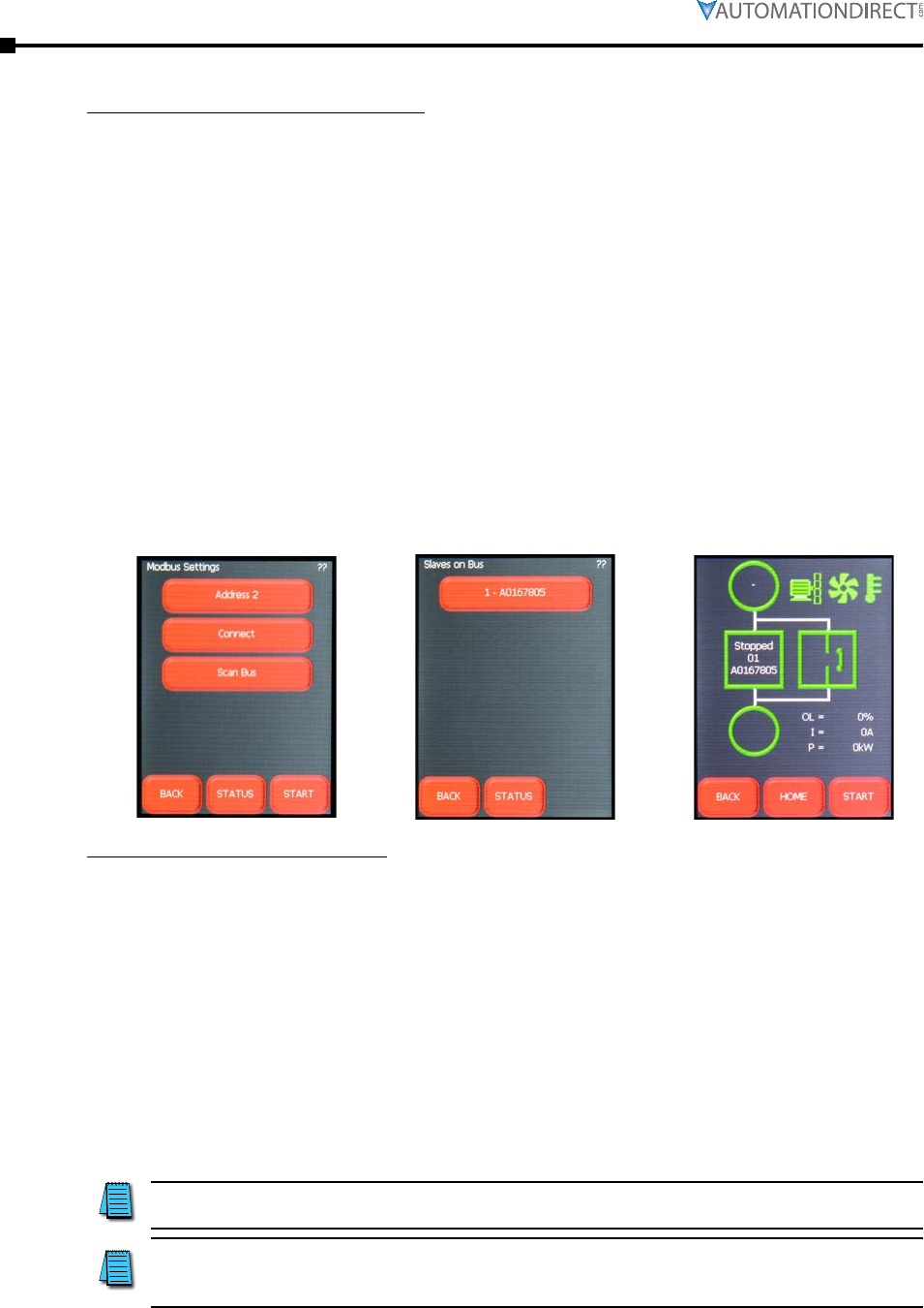
Page 6–4 Stellar® SR55 Series Soft Starter User Manual – 1st Ed. Rev.B – 02/02/2017
Chapter 6: Accessories
Optional Accessories (continued)
How to connect the remote touchscreen
• Ensure starter’s Modbus Network Settings are: Even parity and 19200 baud rate. If
connecting to multiple starters, set the Address to a unique number for each SR55 starter.
• If remote touchscreen start/stop control is desired, set the Control Method to Modbus
Control. If the remote touchscreen will only be used for monitoring or configuration
(digital input or local touchscreen start/stop control will be used), select the appropriate
setting (Local Touchscreen, User Programmable, 2-wire control, or 3-wire control).
• Connect remote touchscreen using the SR55-RJ45-RJ12 adapter and a standard Ethernet
patch cable. If connecting to multiple starters, a Modbus splitter (SR55-SPLT) will be
required for each starter.
• On the remote touchscreen go to Modbus Network Settings as shown in Fig 1. and select
Scan Bus. This will show all the SR55 starters on the bus Fig 2. Select which starter you
wish to connect to.
• Alternatively you can select the Address number and then select Connect to connect to that
particular starter.
• The status screen Fig 3 on the remote touchscreen will display the current starter it is
connected to by displaying the starter’s node address and serial number (EX: address 01 and
serial number A0167805)
Fig 1 Fig 2 Fig 3
How to use the remote touchscreen
• The remote touchscreen’s control for starting and stopping overrides the starter’s onboard
touchscreen when the starter’s Control Method is set to Modbus Control. Menu navigation,
configuration, and monitoring are still possible on the starter’s touchscreen.
• Press the starter icon box on the Status screen of the remote touchscreen to change to
another starter if controlling multiple starters from one remote touchscreen.
• When using the remote touchscreen for start/stop control the remote touchscreen has
full control, configuration, and monitoring capabilities, while the local touchscreen on the
starter only has configuration and monitoring capabilities. Digital outputs always function
as programmed, regardless of Control Mode. Digital inputs are disabled during Modbus
Control and Keypad Control Modes, but are active during all other Control Modes.
• The remote touchscreen can be used for monitoring and configuration during any other
control method besides Modbus Control.
The remote touchscreen cannot be used with a communication module
installed (SR55-CM-ENETIP or SR55-CM-MODTCP).
The remote touchscreen is a Modbus RTU master device. A PLC, HMI,
or other Modbus Master device cannot be used on the same network
while the remote touchscreen is connected.
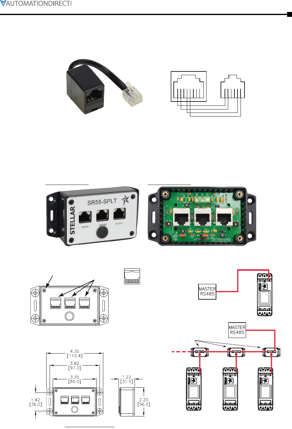
Chapter 6: Accessories
Page 6–5Stellar® SR55 Series Soft Starter User Manual – 1st Ed. Rev.B – 02/02/2017
Optional Accessories (continued)
RJ45 to RJ12 Adapter
SR55-RJ45-RJ12
Splitter End
RJ45 Socket
81524673
Star
ter End
RJ12 Plug
16
5324
SR55-RJ45-RJ12
This adapter allows connection of the Remote Touchscreen, Modbus Splitter, or other Modbus
master to the SR55 soft starter. The adapter plugs directly into the RJ12 port on top of the SR55,
and provides a receptacle for a communication cable with an RJ45 connector.
Serial Modbus Communication Splitter
SR55-SPLT
With front cover on
With front cover off
(4) screws to remove
front cover to access
congration jumpers
RJ45 ports
SR55-SPLT
8 1
1 = n/c
2 = n/c
3 = n/c
4 = TXD1-B
5 = TXD0-A
6 = n/c
7 = 24VDC
8 = GND
Pin-out same
for all 3 ports:
Dimensions = in [mm]
SR55-xxx
SR55-SPLT
SR55-xxx SR55-xxxSR55-xxx
Single SR55 RS-485 network
(SR55-SPLT optional)
Multiple SR55 RS-485 network
(one SR55-SPLT per starter
recommended)

Page 6–6 Stellar® SR55 Series Soft Starter User Manual – 1st Ed. Rev.B – 02/02/2017
Chapter 6: Accessories
Serial Modbus Communication Splitter – Optional Accessories (continued)
The Modus splitter allows for multiple SR55 soft starters to be connected to a Modbus RTU
network over RS-485. The splitter allows for the interconnections to be made with standard RJ45
Ethernet patch cables from splitter to splitter. The splitter can then be connected to the starter’s
RJ12 port with a standard Ethernet patch cable and an SR55-RJ45-RJ12 adapter (included). The
maximum length the network can be is 4000 feet total and a maximum of 31 starters.
If the SR55-KPD-REM optional remote touchscreen is to be the master, then set each starter to a
unique Modbus address (1-31). If another device such as a PLC is to be the master, then set each
starter to a unique Modbus address (2-31).
All three RJ45 ports on the SR55-SPLT are not interchangeable as far as functionality. The
differences are described below along with the BAG terminating strip (located inside the
SR55-SPLT).
• The RJ45 port on the right must go to the Modbus master (remote touchscreen or PLC).
This is only for the first splitter on the network. For all other splitters on the network this
port will be the connection point from the previous splitter.
• The middle RJ45 port connects to the starter using a standard RJ45 Ethernet patch cord and
an SR55-RJ45-RJ12 adapter.
• The RJ45 port on the left connects to the next splitter on the network. If this is the last
splitter on the network then leave this port unconnected.
• The three terminals B, A, and G inside the splitter are for wiring to a third party Modbus
RTU slave device. These terminals are simply TDX00-A and TDX01-B signal lines +
Ground. Use BAG term strip or the middle RJ45 connector; do not use both.
Inside the splitter there are multiple jumpers that need to be configured before the splitter will
function properly. Access these jumpers by removing the front cover, which is attached with four
screws.
• Jumper S6
For the first splitter on the network, jumper S6 inside the box must be connected if using the
SR55-KPD-REM. Jumper S6 provides 24VDC to the touchscreen for power. Do not connect
jumper S6 if using a different master as this could damage the master. Do not connect S6 for
all other splitters on the network, only the first one.
• Jumper S9
Connect jumper S9 on the last splitter on the network. This puts in a 120 Ohm terminating
resistor.
• No other jumper needs to be configured and should not be reconfigured. For reference, the
default settings for the remaining jumpers are:
S1 = open
S2 = open
S3 = closed
S4 = closed
S5 = closed
S7 = closed
S8 = open
S10 = open
S11 = closed
All three RJ45 ports have the same pin layout. (Pins 1, 2, 3, and 6 are not used.)
• Pin 4: TXD1-A
• Pin 5: TXD0B
• Pin 7: 24VDC (when jumper S6 is connected)
• Pin 8: GND
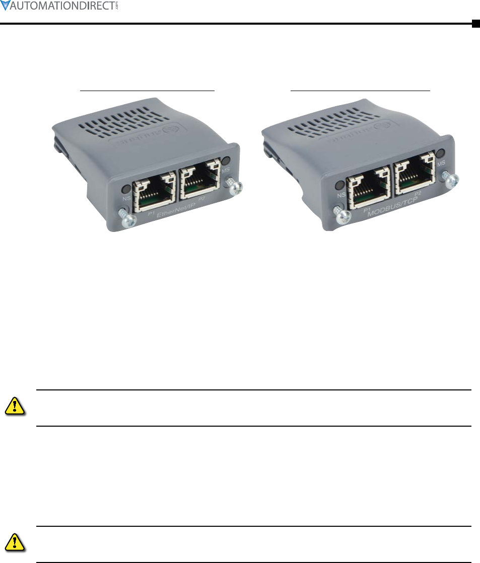
Chapter 6: Accessories
Page 6–7Stellar® SR55 Series Soft Starter User Manual – 1st Ed. Rev.B – 02/02/2017
Optional Accessories (continued)
Communication Modules
SR55-CM-ENETIP
EtherNet/IP Communication Module
SR55-CM-MODTCP
Modbus TCP Communication Module
EtherNet/IP Communication Module
The EtherNet/IP interface is intended to be installed in the SR55 option slot, and allows the SR55
to be connected to an EtherNet/IP network. The interface offers the following functionality:
• CIP Parameter Object Support
• 2 Input Words from the network master to SR55
• 2 Output Words from SR55 to the network master
Refer to “Configuration and Parameters” Chapter 3 and “Communications” Chapter 5 of this user
manual for detailed parameter and EtherNet/IP network communications information.
Refer to the installation instructions in the following section. Great
care must be taken when inserting the communication module into the
SR55.
Modbus TCP Communication Module
Allows an SR55 soft starter to be connected to a Modbus TCP network using TCP/IP protocol.
Refer to “Configuration and Parameters” Chapter 3 and “Communications” Chapter 5 of this user
manual for detailed parameter and Modbus addressing information. (Modbus TCP uses the same
parameters and addresses as does serial Modbus.).
Refer to the installation instructions in the following section. Great
care must be taken when inserting the communication module into the
SR55.
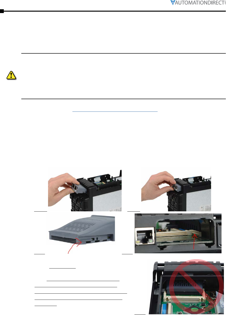
Page 6–8 Stellar® SR55 Series Soft Starter User Manual – 1st Ed. Rev.B – 02/02/2017
Chapter 6: Accessories
Optional Accessories (continued)
Communication Module Installation Instructions
The following installation instructions apply to both network communication modules:
• EtherNet/IP Communication Module SR55-CM-ENETIP
• Modbus TCP Communication Module SR55-CM-MODTCP
These option modules are specifically designed to be used with the
SR55 range of soft-start products, and are intended for professional
incorporation into complete equipment or systems. Incorrect
installation may present a safety hazard. Before commencing
installation and commissioning, the user should ensure that they are
fully familiar with the SR55 unit, and in particular have read the
important safety information and warnings contained in this SR55 User
Manual.
Instructional Video
https://www.youtube.com/watch?v=ybqj_hwGrm8
Written Instructions
1) Ensure that all power is removed from the SR55 soft starter prior to installing the option
module.
2) Remove the blanking plate from the SR55 option module slot.
3) Carefully slide the communication module into the SR55’s communication slot applying
slight downward force and forward pitch as shown in Fig 1a and Fig 1b in order to ensure
the guide channels on the communication module Fig 2 align to the guide rails in the starter
Fig 3.
Fig.1a Fig.1b
Fig.2 Fig.3
4) An image of the starter taken apart is
shown for reference of how the module fits
into these guide rails, see fig 4. Please
note: This view cannot be accessed on a
purchased SR55 unit. This picture was
taken on a unit that was taken apart beyond
repair for the purposes of illustrating this
procedure.
Fig.4
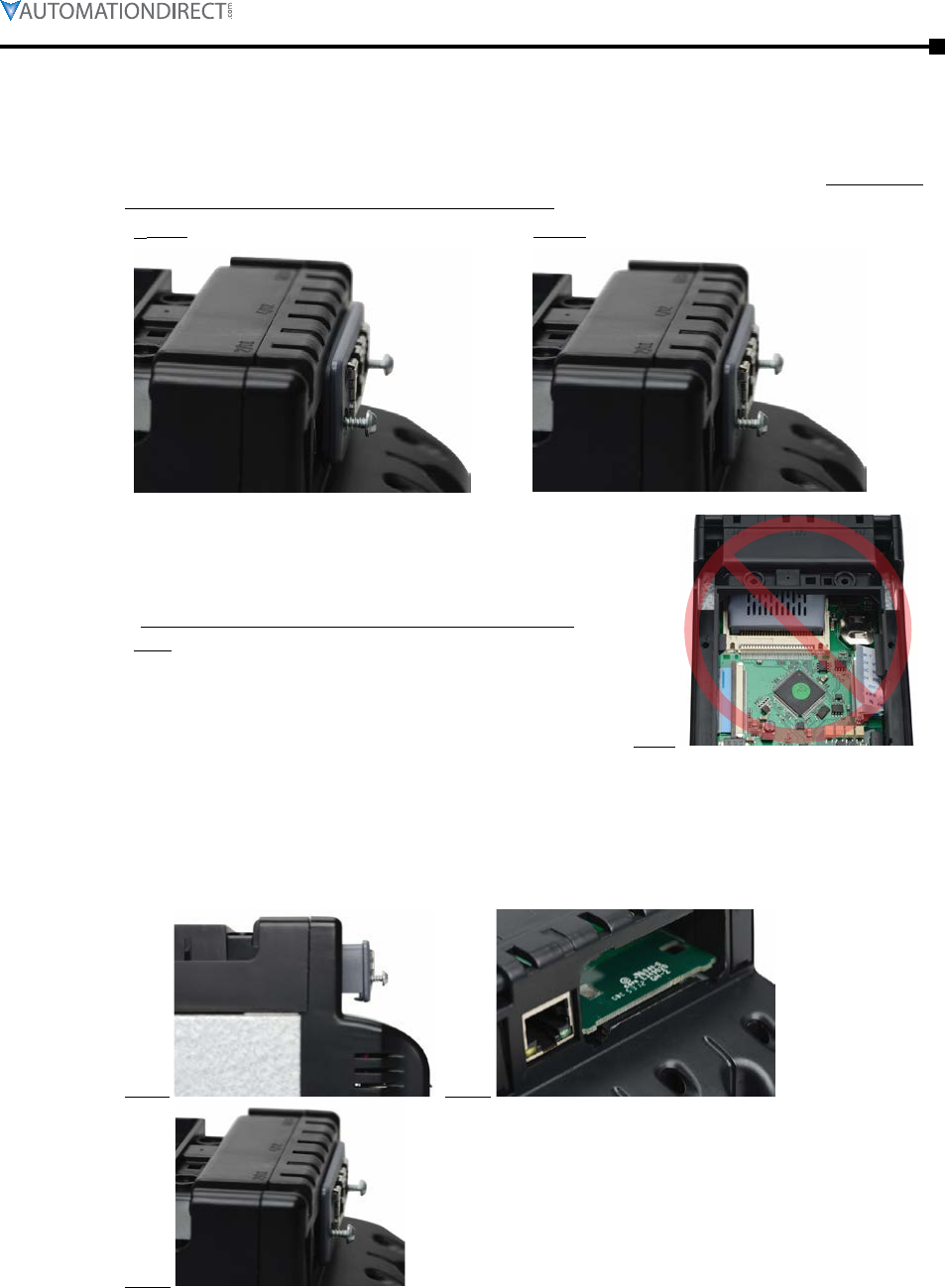
Chapter 6: Accessories
Page 6–9Stellar® SR55 Series Soft Starter User Manual – 1st Ed. Rev.B – 02/02/2017
Communication Module Installation Instructions – Optional Accessories (continued)
5) After the module has been pushed in, the module may feel like it has been seated but may
not have. Fig 5a shows a module that may appear to be seated but is not, notice the slight
gap between the module flange and the SR55 chassis. Fig 5b shows the properly seated
module. Fig 6 shows the pins not fully engaged in this same unseated module. (Fig 6 view
is from a disassembled SR55; for reference only.)
Fig.5a (not seated) Fig.5b (seated properly)
Fig.6
(Fig 6 view is from a disassembled SR55; for reference
only.)
6) This is caused by the two plastic clips on the bottom side of the module shown in fig 7 and
are responsible for holding the module firmly to the printed circuit board once installed.
These clips can get caught on the printed circuit board (Fig 8). To be seated properly and
fully engaged, the module will need to be pushed down in order to have the clips snap
around the printed circuit board. Figure 9 shows a properly seated and engaged module on
the SR55.
Fig.7 Fig.8
Fig.9
7) Tighten the two screws on the option module using a T9 torx driver to secure it in place.
8) The SR55 will automatically configure upon its next power-up after the option module is
installed.
Page 6–10 Stellar® SR55 Series Soft Starter User Manual – 1st Ed. Rev.B – 02/02/2017
Chapter 6: Accessories
Replacement/Spare Parts
SR55 Replacement Parts *
Part Number Description For SR555
Models
SR55-FAN-2 (1) Cooling fan, replacement, for size 1 Stellar SR55 series soft starters, 60 x 60 x 15 mm -017 thru -096
SR55-FAN-3 (1) Cooling fan, replacement, for size 2 Stellar SR55 series soft starters, 80 x 80 x 15 mm -124
SR55-FAN-6 (1) Cooling fan, replacement, for size 2 Stellar SR55 series soft starters, 80 x 80 x 20 mm -156 thru -180
SR55-FAN-7 (1)(2) Cooling fan, replacement, for size 3 Stellar SR55 series soft starters, 120 x 120 x 25 mm -242 thru -361
SR55-FAN-8 (3) Cooling fan, replacement, for size 3 Stellar SR55 series soft starters, 171 x 151 x 151 mm -414 thru -477
SR55-KPD Touchscreen, replacement, for Stellar SR55 series soft starters all
* These items are exact replacements for the comparable part that is originally installed on the applicable SR55.
(1) All fans (except SR55-FAN-8) come with 3 butt-splice terminals. If replacement terminals are needed, they can be
purchased from a third party distributor. PN: UY2; MFG: 3M.
(2) SR55-FAN-7 also comes with 4 push rivets. If replacement rivets are needed, they can be purchased from a third
party distributor. PN:SR-4070B; MFG: Essentra Components.
(3) SR55-FAN-8 uses 1/8” quick-connect terminals.
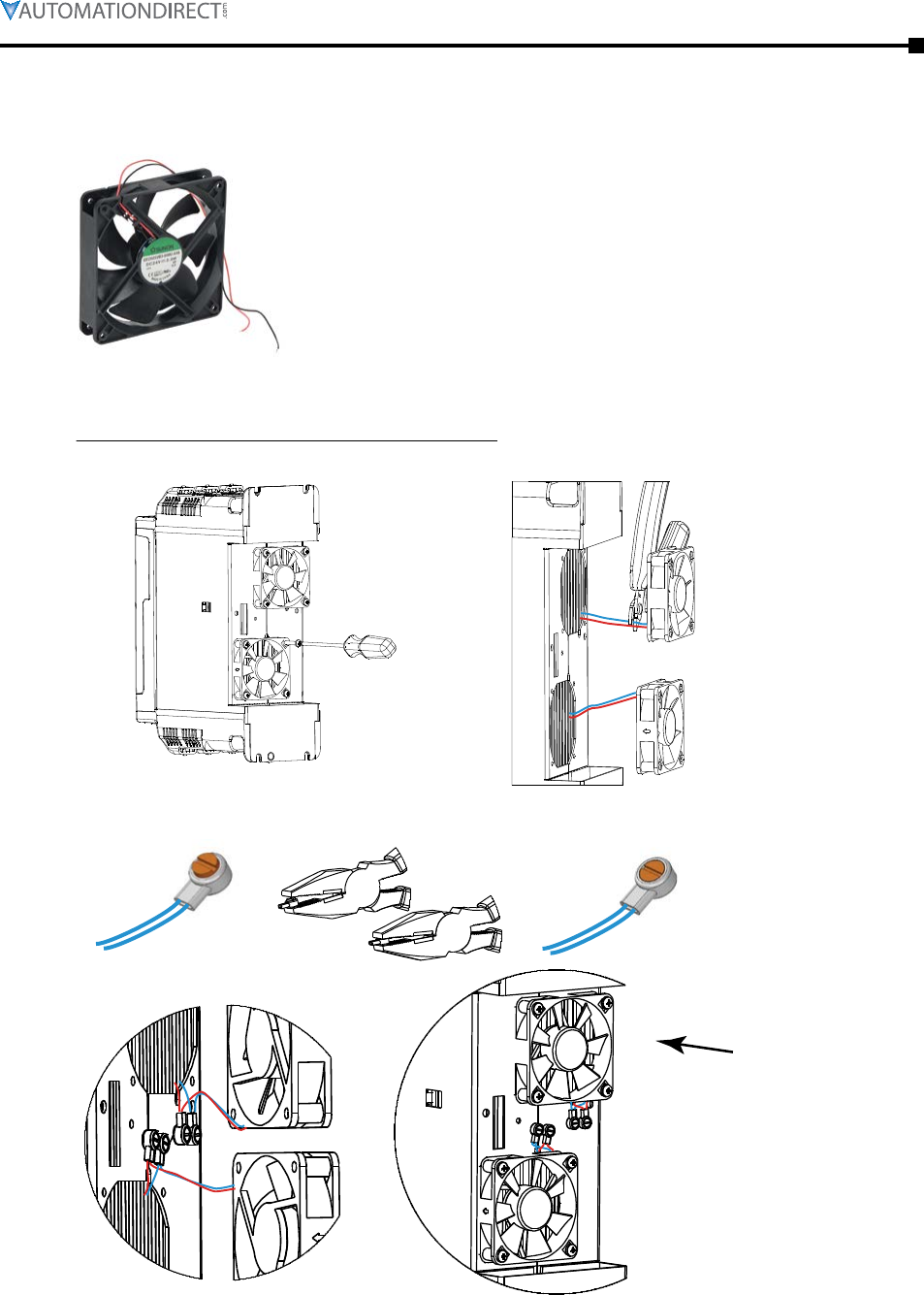
Chapter 6: Accessories
Page 6–11Stellar® SR55 Series Soft Starter User Manual – 1st Ed. Rev.B – 02/02/2017
Replacement Cooling Fans
These cooling fans are exact replacements for the fans that are originally installed on the
applicable SR55.
The fans normally run during the following conditions:
1) During the Ramp and Dwell periods.
(Will continue running if heatsink temperature meets criteria #3)
2) During Stop.
(Will continue running if heatsink temperature meets criteria #3)
3) If heatsink temperature >45°C [113°F].
(Turns off when temperature <39°C [102°F])
Fan Replacement Instructions for soft starters SR55-017 through SR55-361
1) Unscrew existing fan(s).* 2) Cut wires close to fan(s).
Fan Replacement Instructions for SR55-FAN-2, -3, -6, -7
3) Fit blue wires from new fan and
SR55 into connector (included). 4) Push connector
shut with pliers. 5) Repeat with 2nd pair of blue,
then 2 pairs of red wires.
6) Position fan(s) and connectors.*
7) Fix new fan(s)
to SR55.*
Air ow
direction
* Soft starters SR55-242, -302, and -361 have metal fan guards tted for safety reasons.
These must be removed before the fans can be taken o, and they MUST be retted
using the supplied push rivets after the new fans have been attached.
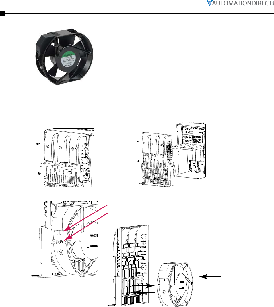
Page 6–12 Stellar® SR55 Series Soft Starter User Manual – 1st Ed. Rev.B – 02/02/2017
Chapter 6: Accessories
Replacement/Spare Parts (continued)
Fan Replacement Instructions for soft starters SR55-414 and SR55-477
1) Remove 4 screws from
lower end molding. 2) Slide lower end molding
o of busbars.
Fan Replacement Instructions for SR55-FAN-8
3) Pull wires o of connectors.
4) Fans held with M4 screws in 2 positions.
5) Remove old fan.
7) Reassemble in reverse order. (Orientation of wires is not critical.)
6) Fit new fan.
Air ow
direction
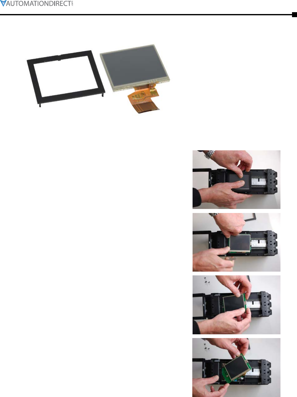
Chapter 6: Accessories
Page 6–13Stellar® SR55 Series Soft Starter User Manual – 1st Ed. Rev.B – 02/02/2017
Replacement/Spare Parts (continued)
Replacement Touchscreen
These touchscreens are exact replacements for the touchscreens that are originally installed on the
SR55 soft starters.
Touchscreen Replacement/Installation Instructions
1) Carefully remove the outer bevel casing around
the LCD display.
2) Remove the two plastic rivets below the LCD
display. Use a small screwdriver to pry the rivets
out.
3) When removing the LCD display and PCB,
slowly lift from the top left corner.
4) Gently remove the LCD and PCB at an angle, so
they can be lifted from the unit. Take care not to
apply excessive force.
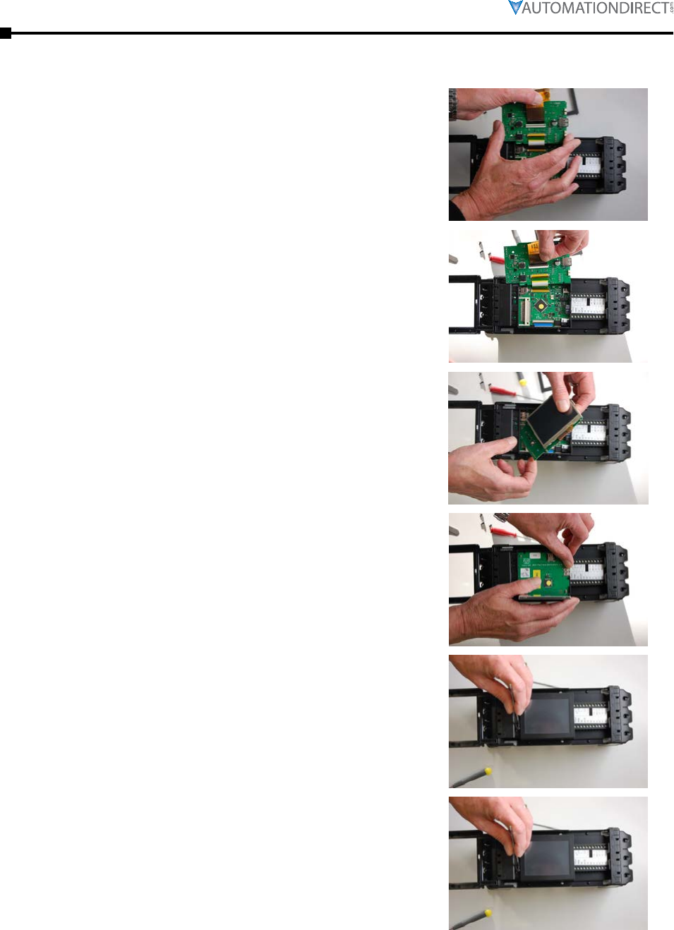
Page 6–14 Stellar® SR55 Series Soft Starter User Manual – 1st Ed. Rev.B – 02/02/2017
Chapter 6: Accessories
Replacement/Spare Parts (continued)
Touchscreen Replacement/Installation Instructions (continued)
5) On the reverse side of the PCB, remove the FFC
cable from the socket (lift gray part from front
edge; do not force.)
6) Place the replacement screen FFC cable in
socket, making sure that it is correctly seated.
Push the gray part down to lock.
7) Once the socket is locked with the FFC cable
firmly connected, gently place the board back in
to the previous position, using the same angled
technique.
8) Place the PCB flat in position.
9) Make sure that the screen is correctly aligned,
and place the outer bevel back on the LCD
display.
10) Once you have placed the outer bevel back
on the LCD display, ensure that the two plastic
rivets below the LCD display are re-installed.

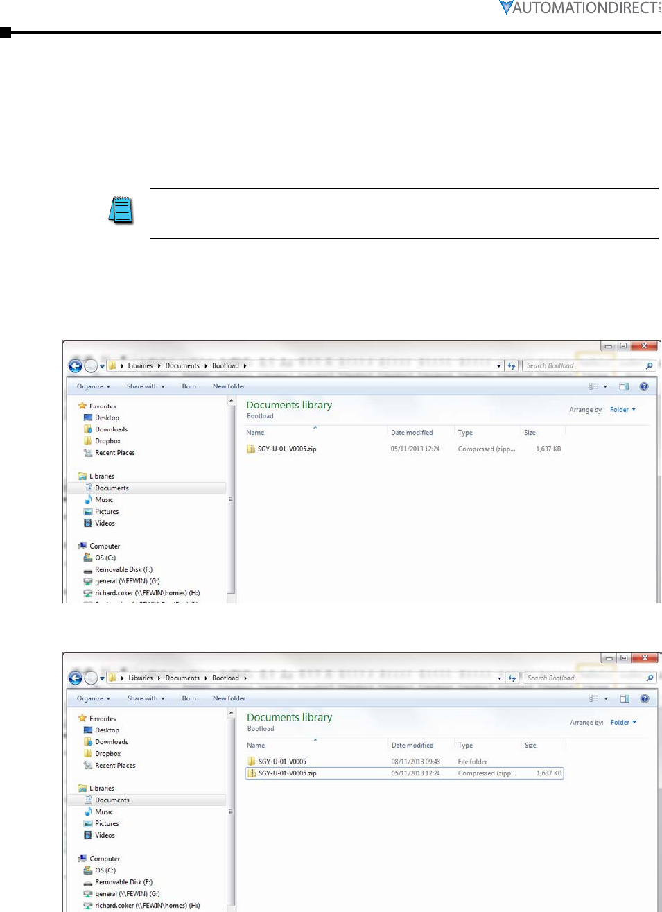
Page A–2 Stellar® SR55 Series Soft Starter User Manual – 1st Ed. Rev.B – 02/02/2017
Appendix A: Updating Firmware
Updating SR55 Firmware
Firmware updates are normally not necessary for the SR55 family of soft starters. If, after talking
with AutomationDirect Technical Support, it is determined that your SR55 requires a firmware
update, please follow the procedure outlined below. It is advised to save your configuration
profile to a USB before updating firmware (Home → Device → Parameters to USB).
Instructions for updating the firmware of an SR55 soft starter.
1) Obtain a USB flash drive, and ensure that it has been formatted to FAT32.
ADC part number USB-FLASH is a 4GB SanDisk USB flash drive
that has been verified to work with the SR55. Other flash
drives may be too wide to fit, or may not perform correctly.
2) Download a new firmware zip file from the Technical Support Firmware Upgrades page of
the AutomationDirect web site:
(http://support.automationdirect.com/firmware/index.html).
3) Copy the zip file into a suitable location on your PC that you can extract all of the firmware
files.
4) Right click on the zip file and select extract all. This will create an unzipped directory in the
same location with the same name.
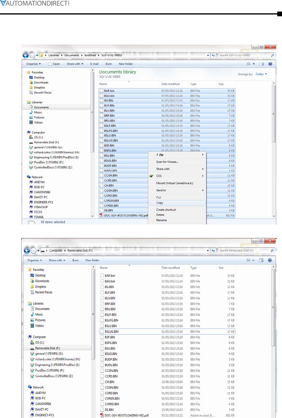
Appendix A: Updating Firmware
Page A–3Stellar® SR55 Series Soft Starter User Manual – 1st Ed. Rev.B – 02/02/2017
5) Double click on the new directory and inside you will see all of the boot-loading files. Select
all of these files and copy them onto the route directory of the USB flash drive.
Extracted Folder on PC
USB Flash Drive
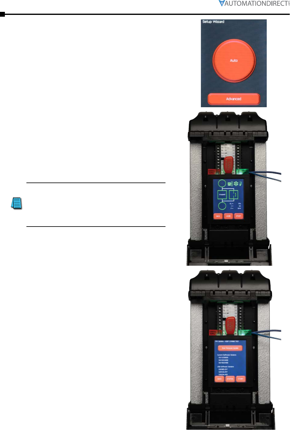
Page A–4 Stellar® SR55 Series Soft Starter User Manual – 1st Ed. Rev.B – 02/02/2017
Appendix A: Updating Firmware
6) If it is the first power-up, the SR55 will
display the “Automatic Set Up” screen. This
screen can be skipped when you plan to carry
out a firmware update. To do this, select
“Advanced,” then press back, and the status
screen will be displayed.
7) Insert the USB flash drive which contains the
new issue of the boot-load firmware into the
USB connector on the SR55. (The flash drive
is shown in red above the touchscreen.)
If using the remote touchscreen, you
will have to update the firmware on
that touchscreen also. Follow the
same procedure, but insert the USB
flash drive into the back of the
remote touchscreen.
8) Navigate through “Home,” “Device,” and
“Update Firmware” screens to get to the
firmware upgrade page. This page shows the
currently installed firmware, as well as the
firmware which is to be uploaded.
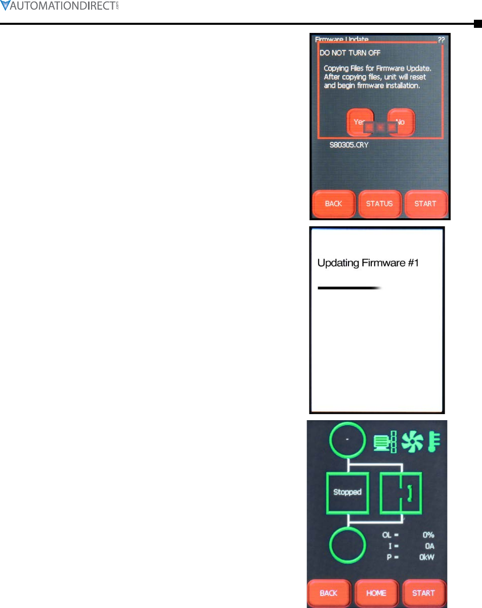
Appendix A: Updating Firmware
Page A–5Stellar® SR55 Series Soft Starter User Manual – 1st Ed. Rev.B – 02/02/2017
9) Once “Update Firmware” and “Confirmation
to Update firmware” has been selected, a
loading bar will appear which shows the
update process has begun.
10) Wait for approximately one minute for the
updating firmware screen to be displayed.
This screen shows the progress of the firmware
being installed on the SR55. There are three
stages of installation.
11) Once the updating process is complete, the
SR55 will reboot. When it has fully rebooted
the status screen will appear.

Page A–6 Stellar® SR55 Series Soft Starter User Manual – 1st Ed. Rev.B – 02/02/2017
Appendix A: Updating Firmware
BLANK
PAG E

Page B–1Stellar® SR55 Series Soft Starter User Manual – 1st Ed. Rev.B – 02/02/2017
Soft Starter application
conSiderationS B
B
B
appendix
appendix
appendix
Table of ConTenTs
B.1 – Motor Suitability and Associated Considerations . . . . . . . . . . . . . . . . . . . . . B–2
B.1.1 – Suitability . . . . . . . . . . . . . . . . . . . . . . . . . . . . . . . . . . . . . . . . . . . . B–2
B.1.2 – Induction Motor Characteristics. . . . . . . . . . . . . . . . . . . . . . . . . . . . . . . . . B–2
B.1.3 – Rating . . . . . . . . . . . . . . . . . . . . . . . . . . . . . . . . . . . . . . . . . . . . . . B–2
B.1.4 – Maximum Motor Cable Length . . . . . . . . . . . . . . . . . . . . . . . . . . . . . . . . . B–3
B.1.5 – Power Factor Correction Capacitors . . . . . . . . . . . . . . . . . . . . . . . . . . . . . . B–3
B.1.6 – Lightly Loaded Small Motors . . . . . . . . . . . . . . . . . . . . . . . . . . . . . . . . . . B–3
B.1.7 – Motors Installed with Integral Brakes. . . . . . . . . . . . . . . . . . . . . . . . . . . . . . B–3
B.1.8 – Older Motors . . . . . . . . . . . . . . . . . . . . . . . . . . . . . . . . . . . . . . . . . . . B–3
B.1.9 – Wound-rotor or Slip-ring Motors . . . . . . . . . . . . . . . . . . . . . . . . . . . . . . . . B–3
B.1.10 – Enclosures. . . . . . . . . . . . . . . . . . . . . . . . . . . . . . . . . . . . . . . . . . . . B–3
B.1.11 – Efficiency . . . . . . . . . . . . . . . . . . . . . . . . . . . . . . . . . . . . . . . . . . . . B–4
B.1.12 – High-Efficiency Motors . . . . . . . . . . . . . . . . . . . . . . . . . . . . . . . . . . . . . B–4
B.1.13 – EU Compliance with the EMC Directive . . . . . . . . . . . . . . . . . . . . . . . . . . . . B–4
B.1.14 – Fuses . . . . . . . . . . . . . . . . . . . . . . . . . . . . . . . . . . . . . . . . . . . . . . B–4
B.2 – Rules for Specific Applications . . . . . . . . . . . . . . . . . . . . . . . . . . . . . . . B–5
B.2.1 – In-Delta Operation . . . . . . . . . . . . . . . . . . . . . . . . . . . . . . . . . . . . . . . B–5
B.2.2 – High-Inertia Loads. . . . . . . . . . . . . . . . . . . . . . . . . . . . . . . . . . . . . . . . B–5
B.2.4 – Resistive Loads . . . . . . . . . . . . . . . . . . . . . . . . . . . . . . . . . . . . . . . . . . B–5
B.2.5 – Frequent Starting . . . . . . . . . . . . . . . . . . . . . . . . . . . . . . . . . . . . . . . . B–5
B.2.6 – Optimizing . . . . . . . . . . . . . . . . . . . . . . . . . . . . . . . . . . . . . . . . . . . . B–5
B.2.7 – Soft Stopping. . . . . . . . . . . . . . . . . . . . . . . . . . . . . . . . . . . . . . . . . . . B–6
B.2.9 – Replacement of Fluid Couplings . . . . . . . . . . . . . . . . . . . . . . . . . . . . . . . . B–6
B.2.12 – Overhauling Loads . . . . . . . . . . . . . . . . . . . . . . . . . . . . . . . . . . . . . . . B–6
B.2.13 – Application Table . . . . . . . . . . . . . . . . . . . . . . . . . . . . . . . . . . . . . . . . B–6
B.3 – Concepts and Principles of Fixed-Speed Induction Motor Starting and Control. . . . . B–8
B.3.1 – Introduction . . . . . . . . . . . . . . . . . . . . . . . . . . . . . . . . . . . . . . . . . . . B–8
B.3.2 – The Induction Motor . . . . . . . . . . . . . . . . . . . . . . . . . . . . . . . . . . . . . . . B–8
B.3.3 – Starting Induction Motors . . . . . . . . . . . . . . . . . . . . . . . . . . . . . . . . . . . B–10
B.3.4 – Electro-Mechanical Methods Of Starting . . . . . . . . . . . . . . . . . . . . . . . . . . . B–11
B.3.5 – The Semiconductor Motor Controller . . . . . . . . . . . . . . . . . . . . . . . . . . . . . B–12
B.3.6 – Running Induction Motors. . . . . . . . . . . . . . . . . . . . . . . . . . . . . . . . . . . B–13
B.3.7 – Reliability Considerations . . . . . . . . . . . . . . . . . . . . . . . . . . . . . . . . . . . B–14
Appendix B Glossary of Terms . . . . . . . . . . . . . . . . . . . . . . . . . . . . . . . . . B–15
Page B–2 Stellar® SR55 Series Soft Starter User Manual – 1st Ed. Rev.B – 02/02/2017
Appendix B: Soft Starter Application Considerations
B.1 – Motor Suitability and Associated Considerations
The SR55 Soft Starter is based on a series of microprocessor-based optimizing soft starters which
have been used world-wide in more than 100,000 critical and non-critical systems. Since 1983,
these soft starters have successfully operated with almost every type of load and environment
from the Antarctic to the jungle. The design has proven to be both reliable and adaptable, and
provides a powerful mechanism with which to control fixed-speed induction motors.
However, due to the intrinsic differences between electronic and electro-mechanical starting
systems, there are a number of simple rules and observations to follow when using the SR55 Soft
Starter. This section introduces guidelines for the user and those incorporating the unit as part of
their system design.
B.1.1 – Suitability
In principle, any three-phase induction motor can be started by a soft starter. Normally, the
breakaway torque of the load should be less than the full-load torque of the motor, unless a motor
with a high locked-rotor torque characteristic is employed. As a quick assessment, any load
which has a low or no-load start with a moderate starting time, or which can be started with a
star-delta (wye-delta) starter, auto transformer or other forms of reduced-voltage starting, can be
considered a potential application for a soft starter.
B.1.2 – Induction Motor Characteristics
Three-phase induction motors are required to provide sufficient torque to accelerate the motor
and its load from standstill to full speed, and to maintain full speed efficiently at all torque levels
up to the design full-load torque. Most modern three-phase induction motors have characteristics
that are wholly suitable for use with soft starters. However, the characteristics vary considerably
between different manufacturers and design types.
It is important that the motor is capable of providing sufficient torque to drive the load at all
speeds from standstill to rated speed, to enable the SR55 to function properly. It is particularly
important that the motor to be soft started does not have a low pull-up or saddle torque, or the
load may not be accelerated correctly.
The primary function of the soft starter is to act as a torque-regulating device. It cannot apply a
torque greater than that which the motor generates. For this reason, problematic applications for
which many different starting methods have been tried but failed may need analysis of the motor
or load performance before a soft starter can be successfully applied.
B.1.3 – Rating
For most applications, except high inertia loads, the starting demands and the inertia of the
rotating masses are small enough to be insignificant. This means that no special consideration
needs to be given to the rating of the soft starter, other than to ensure that it is equal or marginally
greater than the rated voltage and current of the controlled motor.
Alternatively, if the number of poles of the motor and the moments of inertia of the load (Jload)
and motor rotor (Jmotor) are known, a soft starter will be suitable if the figures comply with the
criteria given in the bottom row of Table B.1.3.
Table B.1.3
Number of Poles 2 4 6 8
Synchronous Speed (rpm @ 60 Hz) 3600 1800 1200 900
(Jload)/(Jmotor) less than 5 15 20 25
Section B.2.13 contains a table showing the more common applications.

Appendix B: Soft Starter Application Considerations
Page B–3Stellar® SR55 Series Soft Starter User Manual – 1st Ed. Rev.B – 02/02/2017
B.1.4 – Maximum Motor Cable Length
The length of the cable between the output terminals of the starter and the motor should not
normally be greater than 100 meters [328 ft].
B.1.5 – Power Factor Correction Capacitors
Power factor correction capacitors applied to a single motor must ALWAYS be connected by a
separate contactor placed on the SUPPLY side of the SR55 Soft Starter. Capacitors should be
switched into the circuit after top-of-ramp (full line voltage) is reached, and switched out of the
circuit before a stop is initiated.
It is important that any total system PFC scheme that automatically corrects for a range of
inductive loads is not operated in such a way as to leave it heavily over compensated since this
might introduce oscillations leading to damaging over-voltages.
B.1.6 – Lightly Loaded Small Motors
Lightly loaded small-sized (less than 2kW [2.7 hp]), star connected motors can produce high
voltages at the motor terminals when shut down by simply opening the line contactor. As these
voltages can damage the soft starter, it is safer to control the opening of the line contactor with the
soft starter run relay contacts.
B.1.7 – Motors Installed with Integral Brakes
Motors that include an integral, electrically operated brake internally connected to the motor input
terminals can only be soft started when the brake is re-connected to the supply through its own
contactor. (Do NOT soft start the brake.)
B.1.8 – Older Motors
The action of the fully-controlled soft starter introduces harmonic currents and voltages to the
motor. Therefore, it is important to ensure that the motor employs techniques such as rotor
skewing in its construction to suppress the effects of harmonic fluxes and avoid rough starting.
This is rarely a problem with modern motors, because nearly all motors designed in the last 20
years employ these techniques.
B.1.9 – Wound-rotor or Slip-ring Motors
Slip-ring induction motors ALWAYS need some resistance in the rotor circuit to ensure that
sufficient rotational torque is generated to overcome any alignment torque, which is present
at start-up. The resistance can be safely shorted out in the normal fashion with a contactor
controlled by the programmable relay set as ‘top-of-ramp’ contacts.
B.1.10 – Enclosures
Thyristors are not perfect conductors, and the passage of current through them causes heat
dissipation in the body of the soft starter, which in turn causes the heatsink temperature to
increase. As a guide, the heat generated is 1 watt/amp/phase, which equates to a dissipation of
30 watts from the heatsink for a line current of 10 amps. Therefore, all cabinets or enclosures
that house soft starters should have adequate ventilation. (For more detailed information, refer to
Chapter 1: Mechanical Installation.)

Page B–4 Stellar® SR55 Series Soft Starter User Manual – 1st Ed. Rev.B – 02/02/2017
Appendix B: Soft Starter Application Considerations
B.1.11 – Efficiency
Although the use of the soft starter introduces a power loss, the system still retains an overall
efficiency of approximately 99.5%. If the iERS function is selected, then the gain in motor
efficiency at partial loads is far greater than the loss of efficiency arising from thyristor heat
losses. If prolonged operation at full load is expected, the thyristor loss can be eliminated (as in
some matched motor/pump drives) by closing the internal bypass contactor around the thyristors.
(SR55 soft starters have an internal bypass contactor that is automatically activated when at full
load when iERS is turned on.)
B.1.12 – High-Efficiency Motors
Due to an inherently steep front to the speed/torque curve, high-efficiency motors can exhibit
instability when lightly loaded, and the iERS parameter group may need to be adjusted to
compensate.
B.1.13 – EU Compliance with the EMC Directive
When considering the use or fitting of any Soft Starter, users and installers in European countries
must comply with the EMC Directive 2004/108/EC. The manufacturer of the soft starter has a
statutory obligation to provide a guide for compliance with this directive.
For the SR55, this guidance is given in the EMC guide, which is Appendix C of this user manual.
It is essential that users and installers understand and comply with the requirements described in
these sections.
B.1.14 – Fuses
Circuit protection fuses should be rated to allow for the extended start times associated with the
use of a Soft Starter. Traditional HRC motor fuses may need to be rated higher than the motor
rated current for normal low-inertia applications, but modern “extended start” fuses will generally
give full motor protection. (See also section B.2.2 relating to high inertia loads.)
Semiconductor fuses are available for the short-circuit protection of the thyristors in the SR55.
See the “Fuse and Current Ratings” section in chapter 2 (“Electrical Installation”) of this manual
for semiconductor fuse recommendations and details of the Overload incorporated into the SR55.

Appendix B: Soft Starter Application Considerations
Page B–5Stellar® SR55 Series Soft Starter User Manual – 1st Ed. Rev.B – 02/02/2017
B.2 – Rules for Specific Applications
B.2.1 – In-Delta Operation
The SR55 control system allows the soft starter to be installed “in the delta” connections of
the motor, which can permit the use of a lower current rated unit. However, in this mode of
operation it is important that the soft starter is connected in accordance with the relevant wiring
diagram. The power-circuit wiring diagram in Chapter 2, “Electrical Installation” gives detailed
instructions for this configuration. If motor rotation is incorrect, the connections should be
changed as described in the diagram. It should be noted that six connections are required between
the motor and soft starter. The “Firing Mode” parameter must be set for delta mode, which also
disables iERS (Chapter 3: Configuration and Parameters). For SR55 soft starters, an in-line
isolation contactor controlled by the soft starter MUST be used with the In-Delta Firing Mode and
motor connections.
B.2.2 – High-Inertia Loads
High-inertia loads, such as centrifugal and axial fans, grinders, flywheel presses, etc., may require
a larger size soft starter than the motor. For example, a 75kW [100 hp] starter may be needed for
a 55kW [75 hp] motor. This is necessary to allow for the extra heating effects of the prolonged
over-current on the soft starter thyristors during the extended starting time. If very high-inertia
loads are involved, then an analysis of the starting characteristics should be made. This requires
accurate data about the motor and the load:
• Complete motor data: Current, Voltage, Power, Speed, Rotor Inertia, Speed/Torque/
Current curves.
• Complete load data: Type of load, Speed, Inertia, Speed/Torque curve, Power absorbed or
Full-load Torque.
Consideration must also be given to thermal overload and fuse protection systems when extended
start times are involved. This is the case for heavy duty starting, as a standard thermal overload
will trip under these conditions. A heavy-duty start thermal overload or an electronic overload
with dual settings for start and run is recommended. Modern HRC motor fuses will allow
for some overload during the start, but the fuse curve, giving time/current data, will give an
indication of suitability for the particular application.
B.2.4 – Resistive Loads
AutomationDirect does not support the control of resistive loads with the SR55 Soft Starter.
B.2.5 – Frequent Starting
High starting frequencies require careful consideration of the soft starter thermal capabilities. In
many cases a standard sized SR55 may be suitable, as start times are generally shorter for this
type of application. If this is not the case, then a larger soft starter may be required.
B.2.6 – Optimizing
Drives which operate for long periods of time at less than their rated capacity can benefit from the
energy saving function (iERS optimizing) of the SR55, which adjusts the thyristor triggering to
reduce the excitation losses of the motor. This feature will lower the running temperature of the
machine and help to extend its life. See Chapter 4, Principles of the Energy Saving Mode (iERS).

Page B–6 Stellar® SR55 Series Soft Starter User Manual – 1st Ed. Rev.B – 02/02/2017
Appendix B: Soft Starter Application Considerations
B.2.7 – Soft Stopping
Soft stopping can reduce positive surge pressures in pipelines on shutdown. It is necessary to
make sure that the ramp-down time is long enough to remove the energy from the fluid before
the firing of the thyristors is stopped. Otherwise the surge pressure may still be present. Soft
stopping can also be successfully applied to loads such as conveyor belt systems where sensitive
items such as bottles are being transported.
B.2.9 – Replacement of Fluid Couplings
Soft-starters can replace fluid couplings yielding benefits of higher efficiency running and lower
costs to the user. If the coupling is used to magnify the available breakaway torque, it may be
necessary to replace the installed motor with another of a larger size, or one with a high starting
torque characteristic before a soft starter can be employed.
B.2.12 – Overhauling Loads
Certain applications can overspeed the motor as part of normal operation. Power then flows
from the motor to the power supply. It is important to disable the iERS optimizing mode during
over-speed conditions, and reinstate the optimizing mode during normal conditions. (External
control or communication is required to disable and reinstate iERS.)
B.2.13 – Application Table
The table on the following page shows many common motor applications that suit the SR55
soft starter. It lists typical breakaway torque requirements as a percentage of motor full-load
torque (FLT). For the most satisfactory soft starter in a given application, the motor should have
a full-voltage locked-rotor-torque (LRT) that is at least twice the breakaway torque (e.g. for a
reciprocating compressor the FLT is normally in the region of 50% motor LRT.) As a general
rule, the higher the motor LRT is above the load breakaway torque, the greater the control over
the starting process.

Appendix B: Soft Starter Application Considerations
Page B–7Stellar® SR55 Series Soft Starter User Manual – 1st Ed. Rev.B – 02/02/2017
B.2.13 – Application Table (continued)
Table B.2.13 – Applications
Application
Breakaway
Torque
(%FLT)
Remarks
Agitator 35 –
Air compressor- rotary, unloaded start 25–35 –
Air compressor- reciprocating, unloaded start 50–100 –
Air compressor- screw type, unloaded start 30 Usually two-pole motor
Ball mill 30–50 Eccentric load, needs high starting torque motor
Carding machine 100 Often high inertia
Centrifuge 50–90 Usually high inertia
Centrifugal fan- dampers closed 10–25 Usually high inertia
Centrifugal fan- dampers open 10–25 Usually high inertia, very long ramp times
Centrifugal blower- valve closed 25–35 –
Centrifugal blower- valve open 30–40 Can have long ramp time
Conveyor- horizontal, unloaded 10–50 –
Conveyor- horizontal, loaded 100–150 –
Conveyor- vertical lifting, unloaded 50–85 –
Conveyor- vertical lifting, loaded 100–175 –
Conveyor- vertical lowering, unloaded 10–40 –
Conveyor- vertical lowering, loaded 10–25 –
Crusher (not rock)- unloaded 25–75 Can be high inertia
Drilling machine- unloaded 10 –
Fan, axial-flow propeller 20–40 –
Feeder- screw 100–175 Needs high starting torque motor
Feeder- vibrating, motor driven 100–150 Needs high starting torque motor
Grinder- unloaded 10–25 Usually high inertia
Hammer mill 20–125 Eccentric load, needs high starting torque motor
Mills- flour etc. 30–50 –
Mixer- dry contents 35–75 –
Mixer- fluid contents 10–40 –
Mixer- plastic contents 75–125 High torque motor offers advantage
Mixer- powder contents 75–125 High torque motor offers advantage
Pelletizers 50–100 –
Press, flywheel 50–150 Needs high starting torque motor
Pump- centrifugal 10–25 Soft stopping useful
Pump- positive displacement, piston type 100–175 Needs high starting torque motor
Pump- vane type, positive displacement 100–150 Needs high starting torque motor
Rolling mill 30–50 –
Saw, band 10–35 –
Saw, circular 25–50 May be high inertia; Plug brake may be useful
Screen, vibrating 30–60 –
Transformers, voltage regulators Nil Change firing mode
Tumblers 30–100 Can be eccentric load, may need high torque motor

Page B–8 Stellar® SR55 Series Soft Starter User Manual – 1st Ed. Rev.B – 02/02/2017
Appendix B: Soft Starter Application Considerations
B.3 – Concepts and Principles of Fixed-Speed Induction Motor Starting
and Control
Since its invention one hundred years ago, the standard three-phase induction motor has become
one of the most familiar items of industrial equipment ever known. Due to its simplicity of
construction, low cost, reliability, and relatively high efficiency, it is likely to remain the prime
source of mechanical energy for the foreseeable future.
B.3.1 – Introduction
Energy conversion, from the electrical supply to rotating mechanical energy, is a characteristic
of all motors. To regulate energy flow, most motor circuits require a mechanism to connect
and disconnect them from their electrical power source. Electro-mechanical switches, known
as “contactors,” are the standard means of achieving this control. Even today, more than one
hundred years after their introduction, contactor-based systems remain the most widely used
method of motor control.
Nevertheless, there is a definite trend towards more sophisticated electronic systems of control
being applied to fixed-speed motor drives. This section will discuss these forms of control;
namely electronic microprocessor-controlled optimizing soft starters such as the SR55.
B.3.2 – The Induction Motor
In order to appreciate the benefits of using an electronic controller, it is important to have
some understanding of the characteristics and limitations of the induction motor and the
electro-mechanical systems currently used to control them.
The standard, fixed-speed induction motor fulfills two basic requirements:
• To accelerate itself and its load to full speed (or speeds with multi-speed motors).
• To maintain the load at full speed efficiently and effectively over the full range of loadings.
Due to the constraints of materials and design, it can be difficult to achieve both objectives
effectively and economically in one machine.
So, how does a motor start in the first place? As mentioned previously, motors convert electrical
energy drawn from the power supply into a mechanical form, usually as a shaft rotating at a speed
fixed by the frequency of the supply. The power available from the shaft is equal to the torque
(moment) multiplied by the shaft speed (rpm). From an initial value at standstill, the torque
varies, up or down, as the machine accelerates until reaching a peak at about two thirds of full
speed, and then dropping to zero at synchronous speed. This characteristic means that induction
motors always run at slightly less than synchronous speed in order to develop power (the ‘slip
speed’), and hence the term asynchronous. Figure B.3.2.1 shows a graph is of an induction motor
torque/speed curve, and illustrates this important characteristic of asynchronous three-phase
induction motors.
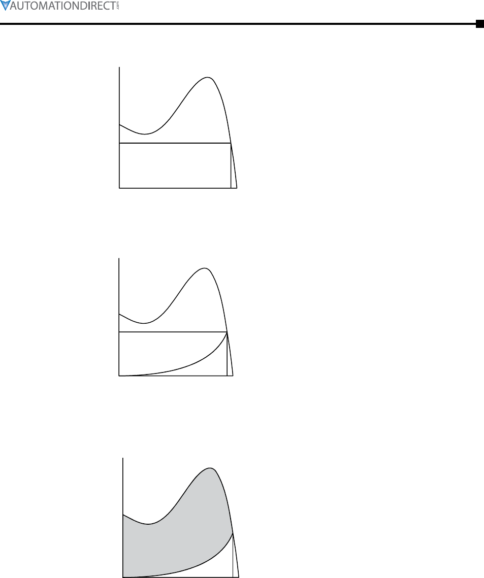
Appendix B: Soft Starter Application Considerations
Page B–9Stellar® SR55 Series Soft Starter User Manual – 1st Ed. Rev.B – 02/02/2017
B.3.2 – The Induction Motor (continued0
Figure B.3.2.1: Torque/Speed Curve – Induction Motor
Pull Out Torque ( M
K
)
TORQUE
Full Load Torque ( FLT, M
A
)
Pull-up Torque
Synchronous speed
Torque/Speed Curve – Induction Motor
Locked Rotor
Torque
( LRT, M
A
)
0 SPEED S
Figure B.3.2.2: Torque/Speed Curve – Coupled Load
Each load coupled to an induction motor has its own speed/torque curve:
Pull Out Torque ( M
K
)
TORQUE
Pull-up Torque
Full Load Torque ( FLT, M
N
)
Synchronous speed
0 SPEED S
Torque/Speed Curve – Coupled Load
Locked Rotor
Torque
( LRT, M
A
)
Figure B.3.2.3: Torque/Speed Curve – Accelerating Torque
The acceleration of a motor-load system is caused by the difference between the developed torque
(motor) and the absorbed torque (load), and is shown by the shaded area in the next figure:
0 SPEED S
Locked Rotor
Torque
( LRT, M
A
)
Pull Out Torque ( M
K
)
Pull-up Torque Full Load Torque ( FLT, M
N
)
Synchronous speed
Torque/Speed Curve – Accelerating Torque
TORQUE
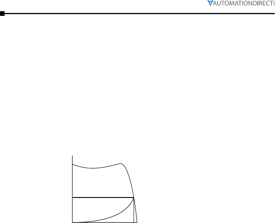
Page B–10 Stellar® SR55 Series Soft Starter User Manual – 1st Ed. Rev.B – 02/02/2017
Appendix B: Soft Starter Application Considerations
B.3.2 – The Induction Motor (continued)
Obviously, the larger the difference between the developed torque and the absorbed torque,
the faster the acceleration and the quicker full speed is reached, and the greater the stresses
experienced by the supply and drive systems during the acceleration process. An “ideal” start
would accelerate the load with just sufficient force to reach full speed smoothly in a reasonable
time, and with minimum stress to the supply and drive mechanisms.
Generally speaking, the motor speed/torque characteristic is controlled by the rotor resistance.
A motor with high rotor resistance can generate its peak torque (pull-out torque) at standstill,
giving the high break-away torque characteristic which reduces steadily as the speed increases,
and becomes zero at synchronous speed. At the other end of the scale, a motor with a very low
rotor resistance will produce a low starting torque, but will generate its peak torque closer to the
synchronous speed. Consequently, this type of motor runs at full power with higher operating
efficiency and low slip speed. It is possible to combine the twin requirements of high starting
torque and efficient full-speed operation within a single motor by techniques such as double-cage
or deep bar design, and this usually is the motor characteristic chosen for lifting and hoisting
applications:
Figure B.3.2.4: Torque/Speed Curve – High Starting Torque
Locked Rotor
Torque
( LRT, M
A
)
Pull Out Torque ( M
K
)
TORQUE
Pull-up Torque
Full Load Torque ( FLT, M
N
)
Synchronous speed
Torque/Speed Curve – High Starting Torque
0 SPEED S
However, most induction motors are designed to have a “standard” characteristic that provides a
compromise between starting torque and operating efficiency. To summarize, an induction motor
will only start and accelerate when it produces more torque than the connected load absorbs. This
is true for all speeds, including standstill and full speed.
B.3.3 – Starting Induction Motors
Starting a demagnetized induction motor from standstill is a demanding and complex process.
At the instant of switching, all the energy must be present that is necessary to magnetize the
motor, to provide the acceleration force, to supply the kinetic energy of the rotor and load,
and to overcome the mechanical and electrical losses. To do so at full supply voltage places
considerable stresses on the supply, the motor windings, and the iron cores of the stator and
rotor. Excessive acceleration of a rotor when the mechanical load is small can produce torque
oscillations in the shaft, causing severe wear to transmissions, gears and drives. Excessive
acceleration when the load inertia is high, such as in centrifugal fans, causes belts to slip on the
pulleys, producing rapid wear and early failure.

Appendix B: Soft Starter Application Considerations
Page B–11Stellar® SR55 Series Soft Starter User Manual – 1st Ed. Rev.B – 02/02/2017
B.3.4 – Electro-Mechanical Methods Of Starting
Method A: Direct-on-Line
The most simple means of controlling energy flow to an induction motor is to interrupt the power
supply by a single contactor. Very widely applied, the method is known variously as “direct-on-
line”, “across-the-line”, “direct”, etc., and is the usual form of control where low cost is the first
and most important consideration. As a result, it is most often used on small motor sizes (up to
approx. 22 kW [30 hp]), or where the supply is strong enough to withstand the inrush and starting
current surges without causing unacceptable voltage drops.
The harsh, damaging effects described earlier are all imposed by direct-on-line starting and, as
a control method, it is the most destructive of equipment. Its simplicity and apparent low cost,
although attractive at first sight, hide large cost penalties in the shape of increased maintenance,
reduced transmission equipment life, and higher risk of motor failure, particularly when frequent
starting and stopping is needed. In larger sized motors, special strengthening is necessary, at
higher cost, before they can be safely used with direct-on-line starting.
However, the shortcomings of the direct-on-line starter have been recognized ever since motors
have been used, and alternative systems have been developed over the years to reduce the
damaging effects of this form of control.
Method B: Wye-Delta and other Reduced Voltage Starting Systems
Reduced voltage starting makes use of the fact that motor torque is proportional to the square
of the terminal voltage. The most familiar type of reduced-voltage starter is the wye-delta, or
star-delta starter.
Consisting of three contactors and a time switch (which can be mechanical, pneumatic, electrical,
or electronic), the wye-delta starter changes the motor winding configuration from an initial wye
connection to a delta connection as the motor accelerates. The change-over or transition point is
controlled by the time switch and is usually arranged to be approximately at 80% of full speed.
The effect of starting in the wye connection is to alter the voltage across each stator winding to
58% of normal. This reduces the starting torque to a third of locked rotor torque (LRT) with a
consequent reduction in starting currents and acceleration forces.
Although an apparent improvement over the direct system, significant disadvantages still
remain. The transfer from wye to delta momentarily removes the motor from the supply. During
this time the motor is under the mechanical influence of the rotating load and, at the instant of
disconnection, current will still flow in the rotor bars due to the time delay necessary for the
magnetic flux to die away. Therefore, there is a residual flux “frozen” on the surface of the
rotating rotor, which cuts the stator windings, generating a voltage whose frequency depends
on the rotor speed. If the load inertia is small, such as in a pump, or if the friction is high, there
could be a significant loss of speed during the time the supply is disconnected. In this case, when
the reconnection to delta is made, a large phase differential can exist between the supply and the
rotor fluxes. This can give rise to very large current surges (as much or more than full-voltage
locked rotor current), together with massive transient torque oscillations, which can peak at levels
in the region of fifteen times full-load torque. Although the effects described are only present
for a very short period of time (about one fifth of a second), they are sources of great stress
and damage to the whole drive system, and where frequent starting is necessary, invoke high
maintenance costs. The current surges, in the form of very high-level short-duration “spikes”,
are an increasing problem for computer control systems and other sensitive electronic equipment.
The voltage disturbance on the supply is very difficult to filter out and can cause severe problems,
especially when larger motors are involved.

Page B–12 Stellar® SR55 Series Soft Starter User Manual – 1st Ed. Rev.B – 02/02/2017
Appendix B: Soft Starter Application Considerations
Method B: Wye-Delta and other Reduced Voltage Starting Systems (continued)
There are methods of control, for example, the Wauchope starter, which eliminate or reduce the
reconnection transients. However, such starters are expensive and have reliability implications,
and they are not widely applied for these reasons.
The wye-delta starter also has disadvantages due to the restricted starting torque available (if you
need 40% LRT to break-away, you can only increase the motor size, or revert to direct-on-line).
Combined with the severe effects of the re-switching surges, and the additional costs of bringing
six conductors from the motor to the starter instead of only three; wye-delta only offers an
imperfect solution to the problem of starting the induction motor.
Method C: Primary Resistance Starter
It has long been recognized that the transition step in the wye-delta system was a source of
problems such as welded contactors, sheared drive shafts etc. For many years a method of
stepless control has been available in the form of the primary resistance starter.
This type of controller inserts a resistance in one, or more often in each, of the phase connections
to the stator at start-up, after which it is progressively reduced and shorted out at the end of the
acceleration process. Frequently, the resistances are movable blades that are gradually inserted
into an electrolyte liquid. The mechanism is usually large and expensive, both to purchase and
to maintain, and considerable heat is created by the passage of current through the electrolyte
resistor. This limits the starting frequency (because the electrolyte has to condense back to liquid
before a new start can proceed), and these restrictions prevent this starter from being a popular
option when selecting a control system. However, it has the distinction of being the smoothest
and least stressful method of accelerating an induction motor and its load.
Method D: Other Electro-Mechanical Systems
Other control methods such as auto-transformer starting (popular in North America), primary
reactance starting etc., are employed to a greater or lesser extent, to compensate for some of
the disadvantages of each type of starter discussed. Nevertheless, the fundamental problems of
electro-mechanical starters remain, and it is only in the last decade or two that their dominance
has been challenged by the introduction of power semiconductors controlled by electronics.
B.3.5 – The Semiconductor Motor Controller
During the 1950s, much effort was put into the development of a four-layer transistor device
which had the power to switch large currents at high voltages when triggered by a very small
pulse of current. This device became known as the silicon controlled rectifier (SCR), or in
Europe, the “Thyristor”, and it is the basis on which all soft starting systems are built. The
characteristic of most interest is the ability of the thyristor to switch rapidly (in about 5 millionths
of a second) from “OFF” to “ON” when pulsed, and to remain “ON” until the current through
the device falls to zero (which conveniently happens at the end of each half-cycle in alternating
current supplies).
By controlling the switch-on point of a thyristor relative to the voltage zero crossing in each
half wave of an alternating current, it is possible to regulate the energy passing through the
device. The closer the turn-on point is to the voltage zero crossing point, the longer the energy
is allowed to flow during the half-cycle. Conversely, delaying the turn-on point reduces the time
for the energy to flow. Putting two thyristors back-to-back (or anti-parallel) in each of the phase
connections to a motor, and by precisely controlling their turn-on points, an electronic soft starter
continuously adjusts the passage of energy from the supply so that it is just sufficient for the
motor to perform satisfactorily.
So, for instance, by starting with a large delay to the turn on point in each half cycle, and
progressively reducing it over a selected time period, the voltage applied to the motor starts from
a relatively low value and increases to full voltage. Due to the motor torque being proportional
to the square of the applied voltage, the starting torque follows the same pattern giving the
characteristic smooth, stepless start of the soft starter.
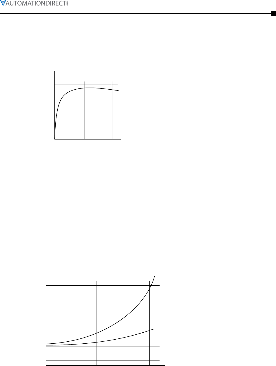
Appendix B: Soft Starter Application Considerations
Page B–13Stellar® SR55 Series Soft Starter User Manual – 1st Ed. Rev.B – 02/02/2017
B.3.6 – Running Induction Motors
Once a start has been completed, the motor operating efficiency becomes of interest. When
working at or near full load, the typical three-phase induction motor is relatively efficient, and
readily achieves efficiencies of 85% to 95%. However, as shown below, motor efficiency falls
dramatically when the load falls to less than 50% of rated output.
Figure B.3.6.1: Motor Efficiency/Load Characteristic
Motor Efficiency/Load Characteristic
EFFICIENCY
LOAD
0 1/2 1/1
100%
In fact, very few motors actually experience consistent fully rated operation, and the vast majority
operate at much lower loads due to either over-sizing (a very frequent situation), or natural load
variations. For Fan and Pumping applications, the affinity laws will allow the inverter drive
to show very considerable energy savings over virtually all other methods of control through
varying the speed of the motor in response to changes in load. Where motor speeds cannot be
varied, an optimizing version of semiconductor motor controller, such as the SR55, will also
produce energy savings in lightly loaded motors. Less sophisticated systems of soft starters
remain at full conduction, and the motor then behaves as if it were connected directly to the
main supply. However, at light loads and mains voltages, induction motors always have excess
magnetic flux, and efficiency loss and power factor degradation result. By detecting the load at
any instant and adjusting the motor terminal voltage accordingly, it is possible to save some of
the excitation energy and load loss, and therefore improve motor power factor when the motor is
running inefficiently at light loads.
Figure B.3.6.2: Motor Efficiency/Loss Characteristic
Motor Ef
ficiency/Loss Characteristic
LOAD
STRAY
EXCITATION
MECHANICAL
LOAD
0 1/2 1/1
LOSSES

Page B–14 Stellar® SR55 Series Soft Starter User Manual – 1st Ed. Rev.B – 02/02/2017
Appendix B: Soft Starter Application Considerations
B.3.6 – Running Induction Motors (continued)
All SR55 Soft Starters are microprocessor controlled, and this gives them a number of
advantages. Firstly, there are no adjustments to be made for the energy saving function; all
calculations necessary to find the best degree of phase-back of the thyristors for any load
condition is made by the microprocessor. Secondly, the start always synchronizes with the supply
voltage, and a special structure of turn-on pulses virtually eliminates the inrush currents normally
associated with motor start-up. This happens every time. Lastly, there is the absolutely stepless
starting process, otherwise found only with primary resistance or reactance electromechanical
starters – but without the wasted energy, and with the opportunity to control the maximum current
allowed to flow during the starting process. Other features such as soft stopping are included to
give considerable control over all modes of induction motor operation.
B.3.7 – Reliability Considerations
Reliability is an aspect which is of increasing concern regarding electronic controllers for
induction motors. There is little point in installing an expensive item of electronic equipment to
save potentially considerable amounts of money if the device is unreliable to the point that vital
processes are constantly interrupted.
There are electronic products in the market place which appear to offer soft starting more cheaply.
However, they almost always rely on less advantageous technologies such as analog control,
or half-control, where one of the two thyristors in each phase is replaced with a diode. There
are systems which only control the energy flow in one phase while the other two are directly
connected. Owing to the variable quality and performance of many so-called inverters and soft
starters available to the unsuspecting purchaser, international standards for these products have
been developed.
So far, IEC 60947-4-2 – “AC Semiconductor Motor Controllers and Starters” defines the soft
starter in every important respect, including thermal and overload performance as well as
electromagnetic compatibility. By ensuring that any motor controller equipment purchased
conforms to IEC 60947-4-2, a user should be reasonably safeguarded from shoddy or inadequate
products when specifying equipment for future installations.
A particular advantage of the use of the optimizing soft starter is its impact on the maintenance
requirements of associated electro-mechanical equipment. Optimizing lowers the surface
temperature of the motor by reducing the losses within the motor. This prolongs the motor life,
and reduces heating of the surrounding atmosphere in the process. If the atmosphere is subject to
air conditioning, reducing the heat input will reduce the air conditioning costs. Reduced starting
and running currents reduces cable losses, and contactor switching operations are carried out
under the most advantageous conditions. No current flows on switch-on since all switching is
carried out by the thyristors, which virtually eliminates the need for contact replacement.
Indeed, there are a growing number of installations where contactors are no longer employed,
being replaced by controllable circuit breakers or isolators instead.
In summary, electronic controllers for most fixed-speed applications are opening new ways of
increasing the efficient operation of induction motors, as well as offering significant benefits
in control. Prospective users should ensure themselves of the quality and performance of
any products they expect to fit, and this can be reasonably expected if compliance with the
appropriate IEC standards is demanded.

Appendix B: Soft Starter Application Considerations
Page B–15Stellar® SR55 Series Soft Starter User Manual – 1st Ed. Rev.B – 02/02/2017
Appendix B Glossary of Terms
Bre akaway Torque: The minimum torque required to achieve rotor movement for the motor with
its load.
Cur rent Limit: The current at which the ramp is held. For the SR55, current limit is only active
during start-up where it contributes to the motor control function. This feature is particularly
useful when starting high-inertia loads that require an extended start-up period. (See also
Overload Level.)
Dir ect-On-Line (DOL): The direct connection and disconnection of a motor from the AC main
supply by means of a contactor or switch. Acceleration and operation is at full mains voltage
only.
iER S: Intelligent Energy Recovery System. An advanced motor control technology proven
to reduce the energy consumed in fixed speed motor applications. It matches the power
consumption to the load required by intelligently monitoring and regulating energy
consumption, voltage, current, and power factor during the motor starting and running
stages. iERS automatically bypasses itself when it is not needed, and continues monitoring to
re-engage itself as needed.
Inr ush Current or Locked Rotor Current: The current that flows at the instant of connection of a
motor to the power source. It is limited by the impedance presented by a de-energized motor
and the applied voltage. Usually expressed as a multiple of motor full-load current.
Kic k-start Voltage: The percentage of supply voltage applied before commencing ramp-up when
a load has a high breakaway torque and the standard settings of pedestal voltage may not
allow sufficient torque to be developed by the motor to cause acceleration.
Loc ked Rotor Current: Same as Inrush Current (defined above).
Ove rload Level: The level of current at which the controller overload begins to integrate. For
the SR55, the overload detector is always active and provides protection against prolonged
over-current operation.
Ped estal Voltage: The voltage that the unit applies to the motor at start-up. It is expressed as a
percentage of the rated supply voltage.
Po w er Factor: The ratio, expressed as a trigonometric cosine, of the real power consumption to
the apparent power consumption.
Top of Ramp (TOR): The unit achieves Top of Ramp (TOR) when it completes the start-up stage
of motor control. (This occurs when the voltage applied to the motor first equals the main
supply voltage.)
Sof t -start: The regulation, by electronic means, of the supply voltage from an initial low value
to full voltage during the starting process. This over-comes the inherent drawbacks of a
switched supply. The motor torque is modified in proportion to the square of the voltage
applied.
Trip : A trip occurs when the unit removes power to the motor because its operation equals the
limit imposed by one of its self-protection features.

Page B–16 Stellar® SR55 Series Soft Starter User Manual – 1st Ed. Rev.B – 02/02/2017
Appendix B: Soft Starter Application Considerations
BLANK
PAG E

Page C–1Stellar® SR55 Series Soft Starter User Manual – 1st Ed. Rev.B – 02/02/2017
ElEctromagnEtic
compatibility c
c
c
appEndix
appEndix
appEndix
Table of ConTenTs
C.0 – Electromagnetic Compatibility (EMC) . . . . . . . . . . . . . . . . . . .C–2
C.1 – Introduction . . . . . . . . . . . . . . . . . . . . . . . . . . . . . . . . .C–2
C.2 – Applicable Standard Within the EU . . . . . . . . . . . . . . . . . . . .C–2
C.3 – Mandatory Requirements Within the EU. . . . . . . . . . . . . . . . . .C–2
C.4 – Guidance for Installation Personnel and System Designers. . . . . . . .C–2
C.5 – EMC Basic Criteria. . . . . . . . . . . . . . . . . . . . . . . . . . . . . .C–3
C.6 – Purchasing Implications of Meeting an EMC Standard . . . . . . . . . .C–3
C.7 – Basic EMC Considerations . . . . . . . . . . . . . . . . . . . . . . . . .C–4
C.7.1 – Immunity . . . . . . . . . . . . . . . . . . . . . . . . . . . . . . . . . . C–4
C.7.2 – Emissions . . . . . . . . . . . . . . . . . . . . . . . . . . . . . . . . . . C–4
C.7.3 – Emissions - Harmonics . . . . . . . . . . . . . . . . . . . . . . . . . . . C–4
C.7.4 – Emissions - Radio Frequency (RF) . . . . . . . . . . . . . . . . . . . . . C–4
C.7.5 – Emissions - Conducted . . . . . . . . . . . . . . . . . . . . . . . . . . . C–5
C.7.6 – Important Systems Information . . . . . . . . . . . . . . . . . . . . . . C–5
C.7.7 – Strategies for Attaining and Maintaining EMC Compliance . . . . . . . C–6

Page C–2 Stellar® SR55 Series Soft Starter User Manual – 1st Ed. Rev.B – 02/02/2017
Appendix C: Electromagnetic Compatibility
C.0 – Electromagnetic Compatibility (EMC)
As supplied, all SR55 Soft Starters meet the standards of emission and immunity levels defined
in the IEC 60947-4-2 and EN 60947-4-2 product standards for AC Semiconductor Motor
Controllers and Starters. However, the EMC performance of the controller can be significantly
affected by the manner in which it is incorporated into the system in which it is intended to
operate. To prevent inadvertent degradation of EMC performance, attention must be given to
motor cable lengths, wiring configurations, the nature of the power supply, etc., at the design,
construction and implementation stages of a project.
C.1 – Introduction
It is widely accepted that electromagnetic compatibility between electronic and electrical
products is a desirable objective. Technical standards are increasingly stipulating levels of EMC
performance which compliant products are required to meet. The decision by the European
Union (EU) to implement a community-wide directive covering EMC caused considerable
activity among electrical and electronic equipment manufacturers and suppliers to identify,
understand, and mitigate the sources of electromagnetic interference within their products and
systems.
C.2 – Applicable Standard Within the EU
The product standard which defines EMC performance for soft starters is IEC 60947-4-2
‘AC Semiconductor Motor Controllers and Starters.’ (The Official Journal of the EC will list
this standard as EN 60947-4-2.) The SR55 has been type tested in accordance with the test
procedures and levels laid down in the product standard.
C.3 – Mandatory Requirements Within the EU
(Applicable to any person involved in the installation and operation of the equipment.)
The EU Directive 2004/108/EC, describes the required EMC performance of all electrical
equipment which is to be connected to a low voltage supply network. It imposes an obligation
on the manufacturer of the soft starter to provide sufficient information for installers, system
integrators, users, and anyone else connected with the installation and operation of the equipment.
This section provides the technical information to support the obligation of the manufacturer.
The provision and maintenance of compatibility extends from the manufacturer to the panel
builder, assembler, systems integrator, and ultimately to the installer and user. Anyone involved
in the installation and operation of the equipment, through a lack of knowledge, misdirection, or
for other reasons, can completely negate the initial EMC performance of the equipment.
C.4 – Guidance for Installation Personnel and System Designers
For safety reasons, all SR55 products are intended to be installed and set to work by skilled
personnel who are capable of interpreting and following EMC guidelines correctly. Any person
not fully trained in the appropriate technology should not attempt the installation.
If you do not understand, or if you are unclear about any part of these guidelines, then please
consult your supplier. Often, consultation with the supplier can avoid unnecessary problems in
specifying and installing the correct combination of equipment.
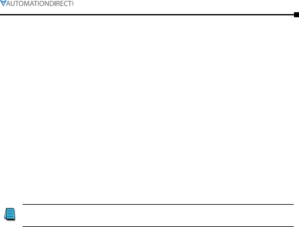
Appendix C: Electromagnetic Compatibility
Page C–3Stellar® SR55 Series Soft Starter User Manual – 1st Ed. Rev.B – 02/02/2017
C.5 – EMC Basic Criteria
The electromagnetic compatibility of a product is defined by two criteria:
1) Immunity to electromagnetic disturbances generated externally to the product.
2) The type and amount of conducted and radiated electromagnetic emissions emanating
from the product.
Ascertaining the nature of the power supply is of primary consideration when deciding on
appropriate EMC requirements. The requirements for equipment installed in heavy industrial
environments (fed from their own isolated low voltage power supply) differ from those installed
in residential, commercial, light industrial, and health-care applications (directly connected to a
public low-voltage network).
Generally, industrial installations require higher immunity levels and permit higher levels of
conducted and radiated emissions than those for non-industrial installations. On the other hand,
lower levels of emissions output, and lower immunity levels, are specified for installations
connected directly to the public low-voltage network.
C.6 – Purchasing Implications of Meeting an EMC Standard
Before purchasing components for the installation, the specifier must evaluate the expected
source of power for the Soft Starter and understand exactly the implications for meeting EMC
requirements. It is likely that failure to do so will result in the purchase and installation of
inappropriate equipment.
IMPORTANT: The information and guidance given in section C.7 forms
part of the statutory requirements of the European Union Directive
2004/108/EC on EMC.
Page C–4 Stellar® SR55 Series Soft Starter User Manual – 1st Ed. Rev.B – 02/02/2017
Appendix C: Electromagnetic Compatibility
C.7 – Basic EMC Considerations
C.7.1 – Immunity
The product standard for immunity requirements is EN 60947-4-2:2012. All SR55 Soft Starter
products meet, or exceed the industrial level immunity requirements laid down in this standard.
C.7.2 – Emissions
Emissions are classified as low frequency (below 9kHz), known as harmonics, and high or radio
frequency (above 9kHz). Both radio-frequency emissions and low-frequency harmonics are
generated by the action of the SR55 Soft-Starter.
NOTICE: This product has been designed for environment A. Use of this
product in environment B may cause unwanted electromagnetic disturbances
in which case the user may be required to take adequate mitigating
measures.
C.7.3 – Emissions - Harmonics
During normal operation, soft starters turn their semiconductor switches on and off in order to
vary the voltage at the motor terminals, and this introduces supply discontinuities and generates
harmonics. However, the mode of pulsing used by SR55 Soft Starters minimizes these harmonic
effects, since SR55 power circuits are configured as a fully-controlled regulators (W3C).
Only non-triplen (integer multiples of the third harmonic), odd harmonic frequencies are created,
starting with and diminishing rapidly from the fifth harmonic, and virtually disappearing by the
nineteenth harmonic.
C.7.4 – Emissions - Radio Frequency (RF)
Radio frequency emissions are propagated in two ways:
1) Conduction along the leads supplying the soft starter.
2) Radiation from the operating equipment.
They also have two sources:
1) The high-frequency currents associated with the control electronics (this includes the
microprocessor).
2) The action of the semiconductor devices forming the power switching elements located in
the controller main circuits.
The radiation measurements made from operating versions of SR55 Soft Starters show levels
lower than the allowed limits. Further, enclosures of metallic construction provide additional
shielding for SR55 Soft Starters mounted within them. The only radiated interference effect
that might arise from a soft starter would be if mobile telephones, walkie-talkies, etc. were to be
used in very close proximity to a unit which was operating with the enclosure door open. For
this reason, any enclosure must display a label that brings the possibility of electromagnetic
interference to the attention of the operator under these circumstances.

Appendix C: Electromagnetic Compatibility
Page C–5Stellar® SR55 Series Soft Starter User Manual – 1st Ed. Rev.B – 02/02/2017
C.7.5 – Emissions - Conducted
Conducted emissions are able to travel great distances and may cause interference to any
neighboring consumers connected to the common low-voltage supply network.
Allowable levels for conducted emissions generated by semiconductor motor controllers
and starters are influenced by the nature of the low-voltage power distribution network. The
determining factor is whether the source of power is, either:
a) a private supply with a single consumer whose Point of Common Coupling (PCC) is at a
high or medium voltage transformer, or
b) a public low-voltage network with more than one consumer, where the individual PCC is
made directly to the network itself.
The first type of supply (a) is identified as “Industrial”, and requires the use of soft starters
compliant with EN 60947-4-2 Table 19 Environment A Emission Levels.
The second type of supply (b) is identified as “Residential” and requires the use of Class B
equipment. Class B equipment is equipment suitable for use in domestic establishments and
in establishments directly connected to a low-voltage power supply network which supplies
buildings for domestic purposes.
C.7.6 – Important Systems Information
The specification limits for both equipment classes assume systems are grounded at the star (wye)
point of the supply transformer through low impedance connections.
Certain industries, particularly continuous process industries, employ distribution systems that
operate either with a ground connection through a high impedance or without a ground at all.
These systems may cause severe problems of operator safety when installed with capacitive high
frequency filters. Such systems are not considered in this document.
In the case of an isolated or high impedance grounded system, seek advice from your supplier
before fitting a capacitive high frequency filter to an SR55 Soft Starter. It is essential that the
specifying authority, user, or installer has a clear knowledge of the type of network to which the
product is to be installed before making decisions as to which EMC strategy to adopt.
As supplied, all SR55 products comply with the conducted emissions requirements for
environment class A as defined by EN 60947-4-2:2012 Table 19. However, the length and type
of cable connecting the motor to the starter module materially affects the level of emissions
generated, and can amplify them greatly. The standard also allows different levels of emissions
depending on rated input power, which also affects the need to fit filters. The EN 60947-4-2:2012
standard only requires consideration of steady-state conditions for EMC emission purposes, and
expressly excludes varying conditions such as those during ramp-up and ramp-down.
Finally, statistics show that the number of disturbances arising from soft starters, operating in
a very wide variety of applications and networks throughout the world, is insignificant. Where
EMC disturbances occur, it is very unlikely that they can be genuinely attributed to a soft starter.

Page C–6 Stellar® SR55 Series Soft Starter User Manual – 1st Ed. Rev.B – 02/02/2017
Appendix C: Electromagnetic Compatibility
C.7.7 – Strategies for Attaining and Maintaining EMC Compliance
Where possible, minimize the effect of electrical interference by using the strategies listed below.
• Locate the SR55 Soft Starter unit as close as reasonably possible to the motor terminal box in
order to minimize cable length.
• Ensure that, within any enclosure, the control wiring does not run parallel to the power
wiring. Where this is unavoidable, maintain a 100 mm [3.9 in] separation between control
cables and power cables.
• Where possible, ensure that the control wiring crosses at right angles to the power wiring.
This practice reduces the cross-coupling between cables.
• Shield any cables carrying sensitive signals. The digital control inputs to a SR55 are
opto-isolated, and do not normally require buffering (e.g. through a small relay) or shielding.
Where a special purpose system filter has been applied at the point of common coupling,
additional filtering of individual drives is not necessary and may introduce undesirable effects due
to resonance.
For the purposes of EMC, the connections between the SR55 controller and motor are considered
to be an extension of the enclosure, and preferably should be contained within grounded metallic
trunking or conduit. Armored cable may be used providing it is correctly terminated, although
the EMC performance will be slightly inferior. Shielded cable is not necessary.
All associated electrical and electronic equipment near to the controller complies with the
emission and immunity requirements of the EMC Directive.

Page D–1Stellar® SR55 Series Soft Starter User Manual – 1st Ed. Rev.B – 02/02/2017
Sizing an SR55
Soft StaRteR D
D
D
appenDix
appenDix
appenDix
Table of ConTenTs
SR55 Soft Starter Selection Steps . . . . . . . . . . . . . . . . . . . . . . . . D–2
SR55 Soft Starter Overload Trip. . . . . . . . . . . . . . . . . . . . . . . . . D–3
SR55 Index Ratings . . . . . . . . . . . . . . . . . . . . . . . . . . . . . . . D–3
Standard Overload Current Profile and Duty Cycle . . . . . . . . . . . . . . D–4
Increased Starts per Hour – Derating. . . . . . . . . . . . . . . . . . . . . . D–5
Derating Examples . . . . . . . . . . . . . . . . . . . . . . . . . . . . . . . . . D–6
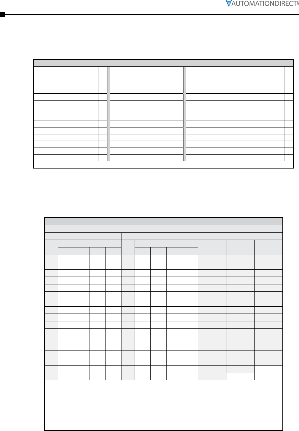
Page D–2 Stellar® SR55 Series Soft Starter User Manual – 1st Ed. Rev.B – 02/02/2017
Appendix D: Sizing an SR55 Soft Starter
SR55 Soft Starter Selection Steps
1) Determine the required trip class based on the motor load and required start time. See O/L
Trip Classes table below. (Also refer to the definitions of Class 10, 20, and 30 Trip Curves in
the “SR55 Soft Starter Overload Trip” section of this chapter.)
SR55 Soft Starters – O/L Trip Classes
Default 10 Crusher 30 Pump - Submersible Centrifugal 10
Heavy 20 Fan - Low Inertia <85A 10 Pump - Submersible Rotodynamic 10
Agitator 10 Fan - High Inertia >85A 30 Pump - Positive Displacement Reciprocating 20
Compressor - Centrifugal 20 Feeder - screw 10 Pump - Positive Displacement Rotary 20
Compressor - Reciprocating 20 Grinder 20 Pump Jack 20
Compressor - Rotary Screw 20 Hammer mill 20 Rolling mill 20
Compressor - Rotary Vane 10 Lathe machines 10 Roots Blower 20
Compressor - Scroll 10 Mills - Flour, etc. 20 Saw - Band 10
Ball mill 20 Mixer - Unloaded 10 Saw - Circular 20
Centrifuge* 30 Mixer - Loaded 20 Screen - Vibrating 20
Bow Thruster - Zero Pitch 10 Molding Machine 10 Shredder 30
Bow Thruster - Loaded 20 Pelletizers 20 Transformers, Voltage Regulators 10
Conveyor - Unloaded 10 Plastic and textile machines 10 Tumblers 20
Conveyor - Loaded 20 Press, flywheel 20 Wood chipper 30
* Size centrifuge starter at I(A) = (motor FLA x 2.3). Trip Class 30.
2) From the SR55 Soft Starters Selection Table below, select the row with the correct motor full
load amps. Then select the correct SR55 soft starter based on Trip Class (longer start times
require a larger starter). Notice that there are different Motor Amps columns for starters wired
In-Line (most common) and In-Delta. Select the applicable SR55 part number based on the
required Trip Class, motor HP, and connection type.
SR55 Soft Starters – Selection Table (per IEC 60947-4-1:2009 Table G.1)
Motor Size Soft Starter Size
In-Line Connection In-Delta Connection * Application Trip Class
I (A) HP @ I (A) HP @ Class 10 Class 20 Class 30
200V 208V 230V 460V 200V 208V 230V 460V
17 3 5 5 10 29 7.5 7.5 10 20 SR55-017 SR55-021 SR55-027
21 5 5 5 15 36 10 10 10 25 SR55-021 SR55-027 SR55-034
27 7.5 7.5 7.5 20 47 10 15 15 30 SR55-027 SR55-034 SR55-040
34 10 10 10 25 59 15 15 20 40 SR55-034 SR55-040 SR55-052
40 10 10 10 30 69 20 20 25 50 SR55-040 SR55-052 SR55-065
52 15 15 15 40 90 25 30 30 60 SR55-052 SR55-065 SR55-077
65 20 20 20 50 113 30 30 40 75 SR55-065 SR55-077 SR55-096
77 20 25 25 60 133 40 40 50 100 SR55-077 SR55-096 SR55-124
96 30 30 30 75 166 50 50 60 125 SR55-096 SR55-124 SR55-156
124 40 40 40 100 215 60 75 75 150 SR55-124 SR55-156 SR55-180
156 50 50 60 125 270 75 75 100 200 SR55-156 SR55-180 SR55-242
180 60 60 60 150 312 100 100 125 250 SR55-180 SR55-242 SR55-302
242 75 75 75 200 419 150 150 150 300 SR55-242 SR55-302 SR55-361
302 100 100 100 250 523 150 150 200 450 SR55-302 SR55-361 SR55-414
361 125 125 150 300 625 200 200 250 500 SR55-361 SR55-414 SR55-477
414 150 150 150 350 717 250 250 250 500 SR55-414 SR55-477 n/a
477 150 150 150 400 826 250 300 300 600 SR55-477 n/a n/a
* For In-Delta connections, all six motor wires must be available for connection, and it is critical to
exactly follow the In-Delta wiring diagram in the SR55 User Manual or Quick-start Guide. Nine-lead
motors CANNOT be connected in the delta. The Soft Starter will only sense the Phase Current, which
is about 58% of the Line Current.
* For In-Delta connections, a main contactor that is controlled by the Run relay of the SR55 must be
used in the incoming power circuit for isolation. Circuit breaker isolation alone is not sufficient.
* iERS energy optimizing feature is not available for In-Delta connections.
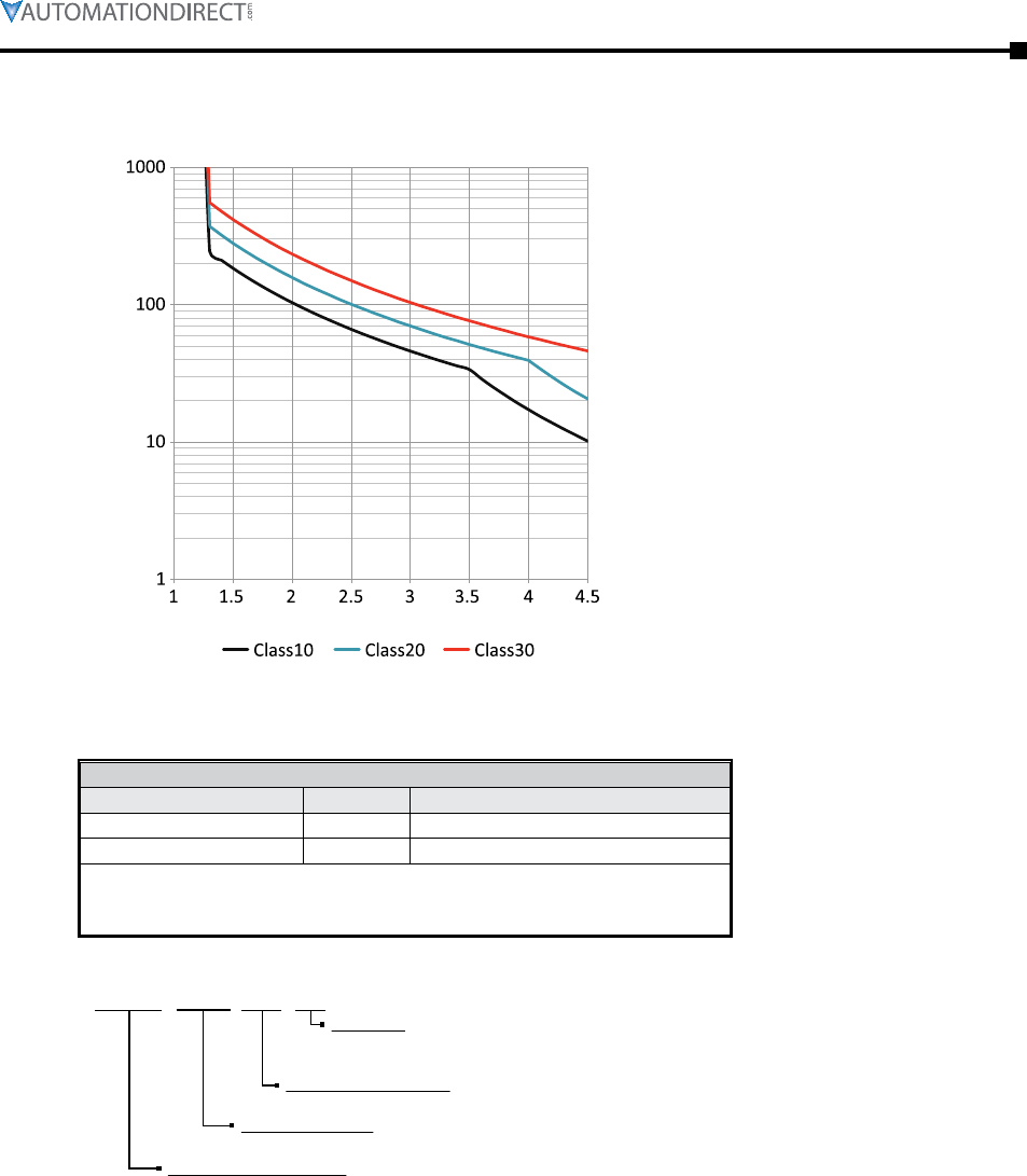
Appendix D: Sizing an SR55 Soft Starter
Page D–3Stellar® SR55 Series Soft Starter User Manual – 1st Ed. Rev.B – 02/02/2017
SR55 Soft Starter Overload Trip
Trip time ( seconds )
Multiple of Motor FLA
Motor overload 'cold' trip curves
(20°C ambient)
The SR55 soft starter provides motor
overload protection, which can be
configured through the touchscreen.
Overload trip settings are determined
by the Motor Current setting and the
Trip Class setting. Trip class choices
are class 10, class 20, and class 30. The
SR55 soft starters are protected using
full I2T motor overload with memory.
SR55 Index Ratings
(per IEC 60947-4-2)
SR55 Index Ratings *
Model Number Ie (A) Standard Operation AC-53a; X-Tx; F-S
SR55-017 to SR55-180 17 to 195 AC-53a: 3.5-17; 90-5
SR55-242 to SR55-477 242 to 500 AC-53a: 3.5-17; 90-3
* Index ratings AC-53a and AC-53b are specified by IEC standard # 60947-4-2.
IEC Index Ratings are comprised of Rated Operational Current (Ie), Utilization
Category, Overload Current Profile (X-Tx), and Duty Cycle (F-S) or OFF-time.
Index Rating Example – Standard Operation (AC-53a Utilization Category per IEC 60947-4-2)
17 to 195 - AC-53a: 3.5-17; 90-5
Duty Cycle (F-S)
90-5 = 90% duty cycle - 5 cycles/hr
[if multiple starts/hr are required, 90% D.C. requires off time ≥ 10% of previous run time]
Overload Current Profile (X-Tx)
3.5-17 = 3.5 times rated current (Ie) for 17s
Utilization Category
AC-53a = controller semiconductors provide squirrel-cage motor Start, Run, and Stop control
Rated Operational Current (Ie)
17 to 195 = controllers with Rated Operational Currents from 17A to 195A
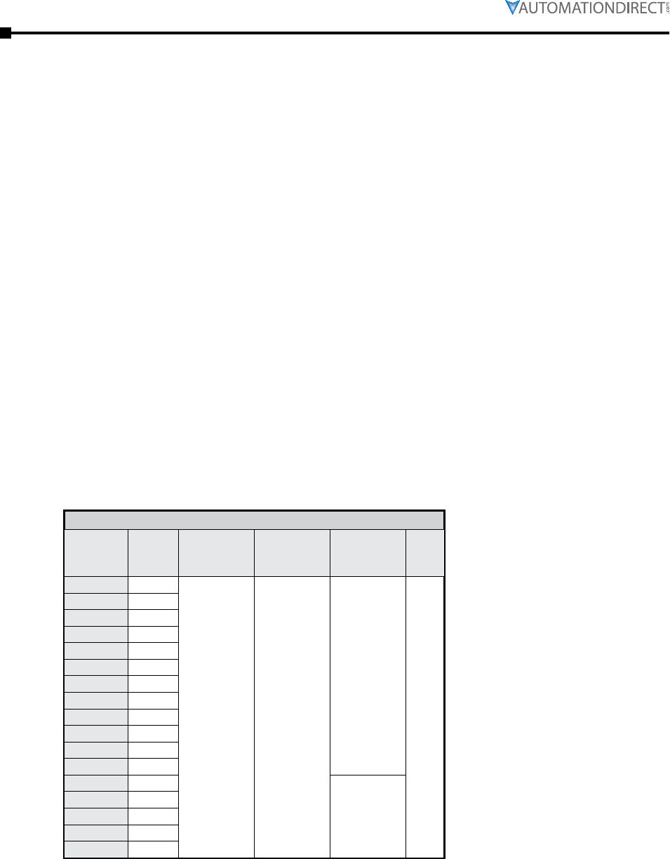
Page D–4 Stellar® SR55 Series Soft Starter User Manual – 1st Ed. Rev.B – 02/02/2017
Appendix D: Sizing an SR55 Soft Starter
Standard Overload Current Profile and Duty Cycle
The SR55 has been designed for a specific Overload Current Profile and Duty Cycle as shown in
the previous SR55 Index Ratings section of this chapter.
The Overload Current Profile is expressed by two symbols, X and Tx.
X denotes the overload current as a multiple of Ie and represents the maximum value of operating
current due to starting, operating, or maneuvering under overload conditions.
• For example, X = 3.5 means that the maximum overload start current allowed is 3.5 times
FLC.
Tx denotes the duration of the controlled overload currents during starting, stopping, operating, or
maneuvering.
• For example, Tx = 17 means that the maximum allowed overload current is permitted for up
to 17 seconds only.
The Duty Cycle is expressed by two symbols, F and S which describe the duty and also set the
time that must be allowed for cooling.
F is the ratio of the on-load period to the total period expressed as a percentage.
• For example, F= 90 means that the soft starter is ON for 90% of the time and then OFF for
10% of the time between each start.
• If there are not multiple starts per hour, then the Duty Cycle is continuous.
S is the number of starts or operating cycles per hour.
• For example, S = 5 means that the soft starter is capable of 5 equally spaced starts per hour.
These characteristics are summarized below in Figure 1.
Figure 1: Standard Overload Current Profiles and Duty Cycles
Model
Rated
Current
(A)
Class 10 O/L
Multiple
(X)
Class 10 O/L
Time
(Tx)
Starts / Hour
(S)
Duty
(F)
SR55-017 017
3.5 17
5
90%
SR55-021 021
SR55-027 027
SR55-034 034
SR55-040 040
SR55-052 052
SR55-065 065
SR55-077 077
SR55-096 096
SR55-124 124
SR55-156 156
SR55-180 180
SR55-242 242
3
SR55-302 302
SR55-361 361
SR55-414 414
SR55-477 477
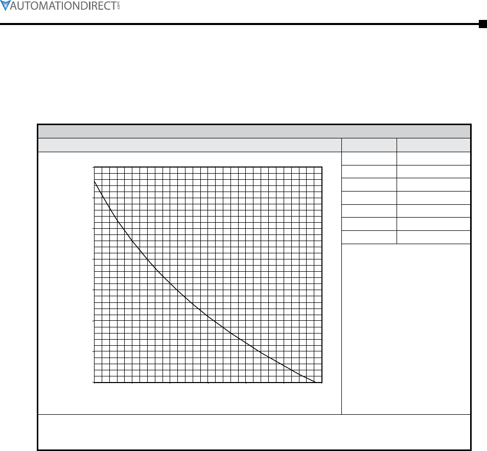
Appendix D: Sizing an SR55 Soft Starter
Page D–5Stellar® SR55 Series Soft Starter User Manual – 1st Ed. Rev.B – 02/02/2017
Increased Starts per Hour – Derating
If more than the standard number of starts/hour is required, the SR55 must be derated. To
derate for more starts/hour, the motor full load current must be less than the SR55 current. The
relationship between the SR55 deration and the starts/hour is given below in Figure 2 and the two
examples that follow. This assumes that the SR55 is still operating at the same duty (F) as given
in Figure 1.
Figure 2: SR55 Starts/Hour Deration
Deration Curve Starts/Hour Deration Factor
0.5
0.55
0.6
0.65
0.7
0.75
0.8
0.85
10 15 20 25 30 35 40
Deration Factor
[ Motor Full Load Current / SR55 Current ]
Starts / Hour
10 0.83
15 0.73
20 0.66
25 0.61
30 0.56
35 0.53
40 0.50
Deration Factor = (138 - (24·ln(starts/hr))) / 100
[where ln(starts/hr) is the natural log of the # of starts/hour]
Example: Deration Factor for 10 starts/hr = (138 - (24·ln(10))) / 100 = 0.83
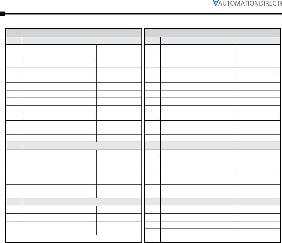
Page D–6 Stellar® SR55 Series Soft Starter User Manual – 1st Ed. Rev.B – 02/02/2017
Appendix D: Sizing an SR55 Soft Starter
Derating Examples
Example 1: SR55 Selection and Configuration
Step SR55 Selection
1 Application Loaded Conveyor
2 Trip Class 20
3 Duty 90%
4 In-Line or In-Delta In-Line
5 Ambient Temperature 40°C
6 Altitude 1000m
7 Full Motor Load Current 80A
8 Current Limit 4 x 80A = 320A
9 Number of Starts/Hour 10
10 Deration Factor (from Fig.2) 0.83
11 SR55 (A) =
Motor FLC / Deration Factor 96A
12 Determine SR55 from Sizing Guide SR55-096
Step SR55 Configuration
1 Select Application (Auto Setup)
2Leave Motor Current 100A
(maximum) (Auto Setup)
3Set Start Current Limit to 320A
(400% of motor FLC) (Start Current Limit)
4Set Overload Level to 88A
(110% of motor FLC) (Overload Settings)
Step SR55 Alternative Configuration
1 Set Application (Auto Setup)
2 Set Motor Current to 80A (Auto Setup)
3Warm Trip Time will be reduced to
Trip Class 10 value (320A for 13s)
Example 2: SR55 Selection and Configuration
Step SR55 Selection
1 Application Agitator
2 Trip Class 10
3 Duty 90%
4 In-Line or In-Delta In-Line
5 Ambient Temperature 40°C
6 Altitude 1000m
7 Full Motor Load Current 66A
8 Current Limit 3.5 x 66A = 231A
9 Number of Starts/Hour 20
10 Deration Factor (from Fig.2) 0.66
11 SR55 (A) =
Motor FLC / Deration Factor 100A
12 Determine SR55 from Sizing Guide SR55-124
Step SR55 Configuration
1 Select Application (Auto Setup)
2Leave Motor Current 100A
(maximum) (Auto Setup)
3Set Start Current Limit to 231A
(350% of motor FLC) (Start Current Limit)
4Set Overload Level to 72A
(110% of motor FLC) (Overload Settings)
Step SR55 Alternative Configuration
1 Set Application (Auto Setup)
2 Set Motor Current to 66A (Auto Setup)
3 Set Trip Class to 30 (Overload Settings)
4Warm Trip Time will be reduced to
Trip Class 10 value (231A for 17s)

Stellar® SR55 Series Soft Starter User Manual – 1st Ed. Rev.B – 02/02/2017
BLANK
PAG E

Stellar® SR55 Series Soft Starter User Manual – 1st Ed. Rev.B – 02/02/2017
