Plymouth Tube Company Stainless Steel Feedwater And Condenser Tubing 268
User Manual: 268
Open the PDF directly: View PDF ![]() .
.
Page Count: 22

1
Stainless Steel Feedwater and Condenser Tubing –
Expectations, Results, and Choices
Power- Gen International
December 3, 2008
Daniel S. Janikowski
Energy Sales Manager
Plymouth Tube
Phone 262-642-8365
djanikowski@plymouth.com
Edward R. Blessman, P.E.
Condenser Sales Manager
Plymouth Tube
Phone 262-206-4516
eblessman@plymouth.com
2
Abstract
A tubing manufacturer has many alternatives for manufacturing and testing stainless steel tubing
for feedwater heater and condenser applications. ASTM/ASME specifications are basic
requirements intended to cover all applications. These minimum requirements may not be
sufficient for providing the appropriate quality tube for demanding requirements, such as
continuous duty for 18 to 24 months common with feedwater heaters and condensers today. This
paper summarizes the basic ASTM/ASME requirements with many of the additional property
and testing options available to ensure reliable service for today’s power plant environment. It
identifies the advantages and disadvantages of each and provides suggestions on what could be
specified to ensure the best value tubing for your application.
Introduction
The initiation of deregulation has driven a need for all power producers to become more efficient
to be competitive. One way to do this is to ensure that base load generation stay on line at full
capacity, months at a time. This requires that materials perform at levels not required in the past.
The purchaser may need to specify additional processing and testing requirements for additional
reliability. ASTM and ASME requirements are intended to cover a broad range of products. For
example, ASTM A 268 and A 249 are commonly specified for stainless steel automotive exhaust
pipe. The expectations for super-critical high pressure feedwater heater tubing are quite
different than exhaust pipe. One phrase common to most ASTM tubing specifications is “It is
the responsibility of the purchaser to specify all requirements that are necessary for material
ordered under this specification.” It’s up to you!
Seamless or Welded?
The first choice that a user has in selecting the tube material is whether it should be made by a
seamless or by a welded process. Traditionally, the seamless product has had a reputation of
having higher quality. Seamless tubular manufacturing requires a process to force the hole into
the billet. This is done by either a high temperature shearing operation, extrusion; or a internal
tearing operation, rotary piercing. Both of these operations have the potential for creating small
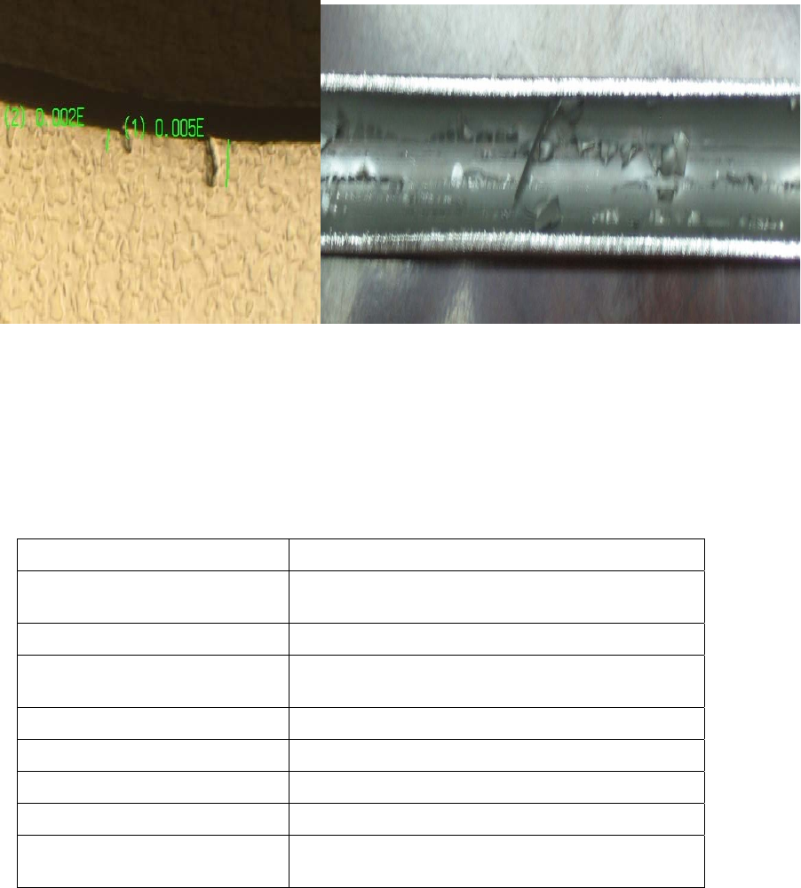
ID surface flaws. An example of these flaws are shown in Figure 1. The higher chromium level
of stainless steels require more care during piecing compared to carbon and alloy steel hollows.
And the potential for these flaws is far lower with extrusion than rotary piercing. This can be
limited by proper process selection and an additional honing operation after the piercing.
Since welded and cold worked tubing manufacturing was developed 65 years ago, there have
been many processing and testing advancements. These have created technical and commercial
advantages for the welded and drawn tubing over seamless products. In North America, the vast
majority of stainless steel feedwater heater and condenser tubing is used in the welded, cold-
worked, and annealed condition. Even though the seamless tubing enjoys an ASME Code
advantage allowing a 15% thinner wall, little, if any, is used in feedwater heaters. The welded
and cold-worked tube manufacturers have developed standard proprietary manufacturing
processes and testing focused toward feedwater heater applications that most seamless producers
have not followed. A summary of the advantages of each product is listed in Table 1.
3
Figure 1 ID flaws in seamless tubing. The hollows made by the extrusion process are on the left and the
rotary piercing process on the right.
At one time, three welded manufacturing plants in the United States were optimized for stainless
steel feedwater heater tubing. This drove the developments of tubing with low residual stress,
special eddy current tests, more stringent OD tolerances (over standard welded ASTM A 249 /A
268 material), ability to offer high speed ultrasonic testing, high tolerance u-bending, and special
surface cleanliness requirements. The predominately seamless tube mills ignored this market and
do not follow these practices.
Seamless SA 213 Welded, and Cold Worked SA 688/803
15 % ASME wall thickness
advantage Excellent eccentricity
Tradition in pressure applications Low residual stresses available
Available with very thick walls More stringent eddy current test available (such as SA
688-S1 or S2)
Highly ultrasonic testable
Air-under-water test available
Chemistry optimized for seal welding
Lower total cost
Specialized ASME specifications for specific
application
Table 1. Advantages of seamless vs. welded and cold worked tubing used in feedwater
heater applications
Common Stainless Feedwater Heater Alloys
Welding techniques matured such that almost every austenitic, duplex, and full ferritic grade that
is made in strip form can be manufactured into a high quality tubular product by welding.
Common grades, such as TP 304, TP 316, and their derivatives, are chemistry balanced to form a
small amount of ferrite during solidification. The ferrite formation in these grades allows a wide
processing range during coil processing and welding, because the shrinkage during solidification

4
is compensated for by the different volume of the two phases. This reduces the risk of weld hot
cracking and also helps to allow higher processing speeds. Grades that do not form the
compensating second phase during solidification, such as the higher alloyed austenitics, and the
ferritics, such as TP 439 and SEA-CURE® require significantly more care. Welding gasses,
process speeds, and other parameters are modified from typical 300 series parameters to provide
a high integrity weld.
Major Elements - Percent Alloy Name UNS
Number Chromium Nickel Molybdenum Carbon Nitrogen
Austenitic Grades
TP 304 S30400 18.0-20.0 8.0-11.0 … 0.08 max …
TP 304L S30403 18.0-20.0 8.0-13.0 … 0.035 max …
TP 304N S30451 18.0-20.0 8.0-11.0 0.08 max 0.10-0.16
TP 316 S31600 16.0-18.0 10.0-14.0 2.0-3.0 0.08 max
TP 316N S31651 16.0-18.0 10.0-14.0 2.0-3.0 0.08 max 0.10-0.16
Alloy 800 N08800 19.0-23.0 30.0-35.0 … 0.10 max …
AL6XN® N08365 20.0-22.0 23.5-25.5 6.0-7.0 0.030 max 0.18-0.25
Ferritic Grades
TP 439 S43035 17.0-19.0 0.50 max … 0.07 max 0.04 max
SEA-CURE® S44660 25.0-28.0 1.0-3.5 3.0-4.0 0.030 max 0.04 max
Table 2. Major Chemical Elements of Common Stainless Steel Feedwater Heater Alloys
Table 2 lists stainless steels that have been installed in North American feedwater heaters. The
most common today are the TP 304 derivatives (TP 304, TP 304L, and TP 304N) and TP 439.
The TP 304 derivatives have a large temperature operation range that allows them to be used in
any of the heater locations from the very low pressure to the one at the highest temperature in a
ultra-critical plant. The “L” grade has low carbon which provides significant extra resistance to
corrosion due to sensitization. However, if one specifies “L” tubing, the Code requires the use of
lower mechanical properties mandating thicker walls and a resultant larger heater. One method to
get both higher mechanical properties and good sensitization resistance is to specify TP 304 with
a carbon content not exceeding 0.035%. Increased nitrogen in 300 series alloys results in higher
mechanical properties. ASME allows approximately 9% thinners walls for the higher strength
TP304 N vs. from the non-“N” version. The thinner wall also provides higher thermal
conductivity per unit foot, compounding the advantage as less square feet of surface area is
needed.
TP 316 has been occasionally chosen for feedwater heaters when the user was concerned about
the potential for pitting. However as TP 316 has only 16% Cr vs. TP 304’s 18%, the overall
corrosion resistance improvement is minimal. At today’s $35/lb molybdenum cost, the
justification is difficult. TP316N has been weaned out of the U.S. steel producer’s inventory
grades because of its very low usages. Minimum purchase quantities of TP 316N today are the
product of a heat. This requires purchase increments of 160,000 lbs, rarely justified by the
minimal advantages. The most cost effective option for solving a pitting problem on feedwater

5
heaters is to invest the money into replacing leaking condenser tubing or solving other water
chemistry problems.
AL6XN® and alloy 800 are high performance austenitic stainless steels originally developed for
their corrosion and high temperature applications. The two alloys contain higher nickel that
makes them resistant to chloride stress corrosion cracking and provides them with excellent high
temperature strength. It also makes them an expensive choice, and results in a lower thermal
conductivity. Fortunately, the high temperature strength allows thinner walls and this helps to
alleviate some, but not all, of the addition cost. AL6XN and TP 439 are often specified when a
utility is concerned about chloride SCC. Since TP 439 has a temperature restriction of
approximately 600 F, the AL6XN is popular for high pressure heaters. Alloy 800 was used for
several heaters in the late 1980’s and those have operated without problems. AL6XN has been
used in approximately 35 feedwater heaters since 1985. Of those, tubes in two have failed from
chloride stress corrosion cracking (at temperatures above the design), and one has had tube
cracking that is believed to be related to water chemistry and oxygenated control.
ASME Specifications
Years ago, seamless stainless steel feedwater tubes were originally specified to SA 213, while
welded austenitic and ferritic feedwater heater tubes were specified to SA 249 and SA 268
respectively. These specifications were developed for general heat exchanger and boiler tubing.
They proved insufficient for the demanding requirements needed in feedwater heaters. SA 688
was developed for austenitics, and later SA 803 for ferritics, to address the need for additional
requirements. These requirements are summarized in Table 3.
Requirements SA 249/ SA 268 SA 688/ SA 803
Non-Destructive Evaluation Non-destructive electric test or
Hydrotest
Optional – Air-under-water test
Non-destructive electric test and
pressure test
Optional –Testing to OD/ID Notches to
S1 or S2
OD Tolerances Standard per SA 1016 More restrictive @ +/- .004”
Surface Chloride Requirement Not addressed 1 mg per square ft
Straight tube IGC testing Not addressed Required per A262-E each heat
U-bend area IGC testing Not addressed Required per A262 on Row 1
Heat treat after bending Not addressed Requirements clear defined when
specified
Bend radius tolerance Not addressed +/- 1/16” maximum
Flattening of bend region Not addressed No more than 10% from straight tube
Bend “ski tip effect” Not addressed No more than 1/16”
Packaging Not addressed Specific to limit problems for bends
Table 3. Summary of requirement for general tubing specifications SA 249/SA 268 vs.
feedwater heater tubing specifications SA 688/SA 803
The Welding Process
Three types of welding processes are commonly used for welding stainless steels: tungsten inert
gas (TIG or GTA), plasma welding, and laser welding. All three of these techniques are
considered “fusion” methods since the weld is completely molten. Techniques, such as high
6
frequency induction welding or resistance welding, that rely upon a “mushy” weld zone, do not
work well welding stainless steels. The high chromium content absorbs oxygen that interferes
with bonding of the two strip edges. TIG and plasma welding are the most common methods for
feedwater heater tubing, followed by laser welding for less critical applications.
Virtually all welded tubing pressure tube grades that have ASME coverage are produced without
the addition of filler metal. Filler metals are usually used when additional cold working and heat
treating may not be available for the final product. This is restricted to large diameter pipe. On
power heat transfer tubing, today’s most common practice includes cold working the weld and
heat-treated the entire pressure tube, thus restoring the mechanical and corrosion resistant
properties of the original parent material. Filler metal, with the additional needs for quality
control, creates more risk than rewards on small diameter product.
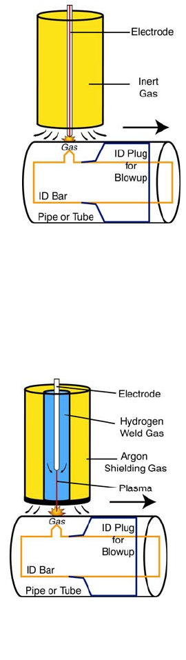
Tungsten Inert Gas (TIG)
Tungsten inert gas (TIG) is the most commonly used welding process
(Figure 2) for stainless steel feedwater heater tubing. During TIG
welding, an arc is maintained between a shaped tungsten electrode and
the tube. Inert gas is used to shield the molten puddle on both the OD
and the ID. To provide good weld shape, a tube manufacturer may
control the ID pressure by using a ID seal arrangement and controlling
pressure. The TIG method provides for a fairly wide (blocky)high
quality weld with good penetration. The blocky shape offers two
advantages. First it will tolerate minor rolling (misalignment) of the
tube during the welding process, and it provides more weld
reinforcement which enables greater cold reduction during the in-line
cold working operation.
Plasma Welding
Plasma welding (Figure 3) is used when greater penetration is needed. In this method, high
temperature ionized plasma is used to provide the energy. Because of its very high-localized
power, it cannot be used on small diameter tubing if an ID cold working mandrel is on the same
piece of equipment. Plasma’s greater penetration develops welds that are narrower than TIG for
the same thickness material.
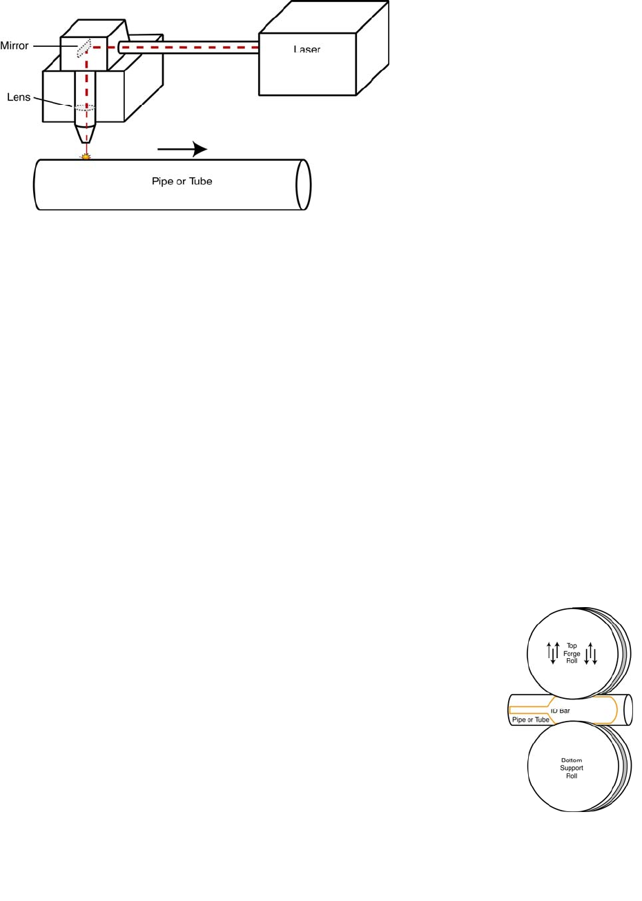
Laser Welding
With the advent of higher power dependable lasers, laser welding
(Figure 4) of stainless steel tubing has become a reality. Because of
its high energy density, the laser produces the narrowest weld of the
three methods. With the increased usage of laser welding, an
interesting controversy has developed. The two acknowledged
advantages are that it provides the highest welding speed and the
least volume of segregated cast material.
Figure 2 – Schematic of
TIG tube welding
Figure 3 – Schematic of
plasma tube welding
7
Figure 4 Schematic of laser welding of stainless tubing
However, the very narrow weld has the disadvantages of an increased potential for off-seam
welding and little opportunity for cold working the weld. Very sophisticated seam tracking, and
edge preparation equipment is mandatory with laser welding. The controversy as to whether less
segregation combined with less cold work is better than being able to more heavily cold work a
weld with greater segregation has no definitive answer.
Weld Bead Cold Working
The purpose of cold working is to assist with homogenization of the segregated as-cast weld
structure ensuring that the mechanical properties, dimensions, and corrosion resistance are
consistent around the tube perimeter. Proper weld bead working is analogous to the tube
reducing or drawing of a seamless hollow. Cold working can be grouped into two categories - in-
line bead working and cold drawing. Typically, the inline methods are used on feedwater heater
tubing with wall thicknesses up to .083”. Cold drawing is commonly performed on wall
thickness exceeding .065”, but can be specified for thinner walls, when desired.
In-Line Bead Reduction
In-line bead reduction is the localized cold working of the weld bead directly on the forming and
welding mill. It is performed immediately following welding to ensure that the weld is
maintained in a controlled position. The cold working is accomplished
by applying pressure with roll tooling on the OD surface, reinforcing the
ID with a hardened mandrel, and supporting the opposite side of the tube
with another roll.
Roll Forging
Roll forging (Figure 5) is a method where the top and bottom roll are
fixed longitudinally and the top roll oscillates vertically hammering or
forging the weld. An ID mandrel, usually made of carbide, is centered
in the tube under the forge roll providing support for the tube and
mandrel.
Figure 5 –Schematic
of the roll forging
method of cold
working
8
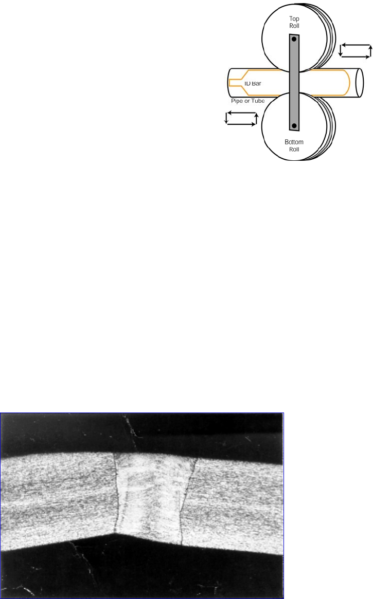
Reciprocating Roll Down
The reciprocating roll down method (Figure 6) uses a
carriage containing two rolls – the top directly centered
over the weld and the other on the bottom side of the tube.
The carriage slowly reciprocates back and forth
longitudinally. The load is normally applied only when the
stroke is in one direction. The mandrel on the ID of the
tube is longer than the stroke and is kept firmly in position.
The length of the stroke is traditionally related to the OD of
the tubing (i.e. larger tubing = longer stroke).
OD Sizing and/or Cross-Polishing
OD sizing is the term used by passing the tube through the
last stages of rolls to set the final size in the tubing.
Typically, this sizing operation reduces the OD of the
tubing approximately .003” to .006”. Virtually all roll form / welding mills contain this process
stage. As no ID mandrel is used during this operation, the actual cold working is very minimal,
less than 1%. This means that cold working has little impact on weld refinement that is needed
for improved corrosion resistance and properties. To lower cost, some tube suppliers us this
sizing operation as their sole cold working mechanism. It should not be considered as a
substitute for full cold-working using an ID mandrel, particularly for critical applications such as
feedwater heaters.
Do not consider using a tube where polishing is used as a substitute for cold working. If seam
alignment is not perfect, the polishing operation can selectively remove material from one side of
the weld. This results in localized regions where the wall may fall below the minimum thickness
of the specification (Figure 7). These defects are impossible to detect using either eddy current
testing or shear wave ultrasonic testing. A cold working method utilizing ID tooling will correct
this imperfection, provided the polishing is not performed.
Figure 7 – Photo micrograph of a tube weld where the strip edges were not properly aligned and the OD
surface was smoothed by cross polishing. The wall thickness at the left edge of the weld is below the
minimum wall requirements
Figure 6– Schematic of the
reciprocating roll down method of
cold working
9
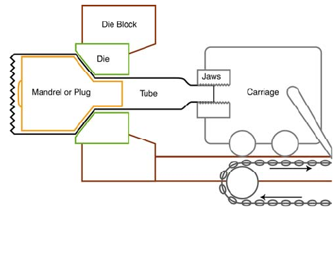
Cold Drawing
Cold drawing is a full cross-sectional
reduction method. Originally developed for
the seamless process, it provides the greatest
amount of effective cold work of any
feedwater heater tube methods. As seen in
Figure 8, the tube is mechanically pulled
through a die reducing the OD size. The ID
is supported with either a fixed plug or a full
length bar.
Advantages
For feedwater heater applications, the
following advantages are possible.
• Tighter Tolerances - The cold drawn process is capable of providing approximately half of
the traditional roll formed OD tolerance. These tolerances can be significantly tighter than
seamless cold drawn tolerances since the welded hollow is very concentric. When this
process is performed, the weld can be very difficult to distinguish.
• Smoother Surface Finishes - The cold drawing operation provides an ironing effect on both
the OD and ID surfaces. This smoothes the surface, thus reducing the roughness, commonly
measured in Ra. Typical surface finish of a cold drawn material is in the 20-30 microinch Ra
or better.
• Wider OD-to-Wall Ratio Range - Very heavy or very light wall welded tube can be made by
starting with a larger diameter tube and drawing to the final size. This allows the use of
thicker or thinner walls than possible with roll forming and welding.
• Improved Homogeneity of the Weld - Multiple cold draw passes can provide substantially
more cold work than bead working. This can result in a wrought equiaxed structure with no
evidence of a prior weld. Other ASTM specifications, such as ASTM A 312, A 249, and A
270, have adopted an HCW class that can be produced using two cold drawing operations or
other heavy work methods.
• More Stringent Testing Requirements – As the process irons the walls, provides a very
concentric product and provides better weld homogeneity, more stringent non-destructive
testing standards can used on cold-drawn welded product than for tubing made by any other
process.
• Higher Strength - Most stainless steels are not heat-treatable for higher strength. For many
applications, such as mechanical or aircraft applications, stainless steel tubing is cold drawn
to raise the tensile and yield strength. In some cases, the yield strength may be three times
the annealed value. However, in most heat exchanging applications, the benefit of cold
working is not recognized, especially when ASME Code requirements are needed. This
could be an advantage when utilizing the European PED requirements.
Cold-drawn tubing is higher priced due to the extra processes such as pointing, lubrication,
drawing, degreasing, and annealing. However, the advantages often outweigh the cost. The
more stringent NDE testing on cold drawn tubing allows the identification of smaller
Figure 8 – Schematic of the cold drawing method for
cold working of the tube
10
imperfections that would not be recognized on tubing that is seamless or roll formed to size.
Signals from smaller imperfections on these products may be indistinguishable from the
background noise of the tube. As the tube is cold drawn, the signal to noise ratio improves. Any
imperfection can be a stress concentrator and elimination of the larger ones can provide a tube
with less likelihood of failure
Carburization from incomplete lubricant removal is always a possibility if extra care is not used
during the degreasing operation. The result is sensitization and decreased corrosion resistance.
Lubricant removal becomes very difficult when the tubing is small diameter and very long, such
as in feedwater heater tubing. An intergranular corrosion test in accordance with A262 should
be carefully followed and specified when this process is used.
Heat Treatment Options
For optimum corrosion resistance, all stainless steel alloys should be annealed after the welding
and cold working operations. This homogenizes the weld improving both the mechanical
properties and corrosion resistance. Tubes may be annealed one at a time in-line or in multiples
using an off-line operation. The optimum method is a function of the alloy, application, and cost
effectiveness. Both are considered to be continuous operations.
In-Line Heat Treating
In-line heat treating is the most common method of annealing stainless steel tubing. In this
method (Figure 9), the tube is heated with an induction coil to the desired temperature and then
rapidly cooled with either water, convective gas such as hydrogen, or an inert gas such as argon.
The heat treatment is performed in-line on the welding mill usually immediately following the
in-line cold working operation (if one is performed). Temperature is monitored using optical
pyrometry. When induction annealing is performed, the time at which the tube is at temperature
is very short. Energy is put into the tube only during the time that the tube is in the coil. The
coil is usually only a few inches long. Once the tube leaves the coil, the cooling process starts.
Figure 9 Induction annealing of stainless steel tubing
Following are a summary of the advantages and
disadvantages of the method:
Advantages
• Low Cost - Since it is in-line with the welding operation, additional costs are minimal.
• Highest Quench Rate – When combined with a high pressure encircling ring, the highest
quench rate of any method is possible. Some alloys, like the super ferritic and super duplex
Figure 10 – In-line water quenching
11
alloys, require this method to guarantee sufficient quench (Figure 9) for prevention of
detrimental second phases. These secondary phases significantly reduce corrosion resistance.
Disadvantage
• Short Homogenization Time – Stainless steels containing more than 6% nickel have slower
diffusion kinetics. The in-line anneal will not completely homogenize these grades.
Homogenization should not be confused with solution annealing. The term “solution
annealing” normally refers to dissolving of chromium carbide particles that lower
intergranular corrosion resistance. When overall corrosion resistance or long term
performance is the primary concern, a separate furnace homogenizing anneal should be
considered. Furnace annealing should always be specified on higher alloyed austenitic alloys
or the heavier wall thickness 300 series feedwater heater tubing.
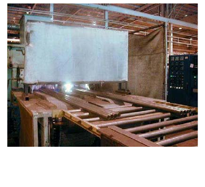
Off-Line Furnace Annealing
The off-line separate “furnace anneal” provides a
significantly longer time at temperature than the in-
line anneal, typically in the five to ten minute
range. This is the time frame needed for full weld
homogenization of the alloys containing greater
than 6% nickel. Since these continuous furnaces
are designed with rollers or belts and has an open
inlet and outlet, tube lengths are not restricted.
Multiple tubes are annealed in a single layer in this
type of furnace (Figure 10).
Advantages
• Greater Homogeneity & Corrosion Resistance - The longer hold time provides for greater
homogeneity and general corrosion resistance for the austenitic grades. This is especially
important for alloys with higher nickel and molybdenum concentrations and feedwater heater
tubing.
• More Predictable & Consistent Properties - This may be important if high ductility and low
hardness is needed for forming operations. Tubing to be u-bent for feedwater heater
applications benefits from this method, as the predictable properties are needed to produce
bends with very consistent dimensions.
Disadvantages
• Higher Cost – Off-line furnace annealing has a higher cost especially at today’s higher
natural gas, hydrogen, and electrical costs.
• Additional Operations – Tubes may need additional straightening, sizing, and cutting
operations after anneal.
• Slower Quench Rates - Quench rates are not as quick as induction anneal. Although
sufficient for austenitic alloys, the furnace anneal should not be used for the super ferritics
and super duplex grades.
Figure 11 – Off-line furnace annealing of
feedwater heater tubing
12
Heat Treat Atmospheres
Two types of atmospheres are commonly used during heat treatment - bright annealing and open
air. These atmospheres can be used with either in-line annealing or furnace annealing.
Bright Annealing
Bright annealing employs a reducing gas atmosphere, such as hydrogen, that minimizes the
formation of oxides. Because the thermodynamics of the hydrogen/oxygen reaction are not
active at lower temperatures, bright annealing is only effective when the annealing temperature is
above approximately 1850° F. Alloys that require a lower annealing temperature, such as TP
439 and super ferritics, cannot be effectively bright annealed. To keep the tube surface bright,
the atmosphere needs to be maintained during both heating and cooling to temperatures below
700 F. Water quenching is not an option as the water will cause scale formation. Therefore,
bright annealing quench rates may not be sufficient for some ferritic and duplex alloys when
corrosion resistance is critical. Since the surface of a bright-annealed tube does not develop a
thick scale, the final tube surface finishes may be smoother.
Open Air Heat Treatment
Open air heat treatment allows water quenching. This ensures that ferritic, duplex, and heavier
wall higher alloy austenitic alloys that have potential for forming detrimental second phases will
not be degraded. However, the exposure to the air and water results in a scale on the tube
surface. This scale must be chemically removed for optimum corrosion resistance.
Chemical Pickle / Passivation
When an oxide forms on the surface of a stainless steel tube during heat treatment, it is
predominately chromium oxide. The scale is usually porous and cracked, and therefore, not very
protective. Beneath this scale is a region of chromium depletion that has inferior corrosion
resistance. In applications requiring high corrosion resistance, it is very important that this
chromium-depleted layer be removed (ref. 2, 3). Mechanical polishing may re-embed these
chromium-depleted layers in the surface, having little beneficial effect. The only sure way to
completely remove all depleted material is to use a chemical process. This is commonly
accomplished using nitric acid or citric acid solutions. Some guidelines for these solutions and
tests for results can be found in ASTM A 380 and ASTM A 967. In feedwater heater
applications, the condensate on both surfaces of the tube is not considered to be aggressive. The
oxide scale that forms in the bend region from the stress- relief heat treatment is rarely removed.
The authors know of no known tube failures related to allowing the scale to remain in this
application.
The chemical scale removal method has some additional benefits for tubing. It can act as a
100% corrosion test of the tubing, particularly when performed before the final eddy current test.
The acid will aggressively attack any sensitized areas or any inhomogeneities such as manganese
sulfide inclusions exposed during prior processing. When an attacked region enters the eddy
current coil, the alarm sounds and the tube is rejected. The most common chemical passivation
bath contains approximately 20% nitric acid and 3% hydrofluoric acid.
13
Non-Destructive Testing
Electric Tests
Two types of non-destructive electric tests (NDE) are
commonly used for stainless steel tubing - eddy current
testing (ET) and ultrasonic testing (UT). Each has
advantages and disadvantages.
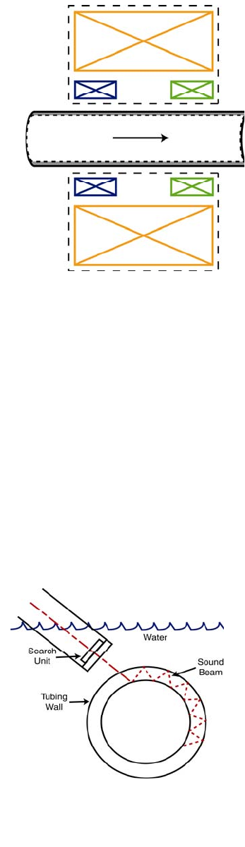
Eddy Current Testing (ET)
Eddy current is the dominate test used for almost all stainless
steel tubing. During production, the tubing is tested from the
outside. The method utilizes a full encircling, differential
coil that is most sensitive to sharp abrupt defects (Figure 12).
The eddy currents are developed by an induced alternating
magnetic driver coil which is represented by the yellow coil.
In this figure, both the blue and green coils are used for
detection of signals produced by imperfections passing
through them. The electronics are balanced so that if the
signal detection is identical in both the blue and green coils,
no signal to the scope or alarm is generated. The differential
coil is not very sensitive to long gradual imperfections that
bridge both sections of the detector coils. The amplitude of the signal from the imperfection is
directly related to its volume.
Advantages
• Cost – ET testing is fast and therefore, relatively inexpensive. Testing rates can exceed 100
meters per minute.
• Locates Partial Wall Defects – This method finds imperfections that are not through wall.
• Volume Sensitivity - This testing is most sensitive to sharp abrupt imperfections with volume.
Disadvantages
• Volume Required - Defects must have volume in order to be identified. Tight narrow defects
may be missed.
• Insensitive to Longitudinal Defects – Since the signal is
generated from volume differences between the two
differential sensing coils, longitudinal gradual
imperfections may produce little or no signal, and are
unlikely to be rejected. Ultrasonic testing should be
specified when longitudinal defects are a concern.
• Attenuation - This causes OD defects to be more easily
found than ID defects.
The most common acceptance criteria is the use of a drilled
through wall hole no larger 0.031” in diameter. The
definition of this is in ASTM A 1016. Longitudinal and
transverse OD and ID notches can also be specified. These
Figure 12 – Schematic drawing of
a full encircling differential eddy
current testing coil
Figure 13– Schematic of an
ultrasonic signal propagating
through the tube wall
14
are defined in ASTM A 688 and A 803 Supplements 1 and 2. The S2 supplement provides the
greatest sensitivity for finding and rejecting small imperfections. The S2 notch requirement is
normally only available on cold drawn tubing where the surface anomalies have been ironed
smooth.
Ultrasonic Testing (UT)
The UT testing method sends a focused sound wave (called a shear wave) into the wall of the
tube and then detects the echo that is reflected back from an imperfection (Figure 13). It is
normally performed by sending the sound wave in a circumferential direction around the tube.
As angular defects may reflect the sound wave differently, the tube should be tested in both
directions.
Advantages
• Finds Longitudinal Defects – Contrary to differential eddy current testing, UT testing is
most sensitive to longitudinal straight defects such as cracks and incomplete welds. The
technique is not particular affected by the defect volume like ECT. Tight narrow defects are
easily found.
• Dependable for Heat Exchanger Sizes – This testing provides a good signal from ID defects
on standard heat exchanger sizes. As the depth of the signal can be orders of magnitude
greater than ECT, attenuation is not a significant issue.
• Finds Partial Wall Defects – This method finds imperfections that are not through wall.
Disadvantages
• Cost - The test is slower and relatively more expensive than ECT. However, for feedwater
heater applications, the small additional cost could be well justified.
• Limited Sensitivity – This method is not normally sensitive to short transverse defects or
defects not oriented to reflect the sound wave directly back to the transducer. These defects
are commonly detected by ECT.
• Requires Furnace Anneal – The ultrasonic signal can be reflected by changes in crystal
structure or significant grain size differences. This may require a full furnace anneal.
The common artificial defect used to calibrate this test is OD and ID longitudinal notches 12.5%
as deep as the specified wall thickness. These notches are defined in ASTM A 1016.
Pressure Testing
Three kinds of pressure testing are commonly used on welded heat exchanger tubing: air-under-
water testing, pressure differential/pressure decay
testing, and hydrostatic testing.
Air-Under-Water Testing
The air-under-water testing method (Figure 14) is
performed by placing air-pressurized tubes in a well lit
tank of water while an operator walks the length of the
tank looking for bubbles. Typical pressures are 150-
250 PSI. Because of its low cost and high sensitivity,
this is the most common pressure test used for welded
Figure 14 – Air-Under-Water Testing
15
heat exchanger tubing. When pressurized at 150 PSI, tube leaks as small as .001” can be
detected and those as large as .002” can be regularly found (ref. 4).
Advantages
• Sensitivity – This is the most sensitive of the common pressure methods.
• Cost - Air-under-water testing is low cost – currently a few pennies per foot.
Disadvantages
• Operator Dependant – The sensitivity of this method may be subject to fatigue of the
operator.
• Defect Limitations - The defect must be through wall in order to be detected.
Pressure Differential /Pressure Decay Testing
The pressure differential testing method became a production reality with the development of
high sensitivity electronic pressure sensors. Currently, it is commonly used for testing welded
titanium tubing. The pressure differential test is performed by pressurizing two tubes to the same
pressure, closing off the pressure source, and monitoring the differential pressure between the
two tubes. If the differential exceeds a predetermined limit, an alarm sounds. A description of
the methods have now been developed in ASTM A 1047. However, as of the time of publishing
of this paper, no acceptance criteria is defined.
Advantages
• Cost – This is a low-cost method.
• Sensitivity – Pressure differential testing is the second most sensitive common test when used
at production rates.
• Operator Independent - This method is not subject to operator fatigue.
Disadvantages
• Defect Requirement - Defects must be through wall in order to be detected.
• Parameters - These must be selected carefully to ensure good testing. As of this date, an
acceptance criteria has not yet been agreed in ASTM. The smallest calibration hole allowed
by A 1047 is .003”. However, larger holes may be required for reasonable cost.
Hydrostatic Testing
Traditionally considered the workhorse of pressure testing, the hydrostatic testing method is
gradually being phased out when other methods are available. For many years, hydrostatic
testing had been the required NDE for a seamless product. ASTM and ASME have now adopted
ET as an alternative test for most seamless products. Hydrostatic testing is significantly less
sensitive than air-under-water testing. At normal production rates, only fairly gross defects are
found. In the ASTM NDE task group work (ref. 4), hole sizes of 0.002”, are almost
undetectable. In general, on welded product, hydrostatic testing is performed only when required
by the specification.
16
Advantage
• Meets ASME Code – Hydrostatic testing is used to meet Code requirements.
Disadvantages
• Lowest Sensitivity – This method is the least sensitive of the common pressure methods.
• Cost – Hydrostatic testing has the highest cost of pressure test methods.
• Operator Dependant - This method may be subject to fatigue of the operator.
• Defect Requirement - Defects must be through wall in order to be detected.
Residual Stress Testing
Most stainless steels are susceptible to chloride stress corrosion cracking. This occurs when the
tubing incurs a combination of three factors; trace amounts of chlorides, high stresses, and a
temperature above a minimum of at least 150 degrees F. A variety of stress sources are
possible: residual stresses from the tube manufacturing, thermally induced stresses, pressure
induced stresses, and other mechanical stresses from operations. The sum of all stress sources is
what drives the cracking. However, residual stress in the tube can be the primary source if not
controlled. Rotary straightened tubing may have residual hoop stresses near the yield strength of
the tube.
All stainless steels are not equally susceptible to chloride stress corrosion cracking (SCC).
Copson and Chang (ref. 5) determined that the alloys most susceptible were those containing 8%
nickel, not unlike TP 304. Lower and higher nickel content resulted in more resistance. Crucible
Materials Research performed a series of test duplicating heavily faulted feedwater applications
(ref. 6). These tests were performed in high temperature autoclaves that ensured that the water
was in a liquid state at the high temperatures of the test. The samples were created by using strip
samples and bending them in the shape of a “C” and holding the shape using an insulated bolt.
This develops stresses in the outer fibers at the yield strength of the material. The samples
exposed to three levels of chloride at three different temperatures. The results of that test are
shown in Table 4.
This data shows that the susceptibility is a function of alloy, chloride content in the water, and
temperature. The results parallel the work of Copson & Chang; the potential for failure due to
chloride SCC is a function of nickel content. The highest potential is when the nickel content is
approximately 8%. TP 439, which has a nickel content of less than 0.5% did not crack even in
the most extreme conditions. UNS S44660, which has a nickel content of approximately 2%,
only cracked under the most extreme conditions. Alloy 2205, a duplex stainless steel commonly
used in HRSG’s, was slightly more susceptible, cracking at the highest temperature but lowest
chloride content. TP 304, an alloy containing 8% nickel, cracked at the lowest test temperature
and highest chloride level (it also cracked at the lowest chloride level at the intermediate
temperature). The nitrogen containing TP304LN failed in a lower chloride content than TP
304L. This is attributed to the combination higher stresses from the higher yield strength of
TP304LN and the design of the test, causing stress levels at the yield strength. This implies that
when TP 304LN is used at the higher Code allowable stresses over TP304L, it will be more
17
susceptible to failure when chlorides are introduced to the condensate. Alloys containing nickel
content above 8% have decreasing sensitivity as the nickel content increases.
Test Temperature Degrees F
250 350 450
Chloride Content (ppm)
Grade Ni
% 100 1,000 10000* 100 1,000 100 1,000
TP 439 0.4 nt nt nt nt OK OK OK
S44660 2 nt nt nt nt OK OK Cracked
2205 5 nt nt nt nt OK Cracked nt
TP 304L 8 OK OK Cracked Cracked Cracked Cracked Cracked
TP 304LN 8 OK Cracked Cracked Cracked Cracked Cracked nt
TP 316L 11 OK OK OK Cracked Cracked Cracked nt
S31254 18 nt nt nt nt OK Cracked Cracked
N08367 25 nt nt nt nt OK Cracked Cracked
* Testing Terminated in 15 days
Table 4. Stress corrosion cracking testing of various alloys using “C” ring samples held with insulated
bolts. The testing was performed for 28 days unless otherwise indicated. The testing was performed in high
pressure autoclaves to ensure that the test solution was always liquid. The term “nt” means that samples
were not tested in those conditions.
This work indicates that tubes in those grades containing 5% to 15% Ni should be manufactured
to restrict residual stress when used in elevated temperature applications, such as feedwater
heater tubing. This is done using proprietary annealing and straightening operations. Residual
stress should be measured on a regular basis during production; typically every 200 tubes. The
most common method for hoop (circumferentual) stress is the Thirkill split ring method shown in
Figure 15 (ref. 7)
Figure 15. Thirkill split ring sample for measurement of residual hoop stress
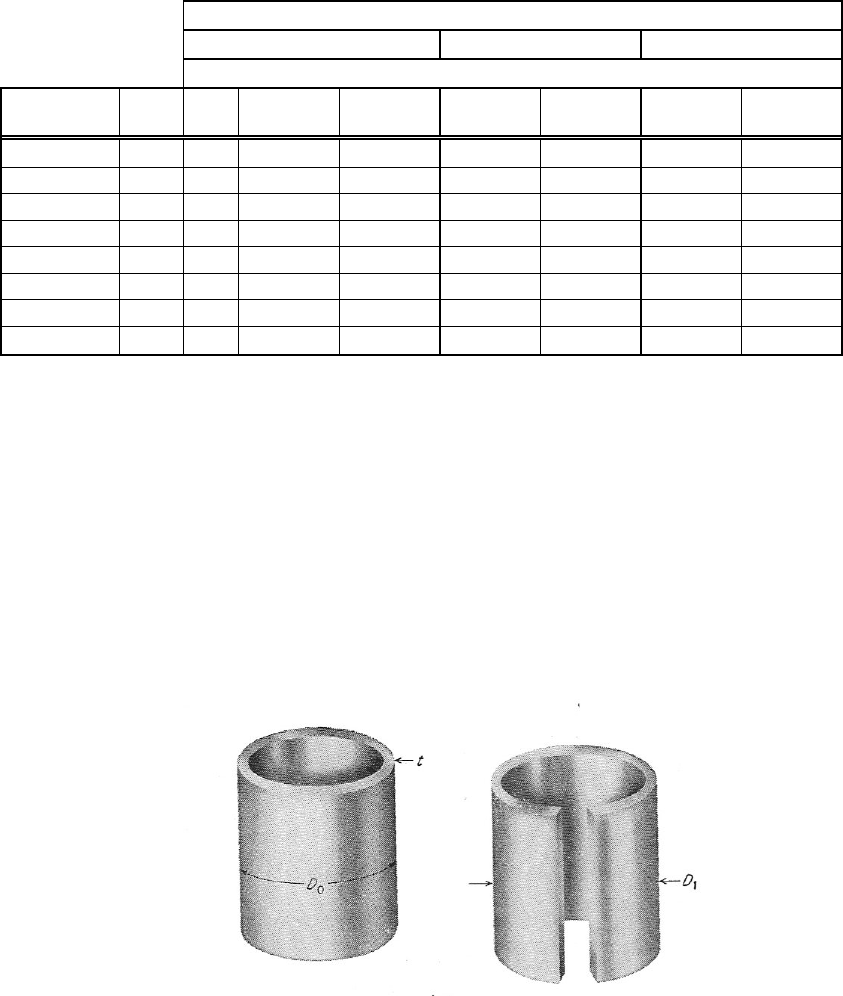
Although when the tube is properly processed the longitudinal stress is normally lower than the
hoop stress, the specifier may want to require occasional measurements for longitudinal stress.
This can be accomplished using the tongue deflection test shown in Figure 16.
18
Figure 16. Tongue deflection method for determination of longitudinal residual stress
Measuring residual stresses in a compound curved region is much more challenging. Neither the
split ring nor the tongue deflection methods are effective in the u-bend region. Even though a
separate stress relief anneal is commonly performed on the bend area after bending, in some
cases, a user may want know if the heat treatment was effective. A strain gage technique,
described in ASTM E 837, utilizes an attached strain gage that monitors the deflection while a
hole is drilled through the center. An example is shown in Figure 17. This method does not
have the precision that the previously two methods described. Typically, the residual stress for
this method is reported to be +/- 5000 psi. This test is also relatively expensive, in the $600 to
$1000 per sample range.
Figure 17. A u-bent tube containing a the drilled-hole strain gage method for determination of residual
stresses
Typically, on grades that are susceptible to cracking, EPRI’s feedwater Guidelines (ref. 8)
recommends a maximum residual stress of 5000 psi. The
ability to meet this requirement is a function of OD to wall
ratio. It is more difficult to prevent higher residual stresses
on thin wall tubes. Fortunately, the lower stresses available
on heavier walls are needed on products that are used in
higher pressure and temperature applications.
In-Process Mill Quality Control Practices
Reputable tube mills use a combination of visual inspection,
in-process eddy current testing, and manipulation
(destructive) samples to continuously monitor the quality of
the weld.
Figure 16 – Flatten Test
19
Manipulation (Destructive) Testing
Manipulation tests are designed to specifically test the ductility
of the weld in various directions. The weld is bent in a manner
to strain a specific surface (OD or ID) in a specific direction (in
the direction of the weld or transverse to the weld). Detailed
explanations for how each test is to be performed is included in
ASTM A 1016. Manipulation tests include:
• Flatten Test - This test is designed to test the transverse
weld ductility
on the exterior surface (Figure 18).
• Reverse Flatten Test - This test was developed to test
transverse weld
ductility on the ID surface (Figure 19).
• Reverse Bend Test - For austenitic stainless steels that are
considered
to have a greater ductility than others, this test is a higher
strain version of the reverse flatten test (Figure 20).
• Flange - This test, which starts out as a flaring operation, is
the test for
longitudinal weld ductility, primarily on the ID surface
(Figure 21).
• Tensile Test - Although not generally considered a
“manipulation test”
(since the tensile sample on welded tubing requires the weld
to be tested), it is a test of longitudinal weld ductility.
Minimum sampling rates for the various manipulation tests are
specified in the appropriate ASTM product specification. These
are listed as a test per maximum of length or maximum number
of pieces. Most high quality welded tube producers will perform
manipulation tests at a much higher frequency during the welding
process, in addition to the ASTM required certification tests on
the final product.
Corrosion Testing
Stainless steel is chosen for resistance to corrosion.
Unfortunately, few ASTM/ASME specifications require a
corrosion test. Several types of corrosion test options are
possible.
Weld Decay (A 249-S7) Tests
The weld decay test was developed as a quick test for
monitoring the presence of residual ferrite in a weld. The
boiling HCl readily attacks the ferrite, and if present in the
weld, will cause thinning of the weld at a much faster rate
Figure 19 – Reverse Flatten Test
Figure 20 – Reverse Bend
Test
Figure 21 – Flange Test
Figure 22 – Weld Decay Test
20
than the base metal. For a properly annealed weld, the ratio should be 1.00 or less (Figure 22).
This test is only effective on austenitic grades that form ferrite during solidification. This
restricts the test to primarily 304 and 316 derivatives. The test does not provide meaningful
results on austenitic grades with higher Mo and Ni, ferritic grades, and duplex grades. The test is
most commonly used in the paper and sugar industries where it is common to clean tubing with
muratic acid to remove deposits.
Intergranular Tests
Intergranular tests are tests specified in ASTM A 262, A 763, or A923 that are designed to detect
sensitization from slow cooling rates, insufficient annealing, or carbon and nitrogen
contamination. This test is normally called for to check if an alloy is “solution annealed”. The
“solution annealed” term is most often designated for dissolving chromium carbides, which
ensures that the chromium is available to keep the stainless “stainless”. These tests may not be
meaningful for determining whether an alloy is suitable for an application and cannot determine
if a weld is adequately homogenized for optimum corrosion resistance.
“G” Type Tests
ASTM “G” type tests are acid based pitting and crevice corrosion tests that are intended to
mimic potential applications. The G 48 test is often used testing high performance stainless
when chloride pitting or crevice is a concern. Because of the difficulty of controlling a “crevice”
on a tube, the “pitting” method C of G-48 should be specified for accurate results. These tests
are probably the best choices for applications requiring corrosion resistance. If a project is large
enough to justify some developmental work, the acid blend could be developed to be process
specific.
Summary
The feedwater heater owner is the expert on how the unit will be operated and should specify the
optimum processes and tests on his feedwater tubes to ensure that the heater will perform as
expected. If no specials are specified, the tube producer may assume that the lowest price
product is desired. Ordering to a basic ASTM/ASME specification does not guarantee a good
tube, whether seamless or welded. To meet the demanding requirements for this application, the
following supplemental purchasing requirements should be strongly considered:
• ASME Feedwater heater specifications- Require SA 688/ SA 803 specification as a bare
minimum. Do not allow tubing to be certified solely to SA 249 or SA 268.
• NDE – One NDE test is not sufficient to find defects in all orientations. For sub-critical
power plants, consider the A 688/A 803-S1 eddy current as a minimum. For super or ultra-
critical applications, consider both an ultrasonic test and the S2 eddy current test for the high
pressure units.
• Pressure Testing – Consider specifying and air-under-water test. It has the ability to find very
small leaks that neither the eddy current nor UT will detect. The price is minimal. The
hydrostatic test that is required by ASME is only sensitive to relatively gross defects.
• Cold Working – Require that the weld be cold worked using OD and ID tooling. Simple
sizing does not provide a wrought weld that the ASME design allowables were based on. For
super and ultra critical high pressure tubing, you may what to specify that the tubing be cold
21
drawn. Do not allow cross polishing and the localized wall thinning it causes is almost
impossible to detect.
• Specify Maximum Residual Stress – Austenitic 300 series tubing is very susceptible to
chloride SCC. With use these grades in feedwater heater applications, residual hoop tensile
stress should be restricted to 5000 psi maximum or lower.
• Specify Corrosion Testing – Although A 688 and A 803 require minimal intergranular
corrosion tests, you may want to specify additional testing. The A 249 weld decay test may
be a good choice on austenitic feedwater heater tubing to ensure that the weld is
homogenized. G type tests may be need for applications where corrosion is the major
concern.
• Require Test Plan Approval – Prior to product, require a test plan that you can review.
Sampling rates of internal destructive tests and other inspections are critical.
• Know the supplier - There are no ASTM police! This is your job as the purchaser.
Interpretations of what may be required run the whole gamut. Your expectations may be far
higher than what the supplier believes is sufficient. You may have to live with those
materials for 30 years.
References
1. ASTM Standards:
A 249/A 249M Specification for Welded Austenitic Steel Boiler, Superheater, Heat-Exchanger,
and Condenser Tubes
A 262 Practices for Detecting Susceptibility to Intergranular Attack in Austenitic Stainless Steels
A 268/A 268M Specification for Seamless and Welded Ferritic and Martensitic Stainless Steel
Tubing for General Service
A 270 Specification for Seamless and Welded Austenitic Stainless Steel Sanitary Tubing
A 312 Specification for Seamless, Welded, and Heavily Cold Worked Austenitic Stainless Steel
Pipes
A 370 Test Methods and Definitions for Mechanical Testing of Steel Products
A 380 Specification for Cleaning, Descaling, and Passivation of Stainless Steel Parts,
Equipment, and Systems
A 668/A 668M Specification for Welded Austenitic Stainless Steel Feedwater Heater Tubes
A 763 Practices for Detecting Susceptibility to Intergranular Attack in Ferritic Stainless Steels
A 789/A 789M Specification for Seamless and Welded Ferritic/Austenitic Stainless Steel
Tubing for General Service
A 803/A 803M Specification for Welded Ferritic Stainless Steel Feedwater Heater Tubes
A 923 Practices for Detecting Susceptibility to Intergranular Attack in Duplex Stainless Steels
A 967 Specification for Chemical Passivation of Stainless Steel Parts
A 1016/A 1016M Specification for General Requirements for Ferritic Alloy Steel, Austenitic
Alloy Steel, and Stainless Steel Tubes
E 837 Standard Test Method for Determining Residual Stresses by the Hole Drilling Strain Gage
Method
G 48 Standard Test Method for Pitting and Crevice Corrosion Resistance of Stainless Steels and
Related Alloys by the Use of Ferric Chloride Solution
2. J.F. Grubb, J.J. Dunn, and D.S. Bergstrom. Paper 04291, Corrosion 2004, NACE
Conference.
22
3. J.C. Tverberg. “Conditioning of Stainless Steel Surfaces for Better Performance.” Stainless
Steel World, April 1999
4. O’Donnell, D., Lee, T., Testing performed for the ASTM A01.09/A01.10 NDE Task Group,
April 30, 2001.
5. Copson, H. O., Physical Metallurgy of Stress-Corrosion Fracture. New York: Interscience,
1959, p. 247.
6. Birkholz, W. J., “Stress Corrosion Cracking of Stainless Steels in High Temperature Chloride
Bearing Waters”. Crucible Research Center Program 109-1, May 7, 1992
7. Dieter, G. E. Jr. Mechanical Metallurgy. McGraw Hill, 1961, pp 402-407.
8. “Feedwater Heaters: Replacement Specification Guidelines”, Part 1.4- Tubing Selection and
Preparation, EPRI Final Report GS-6913, Project 2504-5, August 1990.
