Parallax Standard Servo (#900 00005) Rotation Motor Manual V2.1
standard%20rotation%20servo%20motor%20manual%20v2.1
standard%20rotation%20servo%20motor%20manual%20v2.1
standard%20rotation%20servo%20motor%20manual%20v2.1
standard%20rotation%20servo%20motor%20manual%20v2.1
User Manual:
Open the PDF directly: View PDF ![]() .
.
Page Count: 4
Web Site: www.parallax.com
Forums: forums.parallax.com
Sales: sales@parallax.com
Technical: support@parallax.com
Office: (916) 624-8333
Fax: (916) 624-8003
Sales: (888) 512-1024
Tech Support: (888) 997-8267
Copyright © Parallax Inc. Parallax Standard Servo (#900-00005) v2.1 6/9/2010 Page 1 of 4
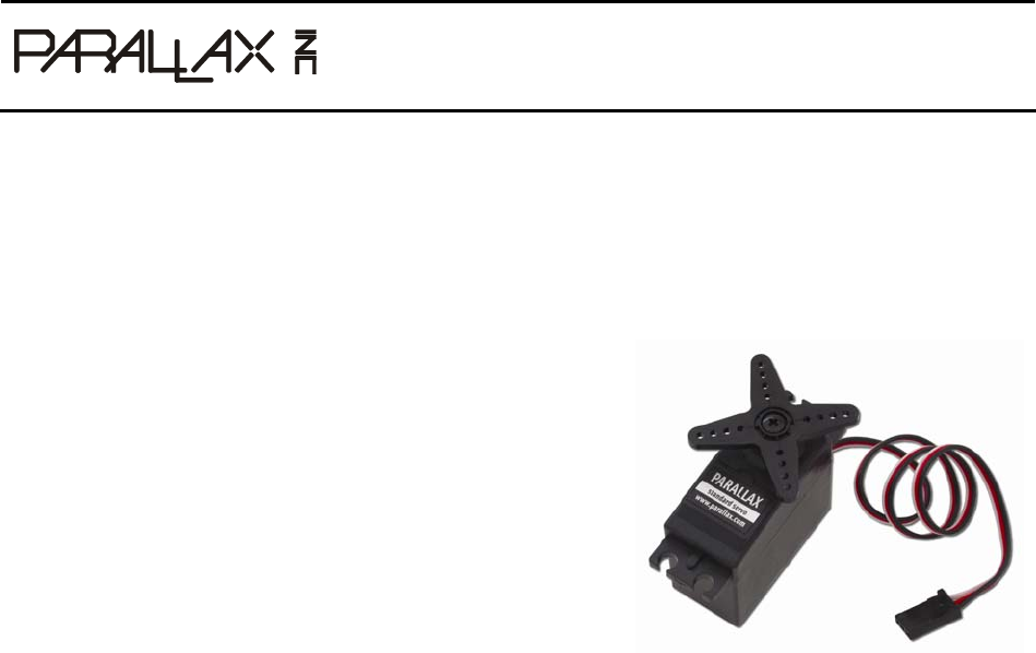
Parallax Standard Servo (#900-00005)
The Parallax Standard Servo is ideal for adding 181° range of motion and position control to your project.
Great for robotics applications.
Features
y Holds any position between 0 and 180 degrees
y 43.1 oz-in torque at 6 V
y Accepts four mounting screws
y Easy to interface with any Parallax microcontroller or
PWM-capable device
y Simple to control with the PULSOUT command in
PBASIC or SX/B
y High precision gear made of POM (polyacetal) resin
makes the operation smooth causing no backlash.
y Weighs only 1.55 oz (44 g)
y Manufactured for Parallax exclusively by Futaba
Key Specifications
y Power requirements: 4 to 6 VDC*; Maximum current draw is 140 +/- 50 mA at 6 VCDC when
operating in no load conditions, 15 mA when in static state
y Communication: Pulse-width modulation
y Dimensions approx 2.2 x 0.8 x 1.6 in (5.58x 1.9 x 40.6 cm) excluding servo horn
y Operating temperature range: 14 to 122 °F (-10 to +50 °C)
*Power Requirement Notes
Futaba specifies 4-6 VDC for this servo. However, we find that this servo is tolerant of a 9 V battery for
very brief periods of time when there is no load, as used in some activities in the Stamps in Class series
of tutorials. (Slight jittering may be observed when batteries are fresh; this does not cause damage). Do
not use this servo with an unregulated wall-mount supply, or a regulated wall mount supply exceeding
6 VDC.
Servo current draw can spike while under load. Be sure that your application's power supply and voltage
regulator is prepared to supply adequate current for all servos used. Do not try to power this servo
directly from a BASIC Stamp module's Vdd or Vin pins; do not connect the servo's Vss line directly to the
BASIC Stamp module's Vss pin.
Copyright © Parallax Inc. Parallax Standard Servo (#900-00005) v2.1 6/9/2010 Page 2 of 4
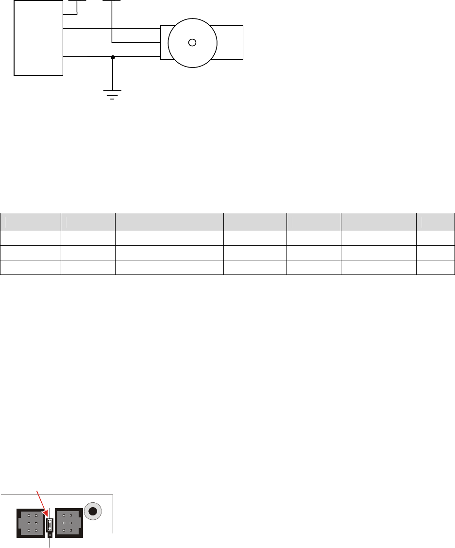
Quick-Start Circuit
Vµ = microcontroller voltage supply
Vservo = 4 to 6 VDC, regulated or battery (See Error! Reference source not found., page Error! Bookmark not
defined. )
I/O = PWM TTL or CMOS output signal, 3.3 to 5 V, not to exceed Vservo + 0.2 V
Specifications
Pin Name Description Minimum Typical Maximum Units
1 (White) Signal Input; TTL or CMOS 3.3 5.0 Vservo + 0.2 V
2 (Red) Vservo Power Supply 4.0 5.0 6.0 V
3 (Black) Vss Ground 0 V
Power Precautions
y Do not use this servo with an unregulated wall-mount supply. Such power supplies may deliver
variable voltage far above the stated voltage.
y Do not power this servo through the BASIC Stamp Module's Vdd pin.
y Servo current draw can spike while under peak load; be sure your application's regulator is
prepared to supply adequate current for all servos used in combination.
y Some Stamps in Class tutorials, such as
What's a Microcontroller?
instruct the user to briefly
power these servos with a 9V battery when using a HomeWork Board and no load; this does not
cause damage.
Board of Education Jumper Connection
When connecting the servo to the Board of Education Rev C’s servo header, be sure the jumper is set to
Vdd (regulated 5 VDC for this board) as shown in the figure below. Failure to place the jumper at this
setting can cause damage your servo.
Black
Red
X4 X5
15 14 13 12
Vdd
Vin
Standard Servo Microcontroller
GND
Vµ Vservo
White
Vss
I/O Red
Black
Vdd
Copyright © Parallax Inc. Parallax Standard Servo (#900-00005) v2.1 6/9/2010 Page 3 of 4
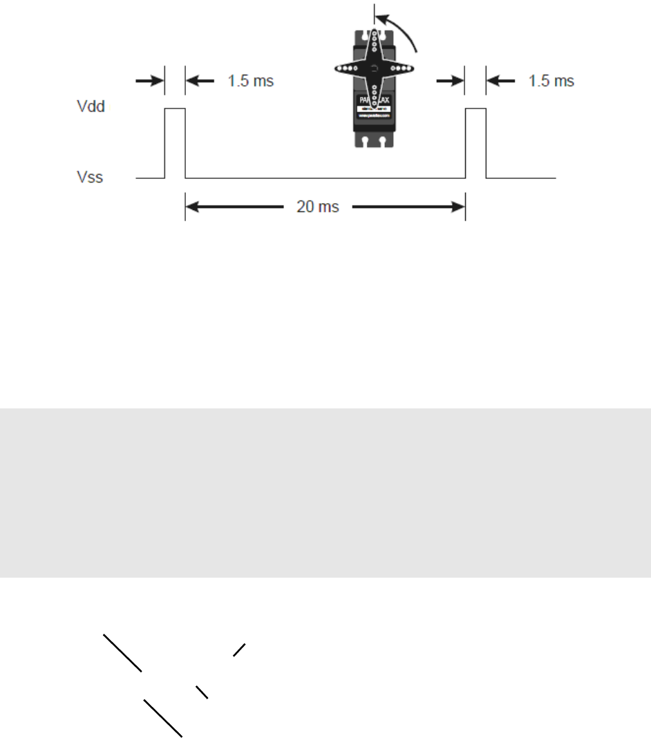
Communication Protocol
The Parallax Standard Servo is controlled through pulse width modulation, where the position of the
servo shaft is dependent on the duration of the pulse. In order to hold its position, the servo needs to
receive a pulse every 20 ms. Below is a sample timing diagram for the center position of the Parallax
Standard Servo.
BASIC Stamp 2 Programming Example
PBASIC has a PULSOUT command that sets the I/O pin to an output and sends a pulse of a specified
duration.
PULSOUT
Pin
,
Duration
The example shown below for a BASIC Stamp 2 causes a servo connected to BASIC Stamp I/0 pin 12 to
turn to and hold its center position for approximately 5 seconds.
' CenterStdServo.bs2
' {$STAMP BS2}
' {$PBASIC 2.5}
counter VAR Word
FOR counter = 1 TO 220
PULSOUT 12, 750
PAUSE 20
NEXT
FOR counter = 1 TO 220
PULSOUT 12, 750
PAUSE 20
NEXT
Number of 44ths of a
second to hold the
position, for the BS2
Position to hold, in 2
µ
s units for the BS2
Required 20 ms
between each pulse
Servo I/O
p
in

Copyright © Parallax Inc. Parallax Standard Servo (#900-00005) v2.1 6/9/2010 Page 4 of 4
For detailed explanations using the BASIC Stamp 2, see
What's a Microcontroller?
Chapter 4, available for
free download from www.parallax.com/go/WAM.
Different BASIC Stamp modules use different units for the PULSOUT command's
Duration
argument.
When adapting BS2 code to another BASIC Stamp model, you may need to make adjustments. The table
below lists the PULSOUT ranges for each BASIC Stamp microcontroller. See the BASIC Stamp Manual or
BASIC Stamp Editor Help for more information.
BASIC Stamp Module 1.3 ms 1.5 ms (center) 1.7 ms
BS1 130 150 170
BS2, BS2e, BS2pe 650 750 850
BS2sx, BS2px, BS2p24/40 1625 1875 2125
You can figure out what the PULSOUT command’s
Duration
argument has to be when you know how
long you want the pulse to last. Just divide the PULSOUT
Duration
units into the time you want the pulse
to last:
(µs) units PULSOUT
(ms)Duration Pulse
Argument Duration
Duration
=
Propeller P8X32A Programming Example
Servo control with the Propeller chip is simplified by using a cog’s counter modules. The code below
causes a servo connected to I/O pin P0 to turn to and hold the 90 degree position. For more information
about counter modules and PWM with the Propeller, see Chapter 7 in the Propeller Education Kit Labs:
Fundamentals text, which is included as a PDF in the Propeller Tool IDE Help.
{{ CenterParallaxServo.spin
For centering Parallax Continuous Rotation Servo
or holding Parallax Standard Servo at 90° position.
Sends a 1.5 ms pulse approx every 20 ms }}
CON
_clkmode = xtal1 + pll16x ' System clock → 80 MHz
_xinfreq = 5_000_000 ' Using 5 MHz external crystal oscillator
servoPin = 0 ' Servo signal to this I/O pin-change if needed
PUB CenterServo | tInc, tc, tHa, t
ctra[30..26] := %00100 ' Configure Counter A to NCO
ctra[8..0] := servoPin
frqa := 1
dira[servoPin]~~
' Set up cycle and high times
tInc := clkfreq/1_000_000
tC := tInc * 21_500
tHa := tInc * 1500
t := cnt ' Mark counter time
repeat ' Repeat PWM signal
phsa := -tHa ' Set up the pulse
t += tC ' Calculate next cycle repeat
waitcnt(t) ' Wait for next cycle
