TC71 Sx10 Administrator Guide
User Manual: TC71
Open the PDF directly: View PDF  .
.
Page Count: 105 [warning: Documents this large are best viewed by clicking the View PDF Link!]
- Audio settings
- Cameras settings
- Conference settings
- Conference [1..1] ActiveControl Mode
- Conference [1..1] AutoAnswer Delay
- Conference [1..1] AutoAnswer Mode
- Conference [1..1] AutoAnswer Mute
- Conference [1..1] CallProtocolIPStack
- Conference [1..1] DefaultCall Rate
- Conference [1..1] DoNotDisturb DefaultTimeout
- Conference [1..1] Encryption Mode
- Conference [1..1] FarEndControl Mode
- Conference [1..1] FarEndControl SignalCapability
- Conference [1..1] MaxReceiveCallRate
- Conference [1..1] MaxTotalReceiveCallRate
- Conference [1..1] MaxTotalTransmitCallRate
- Conference [1..1] MaxTransmitCallRate
- Conference [1..1] MicUnmuteOnDisconnect Mode
- Conference [1..1] Presentation OnPlacedOnHold
- Conference [1..1] Presentation RelayQuality
- Conference [1..1] VideoBandwidth MainChannel Weight
- Conference [1..1] VideoBandwidth Mode
- Conference [1..1] VideoBandwidth PresentationChannel Weight
- FacilityService settings
- Logging settings
- Network settings
- Network [1..1] DHCP RequestTFTPServerAddress
- Network [1..1] DNS Domain Name
- Network [1..1] DNS Server [1..3] Address
- Network [1..1] IEEE8021X AnonymousIdentity
- Network [1..1] IEEE8021X Eap Md5
- Network [1..1] IEEE8021X Eap Peap
- Network [1..1] IEEE8021X Eap Tls
- Network [1..1] IEEE8021X Eap Ttls
- Network [1..1] IEEE8021X Identity
- Network [1..1] IEEE8021X Mode
- Network [1..1] IEEE8021X Password
- Network [1..1] IEEE8021X TlsVerify
- Network [1..1] IEEE8021X UseClientCertificate
- Network [1..1] IPStack
- Network [1..1] IPv4 Address
- Network [1..1] IPv4 Assignment
- Network [1..1] IPv4 Gateway
- Network [1..1] IPv4 SubnetMask
- Network [1..1] IPv6 Address
- Network [1..1] IPv6 Assignment
- Network [1..1] IPv6 DHCPOptions
- Network [1..1] IPv6 Gateway
- Network [1..1] MTU
- Network [1..1] QoS Diffserv Audio
- Network [1..1] QoS Diffserv Data
- Network [1..1] QoS Diffserv ICMPv6
- Network [1..1] QoS Diffserv NTP
- Network [1..1] QoS Diffserv Signalling
- Network [1..1] QoS Diffserv Video
- Network [1..1] QoS Mode
- Network [1..1] RemoteAccess Allow
- Network [1..1] TrafficControl Mode
- Network [1..1] VLAN Voice Mode
- Network [1..1] VLAN Voice VlanId
- NetworkServices settings
- NetworkServices HTTP Mode
- NetworkServices HTTPS Mode
- NetworkServices HTTPS OCSP Mode
- NetworkServices HTTPS OCSP URL
- NetworkServices HTTPS VerifyClientCertificate
- NetworkServices HTTPS VerifyServerCertificate
- NetworkServices NTP Address
- NetworkServices NTP Mode
- NetworkServices SIP Mode
- NetworkServices SNMP CommunityName
- NetworkServices SNMP Host [1..3] Address
- NetworkServices SNMP Mode
- NetworkServices SNMP SystemContact
- NetworkServices SNMP SystemLocation
- NetworkServices SSH AllowPublicKey
- NetworkServices SSH Mode
- NetworkServices Telnet Mode
- NetworkServices WelcomeText
- NetworkServices XMLAPI Mode
- Phonebook settings
- Provisioning settings
- RTP settings
- Security settings
- SerialPort settings
- SIP settings
- SIP ANAT
- SIP AuthenticateTransferror
- SIP ListenPort
- SIP OCSP DefaultResponder
- SIP OCSP Mode
- SIP PreferredIPMedia
- SIP PreferredIPSignaling
- SIP Profile [1..1] Authentication [1..1] LoginName
- SIP Profile [1..1] Authentication [1..1] Password
- SIP Profile [1..1] DefaultTransport
- SIP Profile [1..1] DisplayName
- SIP Profile [1..1] Ice DefaultCandidate
- SIP Profile [1..1] Ice Mode
- SIP Profile [1..1] Line
- SIP Profile [1..1] Mailbox
- SIP Profile [1..1] Outbound
- SIP Profile [1..1] Proxy [1..4] Address
- SIP Profile [1..1] Proxy [1..4] Discovery
- SIP Profile [1..1] TlsVerify
- SIP Profile [1..1] Turn BandwidthProbe
- SIP Profile [1..1] Turn DiscoverMode
- SIP Profile [1..1] Turn DropRflx
- SIP Profile [1..1] Turn Password
- SIP Profile [1..1] Turn Server
- SIP Profile [1..1] Turn UserName
- SIP Profile [1..1] Type
- SIP Profile [1..1] URI
- Standby settings
- SystemUnit settings
- Time settings
- UserInterface settings
- Video settings
- Video AllowWebSnapshots
- Video CamCtrlPip CallSetup Duration
- Video CamCtrlPip CallSetup Mode
- Video Input Connector [1..3] CameraControl CameraId
- Video Input Connector [1..3] CameraControl Mode
- Video Input Connector [1..3] InputSourceType
- Video Input Connector [1..3] Name
- Video Input Connector [1..3] OptimalDefinition Profile
- Video Input Connector [1..3] Quality
- Video Input Connector [1..3] Visibility
- Video Input Connector [2..3] PresentationSelection
- Video Input Connector [2] RGBQuantizationRange
- Video Layout LocalLayoutFamily
- Video Layout PresentationDefault View
- Video Layout RemoteLayoutFamily
- Video Layout ScaleToFrame
- Video Layout ScaleToFrameThreshold
- Video Layout Scaling
- Video Monitors
- Video OSD EncryptionIndicator
- Video OSD LanguageSelection
- Video OSD LoginRequired
- Video OSD Output
- Video Output Connector [1] CEC Mode
- Video Output Connector [1] OverscanLevel
- Video Output Connector [1] Resolution
- Video Output Connector [1] RGBQuantizatonRange
- Video PIP ActiveSpeaker DefaultValue Position
- Video PIP Presentation DefaultValue Position
- Video SelfviewDefault FullscreenMode
- Video SelfviewDefault Mode
- Video SelfviewDefault PIPPosition
- Video SelfviewPosition
- Video WallPaper
- Experimental settings
- Introduction
- User documentation
- Software
- SX10 Quick Set at a glance
- The screen and the remote control
- Accessing the web interface
- Changing the system password
- The interactive menu
- System information
- Placing a call
- Sharing content
- Controlling and monitoring a call
- Controlling your camera
- Local layout control
- Controlling the far end camera
- Accessing call information
- System configuration
- Changing system settings
- System status
- Managing the local contacts
- Local contacts folders
- Choosing a wallpaper
- Choosing a ringtone
- Peripherals overview
- User administration
- Adding a sign in banner
- Managing the video system’s certificates
- Managing the list of trusted certificate authorities
- Adding audit certificates
- Setting strong security mode
- Changing the persistency mode
- Deleting trust lists (CUCM only)
- Troubleshooting
- Downloading log files
- Starting extended logging
- Upgrading the system software
- Backup and restore
- Reverting to the previously used software version
- Factory reset
- Remote support user
- Restarting the system
- Overview of the system settings
- Audio settings
- Cameras settings
- Conference settings
- FacilityService settings
- Logging settings
- Network settings
- NetworkServices settings
- Phonebook settings
- Provisioning settings
- RTP settings
- Security settings
- SerialPort settings
- SIP settings
- Standby settings
- SystemUnit settings
- Time settings
- UserInterface settings
- Video settings
- Experimental settings
- Setting the system password
- Cisco VCS provisioning
- Optimal definition profiles
- ClearPath — Packet loss resilience
- Factory resetting the video system
- Technical specification
- Supported RFCs
- User documentation on the Cisco web site
- Intellectual property rights
D15106.01 SX10 Quick Set Administrator Guide TC7.1, JUNE 2014. www.cisco.com — Copyright © 2014 Cisco Systems, Inc. All rights reserved.
1
Cisco TelePresence SX10 Quick Set
Administrator guide
for Cisco TelePresence SX10 Quick Set
Software version TC7.1
JUNE 2014
Contents
Introduction
System settings
Setting passwords
Appendices
Web interface

D15106.01 SX10 Quick Set Administrator Guide TC7.1, JUNE 2014. www.cisco.com — Copyright © 2014 Cisco Systems, Inc. All rights reserved.
2
Cisco TelePresence SX10 Quick Set Administrator Guide
Table of contents
Introduction ............................................................................. 4
User documentation ................................................................. 5
Software ................................................................................... 5
SX10 Quick Set at a glance....................................................... 6
The screen and the remote control .......................................... 7
Web interface ......................................................................... 8
Accessing the web interface .................................................... 9
Changing the system password ..............................................10
The interactive menu ...............................................................11
System information ..................................................................12
Placing a call ............................................................................13
Sharing content ........................................................................14
Controlling and monitoring a call .............................................15
Controlling your camera ...........................................................16
Local layout control ..................................................................17
Controlling the far end camera ................................................18
Accessing call information .......................................................19
System configuration .............................................................. 20
Changing system settings .......................................................21
System status ......................................................................... 22
Managing the local contacts ................................................... 23
Local contacts folders............................................................. 24
Choosing a wallpaper ............................................................. 25
Choosing a ringtone ................................................................ 26
Peripherals overview .............................................................. 27
User administration ................................................................. 28
Adding a sign in banner .......................................................... 32
Managing the video system’s certificates .............................. 33
Managing the list of trusted certificate authorities ................. 34
Adding audit certificates ......................................................... 35
Setting strong security mode ................................................. 36
Changing the persistency mode ............................................. 37
Deleting trust lists (CUCM only) .............................................. 38
Troubleshooting ...................................................................... 39
Downloading log files .............................................................. 40
Starting extended logging .......................................................41
Upgrading the system software.............................................. 42
Backup and restore ................................................................. 43
Reverting to the previously used software version ................ 44
Factory reset ........................................................................... 45
Remote support user .............................................................. 46
Restarting the system ..............................................................47
System settings .................................................................... 48
Overview of the system settings ............................................ 49
Audio settings ......................................................................... 52
Cameras settings .................................................................... 53
Conference settings ............................................................... 55
FacilityService settings ........................................................... 59
Logging settings ..................................................................... 60
Network settings ......................................................................61
NetworkServices settings ....................................................... 68
Phonebook settings .................................................................71
Provisioning settings ............................................................... 72
RTP settings ............................................................................. 74
Security settings ..................................................................... 75
SerialPort settings................................................................... 77
SIP settings ............................................................................. 78
Standby settings ..................................................................... 82
SystemUnit settings ................................................................ 83
Time settings .......................................................................... 84
UserInterface settings............................................................. 85
Video settings ......................................................................... 87
Experimental settings ............................................................. 93
Setting passwords ................................................................ 94
Setting the system password ................................................. 95
Thank you for choosing Cisco!
Your Cisco product has been designed to give you many
years of safe, reliable operation.
This part of the product documentation is aimed at
administrators working with the setup of the SX10 Quick Set.
Our main objective with this Administrator guide is to address
your goals and needs. Please let us know how well we
succeeded!
May we recommend that you visit the Cisco web site
regularly for updated versions of this guide.
The user documentation can be found on
► http://www.cisco.com/go/sx-docs
How to use this guide
The top menu bar and the entries in the Table of contents are
all hyperlinks. You can click on them to go to the topic.
Contents
Introduction
System settings
Setting passwords
Appendices
Web interface
Contents

D15106.01 SX10 Quick Set Administrator Guide TC7.1, JUNE 2014. www.cisco.com — Copyright © 2014 Cisco Systems, Inc. All rights reserved.
3
Cisco TelePresence SX10 Quick Set Administrator Guide
Appendices ........................................................................... 96
Cisco VCS provisioning .......................................................... 97
Optimal definition profiles ....................................................... 98
ClearPath — Packet loss resilience ......................................... 99
Factory resetting the video system ...................................... 100
Technical specification ...........................................................101
Supported RFCs ................................................................... 103
User documentation on the Cisco web site .......................... 104
Intellectual property rights .................................................... 105
Cisco contacts .................................................................... 105
Contents
Introduction
System settings
Setting passwords
Appendices
Web interface
Contents

D15106.01 SX10 Quick Set Administrator Guide TC7.1, JUNE 2014. www.cisco.com — Copyright © 2014 Cisco Systems, Inc. All rights reserved.
4
Cisco TelePresence SX10 Quick Set Administrator Guide
Chapter 1
Introduction
Contents
Introduction
System settings
Setting passwords
Appendices
Web interface
Introduction

D15106.01 SX10 Quick Set Administrator Guide TC7.1, JUNE 2014. www.cisco.com — Copyright © 2014 Cisco Systems, Inc. All rights reserved.
5
Cisco TelePresence SX10 Quick Set Administrator Guide
This document provides you with the information required to
administrate your product at an advanced level.
How to install the product and the initial configurations
required are described in the Installation guide and Getting
started guide, respectively.
Products covered in this guide
• Cisco TelePresence SX10 Quick Set
User documentation
The user documentation for the Cisco TelePresence systems
running the TC software includes several guides suitable for
various user groups.
• Installation guides:
How to install the products
• Getting started guide:
Initial configurations required to get the system up and
running
• Administering TC Endpoints on CUCM:
Tasks to perform to start using the product with the Cisco
Unified Communications Manager (CUCM)
• Administrator guide (this guide):
Information required to administer your product
• Quick reference guides:
How to use the product
• User guides:
How to use the product
• Video conferencing room primer:
General guidelines for room design and best practice
• Video conference room acoustics guidelines:
Things to do to improve the perceived audio quality
• Software release notes
• Regulatory compliance and safety information guide
• Legal & license information
Downloading the user documentation
We recommend you visit the Cisco web site regularly for
updated versions of the user documentation. Go to:
► http://www.cisco.com/go/sx-docs
Guidelines how to find the documentation
on the Cisco web site are included in the
► User documentation on the Cisco web site appendix.
Software
You can download the software for your product from the
Cisco web site. Go to:
► http://www.cisco.com/cisco/software/navigator.html
We recommend reading the Software Release Notes (TC7),
go to:
► http://www.cisco.com/c/en/us/support/collaboration-
endpoints/telepresence-quick-set-series/tsd-products-
support-series-home.html
Contents
Introduction
System settings
Setting passwords
Appendices
Web interface
Introduction

D15106.01 SX10 Quick Set Administrator Guide TC7.1, JUNE 2014. www.cisco.com — Copyright © 2014 Cisco Systems, Inc. All rights reserved.
6
Cisco TelePresence SX10 Quick Set Administrator Guide
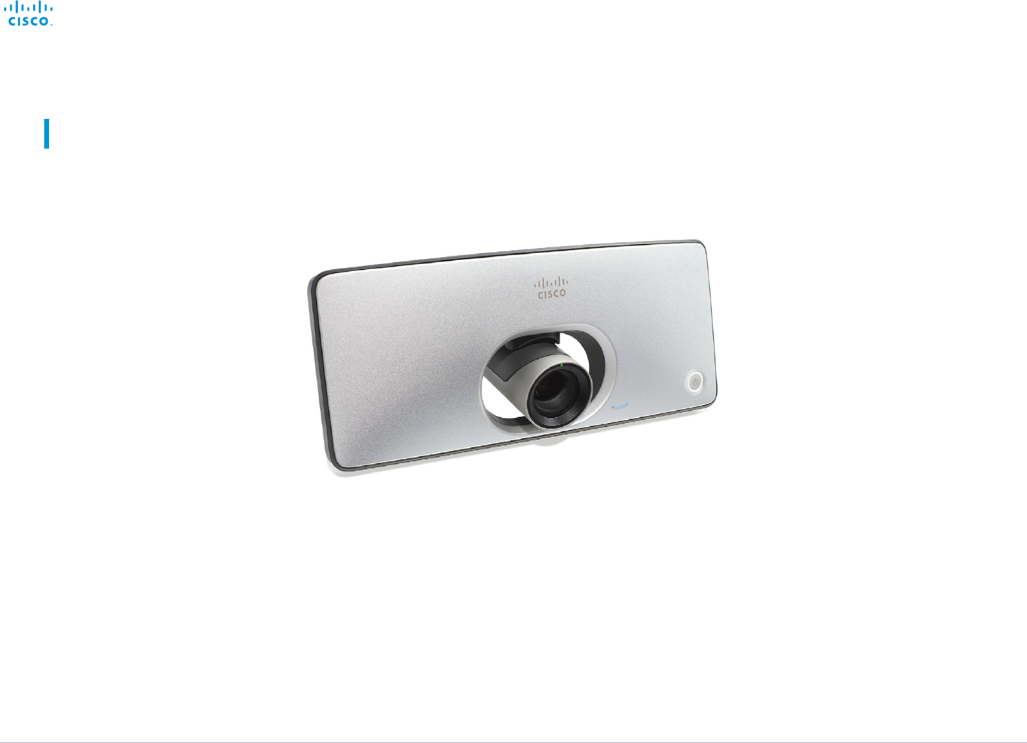
The Cisco TelePresence SX10 Quick Set is an all-in-one unit
designed to video-enable small collaboration spaces.
It is a high quality unit that combines camera and codec into
a compact device that is mounted over a standard flat-panel
display. It can be connected to power and LAN through a
single cable for both power and Ethernet (PoE).
The camera has a wide-angle field of view, and provides
good overview even in small spaces. High-definition video is
enabled with 1080p30 resolution.
Features and benefits
• Optimal definition up to 1080p30 with content sharing at
WXGAp5
• Wide angle 83° horizontal field of view with 5x zoom
(optical and digital)
• Ready-to-use unit with Power over Ethernet (PoE)
• Integrated microphone
• Energy efficient with low power consumption (EU Class B)
• Registers with Cisco Unified Communications Manager
(UCM) and Cisco TelePresence Video Communication
Server (VCS)
SX10 Quick Set at a glance
SX10 Quick Set mounted on top
of a standard flat-panel display
SX10 Quick Set is delivered with a
TRC6 remote control. You may also order the
Cisco TelePresence Table Microphone 20 (optional)
Contents
Introduction
System settings
Setting passwords
Appendices
Web interface
Introduction
D15106.01 SX10 Quick Set Administrator Guide TC7.1, JUNE 2014. www.cisco.com — Copyright © 2014 Cisco Systems, Inc. All rights reserved.
7
Cisco TelePresence SX10 Quick Set Administrator Guide
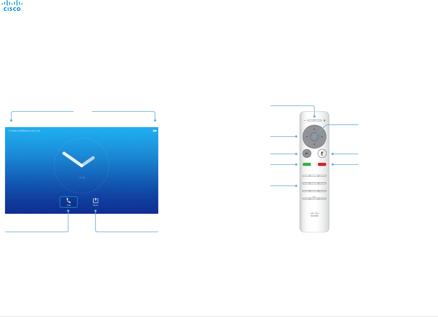
The screen and the remote control
How to operate the video system using the TRC6 remote
control is described in full detail in the User guide for the
video system.
Operating tips
Use the Cursor controls to move about the screen.
Press OK/Enter to open the selected menu field.
Use the Cancel key to exit a menu (and return to the
Home screen), undoing any changes. Use the Back
key to go just one step back.
Place calls. Share content.
Access Settings,
Standby mode and the
Do Not Disturb feature.
Access the
Camera Control menu.
1 2 3
4 5 6
7 8 9
*0#
.@
pqrs tuv wxyz
defabc
ghi jkl mno
Volume control and
Increase/Decrease control
Field selector / Cursor keys
Go back one step Microphone mute/unmute
Reject incoming call /
End call / Cancel /
Back to Home screen
(outside calls)
Place call / Accept incoming call
OK/Enter
Keypad
Contents
Introduction
System settings
Setting passwords
Appendices
Web interface
Introduction

D15106.01 SX10 Quick Set Administrator Guide TC7.1, JUNE 2014. www.cisco.com — Copyright © 2014 Cisco Systems, Inc. All rights reserved.
8
Cisco TelePresence SX10 Quick Set Administrator Guide
Chapter 2
Web interface
Contents
Introduction
System settings
Setting passwords
Appendices
Web interfaceWeb interface
D15106.01 SX10 Quick Set Administrator Guide TC7.1, JUNE 2014. www.cisco.com — Copyright © 2014 Cisco Systems, Inc. All rights reserved.
9
Cisco TelePresence SX10 Quick Set Administrator Guide
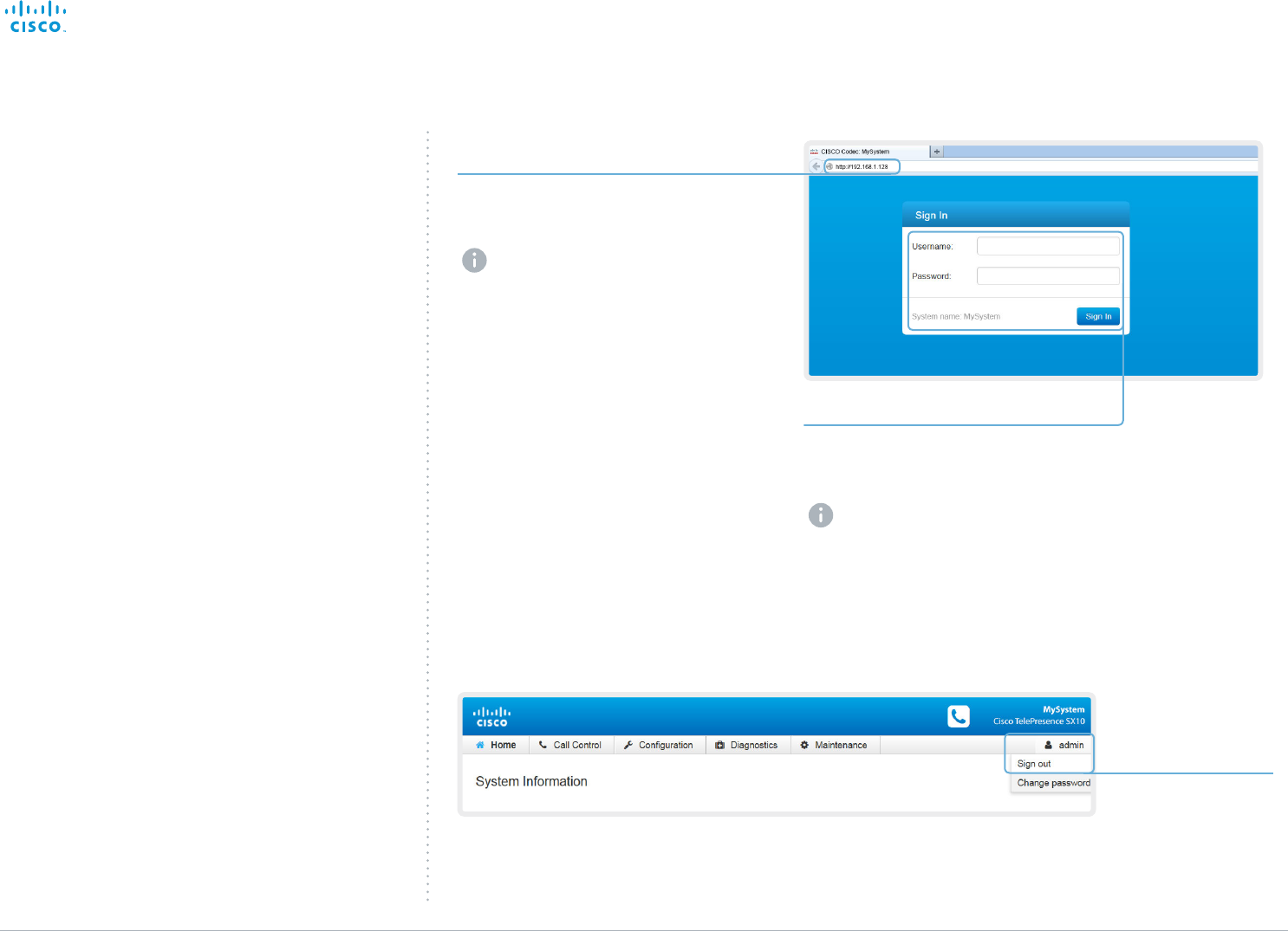
1. Connect to the video system
2. Sign in
Enter the user name and password for your
video system and click Sign In.
The system is delivered with a default
user named admin with no password
(i.e. leave the Password field blank
when signing in for the first time).
It is mandatory to set a password for
the admin user, see the next page.
Signing out
Hover the mouse
over your user
name and choose
Sign out from the
drop-down list.
Accessing the web interface
The web interface provides full configuration access to your
video conference system.
You can connect from a computer and administer the system
remotely.
In this chapter you will find information how to use the web
interface for system configuration and maintenance.
We recommend that you use the latest release of one of the
major web browsers.
Open a web browser and enter the IP address of
the video system in the address bar.
How to find the IP address (IPv4 or IPv6):
Navigate to the contact information in
the upper, left corner of the screen and
press OK on the remote control. Then
open the Settings menu.
Contents
Introduction
System settings
Setting passwords
Appendices
Web interfaceWeb interface
D15106.01 SX10 Quick Set Administrator Guide TC7.1, JUNE 2014. www.cisco.com — Copyright © 2014 Cisco Systems, Inc. All rights reserved.
10
Cisco TelePresence SX10 Quick Set Administrator Guide
Changing the system password
It is mandatory to set a password for any user with
ADMIN rights in order to restrict access to system
configuration. This includes the default admin user.
A warning, saying that the system password is not set, is
shown on screen until you set a password.
You can read more about password protection in the
► Setting passwords chapter.
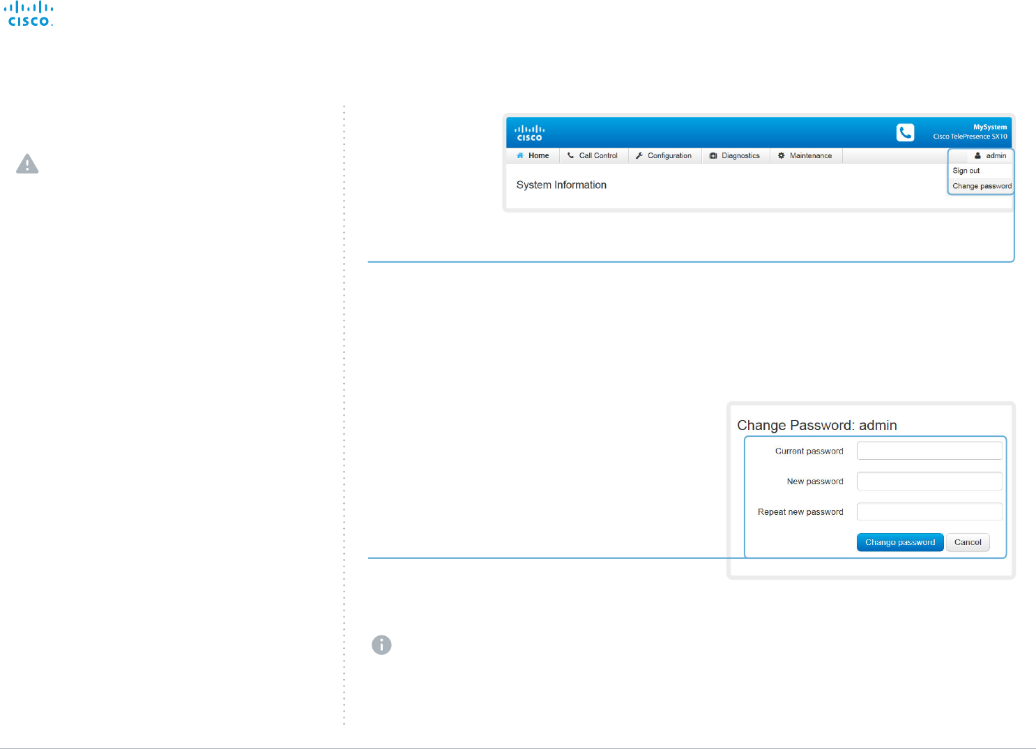
1. Open the Change Password dialog
Hover the mouse over your user name, and
choose Change password in the drop-down list.
2. Set the new password
Enter your current and new passwords as
requested, and click Change password for the
change to take effect.
If the password currently is not set, leave
the Current password field blank.
Contents
Introduction
System settings
Setting passwords
Appendices
Web interfaceWeb interface
D15106.01 SX10 Quick Set Administrator Guide TC7.1, JUNE 2014. www.cisco.com — Copyright © 2014 Cisco Systems, Inc. All rights reserved.
11
Cisco TelePresence SX10 Quick Set Administrator Guide
Configuration
System Configuration
System Status
Local Contents Management
Personalization
The interactive menu
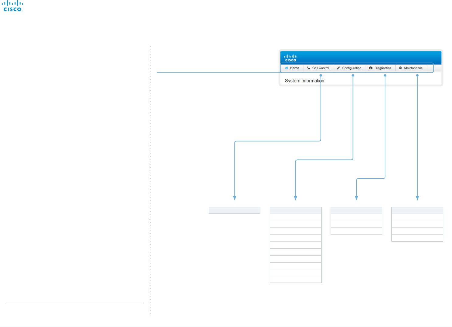
The web interface provides access to tasks and
configurations. They are available from the main menu, which
appears near the top of the page when you have signed in.
When you hover the mouse over an item in the main menu,
you can navigate to its related sub-pages.
Main menu
Hover the mouse over a main menu item in
order to see the titles of the related sub-pages.
Click a sub-page’s title to open it. Click the
main menu item itself if there are no sub-pages.
Only pages that the user has access rights for
are shown*.
Click Home to return to the System Information
page.
Call Control Maintenance
Software Upgrade
Backup and Restore
System Recovery
Restart
Diagnostics
Troubleshooting
Peripherals
User Administration
Sign In Banner
Startup Scripts
Sub-pages
* You can read more about user administration, user roles and access
rights in the ► User administration section.
API
Security
Call History
Log Files
Contents
Introduction
System settings
Setting passwords
Appendices
Web interfaceWeb interface
D15106.01 SX10 Quick Set Administrator Guide TC7.1, JUNE 2014. www.cisco.com — Copyright © 2014 Cisco Systems, Inc. All rights reserved.
12
Cisco TelePresence SX10 Quick Set Administrator Guide
Navigate to: Home
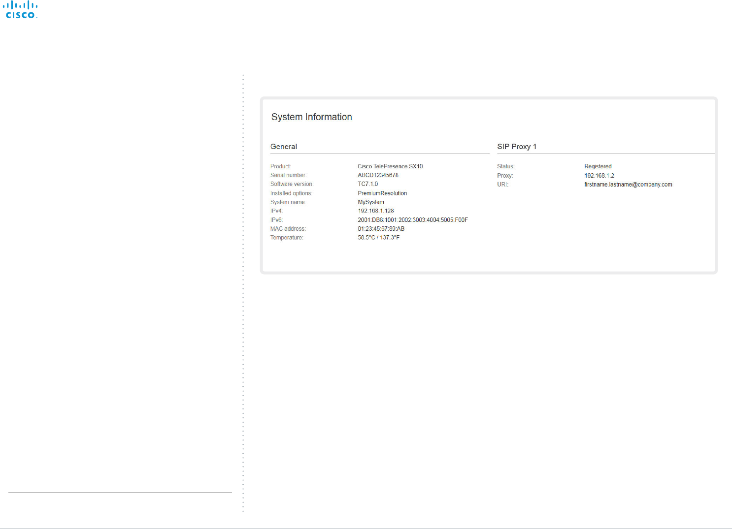
* The system information shown in the illustration serve as an
example. Your system may be different.
System information
The video system’s Home page shows an overview of the
basic set-up and status of the system*.
This includes information like system name and product type,
which software version the system runs, its IPaddress, etc.
Also the registration status for the video network (SIP) is
included, as well as the number/URI to use when making a
call to the system.
Contents
Introduction
System settings
Setting passwords
Appendices
Web interfaceWeb interface
D15106.01 SX10 Quick Set Administrator Guide TC7.1, JUNE 2014. www.cisco.com — Copyright © 2014 Cisco Systems, Inc. All rights reserved.
13
Cisco TelePresence SX10 Quick Set Administrator Guide
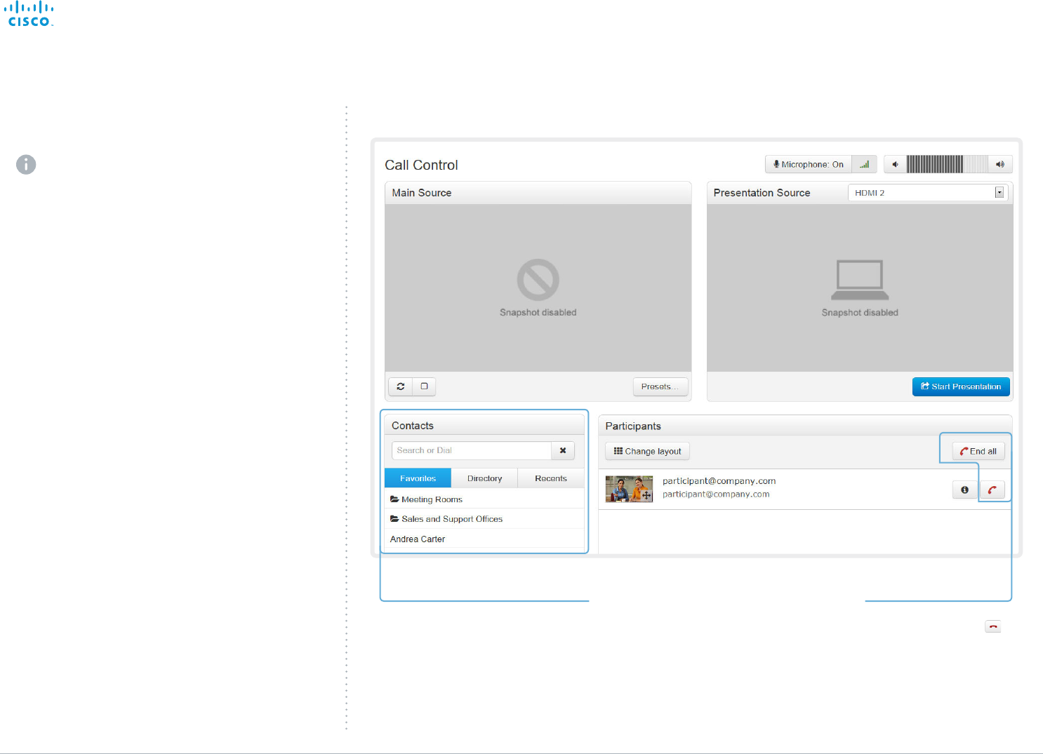
Calling someone
Click a contact name, either in the
Favorites, Directory or Recents lists.
Then click Call in the contact card.
Alternatively, enter the complete URI
or number in the Search and Dial field.
Then click the Call button that appears
next to the URI or number.
Ending a call
Navigate to: Call Control
Placing a call
You can use the Call Control page to place a call.
Even if the web interface is used to initiate the call,
it is the video system (display, microphones and
loudspeakers) that is used for the call; it is not the PC
running the web interface.
Calling
You can call someone either by choosing a contact name
in the Favorites, Directory or Recents lists, or by typing a
complete URI or number in the Search or Dial field. Then click
Call in the associated contact card.
Searching the contact lists
Enter one or more characters in the Search or Dial field.
Matching entries from the Favorites, Directory and Recents
lists will be listed as you type.
Select the correct entry in the list and click Call.
If you want to terminate a
call, click End all or the
button.
Contents
Introduction
System settings
Setting passwords
Appendices
Web interfaceWeb interface
D15106.01 SX10 Quick Set Administrator Guide TC7.1, JUNE 2014. www.cisco.com — Copyright © 2014 Cisco Systems, Inc. All rights reserved.
14
Cisco TelePresence SX10 Quick Set Administrator Guide
Navigate to: Call Control
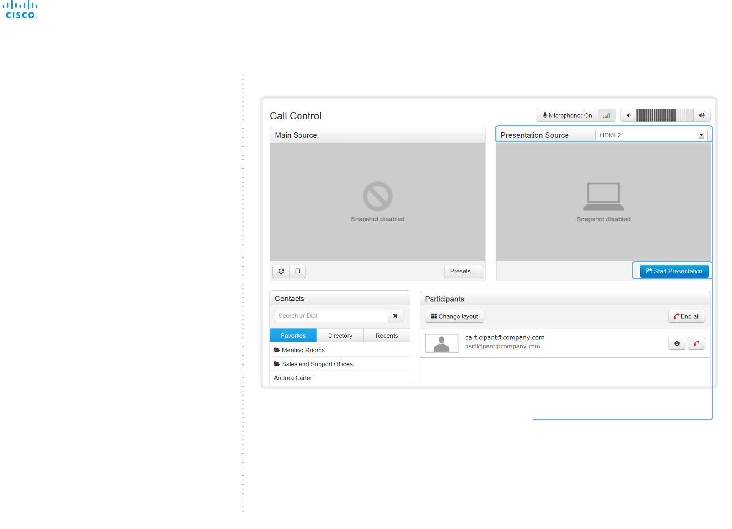
Sharing content
You can connect a presentation source to one of the external
inputs of your video system. Most often a PC is used as
presentation source, but other options may be available
depending on your system setup.
While in a call you can share content with the far end, that is
the other participant in the call.
If you are not in a call, the content is shared locally on your
display.
Sharing content
1. Choose a Presentation source from the
drop-down list.
2. Click Start Presentation.
Stop content sharing:
Click the Stop Presentation button that is present
while sharing.
Contents
Introduction
System settings
Setting passwords
Appendices
Web interfaceWeb interface
D15106.01 SX10 Quick Set Administrator Guide TC7.1, JUNE 2014. www.cisco.com — Copyright © 2014 Cisco Systems, Inc. All rights reserved.
15
Cisco TelePresence SX10 Quick Set Administrator Guide
Controlling and monitoring a call
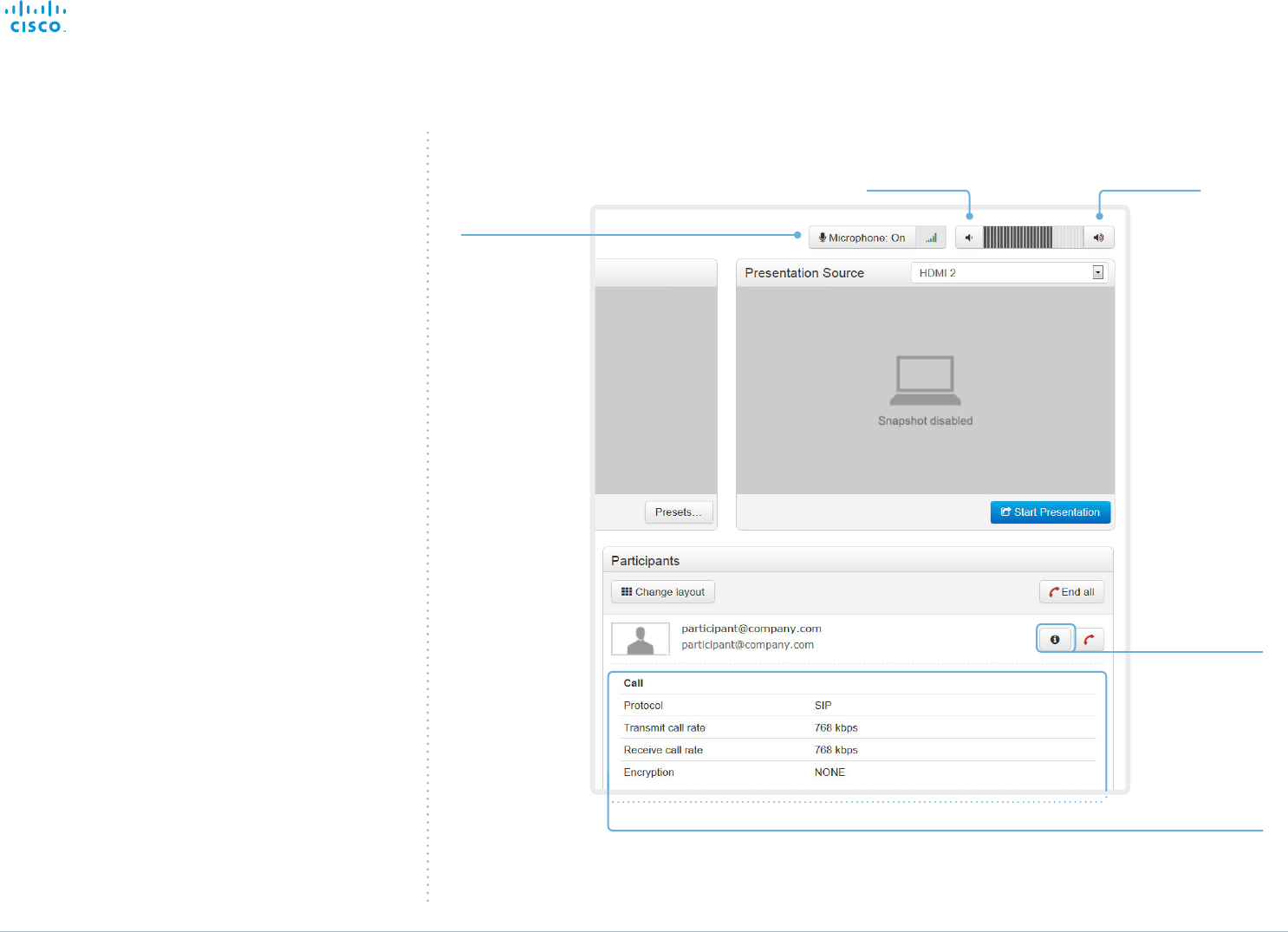
You can control and monitor several call features using the
Call Control page. Volume down
Navigate to: Call Control
Call details
If necessary,
scroll your browser to
see the call details.
Show/hide
call details
Volume up
Microphone
mute
Click the
information button
to show details
about the call.
Click the button
again to hide the
information.
Click the button
to mute the
microphone.
Then the text
changes to
Microphone: Off.
Click again to
unmute.
Contents
Introduction
System settings
Setting passwords
Appendices
Web interfaceWeb interface
D15106.01 SX10 Quick Set Administrator Guide TC7.1, JUNE 2014. www.cisco.com — Copyright © 2014 Cisco Systems, Inc. All rights reserved.
16
Cisco TelePresence SX10 Quick Set Administrator Guide
Navigate to: Call Control
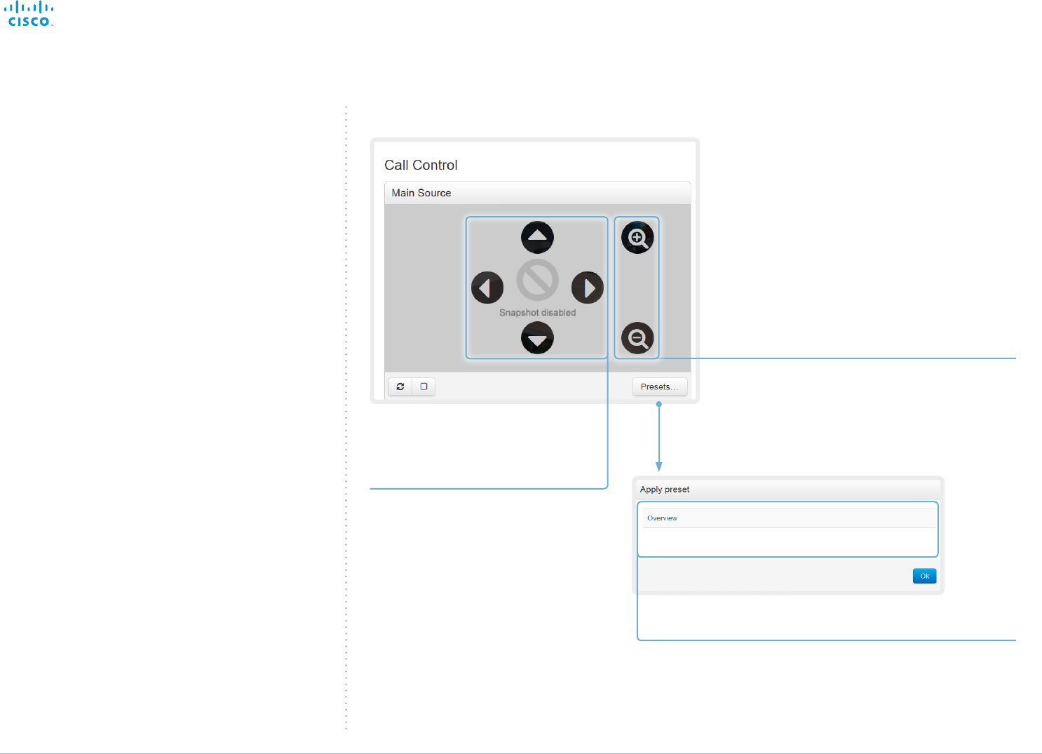
Zoom
Use + and - to zoom in and out.
Pan and tilt
Use the left and right arrows
to pan the camera, and the up
and down arrows to tilt it.
Controlling your camera
You can control the camera from the Call Control page.
The camera controls (pan, tilt, zoom) are available when the
cursor is placed in the Main Source video area.
Note that the camera controls are not available if the system
is in standby mode.
Camera preset
Cliick the preset’s name to move the
camera to it’s default position.
Click OK to close the window.
Contents
Introduction
System settings
Setting passwords
Appendices
Web interfaceWeb interface
D15106.01 SX10 Quick Set Administrator Guide TC7.1, JUNE 2014. www.cisco.com — Copyright © 2014 Cisco Systems, Inc. All rights reserved.
17
Cisco TelePresence SX10 Quick Set Administrator Guide
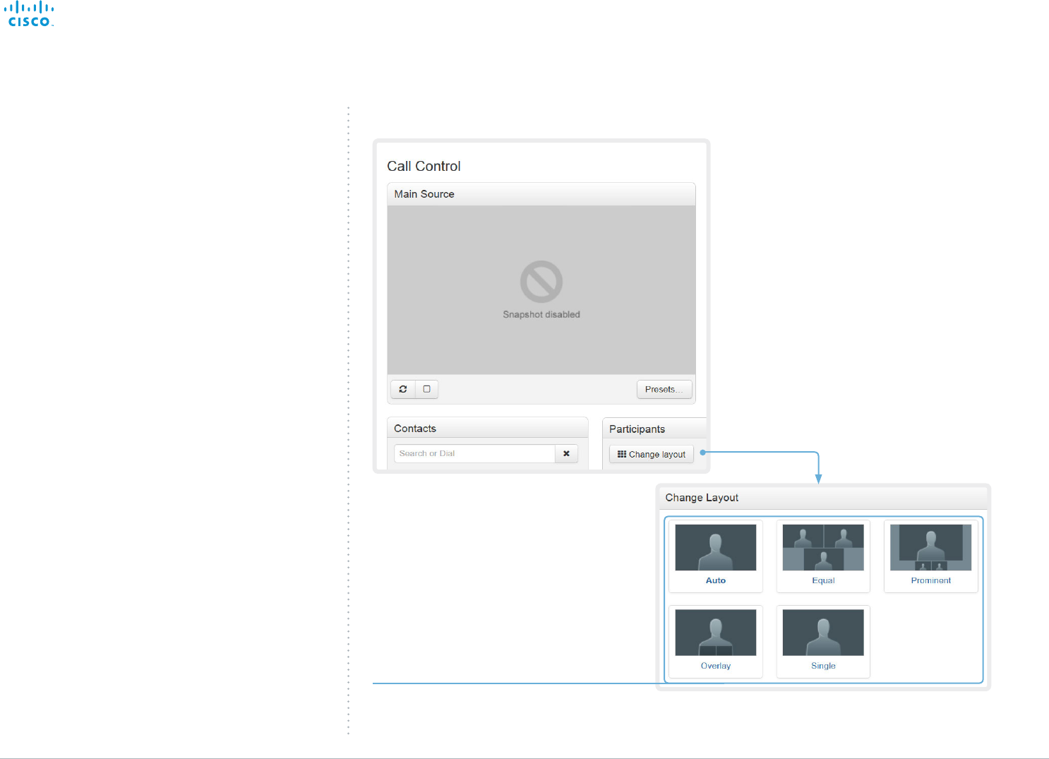
Change the layout
Click Change layout, and choose your preferred
layout in the window that opens.
You may change the layout while in a call.
Navigate to: Call Control
Local layout control
You can choose a local layout using the Call Control page.
The term layout is used to describe the various ways the
video and presentation can appear on your screen. Different
types of meetings may require different layouts.
Contents
Introduction
System settings
Setting passwords
Appendices
Web interfaceWeb interface
D15106.01 SX10 Quick Set Administrator Guide TC7.1, JUNE 2014. www.cisco.com — Copyright © 2014 Cisco Systems, Inc. All rights reserved.
18
Cisco TelePresence SX10 Quick Set Administrator Guide
Controlling the far end camera
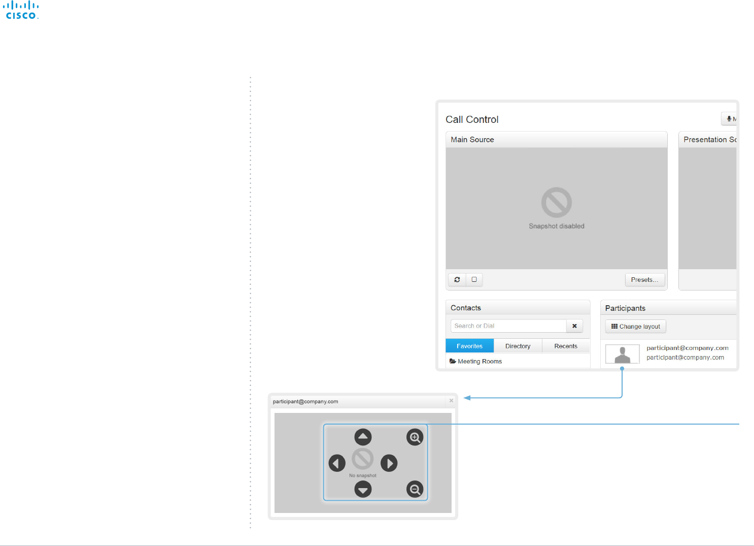
While in a call, you can control the remote participant’s
camera (far end) provided that:
• The Conference FarEndControl Mode setting is switched
On on the far end video system.
• The far end camera has pan, tilt or zoom functionality.
Only the relevant controls will appear.
Control the remote participant’s camera
1. Click the snapshot to show it in a larger window.
2. Place the cursor in the image to enable the controls.
3. Use the left and right arrows to pan the camera; the up and
down arrows to tilt it; and + and - to zoom in and out.
Navigate to: Call Control
Contents
Introduction
System settings
Setting passwords
Appendices
Web interfaceWeb interface
D15106.01 SX10 Quick Set Administrator Guide TC7.1, JUNE 2014. www.cisco.com — Copyright © 2014 Cisco Systems, Inc. All rights reserved.
19
Cisco TelePresence SX10 Quick Set Administrator Guide
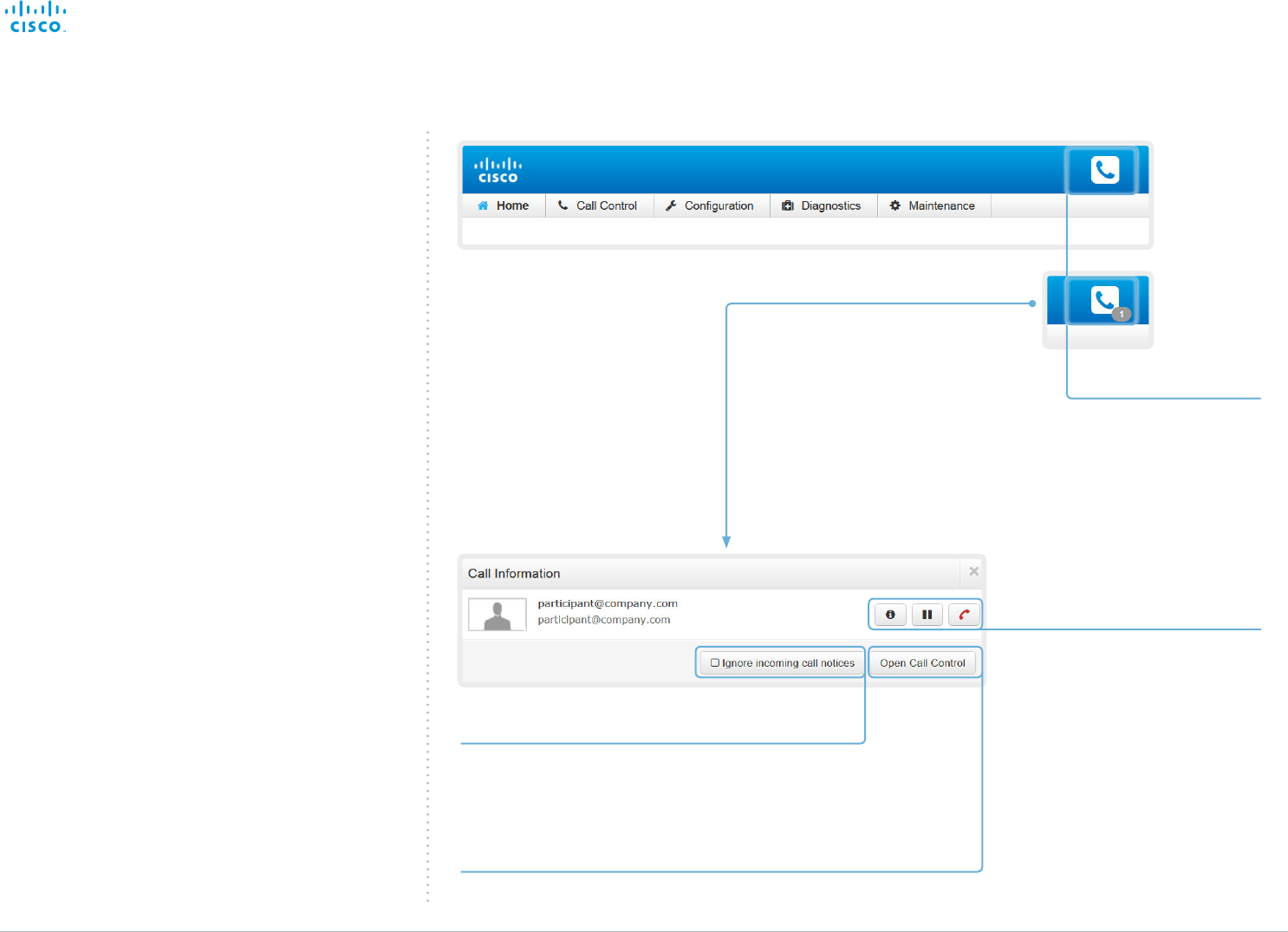
Call state indicator
The call state indicator is
available on all pages except
the Call Control page.
The badge indicates the number
of active calls. If the system is
idle, there is no badge.
Click the indicator to get more
details about connected calls.
Call control
Use these buttons to:
• Show call details
• Put the call on hold
• Disconnect the call
Incoming call notification
As default, a notification is given when the
system receives a call.
Check this box, if you do not want to receive
such notifications.
Opening the Call Control page
Click Open Call Control to go straight to the Call Control page.
Accessing call information
A call state indicator is available in the top bar in the web
interface. It shows whether the system is in a call or not. You
may also be notified about incoming calls.
Contents
Introduction
System settings
Setting passwords
Appendices
Web interfaceWeb interface
D15106.01 SX10 Quick Set Administrator Guide TC7.1, JUNE 2014. www.cisco.com — Copyright © 2014 Cisco Systems, Inc. All rights reserved.
20
Cisco TelePresence SX10 Quick Set Administrator Guide
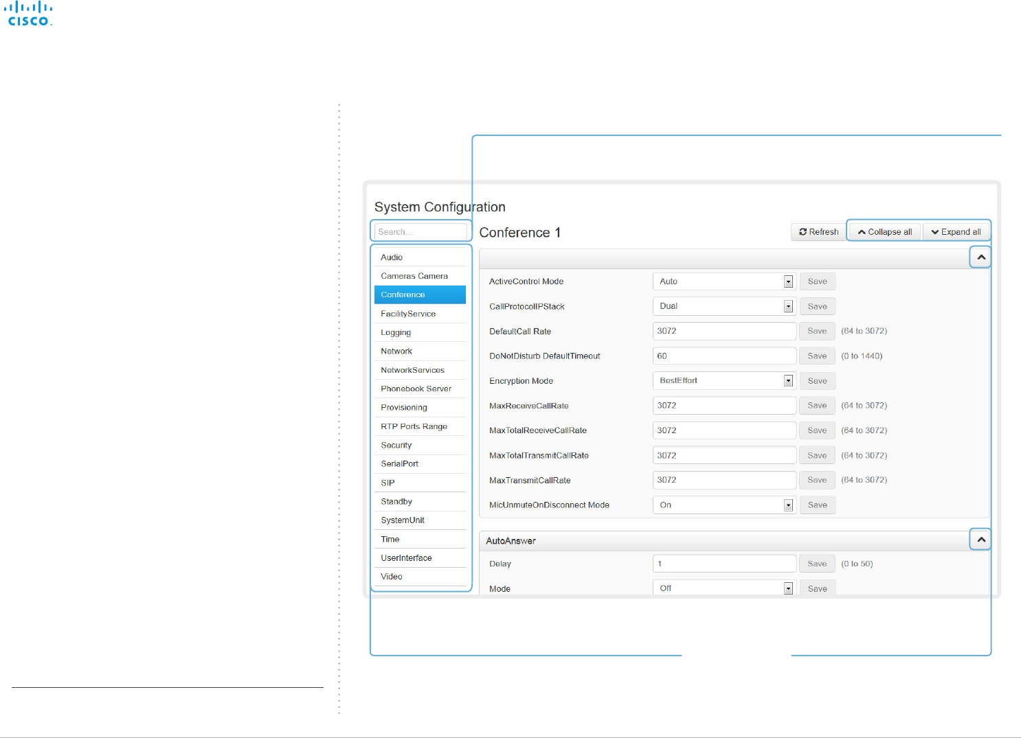
Selecting a category
The system settings are structured in categories.
Choose a category in order to display the related settings.
System configuration
The system settings are grouped in several categories. When
you choose a category in the left pane all related settings
appear to the right*.
Each system setting is further described in the
► System settings chapter.
Expanding and collapsing lists
Use these buttons to expand and
collapse all or individual lists.
Searching for settings
Enter as many letters as needed in the search field.
All settings (value space included) containing these letters will be highlighted.
* The configuration shown in the illustration serve as an example.
Your system may be configured differently.
Navigate to: Configuration > System Configuration
Contents
Introduction
System settings
Setting passwords
Appendices
Web interfaceWeb interface
D15106.01 SX10 Quick Set Administrator Guide TC7.1, JUNE 2014. www.cisco.com — Copyright © 2014 Cisco Systems, Inc. All rights reserved.
21
Cisco TelePresence SX10 Quick Set Administrator Guide
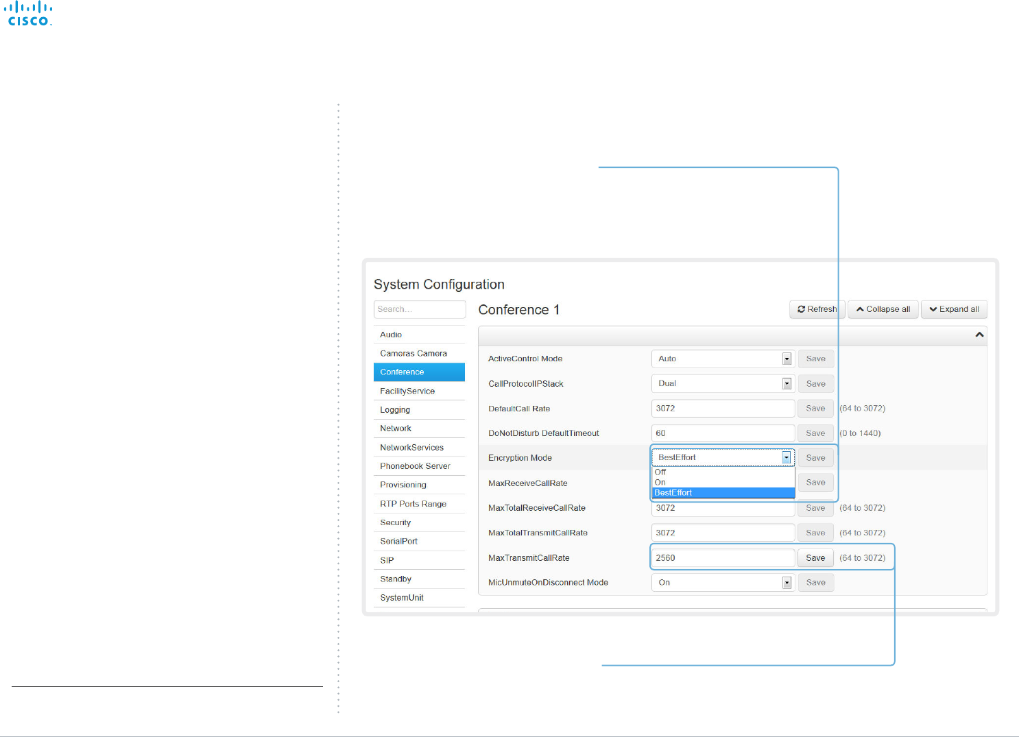
Changing system settings
All system settings can be changed from the System
Configuration page*. The value space for a setting is specified
either in a drop-down list or by text following the input field.
Different settings may require different user credentials. In
order to be sure that an administrator is able to change all
system settings, the signed in user must possess all user
roles.
You can read more about user administration and user roles
in the ► User administration chapter.
Drop-down list
Click the arrow to open the drop-down
list. Choose the preferred value and click
Save for the change to take effect.
Text input field
Enter text in the input field and click
Save for the change to take effect.
* The configuration shown in the illustration serve as an example.
Your system may be configured differently.
Navigate to: Configuration > System Configuration
Contents
Introduction
System settings
Setting passwords
Appendices
Web interfaceWeb interface
D15106.01 SX10 Quick Set Administrator Guide TC7.1, JUNE 2014. www.cisco.com — Copyright © 2014 Cisco Systems, Inc. All rights reserved.
22
Cisco TelePresence SX10 Quick Set Administrator Guide
Navigate to: Configuration > System Status
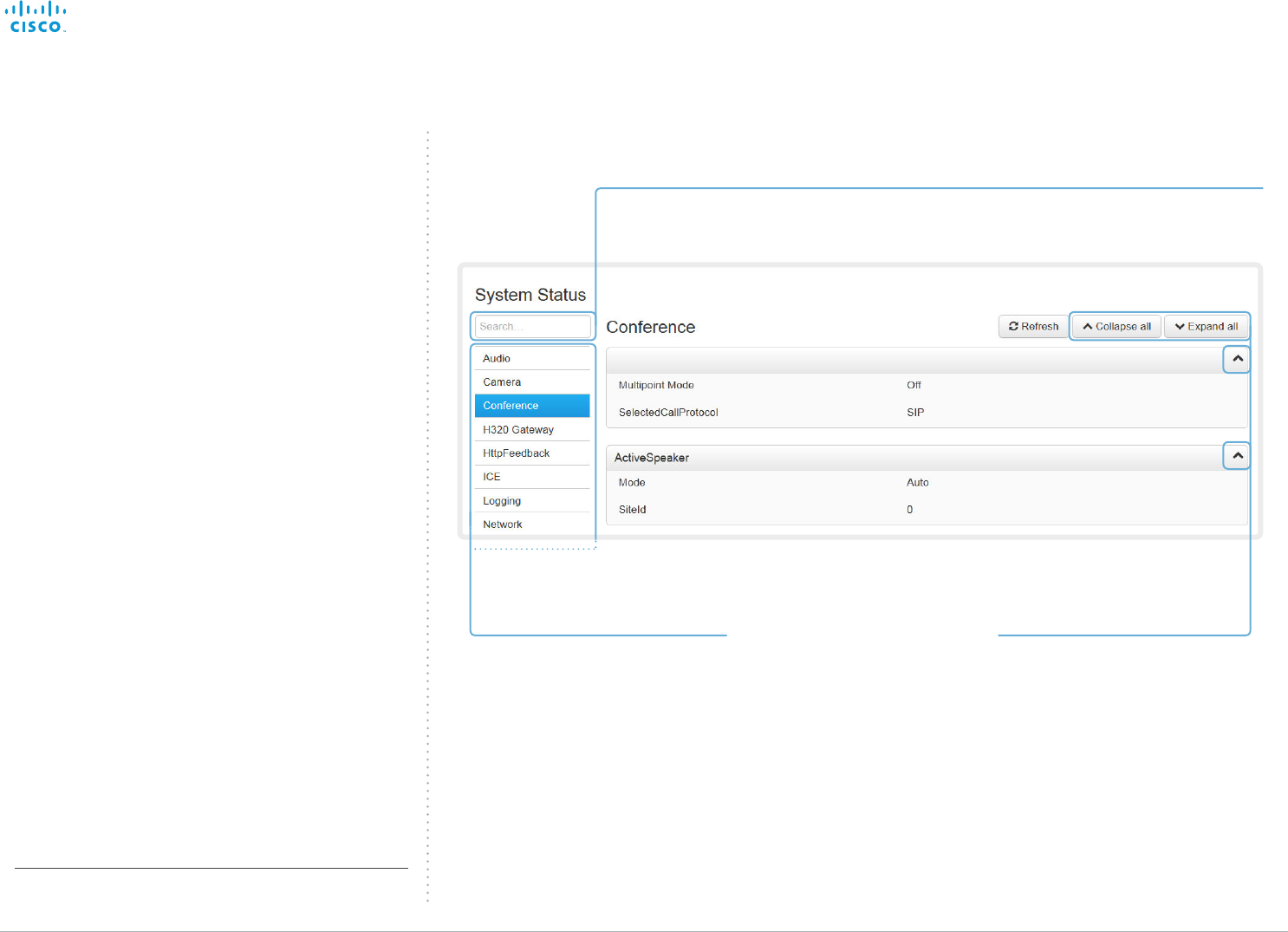
Selecting a category
The system status is structured in
categories. Choose a category in order
to display the related status information.
Expanding and collapsing lists
Use these buttons to expand and
collapse all or individual lists.
Searching for status entries
Enter as many letters as needed in the search field.
All entries (value space included) containing these letters will be highlighted.
System status
The system status is grouped in several categories. When
you choose a category in the left column, the related status
appears in the window to the right*.
* The status shown in the illustration serve as an example. The status
of your system may be different.
Contents
Introduction
System settings
Setting passwords
Appendices
Web interfaceWeb interface
D15106.01 SX10 Quick Set Administrator Guide TC7.1, JUNE 2014. www.cisco.com — Copyright © 2014 Cisco Systems, Inc. All rights reserved.
23
Cisco TelePresence SX10 Quick Set Administrator Guide
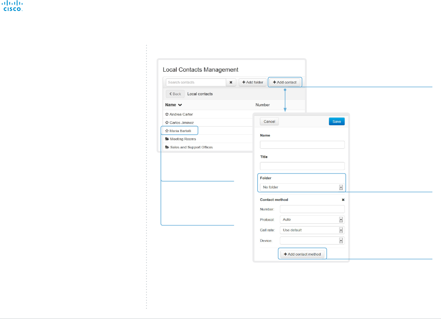
Adding a contact
Editing contact details
Click a contacts name
followed by Edit contact.
Change the details in the form
as appropriate and click Save.
Deleting a contact
You can store more than one
contact method for each contact,
e.g. video, telephone and mobile.
Storing a contact in a folder
Choose the appropriate folder
from the drop down list.
No folder means that the contact
will be stored at the top level.
Navigate to: Configuration > Local Contacts Management
Managing the local contacts
The local contacts can be accessed from the on-screen
menu (the Local contacts folder in the Directory) and the Web
interface.
Click Add contact and fill in
the form that pops up. Then
click Save to store the contact
in Local contacts.
Click a contacts name
followed by Edit contact. Then
click Delete to remove the
entry from Local contacts.
Adding a contact method
Contents
Introduction
System settings
Setting passwords
Appendices
Web interfaceWeb interface
D15106.01 SX10 Quick Set Administrator Guide TC7.1, JUNE 2014. www.cisco.com — Copyright © 2014 Cisco Systems, Inc. All rights reserved.
24
Cisco TelePresence SX10 Quick Set Administrator Guide
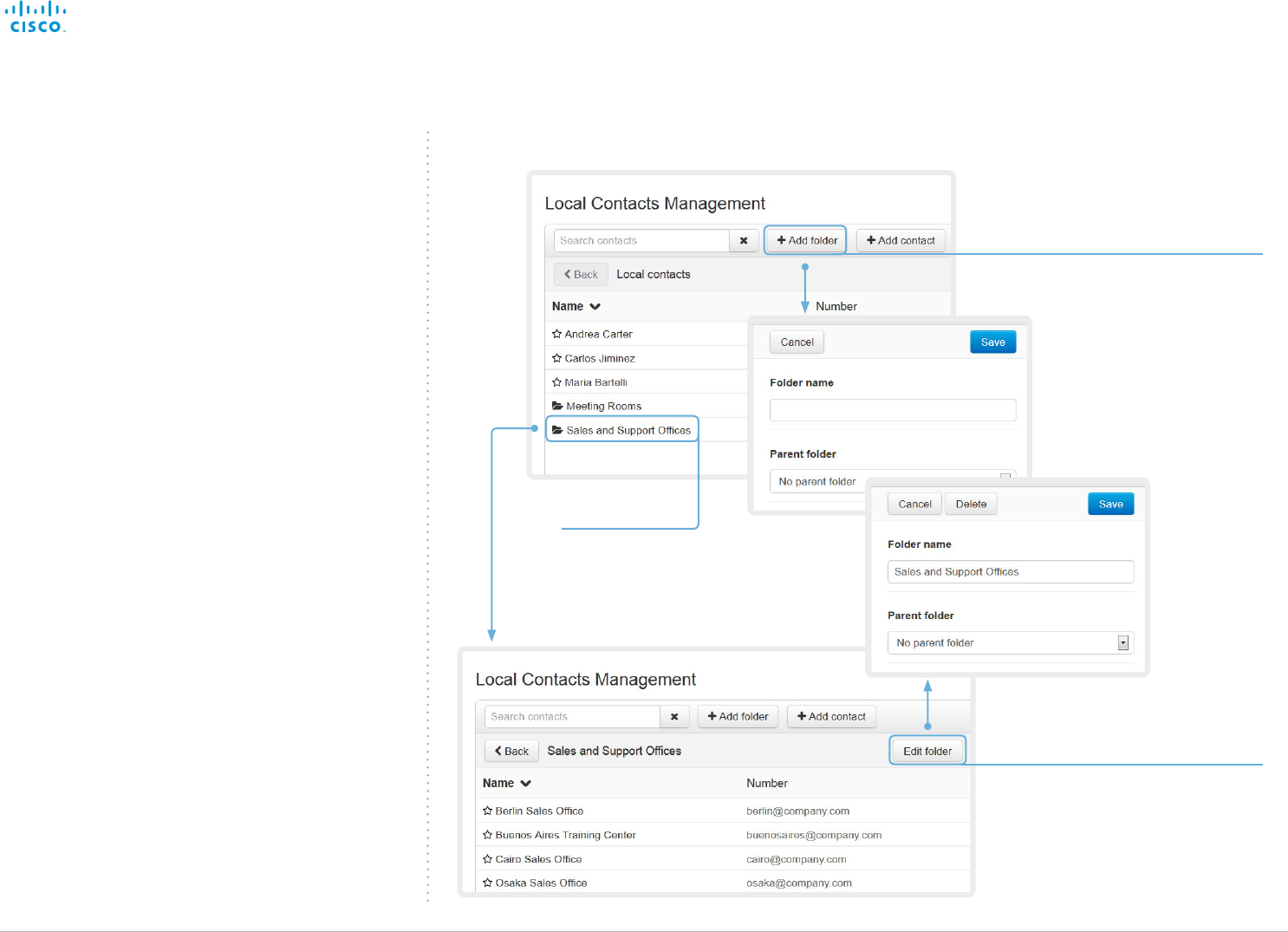
Opening a folder
Click the folder
name to open the
folder and show its
list of contacts.
Adding a folder
Click Add folder and fill in the
form that pops up. Then click
Save to create the folder.
Changing or Deleting a folder
Click Edit folder and update the
information in the form that pops up.
Then click Save to store the changes
Click Delete to remove the folder
and all its contacts and sub-folders.
Confirm your choice in the dialog that
pops up.
Navigate to: Configuration > Local Contacts Management
Local contacts folders
The entries in Local contacts can be organized in folders.
Contents
Introduction
System settings
Setting passwords
Appendices
Web interfaceWeb interface
D15106.01 SX10 Quick Set Administrator Guide TC7.1, JUNE 2014. www.cisco.com — Copyright © 2014 Cisco Systems, Inc. All rights reserved.
25
Cisco TelePresence SX10 Quick Set Administrator Guide
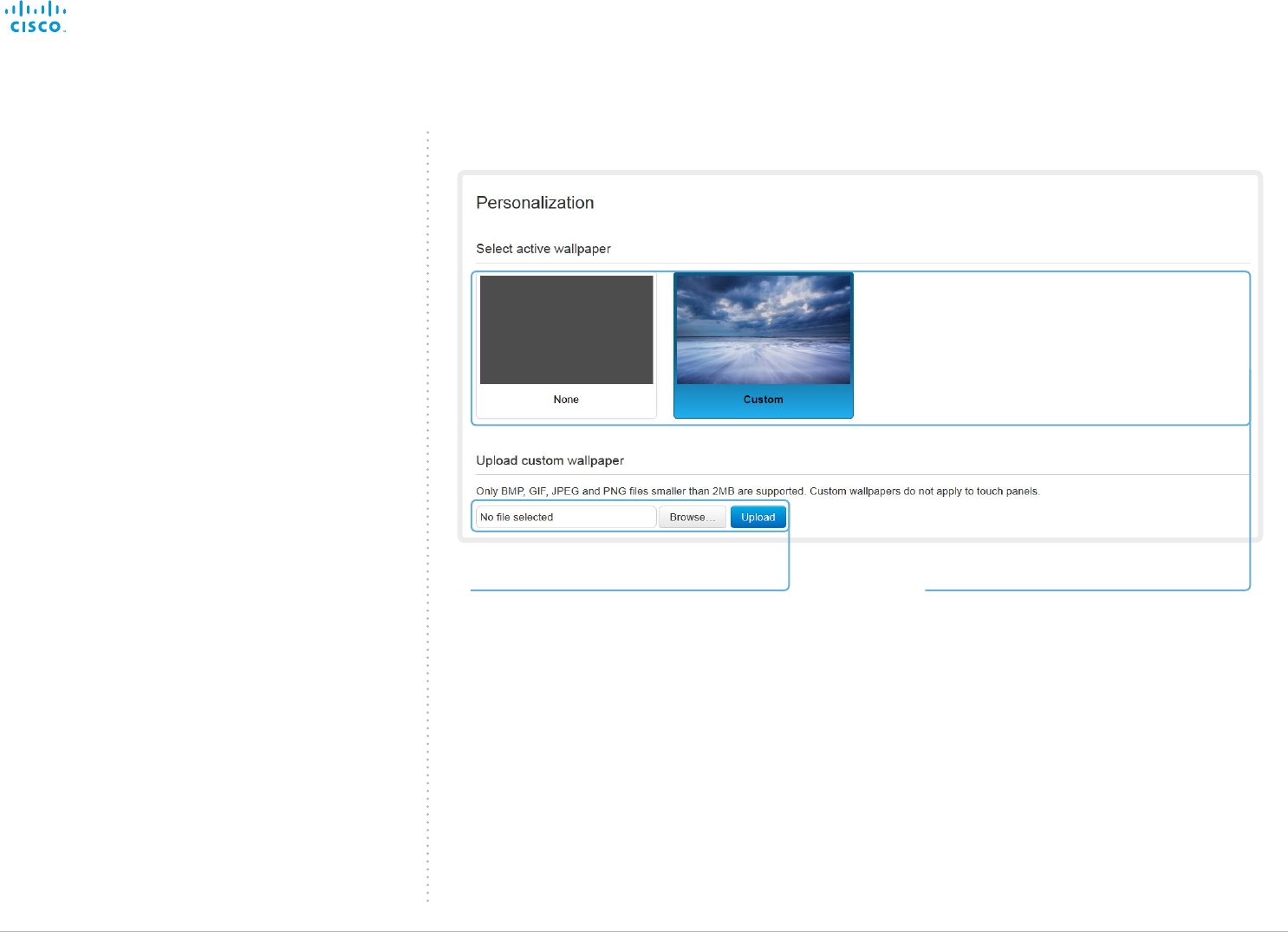
Activate/deactivate a wallpaperUploading a custom wallpaper file
Click Browse... and locate your custom wallpaper
image file.
Click Upload to save the file on the video system.
Supported file formats: BMP, GIF, JPEG, PNG
Maximum file size: 2 MByte
The custom wallpaper will be automatically
activated once uploaded.
Navigate to: Configuration > Personalization
If you have uploaded a custom wallpaper, it will
appear in the list.
Click the miniature to switch to the corresponding
wallpaper. Choose None if you do not want a
wallpaper.
The chosen option is highlighted.
Choosing a wallpaper
If you want the company logo or another custom picture as
background on the main display, you may upload and use a
custom wallpaper.
Contents
Introduction
System settings
Setting passwords
Appendices
Web interfaceWeb interface
D15106.01 SX10 Quick Set Administrator Guide TC7.1, JUNE 2014. www.cisco.com — Copyright © 2014 Cisco Systems, Inc. All rights reserved.
26
Cisco TelePresence SX10 Quick Set Administrator Guide
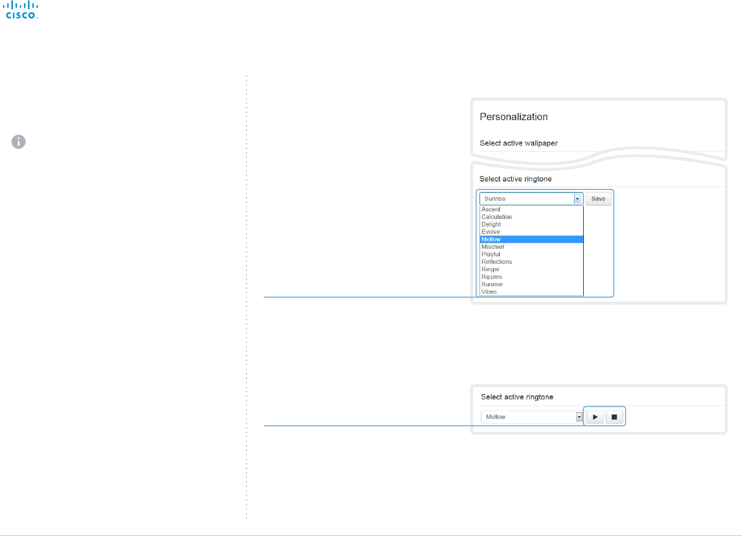
Choosing a ringtone
You can choose from a set of predefined ringtones. The
chosen ringtone can be played back from this page.
The ringtone will be played back on the video system
itself, not through the web interface.
Changing ringtone
Choose a ringtone from the drop-down list,
and click Save to make it the active ringtone.
Playing back the ringtone
Click the play button ( ► ) to play back the
ringtone.
Use the stop button ( ) to end the playback.
Navigate to: Configuration > Personalization
Contents
Introduction
System settings
Setting passwords
Appendices
Web interfaceWeb interface
D15106.01 SX10 Quick Set Administrator Guide TC7.1, JUNE 2014. www.cisco.com — Copyright © 2014 Cisco Systems, Inc. All rights reserved.
27
Cisco TelePresence SX10 Quick Set Administrator Guide
Peripherals overview
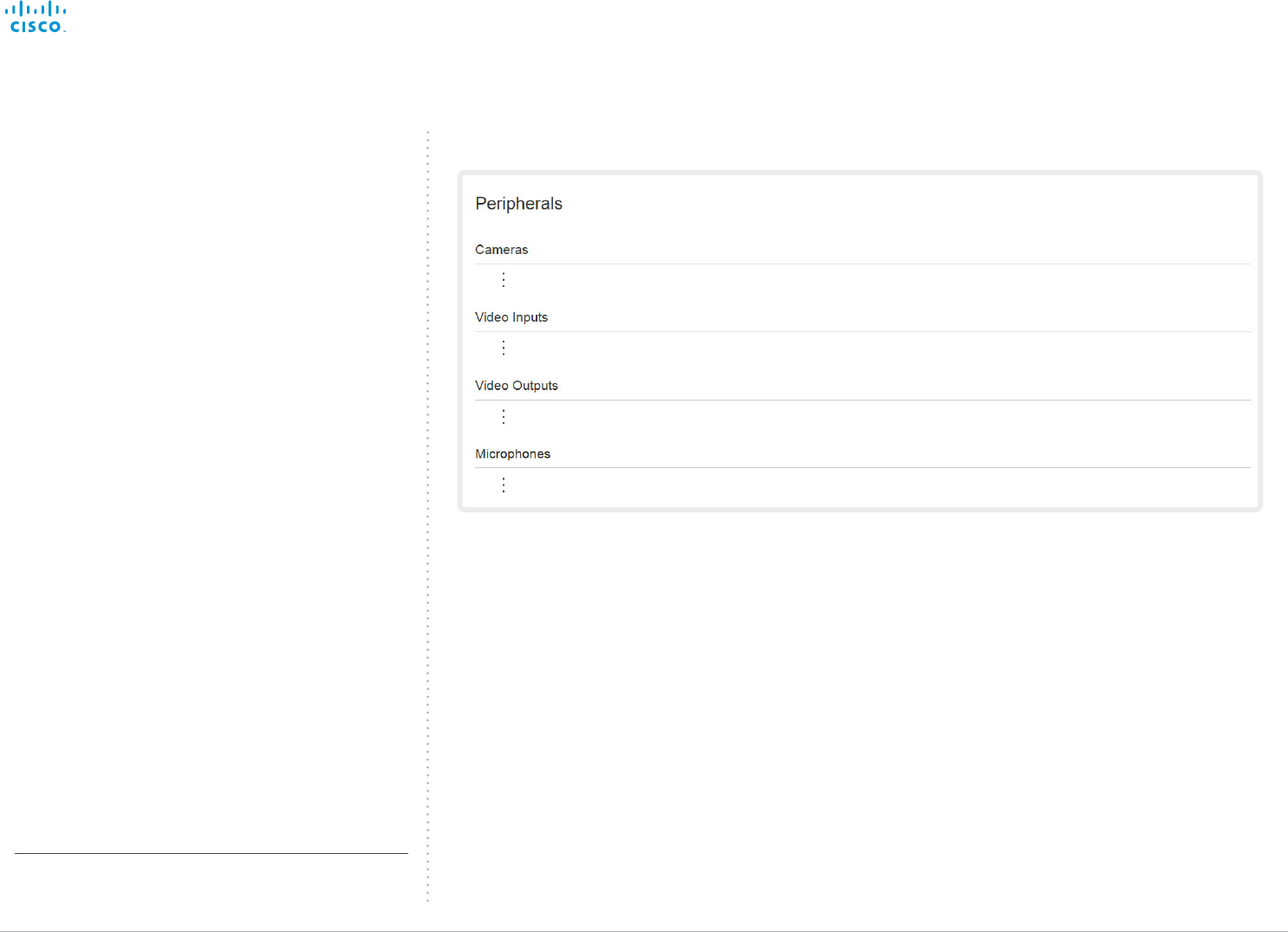
This page shows an overview of devices that are connected
to the video system, like video inputs and outputs, cameras
and microphones*.
Note that this product does not support ISDN Link.
* The peripherals shown in the illustration serve as examples. Your
system may have different peripherals and video input/output
configurations.
Navigate to: Configuration > Peripherals
Contents
Introduction
System settings
Setting passwords
Appendices
Web interfaceWeb interface
D15106.01 SX10 Quick Set Administrator Guide TC7.1, JUNE 2014. www.cisco.com — Copyright © 2014 Cisco Systems, Inc. All rights reserved.
28
Cisco TelePresence SX10 Quick Set Administrator Guide
Default user account
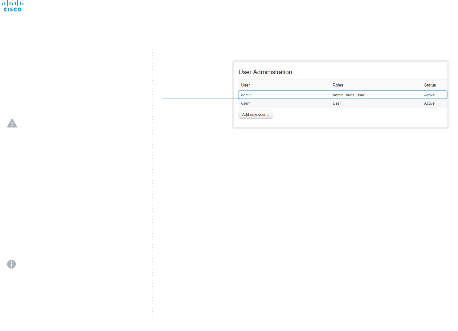
The system comes with
admin as the default user
account. This user has
full access rights.
Navigate to: Configuration > User Administration
User administration
You can manage your video conference system’s user
accounts from this page.
The default user account
The system comes with a default administrator user account
with full access rights. The user name is admin and no
password is set.
It is mandatory to set a password for the admin user.
Read more about passwords in the ► Setting passwords
chapter.
About user roles
A user account must hold one or a combination of several
user roles.
The following three user roles, with non-overlapping rights,
exist:
• ADMIN: A user holding this role can create new users and
change most settings. The user neither can upload audit
certificates nor change the security audit settings.
• USER: A user holding this role can make calls and search
the phone book. The user can modify a few settings, e.g.
adjusting the audio volume.
• AUDIT: A user holding this role can change the security
audit configurations and upload audit certificates.
An administrator user account with full access rights,
like the default admin user, must possess all the three
roles.
Contents
Introduction
System settings
Setting passwords
Appendices
Web interfaceWeb interface
D15106.01 SX10 Quick Set Administrator Guide TC7.1, JUNE 2014. www.cisco.com — Copyright © 2014 Cisco Systems, Inc. All rights reserved.
29
Cisco TelePresence SX10 Quick Set Administrator Guide
Navigate to: Configuration > User Administration
* The password is used with the web interface and command line
interface.
User administration, continued
Creating a new user account
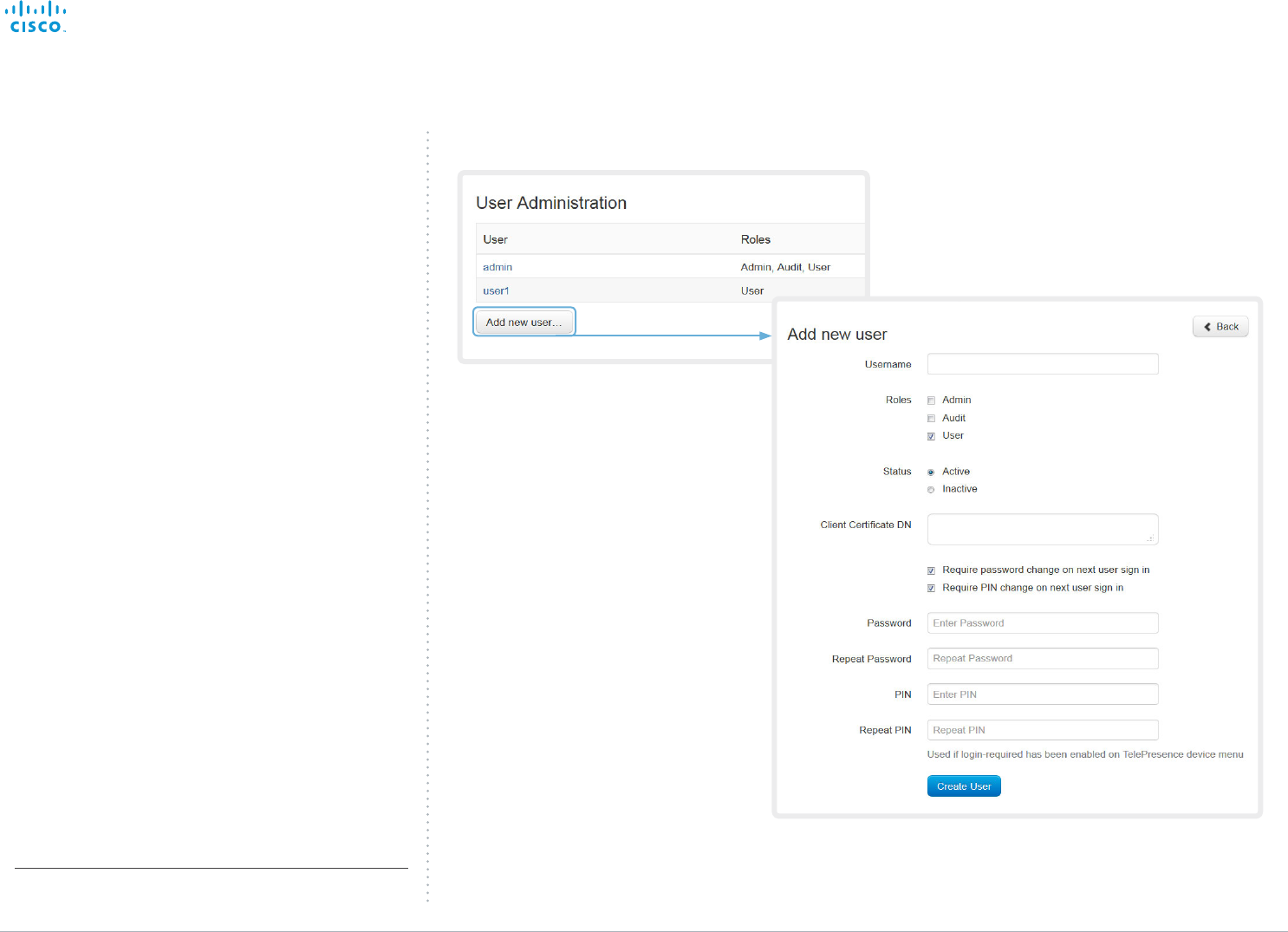
Follow these steps in order to create a new user account:
1. Click Add new user....
2. Fill in the Username and Password*, and check the
appropriate user roles check boxes.
As a default the user has to change the password when
signing in for the first time.
Do not fill in the Client Certificate DN (Distinguished
Name) field unless you want to use certificate login on
HTTPS.
3. Set the Status to Active to activate the user.
4. Click Create User to save the changes.
Use the Back button to leave without making any
changes.
Contents
Introduction
System settings
Setting passwords
Appendices
Web interfaceWeb interface
D15106.01 SX10 Quick Set Administrator Guide TC7.1, JUNE 2014. www.cisco.com — Copyright © 2014 Cisco Systems, Inc. All rights reserved.
30
Cisco TelePresence SX10 Quick Set Administrator Guide
Navigate to: Configuration > User Administration
* The password is used with the web interface and command line
interface.
User administration, continued
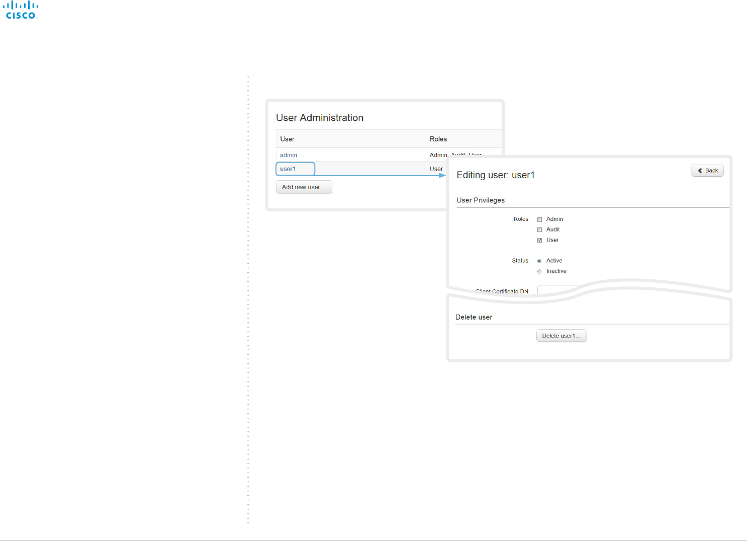
Changing user privileges
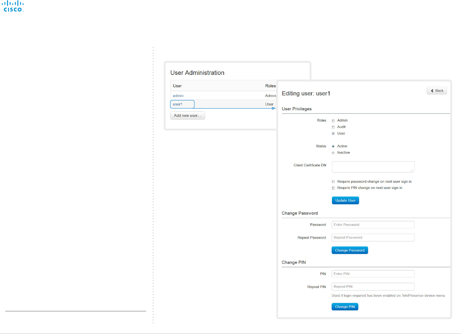
Follow these steps in order to change the user privileges:
1. Click the name of an existing user to open the Editing
user window.
2. Check the appropriate user roles check boxes, decide if
the user has to change the password on the next sign in,
and fill in the Client Certificate DN field if using certificate
login on HTTPS.
3. Click Update User to save the changes.
Use the Back button to leave without making any
changes.
Changing the password
Follow these steps in order to change the password*:
1. Click the name of an existing user to open the Editing
user window.
2. Enter the new password in the appropriate input fields.
3. Click Change Password to save the change.
Use the Back button to leave without making any
changes.
Contents
Introduction
System settings
Setting passwords
Appendices
Web interfaceWeb interface
D15106.01 SX10 Quick Set Administrator Guide TC7.1, JUNE 2014. www.cisco.com — Copyright © 2014 Cisco Systems, Inc. All rights reserved.
31
Cisco TelePresence SX10 Quick Set Administrator Guide
User administration, continued
Deactivating a user account
Follow these steps in order to deactivate a user account:
1. Click the name of an existing user to open the Editing
user window.
2. Set the Status to Inactive.
3. Click Update User to save the changes.
Use the Back button to leave without making any
changes.
Deleting a user account
Follow these steps in order to delete a user account:
1. Click the name of an existing user to open the Editing
user window.
2. Click Delete <user name>... and confirm when prompted.
Navigate to: Configuration > User Administration
Contents
Introduction
System settings
Setting passwords
Appendices
Web interfaceWeb interface
D15106.01 SX10 Quick Set Administrator Guide TC7.1, JUNE 2014. www.cisco.com — Copyright © 2014 Cisco Systems, Inc. All rights reserved.
32
Cisco TelePresence SX10 Quick Set Administrator Guide
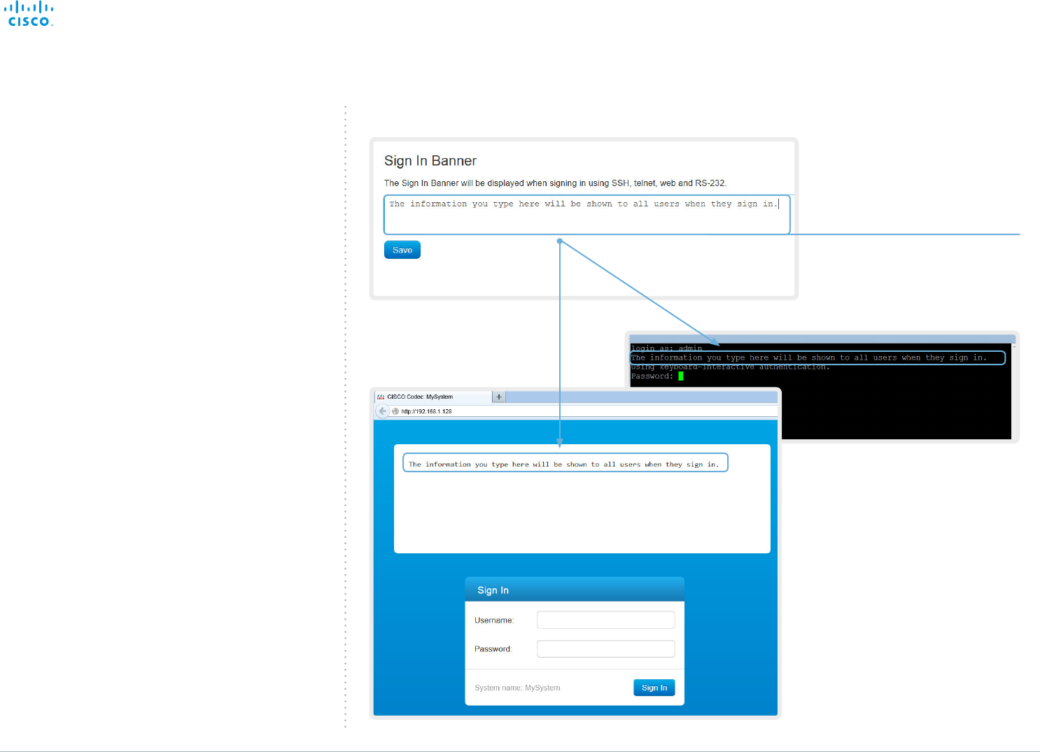
Adding a sign in banner
If a system administrator wants to provide initial information
to all users, he can create a sign in banner. The message will
be shown when the user signs in to the web interface and the
command line interface.
Adding a sign in banner
Enter the message that you
want to present to the user
when signing in, and click
Save to activate the banner.
Navigate to: Configuration > Sign In Banner
Contents
Introduction
System settings
Setting passwords
Appendices
Web interfaceWeb interface
D15106.01 SX10 Quick Set Administrator Guide TC7.1, JUNE 2014. www.cisco.com — Copyright © 2014 Cisco Systems, Inc. All rights reserved.
33
Cisco TelePresence SX10 Quick Set Administrator Guide
Managing the video system’s
certificates
Certificate validation may be required when using TLS
(Transport Layer Security).
A server or client may require that your video system
presents a valid certificate to them before communication can
be set up.
The video system’s certificates are text files that verify the
authenticity of the system. These certificates may be issued
by a certificate authority (CA).
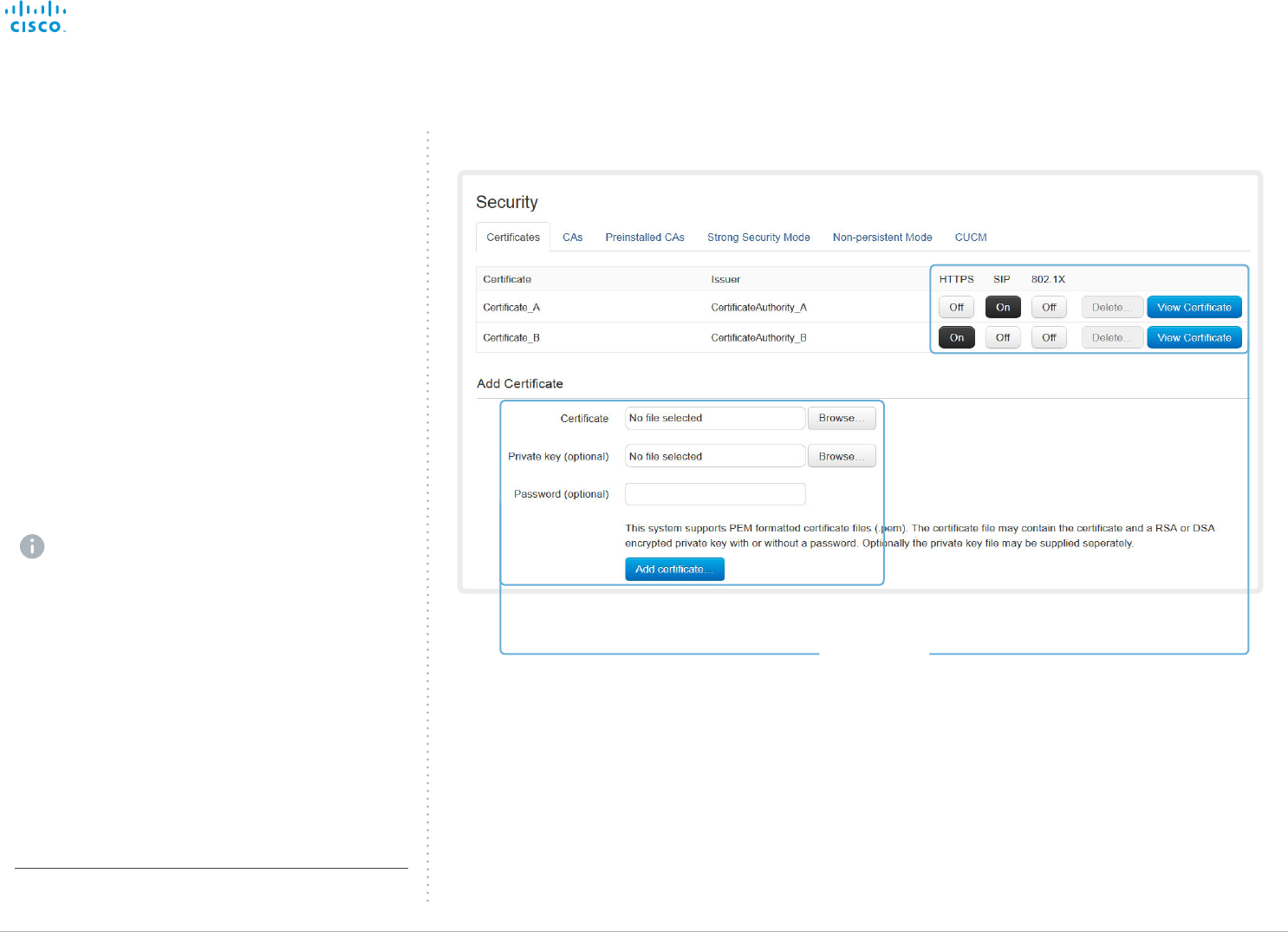
The certificates are listed as shown in the illustration to the
right*. They can be used for the following services: HTTPS,
SIP and IEEE 802.1X.
You can store several certificates on the system, but only one
certificate can be used for each service at a time.
If authentication fails, the connection will not be established.
Enabling and disabling certificates
Use the buttons to switch a certificate on or off for
the different services.
You can also view a certificate, and delete a
certificate using the corresponding buttons.
Adding a certificate
1. Click Browse... and find the Certificate and
Private key file(s) on your computer.
2. Fill in the Password if required.
3. Click Add certificate... to store the certificate
on your system.
Navigate to: Configuration > Security: Certificates tab
* The certificates and certificate issuers shown in the illustration
serve as examples. Your system may have other certificate(s).
Contact your system administrator to obtain the
following file(s):
• Certificate (file format: .PEM)
• Private key, either as a separate file or
included in the same file as the certificate
(file format: .PEM format)
• Password (required only if the private key is
encrypted)
The certificate and the private key will be stored in
the same file on the video system.
Contents
Introduction
System settings
Setting passwords
Appendices
Web interfaceWeb interface
D15106.01 SX10 Quick Set Administrator Guide TC7.1, JUNE 2014. www.cisco.com — Copyright © 2014 Cisco Systems, Inc. All rights reserved.
34
Cisco TelePresence SX10 Quick Set Administrator Guide
Managing the list of trusted
certificate authorities
Certificate validation may be required when using TLS
(Transport Layer Security).
Your video system may be set up to require that a server
or client presents its certificate to the system before
communication can be set up.
The certificates are text files that verify the authenticity of the
server or client. The certificates must be signed by a trusted
certificate authority (CA).
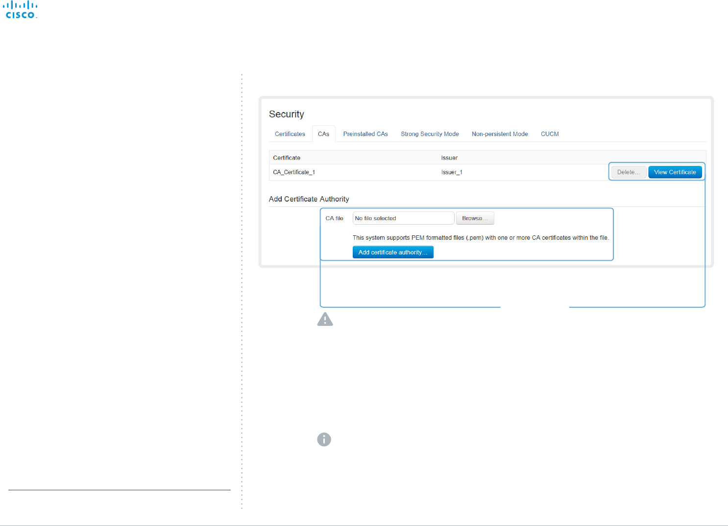
To be able to verify the signature of the certificates, a list of
trusted CAs must reside on the video system. The certificates
of the CAs are listed as shown in the illustration to the right*.
The list must include all CAs needed in order to verify
certificates for HTTPS, SIP and IEEE 802.1X connections.
If the server cannot be authenticated, the connection will not
be established.
* The certificate and certificate issuers shown in the illustration serve
as examples. Your system will have other certificate(s).
Contact your system administrator to obtain
the CA certificate list (file format: .PEM).
Viewing and deleting certificates
You can view a certificate, and
delete a certificate using the
corresponding buttons.
Uploading a list of certificate authorities
i. Click Browse... and find the file containing a
list of CA certificates (file format: .PEM) on
your computer.
ii. Click the Add certificate authority... to store
the new CA certificate(s) on your system.
The entries in a new file with CA certificates
will be appended to the existing list, that is,
the previously stored certificates will not be
deleted.
Navigate to: Configuration > Security: CAs tab
Contents
Introduction
System settings
Setting passwords
Appendices
Web interfaceWeb interface
D15106.01 SX10 Quick Set Administrator Guide TC7.1, JUNE 2014. www.cisco.com — Copyright © 2014 Cisco Systems, Inc. All rights reserved.
35
Cisco TelePresence SX10 Quick Set Administrator Guide
i
ii
iii
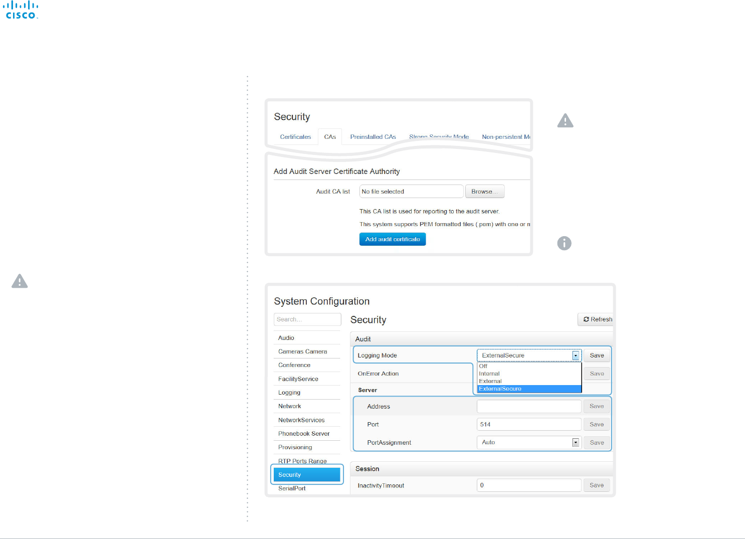
Adding audit certificates
Audit logging records all sign in activity and configuration
changes on your video system.
Audit logging is disabled by default, but you can enable it
using the Security > Audit > Logging > Mode setting on the
web interface.
In ExternalSecure audit logging mode the video system
sends encrypted audit logs to an external audit server
(syslog server), which identity must be verified by a signed
certificate.
To be able to verify the signature of the audit server
certificates, a list of trusted audit certificate authorities (CAs)
must reside on the video system.
If the audit server cannot be authenticated, the logs will not
be sent.
Always upload the audit certificate list before enabling
secure audit logging.
1. Upload a list of audit server certificates
The entries in a new file with CA
certificates will overwrite the existing
list, that is, any previously stored audit
certificates will be lost when you add a
new file.
i. Click Browse... and find the file containing the
list of audit CA certificates (.PEM format) on
your computer.
ii. Click Add audit certificate to store the
certificate(s) on your system.
Contact your system administrator to
obtain the Audit CA list (file format: .PEM).
2. Enable secure audit
logging
i. Go to the System
Configuration page and
choose the Security
category.
ii. Enter the Address of
the audit server. If
you choose Manual
PortAssignment, you
must also enter a Port
number for the audit
server. Click Save for the
changes to take effect.
iii. Choose ExternalSecure
from the Logging Mode
drop-down list. Click
Save for the change to
take effect.
Navigate to: Configuration > Security: CAs tab / Configuration > System Configuration
Contents
Introduction
System settings
Setting passwords
Appendices
Web interfaceWeb interface
D15106.01 SX10 Quick Set Administrator Guide TC7.1, JUNE 2014. www.cisco.com — Copyright © 2014 Cisco Systems, Inc. All rights reserved.
36
Cisco TelePresence SX10 Quick Set Administrator Guide
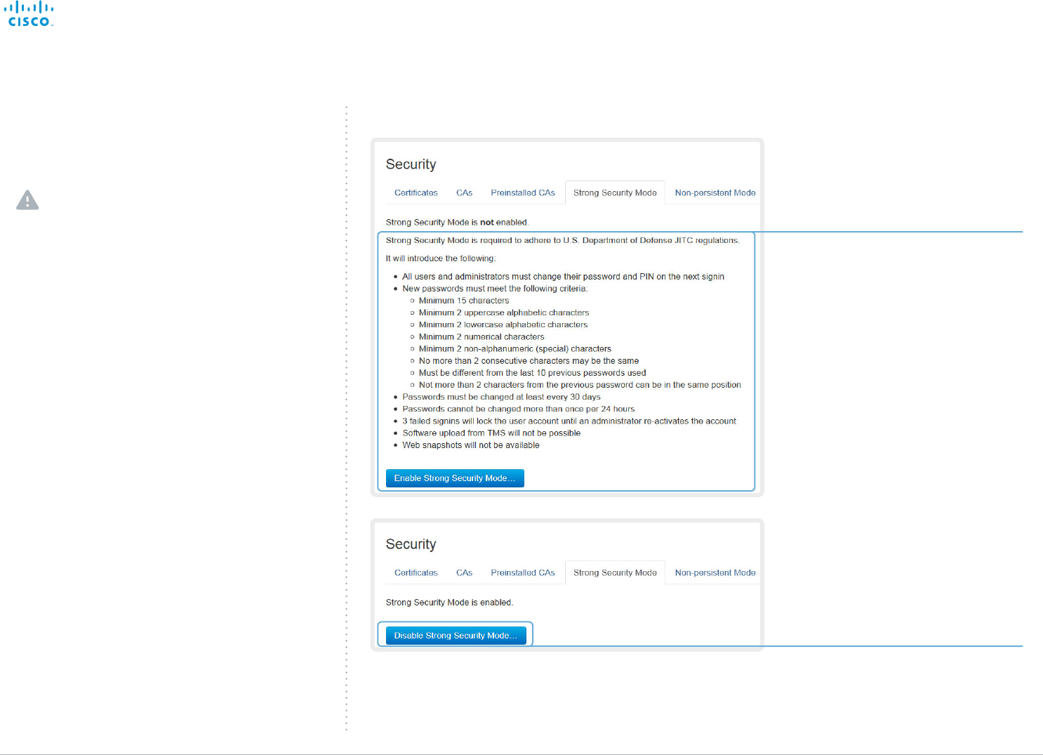
Setting strong security mode
Read carefully about the consequences of
strong security mode before you continue.
1. If you want to use strong security mode,
click Enable strong security mode....
Confirm your choice in the dialog box
that appears.
The system will restart automatically.
2. Change the password when you are
prompted. The new password must meet
the strict criteria as described.
How to change the system password is
described in the ► Setting passwords
section.
Return to normal mode
When in strong security mode, the system
can be restored to normal mode by clicking
Disable strong security mode.... Confirm your
choice in the dialog box that appears
The system will restart automatically.
Navigate to: Configuration > Security: Strong Security Mode tab
Setting strong security mode
Strong security mode should be used only when compliance
with DoD JITC regulations is required.
Read the provided information carefully before setting
strong security mode.
Strong security mode sets very strict password requirements,
and requires all users to change their password on the next
sign in.
Software upload from TMS and calling from the web interface
are prohibited in strong security mode.
Contents
Introduction
System settings
Setting passwords
Appendices
Web interfaceWeb interface
D15106.01 SX10 Quick Set Administrator Guide TC7.1, JUNE 2014. www.cisco.com — Copyright © 2014 Cisco Systems, Inc. All rights reserved.
37
Cisco TelePresence SX10 Quick Set Administrator Guide
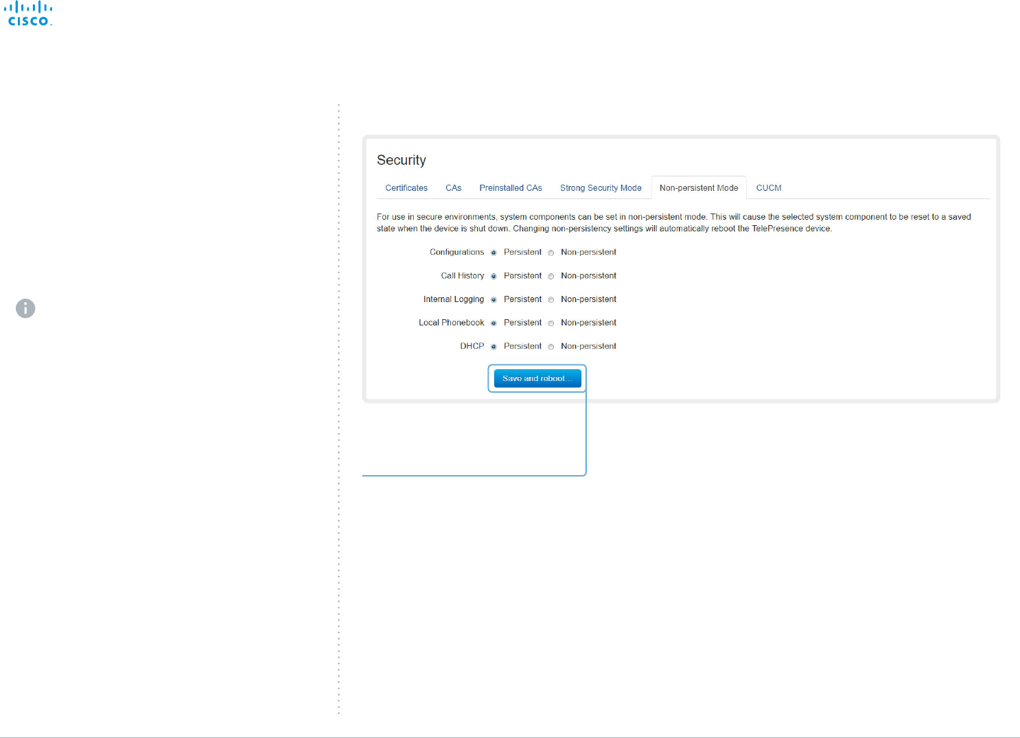
Changing the persistency mode
By default, all persistency settings are set to Persistent. This
means that configurations, call history, internal logs, local
phonebook / favorites list and IP connectivity information
are stored as normal. A system restart does not delete
information.
As a general rule, we recommend NOT to change the
default settings for persistency. But in the case were a
new user is not supposed to see or trace back to any kind
of logged information from the previous session, Non-
persistent mode must be used.
In order to clear/delete information that was stored
before changing to Non-persistent mode, you should
consider to factory reset the video system.
There is more information about performing a factory
reset in the ► Factory resetting appendix.
When in Non-persistent mode, the following information will
be lost/cleared each time the system restarts:
• System Configuration changes that have been made
since the last system restart.
• Information about calls that are placed or received since
the last system restart (call history).
• Internal log files that has been made since the last system
restart.
• Changes that are made to the local contacts / favorites
list since the last system restart.
• All IP related information (DHCP) from the last session.
Checking the persistency status
The radio buttons that are active when you open the Security
page and go to the Non-persistent Mode tab, shows the
current persistency status of the video system.
You can also see the status by checking Security >
Persistency on the Configuration > System Status page.
Changing the persistency settings
1. Set the persistency settings for the five
categories as desired.
2. Click Save and reboot....
The system will restart. After the
restart, behavior according to the new
persistency settings will start.
Note that logs, configurations etc. that
was stored before you switch to Non-
persistent mode, will not be cleared or
deleted.
Navigate to: Configuration > Security: Non-persistent Mode tab
Contents
Introduction
System settings
Setting passwords
Appendices
Web interfaceWeb interface
D15106.01 SX10 Quick Set Administrator Guide TC7.1, JUNE 2014. www.cisco.com — Copyright © 2014 Cisco Systems, Inc. All rights reserved.
38
Cisco TelePresence SX10 Quick Set Administrator Guide
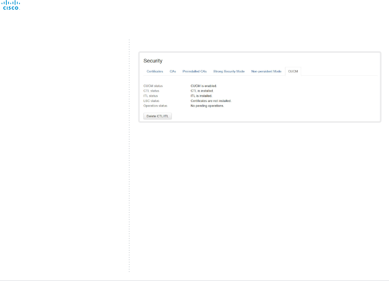
Deleting trust lists (CUCM only)
The information on this page is only relevant for
video systems that are registered to a Cisco Unified
Communications Manager (CUCM).
The web interface can be used to delete existing trust lists
(CTL and ITL) that are stored on the video system. Normally,
you will not delete the old CTL and ITL files, but there are a
few cases when you will need to delete them.
For more information about CUCM and trust lists, read the
Administering TC Endpoints on CUCM guide available on the
Cisco web site.
Navigate to: Configuration > Security: CUCM tab
Contents
Introduction
System settings
Setting passwords
Appendices
Web interfaceWeb interface
D15106.01 SX10 Quick Set Administrator Guide TC7.1, JUNE 2014. www.cisco.com — Copyright © 2014 Cisco Systems, Inc. All rights reserved.
39
Cisco TelePresence SX10 Quick Set Administrator Guide
Troubleshooting
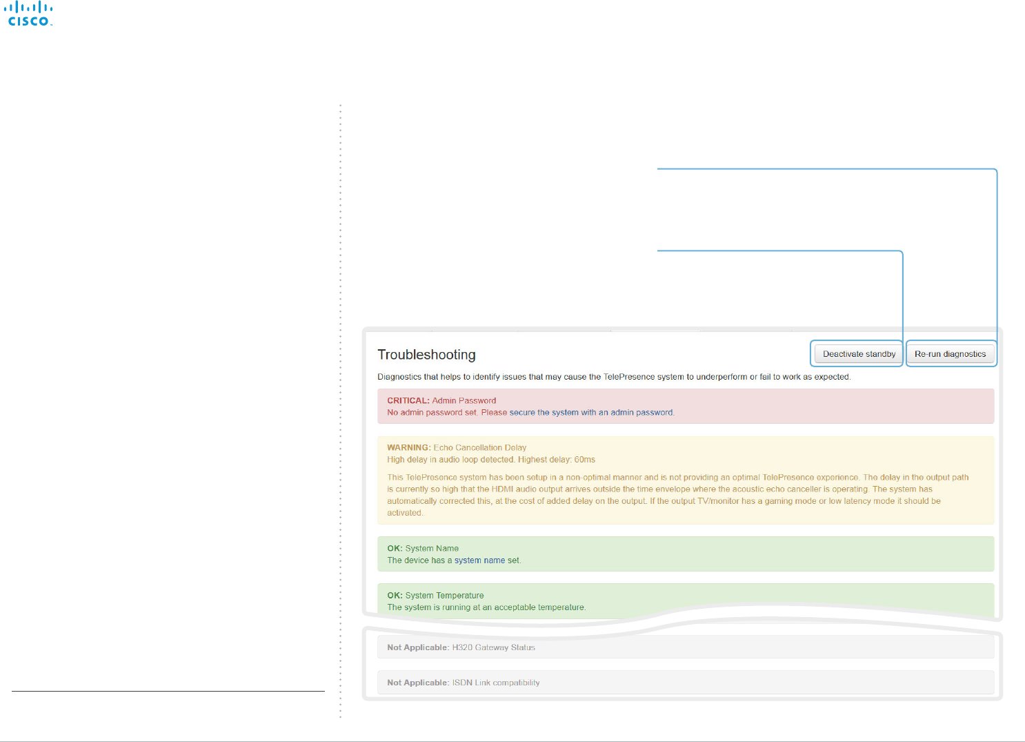
The troubleshooting page lists the status for some common
sources of errors. The list may be different for different
products and installations*.
Note that critical issues and errors are clearly marked in red
color; warnings are yellow.
Run diagnostics
Click Re-run diagnostics to make sure
the information in the list is up-to-date.
* The messages shown in the illustration serve as examples. Your
system may show other information.
Leave standby mode
This button is only visible when the
system is in standby mode. If in
standby mode, click Deactivate standby
to wake up the system.
Navigate to: Diagnostics > Troubleshooting
Contents
Introduction
System settings
Setting passwords
Appendices
Web interfaceWeb interface
D15106.01 SX10 Quick Set Administrator Guide TC7.1, JUNE 2014. www.cisco.com — Copyright © 2014 Cisco Systems, Inc. All rights reserved.
40
Cisco TelePresence SX10 Quick Set Administrator Guide
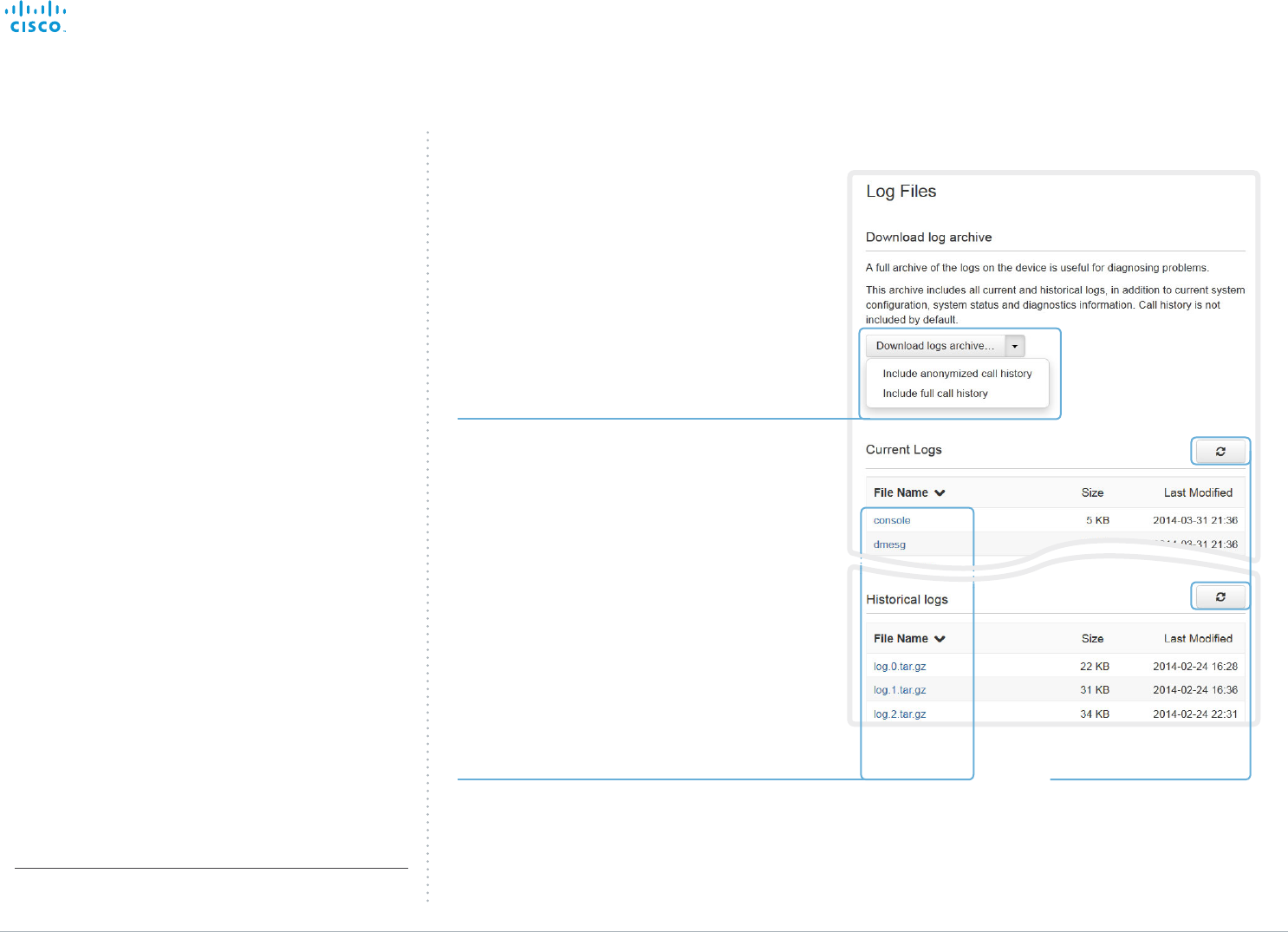
Downloading log files
The log files* are Cisco specific debug files which may be
requested by the Cisco support organization if you need
technical support.
The current log files are time stamped event log files.
All current log files are archived in a time stamped historical
log file each time the system restarts. If the maximum
number of historical log files is reached, the oldest one will be
overwritten.
Downloading all log files
Click Download logs archive and follow
the instructions.
Use the drop down list if you want to
include the call history in the archive.
You can choose whether to include the
full call history or to make the caller/
callee anonymous.
* The log files shown in the illustration serve as examples. Your
system may have other files.
Open/save one log file
Click the file name to open the log file in
the web browser; right click to save the
file on the computer.
Navigate to: Diagnostics > Log Files
Refresh the list of log files
Contents
Introduction
System settings
Setting passwords
Appendices
Web interfaceWeb interface
D15106.01 SX10 Quick Set Administrator Guide TC7.1, JUNE 2014. www.cisco.com — Copyright © 2014 Cisco Systems, Inc. All rights reserved.
41
Cisco TelePresence SX10 Quick Set Administrator Guide
Starting extended logging
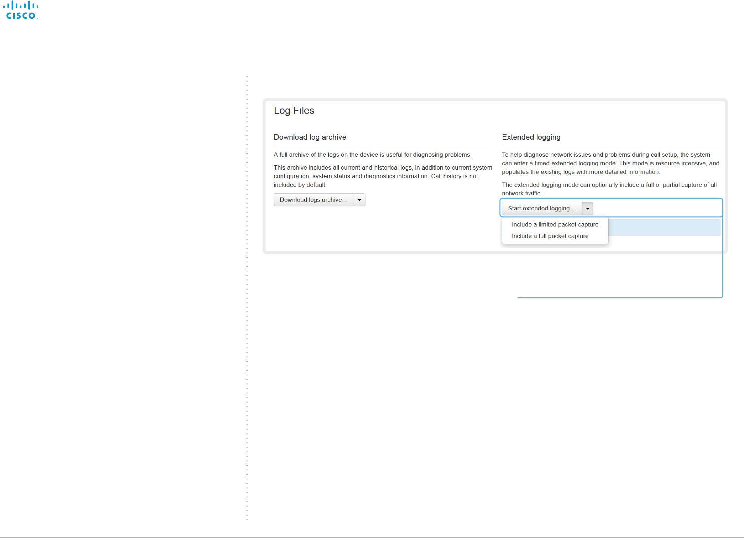
Extended logging mode may be switched on to help diagnose
network issues and problems during call setup. While in this
mode more information is stored in the log files.
Note that extended logging uses more of your video system’s
resources, and may cause your video system to under-
perform. You should only use extended logging mode when
troubleshooting an issue.
Start extended logging
Click Start extended logging.
Extended logging lasts for 10 minutes. You can stop
the extended logging before it times out by clicking
the Stop extended logging button that appears when
extended logging is on.
As default, the network traffic is not captured. Use the
drop down menu if you want to include a full or partial
capture of the network traffic.
Navigate to: Diagnostics > Log Files
Contents
Introduction
System settings
Setting passwords
Appendices
Web interfaceWeb interface
D15106.01 SX10 Quick Set Administrator Guide TC7.1, JUNE 2014. www.cisco.com — Copyright © 2014 Cisco Systems, Inc. All rights reserved.
42
Cisco TelePresence SX10 Quick Set Administrator Guide
Upgrading the system software
This video conference system is using TC software. The
version described in this document is TC7.1.
Contact your system administrator if you have
questions about the software version.
Software release notes
For a complete overview of the news and changes, we
recommend reading the Software Release Notes (TC7).
Go to: ► http://www.cisco.com/c/en/us/support/
collaboration-endpoints/telepresence-quick-set-series/tsd-
products-support-series-home.html
New software
For software download, go to the
Cisco Download Software web page:
► http://www.cisco.com/cisco/software/navigator.html.
Then navigate to your product.
The format of the file name is“s52030tc7_1_0.pkg” (each
software version has a unique file name).
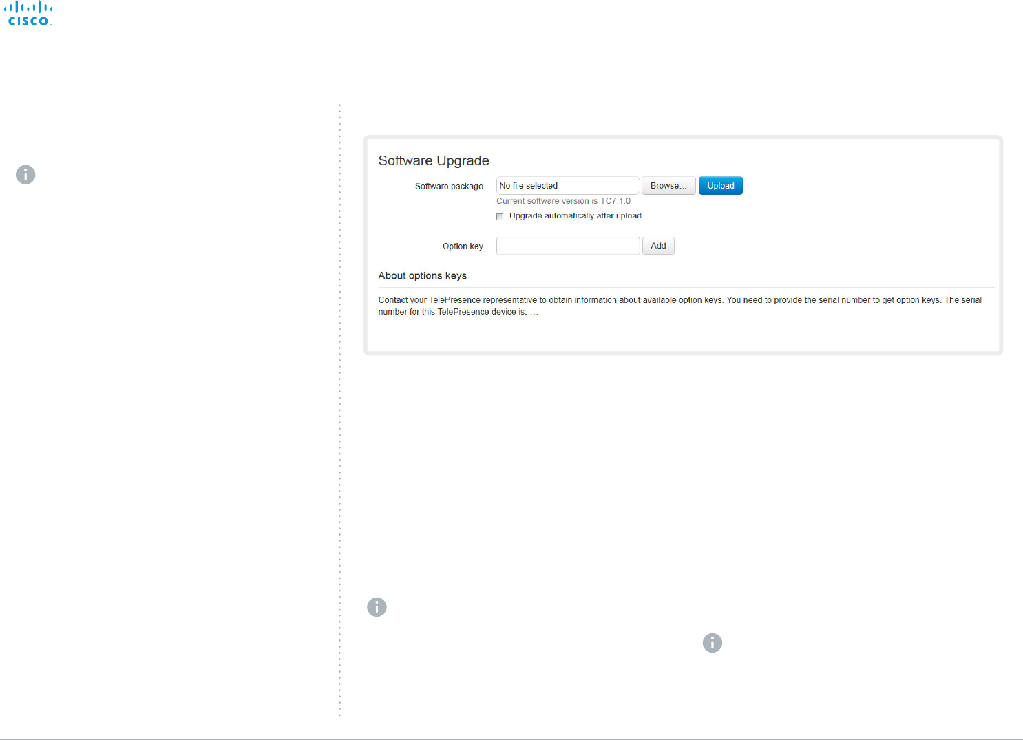
Adding option keys
An option key is required to activate optional functionality.
You may have several option keys in your system. If the keys
are already installed, you can skip this point and continue
with the software installation.
If you do not have the required key(s), contact your Cisco
representative to obtain them.
i. Enter an Option Key in the appropriate text input field
and click Add.
If you have more than one option key, repeat this step
for all keys.
Each system has unique keys, for example:
• 1R000-1-AA7A4A09
Installing new software
Download the appropriate software package from the Cisco
Software Download web page (see link to the left) and store
it on your local computer. This is a .pkg file.
i. Click Browse... and find the downloaded .pkg file that
contains the new software.
ii. Check the Upgrade automatically after upload check
box, then click Upload to start the installation process
straight away.
Keep the check box unchecked if you want to upload
the software now and do the installation later.
The complete installation may take up to 30minutes. You
can follow the progress on the web page. The system
restarts automatically after the installation.
You must sign in anew in order to continue working
with the web interface after the restart.
Navigate to: Maintenance > Software Upgrade
Contents
Introduction
System settings
Setting passwords
Appendices
Web interfaceWeb interface
D15106.01 SX10 Quick Set Administrator Guide TC7.1, JUNE 2014. www.cisco.com — Copyright © 2014 Cisco Systems, Inc. All rights reserved.
43
Cisco TelePresence SX10 Quick Set Administrator Guide
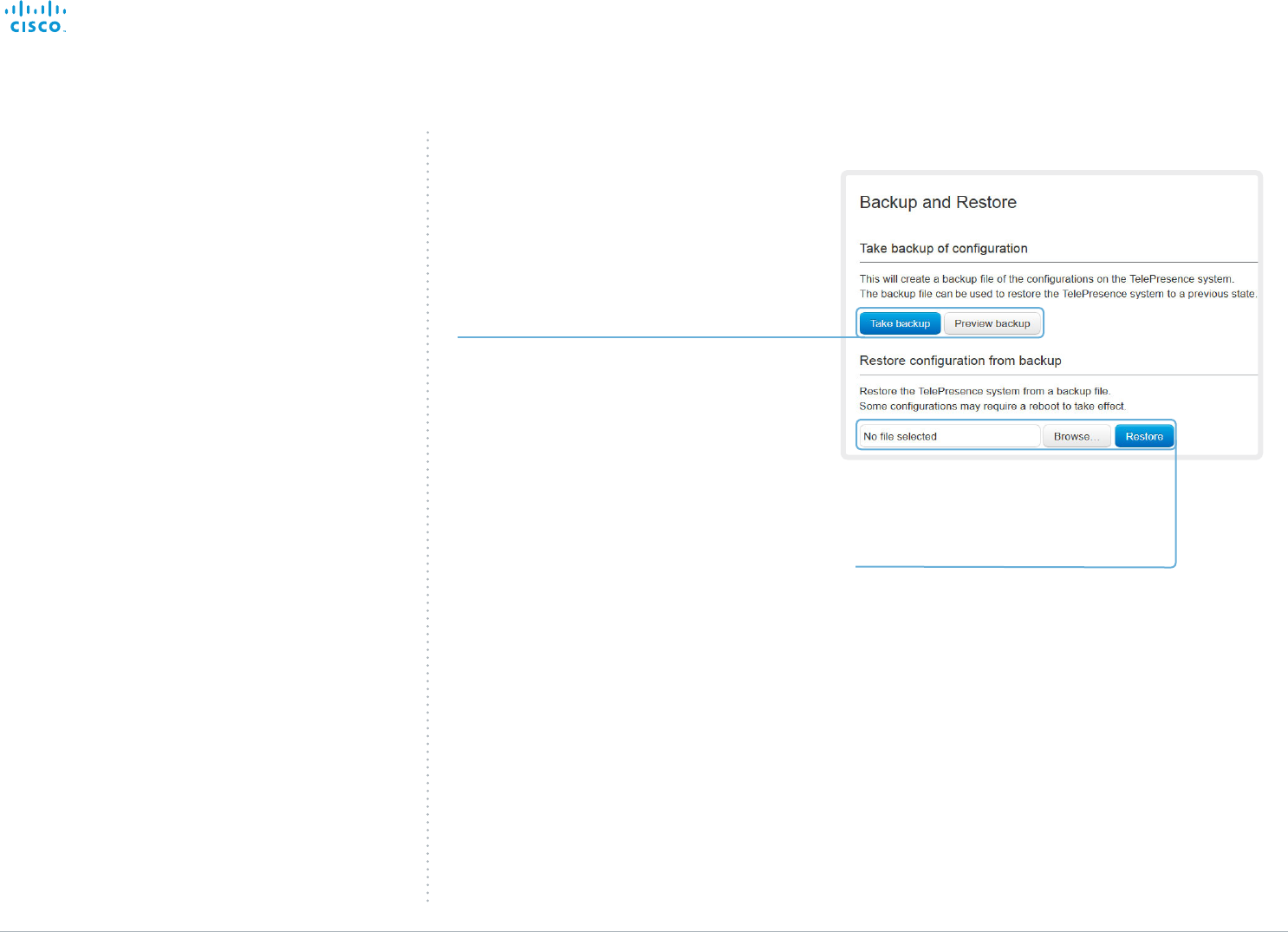
Backup and restore
All the system settings, which are available on the System
configuration page, can be listed on-screen or stored as a
text file.
The text file can be loaded back onto the system, thereby
restoring the configuration.
Backing up or showing the current configuration
Click Preview backup to display the current
settings on-screen.
Click Take backup to store the configuration
as a text file.
Restoring an earlier configuration
Click Browse... and find the file with the
configuration you want to restore.
Click Restore to reconfigure the system as
defined in the file.
Navigate to: Maintenance > Backup and Restore
Contents
Introduction
System settings
Setting passwords
Appendices
Web interfaceWeb interface
D15106.01 SX10 Quick Set Administrator Guide TC7.1, JUNE 2014. www.cisco.com — Copyright © 2014 Cisco Systems, Inc. All rights reserved.
44
Cisco TelePresence SX10 Quick Set Administrator Guide
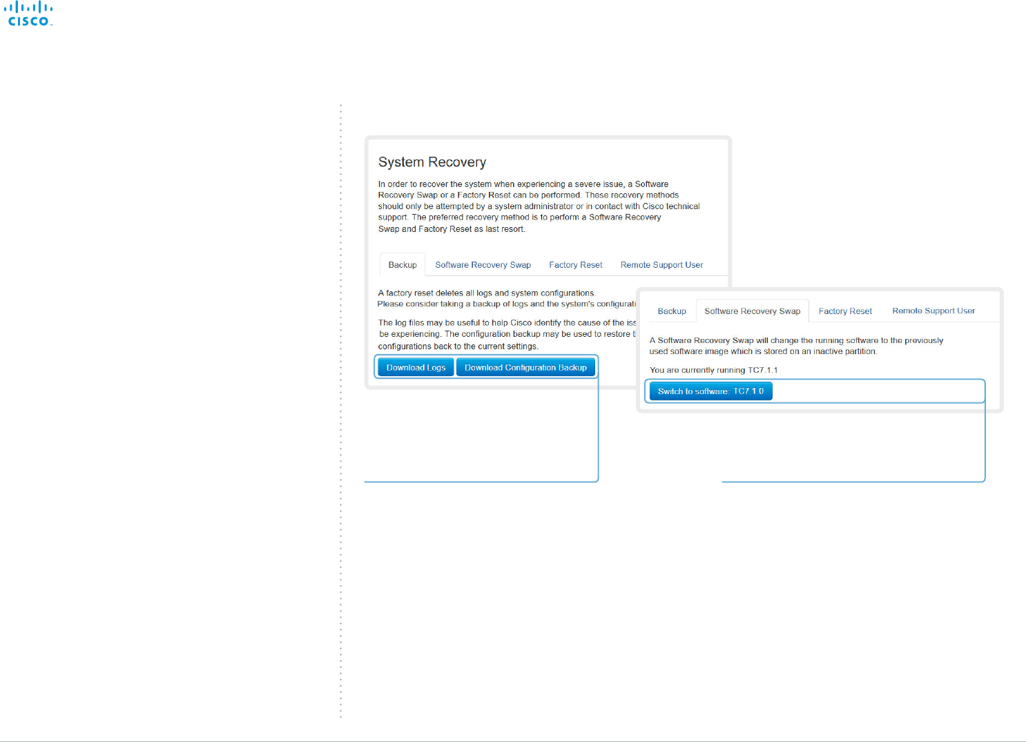
Reverting to the previously used
software version
If there is a severe problem with the video system, switching
to the previously used software version may help solving the
problem.
If the system has not been factory reset since the last
software upgrade, the previously used software image still
resides on the system; you do not have to download the
software again.
Reverting to the previously used software version should only
be done by a system administrator or in contact with Cisco
technical support.
We strongly recommend that you backup your system’s log
files and configuration before you swap to the other software
image.
Navigate to: Maintenance > System Recovery: Backup tab and Software Recovery Swap tab
1. Revert to the previously used software
version by clicking Switch to software
TCx.y.z..., where x.y.z indicates the
software version.
2. Click Yes to confirm your choice, or
Cancel if you have changed your mind.
Wait while the system resets. The
system will restart automatically when
finished.
1. Backing up log files and
system configuration
We recommend that you backup your
system’s log files and configuration before
you swap to the other software image.
Click Download Logs and Download
Configuration Backup and follow the
instructions to save the files on your
computer.
2. Reverting to the previously used
software version
Contents
Introduction
System settings
Setting passwords
Appendices
Web interfaceWeb interface
D15106.01 SX10 Quick Set Administrator Guide TC7.1, JUNE 2014. www.cisco.com — Copyright © 2014 Cisco Systems, Inc. All rights reserved.
45
Cisco TelePresence SX10 Quick Set Administrator Guide
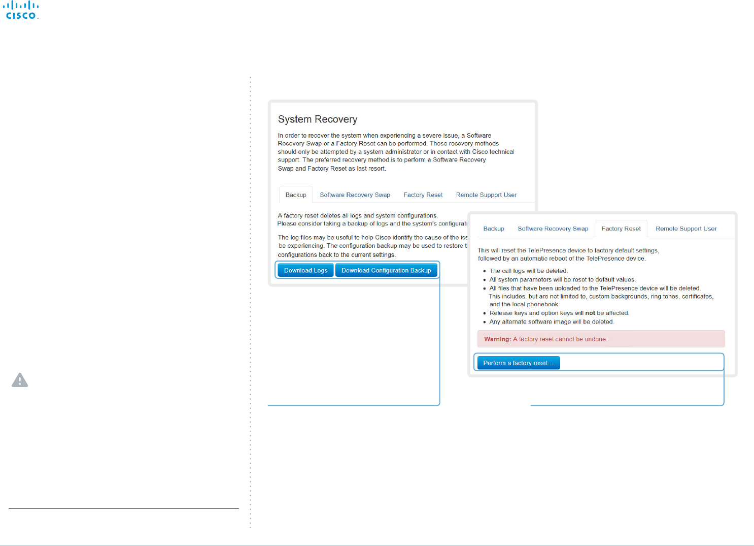
2. Performing a factory reset
Read the provided information carefully
before you restore the factory settings by
clicking Perform a factory reset....
Click Yes to confirm your choice, or Cancel if
you have changed your mind.
Wait while the system resets. The system
will restart automatically when finished.
Navigate to: Maintenance > System Recovery: Backup tab and Factory Reset tab
1. Backing up log files and
system configuration
We strongly recommend that you backup
your system’s log files and configuration
before you perform a factory reset;
otherwise these data will be lost.
Click Download Logs and Download
Configuration Backup and follow the
instructions to save the files on your
computer.
* Read about software swapping in the ► Reverting to the previously
used software version section.
Factory reset
If there is a severe problem with the video system, the last
resort may be to reset it to its default factory settings. Always
consider reverting to the previously used software image
before performing a factory reset. In many situations this will
recover the system*.
A factory reset should only be performed by a system
administrator or in contact with Cisco technical support.
When factory resetting the video system the following
happens:
• The call logs will be deleted.
• Passwords will be reset to default.
• All system parameters will be reset to default values.
• All files that have been uploaded to the system will be
deleted. This includes, but is not limited to, custom
backgrounds, certificates, local contacts and the favorites
list.
• The previous (inactive) software image will be deleted.
• Release keys and option keys will not be affected.
The system restarts automatically after the reset. It is using
the same software image as before.
We strongly recommend that you backup your system’s log
files and configuration before you perform a factory reset.
It is not possible to undo a factory reset.
There is more information about performing a factory reset in
the ► Factory resetting appendix.
Contents
Introduction
System settings
Setting passwords
Appendices
Web interfaceWeb interface
D15106.01 SX10 Quick Set Administrator Guide TC7.1, JUNE 2014. www.cisco.com — Copyright © 2014 Cisco Systems, Inc. All rights reserved.
46
Cisco TelePresence SX10 Quick Set Administrator Guide
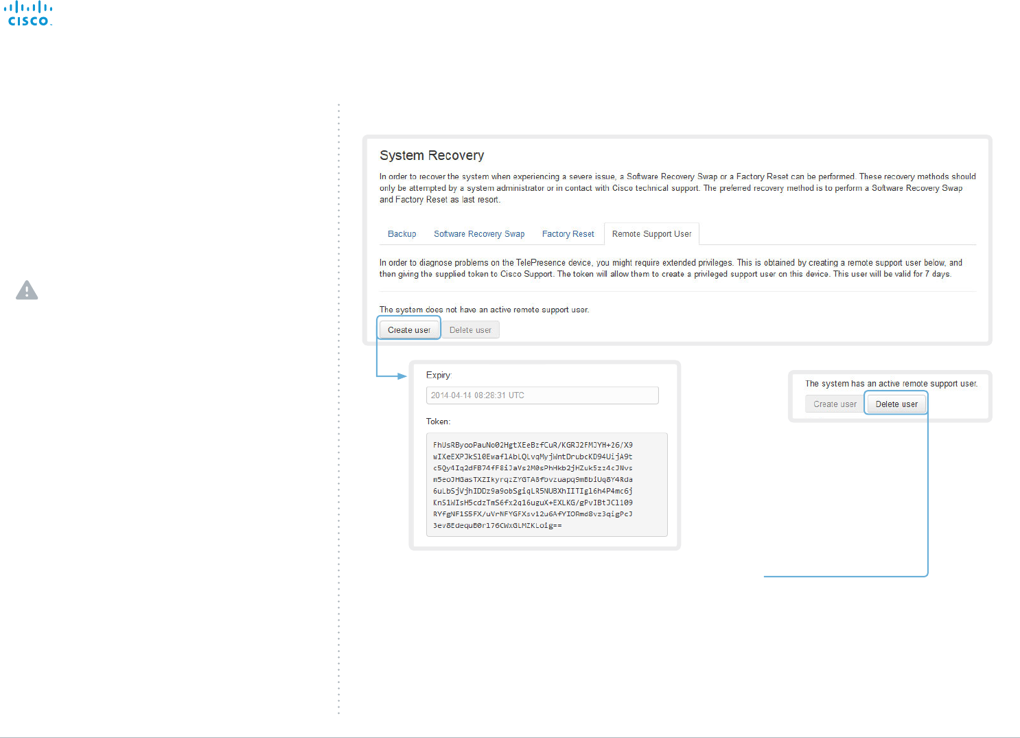
Remote support user
In cases where you need to diagnose problems on the
TelePresence device you can create a remote support user.
The remote support user will be granted read access to the
system and will have access to a limited set of commands
that can aid troubleshooting.
You will need assistance from Cisco Technical Assistance
Center (TAC) to acquire the password for the remote
support user.
The remote support user should only be enabled
for troubleshooting reasons when instructed by
Cisco TAC.
Navigate to: Maintenance > System Recovery: Remote Support User tab
Create remote support user
1. Open a case with Cisco TAC.
2. Click Create user.
3. Copy the text in the Token field and
send to Cisco TAC.
4. Cisco TAC will generate a password.
The remote support user is valid for seven
days, or until it is deleted.
Delete remote support user
Click Delete user.
Contents
Introduction
System settings
Setting passwords
Appendices
Web interfaceWeb interface
D15106.01 SX10 Quick Set Administrator Guide TC7.1, JUNE 2014. www.cisco.com — Copyright © 2014 Cisco Systems, Inc. All rights reserved.
47
Cisco TelePresence SX10 Quick Set Administrator Guide
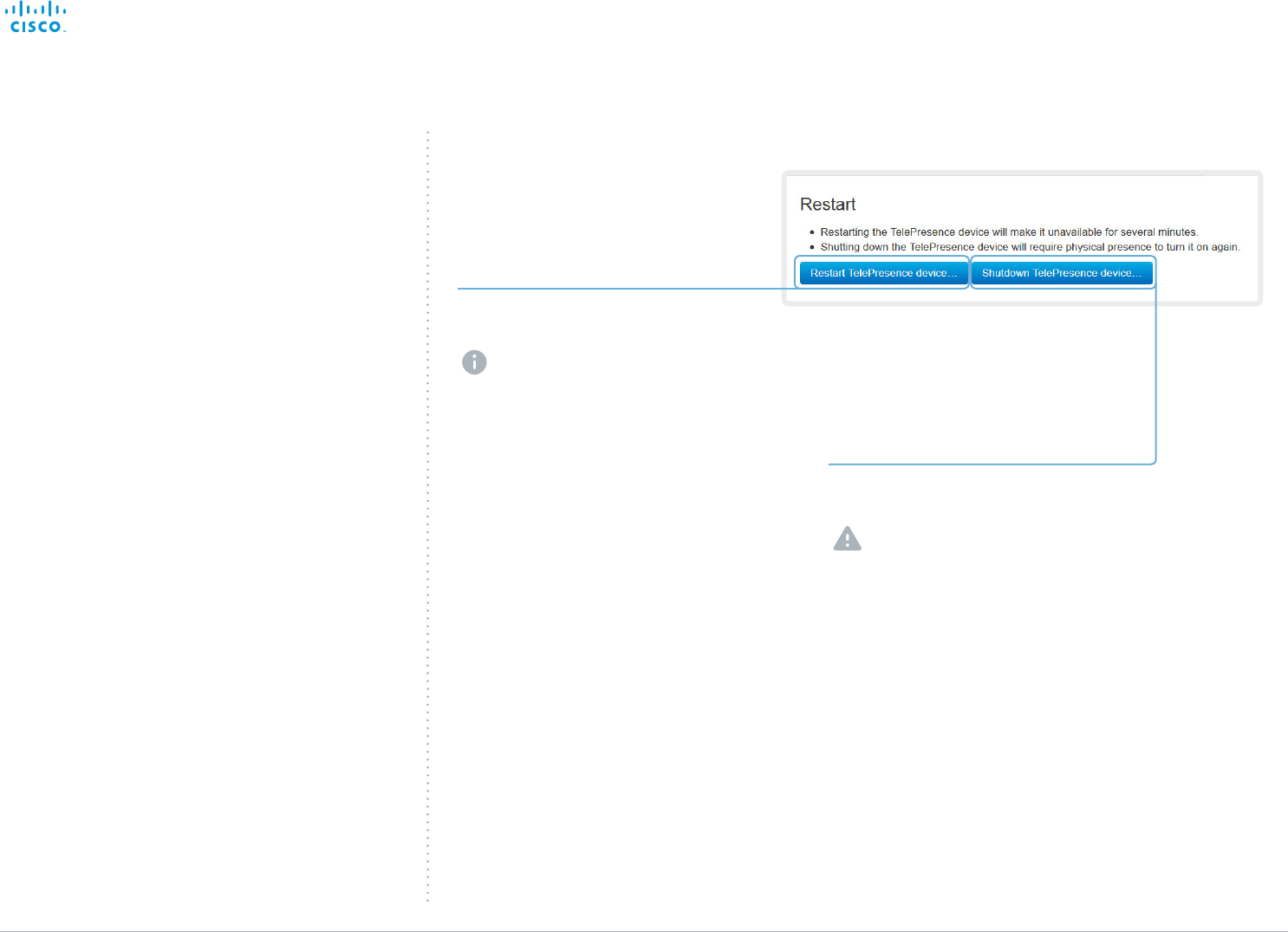
Restarting the system
The system can be shut down or restarted remotely using the
web interface.
Restarting the system
Click Restart TelePresence device... to
restart the system.
It will take a few minutes before
the system is ready for use.
Shutting down the system
Click Shutdown TelePresence device...
to shut down the system.
The system cannot be turned on
again remotely; you must press
its power button physically to
turn it on.
Navigate to: Maintenance > Restart
Contents
Introduction
System settings
Setting passwords
Appendices
Web interfaceWeb interface

D15106.01 SX10 Quick Set Administrator Guide TC7.1, JUNE 2014. www.cisco.com — Copyright © 2014 Cisco Systems, Inc. All rights reserved.
48
Cisco TelePresence SX10 Quick Set Administrator Guide
Chapter 3
System settings
Contents
Introduction
System settings
Setting passwords
Appendices
Web interface
System settings

D15106.01 SX10 Quick Set Administrator Guide TC7.1, JUNE 2014. www.cisco.com — Copyright © 2014 Cisco Systems, Inc. All rights reserved.
49
Cisco TelePresence SX10 Quick Set Administrator Guide
Overview of the system settings
In the following pages you will find a complete list of the
system settings which are configured from the System
Configuration page on the web interface. The examples show
either the default value or an example of a value.
Open a web browser and enter the IP address of the video
system*; then sign in.
Audio settings ....................................................................... 52
Audio DefaultVolume............................................................... 52
Audio Input Microphone [1] ..................................................... 52
Audio Microphones Mute Enabled .......................................... 52
Audio SoundsAndAlerts KeyTones Mode ............................... 52
Audio SoundsAndAlerts RingTone .......................................... 52
Audio SoundsAndAlerts RingVolume...................................... 52
Cameras settings .................................................................. 53
Cameras Camera [1] Backlight ................................................ 53
Cameras Camera [1] Brightness Level .................................... 53
Cameras Camera [1] Brightness Mode ................................... 53
Cameras Camera [1] Flip ......................................................... 53
Cameras Camera [1] Focus Mode........................................... 53
Cameras Camera [1] Mirror ..................................................... 54
Cameras Camera [1] Whitebalance Level ............................... 54
Cameras Camera [1] Whitebalance Mode .............................. 54
Conference settings ............................................................. 55
Conference [1..1] ActiveControl Mode .................................... 55
Conference [1..1] AutoAnswer Delay ....................................... 55
Conference [1..1] AutoAnswer Mode ...................................... 55
Conference [1..1] AutoAnswer Mute ........................................ 55
Conference [1..1] CallProtocolIPStack ..................................... 55
Conference [1..1] DefaultCall Rate ........................................... 56
Conference [1..1] DoNotDisturb DefaultTimeout ..................... 56
Conference [1..1] Encryption Mode ......................................... 56
Conference [1..1] FarEndControl Mode ................................... 56
Conference [1..1] FarEndControl SignalCapability ................... 56
Conference [1..1] MaxReceiveCallRate ................................... 57
Conference [1..1] MaxTotalReceiveCallRate ............................ 57
Conference [1..1] MaxTotalTransmitCallRate ........................... 57
Conference [1..1] MaxTransmitCallRate ................................... 56
Conference [1..1] MicUnmuteOnDisconnect Mode ................. 55
Conference [1..1] Presentation OnPlacedOnHold ................... 58
Conference [1..1] Presentation RelayQuality ........................... 57
Conference [1..1] VideoBandwidth MainChannel Weight ........ 57
Conference [1..1] VideoBandwidth Mode ................................ 57
Conference [1..1] VideoBandwidth PresentationChannel
Weight ..................................................................................... 57
FacilityService settings ......................................................... 59
FacilityService Service [1..5] CallType .................................... 59
FacilityService Service [1..5] Name ........................................ 59
FacilityService Service [1..5] Number ..................................... 59
FacilityService Service [1..5] Type .......................................... 59
Logging settings ................................................................... 60
Logging Mode ......................................................................... 60
Network settings ................................................................... 61
Network [1..1] DHCP RequestTFTPServerAddress ................. 62
Network [1..1] DNS Domain Name ........................................... 62
Network [1..1] DNS Server [1..3] Address ................................ 62
Network [1..1] IEEE8021X AnonymousIdentity ......................... 65
Network [1..1] IEEE8021X Eap Md5 ......................................... 65
Network [1..1] IEEE8021X Eap Peap ........................................ 66
Network [1..1] IEEE8021X Eap Tls ............................................ 66
Network [1..1] IEEE8021X Eap Ttls ........................................... 66
Network [1..1] IEEE8021X Identity ............................................ 65
Network [1..1] IEEE8021X Mode .............................................. 64
Network [1..1] IEEE8021X Password ........................................ 65
Network [1..1] IEEE8021X TlsVerify .......................................... 65
Network [1..1] IEEE8021X UseClientCertificate ....................... 65
Network [1..1] IPStack ...............................................................61
Network [1..1] IPv4 Address .....................................................61
Network [1..1] IPv4 Assignment ................................................61
Network [1..1] IPv4 Gateway .....................................................61
Network [1..1] IPv4 SubnetMask ...............................................61
Network [1..1] IPv6 Address .................................................... 62
Network [1..1] IPv6 Assignment ................................................61
Network [1..1] IPv6 DHCPOptions ........................................... 62
Network [1..1] IPv6 Gateway .................................................... 62
Network [1..1] MTU .................................................................. 66
Network [1..1] QoS Diffserv Audio ........................................... 63
Network [1..1] QoS Diffserv Data ............................................. 63
Network [1..1] QoS Diffserv ICMPv6 ....................................... 64
Network [1..1] QoS Diffserv NTP ............................................. 64
Network [1..1] QoS Diffserv Signalling ..................................... 64
Network [1..1] QoS Diffserv Video ........................................... 63
* How to find the IP address (IPv4 or IPv6):
Navigate to the contact information in the upper, left corner of
the screen and press OK on the remote control. Then open the
Settings menu.
Contents
Introduction
System settings
Setting passwords
Appendices
Web interface
System settings

D15106.01 SX10 Quick Set Administrator Guide TC7.1, JUNE 2014. www.cisco.com — Copyright © 2014 Cisco Systems, Inc. All rights reserved.
50
Cisco TelePresence SX10 Quick Set Administrator Guide
Network [1..1] QoS Mode ........................................................ 63
Network [1..1] RemoteAccess Allow ........................................ 66
Network [1..1] TrafficControl Mode .......................................... 66
Network [1..1] VLAN Voice Mode ............................................ 67
Network [1..1] VLAN Voice VlanId............................................ 67
NetworkServices settings ..................................................... 68
NetworkServices HTTP Mode ................................................ 68
NetworkServices HTTPS Mode .............................................. 68
NetworkServices HTTPS OCSP Mode ................................... 69
NetworkServices HTTPS OCSP URL ..................................... 69
NetworkServices HTTPS VerifyClientCertificate .................... 69
NetworkServices HTTPS VerifyServerCertificate .................. 69
NetworkServices NTP Address .............................................. 69
NetworkServices NTP Mode .................................................. 69
NetworkServices SIP Mode .................................................... 68
NetworkServices SNMP CommunityName ............................ 70
NetworkServices SNMP Host [1..3] Address .......................... 70
NetworkServices SNMP Mode ............................................... 70
NetworkServices SNMP SystemContact ............................... 70
NetworkServices SNMP SystemLocation .............................. 70
NetworkServices SSH AllowPublicKey ................................... 70
NetworkServices SSH Mode .................................................. 70
NetworkServices Telnet Mode ............................................... 68
NetworkServices WelcomeText .............................................. 68
NetworkServices XMLAPI Mode ............................................ 68
Phonebook settings ...............................................................71
Phonebook Server [1..1] ID .......................................................71
Phonebook Server [1..1] Type ..................................................71
Phonebook Server [1..1] URL ...................................................71
Provisioning settings ............................................................. 72
Provisioning Connectivity ....................................................... 72
Provisioning ExternalManager Address .................................. 73
Provisioning ExternalManager AlternateAddress.................... 73
Provisioning ExternalManager Domain ................................... 73
Provisioning ExternalManager Path ........................................ 73
Provisioning ExternalManager Protocol .................................. 73
Provisioning HttpMethod ........................................................ 72
Provisioning LoginName ......................................................... 72
Provisioning Mode .................................................................. 72
Provisioning Password ............................................................ 72
RTP settings ...........................................................................74
RTP Ports Range Start ............................................................. 74
RTP Ports Range Stop .............................................................74
Security settings ................................................................... 75
Security Audit Logging Mode ................................................. 75
Security Audit OnError Action ................................................. 75
Security Audit Server Address ............................................... 75
Security Audit Server Port ...................................................... 75
Security Audit Server PortAssignment ................................... 75
Security Session InactivityTimeout ......................................... 76
Security Session ShowLastLogon .......................................... 76
SerialPort settings ................................................................ 77
SerialPort LoginRequired ........................................................ 77
SerialPort Mode ...................................................................... 77
SIP settings ........................................................................... 78
SIP ANAT ................................................................................ 78
SIP AuthenticateTransferror .................................................... 78
SIP ListenPort ......................................................................... 78
SIP OCSP DefaultResponder .................................................. 78
SIP OCSP Mode...................................................................... 78
SIP PreferredIPMedia .............................................................. 78
SIP PreferredIPSignaling ......................................................... 78
SIP Profile [1..1] Authentication [1..1] LoginName .................... 80
SIP Profile [1..1] Authentication [1..1] Password ....................... 80
SIP Profile [1..1] DefaultTransport ............................................ 80
SIP Profile [1..1] DisplayName.................................................. 80
SIP Profile [1..1] Ice DefaultCandidate ..................................... 79
SIP Profile [1..1] Ice Mode ........................................................ 79
SIP Profile [1..1] Line .................................................................81
SIP Profile [1..1] Mailbox ...........................................................81
SIP Profile [1..1] Outbound ........................................................81
SIP Profile [1..1] Proxy [1..4] Address ........................................81
SIP Profile [1..1] Proxy [1..4] Discovery .....................................81
SIP Profile [1..1] TlsVerify ......................................................... 80
SIP Profile [1..1] Turn BandwidthProbe .................................... 79
SIP Profile [1..1] Turn DiscoverMode ....................................... 79
SIP Profile [1..1] Turn DropRflx ................................................. 79
SIP Profile [1..1] Turn Password ............................................... 80
SIP Profile [1..1] Turn Server .................................................... 79
SIP Profile [1..1] Turn UserName ............................................. 79
SIP Profile [1..1] Type ................................................................81
SIP Profile [1..1] URI ................................................................. 80
Standby settings ................................................................... 82
Standby BootAction ................................................................ 82
Standby Control ...................................................................... 82
Standby Delay ......................................................................... 82
Standby StandbyAction .......................................................... 82
Standby WakeupAction ........................................................... 82
SystemUnit settings .............................................................. 83
SystemUnit CallLogging Mode ............................................... 83
SystemUnit ContactInfo Type ................................................. 83
SystemUnit MenuLanguage .................................................... 83
SystemUnit Name ................................................................... 83
Time settings ........................................................................ 84
Time DateFormat .................................................................... 84
Time TimeFormat .................................................................... 84
Time Zone ............................................................................... 84
UserInterface settings ........................................................... 85
UserInterface Language ......................................................... 85
UserInterface OSD EncryptionIndicator .................................. 85
UserInterface OSD LanguageSelection .................................. 85
UserInterface OSD LoginRequired.......................................... 85
UserInterface OSD Output ...................................................... 85
UserInterface TouchPanel DefaultPanel ................................. 86
UserInterface UserPreferences .............................................. 86
UserInterface Wallpaper ......................................................... 85
Video settings ....................................................................... 87
Video AllowWebSnapshots ..................................................... 87
Video CamCtrlPip CallSetup Duration .................................... 87
Video CamCtrlPip CallSetup Mode ......................................... 87
Contents
Introduction
System settings
Setting passwords
Appendices
Web interface
System settings

D15106.01 SX10 Quick Set Administrator Guide TC7.1, JUNE 2014. www.cisco.com — Copyright © 2014 Cisco Systems, Inc. All rights reserved.
51
Cisco TelePresence SX10 Quick Set Administrator Guide
Video Input Connector [1..3] CameraControl CameraId ......... 88
Video Input Connector [1..3] CameraControl Mode ................ 88
Video Input Connector [1..3] InputSourceType ....................... 87
Video Input Connector [1..3] Name ......................................... 87
Video Input Connector [1..3] OptimalDefinition Profile ............ 88
Video Input Connector [1..3] Quality ....................................... 88
Video Input Connector [1..3] Visibility ..................................... 87
Video Input Connector [2..3] PresentationSelection ............... 88
Video Input Connector [2] RGBQuantizationRange ................. 89
Video Layout LocalLayoutFamily ............................................ 89
Video Layout PresentationDefault View .................................. 89
Video Layout RemoteLayoutFamily ......................................... 89
Video Layout ScaleToFrame ................................................... 90
Video Layout ScaleToFrameThreshold .................................... 90
Video Layout Scaling .............................................................. 90
Video Monitors ........................................................................ 92
Video OSD EncryptionIndicator .............................................. 92
Video OSD LanguageSelection .............................................. 92
Video OSD LoginRequired ...................................................... 92
Video OSD Output .................................................................. 92
Video Output Connector [1] CEC Mode .................................. 92
Video Output Connector [1] OverscanLevel............................ 92
Video Output Connector [1] Resolution ................................... 92
Video Output Connector [1] RGBQuantizatonRange ............... 92
Video PIP ActiveSpeaker DefaultValue Position ..................... 90
Video PIP Presentation DefaultValue Position ........................ 90
Video SelfviewDefault FullscreenMode ...................................91
Video SelfviewDefault Mode ....................................................91
Video SelfviewDefault PIPPosition ...........................................91
Video SelfviewPosition ............................................................91
Video WallPaper...................................................................... 92
Experimental settings ........................................................... 93
Contents
Introduction
System settings
Setting passwords
Appendices
Web interface
System settings

D15106.01 SX10 Quick Set Administrator Guide TC7.1, JUNE 2014. www.cisco.com — Copyright © 2014 Cisco Systems, Inc. All rights reserved.
52
Cisco TelePresence SX10 Quick Set Administrator Guide
Audio settings
Audio Input Microphone [1]
Set the audio input microphone mode.
Requires user role: ADMIN
Value space: <Off/On>
Off: Disable the microphone connector.
On: Enable the microphone connector.
Example:
Audio Input Microphone 1 Mode: On
Audio Microphones Mute Enabled
Determine whether audio-mute is allowed or not. The default value is True.
Requires user role: ADMIN
Value space: <True/InCallOnly>
True: Muting of audio is always available.
InCallOnly: Muting of audio is only available when the device is in a call. When Idle it is not
possible to mute the microphone. This is useful when an external telephone service/audio
system is connected via the codec and is to be available when the codec is not in a call.
When set to InCallOnly this will prevent the audio-system from being muted by mistake.
Example:
Audio Microphones Mute Enabled: True
Audio SoundsAndAlerts KeyTones Mode
The system can be configured to make a keyboard click sound effect (key tone) when pressing
a key on the remote control.
Requires user role: USER
Value space: <Off/On>
Off: No key tone will be played when you press a key.
On: You will hear a key tone when you press a key.
Example:
Audio SoundsAndAlerts KeyTones Mode: On
Audio SoundsAndAlerts RingTone
This setting defines which ringtone to use for incoming calls. You need to enter the exact name
of the ringtone.
The list of available ringtones can be found on the Configuration > Personalization page in the
web interface.
Requires user role: USER
Value space: <S: 1, 100>
Format: String with a maximum of 100 characters.
Example:
Audio SoundsAndAlerts RingTone: "Sunrise"
Audio SoundsAndAlerts RingVolume
Sets the ring volume for an incoming call.
Requires user role: USER
Value space: <0..100>
Range: The value goes in steps of 5 from 0 to 100 (from -34.5 dB to 15 dB). Volume 0 = Off.
Example:
Audio SoundsAndAlerts RingVolume: 50
Audio DefaultVolume
Set the default speaker volume. The volume returns to this value when you switch on or restart
the video system. Use the remote controller to change the volume while the video system is
running.
Requires user role: USER
Value space: <0..100>
Range: The value must be between 0 and 100. The values from 1 to 100 correspond to the
range from -34.5 dB to 15 dB (0.5 dB steps). The value 0 means that the audio is switched
off.
Example:
Audio DefaultVolume: 70
Contents
Introduction
System settings
Setting passwords
Appendices
Web interface
System settings

D15106.01 SX10 Quick Set Administrator Guide TC7.1, JUNE 2014. www.cisco.com — Copyright © 2014 Cisco Systems, Inc. All rights reserved.
53
Cisco TelePresence SX10 Quick Set Administrator Guide
Cameras settings
Cameras Camera [1] Backlight
This configuration turns backlight compensation on or off. Backlight compensation is useful
when there is much light behind the persons in the room. Without compensation the persons
will easily appear very dark to the far end.
Requires user role: ADMIN
Value space: <Off/On>
Off: Turn off the camera backlight compensation.
On: Turn on the camera backlight compensation.
Example:
Cameras Camera 1 Backlight: Off
Cameras Camera [1] Brightness Mode
Set the camera brightness mode.
Requires user role: ADMIN
Value space: <Auto/Manual>
Auto: The camera brightness is automatically set by the system.
Manual: Enable manual control of the camera brightness. The brightness level is set using
the Cameras Camera Brightness Level setting.
Example:
Cameras Camera 1 Brightness Mode: Auto
Cameras Camera [1] Brightness Level
Set the brightness level. Requires the Camera Brightness Mode to be set to Manual.
Requires user role: ADMIN
Value space: <1..31>
Range: Select a value from 1 to 31.
Example:
Cameras Camera 1 Brightness Level: 20
Cameras Camera [1] Flip
With Flip mode (vertical flip) you can flip the image upside down.
Requires user role: ADMIN
Value space: <Auto/Off/On>
Auto: When the camera is placed upside down the image is automatically flipped upside
down. This setting will only take effect for a camera that automatically detects which way it is
mounted.
Off: Display the video on screen the normal way.
On: When enabled the video on screen is flipped. This setting is used when a camera is
mounted upside down, but cannot automatically detect which way it is mounted.
Example:
Cameras Camera 1 Flip: Auto
Cameras Camera [1] Focus Mode
Set the camera focus mode.
Requires user role: ADMIN
Value space: <Auto/Manual>
Auto: The camera will auto focus once a call is connected, as well as after moving the
camera (pan, tilt, zoom). The system will use auto focus only for a few seconds to set the
right focus; then auto focus is turned off to prevent continuous focus adjustments of the
camera.
Manual: Turn the autofocus off and adjust the camera focus manually.
Example:
Cameras Camera 1 Focus Mode: Auto
Contents
Introduction
System settings
Setting passwords
Appendices
Web interface
System settings

D15106.01 SX10 Quick Set Administrator Guide TC7.1, JUNE 2014. www.cisco.com — Copyright © 2014 Cisco Systems, Inc. All rights reserved.
54
Cisco TelePresence SX10 Quick Set Administrator Guide
Cameras Camera [1] Mirror
With Mirror mode (horizontal flip) you can mirror the image on screen.
Requires user role: ADMIN
Value space: <Auto/Off/On>
Auto: When the camera is placed upside down the image is automatically mirrored. Use this
setting with cameras that can be mounted upside down, and that can auto detect that the
camera is mounted upside down.
Off: See the self-view in normal mode, that is the experience of self-view is as seeing
yourself as other people see you.
On: See the self-view in mirror mode, that is the self-view is reversed and the experience of
self-view is as seeing yourself in a mirror.
Example:
Cameras Camera 1 Mirror: Auto
Cameras Camera [1] Whitebalance Mode
Set the camera white balance mode.
Requires user role: ADMIN
Value space: <Auto/Manual>
Auto: The camera will continuously adjust the white balance depending on the camera view.
Manual: Enables manual control of the camera white balance. The white balance level is set
using the Cameras Camera Whitebalance Level setting.
Example:
Cameras Camera 1 Whitebalance Mode: Auto
Cameras Camera [1] Whitebalance Level
Set the white balance level. Requires the Camera Whitebalance Mode to be set to manual.
Requires user role: ADMIN
Value space: <1..16>
Range: Select a value from 1 to 16.
Example:
Cameras Camera 1 Whitebalance Level: 1
Contents
Introduction
System settings
Setting passwords
Appendices
Web interface
System settings

D15106.01 SX10 Quick Set Administrator Guide TC7.1, JUNE 2014. www.cisco.com — Copyright © 2014 Cisco Systems, Inc. All rights reserved.
55
Cisco TelePresence SX10 Quick Set Administrator Guide
Conference settings
Conference [1..1] ActiveControl Mode
Active control is a feature that allows conference participants to administer a conference
on Cisco TelePresence Server using the video system's interfaces. Each user can see the
participant list, change video layout, disconnect participants, etc. from the interface. The active
control feature is enabled by default, provided that it is supported by the infrastructure (Cisco
Unified Communications Manager (CUCM) version 9.1.2 or newer, Cisco TelePresence Video
Communication Server (VCS) version X8.1 or newer). Change this setting if you want to disable
the active control features.
Requires user role: ADMIN
Value space: <Auto/Off>
Auto: Active control is enabled when supported by the infrastructure.
Off: Active control is disabled.
Example:
Conference ActiveControl Mode: Auto
Conference [1..1] CallProtocolIPStack
Select if the system should enable IPv4, IPv6, or dual IP stack on the call protocol (SIP).
Requires user role: ADMIN
Value space: <Dual/IPv4/IPv6>
Dual: Enables both IPv4 and IPv6 for the call protocol.
IPv4: When set to IPv4, the call protocol will use IPv4.
IPv6: When set to IPv6, the call protocol will use IPv6.
Example:
Conference 1 CallProtocolIPStack: Dual
Conference [1..1] AutoAnswer Mode
Set the auto answer mode.
Requires user role: ADMIN
Value space: <Off/On>
Off: An incoming call must be answered manually by pressing the OK key or the green Call
key on the remote control.
On: Enable auto answer to let the system automatically answer all incoming calls.
Example:
Conference 1 AutoAnswer Mode: Off
Conference [1..1] AutoAnswer Mute
Determine if the microphone shall be muted when an incoming call is automatically answered.
Requires that AutoAnswer Mode is switched on.
Requires user role: ADMIN
Value space: <Off/On>
Off: The incoming call will not be muted.
On: The incoming call will be muted when automatically answered.
Example:
Conference 1 AutoAnswer Mute: Off
Conference [1..1] AutoAnswer Delay
Define how long (in seconds) an incoming call has to wait before it is answered automatically by
the system. Requires that AutoAnswer Mode is switched on.
Requires user role: ADMIN
Value space: <0..50>
Range: Select a value from 0 to 50 seconds.
Example:
Conference 1 AutoAnswer Delay: 0
Conference [1..1] MicUnmuteOnDisconnect Mode
Determine if the microphones shall be unmuted automatically when all calls are disconnected.
In a meeting room or other shared resources this may be done to prepare the system for the
next user.
Requires user role: ADMIN
Value space: <Off/On>
Off: If muted during a call, let the microphones remain muted after the call is disconnected.
On: Unmute the microphones after the call is disconnected.
Example:
Conference 1 MicUnmuteOnDisconnect Mode: On
Contents
Introduction
System settings
Setting passwords
Appendices
Web interface
System settings

D15106.01 SX10 Quick Set Administrator Guide TC7.1, JUNE 2014. www.cisco.com — Copyright © 2014 Cisco Systems, Inc. All rights reserved.
56
Cisco TelePresence SX10 Quick Set Administrator Guide
Conference [1..1] DoNotDisturb DefaultTimeout
This setting determines the default duration of a Do Not Disturb session, i.e. the period when
incoming calls are rejected and registered as missed calls. The session can be terminated
earlier by using the user interface (remote control). The default value is 60 minutes.
Requires user role: ADMIN
Value space: <0..1440>
Range: Select the number of minutes (between 0 and 1440, i.e. 24 hours) before the Do Not
Disturb session times out automatically.
Example:
Conference 1 DoNotDisturb DefaultTimeOut: 60
Conference [1..1] FarEndControl Mode
Lets you decide if the remote side (far end) should be allowed to select your video sources and
control your local camera (pan, tilt, zoom).
Requires user role: ADMIN
Value space: <Off/On>
Off: The far end is not allowed to select your video sources or to control your local camera
(pan, tilt, zoom).
On: Allows the far end to be able to select your video sources and control your local camera
(pan, tilt, zoom). You will still be able to control your camera and select your video sources
as normal.
Example:
Conference 1 FarEndControl Mode: On
Conference [1..1] FarEndControl SignalCapability
Set the far end control (H.224) signal capability mode.
Requires user role: ADMIN
Value space: <Off/On>
Off: Disable the far end control signal capability.
On: Enable the far end control signal capability.
Example:
Conference 1 FarEndControl SignalCapability: On
Conference [1..1] Encryption Mode
Set the conference encryption mode. A padlock with the text "Encryption On" or "Encryption
Off" displays on screen for a few seconds when the conference starts.
NOTE: Requires the Encryption Option Key to be installed. When the Encryption Option Key is
not installed the encryption mode is set to Off.
Requires user role: ADMIN
Value space: <Off/On/BestEffort>
Off: The system will not use encryption.
On: The system will only allow calls that are encrypted.
BestEffort: The system will use encryption whenever possible.
> In Point to point calls: If the far end system supports encryption (AES-128), the call will be
encrypted. If not, the call will proceed without encryption.
> In MultiSite calls: In order to have encrypted MultiSite conferences, all sites must support
encryption. If not, the conference will be unencrypted.
Example:
Conference 1 Encryption Mode: BestEffort
Conference [1..1] DefaultCall Rate
Set the Default Call Rate to be used when placing calls from the system.
Requires user role: ADMIN
Value space: <64..3072>
Range: Select a value between 64 and 3072 kbps.
Example:
Conference 1 DefaultCall Rate: 1920
Conference [1..1] MaxTransmitCallRate
Specify the maximum transmit bit rate to be used when placing or receiving calls. Note that this
is the maximum bit rate for each individual call; use the Conference MaxTotalTransmitCallRate
setting to set the aggregated maximum for all simultaneous active calls.
Requires user role: ADMIN
Value space: <64..3072>
Range: Select a value between 64 and 3072 kbps.
Example:
Conference 1 MaxTransmitCallRate: 3072
Contents
Introduction
System settings
Setting passwords
Appendices
Web interface
System settings

D15106.01 SX10 Quick Set Administrator Guide TC7.1, JUNE 2014. www.cisco.com — Copyright © 2014 Cisco Systems, Inc. All rights reserved.
57
Cisco TelePresence SX10 Quick Set Administrator Guide
Conference [1..1] MaxReceiveCallRate
Specify the maximum receive bit rate to be used when placing or receiving calls. Note that this
is the maximum bit rate for each individual call; use the Conference MaxTotalReceiveCallRate
setting to set the aggregated maximum for all simultaneous active calls.
Requires user role: ADMIN
Value space: <64..3072>
Range: Select a value between 64 and 3072 kbps.
Example:
Conference 1 MaxReceiveCallRate: 3072
Conference [1..1] MaxTotalTransmitCallRate
Specify the maximum overall transmit bit rate allowed. This product does not support multiple
simultaneous calls, so the total transmit call rate will be the same as the transmit bit rate for one
call (ref. Conference MaxTransmitCallRate setting).
Requires user role: ADMIN
Value space: <64..3072>
Range: Select a value between 64 and 3072.
Example:
Conference 1 MaxTotalTransmitCallRate: 3072
Conference [1..1] MaxTotalReceiveCallRate
Specify the maximum overall receive bit rate allowed. This product does not support multiple
simultaneous calls, so the total receive call rate will be the same as the receive bit rate for one
call (ref. Conference MaxReceiveCallRate setting).
Requires user role: ADMIN
Value space: <64..3072>
Range: Select a value between 64 and 3072.
Example:
Conference 1 MaxTotalReceiveCallRate: 3072
Conference [1..1] VideoBandwidth Mode
Set the conference video bandwidth mode.
Requires user role: ADMIN
Value space: <Dynamic/Static>
Dynamic: The available transmit bandwidth for the video channels are distributed among the
currently active channels. If there is no presentation, the main video channels will use the
bandwidth of the presentation channel.
Static: The available transmit bandwidth is assigned to each video channel, even if it is not
active.
Example:
Conference 1 VideoBandwidth Mode: Dynamic
Conference [1..1] VideoBandwidth MainChannel Weight
The available transmit video bandwidth is distributed on the main channel and presentation
channel according to "MainChannel Weight" and "PresentationChannel Weight". If the main
channel weight is 2 and the presentation channel weight is 1, then the main channel will use
twice as much bandwidth as the presentation channel.
Requires user role: ADMIN
Value space: <1..10>
Range: 1 to 10.
Example:
Conference 1 VideoBandwidth MainChannel Weight: 5
Conference [1..1] VideoBandwidth PresentationChannel Weight
The available transmit video bandwidth is distributed on the main channel and presentation
channel according to "MainChannel Weight" and "PresentationChannel Weight". If the main
channel weight is 2 and the presentation channel weight is 1, then the main channel will use
twice as much bandwidth as the presentation channel.
Requires user role: ADMIN
Value space: <1..10>
Range: 1 to 10.
Example:
Conference 1 VideoBandwidth PresentationChannel Weight: 2
Conference [1..1] Presentation RelayQuality
Not applicable in this version.
Contents
Introduction
System settings
Setting passwords
Appendices
Web interface
System settings

D15106.01 SX10 Quick Set Administrator Guide TC7.1, JUNE 2014. www.cisco.com — Copyright © 2014 Cisco Systems, Inc. All rights reserved.
58
Cisco TelePresence SX10 Quick Set Administrator Guide
Conference [1..1] Presentation OnPlacedOnHold
Define whether or not to continue sharing a presentation after the remote site has put you on
hold.
Requires user role: ADMIN
Value space: <Stop/NoAction>
Stop: The video system stops the presentation sharing when the remote site puts you on
hold. The presentation will not continue when the call is resumed.
NoAction: The video system will not stop the presentation sharing when put on hold. The
presentation will not be shared while you are on hold, but it will continue automatically when
the call is resumed.
Example:
Conference 1 Presentation OnPlacedOnHold: NoAction
Contents
Introduction
System settings
Setting passwords
Appendices
Web interface
System settings

D15106.01 SX10 Quick Set Administrator Guide TC7.1, JUNE 2014. www.cisco.com — Copyright © 2014 Cisco Systems, Inc. All rights reserved.
59
Cisco TelePresence SX10 Quick Set Administrator Guide
FacilityService settings
FacilityService Service [1..5] Type
Not applicable in this version.
FacilityService Service [1..5] Name
Not applicable in this version.
FacilityService Service [1..5] Number
Not applicable in this version.
FacilityService Service [1..5] CallType
Not applicable in this version.
Contents
Introduction
System settings
Setting passwords
Appendices
Web interface
System settings

D15106.01 SX10 Quick Set Administrator Guide TC7.1, JUNE 2014. www.cisco.com — Copyright © 2014 Cisco Systems, Inc. All rights reserved.
60
Cisco TelePresence SX10 Quick Set Administrator Guide
Logging settings
Logging Mode
Not applicable in this version.
Contents
Introduction
System settings
Setting passwords
Appendices
Web interface
System settings

D15106.01 SX10 Quick Set Administrator Guide TC7.1, JUNE 2014. www.cisco.com — Copyright © 2014 Cisco Systems, Inc. All rights reserved.
61
Cisco TelePresence SX10 Quick Set Administrator Guide
Network settings
Network [1..1] IPStack
Select if the system should use IPv4, IPv6, or dual IP stack, on the network interface. NOTE:
After changing this setting you may have to wait up to 30 seconds before it takes effect.
Requires user role: ADMIN
Value space: <Dual/IPv4/IPv6>
Dual: When set to Dual, the network interface can operate on both IP versions at the same
time, and can have both an IPv4 and an IPv6 address at the same time.
IPv4: When set to IPv4, the system will use IPv4 on the network interface.
IPv6: When set to IPv6, the system will use IPv6 on the network interface.
Example:
Network 1 IPStack: Dual
Network [1..1] IPv4 Assignment
Define how the system will obtain its IPv4 address, subnet mask and gateway address. This
setting only applies to systems on IPv4 networks.
Requires user role: ADMIN
Value space: <Static/DHCP>
Static: The addresses must be configured manually using the Network IPv4 Address,
Network IPv4 Gateway and Network IPv4 SubnetMask settings (static addresses).
DHCP: The system addresses are automatically assigned by the DHCP server.
Example:
Network 1 IPv4 Assignment: DHCP
Network [1..1] IPv4 Address
Enter the static IPv4 network address for the system. This setting is only applicable when
Network Assignment is set to Static.
Requires user role: ADMIN
Value space: <S: 0, 64>
Format: A valid IPv4 address.
Example:
Network 1 IPv4 Address: "192.0.2.2"
Network [1..1] IPv4 Gateway
Define the IPv4 network gateway. This setting is only applicable when the Network Assignment
is set to Static.
Requires user role: ADMIN
Value space: <S: 0, 64>
Format: A valid IPv4 address.
Example:
Network 1 IPv4 Gateway: "192.0.2.1"
Network [1..1] IPv4 SubnetMask
Define the IPv4 network subnet mask. This setting is only applicable when the Network
Assignment is set to Static.
Requires user role: ADMIN
Value space: <S: 0, 64>
Format: The valid IPv4 address format.
Example:
Network 1 IPv4 SubnetMask: "255.255.255.0"
Network [1..1] IPv6 Assignment
Define how the system will obtain its IPv6 address and the default gateway address. This
setting only applies to systems on IPv6 networks.
Requires user role: ADMIN
Value space: <Static/DHCPv6/Autoconf>
Static: The codec and gateway IP addresses must be configured manually using the Network
IPv6 Address and Network IPv6 Gateway settings. The options, for example NTP and DNS
server addresses, must either be set manually or obtained from a DHCPv6 server. The
Network IPv6 DHCPOptions setting determines which method to use.
DHCPv6: All IPv6 addresses, including options, will be obtained from a DHCPv6 server. See
RFC 3315 for a detailed description. The Network IPv6 DHCPOptions setting will be ignored.
Autoconf: Enable IPv6 stateless autoconfiguration of the IPv6 network interface. See RFC
4862 for a detailed description. The options, for example NTP and DNS server addresses,
must either be set manually or obtained from a DHCPv6 server. The Network IPv6
DHCPOptions setting determines which method to use.
Example:
Network 1 IPv6 Assignment: Autoconf
Contents
Introduction
System settings
Setting passwords
Appendices
Web interface
System settings

D15106.01 SX10 Quick Set Administrator Guide TC7.1, JUNE 2014. www.cisco.com — Copyright © 2014 Cisco Systems, Inc. All rights reserved.
62
Cisco TelePresence SX10 Quick Set Administrator Guide
Network [1..1] IPv6 Address
Enter the static IPv6 network address for the system. This setting is only applicable when the
Network IPv6 Assignment is set to Static.
Requires user role: ADMIN
Value space: <S: 0, 64>
Format: A valid IPv6 address.
Example:
Network 1 IPv6 Address: "2001:0DB8:0000:0000:0000:0000:0000:0002"
Network [1..1] IPv6 Gateway
Define the IPv6 network gateway address. This setting is only applicable when the Network
IPv6 Assignment is set to Static.
Requires user role: ADMIN
Value space: <S: 0, 64>
Format: A valid IPv6 address.
Example:
Network 1 IPv6 Gateway: "2001:0DB8:0000:0000:0000:0000:0000:0001"
Network [1..1] IPv6 DHCPOptions
Retrieve a set of DHCP options, for example NTP and DNS server addresses, from a DHCPv6
server.
Requires user role: ADMIN
Value space: <Off/On>
Off: Disable the retrieval of DHCP options from a DHCPv6 server.
On: Enable the retrieval of a selected set of DHCP options from a DHCPv6 server.
Example:
Network 1 IPv6 DHCPOptions: On
Network [1..1] DHCP RequestTFTPServerAddress
This setting is used only for video systems that are registered to a Cisco Unified
Communications Manager (CUCM).
The setting determines whether the endpoint should ask the DHCP server for DHCP option 150,
so that it can discover the address of the TFTP server (provisioning server) automatically.
If this setting is Off or the DHCP server does not support option 150, the TFTP server address
must be set manually using the Provisioning ExternalManager Address setting.
If the Network VLAN Voice Mode setting is Auto and the Cisco Discovery Protocol (CDP)
assigns an ID to the voice VLAN, then a request for option 150 will always be sent. That is, the
Network DHCP RequestTFTFServerAddress setting will be ignored.
Requires user role: ADMIN
Value space: <Off/On>
Off: The video system will not send a request for DHCP option 150 and the address of the
TFTP server must be set manually. See the note above for any exception to this rule.
On: The video system will send a request for option 150 to the DHCP server so that it can
automatically discover the address of the TFTP server.
Example:
Network 1 DHCP RequestTFTPServerAddress: On
Network [1..1] DNS Domain Name
DNS Domain Name is the default domain name suffix which is added to unqualified names.
Example: If the DNS Domain Name is "company.com" and the name to lookup is
"MyVideoSystem", this will result in the DNS lookup "MyVideoSystem.company.com".
Requires user role: ADMIN
Value space: <S: 0, 64>
Format: String with a maximum of 64 characters.
Example:
Network 1 DNS Domain Name: ""
Network [1..1] DNS Server [1..3] Address
Define the network addresses for DNS servers. Up to 3 addresses may be specified. If the
network addresses are unknown, contact your administrator or Internet Service Provider.
Requires user role: ADMIN
Value space: <S: 0, 64>
Format: A valid IPv4 address or IPv6 address.
Example:
Network 1 DNS Server 1 Address: ""
Contents
Introduction
System settings
Setting passwords
Appendices
Web interface
System settings

D15106.01 SX10 Quick Set Administrator Guide TC7.1, JUNE 2014. www.cisco.com — Copyright © 2014 Cisco Systems, Inc. All rights reserved.
63
Cisco TelePresence SX10 Quick Set Administrator Guide
Network [1..1] QoS Mode
The QoS (Quality of Service) is a method which handles the priority of audio, video and data in
the network. The QoS settings must be supported by the infrastructure. Diffserv (Differentiated
Services) is a computer networking architecture that specifies a simple, scalable and coarse-
grained mechanism for classifying, managing network traffic and providing QoS priorities on
modern IP networks.
Requires user role: ADMIN
Value space: <Off/Diffserv>
Off: No QoS method is used.
Diffserv: When you set the QoS Mode to Diffserv, the Network QoS Diffserv Audio, Network
QoS Diffserv Video, Network QoS Diffserv Data, Network QoS Diffserv Signalling, Network
QoS Diffserv ICMPv6 and Network QoS Diffserv NTP settings are used to prioritize packets.
Example:
Network 1 QoS Mode: Diffserv
Network [1..1] QoS Diffserv Audio
This setting will only take effect if Network QoS Mode is set to Diffserv.
Define which priority Audio packets should have in the IP network.
The priority for the packets ranges from 0 to 63 - the higher the number, the higher the priority.
The recommended class for Audio is CS4, which equals the decimal value 32. If in doubt,
contact your network administrator.
The priority set here might be overridden when packets are leaving the network controlled by
the local network administrator.
Requires user role: ADMIN
Value space: <0..63>
Range: Select a value between 0 to 63 - the higher the number, the higher the priority. The
default value is 0 (best effort).
Example:
Network 1 QoS Diffserv Audio: 0
Network [1..1] QoS Diffserv Video
This setting will only take effect if Network QoS Mode is set to Diffserv.
Define which priority Video packets should have in the IP network. The packets on the
presentation channel (shared content) are also in the Video packet category. The priority for the
packets ranges from 0 to 63 - the higher the number, the higher the priority. The recommended
class for Video is CS4, which equals the decimal value 32. If in doubt, contact your network
administrator.
The priority set here might be overridden when packets are leaving the network controlled by
the local network administrator.
Requires user role: ADMIN
Value space: <0..63>
Range: Select a value between 0 to 63 - the higher the number, the higher the priority. The
default value is 0 (best effort).
Example:
Network 1 QoS Diffserv Video: 0
Network [1..1] QoS Diffserv Data
This setting will only take effect if Network QoS Mode is set to Diffserv.
Define which priority Data packets should have in the IP network.
The priority for the packets ranges from 0 to 63 - the higher the number, the higher the priority.
The recommended value for Data is 0, which means best effort. If in doubt, contact your
network administrator.
The priority set here might be overridden when packets are leaving the network controlled by
the local network administrator.
Requires user role: ADMIN
Value space: <0..63>
Range: Select a value between 0 to 63 - the higher the number, the higher the priority. The
default value is 0 (best effort).
Example:
Network 1 QoS Diffserv Data: 0
Contents
Introduction
System settings
Setting passwords
Appendices
Web interface
System settings

D15106.01 SX10 Quick Set Administrator Guide TC7.1, JUNE 2014. www.cisco.com — Copyright © 2014 Cisco Systems, Inc. All rights reserved.
64
Cisco TelePresence SX10 Quick Set Administrator Guide
Network [1..1] QoS Diffserv Signalling
This setting will only take effect if Network QoS Mode is set to Diffserv.
Define which priority Signalling packets that are deemed critical (time-sensitive) for the real-
time operation should have in the IP network.
The priority for the packets ranges from 0 to 63 - the higher the number, the higher the priority.
The recommended class for Signalling is CS3, which equals the decimal value 24. If in doubt,
contact your network administrator.
The priority set here might be overridden when packets are leaving the network controlled by
the local network administrator.
Requires user role: ADMIN
Value space: <0..63>
Range: Select a value between 0 to 63 - the higher the number, the higher the priority. The
default value is 0 (best effort).
Example:
Network 1 QoS Diffserv Signalling: 0
Network [1..1] QoS Diffserv ICMPv6
This setting will only take effect if Network QoS Mode is set to Diffserv.
Define which priority ICMPv6 packets should have in the IP network.
The priority for the packets ranges from 0 to 63 - the higher the number, the higher the priority.
The recommended value for ICMPv6 is 0, which means best effort. If in doubt, contact your
network administrator.
The priority set here might be overridden when packets are leaving the network controlled by
the local network administrator.
Requires user role: ADMIN
Value space: <0..63>
Range: Select a value between 0 to 63 - the higher the number, the higher the priority. The
default value is 0 (best effort).
Example:
Network 1 QoS Diffserv ICMPv6: 0
Network [1..1] QoS Diffserv NTP
This setting will only take effect if Network QoS Mode is set to Diffserv.
Define which priority NTP packets should have in the IP network.
The priority for the packets ranges from 0 to 63 - the higher the number, the higher the priority.
The recommended value for NTP is 0, which means best effort. If in doubt, contact your
network administrator.
The priority set here might be overridden when packets are leaving the network controlled by
the local network administrator.
Requires user role: ADMIN
Value space: <0..63>
Range: Select a value between 0 to 63 - the higher the number, the higher the priority. The
default value is 0 (best effort).
Example:
Network 1 QoS Diffserv NTP: 0
Network [1..1] IEEE8021X Mode
The system can be connected to an IEEE 802.1X LAN network, with a port-based network
access control that is used to provide authenticated network access for Ethernet networks.
Requires user role: ADMIN
Value space: <Off/On>
Off: The 802.1X authentication is disabled (default).
On: The 802.1X authentication is enabled.
Example:
Network 1 IEEE8021X Mode: Off
Contents
Introduction
System settings
Setting passwords
Appendices
Web interface
System settings

D15106.01 SX10 Quick Set Administrator Guide TC7.1, JUNE 2014. www.cisco.com — Copyright © 2014 Cisco Systems, Inc. All rights reserved.
65
Cisco TelePresence SX10 Quick Set Administrator Guide
Network [1..1] IEEE8021X TlsVerify
Verification of the server-side certificate of an IEEE802.1x connection against the certificates in
the local CA-list when TLS is used. The CA-list must be uploaded to the video system. This can
be done from the web interface.
This setting takes effect only when Network [1..1] IEEE8021X Eap Tls is enabled (On).
Requires user role: ADMIN
Value space: <Off/On>
Off: When set to Off, TLS connections are allowed without verifying the server-side X.509
certificate against the local CA-list. This should typically be selected if no CA-list has been
uploaded to the codec.
On: When set to On, the server-side X.509 certificate will be validated against the local CA-
list for all TLS connections. Only servers with a valid certificate will be allowed.
Example:
Network 1 IEEE8021X TlsVerify: Off
Network [1..1] IEEE8021X UseClientCertificate
Authentication using a private key/certificate pair during an IEEE802.1x connection. The
authentication X.509 certificate must be uploaded to the video system. This can be done from
the web interface.
Requires user role: ADMIN
Value space: <Off/On>
Off: When set to Off client-side authentication is not used (only server-side).
On: When set to On the client (video system) will perform a mutual authentication TLS
handshake with the server.
Example:
Network 1 IEEE8021X UseClientCertificate: Off
Network [1..1] IEEE8021X Identity
The 802.1X Identity is the user name needed for 802.1X authentication.
Requires user role: ADMIN
Value space: <S: 0, 64>
Format: String with a maximum of 64 characters.
Example:
Network 1 IEEE8021X Identity: ""
Network [1..1] IEEE8021X Password
The 802.1X Password is the password needed for 802.1X authentication.
Requires user role: ADMIN
Value space: <S: 0, 32>
Format: String with a maximum of 32 characters.
Example:
Network 1 IEEE8021X Password: ""
Network [1..1] IEEE8021X AnonymousIdentity
The 802.1X Anonymous ID string is to be used as unencrypted identity with EAP (Extensible
Authentication Protocol) types that support different tunneled identity, like EAP-PEAP and EAP-
TTLS. If set, the anonymous ID will be used for the initial (unencrypted) EAP Identity Request.
Requires user role: ADMIN
Value space: <S: 0, 64>
Format: String with a maximum of 64 characters.
Example:
Network 1 IEEE8021X AnonymousIdentity: ""
Network [1..1] IEEE8021X Eap Md5
Set the Md5 (Message-Digest Algorithm 5) mode. This is a Challenge Handshake
Authentication Protocol that relies on a shared secret. Md5 is a Weak security.
Requires user role: ADMIN
Value space: <Off/On>
Off: The EAP-MD5 protocol is disabled.
On: The EAP-MD5 protocol is enabled (default).
Example:
Network 1 IEEE8021X Eap Md5: On
Contents
Introduction
System settings
Setting passwords
Appendices
Web interface
System settings

D15106.01 SX10 Quick Set Administrator Guide TC7.1, JUNE 2014. www.cisco.com — Copyright © 2014 Cisco Systems, Inc. All rights reserved.
66
Cisco TelePresence SX10 Quick Set Administrator Guide
Network [1..1] IEEE8021X Eap Ttls
Set the TTLS (Tunneled Transport Layer Security) mode. Authenticates LAN clients without the
need for client certificates. Developed by Funk Software and Certicom. Usually supported by
Agere Systems, Proxim and Avaya.
Requires user role: ADMIN
Value space: <Off/On>
Off: The EAP-TTLS protocol is disabled.
On: The EAP-TTLS protocol is enabled (default).
Example:
Network 1 IEEE8021X Eap Ttls: On
Network [1..1] IEEE8021X Eap Tls
Enable or disable the use of EAP-TLS (Transport Layer Security) for IEEE802.1x connections.
The EAP-TLS protocol, defined in RFC 5216, is considered one of the most secure EAP
standards. LAN clients are authenticated using client certificates.
Requires user role: ADMIN
Value space: <Off/On>
Off: The EAP-TLS protocol is disabled.
On: The EAP-TLS protocol is enabled (default).
Example:
Network 1 IEEE8021X Eap Tls: On
Network [1..1] IEEE8021X Eap Peap
Set the Peap (Protected Extensible Authentication Protocol) mode. Authenticates LAN clients
without the need for client certificates. Developed by Microsoft, Cisco and RSA Security.
Requires user role: ADMIN
Value space: <Off/On>
Off: The EAP-PEAP protocol is disabled.
On: The EAP-PEAP protocol is enabled (default).
Example:
Network 1 IEEE8021X Eap Peap: On
Network [1..1] MTU
Set the Ethernet MTU (Maximum Transmission Unit).
Requires user role: ADMIN
Value space: <576..15 00>
Range: Select a value from 576 to 1500 bytes.
Example:
Network 1 MTU: 1500
Network [1..1] TrafficControl Mode
Set the network traffic control mode to decide how to control the video packets transmission
speed.
Requires user role: ADMIN
Value space: <Off/On>
Off: Transmit video packets at link speed.
On: Transmit video packets at maximum 20 Mbps. Can be used to smooth out bursts in the
outgoing network traffic.
Example:
Network 1 TrafficControl: On
Network [1..1] RemoteAccess Allow
Filter IP addresses for access to ssh/telnet/HTTP/HTTPS.
Requires user role: ADMIN
Value space: <S: 0, 255>
Format: String with a maximum of 255 characters, comma separated IP addresses or IP
range.
Example:
Net w ork 1 Re m ote A c c ess A llow: "192.168.1.231, 192.168.1.182"
Contents
Introduction
System settings
Setting passwords
Appendices
Web interface
System settings

D15106.01 SX10 Quick Set Administrator Guide TC7.1, JUNE 2014. www.cisco.com — Copyright © 2014 Cisco Systems, Inc. All rights reserved.
67
Cisco TelePresence SX10 Quick Set Administrator Guide
Network [1..1] VLAN Voice Mode
Set the VLAN voice mode. The VLAN Voice Mode will be set to Auto automatically if you
choose Cisco UCM (Cisco Unified Communications Manager) as provisioning infrastructure.
Requires user role: ADMIN
Value space: <Auto/Manual/Off>
Auto: The Cisco Discovery Protocol (CDP), if available, assigns an id to the voice VLAN. If
CDP is not available, VLAN is not enabled.
Manual: The VLAN ID is set manually using the Network VLAN Voice VlanId setting. If CDP is
available, the manually set value will be overruled by the value assigned by CDP.
Off: VLAN is not enabled.
Example:
Network 1 VLAN Voice Mode: Auto
Network [1..1] VLAN Voice VlanId
Set the VLAN voice ID. This setting will only take effect if VLAN Voice Mode is set to Manual.
Requires user role: ADMIN
Value space: <1..4094>
Range: Select a value from 1 to 4094.
Example:
Network 1 VLAN Voice VlanId: 1
Contents
Introduction
System settings
Setting passwords
Appendices
Web interface
System settings

D15106.01 SX10 Quick Set Administrator Guide TC7.1, JUNE 2014. www.cisco.com — Copyright © 2014 Cisco Systems, Inc. All rights reserved.
68
Cisco TelePresence SX10 Quick Set Administrator Guide
NetworkServices settings
NetworkServices HTTP Mode
Set the HTTP mode to enable/disable access to the system through a web browser. The web
interface is used for system management, call management such as call transfer, diagnostics
and software uploads.
Requires user role: ADMIN
Value space: <Off/On>
Off: The HTTP protocol is disabled.
On: The HTTP protocol is enabled.
Example:
NetworkServices HTTP Mode: On
NetworkServices SIP Mode
Determine whether the system should be able to place and receive SIP calls or not.
Requires user role: ADMIN
Value space: <Off/On>
Off: Disable the possibility to place and receive SIP calls.
On: Enable the possibility to place and receive SIP calls (default).
Example:
NetworkServices SIP Mode: On
NetworkServices Telnet Mode
Telnet is a network protocol used on the Internet or Local Area Network (LAN) connections.
Requires user role: ADMIN
Value space: <Off/On>
Off: The Telnet protocol is disabled. This is the factory setting.
On: The Telnet protocol is enabled.
Example:
NetworkServices Telnet Mode: Off
NetworkServices WelcomeText
Choose which information the user should see when logging on to the codec through Telnet/
SSH.
Requires user role: ADMIN
Value space: <Off/On>
Off: The welcome text is: Login successful
On: The welcome text is: Welcome to <system name>; Software version; Software release
date; Login successful.
Example:
NetworkServices WelcomeText: On
NetworkServices XMLAPI Mode
Not applicable in this version.
NetworkServices HTTPS Mode
HTTPS is a web protocol that encrypts and decrypts user page requests as well as the pages
that are returned by the web server.
Requires user role: ADMIN
Value space: <Off/On>
Off: The HTTPS protocol is disabled.
On: The HTTPS protocol is enabled.
Example:
NetworkServices HTTPS Mode: On
Contents
Introduction
System settings
Setting passwords
Appendices
Web interface
System settings

D15106.01 SX10 Quick Set Administrator Guide TC7.1, JUNE 2014. www.cisco.com — Copyright © 2014 Cisco Systems, Inc. All rights reserved.
69
Cisco TelePresence SX10 Quick Set Administrator Guide
NetworkServices HTTPS VerifyServerCertificate
When the video system connects to an external HTTPS server (like a phone book server or an
external manager), this server will present a certificate to the video system to identify itself.
Requires user role: ADMIN
Value space: <Off/On>
Off: Do not verify server certificates.
On: Requires the system to verify that the server certificate is signed by a trusted Certificate
Authority (CA). This requires that a list of trusted CAs are uploaded to the system in advance.
Example:
NetworkServices HTTPS VerifyServerCertificate: Off
NetworkServices HTTPS VerifyClientCertificate
When the video system connects to a HTTPS client (like a web browser), the client can be
asked to present a certificate to the video system to identify itself.
Requires user role: ADMIN
Value space: <Off/On>
Off: Do not verify client certificates.
On: Requires the client to present a certificate that is signed by a trusted Certificate
Authority (CA). This requires that a list of trusted CAs are uploaded to the system in advance.
Example:
NetworkServices HTTPS VerifyClientCertificate: Off
NetworkServices HTTPS OCSP Mode
Define the support for OCSP (Online Certificate Status Protocol) responder services. The OCSP
feature allows users to enable OCSP instead of certificate revocation lists (CRLs) to check the
certificate status.
For any outgoing HTTPS connection, the OCSP responder is queried of the status. If the
corresponding certificate has been revoked, then the HTTPS connection will not be used.
Requires user role: ADMIN
Value space: <Off/On>
Off: Disable OCSP support.
On: Enable OCSP support.
Example:
NetworkServices HTTPS OCSP Mode: Off
NetworkServices HTTPS OCSP URL
Specify the URL of the OCSP responder (server) that will be used to check the certificate
status.
Requires user role: ADMIN
Value space: <S: 0, 255>
Format: String with a maximum of 255 characters.
Example:
NetworkServices HTTPS OCSP URL: "http://ocspserver.company.com:81"
NetworkServices NTP Mode
The Network Time Protocol (NTP) is used to synchronize the time of the system to a reference
time server. The time server will subsequently be queried every 24th hour for time updates.
The time will be displayed on the top of the screen. The system will use the time to timestamp
messages transmitted to Gatekeepers or Border Controllers requiring H.235 authentication.
The system will use the time to timestamp messages transmitted to Gatekeepers or Border
Controllers that requires H.235 authentication. It is also used for timestamping Placed Calls,
Missed Calls and Received Calls.
Requires user role: ADMIN
Value space: <Auto/Off/Manual>
Auto: The system will use the NTP server, by which address is supplied from the DHCP
server in the network. If no DHCP server is used, or the DHCP server does not provide
the system with a NTP server address, the system will use the static defined NTP server
address specified by the user.
Off: The system will not use an NTP server.
Manual: The system will always use the static defined NTP server address specified by the
user.
Example:
NetworkServices NTP Mode: Auto
NetworkServices NTP Address
Enter the NTP Address to define the network time protocol server address. This address will
be used if NTP Mode is set to Manual, or if set to Auto and no address is supplied by a DHCP
server.
Requires user role: ADMIN
Value space: <S: 0, 64>
Format: A valid IPv4 address, IPv6 address or DNS name.
Example:
NetworkServices NTP Address: "1.ntp.tandberg.com"
Contents
Introduction
System settings
Setting passwords
Appendices
Web interface
System settings

D15106.01 SX10 Quick Set Administrator Guide TC7.1, JUNE 2014. www.cisco.com — Copyright © 2014 Cisco Systems, Inc. All rights reserved.
70
Cisco TelePresence SX10 Quick Set Administrator Guide
NetworkServices SNMP Mode
SNMP (Simple Network Management Protocol) is used in network management systems to
monitor network-attached devices (routers, servers, switches, projectors, etc) for conditions
that warrant administrative attention. SNMP exposes management data in the form of variables
on the managed systems, which describe the system configuration. These variables can then
be queried (set to ReadOnly) and sometimes set (set to ReadWrite) by managing applications.
Requires user role: ADMIN
Value space: <Off/ReadOnly/ReadWrite>
Off: Disable the SNMP network service.
ReadOnly: Enable the SNMP network service for queries only.
ReadWrite: Enable the SNMP network service for both queries and commands.
Example:
NetworkServices SNMP Mode: ReadOnly
NetworkServices SNMP Host [1..3] Address
Enter the address of up to three SNMP Managers.
The system's SNMP Agent (in the codec) responds to requests from SNMP Managers (a PC
program etc.), for example about system location and system contact. SNMP traps are not
supported.
Requires user role: ADMIN
Value space: <S: 0, 64>
Format: A valid IPv4 address, IPv6 address or DNS name.
Example:
NetworkServices SNMP Host 1 Address: ""
NetworkServices SNMP CommunityName
Enter the name of the Network Services SNMP Community. SNMP Community names are used
to authenticate SNMP requests. SNMP requests must have a password (case sensitive) in order
to receive a response from the SNMP Agent in the codec. The default password is "public".
If you have the Cisco TelePresence Management Suite (TMS) you must make sure the same
SNMP Community is configured there too. NOTE: The SNMP Community password is case
sensitive.
Requires user role: ADMIN
Value space: <S: 0, 50>
Format: String with a maximum of 50 characters.
Example:
NetworkServices SNMP CommunityName: "public"
NetworkServices SNMP SystemContact
Enter the name of the Network Services SNMP System Contact.
Requires user role: ADMIN
Value space: <S: 0, 50>
Format: String with a maximum of 50 characters.
Example:
NetworkServices SNMP SystemContact: ""
NetworkServices SNMP SystemLocation
Enter the name of the Network Services SNMP System Location.
Requires user role: ADMIN
Value space: <S: 0, 50>
Format: String with a maximum of 50 characters.
Example:
NetworkServices SNMP SystemLocation: ""
NetworkServices SSH Mode
SSH (or Secure Shell) protocol can provide secure encrypted communication between the
codec and your local computer.
Requires user role: ADMIN
Value space: <Off/On>
Off: The SSH protocol is disabled.
On: The SSH protocol is enabled.
Example:
NetworkServices SSH Mode: On
NetworkServices SSH AllowPublicKey
Secure Shell (SSH) public key authentication can be used to access the codec.
Requires user role: ADMIN
Value space: <Off/On>
Off: The SSH public key is not allowed.
On: The SSH public key is allowed.
Example:
NetworkServices SSH AllowPublicKey: On
Contents
Introduction
System settings
Setting passwords
Appendices
Web interface
System settings

D15106.01 SX10 Quick Set Administrator Guide TC7.1, JUNE 2014. www.cisco.com — Copyright © 2014 Cisco Systems, Inc. All rights reserved.
71
Cisco TelePresence SX10 Quick Set Administrator Guide
Phonebook settings
Phonebook Server [1..1] ID
Enter a name for the external phone book.
Requires user role: ADMIN
Value space: <S: 0, 64>
Format: String with a maximum of 64 characters.
Example:
Phonebook Server 1 ID: ""
Phonebook Server [1..1] Type
Select the phonebook server type.
Requires user role: ADMIN
Value space: <VCS/TMS/Callway/CUCM>
VCS: Select VCS if the phonebook is located on the Cisco TelePresence Video
Communication Server.
TMS: Select TMS if the phonebook is located on the Cisco TelePresence Management Suite
server.
Callway: Select Callway if the phonebook is to be provided by the WebEx TelePresence
subscription service (formerly called CallWay). Contact your WebEx TelePresence provider
for more information.
CUCM: Select CUCM if the phonebook is located on the Cisco Unified Communications
Manager.
Example:
Phonebook Server 1 Type: TMS
Phonebook Server [1..1] URL
Enter the address (URL) to the external phone book server.
Requires user role: ADMIN
Value space: <S: 0, 255>
Format: String with a maximum of 255 characters.
Example:
Phonebook Server 1 URL: "http://tms.company.com/tms/public/external/
phonebook/phonebookservice.asmx"
Contents
Introduction
System settings
Setting passwords
Appendices
Web interface
System settings

D15106.01 SX10 Quick Set Administrator Guide TC7.1, JUNE 2014. www.cisco.com — Copyright © 2014 Cisco Systems, Inc. All rights reserved.
72
Cisco TelePresence SX10 Quick Set Administrator Guide
Provisioning settings
Provisioning Connectivity
This setting controls how the device discovers whether it should request an internal or external
configuration from the provisioning server.
Requires user role: ADMIN
Value space: <Internal/External/Auto>
Internal: Request internal configuration.
External: Request external configuration.
Auto: Automatically discover using NAPTR queries whether internal or external configurations
should be requested. If the NAPTR responses have the "e" flag, external configurations will
be requested. Otherwise internal configurations will be requested.
Example:
Provisioning Connectivity: Auto
Provisioning Mode
It is possible to configure a video system using a provisioning system (external manager).
This allows video conferencing network administrators to manage many video systems
simultaneously. With this setting you choose which type of provisioning system to use.
Provisioning can also be switched off. Contact your provisioning system provider/representative
for more information.
Requires user role: ADMIN
Value space: <Off/TMS/VCS/CallWay/CUCM/Auto/Edge>
Off: The video system will not be configured by a provisioning system.
Auto: The provisioning server will automatically be selected by the video system.
TMS: The video system will be configured using TMS (Cisco TelePresence Management
System).
VCS: The video system will be configured using VCS (Cisco TelePresence Video
Communication Server).
Callway: The video system will be configured using the WebEx TelePresence subscription
service (formerly named Callway).
CUCM: The video system will be configured using CUCM (Cisco Unified Communications
Manager).
Edge: The system will connect to CUCM via the Collaboration Edge infrastructure.
Example:
Provisioning Mode: Auto
Provisioning LoginName
This is the user name part of the credentials used to authenticate the video system with the
provisioning server. This setting must be used when required by the provisioning server. If
Provisioning Mode is Callway (WebEx TelePresence), enter the video number.
Requires user role: ADMIN
Value space: <S: 0, 80>
Format: String with a maximum of 80 characters.
Example:
Provisioning LoginName: ""
Provisioning Password
This is the password part of the credentials used to authenticate the video system with the
provisioning server. This setting must be used when required by the provisioning server. If
Provisioning Mode is Callway (WebEx TelePresence), enter the activation code.
Requires user role: ADMIN
Value space: <S: 0, 64>
Format: String with a maximum of 64 characters.
Example:
Provisioning Password: ""
Provisioning HttpMethod
Select the HTTP method to be used for the provisioning.
Requires user role: ADMIN
Value space: <G E T/POS T>
G E T: Select GET when the provisioning server supports GET.
POST: Select POST when the provisioning server supports POST.
Example:
Provisioning HttpMethod: POST
Contents
Introduction
System settings
Setting passwords
Appendices
Web interface
System settings

D15106.01 SX10 Quick Set Administrator Guide TC7.1, JUNE 2014. www.cisco.com — Copyright © 2014 Cisco Systems, Inc. All rights reserved.
73
Cisco TelePresence SX10 Quick Set Administrator Guide
Provisioning ExternalManager Address
Enter the IP Address or DNS name of the external manager / provisioning system.
If an External Manager Address (and Path) is configured, the system will send a message to this
address when starting up. When receiving this message the external manager / provisioning
system can return configurations/commands to the unit as a result.
When using CUCM or TMS provisioning, the DHCP server can be set up to provide the external
manager address automatically (DHCP Option 242 for TMS, and DHCP Option 150 for CUCM).
An address set in the Provisioning ExternalManager Address setting will override the address
provided by DHCP.
Requires user role: ADMIN
Value space: <S: 0, 64>
Format: A valid IPv4 address, IPv6 address or DNS name.
Example:
Provisioning ExternalManager Address: ""
Provisioning ExternalManager AlternateAddress
Only applicable when the endpoint is provisioned by Cisco Unified Communication Manager
(CUCM) and an alternate CUCM is available for redundancy. Enter the address of the alternate
CUCM. If the main CUCM is not available, the endpoint will be provisioned by the alternate
CUCM. When the main CUCM is available again, the endpoint will be provisioned by this CUCM.
Requires user role: ADMIN
Value space: <S: 0, 64>
Format: A valid IPv4 address, IPv6 address or DNS name.
Example:
Provisioning ExternalManager AlternateAddress: ""
Provisioning ExternalManager Protocol
Determine whether to use secure management or not.
Requires user role: ADMIN
Value space: <HTTP/HTTPS>
HTTP: Set to HTTP to disable secure management. Requires HTTP to be enabled in the
NetworkServices HTTP Mode setting.
HTTPS: Set to HTTPS to enable secure management. Requires HTTPS to be enabled in the
NetworkServices HTTPS Mode setting.
Example:
Provisioning ExternalManager Protocol: HTTP
Provisioning ExternalManager Path
Set the Path to the external manager / provisioning system. This setting is required when
several management services reside on the same server, i.e. share the same External Manager
address.
Requires user role: ADMIN
Value space: <S: 0, 255>
Format: String with a maximum of 255 characters.
Example:
Provisioning ExternalManager Path: "tms/public/external/management/
SystemManagementService.asmx"
Provisioning ExternalManager Domain
Enter the SIP domain for the VCS provisioning server.
Requires user role: ADMIN
Value space: <S: 0, 64>
Format: String with a maximum of 64 characters.
Example:
Provisioning ExternalManager Domain: "any.domain.com"
Contents
Introduction
System settings
Setting passwords
Appendices
Web interface
System settings

D15106.01 SX10 Quick Set Administrator Guide TC7.1, JUNE 2014. www.cisco.com — Copyright © 2014 Cisco Systems, Inc. All rights reserved.
74
Cisco TelePresence SX10 Quick Set Administrator Guide
RTP settings
RTP Ports Range Start
Specify the first port in the range of RTP ports.
NOTE: Restart the system for any change to this setting to take effect.
Requires user role: ADMIN
Value space: <1024..65438>
Range: Select a value from 1024 to 65438.
Example:
RTP Ports Range Start: 2326
RTP Ports Range Stop
Specify the last RTP port in the range.
NOTE: Restart the system for any change to this setting to take effect.
Requires user role: ADMIN
Value space: <1120..65535>
Range: Select a value from 1120 to 65535.
Example:
RTP Ports Range Stop: 2486
Contents
Introduction
System settings
Setting passwords
Appendices
Web interface
System settings

D15106.01 SX10 Quick Set Administrator Guide TC7.1, JUNE 2014. www.cisco.com — Copyright © 2014 Cisco Systems, Inc. All rights reserved.
75
Cisco TelePresence SX10 Quick Set Administrator Guide
Security settings
Security Audit Logging Mode
Determine where to record or transmit the audit logs. The audit logs are sent to a syslog server.
When using the External/ExternalSecure modes and setting the port assignment to manual in
the Security Audit Server PortAssignment setting, you must also enter the address and port
number for the audit server in the Security Audit Server Address and Security Audit Server Port
settings.
Requires user role: AUDIT
Value space: <Off/Internal/External/ExternalSecure>
Off: No audit logging is performed.
Internal: The system records the audit logs to internal logs, and rotates logs when they are
full.
External: The system sends the audit logs to an external syslog server. The syslog server
must support UDP.
ExternalSecure: The system sends encrypted audit logs to an external syslog server that is
verified by a certificate in the Audit CA list. The Audit CA list file must be uploaded to the
codec using the web interface. The common_name parameter of a certificate in the CA list
must match the IP address of the syslog server, and the secure TCP server must be set up
to listen for secure (TLS) TCP Syslog messages.
Example:
Security Audit Logging Mode: Off
Security Audit OnError Action
Determine what happens when the connection to the syslog server is lost. This setting is only
relevant when Security Audit Logging Mode is set to ExternalSecure.
Requires user role: AUDIT
Value space: <Halt/Ignore>
Halt: If a halt condition is detected the system codec is rebooted and only the auditor is
allowed to operate the unit until the halt condition has passed. When the halt condition has
passed the audit logs are re-spooled to the syslog server. Halt conditions are: A network
breach (no physical link), no syslog server running (or incorrect address or port to the syslog
server), TLS authentication failed (if in use), local backup (re-spooling) log full.
Ignore: The system will continue its normal operation, and rotate internal logs when full.
When the connection is restored it will again send its audit logs to the syslog server.
Example:
Security Audit OnError Action: Ignore
Security Audit Server Address
The audit logs are sent to a syslog server. Enter the IP address of the syslog server. Only valid
IPv4 or IPv6 address formats are accepted. Host names are not supported. This setting is only
relevant when Security Audit Logging Mode is set to External or ExternalSecure.
Requires user role: AUDIT
Value space: <S: 0, 64>
Format: A valid IPv4 address or IPv6 address
Example:
Security Audit Server Address: ""
Security Audit Server Port
The audit logs are sent to a syslog server. Enter the port of the syslog server that the system
shall send its audit logs to. This setting is only relevant when Security Audit PortAssignment is
set to Manual.
Requires user role: AUDIT
Value space: <0..65535>
Range: Select a value from 0 to 65535.
Example:
Security Audit Server Port: 514
Security Audit Server PortAssignment
The audit logs are sent to a syslog server. You can define how the port number of the external
syslog server will be assigned. This setting is only relevant when Security Audit Logging
Mode is set to External or ExternalSecure. To see which port number is used you can check
the Security Audit Server Port status. Navigate to Configuration > System status on the web
interface or; if on a command line interface, run the command xStatus Security Audit Server
Port.
Requires user role: AUDIT
Value space: <Auto/Manual>
Auto: Will use UDP port number 514 when the Security Audit Logging Mode is set to
External. Will use TCP port number 6514 when the Security Audit Logging Mode is set to
ExternalSecure.
Manual: Will use the port value defined in the Security Audit Server Port setting.
Example:
Security Audit Server PortAssignment: Auto
Contents
Introduction
System settings
Setting passwords
Appendices
Web interface
System settings

D15106.01 SX10 Quick Set Administrator Guide TC7.1, JUNE 2014. www.cisco.com — Copyright © 2014 Cisco Systems, Inc. All rights reserved.
76
Cisco TelePresence SX10 Quick Set Administrator Guide
Security Session ShowLastLogon
When logging in to the system using SSH or Telnet you will see the UserId, time and date of the
last session that did a successful login.
Requires user role: ADMIN
Value space: <Off/On>
On: Show information about the last session.
Off: Do not show information about the last session.
Example:
Security Session ShowLastLogon: Off
Security Session InactivityTimeout
Determine how long the system will accept inactivity from the user before he is automatically
logged out.
Requires user role: ADMIN
Value space: <0..10000>
Range: Select a value between 1 and 10000 seconds; or select 0 when inactivity should not
enforce automatic logout.
Example:
Security Session InactivityTimeout: 0
Contents
Introduction
System settings
Setting passwords
Appendices
Web interface
System settings

D15106.01 SX10 Quick Set Administrator Guide TC7.1, JUNE 2014. www.cisco.com — Copyright © 2014 Cisco Systems, Inc. All rights reserved.
77
Cisco TelePresence SX10 Quick Set Administrator Guide
SerialPort settings
SerialPort Mode
Enable/disable the serial port (connection via Micro USB to USB cable). The serial port uses
115200 bps, 8 data bits, no parity and 1 stop bit.
Requires user role: ADMIN
Value space: <Off/On>
Off: Disable the serial port.
On: Enable the serial port.
Example:
SerialPort Mode: On
SerialPort LoginRequired
Determine if login shall be required when connecting to the serial port.
Requires user role: ADMIN
Value space: <Off/On>
Off: The user can access the codec via the serial port without any login.
On: Login is required when connecting to the codec via the serial port.
Example:
SerialPort LoginRequired: On
Contents
Introduction
System settings
Setting passwords
Appendices
Web interface
System settings

D15106.01 SX10 Quick Set Administrator Guide TC7.1, JUNE 2014. www.cisco.com — Copyright © 2014 Cisco Systems, Inc. All rights reserved.
78
Cisco TelePresence SX10 Quick Set Administrator Guide
SIP settings
SIP ANAT
ANAT (Alternative Network Address Types) enables media negotiation for multiple addresses
and address types, as specified in RFC 4091.
Requires user role: ADMIN
Value space: <Off/On>
Off: Disable ANAT.
On: Enable ANAT.
Example:
SIP ANAT: Off
SIP AuthenticateTransferror
Not applicable in this version.
SIP ListenPort
Turn on or off the listening for incoming connections on the SIP TCP/UDP ports. If turned
off, the endpoint will only be reachable through the SIP registrar (CUCM or VCS). It is
recommended to leave this setting at its default value.
Requires user role: ADMIN
Value space: <Off/On>
Off: Listening for incoming connections on the SIP TCP/UDP ports is turned off.
On: Listening for incoming connections on the SIP TCP/UDP ports is turned on.
Example:
SIP ListenPort: On
SIP PreferredIPMedia
Define the preferred IP version for sending and receiving media (audio, video, data). Only
applicable when both Network IPStack and Conference CallProtocolIPStack are set to Dual, and
the network does not have a mechanism for choosing the preferred IP version.
Requires user role: ADMIN
Value space: <IPv4/IPv6>
IPv4: The preferred IP version for media is IPv4.
IPv6: The preferred IP version for media is IPv6.
Example:
SIP PreferredIPMedia: IPv4
SIP PreferredIPSignaling
Define the preferred IP version for signaling (audio, video, data). Only applicable when both
Network IPStack and Conference CallProtocolIPStack are set to Dual, and the network does
not have a mechanism for choosing the preferred IP version. It also determines the priority of
the A/AAAA lookups in DNS, so that the preferred IP version is used for registration.
Requires user role: ADMIN
Value space: <IPv4/IPv6>
IPv4: The preferred IP version for signaling is IPv4.
IPv6: The preferred IP version for signaling is IPv6.
Example:
SIP PreferredIPSignaling: IPv4
SIP OCSP Mode
Not applicable in this version.
SIP OCSP DefaultResponder
Not applicable in this version.
Contents
Introduction
System settings
Setting passwords
Appendices
Web interface
System settings

D15106.01 SX10 Quick Set Administrator Guide TC7.1, JUNE 2014. www.cisco.com — Copyright © 2014 Cisco Systems, Inc. All rights reserved.
79
Cisco TelePresence SX10 Quick Set Administrator Guide
SIP Profile [1..1] Ice Mode
ICE (Interactive Connectivity Establishment, RFC 5245) is a NAT traversal solution that the
endpoints can use to discover the optimized media path. Thus the shortest route for audio and
video is always secured between the endpoints. NOTE: ICE is not supported when registered to
CUCM (Cisco Unified Communication Manager).
Requires user role: ADMIN
Value space: <Auto/Off/On>
Auto: When set to Auto, ICE will be enabled if a turn server is provided, otherwise ICE will be
disabled.
Off: Set to Off to disable ICE.
On: Set to On to enable ICE.
Example:
SIP Profile 1 Ice Mode: Auto
SIP Profile [1..1] Ice DefaultCandidate
This is the default IP address that the endpoint will receive media on until ICE has reached a
conclusion about which media route to use (up to the first 5 seconds of a call.
Requires user role: ADMIN
Value space: <Host/Rflx/Relay>
Host: The endpoint will receive media on its own IP address.
Rflx: The endpoint will receive media on its public IP address as seen by the TURN server.
Relay: The endpoint will receive media on the IP address and port allocated on the TURN
server, and is used as a fallback until ICE has concluded.
Example:
SIP Profile 1 Ice DefaultCandidate: Host
SIP Profile [1..1] Turn DiscoverMode
Set the discover mode to enable/disable the application to search for available Turn servers in
DNS. Before making calls, the system will test if port allocation is possible.
Requires user role: ADMIN
Value space: <Off/On>
Off: Set to Off to disable discovery mode.
On: When set to On, the system will search for available Turn servers in DNS, and before
making calls the system will test if port allocation is possible.
Example:
SIP Profile Turn DiscoverMode: On
SIP Profile [1..1] Turn BandwidthProbe
Not applicable in this version.
SIP Profile [1..1] Turn DropRflx
DropRflx will make the endpoint force media through the Turn relay, unless the remote endpoint
is on the same network.
Requires user role: ADMIN
Value space: <Off/On>
Off: Disable DropRflx.
On: The system will force media through the Turn relay when the remote endpoint is on
another network.
Example:
SIP Profile Turn DropRflx: Off
SIP Profile [1..1] Turn Server
This is the address of the TURN (Traversal Using Relay NAT) server that the endpoints will use.
It is used as a media relay fallback and it is also used to discover the endpoint’s own public IP
address.
Requires user role: ADMIN
Value space: <S: 0, 255>
Format: The preferred format is DNS SRV record (e.g. _turn._udp.<domain>), or it can be a
valid IPv4 or IPv6 address.
Example:
SIP Profile 1 Turn Server: " _ turn. _ udp.example.com"
SIP Profile [1..1] Turn UserName
The user name needed for accessing the TURN server.
Requires user role: ADMIN
Value space: <S: 0, 128>
Format: String with a maximum of 128 characters.
Example:
SIP Profile 1 Turn UserName: ""
Contents
Introduction
System settings
Setting passwords
Appendices
Web interface
System settings

D15106.01 SX10 Quick Set Administrator Guide TC7.1, JUNE 2014. www.cisco.com — Copyright © 2014 Cisco Systems, Inc. All rights reserved.
80
Cisco TelePresence SX10 Quick Set Administrator Guide
SIP Profile [1..1] Turn Password
The password needed for accessing the TURN server.
Requires user role: ADMIN
Value space: <S: 0, 128>
Format: String with a maximum of 128 characters.
Example:
SIP Profile 1 Turn Password: ""
SIP Profile [1..1] URI
The SIP URI (Uniform Resource Identifier) is the address that is used to identify the video
system. The URI is registered and used by the SIP services to route inbound calls to the
system. The SIP URI syntax is defined in RFC 3261.
Requires user role: ADMIN
Value space: <S: 0, 255>
Format: String with maximum 255 characters and compliant with the SIP URI syntax.
Example:
SIP Profile 1 URI: "sip:firstname.lastname@company.com"
SIP Profile [1..1] DisplayName
When configured the incoming call will report the DisplayName instead of the SIP URI.
Requires user role: ADMIN
Value space: <S: 0, 255>
Format: String with a maximum of 255 characters.
Example:
SIP Profile 1 DisplayName: ""
SIP Profile [1..1] Authentication [1..1] LoginName
This is the user name part of the credentials used to authenticate towards the SIP proxy.
Requires user role: ADMIN
Value space: <S: 0, 128>
Format: String with a maximum of 128 characters.
Example:
SIP Profile 1 Authentication 1 LoginName: ""
SIP Profile [1..1] Authentication [1..1] Password
This is the password part of the credentials used to authenticate towards the SIP proxy.
Requires user role: ADMIN
Value space: <S: 0, 128>
Format: String with a maximum of 128 characters.
Example:
SIP Profile 1 Authentication 1 Password: ""
SIP Profile [1..1] DefaultTransport
Select the transport protocol to be used over the LAN.
Requires user role: ADMIN
Value space: <TCP/UDP/Tls/Auto>
TCP: The system will always use TCP as the default transport method.
UDP: The system will always use UDP as the default transport method.
Tls: The system will always use TLS as the default transport method. For TLS connections
a SIP CA-list can be uploaded to the video system. If no such CA-list is available on the
system then anonymous Diffie Hellman will be used.
Auto: The system will try to connect using transport protocols in the following order: TLS,
TC P, U D P.
Example:
SIP Profile 1 DefaultTransport: Auto
SIP Profile [1..1] TlsVerify
For TLS connections a SIP CA-list can be uploaded to the video system. This can be done from
the web interface.
Requires user role: ADMIN
Value space: <Off/On>
Off: Set to Off to allow TLS connections without verifying them. The TLS connections are
allowed to be set up without verifying the x.509 certificate received from the server against
the local CA-list. This should typically be selected if no SIP CA-list has been uploaded.
On: Set to On to verify TLS connections. Only TLS connections to servers, whose x.509
certificate is validated against the CA-list, will be allowed.
Example:
SIP Profile 1 TlsVerify: Off
Contents
Introduction
System settings
Setting passwords
Appendices
Web interface
System settings

D15106.01 SX10 Quick Set Administrator Guide TC7.1, JUNE 2014. www.cisco.com — Copyright © 2014 Cisco Systems, Inc. All rights reserved.
81
Cisco TelePresence SX10 Quick Set Administrator Guide
SIP Profile [1..1] Outbound
Turn on or off the client initiated connections mechanism for firewall traversal, connection reuse
and redundancy. The current version supports RFC 5626.
Requires user role: ADMIN
Value space: <Off/On>
Off: Connect to the single proxy configured first in Proxy Address list.
On: Set up multiple outbound connections to servers in the Proxy Address list.
Example:
SIP Profile 1 Outbound: Off
SIP Profile [1..1] Proxy [1..4] Address
The Proxy Address is the manually configured address for the outbound proxy. It is possible to
use a fully qualified domain name, or an IP address. The default port is 5060 for TCP and UDP
but another one can be provided. If SIP Profile Outbound is enabled, multiple proxies can be
addressed.
Requires user role: ADMIN
Value space: <S: 0, 255>
Format: A valid IPv4 address, IPv6 address or DNS name.
Example:
SIP Profile 1 Proxy 1 Address: ""
SIP Profile [1..1] Proxy [1..4] Discovery
Select if the SIP Proxy address is to be obtained manually or by using Dynamic Host
Configuration Protocol (DHCP).
Requires user role: ADMIN
Value space: <Auto/Manual>
Auto: When Auto is selected, the SIP Proxy address is obtained using Dynamic Host
Configuration Protocol (DHCP).
Manual: When Manual is selected, the manually configured SIP Proxy address will be used.
Example:
SIP Profile 1 Proxy 1 Discovery: Manual
SIP Profile [1..1] Type
Enables SIP extensions and special behavior for a vendor or provider.
Requires user role: ADMIN
Value space: <Standard/Cisco>
Standard: Use this when registering to standard SIP Proxy (tested with Cisco TelePresence
VCS and Broadsoft)
Cisco: Use this when registering to Cisco Unified Communication Manager.
Example:
SIP Profile 1 Type: Standard
SIP Profile [1..1] Mailbox
When registered to a Cisco Unified Communications Manager (CUCM) you may be offered
the option of having a private voice mailbox. Enter the number (address) of the mailbox in this
setting, or leave the string empty if you do not have a voice mailbox.
Requires user role: ADMIN
Value space: <S: 0, 255>>
Format: String with a maximum of 255 characters.
Example:
SIP Profile 1 Mailbox: "12345678"
SIP Profile [1..1] Line
This value is fixed and cannot be changed.
Requires user role: ADMIN
Value space: <Private>
Range: This value is fixed and cannot be changed.
Example:
SIP Profile 1 Line: Private
Contents
Introduction
System settings
Setting passwords
Appendices
Web interface
System settings

D15106.01 SX10 Quick Set Administrator Guide TC7.1, JUNE 2014. www.cisco.com — Copyright © 2014 Cisco Systems, Inc. All rights reserved.
82
Cisco TelePresence SX10 Quick Set Administrator Guide
Standby settings
Standby Control
Determine whether the system should go into standby mode or not.
Requires user role: ADMIN
Value space: <Off/On>
Off: The system will not enter standby mode.
On: Enter standby mode when the Standby Delay has timed out. Requires the Standby Delay
to be set to an appropriate value.
Example:
Standby Control: On
Standby Delay
Define how long (in minutes) the system shall be in idle mode before it goes into standby mode.
Requires the Standby Control to be enabled.
Requires user role: ADMIN
Value space: <1..480>
Range: Select a value from 1 to 480 minutes.
Example:
Standby Delay: 10
Standby BootAction
Define the camera position after a restart of the codec.
Requires user role: ADMIN
Value space: <None/Preset1/Preset2/Preset3/Preset4/Preset5/Preset6/Preset7/Preset8/
Preset9/Preset10/Preset11/Preset12/Preset13/Preset14/Preset15/RestoreCameraPosition/
DefaultCameraPosition>
None: No action.
Preset1 to Preset15: After a reboot the camera position will be set to the position defined by
the selected preset.
RestoreCameraPosition: After a reboot the camera position will be set to the position it had
before the last boot.
DefaultCameraPosition: After a reboot the camera position will be set to the factory default
position.
Example:
Standby BootAction: DefaultCameraPosition
Standby StandbyAction
Define the camera position when going into standby mode.
Requires user role: ADMIN
Value space: <None/PrivacyPosition>
None: No action.
PrivacyPosition: Turns the camera to a sideways position for privacy.
Example:
Standby StandbyAction: PrivacyPosition
Standby WakeupAction
Define the camera position when leaving standby mode.
Requires user role: ADMIN
Value space: <None/Preset1/Preset2/Preset3/Preset4/Preset5/Preset6/Preset7/Preset8/
Preset9/Preset10/Preset11/Preset12/Preset13/Preset14/Preset15/RestoreCameraPosition/
DefaultCameraPosition>
None: No action.
Preset1 to Preset15: When leaving standby the camera position will be set to the position
defined by the selected preset.
RestoreCameraPosition: When leaving standby the camera position will be set to the position
it had before entering standby.
DefaultCameraPosition: When leaving standby the camera position will be set to the factory
default position.
Example:
Standby WakeupAction: RestoreCameraPosition
Contents
Introduction
System settings
Setting passwords
Appendices
Web interface
System settings

D15106.01 SX10 Quick Set Administrator Guide TC7.1, JUNE 2014. www.cisco.com — Copyright © 2014 Cisco Systems, Inc. All rights reserved.
83
Cisco TelePresence SX10 Quick Set Administrator Guide
SystemUnit settings
SystemUnit Name
Enter a System Name to define a name of the system unit. The system name will be displayed:
1) When the codec is acting as an SNMP Agent.
2) Towards a DHCP server.
Requires user role: ADMIN
Value space: <S: 0, 50>
Format: String with a maximum of 50 characters.
Example:
SystemUnit Name: "Meeting Room"
SystemUnit MenuLanguage
This has been replaced with the UserInterface Language setting.
SystemUnit CallLogging Mode
Set the call logging mode for calls that are received or placed by the system. The call logs may
then be viewed via the web interface.
Requires user role: ADMIN
Value space: <Off/On>
Off: Disable logging.
On: Enable logging.
Example:
SystemUnit CallLogging Mode: On
SystemUnit ContactInfo Type
Choose which type of contact information to show in the status field in the upper left corner of
the display.
Requires user role: ADMIN
Value space: <Auto/None/IPv4/IPv6/SipUri/SystemName/DisplayName>
Auto: Show the address which another system can dial to reach this system. The address
depends on the system registration.
None: Do not show any contact information in the status field.
IPv4: Show the IPv4 address as contact information.
IPv6: Show the IPv6 address as contact information.
SipUri: Show the SIP URI as contact information (see the SIP Profile [1..1] URI setting).
SystemName: Show the system name as contact information (see the SystemUnit Name
setting).
DisplayName: Show the display name as contact information (see the SIP Profile [1..1]
DisplayName setting).
Example:
SystemUnit ContactInfo Type: Auto
Contents
Introduction
System settings
Setting passwords
Appendices
Web interface
System settings

D15106.01 SX10 Quick Set Administrator Guide TC7.1, JUNE 2014. www.cisco.com — Copyright © 2014 Cisco Systems, Inc. All rights reserved.
84
Cisco TelePresence SX10 Quick Set Administrator Guide
Time settings
Time Zone
Set the time zone where the system is located, using Windows time zone description format.
Requires user role: USER
Value space: <GMT-12:00 (International Date Line West)/GMT-11:00 (Midway Island, Samoa)/
GMT-10:00 (Hawaii)/GMT-09:00 (Alaska)/GMT-08:00 (Pacific Time (US & Canada); Tijuana)/
GMT-07:00 (Arizona)/GMT-07:00 (Mountain Time (US & Canada))/GMT-07:00 (Chihuahua,
La Paz, Mazatlan)/GMT-06:00 (Central America)/GMT-06:00 (Saskatchewan)/GMT-06:00
(Guadalajara, Mexico City, Monterrey)/GMT-06:00 (Central Time (US & Canada))/GMT-05:00
(Indiana (East))/GMT-05:00 (Bogota, Lima, Quito)/GMT-05:00 (Eastern Time (US & Canada))/
GMT-04:30 (Caracas)/GMT-04:00 (La Paz)/GMT-04:00 (Santiago)/GMT-04:00 (Atlantic Time
(Canada))/GMT-03:30 (Newfoundland)/GMT-03:00 (Buenos Aires, Georgetown, Montevideo)/
GMT-03:00 (Greenland)/GMT-03:00 (Brasilia)/GMT-02:00 (Mid-Atlantic)/GMT-01:00 (Cape
Verde Is.)/GMT-01:00 (Azores)/GMT (Casablanca, Monrovia)/GMT (Coordinated Universal Time)/
GMT (Greenwich Mean Time : Dublin, Edinburgh, Lisbon, London)/GMT+01:00 (West Central
Africa)/GMT+01:00 (Amsterdam, Berlin, Bern, Rome, Stockholm, Vienna)/GMT+01:00 (Brussels,
Copenhagen, Madrid, Paris)/GMT+01:00 (Sarajevo, Skopje, Warsaw, Zagreb)/GMT+01:00
(Belgrade, Bratislava, Budapest, Ljubljana, Prague)/GMT+02:00 (Harare, Pretoria)/GMT+02:00
(Jerusalem)/GMT+02:00 (Athens, Istanbul, Minsk)/GMT+02:00 (Helsinki, Kyiv, Riga, Sofia,
Tallinn, Vilnius)/GMT+02:00 (Cairo)/GMT+02:00 (Bucharest)/GMT+03:00 (Nairobi)/GMT+03:00
(Kuwait, Riyadh)/GMT+04:00 (Moscow, St. Petersburg, Volgograd)/GMT+03:00 (Baghdad)/
GMT+03:30 (Tehran)/GMT+04:00 (Abu Dhabi, Muscat)/GMT+04:00 (Baku, Tbilisi, Yerevan)/
GMT+04:30 (Kabul)/GMT+05:00 (Islamabad, Karachi, Tashkent)/GMT+05:00 (Ekaterinburg)/
GMT+05:30 (Chennai, Kolkata, Mumbai, New Delhi)/GMT+05:45 (Kathmandu)/GMT+06:00 (Sri
Jayawardenepura)/GMT+06:00 (Astana, Dhaka)/GMT+06:00 (Almaty, Novosibirsk)/GMT+06:30
(Rangoon)/GMT+07:00 (Bangkok, Hanoi, Jakarta)/GMT+07:00 (Krasnoyarsk)/GMT+08:00
(Perth)/GMT+08:00 (Taipei)/GMT+08:00 (Kuala Lumpur, Singapore)/GMT+08:00 (Beijing,
Chongqing, Hong Kong, Urumqi)/GMT+08:00 (Ulaan Baataar)/GMT+09:00 (Osaka, Sapporo,
Tokyo)/GMT+09:00 (Seoul)/GMT+09:00 (Irkutsk)/GMT+09:30 (Darwin)/GMT+09:30 (Adelaide)/
GMT+10:00 (Guam, Port Moresby)/GMT+10:00 (Brisbane)/GMT+10:00 (Yakutsk)/GMT+10:00
(Hobart)/GMT+10:00 (Canberra, Melbourne, Sydney)/GMT+11:00 (Magadan, Solomon Is., New
Caledonia)/GMT+11:00 (Vladivostok)/GMT+12:00 (Fiji, Kamchatka, Marshall Is.)/GMT+12:00
(Auckland, Wellington)/GMT+13:00 (Nuku alofa)>
Range: Select a time zone from the list time zones. If using a command line interface; watch
up for typos.
Example:
Time Zone: "GMT (Coordinated Universal Time)"
Time TimeFormat
Set the time format.
Requires user role: USER
Value space: <24H/12H>
24H: Set the time format to 24 hours.
12H: Set the time format to 12 hours (AM/PM).
Example:
Time TimeFormat: 24H
Time DateFormat
Set the date format.
Requires user role: USER
Value space: <DD_MM_YY/MM_DD_YY/YY_MM_DD>
DD_MM_YY: The date January 30th 2010 will be displayed: 30.01.10
MM_DD_Y Y: The date January 30th 2010 will be displayed: 01.30.10
YY_MM_DD: The date January 30th 2010 will be displayed: 10.01.30
Example:
Time DateFormat: DD _ MM _ YY
Contents
Introduction
System settings
Setting passwords
Appendices
Web interface
System settings

D15106.01 SX10 Quick Set Administrator Guide TC7.1, JUNE 2014. www.cisco.com — Copyright © 2014 Cisco Systems, Inc. All rights reserved.
85
Cisco TelePresence SX10 Quick Set Administrator Guide
UserInterface settings
UserInterface Language
Select the language to be used in the menus and messages on the screen.
Requires user role: USER
Value space: <English>
Range: Select a language from the list.
Example:
UserInterface Language: English
UserInterface OSD EncryptionIndicator
Define for how long the encryption indicator (a padlock) will be shown on screen. The setting
applies to both encrypted and non-encrypted calls, i.e. both to secure and non-secure
conferences. The icon for encrypted calls is a locked padlock, and the icon for non-encrypted
calls is a crossed out locked padlock.
Requires user role: ADMIN
Value space: <Auto/AlwaysOn/AlwaysOff>
Auto: If the Conference Encryption Mode setting is set to BestEffort and the call is
encrypted, the encryption indicator is shown during the first seconds of a call. If the
Conference Encryption Mode setting is set to BestEffort and the call is non-encrypted, the
crossed out encryption indicator is shown during the entire call. If the Conference Encryption
Mode setting is NOT set to BestEffort, the encryption indicator is not shown at all.
AlwaysOn: The encryption indicator is displayed on screen during the entire call. This applies
to both encrypted and non-encrypted calls for all Conference Encryption Mode settings.
AlwaysOff: The encryption indicator is never displayed on screen. This applies to both
encrypted and non-encrypted calls for all Conference Encryption Mode settings.
Example:
UserInterface OSD EncryptionIndicator: Auto
UserInterface OSD LanguageSelection
Not applicable in this version.
UserInterface OSD LoginRequired
Determine if the system should require the user to login before accessing the menus on screen.
If enabled, the user must enter his username and his PIN code. After the user has logged in
he can only execute to the configurations changes and commands allowed by his role. The
OSD (On Screen Display) is where you find the menus, dialogs, icons and indicators, and the
navigation is done with a remote control.
NOTE: The PIN code must be set before enabling this setting, this is done from a web interface.
Login to the system from a web browser, navigate to Configuration > User Administration, select
the user and add the PIN code.
Requires user role: ADMIN
Value space: <Off/On>
Off: No login to the menus on screen (OSD) is required.
On: The user must log in to access the menus on screen (OSD).
Example:
UserInterface OSD LoginRequired: Off
UserInterface OSD Output
Define on which monitor the on-screen menus, information and icons should be displayed. The
system supports only one monitor, so this value is fixed and cannot be changed.
Requires user role: ADMIN
Value space: <1>
UserInterface Wallpaper
Select a background image (wallpaper) for the video screen when idle.
Requires user role: USER
Value space: <None/Custom>
None: There is no background image on the screen.
Custom: Use the custom wallpaper that is stored on the system as background image on the
screen. As default, there is no custom wallpaper stored and the background will be black.
You can upload a custom wallpaper to the system using the web interface. The following file
formats are supported: BMP, GIF, JPEG, PNG. The maximum file size is 2 MByte.
Example:
UserInterface Wallpaper: None
Contents
Introduction
System settings
Setting passwords
Appendices
Web interface
System settings

D15106.01 SX10 Quick Set Administrator Guide TC7.1, JUNE 2014. www.cisco.com — Copyright © 2014 Cisco Systems, Inc. All rights reserved.
86
Cisco TelePresence SX10 Quick Set Administrator Guide
UserInterface TouchPanel DefaultPanel
Not applicable in this version.
UserInterface UserPreferences
Not applicable in this version.
Contents
Introduction
System settings
Setting passwords
Appendices
Web interface
System settings

D15106.01 SX10 Quick Set Administrator Guide TC7.1, JUNE 2014. www.cisco.com — Copyright © 2014 Cisco Systems, Inc. All rights reserved.
87
Cisco TelePresence SX10 Quick Set Administrator Guide
Video settings
Video AllowWebSnapshots
Not applicable.
Video CamCtrlPip CallSetup Mode
This setting is used to switch on self-view for a short while when setting up a call. The Video
CamCtrlPip CallSetup Duration setting determines for how long it remains on. This applies when
self-view in general is switched off.
Requires user role: ADMIN
Value space: <Off/On>
Off: self-view is not shown automatically during call setup.
On: self-view is shown automatically during call setup.
Example:
Video CamCtrlPip CallSetup Mode: On
Video CamCtrlPip CallSetup Duration
This setting only has an effect when the Video CamCtrlPip CallSetup Mode setting is switched
On. In this case, the number of seconds set here determines for how long self-view is shown
before it is automatically switched off.
Requires user role: ADMIN
Value space: <1..60>
Range: Choose for how long self-view remains on. The valid range is between 1 and 60
seconds.
Example:
Video CamCtrlPip CallSetup Duration: 10
Video Input Connector [1..3] Name
Enter a name for the video input connector.
Requires user role: ADMIN
Value space: <S: 0, 50>
Format: String with a maximum of 50 characters.
Example:
Video Input Connector 1 Name: ""
Video Input Connector [1..3] InputSourceType
Select which type of input source is connected to the video input.
Note that Connector 1 is the system's integrated camera.
Requires user role: ADMIN
Value space: Connector 1: <camera> Other connectors: <other/camera/PC/DVD/document_
camera>
Other: When none of the below options do match, set to Other.
Camera: Select Camera when you have a camera connected to the video input.
PC: Select PC when you have a PC connected to the video input.
DVD: Select DVD when you have a DVD player connected to the video input.
Document_Camera: Select Document_Camera when you have a document camera
connected to the video input.
Example:
Video Input Connector 2 InputSourceType: PC
Video Input Connector [1..3] Visibility
Define the visibility of the video input connector in the menus on the user interface.
Note that Connector 1 is the system's integrated camera, which is not available as a
presentation source.
> The default value is Always for Video Input Connector 2 Visibility (the HDMI connector).
> The default value is IfSignal for Video Input Connector 3 Visibility (the VGA connector).
Requires user role: ADMIN
Value space: Connector 1: <Never> Other connectors: <Never/Always/IfSignal>
Never: When the input source is not expected to be used as a presentation source, set to
Never.
Always: When set to Always, the menu selection for the video input connector will always be
visible on the graphical user interface.
IfSignal: When set to IfSignal, the menu selection for the video input connector will only be
visible when something is connected to the video input.
Example:
Video Input Connector 2 Visibility: Always
Contents
Introduction
System settings
Setting passwords
Appendices
Web interface
System settings

D15106.01 SX10 Quick Set Administrator Guide TC7.1, JUNE 2014. www.cisco.com — Copyright © 2014 Cisco Systems, Inc. All rights reserved.
88
Cisco TelePresence SX10 Quick Set Administrator Guide
Video Input Connector [1..3] CameraControl Mode
Define the camera control mode when a camera is connected to the video input connector.
Note that camera control is not available for Connector 2 (HDMI) and Connector 3 (VGA).
Requires user role: ADMIN
Value space: Connector 1: <Off/On> Connector 2,3: <Off>
Off: Disable camera control.
On: Enable camera control.
Example:
Video Input Connector 1 CameraControl Mode: On
Video Input Connector [1..3] CameraControl CameraId
Define the camera ID. This value is fixed and cannot be changed.
Requires user role: ADMIN
Value space: <1>
Range: This value is fixed and cannot be changed.
Example:
Video Input Connector 1 CameraControl CameraId: 1
Video Input Connector [1..3] Quality
When encoding and transmitting video there will be a trade-off between high resolution and
high frame rate. For some video sources it is more important to transmit high frame rate than
high resolution and vice versa.
Requires user role: ADMIN
Value space: <Motion/Sharpness>
Motion: Gives the highest possible frame rate. Used when there is a need for higher frame
rates, typically when a large number of participants are present or when there is a lot of
motion in the picture.
Sharpness: Gives the highest possible resolution. Used when you want the highest quality of
detailed images and graphics.
Example:
Video Input Connector 1 Quality: Motion
Video Input Connector [1..3] OptimalDefinition Profile
This setting will only take effect when the Video Input Source Quality setting is set to Motion.
The optimal definition profile reflects the lighting conditions in the video conferencing room and
the quality of the camera. The better lighting conditions and the better quality of the camera,
the higher the profile. In good lighting conditions, the video encoder will provide better quality
(higher resolution or frame rate) for a given call rate. Generally, the Normal or Medium profiles
are recommended. However, when the lighting conditions are very good, the High profile can
be set in order to increase the resolution for a given call rate. The resolution must be supported
by both the calling and called systems.
Requires user role: ADMIN
Value space: <Normal/Medium/High>
Normal: Use this profile for a normally to poorly lit environment. Resolutions will be set rather
conservative.
Medium: Requires good and stable lighting conditions and a good quality video input. For
some call rates this leads to higher resolution.
High: Requires nearly optimal video conferencing lighting conditions and a good quality video
input in order to achieve a good overall experience. Rather high resolutions will be used.
Example:
Video Input Connector 1 OptimalDefinition Profile: Medium
Video Input Connector [2..3] PresentationSelection
Define how the video system will behave when a presentation source is connected to the video
input. Note that sharing the presentation with the far end always requires additional action
(press Share on the user interface).
Requires user role: ADMIN
Value space: <Manual/Automatic/OnConnect>
Manual: In manual mode, the contents of the video input will not be presented on the screen
until you choose it from the user interface.
Automatic: In automatic mode, the contents on the video input will be presented on screen
automatically. If more than one source is set to Automatic, the last connected source will be
used. If any content is active (presented) when a call is disconnected, the content will still be
displayed locally.
OnConnect: When in on-connect mode, the content on the video input will be presented on
screen when a cable is connected. Otherwise, the behavior is the same as in manual mode.
Example:
Video Input Connector 2 PresentationSelection: OnConnect
Contents
Introduction
System settings
Setting passwords
Appendices
Web interface
System settings

D15106.01 SX10 Quick Set Administrator Guide TC7.1, JUNE 2014. www.cisco.com — Copyright © 2014 Cisco Systems, Inc. All rights reserved.
89
Cisco TelePresence SX10 Quick Set Administrator Guide
Video Input Connector [2] RGBQuantizationRange
The devices connected to the video input should follow the rules for RGB video quantization
range defined in CEA-861. Unfortunately some devices do not follow the standard and this
configuration may be used to override the settings to get a perfect image with any source. The
default value is set to Full because most sources expects full quantization range.
Requires user role: ADMIN
Value space: <Auto/Full/Limited>
Auto: RGB quantization range is automatically selected based on video format according to
CEA-861-E. CE video formats will use limited quantization range levels. IT video formats will
use full quantization range levels.
Full: Full quantization range. The R, G, B quantization range includes all code values (0 -
255). This is defined in CEA-861-E.
Limited: Limited Quantization Range. R, G, B quantization range that excludes some code
values at the extremes (16 - 235). This is defined in CEA-861-E.
Example:
Video Input Connector 2 RGBQuantizationRange: Auto
Video Layout LocalLayoutFamily
Select which video layout family to use locally.
Requires user role: ADMIN
Value space: <Auto/FullScreen/Equal/PresentationSmallSpeaker/PresentationLargeSpeaker/
Prominent/Overlay/Single>
Auto: The default layout family, as given in the layout database provided by the system, will
be used as the local layout.
FullScreen: Do not use this value.
Equal: The Equal layout family will be used as the local layout. All videos have equal size, as
long as there is space enough on the screen.
PresentationSmallSpeaker: Do not use this value.
PresentationLargeSpeaker: Do not use this value.
Prominent: The Prominent layout family will be used as the local layout. The active speaker,
or the presentation if present, will be a large picture, while the other participants will be small
pictures. Transitions between active speakers are voice switched.
Overlay: The Overlay layout family will be used as the local layout. The active speaker, or the
presentation if present, will be shown in full screen, while the other participants will be small
pictures-in-picture (PiP). Transitions between active speakers are voice switched.
Single: The active speaker, or the presentation if present, will be shown in full screen. The
other participants are not shown. Transitions between active speakers are voice switched.
Example:
Video Layout LocalLayoutFamily: Auto
Video Layout PresentationDefault View
Determine how the presentation will show on screen when you start sharing a presentation.
Requires user role: ADMIN
Value space: <Default/Minimized/Maximized>
Default: The presentation is a part of the layout.
Minimized: The presentation starts up in PIP mode.
Maximized: The presentation starts up in full screen mode.
Example:
Video Layout PresentationDefault View: Default
Video Layout RemoteLayoutFamily
Select which video layout family to be used for the remote participants.
Requires user role: ADMIN
Value space: <Auto/FullScreen/Equal/PresentationSmallSpeaker/PresentationLargeSpeaker/
Prominent/Overlay/Single>
Auto: The default layout family, as given by the local layout database, will be used as the
remote layout.
FullScreen: Do not use this value.
Equal: The Equal layout family will be used as the remote layout. All videos have equal size,
as long as there is space enough on the screen.
PresentationSmallSpeaker: Do not use this value.
PresentationLargeSpeaker: Do not use this value.
Prominent: The Prominent layout family will be used as the remote layout. The active
speaker, or the presentation if present, will be a large picture, while the other participants will
be small pictures. Transitions between active speakers are voice switched.
Overlay: The Overlay layout family will be used as the remote layout. The active speaker, or
the presentation if present, will be shown in full screen, while the other participants will be
small pictures-in-picture (PiP). Transitions between active speakers are voice switched.
Single: The active speaker, or the presentation if present, will be shown in full screen. The
other participants are not shown. Transitions between active speakers are voice switched.
Example:
Video Layout RemoteLayoutFamily: Auto
Contents
Introduction
System settings
Setting passwords
Appendices
Web interface
System settings

D15106.01 SX10 Quick Set Administrator Guide TC7.1, JUNE 2014. www.cisco.com — Copyright © 2014 Cisco Systems, Inc. All rights reserved.
90
Cisco TelePresence SX10 Quick Set Administrator Guide
Video Layout Scaling
Define how the system shall adjust the aspect ratio for images or frames when there is a
difference between the image and the frame it is to be placed in.
Requires user role: ADMIN
Value space: <Off/On>
Off: No adjustment of the aspect ratio.
On: Let the system automatically adjust aspect ratio.
Example:
Video Layout Scaling: On
Video Layout ScaleToFrame
Define what to do if the aspect ratio of a video input source doesn't match the aspect ratio of
the corresponding image frame in a composition. For example if you have a 4:3 input source
(like XGA) to be displayed on a 16:9 output (like HD720).
Requires user role: ADMIN
Value space: <Manual/MaintainAspectRatio/StretchToFit>
Manual: If the difference in aspect ratio between the video input source and the target image
frame is less than the Video Layout ScaleToFrameThreshold setting (in percent), the image is
stretched to fit. If not, the system will maintain the original aspect ratio.
MaintainAspectRatio: Maintain the aspect ratio of the input source, and fill in black in the rest
of the frame (letter boxing or pillar boxing).
StretchToFit: Stretch (horizontally or vertically) the input source to fit into the image frame.
NOTE: The general limitation is that you cannot upscale in one direction and at the same
time downscale in the other direction. In such situations the codec will apply letterboxing.
Example:
Video Layout ScaleToFrame: MaintainAspectRatio
Video Layout ScaleToFrameThreshold
Only applicable if the Video Layout ScaleToFrame setting is set to manual. If the difference
in aspect ratio between the video input source and the target image frame is less than the
ScaleToFrameThreshold setting (in percent), the image is stretched to fit. If not, the system will
maintain the original aspect ratio.
Requires user role: ADMIN
Value space: <0..100>
Range: Select a value from 0 to 100 percent.
Example:
Video Layout ScaleToFrameThreshold: 5
Video PIP ActiveSpeaker DefaultValue Position
Determine the position on screen of the active speaker picture-in-picture (PiP). The setting only
takes effect when using a video layout where the active speaker is a PiP, i.e. the Overlay layout,
or possibly a Custom layout (see the Video Layout LocalLayoutFamily setting). The setting takes
effect from the next call onwards; if changed during a call, it will have no effect on the current
call.
Requires user role: ADMIN
Value space: <Current/UpperLeft/UpperCenter/UpperRight/CenterLeft/CenterRight/LowerLeft/
LowerRight>
Current: The position of the active speaker PiP will be kept unchanged when leaving a call.
UpperLeft: The active speaker PiP will appear in the upper left corner of the screen.
UpperCenter: The active speaker PiP will appear in the upper center position.
UpperRight: The active speaker PiP will appear in the upper right corner of the screen.
CenterLeft: The active speaker PiP will appear in the center left position.
CentreRight: The active speaker PiP will appear in the center right position.
LowerLeft: The active speaker PiP will appear in the lower left corner of the screen.
LowerRight: The active speaker PiP will appear in the lower right corner of the screen.
Example:
Video PIP ActiveSpeaker DefaultValue Position: Current
Video PIP Presentation DefaultValue Position
Determine the position on screen of the presentation picture-in-picture (PiP). The setting only
takes effect when the presentation is explicitly minimized to a PiP, for example using the remote
control. The setting takes effect from the next call onwards; if changed during a call, it will have
no effect on the current call.
Requires user role: ADMIN
Value space: <Current/UpperLeft/UpperCenter/UpperRight/CenterLeft/CenterRight/LowerLeft/
LowerRight>
Current: The position of the presentation PiP will be kept unchanged when leaving a call.
UpperLeft: The presentation PiP will appear in the upper left corner of the screen.
UpperCenter: The presentation PiP will appear in the upper center position.
UpperRight: The presentation PiP will appear in the upper right corner of the screen.
CenterLeft: The presentation PiP will appear in the center left position.
CentreRight: The presentation PiP will appear in the center right position.
LowerLeft: The presentation PiP will appear in the lower left corner of the screen.
LowerRight: The presentation PiP will appear in the lower right corner of the screen.
Example:
Video PIP Presentation DefaultValue Position: Current
Contents
Introduction
System settings
Setting passwords
Appendices
Web interface
System settings

D15106.01 SX10 Quick Set Administrator Guide TC7.1, JUNE 2014. www.cisco.com — Copyright © 2014 Cisco Systems, Inc. All rights reserved.
91
Cisco TelePresence SX10 Quick Set Administrator Guide
Video SelfviewPosition
Select where the small self-view PiP (Picture-in-Picture) will appear on screen.
This setting is obsoleted by the Video SelfviewDefault PIPPosition setting.
Requires user role: ADMIN
Value space: <UpperLeft/UpperCenter/UpperRight/CenterLeft/CenterRight/LowerLeft/
LowerRight>
UpperLeft: The self-view PiP will appear in the upper left corner of the screen.
UpperCenter: The self-view PiP will appear in the upper center of the screen.
UpperRight: The self-view PiP will appear in the upper right corner of the screen.
CenterLeft: The self-view PiP will appear on the left side of the screen, in center.
CenterRight: The self-view PiP will appear on the right side of the screen, in center.
LowerLeft: The self-view PiP will appear in the lower left corner of the screen.
LowerRight: The self-view PiP will appear in the lower right corner of the screen.
Example:
Video SelfviewPosition: CenterRight
Video SelfviewDefault Mode
Determine if the main video source (self-view) shall be displayed on screen after a call.
The position and size of the self-view window is determined by the Video SelfviewDefault
PIPPosition and the Video SelfviewDefault FullscreenMode settings respectively.
Requires user role: ADMIN
Value space: <Off/Current/On>
Off: self-view is switched off when leaving a call.
Current: self-view is left as is, i.e. if it was on during the call, it remains on after the call; if it
was off during the call, it remains off after the call.
On: self-view is switched on when leaving a call.
Example:
Video SelfviewDefault Mode: Current
Video SelfviewDefault FullscreenMode
Determine if the main video source (self-view) shall be shown in full screen or as a small
picture-in-picture (PiP) after a call. The setting only takes effect when self-view is switched on
(see the Video SelfviewDefault Mode setting).
Requires user role: ADMIN
Value space: <Off/Current/On>
Off: self-view will be shown as a PiP.
Current: The size of the self-view picture will be kept unchanged when leaving a call, i.e. if it
was a PiP during the call, it remains a PiP after the call; if it was fullscreen during the call, it
remains fullscreen after the call.
On: The self-view picture will be shown in fullscreen.
Example:
Video SelfviewDefault FullscreenMode: Current
Video SelfviewDefault PIPPosition
Determine the position on screen of the small self-view picture-in-picture (PiP) after a call. The
setting only takes effect when self-view is switched on (see the Video SelfviewDefault Mode
setting) and fullscreen view is switched off (see the Video SelfviewDefault FullscreenMode
setting).
Requires user role: ADMIN
Value space: <Current/UpperLeft/UpperCenter/UpperRight/CenterLeft/CenterRight/LowerLeft/
LowerRight >
Current: The position of the self-view PiP will be kept unchanged when leaving a call.
UpperLeft: The self-view PiP will appear in the upper left corner of the screen.
UpperCenter: The self-view PiP will appear in the upper center position.
UpperRight: The self-view PiP will appear in the upper right corner of the screen.
CenterLeft: The self-view PiP will appear in the center left position.
CentreRight: The self-view PiP will appear in the center right position.
LowerLeft: The self-view PiP will appear in the lower left corner of the screen.
LowerRight: The self-view PiP will appear in the lower right corner of the screen.
Example:
Video SelfviewDefault PIPPosition: Current
Contents
Introduction
System settings
Setting passwords
Appendices
Web interface
System settings

D15106.01 SX10 Quick Set Administrator Guide TC7.1, JUNE 2014. www.cisco.com — Copyright © 2014 Cisco Systems, Inc. All rights reserved.
92
Cisco TelePresence SX10 Quick Set Administrator Guide
Video Monitors
Set the monitor layout mode.
Requires user role: ADMIN
Value space: <Single>
Single: The layout is shown on the video system's monitor. Note that this video system
supports only one monitor.
Example:
Video Monitors: Single
Video OSD LanguageSelection
This has been replaced with the UserInterface OSD LanguageSelection setting.
Video OSD EncryptionIndicator
This has been replaced with the UserInterface OSD EncryptionIndicator setting.
Video OSD Output
This has been replaced with the UserInterface OSD Output setting.
Video OSD LoginRequired
This has been replaced with the UserInterface OSD LoginRequired setting.
Video Output Connector [1] CEC Mode
Not supported in this version.
Video Output Connector [1] OverscanLevel
Not supported in this version.
Video Output Connector [1] RGBQuantizatonRange
Devices connected to an HDMI output should follow the rules for RGB video quantization
range defined in CEA-861. Unfortunately some devices do not follow the standard and this
configuration may be used to override the settings to get a perfect image with any display. The
default value is set to Full because most HDMI displays expects full quantization range.
Requires user role: ADMIN
Value space: <Auto/Full/Limited>
Auto: RGB quantization range is automatically selected based on the RGB Quantization
Range bits (Q0, Q1) in the AVI infoframe. If no AVI infoframe is available, RGB quantization
range is selected based on video format according to CEA-861-E.
Full: Full quantization range. The R, G, B quantization range includes all code values (0 -
255). This is defined in CEA-861-E.
Limited: Limited Quantization Range. R, G, B quantization range that excludes some code
values at the extremes (16 - 235). This is defined in CEA-861-E.
Example:
Video Output Connector 1 RGBQuantizatonRange: Full
Video Output Connector [1] Resolution
Set the resolution and refresh rate for the connected screen. This value is fixed and cannot be
changed.
Requires user role: ADMIN
Value space: <Auto>
Video WallPaper
This has been replaced with the UserInterface Wallpaper setting.
Contents
Introduction
System settings
Setting passwords
Appendices
Web interface
System settings

D15106.01 SX10 Quick Set Administrator Guide TC7.1, JUNE 2014. www.cisco.com — Copyright © 2014 Cisco Systems, Inc. All rights reserved.
93
Cisco TelePresence SX10 Quick Set Administrator Guide
Experimental settings
The Experimental settings are for testing only and should not be used unless agreed with Cisco.
These settings are not documented and WILL change in later releases.
Contents
Introduction
System settings
Setting passwords
Appendices
Web interface
System settings

D15106.01 SX10 Quick Set Administrator Guide TC7.1, JUNE 2014. www.cisco.com — Copyright © 2014 Cisco Systems, Inc. All rights reserved.
94
Cisco TelePresence SX10 Quick Set Administrator Guide
Chapter 4
Setting passwords
Contents
Introduction
System settings
Setting passwords
Appendices
Web interface
Setting passwords

D15106.01 SX10 Quick Set Administrator Guide TC7.1, JUNE 2014. www.cisco.com — Copyright © 2014 Cisco Systems, Inc. All rights reserved.
95
Cisco TelePresence SX10 Quick Set Administrator Guide
Changing your own system password
Perform the following steps to change the system password.
If a password is currently not set, use a blank Current
password; to remove a password, leave the New password
fields blank.
1. Sign in to the web interface with your user name and
current password.
2. Click your user name in the upper right corner and
choose Change password in the drop down menu.
3. Enter the Current password, the New password, and
repeat the new password in the appropriate input fields.
The password format is a string with 0–64 characters.
4. Click Change password.
Changing another user’s system password
If you have administrator access rights, you can change all
users’ passwords by performing the following steps:
1. Sign in to the web interface with your user name and
password.
2. Go to the Configuration tab and select User
Administration.
3. Choose the appropriate user from the list.
4. Enter a new password and PIN code.
5. Click Save.
Setting the system password
The system password protects the video system. You have to
sign in to be able to use the web interface.
The admin user
The video system is delivered with a default user account
with full credentials. The user name is admin, and initially, no
password is set for the default user.
It is mandatory to set a password for the admin user
in order to restrict access to system configuration.
Also set a password for any other user with similar
credentials.
Make sure to keep a copy of the password in a safe
place. You have to factory reset the unit if you have
forgotten the password.
A warning, saying that the system password is not set, is
shown on screen until a password is set for the admin user.
Other user accounts
You can create as many user accounts as you like for your
video system.
You can read more about how to create and manage user
accounts in the ► User administration section.
Contents
Introduction
System settings
Setting passwords
Appendices
Web interface
Setting passwords

D15106.01 SX10 Quick Set Administrator Guide TC7.1, JUNE 2014. www.cisco.com — Copyright © 2014 Cisco Systems, Inc. All rights reserved.
96
Cisco TelePresence SX10 Quick Set Administrator Guide
Appendices
Contents
Introduction
System settings
Setting passwords
Appendices
Web interface
Appendices

D15106.01 SX10 Quick Set Administrator Guide TC7.1, JUNE 2014. www.cisco.com — Copyright © 2014 Cisco Systems, Inc. All rights reserved.
97
Cisco TelePresence SX10 Quick Set Administrator Guide
Cisco VCS provisioning
When using Cisco VCS (Video Communication Server)
provisioning, a template containing all the settings that can be
provisioned must be uploaded to Cisco TMS (TelePresence
Management System). This is called the Cisco TMS
provisioning configuration template.
All the system settings for your video system are included in
this template. All settings except SystemUnit Name and SIP
Profile [1..1] URI can be automatically provisioned to the video
system.
The settings are described in the ► System settings chapter
in this guide. Examples showing either the default value or an
example value are included.
Downloading the provisioning configuration
template
You can download the templates here:
► http://www.cisco.com/c/en/us/support/collaboration-
endpoints/telepresence-quick-set-series/products-release-
notes-list.html
For each software release there is one provisioning
configuration template (XML file) for each video system
model. Take care to use the correct file.
Read the Cisco TMS Provisioning Deployment Guide to find
how to upload the file to Cisco TMS, and how to set the
desired values for the parameters to be provisioned. If not set
by Cisco TMS, the default values will be used.
Contents
Introduction
System settings
Setting passwords
Appendices
Web interface
Appendices

D15106.01 SX10 Quick Set Administrator Guide TC7.1, JUNE 2014. www.cisco.com — Copyright © 2014 Cisco Systems, Inc. All rights reserved.
98
Cisco TelePresence SX10 Quick Set Administrator Guide
Optimal definition profiles
Under ideal lighting conditions the bandwidth (call rate)
requirements can be substantially reduced.
The optimal definition profile should reflect the lighting
conditions in your room and the quality of the video input
(camera); the better the lighting conditions and video input,
the higher the profile. Then, in good lighting conditions, the
video encoder will provide better quality (higher resolution or
frame rate) for a given call rate.
In general, we recommend the optimal definition profile
set to Normal. However, if lighting conditions are good we
recommend that you test the endpoint on the various Optimal
Definition Profile settings before deciding on a profile.
Go to System Configuration on the web interface
and navigate to Video > Input > Connector [1..n] >
OptimalDefinition > Profile to choose the preferred optimal
definition profile.
The video input quality settings must be set to Motion for the
optimal definition settings to take any effect. With the video
input quality set to Sharpness, the endpoint will transmit the
highest resolution possible, regardless of frame rate.
Go to System Configuration on the web interface and
navigate to Video > Input > Connector [1..n] > Quality to set
the video quality parameter to Motion.
You can read more about the video settings in the
► System settings chapter.
High
Typically used in dedicated video
conferencing rooms. Requires very good
lighting conditions and a good quality
video input to achieve a good overall
experience.
Under ideal conditions the bandwidth
requirements can be reduced by up to
50% compared to Normal.
Medium
Typically used in rooms with good and
stable lighting conditions and a good
quality video input.
The bandwidth requirements can be
reduced by up to 25% compared to
Normal.
Normal
This setting is typically used in office
environments where the room is normally
to poorly lit.
Contents
Introduction
System settings
Setting passwords
Appendices
Web interface
Appendices

D15106.01 SX10 Quick Set Administrator Guide TC7.1, JUNE 2014. www.cisco.com — Copyright © 2014 Cisco Systems, Inc. All rights reserved.
99
Cisco TelePresence SX10 Quick Set Administrator Guide
ClearPath — Packet loss resilience
ClearPath introduces advanced packet loss resilience
mechanisms that increase the experienced quality when you
use your video system in an error prone environment.
We recommend that you keep ClearPath enabled on your
video system.
Go to System Configuration (on the web interface):
• Navigate to Conference 1 > PacketLossResilience > Mode
Choose Off to disable ClearPath and On to enable
ClearPath.
Contents
Introduction
System settings
Setting passwords
Appendices
Web interface
Appendices
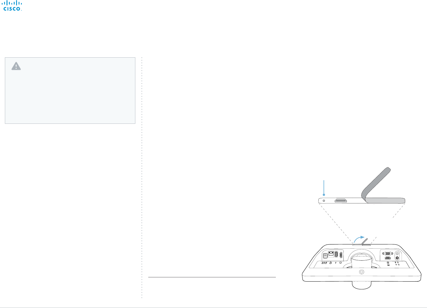
D15106.01 SX10 Quick Set Administrator Guide TC7.1, JUNE 2014. www.cisco.com — Copyright © 2014 Cisco Systems, Inc. All rights reserved.
100
Cisco TelePresence SX10 Quick Set Administrator Guide
Factory resetting the video system
If there is a severe problem with the video system, the last
resort may be to reset it to its default factory settings.
Always consider reverting to the previously used software
version before performing a factory reset. In many situations
this will recover the system. Note that both the current and
the previous software images reside on the system. Read
about software swapping in the ► System recovery section.
We recommend that you use the web interface to factory
reset the system. If these interfaces are not available, you can
use the video system’s reset button.
When factory resetting the video system the following
happens:
• The call logs will be deleted.
• Passwords will be reset to default.
• All system parameters will be reset to default values.
• All files that have been uploaded to the system will be
deleted. This includes, but is not limited to, custom
backgrounds, certificates, and the favorites list.
• The previous (inactive) software image will be deleted.
• Option keys will not be affected.
The system restarts automatically after the reset. It is using
the same software image as before.
Using the reset button
1. Lift the rubber flap on the back of the unit to uncover the
reset button (pin hole).
2. Use the tip of a pen (or similar) to press and hold the
recessed reset button until the screen turns black
(approximately 10 seconds). Then release the button.
The system reverts to the default factory settings and
restarts automatically. This will take a few minutes.
The system confirms the factory reset by displaying a
notification on the main screen when up and running
again. The notification disappears after approximately 10
seconds.
Reset button (pin hole)
The recessed button can
be quite difficult to use.
You should feel the button
go down when pushed.
User interface: Web
1. Open a web browser and enter the IP address of the
video system* in the address bar.
2. Navigate to Maintenance > System Recovery and choose
the Factory Reset tab.
3. Read the provided information carefully before you click
Perform a factory reset....
4. Click the red Yes button to confirm that you want to
perform a factory reset.
The system reverts to the default factory settings and
restarts automatically. This will take a few minutes.
The system confirms the factory reset by displaying a
notification on the main screen when up and running
again. The notification disappears after approximately
10 seconds.
It is not possible to undo a factory reset.
You should always backup the log files and the
current configuration before you factory reset a system.
Open the web interface, sign in, and follow these steps:
• Navigate to Maintenance > System Recovery and
choose the Backup tab.
• Click Download Logs and Download Configuration
Backup and follow the instructions to save the files
on your computer.
Lift the rubber flap
to uncover the reset
button (pin hole).
* How to find the IP address (IPv4 or IPv6):
Navigate to the contact information in the upper, left corner of
the screen and press OK on the remote control. Then open the
Settings menu.
Contents
Introduction
System settings
Setting passwords
Appendices
Web interface
Appendices

D15106.01 SX10 Quick Set Administrator Guide TC7.1, JUNE 2014. www.cisco.com — Copyright © 2014 Cisco Systems, Inc. All rights reserved.
101
Cisco TelePresence SX10 Quick Set Administrator Guide
Technical specification
Software compatibility
Cisco TelePresence Software Version TC7.1 or
later
Product delivered with:
• SX10 codec with integrated HD camera and
microphone
• Wall mount
• TRC6 remote control
• Network and HDMI cables
Integrated HD Camera
• 5x total zoom
• +5°/-25° tilt, +/- 30° pan
• 51.5° vertical field of view
• 83° horizontal field of view
• F-value from 2.1
• 1920 × 1080 pixels progressive @ 30 fps
• Automatic or manual focus, brightness, and
white balance
• Automatic flipping of picture when up-side
down
User interface
• TRC6 remote control and on-screen graphical
user interface
Language support
• English
System management
• Total management using embedded Telnet,
SSH, XML, and SOAP
• Remote software upload using web server, SCP,
HTTP, and HTTPS
• Remote control and on-screen menu system
Directory services
• Support for local directories (Favorites)
• Corporate directory (through Cisco Unified
Communications Manager and Cisco
TelePresence Managment Suite)
• Server directory supporting LDAP and H.350
(requires Cisco TelePresence Managment Suite)
• Call history with received, placed and missed
calls with date and time
Power
• PoE enabled
• Autosensing power supply
• 100–240 VAC, 50/60 Hz
• Maximum 12 W in normal operation
Operating temperature and humidity
• Ambient temperature: 0°C to 40°C
(32°F to 95°F)
• Relative humidity (RH): 10 to 90%
Storage and transport temperature
• –20°C to 60°C (–4°F to 140°F) at RH 10–90%
(noncondensing):
SX10 Codec Dimensions
• Width: 10.8 in. (27.5 cm)
• Height: 4.6 in. (11.7 cm)
• Depth: 3.6 in. (9.1 cm) (with max camera tilt
downward)
• Weight: 2.0 lb (0.9 kg)
Approvals and compliance
EU/EEC
• Directive 2006/95/EC (Low Voltage Directive)
-Standard IEC/EN 60950-1
• Directive 2004/108/EC (EMC Directive)
-Standard EN 55022, Class B
-Standard EN 55024
-Standard EN 61000-3-2/-3-3
• Directive 2011/65/EU (RoHS)
USA/Canada
• Approved according to UL 60950-1
• Approved according to CAN/CSA C22.2 No.
60950-1-07
• Complies with FCC CFR 47 Part15 Class A
Bandwidth
• Up to 3 Mbps
Minimum bandwidth for resolution and frame
rate
• 720p30 from 768 kbps
• 1080p30 from 1472 kbps
Firewall traversal
• Cisco TelePresence Expressway technology
Video standards
• H.263
• H.263+
• H.264
Video input
Two video inputs (HDMI or VGA selectable through
user interface). Support formats up to maximum
1280 × 768@30fps, including:
• 640 × 480 (VGA)
• 720 × 480
• 704 × 576 (4CIF)
• 800 × 600 (SVGA)
• 848 × 480
• 1024 × 768 (XGA)
• 1152 × 864 (XGA+)
• 1280 × 720(720p)
• 1280 × 768 (WXGA)
Extended Display Identification Data (EDID)
Video output
One HDMI output. Supports format:
• 1920 × 1080 @ 60 fps (1080p60)
VESA Monitor Power Management
Extended Display Identification Data (EDID)
Live video resolutions (encode/decode)
Supports encode/decode video formats up to
maximum 1920 × 1080@30fps (HD1080p30),
including:
• 176 × 144 @ 30 fps (QCIF) (decode only)
• 352 × 288 @ 30 fps (CIF)
• 512 × 288 @ 30 fps (w288p)
• 576 × 448 @ 30 fps (448p)
• 640 × 480 @ 30 fps (VGA)
• 704 × 576 @ 30 fps (4CIF)
• 768 × 448 @ 30 fps (w448p)
• 800 × 600 @ 30 fps (SVGA)
• 1024 × 576 @ 30 fps (w576p)
• 1024 × 768 @ 30 fps (XGA)
• 1280 × 720 @ 30 fps (HD720p)
• 1280 × 768 @ 30 fps (WXGA)
• 1920 × 1080 @ 30 fps (HD1080p)
Audio standards
• 64 kbps AAC-LD
• OPUS
• G.722
• G.72 2.1
• G .711m u
• G .711a
• G.729AB
• G.729
Audio features
• High quality 20 kHz audio
• Two acoustic echo cancellers
• Automatic gain control
• Automatic noise reduction
• Active lip synchronization
Audio inputs
• One Internal microphone
• One external microphone, 4-pin mini-jack
(Cisco TelePresence Table Microphone 20)
• One HDMI audio-in
Audio outputs
• One line out, mini-jack
• One HDMI (digital main audio)
Dual stream
• BFCP (SIP) dual stream
• Resolutions up to WXGAp5
Multipoint support
• Cisco ad-hoc conferencing (requires Cisco
Unified Communications Manager, Cisco
TelePresence Serve and Cisco TelePresence
Conductor)
Protocols
• SIP
Contents
Introduction
System settings
Setting passwords
Appendices
Web interface
Appendices

D15106.01 SX10 Quick Set Administrator Guide TC7.1, JUNE 2014. www.cisco.com — Copyright © 2014 Cisco Systems, Inc. All rights reserved.
102
Cisco TelePresence SX10 Quick Set Administrator Guide
Embedded encryption
• SIP point-to-point
• Standards-based: Advanced Encryption Standard
(AES)
• Automatic key generation and exchange
• Supported in dual stream
IP network features
• DNS lookup for service configuration
• Differentiated Services (QoS)
• IP adaptive bandwidth management (including flow
control)
• Dynamic playout and lip-sync buffering
• Date and time support via NTP
• Packet loss based downspeeding
• URI dialing
• TCP/IP
• DHCP
• IEEE 802.1x network authentication
• IEEE 802.1q Virtual LAN
• IEEE 802.1p QoS and class of service
• Cisco ClearPath
• Medianet: Mediatrace and Metadata
IPv6 network support
• Single call stack support for SIP
• Dual stack IPv4 and IPv6 for DHCP, SSH, HTTP,
HTTPS, DNS, DiffServ
• Support for static IP address assignment, stateless
autoconfiguration and DHCPv6
Supported infrastructure
• Cisco Unified Communications Manager 8.6.2 and
newer
• Cisco TelePresence Video Communication Server
(Cisco VCS)
Security features
• Management using web interface (HTTPS/HTTP)
and SSH
• Password protected IP administration
• Password protected administration menu
• Disable IP services
• Network settings protection
Network interfaces
• One PoE enabled LAN connector (RJ-45)
100Mbps
Other interfaces
• One USB port for future use
• One Micro USB port for maintenance
All specifications are subject to change without notice, system specifics may vary.
All images in these materials are for representational purposes only, actual products may differ.
Cisco and the Cisco Logo are trademarks of Cisco Systems, Inc. and/or its affiliates in the U.S. and other
countries. A listing of Cisco’s trademarks can be found at www.cisco.com/go/trademarks. Third party
trademarks mentioned are the property of their respective owners. The use of the word partner does not
imply a partnership relationship between Cisco and any other company.
May 2014
Contents
Introduction
System settings
Setting passwords
Appendices
Web interface
Appendices

D15106.01 SX10 Quick Set Administrator Guide TC7.1, JUNE 2014. www.cisco.com — Copyright © 2014 Cisco Systems, Inc. All rights reserved.
103
Cisco TelePresence SX10 Quick Set Administrator Guide
Supported RFCs
The RFC (Request for Comments) series contains technical
and organizational documents about the Internet, including
the technical specifications and policy documents produced
by the Internet Engineering Task Force (IETF).
Current RFCs and drafts supported
• RFC 2190 RTP Payload Format for H.263 Video Streams
• RFC 2460 Internet protocol, version 6 (IPv6) specification
• RFC 2617 Digest Authentication
• RFC 2782 DNS RR for specifying the location of services
(DNS SRV)
• RFC 2976 The SIP INFO Method
• RFC 3016 RTP Payload Format for MPEG-4 Audio/Visual
Streams
• RFC 3261 SIP: Session Initiation Protocol
• RFC 3262 Reliability of Provisional Responses in SIP
• RFC 3263 Locating SIP Servers
• RFC 3264 An Offer/Answer Model with SDP
• RFC 3311 UPDATE method
• RFC 3361 DHCP Option for SIP Servers
• RFC 3388 Grouping of Media Lines in the Session
Description Protocol (SDP)
• RFC 3420 Internet Media Type message/sipfrag
• RFC 3515 Refer method
• RFC 3550 RTP: A Transport Protocol for Real-Time
Applications
• RFC 3551 RTP Profile for Audio and Video Conferences
with Minimal Control
• RFC 3581 Symmetric Response Routing
• RFC 3605 RTCP attribute in SDP
• RFC 3711 The Secure Real-time Transport Protocol
(SRTP)
• RFC 3840 Indicating User Agent Capabilities in SIP
• RFC 3890 A Transport Independent Bandwidth Modifier
for SDP
• RFC 3891 The SIP “Replaces” Header
• RFC 3892 Referred-By Mechanism
• RFC 3960 Early Media
• RFC 3986 Uniform Resource Identifier (URI): Generic
Syntax
• RFC 4028 Session Timers in SIP
• RFC 4091 The Alternative Network Address Types
(ANAT) Semantics for the Session Description Protocol
(SDP) Grouping Framework
• RFC 4092 Usage of the Session Description Protocol
(SDP) Alternative Network Address Types (ANAT)
Semantics in the Session Initiation Protocol (SIP)
• RFC 4145 TCP-Based Media Transport in the SDP
• RFC 4235 An INVITE-Initiated Dialog Event Package for
the Session Initiation Protocol (SIP)
• RFC 4566 SDP: Session Description Protocol
• RFC 4568 SDP: Security Descriptions for Media Streams
• RFC 4574 The Session Description Protocol (SDP) Label
Attribute
• RFC 4582 The Binary Floor Control Protocol
draft-ietf-bfcpbis-rfc4582bis-00 Revision of the Binary
Floor Control Protocol (BFCP) for use over an unreliable
transport
• RFC 4583 Session Description Protocol (SDP) Format for
Binary Floor Control Protocol (BFCP) Streams
draft-ietf-bfcpbis-rfc4583bis-00 Session Description
Protocol (SDP) Format for Binary Floor Control Protocol
(BFCP) Streams
• RFC 4585 Extended RTP Profile for RTCP-Based
Feedback
• RFC 4587 RTP Payload Format for H.261 Video Streams
• RFC 4629 RTP Payload Format for ITU-T Rec. H.263
Video
• RFC 4733 RTP Payload for DTMF Digits, Telephony Tones
and Telephony Signals
• RFC 4796 The SDP Content Attribute
• RFC 4862 IPv6 stateless address autoconfiguration
• RFC 5104 Codec Control Messages in the RTP Audio-
Visual Profile with Feedback (AVPF)
• RFC 5168 XML Schema for Media Control
• RFC 5245 Interactive Connectivity Establishment (ICE): A
Protocol for Network Address Translator (NAT) Traversal
for Offer/Answer Protocols
• RFC 5389 Session Traversal Utilities for NAT (STUN)
• RFC 5577 RTP Payload Format for ITU-T
Recommendation G.722.1
• RFC 5589: SIP Call Control Transfer
• RFC 5626 Managing Client-Initiated Connections in the
Session Initiation Protocol (SIP)
• RFC 5766 Traversal Using Relays around NAT (TURN):
Relay Extensions to Session Traversal Utilities for NAT
(STUN)
• RFC 5768 Indicating Support for Interactive Connectivity
Establishment (ICE) in the Session Initiation Protocol (SIP)
• RFC 5905 Network Time Protocol Version 4: Protocol and
Algorithms Specification
• RFC 6156 Traversal Using Relays around NAT (TURN)
Extension for IPv6
• RFC 6184 RTP Payload Format for H.264 Video
Contents
Introduction
System settings
Setting passwords
Appendices
Web interface
Appendices

D15106.01 SX10 Quick Set Administrator Guide TC7.1, JUNE 2014. www.cisco.com — Copyright © 2014 Cisco Systems, Inc. All rights reserved.
104
Cisco TelePresence SX10 Quick Set Administrator Guide
In general, user documentation for the Cisco TelePresence products is available here:
► http://www.cisco.com/go/telepresence/docs
You have to choose your product category in the right pane until you find your product.
TelePresence Integration Solutions >
Cisco TelePresence SX Series >
Cisco TelePresence SX Series
Alternatively, you can use the following short-link to find the documentation:
► http://www.cisco.com/go/sx-docs
User documentation on the Cisco web site
The documents are organized in the following categories:
Installation guides:
Install and Upgrade > Install and Upgrade Guides
Getting started guide:
Install and Upgrade > Install and Upgrade Guides
Maintain and Operate > Maintain and Operate Guides
Administrator guides:
Maintain and Operate > Maintain and Operate Guides
User guides:
Maintain and Operate > End-User Guides
CAD drawings:
Reference Guides > Technical References
Video conferencing room guidelines:
Design > Design Guides
Software licensing information:
Software Downloads, Release and General Information > Licensing Information
Regulatory compliance and safety information:
Install and Upgrade > Install and Upgrade Guides
Software release notes:
Software Downloads, Release and General Information > Release Notes
Contents
Introduction
System settings
Setting passwords
Appendices
Web interface
Appendices

D15106.01 SX10 Quick Set Administrator Guide TC7.1, JUNE 2014. www.cisco.com — Copyright © 2014 Cisco Systems, Inc. All rights reserved.
105
Cisco TelePresence SX10 Quick Set Administrator Guide
Intellectual property rights
THE SPECIFICATIONS AND INFORMATION REGARDING THE
PRODUCTS IN THIS MANUAL ARE SUBJECT TO CHANGE
WITHOUT NOTICE. ALL STATEMENTS, INFORMATION, AND
RECOMMENDATIONS IN THIS MANUAL ARE BELIEVED TO BE
ACCURATE BUT ARE PRESENTED WITHOUT WARRANTY OF
ANY KIND, EXPRESS OR IMPLIED. USERS MUST TAKE FULL
RESPONSIBILITY FOR THEIR APPLICATION OF ANY PRODUCTS.
THE SOFTWARE LICENSE AND LIMITED WARRANTY FOR THE
ACCOMPANYING PRODUCT ARE SET FORTH IN THE INFORMATION
PACKET THAT SHIPPED WITH THE PRODUCT AND ARE
INCORPORATED HEREIN BY THIS REFERENCE. IF YOU ARE UNABLE
TO LOCATE THE SOFTWARE LICENSE OR LIMITED WARRANTY,
CONTACT YOUR CISCO REPRESENTATIVE FOR A COPY.
The Cisco implementation of TCP header compression is an
adaptation of a program developed by the University of California,
Berkeley (UCB) as part of UCB’s public domain version of the UNIX
operating system. All rights reserved. Copyright © 1981, Regents of
the University of California.
NOTWITHSTANDING ANY OTHER WARRANTY HEREIN, ALL
DOCUMENT FILES AND SOFTWARE OF THESE SUPPLIERS ARE
PROVIDED “AS IS” WITH ALL FAULTS. CISCO AND THE ABOVE-
NAMED SUPPLIERS DISCLAIM ALL WARRANTIES, EXPRESSED
OR IMPLIED, INCLUDING, WITHOUT LIMITATION, THOSE OF
MERCHANTABILITY, FITNESS FOR A PARTICULAR PURPOSE AND
NONINFRINGEMENT OR ARISING FROM A COURSE OF DEALING,
USAGE, OR TRADE PRACTICE.
IN NO EVENT SHALL CISCO OR ITS SUPPLIERS BE LIABLE FOR ANY
INDIRECT, SPECIAL, CONSEQUENTIAL, OR INCIDENTAL DAMAGES,
INCLUDING, WITHOUT LIMITATION, LOST PROFITS OR LOSS OR
DAMAGE TO DATA ARISING OUT OF THE USE OR INABILITY TO
USE THIS MANUAL, EVEN IF CISCO OR ITS SUPPLIERS HAVE BEEN
ADVISED OF THE POSSIBILITY OF SUCH DAMAGES.
Cisco and the Cisco Logo are trademarks of Cisco Systems, Inc. and/
or its affiliates in the U.S. and other countries. A listing of Cisco’s
trademarks can be found at www.cisco.com/go/trademarks. Third
party trademarks mentioned are the property of their respective
owners. The use of the word partner does not imply a partnership
relationship between Cisco and any other company. (1005R)
Any Internet Protocol (IP) addresses and phone numbers used in
this document are not intended to be actual addresses and phone
numbers. Any examples, command display output, network topology
diagrams, and other figures included in the document are shown for
illustrative purposes only. Any use of actual IP addresses or phone
numbers in illustrative content is unintentional and coincidental.
TANDBERG is now a part of Cisco. TANDBERG® is a registered
trademark belonging to Tandberg ASA.
Cisco contacts
On our web site you will find an overview of the worldwide Cisco contacts.
Go to: ► http://www.cisco.com/go/offices
Corporate Headquarters
Cisco Systems, Inc.
170 West Tasman Dr.
San Jose, CA 95134 USA
Contents
Introduction
System settings
Setting passwords
Appendices
Web interface
