T2613 2 _250 12 Shear_ Manual T26132
User Manual: t26132
Open the PDF directly: View PDF ![]() .
.
Page Count: 75
1

Piranha ¼-12 Operators/Owner’s Manual
2
Piranha
P.O. Box 457
Hutchinson, Ks 67504
Voice (800) 338-5471
Fax (620) 669-8964
Web Site www.piranhafab.com
No part of this manual may be stored in a retrieval system, transmitted, or, reproduced in any way. Including but not limited to photocopy,
photograph, and magnetic or other record without the prior agreement and written permission of Mega Manufacturing Inc.
PN: T2613-2
Programmable CNC/Goto

Piranha ¼-12 Operators/Owner’s Manual
3
Table of Contents
1. Safety............................................................................................................................................ 6
1.1. Warning Labels ...................................................................................................................... 6
1.2. Safety...................................................................................................................................... 9
1.3. Safety Standards & Specifications....................................................................................... 10
2. Introduction ................................................................................................................................ 11
3. Installation .................................................................................................................................. 11
3.1. Unpacking ............................................................................................................................ 12
3.2. Placement ............................................................................................................................. 13
3.2.1. Initial leveling................................................................................................................. 13
3.3. Cleaning ............................................................................................................................... 13
3.4. Precision Leveling................................................................................................................ 13
3.5. Electrical .............................................................................................................................. 14
3.6. Hydraulic.............................................................................................................................. 15
4. Operator Controls ....................................................................................................................... 17
4.1. Main Control Panel Programmable CNC............................................................................. 17
4.1.1. Start................................................................................................................................. 17
4.1.2. Stop................................................................................................................................. 17
4.1.3. E-Stop ............................................................................................................................. 17
4.1.4. Up Button........................................................................................................................ 18
4.1.5. Cut Length Selector Switch............................................................................................ 18
4.1.6. Mode Selector Switch..................................................................................................... 18
4.1.7. Shadow Light Switch...................................................................................................... 18
4.2. Backgauge Control-Programmable CNC............................................................................. 19
4.2.1 Keypad Functions ........................................................................................................... 19
4.2.2 Calibration / Re-calibration ............................................................................................ 19
4.2.3 Programming A Job........................................................................................................ 19
4.2.3.1 Go-To Function .............................................................................................................. 20
4.2.3.2 Programming Jobs .......................................................................................................... 21
4.2.4 Recalling and Running an Existing Job.......................................................................... 22
4.2.5 Editing a Job ...................................................................................................................22
4.2.8 Stroke Counter................................................................................................................ 23
4.2.9 Hour Meter......................................................................................................................23
4.2.10 Protected Access Screens................................................................................................ 23
4.3. Main Control Panel Programmable GOTO.......................................................................... 24
4.3.1. Start................................................................................................................................. 24
4.3.2. Stop................................................................................................................................. 24
4.3.3. Up Button........................................................................................................................ 24
4.3.4. Mode Selector Switch..................................................................................................... 24
4.4. Backgauge Control-Programmable GOTO.......................................................................... 25
4.4.1. Programming and Data Entry Keys................................................................................ 25
4.4.2. Programming Functions.................................................................................................. 25
5. Shear Operation.......................................................................................................................... 27
5.1. Setting the Shear Blades / Ram Gib Check And Adjustment Procedure: ............................ 27
6. Maintenance Procedures............................................................................................................. 29
6.1. Maintenance Schedule.......................................................................................................... 29
6.2. Hydraulic Power Unit........................................................................................................... 30

Piranha ¼-12 Operators/Owner’s Manual
4
6.2.1. Oil Filter Replacement.................................................................................................... 30
7. Hydraulic & Electrical Schematics............................................................................................. 31
7.1. Electrical Schematic-Programmable CNC........................................................................... 31
7.1.1. Electrical Schematic – Programmable GOTO................................................................ 43
7.2. Hydraulic Schematic- 20 HP Motor..................................................................................... 49
7.2.1. Hydraulic Schematic-15 HP Motor ................................................................................ 50
8. Parts ............................................................................................................................................ 51
8.1. Finger Guard ........................................................................................................................ 51
8.2. Ram & Linkage.................................................................................................................... 52
8.3. Back Gauge Assembly-Programmable CNC ....................................................................... 53
8.3.1. Back Gauge Assembly Programmable GOTO ............................................................... 54
8.4. Back Gauge & Bar Adjustment............................................................................................ 55
8.5. .............................................................................................................................................. 55
8.6. Bed Components..................................................................................................................56
8.7. Hydraulic Assemblies-20 HP Motor.................................................................................... 57
8.7.1. Hydraulic Assemblies-15 HP Motor............................................................................... 58
8.7.2. Valve Body Assembly 20 HP......................................................................................... 60
8.8. Oil Filter Assembly.............................................................................................................. 63
8.9. Main Operator Control Panel-Programmable CNC ............................................................. 64
8.10. Blade Adjust Components.................................................................................................... 65
8.11. Ram Slides ........................................................................................................................... 66
8.12. Back Gauge Motor Assembly .............................................................................................. 67
9. Glossary...................................................................................................................................... 69
10. Index........................................................................................................................................... 73
11. Addendums................................................................................................................................. 75

Piranha ¼-12 Operators/Owner’s Manual
5
Table of Figures
Figure 1: Lifting Lug Location..............................................................................................................12
Figure 2: Fuse Size Chart ......................................................................................................................15
Figure 3: Oil Level & Temperature Sight Gauge ..................................................................................15
Figure 4: Main Control Panel-Programmable CNC ..............................................................................17
Figure 5: Oil Filter Assembly Exploded View ......................................................................................30
Figure 6: Electrical Diagram 1 of 10 .....................................................................................................31
Figure 7: Electrical Diagram 2 of 10 .....................................................................................................32
Figure 8: Electrical Diagram 5 of 10 .....................................................................................................35
Figure 9: Electrical Diagram 7 of 10 .....................................................................................................37
Figure 10: Hydraulic Diagram 1 of 1.....................................................................................................49
Figure 11: Finger Guard ........................................................................................................................51
Figure 12: Ram & Linkage....................................................................................................................52
Figure 13: Back Gauge Assembly .........................................................................................................53
Figure 14: Back Gauge & Bar Adjustment............................................................................................55
Figure 15: Bed Components..................................................................................................................56
Figure 16: Hydraulic Power Unit...........................................................................................................57
Figure 17: Hydraulic Fittings.................................................................................................................59
Figure 18: Valve Body Assembly Top View.........................................................................................60
Figure 19: Valve Body Assembly Front View ......................................................................................60
Figure 20: Valve Body Assembly Left Side View ................................................................................61
Figure 21: Oil Filter Assembly (PN-0591550) Exploded View ............................................................63
Figure 22: Piranha 1/4-10 Shear Electrical Panel......................................................................................
Figure 23: Piranha 1/4-10 Shear Operator Control Panel..........................................................................
Figure 24: Electrical Panel T04081 ...........................................................................................................
Figure 25: Blade Adjust Components....................................................................................................65
Figure 26: Gib Parts...............................................................................................................................66
Figure 27: Back Gauge Motor Assembly ..............................................................................................67

Piranha ¼-12 Operators/Owner’s Manual
6
1. Safety
Safety must be a primary concern. When operating or performing maintenance procedures, follow
all standard safety guidelines. Do not wear loose fitting clothing or any articles that may be pulled
into any moving parts.
Be sure that when operating the equipment, all safety devices operate properly. Never under any
circumstances disable, remove, or alter the original configuration of the safety system.
Should any component of the safety system become inoperable, immediately discontinue
operation, and notify a supervisor.
! NEVER place fingers, hands, or any other body part in or under the blade area
or other moving mechanisms.
! Proper eye protection must be worn at all times when operating the machine.
! Always insure that the machine is turned OFF before servicing the machine.
Read and understand this manual prior to operating the machine.
The area around the Piranha 1/4-12 Shear should be well lighted, dry, and free of obstacles.
The Piranha 1/4-12 Shear is designed for single person operation only.
When servicing the machine always practice standard lockout/tag-out procedures to avoid
personal injury.
Qualified maintenance personnel only should perform service operations on the Piranha 1/4-12
Shear.
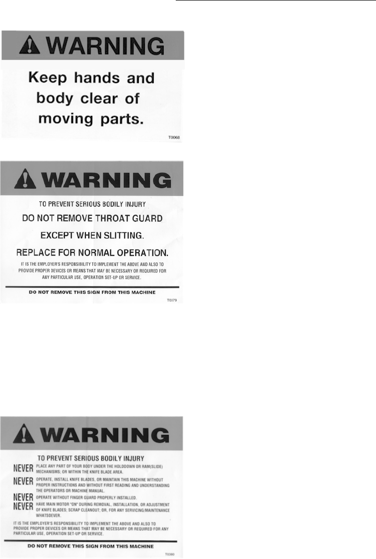
1.1. Warning Labels
Located around the Piranha 1/4-12 Shear are labels warning the operator of various dangers and
precautions to be aware of when operating or servicing the machine.
Do not go near leaks
High-pressure oil easily punctures
skin causing injury, gangrene and
even death. If injured, seek
emergency medical help.
Immediate surgery is required to
remove oil. Do not use finger or
hand to check for leaks. Lower
load or relieve pressure before
loosening fittings.
Part – T0067
Piranha ¼-12 Operators/Owner’s Manual
7
Keep hands clear of moving parts.
Part – T0068
To prevent serious bodily injury do
not remove throat guard except
when slitting. Replace for normal
operation. It is the employer’s
responsibility to implement the
above and also to provide proper
devices or means that may be
necessary or required for any
particular use, operation set-up or
service.
Part – T0379
To prevent serious bodily injury;
Never place any part of your body
under the hold down or ram (slide)
mechanisms; or within the knife
blade area.
Never operate, install knife blades,
or maintain this machine without
first reading and understanding
the operators or machine manual.
Never operate without the finger
guard properly installed.
Never have main motor “on”
during removal, installation, or
adjustment of knife blades; scrap
cleanout; or, for any
servicing/maintenance
whatsoever.
It is the employer’s responsibility
to implement the above and also
to provide proper devices or
means that may be necessary or
required for any particular use,
operation set-up or service.
Part – T0380

Piranha ¼-12 Operators/Owner’s Manual
8
To insure proper operation of
shear back gauge;
Never ram material against back
gauge.
Never use back gauge drive to
move material being cut on table.
Never pass material being cut
over or under back gauge.
Always use disappearing feature
cutting parts larger than normal
back gauge range.
Failure to follow these instructions
may result in damage to back
gauge. Always refer to operation
manual for proper use of machine
Part – T0381
Moving part; do not obstruct.
Part – T0382
To prevent serious bodily injury;
Do not enter rear area of machine
while in operation.
It is the employer’s responsibility
to implement the above and also
to provide proper devices or
means that may be necessary or
required for any particular use,
operation set-up or service.
Part – T0383

Piranha ¼-12 Operators/Owner’s Manual
9
Both ends of the bed are to be
leveled within 0.0005 inch/foot for
proper operation. Running the
machine out of level will cause
damage and void the warranty.
Part – T0384
Maximum allowable clearance
under finger guard is ½”.
Part – T0936
1.2. Safety
1. Immediately report any questionable operation, unusual action, unsafe condition or
improper maintenance to the proper personnel.
2. When working with other people insure that all persons are clear of the shear prior to
machine operation.
3. Insure that the proper safe material handling equipment (tongs, pliers, vacuum lifters or
other mechanical devices) available to the shear operator.
4. When changing the settings of shear controls, insure that the controls are properly
adjusted and test cycle the machine to verify correct operation.
5. Insure that all devices are in proper working order.
6. Anytime that the machine has been left unattended or inoperative for even a brief time,
verify the correct position of all controls and proper shear operation.
7. Develop a sense of safety for yourself and any persons around you as well as your
surrounding area.

Piranha ¼-12 Operators/Owner’s Manual
10
1.3. Safety Standards & Specifications
Electrical System Design/Manufacture:
The machines manufactured in Hutchinson, KS, are furnished with electrical/electronic
products that are UL (Underwriter’s Laboratory) approved. These components have the UL
numbers printed or stamped on them and can be easily traced to the point of manufacture.
Hydraulic System Design/Manufacture:
Hydraulic components used in Piranha machines are approved by NFPA (National Fluid
Power Association), and those approval numbers can be traced through the manufacturer’s
part numbers.
ANSI/OSHA Compliance:
Mega Manufacturing meets the current ANSI construction standards for manufacturing of
ironworkers, press brakes, and shears:
ANSI B11.4—Shears, Construction, Care, and Use
The ANSI B11 standards were developed to establish levels of responsibility for
manufacturing safe products, installation, training, and use of these products. The levels of
responsibility are fairly evenly distributed between the manufacturer, the owner/end user of
the equipment, and the operator. Specific guarding requirements are in general assigned to the
owner/end user of the equipment.
Please understand that this ruling places the primary burden of responsibility for maintenance
of guarding on the owner /end user of the equipment. Inherent in this requirement is the
responsibility of the owner/end user of the equipment to develop and maintain guarding
specific to their application for the equipment. These ANSI safety requirements may be
acquired from:
American National Standard Institute
254 West 43rd Street
New York, New York 10036
Telephone (212) 302-1286
www.ansi.org
PO Box 457
Hutchinson, KS 67504-0457
Phone: (800) 338-5471
Fax: (620) 669-8964

Piranha ¼-12 Operators/Owner’s Manual
11
2. Introduction
The Piranha Maxi Shear is a heavy steel constructed, high performance hydraulic powered
machine that provides you several important advantages surpassing most other shears in today’s
market. The Piranha’s single hydraulic cylinder and mechanical linkage system provides the
following advantages: 1. The upper shear blade moves parallel to the lower blade thus providing
maximum blade life, 2. Full length gibbs guide the ram laterally and front-to-back at all times
during the shearing process thus increasing rigidity, shearing accuracy, and blade life, 3. The
straight-line shearing action improves shearing accuracy in all metal thickness.
The machine arrives fully assembled requiring only hydraulic oil and electrical power to become
fully operational. The heavy steel “C” frames, interlocking cross members, ram, and bed provide
the rigidity and resistance to deflection that is necessary for accurate performance. State-of-the-
art, maintenance-free, aerospace bearings provide high load capacity and low friction in the form
of a thin walled sleeve. They are completely non-metallic and require no lubrication.
Other standard features include: Full length hardened slides with non-metallic ways, variable cut
length adjustment, hydraulic hold downs with replaceable polyurethane shoes, heavy duty,
inch/mm motorized, disappearing back gauge with Go-To features and .100” retract feature on
each stroke. A 53" squaring arm with recessed inch/mm scale, four-edge high chrome, high
carbon shear blades top and bottom.
Proper understanding and application of the information and procedures given in this manual will
aid in establishing a preventative maintenance program and provide assistance for correcting
malfunctions that may occur in the machine. The repair parts list provides information for part
procurement and assembly breakdowns to aid in disassembly and re-assembly for repair parts
installation. Please have machine serial number available when contacting the factory for service
or repair parts.
Warranty
Mega Mfg. will replace or repair with like parts, either new or rebuilt, F.O.B. the factory, or
refund the purchase price for any parts on ironworkers, pressbrakes, or shears, which are
defective in materials and workmanship within (12) months of the date of purchase. Provided the
buyer returns the warranty registration within (30 days) of the purchase date, and, at the seller’s
option, returns the defective materials freight and delivery prepaid to the seller, which shall be the
buyer’s sole remedy for the defective materials. A 5 year warranty against defects in materials
and workmanship applies to major structural components on pressbrakes and shears. Seller shall
not be liable to purchaser or any other person for consequential or incidental damages. Hydraulic
and electrical components are subject to their respective manufacturer’s warranties. This warranty
does not apply to machines and/or components which have been altered in any way, or subjected
to abusive or abnormal use, inadequate maintenance and lubrication, or to use beyond seller
recommended capacities and specifications. Seller shall not be liable under any circumstances for
labor costs expended on such goods or consequential damages. Seller shall not be liable to
purchaser or any other person for loss or damage directly or indirectly arising from the use of the
goods or any other cause. No employee, agent, officer, or seller is authorized to make oral
representations or warranty of fitness or to waive any of the foregoing terms of sale and none
shall be binding on the seller.
Piranha ¼-12 Operators/Owner’s Manual
12
3. Installation
BEFORE INSTALLING THIS SHEAR, READ AND UNDERSTAND THE SHEAR
MANUAL WITH PARTICULAR ATTENTION TO “SAFETY TIPS FOR MAINTENANCE
PERSONNEL” THE CURRENT ANSI B11.4 STANDARD-“SAFETY REQUIREMENTS
FOR THE CONSTRUCTION, CARE AND USE OF SHEARS.” Copies can be ordered
from: American National Standards Institute, 1430 Broadway, New York, New York
10018
3.1. Unpacking
CAUTION: THE SHEAR IS HEAVY IN FRONT. GUARD AGAINST TIPPING UNTIL
ANCHOR BOLTS ARE SECURED.
This machine was carefully packaged at the factory to avoid damage during shipment, should
any accidental damage occur contact the responsible freight company immediately and report
the damage. Indicate any damage on the Bill of Lading. All Warranty information included
in this packet must be returned to the factory.
Figure 1: Lifting Lug Location
The Piranha 1/4-12 Shear must only be lifted using a crane, and the lifting lugs located in
front of the hydraulic oil tank on top of the machine. Do not lift the machine from the bottom
(forklift or jack) as the machine is top and front heavy and can tip resulting in serious bodily
harm or death. Lifting the machine from the bottom can also result in machine damage.
WARNING: CHECK BLADE GAP BEFORE CYCLING MACHINE.
FAILURE TO DO SO MAY CAUSE BLADE DAMAGE

Piranha ¼-12 Operators/Owner’s Manual
13
3.2. Placement
Piranha recommends that the machine be placed on a reasonably level concrete foundation
suitable to support the shear’s total weight and in accordance with local building codes. The
machine should be placed on a single concrete pad free of cracks and seams. Prior to
anchoring or setting, the shear should be leveled and shimmed. Section 3.4 of this manual
discusses leveling the machine. Anchoring can be accomplished using suitable masonry
anchors. Use the machine as a template for anchoring hole locations. Placement of the
machine should allow easy access around the machine for the operator and maintenance
personnel. For safe operation placement should allow tooling to be installed onto the bed
from the end of the machine.
It is recommended that a minimum four-foot area around the Piranha 1/4-12 Shear be
provided.
3.2.1. Initial leveling
CAUTION: THE SHEAR IS HEAVY IN FRONT. GUARD AGAINST TIPPING
BEFORE AND DURING LEVELING.
Level adjusting screws are only provided on the rear feet. The Piranha 1/4-12 Shear
must be placed on four steel pads: 2 each 6" x 6" x ¾" for the front feet and 2 each 6"
x 6" x ½" for the rear feet. These pads are provided with the shear.
3.3. Cleaning
Clean the bed surface, with a mild solvent so as not to damage the paint finish on the
machine. The main cylinder rod must also be free of contaminants. Any contaminants left on
the cylinder rod may damage the chrome finish and related hydraulic seals. The cylinder rod
must be clean and dry. Wipe down the rest of the shear with a mild cleaning solution.
3.4. Precision Leveling
The Piranha 1/4-12 Shear must be leveled precisely prior to operation. The following steps
represent the typical leveling procedure. These instructions must be followed to avoid
damaging the machine.
Using a machinist level, having an accuracy of one-half thousandths of an inch per foot, place
the level facing front to back on the left side of the shear squaring arm. Adjust the rear
leveling bolt until the bubble on the level is centered. Then, repeat for the right side, placing
the level on the outside of the table. It’s very important that the sides of the table be parallel
to each other with no crosscorner binding of the table. Once the machine is level, place
shims having a thickness equal to the gap, between the base plate and the bottom of the shear
foot. After your shim stock is in place release the adjusting bolts and recheck the level to
ensure that the left and right side of the machine have remained parallel. Tighten the
anchoring bolts and recheck the level of the shear. If necessary, re-adjust the shim pack
height if the shear has moved during anchoring. Do not cycle machine before it’s leveled, or
you may damage the shear blades!
NOTE:
Re-check machine level after the first 200 hours of operation, and at regular intervals.
Consult the Maintenance section for additional information.

Piranha ¼-12 Operators/Owner’s Manual
14
3.5. Electrical
CAUTION: ELECTRICIANS CHECKING DIRECTION OF ROTATION SHOULD BE
CAUTIONED NOT TO OPERATE THE SHEAR UNTIL IT HAS BEEN
THOROUGHLY CHECKED, CLEANED, LEVELED AND LUBRICATED. A WIRING
DIAGRAM IS FURNISHED IN THIS MANUAL. SHEAR OPERATING MODE
SWITCH MUST BE IN THE OFF POSITION WHEN CHECKING MOTOR
ROTATION.
BEFORE DRILLING ANY HOLES IN THE ELECTRICAL ENCLOSURE, BE SURE
THAT THE ELECTRONIC CIRCUIT BOARDS/EQUIPMENT ARE PROTECTED
FROM METAL CHIPS CONTACTING THE CIRCUIT BOARD(S). DO NOT USE
COMPRESSED AIR TO BLOW METAL DEBRIS FROM THE ENCLOSURE. USE A
VACUUM TO REMOVE ANY METAL PARTICLES.
Voltage requirements may be verified by comparing the fuse part number to the chart located
on the inner door panel of the main electrical box. (See Figure 2)
Piranha ¼-12 Operators/Owner’s Manual
15
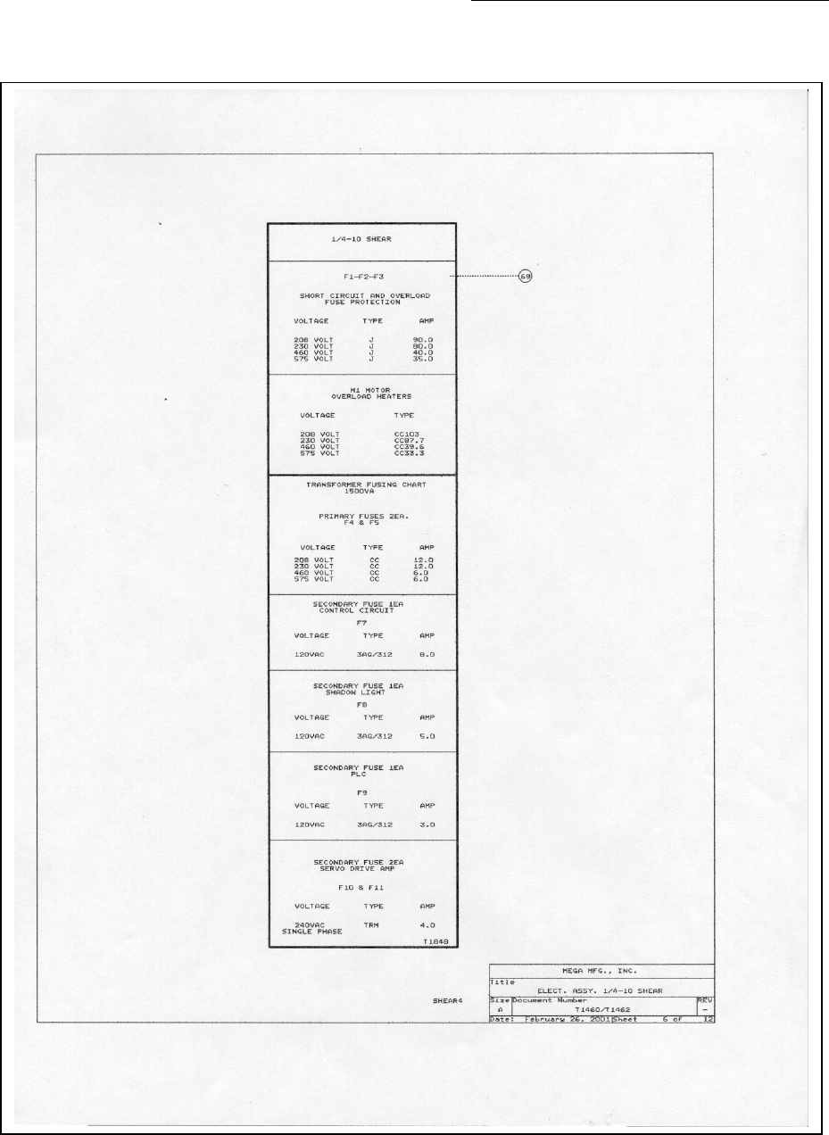
SHORT CIRCUIT AND OVERLOAD FUSE PROTECTION
F1-F2-F3
15 HP MOTOR 20 HP MOTOR
VOLTAGE TYPE AMP VOLTAGE TYPE AMP
208 VOLT J 50 208 VOLT J 90
230 VOLT J 40 230 VOLT J 80
460 VOLT J 20 460 VOLT J 40
575 VOLT J 17.5 575 VOLT J 30
Figure 2: Fuse Size Chart
3.5.1 Motor Rotation
Electrical connection of the 3-phase systems requires proper phasing. When connecting the
press to a 3-phase power source, the rotational direction of the pump drive motor must be
correct. The rotational direction may be observed by removing the orange cover plate located
on the pump/motor adapter. The motor must rotate in the direction of the arrow on the motor.
Before operating the machine insure the cover is securely in place.
A licensed electrician should perform all electrical connections.
! Warning - The control transformer is for machine operation only. Do not use the
machine transformer to power any secondary devices.
3.6. Hydraulic
Before applying power to the Piranha 1/4-12 Shear, the hydraulic reservoir must be filled
with oil. To fill the reservoir, locate and remove the filler/breather cap on top of the reservoir.
Fill the reservoir with Mobil DTE-13 or ISO32 equivalent, filtered to an ISO 17/15/13-
cleanliness level. The proper oil level is between the red and black lines of the sight gauge
found on the rear of the reservoir (See Figure 3). Do not over fill the reservoir. Replace the
filler/breather cap.
Figure 3: Oil Level & Temperature Sight Gauge

Piranha ¼-12 Operators/Owner’s Manual
16
Upon initial start-up of the hydraulic unit visually inspect around the machine for any
possible leaks. Do not search for hydraulic oil leaks using exposed flesh; hydraulic
pressure can puncture the skin.
3.6.1 Rear Safety Guards
Reposition the yellow machine safety guards, so they protrude past the rear of the side frames. The
guards must be positioned to prevent a person from entering the backgauge bar travel area.
Piranha ¼-12 Operators/Owner’s Manual
17
4. Operator Controls
Operator selectable controls are provided on the Pedestal Control and on the Main Control Panel.
Functionality of both stations is described in the following subsections.
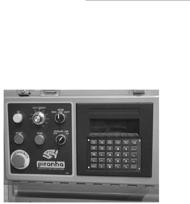
4.1. Main Control Panel Programmable CNC
The main control panel is located on the left hand side of the Piranha 1/4-12 Shear. The
following subsections describe the controls located on this panel.
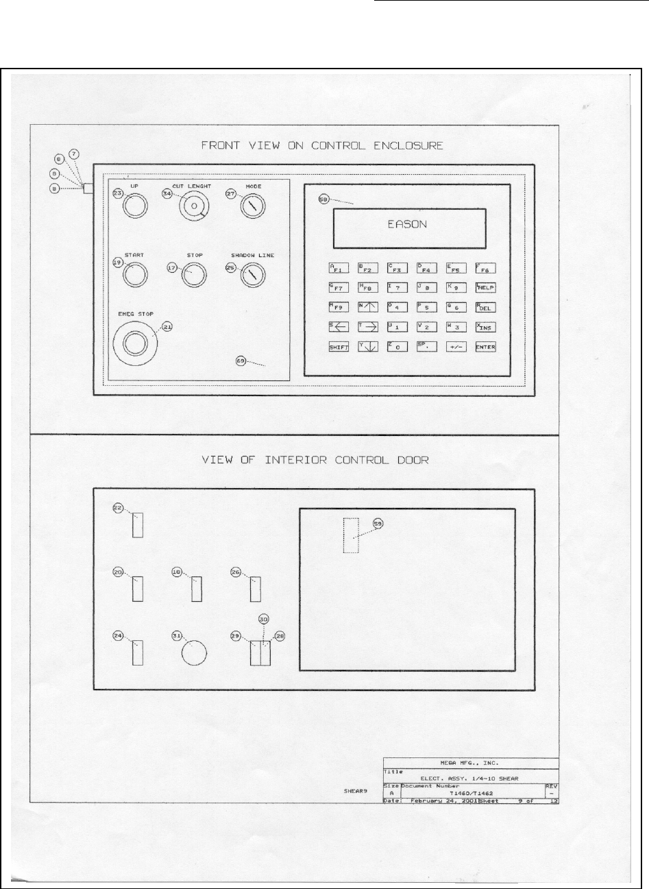
Figure 4: Main Control Panel-Programmable CNC
4.1.1. Start
Depressing the green Start pushbutton will apply power to the electric motor that
drives the Piranha 1/4-12 Shear hydraulic power unit.
4.1.2. Stop
Depressing the stop button will stop the pump motor, but will maintain electrical
power to the backgague control. Re-calibration of the backgague is not required when
the Stop button is depressed.
4.1.3. E-Stop
When you depress the emergency stop, electrical power will be removed from the
drive motor and all base machine control circuits, stopping all machine movement.
Twist the button clockwise to reset it. The machine cannot start until the E-Stop
button has been reset. The backgauge must go through its calibration sequence when
the machine is powered up again.

Piranha ¼-12 Operators/Owner’s Manual
18
4.1.4. Up Button
The up button will raise the ram from any position to the full up position
4.1.5. Cut Length Selector Switch
The cut length selector switch controls the stroke depth of the ram. Shortening the
ram stroke permits rapid shearing of shorter material.
4.1.6. Mode Selector Switch
The run mode selector switch permits three operating modes:
Single: The ram will descend when the footswitch is depressed and will pause when
the footswitch is released at any point during the down stroke. The shear ram will
complete only one cycle in this mode. The footswitch must be reactivated to begin a
new shearing cycle.
Jog: During a shear cycle, the ram will stop when the footswitch is released.
Continuous: The ram will cycle continuously when the footswitch is depressed.
Releasing the footswitch during the down stroke will cause the ram to stop, releasing
the footswitch during the upstroke will not affect the return stroke of the ram.
4.1.7. Shadow Light Switch
The shadow light switch will turn on lights that cast a shadow line onto the material
being sheared.
Piranha ¼-12 Operators/Owner’s Manual
19
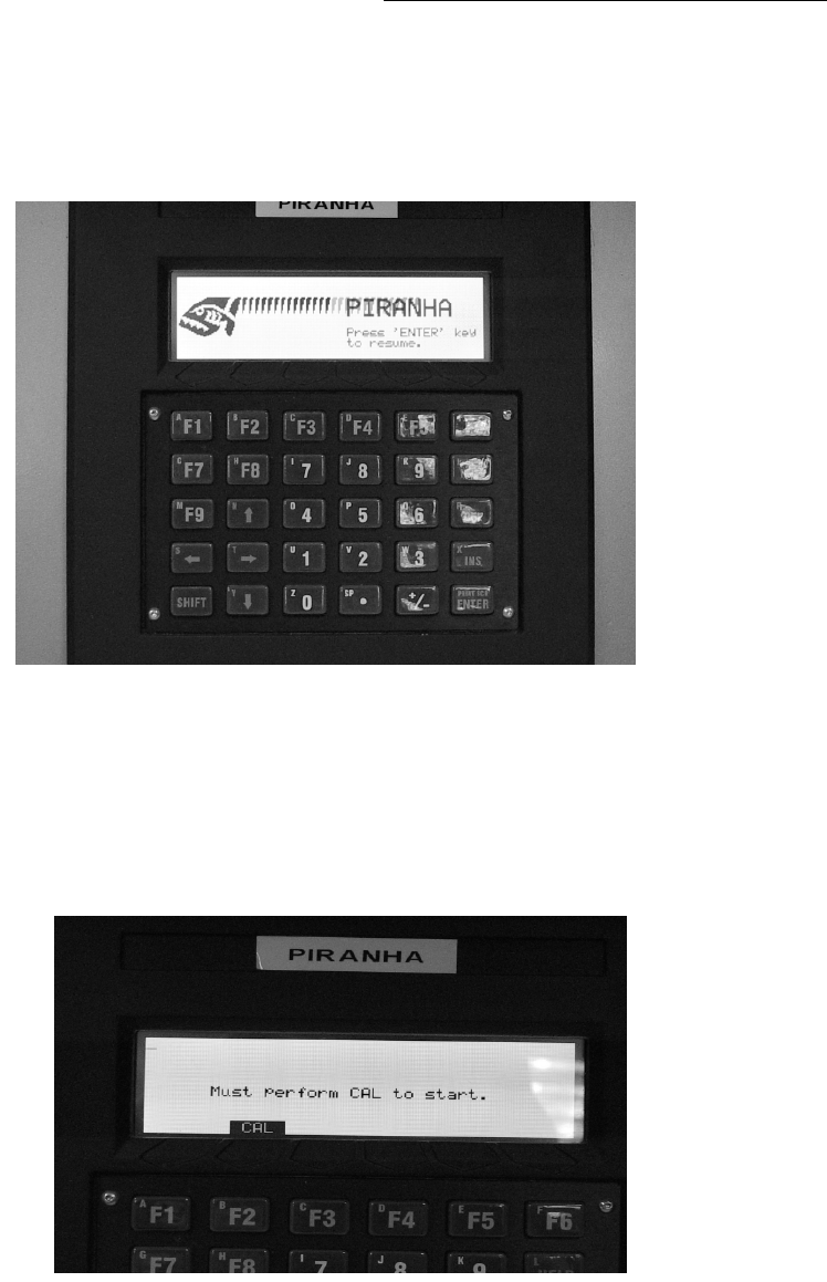
4.2. Backgauge Control-Programmable CNC
4.2.1 Keypad Functions
MAIN BACKGAUGE CONTROL CONSOLE
4.2.2 Calibration / Re-calibration
On initial power up or when the E-Stop button has been depressed, the backgauge
/controller must be calibrated. The controller will sequence through a start routine
and ask for the calibration button to be depressed. Simply depress the “CAL” (F2)
button and the backgauge will automatically perform the calibration sequence.
CALIBRATION SCREEN
4.2.3 Programming A Job
When the calibration sequence has been performed, the controller will display the
“MAIN SCREEN”. See Figure #3.
Piranha ¼-12 Operators/Owner’s Manual
20
MAIN SCREEN
IN/MM: Depress the IN/MM button to toggle between Inch and MM modes.
Programming may be done in either mode.
RETR: Depressing the RETR button will cause the backgague to position in the fully
retracted mode, i.e.: the backstop bar will be positioned at the furthest dimension and
parked in the “disappearing position.
Two options are available for programming a job, a single “Go-To” dimension, or a
multi step job.
4.2.3.1 Go-To Function
Depress the “Go-To” button, enter the desired dimension (must be between .250 &
36.00”) and press enter. The control will display an “Entry accepted” message and
the backgauge will move to the programmed position. Position the material against
the backstop bar, operate the footswitch to initiate the shear cycle.
GO-TO SCREEN

Piranha ¼-12 Operators/Owner’s Manual
21
4.2.3.2 Programming Jobs
To program a multi step job, perform the following steps:
1. Depress the “JOBS” button (F1)
2. Use the up or down arrow keys to select a blank job field.
3. Depress the “MODIFY” button.
4. Depress the “NEW” button.
5. Enter a job name. The entry may be all alphas, numeric or alphanumeric. To use the
alpha characters, depress the “SHIFT” button which is located on the lower left corner
of the keypad.
Note: If you make an error entering the job title, use the left/right arrow button to
move the cursor under the incorrect digit, press the “DEL” button, and continue
entering the correct information.
6. When the job title is programmed, depress the “ENTER” button.
7. Depress the “EDIT” button
8. Enter the target backgauge dimension and depress the “ENTER” button.
9. Enter the number of cuts (or cycles) in the “Reps” field; depress the “ENTER” button.
10. To enter additional steps or cycles, depress the “ADD” (F1) button and repeat steps 8
& 9.
11. If one of the steps requires the backgauge to retract fully, depress the “RTRCT”
button (F5) in the “Length” field.
12. When the job is programmed, depress the: DONE” (F6) button.
13. To run the job, depress the “DONE” button.
14. Depress the “RUN” button.
15. Depress the “ENTER” button, and the backgauge will advance to the position
programmed in step 1.
16. When the complete job has been cycled, the screen will display “JOB COMPLETE”.
17. Depress the “OK” (F5) button and the screen will revert to the “MAIN SCREEN”
display.
MULTI-STEP JOB SCREEN

Piranha ¼-12 Operators/Owner’s Manual
22
4.2.4 Recalling and Running an Existing Job
1. From the Main screen, depress the “JOBS” button (F1)
2. Using the up/down arrow buttons, maneuver the desired job to the
highlighted field and depress “RUN” (F2).
3. Enter the number of cycles required to run this job.
4. The screen will display a confirmation of the job number to run, depress the
“ENTER” button to run the job.
4.2.5 Editing a Job
1. From the Main screen, depress the “JOBS” button (F1)
2. Using the up/down arrow buttons, maneuver the job list to the highlighted
field and depress “MODIFY” (F4).
3. The “JOB ENTRY” screen will display.
4. Depress the “EDIT” (F3) button.
5. The parameters of each step will display. Using the up/down arrow buttons, move
the field to the step to edit and depress the “EDIT” (F2) button.
6. Edit the firs field or press the “ENTER” button to advance to the next field to be
changed. Make the desired changes and depress the “ENTER” button to accept the
changes.
7. Depress the DONE” (F6) button to complete the sequence.
8. Depress the DONE” (F6) button again to enter the “JOBS” screen.
4.2.6 Renaming a Job
1. From the Main screen, depress the “JOBS” (F1) button
2. Using the up/down arrow buttons, maneuver the job list to the highlighted
field and depress “MODIFY” (F4).
3. The “JOB ENTRY” screen will display.
4. Depress the “RENAM” (F2) button.
5. Enter the new name for the job,
6. Depress the “ENTER” button to accept the changes.
7. Depress the DONE” (F6) button to complete the sequence.
4.2.7 Copying a Job
1. From the Main screen, depress the “JOBS” (F1) button
2. Using the up/down arrow buttons, maneuver the job list to the highlighted
field and depress “MODIFY” (F4).
3. The “JOB ENTRY” screen will display.
4. Depress the “COPY” (F4) button.
5. The COPY screen will display information stating the “copy from XXX and the
New Job will be XXX (2)”
6. Depress the “OK” (F2) button.
7. The job will be copied and renamed XXX (2).
8. To rename the job, use the up/down arrow buttons, maneuver the job to the
highlighted field.
8. Depress the “RENAM” (F2) button.
9. Enter the new name for the job,
10. Depress the “ENTER” button to accept the changes.
11. Depress the DONE” (F6) button to complete the sequence.

Piranha ¼-12 Operators/Owner’s Manual
23
4.2.8 Stroke Counter
1. From the Main screen, depress the “RESET” (F3) button
2. To reset the stroke counter, depress the “STRKS” (F4) button.
3. Depress “DONE” (F6) button.
4.2.9 Hour Meter
1. From the Main screen, depress the “RESET” (F3) button
2. To reset the hour meter, depress the “HOURS” (F2) button.
3. Depress “DONE” (F6) button.
4.2.10 Protected Access Screens
F7, - F9 are dedicated function pushbuttons.
F9 will return an operator to the “MAIN SCREEN”
F7 is a protected access screen for supervisor entry. This screen permits the resetting
of service-required messages and other machine tuning functions. A temporary access
code (9999) is programmed, permitting initial access to the protected screen. This
enables a supervisor to enter preferred access code. The following section describes
the functions available in the Supervisor Screen.
Delay Time: Permits programming a “global” time delay between shearing cycles in
Continuous Mode.
Zero Offset: Permits electronic tuning of the backgauge calibration position. This is a
“global” adjustment.
Service Notes: At predetermined intervals, a *Srvc. Req’d message will appear in the
upper left corner of the display. This function reminds the operator or maintenance
department that scheduled preventative maintenance is due. Depressing the “SERVICE
NOTES” (F3) pushbutton will display the maintenance requirements for this service cycle.
Piranha highly recommends that this schedule is followed. Failure to do so may result in
unscheduled maintenance requirements.
To clear the service reminder, press F7 and enter the Supervisor password (Factory default
password is 9999) and press Enter. Press F3 – Clear – Done.
Reset: Supervisor Hours & Supervisor Strokes
New Password: Permits supervisor(s) to change password at their discretion.
F8: is a Mega protected screen and is only accessible through a password supplied by the
factory. This section contains vital machine operational codes and settings and must not be
accessed without authorization and supervision from a Piranha service engineer.
Piranha ¼-12 Operators/Owner’s Manual
24
4.3. Main Control Panel Programmable GOTO
The main control panel is located on the left hand side of the Piranha 1/4-12 Shear. The
following subsections describe the controls located on this panel.
Figure 5: Main Control Panel-Programmable GOTO
4.3.1. Start
Depressing the green Start pushbutton will apply power to the electric motor that
drives the Piranha 1/4-12 Shear hydraulic power unit.
4.3.2. Stop
Depressing the stop button will stop the pump motor.
4.3.3. Up Button
The up button will raise the ram from any position to the full up position
4.3.4. Mode Selector Switch
The run mode selector switch permits the operator to select between three operating
modes:
Single: The ram will descend when the footswitch is depressed and will pause when
the footswitch is released at any point during the down stroke. The shear ram will
complete only one cycle in this mode. The footswitch must be reactivated to begin a
new shearing cycle.
Jog: During a shear cycle, the ram will stop when the footswitch is released.

Piranha ¼-12 Operators/Owner’s Manual
25
Continuous: The ram will cycle continuously when the footswitch is depressed.
Releasing the footswitch during the down stroke will cause the ram to stop, releasing
the footswitch during the upstroke will not affect the return stroke of the ram.
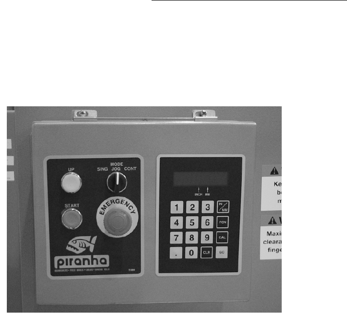
4.4. Backgauge Control-Programmable GOTO
4.4.1. Programming and Data Entry Keys
0-9 Use the number keys to input numerical values, or to perform special
functions when used in conjunction with the Function (FCN) key.
IN/MM Select measurement unit (inch or metric). Depress this key to toggle
between the two modes.
FCN Function key is used in conjunction with other data entry keys to enable
special functions.
CAL Used to enable calibrate the backgauge.
GO Used to initiate backgauge movement to a programmed position.
CLR Clears data entry, zeros display, cancels preset mode.
Decimal Used to enter decimal during data entry. Restores display to target after
GO has been depressed.
Decimal Blinking Target dimension is being displayed, to view actual dimension,
momentarily depress CAL button.
Decimal Solid Actual position is being displayed, to view target dimension,
depress decimal point button.
4.4.2. Programming Functions
4.4.2.1. Backgague Positioning
Enter desired dimension using keypad and depress GO button. Backgague
will position to programmed dimension.
4.4.2.2. Presets
This control will store 9 preset dimensions (1-9).
To program a preset dimension, (1) enter the dimension using the keypad,
(2) press FCN, the letter “P” will show on the left side of the display.
(3) press and hold the preset number the dimension is to be stored with until
the flashing stops. For example, if a dimension of 12.375” is to be stored in
preset #7, use the following procedure. On the keypad enter (1) (2) (,) (3) (7)
(5) (FCN) Press and hold (7) until the flashing stops. 12.375 has been stored
in preset #7.
To recall a stored preset, press the FCN key, press the desired stored preset
number (1-9), when the GO button is depressed, the backgauge will position
to the preset dimension. For example, to recall preset #7 (which has a
dimension of 12.375” stored), Press FCN, press #7 (on the keypad), 12.375

Piranha ¼-12 Operators/Owner’s Manual
26
will display on the LED readout. Depress the GO button to position the
backgague to 12.375”
WARNING: DO NOT USE PRESET STATION #0 for programming
preset stations.
4.4.2.3. Calibration / Re-calibration
To calibrate the backgague to an actual position, use the following
procedure:
1. Measure the actual distance from the lower blade edge to the
backgauge bar. (Example 20 inches) Press (CLR), (2) (0)(.) (0) (0)
Press and hold (CAL) until flashing stops. The display will show the
calibrated value (20.000”)
2. Enter a short distance, (i.e. 3”), press GO button, backgauge will
position to 3”.
3. Shear a piece of metal and measure the sheared part with a caliper.
Enter the measured dimension onto the keypad, press and hold CAL
until the flashing stops. Verify the accuracy by shearing another
part. Repeat step # 3 if minor adjustments are required.
IMPORTANT:
DO NOT DEPRESS THE STOP BUTTON WHEN THE SHEAR
BACKGAUGE IS IN MOTION. This will cause the backgague to loose
calibration and will require recalibration.
ENSURE SHEAR BLADE/RAM IS AT THE TOP OF STROKE before
turning machine off. Failure to do so will require backgague recalibration.
NOTE: If the backgauge begins “Hunting” for position (continuously goes past the target position),
either the drive chain (FIG 25A & B) is too loose or the “Drag Block” (Fig 25C & E) has become
loose. To adjust the drag block, loosen the jam nut (FIG 25E) and tighten the adjusting screw
clockwise in 1/16 rotations until the “Hunting” stops.
WARNING: Over adjusting the tightness on the drag block will cause premature motor failure or
electrical over current which will result in a blown fuse.

Piranha ¼-12 Operators/Owner’s Manual
27
5. Shear Operation
BEFORE OPERATING THE SHEAR, READ AND UNDERSTAND THE CURRENT
ANSI B11.4 STANDARD. CAUTION: READ AND UNDERSTAND THIS ENTIRE
MANUAL BEFORE PLACING SHEAR IN OPERATION.
WARNING: CHECK BLADE GAP BEFORE CYCLING MACHINE.
FAILURE TO DO SO MAY CAUSE BLADE DAMAGE
! Always review the instructions provided in this manual and observe shearing safety rules!
! Insure that no tools, bolts or other obstructions are in the knife area prior to operating the
shear.
! Locate any available safety handling tools required.
! Keep the floor and surrounding area clean and free of obstruction, debris and oil.
5.1. Setting the Shear Blades / Ram Gib Check And Adjustment Procedure:
The following procedure for blade adjustment is recommended:
1. Verify that the shear is level.
2. ALWAYS check gib clearance before adjusting blade clearance.
Checking gib clearance:
3. Position the shear ram at the top of stroke so the slides are in full contact with the gibs.
4. Remove Side Cover Guards from gib area.
5. Ensure clearance exists between the Blades to prevent blade clash when the blades cross.
6. When checking slide clearances, it is easiest to perform the checks from the rear of the
machine. When checking the bottom gib clearances, the low side (left side) and the high side
(right side) should be checked 3” from the bottom of the gib assembly. When checking the
clearances at the top of the gibs, the low (left side) should be checked from the top gib
assembly. The high side (right side) should be checked from the top gib assembly:
7. With a feeler gauge, check the clearance at the bottom of the slide. The feeler gauge must fit
between the bearing material and the front side of the ram slide. Acceptable clearance is .003-
.004”
8. Repeat this measuring procedure for the other side of the machine.
Adjusting gib clearance:
9. To tighten clearances, loosen the 3/8” jam nut located at the bottom of the slide assembly.
Using an Allen wrench rotate the setscrew clockwise until correct clearance is achieved. Lock
jam nut on setscrew.
10. Repeat this procedure for the other side of the machine if adjustment is required.
11. To check the clearance on the top of the slide, insert a feeler gauge between the bearing
surface on the rear side of the ram slide. Acceptable clearance is .003”-.004”
12. To tighten clearances, loosen the 3/8” jam nut located at the top of the slide assembly. Using
an Allen wrench rotate the setscrew clockwise until correct clearance is achieved. Lock jam
nut on setscrew.

Piranha ¼-12 Operators/Owner’s Manual
28
13. Repeat this procedure for the other side of the machine if adjustment is required.
14. Re-adjust the remaining setscrews by tightening the screws with a firm “snug”. Tighten the
jam nuts.
15. After all the adjustments have been made, re-check the clearances to ensure that they have not
moved during the adjustment process.
ADJUSTING SIDE THRUST BEARINGS:
1. To set the clearance, loosen the top and bottom jam nuts. Using an Allen wrench rotate the
top setscrew clockwise until the set screws stops firmly. Back off setscrew and re-tighten to a
light stop. Lock jam nut on setscrew.
2. Repeat this procedure for the bottom adjusting screw.
3. Re-adjust the remaining setscrews by tightening the screws to a light “snug”. Tighten the jam
nuts.
4. Repeat this procedure for the other side of the machine.
5. Grease the gibs after adjustments are complete. Cycle the ram while greasing the gibs.
CHECKING AND ADJUSTING SHEAR BLADE CLEARANCE:
Nominal knife clearance is typically .004” at the ends and .002” in the center of the shear.
The feeler gauge should have a slight resistance or “drag” as it is slid across the blade intersect
point.
1. Jog the ram down until the knives intersect before reaching the first hold down.
2. Check clearance at this point and then jog ram down and check clearance at the center of the
machine and then at the far end or (high side) of the machine.
3. To adjust blade gap clearance at each end of the blade, loosen top 4 bed bolts, two on each end
of the table, and four table stabilizer bolts. Two bolts are located at the bottom of the vertical
table stiffener on the inside of the side frame. The second set of stabilizer bolts are located on
the outside bottom middle of the side frame. Adjust table in or out by adjusting the
“push/pull” table adjusting bolts located in a machined pocket on the table ends.
4. Be sure that the blade gap in the center of the shear will not interfere when adjusting the end
clearance. When correct blade clearance is achieved, re-tighten the four table bolts to 300 ft.
lbs. Tighten the stabilizing bolts on the outside of the side frame to 300 ft. lbs.
5. If blade gap adjustment is required for the center of the shear, use the stiffener adjustment
bolts located at the rear of the stiffener.
6. To close the gap in the center of the shear, loosen one inside bolt and tighten the outside bolt.
When correct blade clearance is achieved, tighten the counter locking bolts securely. Recheck
blade gap before cycling the shear.
NOTE: When rotating the blades, clean and lightly oil blade and seat before
installing blade. Tighten blade bolts firmly. Set clearance adjustment to maximum
before overlapping, blades: Follow procedure in section 5.1. When grinding blades,
grind top and bottom of blade only. Shim lower blade, flush with bed top surface.
Clean and lightly oil blade and seat. Tighten blade bolts firmly; again, set clearance
to maximum before adjusting to avoid damage to blades; proceed as directed in
section 5.1.

Piranha ¼-12 Operators/Owner’s Manual
29
6. Maintenance Procedures
BEFORE MAINTAINING OR REPAIRING THE SHEAR, READ AND UNDERSTAND
THE CURRENT ANSI B11.4 STANDARD.
This section describes the procedures and requirements for maintaining and repairing the major
components of the Piranha 1/4-12 Shear.
6.1. Maintenance Schedule
This section outlines the suggested points and intervals for regular scheduled maintenance.
The hydraulic power unit is very sensitive to dirt and other contaminants, but will provide
many years of reliable service with a minimum amount of service. The operating temperature
and the cleanliness of the oil directly effect the life of the hydraulic oil. Regular oil and filter
changes will keep the system clean and free of sticking and clogged valves. Because
hydraulic cylinders are lubricated with every stroke, keeping them clean and free of scratches
and dings that may damage the cylinder rod seals is most important.
The Piranha 1/4-12 Shear is shipped with an extra hydraulic oil filter. It is important that after
the first forty hours of operation the oil filter be replaced. Upon using the included extra oil
filter it is suggested that a replacement filter be ordered for the next scheduled filter change.
See parts list for correct filter part number.
1. After First 40 hours:
• Change hydraulic filter
• Check fluid level
• Check gib clearances
• Grease ram slides
• Check fittings, bolts, nuts for tightness
2. Every 40 hours (weekly) thereafter:
• Grease ram slides.
• Check fittings, bolts, nuts for tightness
3. Every 3 months:
• Change hydraulic filter
The hydraulic filter element should be changed every 3 months depending on
workload and environmental conditions. See repair parts section for re-ordering
instructions and part numbers.
• Check hydraulic fluid level
• Check machine level & gib clearances
4. Every Year:
• Grease electric motor
• Check machine level
5. Every Two (2) years:
• Change hydraulic fluid
Piranha ¼-12 Operators/Owner’s Manual
30
6.2. Hydraulic Power Unit
The hydraulic power unit is a sophisticated and complex system. Only trained personnel
should attempt to perform adjustment procedures on the unit. The power unit generates very
high pressures. Never check for leaks using hands.
Before servicing the hydraulic system, block the ram and turn power off.
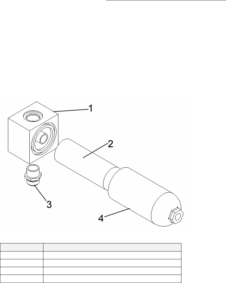
6.2.1. Oil Filter Replacement
Verify the exact element number prior to ordering the replacement element.
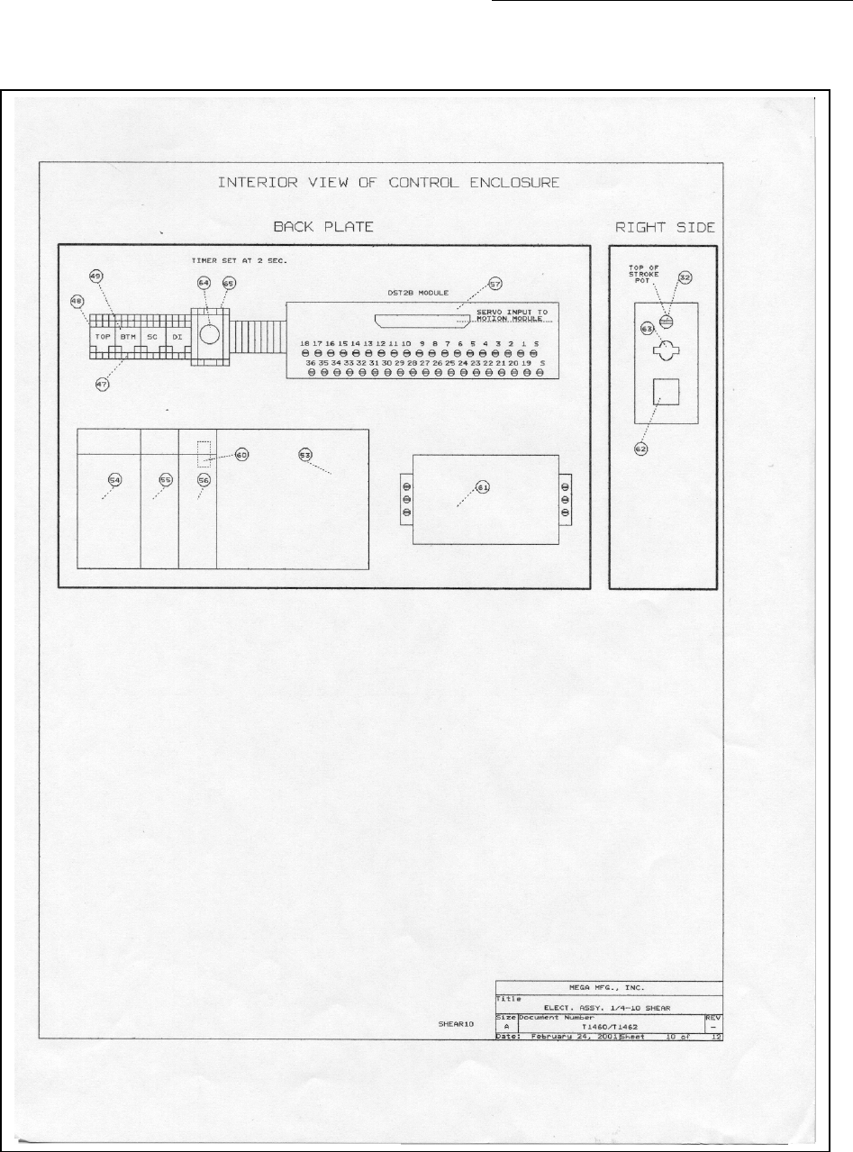
Figure 6: Oil Filter Assembly Exploded View
Item Description
1 Filter Body
2 Filter Element
3 Fitting - inlet
4 Filter Bowl
Table 1: Oil Filter Assembly Descriptions
The following steps represent a typical filter element replacement.
1. Insure the main electric power is locked out at the safety
disconnect.
2. Place a small container (½-gallon) under the filter bowl.
3. Remove the filter bowl by turning in a counterclockwise
direction.
4. Remove the filter element by pulling and turning at the same
time.
5. Lubricate the O-ring on the new filter with hydraulic oil and slide
into place.
6. Wipe the inside of the filter element bowl and replace.
When changing the hydraulic oil, a new oil filter should also be installed.
Piranha ¼-12 Operators/Owner’s Manual
31
7. Hydraulic & Electrical Schematics
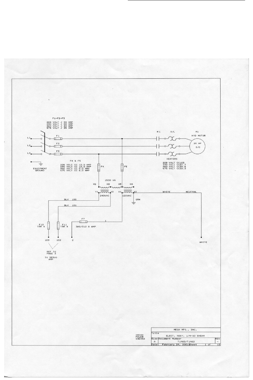
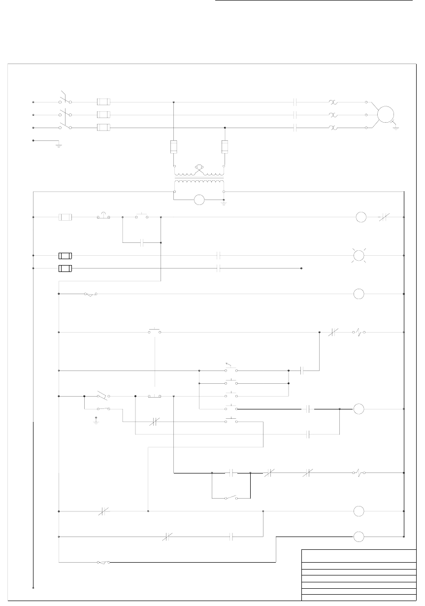
7.1. Electrical Schematic-Programmable CNC
Figure 7: Electrical Diagram 1 of 10
Piranha ¼-12 Operators/Owner’s Manual
32
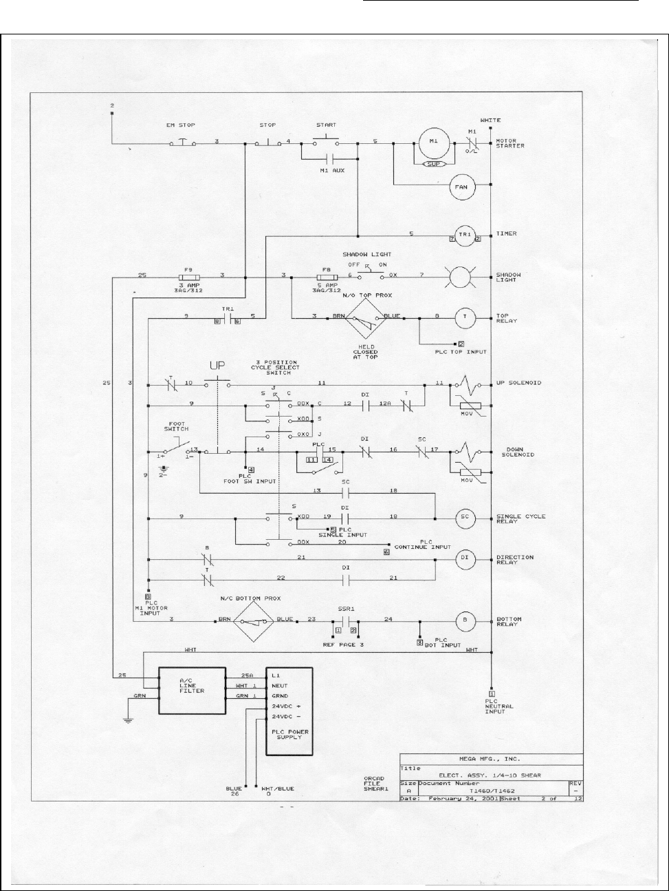
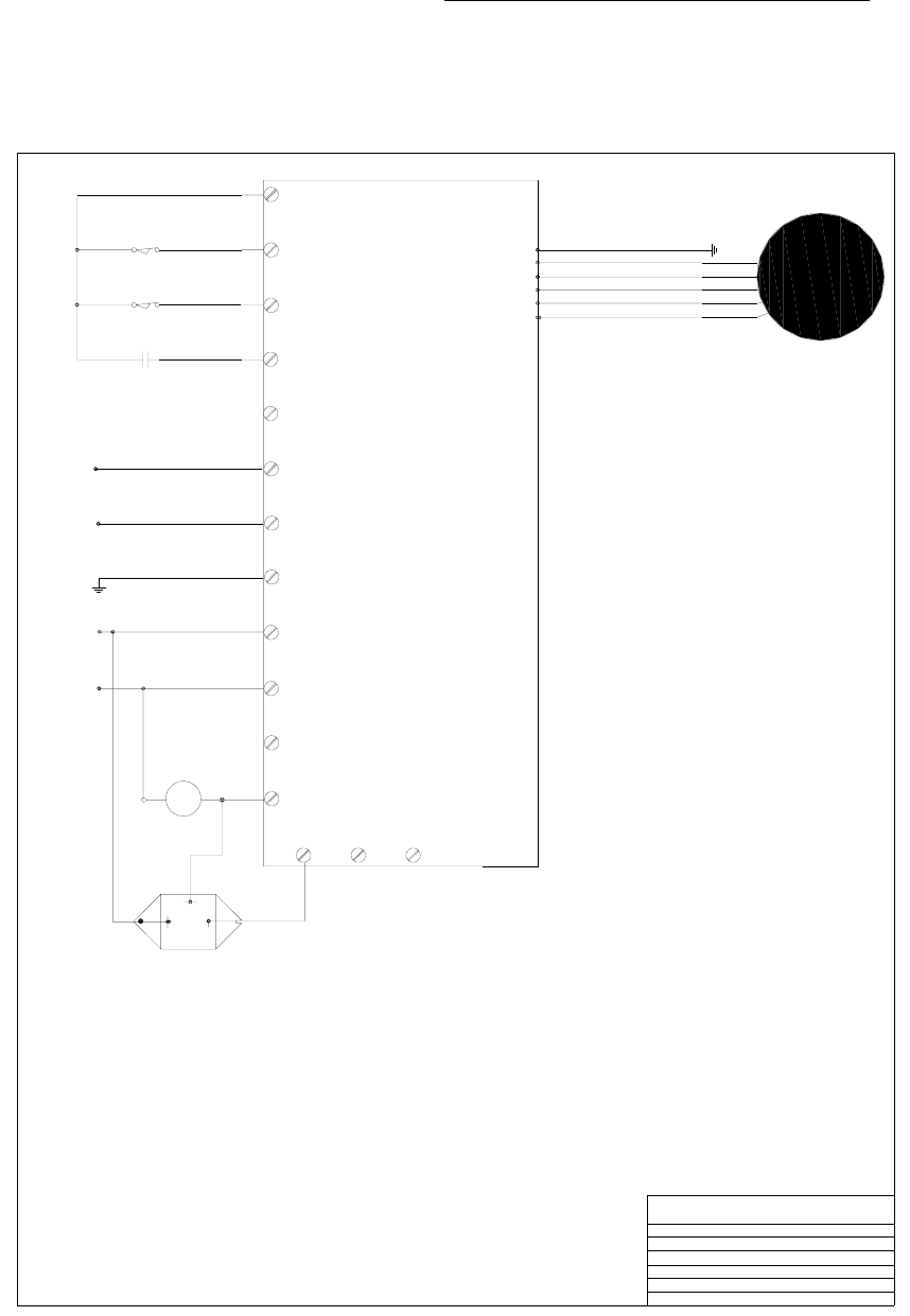
Figure 8: Electrical Diagram 2 of 10
Piranha ¼-12 Operators/Owner’s Manual
33
Figure 9 Electrical Diagram 3 of 10
Piranha ¼-12 Operators/Owner’s Manual
34
Figure 10: Electrical Diagram 4 of 10
Piranha ¼-12 Operators/Owner’s Manual
35
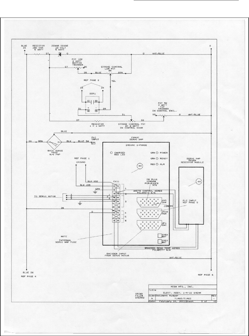
Figure 11 Electrical Diagram 5 of 10
Piranha ¼-12 Operators/Owner’s Manual
36
Figure 12: Electrical Diagram 6 of 10
Piranha ¼-12 Operators/Owner’s Manual
37
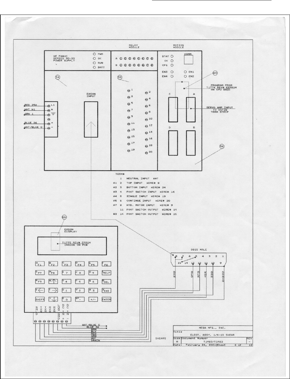
Figure 13: Electrical Diagram 7 of 10
Piranha ¼-12 Operators/Owner’s Manual
38
Figure: 14: Electrical Diagram 8 of 10
Piranha ¼-12 Operators/Owner’s Manual
39
Figure: 15: Electrical Diagram 9 of 10
Piranha ¼-12 Operators/Owner’s Manual
40
Figure: 16: Electrical Diagram 10 of 10

Piranha ¼-12 Operators/Owner’s Manual
41
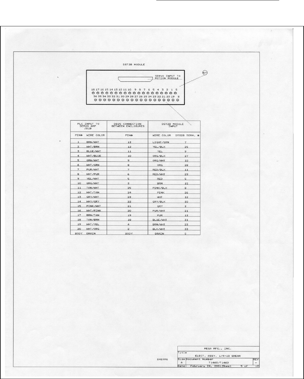
Electrical Component List - Programmable CNC
FIG DESCRIPTION QTY VOLTAGE PART #
1 Transformer 208/230/460/575 Volt 1 208 - 575 Volt T1868
2 Transformer Primary Fuse F4-F5 2 208 Volt T0770
2 Transformer Primary Fuse F4-F5 2 230 Volt T0770
2 Transformer Primary Fuse F4-F5 2 460 Volt T1138
2 Transformer Primary Fuse F4-F5 2 575 Volt T1138
3 Transformer Primary/Secondary Fuse Holder 2 T1866
4 Transformer Secondary Fuse F10-F11 Servo 2 T1867
5 Fuse, Motor Short Circuit Protection AJT-90 3 208 Volt T0781
5 Fuse, Motor Short Circuit Protection AJT-80 3 230 Volt T0780
5 Fuse, Motor Short Circuit Protection AJT-40 3 460 Volt T0777
5 Fuse, Motor Short Circuit Protection AJT-30 3 575 Volt T1869
6 Fuse Holder, " " " 208 Volt 1 208 Volt T0784
6 Fuse Holder, " " " 230 Volt 1 230 Volt T0784
6 Fuse Holder, " " " 460 Volt 1 460 Volt T0784
6 Fuse Holder, " " " 575 Volt 1 575 Volt T0784
7 Fuse Holder, Control Circuits 3 T0733
8 Fuse, Control Circuits F7 1 8 Amp T0734
8 Fuse, Control Circuits F8 1 5 Amp T0736
8 Fuse, Control Circuits F9 1 3 Amp T1870
9 Starter, Motor 1 T0729
10 Starter Overload Heaters CC-103 3 208 Volt T0786
10 Starter Overload Heaters CC-87.7 3 230 Volt T0788
10 Starter Overload Heaters CC-39.6 3 460 Volt T0785
10 Starter Overload Heaters CC-33.0 3 575 Volt T0787
11 Starter Aux Contact 1 T1303
12 Starter Overload Reset Button 1 531686
13 Starter Overload Reset Button Shaft 1 5316861
14. Disconnect Operator 1 531604
15. Disconnect 1 531602
16. Disconnect Shaft 1 T0727
17. Stop Button, Red Extd. 1 5316111
18. Stop Button, Contact Block W/Base, NC 1 5316121
19. Start Button, Green Flush 1 5316101
20. Start Button Contact Block W/Base, NO 1 531696
21. E Stop Button 1 T0737
22. E Stop Button Contact Block W/Base N/C 1 5316121
23. Up Button - Yellow 1 T1668
24. Up Button Contact Block W/Base, NO 1 531696
25. Shadow Light Selecta Switch 2 Pos 1 531695
26. Shadow Light Selecta Contact Block W/Base, NO 1 531696
27. Mode Selecta Switch 3 Pos 1 5316451
28. Mode Selecta, Contact Block W/Base NO 1 531696
29. Mode Selecta, Contact Block N/O 3 5316781
FIG DESCRIPTION QTY VOLTAGE PART #

Piranha ¼-12 Operators/Owner’s Manual
42
30. Mode Selecta, Contact Block N/C 2 591596
31. Potentiometer, Stroke Control, 2 K 2 Watt 1 T1871
32. Potentiometer, Top Stroke Trimmer 5K 1 T1414
33. Potentiometer, Bottom Stroke Trimmer 10K 1 T1678
34. Potentiometer, Knob 1 T0762
35. Potentiometer, Linear Stroke Control 1 T1252
36. Fan 1 T0726
37. Fan Grills, Filter 2 T0725
38. Prox, Top - N/O 1 T1674
39. Prox, Bottom - N/C 1 T1675
40. Suppressor, Motor 1 591604
41. Foot Switch Recp 1 531618
42. Foot Switch 1 T0748
43. Servo Amp 1 T0927
44. Servo Amp Regen Module 1 T0927
45. Servo Amp Motor 1 T0926
46. Resistor 150 OHM 5 Watt 1 591629
47. Relay Socket 4 T1306
48. Relay Socket Clips 8 T1304
49. Relay, 120Vac 4 Pole, Silver Flashed 4 T0739
50. Hyd. Valve Din Cables A/C 2 591531
51. Suppressor, Mov 2 591619
52. Shadow Lamps 8 T0467-1
53. PLC, CPU Base 1 5916073
54. PLC, Power Supply 1 5916072
55. PLC,Relay Module 1 T0924
56. PLC,Motion Module 1 T0925
57. PLC,Aux.Term,Block 1 T0930
58. Eason 1 T0933
59. Eason, E-Prom -Programmed 1 T1775 Rev#
60. PLC, EE Prom 1 T1774 Rev#
61. Suppressor, A/C Line Filter 1 T1861
62. Relay - Solid State 1 T1862
63. Toggle Switch 1 531619
64. Timer - 5 Sec. 1 T1863
65. Timer Socket - 8 Pin Octal 1 T1864
66. Shadow Light Sockets - Double Contact 8 T0466
67. Diode, Zener - 10 Volt 5 Watt 1 10 Volt 5 Watt T1865
68. Decal, Control Legend 1 T1251
69. Decal, Elect. Enclosure 1 T1848
Servo Motor Harness T1465
AC Harness (parts within the harness include) T1464
Backgauge Harness Assembly, PLC T1459
Linear Pot Harness T1463
Prox Switch Assembly T1667
Piranha ¼-12 Operators/Owner’s Manual
43
7.1.1. Electrical Schematic – Programmable GOTO
Figure: 17: Electrical Diagram 1 of 4
H1 H4
X1 X2
3
2
WHITE
HELD
CLOSED
AT
TOP
TOP TOP
T
1
M1
HYD MOTOR
3/0
0/L
M1
F2
F3
EQUIPMENT
GROUND
L1
L2
L3
E STOP START
M1
AUX
UP
1+ 1-
UP
SOL
XOO
DI
T
FOOT
SWITCH
SC
DI
BACK GUAGE
ENABLE
OOX
SINGLE
JOG
CONT
XOO DI
SC
SC
DOWN
SOL
SINGLE
CYCLE
DIRECTION
DI
B
TDI
BOTTOM
LIMIT
N/C
B
BOTTOM
BYPASS
COM
208 VOLT J 60 AMP
230 VOLT J 60 AMP
460 VOLT CC 30 AMP
575 VOLT CC 25 AMP
1KVA
F4 F5
1
PIRANHA
W
T1970_1
-
TITLE
DRAWING
DATE
REV.#
DRAWN BY
PAGE#
BOB RILEY
M1
O/L
F8
SHADOW LIGHTS
OXO
C
S
J
S
2- 2+ T
XOO
M1
AUX
M1
AUX
COM N/O
M1
4
4
4
4
4
4
4
5
7
6
8
9
10
10
11
12
12
10
13
4
4
14 15
16 17
18
18 18
13 19 20
4
22
21
F1
18 23
S
OPTIONAL
F6
312 5 AMP
F7
312 3 AMP
313 8 AMP
8-15-01
TO PC BACK
GUAGE BOARD
TERM.# LINE
RLY1 RLY2
1 OF 4
208 VOLT CC8
230 VOLT CC7
460 VOLT CC4
575 VOLT CC4
MOV
15HP 20HP
J 90 AMP
J 80 AMP
J 40 AMP
J35 AMP 15 OR 20 HP
HEATERS
208 VOLT B70
230 VOLT B70
460 VOLT B32
575 VOLT B25
15HP 20 HP
CC103
CC87.7
CC39.6
CC33.3
BLK
GRN
RED
WHT
BASE SHEAR GOTO B/G
F4 & F5
20 HP A/C
20HP A/C
NOTE*
NOTE*
NOTE* 15 HP OPTION ARE D/C RECTIFIED HYD. DIN CONNECTORS
Piranha ¼-12 Operators/Owner’s Manual
44
Figure: 18: Electrical Diagram 2 of 4
PIRANHA
BASE SHEAR GOTO B/G
T1970_2
-
TITLE
DRAWING
DATE
REV.#
DRAWN BY
PAGE#
BOB RILEY
8-15-01
RETRACT
HL1M
RLY1
RLY2
GRND
LINE
NEUTRAL
MOT1
MOT2
FRONT LIMIT
REAR LIMIT
FRONT
BACK GUAGE
LIMIT
REAR
BACK GUAGE
LIMIT
T
COMMON
COM
COM
N/C
N/C
26
27
28
29
26
8
REF
PAGE 1
13
19
W
REF
PAGE 1
REF
PAGE 1
REF
PAGE 1
REF
PAGE 1
GRN
BACK GUAGE
MOTOR
90V
D/C 32
GT LD
PW
TRAIC
TECCOR Q6040P
25
8
# 2 INDEX
# 3 A CHANNEL
# 4 +5VDC
P3
TERMINAL
RJ11
2
3
4
5
6
PIN # 1 GROUND
# 5 B CHANNEL
1
DRAIN
GRND
INDEX
+5 VOLTS
B CHANNEL
A CHANNEL
BLK
GRN
RED
BRN
WHT
BACK GUAGE PC BOARD
ENCODER
2 OF 4
Piranha ¼-12 Operators/Owner’s Manual
45
Figure: 19: Electrical Diagram 3 of 4
PIRANHA
TITLE
DRAWING
DATE
REV#
DRAWN BY
PAGE#
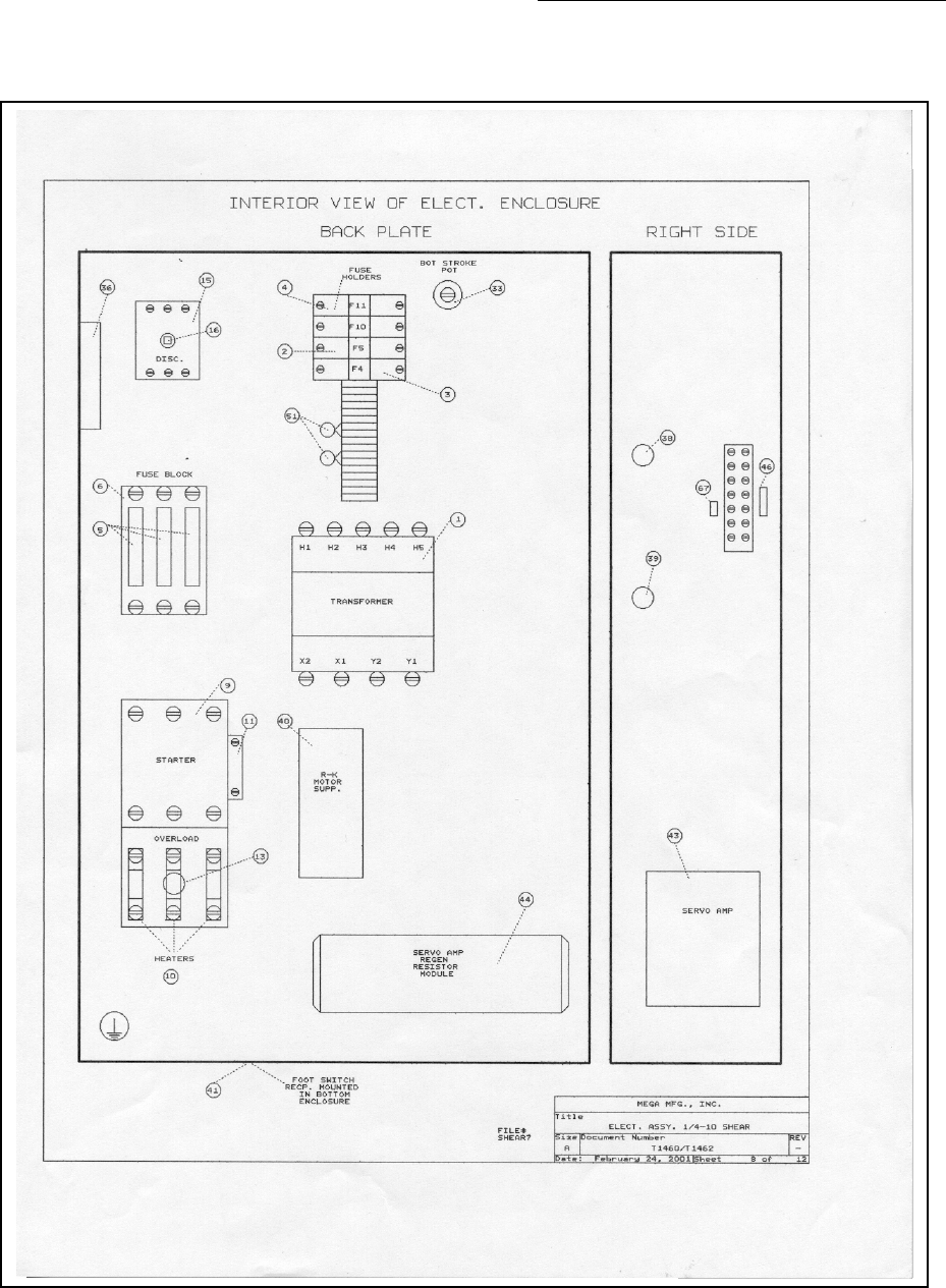
BACK PLATE RIGHT SIDE
T
B
SC
DI
T1970_3
8-15-01
-
BOB RILEY
3 OF 4
1
2
3
4
5
6
7
8
9
10
11
12
13
14
15
16
17
18
19
20
44
38
39
43
BASE SHEAR GOTO B/G
Piranha ¼-12 Operators/Owner’s Manual
46
Figure: 20: Electrical Diagram 4 of 4
PIRANHA
TITLE
DRAWING
DATE
REV#
DRAWN BY
PAGE#
R
ON
OFF
BASE SHEAR GOTO B/G
T1970_4
8-15-01
-
BOB RILEY
4 OF 4
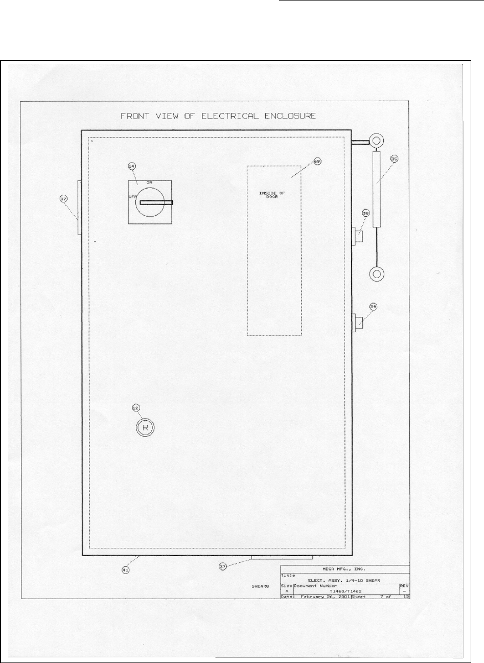
VIEW OF CONTROL ENCLOSURE
12
4
3
56
789
.0
IN
MM
GO
CAL
FC
CLR
INTERIOR VIEW OF DOOR
UPMODE
STARTSTOP
UP MODE
START E STOP
FRONT VIEW OF ELECTRICAL ENCLOSURE
FRONT VIEW OF DOOR
21
22
24
29
30
27
28
25
26
31
32
33
34
35
36 37
45
41 42
FOOT SWITCH
40

Piranha ¼-12 Operators/Owner’s Manual
47
Electrical Component List – Programmable GOTO
FIG DESCRIPTION QTY VOLTAGE PART #
1 DISCONNECT 20HP 1 208/230 0591602
1 DISCONNECT 15HP 1 480/575 0531605
2 DISCONNECT SHAFT 1 ALL T0727
3 FUSES, MOTOR SHORT CIRCUIT 15HP 3 208 T0779
3 FUSES, MOTOR SHORT CIRCUIT 15HP 3 230 T0779
3 FUSES, MOTOR SHORT CIRCUIT 15HP 3 460 T0775
3 FUSES, MOTOR SHORT CIRCUIT 15HP 3 575 T0774
3 FUSES, MOTOR SHORT CIRCUIT 20HP 3 208 T0781
3 FUSES, MOTOR SHORT CIRCUIT 20HP 3 230 T0780
3 FUSES, MOTOR SHORT CIRCUIT 20HP 3 460 T0777
3 FUSES, MOTOR SHORT CIRCUIT 20HP 3 575 T2256
4 FUSE BLOCK, SHORT CIRCUIT 15HP 1 208/230 T0782
4 FUSE BLOCK, SHORT CIRCUIT 15HP 1 460/575 T0783
4 FUSE BLOCK, SHORT CIRCUIT 15HP 1 208/230 T0784
4 FUSE BLOCK, SHORT CIRCUIT 20hP 1 460/575 T0782
5 STARTER, M1 20HP 1 208/230 0541641
5 STARTER, M1 15HP 1 460/575 0531641
5 STARTER, M1 20HP 1 208/230 T0729
5 STARTER, M1 20HP 1 460/575 T2257
6 HEATERS, M1 OVERLOAD 15HP B70 3 208 0541642
6 HEATERS, M1 OVERLOAD 15HP B70 3 230 0541642
6 HEATERS, M1 OVERLOAD 15HP B32 3 460 0541643
6 HEATERS, M1 OVERLOAD 15HP B25 3 575 0521616
6 HEATERS, M1 OVERLOAD 20HP CC103 3 208 T0786
6 HEATERS, M1 OVERLOAD 20HP CC87.7 3 230 T0788
6 HEATERS, M1 OVERLOAD 20HP CC39.6 3 460 0531638
6 HEATERS, M1 OVERLOAD 20HP CC33.0 3 575 T2258
7 SUPPRESSOR, MOTOR M1 1 ALL 0501604
8 TRANSFORMER 1 208 T2244
8 TRANSFORMER 1 230/460 T2245
8 TRANSFORMER 1 575 T2246
9 FUSE HOLDER, TRANSFORMER PRIMARY 1 ALL T1302
10 FUSE, TRANSFORMER PRIMARY 3 208 T2247
10 FUSE, TRANSFORMER PRIMARY 3 230 T2248
10 FUSE, TRANSFORMER PRIMARY 3 460/575 T2249
11 RELAY, 4 POLE 120V A/C 4 ALL T0739
12 RELAY SOCKETS 4 ALL T1306
13 TRIAC, D/C BACK GAUGE MOTOR 1 ALL T2250
14 PRINTED CIRCUIT BOARD, BACK GAUGE 1 ALL T2114
15 FUSE HOLDER, PANEL MOUNT 3 ALL T0733
16 FUSE, CONTROL CIRCUIT 1 ALL T0736
17 FUSE, SHADOW LIGHT 1 ALL T2251
FIG DESCRIPTION QTY VOLTAGE PART #
19 FUSE, BACK GAUGE CIRCUIT 1 ALL T2252

Piranha ¼-12 Operators/Owner’s Manual
48
20 DECAL, CONTROL FUSES 1 ALL T2200
21 DISCONNECT OPERATOR 1 ALL 0531604
22 RESET BUTTON W/ SHAFT 1 ALL 0531686-1
24 DECAL, MOTOR SHORT CIRCUIT/TRANSFORMER 1 ALL T2201
25 BACK GAUGE DISPLAY MODULE 1 ALL T2113
26 KEYPAD, BACKGAUGE 1 ALL T2018
27 SELECTA SWITCH, 3 POS,MODE 1 ALL T1670-1
28 EMEG. STOP OPERATOR, RED MUSHROOM 1 ALL T0737-1
29 PUSH BUTTON OPERATOR, YELLOW EXTED. 1 ALL T1668-1
30 PUSH BUTTON OPERATOR, GREEN FLUSH 1 ALL 05316101-1
31 CONTACT BLOCK W/ BASE 1N/O 1 ALL 0531696-1
32 CONTACT BLOCK 1 N/O 1 ALL 05316781-1
33 CONTACT BLOCK 1 N/C 2 ALL 0591596-1
34 CONTACT BLOCK W/ BASE 1N/O 1 ALL 0531696-1
35 CONTACT BLOCK 1 N/C 1 ALL 0591596-1
36 CONTACT BLOCK W/ BASE 1 N/C 1 ALL 05316121-1
37 CONTACT BLOCK W/BASE 1 N/O 1 ALL 0531696-1
38 STARTER AUX. CONTACT, 1 N/O 1 ALL T01303
39 STARTER AUX. CONTACT, 2 N/O 1 ALL T2253
40 FOOT SWITCH 1 ALL T0748
41 FOOT SWITCH PLUG 1 ALL 0531617
42 FOOT SWITCH RECP. 1 ALL 0531618
SHADOW LIGHT LAMPS 8 ALL T0467-1
SHADOW LIGHT LAMP SOCKETS 8 ALL T0466
43 TOGGLE SWITCH 1 ALL 0531619
44 SUPPRESSOR, MOV 2 ALL 0591619
45 DECAL, CONTROL PANEL 1 ALL T1964
RECTIFIED HYD. PLUGS 2 ALL 0531529
ENCODER 1 ALL T2159
Piranha ¼-12 Operators/Owner’s Manual
49
7.2. Hydraulic Schematic- 20 HP Motor
Figure 21: Hydraulic Diagram 1 of 1
Piranha ¼-12 Operators/Owner’s Manual
50
7.2.1. Hydraulic Schematic-15 HP Motor
Figure: 22: Hydraulic Schematic 1 of 1
Piranha ¼-12 Operators/Owner’s Manual
51
8. Parts
Diagrams are provided for the major assemblies of the shear. The accompanying parts lists
provide item references and descriptions. Part numbers and quantities are provided only where
applicable.
Repair parts are available for the Piranha 1/4-10 Shear from the manufacturer. Always provide the
model and complete serial number of the press brake along with the part number description and
quantity of the desired parts.
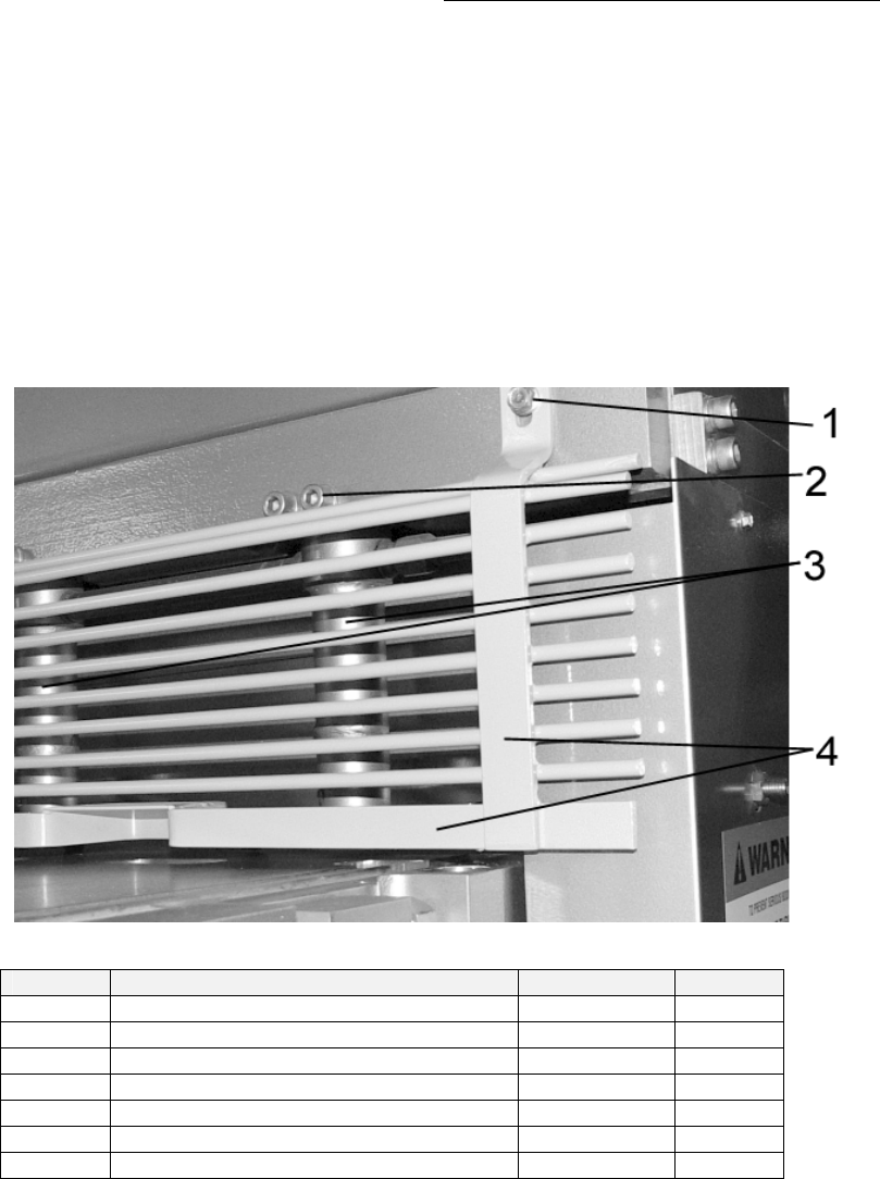
8.1. Finger Guard & Hold downs
Figure 23: Finger Guard
Item Description Part # Qty.
1 Finger Guard Mounting Bolts
2 Hold Down Mounting Bolts 26
*3 Hold Down Cylinder T2606 11
*3 Hold Down Cylinder-LHS T2607 1
*3 Hold Down Cylinder-RHS T2608 1
3 Hold Down Cylinder (STD) T0425 13
4 Finger Guard T3344 1
* Supplied with “Enhancement Package”
Piranha ¼-12 Operators/Owner’s Manual
52
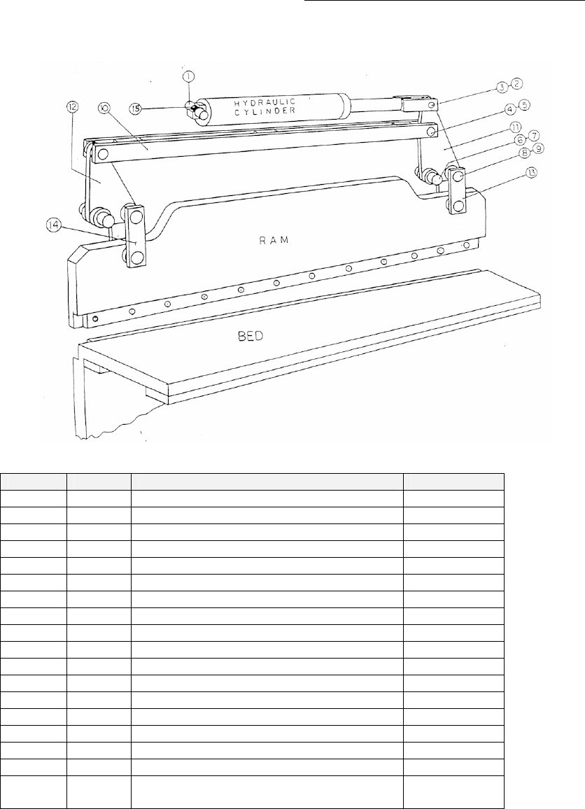
8.2. Ram & Linkage
Figure 24: Ram & Linkage
Item Qty. Description Part #
1 1 Cylinder Pin T2460-1
2 1 Cylinder Lever Pin T2456
3 2 Fiberglide Liner 1.5 x 2.5 T270
4 2 C-Rod Pin T2457
5 2 Fiberglide Liner 1.75 x 2 T271
6 1 Main Hinge Pin T2458
7 2 Fiberglide Liner 3 x 2.5 T273
8 4 Link Pin T8212
9 4 Fiberglide Liner T272
10 1 C-Rod T3276-1
11 1 Lever, Long T2652
12 1 Lever, Short T2648
13 2 Link T8214
14 2 Link T8214
15 2 Fiberglide Liner 1.5 x 2.5 T270
16 1 Hydraulic Cylinder T0603-1
17 1 Ram T32821-1
18 1 Bed T3360(Base)
T3281(EHP)
Piranha ¼-12 Operators/Owner’s Manual
53
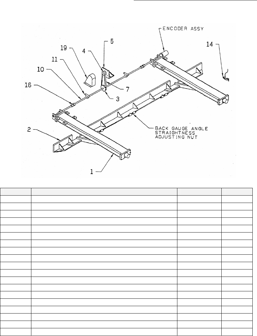
8.3. Back Gauge Assembly-Programmable CNC
Figure 25: Back Gauge Assembly
Item Description Part # Qty.
1 Back Gauge Track 2
2 Back Stop-Machined T33551 1
3 Timing Belt Sprocket T457-10 1
4 Bushing, 5/8” Bore T469 1
5 Motor Mount Bracket T0625 1
6 Motor / Encoder Assembly
7 Timing Belt T468 1
8
9
10 Transmission Shaft T2172 1
11 Bearing, Pillow Block, 5/8” Cast Housing T0698 2
12
13
14 Sensor Bracket Assembly T14-925 1
15 Prox Switch T04085 1
16 5/8” Taper Nut Assembly T1242 1
17
18 Traveling Arm T0592 1
19 Servo Motor Guard T22204 1
Piranha ¼-12 Operators/Owner’s Manual
54
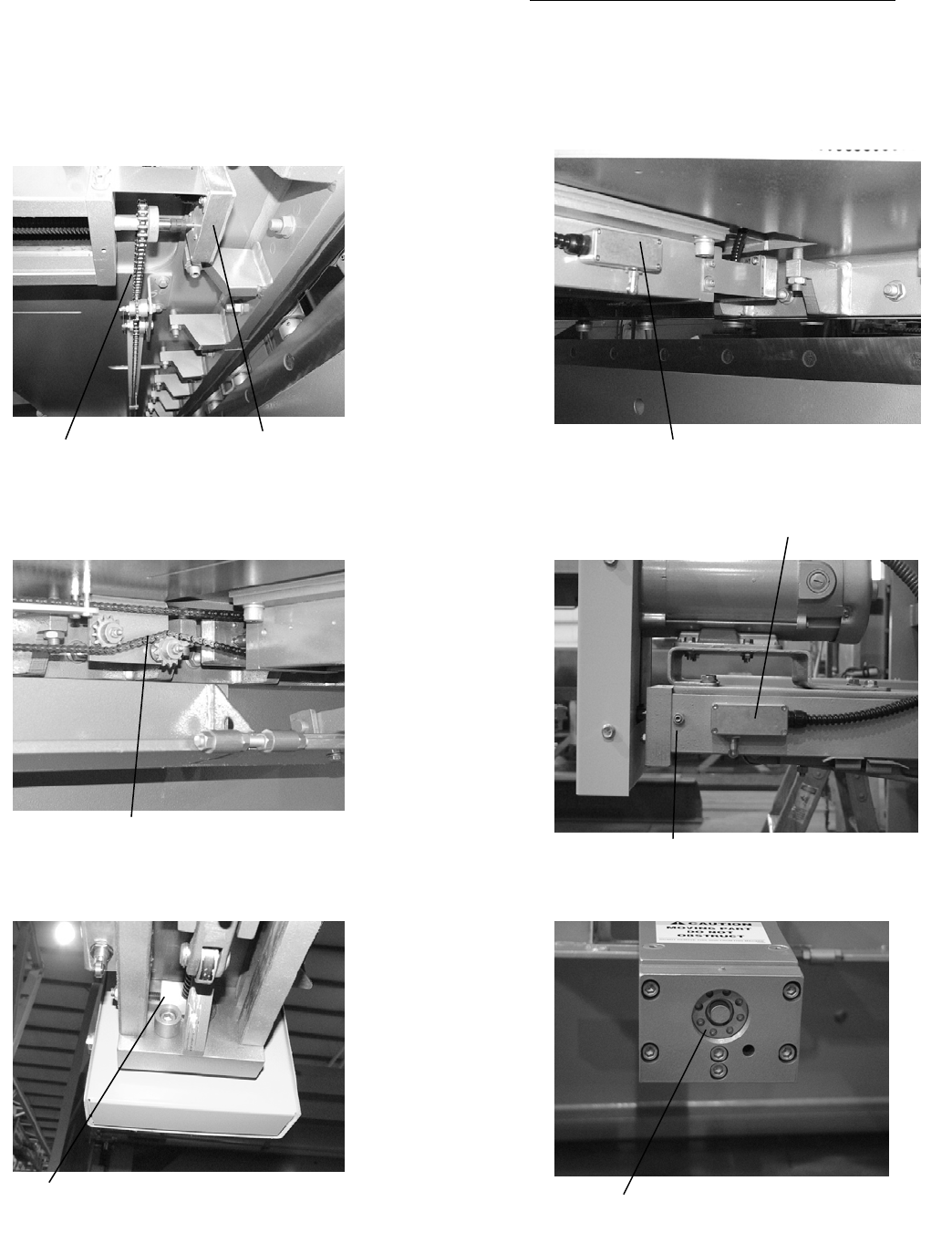
8.3.1. Back Gauge Assembly Programmable GOTO
Chain Drive Encoder Assy Front Power Cut Off Back Gauge Limit Switch
Chain Tension Idler Assy Back Gauge Drag Block Adjustment Nut
Back Gauge Drag Block Back Gauge Lead Screw Spanner Nut
Rear Power Cut Off Back Gauge Limit Switch
FIG #
25A 25D
25B 25E
25C 25F
Piranha ¼-12 Operators/Owner’s Manual
55
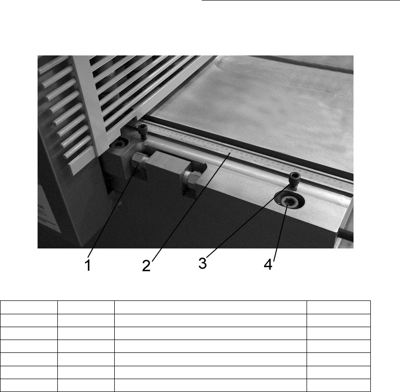
8.4. Back Gauge & Bar Adjustment
Figure 26: Back Gauge & Bar Adjustment
Item Qty. Description Part #
1 3 Back Stop Straightener Assy
2 2 Back Stop Machined ¼-12 T33551
3 8 1” –14 NF ND Hex Nut GR8 0531260
8.5.
Piranha ¼-12 Operators/Owner’s Manual
56
8.6. Bed Components
Figure 27: Bed Components
Item Qty. Description Part #
1 4 Bed Adjustment Bolts T0469
2 4 ¾” x 2 SHCS 0591601
2 4 ¾” Lock Washer 0531314
3 6 ½” x 1-1/4” SHCS 0531081
4 1 Control End Scale 72 (2-Pcs) T0504
5 1 Far End Scale 24” T1196
Piranha ¼-12 Operators/Owner’s Manual
57
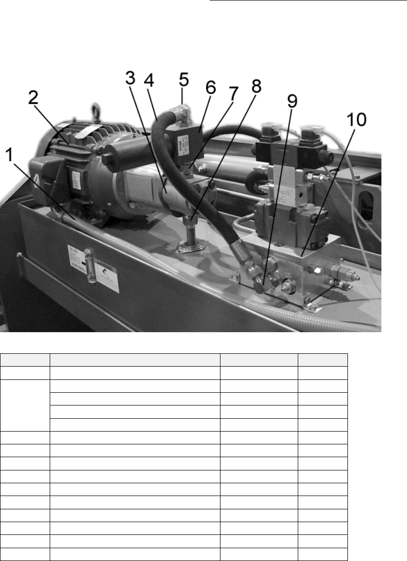
8.7. Hydraulic Assemblies-20 HP Motor
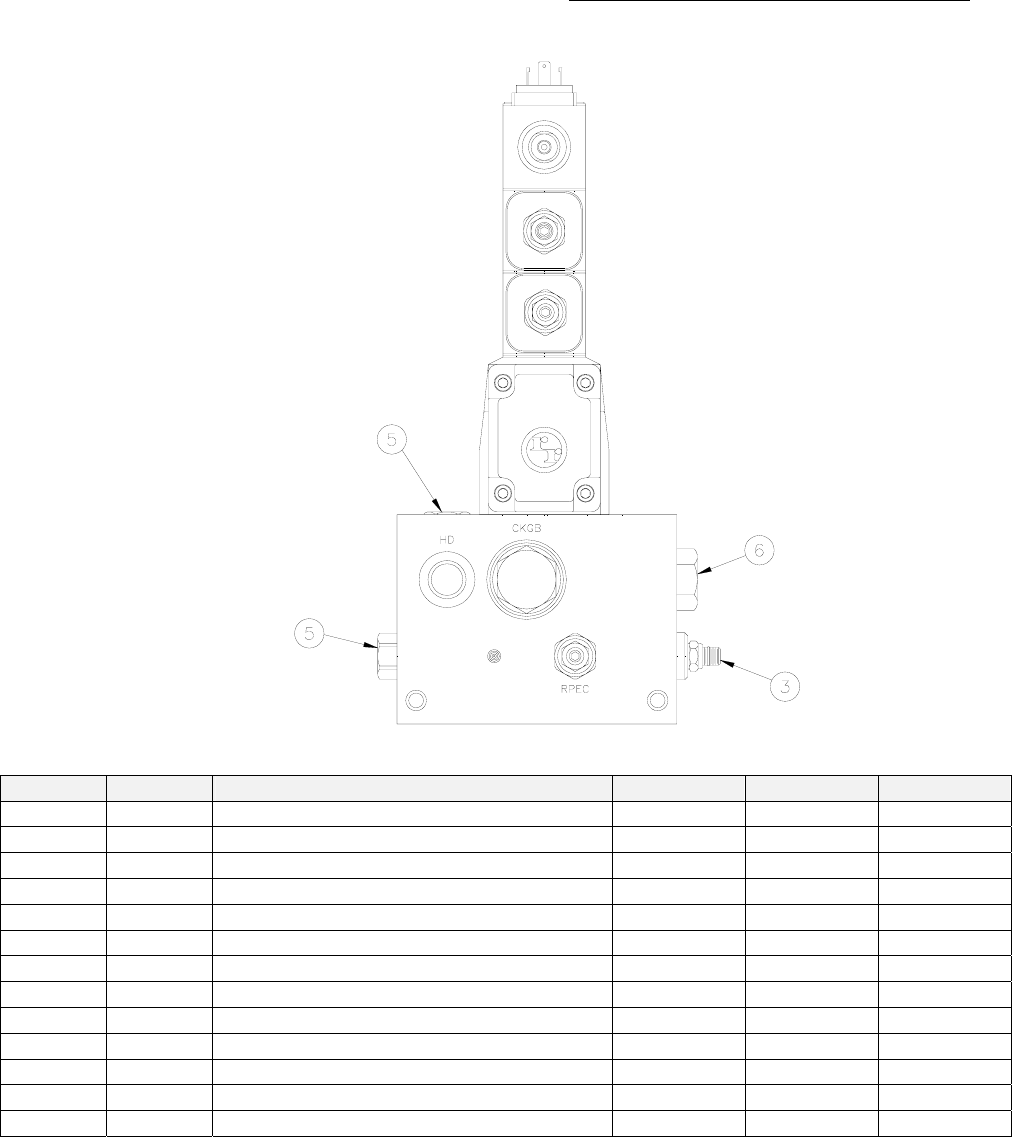
Figure 28: Hydraulic Power Unit
Item Description Part # Qty.
1 Motor Power Harness T04088 1
Motor
20 HP - 220/440 Volt 0571660 1
20 HP – 440 Volt 0571662 1
2
20 HP – 575 Volt 0571665 1
3 Pump 05915701 1
4 Hose, Filter Valve Pack P T1065 1
5 Fitting, Filter Outlet 0531538 1
6 Filter Assembly 0591550 1
7 Fitting, Inlet Filter 6400-12-12 0551211 1
7 Fitting, Outlet /Pump 6400-12-16 0591506 1
8 Fitting, Inlet Pump 6400-16 R539504 1
8 Suction Tube T0434 1
9 Fitting, P Port 6801-12 0531531 1
10 Valvepack T0271-1 1
Table 2: Hydraulic Power Unit Descriptions

Piranha ¼-12 Operators/Owner’s Manual
58
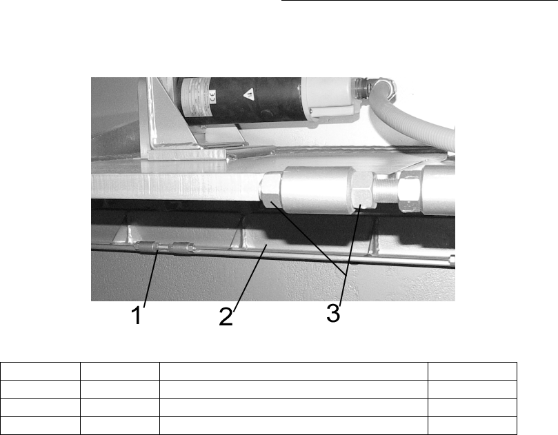
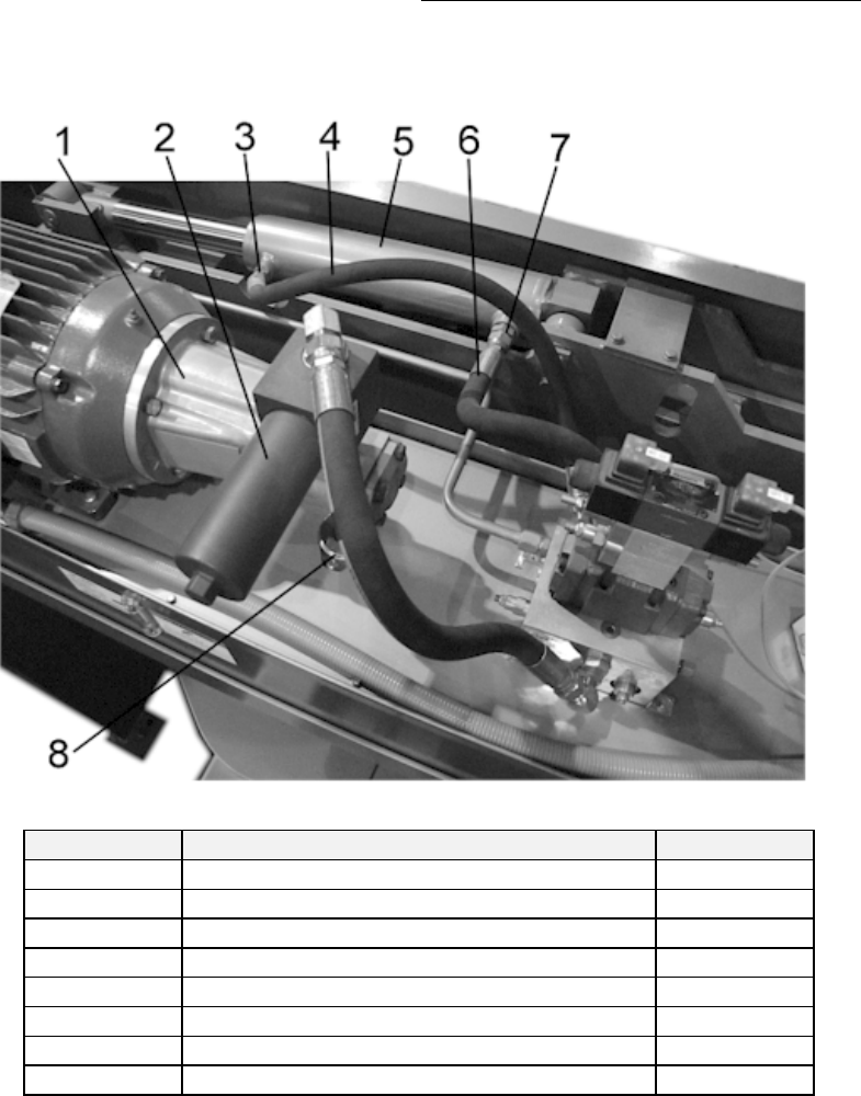
8.7.1. Hydraulic Assemblies-15 HP Motor
Piranha ¼-12 Operators/Owner’s Manual
59
Figure 29: Hydraulic Fittings
Figure-Item Description Part #
1 Pump Adapter 0551571
2 Filter Assembly 0591550
3 Fitting A-Port 6802-10 0531509
4 Hose A-Port to Cylinder 34” #10 T0433
5 Cylinder T0603-1
6 Hose, B-Port to Cylinder 19” #12 T0029
7 Fitting, Cylinder B-Port 6400-12 R639576
8 2-Bolt Flange T0029
Piranha ¼-12 Operators/Owner’s Manual
60
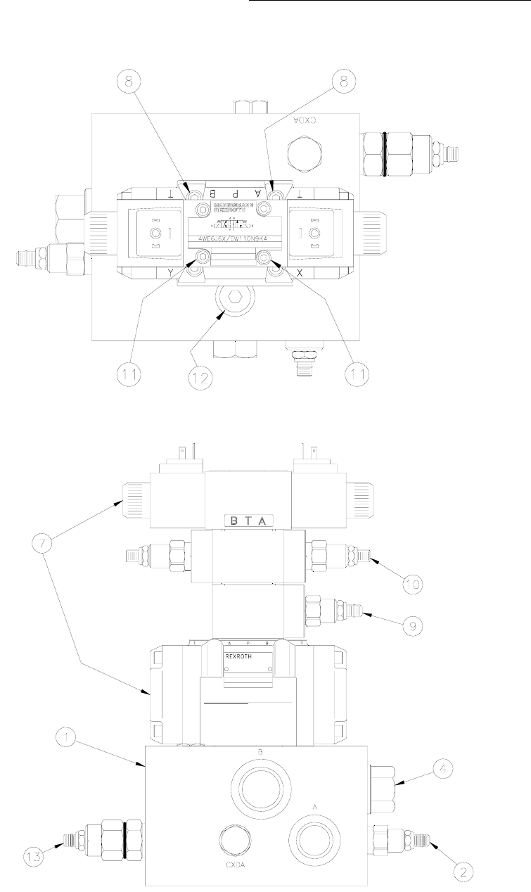
8.7.2. Valve Body Assembly 20 HP
Figure 30: Valve Body Assembly Top View
Figure 31: Valve Body Assembly Front View
Piranha ¼-12 Operators/Owner’s Manual
61
Figure 32: Valve Body Assembly Left Side View
Item Qty. Description Cartridge Coil Seal Kit
1 1 Valve Pack Body T1016 n/a n/a
2 1 PO Relief Valve RPEC-LAN T1067 n/a T1079
3 1 Vented CB Valve CAE-LHN T1069 n/a T0866
4 1 Check Valve PTO CKGB-XCN T0232 n/a T0869
5 2 Check Valve CXDA-XAN T1070 n/a T1079
6 1 Check Valve CXED-XCN T1071 n/a T0867
7 1 Directional Control Valve T1072 n/a T1081
2 Directional Control Valve Coils n/a 0571586 n/a
8 4 ¼”-20 x 1-3/4” SHCS 0581145 n/a n/a
*9 1 Reducing Valve PBDB-LAN-EBP T1273 n/a T0870
*10 1 Valve, Flow D03 Sandwich n/a n/a T1079
11 1 set of 4 M5 x 140 SHCS T1076 n/a n/a
13 1 CB Valve CAEA-LHN T0231 n/a T0866
* Optional

Piranha ¼-12 Operators/Owner’s Manual
62
Item Qty. Description Cartridge Coil Seal Kit
1 1 Valve Pack Body n/a n/a
2 1 PO Relief Valve RPEC-LAN T1067 n/a T1079
3 1 Vented CB Valve CAE-LHN T1069 n/a T0866
4 1 Check Valve PTO CKGB-XCN T0232 n/a T0869
5 2 Check Valve CXDA-XAN T1070 n/a T1079
6 1 Check Valve CXED-XCN n/a
7 1 Directional Control Valve 0531574 n/a T0873
2 Directional Control Valve Coils 0531583 n/a
8 4 ¼”-20 x 1-3/4” SHCS 0581145 n/a n/a
9 n/a
10 n/a n/a
11 1 set of 4 M5 x 140 SHCS n/a n/a
13 1 CB Valve CAEA-LHN T0231 n/a T0866
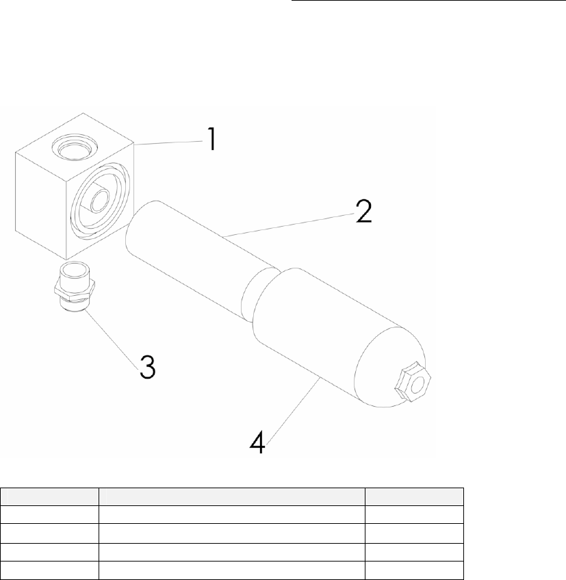
Piranha ¼-12 Operators/Owner’s Manual
63
8.8. Oil Filter Assembly
Figure 33: Oil Filter Assembly (PN-0591550) Exploded View
Figure-Item Description Part #
1 Filter Element 0591551
2 Fitting – inlet T0913

Piranha ¼-12 Operators/Owner’s Manual
64
8.9. Main Operator Control Panel-Programmable CNC
Refer to Section 7 for detailed electrical component list
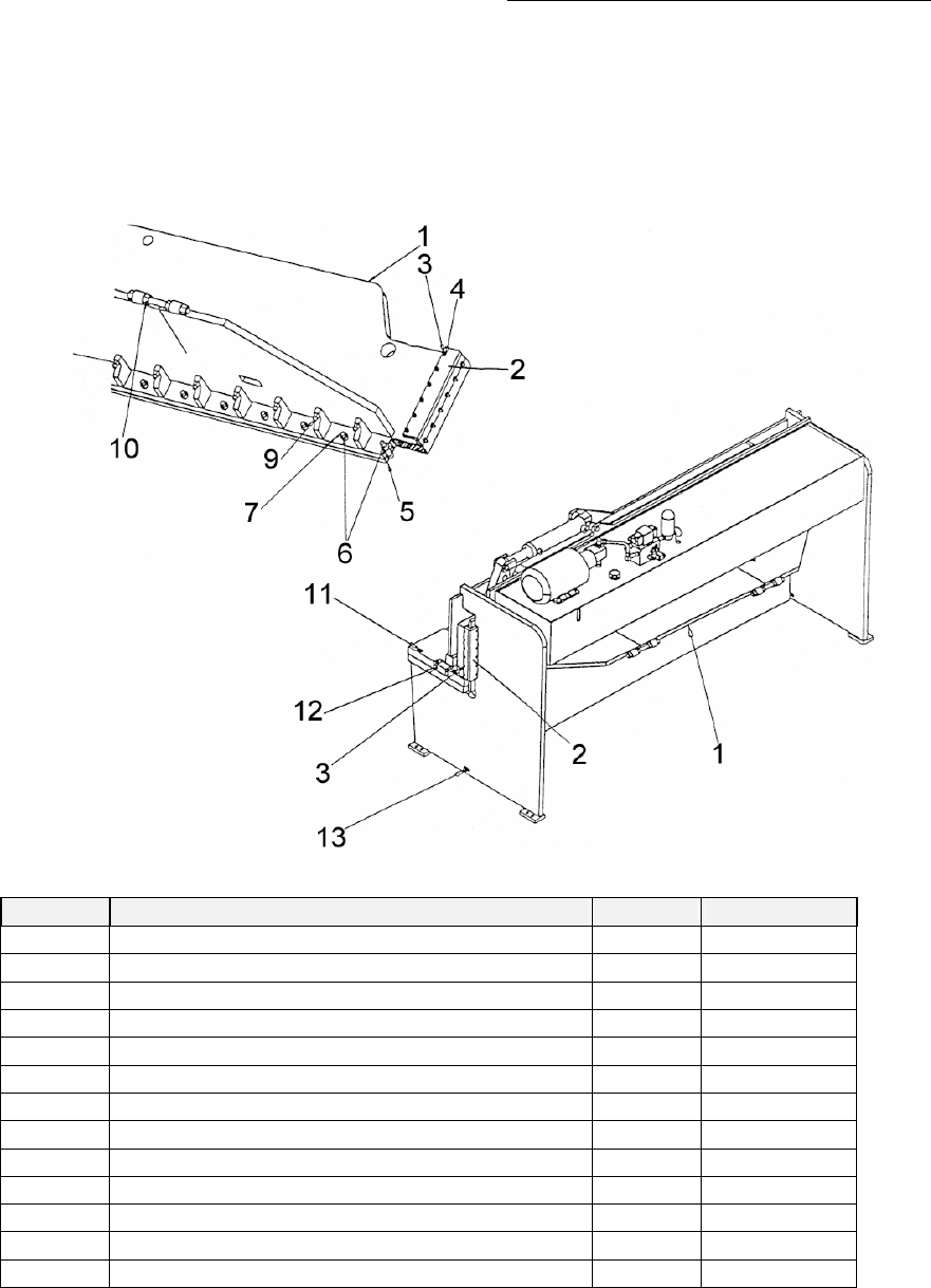
Piranha ¼-12 Operators/Owner’s Manual
65
8.10. Blade Adjust Components
Figure 34: Blade Adjust Components
Item Description Qty Part Number
1 ¼-12 Ram 1 T32821-1
2 Gib Supports 2 T9850
3 3/8”-16 SSS 2-1/4” Flat Point T0078
4 3/8”-16 FIN Hex Nut Plain 0531210
5 ¼-12 Knife 12’ Shear 2 T3283
6 ¼-12 Shear Knife Bolt (Ram) 16 T0456
7 ¼-12 Shear Knife Nut 32 T055
6 ¼-12 Shear Knife Bolt (Table) 16 T1405
9 Blade Straightness Adjustment Nut
10 Ram Tension Nut
11 Bed Locking Bolts
12 Blade Clearance Adjustment Bolts
13 Bed Locking Bolts
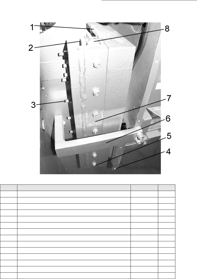
Piranha ¼-12 Operators/Owner’s Manual
66
8.11. Ram Slides
Figure 35: Gib Parts
Item Description Part # Qty
1 Elbow T0445 2
1 Lubrication Fitting T0446 2
2 Slide Bearing Phenolic T0398 4
2 Slide Bearing T0397 4
3 3/8” x 2-1/4” SSS Flat Point T0078 14
4 Shadow Line Adjustment Screw T0319 1
4 Shadow Line Adjustment Nut 0581198 1
5 3/8” Hex Nut 0531210 28
5 3/8” x 1-3/4” SSS Flat Point 0581121 14
6 Tie Bar Left T03171 1
6 Tie Bar Right T03161 1
7 Gibs T9850 1
8 Slide Left T5828 1
8 Slide Right T5637 1
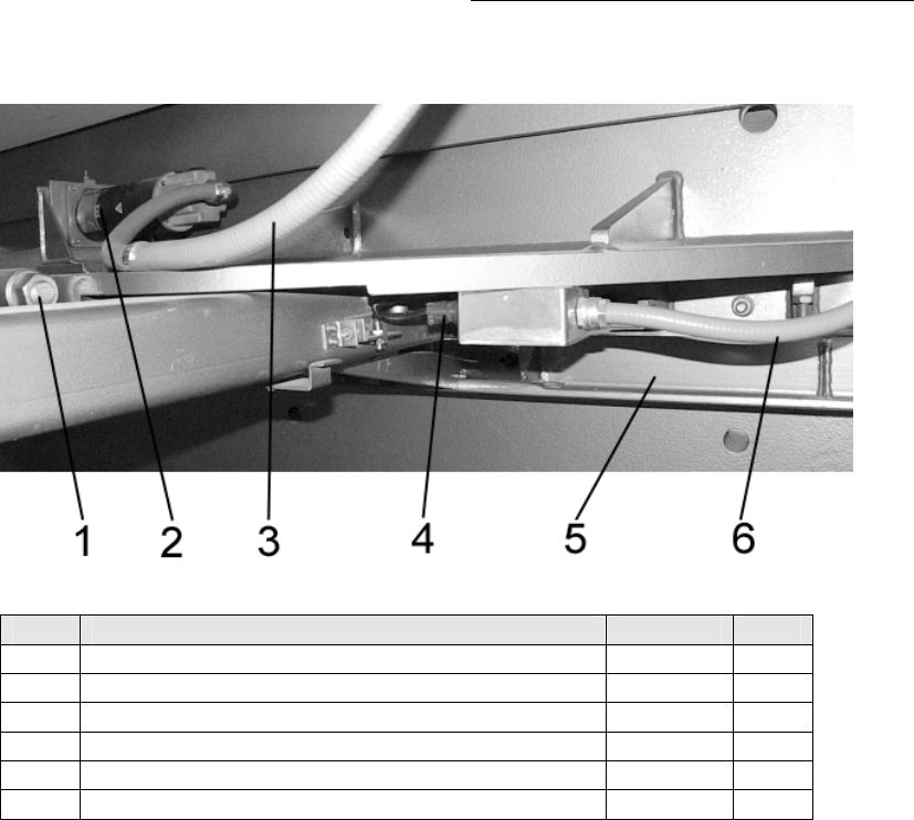
Piranha ¼-12 Operators/Owner’s Manual
67
8.12. Back Gauge Motor Assembly
Figure 36: Back Gauge Motor Assembly
Item Description Part # Qty
1 Servo Motor T0567 1
2 Servomotor Harness T04087 1

Piranha ¼-12 Operators/Owner’s Manual
68
This page is intentionally left blank.

Piranha ¼-12 Operators/Owner’s Manual
69
9. Glossary
AC Motor An electric motor designed to operate using
AC power.
Accuracy The deviation of a value from its theoretical
value after the device has been correctly
calibrated.
Ambient Condition The surrounding atmosphere and
environment.
ANSI American National Standards Institute. A
national, nonprofit organization. Its principle
function is to establish industry-wide
standards that are put in place through a
process of consensus among qualified
participants.
Backlash Mechanical clearances that exists or may
develop through wear between a driven
component and a drive source.
Ball Bushing/Linear Bearing A tubular shaped ball bearing assembly
designed for linear movement on a shaft.
Bed
Circuit Breaker A device used with electrical equipment to
provide overload protection.
Coupling (Shaft) A mechanical device used to join a motor
output shaft to a machine part, typically a
roller.
Cycle A series of events or operations that recur
regularly and usually lead back to the start.
Cylinder A piston-type actuator.
DC Power Supply An electrical device used to convert incoming
AC power to regulated DC power.
Electrical Spike An unpredictable and infrequent momentary
high electrical voltage which can harm
electrical/electronic devices.
Encoder A device typically electromechanical, that
translates motion into electrical pulses. See
also Resolver, Tachometer, or Transducer.

Piranha ¼-12 Operators/Owner’s Manual
70
Feedback The return to an input of a part of the output
of a machine or control system, or process.
Fuse Electrical overload protection device.
Fuse Block A holder for a fuse or fuses including wire
termination.
Gauge A stop against which the material or
workpiece is placed to locate it within the
point of operation.
Gibs The machine members used for guiding the
ram.
Grease zerk Fitting designed to accept grease for
lubricating components.
Hydraulics The branch of mechanics, which uses
controlled hydraulic oil flow, and pressure to
provide force to an actuator.
Inertia A property of matter by which it stays at rest
or in uniform motion in the same straight line
unless acted on by an external force.
Lifting lugs Steel plates with large holes that are
attached to the press brake to assist in lifting
the machine.
Limit Switch Typically, an electrical device that provides
position information to a control system.
Low Voltage A voltage reading that is lower than the
required or expected voltage.
Machinist Square Level Machinists level having four sides. Permits’
measuring vertical surfaces as well as
horizontal surfaces.
Motor Starter A relay capable of withstanding inductive
load generated when starting an electric
motor (AC or DC).
Open Loop A control concept in which feedback is not
used to modify the characteristics of the
output.
Operator Interface Typically, a control or control panel provided
for an operator to modify or monitor system
variables.

Piranha ¼-12 Operators/Owner’s Manual
71
Photo Sensor An electronic sensor that uses light
wavelengths to detect the position or
presence of an object.
Point of Operation The location in the shear where the material
or a workpiece is positioned and work is
performed.
Pressure Reducer Typically, a hydraulic component that senses
secondary pressure to maintain that output
pressure regardless of the incoming
pressure.
Pressure Relief Typically, a hydraulic component that uses a
spring to hold an orifice closed until system
pressure overcomes the spring and allows
flow to the reservoir.
Proximity Sensor An electrical device capable of detecting the
presence of an object.
PSI Acronym. Available Force expressed in
Pounds per Square Inch
Pushbutton A small button or knob actuated by pushing,
provided for operator control, electrical,
pneumatic, or mechanical.
Relay An electromechanical device for remote or
automatic control that is actuated in variation
of conditions of an electrical circuit and that
operates other devices in an electrical circuit.
Repeatability The closeness of agreement among multiple
measurements of an output, for the same
value of the measured signal under the same
operating conditions, approaching from the
same direction for full range traverses.
Reset To restart or arm a control or safety system.
RPM Acronym. Rotational speed expressed as
Revolutions per Minute.
Safeguarding A method for protection of personnel from
hazards using guards, safety devices, or safe
work procedures.
Selector Switch A small button or knob actuated by turning,
provided for operator control, electrical,
pneumatic, or mechanical.

Piranha ¼-12 Operators/Owner’s Manual
72
Service (Safety) Disconnect Typically, a large mechanical switch that is
provided to completely remove incoming
power for the purpose of storage or service
of a machine.
Setup The process of adjusting the press brake and
the installation and adjustment of work
holding devices or tooling and appropriate
safeguarding to ensure proper and safe
operation of the press brake.
Shield (foil or braided) Typically, a metallic encasement surrounding
wiring or components to avoid interference
from RF signals.
Solenoid Valve Typically, a pneumatic or hydraulic valve
actuated by an electromagnetic coil.
Throat An opening or recess in the ram (housing) to
permit the positioning of material or
workpieces.
Transducer A device typically electromechanical, that
translates motion into electrical pulses.
Transformer An electrical device that employs the
principle of mutual induction to convert
variations of current in a primary circuit into
variations of voltage and current in a
secondary circuit.
Valve Any of numerous mechanical devices by
which the flow of liquid, gas, or loose
material in bulk may be started, stopped, or
regulated by a moveable part that opens,
shuts, or partially obstructs one or more ports
or passageways.

Piranha ¼-12 Operators/Owner’s Manual
73
10. Index
A
adjusting screws, 10
Anchoring, 9
anchoring hole locations, 9
ANSI, 9
B
bed, 9
C
Cleaning, 10
E
Electrical, 11
E-Stop, 14
F
foundation, 9
Fuse Size Chart, 11
H
Hydraulic, 12
Hydraulic Assemblies, 24
Hydraulic Power Unit, 18, 24
I
Initial leveling, 10
Installation, 9
Introduction, 7
L
Level adjusting screws, 10
Lifting, 9
Lifting Lugs, 9
M
Main Control Panel, 13
Maintenance Procedures, 17
masonry anchors., 9
O
Oil Filter Assembly Descriptions, 18, 31
Oil Filter Replacement, 18
Oil Level & Temperature Sight Gauge, 12
Operator Control, 13
P
pads, 10
Parts, 23
Placement, 9
Precision Leveling, 11
Press Brake Operation, 15
R
Ram Linkage, 23
Ram Slides, 31
rotational direction, 11; Rotation arrow, 11
S
Safety, 1
sight gauge, 12
Start, 14
steel pads, 10
T
Temperature Sight Gauge, 12
test cycle, 4
Tooling Installation Safety, 4
U
Unpacking, 9
V
Valve Body Assembly, 26
W
Warning Labels, 1
Warranty, 8

Piranha ¼-12 Operators/Owner’s Manual
74
This page is intentionally left blank.

Piranha ¼-12 Operators/Owner’s Manual
75
11. Addendums
