TBV Series 1100 Three Piece Ball Valve IOM
User Manual: TBV Series 1100 Three-Piece Ball Valve IOM Resource Library
Open the PDF directly: View PDF ![]() .
.
Page Count: 6

Page
1
of
6
OM
-
TBV
-
1100 Rev.04
-
05/07
VALVES & MEASUREMENT
TBV™
OPERATION AND MAINTENANCE MANUAL
SERIES 1100: THREE PIECE BALL VALVE
For technical questions, please contact the following:
Engineering Department
1537 Grafton Road
Millbury, MA 01527
Phone: (508) 887
-
9400
Fa
x: (508) 887
-
8612

Page
2
of
6
OM
-
TBV
-
1100 Rev.04
-
05/07
TBV ball valves have been designed and engineered to provide long lasting, trouble
-
free service
when used in accordance with these instructions and specifications.
INSTALLATION
1.
TBV ball valves are bi
-
directional and may be installed for flow or vacuum in either direction.
Valves with vented ball or body are unidirectional valves.
2.
TBV chlorine ball valves are designed, cleaned, and packaged according to Chlorine Institute
specifications. TBV chlorine ball valves are unidirectional and must be installed for flow in
one direction as indicated by the flow arrow marked on the body. When installed with the flow
arrow pointing downstream (opposite the side that you wish to maintain pressure), the valve
cavity will self relieve to the upstream side.
3.
During installation, it is recommended that the valve ball be in the open position in order to
prevent any possible damage to the ball.
4.
After installation, cycle valve several times to assure smooth operation.
CAUTION FOR BRAZING, SOLDERING OR WELDING.
1.
If valve is to be brazed, soldered, or welded, the seats and body seals must be removed before
installation in the following manner:
a.
Rotate valve ball into open position.
b.
Remove four body bolts.
c.
Rotate valve ball back to closed position and remove seats and ball.
d.
Remove body seals from pipe ends.
e.
Place ball, seats, and body seals in a clean suitable container during installation.
f.
Reassemble end plates to body.
2.
When brazing, follow standard procedures for brazing minimizing a direct flame on the valve
body (center section).
3.
When welding, it may be desirable to wrap a damp towel around the center section.
4.
After brazing or welding, allow the valve to cool. Reassemble the seats, seals, and ball with the
valve.
5.
Carefully tighten the body bolts diagonally across from each other before securing to the
following recommended torque:

Page
3
of
6
OM
-
TBV
-
1100 Rev.04
-
05/07
VALVE SIZE
RECOMMENDED BOLT
TORQUE
1/2"
– 3/4"
10
-
12 foot
-
pounds
1"
20
-
24 foot
-
pounds
1 1/2“ –
2”
30
-
35 foot
-
pounds
2 1/2"
45
-
50 foot
-
pounds
6. After
installation, cycle valve several times to assure smooth operation.
Note: TBV chlorine valves are factory cleaned, lubricated, and prepared. Care must be
exercised in order to ensure valve cleanliness during installation.
OPERATION
1.
A quarter turn of the handle clockwise closes the valve and a quarter turn counterclockwise
opens the valve.
2.
Soft
-
seated ball valves perform best with the ball either fully open or fully closed. Consult the
factory regarding characteristics of the media or pressure drop for applications other than fully
open or closed.
3.
In the event that erosive media is present, consult the factory regarding alternate seating
materials.
4.
Any media that might solidify, crystallize, or polymerize should not be allowed to stand in the
ball valv
e cavities. In the event that this should happen, DO NOT force the valve in either
direction; disassemble and clean before resuming service.
5.
Break
-
away torque (i.e. force which must be exerted to start moving the valve ball) will vary
depending on the media, pressure and length of time between cycles, as well as valve seat and
packing materials. Consult the factory for specific values.
6.
The only mechanism of the valve that is adjustable is the stem packing. If adjustment is
required, the stem nut may be taken up on by first loosening the handle nut. Adjustment of the
stem nut should be no more than one
-
quarter turn at a time. Over tightening will produce high
torque and a shortened seal life.
MAINTENANCE
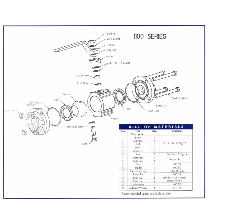
A repair kit containing the appropriate number of components is available for rebuilding each size
and configuration of valve. Be sure to specify the complete valve model number, and the TBV Inc.
sales order number that is stamped on the valve body, when ordering. Additional components, such
as balls, stems, etc. are also available for repair purposes. Refer to illustration for part
identification.

Page
4
of
6
OM
-
TBV
-
1100 Rev.04
-
05/07
AT ALL STAGES OF THE FOLLOWING DISASSEMBLY AND REASSEMBLY
PROCEDURES, CARE MUST BE TAKEN TO AVOID DAMAGE TO ALL SEALING
SURFACES.
1.
Before removing valve from line, make absolutely certain that line pressure is shut down, and
that the line is vented, to remove all pressure from the valve. Operate the valve to assure that
there is no pressure or media trapped within the valve body cavity. Flush the line as
appropr
iate to remove harmful chemicals that may be present.
2.
Remove the valve from the line. Be certain to fully decontaminate the valve, if it has been used
in services that have any degree of toxicity. Wear protective gloves and clothing as
appropriate to avoid contact with potentially harmful chemicals.
REBUILDING
1.
Stem flats should be in line with valve body before valve is removed from line.
2.
Remove body bolts and disassemble from line making sure to allow sufficient pipe and
clearance for center section rem
oval.
3.
Remove body seals from end plates.
4.
With stem flats rotated perpendicular to valve body, remove seats and ball.
5.
If it is necessary to replace the stem seal, remove handle nut, lockwasher, handle, packing nut,
stop, bellevilles, and follower in that order. Lower stem into body cavity and remove stem seal
assembly.
6.
Clean and inspect all components to be sure that they are free from foreign matter and pit
marks, paying particular attention to the areas that must maintain a seal (e.g., finished
diamete
r on stem, inside pipe end surface, ball, and bonnet hole). These areas must be free
from scratches and pitting.
7.
Once all components have been cleaned, inspected, and replaced as necessary, the valve can
be rebuilt using the factory repair kit provided.
8.
R
eassemble new stem seal/thrust bearing package (refer to illustration).
9.
Replace follower, belleville washer, stop, and stem seal adjusting nut. Loosely adjust stem
packing. Replace handle, lockwasher, and handle nut.
10.
Lightly lubricate ball and seats with a lubricant compatible with the media for which the
service is intended.
11.
Replace ball into cavity with stem flats in perpendicular position, making sure that the port
holes are in the desired position for operation. Once ball is engaged with stem, rotate
to in
-
line position. This will prevent the ball from falling out during assembly.
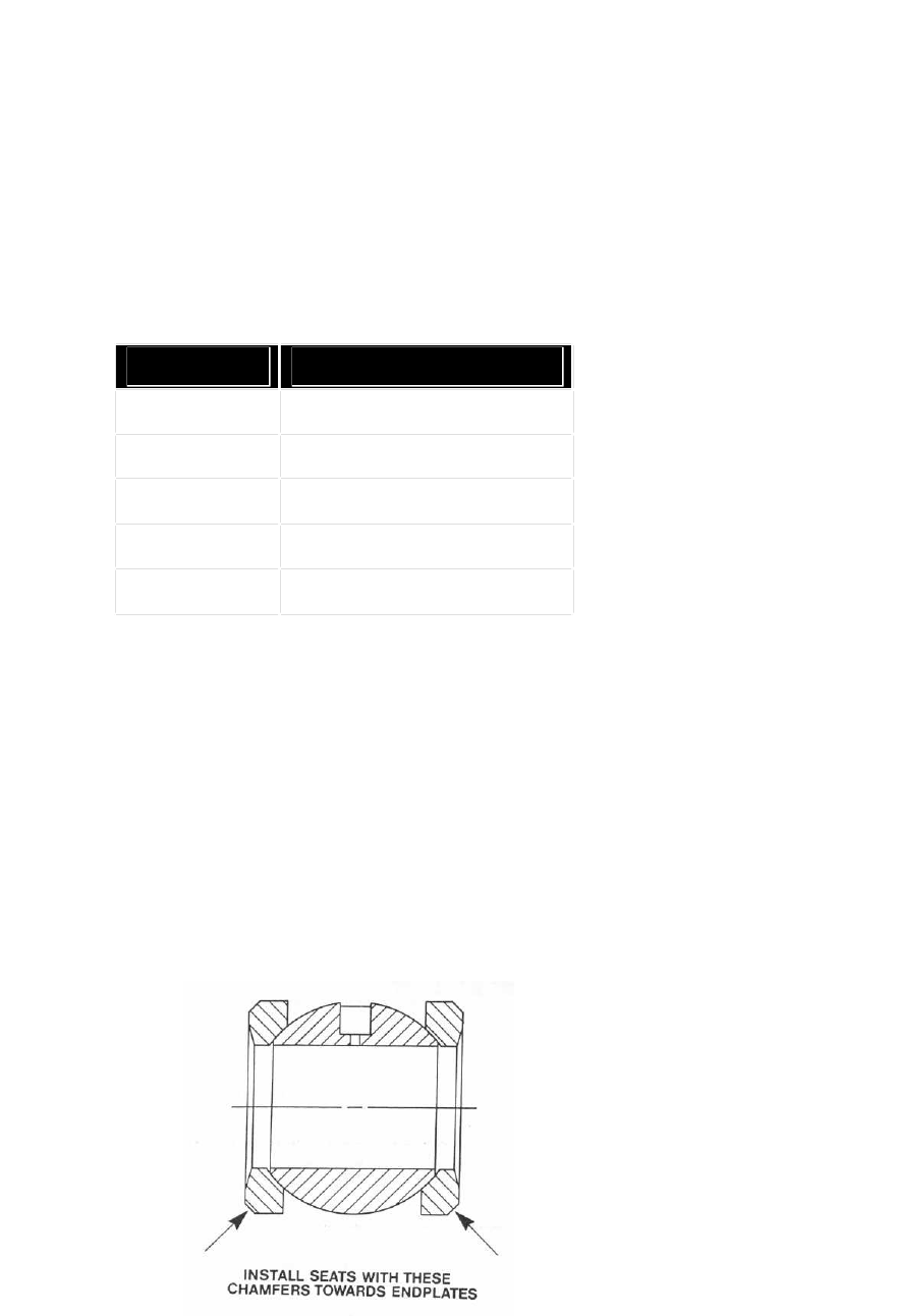
12.
Insert new seats into body and body seals on pipe ends.
13.
Assemble center section back into line again making sure that there is sufficient clearance to
avoid end plate sealing surface damage.
14.
Assemble body bolts and nuts to valve following steps 5 and 6 of the installation procedure.
Page
5
of
6
OM
-
TBV
-
1100 Rev.04
-
05/07
15.
Adjust stem packing as follows:
a.
Tighten packing nut firmly. The following approximate torque values are given as a
guide. It is recommended that the packing be compressed, relaxed, and then re
-
compressed to these same values. This has been found to provide optimum life for the
stem packing.
NOTE:
Pe
r
i
odic stem
packing
adjustment may be required depending on pressure and temperature
and number of cycles
. Refer to the recommended stem
nut
torque
chart located
belo
w
VALVE SIZE
STEM NUT TORQUE
1/2"
– 3/4"
80
-
100 inch
-
pounds
1"
140
-
180 inch
-
pounds
1 1/2“ –
2”
250
-
3
00 inch
-
pounds
3”
–
4”
75
-
95 foot
-
pounds
6”
–
8”
90
-
110 foot
-
pounds
b.
Cycle valve several times to assure smooth operation.
c.
It is recommended that the rebuilt valve be pressure tested prior to re
-
installation.
Perform seat and shell tests using media compatible with the service, checking for any
evidence of leakage. If necessary, adjust packing nut in 1/6
-
turn increments as necessary
to stop leakage. Do not over
-
tighten, as this will shorten the life of the packing. If there is
leakage at the flange joint due to body seal leakage, verify proper and consistent body
bolt torque. If leakage persists, check for proper installation of the body seals.
d.
Install valve in line following procedures described above.
16. Valve is now ready for service.
Page
6
of
6
OM
-
TBV
-
1100 Rev.04
-
05/07
