TC 810 950 Wpa_manual Wpa Manual
TC950 tc-950-wpa_manual
User Manual: tc-950-wpa_manual
Open the PDF directly: View PDF ![]() .
.
Page Count: 27

15

II
Dear customers,
Very pleased that you will purchase and use the tire changer produced by our company
We are the company with reputation of quality. We sincerely wish to produce quality
goods under the ISO9001Quaality system and get the EU CE certificate to help you
promote your business.
Carefully read this operational manual before installation and use this operation manual.
And also keep it with care for future reference.
WARNING
This instruction manual is the important part of the product. Please read it carefully and keep It properly.
This machine is only applied to mount, demount and inflate the tire in the specified scope and not for any other
purpose.
The manufacturer will not be responsible for the damage or injury caused for the operation not properly and out of
the range.
NOTE
This machine should be operated by the special trained qualified personnel. When operating, the unauthorized
personnel will be kept far away from the machine.
III
WARNING
This instruction manual is the important part of the product. Please read it carefully and keep It properly.
Use
This machine is only applied to mount, demount and inflate the tire in the specified scope and not for any other
purpose.
The manufacturer will not be responsible for the damage or injury caused for the operation not properly and out of
the range.
NOTE
This machine should be operated by the special trained qualified personnel. When operating, the unauthorized
personnel will be kept far away from the machine.
Please note the safety label stuck on the machine.
Operators should wear safety protective facilities such as working suit, protective glasses, eye plug and safety
shoes. Keep your hands and body from the movable parts as possible as you can. Necklace, bracelet and loosen
clothing may cause dangerous to the operators.
Tire changer should be installed and fixed on the flat and solid floor. The more than 0.5m of distance from the rear
and lateral side of the machine to
the wall can guarantee the perfect air flow and enough operation space.
Do not place the machine in the site of high temperature, high humidity, dust and with flammable and corrosion gas.
Without the permission from the manufacturer, any change on the machine parts will cause injury/damage to the
machine/operator.
Pay attention that the tire changer should be operated under the specified voltage and air pressure.
If you want to move the tire changer, you should under the guidance of the professional service personnel.
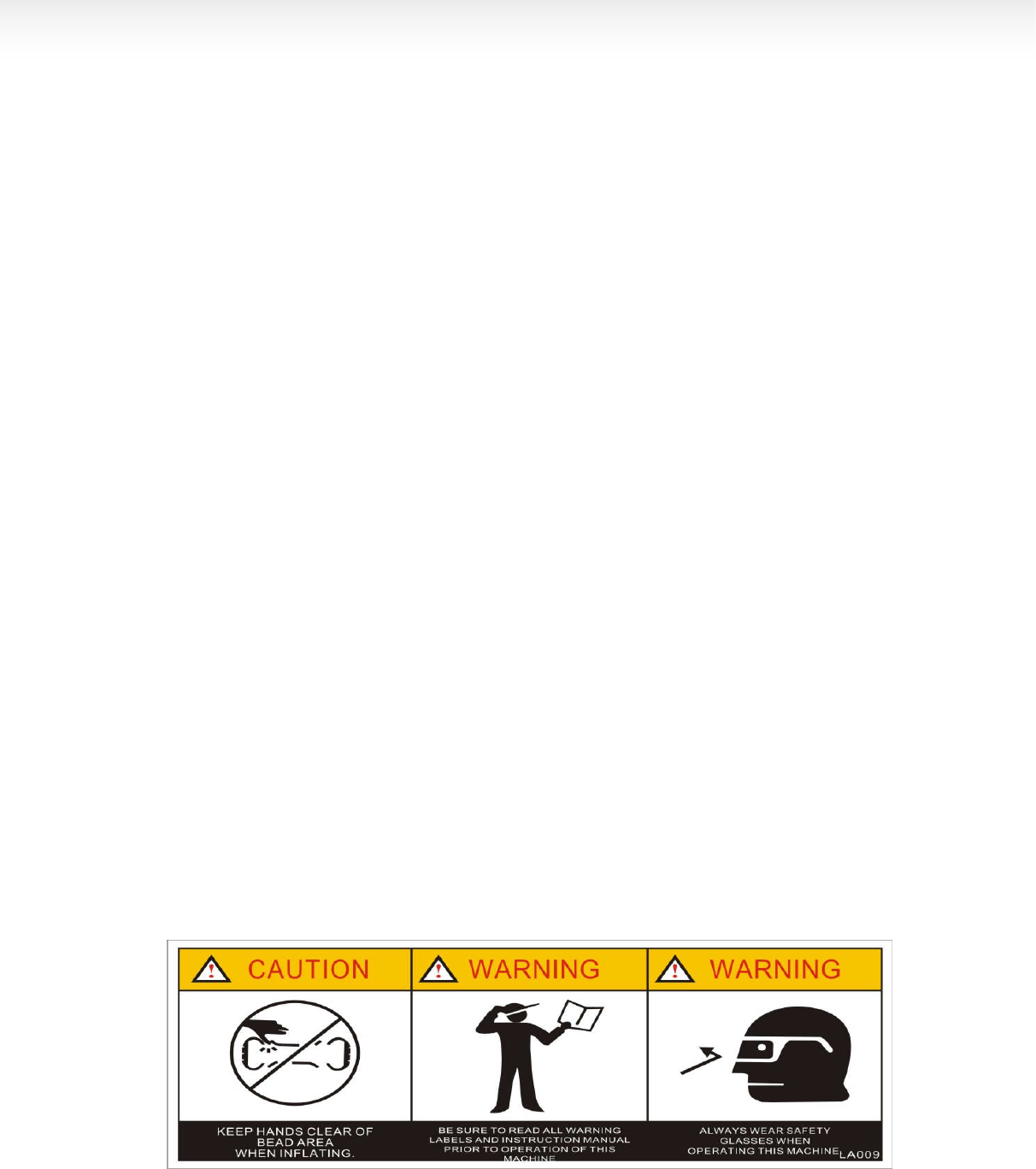
SAFTTY LABEL INSTRUCTION
Keep your hands far Carefully read operation When operation , wear
from tire when operation manual before operation the protective facilities
IV
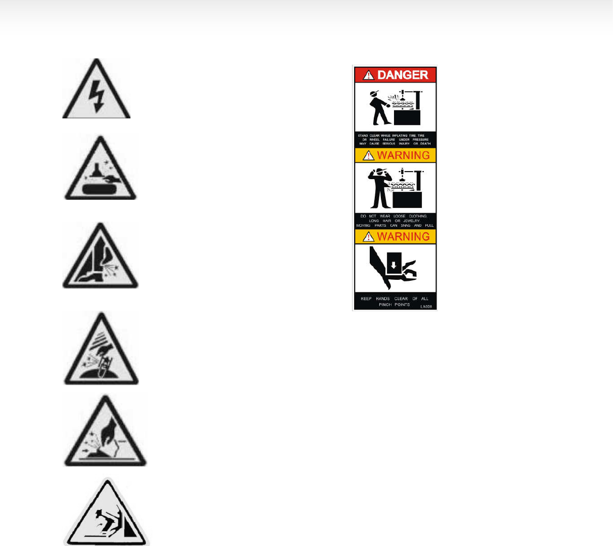
electrical shock!
When rapid inflation,
ensure the wheel
clamped.
Do not reach any part of your
body under the demount tool. When operation, do not
wear long hair, loosen
clothing and jewe
lries..
When breaking bead, the bead Breaking
blade will quickly move leftwards. When operation, do not
reach your hand under
the falling objects.
Note: when press the tire, the
opened clamp cylinder may
injury the hand of the operator.
Remember, do not touch the side
wall of the tire.
When clamping the rim, do not
Reach your hand or other parts
Of the body in between the clamp
& the rim.
Do not stand behind the column to
Avoid the column from injuring the
persons when swing.
SAFETY LABEL POSITION DIAGRAM
Pay attention to keep the safety labels complete. When it is not clear of missing, you should change the new label.
You should let the operators see the safety labels clearly and understand the meaning of the label.
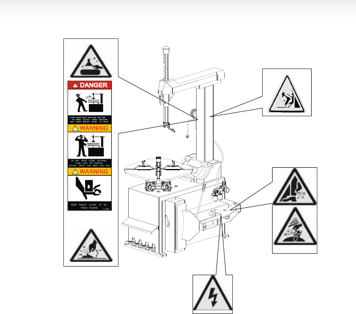
V

VI
CONTENT
CHAPTER Ⅰ
ⅠⅠ
Ⅰ BRIEF INTRODUCTION--------------------------------------------------------------------------------------------------1
1.1BRIEF INTRODUCTION------------------------------------------------------------------------------------------------------------------1
1.2EQUIPMENT OVERALL DIMENSION (EXCLUDING THE ASSSISTANT) --------------------------------------------------1
1.3 TECHNICAL PARAMETER-------------------------------------------------------------------------------------------------------------1
1.4 APPLICATION SCOPE-------------------------------------------------------------------------------------------------------------------1
1.5ENVIRONMENT REQUIREMENT-----------------------------------------------------------------------------------------------------1
CHAPTER Ⅱ
ⅡⅡ
Ⅱ CONFIGERATION AND OPERATION-------------------------------------------------------------------------------2
CHAPTER Ⅲ
ⅢⅢ
Ⅲ INSTALLATION AND CALIBRATION--------------------------------------------------------------------------------2
3.1 OPEN PACKAGE CARTON-------------------------------------------------------------------------------------------------------------3
3.2 INSTALLATION OF THE COLUMN---------------------------------------------------------------------------------------------------3
3.3AIR SOURCE INSTALLATION---------------------------------------------------------------------------------------------------------4
CHAPTER Ⅳ
ⅣⅣ
Ⅳ DEMOUNT AND MOUNT TIRE----------------------------------------------------------------------------------------6
4.1 DEMOUNT TIRE---------------------------------------------------------------------------------------------------------------------------6
4.2 MOUNT TIRE-------------------------------------------------------------------------------------------------------------------------------7
4.3 INFLATION----------------------------------------------------------------------------------------------------------------------------------7
4.4RAPID INFLATION-------------------------------------------------------------------------------------------------------------------------8
CHAPTER Ⅴ
ⅤⅤ
Ⅴ MAINTANENCE AND REPAIR-----------------------------------------------------------------------------------------8
CHAPTERVI
INSTALLATION & OPERATION OF THE ASSISTANT ARM------------------------------------------------10
6.1 LEFT ASSISTANT INSTALLATION ------------------------------------------------------------------------------------------------10
6.2 RIGHT ASSISTANT INSTALLATION-----------------------------------------------------------------------------------------------12
CHAPTER Ⅶ
ⅦⅦ
ⅦTRANSPORTATION------------------------------------------------------------------------------------------------------13
CHAPTER Ⅷ
ⅧⅧ
Ⅷ
ELECTCTRICAL AND PENUMATIC DRAWING---------------------------------------------------------------14
CHAPTER IX GENERAL TROUBLESHOOTING AND SOLUTION------------------------------------------------------------20
15
CHAPTER Ⅰ
ⅠⅠ
Ⅰ BRIEF INTRODUCTION
1.1BRIEF INTRODUCTION
This series of equipment is the tire changer with fixed
column and rocker arm tire changer. It is suitable to
mount, demount and inflate all types of motorcycle tire
with tube & tubeless. The operation is easy, convenient,
safety and reliable. It is the necessary equipment for
the auto service shop and tire shop.
This series of machine can be divided into 4models.
They are LC890,LC850,LC800 (cylindrical column)
and LC112/lc810(square column)
The corresponding models with the quick inflation
function are:GT890,GT850,GT800(cylindrical column).
Among them LC890 and GT890 and be equipped with
the assistant to adapt to demount and mount the low
profile and stiff tires.
1.2EQUIPMENT OVERALL DIMENSION
(
((
(EXCLUDING THE ASSSISTANT)
1.3 TECHNICAL PARAMETER
Operation pressure:8-10bar
motor:50Hz 380V 0.75Kw (standard) 50Hz/60Hz
220V/110V 1.1Kw(optional)
turntable speed:6rpm
noise:<70dB(A)
1.4 APPLICATION SCOPE
(LC800 has adopted the enlargement of the
movement base and clamp diameter for demount and
mount the motorcycle tire.
1.5ENVIRONMENT REQUIREMENT
ambient temperature 0℃~45℃
relative humidity 30~95%
sea level max.1000M
without dust and flammable and explosive gas
The operation space around the machine wills not
smaller than the indicated
in FIG1
If the machine is installed outdoors, you must
have the protective sheds to
protect the rain and sun.It is forbidden to use in
the site with the flammable gas!
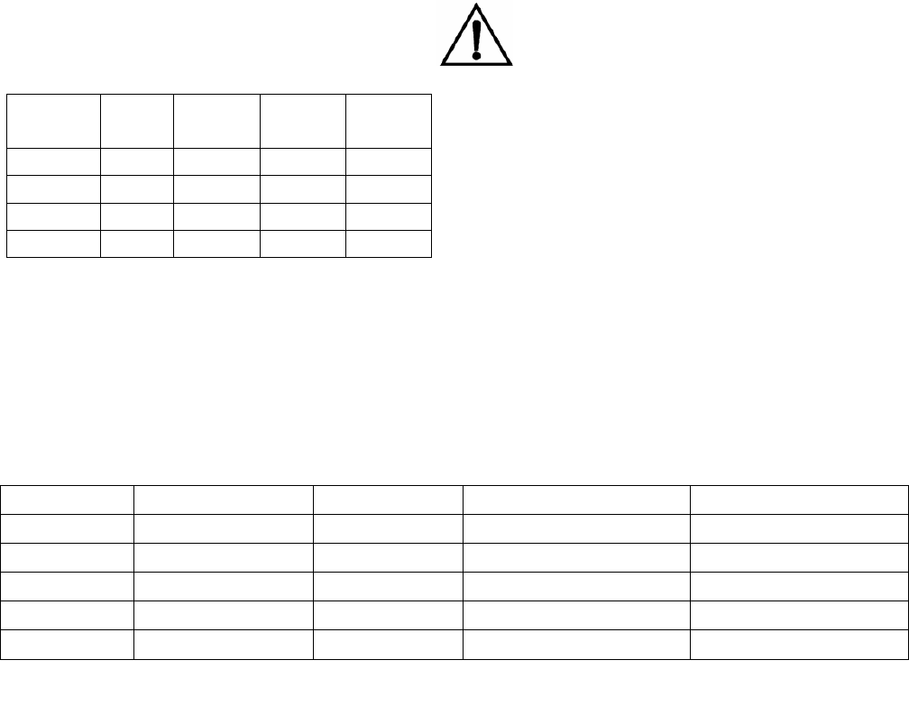
model height
(mm)
length
(mm)
width(mm) Net weight
kg
LC(GT) 890 2040 1135 870 223/233
LC(GT) 850 1820 985 780 200/210
LC(GT) 800 1858 975 895 210/220
LC112/810 1815 965 795 190
model Max. wheel diameter Max. wheel width rim diameter(outer clamp)
rim diameter(inner clamp)
LC890(GT) 1250mm(49″) 400mm(16″) 10″~20″ 12″~23″
LC850(GT) 960mm(37″) 305mm(12″) 10″~18″ 12″~21″
LC800 960mm(37″) 305mm(12″) 8″~20″ 10″~22″
GT800 960mm(37″) 305mm(12″) 10″~20″ 12″~23″
LC112/810 960mm(37″) 305mm(12″) 10″~18″ 12″~21″
2
CHAPTER Ⅱ
ⅡⅡ
Ⅱ CONFIGERATION
AND OPERATION
图
图图
图 2
22
2
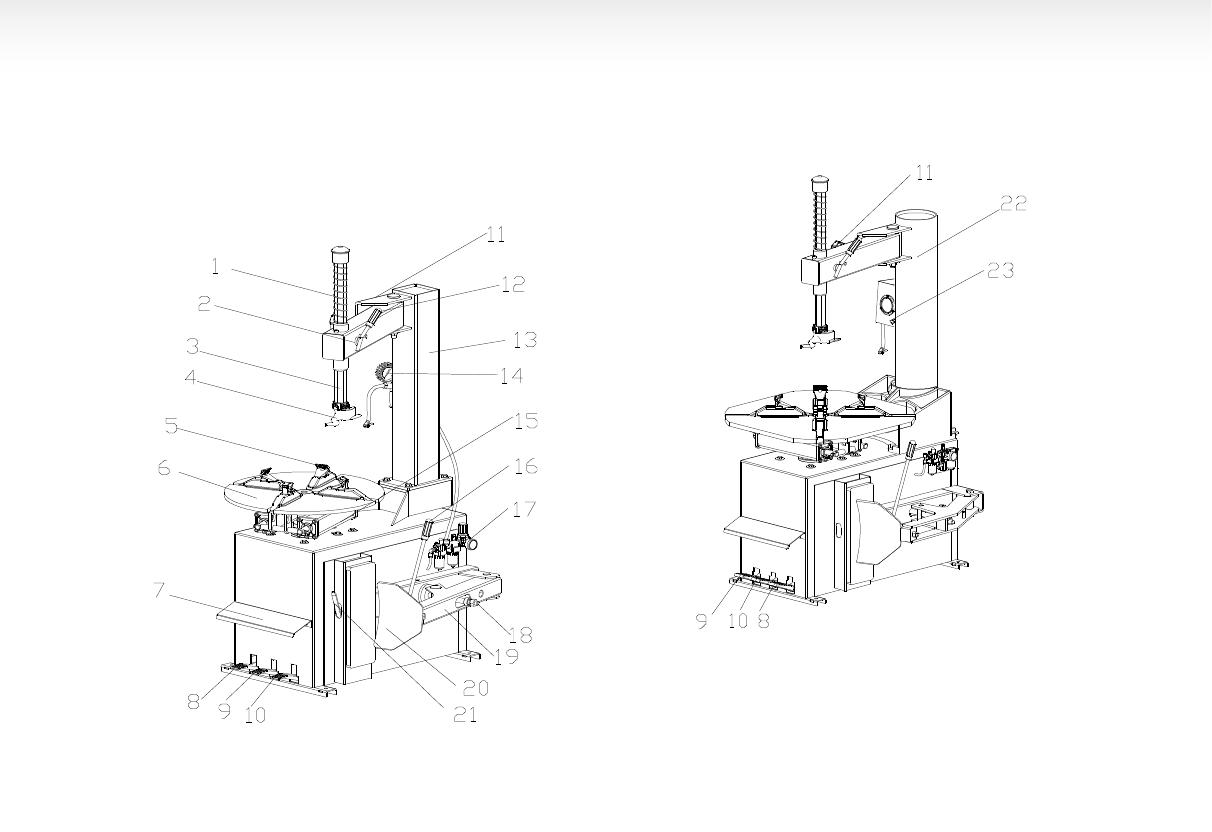
1
-vertical shaft spring
2
– rocker valve
3
- hexagon shaft
4
- demount head
5
- claw
6
- tumtable
7
-operation lable
8
- tumtable pedal
9
- clamp pedal
10
- tire press pedal
11
- limit handle
12
- lock handlel
13
- column
14
- inflation gun
15
-clamp cylinder
16
- blade handle
17
- air source fitting
18
–bead breaking
cylinder
19- tire press arm 20 -bead breaking
blade
21 –crowbar 22- air tank
23 –inflation gauge box
CHAPTER Ⅲ
ⅢⅢ
Ⅲ INSTALLATION AND
CALIBRATION
Before installation and debug, carefully read this
manual. The unauthorized change on the parts and
spare parts of the machine will cause the damage on
the machine.
Installation and debug personnel should have the
specific electrical knowledge.
Operators must be trained and authorized.
Before installation, carefully read the equipment list. If
any question, please contact with the dealers or our
company.
To ensure the success of the installation and debug,
please prepare the following common tools:
FIG
2
FIG 3
3
Two wrenches(10″), one socket wrenches, one
hexangular wrench, one tung and one screw driver.
One hammer and one multi-purpose meter
3.1DEPACKAGE
3.1.1 According to the de-package instruction on the
package box, to detach the box and remove the
package material to check if the machine damage or
not and if the spare parts completed.
3.1.2Keep the package material far away from the
working site and deal with it properly.
3.2 INSTALLATION
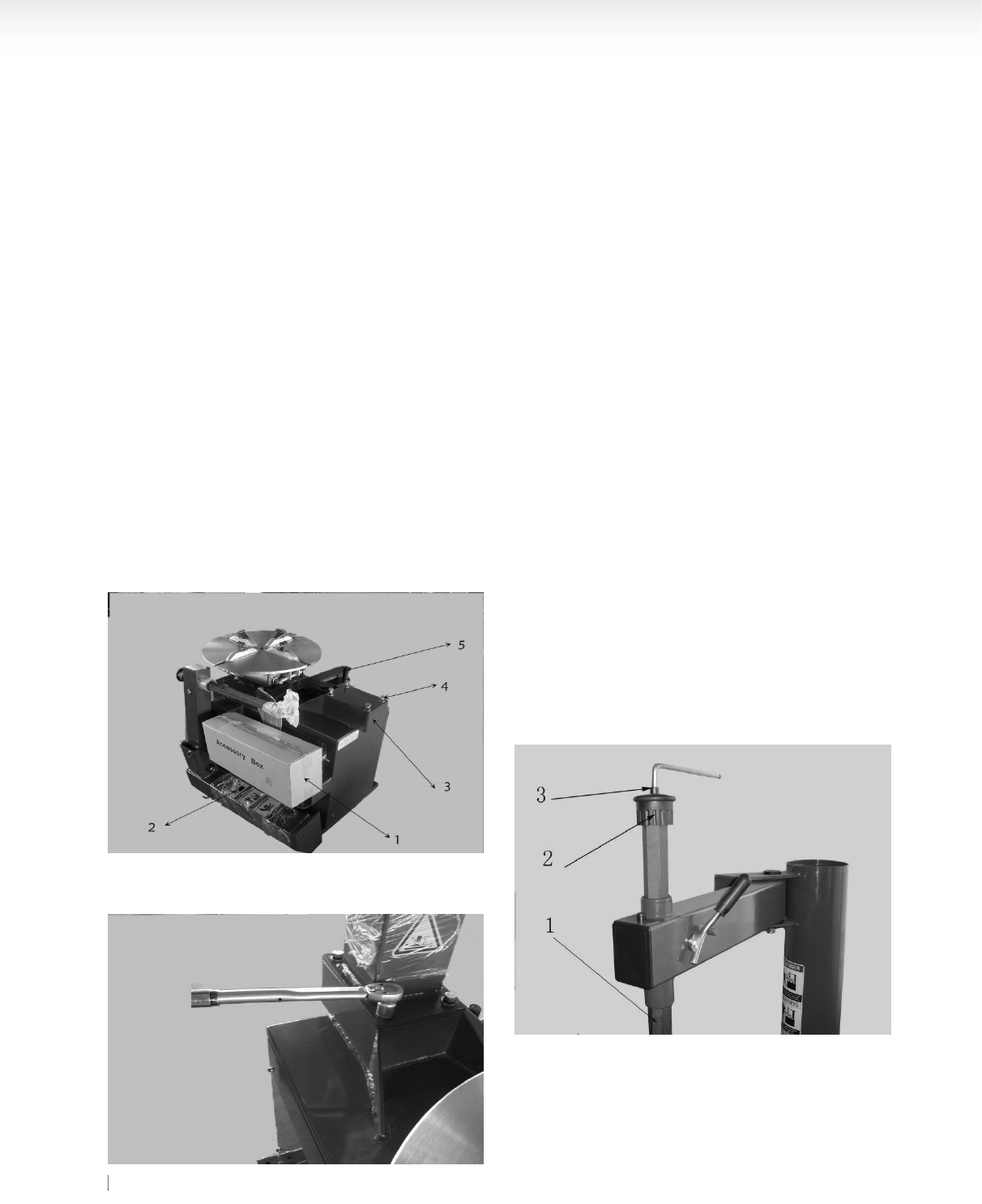
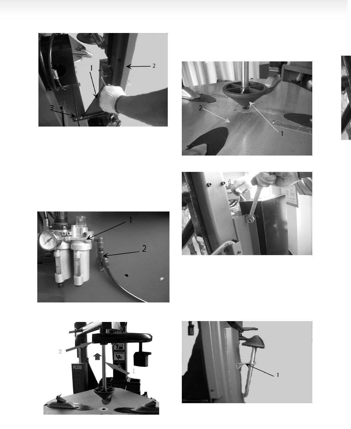
3.2.1After un-package the package carton, take out
accessory boxes(FIG 4-1),bead breaking arm(FIG
4-5)and column assembly(FIG 4-2). And position the
body according to the FIG1.4. Remove the bolt(FIG
4-4), elastic washer and plate washer on the body.
3.2.2 Place the column on the body. The direction of
the warning label is forwards. Make the holes on the
column base plate align to thread holes on the body.
Once again assemble the removed the bolt(3.2.1),
elastic washer and plate washer and plate washer
removed in 3.2.1The torque is 70 N·M(FIG5)Use
torsion wrench to tight.
3.2.3 Use the wrench to remove the screw(FIG 6-3)
hexangular shaft(FIG6-1)and take off the vertical shaft
cap( FIG 6-2). When remove the screw on the vertical
shaft cap, you need use the lock handle to lock the
hexangular shaft to avoid sliding off to damage the
machine or injury personnel!
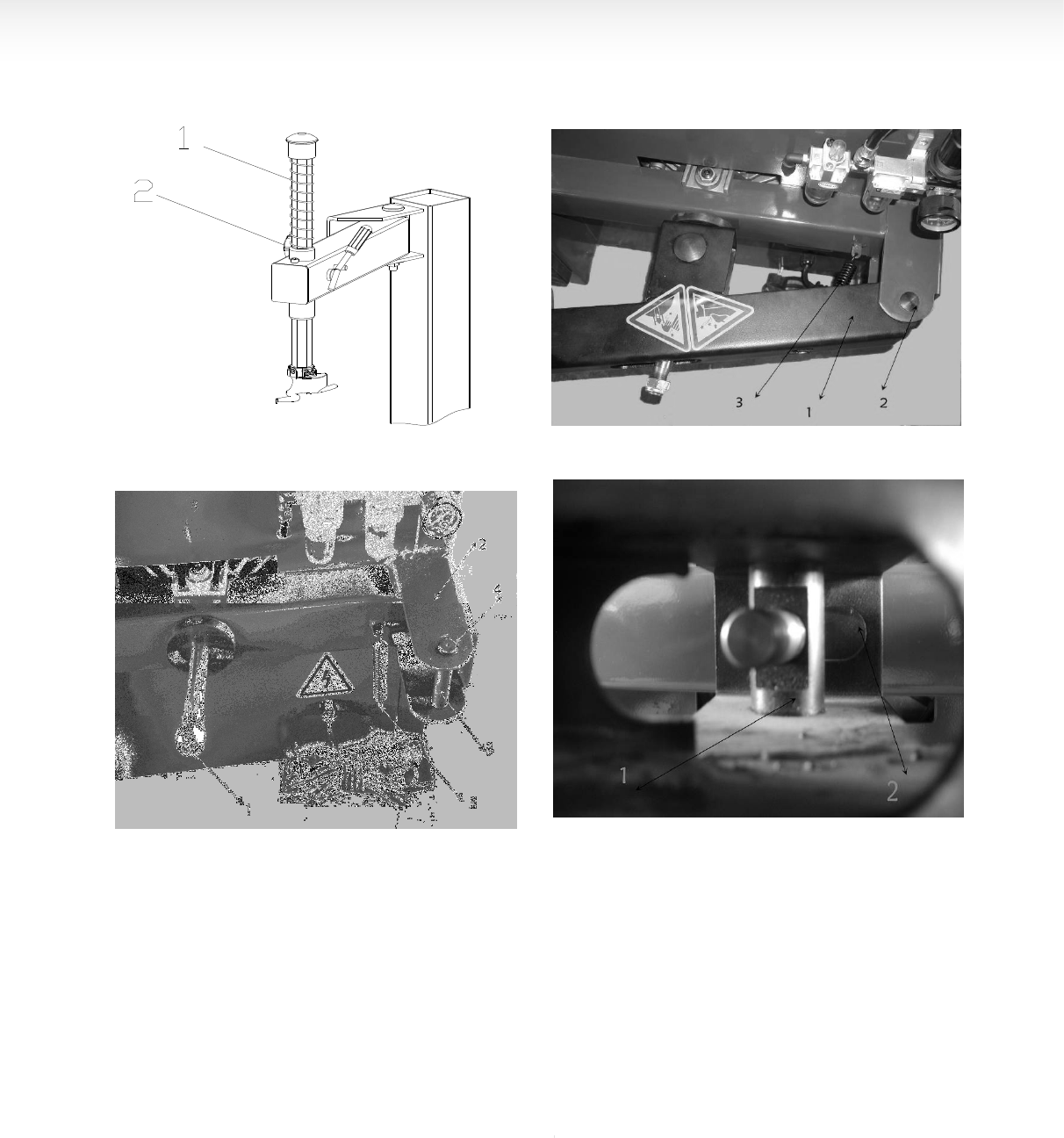
Install the vertical shaft spring(FIG7-1)on the vertical
shaft. Mount the vertical shaft cap and mount the
removed screw and assemble the hand wheel into the
nut bushing of the rocker arm(FIG 7-2)。
3.2.4Remove the lock nut at the front end of the bead
breaking cylinder piston rod(FIG 8-1)and use the
wrench to remove the nut on the bead breaking arm
bolt(FIG8-4) Remove the bolt(FIG8-3)and hang the
spring(FIG8-2)
FIG 4
FIG 5
FIG 6
4
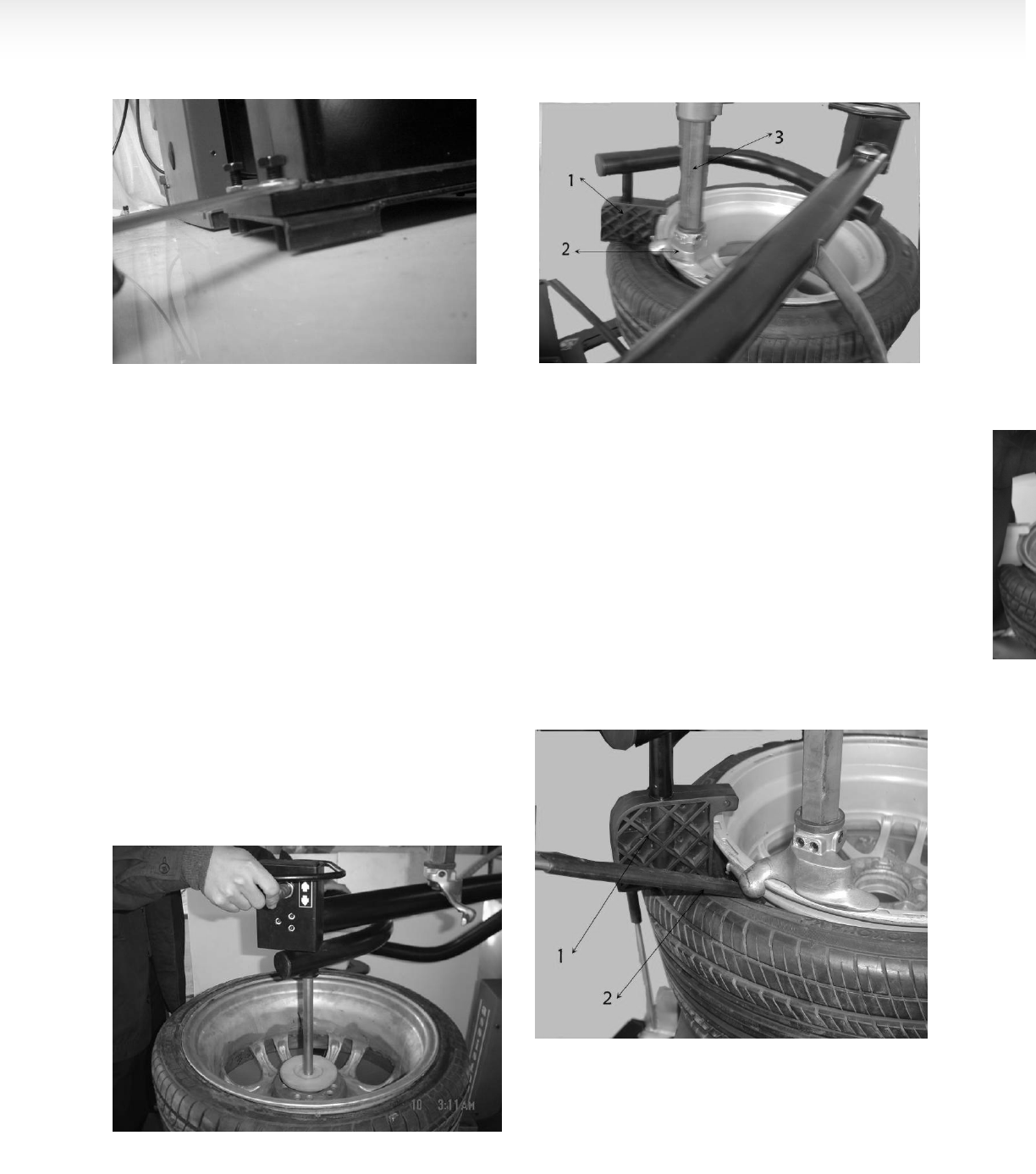
3.2.5Position the bead breaking arm shaft bushing into
the bead breaking support plate on the body(FIG 9-1)
to align the hole and install the bead breaking bolt(FIG
9-2)and assemble the nut to lock(FIG 8-4). Insert the
piston rod(FIG10-2)through the hole of the bead
breaking slide bushing(FIG10-1). The surface of the
slide bushing should be outwards(FIG 10). Assemble
the removed nut(FIG 8-1)into the front end of the
piston rod. The nut will be assembled. The distance
from the edge of the bead breaking blade to the bead
breaking rubber is 30~40mm(FIG11). Hang the spring.
(FIG9-3)。
Note:If the machine is the one with the quick inflation,
please open the side panel and insert 2 pieces of
Ø12pu hose
at the inlet of the quick deflation valve into the 2
Ø12nozzle and then install the side panel.
3.2.6 If being equipped with the tool box, you must fix
firmly and the column completely installed.
3.3 AIR SOURCE FITTING INSTALLATION:
::
:
When the machine out of the factory, the air source
fitting has been detached and placed in the accessory
box and the fitting will be installed when it is in the site
of the customers again.
FIG 7
FIG 8
FIG 9
FIG 10
5
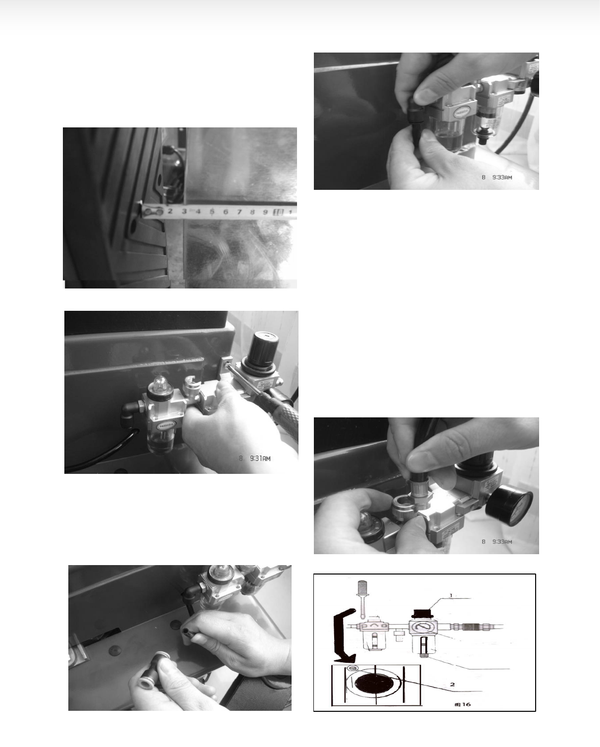
3.3.1Take out the air source fitting out from the
accessory box and the screw and remove the oil and
dust. Use the screw to fix it on the right side of the body
(fig12)。
3.3.2 Connect the air hose. Detach the adapter on the
ø8 PU hose on the side wall of the body and insert it
into the elbow. See the fig13/14. And the adapter is to
keep the hose from sliding into the body.
3.3.3Connect the inflation gun or inflation gauge box:
Inlay the adapter of the inflation gun or inflation gauge
box into the groove(fig15) on the open nut on the air
source fitting. Tight the open nut and then connect the
air source.
3.3.4 Air source has been adjusted before ex-factory. If
it needs change, adjust again:Pressure: Lift up the
pressure adjustable button( FIG16-1 )and twist
clockwise and the air pressure will increase. Meanwhile,
if counterclockwise, the air pressure will decrease.
Oil Feed:
::
:Use screw driver to twist the screw(FIG16-2).
If clockwise, the oil dropping speed will slow. If
counterclockwise, it will become fast.
FIG 11
FIG 12
FIG 13
FIG 15
FIG 14
FIG 16
6
CHAPTER DEMOUNT AND
MOUNT TIRE
4.1 DEMOUNT TIRE
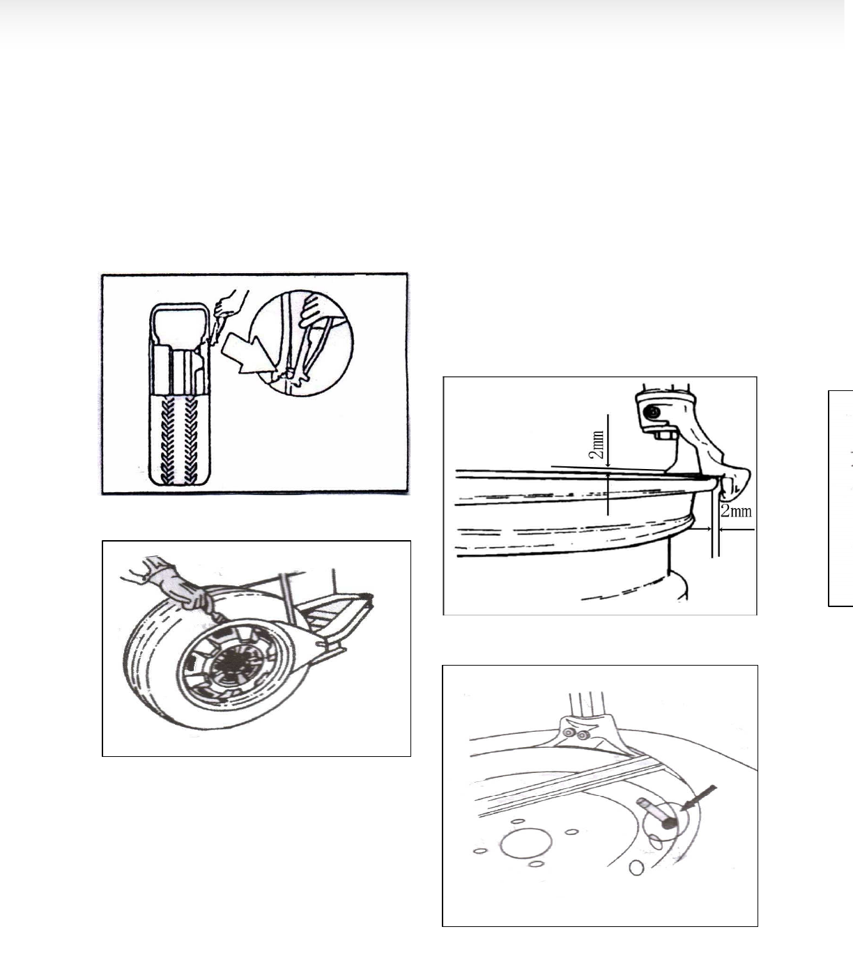
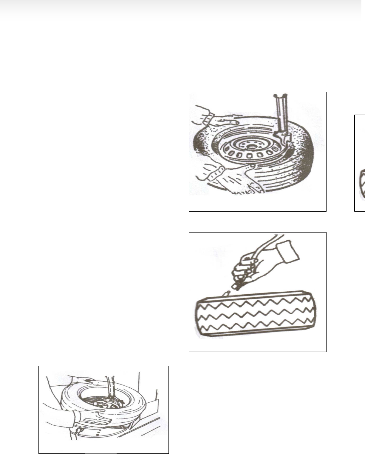
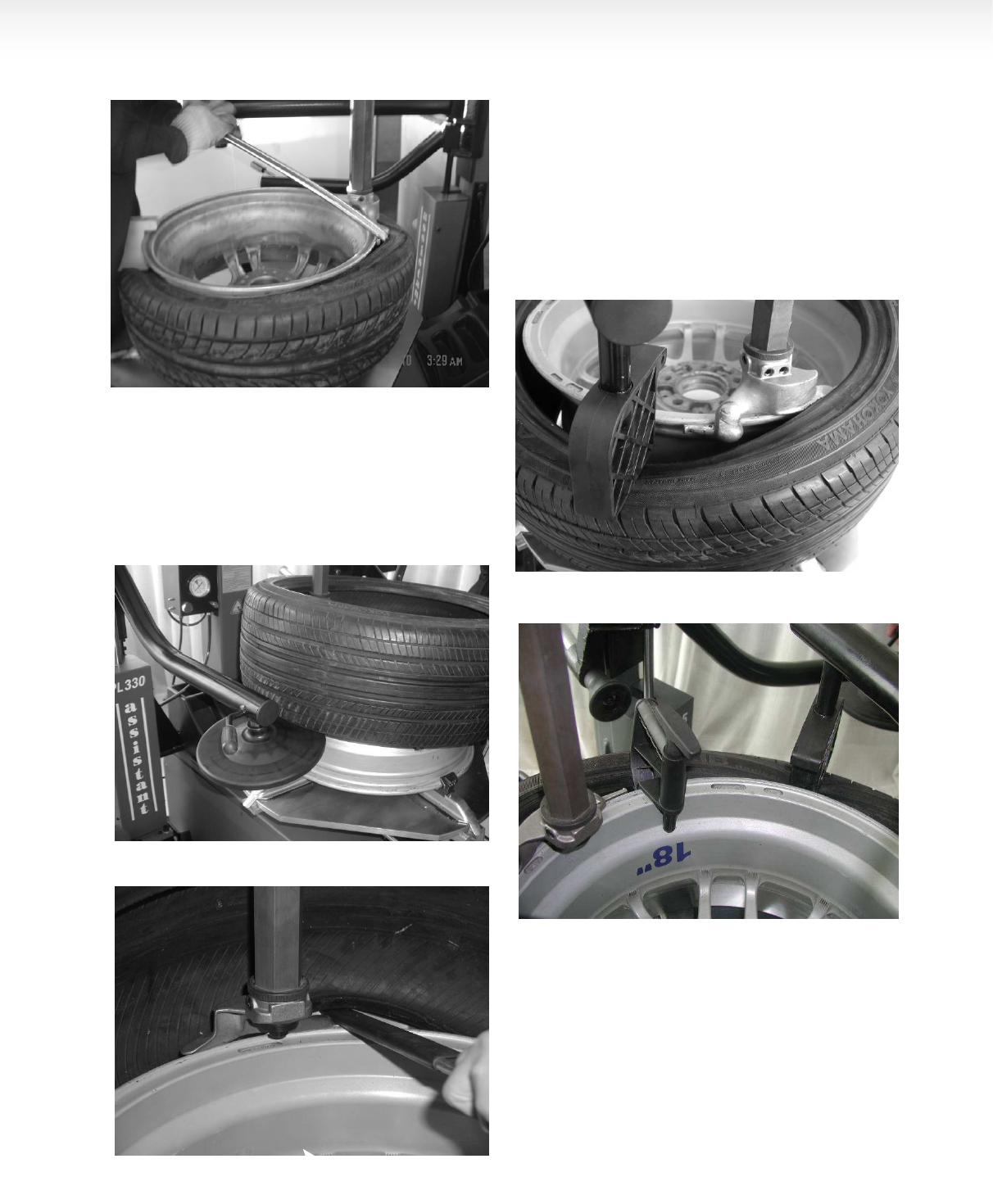
4.1.1 Deflate the air in the tire completely and pull out
the core. Use the special tool to detach the weight on
the rim ( FIG17).
4.1.2 Place the tire between then bead breaking blade
and tire pressing runner clog.(fig18) Then step down
the tire press pedal to detach the rim from the
tire(fig2-10 or 3-10). Repeat the same operation on the
other parts of the tire to make the tire completely
detached from the rim. Place the wheel with the tire
detached from the rim on the turntable and step the
clamp pedal(fig2-9; 3-9) to clamp the rim. You can
select the outer clamp and inner clamp to clamp the
wheel according to the different rim. To detach the lip
smoothly, you can use the brush to spread the lubricant
or thick soap liquid between the lip and rim.
4.1.3Position the hexangular shaft (FIG 2-3) to the
working position to make the demount tool close to the
rim of the wheel. And use the hand wheel (FIG 7-2) to
push against the rocker arm and then use the lock
handle( FIG 2-12) to lock. The demount tool will
automatically move a little of gap (FIG19).
The angle of the demount tool has been calibrated
according to the standard rim (13"). If handling the
extra-big or extra-small rim, you can reposition.
FIG 20
FIG 17
FIG 18
FIG 19
FIG 20
7
4.1.4 Use the crowbar to detach until the lip to the
hump of the demount tool (FIG20). Step the turntable
rotation pedal(FIG2-8)to rotate the turntable clockwise
until the entire lip completely detached. If handling the
tube tire, to avoid the damage on the tube, you should
keep the nozzle of the tire 10cm from the right side of
the demount tool when demounting.
If the demount of the tire is jammed, please stop the
machine immediately and then lift up the pedal to let
the turntable rotate counterclockwise to remove the
resistance!
4.1.5 When handling the tube tire, Take out the tube
and then move the lower lip upwards to the upper edge
of the rim and then repeat the above steps to detach
the other lip .
In the process of demounting tire, you should keep your
hands and the other parts of your body from the
movable parts. Necklace, bracelet and the loose
clothing can injury personnel!
4.2 MOUNT TIRE:
::
:
Before mount tire, check if the tire and rim are of the
same dimension!
4.2.1 Clean the dirt and rust on the rim and lock it on
the chuck. Lock the rim on the turntable.
4.2.2 Spread the lubrication liquid or soap liquid around
the lip. Tilt the tire against the rim and keep the front
end upwards. Press down the hexangular shaft to
move the demount arm to contact with the rim and lock.
The left lip above the tail of the demount tool and the
right lip will be positioned under the front end of the
demount tool (FIG 21),Clockwise rotate the turntable to
guide the bottom lip into the tire detaching slot.
4.2.3If there is tube, place it in the tire and plug the core.
And assemble the lip according to the above mentioned
step(FIG22). In the process of clamping the rim, do not
reach your hands in between the rim and the claw to
avoid the damage to the personnel.
4.3 INFLATION:
::
:
When inflating the tire, please be carefully and series
obey the operation process. Check the air route to see
if the air connection is OK. This machine is equipped
with an inflation gauge for monitoring the inflation of the
tire and the inflation pressure(FIG22).
FIG 23
FIG 22
FIG 23
FIG 21

8
1. Loose the tire from the turntable.
2. Connect the inflation hose with the tire air core. See
FIG23.
3. In the process of inflation, you should repeat
switching the inflation gun to confirm the pressure
indicated on the pressure gauge not exceed the scope
specified by the manufacturer. The pressure decrease
valve equipped in the machine make the pressure not
to exceed 3.5bar. And the customer can get different
inflation pressure by adjust the pressure decrease
valve according to the requirement.
4. If the inflation pressures too high, you can press
down the deflation press button on the inflation device
to reach the required air pressure.
4.4 Rapid Inflation(only for the machines with GT)
If the tubeless tire fit to the tire not tight, you can apply
the rapid inflation first and then common inflation:
1. Clamp the wheel and connect the inflation hose.
2. Step down the inflation pedal to the bottom position
(second gear) and quickly release the pedal when the
tire is full to the position of the first gear
3. Repeat stepping the pedal for many times to confirm
the pressure indicated on the pressure gauge not
exceeds the pressure specified
by the manufacturer.
Note:In this process, you should ensure the
wheel has been tightly clamped. Or you will
be in the dangerous of lose your life.
Warning!Explosive!
When inflating, please obey the following instructions:
*Carefully check if the tire and the rim are of the same
dimension and check the wear condition of the tire to
confirm the tire not damaged before inflation.
* When the air pressure needed for inflation relatively
high, you can take off the tire and to inflate under the
protective cover.
* When inflating the tire, please be carefully. Keep your
hands and body away from the tire.
Chapter V MAINTANENCE &
REPAIR
NOTE:
Only the qualified professional personnel can execute
the maintenance. Beforeany maintenance, Cut off the
power .And ensure the maintenance personnel can
take charge of the power plug. Meanwhile, cut off the
air supply and push the air supply switch to the off
position and completely deflate the residual air in the
machine. To correctly use the tire changer and prolong
its working life, it is necessary to periodically
maintenance and repair according to the instruction
manual. Or the running and reliability of the machine
will be affected and the personnel near the machine or
the operator will be injured.
The following position should be monthly maintenance:
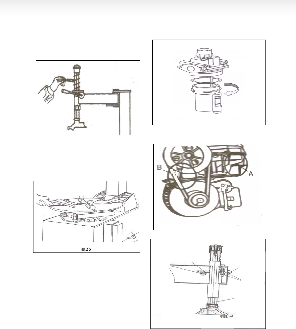
Keep the machine and working area clean.
Use the diesel oil to clean the hexangular shaft
(FIG24),Use the machine oil to lubricate.
Use the diesel oil to clean the turntable claw and its
guide and use the lithium base oil to lubricate (FIG25),
Periodically check the lubrication oil level in the oil fog
device. If the oil level lower than the oil scale, please
feed in the SAE30 lubrication oil in time(FIG 26)
Periodically drain out the water and impurity in the oil
water separator.
Periodically check and adjust the tension of the driven
belt. Properly adjust the adjust nut in A and B to realize
the proper tension.(FIG27).
9
Check all the connect parts and tight the loosen bolt.
HEXANGULAR SHAFT & LOCK PLATE LOCK GAP
ADJUSTMENT
When press downward the hexangular lock handle, the
hexangular shaft will vertically slide under the effect of
the weight of the hexangular shaft and return spring.
When the lock handle rotate clockwise for about 100
degree, the cam connected to the handle will push up
the lock plate to lock the hexangular shaft. If you can
not realize this situation, you can reach the target to
lock the hexangular shaft through adjusting the position
of the screws and nuts.(FIG 28)
FIG 24
FIG 25
FIG 26
FIG 27
FIG 28
LOCK
PLATE
CAM
HEX
SHAFT
ADJUST
NUT
LOCK
HANDLE
10
CHAPTERVI
INSTALLATION &
OPERATION OF THE ASSISTANT
ARM
6.1INSTALL THE LEFT ASSISTANT
6.1.1 PL330 left assistant can be equipped on the tire
changer which can handle the tire with the diameter of
20″ to help complete the demount on the stiff and low
profile tire. We can use it to handle the work which if
difficult and impossible to do only by the operators.
Before installation, the power and air source
must be cut off!
6.1.1 The left and right side of the base plate of body of
the tire changer which can handle the tire with the
diameter of more than 20″ all have the installation hole
for the left assistant prepared. Before installation, you
can remove the side panel and take off the installation
rubber plug. If there being the tool box, you should
detach the tool box.
6.1.2 Detach the package of the PL330assistant.
Check the accessory according to the pack list. After
confirmation, takeout the base assembly(fig29) and
install the screw and washer on it.
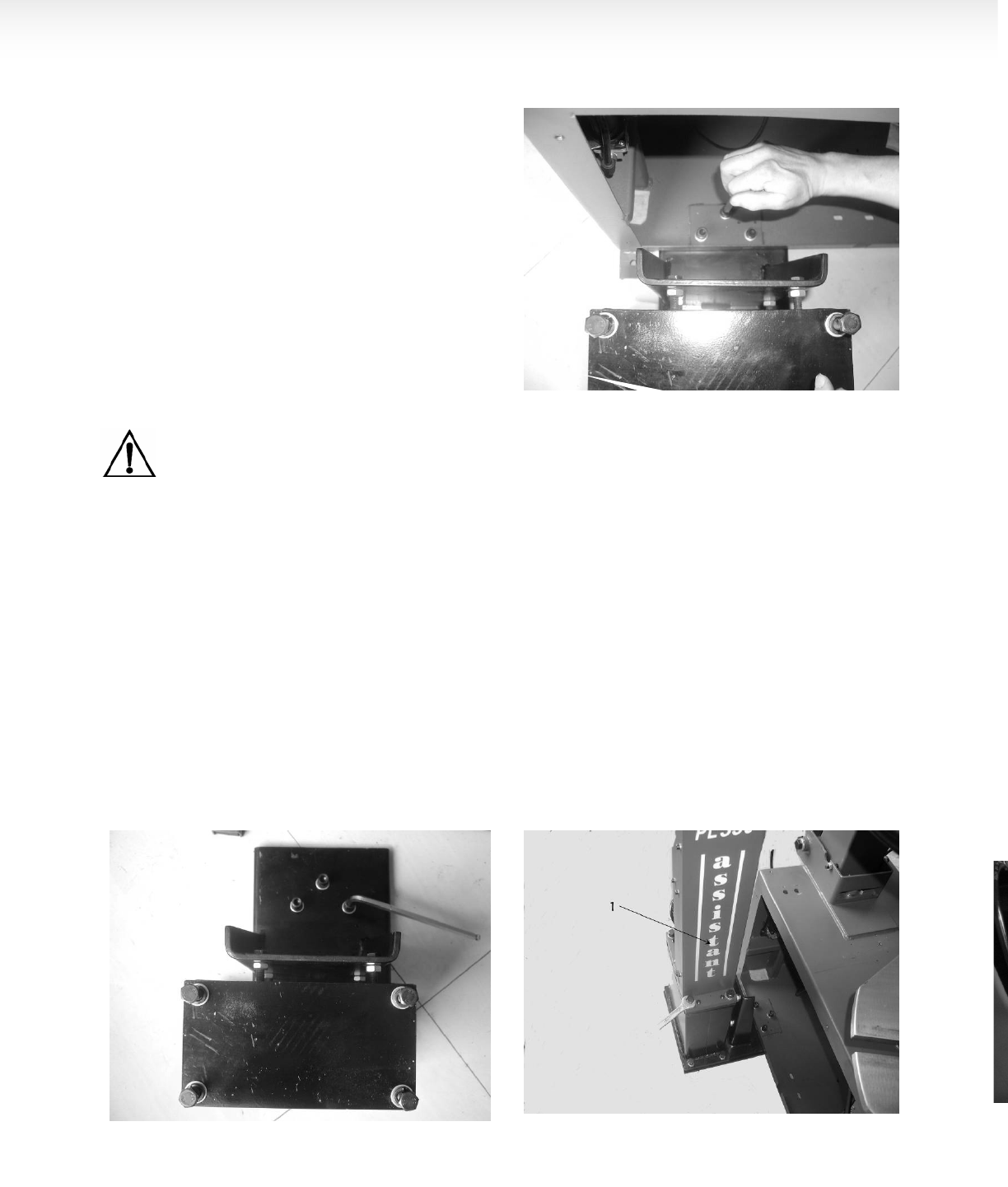
6.1.3 Push the platform of the base plate of the base
assembly into the body through base plate on the
left-back side of the body. Align the thread hole to the
reinforce hole and use the bolt and washer to fix.
(fig30).
6.1.4 Install the body bracket(fig31-1)on the seat
assembly. Align. Use the screw removed before to fix
and not tighten
6.1.5 Use the fix supporting bracket(fig32)to connect
the body bracket and the body and insert the screw to
fix.
6.1.6Connect the air source hose(fig33-2)and use Y
Tee to connect the outlet hose and the other end
connect with the inlet of the assistant pressure
adjusting valve.
FIG 32
FIG 29
FIG 30
FIG 31
11
6.1.7 Connect the air source, insert the press cone
roller connect rod (fig34-1 )into the rotation shaft
hole(fig 34-2) of the rotation arm. Handle manual
direction change valve to make the tip of the press
cone roller coincide to the center of the turntable(fig35).
If not coincide, use the screw to adjust the position of
the base to realize the coincide. After adjustment, fix
the bolt.
6.1.8According to the fig36, fix the fix bracket on the
body and fixes the tool box on the fix bracket and then
use the lock nut to tight.
6.1.9 As fig37, fix the cone support on the body bracket
and install the press cone on the bracket.
6.1.10Loose the nut below the base and turn the screw
clockwise until it against the ground and tight(fig38)
and install The side panel and tool box removed in the
FIG 36
FIG 32
FIG 33
FIG 35
FIG 36
FIG 37
FIG 34
12
6.1.1. At this moment, the installation of the left
assistant completed.
6.2INSTALL THE RIGHT ASSISTANT
6.2.1After detach the tire from the rim according to the
instruction of the chapter IV, we can execute the
following operations.
6.2.2 First, position the claw according to the dimension
of the tire and then clamp the rim by the claw and
position the tire press cone roller at the center of the
rim(fig39). Push down the manual valve to press down
the rim until the external rim of the rim is lower than the
surface of the claw. At this moment, you can
immediately lock the rim. Lift up the support arm and
place it at the working position and take off the press
cone roller and place it on the support.
6.2.3 Use the press(fig40-1)to press down the tire
section by section rim detached from the mouth and
use the brush to spread the lubricant on edge of the lip.
Position the demount tool(fig40-2 )in the demount
position. Place the press beside of the demount tool to
press down the lip and insert the crowbar below the
demount tool in between the rim and lip(fig41),Lift up
the press and move it to the position opposite to the
demount tool and press the lip into the tire detach
groove and then rotate the crowbar to lift the lip onto
the demount tool(fig42). Rotate the turntable to detach
the upper lip.
FIG 42
FIG 38
FIG 39
FIG 40
FIG 41
13
6.2.4 DETACH THE LOWER LIP: Use the disk to lift up
the bottom of the tire from the bottom of the mouth
(fig48) and detach the lower lip (fig43) according to
the step(4.1.5).
6.2.5 MOUNT TIRE
First, according to the step(4.2.1)~(4.2.3), install the
lower lip and use the press to press the lower lip as
shown In the fig45. Rotate the turntable by about 90°.
And then clamp the press in the demount tool(fig46)
and continually rotate the turntable until the completion
of the operation.
6.2.5
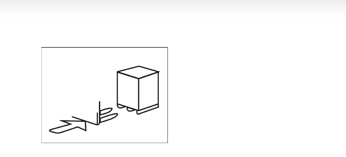
CHAPTER TRANSPORTATION
Ⅶ
ⅦⅦ
Ⅶ
When transport the machine must apply the original
package and place According to the mark on the
package. The machine must be transported by the
forklift with the corresponding tonnage(FIG69)and the
FIG 43
FIG 42
FIG 44
FIG 45
FIG 46
14
stacked layer will not exceed 3layers.
CHAPTER Ⅷ
ⅧⅧ
Ⅷ
ELECTCTRICAL AND
PENUMATIC DRAWING
8.1.220V ELECTRICAL PRINCIPLE DRAWING
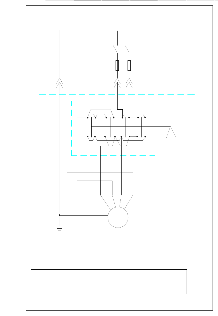
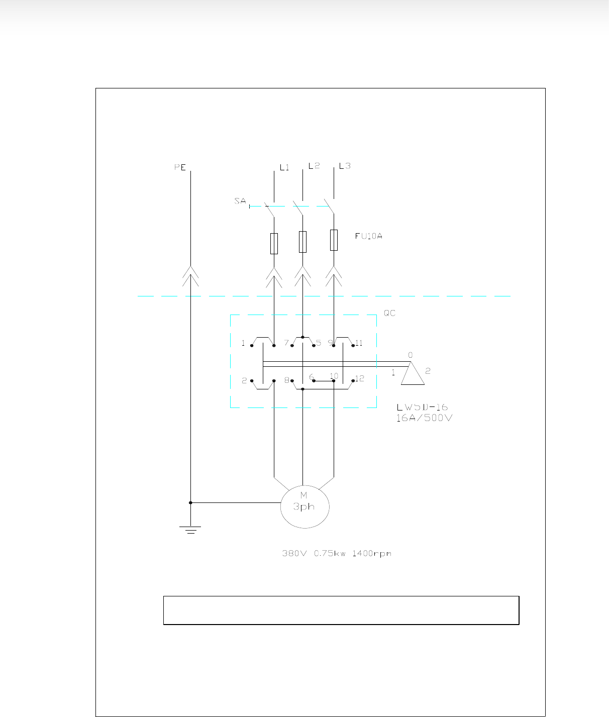
8.2.380V ELECTRICAL PRINCIPLE DRAWING
8.3.110V/220V ELECTRICAL PRINCIPLE DRAWING
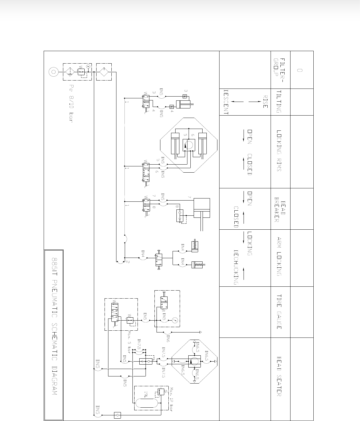
8.4. PNEUMATIC PRINCIPLE DRAWING
FIG 47
15
8.1. 220V ELECTRICAL PRINCIPLE DRAWING
PE N L
SA
FU20A
电源线3X1.5mm
2
QC
拆胎机
内部连线
9 5 7 11 1 3
0
12
10 68 12 24
电机转向开关
LW5D-16
16A/500V
由用户完成的安装
220V 1.1KW 1400rpm
M
1ph
U1 Z2 U2 V1
拆胎机单相电机220V接线原理图(通用)
TIRE CHANGER 1-PHASE MOTOR(220V) WIRING
DRAWING (UNIVERSAL)
BY CUSTOMER
POWER CABLE 3X1.5mm2
INTERNAL
WIRING
MOTOR SWITH
16
8.2. 380V ELECTRICAL PRINCIPLE DRAWING
拆胎机
内 部 连 线
由用户完成的安装
电源线4X1.5mm
电机转向开关
拆胎机三相电机 接线原理图 通用)
TIRE CHANGER 3-PHASE MOTOR(380V) WIRING DRAWING (UNIVERSAL)
BY CUSTOMER
POWER CABLE 4X1.5mm2
INTERNAL WIRING
MOTOR SWITH
17
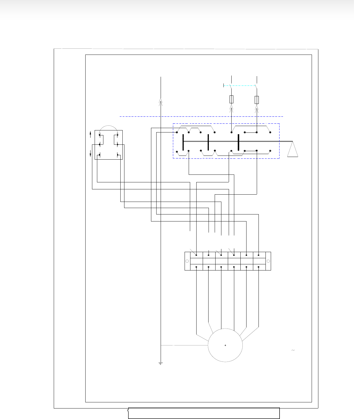
8.3.110V/220V ELECTRICAL PRINCIPLE DRAWING
TIRE CHANGER DUAL VOLTAGE MOTOR ( II)
电机转向开关
用户配置
Z
1
L
2
FU
2
L
1
AC
110V/220V
FU
1
12
2
1
40A/500V
0
LW5-40
97
51
11
24
10 68
U
2
U
4
U
3
U
1
M
1~
FU
1
FU
2
40A
3
Z
2
PE
U
1
U
2
U
3
U
4
Z
1
Z
2
220V
110V
兰绿
黄红
黄 绿 红兰
246115
电压转换开关
2W30A
接线排
TB-2506L
600V/25A
1.1KW 4P
110/220V 50 60HZ
PE
扒胎机双压电机连线图之二
TIRE CHANGER DUAL VOLTAGE MOTOR ( II)
LINE BANK
MOTOR SWITH
VOTAGE SWITH
BY CUSTOMER
B
lue
R
ed
G
reen
Yellow
18
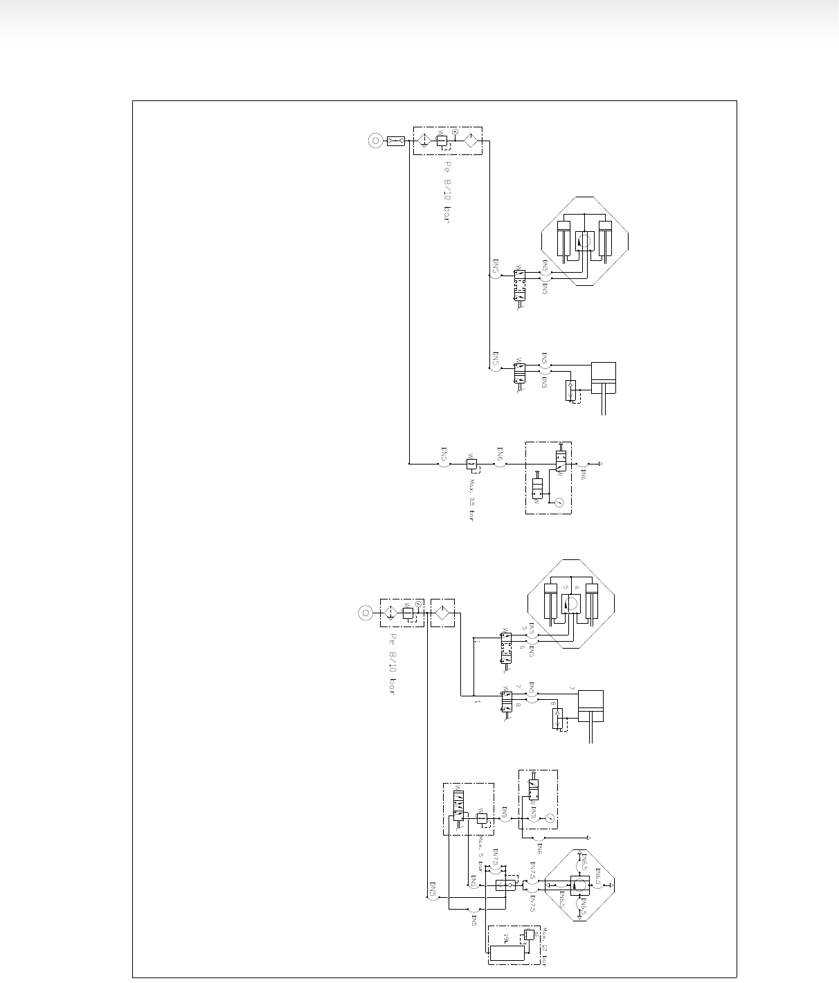
8.4. PNEUMATIC PRINCIPLE DRAWING
SEMI AUTOMATIC PNEUMATIC
SEMI AUTOMATIC PNEUMATIC (IT)
半自动代快充型气动原理图
φ70/20X262
φ70/20X262
φ186/20X150
半自动气动原理图
φ70/20X310
φ70/20X310
φ186/20X150
SEMI AUTOMATIC PNEUMATIC
SEMI AUTOMATIC PNEUMATIC
(IT)
19
φ80/20X80
φ70/20X310
φ70/20X310
φ186/20X150
1 2 3 4 5 6
4
φ66/66.5X16
φ66/66.5X16

20
CHAPTER TROUBLESHOOTING ANALYZE AND SOLUTION
CHAPTER REASON
TROUBLESHOOTING
Turntable rotate in one direction. Universal switch contact burned Change Universal switch
Turntable does not rotate. Belt damage
Belt too loose
Motor or power source have problems
Universal switch contact damage
Change belt
Adjust the tension of the belt
Check motor, power source and
power source cable
Change motor if motor burned
Change Universal switch
Turntable can not clamp the rim as
normal
Claw worn
Clamp cylinder air leakage
Change claws
Change the air leakage sealing parts
Quadric and hexangular shaft
cannot lock
Lock plate not in position
Refer to the chapter V
Chassis pedal not return. Pedal return spring damage Chang torsion spring
Motor not rotate or the output
torque not enough
Drive system jam
Capacitor broken down
Voltage not enough
Short-circuit
+Remove the jam
Change capacitor
Wait for the restore of the voltage
Remove
Cylinder output force not enough Air leakage
Mechanic fault
Air pressure not enough
Change sealing parts
Remove the fault
Adjust the air pressure to meet the
requirement
Air Leakage air hose broken
pipe fitting broken
sealing head broken
loss of the sealing glue
Change broken parts
Refill the sealing glue

21
LC SERIES MACHINE OIL SAFETY DATA SHEET
MOBIL XHP 222
ITEM QUALITY STANDARD
Penetration rate25 mm/10 280
dropping point 280
anticorrosion passed
Basic oil viscosity 220
oxidize stability 100h pressure-drop kpa 35
water lose percentage79% 5
copper corrosion 1A
SAE30# LUBRICATION OIL
ITEM QUALITY STANDARD
density 15 0.893
Flash point 224
Pour point -18
viscosity 40℃ 100
viscosity 100℃ 11.2
Viscosity index 97
2# LITHIUM BASE GREASE
ITEM QUALITY STANDARD
Penetration rate mm/10 278
dropping point ℃ 187
copper corrosion 100 24h No change
oxidize stability(99℃ 100h) 0.2
anticorrosion(52℃ 48h) 1 level
similarity viscosity(-15℃、 10S¯ ¹)/(Pa·S) 800
water lose(35 1h) % 8
CKC460 INDUSTRIAL GEAR OIL
ITEM QUALITY STANDARD
Viscosity 40 461
Viscosity index 92
Flash point ℃ 212
Freezing point ℃ -26
copper corrosion100 3h 1A
mechanical impurity 0.007
Pour point -10
