Tco_e RME Fireface TCO User’s Manual E
User Manual: RME Fireface TCO User’s Manual Troubleshoot RME Fireface TCO |
Open the PDF directly: View PDF ![]() .
.
Page Count: 11

User's Guide
TCO HDSP / FF
Time Code Option
for HDSP / HDSPe / Fireface 800
LTC / SMPTE Reader and Generator
Video to Word Clock Converter
Low Jitter Word Clock Regeneration

User’s Guide TCO 2
Contents
1 Introduction...............................................................3
2 Package Contents.....................................................3
3 Hardware Requirements ..........................................3
4 Technical Specifications
4.1 TCO-FF.................................................................. 4
4.2 TCO-HDSP ............................................................ 4
5 Installing the TCO-HDSP..........................................5
6 Installing the TCO-FF................................................ 5
7 Operation and Usage
7.1 TCO-FF.................................................................. 7
7.2 TCO-HDSP ............................................................ 8
7.3 Updated Information on the TCO - HDSP ............. 9
7.4 Notes on using the HDSPe PCI.............................9
8 Warranty...................................................................10
9 Appendix..................................................................10

User’s Guide TCO 3
1. Introduction
Thank you for choosing the TCO. The Time Code Option provides synchronisation to SMPTE
and video in professional studio quality. SteadyClock ensures that the word clock derived from
the input signals is of low jitter and therefore highly compatible. The TCO supports all standard
formats and conversions of these, turning it into a highly useful tool within the studio environ-
ment.
2. Package Contents
Please check your TCO component's package to include each of the following:
TCO-FF
• TCO board with fixed ribbon cable
• 1 set of screws
• User's guide
TCO-HDSP
• TCO with mounted bracket
• 1 ribbon cable
• User's guide
3. Hardware Requirements
The TCOs can be operated with the following hardware:
TCO-FF: Fireface 800
TCO-HDSP: HDSP AES-32 and the complete HDSPe* series
Current state:
TCO-HDSP: Under Windows XP or up the TCO-HDSP provides the SMPTE position as APP
(ASIO Positioning Protocol) and as MTC Sync. The LTC output only works when the used soft-
ware supports the output of timecode via ASIO.
Under Mac OS X the TCO-HDSP provides the SMPTE position as MTC Sync. The LTC output
is non-functional.
TCO-FF: Under Windows XP or up the TCO-FF provides the SMPTE position as APP (ASIO
Positioning Protocol) and as MTC Sync.
Under Mac OS X the TCO-FF provides the SMPTE position as MTC Sync.
The LTC output of the TCO-FF is non-functional under both Windows and Mac OS X.
*Details on how to use the HDSPe PCI Multiface / Digiface see chapter 7.3.

User’s Guide TCO 4
4. Technical Specifications
4.1 TCO-FF
LTC/Video In
• LTC In: BNC, unbalanced
• Level range LTC In: -25 dBu up to +12 dBu
• Video In: BNC unbalanced, switchable termination 75 Ohm
• Format: PAL and NTSC
LTC Out
• BNC
• Output level: +4 dBu, via jumper –7 dBu
• Output impedance: 220 Ohm
• Power supply via ribbon cable, 5 V DC, 100 mA
• Dimensions (WxD): 100 x 75 mm
4.2 TCO-HDSP
LTC In
• BNC, unbalanced
• Level range: -25 dBu up to +12 dBu
Video In (Word Clock In)
• BNC, switchable termination 75 Ohm
• Format: PAL and NTSC
Word Clock In (Video In)
• BNC, switchable termination 75 Ohm
• Transformer coupled, galvanically isolated input
• Not affected by DC-offsets within the network
• Signal Adaptation Circuit: signal refresh through auto-center and hysteresis
• Overvoltage protection
• Level range: 1.0 Vpp – 5.6 Vpp
• Lock Range: 28 kHz – 200 kHz
• Jitter when synced to input signal: < 1 ns
• Jitter suppression: > 30 dB (2.4 kHz)
LTC Out
• BNC
• Output level: +4 dBu, via jumper –7 dBu
• Output impedance: 220 Ohm
Word Clock Out
• BNC
• Max. output voltage: 5 Vpp
• Output voltage @ 75 Ohm termination: 4.0 Vpp
• Output impedance: 10 Ohm
• Frequency range: 28 kHz – 52 kHz
• Power supply via ribbon cable, 5 V DC, 100 mA
• Standard bracket, dimensions PCB (WxD): 98 x 75 mm

User’s Guide TCO 5
5. Installing the TCO-HDSP
Before installing the TCO card, please make sure the computer is switched off and the
power cable is disconnected from the mains supply.
1. Disconnect the power cord and all other cables from the computer.
2. Remove the computer's housing. Further information on how to do this can be obtained
from your computer’s instruction manual.
3. Before removing the TCO from its protective bag: discharge any static in your body by
touching the metal chassis of the PC.
4. Connect the TCO with the PCI card using the supplied flat ribbon cable. For this, plug one
end of the cable into the matching connector of the PCI card. On the AES-32 the connector
is labelled Synchronizer Board, on other cards the TCO replaces the Word Clock Module.
Plug the other end into the connector X101 on the TCO.
5. Insert the TCO into a free PCI slot and fasten the screw. The TCO needs no slot on the
motherboard, but includes a stabilizing edge, which fits in both PCI and ISA slots.
6. Insert the PCI card firmly into a free PCI slot, press and fasten the screw.
7. Replace the computer's housing.
8. Reconnect all cables including the power cord.
6. Installing the TCO-FF
To install the TCO the Fireface 800 must be opened. If you feel unsecure to do so please con-
sult a technician and let him do this. Else please follow the instructions below step by step.
Before installing the TCO, please make sure the Fireface 800 is switched off and the power
cable is disconnected from the mains supply.
1. Disconnect the power cord and all other cables from the Fireface 800.
2. Loosen and remove both rack ears (two screws each).
3. Use a screwdriver (Phillips 1) to remove the 3 screws on the cover near the back panel, and
2 screws on each side of the Fireface 800, so that the cover can be taken off by sliding it to the
rear.
4. Remove the TCO spare plate within the rear panel (2 screws).
5. Before removing the TCO from its protective bag, discharge any static in your body by touch-
ing the metal chassis of the Fireface.
6. Slide the TCO into the rear panel's hole from the inside. Watch the correct position, so that
both screws found in the PCB of the TCO do not press on the TRS jacks, but are placed in-
between those.
7. Fasten the TCO with the two black self-tapping screws from the TCO screw set. Do not use
the screws of the spare plate, as these are thread screws.
User’s Guide TCO 6
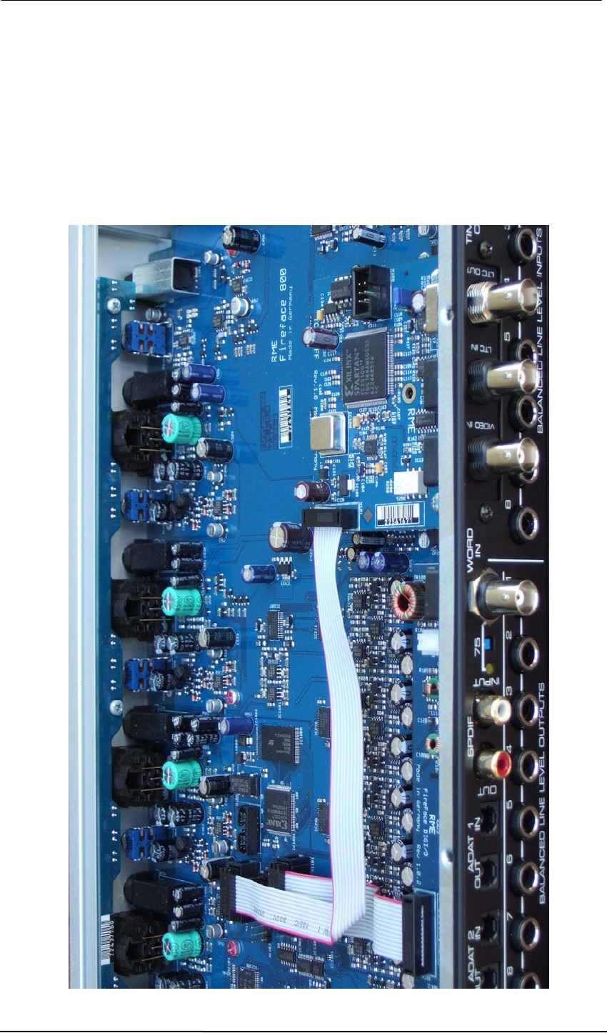
8. Fold the ribbon cable one time and plug it into socket X1105 on the motherboard, see picture
below.
Now you are ready to re-assemble the Fireface.
9. Check that the safety-earth wire (yellow–green) is still connected to the cover. Then put the
cover on and slide it into the aluminum front panel of the Fireface 800.
10. Fasten the 3 screws on the cover and the two screws on each side of the Fireface 800.
11. Attach and fasten the rack ears. Finished!
User’s Guide TCO 7
7. Operation and Usage
7.1 TCO-FF
After installation of the TCO the Fireface 800 has to be updated to the latest driver and firmware
versions, found on the website www.rme-audio.com in the section Download.
After reboot the Settings dialog includes an additional page labelled TCO, and on the main
page the new sync-option TCO can be selected.
For synchronization to a video or LTC signal choose Clock Mode AutoSync and TCO as Pre-
ferred Sync Ref on the main page of the settings dialog. All further settings are done on the
TCO page.
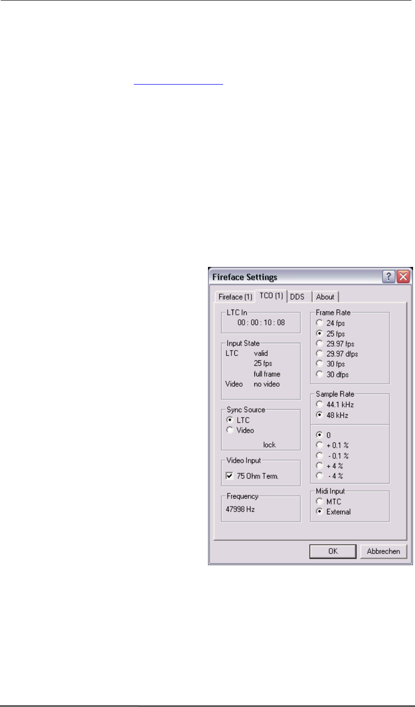
LTC In: The time values read from the LTC signal. These values are passed on to the applica-
tion unchanged.
Input State: An LTC input signal detected as valid (valid) is followed by the display of the num-
ber of frames per second, and whether this is Full Frame or Drop Frame code. A valid video
signal is shown as PAL or NTSC. An incoming word clock signal is analyzed and displayed to
be in the Single Speed, Double Speed or Quad Speed range.
Sync Source: Input select switch for the
inputs LTC and video. Lock is displayed as
soon as the TCO is able to synchronize on an
input signal.
Video Input: The BNC input can be
terminated with 75 Ohms.
Frame Rate: The frame rate of the incoming
SMPTE signal must always be defined
manually.
Sample Rate: The TCO derives a word clock
of 44.1 kHz or 48 kHz from the sync-signal.
With the setting 'from App' chosen the value
sent from the ASIO application to the driver is
used.
The lower field provides common Pull-Up and
Pull-Down values. The final value of the
previously defined sample rate is shown in the
field Frequency, in case the sync-signal is
valid.
Frequency: The TCO measures the word
clock that it generates and shows the current
value in this field.
MIDI Input: The Fireface's MIDI input includes either the MTC signal of the TCO, or the MIDI
data of the 5-pin DIN input (External).
User’s Guide TCO 8
7.2 TCO-HDSP
After installation of the TCO-HDSP update to the latest driver and firmware version, found on
the website www.rme-audio.com in the section Download.
After a reboot the Settings dialog includes an additional page labelled TCO, and on the main
page the new sync-option TCO can be selected.
For synchronization to a video or LTC signal choose Clock Mode AutoSync and TCO as Pre-
ferred Sync Ref on the main page of the settings dialog.
All further settings are then done on the TCO page.
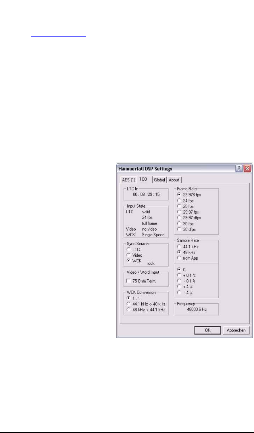
LTC In: The time values read from the LTC signal. These values are passed on to the applica-
tion unchanged.
Input State: An LTC input signal detected as valid (valid) is followed by the display of the num-
ber of frames per second, and whether this is Full Frame or Drop Frame code. 23.976 is de-
tected as 24, 29.97 as 30. A valid video signal is shown as PAL or NTSC. An incoming word
clock signal is analyzed and displayed to be in the Single Speed, Double Speed or Quad Speed
range.
Sync Source: Input select switch for the
inputs LTC, video and word clock. Lock is
displayed as soon as the TCO is able to
synchronize on an input signal. Also at
the bracket the green LED will light up
then.
Video / Word Input: The BNC input can
be terminated with 75 Ohms. At the
bracket the yellow LED will light up with
termination activated.
WCK Conversion: Default setting is 1:1.
This very special option allows for a
synchronous conversion of the word clock
input signal. 44.1 kHz will turn into 48
kHz, where the 48 kHz are not free
running, but have a synchronous
relationship to the original clock. The
same is available for converting 48 kHz to
44.1 kHz.
Frame Rate: The frame rate of the
incoming SMPTE signal must always be
defined manually, as it is not detected
automatically from the input signal.

User’s Guide TCO 9
Sample Rate: The TCO derives a word clock of 44.1 kHz or 48 kHz from the synchronization
signal. With the setting 'from App' active the value sent from the ASIO application to the driver is
used.
The lower field provides common Pull-Up and Pull-Down values. The final value of the previ-
ously defined sample rate is shown in the field Frequency in case the sync-signal is valid.
Frequency: The TCO measures the word clock that it generates and shows the current value in
this field.
Note: The MTC signal is provided via a new (virtual) MIDI input port. This one has to be chosen
as MTC sync source within the application.
7.3 Updated Information on the TCO - HDSP
The latest Windows HDSP(e) drivers 4.06 added several new features to the HDSP TCO:
• Direct support for 23.976 (23.98) fps (HD)
• 23.976 fps can also be used with external word clock
• Support for Double Speed with ASIO. When using an ASIO application in 88.2 or 96 kHz this
frequency will be shown in the Frequency display, although only 44.1 or 48 kHz are present
as external reference. The APP timecode derived from the LTC signal will be automatically
adjusted.
The LTC output of the TCO has the following peculiarities:
• The output of timecode requires an ASIO program that supports this feature. Although this
function is part of the ASIO specifikation, most popular programs do not support it.
• The output signal of the TCO can not be switched off. In Stop mode the same timecode sig-
nal is sent repeatedly (Positional Timecode), which equals a stop.
7.4 Notes on using the HDSPe PCI
Since driver version 3.068 the TCO can also be used with the HDSPe PCI, and therefore with
Multiface and Digiface. The following notes and limitations apply:
• Only ASIO timecode (APP) is supported. Converting LTC to MTC is not supported.
• Generating an audio clock out of the incoming timecode requires a BNC cable from the
TCO's word clock output to the word clock input of the Multiface/Digiface. In the Settings dia-
log Pref. Sync Ref has to be set to TCO and Clock Mode must be set to AutoSync. If the in-
coming timecode is not used to clock the HDSP system the BNC cable is not required.
• The PCI Express Bus provides only 12 Volt and a limited amount of current. Therefore ini-
tially the HDSP TCO will not receive any operating voltage (5 Volt) from the HDSPe PCI. For
the HDSP TCO to receive its operating voltage via the flat ribbon cable from the HDSP PCIe
card, connect the computer’s floppy power supply output to the 4-pin connector found on the
HDSPe PCI.

User’s Guide TCO 10
8. Warranty
Each individual TCO undergoes comprehensive quality control and a complete test at IMM be-
fore shipping. The usage of high grade components should guarantee a long and trouble-free
operation of the unit.
If you suspect that your product is faulty, please contact your local retailer.
Audio AG grants a limited manufacturer warranty of 6 months from the day of invoice showing
the date of sale. The length of the warranty period is different per country. Please contact your
local distributor for extended warranty information and service. Note that each country may
have regional specific warranty implications.
In any case warranty does not cover damage caused by improper installation or maltreatment -
replacement or repair in such cases can only be carried out at the owner's expense.
No warranty service is provided when the product is not returned to the local distributor in the
region where the product had been originally shipped.
Audio AG does not accept claims for damages of any kind, especially consequential damage.
Liability is limited to the value of the TCO. The general terms of business drawn up by Audio AG
apply at all times.
9. Appendix
RME news, driver updates and further product information are available on our website:
http://www.rme-audio.com
Distributor: Audio AG, Am Pfanderling 60, D-85778 Haimhausen, Tel.: (49) 08133 / 91810
Manufacturer:
IMM Elektronik GmbH, Leipziger Strasse 32, D-09648 Mittweida
Trademarks
All trademarks, registered or otherwise, are the property of their respective owners. RME, Ham-
merfall and DIGICheck are registered trademarks of RME Intelligent Audio Solutions. Fireface
800, TCO, SteadyClock, SyncAlign and SyncCheck are trademarks of RME Intelligent Audio
Solutions. Microsoft, Windows, Windows 2000 and Windows XP are registered or trademarks of
Microsoft Corp. Apple and Mac OS are registered trademarks of Apple Computer Inc. ASIO is
trademark of Steinberg Media Technologies GmbH.
Copyright © Matthias Carstens, 05/2015. Version 1.6
Although the contents of this User’s Guide have been thoroughly checked for errors, RME can not guarantee that it is
correct throughout. RME does not accept responsibility for any misleading or incorrect information within this guide.
Lending or copying any part of the guide or the RME Driver CD, or any commercial exploitation of these media without
express written permission from RME Intelligent Audio Solutions is prohibited. RME reserves the right to change specifi-
cations at any time without notice.

User’s Guide TCO 11
CE / FCC Compliance
CE
This device has been tested and found to comply with the limits of the European Council Direc-
tive on the approximation of the laws of the member states relating to electromagnetic compati-
bility according to RL2004/108/EG.
FCC
This equipment has been tested and found to comply with the limits for a Class B digital device,
pursuant to Part 15 of the FCC Rules. These limits are designed to provide reasonable protec-
tion against harmful interference in a residential installation. This equipment generates, uses,
and can radiate radio frequency energy and, if not installed and used in accordance with the
instructions, may cause harmful interference to radio communications. However, there is no
guarantee that interference will not occur in a particular installation. If this equipment does
cause harmful interference to radio or television reception, which can be determined by turning
the equipment off and on, the user is encouraged to try to correct the interference by one or
more of the following measures:
- Reorient or relocate the receiving antenna.
- Increase the separation between the equipment and receiver.
- Connect the equipment into an outlet on a circuit different from that to which the receiver is
connected.
- Consult the dealer or an experienced radio/TV technician for help.
RoHS
This product has been soldered lead-free and fulfils the requirements of the RoHS directive.
ISO 9001
This product has been manufactured under ISO 9001 quality management. The manufacturer,
IMM Elektronik GmbH, is also certified for ISO 14001 (Environment) and ISO 13485 (medical
devices).
Note on Disposal
According to the guide line RL2002/96/EG (WEEE – Directive on Waste
Electrical and Electronic Equipment), valid for all european countries, this
product has to be recycled at the end of its lifetime.
In case a disposal of electronic waste is not possible, the recycling can
also be done by IMM Elektronik GmbH, the manufacturer of the TCO.
For this the device has to be sent free to the door to:
IMM Elektronik GmbH
Leipziger Straße 32
D-09648 Mittweida
Germany
Shipments not prepaid will be rejected and returned on the original sender's costs.
