Tcp015
User Manual: tcp015
Open the PDF directly: View PDF ![]() .
.
Page Count: 22
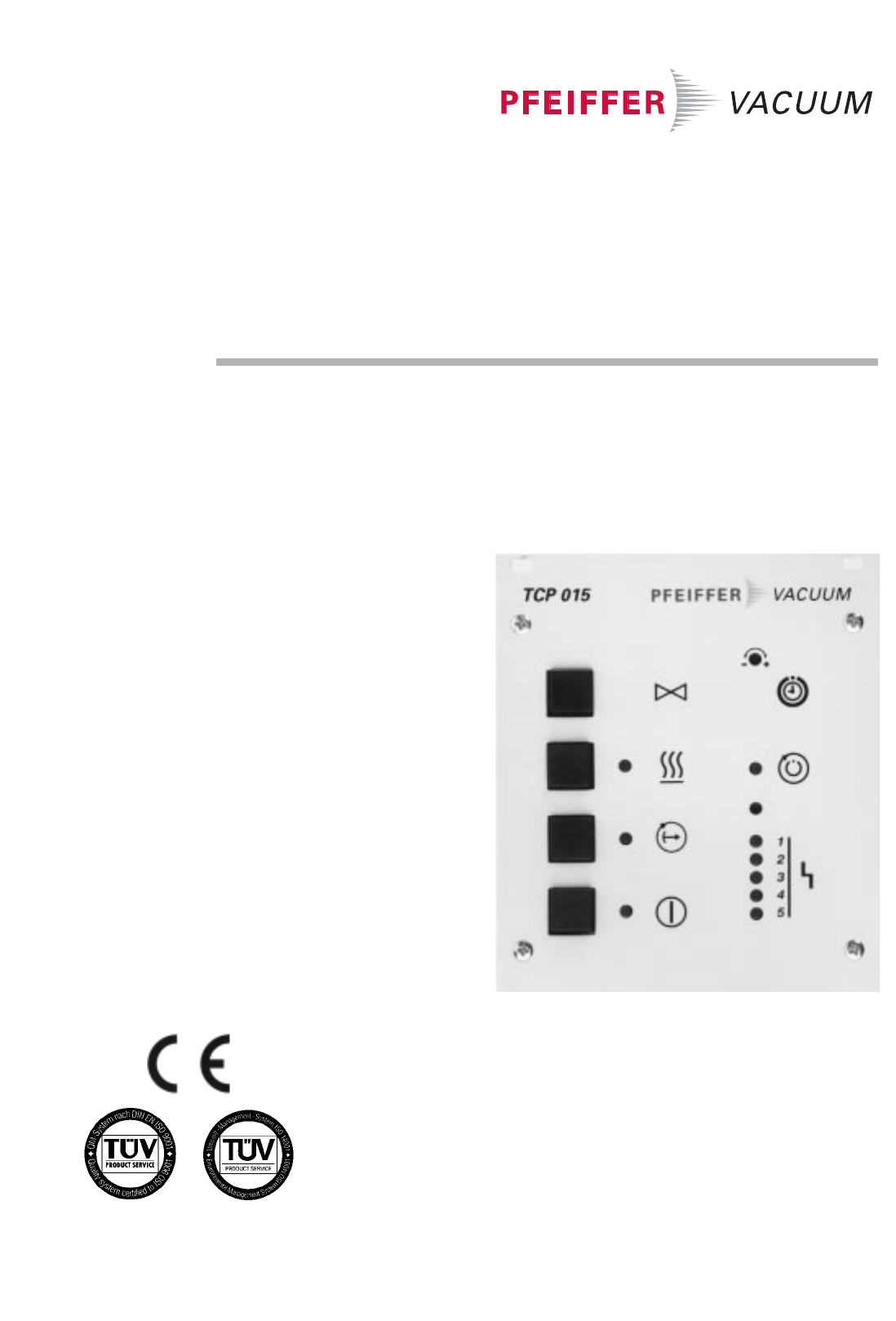
Electronic Drive Unit
TCP 015
PM 800 230 BE/F (9906)
Operating Instructions
...................................
Page 20
TCP 035

2
1. Safety Instructions.................................. 3
2. Understanding The Electronic
Drive Unit TCP 015................................... 4
2.1. For Your Orientation........................................................... 4
2.2. Product Description........................................................... 4
Connection Options ........................................................... 4
Proper Use .......................................................................... 4
Improper Use...................................................................... 4
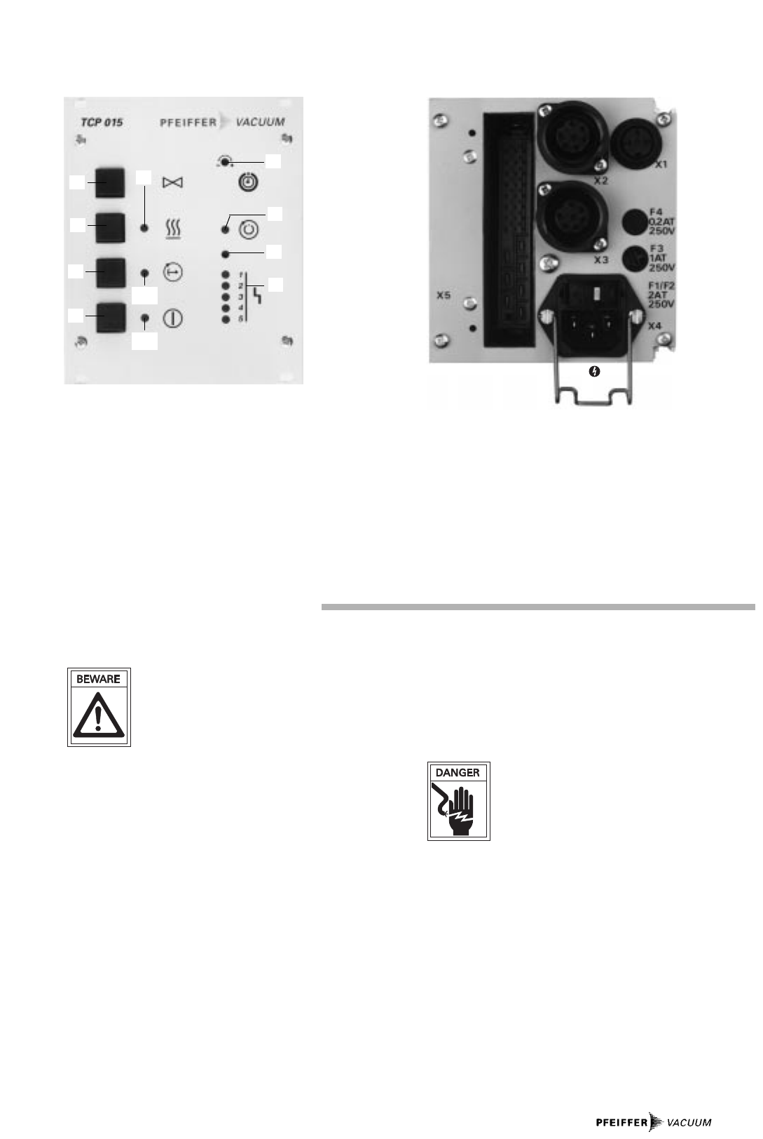
2.3. Description Of The Front Panel........................................ 5
2.4. Description Of The Rear Panel ........................................ 5
3. Installation, TCP 015 ............................... 5
3.1. Preparations For Installation............................................ 5
3.2. Fitting The Unit In A Rack ................................................. 5
3.3. Mains Power Connection................................................. 5
3.4. Connections Diagram........................................................ 5
3.5. Connecting The Turbopump............................................. 6
3.6. Connecting The Venting Valve......................................... 6
3.7. Connecting The Pumping Station Control
Unit TCS 015 (optional)...................................................... 6
3.8. Connecting The Pump Heating Unit................................ 7
3.9. Connecting The Air Cooling Unit .................................... 7
3.10. Connecting The Remote Control Unit ............................. 7
3.11. Connecting The Backing Pump With
Intermittent Operations..................................................... 7
3.12. Connecting The Serial Interface ..................................... 7
4. Operations, TCP 015 ................................ 8
4.1. Switching ON The Electronic Drive Unit And
The Turbopump .................................................................. 8
Self-Testing......................................................................... 8
4.2. Switching “Stand-By” ON And OFF................................ 8
4.3. Turbopump Venting ........................................................... 8
4.4. Switching The Heating Unit ON And OFF....................... 8
4.5. Operations Messages....................................................... 8
4.6. Use Of The Remote Control Unit...................................... 8
4.7. Reset .................................................................................... 9
4.8. The Serial Interface .......................................................... 9
4.9. Operations With The Backing Pump............................... 9
4.10. Operations with Pumping Station Control
Unit TCS 015........................................................................ 9
4.11. Switching OFF..................................................................... 9
5. Understanding The Electronic Drive
Unit TCP 035 ........................................... 10
5.1. Product Description......................................................... 10
Connection Options ......................................................... 10
Proper Use ........................................................................ 10
Improper Use.................................................................... 10
6. Installation, TCP 035 ............................. 11
6.1. Preparations For Installation.......................................... 11
6.2. Fitting The Unit In A Rack ............................................... 11
6.3. Connecting To The Mains................................................11
6.4. Connecting The Turbopump........................................... 12
6.5. Connecting The Remote Control Unit ........................... 12
6.6. The Relay Output.............................................................. 12
6.7. Connecting The Backing Pump ..................................... 12
6.8. Connecting The Serial Interface ................................... 12
7. Operations, TCP 035 .............................. 13
7.1 Setting Various Operating Modes................................. 13
7.2. Switching ON The Electronic Drive Unit...................... 13
Self-Testing....................................................................... 13
7.3. Starting Up The Turbopump........................................... 13
Normal Operations, Turbopump.................................... 13
7.4. Switching “Stand-By” ON And OFF.............................. 13
7.5. Operations With Motor Current Monitoring................ 13
7.6. Altering The Pre-Settings (S14)..................................... 14
7.7. Error Reset ........................................................................ 14
7.8. Switching The Turbopump ON and OFF....................... 14
7.9. The Serial Interface......................................................... 14
8. What To Do In The Case
Of Breakdowns?.................................... 15
8.1. The Function Of The Illuminating Diodes..................... 15
8.2. Function Test In The Event Of A Malfunction.............. 15
8.3. Eliminating Errors............................................................. 15
8.4. Error Code Table .............................................................. 15
9. Maintenance, Service .......................... 16
10. Technical Data....................................... 16
12.1. Data List............................................................................. 16
12.2. Dimensions Diagram ....................................................... 16
11. Connections Diagram ........................... 17
12. Pin Arrangement.................................... 18
13. Spare Parts............................................. 19
14. Accessories ........................................... 19
Manufacturer´s Declaration.....Last page
Index
Page Page
TCP 035
TCP 015/035
TCP 015

3
Danger of damage to the unit or system.
Danger of an electric shock from
touching the contacts.
1. Safety Precautions
☞Read and follow all the instructions in this manual.
Inform yourself regarding:
– Hazards which can be caused by the unit,
– Hazards which can arise in your system,
☞Comply with all safety and accident prevention
regulations.
☞Check regularly that all safety requirements are being
complied with.
☞Take account of the ambient conditions when installing the
TCP 015. The protection type is IP20. The unit is protected
against the ingress of foreign bodies ³ø 12mm. Because
water protection is not provided the unit must be fitted into
a suitable housing (please see Section 3. Installation).
☞Disconnect the plug connector on the TCP or pump only
once the mains plug has been disconnected and the pump
is at rest.
☞When connecting the plug make sure that all mechanical
locking devices are in place.
☞After connecting the mains cable check for safe PE
connection to the housing.
☞Do not open the housing cover when the unit is connected
to the mains nor during pumping operation.
☞Do not carry out any unauthorised conversions or modifi-
cations on the unit.
☞When returning the unit to us please note the shipping
instructions (please see Section 7.).
Modifications reserved.
Danger of personal injury.
Pictogram Definitions

4
2.1. For Your Orientation
Symbol Used
The following symbols are used throughout in the
illustrations:
High vacuum flange
Fore-vacuum flange
Venting connection
Cooling water connection
Electric connection
Air cooling
Position Numbers
Identical pump and accessory parts have the same position
numbers in all illustrations.
In The Text
➡Operating instruction: Here, you have to do something.
2.2. Product Description
The Electronic Drive Unit TCP 015 serves to drive PFEIFFER
turbomolecular pumps with single phase direct current
motors (1500 Hz). With the aid of a transformer the mains vol-
tage is reduced to 32 V, rectified and provides the drive ener-
gy for the Print Module TCP 035 which is an element of the
TCP 015. The switchable transformer power pack covers the
following input voltage ranges:
– 90-112 V
– 108-133 V
– 198-245 V
– 216-267 V AC.
The TCP can be operated in conjunction with Pumping Station
Control Unit TCS 015 to operate a pumping station with
backing pump.
The delivery consignment encompasses:
– Electronic Drive Unit TCP 015
– Mating plug for X1, X2, X3.
The TCP 015 has been suppressed in accordance with
German Industrial Standard VDE 0871, limit value curve B. The
unit has been tested and cleared by the appropriate authori-
ties in accordance with EN 61010/VDE0411 “Safety Ordinance
For Electrical Units”.
The electronic drive unit contains the following functional
features:
– Switching power pack
– Motor drive
– Monitoring and process control
– Illuminating diode display with information concerning the
operational status of the pump
– Serial Interface RS 232/ RS 485 on the Print Module of the
TCP 035
Connection Options For:
– Remote control,
– Pumping Station Control Unit TCS 015 with connection
options for the backing pump and fore-vacuum safety val-
ve,
– Host computer via Serial Interface RS 485/RS 232,
– Heating for the turbomolecular pump,
– Air cooling for the turbomolecular pump.
Proper Use:
– The Electronic Drive Unit TCP 015 may only be used to dri-
ve and monitor PFEIFFER turbomolecular pumps.
– The operations unit TCP- turbopump may only be operated
together with a backing pump.
– Pumping Station Control Unit TCS 015 is necessary for con-
trolling the backing pump and fore-vacuum safety valve.
– Instructions concerning installation, start-up, operating
and maintenance must be observed.
Improper Use:
Improper is:
– Uses not covered above, and, in particular,
– Connection to pumps and units which is not permitted in
their operating instructions.
– Connection to pumps and units which is not permitted in
their operating instructions.
Improper use will cause any rights regarding liability and gua-
rantees to be forfeited.
2. Understanding The Electronic Drive Unit TCP 015
TCP 015
5
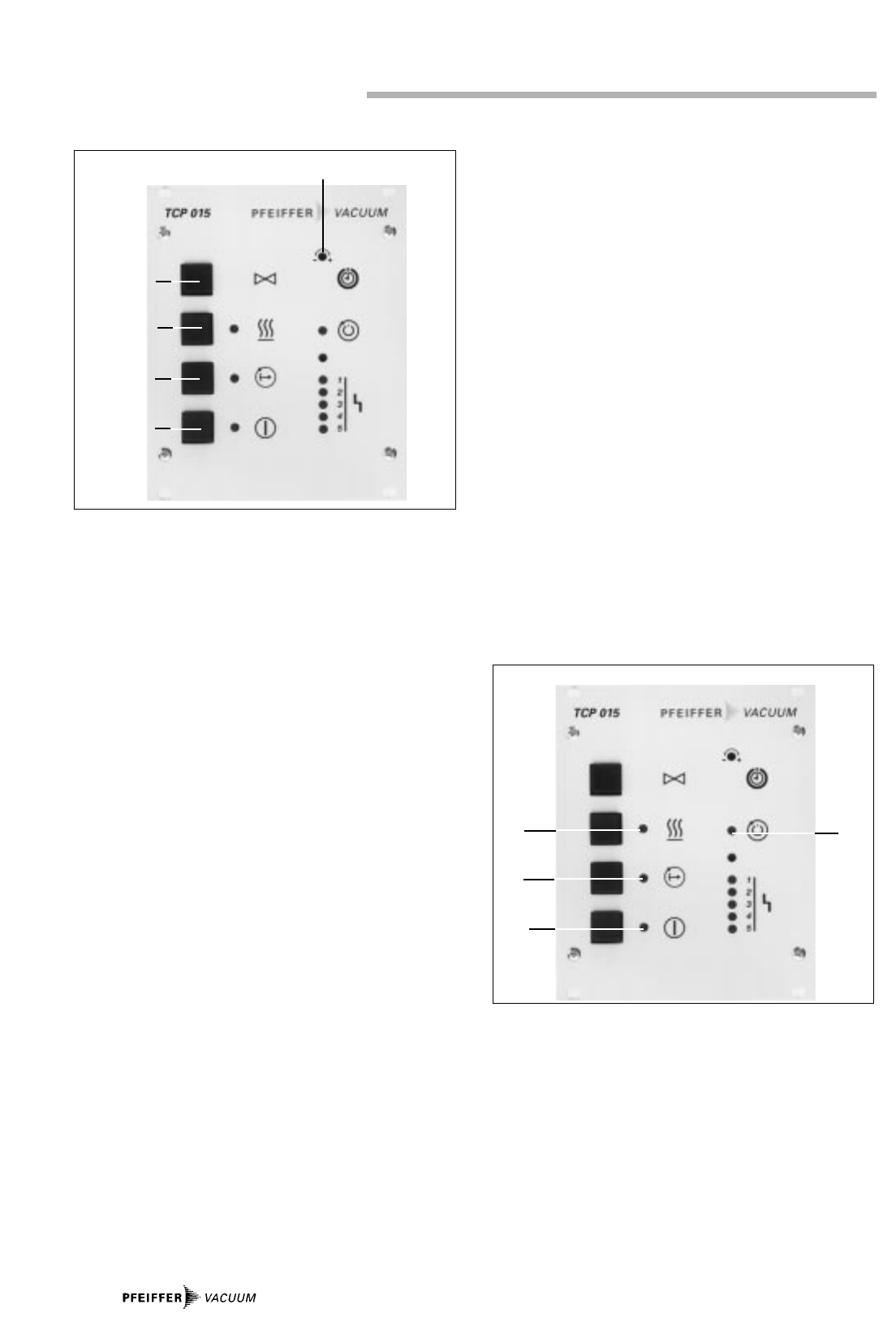
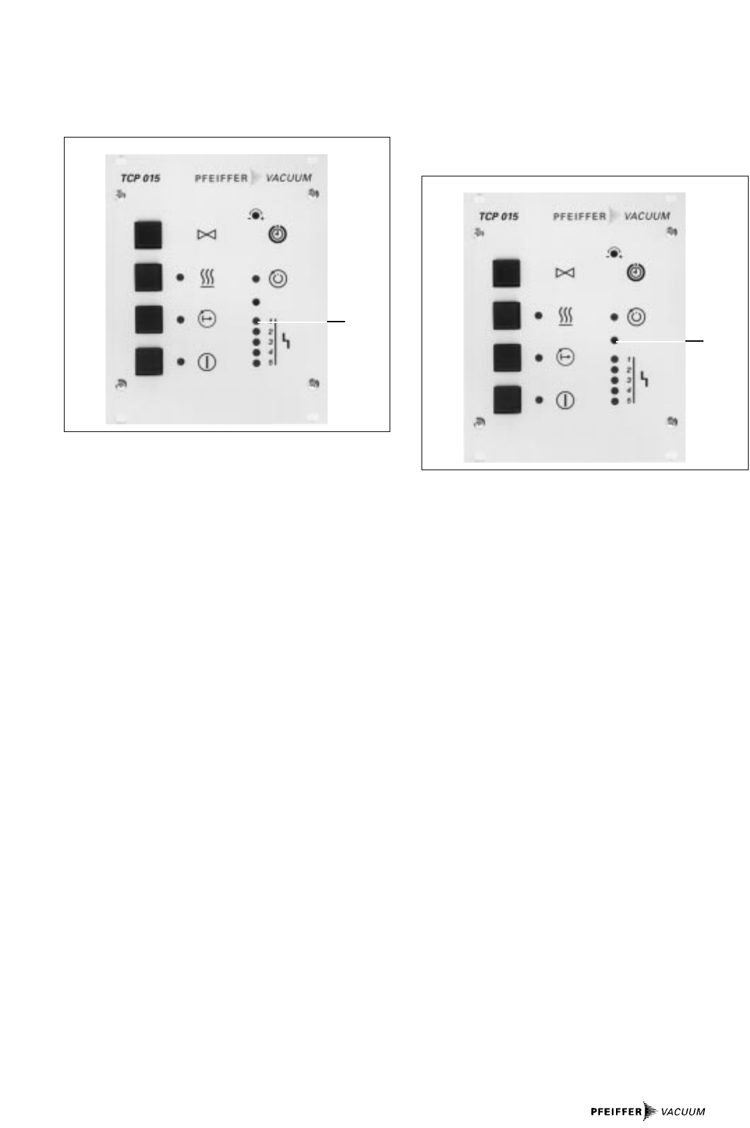
1 S16 Venting ON/OFF
2 S2 Heating ON/OFF
3 S9 Stand-by ON/OFF
4 S1 Mains ON/OFF
5 R52 Potentiometer start time
6 H6 LED rotation speed switchpoint attained
7 R53 Potentiometer current switchpoint
8 H1 LED collective error message
H2-H5 LEDs error coding
9 H7 LED heating ON
10 H8 LED stand-by ON
11 H7 LED mains ON
X1 Connector socket, venting valve
X2 Connector socket, air cooling
X3 Connector socket, pump heating
X4 Connector socket, mains
X5 Connector socket, pump
F1 Mains fuse
F2 Mains fuse
F3 Pump heating/air cooling fuse
F4 Venting valve fuse
2.3. Description Of The Front Panel 2.4. Description Of The Rear Panel
1
2
3
4
5
9
7
8
6
10
11
3.1. Preparations For Installation
Unauthorised modifications or alterations to the
electronic drive unit are not allowed.
The unit must be fitted in a housing taking
account of the ambient conditions (see
Section 9., “Technical Data”).
Please refer to Section 13. for the electrical connections dia-
gram.
➡Disconnect mains power before installation work.
3.2. Fitting The Unit Into A Rack
The Electronic Drive Unit TCP 015 is a 3/12-19”, 3 HE insert
module designed to be fitted into a 19”/3HE rack. The
following should be taken account of when fitting:
The ambient temperature in the rack casing should not
exceed 40 °C and other insert modules should not restrict the
circulation of air.
3.3. Mains Power Connection
–The unit has been designated protection class 1 and must
therefore always be connected with the earthed conduc-
tor (PE).
– Mains connection must be made in accordance with the
local regulations.
Danger of an electrical shock resulting from
incorrect connections.
➡Before connecting the unit check the mains voltage on the
selection switch.
If changes in the settings are necessary:
➡Unlock the fuse drawer with the help of a small screwdri-
ver, remove the grey fuse box and re-insert so that the cor-
rect voltage range (please see Section 2.2.) appears in the
drawer window.
➡Insert drawer, connect mains power cable and secure
with locking guard.
➡If Pumping Station Control Unit TCS 015 is to be operated
make the mains power connection via TCS/X8.
The fuses shown in the following table can be replaced if the
mains power plug is disconnected:
3. Installation, TCP 015
6
3.5. Connecting The Turbopump
Only disconnect the plug connector to the elec-
tronic drive unit once the pump is completely at
rest and the electronic drive unit has been dis-
connected from the mains power supply.
➡Connect the turbomolecular pump with connecting cable
to connector socket X5 as per the connections diagram in
Section 3.4./connections diagram Section 13. Screw tight
the unit plug with 2 self-tapping screws on the rear panel
of the unit.
All voltages on connector socket X5 are safety
low voltages and are doubly insulated from the
mains. Connections to this socket must not be
switched together with dangerous contact vol-
tages.
➡Lock the bayonet catch on the pump after plugging in.
Only PFEIFFER connecting cable should be used for connec-
ting the pump.
3.6. Connecting The Venting Valve
➡Connect the venting valve to connector socket X1 on the
rear side of the TCP 015 in accordance with connections
diagram Section 3.4./connections diagram PM 041 532 -S,
Section 11.
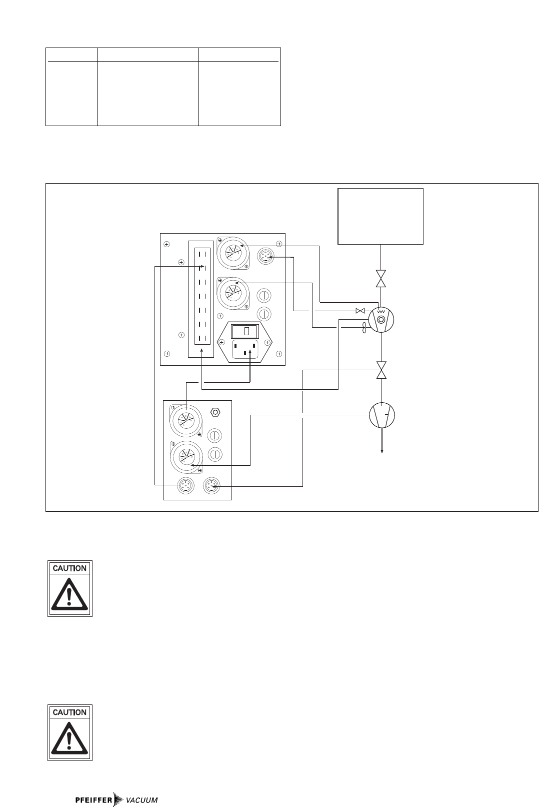
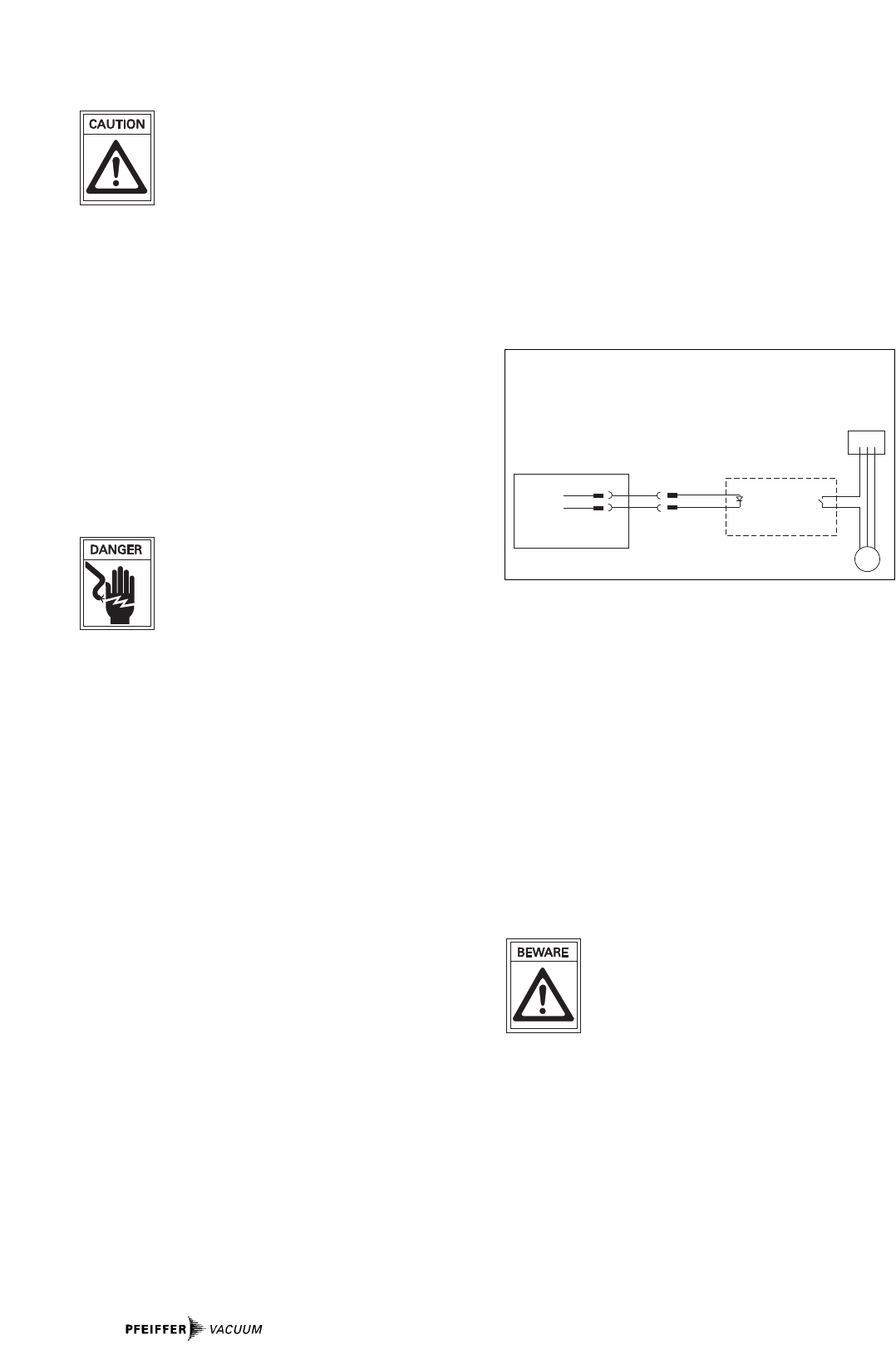
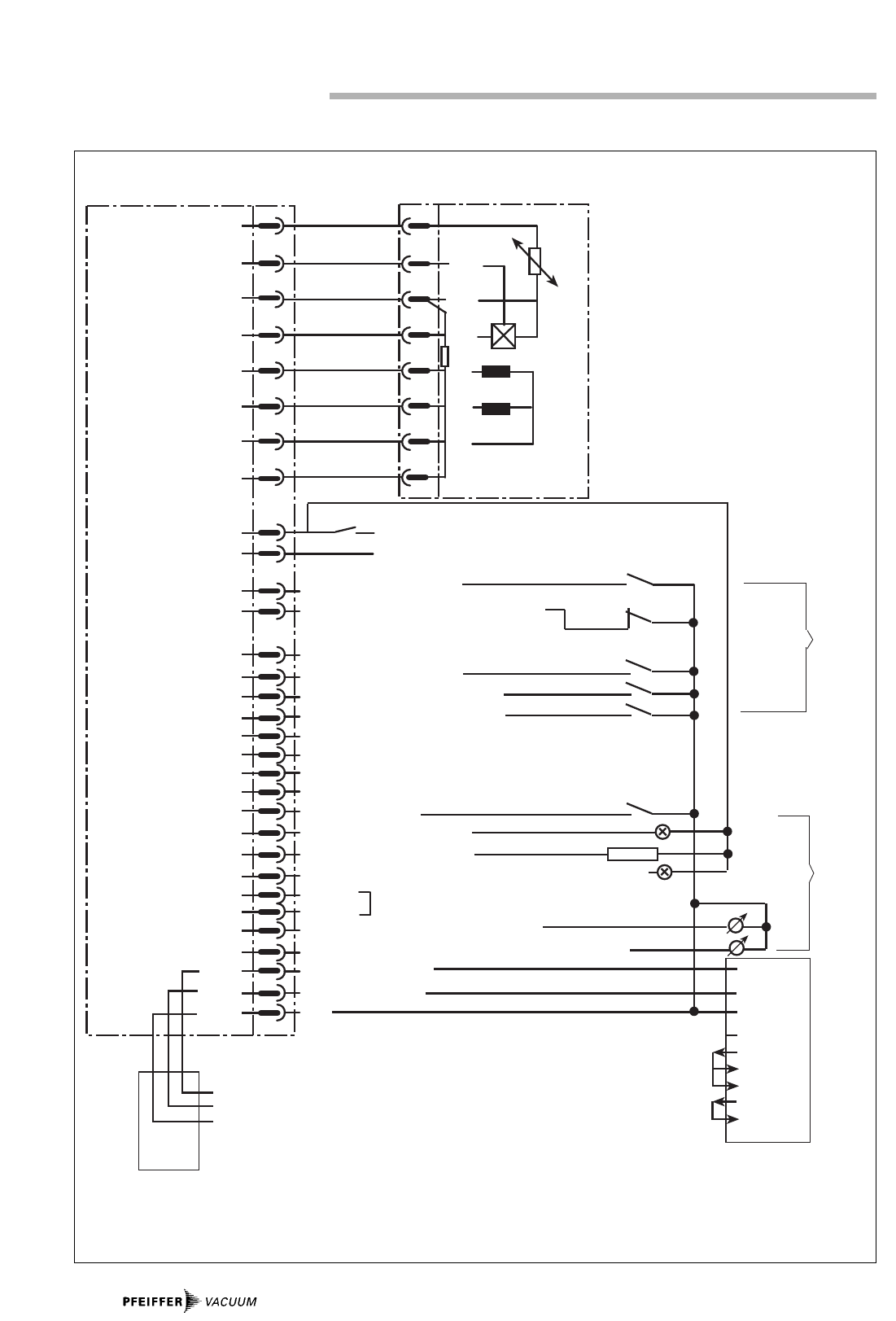
Recipient
HV-Valve
Turbopump
Fore Vacuum
Safety Valve
Backing Pump
TCP 015
Atmosphere
Heating
10AT
10AT
X2
X3
X1
F4
0,2AT
250V
F3
1 AT
250V
F1/F2
2 AT
250V
X4
X5
10AT
10AT
TCS 015
X12
X8
X25 X26
Venting
3.4. Connections Diagram
Designation Current Circuit Type
F1 Primary side 2 AT
Mains transformer
F2 Incoming mains power line 1 AT
F3 Heating, air cooling 1 AT
F4 Venting valve 0,2 AT
Connections Diagram, TCP 015
7
3.7. Connecting The Pumping Station
Control Unit TCS 015 (optional)
➡Connect the Pumping Station Control Unit TCS 015 in
accordance with connections diagram Section
3.4./connections diagram PM 041 532 -S, Section 11.
Only disconnect the plug connector to the
Pumping Station Control Unit TCS 015 once the
pump is completely at rest and the unit has been
disconnected from the mains power supply.
Further notes regarding the connection of Pumping Station
Control Unit TCS 015 can be found in the operating
instructions for the TCS 015, PM 800 248 BN.
3.8. Connecting The Pump Heating Unit
If a heating unit has been fitted to the pump:
➡Connect the heating unit to mating plug X3 in accordance
with connections diagram Section 3.4./connections
diagram PM 041 532 -S, Section 11.
➡For the ranges 100 and 120 V switch the heating unit resi-
stances in parallel, for the ranges 220-240 V in series.
The maximum pump heating current is 1A.
3.9. Connecting The Air Cooling Unit
➡Select the air cooling in accordance with the mains volta-
ge (please see “Accessories”) .
➡Connect the connecting cable to X2 in accordance with
connections diagram PM 041 532 -S.
3.10.Connecting The Remote Control Unit
The TCP 015 or the complete pumping station can be remote
controlled. The respective contacts are made via z2/TCP 035
Print Module. For the connection description please refer to
Section 6.5./TCP 035.
3.11.Connecting The Backing Pump With
Intermittent Operations
It is possible to operate the backing pump without a pumping
station control unit by employing a Diaphragm Pump MVP 012
with semi-conductor relay.
Switch S14 is used to select either non-stop operations (ON)
or intermittent operations (OFF). Please refer to Section 7.6.
If Pumping Station Control Unit TCS 015 is in use, the connec-
tions are made in accordance with connections diagram
PM 041 532 -S. The control line is connected to X5/d12.
Backing pump operations with X5/z12 as control line are also
possible.
Only doubly insulated relays to the mains volta-
ge may be used.
3.12.Connecting The Serial Interface
Serial Interface RS 232C is integrated in Print Module TCP 035
as standard and is therefore a component of the TCP 015. For
a description of the connection please refer to Section 6.8.
Only safety low voltages (SELV) may be
connected to the serial interface plug.
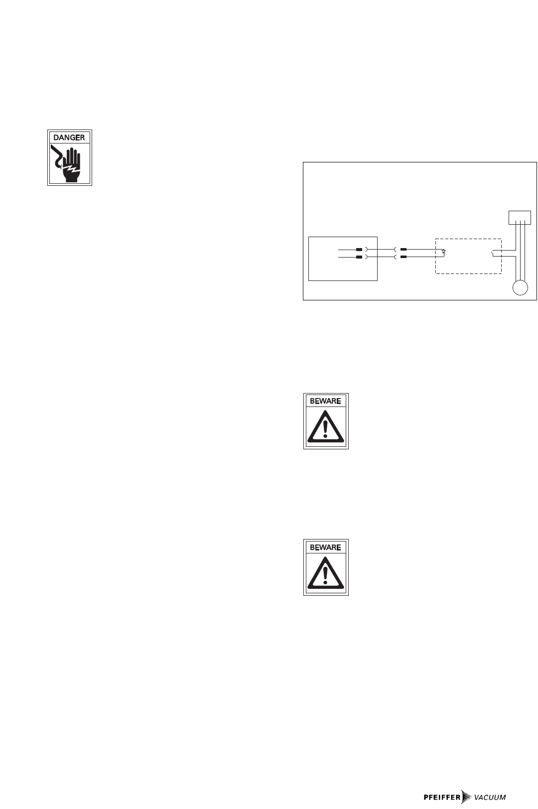
M
C
B
A
–
+~
X5/z8
X5/d10
TCP 015/035
Anschluß Vorpumpe
A Control line
B Terminal box, MVP 012
C Mains
D Motor, MVP 012
8
4.1. Switching ON The Electronic Drive Unit
And The Turbopump
➡Switch on the Electronic Drive Unit TCP 015 with mains
switch S1.
Self-Testing
After the TCP 015 is switched on, the integrated TCP 035 car-
ries out a self-test in respect of the most important functions.
The functions referred to in Section 9. and those designated
with an “S” are tested and possible malfunctions displayed
coded with the aid of LEDs H2-H5 (please refer to the table in
Section 8.4.). If in addition H1 illuminates the TCP will remain
inoperable.
Start-Up
Once the self-test has been successfully completed the pump
starts up during which the maximum current is 2.2 A.
Potentiometer P1 can be used to pre-select a time of 8-60 min
within which the pump must have attained 750 Hz. If the
frequency is not attained within this time or if the rotation
speed falls below this frequency after this time elapses E011
is displayed.
Normal Operations
Once the pump has attained its nominal rotation speed the
rotation speed will be maintained at a constant ± 2 %
4.2. Switching “Stand-By” ON And OFF
➡Switch stand-by with S9 on the front panel.
The pump runs at 66% of its nominal rotation speed. This ope-
rations mode can then be selected when the pressure in the
vacuum chamber is sufficiently low, e.g. during breaks in ope-
rations. Stand-by mode helps to protect the pump bearing..
4.3. Turbopump Venting
➡When the turbopump has been switched off via mains
switch S1, vent the pump by depressing the venting switch
(the venting valve must be fitted). If the rotation speed falls
below 50% of the nominal value venting proceeds automa-
tically.
4.4. Switching The Heating Unit ON And OFF
➡Pre-select turbopump heating with switch S2.
– If the turbopump rotation speed exceeds the switchpoint
of 750 Hz the heating switches on and LED H7 illuminates.
➡Switch off the pump heating via switch S2.
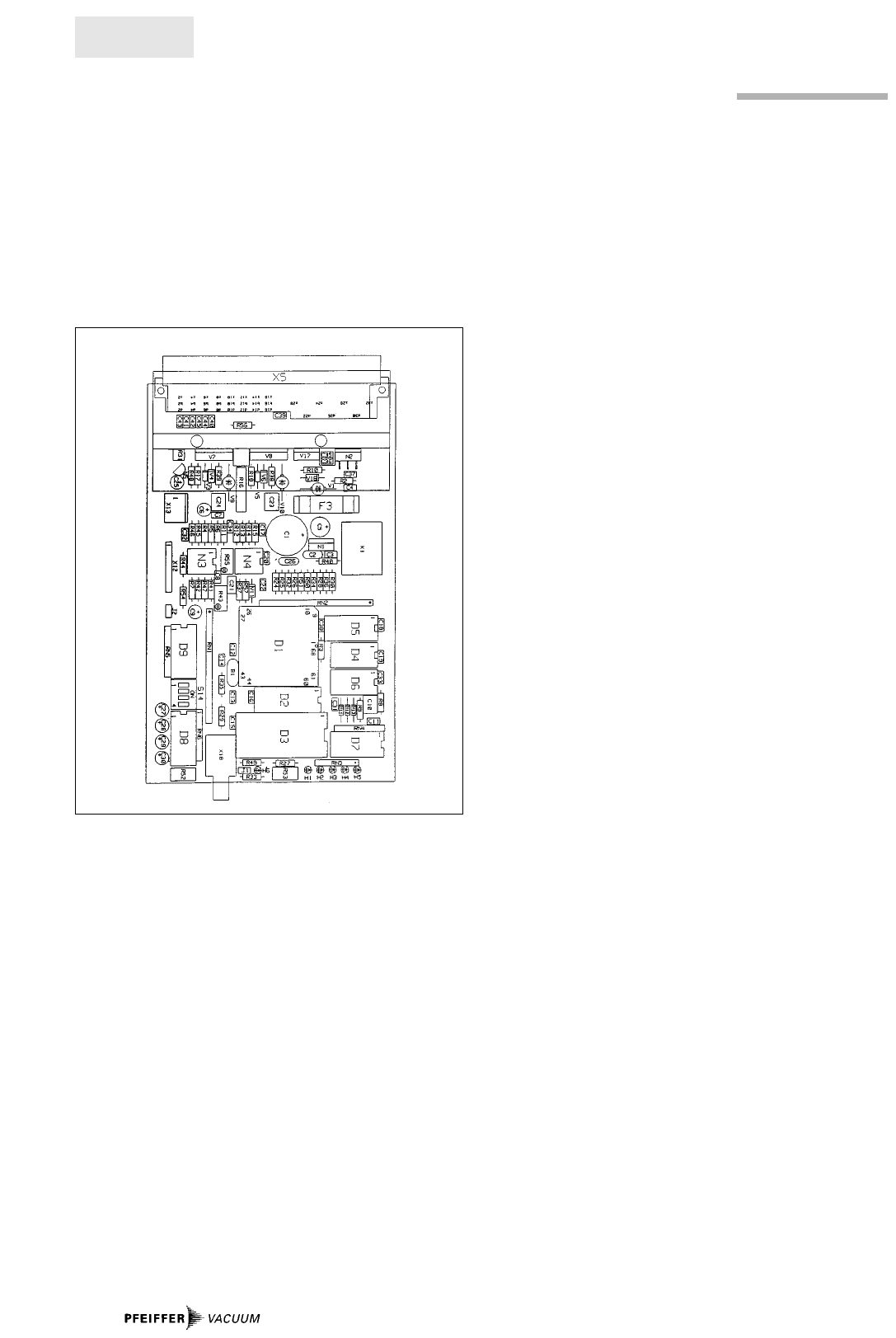
4.5. Operations Messages
H6 LED rotation speed switchpoint attained
H7 LED TCP “ON”
H8 LED stand-by “ON”
H9 LED heating “ON”
4.6. Use Of The Remote Control Unit
The pump or the pumping station can be remote operated via
the Print Module TCP 035. For the procedure please refer to
Section 6.6.
Operations Messages
H9
H8
H7
H6
S 16 Venting
S 2 Heating
S 9 Stand-by
S 1 TCP
P1
4. Operations, TCP 015
9
4.7. Reset
If the TCP 015 identifies an error which is displayed by LED H1
the motor current is switched off.
Once the error has been eliminated the pump does not re-
start automatically. The reset which is necessary is carried
out as follows:
– Switch off S1 for a time of > 5 seconds.
– Remote input “Error Reset” (X5/b6).
– Transmission of the respective command via Serial
Interface RS 232 C.
4.8. The Serial Interface
Electronic Drive Unit TCP 015 is fitted with Serial Interface
RS 232 C as standard.
Serial Interface description: Please see disk PM 800 424 BN.
4.9. Operations With The Backing Pump
Backing pumps are switched on and off (S1) together with the
turbopump where they are connected directly, via the TCS
015 or via a semiconductor relay. In the event of a malfunc-
tion, the backing pump is also switched off and a malfunction
signal (H1) is triggerred.
Interval Operations
A connected backing pump is switched on and off in depen-
dence on the power take-up of the turbopump. The lower
switchpoint1) at which the backing pump switches on is fixed.
The upper switchpoint2) can be varied via potentiometer P2
which is accessible on the front panel and which allows indi-
vidual settings for any arrangement. Turning P2 to the left
means an increase and to the right a decrease of the pressu-
re at which the pump should switch on. P2 has been set to a
power of 20 Watt in the works and this corresponds to a pres-
sure of approximately 4 mbar.
1) lower switchpoint = high forevacuum pressure
2) upper switchpoint = low forevacuum pressure
The adjustment of the upper switchpoint should be carried
out with the help of a fore-vacuum pressure gauge.
Switching off follows after a delay time of 10 seconds. If the
upper switchpoint is exceeded, switching on follows after 20
seconds.
Non-Stop Operations
➡Turn potentiometer P2 to the right up to the stop point.
–> Interval operations is switched off and the backing pump
operates in non-stop mode.
4.10.Operations With Pumping Station
Control Unit TCS 015
The TCS 015 is provided for operations with pumping station
control. The TCS 015 controls and monitors the backing pump
and the fore-vacuum safety valve.
Connection TCS 015: Please refer to Operating Instructions
PM 800 248 BN.
4.11.Switching OFF
The pump can be switched off:
➡By activating switch S1.
--> The voltage supply is disrupted.
Operations Message H1
H1
Potentiometer P2
P2
10
5.1. Product Description
The Electronic Drive Unit TCP 035 has been designed as an
integratable component and serves to drive and monitor
PFEIFFER turbomolecular pumps with single phase direct cur-
rent motors (1500 Hz).
The delivery consignment encompasses:
– Print Module TCP 035
The electronic drive unit contains the following functional
features:
– Motor drive
– Monitoring and process control
– Illuminating diode display with information concerning the
operational status of the pump
– Serial Interface RS 232/ RS485.
Connection Options For:
– Remote control,
– Host computer via Serial Interface RS 485/RS 232.
Proper Use:
– The Electronic Drive Unit TCP 035 has been designed as an
integratable component and may only be used to drive and
monitor PFEIFFER turbomolecular pumps with single pha-
se motors.
– The operations unit TCP- turbopump may only be operated
together with a backing pump.
– Instructions concerning installation, start-up, operating
and maintenance must be observed.
Improper Use:
Improper is:
– Uses not covered above, and, in particular,
– Connection to pumps and units which is not permitted in
their operating instructions.
– Connection to dangerous to touch voltages.
Improper use will cause any rights regarding liability and gua-
rantees to be forfeited.
Safety Instructions
– The operations voltage for the TCP 035 must be safety low
voltage (SELV; 26-42 V=).
– Guarantees apply only to units which are fitted in a conditi-
on which has not in any way been altered.
5. Understanding The Electronic Drive Unit TCP 035
TCP 035
TCP 035
11
6. Installation, TCP 035
6.1. Preparations For Installation
Unauthorised modifications or alterations to the
Display Control Unit are not allowed. The unit
must be fitted in a housing taking account of the
ambient conditions (see Section 10., “Technical
Data”).
Electrical connection: Please refer to connections diagram
PM 041 532 -S, Section 11. and pin arrangement diagram
PM 031 403 -S, Section 12.
➡Secure mating plug X5 against falling out.
6.2. Fitting The Unit Into A Rack
The Electronic Drive Unit TCP 035 has been designed to be
fitted into a rack. The following should be taken account of
when fitting:
➡On installation the TCP should be insulated.
➡Ensure safe distance from the influence of extraneous vol-
tages.
➡Exclude influence ofinterference frequencies.
➡Provide adequate air circulation (cooling). Fit the unit ver-
tically and, if possible, mount a cooling unit on the side
panel.
The ambient temperature in the rack casing should not
exceed 40 °C.
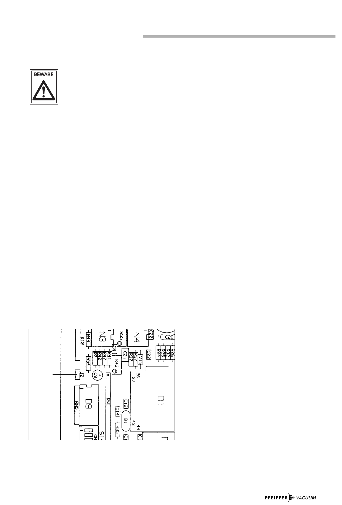
6.3. Connecting The Operations Voltage
The TCP 035 has been designed to operate on a voltage of 26-
42V. This is applied to X5/z28 and X5/z32 and joined with jum-
per J2 on UB*.
The supply voltage must be safety low voltage (SELV). If this
is not available, only low voltage which is generated by an
isolating transformer in accordance with EN 60742 may be
used. In such cases:
➡Earth the pump at the earthing screw provided.
When switching off the pump, the pump motor acts as a
generator and feeds direct voltage back to the electronic dri-
ve unit giving the impression that the unit is still switched on.
This can be prevented by taking the following action:
➡Connect a diode from X5/z28 to X5/b12 and remove jumper
J2 from the print (please see “Layout” in Section 5.1.).
Separate supply from the power unit and control electronics
can also be used. In such cases:
➡Feed separated rectified current UB* of 16-42 V between
X5/z2 (-) and X5/b12 (+) and remove jumper J2.
J2
12
6.4. Connecting The Turbopump
Only disconnect the plug connector to the elec-
tronic drive unit once the pump is completely at
rest and the electronic drive unit has been dis-
connected from the mains power supply.
➡Connect the turbomolecular pump with connecting cable
PM 031 177 -X to connector socket X5 as per the connec-
tions diagram in Section 3.4. If no safety low voltages are
being used the pump must be earthed separately.
➡Secure the plug against falling out.
➡Lock the bayonet catch on the pump after plugging in.
Only PFEIFFER connecting cable should be used for connec-
ting the pump.
6.5. Connecting The Remote Control
The TCP 035 or the complete pumping station can be remote
controlled.
For remote control purposes only connections
to safety low voltage (SELV) may be made.
Remote Control Inputs
The following functions can be switched by connecting the
contacts with z2 (0 V):
– b4: Heating ON (only with the TCP 015)
– z4: Pumping station OFF (switches off the current of the
turbomolecular pump and, if connected, the backing
pump). This status can only be revoked by closing the
switch “Error Reset” (b6) for a short time.
– z6: Switch turbopump current OFF
– d4: Stand-by
– z14: Venting the pump with fitted Venting Valve TSF 012;
also with switched on TCP.
Remote Control Outputs
– b10: “Open collector”, output switches at stand-by to
“low”.
– z12: “Open collector”, output switches with an error to
“low” (H1 illuminates).
– z12: “Open collector”, output switches if the rotation
speed switchpoint is exceeded to “low”.
– d8: 0-10 V = 0 - 2,5 A motor current
– b8: 0-10 V = 0 - 1500 Hz rotation speed.
6.6. The Relay Output
Relay K1 switches in over and above the rotation speed
switchpoint. Connections to X5/d26/d30. The relay can be
used for switching touchable dangerous voltages.
➡Observe the instructions regarding double insulation to all
other connections on the unit.
6.7. Connecting The Backing Pump
It is possible to operate the backing pump without a pumping
station control unit by employing a Diaphragm Pump MVP 012
with semi-conductor relay.
6.8. Connecting The Serial Interface
The Electronic Drive Unit TCP 035 is equipped with Serial
Interface RS 232 C. This serial interface enables queries to be
made regarding the operational status and parameters in the
TCP to be altered.
➡Serial interface connection to plug X18 on the Print
Module and to the pump plug on X5/b2-d2-z2.
Connection to the computer is made in accordance with the
pin arrangement diagram in Section 12.
Serial interface description: Please refer to Operating
Instructions PM 800 424 BN.
Only safety low voltages (SELV) may be
connected to the serial interface plug.
M
C
B
A
–
+~
X5/z8
X5/d10
TCP 015/035
Connection, Backing Pump
A Control line
B Terminal box, MVP 012
C Mains
M Motor, MVP 012
13
7.1. Switching ON The Electronic Drive Unit
And The Turbopump
➡Switch on the Electronic Drive Unit TCP 035 with mains
switch S1. Please also refer to the pin arrangement
diagram in Section 12.
7.2. Self-Testing
After the TCP 035 is switched on, a self-test in respect of the
most important functions is carried out. The functions
referred to in Section 9 and those designated with an “S” are
tested and possible malfunctions displayed coded with the
aid of LEDs H2-H5. If in addition H1 illuminates the TCP will
remain inoperable.
7.3. Turbopump Start-Up
Once the self-test has been successfully completed the pump
starts up during which the maximum current is 2.2 A.
Potentiometer P1 can be used to pre-select a time of 8-60 min
within which the pump must have attained 750 Hz. If the
frequency is not attained within this time or if the rotation
speed falls below this frequency after this time elapses
>E011< is displayed.
Normal Turbopump Operations
Once the pump has attained its nominal rotation speed the
rotation speed will be maintained at a constant ± 2%.
7.4. Switching “Stand-By” ON And OFF
This operations mode can then be selected when the pressu-
re in the vacuum chamber is sufficiently low, e.g. during bre-
aks in operations. Stand-by mode helps to protect the pump
bearing.
Stand-by “ON” (Rotation Speed = 1000 Hz)
➡Connect remote control input X5/d4 with X5/z2 (0 V) by
means of an external switch.
Stand-by “OFF” (Rotation Speed = 1500 Hz)
➡Open remote control input X5/d4-z2.
7.5. Operations With Motor Current
Monitoring
For certain pump processes the motor current is a criterion
for the high vacuum pressure. However, account must be
taken of the fact that the current in high vacuum operations
varies between 0.3 and 0.6A from pump to pump. In addition,
the current take-up depends on the size of the backing pump.
For these reasons it is not possible to state a generally valid
relationship between high vacuum pressure and current. This
means that this relationship has to be established for each
configuration.
Relay K1 closes when the current switchpoint is non-attained.
The switchpoint is set with R53 (please see table).
An additional time delay can be set with S14/4 during which
the pump current must always be non-attained
(see section 7.6.).
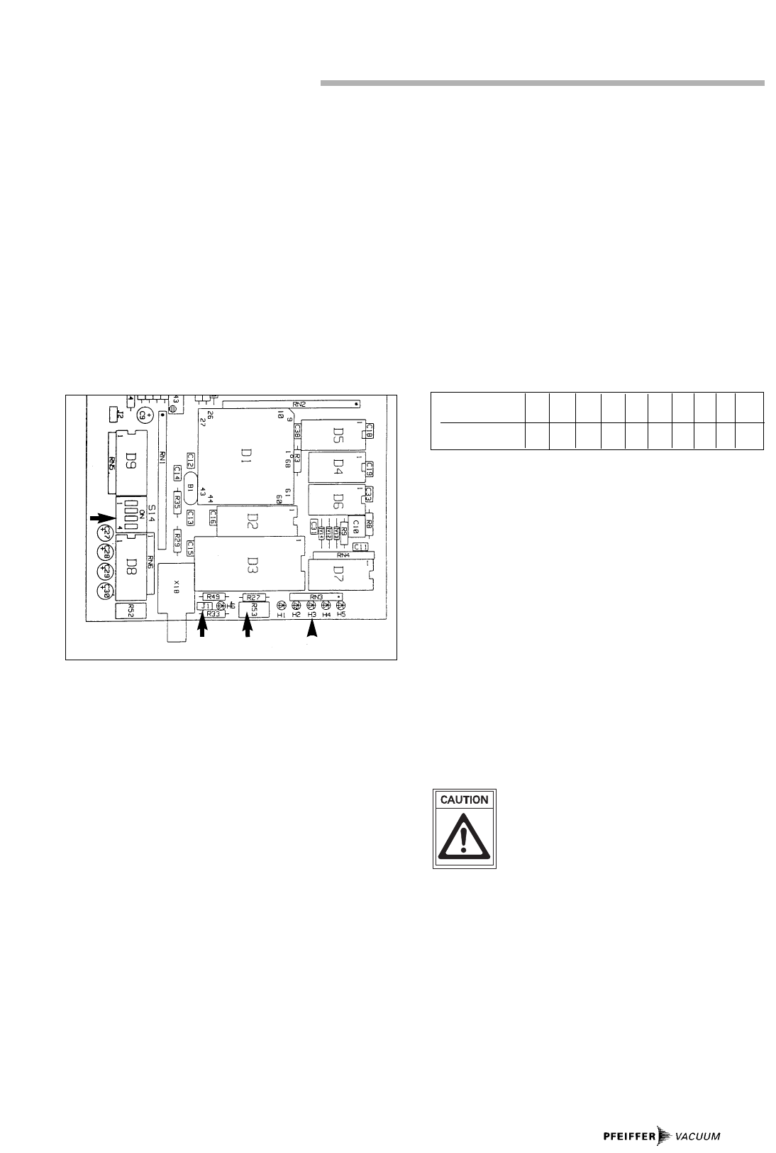
“Setting S14”
The function of the start-up time is preserved. If, once the
start-up time has elapsed, the pump current exceeds the set
current threshold for longer than 1 or 3 minutes both K1 and
the pump current is switched off and the error message
>E003< appears.
Activating Operations Mode “Motor Current Monitoring”
➡Fix jumper J1 onto the two pins next to the LED “H6”.
The establishment of the relationship between current and
high vacuum pressure has to be ascertained experimentally
Switching over to operations with motor current
monitoring may only be performed when the
TCP is current-less.
7. Operations, TCP 035
Voltage on
tap R53 (V) 0 0,5 1,5 2,0 2,5 3,0 3,5 4,0 4,5 5,0
Current Threshold (A) 0 0,13 0,39 0,51 0,64 0,77 0,9 1,031,11 1,27
H1 - H5
R53J1
S 14

14
7.6. Altering The Pre-Settings (S14)
Various operations modes can be set on the DIL switch S14
(TCP 035):
7.7. Error Reset
If the TCP 035 identifies an error the motor current is
switched off. Once the error has been eliminated the pump
does not re-start automatically. The reset which is necessary
is carried out as follows:
– Connect remote control input “Error Reset”.
X5/b6 for a time > 1 second< 5 seconds by means of an
external switch to X5/z2 (0 V).
– Transmission of the respective command via Serial
Interface RS 232 C
7.8. Switching The Turbopump ON and OFF
The pump can be switched off:
➡By activating switch S1,
➡With shut-down: With a switch between X5/z6 and
X5/z2 (0 V).
7.9. The Serial Interface
The Electronic Drive Unit TCP 035 is equipped with Serial
Interface RS 232 C. This serial interface enables queries to be
made regarding the operational status and parameters
(which are described in the various operations modes in
Sections 7.5. and 7.6.) in the TCP to be altered.
DIL Switch Switch Position OFF Switch Position ON*
S 14/2 Baud rate serial interface Baud rate serial interface
9600 Baud 4800 Baud
S 14/3 If, after the start-up time If 750 Hz has been attained
has elapsed, the rotation the start-up time is set to 0.
speed switchpoint (750 Hz)-If 750 Hz is non-attained,
is non attained the motor the pump is switched off
current is switched off and K1 opens.
and relay K1 opens.
S 14/4
Backing Intermittent operations Non-stop operations
pump
operations
on X5/d10;
X5/d12
S 14/4 Time delay of the Time delay of the
Operation current signal: current signal:
with motor- 60 seconds 3 seconds
current
monitoring
* Works setting

15
Folgende Fehler werden angezeigt:
Error LED (illuminates) Type of
Nr. Error1) Error Description Error Elimination
H1 H2 H3 H4 H5
E001 · · B,S UB > 43 V Check operations voltage
E002 ·B,S UB < 26 V, in operation < 22 V Check operations voltage
E003 ··· B,S I operations, current threshold exceeded –
E004 · · · S Pump identification resistanceRf > 2K8 Incorrect pump type
E005 · · · B Excess temperature, pump Cool down pump
E006 · · · B Excess temperature, TCP Cool down TCP
E007 ···· B Rotor blocked Pump defect, inform Service
E008 ··B Excess rotation speed TCP defect, inform Service
E009 · · · B Excess temperature, transformer Cool down TCP
E010 · · B,S Turbo OFF –
E011 · · · · B Start-up time elapsed Repair leak, check backing pump
E012 · · · B Pumping station malfunction Check backing pump and water cooling
E013 · · · · B,S Watchdog reset –
E014 · · · · B,S Interruption A (X8) –
E015 ·····S Motor or cable malfunction Check cable
E016 ·*B,S Keypad lock ON2) –
E017 · · B Pumping station OFF2) –
·LED illuminates 1) B = Operation 2) Switching ON/OFF only via the serial interface
* LED flashes S = Self-test
8.1. The Function Of The Illuminating Diodes
The TCP 035 is equipped with 5 illuminating diodes H1 - H5
which display errors.
The LEDs H2 - H5 display a coded error message. In the event
of serious malfunctions H1 also illuminates and the motor cur-
rent is switched off. In the case of minor malfunctions H1
does not illuminate and the pump continues to operate. The
column “Error Type” of the error table shows whether the
error has been diagnosed in self-test S, in operations B or in
both cases.
Incorrect error displays can arise if the cable from the pump
is disconnected during operations. A reset is necessary if the
TCP is to be operated again after a breakdown.
8.2. Function Test In The Event Of A
Malfunction
When malfunctions occur the following should first be
checked:
– Voltage connection on the TCP 015,
– Connection TCP 015 - pump,
– Fore-vacuum pressure.
8.4. Error Code Table
8.3. Eliminating Errors
Illumination Diode H1 Does Not Illuminate
➡Check switch position of S 8 and/or eliminate the error on
the power pack print.
➡Check mains fuse F1. If mains fuse F1 is defect withdraw
plug connector X13 and X14 (+ UB and 0 V). Insert new
fuses and use a voltmeter (UB = 28 V) to measure the ope-
rations voltage UB on measuring points P1 and P2. Switch
off mains switch S1 and re-connect X13 and X14.
Pump Venting Valve Does Not Close:
➡Check fuse F2.
Air Cooling Does Not Function:
➡Check fuse F4.
8. What To Do In The Case Of Breakdowns?
TCP 015/TCP 035
16
Customers who carry out their own repairs must
take account of the possibility that touchable
dangerous voltages can be present in the unit.
The relevant instructions must be observed
when customers carry out their own repair and
maintenance work on units which have come
into contact with materials which represent a
hazard to health.
Please Note:
Repair orders are carried out according to our general condi-
tions of sale and supply. If repairs are necessary, please send
the pump to your nearest PFEIFFER Service Center.
Contact Addresses And Telephone Hotline
Contact addresses and telephone numbers can be found on
the back cover of these operating instructions.
Electronic Drive Unit TCP 015
Connection voltage (100 V) 90 - 112
switchable V AC (120 V) 108 - 133
V AC (220 V) 198 - 245
(240 V) 216 - 267
Mains frequency Hz 50/60
Power take-up, max. VA 110
With air cooling
Output voltage, max. V 30 - 40 V
Normal operations
Start-up current A 2,2
Nominal frequency ± 2% max. Hz 1500
Stand-by operations
Start-up current A 2,2
Nominal frequency ± 2% max. Hz 1000
Contact load K1
Ohmic load A 4
Inductive load A 21)
Switching voltage, max. VAC 265
VDC 30
Analog outputs:
Rotation speed 10 V = 1500 Hz
± 2%
Current 10 V = 2,5 A
± 5%
BLoad carrying capacity of mA 5
the 0-10 V outputs
Start-up time min 8 - 60
Works setting min 8
Rotation speed switchpoint Hz 750
Permissible ambient temperature °C 0 - 40
Cable length Pump - TCP m 3
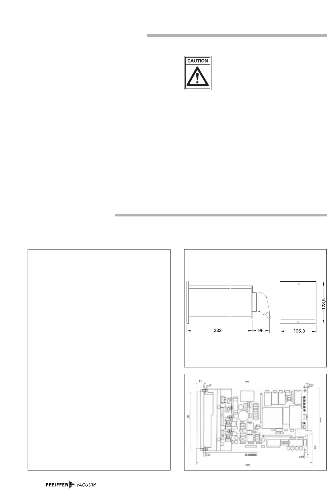
Dimensions, front panel mm 128,5x106,3
Insertion length mm 227
Weight kg 2,7
1) with cos f = 0,5
9. Maintenance, Service
10.Technical Data
The unit is maintenance-free. Dirt on the front panel panel
can be removed with a damp cloth having first disconnected
the unit from the mains power supply.
Do Make Use Of Our Service Facilities
In the event that repairs are necessary a number of options
are available to you to ensure any system down time is kept to
a minimum:
– Have the pump repaired on the spot by our PFEIFFER
Service Engineers;
– Return the pump to the manufacturer for repairs;
– Replace the unit with an as good as new exchange unit.
Local PFEIFFER representatives can provide full information.
The connections diagram in Section 11. shows the power
carrying current paths with their respective operational volta-
ges.
Dimensions TCP 035
Dimensions TCP 015
10.2.Dimensions
10.1.Data List
17
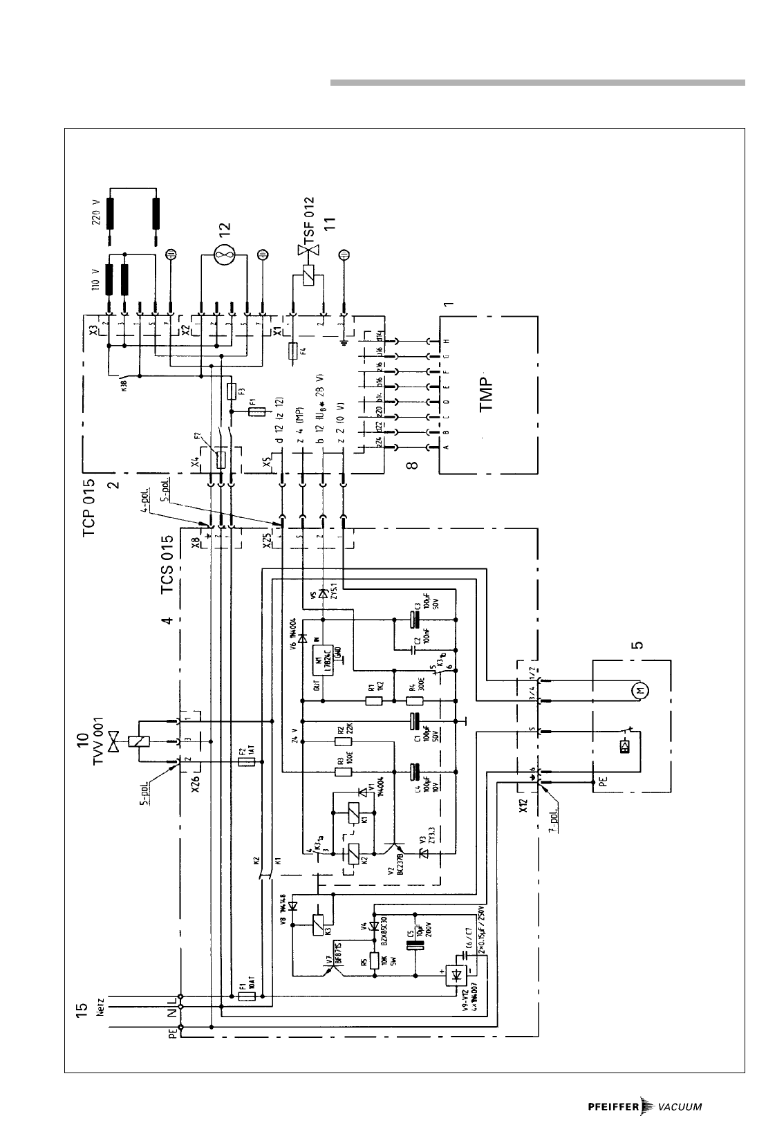
11.Connections Diagram
PM 041 532 -S
1 Turbomolecular pump
2 Electronic Drive Unit TCP
4 Pumping Station Control Unit
5 Backing Pump
8 Connection Turbopump-TCP
10 Fore-Vacuum Safety Valve
11 Venting Valve TSF 012
12 Air cooling
15 Mains connection
18
12.Pin Arrangement
X5
b14
d16
z16
b16
z20
d22
z24
d14
z28
z32
b4
z4
d6
b6
z6
d4
b12
d26
d30
d12
z14
b10
z12
z10
z8
d10
d8
b8
d2
b2
z2
TCP 035
X8
yellow
blue
pink
grey
green
brown
white
red
S1
D
G
F
E
C
B
A
H
Hall
0V
15V
Rf10)
M2
M1
UA
Turbo pump
Operation voltage 26-43V
Operation voltage 0V
HE – Heating ON
MP – Pumping station error
(pumping st. OFF) (T)
UT – PTC-trafo
RE – Error-Reset
CD – Turbopump Off
SE – Stand-by external
UB* – 34-35 V
K1 – Switch contact 4A, cos j = 1
K1 – Switch contact 2A, cos j = 0,5
IV – Interval operation, backing pump2)
FEN – Venting
SB – Stand-by (OC)
FL – Error (OC)
SP – Rot. speed switchpoint (750 Hz) (OC)
UV+ –
IV – Interval operation backing pump9)
UI – Current 0-10V = 0-2,5A
UF – Rotation speed 0-10V = 0-1500 Hz
TDX – Transmit
RXD– Receive
0V
PM 031 403 -S
u
^
^
11)
1)
3)
3)
3)
1) Key
Rf = 0W 2A/1500 Hz
360W 1,5 A/1500 Hz
1K5 1,2A/1000 Hz
10)
for backing pump with opto-coupler relais
9)
with TCS 015
2)
Open collector output
3)
feed separated, only without Jumper J2
11)
2
3
5
9
1
4
6
7
8
RXD
TXD
0V
RI
DCD
DTR
DSR
RTS
CTS
Computer
X 18
1 (TXD)
2 (RXD)
3 (0 V)
Remote control
inputs
Remote control
outputs
Pin Arrangement TCP 035

19
Description Size Number Operating Instructions Order Quantity/
Comments
Venting Valve TSF 012* DN 10-ISO KF PM Z01 105
Counter 2002 PM C00 125
Mains cable P4564 309ZA
Measuring and testing adapter PM 031 522 -U
*With regard to pump types TPH 035 and TPD 020 without special venting connection it is recommended that the venting valve be fitted to the high vacuum side.
14.Accessories
13.Spare Parts
Description Size Number Operating Instructions Order Quantity Comments
Fuses F1 2 AT P 4666 442
Fuses F2, F3 1 AT P 4666 436
Fuses F4 0,2 AT P 4666422

➪DD
DDEE
EE,,
,,
AA
AATT
TT
Herstellererklärung im Sinne folgender EU-Richtlinien:
- Maschinen 89/392/EWG
- Elektromagnetische Verträglichkeit 89/336/EWG
- Niederspannung 73/23/EWG
Hiermit erklären wir, daß das unten aufgeführte Produkt zum Einbau in eine Maschine bestimmt ist und daß deren Inbetriebnahme so lan-
ge untersagt ist, bis festgestellt wurde, daß das Endprodukt den Bestimmungen der EU-Richtlinie 89/392/EWG, Anhang II B entspricht.
Wir bestätigen Konformität mit der EU-Richtlinie über elektromagnetische Verträglichkeit 89/336/EWG und der EU-Niederspannungsrichtlinie 73/23/EWG.
Die angewandten Richtlinien, harmonisierten Normen, nationalen Normen und Spezifikationen sind unten aufgeführt.
➪GG
GGBB
BB,,
,,
II
IIEE
EE
Manufacturer´s declaration pursuant to the following EU directives:
- Machinery Directive 89/392/EEC
- Electromagnetic Compatibility Directive 89/336/EEC
- Low Voltage Directive 73/23/EEC
We hereby certify that the product specified below is intended for installation in a machine which is forbidden to be put into operation until such time as it has
been determined that the end product is in accordance with the provision of EU Directive 89/392/EEC, Annex II B.
We certify conformity with EU Electromagnetic Compatibility Directive 89/336/EEC and EU Low Voltage Directive 73/23/EEC.
The guidelines, harmonized standards, national standards and specifications which have been applied are listed below.
➪BB
BBEE
EE,,
,,
FF
FFRR
RR
Déclaration du constructeur conformément aux directives CE suivantes:
- directive machine CE 89/392/CEE
- directive CE 89/336/CEE concernant la compatibilité électromagnétique
- directive CE 73/23/CEE concernant la basse tension
Nous déclarons par la présente que le produit mentionné ci-dessous est prévu pour le montage sur une machine et que sa mise en service est interdite tant qu’il
n’a pas été déterminé que le produit final répond bien aux dispositions de la directive CE 89/392/CEE, appendice II B.
Nous confirmons la conformité du produit avec la directive CE 89/336/CEE concernant la compatibilité électromagnétique et la directive CE 73/23/CEE concernant
la basse tension. Les directives appliquées, normes harmonisées et les normes et spécifications nationales appliquées figurent ci-dessous.
➪II
IITT
TT
Dichiarazione del costruttore ai sensi delle seguenti direttive UE:
- Macchinari 89/392/CEE
- Compatibilità elettromagnetica 89/336/CEE
- Bassa tensione 73/23/CEE
Si dichiara che il prodotto qui menzionato è destinato al montaggio in una macchina e che la sua messa in funzione è vietata sin quando non è stato accertato
che il prodotto finale non rispetta le disposizioni della direttiva UE 89/392/CEE, Appendice II B.
Attestiamo la conformità con la direttiva UE sulla compatibilità elettromagnetica 89/336/CEE e la direttiva UE sulla bassa tensione 73/23/CEE.
Sono riportate in basso le direttive aplicate, le norme standardizzate nonché le norme e le specifiche nazionali utilizatte.
➪EE
EESS
SS
Declaración del fabricante al tenor de las siguientes Directivas de la UE:
- Maquinarias 89/392/MCE
- Compatibilidad Electromagnética 89/336/MCE
- Baja Tensión 73/23/MCE
Por la presente declaramos que el producto mencionado más abajo está previsto para ser incorporado en una máquina y que la puesta en servicio de la misma
queda prohibida en tanto que no se haya verificado que el producto final concuerda con las disposiciones resultantes de la Directiva 89/392/MCE de la UE,
Apéndice II B.
De nuestra parte certificamos la conformidad con la Directiva 89/336/MCE de la UE sobre Compatibilidad Electromagnética y la Directiva 73/23/MCE de la UE
sobre Baja Tensión.
Las directivas aplicadas, normas armonizadas y las normas y especificaciones nacionales aplicadas se mencionan abajo.
➪NN
NNLL
LL
Verklaring van de fabrikant in de zin van de volgende EU-richtlijnen:
- machinerichtlijn 89/392/EEG
- richtlijn over elektromagnetische compatibiliteit 89/336/EEG
- richtlijn over laagspanning 73/23/EEG
Hiermee verklaren wij dat het hieronder genoemde produkt is bedoeld om te worden ingebouwd in een machine en dat de ingebruikneming hiervan zolang ver-
boden is, totdat is vastgesteld dat het eindprodukt voldoet aan de bepalingen van EU-richtlijn 89/392/EEG, appendix II B.
Wij bevestigen de conformiteit met de EU-richtlijn over elektromagnetische compatibiliteit 89/336/EEG en de EEG-richtlijn over laagspanning 73/23/EEG
De toegepaste richtlijnen, geharmoniseerde normen en de toegepaste nationale normen en specificaties zijn hierna aangegeven.
➪DD
DDKK
KK
Producenterklæring i henhold til følgende EU-direktiver:
- Maskiner 89/392/EWG
- Elektromagnetisk kompatibilitet 89/336/EWG
- Lavspænding 73/23/EWG
Hermed erklærer vi, at det nedenstående produkt er beregnet til indbygning i en maskine og at dennes idriftsættelse er forbudt, indtil det er fastslået, at slutpro-
duktet er i overensstemmelse med EU-direktiv 89/392/EWG tillæg II B.
Vi attesterer konformitet med EU-direktiv vedrørende elektromagnetisk kompatibilitet 89/336/EWG og med EU-lavspændingsdirektiv 73/23/EWG.
De anvendte direktiver, harmoniserede standarder og de anvendte nationale standarder og specifikationer er angivet nedenfor.
Pfeiffer Vacuum GmbH
Emmeliusstr. 33
D-35614 Asslar
Herst.I/9604
➪SS
SSEE
EE
Tillverkarens förklaring enligt följande EG-direktiv:
- Maskindirektiv 89/392/EEC
- Elektromagnetisk tolerans 89/336/EEC
- Lågspänning 73/23/EEC
Härmed förklarar vi, att den nedan nämnda produkten är avsedd för inmontering i en maskin och att denna maskin inte får tas i drift förrän det har konstaterats,
att slutprodukten stämmer överens med EG’s direktiv 89/392/EEC, annex II B.
Vi bekräftar konformitet med EG’s-direktiv om elektromagnetisk tolerans 89/336/EEC och EG’s lågspänningsdirektiv 73/23/EEC.
De riktlinjer, anpassade standarder, nationella standarder och specifikationer som har blivit accepterade, anges här nedan.
➪FF
FFII
II
Valmistajan vakuutus seuraavien EU-direktiivien mukaisesti:
- konedirektiivi 89/392/ETY
- sähkömagneettinen siedettävyys 89/336/ETY
- pienjännite 73/23/ETY
Vakuutamme täten, että allamainittu tuote on tarkoitettu asennettavaksi koneeseen ja sen käyttöönotto on kielletty kunnes on todettu, että lopullinen tuote
vastaa EU-direktiivin 89/392/EtY vaatimuksia.
Vahvistamme vaatimustenmukaisuuden EU-direktiivin sähkömagneettinen siedettävyys 89/336/ETY ja EU-pienjännitedirektiivin 73/23/ETY kanssa.
Soveltamamme suuntaviitat, harmonisoidut standardit, kansalliset standardit ja rakennemääräykset on luteltu alempana.
➪PP
PPTT
TT
Declaração do fabricante, de acordo com as seguintes Directivas CE:
- Máquinas, na redacção 89/392/CEE
- Compatibilidade electromagnética, na redacção 89/336/CEE
- Baixa tensão, na redacção 73/23/CEE
Com a presente, declaramos que o produto abaixo indicado se destina à montagem numa máquina e que é proibida a colocação em serviço da mesma antes de
se ter declarado, que o produto final está em conformidade com o disposto na Directiva CE, na redacção 89/392/CEE, Apêndice II B.
Certificamos haver conformidade com o disposto na Directiva CE sobre compatibilidade electromagnética, na redacção 89/336/CEE, e o disposto na Directiva CE
sobre baixa tensão, na redacção 73/23/CEE.
Abaixo, dá-se indicação das directivas aplicadas, das normas harmonizadas e das normas e especificações aplicades no respectivo país.
➪GG
GGRR
RR
Produkt/Product/Produit/Prodotto/Producto/Produkt/Produkt/Produto/
a) TCP 015
b) TCP 035
Angewendete Richtlinien, harmonisierte Normen und angewendete, nationale Normen in Sprachen und Spezifikationen:
Guidelines, harmonised standards, national standards in languages and specifications which have been applied:
Les directives appliquées, normes harmonisées et les normes nationales appliquées en langues et spécifications:
Direttive aplicate, norme standardizzate e norme nazionali utilizzate in lingue e specifiche:
Directivas aplicadas, normas armonizadas y normas nacionales aplicadas en idiomas y especificaciones:
Toegepaste richtlijnen, geharmoniseerde normen en toegepaste nationale normen met betrekking tot talen en specificaties:
Anvendte direktiver, harmoniserede standarder og de anvendte nationale standarder med sprog og specifikationer:
Directivas aplicadas, normas harmonizadas e normas aplicadas na linguagem e nas especificações do respectivo país:
a) EN 61010, EN 55011, EN 50081-1, EN 50082-2, IEC 801 1-4, VDE 0843-6
b) EN 61010
Unterschriften/Signatures/Signature/Firme/Firmas/Handtekeningen/Underskrifter/Underskrift/ Allekirjoitukset/Assinaturas/
Geschäftsführer (W. Dondorf)
Managing Director Administrerende Direktør
Gérant d’affairs Verkställande Direktör
Gerente Directeur
DTP
Herst.I/9606 Form.-Nr. 10117 / (9606)

Zentrale/Headquarters
Pfeiffer Vacuum GmbH
Emmeliusstrasse 33
D-35614 Asslar
Telefon 06441/802-0
Telefax 06441/802-202
Hotline 06441/802-333
Internet:
http://www.pfeiffer-vacuum.de
India
Pfeiffer Vacuum India Ltd.
25-E Nicholson Road, Tarbund
Secunderabad 500 009,
telephone 0091 / 40 775 0014, telefax 0091 / 40 775 7774
Israel
Eastronics Ltd., 11 Rozanis Street, P.O. Box 39 300,
Tel Aviv 61392,
telephone 00972 / 3 6458 777,
telefax 00972 / 3 6458 666
Italy
Pfeiffer Vacuum Italia S.p.a.
Via San Martino, 44 I-20017 RHO (Milano)
telephone 0039 / 2 93 99 051, telefax 0039 / 2 93 99 05 33
Japan
Hakuto Co. Ltd., C.P.O. Box 25,
Vacuum & Scientific Instruments Division
Tokyo Central 100-91,
telephone 0081 / 3 32 258 910,
telefax 0081 / 3 32 259 009
Korea
Pfeiffer Vacuum Korea Ltd., 3F Haein Building 453,
Dokok-Dong, Kang Nam-Ku, Seoul, 135-270
telephone 0082 / 2 3461 0671,
telefax 0082 / 2 3461 0676
Netherlands
Pfeiffer Vacuum Nederland BV
Veldzigt 30a, NL-3454 PW De Meern,
telephone 0031 / 30 6666050, telefax 0031 / 30 6662794
Peru
Ing. E. Brammertz S.C.R.L., José Pardo 182,
Apartado 173, PE-18 Miraflores,
telephone 0051 / 1 445 8178
telefax 0051 / 1 445-1931
Poland
Softrade Sp.z.o.o, ul. Malwowa 35,
PL-60-175 Poznan, telephone 0048 / 61 8677 168,
telefax 0048 / 61 8677 111
Portugal
Unilaser Lda, Taguspark
Núcleo Central, sala no268, Estrada Cacém-
Porto Salvo, P-2780 Oeiras
telephone 00351 / 1 421 7733,
telefax 00351 / 1 421 7744
Singapore
APP Systems Services Pte. Ltd, 2 Corporation Road
06-14 Corporation Place, Singapore 618494,
telephone 0065 / 268 2024, telefax 0065 / 268 6621
Spain
Tecnovac
Tecnologia de Vacio S.L., Ronda de Poniente, 6 Bajo F
Centro Empresarial Euronova
E-28760 Tres Cantos (Madrid)
telephone 0034 / 91 804 11 34,
telefax 0034 / 91 804 30 91
Sweden
Pfeiffer Vacuum Scandinavia AB
Magasinsgatan 35, Box 10412
S-43424 Kungsbacka
telephone 0046 / 300 710 80
telefax 0046 / 300 172 85
Service Hotline: 0046 / 300 710 85
Switzerland
Pfeiffer Vacuum Schweiz S.A.
Förrlibuckstraße 30, CH-8005 Zürich
telephone 0041 / 1 444 2255,
telefax 0041 / 1 444 2266
Service Hotline: 0041 / 1 2730119
South Africa
Labotec Pty Ltd., P.O. Box 6553,
Halfway House
1685 Midrand
telephone 0027 / 11 315 5434
telefax 0027 / 11 315 5882
Taiwan
S & T Hitech Ltd. Hsinchu office
No. 103, Hsien Chen 11th Street, Jubei City,
HsinChu County, Taiwan, R.O.C.
(zip/postal code: 302)
telephone 00886 / 3 554 1020
telefax 00886 / 3 554 0867
Thailand
S & T Enterprises (Thailand) Ltd.
18th Floor, Chokchail Intíl Bldg.
690 Sukhumvit Road
Klongton, Klongtoey
Bangkok 10110
telephone 00662 / 259 4623
telefax 00662 / 259 6243
U.S.A.
Pfeiffer Vacuum Technology, Inc.
24 Trafalgar Square
Nashua, NH 03063-1988
USA
telephon 001/ 603 578 6500
telefax 001/ 603 578 6550
Venezuela
Secotec S.A., Apartado 3452, Caracas 1010-A,
telephone 0058 / 2 573 8687
telefax 0058 / 2 573 1932
Other countries
AVI - Applied Vaccuum Industries GmbH
Leginglenstrasse 17A; CH-7320 Sargans
Switzerland
telefon 0041 / 81 710 03 80
telefax 0041 81 710 03 81
Scope of represented countries
Armenia, Azerbaijan, Bangladesh, Belarus, Bulgaria,
Cambodia, Estonia, Georgia, Hong Kong, Kazakhstan,
Kingdom of Nepal, Kirghizia, Latvia, Lithuania, Maldavia,
Philippines, P.R. China, Rumania, Russia, Tajikistan,
Turkmenistan, Ukraine, Uzbekistan, Vietnam
A.E.M.S.
Advanced Equipment Materials and Systems
P.O. Box 25
Föhrenweg 18
FL-9496 Balzers
telephon 0041 / 75 380 0550
telefax 0041 / 75 380 0551
Scope of represented countries
Bahrain, Egypt, Iraq, Iran, Jordan, Kuwait, Lebanon,
Lybia, Oman, Pakistan, Saudi-Arabia, Sudan, Syria,
Turkey, United Arab Emirates, Yemen
Argentina
ARO S.A., Casilla de Correo 4890,
1000 Buenos Aires, telephone 0054 / 1 331 3918,
telefax 0054 / 1 331 3572
Australia
Balzers Australia Pty. Ltd., Level 1,
3, Northcliff Street, Milsons Point, NSW 2061,
telephone 0061 / 2 9954 1925, telefax 0061 / 2 9954 1939
Austria
Pfeiffer Vacuum Austria GmbH
Diefenbachgasse 35, A-1150 Wien,
telephone 0043 / 1 8941 704, telefax 0043 / 1 8941 707
Service Hotline: 0043 / 1 8941704
Belgium / Luxemburg
Pfeiffer Vacuum Belgium N.V./S.A.
Minervastraat 14, B-1930 Zaventem
telephone 0032 / 2 725 0525, telefax 0032 / 2 725 0873
Service Hotline: 0032 / 2 725 3545
Brazil
Elmi Tec
Assistencia Técnica e Representação S/C Ltda.
Rua Bernadino de Compos, 551
CEP 04620-002 São Paulo, SP - Brasil
telephone 0055 / 11 532 0740
telefax 0055 / 11 535 3598
Chile
BERMAT S.A., Coyancura 2283, piso 6
Providencia, P.O. Box 9781, Santiago
telephone 0056 / 2 231 8877,
telefax 0056 / 2 231 4294
Colombia
Arotec Colombiana S.A., Carrera 15 No.38-17
P.O. Box 050 862, Santafe de Bogota / D.C.
telephone 0057 / 1 288 7799, telefax 0057 / 1 285 3604
Denmark
Pfeiffer Vacuum Scandinavia AB, Vesterengen 2,
DK-2630 Taastrup, telephone 0045 / 43 52 38 00,
telefax 0045 / 43 52 38 50
France
Pfeiffer Vacuum France SAS
45, rue Senouque, BP 139 F-78531 BUC Cedex
telephone 0033 / (0)1 30 83 04 00,
telefax 0033 / (0)1 30 83 04 04
Germany
Pfeiffer Vacuum Vertriebs GmbH,
Emmeliusstrasse 33, D-35614 Asslar
telephone 0049 / 6441 802 400
telefax 0049 / 6441 802 399
Service Hotline: 0049 / 6441 802 333
Great Britain
Pfeiffer Vacuum Ltd.
Bradbourne Drive, Tilbrook,
Milton Keynes, MK7 8AZ, United Kingdom
telephone 0044 / 1 908 373 333
telefax 0044 / 1 908 377 776
Greece
Analytical Instruments S.A., 1 Mantzarou St.,
GR-15451 Athens,
telephone 0030 / 1 674 8973, telefax 0030 / 1 674 8978
(0299)
