Tp11kac D_manual D Manual
User Manual: tp11kac-d_manual
Open the PDF directly: View PDF ![]() .
.
Page Count: 32
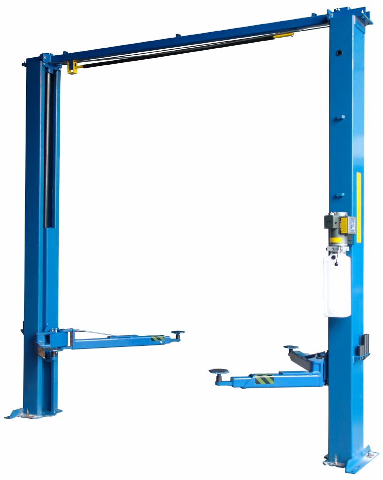
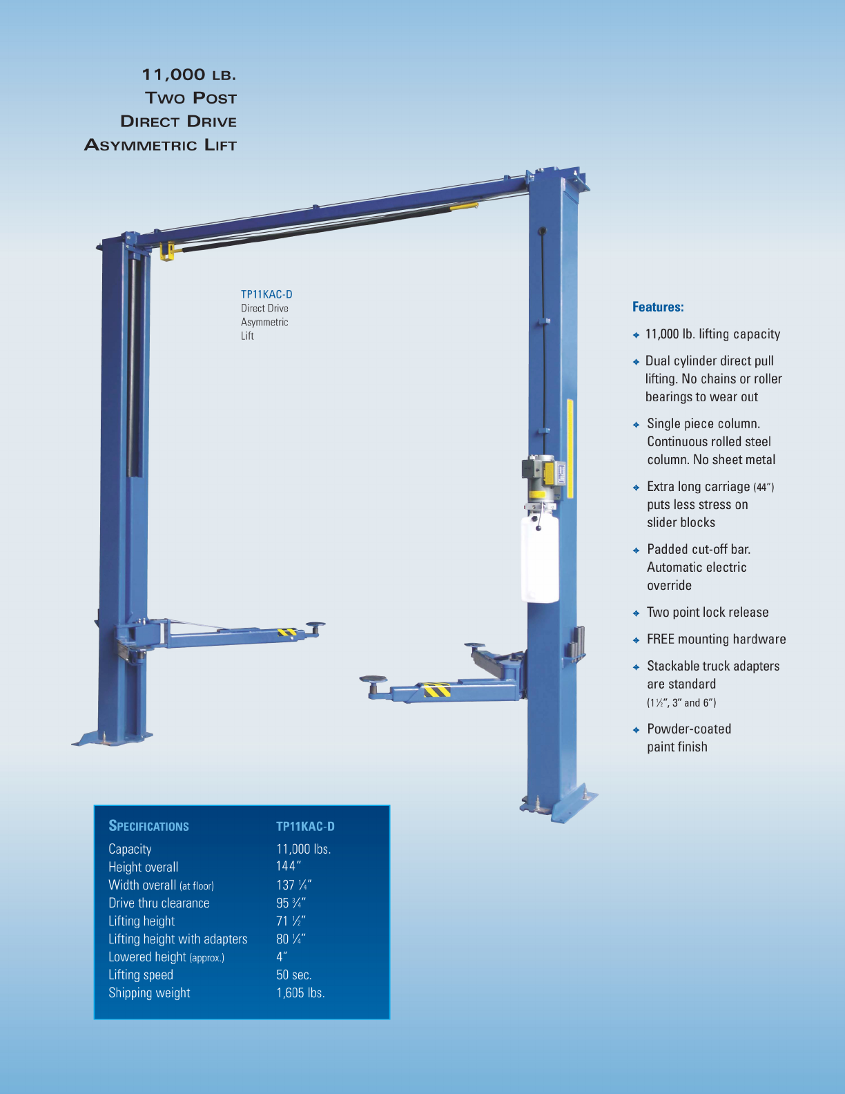
TP11KAC-D
Two Post Clear Floor Auto Lift
11000 lb Capacity
ASSEMBLY & OPERATION
INSTRUCTION MANUAL
REV A-070913


1905 N Main St Suite C, Cleburne, TX 76033
Ph 817-558-9337 Fax 817-558-9740
TUXEDO DISTRIBUTORS LIMITED WARRANTY
Structural Warranty:
The following parts and structural components carry a five year warranty:
Columns Top Rail Beam Uprights Arms Swivel Pins
Legs Carriages Tracks Overhead Beam Cross Rails
Limited One-Year Warranty:
Tuxedo Distributors, LLC (“Tuxedo”) offers a limited one-year warranty to the original purchaser of
Tuxedo lifts and Wheel Service in the United States and Canada. Tuxedo will replace, without charge, any
part found defective in materials or workmanship under normal use, for a period of one year after purchase.
The purchaser is responsible for all shipping charges. This warranty does not apply to equipment that has
been improperly installed or altered or that has not been operated or maintained according to specifications.
Other Limitations:
This warranty does not cover:
1. Parts needed for normal maintenance
2. Wear parts, including but not limited to cables, slider blocks, chains, rubber pads and pulleys
3. Replacement of lift and tire changer cylinders after the first 30 days. A seal kit and installation
instructions will be sent for repairs thereafter.
4. On-site labor
Upon receipt, the customer must visually inspect the equipment for any potential freight damage before
signing clear on the shipping receipt. Freight damage is not considered a warranty issue and therefore must
be noted for any potential recovery with the shipping company.
The customer is required to notify Tuxedo of any missing parts within 72 hours. Timely notification must
be received to be covered under warranty.
Tuxedo will replace any defective part under warranty at no charge as soon as such parts become available
from the manufacturer. No guarantee is given as to the immediate availability of replacement parts.
Tuxedo reserves the right to make improvements and/or design changes to its lifts without any obligation
to previously sold, assembled or fabricated equipment.
There is no other express warranty on the Tuxedo lifts and this warranty is exclusive of and in lieu of all
other warranties, expressed or implied, including all warranties of merchantability and fitness for a
particular purpose.
To the fullest extent allowed by law, Tuxedo shall not be liable for loss of use, cost of cover, lost profits,
inconvenience, lost time, commercial loss or other incidental or consequential damages.
This Limited Warranty is granted to the original purchaser only and is not transferable or
assignable.
Some states do not allow exclusion or limitation of consequential damages or how long an
implied warranty lasts, so the above limitations and exclusions may not apply. This warranty
gives you specific legal rights and you may have other rights, which may vary from state to state.

165948 Two Post Lift Installation and Owners Manual
3
Section 1
Owner’s Manual
Safety Instructions:
1. Do not raise a vehicle on the lift until the installation is completed as described in this manual.
2. Anyone who will be in the vicinity of the lift when it is in use are recommended to read the
following publications:
a. “INSTALLATION AND OWNERS MANUAL”,
b. “LIFTING IT RIGHT”, ALI SM93-1
c. “AUTOMOTIVE LIFT SAFETY TIPS”, ALI-ST90.
d. “VEHICLE LIFTING POINTS FOR FRAME ENGAGING LIFTS”,
ALI/LP-GUIDE.
e. “SAFETY REQUIREMENTS FOR OPERATION, INSPECTION, AND
MAINTENANCE’, ANSI/ALI ALOIM-1994.
3. Technicians should be trained to use and care for the lift by familiarizing themselves with the
publications listed above. The lift should never be operated by an untrained person.
4. Always position the arms and adapters properly out of the way before pulling the vehicle into, or
out of the bay. Failure to do so could damage the vehicle and/or the lift.
5. Do not overload the lift. The capacity of the lift is shown on cover of this document and on
the lift’s serial number tag
6. Positioning the vehicle is very important. Only trained technicians should position the vehicle on
the lift. Never allow anyone to stand in the path of the vehicle as it is being
positioned and never raise vehicle with passengers inside.
7. Position the arms to the vehicle manufacturer’s recommended pickup points. Raise the lift until
contact is made with the vehicle. Make sure that the arms have properly engaged the vehicle
before raising the lift to a working height.
8. Keep everyone clear of the lift when the lift is moving, the locking mechanism is disengaged, or
the vehicle is in danger of falling.
9. Unauthorized personnel should never be in the shop area when the lift is in use.
10.Inspect the lift daily. The lift should never be operated if it has damaged
components, or is malfunctioning. Only qualified technicians should service the lift.
Replace damaged components with manufacturer’s parts, or equivalent.

165948 Two Post Lift Installation and Owners Manual
4
11. Keep the area around the lift clear of obstacles.
12. Never override the self-returning lift controls.
13. Use safety stands when removing or installing heavy vehicle components.
14. Avoid excessive rocking of the vehicle when it is on the lift.
15. To reduce the risk of personal injury, keep hair, loose clothing, fingers, and all body parts away
from moving parts.
16. To reduce the risk of electric shock, do not use the lift when wet, do not expose the lift to rain.
17. To reduce the risk of fire, do not operate equipment in the vicinity of open containers of
flammable liquids (gasoline).
18.Use the lift only as described in this manual, use only manufacturer’s recommended
attachments.
19. Unusual vehicles, such as limousines, RV’s, and long wheelbase vehicles,
may not be suitable for lifting on this equipment. If necessary, consult with the
manufacturer or the manufacturer’s representative.
20.The troubleshooting and maintenance procedures described in this manual can be done by the
lift’s owner/employer. Any other procedure should only be performed by trained lift service
personnel. These restricted procedures include, but are not limited to, the
following: cylinder replacement, carriage and safety latch replacement, leg
replacement, overhead structure replacement.
21. Anyone who will be in the vicinity of the lift when it is in use should familiarize themselves with
following Caution, Warning, and Safety related decals supplied with this lift, and replace them if
the are illegible or missing.
Monthly Maintenance:
1. Lubricate the four inside corners of the legs with heavy duty bearing grease.
2. With lift lowered check the hydraulic fluid level. If necessary add oil as described in the
Installation Instruction section of this manual
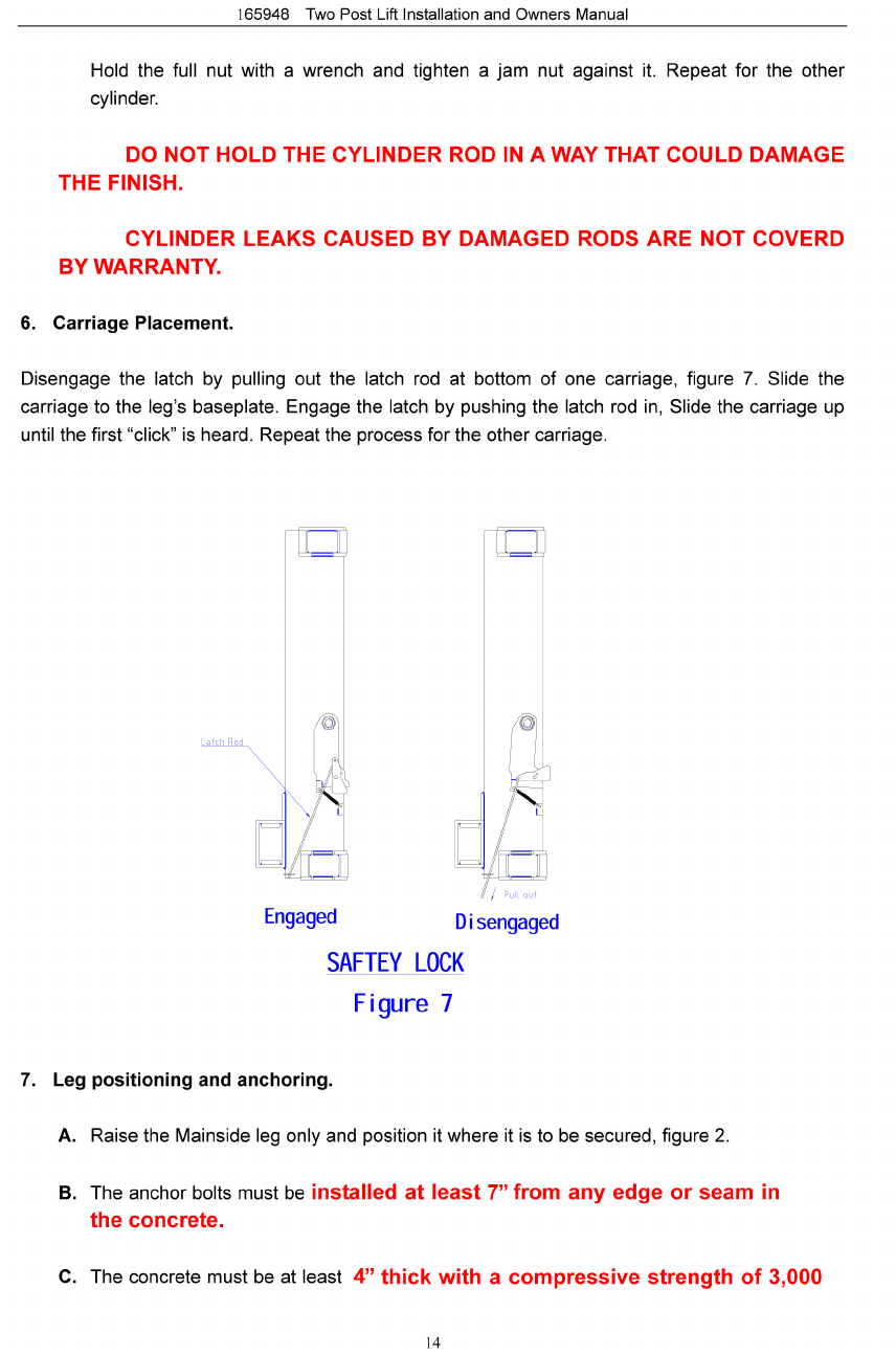
3. Check carriage latch synching: Latches should click at the same time. If
necessary adjust equalization cables as described in the Installation Instruction section of this
manual.

165948 Two Post Lift Installation and Owners Manual
5
4. Check tightness of all bolts.
5. Check anchor bolt tightness. If the anchor bolts are loose, they should be
re-torqued to 90ft/lbs.
Check the nuts for tightness every week for the first month, and every month
afterwards.
6. Replace worn or broken parts with lift manufacturer’s parts, or their equivalent.
Troubleshooting:
1. The power unit does not run:
a. Check electrical supply breaker, or fuse.
b. Check for activation of the travel limit switch by a tall vehicle.
c. Check micro-switch and connections in motor control box.
d. Check voltage to the motor.
e. Check micro-switch and connections in the overhead switch box.
2. The power unit runs but does not raise the lift:
a. Check the oil level.
b. Check that the lowering valve is not stuck open.
c. Check the connections and components on the suction side of the pump.
3. The power unit raises the lift empty, but will not lift a vehicle:
a. Make sure the vehicle is not above the rated capacity of the lift.
b. Make sure the vehicle is positioned properly.
c. Clean the lowering valve by running the power unit for 30 seconds while holding the
lowering valve open.
d. Check the motor voltage.
4.Lift drifts down:
a. Check for external leaks.
b. Clean the lowering valve by running the power unit for 30 seconds while holding the lowering
valve open. Repeat this procedure three times.
c. Clean the check valve seat.
5. Slow Lifting and/or oil foaming up:
a. Check that oil used meets the specification in the Installation Instruction section of this

165948 Two Post Lift Installation and Owners Manual
6
manual.
b. Tighten all suction line fittings.
6. Anchors continually work loose:
a. If holes were drilled too large relocate the lift per the Installation Instruction section of this
manual.
b. Floor is not sufficient to provide the necessary resistance, remove an area of concrete and
repour as described in the Installation Instruction section of this manual.
7. Lift does not raise and lower smoothly:
a. Reposition vehicle for a more even weight distribution.
b. Check the four inside corners of the two legs for roughness. Any rust or burrs must be
removed with 120 grit emery cloth.
c. Lubricate the leg corners with heavy duty bearing grease.
d. Use a level to check the legs for vertical alignment both side to side and front to back. Shim
the legs as necessary per the Installation Instruction section of this manual.
e. Check the oil level.
f. Make sure there is no air in the hydraulic lines, bleed system as described in
the Installation Instruction section of this manual.
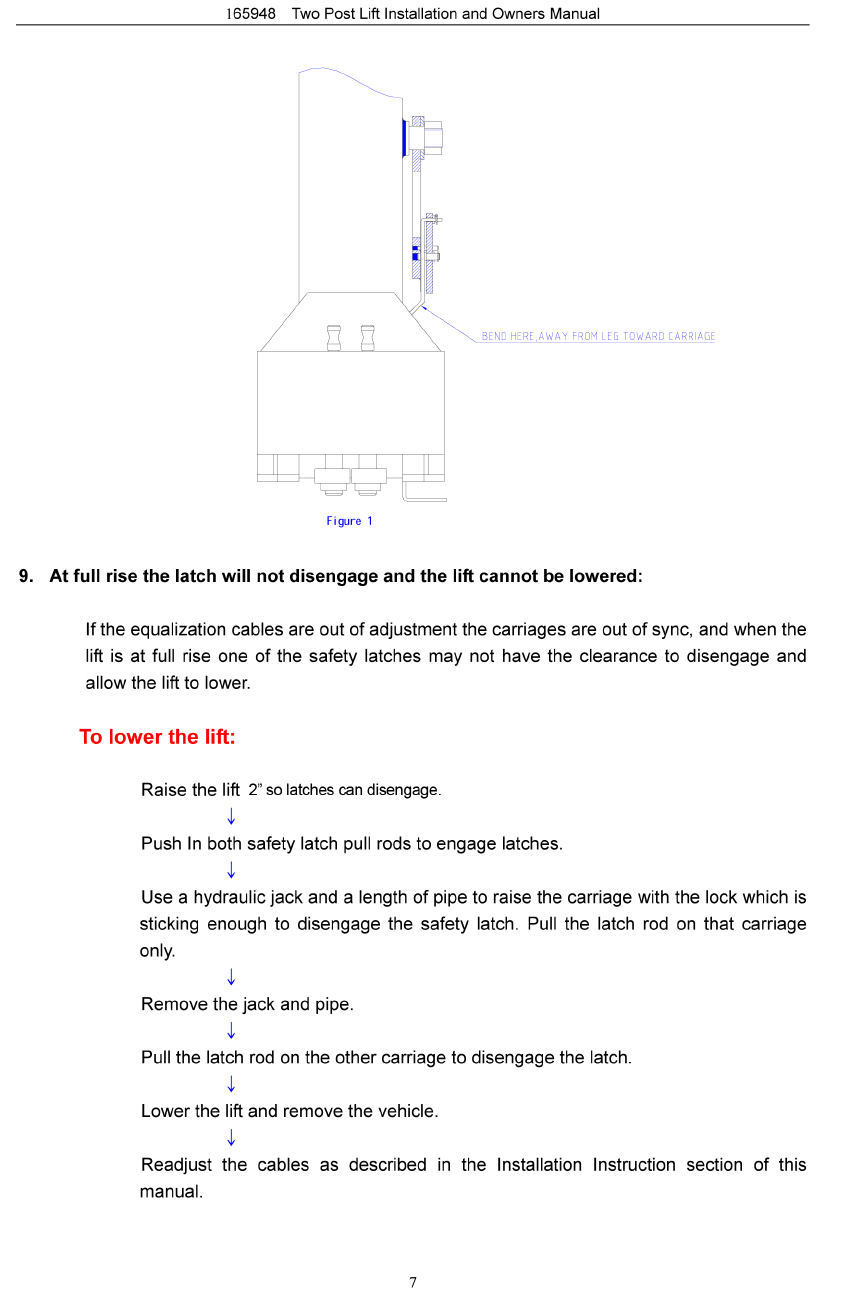
8. The lift will only lower approximately 1”, then stops:
a. Check that the safety latch pull rods are disengaged.
If after disengagement of the pull rods, one of them moves back up as the lift is lowered,
the pull rod is out of adjustment and is rubbing on the leg. Adjusting the rod to clear the leg.
Push down on the first bend of the rod just inside the leg. Bend the rod slightly to allow it to
move freely between the leg and the carriage.

165948 Two Post Lift Installation and Owners Manual
8
10. Power Unit will not stop running:
a. Switch is damaged, Turn off power to the lift and replace switch.
Section 2
Installation Instruction
Tools requires for installation:
Concrete hammer drill with 3/4” bit
11/16” open end wrench
3/4” open end wrench
Torque wrench
15/16” deep socket or wrench
1-1/8” socket
13/16” open end wrench
Level (18” minimum length)
Vise grips
Tape measure
Funnel
Hoist or Forklift (optional)
Two 12’ step ladders
1/4” drive ratchet with 5/16” socket
Procedure:

165948 Two Post Lift Installation and Owners Manual
9
1. Read this manual thoroughly before installing, operating, or maintaining this lift.
2. Site Evaluation and Lift Location:
A. Always use an architect’s plan when provided. Before unpacking the lift entirely, determine
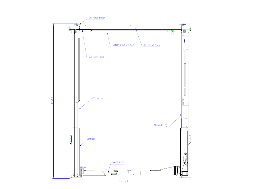
if the site is adequate for the lift model being installed see figures 2 and 3 for typical bay
layout and ceiling height requirements.
B. Snap chalk lines to identify the lift’s centerline.
C. Snap a chalk line parallel to the lift’s centerline, spaced 9” toward the rear of the bay.
This line represents the back edge of the leg bases.
D. Snap chalk lines parallel to the lift’s centerline spaces 68-1/2 to the left and 68-1/2
to the right. These lines represent the APPROXINMATE outside edges of the leg bases.
DO NOT USE THESE LINES TO POSITION THE LEGS, FOLLOW THE
INSTRUCTIONS IN THIS MANUAL.
165948 Two Post Lift Installation and Owners Manual
10
3. Unpack the lift. Remove the swing arms, bolt box, power unit box, and overhead beam.
A. Save all packing hardware, as these components are necessary to complete the
installation.
B. Remove the ½” bolts from the uprights which hold the two legs together.
C. Remove the top leg. Do not stand legs up, instead lay the legs flat their backs on the
floor.
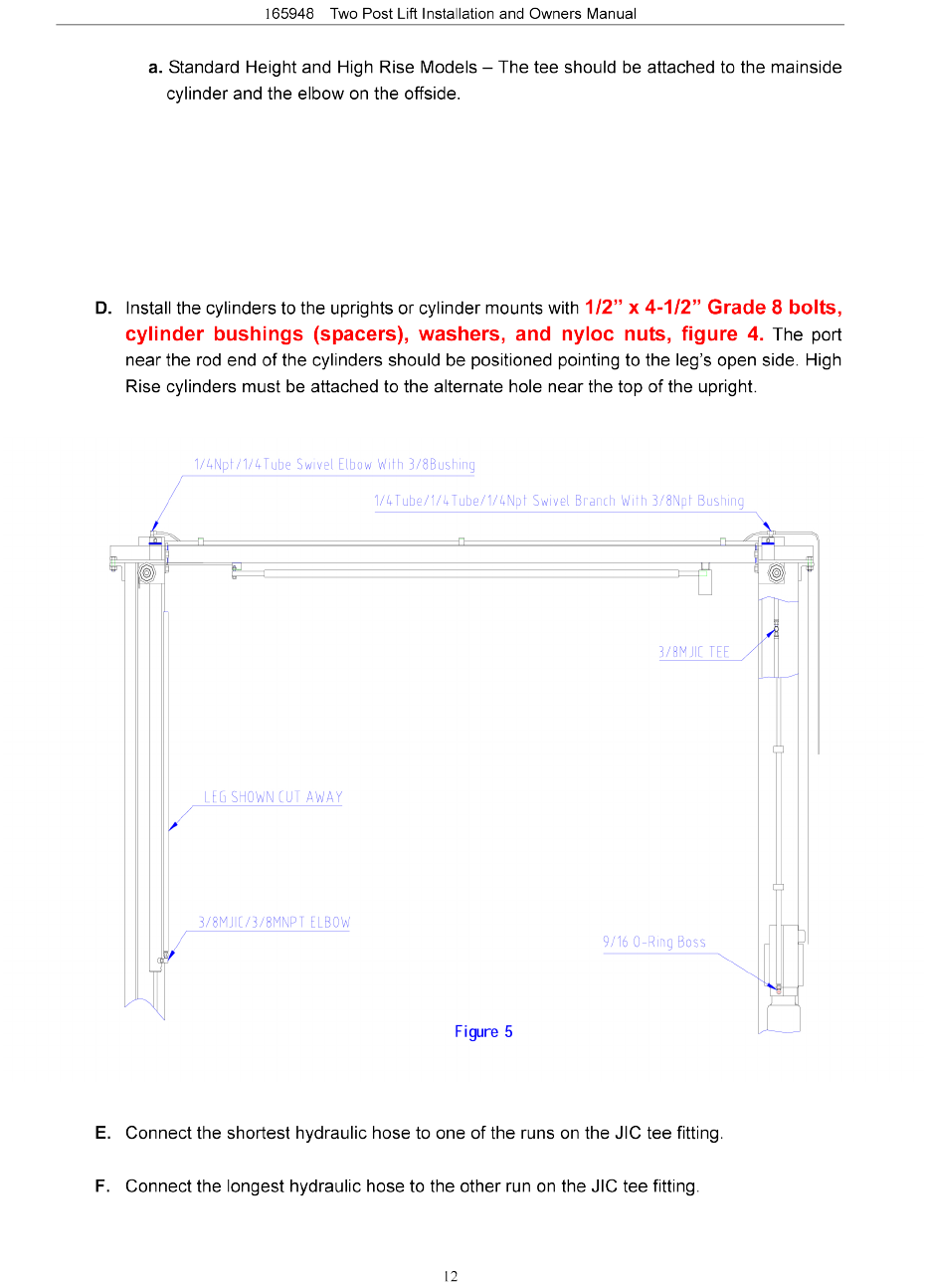
4. Attach the cylinder mount or uprights. Attach the cylinder mounts or uprights to the legs
using four ½” X 1-¾” bolts, washers and nuts as shown in figure 4.
165948 Two Post Lift Installation and Owners Manual
11
Figure 4
5. Install hydraulic cylinders, fittings, hoses, and cables.
A. Warning: When attaching hydraulic fittings with pipe threads to the cylinders use Teflon
tape. DO NOT start the Teflon tape closer than 1/8” from the end of the fitting.
Failure to comply may cause damage to the Hydraulic system.
B. Warning: When tightening connections with flared (JIC) fittings, always follow the
following tightening instructions. Failure to follow these instructions may result in cracked
fitting and/or leaks.
Use the proper size wrench.
↓
The nut portion of the fitting is the only part that should turn during tightening. The
flare seat MUST NOT turn.
↓
Screw the fittings together hand tight.
↓
Use the proper wrench to rotate the nut portion of the fitting 2-1/2 hex flats.
↓
Back the fitting off one full turn.
↓
Again, tighten the fitting hand tight, then rotate the nut portion of the fitting
2-1/2 hex
flats.
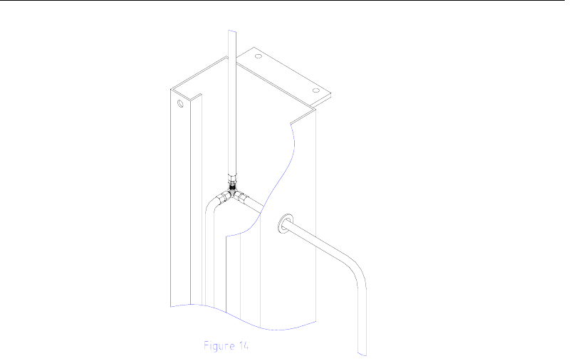
C. Connect the hydraulic bushings and ¼ push-in return line connectors to the return port of
each cylinder.
165948 Two Post Lift Installation and Owners Manual
13
G. Connect the remaining hydraulic hose to the branch on the JIC tee fitting.
H. Install the rubber grommet into the hole in the mainside leg.
I. Connect a male pipe thread to male JIC elbow to the port near the rod end of each cylinder.
The fittings should face away from the leg’s baseplate.
J. Connect the free end of the shortest hydraulic hose to the elbow on the cylinder in the
mainside leg. This connection should be hand-tight only.
K. Feed the shortest remaining hose through the rubber grommet, from inside the leg out.
Feed this hose down through the hose guide welded to the outside of the leg. This hose will
attach to the power unit.
L. Feed the long hose through the cylinder mount or upright tube along the cylinder and out
the end,
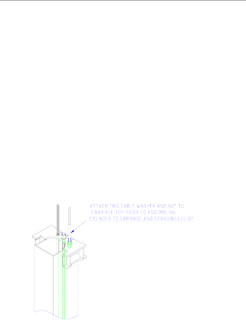
M. Feed one end of an equalization cable down through the rightmost hole in the carriage top,
figure 6. Continue to feed the cable until it extends out the bottom of the carriage. Attach a
nylon insert locknut and washer to the end of the cable so that 1/8” of cable stud extends
past the end of nut. Pull the opposite end of the cable until the washer contacts the carriage
top. Repeat for the other cable/carriage.
Figure 6
N. Attach the cylinders to the carriages. Make sure the snap ring on the cylinder rod
is in the groove. Taking care not to damage the threads on the cylinder rod, pull
carriage up to the cylinder and feed the rod through the hole in the carriage plate until the
snap ring contacts it. Attach the full nut to the rod and tighten until the cylinder rod turns.
165948 Two Post Lift Installation and Owners Manual
15
psi.
D. Using the leg as a template, drill the anchor bolt holes for the Mainside leg Only!!
Use a hammer drill with
a Carbide tip, 3/4” diameter, solid drill bit. The bit tip
diameter should be to ANSI Standard B95.12-1977. (.775” to .787”)
↓
Keep the drill perpendicular to the floor while drilling.
↓
Let the drill do the work. Do not apply excessive pressure.
↓
Lift the drill up and down to remove dust and reduce binding.
↓
Drill the hole completely through the slab.
↓
Clean the dust from the hole.
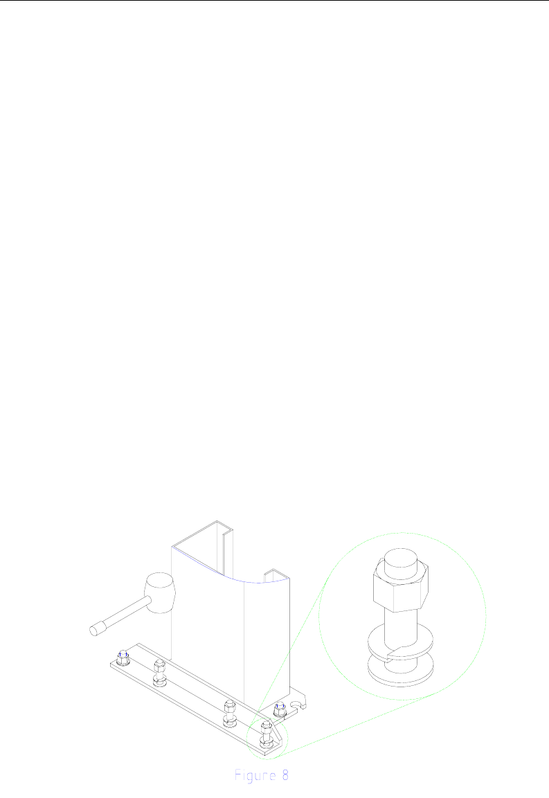
E. Assemble the washers and nuts onto the anchor bolts. Thread the nuts onto the anchor
bolts where the tops of the nuts are just above the top of the bolts, figure 8. Using a
hammer, carefully tap the anchor bolts into the concrete until the washer rests against the
baseplate. Do not damage the nuts or threads.
F. Using a level, plumb the mainside leg both side to side and front to back. Shim the leg as
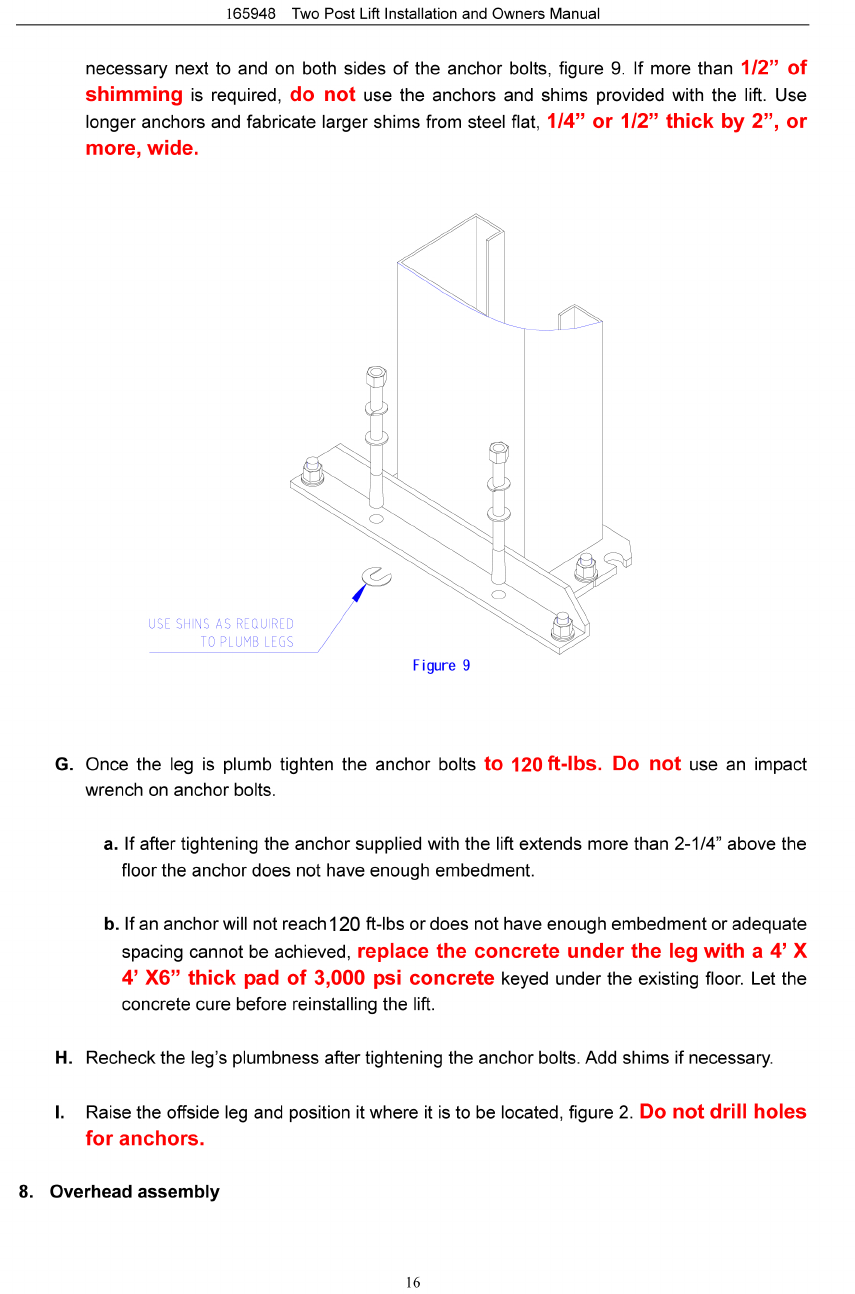
165948 Two Post Lift Installation and Owners Manual
17
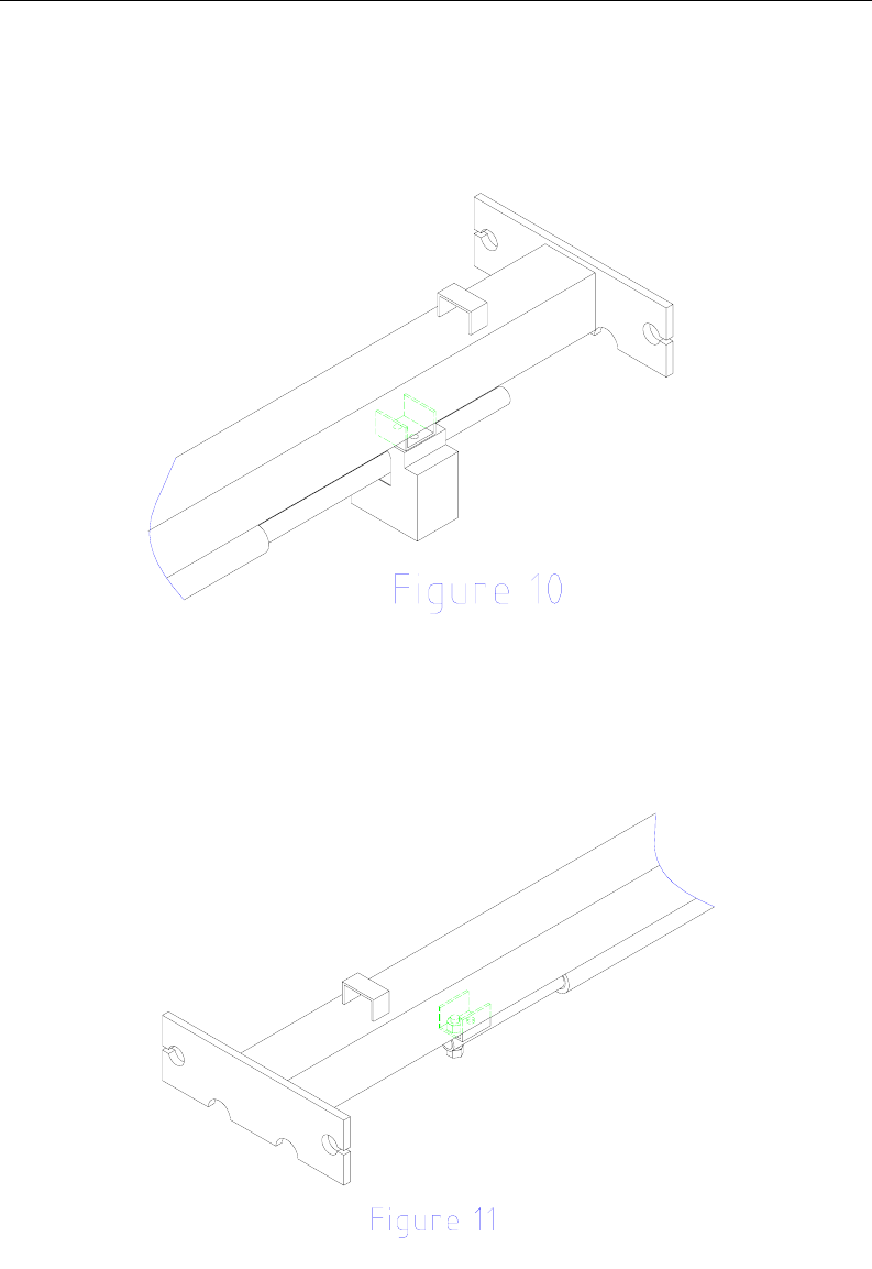
A. Single Phase Instructions, for 3-Phase instruction see 3-Phase kit.
Using (2) ¼-20 X 1/2 HHCS and (2) ¼-20 Flange Lock Nuts attach the
overhead switch assembly to the overhead beam as shown in figure
10.
↓
Slide the end of the padded switchbar without a mounting hole in it through the slot in
the overhead switch assembly. Connect the padded switchbar to the inside hole in the
overhead beam using a cylindrical spacer, ¼-20 X 1-3/4 HHCS, and Flange Nut,
figure 11.
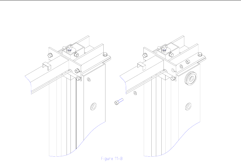
B. Attach the overhead beam to the cylinder mounts or uprights.
165948 Two Post Lift Installation and Owners Manual
18
Raise the overhead beam and secure it to cylinder mount or upright using two 1/2 x
1-3/4 bolts, washers and nuts on each end, Figure 11.
9. Anchoring offside leg.
A. Using a level check the alignment and plumbness of the entire structure. Plumb the offside
leg both side to side and front to back.
B. The base of the leg may vary from the preliminary layout, as it is more important that the
leg be perpendicular to the floor and parallel to the other leg.
C. Install the anchor bolts and shim the base as described in the earlier “Leg positioning and
anchoring” step.
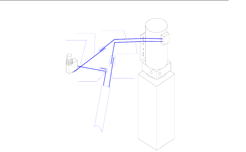
10.Routing carriage equalization cables and offside hose, Figure 12.
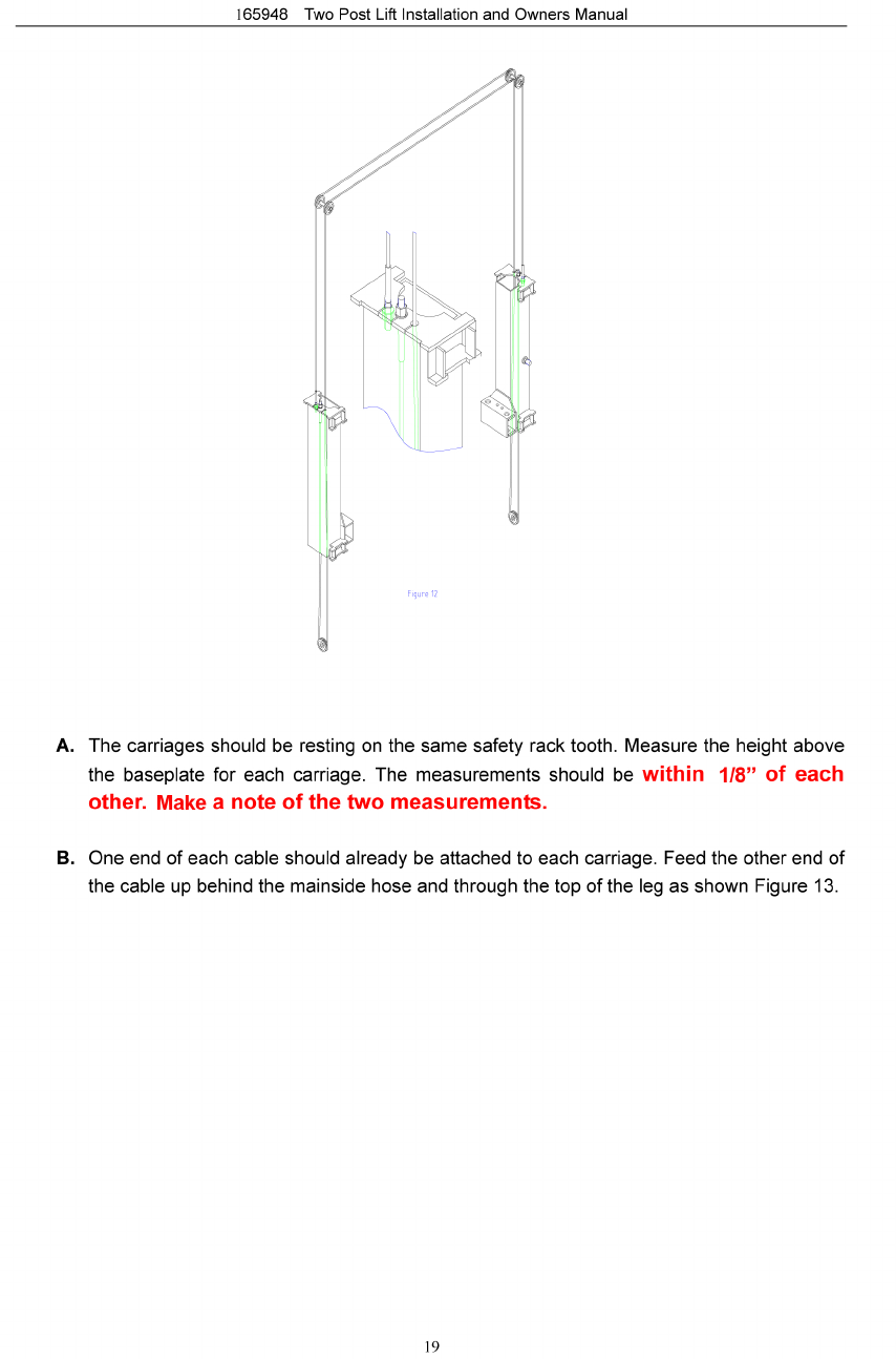
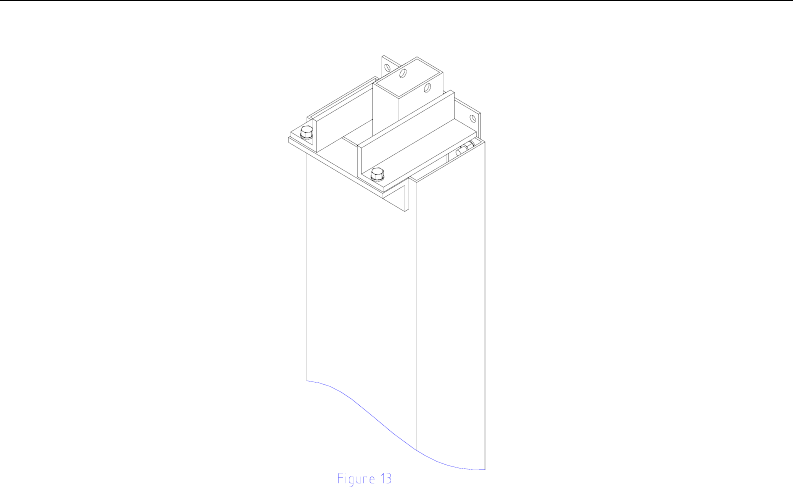
165948 Two Post Lift Installation and Owners Manual
20
around the sheave on the uprights, (while in the elevated position feed the offside
hose through the hose guides welded to the top of the overhead tube and down
through the offside upright tube.)
↓
feed cable through the clearance hole in the left hand corner of the carriage top,
↓
around the sheave at the bottom of the leg,
↓
through the hole in the center of the carriage top.
C. Secure the cable end to the carriage top with a nylon insert nut and washer. Do not
tighten the cable at this time.
D. Repeat the process for the other cable, taking care not to cross them.
E. Take out the slack, but do not tighten, in both cables by turning down the nuts on the top
of each carriage top. Use vise grips to hold the cable end, but be very careful not to
damage the threads.
F. The carriages must remain at the same lock position while the cables are
being tightened. Overtightening of one cable could raise the carriage in the opposite
leg and cause the carriage safety latches to be out of sync.
G. Alternately tighten the cable nuts at both carriages until the cables are tightened. Correct
tension in the cables is indicated by being able to pull the cables together with
165948 Two Post Lift Installation and Owners Manual
22
F. Any excess hose should be taken up in the uprights, or at the corners between
the uprights and overhead.
G. Add fluid. Remove the fill level screw near the top of the power unit tank. Remove the
fill-cap from the tank and fill with Dexron III ATF or hydraulic oil that meets ISO-32, until
fluid reaches the bottom of the screw hole. Replace the fill screw and tank breather.
13. Electrical.
A. Single Phase Instructions, for 3-Phase see the 3-Phase kit.
Have a certified electrician establish 208-230V, single phase, 60Hz., 20 amp,
power supply to motor and overhead switch, figure 15.
↓
Use separate circuits for each lift.
↓
Single phase motor cannot be run on 50 Hz. line without modifications in the
motor.
165948 Two Post Lift Installation and Owners Manual
23
Blue Wire
Black Wire
Red Wire
Red Wire
Green Wire
White Wire
Figure 15
14. Bleeding the hydraulic system, figure 4.
A. Loosen the connections between the hoses and fittings attached to the cylinders. Do not
loosen the connections between the fittings and the cylinders
themselves.
B. Run the power unit until fluid appears at the mainside cylinder port. Tighten that hose
connection.
C. Run the power unit until fluid appears at the offside cylinder port and there is no more air.
Tighten that hose connection.
D. Lower the lift to the ground. If the lift is on the safety latches, raise the lift enough to
disengage the latches and then lower.
E. If the carriages were on the ground when the bleeding process was begun, no further
bleeding is required. If not, repeat the previous steps for bleeding the hydraulic
system.
F. Add fluid to the system as previously described.

165948 Two Post Lift Installation and Owners Manual
25
C. Raise the lift to full height. Lower the lift onto the safety latches. Raise the carriages, pull
out both latch pull rods, and lower the lift to the ground.
D. Raise the lift empty to the top of its travel and lower it to the floor three (3) times to remove
the remaining air from the hydraulic system.
E. The latches should click together as the lift is being raised.
F. When the carriages are lowered onto the locks, neither pull rod should be capable
of being pulled out.
G. The first time a vehicle is placed on the lift, raise it no higher than three
feet. Lower the vehicle onto the safety latches. Raise the lift a few inches and pull out both
latch pull rods then lower the vehicle to the floor.
H. Raise the vehicle to full height and lower the carriages onto the safety latches. Lower the
vehicle to the floor.
I. After cycling the lift ten times with a vehicle on it, recheck the tightness of the
anchors to at least 90 ft-lbs.

26
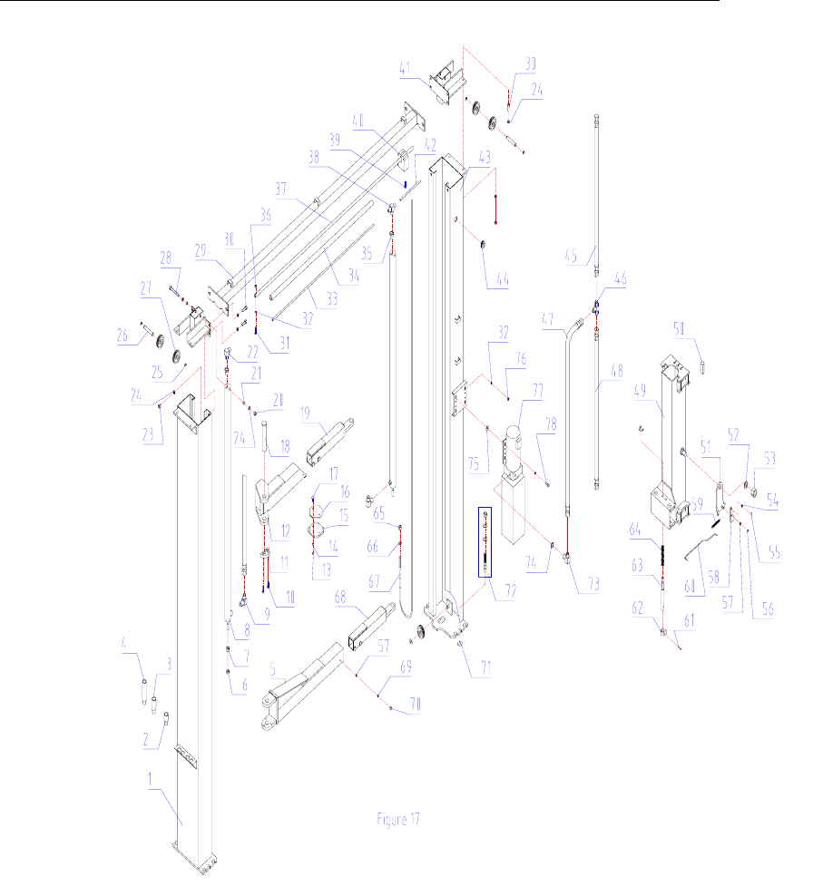
1TP11KACD-001 OFFSIDE COLUMN 1
2TP11KACD-002 4
3TP11KACD-003 MEDIUM 4
4TP11KACD-004 LONG 4
5TP11KACD-005 REAR SWING ARMS 21 each for left & right
6TP11KACD-006 JAM 2
7TP11KACD-007 CYLINDER 2
8TP11KACD-008 HYDRAULIC CYLINDER 2
9TP11KACD-009 ELBOW FITTING 2
10 TP11KACD-010 M10 x 40 BOLT 8M10*40
11 TP11KACD-011 HALF 4
12 TP11KACD-012 SWING ARMS 21 each for left & right
13 TP11KACD-013 M6 LOCKNUT 8M6
14 TP11KACD-014 #6 FLAT WASHER 8φ6
15 TP11KACD-015 SWIVEL PAD 4
16 TP11KACD-016 RUBBER PAD 4
17 TP11KACD-017 ELEVATOR 8
18 TP11KACD-018 SWING 4
19 TP11KACD019 FRONT SWING ARM SLIDER 2
20 TP11KACD-020 E-CLIP 2M14
21 TP11KACD-021 SPACER 4
22 TP11KACD-022 ELBOW FITTING (PUSH CONNECT) 1
23 TP11KACD-023 M1412 M14
24 TP11KACD-024 FLAT WASHER #14 28 φ14
25 TP11KACD-025 E-CLIP 10 φ15
26 TP11KACD-026 CABLE 2
27 TP11KACD-027 CABLE 6
28TP11KACD-028 CYLINDER PIN 2M14*110
29 TP11KACD-029 OVERHEAD 1
30 TP11KACD-030 M14 x 45 BOLT 12 M14*45
31 TP11KACD-031 M8 x 40 BOLT 1M8*40
32 TP11KACD-032 FLAT WASHER #814 φ8
33 TP11KACD-033 RETURN LINE 1
34 TP11KACD-034 FOAM PADDING 1
35 TP11KACD-035 BUSHING 2
36 TP11KACD-036 M8 3M8
37 TP11KACD-037 SHUT 1
38 TP11KACD-038 T-FITTING 1
39 TP11KACD-039 M6 4M6*8
40 TP11KACD-040 OUTER SWITCH HOUSING 1
41 TP11KACD-041 OVERHEAD 1
42 TP11KACD-042 TOP PLATE 2
NO Parts Co de Description Qty Remark
Section 3 – Parts Breakdown
SHORT HEIGHT ADAPTER
HEIGHT ADAPTER
HEIGHT ADAPTER
NUT
NUT
MOON GEAR
BOLT
ARM PIN
NUT
SHEAVE SHAFT
SHEAVE
LOCKNUT
OFF BAR
(PUSH TO CONNECT)
x10 SCREW
SWITCH

165948 Two Post Lift Installation and Owners Manual
27
43 TP11KACD-043 RETURN LINE 1
44 TP11KACD-044 MAINSIDE COLUMN 1
45 TP11KACD-045 1
46 TP11KACD-046 LONG HOSE (207") 1
47 TP11KACD-047 T-FITTING 1
48 TP11KACD-048 MEDIUM HOSE (70") 1
49 TP11KACD-049 SHORT HOSE (54.5") 1
50 TP11KACD-050 CARRIAGE 2
51 TP11KACD-051 RUB BLOCK 16
52 TP11KACD-052 LATCH 1
53 TP11KACD-053 FLAT WASHER 2φ30
54 TP11KACD-054 LOCKNUT 2M30
55 TP11KACD-055 FLAT WASHER #6 2φ5
56 TP11KACD-056 COTTER PIN 2φ2*12
57 TP11KACD-057 E-CLIP 2φ9
58 TP11KACD-058 FLAT WASHER #106φ10
59 TP11KACD-059 LATCH 2
60 TP11KACD-060 LATCH RELEASE SPRING 2
61 TP11KACD-061 LATCH RELEASE ROD 2
62 TP11KACD-062 ROLL PIN 4φ6*38
63 TP11KACD-063 ACTUATOR 4
64 TP11KACD-064 ACTUATOR PIN 4
65 TP11KACD-065 ACTUATOR 4
66 TP11KACD-066 CABLE NUT 4M16
67 TP11KACD-067 FLAT WASHER #16 4φ16
68 TP11KACD-068 33'8" EQUALIZER CABLE 2
69 TP11KACD-069 REAR SWING ARM SLIDER 2
70 TP11KACD-070 COTTER PIN 4φ10
71 TP11KACD-071 M10 X 25 BOLT 4M10*16
72 TP11KACD-072 SHIM 16
73 TP11KACD-073 ANCHOR BOLT 12 3/4*140
74 TP11KACD-074 PU ELBOW FITTING 1
75 TP11KACD-075 O-RING 1φ11.8*φ1.8
76 TP11KACD-076 FLAT WASHER #8 4
77 TP11KACD-077 M8 4M8
78 TP11KACD-078 M8 X 25 BOLT 1
79 TP11KACD-079 INNER SWITCH HOUSING 4M8*25
RUBBER GROMMET
RELEASE
GEAR
PIN SPRING
LOCKNUT
165948 Two Post Lift Installation and Owners Manual
28
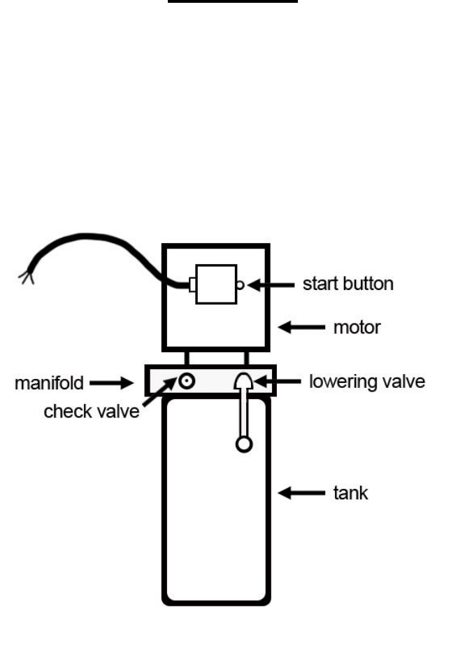
IMPORTANT
POWER UNIT PRIMING PROCEDURE
THE PROBLEM: Power unit runs fine but will not pump any fluid.
Step 1 – Locate the check valve, the flush plug to the left of the lowering valve.
(See drawing below.)
Step 2 – Using an Allen wrench and shop towel – with shop towel in place to catch
fluid – loosen the check valve plug 2 ½ turns to allow it to leak.
Step 3 – Push the START button for one second, then release for three seconds.
Repeat these steps until unit starts pumping fluid.
Step 4 – Tighten the check valve plug.
YOUR POWER UNIT SHOULD BE PRIMED
