Foc7310.tmp Trailer 1
User Manual: trailer-1 MEP 002A
Open the PDF directly: View PDF ![]() .
.
Page Count: 171 [warning: Documents this large are best viewed by clicking the View PDF Link!]
- TABLE OF CONTENTS
- LOI
- LOT
- LAST CHANGE
- WARNINGS
- CHAPTERS
- FIGURES
- FIGURE 1-1
- FIGURE 1-2
- FIGURE 3-1
- FIGURE 3-2
- FIGURE 3-3
- FIGURE 4-1
- FIGURE 4-2
- FIGURE 4-3
- FIGURE 4-4
- FIGURE 4-5
- FIGURE 4-6
- FIGURE 4-7
- FIGURE 4-8
- FIGURE 4-9
- FIGURE 4-10
- FIGURE 4-11
- FIGURE 4-12
- FIGURE 4-13
- FIGURE 4-14
- FIGURE 4-15
- FIGURE 5-1
- FIGURE 5-2
- FIGURE 5-3
- FIGURE 5-4
- FIGURE 5-5
- FIGURE 5-6
- FIGURE 5-7
- FIGURE 5-8
- FIGURE B-1
- FIGURE B-2
- FIGURE D-1
- FIGURE D-2
- FIGURE D-3
- FIGURE D-4
- FIGURE D-5
- FIGURE D-6
- FIGURE D-7
- FIGURE D-8
- FIGURE D-9
- FIGURE D-10
- FIGURE D-11
- FIGURE D-12
- FIGURE D-13
- TABLES
- APPENDICES
- PAGES
- PAGE 1-1
- PAGE 1-2
- PAGE 1-3
- PAGE 2-1
- PAGE 2-2
- PAGE 3-1
- PAGE 3-4
- PAGE 3-19
- PAGE 3-20
- PAGE 3-21
- PAGE 3-22
- PAGE 4-1
- PAGE 4-2
- PAGE 4-4
- PAGE 4-6
- PAGE 4-7
- PAGE 4-8
- PAGE 4-9
- PAGE 4-12
- PAGE 4-13
- PAGE 4-14
- PAGE 4-15
- PAGE 4-16
- PAGE 4-17
- PAGE 4-18
- PAGE 4-20
- PAGE 4-22
- PAGE 4-23
- PAGE 4-24
- PAGE 4-26
- PAGE 4-27
- PAGE 4-28
- PAGE 5-1
- PAGE 5-2
- PAGE 5-3
- PAGE 5-5
- PAGE 5-8
- PAGE 5-9
- PAGE 5-10
- PAGE 5-11
- PAGE 5-13
- PAGE 6-1
- PAGE A-1
- PAGE B-1
- PAGE B-2
- PAGE C-1
- PAGE D-1
- PAGE D-10
- PAGE D-12
- PAGE D-14
- PAGE D-16
- PAGE D-18
- PAGE D-20
- PAGE D-26
- PAGE D-32
- PAGE D-38
- PAGE D-46
- PAGE D-48
- PAGE D-50

TM 5-6115-631-14&P
TECHNICAL MANUAL
OPERATOR, UNIT, INTERMEDIATE DIRECT SUPPORT
AND GENERAL SUPPORT MAINTENANCE MANUAL
(INCLUDING REPAIR PARTS AND
SPECIAL TOOLS LISTS)
POWER PLANT
AN/MJQ-16 (NSN 6115-00-033-1395)
(2) MEP-002A 5 KW 60 HZ
GENERATOR SETS
M103A3 2-WHEEL, 2-TIRE,
MODIFIED TRAILER
Approved for public release; distribution is unlimited.
This manual supersedes Chapter 13 of TM 5-6115-594-14&P dated 25 September 1984.
HEADQUARTERS,
DEPARTMENT OF THE ARMY
24 JUNE 1988
C3
CHANGE
NO. 3
Operator,
TM 5-6115-631-14&P
HEADQUARTERS
DEPARTMENT OF THE ARMY
WASHINGTON, D.C., 8 August 1991
Unit, Intermediate Direct Support and General Support Maintenance Manual
(Including Repair Parts and Special Tools Lists)
POWER PLANT AN/MJQ-16 (NSN 6115-00-033-1395)
(2) MEP-002A, 5 kW, 60 HZ, GENERATOR SETS
M103A3, 2-WHEEL, 2-TIRE, MODIFIED TRAILER
Approved for public release; distribution is unlimited
TM 5-6115-631-14&P, 24 June 1988 is changed as follows:
1. Remove and insert pages as indicated below. New or changed text material is indicated by a
vertical bar in the margin. An illustration change is indicated by a miniature pointing hand.
Remove pages Insert pages
B-1 and B-2 B-1 and B-2
2. Retain this sheet in front of manual for reference purposes.
By
Order of the Secretary of the Army:
GORDON R. SULLIVAN
General, United States Army
Chief of Staff
Official:
PATRICIA P. HICKERSON
Brigadier General,
United States Army
The Adjutant General
DISTRIBUTION:
To be distributed in accordance with DA Form 12-25E,
(qty
rqr block no. 3866).

TM 5-6115-631-14&P
WARNING
All specific cautions and warnings contained in this manual shall be strictly ad-
hered to. Otherwise, severe injury, death and/or damage to the equipment
may result.
HIGH VOLTAGE
is produced when this power plant
DEATH
is in operation.
or severe burns may result if personnel fail to observe safety precautions. Do
not operate this power plant until the ground terminal stud has been connected
to a suitable ground. Disconnect the battery ground cable on the generator
sets before removing and installing components on the engine or in the elec-
trical control panel system. Remove all rings, watches, and other jewelry
when performing maintenance on this equipment. Loose fitting clothing should
be secured to prevent it catching in moving parts. Do not attempt to service or
otherwise make any adjustments, connections or reconnection of wires or
cables until generator sets are shut down and completely de-energized.
DANGEROUS GASES
Batteries generate explosive gas during charging: therefore, utilize extreme
caution. Do not smoke, or use open flame in the vicinity of the generator set
when servicing batteries.
Exhaust discharge contains noxious and deadly fumes. Do not operate power
plant generator sets in enclosed areas unless exhaust discharge is properly
vented to the outside.
To avoid sparking between filler nozzle and fuel tank, always maintain metal to
metal contact between filler nozzle and fuel tank when filling generator set fuel
tanks.
Do not smoke or use open flame in the vicinity of the power plant while fueling
generator sets.
LIQUIDS UNDER HIGH PRESSURE
are generated as a result of operation of the power plant generator sets. Do
not expose any part of the body to a high pressure leak in the fuel injection
system.
NOISE
Operating noise level of a generator set can cause hearing damage. Ear
protectors, as recommended by the medical or safety officer, must be worn
when working near this power plant.
a

TM 5-6115-631-14&P
Clean parts in a well-ventilated area. Avoid inhalation of solvent fumes and
prolonged exposure of skin to cleaning solvent. Wash exposed skin tho-
roughly. Dry cleaning solvent (P-D-680) used to clean parts is potentially
dangerous to personnel and property. Do not smoke or use near open flame or
excessive heat. Flash point of solvent is 100°F. to 138°F. (38°C. to 59°C.).
b

TM 5-6115-631-14&P
SAFETY STEPS TO FOLLOW IF SOMEONE IS THE
VICTIM OF ELECTRICAL SHOCK
DO NOT TRY TO PULL OR GRAB THE INDIVIDUAL
IF POSSIBLE, TURN OFF THE ELECTRICAL POWER
IF YOU CANNOT TURN OFF THE ELECTRICAL
POWER, PULL, PUSH, OR LIFT THE PERSON TO
SAFETY USING A WOODEN POLE OR A ROPE OR
SOME OTHER INSULATING MATERIAL
SEND FOR HELP AS SOON AS POSSIBLE
AFTER THE INJURED PERSON IS FREE OF
CONTACT WITH THE SOURCE OF ELECTRICAL
SHOCK, MOVE THE PERSON A SHORT DISTANCE
AWAY AND IMMEDIATELY START ARTIFICIAL
RESUSCITATION
c/d(blank)

*TM 5-6115-631-14&P
TECHNICAL MANUAL HEADQUARTERS
DEPARTMENT OF THE ARMY
NO. 5-6115-631-14&P WASHINGTON, D.C., 24 June 1988
Operator, Unit, Intermediate Direct Support and
General Support Maintenance Manual
(Including Repair Parts and Special Tools Lists)
POWER PLANT
AN/MJQ-16 (NSN 6115-00-033-1395)
(2) MEP-002A 5 KW 60 HZ
GENERATOR SETS
M103A3 2-WHEEL, 2-TIRE
MODIFIED TRAILER
REPORTING ERRORS AND RECOMMENDING IMPROVEMENTS
You can help improve this manual. If you find any mistakes, or if you know of a way to improve these
procedures, please let us know. Mail your letter or DA Form 2028 (Recommended Changes to
Publications and Blank Forms), or DA Form 2028-2 located in the back of this manual directly to:
Commander, US Army Aviation and Troop Command, ATTN: AMSAT-I-MP, 4300 Goodfellow Blvd., St.
Louis, MO 63120-1798. You may also submit your recommended changes by E-mail directly to
<mpmt%/oavma28@st-louis-emh7.army.mil>. A reply will be furnished directly to you. Instructions for
sending an electronic 2028 may be found at the back of this manual immediately preceding the hard copy
2028.
DISTRIBUTION STATEMENT A: Approved for public release; distribution is unlimited
TABLE OF CONTENTS
PAGE
CHAPTER 1 INTRODUCTION
Section I General..................................................................................................................................................1-1
Section II Description and Data.............................................................................................................................1-2
CHAPTER 2 OPERATING INSTRUCTIONS
Section I Operating Procedures ...........................................................................................................................2-1
Section II Operation of Auxiliary Equipment..........................................................................................................2-2
Section III Operation Under Unusual Conditions....................................................................................................2-2
CHAPTER 3 OPERATOR/CREW MAINTENANCE INSTRUCTIONS
Section I Consumable Operating and Maintenance Supplies..............................................................................3-1
Section II Lubrication Instructions .........................................................................................................................3-1
Section III Preventive Maintenance Checks and Services (PMCS)....................................................................... 3-1
Section IV Troubleshooting...................................................................................................................................3-19
Section V Operator/Crew Maintenance Instructions............................................................................................3-19
*This manual supersedes Chapter 13 of TM 5-6115-594-14&P dated 25 September 1984.
Change 4 i
TM 5-6115-631-14&P
CHAPTER 5.
Section I.
Section Il.
Section Ill.
Section IV.
CHAPTER 6.
Section I.
Section Il.
Section Ill.
APPENDIX A.
APPENDIX B.
APPENDIX C.
APPENDIX D.
ii
Page
INTERMEDIATE (FIELD), DIRECT SUPPORT AND GENERAL
SUPPORT MAINTENANCE INSTRUCTIONS
Introduction . . . . . . . . . . . . . . . . . . . . . . . . . . . . . . . . . . . . . . . . . . . . . . . . . . . . . . . . . . . . . . . . . . . . . . . . . . . . .
Maintenance of Power Plant Trailer . . . . . . . . . . . . . . . . . . . . . . . . . . . . . . . . . . . . . . . . . . . . . . . . . . . . . .
Generator Set . . . . . . . . . . . . . . . . . . . . . . . . . . . . . . . . . . . . . . . . . . . . . . . . . . . . . . . . . . . . . . . . . . . . . . . . . . . .
Maintenance of Electrical System . . . . . . . . . . . . . . . . . . . . . . . . . . . . . . . . . . . . . . . . . . . . . . . . . . . . . . . . .
5-1
5-1
5-9
5-11
TEST AND INSPECTION AFTER REPAIR
General Requirements. . . . . . . . . . . . . . . . . . . . . . . . . . . . . . . . . . . . . . . . . . . . . . . . . . . . . . . . . . . . . . . . . . . .
Inspection . . . . . . . . . . . . . . . . . . . . . . . . . . . . . . . . . . . . . . . . . . . . . . . . . . . . . . . . . . . . . . . . .
Operational Tests . . . . . . . . . . . . . . . . . . . . . . . . . . . . . . . . . . . . . . . . . . . . . . . . . . . . . . . . . . . . . . . . . . . . . . .
REFERENCES. . . . . . . . . . . . . . . . . . . . . . . . . . . . . . . . . . . . . . . . . . . . . . . . . . . . . . . . . . . . . . . . . . . . . . . . . . . . . . . . . .
COMPONENTS OF END ITEM AND BASIC ISSUE ITEMS LISTS . . . . . . . . . . . . . . . . . . . . . . . .
MAINTENANCE ALLOCATION CHART. . . . . . . . . . . . . . . . . . . . . . . . . . . . . . . . . . . . . . . . . . . . . . . . .
UNIT, INTERMEDIATE (FIELD) (DIRECT SUPPORT AND GENERAL
SUPPORT) AND DEPOT MAINTENANCE REPAIR PARTS AND
SPECIAL TOOLS LISTS . . . . . . . . . . . . . . . . . . . . . . . . . . . . . . . . . . . . . . . . . . . . . . . . . . . . . . . . . . . . . . . . . . . . . . . . . . . . . . . . . . . . . .
6-1
6-1
6-1
A-1
B-1
C-1
D-1
Figure
1-1
1-2
3-1
3-2
3-3
4-1
4-2
4-3
4-4
4-5
4-6
4-7
4-8
4-9
4-10
4-11
4-12
4-13
4-14
4-15
5-1
5-2
5-3
5-4
5-5
5-6
5-7
5-8
B-1
B-2
D-1
D-2
D-3
D-4
D-5
D-6
D-7
D-8
D-9
D-10
D-11
D-12
D-13
TM 5-6115-631-14&P
LIST OF ILLUSTRATIONS
Title
Power Plant, Roadside Front, Three-Quarter View . . . . . . . . . . . . . . . . . . . . . . . . . . . . . . . . . . . . . . . . . . . . . . . . . . . . . . . . . .
Power Plant, Curbside Rear, Three-Quarter View . . . . . . . . . . . . . . . . . . . . . . . . . . . . . . . . . . . . . . . . . . . . . . . . . . . . . . . . . . . .
Fitted Cover Installed on Power Plant . . . . . . . . . . . . . . . . . . . . . . . . . . . . . . . . . . . . . . . . . . . . . . . . . . . . . . . . . . . . . . . . . . . . . . . . . . . . . .
Fitted Cover Rolled Up for Removal . . . . . . . . . . . . . . . . . . . . . . . . . . . . . . . . . . . . . . . . . . . . . . . . . . . . . . . . . . . . . . . . . . . . . . . . . . . . . . . . . .
Bow Assembly Replacement . . . . . . . . . . . . . . . . . . . . . . . . . . . . . . . . . . . . . . . . . . . . . . . . . . . . . . . . . . . . . . . . . . . . . . . . . . . . . . . . . . . . . . . . . . . . .
Unpacking Power Plant . . . . . . . . . . . . . . . . . . . . . . . . . . . . . . . . . . . . . . . . . . . . . . . . . . . . . . . . . . . . . . . . . . . . . . . . . . . . . . . . . . . . . . .
Installing Power Plant. . . . . . . . . . . . . . . . . . . . . . . . . . . . . . . . . . . . . . . . . . . . . . . . . . . . . . . . . . . . . . . . . . . . . . . . . . . . . . . . . . . . . . . .
External Fuel Line Connection . . . . . . . . . . . . . . . . . . . . . . . . . . . . . . . . . . . . . . . . . . . . . . . . . . . . . . . . . . . . . . . . . . . . . . . . . . . . . . . . . . . . . . . . . .
Fuel Can Bracket Replacement . . . . . . . . . . . . . . . . . . . . . . . . . . . . . . . . . . . . . . . . . . . . . . . . . . . . . . . . . . . . . . . . . . . . . . . . . . . . . . . . . . . . . . . .
Accessory Box Replacement . . . . . . . . . . . . . . . . . . . . . . . . . . . . . . . . . . . . . . . . . . . . . . . . . . . . . . . . . . . . . . . . . . . . . . . . . . . . . . . . . . . . . . . . . . . .
Fire Extinguisher Bracket Replacement . . . . . . . . . . . . . . . . . . . . . . . . . . . . . . . . . . . . . . . . . . . . . . . . . . . . . . . . . . . . . . . . . . . . . . . . . . .
5-Wire Switch Box Schematic Diagram . . . . . . . . . . . . . . . . . . . . . . . . . . . . . . . . . . . . . . . . . . . . . . . . . . . . . . . . . . . . . . . . . . . . . . . . . . . .
4-Wire Switch Box Schematic Diagram . . . . . . . . . . . . . . . . . . . . . . . . . . . . . . . . . . . . . . . . . . . . . . . . . . . . . . . . . . . . . . . . . . . . . . . . . . . .
Switch Box Replacement. . . . . . . . . . . . . . . . . . . . . . . . . . . . . . . . . . . . . . . . . . . . . . . . . . . . . . . . . . . . . . . . . . . . . . . . . . . . . . . . . . . . . .
Load Terminal Replacement . . . . . . . . . . . . . . . . . . . . . . . . . . . . . . . . . . . . . . . . . . . . . . . . . . . . . . . . . . . . . . . . . . . . . . . . . . . . . . . . . . . . . . . . . . . . .
Indicator Light and Wire Replacement . . . . . . . . . . . . . . . . . . . . . . . . . . . . . . . . . . . . . . . . . . . . . . . . . . . . . . . . . . . . . . . . . . . . . . . . . . . . .
Switch to Load Terminal Wire Replacement . . . . . . . . . . . . . . . . . . . . . . . . . . . . . . . . . . . . . . . . . . . . . . . . . . . . . . . . . . . . . . . . . . . .
Power Cable Replacement . . . . . . . . . . . . . . . . . . . . . . . . . . . . . . . . . . . . . . . . . . . . . . . . . . . . . . . . . . . . . . . . . . . . . . . . . . . . . . . . . . . . . . . . . . . . . . . .
Ground Wire Replacement . . . . . . . . . . . . . . . . . . . . . . . . . . . . . . . . . . . . . . . . . . . . . . . . . . . . . . . . . . . . . . . . . . . . . . . . . . . . . . . . . . . . . . . . . . . . . . . .
Taillight Cable Assembly and Electrical Lead Repair . . . . . . . . . . . . . . . . . . . . . . . . . . . . . . . . . . . . . . . . . . . . . . . . . . . . .
Leg Prop Assembly Replacement . . . . . . . . . . . . . . . . . . . . . . . . . . . . . . . . . . . . . . . . . . . . . . . . . . . . . . . . . . . . . . . . . . . . . . . . . . . . . . . . . . . . .
Leg Prop Disassembly . . . . . . . . . . . . . . . . . . . . . . . . . . . . . . . . . . . . . . . . . . . . . . . . . . . . . . . . . . . . . . . . . . . . . . . . . . . . . . . . . . . . . . . . . . . . . . . . . . . .
Fender and Bed Replacement . . . . . . . . . . . . . . . . . . . . . . . . . . . . . . . . . . . . . . . . . . . . . . . . . . . . . . . . . . . . . . . . . . . . . . . . . . . . . . . . . . . . . . . . . . .
Accessory Box Repair . . . . . . . . . . . . . . . . . . . . . . . . . . . . . . . . . . . . . . . . . . . . . . . . . . . . . . . . . . . . . . . . . . . . . . . . . . . . . . . . . . . . . . . . . . . . . . .
Power Unit Markings. . . . . . . . . . . . . . . . . . . . . . . . . . . . . . . . . . . . . . . . . . . . . . . . . . . . . . . . . . . . . . . . . . . . . . . . . . . . . . . . . . . . . . . . . .
Detaching Generator Set from Trailer . . . . . . . . . . . . . . . . . . . . . . . . . . . . . . . . . . . . . . . . . . . . . . . . . . . . . . . . . . . . . . . . . . . . . . . . . . . . . .
Lifting Generator Set . . . . . . . . . . . . . . . . . . . . . . . . . . . . . . . . . . . . . . . . . . . . . . . . . . . . . . . . . . . . . . . . . . . . . . . . . . . . . . . . . . . . . . . . . .
Switch Replacement . . . . . . . . . . . . . . . . . . . . . . . . . . . . . . . . . . . . . . . . . . . . . . . . . . . . . . . . . . . . . . . . . . . . . . . . . . . . . . . . . . . . . . . . . .
Components of End item . . . . . . . . . . . . . . . . . . . . . . . . . . . . . . . . . . . . . . . . . . . . . . . . . . . . . . . . . . . . . . . . . . . . . . . . . . . . . . . . . . . . . .
Basic Issue items. . . . . . . . . . . . . . . . . . . . . . . . . . . . . . . . . . . . . . . . . . . . . . . . . . . . . . . . . . . . . . . . . . . . . . . . . . . . . . . . . . . . . . . . . . . . . .
Enclosure. . . . . . . . . . . . . . . . . . . . . . . . . . . . . . . . . . . . . . . . . . . . . . . . . . . . . . . . . . . . . . . . . . . . . . . . . . . . . . . . . . . . . . . . . . . . . . . . . . . ....
Generator Set. . . . . . . . . . . . . . . . . . . . . . . . . . . . . . . . . . . . . . . . . . . . . . . . . . . . . . . . . . . . . . . . . . . . . . . . . . . . . . . . . . . . . . . . . . . . . . . . .
Five-Wire Power Cable . . . . . . . . . . . . . . . . . . . . . . . . . . . . . . . . . . . . . . . . . . . . . . . . . . . . . . . . . . . . . . . . . . . . . . . . . . . . . . . . . . . . . . . . . . . . . . . . .
Five-Wire Power Cable . . . . . . . . . . . . . . . . . . . . . . . . . . . . . . . . . . . . . . . . . . . . . . . . . . . . . . . . . . . . . . . . . . . . . . . . . . . . . . . . . . . . . . . . . . . . . . . . . . .
Four-Wire Power Cable. . . . . . . . . . . . . . . . . . . . . . . . . . . . . . . . . . . . . . . . . . . . . . . . . . . . . . . . . . . . . . . . . . . . . . . . . . . . . . . . . . . . . . . . . . . . . . . . . . .
Five-Wire Switch Box . . . . . . . . . . . . . . . . . . . . . . . . . . . . . . . . . . . . . . . . . . . . . . . . . . . . . . . . . . . . . . . . . . . . . . . . . . . . . . . . . . . . . . . . .
Five-Wire Switch Box . . . . . . . . . . . . . . . . . . . . . . . . . . . . . . . . . . . . . . . . . . . . . . . . . . . . . . . . . . . . . . . . . . . . . . . . . . . . . . . . . . . . . . . . .
Four-Wire Switch Box . . . . . . . . . . . . . . . . . . . . . . . . . . . . . . . . . . . . . . . . . . . . . . . . . . . . . . . . . . . . . . . . . . . . . . . . . . . . . . . . . . . . . . . .
Trailer Body. . . . . . . . . . . . . . . . . . . . . . . . . . . . . . . . . . . . . . . . . . . . . . . . . . . . . . . . . . . . . . . . . . . . . . . . . . . . . . . . . . . . . . . . . . . . . . . . . . ..
Accessory Box. . . . . . . . . . . . . . . . . . . . . . . . . . . . . . . . . . . . . . . . . . . . . . . . . . . . . . . . . . . . . . . . . . . . . . . . . . . . . . . . . . . . . . . . . . . . . . . . . . . .
Data Plates and Reflectors . . . . . . . . . . . . . . . . . . . . . . . . . . . . . . . . . . . . . . . . . . . . . . . . . . . . . . . . . . . . . . . . . . . . . . . . . . . . . . . . . . . . . . . . . . . . . . . .
Leg Prop Assembly. . . . . . . . . . . . . . . . . . . . . . . . . . . . . . . . . . . . . . . . . . . . . . . . . . . . . . . . . . . . . . . . . . . . . . . . . . . . . . . . . . . . . . . . . . . .
Taillight Cable Assemblies and Electrical Leads . . . . . . . . . . . . . . . . . . . . . . . . . . . . . . . . . . . . . . . . . . . . . . . . . . . . . . . . . . . .
Page
1-2
1-3
3-20
3-21
3-22
4-2
4-4
4-6
4-15
4-16
4-17
4-18
4-18
4-20
4-22
4-23
4-24
4-26
4-27
4-28
5-2
5-3
5-5
5-8
5-9
5-10
5-11
5-13
B-2
B-3
D-10
D-12
D-14
D-16
D-18
D-20
D-26
D-32
D-38
D-44
D-46
D-48
D-50
iii
TM 5-6115-631-14&P
Number
LIST OF TABLES
Title
Page
3-1
Consumable Operating and Maintenance Supplies . . . . . . . . . . . . . . . . . . . . . . . . . . . . . . . . . . . . 3-1
3-2
Operator/Crew Preventive Maintenance
Checks and Services (PMCS). . . . . . . . . . . . . . . . . . . . . . . . . . . . . . . . . . . . . . . . . . . . . . . . . . . . . . . . . . . 3-4
4-1
Unit Preventive Maintenance Checks and Services (PMCS) . . . . . . . . . . . . . . . . . . . . . . . 4-9
4-2
Troubleshooting
. . . . . . . . . . . . . . . . . . . . . . . . . . . . . . . . . . . . . . . . . . . . . . . . . . . . . . . . . . . . . . . . . . . . . . . . . . . . . . . . . . . . . . . . . . . . . . . . . . . . . . . . . . . . . . . . .
4-13
iv

TM 5-6115-631-14&P
CHAPTER 1
INTRODUCTION
SECTION I. GENERAL
1-1. Scope. This manual is for your use in operating and maintaining the Power Plant, AN/MJQ-16. The AN/MJQ- 16 is a
mobile power plant used to supply power to any system or equipment requiring up to 5 kW of 60 Hz input operating power.
In addition to operating instructions and operator, unit, and intermediate direct support and general support maintenance
procedures, this manual contains a Repair Parts and Special Tools List for the power plant.
1-2. Limited Applicability. Some portions of this publication are not applicable to both services. These portions are
prefixed to indicate the service to which they pertain: (A) for Army, and (F) for Air Force Portions not prefixed are
applicable to both services.
1-3. Maintenance Forms and Records.
a.
(A) Maintenance forms and records used by Army personnel are prescribed by DA Pam 738-750.
b.
(F) Maintenance forms and records used by Air Force personnel are prescribed in AFM66-1 and the applicable 00-
20 Series Technical Orders.
1-4. Reporting of Errors. Reporting of errors and omissions and recommendations for improvement of this publication by
the individual user is encouraged. Reports should be submitted as follows: a. (
a. (A) ARMY - DA Form 2028 directly to: Commander, US Army Aviation and Troop Command, ATTN: AMSAT-
I-MT, 4300 Goodfellow Boulevard, St. Louis, MO 63120-1798..
b.
(F) Air Force - AFTO Form 22 directly to: Commander, Sacramento Air Logistics Center, ATTN: SM-ALC-
MMEDTA, McAllen Air Force Base, CA, 95652-5609, in accordance with TO-00-5-1.
1-5. Reporting Equipment Improvement Recommendations (EIR). EIR’s will be prepared using SF 368, Product
Quality Deficiency Report. Instructions for preparing EIR’s are provided in DA PAM 738-750, The Army Maintenance
Management System. EIR’s should be mailed directly to: Commander, US Army Aviation and Troop Support Command,
ATTN: AMSAT-I-MDO, 4300 Goodfellow Boulevard, St. Louis, MO 63120-1798.
1-6. Levels of Maintenance Accomplishment.
a. (A)
Army users shall refer to the Maintenance Allocation Chart (MAC) for tasks and levels of maintenance to be
performed.
.(
F) Air Force users shall accomplish maintenance at the user level consistent with their capability in accordance
with policies established in AFM 66-1.
1-7. Destruction of Army Materiel. Destruction of Army materiel to prevent enemy use shall be in accordance with TM
750-244-3.
Change 4 1-1
TM 5-6115-631-14&P
1-8. Administrative Storage.
a. Army equipment placed in administrative storage will have preventive maintenance performed
in accordance with the PMCS tables before storage. When equipment is removed from
storage, PMCS will be performed to ensure operational readiness.
b. (F) For administrative storage procedures for Air Force equipment, refer to TO 35-1-4,
Processing and Inspection of Aerospace Ground Equipment for Storage and Shipment.
1-9.
Preparation for Shipment and Storage.
a. (A) Army – Refer to TB 740-97-2.
b. (F) Air Force - Refer to TO 35-1-4 for component of end item generator sets and TO 38-1-5
for installed engine.
Section Il. DESCRIPTION AND DATA
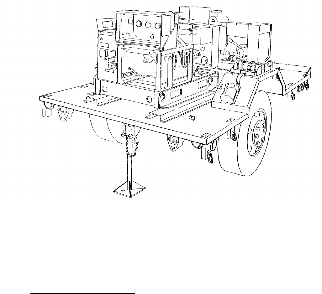
1-10.
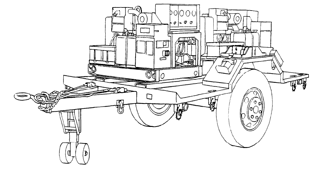
Description. Power Plant AN/MJQ-16 is made up of two Tactical Utility Generator Sets, DOD
Model MEP-002A, mounted on a single modified M103A3 trailer. These generator sets are air-
cooled, diesel engine-driven units, each with a load capacity of 5 KW at 60 Hz. The trailer is a two-
wheeled unit with a l-1/2-ton carrying capacity. The modifications to the basic trailer provide stow-
age for the accessories and all equipment necessary for mobile operation as well as providing a work
platform for the operator and maintenance personnel. Output from the power plant is applied to the
system or equipment being powered through a switch box. The AN/MJQ-16 is supplied with either a 4-
wire or a 5-wire configuration switch box. Figures 1-1 and 1-2 illustrate the power plant with the fitted
cover removed to show the generator sets.
Figure 1-1. Power Plant, Roadside Front, Three-Quarter View.
1-2
TM 5-6115-631-14&P
Figure 1-2. Power Plant, Curbside Rear, Three-Quarter View.
1.11.
Tabulated Data. The tabulated data provides operator and unit level personnel with the
dimensions and weights for Power Plant, AN/MJQ-16. These specifications are computed from the
combined dimensions and weights of the generator sets and trailer as modified for use with the power
plant. Specifications of the individual components can be found in their respective technical publica-
tions. For additional information concerning Generator Set, DOD Model MEP-002A, refer to TM 5-
6115-584-12 and – 34. For additional information on the M103A3 trailer, refer to TM 9-2330-213-
14&P. The tabulated data also includes the location and content of all data plates unique to the power
plant.
a. Identification and Instruction Plates.
(1) Power plant identification plssate.
(a) Location. This plate is located on the front roadside frame between the trailer body and
the drawbar ring.
(b) Content.
us
POWER PLANT, ELECTRIC
AN/MJQ-16
KW 5
HERTZ 60
NSN 6115-00-033-1395
1-3

TM 5-6115-631-14&P
(2) Trailer ground terminallidentification plate.
(a) Location.
This plate is located next to the ground stud on the rear, roadside corner of the
trailer bed.
(b) Content.
GROUND TERMINAL
(3) Wiring diagram information p/ate.
(a) Location. This plate is mounted inside the switch box.
(b) Content. (See figure 4-7 or 4-8).
(4) Switch box AC ground information p/ate.
(a) Location.
This plate is located on the outboard side of the switch box next to ground
terminal E2.
(b) Content.
AC GROUND
(5) Switch box equipment ground information plate.
(a) Location.
This plate is located next to ground terminal E1 on the rear of the switch box.
(b) Content.
EQUIPMENT
(FRAME)
GROUND
(6) Warning plate.
(a) Location.
This plate is located on the switch box terminal board cover.
(b) Content.
DANGER
HIGH VOLTAGE
b. Tabulated Data for Power Plant.
Overall Length 171.5 inches (435.6 centimeters)
Overall Width 83 inches (210.8 centimeters)
Overall Height 95 inches (241.3 centimeters)
Net Weight (empty) 4,690 pounds (2127 kilograms)
Net Weight (filled) 4,770 pounds (2163 kilograms)
Shipping Weight
4,960 pounds (2249 kilograms)
Cubage 799 cubic feet (22.69 cubic meters)
1-12.
Differences Between Models.
There are no differences between models, serial numbers, or
serial number groups applicable to this equipment.
1-4

TM 5-6115-631-14&P
CHAPTER 2
OPERATING INSTRUCTIONS
Section 1. OPERATING PROCEDURES
2-1.
Operating Procedures. Before the power plant generators are started and operated, the power
plant is towed to a worksite and installed. Installation instructions are provided in paragraph 4-2.
Instructions for dismantling the power plant for movement are given in paragraph 4-3.
a. Generator Set Operating Procedures. Detailed prestarting, startup, operating and shutdown
procedures for the generator sets can be found on the Operating Instructions data plate located on the
right hand side of each generator set control cubicle, and in the generator set technical manual, TM
5-6115-584-12.
WARNING
Do not operate power plant until it is properly grounded (paragraph 4-2, b).
Serious injury or death by electrocution can result from operating an
ungrounded generator set.
Operating noise level of the generator sets can cause hearing damage. Ear
protectors, as recommended by medical or safety officer, must be worn when
working near power plant.
CAUTION
To avoid damage to equipment, make certain of voltage, frequency, and
phase requirements of load connected to generator sets.
NOTE
Make sure generator set circuit breakers and switch box rotary switch are in
OFF position before proceeding.
Before starting generator set, do your Before PMCS as described in table 3-2.
b. Switch Box Operating Procedures.
(1) Single generator set operation. Use the switch box to operate only one generator set as
follows:
(a) Make sure power and ground cables are connected to generator set and switch box.
(b) Turn generator set on and bring it up to rated speed, voltage and frequency. (Refer to
TM 5-6115-584-12.)
(c) Close generator set circuit breaker (move to ON position).
(d) Turn rotary switch on switch box to GEN 1 or GEN 2 position, as applicable.
2-1

TM 5-6115-631-14&P
(e) To stop operation, move rotary switch and generator set circuit breaker to OFF position.
Turn generator set off. (Refer to TM 5-6115-584-12.)
(2) Dual generator set operation, Use the switch box to alternately operate both generator sets
as follows:
(a)
Make sure power and ground cables are connected to switch box and both generator
sets.
(b) Select first generator set to be used and bring it into operation in accordance with
paragraph 2-1, b (1), steps (b) through (d).
(c) Turn second generator set on and bring it up to rated speed, voltage and frequency.
(Refer to TM 5-6115-584-12.) Close circuit breaker (move to ON position).
(d)
Move switch box rotary switch to GEN position corresponding to second generator set.
(e) Open circuit breaker on first generator set (move to OFF position) and turn generator set
off. (Refer to TM 5-6115-584-12.)
(t) To stop operation, move rotary switch to OFF position and open circuit breaker on
generator set still running. Turn generator set off. (Refer to TM 5-6115-584-12.)
c. Trailer Operating Procedures.
Refer to TM9-2330-213-14&P for specific operating
procedures for the M103A3 trailer.
Section Il. OPERATING OF AUXILIARY EQUIPMENT
2.2.
Operation of Auxiliary Equipment.
There is no auxiliary equipment supplied with the power plant.
Section Ill. OPERATION UNDER UNUSUAL CONDITIONS
2.3.
Operation Under Unusual Conditions.
When operating the power plant under unusual conditions
such as extremes in temperature or difficult terrain, there are steps that must be taken to protect the
equipment.
a.
Refer to TM 5-6115-584-12 for special procedures when operating the generator set under
unusual conditions.
b.
Refer to TM 9-2330-213-14&P for special procedures when operating the trailer under unusual
conditions.
2-2
TM 5-6115-631-14&P
CHAPTER 3
OPERATOR/CREW MAINTENANCE INSTRUCTIONS
Section I. CONSUMABLE OPERATING AND MAINTENANCE SUPPLIES
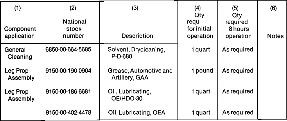
3-1.
Consumable Supplies. Consumable supplies used in the maintenance and operation of the
power plant are listed in Table 3-1.
(1)
Component
application
General
Cleaning
Leg
Prop
Assembly
Leg
Prop
Assembly
Table 3-1. Consumable Operating and Maintenance Supplies.
(2)
National
stock
number
6850-00-664-5685
9150-00-190-0904
9150-00-186-6681
9150-00-402-4478
(3)
Description
Solvent, Drycleaning,
P-D-680
Grease,
Automotive
and
Artillery, GAA
Oil, Lubricating,
OE/HDO-30
Oil, Lubricating,
OEA
(4)
Qty
required
for
initial
operation
1
quart
1
pound
1
quart
1
quart
(5)
Qty
required
8
hours
operation
As required
As required
As required
As required
(6)
Notes
Section Il. LUBRICATION INSTRUCTIONS
3-2. General. Detailed instructions for the lubrication of the major components of the power plant are
contained in the applicable Lubrication Orders (LO’s). Refer to DA Pam 25-30 to ensure that the latest
editions of the LO’s are used.
3-3. Generator Lubrication. Refer to TM 5-6115-584-12 for generator set Lubrication Order.
3-4. Trailer Lubrication. There are no operator/crew lubrication requirements for the power plant
trailer. However, the operator shall assist unit maintenance.
Section Ill. PREVENTIVE MAINTENANCE CHECKS AND SERVICES (PMCS)
NOTE
The PMCS chart in this section contains all necessary Operator/Crew
preventive maintenance checks and services for this equipment.
3-5. General. The preventive maintenance checks and services listed in Table 3-2 are grouped
according to stages of equipment operation or time intervals. Using the following as a guide, do the
checks and services at the intervals shown.
a. Before you operate, perform your before (B) PMCS. Observe all CAUTIONS and WARNINGS.
3-1

b.
c.
d.
e.
f.
TM 5-6115-631-14&P
While you operate, perform your during (D) PMCS. Observe all CAUTIONS and WARNINGS.
After you operate, be sure to perform your after (A) PMCS.
Do (W) PMCS weekly.
Do (M) PMCS monthly.
If equipment fails to operate, refer to Section IV Troubleshooting. If the problem cannot be
corrected, see paragraph 3-8, Reporting Deficiencies.
3.6. Purpose of PMCS Table.
The purpose of the PMCS table is to provide a systematic method of
inspecting and servicing the equipment. In this way, small defects can be detected early before they
become a major problem causing the equipment to fail to complete its mission. The PMCS table is
arranged with the individual PMCS procedures listed in sequence under assigned intervals. The most
logical time (before, during, or after operation) to perform each procedure determines the interval to
which it is assigned. Make a habit of doing the checks and services in the same order each time and
anything wrong will be seen quickly. See paragraph 3-7 for an explanation of the columns in
table 3-2.
3-7. Explanation of Columns.
The following is a list of the PMCS table column headings with a
description of the information found in each column.
a. Item No. This column shows the sequence in which the checks and services are to be
performed, and is used to identify the equipment area on the Equipment Inspection and Maintenance
Worksheet, DA Form 2404.
b. Interval. This column shows when each check is to be done.
c. Item to be Inspected/Procedures. This column identifies the general area or specific part
where the check or service is to be done, lists the checks or services to be done and explains how to do
them.
d. Equipment is Not Ready/Available If. This column lists conditions that make the equipment
unavailable for use because it is unable to perform its mission or because it would represent a safety
hazard. Do not accept or operate equipment with a condition in the “Equipment is Not Ready/Available
If” column.
3-8. Reporting Deficiencies.
If you discover any problem with the equipment during PMCS or while
operating it that you are unable to correct, it must be reported. Refer to DA Pam 738-750 and report
the deficiency using the proper forms.
3-9. Special Instructions.
Preventive maintenance is not limited to performing the checks and ser-
vices listed in the PMCS table. Covering unused receptacles, stowing unused equipment and other
routine procedures such as equipment inventory, cleaning components, and touch-up painting are
not listed in the PMCS table. These are things you should do any time you see they need to be done. If
a routine check is listed in the PMCS table it is because other operators have reported problems with
this item. Take along tools and cleaning cloths needed to perform the required checks and services.
Use the information in the following paragraphs to help you identify problems at any time.
a. Routine Inspections. Use the following information to help identify potential problems before
and during checks and services.
3-2

TM 5-6115-631-14&P
WARNING
Drycleaning solvent P-D-680 is both toxic and flammable. Wear safety goggles
and gloves and use in a well-ventilated area. Avoid prolonged breathing of
vapors and avoid skin contact. Do not smoke or use near open flame or exces-
sive heat. Flash point of solvent is 100°F to 138°F (38°C to 59°C). If you
become dizzy while using P-D-680, get fresh air immediately and get medical
aid. If P-D-680 contacts eyes, flush with water and get medical aid
immediately.
(1) Keep it clean. Dirt, grease, and oil get in the way and may cover up a serious problem.
Use drycleaning solvent P-D-680, to clean metal surfaces. Use soap and water to clean
rubber or plastic parts and material.
(2) Bolts, nuts, and screws. Check them all to make sure they’re not loose, missing, bent, or
broken. Don’t try to check them all with a tool, but look for chipped paint, bare metal, or
rust around bolt heads. If you find one loose, tighten it or report it to unit maintenance.
(3) Welds. Look for loose or chipped paint, rust, or gaps where parts are welded together.
If a broken weld is found, report it to higher level of maintenance.
(4) Electrical wires, connectors, terminals and receptacles. Look for cracked or broken
insulation, bare wires, and loose or broken connectors. Tighten loose connectors and
make sure the wires are in good condition. Examine terminals and receptacles for
serviceability.
(5) Hoses and fluid lines. Look for wear, damage, and leaks. Make sure clamps and fittings
are tight. Wet spots and stains around a fitting or connector can mean a leak. If a leak
comes from a loose connector, tighten it. If something is broken or worn out, report it to
unit maintenance.
b. Leakage Definitions. It is necessary for you to know how fluid leakage affects the status of your
equipment. The following are definitions of the types/classes of leakage you need to know to be able
to determine the status of your equipment. Learn and be familiar with them. When in doubt, NOTIFY
YOUR SUPERVISOR!
Leakage Definitions:
Class I
Class II
Class Ill
Seepage of fluid (as indicated by wetness or discoloration) not great
enough to form drops.
Leakage of fluid great enough to form drops but not enough to cause
drops to drip from item being checked/inspected.
Leakage of fluid great enough to form drops that fall from the item
being checked/inspected.
3-3
TM 5-6115-631-14&P
CAUTION
Equipment operation is allowable with minor leakage (Class I or 11) of any fluid
except fuel. Of course, consideration must be given to the fluid capacity in the
item being checked/inspected. When in doubt, notify your supervisor.
When operating with Class I or II leaks, continue to check fluid level more often
than required in the PMCS. Parts without fluid will stop working and/or cause
equipment damage.
Class Ill leaks should be reported to your supervisor or unit maintenance.
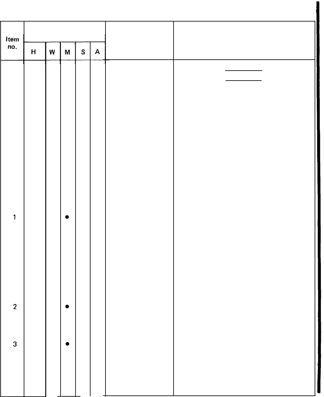
Table 3-2, Operator/Crew Preventive Maintenance Checks and Services (PMCS)
NOTE
If the equipment must be kept in continuous operation, check and service only
those items that can be checked and serviced without disturbing operation.
Make the complete checks and services when the equipment can be shut
down.
Within designated interval, these checks are to be performed in the order
listed.
B – Before D – During A - After W – Weekly M - Monthly
Item
no.
B
Interval
D
A
w
M
Item to be inspected.
Procedure: check for and
have repaired, filled, or
adjusted as needed
WARNING
Before performing any mainte-
nance that requires climbing on or
under trailer, set trailer hand-
brakes, chock wheels, and lower
rear leg prop. Injury to personnel
could result from trailer suddenly
rolling or tipping.
Equipment is not
ready/available if:
3-4
TM 5-6115-631-14&P
Table 3-2. Operator/Crew Preventive Maintenance Checks and Services(PMCS) – CONT.
B – Before D – During A – After W - Weekly M – Monthly
Item
no.
1
2
B
—
●
●
Interval
D
A
WM
Item to be inspected.
Procedure: check for and
have repaired, filled, or
adjusted as needed
NOTE
Perform weekly as well
PMCS if: as before
You are the assigned operator but
have not operated the equipment
since the last weekly inspection.
You are operating the equipment
for the first time.
Generator set checks and ser-
vices in this table are described as
performed on a single generator
set. These procedures must be
performed on each of the two
generator sets that make up the
AN/MJQ-16.
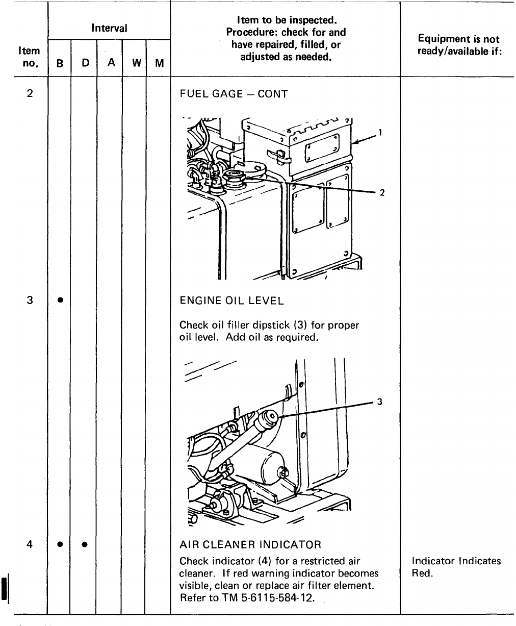
GENERATOR SET EXTERIOR
a. Check on, around, and beneath the
generator set (1) for fuel or oil
leaks.
b. Check that generator set (1)
grounds are properly installed,
and grounding connections are
tight.
FUEL GAGE
Check fuel gage (2) for sufficient fuel for
continuous operation.
Equipment is not
ready/available if:
A Class Ill lubrication
oil or any class fuel
leak is detected.
Not properly
grounded.
3-5
TM 5-6115-584-12
TM 5-6115-631-14&P
Table 3.2. Operator/Crew Preventive Maintenance Checks and Services (PMCS)– CONT.
B – Before D – During A – After W – Weekly M - Monthly
3-6
Change 1
TM 5-6115-631-14&P
Table 3-2. Operator/Crew Preventive Maintenance Checks and Services (PMCS) – CONT.
B
– Before
D
- During A – After W – Weekly
M
- Monthly
4
5
6
7
Item to be inspected.
Procedure: check for and
have repaired, filled, or
adjusted as needed
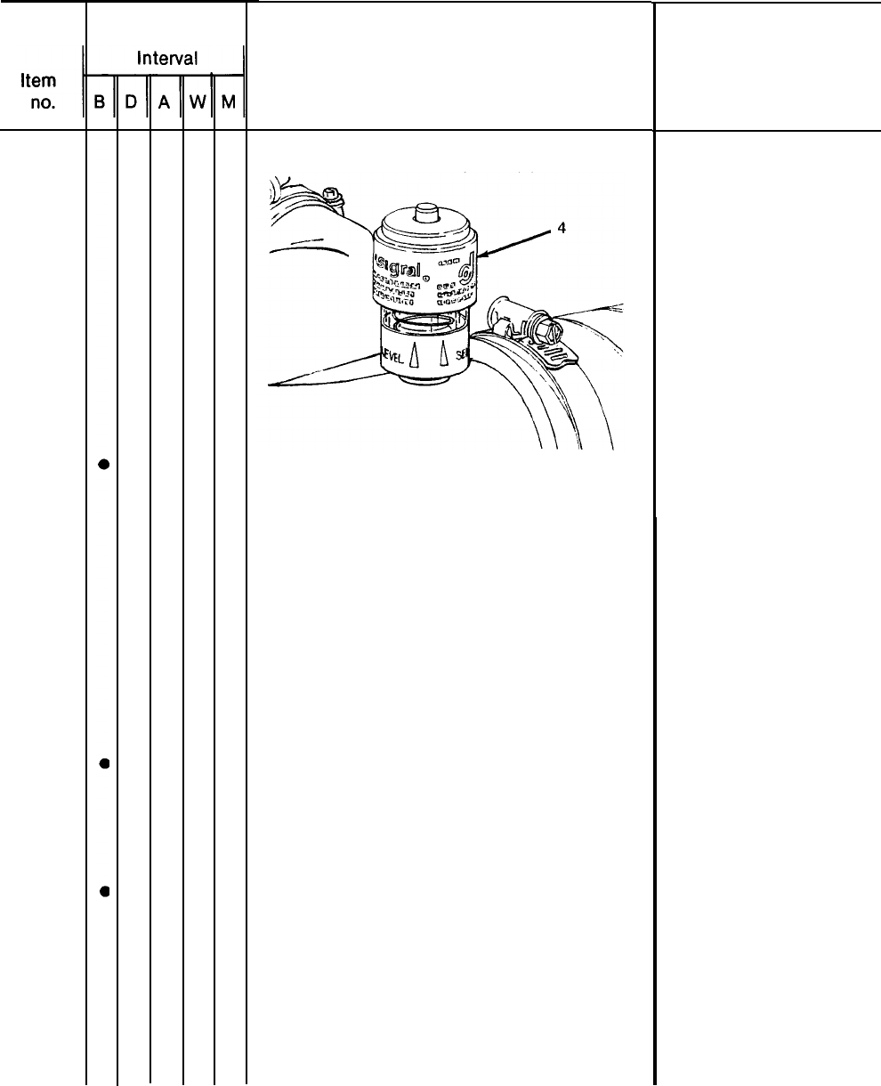
AIR CLEANER INDICATOR – CONT
ACCESSORIES
Check that the following accessories
are not missing.
a. Sledge hammer
b. Fire extinguisher
c. Driver/puller
d. Ground rods
BRACKETS
Check fire extinguisher and fuel can
mounting brackets for loose hardware
and broken fittings.
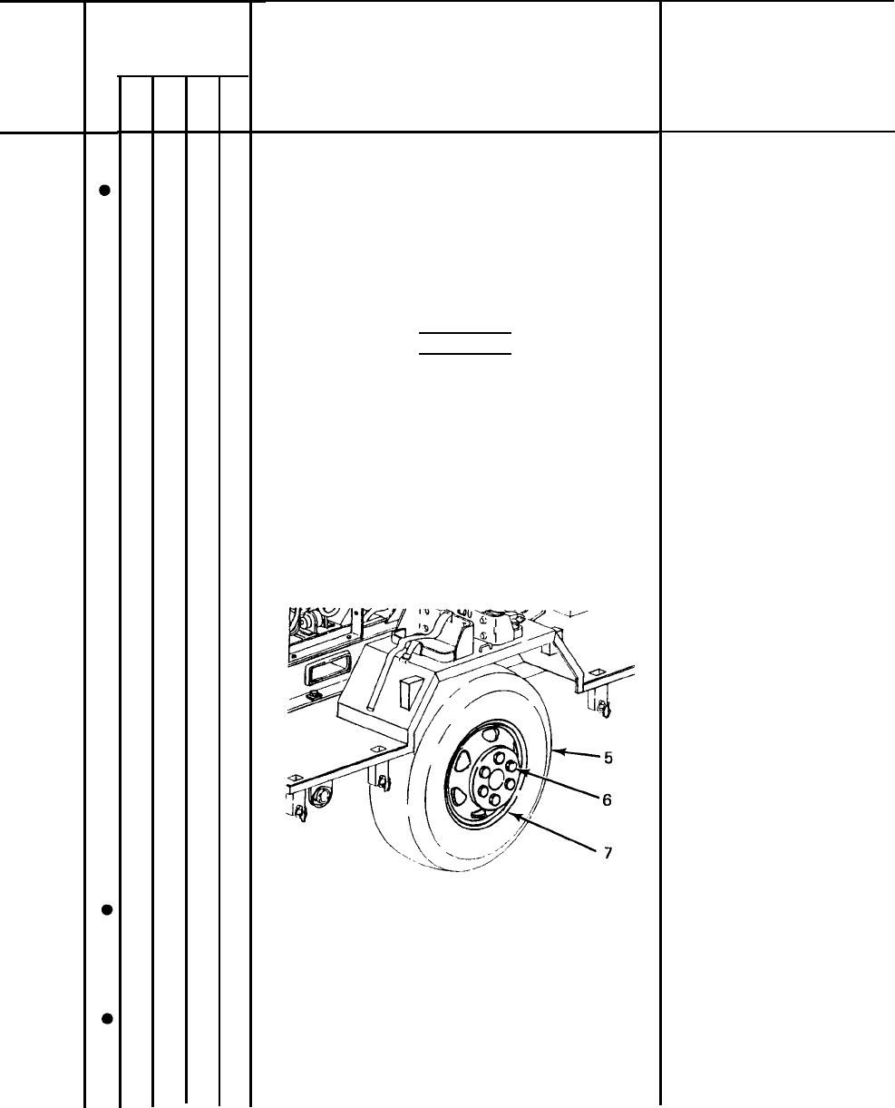
TIRES
a. Check tires (5) for cuts, foreign
objects, or unusual tread wear.
Remove any stones from between the
treads.
b. Check that tire pressure is 50 psi
(344.74 kPa) when tires are cool.
Equipment is not
ready/avai Iable if:
Fire extinguisher is
missing.
Ground rods are
missing.
One tire is flat,
missing, or
unserviceable.
3-7
TM 5-6115-631-14&P
Table 3-2. Operator/Crew Preventive Maintenance Checks and Services(PMCS) - CONT.
B-Before D – During A - After W – Weekly
M
- Monthly
8
9
10
3-8
Interval
—
B D
—
A
W
—
M
Item to be inspected.
Procedure: check for and
have repaired, filled, or
adjusted as needed
WHEELS
a. Check for damage and for missing
or loose stud nuts (6).
WARNING
An improperly seated Iockring can
blow off. Never attempt to seat a
Iockring when tire is inflated.
Serious injury or loss of life could
result.
b. Check for improperly mounted
Iockring assembly (7).
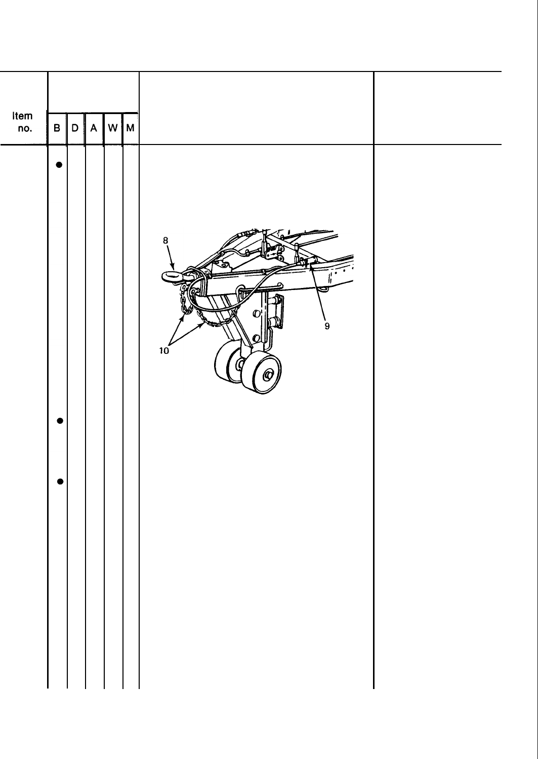
DRAWBAR RING
Check drawbar ring (8) for insecure
mounting and obvious damage.
I
INTERVEHICULAR CABLE
Check cable (9) and connector for cuts
and breaks.
Equipment is not
ready/available if:
One or more wheel is
damaged. One or
more stud nuts are
loose or missing.
Lockring is improperly
seated.
Ring is loose or bent.
Intervehicular cable
is broken or missing.
TM 5-6115-631-14&P
Table 3-2. Operator/Crew Preventive Maintenance Checks and Services (PMCS) – CONT.
B – Before D – During A – After W – Weekly M – Monthly
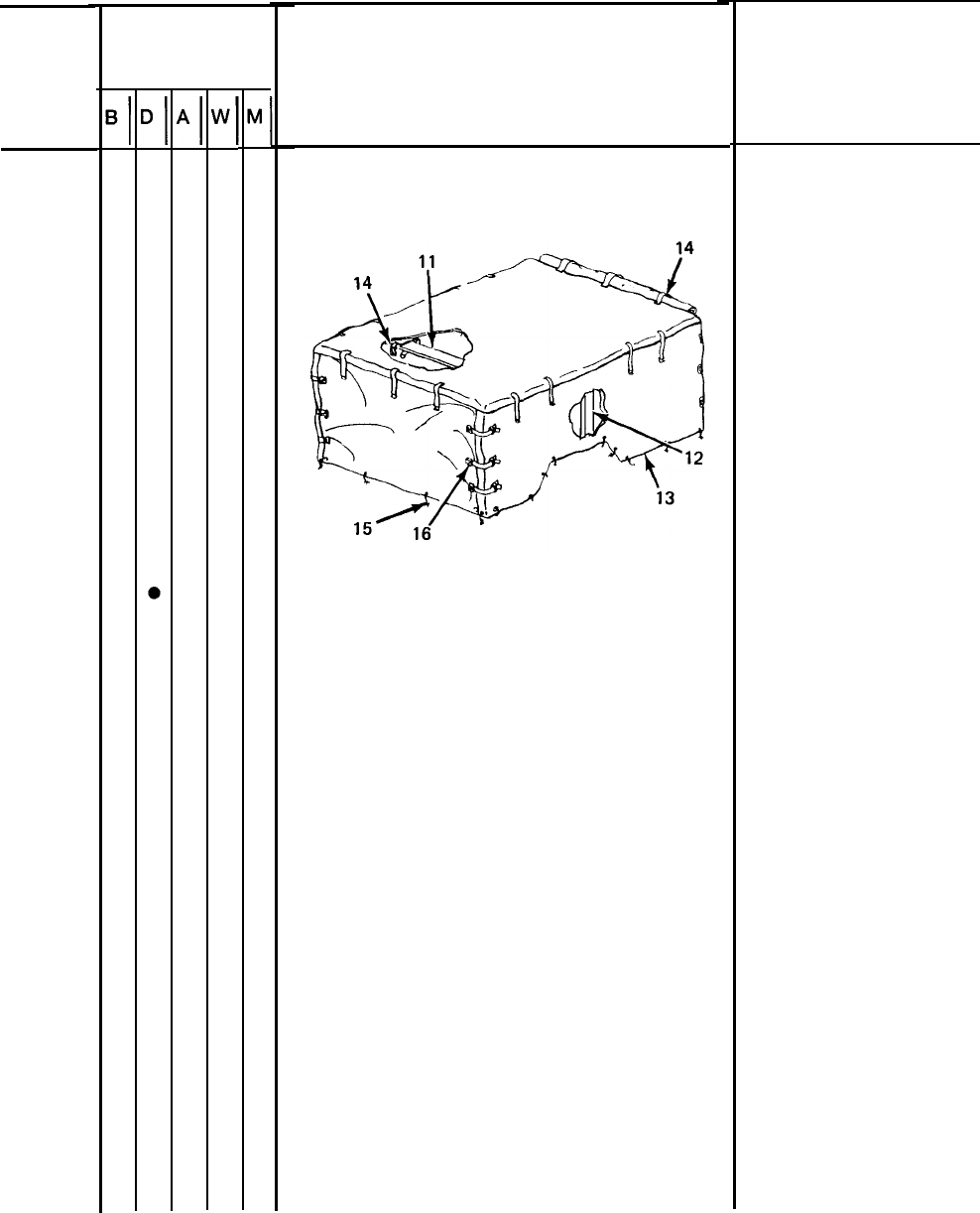
11
12
13
Interval
Item to be inspected.
Procedure: check for and
have repaired, filled, or
adjusted as needed
SAFETY CHAINS
Check safety chains (10) for insecure
mounting and obvious damage.
BOW ASSEMBLIES
Inspect four long bow assemblies (11) and
two short bow assemblies (12).
FITTED COVER
a.
b.
c.
d.
Check fitted cover (13) for missing and
defective tiedown straps and snap
fasteners (14).
Check for missing and defective
ropes (15).
Check for missing and defective straps
and buckles (16).
Check for ripped seams and tears.
Equipment is not
ready/available if:
Safety chains are
missing or
unsecured.
3-9
TM 5-6115-631-14&P
Table 3-2. Operator/Crew Preventive Maintenance Checks and Services(PMCS) - CONT.
B - Before D - During A – After W - Weekly M – Monthly
Item
no.
13
14
3-10
Interval Item to be inspected.
Procedure: check for and
have repaired, filled, or
adjusted as needed
FITTED COVER – CONT
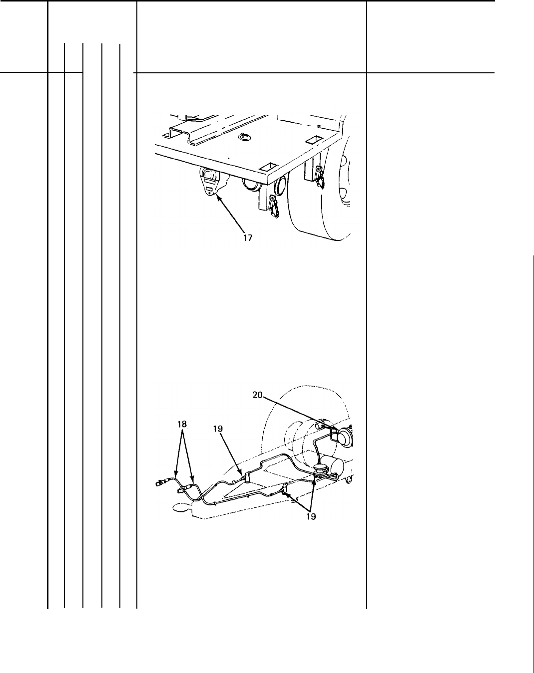
LIGHTS
a.
b.
With intervehicular cable connected to
towing vehicle, operate vehicle light
switch through all settings and check
lights.
NOTE
An assistant is required while
checking brake lights.
Step on brake pedal and check brake
lights (17).
Equipment is not
ready/available if:
TM 5-6115-631-14&P
Table 3-2. Operator/Crew Preventive Maintenance Checks and Services (PMCS) - CONT.
B
- Before D – During A – After W – Weekly
M
- Monthly
Item
no.
14
15
—
B
●
Interval
—
D
—
—
A
—
—
w
—
—
M
Item to be inspected.
Procedure: check for and
have repaired, filled, or
adjusted as needed
LIGHTS - CONT
AIR HOSES, FlTTINGS AND BRAKE AIR
CHAMBER
Check air hoses (18), fittings (19)
and brake air chamber (20) for signs
of damage or leaks.
Equipment is not
ready/available if:
Damage or leaks
are detected.
3-11
TM 5-6115-631-14&P
Table 3-2. Operator/Crew Preventive Maintenance Checks and Services (PMCS) - CONT.
B
- Before D – During A – After W – Weekly M – Monthly
Item
no.
16
17
3-12
Interval
Item to be inspected.
Procedure: check for and
have repaired, filled, or
adjusted as needed
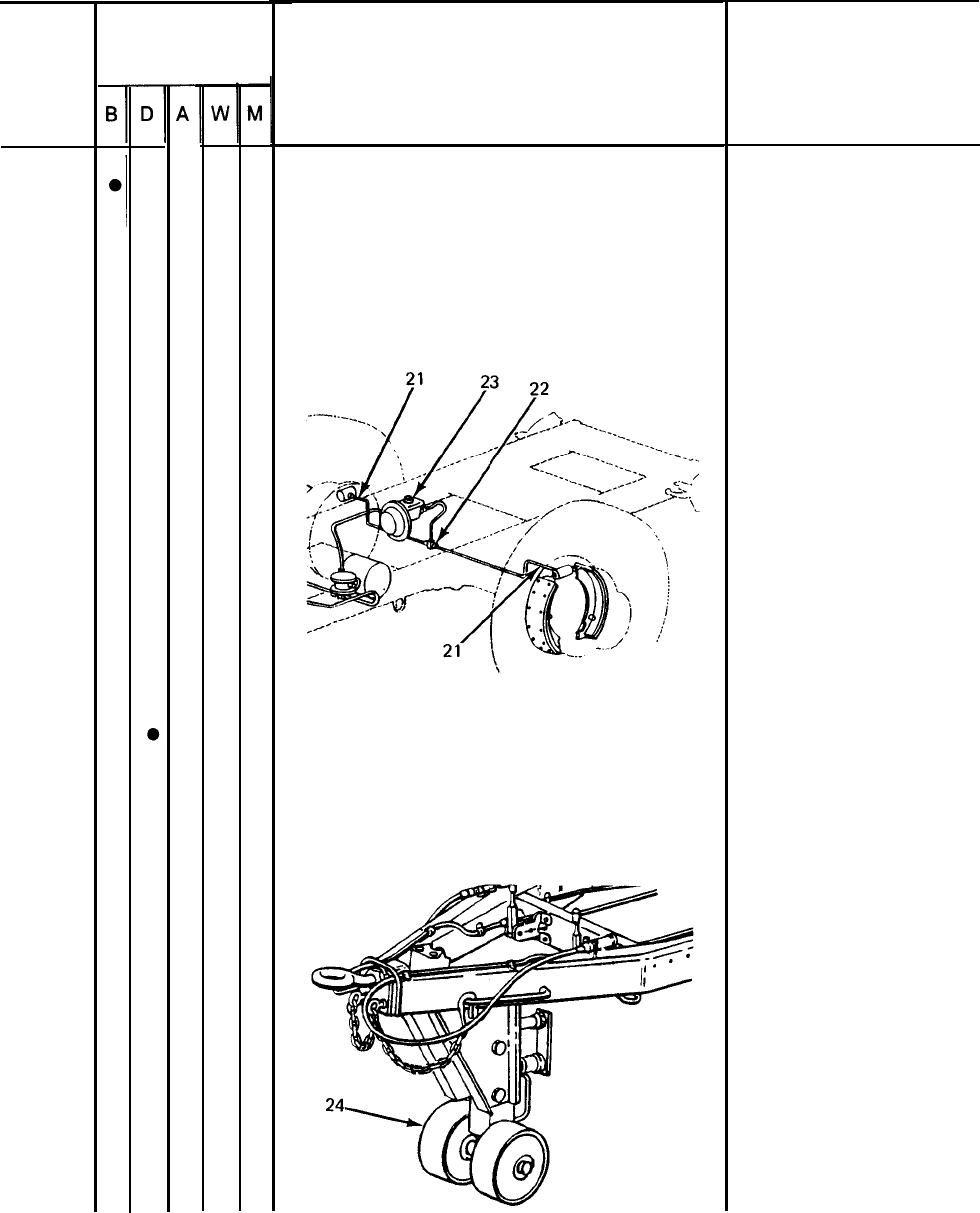
HYDRAULIC HOSES, FITTINGS AND MASTER
CYLINDER
Check brake system hoses (21) and
fittings (22) and master cylinder
(23), and check under vehicle for
signs of brake fluid leaks.
SUPPORT LEG ASSEMBLY
With trailer connected to towing vehi-
cle, check support leg assembly (24)
for ease of operation.
Equipment is not
ready/avaiIable if:
A class Ill brake fluid
leak is detected.
Support leg assembly
is seized.
TM 5-6115-631-14&P
Table 3-2. Operator/Crew Preventive Maintenance Checks and Services(PMCS) - CONT.
B-Before D – During A – After W – Weekly M – Monthly
Item
no.
18
19
20
21
—
B
—
Interval
—
D
—
●
●
●
●
—
A
—
—
w
—
M
—
Item to be inspected.
Procedure: check for and
have repaired, filled, or
adjusted as needed
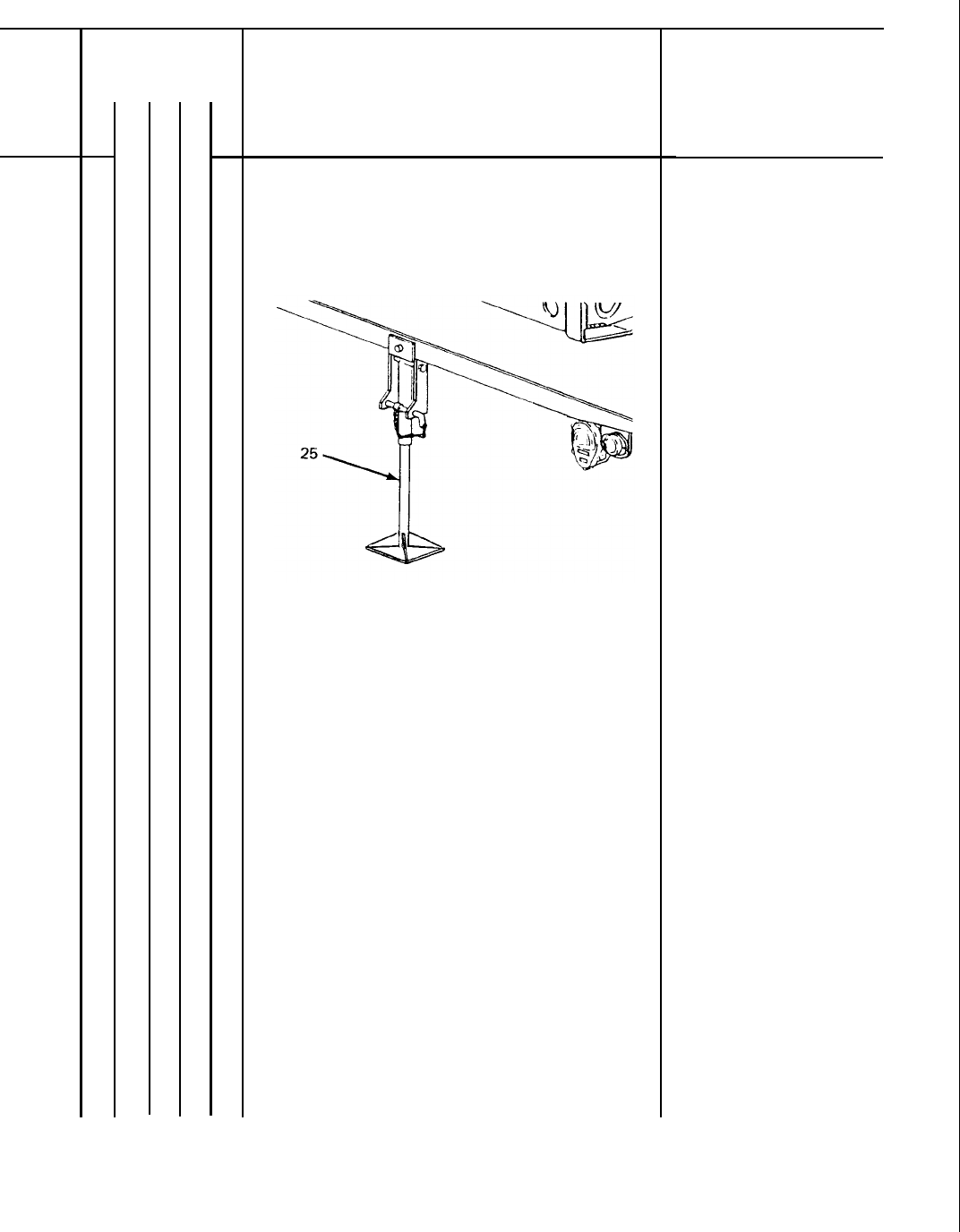
REAR LEG PROP ASSEMBLY
Inspect leg prop assembly (25) for
broken or missing parts.
BRAKE SYSTEM
Test brake system by hooking trailer
to towing vehicle and applying brakes.
TRAILER OPERATION
a. Be alert for any unusual noises while
towing trailer. Stop and investigate
any unusual noises.
b. Ensure that trailer is tracking/following
correctly behind towing vehicle with no
side pull.
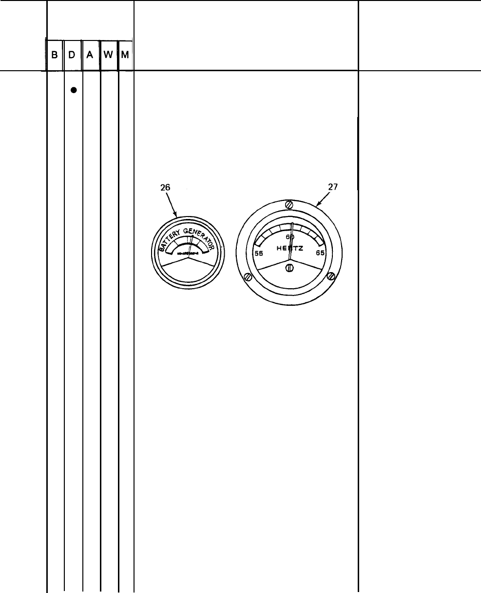
GENERATOR SET GAGES AND INSTRUMENTS
a. Check that battery indicator (26)
is in yellow area while batteries
are charging and in green area when
batteries are fully charged.
Equipment is not
ready/available if:
Leg prop assembly is
unserviceable.
Service brakes fail to
operate.
Battery indicator not
in correct area.
3-13
TM 5-6115-631-14&P
Table 3-2. Operator/Crew Preventive Maintenance Checks and Services(PMCS) – CONT.
B – Before
D
- During A – After W – Weekly
M
– Monthly
Item
no.
21
3-14
Interval
Item to be inspected.
Procedure: check for and
have repaired, filled, or
adjusted as needed
GENERATOR SET GAGES AND
INSTRUMENTS - CONT
b. Check that frequency meter (27)
indicates 60 Hz (red line) when
generator is operating under load.
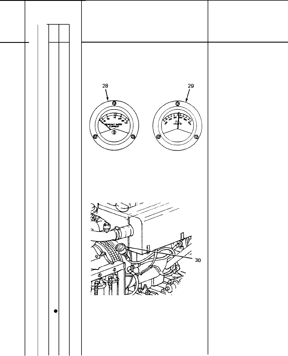
c.
d.
Check that current meter (28) reading
does not exceed 100% or more than 5%
load difference between phases.
Check that voltmeter (29) indicates
desired output voltage as deter-
mined by load connections and amps-
volts transfer switch.
Equipment is not
ready/avaiIable if:
Correct frequency
cannot be
maintained.
Desired voltage can-
not be obtained and
maintained.
TM 5-6115-631-14&P
Table 3-2. Operator/Crew Preventive Maintenance Checks and Services (PMCS) - CONT.
B - Before D – During A – After W - Weekly M – Monthly
Item
no.
21
22
—
B
—
Interval
—
D
—
●
—
A
—
—
w
—
—
M
—
Item to be inspected.
Procedure: check for and
have repaired, filled, or
adjusted as needed
GENERATOR SET GAGES AND
INSTRUMENTS – CONT
e. Check engine oil pressure gage (30)
for 20 to 45 psig indication.
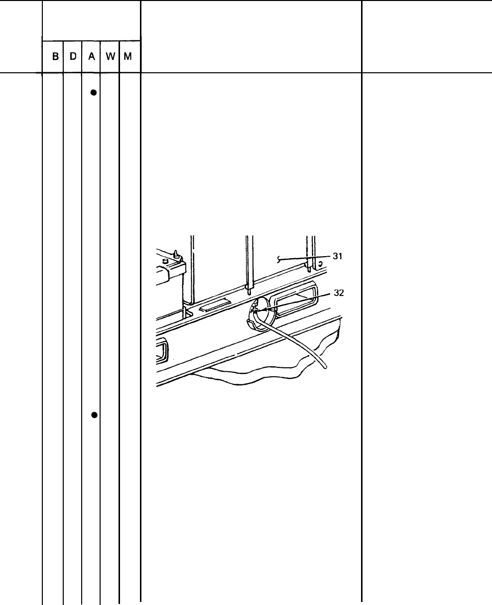
FUEL TANK
a. Fill tank (31) upon completion of
operation.
Equipment is not
ready/available if:
Oil pressure drops
below 20 psig.
3-15
TM 5-6115-631-14&P
Table 3-2. Operator/Crew Preventive Maintenance Checks and Services (PMCS) - CONT.
B
- Before
D
– During A – After W – Weekly
M
- Monthly
Item
no.
22
23
3-16
Interval
Item to be inspected.
Procedure: check for and
have repaired, filled, or
adjusted as needed
FUEL TANK – CONT
NOTE
Fuel system temperature must be
above freezing when draining
water and sediment.
b. Open drain (32) and drain water and
sediment from fuel tank. Allow to drain
until fuel runs clean.
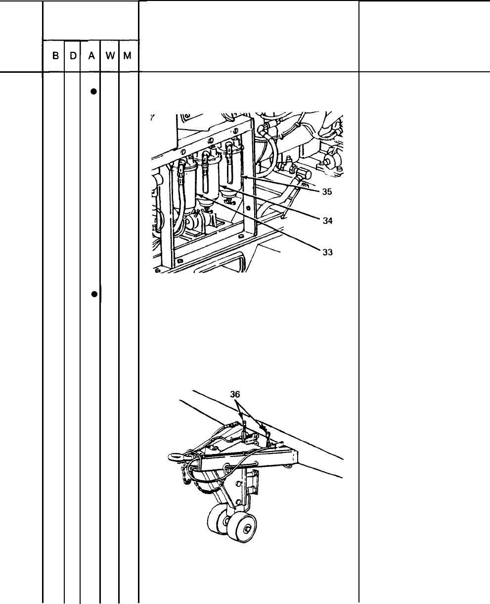
FUEL STRAINER AND FILTERS
Drain water and sediment from strainer
(33), primary (34) and secondary (35)
filters. Allow to drain until fuel runs clean.
Equipment is not
ready/available if:
TM 5-6115-631-14&P
Table 3-2. Operator/Crew Preventive Maintenance Checks and Services (PMCS) - CONT.
B – Before
D
- During A – After W - Weekly
M
- Monthly
Item
no.
23
24
interval
Item to be inspected.
Procedure: check for and
have repaired, filled, or
adjusted as needed
FUEL STRAINER AND FILTERS - CONT
HANDBRAKES
With trailer hooked to towing vehicle, set
handbrakes (36). Move trailer slightly to
see if handbrakes hold wheels.
Equipment is not
ready/available it
3-17
TM 5-6115-631-14&P
Table 3-2. Operator/Crew Preventive Maintenance Checks and Services (PMCS) – CONT.
B – Before D – During A – After W – Weekly M – Monthly
Item
no.
25
26
27
3-18
Interval
Item to be inspected.
Procedure: check for and
have repaired, filled, or
adjusted as needed
I
BRAKE DRUMS AND HUBS
WARNING
A defect in the operation of the
brakes or hub can cause these
parts to get hot enough to cause
serious burns. Use extreme cau-
tion when attempting to detect
heat in this area.
Feel for overheating to detect drag
ging or binding.
REFLECTORS
Check for damaged or missing reflectors.
I
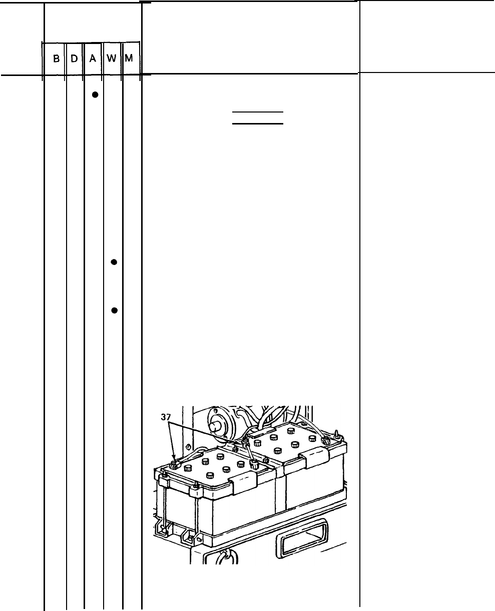
BATTERIES
Check battery (37) electrolyte level. Level
should be about 3/4 inch above top of
plates. Add water if level is low. Use
clean water (distilled water if available).
Equipment is not
ready/available if:
Brakes or hub are
dragging or binding.
TM 5-6115-631-14&P
Table 3.2. Operator/Crew Preventive Maintenance Checks and Services (PMCS) – CONT.
B - Before D – During A – After W - Weekly
28
29
30
Interval Item to be inspected.
Procedure: check for and
have repaired, filled, or
adjusted as needed.
FIRE EXTINGUISHER
Inspect and weigh fire extinguisher.
(See paragraph 3-12.)
TRAILER FRAME
Inspect entire chassis frame for damage,
cracks, and broken welds.
SWITCH BOX
Inspect for broken or damaged connectors
Inspect for frayed or broken wires and wire
insulation. Inspect for loose connections
at the switch box. Inspect rotary
switch for loose or missing parts and
correct operation.
M – Monthly
Equipment is not
ready/available if:
Frame is obviouslv
broken or cracked.
Connectors will not
tighten or if parts
are damaged or
missing, bare wires
are exposed or if
rotary switch is
defective or
unoperational.
Section IV TROUBLESHOOTING
3-10. Power Unit Troubleshooting. There are no troubleshooting procedures authorized at operator level
for the power plant end item. Troubleshooting procedures for the individual generator sets and trailer
are contained in their respective technical manuals referenced below.
a.
Generator Set Troubleshooting. Refer to TM 5-6115-584-12 for troubleshooting procedures.
b.
Trailer Troubleshooting. Refer to TM 9-2330-213-14&P for troubleshooting procedures.
Section V. OPERATOR/CREW MAINTENANCE
3-11. Enclosure Maintenance. Maintenance of the enclosure at operator level is limited to replacement
of the fitted cover and/or the bows.
a.
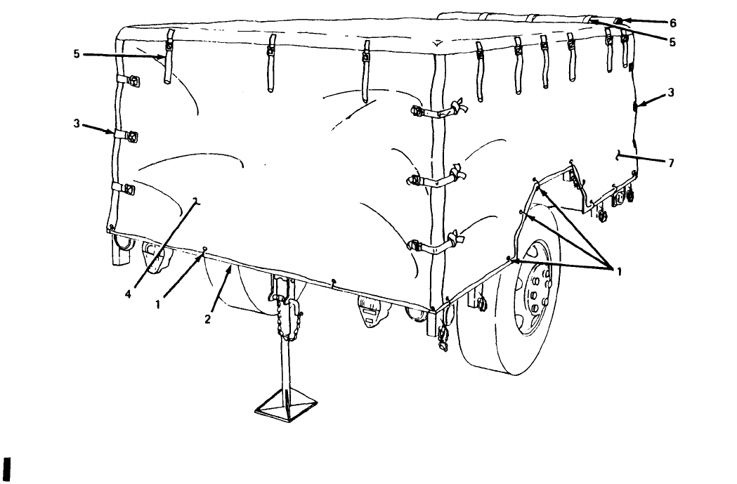
Fitted Cover Replacement. (See figures 3-1 and 3-2.)
(1) Removal.
(a) Untie 25 ropes ( 1, figure 3-1 )fastening fitted cover to trailer body (2).
Change 1
3-19
TM 5-6115-631-14&P
(b) Unfasten six straps and buckles (3) securing rear curtain (4). Roll up curtain, and secure
with three rollup straps (5) provided.
(c) Unfasten six straps and buckles (3) securing front curtain (6). Roll up curtain, and secure
with three rollup straps (5) provided.
(d) Roll up each side (7) of fitted cover, in turn, and secure each side with six rollup straps
(5) provided.
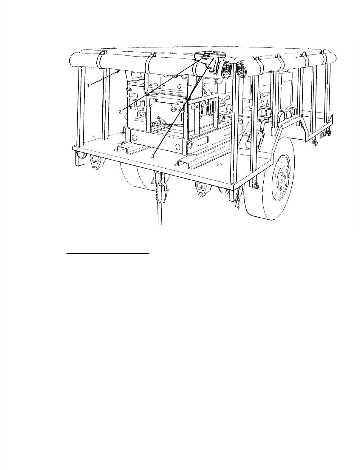
(e) Working under fitted cover (1, figure 3-2), unfasten 12 straps (2) securing fitted cover to
bow assemblies (3). Remove fitted cover.
(2) Installation.
NOTE
Front curtain is provided with three tie-down ropes. Rear curtain only has two ropes.
(a)
(b)
(c)
(d)
(e)
(f)
Position fitted cover (1, figure 3-2) on top of bows (3) making certain front of fitted cover
is at front of trailer.
Secure fitted cover (1) to bow assembly (3) with 12 straps (2) provided.
Unfasten rollup straps (5, figure 3-1) securing sides of fitted cover and lower both sides (7).
Unfasten rollup straps (5) securing front and rear curtains (4, 6) and lower both curtains.
Secure front and rear curtains (4, 6) to sides (7) with six straps and buckles (3) provided
on each curtain.
Secure fitted cover to trailer body (2) with 25 ropes ( 1 ) provided,
Figure 3-1. Fitted Cover Installed on Power Plant.
Change 1
3-20
TM 5-6115-631-14&P
Figure 3-2. Fitted Cover Rolled Up for Removal.
b. Bow Assembly Replacement. (See figure 3-3.)
(1) Removal.
(a) Remove fitted cover (paragraph 3-11, a.(1)).
(b) Remove two quick release pins (1) securing each bow assembly (2) in
pockets (3) on trailer body (4). Lift each bow out of pocket and off trailer body.
(2) Installation.
(a) Lift each bow (2) onto trailer, aline ends with pocket (3) in trailer body (4) and drop
bow in place. Secure each bow assembly with two quick release pins (1) provided.
(b) Install fitted cover on trailer (paragraph 3-11, a.(2)).
3-21
TM 5-6115-631-14&P
Figure 3-3. Bow Assembly Replacement.
3.12.
Fire Extinguisher Maintenance.
WARNING
Monobromotrifluoroethane liquid or gas (Halon 1301) can cause death or
serious injury if personnel fail to observe safety precautions. Inhalation of
monobromotrifluoroethane gas at concentrations of 5% to 6% for more than 4
or 5 minutes may result in serious cardiac or central nervous system effects.
Liquid Halon 1301 (including the spray in the immediate vicinity of the
discharge) may freeze the skin on contact. In the event of frostbite, warm the
affected area quickly to body temperature. Immerse hands in warm water or
place hands in armpits. Get medical attention promptly.
CAUTION
Do not attempt to verify readiness of fire extinguisher by partially discharging
unit. Any discharge of contents will require refilling.
The AN/MJQ-16 Power Plant is equipped with two 2-3/4 lb Halon fire extinguishers.
Maintenance is limited to weighing the fire extinguishers monthly to insure that they
are sufficiently charged. Fully charged, each fire extinguisher (with head and horn
attached) weighs 5 lb. Send the unit to specialized activity for recharging if it weighs
4 lb, 12 oz or less.
3-22

TM 5-6115-631-14&P
CHAPTER 4
UNIT MAINTENANCE
Section I. SERVICE UPON RECEIPT OF EQUIPMENT
4-1.
Inspecting and Servicing Equipment. The power plant shall be unpacked, inspected, and ser-
viced as described in the following paragraphs. Unpacked equipment must be checked against the
Equipment Packing List to ensure completeness. Discrepancies must be reported in accordance with
the instructions given in DA Pam 738-750.
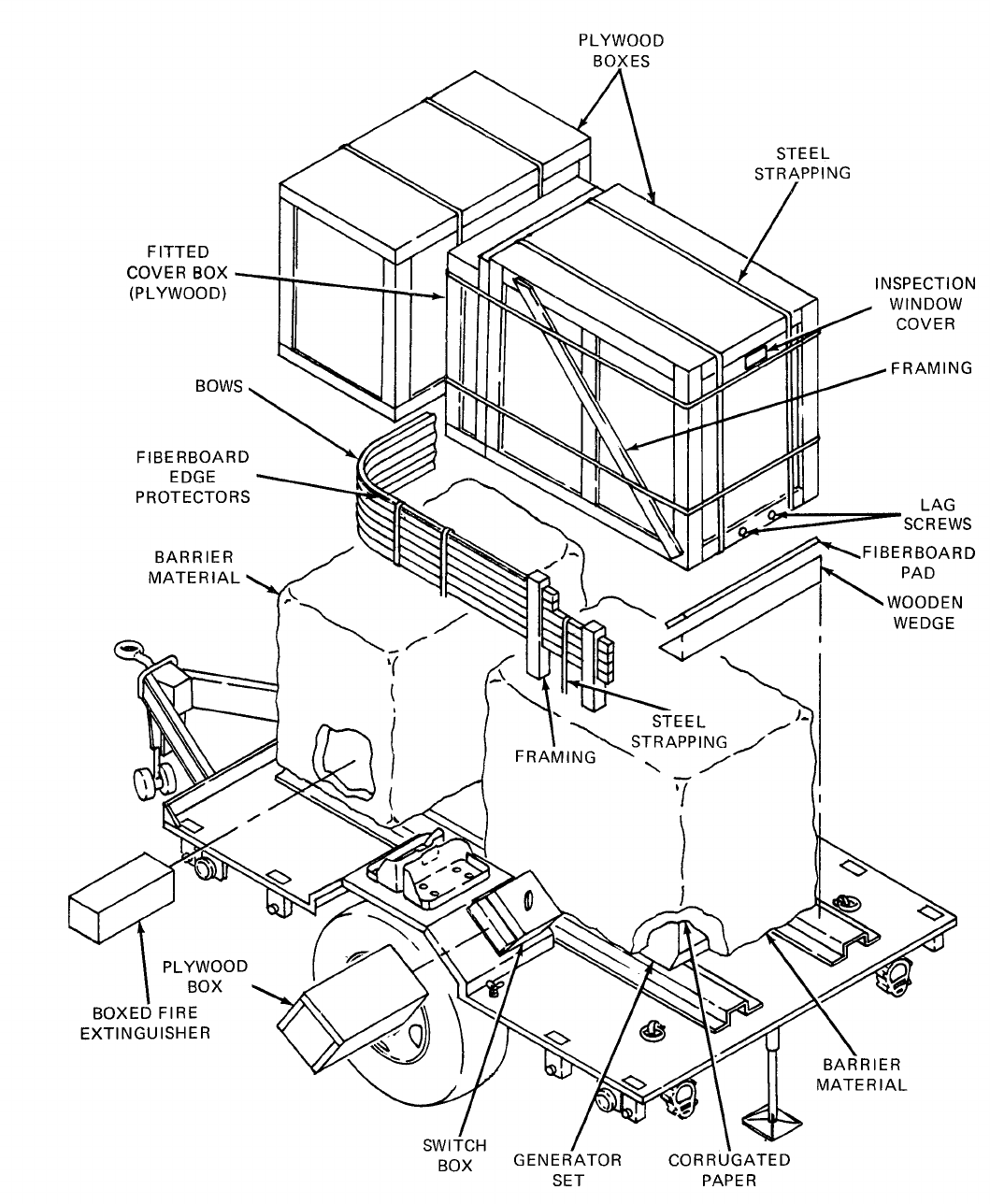
a. Unpacking Power Plant. (See figure 4-1.) The generator sets are packed in place on the
trailer body. Before beginning the unpacking procedure, locate, remove, and save the two
Depreservation Guides.
(1)
(2)
(3)
(4)
(5)
(6)
(7)
(8)
(9)
(10)
(11)
WARNING
Steel strapping used in packaging of power plant has sharp edges. Care
should be taken when cutting and handling strapping to avoid injury to
personnel.
Remove lag screws securing plywood boxes over generator sets and lift boxes off generator
sets. Remove wooden wedges and fiberboard pads positioned around base of generator
sets.
Remove barrier material and corrugated paper surrounding generator sets.
NOTE
Inspection and servicing of equipment will be easier to perform before fitted
cover is put in place on power plant.
Pry off end of plywood fitted cover box (strapped to one generator set box). Take out fitted
cover. Remove plastic protective film and set fitted cover aside.
Remove ground wires and clamps taped to one generator set.
Take tape or covers off ends of power cables.
Remove two boxed fire extinguishers taped to generator sets. Unpack fire extinguishers and
secure one in each fender-mounted bracket.
Take plywood box off switch box.
Remove strapping, framing and fiberboard edge protectors securing bows and remove
bows from trailer.
Remove oil drain taped to generator set and install in place. (Refer to
TM 5-6115-584-12.)
Remove package of technical publications from accessory box and save.
Unpack and inventory accessories in accessory box.
4-1

TM 5-6115-631-14&P
(12) Connect power cables to each generator set load terminal board as follows and in
accordance with identification on cables, wires and generator set terminals:
(a) White wire to load terminal L0;
(b) Black wire to load terminal L1;
(c) Red wire to load terminal L2;
(d) Blue wire to load terminal L3.
(e) Green wire to generator set ground terminal (5-wire switch box only),
(13) Refer to DA Form 2258, Depreservation Guide for Vehicles and Equipment, packed with
power unit and follow instructions given for putting unit in service.
(14) Stow all authorized accessories in accessory box.
(15) Install bows on power plant (paragraph 3-11, b.(2)).
(16) Install fitted cover on power plant (paragraph 3-11, a.(2)).
b. Inspection and Servicing of Generator Set. Refer to Service Upon Receipt of Materiel in
TM 5-6115-584-12 for initial inspection and servicing procedures.
c. Inspection and Servicing of Trailer. Refer to Service Upon Receipt of Materiel in TM 9-2330-
213-14&P for initial inspection and servicing procedures.
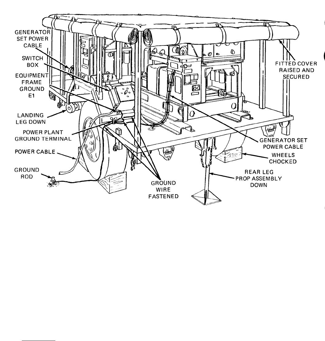
4-2.
Installation. (See figure 4-2.) Installation of the power plant at a worksite involves positioning
the trailer and grounding the power plant.
a. Positioning Power Want. Position the power plant on the worksite as follows:
(1) Select an area as level as possible to install power plant and position trailer.
(2) Set trailer handbrakes and lower trailer support leg,
(3) Chock both wheels and lower rear leg prop assembly. Adjust leg prop assembly by turning
inner leg until leg base makes firm contact with ground.
(4) Lift and secure fitted cover in raised position away from generator set exhaust.
WARNING
Remove fire extinguisher and fuel cans from power unit when generator set is in
operation. This will insure that in the event of fire, extra fuel will not be involved
and extinguisher will remain accessible.
(5) Locate fuel cans and fire extinguisher on ground away from power plant.
4-3
TM 5-6115-631-14&P
Figure 4-2.Installing Power Plant
WARNING
Do not operate generator sets until power plant is properly grounded
(paragraph 4-2, b.). Serious injury or death by electrocution can result from
operating an ungrounded power plant.
CAUTION
To avoid damage to equipment, make certain of voltage, frequency, and
phase requirements of load being connected to generator set.
(6) Refer to data plate on load terminal board cover and to TM5-6115-584-12. Connect power
plant to system or equipment to be powered.
b. Grounding. Check that generator sets are grounded to GROUND TERMINAL stud on trailer
body. Using ground wire supplied, connect power plant to a suitable ground as described below. The
following sources of a good ground are listed in order of preference.
NOTE
As a substitute for the supplied ground wire, any copper wire of at least No. 6
AWG maybe used.
4-4

TM 5-6115-631-14&P
(1)
(2)
(3)
Underground water system. Ground power plant to one of the accessible pipes in an
underground water system. Make certain underground pipe is made of metal and there is
no insulation, such as a water meter, between ground wire and earth.
Ground rod. Drive ground rod a minimum of eight feet into earth and saturate area
around ground rod with salt water.A ground rod must have a minimum diameter
of 5/8-inch, if solid, or 3/4-inch if pipe.
NOTE
It maybe necessary to saturate the area around ground rod with water if soil
conditions are dry.
Ground plate. Ground power plant to a metal plate buried four feet deep. Ground plate
should cover a minimum area of nine square feet.
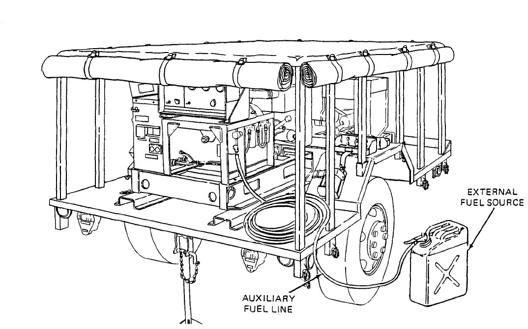
c. Extemal Fuel Line Connection. (See figure 4-3.) The power plant generator sets can be
fueled from an external source such as a five-gallon fuel can or 55 gallon drum. This eliminates the
need for frequent refilling of each generator’s fuel tank during long intervals of operation.
(1)
(2)
(3)
(4)
(5)
Remove fuel can adapter and fuel pickup tube from storage locations on generator set and
assemble by threading pickup tube into adapter.
Thread one end of auxiliary fuel line onto fuel can adapter fitting and tighten.
Connect free end of auxiliary fuel line to AUXILIARY FUEL CONNECTION. This connection is
located immediately below control cubicle on right-hand side of generator set.
Insert fuel can adapter in external fuel source and secure by pressing down on lever.
Set MASTER SWITCH on control panel to PRIME AND RUN AUX FUEL position.
NOTE
When generator set is run on auxiliary fuel, as described above, fuel is first
pumped into generator set fuel tank by auxiliary fuel pump. Fuel is then fed to
generator set engine from fuel tank.
4-5
TM 5-6115-631-14&P
Figure 4-3. External Fuel Line Connection.
Section Il. MOVEMENT TO A NEW WORKSITE
4-3.
Dismantling for Movement.
Because the power plant is designed to be mobile, a minimum
amount of effort is required to relocate to a new worksite. Procedures are as follows:
a.
b.
c.
d.
e.
f.
9.
h.
4-6
Disconnect power plant from system or equipment being powered.
Disconnect ground cable from source of ground and from power plant GROUND TERMINAL
stud. Roll up cable and store in accessory box.
Using slide hammer, remove ground rod. Disassemble, clean, and stow ground rod in
accessory box.
Disconnect power plant from external fuel sources, if applicable.
Stow any remaining authorized equipment in accessory box.
Secure fire extinguishers and fuel cans in their respective mounting brackets.
Lower and secure fitted cover in place on power plant.
Remove locking pin from leg prop assembly on rear of trailer. Swing leg prop back and up
into traveling position and secure with pin.

TM 5-6115-631-14&P
i. Attach power unit to towing vehicle. (Refer to TM 9-2330-213-14&P.)
4-4.
Reinstallation After Movement. After movement to a new worksite, install power plant in
accordance with paragraph 4-2.
Section Ill. REPAIR PARTS, SPECIAL TOOLS, SPECIAL TEST, MEASUREMENT AND
DIAGNOSTIC EQUIPMENT (TMDE)
4-5. Tools and Equipment. There are no special tools or equipment required to maintain the
AN/MJQ-16 power plant.
4-6.
Maintenance Repair Parts. Repair parts and equipment for maintenance of this power plant are
listed and illustrated in the repair parts and special tools list in Appendix D of this manual.
Section IV. LUBRICATION INSTRUCTIONS
4-7. General. Detailed instructions for the lubrication of the major components of the power plant are
contained in the applicable Lubrication Orders (LO’s). Refer to DA Pam 25-30 to ensure that the latest
editions of the L.O.’S are used. This section contains lubrication instructions that are not included in
the Lubrication Orders.
4-6. Generator Lubrication. Refer to LO 5-6115-584-12 for generator set Lubrication Order.
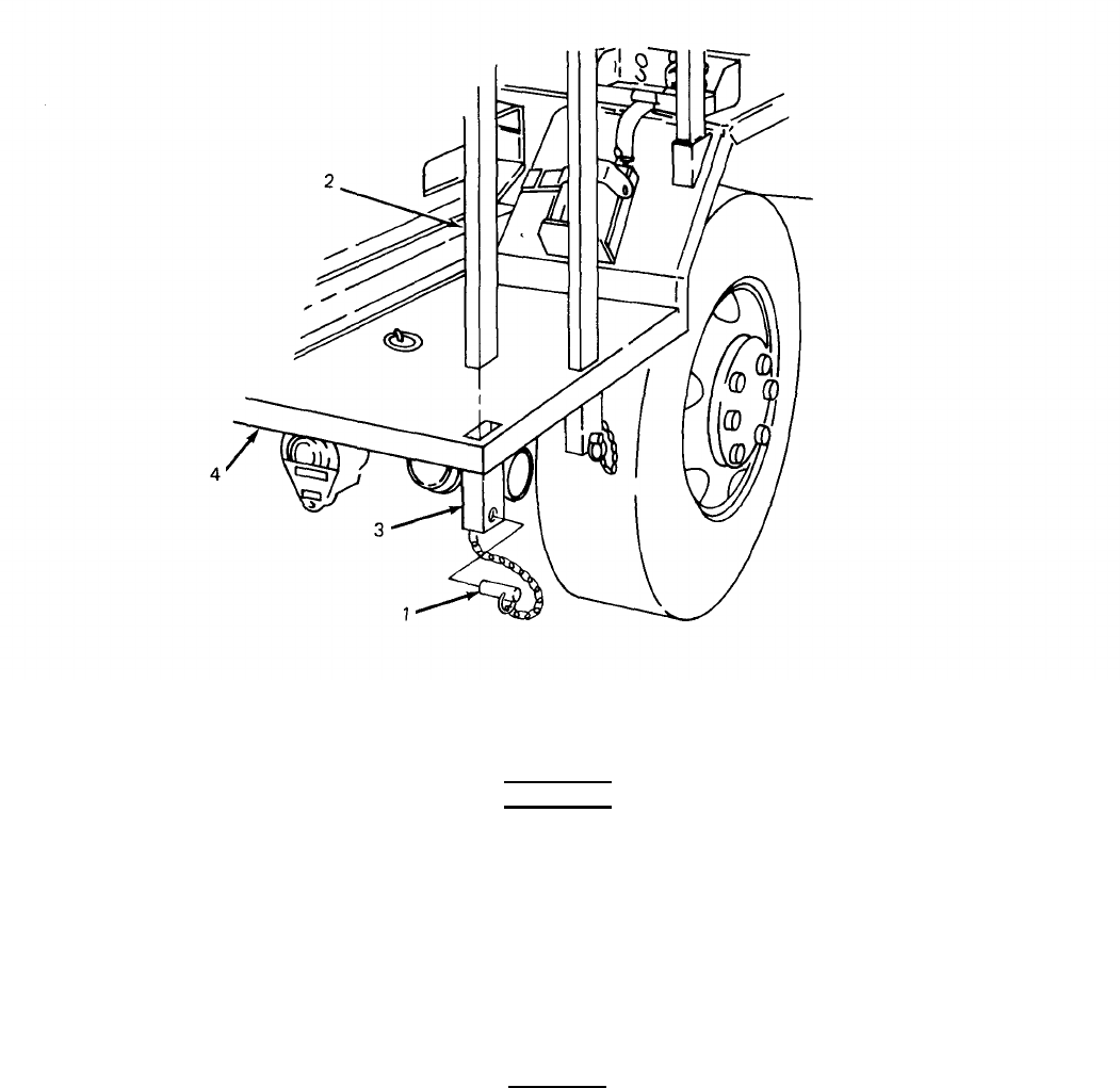
4-9. Trailer Assembly Lubrication.
a. Trailer Lubrication. Refer to TM 9-2330-213-14&P for trailer Lubrication Order.
b. Leg Prop Assembly Lubrication. The rear leg prop assembly is a modification to the standard
M103A3 trailer and, as such, does not appear in the associated L.O. Semiannually lubricate leg prop
assembly as follows:
WARNING
Clean parts in a well-ventilated area. Avoid inhalation of solvent fumes and
prolonged exposure of skin to cleaning solvent. Wash exposed skin tho-
roughly. Dry cleaning solvent (P-D-680) used to clean parts is potentially
dangerous to personnel and property. Do not smoke or use near open flame or
excessive heat. Flash point of solvent is 100°F. to 138°F. (38°C. to 59°C.).
(1) Clean hydraulic lubrication fitting and area around lubrication points with P-D-680 or
equivalent.
(2) Inject sufficient GAA grease into hydraulic fitting to lubricate screw theads inside leg prop
assembly.
NOTE
Refer to Lubrication Instructions in TM 9-2330-213-14&P for lubricating oils
specified for use within different anticipated temperature ranges.
(3) Apply OE lubricating oil to both ends of leg prop assembly pivot shaft.
4-7

TM 5-6115-631-14&P
Section V. PREVENTIVE MAINTENANCE CHECKS AND SERVICES
NOTE
The PMCS chart in this section contains all necessary unit preventive maintenance
checks and services for this equipment.
4-10. General. The trailer assembly and generator sets must be inspected and serviced systematically to –
insure that the power plant is ready for operation at all times. Inspection will allow defects to be
discovered and corrected before they result in serious damage or failture. Table 4-1 contains a tabulated
list of preventive maintenance checks and services to be performed by unit maintenance personnel. All of
the unit PMCS on the trailer is scheduled to be performed semiannually. Unit PMCS on the generator
sets are scheduled weekly or on a per-hours-of-operation basis, The running time meter on the control
panel is used to determine the generator set operating time. Using the following as a guide, do the checks
and services at the intervals shown. Observe all CAUTIONS and WARNINGS.
a.
b.
c.
d.
e.
f.
4-11.
For PMCS performed on an operating time basis, perform your hourly (H) PMCS as close as
possible to the time intervals indicated.
NOTE
For units in continuous operation, perform PMCS before starting operation if
continuous operation will extend service interval past that which is shown.
Perform your weekly (W) PMCS every week or 40 hours of generator set operating time.
Perform your monthly (M) PMCS every month or 100 hours of generator set operating time.
Do your semiannual (S) PMCS once every six months or 500 hours of generator set operating time.
Do your annual (A) PMCS once every year or 1000 hours of generator set operating time.
If you discover a problem with the equipment, refer to Section Vl, Troubleshooting. If you cannot
correct the problem, refer to paragraph 4-12, Reporting Deficiencies.
Explanation of Columns. The following is a list of the PMCS table column headings with a
description of the information found in each column.
a. Item No. This column shows the sequence in which to do the checks and services, and is used
identify the equipment area on the Equipment Inspection and Maintenance Worksheet, DA Form 2404.
b.
c.
service
d.
4-12.
unable
Interval. This column shows when each check is to be done.
Item to be inspected. This column identifies the general area or specific part where the check
is to be done.
Procedures. This column lists the checks or service you have to do and explains how to do them.
Reporting
to correct,
to
or
Deficiencies. If you discover any problem with the equipment during PMCS that you are
it must be reported. Refer to DA Pam 738-750 and report the deficiency using
the proper forms.
4-8Change 1
TM 5-6115-631-14&P
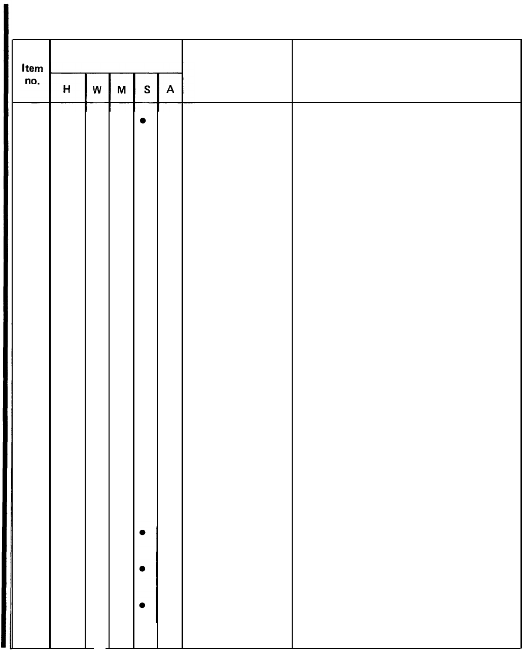
Table 4-1. Unit Preventive Maintenance Checks and Services (PMCS). –CONT.
H – Hours of operation W – Weekly M – Monthly
(As indicated)
S - Semiannually A – Annually
(40 hours)
(100 hours)
(500 hours)
(1000 hours)
Interval
Item to be
Inspected
Generator Set
Fuel Strainer and
Filters
Fuel Tank
Procedures
WARNING
Before performing any maintenance
that requires climbing on or under
trailer, set trailer handbrakes, chock
wheels, and lower rear leg prop.
Injury to personnel could result
from trailer suddenly rolling or
tipping.
NOTE
Generator set checks and services in
this table are described as performed
on a single generator set. These
procedures must be performed
on each of the two generator sets
that make up the AN/MJQ-16.
Inspect generator set for fuel and oil
leaks, loose or missing components and
hardware, and unusual wear or
deterioration. Clean generator set.
NOTE
Fuel system must be above freezing
temperature when draining water
and sediment from strainer, filters,
and tank.
Open drains on fuel strainer, and
secondary filters. Drain water and
sediment (table 3-2, TM 5-61 15-584-12)
Allow to drain until fuel runs clean.
Open drain on fuel tank and drain water
and sediment (table 3-2, TM 5-6115-
584-12). Allow to drain until fuels runs
clean.
Change 1
4-9
5-6115-631-14&P
Table 4-1. Unit Preventive Maintenance Checks and Services (PMCS). – CONT.
H – Hours of operation
W -- Weekly M – Monthly
(As indicated)
S – Semiannually A – Annually
(40 hours)
(1OO
hours)
(500 hours)
(1000
hours)
4
5
6
7
8
9
10
11
12
13
14
15
100
300
500
1000
300
500
100
1000
Interval
Item to be
Inspected
Fuel Pumps
Lubricating Oil
and Filter
Fuel Strainer
Primary Fuel
Secondary Fuel
Filter
Batteries
Crankcase Breather
Dust Caps on Air
Cleaner
Air Cleaner
Taillights
Intervehicular
Cable
Drawbar Ring
Procedures
Clean or replace, as necessary, fuel
strainer in bottom of fuel pumps,
(table 3-2, TM 5-6115-584-12).
Change lubricating oil and filter every
100 hours of operation (L.O.
5-6115-584-12).
Clean fuel strainer every 300 hours of
operation (para 4-20 TM 5-6115-584-12).
Service primary filter every 500 hours of
operation (table 4-1, TM 5-6115-584-12).
Service secondary filter every 1000 hours
(table 4-1, TM 5-6115-584-12).
Perform a hydrometer test on batteries
every 300 hours, or quarterly. Refer to
para 4-25, TM 5-6115-584-12 for test
procedures.
Inspect breather tube every 500 hours.
Clean as necessary (para 4-45,
TM 5-6115-584-12).
Clean out dust caps on air cleaner assembly
every 100 operating hours (more
frequently under unusual conditions).
Clean every 1000 operating hours or as
conditions dictate. Replace air cleaner
every 2000 operating hours.
Replace any broken or cracked lenses
or defective bulbs.
Check for cuts, breaks, frayed wires, or
damaged plug.
Check security of mounting. Inspect ring
for excessive wear.
4-10
Change 1
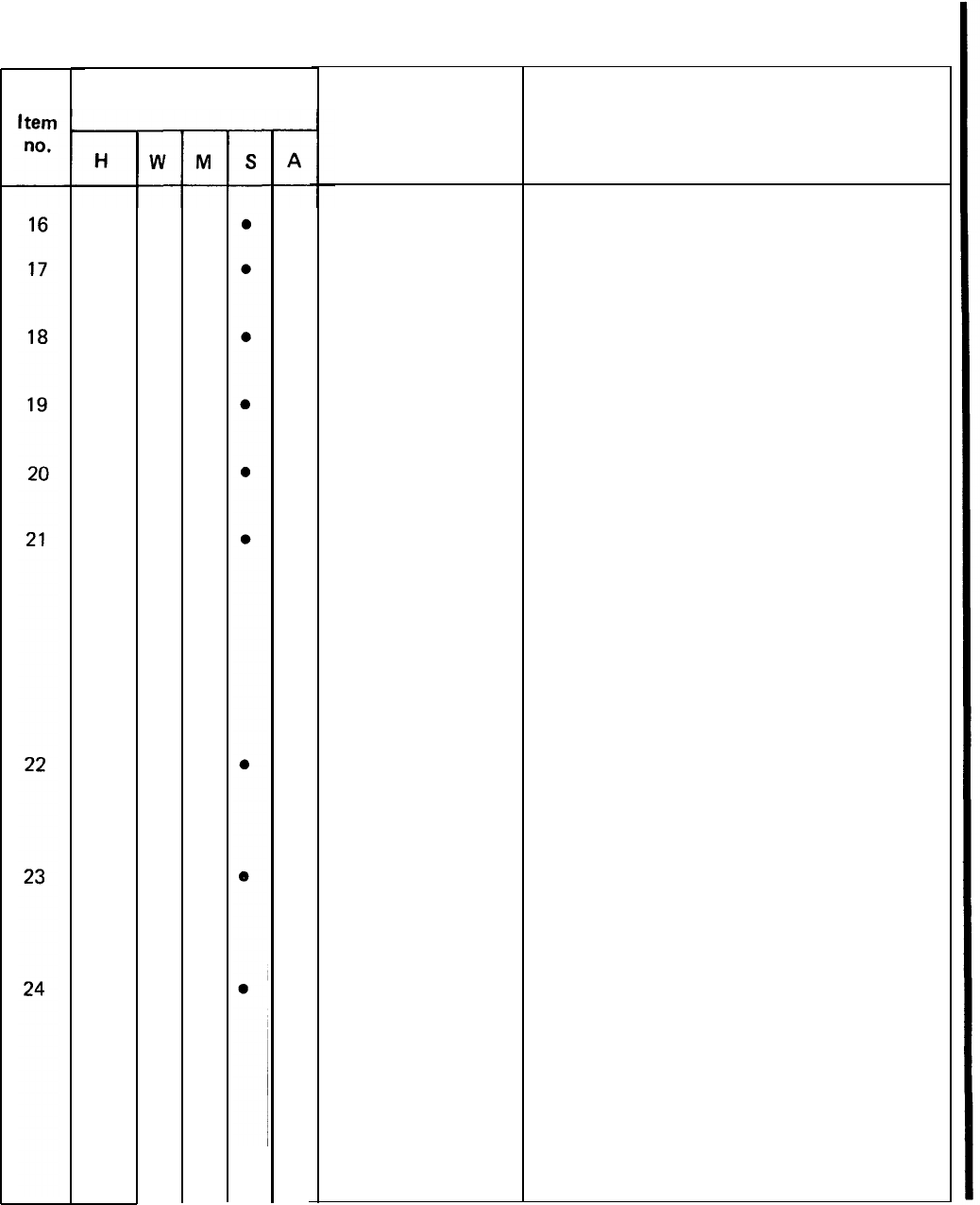
TM 5-6115-631-14&P
Table 4-1. Unit Preventive Maintenance Checks and Services (PMCS). – CONT.
H – Hours of operation W -- Weekly M – Monthly
(As indicated)
S – Semiannually A – Annually
(40 hours) (100 hours) (500 hours) (1000 hours)
Interval
Item to be
Inspected
Safety Chains
Reflectors
Data Plates and
Markings
Support Leg
Assembly
Rear Leg Prop
Assembly
Suspension
Assemblies
Axle
Wheels and Tires
Brakes
Procedures
Inspect for broken links or missing chain(s).
Replace any cracked, broken, or missing
refIectors.
Make sure data plates are legible and
secure. Replace illegible data plates
Inspect brackets and leg for bent or
broken parts.
Inspect bracket and leg prop for bent or
broken parts.
a. Inspect shackles, bearings, pinks, leaf
springs and spring eyes for damage or
broken parts.
b. Inspect mounting brackets for cracks or
loose or missing hardware.
c. Inspect shock absorbers for damage or
leaks.
a. Check for damaged axle tube.
b. Check for loose or missing U-bolts or
nuts.
a. Check serviceability of tires as
indicated in TM 9-2610-200-24.
b. Tighten wheel stud nuts.
a.
b.
Inspect brake linings for wear. Replace
if brake shoe lining is less than l/8-
inch (3.2 mm) thick.
Inspect brake adjusting screw, retaining
screw, retaining pins, springs,
and clips for corrosion and wear.
Change 1
4-11
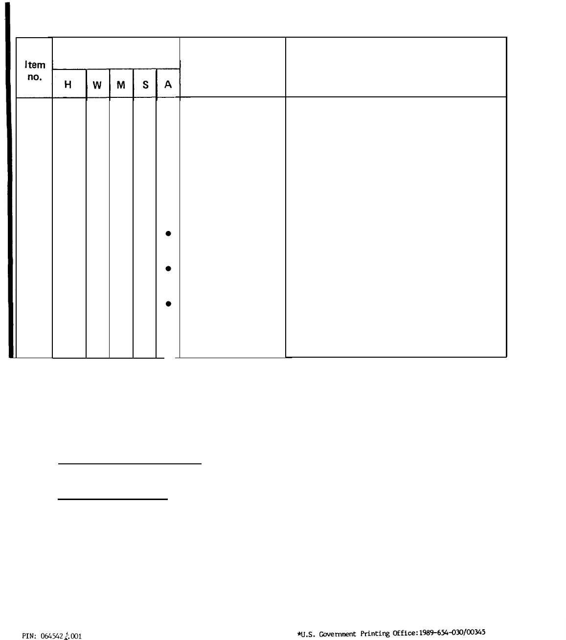
TM 5-6115-631-14&P
Table 4-1. Unit Preventive Maintenance Checks and Services (PMCS). – CONT.
H – Hours of operation
W – Weekly M – Monthlv
(As indicated)
S – Semiannually A – Annually
(40 hours) (100 hours) (500 hours)
(1OOO hours)
24
25
26
27
4-13.
Interval
Item to be
Inspected
Brakes – CONT
Wheel Bearings
Hydraulic Brake
Tubes and Hoses
Trailer – Road
Test
Procedures
c.
d.
e.
Inspect hydraulic wheel cylinders for
leaks.
Inspect master cylinder for leaks or low
fluid level. Fill to within 1/2 inch
from top.
Adjust brake (page 4-52,
TM 9-2330-213-14&P).
Clean and repack. (page 4-105,
TM 9-2330-213-14&P).
Inspect for dents, cracks, loose
connections and leaks.
Perform road test paying special attention
to items that were repaired or adjusted.
Section VI. TROUBLESHOOTING
Troubleshooting. Troubleshooting procedures for components unique to the power plant end item
are given in paragraph 4-14. Troubleshooting information for the individual generator sets and trailer
are contained in their respective technical manuals referenced below.
a.
Generator Set Troubleshooting. Refer to TM 5-6115-584-12 for troubleshooting procedures
applicable to the generator set.
b.
Trailer Troubleshooting. Refer to TM 9-2330-213-14&P for troubleshooting procedures
applicable to the trailer.
4-14. Power Plant Troubleshooting. Table 4-2 contains troubleshooting information for locating and
correcting operating troubles which may develop in components unique to the power plant end item. Each
malfunction is followed by a list of tests or inspections which will help determine probable cause and
corrective actions to take. Perform the tests/inspections and corrective actions in the order listed.
This manual cannot list all malfunctions that may occur, nor all tests or inspections and corrective
actions. If a malfunction is not listed or cannot be corrected by listed corrective actions, notify
your supervisor.
4-12Change 1

TM 5-6115-631-14&P
Table 4-2. Troubleshooting.
MalfunctionTest or inspection Corrective action
1. POWER IS ABSENT AT SWITCH BOX LOAD TERMINAL(S) WHEN ONE GENERATOR SET IS
OPERATING.
Step 1.
Step 2.
Step 3.
Step 4.
Step 5.
Check that generator set circuit breaker is set to ON position.
If circuit breaker is in OFF position, set to ON position.
Check for power output at generator set load terminals.
If power is absent at generator set load terminals, troubleshoot
generator set. (Refer to TM 5-6115-584-12).
Inspect power cable connections inside switch box for looseness or broken wire
terminals.
Tighten loose connections. If any wire terminals are broken, replace
cable (paragraph 4-25, d.) or refer to higher level of maintenance for
repair.
Perform continuity check on associated generator set power cable
(paragraph 4-23, a.).
If cable is defective, replace cable (paragraph 4-25, d.) or refer to
higher level of maintenance for repair.
Perform continuity check on switch (paragraph 4-23, c.).
If switch is defective, notify higher level of maintenance.
2. POWER IS ABSENT AT ONE OR MORE SWITCH BOX LOAD TERMINALS WHEN EITHER GENERATOR
SET IS OPERATING.
Step 1.
Step 2.
Step 3.
Check wire associated with non-functioning load terminal(s) for looseness or
broken terminals inside switch box.
Tighten loose connection(s). If any terminals are broken, replace wire
(paragraph 4-25, c.).
Perform continuity check on wire from switch to non-functioning load terminal(s)
(paragraph 4-23, b.(2)).
Replace defective wire(s) (paragraph 4-25, c.).
Perform continuity check on switch (paragraph 4-23, c.).
If switch is defective, notify higher level of maintenance.
4-13

TM 5-6115-631-14&P
Table 4-2. Troubleshooting – CONT.
MalfunctionTest or inspection Corrective action
3. ONE OR BOTH INDICATOR LIGHTS FAIL TO LIGHT WHEN ASSOCIATED GENERATOR SET IS
OPERATING AND ROTARY SWITCH IS SET TO “ON ” POSITION FOR THAT GENERATOR.
Step 1.
Step 2.
Step 3.
Step 4.
Check if bulb is defective.
If bulb is defective, replace.
Check wires inside switch box associated with non-functioning light for looseness
or broken wire terminals.
Tighten loose connections. If any terminals are broken, replace wire(s)
(paragraph 4-25, c.) or refer to higher level of maintenance for repair.
Perform continuity check on wires associated with non-functioning indicator
(paragraph 4-23, b.(3) or (4), as applicable).
If wires are defective, replace indicator light and wire assembly
(paragraph 4-25, b.).
Perform continuity check on indicator housing (paragraph 4-23, b.(3) or (4),
as applicable).
If housing is defective, replace indicator light and wire assembly
(paragraph 4-25, b.).
Section VII. RADIO INTERFERENCE SUPPRESSION
4-15.
General Methods Used to Attain Proper Suppression. Essentially, suppression is attained by
providing a low resistance path to ground for stray currents. The methods used include shielding
ignition and high-frequency wires, grounding the frame with bonding straps, and using filtering
systems.
4-16.
Radio Interference Suppression Components. All component parts of the power plant end
item, whose primary or secondary function is radio interference suppression, are on the generator
sets. Refer to TM 5-6115-584-12 for location of radio interference suppression components.
Section VIII. MAINTENANCE OF POWER PLANT TRAILER
4-17.
General. This section of the manual contains unit level maintenance procedures for
components of the M103A3 trailer added when the trailer is used as part of the AN/MJQ-16 power
plant. These components are not covered in the overall trailer maintenance manual. For all other unit
maintenance procedures on the trailer, refer to TM 9-2330-213-14&P.
4-14
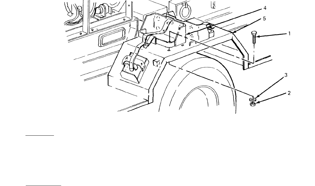
TM 5-6115-631-14&P
WARNING
Before performing any maintenance that requires climbing on or under trailer,
set trailer handbrakes, chock both wheels, and lower rear leg prop. Injury to
personnel could result from trailer suddenly rolling or tipping.
4-18.
Fuel Can Bracket Replacement. (See figure 4-4.) There are four fuel can brackets supplied
with the AN/MJQ-16. Two brackets are mounted on top of each fender. Replacement procedures
,,
described below are typical for all four.
a. Removal.
Figure 4-4. Fuel Can Bracket Replacement.
(1) Remove four screws (1, figure 4-4), four nuts (2) and four flat washers (3) securing
bracket (4) to fender (5).
(2) Remove bracket (4) from fender (5).
b. Installation.
(1) Position fuel can bracket (4) on fender (5).
.
(2) Insert four screws (1) down through bracket (4) and through fender (5).
(3) Install one washer (3) and one nut (2) on each screw (l). Tighten hardware to secure
bracket (4).
4-19. Accessory Box Replacement. (see figure 4-5.) The power plant is equipped
box which is mounted to the trailer bed between the front and rear generator sets. with an accessory
4-15
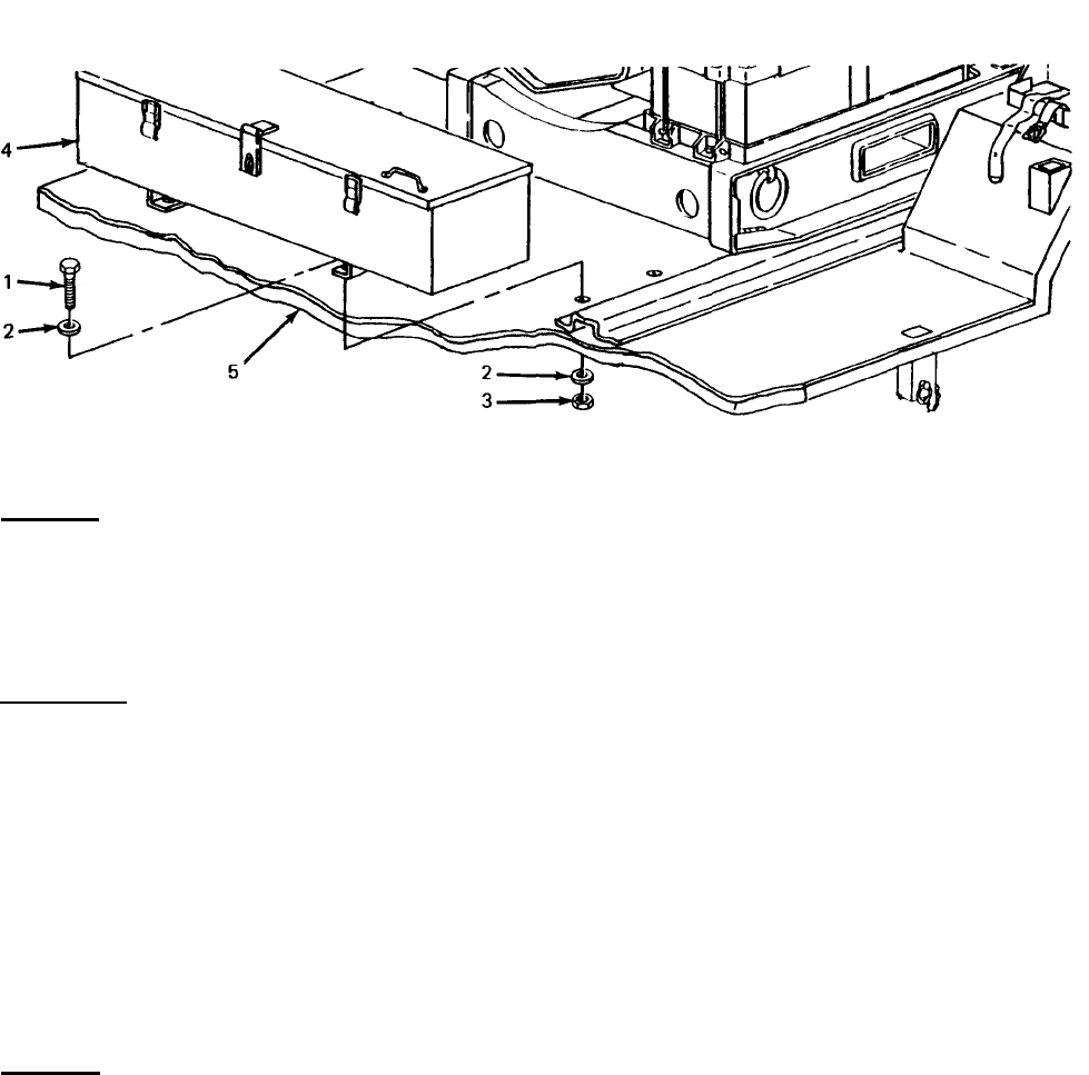
TM 5-6115-631-14&P
Figure 4-5. Accessory Box Replacement.
a. Removal.
(1) Remove four screws (1, figure 4-5), eight flat washers (2), and four nuts (3) securing
accessory box (4) to trailer bed (5).
(2) Lift accessory box (4) off trailer bed (5).
b. Installation.
(1) Position accessory box (4) on trailer bed (5).
(2) Insert four screws (1) with flat washers (2) through accessory box mounting brackets and
trailer bed (5).
(3) Working under trailer, install one flat washer (2) and one nut (3) on each screw (l).
Tighten hardware to secure accessory box (4).
4-20.
Fire Extinguisher Bracket Replacement.
(See
figure 4-6.) Each of the two fire extinguishers
supplied with the power plant is carried in a bracket. One bracket is mounted on each fender.
Replacement procedures described below are the same for both brackets.
a. Removal.
(1) Remove four screws (1, figure 4-6), four flat washers (2) and four nuts (3) securing
bracket (4) to fender (5).
(2) Remove bracket (4) from fender (5).
4-16
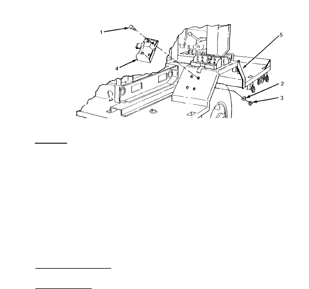
TM 5-6115-631-14&P
Figure 4-6. Fire Extinguisher Bracket Replacement.
b. Installation.
(1) Position fire extinguisher bracket (4) on fender (5).
(2) Insert four screws (1) down through bracket (4) and through fender (5).
(3) Install one flat washer (2) and one nut (3) on each screw (l). Tighten hardware to
secure bracket (4).
4-21.
Leg Prop Assembly Servicing. Servicing of the leg prop assembly is limited to semiannual
lubrication (paragraph 4-9, b.).
Section IX. MAINTENANCE OF ELECTRICAL SYSTEM
4-22.
General. This section contains maintenance information on electrical components unique to
the power plant end item. For all other electrical system maintenance, refer to the applicable
generator set and trailer manuals as follows:
a. Generator Set Maintenance. For generator set maintenance procedures, refer to TM 5-6115-
584-12.
b. Trailer Maintenance. For trailer maintenance procedures, refer to TM 9-2330-213-14&P.
4-23.
Switch Box Testing. To isolate the source of an electrical system problem, perform continuity
tests on the components of the switch box as described below. Refer to the schematic diagram inside
the switch box (shown in figure 4-7 or 4-8, as applicable) to locate and identify the test points
indicated in these procedures.
4-17
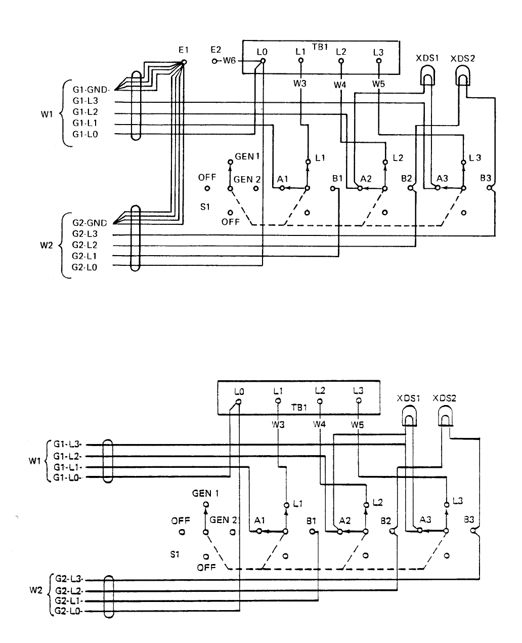

TM 5-6115-631-14&P
a. Power Cable Assembly Test.
(1)
(2)
(3)
(4)
(5)
(6)
Set multimeter for continuity testing.
Set switch box rotary switch to GEN 1 position and locate power cable assembly associated
with that switch position.
Test white wire by touching one probe of multimeter to load terminal LO on generator set
and touching other probe to load terminal on switch box. Multimeter must indicate conti-
nuity between these points.
Repeat step (3) for black wire (between L1 on generator set and A1 on switch), red wire
(between L2 on generator set and A2 on switch), and blue wire (between L3 on generator
set and A3 on switch).
On power plants supplied with the 5-wire configuration switch box, the green (ground) wire
must also be tested. Disconnect wire from frame ground stud under generator set control
panel. Test for continuity between free end of wire and ground stud E1 on switch box.
If multimeter does not indicate continuity exists on each wire in the cable, replace power
cable assembly (paragraph 4-25, d.).
To test power cable assembly associated with GEN 2 switch position, perform steps (2)
through (6) substituting switch terminals B1, B2 and B3 for terminals A1, A2 and A3, as
test points. Generator set load terminal designations and wire color-coding is identical for
both power cables.
b. Switch Box Internal Wiring Test.
(1)
(2)
(3)
(4)
(5)
Set multimeter for continuity testing.
Test wires between switch terminals and load terminals by touching probes to each of the
following pairs of test points: L1 on switch to L1 load terminal, L2 to L2, and L3 to L3. If
multimeter does not indicate continuity between each pair of test points replace associated
wire (paragraph 4-25, c.).
Test wires and socket associated with GEN 1 indicator light by testing for continuity between
switch terminal A2 and socket XDS1, and switch terminal A3 and socket XDS1. If multimeter
does not indicate continuity exists on both of these wires, replace light wire assembly
(paragraph 4-25, b.).
Test wires and socket associated with GEN 2 indicator light by testing for continuity between
switch terminal B2 and XDS2 socket, and switch terminal B3 and XDS2 socket. If multimeter
does not indicate continuity exists on both of these wires, replace light and wire assembly
(paragraph 4-25, b.).
On 5-wire switch box only, test ground wire by touching one probe to wire terminal L0 on
switch box terminal board and touch remaining probe to E2 on switch box. If multimeter
does not indicate continuity, replace associated wire (paragraph 4-25, e.).
4-19
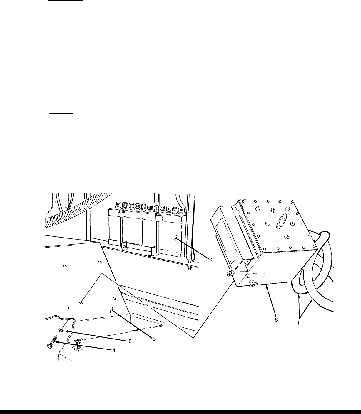
TM 5-6115-631-14&P
c. Switch Test.
(1) Set multimeter for continuity testing.
(2) Set switch lever to GEN 1 position.
(3) Touch one probe to switch terminal A1 and remaining probe to switch terminal L1. Repeat
test between terminals A2 and L2, and terminals A3 and L3. If multimeter does not indicate
continuity exists between each pair of terminals, switch is defective. Notify higher level of
maintenance.
(4) Set switch lever to GEN 2 position and repeat step (3) above, substituting terminals B1, B2
and B3 for A1, A2 and A3.
4-24.
Switch Box Replacement.
(See figure 4-9.)
a. Removal.
(1) Detach power cables (1, figure 4-9) from load terminals on generator sets (2). (Refer to
TM 5-6115-584-12.)
(2) Working underneath roadside fender (3), remove four screws (4) and four Iockwashers
(5) securing switch box (6) to fender.
(3) Lift switch box (6) off fender.
Figure 4-9. Switch Box Replacement.
4-20

TM 5-6115-631-14&P
b. Installation.
(1) Position switch box (6) on fender (3).
(2) Working underneath fender (3)insert fourscrews (4)with lockwashers (5)through fender
and into switch box (6) and tighten.
(3) Attach power cables (1) to load terminals on generator sets (2). (Refer to
TM 5-6115-584-12.)
4-25.
Switch Box Repair.
WARNING
Make sure generator set circuit breakers are in OFF position before performing
any repairs on switch box. Failure to observe this precaution may result in
injury or death by electrocution.
a. Load Terminal and Terminal Board Replacement (See figure 4-10.) There are four load
terminals on the switch box terminal board. This procedure is typical for all four. When reconnecting
wires, refer to the schematic inside the switch box (figure 4-7 or 4-8, as applicable) and to the
identification bands on the wires.
(1) Removal
(a)
(b)
(c)
(d)
Remove 16 screws (1, figure 4-10), 16 Iockwashers (2) and 16 flat washers (3)
securing cover (4) to switch box (5) and take cover off switch box.
NOTE
When disconnecting more than one wire, make sure wires are tagged to
identify the load terminal to which they attach before disconnecting wires.
Working inside switch box (5), remove nut (6) and Iockwasher (7) from terminal (8).
Detach wire(s) (9) by sliding terminal lug(s) off stud.
Remove Iockwasher (10), nut(11) and internal tooth Iockwasher (12) and pull terminal
(8) off terminal board (13).
Remove six screws (14), six Iockwashers (15), six flat washers
16) and six nuts (17)
and take terminal board (13) and gasket (18) off switch box (5).
(2) Installation.
(a) Position gasket (18) and terminal board (13) on switch box (5) and fasten with six
screws (14), six Iockwashers (15), six flat washers (16) and six nuts (17).
(b) Insert terminal (8) through terminal board (13) and into switch box (5).
(c) Install internal tooth Iockwasher (12) and nut(11) on terminal stud (8) and tighten
against inside of terminal board (13).
4-21
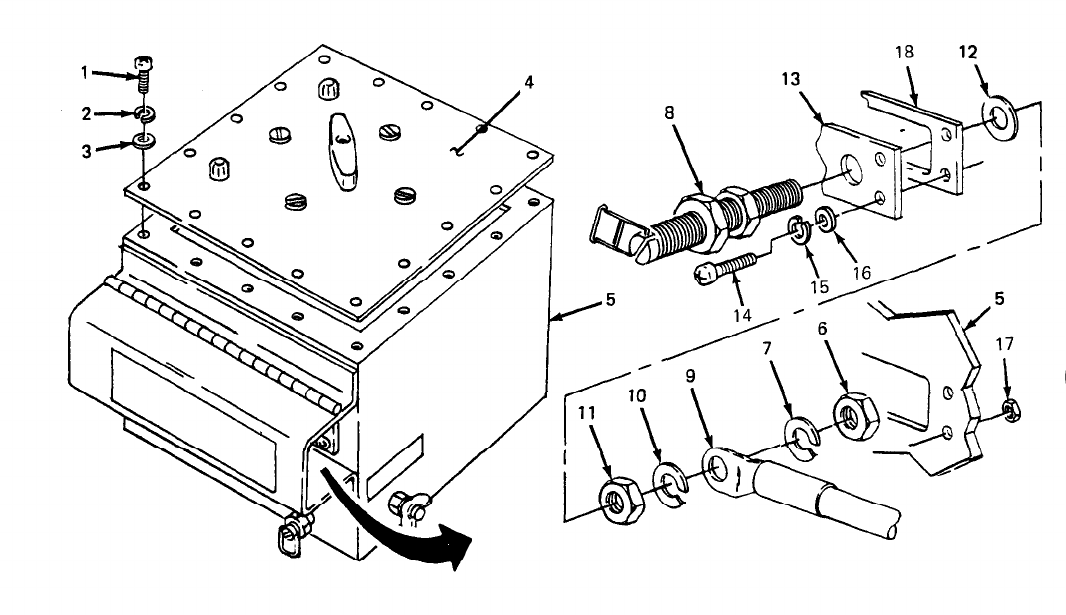
TM 5-6115-631-14&P
NOTE
Observe identification tags when installing internal wires.
(d) Slide Iockwasher (10) and terminal lug(s) of wire(s) (9) onto stud (8).
(e) Install Iockwasher (7) and nut (6) on terminal (8) and tighten against wire terminal lug.
(f) Position cover (4) on switch box (5) and secure with 16 screws (1), 16 Iockwashers (2)
and 16 flat washers (3).
Figure 4-10. Load Terminal Replacement.
b. Indicator Light and Wire Assembly Repair and Replacement. (See figure 4-11.) There are two
indicator light and wire assemblies on the switch box. This procedure is typical for both. When attach-
ing wires, refer to the schematic inside the switch box (figure 4-7 or 4-8, as applicable). The indi-
cator light and wire assembly is repaired by replacing defective terminals or soldering broken wires.
Soldering shall be done in accordance with TB SIG 222.
(1) Removal.
(a) Remove 16 screws (1, figure 4-11), 16 Iockwashers (2) and 16 flat washers (3)
securing cover (4) to switch box (5) and take cover off switch box.
(b) Remove screw (6), nut (7) and star washer (8) attaching each indicator light wire ter-
minal (9) to its respective switch terminal (10). Take power cable wire (11) and indica-
tor light wire (12) off switch terminal.
4-22
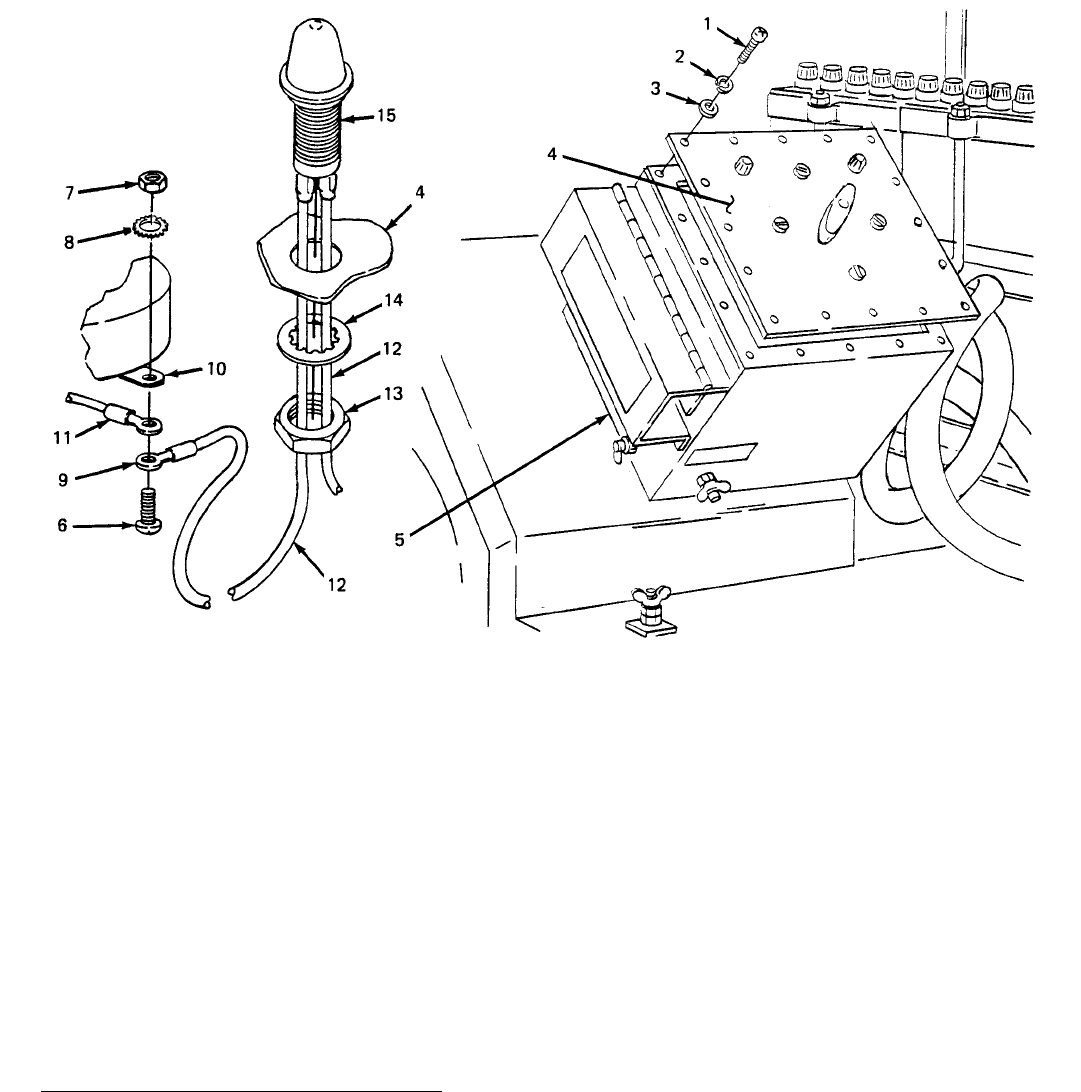
TM 5-6115-631-14&P
(c) Unscrew nut(13) and internal tooth lockwasher (14) securing indicator light
(15) to cover (4) and slide nut and Iockwasher off wires.
(d) Pull out light and wires through cover (4).
housing
Figure 4-11. Indicator Light and Wire Replacement,
(2) Installation.
(a)
(b)
Feed wires through hole in cover (4) and fit light housing (15) in hole.
Slide nut (13) and Iockwasher (14) over both wires (12), thread onto light housing (14)
on inside of cover (4) and tighten.
Position terminal (9) of each indicator light wire (12) against underside of switch ter-
minal (10). Position terminal of power cable wire (11) against terminal of indicator Mht
wire. Insert screw (6) up through wire terminals and”sw;tch terminal. Install star wa;her
(8) and nut (7) on screw and tighten against switch terminal.
(d) Position cover (4) on switch box (5) and secure with 16 screws (l), 16 Iockwashers (2)
and 16 flat washers (3).
c. Switch to Load Termina/lWire Replacement. (See figure 4-12.) There are three wires
connecting the switch to the load terminals. When attaching wires, refer to the schematic inside the
switch box (figure 4-7 or 4-8, as applicable) and to the identification bands on the wires.
4-23
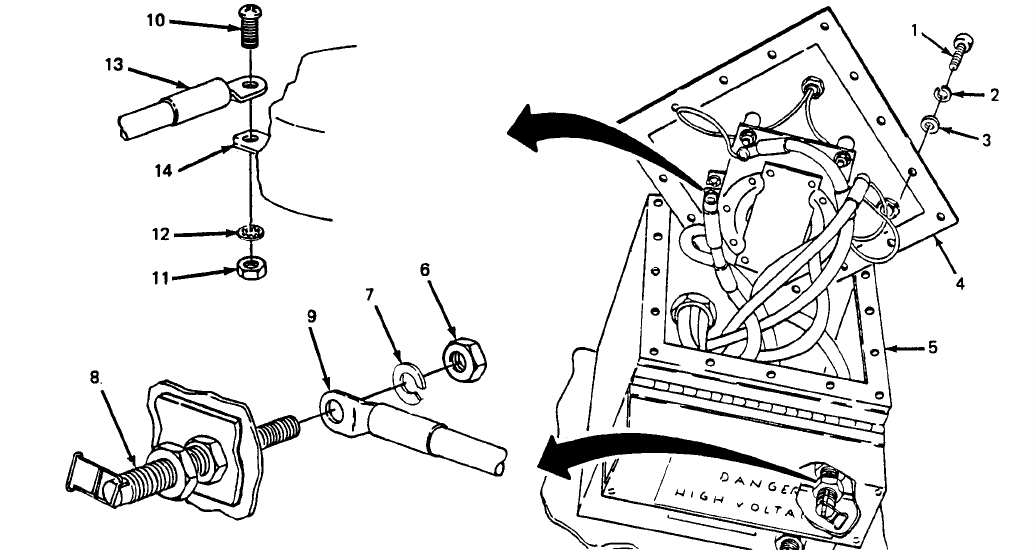
TM 5-6115-631-14&P
4-24
(1)
(a)
(b)
(c)
(2) Installation.
Removal.
Remove 16 screws (1, figure 4-12), 16 Iockwashers (2) and 16 flat washers (3) secur-
ing cover (4) to switch box (5) and take cover off switch box
Remove nut (6) and Iockwasher (7) from load terminal stud (8) inside switch box (5).
Slide wire terminal (9) off stud.
NOTE
When removing more than one wire, tag switch terminals for identification.
Remove screw (10), nut (11) and star washer (12) securing wire terminals (13) to
switch terminal (14). Take wire off switch.
(a)
(b)
(c)
NOTE
Observe identification tags on switch terminals when installing wires.
Position wire terminal (13) against underside of switch terminal (14). Insert screw (10)
up through wire terminal and switch terminal. Install star washer (12) and nut (11) on
screw and tighten against switch terminal.
Slide terminal (9) at free end of wire onto load terminal stud (8) and secure with lock-
washer (7) and nut (6).
Position cover (4) on switch box (5) and secure with 16 screws (l), 16 Iockwashers (2)
and 16 flat washers (3).
Figure 4-12. Switch to Load Terminal Wire Replacement.

TM 5-6115-631-14&P
d. Power Cable Replacement.(See figure 4-13.) There are two power cables on the power
plant – one for each generator set. This procedure is typical for both. When attaching wires, refer to
the schematic inside the switch box (figure 4-7 or 4-8, as applicable) and to the identification bands
on each of the five wires that make up each cable.
(1)
Removal.
(a) Disconnect power cable from load terminals on generator set. (Refer to
TM 5-6115-584-12.)
(b) Remove 16 screws (1, figure 4-13),16 Iockwashers (2) and 16 flat washers (3)
securing cover (4) to switch box (5) and take cover off switch box.
NOTE
Tag switch terminals for identification when removing wires. If identification
bands on wires are illegible, tag wires.
(c) Remove screw (6), nut (7) and star washer (8) attaching each of three wires (9)
(black, red and blue) to its respective switch terminal (10). Take off wires.
(d) Remove nut (11) and Iockwasher (12) from load terminal L0 (13) inside switch box (5).
Take off white wire (14) associated with power cable being removed.
(e) Repeat step (d) for ground terminal El and green wire (15).
(f) Loosen power cable clamping nut (16) on outside of switch box (5) and pull cable
through cable clamp and out of box.
16) and through hole into switch box (5).
(2) Installation.
(a) Feed cable through cable clamping nut
(b) Tighten clamping nut (16) on outside of switch box (5) to prevent cable from moving.
(c) Slide terminal of white wire (14) onto load terminal L0 (12) and secure with Iockwasher
(12) and nut (11).
(d) Repeat step (c) for ground terminal E1 and green wire (15).
NOTE
Observe identification tags when installing wires.
(e) Position each of three wires (9) (black, red and blue) against underside of its respec-
tive switch terminal (10). Insert screw (6) up through wire terminal and switch terminal.
Install star washer (8) and nut (7) on screw and tighten against switch terminal. Where
an indicator light wire is also mounted to the switch terminal, the indicator light wire shall
be positioned against the underside of the switch terminal and the power cable wire shall
be positioned against the indicator light wire.
1), 16 Iockwashers (2)
(f) Position cover (4) on switch box (5) and secure with 16 screws
and 16 flat washers (3).
4-25
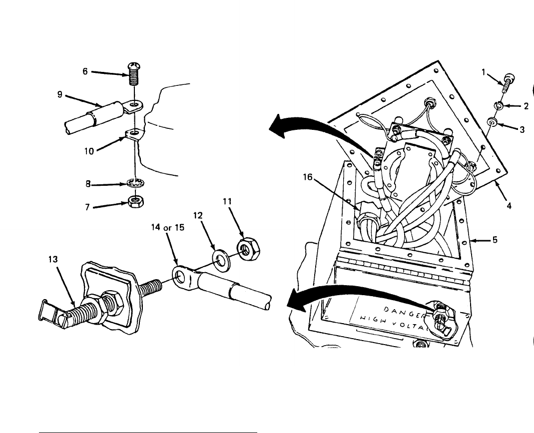
TM 5-6115-631-14&P
Figure 4-13. Power Cable Replacement.
to TM 5-6115-584-12.)
(g) Connect power cable to load terminals on generator set. (Refer
e. Ground Wire Replacement (5-Wire Switch Box). (See figure 4-14.) In the 5-wire switch box
only, a wire connects load terminal LO to AC GROUND terminal E2 located on the side of the switch box
below the terminal board.
(1) Removal
(a)
(b)
(c)
(d)
Remove 16 screws (1, figure 4-14), 16 Iockwashers (2) and 16 flat washers (3) secur-
ing cover (4) to switch box (5) and take cover off switch box.
Remove nut (6) and Iockwasher (7) from load terminal L0 (8) inside switch box.
Slide power cable ground (white) wire terminals (9) and switch box ground wire terminal
(10) off load terminal L0 (8).
Remove nut (11) and Iockwasher (12) from AC GROUND terminal E2 (13) inside box.
Remove ground wire terminal (14).
4-26
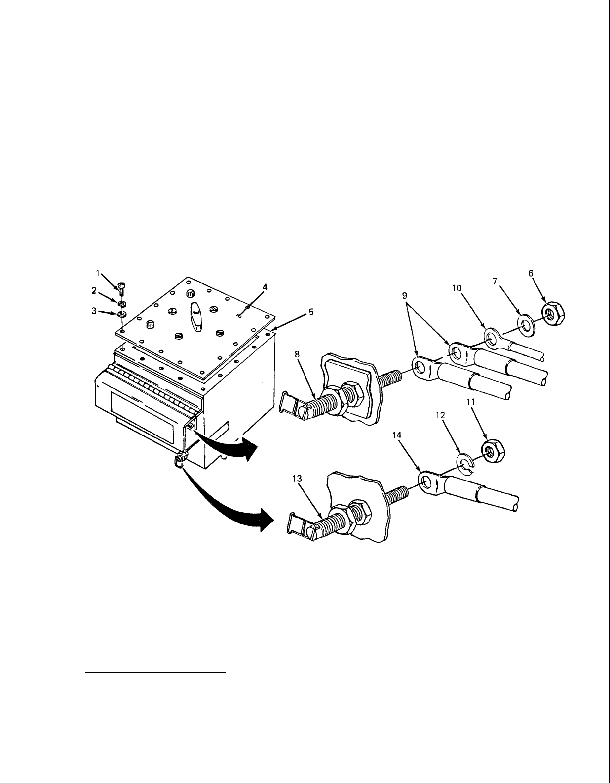
(2) Installation
(a) Install switch box ground wire terminal (14) on AC GROUND terminal E2 (13) and secure
TM
5-6115-631-14&P
with lockwasher (12) and nut (11).
(b) Install remaining box ground wire terminal (10) on load terminal L0 (8). Install power
cable (white) wire terminals (9) on terminal L0 (8) and secure the three wires with lock-
washer (7) and nut (6).
(c) Position cover (4) on switch box (5) and secure with 16 screws (l), 16 Iockwashers (2)
and 16 flat washers (3).
Figure 4-14. Ground Wire Replacement.
4-26.
Taillight Cable Assembly and Electrical Lead Repair and Replacement. One taillight cable
assembly and one electrical lead connects each taillight to the trailer wiring harness. The taillight
cable assembly and electrical lead are replaced by unplugging four connectors at each end. Repair is
accomplished by replacing defective connectors. To manufacture a replacement cable assembly and
electrical lead, install new connectors on suitable lengths of insulated wire using the procedures
described for repair.
a. Male Connector Replacement. (See figure 4-15.)
(1) Slide shell (1) back on wire lead (2).
4-27
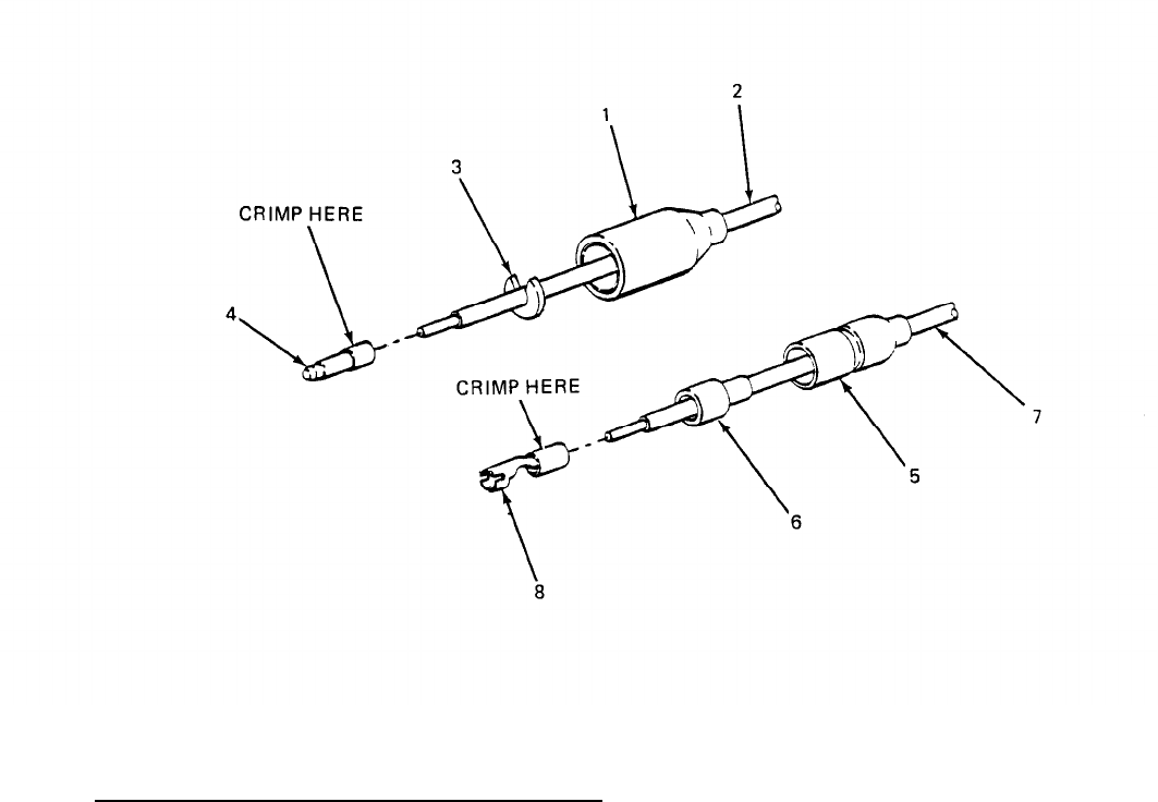
TM 5-6115-631-14&P
(2)
(3)
(4)
(5)
(6)
(7)
(8)
(9)
Remove washer (3).
Slide shell (1) off over contact (4).
Cut off contact (4).
NOTE
Be careful not to strip too much insulation from wire. Connector contact must
be crimped onto insulation to hold securely.
Strip insulation off wire lead (2) equal to depth of new contact (4).
Slide shell (1) and washer (3) of new connector onto wire lead (2).
Slide contact (4) onto stripped wire and solder in accordance with TB SIG 222.
Crimp contact onto wire.
Slide shell (1) forward over washer (3) and contact (4).
.
Figure 4-15. Taillight Cable Assembly and Electrical Lead Repair.
b. Female Connector Replacement. (See figure 4-15.)
(1) Slide shell (5) and sleeve (6) back on wire lead (7).
4-28
TM 5-6115-631-14&P
(2) Cut off contact (8).
(3) Slide shell (5) and sleeve (6) off wire lead (7).
NOTE
Be careful not to strip off too much insulation. Connector contact must be
crimped onto insulation to hold securely.
(4) Strip insulation off wire lead (9) equal to depth of new contact (8).
(5) Slide shell (5) and sleeve (6) onto wire lead (7).
(6) Slide contact (8) onto stripped wire and solder in accordance with TB SIG 222.
(7) Crimp contact onto wire.
(8) Slide shell (5) and sleeve (6) forward over contact (8).
4-29/(4-30 blank)

TM 5-6115-631-14&P
CHAPTER 5
INTERMEDIATE (FIELD), DIRECT SUPPORT
AND GENERAL SUPPORT MAINTENANCE INSTRUCTIONS
Section I. INTRODUCTION
5-1.
General.
This chapter contains Intermediate Direct Support and General Support level main-
tenance procedures for components of the AN/MJQ-16 Power Plant which are not part of the basic
generator sets or trailer. For all other intermediate direct and general support maintenance proce-
dures on the trailer, refer to TM 9-2330-213-14&P. For intermediate direct and general support
maintenance procedures on the generator set, refer to TM 5-6115-584-34.
WARNING
Before performing any maintenance that requires climbing on or under trailer,
set trailer handbrakes, chock wheels and lower rear leg prop. Injury to
personnel could result from trailer suddenly rolling or tipping.
Section Il. MAINTENANCE OF POWER PLANT TRAILER
5-2. Leg Prop Assembly Maintenance. Maintenance of the leg prop assembly at the Intermediate
Direct Support and General Support level consists of repairing or replacing the assembly as required.
a. Leg Prop Assemb/y Replacement. (See figure 5-1.)
(1) Remova/.
(a)
(b)
(c)
(d)
(e)
(f)
(g)
While supporting leg prop assembly, pull out angled bar (1, figure 5-1) and lower leg
from traveling position.
Line up boss (2) on upper leg (3) with holes in bracket (4) and insert angled bar (1) to
lock leg in support position.
Remove either one of two cotter pins (5) from leg prop assembly pivot shaft (6).
While steadying leg prop assembly, remove shaft (6) with remaining cotter pin (5) in
place.
WARNING
When angled bar is removed in step (e), leg prop assembly will fall from
bracket if not supported. To prevent injury to personnel or damage to
equipment, do not permit leg assembly to drop.
Lift leg assembly slightly to take weight off angled bar (1) and remove bar.
Lower leg assembly from bracket (4).
Remove three screws (7), three flat washers (8), three Iockwashers (9) and three nuts
(10) and remove bracket (4) from trailer frame (11).
5-1
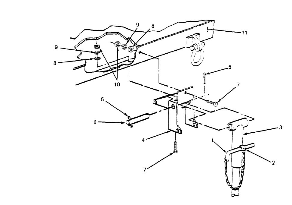
TM 5-6115-631-14&P
Figure 5-1. Leg Prop Assembly Replacement.
(2) Installation.
(a)
(b)
(c)
(d)
(e)
(f)
Position bracket (4) on trailer frame (11) and install three screws (7), three flat
washers (8), three Iockwashers (9) and three nuts (10). Tighten hardware to secure
bracket.
Lift leg prop assembly into bracket (4) and secure by inserting angled bar (1) through
holes in bracket and boss (2) on upper leg (3).
Position leg prop assembly to line up boss on top of leg with pivot holes in bracket
(4). Insert pivot shaft (6).
Insert cotter pin (5) in pivot shaft (6) and bend cotter pin legs in opposite directions.
Pull out angled bar (1) to unlock leg prop assembly.
Swing leg prop assembly up into traveling position and secure by inserting angled bar
(1) through holes in bracket (4) and boss (2) on upper leg (3).
b. Leg Prop Assembly Repair. (See figure 5-2.) Repair of the leg prop assembly is limited to
welding and repainting. However, partial disassembly is possible to facilitate repair. If required,
repaint in accordance with MI L-T-704, Type F, color Green No. 383 of MIL-C-46168.
5-2
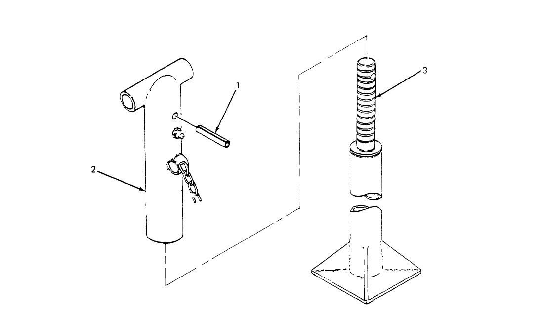
TM 5-6115-631-14&P
(1) Disassembly.
(a) Remove leg prop assembly from trailer (paragraph 5-2, a.(1)).
(b) Clamp leg prop assembly in vise with spring pin facing up.
(c) Using suitable drift, drive spring pin (1, figure 5-2) out of upper leg (2) and remove leg
base (3).
(2) Assembly.
(a) Clamp upper leg (2) in vise with spring pin hole facing up.
(b) Insert leg base (3) into upper leg (2) and turn leg base until hole in screw lines up with
hole in upper leg.
(c) Install spring pin (1) to secure leg base to upper leg.
(d) Install leg prop assembly on trailer (paragraph 5-2, a. (2)).
Figure 5-2. Leg Prop Disassembly.
5-3

TM 5-6115-631-14&P
5-3. Trailer Bed and Fenders Repair and Replacement. (See figure 5-3.) The body of the modified
trailer consists of a single weidment that includes both fenders and the bed of the trailer.
a. Removal.
(1)
(2)
(3)
(4)
(5)
(6)
(7)
(8)
(9)
(10)
(11)
(12)
(13)
5-4
Remove fitted cover (paragraph 3-11, a.(1)).
Remove bow assemblies (paragraph 3-11, b.(1)).
Remove accessory box (paragraph 4-19, a.).
Remove switch box (paragraph 4-24, a.).
Remove both generator sets (paragraph 5-7, a.).
Working under trailer, unplug four connectors (1, figure 5-3) joining trailer main wiring
harness (2) to roadside composite light cable assembly (3), and four connectors (4)
joining cable assembly to composite light (5).
Repeat step (6) for curbside composite light cable assembly.
Remove two screws (6) and two Iockwashers (7) securing each composite light (5) to its
bracket (8) and remove both composite lights.
Remove eight screws (9), 16 flat washers (10) and eight nuts(11) securing each
generator mounting rail (12) to trailer body (13) and remove both rails.
Remove cotter pin (14), nut (15) and flat washer (16) from each of two trailer lifting rings
(17) and remove lifting rings.
NOTE
The two trailer body support brackets located at the front of the trailer are
secured with only two screws and two flat washers each.
Working under trailer, remove 16 screws (18),28 flat washers (19) and 12 nuts (20)
securing trailer body support brackets (21) to trailer frame (22).
NOTE
There are 12 short screws and four long screws securing trailer body to trailer
frame. Since corner screws must extend through trailer frame rails, corner
mounting locations require longer screws (step (13)).
Remove 12 screws (23),24 flat washers (24) and 12 nuts (25) securing trailer body (13)
to trailer frame (22).
Remove four long screws (26), eight flat washers (27) and four nuts (28) securing trailer
body (13) to trailer frame (22) at corner mounting locations.
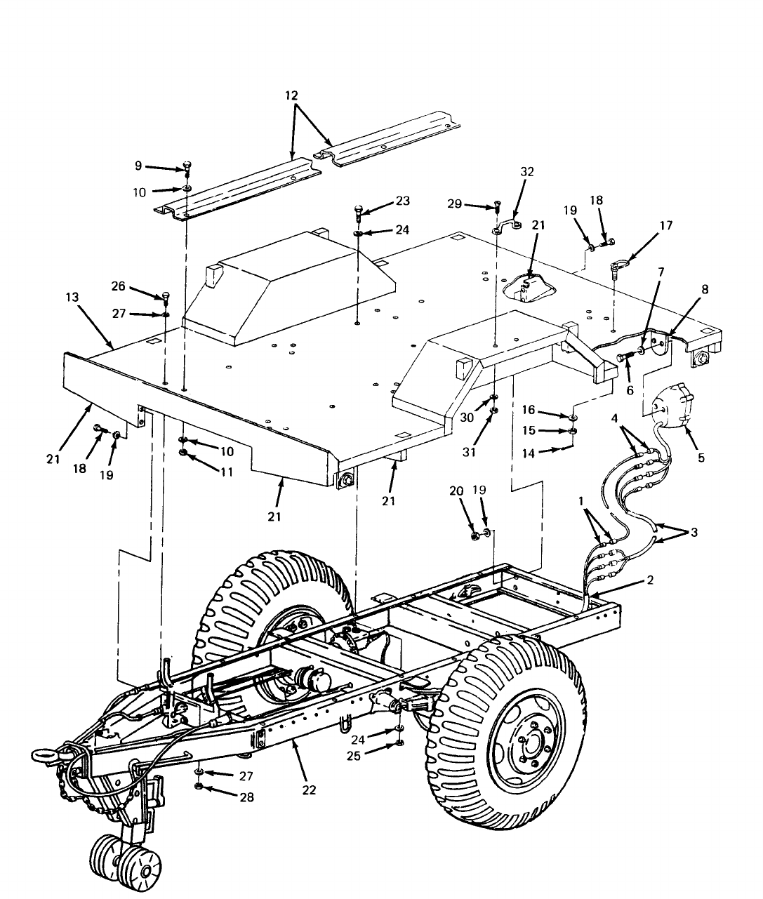

TM 5-6115-631-14&P
WARNING
When lifting trailer body, use lifting equipment with a minimum lifting capacity
of 1500 lb. Do not stand under trailer body while it is being lifted. Failure to
observe these precautions can cause injury to personnel or damage to
equipment.
(14) Using lifting equipment with a minimum lifting capacity of 1500 lb, lift trailer body (13)
off trailer frame (22).
b. Repair. Repair of the trailer bed and fenders is limited to replacement of footmans loops and
straightening, welding, and repainting bed and fender weldment. If required, repaint in accordance
with MIL-T-704, Type F or G, as applicable, color Green, No. 383 of MIL-C-46168. There is one
footmans loop mounted to the top of each fender. Replace footmans loop as follows:
(1) Remove two screws (29), two flat washers (30) and two self-locking nuts (31) securing
footmans loop (32) to fender and take off footmans loop.
(2) Position new footmans loop (32) on fender and secure with two screws (29), two flat
washers (30) and two self-locking nuts (31).
c. Installation.
WARNING
(1)
(2)
(3)
(4)
(5)
(6)
5-6
When lifting trailer body, use lifting equipment with a minimum lifting capacity
of 1500 lb. Do not stand under trailer body while it is being lifted. Failure to
observe these precautions can cause injury to personnel or damage to
equipment.
Using lifting equipment with a minimum lifting capacity of 1500 lb, lift trailer body (13)
onto trailer frame (22) and aline mounting holes.
NOTE
There are 12 short screws and four long screws, securing trailer body to trailer
frame. Since corner screws must extend through trailer chassis rails, corner
mounting locations require longer screws (step (2)).
Working on top of trailer body, insert four long screws (26) with one flat washer (27) each
through trailer body (13) and trailer frame (22) rails at corner mounting locations.
Insert 12 screws (23) with one flat washer (24) each through trailer body (13) and rails of
trailer frame (22).
Working under trailer, install one flat washer (24 and 27) and one nut (25 and 28) on
each of 16 screws installed in steps (2) and (3). Tighten hardware to secure trailer body
(13) to trailer frame (22).
Install and tighten two screws (18) and two flat washers (19) securing each of two front
trailer body support brackets (21) to trailer frame (22).
Install and tighten 12 screws (18), 24 flat washers (19) and 12 nuts (20) securing
remaining trailer body support brackets (21) to trailer frame (22).

TM 5-6115-631-14&P
(7)
(8)
(9)
(10)
(11)
(12)
(13)
(14)
(15)
(16)
Insert one lifting ring (17) into each of two mounting holes in trailer body (13) and secure
with one flat washer (16) and one nut (15). Install one cotter pin (14) in each nut (15) and
spread cotter pin ends.
Position two generator set mounting rails (12) on trailer body (13). Insert eight screws (9)
with eight flat washers (10) through each mounting rail and through trailer bed and
frame (22).
Working under trailer, install one flat washer (10) and one nut (11) on each of 16 mounting
rail screws (9) and tighten.
Position one composite light (5) on each rear mounting bracket (8) and secure each light
with two screws (6) and two Iockwashers (7).
Working under trailer, connect one composite light cable assembly (3) to each composite
light (5) by plugging four cable assembly connectors into four composite light connectors
(4). Plug four connectors at opposite end of each cable assembly into four connectors (1)
on trailer main wiring harness (2).
Install both generator sets (paragraph 5-7, b.).
Install switch box (paragraph 4-24, b.).
Install accessory box (paragraph 4-19, b.).
Install six bows (paragraph 3-11, b(2)).
Install fitted cover (paragraph 3-11, a(2)).
5-4.
Fitted Cover Repair. Repairs to the fitted cover shall be made in accordance with FM 10-16.,
Fabric Repairing.
5.5. Accessory Box Repair. (See figure 5-4.) The accessory box is repaired by replacing the hasp,
the catches and the footmans loops, as required. The box itself may be straightened, welded, and
repainted. If required, repaint in accordance with MIL-T-704, Type F, color Green, No. 383 of MIL-
C-46168.
a. Catch and Hasp Replacement.
(1) Grind off or drill out solid rivets (1, figure 5-4) securing catch or hasp (2) to accessory
box (3).
(2) Position new catch or hasp (2) on accessory box and secure with solid rivets (1).
(3) Touch up with paint as required.
5-7
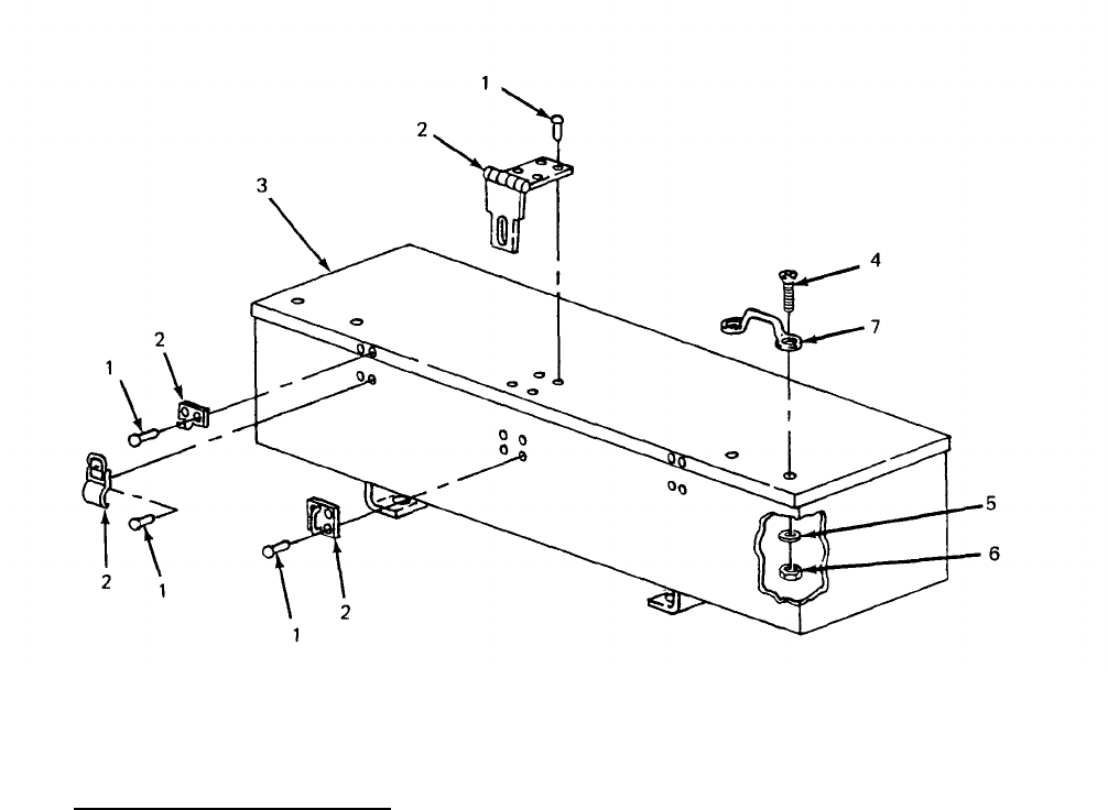
TM 5-6115-631-14&P
Figure 5-4. Accessory Box Repair.
b. Footmans Loop Replacement.
(1) Remove two screws (4, figure 5-4), two flat washers (5), and two self-locking nuts (6)
securing footmans loop (7) to accessory box lid.
(2) Position new footmans loop (7) on accessory box (3) and install two screws (4) two
washers (5), and two self-locking nuts (6).
5.6.
Marking. (See figure 5-5.) The power plant four-digit registration number, preceded by the
prefix “VC” and the words “U.S. ARMY, ” is marked in three places on the trailer. Marking is done in
accordance with MIL-STD-642. On the fender, over each wheel, “T.P. 50 PSI” is marked in 1.00 ±
.12 inch high characters in accordance with MIL-STD-130. On the switch box, “GEN 1”, “GEN 2“ and
“OFF” are marked on the cover at their respective switch lever positions, and “E1” and “E2” are marked
next to their respective ground terminal studs. Figure 5-5 shows the approximate location of markings
on the power plant. If required, touch-up painting of the base color shall be done in accordance with
MIL-T-704, Type F, color Green, No. 383 of MIL-C-46168.
5-8
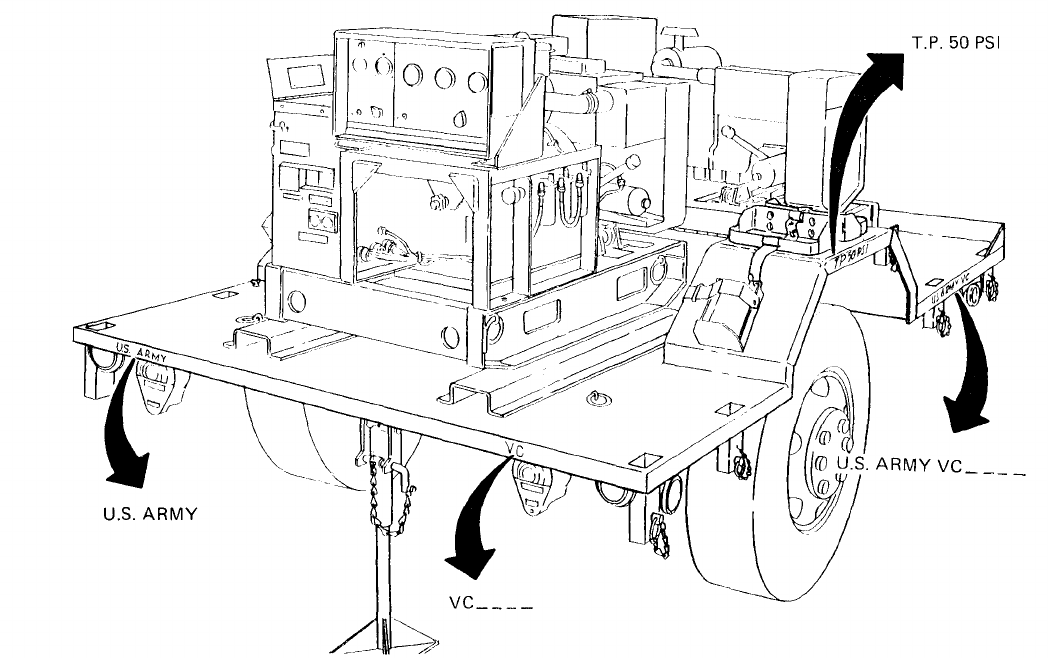
TM 5-6115-631-14&P
Figure 5-5. Power Plant Markings.
Section Ill. GENERATOR SET
5-7.
Generator Set Replacement. (See figures 5-6 and 5-7.) Power Plant AN/MJQ-16 has two
generator sets. Replacement procedures are identical for both.
a. Removal.
.(1) Remove fitted cover (paragraph 3-11, a.(1)).
(2) Remove six bow assemblies (paragraph 3-11, b.(1)).
(3) Disconnect all power cable and ground wires (1, figure 5-6) from generator set (2).
NOTE
The beveled washers (4) may have been welded in place.
(4) Remove four screws (3) and four beveled washers (4), securing generator set (2), to
mounting rails (5) on trailer bed (6).
5-9
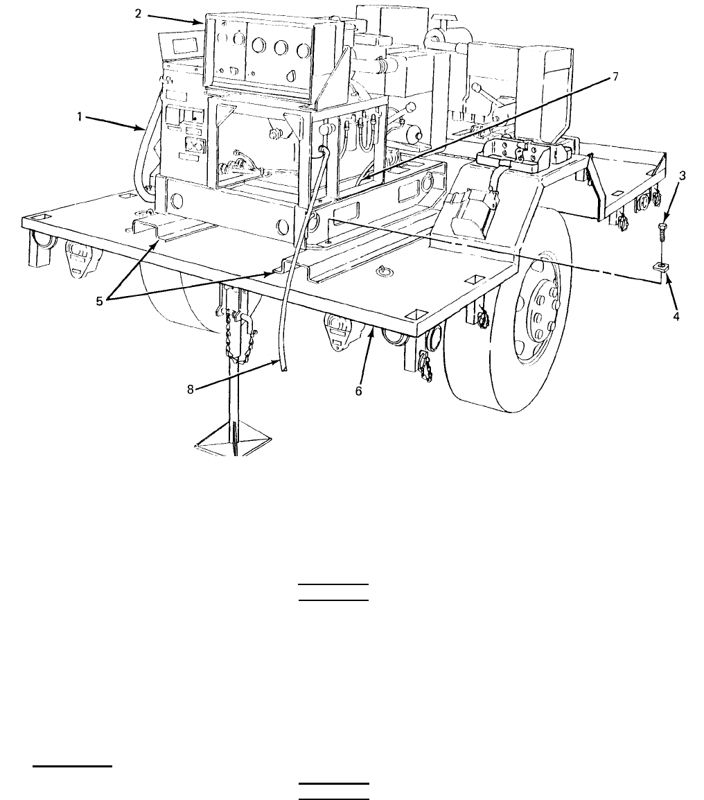
TM 5-6115-631-14&P
Figure 5-6. Detaching Generator Set from Trailer.
(5) Remove engine oil drain hose (7) from grommet in trailer bed (6).
(6) Disconnect auxiliary fuel line (8), if connected.
WARNING
When lifting generator set, use lifting equipment with a minimum lifting capa-
city of 1500 lb. Do not stand under generator while it is being lifted. Failure to
observe these precautions can cause injury to personnel or damage to
equipment.
(7) Attach lifting equipment with a minimum lifting capacity of 1500 lb. (1, figure 5-7) to lifting
eye (2) on top of generator set (3) and remove generator set from trailer.
b. Installation.
WARNING
When lifting generator set, use lifting equipment with a minimum lifting capa-
city of 1500 lb. Do not stand under generator while it is being lifted. Failure to
observe these precautions can cause injury to personnel or damage to
equipment.
5-10
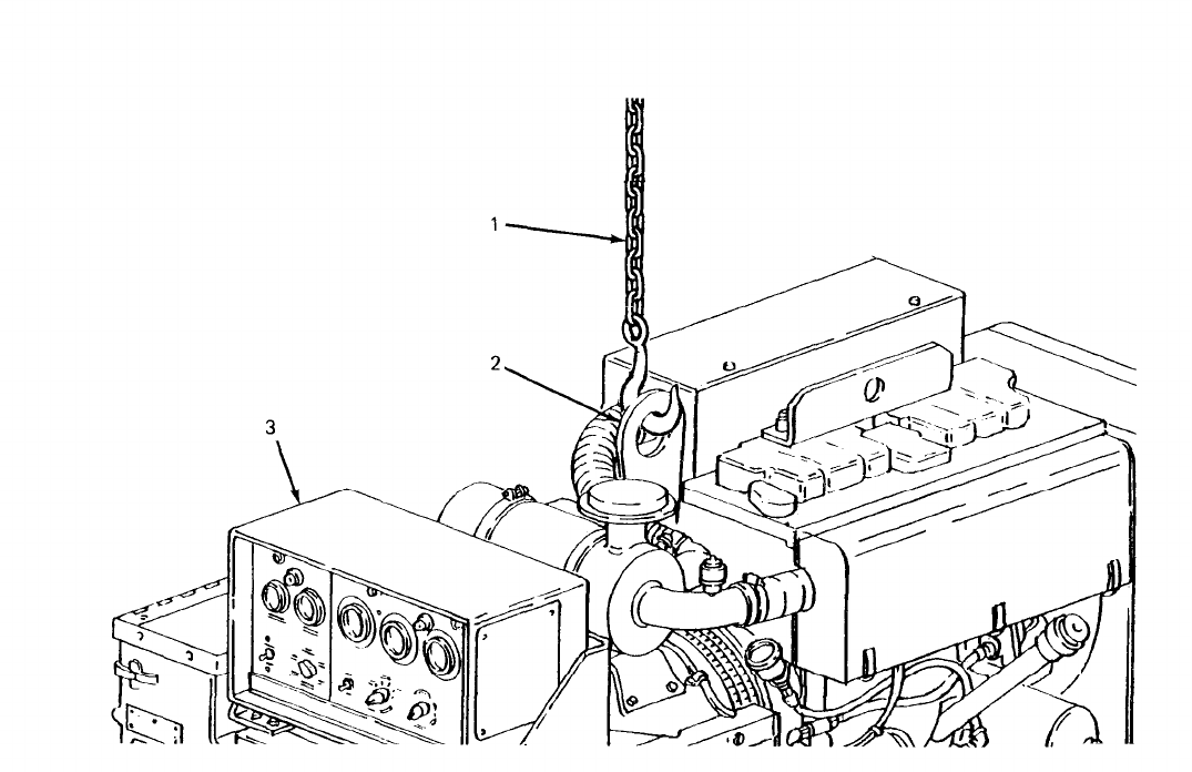
TM 5-6115-631-14&P
(1)
(2)
(3)
(4)
(5)
(6)
(7)
Figure 5-7. Lifting Generator Set.
Attach lifting equipment with a minimum lifting capacity of 1500 lb (1, figure 5-7) to lifting
eye (2) on top of generator set (3) and lift generator.
Lower generator set (2, figure 5-6) onto mounting rails (5) on trailer bed (6) and aline
mounting holes.
Insert four screws (3) with beveled washers (4) down through generator set skid into nuts
welded to underside of mounting rails (5).
Position beveled washers (4) so that screw heads are parallel to tops of washers. While
holding beveled washers in position, tighten hardware to secure generator set (2) to
trailer (6).
Insert engine oil drain hose (7) through grommet in trailer bed (6).
Install six bow assemblies (paragraph 3-11,
Install fitted cover (paragraph 3-11, a.(2)).
Section IV. MAINTENANCE
b.(2)).
OF ELECTRICAL SYSTEM
5.8.
Switch Box Repair. (See figure 5-8,) Repairs to the switch box require disconnecting wires.
When reconnecting wires, refer to the schematic inside the switch box (figure 4-7 or 4-8, as
applicable).
5-11

TM 5-6115-631-14&P
WARNING
Make sure generator set circuit breakers are in OFF position before performing
any repairs on switch box. Failure to observe this precaution may result in
injury or death by electrocution.
a. Switch Replacement. (See figure 5-8.)
NOTE
Replacement switch will have unmarked terminals and will have to be
compared with original switch.
(1) Removal.
(a) Remove 16 screws (1, figure 5-8),16 Iockwashers (2) and 16 flat washers (3)
securing cover (4) to switch box (5) and take cover, with switch (6) attached, off switch
box.
NOTE
Make
sure identification bands on wires are legible before disconnecting
wires from switch.
Tag switch terminals and all unmarked wires. Replace-
ment switch will have unmarked terminals and will have to be compared with
original switch.
(b)
Disconnect all wires from switch (6) by removing one screw (7), one
nut
(8) and one
star washer (9) from each switch terminal.
(c) Remove screw (10) securing knob (11) to switch (6) and take off knob.
(d) Remove four screws (12), four nuts (13), eight flat washers (14) and preformed
packing (15) securing switch (6) to cover (4) and take switch off cover.
(2) Installation.
(a)
(b)
(c)
(d)
(e)
(f)
(9)
5-12
Position switch (6) on inside of cover (4). Insert four screws (12) with one flat washer
(14) and one preformed packing (15) each through cover and switch standoffs.
Install one flat washer (14) and one nut (13) on each screw (12) and tighten.
Position knob (11) on switch (6) and install screw (10).
NOTE
Observe identification bands on wires when reconnecting wires.
Connect indicator light wires to switch (paragraph 4-25, b.(2)).
Connect power cables to switch (paragraph 4-25, d.(2)).
Connect load terminal wires to switch (paragraph 4-25, c.(2)).
Position cover (4) on switch box (5) and secure with 16 screws (1), 16 Iockwashers
(2) and 16 flat washers (3).
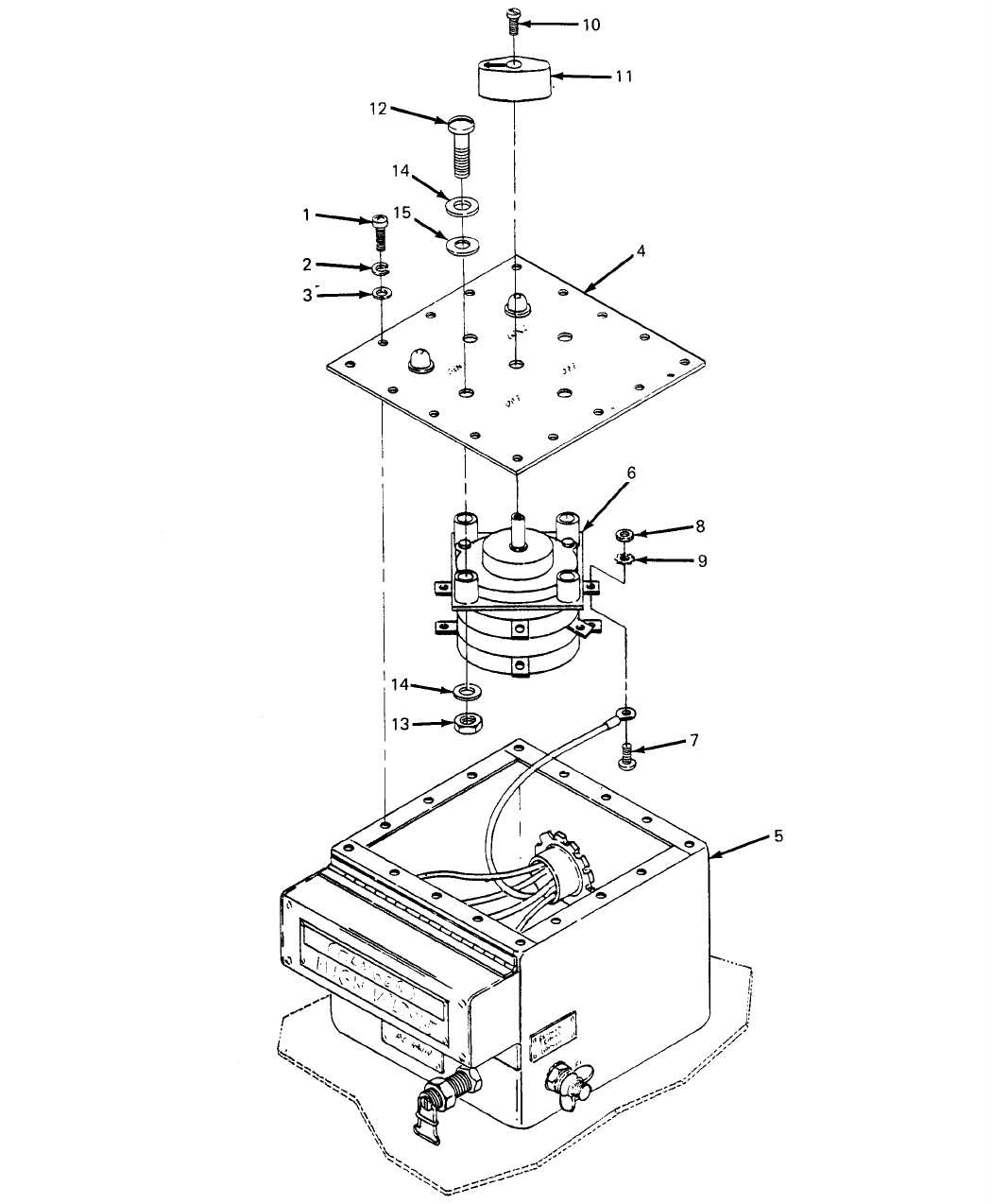

TM 5-6115-631-14&P
b.
Power Cable and Wiring Repair. The switch box wiring is repaired by tightening or replacing
loose or damaged terminals. The power cables are repaired by replacing damaged terminals. The
repair parts and special tools list in this manual lists part numbers for the terminals. The replacement
terminals are soldered onto the wires in accordance with procedures given in TB SIG 222 (TO 31-3-
64) and TM 55-1500-323-25 (TO 1-1A-14).
5-14

TM 5-6115-631-14&P
CHAPTER 6
TEST AND INSPECTION AFTER REPAIR
Section I. GENERAL REQUIREMENTS
6-1.
General Requirements. The activity performing the repair is responsible for the performance of
all applicable tests and inspections specified in the technical manuals referenced below. Activities
performing maintenance on any component of the power plant must perform those tests and inspec-
tions required by the applicable component or system repair instruction.
6-2.
Generator Set Inspections.
ing repair of the generator set.
Section II. INSPECTION
Refer to TM 5-6115-584-12 and --34 for inspections required follow-
6-3. Trailer Inspections. Refer to TM 9-2330-213-14&P for inspections required following repair of
the trailer.
Section Ill. OPERATIONAL TESTS
6.4. Generator Set Operational Tests. Refer to TM 5-6115-584-12 and – 34 for operational tests
required to verify satisfactory performance of the generator set.
6.5. Trailer Operational Tests. Refer to TM 9-2330-213-14&P for operational tests required to verify
satisfactory performance of the trailer.
6-1/(6-2 blank)
TM 5-6115-631-14&P
APPENDIX A
REFERENCES
A-1. Scope. This appendix lists all pamphlets, forms, technical manuals, specific
miscellaneous publications referenced in this manual.
A-2. Forms and Records.
Air Force Maintenance Management Program. . . . . . . . . . . . . . . . . . . . . . . . . . . . . . . . . . . . . . . . . . . . .
Technical Order System Publication Improvement Report
and Reply . . . . . . . . . . . . . . . . . . . . . . . . . . . . . . . . . . . . . . . . . . . . . . . . . . . . . . . . . . . . . . . . . . . . . . . . . . . . . . . . .
Recommended Changes to Publications and Blank Forms . . . . . . . . . . . . . . . . . . . . . . . . . . . . . . . .
Depreservation Guide for Vehicles and Equipment. . . . . . . . . . . . . . . . . . . . . . . . . . . . . . . . . . . . . .
Equipment Inspection and Maintenance Worksheet. . . . . . . . . . . . . . . . . . . . . . . . . . . . . . . . . . . . . .
Maintenance Request . . . . . . . . . . . . . . . . . . . . . . . . . . . . . . . . . . . . . . . . . . . . . . . . . . . . . . . . . . . . . . . . . . . . .
Consolidated Index of Army Publications . . . . . . . . . . . . . . . . . . . . . . . . . . . . . . . . . . . . . . . . . . . . . .
The Army Maintenance Management System (TAMMS) . . . . . . . . . . . . . . . . . . . . . . . . . . . . . . . . . .
Product Quality Deficiency Report . . . . . . . . . . . . . . . . . . . . . . . . . . . . . . . . . . . . . . . . . . . . . . . . . . . . . .
A-3. Military Specifications.
Chemical Agent Resistant Aliphatic Polyurethane Coating . . . . . . . . . . . . . . . . . . . . . . . . . . . . . . . . . . . . . .
Identification Marking of U.S. Military Property . . . . . . . . . . . . . . . . . . . . . . . . . . . . . . . . . . . . . . . . . . . . . . . . . . . . . . . . . .
Identification Marking of Combat and Tactical Transport . . . . . . . . . . . . . . . . . . . . . . . . . . . . . . . . . . . . . . . . .
Treatment and Painting of Materiel . . . . . . . . . . . . . . . . . . . . . . . . . . . . . . . . . . . . . . . . . . . . . . . . . . . . . . . . . . . . . . . . . . . . . . . . . . . . . .
A-4. Technical Manuals.
General Fabric Repair
. . . . . . . . . . . . . . . . . . . . . . . . . . . . . . . . . . . . . . . . . . . . . . . . . . . . . . . . . . . . . . . . . . . . . . . . . . . . . . . . . . . . . . . . .
Operator and Organizational Maintenance Manual for Generator
Set, Diesel Engine Driven, Tactical Skid Mounted, 5 KW,
1 Phase, 2 Wire; 1 Phase, 3 Wire; 3 Phase, 4 Wire; 120, 12/240
and 120/208 V (DOD Model MEP-002A) Utility Class 60 HZ (NSN
6115-00-465-1044) . . . . . . . . . . . . . . . . . . . . . . . . . . . . . . . . . . . . . . . . . . . . . . . . . . . . . . . . . . . . . . . . . . . . . .
Organizational, Intermediate (Field) Direct Support and General
Support and Depot Level Maintenance Repair Parts and Special
Tools List: for Generator Set Diesel Engine Driven, Tactical,
Skid Mounted, 5 KW, 1 Phase, 2 Wire, 1 Phase, 3 Wire; 3
Phase, 4 Wire, 120, 120/240 and 120/208 V (DOD Model MEP-002A)
Utility Class, 60 HZ (NSN 6115-00-465-1044) . . . . . . . . . . . . . . . . . . . . . . . . . . . . . . . . . . . . . . . . . . .
Intermediate (Field) (Direct and General Support) and Depot
Level Maintenance Manual for Generator Set, Diesel Engine
Driven, Tactical Skid Mounted, 5 KW, 1 Phase, 2 Wire;
1 Phase, 3 Wire; 3 Phase, 4 Wire, 120, 120/240 and 120/208 V
(DOD Model MEP-002A), Utility Class, 60 HZ
(NSN 6115-00-465-1044) . . . . . . . . . . . . . . . . . . . . . . . . . . . . . . . . . . . . . . . . . . . . . . . . . . . . . . . . . . . . . . . . . .
Installation Practices for Aircraft Electric and Electronic
Wiring [TO 1-1A-14]. . . . . . . . . . . . . . . . . . . . . . . . . . . . . . . . . . . . . . . . . . . . . . . . . . . . . . . . . . . . . . . . . . . . . . . . . . .
Procedures for Destruction of Equipment to Prevent
Enemy Use (Mobility Equipment Command) . . . . . . . . . . . . . . . . . . . . . . . . . . . . . . . . . . . . . . . . . . .
ations and
AFM66-1
AFTO Form 22
DA Form 2028
DA Form 2258
DA Form 2404
DA Form 2407
DA PAM 25-30
DA PAM 738-750
SF 368
MIL-C-46168
MIL-STD-130
MIL-STD-642
MIL-T-704
FM 10-16
TM 5-6115-584-12
TM 5-6115-584-24P
TM 5-6115-584-34
TM 55-1500-323-25
TM 750-244-3
A-1
TM 5-6115-631-14&P
Operator’s, Organizational, Direct Support and General Support
Maintenance Manual (Including Repair Parts and Special Tools
List) for Chassis Trailer 1-1/2-Ton, 2-Wheel, M103A1
(NSN 2330-00-835-8620), M103A2 (2330-00-049-8050), M103A3
(2330-00-141-8052), M103A3C (2330-00-542-2181), M103A4,
(2330-00-141-8051), M103A4C (233-00-542-2182); Trailer,
Cargo; M104 (2330-00-754-0509), M104A1 (2330-00-835-8630),
M105A1 (2330-00-835-8631), M105A2 (2330-00-141-8050)
M105A2C (2330-00-542-5689); Trailer Tank, Water, 400 Gallon,
M107A1 (2330-00-835-8633) M107A2 (2330-00-141-8049),
M107A2C (2330-00-542-5688) and Trailer, Van, Shop, Folding
Sides, M448(2330-00-63 1-5692) . . . . . . . . . . . . . . . . . . . . . . . . . . . . . . . . . . . . . . . . . . . . . . . . . . . . .
Organizational, Direct Support, and General Support Care
Maintenance and Repair of Pneumatic Tires and Inner
Tubes . . . . . . . . . . . . . . . . . . . . . . . . . . . . . . . . . . . . . . . . . . . . . . . . . . . . . . . . . . . . . . . . . . ....
Air Force Technical Order System . . . . . . . . . . . . . . . . . . . . . . . . . . . . . . . . . . . . . . . . . . . . . . . . . . . . . .
Painting and Marking of USAF Aerospace Ground Equipment . . . . . . . . . . . . . . . . . . . . . . . . . .
Processing and Inspection of Aerospace Ground Equipment
for Storage and Shipment . . . . . . . . . . . . . . . . . . . . . . . . . . . . . . . . . . . . . . . . . . . . . . . . . . . . . . . . . . . . . . . . . .
Processing and Inspection of Non-Mounted, Non-Aircraft
Gasoline and Diesel Engines for Storage and Shipment . . . . . . . . . . . . . . . . . . . . . . . . . . . . . . . .
A-5. Technical Bulletins.
Solder and Soldering [TO 31-3-64] . . . . . . . . . . . . . . . . . . . . . . . . . . . . . . . . . . . . . . . . . . . . . . . . .
Preservation of USAMECOM Mechanical Equipment for
Shipment and Storage . . . . . . . . . . . . . . . . . . . . . . . . . . . . . . . . . . . . . . . . . . . . . . . . . . . . . . . . . . . . . . . . .
TM 9-2330-213-14&P
TM 9-2610-200-24
TO-00-5-1
TO 35-1-3
TO 35-1-4
TO 38-1-5
TB SIG 222
TB 740-97-2
A-2

COMPONENTS
ARMY TM 5-6115-631-14&P
APPENDIX B
OF END ITEM LIST AND BASIC ISSUE ITEMS LIST
Section I. INTRODUCTION
B-1.
Scope.
This appendix lists components of end item and basic issue items for the power plant to help you
inventory items required for safe and efficient operation.
B-2.
General.
The Components of End Item and Basic Issue Items Lists are divided into the following sections:
a.
Sect
ion II. Co
mponents o
f End Item.
This listing is for informational purposes only, and is not authority to
requisition replacements. These items are part of the end item, but are removed and separately packaged for
transportation or shipment. As part of the end item, these items must be with the end item whenever it is issued or
transferred between property accounts. Illustrations are furnished to assist you in identifying the items.
b. Section III. Basic Issue Items.
These are the minimum essential items required to place the power plant in
operation, to operate it, and to perform emergency repairs. Although shipped separately packaged, Bll must be with
the power plant during operation and whenever it is transferred between property accounts. The illustrations will
assist you with hard-to-identify items. This manual is your authority to request/requisition replacement Bll, based
on TOE/MTOE authorization of the end item.
B-3.
a.
b.
Explanation of Columns.
The following provides an explanation of columns found in the tabular listings:
Column (1). Illustration Number (Illus No.).
This column indicates the number assigned to the. item.
Column (2). National Stock
Number.
Indicates the National stock number assigned to the item.
c.
Column
(3).
Description.
Indicates the federal item name and, if required, a minimum description to identif y
and locate the item. The last line for each item indicates the FSCM (in parentheses) followed by the part number.
If item needed differed for different models of this equipment, the model would be shown under the “Usable on
Code” heading in this column. The Usable On Code is not applicable for this equipment.
d.
Column (4), Unit of Measure (U/M) Indicates the measure used in performing the actual
operational/maintenance function. This measure is expressed by a two-character alphabetical abbreviation (eg,
ea, in, pr).
e.
Column
(5). Qu
antity Required(Qty
Req’d).
Indicates the quantity of the item authorized to be used with/on
the equipment.
Change 3
B-1
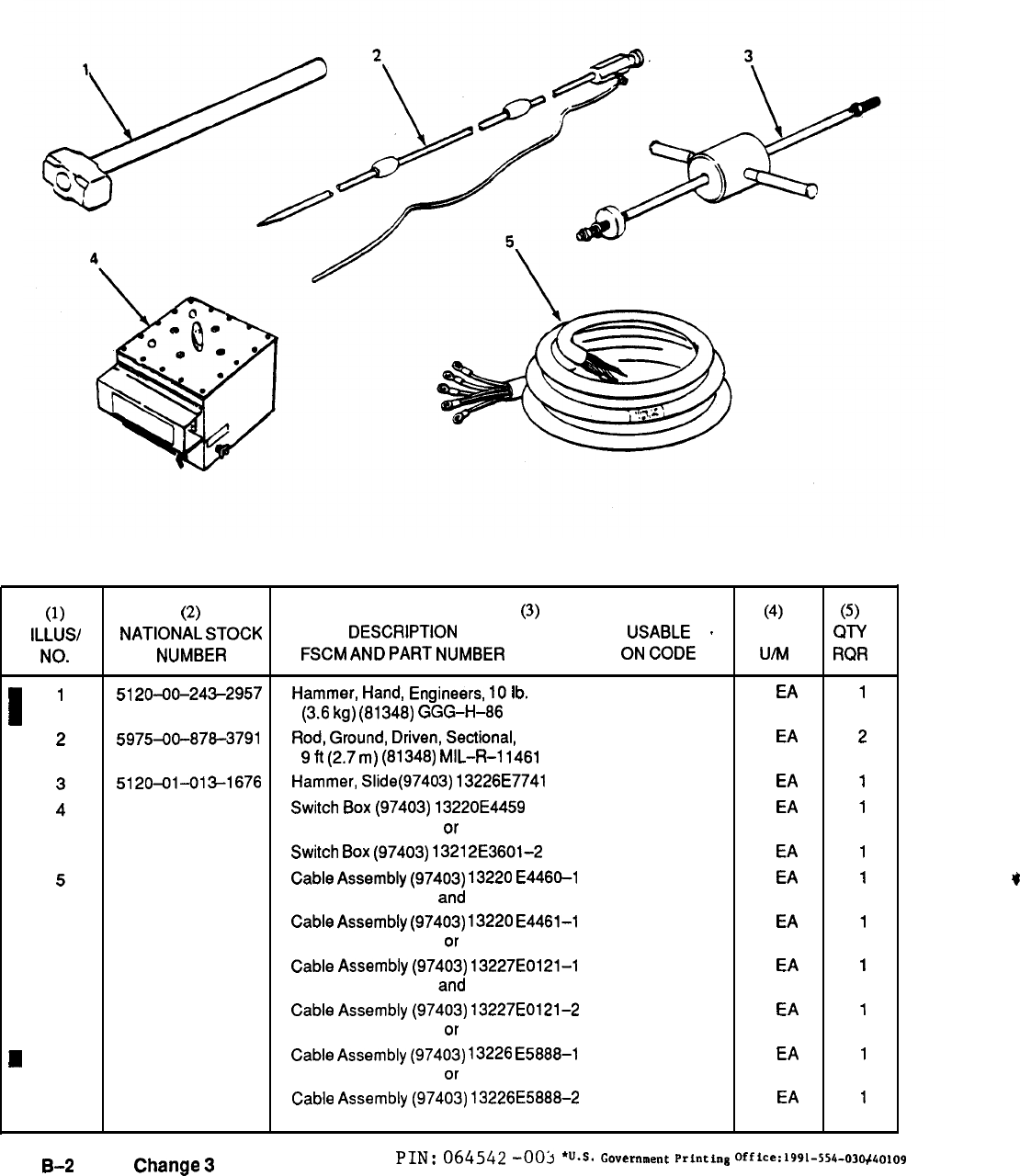
TM 5-6115-631-14&P
Section Il. COMPONENTS OF END ITEM
Figure
B-1. Components of End Item
(1) (2)
(3) (4) (5)
lLLUS/ NATIONAL
STOCK
DESCRIPTION USABLE
~
QTY
NO.
NUMBER
FSCM
AND
PART
NUMBER ON
CODE
u/M
RQR
I
1
5120-00-243-2957
Hammer,
Hand,
Engineers,
10
lb.
EA
1
(3.6
kg)
(81348)
GGG-H-86
2
5975-00-878-3791
Rod,
Ground,
Driven,
Sectional,
EA 2
9
ft
(2.7
m)
(81348)
MlL-R-l
1461
3
5120-01-013-1676
Hammer,
Slide(97403)
13226E7741
EA
1
4Switch
Box
(97403)
13220E4459
EA
1
or
Switch
Box
(97403)
1321
2E3601-2
EA
1
5Cable
Assembly
(97403)
13220
E4460-1
EA
1
and
Cable
Assembly
(97403)
13220
E4461-1
EA
1
or
Cable
Assembly
(97403)
13227E0121-1
EA
1
and
Cable
Assembly
(97403)
13227E0121-2
EA
1
or
H
Cable
Assembly
(97403)
13226
E5888-1
EA
1
or
Cable
Assembly
(97403)
13226E5888–2
EA
1
*
B-2
Change
3
PIN: 064542
-c)oj
‘Us.
Government
printing
office:1991-554-03~~olo9
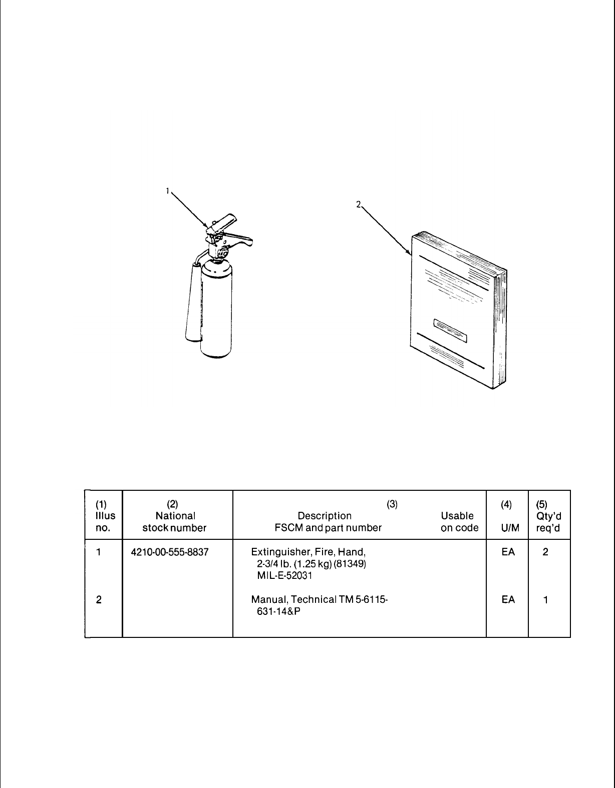
TM 5-6115-631-14&P
Section Ill. BASIC ISSUE ITEMS
Figure B-2.
Basic Issue Items
(1)
(2) (3) (4) (5)
IIlus National Description Usable Qty’d
no.
stock number
FSCM
and
part number
on
code
U/M
req’d
1
4210-00-555-8837
Extinguisher,
Fire,
Hand,
EA
2
2-3/4
lb.
(1
.25
kg)
(81349)
MI
L-E-52031
2
Manual, Technical
TM
5-6115- EA
1
631-14&P
B-3/(B-4 blank)

TM 5-6115-631-14&P
APPENDIX C
MAINTENANCE ALLOCATION CHART
Section I. INTRODUCTION
C-1. General.
a. This section provides a general explanation of all maintenance and repair functions authorized
at various maintenance levels.
b. Section II designates overall responsibility for the performance of maintenance functions on
the identified end item or component. The implementation of the maintenance functions upon the end
item or component will be consistent with the assigned maintenance functions.
c. Section Ill lists the tools and test equipment required for each maintenance function as
referenced from Section II.
d. Section IV contains supplemental instructions, explanatory notes and/or illustrations required
for a particular maintenance function.
C-2. Explanation of Columns in Section H.
a. Group Number. Column 1. The assembly group is a numerical group assigned to each assem-
bly in a top down breakdown sequence. The applicable assembly groups are listed on the MAC in dis-
assembly sequence beginning with the first assembly removed in a top down disassembly sequence.
b. Assembly Group. Column 2. This column contains a brief description of the components of
each assembly group.
c. Maintenance Functions. Column 3. This column lists the various maintenance functions (A
through K) and indicates the lowest maintenance category authorized to perform these functions. The
symbol designations for the various maintenance categories are as follows:
c
- Operator or crew
o
- Unit maintenance
F
- Intermediate direct support maintenance
H
- Intermediate general support maintenance
D
- Depot maintenance
The maintenance functions are defined as follows:
A – Inspect. To determine serviceability of an item by comparing its physical, mechanical, and
electrical characteristics with established standards.
B – Test. To verify serviceability and to detect electrical or mechanical failure by use of test
equipment.
C - Service. To clean, to preserve, to charge, and to add fuel, lubricants, cooling agents, and
air. If it is desired that elements, such as painting and lubricating, be defined separately, they may be
so Iisted.
C-1

TM 5-6115-631-14&P
D-
E-
F–
Adjust. To rectify to the extent necessary to bring into proper operating range,
Aline. To adjust specified variable elements of an item to bring to optimum performance.
Calibrate. To determine the corrections to be made in the readings of instruments or test
equipment used in precise measurement. Consists of the comparison of two instruments, one of
which is a certified standard of known accuracy, to detect and adjust any discrepancy in the accuracy
of the instrument being compared with the certified standard.
G – Install. To set up for use in an operational environment such as an emplacement, site, or
vehicle.
H
- Replace. To replace unserviceable items with serviceable like items.
I – Repair. Those maintenance operations necessary to restore an item to serviceable condition
through correction of material damage or a specific failure. Repair may be accomplished at each
category of maintenance.
J
- Overhaul. Normally, the highest degree of maintenance performed by the Army in order to
minimize time work in process is consistent with quality and economy of operation. It consists of that
maintenance necessary to restore an item to completely serviceable condition as prescribed by
maintenance standard in technical publications for each item of equipment. Overhaul normally does
not return an item to like new, zero mileage, or zero hour condition.
K - Rebuild. The highest degree of material maintenance. It consists of restoring equipment as
nearly as possible to new conditions in accordance with original manufacturing standards. Rebuild is
performed only when required by operational considerations or other paramount factors and then only
at the depot maintenance category. Rebuild reduces to zero the hours or miles the equipment, or
component thereof, has been in use.
d. Symbols. The uppercase letter placed in the appropriate column indicates the lowest level at
which that particular maintenance function is to be performed.
e. Tools and Equipment. Column 4. This column is provided for referencing by code, the special
tools and test equipment, (Section Ill) required to perform the maintenance functions (Section II).
f. Remarks. Column 5. This column is provided for referencing by code, the remarks (Section
IV) pertinent to the maintenance functions.
C-3. Explanation of Columns in Section Ill. Section Ill, Tools, Test, and Support Equipment
Requirements is not applicable.
C-4. Explanation of Columns in Section IV. Section IV, Remarks, is not applicable.
C-2
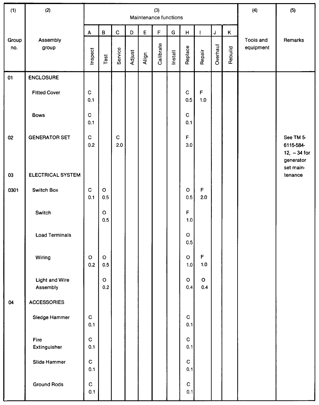
TM 5-6115-584-12
TM 5-6115-631-14&P
L
Section Il. MAINTENANCE ALLOCATION CHART
C-3
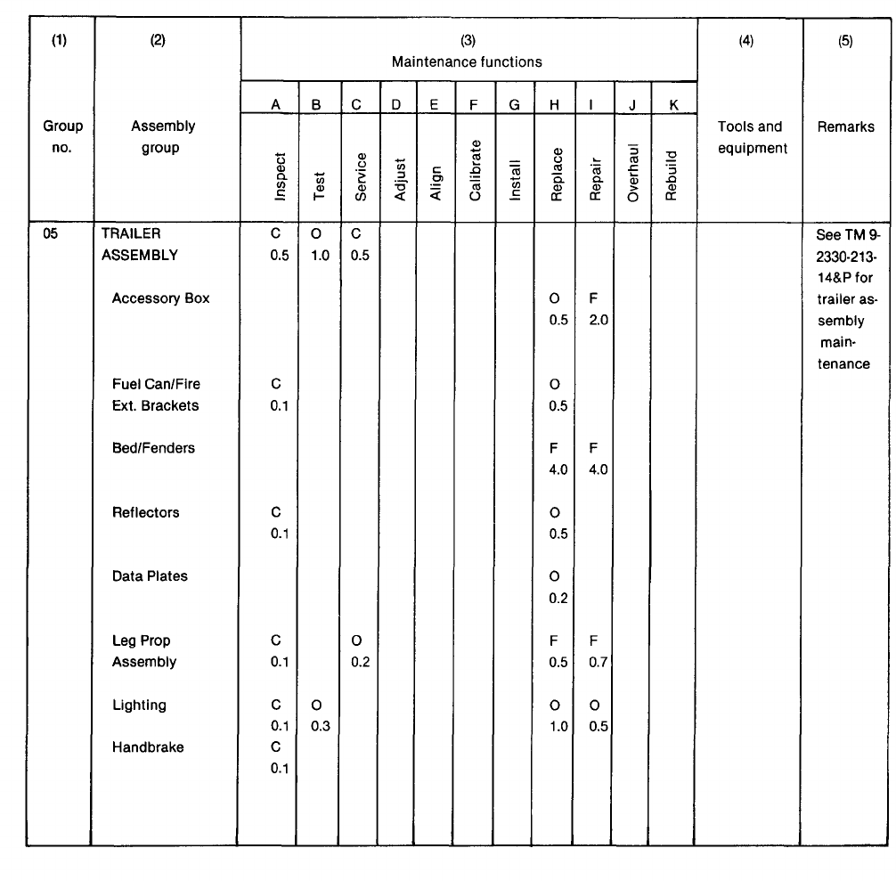
TM 9-2330-213-14
TM 5-6115-631-14&P
C-4

TM 5-6115-631-14&P
APPENDIX D
UNIT, INTERMEDIATE (FIELD) (DIRECT SUPPORT AND
GENERAL SUPPORT) AND DEPOT MAINTENANCE REPAIR PARTS AND
SPECTIAL TOOLS LIST
Section I. INTRODUCTION
D-1. Scope. This joint Army and Air Force manual lists repair parts and special tools required for the
performance of unit, intermediate (field) (direct and general support) and depot maintenance of the
power plant. The following paragraphs are keyed to applicable users. All users should read paragraph
4, Special Information, prior to using this manual.
D-2. General. Repair Parts and Special Tools List is divided into the following sections:
a. (ALL) Repair Parts – Section II. A list of repair parts authorized for the performance of mainte-
nance at the unit, intermediate (field) (direct and general support) and depot level in figure and item
number sequence.
b. (ALL) Special Tools, Test and Support Equipment – Section Ill. A list of special tools, test and
support equipment authorized for the performance of maintenance at the unit, intermediate (field)
(direct and general support), and depot level.
c. National Stock Number and Reference Number Index - Section IV. A list of National stock num-
bers in numerical sequence, followed by a list of reference numbers appearing in all the listings, in
alphanumeric sequence, cross-referenced to the illustration figure number and item number.
d. Reference Designator Index – Section V. The reference Designator Column includes all as-
signed reference designators arranged first in alphabetical order, second in numeric order. Opposite
each symbol is listed the figure and item number of the part in Section II and the reference number.
D-3. Explanation of columns. The following provides an explanation of columns in the tabular lists in
Sections II and Ill.
a. (ALL) Illustrations, (Column 1). This column is divided as follows:
(1) Figure Number. Indicates the figure number of the illustration on which the item is shown.
(2) Item Number. Indicates the number used to identify the item on the illustration.
b. (ALL) Source, Maintenance, and Recoverability Codes (SMR), (Column 2).
(1) Uniform Source Codes applicable to all Military Services.
D-1
TM 5-6115-631-14&P
GENERAL: Source Codes are assigned to support items to indicate the manner of acquiring support
items for maintenance, repair, or overhaul of end items. Source codes are entered in the first and
second positions of the Uniform SMR Code format as follows:
Code
Definition
PA
Item procured and stocked for anticipated or known usage.
PB
Item procured and stocked for insurance purposes because
essentiality dictates that a minimum quantity be available
in the supply systems.
PC
PD
PE
PF
PG
KD
KF
KB
MO
Item procured and stocked and which otherwise would be coded
PA except that it is deteriorative in nature.
Support item, excluding support equipment, procured for initial
issue or outfitting and stocked only for subsequent or
additional initial issues or outfittings. Not subject to auto-
matic replenishment.
Support equipment procured and stocked for initial issue or
outfittings to specified maintenance repair activities.
Support equipment which will not be stocked but which will be
centrally procured on demand.
Item procured and stocked to provide for sustained support for
the life of the equipment. It is applied to an item peculiar to the
equipment which because of probable discontinuance or shutdown
of production facilities would prove uneconomical to reproduce at
a later time.
An item of depot overhaul/repair kit and not purchased separ-
ately. Depot kit defined as a kit that provides items required
at the time of overhaul or repair.
An item of maintenance kit and not purchased separately.
Maintenance kit defined as a kit that provides an item that can
be replaced at unit or intermediate levels of maintenance.
Item included in both a depot overhaul/repair kit and a
maintenance kit.
Item to be manufactured or fabricated at unit level.
D-2

TM 5-6115-631-14&P
Definition
Code
MF
Item to be manufactured or fabricated at intermediate
maintenance levels.
Air Force – Intermediate (*)
Army -General Support (*)
MD
AO
AF
Item to be manufactured or fabricated at depot maintenance level.
Item to be assembled at unit level.
Item to be assembled at intermediate maintenance levels.
Air Force – Intermediate (*)
Army – Direct Support (*)
AH
AD
XA
XB
xc
XD
Item to be assembled at intermediate maintenance levels.
Air Force – Intermediate (*)
Army – General Support (*)
Item to be assembled at depot maintenance level.
Item is not procured or stocked because the requirements for the
item will result in the replacement of the next higher assembly.
Item is not procured or stocked. If not available through salvage,
requisition.
Installation drawings, diagram, instruction sheet, field service
drawing, that is identified by manufacturer’s part number.
A support item that is not stocked. When required, item will be
procured through normal supply channels.
(*) NOTE
For USAF and the USA Safeguard Program, only Code “F” will be used to
denote intermediate maintenance. On joint programs, use of either code F or
H by the jointing service will denote intermediate maintenance to USAF and
USA Safeguard Program.
(2) Uniform Maintenance Codes applicable to all Military Services: GENERAL Maintenance
Codes are assigned to indicate the levels of maintenance authorized to USE and REPAIR support
items. The Maintenance Codes are in the third and fourth position of the Uniform SMR Code Format.
D-3
TM 5-6115-631-14&P
(a) Use (Third Position): The Maintenance Code entered in the third position indicates the
lowest level maintenance level authorized to remove, replace, and use the support item. The
Maintenance Code entered in the third position indicates one of the following levels of maintenance.
Code
Application/Explanation
o
Support item is removed, replaced, used at the unit level of
maintenance.
F
Support item is removed, replaced, used at the following intermediate
levels:
USAF – Intermediate (*)
USA
- Direct Support (*)
Support item is removed, replaced, used at the following intermediate
levels:
USAF – Intermediate (*)
USA – General Support (*)
Code
Definition
D
Support items that are removed, replaced, used at Depot only:
USAF – Depot, Mobile Depot and Specialized Repair Activity.
USA – Depot, Mobile Depot and Specialized Repair Activity
(b) Repair (Fourth Position): The maintenance code entered in the fourth position indicates
whether the item is to be repaired and identifies the lowest maintenance level with the capability to per-
H
form complete repair (i.e., all authorized maintenance functions).
o
The lowest maintenance level capable of complete repair of
item is the unit level.
F
The lowest maintenance level capable of complete repair of
item is the following intermediate level:
USAF – Intermediate (*)
USA - General Support (*)
the support
the support
H
The lowest maintenance level capable of complete repair of the support
item is the following intermediate level:
USAF – Intermediate (*)
USA – General Support (*)
D-4
5-6115-631-14&P
(*) NOTE
For USAF programs and the USA Safeguard Program, Code F will be used to
denote intermediate maintenance. On joint programs, use of either Code F or
H by the joining Service will denote intermediate maintenance to USAF and the
USA Safeguard Program.
Code
Definition
D
The lowest maintenance level capable of complete repair of the support
item is the depot level.
USAF – Depot, Mobile Depot, and Specialized Repair Activity.
USA – Depot, Mobile Depot, and Specialized Repair Activity.
Code
Application/Explanation
L
Repair restricted to designated Specialized Repair Activity.
z
Nonreparable. No repair is authorized.
B
No repair is authorized. The item may be reconditioned by adjusting,
lubricating, etc., at the user level. No parts or special tools are
procured for the maintenance of this item.
(3) Uniform Recoverability Codes applicable to all Military Services: GENERAL: Recover-
ability Codes are assigned to support items to indicate the disposition action on unserviceable items.
The recoverability code is entered in the fifth position of the uniform SMR Code Format as follows:
RecoverabiIity
Codes
Definition
z
Nonreparable item. When unserviceable, condemn and dispose at
the level indicated in column 3.
0
Reparable item. When uneconomically reparable, condemn and
dispose at unit level.
F
Reparable item. When uneconomically reparable, condemn and
dispose at the following intermediate levels:
H
USAF – Intermediate (*)
USA – Direct Support (*)
Reparable item. When uneconomically reparable, condemn and
dispose at the following levels:
USAF – intermediate (*)
USA – General Support (*)
D-5

TM 5-6115-631-14&P
(*) NOTE
For USAF programs and the USA Safeguard Program, Code F will be used to
denote intermediate maintenance. On joint programs, use of either Code F or
H by the joining Service will denote intermediate level of USAF and the USA
Safeguard Program.
Recoverability
Codes
Definition
D
Reparable item. When beyond lower level repair capability,
return to depot. Condemnation and disposal not authorized
below depot level.
L
Reparable item. Repair, condemnation and disposal not
authorized below depot/Specialized Repair Activity level.
A Item requires special handling or condemnation procedure
because of specific reasons (i.e., precious metal content,
high-dollar value, critical material or hazardous material).
Refer to appropriate manuals/directives for specific
instructions.
c. (ALL) /Vational Stock Number (Column 4). Indicates the National Stock Number assigned to
the item and will be used for requisitioning purposes.
d. (ALL) Description (Column 5). Indicates the Federal item name and any additional descrip-
tions of the item required. The abbreviation “w/e” when used as part of the nomenclature, indicates
that the National Stock Number includes all armament, equipment, accessories and repair parts
issued with the item. A part number or other reference number is followed by the applicable five digit
Federal Supply Code for manufacturer in parentheses. If two reference numbers and Federal Supply
Codes for manufacturer are listed, the first listing refers to the Department of Defense Drawing
Number, the second listing refers to the actual part manufacturer. Items that are included in kits and
sets are listed below the name of the kit or set with the quantity of each item in the kit or set indicated in
the quantity incorporated in unit column.
e. (ALL) Unit of Measure (U/M) (Column 6). Indicates the standard of the basic quantity of the
listed item as used in performing the actual maintenance function. This measure is expressed by a
two-character alphabetical abbreviation (e.g., ea, in, pr, etc.). When the unit of measure differs
from the unit of issue, the lowest unit of issue that will satisfy the required units of measure will be
requisitioned.
f. (ALL) Quantity Incorporated in Unit (Column 7). Indicates the quantity of the item used in the
assembly group. A “V” appearing in this column in lieu of a quantity indicates that a definite quantity
cannot be indicated (e.g., shims, spacers, etc.).
D-4. Special Information.
a. (ALL) Identification of Usable On Codes for this Manual is not applicable.
b. Army unit maintenance personnel will extract the items which they require from Section II, 3rd
or 4th position of column 2 of the intermediate direct and general support RPSTL. Parts which are
manufactured or assembled at a higher level than that authorized to install the part are indicated by the
use of higher level code in the source column.
D-6

TM 5-6115-631-14&P
c. Stockage Information.
(1) Air Force stockage information is contained in lnitial Supply Support Lists issued separately
from this publication by Sacramento Air Logistics Center in accordance with AFM 67-1,
part 1, chapter 12.
(2) Army stockage is demand based in accordance with AR 710-2. Repair parts listed in this
publication represent those authorized for use at indicated maintenance levels and will be
requisitioned on an as-required basis until stockage is justified in accordance with
AR 710-2.
d. In the parts list, some items are indented to show that they area component of the item under
which they are indented.
D-5. How to Locate Repair Parts.
a. (ALL When National Stock Number or reference number is unknown:
(1) Using the table of contents, determine the functional group; i.e., batteries and related
parts, exhaust and breather pipes, within which the repair part belongs. This is necessary
since illustrations are prepared for functional groups.
(2) Find the illustration covering the functional group to which the repair part belongs.
(3) Identify the repair part on the illustration and note the illustration figure and item number of
the repair part.
(4) Using the Repair Parts Listing, find the figure and item number noted on the illustration.
b. (ALL) When national stock number or reference number is known:
(1) Using the Index of National Stock Numbers and Reference Numbers, find the pertinent
national stock number or reference number. This index is in ascending NSN sequence
followed by a list of reference numbers in alphanumeric sequence, cross-referenced to
the illustration figure number and item number.
(2) After finding the figure and item number, locate the figure and item number in the repair
parts list.
D-6. (F) Use of the Reference Designator Index Section. This Section (Section V) is used when the
reference designator is known or identified by other technical manuals supporting this equipment. The
reference number is given in this section. If description or location is desired, note the figure and item
number. Turn to Section II to the noted figure and item number. The location of the part and
description is given in this listing.
D-7. Abbreviations.
Abbreviations Explanation
Not Applicable
D-7
TM 5-6115-631-14&P
D-8. Federal Supply Codes for Manufacturers.
Code
Manufacturer
Not Applicable
D-9. Recommendation for Maintenance Publication Improvements. Report of errors, omissions, and
recommendations for improving this publication by the individual user is encouraged. Reports should
be submitted as follows:
a. Air Force AFTO Form 22 in accordance with T.O. 00-5-1, directly to: Commander,
Sacramento Air Logistics Center, ATTN: SM-ALC-MMEDTA, McClellan AFB, CA 95652-5609.
b. Army DA Form 2028, directly to: Commander, US Army Troop Support Command, ATTN:
AMSTR-MCTS, 4300 Goodfellow Boulevard, St. Louis, MO 63120-1798.
D-8
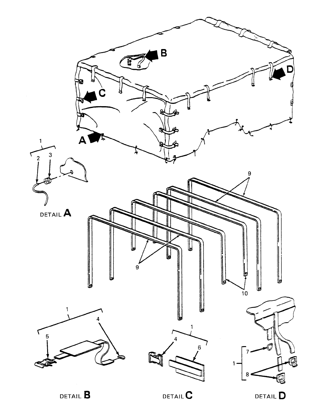

SECTION IITM 9-6115-631-14&P
(1) (2) (3) (4) (5) (6) (7) (8)
ILLUS- SMR CODE USMC DESCRIPTION
TRATION QTY USMC
a b a b c d a b NATIONAL USABLE INC QTY
FIG ITEM AIR REPL STOCK REF NUMBER ON IN PER
NO. NO. ARMY FORCE NAVY USMC SSI FACTOR NUMBER & MFR CODE CODE U/M UNIT EQUIP
Group 01 - ENCLOSUR-
D-1 1 PAOFZ 6115-01-206-1271 FITTED COVER EA 1
13226E7740 97403
D-1 2 PAOZZ • ROPE, SISAL EA 25
MIL-R-24049 81349
D-1 3 PAFZZ 5325-01-B75-3182 • GROMMET, METALLIC EA 25
MIL-G-16491
D-1 4 PAFZZ 5340-00-078-7029 • CLIP, END STRAP EA 24
MS51926-3
D-1 5 PAFZZ 5340-00-057-6956 • BUCKLE, SPRING ACTION EA 12
MS51929-2
D-1 6 AFFFF • CHAPE ASSEMBLY EA 12
13214E1392 97403
D-1 7 PAFZZ 5365-01-031-9674 • RING, DEE EA 16
MS51925-1 96906
D-1 8 • HOOK, SNAP EA 26
M43770/1-SWZE3 81349
D-1 9 PAOZO 2540-00-924-8478 BOW, VEHICULAR, TOP EA 4
13212E3597-1 97403
D-1 10 PAOZZ 2540-00-926-1003 BOW, VEHICLULAR, TOP EA 2
13212E3597-2 97403
Change 4 D-11
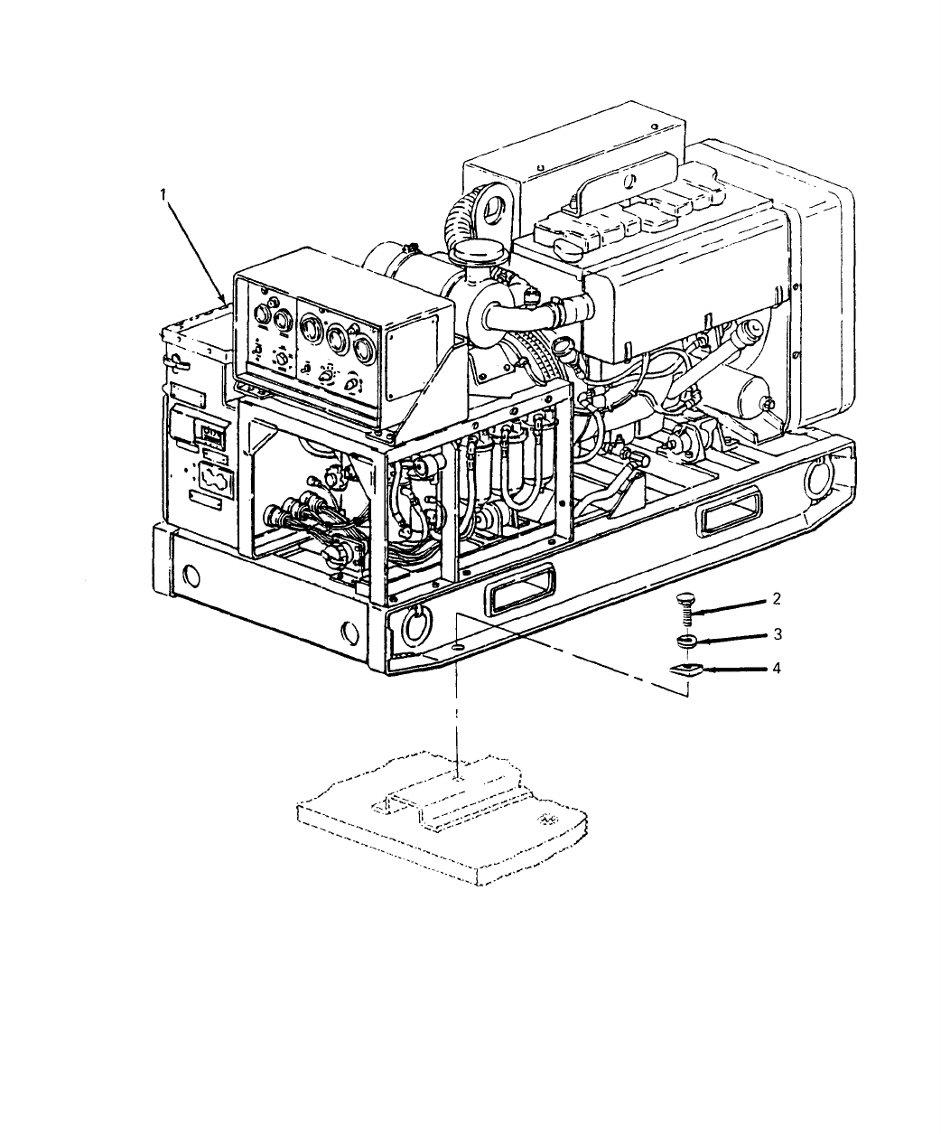
SECTION II TM5-6115-631-14&P
(1) (2) (3) (4) (5) (6) (7) (8)
ILLUS- SMR CODE USMC DESCRIPTION
TRATION QTY USMC
A B A B C D A B NATIONAL USABLE INC QTY
FIG ITEM AIR REPL STOCK REF NUMBER ON IN PER
NO. NO. ARMY FORCE NAVY USMC SSI FACTOR NUMBER & MFR CODE CODE U/M UNIT EQUIP
GROUP 02 - GENERATOR SET
D-2 1 PDOFD 6115-00-465-1044 GENERATOR SET, DIESEL EA 2
MEP-002A 30554
D-2 2 PAOZZ 5305-00-719-5235 SCREW, CAP, HEX EA 8
MS90727-114 96906
D-2 3 PAOZZ 5310-00-584-5272 LOCKWASHER EA 8
MS35338-48 96906
D-2 4 PAOZZ 5310-01-150-5922 WASHER, BEVELED EA 8
13206E4482-2 97304
D-13

SECTION II TM5-6115-631-14&P
(1) (2) (3) (4) (5) (6) (7) (8)
ILLUS- SMR CODE USMC DESCRIPTION
TRATION QTY USMC
A B A B C D A B NATIONAL USABLE INC QTY
FIG ITEM AIR REPL STOCK REF NUMBER ON IN PER
NO. NO. ARMY FORCE NAVY USMC SSI FACTOR NUMBER & MFR CODE CODE U/M UNIT EQUIP
GROUP 03 - ELECTRICAL SYSTEM
0301 - POWER CABLE
D-3 1 PBOFF CABLE ASSY, POWER (FIVE-WIRE) EA 2
13227E0121 97403
D-3 2 PAOZZ
9905-01-875-318
.BAND, IDENTIFICATION EA 17
MIL-P-15024/8 81349
TYPE K2
D-3 3 .TERMINAL, LUG EA 4
MS25036-122 96906
D-3 4 PAOZZ
5940-00-113-819
.TERMINAL, LUG EA 1
MS25036-122 96906
D-3 5 PBOGF .CABLE, POWER EA 1
CO-04HDE 81349
(4/4-4/12R)
D-15
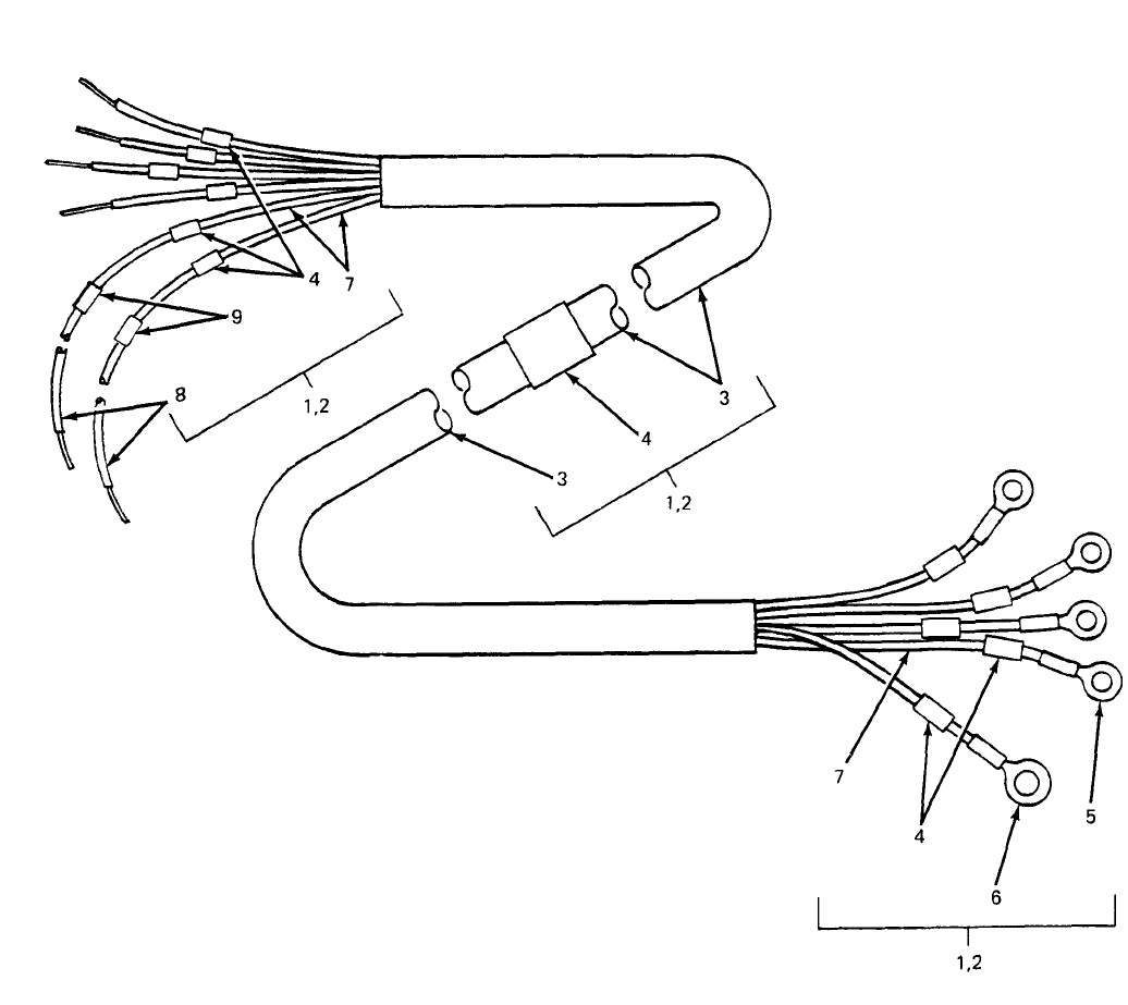
SECTION II TM5-6115-631-14&P
(1) (2) (3) (4) (5) (6) (7) (8)
ILLUS- SMR CODE USMC DESCRIPTION
TRATION QTY USMC
A B A B C D A B NATIONAL USABLE INC QTY
FIG ITEM AIR REPL STOCK REF NUMBER ON IN PER
NO. NO. ARMY FORCE NAVY USMC SSI FACTOR NUMBER & MFR CODE CODE U/M UNIT EQUIP
0301 - POWER CABLE
D-4 1 PAOFH CABLE ASSY, POWER (FIVE-WIRE) EA 1
(GEN 1)
13226E5888-1 97403
D-4 2 PAOFH
6150-01-B76-1221
CABLE ASSY, POWER (FIVE-WIRE) EA 1
(GEN 2)
13226E5888-2 97403
D-4 3 PAFZZ .CABLE FT AR
CO-04-HDF- 81349
(4/1-4/8R) 1620
D-4 4 PAOZZ .BAND, IDENTIFICATION EA 26
MIL-P-15024/8 81349
TYPE K2
D-4 5 PAOZZ
5940-00-115-5007
.TERMINAL, LUG EA 2
MS25036-130 96906
D-4 6 PAOZZ
5940-00-113-9833
.TERMINAL, LUG EA 2
MS25036-131 96906
D-4 7 PAOZZ .SLEEVING, INSULATION EA AR
M23053/5-107-5 81349
D-4 8 PAOZZ .WIRE, SIZE 6 AWG EA 4
QQW343CO6 81348
D-4 9 PAOZZ .SLEEVING, INSULATION EA AR
M23053/5-109-5 81349
D-17
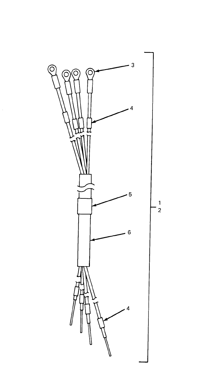
SECTION II TM5-6115-631-14&P
(1) (2) (3) (4) (5) (6) (7) (8)
ILLUS- SMR CODE USMC DESCRIPTION
TRATION QTY USMC
A B A B C D A B NATIONAL USABLE INC QTY
FIG ITEM AIR REPL STOCK REF NUMBER ON IN PER
NO. NO. ARMY FORCE NAVY USMC SSI FACTOR NUMBER & MFR CODE CODE U/M UNIT EQUIP
0301 - POWER CABLES
D-5 1 CABLE ASSY, POWER (FOUR-WIRE) EA 1
(GEN 1)
13220E4460-1 97403
D-5 2 CABLE ASSY, POWER (FOUR-WIRE) EA 1
(GEN 2)
13220E4461-1 97403
D-5 3
5940-00-557-434
.TERMINAL, LUG EA 8
MS25036-120 96906
D-5 4 .INSULATION, TUBING (0.375 ID) EA 16
M23053/5 81349
D-5 5 .INSULATION, TUBING (1.500 ID) EA 2
M23053/5 81349
D-5 6 .CABLE
CO-04HDE (4/6)
D-19(D-20 BLANK)
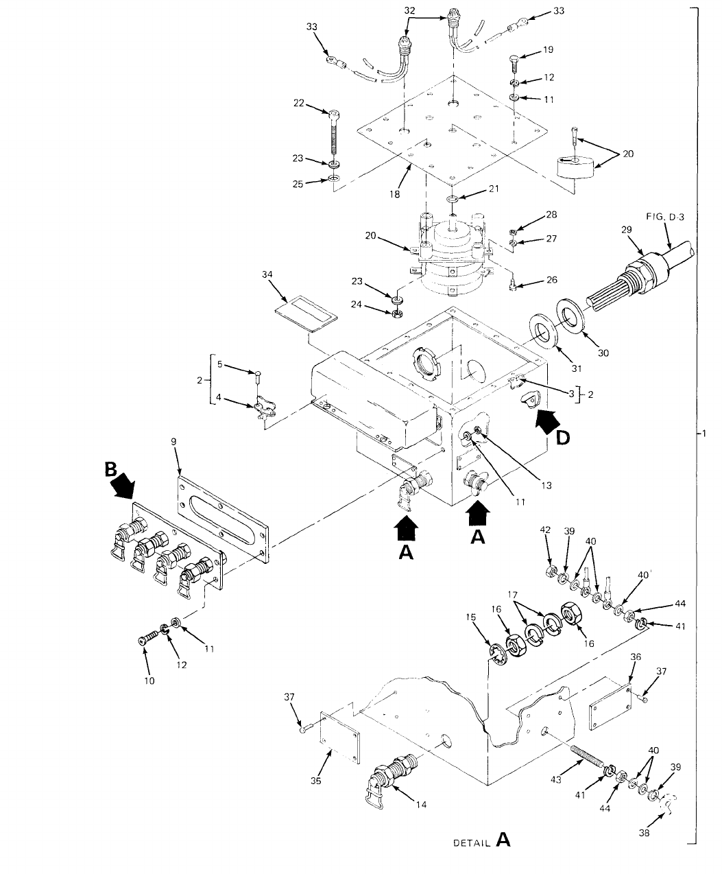
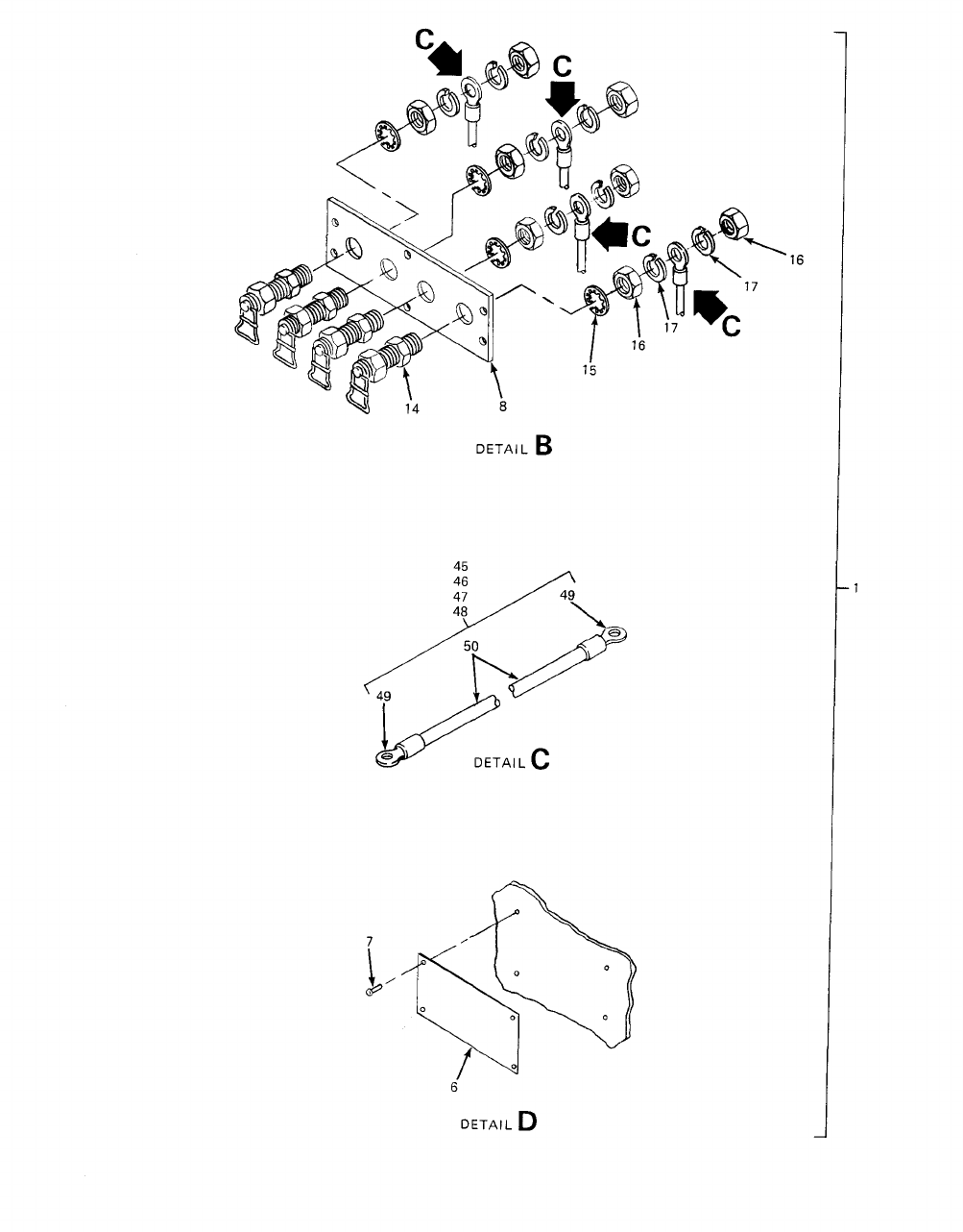
TM 5-6115-631-14&P
Figure D-6. Five- Wire Switch Box (Sheet 2 of 2).
D-22
SECTION II TM5-6115-631-14&P
(1) (2) (3) (4) (5) (6) (7) (8)
ILLUS- SMR CODE USMC DESCRIPTION
TRATION QTY USMC
A B A B C D A B NATIONAL USABLE INC QTY
FIG ITEM AIR REPL STOCK REF NUMBER ON IN PER
NO. NO. ARMY FORCE NAVY USMC SSI FACTOR NUMBER & MFR CODE CODE U/M UNIT EQUIP
0301 - SWITCH BOX
D-6 1 PBOFH BOX,SWITCH (FIVE-WIRE) EA 1
13212E3601-2 97403
D-6 2 .BOX EA 1
13212E3602 97403
D-6 3 PAOZZ ..NUT,BLIND RIVET EA 16
MS27130-S99 96906
D-6 4 PAFZZ ..FASTENER,PANEL EA 2
MIL-F-5591 81349
D-6 5 PAFZZ 5320-00-117-6963 ..RIVET,SOLID EA 4
MS20426A4-6 96906
D-6 6 PAOZZ .PLATE,INFORMATION EA 1
13212E3587 97403
D-6 7 PAFZZ 5320-00-721-5244 .RIVET,TUBULAR EA 4
MS16535-77 96906
D-6 8 PAFZZ 5940-00-105-6331 .BOARD,TERMINAL EA 1
13212E3606 97403
D-6 9 PAOZZ 5330-01-162-8585 .GASKET EA 1
1321E3610 97403
D-6 10 PAOZZ 5305-00-984-6214 .SCREW,MACHINE EA 6
MS35206-267 96906
D-6 11 PAOZZ 5310-00-809-8546 .WASHER,FLAT EA 28
MS27183-8 96906
D-6 12 PAOZZ 5310-00-045-3296 .LOCKWASHER EA 22
MS35338-43 96906
D-6 13 PAOZZ 5310-00-934-9758 .NUT,PLAIN,HEX EA 6
MS35649-202 96906
D-6 14 PAOZZ 5940-00-021-3321 .POST,TERMINAL EA 5
MS39347-2 96906
D-6 15 PAOZZ 5310-00-022-8834 .LOCKWASHER,INTERNAL TOOTH EA 5
MS35333-108 96906
D-6 16 PAFZZ 5310-00-247-7186 .NUT,PLAIN,HEX EA 10
MS16203-37 96906
D-6 17 PAOZZ 5310-00-184-8971 .LOCKWASHER EA 10
MS35338-101 96906
D-7 18 PAFZZ 6110-00-133-9160 .COVER EA 1
13212E3603 97403
D-7 19 PAOZZ 5305-00-989-7434 .SCREW,MACHINE EA 16
MS35207-263 96906
D-6 20 5930-00-829-3243 .SWITCH,ROTARY EA 1
13205E5023 97403
D-6 21 PAFZZ 5330-00-579-8108 .PACKING,PREFORMED EA 1
MS28775-111 96906
D-23
SECTION II TM5-6115-631-14&P
(1) (2) (3) (4) (5) (6) (7) (8)
ILLUS- SMR CODE USMC DESCRIPTION
TRATION QTY USMC
A B A B C D A B NATIONAL USABLE INC QTY
FIG ITEM AIR REPL STOCK REF NUMBER ON IN PER
NO. NO. ARMY FORCE NAVY USMC SSI FACTOR NUMBER & MFR CODE CODE U/M UNIT EQUIP
0301 - SWITCH BOX - CONT
D-6 22 PAFZZ
5305-00-984-569
.SCREW, MACHINE EA 4
MS35206-315 96906
D-6 23 PAOZZ
5310-00-080-600
.WASHER,FLAT EA 8
MS27183-14 96906
D-6 24 PAOZZ
5310-00-087-4652
.NUT, SELF-LOCKING EA 4
MS51922-17 96906
D-6 25 PAFZZ
5330-00-684-342
.PACKING, PREFORMED EA 4
MS28775-013 96906
D-6 26 PAOZZ
5305-00-954-9003
.SCREW, MAHCINE EA 9
MS35215-68 96906
D-6 27 PAOZZ
5310-00-942-510
.LOCKWASHER EA 9
MS35335-89 96906
D-6 28 PAOZZ
5310-00-924-421
.NUT, PLAIN, HEX EA 9
MS51970-1 96906
D-6 29 .TUBE, STUFFING EA 2
13218E5149-8 97403
D-6 30 PAOZZ
5310-01-190-221
.WASHER EA 2
13218E5139-4 97403
D-6 31 PAFZZ
5330-01-187-3493
.GASKET EA 2
13218E5140-4 97403
D-6 32 PAOOZ
6210-00-253-068
.LIGHT AND WIRE ASSY EA 2
13212E3581-2 97403
D-6 33 PAOZZ
5940-00-113-818
.TERMINAL, LUG EA 4
MS25036-150 96906
D-6 34 XBOZZ .PLATE, WARNING EA 1
13216E7603 97403
D-6 35 PAOZZ .PLATE, INFORMATION EA 1
13226E5889-1 97403
D-6 36 PAOZZ .PLATE, INFORMATION EA 1
13226E5889-2 97403
D-6 37 PAFZZ
5320-00-954-0113
.RIVET, TUBULAR EA 8
MS16535-155 96906
D-6 38 PAOZZ
5310-00-543-471
.NUT, PLAIN, WING EA 1
MS35425-28 96906
D-6 39 PAOZZ
5310-00-184-897
.LOCKWASHER EA 2
MS35338-103 96906
D-6 40 PAOZZ
5310-00-187-2413
.WASHER, FLAT EA 5
AN961-616T 81352
D-6 41 PAFZZ
5310-00-022-884
.LOCKWASHER EA 2
MS35333-110 96906
D-6 42 PAFZZ
5310-00-584-799
.NUT, PLAIN, HEX EA 1
MS16203-27 96906
D-24 PIN:064542-002
SECTION II TM5-6115-631-14&P
(1) (2) (3) (4) (5) (6) (7) (8)
ILLUS- SMR CODE USMC DESCRIPTION
TRATION QTY USMC
A B A B C D A B NATIONAL USABLE INC QTY
FIG ITEM AIR REPL STOCK REF NUMBER ON IN PER
NO. NO. ARMY FORCE NAVY USMC SSI FACTOR NUMBER & MFR CODE CODE U/M UNIT EQUIP
0301 - SWITCH BOX - CONT
D-6 43 PAOZZ
5307-00-227-174
.STUD EA 1
13214E1223 97403
D-6 44 PAOZZ
5310-01-026-582
.NUT, PLAIN, HEX EA 2
MS16203-39 96906
D-6 45 MFFZZ .LEAD, ELECTRICAL (W3) EA 1
13212E3609-1 97403
D-6 46 MFFZZ .LEAD, ELECTRICAL (W4) EA 1
13212E3609-2 97403
D-6 47 MFFZZ .LEAD, ELECTRICAL (W5) EA 1
13212E3609-3 97403
D-6 48 MFFZZ .LEAD, ELECTRICAL (W6) EA 1
13212E3609-4 97403
D-6 49 PAOZZ
5940-00-557-434
..TERMINAL, LUG EA 8
MS25036-120 96906
D-6 50 PAOZZ
6145-00-578-659
..WIRE, ELECTRICAL FT AR
M5086/2-6 81349
D-25
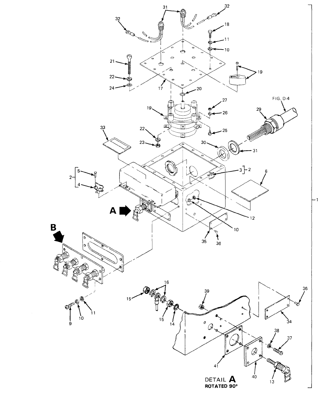
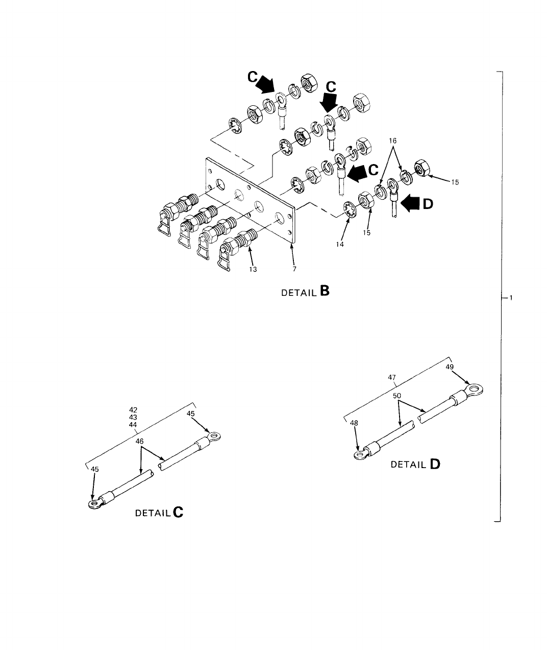
TM 5-6115-631-14&P
Figure D-7. Five- Wire Switch Box (Sheet 2 of 2).-
D-27(D-28 blank)
SECTION II TM5-6115-631-14&P
(1) (2) (3) (4) (5) (6) (7) (8)
ILLUS- SMR CODE USMC DESCRIPTION
TRATION QTY USMC
A B A B C D A B NATIONAL USABLE INC QTY
FIG ITEM AIR REPL STOCK REF NUMBER ON IN PER
NO. NO. ARMY FORCE NAVY USMC SSI FACTOR NUMBER & MFR CODE CODE U/M UNIT EQUIP
0301 - SWITCH BOX
D-7 1 PBOFH BOX, SWITCH (FIVE-WIRE) EA 1
13220E4459 97403
D-7 2 .BOX EA 1
13220E4464 97403
D-7 3 PAFZZ
5310-01-B75-1034
..NUT, CLINCH EA 16
13211E3895-5 97403
D-7 4 PAFZZ ..FASTENER, PANEL EA 2
MIL-F-5591 81349
D-7 5 PAFZZ
5320-00-117-6963
..RIVET, SOLID EA 4
MS20426A4-6 96906
D-7 6 PAOZZ .PLATE, INFORMATION EA 1
13212E3587 974033
D-7 7 PAFZZ
5940-00-105-6331
.BOARD, TERMINAL EA 1
13212E3606 97403
D-7 8 PAOZZ
5330-01-162-8585
.GASKET EA 1
13212E3610 97403
D-7 9 PAOZZ
5305-00-984-6214
.SCREW, MACHINE EA 6
MS35206-267 96906
D-7 10 PAOZZ .WASHER, FLAT EA 28
MS27183-42 96906
D-7 11 PAOZZ
5310-00-045-3296
.LOCKWASHER EA 2
MS35338-43 96906
D-7 12 PAOZZ
5310-00-934-9758
.NUT, PLAIN, HEX EA 6
MS35649-202 96906
D-7 13 PAOZZ
5940-00-021-3321
.POST, TERMINAL EA 5
MS39347-2 96906
D-7 14 PAOZZ
5310-00-022-8834
.LOCKWASHER, INTERNAL TOOTH EA 5
MS35333-108 96906
D-7 15 PAFZZ
5310-00-247-7186
.NUT, PLAIN, HEX EA 10
MS16203-37 96906
D-7 16 PAOZZ
5310-01-004-9129
.LOCKWASHER EA 10
AN961-416S
PAOZZ
5310-00-187-2413
.LOCKWASHER EA 10
AN961-416T
D-7 17 PAFZZ
6110-00-133-9160
.COVER EA 1
13212E3603 97403
D-7 18 PAOZZ .SCREW, MACHINE EA 16
MS35207-264 96906
D-7 19
5930-00-829-3243
.SWITCH, ROTARY EA 1
13205E5023 97403
D-7 20 PAFZZ
5330-00-579-8108
.PACKING, PREFORMED EA 1
MS28775-111 96906
D-29
SECTION II TM5-6115-631-14&P
(1) (2) (3) (4) (5) (6) (7) (8)
ILLUS- SMR CODE USMC DESCRIPTION
TRATION QTY USMC
A B A B C D A B NATIONAL USABLE INC QTY
FIG ITEM AIR REPL STOCK REF NUMBER ON IN PER
NO. NO. ARMY FORCE NAVY USMC SSI FACTOR NUMBER & MFR CODE CODE U/M UNIT EQUIP
0301 - SWITCH BOX - CONT
D-7 21 PAFZZ
5305-00-984-5695
.SCREW, MACHINE EA 4
MS35206-315 96906
D-7 22 PAOZZ
5310-00-080-6004
.WASHER, FLAT EA 8
MS27183-14 96906
D-7 23 PAOZZ
5310-00-087-4652
.NUT, SELF-LOCKING EA 4
MS51922-17 96906
D-7 24 PAFZZ
5330-00-684-3420
.PACKING, PREFORMED EA 4
MS28775-013 96906
D-7 25 PAOZZ
5305-00-954-9003
.SCREW, MACHINE EA 9
MS35215-68 96906
D-7 26 PAOZZ
5310-00-942-5109
.LOCKWASHER EA 9
MS35335-89 96906
D-7 27 PAOZZ
5310-00-924-4218
.NUT, PLAIN, HEX EA 9
MS51970-1 96906
D-7 28 PAFZZ
5975-01-211-3346
.TUBE, STUFFING EA 2
13218E5149-10 97403
D-7 29 PAOZZ
5310-01-164-2342
.WASHER EA 2
13218E5139-3 97403
D-7 30 PAOZZ
5330-01-150-9792
.GASKET EA 2
13218E5140-3 97403
D-7 31 PAOZZ
6120-00-406-1398
.LIGHT AND WIRE ASSY EA 2
13212E3581-1 97403
D-7 32 PAOZZ
5940-00-113-8184
.TERMINAL, LUG EA 4
MS25036-150 96906
D-7 33 XBOZZ .PLATE, WARNING EA 1
13216E7603 97403
D-7 34 PAOZZ .PLATE, INFORMATION EA 1
13226E5889-1 97403
D-7 35 PAOZZ .PLATE, INFORMATION EA 1
13226E5889-2 97403
D-7 36 PAFZZ
5320-00-954-0113
.RIVET, TUBULAR EA 8
MS16535-155 96906
D-7 37 PAOZZ
5305-00-988-1727
.SCREW, MACHINE EA 4
MS35206-283 96906
D-7 38 PAOZZ
5310-00-809-4058
.WASHER, FLAT EA 4
MS27183-10 96906
D-7 39 PAOZZ
5310-00-088-1251
.NUT, SELF-LOCKING EA 4
MS51922-1 96906
D-7 40 PAOZZ
5940-01-B75-1040
.BOARD, TERMINAL EA 1
13226E6011-1 97403
D-7 41 XDOZZ .GASKET EA 1
13226E6012 97403
D-30
SECTION II TM5-6115-631-14&P
(1) (2) (3) (4) (5) (6) (7) (8)
ILLUS- SMR CODE USMC DESCRIPTION
TRATION QTY USMC
A B A B C D A B NATIONAL USABLE INC QTY
FIG ITEM AIR REPL STOCK REF NUMBER ON IN PER
NO. NO. ARMY FORCE NAVY USMC SSI FACTOR NUMBER & MFR CODE CODE U/M UNIT EQUIP
0301 - SWITCH BOX - CONT
D-7 42 MFFZZ .LEAD, ELECTRICAL (W3) EA 1
13212E3609-1 97403
D-7 43 MFFZZ .LEAD, ELECTRICAL (W4) EA 1
13212E3609-2 97403
D-7 44 MFFZZ .LEAD, ELECTRICAL (W5) EA 1
13212E3609-3 97403
D-7 45 PAOZZ
5940-00-557-434
..TERMINAL, LUG EA 6
MS25036-120 96906
D-7 46 PAOZZ
6145-00-578-659
..WIRE, ELECTRICAL FT AR
M5086/2-6 81349
D-7 47 MFFFF .LEAD, ELECTRICAL (W6) EA 1
13212E3586-4 97403
D-7 48 PAFZZ
5940-00-113-819
..TERMINAL, LUG EA 1
MS25036-127 96906
D-7 49 PAFZZ
5940-00-113-983
..TERMINAL, LUG EA 1
MS25036-128 96906
D-7 50 ..WIRE, ELECTRICAL FT AR
M5086/2-2 81349
D-31
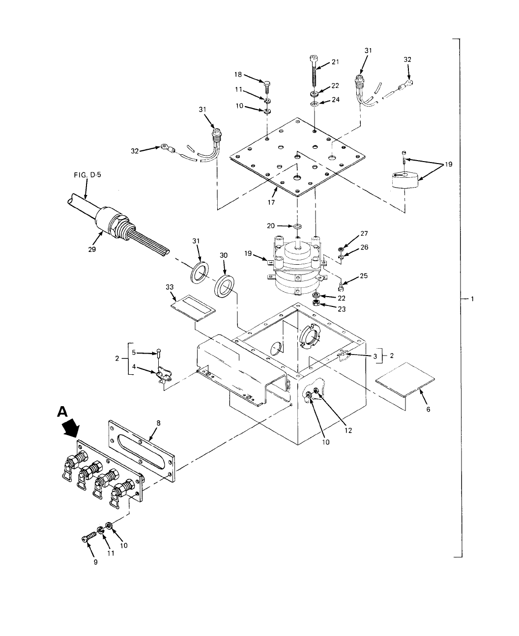
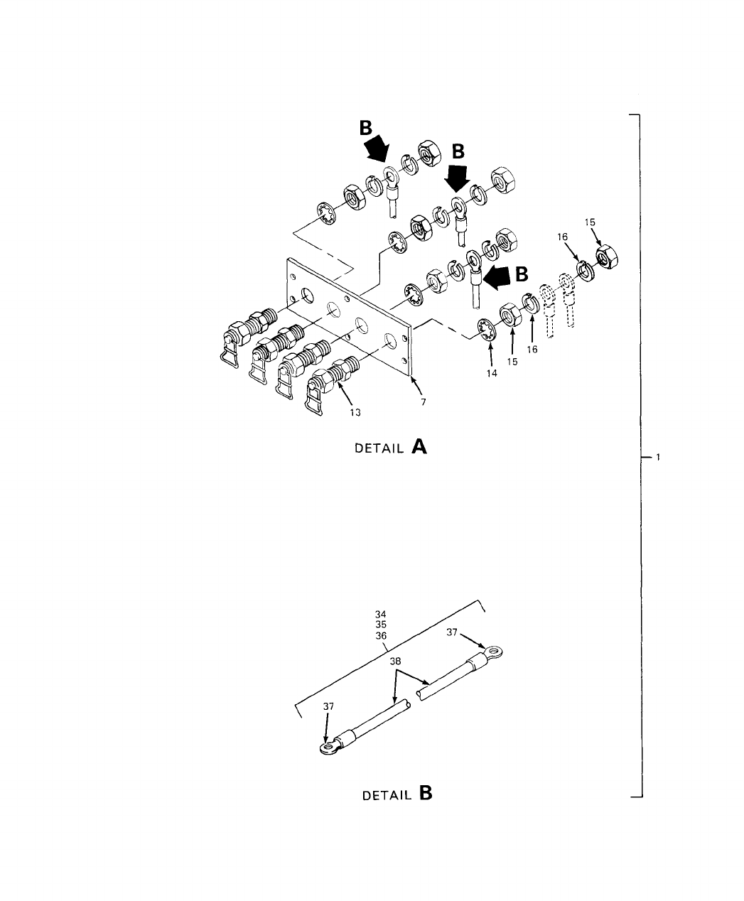
TM 5-6115-631-14&P
Figure D-8. Four- Wire Switch Box (Sheet 2 of 2).
D-33/(D-34 blank)
SECTION II TM5-6115-631-14&P
(1) (2) (3) (4) (5) (6) (7) (8)
ILLUS- SMR CODE USMC DESCRIPTION
TRATION QTY USMC
A B A B C D A B NATIONAL USABLE INC QTY
FIG ITEM AIR REPL STOCK REF NUMBER ON IN PER
NO. NO. ARMY FORCE NAVY USMC SSI FACTOR NUMBER & MFR CODE CODE U/M UNIT EQUIP
0301 - SWITCH BOX
D-8 1 PBOFH BOX, SWITCH (FOUR-WIRE) EA 1
13220E4459 97403
D-8 2 .BOX EA 1
13220E4464 97403
D-8 3 PAFZZ
5310-01-B75-1034
..NUT, CLINCH EA 16
13211E3895-5 97403
D-8 4 PAFZZ ..FASTENER, PANEL EA 2
MIL-F-5591 81349
D-8 5 PAFZZ
5320-00-117-6963
..RIVET, SOLID EA 4
MS20426A4-6 96906
D-8 6 PAOZZ .PLATE, INFORMATION EA 1
13212E3587 97403
D-8 7 PAFZZ
5940-00-105-6331
.BOARD, TERMINAL EA 1
13212E3606 97403
D-8 8 PAOZZ
5330-01-162-8585
.GASKET EA 1
13212E3610 97403
D-8 9 PAOZZ
5305-00-984-6214
.SCREW, MACHINE EA 6
MS35206-267 96906
D-8 10 PAOZZ .WASHER, FLAT EA 28
MS27183-42 96906
D-8 11 PAOZZ
5310-00-045-3296
.LOCKWASHER EA 22
MS35338-43 96906
D-8 12 PAOZZ
5310-00-934-9758
.NUT, PLAIN, HEX EA 6
MS35649-202 96906
D-8 13 PAOZZ
5940-00-021-3321
.POST, TERMINAL EA 4
MS39347-2 96906
D-8 14 PAOZZ
5310-00-022-8834
.LOCKWASHER, INTERNAL TOOTH EA 4
MS35333-108 96906
D-8 15 PAFZZ
5310-00-247-7186
.NUT, PLAIN, HEX EA 8
MS16203-37 96906
D-8 16 PAOZZ
5310-01-004-9129
.LOCKWASHER EA 8
AN961-416S
PAOZZ
5310-00-187-2413
.LOCKWASHER EA 10
AN961-416T
D-8 17 PAFZZ
6110-00-133-9160
.COVER EA 1
13212E3603 97403
D-8 18 PAOZZ .SCREW, MACHINE EA 16
MS35207-264 96906
D-8 19
5930-00-829-3243
.SWITCH, ROTARY EA 1
13205E5023 97403
D-8 20 PAFZZ
5330-00-579-8108
.PACKING, PREFORMED EA 1
MS287745-111 96906
D-35
SECTION II TM5-6115-631-14&P
(1) (2) (3) (4) (5) (6) (7) (8)
ILLUS- SMR CODE USMC DESCRIPTION
TRATION QTY USMC
A B A B C D A B NATIONAL USABLE INC QTY
FIG ITEM AIR REPL STOCK REF NUMBER ON IN PER
NO. NO. ARMY FORCE NAVY USMC SSI FACTOR NUMBER & MFR CODE CODE U/M UNIT EQUIP
0301 - SWITCH BOX - CONT
D-8 21 PAFZZ
5305-00-984-569
.SCREW, MACHINE EA 4
MS35206-315 96906
D-8 22 PAOZZ
5310-00-080-600
.WASHER, FLAT EA 8
MS27183-14 96906
D-8 23 PAOZZ
5310-00-087-4652
.NUT, SELF-LOCKING EA 4
MS51922-17 96906
D-8 24 PAFZZ
5330-00-684-342
.PACKING, PREFORMED EA 4
MS28775-013 96906
D-8 25 PAOZZ
5305-00-954-9003
.SCREW, MACHINE EA 9
MS35215-68 96906
D-8 26 PAOZZ
5310-00-942-510
.LOCKWASHER EA 9
MS35335-89 96906
D-8 27 PAOZZ
5310-00-924-421
.NUT, PLAIN, HEX EA 9
MS51970-1 96906
D-8 28 PAFZZ .TUBE, STUFFING EA 2
13218E5149-6 97403
D-8 29 PAOZZ
5310-01-164-2342
.WASHER EA 2
13218E5139-3 97403
D-8 30 PAOZZ
5330-01-150-9792
.GASKET EA 2
13218E5140-3 97403
D-8 31 PAOOZ
6210-00-406-139
.LIGHT AND WIRE ASSY EA 2
13212E3581-1 97403
D-8 32 PAOZZ
5940-00-113-818
.TERMINAL, LUG EA 4
MS25036-150 96906
D-8 33 XBOZZ .PLATE, WARINING EA 1
13216E7603 97403
D-8 34 MFFZZ .LEAD, ELECTRICAL (W3) EA 1
13212E3609-1 97403
D-8 35 MFFZZ .LEAD, ELECTRICAL (W4) EA 1
13212E3609-2 97403
D-8 36 MFFZZ .LEAD, ELECTRICAL (W5) EA 1
13212E3609-3 97403
D-8 37 PAOZZ
5940-00-557-434
..TERMINAL, LUG EA 6
MS25036-120
D-8 38 PAOZZ
6145-00-578-659
..WIRE, ELECTRICAL FT AR
M5086/2-6
D-36
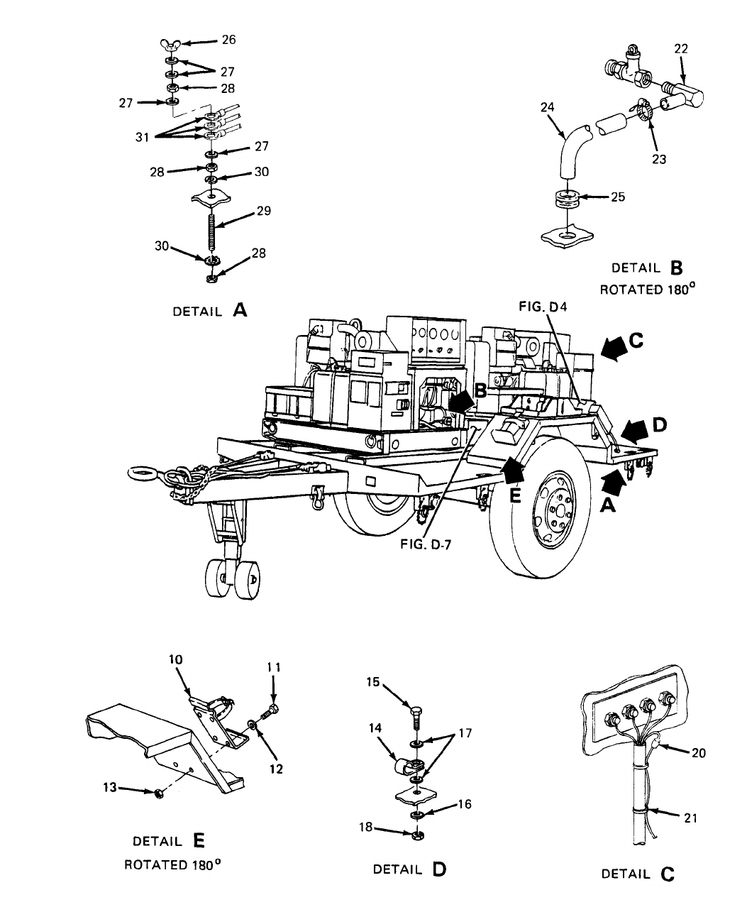
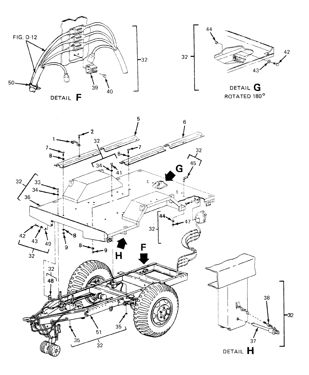
FIG D-12
TM 5-6115-631-14&P
Figure D-9. Trailer Body (Sheet 2 of 2).
D-39/(D-40 blank)
SECTION II TM5-6115-631-14&P
(1) (2) (3) (4) (5) (6) (7) (8)
ILLUS- SMR CODE USMC DESCRIPTION
TRATION QTY USMC
A B A B C D A B NATIONAL USABLE INC QTY
FIG ITEM AIR REPL STOCK REF NUMBER ON IN PER
NO. NO. ARMY FORCE NAVY USMC SSI FACTOR NUMBER & MFR CODE CODE U/M UNIT EQUIP
GROUP 05 - TRAILER
05 - BODY
D-9 1 PAOZZ 5340-00-229-0340 LOOP, STRAP FASTENER EA 4
MS51939-3 96906
D-9 2 PAOZZ 5305-00-957-7086 SCREW, MACHINE EA 8
MS24693-S273 96906
D-9 3 PAOZZ 5310-00-014-5850 WASHER, FLAT EA 8
MS27183-42 96906
D-9 4 PAOZZ 5310-00-059-9263 NUT, SELF-LOCKING EA 8
MS21046C3 96906
D-9 5 XBFZZ RAIL, MOUNTING, CURBSIDE EA 1
13220E4457-1 97403
D-9 6 XBFZZ RAIL, MOUNTING, ROADSIDE EA 1
13220E4458-1 97403
D-9 7 XDOZZ 5305-00-782-9495 SCREW, CAP, HEX EA 16
MS90725-111 96906
D-9 8 PAOZZ 5310-00-809-5998 WASHER, FLAT EA 32
MS27183-18 96906
D-9 9 PAOZZ 5310-00-225-6993 NUT, SELF-LOCKING EA 16
MS51922-33 96906
D-9 10 PAOZZ 4120-00-223-4857 BRACKET, FIRE EXTINGUISHER EA 2
13214E1235 97403
D-9 11 PAOZZ 5305-00-068-0502 SCREW, CAP, HEX EA 8
MS90725-6 96906
D-9 12 PAOZZ 5310-00-809-4058 WASHER, FLAT EA 16
MS27183-10 96906
D-9 13 PAOZZ 5310-00-088-1251 NUT, SELF-LOCKING EA 8
MS51922-1 96906
D-9 14 PAOZZ 5340-00-930-1754 CLAMP, LOOP EA 1
MS21334-2 96906
D-9 15 PAOZZ 5305-00-984-6211 SCREW, MACHINE EA 1
MS35206-264 96906
D-9 16 PAOZZ 5310-00-045-3296 LOCKWASHER EA 1
MS35338-43 96906
D-9 17 PAOZZ 5310-00-809-8546 WASHER, FLAT EA 2
MS27183-8 96906
D-9 18 PAOZZ 5310-00-934-9758 NUT, PLAIN, HEX EA 1
MS35649-202 96906
D-9 19 PAFZZ WIRE, NO. 6 AWG FT AR
QQW-343C06BIB 81348
D-9 20 SLEEVE EA 1
MS51844-49 96906
D-41
SECTION II TM5-6115-631-14&P
(1) (2) (3) (4) (5) (6) (7) (8)
ILLUS- SMR CODE USMC DESCRIPTION
TRATION QTY USMC
A B A B C D A B NATIONAL USABLE INC QTY
FIG ITEM AIR REPL STOCK REF NUMBER ON IN PER
NO. NO. ARMY FORCE NAVY USMC SSI FACTOR NUMBER & MFR CODE CODE U/M UNIT EQUIP
05 - BODY - CONT
D-9 21 PAOZZ
5975-00-074-2072
STRAP, TIEDOWN EA AR
MS3367-1-9 96906
D-9 22
4730-00-809-9703
ELBOW, PIPE TO HOSE EA 2
MS24519-9 96906
D-9 23 PAOZZ
4730-00-908-319
CLAMP, HOSE EA 2
MS35842-11 96906
D-9 24 HOSE, RUBBER EA 2
MIL-H-6000 81349
D-9 25 PAFZZ
5325-00-903-590
GROMMET EA 2
MS35489-112 96906
D-9 26 PAOZZ
5310-00-543-471
NUT, PLAIN, WING EA 1
MS35425-28 96906
D-9 27 PAOZZ
5310-01-004-912
WASHER, FLAT EA 4
AN961-616S 81352
PAOZZ
5310-00-187-2413
WASHER, FLAT EA 4
AN961-616T 81352
D-9 28 PAOZZ
5310-01-026-582
NUT, PLAIN, HEX EA 3
MS16203-39 96906
D-9 29 PAOZZ
5307-00-227-174
STUD EA 1
13214E1223 97403
D-9 30 PAOZZ
5310-00-913-977
LOCKWASHER EA 2
MS35335-91 96906
D-9 31 PAOZZ
5940-00-115-4992
TERMINAL, LUG EA 5
MS20659-110 96906
D-9 32 MDOFF TRAILER ASSY EA 1
13226E5858 97403
D-9 33 PAOZZ
5305-01-186-714
.SCREW, CAP, HEX EA 2
13218E0021-41 97403
D-9 34 PAOZZ
5310-00-823-8803
.WASHER, FLAT EA 16
MS27183-21 96906
D-9 35 PAOZZ
5310-00-269-404
.NUT, SELF-LOCKING EA 16
MS51922-49 96906
D-9 36 XAFFF .FLATBED, TRAILER EA 1
13226E5857 97403
D-9 37 PAFZZ
5340-00-878-526
..PIN, QUICK-RELEASE EA 12
MS17990C613 96906
D-9 38 ..CHAIN, WELDLESS EA 12
13218E0025-4 97403
D-9 39
..CLIP, SPRING TENSIO
EA 8
M24066/2-128
D-9 40
5320-00-637-606
..RIVET, SOLID EA 16
MS20427-4C5 96906
D-42
SECTION II TM5-6115-631-14&P
(1) (2) (3) (4) (5) (6) (7) (8)
ILLUS- SMR CODE USMC DESCRIPTION
TRATION QTY USMC
A B A B C D A B NATIONAL USABLE INC QTY
FIG ITEM AIR REPL STOCK REF NUMBER ON IN PER
NO. NO. ARMY FORCE NAVY USMC SSI FACTOR NUMBER & MFR CODE CODE U/M UNIT EQUIP
05 - BODY - CONT
D-9 41 PAOZZ
5305-00-724-591
.SCREW, CAP, HEX EA 14
MS90725-163 96906
D-9 42 PAOZZ
5305-00-269-321
.SCREW, CAP, HEX EA 16
MS90725-60 96906
D-9 43 PAOZZ
5310-00-080-600
.WASHER, FLAT EA 16
MS27183-14 96906
D-9 44 PAOZZ
5310-00-087-4652
.NUT, SELF-LOCKING EA 12
MS51922-17 96906
D-9 45 PAOZZ .RING, LIFTING EA 2
13226E7730-6 97403
D-9 46 PAOZZ
5310-00-584-788
.WASHER EA 2
MS35338-51 96906
D-9 47 PAOZZ
5310-00-832-971
.NUT, SELF-LOCKING EA 2
MS51922-61 96906
D-9 48 .SHIM EA AR
13212E3590 97403
D-9 49 PAOZZ
5310-00-637-954
.LOCKWASHER EA 4
MS35338-46 96906
D-9 50 PAOZZ
5975-00-074-2072
.STRAP, TIEDOWN EA AR
MS3367-1-9 96906
D-9 51 MDOFF .CHASSIS, TRAILER EA 1
13226E7734 97403
D-43
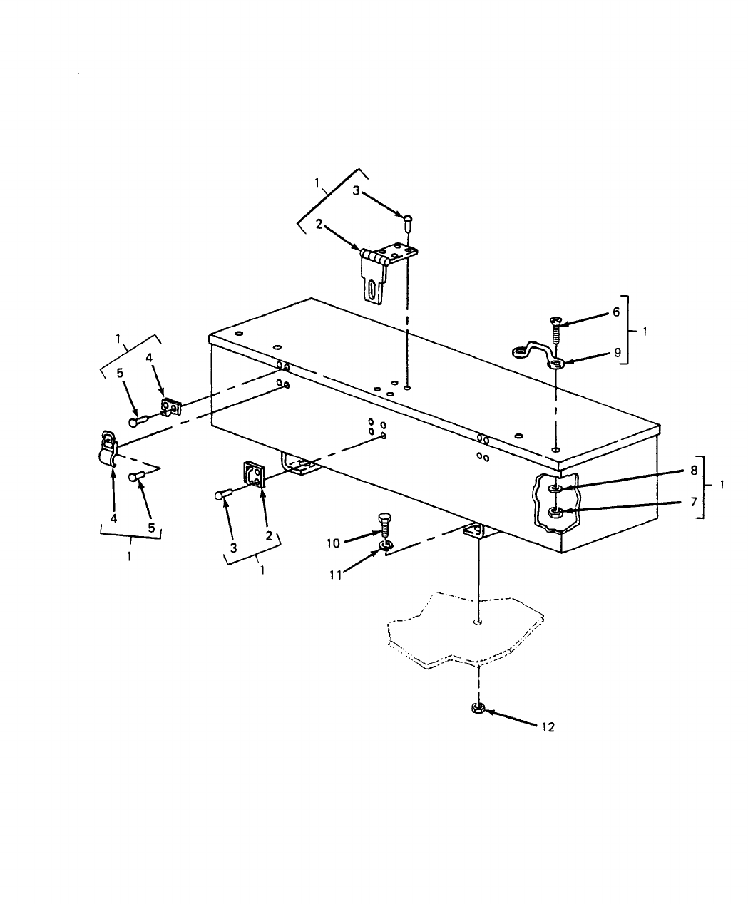
SECTION II TM5-6115-631-14&P
(1) (2) (3) (4) (5) (6) (7) (8)
ILLUS- SMR CODE USMC DESCRIPTION
TRATION QTY USMC
A B A B C D A B NATIONAL USABLE INC QTY
FIG ITEM AIR REPL STOCK REF NUMBER ON IN PER
NO. NO. ARMY FORCE NAVY USMC SSI FACTOR NUMBER & MFR CODE CODE U/M UNIT EQUIP
05 - ACCESSORY BOX
D-10 1 PBOOO
6115-01-230-067
BOX, ACCESSORY EA 1
13226E7737 97403
D-10 2 PBFZZ
5340-00-234-8422
.HASP, HINGED EA 1
MS27969-4 96906
D-10 3 PAFZZ
5320-01-168-309
.RIVET, SOLID EA 8
MS9460-102 96906
D-10 4 PAFZZ
5340-00-975-212
.CATCH, CLAMPING AND STRIKE EA 2
MS18015-1 96906
D-10 5 PAFZZ
5320-00-753-383
.RIVET, SOLID EA 8
MS20613-4P5 96906
D-10 6 PAOZZ
5305-00-957-708
.SCREW, MACHINE EA 4
MS24693-S273 96906
D-10 7 PAOZZ
5310-00-059-9263
.NUT, SELF-LOCKING EA 4
MS21046C3 96906
D-10 8 PAOZZ
5310-00-014-585
.WASHER, FLAT EA 4
MS27183-42 96906
D-10 9 PAOZZ
5340-00-229-034
.LOOP, STRAP FASTENER EA 2
MS51939-3 96906
D-10 10 PAOZZ
5306-00-225-849
SCREW, CAP, HEX EA 4
MS90725-31 96906
D-10 11 PAOZZ
5310-00-407-956
LOCKWASHER EA 4
MS35338-45 96906
D-10 12 PAOZZ
5310-00-880-774
NUT, PLAIN, HEX EA 4
MS51967-5 96906
D-45
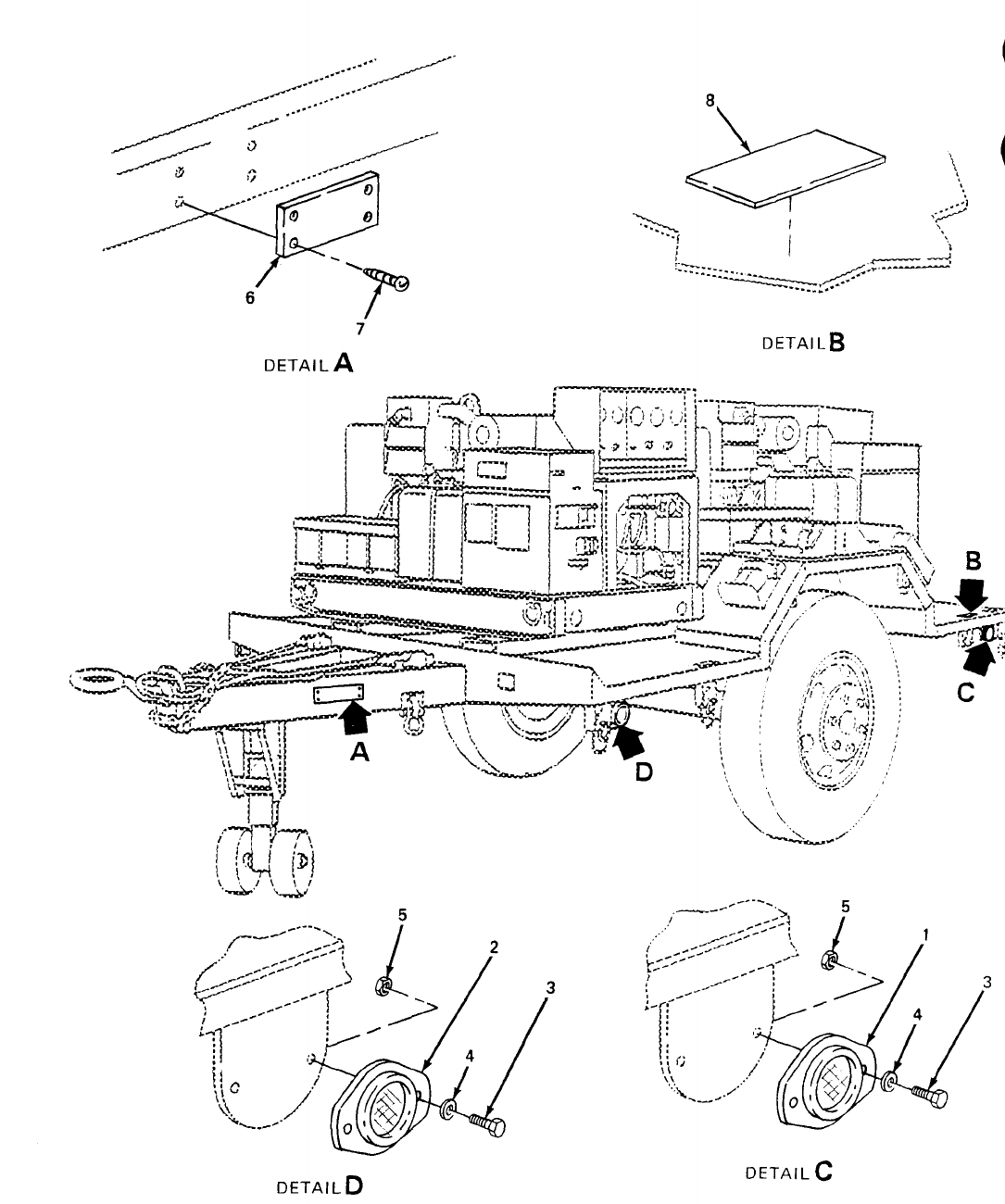
SECTION II TM5-6115-631-14&P
(1) (2) (3) (4) (5) (6) (7) (8)
ILLUS- SMR CODE USMC DESCRIPTION
TRATION QTY USMC
A B A B C D A B NATIONAL USABLE INC QTY
FIG ITEM AIR REPL STOCK REF NUMBER ON IN PER
NO. NO. ARMY FORCE NAVY USMC SSI FACTOR NUMBER & MFR CODE CODE U/M UNIT EQUIP
05 - DATA PLATES AND RELECTORS
D-11 1 PAOZZ 9905-00-205-2795 REFLECTOR, RED EA 4
MS35387-1 96906
D-11 2 PAOZZ 9905-00-202-3639 REFLECTOR, AMBER EA 2
MS35387-2 96906
D-11 3 PAOZZ 5305-00-068-0500 SCREW, CAP, HEX EA 12
MS90725-3 96906
D-11 4 PAOZZ 5310-00-809-4058 WASHER, FLAT EA 12
MS27183-10 96906
D-11 5 PAOZZ 5310-00-088-1251 NUT, SELF-LOCKING EA 12
MS51922-1 96906
D-11 6 PAOZZ PLATE, IDENTIFICATION EA 1
13220E4463-1 97403
D-11 7 PAOZZ 5305-00-253-5614 SCREW, DRIVE EA 4
MS21318-20 96906
D-11 8 PAOZZ 9905-01-085-7703 PLATE, IDENTIFICATION EA 1
13205E4918 97403
D-47
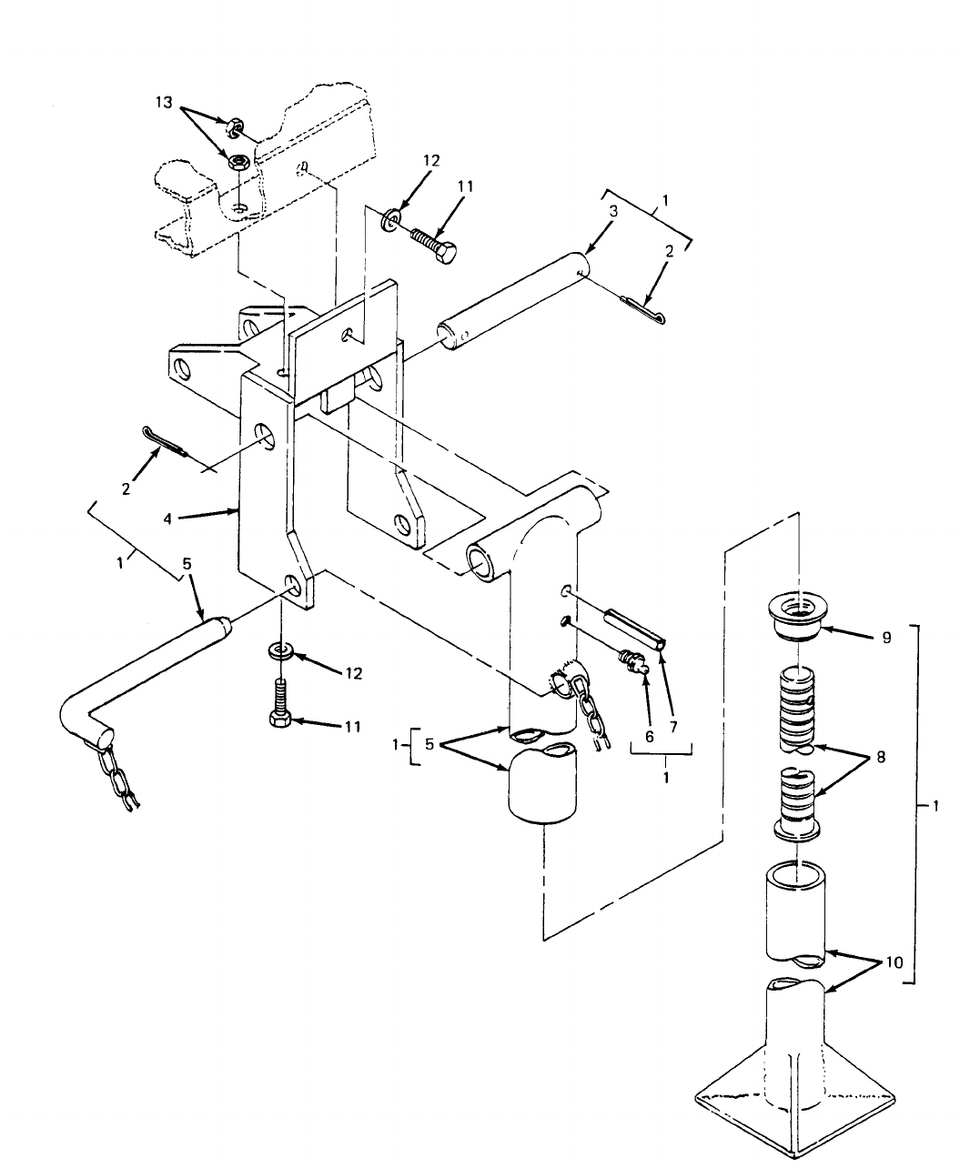
SECTION II TM5-6115-631-14&P
(1) (2) (3) (4) (5) (6) (7) (8)
ILLUS- SMR CODE USMC DESCRIPTION
TRATION QTY USMC
A B A B C D A B NATIONAL USABLE INC QTY
FIG ITEM AIR REPL STOCK REF NUMBER ON IN PER
NO. NO. ARMY FORCE NAVY USMC SSI FACTOR NUMBER & MFR CODE CODE U/M UNIT EQUIP
05 - FRAME
D-12 1 XBFFZ
2950-00-420-892
LEG PROP ASSEMBLY EA 1
13214E1206 97403
D-12 2 PAOZZ
5315-00-839-5822
.PIN, COTTER EA 2
MS24665-353 96906
D-12 3 XBOZZ
5315-01-162-0143
.SHAFT EA 1
13214E1209 97403
D-12 4 XBOZZ
6115-01-220-154
.BRACKET EA 1
13214E1207 97403
D-12 5 XOBZZ
2590-00-453-897
.LEG, UPPER EA 1
13214E1208 97403
D-12 6 PAOZZ
4730-00-172-004
.FITTING, LUBRICATION
EA 1
MS15006-1 96906
D-12 7 XBOZZ
5315-00-838-458
.PIN, SPRING EA 1
MS16562-66 96906
D-12 8 XBOZZ
5315-01-158-214
.SCREW EA 1
13214E1210
D-12 9 PAOZZ
5310-01-149-086
.NUT EA 1
13214E1211 97403
D-12 10 XBOZZ
2590-01-167-859
BASE, LEG EA 1
13214E1212 97403
D-12 11 PAOZZ
5305-00-269-3213
SCREW, CAP, HEX EA 3
MS90725-62 96906
D-12 12 PAOZZ
5310-00-080-600
WASHER, FLAT EA 3
MS27183-14 96906
D-12 13 PAOZZ
5310-00-087-4652
NUT, SELF-LOCKING EA 3
MS51922-17
D-49
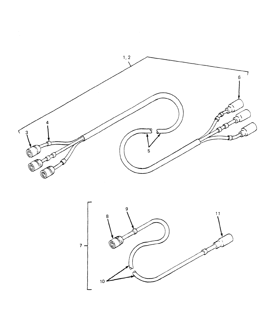
SECTION II TM5-6115-631-14&P
(1) (2) (3) (4) (5) (6) (7) (8)
ILLUS- SMR CODE USMC DESCRIPTION
TRATION QTY USMC
A B A B C D A B NATIONAL USABLE INC QTY
FIG ITEM AIR REPL STOCK REF NUMBER ON IN PER
NO. NO. ARMY FORCE NAVY USMC SSI FACTOR NUMBER & MFR CODE CODE U/M UNIT EQUIP
05 - TAILLIGHT CABLE ASSEMBLIES
AND ELECTRICAL LEADS
D-13 1 MOOFF
6150-01-166-9112
CABLE ASSY, ROADSIDE EA 1
13216E7479-1 97403
D-13 2 MOOFF
6150-01-166-9111
CABLE ASSY, CURBSIDE EA 1
13216E7479-2 97403
D-13 3 PAOZZ
5935-00-167-7775
.CONNECTOR, PLUG EA 6
MS27144-1 96906
D-13 4 PAOZZ
9905-01-B75-1051
.BAND, MARKER EA 20
M43436/1-6 81349
D-13 5 MFFZZ .CABLE EA 2
M13486/7 81349
TYPE I, CL. B
D-13 6 PAOZZ
5935-00-462-6603
.CONNECTOR, PLUG EA 6
MS27142-2 96906
D-13 7 MOOFF
6150-01-166-9135
.LEAD, ELECTICAL EA 2
13216E7476 97403
D-13 8 PAOZZ
5935-00-167-7775
.CONNECTOR, PLUG EA 2
MS27144-1 96906
STYLE I
D-13 9 PAOZZ
9905-01-B75-1051
.BAND, MARKER EA 4
M43436/1-6 81349
D-13 10 PAOZZ
6145-00-152-6499
.CABLE EA 2
M13486/1-5 81349
TYPE I, CL. A
D-13 11 PAOZZ
5935-00-462-6603
.CONNECTOR, PLUG EA 2
MS27142-2 96906
SECTION III. SPECIAL TOOLS, TEST AND SUPPORT EQUIPMENT
NOT APPLICABLE
D-51/(D-52 BLANK)
TM5-6115-631-14&P
SECTION IV. NATIONAL STOCK NUMBER AND REFERENCE NUMBER INDEX
FIGURE ITEM FIGURE ITEM
NSN NO. NO. NSN NO. NO.
2540-00-924-8478 D-1 9 5310-00-809-4058 D-11 4
2540-00-926-1003 D-1 10 5310-00-809-5998 D-9 8
2590-00-420-8929 D-12 1 5310-00-809-8546 D-6 11
4210-00-223-4857 D-9 10 D-9 17
4730-00-809-9703 D-9 22 5310-00-823-8803 D-9 34
4730-00-908-3194 D-9 23 5310-00-832-9719 D-9 47
5305-00-068-0500 D-11 3 5310-00-880-7744 D-10 12
5305-00-068-0502 D-9 11 5310-00-913-9776 D-9 30
5305-00-253-5614 D-11 7 5310-00-924-4218 D-6 28
5305-00-269-3211 D-9 42 D-7 27
5305-00-269-3213 D-12 4 D-8 27
5305-00-719-5235 D-2 2 5310-00-934-9758 D-6 13
5305-00-724-5911 D-9 41 D-7 12
5305-00-782-9495 D-9 7 D-8 12
5305-00-954-9003 D-6 26 D-9 18
D-7 25 5310-00-942-5109 D-6 27
D-8 25 D-7 26
5305-00-957-7086 D-9 2 D-8 26
D-10 6 5310-01-B75-1034 D-7 3
5305-00-984-5695 D-6 22 D-8 3
D-7 21 5310-01-004-9129 D-7 16
D-8 21 D-8 16
5305-00-984-6211 D-9 15 D-9 27
5305-00-984-6214 D-6 10 5310-01-026-5824 D-6 44
D-7 9 D-9 28
D-8 9 5310-01-150-5922 D-2 4
5305-00-988-1727 D-7 37 5310-01-164-2342 D-7 29
5305-00-989-7434 D-6 19 D-8 29
5305-01-186-7145 D-9 33 5310-01-190-2217 D-6 30
5307-00-227-1741 D-6 43 5315-00-839-5822 D-12 2
D-9 29 5315-01-162-0143 D-12 3
5310-00-014-5850 D-9 3 5320-00-117-6963 D-7 5
D-10 8 D-8 5
5310-00-022-8834 D-6 15 5320-00-637-6068 D-9 40
D-7 14 5320-00-721-5244 D-6 5
D-8 14 D-6 7
5310-00-022-8847 D-6 41 5320-00-753-3830 D-10 5
5310-00-045-3296 D-6 12 5320-00-954-0113 D-6 37
D-7 11 D-7 36
D-8 11 5320-01-168-3097 D-10 3
D-9 16 5325-00-903-5909 D-9 25
5310-00-059-9263 D-9 4 5325-01-B75-3182 D-1 3
D-10 7 5330-00-579-8108 D-6 21
5310-00-080-6004 D-6 23 D-7 20
D-7 22 D-8 20
D-8 22 5330-00-684-3420 D-6 25
D-9 43 D-7 24
D-12 5 D-8 24
5310-00-087-4652 D-6 24 5330-01-150-9792 D-7 30
D-7 23 D-8 30
D-8 23 5330-01-162-8585 D-6 9
D-9 44 D-7 8
D-12 6 D-8 8
5310-00-088-1251 D-7 39 5330-01-187-3493 D-6 31
D-9 13 5340-00-057-6956 D-1 5
D-11 5 5340-00-078-7029 D-1 4
5310-00-184-8971 D-6 17 5340-00-229-0340 D-9 1
D-6 39 5340-00-234-8422 D-10 2
5310-00-187-2413 D-6 40 5340-00-878-5264 D-9 37
D-7 16 5340-00-930-1754 D-9 14
D-8 16 5340-00-975-2126 D-10 4
D-9 27 5365-01-031-9674 D-1 7
5310-00-225-6993 D-9 9 5930-00-829-3243 D-6 20
5310-00-247-7186 D-6 16 D-7 19
D-7 15 D-8 19
D-8 15 5935-00-167-7775 D-13 3
5310-00-269-4040 D-9 35 D-13 8
5310-00-407-9566 D-10 11 5935-00-462-6603 D-13 6
5310-00-543-4717 D-6 38 D-13 11
D-9 26 5940-00-021-3321 D-6 14
5310-00-584-5272 D-2 3 D-7 13
5310-00-584-7888 D-9 46 D-8 13
5310-00-584-7995 D-6 42 5940-00-105-6331 D-6 8
5310-00-637-9541 D-9 49 D-7 7
5310-00-809-4058 D-7 38 D-8 7
D-9 12 5940-00-113-8184 D-6 33
D-53
TM5-6115-631-14&P
Section IV. NATIONAL STOCK NUMBER AND REFERENCE NUMBER INDEX - CONT
FIGURE ITEM FIGURE ITEM
NSN NO. NO. NSN NO. NO.
5940-00-113-8184 D-7 32 6115-01-206-1271 D-1 1
D-8 32 6115-01-230-0677 D-10 1
5940-00-113-8190 D-3 4 6145-00-152-6499 D-13 10
5940-00-113-8191 D-7 48 6145-00-578-6594 D-6 50
5940-00-113-9831 D-7 49 D-7 46
5940-00-113-9833 D-4 6 D-8 38
5940-00-115-4992 D-9 31 6150-01-B76-1221 D-4 2
5940-00-115-5007 D-4 5 6150-01-166-9111 D-13 2
5940-00-557-4344 D-5 3 6150-01-166-9112 D-13 1
D-6 49 6150-01-166-9135 D-13 7
D-7 45 6210-00-253-0688 D-6 32
D-8 37 6210-00-406-1398 D-7 31
5940-01-B75-1040 D-7 40 D-8 31
5975-00-074-2072 D-9 21 9905-00-202-3639 D-11 2
D-9 50 9905-00-205-2795 D-11 1
5975-01-211-3346 D-7 28 9905-01-B75-1051 D-13 4
6110-00-133-9160 D-6 18 D-13 9
D-7 17 9905-01-085-7703 D-11 8
D-8 18 9905-01-875-3181 D-3 2
6115-00-465-1044 D-2 1
D-54
TM5-6115-631-14&P
SECTION IV. NATIONAL STOCK NUMBER AND REFERENCE NUMBER INDEX (CONT)
REFERENCE FIG. ITEM REFERENCE FIG. ITEM
NUMBER FSCM NO. NO. NUMBER FSCM NO. NO.
AN961-416S D-7 16 MS27183-21 96906 D-9 34
D-8 16 MS27183-42 96906 D-7 10
AN961-416T D-7 16 D-8 10
D-8 16 D-9 3
AN961-616S 81352 D-9 27 D-10 8
AN961-616T 81352 D-6 40 MS27969-4 96906 D-10 2
D-9 27 MS28775-013 96906 D-6 25
C0-04HDE(4/1- 81349 D-3 5 D-7 24
4/12R) D-8 24
C0-04H0E(4/6) D-5 6 MS28775-111 96906 D-6 21
C0-04-HDF-1620 81349 D-4 3 D-7 20
(4/1-4/8R) D-8 20
MEP-002A 30554 D-2 1 MS3367-1-9 96906 D-9 21
MIL-F-5591 81349 D-6 4 D-6 50
D-7 4 MS35206-264 96906 D-9 15
D-8 4 MS35206-267 96906 D-6 10
MIL-G-16491 D-1 3 D-7 9
MIL-H-6000 81349 D-9 24 D-8 9
MIL-P-15024/8 81349 D-3 2 MS35206-283 96906 D-7 37
TYPE K2 D-4 4 MS35206-315 96906 D-6 22
MIL-S-43770/1- D-1 8 D-7 21
SWZE3 D-8 21
MIL-R-24049 81349 D-1 2 MS35207-263 96906 D-6 19
MS16203-27 96906 D-6 42 MS35207-264 96906 D-7 18
MS16203-37 96906 D-6 16 MS35215-68 96906 D-6 26
D-7 15 D-7 25
D-8 15 D-8 25
MS16203-39 96906 D-6 44 MS35333-108 96906 D-6 15
D-9 28 D-7 14
MS16535-77 96906 D-6 7 D-8 14
MS16535-155 96906 D-6 37 MS35333-110 96906 D-6 41
D-7 36 MS35335-89 96906 D-6 27
MS17990C 96906 D-9 37 D-7 26
MS18015-1 96906 D-10 4 D-8 26
MS20426A4-6 96906 D-6 5 MS35335-91 96906 D-9 30
D-7 5 MS35338-43 96906 D-6 12
D-8 5 D-7 11
MS20427-4C5 96906 D-9 40 D-8 11
MS20613-4P5 96906 D-10 5 D-9 16
MS20659-110 96906 D-9 31 MS35338-45 96906 D-10 11
MS21046C3 96906 D-9 4 MS35338-46 96906 D-9 49
D-10 7 MS35338-48 96906 D-2 3
MS21318-20 96906 D-11 7 MS35338-51 96906 D-9 46
MS21334-2 96906 D-9 14 MS35338-101 96906 D-6 17
MS24519-9 96906 D-9 22 MS35338-103 96906 D-6 39
MS24665-353 96906 D-12 2 MS35387-1 96906 D-11 1
MS24693-S273 96906 D-9 2 MS35425-28 96906 D-6 38
D-10 6 D-9 26
MS25036-120 96906 D-5 3 MS35489-112 96906 D-9 25
D-6 49 MS35649-202 96906 D-6 13
D-7 45 D-7 12
D-8 37 D-8 12
MS25036-122 96906 D-3 4 D-9 18
MS25036-123 96906 D-3 3 MS35842-11 96906 D-9 23
MS25036-127 96906 D-7 48 MS39347-2 96906 D-6 14
MS25036-128 96906 D-7 49 D-7 13
MS25036-130 96906 D-4 5 MS35387-2 96906 D-11 2
MS25036-131 96906 D-4 6 MS39347-2 96906 D-8 13
MS25036-150 96906 D-6 33 MS51844-49 96906 D-9 20
D-7 32 MS51922-1 96906 D-7 39
D-8 32 D-9 13
MS27130-S-99 96906 D-6 3 D-11 5
MS27142-2 96906 D-13 6 MS51922-17 96906 D-6 24
D-13 11 D-7 23
MS27144-1 96906 D-13 3 D-8 23
MS27144-1 96906 D-13 8 D-9 44
STYLE 1 D-12 6
MS27183-8 96906 D-6 11 MS51922-33 96906 D-9 9
D-9 17 MS51922-49 96906 D-9 35
MS27183-10 96906 D-7 38 MS51922-61 96906 D-9 47
D-9 12 MS51925-1 96906 D-1 7
D-11 4 MS51926-3 96906 D-1 4
MS27183-14 96906 D-6 23 MS51929-2 D-1 5
D-7 22 MS51939-3 96906 D-9 1
D-8 22 MS51967-5 96906 D-10 12
D-9 43 MS51970-1 96906 D-6 28
D-12 5 D-7 27
MS27183-18 96906 D-9 8
D-55
TM5-6115-631-14&P
SECTION IV. NATIONAL STOCK NUMBER AND REFERENCE NUMBER INDEX (CONT)
REFERENCE FIG. ITEM REFERENCE FIG. ITEM
NUMBER FSCM NO. NO. NUMBER FSCM NO. NO.
MS51970-1 D-8 27 13212E609-2 97403 D-7 43
MS90725-3 96906 D-11 3 D-8 35
MS90725-6 96906 D-9 11 13212E3609-3 97403 D-6 47
MS90725-60 96906 D-9 42 D-7 44
MS90725-62 96906 D-12 4 D-8 36
MS90725-111 96906 D-9 7 13212E3609-4 97403 D-6 48
MS90725-163 96906 D-9 41 13212E3610 97403 D-6 9
MS90727-114 96906 D-2 2 D-7 8
MS9460-102 96906 D-10 3 D-8 8
M13486/1-5 81349 D-13 10 13214E1206 97403 D-12 1
TYPE 1 CLA 13214E1209 97403 D-12 3
M13486/7 TYPE 1 81349 D-13 5 13214E1223 97403 D-6 43
CLB D-9 29
M23053/5 81349 D-5 4 13214E1235 97403 D-9 10
D-5 5 13214E1392 97403 D-1 6
M23053/5-107-5 81349 D-4 7 13216E7476 97403 D-13 7
M23053/5-109-5 81349 D-4 9 13216E7479-1 97403 D-13 1
M24066/2-128 D-9 39 13216E7479-2 97403 D-13 2
M43436/1-6 81349 D-13 4 13216E7603 97403 D-6 34
D-13 9 D-7 33
M5086/2-2 81349 D-7 50 D-8 33
M5086/2-6 81349 D-6 50 13218E0021-41 97403 D-9 33
D-7 46 13218E0025-4 97403 D-9 38
D-8 38 13218E5139-3 97403 D-7 29
QQW343C06 81349 D-4 8 D-8 29
QQ-W-343C06B1B 81349 D-9 19 13218E5139-4 97403 D-6 30
13205E4918 97403 D-11 8 13218E5140-3 97403 D-7 30
13205E5023 97403 D-6 20 D-8 30
D-7 19 13218E5140-4 97403 D-6 31
D-8 19 13218E5149-6 97403 D-8 28
13206E4482-2 97403 D-2 4 13218E5149-8 97403 D-6 29
13211E3895-5 97403 D-7 3 13218E5149-10 97403 D-7 28
13211E3895-5 97403 D-8 3 13220E4457-1 97403 D-9 5
13212E3581-1 97403 D-7 31 13220E4458-1 97403 D-9 6
D-8 31 13220E4459 97403 D-7 1
13212E3581-2 97403 D-6 32 D-8 1
D-6 33 13220E4460-1 97403 D-5 1
13212E3586-4 97403 D-7 47 13220E4461-1 97403 D-5 2
13212E3587 97403 D-6 6 13220E4463-1 97403 D-11 6
D7 6 13220E4464 97403 D-7 2
D-8 6 D-8 2
13212E3590 97403 D-9 48 13226E5857 97403 D-9 36
13212E3597-1 97403 D-1 9 13226E5858 97403 D-9 32
13212E3597-2 97403 D-1 10 13226E5888-1 97403 D-4 1
13212E3601-2 97403 D-6 1 13226E5888-2 97403 D-4 2
13212E3602 97403 D-6 2 13226E5889-1 97403 D-6 35
13212E3603 97403 D-6 18 D-7 34
D-7 17 13226E5889-2 97403 D-6 36
D-8 18 D-7 35
13212E3606 97403 D-6 8 13226E6011-1 97403 D-7 40
D-7 7 13226E6012 97403 D-7 41
D-8 7 13226E7730-6 97403 D-9 45
13212E6309-1 97403 D-6 45 13226E7734 97403 D-9 51
D-7 42 13226E7737 97403 D-10 1
D-8 34 13226E7740 97403 D-1 1
13212E3609-2 97403 D-6 46 13227E0121 97403 D-3 1
SECTION V. REFERENCE DESIGNATOR INDEX
NOT APPLICABLE
D-56

TM 5-6115-631-14&P
By Order of the Secretary of the Army:
CARL E. VUONO
Official:
General, United States Army
Chief of Staff
R. L. DILWORTH
Brigadier General, United States Army
The Adjutant General
DISTRIBUTION:
To be distributed in accordance with DA Form 12-25A, Operator, Unit, Direct Support
and General Support Maintenance Requirements for Generator Set, Diesel Engine Driven,
Trailer Mounted.
a*
U.S.
GOVERNMENT PRINTING
OFFICE:
1988-554-1 69/87077
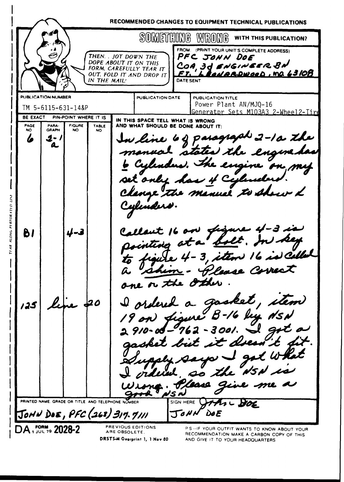

The Metric System and Equivalents
Linear Measure
Liquid Measure
1 centimeter = 10 millimeters = .39 inch
1 decimeter = 10 centimeters = 3.94 inches
1 meter = 10 decimeters = 39.37 inches
1 dekameter = 10 meters = 32.8 feet
1 hectometer = 10 dekameters = 328.08 feet
1 kilometer = 10 hectometers = 3,280.8 feet
Weights
1 centigram = 10 milligrams = .15 grain
1 decigram = 10 centigrams = 1.54 grains
1 gram = 10 decigram = .035 ounce
1 dekagram = 10 grams .35 ounce
1 hectogram = 10 dekagrams = 3.52 ounces
1 kilogram = 10 hectograms = 2.2 pounds
1 quintal = 100 kilograms = 220.46 pounds
I metric ton = 10 quintals = 1.1 short tons
inches
feet
yards
miles
square inches
square feet
square yards
square miles
acres
cubic feet
cubic yards
fluid ounces
pints
quarts
gallons
ounces
pounds
short tons
pound-feet
pound-inches
To
1 centiliter = 10 milliters = .34 fl. ounce
1 deciliter = 10 centiliters = 3.38 fl. ounces
1 liter = 10 deciliters = 33.81 fl. ounces
1 dekaliter = 10 liters = 2.64 gallons
1 hectoliter = 10 dekaliters = 26.42 gallons
1 kiloliter = 10 hectoliters = 264.18 gallons
Square Measure
1 sq. centimeter = 100 sq. millimeters = .155 sq. inch
1 sq. decimeter = 100 sq. centimeters = 15.5 sq. inches
1 sq. meter (centare) = 100 sq. decimeters = 10.76 sq. feet
1 sq. dekameter (are) = 100 sq. meters = 1,076.4 sq. feet
1 sq. hectometer (hectare) = 100 sq. dekameters = 2.47 acres
1 sq. kilometer = 100 sq. hectometers = .386 sq. mile
Cubic Measure
1 cu. centimeter = 1000 cu. millimeters = .06 cu. inch
1 cu. decimeter = 1000 cu. centimeters = 61.02 cu. inches
1 cu. meter = 1000 cu. decimeters = 35.31 cu. feet
Approximate Conversion Factors
centimeters
meters
meters
kilometers
square centimeters
square meters
square meters
square kilometers
square hectometers
cubic meters
cubic meters
milliliters
liters
liters
liters
grams
kilograms
metric tons
newton-meters
newton-meters
Multiply by
2.540
.305
.914
1.609
6.451
.093
.836
2.590
.405
.028
.765
29,573
.473
.946
3.785
28.349
.454
.907
1.356
.11296
To change
ounce-inches
centimeters
meters
meters
kilometers
square centimeters
square meters
square meters
square kilometers
square hectometers
cubic meters
cubic meters
milliliters
liters
liters
liters
grams
kilograms
metric tons
Temperature (Exact)
To
newton-meters
inches
feet
yards
miles
square inches
square feet
square yards
square miles
acres
cubic feet
cubic yards
fluid ounces
pints
quarts
gallons
ounces
pounds
short tons
Multiply by
.007062.
.394
3.280
1.094
.621
.155
10.764
1.196
.386
2.471
35.315
1.308
.034
2.113
1.057
.264
.035
2.205
1.102
°F Fahrenheit
temperature 5/9 (after Celsius
°c
subtracting 32) temperature
PIN: 064542-004
