UNIVERSAL BROADBAND ROUTER UBR10012 Troubgd
User Manual: UNIVERSAL BROADBAND ROUTER UBR10012
Open the PDF directly: View PDF ![]() .
.
Page Count: 86
- Contents
- Preface
- Basic Troubleshooting Tasks and Startup Issues
- PEM Faults and Fan Assembly Failures
- Troubleshooting PRE-1 Modules
- Information Required for Troubleshooting PRE-1 Modules
- PRE Module Not Supported
- PRE-1 Module Status Screen
- Booting Up with Redundant PRE-1 Modules
- PRE-1 Module Faults
- Ethernet Connection Problems
- Console Port Serial Connection Problems
- Troubleshooting Common System Problems
- Troubleshooting Line Cards
- General Information for Troubleshooting Line Card Crashes
- Troubleshooting the Timing, Communication, and Control Plus Card
- Troubleshooting the OC-12 Packet-Over-SONET Line Card
- Troubleshooting the OC-12 Dynamic Packet Transport Spatial Reuse Protocol WAN Card
- Troubleshooting the Cisco uBR10012 OC-48 DPT/POS Line Card
- Troubleshooting the Gigabit Ethernet Line Card
- Replacing or Recovering Passwords
- Unsupported Commands
- Recommended Tools and Test Equipment
- Index


THE SPECIFICATIONS AND INFORMATION REGARDING THE PRODUCTS IN THIS MANUAL ARE SUBJECT TO CHANGE WITHOUT NOTICE. ALL
STATEMENTS, INFORMATION, AND RECOMMENDATIONS IN THIS MANUAL ARE BELIEVED TO BE ACCURATE BUT ARE PRESENTED WITHOUT
WARRANTY OF ANY KIND, EXPRESSED OR IMPLIED. USERS MUST TAKE FULL RESPONSIBILITY FOR THEIR APPLICATION OF ANY PRODUCTS.
THE SOFTWARE LICENSE AND LIMITED WARRANTY FOR THE ACCOMPANYING PRODUCT ARE SET FORTH IN THE INFORMATION PACKET THAT
SHIPPED WITH THE PRODUCT AND ARE INCORPORATED HEREIN BY THIS REFERENCE. IF YOU ARE UNABLE TO LOCATE THE SOFTWARE LICENSE
OR LIMITED WARRANTY, CONTACT YOUR CISCO REPRESENTATIVE FOR A COPY.
The following information is for FCC compliance of Class A devices: This equipment has been tested and found to comply with the limits for a Class A digital device, pursuant
to part 15 of the FCC rules. These limits are designed to provide reasonable protection against harmful interference when the equipment is operated in a commercial
environment. This equipment generates, uses, and can radiate radio-frequency energy and, if not installed and used in accordance with the instruction manual, may cause
harmful interference to radio communications. Operation of this equipment in a residential area is likely to cause harmful interference, in which case users will be required
to correct the interference at their own expense.
The following information is for FCC compliance of Class B devices: The equipment described in this manual generates and may radiate radio-frequency energy. If it is not
installed in accordance with Cisco’s installation instructions, it may cause interference with radio and television reception. This equipment has been tested and found to
comply with the limits for a Class B digital device in accordance with the specifications in part 15 of the FCC rules. These specifications are designed to provide reasonable
protection against such interference in a residential installation. However, there is no guarantee that interference will not occur in a particular installation.
Modifying the equipment without Cisco’s written authorization may result in the equipment no longer complying with FCC requirements for Class A or Class B digital
devices. In that event, your right to use the equipment may be limited by FCC regulations, and you may be required to correct any interference to radio or television
communications at your own expense.
You can determine whether your equipment is causing interference by turning it off. If the interference stops, it was probably caused by the Cisco equipment or one of its
peripheral devices. If the equipment causes interference to radio or television reception, try to correct the interference by using one or more of the following measures:
• Turn the television or radio antenna until the interference stops.
• Move the equipment to one side or the other of the television or radio.
• Move the equipment farther away from the television or radio.
• Plug the equipment into an outlet that is on a different circuit from the television or radio. (That is, make certain the equipment and the television or radio are on circuits
controlled by different circuit breakers or fuses.)
Modifications to this product not authorized by Cisco Systems, Inc. could void the FCC approval and negate your authority to operate the product.
The Cisco implementation of TCP header compression is an adaptation of a program developed by the University of California, Berkeley (UCB) as part of UCB’s public
domain version of the UNIX operating system. All rights reserved. Copyright © 1981, Regents of the University of California.
NOTWITHSTANDING ANY OTHER WARRANTY HEREIN, ALL DOCUMENT FILES AND SOFTWARE OF THESE SUPPLIERS ARE PROVIDED “AS IS” WITH
ALL FAULTS. CISCO AND THE ABOVE-NAMED SUPPLIERS DISCLAIM ALL WARRANTIES, EXPRESSED OR IMPLIED, INCLUDING, WITHOUT
LIMITATION, THOSE OF MERCHANTABILITY, FITNESS FOR A PARTICULAR PURPOSE AND NONINFRINGEMENT OR ARISING FROM A COURSE OF
DEALING, USAGE, OR TRADE PRACTICE.
IN NO EVENT SHALL CISCO OR ITS SUPPLIERS BE LIABLE FOR ANY INDIRECT, SPECIAL, CONSEQUENTIAL, OR INCIDENTAL DAMAGES, INCLUDING,
WITHOUT LIMITATION, LOST PROFITS OR LOSS OR DAMAGE TO DATA ARISING OUT OF THE USE OR INABILITY TO USE THIS MANUAL, EVEN IF CISCO
OR ITS SUPPLIERS HAVE BEEN ADVISED OF THE POSSIBILITY OF SUCH DAMAGES.
Cisco uBR10012 Universal Broadband Router Troubleshooting Guide
OL-1237-01
Copyright © 2001-2004, Cisco Systems, Inc.
All rights reserved.
CCVP, the Cisco Logo, and the Cisco Square Bridge logo are trademarks of Cisco Systems, Inc.; Changing the Way We Work, Live, Play, and Learn is a service mark of Cisco Systems,
Inc.; and Access Registrar, Aironet, BPX, Catalyst, CCDA, CCDP, CCIE, CCIP, CCNA, CCNP, CCSP, Cisco, the Cisco Certified Internetwork Expert logo, Cisco IOS, Cisco
Press,
Cisco Systems, Cisco Systems Capital, the Cisco Systems logo, Cisco Unity, Enterprise/Solver, EtherChannel, EtherFast, EtherSwitch, Fast Step, Follow Me Browsing,
FormShare, GigaDrive, HomeLink, Internet Quotient, IOS, iPhone, IP/TV, iQ Expertise, the iQ logo, iQ Net Readiness Scorecard, iQuick Study, LightStream, Linksys,
MeetingPlace, MGX, Networking Academy, Network Registrar, Packe t, PIX, ProConnect, RateMUX, ScriptShare, SlideCast, SMARTnet, StackWise, The Fastest Way to Increase
Your Internet Quotient, and TransPath are registered trademarks of Cisco Systems, Inc. and/or its affiliates in the United States and certain other countries.
All other trademarks mentioned in this document or Website are the property of their respective owners. The use of the word partner does not imply a partnership relationship
between Cisco and any other company. (0704R)

iii
Cisco uBR10012 Universal Broadband Router Troubleshooting Guide
OL-1237-01
CONTENTS
Preface vii
Purpose vii
Audience vii
Document Organization viii
Related Documentation viii
Obtaining Documentation ix
Cisco.com ix
Ordering Documentation ix
Documentation Feedback ix
Obtaining Technical Assistance x
Cisco TAC Website x
Opening a TAC Case x
TAC Case Priority Definitions xi
Obtaining Additional Publications and Information xi
CHAPTER
1Basic Troubleshooting Tasks and Startup Issues 1-1
Basic Troubleshooting Checklist 1-1
Confirming the Hardware Installation 1-2
Displaying the Cisco IOS Software Version 1-3
Displaying System Environment Information 1-4
Hardware Troubleshooting Flowchart 1-4
Cisco uBR10012 System Startup Sequence 1-5
CHAPTER
2PEM Faults and Fan Assembly Failures 2-1
AC PEM Faults 2-1
DC PEM Faults 2-3
2400W AC-Input Power Shelf 2-5
Other Electrical Problems 2-6
Fan Assembly Module Faults 2-7
CHAPTER
3Troubleshooting PRE-1 Modules 3-1
Information Required for Troubleshooting PRE-1 Modules 3-1

Contents
iv
Cisco uBR10012 Universal Broadband Router Troubleshooting Guide
OL-1237-01
PRE Module Not Supported 3-2
PRE-1 Module Status Screen 3-2
Booting Up with Redundant PRE-1 Modules 3-3
PRE-1 Module Faults 3-4
Ethernet Connection Problems 3-6
Console Port Serial Connection Problems 3-7
Troubleshooting Common System Problems 3-8
Troubleshooting System Crashes 3-8
High CPU Utilization Problems 3-9
ARP Traffic 3-9
CPUHOG Errors 3-11
Debug and System Messages 3-11
Exec and Virtual Exec Processes 3-11
Interrupts are Consuming a Large Amount of Resources 3-12
Invalid Scheduler Allocate Configuration 3-12
IP Input Processing 3-12
One or More Processes is Consuming an Excessive Amount of Resources 3-12
Problems with Access Lists 3-13
SNMP Traffic 3-13
Bus Errors 3-13
Memory Problems 3-15
Alignment Errors 3-15
Low Memory Errors 3-16
Memory Parity Errors 3-16
Particle Pool Fallbacks 3-17
Spurious Interrupts 3-18
Spurious Memory Accesses 3-19
CHAPTER
4Troubleshooting Line Cards 4-1
General Information for Troubleshooting Line Card Crashes 4-2
Cache Parity Errors 4-4
Bus Errors 4-5
Software-Forced Crashes 4-6
Troubleshooting the Timing, Communication, and Control Plus Card 4-8
Troubleshooting the OC-12 Packet-Over-SONET Line Card 4-12
Troubleshooting the OC-12 Dynamic Packet Transport Spatial Reuse Protocol WAN Card 4-14
Troubleshooting the Cisco uBR10012 OC-48 DPT/POS Line Card 4-16
Troubleshooting the Gigabit Ethernet Line Card 4-18

Contents
v
Cisco uBR10012 Universal Broadband Router Troubleshooting Guide
OL-1237-01
CHAPTER
5Replacing or Recovering Passwords 7-1
Password Recovery Procedure Overview 7-1
Password Recovery Procedure 7-1
APPENDIX
AUnsupported Commands A-1
Unsupported Frame Relay Commands A-1
HCCP Commands A-2
MLPPP Commands A-2
Unsupported MPLS VPN Commands A-3
Unsupported PPP Commands A-3
Spectrum Management Commands A-3
Unsupported Telco-Return Commands A-3
APPENDIX
BRecommended Tools and Test Equipment B-1
Testing with Digital Multimeters and Cable Testers B-1
Testing with TDRs and OTDRs B-2
Testing with TDRs B-2
Testing with OTDRs B-2
Testing with Breakout Boxes, Fox Boxes, and BERTs/BLERTs B-3
Testing with Network Monitors B-3
Testing with Network Analyzers B-4
I
NDEX

Contents
vi
Cisco uBR10012 Universal Broadband Router Troubleshooting Guide
OL-1237-01

vii
Cisco uBR10012 Universal Broadband Router Troubleshooting Guide
OL-1237-01
Preface
This guide documents processes and procedures for user level hardware troubleshooting on the
Cisco uBR10012 universal broadband router. For complete configuration instructions, please refer to the
Cisco uBR10012 Universal Broadband Router Software Configuration Guide and the documents listed
in the “Related Documentation” section on page viii.
• Purpose, page vii
• Audience, page vii
• Document Organization, page viii
• Related Documentation, page viii
• Obtaining Documentation, page ix
• Documentation Feedback, page ix
• Obtaining Technical Assistance, page x
• Obtaining Additional Publications and Information, page xi
Purpose
The Cisco uBR10012 router provides data and Voice over IP (VoIP) services to cable modems (CMs)
and customer premises equipment (CPE) devices over a cable TV (CATV) network, supplying
high-speed Internet and voice connectivity over the coaxial cable that provides TV and other signals.
Many of the Cisco uBR10012 modules are available in redundant configurations, so that the failure of
one module does not affect systems operations. This guide provides troubleshooting steps for a failed
component that you can take before system failure occurs and before intervention from higher level
support agencies becomes necessary.
Audience
To benefit from this guide, you must be experienced using Cisco IOS and have some responsibility for
installing, configuring, or operating the Cisco uBR10012 router. Knowledge of basic cable data network
operations and of the Data-Over-Cable Service Interface Specifications (DOCSIS), which define the
transmission of data and other services over a coaxial cable TV network.

viii
Cisco uBR10012 Universal Broadband Router Troubleshooting Guide
OL-1237-01
Preface
Document Organization
Document Organization
The sections of this guide are as follows:
Related Documentation
When troubleshooting the Cisco uBR10012 router, you should use the Cisco uBR10012 Universal
Broadband Router Troubleshooting Guide with the following documents:
• Cisco uBR10012 Universal Broadband Router Release Notes—Provides the most up-to-date
information about software version requirements for using the router. It also provides information
about bugs and workarounds. See the following URL:
http://www.cisco.com/en/US/docs/cable/cmts/ubr10012/release/notes/12_3bc/ubr10k_123bc_rn.ht
ml
• Cisco uBR10012 Universal Broadband Router Software Configuration Guide—Contains detailed
information on the configuration and administration of the Cisco uBR10012 router. See the
following URL:
http://www.cisco.com/en/US/docs/cable/cmts/ubr10012/configuration/guide/scg.html
• Cisco uBR10012 Universal Broadband Router Hardware Installation Guide—Contains information
about the hardware of the Cisco uBR10012 router, how to install the router, connect its cables, and
start the system up for the first time. See the following URL:
http://www.cisco.com/en/US/docs/cable/cmts/ubr10012/installation/guide/hig.html
Chapter Description
Chapter 1, “Basic Troubleshooting Tasks and
Startup Issues”
Basic procedures that users should perform before undertaking a detailed
troubleshooting analysis of the Cisco uBR10012 router or logging a case
with the Cisco Technical Assistance Center (TAC).
Chapter 2, “PEM Faults and Fan Assembly
Failures”
Methods for troubleshooting faults involving the Cisco uBR10012 Power
Entry Modules (PEMs) and blower modules.
Chapter 1, “Troubleshooting PRE Modules” How to troubleshoot Performance Routing Engine (PRE-1) modules. It
provides information on troubleshooting PRE-1 fault states, the
management Ethernet port, and the serial port.
Chapter 4, “Troubleshooting Line Cards” Troubleshooting faults for all following Cisco uBR10012 line cards.
Chapter 5, “Replacing or Recovering
Passwords”
How to recover a lost enable or console login password, and how to replace
a lost enable secret password on the Cisco uBR10012 router.
Appendix A, “Unsupported Commands” A list of the commands that are not supported in Cisco IOS Release
12.2(15)BC1 for the Cisco uBR10012 router.
Appendix B, “Recommended Tools and Test
Equipment”
A list of basic tools and test equipment necessary to perform maintenance
and troubleshooting tasks on the Cisco uBR10012 router.

ix
Cisco uBR10012 Universal Broadband Router Troubleshooting Guide
OL-1237-01
Preface
Obtaining Documentation
For more information about the IOS software that runs on the Cisco uBR10012 router, see the Cisco IOS
command reference books and configuration guides:
• Cisco Broadband Cable Command Reference Guide—Describes the cable specific commands used
on the Cisco uBR10012 router. See the following URL:
http://www.cisco.com/en/US/docs/ios/cable/command/reference/cbl_book.html
• Cisco IOS Release 12.2 Configuration Guides and Command References—Describes the commands
and configuration used in Cisco IOS Release 12.2. See the following URL:
http://www.cisco.com/en/US/docs/ios/12_2/ip/configuration/guide/fipr_c.html
Obtaining Documentation
Cisco documention and additional literature are available on Cisco.com. Cisco also provides several
ways to obtain technical assistance and other technical resources. These sections explain how to obtain
technical information from Cisco Systems.
Cisco.com
You can access the most current Cisco documentation on the World Wide Web at this URL:
http://www.cisco.com/cisco/web/psa/default.html?mode=prod
You can access the Cisco website at this URL:
http://www.cisco.com
International Cisco websites can be accessed from this URL:
http://www.cisco.com/web/siteassets/locator/index.html
Ordering Documentation
You can find instructions for ordering documentation at this URL:
http://www.cisco.com/en/US/docs/general/Illus_process/PDI/pdi.htm
You can order Cisco documentation in these ways:
• Registered Cisco.com users (Cisco direct customers) can order Cisco product documentation from
the Ordering tool:
http://www.cisco.com/en/US/docs/general/Illus_process/PDI/pdi.htm
• Nonregistered Cisco.com users can order documentation through a local account representative by
calling Cisco Systems Corporate Headquarters (California, USA) at 408 526-7208 or, elsewhere in
North America, by calling 800 553-NETS (6387).
Documentation Feedback
You can submit e-mail comments about technical documentation to bug-doc@cisco.com.

x
Cisco uBR10012 Universal Broadband Router Troubleshooting Guide
OL-1237-01
Preface
Obtaining Technical Assistance
You can submit comments by using the response card (if present) behind the front cover of your
document or by writing to the following address:
Cisco Systems
Attn: Customer Document Ordering
170 West Tasman Drive
San Jose, CA 95134-9883
We appreciate your comments.
Obtaining Technical Assistance
For all customers, partners, resellers, and distributors who hold valid Cisco service contracts, the Cisco
Technical Assistance Center (TAC) provides 24-hour-a-day, award-winning technical support services,
online and over the phone. Cisco.com features the Cisco TAC website as an online starting point for
technical assistance. If you do not hold a valid Cisco service contract, please contact your reseller.
Cisco TAC Website
The Cisco TAC website provides online documents and tools for troubleshooting and resolving technical
issues with Cisco products and technologies. The Cisco TAC website is available 24 hours a day, 365
days a year. The Cisco TAC website is located at this URL:
http://www.cisco.com/cisco/web/support/index.html
Accessing all the tools on the Cisco TAC website requires a Cisco.com user ID and password. If you
have a valid service contract but do not have a login ID or password, register at this URL:
http://tools.cisco.com/RPF/register/register.do
Opening a TAC Case
Using the online TAC Case Open Tool is the fastest way to open P3 and P4 cases. (P3 and P4 cases are
those in which your network is minimally impaired or for which you require product information.) After
you describe your situation, the TAC Case Open Tool automatically recommends resources for an
immediate solution. If your issue is not resolved using the recommended resources, your case will be
assigned to a Cisco TAC engineer. The online TAC Case Open Tool is located at this URL:
http://tools.cisco.com/ServiceRequestTool/create/launch.do
For P1 or P2 cases (P1 and P2 cases are those in which your production network is down or severely
degraded) or if you do not have Internet access, contact Cisco TAC by telephone. Cisco TAC engineers
are assigned immediately to P1 and P2 cases to help keep your business operations running smoothly.
To open a case by telephone, use one of the following numbers:
Asia-Pacific: +61 2 8446 7411 (Australia: 1 800 805 227)
EMEA: +32 2 704 55 55
USA: 1 800 553-2447
For a complete listing of Cisco TAC contacts, go to this URL:
http://www.cisco.com/en/US/support/tsd_cisco_worldwide_contacts.html

xi
Cisco uBR10012 Universal Broadband Router Troubleshooting Guide
OL-1237-01
Preface
Obtaining Additional Publications and Information
TAC Case Priority Definitions
To ensure that all cases are reported in a standard format, Cisco has established case priority definitions.
Priority 1 (P1)—Your network is “down” or there is a critical impact to your business operations. You
and Cisco will commit all necessary resources around the clock to resolve the situation.
Priority 2 (P2)—Operation of an existing network is severely degraded, or significant aspects of your
business operation are negatively affected by inadequate performance of Cisco products. You and Cisco
will commit full-time resources during normal business hours to resolve the situation.
Priority 3 (P3)—Operational performance of your network is impaired, but most business operations
remain functional. You and Cisco will commit resources during normal business hours to restore service
to satisfactory levels.
Priority 4 (P4)—You require information or assistance with Cisco product capabilities, installation, or
configuration. There is little or no effect on your business operations.
Obtaining Additional Publications and Information
Information about Cisco products, technologies, and network solutions is available from various online
and printed sources.
• Cisco Marketplace provides a variety of Cisco books, reference guides, and logo merchandise. Go
to this URL to visit the company store:
http://www.cisco.com/go/marketplace/
• The Cisco Product Catalog describes the networking products offered by Cisco Systems, as well as
ordering and customer support services. Access the Cisco Product Catalog at this URL:
http://www.cisco.com/en/US/products/index.html
• Cisco Press publishes a wide range of general networking, training and certification titles. Both new
and experienced users will benefit from these publications. For current Cisco Press titles and other
information, go to Cisco Press online at this URL:
http://www.ciscopress.com/index.asp
• Packet magazine is the Cisco quarterly publication that provides the latest networking trends,
technology breakthroughs, and Cisco products and solutions to help industry professionals get the
most from their networking investment. Included are networking deployment and troubleshooting
tips, configuration examples, customer case studies, tutorials and training, certification information,
and links to numerous in-depth online resources. You can access Packet magazine at this URL:
http://www.cisco.com/web/about/ac123/ac114/about_cisco_packet_magazine.html
• Internet Protocol Journal is a quarterly journal published by Cisco Systems for engineering
professionals involved in designing, developing, and operating public and private internets and
intranets. You can access the Internet Protocol Journal at this URL:
http://www.cisco.com/web/about/ac123/ac147/about_cisco_the_internet_protocol_journal.html
• Training—Cisco offers world-class networking training. Current offerings in network training are
listed at this URL:
http://www.cisco.com/web/learning/index.html

xii
Cisco uBR10012 Universal Broadband Router Troubleshooting Guide
OL-1237-01
Preface
Obtaining Additional Publications and Information

CHAPTER
1-1
Cisco uBR10012 Universal Broadband Router Troubleshooting Guide
OL-1237-01
1
Basic Troubleshooting Tasks and Startup Issues
This section describes the basic procedures that users should perform before undertaking a detailed
troubleshooting analysis of the Cisco uBR10012 router or logging a case with the Cisco Technical
Assistance Center (TAC).
These basic troubleshooting checks are organized as follows:
•Basic Troubleshooting Checklist, page 1-1
•Confirming the Hardware Installation, page 1-2
•Displaying the Cisco IOS Software Version, page 1-3
•Displaying System Environment Information, page 1-4
•Hardware Troubleshooting Flowchart, page 1-4
•Cisco uBR10012 System Startup Sequence, page 1-5
Basic Troubleshooting Checklist
If you encounter a problem after you install the Cisco uBR10012 router, go through the following
troubleshooting checklist to check for the most common error conditions before you contact the Cisco
Technical Assistance Center (TAC) or before you perform a detailed troubleshooting analysis:
1. Is the power on?
2. Is each Power Entry Module (PEM) securely inserted into the router? Is each PEM connected to a
power source that is supplying voltage in the proper AC or DC range? Are all power leads and cables
firmly connected at both ends?
3. Is the fan assembly module installed in the chassis and operating? Can you hear the fans operating,
and when you put your hand in front of the fan blowers, can you feel the air flow? Are all empty
slots covered with blank front panels, to ensure the correct air flow through the chassis for cooling?
4. Is each PRE-1 module firmly seated and securely inserted in the chassis?
5. Is at least one Timing, Communication and Control Plus (TCC+) card installed in the router?
6. Are the other line cards firmly seated and securely screwed to the chassis?
7. Are all data cables firmly connected at both ends?
8. Are the ports properly configured? Refer to the Cisco uBR10012 Universal Broadband Router
Software Configuration Guide for configuration examples.
After going through this checklist, go through the remaining sections in this chapter to verify the
installation and to perform basic troubleshooting.

1-2
Cisco uBR10012 Universal Broadband Router Troubleshooting Guide
OL-1237-01
Chapter 1 Basic Troubleshooting Tasks and Startup Issues
Confirming the Hardware Installation
Confirming the Hardware Installation
Start troubleshooting the installation by issuing the show hardware command. The show hardware
command displays all hardware components that are recognized by the system. These components can
include the following:
•Performance Routing Engine (PRE-1) modules (minimum of one, maximum of two)
•FastEthernet Interface (onboard the active PRE-1 module)
•Cable Interface line cards (minimum of one, maximum of eight):
–
Cisco uBR10-MC5X20S-D
–
Cisco uBR-LCP2-MC16C
–
Cisco uBR-LCP2-MC16E
–
Cisco uBR-LCP2-MC16S
–
Cisco uBR-LCP2-MC28C
•WAN interface uplink line cards (minimum of one, maximum of four):
–
Cisco uBR10-1GE Gigabit Ethernet (GigE)
–
Cisco uBR10-1OC12/P-SMI Packet Over SONET (POS)
–
Cisco uBR10-SRP-OC12SML Dynamic Packet Transport (DPT) Spatial Reuse Protocol (SRP)
–
Cisco uBR10-OC-48 DPT/POS
•Timing, Communication and Control Plus (TCC+) card (minimum of one, maximum of two)
If an installed item does not appear in the command output, make sure the item is properly installed. For
example, make sure the line cards are fully inserted into the slot and the captive screws are tightened. If
the problem persists, consult the Cisco uBR10012 release notes to confirm that this is not an existing
problem. Finally, you should consider replacing the component.
The following example shows typical output from the show hardware command:
UBR10K-ROUTER1#show hardware
Cisco Internetwork Operating System Software
IOS (tm) 10000 Software (UBR10K-P6-M), Released Version 12.2(8)BC2
Copyright (c) 1986-2002 by cisco Systems, Inc.
Compiled Mon 12-Aug-02 17:53 slacmar
Image text-base: 0x60008940, data-base: 0x61730000
ROM: System Bootstrap, Version 12.0(9r)SL2, RELEASE SOFTWARE (fc1)
BOOTLDR: 10000 Software (C10K-EBOOT-M), Version 12.0(17)ST, RELEASE SOFTWARE)
UBR10K-ROUTER1 uptime is 3 weeks, 21 hours, 43 minutes
System returned to ROM by power-on
System restarted at 13:00:51 PDT Mon Dec 13 2003
System image file is “disk0:/ubr10k-k9p6-mz”
cisco uBR10000 (PRE1-RP) processor with 425983K/98304K bytes of memory.
Processor board ID DEFGHIJKLMN
R7000 CPU at 262Mhz, Implementation 39, Rev 2.1, 256KB L2, 2048KB L3 Cache
Backplane version 1.0, 8 slot
Last reset from power-on
PXF processor tmc0 is running.
PXF processor tmc1 is running.
2 TCCplus card(s)
1 FastEthernet/IEEE 802.3 interface(s)

1-3
Cisco uBR10012 Universal Broadband Router Troubleshooting Guide
OL-1237-01
Chapter 1 Basic Troubleshooting Tasks and Startup Issues
Displaying the Cisco IOS Software Version
2 Gigabit Ethernet/IEEE 802.3 interface(s)
4 Cable Modem network interface(s)
509K bytes of non-volatile configuration memory.
125440K bytes of ATA PCMCIA card at slot 1 (Sector size 512 bytes).
32768K bytes of Flash internal SIMM (Sector size 256KB).
Configuration register is 0x2102
UBR10K-ROUTER1#
Displaying the Cisco IOS Software Version
Use the show version command to confirm that the router is running the proper version of Cisco IOS
software and has a sufficient amount of system memory. The command also reports the system uptime
and the method by which the system was powered up.
In the following sample of output from the show version command, some of the information that may
be useful for troubleshooting appears in bold type:
UBR10K-ROUTER1# show version
Cisco Internetwork Operating System Software
IOS (tm) 10000 Software (UBR10K-P6-M), Released Version 12.2(8)BC2
Copyright (c) 1986-2002 by cisco Systems, Inc.
Compiled Thu 19-Apr-01 13:47 by skabar
Image text-base: 0x60008960, data-base: 0x612B0000
ROM: System Bootstrap, Version 12.0(9r)SL1, RELEASE SOFTWARE (fc1)
BOOTFLASH: 10000 Software (C10K-EBOOT-M), Released Version 12.2(1)
UBR10K-ROUTER1 uptime is 3 weeks, 21 hours, 43 minutes
System returned to ROM by power-on
System restarted at 13:00:51 PDT Mon Dec 13 2003
cisco uBR10000 (PRE-1-RP) processor with 393215K/131072K bytes of memory.
Processor board ID DEFGHIJKLMN
R7000 CPU at 262Mhz, Implementation 39, Rev 2.1, 256KB L2, 2048KB L3 Cache
Backplane version 1.0, 8 slot
Last reset from power-on
PXF processor tmc0 is running.
PXF processor tmc1 is running.
2 TCCplus card(s)
1 FastEthernet/IEEE 802.3 interface(s)
2 Gigabit Ethernet/IEEE 802.3 interface(s)
4 Cable Modem network interface(s)
509K bytes of non-volatile configuration memory.
125440K bytes of ATA PCMCIA card at slot 1 (Sector size 512 bytes).
32768K bytes of Flash internal SIMM (Sector size 256KB).
Configuration register is 0x2102
UBR10K-ROUTER1#

1-4
Cisco uBR10012 Universal Broadband Router Troubleshooting Guide
OL-1237-01
Chapter 1 Basic Troubleshooting Tasks and Startup Issues
Displaying System Environment Information
Displaying System Environment Information
Use the show environment command to display the basic system environment status, to verify the
following:
•Make sure the system operating temperature is equal to or less than 41°F at the inlet and 104°F
degrees at the core (5°C and 40°C).
•That the fan assembly module is installed in the chassis and operating properly.
•Report the operational status of the PEMs and blower
If the operating temperature is not between 41°F and 104°F, refer to the “Fan Assembly Module Faults”
section on page 2-7.
The following example is sample output from the show environment command for a system with two
DC PEMs installed:
UBR10K-ROUTER1# show environment
Temperature normal:chassis inlet measured at 29C/84F
Temperature normal:chassis core measured at 39C/98F
Fan: OK
Power Entry Module 0 type DC status: OK
Power Entry Module 0 Power: 555w
Power Entry Module 0 Voltage: 62v
Power Entry Module 1 type DC status: OK
Power Entry Module 1 Power: 558w
Power Entry Module 1 Voltage: 62v
UBR10K-ROUTER1#
Hardware Troubleshooting Flowchart
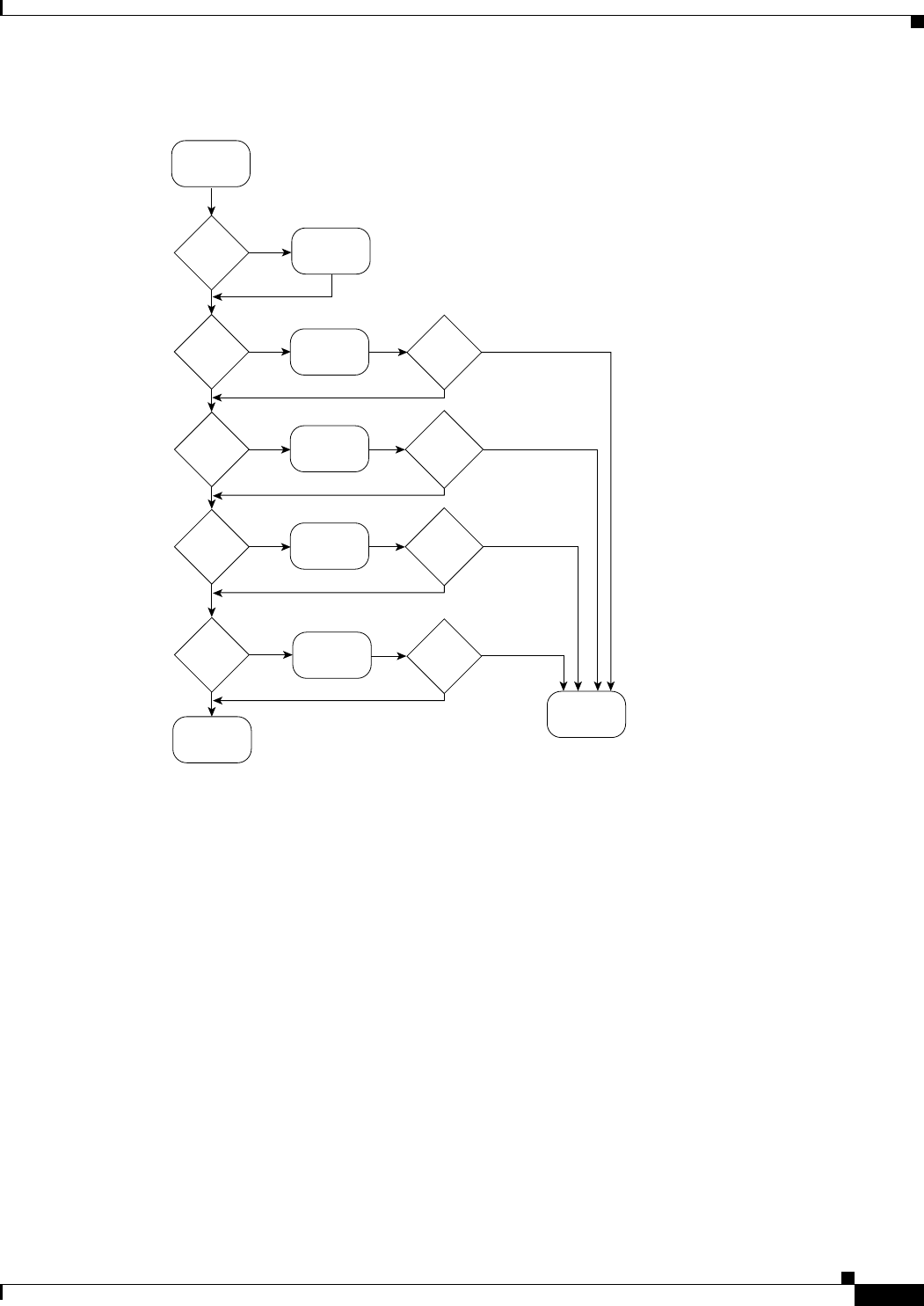
Use Figure 1-1 to determine which component of your Cisco uBR10012 router is malfunctioning.
Figure 1-1 describes a series of hardware dependent startup events that must take place for a
Cisco uBR10012 router to allow the passage of IP traffic. At each main point of the flowchart, there are
pointers to the chapters in this guide that describe how to troubleshoot individual pieces of hardware.
Note This flowchart does not address software configuration problems.
1-5
Cisco uBR10012 Universal Broadband Router Troubleshooting Guide
OL-1237-01
Chapter 1 Basic Troubleshooting Tasks and Startup Issues
Cisco uBR10012 System Startup Sequence
Figure 1-1 Hardware Troubleshooting Flowchart
Cisco uBR10012 System Startup Sequence
Table 1-1 describes the visible sequence of events that occur during a typical Cisco uBR10012 power up.
Correct
input
wiring
Reseat
PRE
and restart
Reseat
line card
and restart
System
startup
successful
Obtain
technical
assistance
*Miswire
LED
off
?
PEM
Power OK
LED on
?
PRE
Status
LEDs OK
?
PEM
Power OK
LED on
?
PRE
status LEDs
OK?
Line
card LEDs
OK
?
No
Yes
Yes
No
No
Yes
Yes
Yes
No
No
No
Yes
No
Yes
Line card
LEDs on
?
Reseat
TCC+
ICC+
Status
LEDs OK
?
ICC+
status LEDs
OK?
No
Yes
No
Yes
Troubleshoot
PEM
See section
"PEM Faults"
See section
"PRE Module
Faults"
See section
"Troubleshooting
TCC+"
See appropriate
line card fault
section
Turn
on
PEM
103381

1-6
Cisco uBR10012 Universal Broadband Router Troubleshooting Guide
OL-1237-01
Chapter 1 Basic Troubleshooting Tasks and Startup Issues
Cisco uBR10012 System Startup Sequence
Table 1-1 Cisco\ uBR10000 Series System Startup Sequence
Startup Event Event Description
PEM is powered off The Fault LED on each PEM is lit yellow to indicate that power is being supplied to the PEM
but that the router is not turned on.
Power on the
Cisco uBR10012 router
1. The Power LED on each PEM is lit green.
2. The yellow Critical, Major, and Minor alarm and Fail LEDs illuminate for about 2 seconds.
3. The alphanumeric display on the active PRE-1 module counts up through a range of
numbers from 1111 to 9999 (1111, 2222, and so on).
4. The alpha numeric display counts up through a sequence of letters from AAA to CCC
(AAA, BBB, and CCC).
5. The message ROM DONE appears on the alphanumeric display.
Note If the system is not configured to auto boot, it stops at the ROM DONE message. The
console displays a rommon> prompt.
6. The Power LED on each TCC+ card turns green. The Status LED on each TCC+ lights
yellow. After a few seconds, the Status LED on the primary TCC+ card lights green, and the
Status LED on the backup TCC+ card begins blinking green.
Cisco IOS software loads 1. If the system is set to boot from the slot0: file system, the green slot LED lights.
2. The message BOOT IMGE appears on the alphanumeric display on the active PRE-1
module.
3. The console displays a series of pound signs (#) as the IOS software image is decompressed.
4. The following messages appear on the alphanumeric display on the active PRE-1 module.
•IOS STRT
•IOS EXC
•IOS FPGA
•IOS FPOK
•IOS FILE
•IOS STBY
•IOS DRVR
•IOS LIB
•IOS MGMT
•IOS CONF
5. The console displays the bootup screen, followed by the prompt:
Press RETURN to get started!
6. The message IOS RUN appears in the alphanumeric display on the active PRE-1 module. In
a redundant configuration, the message IOS STBY appears on the alphanumeric display of
the standby PRE-1 module.
If the boot process fails, no console access is available. If you cannot boot the
Cisco uBR10012 router, call Cisco TAC.

CHAPTER
2-1
Cisco uBR10012 Universal Broadband Router Troubleshooting Guide
OL-1237-01
2
PEM Faults and Fan Assembly Failures
The following sections provide methods for troubleshooting faults involving the Cisco uBR10012 DC
Power Entry Modules (PEMs), the optional 2400W AC-input power shelf, and fan assembly module.
This chapter contains the following major sections:
•AC PEM Faults, page 2-1
•DC PEM Faults, page 2-3
•2400W AC-Input Power Shelf, page 2-5
•Other Electrical Problems, page 2-6
•Fan Assembly Module Faults, page 2-7
AC PEM Faults
On the Cisco uBR10012 router, two AC PEMs are installed in a redundant configuration, which allows
one AC PEM to fail without affecting system operations. A single PEM can power the router for
sufficient time to request and install a new PEM to replace the one that failed.
Tip To quickly check the functional status of your PEMs, use the show environment command.
AC PEM faults can occur for the following reasons:
•PEM failure
•Invalid AC-input power being supplied by the power source
•Backplane interface failures or damage
Figure 2-1 illustrates the AC PEM and its indicators. Table 2-1 describes the indicators.
2-2
Cisco uBR10012 Universal Broadband Router Troubleshooting Guide
OL-1237-01
Chapter 2 PEM Faults and Fan Assembly Failures
AC PEM Faults
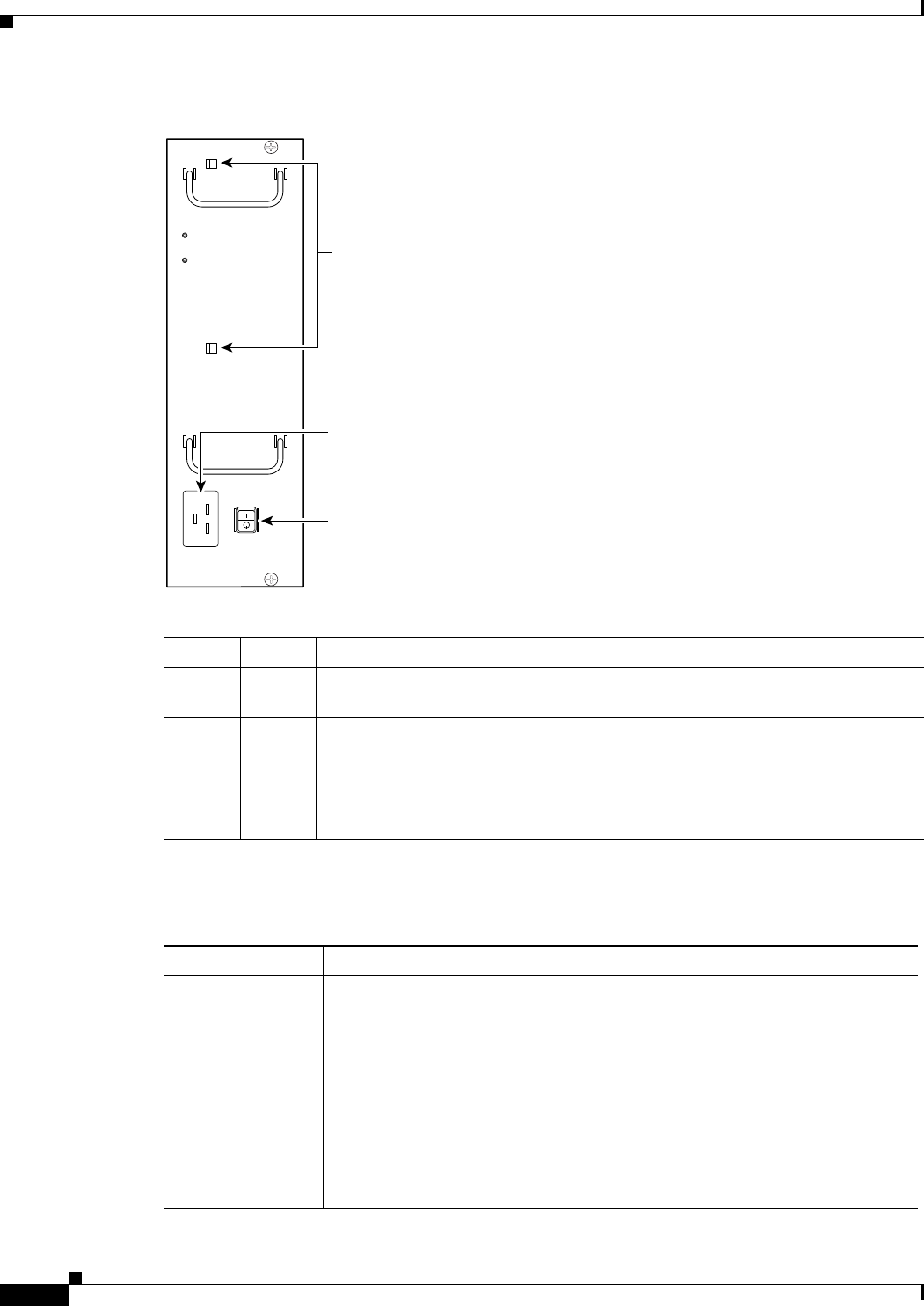
Figure 2-1 AC PEM Front Panel
Table 2-2 lists the AC PEM fault symptoms and corrective actions.
Table 2-1 AC PEM LEDs
LED Color Description
Power Green The PEM is on, is receiving power from the AC power source, and is providing
power to the Cisco uBR10012 chassis (normal operations).
Fault Yellow Indicates that AC-input power is being received by the PEM, but that the PEM is
not supplying power to the chassis, typically because the PEM’s power switch is
turned to the standby position.
If the Fault LED is lit when the power switch is in the ON position, the PEM is
not operating correctly.
62520
POWER
FAULT
AC power
cord clips
AC power switch
AC power plug
Table 2-2 AC PEM Fault Symptoms and Corrective Action
Fault Symptom Corrective Action
Green LED on PEM
fails to light
1. Make sure the power switch on the PEM is turned to the ON position.
2. Make sure the PEM is properly seated and that its captive screws have been
tightened.
3. Make sure that the AC-input power cord is securely plugged into the power
plug on the front panel of the PEM. Secure the cord in the clips to ensure
the plug is not accidentally pulled out.
4. Check the external power source and verify that the AC-input power cord is
correctly connected to the power outlet.
5. Move the PEM to the other PEM slot. If the PEM still fails, replace it.

2-3
Cisco uBR10012 Universal Broadband Router Troubleshooting Guide
OL-1237-01
Chapter 2 PEM Faults and Fan Assembly Failures
DC PEM Faults
Tip Securely tighten the captive screws on your PEMs to prevent heightened levels of electromagnetic
interference.
DC PEM Faults
On the Cisco uBR10012 router, two DC PEMs are in a redundant configuration, which allows one DC
PEM to fail without affecting system operations. A single PEM can usually power the router for
sufficient time to request and install a new PEM to replace the one that failed.
Tip To quickly check the functional status of your PEMs, use the show environment command.
DC PEM faults can occur for the following reasons:
•PEM failure
•Reversed power cables
•Backplane interface failures or damage
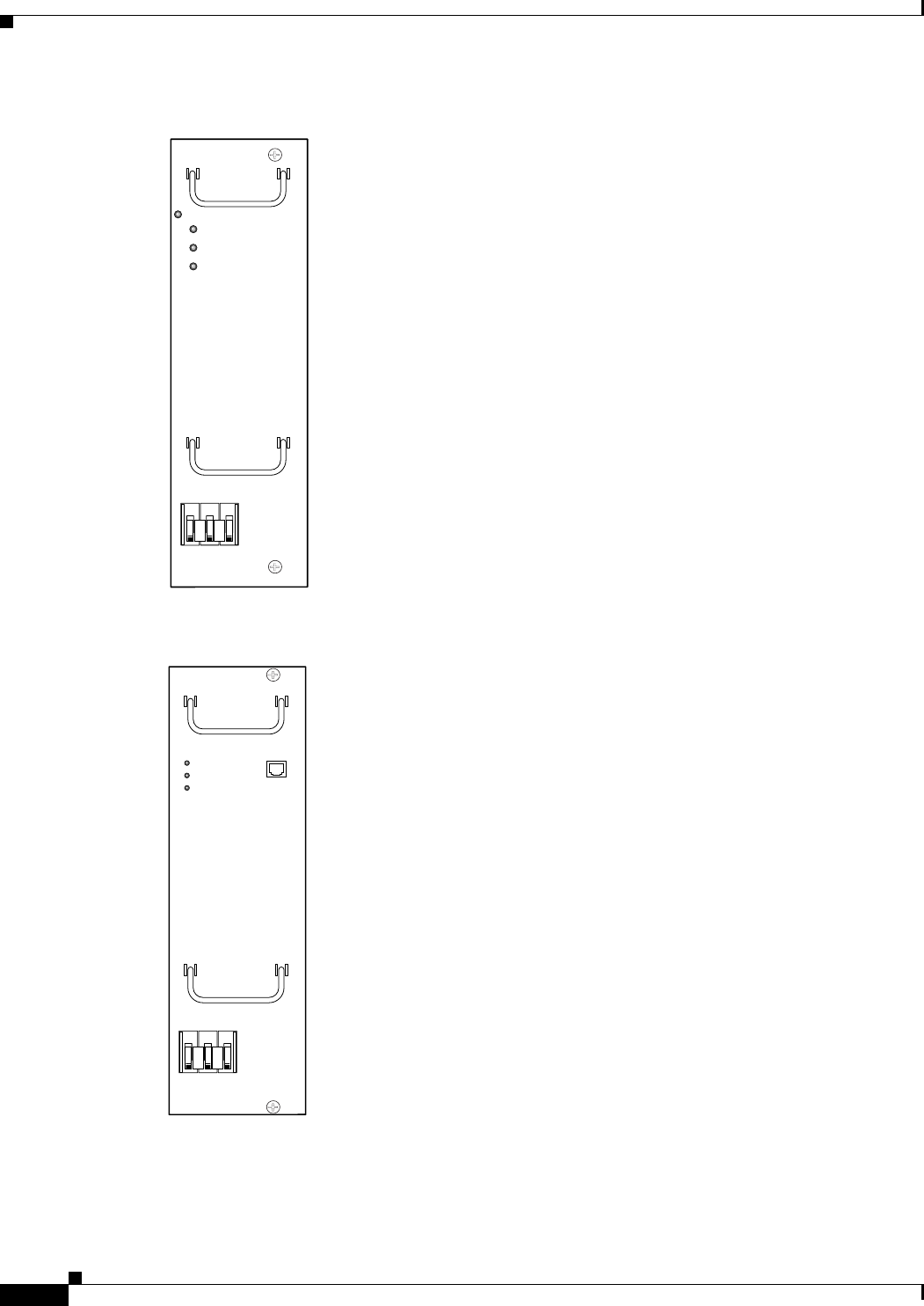
Two models of the DC PEM exist.
•Figure 2-2 shows the front panel of the original DC PEM (UBR10-PWR-DC) that was initially
produced for the Cisco uBR10012 router.
•Figure 2-3 shows the front panel of the DC PEM that is currently being produced for the
Cisco uBR10012 router. The new model of the DC PEM (UBR10-PWR-DC-M) is identical in form
and function to the first version, except that it includes a connector on the front panel for connecting
to the alarm status connectors on the optional 2400-watt AC-input power shelf.
Table 2-3 describes the indicators on the front panel of both models of DC PEM.
PEM experiences
problems in one
slot but operates
normally in a
different slot
1. Ensure that the input power to both slots is correct.
2. Verify that no connections have been made to the DC-power connectors
underneath each PEM.
3. If the problem persists, contact Cisco TAC.
Fault LED is lit
yellow
1. Verify that no connections have been made to the DC-power connectors
underneath each PEM.
2. Verify that the PEM is fully inserted into the power bay and that its captive
screws have been tightened.
3. Check to see if the power switch is set to the standby position. If so, set the
switch to the ON position.
4. If the problem persists, flip the power switch on the PEM to the standby
position, wait several seconds, and then back to the ON position.
5. Replace PEM with a known good replacement.
6. Contact Cisco TAC.
Table 2-2 AC PEM Fault Symptoms and Corrective Action (continued)
2-4
Cisco uBR10012 Universal Broadband Router Troubleshooting Guide
OL-1237-01
Chapter 2 PEM Faults and Fan Assembly Failures
DC PEM Faults
Figure 2-2 DC PEM Front Panel (original model, UBR10-PWR-DC)
Figure 2-3 DC PEM Front Panel (current model with alarm connector, UBR10-PWR-DC-M)
56480
POWER
MISWIRE
FAULT
62518
POWER
MISWIRE
FAULT

2-5
Cisco uBR10012 Universal Broadband Router Troubleshooting Guide
OL-1237-01
Chapter 2 PEM Faults and Fan Assembly Failures
2400W AC-Input Power Shelf
Table 2-4 lists the DC PEM fault symptoms and corrective actions.
Tip Securely tighten the captive screws on your PEMs to prevent heightened levels of electromagnetic
interference.
2400W AC-Input Power Shelf
The 2400W AC-input power shelf converts AC-output power from an external AC power source into DC
power that is suitable for powering the Cisco uBR10012 router. The power shelf supplies –54 VDC
output power to the two DC PEMs in the Cisco uBR10012 chassis.
Table 2-3 DC PEM LEDs
LED Description
Power (green) PEM is powered on and is operational.
Fault (yellow) PEM is not operating correctly or the circuit breaker is in the OFF position.
Miswire (yellow) Input DC power cables are wired incorrectly and should be reversed.
Table 2-4 DC PEM Fault Symptoms and Corrective Action
Fault Symptom Corrective Action
Green LED on PEM
fails to light
1. Make sure the circuit breaker on the PEM is turned on.
2. Make sure the PEM is properly seated and screwed in place.
3. Make sure power leads are properly connected to power connectors on the
backplane. If connections are loose or their polarity is reversed, the chassis
does not receive power.
4. Check the external power source.
5. Move the PEM to the other PEM slot. If the PEM still fails, replace it.
PEM experiences
problems in one
slot but operates
normally in a
different slot
1. Ensure that the input power to both slots is correct.
2. If the problem persists, contact Cisco TAC.
Fault LED is lit
yellow
1. Check to see if the circuit breaker (on/off switch) has tripped. If it has,
return the switch to the ON position.
2. Replace PEM with a known good replacement.
3. Contact Cisco TAC.
Miswire LED is lit
yellow
If the MISWIRE LED is on, the power cables are reversed. Power off the PEM
and the external power source and reconnect the wires correctly. See the
Cisco uBR10012 Universal Broadband Router Hardware Installation Guide.
2-6
Cisco uBR10012 Universal Broadband Router Troubleshooting Guide
OL-1237-01
Chapter 2 PEM Faults and Fan Assembly Failures
Other Electrical Problems
The power shelf includes three 1200-watt (W) AC-input power modules that plug into a common power
backplane in the 2400W AC-input power shelf. Two 1200W AC-input power modules are capable of
powering a fully configured Cisco uBR10012 router. The third power module provides full redundancy.
During normal operation, the three AC-input power modules provide automatic load-sharing with each
power module supporting 33 percent of the power load. When you remove one of the AC-input power
modules, the remaining power modules immediately ramp up to full power and maintain uninterrupted
system power for a limited time. This allows you to replace the affected module without impacting
system operations.
Faults on the 2400W AC-input power shelf can occur for the following reasons:
•The AC-input power to one or more power modules has failed.
•The AC power plug to one or more power modules has been removed or unplugged.
•One or more power modules has failed and must be replaced.
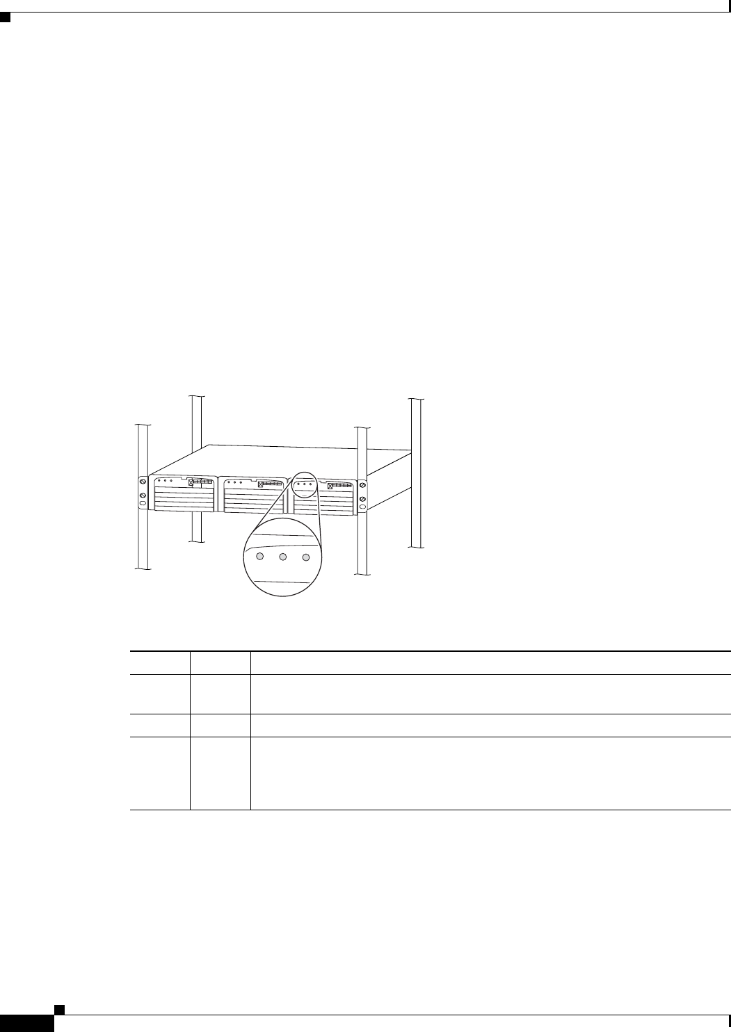
Figure 2-4 illustrates the AC PEM and its indicators. Table 2-5 describes the indicators.
Figure 2-4 AC-Input Power Shelf Front Panel
Other Electrical Problems
If the electrical problem cannot be traced to a PEM, check the unit for:
•Improper power cable connections to the Cisco uBR10012 router
•Improper installation of other field-replaceable units (FRUs)
Table 2-5 AC-Input Power Shelf Module LEDs
LED Color Description
AC OK Green The AC-input power to the power module is present and is within the proper
range.
DC OK Green The power module is producing DC output power in the proper range.
FAULT Red This particular power module has failed and must be replaced. The 2400W
AC-input power shelf can continue operating with only two out of the three power
modules installed, but the failed module should still be replaced as soon as
possible.
36137
DC OKAC OKFAULTDC OKAC OKFAULTDC OKAC OKFAULT
DC OK AC OK FAULT
2-7
Cisco uBR10012 Universal Broadband Router Troubleshooting Guide
OL-1237-01
Chapter 2 PEM Faults and Fan Assembly Failures
Fan Assembly Module Faults
Check the site for:
•Improperly grounded equipment, particularly equipment racks and power grounds
•Fluctuating voltage, which can result from excessive power drains caused by other equipment (such
as air conditioning units)
•Cable corrosion or defective power panels, circuit breakers or fuses, or cable connections
•Undersized power cables or excessive power cable lengths
•Excessive power demand on backup power systems or batteries when alternate power sources
are used
Fan Assembly Module Faults
The fan assembly module is critical to the operation of the Cisco uBR10012 router because it allows the
router to maintain proper operating temperatures. Severe overheating can result in system failure, so a
fan assembly module must always be present in the chassis while the router is operating.
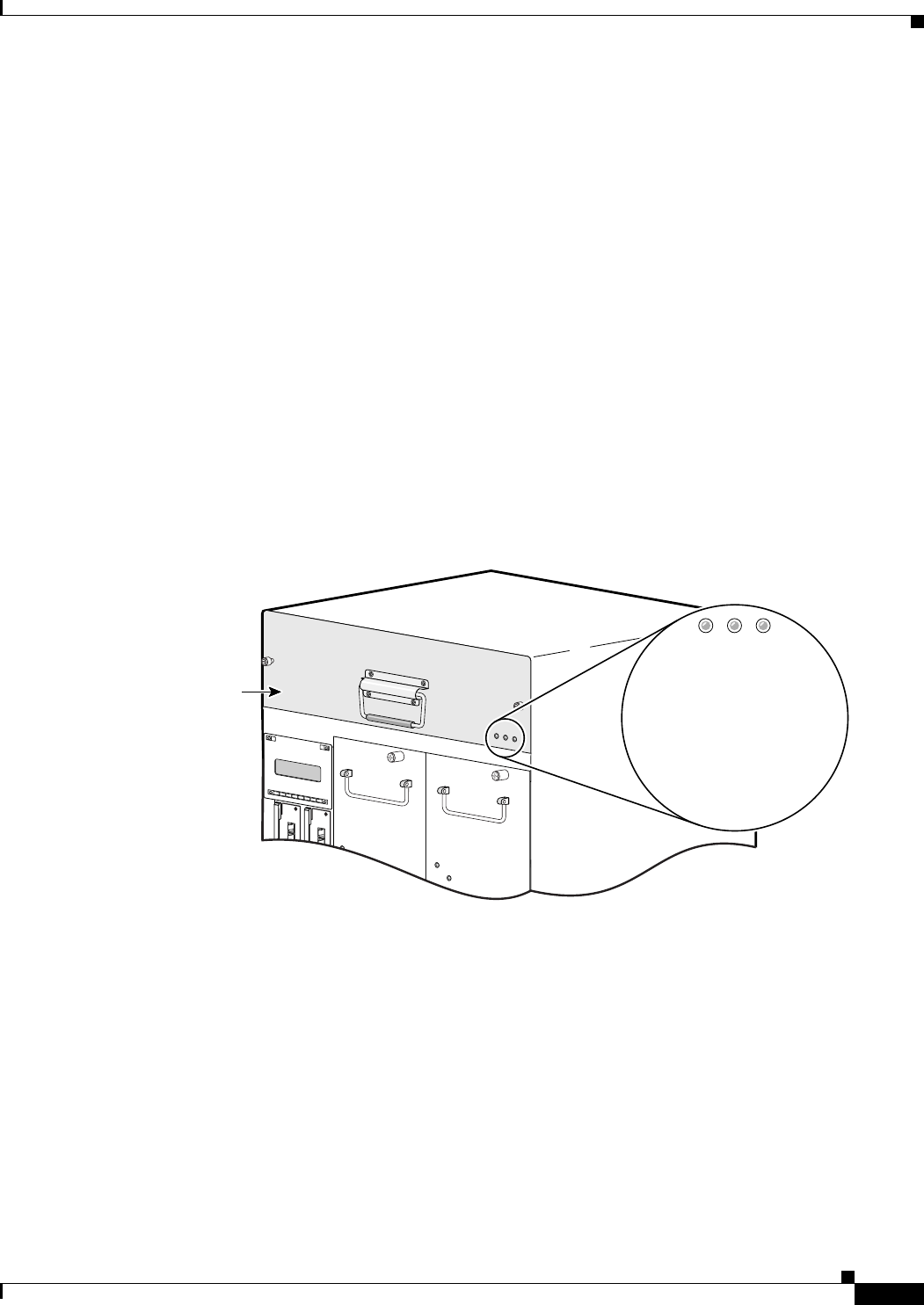
Figure 2-5 shows the fan assembly module front panel and its LED indicators.
Figure 2-5 Fan Assembly Module
The Cisco uBR10012 fan assembly module contains four fans in a redundant configuration. One fan can
fail without affecting system operations. If more than one fan fails, however, the fan assembly module
must be replaced immediately to avoid overheating the system.
The fan assembly module draws air in from the bottom front of the Cisco uBR10012 router, through the
air filter at the bottom of the front bezel. The air is drawn up through the line cards, and then exits
through the vents at the top rear of the router.
Figure 2-6 shows the air circulation pattern of the Cisco uBR10012 router when two DC PEMs are
installed. The air flow when two AC PEMs are installed is similar. The front bezel is not shown for
clarity.
CISCO
10000
ETHERNET
LINK
ACTIVITY
AUX
CISCO
10000
ETHERNET
LINK
ACTIVITY
AUX
Fan
assembly
FANS OK
SINGLE FAN FAILURE
MULTIPLE FAN FAILURE
56479

2-8
Cisco uBR10012 Universal Broadband Router Troubleshooting Guide
OL-1237-01
Chapter 2 PEM Faults and Fan Assembly Failures
Fan Assembly Module Faults
Figure 2-6 Fan Assembly Air Circulation Pattern
The LEDs on the front panel indicate the current status of the fans. Table 2-6 lists the fan assembly
module fault indications and recommended actions.
56430
ALARMS
CISCO
10000
FAIL
PERFORMANCE ROUTING ENGINE
CONSOLE
ST
A
TUS
ACO
CRITICAL
MINOR
MAJOR
ETHERNET
LINK
ACTIVITY
AUX
SLOT 0
SLOT 1
ALARMS
CISCO
10000
FAIL
PERFORMANCE ROUTING ENGINE
CONSOLE
ST
A
TUS
ACO
CRITICAL
MINOR
MAJOR
ETHERNET
LINK
ACTIVITY
AUX
SLOT 0
SLOT 1
POWER
MISWIRE
FAULT
POWER
MISWIRE
FAULT

2-9
Cisco uBR10012 Universal Broadband Router Troubleshooting Guide
OL-1237-01
Chapter 2 PEM Faults and Fan Assembly Failures
Fan Assembly Module Faults
Table 2-6 Fan Assembly Module Fault Indications and Recommended Action
Symptom Steps to Take
Fans OK LED is not lit 1. Make sure the fan assembly module is fully inserted into the chassis.
2. Place your hand in front of the fan assembly module outlet to determine if the fans are
operating. If the fans are running, remove the fan assembly module and inspect the wiring
to the LEDs and fans to ensure that the wires are not nicked or cut.
3. Make sure that two AC PEM or two DC PEM modules are installed in the chassis.
Although only one PEM is required to power the chassis, two PEMs should be installed
for proper airflow. (If one PEM fails, leave the failed module in the chassis until the
replacement module can be installed.)
4. If you use DC PEMs, make sure the wiring is not reversed.
5. Replace the fan assembly module.
SINGLE FAN FAILURE
LED is lit
One fan in the fan assembly module has failed. The fan assembly can cool the chassis
sufficiently with three working fans, but replace the failed fan as soon as possible.
MULTI-FAN FAILURE LED
is lit
More than one fan has failed, and the fan assembly cannot sufficiently cool the chassis.
Replace the failed fans immediately. If necessary, power down the chassis until replacements
are available.
Fans run but the system
overheats
1. Make sure that all intake and exhaust vents on the front and rear of the chassis are free
of blockages.
2. Make sure that the ambient temperature and other environmental factors in the system
area are within the ranges specified in the “Displaying System Environment
Information” section on page 1-4.
3. Make sure all line cards and blank faceplates are in place. Make sure two PEM modules
are installed in the chassis. The cooling system cannot operate effectively unless the
chassis is fully enclosed.
4. Check the air filter, and, if necessary, clean or replace it.
5. Reduce the ambient temperature of the area surrounding the Cisco uBR10012 chassis.
This can be done using air conditioning, using fans to circulate the air in the room, and
closing the blinds on any windows that are facing the sun.

2-10
Cisco uBR10012 Universal Broadband Router Troubleshooting Guide
OL-1237-01
Chapter 2 PEM Faults and Fan Assembly Failures
Fan Assembly Module Faults

CHAPTER
3-1
Cisco uBR10012 Universal Broadband Router Troubleshooting Guide
OL-1237-01
3
Troubleshooting PRE-1 Modules
This chapter describes how to troubleshoot Performance Routing Engine (PRE-1) modules. It provides
information on troubleshooting PRE-1 fault states, the management Ethernet port, and the serial port.
•Information Required for Troubleshooting PRE-1 Modules, page 3-1
•PRE Module Not Supported, page 3-2
•PRE-1 Module Status Screen, page 3-2
•Booting Up with Redundant PRE-1 Modules, page 3-3
•PRE-1 Module Faults, page 3-4
•Ethernet Connection Problems, page 3-6
•Console Port Serial Connection Problems, page 3-7
•Troubleshooting Common System Problems, page 3-8
Information Required for Troubleshooting PRE-1 Modules
The PRE-1 module is the primary processor for the Cisco uBR10012 router, and any problems with the
PRE-1 module affect all operations. If you suspect a problem with the PRE-1 module, please collect the
following information before proceeding further, to aid in troubleshooting the problem:
Step 1 Capture all console logs and system messages.
Step 2 Capture the output of the show tech-support command. Registered users on Cisco.com can decode the
output of this command by using the Output Interpreter tool, which is at the following URL:
https://www.cisco.com/cgi-bin/Support/OutputInterpreter/home.pl
Step 3 Capture the complete bootup sequence, especially if the router is reporting errors at bootup.
Step 4 If the router is unresponsive, or if it refuses to boot to the Cisco IOS prompt, reboot the router to the
ROMMON prompt and capture a stack trace, using the stack ROMMON command. For more
information on this procedure, see the Obtaining a Stack Trace from ROM Monitor section in the
Troubleshooting Router Hangs document, at the following URL:
http://www.cisco.com/en/US/products/hw/routers/ps359/products_tech_note09186a0080106fd7.shtml

3-2
Cisco uBR10012 Universal Broadband Router Troubleshooting Guide
OL-1237-01
Chapter 3 Troubleshooting PRE-1 Modules
PRE Module Not Supported
PRE Module Not Supported
The Cisco uBR10012 router supports only the PRE-1 module in Cisco IOS Release 12.2(8)BC1, and
later releases. If you attempt to boot the Cisco uBR10012 router with a PRE module with one of these
software releases, the router prints the following error message and falls through to the ROM monitor:
%%Error: PRE not supported with this image
rommon>
To correct this error, replace the PRE modules in the router with PRE-1 modules. To continue using the
original PRE modules, you must be reload the router with Cisco IOS Release 12.2(4)BC1 or an earlier
12.2 BC release.
Note For information on the replacement of PRE modules with PRE-1 modules, see the Field Notice,
Cisco uBR10000 Proactive Upgrade of PRE to PRE1, at the following URL:
http://www.cisco.com/en/US/products/hw/cable/ps2209/products_field_notice09186a00800946c5.sht
ml
PRE-1 Module Status Screen
The PRE-1 module contains a small LED screen that displays the current state of the boot process on the
active and standby PRE-1 modules. Table 3-1 lists each message and its meaning.
Table 3-1 LED Messages on the PRE-1 Modules
Message Description
BLDRSTRT The PRE-1 module is starting the boot loader software.
BLDREXC The boot loader software has begun to execute.
BLDRMEM The boot loader software is initializing the memory on the PRE-1 module.
BLDRFILE The boot loader software is initializing the router’s file systems.
BLDRDRVR The boot loader software is initializing the driver subsystems.
BLDRLIB The boot loader software is initializing the subsystem libraries.
BLDRPROT The boot loader software is initializing the protocol subsystems.
BLDRMGMT The boot loader software is initializing the management subsystems.
BLDRINTF The boot loader software is initializing the router’s interfaces.
BLDRSTBY The boot loader software is running and the PRE-1 module is running as the
standby PRE-1 module.
LOADIOS The boot loader software has finished initializing and has begun to load the
Cisco IOS software.
IOS STRT The PRE-1 module is starting the Cisco IOS software.
IOS EXC The Cisco IOS software has begun to execute.
IOS MEM The Cisco IOS software is initializing the memory on the PRE-1 module.
IOS FILE The Cisco IOS software is initializing the router’s file systems.

3-3
Cisco uBR10012 Universal Broadband Router Troubleshooting Guide
OL-1237-01
Chapter 3 Troubleshooting PRE-1 Modules
Booting Up with Redundant PRE-1 Modules
Booting Up with Redundant PRE-1 Modules
When two PRE-1 modules are installed in the Cisco uBR10012 router, the active PRE-1 module is
whichever module that first loads the Cisco IOS software and asserts control over the shared bus between
the two modules. The other PRE-1 module automatically boots the Cisco IOS software and enters the
standby mode.
Typically, the PRE-1 module in slot A (the left-most PRE-1 module slot as you face the chassis) boots
the Cisco IOS software more quickly than the PRE-1 module in slot B (the PRE-1 slot on the right). This
is because the PRE-1 module in slot B adds a slight delay in its bootup sequence, so as to allow the
module in slot A to boot first.
However, the selection of the active PRE-1 module does not affect the operations of the Cisco uBR10012
router. The router can operate normally with either the slot A or the slot B PRE-1 module acting as the
active PRE-1 module.
If you notice that the slot B PRE-1 module is always becoming the active PRE-1 module, and you would
like the slot A PRE-1 module to become the active PRE-1 module, check for the following:
•Check to see if the slot A PRE-1 module is booting Cisco IOS software from a Flash Disk in slot0
or slot1, which indicates it is using an old-style 16 or 20 MB PCMCIA card. These Flash Disk
memory cards operate more slowly than the new ATA-style 48 MB, 64 MB, or 128 MB Flash Disk
cards. If possible, boot the PRE-1 module using an ATA-style card in disk0 or disk1.
•If using an ATA-style Flash Disk is not possible, consider booting the Cisco IOS software image
from the PRE-1 module’s bootflash memory device.
IOS DRVR The Cisco IOS software is initializing the driver subsystems.
IOS LIB The Cisco IOS software is initializing the subsystem libraries.
IOS PROT The Cisco IOS software is initializing the protocol subsystems.
IOS MGMT The Cisco IOS software is initializing the management subsystems.
IOS INTF The Cisco IOS software is initializing the router’s interfaces.
IOS CONF The Cisco IOS software has begun to load the startup configuration file.
IOS RUN The Cisco IOS software is running and the PRE-1 module is running as the
active PRE-1 module. This could indicate that the PRE-1 module originally
booted up as the active module, or that a switchover put this module into the
active state.
Note This message indicates that the Cisco IOS router is running a Cisco IOS
software image. This is typically the full Cisco IOS image that was
found on a Flash disk or TFTP server. However, if an error occurs during
bootup, this could be the boot Cisco IOS image that is permanently
written in the router’s bootflash and is used when the router cannot boot
the full Cisco IOS image.
IOS STBY The Cisco IOS software is running and the PRE-1 module is running as the
standby PRE-1 module. This could indicate that the PRE-1 module originally
booted up as the standby module, or that the PRE-1 module was originally the
active PRE-1module, but that a switchover put it into the standby state.
Table 3-1 LED Messages on the PRE-1 Modules (continued)
Message Description

3-4
Cisco uBR10012 Universal Broadband Router Troubleshooting Guide
OL-1237-01
Chapter 3 Troubleshooting PRE-1 Modules
PRE-1 Module Faults
•Verify that both PRE-1 modules are booting the same version of Cisco IOS software. Slight
variations in the loading of different images could allow the slot B PRE-1 module to boot first.
PRE-1 Module Faults
The PRE-1 module provides the IP routing and forwarding functionality in the Cisco uBR10012 router.
Thus, in a non-redundant PRE-1 configuration, a PRE-1 failure is a system failure. A redundant PRE-1
configuration is recommended because it allows the redundant PRE-1 module to automatically assume
full functionality upon failure of the primary PRE-1 module.
If the PRE-1 module fails, the yellow PRE-1 STATUS LED lights. If this occurs, try the following steps:
•Reboot the Cisco uBR10012 router
•Move the PRE-1 module to the other PRE-1 module slot
•Replace the PRE-1 module with a spare module
In addition, you should capture any error messages that appear on the console, as well as the state of the
PRE-1 LEDs and alphanumeric display. Then contact the Cisco Technical Assistance Center (TAC).
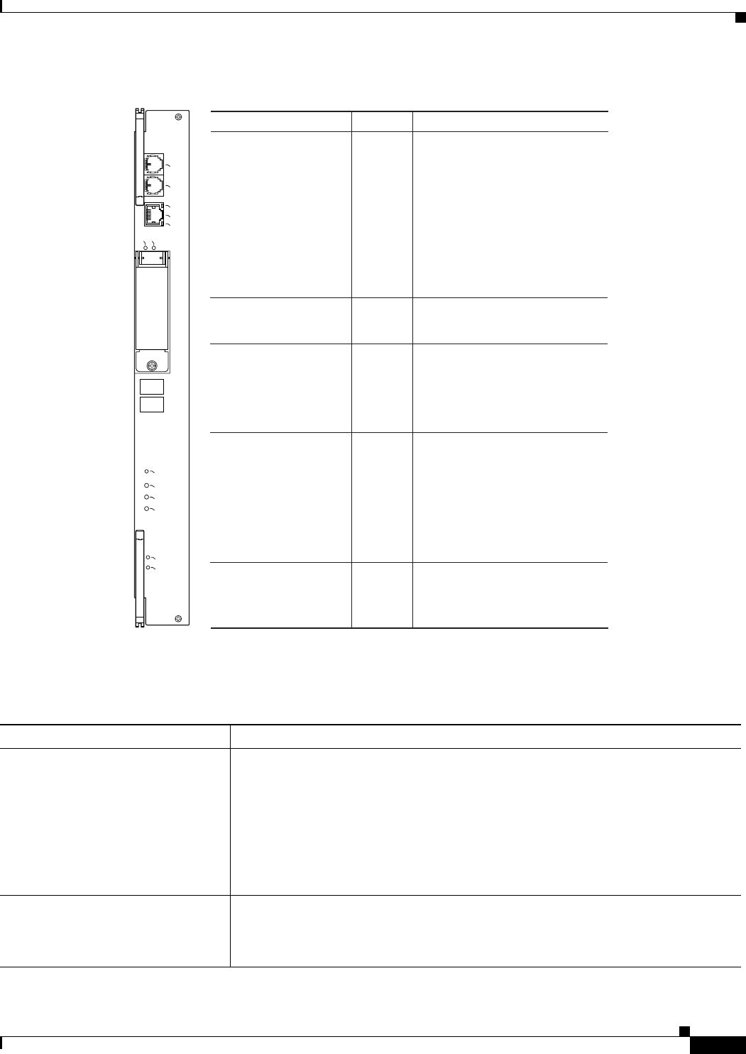
Figure 3-1 describes the LED indicators on the PRE-1 faceplate. Use these descriptions to verify the
operation of the PRE-1 module.
3-5
Cisco uBR10012 Universal Broadband Router Troubleshooting Guide
OL-1237-01
Chapter 3 Troubleshooting PRE-1 Modules
PRE-1 Module Faults
Figure 3-1 PRE-1 Faceplate and LEDs
Table 3-2 lists the PRE-1 fault indications and recommended actions. The information contained in the
table is based on the assumption that you have a nonredundant configuration.
29995
LED Status Description
Fail
Status
Off
A major failure has disabled
the PRE.
The PRE is operating properly.
PRE is active (primary).
No power to PRE.
Off
Yellow
Green
Ethernet port LEDs
Activity
Link
Green
Off
Green
Off
Packets are being transmitted
and received.
No activity.
Carrier detected; the port is
able to pass traffic.
No carrier detected; the port is
not able to pass traffic.
PCMCIA slot 0
PCMCIA slot 1 Green
Green Slot 0 is active.
Slot 1 is active.
Critical, Major, and
Minor LEDs
Off No alarm.
–Pressing this switch disables
an audible alarm.
Alarm Cut-off (ACO)
switch
ALARMS
CISCO
10000
FAI L
PERFORMANCE ROUTING ENGINE
CONSOLE
STATUS
ACO
CRITICAL
MINOR
MAJOR
ETHERNET
LINK
ACTIVITY
AUX
SLOT 0
SLOT 1
Yellow Indicates an alarm condition.
PRE is standby (secondary).
System is booting.
Flashing
yellow
Flashing
green
Table 3-2 PRE-1 Module Fault Indications and Recommended Action
Fault Steps to Take
STATUS LED is not lit 1. Check LEDs on other modules and cards. If none are lit, refer to Table 2 -3 to
check the status of the power modules (AC PEM or DC PEM).
2. If LEDs on other modules and cards are lit, remove the card from its slot and
check for bent or broken pins on the backplane. Return the card to its slot and
screw it firmly into place.
3. Replace the card.
4. If the problem persists, contact Cisco TAC.
FAIL LED is yellow, indicating that
the PRE-1 failed
1. Reinsert the PRE-1 module.
2. Replace the module with a new PRE-1 module.
3. If the problem persists, contact Cisco TAC.

3-6
Cisco uBR10012 Universal Broadband Router Troubleshooting Guide
OL-1237-01
Chapter 3 Troubleshooting PRE-1 Modules
Ethernet Connection Problems
Ethernet Connection Problems
If the management Fast Ethernet interface (F0/0/0) on the PRE-1 fails to work properly, and the
corresponding Link LED is not lit (steady green):
•Visually check that an Ethernet cable is connected to the correct Ethernet port on the
Cisco uBR10012 router.
•Verify that you are using the correct type of cable for a 100BaseT Ethernet.
•Check to see if the cable is bad or broken.
•Make sure the primary PRE-1 module booted up properly by checking the Status LED on its
faceplate. This LED on the primary PRE-1 module should be steady green. If a redundant PRE-1
module is installed, its STATUS LED should be flashing green. If this is not the case with either
PRE-1 module, remove and reinsert the module and boot it up again.
Note The show interface command also shows that there is an Ethernet interface (E0/0/0) on the PRE-1
module, but this is an internal interface that the router uses to communicate between PRE-1 modules and
line cards. This Ethernet interface is not configurable and can be used only by the router’s internal
subsystems.
If the Link LED is lit (steady green), but the Ethernet port is not working properly, make sure that the
port in question is configured properly and is not administratively shut down. If you have a working
console connection, perform the following steps:
Step 1 At the switch prompt, enter show interface fastethernet0/0/0. If the port is administratively down, enter
these commands to enable it:
c10000# configure terminal
Enter configuration commands, one per line. End with CNTL/Z.
c10000(config)#interface fastethernet0/0/0
c10000(config-if)# no shut
c10000(config-if)# exit
c10000(config)# exit
c10000#
The PRE-1 initializes, but you cannot
establish a console connection
1. Ensure that the terminal settings are properly set.
2. If you still cannot connect, check the console cable. Is it firmly connected? Is it
the correct type of cable with proper connectors?
3. If the cable checks out and you cannot establish a console or Telnet session,
reinsert the PRE-1 module. If the problem persists, replace the PRE-1 module.
4. Enter show log to review console messages recorded in the system log.
Card cannot be fully inserted into its
slot
Make sure that you are using the correct slot (A or B) for the PRE-1 module.
An alarm LED is lit 1. Enter the show facility-alarm status command and examine the output to
determine which system component raised the alarm.
2. Troubleshoot using a procedure appropriate to the module or FRU responsible for
the alarm.
Table 3-2 PRE-1 Module Fault Indications and Recommended Action

3-7
Cisco uBR10012 Universal Broadband Router Troubleshooting Guide
OL-1237-01
Chapter 3 Troubleshooting PRE-1 Modules
Console Port Serial Connection Problems
Step 2 Check that the Ethernet port in question is assigned a valid IP address.
For more information about configuring Ethernet ports, refer to the Cisco uBR10012 Universal
Broadband Router Software Configuration Guide.
If the cable, connections, power, and configuration all check out, and you still cannot connect to the
Ethernet port on the module, replace the module in question. If the problem persists, contact the Cisco
TAC for further assistance. Refer to the “Obtaining Technical Assistance” section on page x for
instructions on contacting the Cisco TAC.
Console Port Serial Connection Problems
If the console screen connected to a Cisco uBR10012 console port appears frozen or fails to work
properly, check the following steps:
Step 1 Refer to the “Cisco uBR10012 System Startup Sequence” section on page 1-5. If the display stops
responding during this process, there is no console output.
Step 2 Check the console cable and make sure it is properly connected to the console port on the active PRE-1
module at one end and to your terminal equipment or terminal server at the other end.
Note You cannot connect to the console port on the standby PRE-1 module. You must connect to
the console port on the currently active PRE-1 module. If a switchover occurs, you must
switch the serial cable to the new active PRE-1 module to maintain the console connection.
Step 3 Verify that you are using the right type of cable and adapter. For information about pin-out connections
and installation instructions, refer to the Cisco uBR10012 Universal Broadband Router Hardware
Installation Guide.
Step 4 Make sure the cable is not defective or broken. Replace the cable with another high quality cable if
possible, and check to see if the console port starts working.
Step 5 Check that the terminal equipment is configured with the correct settings for the console port. The
default console port settings are:
•9600 baud
•8 data bits
•1 stop bit
•No parity
•No flow control
Step 6 Check the LEDs on the PRE-1 faceplate to make sure it has powered up properly. If necessary, remove
and reinsert both PRE-1 modules to power them up again. Also, make sure the terminal equipment is
working properly.
Step 7 The console can appear frozen if the PRE-1 processor is busy performing other tasks, such as parsing a
large configuration file or passing a large burst of traffic. These periods are usually only temporary, and
normal reaction resumes after a few moments.

3-8
Cisco uBR10012 Universal Broadband Router Troubleshooting Guide
OL-1237-01
Chapter 3 Troubleshooting PRE-1 Modules
Troubleshooting Common System Problems
Step 8 The console can be frozen if the PRE-1 process is generating a large volume of debug messages. If this
is the case, hit the return key a couple of times and type no debug all to attempt to turn off the debug
messages. This will not work if the router is in global configuration mode, but try typing do no debug
all to execute this EXEC mode command in global configuration mode.
If the cable, connections, power, and terminal settings all check out and you still cannot connect to the
console port on the module, replace the module in question. If the problem persists, contact the Cisco
TAC for further assistance.
Troubleshooting Common System Problems
This section describes how to troubleshoot the following common system problems on the
Cisco uBR10012 router:
•Troubleshooting System Crashes, page 3-8
•High CPU Utilization Problems, page 3-9
•Bus Errors, page 3-13
•Memory Problems, page 3-15
Troubleshooting System Crashes
System crashes occur when the router experiences an unexpected situation from which it cannot recover.
In response, the router stops all processes and reloads. Crashes can result from either hardware or
software problems.
When the router crashes, it is extremely important to gather as much information as possible about the
crash before doing a manual reload or power-cycling the router. All information about the crash, except
that which has been stored in the crashinfo file, is lost after a manual reload or power-cycle.
In particular, use the following commands to gather more information about the crash:
•All console, system, and message logs.
•Crashinfo file, if one was generated at the time of the crash.
•All output from the following commands:
–
show version
–
show context
–
show stacks
–
show tech-support
Note Registered Cisco.com users can decode the output of these show commands by using the Output
Interpreter tool, which is at the following URL:
https://www.cisco.com/cgi-bin/Support/OutputInterpreter/home.pl

3-9
Cisco uBR10012 Universal Broadband Router Troubleshooting Guide
OL-1237-01
Chapter 3 Troubleshooting PRE-1 Modules
Troubleshooting Common System Problems
For additional information on troubleshooting system crashes, see the following URLs:
•Troubleshooting Router Crashes, at the following URL:
http://www.cisco.com/en/US/products/sw/iosswrel/ps1835/products_tech_note09186a00800b4447
.shtml
•Less Common Types of System Crashes, at the following URL:
http://www.cisco.com/en/US/products/sw/iosswrel/ps1831/products_tech_note09186a008010876d
.shtml
High CPU Utilization Problems
The PRE-1 module can experience high CPU utilization, where the CPU processor approaches 100%
usage for extended periods of time, for several reasons. See the following sections for possible causes
and solutions.
•ARP Traffic, page 3-9
•CPUHOG Errors, page 3-11
•Debug and System Messages, page 3-11
•Exec and Virtual Exec Processes, page 3-11
•Interrupts are Consuming a Large Amount of Resources, page 3-12
•Invalid Scheduler Allocate Configuration, page 3-12
•IP Input Processing, page 3-12
•One or More Processes is Consuming an Excessive Amount of Resources, page 3-12
•Problems with Access Lists, page 3-13
•SNMP Traffic, page 3-13
Also see the document Troubleshooting High CPU Utilization on Cisco Routers, which is at the
following URL:
http://www.cisco.com/en/US/products/hw/routers/ps133/products_tech_note09186a00800a70f2.shtml
ARP Traffic
High volumes of Address Resolution Protocol (ARP) requests and responses can occupy a significant
portion of the CPU time, because the router cannot use fast-switching to process ARP packets, but must
instead forward them to the route processor (RP). Because of this, processing a large volume of ARP
traffic can also prevent the router from handling normal traffic.
Theft-of-service and denial-of-service (DNS) attacks also often generate a large number of ARP packets
on the network. Many viruses also use ARP requests to discover computers that might be vulnerable to
attack, and if these computers become infected, they are used to propagate the virus, generating even
more ARP traffic on the network.
ARP requests are broadcast packets, so they are broadcast to all devices on that particular network
segment. In some cases, a router can also forward ARP broadcasts to an ARP proxy for further
processing. Some low-end routers commonly used by subscribers for home networks can also incorrectly
respond to all ARP requests, which generates even more traffic.

3-10
Cisco uBR10012 Universal Broadband Router Troubleshooting Guide
OL-1237-01
Chapter 3 Troubleshooting PRE-1 Modules
Troubleshooting Common System Problems
In addition, the Cisco CMTS router automatically monitors ARP traffic and enters the IP addresses
found in ARP requests into its own ARP table, in the expectation that a device will eventually be found
with that IP address. Unacknowledged IP addresses remain in the router’s ARP table for 60 seconds,
which means that a large volume of ARP traffic can fill the router’s ARP table.
If ARP traffic is excessive, you can try the following ways to limit this traffic:
Step 1 Disable the forwarding of ARP requests on a cable interface by using the no cable arp command in
interface configuration mode.
Step 2 Disable the use of proxy-ARP on a cable interface by using the no cable proxy-arp command in
interface configuration mode.
Note Using the no cable arp and no cable proxy-arp commands shifts all responsibility for the
management of the IP addresses used by CMs and CPE devices to the DHCP server and
provisioning system.
Another approach would be to identify the cable modems and customer premises equipment (CPE) that
are generating the ARP traffic. A simple way of doing this is by using an access list to log requests for
an unassigned IP address in the subnet being used on a cable interface.
Step 1 Reserve at least one IP address on each cable interface’s subnet and ensure that it is not being assigned
to any cable modems or CPE devices. For example, if a cable interface is using the subnet
192.168.100.0/24, you could choose to reserve IP address 192.168.100.253 for this purpose. Ensure that
the IP addresses you have chosen are not assigned to devices by your provisioning system.
Step 2 If you currently have an access list applied to the cable interface, add a line that logs requests for this
particular IP address. If you are not currently using an access list on the cable interface, create one for
this purpose. In both cases, the relevant line would be:
Router(config)# access-list
number
permit ip any host 192.168.100.253 log
where number is the number for the access-list. Change the IP address to whatever address you have
selected to be reserved for this cable interface.
Note If you are creating a new access list, ensure that the last line of the list is access-list number
permit ip any any. Otherwise, all other traffic will be blocked on the interface.
Step 3 Apply the access list to the cable interface using the ip access-group command:
Router(config-if)# ip access-group
number
in
Step 4 After applying the access list, regularly examine the message log to find the devices that are attempting
to access the reserved IP address. If a cable modem or CPE device is repeatedly sending ARP requests
or replies for this IP address, it could be part of a virus or theft-of-service attack, or it could indicate a
cable modem with defective software.
Step 5 After identifying these devices, you can further investigate the matter, and if necessary, block these
devices from further network access.

3-11
Cisco uBR10012 Universal Broadband Router Troubleshooting Guide
OL-1237-01
Chapter 3 Troubleshooting PRE-1 Modules
Troubleshooting Common System Problems
CPUHOG Errors
The router displays a %SYS-3-CPUHOG error message when a process is using an excessive amount of
processor cycles. For example, using the logging buffered command to allocate a significant amount of
memory (for example, 200 MB) for log buffers could generate a %SYS-3-CPUHOG message, because
allocating such an amount of memory requires a large amount of processor time.
For more information on what could cause this problem and how to resolve it, see the document What
Causes %SYS-3-CPUHOG Messages, at the following URL:
http://www.cisco.com/en/US/products/sw/iosswrel/ps1831/products_tech_note09186a00800a6ac4.sht
ml
Debug and System Messages
A large volume of debugging messages or system messages can take a significant amount of processor
time, because the PRE-1 module must spend a significant amount of time displaying these messages on
the console port. In particular, this can happen when using the verbose or detail mode of a debug
command, or if the debug command is dumping the contents of packets or packet buffers.
Use the following techniques to reduce the number of these messages:
1. Turn off the debugging messages by entering the no debug all command in privileged EXEC mode:
Router# no debug all
All possible debugging has been turned off
Router#
2. Disable console messages by using the no logging console command in global configuration mode:
Router# configure terminal
Router(config)# no logging console
Router(config)#
To keep the logging of console messages, but to limit the number of messages that can be displayed,
use the logging rate-limit command. You can rate-limit all messages (including debug messages),
or just the console messages, using one of the following commands:
Router(config)# logging rate-limit console
number-of-messages-per-second
Router(config)# logging rate-limit all
number-of-messages-per-second
3. If you have logged into the router using a Telnet connection, you can disable debug messages using
the terminal default monitor command in privileged EXEC mode:
Router# terminal default monitor
Router#
Exec and Virtual Exec Processes
The Exec process is the Cisco IOS process that handles the TTY serial lines (console, auxiliary,
asynchronous), and the Virtual Exec process handles the Virtual TTY (VTY) Telnet sessions. These
processes run as mid-level processes, so if either one is exceptionally busy, it could generate a high CPU
usage level.

3-12
Cisco uBR10012 Universal Broadband Router Troubleshooting Guide
OL-1237-01
Chapter 3 Troubleshooting PRE-1 Modules
Troubleshooting Common System Problems
For information on resolving problems with high CPU usage caused by the Exec and Virtual EXEC
processes, see the document High CPU Utilization in Exec and Virtual Exec Processes, at the following
URL:
http://www.cisco.com/en/US/products/hw/routers/ps359/products_tech_note09186a00801c2ae4.shtml
Interrupts are Consuming a Large Amount of Resources
Interrupts allow software processes to request resources when needed, as opposed to waiting for time to
be allocated to the process. If a process requests too many interrupts, however, it could impact CPU
usage, resulting in less time available to other processes.
For more information, see the document Troubleshooting High CPU Utilization Due to Interrupts, at the
following URL:
http://www.cisco.com/en/US/products/hw/routers/ps359/products_tech_note09186a00801c2af0.shtml
Invalid Scheduler Allocate Configuration
The scheduler allocate command guarantees the minimum amount of time that can be allocated for
fast-switching during each network interrupt context, and the minimum amount of time that can be
allocated for non-interrupt-driven processes. An incorrect configuration for the scheduler allocate
command can cause high CPU usage, especially when too much time is allocated for non-interrupt
processes. This could result in messages such as %IPCGRP-6-NOKEEP: Too long since a keepalive
was received from the PRE.
We recommend using the default configuration, which can be restored by giving the default scheduler
allocate command in global configuration mode:
Router(config)# default scheduler allocate
Router(config)#
IP Input Processing
The Cisco IOS software uses a process named IP input to process IP packets that cannot be processed
using the fast-switching process. If the router is process-switching a lot of IP traffic, it could result in
excessively high CPU usage.
The most common reasons for excessive IP Input processing are that fast-switching has been disabled
on one or more interfaces, and that the router is receiving a large volume of traffic that must be
process-switched. For more information on resolving problems with the IP Input process, see the
Troubleshooting High CPU Utilization in IP Input Process document at the following URL:
http://www.cisco.com/en/US/products/hw/routers/ps359/products_tech_note09186a00801c2af3.shtml
One or More Processes is Consuming an Excessive Amount of Resources
High CPU usage could occur if one or more processes is consuming an excessive amount of resources.
For example, the router might have an excessive number of TCP connections open, or the TTY
background process is busy displaying logging or debugging messages.

3-13
Cisco uBR10012 Universal Broadband Router Troubleshooting Guide
OL-1237-01
Chapter 3 Troubleshooting PRE-1 Modules
Troubleshooting Common System Problems
For more information, see the document Troubleshooting High CPU Utilization Due to Processes, at the
following URL:
http://www.cisco.com/en/US/products/hw/routers/ps359/products_tech_note09186a00801c2af6.shtml
Problems with Access Lists
The PRE-1 module could experience high CPU usage if the router has been configured with an access
list (ACL) that is too complex or inefficiently written. Access lists are processed for top-down, starting
with the first entry in the list and continuing through each entry until a match is found. The router can
easily reach high CPU usage if it has to process dozens or hundreds of ACL entries for each packet it
receives or transmits.
To resolve the problem, reorganize the list so that the most frequently matched entries are listed first.
Also examine the list to see if multiple statements can be consolidated into a single entry. For example,
instead of listing multiple addresses on the same subnet, use one entry with a wildcard mask that matches
all of the individual addresses.
Consider using the Turbo ACL feature, which compiles the access lists so that they can be searched more
efficiently. Enable the use of Turbo ACLs by giving the access-list compiled command in global
configuration mode.
For more information on access lists, see the Configuring IP Services chapter in the IP Addressing and
Services section of the Cisco IOS IP Configuration Guide, Release 12.2, at the following URL:
http://www.cisco.com/univercd/cc/td/doc/product/software/ios122/122cgcr/fipr_c/ipcprt1/1cfip.htm
Tip If you are using Ciscoworks to manage your network, consider using the Ciscoworks Access
Control List Manager to manage access lists.
SNMP Traffic
High volumes of Simple Network Management Protocol (SNMP) traffic can occupy a significant portion
of the CPU time, as the processor receives SNMP requests and sets the appropriate attributes on the
router, or sends the appropriate information back to the SNMP manager. For information on controlling
SNMP traffic, see the Application Note, IP Simple Network Management Protocol (SNMP) Causes High
CPU Utilization, at the following URL:
http://www.cisco.com/en/US/tech/tk648/tk362/technologies_tech_note09186a00800948e6.shtml
Bus Errors
Bus errors occur when the router tries to access a memory location that either does not exist (which
indicates a software error) or that does not respond (which indicates a hardware error). Bus errors
generated by the PRE-1 module typically cause a crash and force the router to reload.
Use the following procedure to determine the cause of a bus error and to resolve the problem. Perform
these steps as soon as possible after the bus error, before manually reloading or power cycling the router.
Step 1 Use the show version command to display the reason for the last system reload:
Router# show version

3-14
Cisco uBR10012 Universal Broadband Router Troubleshooting Guide
OL-1237-01
Chapter 3 Troubleshooting PRE-1 Modules
Troubleshooting Common System Problems
Cisco Internetwork Operating System Software
IOS (tm) 10000 Software (UBR10K-P6-M), Experimental Version 12.2(20031215:22350]
Copyright (c) 1986-2003 by cisco Systems, Inc.
Compiled Mon 15-Dec-03 17:28 by mnagai
Image text-base: 0x60008968, data-base: 0x61B80000
ROM: System Bootstrap, Version 12.0(9r)SL2, RELEASE SOFTWARE (fc1)
BOOTLDR: 10000 Software (C10K-EBOOT-M), Version 12.0(17)ST, EARLY DEPLOYMENT RE)
ubr10k uptime is 6 days, 18 hours, 59 minutes
System returned to ROM by bus error at PC 0x0, address 0x0 at 04:15:55 UTC Thu Dec 11 2003
System restarted at 04:18:56 UTC Thu Dec 11 2003
...
Router#
Step 2 Determine whether the memory address for the bus error is a valid address. If the address is valid, the
problem is most likely a hardware problem. If the address is an invalid address (such as the above
example of 0x0), the problem is software-related.
Step 3 If the problem is hardware-related, you can map the memory address to a particular hardware component
by using the show region command.
Router# show region
Region Manager:
Start End Size(b) Class Media Name
0x0A000000 0x0FFFFFFF 100663296 Iomem R/W iomem
0x2A000000 0x2FFFFFFF 100663296 Iomem R/W iomem:(iomem_cwt)
0x60000000 0x69FFFFFF 167772160 Local R/W main
0x60008968 0x61B7FFFF 28800664 IText R/O main:text
0x61B80000 0x61CC1ADF 1317600 IData R/W main:data
0x61CC1AE0 0x627663BF 11159776 IBss R/W main:bss
0x627663C0 0x69FFFFFF 126458944 Local R/W main:heap
0x70000000 0x7FFFFFFB 268435452 Local R/W heap2
0x80000000 0x89FFFFFF 167772160 Local R/W main:(main_k0)
0xA0000000 0xA9FFFFFF 167772160 Local R/W main:(main_k1)
Router#
Step 4 When you have identified the hardware that is generating the bus error, try removing and reinserting the
hardware into the chassis. If this does not correct the problem, replace the DRAM chips on the hardware.
If the problem persists, replace the hardware.
Step 5 If the problem is software-related, verify that you are running a released version of software, and that
this release of software supports all of the hardware that is installed in the router. If necessary, upgrade
the router to the latest version of software.
Step 6 To further troubleshoot the problem, registered users on Cisco.com can also decode the output of
multiple show commands by using the Output Interpreter tool, which is at the following URL:
https://www.cisco.com/cgi-bin/Support/OutputInterpreter/home.pl

3-15
Cisco uBR10012 Universal Broadband Router Troubleshooting Guide
OL-1237-01
Chapter 3 Troubleshooting PRE-1 Modules
Troubleshooting Common System Problems
Tip The most effective way of using the Output Interpreter tool is to capture the output of the
show stacks and show tech-support commands and upload the output into the tool. If the
problem appears related to a line card, you can also try decoding the show context command.
For more information on troubleshooting bus errors, see the Troubleshooting Bus Error Crashes
document, at the following URL:
http://www.cisco.com/en/US/products/sw/iosswrel/ps1831/products_tech_note09186a00800cdd51.sht
ml
Memory Problems
This section describes the following types of memory problems:
•Alignment Errors, page 3-15
•Low Memory Errors, page 3-16
•Memory Parity Errors, page 3-16
•Particle Pool Fallbacks, page 3-17
•Spurious Interrupts, page 3-18
•Spurious Memory Accesses, page 3-19
Alignment Errors
Alignment errors occur when the software attempts to read or write data using a data size that is not
aligned with the memory address being used. For example, an alignment error occurs when attempting
to read two bytes from a memory address that is not an even multiple of two bytes.
Alignment errors are always caused by a software bug, and can be either correctable or fatal. See the
following sections for more information. Also see the document Troubleshooting Spurious Accesses,
Alignment Errors, and Spurious Interrupts, at the following URL:
http://www.cisco.com/en/US/products/sw/iosswrel/ps1828/products_tech_note09186a00800a65d1.sht
ml
Correctable Alignment Errors
The Cisco IOS software can automatically correct most alignment errors. When it does so, the router
generates a system error message similar to the following:
%ALIGN-3-CORRECT: Alignment correction made at 0x60262478 reading/writing 0x60A9FF5C
Occasional alignment errors do not necessarily require operator intervention, because the Cisco IOS
software can correct these errors and continue with normal operations. However, correcting alignment
errors consumes processor resources and could impact performance if the errors continuously repeat.

3-16
Cisco uBR10012 Universal Broadband Router Troubleshooting Guide
OL-1237-01
Chapter 3 Troubleshooting PRE-1 Modules
Troubleshooting Common System Problems
Fatal Alignment Errors
If the alignment error was a fatal error, it displays a message similar to the following:
%ALIGN-1-FATAL: Corrupted program counter error.
ERROR: Slot 0, NPE300/IOFE2/VXR, CACHE, External Data Cache Memory Test:
*** Data Expected= 0x99999999 ***
Fatal alignment errors are most likely a hardware fault on the processor card. The card itself could be
faulty, or the memory on the card could be faulty. Try replacing the processor card and rebooting the
router. If a replacement card is not available, try replacing the memory on the processor card, making
sure that the new memory meets the specifications that are required by the card.
Low Memory Errors
The router can experience low memory errors for a number of reasons, including the following possible
causes:
•The router is handling an excessively large volume of traffic. In particular, the router could be
experiencing a large volume of traffic that requires special handling, such as ARP requests.
•Abnormal processes are using excessive amounts of memory.
•Large amounts of memory are still allocated to dead processes.
•Software errors could have resulted in memory leaks.
•Hardware problems with the memory on the processor card or line card.
•Hardware problems on the processor card or line card.
Low memory problems are usually indicated by one or more system messages (for example,
SYS-2-MALLOCFAIL). For troubleshooting steps to resolve problems with low memory, see the Tech
Note titled Troubleshooting Memory Problems, at the following URL:
http://www.cisco.com/warp/customer/63/mallocfail.shtml
Memory Parity Errors
A memory parity error means that one or more bits at a memory location were unexpectedly changed
after they were originally written. This error could indicate a potential problem with the Dynamic
Random Access Memory (DRAM) that is onboard the PRE-1 module.
Parity errors are not expected during normal operations and might force the router to reload. If the router
did reload because of a parity error, the show version command displays a message such as “System
restarted by processor memory parity error” or “System restarted by shared memory parity error.” For
example:
Router# show version
Cisco Internetwork Operating System Software
IOS (tm) 10000 Software (UBR10K-P6-M), Experimental Version 12.2(20031215:22350]
Copyright (c) 1986-2003 by cisco Systems, Inc.
Compiled Mon 15-Dec-03 17:28 by mnagai
Image text-base: 0x60008968, data-base: 0x61B80000
ROM: System Bootstrap, Version 12.0(9r)SL2, RELEASE SOFTWARE (fc1)
BOOTLDR: 10000 Software (C10K-EBOOT-M), Version 12.0(17)ST, EARLY DEPLOYMENT RE)
ubr10k uptime is 6 days, 18 hours, 59 minutes

3-17
Cisco uBR10012 Universal Broadband Router Troubleshooting Guide
OL-1237-01
Chapter 3 Troubleshooting PRE-1 Modules
Troubleshooting Common System Problems
System returned to ROM by processor memory parity error at PC 0x60301298, address 0x0 at
17:19:47 PDT Mon Dec 15 2003
System restarted at 17:19:47 PDT Mon Dec 15 2003
...
Router#
Parity errors can be categorized in two different ways:
•Soft parity errors occur when an energy level within the DRAM memory changes a bit from a one
to a zero, or a zero to a one. Soft errors are rare and are most often the result of normal background
radiation. When the CPU detects a soft parity error, it attempts to recover by restarting the affected
subsystem, if possible. If the error is in a portion of memory that is not recoverable, it could cause
the system to crash. Although soft parity errors can cause a system crash, you do not need to swap
the board or any of the components, because the problem is not defective hardware.
•Hard parity errors occur when a hardware defect in the DRAM or processor board causes data to be
repeatedly corrupted at the same address. In general, a hard parity error occurs when more than one
parity error in a particular memory region occurs in a relatively short period of time (several weeks
to months).
When parity occurs, take the following steps to resolve the problem:
Step 1 Determine whether this is a soft parity error or a hard parity error. Soft parity errors are 10 to 100 times
more frequent than hard parity errors. Therefore, wait for a second parity error before taking any action.
Monitor the router for several weeks after the first incident, and if the problem reoccurs, assume that the
problem is a hard parity error and proceed to the next step.
Step 2 When a hard parity error occurs (two or more parity errors at the same memory location), try removing
and reinserting the PRE-1 module, making sure to fully insert the card and to securely tighten the
restraining screws on the front panel.
Step 3 If this does not resolve the problem, remove and reseat the DRAM chips. If the problem continues,
replace the DRAM chips.
Step 4 If parity errors occur, the problem is either with the PRE-1 module or the router chassis. Replace the
PRE-1 module.
Step 5 If the problems continue, contact Cisco TAC for further instructions.
For more information about parity errors, see the Processor Memory Parity Errors document, at the
following URL:
http://www.cisco.com/en/US/products/hw/routers/ps341/products_tech_note09186a0080094793.shtml
Particle Pool Fallbacks
Private particle pools are buffers in I/O memory that store packets while they are being processed. The
Cisco IOS software allocates a fixed number of private particle pools during system initialization, and
these buffers are reserved for packet use, so as to minimize system contention for memory resources.
The system uses buffer control structures called “rings” to manage the entries in the particle pools. Each
ring is a circular linked-list of pointers to each packet in the particle pool. The system creates a pair of
rings for each interface, with one ring for packets waiting to be transmitted and another ring for packets
that are being received.

3-18
Cisco uBR10012 Universal Broadband Router Troubleshooting Guide
OL-1237-01
Chapter 3 Troubleshooting PRE-1 Modules
Troubleshooting Common System Problems
The system also allocates public pools in a number of different sizes for more general use. If a packet
requires special handling, or if a packet cannot be completely processed at interrupt time, the system
copies the packet into a portion of contiguous memory in the public pool, so it can be processed
switched.
Tip Use the show buffers command to display the current status of the router’s particle pools.
Fallbacks with particle pools occur when bursts of traffic produce more packets than would fit in the
available buffer space. When an interface runs out of space in the private particle pools, it falls back to
using the normal public memory. Fallbacks are expected during periods of bursty traffic, and the router
should be considered to be operating normally in these situations.
If fallbacks occur more frequently, however, it could indicate a problem. In particular, if the private
particle pools are consistently producing fallbacks, it could result in the router using excessive amounts
of public memory for packet processing, reducing the resources that are available to the other router
processes. If this is the case, look for the following possible causes.
•Extremely fast interfaces are handling large volumes of traffic with a high rate of throughput that is
approaching the maximum rate on the interface.
•The Fast Ethernet interfaces on the processor card could be heavily loaded.
•The Cisco IOS software has a memory leak that is not releasing the memory in the private particle
pool after the interface has finished processing a packet.
For more information on resolving problems with particle pool buffers, see the document Buffer Tuning,
at the following URL:
http://www.cisco.com/warp/public/63/buffertuning.html
Also see the document Troubleshooting Buffer Leaks, at the following URL:
http://www.cisco.com/warp/public/63/bufferleak_troubleshooting.html
Spurious Interrupts
A spurious interrupt occurs when the Cisco IOS software generates an unnecessary interrupt for packet
that has been processed already. This is a software error that is usually caused by an improper
initialization of interrupt handling routines, or by a race condition where two processes compete to
handle the same process.
Spurious interrupts can occasionally be expected during normal operations, and the occasional spurious
interrupt has no discernible impact on the router’s performance. However, action might be needed if the
number of spurious interrupts is high or increasing, and performance is being degraded, with packets
being dropped.
For information on resolving the problem with spurious interrupts, see the document Troubleshooting
Spurious Accesses, Alignment Errors, and Spurious Interrupts, at the following URL:
http://www.cisco.com/en/US/products/sw/iosswrel/ps1828/products_tech_note09186a00800a65d1.sht
ml

3-19
Cisco uBR10012 Universal Broadband Router Troubleshooting Guide
OL-1237-01
Chapter 3 Troubleshooting PRE-1 Modules
Troubleshooting Common System Problems
Spurious Memory Accesses
A spurious memory access occurs when a Cisco IOS software process attempts to access memory in the
lowest 16 KB region of memory, which is a restricted location. Typically, such errors display a system
error message similar to the following:
%ALIGN-3-SPURIOUS: Spurious memory access made at 0x60968C44 reading 0x0
%ALIGN-3-TRACE: -Traceback= 60968C44 60269808 602389D8 00000000 00000000 00000000
00000000 00000000
Where possible, the Cisco IOS software handles spurious memory accesses by returning a value of zero
to the calling routine, and then displaying the above error message. If this is not possible, the router
crashes with a Segment Violation (SegV) error. In either case, the cause of the error is almost always a
bug in the Cisco IOS software.
If possible, upgrade to the latest release of the Cisco IOS software. If the bug still exists on the router,
see the section Spurious Accesses in the document Troubleshooting Spurious Accesses, Alignment
Errors, and Spurious Interrupts, at the following URL:
http://www.cisco.com/en/US/products/sw/iosswrel/ps1828/products_tech_note09186a00800a65d1.sht
ml

3-20
Cisco uBR10012 Universal Broadband Router Troubleshooting Guide
OL-1237-01
Chapter 3 Troubleshooting PRE-1 Modules
Troubleshooting Common System Problems

CHAPTER
4-1
Cisco uBR10012 Universal Broadband Router Troubleshooting Guide
OL-1237-01
4
Troubleshooting Line Cards
This chapter discusses troubleshooting faults on the following Cisco uBR10012 line cards:
•General Information for Troubleshooting Line Card Crashes, page 4-2
•Troubleshooting the Timing, Communication, and Control Plus Card, page 4-8
•Troubleshooting the OC-12 Packet-Over-SONET Line Card, page 4-12
•Troubleshooting the OC-12 Dynamic Packet Transport Spatial Reuse Protocol WAN Card, page
4-14
•Troubleshooting the Cisco uBR10012 OC-48 DPT/POS Line Card, page 4-16
•Troubleshooting the Gigabit Ethernet Line Card, page 4-18

4-2
Cisco uBR10012 Universal Broadband Router Troubleshooting Guide
OL-1237-01
Chapter 4 Troubleshooting Line Cards
General Information for Troubleshooting Line Card Crashes
General Information for Troubleshooting Line Card Crashes
Line card crashes occur when the hardware or software encounter unexpected situations that are not
expected in the current design. As a general rule, they usually indicate a configuration error, a software
error, or a hardware problem.
Table 4-1 lists the show commands that are most useful in collecting information to troubleshoot line
card crashes.
Use the following procedure if you suspect that a line card has crashed.
Step 1 If you can identify the particular card that has crashed or is experiencing problems, first use the other
sections in this chapter to perform basic troubleshooting. In particular, ensure that the line card is fully
inserted into the proper slot, and that all cables are properly connected.
Step 2 If any system messages were displayed on the console or in the SYSLOG logs at the time of the crash,
consult the Cisco CMTS System Messages guide and the Cisco IOS System Messages Guide for possible
suggestions on the source of the problem.
Step 3 Line cards can crash or appear to crash when an excessive number of debug messages are being
generated. In particular, this can happen when using the verbose or detail mode of a debug command,
or if the debug command is dumping the contents of packets or packet buffers. If the console contains a
large volume of debug output, turn off all debugging with the no debug all command.
Step 4 If the system message log contains messages that indicate the line card is not responding (for example,
%IPCOIR-3-TIMEOUT), and the card’s LEDs are not lit, the line card might have shut down because of
overheating. Ensure that all chassis slots either have the proper card or module installed in them. If a slot
is blank, ensure that the slot has a blank front panel installed, so that proper airflow and cooling can be
maintained in the chassis.
Step 5 Use the show context summary command to identify all of the line cards that have experienced a crash:
Router# show context summary
CRASH INFO SUMMARY
Slot 1/0: 0 crashes
Slot 1/1: 0 crashes
Slot 2/0: 0 crashes
Slot 2/1: 0 crashes
Slot 3/0: 0 crashes
Slot 3/1: 0 crashes
Slot 4/0: 1 crashes
1 - crash at 04:28:56 EDT Tue Apr 20 1999
Slot 4/1: 0 crashes
Slot 5/0: 0 crashes
Table 4-1 Relevant Show Commands for Line Card Crashes
Command Description
show version Provides general information about the system's hardware and software
configurations
show logging Displays the general logs of the router
show diag [slot/subslot] Provides specific information about a particular slot: type of engine,
hardware revision, firmware revision, memory configuration, and so on.
show context [summary |
slot [slot/subslot] ]
Provides context information about the most recent crashes. This is
often the most useful command for troubleshooting line card crashes.

4-3
Cisco uBR10012 Universal Broadband Router Troubleshooting Guide
OL-1237-01
Chapter 4 Troubleshooting Line Cards
General Information for Troubleshooting Line Card Crashes
Slot 5/1: 0 crashes
Slot 6/0: 0 crashes
Slot 6/1: 0 crashes
Slot 7/0: 0 crashes
Slot 7/1: 0 crashes
Slot 8/0: 0 crashes
Slot 8/1: 0 crashes
Router#
Step 6 After identifying the particular card that crashed, use the show context command again to display more
information about the most recent crash. For example:
Router# show context slot 2/0
CRASH INFO: Slot 2/0, Index 1, Crash at 19:57:56 PDT Wed Nov 27 2002
VERSION:
7200 Software (UBR10KCLC-LCK8-M), Version 12.2(122BC.021127.), CISCO DEVELOPMENN
Compiled Wed 27-Nov-02 12:57 by
Card Type: UNKNOWN, S/N CAB0544L6F5
System exception: sig=10, code=0x8000000C, context=0x60A1BDE4
STACK TRACE:
traceback 601C28FC 601C29B4 601B9E8C 600F99B0 600F999C
CONTEXT:
$0 : 00000000, AT : 60930000, v0 : FFFFFFFF, v1 : 60940000
a0 : 00000000, a1 : 00000000, a2 : 00000001, a3 : 0000EA60
t0 : FFFFFFFF, t1 : FFFFA91C, t2 : 601284E0, t3 : FFFF00FF
t4 : 601284D8, t5 : 00000062, t6 : 00000000, t7 : D1B71759
s0 : 00000000, s1 : 00000008, s2 : 00000000, s3 : 60CD0998
s4 : 60CD0990, s5 : 00000000, s6 : 00000002, s7 : 60940000
t8 : 60D98C2C, t9 : 0000001B, k0 : 3040D001, k1 : BE840244
gp : 6093BD60, sp : 60CD0968, s8 : 60A70000, ra : 601C2900
EPC : 0x601C28F8, SREG : 0x3400F903, Cause : 0x8000000C
ErrorEPC : 0xCF1998F2
SLOT 2/0: *Jan 1 00:01:30.371: %SYS-2-EXCEPTIONDUMP: System Crashed, Writing Coredump...
Router#
Step 7 Look for the SIG Type in the line that starts with “System exception” to identify the reason for the crash.
Table 4-2 lists the most common SIG error types and their causes.
Ta b l e 4 - 2 S I G Va l u e Ty p e s
SIG Value SIG Name Error Reason
SIGINT Unexpected hardware interrupt
3 SIGQUIT Abort due to break key
4 SIGILL Illegal opcode exception
5 SIGTRAP Abort due to Break Point or an arithmetic exception
8 SIGFPE Floating point unit (FPU) exception
9 SIGKILL Reserved exception
10 SIGBUS Bus error exception
11 SIGSEGV SegV exception
20 SIGCACHE Cache parity exception
21 SIGWBERR Write bus error interrupt

4-4
Cisco uBR10012 Universal Broadband Router Troubleshooting Guide
OL-1237-01
Chapter 4 Troubleshooting Line Cards
General Information for Troubleshooting Line Card Crashes
Step 8 The vast majority of line card crashes are either Cache Parity Exception (SIG type=20), Bus Error
Exception (SIG type=10), and Software-forced Crashes (SIG type=23). Use the following sections to
further troubleshoot these problems:
•Cache Parity Errors, page 4-4
•Bus Errors, page 4-5
•Software-Forced Crashes, page 4-6
If the line card crashed for some other reason, capture the output of the show tech-support command.
Registered Cisco.com users can decode the output of this command by using the Output Interpreter tool,
which is at the following URL:
https://www.cisco.com/cgi-bin/Support/OutputInterpreter/home.pl
Step 9 If you cannot resolve the problem using the information from the Output Interpreter, collect the
following information and contact Cisco TAC:
•All relevant information about the problem that you have available, including any troubleshooting
you have performed.
•Any console output that was generated at the time of the problem.
•Output of the show tech-support command.
•Output of the show log command (or the log that was captured by your SYSLOG server, if
available).
For information on contacting TAC and opening a case, see the “Obtaining Technical Assistance” section
on page x.
Cache Parity Errors
A cache parity error (SIG type is 20) means that one or more bits at a memory location were
unexpectedly changed after they were originally written. This error could indicate a potential problem
with the Dynamic Random Access Memory (DRAM) that is onboard the line card.
Parity errors are not expected during normal operations and could force the line card to crash or reload.
These memory errors can be categorized in two different ways:
•Soft parity errors occur when an energy level within the DRAM memory changes a bit from a one
to a zero, or a zero to a one. Soft errors are rare and are most often the result of normal background
radiation. When the CPU detects a soft parity error, it attempts to recover by restarting the affected
subsystem, if possible. If the error is in a portion of memory that is not recoverable, it could cause
the system to crash. Although soft parity errors can cause a system crash, you do not need to swap
the board or any of the components, because the problem is not defective hardware.
22 SIGERROR Fatal hardware error
23 SIGRELOAD Software-forced crash
Ta b l e 4 - 2 S I G Va l u e Ty p e s
SIG Value SIG Name Error Reason

4-5
Cisco uBR10012 Universal Broadband Router Troubleshooting Guide
OL-1237-01
Chapter 4 Troubleshooting Line Cards
General Information for Troubleshooting Line Card Crashes
•Hard parity errors occur when a hardware defect in the DRAM or processor board causes data to be
repeatedly corrupted at the same address. In general, a hard parity error occurs when more than one
parity error in a particular memory region occurs in a relatively short period of time (several weeks
to months).
When parity occurs, take the following steps to resolve the problem:
Step 1 Determine whether this is a soft parity error or a hard parity error. Soft parity errors are 10 to 100 times
more frequent than hard parity errors. Therefore, wait for a second parity error before taking any action.
Monitor the router for several weeks after the first incident, and if the problem reoccurs, assume that the
problem is a hard parity error and proceed to the next step.
Step 2 When a hard parity error occurs (two or more parity errors at the same memory location), try removing
and reinserting the line card, making sure to fully insert the card and to securely tighten the restraining
screws on the front panel.
Step 3 If this does not resolve the problem, remove and reseat the DRAM chips. If the problem continues,
replace the DRAM chips.
Step 4 If parity errors occur, the problem is either with the line card or the router chassis. Try removing the line
card and reinserting it. If the problem persists, try removing the line card from its current slot and
reinserting it in another slot, if one is available. If that does not fix the problem, replace the line card.
Step 5 If the problems continue, collect the following information and contact Cisco TAC:
•All relevant information about the problem that you have available, including any troubleshooting
you have performed.
•Any console output that was generated at the time of the problem.
•Output of the show tech-support command.
•Output of the show log command (or the log that was captured by your SYSLOG server, if
available).
For information on contacting TAC and opening a case, see the “Obtaining Technical Assistance” section
on page x.
Bus Errors
Bus errors (SIG type is 10) occur when the line card tries to access a memory location that either does
not exist (which indicates a software error) or that does not respond (which indicates a hardware error).
Use the following procedure to determine the cause of a bus error and to resolve the problem.
Perform these steps as soon as possible after the bus error. In particular, perform these steps before
manually reloading or power cycling the router, or before performing an Online Insertion/Removal
(OIR) of the line card, because doing so eliminates much of the information that is useful in debugging
line card crashes.
Step 1 Capture the output of the show stacks, show context, and show tech-support commands. Registered
Cisco.com users can decode the output of this command by using the Output Interpreter tool, which is
at the following URL:
https://www.cisco.com/cgi-bin/Support/OutputInterpreter/home.pl

4-6
Cisco uBR10012 Universal Broadband Router Troubleshooting Guide
OL-1237-01
Chapter 4 Troubleshooting Line Cards
General Information for Troubleshooting Line Card Crashes
Step 2 If the results from the Output Interpreter indicate a hardware-related problem, try removing and
reinserting the hardware into the chassis. If this does not correct the problem, replace the DRAM chips
on the hardware. If the problem persists, replace the hardware.
Step 3 If the problem appears software-related, verify that you are running a released version of software, and
that this release of software supports all of the hardware that is installed in the router. If necessary,
upgrade the router to the latest version of software.
Tip The most effective way of using the Output Interpreter tool is to capture the output of the
show stacks and show tech-support commands and upload the output into the tool. If the
problem appears related to a line card, you can also try decoding the show context command.
Upgrading to the latest version of the Cisco IOS software eliminates all fixed bugs that can cause line
card bus errors. If the crash is still present after the upgrade, collect the relevant information from the
above troubleshooting, as well as any information about recent network changes, and contact Cisco TAC.
Software-Forced Crashes
Software-forced crashes (SIG type is 23) occur when the Cisco IOS software encounters a problem with
the line card and determines that it can no longer continue, so it forces the line card to crash. The original
problem could be either hardware-based or software-based.
The most common reason for a software-forced crash on a line card is a “Fabric Ping Timeout,” which
occurs when the PRE-1 module sends five keepalive messages (fabric pings) to the line card and does
not receive a reply. If this occurs, you should see error messages similar to the following in the router’s
console log:
%GRP-3-FABRIC_UNI: Unicast send timed out (4)
%GRP-3-COREDUMP: Core dump incident on slot 4, error: Fabric ping failure
Fabric ping timeouts are usually caused by one of the following problems:
•High CPU Utilization—Either the PRE-1 module or line card is experiencing high CPU utilization.
The PRE-1 module or line card could be so busy that either the ping request or ping reply message
was dropped. Use the show processes cpu command to determine whether CPU usage is
exceptionally high (at 95 percent or more). If so, see the “High CPU Utilization Problems” section
on page 3-9 for information on troubleshooting the problem.
•CEF-Related Problems—If the crash is accompanied by system messages that begin with “%FIB,”
it could indicate a problem with Cisco-Express Forwarding (CEF) on one of the line card’s
interfaces. For more information, see Troubleshooting CEF-Related Error Messages, at the
following URL:
http://www.cisco.com/en/US/products/hw/routers/ps359/products_tech_note09186a0080110d68.s
html
•IPC Timeout—The InterProcess Communication (IPC) message that carried the original ping
request or the ping reply was lost. This could be caused by a software bug that is disabling interrupts
for an excessive period of time, high CPU usage on the PRE-1 module, or by excessive traffic on the
line card that is filling up all available IPC buffers.
If the router is not running the most current Cisco IOS software, upgrade the router to the latest
software release, so that any known IPC bugs are fixed. If the show processes cpu shows that CPU
usage is exceptionally high (at 95 percent or more), or if traffic on the line card is excessive, see the
“High CPU Utilization Problems” section on page 3-9.

4-7
Cisco uBR10012 Universal Broadband Router Troubleshooting Guide
OL-1237-01
Chapter 4 Troubleshooting Line Cards
General Information for Troubleshooting Line Card Crashes
If the crash is accompanied by %IPC-3-NOBUFF messages, see Troubleshooting IPC-3-NOBUFF
Messages on the Cisco 12000, 10000 and 7500 Series, at the following URL:
http://www.cisco.com/en/US/products/hw/routers/ps133/products_tech_note09186a00800945a1.s
html
•Hardware Problem—The card might not be fully inserted into its slot, or the card hardware itself
could have failed. In particular, if the problem began occurring after the card was moved or after a
power outage, the card could have been damaged by static electricity or a power surge. Only a small
number of fabric ping timeouts are caused by hardware failures, so check for the following before
replacing the card:
–
Reload the software on the line card, using the hw-module slot reset command.
–
Remove and reinsert the line card in its slot.
–
Try moving the card to another slot, if one is available.
If software-forced crashes continue, collect the following information and contact Cisco TAC:
•All relevant information about the problem that you have available, including any troubleshooting
you have performed.
•Any console output that was generated at the time of the problem.
•Output of the show tech-support command.
•Output of the show log command (or the log that was captured by your SYSLOG server, if
available).
For information on contacting TAC and opening a case, see the “Obtaining Technical Assistance” section
on page x.
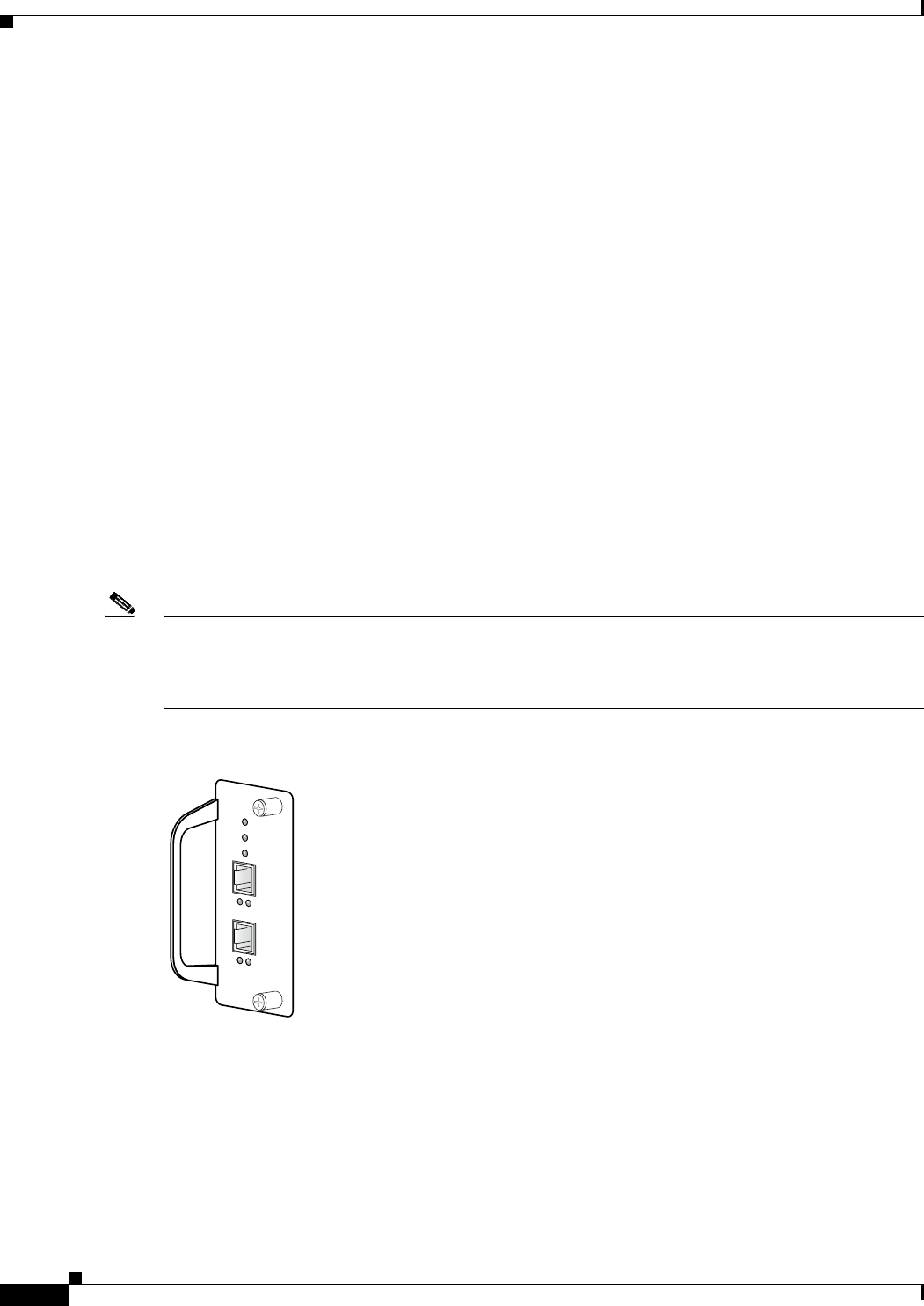
4-8
Cisco uBR10012 Universal Broadband Router Troubleshooting Guide
OL-1237-01
Chapter 4 Troubleshooting Line Cards
Troubleshooting the Timing, Communication, and Control Plus Card
Troubleshooting the Timing, Communication, and Control Plus
Card
At least one working Timing, Communication, and Control Plus (TCC+) card must be installed in the
Cisco uBR10012 router for normal operations. The TCC+ card acts as a secondary processor that
performs the following functions:
•Generates and distributes 10.24 MHz clock references to each cable interface line card.
•Generates and distributes 32-bit time stamp references to each cable interface line card.
•Allows software to independently power off any or all cable interface line cards.
•Provides support for Online Insertion/Removal (OIR) operations of line cards.
•Drives the LCD panel used to display system configuration and status information.
•Monitors the supply power usage of the chassis.
•Provides two redundant RJ-45 ports for external timing clock reference inputs such as a Global
Positioning System (GPS) or BITS clock.
If the Cisco uBR10012 router does not have a working TCC+ card installed, the WAN and cable interface
line cards will experience excessive packet drops, or all traffic will be dropped, because of an invalid
timing signal. Also, if no TCC+ card is installed, the cable power command is disabled, because this
function is performed by the TCC+ card.
Note Because the TCC+ card is considered a half-height card, use slot numbers 1/1 or 2/1 to display
information for the TCC+ card using the show diag command. The show cable clock and show
controllers clock-reference commands also use these slot numbers when displaying clock-related
information.
Figure 4-1 TCC+ Front Panel
The front panel on the TCC+ card has seven LEDs. Table 4-3 describes each LED on the TCC+ card.
56418

4-9
Cisco uBR10012 Universal Broadband Router Troubleshooting Guide
OL-1237-01
Chapter 4 Troubleshooting Line Cards
Troubleshooting the Timing, Communication, and Control Plus Card
When performing any troubleshooting on the TCC+ cards, first check the LEDs as follows:
1. Check the POWER LEDs on each TCC+ card. Are the POWER LEDs on each TCC+ card on
(green)?
–
If no, remove the TCC+ card and reinsert it, making sure that it firmly connects to the backplane
and that both captive screws are tightly connected.
–
If yes, proceed to the next step.
2. Is the STATUS LED on the primary TCC+ card on (green) to indicate that it is the primary card? Is
the STATUS LED on the secondary TCC+ card flashing (green) to indicate that it is the redundant
card?
Use Table 4-4 to continue troubleshooting the TCC+ cards.
Table 4-3 TCC+ Card LEDs and Their Functions
LED Status Description
POWER Green
Off
Indicates that power is supplied to the TCC+ card.
Power is off.
STATUS- bi-color Yellow
Green
Blinking
Green
Indicates that the CPU is in the bootup process, self-test, or downloading code.
Indicates that the CPU has successfully completed the boot, self-test, and code
download process, and that the TCC+ card is the active card.
Indicates that the CPU has successfully completed the boot, self-test, and code
download process, and that the TCC+ card is the backup card.
MAINTENANCE Off
Yellow
Normally off. Indicates that no maintenance action is required.
Indicates a required maintenance operation and that the TCC+ card can be
hot-swapped.
PRESENT (Primary) Green
Off
Normally on. Indicates that a valid clock reference signal is present at the associated
input.
Indicates that no signal is present, or that the TCC+ card is unable to synchronize to
the signal at the associated input.
ACTIVE (Primary) Green
Off
Normally on. Indicates that the associated input has been selected as the active clock
reference for the TCC+ card.
Indicates that the associated input is not the active clock reference.
PRESENT (Secondary) Green
Off
Normally on. Indicates that a valid clock reference signal is present at the associated
input.
Indicates that no signal is present, or that the TCC+ card is unable to synchronize to
the signal at the associated input.
ACTIVE (Secondary) Green
Off
Normally on. Indicates that the associated input has been selected as the active clock
reference for the TCC+ card.
Indicates that the associated input is not the active clock reference.

4-10
Cisco uBR10012 Universal Broadband Router Troubleshooting Guide
OL-1237-01
Chapter 4 Troubleshooting Line Cards
Troubleshooting the Timing, Communication, and Control Plus Card
Table 4-4 TCC+ Card Faults and Recommended Responses
Fault Type Response
The show cable clock command shows that no
TCC+ cards are installed:
Router# show cable clock
Number of TCCplus Cards in the Chassis: 0
TCCplus Cards are not yet configured
Router#
The console also typically displays the error
message %UBR10KTCC-1-NOTCC: No working
TCCplus card available in the system.
1. Verify that at least one TCC+ card is installed in the chassis. If not,
install a TCC+ card, because it is required for normal operations.
2. If only one TCC+ card is installed, it might not have been properly
initialized, so remove it from its slot, wait approximately 30 seconds,
and reinsert it.
3. If only one TCC+ card is installed, its slot might be fault, so remove
the card from its slot and install it in the other TCC+ card slot.
4. Replace the TCC+ card with a known, working TCC+ card.
An IPC error message (IPCGRP-3-SYSCALL)
occurs for the TCC+ card slots (slot 1/1 or slot
2/1).
1. If this message results after a line card is reset using the hw-module
reset command, it is an informational-only message that indicates
only that an IPC message was missed while the processor was
performing the reset of the line card. This error message can be
ignored.
2. Upgrade the Cisco uBR10012 router to Cisco IOS Release
12.2(11)BC2 or later release.
The console displays the following error message:
%UBR10KTCC-1-BADTCC: TCCplus card in
slot put under maintenance: reason
The Cisco uBR10012 router detected that the TCC+ card in the indicated
slot was faulty. If a redundant card is installed, the system passed control
to it. The faulty TCC+ card has been put into maintenance mode. The
following errors are possible:
•Holdover rcvd by Active Card—The active TCC+ card generated a
holdover interrupt to indicate an error in its clock source.
•Holdover rcvd by Backup Card—The backup TCC+ card generated a
holdover interrupt to indicate an error in the clock source being
received by either the Active or Backup card.
•Bad Clock reported by CLC(s)—A cable interface line card reported
that the clock signal being received from the TCC+ card is faulty.
•TRU Loss of Sync—The clock hardware on the TCC+ card reported a
•Unknown—An unknown failure occurred, possibly a hardware
failure.
To correct the problem:
1. If an external clock source is being used, check that the clock source
is valid national clock source, such as a GPS receiver or BITS clock.
2. If the clock source is valid, remove and reinsert the faulty TCC+ card.
3. If the MAINTENANCE LED on the faulty TCC+ card is still lit,
replace the card.

4-11
Cisco uBR10012 Universal Broadband Router Troubleshooting Guide
OL-1237-01
Chapter 4 Troubleshooting Line Cards
Troubleshooting the Timing, Communication, and Control Plus Card
The show controllers clock-reference command
displays compare errors between the two TCC+
cards installed in the Cisco uBR10012 router.
1. If this occurs at system startup or only occasionally at other times,
this error can be ignored, because the system typically records a
slight delay when the TCC+ cards synchronize with each other. These
initial compare errors can be ignored and cleared with the cable
clock clear-counters command.
2. If this error repeatedly occurs, it could indicate a hardware problem
with one of the TCC+ cards. Try replacing each card to see if the
problem disappears.
The show controllers command for a cable
interface displays the message “Timestamp is
from local oscillator.” This command should
show that the timestamp is coming either from an
external source or from the TCC+ card.
1. Verify that at least one TCC+ card is installed in the chassis. If not,
install a TCC+ card.
2. Verify that a valid national clock source, such as a GPS receiver or
BITS clock, is plugged into the TCC+ card’s RJ-45 connector.
3. Replace the TCC+ card.
Table 4-4 TCC+ Card Faults and Recommended Responses
Fault Type Response
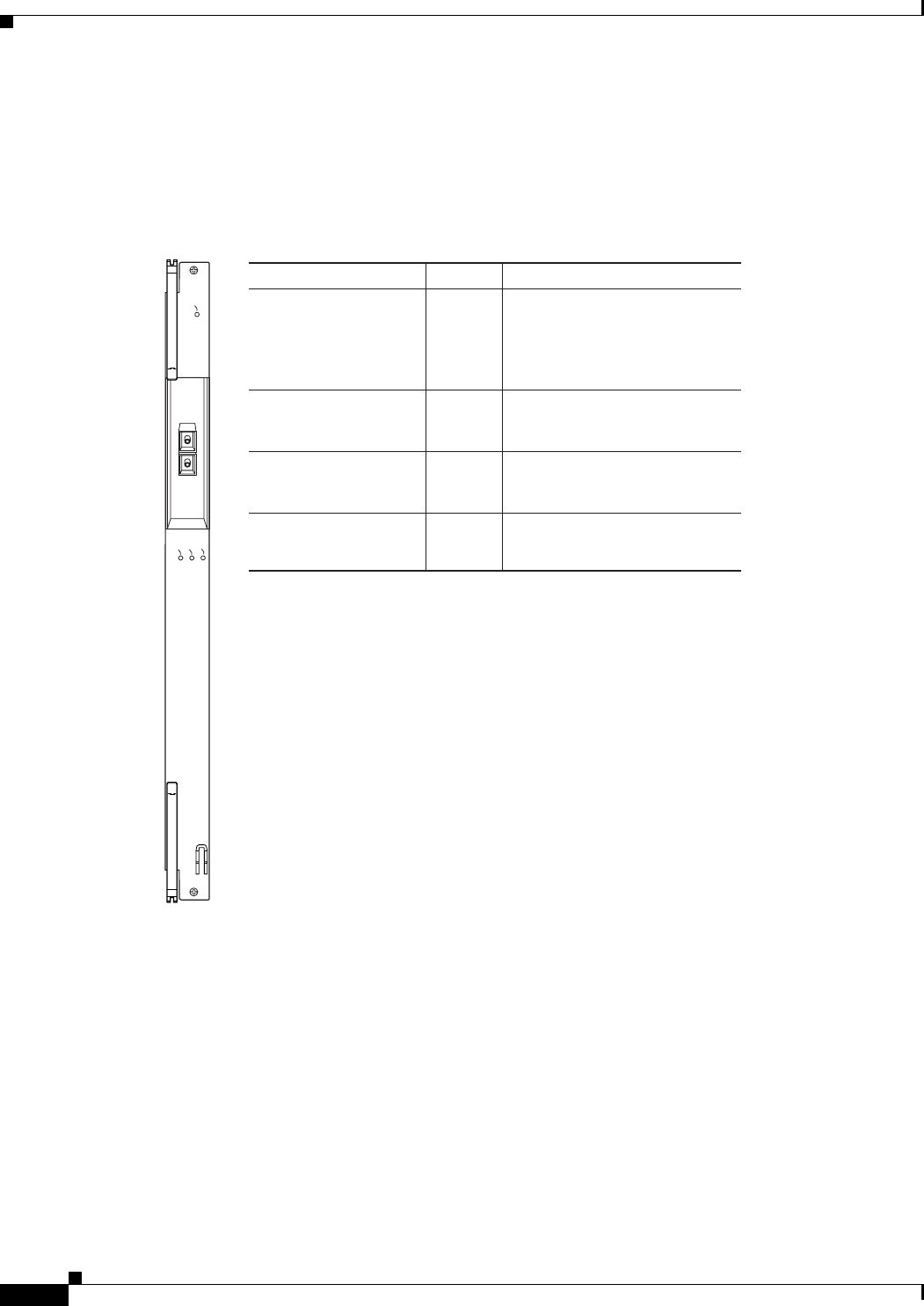
4-12
Cisco uBR10012 Universal Broadband Router Troubleshooting Guide
OL-1237-01
Chapter 4 Troubleshooting Line Cards
Troubleshooting the OC-12 Packet-Over-SONET Line Card
Troubleshooting the OC-12 Packet-Over-SONET Line Card
Figure 4-2 describes the LEDs on the Cisco uBR10-1OC12/P-SMI OC-12 Packet-Over-SONET (POS)
line card faceplate. Use these descriptions to verify the operation of the OC-12 POS line card.
Figure 4-2 OC-12 POS Line Card LEDs
Table 4-5 describes fault conditions on the OC-12 POS line card and recommended corrective actions.
29993
LED Status Description
Fail
Rx (receive)
Tx (transmit)
Carrier
Yellow
Off
Green
A major failure has disabled the
line card.
The line card is operating
properly.
Receiving traffic.
Carrier detected.
Carrier not detected.
Off
Off
Off
Yellow
Not receiving traffic.
Green Transmitting traffic.
Not transmitting traffic.
Green
CISCO
10000
CARRIER
TX
RX
FAIL
OC–12/STM–4 POS SM–IR
0

4-13
Cisco uBR10012 Universal Broadband Router Troubleshooting Guide
OL-1237-01
Chapter 4 Troubleshooting Line Cards
Troubleshooting the OC-12 Packet-Over-SONET Line Card
Table 4-5 OC-12 POS Line Card Fault Indications and Recommended Action
Fault Corrective Action
Fail LED is lit indicating that the line card has failed 1. Reinsert the line card.
2. Replace the line card.
3. Insert the line card in another slot.
4. Contact the Cisco TAC.
Carrier LED is off and interface is enabled 1. Check the fiber optic cable, making sure that it is properly
attached at both ends.
2. Make sure that you are using the proper fiber type.
3. Check the cable connections on the remote equipment.
4. Contact the Cisco TAC.
Fail LED blinks then lights steadily repeatedly
or
Card seems to be passing traffic (Tx/Rx lights), but
cannot communicate with the PRE
1. Check for bent pins on the backplane.
2. If there are no bent pins, replace with a new line card.
3. Try inserting the line card in a different slot.
If the card works in a different slot, the Cisco uBR10012
backplane may be defective. Contact the Cisco TAC.
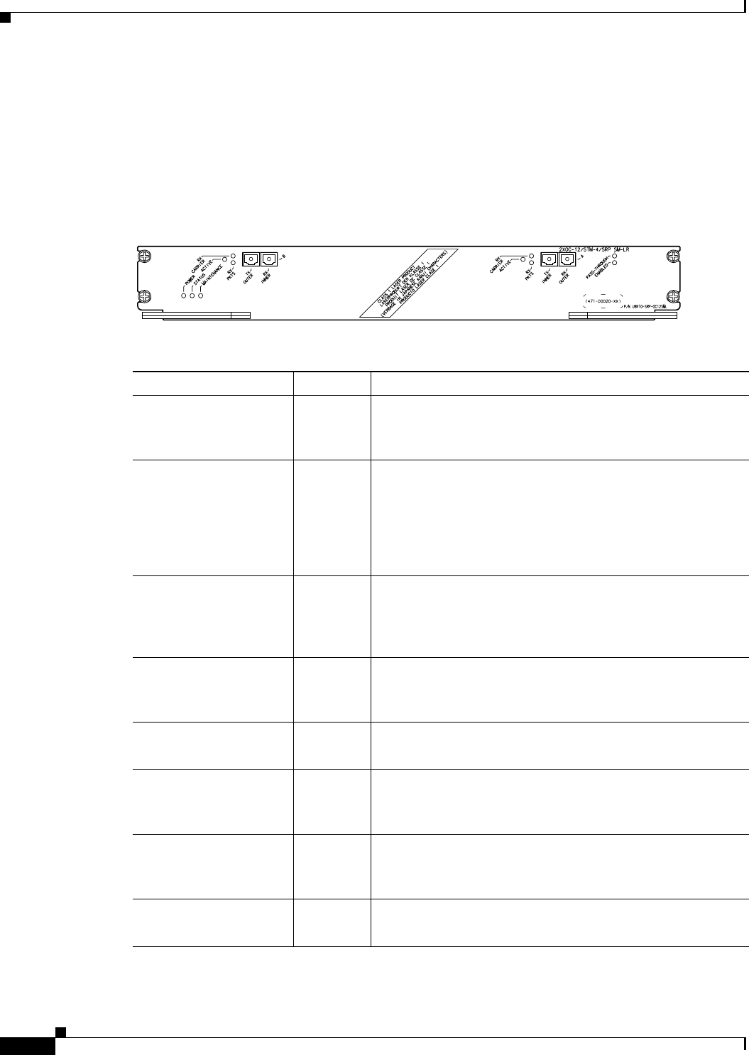
4-14
Cisco uBR10012 Universal Broadband Router Troubleshooting Guide
OL-1237-01
Chapter 4 Troubleshooting Line Cards
Troubleshooting the OC-12 Dynamic Packet Transport Spatial Reuse Protocol WAN Card
Troubleshooting the OC-12 Dynamic Packet Transport Spatial
Reuse Protocol WAN Card
Figure 4-3 shows and Table 4-6 describes the LEDs on the Cisco BR10-SRP-OC12SML Dynamic
Packet Transport (DPT) Spatial Reuse Protocol (SRP) WAN card.
Figure 4-3 OC12 SRP/DPT WAN Line Card LEDs
Table 4-6 Cisco uBR10-SRP-OC12SML DPT WAN Line Card LEDs
LED Status Description
POWER Green
Off
Indicates that power is being supplied to the
Cisco uBR10-SRP- OC12SML DPT WAN line card.
Power off.
STATUS - bi-color Yellow
Green
Indicates that the CPU is in the bootup process, self test, or
downloading code.
Indicates that the CPU has successfully completed the boot,
self test, and code download process, and that the
Cisco uBR10-SRP- OC12SML DPT WAN line card is the
active card.
MAINTENANCE Off
Yellow
Normally off. Indicates that no maintenance action is required.
Indicates a required maintenance operation and that the
Cisco uBR10-SRP- OC12SML DPT WAN line card can be
hot-swapped.
RX CARRIER–B Green
Off
Indicates that the DPT port WAN has detected valid SONET or
SDH framing on the received carrier.
No valid SONET or SDH framing.
ACTIVE Green
Off
Indicates that side B of the DPT port line is functioning.
Not active.
RX PKTS (Packets) Blinking
Green
Off
Indicates that the DPT port line has received a packet. This
LED flickers in normal operation, indicating traffic.
No traffic.
RX CARRIER–A Green
Off
Indicates that the DPT port line has detected valid SONET or
SDH framing on the received carrier.
No valid SONET or SDH framing.
ACTIVE Green
Off
Indicates that side A of the DPT port line is functioning.
Not Active
68499

4-15
Cisco uBR10012 Universal Broadband Router Troubleshooting Guide
OL-1237-01
Chapter 4 Troubleshooting Line Cards
Troubleshooting the OC-12 Dynamic Packet Transport Spatial Reuse Protocol WAN Card
RX PKTS (Packets) Blinking
Green
Off
Indicates that the DPT port line has received a packet. This
LED flickers in normal operation, indicating traffic.
No traffic
PASS-THROUGH Amber
Off
Indicates that the DPT port line is in a pass-through state.
Not active.
ENABLED Green
Off
Indicates that the DPT port line is enabled for operation;
however, the interface port might be in the shutdown state.
Not active.
Table 4-6 Cisco uBR10-SRP-OC12SML DPT WAN Line Card LEDs (continued)
LED Status Description
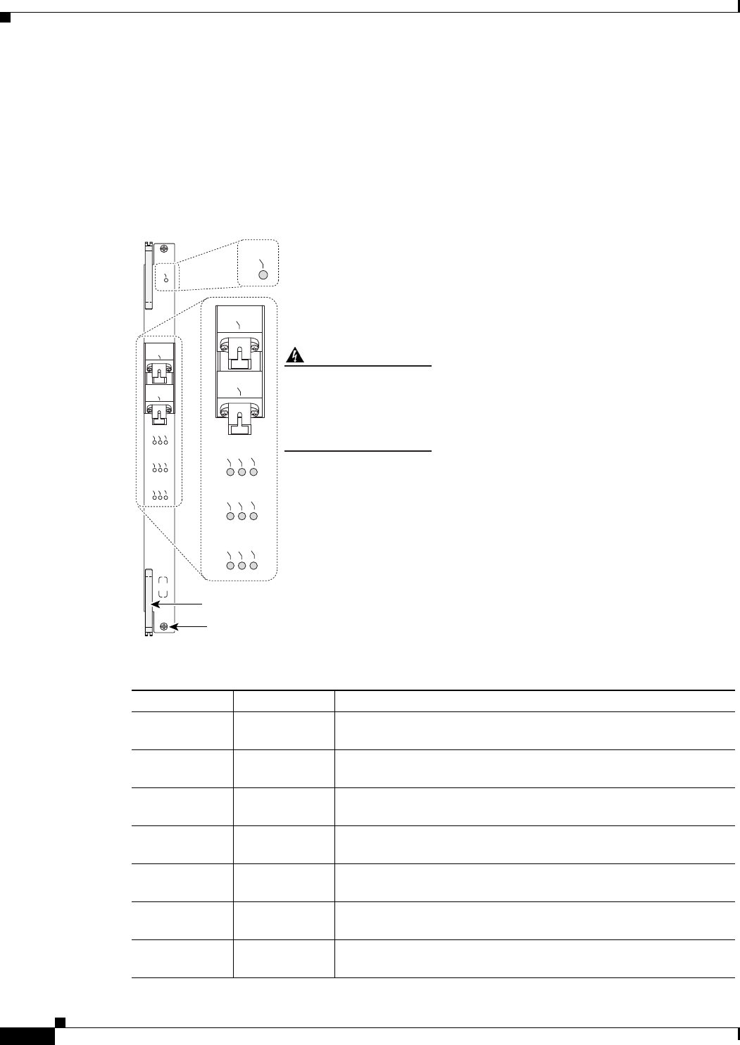
4-16
Cisco uBR10012 Universal Broadband Router Troubleshooting Guide
OL-1237-01
Chapter 4 Troubleshooting Line Cards
Troubleshooting the Cisco uBR10012 OC-48 DPT/POS Line Card
Troubleshooting the Cisco uBR10012 OC-48 DPT/POS Line Card
The Cisco OC-48 DPT⁄POS interface module has a pair of OC-48c, fiber-optic standard connector (SC)
duplex ports that provide an SC connection for either the single-mode short-reach or single-mode
long-reach version. Figure 4-4 shows the faceplate on the Cisco OC-48 DPT⁄POS interface module,
and Ta ble 4-7 describes each LED.
Figure 4-4 Cisco OC-48 DPT Interface Module Faceplate
Table 4-7 Cisco OC-48 DPT LED Status and Description
LED Status Description
FAIL Yellow
Off
Line card is disabled
Line card is operational
ENABLE Green
Off
Port is enabled
Port is disabled
POS Green
Off
Operating in POS mode
Not operating in POS mode
SRP Green
Off
Operating in SRP mode
Not operating in SRP mode
CD Green
Off
Carrier detected
No carrier detected
TX Green
Off
Packets transported
No packets transported
RX Green
Off
Packets received
No packets received
82923
CISCO
10000
ENABLE
POS
SRP
FAI L
OC–48/STM–16 POS/SRP SM–LR
P/N ESR-10C48/P/SRPSMS
CD
TX
RX
SYNC
WRAP
PASS
THRU
TX
RX
FAIL
Ejector lever
Captive screw
ENABLE
POS
SRP
CD
TX
RX
SYNC
WRAP
PASS
THRU
TX
RX
Invisible laser radiation may
be emitted from
disconnected fibers or
connectors. Do not stare
into beams or view directly
with optical instruments.
Warning

4-17
Cisco uBR10012 Universal Broadband Router Troubleshooting Guide
OL-1237-01
Chapter 4 Troubleshooting Line Cards
Troubleshooting the Cisco uBR10012 OC-48 DPT/POS Line Card
SYNC Green
Off
Card synchronized to mate card
Card not synchronized
WRAP Yellow
Off
Interface is wrapped
Interface not wrapped
PASS THRU Yellow
Off
DPT port line is in a pass-through state
DPT port line not in pass-through state
Table 4-7 Cisco OC-48 DPT LED Status and Description
LED Status Description
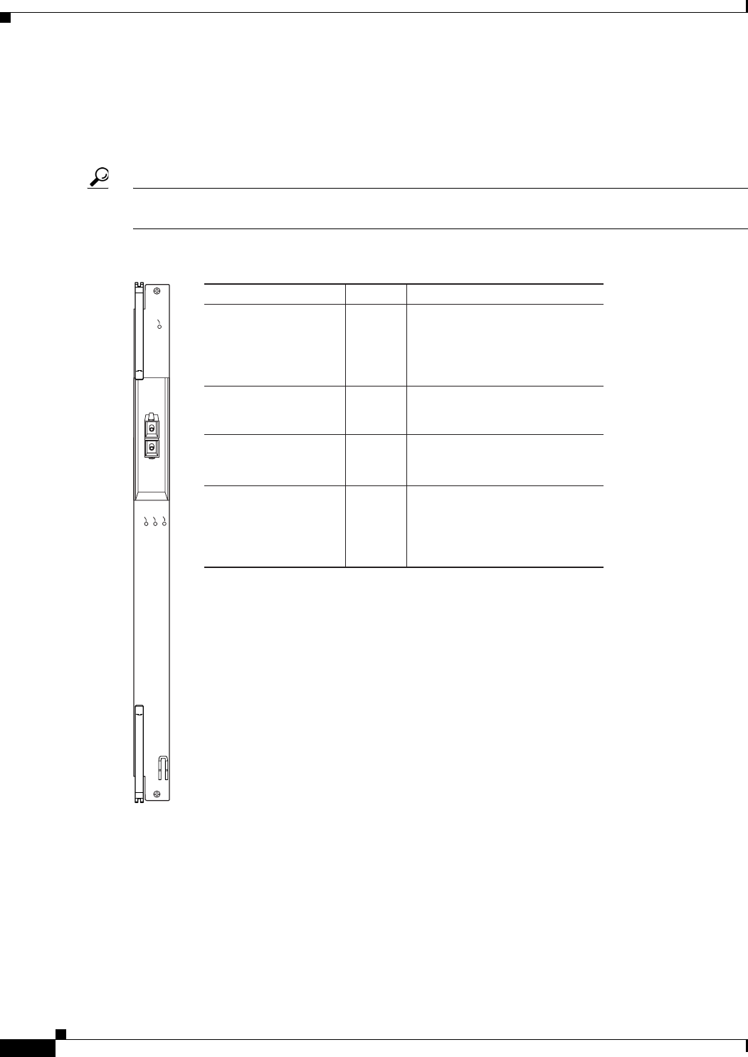
4-18
Cisco uBR10012 Universal Broadband Router Troubleshooting Guide
OL-1237-01
Chapter 4 Troubleshooting Line Cards
Troubleshooting the Gigabit Ethernet Line Card
Troubleshooting the Gigabit Ethernet Line Card
Figure 4-5 describes the LEDs on the Cisco uBR10-1GE Gigabit Ethernet line card faceplate to help you
verify correct operation.
Tip Make sure that the gigabit Ethernet Interface Converter (GBIC) type on the Cisco uBR10012 router
matches the GBIC type at the other end of the fiber optic cable.
Figure 4-5 Gigabit Ethernet Line Card Faceplate and LED Descriptions
29992
LED Status Description
Fail
Rx (receive)
Tx (transmit)
Link
Yellow
Off
Green
A major failure has disabled the
line card.
The line card is operating
properly.
Receiving traffic.
Carrier detected; the port is
able to pass traffic.
No carrier detected; the port is
not able to pass traffic.
Off
Off
Off
Yellow
Not receiving traffic.
Green Transmitting traffic.
Not transmitting traffic.
Green
CISCO
10000
LINK
TX
RX
FAIL
GIGABIT ETHERNET
0

4-19
Cisco uBR10012 Universal Broadband Router Troubleshooting Guide
OL-1237-01
Chapter 4 Troubleshooting Line Cards
Troubleshooting the Gigabit Ethernet Line Card
Table 4-8 describes the gigabit Ethernet line card fault indications and suggests responses to each.
Table 4-8 Gigabit Ethernet Line Card Faults and Recommended Responses
Fault Type Response
Fail LED is lit yellow indicating that a major fault
has disabled the card
1. Reinsert the line card.
2. Insert the line card into another slot.
3. Replace the line card.
4. If neither of the above responses to a card
failure succeeds, call the Cisco TAC.
Fail LED blinks then lights steadily repeatedly
or
Card seems to be passing traffic (Tx/Rx lights),
but cannot communicate with the PRE
1. Check for bent pins on the backplane.
2. If there are no bent pins, replace with a new
line card.
Try inserting the line card in a different slot.
If the card works in a different slot, the
Cisco uBR10012 backplane may be defective.
Call the Cisco TAC.
Fail LED blinks steadily This is a user correctable problem. The steadily
blinking LED indicates a transmit failure.
To correct the problem:
1. Reinsert the GBIC.
If reinsertion fails:
2. Replace the GBIC.
Link LED does not light but the port is enabled 1. Make sure the fiber optic cable is plugged in
properly, unbroken, and undamaged.
2. Make sure that you are using the correct type
of fiber optic cable.
3. If you have autonegotiation enabled on the
local gigabit Ethernet interface, make sure
that it is enabled on the remote interface also.
If autonegotiation is disabled, it must be
disabled at the remote interface as well.
4. Replace the GBIC.
Gigabit Ethernet card resets itself intermittently. 1. Issue the show diag command. If this
indicates a “parity error” occurred, contact
Cisco TAC for possible replacement of the
card.

4-20
Cisco uBR10012 Universal Broadband Router Troubleshooting Guide
OL-1237-01
Chapter 4 Troubleshooting Line Cards
Troubleshooting the Gigabit Ethernet Line Card

CHAPTER
5-1
Cisco uBR10012 Universal Broadband Router Troubleshooting Guide
OL-1237-01
5
Replacing or Recovering Passwords
This section describes how to recover a lost enable or console login password, and how to replace a lost
enable secret password on the Cisco uBR10012 router.
Note It is possible to recover the enable or console login password. The enable secret password is encrypted,
however, and must be replaced with a new enable secret password.
Password Recovery Procedure Overview
The following is an overview of the steps in the password recovery procedure.
•If you can log in to the router, enter the show version command to determine the existing
configuration register value.
•Press the Break key to go to the bootstrap program prompt (ROM monitor). You might need to
reload the system image by power-cycling the router.
•Change the configuration register to 0x2142 so that the router ignores the startup configuration file
during bootup. This allows you to log in without using a password and to display the startup
configuration password.
•Power cycle the router by typing reload at the rommon> prompt.
•Log in to the router and enter the privileged EXEC mode.
•Enter the show startup-config command to display the passwords.
•Recover or replace the displayed passwords.
•Change the configuration register back to its original setting.
Note To recover a lost password if the break function is disabled on the router, you must have physical access
to the router.
Password Recovery Procedure
To recover or replace a lost enable, enable secret, or console login password, use this procedure:
Step 1 Attach an ASCII terminal to the console port on the router.

5-2
Cisco uBR10012 Universal Broadband Router Troubleshooting Guide
OL-1237-01
Chapter 5 Replacing or Recovering Passwords
Password Recovery Procedure
Step 2 Configure the terminal to operate at 9600 baud, 8 data bits, no parity, and 1 stop bit.
Step 3 If you can log in to the router as a nonprivileged user, enter the show version command to display the
existing configuration register value, then go to Step 6. If you cannot log in to the router at all, go to the
next step.
Step 4 Press the Break key or send a break signal from the console terminal.
•If break is enabled, the router enters the ROM monitor, indicated by the ROM monitor prompt
(rommon>). Go to Step 6.
•If break is disabled, power cycle the router (turn off the router or unplug the power cord, and then
restore power). Then go to Step 5.
Step 5 Within 60 seconds of restoring the power to the router, press the break key or send a break signal. This
action causes the router to enter the ROM monitor and display the ROM monitor prompt (rommon>).
Step 6 Set the configuration register using the configuration register utility. Enter the confreg command at the
ROM monitor prompt as follows:
rommon> confreg
Answer yes to the enable “ignore system config info?” Press the return key at all other prompts to accept
the existing value.
Step 7 Reboot the router by entering the reset command:
rommon> reset
The router initializes, the configuration register is set to 0x142, and the router boots the system image
from Flash memory and enters the system configuration dialog (setup):
--- System Configuration Dialog --
Step 8 Enter no in response to the system configuration dialog prompts until the following message appears:
Press RETURN to get started!
Step 9 Press Return. The user EXEC prompt appears:
Router>
Step 10 Enter the enable command to enter privileged EXEC mode. Then enter the show startup-config
command to display the passwords in the configuration file as follows:
Router# show startup-config
Step 11 Scan the configuration file display, looking for the passwords (the enable passwords are usually located
near the beginning of the file, and the console login or user EXEC password is near the end). The
passwords displayed appear similar to the following:
enable secret 5 $1$ORPP$s9syZt4uKn3SnpuLDrhuei
enable password 23skiddoo
.
.
line con 0
password onramp
The enable secret password is encrypted and cannot be recovered; it must be replaced. Go to the next
step to replace an enable secret, console login, or enable password. If there is no enable secret password,
note the enable and console login passwords. If the enable and console login passwords are not
encrypted, go to Step 16.

5-3
Cisco uBR10012 Universal Broadband Router Troubleshooting Guide
OL-1237-01
Chapter 5 Replacing or Recovering Passwords
Password Recovery Procedure
Caution Do not execute the next step unless you have determined you must change or replace the enable, enable
secret, or console login passwords. Failure to follow the steps as shown might cause you to erase the
router configuration.
Step 12 Enter the copy startup-config running-config command to load the startup configuration file into
running memory. This action allows you to modify or replace passwords in the configuration.
Router# copy startup-config running-config
Step 13 Enter the privileged EXEC command configure terminal to enter configuration mode:
Router# configure terminal
Step 14 Change all three passwords using the following commands:
Router(config)# enable secret
newpassword1
Router(config)# enable password
newpassword2
Router(config)# line con 0
Router(config-line)# password
newpassword3
Change only the passwords necessary for your configuration. You can remove individual passwords by
using the no form of the above commands. For example, entering the no enable secret command
removes the enable secret password.
Step 15 You must configure all interfaces to avoid having the system be administratively shut down:
Router(config)# interface fastethernet 0/0
Router(config-int)# no shutdown
Enter the equivalent commands for all interfaces that were originally configured. If you omit this step,
all interfaces are administratively shut down and unavailable when the router is restarted.
Step 16 Use the config-register command to set the configuration register to the original value noted in Step 3
or Step 7, or to the factory default value 0x2102.
Router(config)# config-register 0x2102
Step 17 Press Ctrl-Z (hold down the Control key while you press Z) or enter end to exit configuration mode
and return to the EXEC command interpreter.
Caution Do not execute the next step unless you have changed or replaced a password. If you skipped Step 12
through Step 15, go to Step 19. Failure to observe this caution causes you to erase the router
configuration file.
Step 18 Enter the copy running-config startup-config command to save the new configuration to NVRAM.
Step 19 Enter the reload command to reboot the router.
Step 20 Log in to the router using the new or recovered passwords.

5-4
Cisco uBR10012 Universal Broadband Router Troubleshooting Guide
OL-1237-01
Chapter 5 Replacing or Recovering Passwords
Password Recovery Procedure

A-1
Cisco uBR10012 Universal Broadband Router Troubleshooting Guide
OL-1237-01
APPENDIX
A
Unsupported Commands
The following are lists of the commands that are present but not supported for the
Cisco uBR10012 router in various releases of the Cisco IOS software.
•Unsupported Frame Relay Commands, page A-1
•HCCP Commands, page A-2
•MLPPP Commands, page A-2
•Unsupported MPLS VPN Commands, page A-3
•Unsupported PPP Commands, page A-3
•Spectrum Management Commands, page A-3
•Unsupported Telco-Return Commands, page A-3
Warning
Cisco strongly advises against using unsupported Cisco IOS commands, even if described, because such
commands can have undesirable effects upon the performance of the Cisco CMTS. In particular, Cisco advises
against using any unsupported commands that pertain to service-policy or to Modular Quality of Service
command-line interface (MQC) while Parallel Express Forwarding (PXF) is running on the Cisco CMTS.
Such commands may cause the Cisco CMTS to hang with unpredictable recovery times.
Unsupported Frame Relay Commands
The following commands are not supported in any Cisco IOS software release.
•FRF.12 fragmentation commands
•FRF.11 VoFR commands
•frame-relay adaptive-shaping {becn | foresight}
•frame-relay bc {in | out} bits
•frame-relay be {in | out} bits
•frame-relay cir {in | out} bps
•frame-relay custom-queue-list list-number
•frame-relay de-group group-number dlci
•frame-relay ip [rtp | tcp] header-compression [passive]
•frame-relay map protocol protocol-address dlci [broadcast] [ietf | cisco] [payload-compress
{packet-by-packet | frf9 stac [hardware-options]}]

A-2
Cisco uBR10012 Universal Broadband Router Troubleshooting Guide
OL-1237-01
Appendix A Unsupported Commands
HCCP Commands
•frame-relay map ip ip-address dlci [broadcast] [cisco | ietf] [nocompress] tcp
header-compression {active | passive}
•frame-relay mincir {in | out} bps
•frame-relay traffic-rate average [peak]
•frame-relay traffic-shaping
•show frame-relay ip [rtp | tcp] header-compression [interface]
HCCP Commands
The following commands are supported in Cisco IOS Release 12.2(8)BC2 and later 12.2 BC releases.
These commands are not supported in previous releases.
•hccp authenticate
•hccp authenticate key-chain
•hccp ds-switch
•hccp lockout
•hccp protect
•hccp revert
•hccp reverttime
•hccp switch
•hccp timers
•hccp track
•hccp unlockout
•hccp working
•show hccp
•show hccp interface
•debug hccp authentication
•debug hccp events
•debug hccp sync
MLPPP Commands
The following commands are supported in Cisco IOS Release 12.2(4)BC1 and later 12.2 BC releases.
These commands are not supported in previous releases.
•multilink load-threshold
•multilink max-fragments
•ppp multilink fragment-delay
•ppp multilink fragmentation
•ppp multilink idle-link
•ppp multilink interleave

A-3
Cisco uBR10012 Universal Broadband Router Troubleshooting Guide
OL-1237-01
Appendix A Unsupported Commands
Unsupported MPLS VPN Commands
Unsupported MPLS VPN Commands
The following commands are not supported in any Cisco IOS software release.
•ip vrf
•ip vrf forwarding
•mpls ip
•mpls label-protocol ldp
•show ip protocols vrf
•show ip vrf
•show ip route vrf
Unsupported PPP Commands
The following commands are not supported in any Cisco IOS software release.
•compress [predictor | stac | mppc [ignore-pfc]]
•debug ppp cbcp
•ppp bridge appletalk
•ppp bridge ip
•ppp bridge ipx [novell-ether | arpa | sap | snap]
•ppp reliable-link
Spectrum Management Commands
The following commands are supported in Cisco IOS Release 12.2(8)BC2 and later 12.2 BC releases.
These commands are not supported in previous releases.
•cable upstream hop-priority
•cable upstream threshold
•show cable modem [ip-address | interface | mac-address] snr
•show controllers cable upstream spectrum
Unsupported Telco-Return Commands
The following commands are not supported in any Cisco IOS software release.
•cable telco-return enable
•cable telco-return interval
•cable telco-return spd dhcp-authenticate
•cable telco-return spd dhcp-server
•cable telco-return spd dial-timer

A-4
Cisco uBR10012 Universal Broadband Router Troubleshooting Guide
OL-1237-01
Appendix A Unsupported Commands
Unsupported Telco-Return Commands
•cable telco-return spd factory-default
•cable telco-return spd manual-dial
•cable telco-return spd password
•cable telco-return spd phonenum
•cable telco-return spd ppp-authenticate
•cable telco-return spd radius-realm
•cable telco-return spd service-provider
•cable telco-return spd threshold
•cable telco-return spd username
•debug cable telco-return
•debug telco-return msg

B-1
Cisco uBR10012 Universal Broadband Router Troubleshooting Guide
OL-1237-01
APPENDIX
B
Recommended Tools and Test Equipment
Table B-1 lists the basic tools and test equipment necessary to perform general maintenance and
troubleshooting tasks on the Cisco uBR10012 router.
The following sections describe advanced testing equipment to aid in complex problem isolation.
Testing with Digital Multimeters and Cable Testers
Use a digital multimeter to measure parameters such as AC and DC voltage, current, resistance,
capacitance, cable continuity. Use cable testers, also, to verify physical connectivity.
Use cable testers (scanners) to check physical connectivity. Cable testers are available for shielded
twisted pair (STP), unshielded twisted pair (UTP), 10BaseT, and coaxial and twinax cables. A given
cable tester might be able to perform any of the following functions:
•Test and report on cable conditions, including near-end crosstalk (NEXT), attenuation, and noise.
•Perform time domain reflectometer (TDR), traffic monitoring, and wire map functions.
•Display Media Access Control (MAC) layer information about LAN traffic, provide statistics such
as network utilization and packet error rates, and perform limited protocol testing (for example,
TCP/IP tests such as ping).
Table B-1 Recommended Tools and Test Equipment
Equipment Description
Number 2 Phillips and flat-head
screwdrivers
Small and medium-sized.
Voltage tester Refer to the “Testing with Digital Multimeters and Cable
Testers” section on page B-1.
Optical fiber test equipment Refer to the “Testing with Digital Multimeters and Cable
Testers” section on page B-1.
Cable testing equipment Refer to the “Testing with Digital Multimeters and Cable
Testers” section on page B-1.
ESD-preventive wrist or ankle
strap with connection cord
—

B-2
Cisco uBR10012 Universal Broadband Router Troubleshooting Guide
OL-1237-01
Appendix B Recommended Tools and Test Equipment
Testing with TDRs and OTDRs
Test fiber-optic cable both before installation (on-the-reel testing) and after installation. Continuity
testing of the fiber requires either a visible light source or a reflectometer. Light sources capable of
providing light at the three predominant wavelengths, 850 nanometers (nm), 1300 nm, and 1550 nm, are
used with power meters that can measure the same wavelengths and test attenuation and return loss in
the fiber.
Testing with TDRs and OTDRs
This section describes time domain reflectometers (TDRs) and optical time domain reflectometers
(OTDRs), which are typically used to detect cable defects.
Testing with TDRs
Use time domain reflectometers to test for the following cable defects:
•Open and short circuits
•Crimps, kinks, and sharp bends
•Impedance mismatches
•Other defects
A TDR works by “bouncing” a signal off the end of the cable. Open circuits, short circuits and other
problems reflect the signal back at different amplitudes, depending on the problem.
A TDR measures:
•the amount of time it takes for the signal to reflect
•The physical distance to a fault in the cable
•The length of a cable
Some TDRs can also calculate the propagation rate based on a configured cable length.
Testing with OTDRs
Use optical time domain reflectometers to:
•Locate fiber breaks
•Measure attenuation
•Measure the length of a fiber
•Measure splice or connector losses
An OTDR can be used to identify the “signature” of a particular installation, noting attenuation and
splice losses. This baseline measurement can then be compared with future signatures if you suspect a
problem in the system.

B-3
Cisco uBR10012 Universal Broadband Router Troubleshooting Guide
OL-1237-01
Appendix B Recommended Tools and Test Equipment
Testing with Breakout Boxes, Fox Boxes, and BERTs/BLERTs
Testing with Breakout Boxes, Fox Boxes, and BERTs/BLERTs
Use breakout boxes, fox boxes, and bit/block error rate testers (BERTs/BLERTs) to measure the digital
signals present at:
•PCs
•Printers
•Modems
•CSU/DSUs
These devices can monitor data line conditions, analyze and trap data, and diagnose problems common
to data communication systems. Traffic from data terminal equipment (DTE) through data
communications equipment (DCE) can be examined to:
•Isolate problems
•Identify bit patterns
•Ensure that the correct cabling is installed
These devices cannot test media signals such as Ethernet, Token Ring, or FDDI.
Testing with Network Monitors
Use network monitors to:
•Track packets crossing a network
•Provide an accurate picture of network activity at any moment
•Provide a historical record of network activity over a period of time
Network monitors do not decode the contents of frames. Monitors are useful for baselining, in which the
activity on a network is sampled over a period of time to establish a normal performance profile, or
baseline.
Monitors collect information such as packet sizes, the number of packets, error packets, overall usage of
a connection, the number of hosts and their MAC addresses, and details about communications between
hosts and other devices. This data can be used to:
•Create profiles of LAN traffic
•Locate traffic overloads
•Plan for network expansion
•Detect intruders
•Establish baseline performance
•Distribute traffic more efficiently

B-4
Cisco uBR10012 Universal Broadband Router Troubleshooting Guide
OL-1237-01
Appendix B Recommended Tools and Test Equipment
Testing with Network Analyzers
Testing with Network Analyzers
Use network analyzers (also called protocol analyzers) to decode protocol layers in a recorded frame and
present the layers as readable abbreviations or summaries, detailing which layer is involved (physical,
data link, and so forth) and the function each byte or byte content serves.
Most network analyzers can perform many of the following functions:
•Filter traffic that meets certain criteria so that, for example, all traffic to and from a particular device
can be captured.
•Time-stamp captured data.
•Present protocol layers in an easily readable form.
•Generate frames and transmit them onto the network.
•Incorporate an “expert” system in which the analyzer uses a set of rules, combined with information
about the network configuration and operation, to diagnose and solve, or offer potential solutions
to, network problems.

IN-1
Cisco uBR10012 Universal Broadband Router Troubleshooting Guide
OL-1237-01
INDEX
A
access-list compiled command 3-13
access lists 3-13
AC PEM faults 2-1 to 2-3
ACTIVE LED
OC-12 DPT/SRP 4-14
TCC+ 4-9
alignment errors 3-15
correctable 3-15
fatal 3-16
alphanumeric display
list of messages 3-2
messages 1-6
ARP traffic problems 3-9
B
BERT B-3
bit error rate testers B-3
BLERT B-3
block error rate testers B-3
blower failures 2-7
see also show commands
blower module faults 2-7
breakout boxes B-3
bus errors 3-13
line cards 4-5
C
cable arp command 3-10
cable clock clear-counters command 4-11
cable power command 4-8
cable proxy-arp command 3-10
cable testers B-1
cache parity errors 4-4
Carrier LED
OC-12 POS 4-13
CD LED 4-16
Cisco IOS, displaying version 1-3
commands, unsupported A-1
confreg command 7-2
console 3-6
cable types 3-7
console port 3-7
console problems 3-7
copy startup-config running-config command 7-3
correctable alignment errors 3-15
crashes, line card 4-6
D
DC PEM faults 2-3 to 2-5
debug messages 3-11
digital multimeters B-1
displaying environmental information 1-4
displaying software version 1-3
documentation viii
E
electrical problems 2-6
see also PEM faults
ENABLE LED
OC-48 DPT/POS 4-16

Index
IN-2
Cisco uBR10012 Universal Broadband Router Troubleshooting Guide
OL-1237-01
enable secret command 7-3
environmental information, displaying 1-4
Ethernet problems 3-6
exec processes 3-11
F
Fail LED
Gigabit Ethernet 4-19
OC-12 POS line card 4-13
OC-48 DPT/POS 4-16
fallbacks 3-17
fan assembly failures 2-7
fatal alignment errors 3-16
faults
PRE-1 module 3-5
flowchart 1-4
fox boxes B-3
frame relay commands A-1
FRUs 2-6
G
GBIC 4-18, 4-19
Gigabit Ethernet
autonegotiation 4-19
GBIC type 4-18
LEDs 4-18
troubleshooting 4-18
Gigabit Ethernet interface converter (GBIC) 4-18
H
hard parity errors 3-17
hardware
verifying 1-2
HCCP commands A-2
hw-module reset command 4-10
hw-module slot reset command 4-7
I
interrupts
spurious 3-18
IP input processing 3-12
L
LEDs
ACTIVE, OC-12 DPT/SRP 4-14
ACTIVE, TCC+ 4-9
alarm 3-6
Carrier, OC-12 POS 4-13
CD, OC-48 DPT/POS 4-16
critical 1-6
ENABLE, OC-48 DPT/POS 4-16
Fail, Gigabit Ethernet 4-19
Fail, OC-12 POS 4-13
Fail, OC-48 DPT/POS 4-16
Fail, PRE 1-6
Fail, PRE-1 module 3-5
Gigabit Ethernet 4-18
line cards 4-12, 4-18
Link, Gigabit Ethernet 4-19
MAINTENANCE, OC-12 SRP/DPT 4-14
MAINTENANCE, TCC+ 4-9
Major 1-6
Minor 1-6
OC-12 DPT/SRP 4-14
OC-12 POS 4-12
PASS THRU, OC-48 DPT/POS 4-17
PEM fault 1-6
POS, OC-48 DPT/POS 4-16
Power 1-6
POWER, OC-12 DPT/SRP 4-14
POWER, TCC+ 4-9

Index
IN-3
Cisco uBR10012 Universal Broadband Router Troubleshooting Guide
OL-1237-01
PRE-1 module 3-4 to 3-6
PRESENT, TCC+ 4-9
RX, OC-48 DPT/POS 4-16
RX CARRIER, OC-12 DPT/SRP 4-14
RX PKTS, OC-12 DPT/SRP 4-14
SRP, OC-48 DPT/POS 4-16
Status 3-4
STATUS, OC-12 DPT/SRP 4-14
STATUS, TCC+ 4-9
SYNC, OC-48 DPT/POS 4-17
TCC+ 4-8
transmit 4-12, 4-18
TX, OC-48 DPT/POS 4-16
WRAP, OC-48 DPT/POS 4-17
line cards
bus errors 4-5
cache parity errors 4-4
crashes 4-6
general troubleshooting 4-2
Gigabit Ethernet 4-18
LEDs 4-12, 4-18
OC-12 DPT/SRP 4-14
OC-12 POS 4-12
troubleshooting 4-1
Link LED
Gigabit Ethernet 4-19
low memory errors 3-16
M
MAINTENANCE LED 4-14
TCC+ 4-9
management Ethernet 3-6
memory
cache parity errors 4-4
parity errors 3-16
problems 3-15
spurious accesses 3-19
MLPPP commands A-2
MPLS VPN commands A-3
N
network analyzers B-4
network monitors B-3
O
OC-12 DPT/SRP
LEDs 4-14
troubleshooting 4-14
OC-12 POS
LEDs 4-12
troubleshooting 4-12
OC-48 DPT/POS
LEDs 4-16
troubleshooting 4-16
optical time domain reflectometers B-2
OTDR B-2
overheating 2-7
P
parity errors 3-16
cache 4-4
hard 3-17
soft 3-17
particle pool fallbacks 3-17
PASS THRU LED
OC-48 DPT/POS 4-17
password recovery 7-1
PEM faults 2-1
DC 2-3
POS LED
OC-48 DPT/POS 4-16
power cables 2-6
POWER LED

Index
IN-4
Cisco uBR10012 Universal Broadband Router Troubleshooting Guide
OL-1237-01
OC-12 DPT/SRP 4-14
TCC+ 4-9
PPP commands A-3
PRE-1 module 3-1
alphanumeric display 1-6, 3-2
console connection 3-6
faceplate 3-5
fault indications 3-5
faults 3-4, 3-5
redundant modules 3-3
status screen 1-6, 3-2
support for PRE-1 module and not PRE module 3-2
PRE-1 module LEDs 3-4 to 3-6
description 3-5
fail LED 3-5
Status 3-4
unlit 3-5
PRE module
support for PRE-1 module and not PRE module 3-2
PRESENT LED
TCC+ 4-9
processes 3-12
R
recovering passwords 7-1
related documentation viii
reload command 7-1
reset command 7-2
RX CARRIER LED 4-14
RX LED
OC-48 DPT/POS 4-16
RX PKTS LED 4-14
S
scheduler allocate command 3-12
show commands
Output Interpreter 3-8, 3-15, 4-5
show buffers 3-18
show cable clock 4-8, 4-10
show context 4-2, 4-5
show controllers 4-11
show controllers clock-reference 4-8, 4-11
show diag 4-2, 4-8, 4-19
show environment 1-4, 2-1, 2-3
show facility-alarm status 3-6
show hardware 1-1, 1-2
show interface 3-6
show log 3-6, 4-2, 4-4, 4-5, 4-7
show processes cpu 4-6
show region 3-14
show stacks 3-15, 4-5
show startup-config 7-1
show tech-support 3-1, 3-15, 4-4, 4-5, 4-7
show version 1-3, 3-13, 3-16, 4-2, 7-1, 7-2
SIG type values 4-3
slot problems 3-6
soft parity errors 3-17
software forced crashes 4-6
software version, displaying 1-3
spectrum management commands A-3
spurious interrupts 3-18
spurious memory accesses 3-19
SRP LED
OC-48 DPT/POS 4-16
stack command 3-1
startup sequence 1-5
behavior 1-5
possible boot messages 3-2
STATUS LED 4-14
TCC+ 4-9
SYNC LED
OC-48 DPT/POS 4-17
system exception errors 4-3
system messages 3-11

Index
IN-5
Cisco uBR10012 Universal Broadband Router Troubleshooting Guide
OL-1237-01
T
TCC+
LEDs 4-8
troubleshooting 4-8
TDR B-2
telco-return commands A-3
terminal settings 3-8
test equipment B-1
time domain reflectometers B-2
Timing, Communication, and Control Plus card, see also
TCC+ card
tools and test equipment B-1
troubleshooting
access lists 3-13
alignment errors 3-15
ARP traffic 3-9
basic checklist 1-1
bus errors 3-13, 4-5
cache parity errors 4-4
CPUHOG errors 3-11
debug and system messages 3-11
excessive interrupts 3-12
excessive processes 3-12
excessive SNMP traffic 3-13
flowchart 1-4
Gigabit Ethernet 4-18
hardware 1-4
high CPU utilization 3-9
IP input processing 3-12
line cards 4-1
low memory errors 3-16
memory parity errors 3-16
memory problems 3-15
OC-12 DPT/SRP 4-14
OC-12 POS 4-12
OC-48 DPT/POS 4-16
particle pool fallbacks 3-17
processes 3-11
redundant PRE-1 modules 3-3
scheduler problems 3-12
software forced crashes 4-6
spurious interrupts 3-18
spurious memory accesses 3-19
system crashes 3-8
system problems 3-8
TCC+ 4-8
test equipment B-1
TTY lines 3-11
TX LED
OC-48 DPT/POS 4-16
U
unsupported commands A-1
V
verifying the hardware 1-2
virtual exec processes 3-11
VTY sessions 3-11
W
WRAP LED
OC-48 DPT/POS 4-17

Index
IN-6
Cisco uBR10012 Universal Broadband Router Troubleshooting Guide
OL-1237-01
