GUIDE 2005 Z 9181 Trussteel Design Manual 2012
User Manual: Z 9181
Open the PDF directly: View PDF ![]() .
.
Page Count: 78
The World Leader in
Cold-Formed Steel Trusses
Truss Design Manual
V2
a division of ITW Building Components Group
888.565.9181 • www.TrusSteel.com
a division of ITW Building Components Group
Truss Design Manual
TRUSS DESIGN MANUAL
1 OVERVIEW
1.01 Introduction
1.02 Specifiers & Designers
1.03 Contractor & Installer
1.04 Truss Components & Code Recognition
1.05 Framing & Connections
1.06 Authorized TrusSteel Fabricators
1.07 Education & CES
1.08 Notes Page
2 APPLICATIONS
2.01 Applications
2.02 Projects
3 SPECIFYING / DESIGNING
3.01 Overview
3.02 Building Codes & Design Standards
3.03 Information Required for Truss Design
3.05 TrusSteel System
3.07 Wind Loading
3.10 Snow Loading
3.11 Seismic Loading
3.13 Sound Control
3.14 Sustainability & LEED
3.15 Fire Resistance & UL
3.16 Trusses as Building Components
3.17 Roof Truss Systems - Framing
3.22 Roof Truss Systems - Sample Spans
3.23 Floor Truss Systems
3.26 Guide Specifications
© Copyright 2012 ITW Building Components Group, Inc.
This Design Manual is intended as a guide to building professionals for suggested uses of TrusSteel trusses. The building code of jurisdiction and a truss design
professional should be consulted before incorporating information from this publication into any plan or structure.
ITW Building Components Group, Inc., nor any of its divisions or companies, does not warrant the recommendations and information contained herein as proper
under all conditions and expressly disclaims any responsibility for damages arising from the use, application or reliance on the recommendations contained herein.
4 ENGINEERING / SHOP DRAWINGS
4.01 Engineering
4.03 Shop Drawings
4.04 Notes Page
5 DETAILS / CONNECTIONS
5.01 Overview
5.03 Standard Details
5.04 Truss-to-Truss Connections
5.06 Gable Outlooker Connections
5.07 Truss-to-Bearing Connections
5.13 Piggyback and Valley Truss Connections
6 TRUSS FABRICATION / QUALITY
6.01 Overview
7 INSTALLATION / BRACING
7.01 Site Conditions & Safety
7.02 Handling & Storage
7.03 Lifting & Staging
7.04 Bracing
7.05 Rafting
8 REFERENCES / RESOURCES
8.01 Industry Resources
8.02 Glossary
8.07 Weights of Materials
TABLE OF CONTENTS
1206

NOTES
OVERVIEW
This Manual is intended for quick reference only. Drawings and illustrations shown are samples only and are not intended for detailing
or construction. Please refer to the TrusSteel Standard Details for technical information on connection design, product use and safety.
12345678
1.01
Unmatched strength and stiffness in a
cold-formed steel truss.
TrusSteel is the most accepted, most specified cold-
formed steel (CFS) truss system on the market today. No
other building component combines strength, stiffness, fire
resistance, insect resistance and design flexibility so well.
The unique, patented truss chord shape and Double-
ShearTM fasteners, combined with multiple types of web
shapes, make TrusSteel CFS trusses, pound-for-pound, the
strongest and stiffest cold-formed steel trusses on the
market. Not surprisingly, these same characteristics
combine to create a light, economical steel building
component having exceptional load-span capabilities, with
clear spans in excess of 80 ft.
Supported by powerful Alpine steelVIEWTM design and
analysis software, TrusSteel CFS trusses provide reliable,
economical structural solutions for almost every roof or floor
application.
The Most Trusted Name in CFS Trusses
Alpine Engineered Products, Inc. was a driving
force in the creation of the wood truss industry
over forty years ago. Since that beginning, the
industry has consistently recognized Alpine as
engineering and innovation leaders. Now, as a
part of the ITW Building Components Group, Inc.
Alpine provides the same leadership in the
founding and development of the pre-engineered
CFS truss industry.
The TrusSteel Division has decades of combined
expertise in the truss and CFS building products
industry. The TrusSteel product line combines
over forty years of truss engineering and
software knowledge with cutting-edge
rollforming technology and the proven quality of
in-house truss fabrication. As a result, more
TrusSteel trusses are installed each year than
any other proprietary CFS truss system.
TrusSteel provides ongoing leadership to the
truss industry through hands-on participation in
key organizations such as the Cold-Formed Steel
Engineers Institute (formerly LGSEA), the
American Iron and Steel Institute, the CFS
Council of the SBCA, the AISI Committee on
Framing Standards (COFS), and the Center for
Cold-Formed Steel Structures.
TrusSteel is actively involved in programs with
the International Code Council and Underwriters
Laboratories.
Every TrusSteel truss is designed using the
industry-leading Alpine steelVIEW software.
steelVIEW is the most accurate truss design
software in the industry for a number of reasons,
including:
• True multi-node modeling, not the estimated
node modeling used by other CFS truss design
software packages.
• Multiple load case analysis applied to each
truss, including gravity, wind, seismic and
unbalanced conditions.
• Analysis methodologies derived from the most
extensive full-scale testing program in the
industry, utilizing the AISI Specification for the
Design of Cold-Formed Steel Structural
Members.
Authorized TrusSteel Fabricators, operating
the steelVIEW software in-house and
supported by TrusSteel engineering
resources, provide solutions for the most
complex truss systems.
American
Iron and Steel
Institute
12345678
1.02
OVERVIEW
Outstanding design flexibility
TrusSteel CFS trusses provide the same span
capabilities and design flexibilities as wood
trusses. The pre-engineered system allows much
greater design flexibility than steel “C” truss
framing. As a result, you can design in familiar
roof lines - pitched or flat, with hips, gables,
gambrels, monos, mansards, cantilevers,
overhangs, scissors and floor trusses. This
design flexibility makes TrusSteel trusses ideal
for almost any building type: new construction,
retrofit, commercial, institutional, military,
educational, industrial and municipal structures.
Easy to specify and design
There is a wealth of information available to help
you specify and design with TrusSteel. A guide
specification in CSI format, and standard details
in DXF and DWG formats, can assure that your
specs and construction documents are accurate
and complete. UL, ICC Legacy report (NER) and
Florida Product Approval are available to assist
you in making design decisions and in working
with code officials. Local TrusSteel fabricators
can aid you in making informed decisions about
project designs and costs.
Responsible products
TrusSteel CFS trusses contribute to a safe built
environment. They do not emit moisture or fumes
during their life cycle. They are resistant to insect
attack, and do not provide a medium for the
growth of mold. And most of the steel used for
CFS framing is recycled steel.
Recognized fire resistance
Noncombustible TrusSteel trusses provide
integral, recognized fire resistance that does not
fade with time. See the following pages for a list
of TrusSteel’s useful, cost-saving UL-listed roof
and floor assemblies.
Assured structural performance
With over forty years of experience in the truss
industry, you can be assured that TrusSteel
understands the structural performance of
trusses. The powerful steelVIEWTM truss design
software analyzes each truss individually using
the latest industry standards, guided by the new
ANSI/AISI/COFS -Standard for Cold-Formed Steel
Framing -Truss Design. Finally, each truss design
is reviewed and sealed by a TrusSteel
Professional Engineer.
Quality trusses
TrusSteel CFS trusses are built in a shop
environment with experienced fabrication
personnel. TrusSteel endorses industry truss
shop quality control standards as developed by
the Cold-Formed Steel Council.
Economical system
Since TrusSteel CFS trusses are the stiffest
trusses in the industry, less permanent bracing is
typically required in the truss system. This
feature, combined with excellent performance at
4 ft. on-center spacings or greater, can reduce
the cost of the installed truss system through
reduced labor costs, materials and project
duration. Property insurance premium discounts
may provide long-term savings.
Nationwide availability
TrusSteel supports the largest network of
independent CFS truss fabricators in the
industry. This nationwide network assures that
TrusSteel trusses are available for your projects
in every region of the United States.
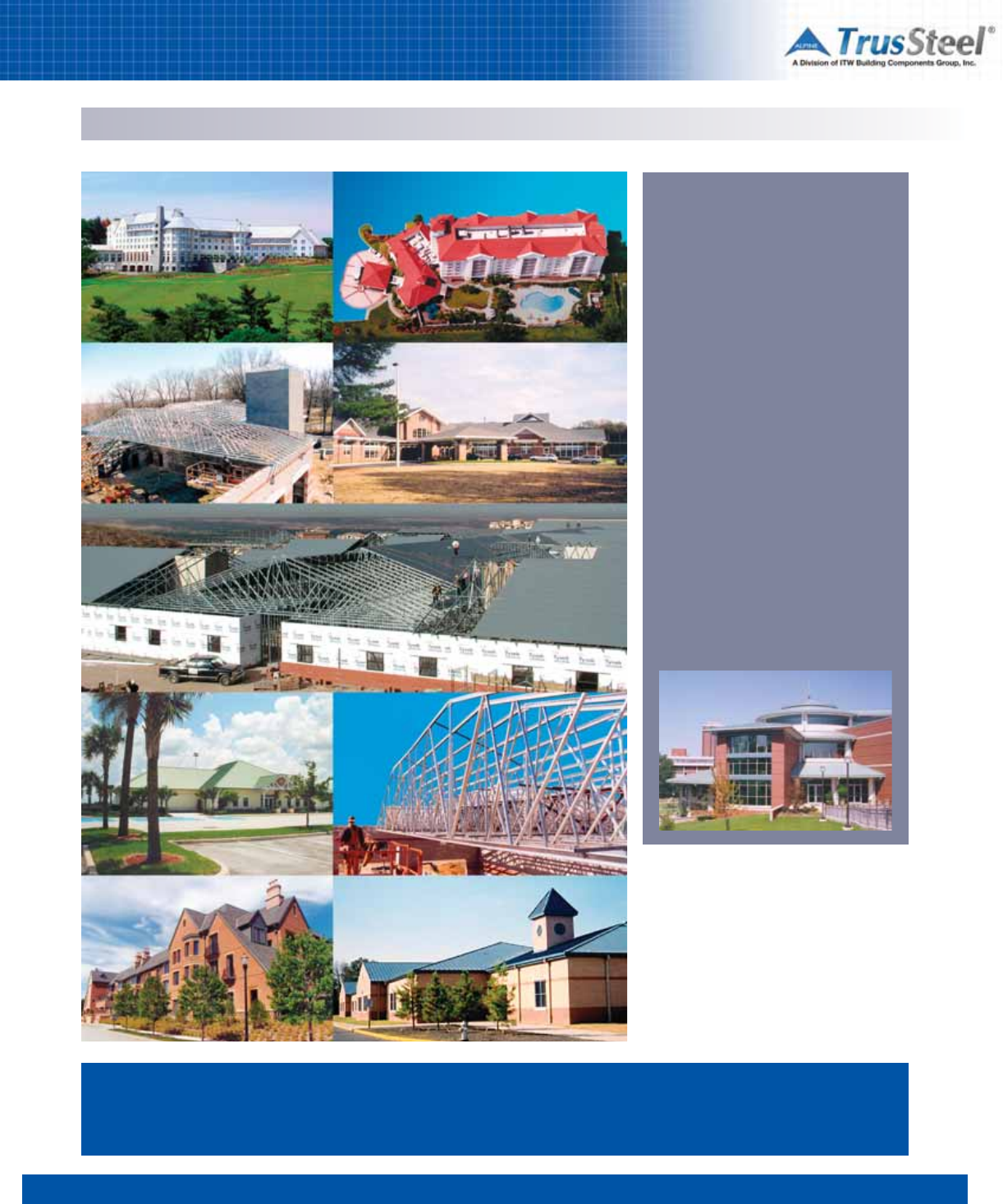
Design Flexibility
Specifiers & Designers
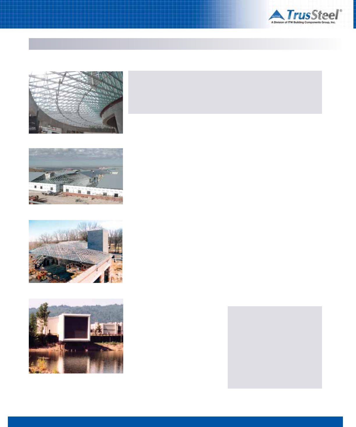
The Inn at Biltmore Estate, Asheville, NC
Project Phoenix-rebuilding the Pentagon after 9-11
PGA Headquarters, FL
12345678
1.03
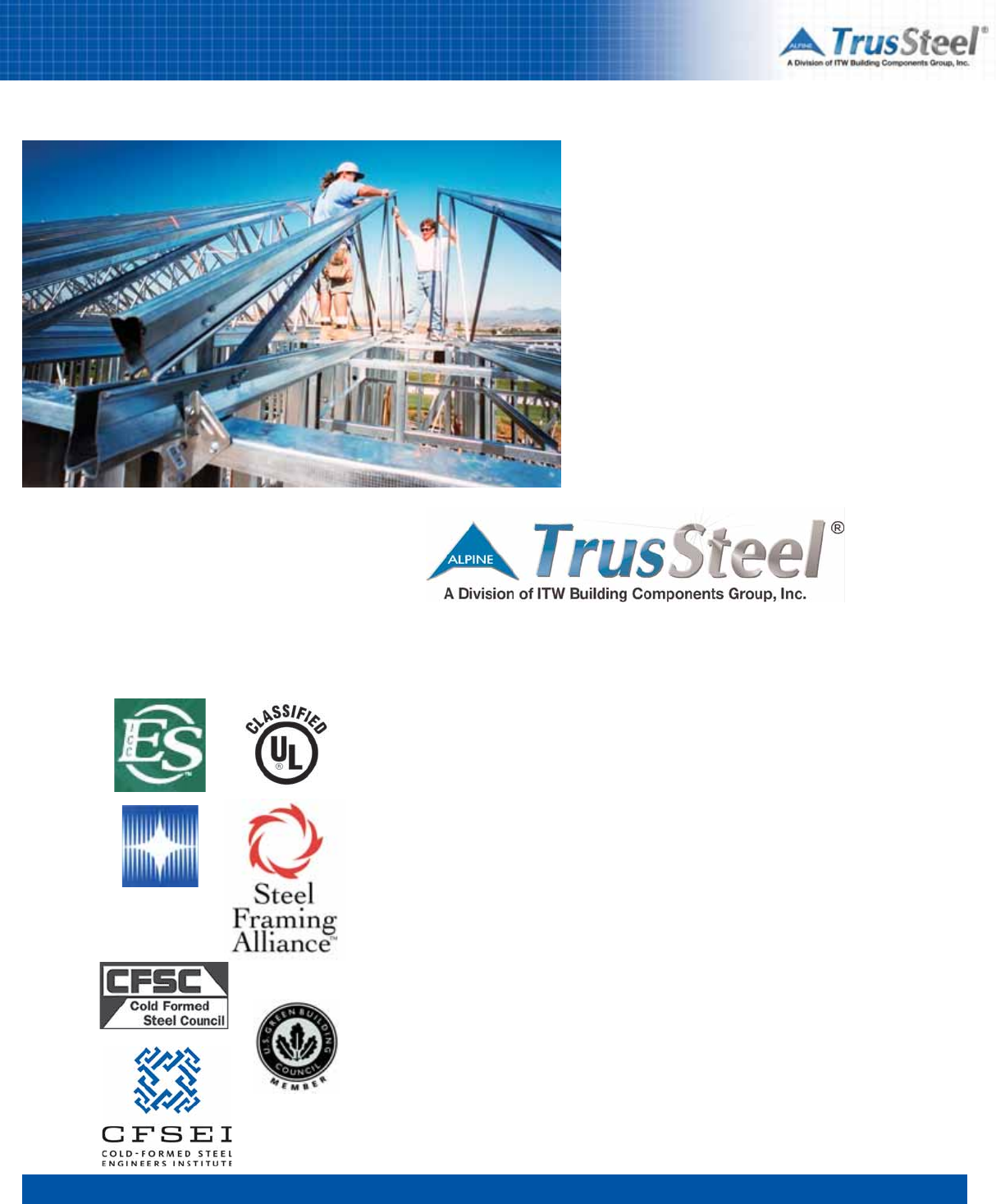
Safer to Handle
Unique features of TrusSteel trusses make them
safe to handle and install. Stiffer trusses add
handling control and reduce the danger of
buckling during lifting and placement. The rolled
edges of the chords and webs help protect
workers from cuts.
Easier to Install
TrusSteel trusses can be as light as one-half the
weight of similar wood or “C” stud steel trusses.
Unlike some other CFS trusses, laterally stiff
TrusSteel trusses resist folding or “butterflying”.
And TrusSteel trusses work exceptionally well in
rafted installations.
No Special Tools Required
The tools you are now using to install CFS
framing are all you need to install TrusSteel
trusses. A full line of TrusSteel construction
hardware allows you to make connections with
standard screws. Installation details and
construction hardware are available from your
Authorized TrusSteel Fabricator.
Reduced Callbacks
TrusSteel trusses reduce callbacks because they
start straighter and remain straighter than many
other types of trusses. And the dimensional
stability of steel reduces drywall fastener pops.
Save Time, Effort and Money
TrusSteel trusses streamline the building cycle
and save money.
• Timely quotations from local TrusSteel
Authorized Fabricators provide
competitive prices and define project
costs up front.
• Sealed engineering drawings and code-
compliant components expedite
submittals.
• Quicker turn-arounds for revisions.
• Delivered to the site ready to install, shop-
built trusses save days of labor.
• Faster truss installation with accurate
layouts, extensive details, and a full line of
installation hardware.
• Easier site inspections with
comprehensive shop drawings and
clearly identified components.
Delivered Quality
Roof lines plane accurately, eaves and soffits
align properly, and interior ceiling lines are flat
and true. High-quality TrusSteel trusses help you
achieve your quality goals.
Delivered Value
From bidding to punch list, TrusSteel delivers
value to your project through increased safety,
quality, efficiency and cost-effectiveness.
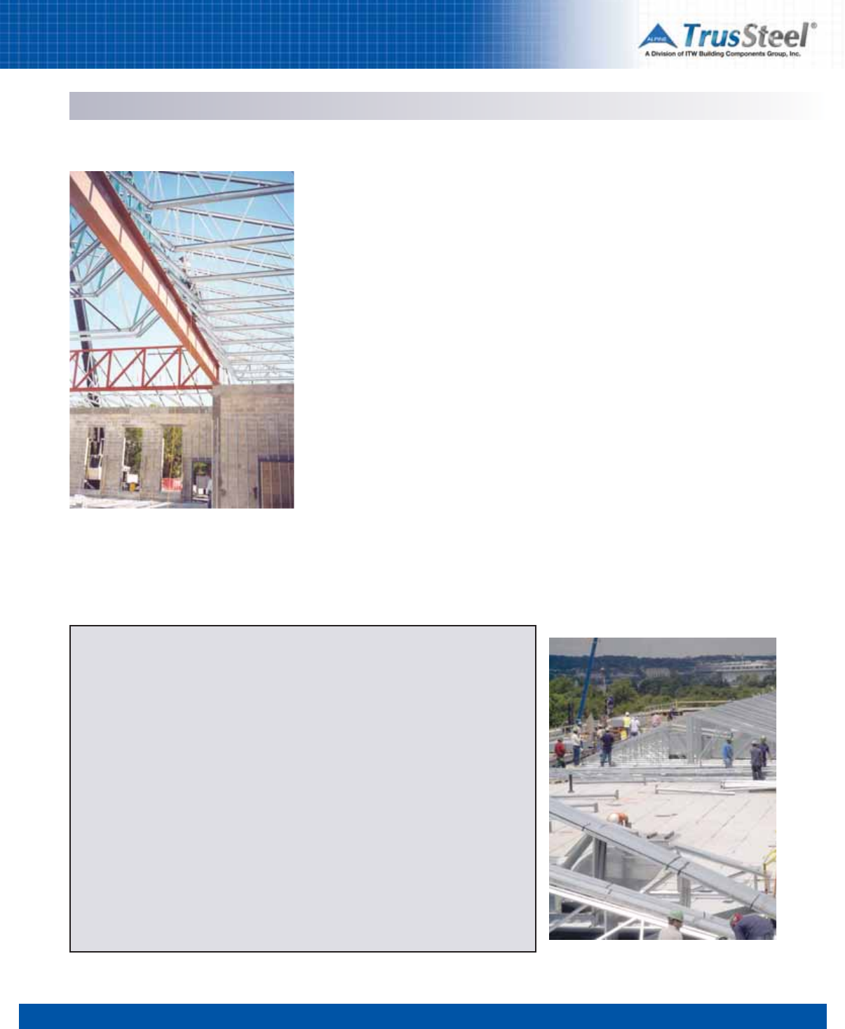
Contractor-Friendly Installation
Truss Rafting
What is Rafting?
Truss rafting is a framing technique where
completed trusses, designed to be rafted, are
assembled into an entire roof section on the
ground and then lifted as an assembly onto the
building structure. The assembly can consist of
just the trusses, or the trusses plus purlins, roof
deck and final roofing which is all installed on the
ground before the assembly is lifted into place.
Employing a rafting technique can save time,
increase safety and reduce insurance costs on
many projects.
Why Raft With TrusSteel?
The exceptional strength-to-weight characteristics
and lateral stability of the TrusSteel trusses make
them the ideal truss for use in a rafting process.
These characteristics allow an average-sized
crane to lift the completed truss assembly into
position. The stiffness and stability of the
TrusSteel trusses create an assembly that will
survive a lift without introducing significant
additional bracing.
Contractor & Installer
OVERVIEW
OVERVIEW
12345678
1.04
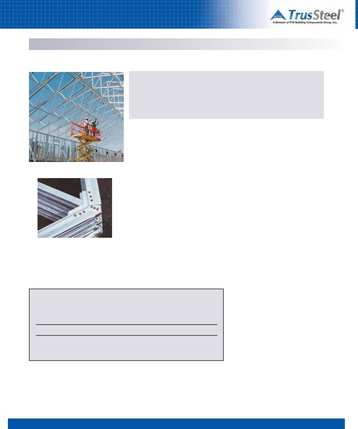
Unique Chord Sections
The symmetrical shape of TrusSteel’s patented
U-shaped chord sections provides nearly equal
chord member moment capacity in both in-plane
directions. The TrusSteel chord members have
superior bending strength in out-of-plane
directions. These characteristics combine to
create an efficient truss that is exceptionally
strong and stiff. The recent addition of special
chord sections for short span / low load
conditions and for long span / high low
conditions improves the value engineering of the
entire system.
Webs
TrusSteel utilizes both commercial grade closed-
tube webs and proprietary roll-formed z-webs to
deliver the most cost effective roof system. Both
products have unique “double symmetric”
properties which contributes to the strength,
stiffness and stability of the truss as well as
reducing lateral bracing.
TrusSteel members are designed and built in compliance with ASTM A370, ASTM A653, ASTM A500,
ANSI Standards, and voluntary standards as described in our own reports from Underwriters
Laboratories (UL) and ICC Legacy reports (NER and Florida Product Approval). Visit our web site to
download the complete reports.
Patented Fasteners
TrusSteel is the only CFS truss system in the
industry using Double-ShearTM fastener
technology. This patented technology provides a
rigid, bolt-like connection at all chord/web
intersections and is specially designed to resist
movement and back-out. Color-coded, marked
fasteners create the most dependable, easily
inspected connection available for CFS
materials.
Structural Connections
TrusSteel delivers a full line of truss-to-truss and
truss-to-bearing connectors that provide
consistent quality and structural values.
The industry’s most extensive library of Standard
Details describing our connections, connectors and
section properties is available in various CAD formats
on CD or from www.TrusSteel.com.
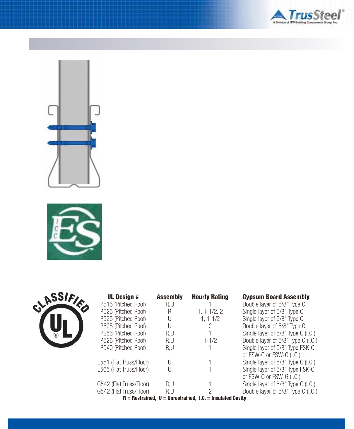
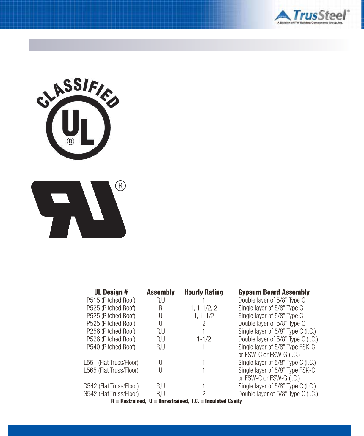
UL Listings TrusSteel products qualify for hourly ratings as shown below.
Assemblies
Truss Components
Code Recognition
Truss Components & Code Recognition
12345678
1.05
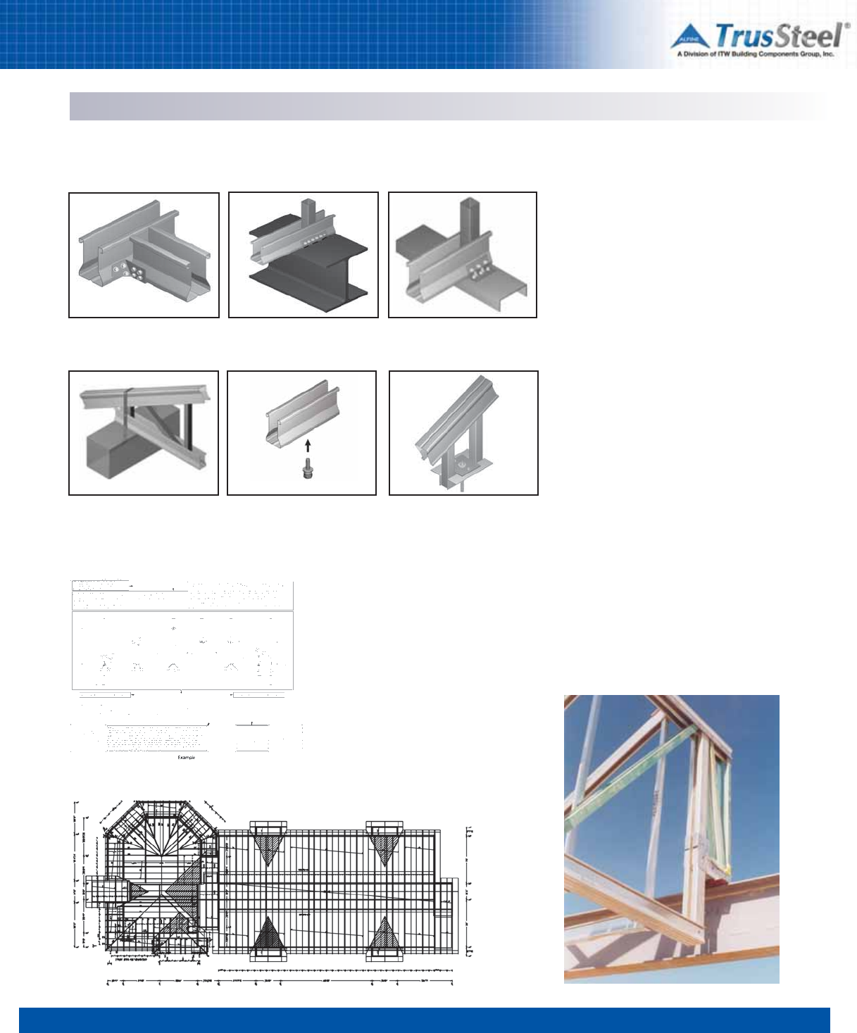
Framing & Connections
TrusSteel Connectors
An extensive set of TrusSteel connectors and
application details allows a designer to create a
complete truss framing system, whatever the
roof type, supporting conditions or other framing
materials. All TrusSteel connectors are load-
rated connectors.
Refer to Section 5 of this manual for the
engineering values of our full line of connectors
(simplified examples are shown here). TrusSteel
Standard Details are available for each
connection application. These Details include
load data as well as installation requirements.
Standard Details are available in CAD formats
from www.TrusSteel.com and are also contained
on the electronic version of this manual.
SteelDraw Truss Shop Drawings with:
• All trusses marked and coordinated to layout
• All truss members clearly identified
• Complete general notes
• Fully dimensioned truss profile with bearing elevations,
fastener quantities, pitch marks, web bracing locations and more
• Truss reactions and bearing widths
• Job-specific loads
Layout Drawings with:
• Truss marks
• Key bearing and framing dimensions
• Truss spacings
• Connection and bracing details
Standard Details
Truss ShopDrawTM and LayoutTM Information
OVERVIEW
HANGER DETAILS UPLIFT ATTACHMENT TO STEEL UPLIFT ATTACHMENT TO STEEL
UPLIFT ATTACHMENT TO CONCRETE SPRINKLER PIPE HANGER SPRINKLER PIPE HANGER
Bottom chord bearing truss
to girder truss
Bottom chord bearing truss
to steel beam connection
Bottom chord bearing truss to
CFS track connection
Bottom chord bearing truss to
concrete bearing
Bottom chord sprinkler pipe hanger
using Sammys x-Press 35 (XP 35)
Truss top chord hanger
detail
12345678
1.06
OVERVIEW
What services can an Authorized
Fabricator provide?
Knowledge. TrusSteel Authorized Fabricators are
truss experts. They can answer questions about
truss applications and installations as well as
questions about pricing and delivery. Do you
have questions about truss layouts, spans,
spacings, profiles, systems, connections,
bracing, overhangs, mechanical chases...and
more? Call your local Authorized Fabricator. They
can save you money up front in your design
development or structural design process.
Engineering. All TrusSteel trusses are
engineered trusses. An Authorized Fabricator can
provide not just building components, but can
also provide individually-engineered and sealed
trusses. A staff of over fifty engineers, covering
every state in the USA, reviews and seals over
4,500,000 truss designs each year.
TrusSteel provides steelVIEWTM software to all
Authorized Fabricators. This powerful proprietary
software package includes 3-D modeling and
truss layout, truss engineering and bidding
modules. By-products of these key elements are
industry-best truss layouts, shop drawings and
cutting sheets.
Quality trusses. Each Authorized Fabricator
builds TrusSteel trusses in a plant environment to
ensure the highest quality components. Trusses
are built according to engineered shop drawings
and highly accurate cutting/assembling
drawings created by the steelVIEW software.
TrusSteel trusses are built with patented Double-
ShearTM fasteners and internal connectors to
assure consistently accurate trusses.
How can I find local Authorized
Fabricators?
You can find a list of Authorized Fabricators on
the TrusSteel Web site at www.TrusSteel.com. Or,
you can call the TrusSteel information line at
888-565-9181. Wherever your project is located,
you can probably find at least two Authorized
Fabricators to provide competitive quotes on
your project.
Additional Services
Structural Services. Through their affiliation
with strategic partner BBD Engineering & Design
Firm, LLC (www.bbdengineering.com), a fee-
based, full-service consulting engineering firm,
TrusSteel Authorized Fabricators can provide full
framing system design services (including the
design of special connections, bracing, purlins,
decks - even entire building framing systems).
Authorized TrusSteel Fabricators
Who is a TrusSteel Authorized
Fabricator?
A TrusSteel Authorized Fabricator is an
independently-owned and operated local
truss fabrication shop. Each Fabricator
markets and services truss projects in their own
region, backed by over 40 continuous years of
Alpine truss experience. Taken together, the nationwide
network of TrusSteel Authorized Fabricators forms a vast repository of truss and framing
knowledge at your disposal.

12345678
1.07
Attention:
Project Architects
and Engineers
The TrusSteel Division has several
educational presentations that we can
make in your office or at the local
chapter of your professional
organization.
The “Cold-Formed Steel Trusses 101”
and “Bracing for Steel Trusses”
presentations are accredited by the
American Institute of Architects under
their Continuing Education System. AIA
members who participate will receive
one LU Hour of credit, and TrusSteel will
file Form B with the AIA. All other
participants will receive a Certificate of
Completion.
Target Audiences
Architects, engineers, specifiers and
other design professionals in the
building market; can be presented to
any size audience.
AV Needed
Electrical power and a screen for
PowerPoint (CES facilitator will provide
the laptop computer, video projector and
samples).
Other Presentations
Other non-accredited presentations are
available, suitable for various venues.
Contact your TrusSteel Regional
Manager for details.
Facilitator Qualifications
TrusSteel facilitators have extensive
experience in the truss and building
industries and are well versed in truss
design and installation.
Length: One Hour
Credits: One LU Hour
HSW: Yes
Cost: None
Description
This presentation includes a brief history and
overview of the various types of cold-formed
steel (CFS) truss systems on the market, their
physical and structural characteristics and
performance, common system applications and
limitations, and how to specify these systems.
Length: One Hour
Credits: One LU Hour
HSW: Yes
Cost: None
Description
This presentation includes an overview of the
various types of cold-formed steel (CFS) truss
systems on the market, common loading
situations, structural construction bracing needs
and how to specify the bracing for these
systems.
Educational & CES
Learning Objectives
At the end of this program, participants will be
able to:
• Identify the different types of CFS truss
systems,
• Understand the product capabilities and
limitations of various CFS truss systems,
• Specify a CFS truss system.
How Taught
Using a PowerPoint presentation and physical
samples, the CES facilitator presents information
on the nature and types of CFS truss systems,
including basic terminology and applications.
Physical samples are used to demonstrate truss
terminology.
Cold-Formed Steel Trusses 101
Bracing for Steel Trusses
Learning Objectives
At the end of this program, participants will be
able to:
• Identify the different types of CFS truss
systems,
• Understand common load conditions,
• Specify the bracing for a CFS truss
system.
How Taught
Using PowerPoint and physical samples, the CES
facilitator presents information on the nature and
types of CFS truss systems, including basic
terminology and applications. Physical samples
are used to demonstrate truss terminology.
OVERVIEW
12345678
1.08
OVERVIEW
Notes
12345678
2.01
Institutional – Schools – Universities – Churches – Museums – Healthcare – Clinics – Hospitals – Assisted Living Centers – Retirement
Centers – Municipal – Community Centers – Town Halls – Hospitality – Hotels – Motels – Commercial – Malls – Banks – Truck Stops
Telecommunications – Shopping Centers – Restaurants – Historical Renovation – Industrial – Storage – Roof Refit - Condominiums
Multi-Family – Single-Family – Recreation – Ball Parks – Gaming – Government/Military – Barracks – Depots – Offices
TrusSteel Cold-Formed Steel (CFS) trusses
are now in service within literally thousands
of buildings, in dozens of building
applications.This guide shares only a small
fraction of the total uses of TrusSteel. You
can view additional information on these
case studies and other studies on the
TrusSteel web site: www.TrusSteel.com.
TrusSteel trusses can be used to create
roofs and floors of all types (gables, hips,
monos, gambrels, etc.). They can be used in
many special applications, including:
• Re-roofs (over existing structures)
• Equipment screens
• Porte cocheres
• Ag structures
• Flat roofs
• Canopies
• Mansards
• Shelters
• Frames
Your imagination is the only limit
APPLICATIONS
12345678
2.02
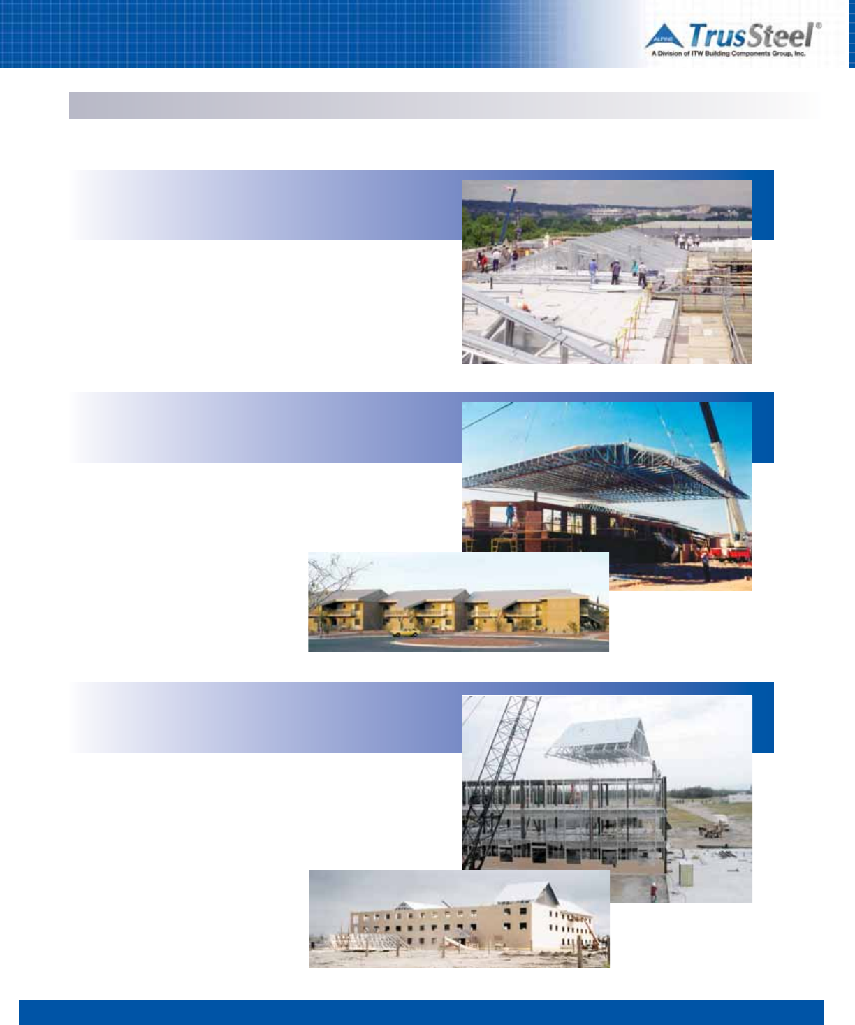
APPLICATIONS
Military
Reconstruction of the Pentagon began immediately after 9-11, with
all parties committed to completing the restoration within 12 months.
The Pentagon reopened on-time, on-budget, on the very hard work
and cooperation of everyone involved.
The Pentagon
Project Phoenix
Arlington, VA
Davis-Monthan AFB
New Dormitories
Tucson, AZ
Seven entire roofs were built on the ground and lifted into place, complete
with trusses, bracing, decking and mechanicals. This installation technique
is called rafting. See Section 7 for more information.
Estimated time savings on the project: two weeks.
Fort Wainwright
New Lodging Facilities
Fairbanks, AK
Rafting (assembling entire sections of the roof system on the ground
and lifting into place) allowed this contractor to meet deadlines set by
the short building season in Alaska. Structural design of the truss
system, lifting bracing, permanent bracing and all connections was
done by TrusSteel.
APPLICATIONS
12345678
2.03
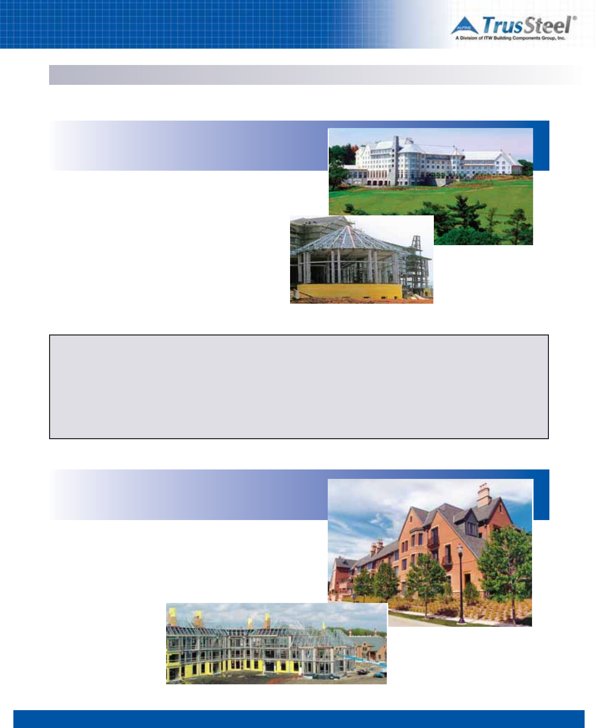
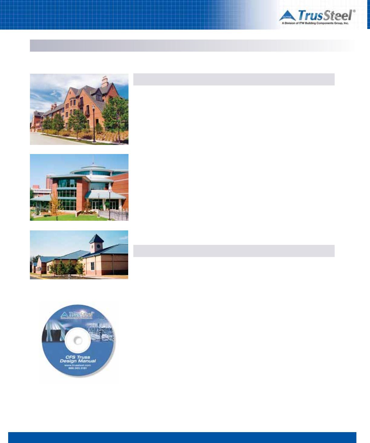
Hospitality / Eldercare
Over 35,000 SF of TrusSteel trusses top the new Inn on Biltmore
Estate. Located on a national historic site, quality and ease of
installation were of paramount importance to the owner.
Unusual framing situations, including radial and conical roof areas,
provided challenges met by the truss fabricator and TrusSteel
engineering team.
The Inn on Biltmore Estate
Luxury Hotel
Asheville,NC
Design Flexibility
The pre-engineered TrusSteel system allows much greater design
flexibility than steel “C” truss framing. As a result, you can design in
familiar roof lines - pitched or flat, with hips, gables, gambrels,
monos, mansards, cantilevers, overhangs, scissors - as well as floor
trusses. This design flexibility makes TrusSteel ideal for almost any
building type.
The Garlands
Assisted-Living Community
Barrington, IL
Over 150,000 SF of TrusSteel trusses helped to create the “French
Country” style of this campus. One of the many TrusSteel UL Listed
assemblies met the architect’s and owner’s requirements for fire
protection.
Noncombustible TrusSteel trusses provide integral, recognized fire
resistance that does not fade with time. Useful, cost-saving UL
Listed roof and floor assemblies can help you meet the needs of
demanding building types, owners and codes. For more information
on UL Listed assemblies, see Section 3 of this Manual.
12345678
2.04
APPLICATIONS
Municipal / Institutional
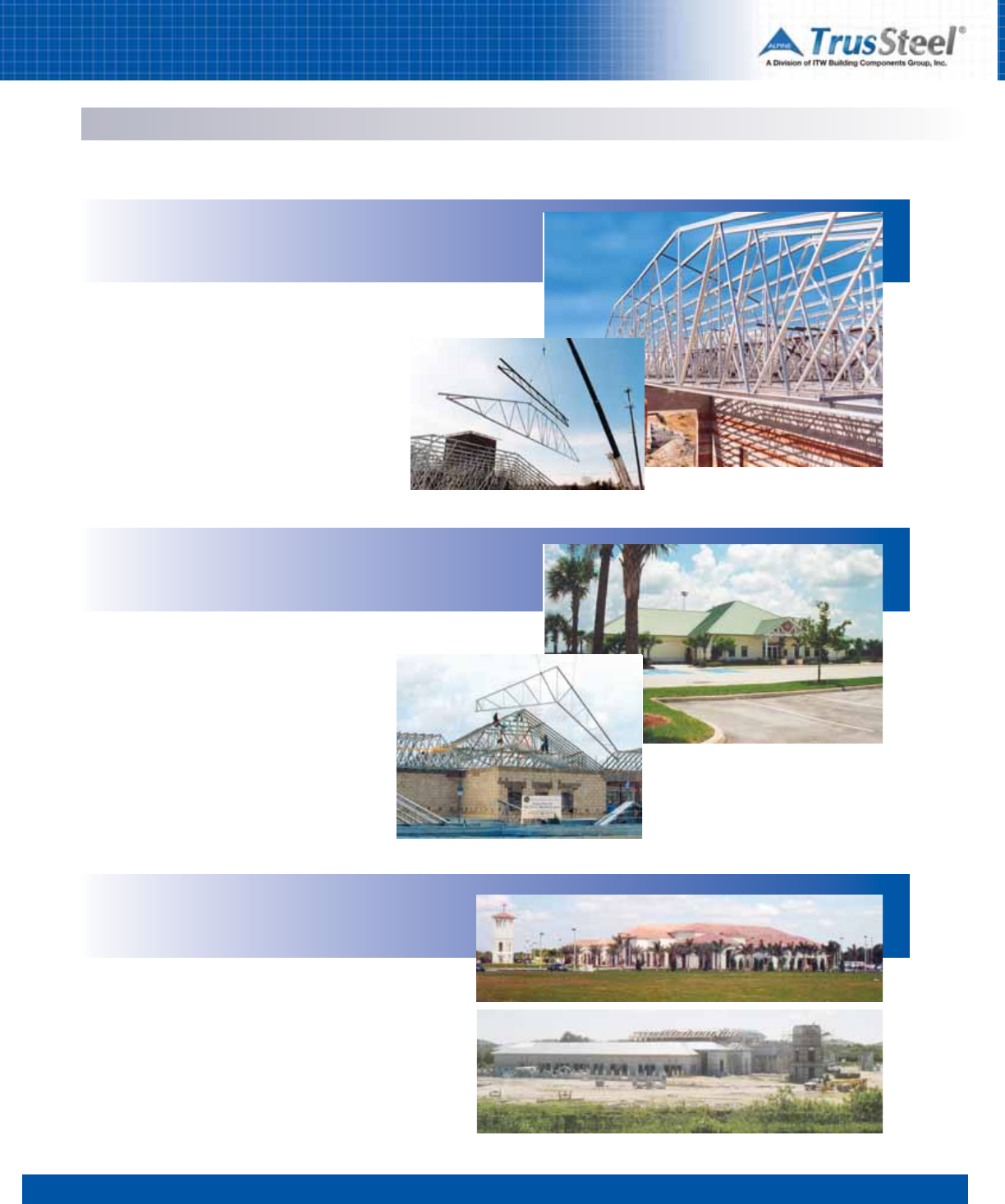
The design of this fire station required long, clear spans and
noncombustible framing. The truck bay areas were covered with 85-foot
clear span TrusSteel trusses. For ease of shipment,
these trusses were shop fabricated in two halves that
were then connected together in the field by the
installer.
Golden City Station
Fire Station
Louisville, KY
PGA Headquarters
Historical Center
Port St. Lucie, FL
The new showpiece of the Professional Golfers
Association headquarters campus is the PGA Historical
Center. TrusSteel trusses were selected for their high
quality and overall economy of installation.
Coral Baptist Church
New Church Complex
Coral Springs, FL
The truss systems for the many roofs over this new worship,
education and fellowship complex contained just about every type
of truss under the sun. There were piggybacked trusses, flats,
drags, hips, commons, monos and radials - with about every
bearing condition imaginable, including heavy steel, CFS steel, bar
joists and masonry. Because of the design flexibility of TrusSteel
CFS trusses, they interfaced well with all these types of framing
systems.
APPLICATIONS
12345678
2.05
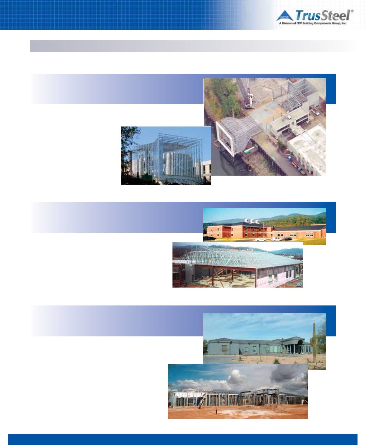
Industrial / Educational / Residential
Collaboration between engineers at Freightliner, TrusSteel and the local
truss fabricator resulted in a state-of-the-art design framed completely
from TrusSteel products.
Freightliner Research Facility
Wind Tunnel
Swan Island, OR
Alleghany Highlands Schools
Elementary and Middle Schools
Lowmoor, VA
This campus of new elementary and middle schools included
over 112,000 SF of TrusSteel trusses. TrusSteel cold-formed
steel (CFS) trusses offer the features of non-combustibility,
UL-Listed assemblies and recycled content demanded on many
school projects.
Schnee Residence
Scottsdale, AZ
Over 12,000 SF of TrusSteel trusses shelter this new home in the
desert. Fifty-foot trusses framed in a radial pattern created large,
open living areas.
TrusSteel CFS trusses are among the lightest and strongest steel
framing made. They are an excellent alternative to heavier steel
framing and trusses, such as “C” stud trusses or stick framing.
Because of their superior lateral stiffness and high strength-to-
weight ratio, TrusSteel common trusses, in short spans, may be
lifted and installed without the use of a crane. This can provide a
significant benefit on small projects or structures built in areas
with limited access.
12345678
3.01
SPECIFYING / DESIGNING
Specifications & Design Overview
Pre-Engineered Trusses
Cold-Formed Steel (CFS) trusses should be
specified as “pre-engineered” trusses. The term
"pre-engineered" reflects the concept of a
desired outcome, where the individual trusses
have been fully analyzed and engineered to meet
all specified load conditions. Individual truss
designs should be sealed by a Professional
Engineer who is registered in the state where the
project is located.
Pre-Fabricated Trusses
CFS trusses should also be specified as “pre-
fabricated cold-formed steel (CFS) trusses”.
Trusses should be fabricated in a shop
environment with experienced fabrication
personnel. Trusses that are fabricated at the job
site should not be allowed. TrusSteel endorses
industry truss shop quality control standards as
developed by the SBCA’s Cold-Formed Steel
Council.
The terminology “cold-formed steel” is replacing
the old terminology of “light gauge steel” for
several reasons. In the code standards for these
products (AISI, COFS, ICC, etc.), these products
are now referred to as cold-formed steel. In
addition, the gauge system of referencing
material thicknesses is becoming obsolete and
has been replaced with mil thickness
designations.
Industry Standards
The specifier should assure that all applicable
industry standards are referenced within the
project specification. All applicable loads and
load conditions, as well as all other performance
criteria, applicable codes, building use and
geometry, etc. should be clearly defined within
the specifications and project design drawings.
For a further discussion on required information,
please see “Information Required for Truss
Design”.
Specifying CFS Trusses
Design and Review Process
Requirements
Due to its importance in the overall success of a
project, it is worth repeating that the Building
Designer must clearly state, in the plans and
specifications, all specific requirements for the
trusses. This clear and thorough communication
of performance criteria will help truss suppliers,
general contractors and truss installers provide
more accurate pricing, preliminary designs, and
ultimately a better product on the project.
Truss Design
Project plans and specifications will eventually
be sent for pricing to companies involved in the
manufacture of CFS trusses. After a truss
manufacturer is awarded the project, the actual
design of the truss system will begin. The truss
manufacturer will use the plans and
specifications to create an economical truss
framing package.
Truss Package Submittal
Once the truss designs have been completed and
sealed by a professional engineer, the designs
will be submitted to the Building Designer for
review and approval. If the Building Designer is
satisfied with the truss submittal, then the truss
manufacturer will begin fabricating the trusses. If
the Building Designer is not satisfied, the truss
submittal will be rejected and returned to the
truss manufacturer along with precise
instructions on corrective action. The truss
manufacturer will make the necessary
corrections and then resubmit the trusses to the
Building Designer. This process will continue
until the Building Designer approves the truss
submittal package.
Approval, Fabrication and Delivery
Once the Building Designer approves the truss
submittal package, the truss manufacturer will
begin the fabrication of the trusses. After
fabrication, the trusses will be delivered to the
jobsite, ready to be installed on the building.
As a tool for the specifier, a complete Guide
Specification for TrusSteel, written in
standard three-part format, is available on
the CD version of this manual.
12345678
3.02
SPECIFYING / DESIGNING
Applicable Building Code
For many years, the vast majority of building
construction within the USA was governed by
one of three model building codes: UBC, SBC or
BOCA. In recent years, these three codes have
merged and been reborn as the International
Building Code (IBC). The IBC, as developed by the
International Code Council (ICC), has been
adopted by municipalities and will be the
applicable model code for the vast majority of
construction within the USA.
The provisions of the applicable building code
will provide important factors in the design of any
given project. For this reason, one of the first
steps a Building Designer should undertake in
the design of any building is the precise
identification of the applicable code. This
concept may seem too obvious, but there can be
different versions of the same building code (e.g.
different publication dates) in use. There are also
instances when a city or an entire state may
decide to publish its own building code.
Requirements for Design Completion
Once the Building Designer has ascertained the
applicable code, they can discover the minimum
requirements for design completion that the
municipality has set forth for its jurisdiction. Most
municipalities state that they require a 100%
complete design at the time of permitting.
Selecting the Structural System
One of the most important decisions made
during building design will be the selection of the
structural system. Once a system is selected, the
Building Designer will go to the applicable code
and find the provisions that will control the
design of the structural elements. For CFS
systems, the “Steel” chapter of the code will
present these provisions.
The applicable building code will either
completely outline the design procedures for a
particular material or it will reference the
required design standard. If a design standard is
referenced, this will be clearly stated in the
building code and the Building Designer can
proceed to the “Referenced Standards” chapter
to locate the proper design standard.
Design Standards
Model building codes contain provisions for the
design of almost any type of building using many
types of materials, including CFS. The
International Building Code (IBC) will determine
the design provisions for construction with CFS
in two different ways. The first way is to provide
explicit provisions that are published within the
Code. The second way is to adopt existing
standards by reference.
For the IBC to adopt a standard by reference, that
standard must be developed according to
guidelines created by the American National
Standards Institute (ANSI). As with any building
material, CFS members are designed according
to standards developed by industry organizations
that are intimately familiar with the design of CFS
members. In the CFS truss industry, the
American Iron and Steel Institute (AISI) is the
organization that is ANSI-approved to develop
standards. Within the AISI, there are two ANSI
standards writing committees: the Committee on
Specifications (AISI/COS) and the Committee on
Framing Standards (AISI/COFS).
The AISI/COS has developed the primary
standard for CFS design that is in use today: the
North American Specification for the Design of
Cold-Formed Steel Structural Members (AISI-
S100). This standard outlines what types of steel
shall be considered as CFS and how CFS
members shall be designed when subjected to
moment, shear and axial forces. The standards
developed by the AISI/COFS use this document
as their baseline for design procedures and
expand upon specific issues of the given framing
type.
Building Codes & Design Standards
AISI / COFS Standards
The AISI/COFS has developed eight
standards that are in use today:
•General Provisions
(AISI-S200)
•Code of Standard Practice
(AISI-S202)
•Wall Stud Design
(AISI-S211)
•Header Design
(AISI-S212)
•Lateral Design
(AISI-S213)
•Truss Design
(AISI-S214)
•Prescriptive Method for One and
Two-Family Dwelling
(AISI-S230)
Of the eight AISI standards listed
above, General Provisions, Truss
Design and the Code of Standard
Priactice documents affect the design
and fabrication of CFS trusses. These
standards are subject to periodic
revision. Please check the AISI Web
site for the most current revisions.
12345678
3.03
SPECIFYING / DESIGNING
Information Required for Truss Design
Building Use
Building regulations differ for various types of
use and occupancy. Specific classifications of
use are: single family residential, multi-family
residential, offices, retail, manufacturing,
churches, institutions (long-term care, nursing
homes, schools, hospitals, jails, etc.) or
agricultural (non-human occupancy). There are
also fire protection requirements for buildings
that may require the CFS members and
assemblies to perform in specific manners.
At times, the CFS truss system may be required
to perform in an atmosphere that may be
corrosive to CFS members. It is important to
properly specify the level of protection that will
be required to keep the underlying steel safe
from damage by this atmosphere.
Applicable Building Code
Clearly identify the Applicable Building Code for
the specific site location (also called the Building
Code of Jurisdiction).
Geometry of the Structure
Furnish span (out-to-out of bearings, plus
cantilevers, if any), slope, overhang conditions,
etc. that form the profiles or external geometry of
the trusses. Truss web configurations need not
be furnished, as they are determined by the
overall truss design.
Truss Bearings
Specify all exterior and interior points of bearing,
showing location by dimensions, size, and
elevation above ground or benchmarks. It is
important to specify the type of bearing material
to be used to properly design connections to the
bearing. Required information could include
grade of steel, grade of wood, strength of
concrete, etc.
Truss Spacings
Give desired center-to-center spacings of
trusses.
Truss Restraint
When designing trusses, it is important that the
truss designer know how the truss chords will be
restrained. The two most common methods of
restraint are structural sheathing and purlins.
In the structural sheathing method, sheathing -
most commonly plywood, oriented strand board
(OSB), and metal deck (such as B-deck) - is
applied directly to the truss chords. The design
and connection of these decks to the trusses is
the responsibility of the building designer.
In the purlin method, CFS members used as
purlins are attached directly to the truss chord to
properly support the truss chord laterally. CFS
hat channels or Z shaped members are
commonly used as purlins. This method is
typically used when the sheathing material is not
capable of spanning the distance between
trusses. The design and connection of the purlin
members is the responsibility of the building
designer.
Truss manufacturers need certain specific information on every project
in order to design and fabricate trusses. As a building designer, specifier
or installer, you can help expedite your order and assure proper fit by
providing the following information to the truss manufacturer.
Support of Mechanical Equipment
Trusses under mechanical units must be
specifically designed. If the building
designer is relying on the sheathing to
support the mechanical load or other heavy
load, it is important that the building
designer verify the sheathing thickness and
capability. Mechanical loads may produce
sufficient vibration to be considered in the
truss design. Such loads may require
additional trusses or custom design.
12345678
3.04
SPECIFYING / DESIGNING
Information Required for Truss Design
Specified Design Loads
Trusses are required to transfer various types of
loads down to the support structure. Ultimately
all loads must be carried down to the foundation
of the structure. Truss design (specified) loads
include both live and dead loads which may be
uniformly distributed or concentrated at various
locations. These loads consist of gravity loads,
wind loads, earthquake loads, snow loads, rain
loads, etc.
Referenced within the IBC, the standard that
deals with loads is the American Society of Civil
Engineers (ASCE) standard, Minimum Design
Loads for Buildings and Other Structures. The
latest version of this standard is published in
cooperation with the Structural Engineering
Institute (SEI) and is referenced as SEI/ASCE7, or
commonly as “ASCE7” where the last two digits
reference the year the standard was published.
ASCE7 is the reference standard that a Building
Designer will use when determining what loads a
building element must resist.
It is the responsibility of the Building Designer to
specify all the loads that the framing members
will encounter and communicate them to the
truss designer. The truss designer will use those
Special Conditions
• Jobsite conditions that may cause rough handling of the trusses.
• High moisture or temperature conditions.
• Extreme environmental exposures that may cause corrosion to CFS members.
• Use of trusses to transfer wind or seismic loads to the supporting structure.
• In-plane and out-of-plane loads, such as lateral loads, are examples of loads that are
required to be transferred to the supporting structure.
• Fire resistance requirements.
• Higher adjacent roofs that may discharge snow onto lower roofs.
• Location from coastline, building exposure, building category and height
above ground for wind.
• Parapets, signage or other obstructions that may cause snow drifting or prevent the free
run-off of water from the roof. These types of building elements may also induce additional
dead loads that must be applied to the trusses.
• Any other condition that affects the load carrying ability of the roof or floor framing.
• Floor trusses, office loads or ceramic tiles require special considerations during the
building and truss design process.
loads when designing the truss system, so it is
very important that the specification of these
loads be both thorough and clear.
Live/Environmental Loads: These loads are
non-permanent loads. Examples include the
weight of temporary construction loads and
occupant floor loads. Environmental loads are
produced by snow, wind, rain or seismic events,
are usually uniform in their application, and are
set by the building codes or the building
designer. They will vary by location and use, and
should be furnished in pounds-per-square-foot
or other clearly defined units.
Dead Loads: Dead loads include the weight of
the materials in the structure and any items
permanently placed on the structure.
Special Loads: Special loads can be live or
dead. Examples of special loads might include
mechanical units, poultry cages, cranes,
sprinkler systems, moveable partition walls, attic
storage, etc. The weight, location and method of
attachment must be provided to the truss
designer. Multiple load cases may be required in
truss design.
Rebuilding the Pentagon
Allowable Shear Loads per Double-Shear Fastener
LBS (kN)
Tube Web Thickness Chord Thickness in Mils (GA)
Mils (GA) 28 (22) 33 (20) 43 (18) 54 (16) 68 (14) 97 (12)
33 (20) 700 (3.11) 772 (3.43) 878 (3.91) 995 (4.43) 995 (4.43) 995 (4.43)
47 (18) 779 (3.47) 977 (4.35) 1263 (5.62) 1348 (5.60) 1348 (5.60) 1348 (5.60)
63 (16) 779 (3.47) 977 (4.35) 1263 (5.62) 1348 (5.60) 1348 (5.60) 1348 (5.60)
12345678
3.05
SPECIFYING / DESIGNING
TrusSteel System
Chord members
Chord members are available in three series:
TSC2.75, TSC3.00 and TSC4.00. Available in a
variety of material thicknesses, chords may be
intermixed within a truss to achieve the most
efficient truss designs. All steel conforms to
ASTM A653 and A500 standards. See the table
in this Section, and the TrusSteel Standard
Details, for member properties.
Web Members
Web members are either closed welded
rectangular steel tubes or patented, proprietary
roll-formed z-webs. Members are available in
many dimensions and thicknesses, and are used
in trusses as needed for their individual strength
and stiffness.
Pitch Break Connectors
Internal connections between truss chords are
made using patented pitch break connectors.
These internal connectors allow for the assembly
of very consistent joints at critical points such as
at the truss peak.
Installation Hardware
A full line of installation hardware is available for
attaching TrusSteel trusses to steel, CFS,
concrete and wood supports as well as to other
trusses. All hardware components are load rated
- see Section 5 for details.
Double-ShearTM Fasteners
TrusSteel trusses are assembled using the
patented #14 Double-Shear self-drilling tapping
fasteners. This technology provides a rigid, bolt-
like connection at all chord-to-web intersections.
Each fastener employs an integral washer and
Anti-BackoutTM technology to resist movement
and back-out. Color-coded, marked fasteners
create the most dependable, easily inspected
connection available for CFS materials. These
fasteners also allow the single-sided fabrication
of trusses (truss assembly without “flipping”
trusses). Refer to Standard Detail TS011 for
allowable shear loads per fastener into various
thicknesses of steel.
Galvanization
TrusSteel chords, webs and hardware
components are galvanized for protection
against corrosion during fabrication and
installation. Most TrusSteel components have G-
90 galvanized coating. TrusSteel’s galvanization
protection far exceeds the industry standard G-
60 coating.
The unique, patented shape of TrusSteel chord members gives them
exceptional strength and stiffness. Combined with the TrusSteel webs,
connectors and the patented Double-ShearTM fasteners, these elements can
create CFS trusses that have the highest strength-to-weight ratio in the
industry.
Notes
1. Based upon the material thicknesses of TrusSteel members.
2. Double-Shear fasteners include 14AMDB1.25, 14AMDR1.5, 14AMDB2.125, 14AMDR2.375.
3. Fastener values were determined by tests following guidelines set forth in Chapter F of the 2007
edition of the North American Specification for the Design of Cold-Formed Steel Structural Members
Typical pitch break connection
12345678
3.06
SPECIFYING / DESIGNING
TrusSteel System
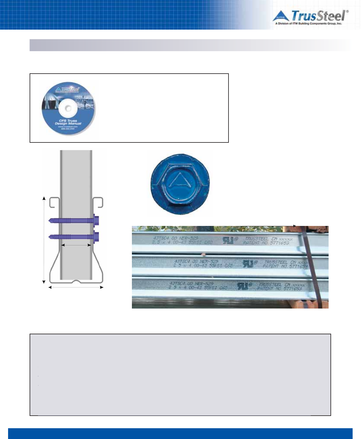
Product Identification
For easy identification, each chord is stenciled
with the following chord information (example
shown in parenthesis - see photo):
• Designation (43TSC4.00)
• ICC-ES Legacy Report (NER 529)
• Size (2.5 x 4.00)
• Mil thickness (43)
• Yield strength of steel (55 KSI)
• Chord galvanization (G-60)
• UL Recognized Component Mark
• TrusSteel name
• Patent number
Double-ShearTM fasteners have head markings
that show the Alpine delta logo (see photo).
Heads are color-coded according to size and use
in the truss.
Additional Info
Refer to the TrusSteel Standard Details for additional
information regarding the physical and structural
properties of TrusSteel components. These Details are
considered an adjunct to this manual and they are
available in CAD formats from www.TrusSteel.com and are
also on the electronic version of this manual.
Cross-Section
Taken through TrusSteel chord and web,
showing the Double-Shear fasteners. TrusSteel chord markings
As shown in a typical bundle of TSC4.00 chord material.
TrusSteel Member Properties
In inches, unless noted otherwise
Member Width Height Throat Fy KSI (MPa) Available Mils (GA) Galvanization
TSC2.75 1-1/2 2-3/4 3/4 55 (379) 28 (22), 33 (20), 43 (18) Min. G-60 or equivalent
TSC3.00 2-1/2 3 1-1/2 55 (379) 28 (22), 33 (20) 43 (18), 54 (16) Min. G-60 or equivalent
TSC4.00 2-1/2 4 1-1/2 55 (379) 28 (22), 33 (20), 43 (18), 54 (16) Min. G-60 or equivalent
50 (350) 68 (14), 97 (12)
Tube Webs various 45 (310) 33 (20), 47 (18), 63 (16) Min. G-60 or equivalent
Z-Webs various 40 (275) 33 (20), 43 (18) Min. G-60 or equivalent
Width
Throat
Depth
12345678
3.07
SPECIFYING / DESIGNING
Wind Loading
Design Responsibility
It is the responsibility of the building designer to
communicate the wind loading requirements to
the truss designer. This includes (but may not be
limited to) all of the factors described in the Wind
Load Factors list shown in this section. The
building code utilized by the local jurisdiction will
outline the wind loading requirements for a
structure either explicitly or by reference. For
instance, the International Building Code (IBC),
2009 edition, references that the American
Society of Civil Engineers (ASCE) standard
ASCE7-05 be used to determine the wind load
applied to a structure.
Vertical Loads and Uplift Loads
Trusses resist wind loads, which include any
loads applied to trusses by the wind when it
encounters a structure. When wind encounters a
surface of a structure, it creates a load on that
surface which must be resisted and transferred.
As wind encounters the roof surface of a
building, it creates loads on those surfaces that
act perpendicular to the surface and can be in
either an inward direction or an outward
direction.
Engineers typically call a load acting inward to
the roof surface a downward load from wind. A
load acting outward to the roof surface is called
an uplift load. The directions of these loads are
dependent on geometric factors associated with
the building. The magnitudes of these loads are
dependent on many factors, including wind
speed, wind direction, site geometry, site
location, building geometry and building type.
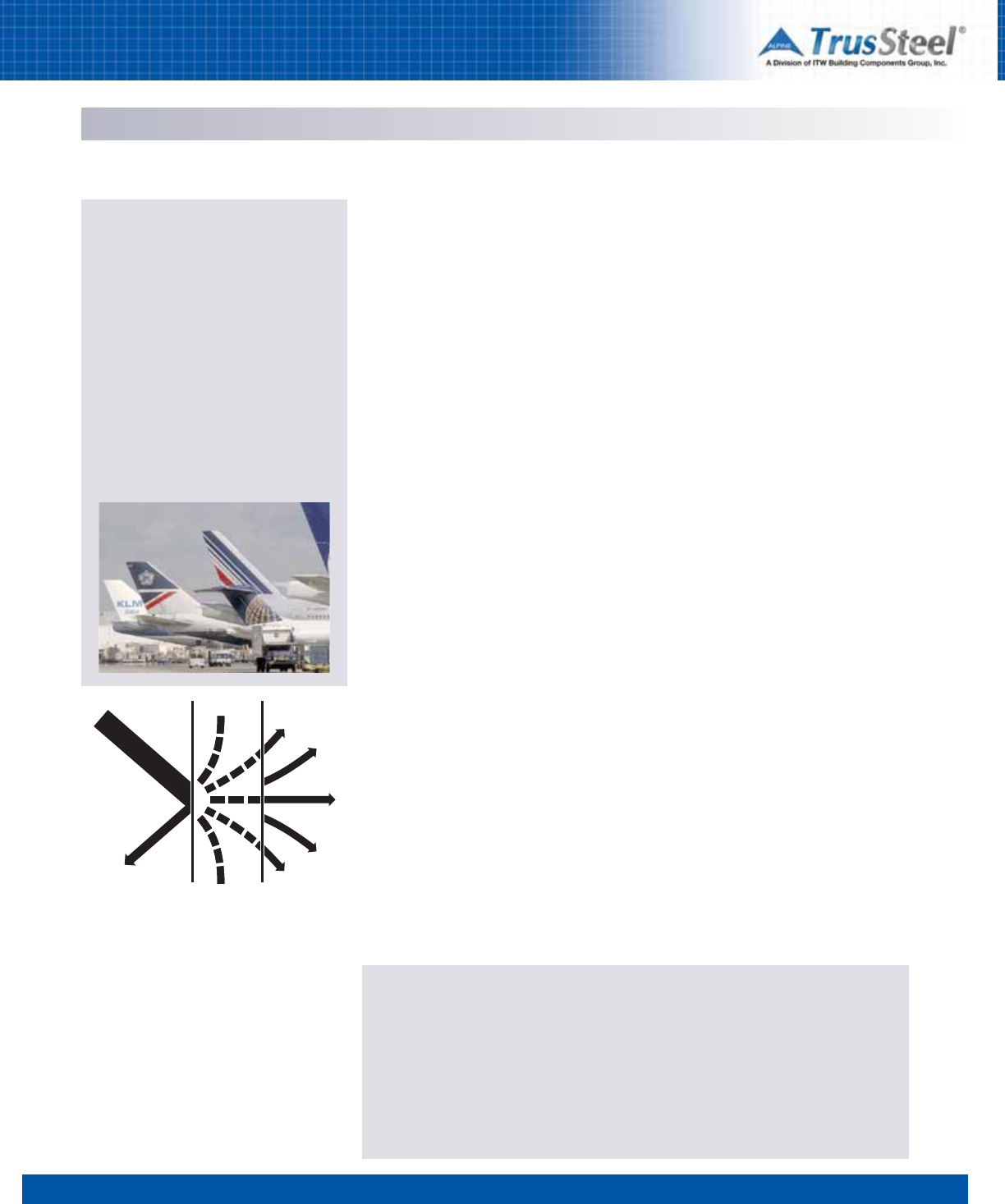
Since wind loads act in a direction that is
perpendicular to the roof surfaces, a sloped roof
surface will have a component of this load that
acts in a vertical direction and a component of
this load that acts in a horizontal direction.
Supporting trusses resist vertical loads, which
they eventually transmit down to the building
components that support the trusses (walls,
girders, etc.). Supporting trusses must also resist
uplift loads transmitted from the roof surface.
These uplift loads produce uplift reactions at the
truss supports that must be resisted.
Lateral Loads
Since roof structures are typically framed entirely
with trusses, it is necessary for trusses to resist
the horizontal component of a wind load, often
called a lateral load.
A truss can resist a lateral load if the truss is
attached directly to its supports in a manner that
is adequate to transfer this load into the truss
support. To do this, the truss support itself must
be designed to receive and resist this load and
ultimately transfer it down to the building
foundation. If the truss-to-support connection
does not resist this load adequately, a truss can
slide off its supports when a horizontal load is
applied.
Another way to resist a horizontal load, which is
more common in modern building design, is to
transmit the load through a diaphragm.
Diaphragms are built of structural sheathing that
is directly applied to the truss top and/or bottom
chords. Common types of structural sheathing
are corrugated metal deck (e.g. B-deck) or wood
structural panels (e.g. plywood). A diaphragm
acts like a beam in that it takes the horizontal
load component applied to many trusses and
transfers it out to building elements that are able
to resist this accumulated horizontal load.
A truss that is used to transfer a diaphragm load
down to a resisting shear wall is commonly
referred to as a “drag truss” as it “drags” the
lateral load from the diaphragm to the shear
wall. If the building designer intends a truss to be
used as a drag truss to transfer lateral loads, it is
important that the loads be determined by the
building designer and transmitted to the truss
designer.
Stress Reversal
It is important to design a structure and its
elements to resist loads for winds coming from
all directions. When subjected to wind loads, the
internal members of a truss can experience a
stress reversal. A stress reversal occurs when a
member is subjected to a force that is in the
opposite direction as another stress from a
different type of load.
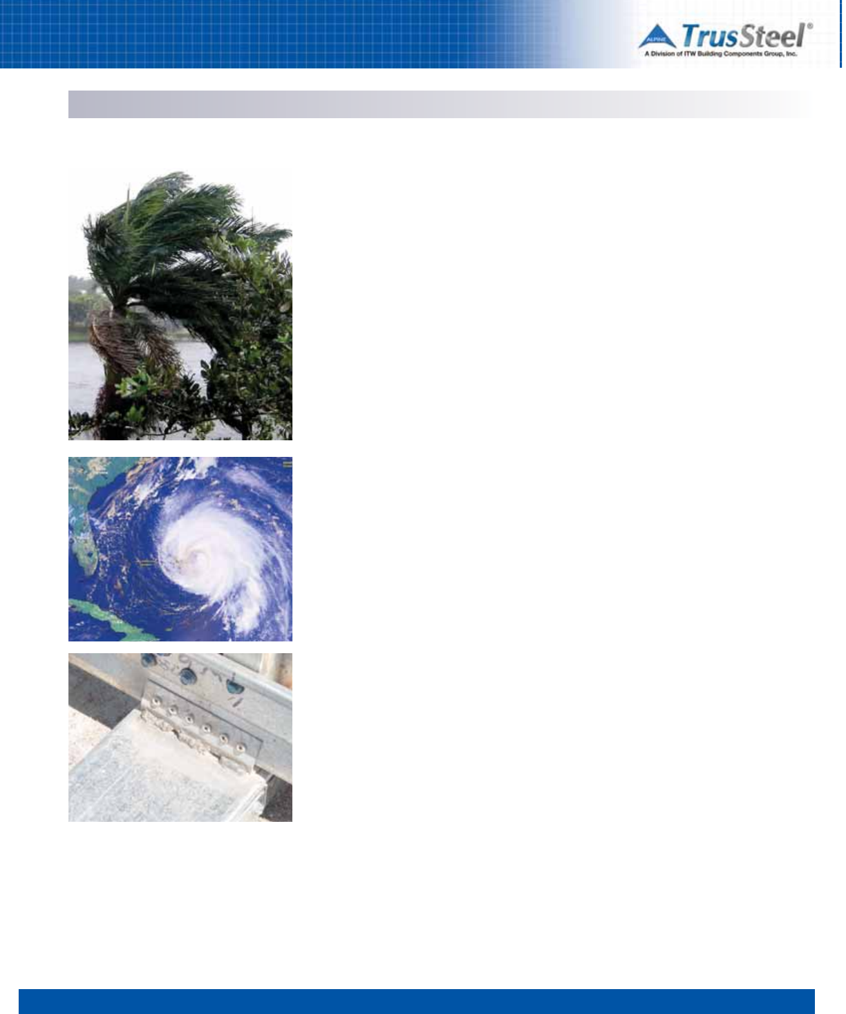
Cold-Formed Steel (CFS) trusses have performed
well when subjected to high wind situations such
as hurricanes, down bursts and tornados. Recent
hurricane activity in the United States
underscores the strong performance of CFS
trusses.
12345678
3.08
SPECIFYING / DESIGNING
Wind Loading
For example, when designing a single truss, a
gravity load is a downward-acting load while a
wind load is typically an uplift or upward-acting
load. It is extremely important that each truss be
analyzed for a stress reversal situation, so that
each truss is designed to support every kind of
load that it may encounter.
Attachment to Supports
A wide variety of TrusSteel connection hardware,
with associated application details, is available
for anchoring trusses to the supporting structure.
These rated hardware connectors can be
installed to resist wind (uplift) loads, in-plane
lateral loads and out-of-plane lateral loads - in
any combination of these loads. It is imperative
that the building designer clearly define the loads
that a truss, and the truss connections, must
resist.
Demise of the Allowable Stress Increase
As a result of recent developments in the
standards associated with the design of CFS
members, designers are no longer able to
increase allowable stresses by 1/3 when the
loads are from wind or seismic events. In the
past, it was common practice to allow such
increases. This practice was supported by design
professionals, design specifications, loading
standards, and building codes for a century and
had deep roots in the design community. This
increase was allowed for seismic loads because
these loads were not considered until recently.
The rationale for the increase was that seismic
loads were intermittent and of short duration.
Research since that time has shown that steel
strength does not increase with load durations
typical of wind and seismic events, has improved
our accuracy in determining wind and seismic
design loads, and has resulted in changes in
design loads to account for the intermittent
nature and variability of such loads. One such
change permits a 25% reduction in live load
when two or more types of live load exist,
provided the 1/3 stress increase is not also
taken. This 25% reduction in load is identical to
a 1/3 increase in allowable stress, insofar as 3/4
is the inverse of 4/3, and has been confused as
being equal to the existing 1.33 increase factor.
However, this 25% reduction cannot be applied
to a load case consisting solely of dead plus wind
loads, which may govern the design of roof
trusses in high wind regions. For this reason, the
loss of the 1/3 stress increase factor may
increase the amount of steel in a member by as
much as 1/3. While such an increase is extreme
and not typical, it is likely that trusses in high
wind regions will show some greater material
thicknesses (gauges) of component sections on
occasion due to the removal of this factor.
The above change was first published in the
1970s and used by some designers instead of
the old 1/3 stress increase factor, but the old
factor remained available (and in use) until
recently. The IBC no longer permits the increase
factor for a load case of solely dead plus wind (or
seismic) load.
While it can be difficult to accept building code
changes that may cause increases in material
costs, this change is needed to assure that CFS
continues to show safe and consistent
engineering performance under severe loadings
like hurricanes and earthquakes.
The IBC no longer permits the increase factor
for a load case of solely dead plus wind (or
seismic) load.
12345678
3.09
SPECIFYING / DESIGNING
Wind Loading
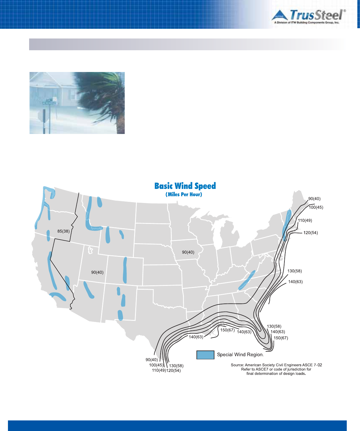
Notes
1. Values are nominal design 3-second gust wind speeds in miles per hour (m/s) at 33 ft. (10m) above ground for Exposure C category.
2. Linear interpolation between wind contours is permitted.
3. Islands and coastal areas outside the last contour shall use the last wind speed contour of the coastal area.
4. Mountainous terrain, gorges, ocean promontories, and special wind regions shall be examined for unusual wind conditions.
5. Regions outside the contiguous 48 states - refer to ASCE 7oryour local building official.
Determining the correct wind loads on individual structures can be very complicated, and it is important
to have a firm understanding of the way that a structure resists the wind. The following is a partial listing
of the factors that may have an influence on the wind loads used for the design of a truss:
• Geographic location of the building (to determine the basic wind speed, see “Basic Wind
Speed Map”)
• Height above ground
• Exposure category of terrain around the building being designed
• Building use
• Location of truss in building
• Location of building in relation to hills and escarpments
• Building dimensions
• Area of load carried by the truss
• Building porosity (open, closed or partially open)
• Dead load on the trusses to be considered for wind analysis (usually
less than the gravity design dead load).
Wind Load Factors

12345678
3.10
SPECIFYING / DESIGNING
Snow Loading
Design Considerations
An important consideration in the roof design
process is the potential for varying types of snow
load conditions. Roofs and buildings that include
details or parapets and add-ons such as shed
roofs or solar panels need to be designed for
potential snow accumulation. Roof slope, surface
material textures and insulation may also affect
the potential for snow and ice accumulation.
The American Society of Civil Engineers (ASCE)
publishes Minimum Design Loads for Buildings
and Other Structures (ASCE7), which contains a
detailed procedure for determining snowdrift
loads. Regional characteristics such as
mountains, flat land and coastal and inland areas
can affect annual snowfall. Refer to the Ground
Snow Load Map, as published by ASCE.
The diagrams shown below are used to illustrate
some of the situations that may be encountered
when designing a roof system. Actual design
procedure as outlined in the applicable code
must be consulted when designing for snow.
Snow Loading

12345678
3.11
SPECIFYING / DESIGNING
Seismic Loading
Seismic Events
Over sixty percent of the land area of the USA is
considered seismically active. Certain regions of
the country are more prone to heavy seismic
activity than other areas, examples being
California, Alaska and Hawaii. Structures in these
regions are required to be designed for specific
lateral loads imposed through seismic activity.
In a seismic event, slippage in the earth's crust
releases energy that is transmitted along the
surface of the earth as a series of waves, similar
to the way that waves travel across water when
the surface is disturbed. These waves can
produce an up-and-down motion, a sideways
motion, or both.
The type and severity of the motion depends on
the amount of initial energy released, the
distance from the epicenter, type of ground fault
and soil characteristics. The back-and-forth
movement can cause brief accelerations of 1g or
higher in strong earthquakes. This ground
vibration changes its magnitude throughout the
duration of a seismic event. The vibrations
usually taper off, or dampen, in a few seconds,
although the waves can continue for several
minutes. Aftershocks are earthquakes of lesser
magnitude than the main earthquake. They may
occur for hours or days after the main
earthquake and originate near the initial
epicenter.
Seismic Design Categories
The International Building Code assigns a
Seismic Design Category to each location in the
USA based on earthquake probability, occupancy,
and soil characteristics. Categories A and B are
assigned to locations that do not require any
seismic design. Structures built in Category C
locations require some special detailing, but one
and two family dwellings are exempt from the
seismic provisions. Categories D1, D2, and E
require successively more load resistance and
attention to prescriptive details.
Map shown for illustration purposes only. See the IBC or ASCE7 for actual seismic loading maps and data.

12345678
3.12
SPECIFYING / DESIGNING
Seismic Loading
Diaphragms
In most instances when buildings with trusses
require seismic or wind analysis, the lateral
forces on the building are resisted by a system of
diaphragms. Roofs and floor planes covered with
wood sheathing (plywood or OSB) or metal decks
can be designed to create “horizontal”
diaphragms that can resist lateral loads. Vertical
members such as exterior walls and interior
shear walls are connected to the horizontal
diaphragms and to the building foundation to tie
the entire structure together. Specific trusses
may be designed to be located directly over the
shear walls to transfer the horizontal load from a
portion of the roof to the shear wall. These
trusses are called “collectors,” or “drag trusses,”
because they collect the forces from the
diaphragms and transmit them to the shear
walls. Determination of the required location,
loading and connections for these drag trusses is
the responsibility of the building design
professional.
The model codes publish tables of shear values
for plywood panel systems and the metal deck
manufacturers publish their own proprietary
values. Typically, shear panel systems designed
using the code tables specify nail or screw
patterns for the perimeter of the diaphragm and
for the interior edges of the individual structural
panels within the diaphragm.
CFS Trusses and Seismic Resistance
Buildings in earthquake-prone regions should be
designed to protect occupants during a
reasonably probable seismic event. Damaging
earthquakes have large motions but are usually
short in duration, lasting only a few seconds. This
is fortunate because the longer an earthquake
lasts the more damage it can cause. All types of
structural members and connections can fail
during long load cycles, as material fatigue
occurs or connections slip apart.
CFS (Cold-Formed Steel) trusses are well suited
for use in seismic applications. They are light in
weight so the forces are low. They are quite stiff
for their weight, so lateral displacements are
minimized. They are also ductile which means
that trussed systems are more likely to deform
under overload than to fail suddenly.
In some structures trusses must be designed to
resist horizontal loads generated by the sideways
acceleration of their own mass during an
earthquake. This requirement is usually ignored
because the connections designed for gravity
loads and wind uplift loads are judged sufficient
to withstand any lateral loads that might occur. If
the roofing materials assembly is sufficiently
heavy and the seismic event severe enough the
building designer may require the inclusion of
additional loads during analysis or the use of
special connections.
Another common horizontal load on trusses
occurs when wind or seismic motion are
imposed perpendicular to a wall that supports
the trusses. In this case a concentration of load
is induced into the heel of the truss that must be
transferred up to the roof diaphragm. This is the
opposite of a drag truss load, where the load
along the roof must be transferred to the wall
below. In either case the connections between
the horizontal diaphragm and the vertical support
are critical to the safe design of the structure.
12345678
3.13
SPECIFYING / DESIGNING
Sound Control
The Mass Law
The amount of sound, or vibration, which is
transmitted through floors, walls and ceilings is
governed by the Mass Law, a theoretical rule that
relates the mass per unit area to the control of
airborne sound. The Mass Law equation
estimates that each time the frequency of
measurement or the mass per unit area of a
single layer is doubled, the sound transmission
loss (STL) is increased by about 6 decibels (dB).
A 6 dB reduction in sound provides roughly a
25% reduction of the original sound level,
contingent upon other factors such as
temperature and the frequency (Hz) of the sound.
In construction terms, a 4 inch thick concrete
floor has a sound transmission loss (STL) of 42
dB at 250 Hz. Doubling the floor thickness to 8
inches only increases the STL to 48 dB. This
doubling in thickness (and mass) provides only
the 25% reduction in transmission loss
described above. This is not an acceptable
solution in today’s construction market.
Sound Control
The subject of sound transmission is situation, or
construction project, specific. The source of the
sound or noise may be airborne, or structure-
borne, or a combination of both. Typically the
elimination of airborne noise requires a reduction
in the energy level of the sound waves, which are
created by fluctuations in atmospheric pressure
reaching the eardrum. Structure-borne noise is
created by unwanted vibrations. The designer
should select, from the outset, the system and
products that will deliver the appropriate results.
It is normally far more economical to integrate
the solution into the initial design than to attempt
to create an “add-on” solution during the
construction phase.
There are a number of companies specializing in
the engineering of noise control systems.
Because increasing mass is no longer the
solution of choice, these companies design
systems and products that create an interruption
in the noise path or create a containment barrier
(at the source) to prevent the noise from reaching
the receiver. These companies use four basic
tools to combat noise transmission: absorption,
barriers, damping and vibration isolation. A
number of products, from decking and fabric
barriers to mechanical devices, are used to
address specific transmission loss needs.
Resources
In general, many sound control design methods,
products and applications that work with other
framing systems can work with CFS framing.
Some of these products have been tested in CFS
applications and the product manufacturers have
published data on these applications. The
building designer who is striving for a particular
sound control solution should carefully examine
the manufacturer’s published data as well as
data published by independent researchers.
Here is a small sampling from the wide range of
valuable informational sources on sound control:
S
Steel
F
Framing
A
Alliance
(SFA)
www.steelframingalliance.com
Residential Steel Framing – Builder’s Guide
to Fire and Acoustical Details, prepared for
The U.S. Department of Housing and Urban
Development (HUD) and the Steel Framing
Alliance by the National Association of
Home Builders (NAHB) Research Center,
Inc (2004).
North
A
American
I
Insulation
M
Manufacturers
Association
(NAIMA)
www.naima.org
Unwanted Sound
The transmission of unwanted sound,
classified as noise, is one of the most
common complaints made by the
occupants of modern buildings. This
problem has grown in recent years as
material suppliers have developed
products and construction methods to
reduce the weight of building components.
The goal has been to conserve material
and reduce both component cost and
construction time. Unfortunately, the goals
of lighter weight building materials and the
containment of noise often come into direct
conflict.
Noise Is Measured in Decibels (dB)
Whispers: about 20 dB
Normal conversations: about 60 dB
City traffic: about 80 dB
Lawn mower/leaf blower: about 103 dB
Repeated exposure to sounds over 85 decibels is considered dangerous to hearing, and the
louder the noise, the less time it takes to damage hearing.
Methods of Sound Propagation
reflection absorption transmission
1 2 34 5 6 7 8
3.14
SPECIFYING / DESIGNING
Sustainability & LEED
Checklist (Materials and Resources section)
allow the award of one point each for overall
building materials totals which exceed 5% (one
point) and 10% (one point) recycled content
(based on post-consumer + 1/2 post-industrial
content). Since local TrusSteel Authorized
Fabricators build TrusSteel trusses, attribution
toward further LEED points may be obtained
when TrusSteel trusses are obtained from an
Authorized Fabricator that is considered local to
the project. Project checklists of the available
LEED points are available from the USGBC.
Recycled Content
TrusSteel trusses are made with 100% U.S.
Prime steel. This steel is not only 100%
recyclable, it is composed of steel that is nearly
all recycled. According to the Steel Recycling
Institute, “steel used in structural steel building
products, whether produced via the EAF (electric
arc furnace) method or the BOF (blast oxygen
furnace) method can be used in the LEED
calculations to exceed both 5% and 10% goals.”
Further information on the LEED calculation may
be obtained from the USGBC and from the Steel
Recycling Institute publication, Steel Takes LEED
with Recycled Content.
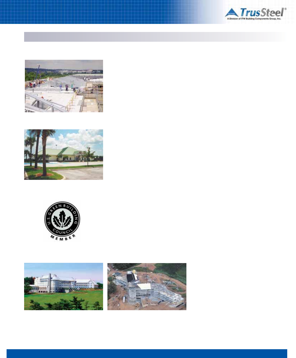
The U. S. Green Building Council
The U. S. Green Building Council (USGBC) defines
itself as “the nation’s foremost coalition of
leaders from across the building industry
working to promote buildings that are
environmentally responsible, profitable and
healthy places to live and work.” Council-
sponsored consensus committees have
developed the Leadership in Energy and
Environmental Design (LEED) Green Building
Rating System in order to accelerate the
development and implementation of green
building practices. TrusSteel is proud to be a
member and supporter of the U.S. Green Building
Council.
LEED Standards
Currently, LEED-NC (New Construction) is a goal-
oriented standard whereby point-based goals are
set for specific areas of building design, with
point awards based upon green-oriented criteria
such as reduced site disturbance, increased
energy performance, resource reuse, use of
materials local to the site and the specific
recycled content of building materials. Sections
4.1 and 4.2 (Recycled Content) of the LEED-NC
Information Resources
Here are Web sites where you can learn more about the USGBC,
calculating LEED percentages and steel recycling:
U.S. Green Building Council (creators of the LEED standards)
www.usgbc.org
Steel Recycling Institute
www.recycle-steel.org
American Institute of Steel Construction (AISC)
www.aisc.org
1 2 34 5 6 7 8
3.15
SPECIFYING / DESIGNING
Fire Resistance & UL
TrusSteel and UL
Building codes often have requirements that
building elements perform for a specific period of
time when subjected to the elevated
temperatures associated with a fire event, based
upon the defined type of building/occupancy. One
of these requirements is that the building
element must withstand a fire event while
supporting a specific load. One method of
documenting this performance is by testing at
Underwriters Laboratories, Inc. (UL). UL has the
ability to perform fire tests on building elements
and assemblies according to standards
published by the American Society of Testing and
Materials (ASTM). Building elements and
assemblies that pass this testing qualify as
Listed UL assemblies.
Building assemblies containing TrusSteel trusses
have been tested at UL, and these assemblies
have been Listed as having 1 hour, 1-1/2 hour
and 2 hour fire resistive properties as described
and when utilized as described in the UL reports
listed in this Guide. TrusSteel has earned the UL
Classification Mark as to its fire-resistive
properties. This mark appears on TrusSteel
members for easy identification.
Insurance rating bureaus and many Federal,
state, county and municipal authorities and
inspectors recognize UL listings. The building
designer is responsible for determining the
suitability of use for UL Listed assemblies in
specific building designs.
Online Updates
Underwriters Laboratories (UL) Listed Fire
Resistive Designs with TrusSteel trusses have
proven to be key documents in gaining the
confidence and specifications of architects,
engineers and end users. TrusSteel Listed Fire
Rated Assemblies have also proven to be living
documents, undergoing frequent updates as
TrusSteel, along with our partner companies in
these listings, continues to expand the Listings to
include different materials and material
configurations. For this reason, we do not provide
a printed copy of these Listings but rather
encourage designers to visit the UL Web site and
view or download the most current Listings. To
find these Listings, point your browser to
http://www.ul.com and search on the Design
Numbers listed in this Guide, or perform a
keyword search for “TrusSteel” under the
Certifications section of the website.
UL Listings TrusSteel products qualify for hourly ratings as shown below.
Assemblies
TrusSteel components bear the UL Recognized
Component mark.
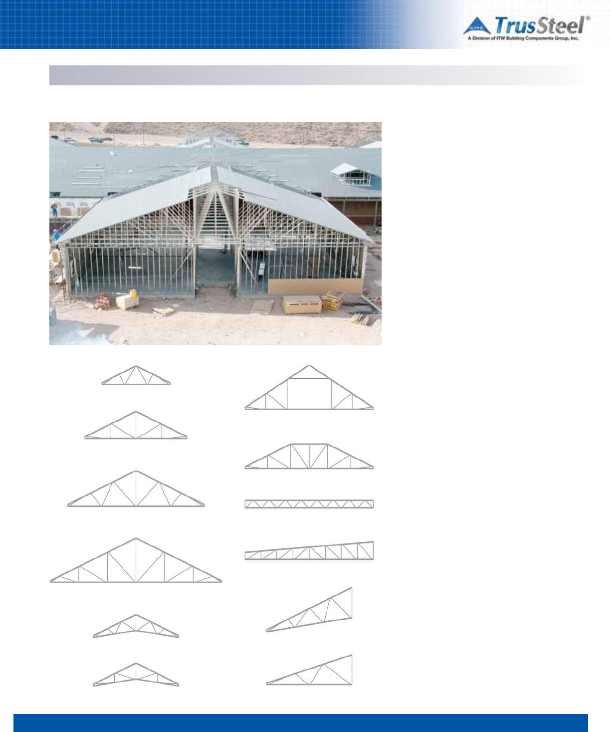
1 2 34 5 6 7 8
3.16
SPECIFYING / DESIGNING
Trusses as Building Components
Efficient Components
Trusses are versatile and efficient framing
components. They are available in an almost
infinite combination of profiles, depths, and
internal web patterns, depending upon the
required building geometry and loads. The great
efficiency of trusses comes as the result of the
custom-design of almost every truss for its
particular location and application.
Truss Profiles
Truss profiles are usually the result of the need to
create specific roof planes and perimeter
conditions. Truss depths are usually driven by
roof planes and heel heights, but are also driven
by the need to create strength.
Truss Web Patterns
Truss web patterns are generated by the truss
designer to create the most efficient truss. Web
patterns are often tailored to allow more efficient
truss bracing. Patterns can also be tailored to
create clear paths (runs or chases) through the
web pattern to allow the passage of ductwork.
The creation of these runs can speed the
installation of mechanical systems.
Available Combinations
The trusses in these charts represent a fraction
of the possible combinations of truss span, load,
profile and depth. If you have a specific truss
configuration and you need load/span
information, please contact your local Authorized
TrusSteel Fabricator. You can find a list of these
Fabricators on www.TrusSteel.com.
Fink
Howe
Double Fink
Double Howe
Double Fink Scissor
Howe Scissor
Room-in-Attic
Hip Girder
Flat Truss
(Warren pattern)
Sloping Top Chord
(Howe pattern)
Scissor mono
Mono
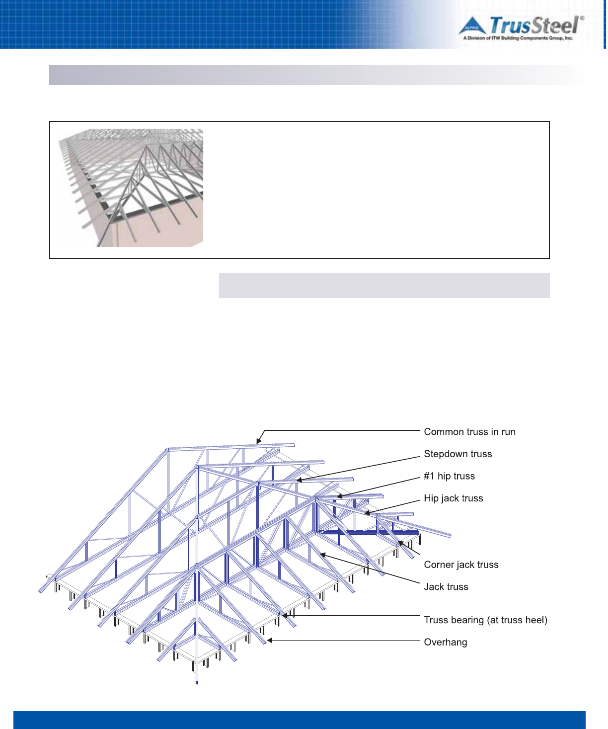
Note: Truss bracing not shown for clarity.
1 2 34 5 6 7 8
3.17
SPECIFYING / DESIGNING
Roof Truss Systems - Framing Styles
Introduction
Framing with trusses gives the building designer the versatility to accomplish a multitude of
interior and exterior building geometries while allowing the inside of the building to be free of
any supports. Within any roof style there are many truss framing methods or systems. These
systems can vary based on framing material (steel or wood), the experience of the designer, and
even vary from region to region. However trusses are designed and regardless of the roof style,
the challenge is to create a truss system that is efficient both to fabricate and to install. A few of
the more common framing systems for steel trusses are described below. Please note that the
names given to specific trusses, truss conditions and framing systems can vary from region to
region. Ceiling lines may be flat or sloped. Sloped ceilings have some limitations, so please
consult the truss designer.
Hip Systems
A hip roof framing system allows a roof area to
have a sloping roof plane rising from every wall
segment. This system uses smaller trusses (jack
trusses) that are placed at 90 degrees to the
front wall (see illustration). A truss (hip jack) runs
directly underneath the hip ridge line and spans
at an angle different from the other trusses. Hip
jack trusses are supported by a larger truss
(sometimes called the #1 hip truss) that spans
the width of the building and is located a short
distance (setback distance) from the front wall.
For best efficiency of the stepdown hip system, a
good rule of thumb is to keep the setback
distance to less than 10 feet. A hip system offers
the benefits of clear span with an eave or fascia
line maintained at the same elevation around the
building. The end slope may be equal to or
different from the side slope.
Typical Stepdown Hip System
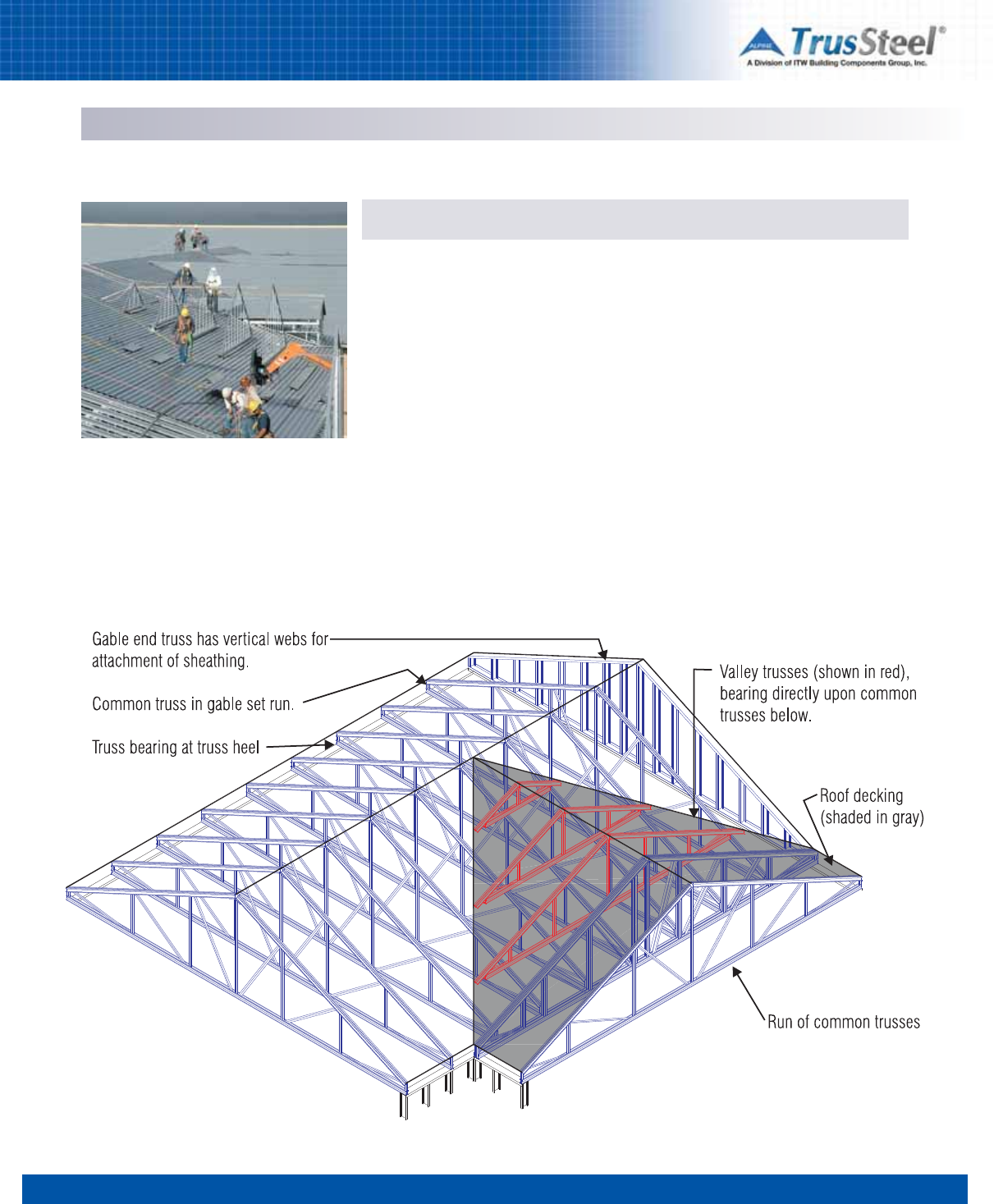
1 2 34 5 6 7 8
3.18
SPECIFYING / DESIGNING
Roof Truss Systems - Framing Styles
Gable and Valley Systems
Gable System
A gabled roof system allows a framed area to
have a vertical plane coming off an end wall.
This framing system gives the appearance that
the vertical plane of the end wall extends up to
the roof plane. The trusses in this system span
the width of the roof area and can be of the same
profile throughout the length of the building
provided other interior or exterior geometry
changes do not occur. The first truss is located
on the end wall and is called the gable end truss.
The gable end truss, unlike the other trusses in
this system, is typically supported continuously
by the end wall for vertical loads, and resists the
horizontal wind load and transfers that load to
the building diaphragm. Because of its unique
role, the gable end truss may have a different
web pattern and may require different types of
bracing than the common trusses. A gable end
truss will typically have vertical webs spaced at
16” or (no more than) 24” on center, to resist
lateral wind loads and to accommodate the
attachment of sheathing. Gable end truss
vertical webs, when sheathed, will act like wall
studs.
Valley System
Valley trusses are generally supported by the
clear-span trusses below to form new,
intersecting ridge lines. Valley trusses can be
attached directly to the top chord of the
supporting trusses below or directly to the roof
decking (see photo).
Note: Truss bracing not shown for clarity.
Typical Gable & Valley System
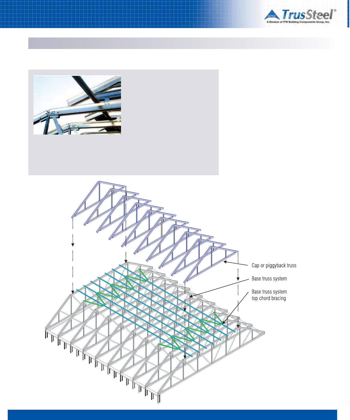
1 2 34 5 6 7 8
3.19
SPECIFYING / DESIGNING
Roof Truss Systems - Piggybacks
Cap truss installed on top of base truss. Note
continuous bracing on top chord of base truss
and connection clip.
Applications
There are instances when a roof truss
application, due to a combination of roof pitch
and truss span, will require trusses that would
be too tall to build, deliver or handle
economically. In such instances, two or more
trusses can be built and delivered which will,
when installed together, do the work of each
single, oversized truss. Of these two trusses,
the bottom component is called the base truss
and the truss that rides on top is called the
piggyback or cap truss (see illustration). As a
rule of thumb, individual trusses that would be
over ten to twelve feet tall would probably be
candidates for a piggyback system.
Installation Sequence
During installation, piggyback system base
trusses are installed first and proper bracing is
installed for the base truss set. Base trusses
must be installed to resist the uplift forces of the
entire piggyback system. Bracing of the top
chords of the base trusses is essential and is
often accomplished using roof decking/
sheathing or continuous purlins. This bracing
must be completed prior to the installation of the
cap trusses.
Cap trusses are then attached to the base
trusses in a proper manner to resist lateral and
uplift forces. Connections of the cap trusses to
the base truss set are sometimes made using
proprietary connectors (see Section 5). Decks or
purlins for the roof membrane system may then
be applied to the cap trusses.
During design and estimation, designers and
contractors will want to account for these
additional materials as well as for the fasteners
required to install decking, purlins, clips, etc.
Additional labor may be required to install these
materials and the piggyback trusses.
Piggyback System
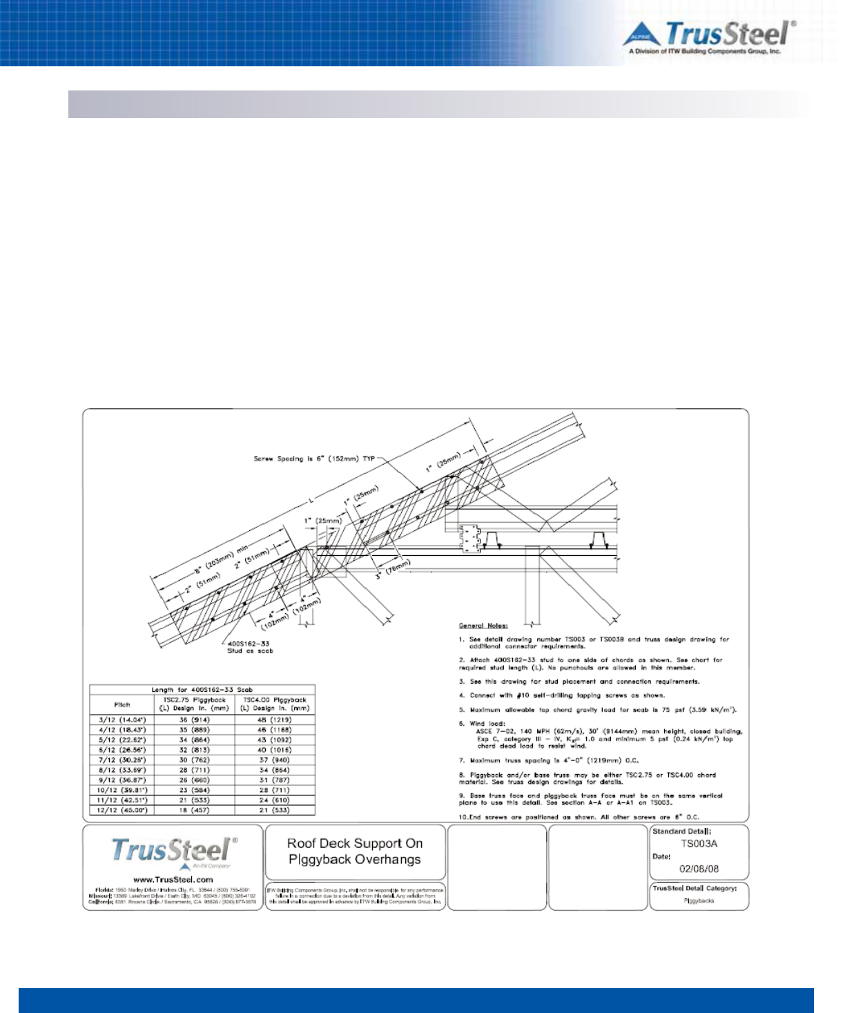
1 2 34 5 6 7 8
3.20
SPECIFYING / DESIGNING
Roof Truss Systems - Piggybacks
Standard Details
Several TrusSteel Standard Details are available
to assist the designer in understanding and
detailing piggyback systems. These Details may
be downloaded from www.TrusSteel.com or from
the electronic version of this manual. Detail
TS003A is shown below as an example.
Rafting
Piggyback truss systems, when properly
designed and braced, can be candidates for the
installation technique known as rafting. See
Section 7 of this manual for more information on
rafting.
Required Information
The Truss Designer will need the following
information about the roof system before
designing the piggyback system:
• all roof conditions that could require trusses
whose height will exceed the maximum
allowable truss height (candidates
for piggybacking)
• type of continuous framing / support to be
used on top of the base trusses (roof
decking/sheathing or continuous purlins)
• type of clip to be used to attach the piggyback
trusses to the base trusses or to the roof
decking/sheathing.
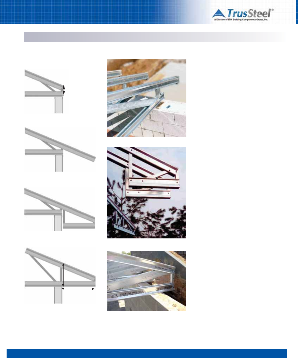
1 2 34 5 6 7 8
3.21
SPECIFYING / DESIGNING
Roof Truss Systems - Overhangs & Cantilevers
Truss Heels
The end of a truss is also known as the heel of a
truss. All trusses have two heels, one at each
end. The heel height of a truss is the distance
from the top edge of the top chord to the bottom
edge of the bottom chord at the heel (see
illustration).
Minimum Heel Heights for
TrusSteel Trusses
Due to the internal configuration of heels for non-
parallel chord trusses, these trusses have a
minimum heel height (see table below). TrusSteel
trusses can be fabricated with lower-than-
minimum heel heights. Using greater than
minimum heel heights can help create more
efficient trusses.
Minimum Heel Height Table
Heel height in inches
Roof Chord Size
Slope TSC2.75 TSC4.00
________________________
2 5-9/16 8-1/16
3 5-5/8 8-1/8
4 5-11/16 8-1/4
5 5-3/4 8-3/8
6 5-7/8 8-1/2
7 5-15/16 8-11/16
8 6-1/16 8-13/16
9 6-3/16 9
10 6-3/8 9-1/4
11 6-1/2 9-7/16
12 6-11/16 9-11/16
Overhangs and Cantilevers
Most designers who place pitched roofs on
buildings design those roofs with perimeter
overhangs. Overhangs can be accomplished with
trusses by extending the top chords of trusses
(overhangs), or by cantilevering the ends of the
trusses out past the perimeter bearing support
(see illustration). Cantilevered trusses are
generally more efficient trusses than those with
overhangs, and can simplify the installation of
fascia and soffit materials. A cantilevered truss
can also have a top chord overhang.
Standard Heel
Standard Heel with Overhang
Standard Heel with Boxed Return
Cantilevered Heel
Heel height
Heel height
Cantilever distance
Common Heel Conditions
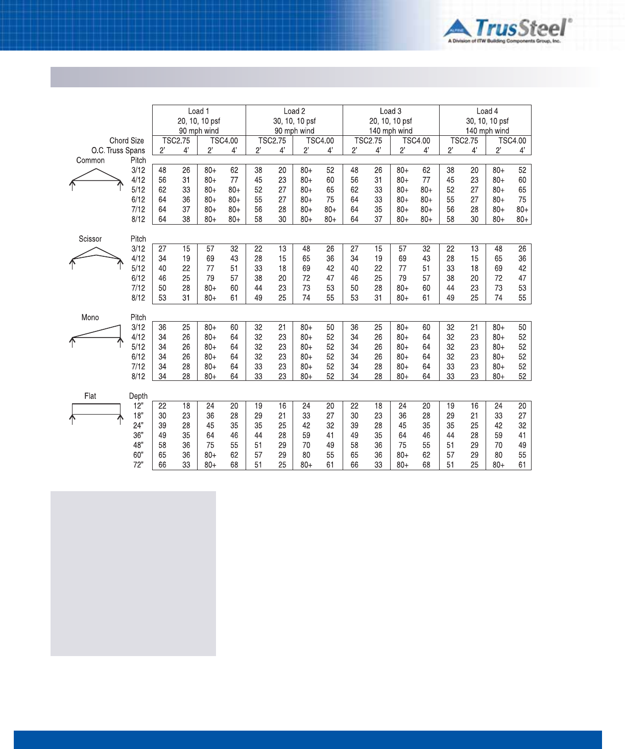
1 2 34 5 6 7 8
3.22
SPECIFYING / DESIGNING
Sample Tables
Each TrusSteel truss is engineered
individually to meet the load, span, spacing
and geometry requirements of a specific
project. There are literally millions of possible
combinations. These tables show a small
sample of those combinations, based on the
most common design criteria and simple
common trusses.
Contact your local TrusSteel Authorized
Fabricator to obtain truss designs for your
specific project needs.
General Notes:
1) Spans shown in charts are in feet.
2) Loads shown above are outlined as Top Chord Live Load (TCLL), Top Chord Dead Load (TCDL) and
Bottom Chord Dead Load (BCDL).
3) Top chords are assumed to be restrained laterally by structural sheathing.
4) Bottom chords are assumed to be restrained laterally at intervals not to exceed 24 inches.
5) Deflection limits: Live Load - L/360, Total Load - L/240
6) Trusses designed in accordance with ASCE7-02 wind and these considerations:
• Wind speed shown in charts
• Exposure C
• Building category II
• Truss bearing elevation is 8’0”
• No topographic effect from escarpment or hill taken into consideration.
• Enclosed building
7) Certain truss span and pitch combinations may require a truss to be “piggybacked”
due to shipping restrictions.
8) Trusses in excess of 80’-0” are possible - refer to TrusSteel
Technical Bulletin TB991102.
For additional information regarding large span trusses, contact a TrusSteel Authorized Fabricator.
9) Scissor trusses described in this table are designed with a bottom chord pitch equal to half of the top
chord pitch (i.e. a 6/12 top chord pitch scissor truss will have a 3/12 bottom chord pitch). Many other
top/bottom chord pitch variations are possible.
10) Designs may include multiple material thicknesses (mils or gauges) for top and bottom chords as
determined by the designer using steelVIEW engineering software. Maximum steel thicknesses are
43 mils (18 GA) for the TSC2.75 chord and 54 mils (16 GA) for the TSC4.00 chord in table above.
11) Truss web patterns will be determined by the designer using steelVIEW engineering software.
Roof Truss Systems - Sample Spans
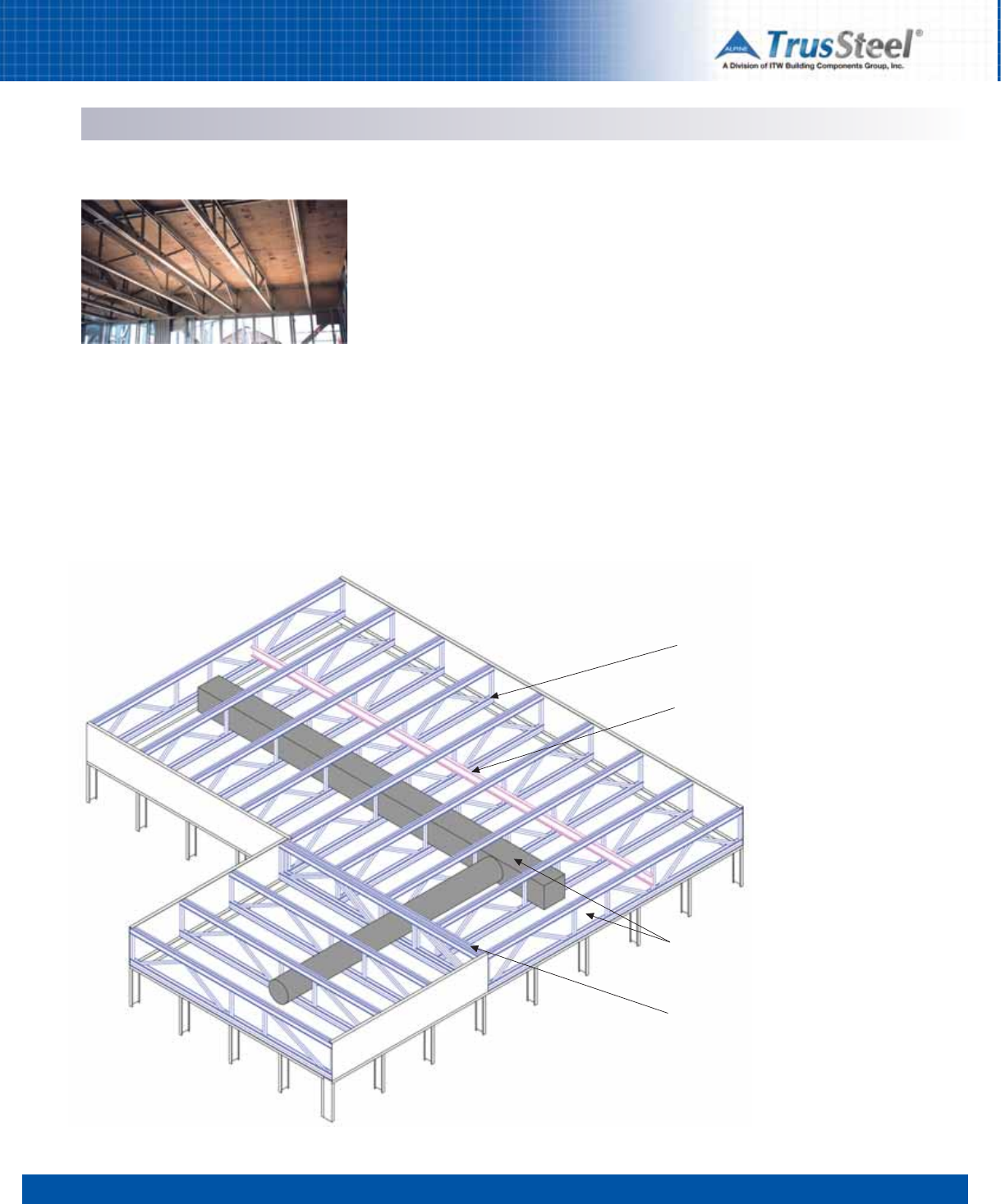
1 2 34 5 6 7 8
3.23
SPECIFYING / DESIGNING
Floor Truss Systems
Configurations
TrusSteel open web floor trusses are fabricated
with the same materials used in TrusSteel roof
trusses. The obvious advantage of an open web
floor truss over conventional joist framing is the
ease of equipment installation for the
mechanical, electrical and plumbing trades.
TrusSteel open web floor trusses may allow
greater clear-span capabilities and facilitate a
variety of bearing options. Truss depth and on-
center spacing will be determined by specific
loading and span requirements.
Serviceability
Serviceability parameters are specified by the
building designer and then trusses are designed
accordingly. In order to ensure a rigid floor
system, TrusSteel recommends a minimum live
load deflection criteria of L/360; more rigid
requirements may be specified. All TrusSteel
floor trusses are recommended to be fabricated
with a minimum of two patented Double-Shear
fasteners at all web-to-chord connections to
ensure rotational stability of the web and
increase product stiffness.
Girders
Multiple ply girders at stairwells and other
openings allow TrusSteel to provide the entire
floor framing package. These girders are
designed to carry concentrated loads at specific
locations and must be installed according to
approved shop drawings. Standard connection
details are provided with the truss package to
ensure proper installation and load transfer.
Truss bears on support member at the
truss heel.
Continuous strongback bracing provides
stability and reduces dynamic response of
truss system.
Duct work runs through optional integral
chase opening created in truss webs.
Truss girder (two-ply girder shown)
supports other CFS trusses.
Typical Floor Truss System
TrusSteel floor trusses provide the convenience
of open web members.
Note: Truss bracing not shown for clarity.
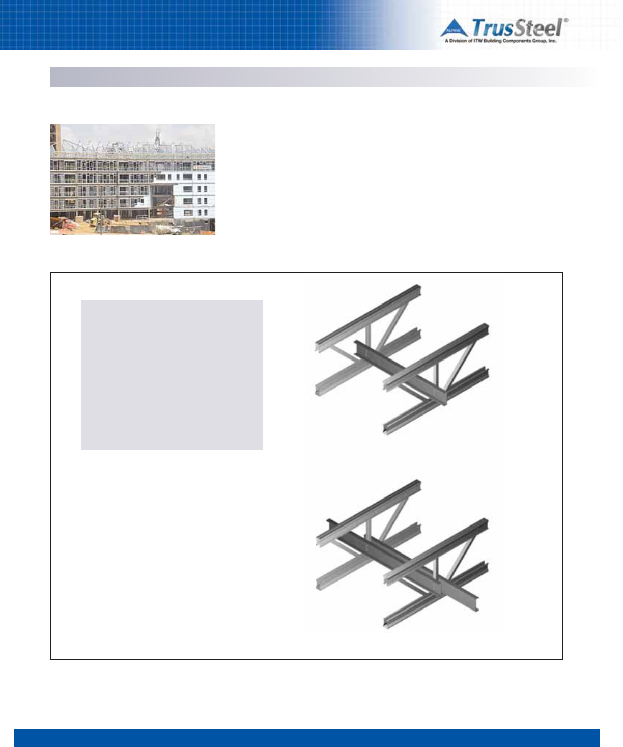
1 2 34 5 6 7 8
3.24
SPECIFYING / DESIGNING
Floor Truss Systems
Bearing Options
Multiple bearing options offer the building
designer flexibility in assigning bearing
elevations and coordinating with other structural
systems. While the majority of floor trusses bear
directly on the truss bottom chord, top chord
bearing can be an option to reduce the overall
building height. Mid-height bearing at both
exterior and interior beams can eliminate the
need for boxed framing and deliver a flat ceiling
throughout.
Dynamic Response
The dynamic response of a TrusSteel open web
truss floor system is greatly reduced by requiring
the installation of strongback bridging (generally
a 5-1/2” cee stud attached to vertical webs) at a
maximum of 10’-0” on-center. This load
distribution mechanism converts individual truss
components into a rigid floor system. Strongback
bridging may be attached to the truss web
members with standard single shear screws.
Deck Connections
Whether using a plywood sub-floor in residential
framing or metal deck with concrete in
commercial construction, deck attachment can
be achieved with screws or proprietary ring
shank pneumatically installed nails. TrusSteel
recommends a minimum steel thickness of 33
mils (20 GA) for the truss top chord in all floor
truss applications. The application of acoustical
and thermal gasket materials to the top chord
can reduce sound and thermal transmission.
Strongback splice - overlap one truss as shown.
Standard strongback installed on vertical webs.
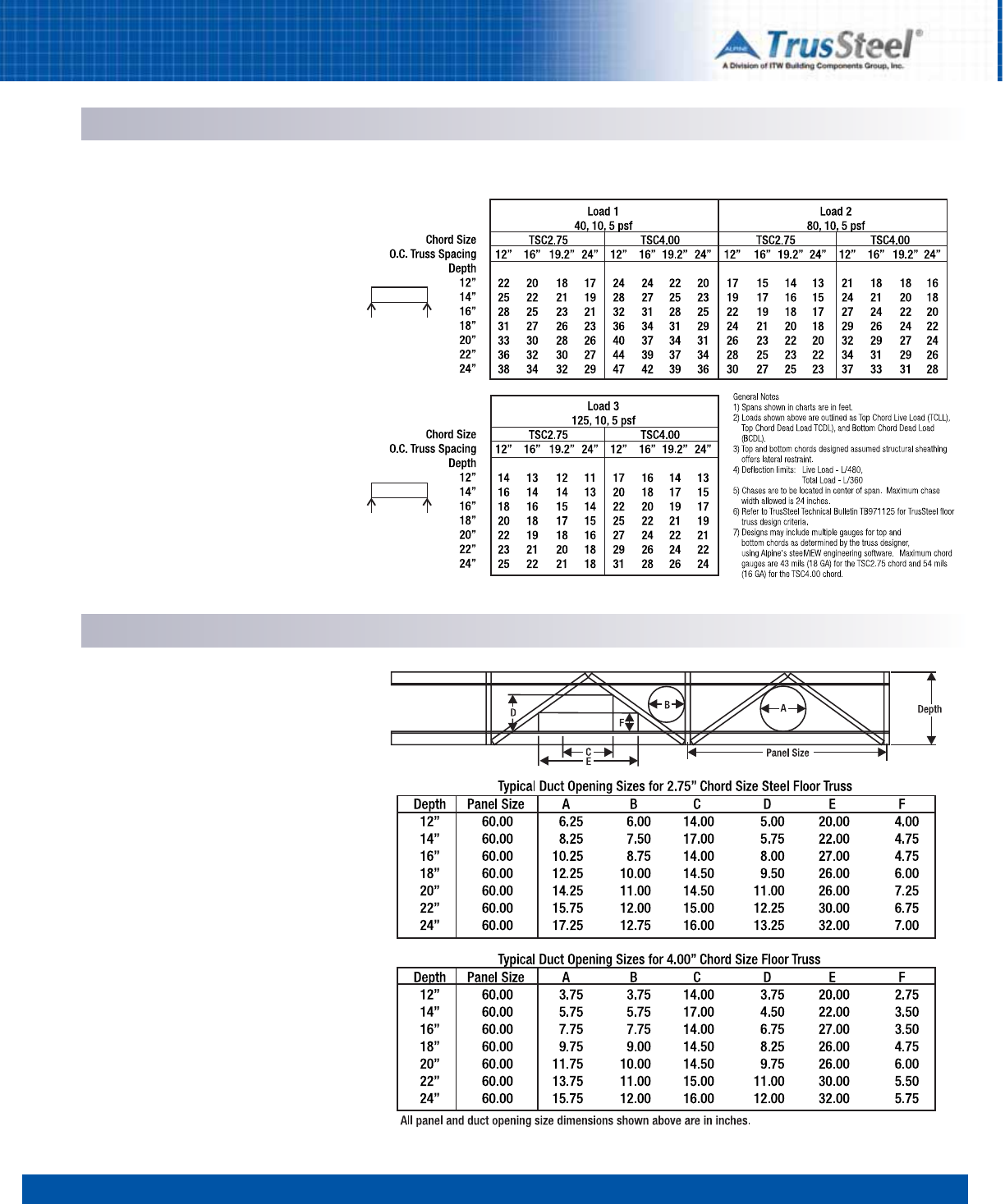
1 2 34 5 6 7 8
3.25
SPECIFYING / DESIGNING
Floor Truss Systems - Sample Span Tables
Floor Truss Span Tables
The abbreviated span tables shown represent
only a small sample of the possible floor truss
load/span/depth combinations. Contact your
local TrusSteel Authorized Fabricator to discuss
your specific truss needs.
Allowable Duct Size Table
This chart shows a sampling of available duct
openings in web patterns that are available in
some of the most common floor truss
configurations. Sizes of allowable openings may
be affected by specific floor loading conditions.
Contact your TrusSteel Authorized Fabricator to
discuss your specific truss needs.
Allowable Duct Sizes
1 2 34 5 6 7 8
3.26
SPECIFYING / DESIGNING
Guide Specification - Section 05 44 00
Notes to Specifier
This section is based on products engineered
by ITW Building Components Group, Inc.,
which is located at:
1950 Marley Drive
Haines City, FL 33844
Tel: (888) 565-9181
www.TrusSteel.com
Truss Fabricators
A nationwide network of TrusSteel
Authorized Fabricators quote, build and
deliver the trusses (in the same business
model as wood trusses). For a list of
TrusSteel Authorized Fabricators, visit
www.TrusSteel.com.
Product
The TrusSteel Division of ITW Builing
Components Group, the Truss Component
Manufacturer, has a unique, proprietary Cold-
Formed Steel (CFS) chord section that, when
combined with a dedicated truss design and
engineering software package, allows local
fabricators to supply high quality, reliable
designs with great speed and flexibility.
The CFS trusses are light in weight and
easy to deliver, handle, and install, while
providing resistance to insect damage,
deterioration, shrinkage, fire damage, and nail
popping that can affect wood truss
assemblies.
The TrusSteel chord shape is a symmetrical
"U" shape that avoids the eccentric loading
conditions that often occur with non-
symmetrical chord shapes like common steel
"C" shapes, sometimes referred to as "back-
to-back" shapes.
Electronic Specifications
An electronic, text-only version of this
specification is available on the CD version of
the manual or from www.TrusSteel.com. This
specification is provided in text-only format
with a minimum of formatting for use in all
word processors.
Additional Notes in Specifications
This specification contains additional
explanatory notes and instructions. These are
indicated with a ## symbol and are printed in
gray text within the body of the specification.
SECTION 05 44 00
(Section 05425 in MasterFormat 1995)
PRE-ENGINEERED PRE-FABRICATED
COLD-FORMED STEEL TRUSSES
PART 1 - GENERAL
1.1 - SECTION INCLUDES
A. Pre-engineered cold-formed steel trusses.
B . Cold-formed steel framing accessories.
1.2 - RELATED SECTIONS
## Delete any sections below not relevant to this
project; add others as required.
A. Section 05 30 00 -Metal Decking (Section
05300 in MasterFormat 1995).
B. Section 05 40 00 - Cold-Formed Metal
Framing (Section 05400 in MasterFormat 1995).
1.3 - DEFINITIONS
A. Truss Component Manufacturer: The
manufacturer of the components that will be
assembled into trusses by the Truss Fabricator.
See MANUFACTURERS for acceptable Truss
Component Manufacturer.
## Delete the last sentence in the following
paragraph if acceptable Truss Fabricators are not
listed in PART 2.
B. Truss Manufacturer: The individual or
organization that assembles the Truss
Component Manufacturer’s components into
completed trusses. See MANUFACTURERS for
acceptable Truss Fabricators.
C. Truss Design Drawing: Written, graphic and
pictorial depiction of an individual truss.
D. Truss Design Engineer: Person who is
licensed to practice engineering as defined by
the legal requirements of the jurisdiction in
which the building is to be constructed and who
supervises the preparation of the truss design
drawings. In this case, the Truss Design
Engineer is the Truss Component Manufacturer.
E. Truss Placement Diagram: Illustration
identifying the assumed location of each truss.
1.4 - REFERENCES
## Delete references from the list below that are
not actually required by the text of the edited
section.
A. ANSI/AISI/COS/S100-07/S2-10: North
American Specification for the Design of Cold-
Formed Steel Structural Members; American Iron
and Steel Institute; 2007 edition including the
2010 Supplement.
B. ANSI/AISI/COFS/S200-07: North American
Standard for Cold-Formed Steel Framing -
General Provisions; 2007.
C. ANSI/AISI/COFS/S214-07/S2-08: North
American Standard for Cold-Formed Steel
Framing - Truss Design; 2007 edition including
the 2008 Supplement.
D. AISI/COFS - Practice Guide - CF06-1: Code of
Standard Practice for Cold-Formed Steel
Structural Framing; 2006.
E. ASTM A 370-09 - Standard Test Methods and
Definitions for Mechanical Testing of Steel
Products; 2009.
F. ASTM A 500-03a - Standard Specification for
Cold-Formed Welded and Seamless Carbon Steel
Structural Tubing in Rounds and Shapes; 2003.
G. ASTM A 653-09 - Standard Specification for
Steel Sheet, Zinc-Coated (Galvanized) or Zinc-
Iron Alloy-Coated (Galvannealed) by the Hot-Dip
Process; 2009.
H. CFSBCSI - Cold-Formed Steel Building
Components Safety Information; Cold-Formed
Steel Council (CFSC); 2008 edition with CFSB3
summary sheet insert.
I. CFSEI Technical Note 551d - Design Guide for
Construction Bracing of Cold-Formed Steel
Trusses; Cold-Formed Steel Engineers Institute;
February 1997.
J. CFSEI Technical Note 551e - Design Guide for
Permanent Bracing of Cold-Formed Steel
Trusses; Cold-Formed Steel Engineers Institute;
February 1998.
1.5 - SUBMITTALS
A. Submit under provisions of Section 01 30 00
(Section 01300 IN MF95).
B. Product Data: Truss Component
Manufacturer's descriptive literature for each
item of cold-formed metal framing and each
accessory specified in this section.

1 2 34 5 6 7 8
3.27
SPECIFYING / DESIGNING
Guide Specification - Section 05 44 00
C. Truss Design Drawings: Detailed drawings
prepared by Truss Manufacturer under the
supervision of the Truss Design Engineer that are
in accordance with AISI references. These
drawings may also include referenced detail
drawings germane to the trusses.
D. Truss Placement Diagram: Diagram that
identifies the assumed location of each
individually designated truss and references the
corresponding Truss Design Drawing.
E. Installation Instructions: Truss Component
Manufacturer's printed instructions for handling,
storage, and installation of each item of cold-
formed metal framing and each accessory
specified in this section.
1.6 - QUALITY ASSURANCE
A. Provide design of trusses by Truss Component
Manufacturer, using design methodologies
recommended in AISI references.
1. Determine mechanical properties of load
bearing components by testing in accordance
with ASTM A 370-09.
2. Provide drawings by a design professional
registered in the State in which project is to be
constructed.
3. Provide Truss Manufacturer’s Truss Design
Drawings.
B. Pre-Installation Meeting: Meet at job site prior
to scheduled beginning of installation to review
requirements:
1. Attendees: Require attendance by
representatives of the following:
a. Installer of this section.
b. Other entities directly affecting, or
affected by, construction activities of this section,
including but not limited to, the following:
1) Installer of truss support framing.
2) Installer of mechanical systems.
3) Installer of electrical systems.
2. Review potential interface conflicts;
coordinate layout and support provisions.
1.7 - DELIVERY, STORAGE, AND
HANDLING OF STEEL TRUSSES
A. Pack, ship, handle, unload, and lift shop
products in accordance with Truss Component
Manufacturer's recommendations and in manner
necessary to prevent damage or distortion.
B. Store and protect products in accordance with
Truss Component Manufacturer's
recommendations and in manner necessary to
prevent damage, distortion and moisture buildup.
PART 2 -PRODUCTS
2.1 - MANUFACTURERS
## ITW Building Component Group, Inc. (the
Truss Component Manufacturer) produces the
truss components, which are then assembled
into completed trusses by one of their approved
fabricators (the Truss Fabricator). Visit
www.TrusSteel.com or call 888-565-9181 for a
list of Truss Fabricators. A free TrusSteel Design
Manual CD is also available.
A. Acceptable Truss Component Manufacturer:
TrusSteel Division of ITW Building Components
Group, Inc.; 1950 Marley Drive, Haines City, FL
33844. Tel: (888) 565-9181.
www.TrusSteel.com.
## Delete the following paragraph if it is not
necessary to list acceptable Truss Fabricators.
Obtain from TrusSteel a current list of Approved
Truss Fabricators known to have the capability of
fabricating products described in this section.
List of TrusSteel Authorized Fabricators is
available from www.TrusSteel.com.
B. Acceptable Truss Fabricators: Truss
components shall be fabricated into completed
trusses by one of the following local fabricators:
1. _________________________________.
2. _________________________________.
3. _________________________________.
## Delete one of the following two paragraphs;
coordinate with requirements of Division 1
section on product options and substitutions.
C. Substitutions: Not permitted.
D. Requests for substitutions will be considered
in accordance with provisions of Section 01 60
00.
1. All substitutions must be approved in
writing by the Architect or Building
Designer.
2. All applications for substitution must
include samples and technical data.
2.2 - COMPONENTS
A. Pre-Engineered Pre-Fabricated Cold-Formed
Steel Trusses: TrusSteel truss components, by
ITW Building Components Group, Inc.; meeting
specified requirements.
1. Truss Type, Span, and Height: As indicated
on drawings.
## Insert name of local code and deflection
requirements.
2. Comply with requirements of
______________________ code.
3. Deflection Under All Loads : 1/______th of
span, maximum.
4. Deflection Under Live Loads: 1/______th of
span, maximum.
5. Shop fabricate in accordance with Truss
Design Drawings, using jigging systems to
ensure consistent component placement
and alignment of components, and to
maintain specified tolerances; field
fabrication is strictly prohibited unless
performed by authorized Truss
Manufacturer using Truss Manufacturer’s
shop assemblers and proper jigging
systems.
6. Shop fabrication of other cold-formed steel
framing components into assemblies prior
to installion is permitted; fabricate
assemblies in accordance with shop
drawings.
7. Fasten connections within truss assembly
with Truss Component Manufacturer’s
fasteners only and as shown on the Truss
Design Drawings; welding and other
fasteners are prohibited.
8. Fabricate straight, level, and true, without
rack, and to the tolerances specified in
ANSI/AISI/COGFS/S214-07/S2-08.
B. Truss Chord and Web Components:
TrusSteel components, with rolled or closed
edges to minimize the danger of cutting during
handling; chord and web components without
rolled edges are prohibited.
1. Shapes, Sizes and Thicknesses: As
required to suit design and as indicated
on shop drawings.
2. Chords: Cold-formed from ASTM
A653-06a galvanized steel sheet,
minimum G60 coating; minimum yield
strength of 55,000 psi (380 MPa).

1 2 34 5 6 7 8
3.28
SPECIFYING / DESIGNING
Guide Specification - Section 05 44 00
## Some TrusSteel chord members are
manufactured from ASTM A653 steel of a higher
grade with minimum yield strength of 55 ksi (380
MPa) and minimum tensile strength of 65 ksi (448
MPa)
a. Nominal 28 mil (22 GA) members:
1) Minimum bare metal thickness:
0.0284 inch (0.72 mm).
2) Maximum design thickness:
0.0299 inch (0.76 mm).
b. Nominal 33 mil (20 GA) members:
1) Minimum bare metal thickness:
0.0329 inch (0.84 mm).
2) Maximum design thickness:
0.0346 inch (0.88 mm).
c. Nominal 43 mil (18 GA) members:
1) Minimum bare metal thickness:
0.0428 inch (1.09 mm).
2) Maximum design thickness:
0.0451 inch (1.15 mm).
d. Nominal 54 mil (16 GA) members:
1) Minimum bare metal thickness:
0.0538 inch (1.37 mm).
2) Maximum design thickness:
0.0566 inch (1.44 mm).
e. Nominal 68 mil (14 GA) members:
1) Minimum bare metal thickness:
0.0677 inch (1.72 mm).
2) Maximum design thickness:
0.0713 inch (1.31 mm).
f. Nominal 97 mil (12 GA) members:
1) Minimum bare metal thickness:
0.0966 inch (2.46 mm).
2) Maximum design thickness:
0.1017 inch (2.58 mm).
3. Tube Webs: Cold-formed ASTM A500
steel structural tubing; minimum yield
strength of 45 ksi (310 MPa); minimum tensile
strength of 55 ksi (380 MPa).
a. Nominal 33 mil (20 GA) members:
1) Minimum bare metal thickness:
0.033 inch (0.84 mm).
2) Maximum design thickness:
0.035 inch (0.89 mm).
b. Nominal 47 mil (18 GA) members:
1) Minimum bare metal thickness:
0.047 inch (1.19 mm).
2)Maximum design thickness:
0.049 inch (1.24 mm).
c. Nominal 63 mil (16 GA) members:
1) Minimum bare metal thickness:
0.063 inch (1.6 mm).
2) Maximum design thickness:
0.065 inch (1.65 mm).
4. Rolled formed Webs: Cold-formed from
ASTM A 653/A 653M galvanized steel sheet,
minimum G90 coating; minimum yield strength
of 40 ksi (276 MPa) for 20 and 18 GA
components or 50 ksi (345 MPa) for 16 GA
components; minimum tensile strength of 55 ksi
(379 MPa) for 20 and 18 GA components or 65
ksi (448 MPa) for 16 GA components.
a. Nominal 33 mil (20 GA) members:
1) Minimum bare metal thickness:
0.0329 inch (0.84 mm).
2) Maximum design thickness:
0.0346 inch (0.88 mm).
b. Nominal 43 mil (18 GA) members:
1) Minimum bare metal thickness:
0.0428 inch (1.09 mm).
2) Maximum design thickness:
0.0451 inch (1.15 mm).
c. Nominal 54 mil (16 GA) members:
1) Minimum bare metal thickness:
0.0538 inch (1.37 mm).
2) Maximum design thickness:
0.0566 inch (1.44 mm).
C. Fasteners Used in Fabricating Trusses:
Fasteners as recommended by Truss Component
Manufacturer, bearing stamp of Truss
Component Manufacturer for ready
identification.
PART 3 EXECUTION
3.1 EXAMINATION
A. Verify that bearing surfaces and substrates are
ready to receive steel trusses.
## The tolerances appropriate for truss bearings
surfaces are dependent on required tolerances of
subsequent construction; coordinate with other
sections and modify as required.
B. Verify that truss bearing surfaces are within
the following tolerances:
1. Variation from Level or Specified Plane:
Maximum 1/8 inch in 10 feet (6 mm in
3 m).
2. Variation from Specified Position: Maximum
1/4 inch (6 mm).
C. Verify that rough-in utilities and chases that
will penetrate plane of trusses are in correct
locations and do not interfere with truss, bracing
or bridging placement.
D. Inspect conditions under which installation is
to be performed and submit written notification if
such conditions are unacceptable to installer.
1. Notify Architect/Engineer-of-Record within
24 hours of inspection.
2. Beginning construction activities of this
section before unacceptable conditions
have been corrected is prohibited.
3. Beginning construction activities of this
section indicates installer’s acceptance of
conditions.
3.2 - INSTALLATION
A. Install trusses in accordance with Truss
Component Manufacturer’s instructions and
Truss Manufacturer’s Truss Design Drawings.
Use correct fasteners as previously described.
B. Place components at spacings indicated on
the Truss Design Drawings.
C. Install all erection (temporary installation)
bracing and permanent bracing and bridging
before application of any loads; follow
recommendations of the CFSBCSI - Cold-Formed
Steel Building Components Safety Information.
D. Install erection bracing -follow
recommendations of CFSBCSI Cold-Formed Steel
Building Components Safety Information.
1. Provide bracing that holds trusses straight
and plumb and in safe condition until
decking and permanent truss bracing has
been fastened to form a structurally sound
framing system.
2. All sub-contractors shall employ proper
construction procedures to insure adequate
distribution of temporary construction loads
so that the carrying capacity of any single
truss or group of trusses is not exceeded.
E. Install permanent bracing and bridging as
shown in the Architect/Engineer-of-Record’s
drawings and notes and as shown in the Truss
Fabricator’s shop drawings.
F. Removal, cutting or alteration of any truss
chord, web or bracing member in the field is
prohibited unless approved in advance in writing
by the Architect/Engineer-of-Record and the
Truss Designer.
G. Repair or replace damaged chords, webs, and
completed trusses as previously directed and
approved in writing by the Architect/Building
Designer and the Truss Component
Manufacturer.
3.3 FIELD QUALITY CONTROL
## This article is optional.
A. Owner will provide inspection service to
inspect field connections; see Section 01 40 00.
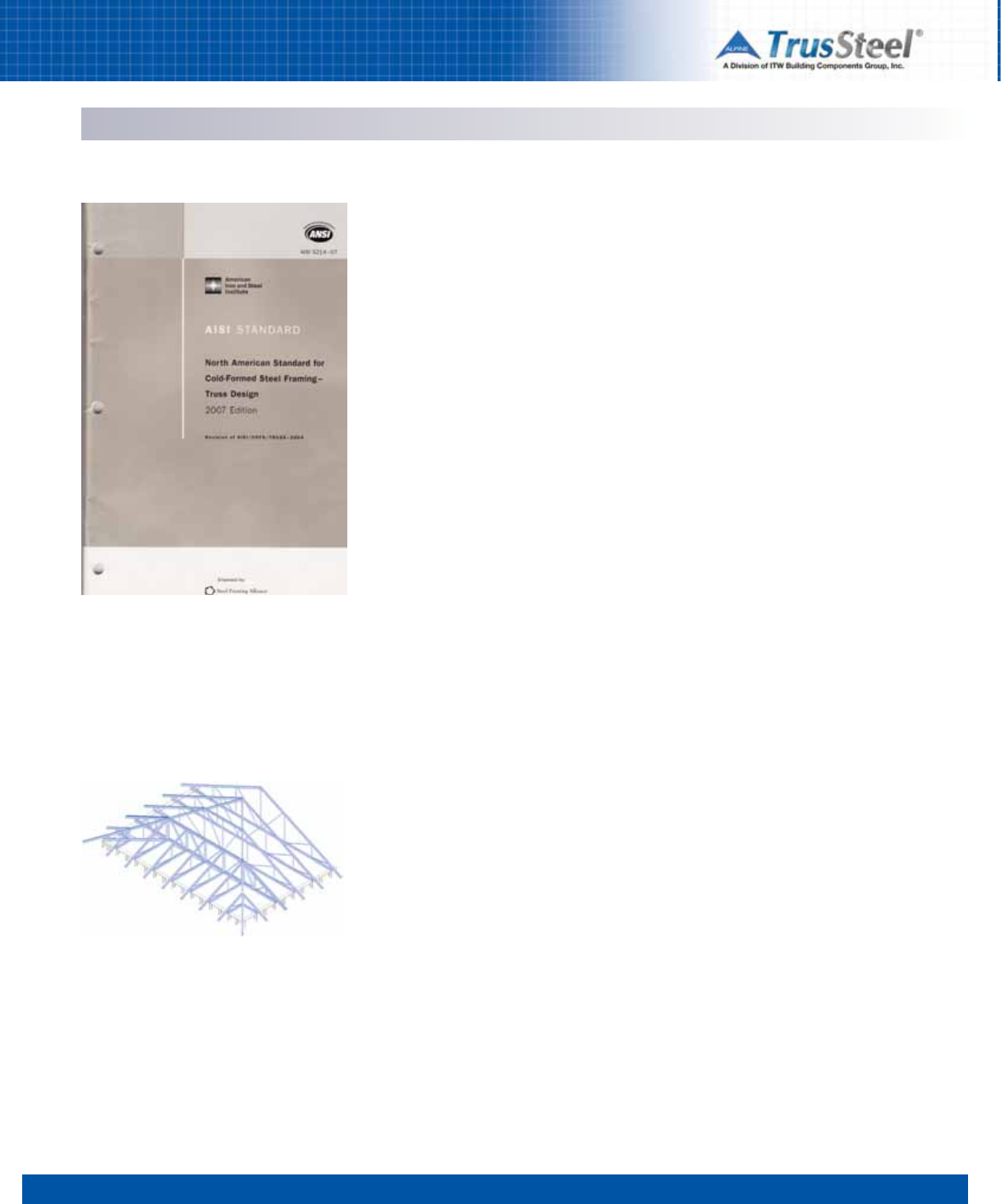
1 2 3 45 6 7 8
ENGINEERING / SHOP DRAWINGS
Engineering
4.01
Design Responsibilities
The Committee on Framing Standards (COFS) of
the American Iron and Steel Institute has created
the Standard for Cold-Formed Steel Framing -
Truss Design (latest revision is AISI S214-07/S2-
08) to provide technical information and
specifications on CFS truss construction. Specific
design responsibilities are defined within the
Standard in Section B. While these definitions are
not intended to replace any other allotments of
responsibilities that may be agreed upon by
involved parties, they do provide a proven
framework for most projects. The
responsibilities, as defined in the Standard, are
given below:
The Building Designer
The Building Designer shall specify the following
information:
(a) design loads in accordance with Section C
of the Standard
(b) roof profile and geometry
(c) bearing conditions
(d) temperature and moisture environment for
the intended end use
(e) any special requirements or considerations
to be taken into the truss design.
The Building Designer shall provide for the
following in the design and detailing of the
building:
(a) horizontal, vertical, or other truss deflection
due to design loads
(b) truss movement due to temperature
changes
(c) truss supports and anchorage
accommodating horizontal, vertical or other
reactions or displacements
(d) permanent truss bracing to resist wind,
seismic, and any other lateral forces acting
perpendicular to the plane of the truss
(e) permanent lateral bracing as specified by
the truss designer.
Truss Designer
The Truss Designer shall make available, upon
request, comprehensive design calculations
including the following information:
(a) loads and load combinations considered
(b) axial forces, moments, and shears
resulting from the applied loads and load
combinations
(c) design assumptions.
Truss Design Drawings
The truss design drawings shall include, as a
minimum, the following information:
(a) slope, depth, span, and spacing of the truss
(b) bearing locations and minimum bearing
lengths
(c) design loading(s)
(d) nominal reaction forces and direction
(e) location of all truss connections
(f) gusset plate locations, sizes and material
specification
(g) fastener type, size, quantities and
locations
(h) shape and material specification for each
component
(i) maximum nominal compressive force in all
truss members
(j) locations of required permanent truss
member bracing
(k) connection requirements for:
(1) truss-to-truss girder
(2) truss ply-to-ply
(3) field assembly of trusses
(l) calculated deflection ratio and / or
maximum deflection for live and total load.
Loading
The loads and load combinations to be used in
the design of cold-formed steel trusses shall be
determined by the building designer as
established by the local building code. In the
absence of such a code, the loads, and
combinations of loads shall be in accordance
with accepted engineering practice for the
geographical area under consideration as
specified by the appropriate sections of ASCE 7.
These and other reference materials are
available from the American Iron and Steel
Institute. See Section 8 of this Manual for contact
information.
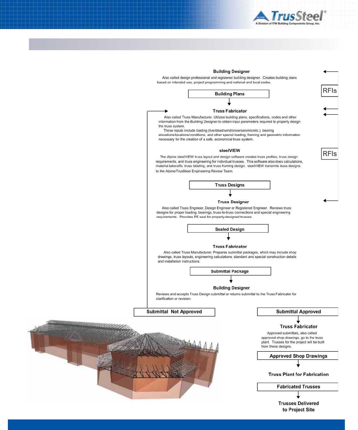
1 2 3 45 6 7 8
ENGINEERING / SHOP DRAWINGS
Engineering
4.02
Information Flow
The flow of design responsibilities within a truss
project creates an information flow that must be
understood by all participants. Each participant
plays a key role in handling large amounts of
information.
Open communication during this process is
critical for the success of a project. This diagram
shows the flow of responsibilities and
information for a typical truss project.
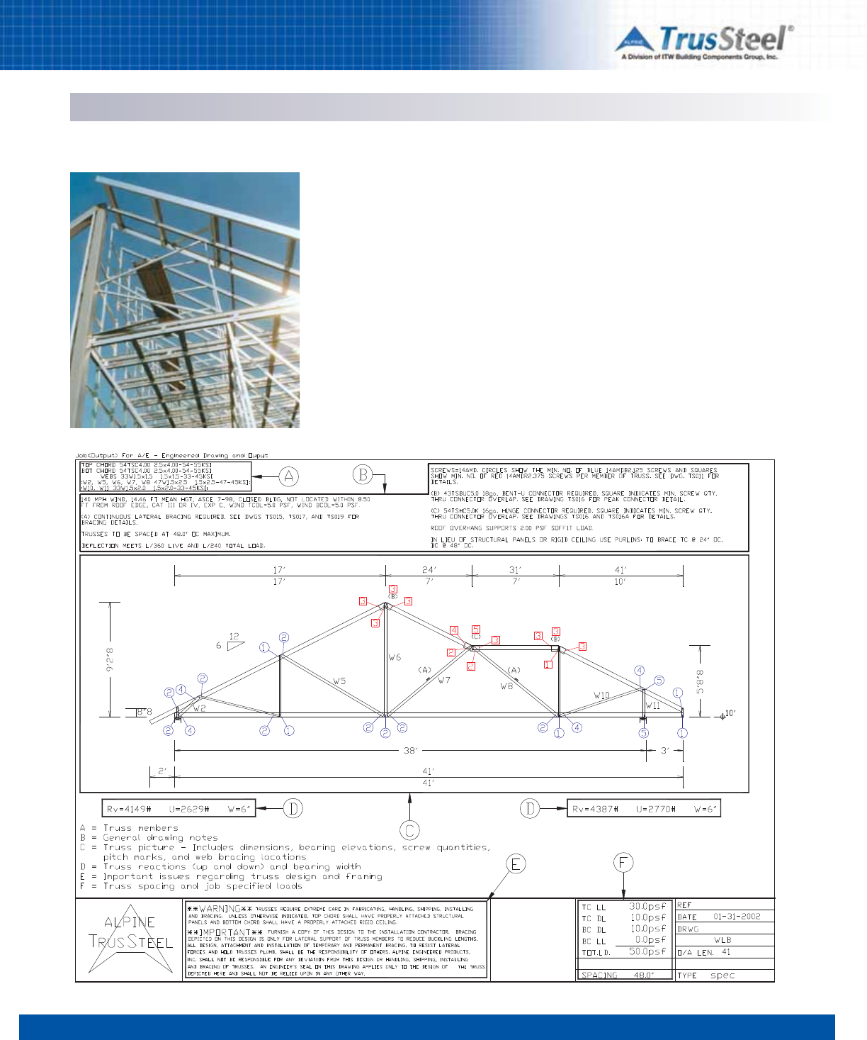
Sample drawing
1 2 3 45 6 7 8
ENGINEERING / SHOP DRAWINGS
Shop Drawings
4.03
Shop drawings are the primary vehicle for
transferring design information from the truss
designer to the building designer for review.
Clear, easy to understand shop drawings make
the job of the reviewer easier and help speed the
approval process. Each individual truss design is
described with a unique shop drawing. Load,
span, deflection and other design parameters are
clearly stated. Special design criteria and
bracing requirements are given, and additional
details are referenced on the drawing. Every
truss component member, fastener and internal
connector is located and identified. Truss profile,
pitch breaks and bearing points are fully
dimensioned.
Individual shop drawings are often supported
with engineering details. These accompanying
details are referenced on the shop drawings and
are included with the shop drawings in the
submittal package. Common internal connection
situations are referred to appropriate Standard
Details. New details are created, as needed, to
describe unique situations.
Key to Illustration
A Truss materials
B Special design considerations
C Truss design
D Reactions (including uplift) and bearing width
E Other considerations
F Load and spacing design parameters
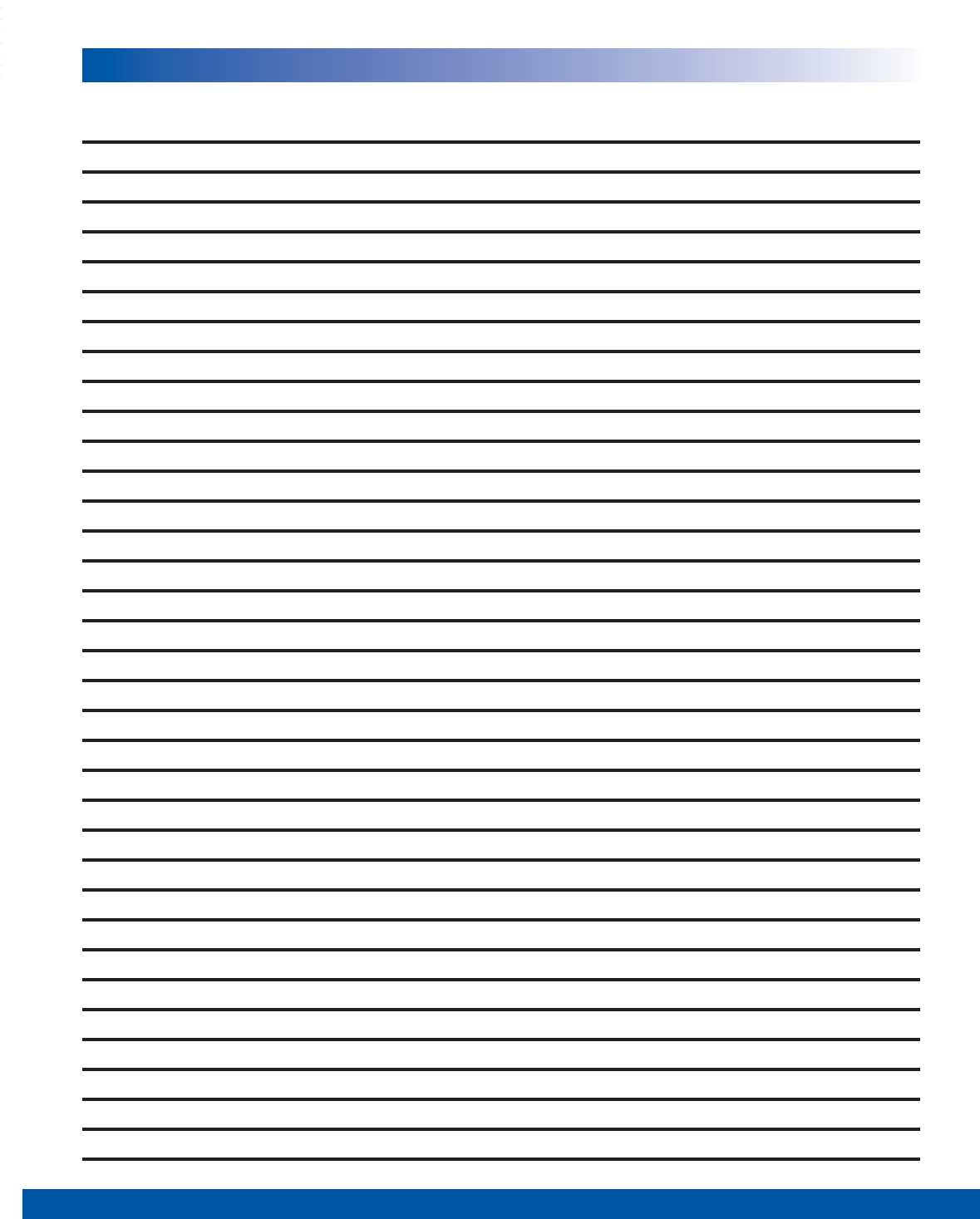
1 2 3 45 6 7 8
4.04
NOTES
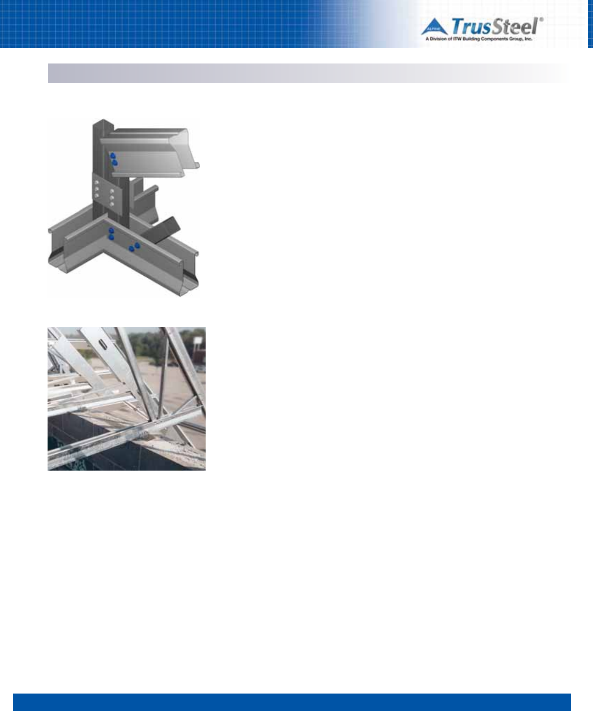
1 2 3 4 56 7 8
5.01
CONNECTIONS / DETAILS
Overview & Applications
Trusses are connected to each other, as well as
to other building systems and bearings, through
the use of proprietary connectors (sometimes
called “connectors”). These proprietary
connectors, sold by Alpine, are manufactured to
Alpine specifications and form an integral part of
the complete TrusSteel system.
The following pages of this manual are an
introduction to these connectors and their use.
This introduction is not intended to be a
comprehensive technical guide for each
connection type. For complete technical data on
each connection, please refer to the TrusSteel
Standard Details.
All connectors attach to TrusSteel trusses with
standard self-drilling tapping screws.
Connectors attach to different bearing materials
through the use of a variety of screws, pins,
welds and embedded anchors.
Other Connections
The following connections are not shown in this
manual - please refer to the Standard Details:
• truss fabrication connections (chord to web,
chord to chord, etc.)
• assembly of multi-ply trusses (whereby
several trusses are connected side-by-side to
create one multi-ply truss)
• connection or suspension of mechanical loads
from trusses.
General Notes for All Connections
• Connectors and fasteners specified are
designed to support the loads listed in the
allowable tables on the TrusSteel Standard
Details and in this manual.
• Install connectors and fasteners as specified
on the TrusSteel Standard Details. Refer to the
Standard Details for important information not
shown in this manual.
• Allowable loads have not been increased for
wind, seismic or other factors.
• Install all fasteners and connectors prior to
loading the connection.
• Allowable loads are listed in imperial (LBS)
and metric (kN) units.
• All steel thicknesses given are actual base
metal thicknesses.
• Connectors are fabricated from
G-90 or equal galvanized steel.
Notes for Truss-to-Truss Connections
• Connections are designed to support vertical
loads only in an upward or downward
direction.
Notes on Truss-to-Bearing Connections
• Upward loads listed are MAXIMUM allowable
loads.
• For lateral load capacities, see the Standard
Details.
• If upward loads will be acting in combination
with lateral loads, please contact a TrusSteel
engineer to determine the adequacy of the
connection.
General Notes for Fasteners
The fasteners specified in this publication, and on
the Standard Details, shall be used in strict
accordance with the Details. If an “or equal”
statement appears within a Detail, the substituted
fastener shall be qualified by a professional
engineer prior to the installation of the substitute.
The allowable load capacity of the substituted
fastener shall be confirmed through reliable
published test data or calculations.
Notes on Self-Drilling Tapping Screws (SDS)
• Allowable loads are determined per the AISI
North American Specification for the Design of
Cold-Formed Steel Structural Members
• SDS shall comply with ASTM C1513 or an
approved design or recognized design
Standard
• #10 tapping screw is 0.19” (nom. dia.)
• #12 tapping screw is 0.216” (nom. dia.)
• #14 tapping screw is 0.25” (nom. dia.)
• Screw spacing, end and edge distance shall
be 3 times the nominal diameter.
• Screw point style to be determined, based
upon the recommended steel thickness for
the given style.
• Screw length to be determined, so that when
installed the screw shows three exposed
threads (out the back of the connected parts)
or as otherwise determined by a professional
engineer.
• References
- AISI/COFS/S200 North American Standard for
Cold-Formed Steel Framing - General
Provisions
- Technical Note F102-11, Screw Fastener
Selection for Cold-Formed Steel Frame
Construction, CFSEI, November 2011
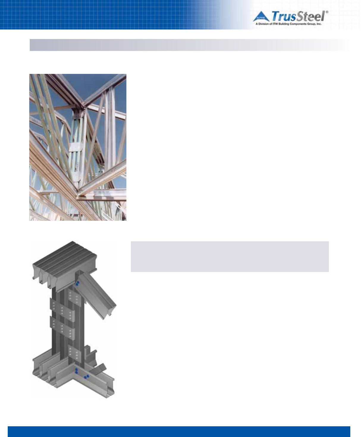
CONNECTIONS / DETAILS
Overview & Application
1 2 3 4 56 7 8
5.02
Notes on Wood Screws
• Allowable loads shall be determined by
ANSI/AF&PA NDS
• All wood screws shall comply with ASME
Standard B18.6.1 or an approved design or
recognized design standard.
Notes on Hilti®Powder-Actuated Fasteners
• Shall comply with ICBO Evaluation Report
ER-2388.
• Allowable loads shall be determined by ICBO
Evaluation Report ER-2388.
• Shall comply with Hilti North American
Product Technical Guide, 2005.
Notes on ITW Buildex®TAPCON®Fasteners
• Shall comply with ICC-ES Legacy Report
ER-3370.
• Allowable loads shall be determined by
ICC-ES Legacy Report ER-3370.
• Shall comply with ITW Buildex Product
Catalog
ITW Building Components Group, Inc. shall not be responsible for any performance failure in a
connection due to a deviation from the Standard Details. Any variation from these Details shall
be approved in advance by Alpine Engineers.
Notes on Welds
• Electrode strength, weld size, length and
spacing shall comply with specifications as
shown on applicable TrusSteel Standard
Details
• Welds shall be designed in accordance with
the AISI North American Specification for the
Design of Cold-Formed Steel Structural
Members
• Welds and welding shall comply with
requirements of American Welding Society
(AWS) D1.3, Structural Welding Code - Sheet
Steel.
This Manual is intended for quick reference only. Drawings and illustrations shown are samples only and are not intended for detailing
or construction. Please refer to the TrusSteel Standard Details for technical information on connection design, product use and safety.
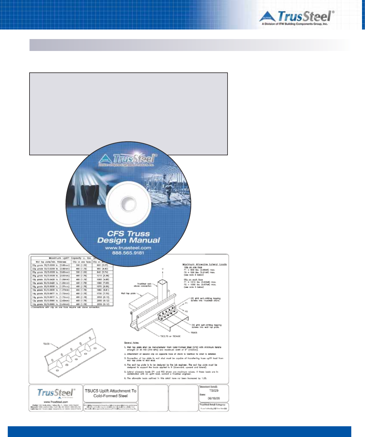
1 2 3 4 56 7 8
5.03
CONNECTIONS / DETAILS
Standard Details
Obtaining the Details
These Details are made available to the design community, free of charge, in DWG and DXF CAD
formats as well as in the printer-friendly PDF format. TrusSteel encourages designers to
incorporate these details directly into their construction documents.
Designers can obtain these Details via download at www.TrusSteel.com, or via the interactive
CD version of this manual. To request the CD, please send an e-mail to info@TrusSteel.com,
and include your name, your company name and your mailing address.
ITWBCG Hardware\
k.nnnn
Standard Details
TrusSteel has developed a library of Standard
Details to assist designers in their understanding
and use of these products. The library is divided
into sets of details, grouped by application. Set
names include:
• Bracing
• Connections: Mechanical/ Hanging
• Connections: Truss-to-Bearing
• Connections: Truss-to-Truss
• Product Properties
• Truss Framing Conditions
• Truss Internal Connections.
Details within these sets cover these applications
and more:
• truss to bearing connections (CFS steel, red
iron, wood and concrete bearings)
• truss bearing types (scissor, top and bottom
chord bearings)
• truss internal connections, including
- multi-ply trusses,
- splices
- pitch breaks
• truss bracing
• gable ends
• piggyback framing
• valley framing
• overhangs
• outlookers
• duct penetrations
• sprinkler and other hanging loads
• member section properties.
Sample Detail
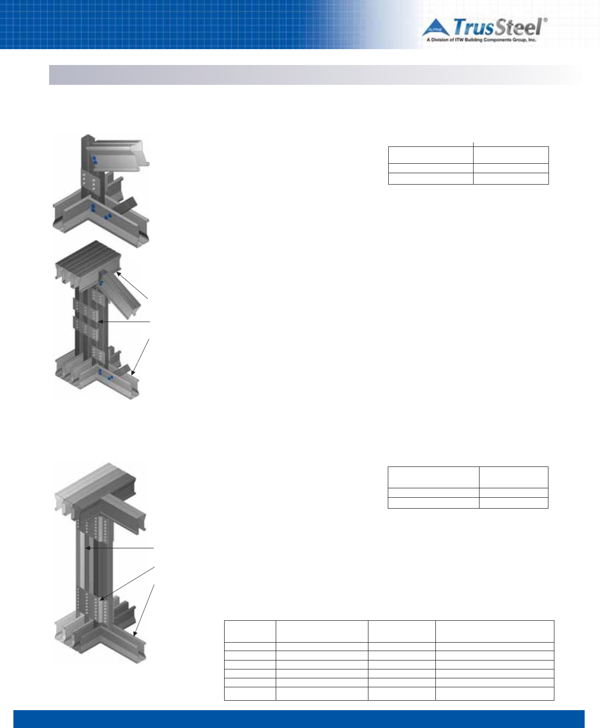
1 2 3 4 56 7 8
5.04
CONNECTIONS / DETAILS
Right Angle (90º) Truss Web-to-Web Connections
Description
Right angle truss-to-truss connections may be
made at the truss vertical webs by using TTC
clips. TTC clips may be used to fasten supported
trusses to single, double and triple-ply girder
trusses. TSC2.75 chord trusses require TTC3
and TTC5 clips. TSC4.00 chord trusses require
TTC4 and TTC7 clips.
Fasteners
TTC clips are installed using industry-standard
#10 self-drilling tapping screws. See Standard
Details for fastener quantities and placement to
reach Maximum Reactions.
Reference Standard Details
Please refer to these Standard Details for
information regarding the selection of TTC clip
sizes and installation requirements:
TS001
TS001A
TS001B
TS001C
TS001D
TS001E
TS001F
Connections using TTC Clips
Connections using TSHDC Clips
Girder truss
TTC clip
Supported
truss
Connections with TTC clips may be made at either
heel or end web of supported truss.
Girder truss
TSHDC clip
Supported
truss
Description
TSHDC clips may be used to fasten supported
trusses to single, double and triple-ply girder
trusses with differing web dimensions. Please
refer to the appropriate Standard Details for
information regarding the selection of TSHDC clip
sizes and installation requirements (see table
below).
Fasteners
TSHDC clips are installed using industry-
standard #10 self-drilling tapping screws. See
Standard Details for fastener quantities and
placement to reach Maximum Reactions.
Connections with TSHDC clips may be made at either
heel (not shown) or at the end web of supported truss.
TrusSteel
Chord Size
TSC2.75
TSC2.75
TSC4.00
TSC4.00
TSC4.00
TSC4.00
Girder
Vertical Size
3/4” x 1-1/2”
3/4” x 2-1/4”
1-1/2” x 1-1/2”
1-1/2” x 2”
1-1/2” x 2-1/2”
1-1/2” x 3-1/2”
Type
of Clip
TSHDC1.52
TSHDC2.252
TSCC664
TSHDC2.04
TSHDC2.54
TSHDC3.54
Standard
Detail
TS059, TS059A, TS059B
TS059, TS059A, TS059B
TS060, TS060A, TS060B
TS060, TS060A, TS060B
TS060, TS060A, TS060B
TS060, TS060A, TS060B
Reference Standard Details and Clip Selection
Valid for one, two and three ply girders.
Maximum Reaction (R)
LBS (kN)
1976 (8.79)
2470 (10.99)
No. of Clips
1
2
Maximum Connection Reactions
Downward and Uplift
Valid for one, two and three ply girders.
Maximum Reaction (R)
LBS (kN)
3500 (15.57)
4700 (20.91)
Chord
Size
TSC2.75
TSC4.00
Maximum Connection Reactions
Downward and Uplift
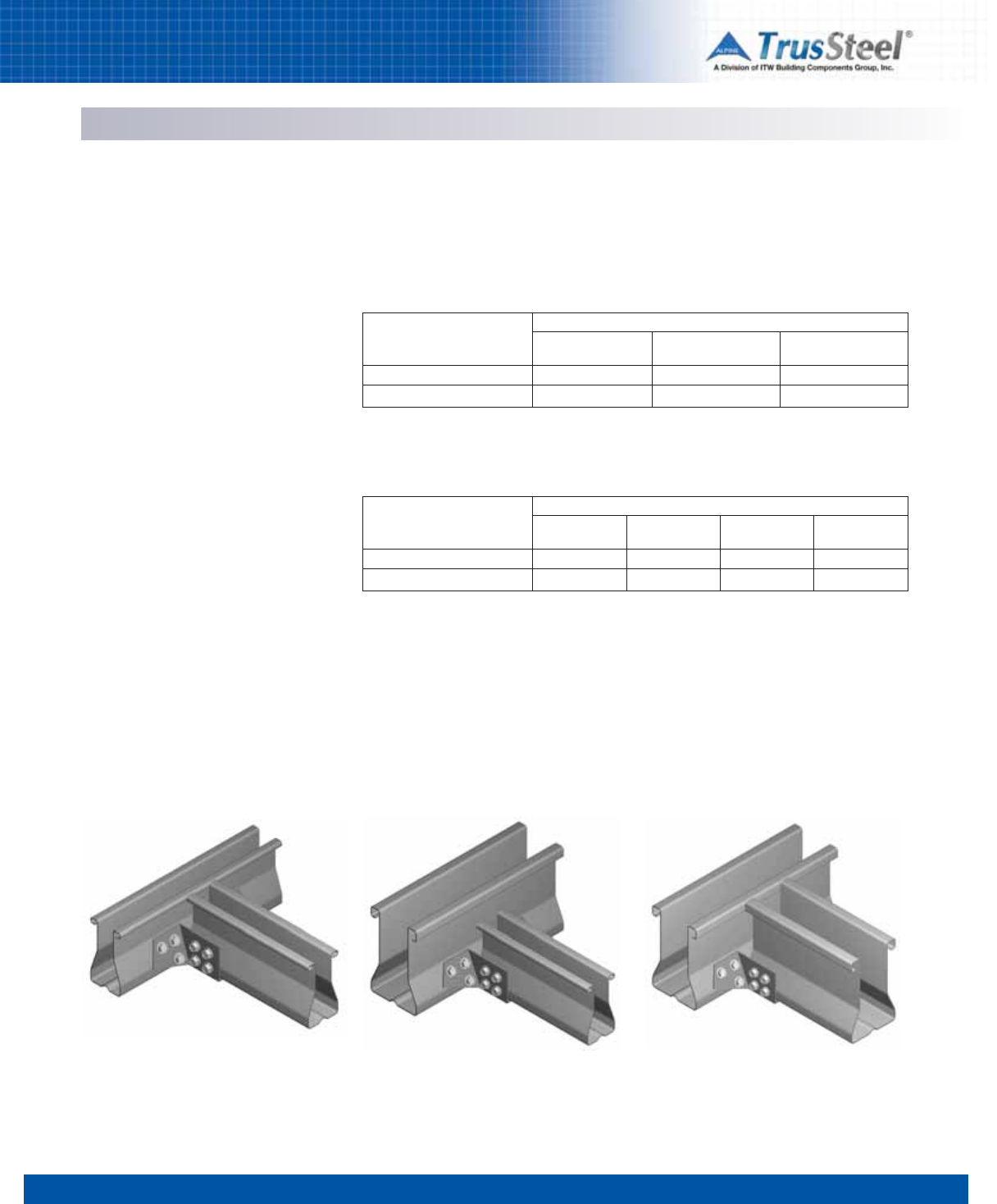
1 2 3 4 56 7 8
5.05
CONNECTIONS / DETAILS
Right Angle (90º) Truss Chord-to-Chord Connections
Description
Right angle truss-to-truss connections may be
made at the truss chords by using TSJH-series
hangers. TSJH-series hangers may be used to
fasten supported trusses to single, double and
triple-ply girder trusses.
Fasteners
Hanger connections are made using industry-
standard #10 self-drilling tapping screws.
Allowable loads shown are for full fastener
patterns. There are also allowable load values
available based upon partial fastener patterns.
See the referenced Standard Details for more
information.
Reference Standard Details
Please refer to these Standard Details for
information regarding the selection of TSJH-
series hanger sizes and installation
requirements:
TS022 connecting to single ply girder trusses
TS022A connecting to single ply girder trusses
TS023 connecting to multi-ply girder trusses
TS024 connecting to multi-ply girder trusses
TS024A connecting to multi-ply girder trusses
TSC2.75 supported truss connection to TSC2.75
girder truss with TSJH22 Hanger.
Connections using TSJH Hangers
TSC2.75 supported truss connection to TSC4.00
girder truss with TSJH24 Hanger.
TSC4.00 supported truss connection to TSC4.00
girder truss with TSJH44 Hanger.
Allowable Load
LBS (kN)
Down
Up
28TSC
22 GA
740 (3.29)
680 (3.02)
Maximum Connection Reactions
Downward and Uplift
TSC2.75 Girder with TSC2.75 Supported Truss
Using TSJH22 Hangers
Girder Chord Gauge
33TSC
20 GA
920 (4.09)
770 (3.43)
43TSC
18 GA
1380 (6.14)
1010 (4.49)
Allowable Load
LBS (kN)
Down
Up
28TSC
22 GA
920 (4.09)
610 (2.71)
TSC4.00 Girder with TSC2.75 or TSC4.00
Supported Truss
Using TSJH24 and TSJH44 Hangers
Girder Chord Gauge
54TSC
16 GA
1360 (6.05)
1130 (5.03)
33TSC
20 GA
1140 (5.07)
780 (3.47)
43TSC
18 GA
1350 (6.01)
1010 (4.49)
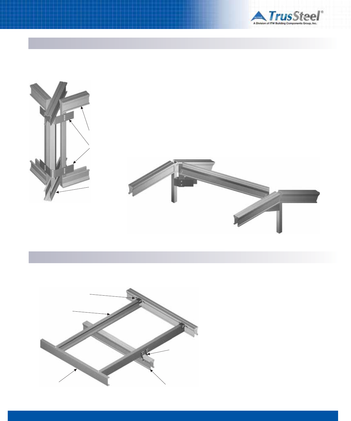
1 2 3 4 56 7 8
5.06
CONNECTIONS / DETAILS
Variable Angle Truss Web-to-Web Connections
Reference Standard Details
Please refer to these Standard Details for
information regarding the selection of TTC clip
sizes, and the required quantities and placement
locations of fasteners:
TS025 45° corner set
TS025A non-45° corner set
TS056 rafters
TS056A rafters
Maximum Connection Reactions
Refer to the referenced Standard Details for
allowable loads.
Connections using TTC Clips
Supported
truss
TTC clip
Girder truss
Description
Truss-to-truss connections of variable angles
may be made at the truss vertical webs by using
TTC clips. TTC clips may be used to fasten
supported trusses to single-ply girder trusses.
They are especially useful for making
connections for hip jacks and corner jacks in hip
sets.
Fasteners
These connections are made with #10 self-
drilling tapping screws.
TTC clips may also be used for rafter
to truss connections.
Connections at Gable Outlookers Using ITWBCG Hardware Connectors
Outlooker “C” member
TSJH Connector
Fascia member End gable truss
(dropped-top gable)
HT2.5A
Description
In gable outlooker situations, CFS “C” framing
may be attached to TrusSteel trusses using
TrusSteel TSJH connectors and ITWBCG
Hardware HT2.5A connectors.
Fasteners
These connectors are attached to the trusses
and the “C” framing with #10 self-drilling
tapping screws.
Reference Standard Details
Please refer to the Standard Detail below for
information regarding the selection of HT2.5A
connectors and installation requirements:
TS041
Connections at Gable Outlookers
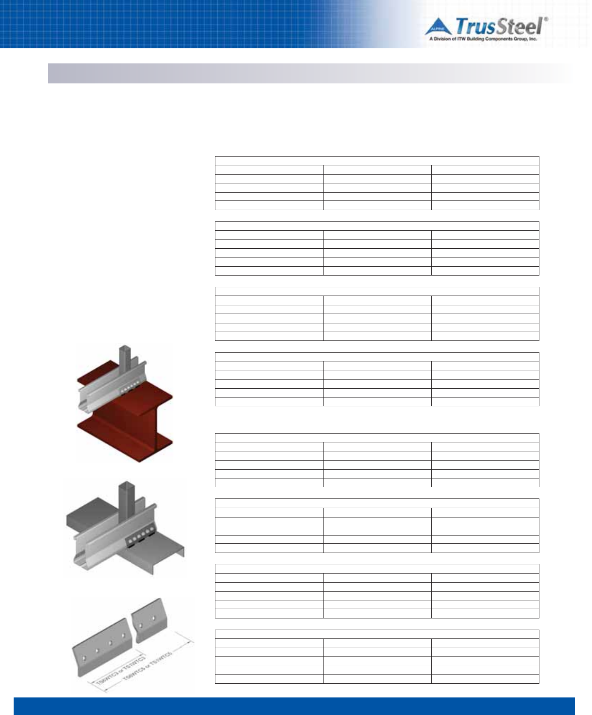
1 2 3 4 56 7 8
5.07
CONNECTIONS / DETAILS
Welded Connections to CFS Steel and Heavy Steel Bearings
Connections using WTC Clips
Description
CFS trusses may be anchored to both CFS steel
and heavy steel bearings using TrusSteel WTC
clips. Several sizes of WTC clips are available,
depending upon the required load transfer
capability.
Fasteners
These clips are attached to the truss with #10
self-drilling tapping screws and are attached to
the supporting members by welding. See
Standard Details for welding specifications.
Reference Standard Details
Please refer to these Standard Details for
information regarding the selection of WTC clips,
clip sizes, top plate minimums, installation
requirements and lateral load capacities:
TS027
TS027A
TS027B
TS027C
Welded connection to heavy steel using WTC Clip
Welded connection to CFS using WTC Clip
Chord Mil (GA)
28TSC (22)
33TSC (20)
43TSC (18)
54TSC (16)
TS6WTC3
Clip on One Face
550 (2.45)
550 (2.45)
550 (2.45)
550 (2.45)
Clip on Each Face
1640 (7.30)
2040 (9.07)
3040 (13.52)
3260 (14.50)
Refer to Standard Detail TS027
Chord Mil (GA)
28TSC (22)
33TSC (20)
43TSC (18)
54TSC (16)
TS1WTC3
Clip on One Face
550 (2.45)
550 (2.45)
550 (2.45)
550 (2.45)
Clip on Each Face
1640 (7.30)
2040 (9.07)
3040 (13.52)
4180 (18.60)
Refer to Standard Detail TS027
Chord Mil (GA)
28TSC (22)
33TSC (20)
43TSC (18)
54TSC (16)
TS6WTC5
Clip on One Face
550 (2.45)
550 (2.45)
550 (2.45)
550 (2.45)
Clip on Each Face
2460 (10.94)
3060 (13.61)
4560 (20.28)
5050 (22.46)
Refer to Standard Detail TS027A
Maximum Connection Reactions - Uplift
LBS (kN)
Chord Mil (GA)
28TSC (22)
33TSC (20)
43TSC (18)
54TSC (16)
TS1WTC5
Clip on One Face
550 (2.45)
550 (2.45)
550 (2.45)
550 (2.45)
Clip on Each Face
2460 (10.94)
3060 (13.61)
4560 (20.28)
6280 (27.93)
Refer to Standard Detail TS027A
Connections to Heavy Steel
Connections to CFS
Chord Mil (GA)
28TSC (22)
33TSC (20)
43TSC (18)
54TSC (16)
TS6WTC3
Clip on One Face
550 (2.45)
550 (2.45)
550 (2.45)
550 (2.45)
Clip on Each Face
1640 (7.30)
2040 (9.07)
3040 (13.52)
3260 (14.50)
Refer to Standard Detail TS027B
Chord Mil (GA)
28TSC (22)
33TSC (20)
43TSC (18)
54TSC (16)
TS1WTC3
Clip on One Face
550 (2.45)
550 (2.45)
550 (2.45)
550 (2.45)
Clip on Each Face
1640 (7.30)
2040 (9.07)
3040 (13.52)
4180 (18.60)
Refer to Standard Detail TS027B
Chord Mil (GA)
28TSC (22)
33TSC (20)
43TSC (18)
54TSC (16)
TS6WTC5
Clip on One Face
550 (2.45)
550 (2.45)
550 (2.45)
550 (2.45)
Clip on Each Face
2460 (10.94)
3060 (13.61)
4560 (20.28)
5050 (22.46)
Refer to Standard Detail TS027C
Chord Mil (GA)
28TSC (22)
33TSC (20)
43TSC (18)
54TSC (16)
TS1WTC5
Clip on One Face
550 (2.45)
550 (2.45)
550 (2.45)
550 (2.45)
Clip on Each Face
2460 (10.94)
3060 (13.61)
4560 (20.28)
6280 (27.93)
Refer to Standard Detail TS027C
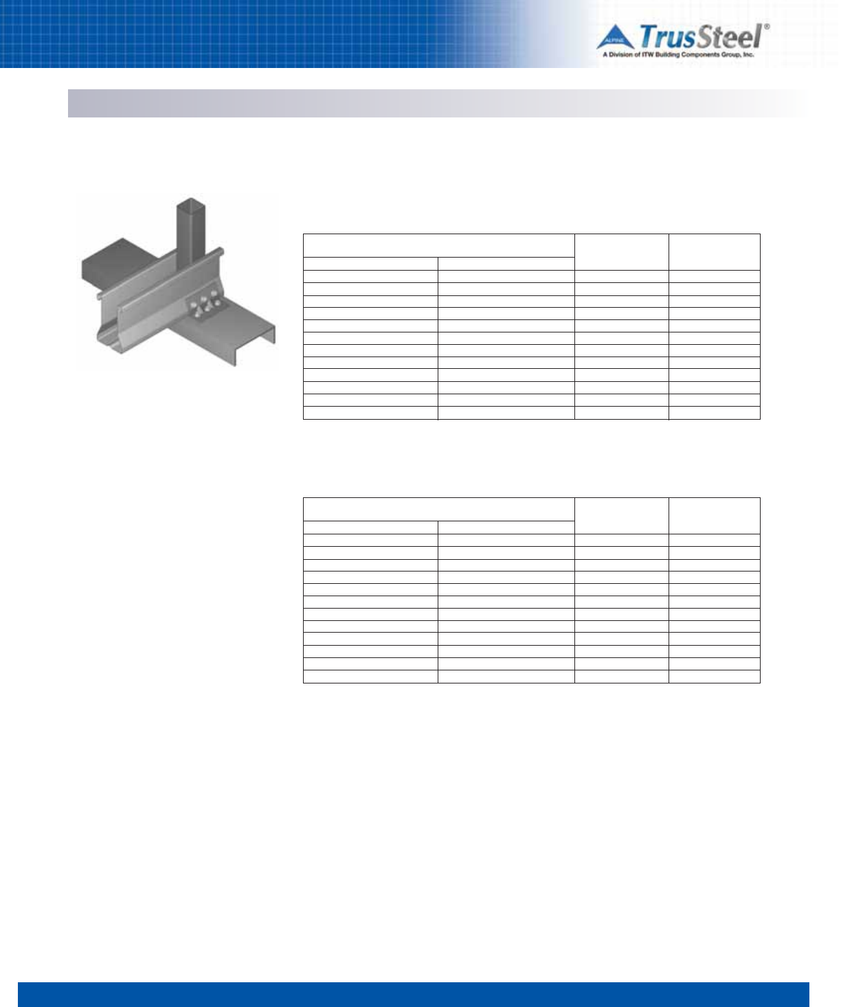
1 2 3 4 56 7 8
5.08
CONNECTIONS / DETAILS
Fastened Connections to CFS Steel Bearings
Connections using TSUC Clips
Description
CFS trusses may be anchored to cold-formed
steel bearings using TrusSteel TSUC clips.
Several sizes of TSUC clips are available,
depending upon the required load transfer
capability.
Fasteners
These clips are attached to the truss and bearing
with #10 self-drilling tapping screws. Note that
the name for these screws is sometimes
abbreviated as SDS.
Reference Standard Details
Please refer to these Standard Details for
information regarding the selection of TSUC
clips, clip sizes, installation requirements and
lateral load capacities:
TS028
TS029
TSUC Clip attached to CFS bearing using #10 self-
drilling tapping screws
Mil - Grade
28 Mil - Grade 33
28 Mil - Grade 50
33 Mil - Grade 33
33 Mil - Grade 50
43 Mil - Grade 33
43 Mil - Grade 50
54 Mil - Grade 33
54 Mil - Grade 50
68 Mil - Grade 33
68 Mil - Grade 50
97 Mil - Grade 33
97 Mil - Grade 50
Wall Top Plate
Minimum Thickness
Refer to Standard Detail TS028
Maximum Connection Reactions - Uplift
TSUC3 Clips to CFS Bearing
IN (mm)
0.0269 (0.68)
0.0269 (0.68)
0.0328 (0.83)
0.0328 (0.83)
0.0428 (1.09)
0.0428 (1.09)
0.0538 (1.37)
0.0538 (1.37)
0.0677 (1.72)
0.0677 (1.72)
0.0966 (2.45)
0.0966 (2.45)
Clip On
One Face
LBS (kN)
170 (0.76)
250 (1.11)
210 (0.93)
310 (1.38)
280 (1.25)
400 (1.78)
350 (1.56)
400 (1.78)
400 (1.78)
400 (1.78)
400 (1.78)
400 (1.78)
Clip On
Each Face
LBS (kN)
410 (1.82)
590 (2.62)
500 (2.22)
730 (3.25)
650 (2.89)
950 (4.23)
830 (3.69)
1190 (5.29)
1040 (4.63)
1230 (5.47)
1230 (5.47)
1230 (5.47)
Mil - Grade
28 Mil - Grade 33
28 Mil - Grade 50
33 Mil - Grade 33
33 Mil - Grade 50
43 Mil - Grade 33
43 Mil - Grade 50
54 Mil - Grade 33
54 Mil - Grade 50
68 Mil - Grade 33
68 Mil - Grade 50
97 Mil - Grade 33
97 Mil - Grade 50
Wall Top Plate
Minimum Thickness
Refer to Standard Detail TS029
TSUC5 Clips to CFS Bearing
IN (mm)
0.0269 (0.68)
0.0269 (0.68)
0.0328 (0.83)
0.0328 (0.83)
0.0428 (1.09)
0.0428 (1.09)
0.0538 (1.37)
0.0538 (1.37)
0.0677 (1.72)
0.0677 (1.72)
0.0966 (2.45)
0.0966 (2.45)
Clip On
One Face
LBS (kN)
290 (1.29)
400 (1.78)
350 (1.56)
400 (1.78)
400 (1.78)
400 (1.78)
400 (1.78)
400 (1.78)
400 (1.78)
400 (1.78)
400 (1.78)
400 (1.78)
Clip On
Each Face
LBS (kN)
680 (3.02)
990 (4.40)
840 (3.74)
1210 (5.38)
1090 (4.85)
1580 (7.03)
1370 (6.09)
1980 (8.81)
1730 (7.70)
2050 (9.12)
2050 (9.12)
2050 (9.12)
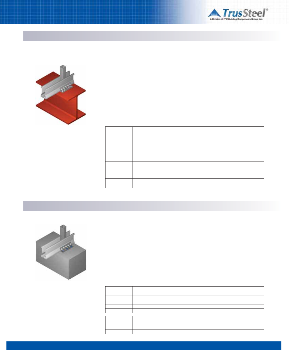
1 2 3 4 56 7 8
5.09
CONNECTIONS / DETAILS
Connections using TSUC Clips Description
CFS trusses may be anchored to heavy steel
bearings by using TrusSteel TSUC clips. Several
sizes of TSUC clips are available, depending upon
the required load transfer capability.
Fasteners
These clips are attached to the truss with #10
self-drilling tapping screws. Clips are attached to
bearing with #12 or #14 screws, or pins.
TSUC5 Clip attached to red iron bearing. See Standard
Details for fastener placement.
Fastened Connections to Heavy Steel Bearings
Reference Standard Details
Please refer to these Standard Details for
information regarding the selection of TSUC
clips, clip sizes, installation requirements and
lateral load capacities:
TS039 pins into 3/16” to 1/2” steel
TS040 pins into 3/16”to 1/2” steel
TS047 screws into 1/8” to 1/2” steel
TS048 screws into 1/8” to 1/2” steel
TSUC5 Clip attached to concrete bearing with
Tapcon®fasteners.
Description
CFS trusses may be anchored to concrete
bearings by using TrusSteel TSUC clips. Several
sizes of TSUC clips are available, depending upon
the required load transfer capability.
Fasteners
These clips are attached to the truss with #10
self-drilling tapping screws, and can be attached
to the bearing with Tapcon®fasteners.
Reference Standard Details
Please refer to these Standard Details for
information regarding the selection of TSUC
clips, clip sizes, installation requirements and
lateral load capacities:
TS030
TS031
Fastened Connections to Concrete Bearings
Connections using TSUC Clips
Maximum Connection Reactions - Uplift
Clip
TSUC3
TSUC3
TSUC5
TSUC5
TSUC3
TSUC5
Steel Thickness
IN (mm)
3/16 (4.76)
1/4 (6.35) to
1/2 (12.70)
3/16 (4.76)
1/4 (6.35) to
1/2 (12.70)
1/8 (3.18) to
1/2 (12.70)
1/8 (3.18) to
1/2 (12.70)
Clip on One Face
LBS (kN)
400 (1.78)
400 (1.78)
400 (1.78)
400 (1.78)
400 (1.78)
400 (1.78)
Clip on Each Face
LBS (kN)
1230 (5.47)
1230 (5.47)
2050 (9.12)
2050 (9.12)
1230 (5.47)
2050 (9.12)
Standard
Detail
TS039
TS039
TS040
TS040
TS047
TS048
Maximum Connection Reactions - Uplift
Clip
TSUC3
TSUC3
TSUC3
TSUC3
Concrete Strength
PSI (MPa)
2000 (13.79)
3000 (20.68)
4000 (27.58)
5000 (34.47)
Clip on One Face
LBS (kN)
n/a
n/a
n/a
n/a
Clip on Each Face
LBS (kN)
520 (2.31)
570 (2.54)
660 (2.94)
740 (3.29)
Standard
Detail
TS030
TS030
TS030
TS030
TSUC5
TSUC5
TSUC5
TSUC5
2000 (13.79)
3000 (20.68)
4000 (27.58)
5000 (34.47)
400 (1.78)
400 (1.78)
400 (1.78)
400 (1.78)
520 (2.31)
570 (2.54)
660 (2.94)
740 (3.29)
TS031
TS031
TS031
TS031
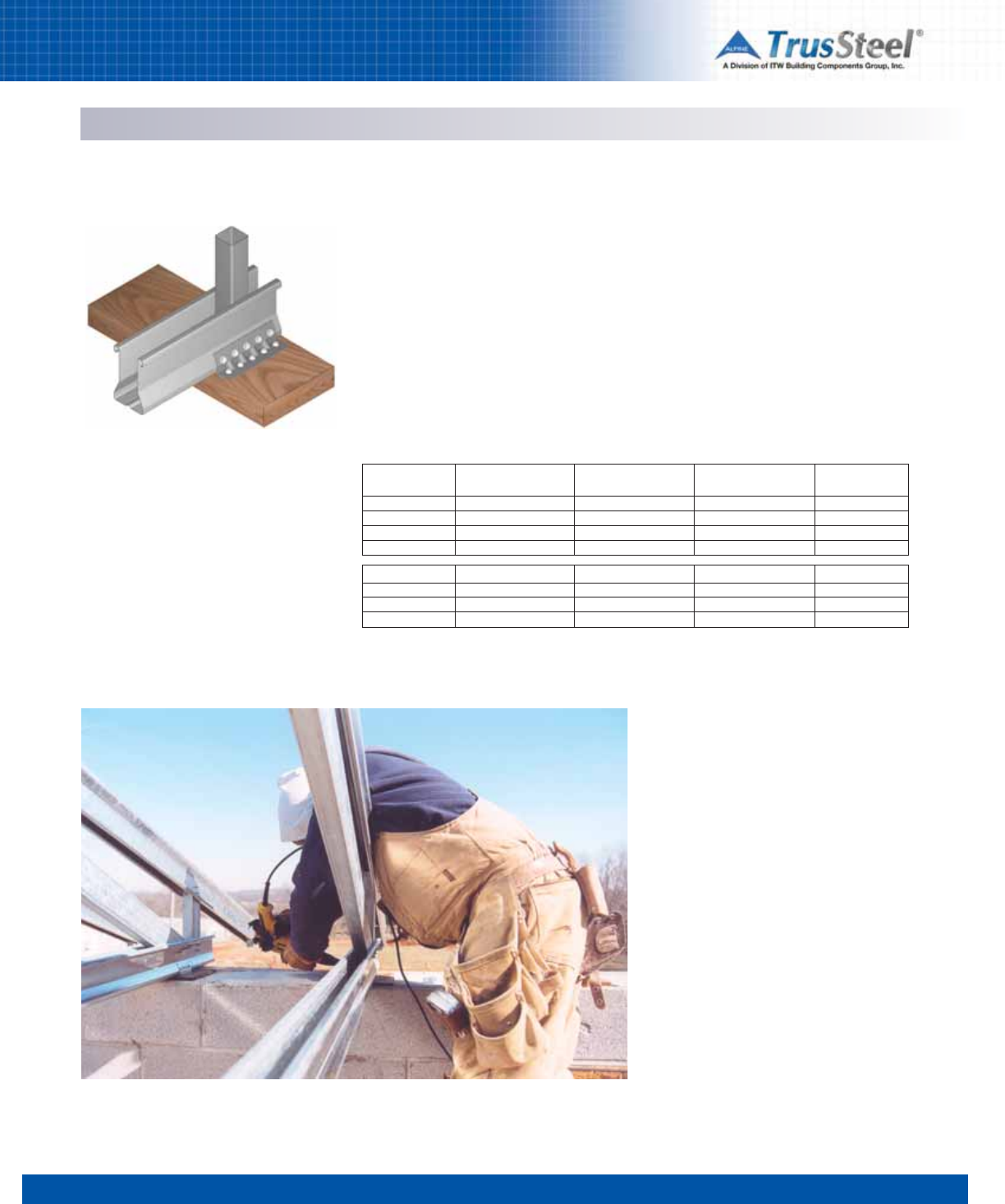
1 2 3 4 56 7 8
5.10
CONNECTIONS / DETAILS
TSUC5 Clip attached to wood bearing with
wood screws.
Description
CFS trusses may be anchored to wood bearings
by using TrusSteel TSUC clips. Several sizes of
TSUC clips are available, depending upon the
required load transfer capability.
Fasteners
These clips are attached to the truss with #10
self-drilling tapping screws, and can be attached
to the bearing with wood screws.
Reference Standard Details
Please refer to these Standard Details for
information regarding the selection of TSUC
clips, clip sizes, installation requirements and
lateral load capacities:
TS032
TS033
Fastened Connections to Wood Bearings
Connections using TSUC Clips
Maximum Connection Reactions - Uplift
Clip
TSUC3
TSUC3
TSUC3
TSUC3
Wall Top Plate
Species
Spruce-Pine-Fir
Hem-Fir
Douglas Fir-Larch
Southern Pine
Clip on One Face
LBS (kN)
380 (1.69)
400 (1.78)
400 (1.78)
400 (1.78)
Clip on Each Face
LBS (kN)
910 (4.05)
960 (4.27)
1230 (5.47)
1230 (5.47)
Standard
Detail
TS032
TS032
TS032
TS032
TSUC5
TSUC5
TSUC5
TSUC5
Spruce-Pine-Fir
Hem-Fir
Douglas Fir-Larch
Southern Pine
400 (1.78)
400 (1.78)
400 (1.78)
400 (1.78)
1520 (6.76)
1600 (7.12)
2050 (9.12)
2050 (9.12)
TS033
TS033
TS033
TS033
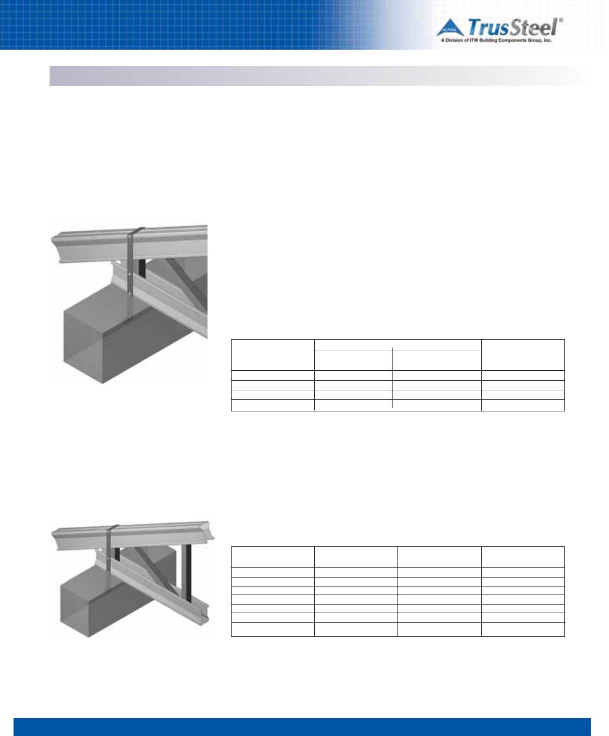
1 2 3 4 56 7 8
5.11
CONNECTIONS / DETAILS
Connections using ITWBCG Hardware
ETAM Straps
Description
CFS trusses may be attached by ETAM straps
embedded into concrete beams. These straps are
attached to the truss with #10 self-drilling
tapping screws. Several sizes of ETAM straps are
available, depending upon the required load
transfer capability. See referred Standard Details
for lateral load capacities.
Fasteners
These straps are attached to the truss with #10
self-drilling tapping screws.
ETAM strap at truss heel or internal bearing
Embedded Connections to Concrete
Reference Standard Details
Please refer to these Standard Details for
information regarding the selection of ETAM
Straps and installation requirements:
TS034
TS035
No. of Screws
per ETAM
3
4
5
6
TSC2.75
LBS (kN)
550 (2.45)
550 (2.45)
550 (2.45)
550 (2.45)
ETAM on One Face
TSC4.00
LBS (kN)
660 (2.94)
880 (3.91)
880 (3.91)
880 (3.91)
ETAM on Each Face
TSC2.75 & TSC4.00
LBS (kN)
1320 (5.87)
1760 (7.83)
1760 (7.83)
1760 (7.83)
ETAM
Straps into Concrete Bearing (Internal)
Refer to Standard Detail TS034
ETAMstrap at truss heel
Maximum Connection Reactions - Uplift
Top Chord
28TSC2.75
33TSC2.75
43TSC2.75
28TSC4.00
33TSC4.00
43TSC4.00
54TSC4.00
Mil (GA)
28 (22)
33 (20)
43 (18)
28 (22)
33 (20)
43 (18)
54 (16)
ETAM on One Face
LBS (kN)
530 (2.36)
550 (2.45)
550 (2.45)
510 (2.27)
660 (2.94)
900 (4.00)
900 (4.00)
ETAM on Each Face
LBS (kN)
1230 (5.47)
1530 (6.81)
1760 (7.83)
1760 (7.83)
1760 (7.83)
1760 (7.83)
1760 (7.83)
ETAM
Straps into Concrete Bearing (Heel)
Refer to Standard Detail TS035
Maximum Connection Reactions - Uplift
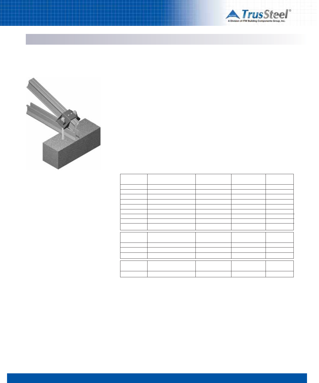
1 2 3 4 56 7 8
5.12
CONNECTIONS / DETAILS
ITWBCG
Part
GTH2
GTH2
Single-Ply TrusSteel
Top Chord
TSC2.75 w/ Seat Plate
TSC4.00 w/ Seat Plate
Mil (GA)
Range
28-43 (22-18)
28-54 (22-16)
Capacity
LBS (kN)
4110 (18.28)
4110 (18.28)
Standard
Detail
TS050
TS050
GTH2
GTH2
GTH2
GTH2
GTH2
GTH2
GTH2
28TSC2.75 w/o Seat Plate
33TSC2.75 w/o Seat Plate
43TSC2.75 w/o Seat Plate
28TSC4.00 w/o Seat Plate
33TSC4.00 w/o Seat Plate
43TSC4.00 w/o Seat Plate
54TSC4.00 w/o Seat Plate
28 (22)
33 (20)
43 (18)
28 (22)
33 (20)
43 (18)
54 (16)
870 (3.87)
1220 (5.43)
1270 (5.65)
810 (3.60)
1140 (5.07)
2100 (9.34)
2530 (11.25)
TS051
TS051
TS051
TS051
TS051
TS051
TS051
ITWBCG
Part
GTH2
GTH4
GTH2
Two-Ply TrusSteel
Top Chord
TSC2.75 w/ Seat Plate
TSC4.00 w/ Seat Plate
TSC2.75 w/o Seat Plate
Mil (GA)
Range
28-43 (22-18)
28-54 (22-16)
28-43 (22-18)
Capacity
LBS (kN)
5050 (22.46)
5290 (23.53)
1270 (5.65)
Standard
Detail
TS052
TS054
TS053
ITWBCG
Part
GTH3
Three-Ply TrusSteel
Top Chord
TSC2.75 w/ Seat Plate
Mil (GA)
Range
28-43 (22-18)
Capacity
LBS (kN)
6580 (29.27)
Standard
Detail
TS055
Connections using ITWBCG Hardware
GTH Connectors
Description
CFS trusses may be attached to concrete
bearings using GTH connectors. Several sizes of
GTH connectors are available, depending upon
the required load transfer capability.
Fasteners
These connectors are attached to the truss with
#10 self-drilling tapping screws and the
connectors are fastened to the concrete bearing
using threaded rods which are installed into the
concrete using an epoxy adhesive.
TrusSteel truss anchored to concrete bearing using
ITWBCG Hardware GTH-series connector and epoxy-
installed threaded rod.
Embedded Connections to Concrete
Reference Standard Details
Please refer to the Standard Details shown in the
chart below for information regarding the
selection of GTH connectors, sizes and
installation requirements:
TS050
TS051
TS052
TS053
TS054
TS055
Maximum Connection Reactions - Uplift
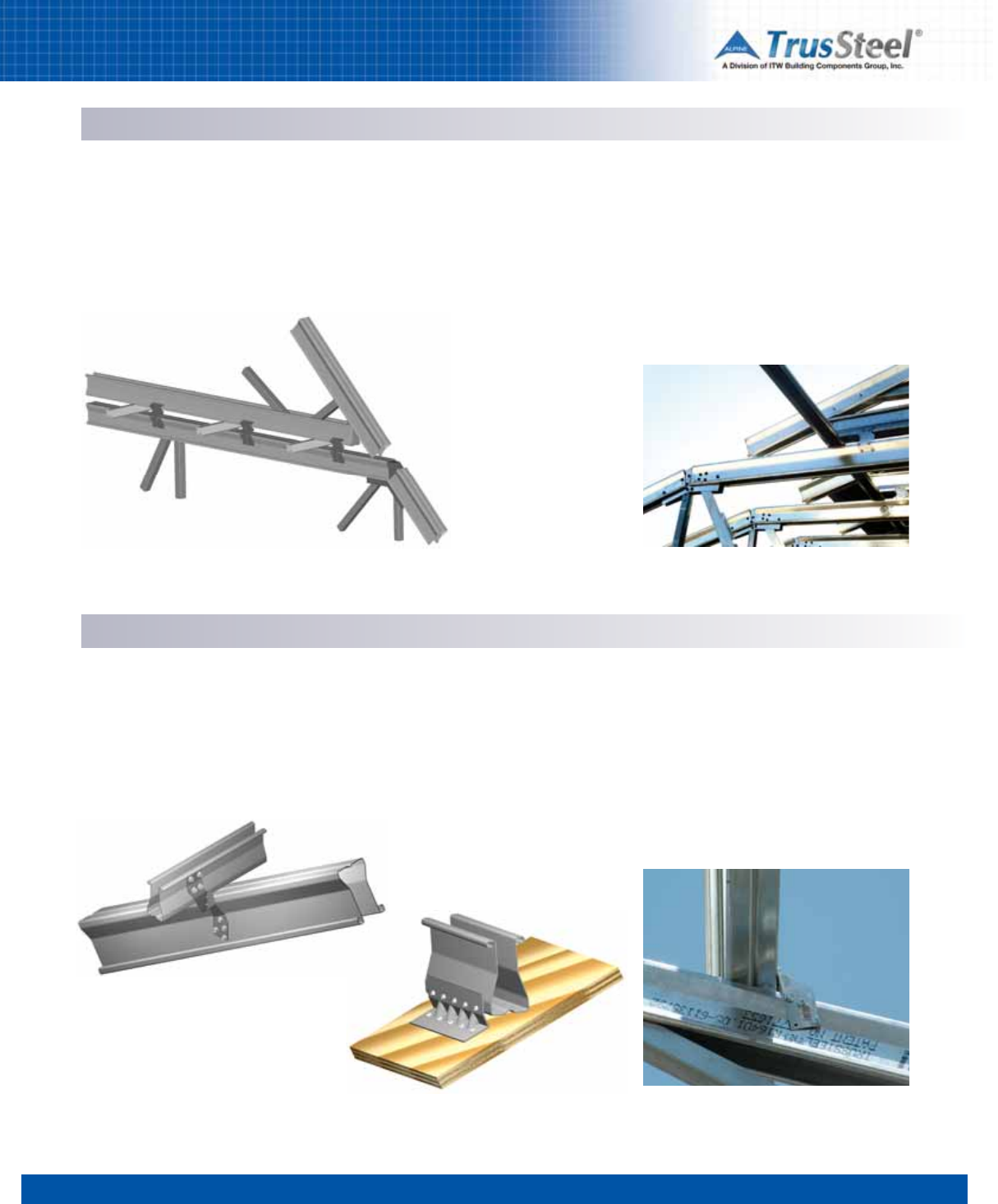
1 2 3 4 56 7 8
5.13
CONNECTIONS / DETAILS
Connections using ITWCBCG Hardware
HT2.5A Connectors
Description
CFS trusses in a piggyback configuration may be
anchored to the top chords of base trusses using
TrusSteel TTC7 clips or ITWBCG Hardware FAL
Framing Anchors.
Fasteners
These connections are made with #10 self-
drilling tapping screws.
Fastened Connections for Piggybacks
Reference Standard Details
Please refer to these Standard Details for
information regarding the selection and
installation requirements:
TS003
TS003A
TS003B
Connections using ITWBCG Hardware
HT2.5A Connectors
Description
CFS trusses in a valley configuration may be
attached to the top chords of TrusSteel trusses
using ITWBCG Hardware HT2.5A connectors.
Fasteners
These connections are made with #10 self-
drilling tapping screws.
Reference Standard Details
Please refer to these Standard Details for
information regarding the selection and
installation requirements:
TS026 as shown at left
TS026A to metal deck
TS026B to wood structural panels
Fastened Connections for Valley Trusses
Truss to truss - refer to TS026
Truss to wood structural panels. - refer to TS026B
NOTES
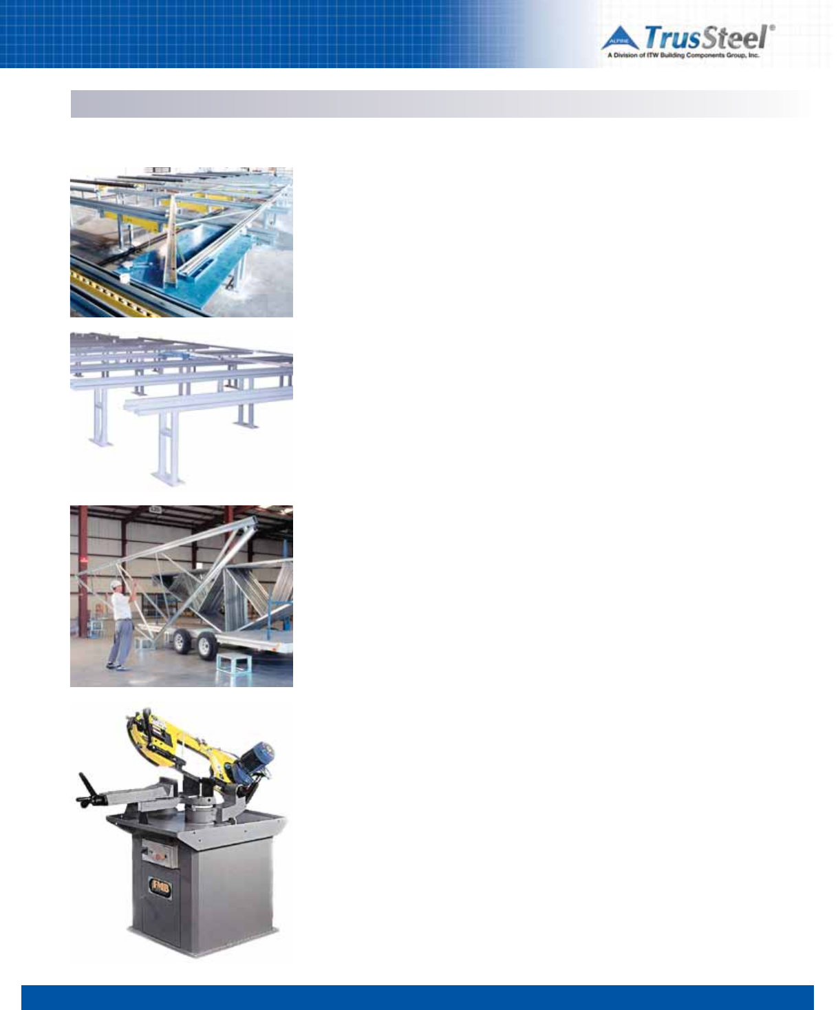
1 2 3 4 5 67 8
6.01
TRUSS FABRICATION / QUALITY
Overview
Site-Fabricated vs Shop-Fabricated
CFS Trusses
Prior to the emergence of pre-fabricated CFS
truss systems, contractors built most CFS
trusses on the jobsite using c-stud material.
While many contractors were more than capable
of building a CFS truss, jobsite issues such as the
availability of flat terrain for truss fabrication,
exposure to the elements, handling issues and
the availability of experienced fabrication
personnel often challenged the completion of
quality trusses in a timely manner. Any one of
these issues could lead to delays in truss
fabrication and so to delays in one of the most
critical phases of construction: the drying-in of
the building.
Overall, the construction industry welcomed the
advent of pre-engineered, pre-fabricated CFS
trusses in the same way as they welcomed the
advent of wood trusses and bar joists. These
building components, assembled in a shop in
advance of need and properly stored until ready
for delivery, removed a burdensome jobsite task
from the contractors’ busy schedule and
delivered a product that was generally high in
quality.
The Advantages of Quality Control
TrusSteel Authorized Fabricators assemble
TrusSteel CFS trusses in a truss shop
environment. The reason is quality control. In-
shop quality control assures that each truss is:
• assembled to dimensional tolerances (to
assure a good fit at the jobsite),
• assembled in strict accordance with the
materials and fastening methods described on
the shop drawings (to assure specified
structural performance),
• handled, stored and eventually shipped in a
manner to eliminate damage.
TrusSteel supports the efforts of industry
organizations, such as SBC Colf_formed Steel
Council in the implementation of quality
assurance standards.
The Advantages of Trained Assemblers
For a truss package to fit and perform according
to dimensional and structural specifications, the
truss fabricator must assemble each individual
truss to exacting standards. The fabricator must
use trained sawyers and proper cutting and
jigging equipment to ensure the trusses will have
straight chords, tight joints and to maintain
consistency of pattern from one truss to the next.
Trained assemblers should install fasteners to
ensure the accuracy of each internal connection
and to avoid commonplace problems such as the
over-torquing of fasteners.
The Advantages of Proper Equipment
TrusSteel is the only proprietary CFS truss
technology supplier that offers a complete line of
truss fabrication equipment. Drawing upon
Alpine’s more than forty years of experience in
wood truss fabrication equipment, TrusSteel
offers a complete line of cutting, measuring,
jigging and handling systems.
TrusSteel provides a line of band saws for
materials cutting that are safe, quiet and
accurate. By teaming these saws with an
automatic or manual measuring system, a
sawyer can greatly improve his output while
maintaining strict dimensional standards.
Sophisticated full-automatic jigging systems,
such as the AutoSet C, allow the electronic
transfer of truss profile data directly to the jig
table. Semi-automatic jigging systems, such as
the AutoSet, and manual jigging tables can allow
any truss shop to make quick and accurate
setups.
Truss ejector systems, roller beds and stacking
systems can make truss handling quick, simple
and safe. Specialty presses, metalworkers and
swagers expedite the assembling of the most
complicated trusses and complete this
comprehensive product line.
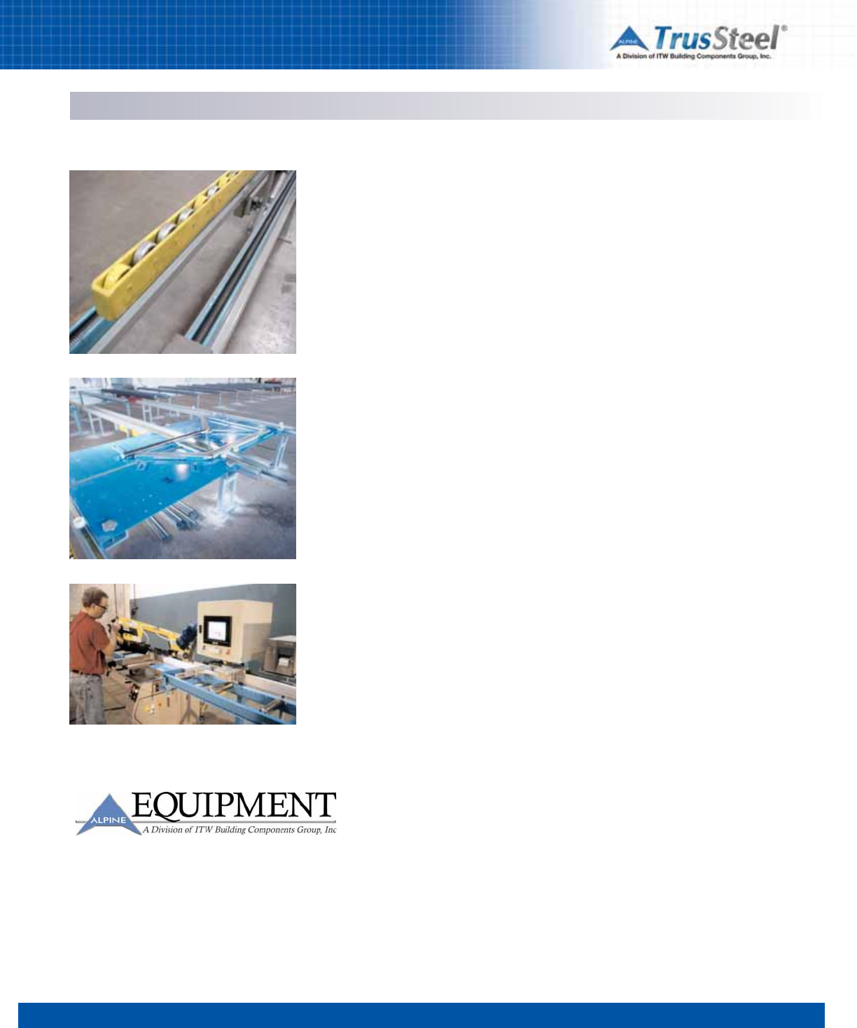
TRUSS FABRICATION / QUALITY
Overview
1 2 3 4 5 67 8
6.02
Truss Size Limitations
Handling and shipping issues limit the size of
individual CFS trusses. Smaller trusses can be
joined in the field (field splicing) to create larger
trusses. Practical limits for handling and shipping
will vary depending upon the capabilities of the
individual truss shop and the distance to the
jobsite. Contact your local TrusSteel Authorized
Fabricator for specific information.
The Advantages of TrusSteel
The advantages of TrusSteel in the fabrication
process translate into advantages to the
designer, contractor and owner. The fact that the
proprietary shape is easy and stable to handle
makes for faster assembly just as it makes for
stronger, lighter, stiffer trusses in the field. Rolled
chord edges and closed tube webs make for
safer handling in both shop and field. Proprietary,
color-coded fasteners make for quick, accurate
assembly just as they make it easier for field
inspection. The in-plane assemblies of
components in the trusses allow the creation of
tight bundles that stack and unstack efficiently at
the shop and jobsite and are more resistant to
handling damage.
The Authorized Fabricator Advantage
Each TrusSteel Authorized Fabricator is an
independently owned and operated
local/regional truss fabrication shop. Authorized
Fabricators market and service truss projects in
their own region, backed by the forty continuous
years of truss experience. Taken together, the
nationwide network of TrusSteel Authorized
Fabricators forms a vast array of truss and
framing knowledge at the disposal of the
designer and installer.
Truss Jigging Systems
Alpine Equipment’s Steel AutoSet CTM and Steel
AutoSetTM Jigging Systems brings accuracy and
automation to the steel truss fabrication shop.
When the Steel AutoSet C is used with the Alpine
steelVIEW software, truss jig setups are created
automatically as the truss is designed. Setups
are then transferred to the shop floor, where a
single shop worker can adjust the jig rail stops
within seconds (using the AutoSet C touch-
screen input computer terminal).
Truss fabrication setups on the AutoSet and
AutoSet C are fast, accurate, and repeatable. No
special tools are required to operate the jigging
systems. Setups on the AutoSet System are
made in minutes by a single worker using a
driver gun and a digital counter.
Both the Steel AutoSet C and the Steel AutoSet
Jigging Systems can be used for the fabrication
of all types of cold-formed components.
Truss Handling Systems
An integral truss ejector system speeds the
removal of completed trusses from the jig. And,
because the ejectors do the lifting, shop workers
are subject to less strain and fatigue. Less
fatigue means workers remain more productive.
Conveyor runs, truss stackers and other handling
equipment are also available from TrusSteel.
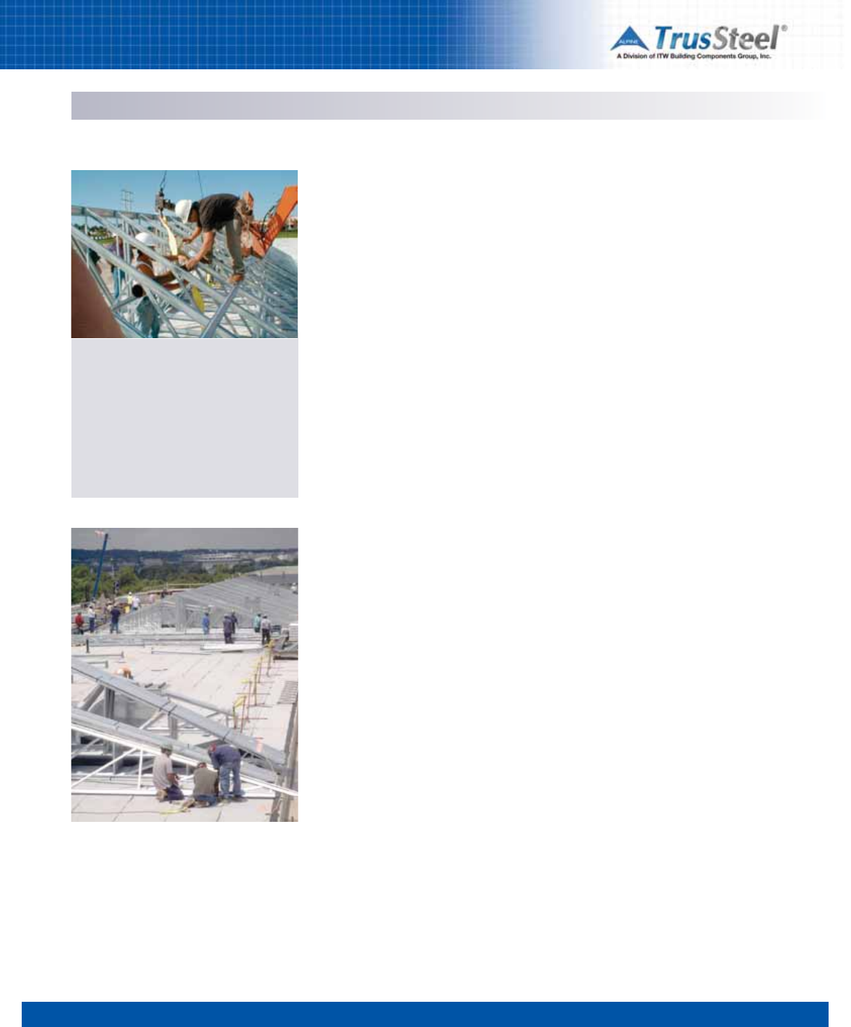
1 2 3 4 5 6 78
7.01
INSTALLATION / BRACING
Site Conditions & Safety
Safety is no accident. Safe work habits and a
safe work environment are the responsibility of
everyone on the job site. All injuries can be
prevented through appropriate training,
awareness and actions. Proper safety
equipment, such as glasses, hard hats, shoes
and harnesses, must be used consistently and
correctly.
Site conditions
Proper site conditions for the installation of
trusses are primarily the responsibility of the
owner’s representative for construction. Unless
otherwise designated, that representative is
usually the general contractor or the construction
manager.
The American Iron and Steel Institute has
published guidelines for establishing good site
practices. The following list of responsibilities is
taken from the AISI/S202. Designations shown in
parentheses refer to the corresponding sections
of that publication.
(F2.1) The installer of CFS trusses shall be
permitted to use the most efficient and
economical method and sequence of installation
or assembly available consistent with the
contract documents. When the owner contracts
separately with a component manufacturer and
installer, the owner is responsible for
coordinating work between contractors.
(F2.2) The installer shall examine areas and
conditions under which framing materials are to
be installed. Work shall not proceed until
unsatisfactory conditions have been corrected by
those responsible.
(F2.3) The owner’s representative for
construction shall provide and maintain
adequate access necessary for equipment and
framing materials to be installed. The owner’s
representative for construction shall provide the
installer with level, convenient, and adequate
space to safely use the necessary equipment
and install the framing materials.
(F2.4) The contractor shall coordinate setting
drawings, dimensional problems, compatibility of
various trades and / or installation.
Bracing
All temporary installation bracing, permanent
bracing and bridging must be fully and correctly
installed prior to the application of any loads,
including any temporary loads resulting from
construction procedures. Refer to Section 7 in
this Manual for more information.
Installation Tolerances
Structural members and component assemblies
shall be installed in accordance with the
tolerances prescribed in the AISI/S200: North
American Standard for Cold-Formed Steel
Framing - General Provisions. Trusses shall be
installed in accordance with the additional
requirements of the AISI /S214: North American
Standard for Cold-Formed Steel Framing - Truss
Design.
Field Modifications and Repairs
Removal, cutting or alteration of any truss chord,
web or bracing member in the field is prohibited,
unless approved in advance, in writing, by the
truss designer (Truss Component Manufacturer).
Field Quality Control
Trusses shall be installed in accordance with the
requirements of the AISI/S214: North American
Standard for Cold-Formed Steel Framing - Truss
Design. and with any standards and
requirements set forth in the construction
documents. The owner's representative for
construction will provide inspection service to
inspect field connections.
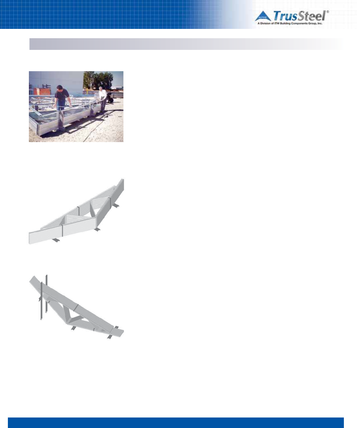
INSTALLATION / BRACING
Handling & Storage
1 2 3 4 5 6 78
7.02
Material Receiving
Inspect all CFS materials immediately upon
arrival. Report all damaged or missing material
immediately to vendor and note all damage on
carrier's shipping documents.
Material Handling
Finished CFS trusses are usually banded with
steel strapping in conveniently sized bundles.
The strapping helps maintain truss alignment
and the bundle strength minimizes damage
during delivery and storage. WARNING: Exercise
care when removing strapping to prevent injury.
Throughout all phases of construction, care must
be taken to avoid excessive lateral bending of the
trusses which can cause joint and member
damage.
If possible, CFS trusses should be unloaded on
relatively smooth ground. They should not be
unloaded on rough terrain that would cause
undue lateral strain resulting in distortion of the
truss joints. Rough terrain can also cause
damage to overhangs, soffit returns and other
parts of the truss.
Always lift long pieces of material from more
than one lift point to avoid crimping. Take care
when banding; do not crimp or bend material. Do
not store other materials on top of CFS materials.
Material Storage
Formed CFS components made of galvanized
steel material shall be stored in a low moisture
environment. Under no circumstances should
stored material be allowed to become wet. When
stored in bundles, materials shall be stored at an
incline to promote the drainage of any moisture
and to avoid moisture build-up in and on the
parts.
Storage area shall have good ventilation. Areas
that have poor ventilation, and that have the
potential for trapping moist air in rising
temperatures, can create a ‘hot house’ effect
that may cause condensation between the layers
of rolled or bundled material. This trapped
condensation can have the same effect on stored
material as exposing it to direct moisture. For
long-term storage, inspect bundled materials
regularly to assure that moisture has not
penetrated the bundle.
Storage environments shall be ventilated to avoid
temperature differentials in excess of 20ºF
between the stored material and the ambient
temperature of the storage. Environments that
allow temperature differentials in excess of 20ºF
can promote moisture condensation on
materials.
Cold steel materials shall be allowed to warm
properly before storage. The rapid warming of
incoming materials (when moved from a cool
environment to a warm environment) can create
condensation. If incoming galvanized steel feels
cold to the touch, allow it to warm slowly in a
cool indoor area away from drafts. When the
steel has warmed it may be transferred to a
proper storage area.
If trusses are stored in the vertical position, they
should be staked on both sides of the bundle to
prevent toppling and personal injury.
These storage instructions must be followed to
avoid chalking on any galvanized materials
(truss, stud, track, etc.). Chalking is created by
the invasion of moisture between two zinc
coated surfaces that are not allowed to dry in an
environment having adequate air flow. The
chalking is created through a chemical reaction
between the two surfaces when they are stored
in an oxygen deprived atmosphere.
TrusSteel trusses are often light enough for two
men to unstack and stage.
Horizontal storage of trusses.
Vertical storage using a rack or stand. Always
stake trusses to prevent toppling.
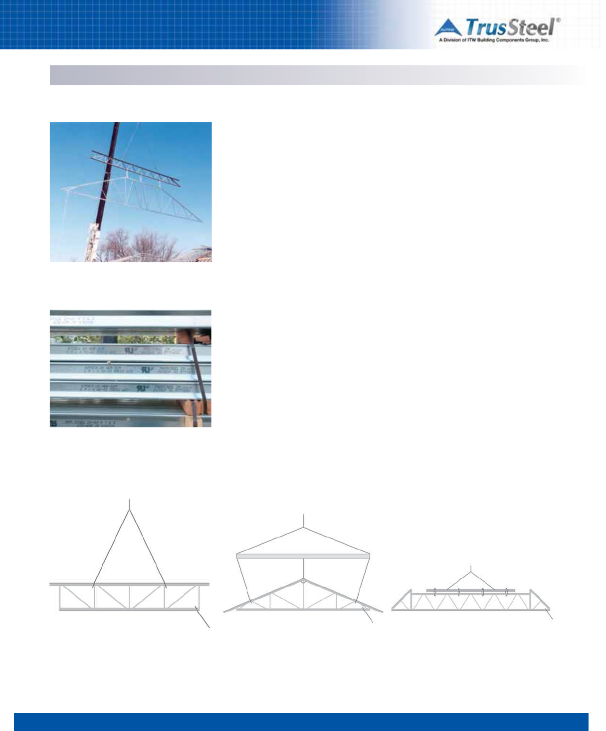
1 2 3 4 5 6 78
7.03
INSTALLATION / BRACING
Lifting & Staging
Proper Lifting of CFS Trusses
Trusses may be installed manually, by crane, or
by forklift, depending on truss size, wall height
and job conditions. Individual trusses should
always be carried vertically to avoid lateral strain
and damage to joints and members.
Trusses installed manually are slid into position
over the sidewall and rotated into position using
poles. The longer the span, the more workers
needed to avoid excessive lateral strain on the
trusses. Trusses should be supported at joints
and the peak while being raised.
Large trusses should be installed by a crane or
forklift employing chokers, slings, spreader bars
and strong-backs to prevent lateral bending.
Trusses may be lifted singly, in banded groups, or
in pre-assembled groups or rafts.
Tag lines should always be used to control
movement of trusses during lifting and
placement. Workers should always use all
appropriate safety equipment.
Storage of Materials During Installation
Care must be taken, after truss installation, not to
overload trusses with the storage of other
building materials. Under no circumstances
should any materials be stored on top of
unbraced trusses!
Reference Document
Refer to the CFSC Cold-Formed Steel Building
Component Safety Information document
CFSBCSI before handling or installing trusses.
This document is available from the CFSC at
www.cfsc.sbcindustry.com/cfsbsci.php.
Lift shown using a spreader bar to distribute the
load. Tag lines must be used during lifting.
Lift shown using a spreader bar to distribute the
load. Tag lines must be used during lifting.
Lift shown using a strongback to distribute the
load. Tag lines must be used during lifting.
WARNING: Exercise care when removing
strapping to prevent injury.
This installer is using a heavy steel truss as a
strongback.
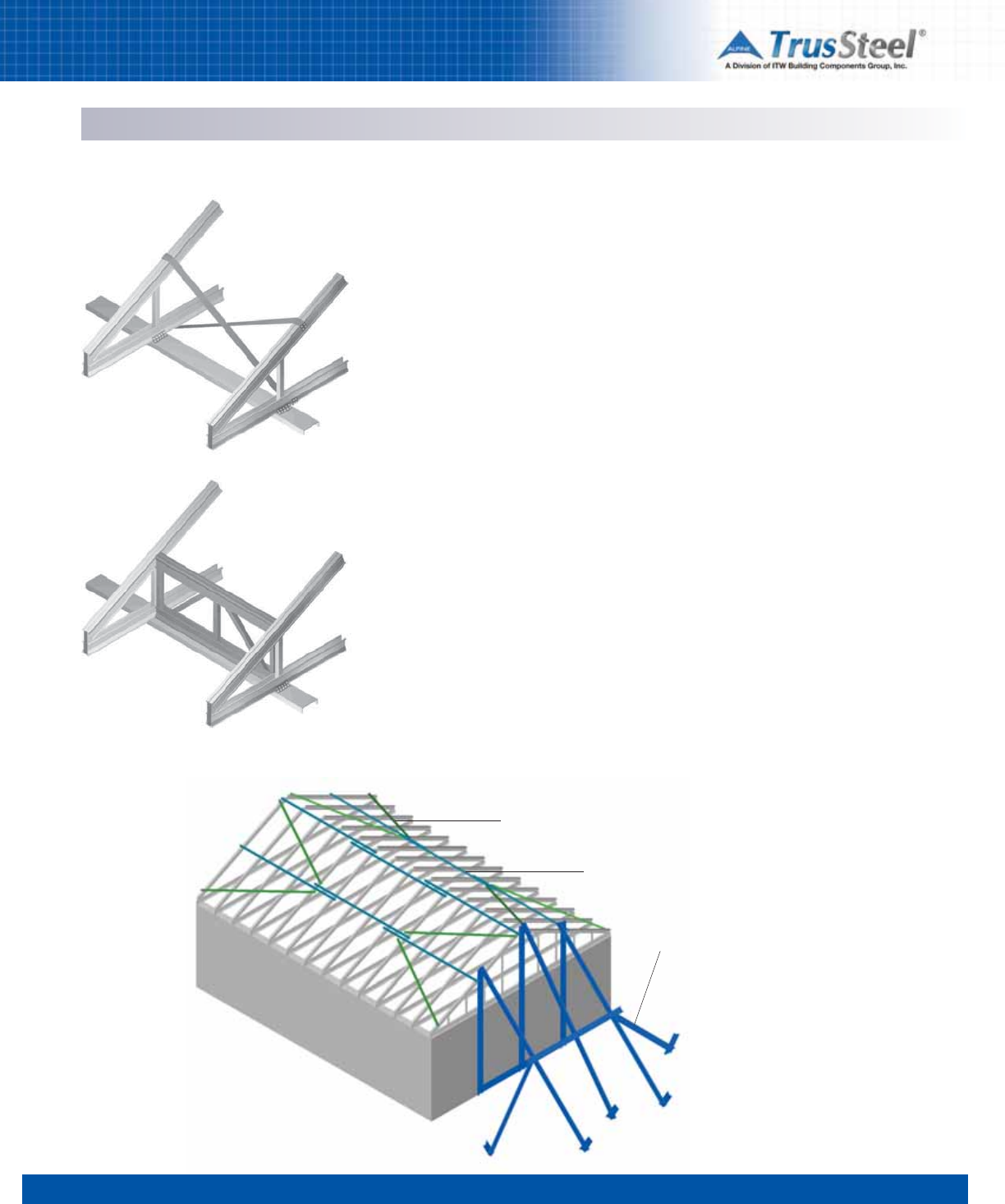
1 2 3 4 5 6 78
7.04
INSTALLATION / BRACING
Bracing
Permanent Bracing
Permanent bracing typically includes continuous
lateral bracing (CLB), diagonal bracing, bridging
and blocking at the heels and ends of the
trusses. This bracing functions to strengthen and
stabilize the truss chords and webs which may
be particularly long or highly stressed. The
required locations of the continuous lateral
bracing are typically called out on the shop
drawings supplied by the truss engineering
company. These lateral braces must be stabilized
at regular intervals with diagonal bracing. This
extremely important bracing system creates the
continuous path through which all loads applied
to the roof are transferred from the truss system
into the walls and eventually to the ground.
Due to the component-centered nature of our
fast track building process, permanent bracing
design is not supplied by the wall panelizer or
designer, or by the truss fabricator, because
neither party controls the design process of the
other component. To bridge this gap in the
information process, a number of engineering
firms are beginning to provide permanent
bracing design based on their review of the wall
and truss layouts supplied by separate parties.
Bracing and Structural Performance
The structural performance of a frame building
depends on continuous paths for all loads to be
transferred to the ground. In the specific instance
of pre-engineered trusses, there are two types of
necessary bracing which are sometimes
confused: construction (temporary) and
permanent bracing. Each is important to the
construction process and to the structural
integrity of the building.
Construction (Temporary) Bracing
This is the proper bracing of the trusses during
the installation phase of the structure. Much like
walls are braced until the completion of the
framing process, when trusses are placed on the
plate line, they must be braced to hold them
safely and securely in place, and to resist
environmental influences such as wind gusts
during the framing process. Construction bracing
guidelines are available through truss industry
documents for truss spans up to 60 ft. For spans
over 60 ft. a professional engineer should be
consulted for the construction bracing plan.
Top chord diagonal bracing
Top chord lateral bracing
Ground bracing for first truss
Temporary Bracing for Installation
Examples of permanent bracing at truss heels,
using cross-bracing (top) and trusses as
blocking (bottom)
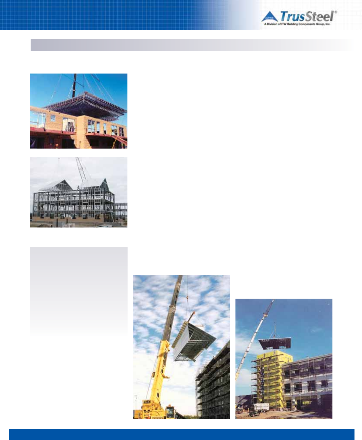
1 2 3 4 5 6 78
7.05
INSTALLATION / BRACING
Rafting
What is rafting?
Rafting is a process where the installer uses
complete trusses to assemble an entire roof, or
section of a roof, on the ground and then lifts the
completed assembly onto the building structure.
The size of rafted sections is based on available
space on-site, lift capacity of the available crane,
or unique footprint of the roof system.
Why use rafting?
On suitable projects, rafting allows most of the
roof framing and decking to be assembled on the
ground, minimizing or eliminating the need for
multiple lifts, scaffolding and fall protection
systems. Less lifts means less crane time, which
can translate into big savings on crane costs. On-
ground assembly of entire roof sections,
including permanent truss bracing, roof decks
and mechanical systems, can save significant
labor time and can allow the simultaneous
construction of walls and roof systems.
What are the special considerations for
rafting?
The design of the roof assembly to be rafted
should consider the effect of an alternate load
path, where the weight of the assembly is
transferred through the lifting cables (or straps)
to the ground at pick points instead of through
the truss bearings. The number and location of
pick points for rafting should be determined with
attention to the following factors:
• total weight of the assembly,
• weight distribution in the assembly,
• truss configuration,
• crane capacity.
In addition to design analysis for conventional
roof loads, rafted trusses must also be analyzed
for a case where the supports are at the pick
points. In some instances, the permanent
bearing members for the trusses (tube steel or
I-beam, for example) could be included as a part
of the assembly on the ground, and the entire
assembly could be lifted from pick points located
on the bearing members. Adequate bracing of
trusses is needed for the stability of the roof
system. Most of the roof decking, and almost all
of the required truss permanent bracing for the
webs and bottom chord, could be installed prior
to rafting.
Why raft with TrusSteel?
TrusSteel trusses are light in weight (up to one-
half the weight of trusses made from wood or
"C" channel materials). Substantial roof sections
can be assembled on the ground and then lifted
with an average crane. With the exceptional
lateral stability (stiffness) of TrusSteel trusses,
roof assemblies can be built that will survive a lift
without introducing significant extra bracing.
How do I get an engineered raft?
Rafts of trusses, no matter the brand or
type, must be engineered so that they will
lift safely and without causing damage to
the trusses. The project Engineer of
Record may perform this design service.
Specialty engineering firms, such as BBD
Engineering and Design, LLC, are
available to perform these design services
on a consulting basis.

1 2 3 4 5 6 7 8
8.01
REFERENCES/RESOURCES
These organizations and materials can
provide resources for the design, use and
installation of CFS framing as well as an
overview of good construction practices.
Please contact the publisher or group
directly for further information.
Industry Resources
American Institute of Architects (AIA)
202-626-7300 www.aia.org
Locate architects and find information on the
profession, contract documents and more.
American Institute of Steel Construction
(AISC)
312-670-2400 www.aisc.org
American Iron and Steel Institute (AISI)
202-452-7100 www.steel.org
AIS S100-07: North American Specification for
the Design of Cold-Formed Steel Structural
Members; American Iron and Steel Institute;
2007 Edition with Supplement 2
AISI-S200-07:
AISI North American
Standard for
Cold-Formed Steel Framing - General Provisions;
2007 Edition.
AISI-S202-11:
AISI Code of Standard Practice
for
Cold-Formed Steel Structural Framing; 2011
Edition.
AISI-S214-07:
AISI Norh American
Standard for
Cold-Formed Steel Framing - Truss Design, 2007
Edition.
American National Standards Institute (ANSI)
212-642-4900 www.ansi.org
Administers and coordinates U.S. voluntary
standards.
American Society of Civil Engineers (ASCE)
800-548-2723 www.asce.org
Minimum Design Loads for Buildings And Other
Structures, ASCE 7-10
Structural Engineering Institute
STRUCTURE magazine
American Society for Testing and Materials
(ASTM)
610-832-9585 www.astm.org
ASTM E-119 - Test Methods for Fire Tests for
Building Construction and Materials
ASTM A 370-06 - Standard Test Methods and
Definitions for Mechanical Testing of Steel
Products.
ASTM A 500-03a - Standard Specification for
Cold-Formed Welded and Seamless Carbon Steel
Structural Tubing in Rounds and Shapes.
ASTM A 653-06a - Standard Specification for
Steel Sheet, Zinc-Coated (Galvanized) or Zinc-
Iron Alloy-Coated (Galvannealed) by the Hot-Dip
Process.
Association of Crane & Rigging Professionals
800-690-3921 www.acrp.net
Gain expertise in lifting and handling building
materials.
Association of the Wall and Ceiling Industry
703-534-8300 www.awci.org
AWCI-SFA Steel Framing Education Program
AWCI Construction Dimension magazine
AWCI bookstore
Center for Cold-Formed Steel Structures
(CCFSS)
573-341-4471 http://campus.umr.edu/ccfss/
CCFSS Technical Bulletins
CCFSS Newsletter
Educational seminars
Construction Specifications Institute (CSI)
800-689-2900 www.csinet.org
MasterFormat 2004
Construction Specifier magazine
National CAD Standard
Design-Build Institute of America (DBIA)
202-682-0110 www.dbia.org
DBIA bookstore
Numerous educational resources
Gypsum Association
202-289-5440 www.gypsum.org
Fire Resistance Design Manual, GA-600
International Code Council (ICC)
888-422-7233 www.iccsafe.org
The International Building Code
ICC-ES Evaluation Service
www.icc-es.org
Cold-Formed Steel Engineers Institute (CFSEI)
202-263-4488 www.cfsei.org
CFSEI 551d - Design Guide: Construction Bracing
of Cold-Formed Steel Trusses; September 2002.
CFSEI 551e - Design Guide: Permanent Bracing
of Cold-Formed Steel Trusses; February 1998.
CFSEI 551f -
Specifying Pre-Engineered Cold-
Formed Steel Floor and Roof Trusses
; October
1998.
Newsletters
Research Notes
Occupational Safety and Health
Administration (OSHA)
Directorate of Construction
202-693-2020 www.osha.gov
Safety regulations and procedures
The Steel Framing Alliance
202-785-2022
www.steelframingalliance.com
Various technical and marketing documents
Training for steel framers
Metal Construction Association
847-375-4718 www.metalconstruction.org
Metalcon Show
SBCA Cold-formed Steel Truss Council
(CFSC)
608-274-4849 www.cfsc.scbindustry.com
Truss labels
Truss educational programs
Quality program
CFSBCSI document
Steel Deck Institute (SDI)
847-458-4647 www.sdi.org
Diaphragm Design Manual
Steel Recycling Institute (SRI)
800-937-1226 www.recycle-steel.org
Steel Takes LEED with Recycled Content°®
Underwriters Laboratories (UL)
877-854-3577 www.ul.com
UL Fire Resistance Directory
U.S. Green Building Council (USGBC)
202-828-7422 www.usgbc.org
Information on the LEED program

REFERENCES/RESOURCES
Glossary
1 2 3 4 5 6 7 8
8.02
Accepted Engineering Practice An engineering
approach that conforms to accepted principles,
tests, technical standards, and sound judgment.
ASD (Allowable Strength Design) Method of
proportioning structural components such that
the allowable strength equals or exceeds the
required strength of the component under the
action of the ASD load combinations.
ASD Load Combination Load combination in the
applicable building code intended for allowable
strength design (allowable stress design).
Allowable Strength* Nominal strength divided
by the safety factor, Rn/Ω.
Applicable Building Code Building code under
which the structure is designed.
Available Strength* Design strength or
allowable strength as appropriate.
Approved Approval by a building official, code
official, design professional, or authority with
jurisdiction.
Axial Force The number of pounds of tension or
compression in a truss member acting parallel to
the length of the member resulting from a load
applied to the truss.
Base Metal Thickness The thickness of bare
steel exclusive of all coatings.
Bearing Structural support of a truss, usually
walls, beams, concrete slabs and hangers.
Bending Moment A measure of the amount of
bending in a member due to forces acting
perpendicular to the member.
Blocking C-shaped, track, brake shape, or flat
strap material attached to structural members,
flat strap, or sheathing panels to transfer shear
forces.
Bottom Chord A horizontal (or inclined in a
scissor truss) member that establishes the lower
edge of the truss, usually carrying combined
tension and bending stresses.
Braced Frame An essentially vertical truss
system that provides resistance to lateral loads
and provides stability for the structural system.
Bracing Structural elements that are installed to
provide restraint or support (or both) to other
framing members so that the complete assembly
forms a stable structure.
Bridging Cross-bracing or blocking placed
between joists to provide lateral support.
Buckling A kink, wrinkle, bulge, or other loss in
the original shape of a member due to
compression, bending, bearing, or shear loads.
Building Designer Also referred to as design
professional and registered building designer is
an individual or organization responsible for the
overall building design in accordance with the
statutes and regulations governing the
professional registration and certification of
architects or engineers of the jurisdiction where
the building will be located.
Camber An upward vertical displacement built
into a truss, usually to offset deflection due to
dead load.
Cantilever The part of a structural member that
extends beyond its support.
Chord Member A structural member that forms
the top or bottom component of a truss.
Clear Span Horizontal distance between interior
edges of supports.
Cold-Formed Sheet Steel Sheet steel or strip
that is formed by (1) press-braking blanks
sheared from sheets or cut length of coils or
plates, or by (2) continuous roll forming of cold-
or hot-rolled coils of sheet steel; both forming
operations are performed at ambient room
temperature, that is, without the addition of heat
such as would be required for hot forming.
Cold-Formed Steel Structural Member Shape
manufactured by press-braking blanks sheared
from sheets, cut lengths of coils or plates, or by
roll forming cold- or hot-rolled coils or sheets;
both forming operations being performed at
ambient room temperature, that is, without
manifest addition of heat such as would be
required for hot forming.
Collateral Load The weight of any non-moving
equipment or material, such as ceilings,
electrical or mechanical equipment, sprinkler
systems, plumbing, or ceilings.
Combined Stress The combination of axial and
bending stresses or shear and bending stresses
acting on a member simultaneously. These
stresses typically occur in both top and bottom
chords.
Concentrated Load A load, in addition to
uniform design loads, applied at a specific point.
Examples include cranes, hoists, HVAC
equipment and sprinkler pipes.
Compression A force caused by loads being
placed on a member that causes a squeezing or
shortening effect of the member as in the top
chord of a truss when load is applied.
Component Assembly A fabricated
assemblage of cold-formed steel structural
members that is manufactured by the
component manufacturer, which may also
include structural steel framing, sheathing,
insulation or other products.
Component Design Drawings The written,
graphic and pictorial definition of an individual
component assembly, which includes
engineering design data.
Component Designer The individual or
organization responsible for the engineering
design of component assemblies. See Truss
Designer.
Component Manufacturer The individual or
organization responsible for the manufacturing
of component assemblies for the project. See
Truss Manufacturer.
Component Placement Diagram The
illustration supplied by the component
manufacturer identifying the location assumed
for each of the component assemblies which
references each individually designated
component design drawing.
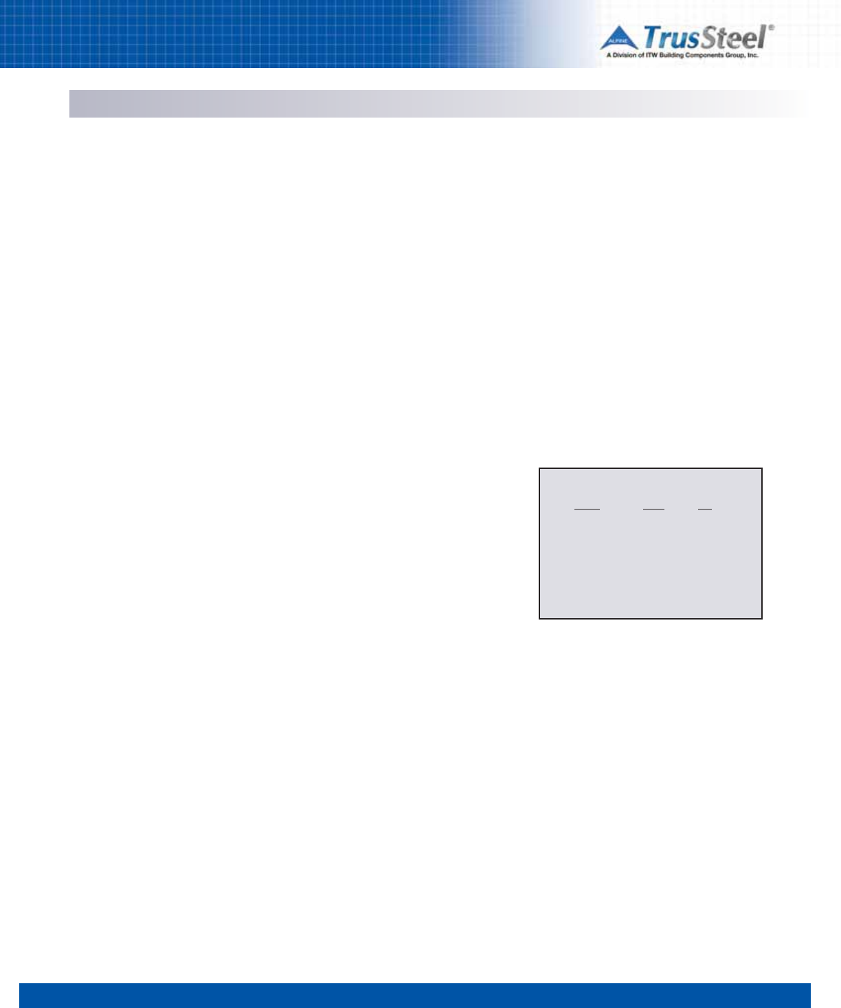
1 2 3 4 5 6 7 8
8.03
Glossary
Connection Combination of structural elements
and joints used to transmit forces between two
or more members.
Construction Manager The individual or
organization designated by the owner to issue
contracts for the construction of the project and
to purchase products.
Continuous Lateral Bracing A member placed
and connected at right angles to a chord or web
to prevent buckling. Required on some chords
and webs, depending on their length and the
forces in the member.
Contract Documents The documents, including,
but not limited to, plans and specifications,
which define the responsibilities of the parties
involved in bidding, purchasing, designing,
supplying, and installing cold-formed steel
framing.
Contractor The individual or organization that is
contracted to assume full responsibility for the
construction of the structure.
Cricket A portion of a roof where it is built up for
the purpose of draining water towards a desired
drainage point.
C-Shape A cold-formed steel shape used for
structural and nonstructural framing members
consisting of a web, two flanges, and two lips
(edge stiffeners). The name comes from the
member’s C-shaped cross-sectional
configuration. It is also called a “C-section.” Web
depth measurements are taken to the outside of
the flanges. Flange width measurements also
use outside dimensions.
Dead Loads Dead loads are the weight of the
walls, partitions, framing, floors, ceilings, roofs,
and all other permanent construction entering
into and becoming a part of a building.
Deflection Movement of a structural member,
like a truss in place, due to the application of
loads. Deflection is usually downward, but
trusses may deflect upward or horizontally
depending on loads and bearings.
Design Load Applied load determined in
accordance with either LRFD load combinations
or ASD load combinations, whichever is
applicable.
Design Strength* Resistance factor multiplied
by the nominal strength: ϕ x Rn.
Design Professional An individual who is
registered or licensed to practice his or her
respective profession as defined by the statutory
requirements of the state in which the project is
to be constructed.
Design Thickness The steel thickness used in
design which is equal to the minimum base
metal thickness divided by 0.95.
Diaphragm Roof, floor or other membrane or
bracing system that transfers in-plane forces to
the lateral force resisting system.
Double Shear Allowing a force to be distributed
through two planes rather than one for increased
strength.
Double ShearTM Fastener Patented TrusSteel
fastener that allows the fabrication of trusses
without flipping in the jig. Double shear action of
these fasteners add stability to trusses.
Drag Strut Typically a horizontal member, such
as a truss or beam, which transfers shear from a
diaphragm to a shearwall.
Eave Overhang The horizontal projection of the
roof measured from the outside face of the
exterior wall framing to the outside edge of the
roof.
Epicenter The part of the earth’s surface directly
above the focus of an earthquake.
Flange That portion of a framing member or
track that is perpendicular to the web.
Factored Load Product of a load factor and the
nominal load.
Flat Strap Sheet steel cut to a specified width
without any bends and typically used for bracing
and transferring loads by tension.
Flashing Pieces of cold-formed steel that are
used to make watertight the openings or the
seams in a roof system.
Flexural-Torsional Buckling Buckling mode in
which a compression member bends and twists
simultaneously without change in cross-
sectional shape.
Floor Joist A horizontal structural framing
member that supports floor loads and
superimposed vertical loads.
Foundation The structural elements through
which the load of a structure is transmitted to
earth.
Gable End A vertical surface formed at the end
of a roof ridge down towards the eave.
Gauge A unit of measurement traditionally used
to describe the nominal thickness of steel. The
lower the gauge the greater the thickness.
Girt Horizontal structural member that supports
wall panels and is primarily subjected to bending
under horizontal loads, such as wind load.
Grade The finished ground level adjoining the
building at exterior walls.
Ground Snow Load Measured load on the
ground due to snow accumulation developed
from a statistical analysis of weather records
expected to be exceeded once every 50 years at
a given site.
Gusset Plate A structural member used to
facilitate the connection of truss chord or web
members at a heel, ridge, or panel point.
Hat-Shape A singly-symmetric shape consisting
of at least two vertical webs and a horizontal
stiffened flange which is used as a chord
member in a truss.
ASTM C955 Color Codes for CFS Steel
Color mils GA
White 33 20
Yellow 43 18
Green 54 16
Orange 68 14
Red 97 12
REFERENCES/RESOURCES

1 2 3 4 5 6 7 8
8.04
REFERENCES/RESOURCES
Glossary
Heel Point on a truss at which the top chord and
bottom chord intersect at the end of a truss with
a sloping top chord.
Hip-Set A sloped roof surface that extends from
a roof ridge towards the eave.
Installation Drawings Drawings that show the
location and installation of the cold-formed steel
structural framing.
Installer Party responsible for the installation of
cold-formed steel products.
Joint Area where two or more ends, surfaces, or
edges are attached. Categorized by type of
fastener or weld used and the method of force
transfer.
Lateral Forces Non-gravity forces acting on a
building such as wind and seismic.
Lateral Force Resisting System The structural
elements and connections required to resist
racking and overturning due to wind and/or
seismic forces imposed upon the structure in
accordance with the applicable building code.
Lateral Load A horizontal force created by wind
or earthquake that acts on a structure or its
components.
Level Return Filler placed horizontally from the
end of an overhang back to the bearing support
to form soffit framing.
Live Loads Live loads are transient and
sustained loads usually created by people and
furnishing, respectively.
Load Force or other action that results from the
weight of building materials, occupants and their
possessions, environmental effects, differential
movement, or restrained dimensional changes.
Load Effect Forces, stresses, and deformations
produced in a structural component by the
applied loads.
Load Factor Factor that accounts for deviations
of the nominal load from the actual load, for
uncertainties in the analysis that transforms the
load into a load effect, and for the probability that
more than one extreme load will occur
simultaneously.
LRFD (Load and Resistance Factor Design)
Method of proportioning structural components
such that the design strength equals or exceeds
the required strength of the component under
the action of the LRFD load combinations.
LRFD Load Combination Load combination in
the applicable building code intended for
strength design (Load and Resistance Factor
Design).
Material Supplier An individual or entity
responsible for furnishing framing materials for
the project.
Mil A unit of measurement used in measuring
the thickness of thin steel elements. One mil
equals 1/1000 of an inch (e.g., 33 mil = 0.033
inch).
Moment Frame Framing system that provides
resistance to lateral loads and provides stability
to the structural system primarily by shear and
flexure of the framing members and their
connections.
Multi-Node Analysis A truss analysis
methodology when each individual web member
at a joint is modeled with its own node.
Multiple Span The span made by a continuous
member with intermediate supports.
Nominal Load Magnitude of the load specified
by the applicable building code.
Nominal Strength* Strength of a structure or
component (without the resistance factor or
safety factor applied) to resist the load effects, as
determined in accordance with a Specification or
Standard.
Overhang The extension of the top or bottom
chord of a truss beyond the bearing support.
Panel In a truss, the chord segment defined by
two successive joints.
Panel Length The centerline distance between
joints measured horizontally.
Panel Point The connection region between a
web and chord member.
Peak Point on a truss where two sloped chords
meet.
P
Permanent
L
Load
Load in which variations over
time are rare or of small magnitude. All other
loads are variable loads.
Piggyback Truss. A truss supported directly on
top of another truss. Trusses are piggybacked
due to height restrictions in fabrication and
delivery.
Pitch See Slope.
Pitch Break A location around the perimeter of
a truss where the chord changes pitch.
Plans Drawings prepared by the design
professional for the owner of the project. These
drawings include but are not limited to floor
plans, framing plans, elevations, sections, details
and schedules as necessary to define the desired
construction.
Purlin Horizontal structural member that
supports roof deck and is primarily subjected to
bending under vertical loads such as snow, wind
or dead loads. (May also brace the top chord of
trusses in certain applications, resulting in an
applied axial force).
Rake The inclined edge of a roof.
Rake Overhang The horizontal projection of the
roof measured from the outside face of a gable
endwall to the outside edge of the roof.
Rational Engineering Analysis Analysis based
on theory that is appropriate for the situation,
relevant test data if available, and sound
engineering judgment.
Reaction Forces acting on a truss through its
supports which are equal (but opposite) to the
sum of the dead and live loads.
Release for Construction The release by the
owner’s representative, permitting the
component manufacturer and/or installer to
commence work under the contract, including

1 2 3 4 5 6 7 8
8.05
Glossary
ordering framing material and preparing
installation drawings.
Required Strength* Forces, stresses, and
deformations produced in a structural
component, determined by either structural
analysis, for the LRFD or ASD load combinations,
as appropriate, or as specified by Specification or
Standard.
Resistance Factor, ΨFactor that accounts for
unavoidable deviations of the nominal strength
from the actual strength and for the manner and
consequences of failure.
Ridge The line formed by the joining of the top
edges of two sloping roof surfaces.
Safety Factor, ΩFactor that accounts for
deviations of the actual strength from the
nominal strength, deviations of the actual load
from the nominal load, uncertainties in the
analysis that transforms the load into a load
effect and for the manner and consequences of
failure.
Secondary Bending The bending stress in a
member caused by the deflection of the whole
truss.
Service Load Load under which serviceability
limit states are evaluated.
Shear Wall Wall that provides resistance to
lateral loads in the plane of the wall and provides
stability for the structural system.
Shop Drawings Drawings for the production of
individual component assemblies for the project.
Slope (Pitch) The inches in vertical rise in 12
inches of horizontal run for inclined members,
generally expressed as 3/12, 4/12, etc.
Specialty Designer The individual or
organization having responsibility for the design
of the specialty items. This responsibility shall be
in accordance with the state’s statues and
regulations governing the professional
registration and certification of architects or
engineers. Also referred to as component
designer, specialty engineer, design engineer,
registered engineer, and engineer, but hereinafter
will be referred to as Specialty Designer. The
requirement for a Specialty Designer is typically
called out on architectural specifications or
structural general notes. The Specialty Designer
is typically not the Structural Engineer-of-
Record.
Specifications Written instructions, which, with
the plans, define the materials, standards, design
of the products, and workmanship expected on a
construction project.
Specified Minimum Yield Stress Lower limit of
yield stress specified for a material as defined by
ASTM
Splice The point at which two chord members of
the same slope are joined together to form a
single member.
Static Load A load or series of loads that are
supported by, or are applied to, a structure so
gradually that forces caused by change in
momentum of the load and structural elements
can be neglected and all parts of the system at
any instant are essentially in equilibrium.
Strain The geometrical expression of
deformation caused by the action of stress on a
physical body.
Stress A unit force working within a member,
usually expressed in pounds per square inch
(psi).
Strongback A load distribution member typically
used in a floor truss system and installed
perpendicular through the trusses.
Structural Analysis Determination of load
effects on members and connections based on
principles of structural mechanics.
Structural Component Member, connector,
connecting element or assemblage.
Structural Engineer-of-Record The design
professional who is responsible for sealing the
contract documents, which indicates that he or
she has performed or supervised the analysis,
design and document preparation for the
structure and has knowledge of the
requirements for the load carrying structural
system.
Structural Sheathing The covering (e.g.,
plywood, oriented strand board or steel deck)
used directly over structural members (e.g.,
joists) to distribute loads, brace walls, and
generally strengthen the assembly.
Sub-Contractor The individual or organization
with whom a contractor has contracted to
furnishl and/or install a portion of the project.
Tensile Strength (of material) See Ultimate
Strength.
Top Chord An inclined or horizontal member
that establishes the upper edge of a truss.
Truss A coplanar system of structural members
joined together at their ends usually to construct
a series of triangles that form a stable beam-like
framework.
Truss Designer Also referred to as truss
engineer, design engineer and registered
engineer, is an individual or organization
responsible for the design of cold-formed steel
trusses.
Truss Manufacturer An individual or
organization engaged in the manufacturing of
site-built or in-plant trusses. Also called the
Truss Fabricator.
Unbalanced Load Live loads that are applied
non-uniformly across the span of the truss. This
type of loading is required by most building
codes.
Ultimate Strength (Fu) The property of steel
associated with the maximum stress that can be
developed prior to rupture. Also known as tensile
strength.
Uniform Load A total load that is equally
distributed over a given length, usually
expressed in pounds per square foot (psf).
Valley A depression in a roof where two roof
slopes meet.
Valley Set A group of trusses required to fill in a
section of a roof. Valley trusses generally have
only vertical webs and are supported on top of
other trusses.
REFERENCES/RESOURCES
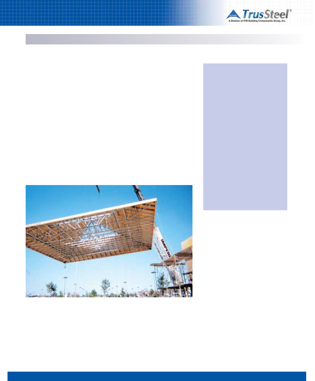
1 2 3 4 5 6 7 8
8.06
REFERENCES/RESOURCES
Variable Load. Load not classified as permanent
load.
Web Crippling. The localized permanent
(inelastic) deformation of the web member
subjected to concentrated load or reaction at
bearing supports.
Webs. Members that join the top and bottom
chords to form the triangular patterns that give
truss action, usually carrying tension or
compression stresses (no bending).
Web Stiffener. Additional material that is
attached to the web to strengthen the member
against web crippling. Also called bearing or
transverse stiffener.
Yield Strength (Fy). Stress at which a material
exhibits a specified limiting deviation from the
proportionality of stress to strain as defined by
ASTM.
Z-Shape. A point-symmetric or non-symmetric
section which is used as a chord member in a
truss.
* Terms shown with an asterisk are usually
qualified by the type of load effect, for example,
nominal tensile strength, available compressive
strength, or design flexural strength.
Glossary
Sources
• AISC and AISI Standard Definitions for Use
in the Design of Steel Structures, 2007
Edition
• AIS S100-07: North American
Specification for the Design of Cold-Formed
Steel Structural Members; American Iron and
Steel Institute; 2007 Edition with
Supplement 2
• AISI-S200-07:
AISI North American
Standard for Cold-Formed Steel Framing -
General Provisions; 2007 Edition.
• AISI-S214-07:
AISI Norh American
Standard for Cold-Formed Steel Framing -
Truss Design, 2007 Edition.
• The Encyclopedia of Trusses, Alpine
Engineered Products, Inc.
Definitions presented in this Glossary were
compiled and provided solely for the
education of the reader. While every effort
has been made to keep these definitions
accurate, helpful and up-to-date, it is not the
intent of this compilation to supplant existing
or future regulatory or statutory definitions.
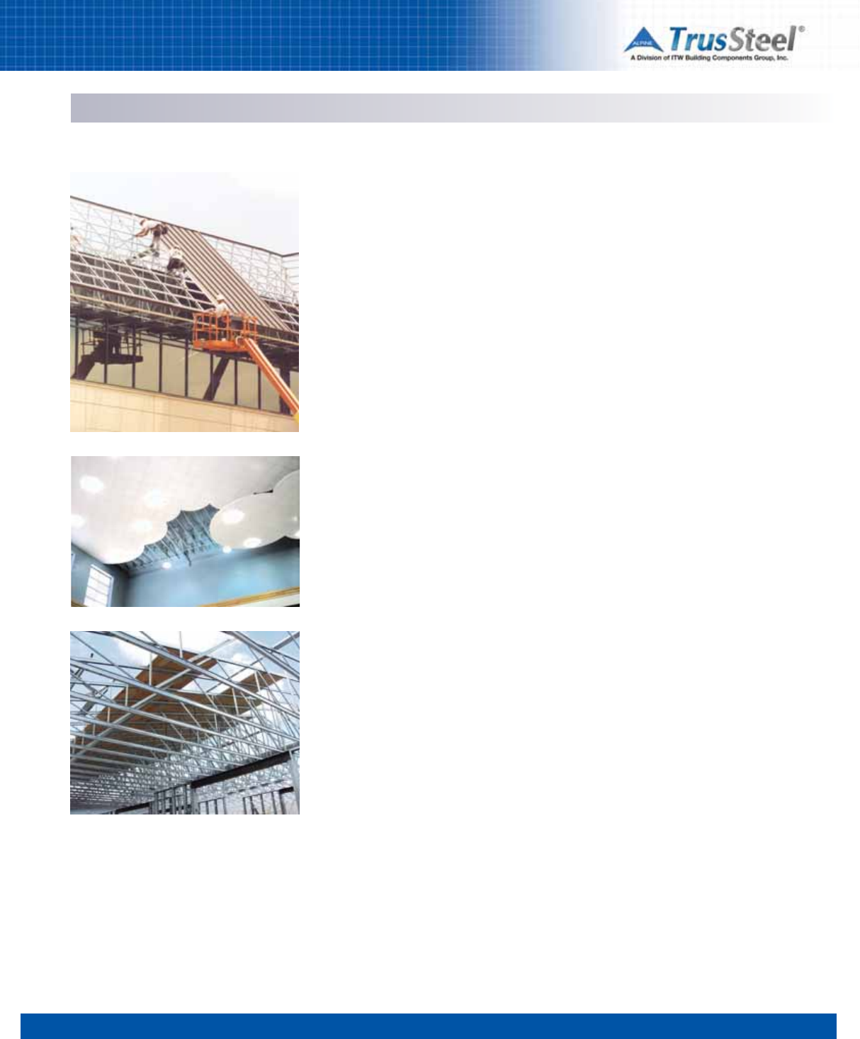
1 2 3 4 5 6 7 8
8.07
Weights of Materials
Composition Roofing
2-15 lb. and 1-90 lb. 1.75
3-15 lb. and 1-90 lb. 2.2
Felt, 3 ply 1.5
Felt, 3 ply and gravel 5.6
Felt, 4 ply and gravel 6.0
Felt, 5 ply and gravel 6.5
3/4” ceramic or quality tile 10.0
Single-ply (mod. bitumen) 1.0
Misc. Roofing Materials
Roll roofing 1.0
Asphalt shinges 2.0
Book tile (2”) 12.0
Cement tile 16.0
Clay tile (w/ mortar) 10.0
Spanish 19.0
Roman 12.0
Misc. Decking Materials
Tectum (1”) 2.0
Vermiculite concrete 2.6
Insulrock (1”) 2.7
Wood Decking
3/8" plywood 1.1
1/2” plywood 1.5
5/8” plywood 1.8
3/4” plywood 2.3
1-1/8” plywood 3.4
1” sheathing 2.3
2” decking 4.3
3” decking 7.0
4” decking 9.3
Roof Sheathing
3/8” plywood 1.1
1/2” plywood 1.5
5/8” plywood 1.8
3/4” plywood 2.2
1-1/8” plywood 3.3
1” (sheathing) nominal 2.1
Floor
Hardwood (nominal 1”) 3.8
Concrete (per 1” of thickness)
Insulating lightweight 2.5
Lightweight 6.0-10.0
Reinforced 12.5
Linoleum or soft tile 1.5
3/4” ceramic or quality tile 10.0
Terrazo (1.5”) 19.0
Cement finish (per 1” thick) 12.0
Corrugated Galvanized Steel Deck (2)
57 mil (16 GA) 3.5
45 mil (18 GA) 2.8
34 mil (20 GA) 2.1
28 mil (22 GA) 1.7
24 mil (24 GA) 1.1
18 mil (26 GA) 1.0
Roll or Batt Insulation
Rock wool (1”) 0.2
Glass wool (1”) 0.1
Rigid Insulation
Temlock (1”) 1.2
Cork 0.7
Gold bond (1”) 1.5
Styrofoam (1”) 0.2
Foamglass (1”) 0.8
Rigid fiber glass (1”) 1.5
Ceilings
Acoustical fiber tile 1.0
1/2” gypsum board 2.0
5/8” gypsum board 2.5
Plaster (1” thick) 8.0
Metal suspension system 0.5
Metal suspension with tile 1.8
Wood suspension system 2.0
Wood suspension with tile 2.5
All weights shown in PSF unless noted otherwise.
Weights and dimensions shown are generic - physical properties of actual materials may vary from product to product.
REFERENCES/RESOURCES
1 2 3 4 5 6 7 8
8.08
REFERENCES/RESOURCES
Industry-Best Resources
TrusSteel has created the industry’s most
complete set of technical resources for the
design and application of pre-engineered Cold-
Formed Steel trusses. This information is
published in several formats that are available to
professionals who specify and design with CFS
trusses.
www.TrusSteel.com
The TrusSteel Web site is the industry’s most
comprehensive resource on CFS trusses. Learn
the history of Alpine and TrusSteel, find a local
Authorized Fabricator, download Standard
Details, research UL and code issues, request an
AIA/CES seminar and much more. Get TrusSteel
information when you need it - 24 / 7 / 365.
Truss Manual CD
TrusSteel also publishes the Manual you are
reading as an interactive CD that is available to
architects and engineers who specify and design
with CFS trusses. The CD contains not only this
manual but also the complete library of TruSteel
Standard Details in DXF and DWG CAD file
formats. To request a copy of the Design Manual
CD, just visit www.TrusSteel.com.
TrusSteel Standard Details
TrusSteel maintains this growing library of over
100 details and makes it available, free of
charge, to industry professionals. Use these
details for reference during design, then cut-
and-paste them right into your construction
documents.
Guide Specification
The TrusSteel Guide Spec is written in the
standard three-part CSI format. This spec is
available from our Web site, and from the Design
Manual CD, in pure text format that you can cut-
and-paste without fear of reformatting your
current specs or importing contaminated files.
TrusSteel Authorized Fabricators
Your local Authorized Fabricators can be one of
your most valuable resources when you are
planning and designing your building. These roof
framing specialists can help you realize your
design vision in the most economical, easily-built
and safe manner. Need information on truss
designs, prices and delivery? Need help in
working out a difficult roof plan? Your local
Authorized Fabricator can help. Go to
www.TrusSteel.com to find a Fabricator near
you.
For more information, contact: info@TrusSteel.com or go to: www.TrusSteel.com
or call 888-565-9181.
The World Leader in
Cold-Formed Steel Trusses
Truss Design Manual
V2
a division of ITW Building Components Group
888.565.9181 • www.TrusSteel.com
a division of ITW Building Components Group
Truss Design Manual
