Tuf14990
User Manual: tuf14990
Open the PDF directly: View PDF ![]() .
.
Page Count: 23

Part # : 14990
2001 — 2006 Chevy or GMC 3500 HD
4” Suspension system
Parts contained in Box 1 of 2
Part # Description Qty.
14985-05 PS differential relocation bracket 1
14985-06 One piece lower sub frame 1
HDDIFF-01 DS differential relocation bracket 1
TBD99-01 Torsion bar cross member brackets 2
BL203 Rear lifted blocks 2
9802 CV axle spacers 2
14985NB Hardware box 1
14985PL Hardware bag 1
14985SL Sleeve bag 1
DECAL Window sticker 1
Parts contained in Box 2 of 2
Part # Description Qty.
16985-01M DS knuckle 1
16985-02M PS knuckle 1
17853 Box kit 1
S10120 HDDIFF-01 sleeve 1
14990INST (Instruction sheet / installer copy) 1
14990INST (Instruction sheet / customer copy) 1
MIRRORHANGER Rear view mirror hanger 1
WARNINGDECAL Warning decal 1
SHOCKTIE Shock ties 10
Congratulations on your selection to purchase a Tuff
Country EZ-Ride Suspension System. We at Tuff
Country EZ-Ride Suspension are proud to offer a
high quality product at the industries most
competitive pricing. Thank you for your confidence
in us and our product.
For a list of all parts, please refer to the Parts
Description Page, at the end of the Installation
Manual.
Make sure to use thread locker or locktite on all new
and stock hardware associated with the installation
of this suspension system.
It is the responsibility of the installers to make sure
that the rear view mirror hanger is hung from the
rear view mirror. The rear view mirror hanger has
instructions on proper post installation procedure.
Important customer information
Tuff Country EZ-Ride Suspension highly
recommends that a qualified or a certified mechanic
performs this installation.
If you desire to return your vehicle to stock, it is the
customers responsibility to save all stock hardware.
It is the responsibility of the customer or the
mechanic to wear safety glasses at all times when
performing this installation.
It is the customers/installers responsibility to read
and understand all steps before installation begins.
OEM manual should be used as a reference guide.
This vehicles reaction and handling characteristics
may differ from standard cars and/or trucks.
Modifications to improve and/or enhance off road
performance may raise the intended center of
gravity. Extreme caution must be utilized when
encountering driving conditions which may cause
vehicle imbalance or loss of control. DRIVE SAFELY!
Avoid abrupt maneuvers: such as sudden sharp
turns which could cause a roll over, resulting in
serious injury or death.
It is the customers responsibility to make sure that a
re-torque is performed on all hardware associated
with this suspension system after the first 100 miles
of installation. It is also the customers responsibility
to do a complete re-torque after every 3000 miles or
after every off road use.
After the original installation, Tuff Country EZ-Ride
Suspension also recommends having the alignment
checked every 6 months to ensure proper tracking,
proper wear on tires and front end components. Tuff
Country EZ-Ride Suspension takes no responsibility
for abuse, improper installation or improper
suspension maintenance.
The Tuff Country EZ-Ride Suspension product safety
label that is included in your kit box must be
installed inside the cab in plain view of all
occupants.
Installation manual
4” Suspension system
Chevy or GMC 3500 Heavy Duty
Part # 14990
sj052306rev.04

Limited lifetime warranty
Notice to all Tuff Country EZ-Ride Suspension
customers: It is your responsibility to keep your
original sales receipt! If failure should occur on any
Tuff Country EZ-Ride Suspension component, your
original sales receipt must accompany the warranted
unit to receive warranty. Warranty will be void if the
customer can not provide the original sales receipt.
Do not install a body lift in conjunction with a
suspension system. If a body lift is used in
conjunction with any Tuff Country EZ-Ride
Suspension product, your Tuff Country EZ-Ride
Suspension WARRANTY WILL BE VOID. Tuff
Country Inc. (“Tuff Country” ) suspension products
are warranted to be free from defects in material and
workmanship for life if purchased, installed and
maintained on a non-commercial vehicle; otherwise,
for a period of twelve (12) months, from the date of
purchase and installation on a commercial vehicle,
or twelve thousand (12,000) miles (which ever occurs
first). Tuff Country does not warrant or make any
representations concerning Tuff Country Products
when not installed and used strictly in accordance
with the manufacturer’s instructions for such
installation and operation and accordance with good
installation and maintenance practices of the
automotive industry. This warranty does not apply to
the cosmetic finish of Tuff Country products nor to
Tuff Country products which have been altered,
improperly installed, maintained, used or repaired, or
damaged by accident, negligence, misuse or racing.
(“Racing is used in its broadest sense, and, for
example, without regards to formalities in relation to
prizes, competition, etc.) This warranty is void if the
product is removed from the original vehicle and re-
installed on that or any other vehicle. This warranty
is exclusive and is in lieu of any implied warranty of
merchantability, fitness for a particular purpose or
other warranty of quality, whether express or
implied, except the warranty of title. All implied
warranties are limited to the duration of this
warranty. The remedies set forth in this warranty are
exclusive. This warranty excludes all labor charges
or other incidental of consequential damages. Any
part or product returned for warranty claim must be
returned through the dealer of the distributor from
whom it was purchased. Tuff Country reserves the
right to examine all parts returned to it for warranty
claim to determine whether or not any such part has
failed because of defect in material or workmanship.
The obligation of Tuff Country under this warranty
shall be limited to repairing, replacing or crediting, at
its option, any part or product found to be so
defective. Regardless of whether any part is
repaired, replaced or credited under this warranty,
shipping and/or transportation charges on the return
of such product must be prepaid by the customer
under this warranty.
Important information that needs to be read and
understood before installation begins;
Tuff Country EZ-Ride Suspension recommends the
use of an 8” wheel once part # 14990 has been
installed on a vehicle. If any wheel wider than a 8”
wheel is used, rubbing on the inner fender wheel and
plastic valance will occur.
After the installation is complete, a front end
alignment is required. Also, some vehicles may need
to have an exhaust modification performed.
After completion of the installation and the new tires
and wheels have been installed, trimming of the
plastic valance may be needed. Slight trimming may
be needed when installing a 33 x 12.50.
If any tire larger than a 33 x 12.50 is installed in
conjunction with part # 14990, the Tuff Country
warranty will be VOID.
Before installation begins, Tuff Country EZ-Ride
Suspension highly recommends that the installer
performs a test drive on the vehicle. During the test
drive, check to see if there are any uncommon
sounds or vibrations. If uncommon sounds or
vibrations occur on the test drive, uncommon
sounds or vibrations will be enhanced once the
suspension system has been installed. Tuff Country
EZ-Ride Suspension highly recommends notifying
the customer prior to installation to inform the
customer of these issues if they exist.
New longer front and rear shocks are needed after
this suspension system has been installed and the
front and rear shocks need to be ordered as a
separate part #. If you have not already ordered your
front and rear shocks, please feel free to contact Tuff
Country or your local Tuff Country dealer and order
your front and rear shocks.
Once the installation is complete and a front end
alignment has been performed, test drive the vehicle
to see if there are any front drive line vibrations. If
front drive line vibration occurs, take the front drive
line to a drive line shop and have the front drive line
re-balanced.

Hardware bag 14985SL includes:
Description Quantity
S10067 (.500” x .375” x 2.610”) 2
S10073 (.690” x .560” x 1.320”) 2
S10074 (.700” x .563” x 1.500”) 4
S10082 (.875” x .563” x 2.080”) 1
Hardware bag 14985PL includes:
Description Quantity
PB6199 (poly bump stops) 4
PB6052 (poly bump stops) 2
PB2408 (poly bushings) 2
PB4902 (poly bushings) 4
S10049 (sway bar end link washers) 8
PB8016 (sway bar end link bushings) 8
PB8297 (front upper shock bushings) 4
S10107 (front upper shock washers) 4
Poly Lube Pack 2
Hardware bag 14985NB includes:
Bag # 1
Description Quantity
3/8” x 7 ” bolts 2
3/8” unitorque nuts 8
5/16” USS flat washers 6
M10 x 35 mm bolt 12
M10 x 60 mm bolt 4
M10 lock washers 16
7/16” x 1 1/2” bolts 10
7/16” x 3” bolts 1
7/16” unitorque nuts 11
3/8” USS flat washers 22
9/16” x 1 3/4” bolts 2
9/16” unitorque nuts 2
1/2” USS flat washers 4
5/8” x 4 1/2” bolts 2
5/8” x 5 1/2” bolts 2
5/8” unitorque nuts 4
9/16” USS flat washers 8
1/4” x 1” self threading bolt 1
Hardware bag 58NW includes:
Description Quantity
5/8” u-bolt high nuts 8
5/8” u-bolt harden washers 8
Special note: Before installation begins, it is the
customers/installers responsibility to make sure that
all parts are on hand. If any parts are missing, please
feel free to call one of our customer service
representatives @ (801) 280-2777.
Special post installation procedure: Tuff Country EZ-
Ride Suspension highly recommends adding a
minimum of 1 pint, but no more that 1 1/2 pints, of
proper front differential fluid into the front
differential. To achieve this, you may have to fill the
differential with it on its side or you may have to
insert the fluid through the vend tube opening. On
occasion, the customer may find burping of fluid
coming out of the front vent tube.
Torque settings:
5/16” 15 — 18 ft lbs.
3/8” 28 — 32 ft lbs.
7/16” 30 — 35 ft lbs.
1/2” 65 — 85 ft lbs.
9/16” 85 — 120 ft lbs.
5/8” 95 — 130 ft lbs.
3/4” 100 — 140 ft lbs.
10 mm bolt 34 — 49 ft lbs.
Recommended tools selection;
Torsion bar puller
(Part # 7822A / LSP code: 769 006 21)
Cut off wheel
Sawzall
Torque wrench
Standard socket set
Standard wrench set
Metric socket set
Metric wrench set
Tape measure
Hydraulic floor jacks

Before installation begins, measure from the center
of the hub, to the bottom of the fender well, and
record measurements below.
Pre installation measurements:
Driver side front:______________________________
Passenger side front:__________________________
Driver side rear:______________________________
Passenger side rear:__________________________
At the end of the installation take the same
measurements and compare to the pre-installation
measurements.
Post installation measurements:
Driver side front:______________________________
Passenger side front:__________________________
Driver side rear:______________________________
Passenger side rear:__________________________
Please follow instructions carefully:
Front end installation:
1. To begin installation, block the rear tires of the vehicle
so that the vehicle is stable and can’t roll backwards.
Safely lift the front of the vehicle and support the frame
with a pair of jack stands. Place a jack stand on both the
driver and passenger side. Next, remove the wheels and
tires from both sides.
2. Remove the stock front upper and lower skid plates.
The stock lower skid plate and stock hardware may be
discarded. Save the stock upper skid plate and the (3)
stock upper bolts for later re-installation.
3. Remove the stock front driveline from the stock
location on the front differential and the transmission.
Save the stock driveline and hardware for later re-
installation.
4. Working on the driver side, remove the stock hardware
on the top of the stock shock. The upper stock hardware
may be discarded. Remove the stock hardware on the
lower shock mount and save the stock hardware for later
re-installation. The stock shock may be discarded.
Special note: New longer front shocks are needed, if
you have not already ordered shocks, please contact
Tuff Country or your local Tuff Country dealer and
order the proper shocks. Tuff Country recommends
using a 23” fully extended nitrogen gas shock.
Repeat procedure on the passenger side.
5. Measure the exposed threads on the torsion bar
adjustment bolt and record measurement here for a later
reference.
Record driver side measurement here:______________
Record passenger side measurement here:__________
Photo # 1
6. Working on the driver side, attach the torsion bar
removing tool to the stock torsion bar cross member,
making sure that the unloading bolt in the center of the
torsion bar removing tool is in the small divot of the stock
torsion bar key. Adjust the torsion bar key up high
enough so that the stock small metal adjusting block and
bolt can be removed. Set the stock torsion bar block and
hardware a side for later re-installation. Repeat
procedure on passenger side.
7. Mark both torsion bars before removal so that they can
be re-installed back into the same location. Example:
Driver vs. Passenger and front vs. rear. Tap the stock
torsion bars forward until the stock torsion bar cross
member can be removed. Once you tap the stock torsion
bar out of the stock torsion bar cross member, the stock
torsion bar key will fall out. Set the stock torsion bar key a
side for later re-installation. Repeat procedure on the
passenger side.
8. Working on the driver side, remove the stock bolt that
connects the stock torsion bar cross member to the stock
mounting point. Special note: The stock mounting
point is on the inside of the stock frame rail. Save the
stock hardware for later re-installation. Repeat procedure
on the passenger side. Remove the stock torsion bar
cross member from the stock location and set a side for
later re-installation.
9. Working on the driver side, slide the stock torsion bar
out of the stock rear lower control arm and set a side for
later re-installation. Repeat procedure on passenger side.
10. Working on the driver side, remove the stock sway
bar end link from the stock location and discard the stock
end link and all the stock hardware. Repeat procedure on
the passenger side. Special note: At this time, invert
the stock sway bar.
11. Working on the driver side, remove the stock nut that
connects the stock outer tie rod ball joint to the stock
steering knuckle. Set the stock nut a side for later re-
installation. Carefully break the stock taper on the stock
outer tie rod ball joint and remove the stock outer tie rod
from the stock knuckle. Special note: Take special care
not to rip or tear the stock outer tie rod ball joint dust
boot.
12. Working on the driver side, remove the stock brake
line bracket that connects to the stock steering knuckle
and discard the stock hardware. Next, remove the stock
brake line mounting point that connects to the stock
upper control arm. Save the stock hardware for later re-
installation. Also, remove any other brake line mounting
points on the stock steering knuckle and stock upper
control arm.
13. Working on the driver side, locate the ABS line quick
disconnect located above the stock upper control arm.
Disconnect the ABS lines from each other. Also,
disconnect the ABS line from any other mounting points.

14. Working on the driver side, remove the (2) stock bolts
that connect the stock brake caliper to the stock knuckle.
Save the stock hardware for later re-installation. Using a
bungee cord, carefully tie the stock brake caliper up and
out of the way in the fender well. Special note: Take
special care not to kink or over extend the stock
brake line.
15. Working on the driver side, remove the stock rotor
and set a side for later re-installation.
16. Working on the driver side, remove the stock cap
right in the middle of the stock hub assembly. Set the
stock cap a side for later re-installation.
17. Working on the driver side, remove the stock nut that
connects the stock axle to the hub assembly. Save the
stock nut for later re-installation.
18. Working on the driver side, scribe a mark on the CV
plate and another directly across to the stock differential.
This will allow you to re-install the stock CV back into the
stock location at a later step.
Photo # 2
19. Working on the driver side, remove the (6) stock bolts
holding the inner CV axle to the stock front differential.
The stock hardware may be discarded. Carefully remove
the stock CV axle from the stock location and set the
stock CV axle a side for later re-installation. Special
note: During the removal of the stock CV axle, take
special care not to damage the threads of the CV axle
or the CV axle dust boot.
20. Working on the driver side, loosen but do not remove
the stock nut that connects the stock upper control arm
ball joint to the stock steering knuckle. Carefully break
the stock taper by striking the stock knuckle with a
hammer. Special note: Take special care not to
damaged the stock upper control arm ball joint or rip
the stock upper control arm ball joint dust boot. For
now, leave the stock upper control arm attached to the
stock knuckle. We want to just break the stock taper for
now.
21. Working on the driver side, loosen but do not remove
the stock nut that connects the stock lower control arm
ball joint to the stock steering knuckle. Carefully break
the stock taper by striking the stock knuckle with a
hammer. Special note: Take special care not to
damaged the stock lower control arm ball joint or rip
the stock lower control arm ball joint dust boot. For
now, leave the stock lower control arm attached to the
stock knuckle. We want to just break the stock taper for
now.
22. Working on the driver side, move back to the stock
nuts holding the stock upper control arm ball joint and the
stock lower control arm ball joint to the stock steering
knuckle and remove completely. Save the stock
hardware for later re-installation. Carefully remove the
stock hub assembly and the stock steering knuckle from
the stock location and set a side for later re-installation.
23. Working on the driver side stock hub assembly,
remove the (4) stock bolts that connect the stock hub
assembly to the stock steering knuckle. Save the stock
hardware and stock hub assembly for later re-installation.
Also, carefully remove the stock rubber “O” ring located
in the stock steering knuckle and save for later re-
installation. A new steering knuckle is used, the stock
steering knuckle can be discarded.
24. Locate the new driver side steering knuckle. Using
the stock rubber “O” ring that was removed in step # 23,
carefully re-install the stock rubber “O” ring into the new
driver side knuckle. Using the stock hardware that was
removed from step # 23, secure the new driver side
steering knuckle to the stock hub assembly. Special
note: Make sure that the ABS line fits in the grove of
the new steering knuckle once the hub assembly has
been torqued down. Torque to 133 ft lbs. Make sure
to use thread locker or lock tite.
Photo # 3
25. Set the new driver side steering knuckle and hub
assembly a side for later re-installation.
26. Working on the driver side, remove the stock front
and rear hardware that connects the stock lower control
arm to the stock location. Set the stock hardware and the
stock lower control arm a side for later re-installation.
27. Repeat step’s 11 - 26 on the passenger side.
28. Working on the driver side, remove the stock bolt that
connects the lower rear portion of the stock front
differential to the stock rear cross member. Save the
stock hardware for later re-installation.
Photo # 4
29. Working on the passenger side, remove the (2) stock
bolts that connect the stock rear cross member to the
stock passenger side rear lower control arm mounting
point. The (2) stock bolts may be discarded.
Photo # 5
30. Working on the driver side, measure 2” towards the
inside of the vehicle from the stock rear lower control arm
mounting point, scribe a mark on the stock rear cross
member. Using a hacksaw or suitable cutting tool,
carefully cut off the stock rear cross member along the
line that was scribed earlier in this step. The stock rear
cross member may be discarded. Special note: When
making this cut, make sure that you cut all the way
through the stock rear lower control arm mounting
point. If this cut is not performed properly, the stock
front differential will not seat properly when the front
differential is lowered into the new one piece lower
sub frame. Also, Tuff Country EZ-Ride highly

recommends not using a cutting torch when
performing step # 30. Clean and dress up any
exposed metal. Photo # 6
31. Working on the driver side, carefully cut flush, the
remainder of the stock rear cross member that is located
on the rear portion of the stock rear lower control arm
mounting bracket. Special note: Take special care not
to cut into the stock rear lower control arm mounting
bracket. Tuff Country recommends not using a
cutting torch when performing step # 31. Clean and
dress up any exposed metal.
32. Locate the wiring harness that connects the 4WD
control panel to the front differential. Disconnect the 4WD
wiring harness from the front differential. Tie the 4WD
wiring harness up and out of the way. Special note:
Take special care not to kink any wiring.
Photo # 7
33. Place a pair of hydraulic floor jacks under the front
differential, and carefully raise up on both hydraulic floor
jacks at the same time, until they come into contact with
the front differential.
34. Disconnect any other vent hoses and/or wiring that is
connected to the front differential.
35. Working on the driver side, remove the stock
hardware that connects the upper driver side tab of the
stock front differential to the stock location. Save the
stock hardware for later re-installation.
36. Working on the passenger side, remove the (2) stock
nuts that connect the passenger side of the stock front
differential to the stock location and save the stock
hardware for later re-installation.
37. Carefully lower down on both hydraulic floor jacks at
the same allowing enough room to remove the front
differential completely from the vehicle. With the help
from a buddy, carefully remove the front differential
completely from underneath the vehicle and set the stock
front differential on the ground or on a work bench.
38. Working on the driver side of the stock front
differential upper tab, measure 2” from the stock
mounting point and scribe a mark on the stock front
differential. Using a sawzall, carefully cut the upper tab
off of the stock front differential and discard.
Photo # 8 / side view
Photo # 9 / pre cut view
Photo # 10 / nose cut off of the front differential
39. Locate the new driver side differential relocation
bracket. Locate (2) PB2408 poly bushings from hardware
bag 14985PL and (1) S10082 crush sleeve from
hardware bag 14985SL. Install the new poly bushings
and crush sleeve into the new driver side differential
relocation bracket. Special note: Make sure to use a
lithium or moly base grease prior to inserting the new
bushings into the new driver side differential
relocation bracket. This will increase the life of the
bushing as well as prevent squeaking.
40. Locate (1) 7/16” X 3” bolt, (1) 7/16” unitorque nut, (2)
3/8” USS flat washers, (4) 10 mm x 60 mm bolts and (4)
10 mm lock washers from hardware bag 14985NB. Also,
locate the S10120 that is packaged with the installer copy
of the installation manual. Remove the (4) stock
differential mounting bolts that connect to two halves of
the front differential together. The stock hardware may be
discarded. Secure the new driver side differential
relocation bracket to the stock front differential using the
new 10 mm x 60 mm bolts and hardware. Special note:
Get all (4) new 10 mm x 60 mm bolts started but do
not tighten at this point and make sure to use thread
locker or lock tite. Secure the lower portion of the new
driver side differential relocation bracket to the stock front
differential using the new 7/16” x 3” bolt and hardware.
Special note: Make sure to install the new S10120
sleeve between the new driver side differential
relocation bracket and the front differential. Also, you
will notice that there are (2) holes in the new driver
side differential relocation bracket where the new
S10120 sleeve will go, we need to match the hole that
is on the front differential. Torque to 34 ft. lbs. Go back
to the (4) new 10 mm x 60 mm bolts that hold the new
driver side differential relocation bracket to the stock front
differential and torque to 34 ft lbs. Special note: Do not
use an air gun when installing the new hardware.
Make sure not to over tighten the stock and new
hardware associated with the front differential. If
bolts are over tightened, the stock front differential
could crack. Also, Tuff Country EZ-Ride Suspension
highly recommends adding a minimum of 1 pint, but
no more that 1 1/2 pints, of proper front differential
fluid into the front differential. To achieve this, you
may have to fill the differential with it on its side or
you may have to insert the fluid through the vend
tube opening. On occasion, the customer may find
burping of fluid coming out of the front vent tube.
41. Locate the new passenger side differential drop
bracket and the stock hardware that was removed from
step # 36. Working on the passenger side, install the new
passenger side differential relocation bracket into the
stock upper location and secure using the stock
hardware. Special note: Make sure to use thread
locker or lock tite and do not tighten at this point.
There is a “4F” cut out in this bracket, the “4F” will
go towards the front of the vehicle and also if you are
standing on the passenger side wheel well looking at
the new passenger side differential relocation
bracket, you should not be able to see the mounting
hardware. This will help you make sure that the
bracket is installed properly.
Photo # 11

42. With the help from a buddy, carefully lift the modified
front differential back onto a pair of hydraulic floor jacks
and move the hydraulic floor jacks back underneath the
vehicle so that the newly modified front differential can be
re-installed.
43. Locate (2) 9/16” x 1 3/4” bolts, (4) 1/2” USS flat
washers and (2) 9/16” unitorque nuts from hardware bag
14985NB. Carefully install the passenger side of the
stock front differential to the previously installed
passenger side differential drop bracket. Secure using
the new 9/16” x 1 3/4” bolts and hardware. Do not
tighten at this point and make sure to use thread
locker or lock tite.
44. Working on the driver side, using a tie down strap or
bungee cord, carefully tie the driver side of the stock front
differential up and out of the way so that the new one
piece lower sub frame can be installed. Once the driver
side of the front differential is tied up and out of the way,
remove the hydraulic floor jacks from under the front
differential. Photo # 12
45. Locate the new one piece lower sub frame and the
stock lower control arm mounting hardware that was
removed from step # 26. On the driver side, install the
front and rear part of the new one piece lower sub frame
into the stock front and rear lower control arm mounting
points using the stock hardware. Do not tighten at this
point and make sure to use thread locker or lock tite.
Repeat procedure on passenger side.
46. Carefully remove the tie down strap or the bungee
cord that is holding the driver side of the stock front
differential up and out of the way. Let the stock front
differential rest on the newly installed one piece lower
sub frame.
47. Locate the stock hardware that was removed from
step # 28. Install the rear portion of the front differential
into the tab on the rear portion of the new one piece
lower sub frame. Secure using the stock hardware. Do
not tighten at this point and make sure to use thread
locker or lock tite. Photo # 13
48. Locate the stock hardware that was removed from
step # 35. Secure the newly installed front differential
relocation bracket to the front portion of the new one
piece lower sub frame. Secure using the stock hardware.
Do not tighten at this point and make sure to use
thread locker or lock tite.
49. Place a hydraulic floor jack under the front portion of
the new one piece lower sub frame. Carefully raise up on
the hydraulic floor jack until the front portion of the sub
frame seats flush with the stock front cross member.
Using the holes in the front portion of the new one piece
lower sub frame as a guide, carefully drill (2) 7/16” holes
into the bottom of the stock front cross member. Special
note: On some vehicles, you may not have to drill the
(2) 7/16” holes, they will already be in the stock front
cross member.
50. Locate (2) 7/16” x 1 1/2” bolts, (4) 3/8” USS flat
washers and (2) 7/16” unitorque nuts from hardware
14985NB. Secure the front portion of the new one piece
sub frame to the stock front cross member using the new
7/16” x 1 1/2” bolt and hardware. Torque to 42 ft lbs.
Make sure to use thread locker or lock tite. Carefully
remove the hydraulic floor jack from under the front
portion of the newly installed one piece lower sub frame.
51. Working in this order, torque the following stock and
new hardware to proper torque specifications. First, on
the driver side of the vehicle, torque the stock hardware
that connects the rear portion of the stock front
differential into the rear pocket of the new one piece
lower sub frame to 75 ft lbs. Next, working on the driver
side, torque the stock hardware that connects the new
driver side differential relocation bracket to the front tabs
located on the front portion of the new one piece lower
sub frame to 75 ft lbs. Next, working on the passenger
side, torque the stock hardware that connects the new
passenger side differential drop bracket to the stock
location to 75 ft lbs. Next, working on the passenger
side, torque the new hardware that connects the stock
front differential to the new passenger side differential
drop bracket to 85 ft lbs. Next, working on the driver
side, torque the stock hardware that connects the new
one piece lower sub frame to the stock front and rear
lower control arm pockets to 105 ft lbs. Finally, working
on the passenger side, torque the stock hardware that
connects the new one piece lower sub frame to the stock
front and rear lower control arm pockets to 105 ft lbs.
52. Reconnect the 4WD wiring to the front differential.
Also, reconnect any other vent hoses and/or wiring that
was connected to the stock front differential.
53. Locate (2) PB6199 poly bump stops from hardware
bag 14985PL. Special note: There are (6) poly bump
stops located in the poly bag, (4) are the same size
and (2) are taller, locate (2) of the shorter poly bump
stops. Also, locate (2) 3/8” unitorque nuts and (2) 5/16”
USS flat washers from hardware bag 14985NB. Working
on the driver side rear portion of the newly installed one
piece lower sub frame, secure the new poly bump stop
using the new 3/8” hardware. Torque to 28 ft lbs. Repeat
procedure on the passenger side. Make sure to use
thread locker or lock tite.
54. Locate (2) 5/8” x 4 1/2” bolts, (2) 5/8” x 5 1/2” bolts,
(8) 9/16” USS flat washers and (4) 5/8” unitorque nuts
from hardware bag 14985NB. Also, locate the stock
lower control arms that were removed from step # 26.
Working on the driver side, install the stock lower control
arm into the newly installed one piece lower sub frame’s

60. Locate the stock rotors that were removed in step #
15. Working on the driver side, install the stock rotor into
the stock location. Repeat procedure on the passenger
side.
61. Locate the stock brake caliper hardware that was
removed in step # 12. Working on the driver side, re-
install the stock brake caliper to the new driver side
spindle and secure using the stock hardware. Torque to
96 ft. lbs. Make sure to use thread locker or lock tite.
Repeat procedure on the passenger side.
62. Locate the stock brake line hardware that was
removed in step # 12. Also, locate (10) shock ties
packaged with the instruction sheet. Working on the
driver side, secure the stock brake line bracket to the
stock upper control arm using the stock hardware. Next,
shock tie the stock ABS line and the stock brake line to
the newly installed spindle. Also, shock tie the stock ABS
line and the stock brake lines together. Repeat procedure
on the passenger side. Special note: In this step make
sure that once you shock tie the stock brake lines
and ABS lines to the spindle, there will be no contact
on the new wheels and tires. If contact occurs, the
stock brake lines or ABS lines may be damaged.
63. Locate the stock outer tie rod ball joint hardware that
was removed from step # 11. Working on the driver side,
install the stock outer tie rod to the new steering knuckle
using the stock hardware. Make sure to use thread locker
or lock tite and torque to 53 ft. lbs. Special note: The
new steering knuckle has a reverse taper on it where
the stock outer tie rod mounts to it, make sure to
install the outer tie rod the proper way. The stock
outer tie rod nut will now be installed on the bottom
side of the new steering knuckle.
64. Locate (2) new torsion bar cross member relocation
brackets. Locate (4) PB4902 poly bushings from
hardware bag 14985PL. Also, locate (2) S10074 sleeves
from hardware bag 14985SL. Install the new poly
bushings and sleeves into the new torsion bar cross
member relocation brackets. Special note: Make sure to
use a lithium or moly base grease prior to inserting
the new bushings and sleeves into the new torsion
bar cross member relocation brackets. This will
increase the life of the bushing as well as prevent
squeaking.
65. Working on the driver side, hold the new torsion bar
cross member relocation bracket to the new location on
the stock frame rail. Special note: Using the larger cut
out holes in the torsion bar cross member relocation
bracket over the stock rivets on the bottom of the
stock frame rail with help center the new torsion bar
cross member relocation bracket. With the new torsion
bar cross member relocation bracket in place, use a pair
of vice grips and secure the new torsion bar drop bracket
to the stock frame rail. Using the new torsion bar cross
member relocation bracket as a guide, carefully drill (4)
front location and secure using the new 5/8” x 4 1/2” bolt
and hardware. Do not tighten at this point. Make sure
to use thread locker or lock tite. Install the stock lower
control into the newly installed one piece lower sub
frame’s rear location and secure using the new 5/8” x 5
1/2” bolt and hardware. Do not tighten at this point.
Make sure to use thread locker or lock tite. Repeat
procedure on the passenger side.
55. Locate the new driver side steering knuckle and stock
hub assembly, the stock hardware for the upper control
arm ball joint and the lower control arm ball joint that was
removed in step # 22. Using the stock hardware, secure
the new driver side steering knuckle and stock hub
assembly to the stock upper control arm ball joint and the
stock lower control arm ball joint. Special note: Do not
install the stock outer tie rod to the new steering
knuckle at this point. Torque the stock upper ball joint
hardware to 74 ft lbs. and the stock lower ball joint
hardware to 101 ft lbs. Special note: When installing
the new driver side spindle, make sure that the stock
brake line is located towards the inside of the
vehicle. Make sure to use thread locker or lock tite.
Repeat procedure on the passenger side using the
passenger side steering knuckle.
56. Locate the stock CV axles that were removed from
step # 19. Working on the driver side, carefully install the
stock CV axle back into the stock hub assembly. Repeat
procedure on the passenger side.
57. Locate (12) 10 mm x 35 mm bolt and (12) 10 mm lock
washers from hardware bag 14985NB. Also, locate (2)
9802 CV axle shims. Working on the driver side, install
(1) new CV axle shim between the stock front differential
and the stock CV axle. Secure using the new 10 mm x 35
mm bolts and hardware. Torque to 45 ft. lbs. Make sure
to use thread locker or lock tite. Special note: Make
sure that the stock axle is re-installed back into the
stock location on the stock front differential. Refer to
the scribe mark that was made in step # 18. Repeat on
the passenger side.
58. Locate the stock hardware that connects the stock
front axle to the stock hub assembly that was removed in
step # 17. Also, locate the stock hub assembly caps that
were removed in step # 16. Working on the driver side,
secure the stock front axle to the hub assembly using the
stock hardware. Torque to 154 ft. lbs. Make sure to use
thread locker or lock tite. Re-install the stock hub
assembly cap back into the stock location. Repeat
procedure on the passenger side.
59. Working on the driver side, reconnect the stock ABS
lines back together. Also reconnect all other stock
mounting points on the stock ABS line. Repeat procedure
on the passenger side.

or your local Tuff Country dealer and order the
proper shocks. Tuff Country recommends using a
23” fully extended nitrogen gas shock. Locate (2)
S10073 from hardware bag 14985SL. Also, locate (4)
PB8297 upper shock bushings and (4) S10107 upper
shock washers from hardware bag 14985PL. Working on
the new shocks, install the new lower shock bushing into
the lower eyelet and install the new S10073 shock
sleeves into the previously installed bushings. Special
note: Make sure to use a lithium or moly base grease
prior to inserting the new lower shock bushings and
sleeves into the new lower shock eyelet. This will
increase the life of the bushing as well as prevent
squeaking. Working on the driver side, install the new
shock into the stock location using the stock hardware on
the bottom mount that was removed in step # 4 and the
new hardware on the top mount. Repeat procedure on
the passenger side. Special note: Make sure to use the
new upper bushings and upper shock washers.
Torque the lower shock mount to 65 ft lbs. and the upper
hardware to 22 ft lbs. Repeat on passenger side.
Special note: Tuff Country EZ-Ride Suspension
highly recommends that the shocks are installed with
shock boots. If shock boots are not installed,
damaged my occur to the piston of the new shock.
72. Locate the stock front drive line and hardware that
was removed from step # 3. Re-install the stock drive line
back into the stock location and secure using the stock
hardware. Special note: Check and make sure that the
stock front driveline does not contact the exhaust, if
contact occurs, an exhaust modification is required.
73. Locate the stock skid plate that was removed in step
# 2. Referring to photo # 15, measure 2 5/8” from the
leading edge of the stock skid plate and scribe a mark.
Carefully cut along the scribed mark.
Photo # 15 / 2 5/8” measurement
Photo # 16 / post cut view
74. Locate the (3) stock upper skid plate mounting
hardware that we removed in step # 2. Install the newly
modified skid upper skid plate to the stock upper location
using the stock hardware. Special note: Make sure to
use thread locker or lock tite and torque to 28 ft lbs.
75. Holding the stock skid plate to the front cross
member, carefully drill a 3/16” hole through the stock skid
plate and the stock front cross member.
Photo # 17
76. Locate (1) 1/4” x 1” self threading bolt from hardware
bag 14985NB. Secure the stock skid plate to the stock
cross member using the new 1/4” x 1” self threading bolt.
Photo # 18
77. Re-install the tires and wheels and carefully lower the
vehicle to the ground.
7/16” holes into the stock frame. (2) on the side of the
frame rail and (2) on the bottom. Take special care not
to drill into any stock hoses and/or lines running
down the inside of the stock frame rail. Remove the
pair of vice grips that is holding the new torsion bar cross
member relocation bracket to the frame rail. Repeat
procedure on the passenger side of the vehicle.
66. Locate (8) 7/16” x 1 1/2” bolts, (16) 3/8” USS flat
washers and (8) 7/16” unitorque nuts from hardware bag
14985NB. Working on the driver side, secure the new
driver side torsion bar cross member relocation bracket
to the stock frame rail using the new 7/16” x 1 1/2” bolt
and hardware. Make sure to use thread locker or lock
tite. Torque to 76 ft lbs. Repeat procedure on the
passenger side. Photo # 14
67. Locate the stock torsion bars that were removed from
step # 9. Refer to the marks that were made in step # 7.
This will allow you to re-install the stock torsion bars back
into the stock location. Example: Driver vs. Passenger
and Front vs. Rear. Working on the driver side, slide the
stock torsion bar back into the stock rear lower control
arm. Slide the stock torsion bar far enough forward so
that the stock torsion bar cross member can be re-
installed. Repeat procedure on the passenger side.
68. Locate the stock torsion bar cross member and stock
hardware that was removed from step # 8. Install the
stock torsion bar cross member to the newly installed
torsion bar cross member relocation brackets and secure
using the stock hardware. Make sure to use thread
locker or lock tite. Torque to 90 ft lbs.
69. Locate the stock torsion bar keys that were removed
from step # 7. Working on the driver side, install the stock
torsion bar key back into the stock location in the stock
torsion bar cross member. Slide the stock torsion bar
back into the previously installed torsion bar key. Repeat
procedure on the passenger side.
70. Locate the torsion bar adjusting blocks and hardware
that was removed from step # 6. Working on the driver
side, attach the torsion bar removing tool to the stock
torsion bar cross member, making sure that the
unloading bolt in the center of the torsion bar removing
tool is in the small divot of the stock torsion bar key.
Adjust the torsion bar key up high enough so that the
stock small metal adjusting block and bolt can be re-
installed back into the stock location. Refer back to the
measurements that were made in step # 5, and set to the
torsion bar adjusting bolt to the stock setting. Repeat
procedure on the passenger side. Carefully remove the
torsion bar removing tool from the stock torsion bar cross
member.
71. Locate the new front shocks. Special note: New
longer front shocks are needed, if you have not
already ordered shocks, please contact Tuff Country

87. Working on the driver side. Special note: New
longer rear shocks are needed, if you have not
already ordered shocks, please contact Tuff Country
or your local Tuff Country dealer and order the
proper shocks. Tuff Country recommends using a
30” fully extended nitrogen gas shock. Locate (2)
S10074 from hardware bag 14985SL. Working on the
new shocks, install the new shock bushing into the upper
and lower eyelets of the new shocks. Next, install the
new shock sleeves into the previously installed shock
bushings. Special note: Use the new S10074 shock
sleeves and the proper shock sleeves that are
located in the new sleeve bag that was provide with
your new shocks. Make sure to use a lithium or moly
base grease prior to inserting the new lower shock
bushings and sleeves into the new lower shock
eyelet. This will increase the life of the bushing as
well as prevent squeaking. Working on the driver side,
install the new shock into the stock location and secure
using the stock hardware that was removed in step # 88.
Special note: Make sure to use thread locker or lock
tite and torque to 75 ft lbs. Repeat procedure on the
passenger side. Special note: Tuff Country EZ-Ride
Suspension highly recommends that the shocks are
installed with shock boots. If shock boots are not
installed, damaged my occur to the piston of the new
shock.
Photo # 19 / complete installation of the new blocks,
u-bolts and shocks.
88. Carefully remove the (2) hydraulic floor jacks from
under the rear differential.
89. Locate (2) PB6199 poly bump stops and (2) PB6052
poly bump stops from hardware bag 14985PL. Also,
locate (4) 3/8” unitorque nuts and (4) 5/16” USS flat
washers from hardware bag 14985NB. Working on the
driver side of the stock rear spring assembly. Remove
the (2) stock teflon inserts located on the stock over load
in the stock spring assembly. Discard the stock teflon
inserts. Install (1) PB6052 (taller poly bump stop) in front
location on the stock spring assembly. Secure using the
new 3/8” hardware. Torque to 28 ft lbs. Install (1)
PB6199 (shorter poly bump stop) in the rear location on
the stock spring assembly. Secure using the new 3/8”
hardware. Torque to 28 ft lbs. Repeat procedure on the
passenger side.
Photo # 20 / front location
Photo # 21 / rear location
90. Install the tires and wheels and carefully lower the
vehicle to the ground.
Step # 91 and # 92 needs to be performed with the
weight of the vehicle on the ground.
91. Working on the driver side, move back to the new
5/8” hardware attaching the stock lower control arms to
the newly installed one piece lower sub frame and torque
to 125 ft lbs. Repeat procedure on the passenger side.
78. There is still a couple of steps that need to be
completed on the front end but these steps will not be
completed until the rear end installation is completed and
the weight of the vehicle is on the ground. These steps
include; the installation of the front sway bar end links
and the tightening of the new hardware that connects the
lower control arms to the newly installed sub frame.
Rear end installation:
79. To begin installation, block the front tires of the
vehicle so that the vehicle is stable and can’t roll forward.
Safely lift the rear of the vehicle and support the frame
with a pair of jack stands. Place a jack stand on both the
driver and passenger side. Next, remove the wheels and
tires from both sides.
80. Working on the driver side, remove the stock shock
from the stock upper and lower mounting points and save
the stock hardware for later re-installation. The stock
shocks may be discarded. Special note: New longer
rear shocks are needed, if you have not already
ordered shocks, please contact Tuff Country or your
local Tuff Country dealer and order the proper
shocks. Tuff Country recommends using a 30” fully
extended nitrogen gas shock. Repeat procedure on the
passenger side.
81. Place a pair of hydraulic floor jacks under the rear
differential and carefully raise up on both hydraulic floor
jacks at the same time until they come into contact with
the rear differential.
82. Working on the driver side, remove the stock u-bolts
from the stock location and discard the stock u-bolts and
hardware. Set the stock upper and lower u-bolt plates a
side for later re-installation. Repeat procedure on
passenger side.
83. Carefully lower down both hydraulic floor jacks at the
same time approximately 3”. Special note: Take special
care not to over extend any brake lines and/or hoses.
84. Locate (2) new rear 2” lifted blocks. Working on the
driver side, install the new 2” lifted block into the stock
location. Repeat procedure on the passenger side.
85. Carefully raise up on both hydraulic floor jacks at the
same time until the stock spring assembly sits flush with
the newly installed 2” lifted block.
86. Locate (4) 5/8” x 2 3/4” x 15 1/2” square u-bolts, (8)
5/8” u-bolt high nuts and (8) u-bolt washers from box kit
17853. Also, locate the stock upper and lower u-bolt
plates that were removed from step # 82. Working on the
driver side, install the new u-bolts into the stock location
and secure using the new 5/8” high nuts and washers.
Special note: Make sure to re-install the stock upper
and lower u-bolt plates. Torque to 135 ft lbs. Repeat
procedure on passenger side.

92. Locate (2) 3/8” x 7” bolts and (2) 3/8” unitorque nuts from hardware bag 14985NB. Locate (2) S10067 sway bar
end link sleeves from hardware bag 14985SL. Also, locate (8) sway bar end link poly bushings and (8) sway bar end
link washers from hardware bag 14985PL. Special note: If you did not invert the stock sway bar in step # 10,
invert the stock sway bar now. Working on the driver side, install the new sway bar end link and hardware into the
stock location and torque to 32 ft lbs. Repeat procedure on passenger side.
93. Check and double check to make sure that all steps were performed properly and then check again. Check and
make sure that all new and stock hardware has been torqued to proper torque specification. Refer to the torque
specification at the end of the installation manual.
94. Take the vehicle directly to an alignment shop for a proper front end alignment.
Tuff Country EZ-Ride Suspension packages (2) sets of instruction sheets with this box kit. (1) is for the
installer and (1) is for the customer. The (1) for the customer has some post installation procedure literature
and it is the installers responsible to make sure that the customer receives a copy of the installation manual
along with the literature.
If you have any questions regarding the installation, please contact the technical department @ Tuff
Country. (801) 280-2777
Congratulations, installation complete. Check and double check to make sure that all steps were performed
properly. Check torque settings to make sure that all stock and new hardware has been torqued to proper
torque specifications
Also refer to the Vehicle owners manual for proper torque specifications on any stock hardware.
If you have any questions and/or concerns about the installation, please feel free to contact Tuff Country or
your local Tuff Country dealer.
Also refer to the Vehicle owners
manual for proper torque
specifications on any stock hardware.
Special post installation procedure: Tuff Country EZ-Ride Suspension highly recommends
adding a minimum of 1 pint, but no more that 1 1/2 pints, of proper front differential fluid
into the front differential. To achieve this, you may have to fill the differential with it on its
side or you may have to insert the fluid through the vend tube opening. On occasion, the
customer may find burping of fluid coming out of the front vent tube.
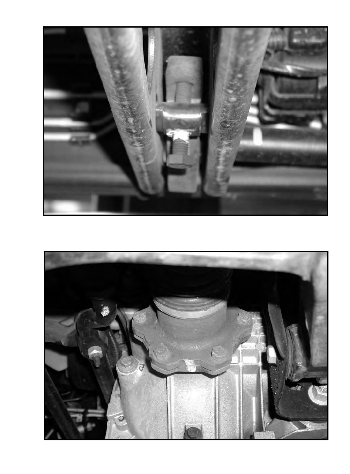
Photo # 1
Photo # 2

Photo # 3
Photo # 4
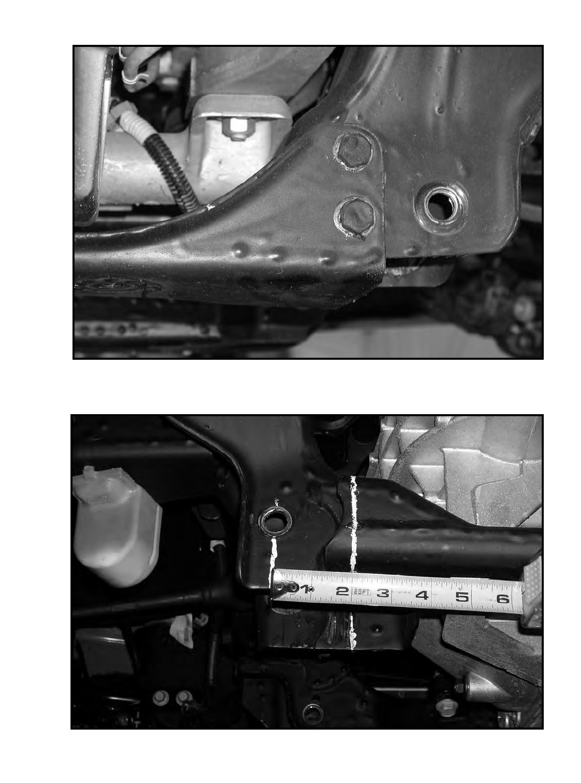
Photo # 5
Photo # 6
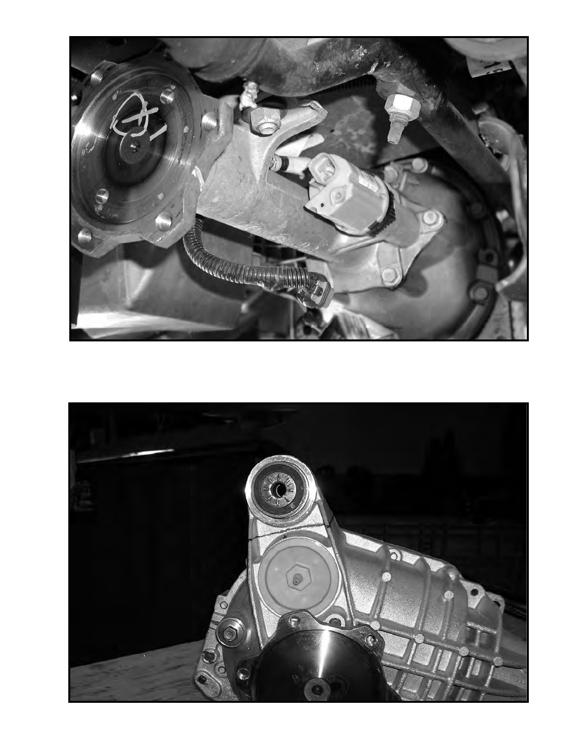
Photo # 7
Photo # 8
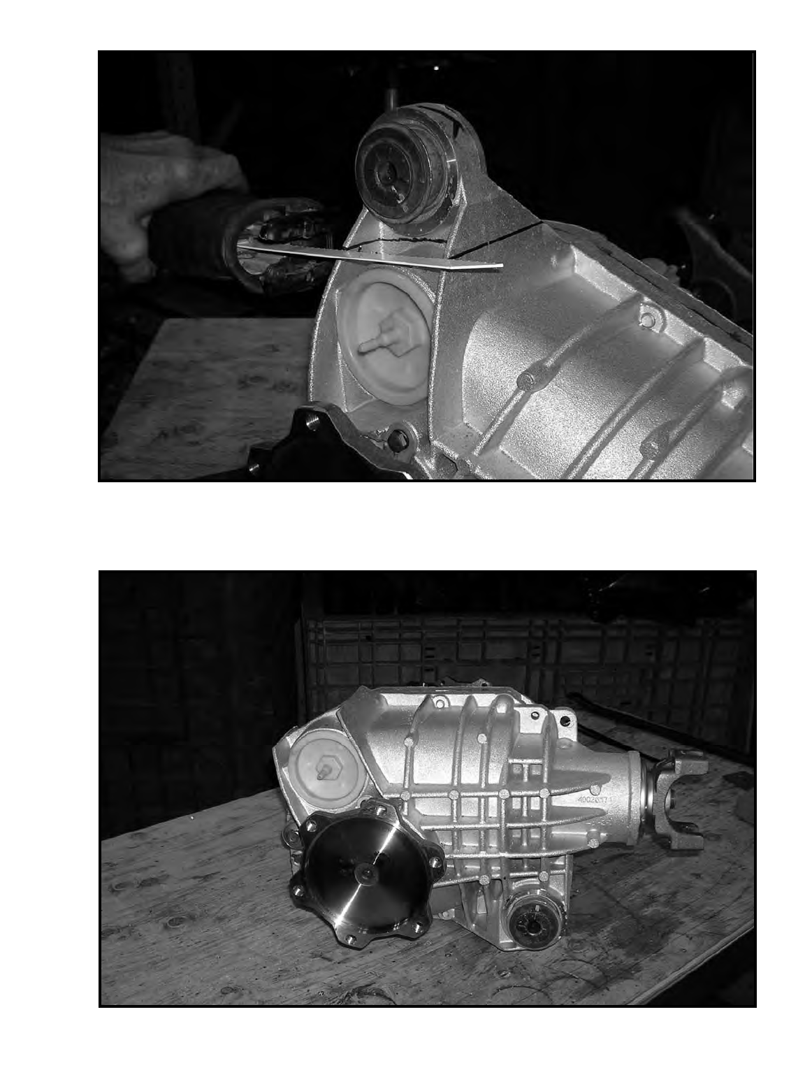
Photo # 9
Photo # 10
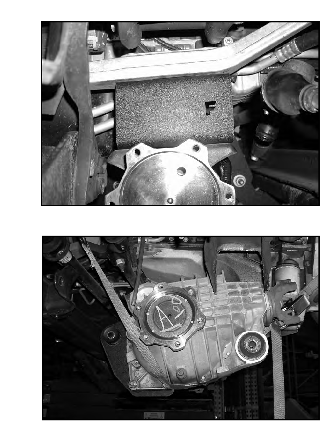
Photo # 11
Photo # 12
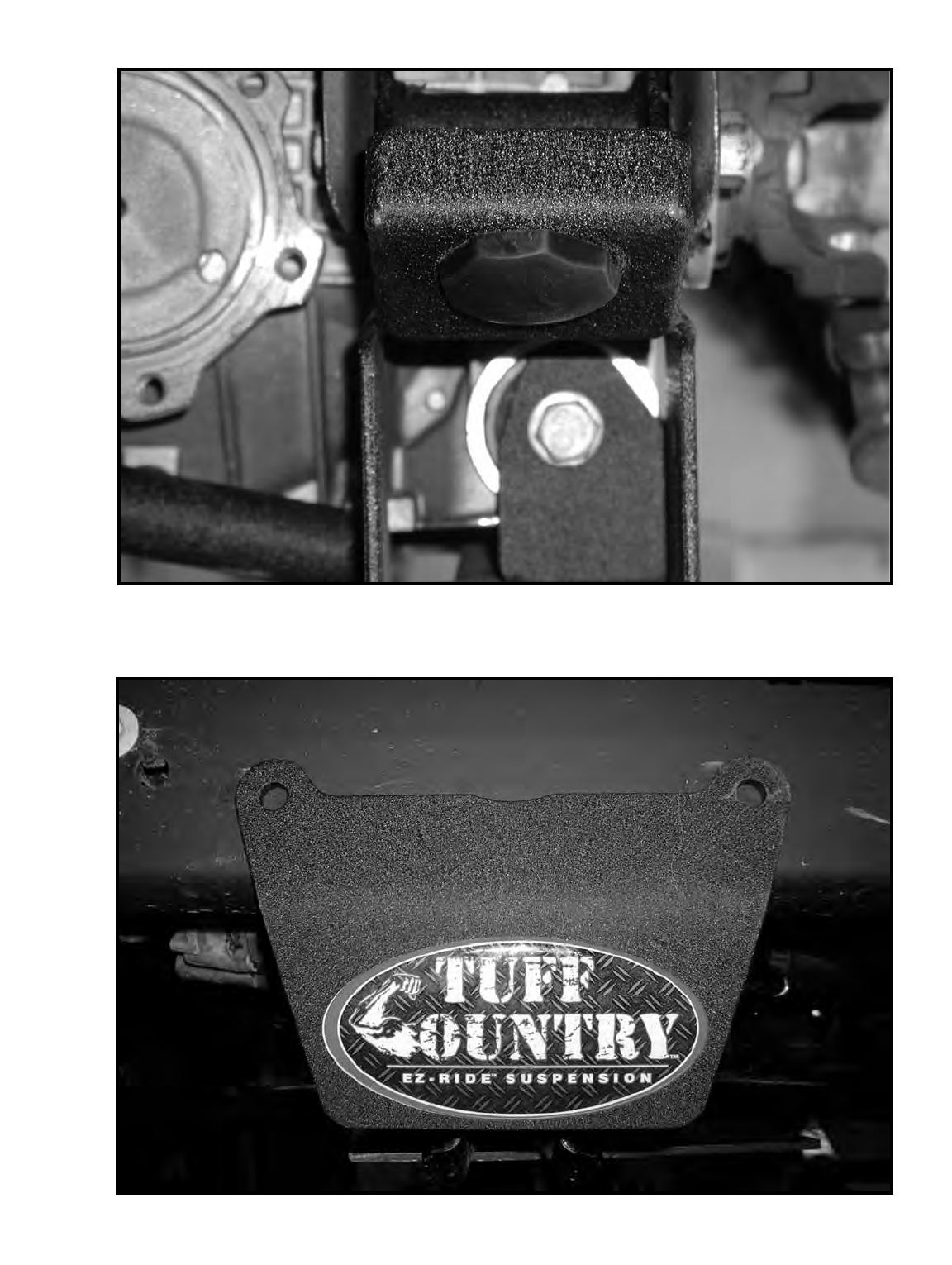
Photo # 13
Photo # 14
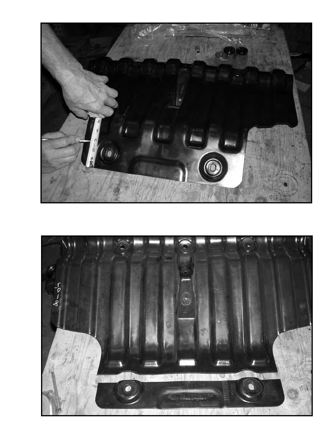
Photo # 15
Photo # 16
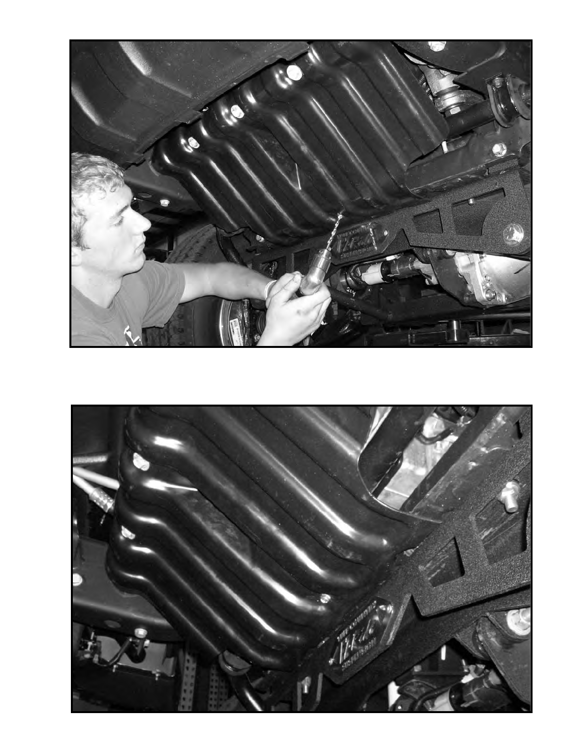
Photo # 17
Photo # 18
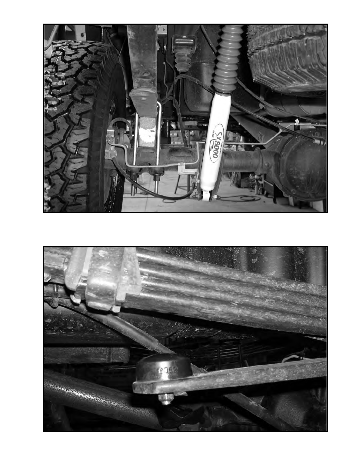
Photo # 19
Photo # 20
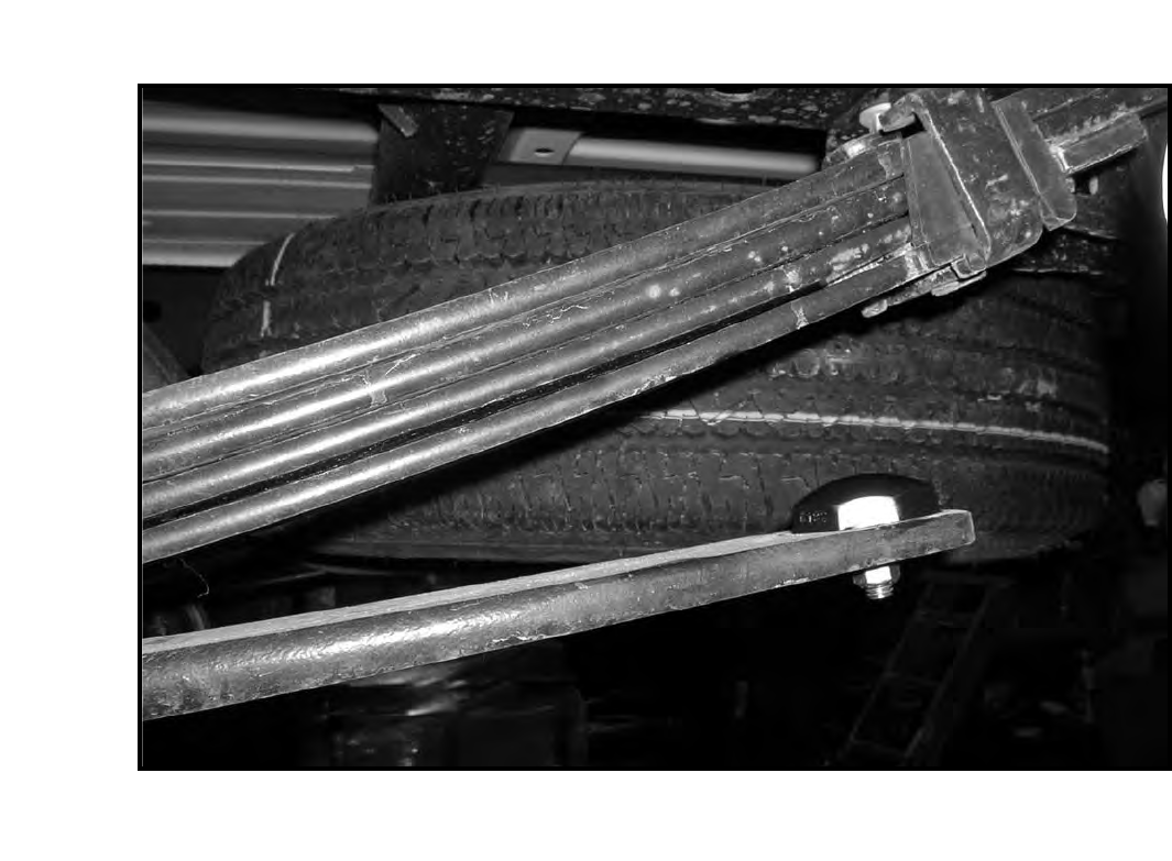
Photo # 21
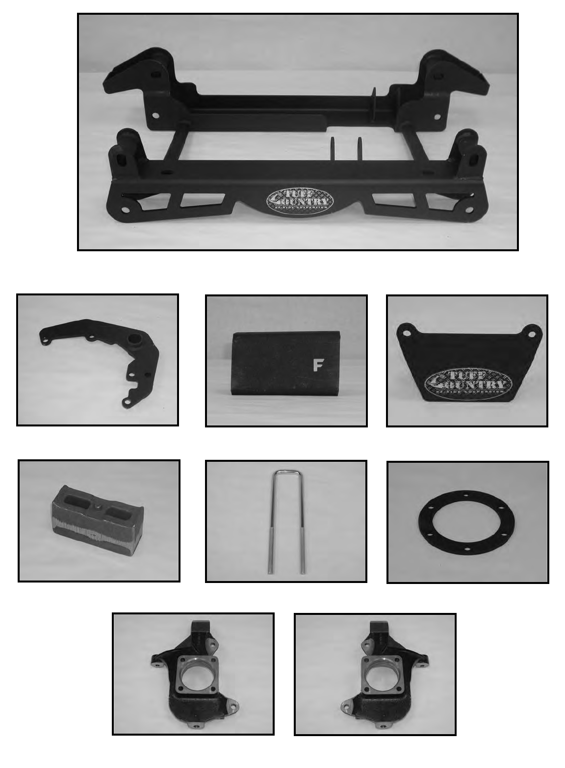
14985-06 / qty. 1
HDDIFF-01 / qty. 1 14985-05 / qty. 1 TBD99-01 / qty. 2
5U-9298S / qty. 4
BL203 / qty. 2
16985-01m / qty. 2 16985-02m / qty. 1
9802 / qty. 2
