UG267: Switched Multiprotocol User’s Guide Ug267 User
ug267-multiprotocol-user-guide
User Manual:
Open the PDF directly: View PDF ![]() .
.
Page Count: 33
- Table of Contents
- 1. Introduction
- 2. Switched Multiprotocol Operation Overview
- 3. Storing Multiple Images
- 4. About the Mailbox
- 5. About the Multiprotocol Stack Interface (MPSI)
- 6. Changing Application Images
- 7. Implementing Switched Multiprotocol
- 7.1 Compiling and Flashing the Gecko Bootloader
- 7.2 Security Features
- 7.3 Build a Multiprotocol Bluetooth Application
- 7.4 Build a Multiprotocol zigbee Application
- 7.5 Load the Main Application Image into Internal Flash
- 7.6 Load the Upgrade Files into Flash
- 7.7 Switching between Zigbee and Bluetooth Applications
- 8. Bluetooth Commissioning Test System

UG267: Switched Multiprotocol User’s
Guide
This user’s guide provides details about the Silicon Labs switch-
ed multiprotocol implementation released in March 2017. Details
on the Multiprotocol Stack Interface (MPSI) are provided, includ-
ing message structure and protocol operation. Data storage is-
sues are reviewed. Finally, a detailed procedure for using the
switched multiprotocol feature is provided.
The multiprotocol implementation relies on the Gecko Bootloader, also introduced in
March 2017. For more information see UG266: Silicon Labs Gecko Bootloader User’s
Guide.
KEY POINTS
• Switched multiprotocol operational
overview
• About the Switched Multiprotocol Stack
Interface (MPSI) communications protocol
and message structure
• Data storage and the mailbox
• Changing application images
• Implementing switched multiprotocol
silabs.com | Building a more connected world. Rev. 0.4

Table of Contents
1. Introduction ................................4
2. Switched Multiprotocol Operation Overview....................5
3. Storing Multiple Images ...........................6
3.1 Internal Storage Configuration ........................6
3.2 SPI-Flash Storage Configuration .......................6
4. About the Mailbox .............................7
5. About the Multiprotocol Stack Interface (MPSI) ..................8
5.1 Summary ...............................8
5.2 End-to-end Messaging ...........................8
5.3 Half-Duplex Single Queue ..........................8
5.4 Message Design .............................9
5.5 Message Support.............................10
5.5.1 Message IDs ............................10
5.5.2 Custom Messages ..........................10
5.5.3 Transaction Paradigm .........................11
5.5.4 Probing Supported Messages ......................11
5.5.5 Unknown Messages in the Mailbox.....................11
6. Changing Application Images ........................12
7. Implementing Switched Multiprotocol .....................13
7.1 Compiling and Flashing the Gecko Bootloader ...................14
7.2 Security Features.............................17
7.2.1 Generating Key Files .........................17
7.2.2 Flashing Keys ............................17
7.2.3 Signing an Image File .........................17
7.2.4 Signing a GBL Upgrade File .......................18
7.3 Build a Multiprotocol Bluetooth Application ....................19
7.4 Build a Multiprotocol zigbee Application .....................20
7.5 Load the Main Application Image into Internal Flash .................20
7.6 Load the Upgrade Files into Flash .......................21
7.6.1 Load the Upgrade Files into External Flash ..................21
7.6.2 Load the Upgrade Files into Internal Flash/Storage ...............21
7.7 Switching between Zigbee and Bluetooth Applications ................22
8. Bluetooth Commissioning Test System ....................24
8.1 Overview ...............................24
8.2 Flashing Applications to Devices .......................26
8.3 Building Host Applications ..........................27
8.4 Running the Test Applications ........................27
silabs.com | Building a more connected world. Rev. 0.4 | 2

8.4.1 Joining Device ...........................27
8.4.2 Trust Center ............................28
8.4.3 Mobile App .............................29
8.5 OTA File Upload .............................30
8.6 Commissioning .............................31
silabs.com | Building a more connected world. Rev. 0.4 | 3
1. Introduction
Multiprotocol devices are capable of running more than one networking protocol. The device can change protocols in different ways, as
described in UG103.16: Multiprotocol Fundamentals. In March 2017 Silicon Labs introduced support for switched multiprotocol on their
Mighty Gecko family of products. In switched multiprotocol, a device running one type of wireless stack/application uses the bootloader
to load and run a different type of wireless stack/application. The focus of this document is on devices operating in SoC (System-on-
Chip) mode, but the concepts apply to NCP (network co-processor) implementations as well.
One of the most common uses for switched multiprotocol devices is where Bluetooth commissioning is used to add devices onto a
mesh network. A device is shipped with a Bluetooth stack and commissioning application active, and also stores a mesh networking
application. The focus of this document is on a Zigbee® implementation.
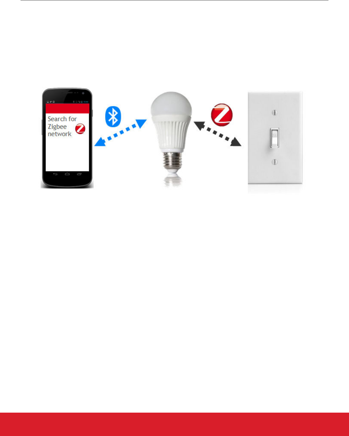
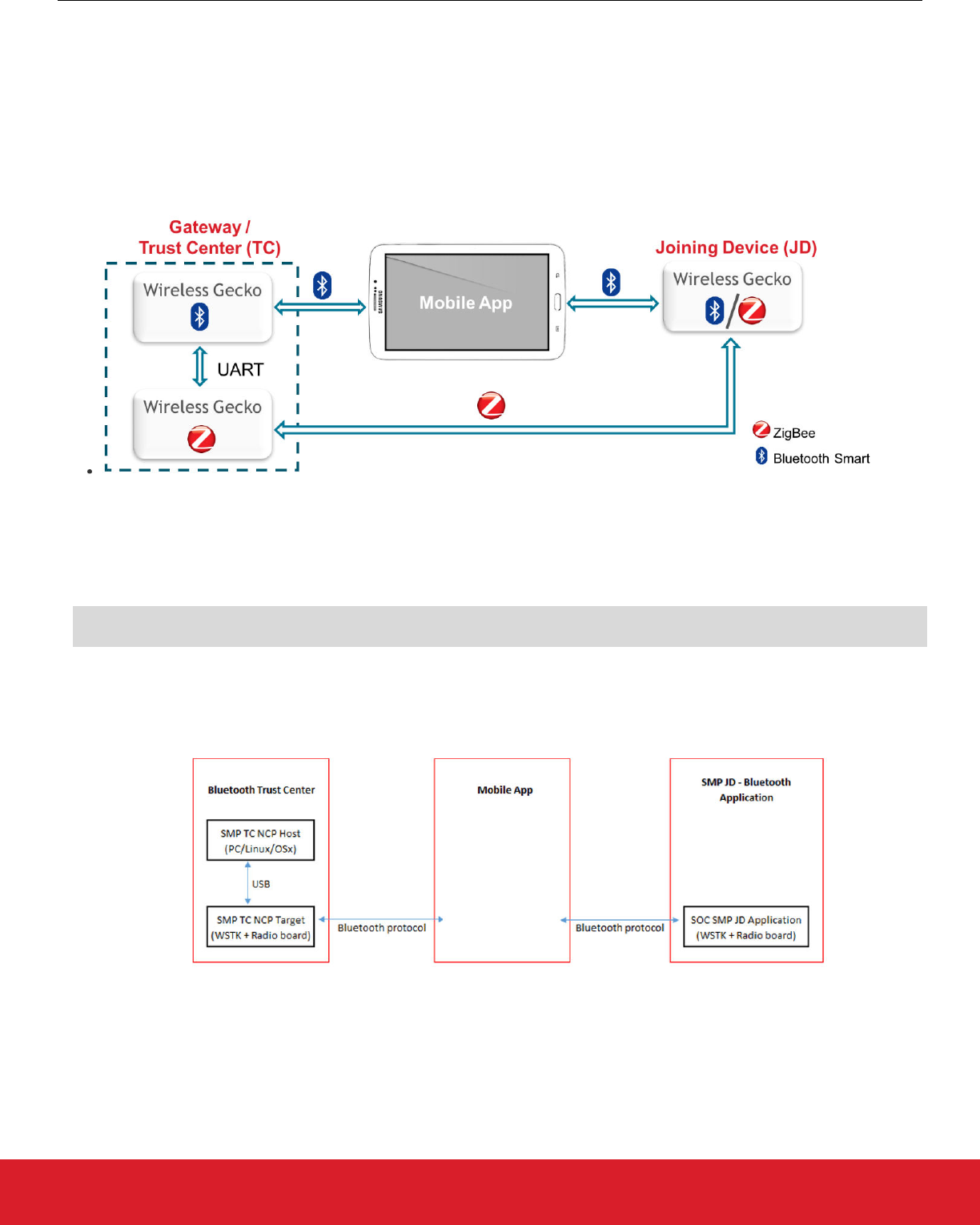
Figure 1.1. Zigbee/Bluetooth Light Example
To install the product:
1. The end user downloads a mobile commissioning application for the product onto a smartphone.
2. The end user then takes the product out of its packaging and powers it up.
3. At startup the product runs a Bluetooth commissioning application.
4. The mobile commissioning application establishes a Bluetooth connection with new product.
5. If new firmware images are available for the target zigbee application, the mobile application can load these onto the device’s flash.
6. When all is complete, the mobile application tells the device to switch to the target zigbee application.
UG267: Switched Multiprotocol User’s Guide
Introduction
silabs.com | Building a more connected world. Rev. 0.4 | 4
2. Switched Multiprotocol Operation Overview
This section provides an overview of the Silicon Labs implementation of a switched multiprotocol device (SMPD), using the Silicon Labs
Bluetooth stack and EmberZNet PRO, the Silicon Labs implementation of a zigbee stack. This implementation is supported by three
technologies:
• The Silicon Labs Gecko Bootloader
• The Multiprotocol Stack Interface (MPSI) communications protocol
• A mobile application
The Gecko Bootloader is a customizable bootloader application framework that supports image acquisition from multiple storage loca-
tions, or slots. For more information on the Gecko Bootloader, see UG266, Using the Silicon Labs Gecko Bootloader. For more informa-
tion about the MPSI see section 5. About the Multiprotocol Stack Interface (MPSI).
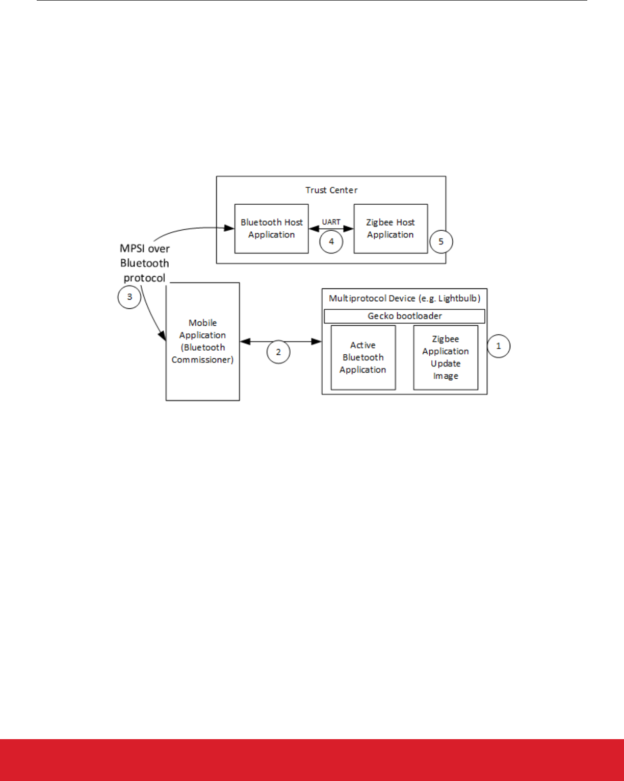
An overview of switched multiprotocol operation is an existing network with a trust center shown in the following figure.
Figure 2.1. Switched Multiprotocol Overview
1. The user powers up the multiprotocol device. The device:
• Boots up into the Bluetooth application.
• Starts advertising.
• Pairs with the Bluetooth commissioner on the mobile device.
2. The Bluetooth commissioner gets an install code and any other information required by the trust center.
3. The Bluetooth commissioner pushes the device’s trust center information to the Bluetooth host application along with the instruc-
tion that a switch is needed.
4. The Bluetooth host application in turn pushes the information to the zigbee host application.
Note: The mobile application and the zigbee host application both incorporate MPSI parsers. Therefore, the Bluetooth host appli-
cation does not need to understand the contents of the MPSI message.
5. The mobile application triggers the multiprotocol device to join to the zigbee network by first sending a message to initiate joining
and second sending a command to initiate boot to zigbee.
UG267: Switched Multiprotocol User’s Guide
Switched Multiprotocol Operation Overview
silabs.com | Building a more connected world. Rev. 0.4 | 5

3. Storing Multiple Images
A switched multiprotocol application uses internal flash or external SPI flash to store upgrade images. The Gecko Bootloader must be
configured correctly to access this storage. An API to access image files to be used in the file update must be included. This API is
based on the concept of storage slots, where each slot has a predefined size and location in memory, and can be used to store a single
upgrade image. The following provides an overview of storage with multiple slots enabled. See UG266: Silicon Labs Gecko Bootloader
User Guide for details.
When multiple storage slots are configured, a bootload list is used to indicate the order in which the bootloader should access slots to
find upgrade images. Before rebooting into the bootloader to initiate a firmware update, the application should write the bootload list by
calling bootloader_setBootloadList. The bootloader attempts to verify the images in these storage slots in sequence, and applies
the first image to pass verification.
3.1 Internal Storage Configuration
When configuring the Gecko Bootloader to obtain images from internal storage, modify the following configuration parameters:
Base address: The address where the bootloader places the bootload list.
The location and size of the storage slots: The addresses are absolute addresses (not offsets from the base address). Enough space
must be reserved between the base address and the first storage slot to fit two copies of the bootload list. These two copies need to
reside on different flash pages, to provide redundancy in case of power loss during writing. Two full flash pages therefore need to be
reserved. The following figure illustrates how the storage area can be partitioned.
Figure 3.1. Internal Storage Area Two-Slot Configurations
3.2 SPI-Flash Storage Configuration
When configuring the Gecko Bootloader to obtain images from SPI flash storage, modify the following configuration parameters.
Base address: The address where the bootloader places the bootload list, if more than one storage slot is configured. Defaults to 0.
The location and size of the storage slots: The addresses are absolute addresses (not offsets from the base address). Enough space to
fit two copies of the bootload list must be reserved between the base address and the first storage slot. These two copies need to re-
side on different flash pages, to provide redundancy in case of power loss during writing. Two full flash pages therefore need to be
reserved. In the default example application, a SPI flash part with 4 kB flash sectors is used. This means that 8 kB must be reserved
before the first storage slot, as shown in the following figure.
Figure 3.2. SPI Flash Storage Area Two-Slot Configuration
UG267: Switched Multiprotocol User’s Guide
Storing Multiple Images
silabs.com | Building a more connected world. Rev. 0.4 | 6

4. About the Mailbox
The mailbox is a location in memory where MPSI messages are stored. This is only applicable for a switched SoC device, where only
one application can run at a time. The intent is that a running Bluetooth application can store commissioning MPSI messages destined
for another application that is about to be booted.
The mailbox itself lives in PS Store. PS Store is a utility for saving information in persistent storage. Physically, it resides in main flash.
When written into PS Store, an MPSI message is encapsulated into a PS Store entry. The PS Store entry format is shown in the follow-
ing table.
Table 4.1. PS Store Entry Format
Tag Field Length Data
2 bytes 1 byte 1 byte Length bytes
An MPSI message is identified as having a tag between 0x3000 and 0x3FFF. As such the mailbox can theoretically fit 4096 (0x1000)
messages between boots, but the PS Store limits this to a smaller number.
The ‘field’ field can be ignored, while the ‘length’ field is determined by the size of the MPSI message. The ‘data’ array contains the
MPSI message serialized into a byte array. The serialization order of MPSI messages is LSB (Least Significant Byte) first.
Silicon Labs provides the MPSI Storage plugin that handles storing and reading MPSI messages in the mailbox. Messages are written
to the mailbox on demand. However, messages are only read and processed from the mailbox once during system initialization. When
an application first boots, it checks for any MPSI messages in the mailbox. If all messages are supported by the running application,
then the messages are all processed. If any message is not supported (either it is not meant for the running application or the message
ID is not understood), then all messages in the mailbox are discarded. This default behavior can be changed to fit a project’s needs.
UG267: Switched Multiprotocol User’s Guide
About the Mailbox
silabs.com | Building a more connected world. Rev. 0.4 | 7
5. About the Multiprotocol Stack Interface (MPSI)
5.1 Summary
The MPSI provides a common protocol to communicate to any Silicon Labs stack. MPSI messages may be commands, configuration
items, queries, or customer-designed request/responses. To support switched multiprotocol, MPSI implements a mailbox style design
with persistent storage, as the device will be rebooting and bootloading when switching application. See section 4. About the Mailbox
for more information about the mailbox design.
5.2 End-to-end Messaging
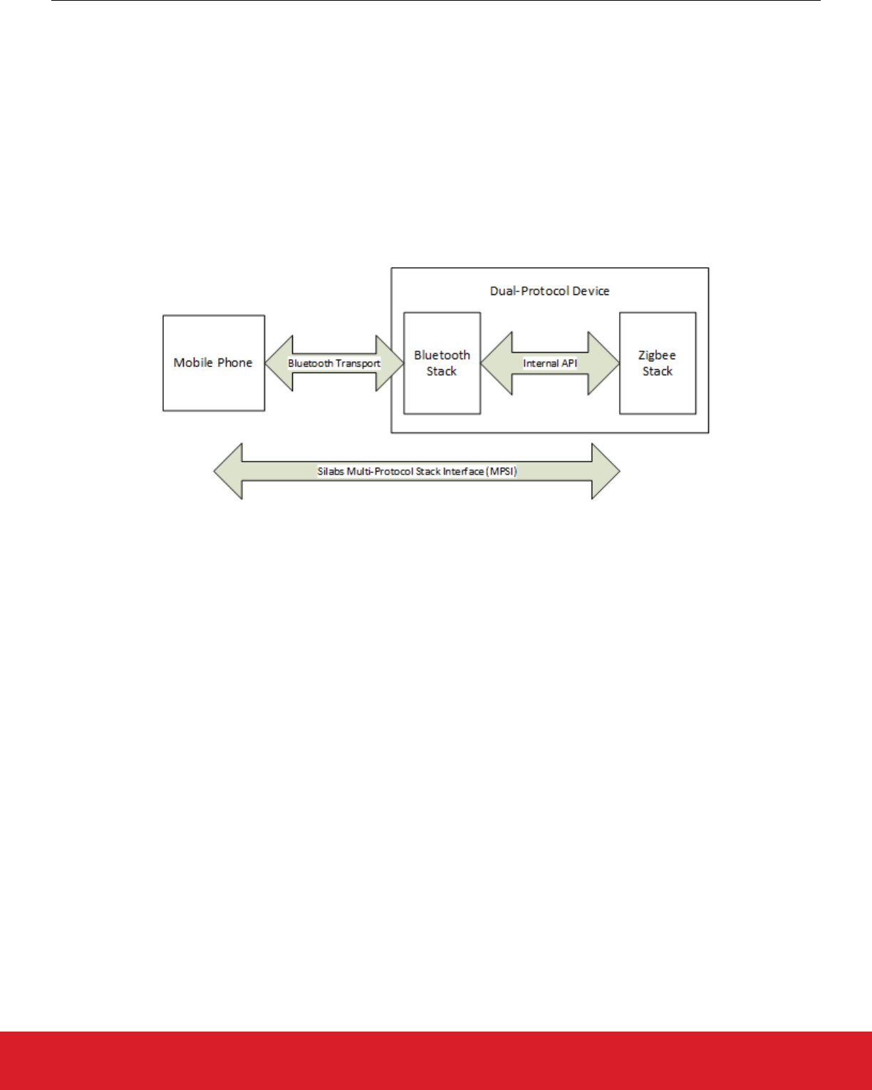
MPSI can send messages from a remote device to a Silicon Labs multiprotocol device. In the following figure the Mobile Phone is run-
ning the MPSI protocol and will transmit messages ultimately bound for the zigbee application. In this case the Bluetooth wireless proto-
col is just a transport for shipping those messages. The Bluetooth stack can also support the protocol for receiving MPSI messages
from a co-located stack or from a remote device.
Figure 5.1. MPSI Implementation
5.3 Half-Duplex Single Queue
In the switched multiprotocol implementation, a single, half-duplex queue passes messages between stacks. Since only one application
can run at a time, there is no need to store multiple messages for different stacks. When a running application (application A) wants to
send messages to a different application (application B), the existing queue must be empty. Application A writes one or more messages
into that queue and then triggers a reboot and bootload into Application B. Application B is responsible for draining the queue complete-
ly after reboot, which involves erasing the area of persistent storage that was used. The entire set of messages is treated as a single
transaction, where Application B will does everything possible to execute the complete set. If one of the steps cannot be executed then
Application B aborts running any of them (if possible). For more on failure processing see section 5.5 Message Support. For an exam-
ple flow, see section 6. Changing Application Images.
UG267: Switched Multiprotocol User’s Guide
About the Multiprotocol Stack Interface (MPSI)
silabs.com | Building a more connected world. Rev. 0.4 | 8

5.4 Message Design
The following table illustrates MPSI message design. A more detailed description of each field follows.
Table 5.1. MPSI Message Design
Field Size Description Values
destinationAppId 1 byte
[uint8]
Specifies which image the messages are intended for. 0x00: None
0x01: Mobile Application
0x02: Zigbee
0x03: Thread
0x04: Connect
0x05: Bluetooth
0x06: MCU
0xFF: Any application
messageId 2 bytes
[uint16]
Message identifier. The most significant bit indicates whether the
message is a custom message or not.
See the table in section 5.5.1 Mes-
sage IDs
payload Variable
[array]
Contains information pertinent to message. Message-specific; see individual
messages in the table in section
5.5.1 Message IDs
payloadLength 1 byte
[uint8]
Specifies number of bytes contained in payload field. 0-255
destinationAppId field
This field specifies which image the message is intended for. If the field matches the currently running image, then the message can be
processed. If the field indicates it is for an application that is not currently active, then the system may store it in the mailbox and boot
into that application at a later point.
messageId field
This field contains a range of values, where 0-32767 are predefined (non-custom) messages and 32768-65535 are custom messages.
Some of the predefined message values are provided in section 5.5.1 Message IDs.
payload
This field specifies the additional parameters that go in hand with the message ID. Some messages do not have options and have no
payload. All integers are transmitted in LSB order.
payloadLength
This field specifies the length of the payload associated with the message ID.
UG267: Switched Multiprotocol User’s Guide
About the Multiprotocol Stack Interface (MPSI)
silabs.com | Building a more connected world. Rev. 0.4 | 9

5.5 Message Support
5.5.1 Message IDs
The following table lists some message IDs along with their origin and description. For up-to-date information refer to the latest SDK
installation.
Table 5.2. Message IDs
MessageId Name Origin Destination Description
0 Get Applications
Info
Mobile App Any App Requests information for all applications on the remote device.
1 Applications Info Any App Mobile App Returns application information such as the slot ID and applica-
tion ID for both the the running application and those in storage.
The first entry in this payload is the currently running image,
identified by a slot ID of 0xFF.
2 Bootload Slot Mobile App Any App Triggers the device to bootload the application in the passed slot
ID.
3 Error Bluetooth JD
and Any TC
App
Mobile App Sent to the mobile app to indicate an error at the MPSI layer.
4 Initiate Joining Any App Any App except
Mobile App
Triggers an attempt to join a network with current parameters.
For Bluetooth, this is interpreted as ‘send Bluetooth advertise-
ments for up to the amount of minutes specified by the Option
parameter and wait for Bluetooth pairing’.
5 Get zigbee Join-
ing Device Info
Mobile App Bluetooth App Requests the device EUI and installation code for joining the zig-
bee device to a network.
6 zigbee Joining
Device Info
Bluetooth App Mobile App Returns the EUI and installation code for the zigbee joining de-
vice.
7 Set zigbee Join-
ing Device Info
Mobile App zigbee App
(Trust Center)
Converts an install code to link key and adds to the Trust Cen-
ter's local link key table.
8 Get zigbee Trust
Center Joining
Credentials
Mobile App zigbee App
(Trust Center)
A command sent to request the zigbee network parameters and
open the network for joining. The parameters returned can be
used by a joining device to join the zigbee network.
On the Trust Center, this command generates a random key and
sets it into the transient key table paired with a wildcard EUI64.
This key, along with the channel mask and extended PAN ID,
are passed along in the response to this message. The network
is then opened for joining for 5 minutes.
9 zigbee Trust
Center Joining
Credentials
zigbee App
(Trust Center)
Mobile App The channel mask, extended PAN ID, and link key that are used
to join the zigbee network.
10 Set zigbee Trust
Center Joining
Credentials
Mobile App zigbee App
(Joining Device)
Connect to a zigbee network on the channel mask specified that
matches the extended PAN specified using the link key speci-
fied.
5.5.2 Custom Messages
Support for adding custom messages is integrated into Simplicity Studio.
UG267: Switched Multiprotocol User’s Guide
About the Multiprotocol Stack Interface (MPSI)
silabs.com | Building a more connected world. Rev. 0.4 | 10

5.5.3 Transaction Paradigm
The application attempts to treat all messages in the mailbox as a single transaction to perform.
Before taking action on any messages, an application verifies that all messages are known to the device and that it has necessary
resources to take the action. For example, if the message indicates that the device should add a link key and also add a binding then
the application checks that there are enough free entries for both of these before executing the action.
5.5.4 Probing Supported Messages
MPSI allows an application to probe what messages another application understands. This is especially important in the switched use
case because the cost of switching is high.
Each application records the version number of the MPSI protocol that it understands and this can be retrieved regardless of whether
the application is running or not. With this information the sender of the MPSI message can reasonably be assured it will be understood
by the target device.
5.5.5 Unknown Messages in the Mailbox
Normally, the running application should not send unsupported messages to another partner application. However if an unknown com-
mand is found in the queue and the partner application needs to inform the first application it can do the following.
• Add an error indicator into the mailbox. This indicator specifies the first unknown message.
• Reboot and bootload back into the other application.
UG267: Switched Multiprotocol User’s Guide
About the Multiprotocol Stack Interface (MPSI)
silabs.com | Building a more connected world. Rev. 0.4 | 11
6. Changing Application Images
Switched multiprotocol makes it possible to update the application code in the flash while running another application. For example, the
zigbee application can be updated while the Bluetooth application is running.
There are two ways to update an application image: either using the Gecko Bootloader or using a custom application implementing
application image upload. For example, the Switched Multiprotocol Joining Device Bluetooth application provided with the Silicon Labs
Bluetooth SDK implements this feature along with MPSI support. By flashing this application into the device, you will be able to update
application images in the external flash memory, and then reboot the device from the updates memory slot.
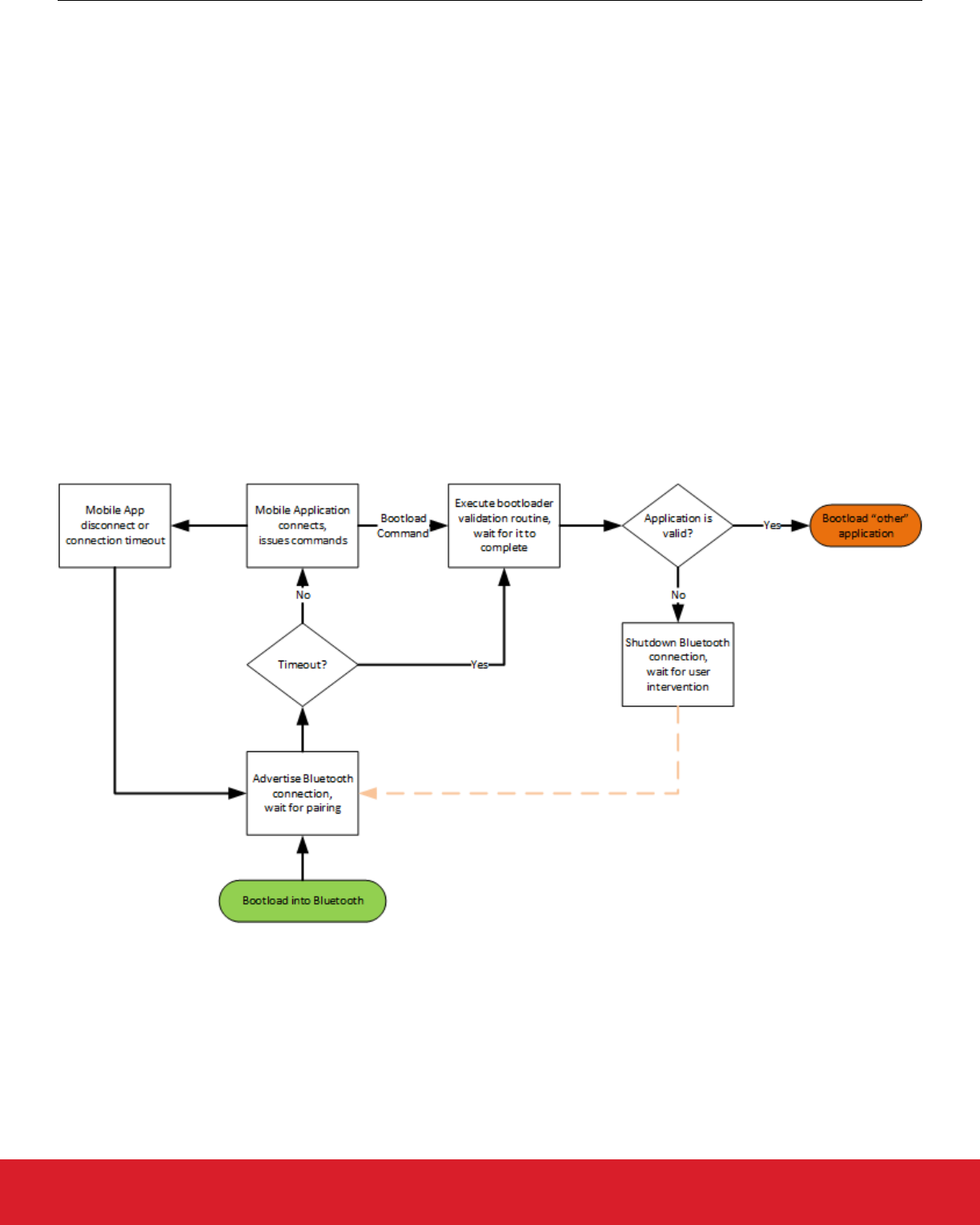
The application is updated as follows:
1. The zigbee application is running in a Switch Multiprotocol Device (SMPD). Through some stimulus, it decides to switch to the
Bluetooth application.
2. The Bluetooth application advertises it is connectable. The mobile application connects to the SMPD.
3. The mobile application queries the SMPD for the application operating in the "other" (non-Bluetooth) slot using MPSI.
4. The application issues a command to update the slot.
5. The mobile application ships blocks of the image to the Bluetooth application to write to flash. This is very similar to the Bluetooth
OTA DFU (see AN1045: Bluetooth Over-the-Air Device Firmware Update for EFR32xG1 and BGM11x Series Products) with the
difference that the application is written to another slot, and it does not overwrite itself.
6. The application verifies that the image is from a trusted source. See UG266: Silicon Labs Gecko Bootloader User’s Guide for more
information on verification procedures.
7. The application issues a command to reboot from the other slot.
8. The updated zigbee application is running.
The following diagram shows the flow of the Bluetooth application:
Figure 6.1. Bluetooth Application Flow
A potential security issue is that a malicious mobile application can connect to the device before the trusted one. In this case, the zig-
bee application can be overwritten by the malicious device. Although the new application will not be accepted as valid due to the false
signature, the old application will be lost. In order to prevent such scenario, the provided example does not use the Bluetooth just-works
pairing mechanism, but instead uses a passkey compare mechanism.
UG267: Switched Multiprotocol User’s Guide
Changing Application Images
silabs.com | Building a more connected world. Rev. 0.4 | 12

7. Implementing Switched Multiprotocol
To program a multiprotocol device you need at least three steps:
• Programming the bootloader
• Uploading the image of the first application (for example, the Bluetooth application)
• Uploading the image of the second application (for example, the zigbee application)
The bootloader can be programmed only by flashing the device. The first application can either be flashed to the device or be uploaded
by the bootloader. The second application can either be flashed to the device, be uploaded by the bootloader, or be uploaded by the
first application as discussed in section 6. Changing Application Images.
Before uploading images, the images can also be signed (except the main bootloader image) in order to protect the device from mali-
cious software. Signing ensures that the image is from a trusted source.
This section provides a step-by-step guide to building and flashing a Gecko Bootloader, generating security keys, packaging, signing
the application image, and loading the various required pieces to bootload an image from external flash. Finally, this section describes a
scenario to switch between zigbee and Bluetooth applications using the Gecko Bootloader.
The procedures assume that you have a Wireless Start Kit (WSTK) with 4151A board header and you have installed the following:
• Simplicity Studio v4.11 or later
• Silicon Labs EmberZNet PRO stack v5.9 or higher
• Silicon Labs Bluetooth stack v2.3 or higher
• IAR Workbench 7.80.2 (this version is required for Silicon Labs stacks)
UG267: Switched Multiprotocol User’s Guide
Implementing Switched Multiprotocol
silabs.com | Building a more connected world. Rev. 0.4 | 13
7.1 Compiling and Flashing the Gecko Bootloader
The Gecko Bootloader can be configured in a number of ways in order to enable different functions, such as:
• Legacy or secure booting
• Updating applications by UART or OTA
• Loading applications into external or internal flash
• Using XMODEM or BGAPI protocol
In the following example an SPI Flash Storage Bootloader is used, which makes it possible to upload application images (received
OTA) into the external SPI flash. Use a radio board with SPI flash for testing. In this example a BRD4151A board is used. For more
details about Gecko Bootloader configurations please refer to UG266, Silicon Labs Gecko Bootloader User’s Guide. The Gecko Boot-
loader is provided both in the Bluetooth SDK v2.3 and in the EmberZNet SDK v5.9.
To create a new bootloader project:
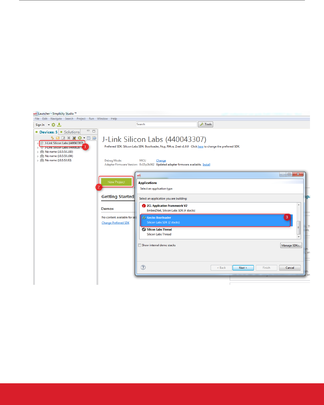
1. Open Simplicity Studio and click your device in the Devices tab to select it.
2. Click [New Project].
3. Select the Gecko Bootloader application. Click [Next].
4. In the next dialog select any of the stacks (Bluetooth / ZNet). The selection does not affect a Gecko Bootloader configuration. Click
[Next].
5. Select the ‘SPI Flash Storage Bootloader (multiple images)’ example. Click [Next], then [Next] again, then [Finish]. The Simplicity
IDE perspective opoens, with the project’s General tab selected.
UG267: Switched Multiprotocol User’s Guide
Implementing Switched Multiprotocol
silabs.com | Building a more connected world. Rev. 0.4 | 14
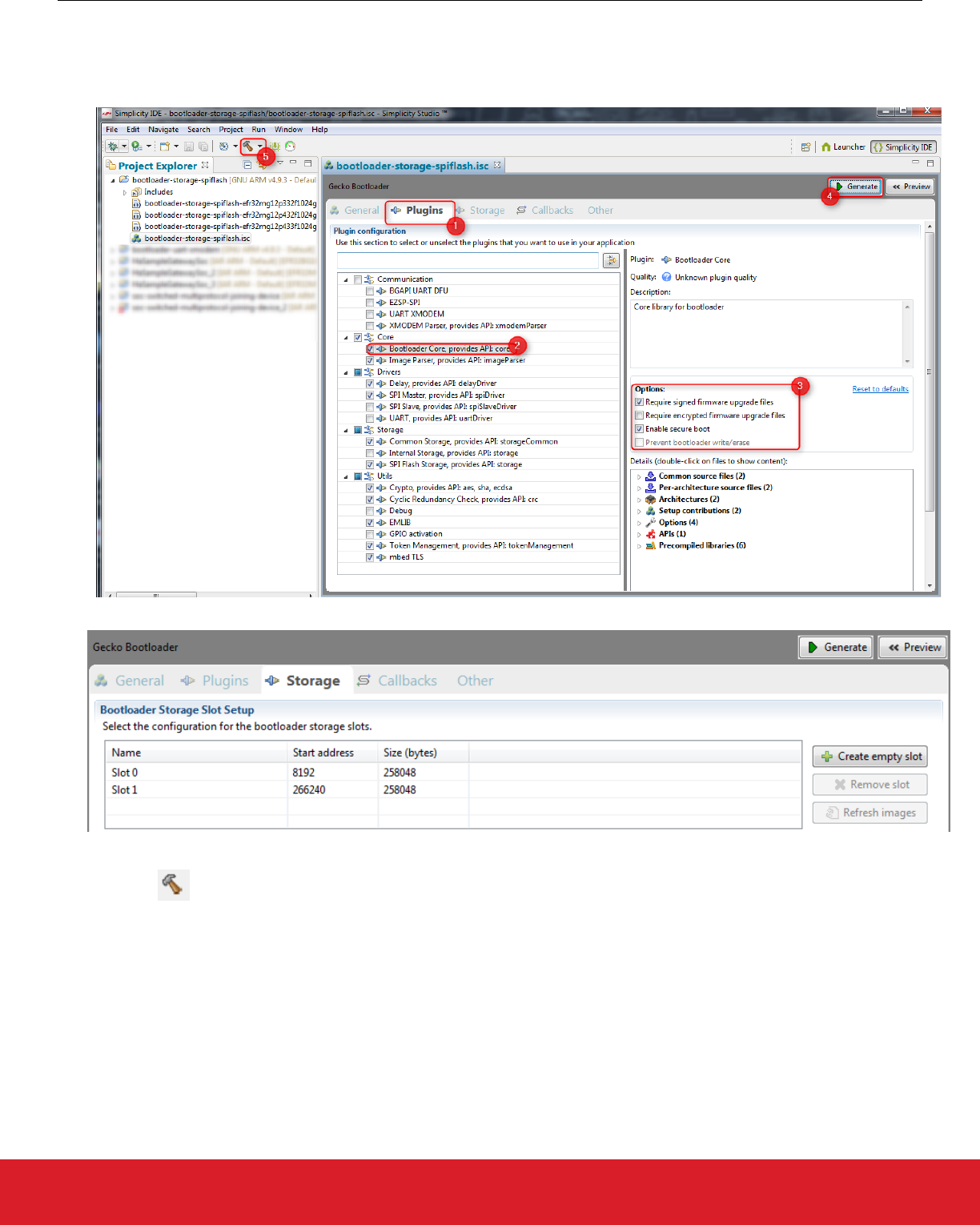
To configure the Gecko Bootloader:
1. Click the Plugins tab.
2. Click Bootloader Core.
3. Check basic settings such as Secure Boot.
Click the Storage tab to check the slots prepared for application images. By default two slots of 252 kB each are available.
4. Click [Generate] to generate the bootloader project.
5. Click Build to build the project.
The build results in a number of output files. The most important ones are ‘bootloader-storage-spiflash.s37’ and ‘bootloader-storage-
spiflash-combined.s37’. The first includes the main bootloader only. The second contains both the first stage bootloader and the main
bootloader. The first time you flash new bootloader firmware to a device in a development or manufacturing scenario, you should use
the second, combined file. The main-stage-only firmware is provided for upgrade purposes on devices already loaded with a prior build
of the Gecko Bootloader.
To flash .s37 files to the device you can use the Flash Programmer tool in Simplicity Studio or you can use Simplicity Commander
version 0v21 or later.
UG267: Switched Multiprotocol User’s Guide
Implementing Switched Multiprotocol
silabs.com | Building a more connected world. Rev. 0.4 | 15
To start the Flash Programmer in Simplicity Studio
1. Start Simplicity Studio and select your device in the Devices tab.
2. Click the Compatible Tools tab.
3. Click Flash Programmer.
Alternatively you can click the Flash Programmer button in the Simplicity IDE perspective.
Browse for the .s37 file to be uploaded and click Program.
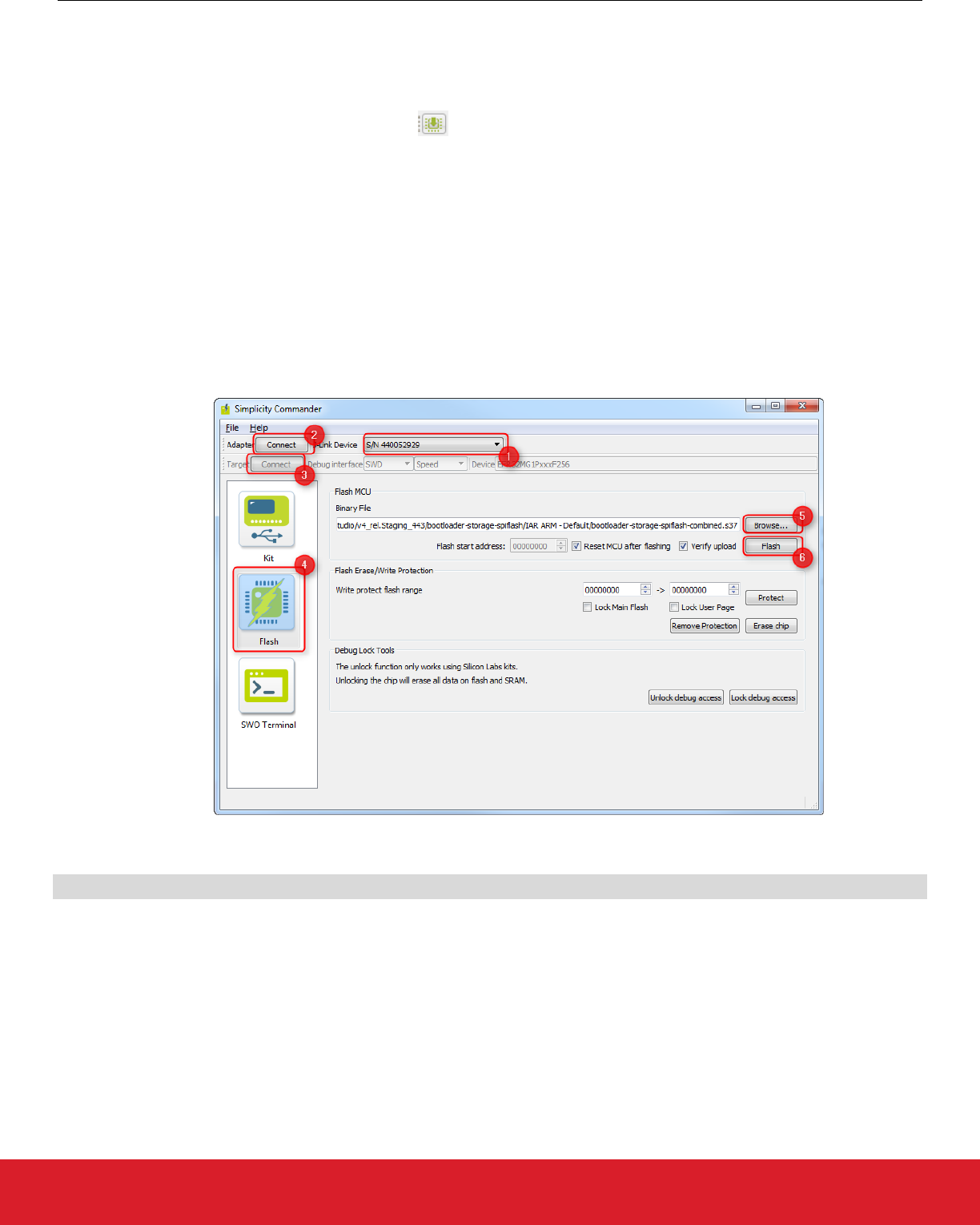
To flash the device with Simplicity Commander start it from
$SIMPLICITY_STUDIO/v4/developer/adapter_packs/commander/.
On the Simplicity Commander GUI
1. Select the J-Link adapter to be used.
2. Connect to the adapter.
3. Connect to the target device.
4. Select the Flash tab.
5. Browse for the .37 file to be uploaded.
6. Click [Flash].
Alternatively use the Simplicity Commander CLI to flash the device in the following form
commander flash -s <J-link serial no.> bootloader-storage-spiflash-combined.s37
Refer to UG162: Simplicity Commander Reference Guide for more information about Simplicity Commander CLI commands.
UG267: Switched Multiprotocol User’s Guide
Implementing Switched Multiprotocol
silabs.com | Building a more connected world. Rev. 0.4 | 16

7.2 Security Features
The Gecko Bootloader has three security feature:
• Authenticated upgrade file
• Encrypted upgrade file
• Secure Boot
Upgrade files are in a custom GBL (Gecko Bootloader) format. An authenticated upgrade file means that an electronic signature is at-
tached to the GBL file. The signature is produced with a public-private key pair. The public key is stored in the device, while the private
key is kept secret by the manufacturer. The signature ensures that the upgrade file is from a trusted source.
An encrypted upgrade file means that the content of the GBL file is encrypted to protect against eavesdroppers.
Secure Boot means that a signature is attached to the bootloader image (.s37). Note that this differs from signing the GBL file, as a
GBL upgrade file is a packed version of the image files. A signed image file ensures that the image was not modified, and that it is from
a trusted source. This is checked at every boot.
In this multiprotocol example we use authenticated upgrade files and Secure Boot, and we show how to sign an .s37 image file and
how to sign a GBL upgrade file. Note that the default configurations of the example applications in the SDK do not have security fea-
tures enabled. For more information on security refer to UG266: Silicon Labs Gecko Bootloader User’s Guide.
7.2.1 Generating Key Files
For switched multiprotocol with the Gecko Bootloader, it is recommended to sign the images to be uploaded to the device. For this, you
need an ECC key pair in PEM format and a public key token file generated as a by-product.
You need Simplicity Commander 0v21 or later to implement this procedure. The gbl keygen command with the type option "ecc-p256"
can be used to generate an ECC key pair in PEM format. The following command creates the ECC key pair and also generates the text
file with which the public key can be written to the appropriate address in the flash.
commander gbl keygen --type ecc-p256 --outfile signing-key.pem
This creates three files: signing-key.pem, signing-key.pem.pub, and signing-key.pem-token.txt.
7.2.2 Flashing Keys
To validate the signature of signed images the bootloader has to be aware of the public key. The private key has to be kept secret by
the company for signing. In order to let the bootloader know the public key, it must be written into the flash memory. We use the token
system for this purpose. The public key is flashed into a predefined token known by the bootloader.
To flash the public key, use the following Simplicity Commander command:
commander flash --tokenfile signing-key.pem-tokens.txt --tokengroup znet -d EFR32F256
The last parameter describes the device family (based on flash size).
7.2.3 Signing an Image File
When a Bluetooth or zigbee project is built, the image file is generated in different formats (.out, .hex, .bin, .s37). In the multiprotocol
environment the .s37 format is used. To sign an image file you can use Simplicity Commander’s convert command:
commander convert --secureboot --keyfile signing-key.pem original_project_name.s37 --outfile signed_project_nam
e.s37
This image can then be flashed to the device using
commander flash -s <J-link serial no.> signed_project_name.s37
If the bootloader is configured with the Secure Boot option, then only signed images will be executed! If Secure Boot is disabled in the
bootloader, you can use unsigned images.
UG267: Switched Multiprotocol User’s Guide
Implementing Switched Multiprotocol
silabs.com | Building a more connected world. Rev. 0.4 | 17

7.2.4 Signing a GBL Upgrade File
If the application will not be flashed directly to the device, a GBL upgrade file must be generated. This upgrade file is then sent to the
bootloader, which either parses the image file from the GBL file and writes the image file into the flash for executing, or stores the GBL
file for later use. The upgrade file can be sent to the bootloader in many different ways, depending on the bootloader configuration:
• Via UART
• Over-The-Air
• From external flash
A signed upgrade file can be created and signed using Simplicity Commander’s gbl create command:
commander gbl create signed_GBL_name.gbl --app original_project_name.s37 --sign signing-key.pem
--encrypt encryption-key
This single command performs three actions:
• Creates a GBL file
• Encrypts the GBL file
• Signs the GBL file
If Secure Boot is also desired, the application must be signed using commander convert –-secureboot prior to creating the GBL.
UG267: Switched Multiprotocol User’s Guide
Implementing Switched Multiprotocol
silabs.com | Building a more connected world. Rev. 0.4 | 18
7.3 Build a Multiprotocol Bluetooth Application
These instructions assume you have Simplicity Studio and the Bluetooth stack version 2.3 or higher installed. To build a multiprotocol
Bluetooth example:
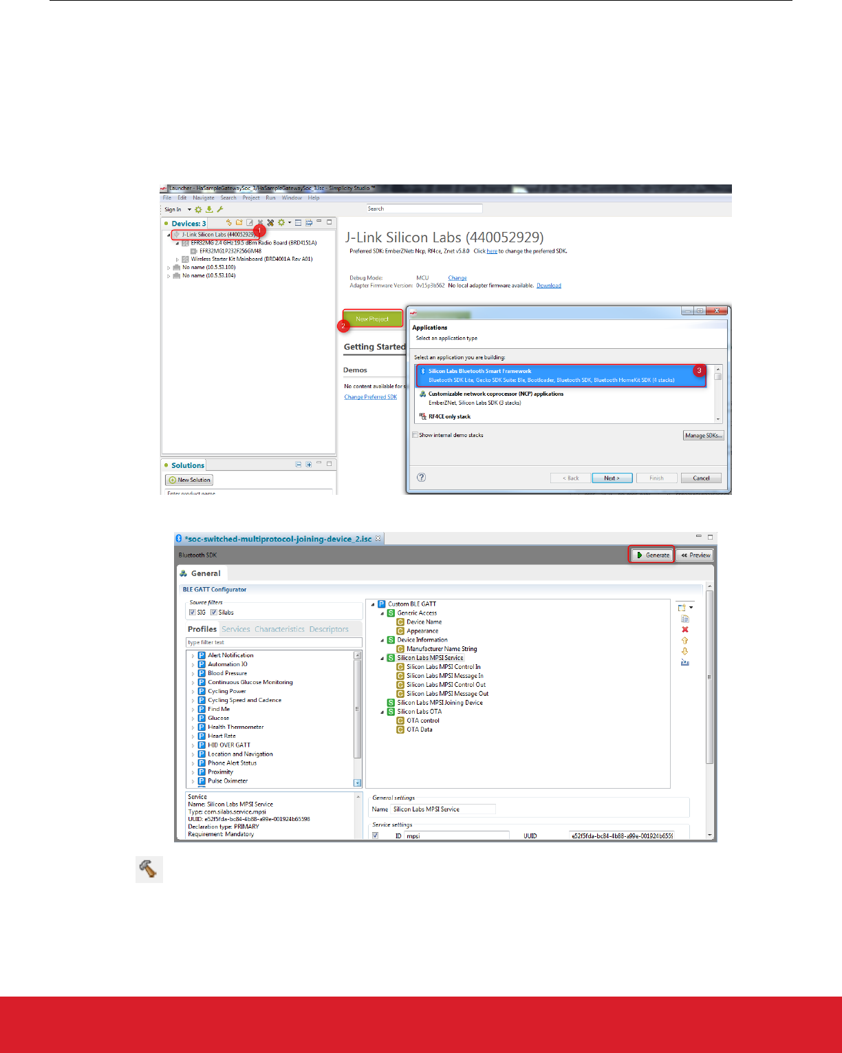
1. Open Simplicity Studio 4 and click your device in the Devices tab.
2. Click [New Project].
3. Select “Silicon Labs Bluetooth Smart Framework”. Click [Next].
4. Select the latest Bluetooth SDK version. Click [Next].
5. Select the “SOC – Switched Multiprotocol Joining Device” application from list of example applications. Click [Next], then [Next],
and then [Finish]. The Simplicity IDE perspective opens.
6. Click [Generate] to generate the Bluetooth project.
7. Click Build to build the project.
UG267: Switched Multiprotocol User’s Guide
Implementing Switched Multiprotocol
silabs.com | Building a more connected world. Rev. 0.4 | 19
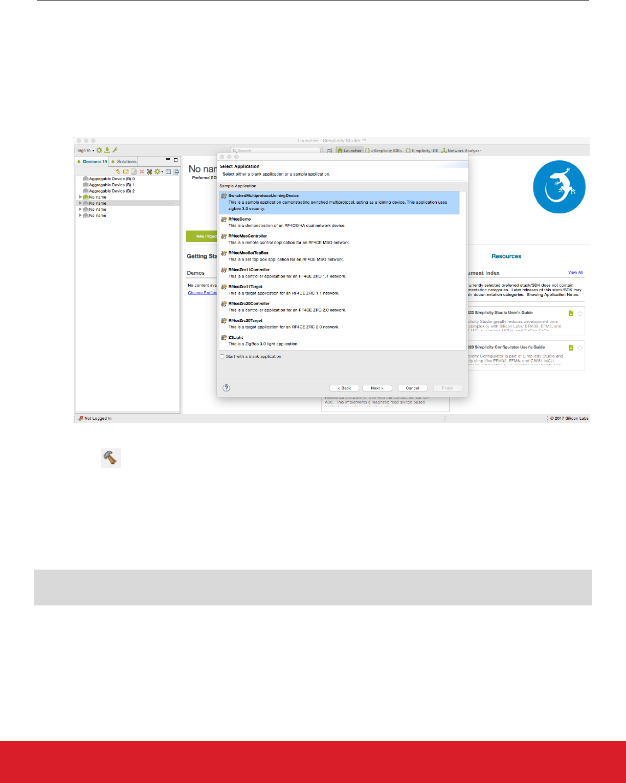
7.4 Build a Multiprotocol zigbee Application
These instructions assume you have Simplicity Studio and the EmberZNet PRO stack version 5.9 or higher installed. To build a multi-
protocol zigbee example follow these steps:
1. Open Simplicity Studio 4 and click your device in the Devices tab.
2. Click [New Project].
3. Select ‘ZCL application Framework V2’. Click [Next].
4. Select the appropriate EmberZNet PRO stack for the SoC application and click [Next].
5. Select the “SwitchedMultiprotocolJoiningDevice” application from the list of example applications. Click [Next], then [Next], and
then [Finish].
6. The Simplicity IDE perspective opens. Click [Generate] to generate the zigbee SwitchedMultiprotocolJoiningDevice project.
7. Click Build to build the project.
7.5 Load the Main Application Image into Internal Flash
The application loaded into the internal flash will be the primary one executed by the bootloader, after verifying its signature. This appli-
cation has to be flashed in .s37 format in order to be immediately executable. If Secure Boot was enabled in the bootloader the .s37 file
has to be signed, too. The signing and flashing process is described in section 7.2.3 Signing an Image File.
Assume the zigbee application is the primary one. Sign and upload the .s37 file with the following commands:
commander convert --secureboot --keyfile signing-key.pem SwitchedMultiprotocolJoiningDeviceSoc.s37 --outfile si
gned_SwitchedMultiprotocolJoiningDeviceSoc.s37
commander flash -s <J-link serial no.> signed_SwitchedMultiprotocolJoiningDeviceSoc.s37
UG267: Switched Multiprotocol User’s Guide
Implementing Switched Multiprotocol
silabs.com | Building a more connected world. Rev. 0.4 | 20

7.6 Load the Upgrade Files into Flash
Switched multiprotocol means that multiple application images can be stored to be loaded later by the bootloader for execution. The
application images can be stored in internal or external flash. In the example an external SPI flash is used, but commands are shown
below showing how to load upgrade files into slots in internal storage.
The images are stored in GBL upgrade file format in order to be loadable. The GBL file format is used in order to make the bootloading
process unified for all communication interfaces: UART, OTA, external flash.
If Secure Boot is enabled in the Gecko Bootloader configuration, the application images have to be signed first. If “Authenticated up-
grade files” is enabled, then the GBL upgrade file has to be signed, too. This can be done in one step as described in 7.2.4 Signing a
GBL Upgrade File.
7.6.1 Load the Upgrade Files into External Flash
First, create a signed upgrade file both for the Bluetooth and the zigbee application with the following commands:
commander gbl create bluetooth_upgrade_signed.gbl --app soc-switched-multiprotocol-joining-device.s37 --sign si
gning-key.pem
commander gbl create zigbee_upgrade_signed.gbl --app SwitchedMultiprotocolJoiningDeviceSoc.s37 --sign signing-k
ey.pem
Now the upgrade files must be written onto the external flash to the appropriate addresses. The slot addresses are defined in the boot-
loader as seen in section 7.1 Compiling and Flashing the Gecko Bootloader. In the example case slot 0 is on the address 0x2000 and
slot 1 is on the address 0x41000. To flash the upgrade files to the external flash use the Simplicity Commander command extflash wr
ite:
commander extflash write bluetooth_upgrade_signed.gbl --address 0x2000
commander extflash write zigbee_upgrade_signed.gbl --address 0x41000
7.6.2 Load the Upgrade Files into Internal Flash/Storage
Although not shown in this example, a chip may store images in internal flash, provided that it uses the Gecko Bootloader configured for
internal storage and that it actually has enough internal flash space. The process for saving upgrade files in the internal storage slots is
similar to that of loading into external flash.
First, create a signed upgrade file both for the Bluetooth and the zigbee application with the following commands. Note that instead of
producing a file with a .gbl extension, we append a .bin extension onto the filename.
commander gbl create bluetooth_upgrade_signed.gbl.bin --app soc-switched-multiprotocol-joining-device.s37 --sig
n signing-key.pem
commander gbl create zigbee_upgrade_signed.gbl.bin --app SwitchedMultiprotocolJoiningDeviceSoc.s37 --sign signi
ng-key.pem
Next, the upgrade files are written into internal flash to appropriate addresses. As before with writing to external flash, the upgrade files
should be written to align with slot addresses. These addresses are the same ones defined when building a Gecko Bootloader with
internal storage. In this example, slot 0 starts at address 0x5A000 and slot 1 starts at address 0xAC800. To flash the upgrade files to
internal flash, use the Simplicity Commander command flash:
commander flash bluetooth_upgrade_signed.gbl.bin --address 0x5A000
commander flash zigbee_upgrade_signed.gbl.bin --address 0xAC800
UG267: Switched Multiprotocol User’s Guide
Implementing Switched Multiprotocol
silabs.com | Building a more connected world. Rev. 0.4 | 21
7.7 Switching between Zigbee and Bluetooth Applications
After upgrade files are uploaded onto the external flash, and the main zigbee application is loaded into the internal flash, reset the de-
vice. The zigbee application is started. Now you can use the Slot Manager plugin to list the application images and bootload from the
Bluetooth slot. This results in loading the Bluetooth application image into the internal flash for execution.
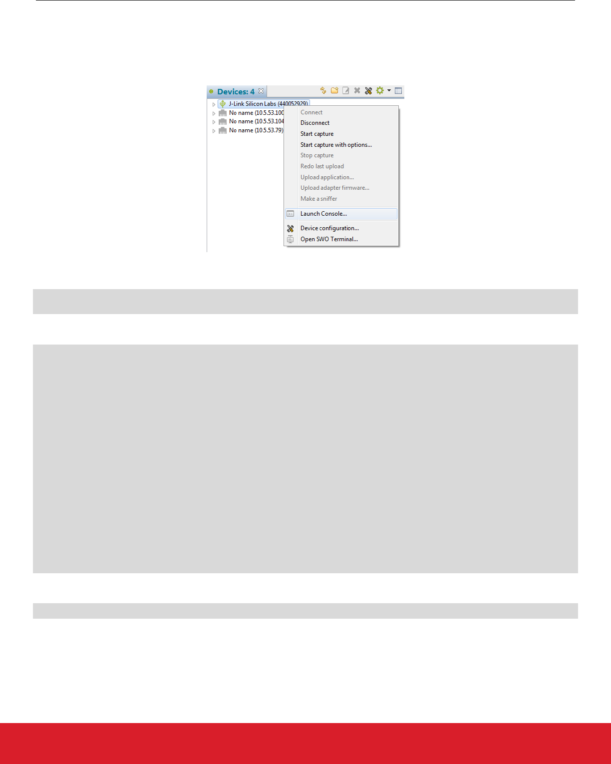
To use the Slot Manager, in Simplicity Studio launch the console for the command line interface for the zigbee application.
On the Serial 1 tab, enter the following commands to get info about upgrade images:
plugin slot-manager ext-flash-info
plugin slot-manager slots-info
Output is as follows.
SwitchedMultiprotocolJoiningDeviceSoc>plugin slot-manager ext-flash-info
Version : 513
Part : MX25R8035F
Capabilities: 0x03
Part size : 1048576 B
Page size : 4096 B
Word size : 1 B
Slots : 2
SwitchedMultiprotocolJoiningDeviceSoc>plugin slot-manager slots-info
Slot 0
Address : 0x00002000
Length : 0x0003F000 (258048 bytes)
Type : Bluetooth application
Version : 0x00000000
Capabilities: 0x00000000
Product ID : 0x00 0x00 0x00 0x00 0x00 0x00 0x00 0x00 0x00 0x00 0x00 0x00 0x00 0x00 0x00 0x00
Slot 1
Address : 0x00041000
Length : 0x0003F000 (258048 bytes)
Type : ZigBee
Version : 0x00000000
Capabilities: 0x80000000
Product ID : 0x00 0x00 0x00 0x00 0x00 0x00 0x00 0x00 0x00 0x00 0x00 0x00 0x00 0x00 0x00 0x00
To boot from the Bluetooth slot (slot 0) use the command:
plugin slot-manager boot-slot 0
Note: To implement rebooting from other slot functionality in your custom application you can use the Gecko Bootloader API, which
includes functions for switching slots, rebooting, and so on. For details see the Gecko Bootloader API Reference Manual, shipped with
the SDK.
UG267: Switched Multiprotocol User’s Guide
Implementing Switched Multiprotocol
silabs.com | Building a more connected world. Rev. 0.4 | 22

This loads the Bluetooth application into the internal flash, and reboots the device. Now you can see the Bluetooth device advertising.
SwitchedMultiprotocolJoiningDeviceSoc>plugin slot-manager boot-slot 0
Slot Manager: beginning image verification.....................................................................
...............................................................................................................
...............................................................................................................
...............................................................................................................
...............................................................................................................
...............................................................................................................
...............................................................................................................
...............................................................................................................
...............................................................................................................
...............................................................................................................
...............................................................................................................
...........................................passed! Booting slot 0
*** Startup ***
Build Date: Mar 1 2017
Build Time: 15:01:42
Server booted!
Local address:00:0b:57:07:ae:4b
HEADS UP! Removing all bondings!
Server: Security Manger is configured.
Server is bondable.
Starting advertisement for 10 minute(s).
Server is discoverable/connectable.
To switch back to the zigbee application, you need to boot from slot 1. Note that now the Bluetooth application is running, which has
different commands than the zigbee application. The Switched Multiprotocol Joining Device Bluetooth example has the following com-
mand for booting from slot 1. Enter it and it loads the zigbee application into the internal flash again, and reboots the device:
set-slot-bootload 1
> set-slot-bootload 1
Slot Manager plugin: beginning image verification..............................................................
...............................................................................................................
...............................................................................................................
...............................................................................................................
...............................................................................................................
...............................................................................................................
...............................................................................................................
...............................................................................................................
...............................................................................................................
...............................................................................................................
...............................................................................................................
...............................................................................................................
...............................................................................................................
...............................................................................................................
...........................................................passed! Booting slot 1
Reset info: 0x02 (BTL)
Extended Reset info: 0x0201 (GO )
SwitchedMultiprotocolJoiningDeviceSoc>
UG267: Switched Multiprotocol User’s Guide
Implementing Switched Multiprotocol
silabs.com | Building a more connected world. Rev. 0.4 | 23
8. Bluetooth Commissioning Test System
8.1 Overview
One of the most common uses for switched multiprotocol devices is where Bluetooth commissioning is used to add devices onto a
mesh network. To demonstrate this use case a test system is designed and implemented including both protocol switching and MPSI.
The Bluetooth commissioning test system contains three main components: the zigbee trust center, the mobile phone application, and
the Switched Multiprotocol Joining Device. Both the trust center and the joining device connect to the Mobile Phone Application over a
Bluetooth protocol connection, and they communicate with MPSI messages.
For testing purposes three different Bluetooth applications are implemented:
•Trust Center Bluetooth Interface: This application provides the Bluetooth interface in the trust center. It is implemented as an NCP
target running on a radio board and a host application running on a PC / Raspberry Pi. The zigbee interface of the trust center is
emulated in the test system with a command line interface. The NCP target image is provided in the Silicon Labs Bluetooth SDK as
“NCP target – Switched Multiprotocol Trust Center”. The host application can be found in the SDK under:
C:\SiliconLabs\SimplicityStudio\v4\developer\sdks\gecko_sdk_suite\v1.0\app\bluetooth_2.3
\examples_ncp_host\switched_multipr_trust_center
•Mobile App: A mobile app is available for Android devices from the Google Play Store (Opt In URL: https://play.google.com/apps/
testing/com.siliconlabs.worcester).
•Switched Multiprotocol Joining Device: This is a Bluetooth SoC application that runs the “Switched Multiprotocol Joining Device”
application provided in the Silicon Labs Bluetooth SDK. It runs on a standalone radio board, which is capable of booting both in
Bluetooth and in zigbee mode.
Figure 8.1. Three Bluetooth Applications
In addition, two zigbee applications must be built: the trust center and joining device. The trust center requires a fourth WSTK and radio
board with a chip that is running a suitable NCP image.
•SwitchedMultiprotocolTrustCenter: This can be generated using Simplicity Studio and built on a POSIX host. It is a sample appli-
cation presented when building a host application. An NCP application must be loaded onto a device to interact with this host appli-
cation.
UG267: Switched Multiprotocol User’s Guide
Bluetooth Commissioning Test System
silabs.com | Building a more connected world. Rev. 0.4 | 24

•SwitchedMultiprotocolJoiningDevice: This is also built using Simplicity Studio. It is also presented as a sample application when
building for a SoC. This image will be converted to a GBL and sent to the joining device using Bluetooth’s OTA transfer mechanism,
as shown later.
Both trust center applications (Trust Center Bluetooth Interface and SwitchedMultiprotocolTrustCenter) must be run on the same host
system. This is due to the fact that the two processes must send MPSI messages to each other using system resources.
UG267: Switched Multiprotocol User’s Guide
Bluetooth Commissioning Test System
silabs.com | Building a more connected world. Rev. 0.4 | 25
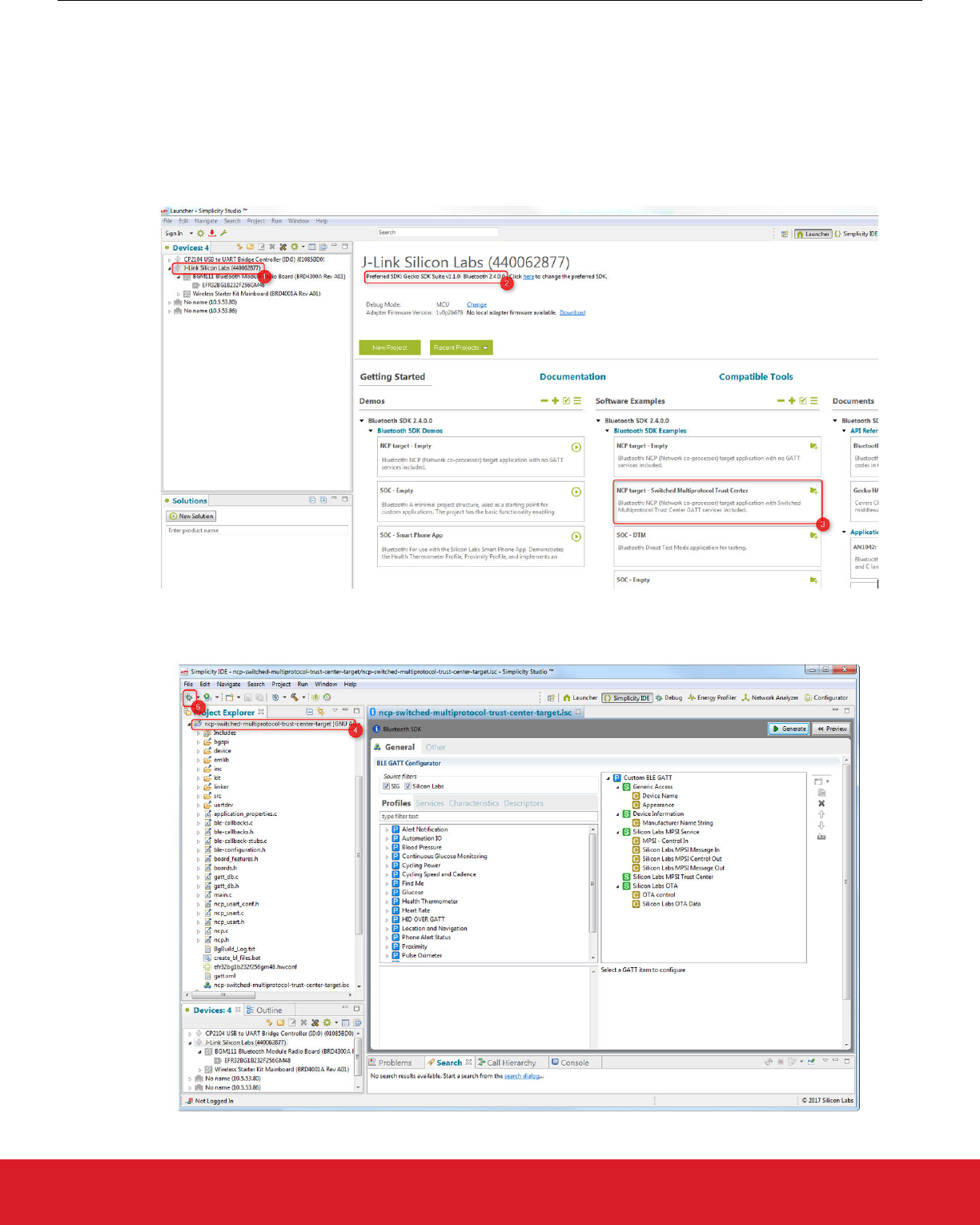
8.2 Flashing Applications to Devices
The test system needs three test devices (where a device is a WSTK + radio board). Each of them has to be flashed separately with
the appropriate application image, according to section 8.1 Overview. As stated before, the Bluetooth and zigbee trust center applica-
tions must be running on the same host.
To flash the NCP target “NCP target – Switched Multiprotocol Trust Center”:
1. Connect your device (WSTK + radio board), start Simplicity Studio, and select the device chosen to be the Trust Center.
2. Verify Bluetooth is installed in the Gecko SDK.
3. Click 'NCP target – Switched Multiprotocol Trust Center’ in the Software Examples column.
4. The project is automatically created. Click on the project name in the Project Explorer.
5. Click the Debug button to build the application and download it to the device.
UG267: Switched Multiprotocol User’s Guide
Bluetooth Commissioning Test System
silabs.com | Building a more connected world. Rev. 0.4 | 26
The NCP target image will be downloaded to the selected device. Now you can control the device from your PC.
To flash the “Switched Multiprotocol Joining Device” Bluetooth SoC application, follow the instructions in section 7. Implementing
Switched Multiprotocol. Flash the Bluetooth application into the internal flash, or reboot from slot 0 after the zigbee application starts as
described in section 7.7 Switching between Zigbee and Bluetooth Applications.
To flash an NCP image for the zigbee SwitchedMultiprotocolTrustCenter application, download to the target either a prebuilt or config-
ured NCP binary. Prebuilt NCP images can be found in the EmberZNet installation folder. Configured NCP applications can be created
using the xNCP framework in Studio.
In this example, the SwitchedMultiprotocolJoiningDevice is sent over OTA to the Joining Device and then booted.
8.3 Building Host Applications
The host application controlling the NCP target is provided as source code under
C:\SiliconLabs\SimplicityStudio\v4\developer\sdks\gecko_sdk_suite\v1.0\app\bluetooth_2.3\examples_ncp_host\switched_multipr
_trust_center
and
C:\SiliconLabs\SimplicityStudio\v4\developer\sdks\gecko_sdk_suite\v1.0\app\bluetooth_2.3\examples_ncp_host\switched_multipr
_mobile_app
Either build the application on your Linux PC or Windows PC using Cygwin, for example, or on a Raspberry Pi by following the instruc-
tions:
1. Power on the Raspberry Pi, connect to it either with a keyboard/monitor or with SSH.
2. Copy the Bluetooth SDK directory (for example C:\SiliconLabs\SimplicityStudio\v4\developer\sdks\gecko_sdk_suite\v1.0\protocol
\bluetooth_2.3\) to the Raspberry Pi (for example, ~/BLE/ble-sdk) either using a USB drive or SSH.
3. Browse to ‘ble-sdk/app/bluetooth_dev/examples_ncp_host/switched_multipr_trust_center’.
4. Run ‘make’.
5. The Trust Center host application should be built at this point.
6. The zigbee host image should be built on the same host by going into the Simplicity Studio project directory and running ‘make.’
8.4 Running the Test Applications
8.4.1 Joining Device
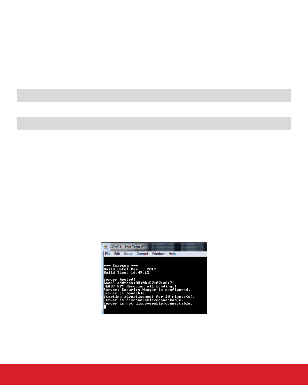
The “Switched Multiprotocol Joining Device” Bluetooth application is a standalone application. After reset, the bootloader checks the
application image, and then starts it. Connect to the WSTK with a USB cable. A new – virtual – COM port is shown among the available
COM ports on your computer. Connect to it with a terminal application. The following should be seen after reset:
At this point you should see the device advertising itself as SLJDxxxx.
UG267: Switched Multiprotocol User’s Guide
Bluetooth Commissioning Test System
silabs.com | Building a more connected world. Rev. 0.4 | 27
8.4.2 Trust Center
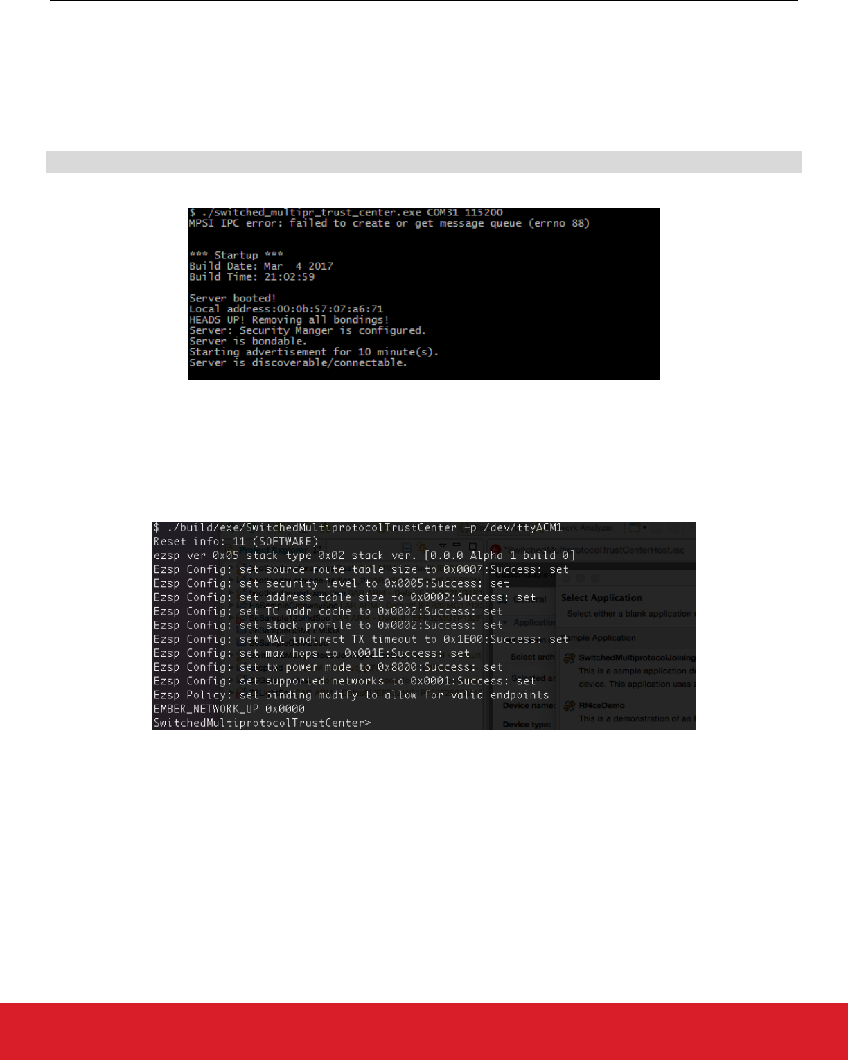
The trust center application needs an ‘NCP target – Switched Multiprotocol Trust Center’ application running on the radio board. After
flashing it to the device the host application has to be started. The executable application can be found in:
ble-sdk/app/bluetooth_dev/examples_ncp_host/switched_multipr_trust_center/exe
Identify the communication port that is opened for the connected device (for example COM31 or /dev/ttyACMx). Run the application as
follows:
./switched_multipr_trust_center COMport 115200
You should see the following in the command line:
At this point you should see the device advertising itself as SLTCxxxx.
The trust center host applications (that is, Bluetooth and zigbee) communicate over inter-process communication (IPC). The MPSI IPC
error shown above suggests that the application cannot create the necessary queue for this communication mechanism. This can hap-
pen if the application runs on a device that is not capable of handling the IPC mechanism such as Windows.
The zigbee trust center is started in a similar fashion. Once an appropriate NCP image is loaded onto the device and the host applica-
tion is built, the host application can interface the NCP.
UG267: Switched Multiprotocol User’s Guide
Bluetooth Commissioning Test System
silabs.com | Building a more connected world. Rev. 0.4 | 28
8.4.3 Mobile App
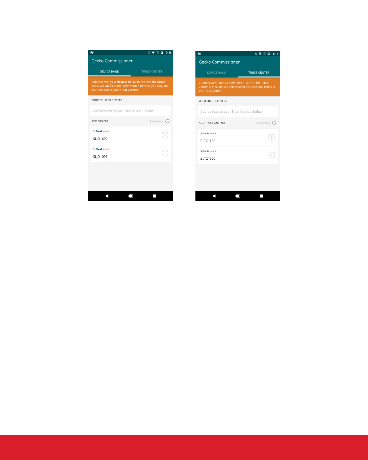
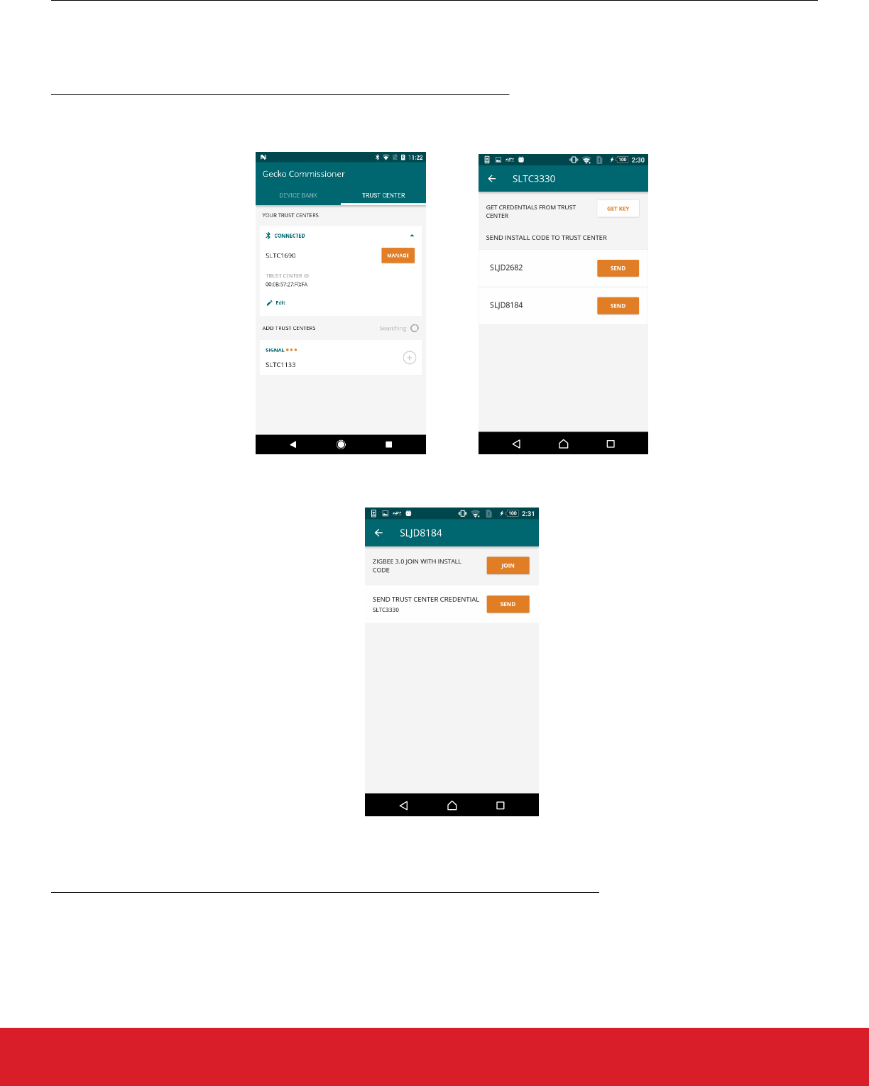
The only configuration necessary is to install the Mobile Application onto a target device.
The Mobile App scans Bluetooth beacons and shows two sets of devices. Joining devices are listed under the Device Bank tab, while
Trust Centers are shown under the Trust Center tab.
In order to connect to the Joining Device, tap the plus sign next to a discovered device. The mobile application will try to bond to the
device. The Joining Device must confirm the bonding, by first accepting the connection and then verifying the passkey.
Similarly for the Trust Center, from the Mobile App, identify the Trust Center of interest and tap the plus sign to begin bonding. The
Trust Center should then confirm the bonding and the passkey.
UG267: Switched Multiprotocol User’s Guide
Bluetooth Commissioning Test System
silabs.com | Building a more connected world. Rev. 0.4 | 29
8.5 OTA File Upload
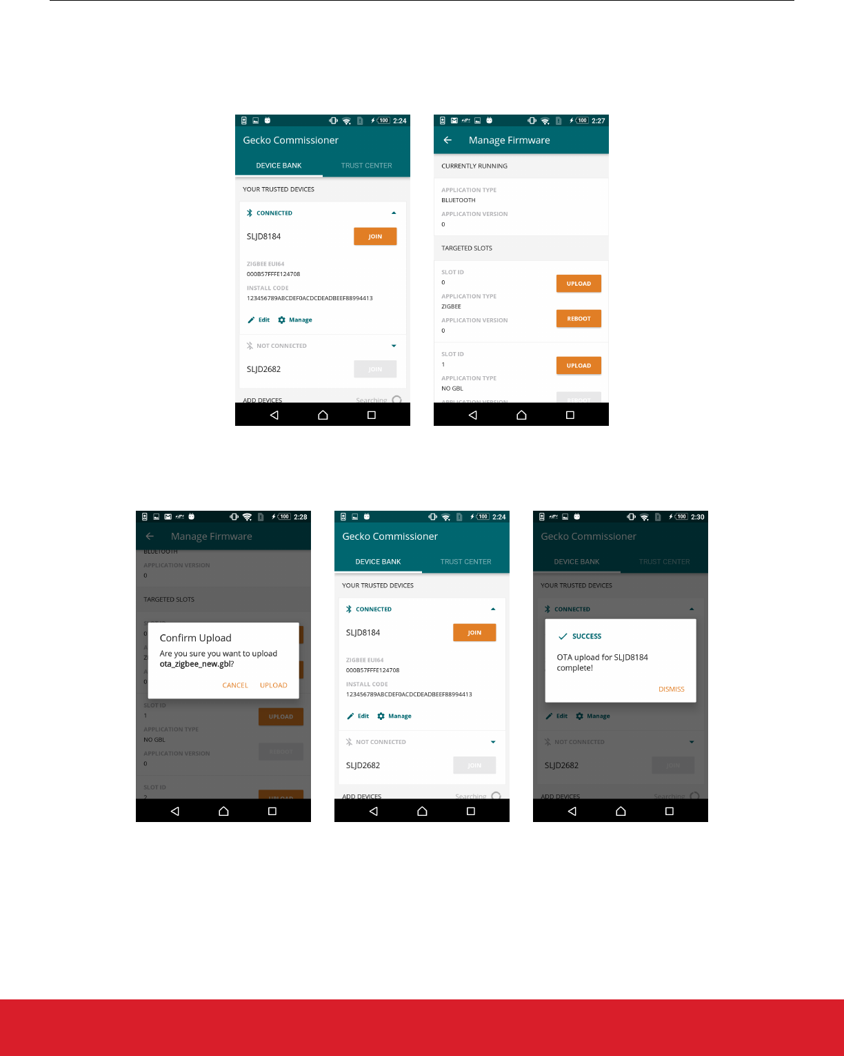
Using the Mobile App, an image can be streamed to a target device over the OTA process.
The user begins by connecting to a joining device, and then tapping [Manage]. A new screen is presented that shows the number of
slots on the target device and what images, if any, are present.
After tapping [Upload], the user is instructed to choose a file for upload. Once the file is chosen, the user is prompted to confirm. Upon
confirmation, the OTA process begins. A progress bar below the target device on the Device Bank tab shows current OTA progress.
During the OTA process, management of the device is restricted.
UG267: Switched Multiprotocol User’s Guide
Bluetooth Commissioning Test System
silabs.com | Building a more connected world. Rev. 0.4 | 30
8.6 Commissioning
Once the Mobile App is connected to the Trust Center and to the Joining device, the three devices are able to communicate with MPSI
messages. Transactions over MPSI can be initiated by tapping appropriate controls on the Mobile App.
Method 1: Having the Joining Devices send their install codes to the Trust Center
• Tap [Manage] next to a Trust Center. Identify a Joining Device and then tap [Send]. This fetches the zigbee install code from the
Joining Device and relays it to the Trust Center. It then instructs the Trust Center to open the network for joining.
• Tap [Manage] next to a Joining Device. Tapping [Join] will cause the Joining Device to boot into zigbee and initiate joining using its
install code.
After rebooting the Joining Device in zigbee mode, the zigbee application finds the “initiate joining” MPSI message stored in the flash,
and executes it. The Trust Center is already prepared to allow the device to connect to the zigbee network.
Method 2: Having the Trust Center generate and send network credentials to the Joining Devices
• Tap [Manage] next to a Trust Center. Tapping [Get Key] will cause the Trust Center to generate a random joining key that any de-
vice can use to join the network. The MPSI response that the Trust Center sends to the Mobile App also contains the current net-
work’s channel mask and zigbee extended PAN ID, so that the Joining Device can use them when scanning for networks. The key
returned has a timer of five minutes, which the Mobile App displays in a timer after the user taps [Get Key].
UG267: Switched Multiprotocol User’s Guide
Bluetooth Commissioning Test System
silabs.com | Building a more connected world. Rev. 0.4 | 31
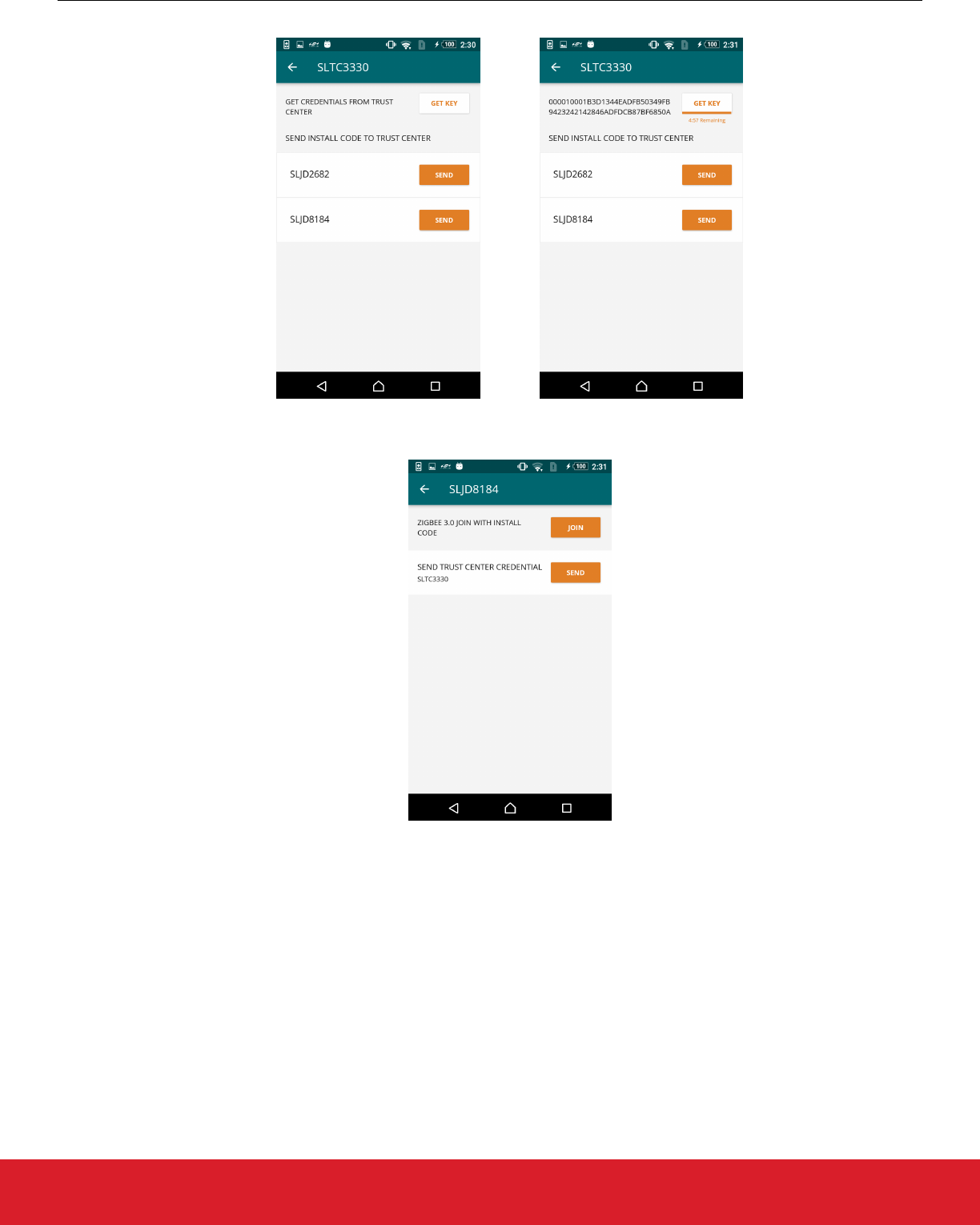
• Tap [Manage] next to a Joining Device. Tap [Send] to relay the previously-retrieved Trust Center joining credentials to the Joining
Device. The Joining Device will then reboot and attempt to join the network using the supplied joining credentials.
UG267: Switched Multiprotocol User’s Guide
Bluetooth Commissioning Test System
silabs.com | Building a more connected world. Rev. 0.4 | 32

http://www.silabs.com
Silicon Laboratories Inc.
400 West Cesar Chavez
Austin, TX 78701
USA
Smart.
Connected.
Energy-Friendly.
Products
www.silabs.com/products
Quality
www.silabs.com/quality
Support and Community
community.silabs.com
Disclaimer
Silicon Labs intends to provide customers with the latest, accurate, and in-depth documentation of all peripherals and modules available for system and software implementers using or
intending to use the Silicon Labs products. Characterization data, available modules and peripherals, memory sizes and memory addresses refer to each specific device, and "Typical"
parameters provided can and do vary in different applications. Application examples described herein are for illustrative purposes only. Silicon Labs reserves the right to make changes
without further notice and limitation to product information, specifications, and descriptions herein, and does not give warranties as to the accuracy or completeness of the included
information. Silicon Labs shall have no liability for the consequences of use of the information supplied herein. This document does not imply or express copyright licenses granted
hereunder to design or fabricate any integrated circuits. The products are not designed or authorized to be used within any Life Support System without the specific written consent of
Silicon Labs. A "Life Support System" is any product or system intended to support or sustain life and/or health, which, if it fails, can be reasonably expected to result in significant
personal injury or death. Silicon Labs products are not designed or authorized for military applications. Silicon Labs products shall under no circumstances be used in weapons of mass
destruction including (but not limited to) nuclear, biological or chemical weapons, or missiles capable of delivering such weapons.
Trademark Information
Silicon Laboratories Inc.® , Silicon Laboratories®, Silicon Labs®, SiLabs® and the Silicon Labs logo®, Bluegiga®, Bluegiga Logo®, Clockbuilder®, CMEMS®, DSPLL®, EFM®,
EFM32®, EFR, Ember®, Energy Micro, Energy Micro logo and combinations thereof, "the world’s most energy friendly microcontrollers", Ember®, EZLink®, EZRadio®, EZRadioPRO®,
Gecko®, ISOmodem®, Micrium, Precision32®, ProSLIC®, Simplicity Studio®, SiPHY®, Telegesis, the Telegesis Logo®, USBXpress®, Zentri and others are trademarks or registered
trademarks of Silicon Labs. ARM, CORTEX, Cortex-M3 and THUMB are trademarks or registered trademarks of ARM Holdings. Keil is a registered trademark of ARM Limited. All other
products or brand names mentioned herein are trademarks of their respective holders.
