Single & Dual Clock FIFO Megafunctions User Guide Ug_fifo Ug
User Manual: ug_fifo
Open the PDF directly: View PDF ![]() .
.
Page Count: 56
- Single & Dual-Clock FIFO Megafunctions User Guide


ii Altera Corporation
Copyright Single & Dual-Clock FIFO Megafunctions User Guide
Copyright © 2003 Altera Corporation. All rights reserved. Altera, The Programmable Solutions Company, the stylized Altera logo,
specific device designations, and all other words and logos that are identified as trademarks and/or service marks are, unless
noted otherwise, the trademarks and service marks of Altera Corporation in the U.S. and other countries. All other product or
service names are the property of their respective holders. Altera products are protected under numerous U.S.
and foreign patents and pending applications, mask work rights, and copyrights. Altera warrants performance
of its semiconductor products to current specifications in accordance with Altera’s standard warranty, but
reserves the right to make changes to any products and services at any time without notice. Altera assumes no
responsibility or liability arising out of the application or use of any information, product, or service described
herein except as expressly agreed to in writing by Altera Corporation. Altera customers are advised to obtain the
latest version of device specifications before relying on any published information and before placing orders for
products or services.
UG-MFNALT_FIFO--1.0

Altera Corporation iii
About this User Guide
This user guide provides comprehensive information about the Altera®
scfifo and dcfifo FIFO megafunctions.
Table 1 shows the user guide revision history. .
How to Find
Information
■Use the Adobe Acrobat Find feature to search the text of a PDF
document. Click the binoculars toolbar icon to open the Find dialog
box.
■Bookmarks serve as an additional table of contents in PDF
documents.
■Thumbnail icons, which provide miniature previews of each page,
provide a link to the pages.
■Numerous links, shown in green text, allow you to jump to related
information.
Design
Examples
The designs used to generate the functional waveforms in this user guide
are available in the Design Example section of the Altera website at
www.altera.com.
Table 1. User Guide Revision History
Date Description
June 2003 First Release

iv Altera Corporation
Single & Dual Clock FIFO Megafunctions User Guide About this User Guide
How to Contact
Altera
For the most up-to-date information about Altera products, go to the
Altera world-wide web site at http://www.altera.com.
For technical support on this product, go to
http://www.altera.com/mysupport. For additional information about
Altera products, consult the sources shown in Table 2.
Note:
(1) You can also contact your local Altera sales office or sales representative.
Table 2. How to Contact Altera
Information Type USA & Canada All Other Locations
Technical support http://www.altera.com/mysupport/ http://www.altera.com/mysupport/
(800) 800-EPLD (3753)
(7:00 a.m. to 5:00 p.m.
Pacific Time)
(408) 544-7000 (1)
(7:00 a.m. to 5:00 p.m.
Pacific Time)
Product literature http://www.altera.com http://www.altera.com
Altera literature services lit_req@altera.com (1) lit_req@altera.com (1)
Non-technical customer
service
(800) 767-3753 (408) 544-7000
(7:30 a.m. to 5:30 p.m.
Pacific Time)
FTP site ftp.altera.com ftp.altera.com

Altera Corporation v
About this User Guide Single & Dual Clock FIFO Megafunctions User Guide
Typographic
Conventions
The Single & Dual-Clock FIFO Megafunctions User Guide uses the
typographic conventions shown in Table 3.
Table 3. Conventions
Visual Cue Meaning
Bold Type with Initial
Capital Letters
Command names, dialog box titles, checkbox options, and dialog box options are
shown in bold, initial capital letters. Example: Save As dialog box.
bold type External timing parameters, directory names, project names, disk drive names,
filenames, filename extensions, and software utility names are shown in bold type.
Examples: fMAX, \qdesigns directory, d: drive, chiptrip.gdf file.
Italic Type with Initial
Capital Letters
Document titles are shown in italic type with initial capital letters. Example: AN 75:
High-Speed Board Design.
Italic type Internal timing parameters and variables are shown in italic type. Examples: tPIA, n + 1.
Variable names are enclosed in angle brackets (< >) and shown in italic type. Example:
<file name>, <project name>.pof file.
Initial Capital Letters Keyboard keys and menu names are shown with initial capital letters. Examples:
Delete key, the Options menu.
“Subheading Title” References to sections within a document and titles of on-line help topics are shown
in quotation marks. Example: “Typographic Conventions.”
Courier type Signal and port names are shown in lowercase Courier type. Examples: data1, tdi,
input. Active-low signals are denoted by suffix n, e.g., resetn.
Anything that must be typed exactly as it appears is shown in Courier type. For
example: c:\qdesigns\tutorial\chiptrip.gdf. Also, sections of an actual
file, such as a Report File, references to parts of files (e.g., the AHDL keyword
SUBDESIGN), as well as logic function names (e.g., TRI) are shown in Courier.
1., 2., 3., and a., b., c.,... Numbered steps are used in a list of items when the sequence of the items is
important, such as the steps listed in a procedure.
■Bullets are used in a list of items when the sequence of the items is not important.
vThe checkmark indicates a procedure that consists of one step only.
1The hand points to information that requires special attention.
rThe angled arrow indicates you should press the Enter key.
fThe feet direct you to more information on a particular topic.

vi Altera Corporation
Single & Dual Clock FIFO Megafunctions User Guide About this User Guide

Altera Corporation vii
Contents
About this User Guide
How to Find Information.............................................................................................................. iii
Design Examples............................................................................................................................ iii
How to Contact Altera .................................................................................................................. iv
Typographic Conventions .............................................................................................................. v
Getting Started
General Description......................................................................................................................... 9
FIFO MegaWizard Plug-In ............................................................................................................. 9
Software Requirements ........................................................................................................... 9
MegaWizard Page Description .............................................................................................. 9
FIFO MegaWizard Plug-In Manager Options ........................................................... 13
Specifications
Functional Description.................................................................................................................. 19
Single-Clock FIFO Megafunction (scfifo) ........................................................................... 20
Functional Waveforms .................................................................................................. 21
Single-Clock FIFO Megafunction Operating in Legacy Mode ................................ 22
Single-Clock FIFO Megafunction Operating in Show-ahead Mode....................... 27
Dual-Clock FIFO Megafunction (dcfifo)............................................................................. 30
Pipeline Structure of Dual-Clock FIFOs ..................................................................... 33
The wrusedw[] & rdusedw[] Ports.............................................................................. 36
The Full & Empty Signals ............................................................................................. 41
Functional Waveforms .................................................................................................. 43
Dual-Clock FIFO Megafunction Legacy & Show-ahead Modes ............................. 44
Ports & Parameters ........................................................................................................................ 53

viii Altera Corporation
Single & Dual Clock FIFO Megafunctions User Guide Contents

Altera Corporation 9
Getting Started
General
Description
The Altera Quartus II software provides the FIFO MegaWizard® Plug-In
to implement first-in, first-out (FIFO) memory functions to buffer data
between systems communicating at the same, or different, clock
frequencies. FIFOs are especially useful for synchronizing data between
clock domains in system-on-a-programmable-chip (SOPC) designs. The
FIFO contains read and write address pointers, a RAM to store data, and
logic to generate status signals. This user guide discusses Altera single-
and dual-clock FIFO megafunctions.
1This user guide assumes that you are familiar with FIFO
behavior, Altera device architectures, and the Quartus® II
software tools, especially the MegaWizard Plug-In Manager and
the Quartus II Simulator.
FIFO
MegaWizard
Plug-In
The FIFO MegaWizard Plug-In instantiates single- and dual-clock FIFO
megafunctions (scfifo and dcfifo). This section provides software
requirements and MegaWizard page descriptions.
Software Requirements
The scfifo and dcfifo megafunctions are provided with the Quartus II
software, version 1.0 and later. To use the scfifo and dcfifo
megafunctions, install the Quartus II software.
MegaWizard Page Description
The Quartus II software allows you to easily and quickly instantiate
megafunctions using the MegaWizard Plug-In Manager. To instantiate a
megafunction, follow these steps:
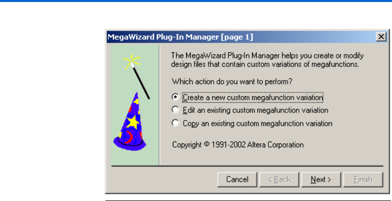
1. Launch the MegaWizard Plug-In Manager. Choose MegaWizard
Plug-In Manager (Tools menu) in the Quartus II software.
2. Select Create a new custom megafunction variation from the
MegaWizard Plug-In Manager dialog box. Click Next. See Figure 1.
10 Altera Corporation
Single & Dual Clock FIFO Megafunctions User Guide Getting Started
Figure 1. Create a New Megafunction Variation
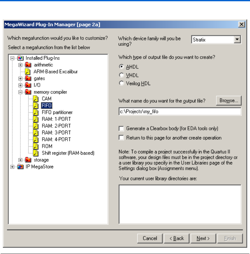
3. Expand either the memory compiler folder or the storage folder to
see the corresponding megafunction list.
4. There are two ways to access the FIFO megafunctions:
a. Choose FIFO from the memory compiler folder. See Figure 2.
12 Altera Corporation
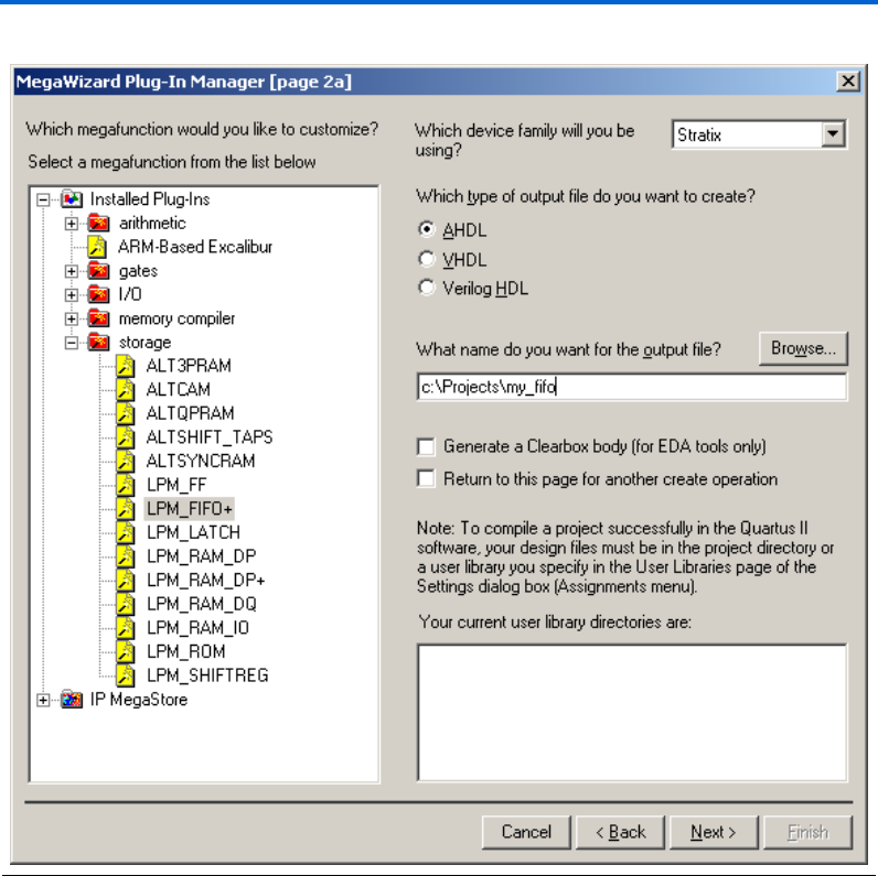
Single & Dual Clock FIFO Megafunctions User Guide Getting Started
Figure 3. Select the FIFO Megafunction from the Storage Folder
5. Select an output file type and enter the desired name of the
megafunction. You can choose AHDL (.tdf), VHDL (.vhd), or Verilog
HDL (.v). Along with the HDL files, the MegaWizard Plug-In
Manager creates an Include File (.inc), a VHDL Component
Declaration file (.cmp) and a Block Symbol File (.bsf).
Altera Corporation 13
Getting Started Single & Dual Clock FIFO Megafunctions User Guide
FIFO MegaWizard Plug-In Manager Options
This section describes pages three through eight of the FIFO MegaWizard
Plug-in Manager options.
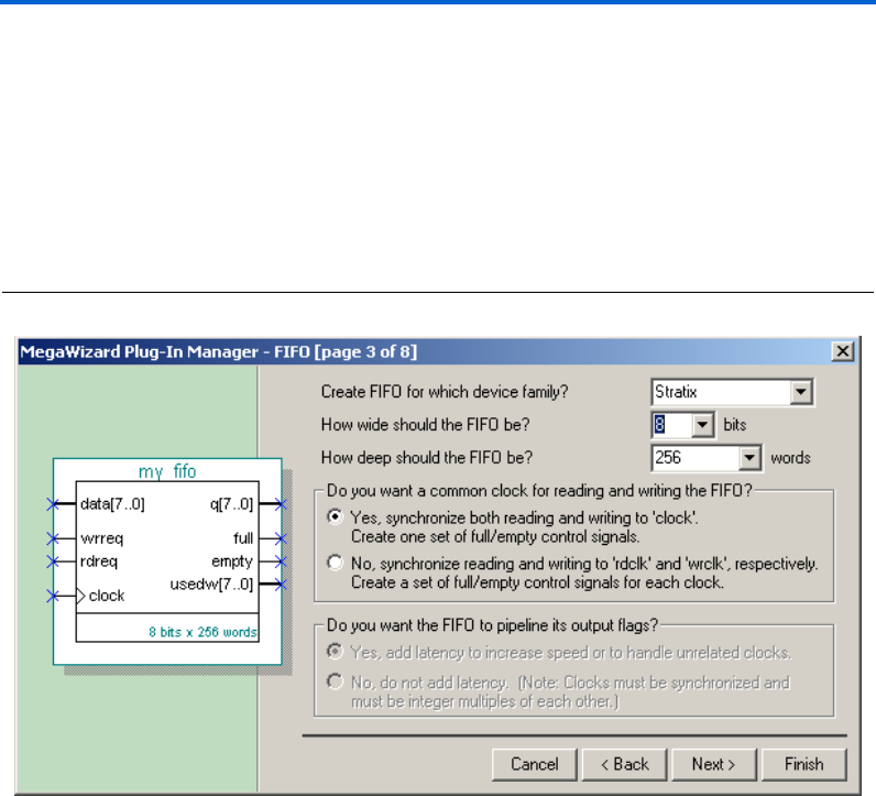
Page Three: Setting the General FIFO Features
Figure 4 shows page three of the FIFO MegaWizard Plug-In Manager,
where you can choose the device family, FIFO width, and depth.
Figure 4. Page Three: Setting the General FIFO Features

14 Altera Corporation
Single & Dual Clock FIFO Megafunctions User Guide Getting Started
Table 4 shows the FIFO MegaWizard Plug-In Manager page three
options.
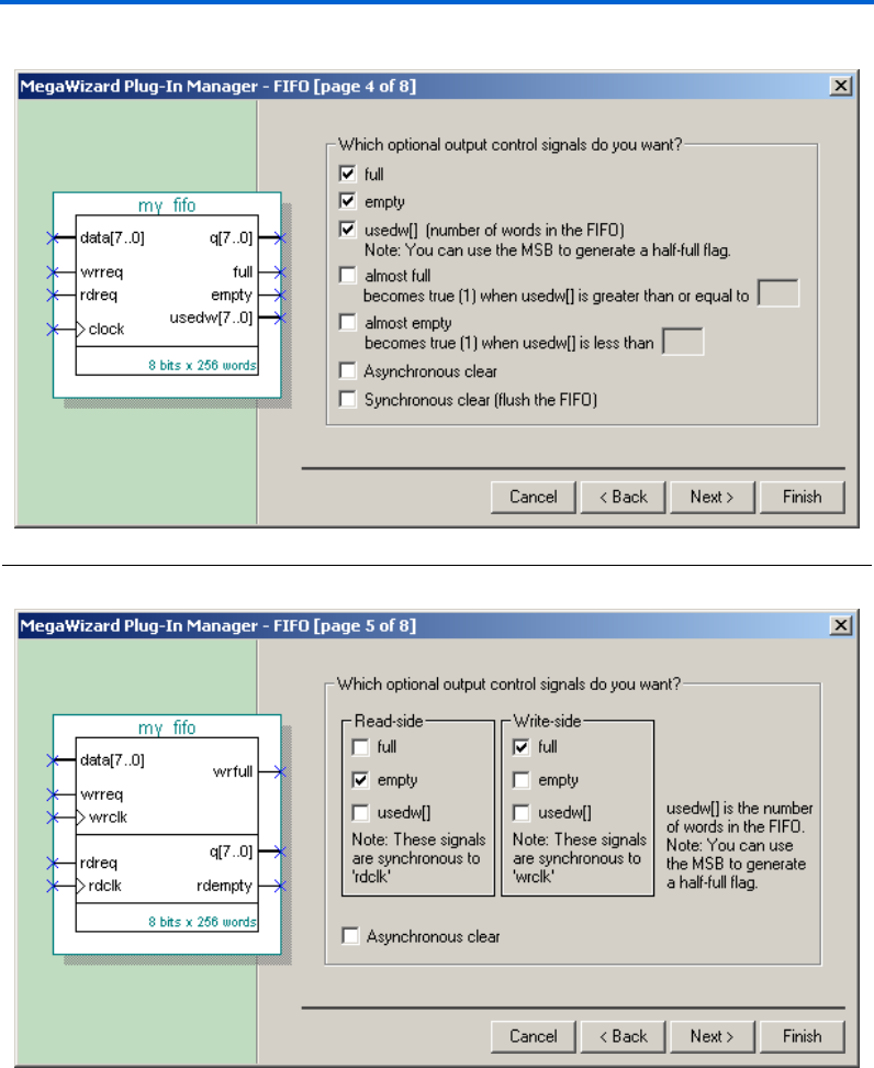
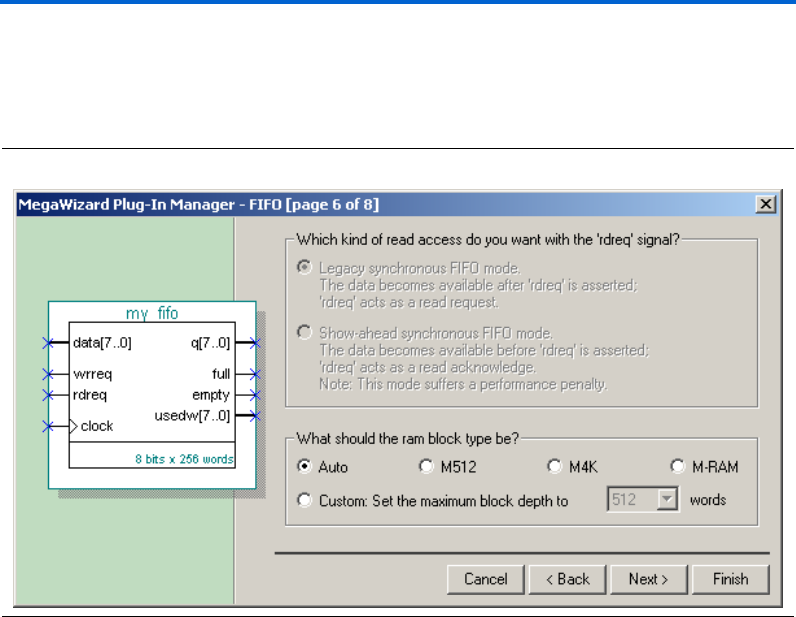
Pages Four & Five: Setting the FIFO Control Signals & Flags
Figures 5 and 6 show pages four and five of the FIFO MegaWizard Plug-
In Manager, where you choose the FIFO control signals and flags. Page
four is displayed when you choose a single-clock FIFO, and page five is
displayed when you choose a dual-clock FIFO.
Table 4. FIFO MegaWizard Plug-In Manager Page Three Options
MegaWizard Option Explanation Availability:
Single-Clock
FIFO
Dual-Clock
FIFO
Create FIFO for which device
family?
Select the Altera device family you are
using.
yes yes
How wide should the FIFO be? Choose the FIFO data width. If the
desired width is not listed, type in the
number.
yes yes
How deep should the FIFO be? Choose the FIFO depth. If the desired
depth is not listed, type in the number.
The depth must be a power of two.
yes yes
Do you want a common clock for
reading and writing the FIFO?
Choose Yes if you want a dual-clock
FIFO; No if you want a single-clock FIFO.
yes yes
Do you want the FIFO to pipeline its
output flags?
Choose Yes to add latency if your clocks
are not synchronized; No if your clocks
are synchronized.
no yes
Altera Corporation 15
Getting Started Single & Dual Clock FIFO Megafunctions User Guide
Figure 5. Page Four: Setting the Single-Clock FIFO Control SIgnals & Flags
Figure 6. Page Five: Setting the Dual-Clock FIFO Control SIgnals & Flags
16 Altera Corporation
Single & Dual Clock FIFO Megafunctions User Guide Getting Started
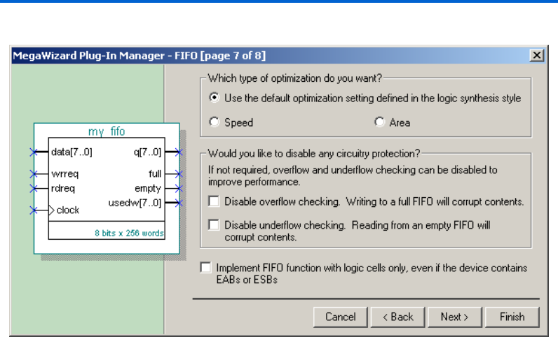
Page Six: Setting the Legacy, Show-Ahead & RAM Block Options
Figure 7 shows page six of the FIFO MegaWizard Plug-In Manager, where
you choose Legacy, Show-ahead mode, as well as RAM block options.
Figure 7. Page Six: Setting the Legacy, Show-Ahead Mode & RAM Block Options
1Both the single- and dual-clock FIFO megafunctions can be
created in Legacy or Show-ahead mode, except when targeting
Altera Cyclone™, Stratix, and Stratix GX devices. In Stratix and
Stratix GX devices, you can choose which TriMatrix™ memory
block to place the FIFO. If you want a specific depth for your
memory block, you can do so by choosing custom.
Page Seven: Setting the Optimization, Overflow/Underflow Checking
& Placement Setting Options
Figure 8 shows page seven of the FIFO MegaWizard Plug-In Manager,
where you choose the optimization, overflow/underflow checking, and
placement setting options.
Altera Corporation 17
Getting Started Single & Dual Clock FIFO Megafunctions User Guide
Figure 8. Page Seven: Setting the Optimization, Overflow/Underflow Checking & Placement Setting Options

18 Altera Corporation
Single & Dual Clock FIFO Megafunctions User Guide Getting Started

Altera Corporation 19
Specifications
Functional
Description
The Altera parameterizable single- and dual-clock FIFO megafunctions
can be designed to meet a wide-range of data buffering requirements. For
example, the single-clock FIFO megafunction is a simpler function that
can simultaneously read and write in the same clock cycle. Whereas, the
dual-clock FIFO megafunction is a more complex function that can
provide high-speed data buffering for asynchronous clock domain
applications—as well as simultaneously read and write in the same clock
cycle.
You can parameterize either the single- or dual-clock FIFO megafunction
to implement any width/depth combination desired. The FIFO depth
must be a power of two, but there is no FIFO depth/width limitation
except for the available memory space in the device itself. If the desired
combination is not available via the Quartus II menu, you can enter the
depth and/or width required for your design. Both megafunctions also
have optional output signals, i.e., empty/full flags and number of words
used ports.
All Altera FPGA’s support the single- and dual-clock FIFO
megafunctions. However, the Stratix and Stratix GX device
implementation is different because these devices:
■Currently do not support the output registers for any FIFO
megafunctions
■Only support the Show-ahead mode with custom logic
■The aclr signal only clears the flag, but not the q[] port
Please contact Altera Applications for more information about the Stratix
and Stratix GX device implementation of the single- and dual-clock FIFO
megafunctions.
1Whenever a write transaction occurs, the data is considered
written, or available to be read at tEABDD time after the clock’s
writing edge. Data is written on the falling edge of the write
clock in all of the Altera device memory blocks, except for the
Stratix and Stratix GX device M-RAM blocks. The Stratix and
Stratix GX device M-RAM blocks write data on the rising edge of
the write clock.

20 Altera Corporation
Single & Dual-Clock FIFO Megafunctions Specifications
This section discusses the functional descriptions of the:
■Single-clock FIFO megafunction, scfifo
■Dual-clock FIFO megafunction, dcfifo
Single-Clock FIFO Megafunction (scfifo)
The scfifo megafunction uses a single-clock signal for both writing to
and reading from the FIFO, and can perform simultaneous read and write
transactions within the same clock cycle.
Figure 19 on page 31 shows a functional block diagram of the dual-clock
FIFO megafunction. You can derive the single-clock FIFO megafunction
block diagram also from Figure 19.
The scfifo megafunction provides two operational modes:
■Legacy mode
■Show-ahead mode
When the scfifo megafunction is configured in Legacy mode, the
requested data is available on the first clock cycle after rdreq is asserted,
i.e., the rdreq signal operates as a normal read request. However, when
the scfifo is configured in Show-ahead mode, the rdreq signal
operates as a read acknowledge signal. Thus, the first bit of data written
in the FIFO immediately appears on its output, i.e., without a read
transaction occurring.
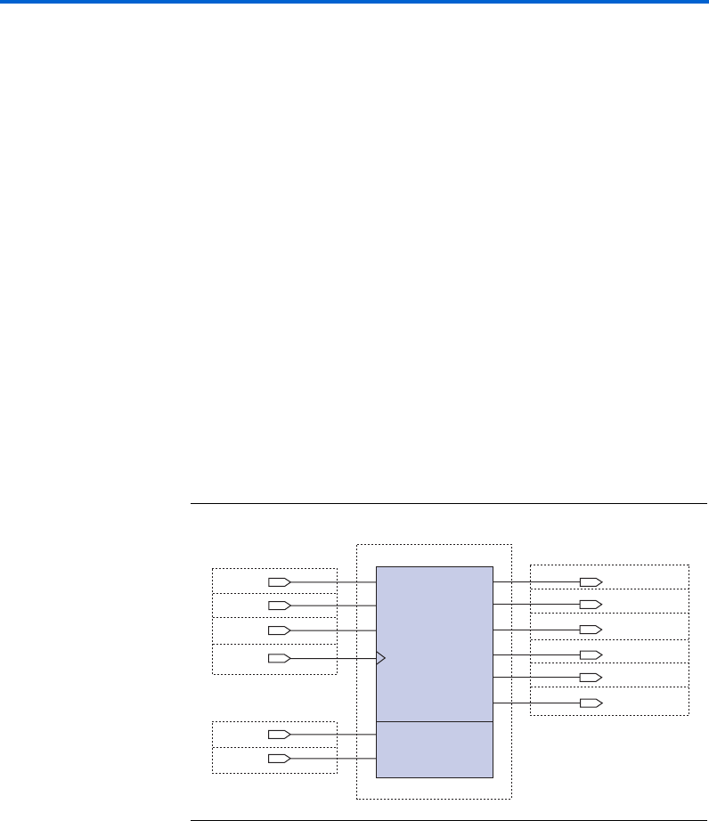
Figure 9 shows the Quartus II symbol for a 256 x 8 bit single-clock
megafunction operating in Legacy mode. The symbols representing
Legacy and Show-ahead modes are the same except that the read request
signal operates as a read acknowledge signal in Show-ahead mode, noted
as rdreq(ack).
1When using Stratix and Stratix GX™ devices, Show-ahead mode
can only be implemented when custom logic is added around
the FIFO megafunction. Otherwise, Stratix and Stratix GX
devices do not support FIFO megafunctions configured in Show-
ahead mode.

Altera Corporation 21
Specifications Single & Dual-Clock FIFO Megafunctions
Figure 9. Quartus II Symbol of scfifo Megafunction Operating in Legacy Mode
The almost_full and almost_empty ports are optional output ports
that are only available in single-clock FIFOs. The almost_full and
almost_empty ports are used as an early indication that the FIFO is
almost full or almost empty.
When using the almost_full and almost_empty ports, the
corresponding ALMOST_EMPTY_VALUE and ALMOST_FULL_VALUE
parameters need to be set. The ALMOST_EMPTY_VALUE and
ALMOST_FULL_VALUE parameters represent the threshold value to assert
the almost_full and almost_empty ports. Parameters are set in the
MegaWizard® Plug-in Manager.
The usedw[] value increments for every write transaction and
decrements for every read transaction. The full port is asserted at the
same rising edge of clock when the usedw[] reaches its maximum
value (LPM_NUMWORDS), while the empty port is asserted at the same
rising edge of clock when the usedw[] reaches its minimum value (i.e.,
0).
fFor more information on scfifo megafunction parameters, go to “Ports
& Parameters” on page 53.
Functional Waveforms
This section discusses data transactions during various read and write
transactions in both Legacy and Show-ahead operational modes.
data[7..0]
wrreq
sclr
clock
my fifo
aclr
rdreq
q[7..0]
full
almost_full
empty
almost_empty
almost_full at 28
almost_empty <5
8 bits x 32 words
usedw[4..0]
single-clock FIFO
22 Altera Corporation
Single & Dual-Clock FIFO Megafunctions Specifications
Single-Clock FIFO Megafunction Operating in Legacy Mode
Operating in Legacy mode, Figure 10 displays the sample design that is
used to generate the functional waveforms (i.e., Figures 11 through 15)
discussed in this section. The scfifo megafunction is generated via the
FIFO MegaWizard Plug-In Manager and is configured to be 32-words
deep and 8-bits wide. The almost_full and almost_empty ports are
set to have a threshold value of 28 and 5 respectively.
Figure 10. Sample Single-Clock FIFO Operating in Legacy Mode
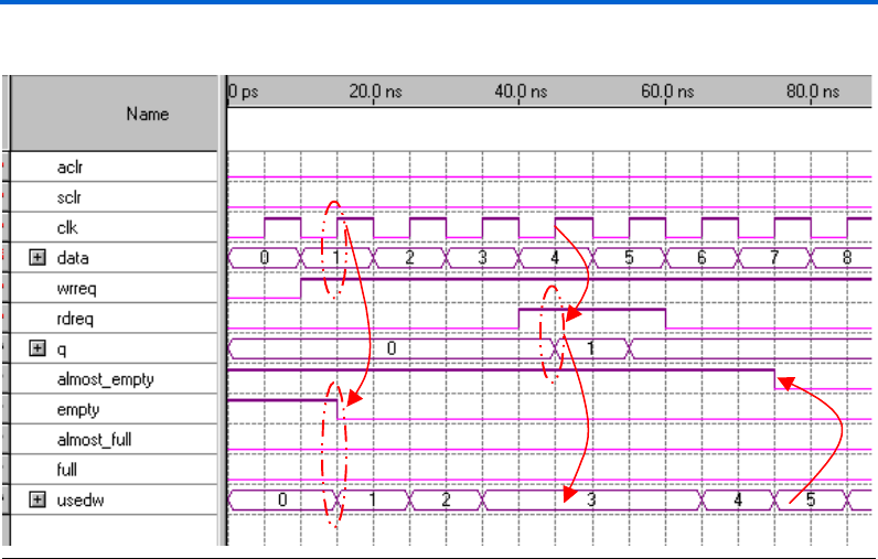
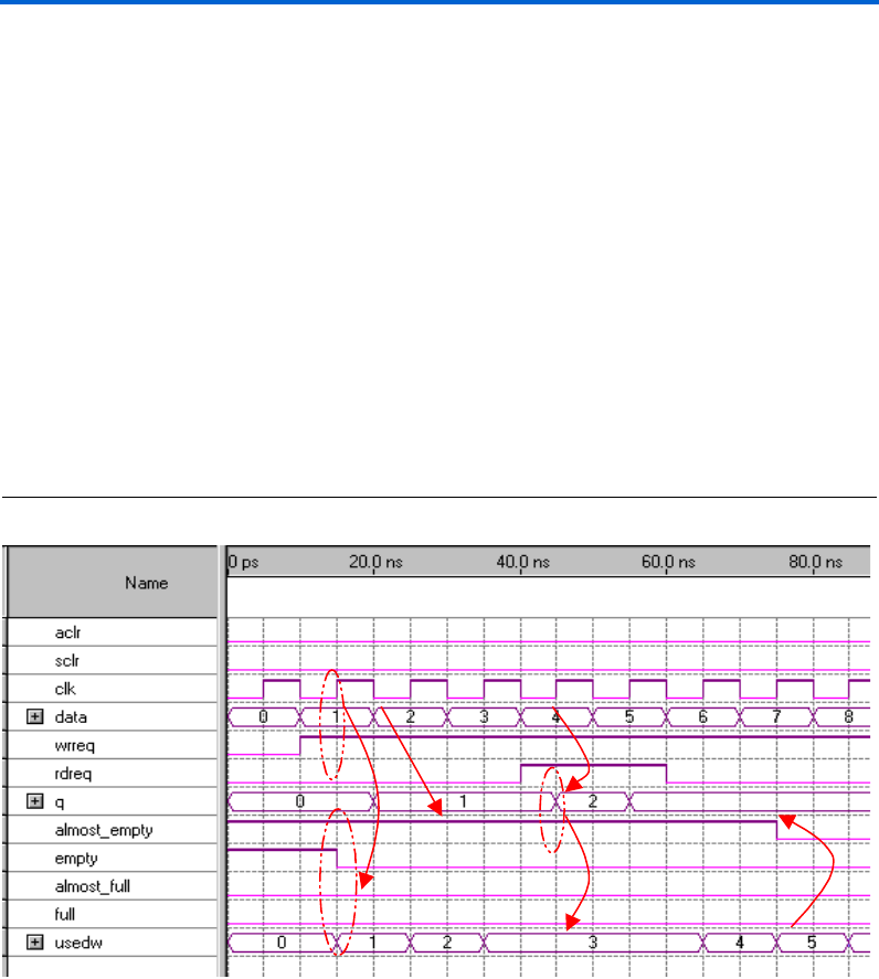
Figure 11 shows how the empty and almost_empty flags are deasserted
when initially writing to the scfifo megafunction. On the first rising
clock edge where wrreq is asserted, data (1) is written into the FIFO, the
empty flag is deasserted, and usedw[] is incremented.
At 40 ns, rdreq is asserted, and the FIFO outputs its oldest value (1) to
q[] on the immediate rising edge of clk. The usedw[] value does not
change because at the same rising edge of clk—while wrreq is still
asserted—the FIFO writes in another data (4). At this point, because the
ALMOST_EMPTY_VALUE is specified to be five, the almost_empty flag is
deasserted when the number of words in the FIFO equals five. Similarly,
because the ALMOST_FULL_VALUE is set to 28, the almost_full flag is
asserted when the number of words in the FIFO equals 28. The full flag
is asserted on the last write, at the same time when the number of words
in this design is 32.
data[7..0]data[7..0]
wrreqwrreq
sclrsclr
clock
clock
my fifo
aclraclr
q[7..0] q[7..0]
full full
almost_full almost_full
empty empty
almost_empty almost_empty
almost_full at 28
almost_empty <5
8 bits x 32 words
usedw[4..0] usedw[4..0]
SingleClockFIFO
INPUT
VCC
INPUT
VCC
rdreqrdreq INPUT
VCC
INPUT
VCC
INPUT
VCC
INPUT
VCC
OUTPUT
OUTPUT
OUTPUT
OUTPUT
OUTPUT
OUTPUT
Altera Corporation 23
Specifications Single & Dual-Clock FIFO Megafunctions
Figure 11. Deasserting the empty & almost_empty Ports During Write Transactions
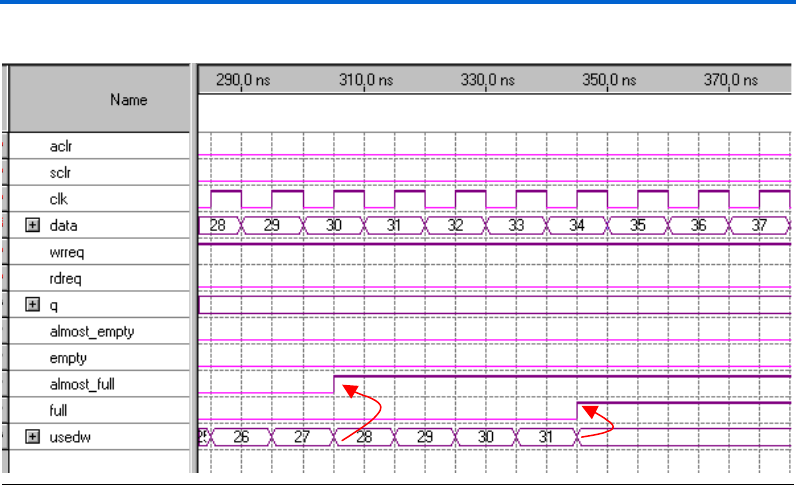
Figure 12 shows how the almost_full and the full flags are asserted.
Once the full flag is asserted, the FIFO will not accept any more write
transactions—unless the overflow checking circuitry is disabled. Writing
to a full FIFO yields unpredictable results and is not recommended.
24 Altera Corporation
Single & Dual-Clock FIFO Megafunctions Specifications
Figure 12. Asserting the almost_full & full Ports During Write Transactions
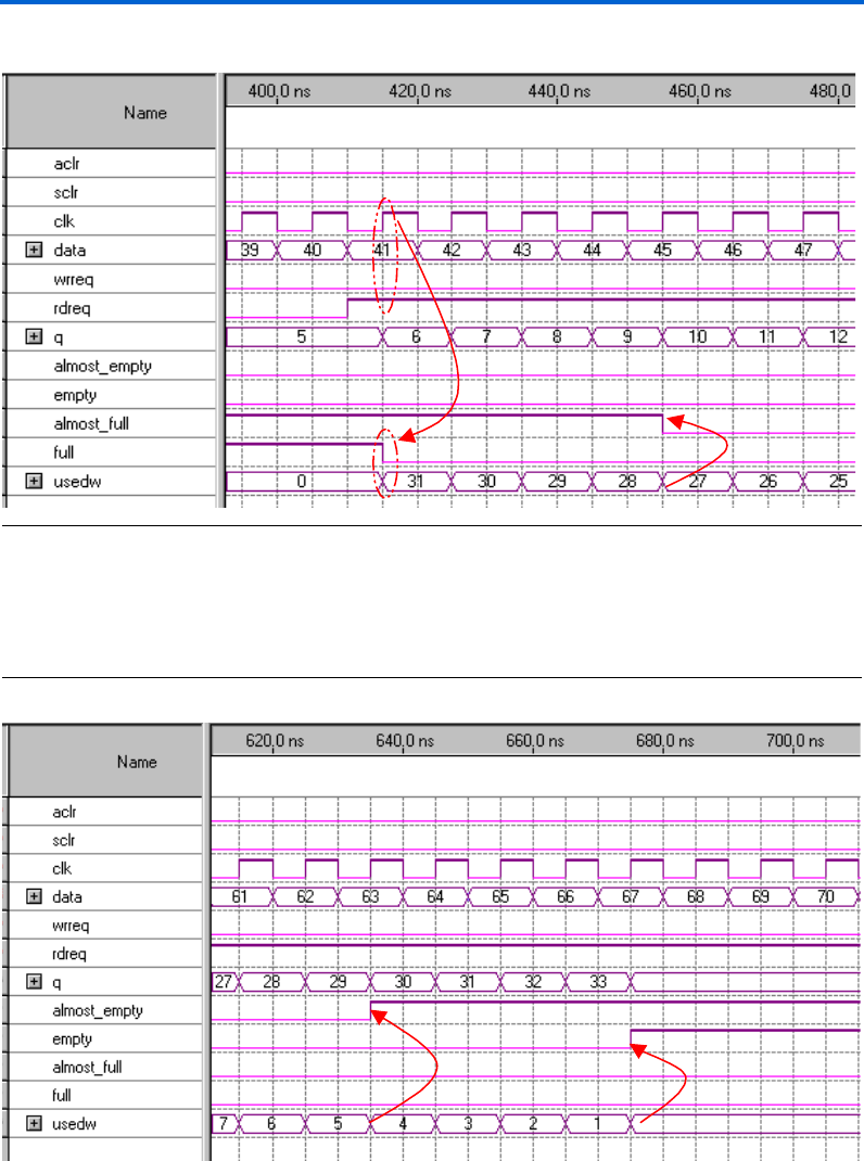
When the FIFO is full, the almost_full and full ports are deasserted
during read transactions. Figure 13 shows how the almost_full and
full ports are deasserted. (In Figure 13, the FIFO is full at the beginning
of the simulation.) When rdreq is asserted, the FIFO outputs the oldest
data to the q[] port, deasserting the full port on the immediate rising
edge of clk. Once the number of words in the FIFO is less than 28, which
is the specified ALMOST_FULL_VALUE, the almost_full port is
deasserted.
Altera Corporation 25
Specifications Single & Dual-Clock FIFO Megafunctions
Figure 13. Deasserting the full & almost_full Ports During Read Transactions
Figure 14 shows when the almost_empty and empty ports are asserted
during read transactions. The almost_empty port is asserted when there
are less than five words in the FIFO, and the empty port is asserted on the
last read transaction when the usedw[] value decrements to 0.
Figure 14. Asserting the almost_empty & empty Ports During Read Transactions
26 Altera Corporation
Single & Dual-Clock FIFO Megafunctions Specifications
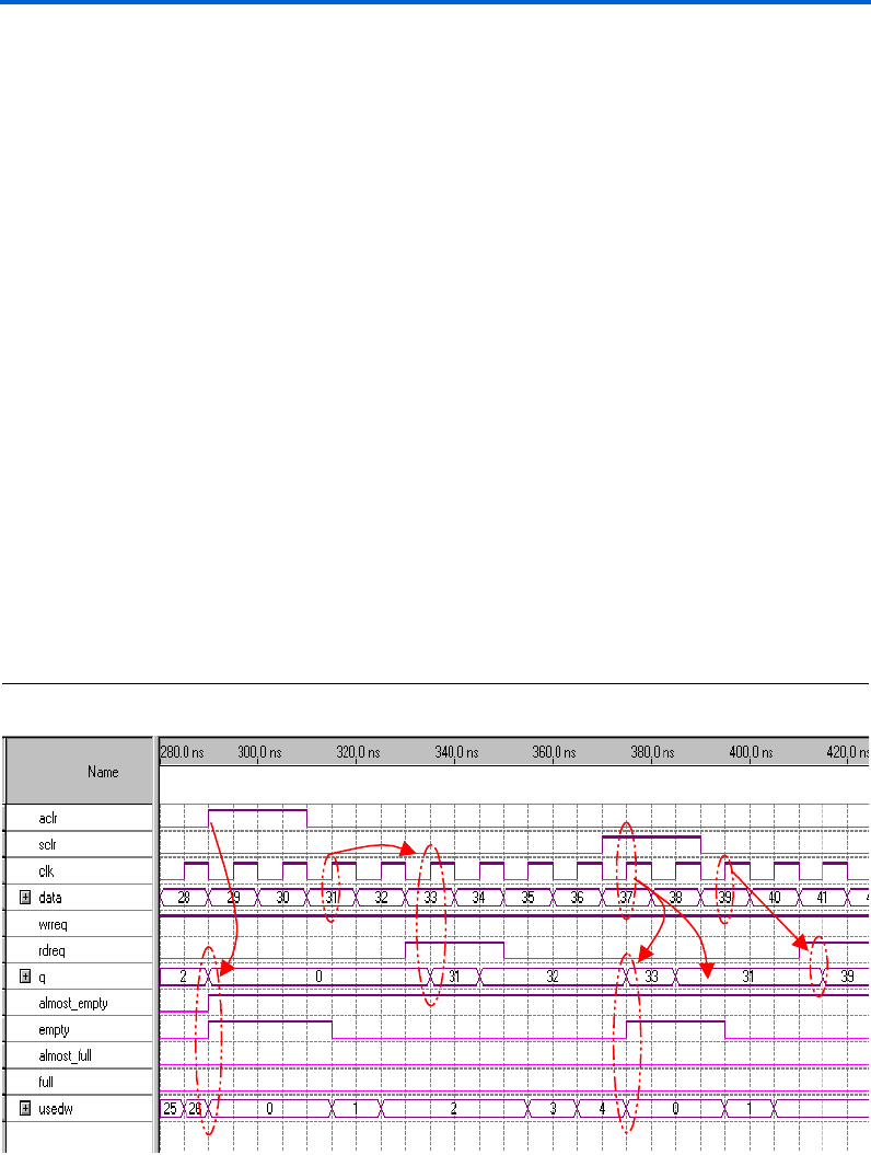
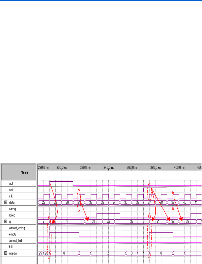
Figure 15 illustrates the asynchronous and synchronous clear operations
for single-clock FIFO megafunctions operating in Legacy mode.
When aclr is asserted, the FIFO megafunction is immediately reset,
which is indicated by the following events:
■The empty and almost_empty flags are asserted
■The usedw[] value defaults to 0
■The q[] output is cleared
■All rdreq and wrreq signals are ignored (as long as the aclr signal
remains asserted)
Internally, the write and read pointers are also reset. In Figure 15, the first
data that is written to the FIFO is 31, which is the first valid data after
aclr is deasserted.
1In Stratix and Stratix GX devices, the asynchronous clear
operation is treated as a synchronous clear operation because
inputs to the Stratix and Stratix GX TriMatrix™ memory are
required to be synchronous. The aclr signal itself is
asynchronous, but the outputs of the FIFO are only updated after
a rising clock edge. Additionally, when targeting Stratix and
Stratix GX devices, only the output flags and the usedw[]
signals are cleared. The q[] port—in FIFO megafunctions
targeted for Stratix and Stratix GX devices—is not cleared during
asynchronous and synchronous clear operations.
Figure 15. Using the Asynchronous & Synchronous Clear Operations, Single-Clock FIFO Legacy Mode
Altera Corporation 27
Specifications Single & Dual-Clock FIFO Megafunctions
When sclr is asserted, the FIFO megafunction is immediately reset,
which is indicated by the following events:
■The empty and almost_empty flags are asserted
■The usedw[] value is set to 0
■The q[] port flushes the first data in the FIFO on the immediate
rising clock edge
■All rdreq and wrreq signals are ignored (as long as the sclr signal
remains asserted)
Internally, the write and read pointers are also reset. On the subsequent
rising clock edge, the q[] port outputs the data pointed by the reset read
pointer (31). In Figure 15, the first write occurs on the next rising edge
after sclr is deasserted, so the first read outputs 39 to the q[] port.
Single-Clock FIFO Megafunction Operating in Show-ahead Mode
Operating in Show-ahead mode, Figure 16 displays the sample design
that is used to generate the functional waveforms (i.e., Figures 17 and 18)
discussed in this section. The scfifo megafunction is generated via the
FIFO MegaWizard Plug-In Manager and is configured to be 32-words
deep and 8-bits wide. The almost_full and almost_empty ports are
set to have a threshold value of 28 and 5 respectively
Figure 16. Sample Single-Clock FIFO Operating in Show-ahead Mode
data[7..0]data[7..0]
wrreqwreq
sclrsclr
clock
clock
my fifo
aclraclr
q[7..0] q[7..0]
full full
almost_full almost_full
empty empty
almost_empty almost_empty
almost_full at 28
almost_empty <5
8 bits x 32 words
usedw[4..0] usedw[4..0]
Single-Clock FIFO
INPUT
VCC
INPUT
VCC
rdreq
(ack)
rdreq INPUT
VCC
INPUT
VCC
INPUT
VCC
INPUT
VCC
OUTPUT
OUTPUT
OUTPUT
OUTPUT
OUTPUT
OUTPUT
28 Altera Corporation
Single & Dual-Clock FIFO Megafunctions Specifications
Figure 17 shows how a single-clock FIFO megafunction, operating in
Show-ahead mode, deasserts the empty and almost_empty ports
during write transactions. Similar to single-clock FIFO megafunctions
operating in Legacy mode, the wrreq is asserted at the beginning of the
simulation. Figure 17 shows the empty signal deasserted on the same
clock edge as data (1) is written. Unlike the single-clock FIFO
megafunctions operating in Legacy mode, the q[] port holds the value of
the oldest data—in this example, the data that was just written—at the
falling edge of clk after empty is deasserted.
Because the FIFO has not yet received a read acknowledge, the usedw[]
value is incremented. When rdreq is asserted, acknowledging a read
from the FIFO, the q[] port is updated with the next oldest data in the
FIFO (2). Because wrreq is still asserted, the FIFO writes in another data
(4), which causes the usedw[] bus value to not change. The
almost_empty flag is deasserted when the number of words in the FIFO
equals five, which is the value specified in the corresponding parameter
(i.e., ALMOST_EMPTY_VALUE).
Figure 17. Deasserting the empty & almost_empty Ports During Write Transactions
Altera Corporation 29
Specifications Single & Dual-Clock FIFO Megafunctions
The functionality of the full, almost_full, and almost_empty flags
is the same in single-clock FIFO megafunctions operating in Legacy and
Show-ahead modes. Each time usedw[] reaches the
ALMOST_FULL_VALUE, the almost_full flag is asserted; when
usedw[] reaches the maximum number of words, the full flag is
asserted. Likewise, when usedw[] dips to the ALMOST_EMPTY_VALUE,
the almost_empty flag is asserted; when usedw[] drops to 0, the
empty flag is asserted.
Figure 18 illustrates the asynchronous and synchronous clear operations
for single-clock FIFO megafunctions operating in Show-ahead mode.
When aclr is asserted, the following events occur:
■The almost_empty and empty ports are asserted
■The usedw[] value defaults to 0 and both the read and write
pointers are reset
■The q[] port immediately outputs the data on the read pointer’s first
address (1 in the Figure 18 example)
■All rdreq and wrreq signals are ignored (as long as aclr is
asserted)
In Figure 18, the first write occurs on the first rising edge after aclr is
deasserted. The q[] port shows the data that was just written at the
immediate falling clock edge.
Figure 18. Using the Asynchronous & Synchronous Clear Operations, Single-Clock FIFO Show-ahead Mode

30 Altera Corporation
Single & Dual-Clock FIFO Megafunctions Specifications
Again, when targeting Stratix and Stratix GX devices, the aclr operation
is similar to the sclr operation, i.e., the q[] port is not cleared during
aclr or sclr operations.
When sclr is asserted the following events occur:
■The almost_empty and empty ports are asserted
■The usedw[] value defaults back to 0
■The read and write pointers are reset, which causes the q[] port to
output the data on the first address (i.e., 31 in this example)
■All read requests are ignored (as long as sclr remains asserted)
■If wrreq is asserted (while sclr is also asserted), data is flushed
straight to the q[] port, but is not stored in memory
In Figure 18, the first data written to the FIFO after sclr is deasserted is
39.
Dual-Clock FIFO Megafunction (dcfifo)
The dcfifo megafunction uses two independent clock ports; one for
writing to the FIFO, and one for reading from the FIFO. Additionally, the
dcfifo provides the option of performing simultaneous read and write
transactions within the same clock cycle. The dual-pipelined FIFO stores
data in the dual port memory structures in Altera devices.
The Altera dcfifo is well-suited for the complex data processing
requirements of high-data-rate, asynchronous-clock-domain applications,
i.e., where data is transferred—or buffered—between asynchronous clock
domains.
In general, dual-clock FIFOs are more complex than single-clock FIFOs.
For example, the simple generation of status signals in dual-clock FIFOs
can incur metastability. For this reason, the Altera dcfifo megafunction
offers features designed to help eliminate these effects, including:
■Synchronization pipelines to reduce the effects of metastability on
both the read and write status signal data paths
■A status signal generator that reduces the chance of metastability
when generating status signals
There are six status signals associated with dual-clock FIFOs:
■The wrusedw[] and rdusedw[] signals, which represent the
number of words stored in the FIFO. The wrusedw[] signal is a
registered output that is synchronous to the write clock, while the
rdusedw[] signal is a registered output that is synchronous to the
read clock.
Altera Corporation 31
Specifications Single & Dual-Clock FIFO Megafunctions
■The rdfull and rdempty signals, which indicate whether the FIFO
is full or empty, are registered outputs synchronous to the read clock.
■The wrfull and wrempty signals, which indicate whether the FIFO
is full or empty, are registered outputs synchronous to the write
clock.
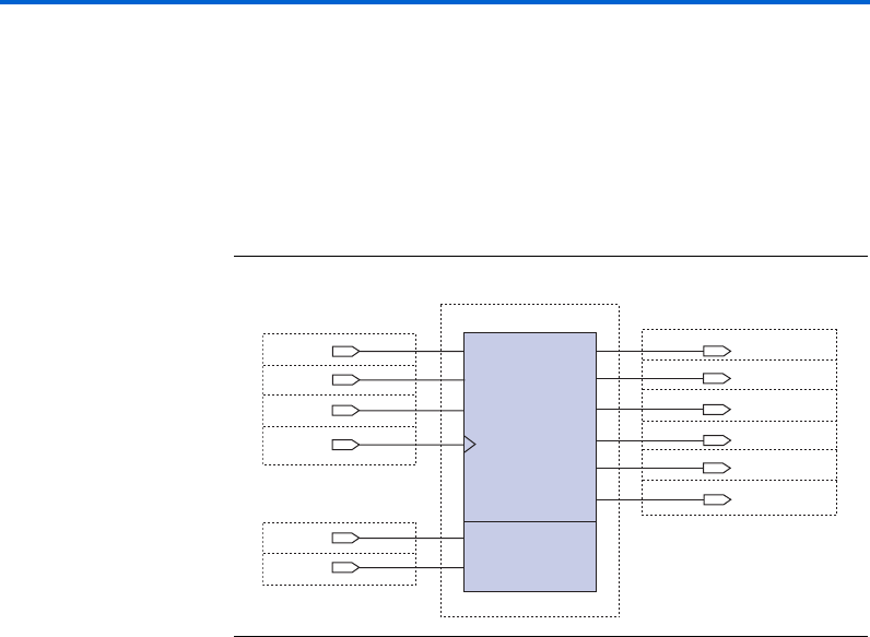
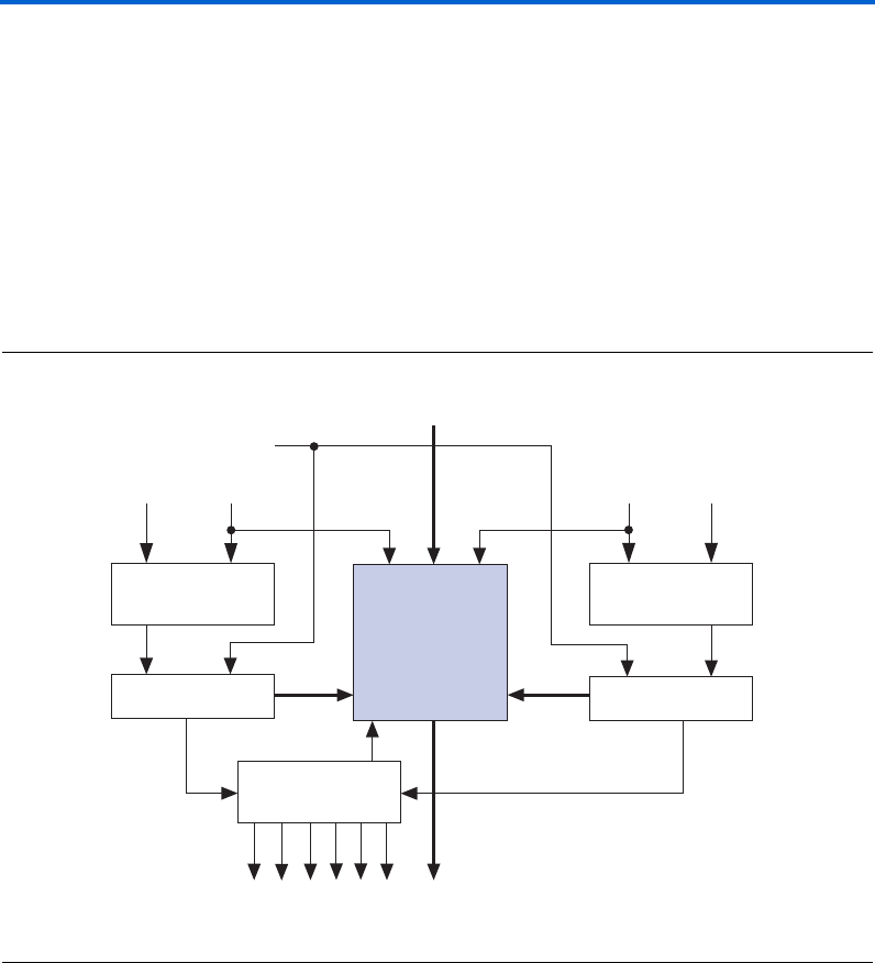
Figure 19 shows how the dcfifo megafunction is implemented within a
memory block. All control logic is implemented in logic elements (LEs).
1The dcfifo can be implemented within either a memory block
or LE design. However, implementing a large dcfifo in LEs can
dramatically increase the overall LE utilization.
Figure 19. Dual-Clock FIFO Megafunction Block Diagram
The dcfifo also provides two operational modes:
■Legacy mode
■Show-ahead mode
Write Control Logic Read Control Logic
Write Pointer Read Pointer
Flag Logic
data[ ]
aclr
rdclk rdreq
wrreq wrclk
q[ ]
rdempty
wrfull
wrempty
rdfull
rdusedw
w
rusedw
Altera
Memory Block

32 Altera Corporation
Single & Dual-Clock FIFO Megafunctions Specifications
When the dcfifo megafunction is configured in Legacy mode, the
requested data is available on the first clock cycle after rdreq is asserted,
i.e., the rdreq signal operates as a normal read request. However, when
the dcfifo is configured in Show-ahead mode, the rdreq signal
operates as a read acknowledge signal. Thus, the first bit of data written
in the FIFO immediately appears on its output, i.e., without a read
transaction occurring.
Figure 20 shows the Quartus II symbol for a 256 x 8 bit double-clock
megafunction in operating in Legacy mode. The symbols representing
Legacy and Show-ahead modes are the same except that the read request
signal operates as a read acknowledge signal in Show-ahead mode, noted
by rdreq(ack).
1When targeting Stratix and Stratix GX devices, Show-ahead
mode can only be implemented when custom logic is added
around the FIFO megafunction. Otherwise, Stratix and
Stratix GX devices do not support FIFO megafunctions
configured in Show-ahead mode.
Figure 20. Quartus II Symbol of dcfifo Megafunction Operating in Legacy Mode
You should not have the wrreq asserted on device power-up or during an
asynchronous clear cycle. If this event occurs there is a possibility that one
of the counters will transition while the other one will not, i.e., if there is
skew on the aclr line, one counter will read the aclr signal longer than
the other counter. The read and write side will then disagree on how many
words there are in the FIFO.
data[7..0]
wrreq
rdclock
my fifo
aclr
wrclock
rdreq
wrfull
wrempty
wrusedw[7..0]
rdusedw[7..0]
q[7..0]
rdfull
8 bits x 256 words
rdempty
DualClockFIFO
Altera Corporation 33
Specifications Single & Dual-Clock FIFO Megafunctions
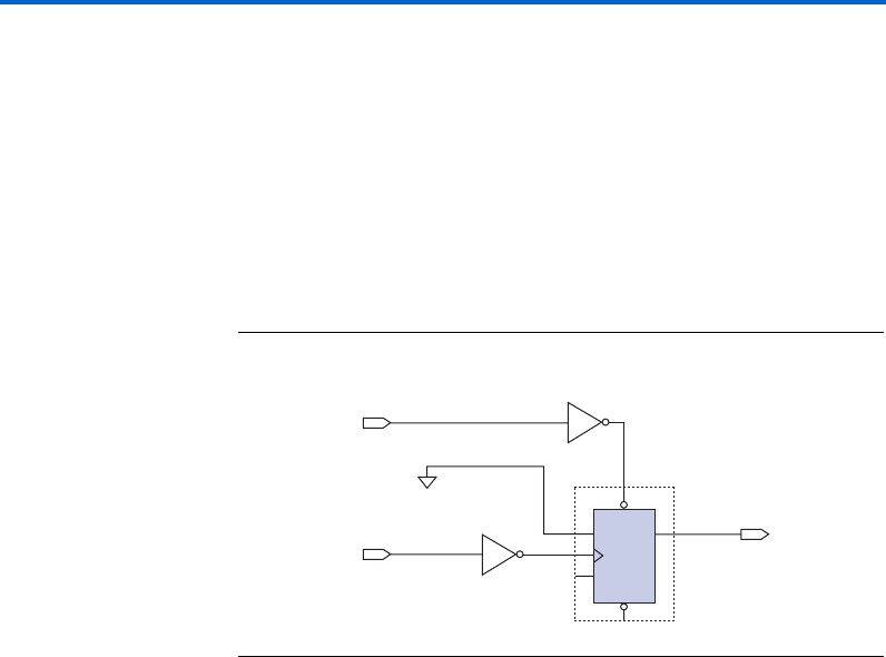
To prevent the counters from unequally reading the aclr signal, delay
the aclr signal for about half a cycle before transmitting to the FIFO. To
delay the aclr signal, add a D flipflop (DFF) where the inverted aclr
signal is connected to the preset port of the DFF and the inverted wrclock
is connected to the DFF clock—with the D port of the DFF connected to
ground. You can then use the output of the DFF as the aclr of your FIFO,
which guarantees that the falling edge of aclr will never occur on the
rising edge of the wrclock. See Figure 21.
1To guarantee that both counters will not transition, set wrreq
low while aclr is asserted and during device power-up.
Figure 21. Block Diagram to Delay aclr for Half a Cycle
1If underflow checking is enabled, the read side will not require a
similar adjustment. The FIFO is emptied when aclr is asserted;
thus, ignoring all read requests, i.e., similar to holding rdreq
low.
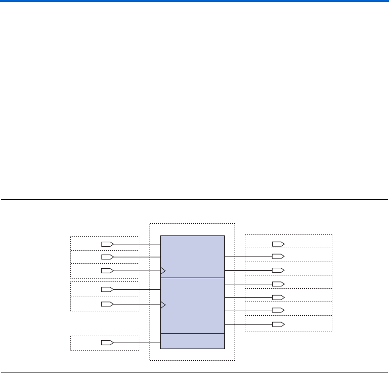
Pipeline Structure of Dual-Clock FIFOs
The Altera dcfifo megafunction is a dual-pipelined function that stores
data in the dual port memory structures of Altera devices—utilizing the
two pipelines to reduce the effects of metastability on both the read and
write status signal data paths. (Metastability can occur in asynchronous
transactions when data is transferred between different clock domains.)
Each pipeline has a word counter as its output. The wrusedw[] and
rdusedw[] signals are intended to provide an estimate of the number of
words stored in the FIFO. Figure 22 shows the pipeline structure of the
dcfifo megafunction.
INPUT
VCC
NOT
inst2
NOT
inst1
OUTPUT
PRN
CLRN
Q
D
DFFE
EMA
inst
aclr
INPUT
VCC
wrclk
GND
new_aclr

34 Altera Corporation
Single & Dual-Clock FIFO Megafunctions Specifications
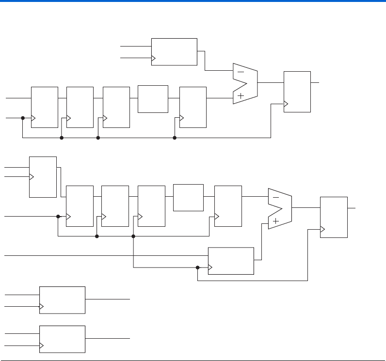
The read pipeline defaults to five registers clocked by the read clock. The
write pipeline contains five registers clocked by the write clock and one
register clocked by the read clock. The depth of the pipeline can be
adjusted by modifying the RDSYNC_DELAYPIPE and
WRSYNC_DELAYPIPE parameters. To provide good metastability
protection, Altera set the default value for the RDSYNC_DELAYPIPE and
WRSYNC_DELAYPIPE parameters to three. For most designs, the default
value of the RDSYNC_DELAYPIPE and WRSYNC_DELAYPIPE parameters
should not be changed. However, there may be some designs where
metastability is less of an issue. Thus, to reduce latency, the pipeline depth
could be set to less than three when metastability is less of an issue.
To modify the WRSYNC_DELAYPIPE and RDSYNC_DELAYPIPE
parameter values, specify the desired value in the Quartus II software.
Choose Default Parameter Settings from the Settings page (Assignment
menu). You can also set the parameters when manually instantiating the
dcfifo megafunction (i.e., without using the MegaWizard Plug-in
Manager). However, be sure to not modify the megafunction file itself, as
the change will be universal for all projects.
To reduce the chances of metastability, Altera recommends maintaining
the default value of three for the WRSYNC_DELAYPIPE and
RDSYNC_DELAYPIPE parameters.
fFor more information on the need for synchronized pipelines, refer to
Application Note 42: Metastability in Altera Devices.
Altera Corporation 35
Specifications Single & Dual-Clock FIFO Megafunctions
Figure 22. The dcfifo Megafunction Pipeline Structure
The last three words of the dcfifo may not be available for writing
because of the synchronization pipelines between the two clock schemes,
e.g., data available to one clock scheme—when read and write
transactions are occurring—may be temporarily unavailable to other
clock schemes because of the synchronization pipelines. To avoid an
overflow, the wrfull and rdfull ports of a dcfifo must be asserted
slightly before the dcfifo megafunction is completely full. This process
may cause several words at the end of the FIFO to become unavailable.
Depending on the data rate written to the FIFO, the wrfull and rdfull
ports may be asserted with three, two, or one word remaining in the FIFO.
This process is necessary both to accommodate the clock synchronization
and to avoid FIFO overflow. If a specific number of words needs to be
maintained, specify a value for the LPM_NUMWORDS parameter that is up
to three words greater than the amount needed.
QD
rd_udwn rdusedw
valid_rdreq
rdclk
LPM_COUNTER
En
QD
rdptr_g
rdclk
q
rdptr_b
QD QD QD QD
Gray Bin rs_dbwp
wrptr_g
rdclk
QD QD QD QD
Gray Bin ws_dbwp
wptr_b
wrclk
RDSYNC_DELAYPIPE = 3
DELAY_RDUSEDW = 1
WRSYNC_DELAYPIPE = 3
QD
wd_udwn wrusedw
DELAY_WRUSEDW = 1
valid_wrreq
valid_rdreq rdptr_g
rdclk
LPM_COUNTER
En q
GRAYCOUNTER
En q
valid_wrreq wrptr_g
wdclk
GRAYCOUNTER
En q

36 Altera Corporation
Single & Dual-Clock FIFO Megafunctions Specifications
The wrusedw[] & rdusedw[] Ports
The asynchronous nature of a dual-clock FIFO makes it very difficult to
accurately quantify the number of words stored in the FIFO at any one
time. The wrusedw[] and rdusedw[] signals can be used to estimate the
number of words in a FIFO; however, the there are limitations associated
the counter signals.
The synchronization and internal logic in the dcfifo megafunction may
cause the information in the wrempty, wrfull, wrusedw[], rdempty,
rdfull, and rdusedw[] signals to be delayed by multiple cycles of
latency. If the rdclk and wrclk signals are unrelated, set-up and hold
violations may occur on the synchronization registers during timing
analysis. Due to the inherent design of the function, the set-up and hold
errors can be ignored if the violating paths point to *dcfifo*dffpipe*
(where the asterisks are variables). However, set-up and hold violations
for other hierarchy paths should be investigated—as this may indicate
possible metastable events.
The dcfifo megafunction uses gray counters to implement the write and
read address pointers to the RAM. Two separate binary counters are also
used in the calculation of the wrusedw[] and rdusedw[] signals. A
binary counter clocked by the write clock and enabled by the write request
signal is used to keep a tally of the number of words written to the FIFO.
The number of words stored in the FIFO can be determined by subtracting
the read pointer from the binary write counter. However, before the read
pointer can be subtracted from the binary write counter, the read pointer
must first be converted from a gray count to a binary value. After
converting the read pointer to a binary value, the read pointer value is
subtracted from the binary write counter and the output of the subtractor
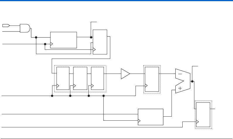
is registered to generate the wrusedw[] signal. Figure 23 shows how the
wrusedw[] is generated.
Altera Corporation 37
Specifications Single & Dual-Clock FIFO Megafunctions
Figure 23. The wrusedw Signal Generator
Because the write and read pointers are clocked by different clock signals,
generating wrusedw may lead to metastability. Therefore, FIFOs should
implement some mechanism that reduces the chance of a metastable event
propagating to the wrusedw[] signal.
The dcfifo megafunction uses a three-stage synchronizer to reduce the
chances of metastability. The synchronizer is clocked by the write clock
with the read address pointer (rdptr_g) as the input. The address
pointer is clocked by the read clock and it is possible that the output of the
pointer may violate the set-up time of the first register in the synchronizer.
However, because the synchronizer is three-stages deep the odds of a
metastable event passing through to the output decrease with each stage
of the synchronizer.
Because the wrusedw[] signal is clocked by the write clock and is the
output of the write pipeline, it can be used as an indicator of the number
of words in the FIFO by any process that uses the write clock. The number
of words contained in a FIFO can be calculated by subtracting the total
number of words read from the total number of words written to the
FIFO. By referring to Figure 23, wrusedw[] can be calculated with the
following equation:
wrusedw[i+1] = wrptr_b[i] - ws_dbrp[i]
valid_rdreq rdptr_g
rdclk
wrclk
wrclk
GRAYCOUNTER
En Q
rdreq
rdfull
initial = 1
QD
EN
Read Address
to RAM
Pointer to wrfull
and wrempty
QD QD QD QD ws_dbwp
wrptr_b
dffpipe dffpipe
GRAY_DELAYPIPE = 1
WRSYNC_DELAYPIPE = 3
DELAY_WRUSEDW = 1
LPM_COUNTER
En q
ws_dgrp ws_nbrp
QD
wr_udwn
wrusedw
dffpipe
gray2bin
valid_wrreq

38 Altera Corporation
Single & Dual-Clock FIFO Megafunctions Specifications
The wrclk clocks each signal in the equation. The wrptr_b signal—
which is transparent to the user—is the output of a binary counter that is
incremented every time there is a valid write request; it is also an
indication of the total number of words written to the FIFO. The ws_dbrp
is the converted output of the read pointer gray counter that represents
the number of words read from the FIFO.
Figure 23 shows that wrptr_b has a direct path to the subtractor and
therefore the wrusedw[] signal has only one clock cycle of latency
associated with a write request. However, read requests incur more
latency as the gray read pointer value must first pass through a DFF that
is clocked by the read clock; then the value is transferred through the
synchronizer where it incurs three delay cycles with respect to the write
clock. At this point, the value must pass through a write clock register
after the gray-to-binary converter. Finally the value passes through a
write clock register at the output of the subtractor.
In sum, read requests takes five write clock cycles plus one read clock
cycle before the wrusedw[] signal reflects that a read transaction has
occurred—which may lead you to believe that a read request is not
reflected in the wrusedw[] signal for six write clock cycles. However, the
read gray counter pointer powers on to 1 instead of 0, which causes a read
request to have one less cycle of latency than is expected. Therefore, in
general, the wrusedw[] signal is updated five write clock cycles after a
read request. Thus, there are two important points regarding the
ws_dbrp signal, it:
■Has at least four cycles of latency with respect to the wr_ptrb signal
■Originates from the read clock domain
The net effect of the write pipeline is that read transactions have a delayed
effect on the wrusedw[] signal. In general, a read request will take five
write clock cycles before it is reflected in the wrusedw[] signal, where the
fifth clock cycle comes from the output register on the wrusedw[] signal.
The result of the delay is that the wrusedw[] signal will indicate that the
FIFO is fuller than it actually is.
Altera Corporation 39
Specifications Single & Dual-Clock FIFO Megafunctions
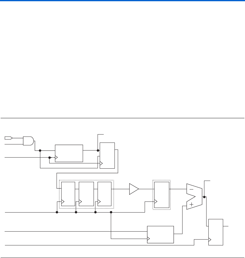
The rdusedw[] signal is also generated by subtracting the number of
words read from the number of words written to the FIFO. Figure 24
shows how the rdusedw[] is generated. The rdusedw[] status flag logic
also uses a synchronizer to prevent metastability. This synchronizer is
clocked by the read clock with the write address pointer (wrptr_g) as the
input. The grey counter address pointer is clocked by the write clock. The
binary counter (rdptr_b) signal is used to keep a tally of the number of
words read from the FIFO, it is clocked by the read clock and enabled by
the read request signal. The number of words stored in the FIFO is
calculated by subtracting the binary read counter from the write pointer
(wrptr_g). Again, the write pointer must first be converted from a gray
count to a binary value before the binary read counter can be subtracted
from it. After the conversion, the binary read counter is subtracted from
the write pointer value and the output of the subtractor is registered to
generate the rdusedw[] signal.
Figure 24. The rdusedw Signal Generator
The rdusedw[] signal can be calculated with the following equation:
rdusedw[i+1] = rs_dbwp[i] - rdptr_b[i]
The rdclk clocks each signal in the equation. The rdptr_b— which is
transparent to the user—is the output of the binary read counter that is
incremented every time there is a valid read request. The rs_dbwp is the
converted output of the write pointer gray counter representing the total
number of words read from the FIFO.
valid_wrreq wrptr_g
wrclk
rdclk
rdclk
GRAYCOUNTER
En q
wrreq
wrfull
initial = 1
QD
EN
Write Address
to RAM
Pointer to rdfull
and rdempty
QD QD QD QD rs_dbwp
rdptr_b
dffpipe dffpipe
GRAY_DELAYPIPE = 1
RDSYNC_DELAYPIPE = 3
DELAY_RDUSEDW = 1
LPM_COUNTER
En q
rs_dgrp rs_nbrp
QD
rd_udwn
rduse
dffpipe
gray2bin
valid_rdreq

40 Altera Corporation
Single & Dual-Clock FIFO Megafunctions Specifications
In Figure 24, rdptr_b has a direct path to the subtractor; therefore, the
rdusedw signal is updated one read clock cycle after a read request. Write
requests incur more latency as the gray write pointer value must first pass
through a DFF that is clocked by the write clock and then pass through the
synchronizer where it incurs three delay cycles with respect to the read
clock.
Finally, after the gray-to-binary conversion, the value passes through a
read clock register—at the output of the subtractor. In sum, a write request
takes five read clock cycles plus one write clock cycle before the rdusedw
signal reflects that a write transaction occurred. Unlike the rdptr_g
signal, the wrptr_g gray counter is initialized to 0; therefore, a write
request will generally have six cycles of latency with same frequency
clocks. Thus, there are two important points about the rs_dbwp signal, it:
■Has at least four cycles of latency with respect to the rdptr_b signal
■Originates from the write clock domain
The net effect of the read pipeline is that write transactions have a delayed
effect on the rdusedw[] signal. In general, a write request will take six
write clock cycles before it is reflected in the rdusedw[] signal, where the
sixth clock cycle comes from the output register on the rdusedw[] signal.
The result of the delay is that the rdusedw[] signal will indicate that the
FIFO is emptier than it actually is.
Because it is difficult to predict the full effect of read and write
transactions on wrusedw[] and rdusedw[] signals, wrusedw[] and
rdusedw[] signals will always be conservative representations of the
number of words stored in the FIFO.
If the read clock is faster than the write clock, the wrusedw[] signal will
tend to overestimate the number of words stored in the FIFO—while the
rdusedw[] signal will have less deviation from the true amount of words
stored in the FIFO. Likewise, if the write clock is faster than the read clock,
the rdusedw[] will tend to underestimate the number of words stored in
the FIFO—while the wrusedw[] signal will have less deviation from the
true amount of words stored in the FIFO.
It is not possible to reliably predict the difference between rdusedw[],
wrusedw[], and the true word count of the FIFO at any given moment in
time. However, it is possible to predict the maximum value by which the
counts will differ from the true value.
The following equation can be used to predict the maximum deviation
between rdusedw[] and the true word count:
rdusedw = CEIL((fWRITE/fREAD) x (RDSYNC_DELAYPIPE+1))
+ DELAY_RDUSEDW + CEIL(fWRITE/fREAD)
∆

Altera Corporation 41
Specifications Single & Dual-Clock FIFO Megafunctions
Where fWRITE is the frequency of the write clock, and fREAD is the
frequency of the read clock. The RDSYNC_DELAYPIPE defaults to 3 and
DELAY_RDUSEDW defaults to 1.
The following equation can be used to predict the maximum deviation
between wrusedw[] and the true word count:
wrusedw = CEIL((fREAD/fWRITE) x (WRSYNC_DELAYPIPE+1))
+ DELAY_WRUSEDW + CEIL(fREAD/fWRITE) - 1
Where fWRITE is the frequency of the write clock, and fREAD is the
frequency of the read clock. The RDSYNC_DELAYPIPE defaults to 3 and
DELAY_RDUSEDW defaults to 1.
From the two deviation equations, you can determine that the signal
clocked by the faster clock will have a deviation that is less than the signal
clocked by the slower clock. Again, the WRSYNC_DELAYPIPE and
RDSYNC_DELAYPIPE parameters control the depth of the
synchronization pipelines.
Some FIFO applications may require a very accurate word count. For
these applications, the following guidelines should be observed:
■The wrusedw[] signal will be most accurate when the write pipeline
is flushed. The write pipeline can be flushed by not reading for a
period of at least five write clock cycles.
■The rdusedw[] signal will be most accurate when the read pipeline
is flushed. The read pipeline can be flushed by not writing for a
period of at least six read clock cycles.
■The status signals generated by the faster clock domain will generally
be more accurate.
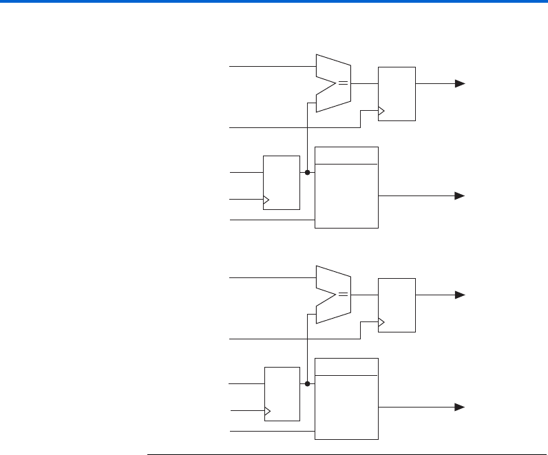
The Full & Empty Signals
The full and empty signals are an important element in most dcfifo
designs. The dcfifo megafunction generates the following full and
empty signals: wrempty, wrfull, rdempty and rdfull. Figure 25
shows the full- and empty-signal generation in the dcfifo megafunction.
∆
42 Altera Corporation
Single & Dual-Clock FIFO Megafunctions Specifications
Figure 25. Full & Empty Signal Generation
The empty signals are generated from a finite state machine (FSM). The
FSM is designed to assert the empty signal if:
■The input count (wrusedw[]/rdusedw[]) equals 1
■The wrusedw[]/rdusedw[] equals 2 and the read request signal is
asserted
The dcfifo megafunction’s empty signal latency phase is three clock
cycles plus one cycle for every pipelined stage specified in the dcfifo.
The three clock cycles of latency are required for synchronization of the
read and write clocks in the FIFO.
The full signals are the outputs of two comparators. The comparators
compare the wrusedw[]/rdusedw[] input signal against the
(LPM_NUMWORDS – 3) parameter. Therefore the full signal will be asserted
whenever the input word count is three words less than the depth of the
dcfifo.
QD
FSM
usedw
rreq
rdempty
QD
LPM_NUMWORDS-3
LPM_COMPARE
rdfull
rdclk
rdclk
rdreq
rd_udwn
QD
FSM
usedw
rreq
wrempty
QD
LPM_NUMWORDS-3
LPM_COMPARE
wrfull
wrclk
wrclk
wrreq
wr_udwn

Altera Corporation 43
Specifications Single & Dual-Clock FIFO Megafunctions
Because the wrfull and the rdempty signals provide the truest
indication of the state of the FIFO, Altera recommends using these two
signals to determine if the FIFO is full or empty. The wrfull and
rdempty signals are also used to prevent overflow and underflow in the
FIFO. Also, because the wrfull signal will be updated within one write
clock cycle after a write request, and the rdfull signal may not be
updated for a number of words after a write request, the wrfull signal
should be used instead of the rdfull signal. Likewise, because the
rdempty signal will be updated within one read clock cycle after a write
request, and the wrempty signal may not be updated for a number of
words after a read request, the rdempty signal should be used instead of
the wrempty signal. The wrfull and rdempty signals are asserted by the
FIFO before the FIFO is actually full or empty, which is an important
design issue when one clock domain is much faster than the other.
When the wrclk is much slower than the rdclk, wrfull may be
asserted when writing to an almost empty FIFO followed by a few read
transactions. Use the following equation to determine the minimum
number of words when wrfull is high:
minWRFULL = LPM_NUMWORDS–3 CEIL(fREAD/fWRITE) x
(WRSYNC_DELAYPIPE + 4)
The wrfull signal determines if new words can be written into the FIFO
when the OVERFLOW_CHECKING parameter is set to ON. Because the
OVERFLOW_CHECKING parameter guarantees that data will not be lost
from the FIFO, Altera recommends leaving it ON .
It is possible for the rdempty signal to be asserted when the FIFO is not
empty. In general, the rdempty signal will be asserted for seven read
clock cycles before a write request deasserts the signal. The seven-cycle
latency makes it possible for a number of words to be stored in the FIFO
before rdempty drips low. The following equation indicates the
maximum number of words that can be stored in the FIFO while rdempty
is high:
maxRDEMPTY = CEIL(fWRITE/fREAD) x (WRSYNC_DELAYPIPE + 3)
Functional Waveforms
This section discusses data transactions during various read and write
transactions in both Legacy and Show-ahead operational modes.
44 Altera Corporation
Single & Dual-Clock FIFO Megafunctions Specifications
Dual-Clock FIFO Megafunction Legacy & Show-ahead Modes
Operating in Legacy mode, Figure 26 displays the sample design that is
used to generate the functional waveforms (i.e., Figure 27 through 36)
discussed in this section. The dcfifo megafunction is generated via the
FIFO MegaWizard Plug-In Manager and is configured to be 32-words
deep and 8-bits wide. The design uses all of the available ports and sets
other options to default; the output flags are pipelined and the underflow
and overflow checking circuitry is enabled. For comparative analysis,
some of the waveforms may represent the dcfifo operating in Show-
ahead mode with all of the other options the same.
1Latency cycles shown on the following waveforms are based on
functional simulation and offered only for example. Depending
on the set-up and clock-to-out time, as well as the relationship
between the wrclk and rdclk signals, latency cycles may differ.
Figure 26. Sample Dual-Clock FIFO Operating in Legacy Mode
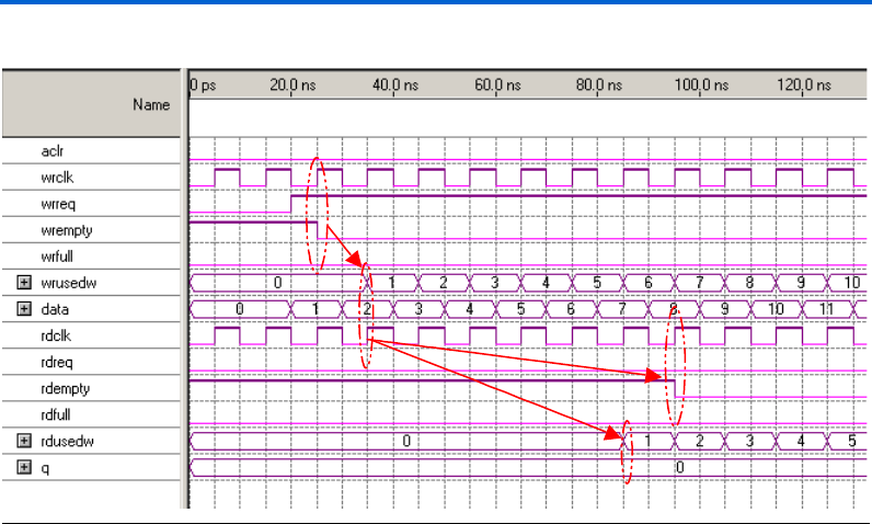
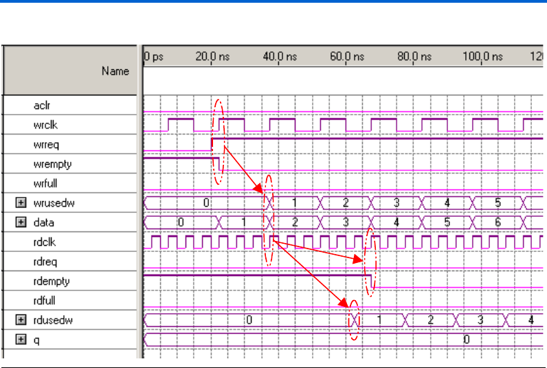
Figure 27 shows how the wrempty and rdempty signals are deasserted
when initially writing to the dcfifo operating in Legacy mode. In this
example, the rdclk and the wrclk are of the same frequency and phase.
The wrempty signal is deasserted at the same rising edge as the wrclk.
When the FIFO initially notices that the wrreq signal is asserted, the
wrusedw[] is incremented on the next rising edge of the wrclk after
wrempty is deasserted. In this example, after the first data is written, the
rdusedw[] counter is incremented after six rdclk cycles, while the
rdempty is deasserted on the next rising edge of rdclk.
data[7..0]data[7..0]
wrreqwrreq
rdreq
rdreq
rdclk
my fifo
aclraclr
wrfull wrfull
wrempty wrempty
wrusedw[4..0] wrusedw[4..0]
q[7..0] q[7..0]
rdempty rdempty
8 bits x 32 words
rdusedw[4..0] rdusedw[4..0]
DualClockFIFO
INPUT
VCC
INPUT
VCC
wrclkwrclk INPUT
VCC
INPUT
VCC
INPUT
VCC
OUTPUT
OUTPUT
OUTPUT
OUTPUT
OUTPUT
OUTPUT
rdclk
INPUT
VCC
rdfull rdfull
OUTPUT
Altera Corporation 45
Specifications Single & Dual-Clock FIFO Megafunctions
Figure 27. Initial Writing Phases of Dual-Clock FIFOs Operating in Legacy Mode
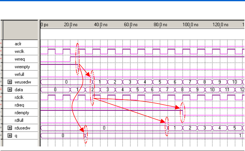
The dcfifo megafunction operating in Show-ahead mode presents
identical transactions to the Legacy mode, with one exception—the q[]
port is updated with the first data in the FIFO on the falling wrclk edge,
where the first write transaction occurs. Even though 1 appears on the
q[] port, it is not considered a read transaction until the rdreq is
asserted, acknowledging the read. See Figure 28.
46 Altera Corporation
Single & Dual-Clock FIFO Megafunctions Specifications
Figure 28. Initial Writing Phases of Dual-Clock FIFOs Operating in Show-ahead Mode
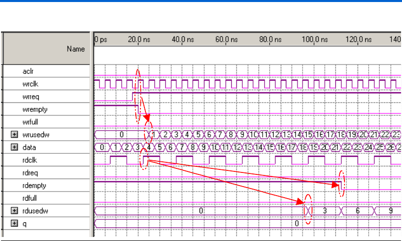
When the wrclk is faster than the rdclk, the rdusedw[] counter
increments by the number of times faster. In the Figure 29 example, the
wrclk is three times faster than the rdclk. The wrempty flag is still
asserted at the first rising edge of the wrclk where the FIFO first notices
the wrreq is asserted. The rdusedw[] counter increments by three after
six rdclk latency cycles. On every subsequent rdclk when data is
written to the FIFO, the rdusedw[] increments by three—because the
wrclk is three times faster than the rdclk, three write transactions occur
within one rdclk cycle.
Altera Corporation 47
Specifications Single & Dual-Clock FIFO Megafunctions
Figure 29. Initial Write Transactions Where wrclk is Three Times Faster Than rdclk
When the wrclk is many times slower than the rdclk, the latency on
rdusedw[] and rdempty—with respect to the wrclk itself—may look
much longer. However, the same six-cycle rdclk latency is still valid.
Figure 30 shows an example where the wrclk is three times slower than
the rdclk. In this example, the wrclk and wrusedw[] are updated like
the previous examples. However, the actual write transaction to the ESB
is on the falling wrclk edge; thus, the rdusedw[] and rdempty signals
are calculated starting from the first rising rdclk edge after the falling
wrclk edge. In effect, rdempty still has seven rdclk latency cycles and
rdusedw[] has six rdclk latency cycles.
48 Altera Corporation
Single & Dual-Clock FIFO Megafunctions Specifications
Figure 30. Initial Write Transactions Where wrclk is Three Times Slower Than rdclk
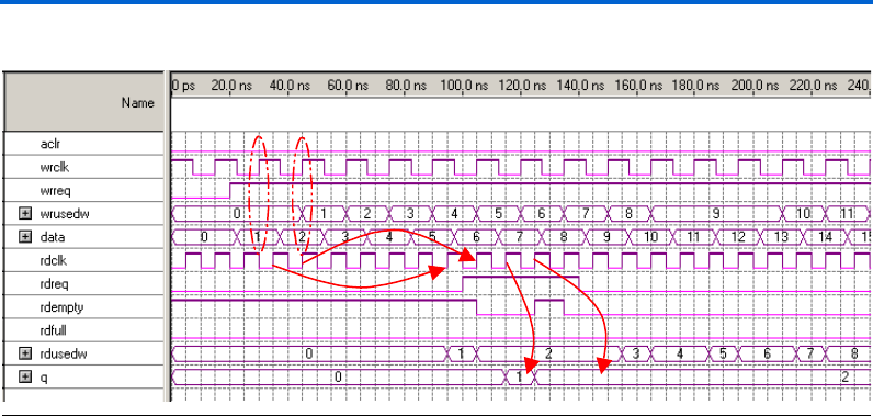
Consider also a read transaction with the first FIFO write transaction.
Figure 31 shows how the rdreq is serviced. Again, the rdempty is
updated after about seven rdclk latency cycles from the first rising
rdclk edge after data is written, denoting that data is available to be read
from the FIFO. Also, any read requests when rdempty is asserted are
ignored (unless the underflow checking option is disabled). As illustrated
in Figure 31, only the second and the third read requests are serviced, and
the rdempty flag goes high after the second read is performed. This is due
to the frequency relationship between the read and write clocks. In the
Figure 31 example, a sufficient number of clock cycles have not occurred
since the third word has been written.
Altera Corporation 49
Specifications Single & Dual-Clock FIFO Megafunctions
Figure 31. A Read Transaction In the Beginning Stages of Writing to an Almost Empty dcfifo, Legacy Mode
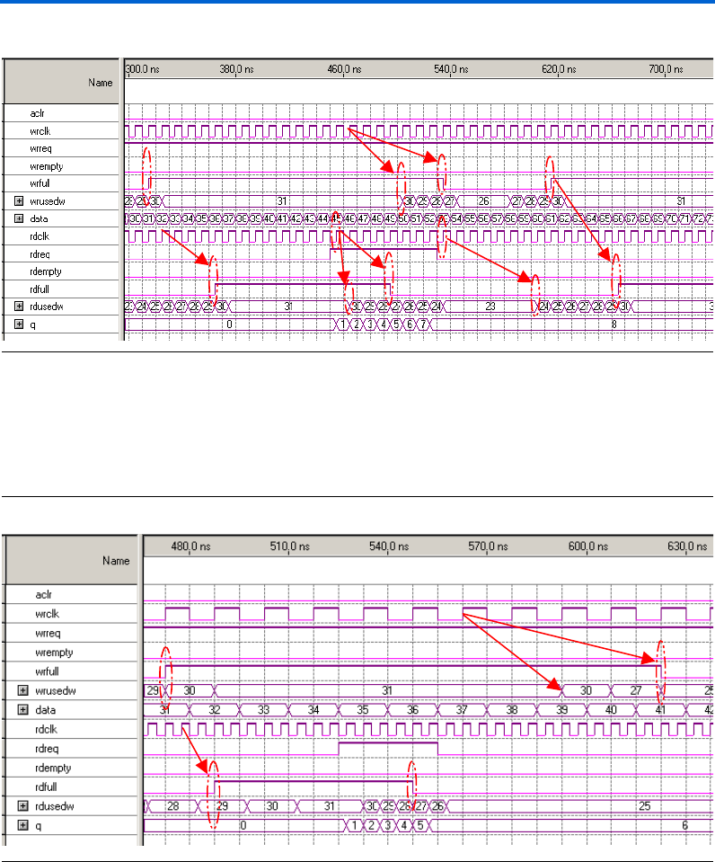
Figure 32 shows how the rdfull and wrfull signals are asserted and
deasserted. The waveform shows that the wrfull flag is deasserted when
the wrusedw[] is equal to LPM_NUMWORDS-1. The calculation actually
occurs when wrusedw[] is equal to LPM_NUMWORDS-3, but because of
pipelined registers, the actual flag asserts two clock cycles later.
In the Figure 32 example, the rdusedw[] counter is five rdclk cycles
behind, which delays the rdfull flag by five rdclk cycles from the last
write cycle. When the rdreq is asserted, the rdusedw[] value is
decremented on the next rising edge of rdclk. However, in this example,
it takes four wrclk cycles after the first read transaction to decrement the
wrusedw[] value. Similar to the previous instance, the calculation for the
rdfull and wrfull begins when the rdusedw[] and the wrusedw[],
are equal to LPM_NUMWORDS-3, but the flag itself is updated two clock
cycles later. Although the wrreq is asserted during the entire example,
the write transaction occurs only when the wrfull flag is deasserted.
50 Altera Corporation
Single & Dual-Clock FIFO Megafunctions Specifications
Figure 32. Read & Write Operations in an Almost Full dcfifo, Legacy Mode
When the rdclk is faster than the wrclk, the rdfull flag is asserted
faster where the rdusedw[] is closer to the LPM_NUMWORDS – 3 value.
Figure 33 shows that the wrfull flag still asserts when wrusedw[]
equals LPM_NUMWORDS – 1. However, the rdfull flag is asserted two
rdclk cycles after rdusedw[] equals LPM_NUMWORDS – 3.
Figure 33. Read & Write Operations with rdclk Three Times Faster Than wrclk
Figure 34 shows an example where the rdclk is three times slower than
the wrclk. In the example, the rdfull is asserted when rdusedw[] is
equal to LPM_NUMWORDS - 1. The example also shows that both the
wrfull and rdfull signals are deasserted at the same time, even though
the wrusedw[] and rdusedw[] are not holding the same value.
Altera Corporation 51
Specifications Single & Dual-Clock FIFO Megafunctions
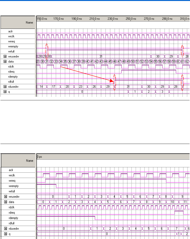
Figure 34. Read & Write Operations With rdclk Three Times Slower Than wrclk
Figure 35 illustrates that the counter clocked by the faster clock will be
more accurate than the counter clocked by the slower clock. In the
example, rdusedw[] is clocked three times faster than wrusedw[].
Therefore, rdusedw[]is updated more frequently than wrusedw[].
Thus, applications that require an accurate word count should rely on the
counter that is clocked by the faster clock domain.
Figure 35. The Faster Clock Holds More Accurate Word Count Than the Slower Clock
52 Altera Corporation
Single & Dual-Clock FIFO Megafunctions Specifications
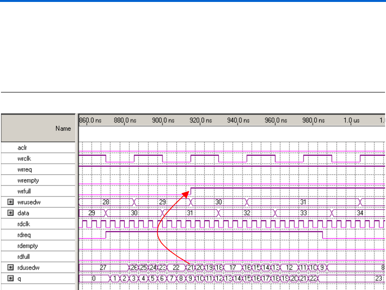
When rdclk is much faster than wrclk, you should use caution because
the flags may become asserted incorrectly. Figure 36 shows the wrfull
flag going high even though there are only 21 words in the FIFO. This
action is the result of the read transactions not being included in the
wrusedw[] calculation, as not enough wrclk cycles have transmitted
from the first read transaction.
Figure 36. The wrfull Flag Asserts Incorrectly When rdclk is Much Faster Than wrclk

Altera Corporation 53
Specifications Single & Dual-Clock FIFO Megafunctions
Ports &
Parameters
Table 5 describes the input ports of both the single- and dual-clock FIFO
megafunctions. Some ports are only available with dual-clock FIFO
megafunctions and have been noted.
1Refer to the latest version of the Quartus II Help for the most
current information on the single- and dual-clock FIFO ports and
parameters.
Notes:
(1) The rdclk and wrclk are only available with dual-clock FIFO megafunctions. With single-clock FIFO
megafunctions, there is only one clock input.
(2) Only the output flags, the usedw[](or the wrusedw[]), and rdusedw[] signals are cleared when the FIFO is
targeted for the Stratix and Stratix GX device’s TriMatrix memory. However, the q[] output of the FIFO will not be
cleared. Moreover, because inputs to the TriMatrix memory must be synchronous, the aclr signal in Stratix and
Stratix GX devices is treated as a synchronous clear.
Table 5. Input Single & Dual Clock FIFO Megafunction Ports
Port Required Description
data[] Yes Data input to the FIFO. The size of data[] port is equal to the
LPM_WIDTH of the FIFO.
rdclk, (1) Yes Positive-edge-triggered clock to read data from FIFO.
wrclk, (1) Yes Positive-edge-triggered clock to write data to the FIFO.
wrreq Yes Write request port. When wrreq = 1, the FIFO stores the data from the
data[7..0] port at the next rising edge of the write clock. Unless the
overflow checking circuitry is disabled, writing is disabled if
wrfull = 1.
rdreq Yes Read request port. For megafunctions operating in Legacy mode,
when rdreq = 1, the oldest data in the FIFO is available at the q[]
output port on the rising rdclk edge. For megafunctions operating in
Show-ahead mode, when rdreq is asserted a read is acknowledged
and the q[] output port is updated with the next data in the FIFO.
Reading is disabled if rdempty = 1, unless the underflow checking
circuitry is disabled.
aclr, (2) No Asynchronous clear input to empty the FIFO.
sclr, (2) No Synchronous clear input. The oldest data is flushed before the FIFO
empties on the next rising edge of the clock. The sclr port is only
available in single-clock FIFO megafunctions.

54 Altera Corporation
Single & Dual-Clock FIFO Megafunctions Specifications
Table 6 describes the output ports of both the single and dual-clock FIFO
megafunctions. Some ports are only available with single-clock or with
dual-clock FIFO megafunctions and have been noted.
Notes:
(1) These ports are only available in dual-clock FIFO megafunctions. In single-clock FIFO megafunctions, there will
only be empty, full, and usedw[] signals, synchronized with the clock port.
(2) These ports can only be instantiated in single-clock FIFO megafunctions.
Table 6. Output Single & Dual Clock FIFO Megafunction Ports
Port Required Description
q[] Yes Data output from the FIFO. The size of the q[] port is equal to the
LPM_WIDTH of the FIFO.
rdempty,(1) No Read empty flag. When asserted, the FIFO is considered empty, and
the rdreq is disabled unless the underflow checking circuitry is
disabled. The rdempty port is synchronized with rdclk, and is
deasserted six rdclk cycles after the first wrreq. The rdempty port
is usually more accurate than wrempty.
wrfull,(1) No Write full flag. When asserted, the FIFO is considered full, and the
wrreq port is disabled unless the underflow checking circuitry is
disabled. The wrfull port is synchronized with wrclk. The wrfull
port is usually more accurate than rdfull.
wrempty,(1) No Write empty flag. Indicates that the FIFO is empty when asserted. The
wrempty port is a delayed version of rdempty that is synchronized
with wrclk. Normally wrempty is asserted six wrclk cycles after
rdempty.
rdfull,(1) No Read full flag. Indicates that the FIFO is full when asserted. The
rdfull port is a delayed version of wrfull that is synchronized with
rdclk. Normally rdfull is asserted up to six rdclk cycles after
wrfull.
rdusedw,(1) No Read used flag. Reflects the current number of words in the FIFO, and
is synchronized with rdclk. The rdusedw port should be used with
wrusedw[]. The width of the rdusedw port is equal to the
LPM_WIDTHU value.
wrusedw,(1) No Write used flag. Reflects the current number of words in the FIFO, and
is synchronized with wrclk. The wrusedw port should be used with
rdusedw[]. The width of the wrusedw port is equal to the
LPM_WIDTHU value.
almost_empty,(2) No Indicates that the scfifo is almost empty. Asserted when usedw[]
<= ALMOST_EMPTY_VALUE. When using the almost_empty port,
specify the ALMOST_EMPTY_VALUE.
almost_full,(2) No Indicates that the scfifo is almost full. Asserted when usedw[] >=
ALMOST_FULL_VALUE. When using the almost_full port, specify
the ALMOST_FULL_VALUE.

Altera Corporation 55
Specifications Single & Dual-Clock FIFO Megafunctions
Table 7 describes the parameters for both the single and dual-clock FIFO
megafunctions.
Table 7. Single & Dual-Clock FIFO Megafunction Parameters (Part 1 of 2)
Parameter Required Type Description
LPM_WIDTH Yes Integer Specifies the width of data[] and q[] ports.
LPM_WIDTHU Yes Integer Specifies the width of the usedw[] (or the rdusedw[]), and
wrusedw[] ports. The recommended value for this
parameter is ceil, (LOG2[LPM_NUMWORDS]).
LPM_NUMWORDS Yes Integer Specifies the depth of the FIFO, which is usually a power of
two.
LPM_SHOWAHEAD, (1) Yes String Specifies whether the FIFO is in Legacy mode (i.e., when
OFF) or Show-ahead mode (i.e., when ON). In Show-ahead
mode, data immediately appears on q[] without explicitly
asserting rdreq. Note, specifying ON for LPM_SHOWAHEAD
may reduce performance.
OVERFLOW_CHECKING No String So that wrfull is no longer checked for wrreq, the
OVERFLOW_CHECKING parameter disables the overflow-
checking logic when set to OFF. Values are ON or OFF (the
default is ON). The OVERFLOW_CHECKING parameter is an
Altera-specific parameter. Note, writing to a full FIFO yields
unpredictable results.
UNDERFLOW_CHECKING No String So that rdempty is no longer checked for rdreq, the
UNDERFLOW_CHECKING parameter disables the underflow-
checking logic when set to OFF. Values are ON or OFF (the
default is ON). The UNDERFLOW_CHECKING parameter is an
Altera-specific parameter. Note, reading to an empty FIFO
yields unpredictable results.
DELAY_RDUSEDW, (2) No Integer Specifies the number of register stages that are added
internally to the rdusedw[] port. The default value of 1
adds a single register stage to the output to improve its
performance. The DELAY_RDUSEDW is an Altera-specific
parameter. Increasing the DELAY_RDUSEDW parameter’s
value does not increase the maximum system speed; it only
adds additional latency to rdusedw[].
DELAY_WRUSEDW, (2) No Integer Specifies the number of register stages that are added
internally to the wrusedw[] port. The default value of 1
adds a single register stage to the output to improve its
performance. The DELAY_WRUSEDW is an Altera-specific
parameter. Increasing the DELAY_WRUSEDW parameter
value does not increase the maximum speed of the system;
it only adds additional latency to wrusedw[]

56 Altera Corporation
Single & Dual-Clock FIFO Megafunctions Specifications
Notes:
(1) Single and dual-clock FIFO megafunctions targeted for Stratix and Stratix GX devices do not support the Show-
ahead mode. However, to implement the functionality, add extra logic to the megafunction.
(2) These parameters are not accessible through the MegaWizard Plug-In Manager. Add the parameter when
instantiating the FIFO, or make a default parameter assignment in the Quartus II software, Settings page
(Assignments menu).
RDSYNC_DELAYPIPE, (2) No Integer Specifies the number of register stages that are internally
added for synchronization from the write control logic to the
read control logic. The default value of three is a good
safeguard value that protects against the possibility of
internal metastability when rdclk and wrclk are unrelated.
The RDSYNC_DELAYPIPE is an Altera-specific parameter.
If rdclk is over 12x faster than wrclk—to prevent reading
unknown data on the first rdreq—you may need to increase
the value for the RDSYNC_DELAYPIPE parameter, which
adds additional latency to rdusedw[]. Decreasing the
RDSYNC_DELAYPIPE parameter value can increase the
chances of metastability
WRSYNC_DELAYPIPE, (2) No Integer Specifies the number of register stages that are added
internally for synchronization from the read control logic to
the write control logic. The default value of three is a good
safeguard value that protects against the possibility of
internal metastability when rdclk and wrclk are unrelated.
The WRSYNC_DELAYPIPE is an Altera-specific parameter.
Increasing the WRSYNC_DELAYPIPE parameter value adds
additional latency to wrusedw[]. Decreasing the
WRSYNC_DELAYPIPE parameter value can increase the
chances of metastability.
USE_EAB No String Specifies whether the FIFO should be implemented in
EABs/ESBs (when ON) or in LEs (when OFF). Values are
ON, OFF, and UNUSED.The USE_EAB is an Altera-specific
parameter.
Table 7. Single & Dual-Clock FIFO Megafunction Parameters (Part 2 of 2)
Parameter Required Type Description
