RM 6600 Uscellar Series Single Evaporator Manual
User Manual: RM 6600
Open the PDF directly: View PDF ![]() .
.
Page Count: 3
OPTIONS
• Twinandtripleevaporator
systemsforlargerapplications
• Eco-friendlywater-cooled
condensingunitsavailable
• Stainlesssteelcabinetsfor
high-corrosiveenvironments
FEATURES
• High-performancestaggeredcoilswithcoppertubingmechanically
expandedintoaluminumns
• Insulatedrust-proofaluminumhousing
• Thermallyprotectedpermanentlylubricatedmotor
• Automaticexpansionvalve(standard)ensuresconstantcoil
temperaturetopromote“HumidityBalance”
• Pump-downsolenoidvalve(standard)protectscompressorintheevent
ofleaks
• Pre-installedvalveseliminateadditionalwiringtothermostat
• Pressuretestedbythemanufacturertoensurequality
• Factorywiredforsimpleeldinstallation
• ETLcertied
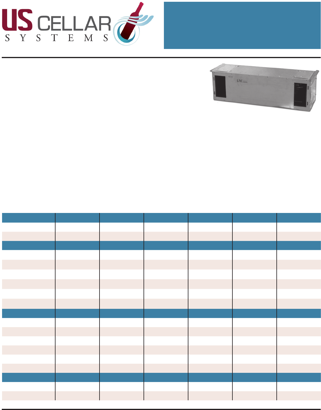
RM SERIES
Rack Mounted / Air or Water Cooled
Single Evaporator Unit with Digital Controller
USCellarSystems/3070GoldenAve,LongBeach,CA90806/www.uscellarsystems.com
(562)513-3017phoneandfax/info@uscellarsystems.com
SYSTEM INFORMATION
TheRackMounted(RM)Systemsare
designedtoproviderefrigerated
airtomedium-hightemperature
spaces.
RMevaporatorsmounthorizontally
andhavemultipleaccesspanelsto
directorre-directthesupplyand
returnvents.Thesecanbeplaced
inasoft,betweenceilingjoists,
oronawall.Byfarthisisourmost
versatilesystemandourbiggest
seller.
RMevaporatorsareavailablein
standardcapacitiesfrom2,600to
6,600BTUperhourandareused
withR134arefrigerant.
Rack Mounted RM2600 RM3600 RM4600 RM4600 HV RM6600 RM6600 HV
Max Cubic Feet 300 650 1,000 1,000 2,000 2,000
BTUH 2600 3600 4600 4600 8600 8600
Fan Coil RM25 RM35 RM35 RM50 RM50 RM65
Length 30” 36” 36” 36” 36” 42”
Width 11.125” 11.125” 11.125” 11.125” 11.125” 11.125”
Height 11.125” 11.125” 11.125” 14.38” 14.38” 14.38”
Weight 26 lbs 27 lbs 27 lbs 35 lbs 35 lbs 43 lbs
Volts 115 V 115 V 115 V 115 V 115 V 115 V
Amps 0.71 A 0.71 A 0.71 A 0.71 A 0.71 A 0.71 A
Condensing Unit CU26 CU36 CU46 CU46 CU66 CU66
Length 17” 17” 13.8” 13.8” 20.6” 20.6”
Width 12” 12” 11.8” 11.8” 13.9” 13.9”
Height 9.4” 9.4” 9.7” 9.7” 13.2” 13.2”
Weight 41 lbs 42 lbs 18 lbs 18 lbs 83 lbs 83 lbs
Volts 115 V 115 V 115 V 115 V 115 V 115 V
Amps MFS 15 A 15 A 20 A 20 A 30 A 30 A
System Line Set
Suction 3/8” 3/8” 1/2” 1/2” 1/2” 1/2”
Liquid 1/4” 1/4” 1/4” 1/4” 1/4” 1/4”
BEST SELLERS
Due to continuing engineering improvements, specications are subject to change without notice.
March29,201210:41PM
RM SERIES
USCellarSystems/3070GoldenAve,LongBeach,CA90806/www.uscellarsystems.com
(562)513-3017phoneandfax/info@uscellarsystems.com
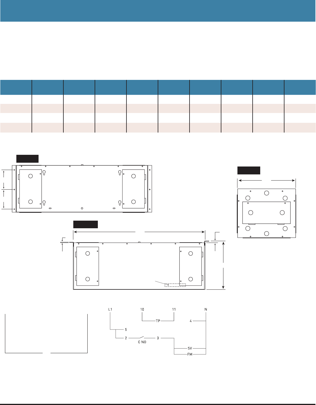
RM Fan Coil Specications
MODEL CFM AMPS
115V LENGTH WIDTH HEIGHT LIQUID SUCTION DRAIN APPROX
SHIPWT.
RM25 220 0.77 30” 11” 11.38” 0.38” 0.38” 0.50” 26lbs
RM35 260 0.77 36” 11” 11.38” 0.38” 0.38” 0.50” 29lbs
RM50 335 0.77 36” 11” 14.38” 0.38” 0.38” 0.50” 35lbs
RM65 420 1.85 42” 11” 14.38” 0.38” 0.38” 0.50” 43lbs
Fan Coil Wiring
Mounting Diagrams
Field Wiring
L1 115 V Line Voltage
N Neutral
SV Solenoid Valve
FM Fan Motor
TP Temperature Probe
Back of Controller Connections
10 Temperature Probe
11 Temperature Probe
4 Neutral
5 115V Line Voltage
2 Jumper from 5
3 Switch Leg to Fan Coil
C NO Internal normally open contact
Condensing Unit Wiring
L1
CU
N
41/2”
41/2”
Top View
DRAIN STUB LOCATED
INSIDE UNIT
L
H
3/8”
1/8”
Front View
Side View
11”
• Itisbesttousethelargercoilwheneverpossible.
• Ifusingasmallercoilasuctionlineaccumulatormustbeused
• Smallercoilscancausethesystemtorunalowerhumidity
• Expansionvalveandliquidlinesolenoidvalvestandard
• Forairowintoandoutoftheunit,atleastoneaccessdoormustberemovedfromeachend
• Connectionsatcoildonotindicaterefrigerationlinesize.Seesysteminformationforlinesizing
Due to continuing engineering improvements, specications are subject to change without notice.
March29,201210:41PM
RM SERIES
USCellarSystems/3070GoldenAve,LongBeach,CA90806/www.uscellarsystems.com
(562)513-3017phoneandfax/info@uscellarsystems.com
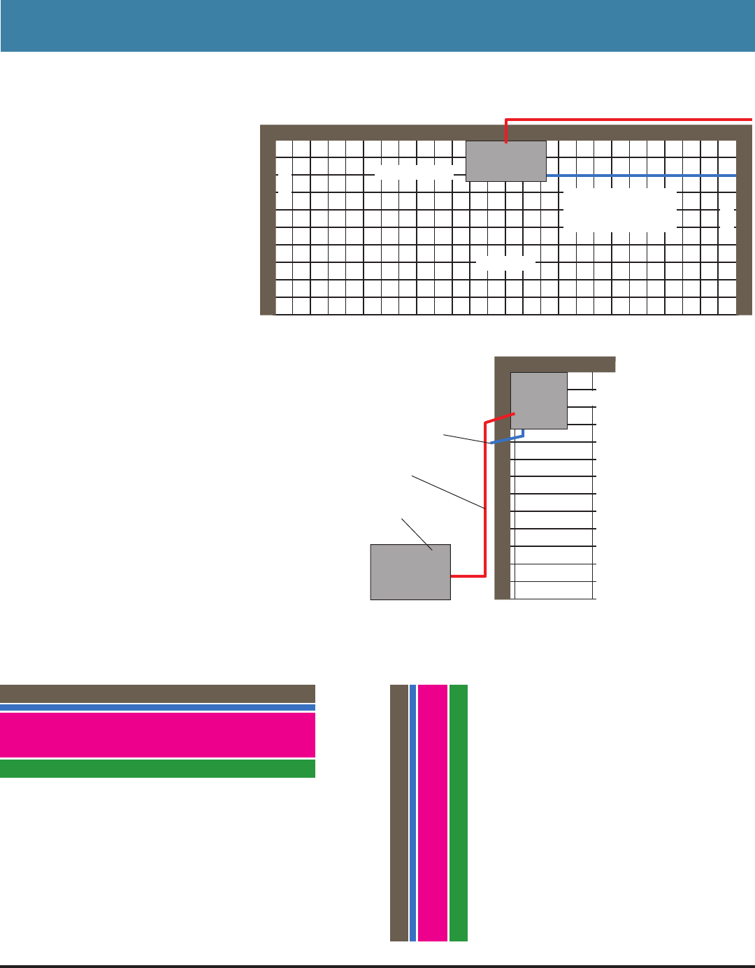
RM Cooling System Typical Installation
• Keep line sets as short as possible.
• Excessive number of turns will
cause refrigerant ow problems.
This could cause early compressor
failure. Suction line accumulators are
recommended. Required if working
lower than the normal 55-65°
operating range from wine cellar
• Drain line must always ow downhill
to drain or pump
• The system is controlled by a pump
down control system. There is no
control wiring between thermostat
and condensing unit
• The line connections at Fan Coil and
Condensing Unit may not be the
same as the required line sizes
• Standard line sets should be 50’
or less. Extended runs may require
larger line sizes and 3oz. oil must be
added for every 10’ over 35’
REFRIGERATION LINES
CEILING
RACKING
RC FAN COIL
DRAIN LINE
LEAVE 2” ON EACH
SIDE AND BELOW
REFRIGERATION
LINES
CEILING
CONDENSING
UNIT
WALL
RACKING
DRAIN LINE
RC FAN COIL
WALL
WALL
(;7(5,25
9$325%$55,(5
,168/$7,21ದ
525%(77(5
,17(5,25
(;7(5,25
9$325%$55,(5
,168/$7,21ದ
525%(77(5
,17(5,25
Wall ConstructionCeiling Construction
March29,201210:41PM
