User Guide Ftp://ftp.software.ibm.com/software/websphere/integration/wbix/library/doc/wbix430/pdf/user_guide
user_guide user_guide user guide pdf - FTP File Search (1/20)
User Manual: ftp://ftp.software.ibm.com/software/websphere/integration/wbix/library/doc/wbix430/pdf/user_guide
Open the PDF directly: View PDF ![]() .
.
Page Count: 114 [warning: Documents this large are best viewed by clicking the View PDF Link!]
- Contents
- About this document
- New in this release
- Chapter 1. Overview
- Chapter 2. Configuration
- Using Connector Configurator Express
- Overview of Connector Configurator Express
- Starting Connector Configurator Express
- Running Configurator Express from System Manager
- Creating a connector-specific property template
- Creating a new configuration file
- Using an existing file
- Completing a configuration file
- Setting the configuration file properties
- Saving your configuration file
- Completing the configuration
- Distributed connector agents
- Distributing a connector agent
- Set up communication between the connector agent and InterChange Server Express
- Prepare the agent host computer
- Copy required files and libraries
- Modify the connector agent environment
- Name of connector agent and InterChange Server instance
- Installing the IBM WebSphere MQ client on the agent host computer
- Using Connector Configurator Express
- Chapter 3. Startup
- Chapter 4. Monitoring the system
- Chapter 5. Operating components of the system
- Chapter 6. Using Test Connector
- Notices
WebSphere
Business
Integration
Express
for
Item
Synchronization
User
Guide
for
WebSphere
Business
Integration
Express
for
Item
Synchronization
V4.3
WebSphere
Business
Integration
Express
for
Item
Synchronization
User
Guide
for
WebSphere
Business
Integration
Express
for
Item
Synchronization
V4.3

Note!
Before
using
this
information
and
the
product
it
supports,
read
the
information
in
“Notices”
on
page
99.
10October2003
This
edition
of
this
document
applies
to
IBM
WebSphere
Business
Integration
Express
for
Item
Synchronization,
V4.3
and
to
all
subsequent
releases
and
modifications
until
otherwise
indicated
in
new
editions.
To
send
us
your
comments
about
this
document,
e-mail
doc-comments@us.ibm.com.
We
look
forward
to
hearing
from
you.
When
you
send
information
to
IBM,
you
grant
IBM
a
nonexclusive
right
to
use
or
distribute
the
information
in
any
way
it
believes
appropriate
without
incurring
any
obligation
to
you.
©
Copyright
International
Business
Machines
Corporation
2003.
All
rights
reserved.
US
Government
Users
Restricted
Rights
–
Use,
duplication
or
disclosure
restricted
by
GSA
ADP
Schedule
Contract
with
IBM
Corp.

Contents
About
this
document
.
.
.
.
.
.
.
.
.
.
.
.
.
.
.
.
.
.
.
.
.
.
.
.
.
.
.
.
.
.v
Audience
.
.
.
.
.
.
.
.
.
.
.
.
.
.
.
.
.
.
.
.
.
.
.
.
.
.
.
.
.
.
.
.
.
.
.
.v
Related
documents
.
.
.
.
.
.
.
.
.
.
.
.
.
.
.
.
.
.
.
.
.
.
.
.
.
.
.
.
.
.
.
.
.v
Typographic
conventions
.
.
.
.
.
.
.
.
.
.
.
.
.
.
.
.
.
.
.
.
.
.
.
.
.
.
.
.
.
.
.v
New
in
this
release
.
.
.
.
.
.
.
.
.
.
.
.
.
.
.
.
.
.
.
.
.
.
.
.
.
.
.
.
.
. vii
New
in
version
4.3
.
.
.
.
.
.
.
.
.
.
.
.
.
.
.
.
.
.
.
.
.
.
.
.
.
.
.
.
.
.
.
.
. vii
Chapter
1.
Overview
.
.
.
.
.
.
.
.
.
.
.
.
.
.
.
.
.
.
.
.
.
.
.
.
.
.
.
.
.
.1
Architecture
and
components
.
.
.
.
.
.
.
.
.
.
.
.
.
.
.
.
.
.
.
.
.
.
.
.
.
.
.
.
.
.1
Toolset
.
.
.
.
.
.
.
.
.
.
.
.
.
.
.
.
.
.
.
.
.
.
.
.
.
.
.
.
.
.
.
.
.
.
.
.
.2
System
Manager
.
.
.
.
.
.
.
.
.
.
.
.
.
.
.
.
.
.
.
.
.
.
.
.
.
.
.
.
.
.
.
.
.
.2
Chapter
2.
Configuration
.
.
.
.
.
.
.
.
.
.
.
.
.
.
.
.
.
.
.
.
.
.
.
.
.
.
.
.7
Using
Connector
Configurator
Express
.
.
.
.
.
.
.
.
.
.
.
.
.
.
.
.
.
.
.
.
.
.
.
.
.
.7
Distributed
connector
agents
.
.
.
.
.
.
.
.
.
.
.
.
.
.
.
.
.
.
.
.
.
.
.
.
.
.
.
.
.17
Distributing
a
connector
agent
.
.
.
.
.
.
.
.
.
.
.
.
.
.
.
.
.
.
.
.
.
.
.
.
.
.
.
.
.18
Chapter
3.
Startup
.
.
.
.
.
.
.
.
.
.
.
.
.
.
.
.
.
.
.
.
.
.
.
.
.
.
.
.
.
.
.23
Chapter
4.
Monitoring
the
system
.
.
.
.
.
.
.
.
.
.
.
.
.
.
.
.
.
.
.
.
.
.
.
.25
Using
the
Web-based
System
Monitor
.
.
.
.
.
.
.
.
.
.
.
.
.
.
.
.
.
.
.
.
.
.
.
.
.
.25
Using
persistent
monitoring
.
.
.
.
.
.
.
.
.
.
.
.
.
.
.
.
.
.
.
.
.
.
.
.
.
.
.
.
.
.41
Chapter
5.
Operating
components
of
the
system
.
.
.
.
.
.
.
.
.
.
.
.
.
.
.
.
.
.45
Overview
of
operating
the
system
.
.
.
.
.
.
.
.
.
.
.
.
.
.
.
.
.
.
.
.
.
.
.
.
.
.
.
.45
Operating
InterChange
Server
Express
.
.
.
.
.
.
.
.
.
.
.
.
.
.
.
.
.
.
.
.
.
.
.
.
.
.45
System
Manager
tasks
.
.
.
.
.
.
.
.
.
.
.
.
.
.
.
.
.
.
.
.
.
.
.
.
.
.
.
.
.
.
.
.49
Operating
connectors
.
.
.
.
.
.
.
.
.
.
.
.
.
.
.
.
.
.
.
.
.
.
.
.
.
.
.
.
.
.
.
.52
Operating
collaboration
objects
.
.
.
.
.
.
.
.
.
.
.
.
.
.
.
.
.
.
.
.
.
.
.
.
.
.
.
.
.60
Operating
maps
.
.
.
.
.
.
.
.
.
.
.
.
.
.
.
.
.
.
.
.
.
.
.
.
.
.
.
.
.
.
.
.
.
.64
Operating
relationships
.
.
.
.
.
.
.
.
.
.
.
.
.
.
.
.
.
.
.
.
.
.
.
.
.
.
.
.
.
.
.65
Backing
up
Business
Integration
Express
for
Item
Sync
components
.
.
.
.
.
.
.
.
.
.
.
.
.
.
.
.68
Using
Repos_Copy
.
.
.
.
.
.
.
.
.
.
.
.
.
.
.
.
.
.
.
.
.
.
.
.
.
.
.
.
.
.
.
.
.71
Scheduling
jobs
.
.
.
.
.
.
.
.
.
.
.
.
.
.
.
.
.
.
.
.
.
.
.
.
.
.
.
.
.
.
.
.
.
.83
Chapter
6.
Using
Test
Connector
.
.
.
.
.
.
.
.
.
.
.
.
.
.
.
.
.
.
.
.
.
.
.
.89
Recommended
testing
procedure
.
.
.
.
.
.
.
.
.
.
.
.
.
.
.
.
.
.
.
.
.
.
.
.
.
.
.
.89
Starting
Test
Connector
.
.
.
.
.
.
.
.
.
.
.
.
.
.
.
.
.
.
.
.
.
.
.
.
.
.
.
.
.
.
.90
Shutting
down
Test
Connector
.
.
.
.
.
.
.
.
.
.
.
.
.
.
.
.
.
.
.
.
.
.
.
.
.
.
.
.
.91
Creating
and
editing
connector
profiles
.
.
.
.
.
.
.
.
.
.
.
.
.
.
.
.
.
.
.
.
.
.
.
.
.
.91
Emulating
a
connector
.
.
.
.
.
.
.
.
.
.
.
.
.
.
.
.
.
.
.
.
.
.
.
.
.
.
.
.
.
.
.
.92
Working
with
business
objects
.
.
.
.
.
.
.
.
.
.
.
.
.
.
.
.
.
.
.
.
.
.
.
.
.
.
.
.
.92
Notices
.
.
.
.
.
.
.
.
.
.
.
.
.
.
.
.
.
.
.
.
.
.
.
.
.
.
.
.
.
.
.
.
.
.
.99
Programming
interface
information
.
.
.
.
.
.
.
.
.
.
.
.
.
.
.
.
.
.
.
.
.
.
.
.
.
.
. 100
Trademarks
and
service
marks
.
.
.
.
.
.
.
.
.
.
.
.
.
.
.
.
.
.
.
.
.
.
.
.
.
.
.
. 100
©
Copyright
IBM
Corp.
2003
iii
iv
User
Guide

About
this
document
The
IBM
(R)
WebSphere
(R)
Business
Integration
Express
for
Item
Synchronization
product
includes
InterChange
Server
Express,
the
associated
Toolset
Express
product,
the
Item
Synchronization
collaboration,
and
a
set
of
software
integration
adapters.
Together
they
provide
business
process
integration
and
connectivity
among
leading
e-business
technologies
and
enterprise
applications
as
well
as
integration
with
the
UCCnet
GLOBALregistry.
This
document
provides
an
overview
of
the
product
and
describes
how
to
monitor
and
operate
the
system
after
you
have
installed
it.
Audience
This
document
is
for
system
administrators,
consultants,
and
developers
who
administer
Business
Integration
Express
for
Item
Synchronization.
Related
documents
The
complete
set
of
documentation
describes
the
features
and
components
common
to
all
installations
of
IBM
WebSphere
Business
Integration
Express
for
Item
Synchronization,
and
includes
reference
material
on
specific
components.
You
can
download,
install,
and
view
the
documentation
at
the
following
site:
http://www.ibm.com/websphere/wbiitemsync/express/infocenter
Typographic
conventions
This
document
uses
the
following
conventions:
courier
font
Indicates
a
literal
value,
such
as
a
command
name,
filename,
information
that
you
type,
or
information
that
the
system
prints
on
the
screen.
bold
Indicates
a
new
term
the
first
time
that
it
appears.
italic,
italic
Indicates
a
variable
name
or
a
cross-reference.
blue
outline
A
blue
outline,
which
is
visible
only
when
you
view
the
manual
online,
indicates
a
cross-reference
hyperlink.
Click
inside
the
outline
to
jump
to
the
object
of
the
reference.
{
}
In
a
syntax
line,
curly
braces
surround
a
set
of
options
from
which
you
must
choose
one
and
only
one.
[
]
In
a
syntax
line,
square
brackets
surround
an
optional
parameter.
...
In
a
syntax
line,
ellipses
indicate
a
repetition
of
the
previous
parameter.
For
example,
option[,...]
means
that
you
can
enter
multiple,
comma-separated
options.
<
>
In
a
naming
convention,
angle
brackets
surround
individual
elements
of
a
name
to
distinguish
them
from
each
other,
as
in
<server_name><connector_name>tmp.log.
/,
\
In
this
document,
backslashes
(\)
are
used
as
the
convention
for
directory
paths.
For
UNIX
installations,
substitute
slashes
(/)
for
backslashes.
All
product
pathnames
are
relative
to
the
directory
where
the
Iproduct
is
installed
on
your
system.
©
Copyright
IBM
Corp.
2003
v

%text%
and
$text
Text
within
percent
(%)
signs
indicates
the
value
of
the
Windows
text
system
variable
or
user
variable.
ProductDir
Represents
the
directory
where
the
product
is
installed.
vi
User
Guide

New
in
this
release
New
in
version
4.3
This
is
the
first
release
of
this
guide.
©
Copyright
IBM
Corp.
2003
vii
viii
User
Guide

Chapter
1.
Overview
This
chapter
provides
a
high-level
introduction
to
the
use
of
IBM
WebSphere
Business
Integration
Express
for
Item
Synchronization
V4.3
(also
referred
to
in
this
guide
as
Business
Integration
Express
for
Item
Sync)
as
a
solution
for
integrating
data
exchange
between
UCCnet-compliant
trading
partners.
The
solution
uses
the
Item
Synchronization
collaboration,
along
with
application
connectors
and
InterChange
Server
Express,
to
provide
affordable,
extensible,
scalable,
and
secure
access
to
the
UCCnet
standard
registry.
(A
subsidiary
of
the
Uniform
Code
Council,
Inc.,
UCCnet
is
a
neutral,
tax-exempt
organization
that
provides
item
registry
and
data
synchronization
for
electronic
commerce
based
on
industry
developed
standards.)
The
resulting
efficiencies
to
supply
chains
can
significantly
drive
down
costs
and
improve
profits
for
suppliers.
Business
Integration
Express
for
Item
Synchronization
provides
the
capability
to
v
Process
and
route
business
information
among
disparate
applications
in
the
enterprise
environment
v
Exchange
business
information
between
trading
partners
who
use
disparate
applications
across
the
Internet
This
chapter
provides
an
overview
of
the
architecture
and
components
of
Business
Integration
Express
for
Item
Synchronization.
Note:
Throughout
this
manual,
illustrations
are
examples
only,
used
to
show
structure
and
concepts.
They
do
not
necessarily
document
specific
actual
components.
Architecture
and
components
The
Business
Integration
Express
for
Item
Sync
system
uses
a
central
infrastructure
(InterChange
Server
Express)
and
modular
components
in
a
hub-and-spoke
design.
In
this
design,
business-process
logic
resides
in
collaborations
at
the
hub;
data
is
exchanged
between
the
hub
and
the
spokes
in
the
form
of
business
objects.
Connectors,
supply
connectivity
to
applications
(or
to
web
servers
or
other
programmatic
entities)
at
the
spokes.
The
components
of
the
system
include:
v
InterChange
Server
Express
An
integration
broker
that
functions
as
the
hub
for
data
exchanges.
v
UCCnet_ItemSync
collaboration
Collaborations
are
software
modules
that
contain
logic
that
describes
a
distributed
business
process.
Collaborations
coordinate
the
functionality
of
business
processes
for
disparate
applications
and
enable
data
exchange
between
them.
Collaborations
are
the
hub;
through
them,
data
is
exchanged
in
the
form
of
business
objects.
The
UCCnet_ItemSync
collaboration,
and
several
related
collaborations,
are
pre-built
templates
from
which
you
configure
collaboration
objects
(see
the
Quick
Start
Guide
for
details).
The
collaboration
objects
enable
suppliers
to
automatically
add
items
to,
update
or
delist
items
within,
or
withdraw
items
©
Copyright
IBM
Corp.
2003
1

from
UCCnet
when
item
updates
are
made
in
their
Enterprise
Resource
Planning
(ERP)applications.
When
an
item
is
updated
in
a
supplier’s
ERP
system,
item
data
is
automatically
validated,
reformatted,
and
sent
to
the
UCCnet
standard
registry.
The
collaboration
objects
also
provide
a
single
process
for
communicating
item
information
to
trading
partners
via
UCCnet.
Thus,
a
supplier’s
enterprise
data
is
synchronized
with
item
data
sent
outside
the
enterprise.
v
Adapters
Each
adapter
includes
a
component
that
provides
connectivity
(referred
to
as
a
connector
throughout
this
guide)
and
(for
many
adapters)
a
mechanism
that
generates
or
provides
application-specific
business
objects
that
are
used
by
that
connector.
Some
adapters,
such
as
the
adapter
for
JText,
are
typically
used
for
exchanging
data
with
back-end
applications
at
your
enterprise
site.
Other
adapters,
such
as
the
adapter
for
iSoft,
are
typically
used
for
data
exchanges
across
the
Intenet
with
a
UCCnet
trading
partner.
These
connectors
transform
data
from
the
application
into
business
objects
that
can
be
manipulated
by
the
collaborations,
and
transform
business
objects
from
the
collaborations
into
data
that
can
be
received
by
the
specific
application.
Each
connector
consists
of
two
parts—the
connector
controller
and
the
connector
agent.
The
connector
controller
interacts
directly
with
WebSphere
InterChange
Server
Express
collaboration
objects
and
resides
on
a
server
that
has
implemented
InterChange
Server
Express
(the
hub
in
a
hub-and-spoke
relationship).
The
connector
agent
interacts
directly
with
an
application,
and
can
reside
with
that
application
on
any
server.
v
Business
Objects
Business
objects
are
the
messages
used
by
the
Business
Integration
Express
for
Item
Sync
system
for
exchanging
data.
v
Maps
Maps
are
used
between
a
business
object
that
is
structured
for
the
data
model
of
a
specific
application
and
a
business
object
that
is
generically
structured
for
use
by
collaborations
at
the
hub.
Toolset
Available
with
the
business
integration
system
are
development
tools,
administrative
tools,
and
System
Manager—an
interface
that
helps
you
with
using
your
system
efficiently,
accessing
the
tools,
and
deploying
the
integration
projects
that
you
develop.
System
Manager
The
System
Manager
interface
is
derived
from
the
Eclipse
platform—an
open-source
integrated
development
environment
for
the
creation
of
tools.
The
Eclipse
platform
provides
tools
developers
with
a
development
kit
and
runtime
that
enables
the
developer
to
write
plug-ins
that
allow
the
user
to
work
with
a
particular
type
of
resource.
System
Manager
is
installed
as
a
plug-in
that
can
be
used
in
IBM
branded
versions
of
the
Eclipse
platform.
System
Manager
features
You
access
System
Manager
as
an
Eclipse-based
perspective.
The
System
Manager
perspective
provides
views
and
editors
for
2
User
Guide
v
Accessing
tools
v
Performing
configuration
tasks
on
individual
integration
components
v
Working
with
instances
of
InterChange
Server
Express
v
Handling
groups
of
integration
components
as
user
projects,
and
deploying
components
to
the
repository
used
by
InterChange
Server
Express
Tasks
in
System
Manager
are
accessible
through
a
menu
and
corresponding
toolbar,
as
well
as
through
the
System
Manager
view.
The
System
Manager
view,
displayed
in
the
left-hand
panel
of
System
Manager,
shows
a
folder-style
list
of
libraries
of
modular
integration
components
(such
as
business
object
definitions,
database
connection
pools,
and
collaboration
templates
and
objects).
You
can
perform
development
and
configuration
tasks
by
right-clicking
on
the
icon
for
a
component
in
a
library.
Using
System
Manager
projects
Using
System
Manager,
you
will
create
projects
that
contain
the
integration
components
that
you
are
using
for
your
solution.
There
are
two
types
of
projects
in
System
Manager:
Integration
Component
Library
(ICL)
projects,
and
User
Projects.
One
of
your
first
tasks
when
developing
a
business
process
interface
is
to
define
an
integration
component
library,
which
is
a
project
that
contains
the
components
you
develop.
When
you
create
the
integration
component
library,
a
folder
is
created
with
the
name
you
specify
for
the
integration
component
library,
and
within
the
library
folder
a
number
of
folders
are
created
for
each
type
of
integration
component
(for
instance,
there
are
folders
named
Maps,
BusinessObjects,
and
Connectors).
When
you
first
install
the
product,
a
preliminary
integration
component
library,
already
containing
some
integration
components,
may
be
provided
for
you.
If
so,
the
icon
for
the
library
will
be
visible
when
you
run
InterChange
Server
Express
and
open
the
System
Manager
display.
Later,
as
you
create
or
modify
individual
integration
components,
you
will
save
them
to
these
folders.
In
the
tools
that
you
use
for
creating
or
modifying
integration
components
(such
as
Connector
Configurator
Express),
you
are
often
given
a
choice
to
save
your
work
either
to
a
file,
or
as
a
project.
Saving
your
work
as
a
project
places
the
integration
component
file
in
the
integration
component
library
folder,
and
this
will
usually
be
your
default
choice.
You
must
also
create
projects
calleduser
projects.
User
projects
are
collections
of
shortcuts
that
reference
the
integration
components
that
reside
in
the
integration
component
library
projects.
You
must
add
integration
components
to
a
user
project
from
integration
component
libraries
in
order
to
deploy
components
to
an
InterChange
Server
instance.
Besides
being
required
to
deploy
components
to
a
server,
user
projects
are
designed
to
allow
you
to
functionally
group
components
together.
An
integration
component
library
is
a
collection
of
all
components
you
might
need
to
work
with,
but
a
user
project
is
designed
to
let
you
group
together
the
components
you
are
working
on
for
a
specific
interface.
You
can
create
a
user
project
either
before
or
after
you
have
created
your
integration
component
libraries.
However,
you
must
create
the
user
project,
and
move
the
desired
integration
components
into
it,
in
order
to
deploy
the
components.
Chapter
1.
Overview
3
For
detailed
instructions
about
using
System
Manager,
press
the
F1
key
from
within
the
System
Manager
perspective
to
access
the
System
Manager
context-sensitive
help.
Modes
of
InterChange
Server
Express
When
you
work
with
projects
and
integration
component
libraries
in
System
Manager,
you
might
occasionally
find
it
useful
to
change
the
mode
in
which
InterChange
Server
Express
is
running.
This
is
typically
a
task
for
advanced
users.
InterChange
Server
Express
has
two
modes:
design
mode
and
production
mode.
In
design
mode,
InterChange
Server
Express
permits
the
repository
to
be
in
an
inconsistent
state—you
can
add
components
to
the
repository
without
components
they
depend
upon
already
existing.
For
instance,
if
you
try
to
import
a
business
object
definition
that
has
a
child
object
into
the
repository,
but
the
child
object
does
not
exist
yet,
then
an
InterChange
Server
Express
instance
in
production
mode
would
cause
the
import
to
fail
to
protect
the
integrity
of
the
repository.
InterChange
Server
Express
in
design
mode,
however,
would
allow
you
to
proceed
so
that
you
can
assemble
your
integration
components
in
a
way
that
best
suits
your
development
approach.
Furthermore,
compiling
maps
and
collaboration
templates
when
deploying
a
package
to
a
design-mode
server
is
optional.
In
production
mode,
the
server
automatically
compiles
all
maps
and
collaboration
templates.
Design
mode
is
particularly
useful
when
you
are
importing
components
from
another
environment.
You
may
not
be
aware
of
all
the
dependencies
yourself,
so
being
able
to
incrementally
import
components
without
the
import
operations
failing
due
to
unresolved
dependencies
is
very
helpful.
To
start
InterChange
Server
Express
in
design
mode,
add
the
-design
parameter
in
the
Target
field
of
the
Windows
shortcut
property
for
InterChange
Server
Express
before
starting
the
server.
For
example:
C:\IBM\WebSphereItemSync\bin\start_server_service.bat
In
production
mode,
InterChange
Server
Express
is
designed
to
guarantee
the
integrity
of
the
repository.
It
will
not
allow
you
to
deploy
a
package
with
unresolved
dependencies
to
the
repository,
and
it
automatically
compiles
all
maps
and
collaboration
templates
in
the
deployment
package.
These
restrictions
guarantee
that
the
server
environment
is
in
a
state
in
which
its
components
can
execute
properly.
If
there
were
components
with
unresolved
dependencies
or
uncompiled
components
in
the
server
environment
at
runtime
then
any
transactions
that
involved
those
components
would
fail.
Although
that
is
an
acceptable
situation
in
a
development
environment,
where
it
is
presumed
that
you
are
still
creating
the
required
components,
it
is
not
considered
acceptable
in
a
production
environment,
so
these
restrictions
enforce
safe
deployment
procedures.
If
you
need
to
manually
change
from
design
mode
to
production
mode,
you
can
do
so
by
removing
the
-design
parameter
from
the
Target
field
of
the
Windows
shortcut
property.
Tools
You
can
use
the
provided
tools
to
configure
connectors,
and
create
and
modify
business
objects,
maps,
and
relationships.
The
following
table
lists
and
describes
some
of
the
software
tools
provided.
4
User
Guide

Table
1.
Tools
Tool
Description
Integrated
Test
Environment
and
Test
Connector
Provides
an
environment
in
which
you
can
test
business
integration
interfaces
you
have
developed.
Provides
graphical
interfaces
to
emulate
connectors,
start
the
required
components,
and
examine
business
object
data.
Connector
Configurator
Express
Used
for
adding
application-specific
properties
to
a
connector
definition,
for
setting
property
values,
and
for
configuring
the
connector
definition
with
its
business
objects
and
maps
Map
Designer
Express
A
graphical
tool
that
specifies
data
transformations
between
application-specific
and
generic
business
objects.
Relationship
Designer
Express
A
graphical
tool
that
defines
relationships
between
types
of
objects.
These
relationships
are
important
in
mapping,
for
example,
to
specify
the
relationship
between
one
type
of
business
object
and
another.
Business
Object
Designer
Express
A
forms-based
interface
used
for
creating
business
object
definitions
both
manually
and
from
Object
Discovery
Agents
(ODAs)
Chapter
1.
Overview
5
6
User
Guide

Chapter
2.
Configuration
The
Installer
provided
with
the
product
performs
most
configuration
tasks
for
you.
However,
you
will
still
need
to
perform
certain
tasks
to
configure
your
adapters.
The
configuration
tasks
necessary
for
a
typical
installation
are
described,
in
a
step-by-step
manner,
in
the
Quick
Start
Guide.
If
you
are
implementing
the
adapters
and
collaborations
provided
in
a
typical
installation,
you
should
begin
your
configuration
with
that
guide.
If
you
are
customizing
your
integration
components
beyond
what
is
necessary
for
the
typical
implementation,
you
may
need
the
information
contained
in
this
chapter
of
the
User
Guide.
This
chapter
describes
two
common
adapter
configuration
tasks--using
Connector
Configurator,
and
distributing
connector
agents.
Using
Connector
Configurator
Express
This
topic
describes
how
to
use
Connector
Configurator
Express
to
set
configuration
property
values
for
your
adapter.
If
you
are
configuring
any
of
the
following
adapters,
you
may
also
want
to
refer
to
the
Quick
Start
Guide:
v
JTextRWLConnector
v
iSoftConnector
v
JTextISoftConnector
v
ERP-source
connector
v
Emailconnector
v
PortConnector
A
more
recent
version
of
the
Quick
Start
Guide
may
be
available
at
the
following
link:
http://www.ibm.com/websphere/wbiitemsync/express/infocenter
You
use
Connector
Configurator
Express
to:
v
Create
a
connector-specific
property
template
for
configuring
your
connector
v
Create
a
connector
configuration
file
v
Set
properties,
specify
business
objects
and
associated
maps,
and
establish
tracing
and
logging
values
in
a
configuration
file
The
topics
covered
in
this
topic
are:
v
“Overview
of
Connector
Configurator
Express”
on
page
7
v
“Starting
Connector
Configurator
Express”
on
page
8
v
“Creating
a
connector-specific
property
template”
on
page
9
v
“Creating
a
new
configuration
file”
on
page
11
v
“Setting
the
configuration
file
properties”
on
page
13
Overview
of
Connector
Configurator
Express
Connector
Configurator
Express
allows
you
to
configure
the
connector
component
of
your
adapter
for
use
with
InterChange
Server
Express.
©
Copyright
IBM
Corp.
2003
7
You
use
Connector
Configurator
Express
to:
v
Create
a
connector-specific
property
template
for
configuring
your
connector.
v
Create
a
connector
configuration
file
--
you
must
create
one
configuration
file
for
each
connector
you
install.
v
Set
properties
in
a
configuration
file
--
you
may
need
to
modify
the
default
values
that
are
set
for
properties
in
the
connector
templates.
You
must
also
designate
supported
business
object
definitions
and,
optionally,
maps
for
use
with
the
Item
Synchronization
Collaboration
as
well
as
specify
messaging,
logging
and
tracing,
and
data
handler
parameters,
as
required.
You
use
Connector
Configurator
Express
to
create
this
configuration
file
and
to
modify
its
settings.
Connector
configuration
properties
include
both
standard
configuration
properties
(the
properties
that
all
connectors
have)
and
connector-specific
properties
(properties
that
are
needed
by
the
connector
for
a
specific
application
or
technology).
The
range
of
standard
properties
may
not
be
the
same
for
all
configurations.
Some
properties
are
available
only
if
other
properties
are
given
a
specific
value.
The
Standard
Properties
window
in
Connector
Configurator
Express
will
show
the
properties
available
for
your
particular
configuration.
Starting
Connector
Configurator
Express
You
can
start
and
run
Connector
Configurator
Express
in
either
of
two
modes:
v
Independently,
in
stand-alone
mode.
v
From
System
Manager.
Running
Configurator
Express
in
stand-alone
mode
You
can
run
Connector
Configurator
Express
independently
to
work
with
connector
configuration
files.
To
do
so:
v
From
Start>Programs,
click
IBM
WebSphere
Business
Integration
Express
for
Item
Sync
v4.3>Toolset
Express
>
Development
>
Connector
Configurator
Express.
v
Select
File
>
New
>
Configuration
File.
If
you
are
creating
a
configuration
file,
you
may
prefer
to
run
Connector
Configurator
Express
independently
to
generate
the
file,
and
then
connect
to
System
Manager
to
save
it
in
an
InterChange
Server
Express
project
(see
“Completing
a
configuration
file”
on
page
13.)
Running
Configurator
Express
from
System
Manager
You
can
also
run
Connector
Configurator
Express
from
System
Manager.
To
run
Connector
Configurator
Express:
1.
Open
the
System
Manager.
2.
In
the
System
Manager
window,
expand
the
Integration
Component
Libraries
icon
and
highlight
Connectors.
3.
From
the
System
Manager
menu
bar,
click
Tools>Connector
Configurator
Express.
The
Connector
Configurator
Express
window
opens
and
displays
a
New
Connector
dialog
box.
8
User
Guide
Creating
a
connector-specific
property
template
To
create
a
configuration
file
for
your
connector,
you
first
need
a
connector-specific
property
template
as
well
as
the
system-supplied
standard
properties.
You
can
create
a
brand-new
template
for
the
connector-specific
properties
of
your
connector,
or
you
can
use
an
existing
file
as
the
template.
v
To
create
a
new
template,
see
“Creating
a
new
template”
on
page
9.
v
To
use
an
existing
file,
simply
modify
an
existing
template
and
save
it
under
the
new
name.
Note:
Connector-specific
templates
are
provided
for
the
iSoft,
JText,
and
e-Mail
connectors
only.
If
you
are
configuring
one
of
these
connectors,
see
the
Quick
Start
Guide,
or
skip
this
section
and
go
to
“Creating
a
new
configuration
file”
on
page
11.
Creating
a
new
template
This
section
describes
how
you
create
properties
in
the
template,
define
general
characteristics
and
values
for
those
properties,
and
specify
any
dependencies
between
the
properties.
You
then
save
the
template
and
use
it
as
the
base
for
creating
a
new
connector
configuration
file.
To
create
a
template:
1.
Click
File>New>Connector-Specific
Property
Template.
2.
The
Connector-Specific
Property
Template
dialog
box
appears,
with
the
following
fields:
v
New
Template
and
Name
Enter
a
unique
name
that
identifies
the
connector,
or
type
of
connector,
for
which
this
template
will
be
used.
You
will
see
this
name
again
when
you
open
the
dialog
box
for
creating
a
new
configuration
file
from
a
template.
v
Old
Template
and
Select
the
existing
template
to
modify
The
names
of
all
currently
available
templates
are
displayed
in
the
Template
Name
display.
v
To
see
the
connector-specific
property
definitions
in
any
template,
select
that
template’s
name
in
the
Template
Name
display.
A
list
of
the
property
definitions
contained
in
that
template
will
appear
in
the
Template
Preview
display.
You
can
use
an
existing
template
whose
property
definitions
are
similar
to
those
required
by
your
connector
as
a
starting
point
for
your
template.
3.
Select
a
template
from
the
Template
Name
display,
enter
that
template
name
in
the
Find
Name
field
(or
highlight
your
selection
in
Template
Name),
and
click
Next.
If
you
do
not
see
any
template
that
displays
the
connector-specific
properties
used
by
your
connector,
you
will
need
to
create
one.
Connector
Configurator
Express
Express
provides
a
template
named
None,
containing
no
property
definitions,
as
a
default
choice.
Specifying
general
characteristics:
When
you
click
Next
to
select
a
template,
the
Properties
-
Connector-Specific
Property
Template
dialog
box
appears.
The
dialog
box
has
tabs
for
General
characteristics
of
the
defined
properties
and
for
Value
restrictions.
The
General
display
has
the
following
fields:
v
Edit
properties
Chapter
2.
Configuration
9
Use
the
buttons
provided
(or
right-click
within
the
Edit
properties
display)
to
add
a
new
property
to
the
template,
to
edit
or
delete
an
existing
property,
or
to
add
a
child
property
to
an
existing
property.
A
child
property
is
an
attribute
of
another
property,
the
parent
property.
The
parent
property
can
obtain
simple
values,
or
child
properties,
or
both.
These
property
relationships
are
hierarchical.
When
you
create
a
configuration
file
from
these
properties,
Connector
Configurator
Express
will
identify
hierarchical
property
sets
with
a
plus
sign
in
a
box
at
the
left
of
any
parent
property.
v
Property
type
Choose
one
of
these
property
types:
Boolean,
String,
Integer,
or
Time.
v
Flags
You
can
set
Standard
Flags
(IsRequired,
IsDeprecated,
IsOverridden)
or
Custom
Flags
(for
Boolean
operators)
to
apply
to
this
property.
After
you
have
made
selections
for
the
general
characteristics
of
the
property,
click
the
Value
tab.
Specifying
values:
The
Value
tab
enables
you
to
set
the
maximum
length,
the
maximum
multiple
values,
a
default
value,
or
a
value
range
for
the
property.
To
do
so:
1.
Click
the
Value
tab.
The
display
panel
for
Value
replaces
the
display
panel
for
General.
2.
Select
the
name
of
the
property
in
the
Edit
properties
display.
3.
In
the
fields
for
Max
Length
and
Max
Multiple
Values,
make
any
changes.
The
changes
will
not
be
accepted
unless
you
also
open
the
Property
Value
dialog
box
for
the
property,
described
in
the
next
step.
4.
Right-click
the
box
in
the
left-hand
corner
of
the
adapter
display
panel.
A
Property
Value
dialog
box
appears.
Depending
on
the
property
type,
the
dialog
box
allows
you
to
enter
either
a
value,
or
both
a
value
and
range.
Enter
the
appropriate
value
or
range,
and
click
OK.
5.
The
Value
panel
refreshes
to
display
any
changes
you
made
in
Max
Length
and
Max
Multiple
Values.
It
displays
a
table
with
three
columns:
The
Value
column
shows
the
value
that
you
entered
in
the
Property
Value
dialog
box,
and
any
previous
values
that
you
created.
The
Default
Value
column
allows
you
to
designate
any
of
the
values
as
the
default.
The
Value
Range
shows
the
range
that
you
entered
in
the
Property
Value
dialog
box.
After
a
value
has
been
created
and
appears
in
the
grid,
it
can
be
edited
from
within
the
table
display.
To
make
a
change
in
an
existing
value
in
the
table,
select
an
entire
row
by
clicking
on
the
row
number.
Then
right-click
in
the
Value
field
and
click
Edit
Value.
Setting
dependencies:
When
you
have
made
your
changes
to
the
General
and
Value
tabs,
click
Next.
The
Dependencies
dialog
box
appears.
A
dependent
property
is
a
property
that
is
included
in
the
template
and
used
in
the
configuration
file
only
if
the
value
of
another
property
meets
a
specific
condition.
For
example,
PollQuantity
appears
in
the
template
only
if
JMS
is
the
transport
mechanism
and
DuplicateEventElimination
is
set
to
True.
To
designate
a
property
as
dependent
and
to
set
the
condition
upon
which
it
depends,
do
this:
10
User
Guide
1.
In
the
Available
Properties
display,
select
the
property
that
will
be
made
dependent.
2.
In
the
Select
Property
field,
use
the
drop-down
menu
to
select
the
property
that
will
hold
the
conditional
value.
3.
In
the
Condition
Operator
field,
select
one
of
the
following:
==
(equal
to)
!=
(not
equal
to)
>
(greater
than)
<
(less
than)
>=
(greater
than
or
equal
to)
<=(less
than
or
equal
to)
4.
In
the
Conditional
Value
field,
enter
the
value
that
is
required
in
order
for
the
dependent
property
to
be
included
in
the
template.
5.
With
the
dependent
property
highlighted
in
the
Available
Properties
display,
click
an
arrow
to
move
it
to
the
Dependent
Property
display.
6.
Click
Finish.
Connector
Configurator
Express
stores
the
information
you
have
entered
as
an
XML
document,
under
\data\app
in
the\bin
directory
where
you
have
installed
Connector
Configurator
Express.
Creating
a
new
configuration
file
You
create
a
connector
configuration
file
from
a
connector-specific
template
or
by
modifying
an
existing
configuration
file.
Creating
a
configuration
file
from
a
connector-specific
template
Once
a
connector-specific
template
has
been
created,
you
can
use
it
to
create
a
connector
configuration
file:
1.
In
the
System
Manager
window,
right-click
on
the
Connectors
folder
and
select
Create
New
Connector.
Connector
Configurator
Express
opens
and
displays
the
New
Connector
dialog
box,
with
the
following
fields:
v
Name
Enter
the
name
of
the
connector
followed
by
the
word
connector
.
Names
are
case-sensitive.
The
name
you
enter
must
be
unique
and
consistent
with
the
file
name
for
a
connector
that
is
installed
on
the
system.
For
example,
enter
iSoftconnector
if
the
connector
file
name
is
iSoft.
Important:
Connector
Configurator
Express
does
not
check
the
spelling
of
the
name
that
you
enter.
You
must
ensure
that
the
name
is
correct.
v
Select
Connector-Specific
Property
Template
Type
the
name
of
the
template
that
has
been
designed
for
your
connector.
The
available
templates
are
shown
in
the
Template
Name
display.
When
you
select
a
name
in
the
Template
Name
display,
the
Property
Template
Preview
display
shows
the
connector-specific
properties
that
have
been
defined
in
that
template.
Select
the
template
you
want
to
use
and
click
OK.
2.
A
configuration
screen
appears
for
the
connector
that
you
are
configuring.
The
title
bar
shows
the
integration
broker
and
connector
names.
You
can
fill
in
all
the
field
values
to
complete
the
definition
now,
or
you
can
save
the
file
and
complete
the
fields
later.
3.
To
save
the
file,
click
File>Save>Save
to
the
project.
To
save
to
a
project,
System
Manager
must
be
running.
Chapter
2.
Configuration
11
If
you
save
as
a
file,
the
Save
File
Connector
dialog
box
appears.
Choose
*.cfg
as
the
file
type,
verify
in
the
File
Name
field
that
the
name
is
spelled
correctly
and
has
the
correct
case,
navigate
to
the
directory
where
you
want
to
locate
the
file,
and
click
Save.
The
status
display
in
the
message
panel
of
Connector
Configurator
Express
indicates
that
the
configuration
file
was
successfully
created.
Important:
The
directory
path
and
name
that
you
establish
here
must
match
the
connector
configuration
file
path
and
name
that
you
supply
in
the
startup
file
for
the
connector.
4.
To
complete
the
connector
definition,
enter
values
in
the
fields
for
each
of
the
tabs
of
the
Connector
Configurator
Express
window,
as
described
later
in
this
topic.
Using
an
existing
file
To
use
an
existing
file
to
configure
a
connector,
you
must
open
the
file
in
Connector
Configurator
Express,
revise
the
configuration,
and
then
save
the
file
as
a
configuration
file
(*.cfg
file).
You
may
have
an
existing
file
available
in
one
or
more
of
the
following
formats:
v
A
connector
definition
file.
This
is
a
text
file
that
lists
properties
and
applicable
default
values
for
a
specific
connector.
Some
connectors
include
such
a
file
in
a
\repository
directory
in
their
delivery
package
(the
file
typically
has
the
extension
.txt;
for
example,
CN_XML.txt
for
the
XML
connector).
v
An
InterChange
Server
Express
repository
file.
Definitions
already
created
for
the
connector
may
be
available
to
you
in
a
repository
file.
Such
a
file
typically
has
the
extension
.in
or.out.
v
A
previous
configuration
file
for
the
connector.
Such
a
file
typically
has
the
extension
*.cfg.
Although
any
of
these
file
sources
may
contain
most
or
all
of
the
connector-specific
properties
for
your
connector,
the
connector
configuration
file
will
not
be
complete
until
you
have
opened
the
file
and
set
properties,
as
described
later
in
this
topic.
Follow
these
steps
to
open
a
*.txt,
*.cfg,
or
*.in
file
from
a
directory:
1.
In
Connector
Configurator
Express,
click
File>Open>From
File.
2.
In
the
Open
File
Connector
dialog
box,
select
one
of
the
following
file
types
to
see
the
available
files:
v
Configuration
(*.cfg)
v
InterChange
Server
Express
Repository
(*.in,
*.out)
Choose
this
option
if
a
repository
file
was
used
to
configure
the
connector.
A
repository
file
may
include
multiple
connector
definitions,
all
of
which
will
appear
when
you
open
the
file.
3.
In
the
directory
display,
navigate
to
the
correct
connector
definition
file,
select
it,
and
click
Open.
Opening
an
existing
file
from
System
Manager
Follow
these
steps
to
open
a
connector
configuration
from
a
System
Manager
project:
1.
Start
System
Manager.
2.
Start
Connector
Configurator
Express.
12
User
Guide
3.
Click
File>Open>From
Project.
To
edit
an
existing
configuration
file:
1.
In
the
System
Manager
window,
select
any
of
the
configuration
files
listed
in
the
Connector
folder
and
right-click
on
it.
Connector
Configurator
Express
opens
and
displays
the
configuration
file
with
the
file
name
at
the
top.
2.
Click
the
Properties
tab
to
see
which
properties
are
included
in
this
configuration
file.
Completing
a
configuration
file
When
you
open
a
configuration
file
or
a
connector
from
a
project,
the
Connector
Configurator
Express
window
displays
the
configuration
screen,
with
the
current
attributes
and
values.
Connector
Configurator
Express
requires
values
for
properties
described
in
the
following
sections:
v
“Setting
standard
connector
properties”
v
“Setting
connector-specific
configuration
properties”
on
page
14
v
“Specifying
supported
business
object
definitions”
on
page
14
v
“Associated
maps”
on
page
16
v
“Setting
trace/log
file
values”
on
page
17
v
“Configuring
messaging”
on
page
16
Note:
For
connectors
that
use
JMS
messaging,
an
additional
category
may
display,
for
special
configuration
of
data
handlers
that
convert
the
data
to
business
objects.
For
further
information,
see
“Data
handlers”
on
page
17.
Setting
the
configuration
file
properties
The
fields
for
Standard
Properties
and
Connector-Specific
Properties
are
color-coded
to
show
which
are
configurable:
v
A
field
with
a
grey
background
indicates
a
standard
property.
You
can
change
the
value
but
cannot
change
the
name
or
remove
the
property.
v
A
field
with
a
white
background
indicates
an
application-specific
property.
These
properties
vary
according
to
the
specific
needs
of
the
application
or
connector.
You
can
change
the
value
and
delete
these
properties.
v
Value
fields
are
configurable.
v
The
Update
Method
field
is
informational
and
not
configurable.
This
field
specifies
the
action
required
to
activate
a
property
whose
value
has
changed.
Setting
standard
connector
properties
To
change
the
value
of
a
standard
property:
1.
Click
in
the
field
whose
value
you
want
to
set.
2.
Either
enter
a
value,
or
select
one
from
the
drop-down
menu
if
it
appears.
v
To
set
values
for
standard
property
values
for
your
connector,
see
the
Standard
Properties
topic
of
this
guide.
3.
After
entering
all
the
values
for
the
standard
properties,
you
can
do
one
of
the
following:
v
To
discard
the
changes,
preserve
the
original
values,
and
exit
Connector
Configurator
Express,
click
File
>
Exit
(or
close
the
window),
and
click
No
when
prompted
to
save
changes.
Chapter
2.
Configuration
13
v
To
enter
values
for
other
categories
in
Connector
Configurator
Express,
select
the
tab
for
the
category.
The
values
you
enter
for
Standard
Properties
(or
any
other
category)
are
retained
when
you
move
to
the
next
category.
When
you
close
the
window,
you
are
prompted
to
either
save
or
discard
the
values
that
you
entered
in
all
the
categories
as
a
whole.
v
To
save
the
revised
values,
click
File
>
Exit
(or
close
the
window)
and
click
Yes
when
prompted
to
save
changes.
Alternatively,
click
Save
>
To
File
from
either
the
File
menu
or
the
toolbar.
Setting
connector-specific
configuration
properties
For
connector-specific
configuration
properties,
you
can
add
or
change
property
names,
configure
values,
delete
a
property,
and
encrypt
a
property.
The
default
property
length
is
255
characters.
1.
Right-click
in
the
top
left
portion
of
the
grid.
A
pop-up
menu
bar
will
appear.
Click
Add
to
add
a
property
or
Add
Child
to
add
a
child
property
to
a
property.
2.
Enter
a
value
for
the
property
or
child
property.
v
To
set
values
for
connector-specific
property
values
for
your
connector,
see
the
connector-specific
properties
section
of
your
adapter
guide.
3.
To
encrypt
a
property,
select
the
Encrypt
box.
4.
Choose
to
save
or
discard
changes,
as
described
for
“Setting
standard
connector
properties”
on
page
13.
The
Update
Method
displayed
for
each
property
indicates
whether
a
component
or
agent
restart
is
necessary
to
activate
changed
values.
Important:
Changing
a
preset
application-specific
connector
property
name
may
cause
a
connector
to
fail.
Certain
property
names
may
be
needed
by
the
connector
to
connect
to
an
application
or
to
run
properly.
Encryption
for
connector
properties:
Connector-specific
properties
can
be
encrypted
by
selecting
the
Encrypt
check
box
in
the
Edit
Property
window.
To
decrypt
a
value,
click
to
clear
the
Encrypt
check
box,
enter
the
correct
value
in
the
Verification
dialog
box,
and
click
OK.
If
the
entered
value
is
correct,
the
value
is
decrypted
and
displays.
The
adapter
user
guide
for
each
connector
contains
a
list
and
description
of
each
property
and
its
default
value.
If
a
property
has
multiple
values,
the
Encrypt
check
box
will
appear
for
the
first
value
of
the
property.
When
you
select
Encrypt,
all
values
of
the
property
will
be
encrypted.
To
decrypt
multiple
values
of
a
property,
click
to
clear
the
Encrypt
check
box
for
the
first
value
of
the
property,
and
then
enter
the
new
value
in
the
Verification
dialog
box.
If
the
input
value
is
a
match,
all
multiple
values
will
decrypt.
Update
method:
Connector
properties
are
almost
all
static
and
the
Update
Method
is
Component
restart.
For
changes
to
take
effect,
you
must
restart
the
connector
after
saving
the
revised
connector
configuration
file.
Specifying
supported
business
object
definitions
Use
the
Supported
Business
Objects
tab
in
Connector
Configurator
Express
to
specify
the
business
objects
that
the
connector
will
use.
You
must
specify
both
14
User
Guide
generic
business
object
definitions
and
application-specific
business
object
definitions,
and
you
must
specify
associations
for
the
maps
between
the
business
objects.
For
you
to
specify
a
supported
business
object,
the
business
objects
and
their
maps
must
exist
in
the
system.
Business
object
definitions,
including
those
for
data
handler
meta-objects,
and
map
definitions
should
be
saved
into
ICL
projects.
Note:
Some
connectors
require
that
certain
business
objects
be
specified
as
supported
in
order
to
perform
event
notification
or
additional
configuration
(using
meta-objects)
with
their
applications.
For
more
information,
see
the
Business
Object
Development
Guide.
To
specify
that
a
business
object
definition
is
supported
by
the
connector,
or
to
change
the
support
settings
for
an
existing
business
object
definition,
click
the
Supported
Business
Objects
tab
and
use
the
following
fields.
Business
object
name:
To
designate
that
a
business
object
definition
is
supported
by
the
connector,
with
System
Manager
running:
1.
Click
an
empty
field
in
the
Business
Object
Name
list.
A
drop-down
list
displays,
showing
all
the
business
object
definitions
that
exist
in
the
System
Manager
project.
2.
Click
on
a
business
object
to
add
it.
3.
Set
the
Agent
Support
(described
below)
for
the
business
object.
4.
In
the
File
menu
of
the
Connector
Configurator
Express
window,
click
Save
to
Project.
The
revised
connector
definition,
including
designated
support
for
the
added
business
object
definition,
is
saved
to
the
project
in
System
Manager.
To
delete
a
business
object
from
the
supported
list:
1.
To
select
a
business
object
field,
click
the
number
to
the
left
of
the
business
object.
2.
From
the
Edit
menu
of
the
Connector
Configurator
Express
window,
click
Delete
Row.
The
business
object
is
removed
from
the
list
display.
3.
From
the
File
menu,
click
Save
to
Project.
Deleting
a
business
object
from
the
supported
list
changes
the
connector
definition
and
makes
the
deleted
business
object
unavailable
for
use
in
this
implementation
of
this
connector.
It
does
not
affect
the
connector
code,
nor
does
it
remove
the
business
object
definition
itself
from
System
Manager.
Agent
support:
If
a
business
object
has
Agent
Support,
the
system
will
attempt
to
use
that
business
object
for
delivering
data
to
an
application
via
the
connector.
Typically,
application-specific
business
objects
for
a
connector
are
supported
by
that
connector’s
agent,
but
generic
business
objects
are
not.
To
indicate
that
the
business
object
is
supported
by
the
connector
agent,
check
the
Agent
Support
box.
The
Connector
Configurator
Express
window
does
not
validate
your
Agent
Support
selections.
Maximum
transaction
level:
The
maximum
transaction
level
for
a
connector
is
the
highest
transaction
level
that
the
connector
supports.
For
most
connectors,
Best
Effort
is
the
only
possible
choice,
because
most
application
APIs
do
not
support
the
Stringent
level.
Chapter
2.
Configuration
15
You
must
restart
the
server
for
changes
in
transaction
level
to
take
effect.
Associated
maps
Each
connector
supports
a
list
of
business
object
definitions
and
their
associated
maps
that
are
currently
active
in
WebSphere
InterChange
Server.
This
list
appears
when
you
select
the
Associated
Maps
tab.
The
list
of
business
objects
contains
the
application-specific
business
object
which
the
connector
supports
and
the
corresponding
generic
object
that
the
controller
sends
to
the
subscribing
collaboration.
The
association
of
a
map
determines
which
map
will
be
used
to
transform
the
application-specific
business
object
to
the
generic
business
object
or
the
generic
business
object
to
the
application-specific
business
object.
If
you
are
using
maps
that
are
defined
for
specific
source
and
destination
business
objects,
the
maps
will
already
be
associated
with
their
business
objects
when
you
open
the
display,
and
you
will
not
need
to
change
them.
If
more
than
one
map
is
available
for
use
by
a
supported
business
object,
you
will
need
to
explicitly
bind
the
business
object
with
the
map
that
it
should
use.
The
Associated
Maps
tab
displays
the
following
fields:
v
Business
Object
Name
These
are
the
application-specific
and
generic
business
objects
supported
by
this
connector,
as
designated
in
the
Supported
Business
Objects
tab.
If
you
designate
additional
business
objects
under
the
Supported
Business
Objects
tab,
they
will
be
reflected
in
this
list
after
you
save
the
changes
by
choosing
Save
to
Project
from
the
File
menu
of
the
Connector
Configurator
Express
window.
v
Associated
Maps
The
display
shows
all
the
maps
that
have
been
installed
to
the
system
for
use
with
the
supported
business
objects
of
the
connector.
The
source
business
object
for
each
map
is
shown
to
the
left
of
the
map
name,
in
the
Business
Object
Name
display.
To
display
the
maps,
you
must
first
designate
the
supported
business
objects,
and
then
save
the
connector
configuration
to
project.
To
see
the
maps,
you
must
first
designate
the
supported
business
objects
and
save
the
connector
configuration
to
project.
v
Explicit
In
some
cases,
you
may
need
to
explicitly
bind
an
associated
map.
Explicit
binding
is
required
only
when
more
than
one
map
exists
for
a
particular
supported
business
object.
When
InterChange
Server
Express
boots,
it
tries
to
automatically
bind
a
map
to
each
supported
business
object
for
each
connector.
If
more
than
one
map
takes
as
its
input
the
same
business
object,
the
server
attempts
to
locate
and
bind
one
map
that
is
the
superset
of
the
others.
If
there
is
no
map
that
is
the
superset
of
the
others,
the
server
will
not
be
able
to
bind
the
business
object
to
a
single
map,
and
you
will
need
to
set
the
binding
explicitly.
To
explicitly
bind
a
map:
1.
In
the
Explicit
column,
place
a
check
in
the
check
box
for
the
map
you
want
to
bind.
2.
Select
the
map
that
you
intend
to
associate
with
the
business
object.
Configuring
messaging
The
messaging
properties
are
available
only
if
you
have
set
MQ
as
the
value
of
the
DeliveryTransport.
These
properties
affect
how
your
connector
will
use
queues.
16
User
Guide

Setting
trace/log
file
values
When
you
open
a
connector
configuration
file,
Connector
Configurator
Express
uses
the
logging
and
tracing
values
of
that
file
as
default
values.
You
can
change
those
values
in
Connector
Configurator
Express.
To
change
the
logging
and
tracing
values:
1.
Click
the
Trace/Log
Files
tab.
2.
For
either
logging
or
tracing,
you
can
choose
to
write
messages
to
one
or
both
of
the
following:
v
To
console
(STDOUT):
Writes
logging
or
tracing
messages
to
the
STDOUT
display.
v
To
File:
Writes
logging
or
tracing
messages
to
a
file
that
you
specify.
To
specify
the
file,
click
the
directory
button
(ellipsis),
navigate
to
the
preferred
location,
provide
a
file
name,
and
click
Save.
Logging
or
tracing
message
are
written
to
the
file
and
location
that
you
specify.
Note:
Both
logging
and
tracing
files
are
simple
text
files.
You
can
use
the
file
extension
that
you
prefer
when
you
set
their
file
names.
For
tracing
files,
however,
it
is
advisable
to
use
the
extension
.trace
rather
than
.trc,
to
avoid
confusion
with
other
files
that
might
reside
on
the
system.
For
logging
files,
.log
and
.txt
are
typical
file
extensions.
Data
handlers
The
data
handlers
section
is
available
for
configuration
only
if
you
have
designated
a
value
of
JMS
for
DeliveryTransport
and
a
value
of
JMS
for
ContainerManagedEvents.
Adapters
that
make
use
of
the
guaranteed
event
delivery
enable
this
tab.
See
the
descriptions
under
ContainerManagedEvents
in
the
standard
properties
section
of
your
adapter
guide
for
values
to
use
for
these
properties.
Saving
your
configuration
file
After
you
have
created
the
configuration
file
and
set
its
properties,
you
need
to
deploy
it
to
the
correct
location
for
your
connector.
Save
the
configuration
in
an
ICL
project,
and
use
System
Manager
to
load
the
file
into
InterChange
Server
Express.
Completing
the
configuration
After
you
have
created
a
configuration
file
for
a
connector
and
modified
it,
make
sure
that
the
connector
can
locate
the
configuration
file
when
the
connector
starts
up.
To
do
so,
open
the
startup
file
used
for
the
connector,
and
verify
that
the
location
and
file
name
used
for
the
connector
configuration
file
match
exactly
the
name
you
have
given
the
file
and
the
directory
or
path
where
you
have
placed
it.
For
more
information
on
the
startup
file,
see
the
appropriate
section
of
your
adapter
guide.
Distributed
connector
agents
By
default,
the
Installer
sets
up
the
adapter’s
connector
agent
to
run
locally,
on
the
same
machine
on
which
InterChange
Server
Express
is
installed.
If
you
wish
to
run
the
connector
agent
on
a
different
machine,
you
must
do
additional
configuration,
as
described
in
this
chapter.
Chapter
2.
Configuration
17

Although
it
is
possible
to
install
and
run
IBM
WebSphere
Business
Integration
Adapters
on
the
same
computer
where
InterChange
Server
is
installed
and
running,
it
is
sometimes
necessary
to
distribute
connector
agents.
This
means
installing
the
connector
agent
on
a
different
computer
than
the
computer
on
which
InterChange
Server
Express
is
installed.
Reasons
for
distributing
connectors
agents
include
the
following:
v
Connector
performance
often
improves
if
the
connector
agent
is
installed
on
the
computer
that
hosts
the
application
with
which
it
communicates.
v
Some
connectors
must
be
installed
on
the
computer
where
the
application
they
communicate
with
is
installed.
Distributing
a
connector
agent
The
following
sections
describe
the
tasks
necessary
to
distribute
a
connector
agent:
v
“Prepare
the
agent
host
computer”
v
“Copy
required
files
and
libraries”
on
page
19
v
“Modify
the
connector
agent
environment”
on
page
19
In
this
instructions,
InterChange
Server
Express
host
computer
refers
to
the
machine
on
which
you
are
running
InterChange
Server
Express
Set
up
communication
between
the
connector
agent
and
InterChange
Server
Express
When
you
install
an
adapter,
the
Installer
program
automatically
creates
an
installation
of
InterChange
Server
Express
on
the
same
machine
as
the
adapter
you
are
installing.
If
you
want
the
adapter’s
connector
agent
to
function
in
a
distributed
manner--that
is,
the
connector
agent
is
on
one
machine,
and
InterChange
Server
Express
(and
the
collaborations
that
run
as
processes
within
it)
is
on
another--you
must
tell
the
connector
agent
which
InterChange
Server
Express
it
should
use.
This
is
done
through
the
CwEnvsh.bat
file,
as
follows:
1.
Obtain
the
IP
address
for
the
machine
that
hosts
the
InterChange
Server
Express
you
want
to
use.
2.
Locate
the
CWSharedEnv.bat
file
on
the
machine
where
you
have
installed
the
adapter.
The
file
resides
in
the
\bin
folder
within
the
folder
where
you
have
installed
the
Business
Integration
Express
for
Item
Sync
product
for
your
adapter.
By
default,
this
location
is:
\\IBM\WebSphereItemSync\bin.
3.
Open
the
CWSharedEnv.bat
file
in
a
text
editor.
Edit
this
line:
set
ORB_HOST=localhost
Replace
localhost
with
the
IP
address
of
the
InterChange
Server
Express
host
machine.
For
example:
set
ORB_HOST=9.26.234.123
Prepare
the
agent
host
computer
Perform
the
following
prerequisite
steps
to
prepare
the
agent
host
computer
for
the
tasks
that
follow
in
subsequent
sections:
1.
Create
a
directory
for
the
Business
Integration
Express
for
Item
Sync
software
on
the
agent
host
computer.
2.
Create
a
subdirectory
named
connectors
within
the
directory
created
in
step
1.
18
User
Guide
3.
Create
a
subdirectory
named
messages
in
the
connectors
directory
created
in
step
2
on
page
18.
Copy
required
files
and
libraries
Connectors
depend
on
several
files
and
directories
to
execute
properly.
Perform
the
following
steps
to
properly
migrate
a
connector
agent:
1.
Copy
the
following
files
or
directories
from
the
product
directory
on
the
InterChange
Server
Express
host
computer
to
the
corresponding
directory
on
the
agent
host
computer:
v
InterchangeSystem.cfg
configuration
file
v
messages
directory
v
bin
directory
v
lib
directory
2.
Migrate
the
connector
agent
libraries
by
copying
the
entire
directory
for
the
connector
agent
from
the
connectors
directory
on
the
InterChange
Server
host
computer
to
the
corresponding
directory
on
the
agent
host
computer.
For
example,
if
the
connector
agent
being
distributed
was
that
for
the
Adapter
for
JDBC,
then
copy
the
Jdbc
directory
into
the
\connectors
directory.
3.
Copy
the
message
file
for
the
connector
agent
into
the
\connectors\messages
directory
within
the
product
directory
on
the
agent
host
computer.
Connector
message
files
have
the
same
name
as
the
connector
and
have
a
.txt
extension.
For
example,
if
the
connector
agent
being
distributed
was
that
for
the
WebSphere
Business
Integration
Adapter
for
JDBC,
then
copy
the
JDBCConnector.txt
file
into
the
\connectors\messages
directory.
Modify
the
connector
agent
environment
Connector
agents
require
a
number
of
pieces
of
information
to
run
correctly,
such
as
the
name
of
InterChange
Server
Express,
and
the
location
of
the
supporting
libraries
for
WebSphere
InterChange
Server.
Modifying
the
location
of
the
WebSphere
InterChange
Server
directory
Connector
agents
need
to
know
the
location
of
the
product
directory
to
reference
things
such
as
the
supporting
classes
that
are
required.
Take
one
of
the
following
two
approaches
to
configure
the
startup
mechanism
of
the
connector
agent
so
that
it
can
reference
the
location
of
the
WebSphere
InterChange
Server
directory:
v
Create
a
system-level
environment
variable
named
CROSSWORLDS
that
identifies
the
location
of
the
WebSphere
InterChange
Server
directory
on
the
agent
host
computer.
Connector
agent
startup
scripts
are
typically
designed
to
query
for
a
system-level
environment
variable
by
that
name,
so
you
should
not
have
to
do
further
work
to
configure
them
to
reference
it.
The
advantages
of
this
approach
are
that
if
one
computer
was
going
to
host
multiple
distributed
connector
agents,
then
all
of
their
startup
scripts
could
then
reference
the
same
environment
variable,
and
that
you
do
not
have
to
modify
the
connector
startup
script
for
this
particular
purpose.
The
disadvantage
of
this
approach
is
that
you
must
create
the
environment
variable,
which
is
an
extra
task.
v
Edit
the
startup
script
for
the
connector
agent
and
define
a
variable
named
CROSSWORLDS
within
the
file
that
points
to
the
WebSphere
InterChange
Server
directory
on
the
agent
host
computer.
The
advantage
of
this
approach
is
that
the
extra
work
of
creating
the
environment
variable
is
not
required.
Furthermore,
if
multiple
instances
of
a
Chapter
2.
Configuration
19
single
connector
must
be
installed
on
multiple
distributed
computers
then
you
only
have
to
edit
the
file
once
and
can
use
it
on
all
of
the
necessary
computers
provided
that
the
WebSphere
InterChange
Server
directory
is
the
same
on
all
of
them.
The
disadvantage
of
this
approach
is
that
you
must
manually
edit
the
connector
startup
script
to
create
the
variable
within
it.
Many
of
the
other
variables
defined
in
the
startup
scripts
make
reference
to
the
CROSSWORLDS
variable
(to
ultimately
reference
dependency
classes
in
the
\lib
directory,
for
instance),
so
the
variable
must
be
defined
prior
to
any
others
that
reference
it.
The
lines
below
are
from
the
start_connector.bat
file
in
a
Windows
environment;
the
second
of
the
lines
was
added
to
define
the
CROSSWORLDS
variable:
setlocal
set
CROSSWORLDS=C:\CrossWorlds
REM
Define
local
batch
PATH
to
insure
we
execute
our
jre
set
PATH="%CROSSWORLDS%"\bin;%PATH%
Name
of
connector
agent
and
InterChange
Server
instance
For
a
connector
agent
to
communicate
with
InterChange
Server
Express,
you
must
configure
it
to
reference
InterChange
Server
Express
by
the
proper
case-sensitive
name.
Similarly,
you
must
configure
the
agent
so
that
when
it
starts,
it
is
assigned
the
proper
case-sensitive
name
for
the
connector
as
defined
in
the
InterChange
Server
Express
repository.
Take
one
of
the
following
three
approaches
to
configure
the
startup
mechanism
of
the
connector
agent
so
that
it
can
reference
the
location
of
the
InterChange
Server
Express
directory:
v
Start
the
connector
by
executing
the
appropriate
startup
script
and
manually
typing
the
name
of
the
connector
agent
and
the
name
of
InterChange
Server
Express
each
time.
The
advantage
of
this
approach
is
that
you
can
typically
use
a
single
connector
startup
script
for
multiple
connectors,
because
you
manually
enter
the
variable
information
each
time
you
execute
the
script.
The
disadvantage
of
this
approach
is
that
the
responsibility
of
passing
the
variables
with
the
proper
case
and
spelling
is
on
you.
This
approach
is
typically
used
in
a
Solaris
environment—you
execute
the
connector_manager.sh
script
and
pass
the
name
of
the
connector
agent
and
InterChange
Server
Express
at
the
command
line
while
doing
so.
This
is
also
a
viable
approach
in
a
Windows
environment,
though
less
common
because
shortcuts
make
it
easier
to
pass
the
variable
information
with
less
of
a
threat
of
misspelling
the
case-sensitive
names.
v
Start
the
connector
by
hard-coding
the
name
of
the
connector
agent
and
the
name
of
InterChange
Server
Express
into
the
startup
script
and
executing
it
each
time.
Below
is
an
example
where
the
start_JText.bat
file
on
a
Windows
computer
is
modified
to
enable
startup
of
the
JTextConnector
by
hard-coding
the
variable
information;
note
that
the
CONNDIR,
CONNAME,
and
SERVER
variables
all
required
modification:
setlocal
set
CROSSWORLDS=C:\CrossWorlds
REM
Define
local
batch
PATH
to
insure
we
execute
our
jre
set
PATH="%CROSSWORLDS%"\bin;%PATH%
REM
set
the
directory
where
the
specific
connector
resides
set
CONNDIR="%CROSSWORLDS%"\connectors\JText
REM
goto
the
connector
specific
drive
&
directory
cd
/d
%CONNDIR%
20
User
Guide
REM
set
the
name
to
be
the
application
connector
that
is
starting
set
CONNAME=JText
REM
set
the
server
name
to
be
the
interchange
that
is
being
targeted
set
SERVER=CrossWorlds
The
advantage
of
this
approach
is
that
you
can
ensure
the
case
and
spelling
of
the
variables
and
minimize
the
amount
of
manual
effort
involved
in
starting
the
connector
agent.
The
disadvantage
of
this
approach
is
that
it
is
very
customized
to
a
particular
agent;
if
you
need
to
start
multiple
agents,
then
you
must
customize
a
startup
script
for
each
one.
v
Include
the
name
of
the
connector
agent
and
the
name
of
InterChange
Server
Express
in
the
target
of
a
shortcut
you
execute,
which
ultimately
executes
the
appropriate
startup
script.
The
advantage
of
this
approach
is
that
you
can
ensure
the
case
and
spelling
of
the
variables
and
minimize
the
amount
of
manual
effort
involved
in
starting
the
connector
agent,
just
as
when
hard-coding
the
variables
within
the
script,
but
without
creating
a
custom
script
for
each
agent.
The
disadvantage
of
this
approach
is
that
it
is
not
viable
in
all
environments:
for
instance,
in
a
situation
where
the
connector
agent
must
operate
as
a
service
a
shortcut
cannot
be
used;
some
connector
agents
require
their
own
custom
startup
scripts
anyway
(typically
Java-based
connectors),
so
there
is
potentially
no
benefit
in
that
respect.
Installing
the
IBM
WebSphere
MQ
client
on
the
agent
host
computer
Connector
agents
require
the
WebSphere
MQ
client.
The
client
must
be
installed
on
the
agent
host
computer.
Chapter
2.
Configuration
21
22
User
Guide

Chapter
3.
Startup
To
start
your
system
after
it
has
been
installed
and
configured,
follow
this
sequence:
1.
Start
InterChange
Server
Express.
2.
Start
each
adapter.
For
details
about
starting
the
adapters,
see
″Operating
Connectors,″
later
in
this
guide.
For
shutting
down
and
other
operational
details
about
InterChange
Server
Express,
see
″Overview
of
operating
the
system,″
later
in
this
guide.
©
Copyright
IBM
Corp.
2003
23
24
User
Guide

Chapter
4.
Monitoring
the
system
Monitoring
includes
monitoring
all
Business
Integration
Express
for
Item
Sync
components,
such
as
connectors
and
collaboration
objects,
as
well
as
the
connection
to
all
integrated
applications.
The
primary
tool
for
this
is
Web-based
System
Monitor.
Using
the
Web-based
System
Monitor
The
Web-based
System
Monitor
is
a
tool
that
allows
you
to
monitor
the
Business
Integration
Express
for
Item
Sync
system
from
the
Web.
It
allows
you
to
configure
how
you
view
the
data
and
also
allows
you
to
view
historical
data
in
addition
to
current
data.
It
allows
you
to
start,
stop,
and
pause
components.
Different
approaches
for
using
the
Web-based
System
Monitor
You
can
use
the
Web-based
System
Monitor
by
taking
either
of
the
following
approaches:
v
Use
the
default
monitors
and
default
views
provided
with
the
product
to
monitor
the
system.
v
Create
new
monitors
and
views
before
monitoring
the
system.
Monitors
are
definitions
of
the
information
you
want
to
view.
You
can
either
create
new
monitors
using
the
Monitor
Definition
Wizard,
a
tool
launched
from
System
Manager,
or
you
can
use
the
default
monitors
provided
with
the
Monitor
Definition
Wizard.
Views
are
definitions
of
the
monitor
or
monitors
you
want
displayed
when
you
monitor
the
system
using
the
Web-based
System
Monitor.
You
can
create
and
configure
views
from
the
Web-based
System
Monitor,
or
you
can
use
the
default
views
provided
with
the
Web-based
System
Monitor.
Once
you
have
created
the
monitors
and
views
you
need,
or
decided
to
use
the
default
monitors
and
views,
you
can
then
monitor
the
InterChange
Server
Express
system
from
the
Web.
Using
default
monitors
Several
default
monitors
are
provided
with
the
Business
Integration
Express
for
Item
Sync
product.
You
can
either
monitor
the
system
using
the
default
monitors,
or
you
can
create
new
monitors.
To
gain
a
better
understanding
of
what
information
is
included
in
each
monitor,
refer
to
the
following
sections:
Table
2
on
page
26
contains
a
description
of
the
default
monitors
provided
with
the
Monitor
Definition
Wizard.
Table
3
on
page
29
contains
a
description
of
display
options
listed
inTable
2
on
page
26.
©
Copyright
IBM
Corp.
2003
25

Table
2.
Default
monitors
Default
monitor
Definition
Display
options
Available
operations
when
viewing
monitor
from
the
Web
System
Overview
Overview
of
the
current
status
of
all
major
components
of
the
system:
collaborations,
connectors,
maps,
and
relationships
Table
tree
(a
table
with
expandable
nodes
in
the
first
column
that
display
more
rows)
v
Start,
stop,
pause,
and
shut
down
a
collaboration
v
Start,
stop,
and
pause
a
connector
v
Start
and
stop
a
map
v
Start
and
stop
a
relationship
Collaboration
Statistics
Current
status
and
statistics
of
all
collaborations
in
the
system:
v
Status
v
Start
time
v
Total
flows
v
Successful
flows
v
Failed
flows
v
Events
in
process
v
Queued
events
v
Max
concurrent
events
Table
Start,
stop,
pause,
and
shut
down
Connector
Statistics
Current
status
and
statistics
of
all
connectors:
v
Status
v
Start
time
v
Total
up
time
v
Business
objects
received
v
Business
objects
sent
v
Agent
status
Table
v
Start,
stop,
and
pause
v
Restart
and
Shut
down
Map
Status
Status
of
all
maps
Table
Start
and
stop
Relationship
Status
Status
of
all
relationships
Table
Start
and
stop
Server
Statistics
Current
statistics
of
the
server:
the
number
of
failed
and
successful
calls,
events,
and
flows
Stacked
bar
None
Database
Connections
Current
status
of
database
connections:
v
Number
of
free
connections
v
Number
of
active
connections
v
Maximum
number
of
connections
v
Peak
number
of
connections
Table
None
26
User
Guide

Table
2.
Default
monitors
(continued)
Default
monitor
Definition
Display
options
Available
operations
when
viewing
monitor
from
the
Web
Message
Queues
Current
status
of
message
queues:
v
Current
depth
v
Maximum
depth
configured
Table
None
Business
Objects
Current
statistics
of
the
business
objects
for
a
particular
connector:
business
objects
sent
and
business
objects
received
Table
None
Connector
Subscriptions
Current
statistics
of
the
subscriptions
for
a
particular
connector:
v
Collaboration
object
v
Initiator
Table
None
Collaboration
Events
Current
statistics
of
collaboration
events,
which
includes
the
following
information:
v
Events
in
process
v
Queued
events
Bar
None
Historical
Server
Statistics
Server
statistics
for
a
specific
period
of
time.
Statistical
information:
v
Successful
calls
v
Failed
calls
v
Total
calls
v
Successful
events
v
Failed
events
v
Total
events
v
Successful
flows
v
Failed
flows
v
Total
flows
Time
intervals:
v
Start
date
v
End
date
Bar
None
Chapter
4.
Monitoring
the
system
27

Table
2.
Default
monitors
(continued)
Default
monitor
Definition
Display
options
Available
operations
when
viewing
monitor
from
the
Web
Historical
Server
Flows
Flow
statistics
of
the
server
for
a
specific
period
of
time
at
certain
time
intervals.
Statistical
information:
v
Successful
flows
v
Failed
flows
v
Total
flows
Time
intervals:
v
15
min.,
30
min.,
hourly,
daily,
weekly,
or
monthly
v
Start
date
v
End
date
v
Line
v
Stacked
bar
v
Bar
None
Historical
Collaboration
Flows
Stack
Flow
statistics
of
a
particular
collaboration
for
a
specific
period
of
time
at
certain
time
intervals.
Statistics
information:
v
Successful
flows
v
Failed
flows
v
Total
flows
Time
intervals:
v
15
min.,
30
min.,
hourly,
4
hours,
12
hours,
daily,
weekly,
or
monthly
v
Start
date
v
End
date
Stacked
bar
None
Historical
Collaboration
Flows
Line
Flow
statistics
of
a
particular
collaboration
for
a
specific
period
of
time
at
certain
time
intervals.
Statistics
information:
v
Successful
flows
v
Failed
flows
v
Total
flows
Time
intervals:
v
15
min.,
30
min.,
hourly,
4
hours,
12
hours,
daily,
weekly,
or
monthly
v
Start
date
v
End
date
Line
None
Event
Rate
Current
number
of
processed
events
per
minute
Meter
None
28
User
Guide

Table
2.
Default
monitors
(continued)
Default
monitor
Definition
Display
options
Available
operations
when
viewing
monitor
from
the
Web
Flow
Control
Current
state
of
collaboration
objects
and
connectors
under
Flow
Control:
v
Buffered
events
v
Max
event
capacity
v
Blocked
status
(does
not
apply
to
non-blocking
collaboration)
v
Events
pending
in
database
(applies
only
to
non-blocking
collaborations)
v
Saturated
status
Table
None
State
Change
Log
Current
persisted
state
changes
on
a
component
for
a
specified
time
period.
State
change
information:
v
Time
stamp
v
State
Time
intervals:
v
Start
date
v
End
date
Table
None
Table
3
describes
the
configurable
properties
of
each
display
option
listed
in
Table
2
on
page
26..
Table
3.
Configurable
properties
of
display
options
Display
option
Build-time
configurable
properties
(using
Monitor
Definition
Wizard)
Runtime
configurable
properties
(from
Web-based
System
Monitor)
v
Table
v
Table
tree
v
Columns
to
display
v
Order
of
columns
v
Number
of
rows
to
display
v
Font
and
color
settings
of
the
labels
and
data
v
Number
of
rows
to
display
v
Stacked
bar
v
Line
v
Bar
None
v
Font
and
color
settings
of
the
labels
and
data
v
Show
or
hide
values
Meter
Meter
threshold
Font
and
color
settings
of
the
labels
and
data
Creating
new
monitors
using
the
Monitor
Definition
Wizard
A
monitor
is
a
definition
of
the
information
you
want
to
view
when
monitoring
the
system
using
the
Web-based
System
Monitor.
For
example,
you
might
have
a
Chapter
4.
Monitoring
the
system
29
monitor
called
System
Overview,
which
displays
status
and
start
time
of
all
system
components.
You
create
this
monitor
using
the
Monitor
Definition
Wizard,
a
tool
launched
from
System
Manager.
When
you
create
a
monitor,
it
contains
a
particular
type
of
system
information
that
can
be
monitored.
Each
type
of
system
information
has
one
or
more
display
options
available.
Each
display
option
has
configurable
properties.
To
see
what
information
types
and
display
options
are
available
when
creating
a
new
monitor,
see
Figure
1
on
page
31.
Note:
Before
creating
new
monitors,
be
sure
to
look
at
the
existing
default
monitors
in
Table
2
on
page
26,
to
see
if
the
monitor
you
want
to
create
already
exists.
To
create
a
new
monitor,
follow
these
steps:
1.
From
the
System
Manager
perspective
of
IBM
WebSphere
Studio
Workbench,
right-click
the
server
instance
you
want
to
connect
to,
then
click
Connect.
The
Server
User
ID
and
Password
dialog
box
appears.
2.
Type
the
User
ID
and
password
for
that
server,
then
click
OK.
The
status
of
the
server
changes
from
″unknown″
or
″disconnected″
to
″connected.″
Note:
If
the
status
does
not
change
to
″connected,″
make
sure
the
selected
InterChange
Server
Express
server
is
running.
3.
Right-click
the
server
instance,
then
select
Monitor
Definition
Wizard.
The
Monitor
Definition
Wizard
appears.
See
Figure
1
on
page
31..
30
User
Guide
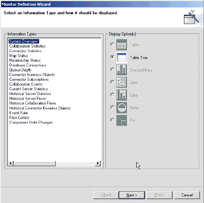
4.
Select
the
type
of
information
you
want
in
the
monitor
from
the
Information
Types
group
box,
then
select
how
you
want
the
information
displayed
from
the
Displayed
Option(s)
group
box.
Each
information
type
has
one
or
more
available
display
options.
For
a
description
of
the
configurable
properties
of
each
display
option,
see
Table
3
on
page
29..
Note:
When
you
select
an
information
type
from
the
Information
Types
group
box,
only
the
available
display
options
are
enabled
in
the
Display
Option(s)
group
box.
The
unavailable
display
options
remain
grayed
out.
5.
Click
Next.
The
Specify
Monitor
Properties
screen
appears
(see
Figure
2
on
page
32).
Figure
1.
Monitor
Definition
Wizard,
screen
for
selecting
information
type
and
display
option
Chapter
4.
Monitoring
the
system
31
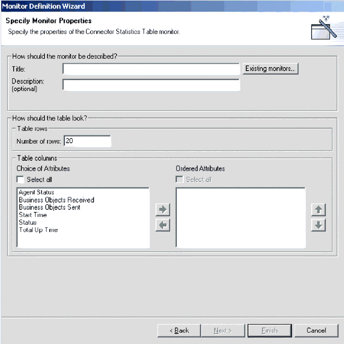
6.
Type
a
name
for
the
new
monitor
in
the
Title
field.
You
can
also
optionally
type
a
description
in
the
Description
field.
To
make
sure
you
do
not
use
an
existing
monitor
name,
click
Existing
Monitors.
This
displays
a
list
of
the
existing
monitors.
7.
Depending
on
what
information
type
and
display
option
you
chose
in
the
previous
screen,
you
may
or
may
not
have
more
choices
to
make
in
this
screen.
For
example,
in
Figure
2,
you
can
enter
the
number
of
rows
to
appear,
select
which
attributes
to
include,
and
place
the
chosen
attributes
in
a
particular
order.
These
options
are
available
for
both
Table
and
Table
Tree
display
options.
Meter
is
the
other
display
option
that
has
configurable
properties
in
this
screen.
If
you
create
a
monitor
with
a
meter,
the
configurable
property
is
″meter
threshold.″
For
a
list
of
all
display
option
configurable
properties,
when
using
either
the
Monitor
Definition
Wizard
or
the
Web-based
System
Monitor,
see
Table
3
on
page
29..
8.
Depending
on
which
attributes
you
chose
in
this
screen,
either
the
Next
button
or
the
Finish
button
is
enabled.
v
If
the
Finish
button
is
enabled,
then
the
attributes
you
chose
cannot
contain
thresholds.
v
If
the
Next
button
is
enabled,
then
the
attributes
you
chose
can
contain
thresholds.
Figure
2.
Monitor
Definition
Wizard,
Specify
Monitor
Properties
screen
32
User
Guide
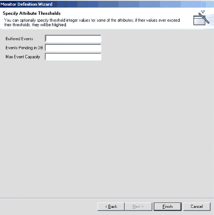
9.
Click
Next
or
Finish,
depending
on
which
button
is
enabled.
v
When
you
click
Finish,
the
following
message
appears,
″The
monitor
was
created
successfully.
Do
you
want
to
create
another
monitor?″
Click
Yes
or
No.
v
When
you
click
Next,
the
Specify
Attribute
Thresholds
screen
appears.
For
an
example
of
a
Specify
Attribute
Thresholds
screen,
see
Figure
9
on
page
24.
In
the
Specify
Attribute
Thresholds
screen,
you
can
optionally
type
a
numeric
value
in
the
threshold
field
for
each
attribute.
Note:
During
runtime,
if
the
value
of
an
attribute
exceeds
the
value
of
the
threshold
set
for
that
attribute,
the
cell
that
contains
the
attribute
value
appears
highlighted
when
it
is
displayed
in
the
table.
10.
After
specifying
any
attribute
thresholds,
click
Finish.
The
following
message
appears,
″The
monitor
was
created
successfully.
Do
you
want
to
create
another
monitor?″
Click
Yes
or
No.
Logging
on
to
the
Web-based
System
Monitor
Once
you
have
either
created
new
monitors
or
decided
to
use
the
default
monitors,
you
are
ready
to
log
on
to
the
Web-based
System
Monitor
to
monitor
the
system.
Before
you
can
log
on
to
the
Web-based
System
Monitor,
you
must
perform
the
following
tasks:
Figure
3.
Monitor
Definition
Wizard,
Specify
Attribute
Thresholds
screen
Chapter
4.
Monitoring
the
system
33
v
Start
InterChange
Server
Express
(ICS)
on
the
machine
being
monitored.
v
Make
sure
the
Web-based
System
Monitor
and
the
application
server
are
installed.
v
Start
the
application
server.
v
Obtain
the
username
and
password
necessary
for
logging
on
to
the
Web-based
System
Monitor.
The
username
and
password
are
the
same
as
those
used
when
logging
on
to
ICS.
To
log
on
to
the
Web-based
System
Monitor,
do
the
following:
1.
In
a
Web
browser,
navigate
to
the
URL
that
was
specified
in
the
DASHBOARD_URL
environment
variable
during
installation
of
the
Web-based
System
Monitor.
This
URL
is
made
up
of
three
elements:
v
The
URL
prefix
http://
v
The
base
URL
of
your
Web
server
v
The
value
specified
for
the
context
root
of
the
installed
application,
as
specified
during
the
installation
of
the
Web-based
System
Monitor.
This
value
must
be
ICSMonitor.
For
instance,
if
the
Web
server
is
named
monitorserver,
and
the
root
context
is
specified
as
ICSMonitor,
as
specified
in
the
installation
instructions,
the
URL
is:
http://monitorserver/ICSMonitor
The
WebSphere
InterChange
Server
System
Monitor
login
screen
appears.
2.
Type
the
server
name,
user
name,
and
password
for
the
InterChange
Server
instance
you
want
to
monitor,
then
click
Login.
The
Web-based
System
Monitor
appears.
Contents
of
the
Web-based
System
Monitor
Web
page
The
Web-based
System
Monitor
Web
page
contains
the
following
items:
v
List
of
views:
Initially,
the
views
listed
in
the
left
column
under
Views
are
the
default
views
provided
with
the
installation
of
the
Web-based
System
Monitor,
but
you
can
add,
change
or
delete
views
to
suit
your
monitoring
needs.
v
Create
and
Configure
Views
link:
This
link
opens
the
Create
and
Configure
Views
dialog
box
(see
Figure
4
on
page
37),
which
allows
you
to
create,
configure,
or
delete
views.
It
also
allows
you
to
set
the
default
view
you
see
when
you
log
on
to
the
Web-based
System
Monitor.
For
instructions
on
creating,
configuring,
or
deleting
views,
or
setting
the
default
view
you
see
when
you
log
on,
refer
to
the
following
sections:
–
“Creating
new
views”
on
page
36
–
“Configuring
existing
views”
on
page
37
–
“Deleting
views”
on
page
37
–
“Setting
the
default
view”
on
page
38
v
Set
Options
link:
The
Set
Options
link
opens
the
Set
Options
dialog
box,
which
allows
you
to
set
the
following
system-wide
or
component
settings:
–
Refresh
rate
of
the
views
that
display
current
statistics
–
Frequency
of
captured
historical
data
captured
for
each
component
type
–
Reset
component
statistics
to
″0″
–
Capture
component
state
changes
–
Delete
component
state
change
log
34
User
Guide
–
Delete
historical
statistics
for
all
components
in
the
system
For
instructions
on
using
the
Set
Options
dialog
box,
refer
to
the
following
sections:
–
“Setting
the
refresh
rate
for
runtime
values
being
monitored”
on
page
39
–
“Setting
the
frequency
for
capturing
historical
data”
on
page
39
–
“Resetting
runtime
statistic
values”
on
page
40
–
“Capturing
state
changes”
on
page
41
–
“Deleting
the
state
change
log”
on
page
41
–
“Deleting
historical
statistics”
on
page
41
v
Default
view:
A
default
view
is
displayed
in
the
body
of
the
Web
page
when
you
log
on
to
the
Web-based
System
Monitor.
The
first
time
you
open
the
tool,
the
System
Overview
view
included
with
the
product
is
displayed.
To
change
the
default
view
displayed,
see
“Setting
the
default
view”
on
page
38.
v
Logoff
link:
The
Logoff
link
allows
you
to
log
off
the
Web-based
System
Manager.
v
Help
link:
The
Help
link
opens
an
HTML
page
with
the
following
information:
–
A
link
to
download
the
documentation
set
for
the
Business
Integration
Express
for
Item
Sync
product
–
A
directory
location
on
your
local
machine
where
you
can
launch
the
Table
of
Contents
file
with
links
to
help
topics.
This
assumes
you
have
already
downloaded
the
documentation
set.
Using
Views
You
can
either
begin
monitoring
the
system
using
the
default
views,
or
you
can
add,
change,
or
delete
views
before
monitoring
the
system.
The
following
sections
describe
how
to
use
existing
views
or
create
and
configure
views
from
the
Web-based
System
Monitor.
A
view
is
a
Web
page
that
contains
one
or
more
monitors.
Several
default
views
are
included
in
the
installation
of
the
Web-based
System
Monitor.
You
may
use
these
default
views
or
create
new
views.
Before
you
can
create
and
configure
views,
you
must
log
on
to
the
Web-based
System
Monitor.
For
instructions
on
logging
on
to
the
Web-based
System
Monitor,
see
“Logging
on
to
the
Web-based
System
Monitor”
on
page
33.
This
section
covers
the
following
topics:
“Using
default
views”
“Creating
new
views”
on
page
36
“Configuring
existing
views”
on
page
37
“Configuring
existing
views”
on
page
37
Using
default
views
The
default
views
that
are
shipped
with
the
Web-based
System
Monitor
are
described
in
Table
4
on
page
36.
The
table
describes
which
monitor
or
monitors
are
contained
in
the
view,
as
well
as
which
display
option
is
used.
For
descriptions
of
default
monitors,
see
Table
2
on
page
26.
Chapter
4.
Monitoring
the
system
35

Table
4.
Default
views
Default
view
Monitor(s)
and
display
options
System
Overview
System
Overview
monitor
displayed
in
a
table
tree
Connector
v
Business
Objects
monitor
displayed
in
a
table
v
Connector
Subscriptions
monitor
displayed
in
a
table
Collaboration
Overview
Collaboration
Statistics
monitor
displayed
in
a
table
Collaboration
v
Collaboration
Events
monitor
displayed
in
bar
chart,
and
v
Event
Rate
monitor
displayed
in
a
meter
Collaboration
History
v
Historical
Collaboration
Flows
monitor
displayed
in
a
bar
chart
v
Historical
Collaboration
Flows
monitor
displayed
in
a
line
chart
Connector
Overview
Connector
Statistics
monitor
displayed
in
a
table
Maps
and
Relationships
v
Map
Status
monitor
displayed
in
a
table
v
Relationship
Status
monitor
displayed
in
a
table
Server
Statistics
v
Historical
Server
Statistics
displayed
in
a
stacked
bar
chart
v
Database
Connections
displayed
in
a
table
v
Message
Queues
displayed
in
a
table
Server
History
v
Historical
Server
Statistics
displayed
in
a
bar
chart
v
Historical
Server
Flows
displayed
in
a
line
chart
Flow
Control
Flow
Control
monitor
displayed
in
a
table
State
Change
Log
State
Change
Log
monitor
displayed
in
a
table
Creating
new
views
The
following
instructions
describe
how
to
create
a
new
view:
1.
Click
Create
and
Configure
Views
in
the
left
frame
of
the
Web-based
System
Monitor.
The
Create
and
Configure
Views
dialog
box
appears
(see
Figure
4
on
page
37).
36
User
Guide
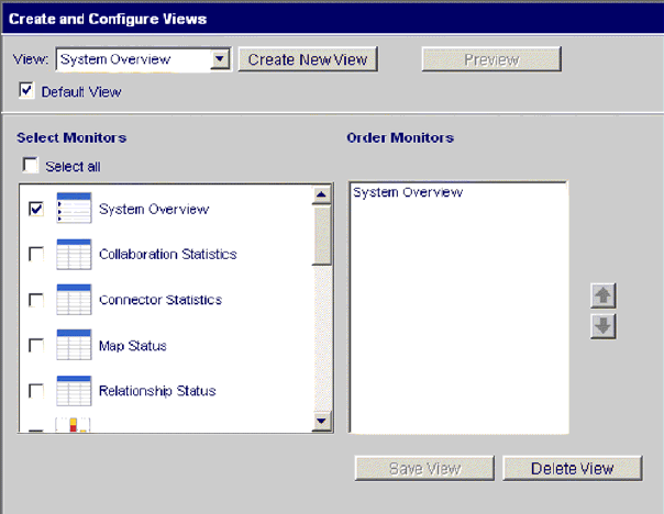
2.
Click
the
Create
New
View
button.
The
View
Name
dialog
box
appears.
3.
Type
a
name
for
the
view
in
the
View
Name
field,
then
click
OK.
The
new
view
name
appears
in
the
View
field
of
the
Create
and
Configure
Views
dialog
box.
4.
Select
one
or
more
monitors
from
the
Select
Monitor(s)
group
box,
or
choose
″Select
all″
to
select
all
the
monitors
listed.
Your
selections
appear
in
the
Order
Monitors
group
box.
5.
Use
the
up
and
down
arrows
to
the
right
of
the
Order
Monitors
group
box
to
put
the
monitors
in
the
order
you
want
to
view
them,
from
top
to
bottom.
6.
Click
Preview
if
you
want
to
see
a
preview
of
the
new
view.
7.
Click
Save
View.
A
″View
was
saved
successfully″
message
appears.
Also,
the
new
view
appears
immediately
in
the
left
frame
of
the
Web-based
System
Monitor
under
Views.
Configuring
existing
views
The
following
instructions
describe
how
to
make
changes
to
an
existing
view:
1.
Click
Create
and
Configure
Views
from
the
left
frame
of
the
Web-based
System
Monitor.
The
Create
and
Configure
Views
dialog
box
appears
(see
Figure
4).
2.
Select
the
view
you
want
to
change
from
the
View
drop-down
menu.
3.
Add
monitors
to
or
remove
monitors
from
the
view,
from
the
Select
Monitors
group
box.
The
revised
monitors
for
the
view
appear
in
the
Order
Monitors
group
box.
4.
Use
the
up
and
down
arrows
to
the
right
of
the
Order
Monitors
group
box
to
put
the
monitors
in
the
order
you
want
to
view
them,
from
top
to
bottom.
5.
Click
Preview
if
you
want
to
see
a
preview
of
the
new
view.
6.
Click
Save
View.
A
″View
was
saved
successfully″
message
appears.
Deleting
views
The
following
instructions
describe
how
to
delete
a
view:
1.
Click
Create
and
Configure
Views
from
the
left
frame
of
the
Web-based
System
Monitor.
The
Create
and
Configure
Views
dialog
box
appears
(see
Figure
4).
Figure
4.
Web-based
System
Monitor,
Create
and
Configure
Views
dialog
box
Chapter
4.
Monitoring
the
system
37
2.
Select
the
view
you
want
to
delete
from
the
View
drop-down
menu.
3.
Click
Delete
View.
A
message
appears,
asking
if
you
are
sure
you
want
to
delete
the
view.
4.
Click
OK.
The
view
is
removed
from
the
Views
list
in
the
left
frame
of
the
Web-based
System
Monitor.
Fine-tuning
the
Web-based
System
Monitor
You
can
make
adjustments
to
many
of
the
elements
of
the
Web-based
System
Monitor,
fine-tuning
the
level
of
system
data
you
can
monitor.
These
adjustments
are
described
in
the
following
sections:
“Setting
the
default
view”
“Customizing
the
visual
appearance
of
the
monitors”
“Setting
the
refresh
rate
for
runtime
values
being
monitored”
on
page
39
“Setting
the
frequency
for
capturing
historical
data”
on
page
39
“Resetting
runtime
statistic
values”
on
page
40
“Capturing
state
changes”
on
page
41
“Deleting
the
state
change
log”
on
page
41
“Deleting
historical
statistics”
on
page
41
Setting
the
default
view
The
default
view
is
the
view
you
first
see
when
you
log
on
to
the
Web-based
System
Monitor.
To
change
the
default
view,
do
the
following:
1.
Click
Create
and
Configure
Views
from
the
left
frame
of
the
Web-based
System
Monitor.
The
Create
and
Configure
Views
dialog
box
appears
(see
Figure
4
on
page
37).
2.
Select
the
view
you
want
to
be
the
default
view
from
the
View
drop-down
menu.
3.
Select
the
Default
View
check
box.
4.
Click
Save
View.
A
″View
was
saved
successfully″
message
appears.
The
next
time
you
log
on
to
the
Web-based
System
Manager,
the
view
you
selected
as
the
default
view
will
be
displayed.
Customizing
the
visual
appearance
of
the
monitors
The
display
options
of
monitors
can
be
customized
by
changing
the
preferences
of
the
display
options.
To
change
the
appearance
of
a
monitor,
do
the
following:
1.
While
viewing
a
monitor,
click
the
chart
icon
in
the
upper
right
corner.
The
Preferences
dialog
box
appears
for
that
particular
display
option
in
that
monitor.
Figure
5
on
page
39
is
an
example
of
the
Table
Preferences
dialog
box.
38
User
Guide
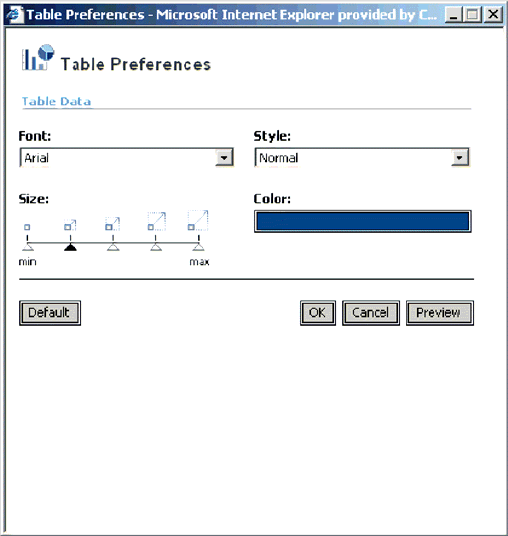
2.
From
the
Preferences
dialog
box,
select
the
appearance
options
you
want
to
change.
For
a
list
of
what
appearance
options
are
available
with
each
display
option,
see
the
Runtime
configurable
properties
column
of
Table
3
on
page
29.
3.
Click
Preview
to
see
a
preview
of
the
changes
you
made.
4.
Click
OK.
The
changes
you
made
appear
in
the
monitor.
Note:
When
you
change
the
preferences
of
a
display
option,
the
changes
appear
in
all
monitors
that
use
that
particular
display
option.
Note:
If
you
want
to
return
the
monitor
to
its
original
appearance,
open
the
Preferences
dialog
box,
select
Default,
then
click
OK.
Setting
the
refresh
rate
for
runtime
values
being
monitored
Some
monitors
display
runtime
values
of
a
component.
For
these
monitors,
you
can
specify
how
often
you
want
statistics
to
be
refreshed.
Note:
The
refresh
rate
you
set
is
for
the
system
as
a
whole,
not
for
individual
components.
To
set
the
refresh
rate
for
monitored
runtime
values,
do
the
following:
1.
Click
Set
Options
from
the
left
frame
of
the
Web-based
System
Monitor.
The
Set
Options
dialog
box
appears.
2.
Enter
a
number
in
the
Refresh
Rate
field
to
specify
the
number
of
seconds
you
want
to
set
for
the
refresh
rate,
then
click
the
Refresh
Rate
Submit
button.
Setting
the
frequency
for
capturing
historical
data
The
rate
at
which
historical
data
is
captured
is
configurable.
To
set
this
rate,
do
the
following:
1.
Click
Set
Options
from
the
left
frame
of
the
Web-based
System
Monitor.
The
Set
Options
dialog
box
appears.
Figure
5.
Web-based
System
Monitor,
Table
Preferences
dialog
box
Chapter
4.
Monitoring
the
system
39
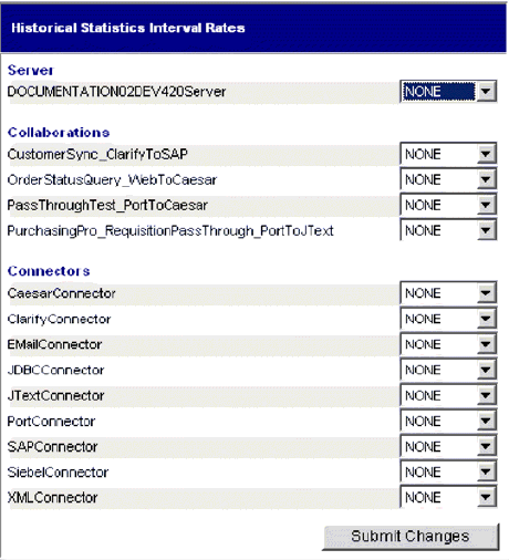
2.
In
the
″How
frequently
should
historical
data
be
captured?″
section,
click
the
″Review
all
interval
settings″
link.
The
Historical
Statistics
Interval
Rates
dialog
box
appears
(see
Figure
6).
3.
Set
the
interval
rates
for
the
server,
and
for
each
collaboration
object
and
connector.
The
interval
rates
to
choose
from
are
as
follows:
v
NONE
v
15
minutes
v
30
minutes
v
1
hour
v
4
hours
v
12
hours
v
24
hours
4.
Click
Submit
Changes
to
submit
all
of
the
interval
rates
for
all
of
the
components.
Note:
Alternatively,
you
can
set
the
interval
rate
for
a
single
component
by
not
selecting
the
″Review
all
interval
settings″
link.
Instead,
select
the
component
from
the
Component
Type
drop-down
menu
and
the
interval
rate
from
the
Frequency
drop-down
menu,
then
click
the
Submit
button
in
that
section.
Resetting
runtime
statistic
values
The
runtime
statistics
are
kept
in
memory
from
the
time
the
server
is
started.
If
the
server
is
running
for
several
days
or
weeks,
these
values
can
become
very
large.
You
can
reset
the
value
of
runtime
statistics
of
a
component
to
″0″
by
doing
the
following:
1.
Click
Set
Options
from
the
left
frame
of
the
Web-based
System
Monitor.
The
Set
Options
dialog
box
appears.
Figure
6.
Web-based
System
Monitor,
Historical
Statistics
Interval
Rates
dialog
box
40
User
Guide

2.
In
the
″Do
you
want
to
reset
component
statistics?″
section,
select
the
component
from
the
Component
Type
drop-down
menu.
v
If
you
select
Server,
then
runtime
statistics
for
all
components
are
reset.
v
If
you
select
Collaboration
or
Connector,
then
select
the
component
from
the
Component
drop-down
list.
Only
statistics
for
that
component
are
reset.
3.
Click
the
Submit.
Capturing
state
changes
You
can
capture
state
changes
for
each
component
and
send
them
to
a
log
file.
To
configure
this,
do
the
following:
1.
Click
Set
Options
from
the
left
frame
of
the
Web-based
System
Monitor.
The
Set
Options
dialog
box
appears.
2.
Under
the
″Do
you
want
to
capture
state
changes
of
a
particular
component?″
section,
select
the
component
from
the
Component
Type
drop-down
menu.
Note:
If
you
selected
Collaboration
or
Connector
as
the
component
type,
you
are
prompted
to
select
a
particular
collaboration
object
or
connector.
3.
Select
the
Capture
State
Changes
check
box,
then
click
the
Submit
button
in
that
section.
Deleting
the
state
change
log
As
the
state
change
log
grows,
you
may
need
to
delete
old
data.
You
can
delete
the
log
for
a
particular
time
period
by
doing
the
following:
1.
Click
Set
Options
from
the
left
frame
of
the
Web-based
System
Monitor.
The
Set
Options
dialog
box
appears.
2.
Under
the
″Do
you
want
to
delete
the
state
change
log
for
all
components?″
section,
click
the
calendar
icons
to
enter
the
start
date
and
end
date
for
the
data
to
be
deleted,
then
click
the
Delete
button
in
that
section.
Deleting
historical
statistics
As
the
historical
data
grows,
you
may
need
to
delete
old
data.
You
can
delete
historical
data
for
a
particular
time
period
by
doing
the
following:
1.
Click
Set
Options
from
the
left
frame
of
the
Web-based
System
Monitor.
The
Set
Options
dialog
box
appears.
2.
Under
the
″Do
you
want
to
delete
the
historical
statistics
for
all
components?″
section,
click
the
calendar
icons
to
enter
the
start
date
and
end
date
for
the
data
to
be
deleted,
then
click
the
Delete
button
in
that
section.
Using
persistent
monitoring
Persistent
monitoring
is
a
subsystem
of
InterChange
Server
Express
that
monitors
and
stores
historical
state
and
statistical
information
of
collaboration
objects,
connectors
and
the
system
as
a
whole.
This
section
describes
how
to
configure
system-wide
and
component-level
persistent
monitoring
and
how
to
access
the
results
from
persistent
monitoring.
Note:
You
must
consider
the
database
volume
requirements,
as
well
as
a
data
deletion
strategy,
when
planning
the
number
of
components
being
monitored
and
the
frequency
at
which
they
are
monitored.
This
section
covers
the
following
topics:
“Configuring
persistent
monitoring”
on
page
42
Chapter
4.
Monitoring
the
system
41
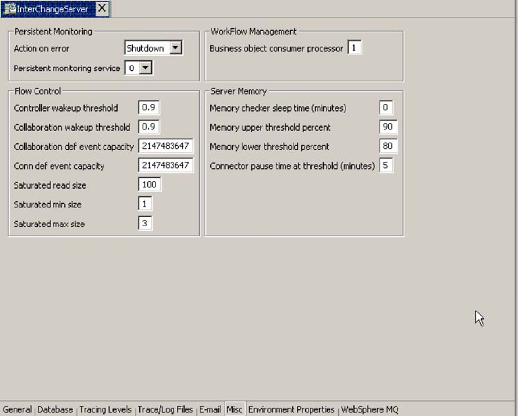
“Accessing
the
results
from
persistent
monitoring”
on
page
43
Configuring
persistent
monitoring
You
configure
the
various
levels
of
persistent
monitoring
for
system
components
from
the
Web-based
System
Monitor.
You
can
also
configure
certain
system-wide
parameters
of
persistent
monitoring.
The
following
instructions
explain
how
to
do
this.
1.
Open
the
Edit
Configuration
tool
by
right-clicking
the
server
from
the
Server
Instances
section
of
System
Manager,
then
select
Edit
Configuration.
The
upper-right
section
of
the
System
Manager
window
becomes
a
tool
from
which
you
can
edit
the
InterchangeServer.cfg
file.
2.
Select
the
Misc
tab
(see
Figure
7).
3.
Do
the
following
in
the
″Persistent
Monitoring
pane:
a.
Select
Continue
in
the
″Action
on
error″
drop-down
menu
if
you
want
InterChange
Server
to
continue
running
in
the
event
of
errors
experienced
by
the
persistent
monitoring
system.
Select
Shutdown
in
the
″Action
on
error″
drop-down
menu
if
you
want
InterChange
Server
to
shut
down
in
response
to
errors
with
the
subsystem.
b.
Select
the
desired
tracing
level
in
the
″Persistent
monitoring
service″
drop-down
menu
to
specify
the
tracing
level
for
the
subsystem.
For
additional
configuration
of
persistent
monitoring,
see
“Deleting
historical
statistics”
on
page
41
and
“Setting
the
frequency
for
capturing
historical
data”
on
page
39.
Figure
7.
Edit
Configuration
screen,
Misc
tab
42
User
Guide
Accessing
the
results
from
persistent
monitoring
You
access
the
results
of
persistent
monitoring
by
using
the
Web-based
System
Monitor.
Many
default
views
are
provided
with
the
Web-based
System
Monitor
that
display
historical
state
and
statistical
information.
These
include:
Connector,
Connector
Overview,
Collaboration
Overview,
Collaboration
History,
Server
Statistics,
and
Server
History.
For
more
information
on
using
default
views,
see
“Using
default
views”
on
page
35.
Alternatively,
you
can
create
your
own
views
that
can
contain
historical
data.
For
more
information
on
creating
views,
see
“Creating
new
views”
on
page
36.
Chapter
4.
Monitoring
the
system
43
44
User
Guide

Chapter
5.
Operating
components
of
the
system
This
chapter
describes
some
of
the
tasks
you
may
need
to
perform
while
operating
a
Business
Integration
Express
for
Item
Sync
system.
Overview
of
operating
the
system
When
starting
the
Business
Integration
Express
for
Item
Sync
system,
the
order
you
must
follow
is
to
start
WebSphere
MQ
Listener
(if
it
is
not
already
running
as
a
service),
then
start
InterChange
Server,
then
System
Manager.
When
shutting
down
an
instance
of
InterChange
Server
Express,
you
have
two
choices.
You
can
shut
down
the
system
gracefully
or
immediately.
A
graceful
shutdown
allows
the
system
to
complete
work
that
is
in
progress
before
shutting
down,
whereas
an
immediate
shutdown
stops
the
system
without
allowing
pending
events
to
process.
Before
you
can
start
the
system,
make
sure
all
of
the
necessary
third-party
software
is
running,
including
the
database
on
which
the
repository
resides.
When
you
start
up
the
system,
all
connectors
and
collaborations
come
up
in
the
state
they
were
in
at
the
time
they
were
last
shut
down.
For
example,
if
a
collaboration
was
paused
at
shutdown,
it
is
paused
when
the
system
is
started
again.
Operating
InterChange
Server
Express
Operating
InterChange
Server
Express
may
involve
the
following
tasks:
“Starting
InterChange
Server
Express”
on
page
45
“Shutting
down
InterChange
Server
Express”
on
page
46
“Changing
the
InterChange
Server
Express
and
database
passwords”
on
page
47
Starting
InterChange
Server
Express
To
start
InterChange
Server:
At
startup,
InterChange
Server
Express
reads
the
InterchangeSystem.cfg
file
and
sets
its
properties
according
to
the
parameter
values
listed
there.
Customizing
InterChange
Server
Express
startup
parameters
The
parameters
in
table
Table
5
customize
the
startup
of
InterChange
Server.
Table
5.
InterChange
Server
Express
startup
parameters
Parameter
Function
-c
configFile
Name
of
the
configuration
file
to
be
used
during
startup.
The
default
is
InterchangeSystem.cfg.
-i
Allows
InterChange
Server
Express
to
start
up
and
ignore
all
error
messages.
©
Copyright
IBM
Corp.
2003
45

Table
5.
InterChange
Server
Express
startup
parameters
(continued)
Parameter
Function
-p
password
Specifies
the
password
to
access
InterChange
Server.
If
you
do
not
use
this
parameter,
the
start_server
command
uses
the
password
in
the
InterchangeSystem.cfg
file.
Use
with
the
-u
parameter.
-s
serverName
Specifies
the
name
of
the
InterChange
Server.
The
name
is
case-sensitive.
-u
loginName
Specifies
the
user
login
name
for
InterChange
Server.
If
you
do
not
use
this
parameter,
the
start_server
command
uses
the
user
login
name
in
the
InterchangeSystem.cfg
file.
Use
with
the
-p
parameter.
-v
Displays
the
version
of
InterChange
Server,
then
exits.
Shutting
down
InterChange
Server
Express
Shutting
down
InterChange
Server
Express
stops
all
running
collaborations
and
connectors,
as
well
as
InterChange
Server
Express
itself.
All
connections
to
the
database
are
closed
and
the
machine’s
system
resources
used
by
InterChange
Server
Express
are
returned.
To
shut
down
the
server,
in
System
Manager,
right-click
the
server
name
under
Server
Instances
in
the
InterChange
Servers
section,
then
select
Shut
Down
>
Gracefully.
Attention:
Refrain
from
using
Ctrl+C
to
shut
down
InterChange
Server.
Doing
so
prevents
the
server
from
shutting
down
in
an
orderly
manner.
Graceful
shutdown
Gracefully
shutting
down
the
system
allows
all
currently
processing
and
queued
flows
to
complete
before
shutting
down.
This
may
take
a
long
time
because
all
flows
waiting
to
be
processed
by
a
running
collaboration
must
complete.
Existing
flows
are
processed
by
the
collaborations,
but
no
new
flows
are
accepted.
If
you
choose
to
gracefully
shut
down
the
system,
the
following
occurs:
v
Connectors
stop
polling.
No
new
events
are
generated.
v
Collaboration
objects
finish
their
current
work,
then
stop.
If
the
collaboration
object
is
a
member
of
a
collaboration
group,
all
collaboration
objects
in
the
group
stop.
If
messages
from
the
connectors
are
in
transit
to
the
collaboration
object
when
it
stops,
they
remain
in
the
messaging
queues
until
the
collaboration
object
starts.
v
InterChange
Server
Express
shuts
down.
Note:
This
procedure
cannot
be
used
to
shut
down
an
HA
system.
Immediate
shutdown
Immediately
stopping
the
system
forces
the
system
to
shut
down
without
processing
any
more
flows.
Running
connectors
and
collaborations
are
stopped
immediately.
When
the
system
is
restarted,
flows
that
were
interrupted
by
the
immediate
shutdown
are
redelivered
in
the
same
processing
order.
If
one
of
these
flows
wrote
data
to
an
application,
when
the
flow
is
redelivered,
it
tries
to
duplicate
the
data
and
fails
because
the
data
already
exists.
If
the
collaboration
processing
the
flow
is
transactional,
a
rollback
occurs.
If
the
flow
is
not
transactional,
it
is
moved
to
the
resubmission
queue.
46
User
Guide
Note:
Immediately
stopping
the
system
does
not
compromise
the
integrity
of
the
data
or
the
integrity
of
the
Business
Integration
Express
for
Item
Sync
system.
Use
this
option
when
you
need
to
quickly
shut
down
the
system.
For
example,
you
may
want
to
reboot
the
system,
but
a
collaboration
has
multiple
events
waiting
to
be
processed.
Shutting
down
gracefully
may
take
too
much
time
because
the
collaborations
need
to
complete
all
existing
work
before
stopping.
Changing
the
InterChange
Server
Express
and
database
passwords
Password
encryption
provides
a
measure
of
security
for
protecting
the
Business
Integration
Express
for
Item
Sync
system
and
underlying
databases
from
unauthorized
user
entry.
The
encrypted
string
for
each
of
the
passwords
is
stored
in
InterChange
Server
Express
and
is
accessed
by
the
server
when
the
password
must
be
decrypted.
In
the
InterchangeSystem.cfg
file,
the
encrypted
password
is
placed
in
the
PASSWORD*=
parameter.
The
InterChange
Server
Express
administrator
and
database
passwords
are
requested
during
system
installation
by
Installer
and
are
encrypted
and
stored
when
the
system
is
rebooted
at
the
completion
of
the
installation.
Thereafter,
you
can
change
the
InterChange
Server
Express
password
or
the
database
password
in
System
Manager.
The
InterChange
Server
Express
user
name
and
password
are
required
during
repository
copy
and
restoration
when
the
repos_copy
command
is
used.
See
“Using
Repos_Copy”
on
page
71.
For
instructions
on
changing
the
password
for
InterChange
Server
Express
or
for
the
database(s),
refer
to
the
following
sections:
“Changing
the
InterChange
Server
Express
password”
“Changing
the
database
passwords”
on
page
48
Changing
the
InterChange
Server
Express
password
To
change
the
password
for
InterChange
Server:
1.
Open
System
Manager.
2.
Right-click
the
server
under
Server
Instances
in
the
InterChange
Servers
section
of
System
Manager,
then
select
Change
Password.
The
Change
InterChange
Server
Express
Password
dialog
box
appears.
3.
Enter
the
current
password
in
the
Old
Password
field.
4.
Enter
a
new
password
in
the
New
Password
field.
5.
Reenter
the
new
password
in
the
Confirm
Password
field.
6.
Click
OK.
The
encrypted
password
is
stored
in
the
InterchangeSystem.cfg
file.
Attention:
The
InterChange
Server
Express
password
can
be
changed
only
by
using
this
procedure.
If
you
try
to
change
the
password
by
editing
the
password
in
the
InterchangeSystem.cfg
file,
InterChange
Server
Express
will
not
start.
Chapter
5.
Operating
components
of
the
system
47
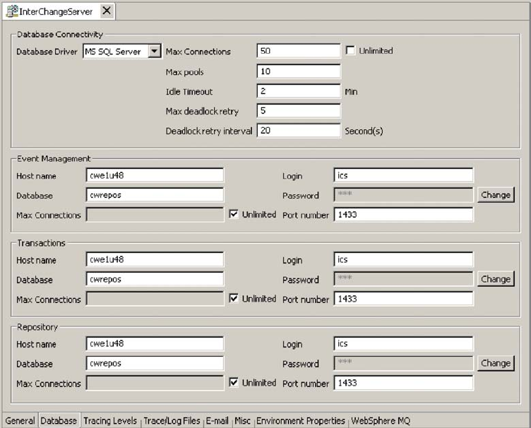
Changing
the
database
passwords
The
repository
database
passwords
can
be
changed
through
System
Manager
once
the
Business
Integration
Express
for
Item
Sync
system
is
operating.
To
change
the
database
passwords:
1.
Under
Server
Instances,
right-click
the
server
under
whose
database
password
you
want
to
change,
then
select
Edit
Configuration.
The
upper-right
section
of
the
window
changes
to
an
editing
tool
in
which
many
system
properties
can
be
changed.
2.
Click
the
Database
tab
to
access
the
database
configuration
properties.
The
Server
Property
and
Configuration
window
for
database
properties
appears
(see
Figure
8).
3.
Change
any
of
the
database
passwords:
a.
In
the
section
for
the
appropriate
database
(Event
Management,
Transactions,
or
Repository),
click
the
Change
button.
A
dialog
box
for
changing
the
password
appears.
b.
Type
the
old
password
in
the
Old
Password
field.
c.
Type
a
new
password
in
the
New
Password
field.
A
maximum
of
30
characters
is
allowed.
d.
Retype
the
new
password
in
the
Confirm
Password
field.
4.
Click
OK.
Figure
8.
Database
tab
of
Edit
Configuration
window
48
User
Guide

System
Manager
tasks
This
section
describes
system
administration
tasks
of
System
Manager,
such
as
starting
up,
shutting
down,
and
refreshing.
For
detailed
information
about
using
System
Manager
while
implementing
the
Business
Integration
Express
for
Item
Sync
system,
refer
to
the
System
Implementation
Guide.
This
section
covers
the
following
topics:
“Starting
System
Manager”
“Shutting
down
System
Manager”
“Refreshing
System
Manager
and
updating
components”
“Configuring
system-wide
flow
control”
on
page
50
Starting
System
Manager
To
start
System
Manager,
click
Start
>
Programs
>
IBM
WebSphere
Business
Integration
Express
for
Item
Sync
V4.3
>
Toolset
Express>
Administrative
>
System
Manager.
The
System
Manager
perspective
appears.
Shutting
down
System
Manager
To
shut
down
System
Manager,
select
Exit
from
the
File
drop-down
menu
of
IBM
WebSphere
Studio
Workbench.
Note:
Be
sure
to
shut
down
InterChange
Server
Express
before
shutting
down
System
Manager.
For
instructions
on
shutting
down
InterChange
Server
Express,
see
“Shutting
down
InterChange
Server
Express”
on
page
46.
Refreshing
System
Manager
and
updating
components
Refreshing
System
Manager
reloads
objects
from
the
local
repository
into
System
Manager,
but
does
not
update
InterChange
Server.
For
example,
if
you
refresh
System
Manager
after
adding
a
newly
created
business
object
definition,
you
can
add
the
new
business
object
to
the
connector’s
supported
business
object
list
and
bind
the
connector
to
a
collaboration
port.
But
InterChange
Server
Express
is
not
aware
of
the
business
object
unless
you
reboot
the
server,
causing
the
business
object’s
specifications
to
be
loaded
from
the
repository
into
the
server’s
cache.
To
refresh
InterChange
Server,
right-click
the
server
under
Server
Instances,
then
select
Refresh.
The
following
describes
which
components
can
be
updated
during
system
runtime:
Business
objects
Not
updated
during
runtime.
The
repository
is
read
only
once
when
InterChange
Server
Express
starts
up.
Collaboration
properties
Updated
during
runtime.
For
example,
collaboration
trace
levels
take
effect
as
soon
as
they
are
set.
Collaboration
code
changes
Updated
during
system
runtime.
Map
code
changes
Updated
during
system
runtime.
If
mapping
code
is
updated
and
recompiled,
connectors
must
be
rebound
to
the
altered
maps.
Chapter
5.
Operating
components
of
the
system
49
Configuring
system-wide
flow
control
Flow
control
is
a
configurable
service
that
allows
you
to
manage
the
flow
of
connector
and
collaboration
object
queues.
The
parameters
for
configuring
flow
control
can
be
configured
system-wide
or
on
individual
components,
or
both.
If
you
configure
both,
the
individual
component
configuration
supersedes
the
system-wide
configuration.
For
instructions
on
configuring
flow
control
for
individual
components,
see
“Configuring
flow
control
for
connectors”
on
page
59
or
“Configuring
flow
control
for
collaboration
objects”
on
page
63.
Note:
Configuration
changes
for
individual
connectors
or
collaboration
objects
are
dynamic,
meaning
they
do
not
require
InterChange
Server
Express
to
be
rebooted.
System-wide
configuration
changes
for
flow
control
require
InterChange
Server
Express
to
be
rebooted.
To
monitor
how
flow
control
is
working
in
the
system,
you
can
use
the
default
Flow
Control
monitor
provided
as
part
of
the
Web-based
System
Monitor,
or
you
can
create
new
Flow
Control
monitors
for
individual
connectors
or
collaboration
objects.
For
more
information
about
monitoring
flow
control,
see
the
description
of
the
default
Flow
Control
monitor
in“Using
default
monitors”
on
page
25,
and
the
instructions
on
creating
new
monitors
in“Creating
new
monitors
using
the
Monitor
Definition
Wizard”
on
page
29.
After
you
have
all
the
flow
control
monitors
created,
refer
to
the
following
sections
to
begin
monitoring
flow
control:
“Using
the
Web-based
System
Monitor”
on
page
25
and
“Logging
on
to
the
Web-based
System
Monitor”
on
page
33.“Operating
collaboration
objects”
on
page
60
To
configure
system-wide
flow
control,
do
the
following:
1.
In
System
Manager,
right-click
the
server
under
Server
Instances
for
which
you
want
to
configure
flow
control,
then
select
Edit
Configuration.
The
upper-right
section
of
the
window
changes
to
an
editing
tool
in
which
many
system
properties
can
be
changed.
2.
Click
the
Misc
tab.
A
dialog
box
appears
with
a
Flow
Control
section
(see
Figure
9
on
page
51).
50
User
Guide
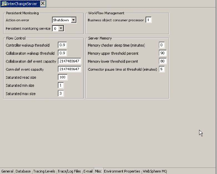
3.
In
the
Flow
Control
section,
enter
information
in
the
following
fields:
Controller
wakeup
threshold:
This
property
applies
to
connector
event
queues.
It
has
a
decimal
value
ranging
from
0
to
1,
but
not
including
0
or
1.
Connector
event
queues
are
always
of
the
blocking
type,
meaning
that
if
the
queue
is
full,
they
do
not
allow
new
events
to
be
added.
After
a
queue
becomes
full,
the
connector
becomes
blocked.
When
the
queue
size
equals
or
falls
below
the
value
of
the
connector
wakeup
threshold
multiplied
by
the
maximum
event
capacity
of
that
connector
(CONTROLLER_WAKEUP_THRESHOLD
x
MaxEventCapacity),
the
connector
becomes
reactivated.
Collaboration
wakeup
threshold:
This
property
applies
to
collaboration
object
event
queues.
It
has
a
decimal
value
ranging
from
0
to
1,
but
not
including
0
or
1.
This
property
applies
only
to
blocking-type
collaboration
objects,
meaning
that
it
does
not
allow
the
connector
to
add
more
events
to
the
collaboration
queue.
When
the
queue
size
equals
or
falls
below
the
value
of
the
collaboration
object
wakeup
threshold
multiplied
by
the
maximum
event
capacity
of
that
connector
(COLLABORATION_WAKEUP_THRESHOLD
x
MaxEventCapacity),
the
connector
is
able
to
add
more
events
to
the
collaboration
queue
for
processing.
Collaboration
def
event
capacity:
This
property
sets
the
maximum
number
of
events
you
want
queued
for
each
collaboration
object
in
the
system.
The
range
of
values
for
this
property
is
from
1
to
2147483647,
inclusive.
Conn
def
event
capacity:
This
property
sets
the
maximum
number
of
events
you
want
queued
for
each
connector
in
the
system.
The
range
of
values
for
this
property
is
from
1
to
2147483647,
inclusive.
Saturated
read
size:
Saturated
readers
attempt
to
process
saturated
events.
For
example,
if
a
collaboration
object
queue
can
accept
more
events,
the
reader
reads
a
particular
number
of
events
from
the
database,
and
then
adds
them
to
Figure
9.
Edit
configuration
tool,
Misc
tab
Chapter
5.
Operating
components
of
the
system
51

the
collaboration
object
queue.
This
property
reflects
the
maximum
number
of
such
events
that
can
be
read
in
one
iteration
of
the
reader.
Saturated
min
size:
This
property
applies
to
saturated
readers,
which
are
readers
that
process
saturated
events
in
the
database,
then
add
those
events
to
the
appropriate
collaboration
object
queue.
This
property
reflects
the
minimum
number
of
threads
doing
these
activities.
The
default
is
1.
Saturated
max
size:
This
property
applies
to
saturated
readers,
which
are
readers
that
process
saturated
events
in
the
database,
then
add
those
events
to
the
appropriate
collaboration
object
queue.
This
property
reflects
the
maximum
number
of
threads
doing
these
activities.
The
default
is
3.
4.
Save
the
changes
you
made
to
the
InterChange
Server
Express
configuration
by
selecting
Save
<ServerName>
from
the
File
menu
of
System
Manager.
5.
Restart
InterChange
Server.
Operating
connectors
Operating
connectors
may
include
such
tasks
as
starting,
pausing,
stopping,
and
shutting
down
connectors.
For
information
about
configuring
connectors,
including
setting
properties,
supported
business
objects,
and
associated
maps,
see
the
System
Implementation
Guide.
You
can
start,
pause,
stop,
and
shut
down
connectors
from
the
Web-based
System
Monitor.
This
section
covers
the
following
topics:
“Connector
states”
on
page
52
“Starting,
stopping,
and
pausing
connectors”
on
page
53
“Configuring
flow
control
for
connectors”
on
page
59
Connector
states
You
can
view
the
state
of
a
connector
by
logging
on
to
the
Web-based
System
Monitor
and
opening
a
view
that
contains
connector
states.
To
see
the
state
of
connectors
using
the
Web-based
System
Monitor,
do
the
following:
1.
If
the
System
Overview
view
is
not
displayed,
click
the
System
Overview
link
under
Views
in
the
left
pane
of
the
Web
page.
The
System
Overview
Monitor
appears
in
the
body
of
the
Web
page.
When
the
product
is
installed,
the
default
view
is
set
to
System
Overview,
and
the
default
monitor
contained
in
that
view
is
set
to
System
Overview.
These
defaults
can
be
changed
to
suit
your
monitoring
needs.
See
“Using
Views”
on
page
35
for
instructions.
2.
Click
the
triangle
next
to
the
name
of
the
server
to
reveal
a
list
of
components
on
the
system.
3.
Click
the
triangle
next
to
a
running
collaboration
to
reveal
its
associated
connectors
(see
Figure
10
on
page
53).
52
User
Guide
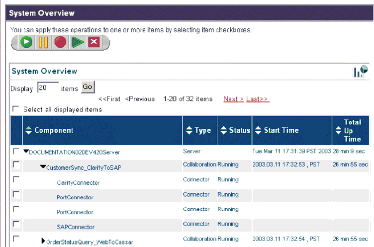
Starting,
stopping,
and
pausing
connectors
This
section
describe
how
to
start,
stop,
and
pause
connectors.
The
following
topics
are
covered:
“Initializing
a
connector”
on
page
53
“Running,
stopping,
and
pausing
connectors
using
System
Monitor”
on
page
54
“Commands
for
changing
connector
states”
on
page
54
“Manually
starting
a
connector”
on
page
54
“Shutting
down
a
connector”
on
page
56
“Restarting
a
connector”
on
page
57
“Setting
Automatic
and
remote
restart
for
a
connector”
on
page
57
“Using
OAD
as
a
Windows
service”
on
page
59
Initializing
a
connector
The
first
time
you
start
a
connector,
it
must
be
initialized.
Initializing
a
connector
requires
that
you
start
it
manually.
For
instructions
on
manually
starting
a
connector,
see
“Starting
a
connector
manually”
on
page
54.
If
the
connector
does
not
start,
check
to
make
sure
that
the
command
line
to
start
it
includes
the
current
InterChange
Server
Express
name.
Figure
10.
Web-based
System
Monitor,
System
Overview
displaying
connector
status
Chapter
5.
Operating
components
of
the
system
53

Running,
stopping,
and
pausing
connectors
using
System
Monitor
After
the
connector
has
been
initialized,
you
can
start,
stop,
and
pause
it
using
Web-based
System
Montor
from
System
Manager:
Web-based
System
Monitor
1.
While
viewing
the
System
Overview
view
(see
Figure
10
on
page
53),
select
a
connector
by
placing
check
in
the
box
to
its
left.
2.
Select
the
Start,
Pause,
or
Stop
icon
from
the
icon
group
in
the
upper-left
corner
of
the
view
(see
Figure
11).
Commands
for
changing
connector
states
The
following
list
describes
the
commands
you
can
use
to
change
the
connector
state
and
describes
their
processing
actions:
Start
NameConnector
Starts
the
connector
for
the
application
Name
if
it
is
paused
or
stopped.
Connectors
poll
the
application
and
connector
controllers
read
the
persistent
queue.
Flows
are
processed.
Pause
NameConnector
Pauses
the
connector
for
the
application
Name
if
it
is
running
or
stopped.
Connectors
stop
polling
the
application
and
connector
controllers
stop
reading
the
persistent
queue.
Flows
are
not
processed.
Stop
NameConnector
Stops
the
connector
for
the
application
Name
if
it
is
running
or
paused.
Connectors
stop
polling
the
application
and
fail
requests
with
an
exception
message.
Connector
controllers
stop
reading
the
persistent
queue.
Flows
and
requests
are
not
processed.
Shut
Down
NameConnector
Shuts
down
the
connector
for
the
application
Name.
The
connector’s
process
is
stopped.
Boot
Up
Connector
Agent
Restarts
the
connector
for
the
application
Name.
This
action
is
available
only
if
you
have
set
the
OADAutoRestartAgent
property
of
the
connector
to
True.
See
“Setting
Automatic
and
remote
restart
for
a
connector”
on
page
57.
Manually
starting
a
connector
Starting
a
connector
manually:
When
you
install
the
IBM
WebSphere
Business
Integration
Adapters
on
a
Windows
machine,
a
shortcut
is
created
for
each
installed
connector
on
the
IBM
WebSphere
program
menu.
The
connector
is
defined
in
the
InterChange
Server
Express
repository
and
is
loaded
when
you
load
the
repository.
Start Pause Stop Restart
Agent Shutdown
Figure
11.
Web-based
System
Monitor,
icons
for
starting,
pausing,
restarting,
or
shutting
down
components
54
User
Guide

Starting
InterChange
Server
Express
automatically
initializes
every
connector
defined
in
the
repository.
The
connector
is
available
for
use
whenever
InterChange
Server
Express
is
running.
Note:
To
make
a
connector
functional
for
the
first
time,
you
must
configure
it
before
you
start
the
connector.
You
can
start
the
connector
in
several
ways:
v
click
the
desktop
shortcut.
Start
the
connector
by
double-clicking
the
desktop
shortcut
created
as
part
of
the
installation
procedure.
v
Select
the
connector’s
menu
option
in
the
IBM
WebSphere
submenu
of
the
Windows
Start
menu.
v
Use
a
DOS
Command
Prompt
window
to
execute
the
startup
script.
Open
a
DOS
Command
Prompt
window
and
navigate
to
the
appropriate
connector
directory.
At
the
prompt,
enter
the
one
of
the
statements
below,
depending
on
whether
the
connector
is
a
Java
connector
or
a
C++
connector:
Java
connector
start_Sap
ConnectorName
InterChangeServerName
C++
connector
start_connector
ConnectorName
InterChangeServerName
where
ConnectorName
is
the
name
of
the
connector
and
InterChangeServerName
is
the
name
of
the
InterChange
Server
Express
instance.
Note:
To
figure
out
whether
the
connector
is
a
Java
connector
or
a
C++
connector,
navigate
to
ProductDir\documentation\wbia_adapters\featurechecklists\
versionlist.htm
in
your
local
directory,
where
ProductDir
is
the
directory
where
you
installed
the
WebSphere
Business
Integration
Adapters
product.
You
can
customize
the
startup
for
each
connector
by
modifying
the
connector
shortcut
or
the
start_connector.bat
file.
Use
the
connector
startup
parameters
listed
in
Table
6
to
customize
the
startup
of
a
connector.
Table
6.
Connector
Startup
Parameters
Parameter
Function
-c
configFile
Name
of
the
configuration
file
to
be
used
during
startup.
If
the
filename
specifies
a
relative
path,
the
startup
script
looks
for
the
file
in
the
directory
where
the
product
is
installed.
This
parameter
is
required
only
to
use
a
local
connector
configuration
file.
If
you
are
not
using
a
local
configuration
file,
enter
the
name
of
the
configuration
file
used
by
InterChange
Server
Express
(by
default,
InterchangeSystem.cfg).
-c
Causes
the
default
configuration
file
to
be
used
if
the
user-specified
configuration
file
does
not
exist.
-d
Specifies
the
name
of
the
C++
connector’s
library
file,
which
is
a
dynamic
link
library
(DLL).
This
DLL
name
does
not
include
the
.dll
file
extension.
The
startup
script
specifies
this
option
for
all
C++
connectors.
Chapter
5.
Operating
components
of
the
system
55

Table
6.
Connector
Startup
Parameters
(continued)
Parameter
Function
-f
pollFrequency
Poll
frequency
is
the
number
of
milliseconds
between
polling
actions.
v
To
specify
the
number
of
milliseconds,
provide
a
value
for
pollFrequency.
v
To
cause
the
connector
to
poll
only
when
you
type
the
value
p
in
the
connector’s
Command
Prompt
window,
specify
the
-fkey
option.
v
If
a
connector
is
configured
to
processes
only
business
object
requests
and
not
application
events,
polling
is
unnecessary;
you
can
disable
polling
by
specifying
-fno.
The
value
of
this
parameter
overrides
any
repository
definitions.
You
can
specify
either
-fkey
or
-fno,
but
not
both.
-j
Specifies
that
the
connector
is
written
in
Java.
This
parameter
is
optional
if
you
specify
-l
className.
-l
className
Specifies
the
name
of
the
Java
connector’s
global
class,
which
is
an
extension
of
the
connector
base
class.
The
startup
script
specifies
this
option
for
all
Java
connectors.
-n
connectorName
Specifies
the
name
of
the
connector
to
start.
-p
password
Specifies
the
password
that
the
connector
uses
to
access
InterChange
Server.
-s
serverName
Specifies
the
name
of
the
InterChange
Server.
This
parameter
is
required.
The
name
is
case-sensitive.
-t
Turns
on
the
connector
property
SingleThreadAppCalls.
This
property
guarantees
that
all
calls
the
connector
framework
makes
to
the
application-specific
connector
code
are
with
one
event-triggered
flow.
The
default
value
is
false.
Important:
Do
not
change
the
value
of
this
property
from
its
shipped
value.
Each
connector
has
the
appropriate
setting
for
its
threading
model.
Specify
this
option
only
when
starting
a
connector
you
created.
-x
connectorProps
Passes
application-specific
connector
properties
to
the
connector.
Use
the
format
prop_name=value
for
each
value
you
enter.
Shutting
down
a
connector
The
generic
connector
manager
script
calls
the
appropriate
start_connector.sh
script,
which
handles
the
actual
connector
management
for
the
connector.
The
Business
Integration
Express
for
Item
Sync
product
provides
a
start_connector.sh
script
for
each
connector
it
delivers.
Shutting
down
a
connector
stops
the
connector’s
processes.
Before
shutting
down
a
connector,
pause
or
stop
each
collaboration
object
that
uses
the
connector
(the
collaboration
must
be
configured
to
pause;
see
the
collaboration
documentation
for
details
on
how
to
do
this).
If
the”Pause
when
critical
error
occurs”
property
has
been
set
for
a
collaboration
in
the
Collaboration
General
Properties
window,
the
collaboration
pauses
automatically
when
a
critical
error
occurs.
The
latest
unprocessed
events
of
such
collaborations
are
then
moved
to
the
event
submission
queue.
You
can
perform
either
a
“permanent”
or
a
“temporary”
shutdown
of
the
connector.
You
control
the
type
of
shutdown
by
enabling
or
disabling
(the
default)
automatic
restart:
v
If
you
have
not
enabled
automatic
restart,
when
you
perform
a
shutdown
action
the
effect
is
“permanent”--that
is,
the
connector
shuts
down
and
will
not
restart
until
and
unless
you
restart
it
manually
at
the
command
line
or
with
a
batch
file.
56
User
Guide
v
If
you
have
enabled
automatic
restart,
the
shutdown
action
is
temporary,
and
you
can
restart
the
connector
by
using
the
Boot
Up
Connector
Agent
action
in
System
Monitor.
For
instructions
on
enabling
or
disabling
automatic
restart,
see
“Setting
Automatic
and
remote
restart
for
a
connector”
on
page
57.
To
shut
down
a
connector
using
Web-based
System
Monitor:
1.
From
the
System
Overview
view,
select
the
collaboration
object
of
the
connector
you
want
to
shut
down
by
placing
a
check
in
the
box
to
its
left,
then
click
the
Pause
icon
from
the
upper-left
corner
of
the
view
(see
Figure
11
on
page
54).
Do
this
for
each
collaboration
associated
with
the
connector.
2.
Select
the
connector
you
want
to
shut
down
by
placing
check
in
the
box
to
its
left,
then
click
the
Shutdown
icon
from
the
upper-left
corner
of
the
view
(see
Figure
11
on
page
54).
Restarting
a
connector
This
action
is
used
to
restart
the
connector
after
you
have
used
the
Shut
Down
Connector
action
the
Web-based
System
Monitor.
This
action
is
available
only
if
you
have
enabled
automatic
and
remote
restart
for
the
connector
(see
“Setting
Automatic
and
remote
restart
for
a
connector”
on
page
57).
To
restart
a
connector:
1.
From
the
System
Overview
view
(see
Figure
10
on
page
53),
place
a
check
in
the
box
to
the
left
of
the
connector
you
want
to
restart.
2.
Click
the
Restart
Agent
icon
from
the
upper-left
corner
of
the
view
(see
Figure
11
on
page
54).
Setting
Automatic
and
remote
restart
for
a
connector
You
can
enable
a
connector
to
attempt
to
restart
automatically
after
it
has
shut
down
abnormally
and
to
be
capable
of
a
remote
restart
from
System
Monitor.
(If
a
connector
is
already
a
member
of
an
HA
group,
the
connector
restart
feature
is
redundant
and
should
not
be
enabled.)
WebSphere
MQ
setup
for
automatic
connector
restart:
To
use
WebSphere
MQ
to
automatically
restart
a
connector,
perform
these
steps:
1.
Enable
WebSphere
MQ
Trigger
Monitor
The
WebSphere
MQ
monitor
has
to
be
running
as
a
daemon
to
monitor
the
incoming
triggering
event
and
then
activate
the
corresponding
adapter.
You
must
start
the
standalone
process,
runmqtrm
(or
runmqtmc
if
you
are
running
WebSphere
MQ
client),
on
the
same
machine
on
which
the
connector
agent
resides.
(Alternatively,
you
can
install
the
WebSphere
MQ
monitor
as
a
Windows
NT
service,
as
described
later
in
this
section.)
2.
Run
the
mqtriggersetup.bat
file
with
required
arguments.
This
batch
file
adds
and
configures
a
queue
to
transport
the
triggering
event.
The
batch
file
is
located
in
thedirectory
of
your
product
installation;
for
example:
C:\IBM\WebSphereItemSync\bin\mqtriggersetup.bat
The
arguments
for
the
file
are:
v
Queue
manager
name
for
your
installation
of
the
product
v
Adapter
name
v
Full
path
of
the
adapter
batch
file
Chapter
5.
Operating
components
of
the
system
57

v
InterChange
Server
Express
name
For
example:
mqtriggersetup.bat
WebSphereICS.queue.manager
iSoft
C:\IBM\WebSphereItemSync\connectors\ISoft\Sta
Enabling
OAD
for
connectors:
To
enable
remote
starting
and
automatic
restart
to
be
used
by
a
connector
for
the
first
time,
perform
these
steps:
1.
Start
InterChange
Server
Express
(ICS).
2.
From
System
Manager,
double-click
the
connector.
This
opens
Connector
Configurator.
3.
Set
the
following
standard
properties
in
the
Standard
Properties
tab.
To
enable
OAD
for
the
connector,
set
the
OADAutoRestartAgent
value
to
True:
Table
7.
Configuring
standard
properties
in
Connector
Configurator
Name
Possible
Values
Description
Default
Values
OADAutoRestartAgent
true
or
false
If
set
to
true,
the
OAD
will
automatically
attempt
to
restart
the
connector
after
an
abnormal
shutdown.
It
can
also
be
used
to
start
the
connector
agent
remotely.
This
value
is
dynamic.
false
OADAutoRestartAgent
true
or
false
If
set
to
true,
the
OAD
will
automatically
attempt
to
restart
the
connector
after
an
abnormal
shutdown.
It
can
also
be
used
to
start
the
connector
agent
remotely.
This
value
is
dynamic.
false
OADAutoRestartAgent
true
or
false
If
set
to
true,
the
OAD
will
automatically
attempt
to
restart
the
connector
after
an
abnormal
shutdown.
It
can
also
be
used
to
start
the
connector
agent
remotely.
This
value
is
dynamic.
false
The
steps
described
above
register
one
connector
with
the
OAD.
When
you
have
performed
these
steps,
OAD
becomes
active
for
that
connector,
and
will
automatically
restart
the
connector
until
and
unless
you
deactivate
the
OAD
feature
by
changing
the
OADAutoRestartAgent
value
to
False.
Toggling
Automatic
and
Remote
Restart:
To
toggle
the
automatic
and
remote
restart
feature
on
and
off,
change
the
value
of
the
OADAutoRestartAgent
property
in
the
Connector
Configurator
window
for
the
connector.
The
change
is
dynamic:
When
you
set
the
value
to
False,
automatic
restart
is
disabled.
When
you
set
the
value
to
True,
automatic
restart
is
enabled.
You
do
not
need
to
restart
InterChange
Server
Express
for
the
change
to
take
effect.
If
OAD
Terminates
Abnormally:
If
the
connector
shuts
down
abnormally
and
the
OAD
also
terminates
abnormally
before
it
is
able
to
restart
the
connector,
the
connector
will
not
be
automatically
restarted
when
you
restart
OAD.
If
this
occurs,
you
will
need
to
restart
the
connector.
58
User
Guide
Using
OAD
as
a
Windows
service
If
you
are
configuring
a
connector
for
automatic
restart
or
remote
starting
using
OAD,
do
not
install
the
connector
to
run
as
a
Windows
service.
Instead,
install
WebSphere
MQ
Trigger
Monitor
to
run
as
a
Windows
service.
When
the
Windows
system
starts,
OAD
will
automatically
start
as
a
Windows
service;
when
InterChange
Server
Express
restarts,
it
will
start
the
connector
through
OAD.
To
install
WebSphere
MQ
Trigger
Monitor
as
a
Windows
service:
1.
Choose
Start>Programs>IBM
WebSphere
MQ>WebSphere
MQ
Services.
2.
Right-click
on
the
queue
manager
that
Business
Integration
Express
for
Item
Sync
is
using,
and
choose
New>Trigger
Monitor.
The
Create
Trigger
Monitor
Service
dialog
appears.
3.
Select
the
Parameters
tab.
In
the
queue
name
field,
enter
the
queue
name
that
you
have
set
up
for
the
adapter.
4.
In
the
Description
column
of
the
display,
Trigger
Monitor
appears
as
one
of
the
services
for
that
queue
manager.
5.
Run
the
Windows
Service
Setup
tool.
Select
“InterChange
Serve
Express”
in
the
Service
Component
field,
and
in
the
Service
Dependencies
field
enter
the
name
for
your
OAD
Windows
service.
After
completing
these
steps,
you
can
use
the
Services
tool
in
Windows
to
start
and
stop
the
daemon.
Configuring
flow
control
for
connectors
Flow
control
is
a
configurable
service
that
allows
you
to
manage
the
flow
of
connector
and
collaboration
object
queues.
The
parameters
for
configuring
flow
control
can
be
configured
system-wide
or
on
individual
components,
or
both.
If
you
configure
both,
the
individual
component
configuration
supersedes
the
system-wide
configuration.
For
instructions
on
configuring
flow
control
system-wide,
see“Configuring
system-wide
flow
control”
on
page
50.
This
section
describes
how
to
configure
flow
control
for
connectors.
Note:
Configuration
changes
for
individual
connectors
or
collaboration
objects
are
dynamic,
meaning
they
do
not
require
ICS
to
be
rebooted.
System-wide
configuration
changes
for
flow
control
require
ICS
to
be
rebooted.
To
monitor
how
flow
control
is
working
in
the
system,
you
can
use
the
default
Flow
Control
monitor
provided
as
part
of
the
Web-based
System
Monitor,
or
you
can
create
new
Flow
Control
monitors
for
individual
connectors
or
collaboration
objects.
For
more
information
about
monitoring
flow
control,
see
the
description
of
the
default
Flow
Control
monitor
in“Using
default
monitors”
on
page
25,
and
the
instructions
on
creating
new
monitors
in“Creating
new
monitors
using
the
Monitor
Definition
Wizard”
on
page
29.
After
you
have
all
the
flow
control
monitors
created,
refer
to
the
following
sections
to
begin
monitoring
flow
control:
“Using
the
Web-based
System
Monitor”
on
page
25
and
“Logging
on
to
the
Web-based
System
Monitor”
on
page
33.
To
configure
flow
control
for
a
connector,
do
the
following:
1.
In
System
Manger,
navigate
to
the
connector
for
which
you
want
to
configure
flow
control,
then
double-click
that
connector.
Connector
Configurator
opens
(see
Figure
12
on
page
60).
Chapter
5.
Operating
components
of
the
system
59
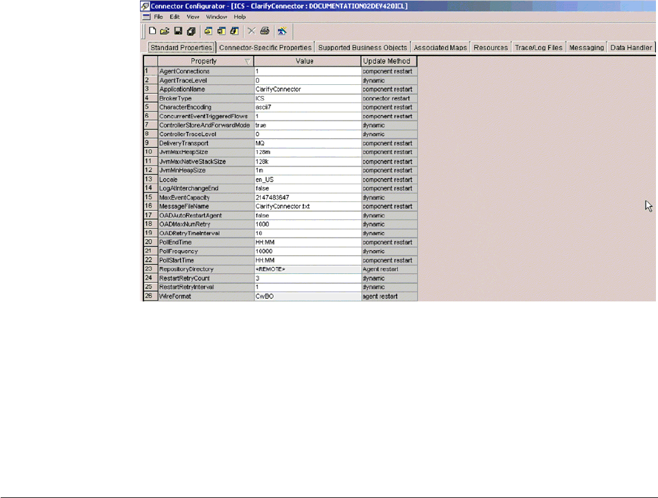
2.
In
the
Standard
Properties
tab,
click
in
the
Value
cell
of
the
MaxEventCapacity
property.
3.
Change
the
value
to
represent
the
maximum
number
of
events
you
want
queued
for
a
connector.
The
valid
range
of
values
for
this
property
is
from
1
to
2147483647.
4.
Click
Save
>
to
Project
from
the
File
drop-down
menu.
The
following
message
appears
in
the
bottom
section
of
Connector
Configurator:
Connector
’<name_of_connector>’
is
saved
successfully.
Operating
collaboration
objects
Operating
collaboration
objects
may
include
such
tasks
as
running,
pausing,
stopping,
and
shutting
down
collaboration
objects.
For
information
about
configuring
collaboration
objects,
see
the
System
Implementation
Guide.
You
can
run,
pause,
stop,
and
shut
down
collaboration
objects
from
the
Web-based
System
Monitor.
By
default,
all
connectors
and
the
active
collaborations
appear.
This
section
covers
the
following
topics:
“Collaboration
object
states”
on
page
60
“Starting,
stopping,
and
pausing
collaboration
objects”
on
page
61
“Configuring
collaboration
run-time
properties”
on
page
62
Collaboration
object
states
You
can
view
the
state
of
a
collaboration
object
by
logging
on
to
the
Web-based
System
Monitor
and
opening
a
view
that
contains
collaboration
object
information.
To
log
on
to
the
Web-based
System
Monitor,
follow
the
instructions
in
“Logging
on
to
the
Web-based
System
Monitor”
on
page
33.
Figure
12.
Connector
Configurator,
Standard
Properties
tab
60
User
Guide
The
following
collaboration
object
states
are
viewable
from
the
Web-based
System
Monitor
and
the
Collaboration
Object
menu
of
the
System
View
window:
Start
Starting
a
collaboration
object
causes
it
to
subscribe
to
its
triggering
business
objects
and
to
process
them
as
they
arrive.
If
you
stop
and
then
restart
InterChange
Server,
collaboration
objects
in
the
Start
state
automatically
start
running
when
InterChange
Server
Express
comes
back
up.
Pause
Pausing
a
collaboration
prevents
it
from
receiving
new
flow
initiators.
The
collaboration
completes
all
of
the
current
processing,
then
enters
an
idle
state.
A
connector
maintains
its
subscription
information;
therefore,
it
continues
to
send
flow
initiators
to
the
connector
queues.
The
collaboration
processes
these
when
it
is
resumed.
To
resume
collaboration
execution,
click
Start
in
the
Web-based
System
Monitor.
Stop
Stopping
a
collaboration
causes
it
to
unsubscribe
to
business
objects.
The
collaboration
completes
all
of
the
current
processing,
then
becomes
inactive.
Unlike
the
Pause
command,
the
Stop
command
causes
connectors
to
stop
sending
business
objects
to
the
collaboration.
To
properly
stop
a
collaboration
without
losing
any
flows,
first
stop
the
associated
connectors
from
polling,
allow
all
flows
to
process,
then
stop
the
collaboration.
Shut
Down
Shutting
down
a
collaboration
immediately
ends
processing
of
current
flows.
When
the
collaboration
is
restarted,
the
system
recovers
by
processing
those
flows
that
were
interrupted
by
the
shut
down
and
recovering
those
flows
waiting
in
the
queue.
This
recovery
is
not
immediate,
so
prepare
to
wait
while
the
system
completes
the
recovery
interval.
Statistics
When
you
choose
Statistics,
the
Open
Collaboration
dialog
box
displays.
Enter
a
collaboration
name
and
choose
Open
to
display
statistics
for
that
collaboration
object.
Note:
When
you
stop
or
shut
down
a
collaboration
object
that
is
part
of
a
collaboration
group,
all
collaborations
in
the
group
stop
or
shut
down.
If
any
member
of
a
collaboration
group
fails
to
start
up
or
has
a
state
change
failure,
the
collaboration
group
is
rolled
back
to
the
initial
state
(deactivated
or
stopped).
Starting,
stopping,
and
pausing
collaboration
objects
To
make
a
collaboration
object
functional
for
the
first
time,
you
must
first
configure
it
then
start
it.
See
“Configuring
collaboration
run-time
properties”
on
page
62
for
more
information
on
configuring
collaborations.
To
run,
stop,
and
pause
collaboration
objects,
do
this:
1.
While
viewing
the
System
Overview
view
(see
Figure
10
on
page
53),
select
a
collaboration
object
by
placing
check
in
the
box
to
its
left.
2.
Select
the
Start,
Pause,
or
Stop
icon
from
the
icon
group
in
the
upper-left
corner
of
the
view
(see
Figure
11
on
page
54).
Chapter
5.
Operating
components
of
the
system
61
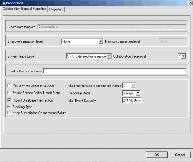
Configuring
collaboration
run-time
properties
This
section
describes
some
aspects
of
collaboration
behavior
that
are
configurable
in
a
production
environment
and
contains
the
following
topics:
“Setting
collaboration
object
general
properties”
on
page
62
“Configuring
collaborations
to
process
concurrent
event-triggered
flows”
on
page
63
“Configuring
flow
control
for
collaboration
objects”
on
page
63
For
information
about
the
following
tasks,
see
the
System
Implementation
Guide:
v
Creating
a
Collaboration
Object
v
Configuring
Collaboration-Specific
Properties
v
Binding
the
Ports
of
the
Collaboration
v
Setting
the
Effective
Transaction
Level
and
Other
General
Properties
Setting
collaboration
object
general
properties
To
open
the
Collaboration
Properties
window
and
change
values
for
general
properties
of
a
collaboration
object,
do
this:
1.
From
System
Manager,
right-click
a
collaboration
object
and
select
Properties.
2.
In
the
Properties
dialog
box,
choose
the
Collaboration
General
Properties
tab.
The
following
dialog
displays:
Figure
13.
Properties
dialog
box,
Collaboration
General
Properties
tab
62
User
Guide
The
dialog
box
shows
the
template
from
which
the
collaboration
object
was
generated
and
the
minimum
transaction
level
that
was
specified
in
the
collaboration
template.
The
dialog
enables
you
to
make
settings
for
the
following:
v
Effective
Transaction
Level
v
System
Trace
Level
v
Collaboration
Trace
Level
v
Email
Notification
Address
v
Pause
When
Critical
Error
Occurs
v
Implicit
Database
Transaction
v
Maximum
Number
of
Concurrent
Events
v
Recovery
Mode
Configuring
collaborations
to
process
concurrent
event-triggered
flows
Tip:
Processing
concurrently
triggered
events
in
collaborations
requires
additional
system
resources.
To
maximize
performance,
ensure
that
system
resources
used
to
handle
concurrent
events
are
not
idle.
For
example,
do
not
set
the
value
for
the
maximum
concurrent
triggered-event
processing
option
to
10
if
the
collaboration
queue
is
set
to
process
a
maximum
of
four
events.
To
set
the
maximum
number
of
concurrent
flows
for
a
collaboration:
1.
From
System
Manager,
right-click
the
collaboration
object
that
you
want
to
change,
then
select
Properties.
The
Properties
dialog
box
appears
(see
Figure
13
on
page
62).
2.
In
the
Collaboration
General
Properties
tab,
enter
a
value
in
the
″Maximum
number
of
concurrent
events″
field.
3.
Click
OK
to
save
your
changes
and
close
the
window.
4.
Restart
the
collaboration
for
changes
to
take
effect.
Configuring
flow
control
for
collaboration
objects
Flow
control
is
a
configurable
service
that
allows
you
to
manage
the
flow
of
connector
and
collaboration
object
queues.
The
parameters
for
configuring
flow
control
can
be
configured
system-wide
or
on
individual
components,
or
both.
If
you
configure
both,
the
individual
component
configuration
supersedes
the
system-wide
configuration.
For
instructions
on
configuring
flow
control
system-wide,
see“Configuring
system-wide
flow
control”
on
page
50.
This
section
describes
how
to
configure
flow
control
for
collaboration
objects.
Note:
Configuration
changes
for
individual
connectors
or
collaboration
objects
are
dynamic,
meaning
they
do
not
require
ICS
to
be
rebooted.
System-wide
configuration
changes
for
flow
control
require
ICS
to
be
rebooted.
To
monitor
how
flow
control
is
working
in
the
system,
you
can
use
the
default
Flow
Control
monitor
provided
as
part
of
the
Web-based
System
Monitor,
or
you
can
create
new
Flow
Control
monitors
for
individual
connectors
or
collaboration
objects.
For
more
information
about
monitoring
flow
control,
see
the
description
of
the
default
Flow
Control
monitor
in“Using
default
monitors”
on
page
25,
and
the
instructions
on
creating
new
monitors
in“Creating
new
monitors
using
the
Monitor
Definition
Wizard”
on
page
29.
After
you
have
all
the
flow
control
monitors
Chapter
5.
Operating
components
of
the
system
63

created,
refer
to
the
following
sections
to
begin
monitoring
flow
control:
“Using
the
Web-based
System
Monitor”
on
page
25
and
“Logging
on
to
the
Web-based
System
Monitor”
on
page
33.
To
configure
flow
control
for
a
collaboration
object,
do
the
following:
1.
In
System
Manger,
right-click
the
collaboration
object
for
which
you
want
to
create
flow
control,
then
select
Properties
from
the
drop-down
menu.
The
Properties
dialog
box
appears
(see
Figure
13
on
page
62).
2.
In
the
Collaboration
General
Properties
tab,
edit
the
value
in
the
Max
Event
Capacity
field
to
represent
the
maximum
number
of
events
you
want
queued
for
a
collaboration
object.
The
valid
range
of
values
for
this
property
is
from
1
to
2147483647.
3.
Click
OK.
The
property
is
changed
immediately.
Reconfiguring
the
timeout
attribute
for
long-lived
business
processing
Long-lived
business
processing
enables
collaboration
objects
to
be
deployed
as
a
long-lived
business
processes.
If
a
collaboration
object
has
been
configured
with
long-lived
business
processing,
the
service
call
timeout
values
can
be
reconfigured
during
runtime.
For
more
information
about
developing
a
collaboration
object
with
long-lived
business
processing,
see
the
Collaboration
Development
Guide.
To
reconfigure
the
service
call
timeout
values
of
a
collaboration
with
long-lived
business
processing,
do
the
following:
1.
From
System
Manager,
right-click
the
collaboration
object
whose
service
call
timeout
value
you
want
to
edit,
then
click
Properties.
The
Properties
dialog
box
appears.
2.
From
the
Properties
tab,
locate
the
property
that
represents
the
service
call
timeout
value
you
want
to
change,
then
click
in
the
value
field.
When
the
property
becomes
highlighted,
the
value
can
be
edited.
Note:
The
name
of
the
service
call
timeout
configuration
property
may
be
something
like,
″CreateTimeout″
or
″RetreiveTimeout,″
but
since
there
is
no
naming
convention
for
this
property,
you
may
have
to
contact
the
person
who
developed
the
collaboration,
if
the
name
of
the
service
call
timeout
configuration
property
is
not
immediately
apparent.
3.
Edit
the
value
so
that
it
represent
the
number
of
timeout
minutes
allowed.
Note:
The
Value
field
must
contain
an
integer
greater
than
0.
If
it
contains
a
0
or
is
left
blank,
the
waittime
is
equal
to
infinity.
If
it
contains
non-numerical
values,
it
will
trigger
a
collaboration
runtime
exception.
4.
Click
OK.
Your
changes
take
place
immediately,
without
the
need
to
restart
InterChange
Server.
Operating
maps
You
can
start
and
stop
maps
from
the
Web-based
System
Monitor.
This
section
covers
the
following
topics:
“Map
states”
on
page
65
“Starting
and
stopping
maps”
on
page
65
64
User
Guide

Map
states
You
can
view
the
state
of
a
map
by
logging
on
to
the
Web-based
System
Monitor.
To
see
the
state
of
connectors
using
the
Web-based
System
Monitor,
do
the
following:
If
the
System
Overview
view
is
displayed,
click
the
Maps
and
Relationships
link
under
Views
in
the
left
pane
of
the
Web
page.
The
Map
Status
and
Relationship
Status
monitors
appear
in
the
body
of
the
Web
page.
When
the
product
is
installed,
the
default
view
is
set
to
System
Overview,
and
the
default
monitor
contained
in
that
view
is
set
to
System
Overview.
These
defaults
can
be
changed
to
suit
your
monitoring
needs.
Starting
and
stopping
maps
Maps
define
the
transfer
(or
transformation)
of
data
between
the
source
and
destination
business
objects.
In
the
Business
Integration
Express
for
Item
Sync
environment,
data
is
mapped
from
an
application-specific
business
object
to
a
generic
business
object
or
from
a
generic
business
object
to
an
application-specific
business
object.
For
detailed
information
about
how
maps
are
used
in
the
Business
Integration
Express
for
Item
Sync
system,
refer
to
the
Map
Development
Guide.
This
section
describes
the
how
to
start
and
stop
maps.
For
information
about
additional
tasks
in
using
maps,
including
map
compilation,
map
properties,
data
validation
levels,
explicit
and
implicit
transaction
bracketing,
and
map
instance
reuse,
see
the
System
Implementation
Guide.
Map
activation
For
a
map
to
be
executable,
it
must
first
be
activated.
Map
Designer
automatically
starts
a
map
when
it
successfully
compiles
the
map.
However,
other
changes
to
the
map
might
require
that
you
explicitly
stop
and
restart
the
map
for
the
change
to
take
effect.
Starting
and
stopping
maps
To
start
and
stop
maps,
do
this:
1.
If
the
System
Overview
view
is
displayed,
click
the
Maps
and
Relationships
link
under
Views
in
the
left
pane
of
the
Web
page.
The
Map
Status
and
Relationship
Status
monitors
appear
in
the
body
of
the
Web
page.
2.
Select
the
Start
or
Stop
icon
from
the
icon
group
in
the
upper-left
corner
of
the
view
(see
Figure
11
on
page
54).
Operating
relationships
You
can
start
and
stop
relationships
from
the
Web-based
System
Monitor.
This
section
covers
the
following
topics:
“Relationship
states”
on
page
65
“Starting
and
stopping
relationships”
on
page
66
Relationship
states
You
can
view
the
state
of
a
relationship
by
logging
on
to
the
Web-based
System
Monitor
and
opening
a
view
that
contains
relationship
status.
To
log
on
to
the
Web-based
System
Monitor,
follow
the
instructions
in
“Logging
on
to
the
Web-based
System
Monitor”
on
page
33.
Chapter
5.
Operating
components
of
the
system
65

Table
8
lists
the
relationship
states
represented
by
the
System
View
traffic
light
display
color
and
describes
what
actions
can
be
performed
during
that
state.
Table
8.
Relationship
States
Relationship
State/Traffic
Light
Description
Active
(green)
Relationship
is
ready
to
run
and
available
for
use
in
the
Business
Integration
Express
for
Item
Sync
system.
To
use
Relationship
Manager
on
a
relationship,
the
relationship
must
be
in
the
active
state.
Inactive
(red)
Relationship
is
not
ready
to
run
or
available
for
use
in
the
Business
Integration
Express
for
Item
Sync
system.
This
state
is
entered
when
the
relationship
is
stopped,
where
all
current
jobs
in
queue
are
completed
and
no
new
jobs
are
accepted.
To
modify
a
relationship
definition,
it
must
be
in
this
state.
Unknown
(grey)
Relationship
does
not
have
a
compatible
runtime
schema.
To
create
a
compatible
runtime
schema,
from
the
Relationship
Designer,
save
the
relationship
with
the
Create
runtime
schema
option
selected.
The
state
changes
to
Inactive,
at
which
point
the
relationship
can
then
be
started.
Starting
and
stopping
relationships
Relationships
are
used
to
establish
associations
between
business
object
attributes
that
cannot
easily
be
mapped.
The
tool
used
for
creating
relationships
is
Relationship
Designer.
For
more
information
about
Relationship
Designer,
see
the
Map
Development
Guide.
When
you
expand
the
Relationships
folder
in
System
Manager,
two
subfolders
appear:
Dynamic
and
Static.
v
Dynamic
relationship—a
relationship
whose
runtime
data
changes
frequently;
that
is,
its
relationship
tables
have
frequent
Insert,
Update,
or
Delete
operations.
All
relationships
are
dynamic
by
default.
v
Static
relationship—a
relationship
whose
runtime
data
undergoes
very
minimal
change;
that
is,
its
relationship
tables
have
very
few
Insert,
Update,
or
Delete
operations.
For
example,
because
lookup
tables
store
information
such
as
codes
and
status
values,
their
data
very
often
is
static.
Such
tables
make
good
candidates
for
being
cached
in
memory.
This
section
describes
the
following
topics:
“Relationship
activation”
on
page
66
“Starting
and
stopping
relationships”
“Relationship
table
caching”
on
page
67
Relationship
activation
For
a
relationship
to
be
executable,
it
must
be
activated.
However,
you
cannot
modify
a
relationship
when
it
is
active.
Therefore,
you
must
stop
the
relationship,
make
the
change
to
the
relationship,
and
then
restart
the
relationship.
Starting
and
stopping
relationships
To
start
and
stop
relationships,
do
this:
66
User
Guide
1.
From
the
System
View
window,
select
Show
Maps
and
Relationships
from
the
View
drop-down
menu.
The
Maps
and
Relationships
columns
appear
next
to
Collaborations
and
Connectors.
2.
Right-click
a
relationship,
then
select
either
the
Start<name_of_relationship>
or
Stop
<name_of_relationship>
option.
Relationship
table
caching
As
part
of
the
design
process
of
a
static
relationship,
a
developer
can
indicate
whether
the
relationship’s
tables
are
to
be
cached
in
memory.
A
static
relationship
is
one
whose
data
does
not
change
frequently.
If
the
developer
has
indicated
that
the
static
relationship’s
tables
can
be
cached,
you
can
control
whether
to
enable
caching
from
System
Manager.
System
Manager
lists
all
static
relationships
in
the
folder
labelled
Static
under
the
Relationships
folder.
Note:
For
information
on
how
to
design
a
static
relationship
so
that
its
tables
to
be
cached
in
memory,
see
the
Map
Development
Guide.
Enabling
Caching:
To
enable
relationship
table
caching
for
a
static
relationship:
1.
Expand
the
Relationships
folder
in
System
Manager.
2.
Expand
the
Static
folder
in
the
object
browser
to
locate
the
static
relationship
whose
tables
you
want
to
be
cached.
3.
Right-click
the
static
relationship
to
determine
its
current
cached
state.
If
the
Cached
option
appears
with
no
check
mark
to
the
left,
caching
for
that
relationship
is
currently
disabled.
Choose
Cached
from
the
context
menu
to
enable
caching.
When
the
Cached
option
appears
with
a
check
mark
to
the
left,
InterChange
Server
Express
reads
the
relationship
tables
into
memory
the
next
time
the
runtime
data
is
accessed.
Disabling
Caching:
To
disable
relationship
table
caching
for
a
static
relationship:
1.
Expand
the
Relationships
folder
in
System
Manager.
2.
Expand
the
Static
folder
in
the
object
browser
to
locate
the
static
relationship
whose
tables
you
do
not
want
to
be
cached.
3.
Right-click
the
static
relationship
to
determine
its
current
cached
state.
If
the
Cached
option
appears
with
a
check
mark
to
the
left,
caching
for
that
relationship
is
currently
enabled.
Choose
Cached
from
the
context
menu
to
disable
caching.
When
the
Cached
option
appears
with
no
check
mark
to
the
left,
InterChange
Server
Express
reads
runtime
data
from
the
tables
in
the
relationship
database.
Reloading
the
Cached
Tables:
You
can
tell
InterChange
Server
Express
to
reread
the
relationship’s
tables
into
memory
with
the
Reload
feature,
as
follows:
1.
Expand
the
Relationships
folder
in
System
Manager.
2.
Expand
the
Static
folder
in
the
object
browser
to
locate
the
static
relationship
whose
tables
you
want
to
be
reloaded.
3.
Right-click
the
static
relationship
to
determine
its
current
cached
state.
If
the
Cached
option
appears
with
a
check
mark
to
the
left,
caching
for
that
relationship
is
currently
enabled.
Therefore,
the
Reload
option
is
enabled.
4.
Choose
Reload
from
the
context
menu
to
reload
the
static
relationship’s
tables.
When
you
choose
this
option,
InterChange
Server
Express
reloads
the
cached
relationship
tables
by
rereading
the
tables
from
the
relationship
database
into
Chapter
5.
Operating
components
of
the
system
67

memory.
This
option
is
useful
when
the
static
relationship’s
tables
are
updated
directly
in
the
database
through
SQL
statements.
To
get
the
more
current
version
of
the
tables
into
cache,
choose
the
Reload
option.
Tracing
Cached
Tables:
To
tell
InterChange
Server
Express
to
log
a
trace
message
each
time
it
loads
and
unloads
relationship
tables
in
memory,
set
the
RELATIONSHIP.CACHING
configuration
parameter
to
five
(5)
in
the
TRACING
section
of
the
InterchangeSystem.cfg
file:
RELATIONSHIP.CACHING=5
ICS
routes
these
messages
to
the
trace
file
(if
one
is
configured).
By
default,
ICS
does
not
generate
trace
messages
when
it
loads
and
unloads
the
relationship
tables.
Trace
levels
less
than
five
(0-4)
do
not
produce
messages
either.
Backing
up
Business
Integration
Express
for
Item
Sync
components
Standardized
backup
procedures
allow
for
easier
environment
restoration
in
the
event
of
system
failures.
Backing
up
the
Business
Integration
Express
for
Item
Sync
system
is
also
important
because
hardware
or
software
failures
may
leave
data
in
an
inconsistent
state
between
Business
Integration
Express
for
Item
Sync
and
the
integrated
applications.
This
section
covers
the
following
topics:
“Planning
a
Backup
Schedule”
on
page
68
“Backing
Up
Components”
on
page
69
Planning
a
Backup
Schedule
Plan
and
carry
out
procedures
for
regularly
scheduled
backups
of
the
Business
Integration
Express
for
Item
Sync
system.
The
more
frequently
you
perform
backups,
the
less
data
you
need
to
recover
in
the
event
of
data
loss.
When
planning
a
backup
schedule,
keep
in
mind
the
information
in
this
section.
Within
the
Business
Integration
Express
for
Item
Sync
system,
two
types
of
data
should
be
backed
up:
static
data
and
dynamic
data.
v
Static
data
rarely
changes
and
should
be
backed
up
only
when
changed.
For
example,
static
configuration
data
stored
in
the
Business
Integration
Express
for
Item
Sync
repository
needs
backing
up
only
when
it
has
changed.
Static
data
should
also
be
backed
up
before
any
planned
reinstallations
or
upgrades
to
the
system.
Following
is
a
partial
list
of
static
data
in
the
Business
Integration
Express
for
Item
Sync
system:
–
Business
Integration
Express
for
Item
Sync
repository
(except
for
relationship
tables)
–
Custom
collaborations
components,
such
as
Java
class
files
(.class),
and
message
files
(.msg)
–
Custom
connectors
–
Map
components,
including:
map
design
files
and
Java
class
files
(.class).
v
Dynamic
data
constantly
changes
and
should
be
backed
up
on
a
regular
basis.
For
example,
the
relationship
tables
maintain
the
instance
data
for
relationship
definitions.
Since
relationship
instance
data
is
maintained
continuously,
regularly
back
up
this
data
as
well
as
application
data.
68
User
Guide
The
relationship
tables
are
stored
by
default
in
the
repository
database.
If
you
store
them
in
another
database,
you
need
to
back
up
that
database.
For
more
information
about
settings
for
storage
of
relationship
tables,
see
the
Map
Development
Guide.
Following
is
a
partial
list
of
dynamic
data
in
the
Business
Integration
Express
for
Item
Sync
system:
–
Business
Integration
Express
for
Item
Sync
cross-reference
database
–
Business
Integration
Express
for
Item
Sync
relationship
tables
–
Business
Integration
Express
for
Item
Sync
WIP
(event
management)
and
transaction
tables
–
WebSphere
MQ
queue
data
–
Business
Integration
Express
for
Item
Sync
connector
archive
tables
(this
is
part
of
the
application
backup;
all
events
since
the
last
backup
should
be
archived)
–
Log
files
(as
desired
for
historical
information)
Plan
your
backup
schedule
at
times
when
your
systems
environment
is
in
a
quiescent
state
or
in
a
state
with
a
minimal
amount
of
event
processing.
Business
Integration
Express
for
Item
Sync
is
in
a
quiescent
state
when
all
of
the
following
conditions
exist:
v
All
working
queues
are
drained.
v
All
collaborations
are
paused
so
that
no
new
data
can
be
written
to
the
cross-reference
tables.
v
All
data
is
consistent
between
the
integrated
applications.
Backing
Up
Components
Different
components
of
the
Business
Integration
Express
for
Item
Sync
environment
require
different
backup
procedures.
The
following
topics
are
described
in
this
section:
“Backing
Up
Relationship
Tables”
on
page
69
“Backing
Up
and
Loading
the
Repository”
on
page
70
“Backing
up
System
Installation
Files”
on
page
70
“Backing
Up
Collaboration
Class
Files”
on
page
71
“Backing
Up
Archive
Tables”
on
page
71
Attention:
When
backing
up
Business
Integration
Express
for
Item
Sync
components,
do
not
back
up
the
WebSphere
MQ
queues.
WebSphere
MQ
queues
represent
in-progress
transactions
in
the
system,
which
are
dynamic
and
therefore
should
never
be
backed
up.
Instead,
it
is
recommended
that
the
WebSphere
MQ
queues
be
mirrored
in
a
fail-over
scenario.
Backing
Up
Relationship
Tables
Relationship
tables
are
backed
up
using
the
standard
backup
utility
for
the
database
where
these
tables
reside.
Schedule
this
backup
to
coincide
with
the
corresponding
application
backups.
If
you
back
up
applications
at
different
times,
back
up
the
relationship
tables
each
time
you
back
up
an
application.
There
are
often
static
relationship
tables
within
the
relationship
database.
Although
this
data
Chapter
5.
Operating
components
of
the
system
69
is
static,
it
is
recommended
that
you
back
up
all
relationship
tables
together.
Make
sure
the
Business
Integration
Express
for
Item
Sync
system
is
in
a
quiescent
state
when
backing
up
the
relationship
tables.
For
more
information
on
bringing
the
system
to
a
quiescent
state,
see
“Shutting
down
InterChange
Server
Express”
on
page
46.
It
is
recommended
that
the
relationship
database
log
be
mirrored
to
assist
in
recovery.
If
hardware/software
cost
is
not
a
consideration,
the
relationship
runtime
data
can
also
be
mirrored.
The
set
of
relationship
tables
for
one
relationship
are
closely
associated,
so
you
should
back
up
all
of
these
at
the
same
time.
Back
up
relationship
information
using
the
standard
backup
utility
from
the
DBMS
(Database
Management
System)
where
these
tables
reside.
Note:
To
avoid
data
loss,
run
relationship
backups
at
the
same
time
you
run
backups
for
the
applications
that
the
tables
reflect.
Backing
Up
and
Loading
the
Repository
Repository
tables
are
backed
up
using
the
repos_copy
command.
For
more
information
on
this
command,
see
“Using
Repos_Copy”
on
page
71.
Back
up
the
repository
whenever
it
is
modified
and
before
and
after
performing
a
reinstallation
or
a
Business
Integration
Express
for
Item
Sync
software
upgrade.
The
Business
Integration
Express
for
Item
Sync
system
does
not
need
to
be
in
a
quiescent
state
when
backing
up
the
repository.
The
method
to
use
for
backing
up
the
repository
depends
on
whether
your
database
is
partitioned
or
unpartitioned.
Backing
Up
Partitioned
Databases:
If
your
databases
are
partitioned,
you
can
use
the
standard
database
backup
utility
from
the
DBMS
to
back
up
the
Repository,
Event
Management,
and
Transaction
databases.
Note:
It
is
recommended
that
the
Repository,
Event
Management,
and
Transaction
database
logs
be
mirrored
to
assist
in
recovery.
Backing
Up
an
Unpartitioned
(Single)
Database:
If
your
Business
Integration
Express
for
Item
Sync
databases
are
not
partitioned,
meaning
they
are
contained
in
a
single
database,
they
should
not
be
part
of
your
normal
database
backup
routine.
The
Business
Integration
Express
for
Item
Sync
databases
contain
transient
data
whose
recovery
can
cause
inconsistencies
in
the
system.
Instead,
back
up
the
objects
in
the
Business
Integration
Express
for
Item
Sync
repository
by
using
the
repos_copy
utility.
Backing
up
System
Installation
Files
The
system
installation
files
should
be
backed
up
at
the
following
stages:
v
After
initial
installation.
v
Periodically
during
the
development
phase:
–
After
collaboration
design
and
development
–
After
connector
design
and
development
–
After
map
development
and
customization
v
After
the
configuration
and
customization
phase
is
complete.
70
User
Guide

Backing
Up
Collaboration
Class
Files
Back
up
collaboration
class
files
with
your
other
non-Business
Integration
Express
for
Item
Sync
system
files.
Coordinate
the
repository
backup
with
the
collaboration
class
file
backups.
Backing
Up
Archive
Tables
Some
applications
have
archive
tables.
Back
up
archive
tables
using
the
standard
database
utility
for
the
database
in
which
they
reside.
The
archive
tables
are
part
of
the
Business
Integration
Express
for
Item
Sync
system,
but
typically
reside
in
the
application’s
database.
Back
up
the
archive
tables
on
a
regular
basis.
Data
in
the
archive
table
represents
all
of
the
events
that
have
passed
from
the
application
to
the
Business
Integration
Express
for
Item
Sync
system.
These
events
can
be
used
to
“resynchronize”
the
application
and
the
Business
Integration
Express
for
Item
Sync
cross-reference
tables.
Using
Repos_Copy
Repos_copy
is
a
command
line
interface
for
working
with
integration
components
and
InterChange
Server
Express
repositories.
It
allows
you
to
deploy
a
package—a
collection
of
integration
components—to
a
server
repository,
or
to
export
components
from
the
repository
to
a
package.
To
run
repos_copy,
enter
the
command
in
an
MS-DOS
command
prompt
window.
The
ProductDir/bin
directory,
where
the
utility
resides,
should
be
in
your
path
as
a
result
of
installation.
Note:
The
repos_copy
output
file
contains
encrypted
passwords
for
relationships
and
connector
applications.
If
you
try
to
edit
the
output
file
and
change
these
passwords,
repos_copy
will
not
work.
Important:
When
repos_copy
deploys
components
to
the
repository,
it
deploys
them
to
the
repository
only.
It
does
not
deploy
them
to
any
in-memory
tables
of
business
object
definitions.
For
instance,
connectors
load
business
object
definitions
from
the
repository
into
their
memory
space
when
they
start.
If
you
deploy
a
business
object
definition
to
the
repository
to
update
it,
you
must
restart
the
connector
agent
so
that
it
loads
the
modified
business
object
definition
into
memory.
You
must
therefore
stop
and
restart
InterChange
Server
Express
and
components
that
load
definitions
into
memory
for
them
to
load
recently
deployed
components.
This
chapter
has
the
following
sections:
v
“Repos_copy
syntax”
on
page
71
v
“Repos_copy
usage
scenarios”
on
page
77
v
“Locale
for
repos_copy
files”
on
page
83
Repos_copy
syntax
Table
9
on
page
72
describes
the
options
of
repos_copy
and
their
arguments,
and
shows
the
correct
case
usage
for
the
options
and
the
lack
of
spacing
between
the
option
and
its
argument.
The
syntax
shows
that
the
options
between
curly
braces
({})
represent
a
set
of
options
that
are
required.
If
you
do
not
specify
the
-u,
-p,
-i,
-o,
or
-s
options
at
the
command
line,
then
repos_copy
prompts
you
for
them.
If
you
do
not
specify
them
when
prompted,
repos_copy
does
not
execute.
Options
enclosed
in
brackets
([])
are
optional.
Chapter
5.
Operating
components
of
the
system
71

repos_copy
[-sserverName][-uusername][-ppassword]
{-i[filename1][-rrelationshipName[relationshipName2]][[-k][-ai|-ar|-arp]
[-xcompilePackage][-vp|-vr]}
{-o[outfilename[[-fEntityFile][-eEntityType:Entity1[+EntityType:Entity2][+...]]
[-deep][-summary]}
{[-d]|[-doEntityType:Entity[+EntityType:Entity2][+...]|
[-dfoEntityType:Entity[+EntityType:Entity2][+...]}
{-v}
{-vr}
{[-xCompileAll]|[-xCompileAllCollabs]|[-xCompileAllMaps]|
[-xCompileCollab:collabTemplateName[+collabTemplateName][+...]]|
[-xCompileMap:nativeMapName[+nativeMapName][+...]]}
Table
9.
Repos_copy
command
options
Option
Description
-ai
Ignore
and
do
not
load
any
duplicate
objects
(business
objects,
maps,
relationships,
collaboration
templates
and
objects,
and
connectors)
that
are
found
when
deploying
a
package.
-ar
Replace
any
duplicate
objects
(business
objects,
maps,
relationships,
collaboration
templates
and
objects,
and
connectors)
that
are
found
when
deploying
a
package.
Note:
The
-ar
option
only
works
with
release
4.2.0
or
later.
-arp
This
is
an
interactive
version
of
the
-ar
option.
If
the
components
in
the
package
being
deployed
already
exist
in
the
repository
then
repos_copy
displays
a
prompt
asking
if
you
want
to
ignore
or
replace
the
component.
Note:
The
-arp
option
only
works
with
release
4.2.0
or
later.
-d
Deletes
the
components
in
the
repository,
except
the
state
data.
Use
this
option
to
delete
all
of
the
components
from
the
repository.
-deep
Used
with
the
-e
option
when
you
want
to
include
all
the
dependent
components.
If
you
omit
the
-deep
option,
only
the
component
that
is
specified
with
the
-e
option
will
be
included.
-dfoEntityType:Entity[+EntityType:Entity2]
This
option
is
the
same
as
the
-do
option
except
that
it
will
forcefully
delete
the
component
even
if
the
component
has
referents
that
depend
on
it.
This
option
only
works
with
the
repository
of
a
server
that
is
running
in
design
mode.
A
server
that
is
running
in
production
mode
does
not
permit
unresolved
dependencies
and
references.
72
User
Guide

Table
9.
Repos_copy
command
options
(continued)
Option
Description
-doEntityType:Entity[+EntityType:Entity2]
Specifies
the
entities
to
be
deleted
from
the
repository.
See
Table
10
on
page
77
for
the
list
of
entity
types
and
keywords.
If
the
object
has
no
referents—other
components
that
depend
on
it—then
the
deletion
takes
place.
If
the
object
has
referents,
then
the
deletion
fails
and
a
message
is
displayed.
The
behavior
is
the
same
in
both
design
mode
and
production
mode.
For
more
information
about
starting
the
server
in
design
mode
or
production
mode,
see
the
System
Implementation
Guide.
-eEntityType:Entity1[+EntityType:Entity2...]
Exports
one
or
more
referenced
first-class
entities.
A
first-class
entity
is
a
business
object,
collaboration
object,
collaboration
template,
connector,
database
connection
pool,
map,
or
relationship.
You
identify
the
entity
to
load
or
unload
by
specifying
one
of
the
keywords
in
Table
10
on
page
77.
Follow
the
EntityType
keyword
with
a
colon
(:)
and
the
name
of
the
entity.
Use
the
“+”
to
specify
more
than
one
entity.
When
combined
with
the
-o
option,
the
-e
option
unloads
the
data
to
an
output
file.
-fentityFile
This
option
is
similar
to
the
-e
option
except
that
the
names
of
the
entities
to
be
imported
are
stored
in
a
file.
The
file
should
contain
references
to
the
entities,
with
the
following
conditions:
v
The
entity
names
must
follow
after
the
proper
entity
type
keyword.
The
entity
types
and
their
keywords
are
listed
in
Table
10
on
page
77.
v
A
colon
must
separate
the
entity
type
from
the
entity
name.
v
There
must
be
a
new
line
separating
each
entity
reference.
When
combined
with
the
-o
option,
this
option
exports
the
components
to
a
package.
Chapter
5.
Operating
components
of
the
system
73

Table
9.
Repos_copy
command
options
(continued)
Option
Description
-ifilename
Deploys
the
specified
package
file
to
the
repository.
If
you
omit
the
input
file
name
value,
the
command
interactively
prompts
you
to
enter
the
name
of
the
input
file.
The
file
can
be
either
a
.jar
file
containing
objects
in
XML
format,
or
a
file
in
text
format
from
a
release
prior
to
4.2.0.
The
.jar
files
created
by
repos_copy
or
System
Manager
have
a
particular
structure
which
must
be
maintained
for
any
subsequent
imports
of
such
a
file
to
be
successful.
You
should
not,
therefore,
ever
modify
an
input
file
manually.
-k
Overrides
the
default
behavior
of
repos_copy
when
it
finds
a
Mercator
map
in
the
package
file
it
is
loading.
By
default,
repos_copy
exits
if
it
encounters
a
Mercator
map.
If
you
use
the
-k
option,
repos_copy
skips
over
any
Mercator
maps
in
the
package
file
and
proceeds
with
the
deployment
process.
-mode
Returns
the
mode
of
the
server.
-ncencoding
Specifies
the
character
encoding
when
importing
a
text-based
repository
file
fromreleases
prior
to
4.2.0.
For
a
list
of
valid
character
encodings,
see
the
Java
documentation
about
the
String
class.
74
User
Guide

Table
9.
Repos_copy
command
options
(continued)
Option
Description
-ooutfilename
Exports
the
components
in
the
repository
to
the
specified
package
file.
You
must
specify
the
name
of
the
package
file.
If
the
file
already
exists
then
repos_copy
prompts
you
to
overwrite
it
or
not.
The
output
file
is
in
.jar
format,
and
contains
the
component
definitions
in
XML
format,
as
well
as
.java
source
files
for
components
that
have
them.
This
option
cannot
be
combined
with
the
-i
or
-d
options,
nor
can
it
export
components
in
text
format
as
it
did
in
previous
releases.
Repos_copy
does
not
append
the
.jar
extension,
so
you
must
specify
it
when
specifying
the
name
of
the
output
file.
-ppassword
Specifies
the
password
for
the
user
name
supplied
with
the
-u
option.
The
password
case-sensitive.
If
you
do
not
specify
this
option
then
repos_copy
prompts
you
for
the
password.
-r*
This
option
is
similar
to
the
-r
option;
it
allows
you
to
import
relationship
definitions
and
not
create
the
runtime
schemas
for
any
of
them.
-rrelationshipName1[:relationshipName2]
Loads
the
named
relationship
definition(s)
into
the
repository
without
creating
its
runtime
schema.
-sserverName
Specifies
the
name
of
the
InterChange
Server
Express
instance
with
which
repos_copy
should
interface.
The
name
is
case-sensitive.
If
the
server
name
is
not
specified,
the
tool
prompts
for
a
server
name.
-summary
This
option
prints
a
list
of
components
in
the
server
repository
(they
are
identified
as
“artifacts”
rather
than
as
components
in
the
output).
The
output
is
in
XML
format.
You
can
combine
this
option
with
the
-o
option
to
print
the
output
to
a
file
rather
than
the
console.
Chapter
5.
Operating
components
of
the
system
75

Table
9.
Repos_copy
command
options
(continued)
Option
Description
-uusername
Specifies
the
user
name
to
log
in
to
InterChange
Server.
If
no
user
name
is
specified,
repos_copy
prompts
for
a
user
name.
-v
Prints
the
version
number
of
the
program
that
the
repos_copy
utility
executes.
-vp
This
option
validates
a
package
file.
The
server
validates
packages
against
the
repository
and
makes
sure
that
the
dependencies
among
the
components
in
the
package
are
resolved.
If
the
validation
is
not
successful,
repos_copy
prints
a
list
of
the
missing
dependencies.
This
option
does
not
make
any
changes
to
the
repository;
it
just
validates
the
package
file.
When
using
the
-vp
option
you
must
also
use
the
-i
option
to
specify
the
package
file
to
be
validated.
-vr
This
option
validates
the
repository.
The
output
message
indicates
whether
the
validation
is
successful
or
not.
If
the
validation
is
not
successful,
repos_copy
prints
a
list
of
the
missing
dependencies.
-wi
When
this
option
is
specified,
repos_copy
does
not
display
any
warnings
that
occur
during
the
compilation
of
collaboration
templates
or
maps.
Only
errors
that
occur
during
compilation
are
displayed.
This
allows
the
user
to
ignore
warnings
about
deprecated
methods,
for
instance.
-xCompileAll
Compiles
all
collaboration
templates
and
maps
in
the
repository.
Valid
only
for
collaboration
templates
and
maps
created
using
release
4.2
or
later.
-xCompileAllCollabs
Compiles
all
collaboration
templates
in
the
repository.
Valid
only
for
templates
created
using
release
4.2
or
later.
-xCompileAllMaps
Compiles
all
maps
in
the
repository.
Valid
only
for
maps
created
using
release
4.2
or
later.
76
User
Guide

Table
9.
Repos_copy
command
options
(continued)
Option
Description
-xCompileCollab:collabTemplateName[+collabTemplateName]
Compiles
the
specified
collaboration
templates
in
the
repository.
Valid
only
for
templates
created
using
release
4.2
or
later.
-xCompileMap:nativeMapName[+nativeMapName]
Compiles
the
specified
maps
in
the
repository.
Valid
only
for
maps
created
using
release
4.2
or
later.
-xCompilePackage
This
option
automatically
compiles
the
package
being
deployed
to
the
server.
Since
the
production-mode
server
automatically
compiles
all
packages,
this
option
applies
only
to
design-mode
servers.
For
a
full
description
of
InterChange
Server
Express
modes,
see
the
System
Implementation
Guide.
Note:
This
option
works
only
if
you
are
deploying
components
from
release
4.2.
If
the
components
are
from
a
prior
release,
this
option
will
be
ignored.
Table
10.
Keywords
for
different
entity
types
Entity
type
Keyword
Business
object
BusObj
Collaboration
object
Collaboration
Collaboration
template
CollabTemplate
Database
connection
pool
ConnectionPool
Connector
Connector
Map
Map
Relationship
Relationship
Repos_copy
usage
scenarios
This
section
describes
many
of
the
common
situations
in
which
you
will
use
repos_copy.
It
contains
the
following
sections:
v
“Printing
the
repos_copy
command”
on
page
78
v
“Validating
a
package”
on
page
78
v
“Validating
a
package”
on
page
78
v
“Deploying
a
package
to
the
repository”
on
page
78
v
“Validating
the
repository”
on
page
80
v
“Deleting
components
from
the
repository”
on
page
80
v
“Exporting
components
to
a
package”
on
page
82
v
“Printing
a
list
of
components
in
the
repository”
on
page
82
Chapter
5.
Operating
components
of
the
system
77
Printing
the
repos_copy
command
You
can
run
repos_copy
without
any
arguments
to
have
the
command
and
its
arguments
printed
out.
The
example
below
shows
repos_copy
when
executed
without
any
arguments,
and
the
resulting
output:
C:\>repos_copy
No
Command
line
arguments
to
ReposCopy
were
specified
Usage:
repos_copy
{-o[outputFile]
|
-i[inputFile]}
[-sserverName]
[-uuserName]
[-ppassword]
[-ai]
[-ar]
[-arp]
[-d]
[-k]
[-v]
[-eentityType:entityName1[+entityType:entityName2]
-deep]
[-fentityFileName]
[-rrelationshipName1[:relationshipName2]
]
[-xCompileAll]
[-xCompileAllCollabs]
[-xCompileAllMaps]
[-xCompileCollab:collabTemplateName[+collabTemplateName]]
[-xCompileMap:nativeMapName[+nativeMapName]]
[-xcompilepackage]
[-mode]
[-doentityType:entityName1[+entityType:entityName2]
-deep]
[-dfoentityType:entityName1[+entityType:entityName2]
-deep]
[-summary]
[-vp]
[-vr]
Validating
a
package
You
can
validate
a
package
of
components
before
deploying
the
package
to
a
server.
This
is
very
useful
because
if
you
deploy
a
package
to
a
production-mode
server
all
the
dependencies
must
be
resolved
or
the
deployment
will
fail.
You
cannot
validate
a
user
project
or
integration
component
library
in
System
Manager
to
make
sure
that
the
dependencies
are
satisfied,
so
the
only
way
to
find
out
if
a
package
is
valid
when
deploying
with
System
Manager
is
to
attempt
the
deployment
and
use
the
error
information
when
it
fails
to
resolve
the
dependencies.
If
there
are
many
components
in
the
package,
this
can
be
a
very
time-consuming
process.
Although
you
cannot
validate
an
integration
component
library,
you
can
export
it
to
a
package
file
and
then
validate
the
package
file
using
repos_copy.
To
validate
a
package
file
using
repos_copy,
use
the
-i
option
to
specify
the
name
of
the
package
file
to
be
validated
and
the
-vp
argument
to
validate
it
rather
than
deploy
it.
C:\WebSphereICS420DEV>repos_copy
-sWebSphereICS420DEVServer
-uadmin
-pnull
-iWebSphereICS420DEVServer.jar
-vp
Repos_copy
validates
the
contents
of
the
package
and
displays
a
message
to
indicate
whether
or
not
the
dependencies
are
resolved.
Deploying
a
package
to
the
repository
The
-i
option
allows
you
to
deploy
a
package
of
components
to
the
repository.
If
you
do
not
specify
the
name
of
the
package
file
then
you
are
prompted
to
enter
it.
The
following
example
shows
a
a
file
named
WebSphereICS420DEVServer.jar
being
deployed
to
a
repository:
C:\WebSphereICS420DEV>repos_copy
-sWebSphereICS420DEVServer
-uadmin
-pnull
-iWebSphereICS420DEVServer.jar
Working
with
duplicate
components
during
deployment:
Commonly
there
will
be
components
with
the
same
name
in
the
package
file
as
there
are
in
the
repository.
In
this
case
you
must
decide
whether
or
not
you
want
to
replace
the
78
User
Guide
components
in
the
repository
with
those
in
the
package
file.
The
-ai
option
specifies
that
duplicate
components
should
not
be
loaded
into
the
repository:
C:\WebSphereICS420DEV>repos_copy
-sWebSphereICS420DEVServer
-uadmin
-pnull
-iCustomer.jar
-ai
If
you
want
to
replace
all
the
duplicate
components
in
the
repository,
use
the
-ar
option
as
in
the
following
example:
C:\WebSphereICS420DEV>repos_copy
-sWebSphereICS420DEVServer
-uadmin
-pnull
-iCustomerSyncInterface.jar
-ar
You
can
use
the
-arp
option
to
interactively
replace
duplicate
components
in
the
repository.
This
lets
you
decide
for
each
individual
duplicate
component
whether
it
should
be
replaced
or
not.
C:\WebSphereICS420DEV>repos_copy
-sWebSphereICS420DEVServer
-uadmin
-pnull
-iCustomerSyncInterface.jar
-arp
Compiling
and
creating
schemas:
For
maps
and
collaboration
to
execute
at
runtime,
the
maps
and
collaboration
templates
defined
in
the
repository
must
be
compiled.
For
relationships
to
function
properly
at
runtime,
their
schemas
must
be
created.
When
you
deploy
components
to
a
server
running
in
production
mode,
all
templates
are
automatically
compiled
and
all
relationship
schemas
are
created.
For
the
deployment
to
succeed,
then,
the
code
of
the
map
and
collaboration
templates
must
be
valid
and
InterChange
Server
Express
must
be
able
to
communicate
with
the
databases
specified
in
the
settings
of
the
relationship
definitions.
When
you
deploy
components
to
a
server
running
in
design
mode,
the
templates
are
not
automatically
compiled;
relationship
schemas
are
automatically
created.
There
are
options
you
can
use
to
compile
the
templates,
however,
and
there
are
options
to
not
create
relationship
schemas.
The
following
example
uses
the
-xCompilePackage
option
and
does
not
use
any
form
of
the
-r
option.
The
result
is
that
when
the
package
specified
by
the
-i
option
is
deployed,
the
maps
and
collaboration
templates
are
compiled
and
schemas
are
created
for
the
relationships:
C:\WebSphereICS420DEV>repos_copy
-sWebSphereICS420DEVServer
-uadmin
-pnull
-iWebSphereICS420DEVServer.jar
-xCompilePackage
You
may
not
want
relationship
schemas
created
when
you
do
a
deployment.
For
instance,
if
you
are
deploying
a
package
from
one
environment
to
another
and
did
not
change
the
properties
of
the
relationships
to
use
the
database
resources
in
the
new
environment
then
you
will
not
want
the
schemas
created
until
after
you
have
changed
the
relevant
properties.
The
following
example
uses
the
-r*
option
to
not
create
schemas
for
all
of
the
relationships
in
the
package
being
deployed:
C:\WebSphereICS420DEV>repos_copy
-sWebSphereICS420DEVServer
-uadmin
-pnull
-iWebSphereICS420DEVServer.jar
-xCompilePackage
-r*
Note:
You
can
use
the
-r
option
without
the
asterisk
to
specify
the
names
of
individual
relationships
whose
schemas
should
not
be
created.
For
instance,
-rCustomer:Order
would
not
create
schemas
for
the
Customer
and
Order
relationships,
but
would
still
create
schemas
for
any
other
relationships
in
the
package
being
deployed.
Important:
Although
there
are
options
to
compile
maps
and
collaboration
templates
after
deployment,
there
is
no
way
to
either
through
Chapter
5.
Operating
components
of
the
system
79
repos_copy
or
System
Manager
to
create
the
schema
for
a
relationship
other
than
during
deployment.
So,
if
you
chose
not
to
create
the
schema
for
a
relationship
during
deployment
because
you
needed
to
change
the
database
settings,
then
you
need
to
re-deploy
the
relationship
afterwards
and
allow
repos_copy
to
create
the
schema
for
the
relationship.
Validating
the
repository
The
repository
must
be
in
a
valid
state
for
a
server
instance
to
start
in
production
mode.
The
reason
for
this
is
that
ultimately
the
repository
must
be
valid
for
the
server
to
process
flows
successfully.
Use
the
-vr
option
to
validate
a
server
repository,
as
in
the
example
below:
C:\WebSphereICS420DEV>repos_copy
-sWebSphereICS420DEVServer
-uadmin
-pnull
-vr
If
the
server
is
valid
then
repos_copy
writes
the
following
output
to
the
console:
Validation
Succeeded.All
Dependencies
Resolved.
If
the
repository
is
not
valid
then
repos_copy
prints
a
list
of
the
dependencies
that
must
be
resolved.
Compiling
components
in
the
repository
If
you
deployed
maps
or
collaboration
templates
to
the
repository
and
did
not
compile
them
during
deployment,
you
can
use
repos_copy
to
compile
them
afterwards.
This
can
be
useful
in
situations
where
there
are
many
components
to
deploy
because
deployment
can
take
a
long
time
and
compiling
can
make
the
operation
take
even
longer.
Waiting
until
after
the
deployment
has
succeeded
to
do
the
compilation
task
can
reduce
the
risk
of
spending
an
even
greater
amount
of
time
migrating
the
environment
if
an
error
occurs.
The
following
example
shows
the
use
of
the
-xCompileAll
option
to
compile
all
maps
and
collaboration
templates
in
the
the
repository:
C:\WebSphereICS420DEV>repos_copy
-sWebSphereICS420DEVServer
-uadmin
-pnull
-xCompileAll
There
are
options
to
compile
all
of
either
type
of
component
as
well.
Use
-xCompileAllCollabs
to
compile
all
the
collaboration
templates,
and
-xCompileAllMaps
to
compile
all
the
maps.
The
example
below
shows
the
use
of
-xCompileAllMaps:
C:\WebSphereICS420DEV>repos_copy
-sWebSphereICS420DEVServer
-uadmin
-pnull
-xCompileAllMaps
Just
as
you
can
compile
all
of
one
type
of
component,
you
can
also
compile
an
individual
component.
Use
the
-xCompileCollab
or
-xCompileMap
option
followed
by
a
colon
and
the
name
of
the
collaboration
template
or
map
to
compile
a
single
component.
The
example
below
would
compile
a
collaboration
template
named
CustomerSync:
C:\WebSphereICS420DEV>repos_copy
-sWebSphereICS420DEVServer
-uadmin
-pnull
-xCompileCollab:CustomerSync
Deleting
components
from
the
repository
There
are
several
options
provided
by
repos_copy
for
deleting
components
in
the
repository.
You
can
delete
the
entire
repository,
individual
components,
and
individual
components
as
well
as
any
components
that
reference
them.
Note:
Components
must
be
inactive
for
you
to
delete
them.
If
you
delete
a
single
component
then
you
must
deactivate
it
first
or
the
delete
operation
will
fail.
80
User
Guide
If
you
want
to
delete
a
component
and
all
the
components
that
reference
it,
you
must
deactivate
not
only
the
single
component,
but
all
those
that
reference
it
as
well.
You
can
delete
the
entire
repository
while
the
components
are
in
an
active
state.
Use
System
Monitor
or
web-based
System
Monitor
to
manage
the
states
of
components.
System
Monitor
and
web-based
System
Monitor
are
described
in
the
User
Guide.
Deleting
the
entire
repository:
Use
the
-d
option
to
delete
all
of
the
components
in
the
repository.
The
following
example
shows
the
syntax:
C:\WebSphereICS420DEV>repos_copy
-sWebSphereICS420DEVServer
-uadmin
-pnull
-d
Repos_copy
presents
a
prompt
asking
if
you
want
to
delete
the
entire
repository
or
not.
Deleting
components
without
referents:
If
a
component
does
not
have
any
referents—other
components
that
reference
it
and
require
it
to
exist
in
order
to
perform
their
function
in
the
system—then
you
can
delete
the
individual
component.
Use
the
-do
option
followed
by
the
entity
type,
a
colon,
and
the
name
of
the
component.
The
entity
types
are
listed
in
Table
10
on
page
77.
The
following
example
deletes
the
relationship
named
Customer:
C:\WebSphereICS420DEV>repos_copy
-sWebSphereICS420DEVServer
-uadmin
-pnull
-doRelationship:Customer
Deleting
components
with
referents:
If
a
component
does
have
referents—other
components
that
reference
it
and
require
it
to
exist
in
order
to
perform
their
function
in
the
system—then
you
can
only
delete
the
component
if
the
server
is
running
in
design-mode,
and
by
using
certain
options.
Forcing
a
delete
in
spite
of
references:
If
a
component
has
referents,
repos_copy
will
not
let
you
delete
it
with
the
-do
option.
You
must
use
the
-dfo
option
to
force
deletion
of
a
component
with
referents.
Forcing
deletion
of
a
component
that
has
referents
will
leave
the
repository
in
an
inconsistent
state,
and
a
server
running
in
production
mode
does
not
permit
that,
so
this
option
only
works
with
a
design-mode
server.
The
following
example
shows
the
use
of
the
-dfo
option
to
delete
the
Order
business
object
in
spite
of
the
fact
that
other
components
in
the
system
(such
as
maps
and
relationships)
have
references
to
it:
C:\WebSphereICS420DEV>repos_copy
-sWebSphereICS420DEVServer
-uadmin
-pnull
-dfoBusObj:Order
Deleting
the
referents
as
well:
Another
way
you
can
delete
a
component
that
has
referents
is
to
use
the
-deep
option
to
delete
the
referents
as
well.
This
deletes
the
component
and
all
of
the
components
that
have
references
to
it.
The
following
example
shows
the
use
of
the
-deep
option
when
using
the
-do
option
to
delete
the
Customer
business
object:
C:\WebSphereICS420DEV>repos_copy
-sWebSphereICS420DEVServer
-uadmin
-pnull
-doBusObj:Customer
-deep
This
option,
unlike
the
-dfo
option,
is
supported
with
servers
running
in
production
mode
because
the
deletion
of
the
referents
along
with
the
component
guarantees
that
the
repository
remains
valid.
Keep
in
mind,
however,
that
it
can
result
in
many
components
being
deleted;
you
should
be
aware
of
the
implications
of
this
action
prior
to
taking
it.
Chapter
5.
Operating
components
of
the
system
81
Exporting
components
to
a
package
The
-o
option
allows
you
to
export
components
from
the
repository
to
a
package.
You
must
specify
the
name
of
the
package
file.
When
the
-o
option
is
used
alone
the
entire
repository
is
exported
to
a
file,
as
in
the
following
example:
C:\WebSphereICS420DEV>repos_copy
-sWebSphereICS420DEVServer
-uadmin
-pnull
-oWebSphereICS420DEVServer.jar
You
can
specify
individual
components
to
be
exported
by
using
the
-e
option.
You
must
use
the
-e
option
with
the
appropriate
EntityType
keyword
listed
in
Table
10
on
page
77,
and
must
follow
the
keyword
with
the
name
of
the
component.
You
can
specify
multiple
components
by
concatenating
them
with
the
plus
(+)
sign.
In
the
following
example,
the
Customer
business
object
and
CustomerSync
collaboration
template
are
exported
to
a
package
named
CustomerSyncInterface.jar.
C:\WebSphereICS420DEV>repos_copy
-sWebSphereICS420DEVServer
-uadmin
-pnull
-eBusObj:Customer+CollabTemplate:CustomerSync
-oCustomerSyncInterface.jar
You
can
use
the
-deep
option
to
export
the
dependencies
of
a
component
as
well.
In
the
previous
example,
the
Customer
business
object
was
exported,
but
none
of
its
child
business
objects
were.
The
following
example
uses
the
-deep
option
to
export
the
CustomerSync_ClarifyToSAP
collaboration
object
and
all
of
its
dependencies.
C:\WebSphereICS420DEV>repos_copy
-sWebSphereICS420DEVServer
-uadmin
-pnull
-eCollaboration:CustomerSync_ClarifyToSAP
-oCustomerSyncInterface.jar
-deep
If
you
want
to
export
specific
components,
but
do
not
want
to
have
to
enter
the
entity
type
keyword
and
component
names,
you
can
store
them
in
a
text
file
and
use
the
-f
option.
This
is
very
convenient
when
you
want
to
frequently
export
the
same
components.
The
following
example
uses
the
-f
option
to
load
the
components
listed
in
a
text
file
named
Components.txt
:
C:\WebSphereICS420DEV>repos_copy
-sWebSphereICS420DEVServer
-uadmin
-pnull
-fComponents.txt
-oCustomerSyncInterface.jar
-deep
The
contents
of
the
file
Components.txt
are
shown
below;
a
paragraph
return
follows
each
entity
type
keyword
and
name
combination:
BusObj:Customer
Relationship:Customer
CollabTemplate:CustomerSync
Note:
Repos_copy
and
System
Manager
are
unfortunately
inconsistent
with
respect
to
what
they
identify
as
“dependencies”.
If
you
attempt
to
delete
a
component
using
repos_copy
but
there
are
components
that
depend
upon
it
then
repos_copy
lists
those
referring
components
as
dependencies.
However,
if
you
right-click
the
component
in
System
Manager
and
select
Show
Dependencies
from
the
context
menu
the
tool
lists
the
components
that
the
selected
component
depends
on.
Printing
a
list
of
components
in
the
repository
You
can
use
the
-summary
argument
when
executing
repos_copy
to
print
a
list
of
the
components
in
the
repository.
The
output
is
presented
in
XML
format.
Although
it
is
not
particularly
useful
to
view
at
the
command
line,
you
can
combine
the
-summary
argument
with
the
the
-o
argument
to
redirect
the
output
to
a
file
and
then
view
the
file
in
a
browser
or
XML
editor.
The
command
usage
in
this
case
would
be
the
following:
C:\>repos_copy
-sWebSphereICS420DEVServer
-uadmin
-pnull
-summary
-oRepository.xml
82
User
Guide

Locale
for
repos_copy
files
The
repos_copy
utility
reads
metadata
from
the
repository
and
writes
the
data
out
to
files
in
Unicode
(UTF-8
format).
It
also
reads
such
files
and
loads
them
into
the
repository
in
Unicode
(UTF-8
or
UCS-2,
as
the
underlying
repository
database
dictates).
Repos_copy
files
created
with
Business
Integration
Express
for
Item
Sync
version
levels
earlier
than
4.1.1
can
be
loaded
ino
the
repository
correctly
only
if
the
dates
and
times
for
the
component
schedules
are
in
full
US
format.
(This
is
usually
not
an
issue.
Repos_copy
saves
all
schedule
dates
in
full
US
format
only.
The
incompatibility
could
typically
arise
if
the
repos_copy
files
have
been
manually
edited.)
Scheduling
jobs
Scheduling
jobs
allows
you
to
create
schedules
to
manipulate
the
operational
states
(start,
stop,
and
pause)
of
connectors
and
collaborations.
By
manipulating
component
states,
you
can
better
manage
how
InterChange
Server
Express
processes
events.
You
can
distribute
the
server’s
workload
over
scheduled
time
periods,
thereby
reducing
traffic
and
allowing
for
more
efficient
resource
management.
This
section
covers
the
following
topics:
“About
scheduling
jobs”
on
page
83
“Creating
schedules”
on
page
86
“Modifying
schedules”
on
page
87
“Deleting
schedules”
on
page
88
“Displaying
schedules”
on
page
88
“Enabling
or
disabling
schedules”
on
page
88
About
scheduling
jobs
Scheduling
jobs
is
done
through
the
Schedule
window
(see
Figure
14).
From
the
Schedule
window,
you
can
create,
modify,
and
delete
scheduled
items.
You
can
see
a
list
of
all
the
schedules
that
are
defined
for
components,
or
selectively
view
schedules
based
on
your
requirements.
You
can
also
enable
or
disable
all
schedules
on
the
server.
Chapter
5.
Operating
components
of
the
system
83
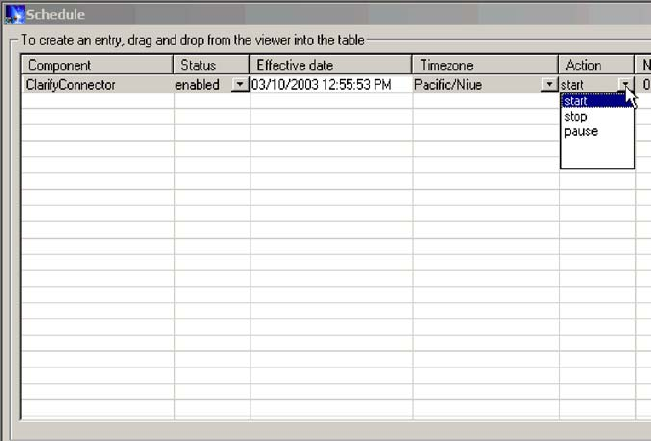
When
you
create
a
schedule
for
a
component,
you
supply
information
such
as
when
and
how
often
(recurrence)
an
action
(state
change)
occurs.
By
default,
no
schedules
are
defined
for
a
component.
You
can
define
as
many
schedules
as
you
want
for
a
component.
Once
a
schedule
is
set,
you
can
enable
or
disable
its
use.
The
Schedule
window
allows
you
to
determine
the
following
items:
Status
Enable
turns
the
schedule
on
and
Disable
turns
the
schedule
off.
The
default
status
is
enabled.
Effective
Date
The
date
and
time
the
schedule
is
enabled.
The
default
is
the
current
date
and
time.
Timezone
The
time
zone
where
the
server
is
located.
The
default
is
Pacific
Standard
time.
Action
The
action
the
schedule
performs.
Actions
are
Start,
Pause,
and
Stop.
Next
Occurrence
The
next
time
the
scheduled
action
occurs.
If
the
schedule
is
non-recurring,
the
date
is
the
same
as
the
Effective
Date.
If
the
schedule
is
disabled,
this
field
is
blank.
Component
The
name
of
the
connector
or
collaboration
being
scheduled.
Comments
Text
field
that
contains
comments
you
enter
about
the
schedule.
If
you
choose
to
make
the
schedule
recurring,
you
can
choose
from
several
options
including
daily,
weekly,
or
monthly.
Because
each
schedule
consists
of
one
action
that
occurs
at
a
specified
time,
to
create
an
interval
when
the
server
processes
a
component,
you
must
define
both
a
schedule
to
start
and
end
processing.
As
an
example,
for
a
connector,
you
can
create
one
schedule
to
start
processing
events
at
1
A.M.,
and
another
schedule
to
pause
processing
at
3
A.M.,
daily.
Only
during
that
two-hour
time
period
can
the
Figure
14.
Schedule
window
84
User
Guide
connector
deliver
events
to
InterChange
Server
Express
for
processing
by
collaborations
that
subscribe
to
that
connector.
About
scheduling
connectors
When
you
schedule
the
connector
operation,
the
state
you
select
(start,
pause,
or
stop)
determines
to
what
extent
work
is
processed.
For
example,
when
you
start
a
connector,
it
constantly
polls
an
application
for
new
events.
When
you
pause
a
connector,
it
stops
polling
until
started
again,
but
is
still
able
to
handle
service
call
requests
from
InterChange
Server.
A
stopped
connector
is
inactive.
By
manipulating
connector
activity
with
collaboration
activity,
it
is
possible
to
schedule
dedicated
event
processing
for
an
application
during
a
specified
time
window.
To
do
this,
both
the
collaboration
and
connector
must
be
running
during
the
same
time
interval.
If
the
connector
was
paused,
events
that
were
queued
can
be
processed
when
the
connector
resumes
its
activity.
About
scheduling
collaboration
objects
As
with
connectors,
when
you
schedule
the
collaboration
Object’s
operation,
the
state
you
select
(start,
pause,
or
stop)
determines
to
what
extent
work
is
processed.
To
review
the
collaboration
states,
see
“Collaboration
object
states”
on
page
60.
For
example,
when
you
start
a
collaboration
object,
it
processes
the
business
objects
that
it
receives
from
connectors.
When
you
stop
a
collaboration
object,
all
subsequent
events
are
ignored.
So
unless
you
must
stop
the
collaboration
object,
pause
it
instead.
Attention:
Stopping
a
collaboration
object
can
cause
the
connector
to
delete
events
as
unsubscribed.
As
a
warning,
the
system
produces
a
message
if
you
select
Stop.
When
you
pause
a
collaboration
object,
events
remain
in
the
collaboration
queue
until
you
restart
the
collaboration
object.
Note:
If
a
scheduled
collaboration
object
is
part
of
a
collaboration
group,
all
collaboration
objects
in
that
group
are
scheduled
with
the
same
action.
By
manipulating
collaboration
object
activity
with
connector
activity,
it
is
possible
to
schedule
dedicated
event
processing
for
an
application
during
a
specified
time
window.
To
do
this,
both
the
collaboration
object
and
connector
must
be
running
during
the
same
time
interval.
By
assigning
different
processing
windows
to
collaboration
objects
that
are
bound
to
the
same
connector,
you
can
distribute
the
workload,
and
to
some
extent,
control
the
amount
of
traffic
a
connector
must
handle.
For
example,
in
Figure
15,
each
collaboration
object
gets
a
dedicated
time
period
when
the
connector
is
processing
only
that
collaboration
object’s
events.
Chapter
5.
Operating
components
of
the
system
85
Multiple
collaboration
objects
can
subscribe
to
the
same
business
object.
In
that
case,
the
object
is
sent
to
InterChange
Server,
where
it
remains
until
it
is
picked
up
by
each
collaboration
object
that
subscribes
to
it,
when
the
collaboration
object
is
started
after
being
paused.
Overriding
schedules
Using
System
Monitor,
you
can
override
the
state
of
a
scheduled
component
(for
example,
start
a
collaboration
object
that
the
scheduler
stopped
a
few
minutes
ago).
Or
you
can
set
it
to
a
state
to
one
that
the
scheduler
cannot
change.
For
instance,
if
a
collaboration
object
is
scheduled
to
pause,
you
can
stop
it,
not
allowing
the
scheduler
to
pause
it
(a
collaboration
object
cannot
transition
from
stop
to
pause).
In
such
a
case,
the
scheduler
does
not
override
the
manual
change,
but
logs
an
error
instead.
Creating
schedules
To
create
a
schedule
for
a
collaboration
or
a
connector:
1.
Open
the
Schedule
window
by
right-clicking
the
Schedule
folder
in
System
Manager,
then
selecting
″Edit
components’
schedule.″
The
Schedule
window
appears,
as
shown
in
Figure
14.
2.
From
System
Manager,
select
the
collaboration
object
or
connector
to
be
scheduled
and
drag
it
to
the
Schedule
window.
A
new
line
entry
with
the
name
and
type
of
the
component
is
created
in
the
Schedule
window
(for
example,
ClarifyConnector
(Connector)).
3.
Enter
information
about
the
schedule
by
clicking
the
down
arrow
in
each
of
the
schedule
cells:
a.
In
the
Status
field,
accept
Enable
to
turn
the
scheduled
item
on
or
select
Disable
to
turn
it
off.
An
enabled
schedule
is
effective
as
soon
as
you
click
OK
or
Apply;
a
disabled
schedule
is
immediately
dormant
until
enabled.
When
a
schedule
is
disabled,
the
Next
Occurrence
cell
is
blank
to
indicate
there
is
no
scheduled
occurrence
for
this
schedule
item.
b.
In
the
Effective
Date
field,
use
the
calendar
to
select
the
date
and
time
when
the
scheduled
item
will
occur.
By
default,
the
current
date
and
time
are
set.
Use
the
MM/DD/YYYY
hh:mm:ss
format.
A
12
or
24
hour
clock
is
used,
based
on
the
Time
format
configured
in
the
Preferences
window,
which
is
available
from
the
Edit
menu.
c.
In
the
Timezone
field,
select
the
name
of
the
time
zone
where
the
scheduled
item
is
being
created,
if
necessary.
By
default,
the
time
zone
for
the
scheduled
item
is
set
to
Pacific
Standard
Time.
Connector
Item
Contact
Customer
CollabA
2-4 P.M.
CollabB
4-6 P.M.
CollabC
6-8 P.M.
Figure
15.
Dedicated
processing
86
User
Guide
For
example,
the
schedule
for
a
connector
is
created
in
New
York
(select
Eastern
Standard
time)
while
InterChange
Server
Express
is
located
in
Japan.
InterChange
Server
Express
uses
this
information
to
determine
the
local
time
for
the
schedule
so
it
can
run
the
job
at
the
appropriate
time.
d.
In
the
Action
field,
select
the
action
to
be
performed.
Actions
are
Start,
Pause,
and
Stop.
e.
Type
in
any
comments
you
may
have
in
the
Comments
text
cell.
A
maximum
of
255
characters
is
allowed.
4.
If
you
want
this
schedule
to
be
ongoing,
click
the
Recurrence
check
box
and
enter
information
about
the
next
occurrence
of
the
action.
Click
one
of
the
radio
buttons
to
determine
a
style
for
inputting
the
recurrence
information
and
use
the
down
arrow
menus
to
select
specific
date
information:
v
The
first
radio
button,
Every,
specifies
a
number
and
a
date
element,
such
as
every
2
days
or
every
3
weeks.
v
The
second
radio
button
specifies
the
date
in
terms
of
a
monthly
event
by
the
day
of
the
week,
such
as
the
first
Tuesday
of
every
month
or
the
fourth
Friday
of
every
month.
v
The
third
radio
button
specifies
the
date
as
the
last
day
of
some
number
of
months,
such
as
the
last
day
of
every
3
months.
If
you
do
not
enable
the
recurrence
option,
the
Next
Occurrence
field
is
blank
and
the
schedule
expires
after
it
runs.
Consistency
checks
are
made
to
ensure
that
only
one
action
is
scheduled
for
a
particular
component
on
a
given
date
and
time.
No
checks
are
performed
for
scheduling
conflicts.
Note:
InterChange
Server
Express
automatically
handles
changes
between
standard
and
daylight
savings
time
for
recurring
events.
5.
Click
either
of
the
Show
option
check
boxes
to
display
specific
information
about
schedules.
The
Show
options
are:
v
Show
Dependencies,
which
displays
schedules
for
a
Collaboration
object’s
bound
connectors
and
collaborations.
v
Show
Expired,
which
displays
schedules
that
have
already
processed
and
whose
time
to
run
has
expired.
Only
non-recurring
schedules
expire.
6.
Click
OK
or
Apply
to
create
the
scheduled
item,
which
is
effective
once
InterChange
Server
Express
receives
the
information.
When
InterChange
Server
Express
and
components
are
geographically
distant,
there
can
be
a
slight
delay.
If
you
need
to
immediate
change
the
state
of
a
component,
it
is
preferable
to
use
System
Monitor
to
start,
stop,
or
pause
a
component
rather
than
the
scheduler.
Tip:
To
schedule
a
time
interval
when
events
are
processed
for
a
component,
you
must
create
a
schedule
with
the
Start
action
and
another
with
the
Stop
or
Pause
action.
See
“About
scheduling
jobs”
on
page
83
for
information
and
examples
about
determining
start
and
end
schedules.
Modifying
schedules
To
modify
an
existing
schedule
for
a
collaboration
or
a
connector:
1.
Right-click
the
component
in
System
Manager,
then
select
″Edit
Components’
schedule.″
The
Schedule
window
appears
(see
Figure
14).
2.
Edit
any
field
in
the
Schedule
list
window
to
change
its
value.
Chapter
5.
Operating
components
of
the
system
87
To
edit
Recurrence
options,
click
the
cursor
anywhere
on
the
scheduled
item
row;
the
recurrent
values
for
that
scheduled
item
display
in
the
Recurrence
pane
if
they
have
been
assigned.
3.
Click
OK
to
save
changes
and
exit,
or
click
Apply
to
save
changes
and
keep
the
window
open.
Deleting
schedules
To
delete
an
existing
schedule
for
a
collaboration
object
or
a
connector:
1.
Right-click
the
component
from
System
Manager,
then
select
″Edit
Components’
schedule.″
The
Schedule
window
appears
(see
Figure
14).
2.
Select
a
scheduled
item
in
the
schedule
list
and
click
the
Delete
button
(or
use
the
keyboard
Delete
key)
to
remove
the
schedule.
3.
Click
OK
to
save
changes
and
exit,
or
click
Apply
to
save
changes
and
keep
the
window
open.
Displaying
schedules
To
display
a
schedule
or
a
group
of
schedules:
1.
Select
and
open
an
object
for
displaying
schedules:
v
Collaboration
or
connector
icon
from
System
Manager.
The
Schedule
window
displays
all
schedules
defined
for
that
object.
If
Show
Dependencies
is
active,
all
schedules
for
components
connected
to
the
object
are
displayed.
v
Collaboration
or
connector
folder
from
System
Manager.
The
Schedule
window
displays
schedules
for
all
objects
in
that
folder.
v
InterChange
Server
Express
from
System
Manager.
The
Schedule
window
displays
all
schedules
defined
for
that
server,
with
times
shown
for
the
server’s
time
zone.
v
If
you
choose
the
Schedule
option
from
the
main
window,
all
schedules
in
the
system
are
displayed.
2.
Click
any
of
the
column
headings
to
sort
schedules
by
that
column.
Enabling
or
disabling
schedules
To
selectively
disable
or
enable
schedules:
1.
Select
an
object
for
displaying
schedules.
See
“Displaying
schedules”
on
page
88.
2.
Enable
or
disable
the
schedule:
v
To
enable
or
disable
all
schedules,
click
either
the
Enable
All
or
Disable
All
radio
button.
v
To
enable
or
disable
a
single
schedule,
click
the
down
arrow
in
the
Status
column
and
choose
the
Enable
or
Disable
option.
3.
Click
Apply
to
complete
this
task.
4.
Click
OK
to
exit.
88
User
Guide

Chapter
6.
Using
Test
Connector
Test
Connector
simulates
the
activities
of
a
connector
to
allow
you
to
test
your
integration
components
without
the
complexity
of
running
an
actual
connector.
This
chapter
consists
of
the
following
sections:
v
“Recommended
testing
procedure”
v
“Starting
Test
Connector”
on
page
90
v
“Shutting
down
Test
Connector”
on
page
91
v
“Creating
and
editing
connector
profiles”
on
page
91
v
“Emulating
a
connector”
on
page
92
v
“Working
with
business
objects”
on
page
92
Recommended
testing
procedure
This
is
the
recommended
test
procedure
for
testing
components:
1.
Set
up
Test
Connector
to
emulate
a
source
connector.
a.
Launch
Test
Connector
as
described
in
“Starting
Test
Connector”
on
page
90.
b.
Create
a
profile
for
the
source
connector
in
the
interface
as
described
in
“Creating
a
new
profile”
on
page
91.
c.
Connect
Test
Connector
to
the
agent
to
begin
emulating
the
source
connector,
as
described
in
“Emulating
a
connector”
on
page
92.
2.
Set
up
instances
of
Test
Connector
to
emulate
each
destination
connector
involved
in
the
interface.
a.
Launch
Test
Connector
as
described
in
“Starting
Test
Connector”
on
page
90.
b.
Create
a
profile
for
a
destination
connector
as
described
in
“Creating
a
new
profile”
on
page
91.
c.
Connect
Test
Connector
to
the
agent
to
begin
emulating
the
destination
connector
as
described
in
“Emulating
a
connector”
on
page
92.
d.
Repeat
2a
through
2c
above
for
all
destination
connectors
involved
in
the
interface.
Note:
Do
not
set
up
a
scenario
in
which
the
same
source
test
connector
object
and
same
destination
test
connector
object
are
used
with
multiple
collaboration
instances.
In
such
a
scenario,
the
calls
on
the
destination
connector
from
the
two
collaborations
would
be
in
conflict.
3.
Arrange
the
instances
of
Test
Connector
on
your
screen
so
that
you
can
easily
identify
the
connector
being
emulated
in
each
Test
Connector
window.
4.
Send
a
request
business
object
from
the
source
connector.
From
the
source
Test
Connector,
do
the
following:
a.
Create
a
business
object
that
is
managed
by
the
interface
you
need
to
test
as
described
in
“Creating
request
business
objects”
on
page
93.
b.
Save
the
business
object
to
a
file
to
use
in
subsequent
tests
as
described
in
“Saving
a
business
object”
on
page
95.
c.
Send
the
business
object
as
described
in
“Sending
request
business
objects”
on
page
93.
©
Copyright
IBM
Corp.
2003
89
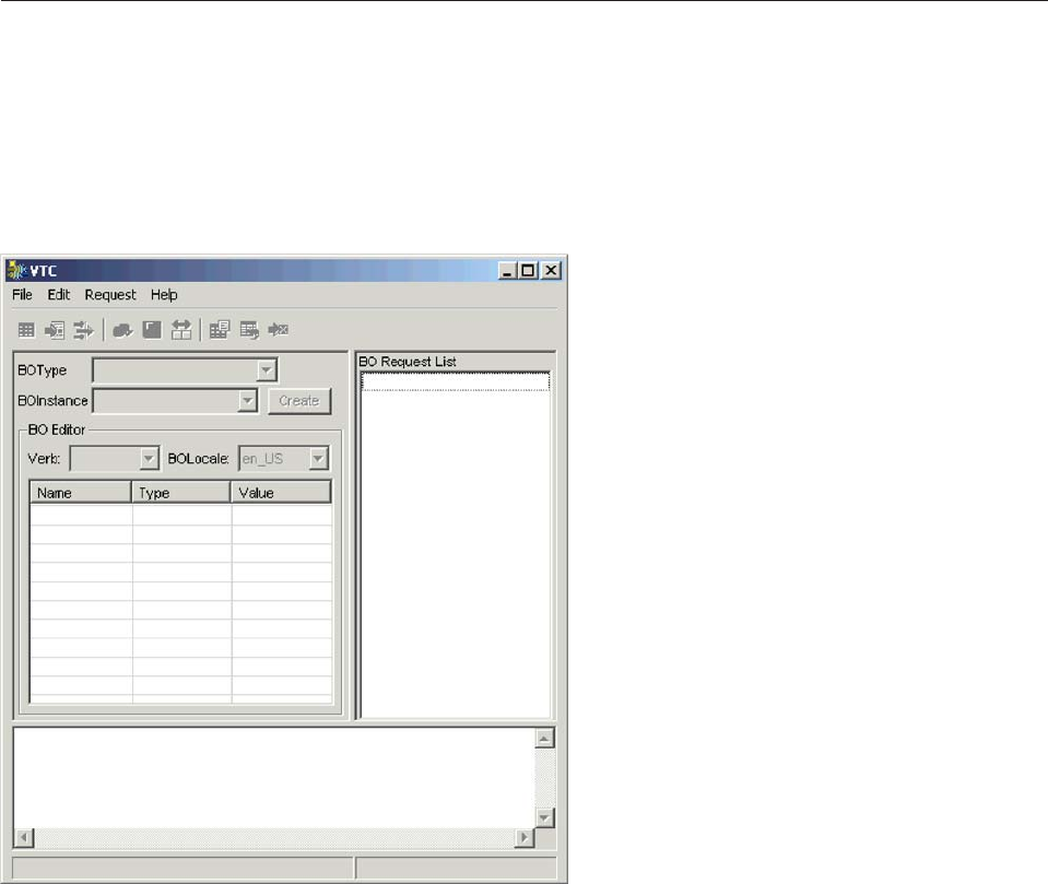
5.
Simulate
the
response
to
the
request
business
object
from
the
destination
connector.
From
the
destination
Test
Connector
window,
do
the
following:
a.
Accept
the
request
business
object
as
described
in
“Accepting
a
request
business
object”
on
page
96.
b.
Send
the
business
object
as
a
response
as
described
in
“Sending
a
response
business
object”
on
page
97.
6.
Repeat
step
4
on
page
89
through
step
5
as
many
times
as
necessary
to
test
each
interface.
Starting
Test
Connector
To
start
Test
Connector,
select
Start
>
Programs
>
IBM
WebSphere
Business
Integration
Express
for
Item
Sync
V4.3>Toolset
Express>
Development
>
Test
Connector:
Figure
16
shows
Test
Connector
after
starting.
The
Test
Connector
window
includes
the
following
panes:
v
The
“Supported
Business
Objects”
pane
in
which
you
can
create
business
object
instances
to
send
v
The
“BO
Request
List”
pane,
which
displays
any
business
object
requests
that
the
connector
has
received
v
The
“Output”
pane,
which
displays
messages
about
Test
Connector’s
operations,
such
as
when
a
business
object
has
been
sent.
Figure
16.
Test
Connector
90
User
Guide

Shutting
down
Test
Connector
To
shut
down
Test
Connector
and
cause
it
to
stop
emulating
a
connector
agent,
select
File
>
Exit
from
the
menu
bar.
When
presented
with
the
“Shutdown”
prompt,
click
Yes.
Creating
and
editing
connector
profiles
Test
Connector
uses
profiles
to
store
the
information
it
needs
to
emulate
a
connector.
You
must
create
a
profile
for
each
connector
you
want
to
emulate.
You
can
edit
and
delete
existing
profiles.
Saving
the
connector
definition
to
a
file
To
emulate
a
connector
using
Test
Connector,
you
must
save
the
connector
definition
to
a
file.
Do
the
following
to
save
a
connector
definition
to
a
file:
1.
Open
the
connector
definition
in
Connector
Configurator.
2.
Select
File
>
Save
As
>
To
File
from
the
menu
bar.
3.
Navigate
to
the
directory
in
which
you
want
the
file
saved,
type
a
name
in
the
File
name
field,
ensure
that
the
value
Configuration
(*.cfg)
is
displayed
in
the
Save
as
type
drop-down
menu,
and
click
Save.
Connector
Configurator
saves
the
connector
definition
to
a
file
with
the
specified
name.
Creating
a
new
profile
You
must
create
a
profile
for
any
connector
you
want
to
emulate
in
Test
Connector.
The
profile
specifies
information
such
as
the
name
of
the
connector,
the
configuration
file
to
be
used,
and
the
type
of
integration
broker
with
which
the
connector
communicates
(you
must
always
set
the
type
toICS).
To
create
a
new
connector
profile,
do
the
following:
1.
Select
File
>
Create/Select
Profile
from
the
menu
bar
to
display
the
“Connector
Profile”
window.
2.
In
the
“Connector
Profile
window”,
select
File
>
New
Profile
from
the
menu
bar.
3.
In
the
“New
Profile”
window,
click
Browse
and
then
navigate
to
the
configuration
file
for
the
connector
you
preparing
in
“Saving
the
connector
definition
to
a
file.”
4.
Type
the
name
of
the
connector
in
the
Connector
Name
field.
You
must
type
the
exact
name
of
the
connector
definition
as
it
exists
in
the
integration
broker
repository.
For
the
adapter
for
JText,
for
instance,
you
must
type
JTextConnector,
without
any
spaces
between
the
words
JText
and
Connector,
and
with
each
letter
being
the
proper
case.
5.
Set
the
integration
broker
value
in
the
Broker
Type
drop-down
menu
toICS.
6.
Do
the
following:
a.
Type
the
name
of
the
InterChange
Server
Express
instance
in
the
Server
field.
Be
sure
to
type
the
name
precisely;
it
is
case-sensitive
and
Test
Connector
will
not
be
able
to
communicate
with
InterChange
Server
Express
if
the
name
is
not
correct.
b.
Type
the
password
for
the
admin
user
account
in
the
Password
field.
The
default
password
is
null.
7.
Click
OK
to
close
the
“New
Profile”
window.
Chapter
6.
Using
Test
Connector
91

The
“Connector
Profile”
window
displays
the
name
of
the
connector
in
the
Connector
column,
the
name
of
the
InterChange
Server
Express
instance
in
the
Server
column
(if
the
integration
broker
is
ICS),
and
the
path
and
name
of
the
connector
configuration
file
in
the
Configuration
File
column.
8.
Click
OK
to
close
the
“Connector
Profile”
window.
Editing
a
profile
Follow
the
steps
below
to
make
changes
to
an
existing
connector
profile:
1.
Select
File
>
Create/Select
Profile
from
the
menu
bar
of
Test
Connector
or
use
the
keyboard
shortcut
Ctrl+N
to
display
the
Connector
Profile
window.
2.
In
the
“Connector
Profile”
window
select
the
profile
you
want
to
edit
and
then
select
Edit
>
Edit
Profile
from
the
menu
bar.
3.
Type
new
values
in
the
fields
of
the
“New
Profile”
window
and
use
the
Browse
button
to
change
the
configuration
file
as
necessary
to
make
your
edits.
4.
Click
OK
to
close
the
“New
Profile”
window.
Deleting
a
profile
Do
the
following
to
delete
a
connector
profile:
1.
Select
File
>
Create/Select
Profile
from
the
menu
bar
of
Test
Connector
or
use
the
keyboard
shortcut
Ctrl+N
to
display
the
“Connector
Profile”
window.
2.
In
the
“Connector
Profile”
window,
select
the
profile
you
want
to
delete
and
then
select
Edit
>
Delete
Profile
from
the
menu
bar.
Emulating
a
connector
After
creating
a
profile
for
a
connector,
you
may
use
that
profile
to
connect
Test
Connector
to
the
agent.
Once
you
connect
Test
Connector
to
the
agent,
Test
Connector
begins
emulating
the
connector
defined
in
the
selected
profile.
To
connect
Test
Connector
to
the
agent,
do
the
following:
1.
Select
File
>
Create/Select
Profile
from
the
menu
bar
of
Test
Connector.
2.
In
the
“Connector
Profile”
window,
select
the
name
of
the
connector
whose
profile
you
want
to
open.
3.
Click
OK.
4.
Select
File
>
Connect
from
the
menu
bar.
Test
Connector
displays
messages
in
the
“Output”
pane
as
it
attempts
to
emulate
the
connector.
When
it
finishes
connecting,
it
displays
a
message
indicating
that
it
is
“ready”
in
the
“Output”
pane
and
populates
the
BOType
list
in
the
“Supported
Business
Objects”
pane.
Working
with
business
objects
To
test
whether
a
business
process
interface
has
been
developed
correctly,
you
need
to
verify
that
business
objects
can
be
successfully
exchanged
and
processed.
This
section
describes
how
to:
v
Create,
modify,
delete,
and
save
business
object
test
data
v
Compare
the
attribute
values
of
business
objects
to
easily
and
quickly
view
changes
made
during
processing
v
Send
and
receive
business
objects
92
User
Guide
Working
with
request
business
objects
Request
business
objects
are
those
that
you
send
from
Test
Connector
when
it
is
emulating
a
connector
that
is
the
source
of
the
events
that
trigger
an
interface.
Working
with
request
business
objects
consists
of
creating
a
business
object
instance,
populating
it
with
data,
and
sending
the
request.
Creating
request
business
objects
To
create
a
new
business
object
in
Test
Connector,
do
the
following:
1.
In
the
“Supported
Business
Objects”
pane,
select
the
name
of
the
business
object
you
want
to
create
from
the
BOType
drop-down
menu.
2.
Click
Create
next
to
the
BOInstance
field.
3.
When
presented
with
the
“New
Instance”
dialog,
type
a
name
for
the
instance
in
the
Enter
Name
field.
4.
Select
the
desired
verb
from
the
Verb
drop-down
menu.
5.
Select
the
desired
locale
from
the
the
BOLocale
drop-down
menu.
6.
Provide
values
for
the
simple
attributes
and
child
business
objects
within
the
top-level
object,
as
described
in
“Setting
values
for
business
object
attributes”
on
page
94.
7.
Click
OK.
Sending
request
business
objects
Once
you
have
created
or
loaded
a
business
object
and
specified
values
for
its
attributes,
you
have
several
ways
to
send
the
business
object
as
a
request
to
the
integration
broker.
Sending
request
business
objects
asynchronously:
When
a
source
connector
sends
a
request
business
object
in
asynchronous
mode,
it
does
not
expect
to
get
back
a
response
business
object.
Once
the
request
business
object
is
dispatched,
the
source
connector’s
role
in
the
transaction
is
finished.
The
response
business
object
is
typically
processed
by
the
integration
broker.
The
default
mode
for
Test
Connector
is
asynchronous.
To
send
a
business
object
asynchronously,
do
the
following:
1.
Select
Request
>
Mode
>Asynchronous
from
the
menu
bar.
Note:
Test
Connector
operates
in
“Asynchronous”
mode
by
default,
so
you
only
have
to
perform
this
step
if
you
previously
were
sending
synchronous
requests
from
the
connector.
Furthermore,
you
do
not
have
to
set
the
mode
before
sending
each
request.
2.
Select
Request
>
Send
from
the
menu
bar.
The
business
object
request
is
sent
to
the
server
for
processing.
Sending
request
business
objects
synchronously:
When
a
source
connector
sends
a
request
business
object
synchronously,
it
expects
to
get
back
a
response
business
object
from
the
integration
broker
after
any
destination
applications
have
processed
the
request.
In
synchronous
mode,
Test
Connector
puts
the
response
business
object
on
the
queue
specified
by
the
source
connector’s
Synchronous
Request
Queue
property.
The
default
mode
for
Test
Connector
is
asynchronous.
1.
Set
Test
Connector
to
synchronous
mode
by
selecting
Request
>
Mode
>
Synchronous
from
the
menu
bar.
2.
Select
Request
>
Send
from
the
menu
bar.
Chapter
6.
Using
Test
Connector
93
3.
If
the
broker
specified
in
the
connector
definition
is
InterChange
Server
Express
then
the
“Select
Collaboration”
dialog
is
displayed.
Select
the
collaboration
to
which
the
business
object
should
be
sent
from
the
Collaboration
drop-down
menu
and
click
OK.
The
business
object
request
is
sent
to
the
configured
port
of
the
collaboration
object
chosen
for
processing.
Sending
request
business
objects
in
batch
mode:
In
batch
mode,
Test
Connector
lets
you
specify
the
number
of
instances
of
a
particular
business
object
you
want
to
send,
as
well
as
one
attribute
in
the
top-level
object
—a
primary
key
attribute,
for
example—that
you
want
set
to
a
unique
value
for
each
instance.
Test
Connector
copies
the
business
object
as
many
times
as
you
have
specified,
incrementing
the
value
of
the
single
attribute
you
specified,
and
sends
each
business
object.
This
option
allows
you
to
create
a
large
number
of
business
objects
quickly
and
easily.
If
the
selected
attribute
is
a
key
field
that
participates
in
dynamic
cross-referencing
as
part
of
an
identity
relationship,
then
you
must
guarantee
that
the
initial
value
and
all
those
that
follow
it
are
unique.
Otherwise,
the
cross-referencing
logic
will
fail,
causing
the
request
business
objects
to
fail.
To
ensure
that
the
values
are
unique,
you
can
use
Relationship
Manager
or
execute
SQL
statements
against
the
table
for
the
relationship
participant
as
follows.
v
Determine
the
highest
current
value
for
the
participant
and
set
the
Initial
Value
field
to
an
even
higher
value.
The
first
business
object
instance
in
the
batch
and
all
those
that
follow
will
then
be
unique.
v
Delete
the
existing
table
entries
for
the
participant,
thus
guaranteeing
that
no
entries
have
the
same
attribute
value
as
any
of
the
batch
business
objects.
To
send
business
objects
in
batch
mode,
do
the
following:
1.
Select
the
name
of
the
business
object
you
would
like
to
send
from
the
BOType
drop-down
menu.
2.
Select
Request
>
Send
Batch
from
the
menu
bar.
3.
In
the
“Batch
Mode”
window,
select
from
the
Attribute
list
the
attribute
in
the
top-level
business
object
that
you
want
incremented
with
each
business
object
request
in
the
batch.
The
selected
attribute
should
typically
be
an
attribute
that
uniquely
identifies
the
business
object,
such
as
a
primary
key.
4.
In
the
Initial
Value
field,
type
the
starting
value
for
the
attribute
to
be
incremented.
5.
In
the
No.
of
BO’s
field,
type
the
number
of
business
object
instances
you
want
generated
and
sent.
6.
Click
OK.
Test
Connector
generates
the
number
of
business
objects
you
specified,
all
identical
with
the
exception
of
the
one
specified
attribute,
whose
value
is
incremented
for
each
instance.
Then
the
business
object
request
is
sent
to
the
server
for
processing.
Setting
values
for
business
object
attributes
The
following
sections
describe
the
various
ways
you
can
set
the
values
of
simple
and
compound
attributes
in
a
business
object
instance:
v
“Setting
values
for
simple
attributes”
on
page
95
v
“Adding
child
business
objects”
on
page
95
94
User
Guide
v
“Removing
child
business
objects”
v
“Setting
the
verb
of
a
child
business
object”
Setting
values
for
simple
attributes
To
provide
a
value
for
a
simple
attribute,
click
its
cell
in
the
Value
column
and
enter
a
value.
Adding
child
business
objects
To
add
an
instance
of
a
child
business
object,
right-click
the
attribute
that
represents
the
child
object
and
select
Add
Instance
from
the
context
menu.
A
plus
sign
(+)
is
added
next
to
the
attribute
that
represents
child
business
object
to
show
that
there
is
at
least
one
child
business
object
instance.
If
you
expand
the
child
object
attribute,
numbered
entries
are
displayed
for
each
instance.
The
individual
instances
also
have
plus
signs
(+)
next
to
them,
so
you
can
expand
them
and
set
values
for
their
attributes.
To
add
more
child
business
object
instances,
right-click
the
attribute
that
represents
the
child
object
and
select
Add
Instance
from
the
context
menu.
Note:
If
the
Card
property
of
the
attribute
that
references
the
child
business
object
is
set
to
the
value
1
(indicating
it
is
of
single-cardinality),
then
you
will
only
be
able
to
add
one
instance
of
the
child
object.
Removing
child
business
objects
To
remove
an
instance
of
a
child
business
object,
right-click
the
instance
and
select
Remove
Instance
from
the
context
menu.
To
remove
all
instances
of
a
child
business
object,
right-click
the
attribute
that
represents
the
child
business
object
and
select
Delete
All
Instances
from
the
context
menu.
Setting
the
verb
of
a
child
business
object
You
can
set
the
verb
of
a
child
business
object
to
test
the
effect
that
value
has
on
the
business
process.
This
can
be
helpful
when
you
are
troubleshooting
logic
that
involves
the
cross-referencing
of
child
objects.
To
set
the
verb
of
a
child
business
object
instance,
right-click
it
and
choose
Set
Verb
from
the
context
menu.
When
presented
with
the
“Select
Verb”
prompt,
selected
the
desired
verb
and
click
OK.
Using
the
Response
BO
toolbar
You
can
edit
the
attributes
of
a
business
object
received
by
a
destination
connector
before
you
send
it
as
a
response.
The
toolbar
of
the
“Response
BO”
dialog
that
you
use
when
doing
so
has
several
toolbar
buttons
that
can
be
used
to
set
the
values
of
the
business
object.
For
more
information,
see
“Editing
response
business
objects”
on
page
97.
Saving
a
business
object
You
can
save
a
business
object
in
Test
Connector
so
that
it
can
be
used
for
later
tests,
shared
with
technical
support
(to
help
troubleshoot
problems),
or
used
as
response
data.
You
can
save
any
business
object,
including
ones
that
you
have
created
and
ones
that
appear
as
requests
in
the
Test
Connector
window
of
a
destination
connector.
By
default,
business
objects
are
saved
to
a
file
with
a
business
object
extension
(.bo).
Chapter
6.
Using
Test
Connector
95
It
is
recommended
that
you
create
a
directory
or
directory
structure
specifically
for
test
data
files,
with
subdirectories
dedicated
to
each
interface
or
to
each
connector,
as
appropriate.
This
organization
makes
the
necessary
files
are
easy
to
locate
and
makes
testing
more
efficient.
Furthermore,
it
is
recommended
that
you
give
the
test
data
file
for
a
business
object
the
same
name
as
the
business
object
definition
itself.
Saving
business
object
requests
Do
the
following
to
save
a
business
object
instance
that
you
have
created
as
a
request:
1.
Select
the
business
object
you
want
to
save.
2.
From
the
menu
bar,
select
Edit
>
Save
BO.
3.
Navigate
to
the
desired
directory
and
specify
a
name
for
the
file
in
the
File
name
field.
4.
Click
Save.
Saving
business
object
responses
Do
the
following
to
save
a
business
object
instance
that
has
been
received
by
a
destination
instance
of
Test
Connector
and
will
be
sent
as
a
response:
1.
Select
the
business
object
instance
in
the
“BO
Request
List”
pane.
2.
Select
Request
>
Edit
Response
from
the
menu
bar.
3.
Click
Save
BO.
4.
Navigate
to
the
desired
directory
and
specify
a
name
for
the
file
in
the
File
name
field.
5.
Click
Save.
Loading
a
business
object
To
load
a
business
object
that
has
been
saved
to
a
file,
do
the
following:
1.
Select
Edit
>
Load
BO
from
the
menu
bar
of
Test
Connector.
2.
Navigate
to
the
business
object
test
data
file
and
open
it.
3.
When
presented
with
the
“New
Instance”
dialog,
type
a
name
for
the
instance
in
the
Enter
Name
field.
4.
Click
OK.
Deleting
a
business
object
To
delete
a
business
object
from
Test
Connector,
select
Edit
>
Delete
BO
from
the
menu
bar.
Note:
This
action
only
removes
the
business
object
from
the
Test
Connector.
It
does
not
remove
the
connector’s
support
for
the
business
object
definition.
Accepting
a
request
business
object
When
you
send
a
business
object
as
a
request,
the
business
object
appears
in
the
“BO
Request
List”
pane
of
any
Test
Connector
instances
that
are
emulating
destination
connectors
in
the
interface,
provided
that
the
transaction
did
not
fail.
After
you
have
accepted
the
request
business
object,
you
can
edit
it
if
necessary
as
described
in
“Editing
response
business
objects”
on
page
97.
Working
with
response
business
objects
Response
business
objects
are
those
that
you
send
from
Test
Connector
when
it
is
emulating
a
connector
that
is
the
recipient
of
business
object
requests
in
an
96
User
Guide

interface.
Working
with
request
business
objects
consists
of
editing
the
values
in
the
business
object
instance
and
sending
the
response
back
to
the
broker.
Editing
response
business
objects
When
you
receive
a
business
object
request
in
a
destination
instance
of
Test
Connector,
you
commonly
want
to
edit
the
values
of
the
attributes.
For
instance,
you
will
want
to
provide
unique
values
for
primary
key
attributes
that
participate
in
relationships,
or
you
will
want
to
modify
the
value
of
other
attributes
to
test
map
or
collaboration
logic
that
responds
differently
depending
on
the
exact
values
in
the
business
object.
Do
the
following
to
set
the
values
of
business
object
attributes
:
1.
Select
the
business
object
instance
in
the
“BO
Request
List”
pane.
2.
Select
Request
>
Edit
Response
from
the
menu
bar.
3.
Do
the
following
to
edit
the
attributes
of
the
business
object:
v
Use
one
of
the
techniques
described
in
“Setting
values
for
business
object
attributes”
on
page
94
to
modify
the
values
of
the
business
object
attributes.
v
Click
Reset
BO
to
default
to
set
the
values
of
the
business
object
attributes
to
their
default
values
as
specified
in
the
business
object
definition.
v
Click
Clear
BO
values
to
clear
the
values
of
all
the
attributes
in
the
business
object.
v
Click
Load
BO
to
populate
the
attributes
of
the
business
object
with
test
data
from
a
file.
The
ability
to
load
saved
data
into
a
business
object
request
is
very
useful
in
situations
where
you
have
to
populate
a
response
business
object
with
data
before
sending
it
as
a
reply.
Instead
of
manually
typing
a
value
for
each
attribute
that
requires
response
data,
you
can
type
the
values
once,
save
the
business
object
(as
described
in
“Saving
a
business
object”
on
page
95),
and
then
load
the
saved
data
on
subsequent
tests.
Sending
a
response
business
object
After
you
accept
a
request
business
object,
edit
the
business
object,
if
needed,
and
send
it
back
as
a
reply.
Table
11
lists
Test
Connector’s
reply
options
and
shows
their
corresponding
connector
return
codes
for
both
C++
and
Java
connectors.
Table
11.
Test
Connector
reply
types
and
connector
return
codes.
Test
Connector
reply
type
C++
connector
return
code
Java
connector
return
code
Success
BON_SUCCESS
SUCCESS
Fail
BON_FAIL
FAIL
Multiple
Hits
BON_MULTIPLE_HITS
MULTIPLE_HITS
Retrieve
By
Content
Fail
BON_FAIL_RETRIEVE_BY_CONTENT
RETRIEVEBYCONTENT_FAILED
Not
Found
BON_BO_DOES_NOT_EXIST
BO_DOES_NOT_EXIST
Value
Duplicate
BON_VALDUPES
VALDUPES
To
reply
to
a
request
business
object,
do
the
following:
1.
Select
the
business
object
in
the
“BO
Request
List”
pane.
2.
From
the
menu
bar,
select
Request
>
Reply.
3.
Select
an
item
from
the
Reply
submenu.
Chapter
6.
Using
Test
Connector
97
Comparing
business
object
instances
Test
Connector
can
compare
two
business
objects
of
the
same
type
and
display
the
attributes
that
differ
in
value.
You
can
use
this
function
to
view
changes
to
a
business
object
at
different
points
in
the
execution
of
a
transaction
(for
instance,
you
could
compare
a
business
object
that
has
been
sent
to
the
integration
broker
with
the
same
business
object
after
the
integration
broker
has
updated
it).
To
compare
two
business
objects,
do
the
following:
1.
Create
a
request
business
object
instance
by
following
the
instructions
in
either
“Creating
request
business
objects”
on
page
93
or
“Loading
a
business
object”
on
page
96.
2.
Select
the
response
business
object
instance
in
the
“BO
Request
List”
pane
that
you
would
like
to
compare
the
request
business
object
instance
to.
3.
From
the
menu
bar,
select
Edit
>
Compare
BO’s.
Test
Connector
opens
the
“Compare
Business
Objects”
window
with
a
table
that
displays
the
attributes
which
have
different
values
in
the
two
business
objects.
4.
Click
OK
to
close
the
window.
98
User
Guide

Notices
IBM
may
not
offer
the
products,
services,
or
features
discussed
in
this
document
in
all
countries.
Consult
your
local
IBM
representative
for
information
on
the
products
and
services
currently
available
in
your
area.
Any
reference
to
an
IBM
product,
program,
or
service
is
not
intended
to
state
or
imply
that
only
that
IBM
product,
program,
or
service
may
be
used.
Any
functionally
equivalent
product,
program,
or
service
that
does
not
infringe
any
IBM
intellectual
property
right
may
be
used
instead.
However,
it
is
the
user’s
responsibility
to
evaluate
and
verify
the
operation
of
any
non-IBM
product,
program,
or
service.
IBM
may
have
patents
or
pending
patent
applications
covering
subject
matter
described
in
this
document.
The
furnishing
of
this
document
does
not
give
you
any
license
to
these
patents.
You
can
send
license
inquiries,
in
writing,
to:
IBM
Director
of
Licensing
IBM
Corporation
North
Castle
Drive
Armonk,
NY
10504-1785
U.S.A.
The
following
paragraph
does
not
apply
to
the
United
Kingdom
or
any
other
country
where
such
provisions
are
inconsistent
with
local
law:
INTERNATIONAL
BUSINESS
MACHINES
CORPORATION
PROVIDES
THIS
PUBLICATION
“AS
IS”
WITHOUT
WARRANTY
OF
ANY
KIND,
EITHER
EXPRESS
OR
IMPLIED,
INCLUDING,
BUT
NOT
LIMITED
TO,
THE
IMPLIED
WARRANTIES
OF
NON-INFRINGEMENT,
MERCHANTABILITY
OR
FITNESS
FOR
A
PARTICULAR
PURPOSE.
Some
states
do
not
allow
disclaimer
of
express
or
implied
warranties
in
certain
transactions,
therefore,
this
statement
may
not
apply
to
you.
This
information
could
include
technical
inaccuracies
or
typographical
errors.
Changes
are
periodically
made
to
the
information
herein;
these
changes
will
be
incorporated
in
new
editions
of
the
publication.
IBM
may
make
improvements
and/or
changes
in
the
product(s)
and/or
program(s)
described
in
this
publication
at
any
time
without
notice.
Any
references
in
this
information
to
non-IBM
Web
sites
are
provided
for
convenience
only
and
do
not
in
any
manner
serve
as
an
endorsement
of
those
Web
sites.
The
materials
at
those
Web
sites
are
not
part
of
the
materials
for
this
IBM
product
and
use
of
those
Web
sites
is
at
your
own
risk.
IBM
may
use
or
distribute
any
of
the
information
you
supply
in
any
way
it
believes
appropriate
without
incurring
any
obligation
to
you.
Licensees
of
this
program
who
wish
to
have
information
about
it
for
the
purpose
of
enabling:
(i)
the
exchange
of
information
between
independently
created
programs
and
other
programs
(including
this
one)
and
(ii)
the
mutual
use
of
the
information
which
has
been
exchanged,
should
contact:
IBM
Burlingame
Laboratory
Director
IBM
Burlingame
Laboratory
577
Airport
Blvd.,
Suite
800
©
Copyright
IBM
Corp.
2003
99

Burlingame,
CA
94010
U.S.A
Such
information
may
be
available,
subject
to
appropriate
terms
and
conditions,
including
in
some
cases,
payment
of
a
fee.
The
licensed
program
described
in
this
document
and
all
licensed
material
available
for
it
are
provided
by
IBM
under
terms
of
the
IBM
Customer
Agreement,
IBM
International
Program
License
Agreement,
or
any
equivalent
agreement
between
us.
Any
performance
data
contained
herein
was
determined
in
a
controlled
environment.
Therefore,
the
results
obtained
in
other
operating
environments
may
vary
significantly.
Some
measurements
may
have
been
made
on
development-level
systems
and
there
is
no
guarantee
that
these
measurements
will
be
the
same
on
generally
available
systems.
Furthermore,
some
measurement
may
have
been
estimated
through
extrapolation.
Actual
results
may
vary.
Users
of
this
document
should
verify
the
applicable
data
for
their
specific
environment.
Information
concerning
non-IBM
products
was
obtained
from
the
suppliers
of
those
products,
their
published
announcements
or
other
publicly
available
sources.
IBM
has
not
necessarily
tested
those
products
and
cannot
confirm
the
accuracy
of
performance,
compatibility
or
any
other
claims
related
to
non-IBM
products.
Questions
on
the
capabilities
of
non-IBM
products
should
be
addressed
to
the
suppliers
of
those
products.
This
information
may
contain
examples
of
data
and
reports
used
in
daily
business
operations.
To
illustrate
them
as
completely
as
possible,
the
examples
may
include
the
names
of
individuals,
companies,
brands,
and
products.
All
of
these
names
are
fictitious
and
any
similarity
to
the
names
and
addresses
used
by
an
actual
business
enterprise
is
entirely
coincidental.
All
statements
regarding
IBM’s
future
direction
or
intent
are
subject
to
change
or
withdrawal
without
notice,
and
represent
goals
and
objectives
only.
Programming
interface
information
Programming
interface
information,
if
provided,
is
intended
to
help
you
create
application
software
using
this
program.
General-use
programming
interfaces
allow
you
to
write
application
software
that
obtain
the
services
of
this
program’s
tools.
However,
this
information
may
also
contain
diagnosis,
modification,
and
tuning
information.
Diagnosis,
modification
and
tuning
information
is
provided
to
help
you
debug
your
application
software.
Warning:
Do
not
use
this
diagnosis,
modification,
and
tuning
information
as
a
programming
interface
because
it
is
subject
to
change.
Trademarks
and
service
marks
The
following
terms
are
trademarks
or
registered
trademarks
of
International
Business
Machines
Corporation
in
the
United
States
or
other
countries,
or
both:
100
User
Guide

IBM
the
IBM
logo
AIX
CrossWorlds
DB2
DB2
Universal
Database
Domino
Lotus
Lotus
Notes
MQIntegrator
MQSeries
Tivoli
WebSphere
Microsoft,
Windows,
Windows
NT,
and
the
Windows
logo
are
trademarks
of
Microsoft
Corporation
in
the
United
States,
other
countries,
or
both.
MMX,
Pentium,
and
ProShare
are
trademarks
or
registered
trademarks
of
Intel
Corporation
in
the
United
States,
other
countries,
or
both.
Java
and
all
Java-based
trademarks
are
trademarks
of
Sun
Microsystems,
Inc.
in
the
United
States,
other
countries,
or
both.
Other
company,
product
or
service
names
may
be
trademarks
or
service
marks
of
others.
The
Monitor
Definition
Wizard
and
System
Monitor
include
software
developed
by
the
Eclipse
Project
(http://www.eclipse.org).
WebSphere
Business
Integration
Express
for
Item
Synchronization
V4.3.
Notices
101
102
User
Guide
Printed
in
USA
