Dreamteck Splines – User Manual
user_manual
user_manual
user_manual
user_manual
user_manual
User Manual:
Open the PDF directly: View PDF ![]() .
.
Page Count: 65

Dreamteck Splines – User Manual
2
Contents
1. Introduction .......................................................................................................................................... 6
1.1. Key Features .................................................................................................................................. 6
2. Getting Started ...................................................................................................................................... 6
2.1. First time install ............................................................................................................................. 6
2.2. Updating Dreamteck Splines ......................................................................................................... 7
2.3. Preferences configuration............................................................................................................. 7
2.4. Creating a new Spline ................................................................................................................... 7
2.4.1. Adding control points ............................................................................................................ 8
2.5. Selecting points ........................................................................................................................... 10
2.5.1. Selecting multiple points ..................................................................................................... 10
2.5.2. More selection options ....................................................................................................... 11
2.6. Deleting points ............................................................................................................................ 11
2.7. Closing and breaking a spline ...................................................................................................... 11
2.7.1. Closing ................................................................................................................................. 11
2.7.2. Breaking .............................................................................................................................. 12
2.8. Changing the spline type ............................................................................................................. 12
2.9. Inversing the point order ............................................................................................................ 13
2.10. Spline precision ....................................................................................................................... 13
2.11. Framing control points ............................................................................................................ 13
2.12. Instantiating Spline Prefabs .................................................................................................... 14
3. Editing splines ..................................................................................................................................... 14
3.1. Point components ....................................................................................................................... 14
3.1.1. Position ............................................................................................................................... 14
3.1.2. Normal ................................................................................................................................ 14
3.1.3. Size ...................................................................................................................................... 14
3.1.4. Color .................................................................................................................................... 14
3.1.5. Tangents .............................................................................................................................. 14
3.1.6. Type ..................................................................................................................................... 14
3.2. Editing points .............................................................................................................................. 15
3.2.1. Move tool ............................................................................................................................ 15
3.2.2. Rotate tool .......................................................................................................................... 15
Dreamteck Splines – User Manual
3
3.2.3. Scale tool ............................................................................................................................. 16
3.2.4. Normal tool ......................................................................................................................... 16
3.3. Symmetry editor ......................................................................................................................... 17
3.4. Merging Splines ........................................................................................................................... 18
3.5. Splitting Splines ........................................................................................................................... 19
3.6. Point operations .......................................................................................................................... 20
3.6.1. Center To Transform ........................................................................................................... 20
3.6.2. Move Transform To ............................................................................................................. 21
3.6.3. Flat X, Y and Z ...................................................................................................................... 21
3.6.4. Mirror X, Y and Z ................................................................................................................. 21
3.6.5. Distribute evenly ................................................................................................................. 21
3.7. Spline Computer settings ............................................................................................................ 22
3.7.1. Space ................................................................................................................................... 22
3.7.2. Spline type ........................................................................................................................... 23
3.7.3. Custom interpolation .......................................................................................................... 24
3.8. Primitives and presets ................................................................................................................. 24
3.8.1. Using primitives................................................................................................................... 25
3.8.2. Using presets ....................................................................................................................... 25
3.9. Configuring the Spline Computer editor ..................................................................................... 26
3.9.1. 2D and 3D Mode ................................................................................................................. 26
3.9.2. Custom Color ....................................................................................................................... 26
3.9.3. Always draw ........................................................................................................................ 27
3.9.4. Draw thickness .................................................................................................................... 27
4. Morph states ....................................................................................................................................... 27
4.1. Creating morph channels ............................................................................................................ 28
4.2. Editing morph channels .............................................................................................................. 29
4.3. Blending between shapes ........................................................................................................... 30
5. Spline Users ......................................................................................................................................... 31
5.1. Basic SplineUser properties ........................................................................................................ 31
5.1.1. Sample Target – Computer ................................................................................................. 31
5.1.2. Sample Target – User .......................................................................................................... 32
5.2. Spline Tracer ............................................................................................................................... 33
Dreamteck Splines – User Manual
4
5.2.1. Transform Module .............................................................................................................. 33
5.2.2. Custom Offset Module ........................................................................................................ 33
5.2.3. Custom Rotation Module .................................................................................................... 34
5.2.4. Triggers ................................................................................................................................ 35
5.2.5. Physics mode ....................................................................................................................... 35
5.2.6. Direction .............................................................................................................................. 36
5.3. Spline Follower : SplineTracer ..................................................................................................... 36
5.4. Spline Projector : SplineTracer .................................................................................................... 36
5.5. Spline Positioner : SplineTracer .................................................................................................. 37
5.6. Particle Controller ....................................................................................................................... 38
5.7. Object Controller......................................................................................................................... 39
5.8. Mesh Generators ........................................................................................................................ 40
5.9. Spline Renderer : MeshGenerator .............................................................................................. 41
5.10. Path Generator : MeshGenerator ........................................................................................... 43
5.11. Tube Generator : MeshGenerator .......................................................................................... 44
5.12. Waveform Generator : MeshGenerator ................................................................................. 44
5.13. Surface Generator : MeshGenerator ...................................................................................... 45
5.14. Spline Mesh : MeshGenerator ................................................................................................ 47
5.15. Extrude Mesh : MeshGenerator ............................................................................................. 48
5.16. Length Calculator .................................................................................................................... 49
5.17. Polygon Collider Generator ..................................................................................................... 50
5.18. Object Bender ......................................................................................................................... 50
6. Baking Mesh Generators ..................................................................................................................... 52
7. Nodes .................................................................................................................................................. 53
7.1. Junctions ..................................................................................................................................... 54
8. Editor Tools ......................................................................................................................................... 57
8.1. Mass Baking Spline-generated Meshes ...................................................................................... 58
8.2. Leveling terrain ........................................................................................................................... 58
8.3. Import/Export ............................................................................................................................. 59
8.3.1. Importing............................................................................................................................. 59
8.3.2. Exporting ............................................................................................................................. 60
9. Performance, Oprimization and under the hood ............................................................................... 61
Dreamteck Splines – User Manual
5
9.1. What impacts performance and what doesn’t? ......................................................................... 61
9.1.1. What happens if multiple SplineUsers sample a single spline? .......................................... 62
9.1.2. Does having many SplineComputer components in the scene hurt performance? ........... 62
9.2. What each Evaluate method does .............................................................................................. 63
9.2.1. Methods in Spline ............................................................................................................... 63
9.2.2. Methods in SplineComputer ............................................................................................... 63
9.2.3. Methods in SplineAddress .................................................................................................. 63
9.2.4. Methods in SplineUser ........................................................................................................ 63
9.3. Does the clip range of the SplineUser control the sample count? ............................................. 64
10. Writing a custom SplineUser class .................................................................................................. 64
10.1. Protected and virtual Methods ............................................................................................... 64
10.1.1. Protected virtual void Run() ................................................................................................ 64
10.1.2. Protected virtual void Build() .............................................................................................. 64
10.1.3. Protected virtual void PostBuild() ....................................................................................... 64
10.2. Rebuilding ............................................................................................................................... 65
10.2.1. RebuildImmediate ............................................................................................................... 65
Dreamteck Splines – User Manual
6
1. Introduction
Dreamteck Splines is a Spline system and extension for Unity which comes with a collection of tools
and components for mesh generation, particle control, object spawning and much more. For a full list of
features, refer to Spline Users and Editor Tools. The tool was initially created to aid our company’s
developers (Dreamteck Ltd.) in the process of level editing and creating game mechanics. The tool has
been growing ever since it was first created in 2013. Over the years it has been used for many different
purposes in many different projects (action games, TCG games, racing games, children’s games and
more).
1.1. Key Features
➢ Rapid spline creation and editing via custom editor in Unity.
➢ Four types of spline: Hermite, Bezier, B-Spline and Linear
➢ Procedural primitives and saving presets for later use
➢ Junctions
➢ Morph states
➢ On-the-fly mesh generation
➢ Multithreading
➢ Open source
➢ Easily expandable functionality
2. Getting Started
This chapter will guide the user through the installation, configuration and usage of the Dreamteck
Splines system.
2.1. First time install
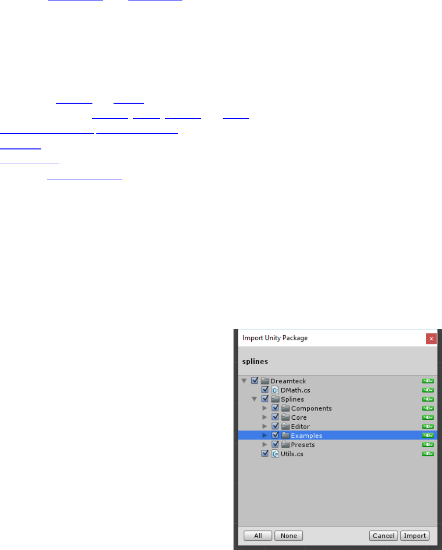
Dreamteck Splines comes packed in a .unitypackage
file. Upon import, all the files and directories of the
Dreamteck Spline system will be listed.
The “Examples” folder is optional. It contains example
scenes which demonstrate the features of the system. It
can be safely excluded from the import or deleted later if it
isn’t wanted.
The “Presets” folder contains an example preset file,
saved with the preset manager. This folder can also be
deleted but it will be automatically created as soon as a
new preset is saved.
Clicking “Import” will decompress and import all of the
selected files in the current Unity Project.
Dreamteck Splines – User Manual
7
Dreamteck Splines 1.0.8 comes with an additional PlaymakerActions.unitypackage file found inside
the Dreamteck/Splines folder. Importing this package will add Playmaker actions that work with
Dreamteck Splines components.
2.2. Updating Dreamteck Splines
If you already have Dreamteck Splines installed and have downloaded a newer version from the Asset
Store, it is recommended that you delete the entire Dreamteck/Splines folder before importing the new
version.
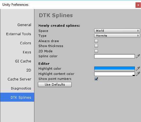
2.3. Preferences configuration
Since version 1.0.8 Dreamteck Splines comes with its own preferences screen that lets the user
configure how the system behaves. These are all editor configurations and do not affect builds in any
way.
To access the preferences screen go to Edit->Preferences->DTK Splines. This will open the following
screen:
The options under “Newly created splines” allow the user to configure the default settings for each
newly created spline. For example, if the game scene is full of light colors, then the default spline color
could be set to black and that way each newly created spline will be black upon creation without the
need of setting the color every time.
The options under the “Editor” section let the user customize the UI and scene view of the editor.
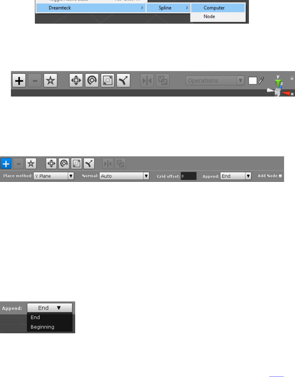
2.4. Creating a new Spline
To create a new spline, select GameObject in the toolbar and navigate to Dreamteck->Spline->Computer
Dreamteck Splines – User Manual
8
This will create a new Game Object called “Spline” with an empty Spline Computer component.
Once created, the object will be automatically selected and the currently selected editor tool for
movement, rotation or scaling will be turned off. A new toolbar will appear in the scene view.
2.4.1. Adding control points
A spline needs at least two control points to exist. To add control points click the Plus button on the
left of the toolbar. This will enter point creation mode and the button will get highlighted in blue. An
additional toolbar will appear with the following options: Place method, Normal orientation and Far
plane.
To create a new point, simply left click with the mouse somewhere in the scene. Where the
point is created is defined by the place method. By default, the place method is set to Camera plane
with far plane set to 0. This will create points in the position of the editor camera. The normal
orientation option defines the direction of the normal of each new point upon creation. “Auto” will
automatically pick a direction, appropriate for the selected placement method.
To exit point creation mode either press the Plus button again or click the right mouse button
and without releasing it click the left mouse button too, then release both buttons – this is a shortcut for
exiting point creation mode.
Version 1.0.5 introduces the append dropdown menu which lets the user select which end of
the splines will the newly created points be appended to.
- End: Adds the new point to end of the spline
- Beginning: Adds the new point in the beginning of the spline,
before the first point
Dreamteck Splines offers six placement methods to accommodate a big range of developer
needs related to point creation. To choose a different method, click on the Place method dropdown
menu and select a different method.
Version 1.0.7 introduces the Add Node option which will automatically create a new Node
object and link it to the newly created point.
Dreamteck Splines – User Manual
9
2.4.1.1. Camera plane
The camera plane placement method places points on a plane, perpendicular to the scene
camera. Far plane controls how far from the camera is the plane on which the points are created.
The further the plane is, the bigger it becomes. If Far plane is set to 0, then the points will be created
at exact position of the scene camera.
2.4.1.2. Insert
Insert inserts a new point between two points of the spline. When this method is selected, a
circular button will appear in the scene. Moving the mouse around will move the button along the
spline. Clicking the button will insert the point in the spline.
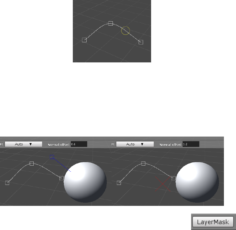
2.4.1.3. Surface
The surface method requires the scene to have at least one object with a collider. It will place
the new point on the surface of the collider under the mouse upon left clicking. Normal offset
controls the offset along the surface normal where the point will be created. If normal offset is 0,
then the point will be created exactly on the surface of the collider. If the mouse does not hover
over an object with a collider, a red cross will be displayed at the mouse position indicating that a
point cannot be created.
Version 1.0.8 introduces the LayerMask button which opens a window with a
layer mask field. This field lets the user set the layer mask of the surface raycast
so that certain layers may be excluded from raycastig.
2.4.1.4. Plane-X, Y and Z
This placement method will project the mouse position onto infinite planes positioned at (0,0,0)
world coordinates. This method is useful when the splines should be aligned to one of the three
axes. In order to create a point the mouse must hover over the selected plane. If the mouse doesn’t
Dreamteck Splines – User Manual
10
hover over the plane, a red cross will be drawn indicating that a point cannot be created. Plane
offset controls the offset along the plane axis.
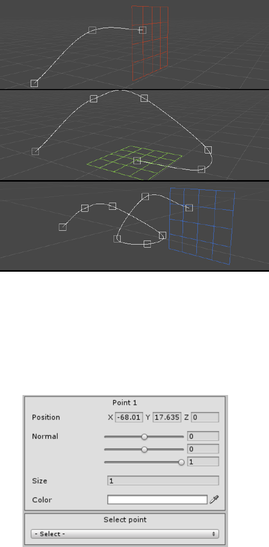
2.5. Selecting points
To select a point either click on it in the scene view or select it from the inspector using the point
selection drop down menu.
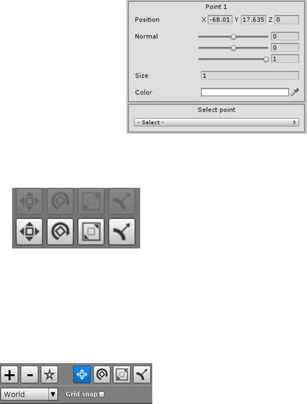
When a point is selected, its parameters will be displayed in the inspector:
2.5.1. Selecting multiple points
To select multiple points either drag-select them in the scene view or select them one-by-one
while holding Ctrl on the keyboard.
Dreamteck Splines – User Manual
11
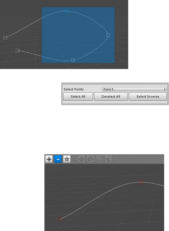
2.5.2. More selection options
In version 1.0.8 three new buttons are
introduced along with the Select point
dropdown menu:
• Select All – Selects all points of the spline
• Deselect All – Deselects all points of the spline
• Select Inverse – Inverses the selection so that the selected points become unselected
and vice versa
2.6. Deleting points
Points can be deleted by selecting
them and pressing Delete on the
keyboard or by entering Delete point
mode.
To enter Delete point mode, click on
the Minus button in the scene toolbar.
The button will get highlighted in blue
and the control points will turn red.
Clicking on a point in delete mode will
delete the point.
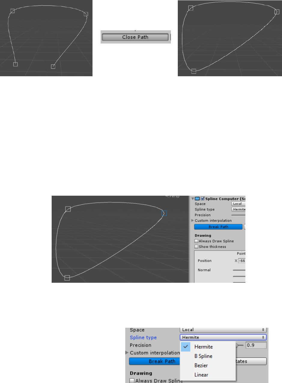
2.7. Closing and breaking a spline
A spline path consisting of four or more points can be closed. This will connect the first and the
last points of the spline.
2.7.1. Closing
To close a spline, first ensure that there are at least four control points present, go to the inspector
and click the “Close spline” button. The button will get replaced with a “Break path” button and the path
will get closed.
Dreamteck Splines – User Manual
12
2.7.1.1. Close spline during point creation
If a spline consists of three or more control points, it can be closed in point creation mode if the first
point of the spline is clicked. Doing so will open a dialog asking whether or not the spline should be
closed. This is convenient when the intention is to start off with a closed spline.
2.7.2. Breaking
To break a closed spline, press the “Break path button”. The two end points at which the path was
closed will be able to move separately once again.
2.7.2.1. Breaking a path at point
To break a spline path at a point simply select the point at which the path should be broken. The
“Break Path” button in the inspector will get highlighted in blue. This indicates that the path will be
broken at the selected point.
Make sure to select only one point, otherwise the path will break at the point it was previously
connected.
2.8. Changing the spline type
Dreamteck Splines supports four types of
interpolations: Hermite, Bezier, B-Spline and
Linear. To change the spline type, navigate to
the inspector and select a different type from
the “Spline type” dropdown.
Dreamteck Splines – User Manual
13
In version 1.0.8, a new dialog is introduced when changing the type from Hermite to Bezier, which
offers to convert the Hermite spline to Bezier one. Clicking “Yes” will retain the spline’s shape after
switching to Bezier. No extra points will be added but the tangents of the points will be recalculated.
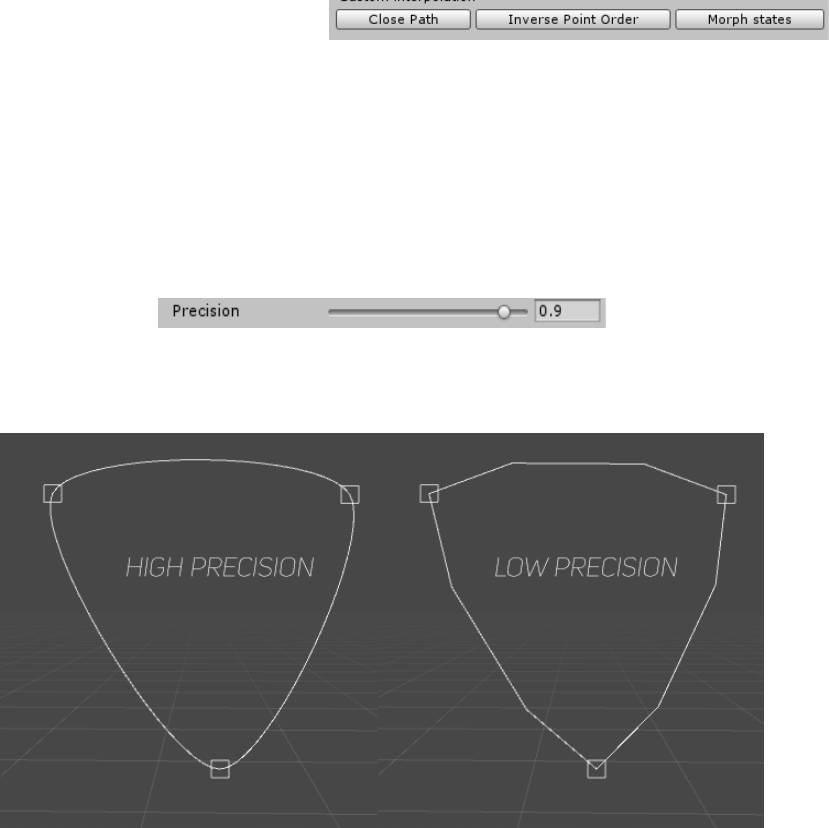
2.9. Inversing the point order
Sometimes it’s useful to be able to inverse the control point order without changing the spline’s
shape. Doing so will inverse the spline’s direction. To inverse the point order, click the “Inverse Point
Order” button in the SplineComputer inspector:
2.10. Spline precision
In computer graphics, splines aren’t endlessly smooth but are rather approximated at a certain rate.
The higher the rate is the smoother the spline will be and the more computations it will require to
approximate. It is usually a good idea to balance the precision so the spline looks visually smooth but it’s
not too detailed.
To change the spline approximation rate, use the Precision slider in the inspector.
Note that precision should never be 1 (that would mean dividing by zero) and therefore the
maximum precision that can be set is 0.9999
2.11. Framing control points
When a SplineComputer is selected and is in edit mode, the framing functionality of the Unity
editor can be used to frame all or only the selected spline points. If the spline computer has one or
more spline points, then going to Edit->Frame selected will frame the selected points or all points if
none are selected. If the Spline Computer doesn’t have spline points, then the default command
behavior is executed.

Dreamteck Splines – User Manual
14
2.12. Instantiating Spline Prefabs
Since the Spline Computers are regular Game Objects, they can be put into prefabs and
instantiated during runtime. One important thing to know about instantiating splines is that upon
instantiation, splines will not automatically update. Therefore, if the spline is referenced by a
SplineUser, the SplineUser will start using the spline at the position it was last saved in.
This is why it is important to call RebuildImmediate() on the Spline Computer as soon as it is
instantiated:
GameObject splineObject = Instantiate(splinePrefab, position, rotation);
splineObject.GetComponent<SplineComputer>().RebuildImmediate();
3. Editing splines
Dreamteck Splines are highly configurable and comes with a set of tools that aid the creation
process. This chapter offers an in-depth look at those tools and explains how they work.
3.1. Point components
Each spline consists of a set of control points and each control point has a set of components
that define it. These components get interpolated during spline evaluation.
3.1.1. Position
The position is a Vector3 point in space where the control point is located.
3.1.2. Normal
The normal is a Vector3 direction of the point normal. It is used to define object orientation along
the spline.
3.1.3. Size
A float value defining the size of the point. It is used as a multiplier for scaling and offsetting.
3.1.4. Color
The color of the point.
3.1.5. Tangents
Each point has two additional Vector3 values for tangent position (tangent1 position and tangent2
position). The tangents are required by the Bezier algorithm otherwise do not have a function.
3.1.6. Type
The type of the point. Can be Smooth or Broken. This is used by the Bezier algorithm only to define
whether or not the tangents will be free or locked.
Dreamteck Splines – User Manual
15
3.2. Editing points
Selecting each point opens up the point menu in the
inspector which exposes the point parameters. From
there each point’s position, normal, size, color and type
can be edited. This menu is the only place where the
point’s size and color can be set however it isn’t
comfortable for setting the point’s position and normal
unless a precise value needs to be entered.
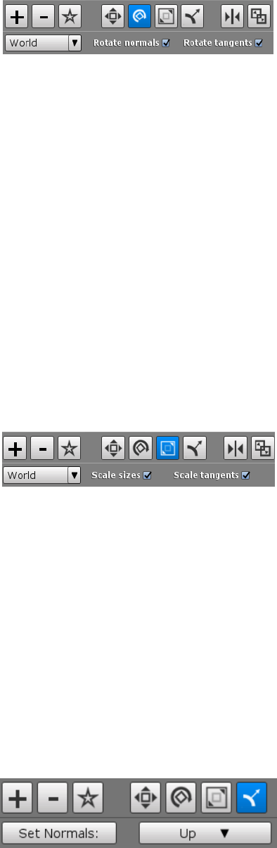
Dreamteck Splines comes with tools for movement,
rotation scaling and editing normal. The buttons for
those tools are located in the scene view toolbar and are unavailable by default. They become
available once one or more points are selected.
3.2.1. Move tool
The move tool provides a standard move handle for each point. Clicking on the move tool
button enables the move tool. Clicking on the button again, once it’s highlighted disables the
tool.
The move tool can be selected with by pressing “W” on the keyboard. This overrides Unity’s
built-in shortcut.
The Move tool has a Space dropdown menu which lets the user choose the space they want to
move the point in. By default, “World” is selected which orients the move handle to align with the world
axes. Local space will orient the handle to align with the local space of the SplineComputer’s object and
Spline space will orient the handle based on the spline direction.
• Grid snap enables automatic grid snapping. When grid snap is toggled, the size of the grid
can be configured in the toolbar.
3.2.2. Rotate tool
The rotate tool provides a standard rotation handle for the selected points. Clicking on the
rotate tool button enables the rotate tool. Clicking on the button again, once it’s highlighted
disables the tool.
Dreamteck Splines – User Manual
16
The rotate tool can be selected with by pressing “E” on the keyboard. This overrides Unity’s
built-in shortcut.
This tool has two options which appear in the toolbar extension below.
• Rotate normal – whether or not the normal of the point should be rotated
• Rotate tangents – whether or not the tangents’ positions should be rotated
Rotating a single point will only result in rotating the normal and tangents IF the
appropriate options are selected in the toolbar.
When multiple points are selected, the rotation handle is positioned in the center of
both points. Points’ positions are rotated around the position of the handle.
3.2.3. Scale tool
The scale tool provides a standard scale handle for the selected points. Clicking on the scale
tool button enables the scale tool. Clicking on the button again, once it’s highlighted disables the
tool.
The scale tool can be selected with by pressing “R” on the keyboard. This overrides Unity’s
built-in shortcut.
This tool has two options which appear in the toolbar extension below.
• Scale sizes – whether or not to scale the points’ size parameters
• Scale tangents – whether or not to scale the points’ tangents’ positions
Scaling a single point will only result in scaling its size and tangents IF the appropriate
options are selected in the toolbar.
When multiple points are selected, the scale handle is positioned in the center of both
points. Points’ positions are scaled away or towards the scale handle’s position.
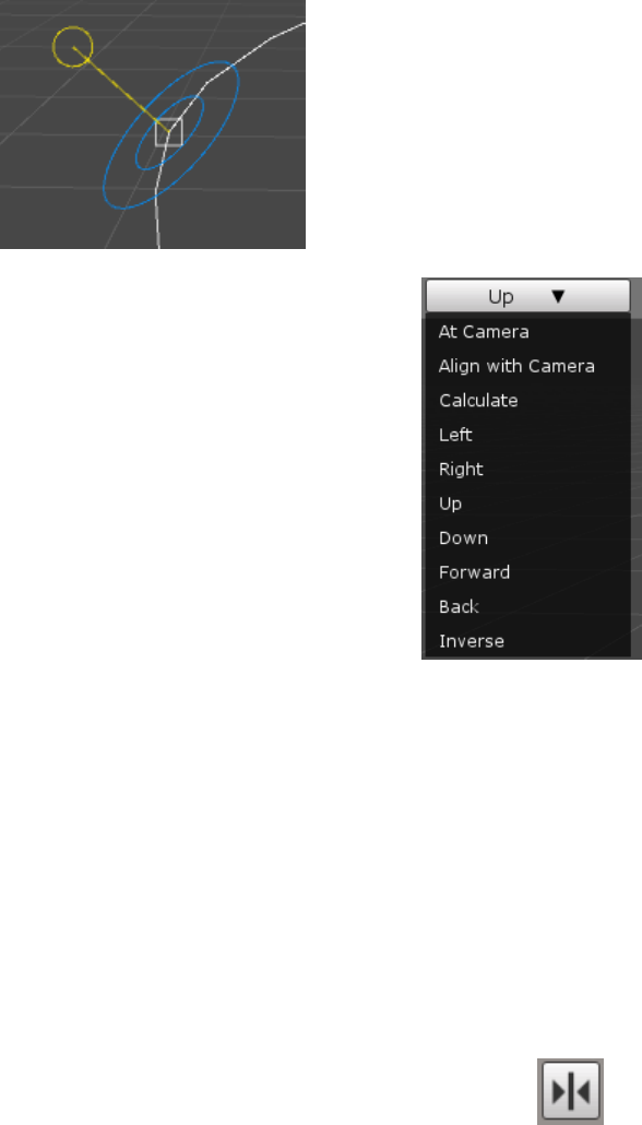
3.2.4. Normal tool
The move tool provides a special directional handle for each selected point. Clicking on the normal
tool button enables the normal tool. Clicking on the button again, once it’s highlighted disables the tool.
Dreamteck Splines – User Manual
17
Dragging the yellow circular handle sets the normal’s orientation.
The normal tool comes with a “Set Normals” function in the toolbar
extension. This function sets the normal to automatically point at a certain
direction. To choose where the normal should point, use the dropdown menu
next to the “Set Normals” button. The available options are:
• At Camera – sets the normal to point at the editor camera position
• Align with camera – aligns the normal with the forward direction of
the editor camera
• Calculate – Calculates the normal based on the point’s neighbours
• Left – World left
• Right – World right
• Up – World up
• Down – World down
• Forward – World forward
• Back – World back
• Inverse – Inverses the normal’s direction
• At Avg. Center – Orients the normal to look at the selected points’ average position
• By Direction – Adjusts the normal so that it’s perpendicular to the spline direction
Clicking on the button “Set normals” will set the normals of the selected points to the selected direction.
3.3. Symmetry editor
The symmetry editor is introduced in version 1.0.6 and its purpose is to help developers
make symmetrical splines. To enter symmetry editing mode, click the symmetry editing
button from the scene view toolbar. There needs to be at least at least one created spline
point, otherwise the symmetry button will be disabled.
When in symmetry mode, the spline is reflected based on the symmetry center which by default
matches the position of the SplineComputer’s Transform. If the symmetry center isn’t visible, make sure
to look for it around the computer’s transform position.
Dreamteck Splines – User Manual
18
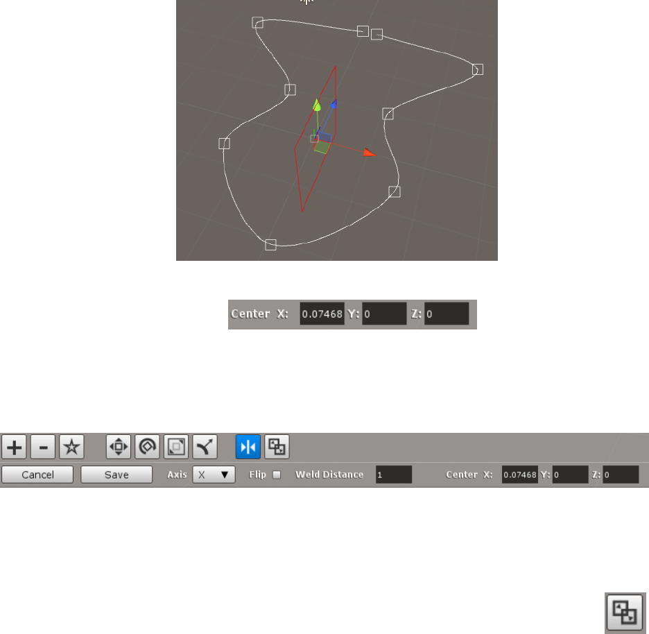
The symmetry center can be moved with the position handle attached to it or by modifying the
center coordinates in the toolbar.
By default, the spline is reflected along the X axis, but this can be changed using the Axis dropdown
menu. If flip is unchecked, the points to the left of the center will be reflected to the right, otherwise the
points on the right will be reflected to the left.
The “Weld Distance” setting defines at what distance from the symmetry plane two reflected points
will be merged into one. If the spline is of Bezier type, the merged point will have broken tangents.
3.4. Merging Splines
A spline merging editor is introduced in version 1.0.6. Its purpose is to merge two or more
spline computers into one. To toggle the merge editor, click the “Merge Splines” button in the
scene view toolbar. The spline needs to have at least two control points and must not be closed
in order for the merge editor to work.
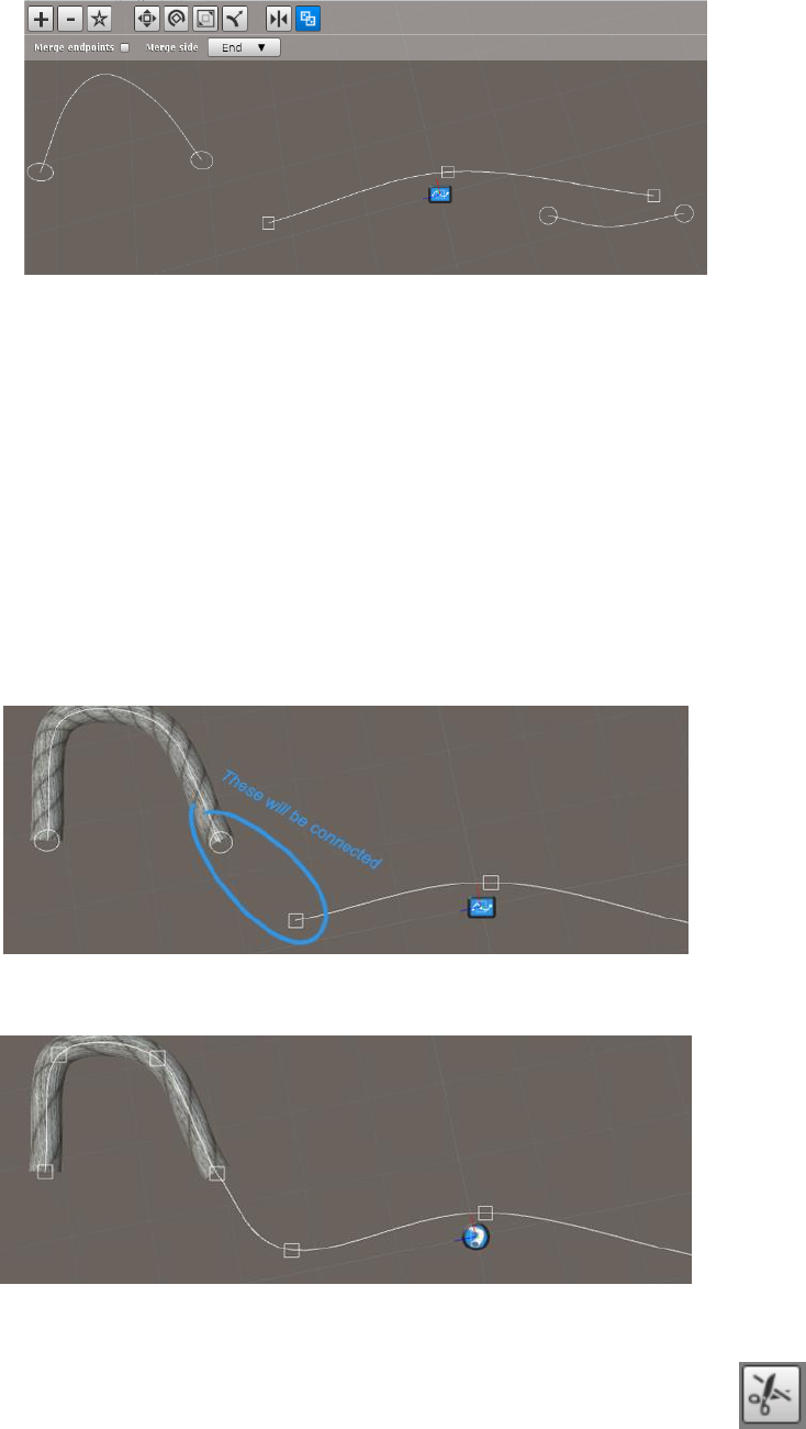
When the merge editor is selected, it will display all other available Spline Computers in the scene,
each of them having a circular button at each endpoint.
Dreamteck Splines – User Manual
19
To merge the selected spline with another available spline, click one of the endpoints of the other
splines. By default the merged spline will be appended to the end of the selected spline, but this can be
changed by setting the “Merge Side” option to “Start” – then the merged spline will be appended to the
beginning.
If the “Merge Endpoints” option is toggled, then the endpoint of the selected spline and the
endpoint of the merged spline will be merged into one point. Basically, the endpoint of the merged
spline will be removed.
When two splines are merged, all of the SplineUsers, subscribed to the merged spline get subscribed
to the selected spline that “consumes” the merged spline. So for example, if the merged spline has a
TubeGenerator attached to it, the TubeGenerator will get transferred to the selected spline.
After the merge, the above Tube Generator starts referencing the new spline.
3.5. Splitting Splines
The split functionality is introduced in version 1.0.83 and allows for a spline to be split
at any point into two separate splines. To toggle the split editor, click the “Split spline”
Dreamteck Splines – User Manual
20
button in the scene view toolbar. The spline needs to have at least two control points in order to be
split.
When the Split mode is toggled, the split editor will be activated. The control points of the spline will
be displayed as circular buttons and the mouse position will be projected along the spline as another
circular button:
Clicking on any circular button will split the spline at the given point. The split will trim the selected
spline and will create a new SplineComputer in the scene starting from the split point.
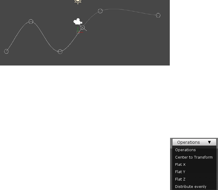
3.6. Point operations
Dreamteck Splines provides a set of simple and handy operations for editing
points. These operations can be found on the right side of the scene view toolbar
and become available when at least one point is selected. Since most of the
operations require two or more points to be selected, it’s recommended to select at
least three points when examining this feature for the first time.
When an operation is selected from the dropdown menu it is immediately
executed.
3.6.1. Center To Transform
When splines are created, their points can be positioned very far from the position of the Spline
Computer’s Transform. Sometimes the control points need to be brought to the center of their
transform so proper transformation can be applied. This operation brings all of the selected points to
the center of the transform while maintaining their relative position.
Dreamteck Splines – User Manual
21
3.6.2. Move Transform To
This is the reverse equivalent of Center To Transform. This operation will move the position of
the SplineComputer’s transform to the average center of the selected points without moving any
points.
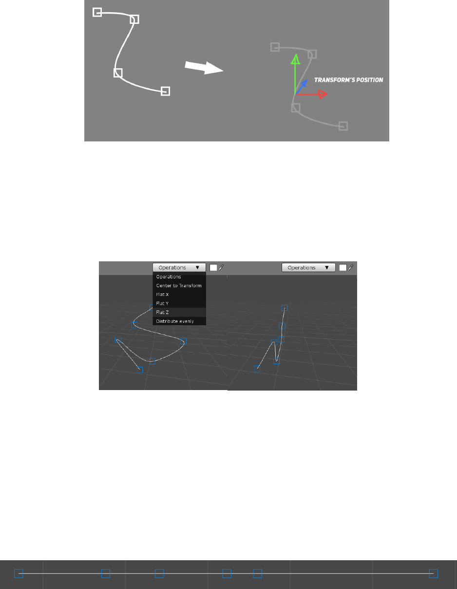
3.6.3. Flat X, Y and Z
These operations flat the selected points’ positions along the given axis.
If the spline type is Bezier, a dialog will appear upon selecting the flat operation giving the option to
flat only the points’ positions, only the points’ tangents or everything.
3.6.4. Mirror X, Y and Z
Mirroring is introduced in version 1.0.3 and mirrors the selected spline points along the given axis.
3.6.5. Distribute evenly
As the name suggest, this operation will attempt to distribute the points at even distances from
each other.
Before:
After:

Dreamteck Splines – User Manual
22
3.7. Spline Computer settings
The Spline Computer component has several very important settings that can change the way it
works. These settings can be found in the inspector.
3.7.1. Space
She Space of the Spline Computer can be either world or local and defines how the its spline is
computed. Local space applies the transform’s position, scale and rotation to the spline resulting in
a transformed spline. Setting the space to World will cause the spline to ignore the object’s
transform much like the Space attribute of Unity’s Built-in Line Renderer.
When changing the space of a Spline Computer, the spline’s coordinates are preserved into the
new coordinate system resulting in the spline staying the same.
Example case:
- A spline with five control points is created
- The Spline Computer’s space is set to local
- The Spline Computer’s scale is set to (2, 2, 2) (twice the initial). This results in a scaled spline
- The Spline Computer’s space is set to world. The spline’s size stays the same
- The Spline Computer’s scale is set back to (1, 1, 1). The space is set to world so the spline’s size
stays the same
- The Spline Computer’s space is set back to local; The spline’s size stays the same.
Dreamteck Splines – User Manual
23
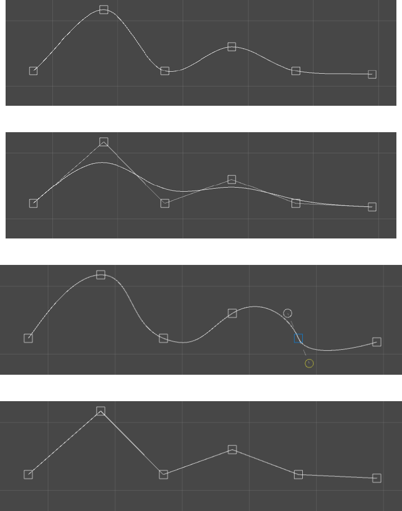
3.7.2. Spline type
The spline type defines which interpolation method should be used to calculate the spline.
3.7.2.1. Hermite
3.7.2.2. B-Spline
3.7.2.3. Bezier
3.7.2.4. Linear
Dreamteck Splines – User Manual
24
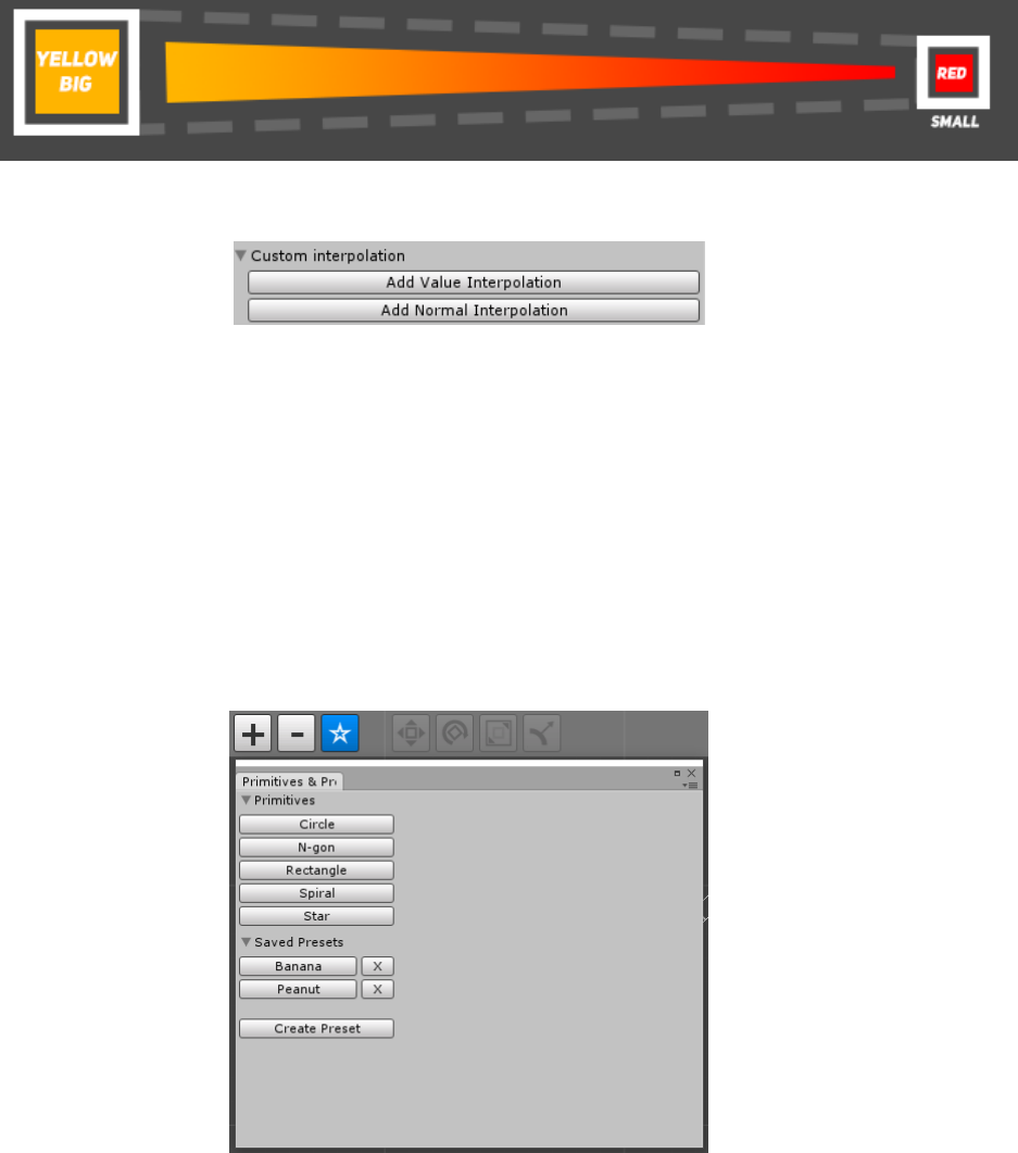
3.7.3. Custom interpolation
By default the points’ colors, sizes and normals are linearly interpolated which may not be desired in
some cases.
To set an interpolation curve, expand the “Custom interpolation” foldout in the inspector.
Then click on “Add Value Interpolation” to add a custom curve for the color and size interpolation or
click “Add Normal Interpolation” to add a custom curve for the normal interpolation.
Doing so will create a default Ease-in, Ease-out curve which can then be edited to something else.
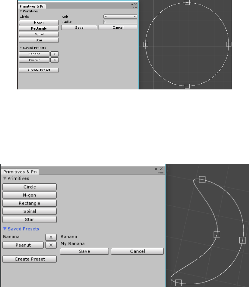
3.8. Primitives and presets
Dreamteck Splines provides a list of procedural primitives and a preset saving system. Both are
located in the Primitives & Presets window which can be opened by clicking the Star button from
the scene view toolbar.
The primitives are listed first with buttons. Clicking on a primitive button will open the primitive
preview and menu. The saved presets are listed second and like the primitives, clicking on a preset
Dreamteck Splines – User Manual
25
button opens the preset preview and menu. Presets can be deleted by clicking on the button with a
cross next to the preset button.
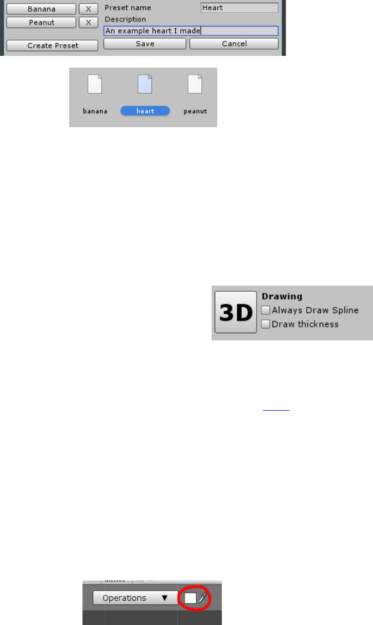
3.8.1. Using primitives
When a primitive is selected, its menu is displayed in the right side of the Primitives & Presets
window. This menu features settings for the procedural primitive and a “Save” and “Cancel” button. In
the scene view, the spline is set to display the primitive.
If “Save” is pressed, the spline shape and settings is set, if “Cancel” is pressed, the spline gets
reverted to its previous state.
3.8.2. Using presets
When a preset is selected, it’s title and description as well as “Save” and “Cancel” buttons are
displayed on the right side of the Primitives & Presets window. If “Save” is pressed, the preset is applied,
if “Cancel” is pressed, the spline gets reverted to its previous state.
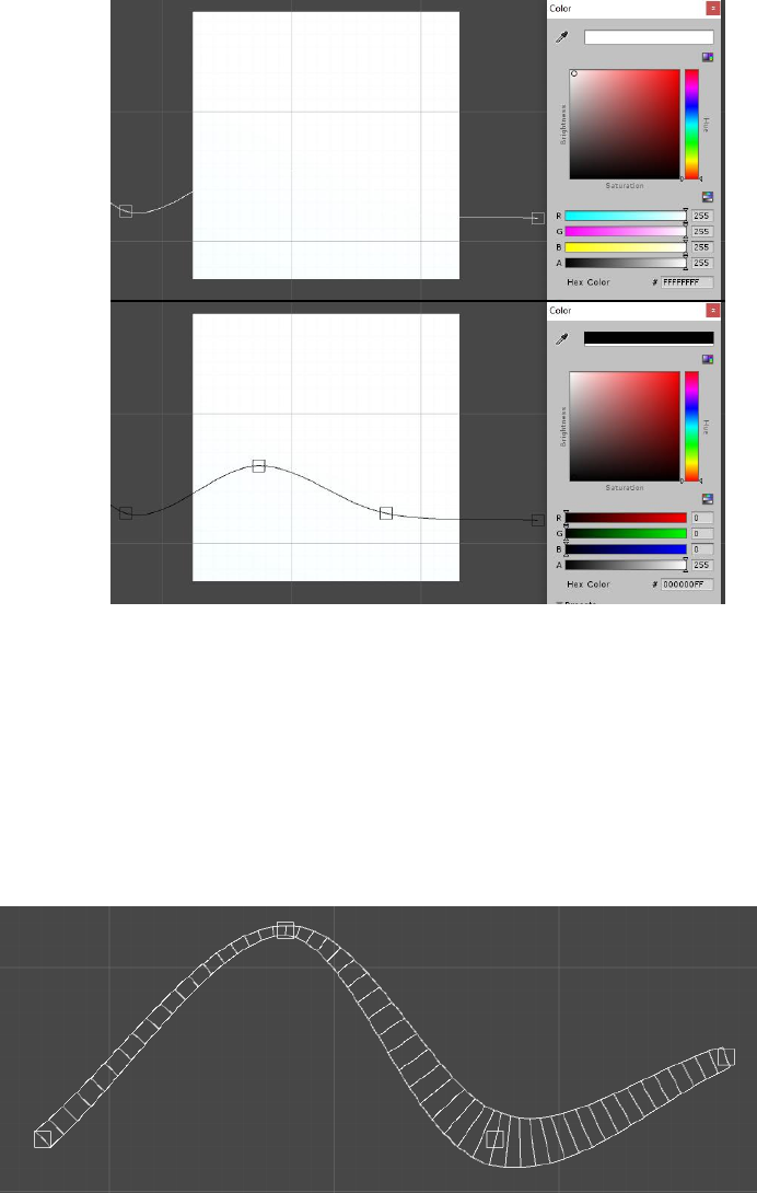
3.8.2.1. Creating a preset
To create a new preset, click the “Create preset” button. Fill the name and description fields that are
displayed and click “Save”. This will create a new preset file in the presets folder.
Dreamteck Splines – User Manual
26
If after saving, the file does not appear in the Presets folder, right click inside the folder and
select “Refresh”.
Presets can be transferred between projects.
3.9. Configuring the Spline Computer editor
The SplineComputer provides a set of settings which defined how the spline is drawn in the
editor or how it behaves.
3.9.1. 2D and 3D Mode
Dreamteck Splines are 3D splines but version 1.0.8
introduces the 2D mode. It can be toggled by clicking the big
button in the SplineComputer inspector saying “3D”.
Once clicked, the button will change its text to “2D”, the
spline will be flattened and the normals will automatically be handled so that they point along the
negative Z axis.
In 2D mode, the only available point creation modes are “Free” and “Insert”. The Free point
creation mode is an analogue of the Z-plane creation mode.
Note that the 2D mode only changes the behavior of the editor. The splines are still 3D and their
control points can be displaced along the Z axis during runtime using code.
3.9.2. Custom Color
Custom colors can be used differentiating Spline Computers when several are drawn
simultaneously or to prevent blending with the background.
To choose a color for the currently selected Spline Computer use the color picker located in the
right side of the scene view toolbar.
Dreamteck Splines – User Manual
27
3.9.3. Always draw
Always draw can be toggled on or off from the Spline Computer’s inspector. This option causes the
spline to be drawn all the time even when the Spline Computer is not selected.
3.9.4. Draw thickness
Draw thickness is toggled on or off from the Spline Computer’s inspector. This option causes the
spline’s thickness to visualize. The thickness is defined by the size of the points (which by default is
1).
4. Morph states
Each Spline Computer has a morph state module which allows adding channels that contain
different spline shapes to the Spline Computer. These channels can then be blended using weights.
Dreamteck Splines – User Manual
28
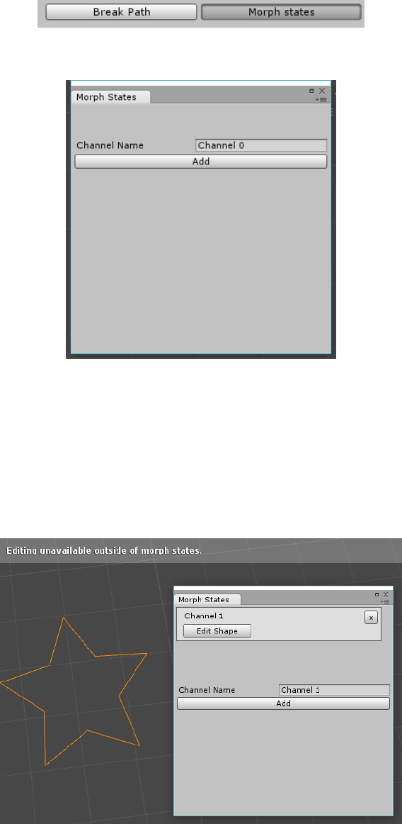
To open the Morph States window click the “Morph States” button in the Spline Computer
inspector.
This will open a new empty window with the option to add a channel.
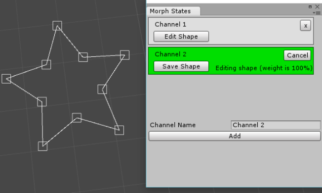
4.1. Creating morph channels
Clicking on the “Add” button in the Morph States window will create a new base channel which
has 100% weight.
After the first channel is created, it will appear in the window above the “Add” button. The
spline will turn orange and editing will be disabled. From this moment on, editing will be only
enabled inside channels.
Dreamteck Splines – User Manual
29
4.2. Editing morph channels
To edit the shape of a morph channel, go to the Morph States menu and click the “Edit Shape”
button of the morph channel which shape must be edited. This will highlight the morph channel in
green. It will also enable the spline points and editing tools.
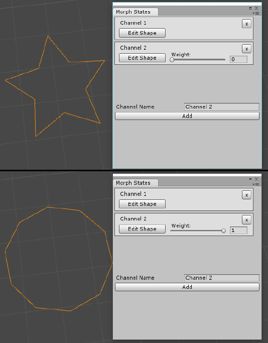
When editing the shape of a morph channel, the morph channel is weighted at 100%. After
editing is complete, “Save Shape” should be pressed. This will write the edited shape to the channel
and exit edit mode.
IMPORTANT! Each channel must contain exactly the same amount of points as the other
channels. Therefore deleting and creation of points is disabled.
Dreamteck Splines – User Manual
30
4.3. Blending between shapes
Once there are two channels with different shapes they can be blended. To blend a channel, drag its
weight slider to the right.
During runtime, channel weights are set via code or UnityEvents. Look at the API reference to see
examples of how to do this.

Dreamteck Splines – User Manual
31
5. Spline Users
The Spline Computer all by itself cannot do much more than to provide sample data from its spline.
To make use of the Spline Computer, Dreamteck Splines implements the Spline User. This is a base class,
derived from MonoBeaviour. Its purpose is to sample the Spline Computer and use the sampled data for
various purposes.
When a Spline User is selected in the editor, its Spline Computer is automatically drawn.
The Spline Users only sample Spline Computers when there has been a change in the spline,
therefore do not have a constant overhead if no changes are made.
The Spline User class supports multithreading so sampling and calculations can be done in a
separate thread, not affecting the game performance.
5.1. Basic SplineUser properties
As of version 1.0.5 the SplineUser components have two Sample modes that can be toggled in
the SplineUser inspector:
- Computer
- User
The sample mode defines the type of the sample target of the specific SplineUser.
5.1.1. Sample Target – Computer
When the sample mode is set to Computer, the SplineUser requires a SplineComputer reference
to be set. The SplineUser then samples the referenced SplineComputer when there are changes in the
spline.
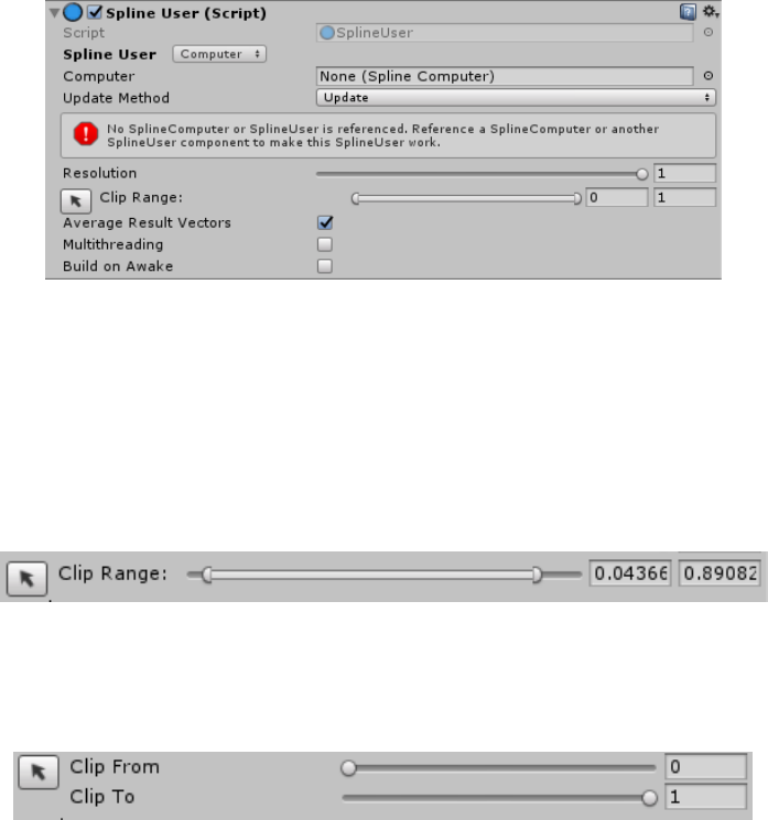
When a SplineUser is set to sample a SplineComputer, the following properties are exposed:
- UpdateMethod: When is the user updated? Update/FixedUpdate/LateUpdate
- Resolution: (0-1) acts like a multiplier to the Spline Computer’s precision
- Clip Range: Two values – clipFrom and clipTo which define the range of the spline that will be
used
- Average result vectors: Whether or not to average each samples’ directions and normals (in
overall gives a good result when turned on)
Dreamteck Splines – User Manual
32
When many SplineUsers are set to sample the same SplineComputer, each user will sample the
computer individually when there is a change in the spline. This can cause a big performance drop due
to the multiple sampling and in cases like this, it’s recommended to use the User sample method.
5.1.1.1. The Clip Range
The clip range is defined by the Clip From and Clip To values. By default, the editor displays the
range with a MinMax slider:
This type of control prevents the “clipFrom” value from being bigger than the “clipTo” value. In
version 1.0.8. the clip range looping is introduced. If the sampled spline is closed, the clip range is
controlled with two separate slider:
This allows for the “clipFrom” value to be bigger than the “clipTo” value. If clipFrom is bigger
than clipTo, then the clipped range becomes looped, meaning that the sampled splines become
[clipFrom;1.0] and [0.0;clipTo]
5.1.2. Sample Target – User
This sample mode requires a reference to another SplineUser. The referenced SplineUser must
either be referencing a SplineComputer or a SplineUser which is referencing a SplineComputer.
This sample mode does not use the “resolution”, “update method” and “average result vectors”
properties. Instead it gets them from the referenced SplineUser.
When referenced SplineUsers get updated, all other SplineUsers which are referencing them
also get updated.
Dreamteck Splines – User Manual
33
5.2. Spline Tracer
The Spline Tracer is a new base component, introduced in version 1.0.8. It serves as a parent class to
the SplineFollower, SplinePositioner and SplineProjector components. Its purpose is to provide base
functionality for evaluation and positioning of objects along splines. By itself, the SplineTracer doesn’t
do anything but it comes with several key modules and properties which are inherited by the
aforementioned components.
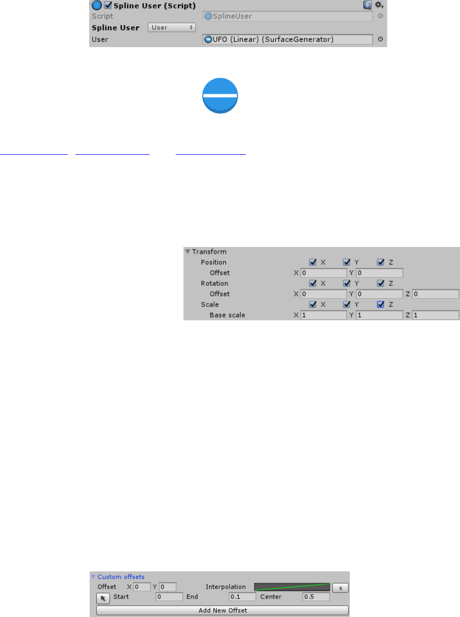
5.2.1. Transform Module
The transform module defines how
the transformation from evaluating the
spline is applied to the object. There are
three axes for each position, rotation and
scale. When an axis is toggled,
transformation will be applied along it. The position and rotation components use world axes while the
scale axes are local to the object.
Applying scale is disabled by default meaning that all axes are unchecked. When applying scale is
enabled, an additional “Base Scale” Vector3 field is presented. The base scale is the scale that is going to
be applied to the object. If the spline has various sizes, the base scale will be multiplied by the size value
of the current spline evaluation.
Offsets can be applied to both the position and rotation. These offsets are local to the evaluation
result’s directions and are used constantly.
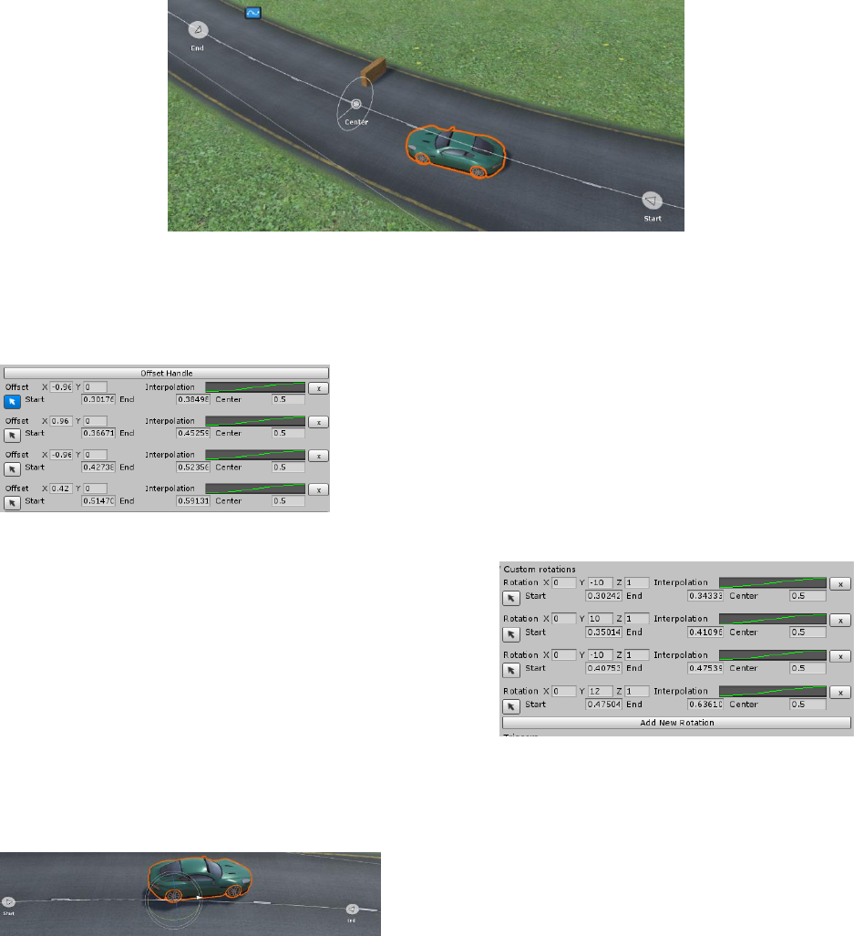
5.2.2. Custom Offset Module
The custom offset module adds a custom position offset to a specific area of the spline, defined by
the user. This module comes empty since by default no custom offsets are assigned. Clicking the “Add
New Offset” button will add a new area with a zero offset. The offset area will be immediately listed in
the inspector:
Dreamteck Splines – User Manual
34
Each offset area is defined by a start percent along the spline [0-1], an end percent along the spline
[0-1] and a center percent [0-1] to define where the offset’s effect will be strongest. The center percent
is local to the start-end range. An interpolation curve is provided to define motion easing.
Clicking the little black cursor at the left of the custom offset row will enable the scene view editor
for the offset area:
The scene view editor provides handles that can be used to visually set up the offset area. Dragging
the “Start”, “End” and “Center” handles along the spline will result in changes in the inspector. The
target offset itself is visualized with a circle with a line going from its center to the edge.
When in scene edit mode, a button appears in the
inspector with the text “Offset Handle”. Clicking it toggles
editing of the offset directly in the scene.
5.2.3. Custom Rotation Module
Similarly to the Custom Offset Module, the Custom
Rotation module is used to apply a custom rotation offset
to a specific region of the spline. Clicking the “Add New
Rotation” button will add a new area with a zero rotation
offset.
Just like the custom offset module, each custom
rotation area is defined by a Start, End and Center percent and an interpolation curve is provided to
define the easing of the motion.
Clicking the black cursor on the side opens the scene editor which allows values to be set directly
through the scene. The difference between this module
and the custom offset module is that here a rotation
handle is used.
Dreamteck Splines – User Manual
35
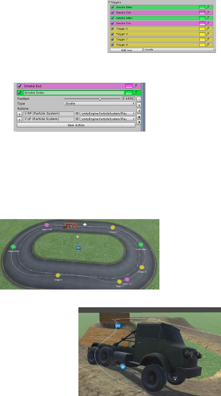
5.2.4. Triggers
The SplineFollower, SplineProjector and
LengthCalculator components can call events when a certain
point of the spline has been reached or a certain length has
been passed. These events are configured through triggers.
To add a new trigger, expand the “Triggers” foldout and click
the “Add new” button.
Each trigger can have a custom color and name and can raise multiple events. To configure a trigger,
click on its name in the trigger list.
The position parameter of the trigger defines the place along the spline where the trigger will be
located. Triggers can be three types: Double, Forward and Backward. The type defines the movement
direction along the spline which activates the trigger. For example if a car is moving along the spline
backwards and passes a Forward-type trigger, the trigger will not be activated.
To add a new event, click the “New Action” button, then select the object, script and function name
to be called.
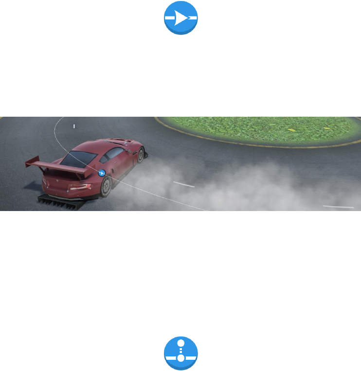
All triggers’ positions can also be edited directly in the scene.
5.2.5. Physics mode
The Physics mode of a SplineTracer can
be either Transform, Rigidbody and
Rigidbody2D. By default the Physics mode is
set to Transform which modifies the property
of the Transform directly. Using Rigidbody or
Rigidbody2D will modify the rotation and
Dreamteck Splines – User Manual
36
position of a Rigidbody component instead of the Transform. Rigidbody mode is preferred when
physical interactions are needed.
Using PhysicsMode Rigidbody with a combination of the proper motion application settings can
create realistically behaving followers.
5.2.6. Direction
The direction of the SplineTracer defines the direction that the object will be facing along the
spline. In the SplineFollower component, the direction is also used to define the direction of
movement.
5.3. Spline Follower : SplineTracer
The Spline Follower component makes the object it’s attached to follow a spline with a uniform
speed. If autoFollow is enabled, the follower will automatically follow the spline with the follow speed
during runtime. If autoFollow is disabled, the follower can be caused to follow by calling it’s public
method Move(float distance).
The Spline Follower has three wrap modes:
• Default – when the end of the spline is reached, the follower will stop
• Loop – When the end of the spline is reached, the follower will start again from the
beginning.
• PingPong – When the end of the spline is reached, the follower will change its direction
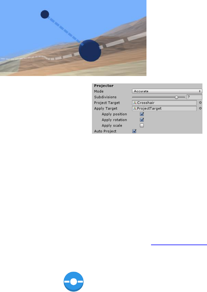
5.4. Spline Projector : SplineTracer
The Spline Projector projects a Game Object from the scene on a spline. It will find the closest
point of the spline to the object’s position.
Dreamteck Splines – User Manual
37
The Spline Projector needs two Transform
components as targets – The target that is projected on
the spline (Project Target) and the target that is
positioned at the Project Target’s projection. If Project
Target is not set, then the Spline Projector’s Transform is
used by default. If Apply Target is not set, then Transform
is set to the projection’s result. The projection result can be accessed via code using the projectResult
property.
The Spline Projector has two modes: Accurate and Cached.
In accurate mode, the resolution slider of the Spline User is disabled. This tries to project the point
on the spline as accurately as possible using subdivisions. The subdivisions are set to 4 by default. This in
overall is a good value to produce an accurate result but there might be cases when it isn’t enough.
In cached mode, the projector will find the two closest sampled results and project the target on the
line between them. This is mode is designed to be a lot lighter than the Accurate mode but it will not
give smooth results with low resolution samples.
This component has an additional module that control its behavior. Refer to Triggers and Modules
for more information.
5.5. Spline Positioner : SplineTracer
This component positions a single Transform along a given path. This component is very similar to
the Spline Follower but the difference is that it doesn’t move the Transform along the spline. Its idea is
to be used with animations, tweeners or other MonoBehaviour scripts. The way it works is it uses a
position property which determines the object’s position along the spline. Changing that property
moves the object along the spline.
Dreamteck Splines – User Manual
38
The positioner has two modes – Percent and Distance
• Percent maps the whole spline to the range [0-1]
• Distance positions the object at the given distance
from the spline’s start
This component has one additional module which controls
its behavior. Refer to Triggers and Modules for more
information.
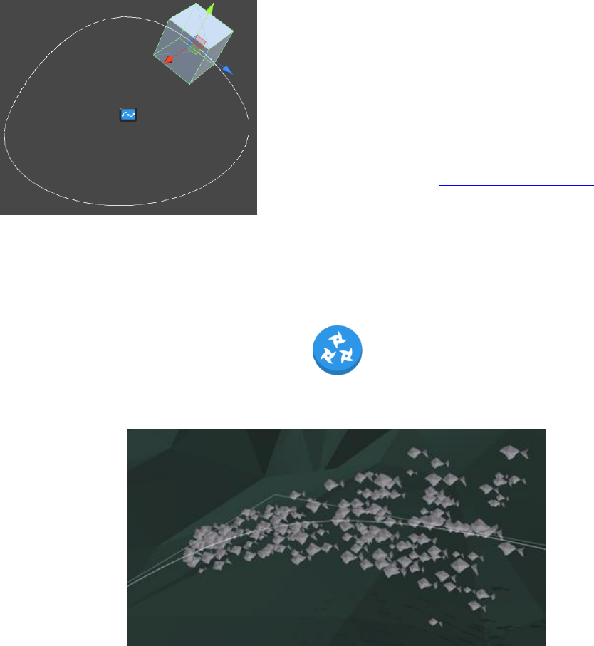
5.6. Particle Controller
The Particle Controller uses a Shuriken particle system and places its particles along a spline.
This component offers a preview right in the editor if it’s attached to the particle system that it
controls.
The Particle Controller has an Emit point which controls where new particles will be spawned.
The modes are:
• Beginning – Emits particles from the beginning of the spline
• Ending – Emits particles from the final point of the spline
• Ordered – Emits particles from the beginning of the spline towards it’s end based on particle
index
• Random – Emits particles between the beginning and the end of the spline on a random basis
Dreamteck Splines – User Manual
39
Another very important option of the Particle
Controller is the Motion type. This controls the particle
behavior over its lifetime. The available motion types are:
• Use Particle System – Uses the motion, defined
by the Particle System component
• Follow Forward – Particles move forward along
the spline based on their lifetime
• Follow Backward – Particles move backward
along the spline based on their lifetime
• By Normal – Particles get their initial velocity set in the direction of the spline sample’s
normal
• By Normal Randomized – Same as above but the direction vector is randomized
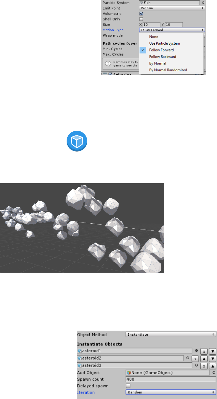
5.7. Object Controller
The Object Controller component instantiates and positions Game Objects along a spline. This could
be done both during runtime and in the editor.
The Object Controller has two Object Methods which define how the objects it controls are created.
• Instantiate – This will instantiate new objects
• Get Children – This will not instantiate new objects but instead will take the existing children
of the Object Controller’s Transform and use them.
In Instantiate mode, a Game Object array is
presented. For Instantiate to work there must be
at least one added Game Object reference.
Dreamteck Splines – User Manual
40
A Spawn Count property is presented. Modifying it will create or destroy objects.
The Iteration dropdown defines in what order the Game Objects are instantiated. If Ordered is
selected, the Game Objects will be spawned in the order they are added. To change this order, use the
up and down arrows next to the objects. In Random mode, objects will be instantiated in a random
order.
If Delayed spawn is turned on, the objects will spawn over a certain period of time. This is mostly
used to prevent spike lags caused by spawning many objects at once. Delayed spawn does not work in
the editor.
In Get Children mode, the child objects of the Object Controller’s Transform will be used. Adding or
removing objects from the hierarchy will include or exclude them from the controller.
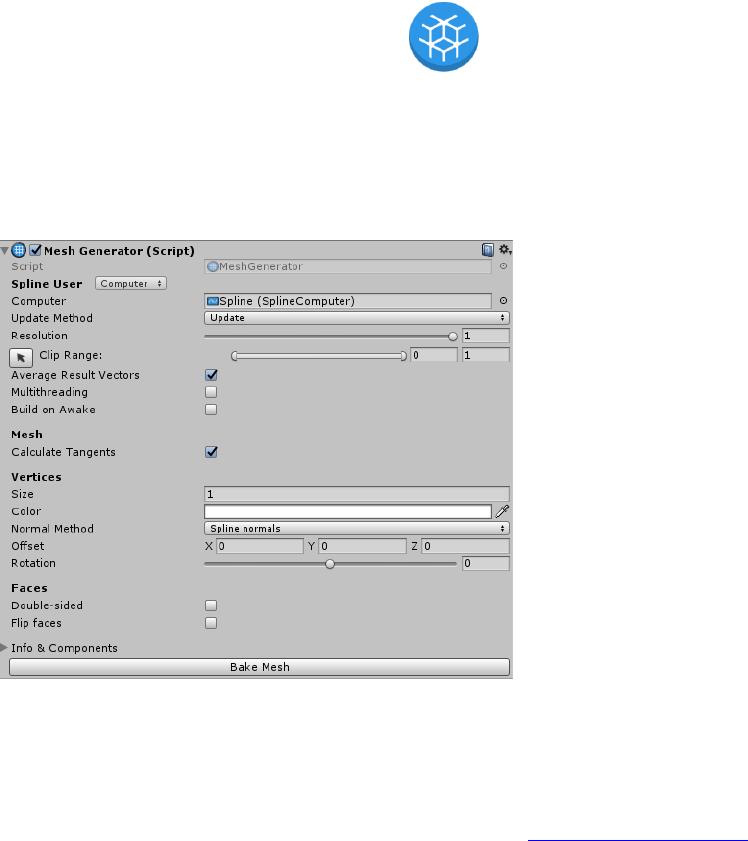
5.8. Mesh Generators
The Mesh Generators are a special kind of SplineUser class, dedicated to generating mesh geometry
using a spline. The MeshGenerator component by itself doesn’t do anything but is used as a base for
creating other components. It provides basic properties, functionality and pipeline which are needed for
the generation of meshes. It comes with its own custom editor which extends the SplineUser editor.
The MeshGeneration properties and
functions are:
- Calc. Tangents: If checked,
tangents will be calculated for normal
mapping
- Size: The size of the generated
geometry’s circumference around the
spline.
- Color: A color multiplier for the
vertices
- Normal method: the method used
for the vertex normal calculation
- Offset: A Vector3 offset direction
local to the spline.
- Rotation: Rotation in degrees around the spline
- Double-sided: If checked, the generated mesh will be double-sided
- Flip faces: If checked, the generated mesh will have flipped faces
- Info & Components: a foldout with information about the mesh and the mesh components
- Bake mesh button: Button used for mesh baking (See Baking Mesh Generators)
Dreamteck Splines – User Manual
41
Each MeshGenerator’s behavior is affected by the spline points’ colors and most of them are
affected by the points’ sizes.
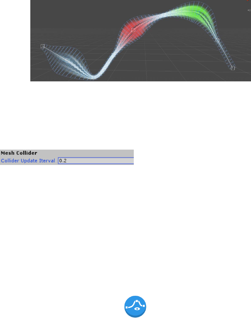
If a MeshCollider component is present, the MeshGenerator will offer to update the
MeshCollider when geometry is generated. Since updating mesh colliders is a heavy task, when a
Mesh Collider is present an additional value will be exposed in the inspector. This value is called
“Collider Update Interval” and defines how frequently the mesh collider will be updated.
Setting this value to 0 will cause the Mesh Collider to update as soon as there is a change in the
mesh. Note that the Mesh Collider will not update if there aren’t changes in the mesh.
If multithreading is enabled, the mesh generation algorithm will be executed on another thread.
However, due to the thread-unsafe nature Unity’s API, mesh writing, collider updates and
optimization are done on the main thread.
Note: Optimizing the mesh and calculating tangents are heavy operations.
- Optimize should be used if the mesh isn’t updated frequently
- Calculate Tangents is toggled by default and must be toggled if the mesh uses a material with a
normal map, otherwise, it is a good idea to uncheck it since tangents will not be used.
5.9. Spline Renderer : MeshGenerator
The Spline Renderer is an analogue of Unity’s Built-in Line renderer. It uses a spline to visualize
instead of a set of points. It’s the first of a set of behaviors, derived from a special Spline User class
called MeshGenerator. This class is used to provide basic functionality for creating procedural geometry
using a spline.
Dreamteck Splines – User Manual
42
Editing the SplineRenderer and anything else, derived from MeshGenerator is as easy as editing the
Spline Computer’s spline.
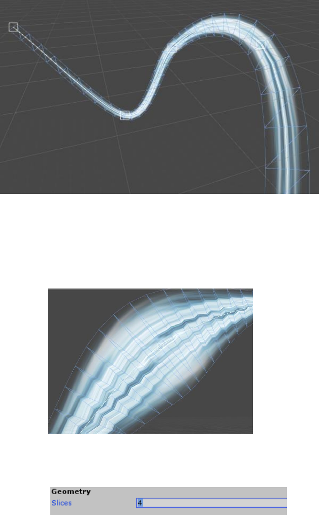
Because of the triangular nature of the mesh, in some cases the texture coordinates of the Spline
Renderer might appear jagged.
This is most often observed when there are spline points with different sizes and the solution to
this is to add more edge loops. To do so go to the inspector and increase the number of Slices:
This will reduce the jagged artefacts. The same applies for the Path Generator component.
Dreamteck Splines – User Manual
43
The SplineRenderer does not update Mesh Colliders.
5.10. Path Generator : MeshGenerator
The Path Generator is very similar to the Spline Renderer with a few exceptions. First, unlike the
Spline Renderer, the Path Generator does not orientate the generated geometry to face the camera.
Instead the geometry is orientated in the direction of the spline normal.
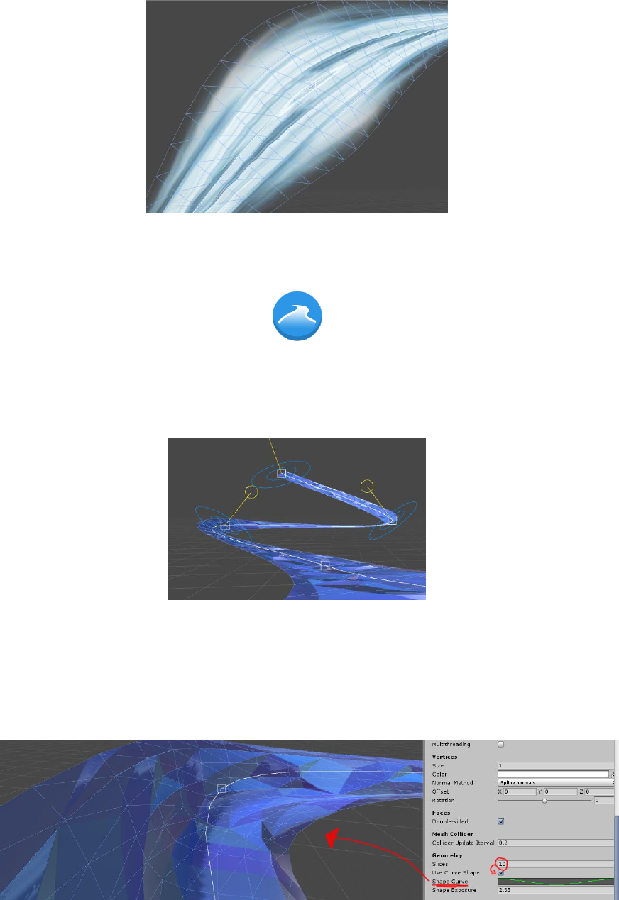
Like the Spline Renderer, the Path Generator has the option for multiple edge loops (called Slices) to
prevent jagged texture coordinates. However, the Path Generator’s slices also serve a function of
deforming the generated path. Turning on the “Use Shape Curve” option will expose a curve editor. If
the slices of the Path Generator are set to a value bigger than 1, then the path can be deformed using
the curve editor.
Dreamteck Splines – User Manual
44
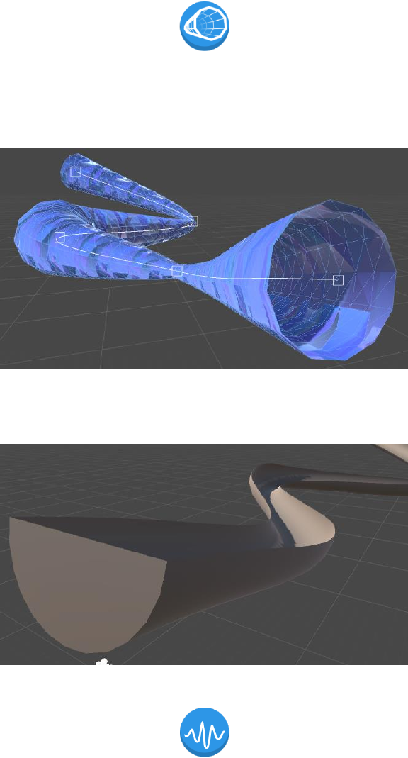
5.11. Tube Generator : MeshGenerator
The Tube Generator is another Mesh Generator, derived from the MeshGenerator class. It
Creates a tube along a spline and is affected by the same things the Path Generator and the Spline
Renderer are.
Its ends can have flat or round caps at its ends and the integrity value controls how much it revolves
around the center.
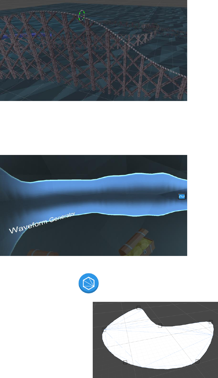
5.12. Waveform Generator : MeshGenerator
The Waveform Generator creates curved surfaces that resemble a waveform. It can be used for
audio visualization, 2D terrains, fences and other structures. In the Roller Coaster example, Waveform
Generators are used to make the railway supports.
Dreamteck Splines – User Manual
45
The Waveform Generator does not use the spline points’ sizes for the mesh generation unlike the
other three components described above.
There is a symmetry option which causes the waveform’s shape to mirror along the axis it’s created
on.
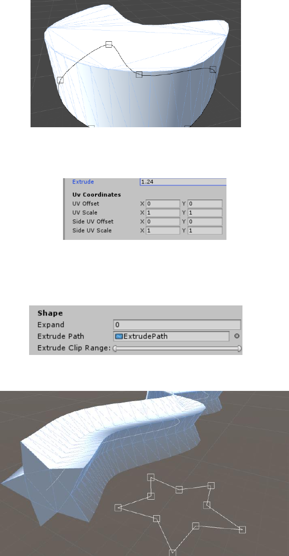
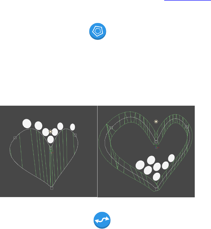
5.13. Surface Generator : MeshGenerator
The Surface Generator creates a 3D surface
from a spline. These surfaces can be used for
creating different kinds of platforms, natural water
pools, shape animations etc. They don’t require the
spline to be closed to work.
Dreamteck Splines – User Manual
46
By default, the generated surfaces don’t have thickness which may not look good in some situations.
To add thickness to the surface, increase the “Extrude” value in the inspector.
If Extrude is different than zero, a secondary set of UV coordinates which control the side UVs will
be exposed in the inspector.
Version 1.0.3 introduces extrusion along another Spline. To extrude the surface along a spline, drag
the SplineComputer component of the extrusion spline in the “Extrude Path” field in the Inspector:
Doing so will automatically extrude the generated shape along the extrusion path.
Dreamteck Splines – User Manual
47
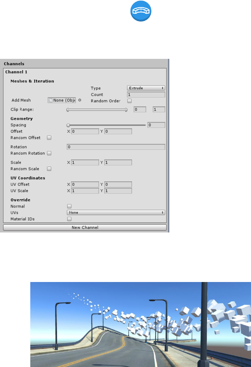
5.14. Spline Mesh : MeshGenerator
This is a universal component for extruding and placing meshes along a spline. It produces a
single mesh which can have multiple material IDs.
The Spline Mesh component
contains channels which contain
meshes. Each channel is computed
independently which makes it possible
for complex meshes with lots of
different elements to be composed.
As soon as a channel has a
single mesh assigned to it, the mesh
will be extruded along the spline.
Adding more meshes will cause the
channel to iterate through them in the
order of adding. It is possible to
randomize the iteration by checking
the “Random Order” checkbox. Note
that when more than one meshes are
added to a channel, they will not
appear unless the channel’s mesh
count (to the right) is set to at least the
number of the meshes.
There are two types of channels:
• Extrude – deforms the meshes along the spline
• Place – places the meshes along the spline without deforming
Dreamteck Splines – User Manual
48
Each channel has its own clip range which defines the spline region it is going to take up.
When a mesh is added to a channel, it can be edited prior to the generation. This helps for
correcting pivot orientations, unwanted offsets or sizes. To configure a mesh, click on it in the Channel
tab – it will open the Configure mesh window:
It is also possible to use a custom handler function for controlling the offset, rotation and scale
along the extrusion. This can be used for some interesting effects and deformations (see API Reference).
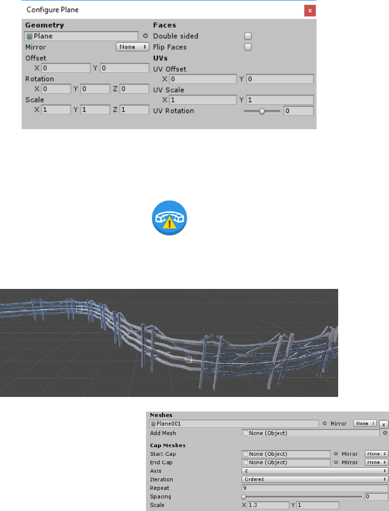
5.15. Extrude Mesh : MeshGenerator
The Extrude Mesh component extrudes a mesh along a spline. This component is now
deprecated in favor of Spline Mesh.
When an Extrude Mesh component
is added it will require at least one input
mesh. Input meshes can be added using the
Add Mesh object field. This object field
accepts Game Objects and Renderers too. If
a Game Objects is passed, it will try to find a
Mesh Renderer in the object. If a Mesh
Renderer is found, then the Mesh Renderer’s mesh and materials will be used for the Extrude Mesh
object. After the first mesh is added it will appear in the inspector and will get extruded in the scene.
Dreamteck Splines – User Manual
49
Since 1.0.7 the ExtrudeMesh component can work with more than one mesh and can have cap
meshes. Each mesh can be mirrored so when cap meshes are needed only one mesh can be modeled for
one of the caps and then mirrored for the other cap.
When multiple meshes are added, the ExtrudeMesh component will iterate through them in the
order they are added but this can be changed by setting the Iteration property to “Random”.
Once a mesh is set, it will automatically get extruded along the spline. The Axis dropdown menu
changes the axis along which the mesh will be extruded. Repeat controls how many times the mesh will
be repeated.
Increasing the Spacing will add space between each
repeat. The Spacing actually shrinks the mesh along the
extrude axis. A spacing of 1 will result in an infinitely
thin mesh while a spacing of 0 will result in stretched
meshes without space in between.
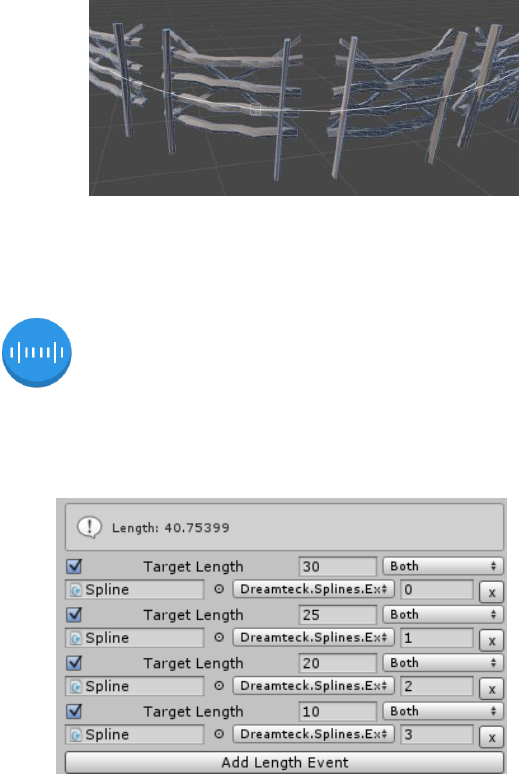
5.16. Length Calculator
A basic component which calculates the length of the spline using the approximation rate defined by
the Spline Computer’s precision and the Resolution of the Length Calculator component.
The Length Calculator can have length events
added to it which fire when the spline has reached a
certain length.
To add an event, click the “Add Length Event”
button. This will create a new empty event. Set the
“target length” value to the value that should be
listened for, select the target object (an object with
a certain behavior), select the method and assign
the argument’s value. The Dropdown menu tells the
Length Calculator when to listen for the specific event.
• Growing: will invoke the event when the target length has been reached by growing
• Shrinking: will invoke the event when the target length has been reached by shrinking
• Both: will invoke the event when this value has been reached or passed in both directions
Dreamteck Splines – User Manual
50
This component has one additional module that controls its behavior. Refer to Triggers and Modules
for more information.
5.17. Polygon Collider Generator
As the name suggests, this component generates a 2D Polygon Collider to be used with 2D
physics. The collider is immediately updated on change in the editor and has an update interval
property used to restrict the number of updates during runtime.
The Polygon Collider Generator has two modes:
• Path: creates a path along the spline, much like the Path Generator
• Surface: creates a solid shape, much like the surface generator
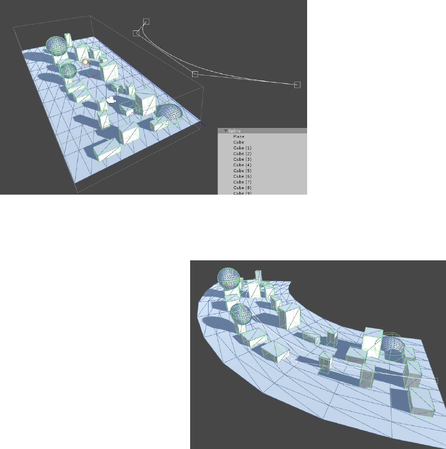
5.18. Object Bender
The purpose of the Object Bender is to bend a game object and all of its children along a spline.
The Object Bender will position and orient all of the objects in the hierarchy along the spline. The
difference between the Object Bender and the Object Controller however is that the Object Bender
will also bend any Meshes, MeshColliders and SplineComputers in the hierarchy.
When an Object Bender is added in the editor or in runtime, it will be in edit mode by default.
This means that the object bender will not work. The edit mode allows the developer to edit the
children in the hierarchy.
Dreamteck Splines – User Manual
51
In edit mode, the
ObjectBender editor will
visualize the bounds of the
parent object and all of the
children in the hierarchy.
These bounds include the
Transform components,
meshes, colliders and
SplineComputers.
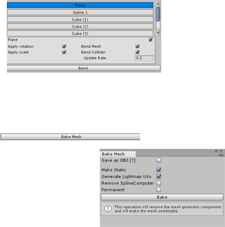
When in edit mode,
there is a “Bend” button at
the bottom of the
ObjectBender’s inspector.
Clicking it will exit edit mode and will start bending the objects along the spline.
When in Bend mode, all objects will
be controlled by the spline. Each object
from the hierarchy will be editable after
it has been bent but if the spline
updates, it will get recalculated and
repositioned.
In Bend mode, the “Bend” button
will be replaced with an “Enter edit
mode” button which will revert the bend
and enable editing.
The ObjectBender bends all the objects along one of the three local axes. The axes are local to
the parent object. The bend axis can be selected through the ObjectBender’s inspector and will be
applied immediately even if the ObjectBender is in edit mode.
The ObjectBender component gives complete control over what is bent and how it’s bent. A
bend property is created for each object from the hierarchy. Each bend property allows the developer to
toggle certain aspects of the bending process on and off for each object individually or toggle off
bending for the object completely.
All bend properties are automatically exposed in the inspector. Clicking on a property will
highlight it in blue and will open the property editor. Several properties can be edited simultaneously.
Dreamteck Splines – User Manual
52
To select multiple properties, hold down Ctrl and click on properties to add them to the selection. Shift +
click will select multiple properties in a row.
6. Baking Mesh Generators
Starting with version 1.0.4, each MeshGenerator component can be baked into a static mesh
with lightmap UVs. To do that, click the “Bake Mesh” button at the bottom of the MeshGenerator’s
inspector. This will open the Bake Mesh window.
The Bake Mesh window provides a range of settings
for baking and a Bake button.
• Save as OBJ will save the baked mesh as an OBJ
file in the Assets folder so it can be used later
again in another scene or in a prefab.
• Make static will make the object static when
bake is finished.
• Generate Lightmap UVs will generate lightmap
UVs for the baked mesh so it can be properly lightmapped.
• Remove computer will remove the SplineComputer component that is referenced by the Mesh
Generator
• Permanent will remove the Mesh Generator component making the bake permanent.
Otherwise the Mesh Generator will be left and be disabled so it could be re-enabled later.
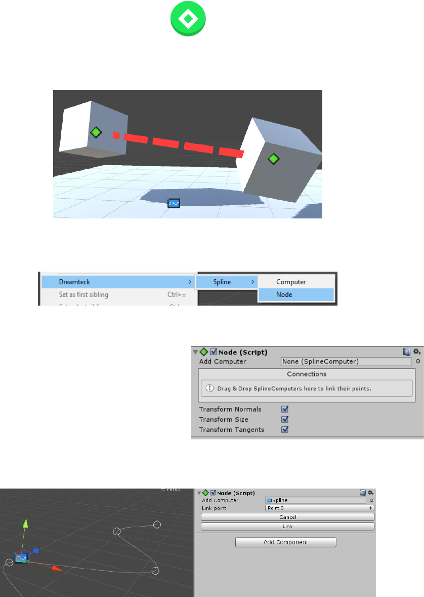
Dreamteck Splines – User Manual
53
7. Nodes
Nodes are a key feature and serve two very important purposes - to bind points of Spline Computers
to other scene objects and to create junctions.
To create a Node, go to Game Object->Dreamteck->Spline->Node. This will create a new Game
Object with a Node component in the scene.
Another way to create a Node is just by adding a Node component to an existing object.
The newly created node will be empty and
will require a connection to be added. To add a
connection, drag a Game Object with a Spline
Computer from the scene into the Connections
box or select it through the object field above the
connections box.
When a Spline Computer is added, its points will visualize as circles and a point dropdown menu
will be shown in the inspector.
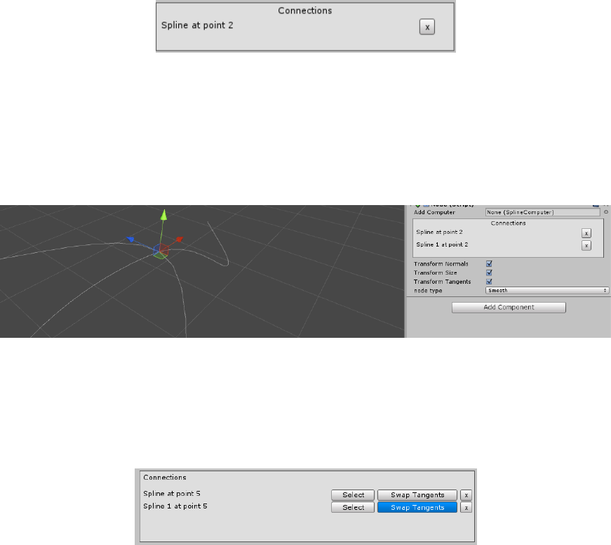
Dreamteck Splines – User Manual
54
The Node will now require a point from the Spline Computer to be selected. To select a point
either select it from the dropdown menu and click “Link” or click on a point in the scene view. After a
point is selected, a new connection will be added in the Node. The new connection will be listed in the
Connections box.
After a connection is added, the spline point of the added Spline Computer will snap to the
Node’s transform. The Node’s Transform can then be animated or a Rigidbody can be attached and
when the Node moves, the connected point will also be updated.
A Node can have more than one Spline Computer connected to it. Repeat the procedure with
another Spline Computer to add a new connection.
When editing a point that is connected to a Node in the Spline Editor, the node’s position will
also be updated and therefore all the other Spline Computers connected to it.
Since version 1.0.8 the connections box has two new buttons – the Select button and the Swap
tangents button:
Clicking the Select button will select the given spline in the Unity editor. The Swap tangents
button is available if the spline is of Bezier type. Clicking it will swap the tangent direction for the
connected point.
7.1. Junctions
When two Spline Computers are connected to the same Node, this is considered a junction. Each
Spline User has its own junction address that defines which parts of the connected splines are being
traversed.
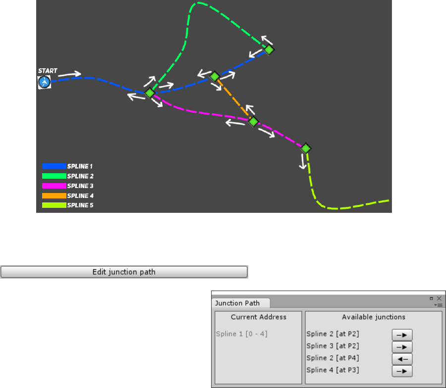
Dreamteck Splines – User Manual
55
A user’s junction address can be set up if its base computer has at least one junction. When this
condition is met, an “Edit junction path” button will appear in the inspector of the Spline User.
Clicking this button will open up the Junction
Path window. This window lets the developer
pick the paths and directions through which the
Spline User will traverse.
The Junction Path window consists of two
panels: Current address and Available junctions.
The Current Address holds the current address of the Spline User. It shows all connections and
directions. Each element in the Current Address can be exited using the “x” button.
The Available Junctions panel shows the available junctions ahead of the last connection. In the
above case, starting from point 0 of Spline 1 there are four available connections. Each connection has a
button with an arrow next to it. Clicking the button will enter the given connection. If the arrow points
to the left, the entered Spline Computer will be traversed backwards and if the arrow points to the right,
the entered Spline Computer will be traversed forwards.
EXAMPLE:
Using the above setup, a new white Spline Renderer is added to the scene. Its computer reference is
set to Spline 1. When opening the Junction Path window, the same options as above are displayed.
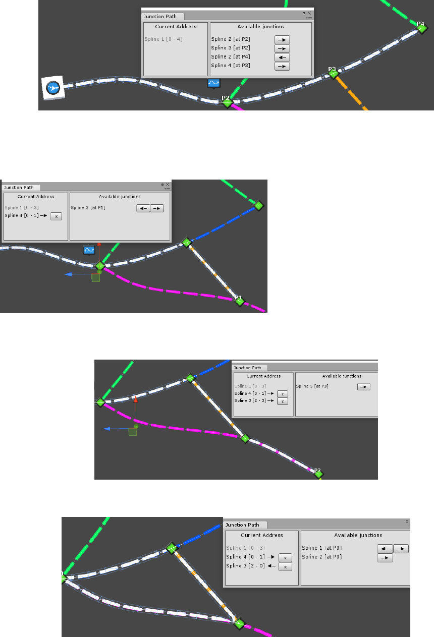
Dreamteck Splines – User Manual
56
In this example, the connection with Spline 4 at point 3 is chosen and the arrow button next to it is
clicked in the Available junctions. Right away, Spline 4 is added to the current address and the Spline
Renderer takes on its new path.
The newly entered Spline 4 has
another junction ahead so it’s immediately
listed in the Available Junctions panel. This
junction could be entered backwards or
forwards and therefore there are both a
left and a right arrow available.
Clicking the Right arrow will enter Spline 3 forwards:
And clicking the left arrow will enter Spline 3 backwards:
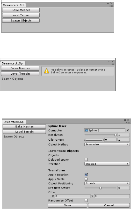
Dreamteck Splines – User Manual
57
There is no limit to how long the Spline Address can be but when entering addresses at runtime
(refer to the Scripting Reference document) it’s usually a good practice not to go in circles and enter the
same segments again and again.
8. Editor Tools
The Spline User is a component that is mostly meant to work in runtime although it can be
configured in the editor. Sometimes, however, level designers just need a tool to help them in the
work process. For pure level design purposes, Dreamteck Splines offers the Spline Tools window
which is located in Window->Dreamteck->Spline Tools
This will open a window with a set of tools for level editing:
Each tool can be selected by clicking on its button. Some tools require an object with a Spline
Computer to be selected in the editor in order to work. Otherwise a warning will be displayed:
If this warning appears, go to the scene’s hierarchy, select a Spline Computer and click on the
tools window again. This will update it and the warning will disappear.
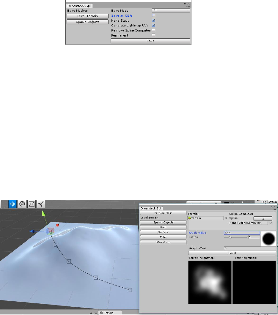
Dreamteck Splines – User Manual
58
8.1. Mass Baking Spline-generated Meshes
If a lot of Mesh Generators need to be baked simultaneously, the Bake Meshes tool can help
with that. It does not need a Spline Computer to be selected in order to work and can be opened
right away.
There are three bake modes:
• All: Bakes all Mesh Generators in the scene
• Selected: Bakes only the selected Mesh Generators
• AllExcluding: Bakes all Mesh Generators except for the selected ones
When “Save OBJs” is checked the bake operation will save all meshes as OBJ files in the selected
directory. Meshes with the same names will be renamed with a number to prevent overwriting.
8.2. Leveling terrain
The Level Terrain tool is an editor-only tool meant for sculpting terrains using splines.
For the Level Terrain tool to work, the scene needs to have at least one terrain and a Spline
Computer needs to be selected. If the scene has more than one terrain, the terrain that should be
leveled should also be selected along with the Spline Computer.
Once open, the Level Terrain tool will display a preview of the terrain’s heightmap, the path
heightmap which will be black and a preview of the brush feather.
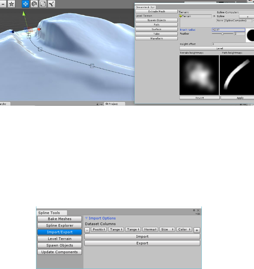
Dreamteck Splines – User Manual
59
The tool has only three settings:
• Brush Radius – the radius of the brush in world units
• Feather – the feather of the brush
• Height Offset – height offset
To level the terrain using the selected spline(s), click the “Level” button. The path heightmap will
be drawn and the terrain will be sculpted.
An “Apply” and “Revert” buttons will appear under the heightmap previews. If the result is not
satisfying, edit the spline and the settings and click Level again – the previous level will get replaced with
the new one. To save the terrain, click “Apply” – this will write the level data to the terrain permanently.
The brush radius is affected by the sizes of the points.
8.3. Import/Export
Version 1.0.8 introduces a new import and export tool which is capable of importing splines
from external files and exporting splines to external files. The currently supported formats are SVG
and CSV datasets.
8.3.1. Importing
The import tool is pretty straightforward. To import an SVG or a CSV file click the “Import”
button. This will open a new file browser. Navigating to the desired SVG or CSV file and clicking
“Open” will instantly import the splines from the file in the Unity scene.
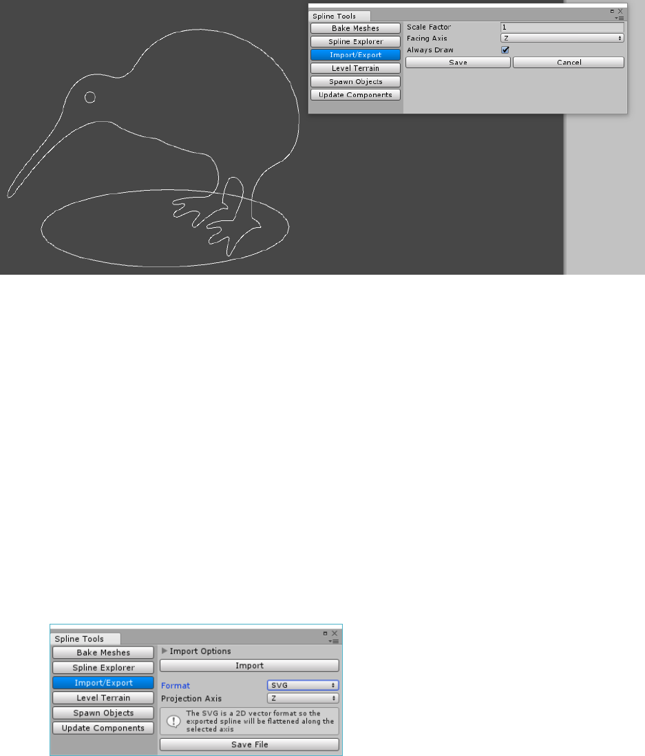
Dreamteck Splines – User Manual
60
WARNING: Splines from SVG files are usually very big, about the size of a Canvas or even
bigger. If the imported SVG spline isn’t visible after import, make sure to zoom-out further in the
scene.
After the spline has been imported, a new object with the name of the file will be created in the
scene and the import tool’s panel will display some importing options:
• Scale Factor – This is the scale factor of the imported graphic. A scale factor of 1 will
retain the size of the graphic.
• Facing axis – The orientation of the imported graphic. By default it is Z which means no
rotation
• Always draw – Should the splines be drawn in the scene constantly after closing the
import tool?
8.3.2. Exporting
To export one or more splines, the splines first have to be selected in the scene. If no splines are
selected in the scene, the export button will be unavailable.
When the export mode is toggled, a Format dropdown menu will be available, allowing the user
to select between SVG and CSV.
8.3.2.1. Exporting SVG
Since the SVG is a 2D vector format, when a spline is exported to SVG it is flattened.
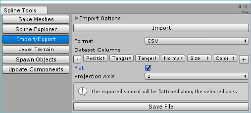
Dreamteck Splines – User Manual
61
The projection axis dropdown menu defines the axis along which the spline will be
flattened and projected onto the SVG canvas.
8.3.2.2. Exporting CSV
The CSV export creates a new Excel file with each spline point’s data written on each row.
The Dataset columns field allows for customization of the columns that will be written in the
CSV file. For example if only the points’ positions are needed, all columns except the position
column should be removed.
CSV Export also supports flattening. If “Flat” is toggled, a projection axis dropdown menu is
presented.
9. Performance, Oprimization and under the hood
Dreamteck Splines is optimized for speed and runs smoothly on all mobile devices, including
older ones. This chapter will go over the main concepts behind the system’s design and shed some
light on how the main components – the SplineComputer and the SplineUser work.
9.1. What impacts performance and what doesn’t?
A common question among the developers using Dreamteck Splines is “How big a spline can be
before there is a performance drop?”
The short answer is:
There is no limit to the length of the spline and this doesn’t impact the performance.
This is true, because when a SplineComputer is added to the scene, it doesn’t do any
calculations at all. Spline calculations are done when the following methods are called:
• SplineComputer.Evaluate
• SplineComputer.EvaluatePosition
• SplineComputer.Travel
• SplineComputer.Project
• SplineComputer.CalculateLength
Dreamteck Splines – User Manual
62
Having a SplineComputer in the scene by itself doesn’t cause any of the aforementioned
methods to be called.
However, as soon as a SplineUser is added, things change. By design, the SplineUser component
iterates over the referenced SplineComputer and caches all of the sample results in an array called
“samples”. This doesn’t happen every frame – it only happens when there has been a change in the
spline. This includes moving the SplineComputer’s transform in Local space mode. So after the
SplineUser samples the referenced computer, it does no further calculations until another change is
present. This means that even if the spline is very big and the sampling process takes a long time,
the framerate will be restored after the initial hiccup. But this concerns only very big splines with
high precision. Usually a calculation hiccup is not present. If a very big spline needs to be re-sampled
oftenly, consider toggling the multithreading option of the SplineUser component – this will take the
spline calculation to another thread and will free up the performance of the main game thread.
9.1.1. What happens if multiple SplineUsers sample a single spline?
When multiple user sample a single spline, they all re-sample the spline on their own and a
cached version of the spline is kept for each user. Sampling a spline twice is not an optimal
solution and this is why the SplineUser sample mode has been introduced. This sampling mode
lets the SplineUsers read from the samples of another SplineUser which samples the
SplineComputer instead of re-sampling the SplineComputer by themselves.
9.1.2. Does having many SplineComputer components in the scene hurt performance?
As mentioned above, the SplineComputer by itself doesn’t re-calculate the spline so there will
be no Spline calculations. However, in order to ensure that the splines will be updated properly
when the SplineComputer’s transform changes, there will be a couple of if-checks during update.
This means that having several thousand SplineComputers in the scene will indeed take up
performance. However, having thousands of active monobehaviours is rarely the case in Unity .
9.1.2.1. How to optimize if a thousand SplineComputers are present?
The easiest way to optimize would be to disable all SplineComputer components. This will not
disable the splines, but will disable the checks every frame. Then whenever you need a computer
updated, either enable while its needed or call ResampleTransform() on it.
9.1.3. What happens when a scene, full of SplineComputers and SplineUsers loads?
The initial load time of a scene is important and so it’s important to discuss what happens when
a new scene full of spline objects is loaded.
When a SplineUser samples a SplineComputer and caches it into its memory, the samples get
serialized, meaning that when a new scene is loaded, there is no need for the SplineUser to re-
sample the computer it’s referencing. So the short answer to this questions is:
There is no performance overhead when a new scene is loaded.
However, there is one exception. SplineUsers set to build on awake will re-sample the
referenced spline on awake regardless of whether there is a change in the spline or not.
Dreamteck Splines – User Manual
63
9.2. What each Evaluate method does
In Dreamteck Splines, a couple of methods with the same name can be found in several classes.
These methods are:
• Evaluate
• EvaluatePosition
• Travel
• CalculateLength
• Project
They can be found in the Spline class, as well as in SplineComputer, SplineUser and
SplineAddress. So what is the difference between all of them?
9.2.1. Methods in Spline
The Spline class represents a spline in world coordinates. It isn’t transformed by any transform
and it isn’t used directly by any SplineUser component. Instead, it is wrapped by the SplineComputer
class.
Creating a new Spline object and calling one of the listed above methods will call the internal
spline calculation methods of the Spline class. This is considered expensive if done many times per
frame.
9.2.2. Methods in SplineComputer
The SplineComputer class creates a Spline instance and then transforms it using its own
Transform component.
Calling one of the methods listed above on SplineComputer will call them on Spline and then will
transform the result using the Transform component. If the space is set to Local, this will be more
expensive than calling the methods on Spline because of the additional transformation that takes
place after the result is calculated.
9.2.3. Methods in SplineAddress
The SplineAddress is just a collection of SplineComputers and their connection points so calling
any of the methods on a SplineAddress object, will call these methods on a single Computer from
the listed ones in the SplineAddress object.
9.2.4. Methods in SplineUser
Since the SplineUser samples a SplineComputer and caches the result, calling one of the
methods on a SplineUser object will not cause the spline to be recalculated. Instead, the cached
results will be interpolated to find the best value that fits the arguments.
This is very fast since there are no spline calculations and no transformations.
Dreamteck Splines – User Manual
64
9.3. Does the clip range of the SplineUser control the sample count?
The answer is no. When a SplineUser samples a SplineComputer, it samples the whole spline
computer completely and stores the samples in the samples array. If the clip range is modified to be
smaller than [0-1], the spline will not be re-evaluated. The clip range only defines what portion of
the already evaluated results to use. This ensures that no spline calculations will be performed if a
SplineUser’s clip range is changed.
10. Writing a custom SplineUser class
Dreamteck Splines’ functionality can be expanded easily by creating new SplineUser components.
For a SplineUser class to be created it needs to derive from the SplineUser base class. Before deriving
the class from SplineUser, the following using directive should be added to the new script:
using Dreamteck.Splines;
A basic SplineUser example is provided in the Components folder. It can be used as a template for
creating SplineUsers.
10.1. Protected and virtual Methods
Each SplineUser class inherits a set of methods which are automatically called. These methods are
automatically called and should be overridden in order to create custom functionality.
SplineUser classes are not supposed to have Update, FixedUpdate and LateUpdate methods. They
can have a Start method and an Awake method through overriding:
protected override void Awake()
{
base.Awake();
//Code here
}
10.1.1. Protected virtual void Run()
Run is called automatically on Update, FixedUpdate or LateUpdate based on the Update Method
setting of the SplineUser. It’s mainly used for game logic that will run on each update cycle.
10.1.2. Protected virtual void Build()
Build is called when there has been a change in the spline user. For example if the spline has
changed or a property of the SplineUser has been set. Build can either be called from the main thread or
from a separate one if multithreading is enabled. Therefore it is advised that there should be only
thread-safe code inside. Make call calculations inside Build and then apply them in PostBuild.
10.1.3. Protected virtual void PostBuild()
PostBuild is always called on the main thread after Build has finished even if multithreading is
enabled. It’s used to apply the results, calculated in Build(). For example if the custom SplineUser will

Dreamteck Splines – User Manual
65
position objects along path. The objects’ positions should be calculated in Build and then applied to the
objects’ transforms in PostBuild().
10.2. Rebuilding
The SplineUser class has the Rebuild(bool sampleComputer) method which forces the user to
recalculate on the next update cycle.
SplineUsers rebuild automatically when their spline is modified or their properties are changed. That
however does not happen when the properties of custom SplineUser classes are modified. In order to
make the SplineUser class rebuild, custom setters should be implemented that call the Rebuild method.
Example:
private bool _state = false;
public bool state
{
get { return _state; }
set
{
if (value != _state) //Only rebuild if the value is different
{
_state = value;
Rebuild(false); //Rebuild but don’t resample the spline
}
}
}
Rebuild is a public method so it can also be called from another object. Rebuilding happens once per
update cycle no matter how many times it’s called prior to that.
10.2.1. RebuildImmediate
Rebuild waits for the next update cycle so calling it will not yield any changes immediately. In some
cases, however, rebuild should happen on demand and that’s what RebuildImmediate(bool
sampleComputer) is for. RebuildImmediate calls he rebuild sequence regardless of update cycles
and will yield results immediately.
Calling RebuildImmediately multiple times per update cycle will cause the SplineUser to rebuild as
many times as RebuildImmediately is called.
