INET Framework User's Guide Users
User Manual:
Open the PDF directly: View PDF ![]() .
.
Page Count: 174 [warning: Documents this large are best viewed by clicking the View PDF Link!]
- Introduction
- Using the INET Framework
- Networks
- Network Nodes
- Network Interfaces
- Applications
- Transport Protocols
- The IPv4 Protocol Family
- IPv6 and Mobile IPv6
- Other Network Protocols
- Internet Routing
- Ad Hoc Routing
- Differentiated Services
- The MPLS Models
- Point-to-Point Links
- The Ethernet Model
- The 802.11 Model
- The 802.15.4 Model
- MAC Protocols for Wireless Sensor Networks
- The Physical Layer
- The Transmission Medium
- The Physical Environment
- Node Mobility
- Modeling Power Consumption
- Network Emulation
- Network Autoconfiguration
- Scenario Scripting
- Modeling Node Failures
- Collecting Results
- Visualization
- Instrument Figures
- Appendix: Author’s Guide
- History

INET Framework User’s Guide
OpenSim Ltd.
Jan 30, 2019

CONTENTS
1 Introduction 3
1.1 What is INET Framework ............................ 3
1.2 Designed for Experimentation .......................... 3
1.3 Scope of this Manual ............................... 4
2 Using the INET Framework 5
2.1 Installation .................................... 5
2.2 Installing INET Extensions ........................... 5
2.3 Getting Familiar with INET ........................... 6
3 Networks 7
3.1 Overview ..................................... 7
3.2 Built-in Network Nodes and Other Top-Level Modules ............. 7
3.3 Typical Networks ................................. 9
3.4 Frequent Tasks (How To. . . ) ........................... 11
4 Network Nodes 15
4.1 Overview ..................................... 15
4.2 Ingredients .................................... 15
4.3 Node Architecture ................................ 16
4.4 Customizing Nodes ............................... 17
4.5 Custom Network Nodes ............................. 18
5 Network Interfaces 21
5.1 Overview ..................................... 21
5.2 Built-in Network Interfaces ........................... 21
5.3 Anatomy of Network Interfaces ......................... 22
5.4 The Interface Table ................................ 24
5.5 Wired Network Interfaces ............................ 24
5.6 Wireless Network Interfaces ........................... 24
5.7 Special-Purpose Network Interfaces ....................... 26
5.8 Custom Network Interfaces ........................... 27
6 Applications 29
6.1 Overview ..................................... 29
6.2 TCP applications ................................. 29
6.3 UDP applications ................................. 32
i

6.4 IPv4/IPv6 traffic generators ........................... 34
6.5 The PingApp application ............................. 35
6.6 Ethernet applications ............................... 35
7 Transport Protocols 37
7.1 Overview ..................................... 37
7.2 TCP ........................................ 37
7.3 UDP ....................................... 40
7.4 SCTP ....................................... 41
7.5 RTP ........................................ 41
8 The IPv4 Protocol Family 43
8.1 Overview ..................................... 43
8.2 Ipv4 ........................................ 44
8.3 Ipv4RoutingTable ................................ 44
8.4 Icmp ....................................... 45
8.5 Arp ........................................ 45
8.6 Igmp ....................................... 46
9 IPv6 and Mobile IPv6 49
9.1 Overview ..................................... 49
10 Other Network Protocols 51
10.1 Overview ..................................... 51
10.2 Protocols ..................................... 52
10.3 Address Types .................................. 53
10.4 Address Resolution ................................ 53
11 Internet Routing 55
11.1 Overview ..................................... 55
11.2 RIP ........................................ 55
11.3 OSPF ....................................... 56
11.4 BGP ....................................... 57
12 Ad Hoc Routing 61
12.1 Overview ..................................... 61
12.2 AODV ...................................... 61
12.3 DSDV ...................................... 62
12.4 DYMO ...................................... 62
12.5 GPSR ....................................... 62
13 Differentiated Services 63
13.1 Overview ..................................... 63
13.2 Architecture of NICs ............................... 64
13.3 Simple modules ................................. 65
13.4 Compound modules ............................... 71
14 The MPLS Models 75
14.1 Overview ..................................... 75
ii

14.2 Core Modules .................................. 75
14.3 Classifier ..................................... 79
14.4 MPLS-Enabled Router Models ......................... 79
15 Point-to-Point Links 81
15.1 Overview ..................................... 81
15.2 The PPP module ................................. 81
15.3 PppInterface ................................... 82
16 The Ethernet Model 83
16.1 Overview ..................................... 83
16.2 Nodes ....................................... 83
16.3 The Physical Layer ................................ 84
16.4 Ethernet Interface ................................ 85
16.5 Components ................................... 85
16.6 Implemented Standards ............................. 87
17 The 802.11 Model 89
17.1 Overview ..................................... 89
17.2 MAC ....................................... 90
17.3 Physical Layer .................................. 91
17.4 Management ................................... 91
17.5 Agent ....................................... 91
18 The 802.15.4 Model 93
18.1 Overview ..................................... 93
18.2 Network Interfaces ................................ 93
18.3 Physical Layer .................................. 94
18.4 MAC Protocol .................................. 94
19 MAC Protocols for Wireless Sensor Networks 95
19.1 Overview ..................................... 95
19.2 B-MAC ...................................... 95
19.3 L-MAC ...................................... 95
19.4 X-MAC ...................................... 96
20 The Physical Layer 97
20.1 Overview ..................................... 97
20.2 Generic Radio .................................. 97
20.3 Components of a Radio ............................. 98
20.4 Layered Radio Models ..............................100
20.5 Notable Radio Models ..............................101
21 The Transmission Medium 103
21.1 Overview .....................................103
21.2 RadioMedium ..................................103
21.3 Propagation Models ...............................104
21.4 Path Loss Models ................................105
21.5 Obstacle Loss Models ..............................105
iii

21.6 Background Noise Models ............................106
21.7 Analog Models ..................................106
21.8 Neighbor Cache .................................107
21.9 Medium Limit Cache ...............................108
21.10 Communication Cache ..............................108
21.11 Improving Scalability ..............................108
22 The Physical Environment 111
22.1 Overview .....................................111
22.2 PhysicalEnvironment ...............................111
22.3 Physical Objects .................................112
22.4 Ground Models ..................................113
22.5 Geographic Coordinate System Models .....................113
22.6 Object Cache ...................................114
23 Node Mobility 115
23.1 Overview .....................................115
23.2 Built-In Mobility Models ............................116
24 Modeling Power Consumption 123
24.1 Overview .....................................123
24.2 Energy Consumer Models ............................123
24.3 Energy Generator Models ............................124
24.4 Energy Storage Models .............................125
24.5 Energy Management Models ...........................125
25 Network Emulation 127
25.1 Motivation ....................................127
25.2 Overview .....................................127
25.3 Preparation ....................................128
25.4 Configuring ....................................128
26 Network Autoconfiguration 131
26.1 Overview .....................................131
26.2 Configuring IPv4 Networks ...........................131
26.3 Configuring Layer 2 ...............................142
27 Scenario Scripting 143
27.1 Overview .....................................143
27.2 ScenarioManager .................................143
28 Modeling Node Failures 145
28.1 Overview .....................................145
28.2 NodeStatus ....................................146
28.3 Scripting .....................................146
29 Collecting Results 149
29.1 Recording Statistics ...............................149
29.2 Recording PCAP Traces .............................149
iv

29.3 Recording Routing Tables ............................149
29.4 Packet Recorder .................................149
29.5 Eventlog Recording ...............................149
30 Visualization 151
30.1 Overview .....................................151
30.2 Visualizing Network Communication ......................151
30.3 Visualizing The Infrastructure ..........................156
31 Instrument Figures 159
31.1 Overview .....................................159
31.2 Instrument Types .................................159
31.3 Using Instrument Figures ............................161
31.4 Instrument Figure Attributes ...........................162
32 Appendix: Author’s Guide 163
32.1 Overview .....................................163
32.2 Guidelines ....................................163
33 History 165
33.1 IPSuite to INET Framework (2000-2006) ....................165
v

vi

INET Framework User’s Guide
This manual is written for users who are interested in assembling simulations using the compo-
nents provided by the INET Framework. (In contrast, if you are interested in modifing INET’s
components or plan to extend INET with new protocols or other components using C++, we
recommend the INET Developer’s Guide.)
CONTENTS 1

INET Framework User’s Guide
2 CONTENTS

CHAPTER
ONE
INTRODUCTION
1.1 What is INET Framework
INET Framework is an open-source model library for the OMNeT++ simulation environment.
It provides protocols, agents and other models for researchers and students working with com-
munication networks. INET is especially useful when designing and validating new protocols,
or exploring new or exotic scenarios.
INET supports a wide class of communication networks, including wired, wireless, mobile,
ad hoc and sensor networks. It contains models for the Internet stack (TCP, UDP, IPv4, IPv6,
OSPF, BGP, etc.), link layer protocols (Ethernet, PPP, IEEE 802.11, various sensor MAC proto-
cols, etc), refined support for the wireless physical layer, MANET routing protocols, DiffServ,
MPLS with LDP and RSVP-TE signalling, several application models, and many other pro-
tocols and components. It also provides support for node mobility, advanced visualization,
network emulation and more.
Several other simulation frameworks take INET as a base, and extend it into specific directions,
such as vehicular networks, overlay/peer-to-peer networks, or LTE.
1.2 Designed for Experimentation
INET is built around the concept of modules that communicate by message passing. Agents
and network protocols are represented by components, which can be freely combined to form
hosts, routers, switches, and other networking devices. New components can be programmed
by the user, and existing components have been written so that they are easy to understand and
modify.
INET benefits from the infrastructure provided by OMNeT++. Beyond making use of the
services provided by the OMNeT++ simulation kernel and library (component model, param-
eterization, result recording, etc.), this also means that models may be developed, assembled,
parameterized, run, and their results evaluted from the comfort of the OMNeT++ Simulation
IDE, or from the command line.
INET Framework is maintained by the OMNeT++ team for the community, utilizing patches
and new models contributed by members of the community.
3

INET Framework User’s Guide
1.3 Scope of this Manual
This manual is written for users who are interested in assembling simulations using the compo-
nents provided by the INET Framework. (In contrast, if you are interested in modifing INET’s
components or plan to extend INET with new protocols or other components using C++, we
recommend the INET Developers Guide.)
This manual does not attempt to be a reference for INET. It concentrates on conveying the
big picture, and does not attempt to cover all components, or try to document the parameters,
gates, statistics or precise operation of individual components. For such information, users
should refer to the INET Reference, a web-based cross-referenced documentation generated
from NED and MSG files.
A working knowledge of OMNeT++ is assumed.
4 Chapter 1. Introduction

CHAPTER
TWO
USING THE INET FRAMEWORK
2.1 Installation
There are several ways to install the INET Framework:
• Let the OMNeT++ IDE download and install it for you. This is the easiest way. Just
accept the offer to install INET in the dialog that comes up when you first start the IDE,
or choose Help →Install Simulation Models any time later.
• From INET Framework web site, http://inet.omnetpp.org. The IDE always installs the
last stable version compatible with your version of OMNeT++. If you need some other
version, they are available for download from the web site. Installation instructions are
also provided there.
• From GitHub. If you have experience with git, clone the INET Framework project
(inet-framework/inet), check out the revision of your choice, and follow the IN-
STALL file in the project root.
2.2 Installing INET Extensions
If you plan to make use of INET extensions (e.g. Veins or SimuLTE), follow the installation
instructions provided with them.
In the absence of specific instructions, the following procedure usually works:
• First, check if the project root contains a file named .project.
• If it does, then the project can be imported into the IDE (use File →Import →General
→Existing Project into workspace). Make sure that the project is recognized as an
OMNeT++ project (the Project Properties dialog contains a page titled OMNeT++), and
it lists the INET project as dependency (check the Project References page in the Project
Properties dialog).
• If there is no .project file, you can create an empty OMNeT++ project using the New
OMNeT++ Project wizard in File →New, add the INET project as dependency using the
Project References page in the Project Properties dialog, and copy the source files into
the project.
5

INET Framework User’s Guide
2.3 Getting Familiar with INET
The INET Framework builds upon OMNeT++, and uses the same concept: modules that com-
municate by message passing. Hosts, routers, switches and other network devices are rep-
resented by OMNeT++ compound modules. These compound modules are assembled from
simple modules that represent protocols, applications, and other functional units. A network is
again an OMNeT++ compound module that contains host, router and other modules.
Modules are organized into a directory structure that roughly follows OSI layers:
•src/inet/applications/ – traffic generators and application models
•src/inet/transportlayer/ – transport layer protocols
•src/inet/networklayer/ – network layer protocols and accessories
•src/inet/linklayer/ – link layer protocols and accessories
•src/inet/physicallayer/ – physical layer models
•src/inet/routing/ – routing protocols (internet and ad hoc)
•src/inet/mobility/ – mobility models
•src/inet/power/ – energy consumption modeling
•src/inet/environment/ – model of the physical environment
•src/inet/node/ – preassembled network node models
•src/inet/visualizer/ – visualization components (2D and 3D)
•src/inet/common/ – miscellaneous utility components
The OMNeT++ NED language uses hierarchical packages names. Packages correspond to
directories under src/, so e.g. the src/inet/transportlayer/tcp directory corre-
sponds to the inet.transportlayer.tcp NED package.
For modularity, the INET Framework has about 80 project features (parts of the codebase that
can be disabled as a unit) defined. Not all project features are enabled in the default setup
after installation. You can review the list of available project features in the Project →Project
Features. . . dialog in the IDE. If you want to know more about project features, refer to the
OMNeT++ User Guide.
6 Chapter 2. Using the INET Framework

CHAPTER
THREE
NETWORKS
3.1 Overview
INET heavily builds upon the modular architecture of OMNeT++. It provides numerous do-
main specific and highly parameterizable components which can be combined in many ways.
The primary means of building large custom network simulations in INET is the composition
of existing models with custom models, starting from small components and gradually form-
ing ever larger ones up until the composition of the network. Users are not required to have
programming experience to create simulations unless they also want to implement their own
protocols, for example.
Assembling an INET simulation starts with defining a module representing the network. Net-
works are compound modules which contain network nodes, automatic network configurators,
and sometimes additionally transmission medium, physical environment, various visualizer,
and other infrastructure related modules. Networks also contain connections between network
nodes representing cables. Large hierarchical networks may be further organized into com-
pound modules to directly express the hierarchy.
There are no predefined networks in INET, because it is very easy to create one, and because
of the vast possibilities. However, the OMNeT++ IDE provides several topology generator
wizards for advanced scenarios.
As INET is an OMNeT++-based framework, users mainly use NED to describe the model
topology, and ini files to provide configuration.1
3.2 Built-in Network Nodes and Other Top-Level Mod-
ules
INET provides several pre-assembled network nodes with carefully selected components. They
support customization via parameters and parametric submodule types, but they are not meant
to be universal. Sometimes it may be necessary to create special network node models for
particular simulation scenarios. In any case, the following list gives a taste of the built-in
network nodes.
1Some components require additional configuration to be provided as separate files, e.g. in XML.
7

INET Framework User’s Guide
•StandardHost contains the most common Internet protocols: UDP, TCP, IPv4, IPv6, Eth-
ernet, IEEE 802.11. It also supports an optional mobility model, optional energy models,
and any number of applications which are entirely configurable from INI files.
•EtherSwitch models an Ethernet switch containing a relay unit and one MAC unit per
port.
•Router provides the most common routing protocols: OSPF, BGP, RIP, PIM.
•AccessPoint models a Wifi access point with multiple IEEE 802.11 network interfaces
and multiple Ethernet ports.
•WirelessHost provides a network node with one (default) IEEE 802.11 network interface
in infrastructure mode, suitable for using with an AccessPoint.
•AdhocHost is a WirelessHost with the network interface configured in ad-hoc mode and
forwarding enabled.
Network nodes communicate at the network level by exchanging OMNeT++ messages which
are the abstract representations of physical signals on the transmission medium. Signals are
either sent through OMNeT++ connections in the wired case, or sent directly to the gate of
the receiving network node in the wireless case. Signals encapsulate INET-specific packets
that represent the transmitted digital data. Packets are further divided into chunks that provide
alternative representations for smaller pieces of data (e.g. protocol headers, application data).
Additionally, there are components that occur on network level, but they are not models of
physical network nodes. They are necessary to model other aspects. Some of them are:
• A radio medium module such as Ieee80211RadioMedium,ApskScalarRadioMedium and
UnitDiskRadioMedium (there are a few of them) are a required component of wireless
networks.
•PhysicalEnvironment models the effect of the physical environment (i.e. obstacles) on
radio signal propagation. It is an optional component.
•Configurators such as Ipv4NetworkConfigurator,L2NetworkConfigurator and Nex-
tHopNetworkConfigurator configure various aspects of the network. For example,
Ipv4NetworkConfigurator assigns IP addresses to hosts and routers, and sets up static
routing. It is used when modeling dynamic IP address assignment (e.g. via DHCP) or
dynamic routing is not of importance. L2NetworkConfigurator allows one to configure
802.1 LANs and provide STP/RSTP-related parameters such as link cost, port priority
and the “is-edge” flag.
•ScenarioManager allows scripted scenarios, such as timed failure and recovery of net-
work nodes.
•Group coordinators are needed for the operation of some group mobility mdels. For
example, MoBanCoordinator is the coordinator module for the MoBAN mobility model.
•Visualizers like PacketDropOsgVisualizer provide graphical rendering of some aspect of
the simulation either in 2D (canvas) or 3D (using OSG or osgEarth). The usual choice is
IntegratedVisualizer which bundles together an instance of each specific visualizer type
in a compound module.
8 Chapter 3. Networks

INET Framework User’s Guide
3.3 Typical Networks
3.3.1 Wired Networks
Wired network connections, for example Ethernet cables, are represented with standard OM-
NeT++ connections using the DatarateChannel NED type. The channel’s datarate and
delay parameters must be provided for all wired connections. The number of wired inter-
faces in a host (or router) usually does not need to be manually configured, because it can be
automatically inferred from the actual number of links to neighbor nodes.
The following example shows how straightforward it is to create a model for a simple wired
network. This network contains a server connected to a router using PPP, which in turn is
connected to a switch using Ethernet. The network also contains a parameterizable number of
clients, all connected to the switch forming a star topology. The utilized network nodes are all
predefined modules in INET. To avoid the manual configuration of IP addresses and routing
tables, an automatic network configurator is also included.
network WiredNetworkExample
{
parameters:
int numClients; // number of clients in the network
submodules:
configurator:Ipv4NetworkConfigurator; // network
˓→autoconfiguration
server:StandardHost; // predefined standard host
router:Router; // predefined router
switch:EtherSwitch; // predefined ethernet switch
client[numClients]:StandardHost;
connections:// network level connections
router.pppg++ <--> { datarate = 1GBps; } <--> server.pppg++;
˓→// PPP
switch.ethg++ <--> Eth1G <--> router.ethg++;//
˓→bidirectional ethernet
for i=0..numClients-1 {
client[i].ethg++ <--> Eth1G <--> switch.ethg++;//
˓→ethernet
}
}
In order to run a simulation using the above network, an OMNeT++ INI file must be created.
The INI file selects the network, sets its number of clients parameter, and configures a simple
TCP application for each client. The server is configured to have a TCP application which
echos back all data received from the clients individually.
network =WiredNetworkExample
*.numClients =10 # number of clients in network
*.client[*].numApps =1# number of applications on clients
*.client[*].app[0].typename ="TcpSessionApp" # client application
˓→type
(continues on next page)
3.3. Typical Networks 9

INET Framework User’s Guide
(continued from previous page)
*.client[*].app[0].connectAddress ="server" # destination address
*.client[*].app[0].connectPort =1000 # destination port
*.client[*].app[0].sendBytes =1MB # amount of data to send
*.server.numApps =1# number of applications on server
*.server.app[0].typename ="TcpEchoApp" # server application type
*.server.app[0].localPort =1000 # TCP server listen port
When the above simulation is run, each client application connects to the server using a TCP
socket. Then each one of them sends 1MB of data, which in turn is echoed back by the server,
and the simulation concludes. The default statistics are written to the results folder of the
simulation for later analysis.
3.3.2 Wireless Networks
Wireless network connections are not modeled with OMNeT++ connections due the dynami-
cally changing nature of connectivity. For wireless networks, an additional module, one that
represents the transmission medium, is required to maintain connectivity information.
network WirelessNetworkExample
submodules:
configurator:Ipv4NetworkConfigurator;
radioMedium:Ieee80211ScalarRadioMedium;
host1:WirelessHost { @display("p=200,100"); }
host2:WirelessHost { @display("p=500,100"); }
accessPoint:AccessPoint { @display("p=374,200"); }
}
In the above network, positions in the display strings provide positions for the transmission
medium during the computation of signal propagation and path loss.
In addition, host1 is configured to periodically send UDP packets to host2 over the AP.
network =WirelessNetworkExample
*.host1.numApps =1
*.host1.app[0].typename ="UdpBasicApp"
*.host1.app[0].destAddresses ="host2"
*.host1.app[0].destPort =1000
*.host1.app[0].messageLength =100Byte
*.host1.app[0].sendInterval =100ms
*.host2.numApps =1
*.host2.app[0].typename ="UdpSink"
*.host2.app[0].localPort =1000
**.arp.typename ="GlobalArp"
**.netmaskRoutes =""
3.3.3 Mobile Ad hoc Networks
10 Chapter 3. Networks

INET Framework User’s Guide
network MobileAdhocNetworkExample
{
parameters:
int numHosts; // number of nodes in the network
submodules:
configurator:Ipv4NetworkConfigurator; // network
˓→autoconfiguration
radioMedium:Ieee80211ScalarRadioMedium; // 802.11 physical
˓→medium
host[numHosts]:AdhocHost; // ad-hoc wifi nodes
}
network =MobileAdhocNetworkExample
*.numHosts =10 # number of hosts in the MANET
*.host[*].mobility.typename ="MassMobility" # stochastic mobility
˓→model
*.host[*].mobility.initFromDisplayString =false # ignore display
˓→string
*.host[*].mobility.changeInterval =truncnormal(2s, 0.5s) # between
˓→turns
*.host[*].mobility.angleDelta =normal(0deg, 30deg) # random turn
*.host[*].mobility.speed =truncnormal(20mps, 8mps) # random speed
*.host[*].numApps =1# number of applications on hosts
*.host[*].app[0].typename ="PingApp" # application type for all
˓→hosts
*.host[*].app[0].destAddr ="host[0]" # ping destination
*.host[*].app[0].startTime =uniform(1s,5s) # to avoid
˓→synchronization
*.host[*].app[0].printPing =true # print usual ping results to
˓→stdout
3.4 Frequent Tasks (How To. . . )
This section contains quick and somewhat superficial advice to many practical tasks.
3.4.1 Automatic Wired Interfaces
In many wired network simulations, the number of wired interfaces need not be manually
configured, because it can be automatically inferred from the actual number of connections
between network nodes.
router1.ethg++ <--> Eth1G <--> router2.ethg++;// automatic
˓→interfaces
3.4. Frequent Tasks (How To. . . ) 11

INET Framework User’s Guide
3.4.2 Multiple Wireless Interfaces
All built-in wireless network nodes support multiple wireless interfaces, but only one is enabled
by default.
*.host[*].numWlanInterfaces =2# number of wireless network
˓→interfaces
*.host[*].wlan[0].agent.defaultSsid ="alpha" # connects to alpha
˓→network
*.host[*].wlan[1].agent.defaultSsid ="bravo" # connects to bravo
˓→network
3.4.3 Specifying Addresses
Nearly all application layer modules, but several other components as well, have parameters
that specify network addresses. They typically accept addresses given with any of the following
syntax variations:
• literal IPv4 address: "186.54.66.2"
• literal IPv6 address: "3011:7cd6:750b:5fd6:aba3:c231:e9f9:6a43"
• module name: "server","subnet.server[3]"
• interface of a host or router: "server/eth0","subnet.server[3]/eth0"
• IPv4 or IPv6 address of a host or router: "server(ipv4)","subnet.
server[3](ipv6)"
• IPv4 or IPv6 address of an interface of a host or router: "server/eth0(ipv4)",
"subnet.server[3]/eth0(ipv6)"
3.4.4 Node Failure and Recovery
3.4.5 Enabling Dual IP Stack
All built-in network nodes support dual Internet protocol stacks, that is both IPv4 and IPv6
are available. They are also supported by transport layer protocols, link layer protocols, and
most applications. Only IPv4 is enabled by default, so in order to use IPv6, it must be enabled
first, and an application supporting IPv6 (e.g., PingApp must be used). The following example
shows how to configure two ping applications in a single node where one is using an IPv4 and
the other is using an IPv6 destination address.
*.host[*].hasIpv4 =true # enable IPv4 protocol
*.host[*].hasIpv6 =true # enable IPv6 protocol
*.host[*].numApps =2# number of applications on hosts
*.host[*].app[*].typename ="PingApp" # type for both applications
(continues on next page)
12 Chapter 3. Networks

INET Framework User’s Guide
(continued from previous page)
*.host[*].app[0].destAddr ="host[0](ipv4)" # uses IPv4 detination
˓→address
*.host[*].app[1].destAddr ="host[0](ipv6)" # uses IPv6 detination
˓→address
3.4.6 Enabling Packet Forwarding
In general, network nodes don’t forward packets by default, only Router and the like do. Nev-
ertheless, it’s possible to enable packet forwarding as simply as flipping a switch.
*.host[*].forwarding =true
3.4. Frequent Tasks (How To. . . ) 13

INET Framework User’s Guide
14 Chapter 3. Networks

CHAPTER
FOUR
NETWORK NODES
4.1 Overview
Hosts, routers, switches, access points, mobile phones, and other network nodes are represented
in INET with compound modules. The previous chapter has introduced a few node types like
StandardHost,Router, and showed how to put together networks from them. In this chapter,
we look at the internals of such node models, in order to provide a deeper understanding of
their customization possibilities and to give some guidance on how custom nodes models can
be assembled.
4.2 Ingredients
Node models are assembled from other modules which represent applications, communica-
tion protocols, network interfaces, routing tables, mobility models, energy models, and other
functionality. These modules fall into the following broad categories:
•Applications often model the user behavior as well as the application program (e.g.,
browser), and the application layer protocol (e.g., HTTP). Applications typically use
transport layer protocols (e.g., TCP and/or UDP), but they may also directly use lower
layer protocols (e.g., IP or Ethernet) via sockets.
•Routing protocols are provided as separate modules: OSPF, BGP, or AODV for MANET
routing. These modules use TCP, UDP, and IPv4, and manipulate routes in the
Ipv4RoutingTable module.
•Transport layer protocols are connected to applications and network layer protocols.
They are most often represented by simple modules, currently TCP, UDP, and SCTP
are supported. TCP has several implementations: Tcp is the OMNeT++ native imple-
mentation; TcpLwip module wraps the lwIP TCP stack; and TcpNsc module wraps the
Network Simulation Cradle library.
•Network layer protocols are connected to transport layer protocols and network inter-
faces. They are usually modeled as compound modules: Ipv4NetworkLayer for IPv4,
and Ipv6NetworkLayer for IPv6. The Ipv4NetworkLayer module contains several pro-
tocol modules: Ipv4,Arp,Icmp and Icmpv6.
15

INET Framework User’s Guide
•Network interfaces are represented by compound modules which are connected to the
network layer protocols and other network interfaces in the wired case. They are of-
ten modeled as compound modules containing separate modules for queues, classifiers,
MAC, and PHY protocols.
•Link layer protocols are usually simple modules sitting in network interface modules.
Some protocols, for example IEEE 802.11 MAC, are modeled as a compound module
themselves due to the complexity of the protocol.
•Physical layer protocols are compound modules also being part of network interface
modules.
•Interface table maintains the set of network interfaces (e.g. eth0,wlan0) in the net-
work node. Interfaces are registered dynamically during initialization of network inter-
faces.
•Routing tables maintain the list of routes for the corresponding network protocol (e.g.,
Ipv4RoutingTable for Ipv4). Routes are added by automatic network configurators or
routing protocols. Network protocols use the routing tables to find out the best matching
route for datagrams.
•Mobility modules are responsible for moving around the network node in the simulated
scene. The mobility model is mandatory for wireless simulations even if the network
node is stationary. The mobility module stores the location of the network node which
is needed to compute wireless propagation and path loss. Different mobility models are
provided as different modules. Network nodes define their mobility submodule with a
parametric type, so the mobility model can be changed in the configuration.
•Energy modules model energy storage mechanisms, energy consumption of devices and
software processes, energy generation of devices, and energy management processes
which shutdown and startup network nodes.
•Status (NodeStatus) keeps track of the status of the network node (up, down, etc.)
•Other modules with particular functionality such as PcapRecorder are also available.
4.3 Node Architecture
Within network nodes, OMNeT++ connections are used to represent communication opportu-
nities between protocols. Packets and messages sent on these connections represent software
or hardware activity.
Although protocols may also be connected to each other directly, in most cases they are con-
nected via dispatcher modules. Dispatchers (MessageDispatcher) are small, low-overhead
modules that allow protocol components to be connected in one-to-many and many-to-many
fashion, and ensure that messages and packets sent from one component end up being delivered
to the correct component. Dispatchers need no manual configuration, as they use discovery and
peek into packets.
In there pre-assembled node models, dispatchers allow arbitrary protocol components to talk
directly to each other, i.e. not only to ones in neighboring layers.
16 Chapter 4. Network Nodes

INET Framework User’s Guide
4.4 Customizing Nodes
The built-in network nodes are written to be as versatile and customizable as possible. This is
achieved in several ways:
4.4.1 Submodule and Gate Vectors
One way is the use of gate vectors and submodule vectors. The sizes of vectors may come
from parameters or derived by the number of external connections to the network node. For
example, a host may have an arbitrary number of wireless interfaces, and it will automatically
have as many Ethernet interfaces as the number of Ethernet devices connected to it.
For example, wireless interfaces for hosts are defined like this:
wlan[numWlanInterfaces]: <snip>// wlan interfaces in StandardHost
˓→etc al.
Where numWlanInterfaces is a module parameter that defaults to either 0 or 1 (this is
different for e.g. StandardHost and WirelessHost.) To configure a host to have two interfaces,
add the following line to the ini file:
**.hostA.numWlanInterfaces =2
4.4.2 Conditional Submodules
Submodules that are not vectors are often conditional. For example, the TCP protocol module
in hosts is conditional on the hasTcp parameter. Thus, to disable TCP support in a host (it is
enabled by default), use the following ini file line:
**.hostA.hasTcp =false
4.4.3 Parametric Types
Another often used way of customization is parametric types, that is, the type of a submodule
(or a channel) may be specified as a string parameter. Almost all submodules in the built-in
node types have parametric types. For example, the TCP protocol module is defined like this:
tcp: <tcpType>like ITcp if hasTcp;
The tcpType parameter defaults to the default implementation, Tcp. To use another imple-
mentation instead, add the following line to the ini file:
**.host*.tcpType ="TcpLwip" # use lwIP's TCP implementation
Submodule vectors with parametric types are defined without the use of a module parameter to
allow elements have different types. An example is how applications are defined in hosts:
4.4. Customizing Nodes 17

INET Framework User’s Guide
app[numApps]: <> like IApp; // applications in StandardHost et al.
And applications can be added in the following way:
**.hostA.numApps =2
**.hostA.apps[0].typename ="UdpBasicApp"
**.hostA.apps[1].typename ="PingApp"
4.4.4 Inheritance
Inheritance can be use to derive new, specialized node types from existing ones. A derived
NED type may add new parameters, gates, submodules or connections, and may set inherited
unassigned parameters to specific values.
For example, WirelessHost is derived from StandardHost in the following way:
module WirelessHost extends StandardHost
{
@display("i=device/wifilaptop");
numWlanInterfaces =default(1);
}
4.5 Custom Network Nodes
Despite the many pre-assembled network nodes and the several available customization op-
tions, sometimes it is just easier to build a network node from scratch. The following example
shows how easy it is to build a simple network node.
This network node already contains a configurable application and several standard protocols.
It also demonstrates how to use the packet dispatching mechanism which is required to connect
multiple protocols in a many-to-many relationship.
module NetworkNodeExample
{
parameters:
gates:
inout ethg; // ethernet interface connector
input radioIn; // incoming radio frames from physical medium
submodules:
app: <> like IApp; // configurable application
tcp:Tcp; // standard TCP protocol
ip:Ipv4; // standard IP protocol
md:MessageDispatcher; // connects multiple interfaces to IP
wlan:Ieee80211Interface; // standard wifi interface
eth:EthernetInterface; // standard ethernet interface
interfaceTable:InterfaceTable;
(continues on next page)
18 Chapter 4. Network Nodes

INET Framework User’s Guide
(continued from previous page)
connections:// network node internal connections
app.socketOut --> tcp.appIn; // application sends data
˓→stream
app.socketIn <-- tcp.appOut; // application receives data
˓→stream
tcp.ipOut --> ip.transportIn; // TCP sends segments
tcp.ipIn <-- ip.transportOut; // TCP receives segments
ip.queueOut --> md.in++;// IP sends datagrams
ip.queueIn <-- md.out++;// IP receives datagrams
md.out++ --> wlan.upperLayerIn;
md.in++ <-- wlan.upperLayerOut;
md.out++ --> eth.upperLayerIn;
md.in++ <-- eth.upperLayerOut;
eth.phys <--> ethg; // Ethernet sends frames to cable
radioIn --> wlan.radioIn; // IEEE 802.11 sends frames to
˓→medium
}
4.5. Custom Network Nodes 19

INET Framework User’s Guide
20 Chapter 4. Network Nodes

CHAPTER
FIVE
NETWORK INTERFACES
5.1 Overview
In INET simulations, network interface modules are the primary means of communication
between network nodes. They represent the required combination of software and hardware
elements from an operating system point-of-view.
Network interfaces are implemented with OMNeT++ compound modules that conform to the
INetworkInterface module interface. Network interfaces can be further categorized as wired
and wireless; they conform to the IWiredInterface and IWirelessInterface NED types, respec-
tively, which are subtypes of INetworkInterface.
5.2 Built-in Network Interfaces
INET provides pre-assembled network interfaces for several standard protocols, protocol tun-
neling, hardware emulation, etc. The following list gives the most commonly used network
interfaces.
•EthernetInterface represents an Ethernet interface
•PppInterface is for wired links using PPP
•Ieee80211Interface represents a Wifi (IEEE 802.11) interface
•Ieee802154NarrowbandInterface and Ieee802154UwbIrInterface represent a IEEE
802.15.4 interface
•BMacInterface,LMacInterface,XMacInterface provide low-power wireless sensor MAC
protocols along with a simple hypothetical PHY protocol
•TunInterface is a tunneling interface that can be directly used by applications
•LoopbackInterface provides local loopback within the network node
•ExtInterface represents a real-world interface, suitable for hardware-in-the-loop simula-
tions
21

INET Framework User’s Guide
5.3 Anatomy of Network Interfaces
Network interfaces in the INET Framework are OMNeT++ compound modules that contain
many more components than just the corresponding layer 2 protocol implementation. Most of
these components are optional, i.e. absent by default, and can be added via configuration.
Typical ingredients are:
•Layer 2 protocol implementation. For some interfaces such as PppInterface this is a single
module; for others like Ethernet and Wifi it consists of separate modules for MAC, LLC,
and possibly other subcomponents.
•PHY model. Some interfaces also contain separate module(s) that implement the physical
layer. For example, Ieee80211Interface contains a radio module.
•Output queue. This module is optional and absent by default, because most MAC pro-
tocol implementations already contain an internal queue which is more efficient to work
with. The possibility to plug in an external queue module allows one to experiment with
different queueing policies and implement QoS, RED, etc.
•Traffic conditioners allow traffic shaping and policing elements to be added to the inter-
face, for example to implement a Diffserv router.
•Hooks allow extra modules to be inserted in the incoming and outgoing paths of packets.
5.3.1 Internal vs External Output Queue
Network interfaces usually have the external queue module defined with a parametric type like
this:
queue: <queueType>like IOutputQueue if queueType != "";
When queueType is empty (this is the default), the external queue module is absent, and the
MAC (or equivalent L2) protocol will use its internal queue object. Conceptually, the internal
queue is of inifinite size, but for better diagnostics one can often specify a hard limit for the
queue length in a module parameter – if this is exceeded, the simulation stops with an error.
When queueType is not empty, it must name a NED type that implements the IOutputQueue
interface. The external queue module model allows modeling a finite buffer, or implement
various queueing policies for QoS and/or RED.
The most frequently used module type for external queue is DropTailQueue, a finite-size FIFO
that drops overflowing packets). Other queue types that implement queueing policies can be
created by assembling compound modules from DiffServ components (see chapter Differenti-
ated Services). An example of such compound modules is DiffservQueue.
An example ini file fragment that installs drop-tail queues of size 10 on PPP interfaces:
**.ppp[*].queueType ="DropTailQueue"
**.ppp[*].queue.frameCapacity =10
22 Chapter 5. Network Interfaces

INET Framework User’s Guide
5.3.2 Traffic Conditioners
Many network interfaces contain optional traffic conditioner submodules defined with paramet-
ric types, like this:
ingressTC: <ingressTCType>like ITrafficConditioner if
˓→ingressTCType != "";
egressTC: <egressTCType>like ITrafficConditioner if egressTCType !
˓→="";
Traffic conditioners allow one to implement the policing and shaping actions of a Diffserv
router. They are added to the input or output packets paths in the network interface. (On the
output path they are added before the queue module.)
Traffic conditioners must implement the ITrafficConditioner module interface. Traffic con-
ditioners can be assembled from DiffServ components (see chapter Differentiated Services).
There is no preassembled traffic conditioner in INET, but you can find some in the example
simulations.
An example configuration with fictituous types:
**.ppp[*].ingressTCType ="CustomIngressTC"
**.ppp[*].egressTCType ="CustomEgressTC"
5.3.3 Hooks
Several network interfaces allow extra modules to be inserted in the incoming and outgoing
paths of packets at the top of the netwok interface. Hooks are added as a submodule vector
with parametric type, like this:
outputHook[numOutputHooks]: <default("Nop")>like IHook if
˓→numOutputHooks>0;
inputHook[numInputHooks]: <default("Nop")>like IHook if
˓→numInputHooks>0;
This allows any number of hook modules to be added. The hook modules are chained in their
numeric order.
Modules inserted as hooks may act as probes (for measuring or recording traffic) or as means
of modifying or perturbing the packet flow for experimentation. Module types implementing
the IHook NED interface include ThruputMeter,Delayer,OrdinalBasedDropper, and Ordinal-
BasedDuplicator.
The following ini file fragment inserts two hook modules into the output paths of PPP inter-
faces, a delayer and a throughput meter:
**.ppp[*].numOutputHooks =2
**.ppp[*].outputHook[0].typename ="Delayer"
**.ppp[*].outputHook[1].typename ="ThruputMeter"
**.ppp[*].outputHook[0].delay =3ms
5.3. Anatomy of Network Interfaces 23

INET Framework User’s Guide
5.4 The Interface Table
Network nodes normally contain an InterfaceTable module. The interface table is a sort of
registry of all the network interfaces in the host. It does not send or receive messages, other
modules access it via C++ function calls. Contents of the interface table can also be inspected
e.g. in Qtenv.
Network interfaces register themselves in the interface table at the beginning of the simulation.
Registration is usually the task of the MAC (or equivalent) module.
5.5 Wired Network Interfaces
Wired interfaces have a pair of special purpose OMNeT++ gates which represent the capability
of having an external physical connection to another network node (e.g. Ethernet port). In
order to make wired communication work, these gates must be connected with special con-
nections which represent the physical cable between the physical ports. The connections must
use special OMNeT++ channels (e.g. DatarateChannel) which determine datarate and delay
parameters.
Wired network interfaces are compound modules that implement the IWiredInterface interface.
INET has the following wired network interfaces.
5.5.1 PPP
Network interfaces for point-to-point links (PppInterface) are described in chapter Point-to-
Point Links. They are typically used in routers.
5.5.2 Ethernet
Ethernet interfaces (EthernetInterface), alongside with models of Ethernet devices such as
switches and hubs, are described in chapter The Ethernet Model.
5.6 Wireless Network Interfaces
Wireless interfaces use direct sending1for communication instead of links, so their compound
modules do not have output gates at the physical layer, only an input gate dedicated to receiving.
Another difference from the wired case is that wireless interfaces require (and collaborate with)
atransmission medium module at the network level. The medium module represents the shared
transmission medium (electromagnetic field or acoustic medium), is responsible for modeling
physical effects like signal attenuation, and maintains connectivity information. Also, while
wired interfaces can do without explicit modeling of the physical layer, a PHY module is an
indispensable part of a wireless interface.
1OMNeT++ sendDirect() calls
24 Chapter 5. Network Interfaces

INET Framework User’s Guide
Wireless network interfaces are compound modules that implement the IWirelessInterface in-
terface. In the following sections we give an overview of the wireless interfaces available in
INET.
5.6.1 Generic Wireless Interface
The WirelessInterface compound module is a generic implementation of IWirelessInterface.
In this network interface, the types of the MAC protocol and the PHY layer (the radio) are
parameters:
mac: <macType>like IMacProtocol;
radio: <radioType>like IRadio if radioType != "";
There are specialized versions of WirelessInterface where the MAC and the radio modules are
fixed to a particular value. One example is BMacInterface, which contains a BMac and an
ApskRadio.
5.6.2 IEEE 802.11
IEEE 802.11 or Wifi network interfaces (Ieee80211Interface), alongside with models of devices
acting as access points (AP), are covered in chapter The 802.11 Model.
5.6.3 IEEE 802.15.4
Ieee802154NarrowbandInterface is covered in a separate chapter, see The 802.15.4 Model.
5.6.4 Wireless Sensor Networks
MAC protocols for wireless sensor networks (WSNs) and the corresponding network interfaces
are covered in chapter MAC Protocols for Wireless Sensor Networks.
5.6.5 CSMA/CA
CsmaCaMac implements an imaginary CSMA/CA-based MAC protocol with optional ac-
knowledgements and a retry mechanism. With the appropriate settings, it can approximate
basic 802.11b ad-hoc mode operation.
CsmaCaMac provides a lot of room for experimentation: acknowledgements can be turned
on/off, and operation parameters like inter-frame gap sizes, backoff behaviour (slot time, mini-
mum and maximum number of slots), maximum retry count, header and ACK frame sizes, bit
rate, etc. can be configured via NED parameters.
CsmaCaInterface interface is a WirelessInterface with the MAC type set to CsmaCaMac.
5.6. Wireless Network Interfaces 25

INET Framework User’s Guide
5.6.6 Acking MAC
Not every simulation requires a detailed simulation of the lower layers. AckingWirelessInter-
face is a highly abstracted wireless interface that offers simplicity for scenarios where Layer
1 and 2 effects can be completely ignored, for example testing the basic functionality of a
wireless ad-hoc routing protocol.
AckingWirelessInterface is a WirelessInterface parameterized to contain a unit disk radio (Unit-
DiskRadio) and a trivial MAC protocol (AckingMac).
The most important parameter UnitDiskRadio accepts is the transmission range. When a ra-
dio transmits a frame, all other radios within transmission range are able to receive the frame
correctly, and radios that are out of range will not be affected at all. Interference modeling
(collisions) is optional, and it is recommended to turn it off with AckingMac.
AckingMac implements a trivial MAC protocol that has packet encapsulation and decapsu-
lation, but no real medium access procedure. Frames are simply transmitted on the wireless
channel as soon as the transmitter becomes idle. There is no carrier sense, collision avoidance,
or collison detection. AckingMac also provides an optional out-of-band acknowledgement
mechanism (using C++ function calls, not actual wirelessly sent frames), which is turned on
by default. There is no retransmission: if the acknowledgement does not arrive after the first
transmission, the MAC gives up and counts the packet as failed transmission.
5.6.7 Shortcut
ShortcutMac implements error-free “teleportation” of packets to the peer MAC entity, with
some delay computed from a transmission duration and a propagation delay. The physical
layer is completely bypassed. The corresponding network interface type, ShortcutInterface,
does not even have a radio model.
ShortcutInterface is useful for modeling wireless networks where full connectivity is assumed,
and Layer 1 and Layer 2 effects can be completely ignored.
5.7 Special-Purpose Network Interfaces
5.7.1 Tunnelling
TunInterface is a virtual network interface that can be used for creating tunnels, but it is more
powerful than that. It lets an application-layer module capture packets sent to the TUN interface
and do whatever it pleases with it (including sending it to a peer entity in an UDP or plain IPv4
packet.)
To set up a tunnel, add an instance of TunnelApp to the node, and specify the protocol (IPv4 or
UDP) and the remote endpoint of the tunnel (address and port) in parameters.
26 Chapter 5. Network Interfaces

INET Framework User’s Guide
5.7.2 Local Loopback
LoopbackInterface provides local loopback within the network node.
5.7.3 External Interface
ExtInterface represents a real-world interface, suitable for hardware-in-the-loop simulations.
External interfaces are explained in chapter Network Emulation.
5.8 Custom Network Interfaces
It’s also possible to build custom network interfaces, the following example shows how to build
a custom wireless interface.
module WirelessInterfaceExample
{
gates:
input upperLayerIn; // packets from network layer in the
˓→same host
output upperLayerOut; // packets to network layer in the
˓→same host
input radioIn; // incoming packets from other hosts in the
˓→network
submodules:
mac:AckingMac; // simple MAC supporting ACKs
radio:ApskScalarRadio; // simple radio supporting many
˓→modulations
connections:// network interface internal connections
mac.upperLayerOut --> upperLayerOut;
mac.upperLayerIn <-- upperLayerIn;
radio.upperLayerOut --> mac.lowerLayerIn;
radio.upperLayerIn <-- mac.lowerLayerOut;
radioIn --> radio.radioIn;
}
The above network interface contains very simple hypothetical MAC and PHY protocols. The
MAC protocol only provides acknowledgment without other services (e.g., carrier sense, colli-
sion avoidance, collision detection), the PHY protocol uses one of the predefined APSK mod-
ulations for the whole signal (preamble, header, and data) without other services (e.g., scram-
bling, interleaving, forward error correction).
5.8. Custom Network Interfaces 27

INET Framework User’s Guide
28 Chapter 5. Network Interfaces

CHAPTER
SIX
APPLICATIONS
6.1 Overview
This chapter describes application models and traffic generators. All applications implement
the IApp module interface to ease configuring the StandardHost module.
6.2 TCP applications
This sections describes the applications using the TCP protocol. These applications use Gener-
icAppMsg objects to represent the data sent between the client and server. The client message
contains the expected reply length, the processing delay, and a flag indicating that the con-
nection should be closed after sending the reply. This way intelligence (behaviour specific to
the modelled application, e.g. HTTP, SMB, database protocol) needs only to be present in the
client, and the server model can be kept simple and dumb.
6.2.1 TcpBasicClientApp
Client for a generic request-response style protocol over TCP. May be used as a rough model
of HTTP or FTP users.
The model communicates with the server in sessions. During a session, the client opens a single
TCP connection to the server, sends several requests (always waiting for the complete reply to
arrive before sending a new request), and closes the connection.
The server app should be TcpGenericServerApp; the model sends GenericAppMsg messages.
Example settings:
FTP:
numRequestsPerSession =exponential(3)
requestLength =truncnormal(20,5)
replyLength =exponential(1000000)
HTTP:
29

INET Framework User’s Guide
numRequestsPerSession =1# HTTP 1.0
numRequestsPerSession =exponential(5) # HTTP 1.1, with keepalive
requestLength =truncnormal(350,20)
replyLength =exponential(2000)
Note that since most web pages contain images and may contain frames, applets etc, possibly
from various servers, and browsers usually download these items in parallel to the main HTML
document, this module cannot serve as a realistic web client.
Also, with HTTP 1.0 it is the server that closes the connection after sending the response, while
in this model it is the client.
6.2.2 TcpSinkApp
Accepts any number of incoming TCP connections, and discards whatever arrives on them.
6.2.3 TcpGenericServerApp
Generic server application for modelling TCP-based request-reply style protocols or applica-
tions.
The module accepts any number of incoming TCP connections, and expects to receive mes-
sages of class GenericAppMsg on them. A message should contain how large the reply should
be (number of bytes). TcpGenericServerApp will just change the length of the received mes-
sage accordingly, and send back the same message object. The reply can be delayed by a
constant time (replyDelay parameter).
6.2.4 TcpEchoApp
The TcpEchoApp application accepts any number of incoming TCP connections, and sends
back the data that arrives on them, The byte counts are multiplied by echoFactor before
echoing. The reply can also be delayed by a constant time (echoDelay parameter).
6.2.5 TcpSessionApp
Single-connection TCP application: it opens a connection, sends the given number of bytes,
and closes. Sending may be one-off, or may be controlled by a “script” which is a series of
(time, number of bytes) pairs. May act either as client or as server. Compatible with both IPv4
and IPv6.
Opening the connection
Depending on the type of opening the connection (active/passive), the application may be either
a client or a server. In passive mode, the application will listen on the given local local port,
30 Chapter 6. Applications

INET Framework User’s Guide
and wait for an incoming connection. In active mode, the application will bind to given local
local address and local port, and connect to the given address and port. It is possible to use an
ephemeral port as local port.
Even when in server mode (passive open), the application will only serve one incoming connec-
tion. Further connect attempts will be refused by TCP (it will send RST) for lack of LISTENing
connections.
The time of opening the connection is in the tOpen parameter.
Sending data
Regardless of the type of OPEN, the application can be made to send data. One way of specify-
ing sending is via the tSend,sendBytes parameters, the other way is sendScript. With
the former, sendBytes bytes will be sent at tSend. When using sendScript, the format
of the script is:
<time> <numBytes>;<time> <numBytes>;...
Closing the connection
The application will issue a TCP CLOSE at time tClose. If tClose=-1, no CLOSE will
be issued.
6.2.6 TelnetApp
Models Telnet sessions with a specific user behaviour. The server app should be TcpGeneric-
ServerApp.
In this model the client repeats the following activity between startTime and stopTime:
1. Opens a telnet connection
2. Sends numCommands commands. The command is commandLength bytes long.
The command is transmitted as entered by the user character by character, there is
keyPressDelay time between the characters. The server echoes each character.
When the last character of the command is sent (new line), the server responds with
acommandOutputLength bytes long message. The user waits thinkTime interval
between the commands.
3. Closes the connection and waits idleInterval seconds
4. If the connection is broken, it is noticed after reconnectInterval and the connec-
tion is reopened
Each parameter in the above description is “volatile”, so you can use distributions to emulate
random behaviour.
6.2. TCP applications 31

INET Framework User’s Guide
Note: This module emulates a very specific user behaviour, and as such, it should be viewed
as an example rather than a generic Telnet model. If you want to model realistic Telnet traffic,
you are encouraged to gather statistics from packet traces on a real network, and write your
model accordingly.
6.2.7 TcpServerHostApp
This module hosts TCP-based server applications. It dynamically creates and launches a new
“thread” object for each incoming connection.
Server threads can be implemented in C++. An example server thread class is
TcpGenericServerThread.
6.3 UDP applications
The following UDP-based applications are implemented in INET:
•UdpBasicApp sends UDP packets to a given IP address at a given interval
•UdpBasicBurst sends UDP packets to the given IP address(es) in bursts, or acts as a
packet sink.
•UdpEchoApp is similar to UdpBasicApp, but it sends back the packet after reception
•UdpSink consumes and prints packets received from the Udp module
•UdpVideoStreamClient,:ned:UdpVideoStreamServer simulates video streaming over
UDP
The next sections describe these applications in details.
6.3.1 UdpBasicApp
The UdpBasicApp sends UDP packets to a the IP addresses given in the destAddresses
parameter. The application sends a message to one of the targets in each sendInterval
interval. The interval between message and the message length can be given as a random
variable. Before the packet is sent, it is emitted in the signal.
The application simply prints the received UDP datagrams. The signal can be used to detect
the received packets.
6.3.2 UdpSink
This module binds an UDP socket to a given local port, and prints the source and destination
and the length of each received packet.
32 Chapter 6. Applications

INET Framework User’s Guide
6.3.3 UdpEchoApp
Similar to UdpBasicApp, but it sends back the packet after reception. It accepts only packets
with UdpHeader, i.e. packets that are generated by another UdpEchoApp.
When an echo response received, it emits an signal.
6.3.4 UdpVideoStreamClient
This module is a video streaming client. It send one “video streaming request” to the server at
time startTime and receives stream from UdpVideoStreamServer.
The received packets are emitted by the signal.
6.3.5 UdpVideoStreamServer
This is the video stream server to be used with UdpVideoStreamClient.
The server will wait for incoming “video streaming requests”. When a request arrives,
it draws a random video stream size using the videoSize parameter, and starts stream-
ing to the client. During streaming, it will send UDP packets of size packetLen at ev-
ery sendInterval, until videoSize is reached. The parameters packetLen and
sendInterval can be set to constant values to create CBR traffic, or to random values
(e.g. sendInterval=uniform(1e-6, 1.01e-6)) to accomodate jitter.
The server can serve several clients, and several streams per client.
6.3.6 UdpBasicBurst
Sends UDP packets to the given IP address(es) in bursts, or acts as a packet sink. Compatible
with both IPv4 and IPv6.
Addressing
The destAddresses parameter can contain zero, one or more destination addresses, sep-
arated by spaces. If there is no destination address given, the module will act as packet
sink. If there are more than one addresses, one of them is randomly chosen, either for the
whole simulation run, or for each burst, or for each packet, depending on the value of the
chooseDestAddrMode parameter. The destAddrRNG parameter controls which (local)
RNG is used for randomized address selection. The own addresses will be ignored.
An address may be given in the dotted decimal notation, or with the module name. (The
L3AddressResolver class is used to resolve the address.) You can use the “Broadcast”
string as address for sending broadcast messages.
INET also defines several NED functions that can be useful:
•moduleListByPath("pattern",...):
6.3. UDP applications 33

INET Framework User’s Guide
Returns a space-separated list of the modulenames. All modules whose full path
matches one of the pattern parameters will be included. The patterns may contain
wilcards in the same syntax as in ini files. Example:
•moduleListByNedType("fully.qualified.ned.type",...):
Returns a space-separated list of the modulenames with the given NED type(s). All
modules whose NED type name occurs in the parameter list will be included. The NED
type name is fully qualified. Example:
Examples:
**.app[0].destAddresses =moduleListByPath("**.host[*]", "**.
˓→fixhost[*]")
**.app[1].destAddresses =moduleListByNedType("inet.nodes.inet.
˓→StandardHost")
The peer can be UDPSink or another UDPBasicBurst.
Bursts
The first burst starts at startTime. Bursts start by immediately sending a packet; subsequent
packets are sent at sendInterval intervals. The sendInterval parameter can be a ran-
dom value, e.g. exponential(10ms). A constant interval with jitter can be specified as
1s+uniform(-0.01s,0.01s) or uniform(0.99s,1.01s). The length of the burst
is controlled by the burstDuration parameter. (Note that if sendInterval is greater
than burstDuration, the burst will consist of one packet only.) The time between burst is
the sleepDuration parameter; this can be zero (zero is not allowed for sendInterval.)
The zero burstDuration is interpreted as infinity.
Operation as sink
When destAddresses parameter is empty, the module receives packets and makes statistics
only.
6.4 IPv4/IPv6 traffic generators
The applications described in this section use the services of the network layer only, they do
not need transport layer protocols. They can be used with both IPv4 and IPv6.
IIpvxTrafficGenerator (prototype) sends IP or IPv6 datagrams to the given address at the given
sendInterval. The sendInterval parameter can be a constant or a random value (e.g.
exponential(1)). If the destAddresses parameter contains more than one address,
one of them is randomly for each packet. An address may be given in the dotted decimal
notation (or, for IPv6, in the usual notation with colons), or with the module name. (The
L3AddressResolver class is used to resolve the address.) To disable the model, set
destAddresses to “”.
34 Chapter 6. Applications

INET Framework User’s Guide
The IpvxTrafGen sends messages with length packetLength. The sent packet is emitted in
the signal. The length of the sent packets can be recorded as scalars and vectors.
The IpvxTrafSink can be used as a receiver of the packets generated by the traffic gener-
ator. This module emits the packet in the signal and drops it. The rcvdPkBytes and
endToEndDelay statistics are generated from this signal.
The IpvxTrafGen can also be the peer of the traffic generators; it handles the received packets
exactly like IpvxTrafSink.
6.5 The PingApp application
The PingApp application generates ping requests and calculates the packet loss and round trip
parameters of the replies.
Start/stop time, sendInterval etc. can be specified via parameters. An address may be given in
the dotted decimal notation (or, for IPv6, in the usual notation with colons), or with the module
name. (The L3AddressResolver class is used to resolve the address.) To disable send,
specify empty destAddr.
Every ping request is sent out with a sequence number, and replies are expected to arrive in the
same order. Whenever there’s a jump in the in the received ping responses’ sequence number
(e.g. 1, 2, 3, 5), then the missing pings (number 4 in this example) is counted as lost. Then if it
still arrives later (that is, a reply with a sequence number smaller than the largest one received
so far) it will be counted as out-of-sequence arrival, and at the same time the number of losses
is decremented. (It is assumed that the packet arrived was counted earlier as a loss, which is
true if there are no duplicate packets.)
6.6 Ethernet applications
The inet.applications.ethernet package contains modules for a simple client-
server application. The EtherAppClient is a simple traffic generator that peridically sends
EtherAppReq messages whose length can be configured. destAddress, startTime,waitType,
reqLength, respLength
The server component of the model (EtherAppServer) responds with a EtherAppResp message
of the requested length. If the response does not fit into one ethernet frame, the client receives
the data in multiple chunks.
Both applications have a registerSAP boolean parameter. This parameter should be set to
true if the application is connected to the EtherLlc module which requires registration of the
SAP before sending frames.
Both applications collects the following statistics: sentPkBytes, rcvdPkBytes, endToEndDelay.
The client and server application works with any model that accepts Ieee802Ctrl control info
on the packets (e.g. the 802.11 model). The applications should be connected directly to the
EtherLlc or an EthernetInterface NIC module.
6.5. The PingApp application 35

INET Framework User’s Guide
The model also contains a host component that groups the applications and the LLC and MAC
components together (EtherHost). This node does not contain higher layer protocols, it gener-
ates Ethernet traffic directly. By default it is configured to use half duplex MAC (CSMA/CD).
36 Chapter 6. Applications

CHAPTER
SEVEN
TRANSPORT PROTOCOLS
7.1 Overview
In the OSI reference model, the protocols of the transport layer provide host-to-host communi-
cation services for applications. They provide services such as connection-oriented communi-
cation, reliability, flow control, and multiplexing.
INET currently provides support for the TCP, UDP, SCTP and RTP transport layer protocols.
INET nodes like StandardHost contain optional and replaceable instances of these protocols,
like this:
tcp: <tcpType>like ITcp if hasTcp;
udp: <udpType>like IUdp if hasUdp;
sctp: <sctpType>like ISctp if hasSctp;
As RTP is more specialized that the other ones (multimedia streaming), INET provides a sepa-
rate node type, RtpHost, for modeling RTP traffic.
7.2 TCP
7.2.1 Overview
TCP protocol is the most widely used protocol of the Internet. It provides reliable, ordered
delivery of stream of bytes from one application on one computer to another application on
another computer. The baseline TCP protocol is described in RFC793, but other tens of RFCs
contains modifications and extensions to the TCP. As a result, TCP is a complex protocol and
sometimes it is hard to see how the different requirements interact with each other.
INET contains three implementations of the TCP protocol:
•Tcp is the primary implementation, designed for readability, extensibility, and experi-
mentation.
•TcpLwip is a wrapper around the lwIP (Lightweight IP) library, a widely used open
source TCP/IP stack designed for embedded systems.
37

INET Framework User’s Guide
•TcpNsc wraps Network Simulation Cradle (NSC), a library that allows real world TCP/IP
network stacks to be used inside a network simulator.
All three module types implement the ITcp interface and communicate with other layers
through the same interface, so they can be interchanged and also mixed in the same network.
7.2.2 Tcp
The Tcp simple module is the main implementation of the TCP protocol in the INET frame-
work.
Tcp implements the following:
• TCP state machine
• initial sequence number selection according to the system clock.
• window-based flow control
• Window Scale option
• Persistence timer
• Keepalive timer
• Transmission policies
• RTT measurement for retransmission timeout (RTO) computation
• Delayed ACK algorithm
• Nagle’s algorithm
• Silly window avoidance
• Timestamp option
• Congestion control schemes: Tahoe, Reno, New Reno, Westwood, Vegas, etc.
• Slow Start and Congestion Avoidance
• Fast Retransmit and Fast Recovery
• Loss Recovery Using Limited Transmit
• Selective Acknowledgments (SACK)
• SACK based loss recovery
Several protocol features can be turned on/off with parameters like delayedAcksEnabled,
nagleEnabled,limitedTransmitEnabled,increasedIWEnabled,
sackSupport,windowScalingSupport, or timestampSupport.
The congestion control algorithm can be selected with the tcpAlgorithmClass parameter.
For example, the following ini file fragment selects TCP Vegas:
**.tcp.tcpAlgorithmClass ="TcpVegas"
38 Chapter 7. Transport Protocols

INET Framework User’s Guide
Values like "TcpVegas" name C++ classes. Indeed, Tcp can be extended with new conges-
tion control schemes by implementing and registering them in C++.
7.2.3 TcpLwip
lwIP is a light-weight implementation of the TCP/IP protocol suite that was originally written
by Adam Dunkels of the Swedish Institute of Computer Science. The current development
homepage is http://savannah.nongnu.org/projects/lwip/.
The implementation targets embedded devices: it has very limited resource usage (it works
“with tens of kilobytes of RAM and around 40 kilobytes of ROM”), and does not require an
underlying OS.
The TcpLwip simple module is based on the 1.3.2 version of the lwIP sources.
Features:
• delayed ACK
• Nagle’s algorithm
• round trip time estimation
• adaptive retransmission timeout
• SWS avoidance
• slow start threshold
• fast retransmit
• fast recovery
• persist timer
• keep-alive timer
Limitations
• only MSS and TS TCP options are supported. The TS option is turned off by default, but
can be enabled by defining LWIP_TCP_TIMESTAMPS to 1 in lwipopts.h.
•fork must be true in the passive open command
• The status request command (TCP_C_STATUS) only reports the local and remote
addresses/ports of the connection and the MSS, SND.NXT, SND.WND, SND.WL1,
SND.WL2, RCV.NXT, RCV.WND variables.
7.2.4 TcpNsc
Network Simulation Cradle (NSC) is a tool that allow real-world TCP/IP network stacks to be
used in simulated networks. The NSC project is created by Sam Jansen and available on http:
7.2. TCP 39

INET Framework User’s Guide
//research.wand.net.nz/software/nsc.php. NSC currently contains Linux, FreeBSD, OpenBSD
and lwIP network stacks, although on 64-bit systems only Linux implementations can be built.
To use the TcpNsc module you should download the nsc-0.5.2.tar.bz2 package and
follow the instructions in the <inet_root>/3rdparty/README file to build it.
Warning: Before generating the INET module, check that the opp_makemake call in
the make file (<inet_root>/Makefile) includes the -DWITH_TCP_NSC argument.
Without this option the TcpNsc module is not built. If you build the INET library from the
IDE, it is enough to enable the TCP (NSC) project feature.
Parameters
The module has the following parameters:
•stackName: the name of the TCP implementation to be used. Possible val-
ues are: liblinux2.6.10.so,liblinux2.6.18.so,liblinux2.6.26.so,
libopenbsd3.5.so,libfreebsd5.3.so and liblwip.so. (On the 64 bit sys-
tems, the liblinux2.6.26.so and liblinux2.6.16.so are available only).
•stackBufferSize: the size of the receive and send buffer of one connection for
selected TCP implementation. The NSC sets the wmem_max,rmem_max,tcp_rmem,
tcp_wmem parameters to this value on linux TCP implementations. For details, you can
see the NSC documentation.
Limitations
• Because the kernel code is not reentrant, NSC creates a record containing the global
variables of the stack implementation. By default there is room for 50 instance in this
table, so you can not create more then 50 instance of TcpNsc. You can increase the
NUM_STACKS constant in num_stacks.h and recompile NSC to overcome this limi-
tation.
• The TcpNsc module does not supprt TCP_TRANSFER_OBJECT data transfer mode.
• The MTU of the network stack fixed to 1500, therefore MSS is 1460.
• TCP_C_STATUS command reports only local/remote addresses/ports and current win-
dow of the connection.
7.3 UDP
The UDP protocol is a very simple datagram transport protocol, which basically makes the
services of the network layer available to the applications. It performs packet multiplexing and
demultiplexing to ports and some basic error detection only.
40 Chapter 7. Transport Protocols

INET Framework User’s Guide
The Udp simple module implements the UDP protocol. There is a module interface (IUdp) that
defines the gates of the Udp component. In the StandardHost node, the UDP component can
be any module implementing that interface.
7.4 SCTP
The Sctp module implements the Stream Control Transmission Protocol (SCTP). Like TCP,
SCTP provides reliable ordered data delivery over an ureliable network. The most prominent
feature of SCTP is the capability of transmitting multiple streams of data at the same time
between two end points that have established a connection.
7.5 RTP
The Real-time Transport Protocol (RTP) is a transport layer protocol for delivering audio and
video over IP networks. RTP is used extensively in communication and entertainment systems
that involve streaming media, such as telephony, video teleconference applications including
WebRTC, television services and web-based push-to-talk features.
The RTP Control Protocol (RTCP) is a sister protocol of the Real-time Transport Protocol
(RTP). RTCP provides out-of-band statistics and control information for an RTP session.
INET provides the following modules:
•Rtp implements the RTP protocol
•Rtcp implements the RTCP protocol
7.4. SCTP 41

INET Framework User’s Guide
42 Chapter 7. Transport Protocols

CHAPTER
EIGHT
THE IPV4 PROTOCOL FAMILY
8.1 Overview
The IP protocol is the workhorse protocol of the TCP/IP protocol suite. All UDP, TCP, ICMP
packets are encapsulated into IP datagrams and transported by the IP layer. While higher layer
protocols transfer data among two communication end-point, the IP layer provides an hop-by-
hop, unreliable and connectionless delivery service. IP does not maintain any state information
about the individual datagrams, each datagram handled independently.
The nodes that are connected to the Internet can be either a host or a router. The hosts can
send and recieve IP datagrams, and their operating system implements the full TCP/IP stack
including the transport layer. On the other hand, routers have more than one interface cards and
perform packet routing between the connected networks. Routers does not need the transport
layer, they work on the IP level only. The division between routers and hosts is not strict,
because if a host have several interfaces, they can usually be configured to operate as a router
too.
Each node on the Internet has a unique IP address. IP datagrams contain the IP address of the
destination. The task of the routers is to find out the IP address of the next hop on the local
network, and forward the packet to it. Sometimes the datagram is larger, than the maximum
datagram that can be sent on the link (e.g. Ethernet has an 1500 bytes limit.). In this case the
datagram is split into fragments and each fragment is transmitted independently. The destina-
tion host must collect all fragments, and assemble the datagram, before sending up the data to
the transport layer.
The INET framework contains several modules to build the IPv4 network layer of hosts and
routers:
•Ipv4 is the main module that implements RFC791. This module performs IP encapsula-
tion/decapsulation, fragmentation and assembly, and routing of IP datagrams.
• The Ipv4RoutingTable is a helper module that manages the routing table of the node.
It is queried by the Ipv4 module for best routes, and updated by the routing daemons
implementing RIP, OSPF, Manet, etc. protocols.
• The Icmp module can be used to generate ICMP error packets. It also supports ICMP
echo applications.
• The Arp module performs the dynamic translation of IP addresses to MAC addresses.
43

INET Framework User’s Guide
• The Igmpv2 module to generate and process multicast group membership reports.
These modules are assembled into a complete network layer module called Ipv4NetworkLayer.
The Ipv4NetworkLayer module is present e.g. in StandardHost and Router.
The subsequent sections describe the IPv4 modules in detail.
8.2 Ipv4
The Ipv4 module implements the IPv4 protocol.
Its parameters include:
•crcMode TODO: @enum(“declared”, “computed”) = default(“declared”);
•procDelay processing time of each incoming datagram.
•timeToLive default TTL of unicast datagrams.
•multicastTimeToLive default TTL of multicast datagrams.
•fragmentTimeout the maximum duration until fragments are kept in the fragment
buffer.
•limitedBroadcast if true, then link-local broadcast datagrams are sent out
through each interface, if the higher layer did not specify the outgoing interface.
•useProxyARP TODO: default(true);
8.3 Ipv4RoutingTable
The Ipv4RoutingTable module represents the IPv4 route table. Hosts and routers normally
contain one instance of this module. The Ipv4RoutingTable module does not send or receive
messages. Instead, C++ methods are for querying and updating the table, as well as for unicast
and multicast routing.
The Ipv4RoutingTable module has the following parameters:
•routerId: for routers, the router id using IPv4 address dotted notation; specify “auto”
to select the highest interface address; should be left empty for hosts.
•forwarding: turns IP forwarding on/off. It is always true inaRouter and is false
by default in a StandardHost.
•multicastForwarding: turns multicast IP forwarding on/off. Default is false,
should be set to true in multicast routers.
The preferred method for static initialization of routing tables is to use
Ipv4NetworkConfigurator. While Ipv4RoutingTable can read the routes from a routing
file, that is considered obsolete. Old routing files should be replaced with the XML config-
uration of Ipv4NetworkConfigurator. The Network Autoconfiguration chapter describes the
format of the new configuration files.
44 Chapter 8. The IPv4 Protocol Family

INET Framework User’s Guide
8.4 Icmp
The Icmp module implements the Internet Control Message Protocol (ICMP). ICMP is the
error reporting and diagnostic mechanism of the Internet. It uses the services of IP, so it is a
transport layer protocol, but unlike TCP or UDP it is not used to transfer user data. It cannot be
separated from IP, because the routing errors are reported by ICMP.
The Icmp module can be used to send error messages and ping request. It can also respond to
incoming ICMP messages.
Each ICMP message is encapsulated within an IP datagram, so its delivery is unreliable.
8.5 Arp
The Arp module implements the Address Resolution Protocol (ARP). The ARP protocol is
designed to translate a local protocol address to a hardware address. Although the ARP protocol
can be used with several network protocol and hardware addressing schemes, in practice they
are almost always IPv4 and 802.3 addresses. The Arp module only supports IPv4-to-MAC
address translation, but not the opposite direction, Reverse ARP (RARP).
The address to be resolved can be either an IPv4 broadcast/multicast or a unicast address. The
corresponding MAC addresses can be computed for broadcast and multicast addresses (RFC
1122, 6.4); unicast addresses are resolved using the ARP procotol.
If the MAC address is found in the ARP cache, then the packet is transmitted to the addressed
interface immediately. Otherwise the packet is queued and an address resolution takes place.
For address resolution, ARP broadcasts a request frame on the network. In the request it pub-
lishes its own IP and MAC addresses, so each node in the local subnet can update their mapping.
The node whose MAC address was requested will respond with an ARP frame containing its
own MAC address directly to the node that sent the request. When the original node receives
the ARP response, it updates its ARP cache and sends the delayed IP packet using the learned
MAC address.
ARP resolution is initiated with a C++ call.
The module parameters of Arp are:
•retryTimeout: number of seconds ARP waits between retries to resolve an IPv4
address (default is 1s)
•retryCount: number of times ARP will attempt to resolve an IPv4 address (default is
3)
•cacheTimeout: number of seconds unused entries in the cache will time out (default
is 120s)
•proxyARP: enables proxy ARP mode (default is true)
•globalARP: use global ARP cache (default is false)
8.4. Icmp 45

INET Framework User’s Guide
8.6 Igmp
The Igmpv3 module implements the Internet Group Management Protocol (IGMP). IGMP is
a communications protocol used by hosts and adjacent routers on IPv4 networks to establish
multicast group memberships. IGMP is an integral part of IP multicast.
IGMP is responsible for distributing the information of multicast group memberships from
hosts to routers. When an interface of a host joins to a multicast group, it will send an IGMP
report on that interface to routers. It can also send reports when the interface leaves the mul-
ticast group, so it does not want to receive those multicast datagrams. The IGMP module of
multicast routers processes these IGMP reports: it updates the list of groups, that has members
on the link of the incoming message.
The IIgmp module interface defines the connections of IGMP modules. IGMP reports are trans-
mitted by IP, so the module contains gates to be connected to the IP module (ipIn/ipOut).
The IP module delivers packets with protocol number 2 to the IGMP module. However some
multicast routing protocols (like DVMRP) also exchange routing information by sending IGMP
messages, so they should be connected to the routerIn/routerOut gates of the IGMP
module. The IGMP module delivers the IGMP messages not processed by itself to the con-
nected routing module.
The Igmpv2 module implements version 2 of the IGMP protocol (RFC 2236). Next we describe
its behaviour in host and routers in details. Note that multicast routers behaves as hosts too, i.e.
they are sending reports to other routers when joining or leaving a multicast group.
8.6.1 Host behaviour
When an interface joins to a multicast group, the host will send a Membership Report immedi-
ately to the group address. This report is repeated after unsolicitedReportInterval
to cover the possibility of the first report being lost.
When a host’s interface leaves a multicast group, and it was the last host that sent a Membership
Report for that group, it will send a Leave Group message to the all-routers multicast group
(224.0.0.2).
This module also responds to IGMP Queries. When the host receives a Group-Specific Query
on an interface that belongs to that group, then it will set a timer to a random value between 0
and Max Response Time of the Query. If the timer expires before the host observe a Member-
ship Report sent by other hosts, then the host sends an IGMPv2 Membership Report. When the
host receives a General Query on an interface, a timer is initialized and a report is sent for each
group membership of the interface.
8.6.2 Router behaviour
Multicast routers maintains a list for each interface containing the multicast groups that have
listeners on that interface. This list is updated when IGMP Membership Reports and Leave
Group messages arrive, or when a timer expires since the last Query.
46 Chapter 8. The IPv4 Protocol Family

INET Framework User’s Guide
When multiple routers are connected to the same link, the one with the smallest IP address
will be the Querier. When other routers observe that they are Non-Queriers (by receiv-
ing an IGMP Query with a lower source address), they stop sending IGMP Queries until
otherQuerierPresentInterval elapsed since the last received query.
Routers periodically (queryInterval) send a General Query on each attached network for
which this router is a Querier. On startup the router sends startupQueryCount queries
separated by startupQueryInterval. A General Query has unspecified Group Address
field, a Max Response Time field set to queryResponseInterval, and is sent to the all-
systems multicast address (224.0.0.1).
When a router receives a Membership Report, it will add the reported group to the list of
multicast group memberships. At the same time it will set a timer for the membership to
groupMembershipInterval. Repeated reports restart the timer. If the timer expires, the
router assumes that the group has no local members, and multicast traffic is no more forwarded
to that interface.
When a Querier receives a Leave Group message for a group, it sends a Group-Specific Query
to the group being left. It repeats the Query lastMemberQueryCount times in separated
by lastMemberQueryInterval until a Membership Report is received. If no Report
received, then the router assumes that the group has no local members.
8.6.3 Parameters
The following parameters have effects in both hosts and routers:
•enabled if false then the IGMP module never sends any message and discards in-
coming messages. Default is true.
The following parameters are only used in hosts:
•unsolicitedReportInterval the time between repetitions of a host’s initial re-
port of membership in a group. Default is 10s.
Router timeouts are configured by these parameters:
•robustnessVariable the IGMP is robust to robustnessVariable-1 packet
losses. Default is 2.
•queryInterval the interval between General Queries sent by a Querier. Default is
125s.
•queryResponseInterval the Max Response Time inserted into General Queries
•groupMembershipInterval the amount of time that must pass before a multi-
cast router decides there are no more members of a group on a network. Fixed to
robustnessVariable *queryInterval +queryResponseInterval.
•otherQuerierPresentInterval the length of time that must pass before
a multicast router decides that there is no longer another multicast router which
should be the querier. Fixed to robustnessVariable *queryInterval +
queryResponseInterval / 2.
8.6. Igmp 47

INET Framework User’s Guide
•startupQueryInterval the interval between General Queries sent by a Querier on
startup. Default is queryInterval / 4.
•startupQueryCount the number of Queries sent out on startup, separated by the
startupQueryInterval. Default is robustnessVariable.
•lastMemberQueryInterval the Max Response Time inserted into Group-Specific
Queries sent in response to Leave Group messages, and is also the amount of time be-
tween Group-Specific Query messages. Default is 1s.
•lastMemberQueryCount the number of Group-Specific Queries sent before the
router assumes there are no local members. Default is robustnessVariable.
48 Chapter 8. The IPv4 Protocol Family

CHAPTER
NINE
IPV6 AND MOBILE IPV6
9.1 Overview
Similarly to IPv4, IPv6 support is implemented by several cooperating modules. The base
protocol is in the Ipv6 module, which relies on the Ipv6RoutingTable to get access to the routes.
Interface configuration (address, state, timeouts, etc.) is held in the node’s InterfaceTable.
The Ipv6NeighbourDiscovery module implements all tasks associated with neighbour discov-
ery and stateless address autoconfiguration. The data structures themselves (destination cache,
neighbour cache, prefix list) are kept in Ipv6RoutingTable. The rest of ICMPv6’s functionality,
such as error messages, echo request/reply, etc.) is implemented in Icmpv6.
Mobile IPv6 support has been contributed to INET by the xMIPv6 project. The main module
is xMIPv6, which implements Fast MIPv6, Hierarchical MIPv6 and Fast Hierarchical MIPv6
(thus, 𝑥∈𝐹, 𝐻, 𝐹 𝐻). The binding cache and related data structures are kept in the Binding-
Cache module.
49

INET Framework User’s Guide
50 Chapter 9. IPv6 and Mobile IPv6

CHAPTER
TEN
OTHER NETWORK PROTOCOLS
10.1 Overview
Network layer protocols in INET are not restricted to IPv4 and IPv6. INET nodes such as
Router and StandardHost can be configured to use an alternative network layer protocols instead
of, or in addition to, IPv4 and IPv6.
Node models contain three optional network layers that can be individually turned on or off:
ipv4: <ipv4NetworkLayerType>like INetworkLayer if hasIpv4;
ipv6: <ipv6NetworkLayerType>like INetworkLayer if hasIpv6;
generic: <networkLayerType>like INetworkLayer if hasGn;
In the default configuration, only IPv4 is turned on. If you want to use an alternative network
layer protocol instead of IPv4/IPv6, your configuration will look something like this:
**.hasIpv4 =false
**.hasIpv6 =false
**.hasGn =true
**.networkLayerType ="WiseRouteNetworkLayer"
The list of alternative network layers includes:
•SimpleNetworkLayer is a generic network layer where the concrete protocol type is a
parameter
•NextHopNetworkLayer is a network layer specialized for the “Next-Hop Forwarding
Protocol”, an abstract implementation of the next-hop routing concept
•WiseRouteNetworkLayer is specialized for the Wise Route protocol
The list of network layer protocols that can be plugged into SimpleNetworkLayer includes:
•Flooding implements controlled flooding
•WiseRoute implements Wise Route, a convergecasting protocol for wireless sensor net-
works
•ProbabilisticBroadcast implements a multi-hop ad-hoc data dissemination protocol
•AdaptiveProbabilisticBroadcast is a variant of the previous one
51

INET Framework User’s Guide
In addition to the network layer protocol, SimpleNetworkLayer includes an instance of Glob-
alArp for address resolution, and an instance of EchoProtocol, a module type that implements
a simple ping-like protocol.
All the above network protocols can work with IPv4 addresses, IPv6 addresses, use MAC
address as network address (this is sometimes useful in WSNs), or use sythetic addresses that
only make sense within the simulation.1
In apps, you need to specify which network layer protocol you want to use. For example:
**.app[*].networkProtocol ="flood"
10.2 Protocols
10.2.1 Flooding
Flooding is a simple flooding protocol for network-level broadcast. It remembers already
broadcast messages, and does not rebroadcast them if it gets another copy of that message.
10.2.2 ProbabilisticBroadcast
ProbabilisticBroadcast is a multi-hop ad-hoc data dissemination protocol based on probabilistic
broadcast.
This method reduces the number of packets sent on the channel (reducing the broadcast storm
problem) at the risk of some nodes not receiving the data. It is particularly interesting for
mobile networks.
The transmission probability for each attempt, the time between two transmission attempts, the
maximum number of broadcast transmissions of a packet, and some other settings are parame-
ters.
10.2.3 AdaptiveProbabilisticBroadcast
AdaptiveProbabilisticBroadcast is a variant of ProbabilisticBroadcast that automatically adjusts
transmission probabilities depending on the estimated number of neighbours.
10.2.4 WiseRoute
WiseRoute implements Wise Route, a simple loop-free routing algorithm that builds a rout-
ing tree from a central network point, designed for sensor networks and convergecast traffic
(WIreless SEnsor routing).
1This is possible because the implementation of these modules simply use the L3Address C++ class, which
is a variant type capable of holding several types of L3 addresses.
52 Chapter 10. Other Network Protocols

INET Framework User’s Guide
The sink (the device at the center of the network) broadcasts a route building message. Each
network node that receives it selects the sink as parent in the routing tree, and rebroadcasts the
route building message. This procedure maximizes the probability that all network nodes can
join the network, and avoids loops.
The sinkAddress parameter specifies the sink network address, rssiThreshold
is a threshold to avoid using bad links (with too low RSSI values) for routing, and
routeFloodsInterval should be set to zero for all nodes except the sink. Each
routeFloodsInterval, the sink restarts the tree building procedure. Set it to a large
value if you do not want the tree to be rebuilt.
10.2.5 NextHopForwarding
The NextHopForwarding module is an implementation of the next-hop forwarding concept. (It
can be thought of as an abstracted version of IP.)
The protocol needs an additional module, a NextHopRoutingTable for its operation. The rout-
ing table module is included in the NextHopNetworkLayer compound module.
10.3 Address Types
The following address types are available:
• IPv4 address
• IPv6 address
• MAC address
• module ID
• module path
Protocols described in this chapter work with “generic” L3 addresses, they can use any address
type.
When choosing IPv4 addresses, an Ipv4NetworkConfigurator global instance can be used to
assign addresses to network interfaces. (Note that Ipv4NetworkConfigurator also needs a per-
node instance of Ipv4NodeConfigurator for it to work.)
10.4 Address Resolution
Address resolution is done by GlobalArp. If the address type is IPv4, Arp can be used instead
of GlobalArp.
10.3. Address Types 53

INET Framework User’s Guide
54 Chapter 10. Other Network Protocols

CHAPTER
ELEVEN
INTERNET ROUTING
11.1 Overview
INET Framework has models for several internet routing protocols, including RIP, OSPF and
BGP.
The easiest way to add routing to a network is to use the Router NED type for routers. Router
contains a conditional instance for each of the above protocols. These submodules can be
enabled by setting the hasRip,hasOspf and/or hasBgp parameters to true.
Example:
**.hasRip =true
There are also NED types called RipRouter,OspfRouter,BgpRouter, which are all Router’s
with appropriate routing protocol enabled.
11.2 RIP
RIP (Routing Information Protocol) is a distance-vector routing protocol which employs the
hop count as a routing metric. RIP prevents routing loops by implementing a limit on the
number of hops allowed in a path from source to destination. RIP uses the split horizon with
poison reverse technique to work around the “count-to-infinity” problem.
The Rip module implements distance vector routing as specified in RFC 2453 (RIPv2) and RFC
2080 (RIPng). The behavior can be selected by setting the mode parameter to either "RIPv2"
or "RIPng". Protocol configuration such as link metrics and per-interface operation mode
(such as whether RIP is enabled on the interface, and whether to use split horizon) can be
specified in XML using the ripConfig parameter.
The following example configures a Router module to use RIPv2:
**.hasRip =true
**.mode ="RIPv2"
**.ripConfig =xmldoc("RIPConfig.xml")
55

INET Framework User’s Guide
The configuration file specifies the per interface parameters. Each <interface> element
configures one or more interfaces; the hosts,names,towards,among attributes select the
configured interfaces (in a similar way as with Ipv4NetworkConfigurator). See the Network
Autoconfiguration chapter for further information.
Additional attributes:
•metric: metric assigned to the link, default value is 1. This value is added to the metric
of a learned route, received on this interface. It must be an integer in the [1,15] interval.
•mode: mode of the interface.
The mode attribute can be one of the following:
•NoRIP: no RIP messages are sent or received on this interface.
•NoSplitHorizon: no split horizon filtering; send all routes to neighbors.
•SplitHorizon: do not sent routes whose next hop is the neighbor.
•SplitHorizonPoisenedReverse (default): if the next hop is the neighbor, then
set the metric of the route to infinity.
The following example sets the link metric between router R1 and RB to 2, while all other links
will have a metric of 1.
<RIPConfig>
<interface among="R1 RB" metric="2"/>
<interface among="R? R?" metric="1"/>
</RIPConfig>
11.3 OSPF
OSPF (Open Shortest Path First) is a routing protocol for IP networks. It uses a link state
routing (LSR) algorithm and falls into the group of interior gateway protocols (IGPs), operating
within a single autonomous system (AS).
OspfRouter isaRouter with the OSPF protocol enabled.
The Ospf module implements OSPF protocol version 2. Areas and routers can be configured
using an XML file specified by the ospfConfig parameter. Various parameters for the net-
work interfaces can be specified also in the XML file or as a parameter of the Ospf module.
**.ospf.ospfConfig =xmldoc("ASConfig.xml")
**.ospf.helloInterval =12s
**.ospf.retransmissionInterval =6s
The <OSPFASConfig> root element may contain <Area> and <Router> elements with
various attributes specifying the parameters for the network interfaces. Most importantly
<Area> contains <AddressRange> elements enumerating the network addresses that
should be advertized by the protocol. Also <Router> elements may contain data for con-
figuring various pont-to-point or broadcast interfaces.
56 Chapter 11. Internet Routing

INET Framework User’s Guide
<?xml version="1.0"?>
<OSPFASConfig xmlns:xsi="http://www.w3.org/2001/XMLSchema-instance"
˓→xsi:schemaLocation="OSPF.xsd">
<!-- Areas -->
<Area id="0.0.0.0">
<AddressRange address="H1" mask="H1" status="Advertise" />
<AddressRange address="H2" mask="H2" status="Advertise" />
<AddressRange address="R1>R2" mask="R1>R2" status="Advertise" />
<AddressRange address="R2>R1" mask="R2>R1" status="Advertise" />
</Area>
<!-- Routers -->
<Router name="R1" RFC1583Compatible="true">
<BroadcastInterface ifName="eth0" areaID="0.0.0.0"
˓→interfaceOutputCost="1" routerPriority="1" />
<PointToPointInterface ifName="eth1" areaID="0.0.0.0"
˓→interfaceOutputCost="2" />
</Router>
<Router name="R2" RFC1583Compatible="true">
<PointToPointInterface ifName="eth0" areaID="0.0.0.0"
˓→interfaceOutputCost="2" />
<BroadcastInterface ifName="eth1" areaID="0.0.0.0"
˓→interfaceOutputCost="1" routerPriority="2" />
</Router>
</OSPFASConfig>
11.4 BGP
BGP (Border Gateway Protocol) is a standardized exterior gateway protocol designed to ex-
change routing and reachability information among autonomous systems (AS) on the Internet.
BgpRouter isaRouter with the BGP protocol enabled.
The Bgp module implements BGP Version 4. The model implements RFC 4271, with some
limitations. Autonomous Systems and rules can be configured in an XML file that can be
specified in the bgpConfig parameter.
**.bgpConfig =xmldoc("BGPConfig.xml")
The configuration file may contain <TimerParams>,<AS> and Session elements at the
top level.
•<TimerParams>: allows specifying various timing parameters for the routers.
•<AS>: defines Autonomous Systems, routers and rules to be applied.
•<Session>: specifies open sessions between edge routers. It must contain exactly two
<Router exterAddr="x.x.x.x"/> elements.
11.4. BGP 57

INET Framework User’s Guide
<BGPConfig xmlns:xsi="http://www.w3.org/2001/XMLSchema-instance"
xsi:schemaLocation="BGP.xsd">
<TimerParams>
<connectRetryTime> 120 </connectRetryTime>
<holdTime> 180 </holdTime>
<keepAliveTime> 60 </keepAliveTime>
<startDelay> 15 </startDelay>
</TimerParams>
<AS id="60111">
<Router interAddr="172.1.10.255"/> <!--Router A1-->
<Router interAddr="172.1.20.255"/> <!--Router A2-->
</AS>
<AS id="60222">
<Router interAddr="172.10.4.255"/> <!--Router B-->
</AS>
<AS id="60333">
<Router interAddr="172.13.1.255"/> <!--Router C1-->
<Router interAddr="172.13.2.255"/> <!--Router C2-->
<Router interAddr="172.13.3.255"/> <!--Router C3-->
<Router interAddr="172.13.4.255"/> <!--Router C4-->
<DenyRouteOUT Address="172.10.8.0" Netmask="255.255.255.0"/>
<DenyASOUT> 60111 </DenyASOUT>
</AS>
<Session id="1">
<Router exterAddr="10.10.10.1" > </Router> <!--Router A1-->
<Router exterAddr="10.10.10.2" > </Router> <!--Router C1-->
</Session>
<Session id="2">
<Router exterAddr="10.10.20.1" > </Router> <!--Router A2-->
<Router exterAddr="10.10.20.2" > </Router> <!--Router B-->
</Session>
<Session id="3">
<Router exterAddr="10.10.30.1" > </Router> <!--Router B-->
<Router exterAddr="10.10.30.2" > </Router> <!--Router C2-->
</Session>
</BGPConfig>
Inside <AS> elements various rules can be sepecified:
• DenyRoute: deny route in IN and OUT traffic (Address and Netmask attributes must
be specified.)
• DenyRouteIN : deny route in IN traffic (Address and Netmask attributes must be
specified.)
58 Chapter 11. Internet Routing

INET Framework User’s Guide
• DenyRouteOUT: deny route in OUT traffic (Address and Netmask attributes must be
specified.)
• DenyAS: deny routes learned by AS in IN and OUT traffic (AS id must be specified as
the body of the element.)
• DenyASIN : deny routes learned by AS in IN traffic (AS id must be specified as the body
of the element.)
• DenyASOUT: deny routes learned by AS in OUT traffic (AS id must be specified as the
body of the element.)
11.4. BGP 59

INET Framework User’s Guide
60 Chapter 11. Internet Routing

CHAPTER
TWELVE
AD HOC ROUTING
12.1 Overview
In ad hoc networks, nodes are not familiar with the topology of their networks. Instead, they
have to discover it: typically, a new node announces its presence and listens for announcements
broadcast by its neighbors. Each node learns about others nearby and how to reach them, and
may announce that it too can reach them. The difficulty of routing may be compounded by the
fact that nodes may be mobile, which results in a changing topology.
Ad hoc routing protocols fall in two broad categories: proactive and reactive. Proactive or
table-driven protocols maintain fresh lists of destinations and their routes by periodically dis-
tributing routing tables throughout the network. Reactive or on-demand protocols find a route
on demand by flooding the network with Route Request packets.
The INET Framework contains the implementation of several ad hoc routing protocols includ-
ing AODV, DSDV, DYMO and GPSR.
The easiest way to add routing to an ad hoc network is to use the ManetRouter NED type for
nodes. ManetRouter contains a submodule named routing whose type is a parameter, so it
can be configured to be an AODV router, a DYMO router, or a router of any other supported
routing protocol. For example, you can configure ManetRouter nodes in the network to use
AODV with the following ini file line:
**.routingProtocolType ="Aodv"
There are also NED types called AodvRouter,DymoRouter,DsdvRouter,GpsrRouter, which
are all ManetRouter’s with the routing protocol submodule type set appropriately.
12.2 AODV
AODV (Ad hoc On-Demand Distance Vector Routing) is a routing protocol for mobile ad
hoc networks and other wireless ad hoc networks. It offers quick adaptation to dynamic link
conditions, low processing and memory overhead, low network utilization, and determines
unicast routes to destinations within the ad hoc network.
The Aodv module type implements AODV, based on RFC 3561.
61

INET Framework User’s Guide
AodvRouter isaManetRouter with the routing module type set to Aodv.
12.3 DSDV
DSDV (Destination-Sequenced Distance-Vector Routing) is a table-driven routing scheme for
ad hoc mobile networks based on the Bellman-Ford algorithm.
The Dsdv module type implements DSDV. It is currently a partial implementation.
DsdvRouter isaManetRouter with the routing module type set to Dsdv.
12.4 DYMO
The DYMO (Dynamic MANET On-demand) routing protocol is successor to the AODV rout-
ing protocol. DYMO can work as both a pro-active and as a reactive routing protocol, i.e.
routes can be discovered just when they are needed.
The Dymo module type implements DYMO, based on the IETF draft draft-ietf-manet-dymo-24.
DymoRouter isaManetRouter with the routing module type set to Dymo.
12.5 GPSR
GPSR (Greedy Perimeter Stateless Routing) is a routing protocol for mobile wireless networks
that uses the geographic positions of nodes to make packet forwarding decisions.
The Gpsr module type implements GPSR, based on the paper “GPSR: Greedy Perimeter State-
less Routing for Wireless Networks” by Brad Karp and H. T. Kung, 2000. The implementation
supports both GG and RNG planarization algorithms.
GpsrRouter isaManetRouter with the routing module type set to Gpsr.
62 Chapter 12. Ad Hoc Routing

CHAPTER
THIRTEEN
DIFFERENTIATED SERVICES
13.1 Overview
In the early days of the Internet, only best effort service was defined. The Internet delivers
individually each packet, and delivery time is not guaranteed, moreover packets may even be
dropped due to congestion at the routers of the network. It was assumed that transport protocols,
and applications can overcome these deficiencies. This worked until FTP and email was the
main applications of the Internet, but the newer applications such as Internet telephony and
video conferencing cannot tolerate delay jitter and loss of data.
The first attempt to add QoS capabilities to the IP routing was Integrated Services. Integrated
services provide resource assurance through resource reservation for individual application
flows. An application flow is identified by the source and destination addresses and ports and
the protocol id. Before data packets are sent the necessary resources must be allocated along
the path from the source to the destination. At the hops from the source to the destination
each router must examine the packets, and decide if it belongs to a reserved application flow.
This could cause a memory and processing demand in the routers. Other drawback is that the
reservation must be periodically refreshed, so there is an overhead during the data transmission
too.
Differentiated Services is a more scalable approach to offer a better than best-effort service.
Differentiated Services do not require resource reservation setup. Instead of making per-flow
reservations, Differentiated Services divides the traffic into a small number of forwarding
classes. The forwarding class is directly encoded into the packet header. After packets are
marked with their forwarding classes at the edge of the network, the interior nodes of the net-
work can use this information to differentiate the treatment of packets. The forwarding classes
may indicate drop priority and resource priority. For example, when a link is congested, the
network will drop packets with the highest drop priority first.
In the Differentiated Service architecture, the network is partitioned into DiffServ domains.
Within each domain the resources of the domain are allocated to forwarding classes, taking into
account the available resources and the traffic flows. There are service level agreements (SLA)
between the users and service providers, and between the domains that describe the mapping
of packets to forwarding classes and the allowed traffic profile for each class. The routers at
the edge of the network are responsible for marking the packets and protect the domain from
misbehaving traffic sources. Nonconforming traffic may be dropped, delayed, or marked with
a different forwarding class.
63

INET Framework User’s Guide
13.1.1 Implemented Standards
The implementation follows these RFCs below:
• RFC 2474: Definition of the Differentiated Services Field (DS Field) in the IPv4 and
IPv6 Headers
• RFC 2475: An Architecture for Differentiated Services
• RFC 2597: Assured Forwarding PHB Group
• RFC 2697: A Single Rate Three Color Marker
• RFC 2698: A Two Rate Three Color Marker
• RFC 3246: An Expedited Forwarding PHB (Per-Hop Behavior)
• RFC 3290: An Informal Management Model for Diffserv Routers
13.2 Architecture of NICs
Network interface modules, such as PppInterface and EthernetInterface, may contain traffic
conditioners in their input and output data path.
Network interfaces may also contain an optional external queue component. In the absence
of an external queue module, Ppp and EtherMac use an internal drop-tail queue to buffer the
packets while the line is busy.
13.2.1 Traffic Conditioners
Traffic conditioners have one input and one output gate as defined in the ITrafficConditioner
interface. They can transform the incoming traffic by dropping or delaying packets. They can
also set the DSCP field of the packet, or mark them other way, for differentiated handling in
the queues.
Traffic conditioners perform the following actions:
• classify the incoming packets
• meter the traffic in each class
• marks/drops packets depending on the result of metering
• shape the traffic by delaying packets to conform to the desired traffic profile
INET provides classifier, meter, and marker modules, that can be composed to build a traffic
conditioner as a compound module.
13.2.2 Output Queues
Queue components must implement the IOutputQueue module interface. In addition to having
one input and one output gate, these components must implement a passive queue behaviour:
64 Chapter 13. Differentiated Services

INET Framework User’s Guide
they only deliver a packet when the module connected to their output explicitly requests it. (In
C++ terms, the module must implement the IPassiveQueue interface. The next module
requests a packet by calling the requestPacket() method of that interface.)
13.3 Simple modules
This section describes the primitive elements from which traffic conditioners and output queues
can be built. The next sections shows some examples, how these queues, schedulers, droppers,
classifiers, meters, markers can be combined.
The type of the components are:
•queue: container of packets, accessed as FIFO
•dropper: attached to one or more queue, it can limit the queue length below some
threshold by selectively dropping packets
•scheduler: decide which packet is transmitted first, when more packets are available
on their inputs
•classifier: classify the received packets according to their content (e.g.
source/destination, address and port, protocol, dscp field of IP datagrams) and forward
them to the corresponding output gate.
•meter: classify the received packets according to the temporal characteristic of their
traffic stream
•marker: marks packets by setting their fields to control their further processing
13.3.1 Queues
When packets arrive at higher rate, than the interface can trasmit, they are getting queued.
Queue elements store packets until they can be transmitted. They have one input and one output
gate. Queues may have one or more thresholds associated with them.
Received packets are enqueued and stored until the module connected to their output asks a
packet by calling the requestPacket() method.
They should be able to notify the module connected to its output about the arrival of new
packets.
FIFO Queue
The FifoQueue module implements a passive FIFO queue with unlimited buffer space. It can
be combined with algorithmic droppers and schedulers to form an IOutputQueue compound
module.
The C++ class implements the IQueueAccess and IPassiveQueue interfaces.
13.3. Simple modules 65

INET Framework User’s Guide
DropTailQueue
The other primitive queue module is DropTailQueue. Its capacity can be specified by the
frameCapacity parameter. When the number of stored packet reached the capacity of the
queue, further packets are dropped. Because this module contains a built-in dropping strategy,
it cannot be combined with algorithmic droppers as FifoQueue can be. However its output can
be connected to schedulers.
This module implements the IOutputQueue interface, so it can be used as the queue component
of interface card per se.
13.3.2 Droppers
Algorithmic droppers selectively drop received packets based on some condition. The condition
can be either deterministic (e.g. to bound the queue length), or probabilistic (e.g. RED queues).
Other kind of droppers are absolute droppers; they drop each received packet. They can be
used to discard excess traffic, i.e. packets whose arrival rate exceeds the allowed maximum. In
INET the Sink module can be used as an absolute dropper.
The algorithmic droppers in INET are ThresholdDropper and RedDropper. These modules has
multiple input and multiple output gates. Packets that arrive on gate in[i] are forwarded to
gate out[i] (unless they are dropped). However the queues attached to the output gates are
viewed as a whole, i.e. the queue length parameter of the dropping algorithm is the sum of the
individual queue lengths. This way we can emulate shared buffers of the queues. Note, that it
is also possible to connect each output to the same queue module.
Threshold Dropper
The ThresholdDropper module selectively drops packets, based on the available buffer space
of the queues attached to its output. The buffer space can be specified as the count of packets,
or as the size in bytes.
The module sums the buffer lengths of its outputs and if enqueuing a packet would exceed the
configured capacities, then the packet will be dropped instead.
By attaching a ThresholdDropper to the input of a FIFO queue, you can compose a drop tail
queue. Shared buffer space can be modeled by attaching more FIFO queues to the output.
RED Dropper
The RedDropper module implements Random Early Detection ([?]).
It has 𝑛input and 𝑛output gates (specified by the numGates parameter). Packets that ar-
rive at the 𝑖𝑡ℎ input gate are forwarded to the 𝑖𝑡ℎ output gate, or dropped. The output gates
must be connected to simple modules implementing the IQueueAccess C++ interface (e.g.
FifoQueue).
66 Chapter 13. Differentiated Services
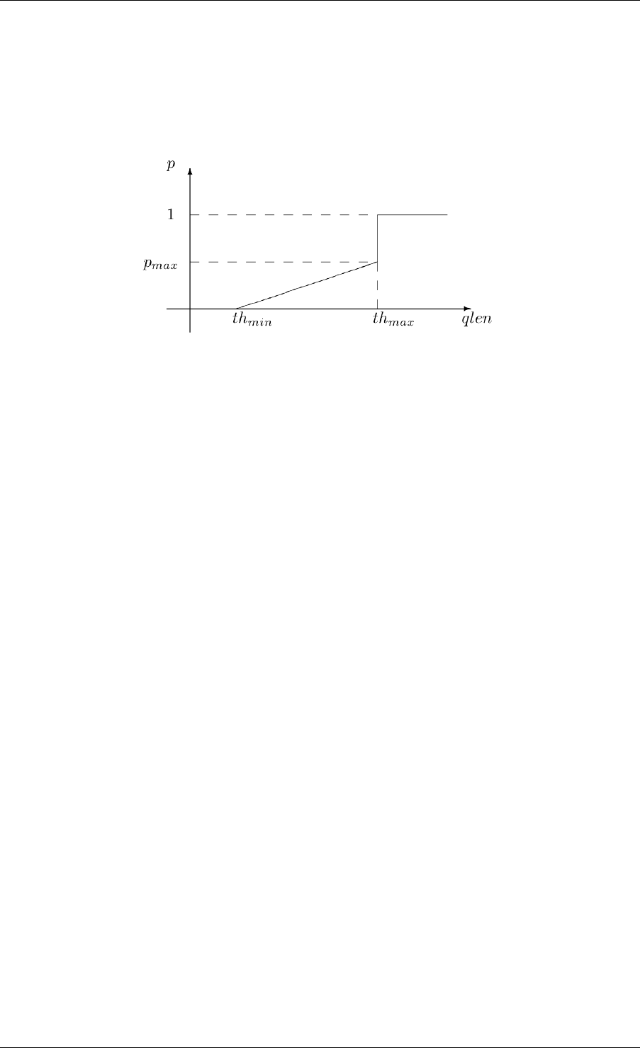
INET Framework User’s Guide
The module sums the used buffer space of the queues attached to the output gates. If it is below
a minimum threshold, the packet won’t be dropped, if above a maximum threshold, it will be
dropped, if it is between the minimum and maximum threshold, it will be dropped by a given
probability. This probability determined by a linear function which is 0 at the minth and maxp
at maxth.
The queue length can be smoothed by specifying the wq parameter. The average queue length
used in the tests are computed by the formula:
𝑎𝑣𝑔 = (1 −𝑤𝑞)*𝑎𝑣𝑔 +𝑤𝑞 *𝑞𝑙𝑒𝑛
The minth,maxth, and maxp parameters can be specified separately for each input gate, so
this module can be used to implement different packet drop priorities.
13.3.3 Schedulers
Scheduler modules decide which queue can send a packet, when the interface is ready to trans-
mit one. They have several input gates and one output gate.
Modules that are connected to the inputs of a scheduler must implement the IPassiveQueue
C++ interface. Schedulers also implement IPassiveQueue, so they can be cascaded to other
schedulers, and can be used as the output module of IOutputQueue’s.
There are several possible scheduling discipline (first come/first served, priority, weighted fair,
weighted round-robin, deadline-based, rate-based). INET contains implementation of priority
and weighted round-robin schedulers.
Priority Scheduler
The PriorityScheduler module implements a strict priority scheduler. Packets that arrived on
in[0] has the highest priority, then packets arrived on in[1], and so on. If more packets
available when one is requested, then the one with highest priority is chosen. Packets with lower
priority are transmitted only when there are no packets on the inputs with higher priorities.
PriorityScheduler must be used with care, because a large volume of higher packets can starve
lower priority packets. Therefore it is necessary to limit the rate of higher priority packets to a
fraction of the output datarate.
PriorityScheduler can be used to implement the EF PHB.
13.3. Simple modules 67

INET Framework User’s Guide
Weighted Round Robin Scheduler
The WrrScheduler module implements a weighted round-robin scheduler. The scheduler visits
the input gates in turn and selects the number of packets for transmission based on their weight.
For example if the module has three input gates, and the weights are 3, 2, and 1, then packets
are transmitted in this order:
A, A, A, B, B, C, A, A, A, B, B, C, ...
where A packets arrived on in[0], B packets on in[1], and C packets on in[2]. If there
are no packets in the current one when a packet is requested, then the next one is chosen that
has enough tokens.
If the size of the packets are equal, then WrrScheduler divides the available bandwith according
to the weights. In each case, it allocates the bandwith fairly. Each flow receives a guaranteed
minimum bandwith, which is ensured even if other flows exceed their share (flow isolation). It
is also efficiently uses the channel, because if some traffic is smaller than its share of bandwidth,
then the rest is allocated to the other flows.
WrrScheduler can be used to implement the AFxy PHBs.
13.3.4 Classifiers
Classifier modules have one input and many output gates. They examine the received packets,
and forward them to the appropriate output gate based on the content of some portion of the
packet header. You can read more about classifiers in RFC 2475 and RFC 3290.
The inet.networklayer.diffserv package contains two classifiers: MultiFieldClas-
sifier to classify the packets at the edge routers of the DiffServ domain, and BehaviorAggre-
gateClassifier to classify the packets at the core routers.
Multi-field Classifier
The MultiFieldClassifier module can be used to identify micro-flows in the incoming traffic.
The flow is identified by the source and destination addresses, the protocol id, and the source
and destination ports of the IP packet.
The classifier can be configured by specifying a list of filters. Each filter can specify a
source/destination address mask, protocol, source/destination port range, and bits of Type-
OfService/TrafficClass field to be matched. They also specify the index of the output gate
matching packet should be forwarded to. The first matching filter determines the output gate,
if there are no matching filters, then defaultOut is chosen.
The configuration of the module is given as an XML document. The document element must
contain a list of <filter> elements. The filter element has a mandatory @gate attribute
that gives the index of the gate for packets matching the filter. Other attributes are optional and
specify the condition of matching:
•@srcAddress,@srcPrefixLength: to match the source address of the IP
68 Chapter 13. Differentiated Services

INET Framework User’s Guide
•@destAddress,@destPrefixLength:
•@protocol: matches the protocol field of the IP packet. Its value can be a name (e.g.
“udp”, “tcp”), or the numeric code of the protocol.
•@tos,@tosMask: matches bits of the TypeOfService/TrafficClass field of the IP packet.
•@srcPort: matches the source port of the TCP or UDP packet.
•@srcPortMin,@srcPortMax: matches a range of source ports.
•@destPort: matches the destination port of the TCP or UDP packet.
•@destPortMin,@destPortMax: matches a range of destination ports.
The following example configuration specifies
• to transmit packets received from the 192.168.1.x subnet on gate 0,
• to transmit packets addressed to port 5060 on gate 1,
• to transmit packets having CS7 in their DSCP field on gate 2,
• to transmit other packets on defaultGate.
<filters>
<filter srcAddress="192.168.1.0" srcPrefixLength="24" gate="0"/>
<filter protocol="udp" destPort="5060" gate="1"/>
<filter tos="0b00111000" tosMask="0x3f" gate="2"/>
</filters>
Behavior Aggregate Classifier
The BehaviorAggregateClassifier module can be used to read the DSCP field from the IP data-
gram, and direct the packet to the corresponding output gate. The DSCP value is the lower six
bits of the TypeOfService/TrafficClass field. Core routers usually use this classifier to guide
the packet to the appropriate queue.
DSCP values are enumerated in the dscps parameter. The first value is for gate out[0], the
second for out[1], so on. If the received packet has a DSCP value not enumerated in the
dscps parameter, it will be forwarded to the defaultOut gate.
13.3.5 Meters
Meters classify the packets based on the temporal characteristics of their arrival. The arrival
rate of packets is compared to an allowed traffic profile, and packets are decided to be green
(in-profile) or red (out-of-profile). Some meters apply more than two conformance level, e.g.
in three color meters the partially conforming packets are classified as yellow.
The allowed traffic profile is usually specified by a token bucket. In this model, a bucket is
filled in with tokens with a specified rate, until it reaches its maximum capacity. When a
packet arrives, the bucket is examined. If it contains at least as many tokens as the length of
the packet, then that tokens are removed, and the packet marked as conforming to the traffic
13.3. Simple modules 69

INET Framework User’s Guide
profile. If the bucket contains less tokens than needed, it left unchanged, but the packet marked
as non-conforming.
Meters has two modes: color-blind and color-aware. In color-blind mode, the color assigned
by a previous meter does not affect the classification of the packet in subsequent meters. In
color-aware mode, the color of the packet can not be changed to a less conforming color: if a
packet is classified as non-conforming by a meter, it also handled as non-conforming in later
meters in the data path.
Important: Meters take into account the length of the IP packet only, L2 headers are omitted
from the length calculation. If they receive a packet which is not an IP datagram and does not
encapsulate an IP datagram, an error occurs.
TokenBucketMeter
The TokenBucketMeter module implements a simple token bucket meter. The module has two
output, one for green packets, and one for red packets. When a packet arrives, the gained tokens
are added to the bucket, and the number of tokens equal to the size of the packet are subtracted.
Packets are classified according to two parameters, Committed Information Rate (𝑐𝑖𝑟), Com-
mitted Burst Size (𝑐𝑏𝑠), to be either green, or red.
Green traffic is guaranteed to be under 𝑐𝑖𝑟 *(𝑡1−𝑡0)+8*𝑐𝑏𝑠 in every [𝑡0, 𝑡1]interval.
SingleRateThreeColorMeter
The SingleRateThreeColorMeter module implements a Single Rate Three Color Meter (RFC
2697). The module has three output for green, yellow, and red packets.
Packets are classified according to three parameters, Committed Information Rate (𝑐𝑖𝑟), Com-
mitted Burst Size (𝑐𝑏𝑠), and Excess Burst Size (𝑒𝑏𝑠), to be either green, yellow or red. The
green traffic is guaranteed to be under 𝑐𝑖𝑟 *(𝑡1−𝑡0)+8*𝑐𝑏𝑠, while the green+yellow traffic
to be under 𝑐𝑖𝑟 *(𝑡1−𝑡0)+8*(𝑐𝑏𝑠 +𝑒𝑏𝑠)in every [𝑡0, 𝑡1]interval.
TwoRateThreeColorMeter
The TwoRateThreeColorMeter module implements a Two Rate Three Color Meter (RFC 2698).
The module has three output gates for the green, yellow, and red packets.
It classifies the packets based on two rates, Peak Information Rate (𝑝𝑖𝑟) and Committed Infor-
mation Rate (𝑐𝑖𝑟), and their associated burst sizes (𝑝𝑏𝑠 and 𝑐𝑏𝑠) to be either green, yellow or
red. The green traffic is under 𝑝𝑖𝑟 *(𝑡1−𝑡0)+8*𝑝𝑏𝑠 and 𝑐𝑖𝑟 *(𝑡1−𝑡0)+8*𝑐𝑏𝑠, the yellow
traffic is under 𝑝𝑖𝑟 *(𝑡1−𝑡0)+8*𝑝𝑏𝑠 in every [𝑡0, 𝑡1]interval.
70 Chapter 13. Differentiated Services

INET Framework User’s Guide
13.3.6 Markers
DSCP markers sets the codepoint of the crossing packets. The codepoint determines the further
processing of the packet in the router or in the core of the DiffServ domain.
The DscpMarker module sets the DSCP field (lower six bit of TypeOfService/TrafficClass) of
IP datagrams to the value specified by the dscps parameter. The dscps parameter is a space
separated list of codepoints. You can specify a different value for each input gate; packets
arrived at the 𝑖𝑡ℎ input gate are marked with the 𝑖𝑡ℎ value. If there are fewer values, than gates,
then the last one is used for extra gates.
The DSCP values are enumerated in the DSCP.msg file. You can use both names and integer
values in the dscps parameter.
For example the following lines are equivalent:
**.dscps ="EF 0x0a 0b00001000"
**.dscps ="46 AF11 8"
13.4 Compound modules
13.4.1 AFxyQueue
The AFxyQueue module is an example queue, that implements one class of the Assured For-
warding PHB group (RFC 2597).
Packets with the same AFx class, but different drop priorities arrive at the afx1In,afx2In,
and afx3In gates. The received packets are stored in the same queue. Before the packet
is enqueued, a RED dropping algorithm may decide to selectively drop them, based on the
average length of the queue and the RED parameters of the drop priority of the packet.
The afxyMinth, afxyMaxth, and afxyMaxp parameters must have values that ensure that pack-
ets with lower drop priorities are dropped with lower or equal probability than packets with
higher drop priorities.
13.4.2 DiffservQeueue
The DiffservQueue is an example queue, that can be used in interfaces of DS core and edge
nodes to support the AFxy (RFC 2597) and EF (RFC 3246) PHB’s.
The incoming packets are first classified according to their DSCP field. DSCP’s other than
AFxy and EF are handled as BE (best effort).
EF packets are stored in a dedicated queue, and served first when a packet is requested. Because
they can preempt the other queues, the rate of the EF packets should be limited to a fraction of
the bandwith of the link. This is achieved by metering the EF traffic with a token bucket meter
and dropping packets that does not conform to the traffic profile.
13.4. Compound modules 71
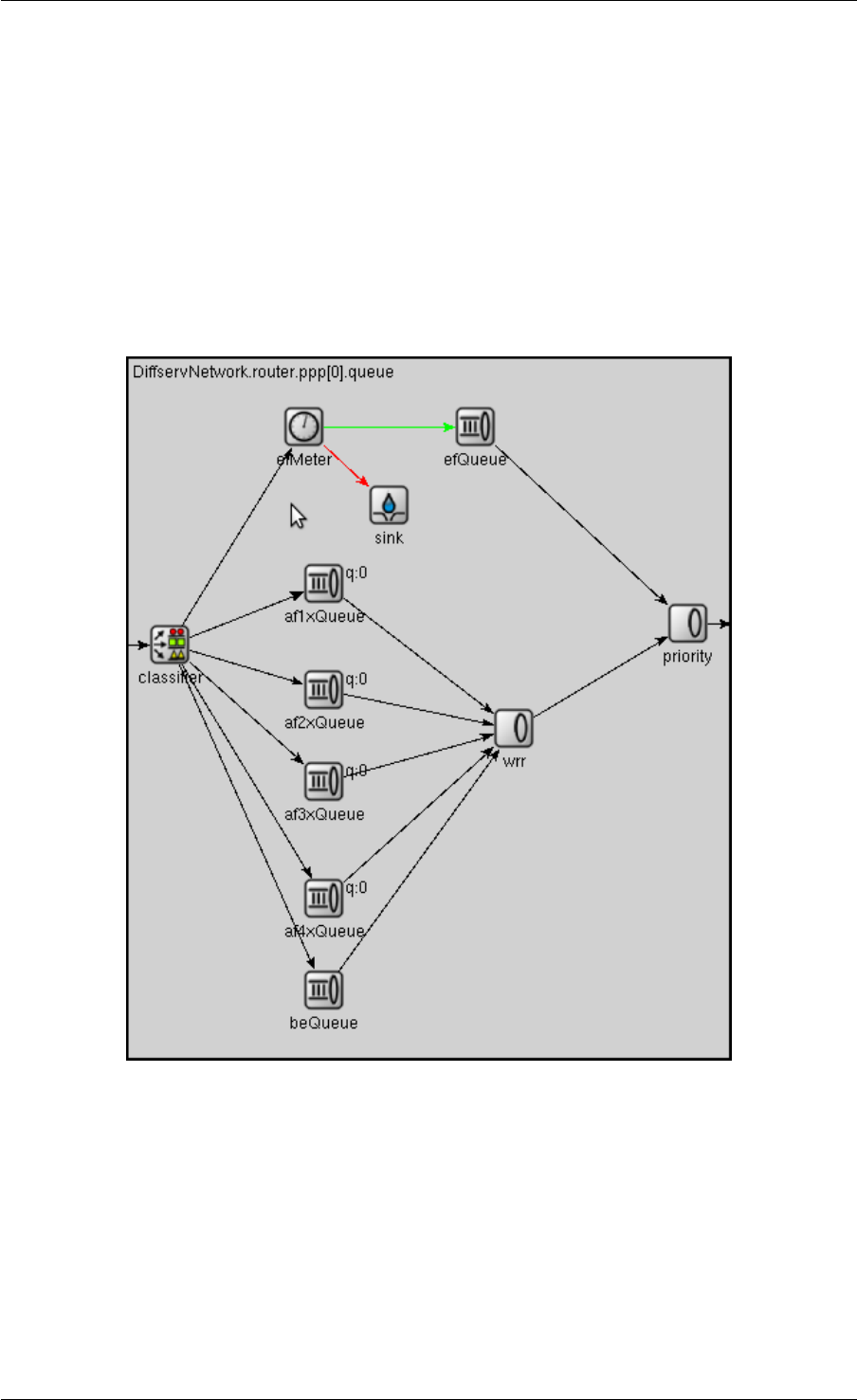
INET Framework User’s Guide
72 Chapter 13. Differentiated Services

INET Framework User’s Guide
There are other queues for AFx classes and BE. The AFx queues use RED to implement 3
different drop priorities within the class. BE packets are stored in a drop tail queue. Packets
from AFxy and BE queues are sheduled by a WRR scheduler, which ensures that the remaining
bandwith is allocated among the classes according to the specified weights.
13.4. Compound modules 73

INET Framework User’s Guide
74 Chapter 13. Differentiated Services

CHAPTER
FOURTEEN
THE MPLS MODELS
14.1 Overview
Multi-Protocol Label Switching (MPLS) is a “layer 2.5” protocol for high-performance
telecommunications networks. MPLS directs data from one network node to the next based
on numeric labels instead of network addresses, avoiding complex lookups in a routing ta-
ble and allowing traffic engineering. The labels identify virtual links (label-switched paths or
LSPs, also called MPLS tunnels) between distant nodes rather than endpoints. The routers
that make up a label-switched network are called label-switching routers (LSRs) inside the net-
work (“transit nodes”), and label edge routers (LER) on the edges of the network (“ingress” or
“egress” nodes).
A fundamental MPLS concept is that two LSRs must agree on the meaning of the labels used
to forward traffic between and through them. This common understanding is achieved by using
signaling protocols by which one LSR informs another of label bindings it has made. Such
signaling protocols are also called label distribution protocols. The two main label distribution
protocols used with MPLS are LDP and RSVP-TE.
INET provides basic support for building MPLS simulations. It provides models for the MPLS,
LDP and RSVP-TE protocols and their associated data structures, and preassembled MPLS-
capable router models.
14.2 Core Modules
The core modules are:
•Mpls implements the MPLS protocol
•LibTable holds the LIB (Label Information Base)
•Ldp implements the LDP signaling protocol for MPLS
•RsvpTe implements the RSVP-TE signaling protocol for MPLS
•Ted contains the Traffic Engineering Database
•LinkStateRouting is a simple link-state routing protocol
•RsvpClassifier is a configurable ingress classifier for MPLS
75

INET Framework User’s Guide
14.2.1 Mpls
The Mpls module implements the MPLS protocol. MPLS is situated between layer 2 and 3,
and its main function is to switch packets based on their labels. For that, it relies on the data
structure called LIB (Label Information Base). LIB is fundamentally a table with the following
columns: input-interface,input-label,output-interface,label-operation(s).
Upon receiving a labelled packet from another LSR, MPLS first extracts the incoming interface
and incoming label pair, and then looks it up in local LIB. If a matching entry is found, it applies
the prescribed label operations, and forwards the packet to the output interface.
Label operations can be the following:
•Push adds a new MPLS label to a packet. (A packet may contain multiple labels, acting
as a stack.) When a normal IP packet enters an LSP, the new label will be the first label
on the packet.
•Pop removes the topmost MPLS label from a packet. This is typically done at either the
penultimate or the egress router.
•Swap: Replaces the topmost label with a new label.
In INET, the local LIB is stored in a LibTable module in the router.
Upon receiving an unlabelled (e.g. plain IPv4) packet, MPLS first determines the forwarding
equivalence class (FEC) for the packet using an ingress classifier, and then inserts one or more
labels in the packet’s newly created MPLS header. The packet is then passed on to the next hop
router for the LSP.
The ingress classifier is also a separate module; it is selected depending on the choice of the
signaling protocol.
14.2.2 LibTable
LibTable stores the LIB (Label Information Base), as described in the previous section.
LibTable is expected to have one instance in the router.
LIB is normally filled and maintained by label distribution protocols (RSVP-TE, LDP), but in
INET it is possible to preload it with initial contents.
The LibTable module accepts an XML config file whose structure follows the contents of the
LIB table. An example configuration:
<libtable>
<libentry>
<inLabel>203</inLabel>
<inInterface>ppp1</inInterface>
<outInterface>ppp2</outInterface>
<outLabel>
<op code="pop"/>
<op code="swap" value="200"/>
<op code="push" value="300"/>
(continues on next page)
76 Chapter 14. The MPLS Models

INET Framework User’s Guide
(continued from previous page)
</outLabel>
<color>200</color>
</libentry>
</libtable>
There can be multiple <libentry> elements, each describing a row in the table. Colums
are given as child elements: <inLabel>,<inInterface>, etc. The <color> element is
optional, and it only exists to be able to color LSPs on the GUI. It is not used by the protocols.
14.2.3 Ldp
The Ldp module implements the Label Distribution Protocol (LDP). LDP is used to establish
LSPs in an MPLS network when traffic engineering is not required. It establishes LSPs that
follow the existing IP routing table, and is particularly well suited for establishing a full mesh
of LSPs between all of the routers on the network.
LDP relies on the underlying routing information provided by a routing protocol in order to
forward label packets. The router’s forwarding information base, or FIB, is responsible for
determining the hop-by-hop path through the network.
In INET, the Ldp module takes routing information from Ted module. The Ted instance in the
network is filled and maintained by a LinkStateRouting module. Unfortunately, it is currently
not possible to use other routing protocol implementations such as Ospf in conjunction with
Ldp.
When Ldp is used as signaling protocol, it also serves as ingress classifier for Mpls.
14.2.4 Ted
The Ted module contains the Traffic Engineering Database (TED). In INET, Ted contains a link
state database, including reservations for each link by RSVP-TE.
14.2.5 LinkStateRouting
The LinkStateRouting module provides a simple link state routing protocol. It uses Ted as its
link state database. Unfortunately, the LinkStateRouting module cannot operate independently,
it can only be used inside an MPLS router.
14.2.6 RsvpTe
The RsvpTe module implements RSVP-TE (Resource Reservation Protocol – Traffic Engi-
neering), as signaling protocol for MPLS. RSVP-TE handles bandwidth allocation and allows
traffic engineering across an MPLS network. Like LDP, RSVP uses discovery messages and
advertisements to exchange LSP path information between all hosts. However, whereas LDP
14.2. Core Modules 77

INET Framework User’s Guide
is restricted to using the configured IGP’s shortest path as the transit path through the net-
work, RSVP can take taking into consideration network constraint parameters such as avail-
able bandwidth and explicit hops. RSVP uses a combination of the Constrained Shortest Path
First (CSPF) algorithm and Explicit Route Objects (EROs) to determine how traffic is routed
through the network.
When RsvpTe is used as signaling protocol, Mpls needs a separate ingress classifier module,
which is usually a RsvpClassifier.
The RsvpTe module allows LSPs to be specified statically in an XML config file. An example
traffic.xml file:
<sessions>
<session>
<endpoint>host3</endpoint>
<tunnel_id>1</tunnel_id>
<paths>
<path>
<lspid>100</lspid>
<bandwidth>100000</bandwidth>
<route>
<node>10.1.1.1</node>
<lnode>10.1.2.1</lnode>
<node>10.1.4.1</node>
<node>10.1.5.1</node>
</route>
<permanent>true</permanent>
<color>100</color>
</path>
</paths>
</session>
</sessions>
In the route, <node> stands for strict hop, and <lnode> for loose hop.
Paths can also be set up and torn down dynamically with ScenarioManager com-
mands (see chapter Scenario Scripting). RsvpTe understands the <add-session> and
<del-session> ScenarioManager commands. The contents of the <add-session> el-
ement can be the same as the <session> element for the traffic.xml above. The
<del-command> element syntax is also similar, but only <endpoint>,<tunnel_id>
and <lspid> need to be specified.
The following is an example scenario.xml file:
<scenario>
<at t="2">
<add-session module="LSR1.rsvp">
<endpoint>10.2.1.1</endpoint>
<tunnel_id>1</tunnel_id>
<paths>
...
(continues on next page)
78 Chapter 14. The MPLS Models

INET Framework User’s Guide
(continued from previous page)
</paths>
</add-session>
</at>
<at t="2.4">
<del-session module="LSR1.rsvp">
<endpoint>10.2.1.1</endpoint>
<tunnel_id>1</tunnel_id>
<paths>
<path>
<lspid>100</lspid>
</path>
</paths>
</del-session>
</at>
</scenario>
14.3 Classifier
The RsvpClassifier module implements an ingress classifier for Mpls when using RsvpTe for
signaling. The classifier can be configured with an XML config file.
**.classifier.config =xmldoc("fectable.xml");
An example fectable.xml file:
<fectable>
<fecentry>
<id>1</id>
<destination>host5</destination>
<source>host1</source>
<tunnel_id>1</tunnel_id>
<lspid>100</lspid>
</fecentry>
</fectable>
14.4 MPLS-Enabled Router Models
INET provides the following pre-assembled MPLS routers:
•LdpMplsRouter is an MPLS router with the LDP signaling protocol
•RsvpMplsRouter is an MPLS router with the RSVP-TE signaling protocol
14.3. Classifier 79

INET Framework User’s Guide
80 Chapter 14. The MPLS Models

CHAPTER
FIFTEEN
POINT-TO-POINT LINKS
15.1 Overview
For simulating wired point-to-point links, the INET Framework contains a minimal implemen-
tation of the PPP protocol and a corresponding network interface module.
•Ppp is a simple module that performs encapsulation of network datagrams into PPP
frames and decapsulation of the incoming PPP frames. It can be connected to the net-
work layer directly or can be configured to get the outgoing messages from an output
queue. The module collects statistics about the transmitted and dropped packages.
•PppInterface is a compound module that complements the Ppp module with an output
queue. It implements the IWiredInterface interface. Input and output hooks can be con-
figured for further processing of the network messages.
PPP (RFC 1661) is a complex protocol which, in addition to providing a method for encapsulat-
ing multi-protocol datagrams, also contains control protocols for establishing, configuring, and
testing the data-link connection (LCP) and for configuring different network-layer protocols
(NCP).
The INET implementation only covers encapsulation and decapsulation of data into PPP
frames. Control protocols, which do not have a significant effect on the links’ capacity and
latency during normal link operation, are not simulated. In addition, header field compressions
(PFC and ACFC) are also bot supported, so a simulated PPP frame always contains 1-byte
Address and Control fields and a 2-byte Protocol field.
15.2 The PPP module
The PPP module receives packets from the upper layer in the netwIn gate, adds a PppHeader,
and send it to the physical layer through the phys gate. The packet with PppHeader is received
from the phys and sent to the upper layer immediately through the netwOut gate.
Incoming datagrams are waiting in a queue if the line is currently busy. In routers, PPP relies
on an external queue module (implementing IOutputQueue) to model finite buffer, implement
QoS and/or RED, and requests packets from this external queue one-by-one. The name of this
queue is given as the queueModule parameter.
81

INET Framework User’s Guide
In hosts, no such queue is used, so Ppp contains an internal queue named txQueue to queue
up packets wainting for transmission. Conceptually txQueue is of inifinite size, but for better
diagnostics one can specify a hard limit in the txQueueLimit parameter – if this is exceeded,
the simulation stops with an error.
The module can be used in simulations where the nodes are connected and disconnected di-
namically. If the channel between the PPP modules is down, the messages received from the
upper layer are dropped (including the messages waiting in the queue). When the connection
is restored it will poll the queue and transmits the messages again.
The PPP module registers itself in the interface table of the node. The mtu of the entry can be
specified by the mtu module parameter. The module checks the state of the physical link and
updates the entry in the interface table.
15.3 PppInterface
PppInterface is a compound module that implements the IWiredInterface interface. It contains
aPpp module and a passive queue for the messages received from the network layer.
The queue type is specified by the queueType parameter. It can be set to NoQueue or to a
module type implementing the IOutputQueue interface. There are implementations with QoS
and RED support.
In typical use of the Ppp module it is augmented with other nodes that monitor the traffic or
simulate package loss and duplication. The PppInterface module abstract that usage by adding
IHook components to the network input and output of the Ppp component. Any number of
hook can be added by specifying the numOutputHooks and numInputHooks parameters
and the types of the outputHook and inputHook components. The hooks are chained in
their numeric order.
82 Chapter 15. Point-to-Point Links

CHAPTER
SIXTEEN
THE ETHERNET MODEL
16.1 Overview
Ethernet is the most popular wired LAN technology nowadays, and its use is also growing in
metropolitan area and wide area networks. Since its introduction in 1980, Ethernet data transfer
rates have increased from the original 10Mb/s to the latest 400Gb/s. Originally, The technology
has changed from using coaxial cables and repeaters to using unshielded twisted-pair cables
with hubs and switches. Today, switched Ethernet is prevalent, and most links operate in full
duplex mode. The INET Framework contains support for all major Ethernet technologies and
device types.
In Ethernet networks containing multiple switches, broadcast storms are prevented by use of
a spanning tree protocol (STP, RSTP) that disables selected links to eliminate cycles from the
topology. Ethernet switch models in INET contain support for STP and RSTP.
16.2 Nodes
There are several node models that can be used in an Ethernet network:
• Node models such as StandardHost and Router are Ethernet-capable
•EtherSwitch models an Ethernet switch, i.e. a multiport bridging device
•EtherHub models an Ethernet hub or multiport repeater
•EtherBus models the coaxial cable (10BASE2 or 10BASE5 network segments) on legacy
Ethernet networks
•EtherHost is a sample node which can be used to generate “raw” Ethernet traffic
16.2.1 EtherSwitch
EtherSwitch models an Ethernet switch. Ethernet switches play an important role in modern
Ethernet LANs. Unlike passive hubs and repeaters that work in the physical layer, the switches
operate in the data link layer and relay frames between the connected subnets.
83

INET Framework User’s Guide
In modern Ethernet LANs, each node is connected to the switch directly by full duplex lines, so
no collisions are possible. In this case, the CSMA/CD is not needed and the channel utilization
can be high.
The duplexMode parameters of the MACs must be set according to the medium connected
to the port; if collisions are possible (it’s a bus or hub) it must be set to false, otherwise it can
be set to true. By default it uses half-duplex MAC with CSMA/CD.
16.2.2 EtherHub
EtherHub models an Ethernet hub. Ethernet hubs are a simple broadcast devices. Messages
arriving on a port are regenerated and broadcast to every other port.
The connections connected to the hub must have the same data rate. Cable lengths should be
reflected in the delays of the connections.
16.2.3 EtherBus
The EtherBus component can model a common coaxial cable found in early Ethernet LANs.
The nodes are attached via taps at specific positions on the cable. When a node sends a signal,
it will propagate along the cable in both directions at the given propagation speed.
The gates of the EtherBus represent taps. The positions of the taps are given by the
positions parameter as a space separated list of distances in metres. If there are more gates
then positions given, the last distance is repeated. The bus component send the incoming mes-
sage in one direction and a copy of the message to the other direction (except at the ends). The
propagation delays are computed from the distances of the taps and the propagationSpeed
parameter.
16.3 The Physical Layer
Stations on an Ethernet networks are connected by coaxial, twisted pair or fibre cables. (Coaxial
only has historical importance, but is supported by INET anyway.) There are several cable types
specified in the standard.
In the INET framework, the cables are represented by connections. The connections used in
Ethernet LANs must be derived from ned::DatarateChannel and should have their delay
and datarate parameters set. The delay parameter can be used to model the distance between
the nodes. The datarate parameter can have four values:
• 10Mbps (classic Ethernet)
• 100Mbps (Fast Ethernet)
• 1Gbps (Gigabit Ethernet, GbE)
• 10Gbps (10 Gigabit Ethernet, 10GbE)
• 40Gbps (40 Gigabit Ethernet, 40GbE)
84 Chapter 16. The Ethernet Model

INET Framework User’s Guide
• 100Gbps (100 Gigabit Ethernet, 100GbE)
There is currently no support for 200Gbps and 400Gbps Ethernet.
Eth10M,Eth100M,Eth1G,Eth10G,Eth40G,Eth100G
16.4 Ethernet Interface
The EthernetInterface compound module implements the IWiredInterface interface. Comple-
ments EtherMac and EtherEncap with an output queue for QoS and RED support. It also has
configurable input/output filters as IHook components similarly to the PppInterface module.
The Ethernet MAC (Media Access Control) layer transmits the Ethernet frames on the physical
media. This is a sublayer within the data link layer. Because encapsulation/decapsulation is not
always needed (e.g. switches does not do encapsulation/decapsulation), it is implemented in a
separate modules (e.g. EtherEncap) that are part of the LLC layer.
Nowadays almost all Ethernet networks operate using full-duplex point-to-point connections
between hosts and switches. This means that there are no collisions, and the behaviour of the
MAC component is much simpler than in classic Ethernet that used coaxial cables and hubs.
The INET framework contains two MAC modules for Ethernet: the EtherMacFullDuplex is
simpler to understand and easier to extend, because it supports only full-duplex connections.
The EtherMac module implements the full MAC functionality including CSMA/CD, it can
operate both half-duplex and full-duplex mode.
16.5 Components
The following components are present in the model:
•EtherMacFullDuplex
•EtherMac
•EtherEncap
•MacRelayUnit
•MacAddressTable
•Ieee8021dRelay
16.5.1 EtherMacFullDuplex
From the two MAC implementation EtherMacFullDuplex is the simpler one, it operates only in
full-duplex mode (its duplexEnabled parameter fixed to true in its NED definition). This
module does not need to implement CSMA/CD, so there is no collision detection, retransmis-
sion with exponential backoff, carrier extension and frame bursting.
16.4. Ethernet Interface 85

INET Framework User’s Guide
16.5.2 EtherMac
Ethernet MAC layer implementing CSMA/CD. It supports both half-duplex and full-duplex
operations; in full-duplex mode it behaves as EtherMacFullDuplex. In half-duplex mode it
detects collisions, sends jam messages and retransmit frames upon collisions using the expo-
nential backoff algorithm. In Gigabit Ethernet networks it supports carrier extension and frame
bursting. Carrier extension can be turned off by setting the carrierExtension parameter
to false.
16.5.3 EtherEncap
The EtherEncap module performs Ethernet II or Ethernet with SNAP encapsula-
tion/decapsulation.
16.5.4 MacRelayUnit
INET framework ethernet switches are built from IMacRelayUnit components. Each relay unit
has N input and output gates for sending/receiving Ethernet frames. They should be connected
to EthernetInterface modules.
The relay unit holds a table for the destination address -> output port mapping in a MacAd-
dressTable module. When the relay unit receives a data frame, it updates the table with the
source address->input port.
If the destination address is not found in the table, the frame is broadcast. The frame is not sent
to the same port it was received from, because then the target should already have received the
original frame.
A simple scheme for sending PAUSE frames is built in (although users will probably change it).
When the buffer level goes above a high watermark, PAUSE frames are sent on all ports. The
watermark and the pause time is configurable; use zero values to disable the PAUSE feature.
16.5.5 MacAddressTable
The MacAddressTable module stores the mapping between ports and MAC addresses. Entries
are deleted if their age exceeds a certain limit.
If needed, address tables can be pre-loaded from text files at the beginning of the simulation;
this controlled by the addressTableFile module parameter. In the file, each line contains
a literal 0 (reserved for VLAN id), a hexadecimal MAC address and a decimal port number,
separated by tabs. Comment lines beginning with ’#’ are also allowed:
0 01 ff ff ff ff 0
0 00-ff-ff-ee-d1 1
0 0A:AA:BC:DE:FF 2
Entries are deleted if their age exceeds the duration given as the agingTime parameter.
86 Chapter 16. The Ethernet Model

INET Framework User’s Guide
16.5.6 Ieee8021dRelay
Ieee8021dRelay is a MAC relay unit that should be used instead of MacRelayUnit that when
STP or RSTP is needed.
16.5.7 Stp
The Stp module type implements Spanning Tree Protocol (STP). STP is a network protocol
that builds a loop-free logical topology for Ethernet networks. The basic function of STP is to
prevent bridge loops and the broadcast radiation that results from them.
STP creates a spanning tree within a network of connected layer-2 bridges, and disables those
links that are not part of the spanning tree, leaving a single active path between any two network
nodes.
16.5.8 Rstp
Rstp implements Rapid Spanning Tree Protocol (RSTP), an improved version of STP. RSTP
provides significantly faster recovery in response to network changes or failures.
16.6 Implemented Standards
The Ethernet model operates according to the following standards:
• Ethernet: IEEE 802.3-1998
• Fast Ethernet: IEEE 802.3u-1995
• Full-Duplex Ethernet with Flow Control: IEEE 802.3x-1997
• Gigabit Ethernet: IEEE 802.3z-1998
16.6. Implemented Standards 87

INET Framework User’s Guide
88 Chapter 16. The Ethernet Model

CHAPTER
SEVENTEEN
THE 802.11 MODEL
17.1 Overview
IEEE 802.11 a.k.a. WiFi is the most widely used and universal wireless networking standard.
Specifications are updated every few years, adding more features and ever increasing bit rates.
In INET, nodes become WiFi-enabled by adding a Ieee80211Interface to them. (As men-
tioned earlier, WirelessHost and AdhocHost already contain one in their default configu-
ration.) APs are represented with the AccessPoint node type. WiFi networks require a
matching transmission medium module to be present in the network, which is usually a
Ieee80211ScalarRadioMedium.
Operation mode (infrastructure vs ad hoc) is determined by the ingredients of the wireless
interface. Ieee80211Interface has the following submodules (incomplete list):
1. management: performs association/disassociation with access points, channel scanning,
beaconing
2. agent: initiates actions such as channel scanning and connecting to and disconnecting
from access points
3. MAC: transmits and receives frames according to the IEEE 802.11 medium access pro-
cedure
4. PHY: represents the radio
The management component has several implementations which differ in their role and level
of detail:
•Ieee80211MgmtAdhoc: for ad hoc mode stations
•Ieee80211MgmtSta,Ieee80211MgmtStaSimplified: for infrastructure mode stations
•Ieee80211MgmtAp,Ieee80211MgmtApSimplified: for access points
The “simplified” ones assume that stations are statically associated to an access point for the
entire duration of the simulation (the scan-authenticate-associate process is not simulated), so
they cannot be used e.g. in experiments involving handover.
Ieee80211MgmtSta is does not take any action by itself, it requires an agent
(Ieee80211AgentSta or a custom one) to initiate actions.
The following sections examine the above components.
89

INET Framework User’s Guide
17.2 MAC
The Ieee80211Mac module type represents the IEEE 802.11 MAC. The implementation is
entirely based on the standard IEEE 802.11-2012 Part 11: Wireless LAN Medium Access
Control (MAC) and Physical Layer (PHY) Specifications.
Ieee80211Mac performs transmission of frames according to the CSMA/CA protocol. It re-
ceives data and management frames from the upper layers, and transmits them.
The Ieee80211Mac was designed to be modular to facilitate experimenting with new policies,
features and algorithms within the MAC layer. Users can easily replace individual components
with their own implementations. Policies, which most likely to be experimented with, are
extracted into their own modules.
The model has the following replaceable built-in policies:
• ACK policy
• RTS/CTS policy
• Originator and recipient block ACK agreement policies
• MSDU aggregation policy
• Fragmentation policy
The new model also separates the following components:
• Coordination functions
• Channel access methods
• MAC data services
• Aggregation and deaggregation
• Fragmentation and defragmentation
• Block ACK agreements and reordering
• Frame exchange sequences
• Duplicate removal
• Rate selection
• Rate control
• Protection mechanisms
• Recovery procedure
• Contention
• Frame queues
• TX/RX
90 Chapter 17. The 802.11 Model

INET Framework User’s Guide
17.3 Physical Layer
The physical layer modules (Ieee80211Radio) deal with modelling transmission and reception
of frames. They model the characteristics of the radio channel, and determine if a frame was
received correctly (that is, it did not suffer bit errors due to low signal power or interference in
the radio channel). Frames received correctly are passed up to the MAC.
On the physical layer, one can choose from several radios with different levels of detail. The
various radio types (with the matching transmission medium types in parentheses) are:
•Ieee80211ScalarRadio (Ieee80211ScalarRadioMedium)
•Ieee80211DimensionalRadio (Ieee80211DimensionalRadioMedium)
•Ieee80211UnitDiskRadio (UnitDiskRadioMedium)
17.4 Management
The management layer exchanges management frames via the MAC with its peer management
entities in other STAs and APs. Beacon, Probe Request/Response, Authentication, Associa-
tion Request/Response etc frames are generated and interpreted by management entities, and
transmitted/received via the MAC layer. During scanning, it is the management entity that
periodically switches channels, and collects information from received beacons and probe re-
sponses.
The management layer has several implementations which differ in their role
(STA/AP/ad-hoc) and level of detail: Ieee80211MgmtAdhoc,Ieee80211MgmtAp,
Ieee80211MgmtApSimplified,Ieee80211MgmtSta,Ieee80211MgmtStaSimplified. The
..Simplified ones differ from the others in that they do not model the scan-authenticate-
associate process, so they cannot be used in experiments involving handover.
17.5 Agent
The agent is what instructs the management layer to perform scanning, authentication and
association. The management layer itself just carries out these commands by performing the
scanning, authentication and association procedures, and reports back the results to the agent.
The agent component is currently only needed with the Ieee80211MgmtSta module. The man-
agament entities in other NIC variants do not have as much freedom as to need an agent to
control them.
Ieee80211MgmtSta requires a Ieee80211AgentSta or a custom agent. By modifying or re-
placing the agent, one can alter the dynamic behaviour of STAs in the network, for example
implement different handover strategies.
17.3. Physical Layer 91

INET Framework User’s Guide
92 Chapter 17. The 802.11 Model

CHAPTER
EIGHTEEN
THE 802.15.4 MODEL
18.1 Overview
IEEE 802.15.4 is a technical standard which defines the operation of low-rate wireless personal
area networks (LR-WPANs). IEEE 802.15.4 was designed for data rates of 250 kbit/s or lower,
in order to achieve long battery life (months or even years) and very low complexity. The
standard specifies the physical layer and media access control.
IEEE 802.15.4 is the basis for the ZigBee, ISA100.11a, WirelessHART, MiWi, SNAP,and the
Thread specifications, each of which further extends the standard by developing the upper
layers which are not defined in IEEE 802.15.4. Alternatively, it can be used with 6LoWPAN,
the technology used to deliver IPv6 over WPANs, to define the upper layers. (Thread is also
6LoWPAN-based.)
The INET Framework contains a basic implementation of IEEE 802.15.4 protocol.
18.2 Network Interfaces
There are two network interfaces that differ in the type of radio:
•Ieee802154NarrowbandInterface is for use with narrowband radios
•Ieee802154UwbIrInterface is for use with the UWB-IR radio
To create a wireless node with a 802.15.4 interface, use a node type that has a wireless interface,
and set the interface type to the appropriate type. For example, WirelessHost is a node type
which is preconfigured to have one wireless interface, wlan[0].wlan[0] is of parametric
type, so if you build the network from WirelessHost nodes, you can configure all of them to
use 802.15.4 with the following line in the ini file:
**.wlan[0].typename ="Ieee802154NarrowbandInterface"
93

INET Framework User’s Guide
18.3 Physical Layer
The IEEE 802.15.4 standard defines several alternative PHYs. There are several narrowband
radios at various frequency bands using various modulation schemes (DSSS, O-QPSK, MPSK,
GFSK BPSK, etc.), a Direct Sequence ultra-wideband (UWB), and one using chirp spread
spectrum (CSS).
INET provides the following radios:
•Ieee802154NarrowbandScalarRadio is currently a partially parameterized version of the
APSK radio. Before using this radio, one must check its parameters and make sure that
they correspond to the specification of the 802.15.4 narrowband PHY to be simulated.
•Ieee802154UwbIrRadio models the 802.14.5 UWB radio.
One must choose a matching medium model, for example Ieee802154UwbIrRadioMedium
for Ieee802154UwbIrRadio, and Ieee802154NarrowbandScalarRadioMedium for
Ieee802154NarrowbandScalarRadio.
18.4 MAC Protocol
The 802.15.4 MAC is based on collision avoidance via CSMA/CA. Important other features
include real-time suitability by reservation of guaranteed time slots, and integrated support for
secure communications. Devices also include power management functions such as link quality
and energy detection.
The Ieee802154Mac type in INET is currently a parameterized version of a generic CSMA/CA
protocol model with ACK support.
There is also a Ieee802154NarrowbandMac.
94 Chapter 18. The 802.15.4 Model

CHAPTER
NINETEEN
MAC PROTOCOLS FOR WIRELESS SENSOR
NETWORKS
19.1 Overview
The INET Framework contains the implementation of several MAC protocols for wireless sen-
sor networks (WSNs), including B-MAC, L-MAC and X-MAC.
To create a wireless node with a specific MAC protocol, use a node type that has a wireless
interface, and set the interface type to the appropriate type. For example, WirelessHost is a
node type which is preconfigured to have one wireless interface, wlan[0].wlan[0] is of
parametric type, so if you build the network from WirelessHost nodes, you can configure all of
them to use e.g. B-MAC with the following line in the ini file:
**.wlan[0].typename ="BMacInterface"
19.2 B-MAC
B-MAC (Berkeley MAC) is a carrier sense media access protocol for wireless sensor networks
that provides a flexible interface to obtain ultra low power operation, effective collision avoid-
ance, and high channel utilization. To achieve low power operation, B-MAC employs an adap-
tive preamble sampling scheme to reduce duty cycle and minimize idle listening. B-MAC is
designed for low traffic, low power communication, and is one of the most widely used proto-
cols (e.g. it is part of TinyOS).
The BMac module type implements the B-MAC protocol.
BMacInterface isaWirelessInterface with the MAC type set to BMac.
19.3 L-MAC
L-MAC (Lightweight MAC) is an energy-efficient medium acces protocol designed for wireless
sensor networks. Although the protocol uses TDMA to give nodes in the WSN the opportunity
to communicate collision-free, the network is self-organizing in terms of time slot assignment
95

INET Framework User’s Guide
and synchronization. The protocol reduces the number of transceiver state switches and hence
the energy wasted in preamble transmissions.
The LMac module type implements the L-MAC protocol, based on the paper “A lightweight
medium access protocol (LMAC) for wireless sensor networks” by van Hoesel and P. Havinga.
LMacInterface isaWirelessInterface with the MAC type set to LMac.
19.4 X-MAC
X-MAC is a low-power MAC protocol for wireless sensor networks (WSNs). In contrast to B-
MAC which employs an extended preamble and preamble sampling, X-MAC uses a shortened
preamble that reduces latency at each hop and improves energy consumption while retaining
the advantages of low power listening, namely low power communication, simplicity and a
decoupling of transmitter and receiver sleep schedules.
The XMac module type implements the X-MAC protocol, based on the paper “X-MAC: A
Short Preamble MAC Protocol for Duty-Cycled Wireless Sensor Networks” by Michael Buet-
tner, Gary V. Yee, Eric Anderson and Richard Han.
XMacInterface isaWirelessInterface with the MAC type set to XMac.
96 Chapter 19. MAC Protocols for Wireless Sensor Networks

CHAPTER
TWENTY
THE PHYSICAL LAYER
20.1 Overview
Wireless network interfaces contain a radio model component, which is responsible for model-
ing the physical layer (PHY).1The radio model describes the physical device that is capable of
transmitting and receiving signals on the medium.
Conceptually, a radio model relies on several sub-models:
• antenna model
• transmitter model
• receiver model
• error model (as part of the receiver model)
• energy consumption model
The antenna model is shared between the transmitter model and the receiver model. The sepa-
ration of the transmitter model and the receiver model allows asymmetric configurations. The
energy consumer model is optional, and it is only used when the simulation of energy con-
sumption is necessary.
20.2 Generic Radio
In INET, radio models implement the IRadio module interface. A generic, often used imple-
mentation of IRadio is the Radio NED type. Radio is an active compound module, that is, it
has an associated C++ class that encapsulates the computations.
Radio contains its antenna, transmitter, receiver and energy consumer models as submodules
with parametric types:
1Wired network interfaces could similarly contain an explicit PHY model. The reason they do not is that
wired links normally have very low error rates and simple observable behavior, and there is usually not much to
be gained from modeling the physical layer in detail.
97

INET Framework User’s Guide
antenna: <antennaType>like IAntenna;
transmitter: <transmitterType>like ITransmitter;
receiver: <receiverType>like IReceiver;
energyConsumer: <energyConsumerType>like IEnergyConsumer
if energyConsumerType != "";
The following sections describe the parts of the radio model.
20.3 Components of a Radio
20.3.1 Antenna Models
The antenna model describes the effects of the physical device which converts electric signals
into radio waves, and vice versa. This model captures the antenna characteristics that heavily
affect the quality of the communication channel. For example, various antenna shapes, an-
tenna size and geometry, antenna arrays, and antenna orientation causes different directional or
frequency selectivity.
The antenna model provides a position and an orientation using a mobility model that defaults
to the mobility of the node. The main purpose of this model is to compute the antenna gain
based on the specific antenna characteristics and the direction of the signal. The signal direction
is computed by the medium from the position and the orientation of the transmitter and the
receiver. The following list provides some examples:
•IsotropicAntenna: antenna gain is exactly 1 in any direction
•ConstantGainAntenna: antenna gain is a constant determined by a parameter
•DipoleAntenna: antenna gain depends on the direction according to the dipole antenna
characteristics
•InterpolatingAntenna: antenna gain is computed by linear interpolation according to a
table indexed by the direction angles
20.3.2 Transmitter Models
The transmitter model describes the physical process which converts packets into electric sig-
nals. In other words, this model converts an L2 frame into a signal that is transmitted on the
medium. The conversion process and the representation of the signal depends on the level of
detail and the physical characteristics of the implemented protocol.
There are two main levels of detail (or modeling depths):
• In the flat model, the transmitter model skips the symbol domain and the sample domain
representations, and it directly creates the analog domain representation. The bit domain
representation is reduced to the bit length of the packet, and the actual bits are ignored.
• In the layered model, the conversion process involves various processing steps such as
packet serialization, forward error correction encoding, scrambling, interleaving, and
98 Chapter 20. The Physical Layer

INET Framework User’s Guide
modulation. This transmitter model requires significantly more computation, but it pro-
duces accurate bit domain, symbol domain, and sample domain representations.
Some of the transmitter types available in INET:
•UnitDiskTransmitter
•ApskScalarTransmitter
•ApskDimensionalTransmitter
•ApskLayeredTransmitter
•Ieee80211ScalarTransmitter
•Ieee80211DimensionalTransmitter
20.3.3 Receiver Models
The receiver model describes the physical process which converts electric signals into packets.
In other words, this model converts a reception, along with an interference computed by the
medium model, into a MAC packet and a reception indication.
For a packet to be received successfully, reception must be possible (based on reception power,
bandwidth, modulation scheme and other characteristics), it must be attempted (i.e. the receiver
must synchronize itself on the preamble and start receiving), and it must be successful (as
determined by the error model and the simulated part of the signal decoding).
In the flat model, the receiver model skips the sample domain, the symbol domain, and the bit
domain representations, and it directly creates the packet domain representation by copying
the packet from the transmission. It uses the error model to decide whether the reception is
successful.
In the layered model, the conversion process involves various processing steps such as demod-
ulation, descrambling, deinterleaving, forward error correction decoding, and deserialization.
This reception model requires much more computation than the flat model, but it produces
accurate sample domain, symbol domain, and bit domain representations.
Some of the receiver types available in INET:
•UnitDiskReceiver
•ApskScalarReceiver
•ApskDimensionalReceiver
•ApskLayeredReceiver
•Ieee80211ScalarReceiver
•Ieee80211DimensionalReceiver
20.3. Components of a Radio 99

INET Framework User’s Guide
20.3.4 Error Models
Determining reception errors is a crucial part of the reception process. There are often several
different statistical error models in the literature even for a particular physical layer. In order to
support this diversity, the error model is a separate replaceable component of the receiver.
The error model describes how the signal to noise ratio affects the amount of errors at the
receiver. The main purpose of this model is to determine whether the received packet has
errors or not. It also computes various physical layer indications for higher layers such as
packet error rate, bit error rate, and symbol error rate. For the layered reception model it needs
to compute the erroneous bits, symbols, or samples depending on the lowest simulated physical
domain where the real decoding starts. The error model is optional (if omitted, all receptions
are considered successful.)
The following list provides some examples:
•StochasticErrorModel: simplistic error model with constant symbol/bit/packet error rates
as parameters; suitable for testing.
•ApskErrorModel
•Ieee80211NistErrorModel,Ieee80211YansErrorModel,Ieee80211BerTableErrorModel:
various error models for IEEE 802.11 network interfaces.
20.3.5 Power Consumption Models
A substantial part of the energy consumption of communication devices comes from transmit-
ting and receiving signals. The energy consumer model describes how the radio consumes
energy depending on its activity. This model is optional (if omitted, energy consumption is
ignored.)
The following list provides some examples:
•StateBasedEpEnergyConsumer: power consumption is determined by the ra-
dio state (a combination of radio mode, transmitter state and receiver state),
and specified in parameters like receiverIdlePowerConsumption and
receiverReceivingDataPowerConsumption, in watts.
•StateBasedCcEnergyConsumer: similar to the previous one, but consumption is given in
ampères.
20.4 Layered Radio Models
In layered radio models, the transmitter and receiver models are split to several stages to allow
more fine-grained modeling.
For transmission, processing steps such as packet serialization, forward error correction (FEC)
encoding, scrambling, interleaving, and modulation are explicitly modeled. Reception involves
the inverse operations: demodulation, descrambling, deinterleaving, FEC decoding, and dese-
rialization.
100 Chapter 20. The Physical Layer

INET Framework User’s Guide
In layered radio models, these processing steps are encapsulated in four stages, represented as
four submodules in both the transmitter and receiver model:
1. Encoding and Decoding describe how the packet domain signal representation is con-
verted into the bit domain, and vice versa.
2. Modulation and Demodulation describe how the bit domain signal representation is con-
verted into the symbol domain, and vice versa.
3. Pulse Shaping and Pulse Filtering describe how the symbol domain signal representation
is converted into the sample domain, and vice versa.
4. Digital Analog and Analog Digital Conversion describe how the sample domain signal
representation is converted into the analog domain, and vice versa.
In layered radio transmitters and receivers such as ApskLayeredTransmitter and ApskLayere-
dReceiver, these submodules have parametric types to make them replaceable. This provides
immense freedom for experimentation.
20.5 Notable Radio Models
The Radio module has several specialized versions derived from it, where certain submodule
types and parameters are set to fixed values. This section describes some of the frequently used
ones.
The radio can be replaced in wireless network interfaces by setting the radioType parameter,
like in the following ini file fragment.
**.wlan[*].radioType ="UnitDiskRadio"
However, be aware that not all MAC protocols can be used with all radio models, and that some
radio models require a matching transmission medium module.
20.5.1 UnitDiskRadio
UnitDiskRadio provides a very simple but fast and predictable physical layer model. It is the
implementation (with some extensions) of the Unit Disk Graph model, which is widely used for
the study of wireless ad-hoc networks. UnitDiskRadio is applicable if network nodes need to
have a finite communication range, but physical effects of signal propagation are to be ignored.
UnitDiskRadio allows three radii to be given as parameters, instead of the usual one: com-
munication range, interference range, and detection range. One can also turn off interference
modeling (meaning that signals colliding at a receiver will all be received correctly), which is
sometimes a useful abstraction.
UnitDiskRadio needs to be used together with a special physical medium model, UnitDiskRa-
dioMedium.
The following ini file fragment shows an example configuration.
20.5. Notable Radio Models 101

INET Framework User’s Guide
*.radioMediumType ="UnitDiskRadioMedium"
*.host[*].wlan[*].radioType ="UnitDiskRadio"
*.host[*].wlan[*].radio.transmitter.bitrate =2Mbps
*.host[*].wlan[*].radio.transmitter.preambleDuration =0s
*.host[*].wlan[*].radio.transmitter.headerLength =100b
*.host[*].wlan[*].radio.transmitter.communicationRange =100m
*.host[*].wlan[*].radio.transmitter.interferenceRange =0m
*.host[*].wlan[*].radio.transmitter.detectionRange =0m
*.host[*].wlan[*].radio.receiver.ignoreInterference =true
As a side note, if modeling full connectivity and ignoring interference is required, then Short-
cutInterface provides an even simpler and faster alternative.
20.5.2 APSK Radio
APSK radio models provide a hypothetical radio that simulates one of the well-known ASP,
PSK and QAM modulations. (APSK stands for Amplitude and Phase-Shift Keying.)
APSK radio has scalar/dimensional, and flat/layered variants. The flat variants, ApskScalarRa-
dio and ApskDimensionalRadio model frame transmissons in the selected modulation scheme
but without utilizing other techniques such as forward error correction (FEC), interleaving,
spreading, etc. These radios require matching medium models, ApskScalarRadioMedium and
ApskDimensionalRadioMedium.
The layered versions, ApskLayeredScalarRadio and ApskLayeredDimensionalRadio can not
only model the processing steps missing from their simpler counterparts, they also feature
configurable level of detail: the transmitter and receiver modules have levelOfDetail
parameters that control which domains are actually simulated. These radio models must be
used in conjuction with ApskLayeredScalarRadioMedium and ApskLayeredDimensionalRa-
dioMedium, respectively.
102 Chapter 20. The Physical Layer

CHAPTER
TWENTYONE
THE TRANSMISSION MEDIUM
21.1 Overview
For wireless communication, an additional module is required to model the shared physical
medium where the communication takes place. This module keeps track of transceivers, noise
sources, ongoing transmissions, background noise, and other ongoing noises.
It relies on several models:
1. signal propagation model
2. path loss model
3. obstacle loss model
4. background noise model
5. signal analog model
With the help of the above models, the medium module computes when, where, and how signals
arrive at receivers, including the set of interfering signals and noises. In addition, the medium
module also contains various mechanisms and ways to improve the scalability of wireless net-
work simulations.
21.2 RadioMedium
The standard transmission medium model in INET is RadioMedium.RadioMedium is as an
OMNeT++ compound module with several replaceable submodules. It contains submodules
for each of the above models (signal propagation, path loss, etc.), and various caches for effi-
ciency.
Note that RadioMedium is an active compound module, that is, it has an associated C++ class
that encapsulates the computations.
RadioMedium contains its components as submodules with parametric types:
propagation: <propagationType>like IPropagation;
analogModel: <analogModelType>like IAnalogModel;
backgroundNoise: <backgroundNoiseType>like IRadioBackgroundNoise
(continues on next page)
103

INET Framework User’s Guide
(continued from previous page)
if backgroundNoiseType != "";
pathLoss: <pathLossType>like IPathLoss;
obstacleLoss: <obstacleLossType>like IObstacleLoss
if obstacleLossType != "";
mediumLimitCache: <mediumLimitCacheType>like IMediumLimitCache;
communicationCache: <communicationCacheType>like
˓→ICommunicationCache;
neighborCache: <neighborCacheType>like INeighborCache
if neighborCacheType != "";
There are many preconfigured versions of RadioMedium:
• For use with UnitDiskRadio:UnitDiskRadioMedium
• For APSK radios: ApskScalarRadioMedium,ApskDimensionalRadioMedium,Ap-
skLayeredScalarRadioMedium,ApskLayeredDimensionalRadioMedium,
• For IEEE 802.11: Ieee80211ScalarRadioMedium,
Ieee80211DimensionalRadioMedium,Ieee80211LayeredScalarRadioMedium,
Ieee80211LayeredDimensionalRadioMedium,
• For IEEE 802.15.4: Ieee802154UwbIrRadioMedium,
Ieee802154NarrowbandScalarRadioMedium
The following sections describe the parts of the medium model.
21.3 Propagation Models
When a transmitter starts to transmit a signal, the beginning of the signal propagates through the
transmission medium. When the transmitter ends the transmission, the signal’s end propagates
similarly. The propagation model describes how a signal moves through space over time. Its
main purpose is to compute the arrival space-time coordinates at receivers. There are two
built-in models in INET, implemented as simple modules:
•ConstantTimePropagation is a simplistic model where the propagation time is indepen-
dent of the traveled distance. The propagation time is simply determined by a module
parameter.
•ConstantSpeedPropagation is a more realistic model where the propagation time is pro-
portional to the traveled distance. The propagation time is independent of the transmitter
and receiver movement during both signal transmission and propagation. The propaga-
tion speed is determined by a module parameter.
The default propagation model is configured as follows:
*.radioMedium.propagation.typename ="ConstantSpeedPropagation" #
˓→module type
*.radioMedium.propagation.propagationSpeed =299792458 mps # speed
˓→of light
104 Chapter 21. The Transmission Medium

INET Framework User’s Guide
A more accurate model could take into consideration the transmitter and receiver movement.
This effect becomes especially important for acoustic communication, because the propagation
speed of the signal is much more comparable to the speed of the transceivers.
21.4 Path Loss Models
As a signal propagates through space its power density decreases. This is called path loss and
it is the combination of many effects such as free-space loss, refraction, diffraction, reflection,
and absorption. There are several different path loss models in the literature, which differ in
their parameterization and application area.
In INET, a path loss model is an OMNeT++ simple module implementing a specific path loss
algorithm. Its main purpose is to compute the power loss for a given signal, but it is also capable
of estimating the range for a given loss. The latter is useful, for example, to allow visualizing
communication range. INET contains a number of built-in path loss algorithms, each comes
with its own set of parameters:
•FreeSpacePathLoss models line of sight path loss for air or vacuum.
•BreakpointPathLoss refines it using dual slope model with two separate path loss expo-
nents.
•LogNormalShadowing models path loss for a wide range of environments (e.g. urban
areas, and buildings)
•TwoRayGroundReflection models interference between line of sight and single ground
reflection.
•TwoRayInterference refines the above for inter-vechicle communication.
•RicianFading is a stochastical model for the anomaly caused by partial cancellation of a
signal by itself.
•RayleighFading is a stochastical model for heavily built-up urban environments when
there is no dominant propagation along the line of sight.
•NakagamiFading further refines the above two models for cellular systems.
The following example replaces the default free-space path loss model with log normal shad-
owing:
*.radioMedium.pathLoss.typename ="LogNormalShadowing" # module type
*.radioMedium.pathLoss.sigma =1.1 # override default value of 1
21.5 Obstacle Loss Models
When the signal propagates through space it also passes through physical objects present in
that space. As the signal penetrates physical objects, its power decreases when it reflects from
surfaces, and also when it is absorbed by their material. There are various ways to model this
effect, which differ in the trade-off between accuracy and performance.
21.4. Path Loss Models 105

INET Framework User’s Guide
In INET, an obstacle loss model is an OMNeT++ simple module. Its main purpose is to com-
pute the power loss based on the traveled path and the signal frequency. The obstacle loss
models most often use the physical environment model to determine the set of penetrated phys-
ical objects. INET contains a few built-in obstacle loss models:
•IdealObstacleLoss model determines total or no power loss at all by checking if there is
any obstructing physical object along the straight propagation path.
•DielectricObstacleLoss computes the power loss based on the accurate dielectric and
reflection loss along the straight path considering the shape, position, orientation, and
material of obstructing physical objects.
By default, the medium module doesn’t contain any obstacle loss model, but configuring one
is very simple:
*.radioMedium.obstacleLoss.typename ="DielectricObstacleLoss" #
˓→module type
Statistical obstacle loss models are also possible but currently not provided.
21.6 Background Noise Models
Thermal noise, cosmic background noise, and other random fluctuations of the electromagnetic
field affect the quality of the communication channel. This kind of noise doesn’t come from
a particular source, so it doesn’t make sense to model its propagation through space. The
background noise model describes instead how it changes over space and time.
In INET, a background noise model is an OMNeT++ simple module. Its main purpose is to
compute the analog representation of the background noise for a given space-time interval. For
example, IsotropicScalarBackgroundNoise computes a background noise that is independent
of space-time coordinates, and its scalar power is determined by a module parameter.
The simplest background noise model can be configured as follows:
*.radioMedium.backgroundNoise.typename =
˓→"IsotropicScalarBackgroundNoise" # type
*.radioMedium.backgroundNoise.power =-110 dBm # isotropic scalar
˓→noise power
21.7 Analog Models
The analog signal is a complex physical phenomenon which can be modeled in many differ-
ent ways. Choosing the right analog domain signal representation is the most important factor
in the trade-off between accuracy and performance. The analog model of the transmission
medium determines how signals are represented while being transmitted, propagated, and re-
ceived.
106 Chapter 21. The Transmission Medium

INET Framework User’s Guide
In INET, an analog model is an OMNeT++ simple module. Its main purpose is to compute
the received signal from the transmitted signal. The analog model combines the effect of the
antenna, path loss, and obstacle loss models. Transceivers must be configured transmit and
receive signals according to the representation used by the analog model.
The most commonly used analog model, which uses a scalar signal power representation over
a frequency and time interval, can be configured as follows:
*.radioMedium.analogModel.typename ="ScalarAnalogModel" # module
˓→type
21.8 Neighbor Cache
Transceivers are considered neighbors if successful communication is possible between them.
For wired communication it is easy to determine which transceivers are neighbors, because they
are connected by wires. In contrast, in wireless communication determining which transceivers
are neighbors isn’t obvious at all.
In INET, a neighbor cache is an OMNeT++ simple module which provides an efficient way of
keeping track of the neighbor relationship between transceivers. Its main purpose is to compute
the set of affected receivers for a given transmission. All built-in models in INET provide a
conservative approximation only, because they update their state periodically:
•NeighborListNeighborCache takes a range as parameter, and for each transceiver it main-
tains the list of receivers within range (neighbor list).
•GridNeighborCache organizes transceivers in a 3D grid with constant cell size.
•QuadTreeNeighborCache organizes transceivers in a 2D quad tree (ignoring the Z axis)
with constant node size.
The following example sets QuadTreeNeighborCache as neighbor cache:
**.radioMedium.neighborCache.typename ="QuadTreeNeighborCache" #
˓→module type
**.radioMedium.neighborCache.maxNumOfPointsPerQuadrant =4#
˓→affects tree depth
How should one decide which neighbor cache to choose for a given simulation? As the sole
purpose of the neighbor cache is to speed up the simulation, one should choose the one that
leads to the best performance for that particular network. Which one performs best is best
determined by experimentation, as it depends on many factors: number of nodes, their spatial
distribution, their speed and movement pattern, their communication pattern, and so on. Note
that not only the choice of neighbor cache but also its parameterization can affect performance.
21.8. Neighbor Cache 107

INET Framework User’s Guide
21.9 Medium Limit Cache
The medium limit cache (and its default implementation MediumLimitCache) keeps track of
certain thresholds and minimum/maximum values of quantities related to layer 1 modeling.
Some of these limits can be gathered from other modules in the network, but still, all of them
can be explicitly specified by the user. The quantities include:
• maximum speed (can be gathered from mobility models)
• maximum transmission power
• minimum interference power and reception power
• maximum antenna gain (can be computed from antenna models)
• minimum time interval to consider two overlapping signals interfering
• maximum duration of a transmission
• maximum communication range and interference range (can be computed from transmit-
ter and receiver models)
These limits allow the transmission medium model to make assumptions about the locations of
nodes (i.e. the maximum distance they can move during some interval), about the possibility
of interference, and about the possibility of a signal being receivable.
21.10 Communication Cache
The communication cache is used to cache various intermediate computation results related to
the communication on the medium. The main motivation to have multiple implementations
is that different implementations may be the most efficient in different simulations. Also, a
conservative (simple but robust) implementation may be used for validating new (more efficient
but also more complex) implementations.
Implementations include:
•ReferenceCommunicationCache
•MapCommunicationCache
•VectorCommunicationCache
21.11 Improving Scalability
The simulation of wireless networks is inherently less scalable than that of wired networks. In
wired networks, a transmission only affects the host’s neighbors on the link, which is usually 1
in modern networks that are dominated by point-to-point links. The wireless medium, however,
is a broadcast medium. Any transmission is “heard” by all nodes within interference range, not
only the intended recipients. The signal may be receivable by them (and must be indeeded
received before the destination address field in it can be examined), or may interfere with the
108 Chapter 21. The Transmission Medium

INET Framework User’s Guide
reception of other transmissions. Whichever the case, the transmission must be evaluated or
processed by a much larger number of nodes than in the wired case. This makes the compu-
tational complexity at least 𝑂(𝑛2)(𝑛being the number of nodes.) Other effects may further
increase the exponent.
The medium module provides a set of parameters that can be used to alleviate the scalability
issue. These filter parameters that can be used to reduce the amount of processing at nodes that
are not the indended recipients of the frame, increasing simulation performance.
There are several filters that can be enabled/disabled individually:
•Range filter. When this filter is active, the medium module does not send signals to a
radio if it is outside interference range (or communication range, this option can also be
selected.)
•Radio mode filter. When this filter is active, the medium module does not send signals to
a radio if it is neither in receiver nor in transceiver mode.
•Listening filter. When this filter is active, the medium module does not send signals to
a radio if it listens on the channel in incompatible mode (e.g. different carrier frequency
and bandwidth, or different modulation)
•MAC address filter. When this filter is active, the radio medium does not send signals to
a radio if it the destination MAC address does not match
The corresponding module parameters are called rangeFilter,radioModeFilter,
listeningFilter and macAddressFilter. By default, all filters are turned off.
21.11. Improving Scalability 109

INET Framework User’s Guide
110 Chapter 21. The Transmission Medium

CHAPTER
TWENTYTWO
THE PHYSICAL ENVIRONMENT
22.1 Overview
Wireless networks are heavily affected by the physical environment, and the requirements for
today’s ubiquitous wireless communication devices are increasingly demanding. Cellular net-
works serve densely populated urban areas, wireless LANs need to be able to cover large build-
ings with several offices, low-power wireless sensors must tolerate noisy industrial environ-
ments, batteries need to remain operational under various external conditions, and so on.
The propagation of radio signals, the movement of communicating agents, battery exhaustion,
etc., depend on the surrounding physical environment. For example, signals can be absorbed by
objects, can pass through objects, can be refracted by surfaces, can be reflected from surfaces,
or battery capacity might depend on external temperature. These effects cannot be ignored in
high-fidelity simulations.
In order to help the modeling process, the model of the physical environment in the INET
Framework is separated from the rest of the simulation model. The main goal of the physi-
cal environment model is to describe buildings, walls, vegetation, terrain, weather, and other
physical objects and conditions that might have effects on radio signal propagation, movement,
batteries, etc. This separation makes the model reusable by all other simulation models that
depend on these circumstances.
The following sections provide a brief overview of the physical environment model.
22.2 PhysicalEnvironment
In INET, the physical environment is modeled by the PhysicalEnvironment compound module.
This module normally has one instance in the network, and acts as a database that other parts
of the simulation can query at runtime. It contains the following information:
• geometry and properties of physical objects (usually referrred to as “obstacles” in wire-
less simulations)
• a ground model
• other physical properties of the environment, like its bounds in space
111

INET Framework User’s Guide
PhysicalEnvironment is an active compound module, that is, it has an associated C++ class that
contains the data structures and implements an API that allows other modules to query the data.
Part of PhysicalEnvironment’s functionality is implemented in submodules for easy replace-
ment. They are currently the ground model, and an object cache (for efficient queries):
ground: <groundType>like IGround if groundType != "";
objectCache: <objectCacheType>like IObjectCache if objectCacheType
˓→!= "";
22.3 Physical Objects
The most important aspect of the physical environment is the objects which are present in it. For
example, simulating an indoor Wifi scenario may need to model walls, floors, ceilings, doors,
windows, furniture, and similar objects, because they all affect signal propagation (obstacle
modeling).
Objects are located in space, and have shapes and materials. The physical environment model
supports basic shapes and homogeneous materials, which is a simplified description but still
allows for a reasonable approximation of reality. Physical objects in INET have the following
properties:
•shape describes the object in 3D independent of its position and orientation.
•position determines where the object is located in the 3D space.
•orientation determines how the object is rotated relative to its default orientation.
•material describes material specific physical properties.
•graphical properties provide parameters for better visualization.
Graphical properties include:
•line width: affects surface outline
•line color: affects surface outline
•fill color: affects surface fill
•opacity: affects surface outline and fill
•tags: allows filtering objects on the graphical user interface
Physical objects in INET are stationary, they cannot change their position or orientation over
time. Since the shape of the physical objects might be quite diverse, the model is designed to
be extensible with new shapes. INET provides the following shapes:
•sphere shapes are specified by a radius
•cuboid shapes are specified by a length, a width, and a height
•prism shapes are specified by a 2D polygon base and a height
•polyhedron shapes are specified by the convex hull of a set of 3D vertices
112 Chapter 22. The Physical Environment

INET Framework User’s Guide
The following example shows how to define various physical objects using the XML syntax
supported by the physical environment:
<environment>
<!-- shapes and materials -->
<shape id="1" type="sphere" radius="10"/>
<shape id="2" type="cuboid" size="20 30 40"/>
<shape id="3" type="prism" height="10" points="001001010010
˓→"/>
<shape id="4" type="polyhedron" points="000100010100010
˓→0 ..."/>
<material id="1" resistivity="10" relativePermittivity="4.5"/>
<!-- an object that uses a previously defined shape and material -
˓→->
<object position="min 10 20 0" orientation="45 0 0" shape="1"
˓→material="1"/>
<!-- an object defined with an in-line shape -->
<object position="min 10 20 0" orientation="45 -30 0" shape=
˓→"cuboid 20 30 40"
material="concrete" line-color="000"fill-color="112
˓→128 144"/>
</environment>
In order to load the above XML file, the following configuration could be used:
*.physicalEnvironment.config =xmldoc("objects.xml") # load
˓→physical objects
22.4 Ground Models
In inter-vehicle simulations the terrain has profound effects on signal propagation. For example,
vehicles on the opposite sides of a mountain cannot directly communicate with each other.
A ground model describes the 3D surface of the terrain. Its main purpose is to compute a
position on the surface underneath an particular position.
INET contains the following built-in ground models implemented as OMNeT++ simple mod-
ules:
•FlatGround is a trivial model which provides a flat surface parallel to the XY plane at a
certain height.
•OsgEarthGround is a more realistic model (based on ) which provides a terrain surface.
22.5 Geographic Coordinate System Models
In order to run high fidelity simulations, it is often required to embed the communication net-
work into a real world map. With the new OMNeT++ 5 version, INET already provides support
22.4. Ground Models 113

INET Framework User’s Guide
for 3D maps using for visualization and as the map provider.
However, INET carries out all geometric computation internally (including signal propagation
and path loss) in a 3D Euclidean coordinate system. The discrepancy between the internal
scene coordinate system and the usual geographic coordinate systems must be resolved.
A geographic coordinate system model maps scene coordinates to geographic coordinates, and
vice versa. Such a model allows positioning physical objects and describing network node
mobility using geographical coordinates (e.g longitude, latitude, altitude).
In INET, a geographic coordinate system model is implemented as an OMNeT++ simple mod-
ule:
•SimpleGeographicCoordinateSystem provides a trivial linear approximation without any
external dependency.
•OsgGeographicCoordinateSystem provides an accurate mapping using the external li-
brary.
In order to use geographic coordinates in a simulation, a geographic coordinate system mod-
ule must be included in the network. The desired physical environment module and mobility
modules must be configured (using module path parameters) to use the geographic coordinate
system module. The following example also shows how the geographic coordinate system
module can be configured to place the scene at a particular geographic location and orientation.
*.physicalEnvironment.coordinateSystemModule ="coordinateSystem" #
˓→reference
*.*.mobility.coordinateSystemModule ="coordinateSystem" # reference
*.coordinateSystem.sceneLongitude =-71.070421deg # scene origin
*.coordinateSystem.sceneLatitude =42.357824deg # scene origin
*.coordinateSystem.sceneHeading =68.3deg # scene orientation
22.6 Object Cache
If a simulation contains a large number of physical objects, then signal propagation may be-
come computationally very expensive. The reason is that the transmission medium model must
check each line of sight path between all transmitter and receiver pairs against all physical
objects.
An object cache organizes physical objects into a data structure which provides efficient ge-
ometric queries. Its main purpose is to iterate all physical objects penetrated by a 3D line
segment.
In INET, an object cache model is implemented as an OMNeT++ simple module:
•GridObjectCache organizes objects into a fixed cell size 3D spatial grid.
•BvhObjectCache organizes objects into a tree data structure based on recursive 3D vol-
ume division.
114 Chapter 22. The Physical Environment

CHAPTER
TWENTYTHREE
NODE MOBILITY
23.1 Overview
In order to simulate ad-hoc wireless networks, it is important to model the motion of mobile
network nodes. Received signal strength, signal interference, and channel occupancy depend
on the distances between nodes. The selected mobility models can significantly influence the
results of the simulation (e.g. via packet loss rates).
A mobility model describes position and orientation over time in a 3D Euclidean coordinate
system. Its main purpose is to provide position, velocity and acceleration, and also angular
position, angular velocity, and angular acceleration data as three-dimensional quantities at the
current simulation time.
In INET, a mobility model is most often an OMNeT++ simple module implementing the mo-
tion as a C++ algorithm. Although most models have a few common parameters (e.g. for
initial positioning), they always come with their own set of parameters. Some models support
geographic positioning to ease the configuration of map based scenarios.
Mobility models be single or group mobility models. Single mobility models describe the
motion of entities independent of each other. Group mobility models provide such a motion
where group members are dependent on each other.
Mobility models can also be categorized as trace-based,deterministic,stochastic, and combin-
ing models.
23.1.1 Using Mobility Models
In order for a mobility model to actually have an effect on the motion of a network node, the
mobility model needs to be included as a submodule in the compound module of the network
node. By default, a transceiver antenna within a network node uses the same mobility model as
the node itself, but that is completely optional. For example, it is possible to model a vehicle
facing forward while moving on a road that contains multiple transceiver antennas at different
relative locations with different orientations.
115

INET Framework User’s Guide
23.1.2 The Scene
Many mobility models allow the user to define a cubic volume that the node can not leave.
The volume is configured by setting the constraintAreaX,constraintAreaY,
constraintAreaZ,constraintAreaWidth,constraintAreaHeight and
constraintAreaDepth parameters.
If the initFromDisplayString parameter, the initial position is taken from the display
string. Otherwise, the position can be given in the initialX,initialY and initialZ
parameters. If neither of these parameters are given, a random initial position is choosen within
the contraint area.
When the node reaches the boundary of the constraint area, the mobility component has to
prevent the node to exit. Many mobility models offer the following policies:
• reflect of the wall
• reappear at the opposite edge (torus area)
• placed at a randomly chosen position of the area
• stop the simulation with an error
23.2 Built-In Mobility Models
23.2.1 List of Mobility Models
The following, potentially list contains the mobility models available in INET. Nearly all of
these models als single mobility models; group mobility can be implemented e.g. with com-
bining other mobility models.
Stationary
Stationary models only define position (and orientation), but no motion.
•StationaryMobility provides deterministic and random positioning.
•StaticGridMobility places several mobility models in a rectangular grid.
•StaticConcentricMobility places several models in a set of concentric circles.
Deterministic
Deterministic mobility models use non-random mathematical models for describing motion.
•LinearMobility moves linearly with a constant speed or constant acceleration.
•CircleMobility moves around a circle parallel to the XY plane with constant speed.
•RectangleMobility moves around a rectangular area parallel to the XY plane with con-
stant speed.
116 Chapter 23. Node Mobility

INET Framework User’s Guide
•TractorMobility moves similarly to a tractor on a field with a number of rows.
•VehicleMobility moves similarly to a vehicle along a path especially turning around cor-
ners.
•TurtleMobility moves according to an XML script written in a simple yet expressive
LOGO-like programming language.
•FacingMobility orients towards the position of another mobility model.
Trace-Based
Trace-based mobility models replay recorded motion as observed in real life.
•BonnMotionMobility replays trace files of the BonnMotion scenario generator.
•Ns2MotionMobility replays files of the CMU’s scenario generator used in ns2.
•AnsimMobility replays XML trace files of the ANSim (Ad-Hoc Network Simulation)
tool.
Stochastic
Stochastic or random mobility models use mathematical models involving random numbers.
•RandomWaypointMobility moves to random destination with random speed.
•GaussMarkovMobility uses one parameter to vary the degree of randomness from linear
to Brown motion.
•MassMobility moves similarly to a mass with inertia and momentum.
•ChiangMobility uses a probabilistic transition matrix to change the motion state.
Combining
Combining mobility models are not mobility models per se, but instead, they allow more com-
plex motions to be formed from simpler ones via superposition and other ways.
•SuperpositioningMobility model combines several other mobility models by summing
them up. It allows creating group mobility by sharing a mobility model in each group
member, separating initial positioning from positioning during the simulation, and sepa-
rating positioning from orientation.
•AttachedMobility models a mobility that is attached to another one at a given offset.
Position, velocity and acceleration are all affected by the respective quantites and also
the orientation of the referenced mobility.
23.2. Built-In Mobility Models 117
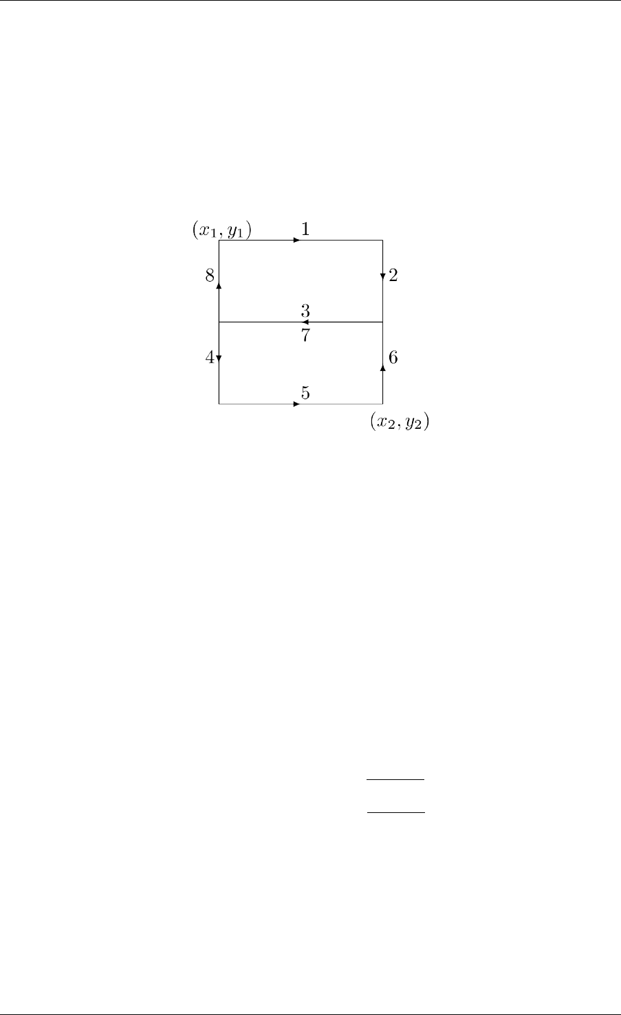
INET Framework User’s Guide
23.2.2 More Information on Some Mobility Models
TractorMobility
Moves a tractor through a field with a certain amount of rows. The following figure illustrates
the movement of the tractor when the rowCount parameter is 2. The trajectory follows the
segments in 1,2,3,4,5,6,7,8,1,2,3... order. The area is configured by the x1,y1,
x2,y2 parameters.
RandomWaypointMobility
In the Random Waypoint mobility model the nodes move in line segments. For each line
segment, a random destination position (distributed uniformly over the scene) and a random
speed is chosen. You can define a speed as a variate from which a new value will be drawn
for each line segment; it is customary to specify it as uniform(minSpeed, maxSpeed).
When the node reaches the target position, it waits for the time waitTime which can also be
defined as a variate. After this time the the algorithm calculates a new random position, etc.
GaussMarkovMobility
The Gauss-Markov model contains a tuning parameter that control the randomness in the move-
ment of the node. Let the magnitude and direction of speed of the node at the 𝑛th time step be
𝑠𝑛and 𝑑𝑛. The next speed and direction are computed as
𝑠𝑛+1 =𝛼𝑠𝑛+ (1 −𝛼)¯𝑠+(1 −𝛼2)𝑠𝑥𝑛
𝑑𝑛+1 =𝛼𝑠𝑛+ (1 −𝛼)¯
𝑑+(1 −𝛼2)𝑑𝑥𝑛
where ¯𝑠and ¯
𝑑are constants representing the mean value of speed and direction as 𝑛→ ∞; and
𝑠𝑥𝑛and 𝑑𝑥𝑛are random variables with Gaussian distribution.
Totally random walk (Brownian motion) is obtained by setting 𝛼= 0, while 𝛼= 1 results a
linear motion.
To ensure that the node does not remain at the boundary of the constraint area for a long time,
the mean value of the direction ( ¯
𝑑) modified as the node enters the margin area. For example at
the right edge of the area it is set to 180 degrees, so the new direction is away from the edge.
118 Chapter 23. Node Mobility

INET Framework User’s Guide
MassMobility
This is a random mobility model for a mobile host with a mass. It is the one used in [?].
“An MH moves within the room according to the following pattern. It moves along
a straight line for a certain period of time before it makes a turn. This moving
period is a random number, normally distributed with average of 5 seconds and
standard deviation of 0.1 second. When it makes a turn, the new direction (angle)
in which it will move is a normally distributed random number with average equal
to the previous direction and standard deviation of 30 degrees. Its speed is also a
normally distributed random number, with a controlled average, ranging from 0.1
to 0.45 (unit/sec), and standard deviation of 0.01 (unit/sec). A new such random
number is picked as its speed when it makes a turn. This pattern of mobility is
intended to model node movement during which the nodes have momentum, and
thus do not start, stop, or turn abruptly. When it hits a wall, it reflects off the wall
at the same angle; in our simulated world, there is little other choice.”
This implementation can be parameterized a bit more, via the changeInterval,
changeAngleBy and changeSpeedBy parameters. The parameters described above cor-
respond to the following settings:
• changeInterval = normal(5, 0.1)
• changeAngleBy = normal(0, 30)
• speed = normal(avgSpeed, 0.01)
ChiangMobility
Implements Chiang’s random walk movement model ([?]). In this model, the state of the mobile
node in each direction (x and y) can be:
• 0: the node stays in its current position
• 1: the node moves forward
• 2: the node moves backward
The (𝑖, 𝑗)element of the state transition matrix determines the probability that the state changes
from 𝑖to 𝑗:
⎛
⎝
0 0.5 0.5
0.3 0.7 0
0.300.7
⎞
⎠
23.2.3 Replaying trace files
BonnMotionMobility
Uses the native file format of BonnMotion.
23.2. Built-In Mobility Models 119

INET Framework User’s Guide
The file is a plain text file, where every line describes the motion of one host. A line consists
of one or more (t, x, y) triplets of real numbers, like:
t1 x1 y1 t2 x2 y2 t3 x3 y3 t4 x4 y4 ...
The meaning is that the given node gets to (𝑥𝑘, 𝑦𝑘)at 𝑡𝑘. There’s no separate notation for wait,
so x and y coordinates will be repeated there.
Ns2MotionMobility
Nodes are moving according to the trace files used in NS2. The trace file has this format:
# '#' starts a comment, ends at the end of line
$node_(<id>) set X_ <x> # sets x coordinate of the node identified
˓→by <id>
$node_(<id>) set Y_ <y> # sets y coordinate of the node identified
˓→by <id>
$node_(<id>) set Z_ <z> # sets z coordinate (ignored)
$ns at $time "$node_(<id>) setdest <x> <y> <speed>" # at $time
˓→start moving
towards <x>,<y> with <speed>
The Ns2MotionMobility module has the following parameters:
•traceFile the Ns2 trace file
•nodeId node identifier in the trace file; -1 gets substituted by parent module’s index
•scrollX,scrollY user specified translation of the coordinates
ANSimMobility
It reads trace files of the ANSim Tool. The nodes are moving along linear segments described
by an XML trace file conforming to this DTD:
<!ELEMENT mobility (position_change*)>
<!ELEMENT position_change (node_id, start_time, end_time,
˓→destination)>
<!ELEMENT node_id (#PCDATA)>
<!ELEMENT start_time (#PCDATA)>
<!ELEMENT end_time (#PCDATA)>
<!ELEMENT destination (xpos, ypos)>
<!ELEMENT xpos (#PCDATA)>
<!ELEMENT ypos (#PCDATA)>
Parameters of the module:
•ansimTrace the trace file
•nodeId the node_id of this node, -1 gets substituted to parent module’s index
120 Chapter 23. Node Mobility

INET Framework User’s Guide
Note: The AnsimMobility module processes only the position_change elements and it
ignores the start_time attribute. It starts the move on the next segment immediately.
23.2.4 TurtleMobility
The TurtleMobility module can be parametrized by a script file containing LOGO-style move-
ment commands in XML format. The content of the XML file should conform to the DTD in
the TurtleMobility.dtd file in the source tree.
The file contains movement elements, each describing a trajectory. The id attribute of the
movement element can be used to refer the movement from the ini file using the syntax:
**.mobility.turtleScript =xmldoc("turtle.xml", "movements//
˓→movement[@id='1']")
The motion of the node is composed of uniform linear segments. The movement elements
may contain the the following commands as elements (names in parens are recognized attribute
names):
•repeat(n) repeats its content n times, or indefinitely if the nattribute is omitted.
•set(x,y,speed,angle,borderPolicy) modifies the state of the node.
borderPolicy can be reflect,wrap,placerandomly or error.
•forward(d,t) moves the node for ttime or to the ddistance with the current speed.
If both dand tis given, then the current speed is ignored.
•turn(angle) increase the angle of the node by angle degrees.
•moveto(x,y,t) moves to point (x,y) in the given time. If 𝑡is not specified, it is
computed from the current speed.
•moveby(x,y,t) moves by offset (x,y) in the given time. If 𝑡is not specified, it is
computed from the current speed.
•wait(t) waits for the specified amount of time.
Attribute values must be given without physical units, distances are assumed to be given as
meters, time intervals in seconds and speeds in meter per seconds. Attibutes can contain ex-
pressions that are evaluated each time the command is executed. The limits of the constraint
area can be referenced as $MINX,$MAXX,$MINY, and $MAXY. Random number distibutions
generate a new random number when evaluated, so the script can describe random as well as
deterministic scenarios.
To illustrate the usage of the module, we show how some mobility models can be implemented
as scripts.
RectangleMobility:
23.2. Built-In Mobility Models 121

INET Framework User’s Guide
<movement>
<set x="$MINX" y="$MINY" angle="0" speed="10"/>
<repeat>
<repeat n="2">
<forward d="$MAXX-$MINX"/>
<turn angle="90"/>
<forward d="$MAXY-$MINY"/>
<turn angle="90"/>
</repeat>
</repeat>
</movement>
Random Waypoint:
<movement>
<repeat>
<set speed="uniform(20,60)"/>
<moveto x="uniform($MINX,$MAXX)" y="uniform($MINY,$MAXY)"/>
<wait t="uniform(5,10)">
</repeat>
</movement>
MassMobility:
<movement>
<repeat>
<set speed="uniform(10,20)"/>
<turn angle="uniform(-30,30)"/>
<forward t="uniform(0.1,1)"/>
</repeat>
</movement>
122 Chapter 23. Node Mobility

CHAPTER
TWENTYFOUR
MODELING POWER CONSUMPTION
24.1 Overview
Modeling power consumption becomes more and more important with the increasing number
of embedded devices and the upcoming Internet of Things. Mobile personal medical devices,
large scale wireless environment monitoring devices, electric vehicles, solar panels, low-power
wireless sensors, etc. require paying special attention to power consumption. High-fidelity
simulation of power consumption allows designing power-sensitive routing protocols, MAC
protocols with power management features, etc., which in turn results in more energy efficient
devices.
In order to help the modeling process, the INET power model is separated from other sim-
ulation models. This separation makes the power model extensible, and it also allows easy
experimentation with alternative implementations. In a nutshell, the power model consists of
the following components:
• energy consumption models
• energy generation models
• temporary energy storage models
The power model elements fall into two categories, abbreviated with Ep and Cc as part of their
names:
•Ep models are simpler, and deal with energy and power quantities.
•Cc models are more realistic, and deal with charge, current, and voltage quantities.
The following sections provide a brief overview of the power model.
24.2 Energy Consumer Models
Energy consumer models describe the energy consumption of devices over time. For example,
a transceiver consumes energy when it transmits or receives a signal, a CPU consumes energy
when the network protocol forwards a packet, and a display consumes energy when it is turned
on.
123

INET Framework User’s Guide
In INET, an energy consumer model is an OMNeT++ simple module that implements the en-
ergy consumption of software processes or hardware devices over time. Its main purpose is to
provide the power or current consumption for the current simulation time. Most often energy
consumers are included as submodules in the compound module of the hardware devices or
software components.
INET provides only a few built-in energy consumer models:
•AlternatingEpEnergyGenerator is a trivial energy/power based statistical energy con-
sumer model example.
•StateBasedEpEnergyConsumer is a transceiver energy consumer model based on the ra-
dio mode and transmission/reception states.
In order to simulate power consumption in a wireless network, the energy consumer model type
must be configured for the transceivers. The following example demonstrates how to configure
the power consumption parameters for a transceiver energy consumer model:
*.host[*].wlan[*].radio.energyConsumer.typename =
˓→"StateBasedEpEnergyConsumer"
*.host[*].wlan[*].radio.energyConsumer.sleepPowerConsumption =0.1mW
*.host[*].wlan[*].radio.energyConsumer.receiverIdlePowerConsumption
˓→=2mW
*.host[*].wlan[*].radio.energyConsumer.receiverBusyPowerConsumption
˓→=5mW
*.host[*].wlan[*].radio.energyConsumer.
˓→receiverReceivingPowerConsumption =10mW
*.host[*].wlan[*].radio.energyConsumer.
˓→transmitterIdlePowerConsumption =2mW
*.host[*].wlan[*].radio.energyConsumer. \
transmitterTransmittingPowerConsumption =100mW # continue
˓→previous line
24.3 Energy Generator Models
Energy generator models describe the energy generation of devices over time. A solar panel,
for example, produces energy based on time, the panel’s location on the globe, its orientation
towards the sun and the actual weather conditions. Energy generators connect to an energy
storage that absorbs the generated energy.
In INET, an energy generator model is an OMNeT++ simple module implementing the energy
generation of a hardware device using a physical phenomena over time. Its main purpose is
to provide the power or current generation for the current simulation time. Most often energy
generation models are included as submodules in network nodes.
INET provides only one trivial energy/power based statistical energy generator model called
AlternatingEpEnergyGenerator. The following example shows how to configure its power gen-
eration parameters:
124 Chapter 24. Modeling Power Consumption

INET Framework User’s Guide
*.host[*].energyGenerator.typename ="AlternatingEpEnergyGenerator"
*.host[*].energyGenerator.energySinkModule ="^.energyStorage" #
˓→module ref.
*.host[*].energyGenerator.powerGeneration =1mW
*.host[*].energyGenerator.sleepInterval =exponential(10s) # random
˓→intervals
*.host[*].energyGenerator.generationInterval =exponential(10s)
24.4 Energy Storage Models
Electronic devices which are not connected to external power source must contain some com-
ponent to store energy. For example, an electrochemical battery in a mobile phone provides
energy for its display, its CPU, and its communication devices. It might also absorb energy
produced by a solar installed on its display, or by a portable charger plugged into the wall
socket.
In INET, an energy storage model is an OMNeT++ simple module which models the physical
phenomena that is used to store energy produced by generators and provide energy for con-
sumers. Its main purpose is to compute the amount of available energy or charge at the current
simulation time. It maintains a set of connected energy consumers and energy generators, their
respective total power consumption and total power generation.
INET contains a few built-in energy storage models:
•IdealEpEnergyStorage is an idealistic model with infinite energy capacity and infinite
power flow.
•SimpleEpEnergyStorage is a non-trivial model integrating the difference between the
total consumed power and the total generated power over time.
•SimpleCcBattery is a more realistic charge/current based battery model using a charge
independent ideal voltage source and internal resistance.
The following example shows how to configure a simple energy storage model:
*.host[*].energyStorage.typename ="SimpleEpEnergyStorage"
*.host[*].energyStorage.nominalCapacity =0.05J # maximum capacity
*.host[*].energyStorage.initialCapacity =uniform(0J, this.
˓→nominalCapacity)
24.5 Energy Management Models
SimpleEpEnergyManagement
24.4. Energy Storage Models 125

INET Framework User’s Guide
*.host[*].energyManagement.typename ="SimpleEpEnergyManagement"
*.host[*].energyManagement.nodeStartCapacity =0.025J # start
˓→threshold
*.host[*].energyManagement.nodeShutdownCapacity =0J # shutdown
˓→threshold
126 Chapter 24. Modeling Power Consumption

CHAPTER
TWENTYFIVE
NETWORK EMULATION
25.1 Motivation
There are several projects that may benefit from the network emulation capabilities of INET,
that is, from the ability to mix simulated components with real networks.
Some example scenarios:
• Run a simulated component, such as an app or a routing protocol, on nodes of an actual
ad-hoc network. This setup would allow testing the component’s behavior under real-life
conditions.
• Test the interoperability of a simulated protocol with its real-world counterparts. Several
setups are possible: simulated node in a real network; a simulated subnet in real network;
real-world node in simulated network; etc.
• As a means of implementing hybrid simulation. The real network (or a single host
OS) may contain several network emulator devices or simulations running in emulation
mode. Such a setup provides a relatively easy way for connecting heterogenous simu-
lators/emulators with each other, sparing the need for HLA or a custom interoperability
solution.
25.2 Overview
To act as a network emulator, the simulation must run in real time, and must be able to com-
municate with the real world.
This is achieved with two components in INET:
•ExtInterface is an INET network interface that represents a real interface (an interface
of the host OS) in the simulation. Packets sent to an ExtInterface will be sent out on the
host OS interface, and packets received by the host OS interface (or rather, the appropriate
subset of them) will appear in the simulation as if received on an ExtInterface. The code
uses the pcap library for capturing packets, and raw sockets for sending.
•RealTimeScheduler, a socket-aware real-time scheduler class.
127

INET Framework User’s Guide
Note: It is probably needless to say, but the simulation must be fast enough to be able to keep
up with real time. That is, its relative speed compared to real time (the simsec/sec value) must
be >>1. (Under Qtenv, this can usually only be achieved in Express mode.)
The simulation is run under Qtenv,
25.3 Preparation
There are a few things that need to be arranged before you can successfully run simulations in
network emulation mode.
First, network emulation is a separate project feature that needs to be enabled before it can be
used. (Project features can be reviewed and changed in the Project | Project Features. . . dialog
in the IDE.)
The network emulation code makes use of the pcap library, and therefore it must be available
on your system. On Ubuntu, for example, pcap can be installed with the following command:
$ sudo apt install libpcap-dev
Also, when running a simulation, make sure you have the necessary permissions. Sending uses
raw sockets (type SOCK_RAW), which, on many systems, is only allowed for processes that
have root (administrator) privileges.
25.4 Configuring
INET nodes such as StandardHost and Router can be configured to have ExtInterface’s. The
simulation may contain several nodes with external interfaces, and one node may also have
several external interfaces.
A network node can be configured to have an external interface in the following way:
**.host1.numExtInterfaces =1
Also, the simulation must be configured to run under control the of the appropriate real-time
scheduler class:
scheduler-class ="inet::RealTimeScheduler"
ExtInterface has two important parameters which need to be configured. The device pa-
rameter should be set to the name of the real interface on the host OS, and filterString
should contain a packet filter expression that selects which packets captured on the real inter-
face should be relayed into the simulation via this ExtInterface. (filterString is simply
passed to the pcap library, so it should follow the tcpdump filter expressions syntax that pcap
understands.)
128 Chapter 25. Network Emulation

INET Framework User’s Guide
An example configuration:
**.numExtInterfaces =1
**.ext[0].ext.filterString ="(sctp or icmp) and ip dst host 10.1.1.
˓→1"
**.ext[0].ext.device ="eth0" # or "en0" on macOS, or something
**.ext[0].ext.mtu =1500B
The filter string "(sctp or icmp) and ip dst host 10.1.1.1" means that the
protocol must be SCTP or ICMP, and the destination host must be 10.1.1.1.
Note: Why is filtering of incoming packets done at packet capture (in pcap), and not in Ex-
tInterface? The reason is performance: it costs much fewer CPU cycles to discard unnecessary
packets right where they come in, and not send them up into the simulation for the same de-
cision. And, given that the simulation needs to keep up with real time, saving CPU cycles is
important.
Let us examine the paths outgoing and incoming packets take, and the necessary configuration
requirements to make them work. We assume IPv4 as network layer protocol, but the pic-
ture does not change much with other protocols. We assume the external interface is named
ext[0].
25.4.1 Outgoing path
The network layer of the simulated node routes datagrams to its ext[0] external interface.
For that to happen, the routing table needs to contain an entry where the interface is set to
ext[0]. Such entries are not created automatically, one needs to add them to the routing table
explicitly, e.g. by using an Ipv4NetworkConfigurator and an appropriate XML file.
Another point is that if the packet comes from a local app (and from another simulated node),
it needs to have a source IP address assigned. There are two ways for that to happen. If the
sending app specified a source IP address, that will be used. Otherwise, the IP address of the
ext[0] interface will be used, but for that, the interface needs to have an IP address at all.
Once in ext[0], the datagram is serialized. Serialization is a built-in feature of INET packets.
(Packets, or rather, packet chunks have multiple alternative representations, i.e. C++ object and
serialized form, and conversion between them is transparent.)
The result of serialization is a byte string, which is written into a raw socket with a sendto
system call.
The packet will then travel normally in the real network to the destination address.
25.4.2 Incoming path
First of all, packets intended to be received by the simulation need to find their way to the
correct interface of the host that runs the simulation. For that, IP addresses of simulated hosts
25.4. Configuring 129

INET Framework User’s Guide
must be routable in the real network, and routed to the captured interface of the host OS. (On
Linux, for example, this can be achieved by adding static routes with the command.)
As packets are received by the interface of the host OS, they are examined by the pcap library
to find out whether they match the filter expression. If the filter matches, pcap hands the packet
over to the simulation, and after deserialization it pops out of ext[0] and sent up to the
network layer. After that, it is routed to the simulated destination host in the normal way.
The pcap filter expression must be crafted so that it matches the packets destined to simulated
hosts, and does not match any other packet.
Moreover, if the simulation contains several external interfaces that map to the same real in-
terface, care must be taken so that filter expressions are disjunct. Otherwise, a packet may be
matched by more than one filter, and then it will be inserted into the simulation in multiple
copies (once for each matching ExtInterface.) This is usually not what is wanted.
130 Chapter 25. Network Emulation

CHAPTER
TWENTYSIX
NETWORK AUTOCONFIGURATION
26.1 Overview
This chapter describes static autoconfiguration of networks.
26.2 Configuring IPv4 Networks
An IPv4 network is composed of several nodes like hosts, routers, switches, hubs, Ethernet
buses, or wireless access points. The nodes having a IPv4 network layer (hosts and routers)
should be configured at the beginning of the simulation. The configuration assigns IP ad-
dresses to the nodes, and fills their routing tables. If multicast forwarding is simulated, then the
multicast routing tables also must be filled in.
The configuration can be manual (each address and route is fully specified by the user), or
automatic (addresses and routes are generated by a configurator module at startup).
Before version 1.99.4 INET offered Ipv4FlatNetworkConfigurator for automatic and routing
files for manual configuration. Both had serious limitations, so a new configurator has been
added in version 1.99.4: Ipv4NetworkConfigurator. This configurator supports both fully man-
ual and fully automatic configuration. It can also be used with partially specified manual con-
figurations, the configurator fills in the gaps automatically.
The next section describes the usage of Ipv4NetworkConfigurator. The legacy solutions
Ipv4FlatNetworkConfigurator and routing files are described in subsequent sections.
26.2.1 Ipv4NetworkConfigurator
The Ipv4NetworkConfigurator assigns IP addresses and sets up static routing for an IPv4 net-
work.
It assigns per-interface IP addresses, strives to take subnets into account, and can also optimize
the generated routing tables by merging routing entries.
Hierarchical routing can be set up by using only a fraction of configuration entries compared
to the number of nodes. The configurator also does routing table optimization that significantly
decreases the size of routing tables in large networks.
131

INET Framework User’s Guide
The configuration is performed in stage 2 of the initialization. At this point interface modules
(e.g. PPP) has already registered their interface in the interface table. If an interface is named
ppp[0], then the corresponding interface entry is named ppp0. This name can be used in the
config file to refer to the interface.
The configurator goes through the following steps:
1. Builds a graph representing the network topology. The graph will have a vertex for
every module that has a @node property (this includes hosts, routers, and L2 devices
like switches, access points, Ethernet hubs, etc.) It also assigns weights to vertices and
edges that will be used by the shortest path algorithm when setting up routes. Weights
will be infinite for IP nodes that have IP forwarding disabled (to prevent routes from
transiting them), and zero for all other nodes (routers and and L2 devices). Edge weights
are chosen to be inversely proportional to the bitrate of the link, so that the configurator
prefers connections with higher bandwidth. For internal purposes, the configurator also
builds a table of all “links” (the link data structure consists of the set of network interfaces
that are on the same point-to-point link or LAN)
2. Assigns IP addresses to all interfaces of all nodes. The assignment process takes into con-
sideration the addresses and netmasks already present on the interfaces (possibly set in
earlier initialize stages), and the configuration provided in the XML format (described be-
low). The configuration can specify “templates” for the address and netmask, with parts
that are fixed and parts that can be chosen by the configurator (e.g. “10.0.x.x”). In the
most general case, the configurator is allowed to choose any address and netmask for all
interfaces (which results in automatic address assignment). In the most constrained case,
the configurator is forced to use the requested addresses and netmasks for all interfaces
(which translates to manual address assignment). There are many possible configuration
options between these two extremums. The configurator assigns addresses in a way that
maximizes the number of nodes per subnet. Once it figures out the nodes that belong to
a single subnet it, will optimize for allocating the longest possible netmask. The config-
urator might fail to assign netmasks and addresses according to the given configuration
parameters; if that happens, the assignment process stops and an error is signalled.
3. Adds the manual routes that are specified in the configuration.
4. Adds static routes to all routing tables in the network. The configurator uses Dijkstra’s
weighted shortest path algorithm to find the desired routes between all possible node
pairs. The resulting routing tables will have one entry for all destination interfaces in the
network. The configurator can be safely instructed to add default routes where applicable,
significantly reducing the size of the host routing tables. It can also add subnet routes
instead of interface routes further reducing the size of routing tables. Turning on this
option requires careful design to avoid having IP addresses from the same subnet on
different links. CAVEAT: Using manual routes and static route generation together may
have unwanted side effects, because route generation ignores manual routes.
5. Then it optimizes the routing tables for size. This optimization allows configuring larger
networks with smaller memory footprint and makes the routing table lookup faster. The
resulting routing table might be different in that it will route packets that the original
routing table did not. Nevertheless the following invariant holds: any packet routed by
the original routing table (has matching route) will still be routed the same way by the
optimized routing table.
132 Chapter 26. Network Autoconfiguration

INET Framework User’s Guide
6. Finally it dumps the requested results of the configuration. It can dump network topology,
assigned IP addresses, routing tables and its own configuration format.
The module can dump the result of the configuration in the XML format which it can read. This
is useful to save the result of a time consuming configuration (large network with optimized
routes), and use it as the config file of subsequent runs.
Network topology graph
The network topology graph is constructed from the nodes of the network. The node is a
module having a @node property (this includes hosts, routers, and L2 devices like switches,
access points, Ethernet hubs, etc.). An IP node is a node that contains an InterfaceTable and
aIpv4RoutingTable. A router is an IP node that has multiple network interfaces, and IP for-
warding is enabled in its routing table module. In multicast routers the forwardMulticast
parameter is also set to true.
A link is a set of interfaces that can send datagrams to each other without intervening routers.
Each interface belongs to exactly one link. For example two interface connected by a point-to-
point connection forms a link. Ethernet interfaces connected via buses, hubs or switches. The
configurator identifies links by discovering the connections between the IP nodes, buses, hubs,
and switches.
Wireless links are identified by the ssid or accessPointAddress parameter of the 802.11
management module. Wireless interfaces whose node does not contain a management module
are supposed to be on the same wireless link. Wireless links can also be configured in the
configuration file of Ipv4NetworkConfigurator:
<config>
<wireless hosts="area1.*"interfaces="wlan*">
</config>
puts wlan interfaces of the specified hosts into the same wireless link.
If a link contains only one router, it is marked as the gateway of the link. Each datagram whose
destination is outside the link must go through the gateway.
Address assignment
Addresses can be set up manually by giving the address and netmask for each IP node. If some
part of the address or netmask is unspecified, then the configurator can fill them automatically.
Unspecified fields are given as an “x” character in the dotted notation of the address. For
example, if the address is specified as 192.168.1.1 and the netmask is 255.255.255.0, then the
node address will be 192.168.1.1 and its subnet is 192.168.1.0. If it is given as 192.168.x.x
and 255.255.x.x, then the configurator chooses a subnet address in the range of 192.168.0.0 -
192.168.255.252, and an IP address within the chosen subnet. (The maximum subnet mask is
255.255.255.252 allows 2 nodes in the subnet.)
The following configuration generates network addresses below the 10.0.0.0 address for each
link, and assign unique IP addresses to each host:
26.2. Configuring IPv4 Networks 133

INET Framework User’s Guide
<config>
<interface hosts="*"address="10.x.x.x" netmask="255.x.x.x"/>
</config>
The configurator tries to put nodes on the same link into the same subnet, so its enough to
configure the address of only one node on each link.
The following example configures a hierarchical network in a way that keeps routing tables
small.
<config>
<interface hosts="area11.lan1.*"address="10.11.1.x" netmask="255.
˓→255.255.x"/>
<interface hosts="area11.lan2.*"address="10.11.2.x" netmask="255.
˓→255.255.x"/>
<interface hosts="area12.lan1.*"address="10.12.1.x" netmask="255.
˓→255.255.x"/>
<interface hosts="area12.lan2.*"address="10.12.2.x" netmask="255.
˓→255.255.x"/>
<interface hosts="area*.router*"address="10.x.x.x" netmask="x.x.
˓→x.x"/>
<interface hosts="*"address="10.x.x.x" netmask="255.x.x.0"/>
</config>
The XML configuration must contain exactly one <config> element. Under the root element
there can be multiple of the following elements:
The interface element provides configuration parameters for one or more interfaces in the net-
work. The selector attributes limit the scope where the interface element has effects. The pa-
rameter attributes limit the range of assignable addresses and netmasks. The <interface>
element may contain the following attributes:
•@hosts Optional selector attribute that specifies a list of host name patterns. Only
interfaces in the specified hosts are affected. The pattern might be a full path starting
from the network, or a module name anywhere in the hierarchy, and other patterns similar
to ini file keys. The default value is “*” that matches all hosts. e.g. “subnet.client*” or
“host* router[0..3]” or “area*.*.host[0]”
•@names Optional selector attribute that specifies a list of interface name patterns. Only
interfaces with the specified names are affected. The default value is “*” that matches all
interfaces. e.g. “eth* ppp0” or “*”
•@towards Optional selector attribute that specifies a list of host name patterns. Only
interfaces connected towards the specified hosts are affected. The specified name will
be matched against the names of hosts that are on the same LAN with the one that is
being configured. This works even if there’s a switch between the configured host and
the one specified here. For wired networks it might be easier to specify this parameter
instead of specifying the interface names. The default value is “*”. e.g. “ap” or “server”
or “client*”
•@among Optional selector attribute that specifies a list of host name patterns. Only
interfaces in the specified hosts connected towards the specified hosts are affected. The
134 Chapter 26. Network Autoconfiguration

INET Framework User’s Guide
’among=”X Y Z”’ is same as ’hosts=”X Y Z” towards=”X Y Z”’.
•@address Optional parameter attribute that limits the range of assignable addresses.
Wildcards are allowed with using ’x’ as part of the address in place of a byte. Unspecified
parts will be filled automatically by the configurator. The default value “” means that the
address will not be configured. Unconfigured interfaces still have allocated addresses in
their subnets allowing them to become configured later very easily. e.g. “192.168.1.1”
or “10.0.x.x”
•@netmask Optional parameter attribute that limits the range of assignable netmasks.
Wildcards are allowed with using ’x’ as part of the netmask in place of a byte. Unspeci-
fied parts will be filled automatically be the configurator. The default value “” means that
any netmask can be configured. e.g. “255.255.255.0” or “255.255.x.x” or “255.255.x.0”
•@mtu number Optional parameter attribute to set the MTU parameter in the interface.
When unspecified the interface parameter is left unchanged.
•@metric number Optional parameter attribute to set the Metric parameter in the inter-
face. When unspecified the interface parameter is left unchanged.
Wireless interfaces can similarly be configured by adding <wireless> elements to the con-
figuration. Each <wireless> element with a different id defines a separate subnet.
•@id (optional) identifies wireless network, unique value used if missed
•@hosts Optional selector attribute that specifies a list of host name patterns. Only
interfaces in the specified hosts are affected. The default value is “*” that matches all
hosts.
•@interfaces Optional selector attribute that specifies a list of interface name pat-
terns. Only interfaces with the specified names are affected. The default value is “*” that
matches all interfaces.
Multicast groups
Multicast groups can be configured by adding <multicast-group> elements to the con-
figuration file. Interfaces belongs to a multicast group will join to the group automatically.
For example,
<config>
<multicast-group hosts="router*"interfaces="eth*"address="224.0.
˓→0.5"/>
</config>
adds all Ethernet interfaces of nodes whose name starts with “router” to the 224.0.0.5 multicast
group.
The <multicast-group> element has the following attributes:
•@hosts Optional selector attribute that specifies a list of host name patterns. Only
interfaces in the specified hosts are affected. The default value is “*” that matches all
hosts.
26.2. Configuring IPv4 Networks 135

INET Framework User’s Guide
•@interfaces Optional selector attribute that specifies a list of interface name pat-
terns. Only interfaces with the specified names are affected. The default value is “*” that
matches all interfaces.
•@towards Optional selector attribute that specifies a list of host name patterns. Only
interfaces connected towards the specified hosts are affected. The default value is “*”.
•@among Optional selector attribute that specifies a list of host name patterns. Only
interfaces in the specified hosts connected towards the specified hosts are affected. The
’among=”X Y Z”’ is same as ’hosts=”X Y Z” towards=”X Y Z”’.
•@address Mandatory parameter attribute that specifies a list of multicast group ad-
dresses to be assigned. Values must be selected from the valid range of multicast ad-
dresses. e.g. “224.0.0.1 224.0.1.33”
Manual route configuration
The Ipv4NetworkConfigurator module allows the user to fully specify the routing tables of IP
nodes at the beginning of the simulation.
The <route> elements of the configuration add a route to the routing tables of selected nodes.
The element has the following attributes:
•@hosts Optional selector attribute that specifies a list of host name patterns. Only
routing tables in the specified hosts are affected. The default value “” means all hosts
will be affected. e.g. “host* router[0..3]”
•@destination Optional parameter attribute that specifies the destination address in
the route (L3AddressResolver syntax). The default value is “*”. e.g. “192.168.1.1” or
“subnet.client[3]” or “subnet.server(ipv4)” or “*”
•@netmask Optional parameter attribute that specifies the netmask in the route. The
default value is “*”. e.g. “255.255.255.0” or “/29” or “*”
•@gateway Optional parameter attribute that specifies the gateway (next-hop) address in
the route (L3AddressResolver syntax). When unspecified the interface parameter must
be specified. The default value is “*”. e.g. “192.168.1.254” or “subnet.router” or “*”
•@interface Optional parameter attribute that specifies the output interface name in
the route. When unspecified the gateway parameter must be specified. This parameter
has no default value. e.g. “eth0”
•@metric Optional parameter attribute that specifies the metric in the route. The default
value is 0.
Multicast routing tables can similarly be configured by adding <multicast-route> ele-
ments to the configuration.
•@hosts Optional selector attribute that specifies a list of host name patterns. Only
routing tables in the specified hosts are affected. e.g. “host* router[0..3]”
•@source Optional parameter attribute that specifies the address of the source network.
The default value is “*” that matches all sources.
136 Chapter 26. Network Autoconfiguration

INET Framework User’s Guide
•@netmask Optional parameter attribute that specifies the netmask of the source net-
work. The default value is “*” that matches all sources.
•@groups Optional List of IPv4 multicast addresses specifying the groups this entry
applies to. The default value is “*” that matches all multicast groups. e.g. “225.0.0.1
225.0.1.2”.
•@metric Optional parameter attribute that specifies the metric in the route.
•@parent Optional parameter attribute that specifies the name of the interface the multi-
cast datagrams are expected to arrive. When a datagram arrives on the parent interface, it
will be forwarded towards the child interfaces; otherwise it will be dropped. The default
value is the interface on the shortest path towards the source of the datagram.
•@children Mandatory parameter attribute that specifies a list of interface name pat-
terns:
–a name pattern (e.g. “ppp*”) matches the name of the interface
–a ’towards’ pattern (starting with “>”, e.g. “>router*”) matches the interface by
naming one of the neighbour nodes on its link.
Incoming multicast datagrams are forwarded to each child interface except the one they
arrived in.
The following example adds an entry to the multicast routing table of router1, that intsructs
the routing algorithm to forward multicast datagrams whose source is in the 10.0.1.0 network
and whose destinatation address is 225.0.0.1 to send on the eth1 and eth2 interfaces assum-
ing it arrived on the eth0 interface:
<multicast-route hosts="router1" source="10.0.1.0" netmask="255.255.
˓→255.0"
groups="225.0.0.1" metric="10"
parent="eth0" children="eth1 eth2"/>
Automatic route configuration
If the addStaticRoutes parameter is true, then the configurator add static routes to all
routing tables.
The configurator uses Dijkstra’s weighted shortest path algorithm to find the desired routes be-
tween all possible node pairs. The resulting routing tables will have one entry for all destination
interfaces in the network.
The configurator can be safely instructed to add default routes where applicable, significantly
reducing the size of the host routing tables. It can also add subnet routes instead of interface
routes further reducing the size of routing tables. Turning on this option requires careful design
to avoid having IP addresses from the same subnet on different links.
26.2. Configuring IPv4 Networks 137

INET Framework User’s Guide
Caution: Using manual routes and static route generation together may have unwanted
side effects, because route generation ignores manual routes. Therefore if the configura-
tion file contains manual routes, then the addStaticRoutes parameter should be set to
false.
Route optimization
If the optimizeRoutes parameter is true then the configurator tries to optimize the rout-
ing table for size. This optimization allows configuring larger networks with smaller memory
footprint and makes the routing table lookup faster.
The optimization is performed by merging routes whose gateway and outgoing interface is
the same by finding a common prefix that matches only those routes. The resulting routing
table might be different in that it will route packets that the original routing table did not.
Nevertheless the following invariant holds: any packet routed by the original routing table (has
matching route) will still be routed the same way by the optimized routing table.
Parameters
This list summarize the parameters of the Ipv4NetworkConfigurator:
•config: XML configuration parameters for IP address assignment and adding manual
routes.
•assignAddresses: assign IP addresses to all interfaces in the network
•assignDisjunctSubnetAddresses: avoid using the same address prefix and net-
mask on different links when assigning IP addresses to interfaces
•addStaticRoutes: add static routes to the routing tables of all nodes to route to all
destination interfaces (only where applicable; turn off when config file contains manual
routes)
•addDefaultRoutes: add default routes if all routes from a source node go through
the same gateway (used only if addStaticRoutes is true)
•addSubnetRoutes: add subnet routes instead of destination interface routes (only
where applicable; used only if addStaticRoutes is true)
•optimizeRoutes: optimize routing tables by merging routes, the resulting routing
table might route more packets than the original (used only if addStaticRoutes is true)
•dumpTopology: if true, then the module prints extracted network topology
•dumpAddresses: if true, then the module prints assigned IP addresses for all inter-
faces
•dumpRoutes: if true, then the module prints configured and optimized routing tables
for all nodes to the module output
138 Chapter 26. Network Autoconfiguration

INET Framework User’s Guide
•dumpConfig: name of the file, write configuration into the given config file that can be
fed back to speed up subsequent runs (network configurations)
26.2.2 Ipv4FlatNetworkConfigurator (Legacy)
The Ipv4FlatNetworkConfigurator module configures IP addresses and routes of IP nodes of
a network. All assigned addresses share a common subnet prefix, the network topology will
be ignored. Shortest path routes are also generated from any node to any other node of the
network. The Gateway (next hop) field of the routes is not filled in by these configurator, so
it relies on proxy ARP if the network spans several LANs. It does not perform routing table
optimization (i.e. merging similar routes into a single, more general route.)
Warning: Ipv4FlatNetworkConfigurator is considered legacy, do not use it for new
projects.
The Ipv4FlatNetworkConfigurator module configures the network when it is initialized. The
configuration is performed in stage 2, after interface tables are filled in. Do not use a
Ipv4FlatNetworkConfigurator module together with static routing files, because they can iter-
fere with the configurator.
The Ipv4FlatNetworkConfigurator searches each IP nodes of the network. (IP nodes are those
modules that have the @node NED property and has a Ipv4RoutingTable submodule named
“routingTable”). The configurator then assigns IP addresses to the IP nodes, controlled by the
following module parameters:
•netmask common netmask of the addresses (default is 255.255.0.0)
•networkAddress higher bits are the network part of the addresses, lower bits should
be 0. (default is 192.168.0.0)
With the default parameters the assigned addresses are in the range 192.168.0.1 -
192.168.255.254, so there can be maximum 65534 nodes in the network. The same IP address
will be assigned to each interface of the node, except the loopback interface which always has
address 127.0.0.1 (with 255.0.0.0 mask).
After assigning the IP addresses, the configurator fills in the routing tables. There are two kind
of routes:
• default routes: for nodes that has only one non-loopback interface a route is added that
matches with any destination address (the entry has 0.0.0.0 host and netmask fields).
These are remote routes, but the gateway address is left unspecified. The delivery of the
datagrams rely on the proxy ARP feature of the routers.
• direct routes following the shortest paths: for nodes that has more than one non-loopback
interface a separate route is added to each IP node of the network. The outgoing interface
is chosen by the shortest path to the target node. These routes are added as direct routes,
even if there is no direct link with the destination. In this case proxy ARP is needed to
deliver the datagrams.
26.2. Configuring IPv4 Networks 139

INET Framework User’s Guide
Note: This configurator does not try to optimize the routing tables. If the network contains $n$
nodes, the size of all routing tables will be proportional to $n^2$, and the time of the lookup of
the best matching route will be proportional to $n$.
26.2.3 Routing Files (Legacy)
Routing files are files with .irt or .mrt extension, and their names are passed in the
routingFile parameter to Ipv4RoutingTable modules.
Routing files may contain network interface configuration and static routes. Both are optional.
Network interface entries in the file configure existing interfaces; static routes are added to the
route table.
Warning: Routing files are considered legacy, use do not use them for new projects. Their
contents can be expressed in Ipv4NetworkConfigurator config files.
Interfaces themselves are represented in the simulation by modules (such as the PPP module).
Modules automatically register themselves with appropriate defaults in the IPv4RoutingTable,
and entries in the routing file refine (overwrite) these settings. Interfaces are identified by names
(e.g. ppp0, ppp1, eth0) which are normally derived from the module’s name: a module called
"ppp[2]" in the NED file registers itself as interface ppp2.
An example routing file (copied here from one of the example simulations):
ifconfig:
# ethernet card 0 to router
name: eth0 inet_addr: 172.0.0.3 MTU: 1500 Metric: 1
˓→BROADCAST MULTICAST
Groups: 225.0.0.1:225.0.1.2:225.0.2.1
# Point to Point link 1 to Host 1
name: ppp0 inet_addr: 172.0.0.4 MTU: 576 Metric: 1
ifconfigend.
route:
172.0.0.2 *255.255.255.255 H0ppp0
172.0.0.4 *255.255.255.255 H0ppp0
default: 10.0.0.13 0.0.0.0 G0eth0
225.0.0.1 *255.255.255.255 H0ppp0
225.0.1.2 *255.255.255.255 H0ppp0
225.0.2.1 *255.255.255.255 H0ppp0
225.0.0.0 10.0.0.13 255.0.0.0 G0eth0
(continues on next page)
140 Chapter 26. Network Autoconfiguration

INET Framework User’s Guide
(continued from previous page)
routeend.
The ifconfig...ifconfigend. part configures interfaces, and route..routeend.
part contains static routes. The format of these sections roughly corresponds to the output of
the ifconfig and netstat -rn Unix commands.
An interface entry begins with a name: field, and lasts until the next name: (or until
ifconfigend.). It may be broken into several lines.
Accepted interface fields are:
•name: - arbitrary interface name (e.g. eth0, ppp0)
•inet_addr: - IP address
•Mask: - netmask
•Groups: Multicast groups. 224.0.0.1 is added automatically, and 224.0.0.2 also if the
node is a router (IPForward==true).
•MTU: - MTU on the link (e.g. Ethernet: 1500)
•Metric: - integer route metric
• flags: BROADCAST,MULTICAST,POINTTOPOINT
The following fields are parsed but ignored: Bcast,encap,HWaddr.
Interface modules set a good default for MTU, Metric (as 2*109/bitrate) and flags, but leave
inet_addr and Mask empty. inet_addr and mask should be set either from the routing
file or by a dynamic network configuration module.
The route fields are:
Destination Gateway Netmask Flags Metric Interface
Destination,Gateway and Netmask have the usual meaning. The Destination field
should either be an IP address or “default” (to designate the default route). For Gateway,*is
also accepted with the meaning 0.0.0.0.
Flags denotes route type:
•H“host”: direct route (directly attached to the router), and
•G“gateway”: remote route (reached through another router)
Interface is the interface name, e.g. eth0.
Important: The meaning of the routes where the destination is a multicast address has been
changed in version 1.99.4. Earlier these entries was used both to select the outgoing interfaces
of multicast datagrams sent by the higher layer (if multicast interface was otherwise unspeci-
fied) and to select the outgoing interfaces of datagrams that are received from the network and
forwarded by the node.
26.2. Configuring IPv4 Networks 141

INET Framework User’s Guide
From version 1.99.4 multicast routing applies reverse path forwarding. This requires a separate
routing table, that can not be populated from the old routing table entries. Therefore simulations
that use multicast forwarding can not use the old configuration files, they should be migrated
to use an Ipv4NetworkConfigurator instead.
Some change is needed in models that use link-local multicast too. Earlier if the IP module
received a datagram from the higher layer and multiple routes was given for the multicast
group, then IP sent a copy of the datagram on each interface of that routes. From version
1.99.4, only the first matching interface is used (considering longest match). If the application
wants to send the multicast datagram on each interface, then it must explicitly loop and specify
the multicast interface.
26.3 Configuring Layer 2
The L2NetworkConfigurator module allows configuring network scenarios at layer 2. The
STP/RTP-related parameters such as link cost, port priority and the “is-edge” flag can be con-
figured with XML files.
This module is similar to Ipv4NetworkConfigurator. It supports the selector at-
tributes @hosts,@names,@towards,@among, and they behave similarly to its
Ipv4NetworkConfigurator equivalent. The @ports selector is also supported, for configur-
ing per-port parameters.
The following example configures port 5 (if it exists) on all switches, and sets cost=19 and
priority=32768:
<config>
<interface hosts='**'ports='5' cost='19' priority='32768'/>
</config>
For more information about the usage of the selector attributes see Ipv4NetworkConfigurator.
142 Chapter 26. Network Autoconfiguration

CHAPTER
TWENTYSEVEN
SCENARIO SCRIPTING
27.1 Overview
The INET Framework contains scripting support to help the user express scenarios that cannot
be adequately described using static configuration. You can schedule actions to be carried out
at specified simulation times, for example changing a parameter value, changing the bit error
rate of a connection, removing or adding connections, removing or adding routes in a routing
table, shutting down or crashing routers, etc. The aim is usually to observe transient behaviour
caused by the changes.
INET supports the following built-in actions:
• Create or delete module
• Create or delete connection
• Set module or channel parameter
• Initiate lifecycle operation (startup, shutdown, crash) on a network node or part of it
27.2 ScenarioManager
The ScenarioManager module type is for setting up and controlling simulation experiments. In
typical usage, it has only one instance in the network:
network Test {
submodules:
scenarioManager:ScenarioManager;
...
}
ScenarioManager executes a script specified in XML. It has a few built-in commands, while
other commands are dispatched (in C++) to be carried out by other simple modules.
An example script:
143

INET Framework User’s Guide
<scenario>
<set-param t="10" module="host[1].mobility" par="speed" value="5
˓→"/>
<set-param t="20" module="host[1].mobility" par="speed" value=
˓→"30"/>
<at t="50">
<set-param module="host[2].mobility" par="speed" value="10"/
˓→>
<set-param module="host[3].mobility" par="speed" value="10"/
˓→>
<connect src-module="host[2]" src-gate="ppp[0]"
dest-module="host[1]" dest-gate="ppp[0]"
channel-type="ned.DatarateChannel">
<param name="datarate" value="10Mbps" />
<param name="delay" value="0.1us" />
</connect>
</at>
<at t="60">
<disconnect src-module="host[2]" src-gate="ppp[0]" />
<disconnect src-module="host[1]" src-gate="ppp[0]" />
</at>
</scenario>
The above script probably does not need much explanation.
The built-in commands of ScenarioManager are: <connect>,
<disconnect>,<create-module>,<delete-module>,<initiate>,
<shutdown>,‘‘<startup>‘‘,‘‘<crash>‘‘, <set-param>,<set-channel-attr>,
<at>.
All commands have a tattribute which carries the simulation time at which the command has
to be carried out. You can group several commands to be carried out at the same simulation
time using <at>, and then only the <at> command needs to have a tattribute.
More information can be found in the ScenarioManager documentation.
The script is usually placed in a separate file, and specified like this:
*.scenarioManager.script =xmldoc("scenario.xml")
Short scripts can also be written inline:
*.scenarioManager.script =xml("<x><shutdown t='2s' module='Router2
˓→'/></x>")
144 Chapter 27. Scenario Scripting

CHAPTER
TWENTYEIGHT
MODELING NODE FAILURES
28.1 Overview
Simulation is often used to study the effects of unexpected events like a router crash on the net-
work. In order to accommodate such scenarios, INET supports lifecycle modeling of network
nodes. The up/down status of a node is changed via lifecycle operations.
INET supports the following lifecycle operations:
•Startup represents the process of booting up or starting a network node after a shutdown
or crash operation.
•Shutdown represents the process of orderly shutting down a network node.
•Crash represents the process of crashing a network node. The difference between crash
and shutdown is that for a crash, the network node will not do a graceful shutdown (e.g.
routing protocols will not have a chance of notifying peers about broken routes).
In a real-life router or other network node, a crash or shutdown and subsequent restart affects
all parts of the system. All non-persistent information is lost. Protocol states are reset, various
tables are cleared, connections are broken or torn down, applications restart, and so on.
Mimicking this behavior in simulation does not come for free, it needs to be explicitly pro-
grammed into each affected component. Here are some examples how INET components react
to a crash lifecycle event:
•Tcp forgets all open connections and sockets
•Ipv4 clears the fragmentation reassembly buffers and pending packets
•Ipv4RoutingTable clears the route table
•EtherMac and other MAC protocols clear their queues and reset their state associated
with the current transmission(s)
•Ospf clears its full state
•UdpBasicApp,TcpSessionApp and other applications reset their state and stop/restart
their timers
•EtherSwitch,AccessPoint, and other L2 bridging devices clear their MAC address tables
145

INET Framework User’s Guide
While down, network interfaces, and components in general, ignore (discard) messages sent to
them.
Lifecycle operations are currently instanteneous, i.e. they complete in zero simulation time.
The underlying framework would allow for modeling them as processes that take place in some
finite (nonzero) simulation time, but this possibility is currently not in use.
It also is possible to simulate a crash or shutdown of part of a node (certain protocols or inter-
faces only). Such scenarios would correspond to e.g. the crash of an OSPF daemon on a real
OS.
Some energy-related INET components trigger node shutdown or crash under certain condi-
tions. For example, a node will crash when it runs out of power (e.g. its battery depletes); see
the chapter on power consumption modeling Modeling Power Consumption for details.
In the following sections we outline the INET components that participate in lifecycle model-
ing, and show a usage example.
28.2 NodeStatus
Node models contain a NodeStatus module that keeps track of the status of the node (up, down,
etc.) for other modules, and also displays it in the GUI as a small overlay icon.
The NodeStatus module is declared conditionally (so that it is only created in simulations that
need it), like this:
status:NodeStatus if hasStatus;
If lifecycle modeling is required, the following line must be added to the ini file to ensure that
nodes have status modules:
**.hasStatus =true
28.3 Scripting
Lifecycle operations can be triggered from C++ code, or from scripts. INET supports script-
ing via the ScenarioManager NED type, described in chapter Scenario Scripting. Here is an
example script that shuts down a router at simulation time 2s, and starts it up a again at time 8s:
<scenario>
<initiate t="2s" module="Router2" operation="shutdown"/>
<initiate t="8s" module="Router2" operation="startup"/>
</scenario>
The module attribute should point to the module (host, router, network interface, protocol,
etc.) to be operated on. The operation attribute should contain the operation to perform:
"shutdown","crash", or "startup".tis the simulation time the operation should be
initiated at.
146 Chapter 28. Modeling Node Failures

INET Framework User’s Guide
An alternative, shorter form is to use <shutdown> /<crash> /<startup> elements in-
stead of the operation attribute:
<scenario>
<shutdown t="2s" module="Router2"/>
<startup t="8s" module="Router2"/>
</scenario>
28.3. Scripting 147

INET Framework User’s Guide
148 Chapter 28. Modeling Node Failures

CHAPTER
TWENTYNINE
COLLECTING RESULTS
TODO
29.1 Recording Statistics
@statistic
29.2 Recording PCAP Traces
PcapRecorder
29.3 Recording Routing Tables
RoutingTableRecorder
29.4 Packet Recorder
29.5 Eventlog Recording
mention
149

INET Framework User’s Guide
150 Chapter 29. Collecting Results

CHAPTER
THIRTY
VISUALIZATION
30.1 Overview
The INET Framework is able to visualize a wide range of events and conditions in the network:
packet drops, data link connectivity, wireless signal path loss, transport connections, routing
table routes, and many more. Visualization is implemented as a collection of configurable
INET modules that can be added to simulations at will.
30.2 Visualizing Network Communication
30.2.1 Visualizing Packet Drops
Several network problems manifest themselves as excessive packet drops, for example poor
connectivity, congestion, or misconfiguration. Visualizing packet drops helps identifying such
problems in simulations, thereby reducing time spent on debugging and analysis. Poor con-
nectivity in a wireless network can cause senders to drop unacknowledged packets after the
retry limit is exceeded. Congestion can cause queues to overflow in a bottleneck router, again
resulting in packet drops.
Packet drops can be visualized by including a PacketDropVisualizer module in the simulation.
The PacketDropVisualizer module indicates packet drops by displaying an animation effect at
the node where the packet drop occurs. In the animation, a packet icon gets thrown out from
the node icon, and fades away.
The visualization of packet drops can be enabled with the visualizer’s
displayPacketDrops parameter. By default, packet drops at all nodes are visual-
ized. This selection can be narrowed with the nodeFilter,interfaceFilter and
packetFilter parameters.
One can click on the packet drop icon to display information about the packet drop in the
inspector panel.
Packets are dropped for the following reasons:
• queue overflow
• retry limit exceeded
151

INET Framework User’s Guide
• unroutable packet
• network address resolution failed
• interface down
30.2.2 Visualizing Transport Path Activity
With INET simulations, it is often useful to be able to visualize network traffic. INET provides
several visualizers for this task, operating at various levels of the network stack. One of such
visualizers is TransportRouteVisualizer that provides graphical feedback about transport layer
traffic.
TransportRouteVisualizer visualizes traffic that passes through the transport layers of two end-
points. Adding an IntegratedVisualizer is also an option, because it also contains a Trans-
portRouteVisualizer. Transport path activity visualization is disabled by default, it can be en-
abled by setting the visualizer’s displayRoutes parameter to true.
TransportRouteVisualizer observes packets that pass through the transport layer, i.e. carry data
from/to higher layers.
The activity between two nodes is represented visually by a polyline arrow which points from
the source node to the destination node. TransportRouteVisualizer follows packets throughout
their path so that the polyline goes through all nodes which are the part of the path of packets.
The arrow appears after the first packet has been received, then gradually fades out unless it is
reinforced by further packets. Color, fading time and other graphical properties can be changed
with parameters of the visualizer.
By default, all packets and nodes are considered for the visualization. This selection can be
narrowed with the visualizer’s packetFilter and nodeFilter parameters.
30.2.3 Visualizing Network Path Activity
Network layer traffic can be visualized by including a NetworkRouteVisualizer module in the
simulation. Adding an IntegratedVisualizer module is also an option, because it also contains
aNetworkRouteVisualizer module. Network path activity visualization is disabled by default,
it can be enabled by setting the visualizer’s displayRoutes parameter to true.
NetworkRouteVisualizer currently observes packets that pass through the network layer (i.e.
carry data from/to higher layers), but not those that are internal to the operation of the network
layer protocol. That is, packets such as ARP, although potentially useful, will not trigger the
visualization.
The activity between two nodes is represented visually by a polyline arrow which points from
the source node to the destination node. NetworkRouteVisualizer follows packet throughout its
path so the polyline goes through all nodes that are part of the packet’s path. The arrow appears
after the first packet has been received, then gradually fades out unless it is reinforced by further
packets. Color, fading time and other graphical properties can be changed with parameters of
the visualizer.
152 Chapter 30. Visualization

INET Framework User’s Guide
By default, all packets and nodes are considered for the visualization. This selection can be
narrowed with the visualizer’s packetFilter and nodeFilter parameters.
30.2.4 Visualizing Data Link Activity
Data link activity (layer 2 traffic) can be visualized by adding a DataLinkVisualizer module to
the simulation. Adding an IntegratedVisualizer module is also an option, because it includes a
DataLinkVisualizer module. Data link visualization is disabled by default, it can be enabled by
setting the visualizer’s displayLinks parameter to true.
DataLinkVisualizer currently observes packets that pass through the data link layer (i.e. carry
data from/to higher layers), but not those that are internal to the operation of the data link
layer protocol. That is, frames such as ACK, RTS/CTS, Beacon or Authentication/Association
frames of IEEE 802.11, although potentially useful, will not trigger the visualization. Visual-
izing such frames may be implemented in future INET revisions.
The activity between two nodes is represented visually by an arrow that points from the sender
node to the receiver node. The arrow appears after the first packet has been received, then
gradually fades out unless it is refreshed by further packets. The style, color, fading time and
other graphical properties can be changed with parameters of the visualizer.
By default, all packets, interfaces and nodes are considered for the visualization. This selec-
tion can be narrowed to certain packets and/or nodes with the visualizer’s packetFilter,
interfaceFilter, and nodeFilter parameters.
30.2.5 Visualizing Physical Link Activity
Physical link activity can be visualized by including a PhysicalLinkVisualizer module in the
simulation. Adding an IntegratedVisualizer module is also an option, because it also contains
aPhysicalLinkVisualizer module. Physical link activity visualization is disabled by default, it
can be enabled by setting the visualizer’s displayLinks parameter to true.
PhysicalLinkVisualizer observes frames that pass through the physical layer, i.e. are received
correctly.
The activity between two nodes is represented visually by a dotted arrow which points from
the sender node to the receiver node. The arrow appears after the first frame has been received,
then gradually fades out unless it is refreshed by further frames. Color, fading time and other
graphical properties can be changed with parameters of the visualizer.
By default, all packets, interfaces and nodes are considered for the visualization. This se-
lection can be narrowed with the visualizer’s packetFilter,interfaceFilter, and
nodeFilter parameters.
30.2.6 Visualizing Routing Tables
In a complex network topology, it is difficult to see how a packet would be routed because the
relevant data is scattered among network nodes and hidden in their routing tables. INET con-
30.2. Visualizing Network Communication 153

INET Framework User’s Guide
tains support for visualization of routing tables, and can display routing information graphically
in a concise way. Using visualization, it is often possible to understand routing in a simulation
without looking into individual routing tables. The visualization currently supports IPv4.
The RoutingTableVisualizer module (included in the network as part of IntegratedVisualizer)
is responsible for visualizing routing table entries.
The visualizer basically annotates network links with labeled arrows that connect source nodes
to next hop nodes. The module visualizes those routing table entries that participate in the
routing of a given set of destination addresses, by default the addresses of all interfaces of
all nodes in the network. That is, it selects the best (longest prefix) matching routes for all
destination addresses from each routing table, and shows them as arrows that point to the next
hop. Note that one arrow might need to represent several routing entries, for example when
distinct prefixes are routed towards the same next hop.
Routing table entries are represented visually by solid arrows. An arrow going from a source
node represents a routing table entry in the source node’s routing table. The endpoint node of
the arrow is the next hop in the visualized routing table entry. By default, the routing entry is
displayed on the arrows in following format:
destination/mask -> gateway (interface)
The format can be changed by setting the visualizer’s labelFormat parameter.
Filtering is also possible. The nodeFilter parameter controls which nodes’ routing tables
should be visualized (by default, all nodes), and the destinationFilter parameter selects
the set of destination nodes to consider (again, by default all nodes.)
The visualizer reacts to changes. For example, when a routing protocol changes a routing entry,
or an IP address gets assigned to an interface by DHCP, the visualizer automatically updates
the visualizations according to the specified filters. This is very useful e.g. for the simulation
of mobile ad-hoc networks.
30.2.7 Displaying IP Addresses and Other Interface Information
In the simulation of complex networks, it is often useful to be able to display node IP addresses,
interface names, etc. above the node icons or on the links. For example, when automatic
address assignment is used in a hierarchical network (e.g. using Ipv4NetworkConfigurator),
visual inspection can help to verify that the result matches the expectations. While it is true
that addresses and other interface data can also be accessed in the GUI by diving into the
interface tables of each node, that is tedious, and unsuitable for getting an overview.
The InterfaceTableVisualizer module (included in the network as part of IntegratedVisualizer)
displays data about network nodes’ interfaces. (Interfaces are contained in interface tables,
hence the name.) By default, the visualization is turned off. When it is enabled using the
displayInterfaceTables parameter, the default is that interface names, IP addresses
and netmask length are displayed, above the nodes (for wireless interfaces) and on the links
(for wired interfaces). By clicking on an interface label, details are displayed in the inspector
panel.
154 Chapter 30. Visualization

INET Framework User’s Guide
The visualizer has several configuration parameters. The format parameter specifies what
information is displayed about interfaces. It takes a format string, which can contain the fol-
lowing directives:
• %N: interface name
• %4: IPv4 address
• %6: IPv6 address
• %n: network address. This is either the IPv4 or the IPv6 address
• %l: netmask length
• %M: MAC address
• %: conditional newline for wired interfaces. The ” needs to be escaped with another ”,
i.e. ’%\’
• %i and %s: the info() and str() functions for the interfaceEntry class, respectively
The default format string is "%N %\\%n/%l", i.e. interface name, IP address and netmask
length.
The set of visualized interfaces can be selected with the configurator’s nodeFilter and
interfaceFilter parameters. By default, all interfaces of all nodes are visualized, except
for loopback addresses (the default for the interfaceFilter parameter is "not lo\".)
It is possible to display the labels for wired interfaces above the node icons, instead of on
the links. This can be done by setting the displayWiredInterfacesAtConnections
parameter to false.
There are also several parameters for styling, such as color and font selection.
30.2.8 Visualizing IEEE 802.11 Network Membership
When simulating wifi networks that overlap in space, it is difficult to see which node is a
member of which network. The membership may even change over time. It would be useful to
be able to display e.g. the SSID above node icons.
IEEE 802.11 network membership can be visualized by including a Ieee80211Visualizer mod-
ule in the simulation. Adding an IntegratedVisualizer is also an option, because it also contains
aIeee80211Visualizer. Displaying network membership is disabled by default, it can be en-
abled by setting the visualizer’s displayAssociations parameter to true.
The Ieee80211Visualizer displays an icon and the SSID above network nodes which are part of
a wifi network. The icons are color-coded according to the SSID. The icon, colors, and other
visual properties can be configured via parameters of the visualizer.
The visualizer’s nodeFilter parameter selects which nodes’ memberships are visualized.
The interfaceFilter parameter selects which interfaces are considered in the visualiza-
tion. By default, all interfaces of all nodes are considered.
30.2. Visualizing Network Communication 155

INET Framework User’s Guide
30.2.9 Visualizing Transport Connections
In a large network with a complex topology, there might be many transport layer applica-
tions and many nodes communicating. In such a case, it might be difficult to see which nodes
communicate with which, or if there is any communication at all. Transport connection visual-
ization makes it easy to get information about the active transport connections in the network
at a glance. Visualization makes it easy to identify connections by their two endpoints, and to
tell different connections apart. It also gives a quick overview about the number of connections
in individual nodes and the whole network.
The TransportConnectionVisualizer module (also part of IntegratedVisualizer) displays color-
coded icons above the two endpoints of an active, established transport layer level connection.
The icons will appear when the connection is established, and disappear when it is closed.
Naturally, there can be multiple connections open at a node, thus there can be multiple icons.
Icons have the same color at both ends of the connection. In addition to colors, letter codes
(A, B, AA, . . . ) may also be displayed to help in identifying connections. Note that this
visualizer does not display the paths the packets take. If you are interested in that, take a look
at TransportRouteVisualizer, covered in section Visualizing Transport Path Activity.
The visualization is turned off by default, it can be turned on by setting the
displayTransportConnections parameter of the visualizer to true.
It is possible to filter the connections being visualized. By default, all connections are included.
Filtering by hosts and port numbers can be achieved by setting the sourcePortFilter,
destinationPortFilter,sourceNodeFilter and destinationNodeFilter
parameters.
The icon, colors and other visual properties can be configured by setting the visualizer’s pa-
rameters.
30.3 Visualizing The Infrastructure
30.3.1 Visualizing the Physical Environment
The physical environment has a profound effect on the communication of wireless devices. For
example, physical objects like walls inside buildings constraint mobility. They also obstruct
radio signals often resulting in packet loss. It’s difficult to make sense of the simulation without
actually seeing where physical objects are.
The visualization of physical objects present in the physical environment is essential.
The PhysicalEnvironmentVisualizer (also part of IntegratedVisualizer) is responsible for dis-
playing the physical objects. The objects themselves are provided by the PhysicalEnvironment
module; their geometry, physical and visual properties are defined in the XML configuration of
the PhysicalEnvironment module.
The two-dimensional projection of physical objects is determined by the SceneCanvasVisual-
izer module. (This is because the projection is also needed by other visualizers, for example
156 Chapter 30. Visualization

INET Framework User’s Guide
MobilityVisualizer.) The default view is top view (z axis), but you can also configure side view
(x and y axes), or isometric or ortographic projection.
The visualizer also supports OpenGL-based 3D rendering using the OpenSceneGraph (OSG)
library. If the OMNeT++ installation has been compiled with OSG support, you can switch to
3D view using the Qtenv toolbar.
30.3.2 Visualizing Node Mobility
In INET simulations, the movement of mobile nodes is often as important as the communication
among them. However, as mobile nodes roam, it is often difficult to visually follow their
movement. INET provides a visualizer that not only makes visually tracking mobile nodes
easier, but also indicates other properties like speed and direction.
Node mobility of nodes can be visualized by MobilityVisualizer module (included in the net-
work as part of IntegratedVisualizer). By default, mobility visualization is enabled, it can be
disabled by setting displayMovements parameter to false.
By default, all mobilities are considered for the visualization. This selection can be narrowed
with the visualizer’s moduleFilter parameter.
The visualizer has several important features:
• Movement Trail: It displays a line along the recent path of movements. The trail grad-
ually fades out as time passes. Color, trail length and other graphical properties can be
changed with parameters of the visualizer.
• Velocity Vector: Velocity is represented visually by an arrow. Its starting point is the
node, and its direction coincides with the movement’s direction. The arrow’s length is
proportional to the node’s speed.
• Orientation Arc: Node orientation is represented by an arc whose size is specified by the
orientationArcSize parameter. This value is the relative size of the arc compared
to a full circle. The arc’s default value is 0.25, i.e. a quarter of a circle.
These features are disabled by default; they can be enabled by setting the visualizer’s
displayMovementTrails,displayVelocities and displayOrientations
parameters to true.
30.3. Visualizing The Infrastructure 157

INET Framework User’s Guide
158 Chapter 30. Visualization
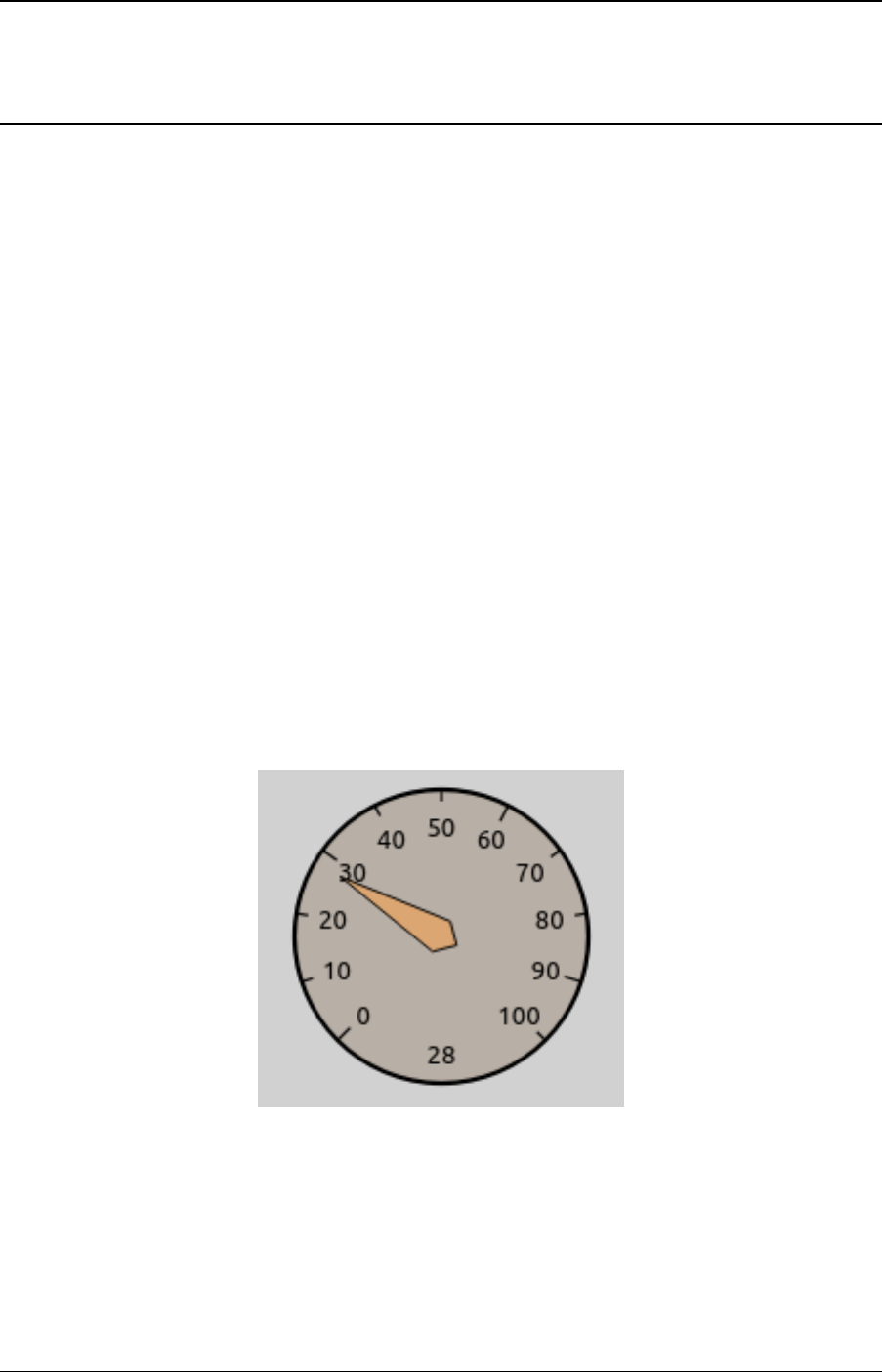
CHAPTER
THIRTYONE
INSTRUMENT FIGURES
31.1 Overview
In complex simulations, there are usually several statistics that are vital for understanding what
is happening inside the network. Although statistics can also be found and read in Qtenv’s
object inspector panel, it is often more convenient to directly display them on the top-level
canvas in a graphical form. INET supports such visualization in the form of inspector figures
that display various gauges and meters. This chapter covers the usage of instrument figures.
31.2 Instrument Types
Some of the instrument figure types available in INET are the following:
•gauge: A circular gauge similar to a speedometer or pressure indicator.
•linearGauge: A horizontal linear gauge similar to a VU meter.
•progressMeter: A horizontal progress bar.
•counter: An integer counter.
•thermometer: A vertical meter visually similar to a real-life thermometer.
159
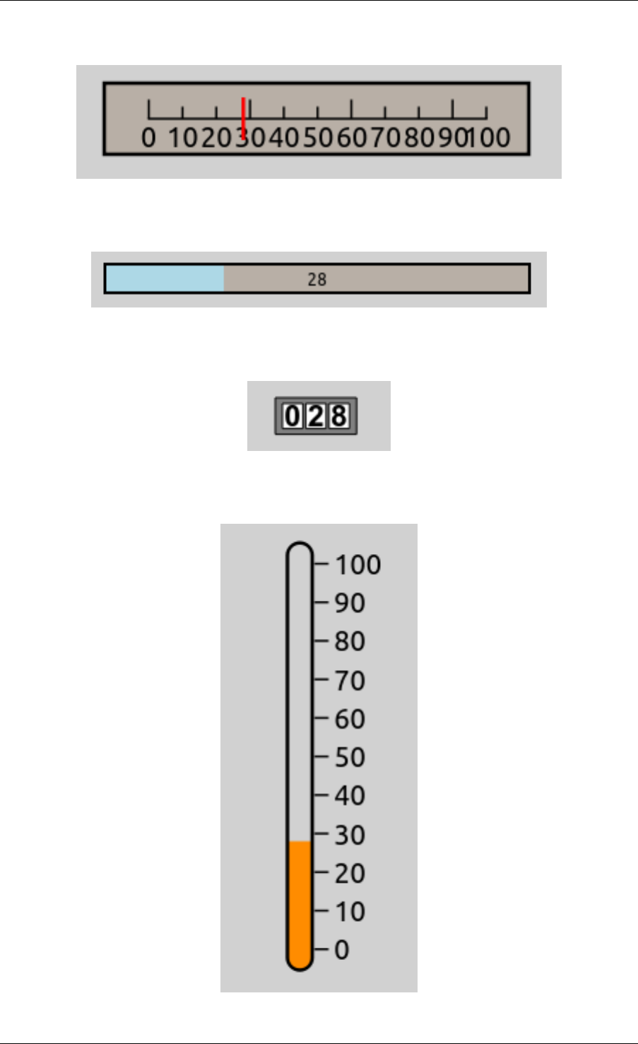
INET Framework User’s Guide
160 Chapter 31. Instrument Figures
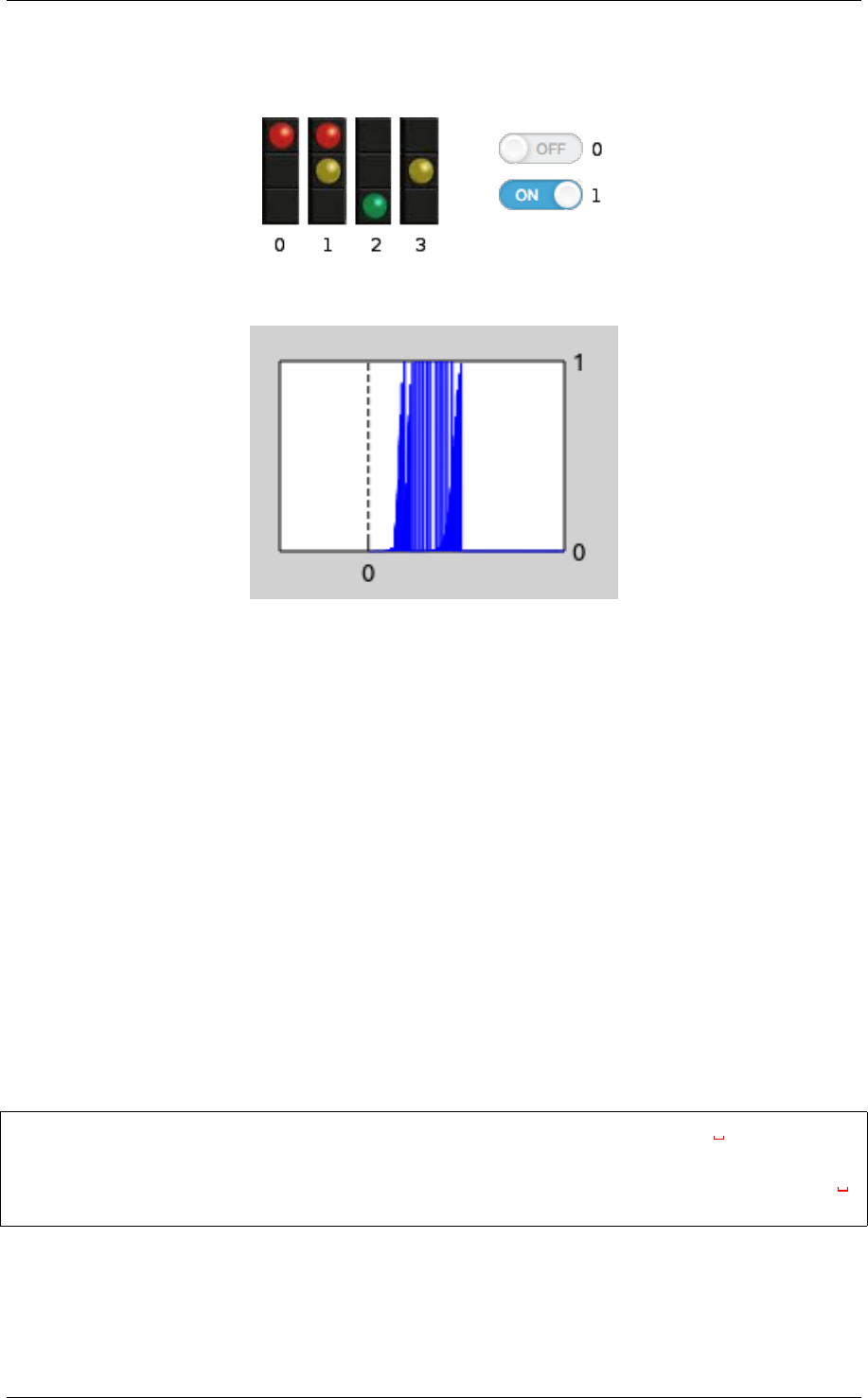
INET Framework User’s Guide
•indexedImage: A figure that displays one of several images: the first image for the value
0, the second image for the value of 1, and so on.
•plot: An XY chart that plots a statistic in the function of time.
31.3 Using Instrument Figures
Instrument figures visualize statistics derived from signals emitted by modules in the network.
This statistic is declared in the NED file, with the @statistic property. The property’s
source attribute is an expression that specifies which signals to use from which modules,
and the mathematical operations on it, to derive the statistic. The record attribute specifies
where the values of the statistic is recorded into. In the case of instrument figures, this is set to
figure, i.e. record=figure. The targetFigure attribute selects which figure should
display the statistic.
The instrument figure itself is specified in the NED file with the @figure property. The prop-
erty’s type attribute selects the type of the instrument figure (gauge,thermometer, etc.),
and the property’s index (i.e. the figure name) should match the name given in the statistic’s
targetFigure attribute.
Here is an example NED file:
@statistic[numRcvdPk](source=count(client.app[0].rcvdPk);
˓→record=figure; targetFigure=counter);
@figure[numRcvdPkCounter](type=counter; pos=413,327; label="Packets
˓→received"; decimalPlaces=4);
This creates a figure named numRcvdPkCounter, which displays a counter. The statistic
numRcvdPk counts the packets received by the client host’s first application, and records
it in the numRcvdPkCounter figure.
31.3. Using Instrument Figures 161

INET Framework User’s Guide
31.4 Instrument Figure Attributes
Instrument figures have various attributes that customize their position, size, appearance, label
text and font, minimum and maximum values, and so on. The following list shows the attributes
recognized by the various figure types (a similar list can be produced by running INET with
the -h figures command-line option):
counter:type,visible,zIndex,tooltip,tags,transform,
backgroundColor,decimalPlaces,digitBackgroundColor,
digitBorderColor,digitFont,digitColor,label,labelFont,
labelColor,initialValue,pos,anchor,labelOffset
gauge:type,visible,zIndex,tooltip,tags,transform,
backgroundColor,needleColor,label,labelFont,labelColor,
minValue,maxValue,tickSize,colorStrip,initialValue,pos,size,
anchor,bounds,labelOffset
indexedImage:type,visible,zIndex,tooltip,tags,transform,images,
tintAmount,tintColor,opacity,interpolation,label,labelFont,
labelColor,labelOffset,initialValue,pos,size,anchor,bounds
indicatorLabel:type,visible,zIndex,tooltip,tags,transform,pos,
anchor,text,font,color,opacity,halo,textFormat,initialValue
indicatorText:type,visible,zIndex,tooltip,tags,transform,pos,
anchor,text,font,color,opacity,halo,textFormat,initialValue
linearGauge:type,visible,zIndex,tooltip,tags,transform,
backgroundColor,needleColor,label,labelFont,labelColor,
minValue,maxValue,tickSize,cornerRadius,initialValue,pos,
size,anchor,bounds,labelOffset
plot:type,visible,zIndex,tooltip,tags,transform,valueTickSize,
timeWindow,timeTickSize,lineColor,minValue,maxValue,
backgroundColor,label,labelOffset,labelColor,labelFont,
numberSizeFactor,pos,size,anchor,bounds
progressMeter:type,visible,zIndex,tooltip,tags,transform,
backgroundColor,stripColor,cornerRadius,borderWidth,
minValue,maxValue,text,textFont,textColor,label,labelOffset,
labelFont,labelColor,initialValue,pos,size,anchor,bounds
thermometer:type,visible,zIndex,tooltip,tags,transform,
mercuryColor,label,labelFont,labelColor,minValue,maxValue,
tickSize,initialValue,pos,size,anchor,bounds,labelOffset
162 Chapter 31. Instrument Figures

CHAPTER
THIRTYTWO
APPENDIX: AUTHOR’S GUIDE
32.1 Overview
This chapter is intended for authors and contributors of this INET User’s Guide, and covers the
guidelines for deciding what type of content is appropriate for this Guide and what is not.
The main guiding principle is to avoid redundancy and duplication of information with other
pieces of documentation, namely:
• Standards documents (RFCs, IEEE specifications, etc.) that describe protocols that INET
modules implement;
•INET Developer’s Guide, which is intended as a guide for anyone wishing to understand
or modify the operation of INET’s components at C++ level;
•INET Framework Reference, directly generated from NED and MSG comments by OM-
NeT++ documentation generator;
• Showcases, tutorials and simulation examples (showcases/,tutorials/ and
examples/ folders in the INET project)
Why is duplication to be avoided? Multiple reasons:
• It is a waste of our reader’s time they have to skip information they have already seen
elsewhere
• The text can easily get out of date as the INET Framework evolves
• It is extra effort for maintainers to keep all copies up to date
32.2 Guidelines
32.2.1 Do Not Repeat the Standard
When describing a module that implements protocol X, do not go into lengths explaining what
protocol X does and how it works, because that is appropriately (and usually, much better)
explained in the specification or books on protocol X. It is OK to summarize the protocol’s
goal and principles in short paragraph though.
163

INET Framework User’s Guide
In particular, do not describe the format of the protocol messages. It surely looks nice and takes
up a lot of space, but the same information can probably be found in a myriad places all over
the internet.
32.2.2 Do Not Repeat NED
Things like module parameters, gate names, emitted signals and collected statistics are ap-
propriately and formally part of the NED definitions, and there is no need to duplicate that
information in this Guide.
Detailed information on the module, such as usage details and the list of implemented standards
should be covered in the module’s NED documentation, not in this Guide.
32.2.3 No C++
Any content which only makes sense on C++ level should go to the Developer’s Guide, and
has no place in this Guide.
32.2.4 Keep Examples Short
When giving examples about usage, keep them concise and to the point. Giving ini or NED file
fragments of a few lines length is preferable to complete working examples.
Complete examples should be written up as showcases. A working simulation without much
commentary should go under examples. A practical, potentially multi-step guide to using a
nontrivial feature should be written up as a tutorial.
32.2.5 No Reference to Simulation Examples
Do not refer to concrete example simulations, showcases or tutorials in the text, because they
might get renamed, moved, merged or deleted, and when they do, no one will think about
updating the reference in the Users Guide.
32.2.6 What then?
Concentrate on giving a “big picture” of the models: what it is generally capable of, how the
parts fit together, etc. Give just enough information that after a quick read, users can “bootstrap”
into putting together their own simulations with the model. If they have questions afterwards,
they will/should refer to the NED documentation (INET Reference), or if that’s not enough,
delve into the C++ code to find the answers.
164 Chapter 32. Appendix: Author’s Guide

CHAPTER
THIRTYTHREE
HISTORY
33.1 IPSuite to INET Framework (2000-2006)
The predecessor of the INET framework was written by Klaus Wehrle, Jochen Reber, Dirk
Holzhausen, Volker Boehm, Verena Kahmann, Ulrich Kaage and others at the University of
Karlsruhe during 2000-2001, under the name IPSuite.
The MPLS, LDP and RSVP-TE models were built as an add-on to IPSuite during 2003 by
Xuan Thang Nguyen (Xuan.T.Nguyen@uts.edu.au) and other students at the University of
Technology, Sydney under supervision of Dr Robin Brown. The package consisted of around
10,000 LOCs, and was published at http://charlie.it.uts.edu.au/ tkaphan/xtn/capstone (now un-
available).
After a period of IPSuite being unmaintained, Andras Varga took over the development in July
2003. Through a series of snapshot releases in 2003-2004, modules got completely reorganized,
documented, and many of them rewritten from scratch. The MPLS models (including RSVP-
TE, LDP, etc) also got refactored and merged into the codebase.
During 2004, Andras added a new, modular and extensible TCP implementation, application
models, Ethernet implementation and an all-in-one IP model to replace the earlier, modularized
one.
The package was renamed INET Framework in October 2004.
Support for wireless and mobile networks got added during summer 2005 by using code from
the Mobility Framework.
The MPLS models (including LDP and RSVP-TE) got revised and mostly rewritten from
scratch by Vojta Janota in the first half of 2005 for his diploma thesis. After further refine-
ments by Vojta, the new code got merged into the INET CVS in fall 2005, and got eventually
released in the March 2006 INET snapshot.
The OSPFv2 model was created by Andras Babos during 2004 for his diploma thesis which
was submitted early 2005. This work was sponsored by Andras Varga, using revenues from
commercial OMNEST licenses. After several refinements and fixes, the code got merged into
the INET Framework in 2005, and became part of the March 2006 INET snapshot.
The Quagga routing daemon was ported into the INET Framework also by Vojta Janota. This
work was also sponsored by Andras Varga. During fall 2005 and the months after, ripd and
165

INET Framework User’s Guide
ospfd were ported, and the methodology of porting was refined. Further Quagga daemons still
remain to be ported.
Based on experience from the IPv6Suite (from Ahmet Sekercioglu’s group at CTIE, Monash
University, Melbourne) and IPv6SuiteWithINET (Andras’s effort to refactor IPv6Suite and
merge it with INET early 2005), Wei Yang Ng (Monash Uni) implemented a new IPv6 model
from scratch for the INET Framework in 2005 for his diploma thesis, under guidance from
Andras who was visiting Monash between February and June 2005. This IPv6 model got first
included in the July 2005 INET snapshot, and gradually refined afterwards.
The SCTP implementation was contributed by Michael Tuexen, Irene Ruengeler and Thomas
Dreibholz
Support for Sam Jensen’s Network Simulation Cradle, which makes real-world TCP stacks
available in simulations was added by Zoltan Bojthe in 2010.
TCP SACK and New Reno implementation was contributed by Thomas Reschka.
Several other people have contributed to the INET Framework by providing feedback, reporting
bugs, suggesting features and contributing patches; I’d like to acknowledge their help here as
well.
166 Chapter 33. History
