Uvm_guide Uvm Users Guide 1.1
User Manual:
Open the PDF directly: View PDF ![]() .
.
Page Count: 198 [warning: Documents this large are best viewed by clicking the View PDF Link!]
- 1. Overview
- 2. Transaction-Level Modeling (TLM)
- 3. Developing Reusable Verification Components
- 3.1 Modeling Data Items for Generation
- 3.2 Transaction-Level Components
- 3.3 Creating the Driver
- 3.4 Creating the Sequencer
- 3.5 Connecting the Driver and Sequencer
- 3.6 Creating the Monitor
- 3.7 Instantiating Components
- 3.8 Creating the Agent
- 3.9 Creating the Environment
- 3.10 Enabling Scenario Creation
- 3.11 Managing End of Test
- 3.12 Implementing Checks and Coverage
- 4. Using Verification Components
- 4.1 Using a Verification Component
- 4.2 Testbench Class
- 4.3 Instantiating Verification Components
- 4.4 Test Class
- 4.5 Verification Component Configuration
- 4.6 Creating and Selecting a User-Defined Test
- 4.7 Creating Meaningful Tests
- 4.8 Virtual Sequences
- 4.9 Checking for DUT Correctness
- 4.10 Scoreboards
- 4.11 Implementing a Coverage Model
- 5. Using the Register Layer Classes
- 6. Advanced Topics
- 7. UBus Verification Component Example
- 8. UBus Specification
- Appendix A

Universal Verification Methodology
(UVM) 1.1 User’s Guide
May 18, 2011

ii UVM 1.1 User’s Guide May 18, 2011
Copyright© 2011 Accellera. All rights reserved.
Copyright© 2011 Cadence Design Systems, Inc. (Cadence). All rights reserved.
Cadence Design Systems, Inc., 2655 Seely Ave., San Jose, CA 95134, USA.
Copyright© 2011 Mentor Graphics, Corp. (Mentor). All rights reserved.
Mentor Graphics, Corp., 8005 SW Boeckman Rd., Wilsonville, OR 97070, USA
Copyright© 2011 Synopsys, Inc. (Synopsys). All rights reserved.
Synopsys, Inc., 700 E. Middlefield Rd, Mountain View, CA 94043
This product is licensed under the Apache Software Foundation’s Apache License, Version 2.0,
January 2004. The full license is available at: http://www.apache.org/licenses/.
Notices
While this guide offers a set of instructions to perform one or more specific verification tasks, it should be
supplemented by education, experience, and professional judgment. Not all aspects of this guide may be
applicable in all circumstances. The UVM 1.1 User’s Guide does not necessarily represent the standard of
care by which the adequacy of a given professional service must be judged nor should this document be
applied without consideration of a project’s unique aspects. This guide has been approved through the
Accellera consensus process and serves to increase the awareness of information and approaches in
verification methodology. This guide may have several recommendations to accomplish the same thing and
may require some judgment to determine the best course of action.
The UVM 1.1 Class Reference represents the foundation used to create the UVM 1.1 User’s Guide. This
guide is a way to apply the UVM 1.1 Class Reference, but is not the only way. Accellera believes standards
are an important ingredient to foster innovation and continues to encourage industry innovation based on its
standards.
Suggestions for improvements to the UVM 1.1 User’s Guide are welcome. They should be sent to the VIP
email reflector
vip-tc@lists.accellera.org
The current Working Group’s website address is
www.accellera.org/activities/vip
May 18, 2011 UVM 1.1 User’s Guide iii
Contents
1. Overview.............................................................................................................................................. 1
1.1 Introduction to UVM.................................................................................................................. 1
1.1.1 Coverage-Driven Verification (CDV) ........................................................................ 1
1.1.2 Testbenches and Environments .................................................................................. 1
1.2 Verification Component Overview ............................................................................................ 3
1.2.1 Data Item (Transaction) .............................................................................................. 3
1.2.2 Driver (BFM) ..............................................................................................................3
1.2.3 Sequencer .................................................................................................................... 3
1.2.4 Monitor ....................................................................................................................... 3
1.2.5 Agent ........................................................................................................................... 4
1.2.6 Environment ................................................................................................................ 4
1.3 The UVM Class Library............................................................................................................. 5
1.4 Other UVM Facilities................................................................................................................. 7
1.4.1 UVM Factory .............................................................................................................. 7
1.4.2 Transaction-Level Modeling (TLM) .......................................................................... 8
2. Transaction-Level Modeling (TLM) ................................................................................................... 9
2.1 Overview .................................................................................................................................... 9
2.2 TLM, TLM-1, and TLM-2.0 ......................................................................................................9
2.2.1 TLM-1 Implementation ............................................................................................ 10
2.2.2 TLM-2.0 Implementation ......................................................................................... 10
2.3 Basics ....................................................................................................................................... 10
2.3.1 Transactions ..............................................................................................................10
2.3.2 Transaction-Level Communication .......................................................................... 11
2.3.3 Basic TLM Communication ..................................................................................... 11
2.3.4 Communicating between Processes .......................................................................... 12
2.3.5 Blocking versus Nonblocking ................................................................................... 13
2.3.6 Connecting Transaction-Level Components ............................................................ 13
2.3.7 Peer-to-Peer connections .......................................................................................... 14
2.3.8 Port/Export Compatibility ......................................................................................... 14
2.4 Encapsulation and Hierarchy ................................................................................................... 14
2.4.1 Hierarchical Connections .......................................................................................... 14
2.4.2 Connection Types ..................................................................................................... 16
2.5 Analysis Communication ......................................................................................................... 16
2.5.1 Analysis Ports ........................................................................................................... 16
2.5.2 Analysis Exports ....................................................................................................... 17
2.6 Generic Payload ....................................................................................................................... 18
2.6.1 Attributes .................................................................................................................. 18
2.6.2 Accessors .................................................................................................................. 19
2.6.3 Extensions ................................................................................................................. 20
2.7 Core Interfaces and Ports ......................................................................................................... 21
2.8 Blocking Transport................................................................................................................... 22
2.9 Nonblocking Transport ............................................................................................................ 22
2.10 Sockets ..................................................................................................................................... 24
2.11 Time ......................................................................................................................................... 26
2.12 Use Models............................................................................................................................... 28
iv UVM 1.1 User’s Guide May 18, 2011
3. Developing Reusable Verification Components................................................................................ 31
3.1 Modeling Data Items for Generation ....................................................................................... 31
3.1.1 Inheritance and Constraint Layering ......................................................................... 32
3.1.2 Defining Control Fields (“Knobs”) ........................................................................... 33
3.2 Transaction-Level Components ............................................................................................... 34
3.3 Creating the Driver................................................................................................................... 36
3.4 Creating the Sequencer............................................................................................................. 37
3.5 Connecting the Driver and Sequencer..................................................................................... 37
3.5.1 Basic Sequencer and Driver Interaction ................................................................... 38
3.5.2 Querying for the Randomized Item .......................................................................... 38
3.5.3 Fetching Consecutive Randomized Items ................................................................. 39
3.5.4 Sending Processed Data back to the Sequencer ........................................................ 39
3.5.5 Using TLM-Based Drivers ....................................................................................... 40
3.6 Creating the Monitor ................................................................................................................ 40
3.7 Instantiating Components......................................................................................................... 42
3.8 Creating the Agent ................................................................................................................... 43
3.8.1 Operating Modes ....................................................................................................... 44
3.8.2 Connecting Components ........................................................................................... 45
3.9 Creating the Environment ........................................................................................................ 45
3.9.1 The Environment Class ............................................................................................. 46
3.9.2 The UVM Configuration Mechanism ....................................................................... 46
3.10 Enabling Scenario Creation...................................................................................................... 47
3.10.1 Declaring User-Defined Sequences .......................................................................... 48
3.10.2 Generating Stimulus with Sequences and Sequence Items ...................................... 49
3.10.3 Configuring the Sequencer’s Default Sequence ....................................................... 52
3.10.4 Overriding Sequence Items and Sequences .............................................................. 53
3.11 Managing End of Test.............................................................................................................. 54
3.12 Implementing Checks and Coverage........................................................................................ 55
3.12.1 Implementing Checks and Coverage in Classes ....................................................... 56
3.12.2 Implementing Checks and Coverage in Interfaces ................................................... 57
3.12.3 Controlling Checks and Coverage ............................................................................ 58
4. Using Verification Components ........................................................................................................ 59
4.1 Using a Verification Component.............................................................................................. 59
4.2 Testbench Class........................................................................................................................ 59
4.3 Instantiating Verification Components .................................................................................... 60
4.4 Test Class ................................................................................................................................. 62
4.5 Verification Component Configuration ................................................................................... 62
4.5.1 Verification Component Configurable Parameters ................................................... 62
4.5.2 Verification Component Configuration Mechanism ................................................ 63
4.5.3 Choosing between uvm_resource_db and uvm_config_db ...................................... 64
4.5.4 Using a Configuration Class ..................................................................................... 64
4.6 Creating and Selecting a User-Defined Test ............................................................................ 65
4.6.1 Creating the Base Test .............................................................................................. 65
4.6.2 Creating Tests from a Test-Family Base Class ......................................................... 65
4.6.3 Test Selection ............................................................................................................66
4.7 Creating Meaningful Tests ....................................................................................................... 67
4.7.1 Constraining Data Items ........................................................................................... 67
4.7.2 Data Item Definitions ................................................................................................ 68
4.7.3 Creating a Test-Specific Frame ................................................................................ 68
May 18, 2011 UVM 1.1 User’s Guide v
4.8 Virtual Sequences..................................................................................................................... 69
4.8.1 Creating a Virtual Sequencer .................................................................................... 70
4.8.2 Creating a Virtual Sequence ..................................................................................... 71
4.8.3 Controlling Other Sequencers ................................................................................... 72
4.8.4 Connecting a Virtual Sequencer to Subsequencers .................................................. 72
4.9 Checking for DUT Correctness................................................................................................ 73
4.10 Scoreboards .............................................................................................................................. 74
4.10.1 Creating the Scoreboard ............................................................................................ 74
4.10.2 Adding Exports to uvm_scoreboard ......................................................................... 75
4.10.3 Requirements of the TLM Implementation .............................................................. 75
4.10.4 Defining the Action Taken ....................................................................................... 75
4.10.5 Adding the Scoreboard to the Environment ............................................................. 76
4.10.6 Summary ................................................................................................................... 76
4.11 Implementing a Coverage Model............................................................................................. 77
4.11.1 Selecting a Coverage Method ................................................................................... 77
4.11.2 Implementing a Functional Coverage Model ........................................................... 77
4.11.3 Enabling and Disabling Coverage ............................................................................ 77
5. Using the Register Layer Classes ...................................................................................................... 79
5.1 Overview .................................................................................................................................. 79
5.2 Usage Model ............................................................................................................................ 79
5.2.1 Sub-register Access ................................................................................................... 82
5.2.2 Mirroring ................................................................................................................... 83
5.2.3 Memories are not Mirrored ....................................................................................... 84
5.3 Access API ............................................................................................................................... 84
5.3.1 read / write ................................................................................................................ 84
5.3.2 peek / poke ................................................................................................................ 85
5.3.3 get / set ...................................................................................................................... 85
5.3.4 randomize .................................................................................................................. 85
5.3.5 update ........................................................................................................................ 86
5.3.6 mirror ........................................................................................................................ 86
5.3.7 Concurrent Accesses ................................................................................................. 86
5.4 Coverage Models...................................................................................................................... 87
5.4.1 Predefined Coverage Identifiers ............................................................................... 87
5.4.2 Controlling Coverage Model Construction and Sampling ....................................... 87
5.5 Constructing a Register Model................................................................................................. 88
5.5.1 Field Types ...............................................................................................................88
5.5.2 Register Types .......................................................................................................... 94
5.5.3 Register File Types ................................................................................................... 97
5.5.4 Memory Types .......................................................................................................... 99
5.5.5 Block Types ............................................................................................................ 100
5.5.6 Packaging a Register Model ................................................................................... 104
5.5.7 Maximum Data Size ............................................................................................... 104
5.6 Back-door Access................................................................................................................... 105
5.6.1 Back-door read/write vs. peek/poke ....................................................................... 105
5.6.2 Hierarchical HDL Paths .......................................................................................... 106
5.6.3 VPI-based Back-door Access ................................................................................. 107
5.6.4 User-defined Back-door Access ............................................................................. 108
5.6.5 Back-door Access for Protected Memories ............................................................ 108
5.6.6 Active Monitoring ................................................................................................... 109
5.7 Special Registers .................................................................................................................... 110
5.7.1 Pre-defined Special Registers ................................................................................. 111
5.7.2 Unmapped Registers and Memories ....................................................................... 112
vi UVM 1.1 User’s Guide May 18, 2011
5.7.3 Aliased Registers .................................................................................................... 114
5.7.4 Unimplemented Registers ....................................................................................... 116
5.7.5 RO and WO Registers Sharing the Same Address ................................................. 117
5.8 Integrating a Register Model in a Verification Environment................................................. 117
5.9 Integrating a Register Model.................................................................................................. 118
5.9.1 Transaction Adapter ................................................................................................ 119
5.9.2 Integrating Bus Sequencers .................................................................................... 121
5.9.3 Integrating the Register Model with a Bus Monitor ............................................... 127
5.10 Randomizing Field Values ..................................................................................................... 128
5.11 Pre-defined Sequences ........................................................................................................... 129
6. Advanced Topics ............................................................................................................................. 131
6.1 The uvm_component Base Class ........................................................................................... 131
6.2 The Built-In Factory and Overrides ....................................................................................... 131
6.2.1 About the Factory ................................................................................................... 131
6.2.2 Factory Registration ................................................................................................ 132
6.2.3 Component Overrides ............................................................................................. 132
6.3 Callbacks ................................................................................................................................ 135
6.3.1 Use Model ............................................................................................................... 135
6.3.2 Example .................................................................................................................. 135
6.4 The Sequence Library ............................................................................................................ 138
6.5 Advanced Sequence Control .................................................................................................. 139
6.5.1 Implementing Complex Scenarios .......................................................................... 139
6.5.2 Protocol Layering ................................................................................................... 143
6.5.3 Generating the Item or Sequence in Advance ........................................................ 151
6.5.4 Executing Sequences and Items on other Sequencers ............................................ 153
6.6 Command Line Interface (CLI).............................................................................................. 153
6.6.1 Introduction ............................................................................................................. 153
6.6.2 Getting Started ........................................................................................................ 154
6.6.3 UVM-aware Command Line Processing ................................................................ 154
7. UBus Verification Component Example ......................................................................................... 157
7.1 UBus Example........................................................................................................................ 157
7.2 UBus Example Architecture................................................................................................... 160
7.3 UBus Top Module.................................................................................................................. 160
7.4 The Test.................................................................................................................................. 161
7.5 Testbench Environment.......................................................................................................... 164
7.6 UBus Environment................................................................................................................. 166
7.7 UBus Master Agent................................................................................................................ 167
7.8 UBus Master Sequencer......................................................................................................... 168
7.9 UBus Driver ........................................................................................................................... 169
7.10 UBus Agent Monitor.............................................................................................................. 170
7.11 UBus Bus Monitor ................................................................................................................. 170
7.11.1 Collecting Transfers from the Bus .......................................................................... 171
7.11.2 Number of Transfers ............................................................................................... 171
7.11.3 Notifiers Emitted by the UBus Bus Monitor .......................................................... 171
7.11.4 Checks and Coverage .............................................................................................. 172
7.12 UBus Interface........................................................................................................................ 172
May 18, 2011 UVM 1.1 User’s Guide vii
8. UBus Specification .......................................................................................................................... 173
8.1 Introduction ............................................................................................................................ 173
8.1.1 Motivation ............................................................................................................... 173
8.1.2 Bus Overview ......................................................................................................... 173
8.2 Bus Description ...................................................................................................................... 173
8.2.1 Bus Signals ............................................................................................................. 173
8.2.2 Clocking ..................................................................................................................174
8.2.3 Reset ........................................................................................................................ 174
8.3 Arbitration Phase.................................................................................................................... 174
8.4 Address Phase ........................................................................................................................ 175
8.4.1 NOP Cycle .............................................................................................................. 175
8.4.2 Normal Address Phase ............................................................................................ 175
8.5 Data Phase .............................................................................................................................. 175
8.5.1 Write Transfer ......................................................................................................... 176
8.5.2 Error during Write Transfer .................................................................................... 176
8.5.3 Read Transfer .......................................................................................................... 176
8.5.4 Error during Read Transfer ..................................................................................... 176
8.6 How Data is Driven................................................................................................................ 177
8.7 Optional Pipelining Scheme...................................................................................................177
8.7.1 Pipelined Arbitration Phase .................................................................................... 177
8.7.2 Pipelined Address Phase ......................................................................................... 178
8.7.3 Pipelined Data Phase .............................................................................................. 178
8.8 Example Timing Diagrams .................................................................................................... 178
Appendix A (informative) Sequence Library ............................................................................................. 181
A.1 Creating the Sequencer .................................................................................................... 181
A.2 Enabling Scenario Creation ............................................................................................. 182
viii UVM 1.1 User’s Guide May 18, 2011
May 18, 2011 UVM 1.1 User’s Guide 1
1. Overview
This chapter describes:
— How to use the Universal Verification Methodology (UVM) for creating SystemVerilog testbenches.
— The recommended architecture of a verification component.
1.1 Introduction to UVM
The following subsections describe the UVM basics.
1.1.1 Coverage-Driven Verification (CDV)
UVM provides the best framework to achieve coverage-driven verification (CDV). CDV combines
automatic test generation, self-checking testbenches, and coverage metrics to significantly reduce the time
spent verifying a design. The purpose of CDV is to:
— Eliminate the effort and time spent creating hundreds of tests.
— Ensure thorough verification using up-front goal setting.
— Receive early error notifications and deploy run-time checking and error analysis to simplify debug-
ging.
The CDV flow is different than the traditional directed-testing flow. With CDV, you start by setting
verification goals using an organized planning process. You then create a smart testbench that generates
legal stimuli and sends it to the DUT. Coverage monitors are added to the environment to measure progress
and identify non-exercised functionality. Checkers are added to identify undesired DUT behavior.
Simulations are launched after both the coverage model and testbench have been implemented. Verification
then can be achieved.
Using CDV, you can thoroughly verify your design by changing testbench parameters or changing the
randomization seed. Test constraints can be added on top of the smart infrastructure to tune the simulation to
meet verification goals sooner. Ranking technology allows you to identify the tests and seeds that contribute
to the verification goals, and to remove redundant tests from a test-suite regression.
CDV environments support both directed and constrained-random testing. However, the preferred approach
is to let constrained-random testing do most of the work before devoting effort to writing time-consuming,
deterministic tests to reach specific scenarios that are too difficult to reach randomly.
Significant efficiency and visibility into the verification process can be achieved by proper planning.
Creating an executable plan with concrete metrics enables you to accurately measure progress and
thoroughness throughout the design and verification project. By using this method, sources of coverage can
be planned, observed, ranked, and reported at the feature level. Using an abstracted, feature-based approach
(and not relying on implementation details) enables you to have a more readable, scalable, and reusable
verification plan.
1.1.2 Testbenches and Environments
An UVM testbench is composed of reusable verification environments called verification components. A
verification component is an encapsulated, ready-to-use, configurable verification environment for an
interface protocol, a design submodule, or a full system. Each verification component follows a consistent
architecture and consists of a complete set of elements for stimulating, checking, and collecting coverage
2 UVM 1.1 User’s Guide May 18, 2011
information for a specific protocol or design. The verification component is applied to the device under test
(DUT) to verify your implementation of the protocol or design architecture.
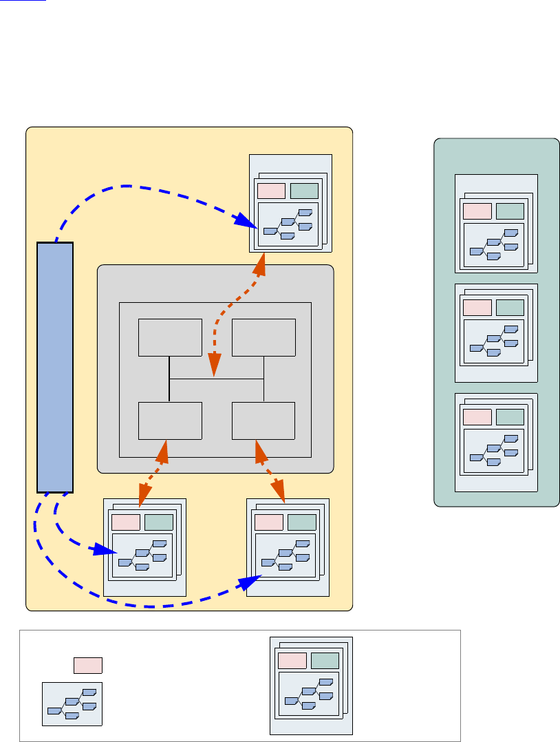
Figure 1 shows an example of a verification environment with three interface verification components.
These verification components might be stored in a company repository and reused for multiple verification
environments. The interface verification component is instantiated and configured for a desired operational
mode. The verification environment also contains a multi-channel sequence mechanism (that is, virtual
sequencer) which synchronizes the timing and the data between the different interfaces and allows fine
control of the test environment for a particular test.
Figure 1—Verification Environment Example
Virtual Sequencer
CPU Mem
Periph Periph
DUT
Verification Environment Verification Component Repository
vc 1
mon driver
mon driver
bus vc
mon driver
bus vc
vc 2
mon driver
vc 1
mon driver
mon
vc 2
mon driver
Legend
monitor
sequencer
vc x
mon driver
interface verification component

May 18, 2011 UVM 1.1 User’s Guide 3
1.2 Verification Component Overview
The following subsections describe the components of a verification component.
1.2.1 Data Item (Transaction)
Data items represent the input to the device under test (DUT). Examples include networking packets, bus
transactions, and instructions. The fields and attributes of a data item are derived from the data item’s
specification. For example, the Ethernet protocol specification defines valid values and attributes for an
Ethernet data packet. In a typical test, many data items are generated and sent to the DUT. By intelligently
randomizing data item fields using SystemVerilog constraints, you can create a large number of meaningful
tests and maximize coverage.
1.2.2 Driver (BFM)
A driver is an active entity that emulates logic that drives the DUT. A typical driver repeatedly receives a
data item and drives it to the DUT by sampling and driving the DUT signals. (If you have created a
verification environment in the past, you probably have implemented driver functionality.) For example, a
driver controls the read/write signal, address bus, and data bus for a number of clocks cycles to perform a
write transfer.
1.2.3 Sequencer
A sequencer is an advanced stimulus generator that controls the items that are provided to the driver for
execution. By default, a sequencer behaves similarly to a simple stimulus generator and returns a random
data item upon request from the driver. This default behavior allows you to add constraints to the data item
class in order to control the distribution of randomized values. Unlike generators that randomize arrays of
transactions or one transaction at a time, a sequencer captures important randomization requirements out-of-
the-box. A partial list of the sequencer’s built-in capabilities includes:
— Ability to react to the current state of the DUT for every data item generated.
— Captures the order between data items in user-defined sequences, which forms a more structured and
meaningful stimulus pattern.
— Enables time modeling in reusable scenarios.
— Supports declarative and procedural constraints for the same scenario.
— Allows system-level synchronization and control of multiple interfaces.
For more information about creating and using sequencers, refer to the UVM 1.1 Class Reference and to
Section 3.10, and Section 4.8.2.
Sequencers also can be layered on top of each other to model protocol layering. Refer to Section 6.5.2.5 for
more information.
1.2.4 Monitor
A monitor is a passive entity that samples DUT signals but does not drive them. Monitors collect coverage
information and perform checking. Even though reusable drivers and sequencers drive bus traffic, they are
not used for coverage and checking. Monitors are used instead. A monitor:

4 UVM 1.1 User’s Guide May 18, 2011
— Collects transactions (data items). A monitor extracts signal information from a bus and translates
the information into a transaction that can be made available to other components and to the test
writer.
— Extracts events. The monitor detects the availability of information (such as a transaction), structures
the data, and emits an event to notify other components of the availability of the transaction. A mon-
itor also captures status information so it is available to other components and to the test writer.
— Performs checking and coverage.
Checking typically consists of protocol and data checkers to verify that the DUT output meets the
protocol specification.
Coverage also is collected in the monitor.
— Optionally prints trace information.
A bus monitor handles all the signals and transactions on a bus, while an agent monitor handles only signals
and transactions relevant to a specific agent.
Typically, drivers and monitors are built as separate entities (even though they may use the same signals) so
they can work independently of each other. However, you can reuse code that is common between a driver
and a monitor to save time.
Do not have monitors depend on drivers for information so that an agent can operate passively when only
the monitor is present.
1.2.5 Agent
Sequencers, drivers, and monitors can be reused independently, but this requires the environment integrator
to learn the names, roles, configuration, and hookup of each of these entities. To reduce the amount of work
and knowledge required by the test writer, UVM recommends that environment developers create a more
abstract container called an agent. Agents can emulate and verify DUT devices. They encapsulate a driver,
sequencer, and monitor. Verification components can contain more than one agent. Some agents (for
example, master or transmit agents) initiate transactions to the DUT, while other agents (slave or receive
agents) react to transaction requests. Agents should be configurable so that they can be either active or
passive. Active agents emulate devices and drive transactions according to test directives. Passive agents
only monitor DUT activity.
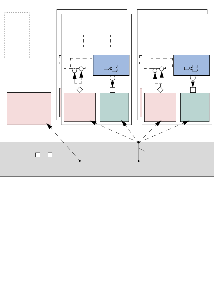
1.2.6 Environment
The environment (env) is the top-level component of the verification component. It contains one or more
agents, as well as other components such as a bus monitor. The env contains configuration properties that
enable you to customize the topology and behavior and make it reusable. For example, active agents can be
changed into passive agents when the verification environment is reused in system verification. Figure 2
illustrates the structure of a reusable verification environment. Notice that a verification component may
contain an environment-level monitor. This bus-level monitor performs checking and coverage for activities
that are not necessarily related to a single agent. An agent’s monitors can leverage data and events collected
by the global monitor.
May 18, 2011 UVM 1.1 User’s Guide 5
Figure 2—Typical Verification Component Environment
The environment class (uvm_env) is architected to provide a flexible, reusable, and extendable verification
component. The main function of the environment class is to model behavior by generating constrained-
random traffic, monitoring DUT responses, checking the validity of the protocol activity, and collecting
coverage.
You can use derivation to specialize the existing classes to their specific protocol. This manual describes the
process and infrastructure that UVM provides to replace existing component behavior with IP-specific
behavior.
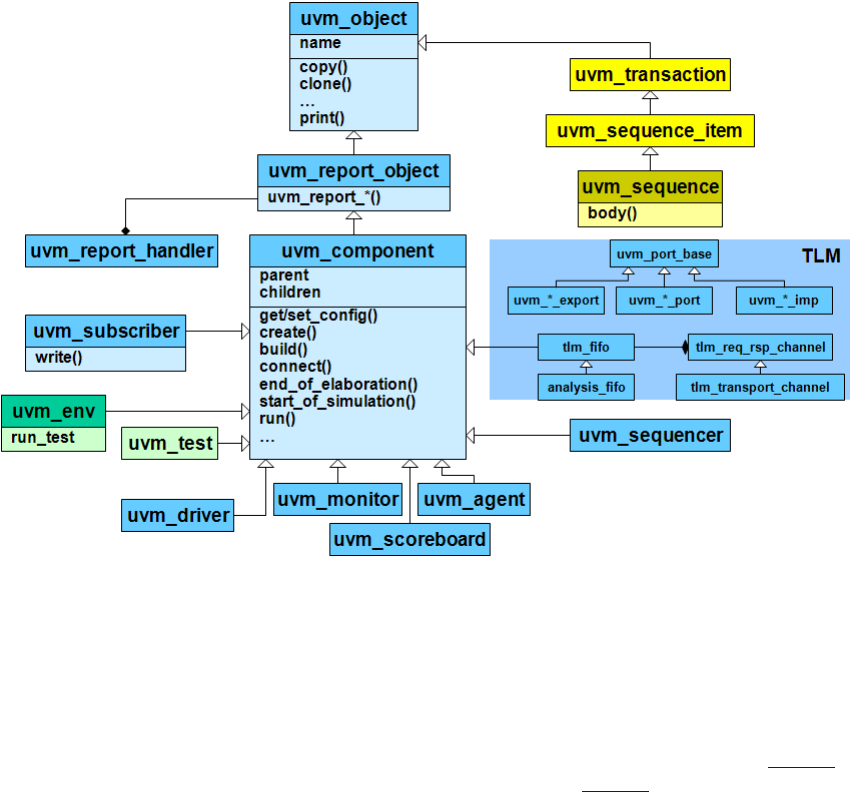
1.3 The UVM Class Library
The UVM Class Library provides all the building blocks you need to quickly develop well-constructed,
reusable, verification components and test environments (see Figure 3). The library consists of base classes,
utilities, and macros. Components may be encapsulated and instantiated hierarchically and are controlled
through an extendable set of phases to initialize, run, and complete each test. These phases are defined in the
base class library but can be extended to meet specific project needs. See the UVM 1.1 Class Reference for
more information.
DUT
Verification Component Environment
Config:
...
...
name
has_...
...
bus
bus monitor
checks
coverage
sequencer
Config
Analysis
Master Agent
uvm_drivemonitor
Analysis
driver
sequencer
Config
Analysis
Slave Agent
uvm_drivemonitor
Analysis
driver
sequencer
Config
Analysis
Master Agent
uvm_drivemonitor
Analysis
driver
sequencer
Config
Analysis
Slave Agent
uvm_drivemonitor
Analysis
driver
6 UVM 1.1 User’s Guide May 18, 2011
Figure 3—(Partial) UVM Class Hierarchy
The advantages of using the UVM Class Library include:
a) A robust set of built-in features—The UVM Class Library provides many features that are required
for verification, including complete implementation of printing, copying, test phases, factory meth-
ods, and more.
b) Correctly-implemented UVM concepts—Each component in the block diagram in Figure 2 is
derived from a corresponding UVM Class Library component. Figure 4 shows the same diagram
using the derived UVM Class Library base classes. Using these base-class elements increases the
readability of your code since each component’s role is predetermined by its parent class.

May 18, 2011 UVM 1.1 User’s Guide 7
Figure 4—Typical UVM Environment using Library Classes
1.4 Other UVM Facilities
The UVM Class Library also provides various utilities to simplify the development and use of verification
environments. These utilities support debugging by providing a user-controllable messaging utility. They
support development by providing a standard communication infrastructure between verification
components (TLM) and flexible verification environment construction (UVM factory).
The UVM Class Library provides global messaging facilities that can be used for failure reporting and
general reporting purposes. Both messages and reporting are important aspects of ease of use.
1.4.1 UVM Factory
The factory method is a classic software design pattern that is used to create generic code, deferring to run
time the exact specification of the object that will be created. In functional verification, introducing class
variations is frequently needed. For example, in many tests you might want to derive from the generic data
item definition and add more constraints or fields to it; or you might want to use the new derived class in the
entire environment or only in a single interface; or perhaps you must modify the way data is sent to the DUT
by deriving a new driver. The factory allows you to substitute the verification component without having to
provide a derived version of the parent component as well.
DUT
uvm_env
Config:
...
...
name
has_...
...
bus
uvm_monitor
checks
coverage
uvm_sequenc
Config
uvm_agent
Analysis
Slave Agent
uvm_sequence
uvm_driveuvm_monitor
Analysis
uvm_drive
uvm_sequencer
Config
uvm_agent
Analysis
Slave Agent
uvm_driveuvm_monitor
Analysis
uvm_driver
uvm_sequenc
Config
uvm_agent
Analysis
Slave Agent
uvm_driveuvm_monitor
Analysis
uvm_drive
uvm_sequencer
Config
uvm_agent
Analysis
Master Agent
uvm_driveuvm_monitor
Analysis
uvm_driver
8 UVM 1.1 User’s Guide May 18, 2011
The UVM Class Library provides a built-in central factory that allows:
— Controlling object allocation in the entire environment or for specific objects.
— Modifying stimulus data items as well as infrastructure components (for example, a driver).
Using the UVM built-in factory reduces the effort of creating an advanced factory or implementing factory
methods in class definitions. It facilitates reuse and adjustment of predefined verification IP in the end-
user’s environment. One of the biggest advantages of the factory is that it is transparent to the test writer and
reduces the object-oriented expertise required from both developers and users.
1.4.2 Transaction-Level Modeling (TLM)
UVM components communicate via standard TLM interfaces, which improves reuse. Using a
SystemVerilog implementation of TLM in UVM, a component may communicate via its interface to any
other component that implements that interface. Each TLM interface consists of one or more methods used
to transport data. TLM specifies the required behavior (semantic) of each method, but does not define their
implementation. Classes inheriting a TLM interface must provide an implementation that meets the
specified semantic. Thus, one component may be connected at the transaction level to others that are
implemented at multiple levels of abstraction. The common semantics of TLM communication permit
components to be swapped in and out without affecting the rest of the environment.

May 18, 2011 UVM 1.1 User’s Guide 9
2. Transaction-Level Modeling (TLM)
2.1 Overview
One of the keys to verification productivity is to think about the problem at a level of abstraction that makes
sense. When verifying a DUT that handles packets flowing back and forth, or processes instructions, or
performs other types of functionality, you must create a verification environment that supports the
appropriate abstraction level. While the actual interface to the DUT ultimately is represented by signal-level
activity, experience has shown that it is necessary to manage most of the verification tasks, such as
generating stimulus and collecting coverage data, at the transaction level, which is the natural way engineers
tend to think of the activity of a system.
UVM provides a set of transaction-level communication interfaces and channels that you can use to connect
components at the transaction level. The use of TLM interfaces isolates each component from changes in
other components throughout the environment. When coupled with the phased, flexible build infrastructure
in UVM, TLM promotes reuse by allowing any component to be swapped for another, as long as they have
the same interfaces. This concept also allows UVM verification environments to be assembled with a
transaction-level model of the DUT, and the environment to be reused as the design is refined to RTL. All
that is required is to replace the transaction-level model with a thin layer of compatible components to
convert between the transaction-level activity and the pin-level activity at the DUT.
The well-defined semantics of TLM interfaces between components also provide the ideal platform for
implementing mixed-language verification environments. In addition, TLM provides the basis for easily
encapsulating components into reusable components, called verification components, to maximize reuse and
minimize the time and effort required to build a verification environment.
This chapter discusses the essential elements of transaction-level communication in UVM, and illustrates
the mechanics of how to assemble transaction-level components into a verification environment. Later in
this document we will discuss additional concerns in order to address a wider set of verification issues. For
now, it is important to understand these foundational concepts first.
2.2 TLM, TLM-1, and TLM-2.0
TLM, transaction-level modeling, is a modeling style for building highly abstract models of components and
systems. It relies on transactions (see Section 2.3, Basics), objects that contain arbitrary, protocol-specific
data to abstractly represent lower-level activity. In practice, TLM refers to a family of abstraction levels
beginning with cycle-accurate modeling, the most abstract level, and extending upwards in abstraction as far
as the eye can see. Common transaction-level abstractions today include: cycle-accurate, approximately-
timed, loosely-timed, untimed, and token-level.
The acronym TLM also refers to a system of code elements used to create transaction-level models. TLM-1
and TLM-2.0 are two TLM modeling systems which have been developed as industry standards for building
transaction-level models. Both were built in SystemC and standardized within the TLM Working Group of
the Open SystemC Initiative (OSCI). TLM-1 achieved standardization in 2005 and TLM-2.0 became a
standard in 2009.
TLM-1 and TLM-2.0 share a common heritage and many of the same people who developed TLM-1 also
worked on TLM-2.0. Otherwise, they are quite different things. TLM-1 is a message passing system.
Interfaces are either untimed or rely on the target for timing. None of the interfaces provide for explicit
timing annotations. TLM-2.0, while still enabling transfer of data and synchronization between independent
processes, is mainly designed for high performance modeling of memory-mapped bus-based systems. A
subset of both these facilities has been implemented in SystemVerilog and is available as part of UVM.
10 UVM 1.1 User’s Guide May 18, 2011
2.2.1 TLM-1 Implementation
The following subsections specify how TLM-1 is to be implemented in SystemVerilog.
—Section 2.4, Encapsulation and Hierarchy
—Section 2.5, Analysis Communication
2.2.2 TLM-2.0 Implementation
The following subsections specify how TLM-2.0 is to be implemented in SystemVerilog.
—Section 2.6, Generic Payload
—Section 2.7, Core Interfaces and Ports
—Section 2.8, Blocking Transport
—Section 2.9, Nonblocking Transport
—Section 2.10, Sockets
—Section 2.11, Time
—Section 2.12, Use Models
2.3 Basics
Before you can fully understand how to model verification at the transaction level, you must understand
what a transaction is.
2.3.1 Transactions
In UVM, a transaction is a class object, uvm_transaction (extended from uvm_object), that
includes whatever information is needed to model a unit of communication between two components. In the
most basic example, a simple bus protocol transaction would be modeled as follows:
class simple_trans extends uvm_transaction;
rand data_t data;
rand addr_t addr;
rand enum {WRITE,READ} kind;
constraint c1 { addr < 16’h2000; }
...
endclass
The transaction object includes variables, constraints, and other fields and methods necessary for generating
and operating on the transaction. Obviously, there is often more than just this information that is required to
fully specify a bus transaction. The amount and detail of the information encapsulated in a transaction is an
indication of the abstraction level of the model. For example, the simple_trans transaction above could
be extended to include more information, such as the number of wait states to inject, the size of the transfer,
or any number of other properties. The transaction could also be extended to include additional constraints.
It is also possible to define higher-level transactions that include some number of lower-level transactions.
Transactions can thus be composed, decomposed, extended, layered, and otherwise manipulated to model
whatever communication is necessary at any level of abstraction.
May 18, 2011 UVM 1.1 User’s Guide 11
2.3.2 Transaction-Level Communication
Transaction-level interfaces define a set of methods that use transaction objects as arguments. A TLM port
defines the set of methods (the application programming interface (API)) to be used for a particular
connection, while a TLM export supplies the implementation of those methods. Connecting a port to an
export allows the implementation to be executed when the port method is called.
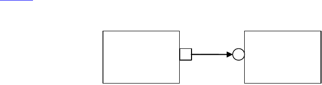
2.3.3 Basic TLM Communication
The most basic transaction-level operation allows one component to put a transaction to another. Consider
Figure 5.
Figure 5—Simple Producer/Consumer
The square box on the producer indicates a port and the circle on the consumer indicates the export. The
producer generates transactions and sends them out its put_port:
class producer extends uvm_component;
uvm_blocking_put_port #(simple_trans) put_port; // 1 parameter
function new( string name, uvm_component parent);
put_port = new(“put_port”, this);
...
endfunction
virtual task run();
simple_trans t;
for(int i = 0; i < N; i++) begin
// Generate t.
put_port.put(t);
end
endtask
NOTE—The uvm_*_port is parameterized by the transaction type that will be communicated. This may either be
specified directly or it may be a parameter of the parent component.
The actual implementation of the put() call is supplied by the consumer.
class consumer extends uvm_component;
uvm_blocking_put_imp #(simple_trans, consumer) put_export; // 2 parameters
...
task put(simple_trans t);
case(t.kind)
READ: // Do read.
WRITE: // Do write.
endcase
endtask
endclass
NOTE—The uvm_*_imp takes two parameters: the type of the transaction and the type of the object that declares the
method implementation.
p
r
oducer
co
n
su
m
er
12 UVM 1.1 User’s Guide May 18, 2011
NOTE—The semantics of the put operation are defined by TLM. In this case, the put() call in the producer will
block until the consumer’s put implementation is complete. Other than that, the operation of producer is completely
independent of the put implementation (uvm_put_imp). In fact, consumer could be replaced by another component
that also implements put and producer will continue to work in exactly the same way. The modularity provided by
TLM fosters an environment in which components may be easily reused since the interfaces are well defined.
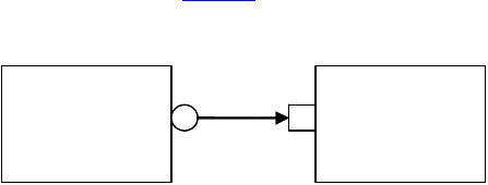
The converse operation to put is get. Consider Figure 6.
Figure 6—Consumer gets from Producer
In this case, the consumer requests transactions from the producer via its get port:
class get_consumer extends uvm_component;
uvm_blocking_get_port #(simple_trans) get_port;
function new( string name, uvm_component parent);
get_port = new(“get_port”, this);
...
endfunction
virtual task run();
simple_trans t;
for(int i = 0; i < N; i++) begin
// Generate t.
get_port.get(t);
end
endtask
The get() implementation is supplied by the producer.
class get_producer extends uvm_component;
uvm_blocking_get_imp #(simple_trans, get_producer) get_export;
...
task get(output simple_trans t);
simple_trans tmp = new();
// Assign values to tmp.
t = tmp;
endtask
endclass
As with put() above, the get_consumer’s get() call will block until the get_producer’s method
completes. In TLM terms, put() and get() are blocking methods.
NOTE—In both these examples, there is a single process running, with control passing from the port to the export and
back again. The direction of data flow (from producer to consumer) is the same in both examples.
2.3.4 Communicating between Processes
In the basic put example above, the consumer will be active only when its put() method is called. In
many cases, it may be necessary for components to operate independently, where the producer is creating
transactions in one process while the consumer needs to operate on those transactions in another. UVM
get_
producer
get_
consume
r
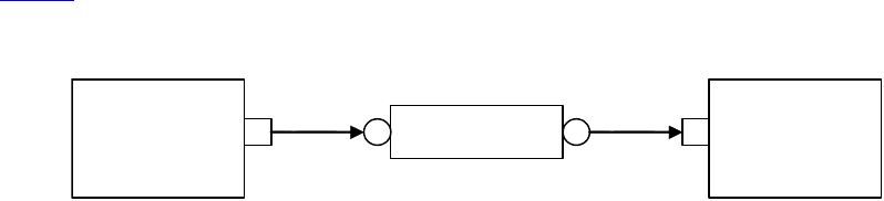
May 18, 2011 UVM 1.1 User’s Guide 13
provides the uvm_tlm_fifo channel to facilitate such communication. The uvm_tlm_fifo
implements all of the TLM interface methods, so the producer puts the transaction into the
uvm_tlm_fifo, while the consumer independently gets the transaction from the fifo, as shown in
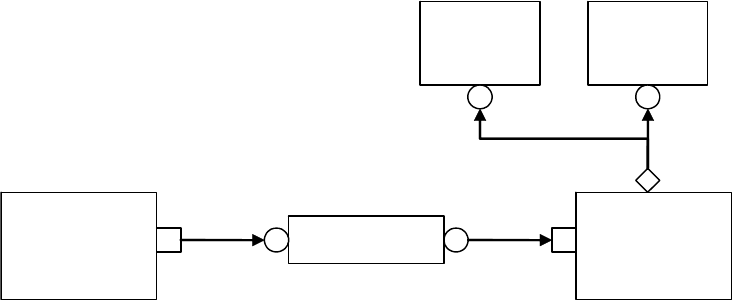
Figure 7.
Figure 7—Using a uvm_tlm_fifo
When the producer puts a transaction into the fifo, it will block if the fifo is full, otherwise it will put the
object into the fifo and return immediately. The get operation will return immediately if a transaction is
available (and will then be removed from the fifo), otherwise it will block until a transaction is available.
Thus, two consecutive get() calls will yield different transactions to the consumer. The related peek()
method returns a copy of the available transaction without removing it. Two consecutive peek() calls will
return copies of the same transaction.
2.3.5 Blocking versus Nonblocking
The interfaces that we have looked at so far are blocking—the tasks block execution until they complete;
they are not allowed to fail. There is no mechanism for any blocking call to terminate abnormally or
otherwise alter the flow of control. They simply wait until the request is satisfied. In a timed system, this
means that time may pass between the time the call was initiated and the time it returns.
In contrast, a nonblocking call returns immediately. The semantics of a nonblocking call guarantee that the
call returns in the same delta cycle in which it was issued, that is, without consuming any time, not even a
single delta cycle. In UVM, nonblocking calls are modeled as functions.
class consumer extends uvm_component;
uvm_get_port #(simple_trans) get_port;
task run;
...
for(int i=0; i<10; i++)
if(get_port.try_get(t))
//Do something with t.
...
endtask
endclass
If a transaction exists, it will be returned in the argument and the function call itself will return TRUE. If no
transaction exists, the function will return FALSE. Similarly, with try_peek(). The try_put()
method returns TRUE if the transaction is sent.
2.3.6 Connecting Transaction-Level Components
With ports and exports defined for transaction-level components, the actual connection between them is
accomplished via the connect() method in the parent (component or env), with an argument that is the
object (port or export) to which it will be connected. In a verification environment, the series of
t
lm fif
o
get_
consume
r
p
r
oducer

14 UVM 1.1 User’s Guide May 18, 2011
connect() calls between ports and exports establishes a netlist of peer-to-peer and hierarchical
connections, ultimately terminating at an implementation of the agreed-upon interface. The resolution of
these connections causes the collapsing of the netlist, which results in the initiator’s port being assigned to
the target’s implementation. Thus, when a component calls
put_port.put(t);
the connection means that it actually calls
target.put_export.put(t);
where target is the connected component.
2.3.7 Peer-to-Peer connections
When connecting components at the same level of hierarchy, ports are always connected to exports. All
connect() calls between components are done in the parent’s connect() method.
class my_env extends uvm_env;
...
virtual function void connect();
// component.port.connect(target.export);
producer.blocking_put_port.connect(fifo.put_export);
get_consumer.get_port.connect(fifo.get_export);
...
endfunction
endclass
2.3.8 Port/Export Compatibility
Another advantage of TLM communication in UVM is that all TLM connections are checked for
compatibility before the test runs. In order for a connection to be valid, the export must provide
implementations for at least the set of methods defined by the port and the transaction type parameter for the
two must be identical. For example, a blocking_put_port, which requires an implementation of
put() may be connected to either a blocking_put_export or a put_export. Both exports supply
an implementation of put(), although the put_export also supplies implementations of try_put()
and can_put().
2.4 Encapsulation and Hierarchy
The use of TLM interfaces isolates each component in a verification environment from the others. The
environment instantiates a component and connects its ports/exports to its neighbor(s), independent of any
further knowledge of the specific implementation. Smaller components may be grouped hierarchically to
form larger components (see Chapter 3). Access to child components is achieved by making their interfaces
visible at the parent level. At this level, the parent simply looks like a single component with a set of
interfaces on it, regardless of its internal implementation.
2.4.1 Hierarchical Connections
Making connections across hierarchical boundaries involves some additional issues, which are discussed in
this section. Consider the hierarchical design shown in Figure 8.
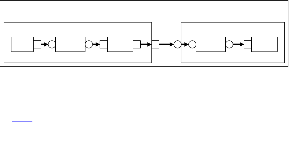
May 18, 2011 UVM 1.1 User’s Guide 15
Figure 8—Hierarchy in TLM
The hierarchy of this design contains two components, producer and consumer. producer contains
three components, stim, tlm_fi, and conv. consumer contains two components, tlm_fi and
drive. Notice that, from the perspective of top, the producer and consumer appear identical to those in
Figure 5, in which the producer’s put_port is connected to the consumer’s put_export. The two fifos
are both unique instances of the same uvm_tlm_fifo component.
In Figure 8, connections A, B, D, and F are standard peer-to-peer connections as discussed above. As an
example, connection A would be coded in the producer’s connect() method as:
gen.put_port.connect(fifo.put_export);
Connections C and E are of a different sort than what have been shown. Connection C is a port-to-port
connection, and connection E is an export-to-export connection. These two kinds of connections are
necessary to complete hierarchical connections. Connection C imports a port from the outer component to
the inner component. Connection E exports an export upwards in the hierarchy from the inner component to
the outer one. Ultimately, every transaction-level connection must resolve so that a port is connected to an
export. However, the port and export terminals do not need to be at the same place in the hierarchy. We use
port-to-port and export-to-export connections to bring connectors to a hierarchical boundary to be accessed
at the next-higher level of hierarchy.
For connection E, the implementation resides in the fifo and is exported up to the interface of consumer. All
export-to-export connections in a parent component are of the form
export.connect(subcomponent.export)
so connection E would be coded as:
class consumer extends uvm_component;
uvm_put_export #(trans) put_export;
uvm_tlm_fifo #(trans) fifo;
...
function void connect();
put_export.connect(fifo.put_export); // E
bfm.get_port.connect(fifo.get_export); // F
endfunction
...
endclass
Conversely, port-to-port connections are of the form:
subcomponent.port.connect(port);
co
n
v
st
im
tlm_fi
d
ri
ve
tlm_fi
top
A B
C
DE F
p
r
oducer
co
n
su
m
er

16 UVM 1.1 User’s Guide May 18, 2011
so connection C would be coded as:
class producer extends uvm_component;
uvm_put_port #(trans) put_port;
conv c;
...
function void connect();
c.put_port.connect(put_port);
...
endfunction
2.4.2 Connection Types
Table 1 summarizes connection types and elaboration functions.
NOTE—The argument to the port.connect() method may be either an export or a port, depending on the nature of
the connection (that is, peer-to-peer or hierarchical). The argument to export.connect() is always an export of a
child component.
2.5 Analysis Communication
The put/get communication as described above allows verification components to be created that model the
“operational” behavior of a system. Each component is responsible for communicating through its TLM
interface(s) with other components in the system in order to stimulate activity in the DUT and/or respond its
behavior. In any reasonably complex verification environment, however, particularly where randomization
is applied, a collected transaction should be distributed to the rest of the environment for end-to-end
checking (scoreboard), or additional coverage collection.
The key distinction between the two types of TLM communication is that the put/get ports typically require
a corresponding export to supply the implementation. For analysis, however, the emphasis is on a particular
component, such as a monitor, being able to produce a stream of transactions, regardless of whether there is
a target actually connected to it. Modular analysis components are then connected to the analysis_port,
each of which processes the transaction stream in a particular way.
2.5.1 Analysis Ports
The uvm_analysis_port (represented as a diamond on the monitor in Figure 9) is a specialized TLM
port whose interface consists of a single function, write(). The analysis port contains a list of
analysis_exports that are connected to it. When the component calls analysis_port.write(),
the analysis_port cycles through the list and calls the write() method of each connected export. If
nothing is connected, the write() call simply returns. Thus, an analysis port may be connected to zero,
Table 1—TLM Connection Types
Connection type connect() form
port-to-export comp1.port.connect(comp2.export);
port-to-port subcomponent.port.connect(port);
export-to-export export.connect(subcomponent.export);
May 18, 2011 UVM 1.1 User’s Guide 17
one, or many analysis exports, but the operation of the component that writes to the analysis port does not
depend on the number of exports connected. Because write() is a void function, the call will always
complete in the same delta cycle, regardless of how many components (for example, scoreboards, coverage
collectors, and so on) are connected.
Figure 9—Analysis Communication
class get_ap_consumer extends get_consumer;
uvm_analysis_port #(my_trans) ap;
function new(...);
super.new()
ap = new(“analysis_port”, this);
...
endfunction
task run;
...
for(int i=0; i<10; i++)
if(get_port.try_get(t)) begin
//Do something with t.
ap.write(t); // Write transaction.
...
end
endtask
In the parent environment, the analysis port gets connected to the analysis export of the desired components,
such as coverage collectors and scoreboards.
2.5.2 Analysis Exports
As with other TLM connections, it is up to each component connected to an analysis port to provide an
implementation of write() via an analysis_export. The uvm_subscriber base component can
be used to simplify this operation, so a typical analysis component would extend uvm_subscriber as:
class sub1 #(type T = simple_trans) extends uvm_subscriber #(T);
...
function void write(T t);
// Record coverage information of t.
endfunction
endclass
t
lm fif
o
get_sp_
consume
r
p
r
oducer
cov
cov
2
subsub2

18 UVM 1.1 User’s Guide May 18, 2011
As with put() and get() described above, the TLM connection between an analysis port and export,
allows the export to supply the implementation of write(). If multiple exports are connected to an
analysis port, the port will call the write() of each export, in order. Since all implementations of
write() must be functions, the analysis port’s write() function completes immediately, regardless of
how many exports are connected to it.
class my_env extends uvm_env;
get_ap_component g;
sub1 s1;
sub2 s2;
...
function void connect();
g.ap.connect(s1.analysis_export);
g.ap.connect(s2.analysis_export);
...
endfunction
endclass
When multiple subscribers are connected to an analysis_port, each is passed a pointer to the same
transaction object, the argument to the write() call. Each write() implementation must make a local
copy of the transaction and then operate on the copy to avoid corrupting the transaction contents for any
other subscriber that may have received the same pointer.
UVM also includes an analysis_fifo, which is a uvm_tlm_fifo that also includes an analysis
export, to allow blocking components access to the analysis transaction stream. The analysis_fifo is
unbounded, so the monitor’s write() call is guaranteed to succeed immediately. The analysis component
may then get the transactions from the analysis_fifo at its leisure.
2.6 Generic Payload
TLM-2.0 defines a base object, called the generic payload, for moving data between components. In
SystemC, this is the primary transaction vehicle. In SystemVerilog, this is the default transaction type, but it
is not the only type that can be used (as will be explained more fully in Section 2.7).
2.6.1 Attributes
Each attribute in the SystemC version has a corresponding member in the SystemVerilog generic payload.
protected rand bit [63:0] m_address;
protected rand uvm_tlm_command_e m_command;
protected rand byte m_data[];
protected rand int unsigned m_length;
protected rand uvm_tlm_response_status_e m_response_status;
protected rand bit m_dmi;
protected rand byte m_byte_enable[];
protected rand int unsigned m_byte_enable_length;
protected rand int unsigned m_streaming_width;
The data types of most members translate directly into SystemVerilog. Bool and unsigned int in
SystemC become bit and int unsigned in SystemVerilog. M_data and m_byte_enable, which
are defined as type char* in SystemC, are defined as dynamic arrays of bytes. uvm_tlm_command_e
and uvm_tlm_response_status_e are enumerated types. They are defined as:
May 18, 2011 UVM 1.1 User’s Guide 19
typedef enum
{
TLM_READ_COMMAND,
TLM_WRITE_COMMAND,
TLM_IGNORE_COMMAND
} uvm_tlm_command_e;
typedef enum
{
TLM_OK_RESPONSE = 1,
TLM_INCOMPLETE_RESPONSE = 0,
TLM_GENERIC_ERROR_RESPONSE = -1,
TLM_ADDRESS_ERROR_RESPONSE = -2,
TLM_COMMAND_ERROR_RESPONSE = -3,
TLM_BURST_ERROR_RESPONSE = -4,
TLM_BYTE_ENABLE_ERROR_RESPONSE = -5
} uvm_tlm_response_status_e;
All of the members of the generic payload have the rand qualifier. This enables instances of the generic
payload to be randomized. SystemVerilog allows arrays, including dynamic arrays to be randomized. See
subclause 18.4 of IEEE Std. 1800-2009, the SystemVerliog LRM, for more details.
2.6.2 Accessors
In SystemC, all of the attributes are private and are accessed through accessor methods. In SystemVerilog,
this means all members are protected and similarly accessed through accessor methods.
virtual function uvm_tlm_command_e get_command();
virtual function void set_command(uvm_tlm_command_e command);
virtual function bit is_read();
virtual function void set_read();
virtual function bit is_write();
virtual function void set_write();
virtual function void set_address(bit [63:0] addr);
virtual function bit[63:0] get_address();
virtual function void get_data (output byte p []);
virtual function void set_data_ptr(ref byte p []);
virtual function int unsigned get_data_length();
virtual function void set_data_length(int unsigned length);
virtual function int unsigned get_streaming_width();
virtual function void set_streaming_width(int unsigned width);
virtual function void get_byte_enable(output byte p[]);
virtual function void set_byte_enable(ref byte p[]);
virtual function int unsigned get_byte_enable_length();
virtual function void set_byte_enable_length(int unsigned length);
virtual function void set_dmi_allowed(bit dmi);
virtual function bit is_dmi_allowed();
virtual function uvm_tlm_response_status_e get_response_status();
virtual function void set_response_status(uvm_tlm_response_status_e status);
virtual function bit is_response_ok();
virtual function bit is_response_error();
virtual function string get_response_string();
The accessor functions let you set and get each of the members of the generic payload. All of the accessor
methods are virtual. This implies a slightly different use model for the generic payload than in SystemC. The
way the generic payload is defined in SystemC does not encourage you to create new transaction types

20 UVM 1.1 User’s Guide May 18, 2011
derived from uvm_tlm_generic_payload. Instead, you would use the extensions mechanism (see
Section 2.6.3). Thus, in SystemC, none of the accessors are virtual.
In SystemVerilog, an important use model is to add randomization constraints to a transaction type. This is
most often done with inheritance—take a derived object and add constraints to a base class. These
constraints can further be modified or extended by deriving a new class, and so on. To support this use
model, the accessor functions are virtual, and the members are protected and not local.
2.6.3 Extensions
The generic payload extension mechanism is very similar to the one used in SystemC; minor differences
exist simply due to the lack of function templates in SystemVerilog. Extensions are used to attach additional
application-specific or bus-specific information to the generic bus transaction described in the generic
payload.
An extension is an instance of a user-defined container class based on the uvm_tlm_extension class.
The set of extensions for any particular generic payload object are stored in that generic payload object
instance. A generic payload object may have only one extension of a specific extension container type.
Each extension container type is derived from the uvm_tlm_extension class and contains any
additional information required by the user:
class gp_Xs_ext extends uvm_tlm_extension#(gp_Xs_ext);
byte Xmask[];
‘uvm_object_new
‘uvm_object_utils_begin(gp_Xs_ext)
‘uvm_field_int_array(Xmask, UVM_ALL_ON)
‘uvm_object_utils_end
endclass
To add an extension to a generic payload object, allocate an instance of the extension container class and
attach it to the generic payload object using the set_extension() method:
gp_Xs_ext Xs = new();
gp.set_extension(Xs);
The static function ID() in the user-defined extension container class can be used as an argument to the
function get_extension method to retrieve the extension (if any) of the corresponding container type—
if it is attached to the generic payload object.
gp_Xs_ext Xs;
$cast(Xs, gp.get_extension(gp_Xs_ext::ID));
The following methods are also available in the generic payload for managing extensions.
function int get_num_extensions();
function void clear_extension();
function void clear_extensions();
clear_extension() removes any extension of a specified type. clear_extensions() removes all
extension containers from the generic payload.

May 18, 2011 UVM 1.1 User’s Guide 21
2.7 Core Interfaces and Ports
In the SystemVerilog implementation of TLM-2.0, we have provided only the basic transport interfaces.
They are defined in the uvm_tlm_if#() class:
class uvm_tlm_if #(type T=uvm_tlm_generic_payload, type P=uvm_tlm_phase_e);
endclass
The interface class is parameterized with the type of the transaction object that will be transported across the
interface and the type of the phase enum. The default transaction type is the generic payload. The default
phase enum is:
typedef enum
{
UNINITIALIZED_PHASE,
BEGIN_REQ,
END_REQ,
BEGIN_RESP,
END_RESP
} uvm_tlm_phase_e;
Each of the interface methods take a handle to the transaction to be transported and a handle to a timescale-
independent time value object. In addition, the nonblocking interfaces take a reference argument for the
phase.
virtual function uvm_tlm_sync_e nb_transport_fw(T t, ref P p, input
uvm_tlm_time delay);
virtual function uvm_tlm_sync_e nb_transport_bw(T t, ref P p, input
uvm_tlm_time delay);
virtual task b_transport(T t, uvm_tlm_time delay);
In SystemC, the transaction argument is of type T&. Passing a handle to a class in SystemVerilog most
closely represents the semantics of T& in SystemC. One implication in SystemVerilog is transaction types
cannot be scalars. If the transaction argument was qualified with ref, indicating it was a reference
argument, then it would be possible to use scalar types for transactions. However, that would also mean
downstream components could change the handle to a transaction. This violates the required semantics in
TLM-2.0 as stated in rule 4.1.2.5-b of the TLM-2.0 LRM, which is quoted here.
“If there are multiple calls to nb_transport associated with a given transaction instance, one and the
same transaction object shall be passed as an argument to every such call. In other words, a given
transaction instance shall be represented by a single transaction object.”
The phase and delay arguments may change value. These are also references in SystemC; e.g., P& and
sc_time&. However, phase is a scalar, not a class, so the best translation is to use the ref qualifier to
ensure the same object is used throughout the call sequence.
The uvm_tlm_time argument, which is present on all the interfaces, represents time. In the SystemC
TLM-2.0 specification, this argument is reference to an sc_time variable, which lets the value change on
either side. This was translated to a class object in SystemVerilog in order to manage timescales in different
processes. Times passed through function calls are not automatically scaled. See also: Section 2.11.
An important difference between TLM-1 and TLM-2.0 is the TLM-2.0 interfaces pass transactions by
reference and not by value. In SystemC, transactions in TLM-1 were passed as const references and in
TLM-2.0 just as references. This allows the transaction object to be modified without copying the entire
transaction. The result is much higher performance characteristics as a lot of copying is avoided. Another
result is any object that has a handle to a transaction may modify it. However, to adhere to the semantics of
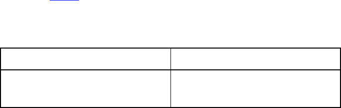
22 UVM 1.1 User’s Guide May 18, 2011
the TLM-2.0 interfaces, these modifications must be made within certain rules and in concert with
notifications made via the return enum in the nb_* interfaces and the phase argument.
2.8 Blocking Transport
The blocking transport is implemented using one interfaces:
task b_transport(T t, uvm_tlm_time delay);
The b_transport task transports a transaction from the initiator to the target in a blocking fashion. The
call to b_transport by the initiator marks the first timing point in the execution of the transaction. That
first timing point may be offset from the current simulation by the delay value specified in the delay
argument. The return from b_transport by the target marks the final timing point in the execution of the
transaction. That last timing point may be offset from the current simulation time by the delay value
specified in the delay argument. Once the task returns, the transaction has been completed by the target.
Any indication of success or failure must be annotated in the transaction object by the target.
The initiator may read or modify the transaction object before the call to b_transport and after its return,
but not while the call to b_transport is still active. The target may modify the transaction object only
while the b_transport call is active and must not keep a reference to it after the task return. The initiator
is responsible for allocating the transaction object before the call to b_transport. The same transaction
object may be reused across b_transport calls.
2.9 Nonblocking Transport
The blocking transport is implemented using two interfaces:
function uvm_tlm_sync_e nb_transport_fw(T t, ref P p, input uvm_tlm_time
delay);
function uvm_tlm_sync_e nb_transport_bw(T t, ref P p, input uvm_tlm_time
delay);
nb_transport_fw transports a transaction in the forward direction, that is from the initiator to the target
(the forward path). nb_transport_bw does the reverse, it transports a transaction from the target back to
the initiator (the backward path). An initiator and target will use the forward and backward paths to update
each other on the progress of the transaction execution. Typically, nb_transport_fw is called by the
initiator whenever the protocol state machine in the initiator changes state and nb_transport_bw is
called by the target whenever the protocol state machine in the target changes state.
The nb_* interfaces each return an enum uvm_tlm_sync_e. The possible enum values and their
meanings are shown in Table 2.
Table 2—uvm_tlm_sync_e enum Description
Enum value Interpretation
UVM_TLM_ACCEPTED Transaction has been accepted. Neither the
transaction object, the phase nor the
delay arguments have been modified.

May 18, 2011 UVM 1.1 User’s Guide 23
The P argument of nb_transport_fw and nb_transport_bw represents the transaction phase. This
can be a user-defined type that is specific to a particular protocol. The default type is uvm_tlm_phase_e,
whose values are shown in Table 3. These can be used to implement the Base Protocol.
The first call to nb_transport_fw by the initiator marks the first timing point in the transaction
execution. Subsequent calls to nb_transport_fw and nb_transport_bw mark additional timing
points in the transaction execution. The last timing point is marked by a return from nb_transport_fw
or nb_transport_bw with UVM_TLM_COMPLETED. All timing points may be offset from the current
simulation time by the delay value specified in the delay argument. An nb_transport_fw call on the
forward path shall under no circumstances directly or indirectly make a call to nb_transport_bw on the
backward path, and vice versa.
The value of the phase argument represents the current state of the protocol state machine. Any change in
the value of the transaction object should be accompanied by a change in the value of phase. When using
the Base Protocol, successive calls to nb_transport_fw or nb_transport_bw with the same phase
value are not permitted.
The initiator may modify the transaction object, the phase and the delay arguments immediately before
calls to nb_transport_fw and before it returns from nb_transport_bw only. The target may
modify the transaction object, the phase and the delay arguments immediately before calls to
nb_transport_bw and before it returns from nb_transport_fw only. The transaction object,
phase and delay arguments may not be otherwise modified by the initiator or target.
The initiator is responsible for allocating the transaction object before the first call to nb_transport_fw.
The same transaction object is used by all of the forward and backward calls during its execution. That
UVM_TLM_UPDATED Transaction has been modified. The transac-
tion object, the phase or the delay argu-
ments may have been modified.
UVM_TLM_COMPLETED Transaction execution has completed. The
transaction object, the phase or the
delay arguments may have been modified.
There will be no further transport calls asso-
ciated with this transaction.
Table 3—uvm_tlm_phase_e Description
Enum value Interpretation
UNITIALIZED_PHASE Phase has not yet begun
BEGIN_REQ Request has begun
END_REQ Request has completed
BEGIN_RESP Response has begun
END_RESP Response has terminated
Table 2—uvm_tlm_sync_e enum Description (Continued)
Enum value Interpretation
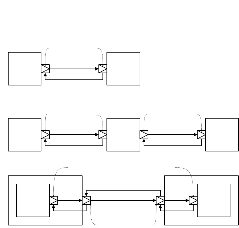
24 UVM 1.1 User’s Guide May 18, 2011
transaction object is alive for the entire duration of the transaction until the final timing point. The same
transaction object may be reused across different transaction execution that do not overlap in time.
2.10 Sockets
In TLM-1, the primary means of making a connection between two processes is through ports and exports,
whereas in TLM-2.0 this done through sockets. A socket is like a port or export; in fact, it is derived from the
same base class as ports and export, namely uvm_port_base. However, unlike a port or export a socket
provides both a forward and backward path. Thus, you can enable asynchronous (pipelined) bi-directional
communication by connecting sockets together. To enable this, a socket contains both a port and an export.
Components that initiate transactions are called initiators and components that receive transactions sent by
an initiator are called targets. Initiators have initiator sockets and targets have target sockets. Initiator
sockets can only connect to target sockets; target sockets can only connect to initiator sockets.
Figure 10 shows the diagramming of socket connections. The socket symbol is a box with an isosceles
triangle with its point indicating the data and control flow direction of the forward path. The backward path
is indicated by an arrow connecting the target socket back to the initiator socket. Section 3.4 of the TLM-2.0
LRM fully explains sockets, initiators, targets, and interconnect components.
Figure 10—Socket Connections
,1,7,$725
&20321(17
7$5*(7
&20321(17
,QLWLDWRU
WHUPLQDWRU
VRFNHW
7DUJHW
WHUPLQDWRU
VRFNHW
,1,7,$725
&20321(17
,17(5&211(&7
&20321(17
7$5*(7
&20321(17
,1,7,$725
&20321(17
7$5*(7
&20321(17
,QLWLDWRUWHUPLQDWRU
VRFNHW
7DUJHWWHUPLQDWRU
VRFNHW
,QLWLDWRU
WHUPLQDWRU
VRFNHW
7DUJHW
WHUPLQDWRU
VRFNHW
,QLWLDWRU
WHUPLQDWRU
VRFNHW
7DUJHW
WHUPLQDWRU
VRFNHW
,QLWLDWRU
SDVVWKURXJK
6RFNHW
7DUJHW
SDVVWKURXJK
6RFNHW
May 18, 2011 UVM 1.1 User’s Guide 25
Sockets come in several flavors: Each socket is an initiator or a target, a passthrough, or a terminator.
Furthermore, any particular socket implements either blocking interfaces or nonblocking interfaces.
Terminator sockets are used on initiators and targets as well as interconnect components as shown in
Figure 10. Passthrough sockets are used to enable connections to cross hierarchical boundaries.
The cross product of {initiator, target} X {terminator, passthrough} X {blocking, nonblocking} yields eight
different kinds of sockets. The class definitions for these sockets are as follows:
class uvm_tlm_nb_passthrough_initiator_socket #(type
T=uvm_tlm_generic_payload,
type P=uvm_tlm_phase_e)
extends uvm_tlm_nb_passthrough_initiator_socket_base #(T,P);
class uvm_tlm_nb_passthrough_target_socket #(type T=uvm_tlm_generic_payload,
type P=uvm_tlm_phase_e)
extends uvm_tlm_nb_passthrough_target_socket_base #(T,P);
class uvm_tlm_b_passthrough_initiator_socket #(type
T=uvm_tlm_generic_payload)
extends uvm_tlm_b_passthrough_initiator_socket_base #(T);
class uvm_tlm_b_passthrough_target_socket #(type T=uvm_tlm_generic_payload)
extends uvm_tlm_b_passthrough_target_socket_base #(T);
class uvm_tlm_b_target_socket #(type T=uvm_tlm_generic_payload,
type IMP=int)
extends uvm_tlm_b_target_socket_base #(T);
class uvm_tlm_b_initiator_socket #(type T=uvm_tlm_generic_payload)
extends uvm_tlm_b_initiator_socket_base #(T);
class uvm_tlm_nb_target_socket #(type T=uvm_tlm_generic_payload,
type P=uvm_tlm_phase_e,
type IMP=int)
extends uvm_tlm_nb_target_socket_base #(T,P);
class uvm_tlm_nb_initiator_socket #(type T=uvm_tlm_generic_payload,
type P=uvm_tlm_phase_e,
type IMP=int)
extends uvm_tlm_nb_initiator_socket_base #(T,P);
Table 4 shows the different kinds of sockets and how they are constructed.
Table 4—Socket Construction
Socket Blocking Nonblocking
initiator IS-A forward port IS-A forward port; HAS-A backward imp
target IS-A forward imp IS-A forward imp; HAS-A backward port
passthrough initiator IS-A forward port IS-A forward port; HAS-A backward export
passthrough target IS-A forward export IS-A forward port; HAS-A backward export
26 UVM 1.1 User’s Guide May 18, 2011
IS-A and HAS-A are types of object relationships. IS-A refers to the inheritance relationship and HAS-A
refers to the ownership relationship. For example, if you say D is a B, it means D is derived from base B. If
you say object A HAS-A B, it means B is a member of A.
Each <socket_type>::connect() calls super.connect(), which performs all the connection
mechanics. For the nonblocking sockets which have a secondary port/export for the backward path,
connect() is called on the secondary port/export to form a backward connection.
Each socket type provides an implementation of the connect() method. Connection is defined
polymorphically using the base class type as the argument.
function void connect(this_type provider);
where this_type is defined in uvm_port_base as:
uvm_port_base #(IF) this_type;
Further, IF is defined by uvm_tlm_if#(T,P). Thus, compile-time interface type checking is achieved.
However, this is not sufficient type checking. Additionally, each implementation of connect() in each
socket type does run-time type checking to ensure it is connected to allowable socket types. For example, an
initiator socket can connect to an initiator passthrough socket, a target passthrough socket, or a target socket.
It cannot connect to another initiator socket. These kinds of checks are performed for each socket type.
2.11 Time
Integers are not sufficient on their own to represent time without any ambiguity; you need to know the scale
of that integer value, which is conveyed outside of the integer. In SystemVerilog, this is based on the
timescale that was active when the code was compiled. SystemVerilog properly scales time literals, but not
integer values because it does not know the difference between an integer that carries an integer value and an
integer that carries a time value. time variables are simply 64-bit integers, they are not scaled back and
forth to the underlying precision. Here is a short example that illustrates part of the problem.
`timescale 1ns/1ps
module m();
time t;
initial begin
#1.5;
$write("T=%f ns (Now should be 1.5)\n", $realtime());
t = 1.5;
#t; // 1.5 will be rounded to 2
$write("T=%f ns (Now should be 3.0)\n", $realtime());
#10ps;
$write("T=%f ns (Now should be 3.010)\n", $realtime());
t = 10ps; // 0.010 will be converted to int (0)
#t;
$write("T=%f ns (Now should be 3.020)\n", $realtime());
end
endmodule
yields
T=1.500000 ns (Now should be 1.5)
T=3.500000 ns (Now should be 3.0)
May 18, 2011 UVM 1.1 User’s Guide 27
T=3.510000 ns (Now should be 3.010)
T=3.510000 ns (Now should be 3.020)
Within SystemVerilog, we have to worry about different time scales and precision. Because each endpoint
in a socket could be coded in different packages and, thus, be executing under different timescale directives,
a simple integer cannot be used to exchange time information across a socket.
For example,
`timescale 1ns/1ps
package a_pkg;
class a;
function void f(inout time t);
t += 10ns;
endfunction
endclass
endpackage
`timescale 1ps/1ps
program p;
import a_pkg::*;
time t = 0;
initial begin
a A = new;
A.f(t);
#t;
$write("T=%0d ps (Should be 10,000)\n", $time());
end
endprogram
yields
T=10 ps (Should be 10,000)
Scaling is needed every time you make a procedural call to code that may interpret a time value in a different
timescale. Using the uvm_tlm_time type:
`timescale 1ns/1ps
package a_pkg;
import uvm_pkg::*;
class a;
function void f(uvm_tlm_time t);
t.incr(10ns, 1ns);
endfunction
endclass
endpackage
`timescale 1ps/1ps
28 UVM 1.1 User’s Guide May 18, 2011
program p;
import uvm_pkg::*;
import a_pkg::*;
uvm_tlm_time t = new;
initial begin
a A = new;
A.f(t);
#(t.get_realtime(1ns));
$write("T=%0d ps (Should be 10,000)\n", $time());
end
endprogram
yields
T=10000 ps (Should be 10,000)
To solve these problems, the uvm_tlm_time class contains the scaling information so that as time
information is passed between processes, which may be executing under different time scales, the time can
be scaled properly in each environment.
2.12 Use Models
Since sockets are derived from uvm_port_base, they are created and connected in the same way as port
and exports. You can create them in the build phase and connect them in the connect phase by calling
connect(). Initiator and target termination sockets are the end points of any connection. There can be an
arbitrary number of passthrough sockets in the path between the initiator and target.
Some socket types must be bound to imps—implementations of the transport tasks and functions. Blocking
terminator sockets must be bound to an implementation of b_transport(), for example. Nonblocking
initiator sockets must be bound to an implementation of nb_transport_bw and nonblocking target
sockets must be bound to an implementation of nb_transport_fw. Typically, the task or function is
implemented in the component where the socket is instantiated and the component type and instance are
provided to complete the binding.
Consider, for example, a consumer component with a blocking target socket:
class consumer extends uvm_component;
uvm_tlm_b_target_socket #(trans, consumer) target_socket;
function new(string name, uvm_component parent);
super.new(name, parent);
endfunction
function void build();
target_socket = new("target_socket", this, this);
endfunction
task b_transport(ref trans t, ref time delay);
#5;
‘uvm_info("consumer", t.convert2string());
endtask
endclass
May 18, 2011 UVM 1.1 User’s Guide 29
The interface task b_transport is implemented in the consumer component. The consumer component
type is used in the declaration of the target socket, which informs the socket object of the type of the object
containing the interface task, in this case b_transport(). When the socket is instantiated this is
passed in twice, once as the parent, just like any other component instantiation, and again to identify the
object that holds the implementation of b_transport(). Finally, in order to complete the binding, an
implementation of b_transport() must be present in the consumer component.
Any component that has a blocking termination socket, nonblocking initiator socket, or nonblocking
termination socket must provide implementations of the relevant components. This includes initiator and
target components, as well as interconnect components that have these kinds of sockets. Components with
passthrough sockets do not need to provide implementations of any sort. Of course, they must ultimately be
connected to sockets that do provide the necessary implementations.
30 UVM 1.1 User’s Guide May 18, 2011

May 18, 2011 UVM 1.1 User’s Guide 31
3. Developing Reusable Verification Components
This chapter describes the basic concepts and components that make up a typical verification environment.
It also shows how to combine these components using a proven hierarchical architecture to create reusable
verification components. The sections in this chapter follow the same order you should follow when
developing a verification component:
—Modeling Data Items for Generation
—Transaction-Level Components
—Creating the Driver
—Creating the Sequencer
—Creating the Monitor
—Instantiating Components
—Creating the Agent
—Creating the Environment
—Enabling Scenario Creation
—Managing End of Test
—Implementing Checks and Coverage
NOTE—This chapter builds upon concepts described in Chapter 1 and Chapter 2.
3.1 Modeling Data Items for Generation
Data items:
— Are transaction objects used as stimulus to the device under test (DUT).
— Represent transactions that are processed by the verification environment.
— Are classes that you define (“user-defined” classes).
— Capture and measure transaction-level coverage and checking.
NOTE—The UVM Class Library provides the uvm_sequence_item base class. Every user-defined data item must
be derived directly or indirectly from this base class.
To create a user-defined data item:
a) Review your DUT's transaction specification and identify the application-specific properties, con-
straints, tasks, and functions.
b) Derive a data item class from the uvm_sequence_item base class (or a derivative of it).
c) Define a constructor for the data item.
d) Add control fields (“knobs”) for the items identified in Step (a) to enable easier test writing.
e) Use UVM field macros to enable printing, copying, comparing, and so on.
UVM has built-in automation for many service routines that a data item needs. For example, you can use:
—print() to print a data item.
—copy() to copy the contents of a data item.
—compare() to compare two similar objects.
UVM allows you to specify the automation needed for each field and to use a built-in, mature, and consistent
implementation of these routines.
To assist in debugging and tracking transactions, the uvm_transaction base class includes the
m_transaction_id field. In addition, the uvm_sequence_item base class (extended from
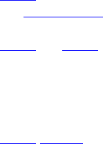
32 UVM 1.1 User’s Guide May 18, 2011
uvm_transaction) also includes the m_sequence_id field, allowing sequence items to be correlated
to the sequence that generated them originally. This is necessary to allow the sequencer to route response
transactions back to the correct sequence in bidirectional protocols.
The class simple_item in this example defines several random variables and class constraints. The UVM
macros implement various utilities that operate on this class, such as copy, compare, print, and so on. In
particular, the `uvm_object_utils macro registers the class type with the common factory.
1 class simple_item extends uvm_sequence_item;
2 rand int unsigned addr;
3 rand int unsigned data;
4 rand int unsigned delay;
5 constraint c1 { addr < 16'h2000; }
6 constraint c2 { data < 16'h1000; }
7 // UVM automation macros for general objects
8 `uvm_object_utils_begin(simple_item)
9 `uvm_field_int(addr, UVM_ALL_ON)
10 `uvm_field_int(data, UVM_ALL_ON)
11 `uvm_field_int(delay, UVM_ALL_ON)
12 `uvm_object_utils_end
13 // Constructor
14 function new (string name = "simple_item");
15 super.new(name);
16 endfunction : new
17 endclass : simple_item
Line 1 Derive data items from uvm_sequence_item so they can be generated in a procedural sequence.
See Section 3.10.2 for more information.
Line 5 and Line 6Add constraints to a data item definition in order to:
Reflect specification rules. In this example, the address must be less than 16'h2000.
Specify the default distribution for generated traffic. For example, in a typical test most transactions
should be legal.
Line 7-Line 12 Use the UVM macros to automatically implement functions such as copy(), compare(),
print(), pack(), and so on. Refer to “Macros” in the UVM 1.1 Class Reference for information on the
`uvm_object_utils_begin, `uvm_object_utils_end, `uvm_field_*, and their associated
macros.
NOTE—UVM provides built-in macros to simplify development of the verification environment. The macros automate
the implementation of functions defined in the base class, such as copy(), compare(), and print(), thus saving
many lines of code. Use of these macros is optional, but recommended.
3.1.1 Inheritance and Constraint Layering
In order to meet verification goals, the verification component user might need to adjust the data-item
generation by adding more constraints to a class definition. In SystemVerilog, this is done using inheritance.
The following example shows a derived data item, word_aligned_item, which includes an additional
constraint to select only word-aligned addresses.
class word_aligned_item extends simple_item;
constraint word_aligned_addr { addr[1:0] == 2'b00; }
`uvm_object_utils(word_aligned_item)
// Constructor
function new (string name = "word_aligned_item");

May 18, 2011 UVM 1.1 User’s Guide 33
super.new(name);
endfunction : new
endclass : word_aligned_item
To enable this type of extensibility:
— The base class for the data item (simple_item in this chapter) should use virtual methods to allow
derived classes to override functionality.
— Make sure constraint blocks are organized so that they are able to override or disable constraints for
a random variable without having to rewrite a large block.
— Do not use the protected or local keyword to restrict access to properties that may be con-
strained by the user. This will limit your ability to constrain them with an inline constraint.
3.1.2 Defining Control Fields (“Knobs”)
The generation of all values of the input space is often impossible and usually not required. However, it is
important to be able to generate a few samples from ranges or categories of values. In the simple_item
example in Section 3.1, the delay property could be randomized to anything between zero and the maximum
unsigned integer. It is not necessary (nor practical) to cover the entire legal space, but it is important to try
back-to-back items along with short, medium, and large delays between the items, and combinations of all
of these. To do this, define control fields (often called “knobs”) to enable the test writer to control these
variables. These same control knobs can also be used for coverage collection. For readability, use
enumerated types to represent various generated categories.
Knobs Example
typedef enum {ZERO, SHORT, MEDIUM, LARGE, MAX} simple_item_delay_e;
class simple_item extends uvm_sequence_item;
rand int unsigned addr;
rand int unsigned data;
rand int unsigned delay;
rand simple_item_delay_e delay_kind; // Control field
// UVM automation macros for general objects
`uvm_object_utils_begin(simple_item)
`uvm_field_int(addr, UVM_ALL_ON)
`uvm_field_enum(simple_item_delay_e, delay_kind, UVM_ALL_ON)
`uvm_object_utils_end
constraint delay_order_c { solve delay_kind before delay; }
constraint delay_c {
(delay_kind == ZERO) -> delay == 0;
(delay_kind == SHORT) -> delay inside { [1:10] };
(delay_kind == MEDIUM) -> delay inside { [11:99] };
(delay_kind == LARGE) -> delay inside { [100:999] };
(delay_kind == MAX ) -> delay == 1000;
delay >=0; delay <= 1000; }
endclass : simple_item
Using this method allows you to create more abstract tests. For example, you can specify distribution as:
constraint delay_kind_d {delay_kind dist {ZERO:=2, SHORT:=1,
MEDIUM:=1, LONG:=1, MAX:=2};}
When creating data items, keep in mind what range of values are often used or which categories are of
interest to that data item. Then add knobs to the data items to simplify control and coverage of these data
item categories.
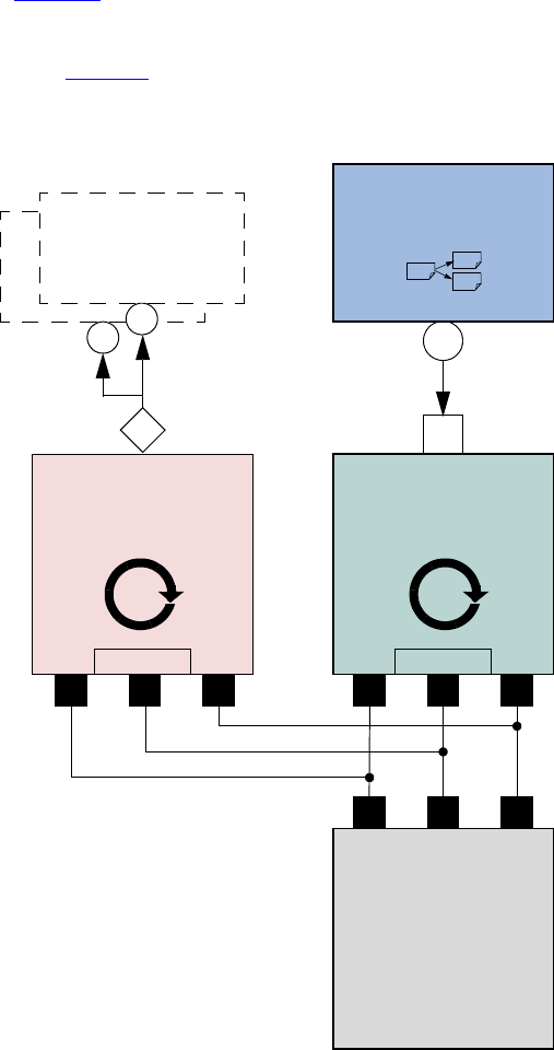
34 UVM 1.1 User’s Guide May 18, 2011
3.2 Transaction-Level Components
As discussed in Chapter 2, TLM interfaces in UVM provide a consistent set of communication methods for
sending and receiving transactions between components. The components themselves are instantiated and
connected in the testbench, to perform the different operations required to verify a design. A simplified
testbench is shown in Figure 11.
Figure 11—Simplified Transaction-Level Testbench
The basic components of a simple transaction-level verification environment are:
a) A stimulus generator (sequencer) to create transaction-level traffic to the DUT.
b) A driver to convert these transactions to signal-level stimulus at the DUT interface.
c) A monitor to recognize signal-level activity on the DUT interface and convert it into transactions.
d) An analysis component, such as a coverage collector or scoreboard, to analyze transactions.
Driver
Consumes and sends
data to the DUT
vi
Sequencer
Produces data
seq_item_export
seq_item_port
Monitor
checking
coverage
vi
DUT
Analysis
Analysis
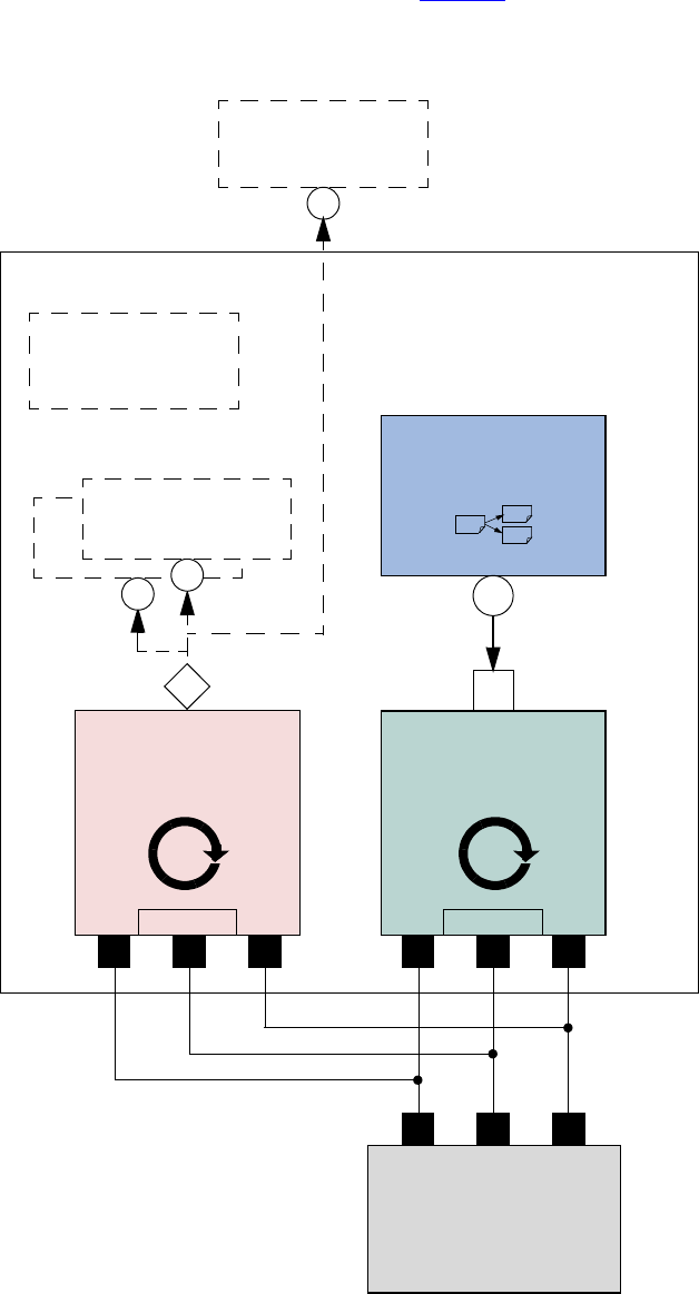
May 18, 2011 UVM 1.1 User’s Guide 35
As we shall see, the consistency and modularity of the TLM interfaces in UVM allow components to be
reused as other components are replaced and/or encapsulated. Every component is characterized by its
interfaces, regardless of its internal implementation (see Figure 12). This chapter discusses how to
encapsulate these types of components into a proven architecture, a verification component, to improve
reuse even further.
Figure 12—Highly Reusable Verification Component Agent
Driver
Consumes and sends
data to the DUT
vi
Sequencer
Produces data
seq_item_export
seq_item_port
Monitor
checking
coverage
vi
DUT
Config
Analysis
Analysis
Agent
Analysis

36 UVM 1.1 User’s Guide May 18, 2011
Figure 12 shows the recommended grouping of individual components into a reusable interface-level
verification component agent. Instead of reusing the low-level classes individually, the developer creates a
component that encapsulates it’s sub-classes in a consistent way. Promoting a consistent architecture makes
these components easier to learn, adopt, and configure.
3.3 Creating the Driver
The driver’s role is to drive data items to the bus following the interface protocol. The driver obtains data
items from the sequencer for execution. The UVM Class Library provides the uvm_driver base class,
from which all driver classes should be extended, either directly or indirectly. The driver has a run()
method that defines its operation, as well as a TLM port through which it communicates with the sequencer
(see the example below). The driver may also implement one or more of the parallel run-time phases
(pre_reset - post_shutdown) to refine its operation further.
To create a driver:
a) Derive a driver from the uvm_driver base class.
b) If desired, add UVM infrastructure macros for class properties to implement utilities for printing,
copying, comparing, and so on.
c) Obtain the next data item from the sequencer and execute it as outlined above.
d) Declare a virtual interface in the driver to connect the driver to the DUT.
Refer to Section 3.10.2 for a description of how a sequencer, driver, and sequences synchronize with each
other to generate constrained random data.
The class simple_driver in the example below defines a driver class. The example derives
simple_driver from uvm_driver (parameterized to use the simple_item transaction type) and
uses the methods in the seq_item_port object to communicate with the sequencer. As always, include a
constructor and the `uvm_component_utils macro to register the driver type with the common
factory.
1 class simple_driver extends uvm_driver #(simple_item);
2 simple_item s_item;
3 virtual dut_if vif;
4 // UVM automation macros for general components
5 `uvm_component_utils(simple_driver)
6 // Constructor
7 function new (string name = "simple_driver", uvm_component parent);
8 super.new(name, parent);
9 endfunction : new
10 function void build_phase(uvm_phase phase);
11 string inst_name;
12 super.build_phase(phase);
13 if(!uvm_config_db#(virtual dut_if)::get(this,
14 “”,"vif",vif))
15 `uvm_fatal("NOVIF",
16 {"virtual interface must be set for: ",
17 get_full_name(),".vif"});
18 endfunction : build_phase
19 task run_phase(uvm_phase phase);
20 forever begin
21 // Get the next data item from sequencer (may block).
22 seq_item_port.get_next_item(s_item);
23 // Execute the item.
24 drive_item(s_item);

May 18, 2011 UVM 1.1 User’s Guide 37
25 seq_item_port.item_done(); // Consume the request.
26 end
27 endtask : run
28
29 task drive_item (input simple_item item);
30 ... // Add your logic here.
31 endtask : drive_item
32 endclass : simple_driver
Line 1 Derive the driver.
Line 5 Add UVM infrastructure macro.
Line 13 Get the resource that defines the virtual interface
Line 22 Call get_next_item() to get the next data item for execution from the sequencer.
Line 25 Signal the sequencer that the execution of the current data item is done.
Line 30 Add your application-specific logic here to execute the data item.
More flexibility exists on connecting the drivers and the sequencer. See Section 3.5.
3.4 Creating the Sequencer
The sequencer generates stimulus data and passes it to a driver for execution. The UVM Class Library
provides the uvm_sequencer base class, which is parameterized by the request and response item
types. The uvm_sequencer base class contains all of the base functionality required to allow a sequence
to communicate with a driver. The only time it is necessary to extend the uvm_sequencer class is if you
need to add additional functionality, such as additional ports. The uvm_sequencer gets instantiated
directly, with appropriate parameterization as shown in Section 3.8.1, Line 4. In the class definition, by
default, the response type is the same as the request type. If a different response type is desired, the optional
second parameter must be specified for the uvm_sequencer base type:
uvm_sequencer #(simple_item, simple_rsp) sequencer;
Refer to Section 3.10.2 for a description of how a sequencer, driver, and sequences synchronize with each
other to generate constrained-random data.
3.5 Connecting the Driver and Sequencer
The driver and the sequencer are connected via TLM, with the driver’s seq_item_port connected to the
sequencer’s seq_item_export (see Figure 13). The sequencer produces data items to provide via the
export. The driver consumes data items through its seq_item_port and, optionally, provides responses.
The component that contains the instances of the driver and sequencer makes the connection between them.
See Section 3.8.
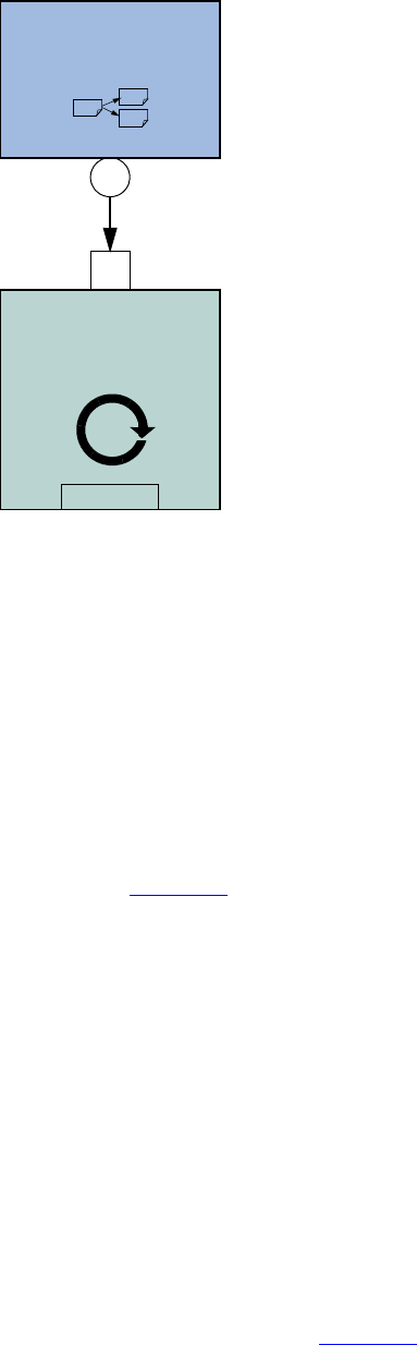
38 UVM 1.1 User’s Guide May 18, 2011
Figure 13—Sequencer-Driver Interaction
The seq_item_port in uvm_driver defines the set of methods used by the driver to obtain the next
item in the sequence. An important part of this interaction is the driver’s ability to synchronize to the bus,
and to interact with the sequencer to generate data items at the appropriate time. The sequencer implements
the set of methods that allows flexible and modular interaction between the driver and the sequencer.
3.5.1 Basic Sequencer and Driver Interaction
Basic interaction between the driver and the sequencer is done using the tasks get_next_item() and
item_done(). As demonstrated in the example in Section 3.3, the driver uses get_next_item() to
fetch the next randomized item to be sent. After sending it to the DUT, the driver signals the sequencer that
the item was processed using item_done().Typically, the main loop within a driver resembles the
following pseudo code.
get_next_item(req);
// Send item following the protocol.
item_done();
NOTE—get_next_item() is blocking.
3.5.2 Querying for the Randomized Item
In addition to the get_next_item() task, the uvm_seq_item_pull_port class provides another
task, try_next_item(). This task will return in the same simulation step if no data items are available
for execution. You can use this task to have the driver execute some idle transactions, such as when the DUT
has to be stimulated when there are no meaningful data to transmit. The following example shows a revised
implementation of the run() task in the previous example (in Section 3.3), this time using
try_next_item() to drive idle transactions as long as there is no real data item to execute:
Driver
Consumes and sends
data to the DUT
vi
Sequencer
Produces data
uvm_seq_item_pull_export
seq_item_export
uvm_seq_item_pull_port
seq_item_port
May 18, 2011 UVM 1.1 User’s Guide 39
task run_phase(uvm_phase phase);
forever begin
// Try the next data item from sequencer (does not block).
seq_item_port.try_next_item(s_item);
if (s_item == null) begin
// No data item to execute, send an idle transaction.
...
end
else begin
// Got a valid item from the sequencer, execute it.
...
// Signal the sequencer; we are done.
seq_item_port.item_done();
end
end
endtask: run
3.5.3 Fetching Consecutive Randomized Items
In some protocols, such as pipelined protocols, the driver gets a few generated items to fill the pipeline
before the first items were completely processed. In such cases, the driver calls item_done() without
providing the response to the sequencer. In such scenarios the driver logic may look like the following
pseudo code:
while the pipeline is not empty{
get_next_item(req);
fork;
logic that sends item to the pipeline
join_none;
item_done();
for each completed process call{
...
}
}
3.5.4 Sending Processed Data back to the Sequencer
In some sequences, a generated value depends on the response to previously generated data. By default, the
data items between the driver and the sequencer are copied by reference, which means that changes the
driver makes to the data item will be visible inside the sequencer. In cases where the data item between the
driver and the sequencer is copied by value, the driver needs to return the processed response back to the
sequencer. Do this using the optional argument to item_done().
seq_item_port.item_done(rsp);
using the put_response() method.
seq_item_port.put_response(rsp);
or using the built-in analysis port in uvm_driver.
rsp_port.write(rsp);
40 UVM 1.1 User’s Guide May 18, 2011
NOTE—Before providing the response, the response’s sequence and transaction id must be set to correspond to the
request transaction using rsp.set_id_info(req).
NOTE—put_response() is a blocking method, so the sequence must do a corresponding
get_response(rsp).
With the basic functionality of driver-sequencer communication outlined above, the steps required to create
a driver are straightforward.
3.5.5 Using TLM-Based Drivers
The seq_item_port, which is built into uvm_driver, is a bidirectional port. It also includes the
standard TLM methods get() and peek() for requesting an item from the sequencer, and put() to
provide a response. Thus, other components, which may not necessarily be derived from uvm_driver,
may still connect to and communicate with the sequencer. As with the seq_item_port, the methods to
use depend on the interaction desired.
// Pause sequencer operation while the driver operates on the transaction.
peek(req);
// Process req operation.
get(req);
// Allow sequencer to proceed immediately upon driver receiving transaction.
get(req);
// Process req operation.
The following also apply.
—peek() is a blocking method, so the driver may block waiting for an item to be returned.
— The get() operation notifies the sequencer to proceed to the next transaction. It returns the same
transaction as the peek(), so the transaction may be ignored.
To provide a response using the blocking_slave_port, the driver would call:
seq_item_port.put(rsp);
The response may also be sent back using an analysis_port as well.
3.6 Creating the Monitor
The monitor is responsible for extracting signal information from the bus and translating it into events,
structs, and status information. This information is available to other components and to the test writer via
standard TLM interfaces and channels. The monitor should never rely on state information collected by
other components, such as a driver, but it may need to rely on request-specific id information in order to
properly set the sequence and transaction id information for the response.
The monitor functionality should be limited to basic monitoring that is always required. This can include
protocol checking—which should be configurable so it can be enabled or disabled—and coverage
collection. Additional high-level functionality, such as scoreboards, should be implemented separately on
top of the monitor.
If you want to verify an abstract model or accelerate the pin-level functionality, you should separate the
signal-level extraction, coverage, checking, and the transaction-level activities. An analysis port should
allow communication between the sub-monitor components (see the UVM 1.1 Class Reference).
May 18, 2011 UVM 1.1 User’s Guide 41
Monitor Example
The following example shows a simple monitor which has the following functions:
— The monitor collects bus information through a virtual interface (xmi).
— The collected data is used in coverage collection and checking.
— The collected data is exported on an analysis port (item_collected_port).
Actual code for collection is not shown in this example. A complete example can be found in the UBus
example in ubus_master_monitor.sv.
class master_monitor extends uvm_monitor;
virtual bus_if xmi; // SystemVerilog virtual interface
bit checks_enable = 1; // Control checking in monitor and interface.
bit coverage_enable = 1; // Control coverage in monitor and interface.
uvm_analysis_port #(simple_item) item_collected_port;
event cov_transaction; // Events needed to trigger covergroups
protected simple_item trans_collected;
`uvm_component_utils_begin(master_monitor)
`uvm_field_int(checks_enable, UVM_ALL_ON)
`uvm_field_int(coverage_enable, UVM_ALL_ON)
`uvm_component_utils_end
covergroup cov_trans @cov_transaction;
option.per_instance = 1;
... // Coverage bins definition
endgroup : cov_trans
function new (string name, uvm_component parent);
super.new(name, parent);
cov_trans = new();
cov_trans.set_inst_name({get_full_name(), ".cov_trans"});
trans_collected = new();
item_collected_port = new("item_collected_port", this);
endfunction : new
virtual task run_phase(uvm_phase phase);
fork
collect_transactions(); // Spawn collector task.
join
endtask : run
virtual protected task collect_transactions();
forever begin
@(posedge xmi.sig_clock);
...// Collect the data from the bus into trans_collected.
if (checks_enable)
perform_transfer_checks();
if (coverage_enable)
perform_transfer_coverage();
item_collected_port.write(trans_collected);
end
endtask : collect_transactions
virtual protected function void perform_transfer_coverage();
-> cov_transaction;
endfunction : perform_transfer_coverage
virtual protected function void perform_transfer_checks();
... // Perform data checks on trans_collected.
endfunction : perform_transfer_checks
endclass : master_monitor

42 UVM 1.1 User’s Guide May 18, 2011
The collection is done in a task (collect_transaction) which is spawned at the beginning of the
run() phase. It runs in an endless loop and collects the data as soon as the signals indicate that the data is
available on the bus.
As soon as the data is available, it is sent to the analysis port (item_collected_port) for other
components waiting for the information.
Coverage collection and checking are conditional because they can affect simulation run-time performance.
If not needed, they can be turned off by setting coverage_enable or checks_enable to 0, using the
configuration mechanism. For example:
uvm_config_db#(bit)::set(this,“*.master0.monitor”, “checks_enable”, 0);
If checking is enabled, the task calls the perform_transfer_checks function, which performs the
necessary checks on the collected data (trans_collected). If coverage collection is enabled, the task
emits the coverage sampling event (cov_transaction) which results in collecting the current values.
NOTE—SystemVerilog does not allow concurrent assertions in classes, so protocol checking can also be done using
assertions in a SystemVerilog interface.
3.7 Instantiating Components
The isolation provided by object-oriented practices and TLM interfaces between components facilitate reuse
in UVM enabling a great deal of flexibility in building environments. Because each component is
independent of the others, a given component can be replaced by a new component with the same interfaces
without having to change the parent’s connect() method. This flexibility is accomplished through the use
of the factory in UVM.
When instantiating components in UVM, rather than calling its constructor (in bold below),
class my_component extends uvm_component;
my_driver driver;
...
function build();
driver = new(“driver”,this);
...
endfunction
endclass
components are instantiated using the create() method.
class my_component extends uvm_component;
my_driver driver;
...
function build();
driver = my_driver::type_id::create("driver",this);
...
endfunction
endclass
The factory operation is explained in Section 6.2. The type_id::create() method is a type-specific
static method that returns an instance of the desired type (in this case, my_driver) from the factory. The
arguments to create() are the same as the standard constructor arguments, a string name and a parent
component. The use of the factory allows the developer to derive a new class extended from my_driver
and cause the factory to return the extended type in place of my_driver. Thus, the parent component can
use the new type without modifying the parent class.
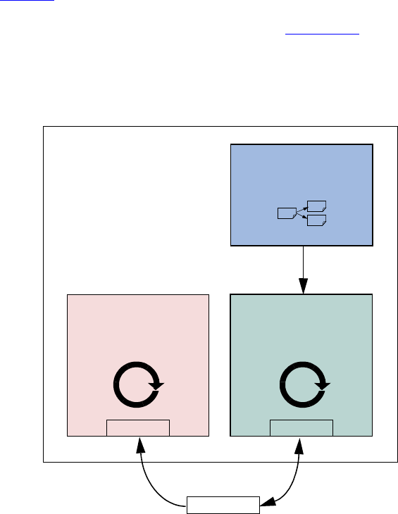
May 18, 2011 UVM 1.1 User’s Guide 43
For example, for a specific test, an environment user may want to change the driver. To change the driver for
a specific test:
a) Declare a new driver extended from the base component and add or modify functionality as desired.
class new_driver extends my_driver;
... // Add more functionality here.
endclass: new_driver
b) In your test, environment, or testbench, override the type to be returned by the factory.
virtual function build();
set_type_override_by_type(my_driver::get_type(),
new_driver::get_type());
endfunction
The factory also allows a new type to be returned for the creation of a specific instance as well. In either
case, because new_driver is an extension of my_driver and the TLM interfaces are the same, the
connections defined in the parent remain unchanged.
3.8 Creating the Agent
An agent (see Figure 14) instantiates and connects together a driver, monitor, and sequencer using TLM
connections as described in the preceding sections. To provide greater flexibility, the agent also contains
configuration information and other parameters. As discussed in Section 1.2.5, UVM recommends that the
verification component developer create an agent that provides protocol-specific stimuli creation, checking,
and coverage for a device. In a bus-based environment, an agent models either a master or a slave
component.
Figure 14—Agent
Driver
Consumes and sends
data to the DUT
is_active
...
Agent
interface
Monitor
checking
coverage
vi vi
Sequencer
Produces data

44 UVM 1.1 User’s Guide May 18, 2011
3.8.1 Operating Modes
An agent has two basic operating modes:
— Active mode, where the agent emulates a device in the system and drives DUT signals. This mode
requires that the agent instantiate a driver and sequencer. A monitor also is instantiated for checking
and coverage.
— Passive mode, where the agent does not instantiate a driver or sequencer and operates passively.
Only the monitor is instantiated and configured. Use this mode when only checking and coverage
collection is desired.
The class simple_agent in the example below instantiates a sequencer, a driver, and a monitor in the
recommended way. Instead of using the constructor, the UVM build() phase is used to configure and
construct the subcomponents of the agent. Unlike constructors, this virtual function can be overridden
without any limitations. Also, instead of hard coding, the allocation type_id::create() is used to
instantiate the subcomponents. The example in “To change the driver for a specific test:” in Section 3.8
illustrates how you can override existing behavior using extends.
1 class simple_agent extends uvm_agent;
2 uvm_active_passive_enum is_active;
3 ... // Constructor and UVM automation macros
4 uvm_sequencer #(simple_item) sequencer;
5 simple_driver driver;
6 simple_monitor monitor;
7 // Use build() phase to create agents's subcomponents.
8 virtual function void build_phase(uvm_phase phase);
9 super.build_phase(phase)
10 monitor = simple_monitor::type_id::create("monitor",this);
11 if (is_active == UVM_ACTIVE) begin
12 // Build the sequencer and driver.
13 sequencer =
14 uvm_sequencer#(simple_item)::type_id::create("sequencer",this);
15 driver = simple_driver::type_id::create("driver",this);
16 end
17 endfunction : build_phase
18 virtual function void connect_phase(uvm_phase phase);
19 if(is_active == UVM_ACTIVE) begin
20 driver.seq_item_port.connect(sequencer.seq_item_export);
21 end
22 endfunction : connect_phase
23 endclass : simple_agent
NOTE—You should always call super.build_phase() (see Line 9) to update the given component's configura-
tion overrides if the UVM automation macros were used. This is crucial to providing the capability for an enclosing
component to be able to override settings of an instance of this component.
Line 10 The monitor is created using create().
Line 11 - Line 16 The if condition tests the is_active property to determine whether the driver and
sequencer are created in this agent. If the agent is set to active (is_active = UVM_ACTIVE), the driver
and sequencer are created using additional create() calls.
Both the sequencer and the driver follow the same creation pattern as the monitor.
This example shows the is_active flag as a configuration property for the agent. You can define any
control flags that determine the component's topology. At the environment level, this could be a
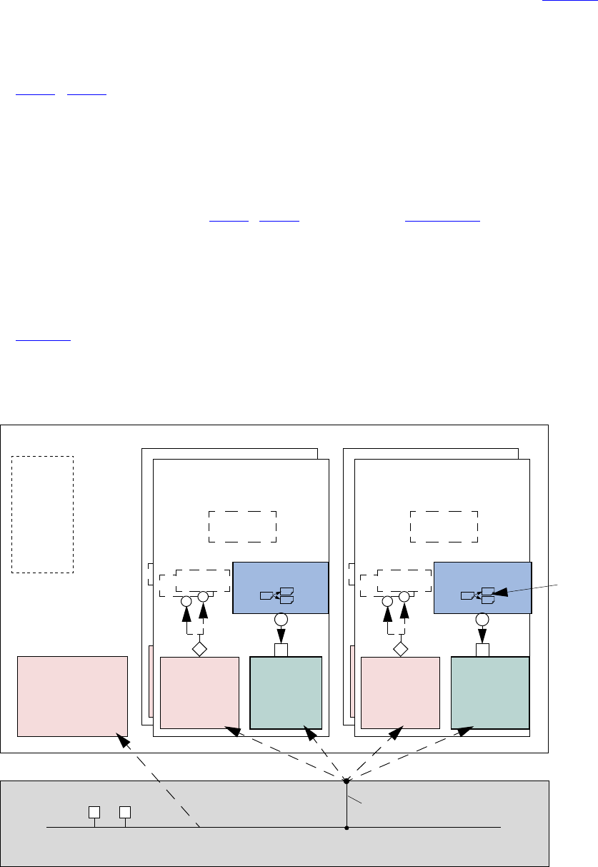
May 18, 2011 UVM 1.1 User’s Guide 45
num_masters integer, a num_slaves integer, or a has_bus_monitor flag. See Chapter 7 for a
complete interface verification component example that uses all the control fields previously mentioned.
NOTE—create() should always be called from the build_phase() method to create any multi-hierarchical com-
ponent.
Line 19 - Line 21 The if condition should be checked to see if the agent is active and, if so, the connection
between the sequencer and driver is made using connect().
3.8.2 Connecting Components
The connect_phase() phase, which happens after the build is complete, should be used to connect the
components inside the agent. See Line 19 - Line 21 in the example in Section 3.8.1.
3.9 Creating the Environment
Having covered the basic operation of transaction-level verification components in a typical environment
above, this section describes how to assemble these components into a reusable environment (see
Figure 15). By following the guidelines here, you can ensure that your environment will be architecturally
correct, consistent with other verification components, and reusable. The following sections describe how to
create and connect environment sub-components.
Figure 15—Typical UVM Environment Architecture
DUT
uvm_env
Config:
...
...
name
has_...
...
bus
uvm_monitor
checks
coverage
uvm_sequenc
Config
uvm_agent
Analysis
Slave Agent
uvm_sequence
uvm_driveuvm_monitor
Analysis
uvm_drive
uvm_sequencer
Config
uvm_agent
Analysis
Slave Agent
uvm_drive
uvm_monitor
Analysis
uvm_driver
uvm_sequenc
Config
uvm_agent
Analysis
Slave Agent
uvm_driveuvm_monitor
Analysis
uvm_drive
uvm_sequencer
Config
uvm_agent
Analysis
Master Agent
uvm_drive
uvm_monitor
Analysis
uvm_driver
46 UVM 1.1 User’s Guide May 18, 2011
3.9.1 The Environment Class
The environment class is the top container of reusable components. It instantiates and configures all of its
subcomponents. Most verification reuse occurs at the environment level where the user instantiates an
environment class and configures it and its agents for specific verification tasks. For example, a user might
need to change the number of masters and slaves in a new environment as shown below.
class ahb_env extends uvm_env;
int num_masters;
ahb_master_agent masters[];
`uvm_component_utils_begin(ahb_env)
`uvm_field_int(num_masters, UVM_ALL_ON)
`uvm_component_utils_end
virtual function void build_phase(phase);
string inst_name;
super.build_phase(phase);
if(!uvm_config_db#(virtual ubus_if)::get(this,””,
"vif",vif))
`uvm_fatal("NOVIF",{"virtual interface must be set for: ",
get_full_name(),".vif"});
masters = new[num_masters];
for(int i = 0; i < num_masters; i++) begin
$sformat(inst_name, "masters[%0d]", i);
masters[i] = ahb_master_agent::type_id::create(inst_name,this);
end
// Build slaves and other components.
endfunction
function new(string name, uvm_component parent);
super.new(name, parent);
endfunction : new
endclass
NOTE—Similarly to the agent, create is used to allocate the environment sub-components. This allows introducing
derivations of the sub-components later.
The user is not required to call build_phase() explicitly. The UVM Class Library will do this for all
created components. Once all the components’ build() functions are complete, the library will call each
component's connect() function. Any connections between child components should be made in the
connect() function of the parent component.
3.9.2 The UVM Configuration Mechanism
A verification component is created on a per-protocol basis for general-purpose protocol-related use. It may
support various features or operation modes that are not required in a particular project. UVM provides a
standard configuration mechanism which allows you to define the verification component’s configuration to
suit the current project’s requirements. The verification component can get the configuration during run time
or during the build process. Doing this during the build allows you to modify the environment object
structure without touching multiple classes.
Properties that are registered as UVM fields using the uvm_field_* macros will be automatically
updated by the component’s super.build_phase() method. These properties can then be used to
determine the build_phase() execution for the component.
It is not required to call a created component’s build_phase() function. The UVM Class Library will do
this automatically for all components that have not had their build_phase() function called explicitly
by the user.

May 18, 2011 UVM 1.1 User’s Guide 47
Connections among the created components is made in the connect_phase() function of the
component. Since connect_phase() happens after build_phase(), the user can assume the
environment topology is fully created. With the complete topology, the user can then make the necessary
connections.
3.9.2.1 Making the Verification Component Reusable
There are times when you as the developer know the context in which the verification component you are
developing will be used. In such cases you should take care to separate the requirements of the verification
component’s protocol from those of the project. It is strongly recommended that you use only the interface-
protocol documentation in developing the verification component. Later, you can consult your project’s
documentation to see if there are some generic features which might be useful to implement. For example,
you should be able to configure slave devices to reside at various locations within an address space.
As another example, when a few bits are defined as reserved in a protocol frame, they should stay reserved
within the verification component. The verification logic that understands how a specific implementation
uses these bits should be defined outside the global generic code.
As a developer, it is critical to identify these generic parameters and document them for the environment
users.
3.9.2.2 How to Create a Configurable Attribute
Making an attribute configurable is part of the built-in automation that the UVM Class Library provides.
Using the automation macros for copy(), print(), compare(), and so on, also introduces these
attributes to the configuration mechanism. In the example in Section 3.9.1, num_master is a configuration
parameter that allows changing the master agent numbers as needed. Since the `uvm_field_int
declaration is already provided for printing, there is no further action needed to allow the users to configure
it.
For example, to get three master agents, you can specify:
uvm_config_db#(int)::set(this, "*.my_env", "num_masters", 3);
This can be done in procedural code within the testbench. For more information, see Section 4.5.
The following also apply.
— The values of parameters are automatically updated in the super.build() phase. Make sure that
you call super.build() before accessing these values.
— If you prefer not to use the automation macros, you can use uvm_config_db#()::get() to
fetch the configuration value of a parameter. You can also do this if you are concerned that the
num_masters field was overridden and you want to re-fetch the original configuration value for
it.
— A larger environment can integrate smaller ones and reconfigure their parameters to suit the needs of
the parent environment. In this case, when there are contradicting configuration directives, the value
set from the highest level in the hierarchy (i.e., the level that executed build_phase() first)
takes precedence.
3.10 Enabling Scenario Creation
The environment user will need to create many test scenarios to verify a given DUT. Since the verification
component developer is usually more familiar with the DUT’s protocol, the developer should facilitate the
test writing (done by the verification component’s user) by doing the following:

48 UVM 1.1 User’s Guide May 18, 2011
— Place knobs in the data item class to simplify declarative test control.
— Create a library of interesting reusable sequences.
The environment user controls the environment-generated patterns configuring its sequencers. The user can:
— Add a sequence of transactions to a sequencer.
— Modify the sequencer to use specific sequences more often than others.
— Override the sequencer's main loop to start with a user-defined sequence instead.
In this section we describe how to create a library of reusable sequences and review their use. For more
information on how to control environments, see Section 4.7.
3.10.1 Declaring User-Defined Sequences
Sequences are made up of several data items, which together form an interesting scenario or pattern of data.
Verification components can include a library of basic sequences (instead of single-data items), which test
writers can invoke. This approach enhances reuse of common stimulus patterns and reduces the length of
tests. In addition, a sequence can call upon other sequences, thereby creating more complex scenarios.
NOTE—The UVM Class Library provides the uvm_sequence base class. You should derive all sequence classes
directly or indirectly from this class.
To create a user-defined sequence:
a) Derive a sequence from the uvm_sequence base class and specify the request and response item
type parameters. In the example below, only the request type is specified, simple_item. This will
result in the response type also being of type simple_item.
b) Use the `uvm_object_utils macro to register the sequence type with the factory.
c) If the sequence requires access to the derived type-specific functionality of its associated sequencer,
use the ‘uvm_declare_p_sequencer macro to declare the desired sequencer pointer.
d) Implement the sequence’s body task with the specific scenario you want the sequence to execute. In
the body task, you can execute data items and other sequences using `uvm_do (see
Section 3.10.2.2.1) and `uvm_do_with (see Section 3.10.2.2.2).
The class simple_seq_do in the following example defines a simple sequence. It is derived from
uvm_sequence and uses the `uvm_sequence_utils macro to associate this sequence with
simple_sequencer and declare the various utilities `uvm_object_utils would provide.
class simple_seq_do extends uvm_sequence #(simple_item);
rand int count;
constraint c1 { count >0; count <50; }
// Constructor
function new(string name="simple_seq_do");
super.new(name);
endfunction
// UVM automation macros for sequences
`uvm_object_utils(simple_seq_do)
// The body() task is the actual logic of the sequence.
virtual task body();
repeat(count)
`uvm_do(req)
endtask : body
endclass : simple_seq_do

May 18, 2011 UVM 1.1 User’s Guide 49
Once you define a sequence, it is registered with the factory and may be generated by the sequencer’s
default generation loop.
3.10.2 Generating Stimulus with Sequences and Sequence Items
Sequences allow you to define:
— Streams of data items sent to a DUT.
— Streams of actions performed on a DUT interface.
You can also use sequences to generate static lists of data items with no connection to a DUT interface.
3.10.2.1 Getting Started with Sequences
Previous sections discussed the basics of creating sequences and sequence items using the UVM Class
Library. This section discusses how to generate stimulus using the sequence and sequence item macros
provided in the class library.
Figure 16 and Figure 17 show the complete flow for sequence items and sequences when used with the
uvm_do macros. The entire flow includes the allocation of an object based on factory settings for the
registered type, which is referred to as “creation” in this section. After creation, comes the initialization of
class properties. Although the balance of the object processing depends on whether the object is a sequence
item or a sequence, the pre_do(), mid_do(), and post_do() callbacks of the parent sequence and
randomization of the objects are also called, but at different points of processing for each object type as
shown in the figures.
NOTE—You can use any of the macros with the SystemVerilog looping constructs.
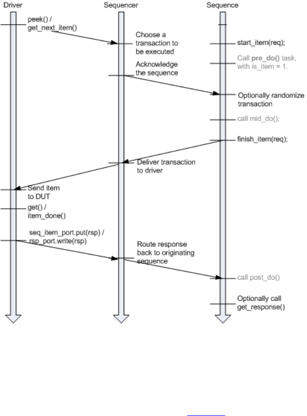
50 UVM 1.1 User’s Guide May 18, 2011
Figure 16—Sequence Item Flow in Pull Mode
The ‘uvm_do macro and all related macros provide a convenient set of calls to create, randomize, and send
transaction items in a sequence. The ‘uvm_do macro delays randomization of the item until the driver has
signaled that it is ready to receive it and the pre_do method has been executed. Other macro variations
allow constraints to be applied to the randomization (uvm_do_with) or bypass the randomization
altogether. The individual methods wrapped by ‘uvm_do in Figure 16 may be called individually with no
loss of functionality.
a) Call start_item() to create the item via the factory.
b) Optionally call pre_do() or some other functionality.
c) Optionally randomize item.
d) Optionally call mid_do() or some other functionality, if desired.
e) Call finish_item().
f) Optionally call post_do() or some other functionality.
g) Optionally call get_response().

May 18, 2011 UVM 1.1 User’s Guide 51
Figure 17—Subsequence Flow
3.10.2.2 Sequence and Sequence Item Macros
This section describes the sequence and sequence item macros, `uvm_do and `uvm_do_with.
3.10.2.2.1 `uvm_do
This macro takes as an argument a variable of type uvm_sequence or uvm_sequence_item. An
object is created using the factory settings and assigned to the specified variable. Based on the processing in
Figure 16, when the driver requests an item from the sequencer, the item is randomized and provided to the
driver.
The simple_seq_do sequence declaration in the example in Section 3.10.1 is repeated here. The body of
the sequence invokes an item of type simple_item, using the `uvm_do macro.
class simple_seq_do extends uvm_sequence #(simple_item);
... // Constructor and UVM automation macros
// See Section 4.8.2
virtual task body();
`uvm_do(req)
endtask : body
endclass : simple_seq_do
Similarly, a sequence variable can be provided and will be processed as shown in Figure 17. The following
example declares another sequence (simple_seq_sub_seqs), which uses `uvm_do to execute a
sequence of type simple_seq_do, which was defined earlier.
class simple_seq_sub_seqs extends uvm_sequence #(simple_item);
... // Constructor and UVM automation macros
// See Section 4.8.2
simple_seq_do seq_do;
Sequence
Sequencer
The sequencer does not
schedule sequences but
only items; therefore,
when do-ing a
sequence, no
synchronization is done
between the sequencer
and the doing sequence
or the done
subsequence
Call mid_do()
Call post_do()
End of do subsequence
Note This flow does not depend on the driver interaction mode.
(1) n
trigger subsequence.started
Call subsequence.body()
trigger subsequence.ended
`uvm_do(subsequence);
Call pre_do() task with is_item = 0

52 UVM 1.1 User’s Guide May 18, 2011
virtual task body();
`uvm_do(seq_do)
endtask : body
endclass : simple_seq_sub_seqs
3.10.2.2.2 `uvm_do_with
This macro is similar to `uvm_do (Section 3.10.2.2.1). The first argument is a variable of a type derived
from uvm_sequence_item, which includes items and sequences. The second argument can be any valid
inline constraints that would be legal if used in arg1.randomize() with inline constraints. This
enables adding different inline constraints, while still using the same item or sequence variable.
Example
This sequence produces two data items with specific constraints on the values of addr and data.
class simple_seq_do_with extends uvm_sequence #(simple_item);
... // Constructor and UVM automation macros
// See Section 4.8.2
virtual task body();
`uvm_do_with(req, { req.addr == 16'h0120; req.data == 16'h0444; } )
`uvm_do_with(req, { req.addr == 16'h0124; req.data == 16'h0666; } )
endtask : body
endclass : simple_seq_do_with
If constraints are used simply to set parameters to specific values, as in the previous example, the macro can
be replaced with a user-defined task.
class simple_seq_do_with extends uvm_sequence #(simple_item);
task do_rw(int addr, int data);
item= simple_item::type_id::create("item",,get_full_name());
item.addr.rand_mode(0);
item.data.rand_mode(0);
item.addr = addr;
item.data = data;
start_item(item);
randomize(item);
finish_item(item);
endtask
virtual task body();
repeat (num_trans)
do_rw($urandom(),$urandom());
endtask
...
endclass : simple_seq_do_with
3.10.3 Configuring the Sequencer’s Default Sequence
Sequencers do not execute any sequences by default. In each phase, the sequencer will check for a resource
corresponding to the specific phase to determine which sequence to start upon entering the phase. The
resource is typically defined by the test.
uvm_config_db#(uvm_object_wrapper)::set(this,
".ubus_example_tb0.ubus0.masters[0].sequencer.main_phase",
May 18, 2011 UVM 1.1 User’s Guide 53
"default_sequence",
loop_read_modify_write_seq::type_id::get());
In the previous example, the sequencer, upon entering the main phase, will create an instance of the
loop_read_modify_write_seq sequence, randomize it, and start executing it. It is also possible to
start a specific instance of a sequence:
lrmw_seq = loop_read_modify_write_seq::type_id::create(“lrmw”,,
get_full_name());
// set parameters in lrmw_seq, if desired
uvm_config_db#(uvm_sequence_base)::set(this,
".ubus_example_tb0.ubus0.masters[0].sequencer.main_phase",
"default_sequence", lrmw_seq);
By creating a specific instance of the sequence, the instance may be randomized and/or specific parameters
set explicitly or constrained as needed. Upon entering the specified phase, the sequence instance will be
started. The sequencer will not randomize the sequence instance.
3.10.4 Overriding Sequence Items and Sequences
In a user-defined uvm_test, e.g., base_test_ubus_demo (discussed in Section 4.6.1), you can
configure the simulation environment to use a modified version of an existing sequence or a sequence item
by using the common factory to create instances of sequence and sequence-item classes. See Section 6.2 for
more information.
To override any reference to a specific sequence or sequence-item type:
a) Declare a user-defined sequence or sequence item class which derives from an appropriate base
class. The following example shows the declaration of a basic sequence item of type
simple_item and a derived item of type word_aligned_item.
b) Invoke the appropriate uvm_factory override method, depending on whether you are doing a
global or instance-specific override. For example, assume the simple_seq_do sequence is exe-
cuted by a sequencer of type simple_sequencer (both defined in Section 3.10.1). You can
choose to replace all processing of simple_item types with word_aligned_item types. This
can be selected for all requests for simple_item types from the factory or for specific instances
of simple_item. From within an UVM component, the user can execute the following:
// Affect all factory requests for type simple_item.
set_type_override_by_type(simple_item::get_type(),
word_aligned_item::get_type());
// Affect requests for type simple_item only on a given sequencer.
set_inst_override_by_type("env0.agent0.sequencer.*",
simple_item::get_type(), world_aligned_item::get_type());
// Alternatively, affect requests for type simple_item for all
// sequencers of a specific env.
set_inst_override_by_type("env0.*.sequencer.*",
simple_item::get_type(),
word_aligned_item::get_type());
c) Use any of the sequence macros that allocate an object (as defined in Section 3.10.2.2), for example,
the `uvm_do macro.
Since the sequence macros call the common factory to create the data item object, existing override requests
will take effect and a word_aligned_item will be created instead of a simple_item.
54 UVM 1.1 User’s Guide May 18, 2011
3.11 Managing End of Test
UVM provides an objection mechanism to allow hierarchical status communication among components.
There is a built-in objection for each phase, which provides a way for components and objects to
synchronize their testing activity and indicate when it is safe to end the phase and, ultimately, the test.
In general, the process is for a component or sequence to raise a phase objection at the beginning of an
activity that must be completed before the phase stops and to drop the objection at the end of that activity.
Once all of the raised objections are dropped, the phase terminates.
In simulation, agents may have a meaningful agenda to be achieved before the test goals can be declared as
done. For example, a master agent may need to complete all its read and write operations before the run
phase should be allowed to stop. A reactive slave agent may not object to the end-of-test as it is merely
serving requests as they appear without a well-defined agenda.
A typical use model of objections is for a sequence from an active agent to raise an objection when it is
started as a root sequence (a sequence which has no parent sequence), and to drop the objection when it is
finished as a root sequence. This would look like the following:
class interesting_sequence extends uvm_sequence#(data_item);
task pre_body();
// raise objection if started as a root sequence
if(starting_phase != null)
starting_phase.raise_objection(this);
endtask
task body();
//do interesting activity
...
endtask
task post_body();
// drop objection if started as a root sequence
if(starting_phase != null)
starting_phase.drop_objection(this);
endtask
endclass
The starting_phase member is only set automatically if the sequence is started as the default sequence
for a particular phase. Usually, such default phases are used to create “background traffic” on a particular
interface and should, therefore, not raise an objection to the current phase, since they may never terminate
and would thus prevent the phase from ending. If you wish to start a sequence explicitly and have it raise and
lower the objection to manage the end of the current phase, the sequence should be started explicitly from
the test during the desired phase:
class interesting_test extends uvm_test;
task main_phase(uvm_phase phase);
seq.starting_phase = phase;
seq.start(foo_agent.sequencer); // blocking
endtask
Since the start() call is blocking, the test could handle raising and dropping the objection directly,
instead of relying on the sequence to do it.
class interesting_test extends uvm_test;
task main_phase(uvm_phase phase);
phase.raise_objection();
seq.start(foo_agent.sequencer); // blocking
May 18, 2011 UVM 1.1 User’s Guide 55
phase.drop_objection();
endtask
Note—When the sequence is started explicitly, the starting_phase member is null, so the sequence will not raise
or drop the phase objection.
When all objections are dropped, the currently running phase is ended. In practice, there are times in
simulation when the “all objections dropped” condition is temporary. For example, concurrently running
processes may need some additional cycles to convey the last transaction to a scoreboard.
To accommodate this, you may use the phase_ready_to_end() method to re-raise the phase objection
if a transaction is currently in-flight.
Alternatively, you may set a drain time to inject a delay between the time a component’s total objection
count reaches zero for the current phase and when the drop is passed to its parent. If any objections are re-
raised during this delay, the drop is cancelled and the raise is not propagated further. While a drain time can
be set at each level of the component hierarchy with the adding effect, typical usage would be to set a single
drain time at the env or test level. If you require control over drain times beyond a simple time value (for
example, waiting for a few clock cycles or other user-defined events), you can also use the all_dropped
callback to calculate drain times more precisely. For more information on the all_dropped callback,
refer to uvm_objection in the UVM 1.1 Class Reference.
Vertical reuse means building larger systems out of existing ones. What was once a top-level environment
becomes a sub-environment of a large testbench. The objection mechanism allows sub-system environment
developers to define a drain time per sub-system.
3.12 Implementing Checks and Coverage
Checks and coverage are crucial to a coverage-driven verification flow. SystemVerilog allows the usage
shown in Table 5 for assert, cover, and covergroup constructs.
NOTE—This overview is for concurrent assertions. Immediate assertions can be used in any procedural statement. Refer
to the SystemVerilog IEEE1800 LRM for more information.
In a verification component, checks and coverage are defined in multiple locations depending on the
category of functionality being analyzed. In Figure 18, checks and coverage are depicted in the
uvm_monitor and interface. The following sections describe how the assert, cover, and covergroup
constructs are used in the Ubus verification component example (described in Chapter 7).
Table 5—SystemVerilog Checks and Coverage Construct Usage Overview
class interface package module initial always generate program
assert no yes no yes yes yes yes yes
cover no yes yes yes yes yes yes yes
covergroup yes yes yes yes no no yes yes
56 UVM 1.1 User’s Guide May 18, 2011
3.12.1 Implementing Checks and Coverage in Classes
Class checks and coverage should be implemented in the classes derived from uvm_monitor. The derived
class of uvm_monitor is always present in the agent and, thus, will always contain the necessary checks
and coverage. The bus monitor is created by default in an env and if the checks and coverage collection is
enabled the bus monitor will perform these functions. The remainder of this section uses the master monitor
as an example of how to implement class checks and coverage, but they apply to the bus monitor as well.
You can write class checks as procedural code or SystemVerilog immediate assertions.
Tip: Use immediate assertions for simple checks that can be written in a few lines of code and use functions
for complex checks that require many lines of code. The reason is that, as the check becomes more
complicated, so does the debugging of that check.
NOTE—Concurrent assertions are not allowed in SystemVerilog classes per the IEEE1800 LRM.
The following is a simple example of an assertion check. This assertion verifies the size field of the transfer
is 1, 2, 4, or 8. Otherwise, the assertion fails.
function void ubus_master_monitor::check_transfer_size();
check_transfer_size : assert(trans_collected.size == 1 ||
trans_collected.size == 2 || trans_collected.size == 4 ||
trans_collected.size == 8) else begin
// Call DUT error: Invalid transfer size!
end
endfunction : check_transfer_size
The following is a simple example of a function check. This function verifies the size field value matches
the size of the data dynamic array. While this example is not complex, it illustrates a procedural-code
example of a check.
function void ubus_master_monitor::check_transfer_data_size();
if (trans_collected.size != trans_collected.data.size())
// Call DUT error: Transfer size field / data size mismatch.
endfunction : check_transfer_data_size
The proper time to execute these checks depends on the implementation. You should determine when to
make the call to the check functions shown above. For the above example, both checks should be executed
after the transfer is collected by the monitor. Since these checks happen at the same instance in time, a
wrapper function can be created so that only one call has to be made. This wrapper function follows.
function void ubus_master_monitor::perform_transfer_checks();
check_transfer_size();
check_transfer_data_size();
endfunction : perform_transfer_checks
The perform_transfer_checks() function is called procedurally after the item has been collected
by the monitor.
Functional coverage is implemented using SystemVerilog covergroups. The details of the covergroup (that
is, what to make coverpoints, when to sample coverage, and what bins to create) should be planned and
decided before implementation begins.
The following is a simple example of a covergroup.

May 18, 2011 UVM 1.1 User’s Guide 57
// Transfer collected beat covergroup.
covergroup cov_trans_beat @cov_transaction_beat;
option.per_instance = 1;
beat_addr : coverpoint addr {
option.auto_bin_max = 16; }
beat_dir : coverpoint trans_collected.read_write;
beat_data : coverpoint data {
option.auto_bin_max = 8; }
beat_wait : coverpoint wait_state {
bins waits[] = { [0:9] };
bins others = { [10:$] }; }
beat_addrXdir : cross beat_addr, beat_dir;
beat_addrXdata : cross beat_addr, beat_data;
endgroup : cov_trans_beat
This embedded covergroup is defined inside a class derived from uvm_monitor and is sampled explicitly.
For the above covergroup, you should assign the local variables that serve as coverpoints in a function, then
sample the covergroup. This is done so that each transaction data beat of the transfer can be covered. This
function is shown in the following example.
// perform_transfer_coverage
virtual protected function void perform_transfer_coverage();
cov_trans.sample(); // another covergroup
for (int unsigned i = 0; i < trans_collected.size; i++) begin
addr = trans_collected.addr + i;
data = trans_collected.data[i];
wait_state = trans_collected.wait_state[i];
cov_trans_beat.sample();
end
endfunction : perform_transfer_coverage
This function covers several properties of the transfer and each element of the dynamic array data.
SystemVerilog does not provide the ability to cover dynamic arrays. You should access each element
individually and cover that value, if necessary. The perform_transfer_coverage() function
would, like perform_transfer_checks(), be called procedurally after the item has been collected
by the monitor.
3.12.2 Implementing Checks and Coverage in Interfaces
Interface checks are implemented as assertions. Assertions are added to check the signal activity for a
protocol. The assertions related to the physical interface are placed in the env’s interface. For example, an
assertion might check that an address is never X or Y during a valid transfer. Use assert as well as assume
properties to express these interface checks.
An assert directive is used when the property expresses the behavior of the device under test. An assume
directive is used when the property expresses the behavior of the environment that generates the stimulus to
the DUT.
The mechanism to enable or disable the physical checks performed using assertions is discussed in
Chapter 3.12.3.
58 UVM 1.1 User’s Guide May 18, 2011
3.12.3 Controlling Checks and Coverage
You should provide a means to control whether the checks are enforced and the coverage is collected. You
can use an UVM bit field for this purpose. The field can be controlled using the uvm_config_db
interface. Refer to uvm_config_db in the UVM 1.1 Class Reference for more information. The following
is an example of using the checks_enable bit to control the checks.
if (checks_enable)
perform_transfer_checks();
If checks_enable is set to 0, the function that performs the checks is not called, thus disabling the
checks. The following example shows how to turn off the checks for the master0.monitor.
uvm_config_db#(int)::set(this,"masters[0].monitor", "checks_enable", 0);
The same facilities exist for the coverage_enable field in the Ubus agent monitors and bus monitor.
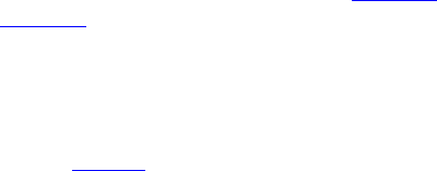
May 18, 2011 UVM 1.1 User’s Guide 59
4. Using Verification Components
This chapter covers the steps needed to build a testbench from a set of reusable verification components.
UVM accelerates the development process and facilitates reuse. UVM users will have fewer hook-up and
configuration steps and can exploit a library of reusable sequences to efficiently accomplish their
verification goals.
In this chapter, a distinction is made between the environment integrator and the test writer who might have
less knowledge about verification and wants to use UVM for creating tests. The test writer may skip the
configuration sections and move directly into the test-creation sections.
The steps you need to perform to create a testbench from verification components are:
a) Review the reusable verification component configuration parameters.
b) Instantiate and configure reusable verification components.
c) Create reusable sequences for interface verification components (optional).
d) Add a virtual sequencer (optional).
e) Add checking and functional coverage extensions.
f) Create tests to achieve coverage goals.
Before reading this chapter make sure you read Chapter 1. It is also recommended (but not required) that
you read Chapter 3 to get a deeper understanding of verification components.
4.1 Using a Verification Component
As illustrated in Figure 1, the environment integrator instantiates and configures reusable components to
build a desired testbench. The integrator also writes multiple tests to follow the verification plan in an
organized way.
4.2 Testbench Class
The testbench is the container object that defines the testbench topology. The testbench instantiates the
reusable verification IP and defines the default configuration of that IP as required by the application.
Instantiating individual verification components directly inside the tests has several drawbacks:
— The test writer must know how to configure the environment.
— Changes to the topology require updating multiple test files, which can turn into a big task.
— The tests are not reusable because they rely on a specific environment structure.
For these reasons, UVM recommends using a testbench class, derived from the uvm_env class. The
testbench instantiates and configures the reusable components for the desired verification task. Multiple
tests can instantiate the testbench class and determine the nature of traffic to generate and send for the
selected configuration.
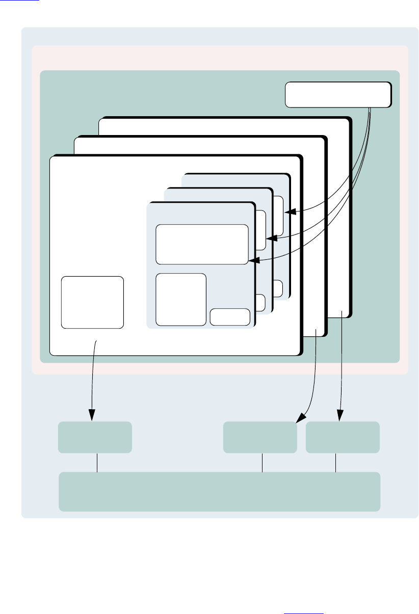
60 UVM 1.1 User’s Guide May 18, 2011
Figure 18 shows a typical verification environment that includes the test class containing the testbench class.
Other verification components (or environments) are contained inside the testbench.
Figure 18—Verification Environment Class Diagram
4.3 Instantiating Verification Components
This section describes how you can use verification components to create a testbench that can be reused for
multiple tests. The following example uses the verification IP in Chapter 7. This interface verification
component can be used in many environments due to its configurability, but in this scenario it will be used in
a simple configuration consisting of one master and one slave. The testbench sets the applicable topology
overrides.
uvm_test
interface
DUT module(s) (RTL, signals)
interface ports
top module
virtual interface connections
checks & coverage
uvm_env (testbench)
uvm_env
uvm_env
uvm_env
uvm_monitor
coverage
checks
uvm_sequencer
uvm_driver
uvm_monitor
coverage
checks
uvm_agent
uvm_sequences
uvm_sequence_base
uvm_sequencer
uvm_driver
uvm_monitor
coverage
checks
uvm_agent
uvm_sequences
uvm_sequence_base
uvm_sequencer
uvm_driver
uvm_monitor
coverage
checks
uvm_agent
uvm_sequence
uvm_sequencer
uvm_sequence
interface
checks & coverage
interface
checks & coverage
May 18, 2011 UVM 1.1 User’s Guide 61
The following also apply.
— Examples for the uvm_config_db::set calls can be found within the build_phase() func-
tion.
class ubus_example_tb extends uvm_env;
// Provide implementations of virtual methods such as get_type_name().
`uvm_component_utils(ubus_example_tb)
// UBus reusable environment
ubus_env ubus0;
// Scoreboard to check the memory operation of the slave
ubus_example_scoreboard scoreboard0;
// new()
function new(string name, uvm_component parent);
super.new(name, parent);
endfunction : new
// build()
virtual function void build();
super.build_phase(phase); // Configure before creating the
// subcomponents.
uvm_config_db#(int)::set(this,"ubus0",
"num_masters", 1);
uvm_config_db#(int)::set(this,".ubus0",
"num_slaves", 1);
ubus0 = ubus_env::type_id::create("ubus0", this);
scoreboard0 =
ubus_example_scoreboard::type_id::create("scoreboard0",
this);;
endfunction : build_phase
virtual function connect_phase();
// Connect slave0 monitor to scoreboard.
ubus0.slaves[0].monitor.item_collected_port.connect(
scoreboard0.item_collected_export);
endfunction : connect
virtual function void end_of_elaboration();
// Set up slave address map for ubus0 (basic default).
ubus0.set_slave_address_map("slaves[0]", 0, 16'hffff);
endfunction : end_of_elaboration
endclass : ubus_example_tb
Other configuration examples include:
— Set the masters[0] agent to be active:
uvm_config_db#(int)::set(this,"ubus0.masters[0]", “is_active",
UVM_ACTIVE);
— Do not collect coverage for masters[0] agent:
uvm_config_db#(int)::set(this, "ubus0.masters[0].monitor",
“coverage_enable", 0);
— Set all slaves (using a wildcard) to be passive:
uvm_config_db#(int)::set(this,"ubus0.slaves*", “is_active", UVM_PASSIVE);
Many test classes may instantiate the testbench class above, and configure it as needed. A test writer may
use the testbench in its default configuration without having to understand all the details of how it is created
and configured.

62 UVM 1.1 User’s Guide May 18, 2011
The ubus_example_tb’s new() constructor is not used for creating the testbench subcomponents
because there are limitations on overriding new() in object-oriented languages such as SystemVerilog.
Instead, use a virtual build_phase() function, which is a built-in UVM phase.
The uvm_config_db::set calls specify that the number of masters and slaves should both be 1. These
configuration settings are used by the ubus0 environment during the ubus0 build_phase(). This
defines the topology of the ubus0 environment, which is a child of the ubus_example_tb.
In a specific test, a user might want to extend the ubus_env and derive a new class from it. create() is
used to instantiate the subcomponents (instead of the new() constructor) so the ubus_env or the
scoreboard classes can be replaced with derivative classes without changing the testbench file. See
Section 6.2.3 for more information.
If the UVM field automation macros are used, super.build_phase() is called as the first line of the
ubus_example_tb’s build() function. This updates the configuration fields of the
ubus_example_tb.
connect_phase() is used to make the connection between the slave monitor and the scoreboard. The
slave monitor contains a TLM analysis port which is connected to the TLM analysis export on the
scoreboard. connect_phase() is a built-in UVM phase.
After the build_phase() and connect_phase() functions are complete, the user can make
adjustments to run-time properties since the environment is completely elaborated (that is, created and
connected). The end_of_elaboration_phase() function makes the environment aware of the
address range to which the slave agent should respond.
The ubus_example_tb defines the topology needed for the Ubus demo tests. This object can be used as
is or can be overridden from the test level, if necessary.
4.4 Test Class
The uvm_test class defines the test scenario for the testbench specified in the test. The test class enables
configuration of the testbench and verification components, as well as utilities for command-line test
selection. Although IP developers provide default values for topological and run-time configuration
properties, use the configuration override mechanism provided by the UVM Class Library when you require
configuration customization. You can provide user-defined sequences in a file or package, which is included
or imported by the test class. A test provides data and sequence generation and inline constraints. Test files
are typically associated with a single configuration. For usage examples of test classes, refer to Section 4.6.
Tests in UVM are classes that are derived from an uvm_test class. Using classes allows inheritance and
reuse of tests. Typically, you define a base test class that instantiates and configures the testbench (see
Section 4.6.1), and then extend the base test to define scenario-specific configurations such as which
sequences to run, coverage parameters, etc. The test instantiates the testbench just like any other verification
component (see Section 4.3)
4.5 Verification Component Configuration
4.5.1 Verification Component Configurable Parameters
Based on the protocols used in a device, the integrator instantiates the needed verification components and
configures them for a desired operation mode. Some standard configuration parameters are recommended to
address common verification needs. Other parameters are protocol- and implementation-specific.

May 18, 2011 UVM 1.1 User’s Guide 63
Examples of standard configuration parameters:
— An agent can be configured for active or passive mode. In active mode, the agent drives traffic to the
DUT. In passive mode, the agent passively checks and collects coverage for a device. A rule of
thumb to follow is to use an active agent per device that needs to be emulated, and a passive agent
for every RTL device that needs to be verified.
— The monitor collects coverage and checks a DUT interface by default. The user may disable these
activities by the standard checks_enable and coverage_enable parameters.
Examples of user-defined parameters:
— The number of master agents and slave agents in an AHB verification component.
— The operation modes or speeds of a bus.
A verification component should support the standard configuration parameters and provide user-defined
configuration parameters as needed. Refer to the verification component documentation for information
about its user-defined parameters.
4.5.2 Verification Component Configuration Mechanism
UVM provides a configuration mechanism (see Figure 19) to allow integrators to configure an environment
without needing to know the verification component implementation and hook-up scheme. The following
are some examples.
uvm_config_db#(int)::set(this,"*.masters[0]", "master_id", 0);
uvm_config_db#(uvm_object_wrapper)::
set(this, “*.ubus0.masters[0].sequencer.main_phase",
"default_sequence", read_modify_write_seq::type_id::get());
uvm_config_db#(virtual ubus_if)::set(this,"ubus_example_tb0.*","vif",vif);
uvm_resource_db#(myobject)::set(“anyobject”, “shared_config”, data, this);
The uvm_config_db is a type-specific configuration mechanism, offering a robust facility for specifying
hierarchical configuration values of desired parameters. It is built on top of the more general purpose
uvm_resource_db which provides side-band (non-hierarchical) data sharing. The first example above
shows how to set in integral value for the master_id field of all master components whose instance name
ends with masters[0]. The second example shows how to tell the masters[0].sequencer to
execute a sequence of type read_modify_write_seq upon entering the main phase. The third
example shows how to define the virtual interface type that all components under ubus_example_tb0
should use to set their vif variable. The last example shows how to store some shared resource to a location
where any object anywhere in the verification hierarchy can access it. When the
uvm_resource_db::set() call is made from a class, the last parameter should be this to allow
debugging messages to show where the setting originated.
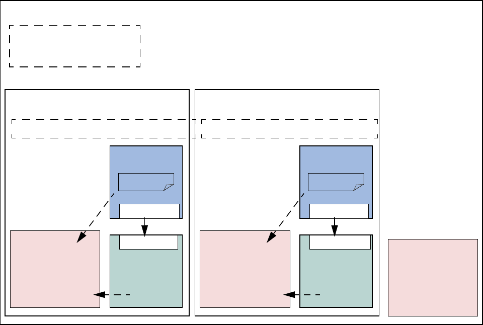
64 UVM 1.1 User’s Guide May 18, 2011
Figure 19—Standard Configuration Fields and Locations
4.5.3 Choosing between uvm_resource_db and uvm_config_db
The uvm_config_db and uvm_resource_db share the same underlying database. Because of this, it is
possible to write to the database using uvm_config_db::set() and retrieve from the database using
uvm_resource_db::read_by_name(). The primary reason for using one method over the other is
whether or not a hierarchical context is important to the setting. For configuration properties that are related
to hierarchical position, e.g., “set all of coverage_enable bits for all components in a specific agent”,
uvm_config_db is the correct choice. uvm_config_db was architected to provide the required
semantic for hierarchical configuration. Likewise, for cases where a configuration property is being shared
without regard to hierarchical context, uvm_resource_db should be used.
4.5.4 Using a Configuration Class
Some verification components randomize configuration attributes inside a configuration class.
Dependencies between these attributes are captured using constraints within the configuration object. In
such cases, users can extend the configuration class to add new constraints or layer additional constraints on
the class using inline constraints. Once configuration is randomized, the test writer can use
uvm_config_db::set() to assign the configuration object to one or more environments within the
testbench. Setting resources allows you to set the configuration to multiple environments in the testbench
regardless of their location and impact the build process of the testbench.
sequencer
driver
sequence
interface
interface
monitor
bit coverage_enable
bit checks_enable
monitor
bit
coverage_enable
bit checks_enable
uvm_active_passive_enum is_active
master agent
sequencer
driver
sequence
interface
interface
monitor
bit coverage_enable
bit checks_enable
uvm_active_passive_enum is_active
slave agent
int unsigned num_masters
int unsigned num_slaves
bit has_bus_monitor
Environment

May 18, 2011 UVM 1.1 User’s Guide 65
4.6 Creating and Selecting a User-Defined Test
In UVM, a test is a class that encapsulates test-specific instructions written by the test writer. This section
describes how to create and select a test. It also describes how to create a test family base class to verify a
topology configuration.
4.6.1 Creating the Base Test
The following example shows a base test that uses the ubus_example_tb defined in Section 4.3. This
base test is a starting point for all derivative tests that will use the ubus_example_tb. The complete test
class is shown here:
class ubus_example_base_test extends uvm_test;
`uvm_component_utils(ubus_example_base_test)
ubus_example_tb ubus_example_tb0;
// The test’s constructor
function new (string name = "ubus_example_base_test",
uvm_component parent = null);
super.new(name, parent);
endfunction
// Update this component's properties and create the ubus_example_tb
component.
virtual function build_phase(); // Create the testbench.
super.build_phase(phase);
ubus_example_tb0 =
ubus_example_tb::type_id::create("ubus_example_tb0", this);
endfunction
endclass
The build_phase() function of the base test creates the ubus_example_tb. The UVM Class Library
will execute the build_phase() function of the ubus_example_base_test for the user when
cycling through the simulation phases of the components. This creates the testbench environment because
each sub-component will create their own child components in their build_phase() functions.
All of the definitions in the base test are inherited by any test that derives from
ubus_example_base_test. This means any derivative test will not have to build the testbench if the
test calls super.build_phase(). Likewise, the run_phase() task behavior can be inherited, as well
as all other run-time phases. If the current implementation does not meet your needs, you can redefine the
build_phase(), run_phase(), and other run-time phase methods as needed because they are all
virtual.
4.6.2 Creating Tests from a Test-Family Base Class
You can derive from the base test defined in Section 4.6.1 to create tests that reuse the same topology. Since
the testbench is created by the base test’s build_phase() function, and the run_phase() task defines
the run phase, the derivative tests can make minor adjustments. (For example, changing the default sequence
executed by the agents in the environment.) The following is a simple test that inherits from
ubus_example_base_test.
class test_read_modify_write extends ubus_example_base_test;
`uvm_component_utils(test_read_modify_write)

66 UVM 1.1 User’s Guide May 18, 2011
// The test’s constructor
function new (string name = "test_read_modify_write",
uvm_component parent = null);
super.new(name, parent);
endfunction
// Register configurations to control which
// sequence is executed by the sequencers.
virtual function void build_phase(uvm_phase phase);
// Substitute the default sequence.
uvm_config_db#(uvm_object_wrapper)::
set(this, “ubus0.masters[0].sequencer.run_phase",
"default_sequence", read_modify_write_seq::type_id::get());
uvm_config_db#(uvm_object_wrapper)::
set(this, “ubus0.slaves[0].sequencer.run_phase",
"default_sequence",slave_memory_seq::type_id::get());
super.build_phase(phase);
endfunction
endclass
This test changes the default sequence executed by the masters[0] agent and the slaves[0] agent. It
is important to understand that super.build_phase(), through the base class, will create the
testbench, ubus_example_tb0, and all its subcomponents. Therefore, any configuration that will affect
the building of these components (such as how many masters to create) must be set before calling
super.build_phase(). For this example, since the sequences don’t get started until a later phase, they
could be called after super.build_phase().
This test relies on the ubus_example_base_test implementation of the run_phase() phase.
4.6.3 Test Selection
After you have declared a user-defined test (described in Section 4.6.2), invoke the global UVM
run_test() task in the top-level module to select a test to be simulated. Its prototype is:
task run_test(string test_name="");
When a test name is provided to the run_test() task, the factory is called to create an instance of the test
with that type name. Simulation then starts and cycles through the simulation phases.
The following example shows how the test type name test_read_modify_write (defined in
Section 4.6.2) can be provided to the run_test() task. A test name is provided to run_test() via a
simulator command-line argument. If the top module calls run_test() without an argument, the
+UVM_TESTNAME=test_name simulator command-line argument is checked. If present, run_test()
will use test_name. Using the simulator command-line argument avoids having to hardcode the test name
in the run_test() task. For example, in the top-level module, call the run_test() as follows:
module tb_top;
// DUT, interfaces, and all non-testbench code
initial
run_test();
endmodule
To select a test of type test_read_modify_write (described in Section 4.6.2) using simulator
command-line option, use the following command:
% simulator-command other-options +UVM_TESTNAME=test_read_modify_write

May 18, 2011 UVM 1.1 User’s Guide 67
If the test name provided to run_test() does not exist, the simulation will exit immediately via a call to
$fatal. If this occurs, it is likely the name was typed incorrectly or the `uvm_component_utils
macro was not used.
By using this method and only changing the +UVM_TESTNAME argument, you can run multiple tests
without having to recompile or re-elaborate the design or testbench.
4.7 Creating Meaningful Tests
The previous sections show how test classes are put together. At this point, random traffic is created and sent
to the DUT. The user can change the randomization seed to achieve new test patterns. To achieve
verification goals in a systematic way, the user will need to control test generation to cover specific areas.
The user can control the test creation using these methods:
— Add constraints to control individual data items. This method provides basic functionality (see
Section 4.7.1).
— Use UVM sequences to control the order of multiple data items. This method provides more flexibil-
ity and control (see Section 4.8.2).
4.7.1 Constraining Data Items
By default, sequencers repeatedly generate random data items. At this level, the test writer can control the
number of generated data items and add constraints to data items to control their generated values.
To constrain data items:
a) Identify the data item classes and their generated fields in the verification component.
b) Create a derivation of the data item class that adds or overrides default constraints.
c) In a test, adjust the environment (or a subset of it) to use the newly-defined data items.
d) Run the simulation using a command-line option to specify the test name.
Data Item Example
typedef enum bit {BAD_PARITY, GOOD_PARITY} parity_e;
class uart_frame extends uvm_sequence_item;
rand int unsigned transmit_delay;
rand bit start_bit;
rand bit [7:0] payload;
rand bit [1:0] stop_bits;
rand bit [3:0] error_bits;
bit parity;
// Control fields
rand parity_e parity_type;
function new(input string name);
super.new(name);
endfunction
// Optional field declarations and automation flags
`uvm_object_utils_begin(uart_frame)
`uvm_field_int(start_bit, UVM_ALL_ON)
`uvm_field_int(payload, UVM_ALL_ON)
`uvm_field_int(parity, UVM_ALL_ON)

68 UVM 1.1 User’s Guide May 18, 2011
`uvm_field_enum(parity_e, parity_type, UVM_ALL_ON + UVM_NOCOMPARE)
`uvm_field_int(xmit_delay, UVM_ALL_ON + UVM_DEC + UVM_NOCOMPARE)
`uvm_object_utils_end
// Specification section 1.2: the error bits value should be
// different than zero.
constraint error_bits_c {error_bits != 4'h0;}
// Default distribution constraints
constraint default_parity_type {parity_type dist {
GOOD_PARITY:=90, BAD_PARITY:=10};}
// Utility functions
extern function bit calc_parity ( );
...
endfunction
endclass: uart_frame
The uart_frame is created by the uart environment developer.
4.7.2 Data Item Definitions
A few fields in the derived class come from the device specification. For example, a frame should have a
payload that is sent to the DUT. Other fields are there to assist the test writer in controlling the generation.
For example, the field parity_type is not being sent to the DUT, but it allows you to easily specify and
control the parity distribution. Such control fields are called “knobs”. The verification component
documentation should list the data item’s knobs, their roles, and legal range.
Data items have specification constraints. These constraints can come from the DUT specification to create
legal data items. For example, a legal frame must have error_bits_c not equal to 0. A different type of
constraint in the data items constrains the traffic generation. For example, in the constraint block
default_parity_type (in the example in Section 4.7.1), the parity bit is constrained to be 90-percent
legal (good parity) and 10-percent illegal (bad parity).
4.7.3 Creating a Test-Specific Frame
In tests, the user may wish to change the way data items are generated. For example, the test writer may wish
to have short delays. This can be achieved by deriving a new data item class and adding constraints or other
class members as needed.
// A derived data item example
// Test code
class short_delay_frame extends uart_frame;
// This constraint further limits the delay values.
constraint test1_txmit_delay {transmit_delay < 10;}
`uvm_object_utils(short_delay_frame)
function new(input string name="short_delay_frame");
super.new(name);
endfunction
endclass: short_delay_frame
Deriving the new class is not enough to get the desired effect. You also need to have the environment use the
new class (short_delay_frame) rather than the verification component frame. The UVM Class Library
provides a mechanism that allows you to introduce the derived class to the environment.

May 18, 2011 UVM 1.1 User’s Guide 69
class short_delay_test extends uvm_test;
`uvm_component_utils(short_delay_test)
uart_tb uart_tb0;
function new (string name = "short_delay_test",uvm_component parent =
null);
super.new(name, parent);
endfunction
virtual function build_phase(uvm_phase phase);
super.build_phase(phase);
// Use short_delay_frame throughout the environment.
factory.set_type_override_by_type(uart_frame::get_type(),
short_delay_frame::get_type());
uart_tb0 = uart_tb::type_id::create("uart_tb0", this);
endfunction
task run_phase(uvm_phase phase);
uvm_top.print_topology();
endtask
endclass
Calling the factory function set_type_override_by_type() (in bold above) instructs the
environment to use short-delay frames.
At times, a user may want to send special traffic to one interface but keep sending the regular traffic to other
interfaces. This can be achieved by using set_inst_override_by_type() inside an UVM
component.
set_inst_override_by_type("uart_env0.master.sequencer.*",
uart_frame::get_type(), short_delay_frame::get_type());
You can also use wildcards to override the instantiation of a few components.
set_isnt_override_by_type("uart_env*.msater.sequencer.*",
uart_frame::get_type(), short_delay_frame::get_type());
4.8 Virtual Sequences
Section 4.7 describes how to efficiently control a single-interface generation pattern. However, in a system-
level environment, multiple components are generating stimuli in parallel. The user might want to
coordinate timing and data between the multiple channels. Also, a user may want to define a reusable
system-level scenario. Virtual sequences are associated with a virtual sequencer and are used to coordinate
stimulus generation in a testbench hierarchy. In general, a virtual sequencer contains references to its
subsequencers, that is, driver sequencers or other virtual sequencers in which it will invoke sequences.
Virtual sequences can invoke other virtual sequences associated with its sequencer, as well as sequences in
each of the subsequencers. However, virtual sequencers do not have their own data item and therefore do not
execute data items on themselves. Virtual sequences can execute items on other sequencers that can execute
items.
Virtual sequences enable centralized control over the activity of multiple verification components which are
connected to the various interfaces of the DUT. By creating virtual sequences, you can easily reuse existing
sequence libraries of the underlying interface components and block-level environments to create
coordinated system-level scenarios.
In Figure 20, the virtual sequencer invokes configuration sequences on the ethernet and cpu verification
components. The configuration sequences are developed during block-level testing.
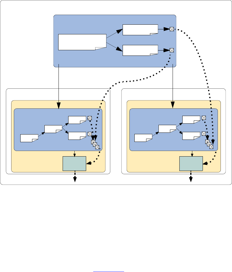
70 UVM 1.1 User’s Guide May 18, 2011
Figure 20—Virtual Sequence
There are three ways in which the virtual sequencer can interact with its subsequencers:
a) “Business as usual”—Virtual subsequencers and subsequencers send transactions simultaneously.
b) Disable subsequencers—Virtual sequencer is the only one driving.
c) Using grab() and ungrab()—Virtual sequencer takes control of the underlying driver(s) for a
limited time.
When using virtual sequences, most users disable the subsequencers and invoke sequences only from the
virtual sequence. For more information, see Section 4.8.3.
To invoke sequences, you can do one of the following:
Use the appropriate do macro.
Use the sequence start() method.
4.8.1 Creating a Virtual Sequencer
For high-level control of multiple sequencers from a single sequencer, use a sequencer that is not attached to
a driver and does not process items itself. A sequencer acting in this role is referred to as a virtual sequencer.
To create a virtual sequencer that controls several subsequencers:
a) Derive a virtual sequencer class from the uvm_sequencer class.
comm_env
ethernet_env
ethernet_agent
ethernet_sequencer
cpu_env
cpu_agent
virtual_sequencer
comm_sequence_s
cpu_config
eth_legal
seq
seq
seq
seq
driver driver
seq
seq
seq
seq
cpu_bus_sequencer

May 18, 2011 UVM 1.1 User’s Guide 71
b) Add references to the sequencers where the virtual sequences will coordinate the activity. These ref-
erences will be assigned by a higher-level component (typically the testbench).
The following example declares a virtual sequencer with two subsequencers. Two interfaces called eth and
cpu are created in the build function, which will be hooked up to the actual sub-sequencers.
class simple_virtual_sequencer extends uvm_sequencer;
eth_sequencer eth_seqr;
cpu_sequencer cpu_seqr;
// Constructor
function new(input string name="simple_virtual_sequencer",
input uvm_component parent=null);
super.new(name, parent);
endfunction
// UVM automation macros for sequencers
`uvm_component_utils(simple_virtual_sequencer)
endclass: simple_virtual_sequencer
Subsequencers can be driver sequencers or other virtual sequencers. The connection of the actual
subsequencer instances via reference is done later, as shown in Section 4.8.4.
4.8.2 Creating a Virtual Sequence
Creating a virtual sequence is similar to creating a driver sequence, with the following differences:
— A virtual sequence use `uvm_do_on or `uvm_do_on_with to execute sequences on any of the
subsequencers connected to the current virtual sequencer.
— A virtual sequence uses `uvm_do or `uvm_do_with to execute other virtual sequences of this
sequencer. A virtual sequence cannot use `uvm_do or `uvm_do_with to execute items. Virtual
sequencers do not have items associated with them, only sequences.
To create a virtual sequence:
c) Declare a sequence class by deriving it from uvm_sequence, just like a driver sequence.
d) Define a body() method that implements the desired logic of the sequence.
e) Use the `uvm_do_on (or `uvm_do_on_with) macro to invoke sequences in the underlying
subsequencers.
f) Use the `uvm_do (or `uvm_do_with) macro to invoke other virtual sequences in the current vir-
tual sequencer.
The following example shows a simple virtual sequence controlling two subsequencers: a cpu sequencer
and an ethernet sequencer. Assume the cpu sequencer has a cpu_config_seq sequence in its library and
the ethernet sequencer provides an eth_large_payload_seq sequence in its library. The following
sequence example invokes these two sequencers, one after the other.
class simple_virt_seq extends uvm_sequence;
... // Constructor and UVM automation macros
// A sequence from the cpu sequencer library
cpu_config_seq conf_seq;
// A sequence from the ethernet subsequencer library
eth_large_payload_seq frame_seq;
// A virtual sequence from this sequencer's library
random_traffic_virt_seq rand_virt_seq;

72 UVM 1.1 User’s Guide May 18, 2011
virtual task body();
// Invoke a sequence in the cpu subsequencer.
`uvm_do_on(conf_seq, p_sequencer.cpu_seqr)
// Invoke a sequence in the ethernet subsequencer.
`uvm_do_on(frame_seq, p_sequencer.eth_seqr)
// Invoke another virtual sequence in this sequencer.
`uvm_do(rand_virt_seq)
endtask : body
endclass : simple_virt_seq
4.8.3 Controlling Other Sequencers
When using a virtual sequencer, you will need to consider how you want the subsequencers to behave in
relation to the virtual sequence behavior being defined. There are three basic possibilities:
a) Business as usual—You want the virtual sequencer and the subsequencers to generate traffic at the
same time, using the built-in capability of the original subsequencers. The data items resulting from
the subsequencers’ default behavior—along with those injected by sequences invoked by the virtual
sequencer—will be intermixed and executed in an arbitrary order by the driver. This is the default
behavior, so there is no need to do anything to achieve this.
b) Disable the subsequencers—Using the set_config routines, you can set the count property of the
subsequencers to 0 and disable their default behavior. Recall that, by default, sequencers start their
uvm_random_sequence, which uses the count property of the sequencer to determine how
many sequences to execute.
The following code snippet disables the subsequencers in the example in Section 4.8.4.
// Configuration: Disable subsequencer sequences.
uvm_config_db#(int)::set(this, "*.cpu_seqr", "count", 0);
uvm_config_db#(int)::set(this, "*.eth_seqr", "count", 0);
c) Use grab() and ungrab()—In this case, a virtual sequence can achieve full control over its sub-
sequencers for a limited time and then let the original sequences continue working.
NOTE—Only (non-virtual) driver sequencers can be grabbed. Therefore, make sure a given subsequencer is not
a virtual sequencer before you attempt to grab it. The following example illustrates this using the functions
grab() and ungrab() in the sequence consumer interface.
virtual task body();
// Grab the cpu sequencer if not virtual.
if (p_sequencer.cpu_seqr != null)
p_sequencer.cpu_seqr.grab(this);
// Execute a sequence.
`uvm_do_on(conf_seq, p_sequencer.cpu_seqr)
// Ungrab.
if (p_sequencer.cpu_seqr != null)
p_sequencer.cpu_seqr.ungrab(this);
endtask
NOTE—When grabbing several sequencers, make sure to use some convention to avoid deadlocks. For example,
always grab in a standard order.
4.8.4 Connecting a Virtual Sequencer to Subsequencers
To connect a virtual sequencer to its subsequencers:
a) Assign the sequencer references specified in the virtual sequencer to instances of the sequencers.
This is a simple reference assignment and should be done only after all components are created.

May 18, 2011 UVM 1.1 User’s Guide 73
v_sequencer.cpu_seqr = cpu_seqr;
v_sequencer.eth_seqr = eth_seqr;
b) Perform the assignment in the connect() phase of the verification environment at the appropriate
location in the verification environment hierarchy.
Alternatively, the sequencer pointer could be set as a resource during build, as shown with eth_seqr
below.
The following more-complete example shows a top-level testbench, which instantiates the ethernet and cpu
components and the virtual sequencer that controls the two. At the testbench level, the path to the sequencers
inside the various components is known and that path is used to get a handle to them and connect them to the
virtual sequencer.
class simple_tb extends uvm_env;
cpu_env_c cpu0; // Reuse a cpu verification component.
eth_env_c eth0; // Reuse an ethernet verification component.
simple_virtual_sequencer v_sequencer;
... // Constructor and UVM automation macros
virtual function void build_phase(uvm_phase phase);
super.build_phase(phase);
// Configuration: Set the default sequence for the virtual sequencer.
uvm_config_db#(uvm_object_wrapper)::set(this,
"v_sequencer.run_phase",
"default_sequence",
simple_virt_seq.type_id::get());
// Build envs with subsequencers.
cpu0 = cpu_env_c::type_id::create("cpu0", this);
eth0 = eth_env_c::type_id::create("eth0", this);
// Build the virtual sequencer.
v_sequencer =
simple_virtual_sequencer::type_id::create("v_sequencer",
this);
endfunction : build_phase
// Connect virtual sequencer to subsequencers.
function void connect();
v_sequencer.cpu_seqr = cpu0.master[0].sequencer;
uvm_config_db#(uvm_sequencer)::set(this,”v_sequencer”,
”eth_seqr”,eth0.tx_rx_agent.sequencer);
endfunction : connect
endclass: simple_tb
4.9 Checking for DUT Correctness
Getting the device into desired states is a significant part of verification. The environment should verify
valid responses from the DUT before a feature is declared verified. Two types of auto-checking mechanisms
can be used:
a) Assertions—Derived from the specification or from the implementation and ensure correct timing
behavior. Assertions typically focus on signal-level activity.
b) Data checkers—Ensure overall device correctness.
As was mentioned in Section 1.2.4, checking and coverage should be done in the monitor regardless of the
driving logic. Reusable assertions are part of reusable components. See Chapter 3 for more information.
Designers can also place assertions in the DUT RTL. Refer to your ABV documentation for more
information.
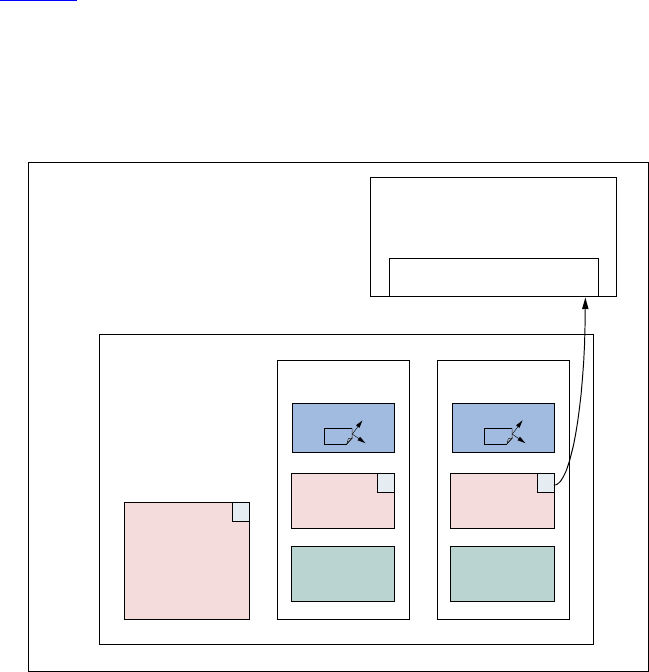
74 UVM 1.1 User’s Guide May 18, 2011
4.10 Scoreboards
A crucial element of a self-checking environment is the scoreboard. Typically, a scoreboard verifies the
proper operation of your design at a functional level. The responsibility of a scoreboard varies greatly
depending on the implementation. This section will show an example of a scoreboard that verifies that a
given UBus slave interface operates as a simple memory. While the memory operation is critical to the
UBus demonstration environment, you should focus on the steps necessary to create and use a scoreboard in
an environment so those steps can be repeated for any scoreboard application.
UBus Scoreboard Example
For the UBus demo environment, a scoreboard is necessary to verify the slave agent is operating as a simple
memory. The data written to an address should be returned when that address is read. The desired topology
is shown in Figure 21.
In this example, the user has created a testbench with one UBus environment that contains the bus monitor,
one active master agent, and one active slave agent. Every component in the UBus environment is created
using the build_phase() methods defined by the IP developer.
Figure 21—UBus Demo Environment
4.10.1 Creating the Scoreboard
Before the scoreboard can be added to the ubus_example_tb, the scoreboard component must be
defined.
To define the scoreboard:
a) Add the TLM export necessary to communicate with the environment monitor(s).
ubus0
sequencer
driver
monitor
master0
P
sequencer
driver
monitor
slave0
P
monitor
P
scoreboard0
item_collected_export
ubus_example_tb0

May 18, 2011 UVM 1.1 User’s Guide 75
b) Implement the necessary functions and tasks required by the TLM export.
c) Define the action taken when the export is called.
4.10.2 Adding Exports to uvm_scoreboard
In the example shown in Figure 21, the scoreboard requires only one port to communicate with the
environment. Since the monitors in the environment have provided an analysis port write() interface via
the TLM uvm_analysis_port(s), the scoreboard will provide the TLM uvm_analysis_imp.
The ubus_example_scoreboard component derives from the uvm_scoreboard and declares and
instantiates an analysis_imp. For more information on TLM interfaces, see “TLM Interfaces” in the
UVM 1.1 Class Reference. The declaration and creation is done inside the constructor.
1 class ubus_example_scoreboard extends uvm_scoreboard;
2 uvm_analysis_imp #(ubus_transfer, ubus_example_scoreboard)
3 item_collected_export;
4 ...
5 function new (string name, uvm_component parent);
6 super.new(name, parent);
7 endfunction : new
8 function void build_phase(uvm_phase phase);
9 item_collected_export = new("item_collected_export", this);
10 endfunction
11 ...
Line 2 declares the uvm_analysis_export. The first parameter, ubus_transfer, defines the
uvm_object communicated via this TLM interface. The second parameter defines the type of this
implementation’s parent. This is required so that the parent’s write() method can be called by the export.
Line 9 creates the implementation instance. The constructor arguments define the name of this
implementation instance and its parent.
4.10.3 Requirements of the TLM Implementation
Since the scoreboard provides an uvm_analysis_imp, the scoreboard must implement all interfaces
required by that export. This means you must define the implementation for the write virtual function. For
the ubus_example_scoreboard, write() has been defined as:
virtual function void write(ubus_transfer trans);
if (!disable_scoreboard)
memory_verify(trans);
endfunction : write
The write() implementation defines what happens when data is provided on this interface. In this case, if
disable_scoreboard is 0, the memory_verify() function is called with the transaction as the
argument.
4.10.4 Defining the Action Taken
When the write port is called via write(), the implementation of write() in the parent of the
implementation is called. For more information, see “TLM Interfaces” in the UVM 1.1 Class Reference. As

76 UVM 1.1 User’s Guide May 18, 2011
seen in Section 4.10.3, the write() function is defined to called the memory_verify() function if
disable_scoreboard is set to 0.
The memory_verify() function makes the appropriate calls and comparisons needed to verify a
memory operation. This function is not crucial to the communication of the scoreboard with the rest of the
environment and not discussed here. The ubus_example_scoreboard.sv file shows the
implementation.
4.10.5 Adding the Scoreboard to the Environment
Once the scoreboard is defined, the scoreboard can be added to the UBus demo testbench. First, declare the
ubus_example_scoreboard inside the ubus_example_tb class.
ubus_example_scoreboard scoreboard0;
After the scoreboard is declared, you can construct the scoreboard inside the build() phase:
function ubus_example_tb::build_phase(uvm_phase phase);
...
scoreboard0 = ubus_example_scoreboard::type_id::create("scoreboard0",
this);
...
endfunction
Here, the scoreboard0 of type ubus_example_scoreboard is created using the create()
function and given the name scoreboard0. It is then assigned the ubus_example_tb as its parent.
After the scoreboard is created, the ubus_example_tb can connect the port on the UBus environment
slaves[0] monitor to the export on the scoreboard.
function ubus_example_tb::connect_phase(uvm_phase phase);
...
ubus0.slaves[0].monitor.item_collected_port.connect(
scoreboard0.item_collected_export);
...
endfunction
This ubus_example_tb’s connect() function code makes the connection, using the TLM ports
connect() interface, between the port in the monitor of the slaves[0] agent inside the ubus0
environment and the implementation in the ubus_example_scoreboard called scoreboard0. For
more information on the use of binding of TLM ports, see “TLM Interfaces” in the UVM 1.1 Class
Reference.
4.10.6 Summary
The process for adding a scoreboard in this section can be applied to other scoreboard applications in terms
of environment communication. To summarize:
a) Create the scoreboard component.
1) Add the necessary exports.
2) Implement the required functions and tasks.
3) Create the functions necessary to perform the implementation-specific functionality.
b) Add the scoreboard to the environment.

May 18, 2011 UVM 1.1 User’s Guide 77
1) Declare and instantiate the scoreboard component.
2) Connect the scoreboard implementation(s) to the environment ports of interest.
The UBus demo has a complete scoreboard example. See Chapter 7 for more information.
4.11 Implementing a Coverage Model
To ensure thorough verification, you need observers to represent your verification goals. SystemVerilog
provides a rich set of functional-coverage features.
4.11.1 Selecting a Coverage Method
No single coverage metric ensures completeness. There are two coverage methods:
a) Explicit coverage—is user-defined coverage. The user specifies the coverage goals, the needed val-
ues, and collection time. As such, analyzing these goals is straightforward. Completing all your cov-
erage goals means you have achieved 100% of your verification goals and verification has been
completed. An example of such a metric is SystemVerilog functional coverage. The disadvantage of
such metrics is that missing goals are not taken into account.
b) Implicit coverage—is done with automatic metrics that are driven from the RTL or other metrics
already existing in the code. Typically, creating an implicit coverage report is straightforward and
does not require a lot of effort. For example, code coverage, expression coverage, and FSM (finite-
state machine) coverage are types of implicit coverage. The disadvantage of implicit coverage is it is
difficult to map the coverage requirements to the verification goals. It also is difficult to map cover-
age holes into unexecuted high-level features. In addition, implicit coverage is not complete, since it
does not take into account high-level abstract events and does not create associations between paral-
lel threads (that is, two or more events occurring simultaneously).
Starting with explicit coverage is recommended. You should build a coverage model that represents your
high-level verification goals. Later, you can use implicit coverage as a “safety net” to check and balance the
explicit coverage.
NOTE—Reaching 100% functional coverage with very low code-coverage typically means the functional coverage
needs to be refined and enhanced.
4.11.2 Implementing a Functional Coverage Model
A verification component should come with a protocol-specific functional-coverage model. You may want
to disable some coverage aspects that are not important or do not need to be verified. For example, you
might not need to test all types of bus transactions in your system or you might want to remove that goal
from the coverage logic that specifies all types of transactions as goals. You might also want to extend the
functional-coverage model and create associations between the verification component coverage and other
attributes in the system or other interface verification components. For example, you might want to ensure
proper behavior when all types of transactions are sent and the FIFO in the system is full. This would
translate into crossing the transaction type with the FIFO-status variable. This section describes how to
implement this type of functional coverage model.
4.11.3 Enabling and Disabling Coverage
The verification IP developer should provide configuration properties that allow you to control the
interesting aspects of the coverage (see Section 3.12.3). The VIP documentation will tell you what
78 UVM 1.1 User’s Guide May 18, 2011
properties can be set to affect coverage. The most basic of controls would determine whether coverage is
collected at all. The UBus monitors demonstrate this level of control. If the you want to disable coverage
before the environment is created, use the uvm_config_db() interface.
uvm_config_db#(int)::(this,"ubus0.masters[0].monitor", "coverage_enable", 0);
Once the environment is created, you can set this property directly.
ubus0.masters[0].monitor.coverage_enable = 0;
This is a simple SystemVerilog assignment to a class property (or variable).
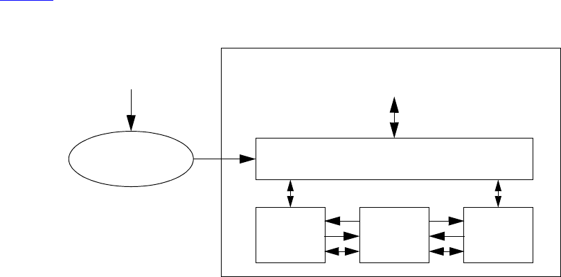
May 18, 2011 UVM 1.1 User’s Guide 79
5. Using the Register Layer Classes
5.1 Overview
The UVM register layer classes are used to create a high-level, object-oriented model for memory-mapped
registers and memories in a design under verification (DUV). The UVM register layer defines several base
classes that, when properly extended, abstract the read/write operations to registers and memories in a DUV.
This abstraction mechanism allows the migration of verification environments and tests from block to
system levels without any modifications. It also can move uniquely named fields between physical registers
without requiring modifications in the verification environment or tests. Finally, UVM provides a register
test sequence library containing predefined testcases you can use to verify the correct operation of registers
and memories in a DUV.
A register model is typically composed of a hierarchy of blocks that map to the design hierarchy. Blocks can
contain registers, register files and memories, as well as other blocks. The register layer classes support
front-door and back-door access to provide redundant paths to the register and memory implementation, and
verify the correctness of the decoding and access paths, as well as increased performance after the physical
access paths have been verified. Designs with multiple physical interfaces, as well as registers, register files,
and memories shared across multiple interfaces, are also supported.
Most of the UVM register layer classes must be specialized via extensions to provide an abstract view that
corresponds to the actual registers and memories in a design. Due to the large number of registers in a design
and the numerous small details involved in properly configuring the UVM register layer classes, this
specialization is normally done by a model generator. Model generators work from a specification of the
registers and memories in a design and thus are able to provide an up-to-date, correct-by-construction
register model. Model generators are outside the scope of the UVM library.
Figure 22 shows how a register model is used in a verification environment.
Figure 22—Register Model in an UVM Environment
5.2 Usage Model
A register model is an instance of a register block, which may contain any number of registers, register files,
memories, and other blocks. Each register file contains any number of registers and other register files. Each
register contains any number of fields, which mirror the values of the corresponding elements in hardware.
DUT
Register Model
Sequences
Specification
Generator
Environment
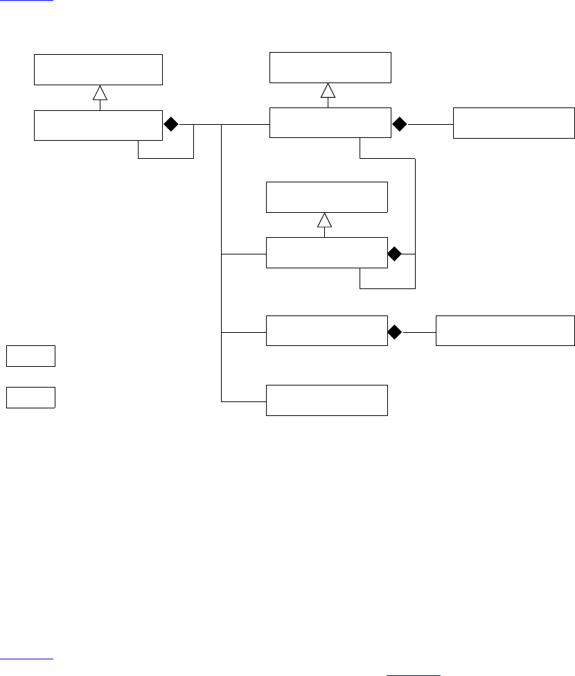
80 UVM 1.1 User’s Guide May 18, 2011
For each element in a register model—field, register, register file, memory or block—there is a class
instance that abstracts the read and write operations on that element.
Figure 23 shows the class collaboration diagram of the register model.
Figure 23—Register Model Class Collaboration
A block generally corresponds to a design component with its own host processor interface(s), address
decoding, and memory-mapped registers and memories. If a memory is physically implemented externally
to the block, but accessed through the block as part of the block’s address space, then the memory is
considered as part of the block register model.
All data values are modeled as fields. Fields represent a contiguous set of bits. Fields are wholly contained
in a register. A register may span multiple addresses. The smallest register model that can be used is a block.
A block may contain one register and no memories, or thousands of registers and gigabytes of memory.
Repeated structures may be modelled as register arrays, register file arrays, or block arrays.
Figure 24 shows the structure of a sample design block containing two registers, which have two and three
fields respectively, an internal memory, and an external memory. Figure 25 shows the structure of the
corresponding register model.
uvm_reg_block
1..N uvm_reg_field
uvm_mem_mam
my_reg
uvm_reg
uvm_reg_file
uvm_mem
uvm_reg_map
1..N
1..N
1..N
1..N
my_regfile
1..N
1..N 1..N
my_block
= user-defined class
(generated)
my_*
= UVM base class
uvm_*
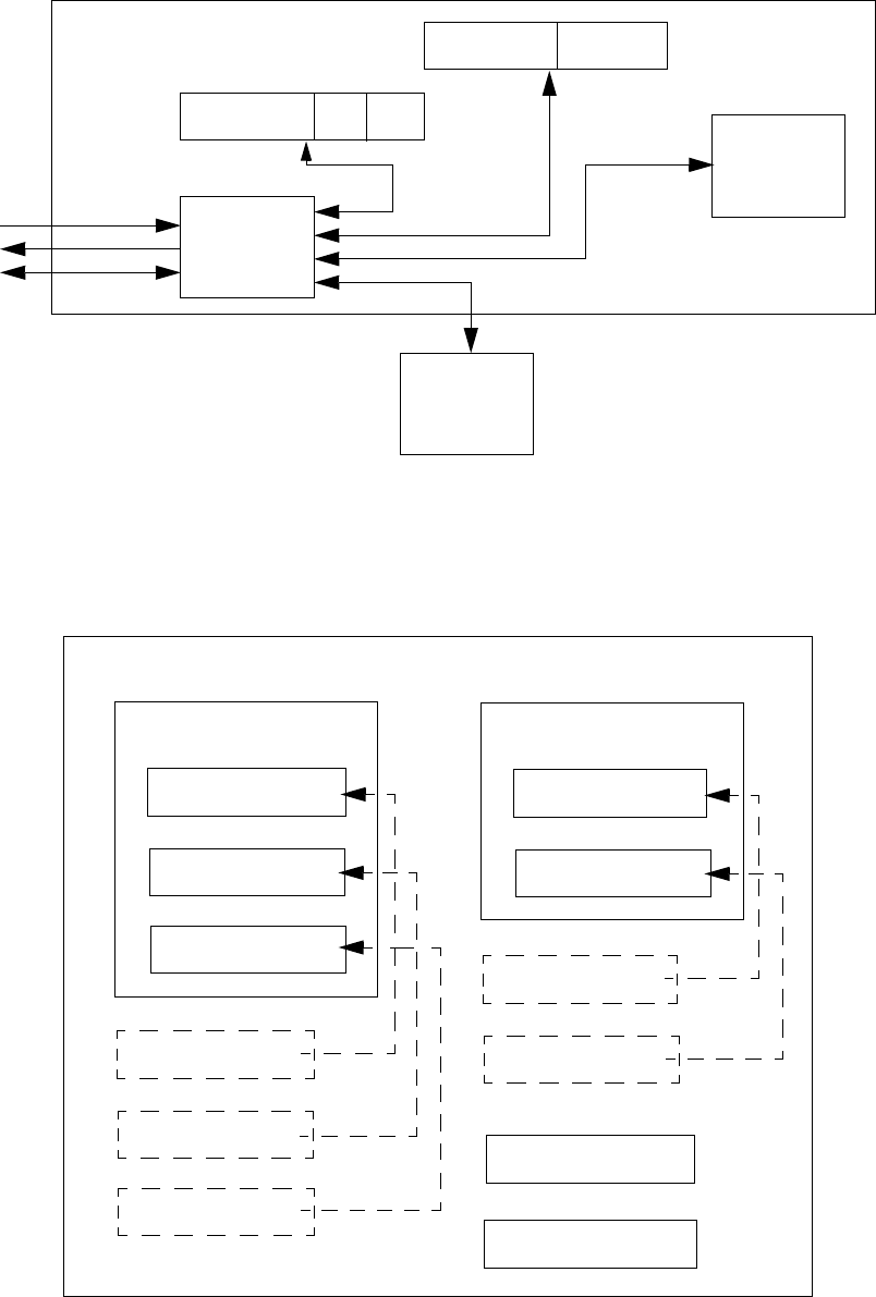
May 18, 2011 UVM 1.1 User’s Guide 81
Figure 24—Design Structure of Registers, Fields, and Memories
Figure 25—Register Model Structure
RAM
BFR
RAM
TBL
ADDR OECONFIG
STATUS MASKINTRPT
DS
Host_IF
CODEC
uvm_reg_block
CODEC
CONFIG
uvm_reg
ADDR
uvm_reg_field
DS
uvm_reg_field
OE
uvm_reg_field
ADDR
uvm_reg_field
DS
uvm_reg_field
OE
uvm_reg_field
INTRPT
uvm_reg
STATUS
uvm_reg_field
MASK
uvm_reg_field
STATUS
uvm_reg_field
MASK
uvm_reg_field
TBL
uvm_mem
BFR
uvm_mem
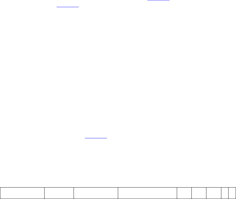
82 UVM 1.1 User’s Guide May 18, 2011
When using a register model, fields, registers, and memory locations are accessed through read and write
methods in their corresponding abstraction class. It is the responsibility of the register model to turn these
abstracted accesses into read and write cycles at the appropriate addresses via the appropriate bus driver. A
register model user never needs to track the specific address or location of a field, register, or memory
location, only its name.
For example, the field ADDR in the CONFIG register shown in Figure 24 can be accessed through the
register model shown in Figure 25 using the CODEC.CONFIG.ADDR.read() method. Similarly,
location 7 in the BFR memory can be accessed using the CODEC.BFR.write(7,value) method.
The location of fields within a physical register is somewhat arbitrary. If a field name is unique across all
registers’ fields within a block, it may also be accessed independently of their register location using an alias
handle declared in the block. For example, the same ADDR field, being unique in name to all other fields in
the CODEC block, may also be accessed using CODEC.ADDR.read(). Then, if ADDR is relocated from
CONFIG to another register, any tests or environments that reference CODEC.ADDR will not be affected.
Because a typical design has hundreds if not thousands of fields, the declaration and assignment of field
aliases in a block are left as an optional feature in a register model generator.
5.2.1 Sub-register Access
When reading or writing a field using uvm_reg_field::read() or uvm_reg_field::write(),
what actually happens depends on a lot of factors. If possible, only that field is read or written. Otherwise,
the entire register containing that field is read or written, possibly causing unintended side effects to the
other fields contained in that same register.
Consider the 128-bit register shown in Figure 26. Assuming a 32-bit data bus with a little-endian layout,
accessing this entire register requires four cycles at addresses 0x00, 0x04, 0x08, and 0x0C respectively.
However, field D can be accessed using a single cycle at address 0x01. Since this field occupies an entire
physical address, accessing it does not pose a challenge.
Figure 26—128-bit Register
Similarly, accessing field C can be done using a single access at address 0x00. However, this will also
access fields B and A. Accessing field F requires two physical accesses, at addresses 0x02 and 0x03, but
this would also access fields E and G at the same time. Accessing adjacent fields might not be an issue, but if
the access has a side-effect on any of these fields, such as a clear-on-read field or writable field, this
process will have unintended consequences.
When the underlying bus-protocol supports byte-enabling, field C (at address 0x00, lane #2) can be
accessed without affecting the other fields at the same address. And since field F is byte-aligned, it can be
accessed without side effects by accessing address 0x02, lane #3 and address 0x03, lane #0. However,
fields B and A remain inaccessible without mutual side effects as they do not individually occupy an entire
byte lane.
Thus, individual field access is supported for fields that are the sole occupant of one or more byte lane(s) if
the containing register does not use a user-defined front-door and the underlying bus protocol supports byte
enabling. A field may also be individually-accessible if the other fields in the same byte lanes are not
AGC
0424127 88 8163264104
BDFE
May 18, 2011 UVM 1.1 User’s Guide 83
affected by read or write operations. Whether a field can be individually accessible (assuming the
underlying protocol supports byte-enabling) is specified by the register model generator in the
uvm_reg_field::configure() method.
For individual field access to actually occur, two conditions must be met: the field must be identified as
being the sole occupant of its byte lane by the register model generator via the
uvm_reg_field::configure() method and the bus protocol must report that it supports byte-
enables via the uvm_reg_adapter::supports_byte_enable property.
Finally, individual field access is only supported for front-door accesses. When using back-door accesses,
the entire register—and thus all the fields it contains—will always be accessed via a peek-modify-poke
operation.
5.2.2 Mirroring
The register model maintains a mirror of what it thinks the current value of registers is inside the DUT. The
mirrored value is not guaranteed to be correct because the only information the register model has is the read
and write accesses to those registers. If the DUT internally modifies the content of any field or register
through its normal operations (e.g., by setting a status bit or incrementing an accounting counter), the
mirrored value becomes outdated.
The register model takes every opportunity to update its mirrored value. For every read operation, the mirror
for the read register is updated. For every write operation, the new mirror value for the written register is
predicted based on the access modes of the bits in the register (read/write, read-only, write-1-
to-clear, etc.). Resetting a register model sets the mirror to the reset value specified in the model. A
mirror is not a scoreboard, however; while a mirror can accurately predict the content of registers that are
not updated by the design, it cannot determine if an updated value is correct or not.
You can update the mirror value of a register to the value stored in the DUT by using the
uvm_reg_field::mirror(), uvm_reg::mirror(), or uvm_reg_block::mirror()
methods. Updating the mirror for a field also updates the mirror for all the other fields in the same register.
Updating the mirror for a block updates the mirror for all fields and registers it contains. Updating a mirror
in a large block may take a lot of simulation time if physical read cycles are used; whereas, updating using
back-door access usually takes zero-time.
You can write to mirrored values in the register model in zero-time by using the
uvm_reg_field::set() or uvm_reg::set() methods. Once a mirror value has been overwritten,
it no longer reflects the value in the corresponding field or register in the DUT. You can update the DUT to
match the mirror values by using the uvm_reg::update() or uvm_reg_block::update()
methods. If the new mirrored value matches the old mirrored value, the register is not updated, thus saving
unnecessary bus cycles. Updating a block with its mirror updates all the fields and registers the block
contains with their corresponding mirror values. Updating a large block may take a lot of simulation time if
physical write cycles are used; whereas, updating using back-door access usually takes zero-time. It is
recommended you use this update-from-mirror process when configuring the DUT to minimize the number
of write operations performed.
To access a field or register’s current mirror value in zero-time, use the uvm_reg_field::get() or
uvm_reg::get() methods. However, if uvm_reg_field::set() or uvm_reg::set() is used to
write a desired value to the DUT, get() only returns the desired value, modified according to the access
mode for that field or register, until the actual write to the DUT has taken place via update().
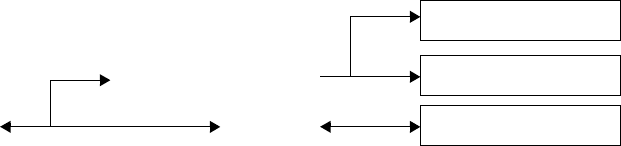
84 UVM 1.1 User’s Guide May 18, 2011
5.2.3 Memories are not Mirrored
Memories can be quite large, so they are usually modelled using a sparse-array approach. Only the locations
that have been written to are stored and later read back. Any unused memory location is not modelled.
Mirroring a memory would require that the same technique be used.
When verifying the correct operations of a memory, it is necessary to read and write all addresses. This
negates the memory-saving characteristics of a sparse-array technique, as both the memory model of the
DUT and the memory would mirror, become fully populated, and duplicate the same large amount of
information.
Unlike bits in fields and registers, the behavior of bits in a memory is very simple: all bits of a memory can
either be written to or not. A memory mirror would then be a ROM or RAM memory model—a model that
is already being used in the DUT to model the memory being mirrored. The memory mirror can then be
replaced by providing back-door access to the memory model.
Therefore, using the uvm_mem::peek() or uvm_mem::poke() methods provide the exact same
functionality as a memory mirror. Additionally, unlike a mirror based on observed read and write
operations, using back-door accesses instead of a mirror always returns or sets the actual value of a memory
location in the DUT.
5.3 Access API
Register and fields have a variety of methods to get the current value of a register or field and modify it. It is
important to use the correct API to obtain the desired result.
5.3.1 read / write
The normal access API are the read() and write() methods. When using the front-door (path=BFM),
one or more physical transactions is executed on the DUT to read or write the register. The mirrored value is
then updated to reflect the expected value in the DUT register after the observed transactions.
When using the back-door (path=BACKDOOR), peek or poke operations are executed on the DUT to read
or write the register via the back-door mechanism, bypassing the physical interface. The behavior of the
registers is mimicked as much as possible to duplicate the effect of reading or writing the same value via the
front-door. For example, a read from a clear-on-read field causes 0’s to be poked back into the field
after the peek operation. The mirrored value is then updated to reflect the actual sampled or deposited value
in the register after the observed transactions.
Desired Value
Mirrored Value
Register in DUT
read/write(frontdoor)
predict(READ/WRITE)
Bus Agent
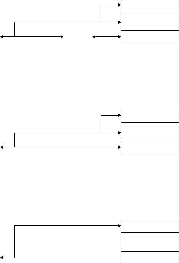
May 18, 2011 UVM 1.1 User’s Guide 85
5.3.2 peek / poke
Using the peek() and poke() methods reads or writes directly to the register respectively, which
bypasses the physical interface. The mirrored value is then updated to reflect the actual sampled or deposited
value in the register after the observed transactions.
5.3.3 get / set
Using the get() and set() methods reads or writes directly to the desired mirrored value respectively,
without accessing the DUT. The desired value can subsequently be uploaded into the DUT using the
update() method.
5.3.4 randomize
Using the randomize() method copies the randomized value in the uvm_reg_field::value
property into the desired value of the mirror by the post_randomize() method. The desired value can
subsequently be uploaded into the DUT using the update() method.
Desired Value
Mirrored Value
Register in DUT
read/write(backdoor) Mimic
Desired Value
Mirrored Value
Register in DUT
peek/poke()
Desired Value
Mirrored Value
Register in DUT
get/set()
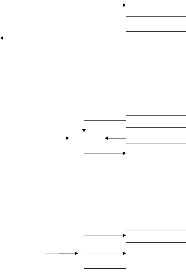
86 UVM 1.1 User’s Guide May 18, 2011
5.3.5 update
Using the update() method invokes the write() method if the desired value (previously modified
using set() or randomize()) is different from the mirrored value. The mirrored value is then updated
to reflect the expected value in the register after the executed transactions.
5.3.6 mirror
Using the mirror() method invokes the read() method to update the mirrored value based on the
readback value. mirror() can also compare the readback value with the current mirrored value before
updating it.
5.3.7 Concurrent Accesses
The register model can be accessed from multiple concurrent execution threads. However, it internally
serializes the access to the same register to ensure predictability of the implicitly-updated mirrored value and
of the other field values in the same register when a individual field is accessed.
A semaphore in each register ensures it can be read or written by only one process at a time. Any other
process attempting access will block and not resume until after the current operation completes and after
other processes that were blocked before it have completed their operations.
If a thread in the middle of executing a register operation is explicitly killed, it will be necessary to release
the semaphore in the register it was accessing by calling the uvm_reg::reset() method.
Desired Value
Mirrored Value
Register in DUT
randomize()
Desired Value
Mirrored Value
Register in DUT
update() If different
Desired Value
Mirrored Value
Register in DUT
mirror()

May 18, 2011 UVM 1.1 User’s Guide 87
5.4 Coverage Models
The UVM register library classes do not include any coverage models as a coverage model for a register will
depend on the fields it contains and the layout of those fields, and a coverage model for a block will depend
on the registers and memories it contains and the addresses where they are located. Since coverage model
information is added to the UVM register library classes by the register model generator, that generator
needs to include a suitable coverage model. Consequently, the UVM register library classes provide the
necessary API for a coverage model to sample the relevant data into a coverage model.
Due to the significant memory and performance impact of including a coverage model in a large register
model, the coverage model needs to handle the possibility that specific cover groups will not be instantiated
or to turn off coverage measurement even if the cover groups are instantiated. Therefore, the UVM register
library classes provide the necessary API to control the instantiation and sampling of various coverage
models.
5.4.1 Predefined Coverage Identifiers
The UVM library has several predefined functional coverage model identifiers, as shown in Table 6. Each
symbolic value specifies a different type of coverage model. The symbolic values use a one-hot encoding.
Therefore, multiple coverage models may be specified by OR’ing them. Additional symbolic values may be
provided for vendor-specific and user-specific coverage models that fall outside of the pre-defined coverage
model types. To avoid collisions with pre-defined UVM, vendor-defined, and user-defined coverage model
identifiers, bits 0 through 7 are reserved for UVM, bits 8 through 15 are reserved for vendors, and bits 16
through 23 are reserved for users. Finally, bits 24 and above are reserved for future assignment.
5.4.2 Controlling Coverage Model Construction and Sampling
By default, coverage models are not included in a register model when it is instantiated. To be included, they
must be enabled via the uvm_reg::include_coverage() method. It is recommended register-level
coverage models are only included in unit-level environments; block-level coverage models may be
included in block and system-level environments.
uvm_reg::include_coverage(“*”, UVM_CVR_REG_BITS + UVM_CVR_FIELD_VALS);
Furthermore, the sampling for a coverage model is implicitly disabled by default. To turn the sampling for
specific coverage models on or off, use the uvm_reg_block::set_coverage(),
uvm_reg::set_coverage(), and uvm_mem::set_coverage() methods.
Table 6—Pre-defined Functional Coverage Type Identifiers
Identifier Description
UVM_NO_COVERAGE No coverage models.
UVM_CVR_REG_BITS Coverage models for the bits read or written in registers.
UVM_CVR_ADDR_MAP Coverage models for the addresses read or written in an address map.
UVM_CVR_FIELD_VALS Coverage models for the values of fields.
UVM_CVR_ALL All coverage models.
88 UVM 1.1 User’s Guide May 18, 2011
5.5 Constructing a Register Model
This section describes how to construct a UVM register model to represent different register and memory
access and composition structures. The target audience for this section is generator writers. End users of the
register model need not be familiar with the model construction process, only the final structure of the
model.
5.5.1 Field Types
There is usually no need to construct field types. Fields are simple instantiations of the uvm_reg_field
class. A field type may only be needed to specify field-level constraints, which could also be specified in the
containing register.
A field type is constructed using a class extended from the uvm_reg_field class. There must be one
class per unique field type. The name of the field type is created by the register model generator. The name
of the field type class must be unique within the scope of its declaration. The field type class must include an
appropriate invocation of the `uvm_object_utils() macro.
class my_fld_type extends uvm_reg_field;
`uvm_object_utils(my_fld_type)
endclass
Field types are instantiated in the build() method of the containing register types.
5.5.1.1 Class Properties and Constraints
A separate constraint block should be defined for each aspect being constrained—e.g., one to keep it valid,
one to keep it reasonable—so they can be turned off individually. The name of a constraint block shall be
indicative of its purpose. Constraints shall constrain the value class property. Additional state variables
may be added to the field class if they facilitate the constraints.
class my_fld_type extends uvm_reg_field;
constraint valid {
value inside {0, 1, 2, 4, 8, 16, 32};
};
endclass
To ensure state variable and constraint block names do not collide with other symbols in uvm_reg_field
base class, it is recommended their names be in all UPPERCASE.
If the post_randomize() method is overridden, it must call super.post_randomize().
5.5.1.2 Constructor
The constructor must be a valid uvm_object constructor. The constructor shall call the
uvm_reg_field::new() method with appropriate argument values for the field type.
class my_fld_type extends uvm_reg_field;
function new(name = “my_fld_type”);
super.new(name);
endfunction
endclass

May 18, 2011 UVM 1.1 User’s Guide 89
5.5.1.3 Predefined Field Access Policies
The access policy of a field is specified using the uvm_reg_field::configure() method, called
from the build() method of the register that instantiates it.
Table 7 shows the pre-defined access policies for uvm_reg_field. Unless otherwise stated, the effect of
a read cycle on the current value is performed after the current value has been sampled for read-back.
Additional field access policies may be defined using the uvm_reg_field::define_access()
method and by modeling their behavior by extending the uvm_reg_field or uvm_reg_cbs classes.
Table 7—Pre-defined Field Access Policies
Access
Policy Description Effect of a Write
on Current Field Value
Effect of a Read
on Current Field
Value
Read-
back
Value
RO Read Only No effect. No effect. Current
value
RW Read, Write Changed to written value. No effect. Current
value
RC Read Clears All No effect. Sets all bits to 0’s. Current
value
RS Read Sets All No effect. Sets all bits to 1’s. Current
value
WRC Write,
Read Clears All
Changed to written value. Sets all bits to 0’s. Current
value
WRS Write, Read Sets
All
Changed to written value. Sets all bits to 1’s. Current
value
WC Write Clears All Sets all bits to 0’s. No effect. Current
value
WS Write Sets All Sets all bits to 1’s. No effect. Current
value
WSRC Write Sets All,
Read Clears All
Sets all bits to 1’s. Sets all bits to 0’s. Current
value
WCRS Write Clears All,
Read Sets All
Sets all bits to 0’s. Sets all bits to 1’s. Current
value
W1C Write 1 to Clear If the bit in the written value is a 1, the cor-
responding bit in the field is set to 0. Other-
wise, the field bit is not affected.
No effect. Current
value
W1S Write 1 to Set If the bit in the written value is a 1, the cor-
responding bit in the field is set to 1. Other-
wise, the field bit is not affected.
No effect. Current
value
W1T Write 1 to Toggle If the bit in the written value is a 1, the cor-
responding bit in the field is inverted. Other-
wise, the field bit is not affected.
No effect. Current
value
W0C Write 0 to Clear If the bit in the written value is a 0, the cor-
responding bit in the field is set to 0. Other-
wise, the field bit is not affected.
No effect. Current
value

90 UVM 1.1 User’s Guide May 18, 2011
5.5.1.4 IP-XACT Field Access Mapping
Table 8 — Table 12 show the mapping between the IEEE 1685-2009 field access policies (as specified by
the fieldData group, see section 6.10.9.2 of the IEEE 1685-2009 Standard) and the pre-defined access
policies for uvm_reg_field. Several combinations of access, modifiedWriteValue, and
readAction are specified as n/a because they do not make practical sense. However, they can always be
modeled as user-defined fields if they are used in a design.
W0S Write 0 to Set If the bit in the written value is a 0, the cor-
responding bit in the field is set to 1. Other-
wise, the field bit is not affected.
No effect. Current
value
W0T Write 0 to Toggle If the bit in the written value is a 0, the cor-
responding bit in the field is inverted. Other-
wise, the field bit is not affected.
No effect. Current
value
W1SRC Write 1 to Set,
Read Clears All
If the bit in the written value is a 1, the cor-
responding bit in the field is set to 1. Other-
wise, the field bit is not affected.
Sets all bits to 0’s. Current
value
W1CRS Write 1 to Clear,
Read Sets All
If the bit in the written value is a 1, the cor-
responding bit in the field is set to 0. Other-
wise, the field bit is not affected.
Sets all bits to 1’s. Current
value
W0SRC Write 0 to Set,
Read Clears All
If the bit in the written value is a 0, the cor-
responding bit in the field is set to 1. Other-
wise, the field bit is not affected.
Sets all bits to 0’s. Current
value
W0CRS Write 0 to Clear,
Read Sets All
If the bit in the written value is a 0, the cor-
responding bit in the field is set to 0. Other-
wise, the field bit is not affected.
Sets all bits to 1’s. Current
value
WO Write Only Changed to written value. No effect. Undefined
WOC Write Only
Clears All
Sets all bits to 0’s. No effect. Undefined
WOS Write Only Sets
All
Sets all bits to 1’s. No effect. Undefined
W1 Write Once Changed to written value if this is the first
write operation after a hard reset. Otherwise,
has no effect.
No effect. Current
value
WO1 Write Only, Once Changed to written value if this is the first
write operation after a hard reset. Otherwise,
has no effect.
No effect. Undefined
Table 7—Pre-defined Field Access Policies (Continued)
Access
Policy Description Effect of a Write
on Current Field Value
Effect of a Read
on Current Field
Value
Read-
back
Value

May 18, 2011 UVM 1.1 User’s Guide 91
Table 8—IP-XACT Mapping for access==read-write
access == read-write
modifiedWriteValue
readAction
Unspecified clear set modify
Unspecified RW WRC WRS User-defined
oneToClear W1C n/a W1CRS User-defined
oneToSet W1S W1SRC n/a User-defined
oneToToggle W1T n/a n/a User-defined
zeroToClear W0C n/a W0CRS User-defined
zeroToSet W0S W0SRC n/a User-defined
zeroToToggle W0T n/a n/a User-defined
clear WC n/a WCRS User-defined
set WS WSRC n/a User-defined
modify User-defined User-defined User-defined User-defined
Table 9—IP-XACT Mapping for access==read-only
access == read-only
modifiedWriteValue
readAction
Unspecified clear set modify
Unspecified RO RC RS User-defined
All others n/a n/a n/a n/a
Table 10—IP-XACT Mapping for access==write-only
access == write-only
modifiedWriteValue
readAction
Unspecified clear set modify
Unspecified WO n/a n/a n/a
clear WOC n/a n/a n/a
set WOS n/a n/a n/a
All others n/a n/a n/a n/a
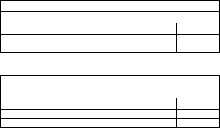
92 UVM 1.1 User’s Guide May 18, 2011
5.5.1.5 Reserved Fields
There is no pre-defined field access policy for reserved fields. That is because “reserved” is a documentation
concept, not a behavioral specification. Reserved fields should be left unmodelled (where they will be
assumed to be RO fields filled with 0’s), modelled using an access policy that corresponds to their actual
hardware behavior or not be compared using uvm_reg_field::set_compare(0).
If reserved fields are not to be used, they should be identified with the NO_REG_TESTS attribute and have a
user-defined behavior extension that will issue an error message if they are used.
5.5.1.6 User-defined Field Access Policy
The UVM field abstraction class contains several predefined field access modes. The access modes are used,
in combination with observed read and write operations, to determine the expected value of a field.
Although most fields fall within one of the predefined access policies, it is possible to design a field that
behaves predictably but differently from the predefined ones.
New access policy identifiers can similarly be defined to document the user-defined behavior of the field.
class protected_field extends uvm_reg_field;
local static bit m_protected = define_access(“Protected”);
...
endclass
The behavior of the user-defined field access policy is implemented by extending the pre/post read/write
virtual methods in the field abstraction class or in the field callback methods. For example, a protected field
that can only be written if another field is set to a specific value can be modelled as shown below:
class protected_field extends uvm_reg_field;
local uvm_reg_field protect_mode;
Table 11—IP-XACT Mapping for access==read-writeOnce
access == read-writeOnce
modifiedWriteValue
readAction
Unspecified clear set modify
Unspecified W1 n/a n/a n/a
All others n/a n/a n/a n/a
Table 12—IP-XACT Mapping for access==writeOnce
access == writeOnce
modifiedWriteValue
readAction
Unspecified clear set modify
Unspecified WO1 n/a n/a n/a
All others n/a n/a n/a n/a
May 18, 2011 UVM 1.1 User’s Guide 93
virtual task pre_write(uvm_reg_item rw);
// Prevent the write if protect mode is ON
if (protect_mode.get()) begin
rw.value = value;
endtask
endclass
You can modify the behavior of any field to the user-specified behavior by registering a callback extension
with that field. First, define the callback class; then, register an instance of it with an instance of the field
whose behavior you want to modify:
class protected_field_cb extends uvm_reg_cbs;
local uvm_reg_field protect_mode;
virtual task pre_write(uvm_reg_item rw);
// Prevent the write if protect mode is ON
if (protect_mode.get()) begin
uvm_reg_field field;
if ($cast(field,rw.element))
rw.value = field.get();
end
endtask
endclass
protected_field_cb protect_cb = new(“protect_cb”,protect_mode)
uvm_callbacks#(my_field_t, uvm_reg_cbs)::add(my_field, protect_cb);
5.5.1.7 Field Usage vs. Field Behavior
The access mode of a field is used to specify the physical behavior of the field so the mirror can track, as
best as it can, the value of the field. It is not designed to specify whether or not it is suitable or functionally
correct to use the field in a particular fashion from the application’s perspective.
For example, a configuration field could be designed to be written only once by the software after the design
comes out of reset. If the design does not support dynamic reprovisioning, it may not be proper to
subsequently modify the value of that configuration field. Whether the field should be specified as write-
once (W1) depends on the hardware functionality. If the hardware does not prevent the subsequent write
operation, the field should be specified as read-write as that would accurately reflect the actual behavior of
the field.
To include usage assertions to specific fields (e.g., specifying a configuration field is never written to more
than once despite the fact that doing so is physically possible), implement that check in an extension of the
field abstraction class, but do not prevent the mirror from reflecting that value in the hardware.
class config_once_field extends uvm_reg_field;
local bit m_written = 0;
virtual task pre_write(uvm_reg_item rw);
if (m_written)
‘uvm_error(field.get_full_name(), "...");
m_written = 1;
endtask: pre_write
virtual function reset(string kind = “HARD”);
if (has_reset(kind))
m_written = 0;
super.reset(kind);
endfunction
endclass
94 UVM 1.1 User’s Guide May 18, 2011
5.5.2 Register Types
A register type is constructed using a class extended from the uvm_reg class. There must be one class per
unique register type. The name of the register type is created by the register model generator. The name of
the register type class must be unique within the scope of its declaration. The register type class must include
an appropriate invocation of the `uvm_object_utils() macro.
class my_reg_type extends uvm_reg;
`uvm_object_utils(my_reg_type)
endclass
Register types are instantiated in the build() method of the block and register file types.
5.5.2.1 Class Properties and Constraints
The register type must contain a public class property for each field it contains. The name of the field class
property shall be the name of the field. The field class property shall have the rand attribute. Field class
properties may be arrays.
class my_reg_type extends uvm_reg;
rand uvm_reg_field F1;
rand uvm_reg_field F2[3];
endclass
To ensure field names do not collide with other symbols in the uvm_reg base class, it is recommended their
names be in all UPPERCASE.
Constraints, if any, should be defined in separate blocks for each aspect being constrained. This allows them
to be turned off individually. The name of a constraint block shall be indicative of its purpose. Constraints
shall constrain the value class property of each field in the register. Additional state variables may be
added to the register type class if they facilitate the constraints. If the post_randomize() method is
overridden, it must call the super.post_randomize() method.
If a register has only one field, then you would not want to have to write:
R.randomize() with (value.value == 5);
Instead, instantiate a private dummy field and include a rand class property named value in the register
class. A constraint shall keep the value class property equal to the field’s value class property.
class my_reg_type extends uvm_reg;
rand uvm_reg_data_t value;
local rand uvm_reg_field _dummy;
constraint _dummy_is_reg {
_dummy.value == value;
}
endclass
Then, randomizing an instance of the register looks like the more natural:
R.randomize() with (value == 5);
May 18, 2011 UVM 1.1 User’s Guide 95
5.5.2.2 Constructor
The constructor must be a valid uvm_object constructor. The constructor shall call the
uvm_reg::new() method with appropriate argument values for the register type.
class my_reg_type extends uvm_reg;
function new(name = “my_reg_type”);
super.new(.name(name),
.n_bits(32),
.has_coverage(UVM_NO_COVERAGE));
endfunction
endclass
5.5.2.3 Build() Method
A virtual build() function, with no arguments, shall be implemented.
The build() method shall instantiate all field class properties using the class factory. Because the register
model is a uvm_object hierarchy, not a uvm_component hierarchy, no parent reference is specified
and the full hierarchical name of the register type instance is specified as the context. The build() method
shall call the uvm_reg_field::configure() method for all field class properties with the
appropriate argument values for the field instance and specifying this as the field parent.
class my_reg_type extends uvm_reg;
virtual function build();
this.F1 = uvm_reg_field::type_id::create(.name(“F1”),
.parent(null),
.contxt(get_full_name()));
this.F1.configure(this, ...);
endfunction
endclass
5.5.2.4 Additional Methods
Register model generators are free to add access methods to abstract common operations, For example, a
read-modify-write method could be added to a register model:
class my_reg extends uvm_reg;
...
task RMW(output uvm_status_e status;
input uvm_reg_data_t data;
input uvm_reg_data_t mask; ...);
uvm_reg_data_t tmp;
read(status, tmp, ...);
tmp &= ~mask;
tmp |= data & mask;
write(status, tmp, ...);
endtask
endclass
Although allowed by UVM, such additional methods are not part of the standard. To avoid collisions with
class members that may be added in the future, the name of these methods should be in UPPERCASE or be
given a generator-specific prefix.
96 UVM 1.1 User’s Guide May 18, 2011
5.5.2.5 Coverage Model
A register-level coverage model is defined and instantiated in the register type class. It measures the
coverage of read and write operations and field values on each instance of that register type. The
uvm_reg::sample() or uvm_reg::sample_values() methods shall be used to trigger the
sampling of a coverage point based on the data provided as argument or data gathered from the current state
of the register type instance. The sampling of the coverage model shall only occur if sampling for the
corresponding coverage model has been turned on, as reported by the uvm_reg::get_coverage()
method.
class my_reg extends uvm_reg;
protected uvm_reg_data_t m_current;
protected uvm_reg_data_t m_data;
protected bit m_is_read;
covergroup cg1;
...
endgroup
...
virtual function void sample(uvm_reg_data_t data,
uvm_reg_data_r byte_en,
bit is_read,
uvm_reg_map map);
if (get_coverage(UVM_CVR_REG_BITS)) begin
m_current = get();
m_data = data;
m_is_read = is_read;
cg1.sample();
endif
endfunction
endclass
All the coverage models that may be included in the register type shall be reported to the uvm_reg base
class using the uvm_reg::build_coverage() method when super.new() is called or the
uvm_reg::add_coverage() method. If no functional coverage models are included in the generated
register type, UVM_NO_COVERAGE shall be specified. Register-level coverage groups shall only be
instantiated in the constructor if the construction of the corresponding coverage model is enabled, as
reported by the uvm_reg::has_coverage() method.
class my_reg_typ extends uvm_reg;
...
covergroup cg1;
...
endgroup
covergroup cg_vendor;
...
endgroup
function new(string name = “my_reg_typ”);
super.new(name, 32, build_coverage(UVM_CVR_REG_BITS + VENDOR_CVR_REG));
if (has_coverage(UVM_CVR_REG_BITS))
cg1 = new();
if (has_coverage(VENDOR_CVR_REG))
cg_vendor = new();
endfunction
May 18, 2011 UVM 1.1 User’s Guide 97
...
endclass
The content, structure, and options of the coverage group is defined by the register model generator and is
outside the scope of UVM.
5.5.3 Register File Types
A register file type is constructed using a class extended from the uvm_reg_file class. There must be
one class per unique register file type. The name of the register file type is created by the register model
generator. The name of the register file type class must be unique within the scope of its declaration. The
register file type class must include an appropriate invocation of the `uvm_object_utils() macro.
class my_rf_type extends uvm_reg_file;
‘uvm_object_utils(my_rf_type)
endclass
Register file types are instantiated in the build() method of the block and register file types.
5.5.3.1 Class Properties
A register file type must contain a public class property for each register it contains. The name of the register
class property shall be the name of the register. The type of the register class property shall be the name of
the register type. Each register class property shall have the rand attribute. Register class properties may be
arrays.
class my_rf_type extends uvm_reg_file;
rand my_reg1_type R1;
rand my_reg2_type R2[3];
endclass
Register files can contain other register files. A register file type must contain a public class property for
each register file it contains. The name of the register file class property shall be the name of the register file.
The type of the register file class property shall be the name of the register file type. The register file class
property shall have the rand attribute. Register file class properties may be arrays.
class my_rf_type extends uvm_reg_file;
rand my_regfile1_type RF1;
rand my_regfile2_type RF2[3];
endclass
To ensure register and register file names do not collide with other symbols in the register file abstraction
base class, it is recommended their name be in all UPPERCASE or prefixed with an underscore (_).
The register file type may contain a constraint block for each cross-register constraint group it contains. The
name of the constraint block shall be indicative of its purpose. Constraints shall constraint the
uvm_reg_field::value class property of the fields in the registers contained in the register file.
Additional state variables may be added to the register field type if they facilitate the constraints.
5.5.3.2 Constructor
The constructor must be a valid uvm_object constructor. The constructor shall call the uvm_
reg::configure() method with appropriate argument values for the register type.
98 UVM 1.1 User’s Guide May 18, 2011
class my_rf_type extends uvm_reg_file;
function new(name = “my_rf_type”);
super.(name);
endfunction
endclass
5.5.3.3 build() Method
A virtual build() function, with no arguments, shall be implemented.
The build() method shall instantiate all register and register file class properties using the class factory.
The name of the register or register file instance shall be prefixed with the name of the enclosing register file
instance. Because the register model is a uvm_object hierarchy, not a uvm_component hierarchy, no
parent reference is specified and the full hierarchical name of the block parent of the register file type
instance is specified as the context. The build() method shall call the configure() method for all
register and register file class properties, specifying get_block() for the parent block and this for the
parent register file. The build() method shall call the build() method for all register and register file
class properties.
class my_rf_type extends uvm_reg_file;
virtual function build();
uvm_reg_block blk = get_block();
this.RF1 = my_rf1_type::type_id::create(
.name($psprintf(“%s.rf1”, get_name())),
.parent(null),
.contxt(blk.get_full_name()));
this.RF1.configure(get_block(), this, ...);
this.RF1.build();
this.RF1.add_hdl_path();
endfunction
endclass
5.5.3.4 map() Method
A virtual map() function, with uvm_reg_map and address offset arguments, shall be implemented. The
map() method shall call uvm_reg_map::add_reg() for all register class properties, adding the value
of the address offset argument to the offset of the register in the register file. The map() method shall call
the map() method of all register file class properties, adding the value of the address offset argument to the
offset of the register file base offset. The map() method may call the add_hdl_path() method for all
register or register file class properties with appropriate argument values for the register or register file
instance.
class my_rf_type extends uvm_reg_file;
virtual function map(uvm_reg_map mp, uvm_reg_addr_t offset);
mp.add_reg(this.R1, offset + ’h04, ...);
mp.add_reg(this.R2, offset + ’h08, ...);
this.RF1.map(mp, offset + ’h200);
endfunction
endclass
5.5.3.5 set_offset() Method
A virtual set_offset() function, with a uvm_reg_map and address offset arguments, may also be
implemented. The set_offset() method shall call the set_offset() method for all register and
May 18, 2011 UVM 1.1 User’s Guide 99
register file class properties with appropriate argument values for the each instance, adding the value of the
address offset argument to the offset of the register and register file base offset.
class my_rf_type extends uvm_reg_file;
virtual function set_offset(uvm_reg_map mp, uvm_reg_addr_t offset);
this.R1.set_offset(mp, offset + ’h04, ...);
this.R2.set_offset(mp, offset + ’h08, ...);
this.RF1.set_offset(mp, offset + ’h200);
endfunction
endclass
5.5.4 Memory Types
A memory type is constructed using a class extended from the uvm_mem class. There must be one class per
unique memory type. The name of the memory type is created by the register model generator. The name of
the memory type class must be unique within the scope of its declaration. The memory type class must
include an appropriate invocation of the `uvm_object_utils() macro.
class my_mem_type extends uvm_mem;
`uvm_object_utils(my_mem_type)
endclass
Memory types are instantiated in the build() method of the block and register file types.
5.5.4.1 Class Properties
The memory type need not contain any class property.
5.5.4.2 Constructor
The constructor must be a valid uvm_object constructor. The constructor shall call the uvm_
mem::new() method with appropriate argument values for the memory type.
class my_mem_type extends uvm_mem;
function new(name = “my_mem_type”);
super.new(name, ...);
endfunction
endclass
5.5.4.3 Coverage Model
A memory-level coverage model is defined and instantiated in the memory type class. It measures the
coverage of the accessed offsets on each instance of that memory type. The uvm_mem::sample()
method shall be used to trigger the sampling of a coverage point, based on the data provided as an argument
or gathered from the current state of the memory type instance. The sampling of the coverage model shall
only occur if sampling for the corresponding coverage model has been turned on, as reported by the
uvm_mem::get_coverage(() method.
class my_mem extends uvm_mem;
local uvm_reg_addr_t m_offset;
covergroup cg_addr;
...
endgroup
...
100 UVM 1.1 User’s Guide May 18, 2011
virtual function void sample(uvm_reg_addr_t offset,
bit is_read,
uvm_reg_map map);
if (get_coveragen(UVM_CVR_ADDR_MAP)) begin
m_offset = offset;
cg_addr.sample();
end
endfunction
endclass
All the coverage models that may be included in the memory type shall be reported to the uvm_mem base
class using uvm_mem::build_coverage() when super.new() is called or using the
uvm_mem::add_coverage() method. If no functional coverage models are included in the generated
memory type, UVM_NO_COVERAGE shall be specified. Memory-level coverage groups shall only be
instantiated in the constructor if the construction of the corresponding coverage model is enabled, as
reported by the uvm_mem::has_coverage() method.
class my_mem extends uvm_mem;
...
covergroup cg_addr;
...
endgroup
function new(string name = "my_mem");
super.new(name, ..., build_coverage(UVM_CVR_ADDR_MAP));
if (has_coverage(UVM_CVR_ADDR_MAP))
cg_addr = new();
endfunction: new
...
endclass : my_mem
The content, structure, and options of the coverage group is defined by the register model generator and is
outside the scope of UVM.
5.5.5 Block Types
A block type is constructed using a class extended from the uvm_reg_block class. There must be one
class per unique block type. The name of the block type is created by the register model generator. The name
of the block type class must be unique within the scope of its declaration. The block type class must include
an appropriate invocation of the `uvm_object_utils() macro.
class my_blk_type extends uvm_reg_block;
`uvm_object_utils(my_blk_type)
endclass
Block types are instantiated in the build() method of other block types and in verification environments.
5.5.5.1 Class Properties
The block type must contain a class property for each named address map it contains. The name of the
address map class property shall be the name of the address map. The type of the address map class property
shall be uvm_reg_map. The address map class property shall not have the rand attribute. Address map
class properties shall not be arrays.
class my_blk_type extends uvm_reg_block;
May 18, 2011 UVM 1.1 User’s Guide 101
uvm_reg_map AHB;
uvm_reg_map WSH;
endclass
The block type must contain a class property for each register it contains. The name of the register class
property shall be the name of the register. The type of the register class property shall be the name of the
register type. The register class property shall have the rand attribute. Register class properties may be
arrays.
class my_blk_type extends uvm_reg_block;
rand my_r1_type R1;
rand my_r2_type R2[3];
endclass
The block type must contain a class property for each register file it contains. The name of the register file
class property shall be the name of the register file. The type of the register file class property shall be the
name of the register file type. The register file class property shall have the rand attribute. Register file
class properties may be arrays.
class my_blk_type extends uvm_reg_block;
rand my_rf1_type RF1;
rand my_rf2_type RF2[3];
endclass
The block type must contain a class property for each memory it contains. The name of the memory class
property shall be the name of the memory. The type of the memory class property shall be the name of the
memory type. The memory class property should not have the rand attribute. Memory class properties may
be arrays.
class my_blk_type extends uvm_reg_block;
my_mem1_type RAM1;
my_mem2_type RAM2[3];
endclass
The block type must contain a class property for each sub-block it contains. The name of the sub-block class
property shall be the name of the sub-block. The type of the sub-block class property shall be the name of
the sub-block type. The sub-block class property shall have the rand attribute. Sub-block class properties
may be arrays.
class my_blk_type extends uvm_reg_block;
rand my_blk1_type BLK1;
rand my_blk2_type BLK2[3];
endclass
To ensure register, register file, memory and block names do not collide with other symbols in
uvm_reg_block base class, it is recommended their name be in all UPPERCASE or prefixed with an
underscore (_).
Constraints, if any, should be defined in separate blocks for each aspect being constrained. This allows them
to be turned off individually. The name of a constraint block shall be indicative of its purpose. Constraints
shall constraint the uvm_reg_field::value class property of the fields in lower-level registers.
Additional state variables may be added to the block type class if they facilitate the constraints. If the
post_randomize() method is overridden, it must call the super.post_randomize() method.
102 UVM 1.1 User’s Guide May 18, 2011
5.5.5.2 Constructor
The constructor must be a valid uvm_object constructor. The constructor shall call the
uvm_reg_block::new() method with appropriate argument values for the block type.
class my_blk_type extends uvm_reg_block;
function new(name = “my_blk_type”);
super.new(.name(name), .has_coverage(UVM_NO_COVERAGE));
endfunction
endclass
5.5.5.3 build() Method
A virtual build() function, with no arguments, shall be implemented.
The build() method shall instantiate all named address maps by calling the
uvm_reg_block::create_map() method, specifying appropriate argument values for the address
map in the block type. One of the named address maps shall be assigned to the
uvm_reg_block::default_map class property.
class my_blk_type extends uvm_reg_block;
virtual function build();
this.AHB = create_map();
this.WSH = create_map();
this.default_map = this.AHB;
endfunction
endclass
If the block does not contain any named address maps, the build() method shall instantiate an anonymous
address map by calling the uvm_reg_block::create_map() method, specifying the name of the
address map and other appropriate argument values for the block type, and assign those to the
uvm_reg_block::default_map class property.
class my_blk_type extends uvm_reg_block;
virtual function build();
this.default_map = create_map(.name(“default_map”,
.base_addr(‘h1000),
.n_bytes(4),
.endian(UVM_LITTLE_ENDIAN));
endfunction
endclass
The build() method shall instantiate all register, register file, memory, and sub-block class properties
using the class factory. Because the register model is a uvm_object hierarchy, not a uvm_component
hierarchy, no parent reference is specified and the full hierarchical name of the block type instance is
specified as the context. The build() method shall call the configure() method for all register,
register file, memory, and sub-block class properties, specifying this as the block parent and null as the
register file parent. The build() method shall call the build() method for all register, register file, and
sub-block class properties. The build() method may call the add_hdl_path() method for any
register, register file, memory, or sub-block class properties with the appropriate argument values for the
register, register file, memory, or sub-block instance.
class my_blk_type extends uvm_reg_block;
May 18, 2011 UVM 1.1 User’s Guide 103
virtual function build();
this.BLK1 = my_blk1_type::type_id::create(“BLK1”, null,
get_full_name());
this.BLK1.configure(this, ...);
this.BLK1.build();
endfunction
endclass
After a register or memory has been created, the build() method shall call the appropriate
uvm_reg_map::add_*() method for all address maps where the register, register file, or memory is
accessible, specifying its offset in that address map.
class my_blk_type extends uvm_reg_block;
virtual function build();
this.R1 = my_reg1_type::type_id::create(“R1”, null, get_full_name());
this.R1.configure(this,...);
this.R1.build();
this.default_map.add_reg(this.R1, ‘h04, ...);
endfunction
endclass
After a register file has been built, the build() method shall call its map() method for all address maps
where the register file is accessible, specifying its offset in that address map.
class my_rf_type extends uvm_reg_regfile;
virtual function build();
this.RF1 = my_rf1_type::type_id::create(“RF1”, null, get_full_name());
this.RF1.build();
this.RF1.map(this.default_map, ‘h200, ...);
endfunction
endclass
After a sub-block has been built, for each address map in that sub-block, the build() method shall call the
appropriate uvm_reg_map::add_submap() method for all address maps where the sub-block address
map is accessible, specifying its offset in that upper address map.
class my_blk_type extends uvm_reg_block;
virtual function build();
this.BLK1.build();
this.default_map.add_submap(this.BLK1.default_map, ‘h8000);
endfunction
endclass
5.5.5.4 Coverage Model
A block-level coverage model is defined and instantiated in the block type class. It measures the coverage of
the accessed offsets and field values on each instance of that block type. The
uvm_reg_block::sample() or uvm_reg_block::sample_values() methods shall be used to
trigger the sampling of a coverage point, based on the data provided as an argument or gathered from the
current state of the block type instance. The sampling of the coverage model shall only occur if sampling for
the corresponding coverage model has been turned on, as reported by the
uvm_reg_block::get_coverage() method.
class my_blk extends uvm_reg_block;
covergroup cg_vals;
...
endgroup
104 UVM 1.1 User’s Guide May 18, 2011
...
virtual function void sample_values();
super.sample_values();
if (get_coverage(UVM_CVR_FIELD_VALS))
cg_vals.sample();
endfunction
endclass : my_blk
All the coverage models that may be included in the block type shall be reported to the uvm_reg_mem base
class using uvm_reg_block::build_coverage() when super.new() is called or using the
uvm_reg_block::add_coverage() method. If no functional coverage models are included in the
generated block type, UVM_NO_COVERAGE shall be specified. Block-level coverage groups shall only be
instantiated in the constructor if the construction of the corresponding coverage model is enabled, as
reported by the uvm_reg_block::has_coverage() method.
class my_blk extends uvm_reg_block;
covergroup cg_vals;
...
endgroup
...
function new(string name = "my_blk");
super.new(name, build_coverage(UVM_CVR_FIELD_VALS));
if (has_coverage(UVM_CVR_FIELD_VALS))
cg_vals = new();
endfunction: new
...
endclass : my_blk
The content, structure, and options of the coverage group is defined by the register model generator and is
outside the scope of UVM.
5.5.6 Packaging a Register Model
The generator is free to structure the generated code into packages and files to facilitate compilation or
reuse.
The following practices are recommended, but not required:
a) Block types, and all the register, register file, and memory types they require, should be located in
separate packages.
b) Register, register file, and memory types shared by more than one block type should be located in
separate packages.
c) A header file, with all the required import statements to use the register model, should be generated.
d) A lengthy build() method may be split into several, shorter sub-methods. The sub-methods shall
be declared local and called by the build() method.
5.5.7 Maximum Data Size
By default, the maximum size of fields, registers, and memories is 64 bits. This limitation is implemented
via the definition of the uvm_reg_data_t type.
typedef bit [63:0] uvm_reg_data_t;
May 18, 2011 UVM 1.1 User’s Guide 105
The uvm_reg_data_t type is used in all methods and API that deal with data values to and from the
register model. Smaller fields, registers, and memories are intrinsically supported by using the
SystemVerilog automatic value extension and truncation.
The maximum data size may be reduced to save memory in large register models. It may also be increased to
support larger fields, registers, or memory values. The size of data values may be specified at compile-time
by defining the ‘UVM_REG_DATA_WIDTH macro.
% ... +define+UVM_REG_DATA_WIDTH=256 ...
It is recommended register model generator provide a warning message if the maximum data size need to be
increased. It is also recommended the register model contain a static initializer check for the required
minimum data size and issue a fatal error message when that is not set appropriately:
class my_blk extends uvm_reg_block;
local static bit m_req_data_width = check_data_width(256);
...
endclass
5.6 Back-door Access
Back-door access to registers and memory locations is an important tool for efficiently verifying their
correct operation.
A back-door access can uncover bugs that may be hidden because write and read cycles are performed using
the same access path. For example, if the wrong memory is accessed or the data bits are reversed, whatever
bug is introduced on the way in (during the write cycle) will be undone on the way out (during the read
cycle).
A back-door improves the efficiency of verifying registers and memories since it can access registers and
memory locations with little or no simulation time. Later, once the proper operation of the physical interface
has been demonstrated, you can use back-door access to completely eliminate the simulation time required
to configure the DUT (which can sometimes be a lengthy process).
A back-door access operates by directly accessing the simulation constructs that implement the register or
memory model through a hierarchical path within the design hierarchy. The main challenges of
implementing a back-door access are the identification and maintenance of that hierarchical path and the
nature of the simulation constructs used to implement the register or memory model.
5.6.1 Back-door read/write vs. peek/poke
You can perform back-door access to registers and memory by calling the following read/write methods
with their path argument as UVM_BACKDOOR:
a) uvm_reg_field::read() or uvm_reg_field::write()
b) uvm_reg::read() or uvm_reg::write()
c) uvm_mem::read() or uvm_mem::write()
... or by calling the following peek/poke methods:
d) uvm_reg_field::peek() or uvm_reg_field::poke()
e) uvm_reg::peek() or uvm_reg::poke()
f) uvm_mem::peek() or uvm_mem::poke()
106 UVM 1.1 User’s Guide May 18, 2011
The peek() methods return the raw value read using the back-door without modifying the content of the
register or memory. Should the register content be modified upon a normal read operation, such as a
clear-on-read field, it will not be modified. Therefore, reading using peek() methods may yield
different results than reading through read() methods.
The poke() methods deposit the specified value directly in the register or memory. Should the register
contain non-writable bits or bits that do not reflect the exact value written, such as read-only or write-
1-to-clear fields, they will contain a different value than if the same value had been written through
normal means. All field values, regardless of their access mode, will be forced to the poked value.
Therefore, writing using poke() methods may yield different results than writing through the front-door.
When using the read() methods with a back-door access path, the behavior of the register or memory
access mimics the same access performed using a front-door access. For example, reading a register
containing a clear-on-read field will cause the field value to be cleared by poking 0’s into it.
When using the write() method with a back-door access path, the behavior of the register or memory
access mimics the same access performed using a front-door access. For example, writing to a read-only
field using back-door access will cause the field value to be maintained by first peeking its current value
then poking it back in instead of the specified value.
5.6.2 Hierarchical HDL Paths
To access a register or memory directly into the design, it is necessary to know how to get at it. The UVM
register library can specify arbitrary hierarchical path components for blocks, register files, registers and
memories that, when strung together, provide a unique hierarchical reference to a register or memory. For
example, a register with a hierarchical path component defined as X, inside a block with a hierarchical path
component defined as Y, inside a block with a hierarchical path component defined as Z has a full
hierarchical path defined as Z.Y.X.
HDL path components are specific to the language used to model the DUT and the structure of the DUT
model. They may be individual hierarchical scope names (e.g., decoder), partial dot-separated (.)
hierarchical paths (e.g., bus_if.decoder) or empty (i.e., they do not contribute to the overall path).
They can also be build-time string expressions, but must be string constants at run-time, where the value of
the string must be a constant name or partial path: it cannot be an expression. Each path component must be
empty or a valid path component: they cannot start or end with a dot separator (.). They need not be valid
SystemVerilog path components, as they may be used to refer to hierarchical paths that cross language
boundaries. HDL paths terminate at registers and memories.
Multiple HDL paths may be defined for the same block, register file, register or memory abstraction. This
indicates the block, register file, register, or memory is duplicated in the model of the DUT. The value of a
duplicated register or memory must be kept coherent across all copies.
For example, assuming the following register model hierarchy and HDL path components:
Block b1 "b1"
Block b2 "b2_a", "b2_b"
Register r1 "r1"
Register r2 {"r2_1", "r2_0"}
Block b3 ""
Register r3 "r3.z", {"r3_1", "r3_0"}
The full hierarchical paths would be as follows:
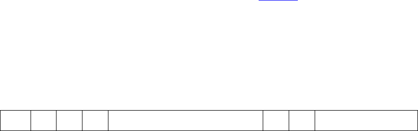
May 18, 2011 UVM 1.1 User’s Guide 107
Block b1 "b1"
Block b2 "b1.b2_a", "b1.b2_b"
Register r1 "b1.b2_a.r1", "b1.b2_b.r1"
Register r2 {"b1.b2_a.r2_1", "b1.b2_a.r2_0"},
{"b1.b2_b.r2_1", "b1.b2_b.r2_0"}
Block b3 n/a
Register r3 "b1.r3.z", {" b1.r3_1", "b1.r3_0"}
HDL path components are specified using the following methods:
a) uvm_reg_block::configure() and uvm_reg_block::add_hdl_path()
b) uvm_reg_file::configure() and uvm_reg_file::add_hdl_path()
c) uvm_reg::configure() and uvm_reg::add_hdl_path_slice()
d) uvm_mem::configure() and uvm_mem::add_hdl_path_slice()
The HDL path for a register or memory may be a concatenation of simple names. This is used when the
register is implemented or modelled as a concatenation of individual fields variables, or when the memory is
implemented or modelled using vertical banking. When specifying a concatenation, the bits may be left
unspecified if they are not physically implemented.
For example, the register with the implementation illustrated in Figure 27 has its HDL path component
specified using the following concatenation:
rg.add_hdl_path_slice(“RDY”, 15, 1);
rg.add_hdl_path_slice(“ID”, 6, 6);
rg.add_hdl_path_slice(“COUNT”, 0, 4);
Figure 27—Composite Register Structure
HDL paths are created by concatenating each path component from the root block to the leaf register or
memory. However, if a block HDL path component is defined has a root HDL path component, the HDL
path component of any blocks above it are ignored.
5.6.3 VPI-based Back-door Access
The UVM register library provides a default back-door access mechanism that uses the HDL path(s)
returned by the uvm_reg::get_full_hdl_path() and uvm_reg::get_full_hdl_path()
methods for the default design abstraction. Using standard SystemVerilog VPI routines, it samples or
deposits values in the HDL constructs referenced by the resulting hierarchical HDL paths. If the HDL paths
are valid hierarchical SystemVerilog variables, including indexing and slicing operators, this should work
without any further requirements.
5.6.3.1 Including the DPI C Library
The implementation of the default back-door access mechanism requires the inclusion of some DPI C code.
Please refer to the supplementary UVM documentation provided by your simulator vendor on how to
compile and link the UVM C library.
COUNTRDY ID
03615 11
108 UVM 1.1 User’s Guide May 18, 2011
5.6.3.2 Performance Issues with the VPI-based Back-door Access
Enabling the VPI functionality required by the default back-door access mechanism may disable
performance optimizations normally done in your simulator. Please refer to the supplementary UVM
documentation provided by your simulator vendor for additional or alternative steps that may be taken to
improve the performance of your simulation.
5.6.4 User-defined Back-door Access
Should the DPI-based back-door access prove to be insufficient, a user-defined back-door access can be
used instead. A user-defined back-door access is able to use any SystemVerilog constructs or tool-specific
utility to access registers and memories. For example, if a memory or register is located in an encrypted
model, a user-defined back-door may be used to peek and poke values directly into the encrypted model via
a suitable API.
A user-defined register back-door is provided through an extension of the uvm_reg_backdoor class. A
back-door write operation is implemented in the uvm_reg_backdoor::write() virtual method
whereas a back-door read operation is implemented in the uvm_reg_backdoor::read() virtual
method. This back-door access is then associated with a specific register through the
uvm_reg::set_backdoor() method or with all the registers within a block using the
uvm_reg_block::set_backdoor() method.
A user-defined memory back-door is provided through an extension of the uvm_mem_backdoor class. A
back-door write operation is implemented in the uvm_mem_backdoor::write() virtual method
whereas a back-door read operation is implemented in the uvm_mem_backdoor::read() virtual
method. This back-door access is then associated with a specific memory through the
uvm_mem::set_backdoor() method.
User-defined back-door access mechanisms may be defined by the register model generators. They are
instantiated and associated with their corresponding block, register, or memory abstraction class in the
implementation of their respective build() method. User-defined back-door access mechanisms may also
be registered with their corresponding block, register, or memory after the register model construction,
overriding any previously defined (or default) back-door access mechanisms. In the latter case, they are
instantiated and associated with their corresponding block, register, or memory abstraction class in the
implementation of the environment’s build() method.
function void tb_env::build();
super.build();
...
begin
my_mem_backdoor bkdr = new;
regmodel.mem.set_backdoor(bkdr);
end
endfunction: build
5.6.5 Back-door Access for Protected Memories
The content of memories may be protected using one or more protection schemes. They can vary from
simple additional bits providing an Error Correction Code to full encryption of its content.
When performing back-door write operations, it is necessary to correctly protect the memory content to
avoid errors when a physical interface subsequently reads these memory locations. It may also be useful or

May 18, 2011 UVM 1.1 User’s Guide 109
necessary to have direct access to the protected form because these bits are created and used entirely within
the design, and can only be accessed through back-door access. The back-door is the only way protected
values can be checked and protection errors injected.
The encode() and decode() callback methods located in the uvm_mem_backdoor_cbs class are
designed to handle such data protection. The encode() method is applied on the way in and the
decode() method is applied on the way out. But, unlike regular callback methods, the decoding is done in
the reverse order of registration. This allows multiple layers of data protections to be implemented in the
same memory, each modelled using a single callback extension. The order of registration determines the
order in which the various layers of protections are applied—then undone.
For example, ECC bits are located in additional memory bits within the same memory location as the data
they protect; they must be generated and set for write accesses, and must checked and masked when read.
class ecc_protected extends uvm_mem_backdoor_cbs;
virtual function uvm_reg_data_t encode(uvm_reg_data_t data);
// Append the ECC bits to the data to write
data[35:32] = ecc::compute(data[31:0]);
return data;
endfunction
virtual function uvm_reg_data_t decode(uvm_reg_data_t data);
// Check and mask the ECC bits to the data to write
if (data[35:32] != ecc::compute(data[31:0])) ‘uvm_error(...)
return data[31:0];
endfunction
endclass
Similarly, data written to an encrypted memory must be ciphered during write accesses and deciphered
when read.
class encrypted_mem extends uvm_mem_backdoor_cbs;
virtual function uvm_reg_data_t encode(uvm_reg_data_t data);
return crypt::encrypt(data);
endfunction
virtual function uvm_reg_data_t decode(uvm_reg_data_t data);
return crypt::decrypt(data);
endfunction
endclass
5.6.6 Active Monitoring
The mirrored field values in a register model are updated when the fields are accessed through the register
model based on the current mirrored value, the accessed data value, and the access policy of the field. They
may also be updated based on observed read and write transactions on the bus interface if the register model
is integrated with the bus monitor and explicit monitoring is enabled (see Section 5.9.3). Any changes to the
field value performed by the design itself cannot be detected and then mirrored in the register model.
110 UVM 1.1 User’s Guide May 18, 2011
The back-door mechanism can be used to automatically update the mirror value of fields that are modified
by the design itself by observing the SystemVerilog constructs which are used to store the field values.
When a change of value is detected, the mirrored value can be similarly updated.
Because there is no standard value-change callback VPI or PLI functionality, the automatic update of a field
can only be implemented using a user-defined back-door. The active monitoring of a register requires the
implementation of the uvm_reg_backdoor::is_auto_updated() and
uvm_reg_backdoor::wait_for_change() methods.
uvm_reg_backdoor::is_auto_updated() returns TRUE if the specified named field is actively
monitored. All actively-monitored fields have their mirror value updated strictly and only through the active
mirroring mechanism. Executed or observed transactions are not used to update their mirrored value.
The uvm_reg_backdoor::wait_for_change() task must return only when a change in any of the
actively-monitored fields is observed. For each actively-monitored register, a thread calls this task to wait
for any change in any of the fields in the register. As soon as it returns, their values are sampled and their
mirror values updated. The implementation of that method should not simply wait for the active edge of the
clock signal used to update the field values in the design; for optimal performance, the implementation of
that method should only return when an actual change occurs.
class active_monitor_r1 extends uvm_reg_backdoor;
virtual function bit is_auto_updated(string fld_name);
case (fld_name)
"f1": return 1;
"f2": return 1;
endcase
endfunction
virtual task wait_for_change();
@($root.tb_top.dut.rf.f1 or $root.tb_top.dut.rf.f2);
endtask
endclass
The active-monitoring thread must be started for each actively-monitored register by invoking the
uvm_reg_backdoor::start_update_thread() method of its back-door access class once an
instance of that back-door access class is created, as shown in the following example:
class add_active_monitors extends my_blk;
virtual function build();
super.build();
begin
active_monitor_r1 am_r1 = new;
r1.set_backdoor(am_r1);
am_r1.start_update_thread(r1);
end
endfunction
endclass
5.7 Special Registers
The UVM register library presumes all registers and memories are average registers and memories, they are
accessible at a known, constant, unique physical address(es), their behavior is constant throughout the
simulation regardless of the physical interface used to access them, and they contain a single value.
May 18, 2011 UVM 1.1 User’s Guide 111
Designer creativity, the demands of the application, or implementation constraints often require special
behaviors be implemented. Special register behavior can be modeled using any number of extension
capabilities provided in the UVM register and field abstraction classes. Pre- and post-read/write callback
objects, virtual callback methods, user-defined front-doors, and user-defined back-doors may be used to
extend the behavior of the base library. And, if all else fails, it is always possible to override virtual methods
that are used to access the register content, i.e., read(), write(), peek(), and poke().
5.7.1 Pre-defined Special Registers
The UVM library pre-defines some commonly used special registers. A register model generator is free to
provide a library of additional special register models and use them in its generated model.
5.7.1.1 Indirect Indexed Registers
Some registers are not directly accessible via a dedicated address. Indirect access of an array of such
registers is accomplished by first writing an “index” register with a value that specifies the array’s offset,
followed by a read or write of a “data” register to obtain or set the value for the register at that specified
offset. The pre-defined uvm_reg_indirect_data class models the behavior the “data” register.
A “data” register type is defined by extending the uvm_reg_indirect_data register class. The “data”
register must not contain any fields. The “index” and indirect register array must be built first, as the “index”
registers and the register array are specified when the “data” register is configured using the
uvm_reg_indirect_data::configure() method. The indirect register array, “index”, and “data”
registers are added as members of the containing block. However, only the “index” and “data” registers are
added to a map in the containing block. The registers in the indirect register array must be not added to the
address map in the containing block because they have no dedicated address.
class my_blk_type extends uvm_reg_block;
ind_idx_reg IND_IDX;
ind_data_reg IND_DATA;
ind_reg INDIRECT_REG[256];
virtual function build();
foreach (INDIRECT_REG[i]) begin
string name = $sformatf("INDIRECT_REG[%0d]",i);
INDIRECT_REG[i]=
ind_reg::type_id::create(name,,get_full_name());
INDIRECT_REG[i].configure(this, null, ...);
INDIRECT_REG[i].build();
end
IND_IDX = ind_idx_reg::type_id::create(“IND_IDX”,,get_full_name());
IND_IDX.configure(this, null, ...);
IND_IDX.build();
IND_DATA = ind_data_reg::type_id::create(“IND_DATA”,,get_full_name());
IND_DATA.configure(IND_IDX, INDIRECT_REG, this, null);
IND_DATA.build();
default_map = create_map(““, 0, 4, UVM_BIG_ENDIAN);
default_map.add_reg(IND_IDX, 0);
default_map.add_reg(IND_DATA, 4);
endfunction
endclass

112 UVM 1.1 User’s Guide May 18, 2011
The registers in the indirect register array cannot be accessed via a back-door access to the “data” register.
Back-door access to the register array is provided by performing back-door accesses via the unmapped,
indirect register itself.
If a different indirection mechanism is required, a user-defined register extension will be necessary.
5.7.1.2 FIFO (first-in, first-out) Registers
A FIFO register is not a register in the usual sense. It is a FIFO whose push and pop operations are mapped
to write and read operations at a specific address. Writing to that address causes the data written to be
pushed at the end of the FIFO. Reading from that address returns the data that is currently at the head of the
FIFO and pops it. Whether the FIFO is full or empty is usually specified via status bits in another register.
To model a FIFO register, the register type shall be extended from the uvm_reg_fifo class. The
maximum number of entries in the FIFO and the size of each entry is specified when calling
super.new().
class fifo_reg extends uvm_reg_fifo;
function new(string name = "fifo_reg");
super.new(name,8,32,UVM_NO_COVERAGE);
endfunction: new
`uvm_object_utils(fifo_reg)
endclass
Backdoor access to a FIFO register is not allowed.
5.7.2 Unmapped Registers and Memories
By default, the entire register or memory is assumed to be linearly mapped into the address space of the
block that instantiates it. Each register or location in a memory thus corresponds to a unique address in the
block. However, you can use different addressing mechanisms. For example, you could access a large
memory in a limited address space using an indexing mechanism: the desired offset within the memory is
written into a register, then the data at that memory offset is read or written by reading or writing another
register. This memory is effectively unmapped: it does not appear in the linear address space used to access
it. See Section 5.7.1.1.
The number of possible access mechanisms is potentially infinite and only limited by the imagination,
requirements, and constraints of designers. To support arbitrary access mechanisms, it is possible to replace
the default linearly mapped access mechanism with any user-defined access mechanism.
5.7.2.1 User-defined Front-door Access
User-defined front-door access is made possible by extending the uvm_reg_frontdoor class and
registering an instance of the class with specific registers or memories using the
uvm_reg::set_frontdoor() or uvm_mem::set_frontdoor() method. The
uvm_reg_frontdoor is a uvm_sequence. For each write or read operation, the register model creates
a uvm_reg_item object representing the operation, assigns it to the rw_info property of registered
front-door sequence, and calls its start method. Ultimately, the front-door’s body task is called, which
must be implement to perform the actual operation.
May 18, 2011 UVM 1.1 User’s Guide 113
class indexed_reg_frontdoor extends uvm_reg_frontdoor;
local uvm_reg m_idx_reg;
local uvm_reg m_data_reg;
local bit [7:0] m_addr;
function new(string name=”indexed_reg_frontdoor_inst”);
super.new(name);
endfunction
function void configure(uvm_reg idx, uvm_reg data, bit [7:0] addr);
m_idx = idx;;
m_data = data;
m_addr = addr;
endfunction: new
virtual task body(uvm_reg_item rw);
m_idx_reg.write(status, m_addr, ...);
if (status != UVM_IS_OK)
return;
if (rw.kind == UVM_WRITE)
m_data.write(rw.status, data, ...);
else
m_data.read(rw.status, data, ...);
endtask
endclass
User-defined front-doors are instantiated and associated with their corresponding register or memory
abstraction class in the build() method of the block or register file that instantiates them or the build()
phase callback of the environment component where the register model is instantiated and built.
virtual function void build();
foreach TABLE[i] begin
indexed_reg_frontdoor idx_frtdr = new(INDEX, DATA, i);
= idx_reg_frontdoor::type_id::create(“idx_frtdr”,,get_full_name());
idx_frntdoor.configure(idx_reg, data_reg, i);
regmodel.TABLE[i].set_frontdoor(idx_frontdoor, default_map, ...);
end
endfunction: build
A user-defined front-door is registered on a per-map basis, affecting the access of a register or memory
through a specific physical interface. A different front-door mechanism (or the built-in one) can be used for
other physical interfaces. For example, a memory could use the indexed addressing scheme described above
for one physical interface but be mapped normally within the address map of another physical interface.
5.7.2.2 Mirroring Unmapped Registers
When using explicit or passive monitoring to update the mirror value in unmapped registers, it will be
necessary to override the uvm_reg::predict() method of the register(s) used to access the unmapped
registers, since the observed transactions will be using the address of those access registers, not the
unmapped (unaddressable) registers that are ultimately accessed.
In the case of an indirect register, the uvm_reg_indirect_data class extends predict for you and
serves as an example of how you do this for your custom unmapped registers.
function bit uvm_reg_indirect_data::predict (uvm_reg_data_t value, ...);
if (m_idx.get() >= m_tbl.size()) begin
114 UVM 1.1 User’s Guide May 18, 2011
`uvm_error(“Index reg > than size of indirect register array”)
return 0;
end
return m_tbl[m_idx.get()].predict(value, ...);
endfunction
5.7.3 Aliased Registers
Aliased registers are registers that are accessible from multiple addresses in the same address map. They are
different from shared registers as the latter are accessible from multiple address maps. Typically, the fields
in aliased registers will have different behavior depending on the address used to access them. For example,
the fields in a register may be readable and writable when accessed using one address, but read-only when
accessed from another.
Modelling aliased registers in UVM involves more than simply mapping the same register at two different
addresses. A UVM register model requires each instance of a uvm_reg class be mapped to a unique
address in an address map. For aliased registers, this requires a register class instance for each address. All
this enables using a specific register instance to access the aliased register via a specific address.
For example, the (incomplete) register model shown below models a register aliased at two addresses:
‘h0100 and ‘h0200. Each alias is known under a different instance name, Ra and Rb respectively. To
access the aliased register via address ‘h0100, the Ra instance would be used.
class my_blk extends uvm_reg_block;
rand my_reg_Ra Ra;
rand my_reg_Rb Rb;
virtual function build();
...
default_map.add_reg(Ra, ‘h0100);
default_map.add_reg(Rb, ‘h0200);
endfunction
endclass
Each register instance must be of a register type that models the behavior of the register and field it contains
of its corresponding alias. For example, a register that contains a field that is RW when accessed via one
address, but RO when accessed via another would require two register types: one with a RW field and another
one with a RW field, and both using the same field names.
class my_reg_Ra extends uvm_reg;
rand uvm_reg_field F1;
...
virtual function void build();
F1 = uvm_reg_field::type_id::create("F1");
F1.configure(this, 8, 0, "RW", 0, 8'h0, 1, 1, 1);
endfunction
...
endclass
class my_reg_Rb extends uvm_reg;
uvm_reg_field F1;
...
virtual function void build();
F1 = uvm_reg_field::type_id::create("F1");
F1.configure(this, 8, 0, "RO", 0, 8'h0, 1, 0, 1);
endfunction
May 18, 2011 UVM 1.1 User’s Guide 115
...
endclass
The aliasing functionality must be provided in a third class that links the two register type instances. The
aliasing class can make use of the pre-defined register and field callback methods to implement the aliasing
functionality. It may also make use of additional APIs or functionality created by the register model
generator in the different register types that model each alias of the register. The aliasing class should be
based on uvm_object to be factory-enabled. The required reference to the various register instance aliases
shall be supplied via a configure() method.
class write_also_to_F extends uvm_reg_cbs;
local uvm_reg_field m_toF;
function new(uvm_reg_field toF);
m_toF = toF;
endfunction
virtual function void post_predict(uvm_reg_field fld,
uvm_reg_data_t value,
uvm_predict_e kind,
uvm_path_e path,
uvm_reg_map map);
if (kind != UVM_PREDICT_WRITE) return;
void'(m_toF.predict(value, -1, UVM_PREDICT_WRITE, path, map));
endfunction
endclass
class alias_RaRb extends uvm_object;
protected reg_Ra m_Ra;
protected reg_Rb m_Rb;
`uvm_object_utils(alias_RaRb)
function new(string name = "alias_RaRb");
super.new(name);
endfunction: new
function void configure(reg_Ra Ra, reg_Rb Rb);
write_also_to_F F2F;
m_Ra = Ra;
m_Rb = Rb;
F2F = new(Rb.F1);
uvm_reg_field_cb::add(Ra.F1, F2F);
endfunction : configure
endclass : alias_RaRb
The register file or block containing the various register aliases shall also instantiate the aliasing class in its
build() method and call the configure() method with appropriate arguments.
class my_blk extends uvm_reg_block;
rand my_reg_Ra Ra;
rand my_reg_Rb Rb;
...
116 UVM 1.1 User’s Guide May 18, 2011
virtual function build();
default_map = create_map("", 0, 4, UVM_BIG_ENDIAN);
Ra = reg_Ra::type_id::create("Ra",,get_full_name());
Ra.configure(this, null);
Ra.build();
Rb = reg_Rb::type_id::create("Rb",,get_full_name());
Rb.configure(this, null);
Rb.build();
default_map.add_reg(Ra, ‘h0100);
default_map.add_reg(Rb, ‘h0200);
begin
alias_RaRb RaRb;
RaRb = alias_RaRb::type_id::create("RaRb",,get_full_name());
RaRb.configure(Ra, Rb);
end
endfunction
endclass
There are no pre-defined aliasing classes because the nature of the aliasing is highly variable, not just in how
the fields provide different behaviors through the various aliases, but potentially in their layout as well.
5.7.4 Unimplemented Registers
A UVM register model can model registers that are specified, but have not yet been implemented in the
DUV. This allows the verification environment and testcases to make use of these registers before they are
available.
Because these registers are unimplemented, there is nothing to actually read or write inside the DUT. Since
the mirror in a register abstraction class provides a faithful model of the expected behavior of that register, it
can be used to provide a read back value. A yet-to-be-implemented register is thus modelled by writing to
and reading from the mirror.
An unimplemented register can be modelled by providing a user-defined front- and back-door that access
the mirrored value instead of performing bus transactions.
class not_yet_implemented_fd extends uvm_reg_frontdoor;
...
virtual task body();
uvm_reg R;
$cast(R, rw_info.element);
if (rw_info.kind == UVM_READ) rw_info.value[0] = R.get();
R.predict(rw_info.value[0], -1,
(rw_info.kind == UVM_READ) ?
UVM_PREDICT_READ : UVM_PREDICT_WRITE,
rw_info.path,
rw_info.map);
endtask
endclass
May 18, 2011 UVM 1.1 User’s Guide 117
The user-defined front- and back-door shall be registered in the environment where the register model is
instantiated and clearly identified as temporary work-arounds.
virtual function void connect();
...
if (get_parent() == null) begin
not_yet_implemented_fd fd;
‘uvm_warning(“NotYetImpl”,
“Working around yet-to-be-implemented registers”);
fd = new;
regmodel.R2.set_frontdoor(fd);
end
endfunction
5.7.5 RO and WO Registers Sharing the Same Address
It is possible for a register containing only write-only fields (WO, WOC, WOS, and WO1) to share the same
address with another register containing only read-only fields (RO, RC, and RS). The fields in each register
are unrelated and can have different layouts.
This register structure is modelled by simply mapping both registers at the same address. Only one read-only
register and one write-only register may be mapped at the same address. Once mapped, calling the
uvm_reg::read() method on a write-only register or calling the uvm_reg::write() method on a
read-only register will cause an error message to be issued, the operation will be aborted, and UVM_NOT_OK
will be returned as the status. Back-door poke and peek are allowed on read-only and write-only registers
respectively.
class block_B extends uvm_reg_block;
rand reg_RO R;
rand reg_WO W;
...
virtual function void build();
default_map = create_map("", 0, 4, UVM_BIG_ENDIAN);
R = reg_RO::type_id::create("R");
R.configure(this, null, "R_reg");
R.build();
W = reg_WO::type_id::create("W");
W.configure(this, null, "W_reg");
W.build();
default_map.add_reg(R, 'h100, "RO");
default_map.add_reg(W, 'h100, "WO");
endfunction : build
...
endclass
5.8 Integrating a Register Model in a Verification Environment
Test sequences, whether pre-defined or user-defined ones, need a verification environment in which to
execute. The register model needs to be an integral part of that verification environment to be used by the
tests to access registers and memories in the DUT.
118 UVM 1.1 User’s Guide May 18, 2011
An environment must have a reference to the register model that corresponds to the DUT it verifies. It is
recommended a class property named regmodel be used for that purpose. To enable vertical reuse of the
environment, it must first check if its register model has been defined by a higher-level environment. If not,
it must be allocated using the class factory, explicitly built by calling its build() method, then it calls the
uvm_reg_block::lock_model() method. After creating any sub-block environments, their register
models must then be specified by setting their respective regmodel class properties. All of this must be
implemented in the environment’s build() method.
class block_env extends uvm_env;
block_reg_model regmodel;
subblk_env subblk;
virtual function void build();
if (regmodel == null) begin
regmodel = block_reg_model::type_id::create(“regmodel”, this);
regmodel.build();
regmodel.lock_model();
end
subblk = subblk_env::type_id::create(“subblk”, this);
subblk.regmodel = regmodel.subblk;
endfunction
endclass
If HDL paths are used, the root HDL paths must be specified in the environment that instantiates the register
model. The value of that root path will depend on the location of the model for the DUT within the complete
simulation model.
class block_env extends uvm_env;
block_reg_model regmodel;
virtual function void build();
if (regmodel == null) begin
regmodel = block_reg_model::type_id::create(“regmodel”, this);
regmodel.build();
regmodel.set_hdl_path_root(“tb_top.dut”);
end
endfunction
endclass
5.9 Integrating a Register Model
A register model must be integrated with the bus agents that perform and monitor the actual read and write
operations. The terms “bus driver”, “bus agent”, “bus interface” and “bus operations” are used to describe
the components, protocol, and interface associated with the execution of read and write operations on the
DUT. The integration may be established via a non-bus-based interface and protocol.
The integration with the bus agent must only be done on root blocks. Root blocks model the entire DUT and
they are the only ones who have access to and knowledge of the externally-visible address maps. Lower-
level register models will translate their read and write operations in terms of read and write operations at the
root block level, using root-level addresses and bus protocols.
To that end, the integration process must be conditional to the register model being a root register model.
This is accomplished by checking if the register model has a parent. If not, it is a root model and integration
with the bus agent may proceed. All this must be implemented in the environment’s connect() method.
class block_env extends uvm_env;
May 18, 2011 UVM 1.1 User’s Guide 119
block_reg_model regmodel;
subblk_env subblk;
virtual function void connect();
if (regmodel.get_parent() == null) begin
// Integrate register model with bus agent
...
end
endfunction
endclass
There are three structural bus agent integration approaches for keeping the register model’s mirror values in
sync with the DUT: implicit prediction, explicit prediction, and passive.
Implicit prediction only requires the integration of the register model with one or more bus sequencers.
Updates to the mirror are predicted automatically (i.e., implicitly) by the register model after the completion
of each read, write, peek, or poke operation. This integration is the simplest and quickest, but it will fail to
observe bus operations that did not originate from the register model (e.g., by a third-party bus agent) and
thus fail to appropriately update the corresponding mirror values.
Explicit prediction requires the register model be integrated with both the bus sequencers and corresponding
bus monitors. In this mode, implicit prediction is turned off and all updates to the mirror are predicted
externally (i.e., explicitly) by a uvm_reg_predictor component, one for each bus interface. The
predictor receives the bus operations observed by a connected bus monitor, determines the register being
accessed by performing a reverse-lookup using the observed address, and then calls the found register’s
predict method explicitly to update the mirror. This integration requires more work, but it will observe all
bus operations, whether they originated from the register model or a third-party bus agent, and thus
appropriately update the corresponding mirror values.
Passive integration only requires the integration of the register model with the bus monitor as described
above. All the monitoring of the register operations is performed externally to (i.e., explicitly) the register
model. All bus operations, whether they originated from the register model or a third-party bus agent, are
observed and thus appropriately reflected in the corresponding mirror values. Because the register model is
not integrated with a bus sequencer, it cannot be used to read and write register and memories in the DUT,
only to track and verify their current value.
5.9.1 Transaction Adapter
The first step in integrating a register model with a bus agent are the conversion functions between a generic
read/write bus operation descriptor, uvm_reg_bus_op, used by the register model and the protocol-
specific read/write transaction descriptor used by the bus agent.
The transaction adapter is implemented by extending the uvm_reg_adapter class and implementing the
reg2bus() and bus2reg() methods. Being a uvm_object, the bus adapter must implement a suitable
uvm_object constructor and use the ‘uvm_object_utils() macro to enable it for the class factory.
class reg2apb_adapter extends uvm_reg_adapter;
`uvm_object_utils(reg2apb_adapter)
function new(string name = "reg2apb_adapter");
super.new(name);
endfunction
120 UVM 1.1 User’s Guide May 18, 2011
virtual function uvm_sequence_item reg2bus(const ref uvm_reg_bus_op rw);
apb_rw apb = apb_rw::type_id::create("apb_rw");
apb.kind = (rw.kind == UVM_READ) ? apb_rw::READ : apb_rw::WRITE;
apb.addr = rw.addr;
apb.data = rw.data;
return apb;
endfunction
virtual function void bus2reg(uvm_sequence_item bus_item,
ref uvm_reg_bus_op rw);
apb_rw apb;
if (!$cast(apb,bus_item)) begin
`uvm_fatal("NOT_APB_TYPE",
"Provided bus_item is not of the correct type")
return;
end
rw.kind = apb.kind ? UVM_READ : UVM_WRITE;
rw.addr = apb.addr;
rw.data = apb.data;
rw.status = UVM_IS_OK;
endfunction
endclass
If the bus protocol supports byte lane enables (i.e., it is possible to read or write individual bytes in a multi-
byte bus), the supports_byte_enable class property should be set to TRUE in the constructor.
Similarly, the provides_responses class property should be set to TRUE if the bus driver returns
responses, e.g., the result of a read operation, in a separate response descriptor:
class reg2apb_adapter extends uvm_reg_adapter;
function new(string name = “”);
super.new(name);
supports_byte_enables = 0;
provides_responses = 1;
endfunction
endclass
Because this transaction adapter is specific to the bus agent, not the register model, it should be provided as
part of a UVM-compliant bus UVC.
The transaction adapter is then instantiated in the connect() method of the environments corresponding
to root register models:
class block_env extends uvm_env;
block_reg_model regmodel;
subblk_env subblk;
virtual function void connect();
...
if (regmodel.get_parent() == null) begin
reg2apb_adapter reg2apb =
reg2apb_adapter::type_id::create(“reg2apb”,,get_full_name());
...
end
endfunction
endclass
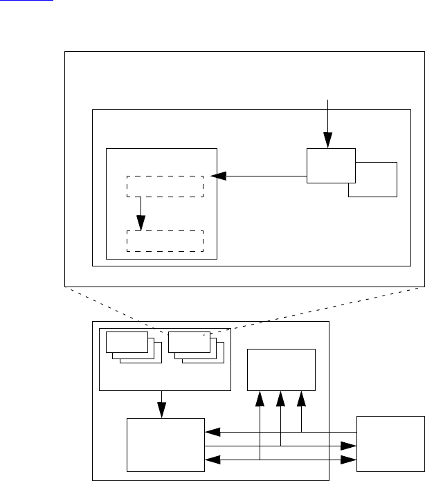
May 18, 2011 UVM 1.1 User’s Guide 121
5.9.2 Integrating Bus Sequencers
All integration approaches require a register model be configured with one or more bus sequencers. The
register model becomes a property of a uvm_reg_sequence subtype that executes
a) directly on a bus sequencer, if there is only one bus interface providing access to the DUT registers;
b) as a virtual sequence, if there are one or more bus interfaces providing access to the DUT registers;
c) as a register sequence running on a generic, bus-independent sequencer, which is layered on top of a
downstream bus sequencer.
Note—To keep the code examples that follow succinct and focused on register model integration, we do not show
obtaining handles via configuration or the resources database, or a priori sequence registration to a specific sequencer.
5.9.2.1 Register Sequence Running on the Bus Sequencer
The simplest approach is to run register sequences directly on the bus sequencer, competing directly with all
other “native” bus sequences concurrently running on the bus sequencer. The register sequence will, via the
register model, produce bus sequence stimulus using a preconfigured bus adapter. This approach is suitable
for when the registers being accessed by the register sequence are accessible via a single bus interface, as
shown in Figure 28.
Figure 28—Register Sequence Running Directly on a Bus Sequencer
Implementing this approach is accomplished by registering the bus sequencer and corresponding transaction
adapter with the appropriate address map in the register model. The model is registered with the user-
DUT
register model
monitor
driver
bus sequencer
bus agent
adapter
sequencer
address map
register sequence task body();
model.regA.write(47);
uvm_reg_item
bus item(s)
regA
regB
endtask
bus seq reg seq
122 UVM 1.1 User’s Guide May 18, 2011
defined register sequence and the sequence started on the bus sequencer. As with any other running bus
sequence, the register sequence’s is_relevant, pre_do, mid_do, and post_do methods are called
during execution of each bus item generated by the model. To gain exclusive access to the bus, the register
sequence may also call grab or lock to prevent other bus sequences from running.
class block_env extends uvm_env;
block_reg_model regmodel;
apb_agent apb;
virtual function void connect();
if (regmodel.get_parent() == null) begin
reg2apb_adapter reg2apb =
reg2apb_adapter::type_id::create(“reg2apb”,,get_full_name());
regmodel.APB.set_sequencer(apb.sequencer, reg2apb);
regmodel.set_auto_predict(1);
end
...
endfunction
...
endclass
The above example registers an APB bus sequencer and APB-specific bus adapter with the APB address
map defined in top-level register model. If the register model defines only a single map, the map may be
referenced via the handle default_map.
You define a register sequence by extending uvm_reg_sequence and defining the body() task to use
the model property.
class my_reg_sequence extends uvm_reg_sequence;
`uvm_object_utils(my_reg_sequence)
block_reg_model model;
virtual task body();
uvm_status_e status;
uvm_reg_data_t data;
model.A.write(status, 'h33, .parent(this));
if (status == UVM_NOT_OK)
‘uvm_error(...)
model.A.read(status, data, .parent(this));
if (data != ‘h33)
‘uvm_error(...)
endtask
endclass
The uvm_reg_sequence class parameterizes its base class. This allows you to splice in any user-defined
uvm_sequence subtype if needed:
class VIP_sequence extends uvm_sequence #(VIP_base_item);
class my_reg_sequence extends uvm_reg_sequence (VIP_sequence);
Alternatively, you can promote the parameter to your register sequence, which allows the end-user to choose
the super class:
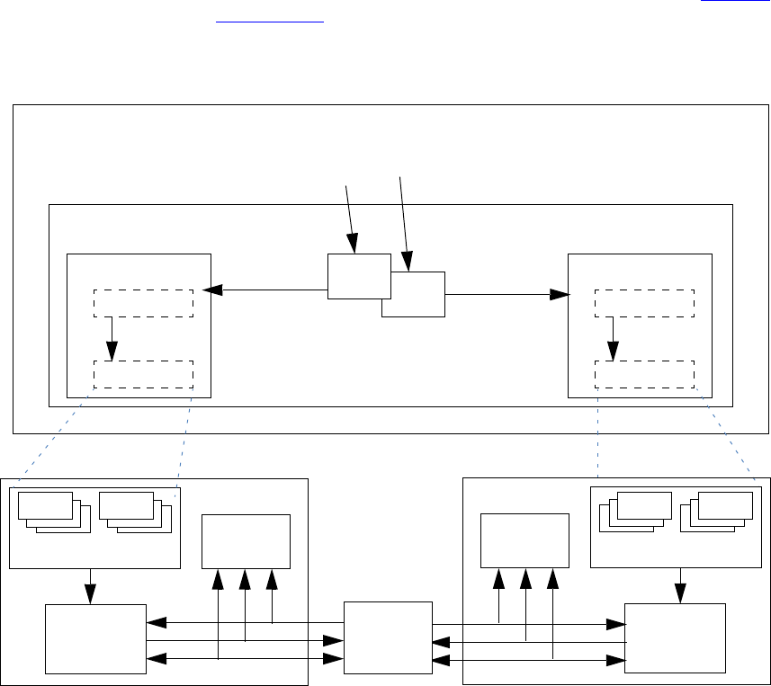
May 18, 2011 UVM 1.1 User’s Guide 123
class my_reg_sequence #(type BASE=uvm_sequence #(uvm_reg_item))
extends uvm_reg_sequence #(BASE);
To run the register sequence, assign the sequence model property and start it on the bus sequencer:
class my_test extends uvm_test;
block_env env;
virtual function void run();
my_reg_sequence seq = my_reg_sequence::type_id::create(“seq”,this);
seq.start(env.apb.master);
endfunction
endclass
5.9.2.2 Register Sequence Running as a Virtual Sequence
When the registers in the DUT become accessible via more than one physical bus interface, the same
register sequence may instead be started as a virtual sequence as the sequencer used in each write/read call is
not directly referenced. The register model routes the operation to the appropriate sequencer based on which
map is in effect.
Consider a register model with two registers accessible via different bus interfaces, as shown in Figure 29.
As in the previous example in Section 5.9.2.1, the sequence calls write and read on regA and regB without
referring to a map or sequencer.
Note—Write and read calls have an optional map argument, but specifying a map explicitly would limit sequence reuse.
Figure 29—Register Sequence Running as a Virtual Sequence
register model
ymonitor
ydriver
ybus sequencer
ybus agent
adapter
sequencer
address mapY
register sequence
task body();
model.regA.write(47);
uvm_reg_item
ybus item(s)
regA
regB
model.regB.read(value);
bus seq reg seq
(virtual)
adapter
sequencer
address mapZ
zbus item(s)
uvm_reg_item
endtask
zmonitor
zdriver
zbus sequencer
zbus agent bus seqreg seq
DUT
124 UVM 1.1 User’s Guide May 18, 2011
The only difference between this and running directly on a bus sequencer is more than one sequencer/
adapter pair is registered with the register model and the register sequence’s start method is called
without specifying a sequencer to run.
class block_env extends uvm_env;
block_reg_model regmodel;
apb_agent apb;
wishbone_agent wsh;
virtual function void connect();
if (regmodel.get_parent() == null) begin
reg2apb_adapter reg2apb =
reg2apb_adapter::type_id::create(“reg2apb”,,get_full_name());
reg2wsh_adapter reg2wsh =
reg2wsh_adapter::type_id::create(“reg2wsh”,,get_full_name());
regmodel.APB.set_sequencer(apb.sequencer, reg2apb);
regmodel.WSH.set_sequencer(wsh.sequencer, reg2wsh);
regmodel.set_auto_predict(1);
end
...
endfunction
...
endclass
A register model having more than one configured interface offers interesting timing possibilities. For
example, if two registers are accessible via different busses, their accesses can be concurrent:
class my_reg_sequence extends uvm_reg_sequence;
`uvm_object_utils(my_reg_sequence)
block_reg_model model;
virtual task body();
uvm_status_e status;
fork
model.APB.write(status, 'h33, .parent(this));
model.WSH.read(status, ‘h66, .parent(this));
join
endtask
endclass
To run the register sequence, register the model and start it without specifying a particular sequencer:
class my_test extends uvm_test;
block_env env;
virtual function void run();
my_reg_sequence seq = my_reg_sequence::type_id::create(“seq”,this);
seq.start(null);
endfunction
endclass
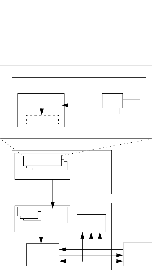
May 18, 2011 UVM 1.1 User’s Guide 125
If you needed to grab a particular sequencer for corner-case testing and were not concerned about creating a
dependency on a particular sequencer:
grab(regmodel.APB.get_sequencer());
...
ungrab(regmode.APB.get_sequencer());
5.9.2.3 Register Sequence Running on a Layered Register Sequencer
An alternative integration mechanism is to connect the register model with a register sequencer, then layer
that register sequencer on top of the bus sequencer, as shown in Figure 30. The register operations will
“execute” as abstract sequence items on the register sequencer, allowing central, bus-independent control of
the register sequences. However, this also prevents register sequences from competing directly with or
having control over concurrently executing bus sequences (i.e., via grab and ungrab), mixing register and
bus-specific sequences and sequence item execution within the same sequence, and being notified of bus-
specific operations (via pre_do, mid_do, post_do, and is_relevant). This process also only works
with a single bus interface, as all register operations are funneled through a single register sequence.
Figure 30—Register Sequence Running on a Layered Register Sequencer
register model
register sequencer
reg agent
sequencer
address map
register sequence
uvm_reg_item regA
regB
pure register
DUT
monitor
driver
bus sequencer
bus agent
bus seq register
(optional)
translation
sequence
sequence
126 UVM 1.1 User’s Guide May 18, 2011
In this scheme, you are effectively moving the built-in register-to-bus item conversion and bus item
execution from the register model to an external translation sequence, which can be overridden to perform
custom address translation or item conversions. The register model sends abstract uvm_reg_item
descriptors to the register sequencer. It is the responsibility of the translation sequence running on the bus
sequencer to get these abstract items and convert them to physical bus items and start them on the bus
sequencer. The uvm_reg_sequence base class provides this functionality. It parameterizes its base class
to enable it to run on bus-specific sequencers.
This is implemented in the connect phase by first registering a uvm_reg_item sequencer and null
adapter with the address map corresponding to the bus being targeted. In a single-map model, the
default_map is typically used.
You then create an instance of a translation sequence and configure it with the register sequencer handle and
bus adapter. The pre-defined layering sequence uvm_reg_sequence, properly parameterized and
configured, may be used in this step.
Then, in the run phase, you start the translation sequence on the bus sequencer.
// translation sequence type
typedef uvm_reg_sequence #(uvm_sequence #(apb_rw)) reg2apb_seq_t;
class block_env extends uvm_env;
block_reg_model regmodel;
uvm_sequencer#(uvm_reg_item) reg_seqr;
apb_agent apb;
reg2apb_seq_t reg2apb_seq;
virtual function void connect();
if (regmodel.get_parent() == null) begin
regmodel.default_map.set_sequencer(reg_seqr,null);
reg2apb_seq = reg2apb_seq_t::type_id::create(“reg2apb_seq”,,
get_full_name());
reg2apb_seq.reg_seqr = reg_seqr;
reg2apb_seq.adapter =
reg2apb_adapter::type_id::create(“reg2apb”,,
get_full_name());
regmodel.set_auto_predict(1);
end
endfunction
virtual task run();
reg2apb_seq.start(apb.sequencer);
endtask
endclass
To run a register sequence, you register the model and start it on the register sequencer:
class my_test extends uvm_test;
block_env env;
virtual function void run();
my_reg_sequence seq = my_reg_sequence::type_id::create(“seq”,this);
seq.start(env.reg_seqr);
endfunction
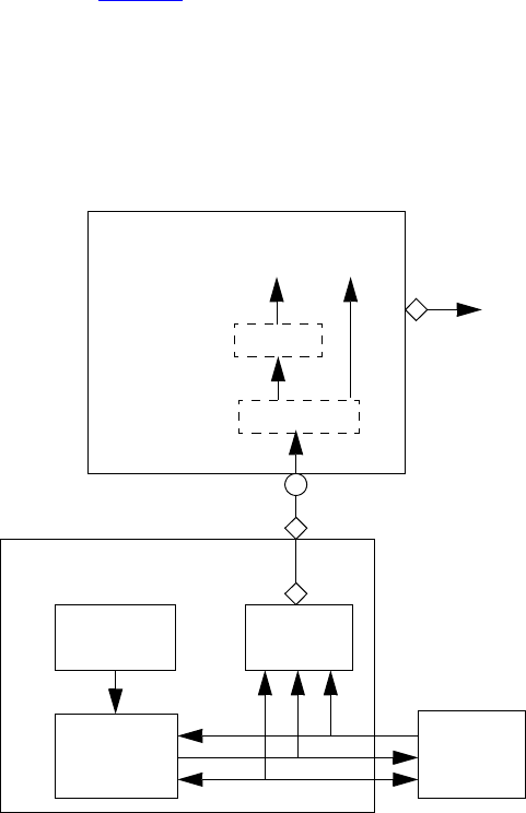
May 18, 2011 UVM 1.1 User’s Guide 127
endclass
5.9.3 Integrating the Register Model with a Bus Monitor
By default, the register model updates its mirror copy of the register values implicitly. Every time a register
is read or written through the register model, its mirror value is updated. However, if other agents on the bus
interface perform read and write transactions outside the context of the register model, the register model
must learn of these bus operations to update its mirror accordingly.
Integration of a bus monitor (see Figure 31) to make predictions based on observed transactions is
independent from how bus sequencers are integrated. All previously described bus sequencer integration
approaches may employ explicit, bus monitor-based prediction.
Figure 31—Integration with a Bus Monitor
The predictor accepts bus transactions from a connected bus monitor. It uses the preconfigured adapter to
obtain the canonical address and data from the bus operation. The map is used to lookup the register object
associated with that address. The register’s predict() method is then called with the observed data to
update the mirror value. If the register width is wider than the bus, the predictor will collect multiple
observed bus operations before calling predict() with the register’s full value. As a final step, a generic
uvm_reg_item descriptor representing the abstract register operation is broadcast to subscribers of its
analysis port.
DUT
predictor
monitor
driver
sequencer
bus agent
map
reg.predict(data)
register
adapter
address data
uvm_reg_item
128 UVM 1.1 User’s Guide May 18, 2011
Integration is accomplished by first instantiating a uvm_reg_predictor component, parameterized to
the bus transaction type, and configuring it with the adapter and address map in the register model that
corresponds to the bus being monitored. The uvm_reg_predictor component is then connected to the
bus monitor’s analysis port.
class block_env extends uvm_env;
block_reg_model regmodel;
uvm_reg_predictor#(apb_rw) apb2reg_predictor;
apb_agent apb;
virtual function void build();
...
apb2reg_predictor = new(“apb2reg_predictor”, this);
endfunction
virtual function void connect();
if (regmodel.get_parent() == null) begin
reg2apb_adapter reg2apb =
reg2apb_adapter::type_id::create(“reg2apb”,,get_full_name());
...
apb2reg_predictor.map = regmodel.APB;
apb2reg_predictor.adapter = reg2apb;
regmodel.APB.set_auto_predict(0);
apb.monitor.ap.connect(apb2reg_predictor.bus_in);
end
...
endfunction
...
endclass
When explicit prediction is employed, the implicit prediction must be turned off using
uvm_reg_map::set_auto_predict(0).
Note—For register models with a single address map, the name of the address map will be default_map.
5.10 Randomizing Field Values
A register model can specify constraints on field values. You can add additional constraints by extending the
field, register, register file, or block abstraction class and substituting it in the register model using the
factory or by using randomize() with {} when randomizing a field, register, register file, or block.
When constraining a field value, the class property to be constrained is named value. This is not the class
property that is eventually mirrored or updated and used by the get() and set() methods; it cannot be
used for purposes other than random constraints.
ok = regmodel.r1.randomize() with { f1.value <=‘hF; };
Once randomized, the selected field values in a register or block may be automatically uploaded to the DUT
by using the uvm_reg::update() or uvm_reg_block::update() method. This will upload any
randomized value that is different from the current mirrored value to the DUT. If you override the
post_randomize() method of a field abstraction class, you must call super.post_randomize()
to ensure the randomized value is properly set into the mirror.
You can relax constraints specified in a register model by turning the corresponding constraint block OFF.

May 18, 2011 UVM 1.1 User’s Guide 129
regmodel.r1.consistency.constraint_mode(0);
5.11 Pre-defined Sequences
Once a register model has been instantiated in an environment and integrated with the DUT, it is possible to
execute any of the predefined register tests sequences to verify the proper operation of the registers and
memories in the DUV. It is recommended you start with the simplest test—the hardware reset test—to
debug the register model, the environment, the physical transactors, and the DUV to a level where it can be
taken through more complicated tests. Some of the predefined test sequences require back-door access be
available for registers or memories.
The predefined test sequences in Table 13 are included in the register library. You can combine them in a
higher-level virtual sequence to better verify your design. Test sequences are not applied to any block,
register, or memory with the NO_REG_TESTS attribute defined. Refer to the UVM 1.1 Class Reference for
more details on each pre-defined test sequence.
Table 13—Pre-defined Test Sequences
Sequence Name Description Attributes
uvm_reg_hw_reset_seq Reads all the register in a block and
check their value is the specified reset
value.
Skip block or register if any of the
following attributes are defined:
NO_REG_HW_RESET_TEST
NO_REG_TESTS
uvm_reg_single_bit_bash_
seq
Sequentially writes 1’s and 0’s in each
bit of the register, checking it is appro-
priately set or cleared, based on the
field access policy specified for the
field containing the target bit.
Skip register if any of the follow-
ing attributes are defined:
NO_REG_BIT_BASH_TEST
NO_REG_TESTS
uvm_reg_bit_bash_seq Executes the uvm_reg_single_
bit_bash_seq sequence for all reg-
isters in a block and sub-blocks.
Skip block if any of the following
attributes are defined:
NO_REG_BIT_BASH_TEST
NO_REG_TESTS
uvm_reg_single_access_
seq
Requires the back-door be defined for
the register. For each address map in
which the register is accessible, writes
the register then confirms the value
was written using the back-door. Sub-
sequently writes a value via the back-
door and checks the corresponding
value can be read through the address
map.
Skip register if any of the follow-
ing attributes are defined:
NO_REG_ACCESS_TEST
NO_REG_TESTS
uvm_reg_access_seq Executes the uvm_reg_single_
access_seq sequence for all regis-
ters in a block and sub-blocks.
Skip block if any of the following
attributes are defined:
NO_REG_ACCESS_TEST
NO_REG_TESTS
uvm_mem_single_walk_seq Write a walking pattern into the mem-
ory then checks it can be read back
with the expected value.
Skip memory if any of the follow-
ing attributes are defined:
NO_MEM_WALK_TEST
NO_MEM_TESTS
NO_REG_TESTS

130 UVM 1.1 User’s Guide May 18, 2011
uvm_mem_walk_seq Executes the uvm_mem_single_
walk_seq sequence for all memories
in a block and sub-blocks.
Skip block if any of the following
attributes are defined:
NO_MEM_WALK_TEST
NO_MEM_TESTS
NO_REG_TESTS
uvm_mem_single_access_
seq
Requires the back-door be defined the
memory. For each address map in
which the memory is accessible, writes
the memory locations for each memory
then confirms the value was written
using the back-door. Subsequently
writes a value via the back-door and
checks the corresponding value can be
read through the address map.
Skip memory if any of the follow-
ing attributes are defined:
NO_MEM_ACCESS_TEST
NO_MEM_TESTS
NO_REG_TESTS
uvm_mem_access_seq Executes the uvm_mem_single_
access_seq sequence for all memo-
ries in a block and sub-blocks.
Skip block if any of the following
attributes are defined:
NO_MEM_ACCESS_TEST
NO_MEM_TESTS
NO_REG_TESTS
uvm_reg_shared_access_
seq
Requires the register be mapped in
multiple address maps. For each
address map in which the register is
accessible, writes the register via one
map then confirms the value was writ-
ten by reading it from all other address
maps.
Skip register if any of the follow-
ing attributes are defined:
NO_SHARED_ACCESS_TEST
NO_REG_TESTS
uvm_mem_shared_access_
seq
Requires the memory be mapped in
multiple address maps. For each
address map in which the memory is
accessible, writes each memory loca-
tion via one map then confirms the
value was written by reading it from all
other address maps.
Skip memory if any of the follow-
ing attributes are defined:
NO_SHARED_ACCESS_TEST
NO_MEM_TESTS
NO_REG_TESTS
uvm_reg_mem_shared_
access_seq
Executes the uvm_reg_shared_
access_seq sequence for all regis-
ters in a block and sub-blocks. Exe-
cutes the uvm_mem_shared_
access_seq sequence for all memo-
ries in a block and sub-blocks.
Skip block if any of the following
attributes are defined:
NO_SHARED_ACCESS_TEST
NO_MEM_TESTS
NO_REG_TESTS
uvm_reg_mem_built_in_seq Execute all the selected predefined
block-level sequences. By default, all
pre-defined block-level sequences are
selected.
Applies attributes governing each
predefined sequence, as defined
above.
uvm_reg_mem_hdl_paths_
seq
Verify the HDL path(s) specified for
registers and memories are valid.
Skip register or memory if no
HDL path(s) have been specified.
Table 13—Pre-defined Test Sequences (Continued)
Sequence Name Description Attributes
May 18, 2011 UVM 1.1 User’s Guide 131
6. Advanced Topics
This chapter discusses UVM topics and capabilities of the UVM Class Library that are beyond the essential
material covered in the previous chapters. Consult this chapter as needed.
6.1 The uvm_component Base Class
All the infrastructure components in an UVM verification environment, including environments and tests,
are derived either directly or indirectly from the uvm_component class. User-defined classes derived
from this class inherit built-in automation. Typically, you will derive your classes from the methodology
classes, which are themselves extensions of uvm_component. However, understanding the
uvm_component is important because many of the facilities that the methodology classes offer are
derived from this class.
NOTE—The uvm_threaded_component class has been deprecated in UVM and is now simply a typedef for
uvm_component.
The following sections describe some of the capabilities that are provided by the uvm_component base
class and how to use them.The key pieces of functionality provided by the uvm_component base class
include:
— Phasing and execution control
— Configuration methods
— Factory convenience methods
— Hierarchical reporting control.
6.2 The Built-In Factory and Overrides
6.2.1 About the Factory
UVM provides a built-in factory to allow components to create objects without specifying the exact class of
the object being creating. The factory provides this capability with a static allocation function that you can
use instead of the built-in new function. The function provided by the factory is:
type_name::type_id::create(string name, uvm_component parent)
Since the create() method is automatically type-specific, it may be used to create components or objects.
When creating objects, the second argument, parent, is optional.
A component using the factory to create data objects would execute code like the following:
task mycomponent::run_phase(uvm_phase phase);
mytype data; // Data must be mytype or derivative.
data = mytype::type_id::create("data");
$display("type of object is: %0s", data.get_type_name());
...
endtask
In the code above, the component requests an object from the factory that is of type mytype with an
instance name of data.
132 UVM 1.1 User’s Guide May 18, 2011
When the factory creates this object, it will first search for an instance override that matches the full instance
name of the object. If no instance-specific override is found, the factory will search for a type-wide override
for the type mytype. If no type override is found then the type created will be of type mytype.
6.2.2 Factory Registration
You must tell the factory how to generate objects of specific types. In UVM, there are a number of ways to
do this allocation.
—Use the `uvm_object_utils(T) or `uvm_component_utils(T) macro in a derivative
uvm_object or uvm_component class declaration, respectively. These macros expand code
which will register the given type with the factory. The argument T may be a parameterized type
`uvm_object_utils(packet)
‘uvm_component_utils(my_driver)
—Use the `uvm_object_registry(T,S) or `uvm_component_registry(T,S) registra-
tion macros. These macros can appear anywhere in the declaration space of the class declaration of
T and will associate the string S to the object type T. These macros are called by the corresponding
uvm_*_utils macros, so you may only use them if you do not use the ‘uvm_*_utils macros.
6.2.3 Component Overrides
A global factory allows you to substitute a predefined-component type with some other type that is
specialized for your needs, without having to derive the container type. The factory can replace a component
type within the component hierarchy without changing any other component in the hierarchy. You need to
know how to use the factory, but not how the factory works.
NOTE—All type-override code should be executed in a parent prior to building the child(ren). This means that environ-
ment overrides should be specified in the test.
Two interfaces, set_type_override_by_type and set_inst_override_by_type, exist to
replace default components. These interfaces will be examined one at a time.
To override a default component:
a) Define a class that derives from the appropriate UVM base class.
b) Execute the override (described in the following sections).
c) Build the environment.
6.2.3.1 Type Overrides
The first component override replaces all components of the specified type with the new specified type. The
prototype is.
set_type_override_by_type(orig_type, override_type, bit replace = 1);
The first argument (orig_type) is the type, obtained by calling the static get_type() method of the
type (orig_type:get_type()). That type will be overridden by the second argument
(override_type:get_type()). The third argument, replace, determines whether to replace an
existing override (replace = 1). If this bit is 0 and an override of the given type does not exist, the
override is registered with the factory. If this bit is 0 and an override of the given type does exist, the
override is ignored.
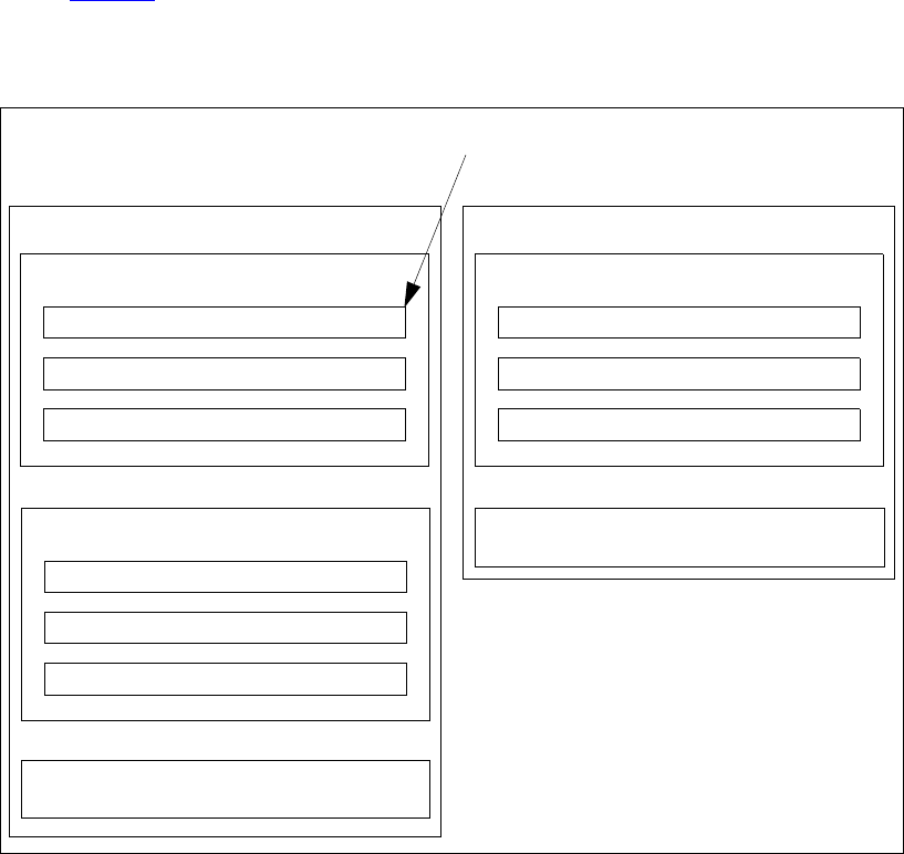
May 18, 2011 UVM 1.1 User’s Guide 133
If no overrides are specified, the environment will be constructed using default types. For example, the
environment would be created using an ubus_master_driver type component inside
ubus_master_agent.build(). The set_type_override_by_type interface allows you to
override this behavior in order to have an ubus_new_master_driver for all instances of
ubus_master_driver.
set_type_override_by_type(ubus_master_driver::get_type(),
ubus_new_master_driver::get_type);
This overrides the default type (ubus_master_driver) to be the new type
(ubus_new_master_driver). In this case, we have overridden the type that is created when the
environment should create an ubus_master_driver. The complete hierarchy would now be built as
shown in Figure 32.
NOTE—While only one ubus_master_driver instance is replaced in this example, any and all
ubus_master_driver instances would be replaced in an environment containing multiple
ubus_master_drivers
Figure 32—Hierarchy Created with set_type_override() Applied
6.2.3.2 Instance Overrides
The second component override replaces targeted components of the matching instance path with the new
specified type. The prototype for uvm_component is
set_inst_override_by_type(string inst_path, orig_type, override_type);
New type created by type override
ubus_demo_tb0
(ubus_demo_tb)
ubus0 (ubus_env)
masters[0] (ubus_master_agent)
monitor (ubus_master_monitor)
sequencer (ubus_master_sequencer)
driver (ubus_new_master_driver)
slaves[0] (ubus_slave_agent)
monitor (ubus_slave_monitor)
sequencer (ubus_slave_sequencer)
driver (ubus_slave_driver)
xserial0 (xserial_env)
tx (xserial_tx_agent)
bus_monitor (xserial_bus_monitor)
monitor (xserial_tx_monitor)
sequencer (xserial_tx_sequencer)
driver (xserial_tx_driver)
bus_monitor (ubus_bus_monitor)

134 UVM 1.1 User’s Guide May 18, 2011
The first argument, inst_path, is the relative component name of the instance override. It can be
considered the “target” of the override. The second argument, orig_type, is the type to be overridden
(specified by orig_type:get_type()) and replaced by the type specified by the last argument,
override_type (also using override_type:get_type()).
Assume the ubus_new_slave_monitor has already been defined. Once the following code is
executed, the environment will now create the new type, ubus_new_slave_monitor, for all instances
that match the instance path.
set_inst_override_by_type(“slaves[0].monitor”,
ubus_slave_monitor::get_type(), ubus_new_slave_monitor::get_type());
In this case, the type is overridden that is created when the environment should create an
ubus_slave_monitor for only the slaves[0].monitor instance that matches the instance path in
the override. The complete hierarchy would now be built as shown in Figure 33. For illustration purposes,
this hierarchy assumes both overrides have been executed.
Figure 33—Hierarchy Created with both Overrides Applied
NOTE—Instance overrides are used in a first-match order. For each component, the first applicable instance override is
used when the environment is constructed. If no instance overrides are found, then the type overrides are searched for
any applicable type overrides. The ordering of the instance overrides in your code affects the application of the instance
overrides. You should execute more-specific instance overrides first. For example,
set_inst_override_by_type("a.b.*", mytype::get_type(),
newtype::get_type());
New type created by type override
ubus_demo_tb0
(ubus_demo_tb)
ubus0 (ubus_env)
masters[0] (ubus_master_agent)
monitor (ubus_master_monitor)
sequencer (ubus_master_sequencer)
driver (ubus_new_master_driver)
slaves[0] (ubus_slave_agent)
monitor (ubus_new_slave_monitor)
sequencer (ubus_slave_sequencer)
driver (ubus_slave_driver)
xserial0 (xserial_env)
tx (xserial_tx_agent)
bus_monitor (xserial_bus_monitor)
monitor (xserial_tx_monitor)
sequencer (xserial_tx_sequencer)
driver (xserial_tx_driver)
New type created by instance override
bus_monitor (ubus_bus_monitor)

May 18, 2011 UVM 1.1 User’s Guide 135
set_inst_override_by_Type("a.b.c", mytype::get_type(),
different_type::get_type());
will create a.b.c with different_type. All other objects under a.b of mytype are created using newtype. If
you switch the order of the instance override calls then all of the objects under a.b will get newtype and the instance
override a.b.c is ignored.
set_inst_override_by_type("a.b.c", mytype::get_type(),
different_type::get_type());
set_inst_override_by_type("a.b.*", mytype::get_type(),
newtype::get_type());
6.3 Callbacks
Callbacks are an optional facility end users can use to augment component behavior
6.3.1 Use Model
To provide a callback facility to end-users, the component developer needs to:
a) Derive a callback class from the uvm_callback base. It should declare one or more methods that
comprise the “callback interface”.
b) Optionally, define a typedef to the uvm_callbacks pool typed to our specific component-call-
back combination.
c) Define the component to iteratively invoke the registered implementations of each method defined
in the callback class defined in Step (a) at the desired locations within a component main body of
code. Whether a function or a task is used is determined by the ability of the component’s code or
behavior to be suspended or not during its execution.
To use callbacks, the user needs to:
d) Define a new callback class extending from the callback base class provided by the developer, over-
riding one or more of the available callback methods.
e) Register one or more instances of the callback with the component(s) you wish to extend.
These steps are illustrated in the following simple example.
6.3.2 Example
The example below demonstrates callback usage. The component developer defines a driver component and
a driver-specific callback class. The callback class defines the hooks available for users to override. The
component using the callbacks (that is, calling the callback methods) also defines corresponding virtual
methods for each callback hook. The end-user may then define either a callback or a driver subtype to
extend driver’s behavior.
6.3.2.1 Developer Code
a) Define a callback class extending from uvm_callback.
The callback class defines an application-specific interface consisting of one or more function or
task prototypes. The signatures of each method have no restrictions. To be able to use the callback
invocation macros, functions should return void or bit type.
136 UVM 1.1 User’s Guide May 18, 2011
In the example below, a new bus_bfm_cb class extending from uvm_callback is defined. The
developer of the bus_bfm component decides to add two hooks for users, trans_received and
trans_executed:
1) trans_received—the bus driver calls this after it first receives a new transaction item. It
provides a handle to both itself and the new transaction. An additional argument determines
whether to drop (1) or execute (0) the transaction.
2) trans_executed—the bus driver calls this after executing the transaction, passing in a han-
dle to itself and the transaction, which may contain read data or other status information.
virtual class bus_driver_cb extends uvm_callback;
virtual function void trans_received(bus_driver driver, bus_tr tr,
ref bit drop);
endfunction
virtual task trans_executed(bus_driver driver, bus_tr tr);
endtask
function new(string name="bus_driver_cb");
super.new(name);
endfunction
endclass
b) Define a typedef to the uvm_callbacks pool typed to our specific component-callback com-
bination.
UVM callbacks are type-safe, meaning any attempt to register a callback to a component not
designed for that callback simply will not compile. In exchange for this type-safety we must endure
a bit of parameterized syntax as follows:
typedef uvm_callbacks #(bus_driver, bus_driver_cb) bus_driver_cb_pool;
The alias bus_driver_cb_pool can help both the component developer and the end-user pro-
duce more readable code.
c) Embed the callback feature in the component that will use it.
The developer of the bus_bfm adds the trans_received and trans_executed virtual methods,
with empty default implementations and utilizes some macros that implement the most common algorithms
for executing all registered callbacks. With this in place, end-users can now customize component behavior
in two ways:
— extend bus_driver and override one or more of the virtual methods trans_received or
trans_executed. Then configure the factory to use the new type via a type or instance override.
— extend bus_driver_cb and override one or more of the virtual methods trans_received or
trans_executed. Then register an instance of the new callback type with all or a specific
instance of bus_driver. The latter requires access to the specific instance of the bus_driver.
class bus_driver extends uvm_driver;
function new (string name, uvm_component parent=null);
super.new(name,parent);
endfunction
`uvm_register_cb(bus_driver, bus_driver_cb)
virtual function bit trans_received(bus_tr tr, ref bit drop);
endfunction
virtual task trans_executed(bus_tr tr);
endtask
virtual task run_phase(uvm_phase phase);
super.run_phase(phase);
forever begin
bus_tr tr;
bit drop = 0;
seq_item_port.get_next_item(tr);
May 18, 2011 UVM 1.1 User’s Guide 137
‘uvm_info("bus_tr received",tr.convert2string(), UVM_LOW)
trans_received(tr, drop);
‘uvm_do_callbacks(bus_driver_cb, bus_driver,
trans_received(this, tr, drop))
if (drop) begin
‘uvm_info("bus_tr dropped",
"user callback indicated DROPPED", UVM_HIGH)
return;
end
#100;
trans_executed(tt);
`uvm_do_callbacks(bus_driver_cb, bus_driver,
trans_executed(this, tr))
‘uvm_info("bus_tr executed", tr.convert2string(), UVM_LOW)
seq_item_port.item_done(tr);
end // forever
endtask
endclass
The driver’s put task, which implements the component’s primary functionality, merely calls the virtual
methods and callbacks at the appropriate times during execution.
6.3.2.2 End User Code
Using the callback feature of a component involves the following steps:
a) Extend the developer-supplied callback class.
Define a new callback class that extends from the class provided by the component developer,
implementing any or all of the methods of the callback interface.
In our example, we define both hooks, trans_received and trans_executed. For
trans_received, we randomly choose whether to return 0 or 1. When 1, the bus_driver
will “drop” the received transaction. For trans_executed, we delay #10 to prevent back-to-
back transactions.
class my_bus_bfm_cb extends bus_bfm_cb;
function new(string name="bus_bfm_cb_inst");
super.new(name);
endfunction
`uvm_object_utils(my_bus_bfm_cb)
virtual function bit trans_received(bus_bfm driver, bus_tr tr);
‘uvm_info_context("trans_received_cb",
{" bus_bfm=",driver.get_full_name(),"
tr=",tr.convert2string()}, UVM_LOW, driver)
return $urandom & 1;
endfunction
virtual task trans_executed(bus_bfm driver, bus_tr tr);
‘uvm_info("trans_executed_cb",
{" bus_bfm=",driver.get_full_name(),"
tr=",tr.convert2string()}, UVM_LOW, driver)
#10;
endtask
endclass
b) Create callback object(s) and register with component you wish to extend.
To keep the example simple and focus on callback usage, we do not show a complete or compliant
UVM environment.
In the top module, we instantiate the bus_bfm and an instance of our custom callback class. To
register the callback object with the driver, we first get a handle to the global callback pool for our

138 UVM 1.1 User’s Guide May 18, 2011
specific driver-callback combination. Luckily, the developer provided a convenient typedef in his
Step (b) that makes our code a little more readable.
Then, we associate (register) the callback object with a driver using the callback pool’s add_cb
method. After calling display_cbs to show the registration was successful, we push several
transactions into the driver. The output shows that the methods in our custom callback implementa-
tion are called for each transaction the driver receives.
module top;
bus_tr tr = new;
bus_bfm driver = new("driver");
my_bus_bfm_cb cb = new("cb");
initial begin
bd_cb::add(driver,cb);
cbs.display_cbs();
for (int i=1; i<=5; i++) begin
tr.addr = i;
tr.data = 6-i;
driver.in.put(tr);
end
end
endmodule
c) Instance-specific callback registrations can only be performed after the component instance exists.
Therefore, those are typically done in the build() and end_of_elaboration() for exten-
sions that need to apply for the entire duration of the test and in the run() method for extensions
that need to apply for a specific portion of the testcase.
class error_test extends uvm_test;
function new(name = “error_test”, uvm_component parent = null);
super.new(name, parent);
endfunction
virtual task run_phase(uvm_phase phase);
cbs = new;
#1000;
bd_cb::add_by_name(cbs, “top.bfm”);
#100;
bd_cb::delete(cbs);
endtask
endclass
6.4 The Sequence Library
In UVM, it is possible to group similar sequences together into a sequence library. The
uvm_sequence_library is an extension of the uvm_sequence base class.
class uvm_sequence_library #(type REQ=int, RSP=REQ)
extends uvm_sequence#(REQ,RSP);
The uvm_sequence_library is a sequence that contains a list of registered sequence types. It can be
configured to create and execute these sequences any number of times using one of several modes of
operation, including a user-defined mode. When started (as any other sequence) the sequence library will
randomly select and execute a sequence from its sequences queue, depending on the
selection_mode chosen.
May 18, 2011 UVM 1.1 User’s Guide 139
—UVM_SEQ_LIB_RAND: Randomly select from the queue.
—UVM_SEQ_LIB_RANDC: Randomly select from the queue without repeating until all sequences
have executed.
—UVM_SEQ_LIB_ITEM: Execute a single item.
—UVM_SEQ_LIB_USER: Call the select_sequence() method, which the user may override, to
generate an index into the queue to select a sequence to execute.
The selection mode may be set using the configuration database:
uvm_config_db#(uvm_sequence_lib_mode)::set(this, “<sequencer path>”,
“default_sequence.selection_mode”,
MODE);
To create a sequence library, declare your own extension of uvm_sequence_library and initialize it as
follows:
class my_seq_lib extends uvm_sequence_library #(my_item);
‘uvm_object_utils(my_seq_lib)
‘uvm_sequence_library_utils(my_seq_lib)
function new(string name=””);
super.new(name);
init_sequence_library();
endfunction
...
endclass
Individual sequence types may then be added to the sequence library, by type, using the
‘uvm_add_to_seq_lib macro:
class my_seq1 extends my_seq;
‘uvm_object_utils(my_seq1);
‘uvm_add_to_seq_lib(my_seq1, my_seq_lib)
‘uvm_add_to_seq_lib(my_seq1, my_other_seq_lib)
...
endclass
A sequence type may be added to more than one sequence library by having multiple
‘uvm_add_to_seq_lib calls in the sequence definition. The parameterization of the sequences and the
sequence library must be compatible. The sequence library is then just started as any other sequence.
uvm_config_db#(ovm_object_wrapper)::set(this,”<sequencer path>.<phase>”,
“default_sequence”,
my_seq_lib::type_id::get());
6.5 Advanced Sequence Control
This section discusses advanced techniques for sequence control.
6.5.1 Implementing Complex Scenarios
This section highlights how to implement various complex scenarios.

140 UVM 1.1 User’s Guide May 18, 2011
6.5.1.1 Executing Multiple Sequences Concurrently
There are two ways you can create concurrently-executing sequences: the following subsections show an
example of each method.
6.5.1.1.1 Using the uvm_do Macros with fork/join
In this example, the sequences are executed with fork/join. The simulator schedules which sequence
requests interaction with the sequencer. The sequencer schedules which items are provided to the driver,
arbitrating between the sequences that are willing to provide an item for execution and selects them one at a
time. The a and b sequences are subsequences of the fork_join_sequence.
class fork_join_sequence extends uvm_sequence #(simple_item);
... // Constructor and UVM automation macros go here.
// See Section 4.8.2
a_seq a;
b_seq b;
virtual task body();
fork
`uvm_do(a)
`uvm_do(b)
join
endtask : body
endclass : fork_join_sequence
6.5.1.1.2 Starting several Sequences in Parallel
In this example, the concurrent_seq sequence activates two sequences in parallel. It does not wait for
the sequences to complete. Instead, it immediately finishes after activating the sequences. Also, the a and b
sequences are started as root sequences.
class concurrent_seq extends uvm_sequence #(simple_item);
... // Constructor and UVM automation macros go here.
// See Section 4.8.2
a_seq a;
b_seq b;
virtual task body();
// Initialize the sequence variables with the factory.
`uvm_create(a)
`uvm_create(b)
// Start each subsequence as a new thread.
fork
a.start(p_sequencer);
b.start(p_sequencer);
join
endtask : body
endclass : concurrent_seq
NOTE—The sequence.start() method allows the sequence to be started on any sequencer.
See uvm_create in the UVM 1.1 Class Reference for additional information.
6.5.1.1.3 Using the pre_body() and post_body() Callbacks
The UVM Class Library provides two additional callback tasks, pre_body() and post_body(), which
are invoked before and after the sequence’s body() task, respectively. These callbacks are invoked only
when a sequence is started by its sequencer’s start_sequence() task or the sequence’s start() task.

May 18, 2011 UVM 1.1 User’s Guide 141
Examples of using the pre_body() and post_body() callbacks include:
— Synchronization to some event before the body() task starts.
— Calling a cleanup task when the body() task ends.
The following example declares a new sequence type and implements its callback tasks.
class revised_seq extends fork_join_sequence;
... // Constructor and UVM automation macros go here.
// See Section 4.8.2
task pre_body();
super.pre_body();
// Wait until initialization is done.
@p_sequencer.initialization_done;
endtask : pre_body
task post_body();
super.post_body();
do_cleanup();
endtask : post_body
endclass : revised_seq
The pre_body() and post_body() callbacks are not invoked in a sequence that is executed by one of
the `uvm_do macros.
NOTE—The initialization_done event declared in the sequencer can be accessed directly via the
p_sequencer variable. The p_sequencer variable is available since the `uvm_sequence_utils macro was
used. This prevents the user from having to declare a variable of the appropriate type and initialize it using $cast.
6.5.1.2 Interrupt Sequences
A DUT might include an interrupt option. Typically, an interrupt should be coupled with some response by
the agent. Once the interrupt is serviced, activity prior to the interrupt should be resumed from the point
where it was interrupted. Your verification environment can support interrupts using sequences.
To handle interrupts using sequences:
a) Define an interrupt handler sequence that will do the following:
1) Wait for the interrupt event to occur.
2) Grab the sequencer for exclusive access.
3) Execute the interrupt service operations using the proper items or sequences.
4) Ungrab the sequencer.
b) Start the interrupt-handler sequence in the sequencer or in the default sequence. (You can configure
the sequencer to run the default sequence when the simulation begins.)
Example
Define an interrupt handler sequence.
// Upon an interrupt, grab the sequencer, and execute a
// read_status_seq sequence.
class interrupt_handler_seq extends uvm_sequence #(bus_transfer);
... // Constructor and UVM automation macros here
// See Section 4.8.2
read_status_seq interrupt_clear_seq;
virtual task body();
forever begin
// Initialize the sequence variables with the factory.

142 UVM 1.1 User’s Guide May 18, 2011
@p_sequencer.interrupt;
grab(p_sequencer);
`uvm_do(interrupt_clear_seq)
ungrab(p_sequencer);
end
endtask : body
endclass : interrupt_handler_seq
Then, start the interrupt handler sequence in the sequencer. The example below does this in the sequencer
itself at the run phase:
class my_sequncer extends uvm_sequencer;
... // Constructor and UVM automation macros here
// See Section 4.8.2
interrupt_handler_seq interrupt_seq;
virtual task run_phase(uvm_phase phase);
interrupt_seq =
interrupt_handler_seq::type_id::create("interrupt_seq");
fork
interrupt_seq.start(this);
join_none
super.run();
endtask : run
endclass : my_sequncer
NOTE—In this step, we cannot use any of the `uvm_do macros since they can be used only in sequences. Instead, we
use utility functions in the sequencer itself to create an instance of the interrupt handler sequence through the common
factory.
6.5.1.3 Controlling the Scheduling of Items
There might be several sequences doing items concurrently. However, the driver can handle only one item at
a time. Therefore, the sequencer maintains a queue of do actions. When the driver requests an item, the
sequencer chooses a single do action to perform from the do actions waiting in its queue. Therefore, when a
sequence is doing an item, the do action is blocked until the sequencer is ready to choose it.
The scheduling algorithm works on a first-come-first-served basis. You can affect the algorithm using
grab(), ungrab(), and is_relevant().
If a sequence is grabbing the sequencer, then the sequencer will choose the first do action that satisfies the
following conditions:
— It is done by the grabbing sequence or its descendants.
— The is_relevant() method of the sequence doing it returns 1.
If no sequence is grabbing the sequencer, then the sequencer will choose the first do action that satisfies the
following condition:
The is_relevant() method of the sequence doing it returns 1.
If there is no do action to choose, then get_next_item() is blocked. The sequencer will try to choose
again (that is, reactivate the scheduling algorithm) when one of the following happens:
a) Another do action is added to the queue.
b) A new sequence grabs the sequencer, or the current grabber ungrabs the sequencer.
c) Any one of the blocked sequence’s wait_for_relevant() task returns. See Section 6.5.1.4 for
more information.

May 18, 2011 UVM 1.1 User’s Guide 143
When calling try_next_item(), if the sequencer does not succeed in choosing a do action before the
time specified in uvm_driver::wait_for_sequences(), uvm_driver::try_next_item()
returns with NULL.
6.5.1.4 Run-Time Control of Sequence Relevance
In some applications, it is useful to invoke sequences concurrently with other sequences and have them
execute items under certain conditions. Such a sequence can therefore become relevant or irrelevant, based
on the current conditions, which may include the state of the DUT, the state of other components in the
verification environment, or both. To implement this, you can use the sequence is_relevant()
function. Its effect on scheduling is discussed in Section 6.5.1.3.
If you are using is_relevant(), you must also implement the wait_for_relevant() task to
prevent the sequencer from hanging under certain circumstances. The following example illustrates the use
of both.
class flow_control_seq extends uvm_sequence #(bus_transfer);
... // Constructor and UVM automation macros go here.
// See Section 4.8.2
bit relevant_flag;
function bit is_relevant();
return(relevant_flag);
endfunction
// This task is started by the sequencer if none of the running
// sequences is relevant. The task must return when the sequence
// becomes relevant again.
task wait_for_relevant();
while(!is_relevant())
@(relevant_flag); // Use the appropriate sensitivity list.
endtask
task monitor_credits();
...
// Logic goes here to monitor available credits, setting
// relevant_flag to 1 if enough credits exist to send
// count frames, 0 otherwise.
endtask : monitor_credits
task send_frames();
my_frame frame;
repeat (count) `uvm_do(frame)
endtask : send_frames
virtual task body();
fork
monitor_credits();
send_frames();
join_any
endtask : body
endclass : flow_control_seq
6.5.2 Protocol Layering
This section discusses the layering of protocols and how to implement it using sequences.

144 UVM 1.1 User’s Guide May 18, 2011
6.5.2.1 Introduction to Layering
Some verification environments require layering of data items of different protocols. Examples include TCP
over IP and ATM over Sonet. Sequence layering and virtual sequences are two ways in which sequencers
can be composed to create a layered protocol implementation.
6.5.2.2 Layering of Protocols
The classic example of protocol layering can be described by generic higher- and lower-levels (or layers) of
a protocol. An array of bytes may be meaningless to the lower-level protocol, while in the higher-level
protocol context, the array provides control and data messages to be processed appropriately.
For example, assume there are two sequencers. The low-layer sequencer drives lower_layer_items,
defined as:
class lower_layer_item extends uvm_sequence_item;
... // Constructor and UVM automation macros go here.
// See Section 4.8.2.
bit[`MAX_PL:0][`DATA_SIZE-1:0] payload;
endclass : lower_layer_item
The low-level sequences base class is defined as:
class lower_layer_seq_base extends uvm_sequence #(lower_layer_item);
... // Constructor and UVM automation macros go here.
// See Section 4.8.2
lower_layer_item item;
virtual task body();
...
endtask : body
endclass : lower_layer_seq_base
In one case, you want to send lower_layer_items with random data. In another case, you want the data
to come from a higher-layer data protocol. The higher-layer protocol in this example drives
lower_layer_items which will be mapped to one or more lower_layer_items. Therefore, the
high-level sequence base class is defined as:
class higher_layer_seq_base extends uvm_sequence #(higher_layer_item);
... // Constructor and UVM automation macros
// See Section 4.8.2
higher_layer_item item;
virtual task body();
...
endtask : body
endclass : higher_layer_seq_base
6.5.2.3 Layering and Sequences
Layering is best implemented with sequences. There are two ways to do layering using sequences: the
following subsections show an example of each method.
6.5.2.3.1 Layering inside one Sequencer
For simple cases, you can layer inside one sequencer by generating a data item of the higher layer within a
lower-layer sequence. Do this by creating another sequence kind for the lower-layer sequencer. For
example:

May 18, 2011 UVM 1.1 User’s Guide 145
class use_higher_level_item_seq extends lower_layer_base_seq;
... // Constructor and UVM automation macros go here.
// See Section 4.8.2
higher_layer_item hli;
lower_layer_item lli;
task body();
// Create a higher-level item.
`uvm_create(hli)
... // Randomize it here.
send_higher_level_item(hli);
endtask : body
task send_higher_level_item(higher_layer_item hli);
for(int i = 0 ; i< hli.length; i++) begin
// Convert the higher-level item to lower-level items and send.
`uvm_create(lli);
... // Slice and dice hli to form property values of lli.
`uvm_send(lli)
end
endtask : send_higher_level_item
endclass: use_higher_level_item_seq
The use_higher_level_item_seq sequence generates a single higher_layer_item and sends
it in chunks, in one or more lower_layer_items, until the data of the higher_layer_item is
exhausted. See uvm_create in the UVM 1.1 Class Reference for more information.
6.5.2.3.2 Layering of Several Sequencers
This general approach to layering several sequencers uses multiple sequencers as shown in Figure 34.
Taking the higher_layer_item and lower_layer_item example, there is a lower-layer sequence
and a higher-layer sequence (complete with their sequencers). The lower-layer sequence pulls data from the
higher-layer sequencer (or from the higher-layer driver).
Each sequencer can be encapsulated in a verification component so that layering can be done by connecting
the verification components.
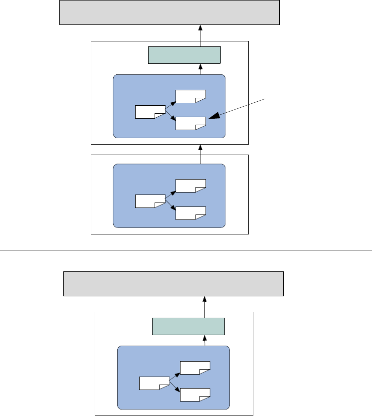
146 UVM 1.1 User’s Guide May 18, 2011
Figure 34—Layering Architecture
6.5.2.4 Styles of Layering
This section explores the various layering styles.
6.5.2.4.1 Basic Layering
The simplest general scenario of basic layering consists of:
— The driver accepts layer1 items.
— The layer1 items are constructed from layer2 items in some way. The layer2 items are, in
turn, constructed from layer3 items, and so on.
— For every layerN and layerN+1, there is a mechanism that takes layerN+1 items and converts
them into layerN items.
DUT
seq
seq
seq
Packet Sequencer
packet driver
seq
seq
seq
Frame Sequencer
This lower-layer sequence
pulls information directly
from the higher-layer
sequencer
DUT
seq
seq
seq
Packet Sequencer
packet driver
Multi-Layer
Architecture
Single-Layer
Architecture
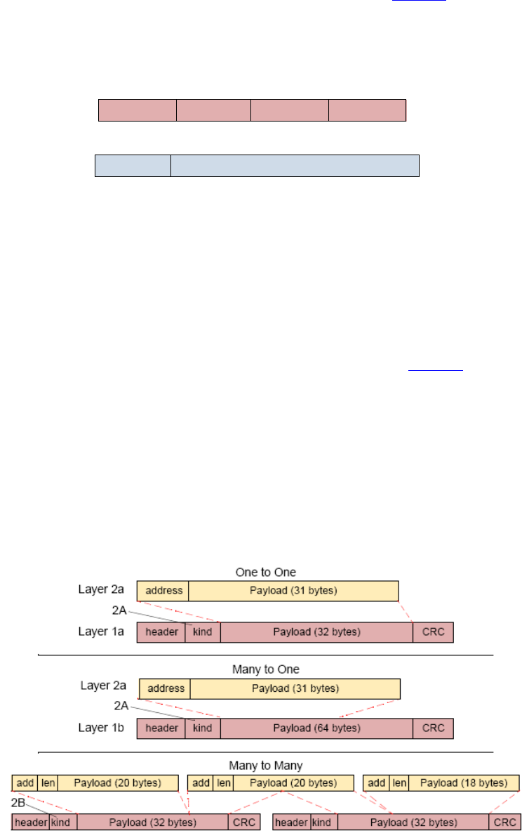
May 18, 2011 UVM 1.1 User’s Guide 147
You can also have multiple kinds of layer1 and layer2 items. In different configurations, you might
want to layer any kind of layer2 item over any kind of layer1 item (see Figure 35).
The remainder of this section describes possible variations and complications, depending on the particular
protocol or on the desired test-writing flexibility.
Figure 35—Protocol Layering
6.5.2.4.2 One-to-One, One-to-Many, Many-to-One, Many-to-Many
A conversion mechanism might need to cope with the following situations (see Figure 36):
a) One-to-one—One high-layer item must be converted into one low-layer item.
b) One-to-many—One large high-layer item must be broken into many low-layer items.
c) Many-to-one—Many high-layer items must be combined into one large low-layer item (as in Sonet,
for example).
d) Many-to-many—Multiple higher-layer items must be taken in and converted into multiple lower-
layer items. For example, high-layer packets are 10-bytes long, and low-layer packets are 3- to 35-
bytes long. In this case, there could be remainders.
Figure 36—Layer Mapping
fielda fieldb fieldc fieldd
fielde fieldf
layer1
layer2 layerN+1
layerN
fielda = f1(fielde, fieldf);
fieldb = f2(fielde, fieldf);
fieldc = f3(fielde, fieldf);

148 UVM 1.1 User’s Guide May 18, 2011
6.5.2.4.3 Different Configurations at Pre-Run Generation and Run Time
A system might need to support different modes of operation defined by topology, data type, or other
application-specific requirements. For example, in one environment, you might have only layer1 items. In
another environment, layer1 items would be dictated by layer2 items. You might also want to decouple
the layers further, for example, so layer2 items could drive either layer1 items or layer1 cells (on
another interface) or both.
At times, you might have a mix of inputs from multiple sources at run time. For example, you might want to
have one low-layer sequencer send items that come from several high-layer sequencers.
6.5.2.4.4 Timing Control
In some configurations, the high-layer items drive the timing completely. When high-layer items are
created, they are immediately converted into low-layer items.
In other configurations, the low-layer sequences pace the operation. When a low-layer do macro is
executed, the corresponding high-layer item should appear in zero time.
Finally, there is a case where items are driven to the DUT according to the timing of the low-layer
sequences, but the high-layer sequences are not reacting in zero time. Rather, if there is no data available
from the high-layer sequences, then some default value (for example, a zero filler) is used instead.
uvm_driver:try_next_item() would be used by the lower-level driver in this case.
6.5.2.4.5 Data Control
In some configurations, the high-layer items completely dictate which low-layer items reach the DUT. The
low layer simply acts as a slave.
Often, however, both layers influence what reaches the DUT. For example, the high layer might influence
the data in the payload while the low layer influences other attributes of the items reaching the DUT. In
these cases, the choice of sequences for both layers is meaningful.
6.5.2.4.6 Controlling Sequences on Multiple Sequencers
In the most general case, you have a graph consisting of several sequencers, some of which may control
sequence execution on other sequencers and some of which may generate items directly. Some low-layer
“driver sequencers” are connected to the DUT, some higher-layer driver sequencers are layered above them,
and some sequencers on top feed into all of the driver sequencers below.
In the example configuration shown in Figure 37, a low-layer sequencer (L1B) gets input from multiple
high-layer sequencers (two instances of L2A), as well as from a controlling sequencer.
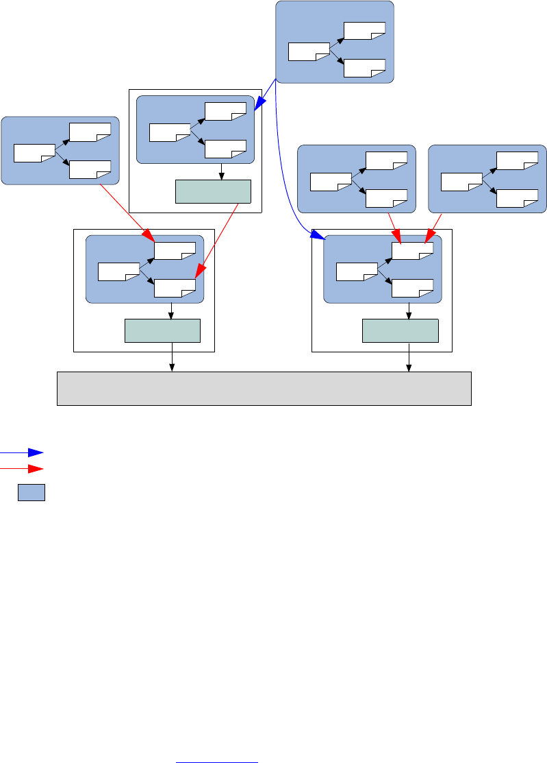
May 18, 2011 UVM 1.1 User’s Guide 149
Figure 37—Most-General Case of using Virtual Sequencers
6.5.2.5 Using Layered Sequencers
Layered sequencers work as follows:
— Higher-layer sequencers operate as usual, generating upper-layer data items and sending them
through the seq_item_pull_export. In most cases, you will not need to change the upper-
layer sequencer or sequences that will be used in a layered application.
— The lower-layer sequencers connect to the higher-layer sequencer(s) from which information must
be pulled. The pulled information (a higher-layer item) is put in a property of the sequence and is
then used to constrain various properties in the lower-layer item(s). The actual connectivity between
the layers is done in the same manner as the connection between a sequencer and a driver. To con-
nect to the higher-layer sequencer, declare a corresponding uvm_seq_item_pull_port in the
lower-layer sequencer (see Section 6.5.2.6). The connection itself is performed at the time the con-
taining object’s connect() method is invoked.
— The lower-layer sequencers send information to a lower-layer driver that interacts with a DUT’s
physical interface.
Assuming you already have created (or are reusing) upper-layer and lower-layer sequencers, follow these
steps to create the layering:
DUT
seq
seq
seq
L1A
L1A driver
seq
seq
seq
L1B
L1B driver
seq
seq
seq
L2A
seq
seq
seq
L2B
L2B driver seq
seq
seq
L2A
seq
seq
seq
Control Sequencer
seq
seq
seq
L2A
Layering with virtual sequences
Layering with connector sequence
Sequencer

150 UVM 1.1 User’s Guide May 18, 2011
a) Create a lower-layer sequence which does the following:
1) Repeatedly pulls upper-layer items from the upper-layer sequencer.
2) Translates them to lower-layer items.
3) Sends them to the lower-layer driver.
To preserve late generation of the upper-layer items, pull the upper-layer items from within the
lower-sequence’s pre_do() task. This ensures the upper-layer item will be randomized only when
the lower-layer driver is ready to start processing the matching lower-layer items.
b) Connect the lower-layer sequencer to the upper-layer sequencer using the same technique as when
connecting a driver to a sequencer.
c) Configure the lower-layer sequencer’s default sequence to be the sequence you created in Step (a).
6.5.2.6 Layered Sequencers Examples
Assume you are reusing the upper- and lower-layer classes from components created earlier. The lower-
layer components are likely to be encapsulated inside an agent modeling the interface protocol. This
example shows how to achieve layering without introducing the recommended reuse structure to keep the
code compact.
// Upper-layer classes
class upper_item extends uvm_sequence_item;
...
endclass : upper_item
class upper_sequencer extends uvm_sequencer #(upper_item);
...
endclass : upper_sequencer
// Lower-layer classes
class lower_item extends uvm_sequence_item;
...
endclass : lower_item
class lower_sequencer extends uvm_sequencer #(lower_item);
uvm_seq_item_pull_port #(upper_item) upper_seq_item_port;
...
function new (string name, uvm_component parent);
super.new(name, parent);
upper_seq_item_port = new(“upper_seq_item_port”,this);
endfunction : new
...
endclass : lower_sequencer
class lower_driver extends uvm_driver #(lower_item);
...
endclass : lower_driver
Now create a lower-layer sequence that pulls upper-layer items and translates them to lower-layer items.
class higher_to_lower_seq extends uvm_sequence #(lower_item);
... // Constructor and UVM automation macros go here.
// See Section 4.8.2
upper_item u_item;
lower_item l_item;
virtual task body();
forever begin
`uvm_do_with(l_item,
{ ... }) // Constraints based on u_item
end
endtask : body
May 18, 2011 UVM 1.1 User’s Guide 151
// In the pre_do task, pull an upper item from upper sequencer.
virtual task pre_do(bit is_item);
p_sequencer.upper_seq_item_port.get_next_item(u_item);
endtask : pre_do
// In the post_do task, signal the upper sequencer we are done.
// And, if desired, update the upper-item properties for the
// upper-sequencer to use.
virtual function void post_do(uvm_sequence_item this_item);
p_sequencer.upper_seq_item_port.item_done(this_item);
endfunction : post_do
endclass : higher_to_lower_seq
The following example illustrates connecting a lower-layer sequencer with an upper-layer sequencer.
NOTE—The lower-layer sequencer is likely to be encapsulated inside an interface verification component; therefore, it
will be encapsulated in an env and an agent. This does not change the layering scheme, but changes the path to connect
the sequencers to each other in the tb file. The connection to the upper sequencer to the lower sequencer will typically
happen in the tb env, whereas the connection from lower sequencer to its driver will happen in the connect() phase
of the agent.
// This code resides in an env class.
lower_driver l_driver0;
lower_sequencer l_sequencer0;
upper_sequencer u_sequencer0;
function void build();
super.build();
// Make lower sequencer execute upper-to-lower translation sequence.
set_config_string("l_sequencer0", "default_sequence",
"higher_to_lower_seq");
// Build the components.
l_driver0 = lower_driver::type_id::create(“l_driver0”, this);
l_sequencer0 = lower_sequencer::type_id::create((“l_sequencer0”, this);
u_sequencer0 = upper_sequencer::type_id::create((“u_sequencer0”, this);
endfunction : build
// Connect the components.
function void connect();
// Connect the upper and lower sequencers.
l_sequencer0.upper_seq_item_port.connect(u_sequencer0.seq_item_export);
// Connect the lower sequencer and driver.
l_driver0.seq_item_port.connect(l_sequencer0.seq_item_export);
endfunction : connect
6.5.3 Generating the Item or Sequence in Advance
The various `uvm_do* macros perform several steps sequentially, including the allocation of an object
(sequence or sequence item), synchronization with the driver (if needed), randomization, sending to the
driver, and so on. The UVM Class Library provides additional macros that enable finer control of these
various steps. This section describes these macros.
6.5.3.1 `uvm_create
This macro allocates an object using the common factory and initializes its properties. Its argument is a
variable of type uvm_sequence_item or uvm_sequence. You can use the macro with
SystemVerilog’s constraint_mode() and rand_mode() functions to control subsequent
randomization of the sequence or sequence item.

152 UVM 1.1 User’s Guide May 18, 2011
In the following example, my_seq is similar to previous sequences that have been discussed. The main
differences involve the use of the `uvm_create(item0) call. After the macro call, the rand_mode()
and constraint_mode() functions are used and some direct assignments to properties of item0 occur.
The manipulation of the item0 object is possible since memory has been allocated for it, but randomization
has not yet taken place. Subsequent sections will review the possible options for sending this pre-generated
item to the driver.
class my_seq extends uvm_sequence #(my_item);
... // Constructor and UVM automation macros go here.
// See Section 4.8.2
virtual task body();
`uvm_create(req)
req.addr.rand_mode(0); // Disables randomization of addr
req.dc1.constraint_mode(0); // Disables constraint dc1
req.addr = 27;
...
endtask : body
endclass: my_seq
You can also use a sequence variable as an argument to `uvm_create.
NOTE—You might need to disable a constraint to avoid a conflict.
6.5.3.2 `uvm_send
This macro processes the uvm_sequence_item or uvm_sequence class handle argument as shown in
Figure 16 and Figure 17, without any allocation or randomization. Sequence items are placed in the
sequencer’s queue to await processing while subsequences are processed immediately. The parent
pre_do(), mid_do(), and post_do() callbacks still occur as shown.
In the following example, we show the use of uvm_create() to pre-allocate a sequence item along with
`uvm_send, which processes it as shown in Figure 16, without allocation or randomization.
class my_seq2 extends uvm_sequence #(my_item);
... // Constructor and UVM automation macros go here.
// See Section 4.8.2
virtual task body();
`uvm_create(req)
req.addr = 27;
req.data = 4;
// No randomization. Use a purely pre-generated item.
`uvm_send(req)
endtask : body
endclass: my_seq2
Similarly, a sequence variable could be provided to the `uvm_create and `uvm_send calls above, in
which case the sequence would be processed in the manner shown in Figure 17, without allocation or
randomization.
6.5.3.3 `uvm_rand_send, `uvm_rand_send_with
These macros are identical to `uvm_send (see Section 6.5.3.2), with the single difference of randomizing
the given class handle before processing it. This enables you to adjust an object as required while still using
class constraints with late randomization, that is, randomization on the cycle that the driver is requesting the
item. `uvm_rand_send() takes just the object handle. `uvm_rand_send_with() takes an extra
argument, which can be any valid inline constraints to be used for the randomization.

May 18, 2011 UVM 1.1 User’s Guide 153
The following example shows the use of `uvm_create to pre-allocate a sequence item along with the
`uvm_rand_send* macros, which process it as shown in Figure 16, without allocation. The
rand_mode() and constraint_mode() constructs are used to show fine-grain control on the
randomization of an object.
class my_seq3 extends uvm_sequence #(my_item);
... // Constructor and UVM automation macros go here.
// See Section 4.8.2
virtual task body();
`uvm_create(req)
req.addr.rand_mode(0);
req.dc1.constraint_mode(0);
req.addr = 27;
// Randomize and process the item.
`uvm_rand_send(req)
// Randomize and process again, this time with inline constraints.
`uvm_rand_send_with(req, {data < 1000;})
endtask : body
endclass: my_seq3
6.5.4 Executing Sequences and Items on other Sequencers
In the preceding sections, all uvm_do macros (and their variants) execute the specified item or sequence on
the current p_sequencer. To allow sequences to execute items or other sequences on specific sequencers,
additional macro variants are included that allow specification of the desired sequencer.
‘uvm_do_on, ‘uvm_do_on_with, ‘uvm_do_on_pri, and ‘uvm_do_on_pri_with
All of these macros are exactly the same as their root versions, except they all take an additional argument
(always the second argument) that is a reference to a specific sequencer.
‘uvm_do_on(s_seq, that_sequencer);
‘uvm_do_on_with(s_seq, that_sequencer, {s_seq.foo == 32’h3;})
6.6 Command Line Interface (CLI)
6.6.1 Introduction
The Command Line Processor class provides a general interface to the command line arguments that are
provided for the given simulation. Not only can users retrieve the complete arguments using methods such
as ~get_args()~ and ~get_arg_matches()~, but they can also retrieve the suffixes of arguments
using ~get_arg_values()~.
The uvm_cmdline_processor class also provides support for setting various UVM variables from the
command line, such as components’ verbosities and configuration settings for integral types and strings.
Command line arguments that are in UPPERCASE should only have one setting to invocation. Command
line arguments in lowercase can have multiple settings per invocation. All of this is further described in
uvm_cmdline_processor in the UVM 1.1 Class Reference.

154 UVM 1.1 User’s Guide May 18, 2011
6.6.2 Getting Started
To start using the uvm_cmdline_processor, the user needs to first get access to the singleton instance of the
uvm_cmdline_processor.
uvm_cmdline_processor cmdline_processor = uvm_cmdline_processor::get_inst();
A common use case involves using the get_arg_value() function to get the value of a specific argument,
which is returned through an output argument. The total number of matches returned from this function
usually is of interest when there are no matches and no default value. In this case, the user may generate an
error. Similar to $test$plusargs, if the command line contains multiple matching arguments, the first
value is returned.
string my_value = "default_value";
int rc = cmdline_processor.get_arg_value("+abc=", my_value);
If the user knows the value is an integer, this string value may be further turned into an integer by calling the
SystemVerilog function atoi() as follows.
int my_int_value = my_value.atoi();
If processing multiple values makes sense for a particular option (as opposed to just the first one found), use
the get_arg_values() function instead, which returns a queue of all the matches.
string my_value_list[$];
int rc = cmdline_process.get_values("+abc=", my_value_list);
The uvm_cmdline_processor provides comprehensive access to the command line processing; see
Section 6.6.3 and the UVM 1.1 Class Reference for more details.
6.6.3 UVM-aware Command Line Processing
This section highlights how to select tests, set verbosity, and control other UVM facilities using the CLI.
6.6.3.1 Selecting Tests
The uvm_cmdline_processor is used to pass the +UVM_TESTNAME option to the run_test() routine to
select which class will get constructed as the top-level testcase.
6.6.3.2 Setting Verbosity
The uvm_cmdline_processor looks for the +UVM_VERBOSITY option to change the verbosity for all
UVM components. It is also possible to control the verbosity in a much more granular way by using the
+uvm_set_verbosity option. The +uvm_set_verbosity option has a specific format that allows
control over the phases where the verbosity change applies, and in the case of time-consuming phases,
exactly what time it applies. Typically, verbosity is only turned up during time-consuming phases as the test
approaches the time where an error occurs to help in debugging that error. The simulation will run faster if it
is not burdened by generating debug messages earlier on where they are not required.
The +uvm_set_verbosity option is used as follows.
sim_cmd
+uvm_set_verbosity=component_name,id,verbosity,phase_name,optional_time
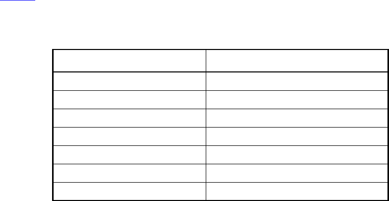
May 18, 2011 UVM 1.1 User’s Guide 155
In a similar fashion, the severity, and also the action taken, can be modified as follows.
sim_cmd +uvm_set_action=component_name,id,severity,action
sim_cmd +uvm_set_severity=component_name,id,current_severity,new_severity
6.6.3.3 Other UVM facilities that can be Controlled from the Command Line
Table 14 shows other UVM options the user can set from the CLI.
Please see the UVM 1.1 Class Reference for more examples of using the uvm_cmdline_processor
class facilities.
Table 14—UVM CLI Options
Facility Setting
Instance-specific factory override +uvm_set_inst_override
Type-specific factory override +uvm_set_type_override
Integer configuration +uvm_set_config_int
String configuration +uvm_set_config_string
Timeout +UVM_TIMEOUT
Max quit count +UVM_MAX_QUIT_COUNT
Objection mechanism debug +UVM_OBJECTION_TRACE
156 UVM 1.1 User’s Guide May 18, 2011

May 18, 2011 UVM 1.1 User’s Guide 157
7. UBus Verification Component Example
This chapter introduces the basic architecture of the UBus verification component. It also discusses an
executable demo you can run to get hands-on experience in simulation. The UBus source code is provided as
a further aid to understanding the verification component architecture. When developing your own
simulation environment, you should follow the UBus structure and not its protocol-specific functionality.
All UBus verification component subcomponents inherit from some base class in the UVM Class Library,
so make sure you have the UVM 1.1 Class Reference available while reading this chapter. It will be
important to know, understand, and use the features of these base classes to fully appreciate the rich features
you get—with very little added code—right out of the box.
You should also familiarize yourself with the UBus specification in Chapter 8. While not a prerequisite,
understanding the UBus protocol will help you distinguish UBus protocol-specific features from verification
component protocol-independent architecture.
7.1 UBus Example
The UBus example constructs an verification environment consisting of a master and a slave. In the default
test, the UBus slave communicates using the slave_memory sequence and the UBus master sequence
read_modify_write validates the behavior of the UBus slave memory device. Instructions for running
the UBus example can be found in the readme.txt file in the examples/ubus/examples directory of the
UVM kit.
The output from the simulation below shows the UBus testbench topology containing an environment.The
environment contains one active master and one active slave agent. The test runs the
read_modify_write sequence, which activates the read byte sequence followed by the write byte
sequence, followed by another read byte sequence. An assertion verifies the data read in the second read
byte sequence is identical to the data written in the write byte sequence. The following output is generated
when the test is simulated with UVM_VERBOSITY = UVM_LOW.
# UVM_INFO @ 0: reporter [RNTST] Running test test_read_modify_write...
# UVM_INFO test_lib.sv(55) @ 0: uvm_test_top [test_read_modify_write] Printing
the test topology :
# --------------------------------------------------------------------
# Name Type Size Value
# --------------------------------------------------------------------
# uvm_test_top test_read_modify_write - @459
# ubus_example_tb0 ubus_example_tb - @478
# scoreboard0 ubus_example_scoreboard - @500
# item_collected_export uvm_analysis_imp - @507
# disable_scoreboard integral 1 'h0
# num_writes integral 32 'd0
# num_init_reads integral 32 'd0
# num_uninit_reads integral 32 'd0
# recording_detail uvm_verbosity 32 UVM_FULL
# ubus0 ubus_env - @493
# bus_monitor ubus_bus_monitor - @517
# masters[0] ubus_master_agent - @546
# slaves[0] ubus_slave_agent - @557
# has_bus_monitor integral 1 'h1
# num_masters integral 32 'h1
# num_slaves integral 32 'h1
# intf_checks_enable integral 1 'h1
# intf_coverage_enable integral 1 'h1
158 UVM 1.1 User’s Guide May 18, 2011
# recording_detail uvm_verbosity 32 UVM_FULL
# recording_detail uvm_verbosity 32 UVM_FULL
# --------------------------------------------------------------------
#
# UVM_INFO ubus_example_scoreboard.sv(100) @ 110:
uvm_test_top.ubus_example_tb0.scoreboard0 [ubus_example_scoreboard] READ
to empty address...Updating address : 8764 with data : dd
# UVM_INFO ../sv/ubus_bus_monitor.sv(223) @ 110:
uvm_test_top.ubus_example_tb0.ubus0.bus_monitor [ubus_bus_monitor]
Transfer collected :
# ----------------------------------------------------------
# Name Type Size Value
# ----------------------------------------------------------
# ubus_transfer_inst ubus_transfer - @524
# addr integral 16 'h8764
# read_write ubus_read_write_enum 32 READ
# size integral 32 'h1
# data da(integral) 1 -
# [0] integral 8 'hdd
# wait_state da(integral) 0 -
# error_pos integral 32 'h0
# transmit_delay integral 32 'h0
# master string 10 masters[0]
# slave string 9 slaves[0]
# begin_time time 64 70
# end_time time 64 110
# ----------------------------------------------------------
#
# UVM_INFO ubus_example_scoreboard.sv(89) @ 260:
uvm_test_top.ubus_example_tb0.scoreboard0 [ubus_example_scoreboard] WRITE
to existing address...Updating address : 8764 with data : de
# UVM_INFO ../sv/ubus_bus_monitor.sv(223) @ 260:
uvm_test_top.ubus_example_tb0.ubus0.bus_monitor [ubus_bus_monitor]
Transfer collected :
# ----------------------------------------------------------
# Name Type Size Value
# ----------------------------------------------------------
# ubus_transfer_inst ubus_transfer - @524
# addr integral 16 'h8764
# read_write ubus_read_write_enum 32 WRITE
# size integral 32 'h1
# data da(integral) 1 -
# [0] integral 8 'hde
# wait_state da(integral) 0 -
# error_pos integral 32 'h0
# transmit_delay integral 32 'h0
# master string 10 masters[0]
# slave string 9 slaves[0]
# begin_time time 64 220
# end_time time 64 260
# ----------------------------------------------------------
#
# UVM_INFO ubus_example_scoreboard.sv(75) @ 330:
uvm_test_top.ubus_example_tb0.scoreboard0 [ubus_example_scoreboard] READ
to existing address...Checking address : 8764 with data : de
# UVM_INFO ../sv/ubus_bus_monitor.sv(223) @ 330:
uvm_test_top.ubus_example_tb0.ubus0.bus_monitor [ubus_bus_monitor]
Transfer collected :
May 18, 2011 UVM 1.1 User’s Guide 159
# ----------------------------------------------------------
# Name Type Size Value
# ----------------------------------------------------------
# ubus_transfer_inst ubus_transfer - @524
# addr integral 16 'h8764
# read_write ubus_read_write_enum 32 READ
# size integral 32 'h1
# data da(integral) 1 -
# [0] integral 8 'hde
# wait_state da(integral) 0 -
# error_pos integral 32 'h0
# transmit_delay integral 32 'h0
# master string 10 masters[0]
# slave string 9 slaves[0]
# begin_time time 64 290
# end_time time 64 330
# ----------------------------------------------------------
#
# UVM_INFO ../../../../src/base/uvm_objection.svh(1122) @ 380: reporter
[TEST_DONE] 'run' phase is ready to proceed to the 'extract' phase
# UVM_INFO ubus_example_scoreboard.sv(114) @ 380:
uvm_test_top.ubus_example_tb0.scoreboard0 [ubus_example_scoreboard]
Reporting scoreboard information...
# ------------------------------------------------------------------
# Name Type Size Value
# ------------------------------------------------------------------
# scoreboard0 ubus_example_scoreboard - @500
# item_collected_export uvm_analysis_imp - @507
# recording_detail uvm_verbosity 32 UVM_FULL
# disable_scoreboard integral 1 'h0
# num_writes integral 32 'd1
# num_init_reads integral 32 'd1
# num_uninit_reads integral 32 'd1
# recording_detail uvm_verbosity 32 UVM_FULL
# ------------------------------------------------------------------
#
# UVM_INFO test_lib.sv(70) @ 380: uvm_test_top [test_read_modify_write] ** UVM
TEST PASSED **
#
# --- UVM Report Summary ---
#
# ** Report counts by severity
# UVM_INFO : 11
# UVM_WARNING : 0
# UVM_ERROR : 0
# UVM_FATAL : 0
# ** Report counts by id
# [RNTST] 1
# [TEST_DONE] 1
# [test_read_modify_write] 2
# [ubus_bus_monitor] 3
# [ubus_example_scoreboard] 4
# ** Note: $finish : ../../../../src/base/uvm_root.svh(392)
# Time: 380 ns Iteration: 42 Instance: /ubus_tb_top
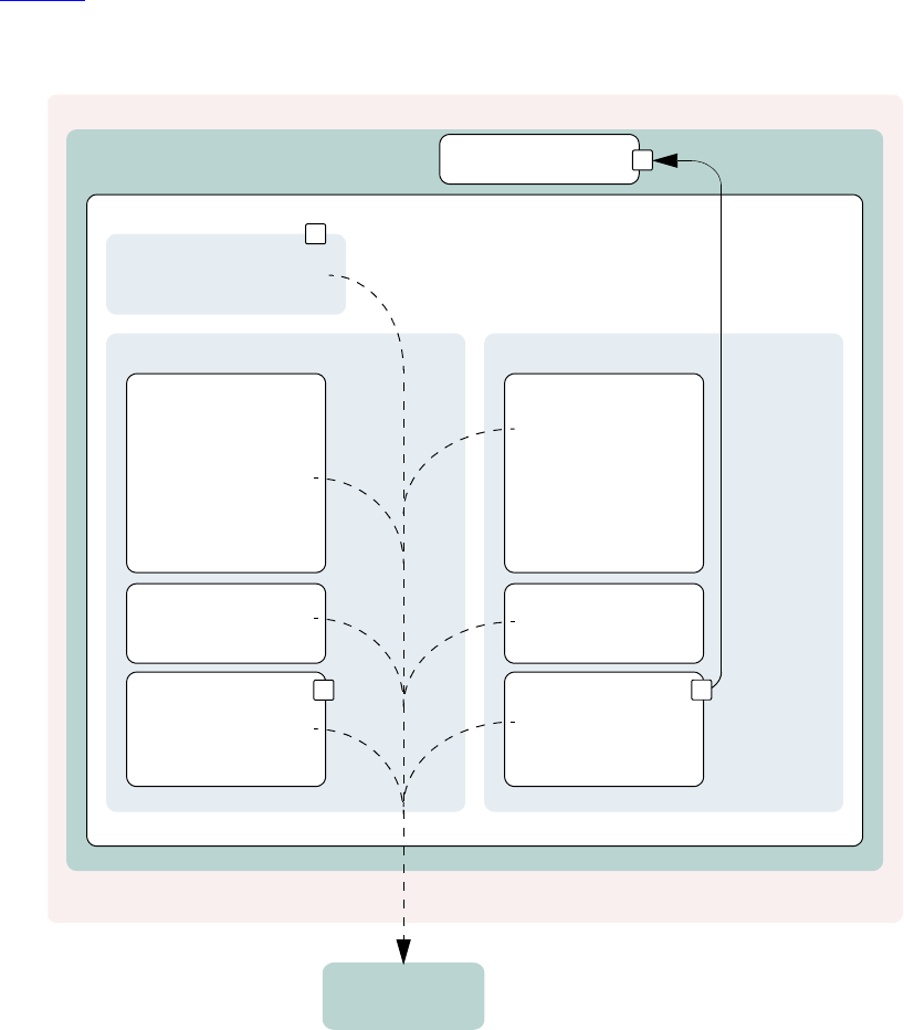
160 UVM 1.1 User’s Guide May 18, 2011
7.2 UBus Example Architecture
Figure 38 shows the testbench topology of the UBus simulation environment in the UBus example delivered
with this release.
Figure 38—UBus Example Architecture
7.3 UBus Top Module
The UBus testbench is instantiated in a top-level module to create a class-based simulation environment.
The example below uses an example DUT with UBus-specific content. The example is intentionally trivial
so the focus is on the UBus verification component environment.
The top module contains the typical HDL constructs and a SystemVerilog interface. This interface is used to
connect the class-based testbench to the DUT. The UBus environment inside the testbench uses a virtual
test_read_modify_write
ubus_example_tb
ubus_env
ubus_master_agent
ubus_master_sequencer
read_modify_write
incr_read
incr_read_write
seq_r8_w8_r4_w4
incr_write
ubus_slave_agent
ubus_slave_sequencer
slave_memory
ubus_master_driver
ubus_master_monitor
simple_response
ubus_slave_driver
ubus_slave_monitor
ubus_bus_monitor
checks
coverage
checks
ubus_if
covergroups
checks
covergroups
checks &
coverage
ubus_example_scoreboard

May 18, 2011 UVM 1.1 User’s Guide 161
interface variable to refer to the SystemVerilog interface. The following example shows the UBus interface
(xi0) and the example DUT connected together and passed to the components in the testbench via the
resource database (Line 16). The run_test() command used to simulate the DUT and the testbench is
covered in the next section.
Example: ubus_tb_top.sv
1 module ubus_tb_top;
2
3 import uvm_pkg::*;
4 import ubus_pkg::*;
5 `include "test_lib.sv"
6
7 ubus_if vif(); // SystemVerilog interface to the DUT
8
9 dut_dummy dut(
10 vif.sig_request[0],
11 ...
12 vif.sig_error
13 );
14
15 initial begin
16 uvm_config_db#(virtual ubus_if)::set(null,"ubus_example_tb0.*",
17 "vif",vif);
18 run_test();
19 end
20
21 initial begin
22 vif.sig_reset <= 1'b1;
23 vif.sig_clock <= 1'b1;
24 #51 vif.sig_reset = 1'b0;
25 end
26
27 //Generate clock.
28 always
29 #5 vif.sig_clock = ~vif.sig_clock;
30
31 endmodule
The UBus SystemVerilog interface is instantiated in the top-level testbench module. The interface uses
generally-accepted naming conventions for its signals to allow easy mapping to any naming conventions
employed by other implementations of the UBus protocol. The DUT pins connect directly to the signal
inside the interface instance. Currently, the signals are simple non-directional variables that are driven either
by the DUT or the class-based testbench environment via a virtual interface. The UBus interface contains
concurrent assertions to perform physical checks. Refer to Section 4.9 and Section 7.12 for more
information.
7.4 The Test
In UVM, the test is defined in a separate class, test_read_modify_write. It derives from
ubus_example_base_test that, in turn, derives from uvm_test. The
ubus_example_base_test test builds the ubus_example_tb object and manages the
run_phase() phase of the test. Subsequent derived tests, such as test_read_modify_write, can
leverage this functionality as shown in the example below.

162 UVM 1.1 User’s Guide May 18, 2011
All classes that use the `uvm_component_utils macros are registered with a common factory,
uvm_factory. When the top module calls run_test(test_name), the factory is called upon to
create an instance of a test with type test_name and then simulation is started. When run_test is called
without an argument, a +UVM_TESTNAME=test_name command-line option is checked and, if it exists,
the test with that type name is created and executed. If neither are found, all constructed components will be
cycled through their simulation phases. Refer to Section 4.6 for more information.
Example: test_lib.sv
1 `include "ubus_example_tb.sv"
2
3 class ubus_example_base_test extends uvm_test;
4
5 `uvm_component_utils(ubus_example_base_test)
6
7 ubus_example_tb ubus_example_tb0; // UBus verification environment
8 uvm_table_printer printer;
9 bit test_pass = 1;
10
11 function new(string name = "ubus_example_base_test",
12 uvm_component parent=null);
13 super.new(name, parent);
14 endfunction
15 // UVM build_phase() phase
16 virtual function void build_phase();
17 super.build_phase();
18 // Enable transaction recording.
19 set_config_int("*", "recording_detail", UVM_FULL);
20 // Create the testbench.
21 ubus_example_tb0 =
ubus_example_tb::type_id::create("ubus_example_tb0",
this);
22 // Create a specific-depth printer for printing the topology.
23 printer = new();
24 printer.knobs.depth = 3;
25 endfunction
26 // Built-in UVM phase
27 function void end_of_elaboration_phase();
28 // Set verbosity for the bus monitor.
29 ubus_example_tb0.ubus0.bus_monitor.set_report_verbosity_level
(UVM_FULL);
30 // Print the test topology.
31 `uvm_info(get_type_name(),
32 $psprintf("Printing the test topology :\n%s",
33 this.sprint(printer)), UVM_LOW)
34 endfunction : end_of_elaboration_phase();
35 // UVM run_phase() phase
36 task run_phase();
37 // Set a drain time for the environment if desired.
38 uvm_test_done.set_drain_time(this, 50);
39 endtask: run
40
41 function void extract();
42 if(ubus_example_tb0.scoreboard0.sbd_error)
43 test_pass = 1'b0;
44 endfunction // void
45
46 function void report();

May 18, 2011 UVM 1.1 User’s Guide 163
47 if(test_pass) begin
48 `uvm_info(get_type_name(), "** UVM TEST PASSED **", UVM_NONE)
49 end
50 else begin
51 `uvm_error(get_type_name(), "** UVM TEST FAIL **")
52 end
53 endfunction
54 endclass
Line 1 Include the necessary file for the test. The testbench used in this example is the
ubus_example_tb that contains, by default, the bus monitor, one master, and one slave. See Section 7.5.
Line 3 - Line 5 All tests should derive from the uvm_test class and use the `uvm_component_utils
or the `uvm_component_utils_begin/`uvm_component_utils_end macros. See the UVM
1.1 Class Reference for more information.
Line 7 Declare the testbench. It will be constructed by the build_phase() function of the test.
Line 8 Declare a printer of type uvm_table_printer, which will be used later to print the topology.
This is an optional feature. It is helpful in viewing the relationship of your topology defined in the
configuration and the physical testbench created for simulation. Refer to the UVM 1.1 Class Reference for
different types of printers available.
Line 16 - Line 25 Specify the build_phase() function for the base test. As required, build first calls
the super.build_phase() function in order to update any overridden fields. Then the
ubus_example_tb is created using the create() function. The build_phase() function of the
ubus_example_tb is executed by the UVM library phasing mechanism during build_phase(). The
user is not required to explicitly call ubus_example_tb0.build_phase().
Line 27 - Line 34 Specify the end_of_elaboration_phase() function for the base test. This
function is called after all the component’s build_phase() and connect() phases are executed. At
this point, the test can assume that the complete testbench hierarchy is created and all testbench connections
are made. The test topology is printed.
Line 36 - Line 39 Specify the run_phase() task for the base test. In this case, we set a drain time of 50
micro-seconds. Once all of the end-of-test objections were dropped, a 50 micro-second delay is introduced
before the run phase it terminated.
Now that the base test is defined, a derived test will be examined. The following code is a continuation of the
test_lib.sv file.
class test_read_modify_write extends ubus_example_base_test;
`uvm_component_utils(test_read_modify_write)
function new(string name = "test_read_modify_write",
uvm_component parent=null);
super.new(name,parent);
endfunction
virtual function void build_phase();
// Set the default sequence for the master and slave.
uvm_config_db#(uvm_object_wrapper)::set(this,
"ubus_example_tb0.ubus0.masters[0].sequencer.main_phase",
"default_sequence",
read_modify_write_seq::type_id::get());
uvm_config_db#(uvm_object_wrapper)::set(this,
"ubus_example_tb0.ubus0.slaves[0].sequencer.run_phase",
"default_sequence",
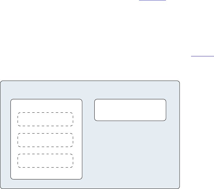
164 UVM 1.1 User’s Guide May 18, 2011
slave_memory_seq::type_id::get());
endfunction
endclass
The build_phase() function of the derivative test, test_read_modify_write, is of interest. The
build_phase() function uses the resource database to set the master agent sequencer’s default sequence
for the main() phase to use the read_modify_write_seq sequence type. Similarly, it defines the
slave agent sequencer’s default sequence for the run_phase() phase to use the slave_memory_seq
sequence type. Once these resources are set, super.build_phase() is called which creates the
ubus_example_tb0 as specified in the ubus_example_base_test build function.
The run_phase() task implementation is inherited by test_read_modify_write since this test
derives from the ubus_example_base_test. Since that implementation is sufficient for this test, no
action is required by you. This greatly simplifies this test.
7.5 Testbench Environment
This section discusses the testbench created in the Example: test_lib.sv in Section 7.4. The code that creates
the ubus_example_tb is repeated here.
ubus_example_tb0 = ubus_example_tb::type_id::create("ubus_example_tb0",
this);
In general, testbenches can contain any number of envs (verification components) of any type: ubus, pci,
ahb, ethernet, and so on. The UBus example creates a simple testbench consisting of a single UBus
environment (verification component) with one master agent, slave agent, and bus monitor (see Figure 39).
Figure 39—Testbench derived from uvm_env
The following code defines a class that specifies this configuration. The test will create an instance of this
class.
ubus_example_tb0
ubus_example_tb
ubus_env
ubus_master_agent
ubus_slave_agent
ubus_example_tb0.ubus0
ubus_bus_monitor
ubus_example_tb0.scoreboard0
ubus_example_scoreboard
May 18, 2011 UVM 1.1 User’s Guide 165
Example: ubus_example_tb.sv
1 function void ubus_example_tb::build_phase();
2 super.build_phase();
3 uvm_config_db#(int)::set(this,".ubus0",
4 "num_masters", 1);
5 uvm_config_db#(int)::set(this,".ubus0",
6 "num_slaves", 1);
7 ubus0 = ubus_env::type_id::create("ubus0", this);
8 scoreboard0 = ubus_example_scoreboard::type_id::create("scoreboard0",
this);
9 endfunction : build
10
11 function void ubus_example_tb::connect();
12 // Connect the slave0 monitor to scoreboard.
13 ubus0.slaves[0].monitor.item_collected_port.connect(
14 scoreboard0.item_collected_export);
15 endfunction : connect
16
17 function void end_of_elaboration_phase();
18 // Set up slave address map for ubus0 (basic default).
19 ubus0.set_slave_address_map("slaves[0]", 0, 16'hffff);
20 endfunction : end_of_elaboration
Line 1 Declare the build_phase() function.
Line 2 Call super.build_phase() in order to update any overridden fields. This is important because
the test, which creates the testbench, may register overrides for the testbench. Calling
super.build_phase() will ensure that those overrides are updated.
Line 3 - Line 5 The set_config_int calls are adjusting the num_masters and num_slaves
configuration fields of the ubus_env. In this case, the ubus0 instance of the ubus_env is being
manipulated. Line 3 instructs the ubus0 instance of the ubus_env to contain one master agent. The
num_masters property of the ubus_env specifies how many master agents should be created. The same
is done for num_slaves.
Line 7 Create the ubus_env instance named ubus0. The create() call specifies that an object of type
ubus_env should be created with the instance name ubus0.
Line 7 As with ubus0, the scoreboard is created.
Line 11 Declare the connect() function.
Line 12 Make the connections necessary for the ubus0 environment and the scoreboard0 between the
analysis port on the ubus0.slaves[0].monitor and the analysis export on the scoreboard0
instance.
Line 17 Declare the end_of_elaboration_phase() built-in UVM phase.
Line 19 Assign the slave address map for the slaves[0]. Since all components in the complete testbench
have been created and connected prior to the start of end_of_elaboration_phase(), the slave
instances are guaranteed to exist at this point.
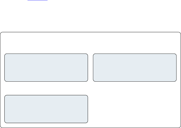
166 UVM 1.1 User’s Guide May 18, 2011
7.6 UBus Environment
The ubus_env component contains any number of UBus master and slave agents. In this demo, the
ubus_env (shown in Figure 40) is configured to contain just one master and one slave agent.
NOTE—The bus monitor is created by default.
Figure 40—Instance of ubus_env
The build_phase() function of the ubus_env creates the master agents, slave agents, and the bus
monitor. Three properties control whether these are created. The source code is shown here.
1 function void ubus_env::build_phase();
2 string inst_name;
3 super.build_phase();
4 if(!uvm_config_db#(virtual ubus_if)::get(this,””,"vif",vif))
5 `uvm_fatal("NOVIF",{"virtual interface must be set for:",
6 get_full_name(),".vif"});
7
8 if(has_bus_monitor == 1) begin
9 bus_monitor = ubus_bus_monitor::type_id::create("bus_monitor",
this);
10 end
11 uvm_config_db#(int)::get(this, “”, “num_masters", num_masters);
12 masters = new[num_masters];
13
14 for(int i = 0; i < num_masters; i++) begin
15 $sformat(inst_name, "masters[%0d]", i);
16 masters[i] = ubus_master_agent::type_id::create(inst_name, this);
17 uvm_config_db#(int)::set(this,{inst_name,"*"},
18 "master_id", i);
19 end
20 uvm_config_db#(int)::get(this,””, "num_slaves", num_slaves);
21
22 slaves = new[num_slaves];
23 for(int i = 0; i < num_slaves; i++) begin
24 $sformat(inst_name, "slaves[%0d]", i);
ubus_example_tb0.ubus0
ubus_env
ubus_master_agent
ubus_example_tb0.ubus0.master0
ubus_slave_agent
ubus_example_tb0.ubus0.slave0
ubus_bus_monitor
ubus_example_tb0.ubus0.bus_monito
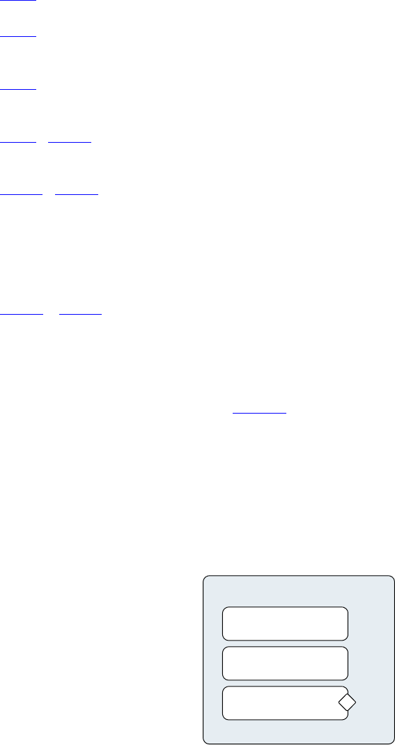
May 18, 2011 UVM 1.1 User’s Guide 167
25 slaves[i] = ubus_slave_agent::type_id::create("ubus_slave_agent",
26 this);
27 inst_name));
28 end
29 endfunction: build
Line 1 Declare the build_phase() function.
Line 3 Call super.build_phase(). This guarantees that the configuration fields (num_masters,
num_slaves, and has_bus_monitor) are updated per any resource settings.
Line 4 Read the “vif” resource to get the virtual interface instance that was set in the top-level module. If no
virtual interface has been set, issue a FATAL error.
Line 8 - Line 10 Create the bus monitor if the has_bus_monitor control field is set to 1. The create
function is used for creation.
Line 11 - Line 19 The master’s dynamic array is sized per the num_masters control field, which is read
from the resource database. This allows the for loop to populate the dynamic array according to the
num_masters value. The instance name that is used for the master agent instance is built using
$sformat so the instance names match the dynamic-array identifiers exactly. The iterator of the for loop is
also used to set a resource value for the master_id properties of the master agent and all its children
(through the use of the asterisk). This defines which request-grant pair is driven by the master agent.
Line 20 - Line 28 As in the master-agent creation code above, this code creates the slave agents using
num_slaves but does not set a resource for the slave agent.
7.7 UBus Master Agent
The ubus_master_agent (shown in Figure 41) and ubus_slave_agent are structured identically;
the only difference is the protocol-specific function of its subcomponents.
The UBus master agent contains up to three subcomponents: the sequencer, driver, and monitor. By default,
all three are created. However, the configuration can specify the agent as passive
(is_active=UVM_PASSIVE), which disables the creation of the sequencer and driver. The
ubus_master_agent is derived from uvm_agent.
Figure 41—Instance of ubus_master_agent
ubus_master_agent
uvm_sequencer
ubus_master_driver
ubus_master_monitor
ubus_example_tb0.ubus0.master0
#(ubus_transfer)
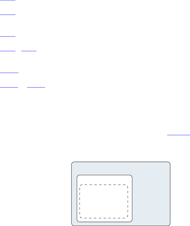
168 UVM 1.1 User’s Guide May 18, 2011
The build_phase() function of the ubus_master_agent is specified to create the driver, sequencer,
and the monitor. The is_active property controls whether the driver and sequencer are created.
1 function void ubus_master_agent::build_phase();
2 super.build_phase();
3 monitor = ubus_master_monitor::type_id::create("monitor", this);
4 if (is_active == UVM_ACTIVE) begin
5 sequencer =
uvm_sequencer#(ubus_transfer)::type_id::create("sequencer",
this);
6 driver = ubus_master_driver::type_id::create("driver", this);
7 end
8 endfunction : build
9
10 function void ubus_master_agent::connect();
11 if (is_active == UVM_ACTIVE) begin
12 driver.seq_item_port.connect(sequencer0.seq_item_export);
13 end
14 endfunction
Line 1 Declare the build_phase() function.
Line 2 Call super.build_phase(). This guarantees that the configuration field (is_active) is
updated per any overrides.
Line 3 Create the monitor. The monitor is always created. Creation is not conditional on a control field.
Line 4 - Line 7 Create the sequencer and driver if the is_active control field is set to UVM_ACTIVE.
The create() function is used for creation. Note the use of the base uvm_sequencer.
Line 10 Declare the connect() function.
Line 11 - Line 13 Since the driver expects transactions from the sequencer, the interfaces in both
components should be connected using the connect() function. The agent (which creates the monitor,
sequencer, and driver) is responsible for connecting the interfaces of its children.
7.8 UBus Master Sequencer
This component controls the flow of sequence items to the driver (see Figure 42).
Figure 42—Instance of ubus_master_sequencer
ubus_example_tb0.ubus0.master0.sequencer
ubus_master_sequencer
read_modify_write_seq
incr_read_seq
incr_read_write_seq
r8_w8_r4_w4_seq
incr_write_seq
ubus_master_agent
sequences
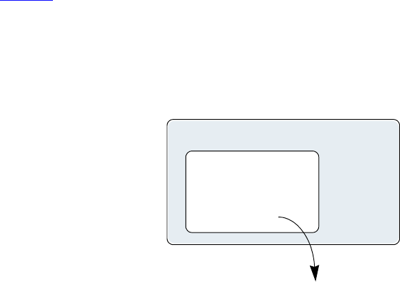
May 18, 2011 UVM 1.1 User’s Guide 169
The sequencer controls which sequence items are provided to the driver. The uvm_sequencer base class
will automatically read the sequence resource set for each specific run-time phase and start an instance of
that sequence by default.
7.9 UBus Driver
This component drives the UBus bus-signals interface by way of the xmi virtual interface property (see
Figure 43). The ubus_master_driver fetches ubus_transfer transactions from the sequencer and
processes them based on the physical-protocol definition. In the UBus example, the seq_item_port
methods get_next_item() and item_done() are accessed to retrieve transactions from the
sequencer.
Figure 43—Instance of ubus_master_driver
The primary role of the driver is to drive (in a master) or respond (in a slave) on the UBus bus according to
the signal-level protocol. This is done in the run_phase() task that is automatically invoked as part of
UVM’s built-in simulation phasing. For the master driver, the core routine is summarized as follows:
task ubus_master_driver::run_phase();
...
@(negedge vif.sig_reset);
forever begin // Repeat the following forever.
@(posedge vif.sig_clock);
seq_item_port.get_next_item(req); // Pull item from sequencer.
...
drive_transfer(req); // Drive item onto signal-level bus.
...
seq_item_port.item_done(); // Indicate we are done.
seq_item_port.put_response(rsp); // Provide response
end
endtask
Once the sig_reset signal is deasserted, the driver’s run task runs forever until stopped by having all
run_phase objections dropped. You are encouraged to study the UBus driver source code to gain a deeper
understanding of the implementation specific to the UBus protocol.
ubus_example_tb0.ubus0.master0.driver
ubus_master_driver
ubus_master_agent
pointer to ubus_if ‘interfac
vif
signal-driving methods
from event pool
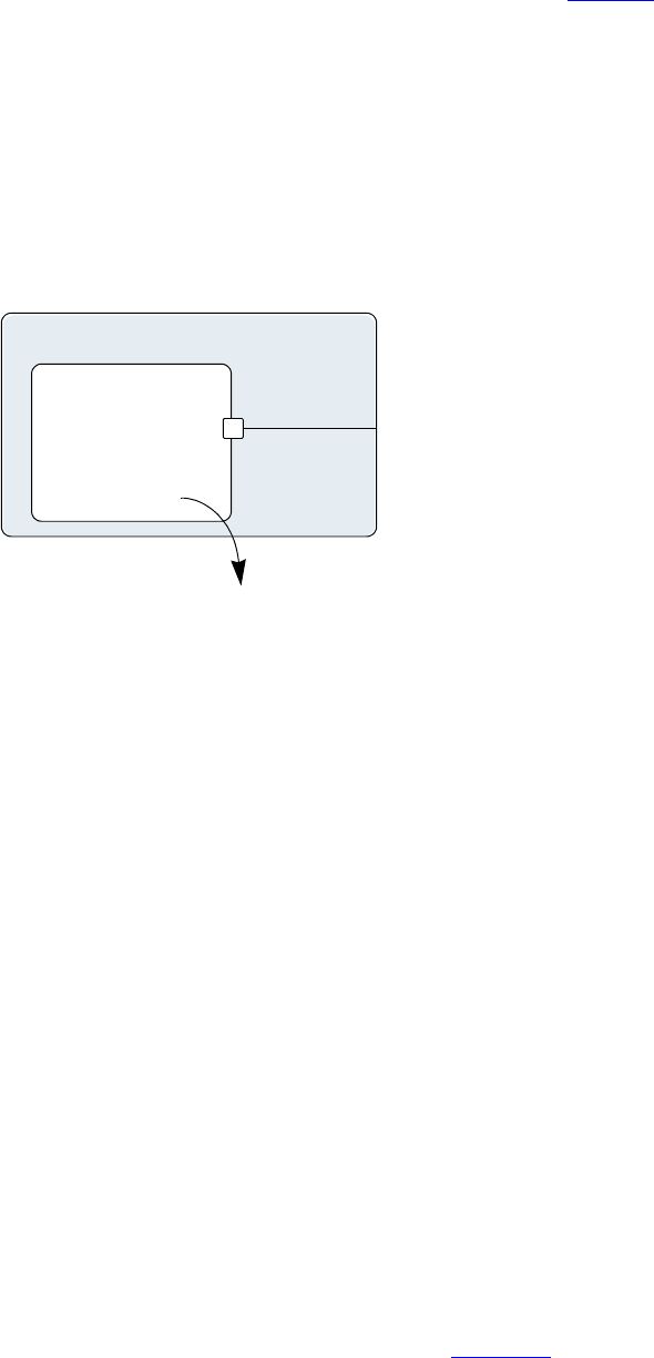
170 UVM 1.1 User’s Guide May 18, 2011
7.10 UBus Agent Monitor
The UBus monitor collects ubus_transfers seen on the UBus signal-level interface (see Figure 44). If
the checks and coverage are present, those corresponding functions are performed as well.
The primary role of the UBus master monitor is to sample the activity on the UBus master interface and
collect the ubus_transfer transactions that pertain to its parent master agent only. The transactions that
are collected are provided to the external world by way of a TLM analysis port. The monitor performs this
duty in the run task that is automatically invoked as part of simulation phasing. The run task may fork other
processes and call other functions or tasks in performance of its duties. The exact implementation is
protocol- and programmer-dependent, but the entry point, the run task, is the same for all components.
Figure 44—Instance of ubus_master_monitor
The monitor’s functionality is contained in an infinite loop defined with the run_phase() task. Once all
of the run_phase objections were dropped, the run_phase() tasks finish, allowing other simulation
phases to complete, and the simulation itself to end.
The checks are responsible for enforcing protocol-specific checks, and the coverage is responsible for
collecting functional coverage from the collected ubus_transfers.
7.11 UBus Bus Monitor
The UBus bus monitor collects ubus_transfers seen on the UBus signal-level interface and emits
status updates via a state transaction, indicating different activity on the bus. The UBus bus monitor has
class checks and collects coverage if checks and coverage collection is enabled. The UBus bus monitor is
instantiated within the UBus environment.
The ubus_env build_phase() function has a control field called has_bus_monitor, which
determines whether the ubus_bus_monitor is created or not. The bus monitor will be created by default
since the default value for this control field is 1. You can use the uvm_config_db interface to override
this value.
uvm_config_db#(int)::set(this, "ubus0", "has_bus_monitor", 0);
Here, the ubus0 instance of ubus_env has its has_bus_monitor control field overridden to 0.
Therefore, the ubus_bus_monitor in ubus0 will not be present. The build_phase() function for
the ubus_env that uses the has_bus_monitor control field can be found in Section 7.6.
ubus_example_tb0.ubus0.master0.monitor
ubus_master_monitor
ubus_master_agent
pointer to ubus_if ‘interfac
checks
covergroups
vif
May 18, 2011 UVM 1.1 User’s Guide 171
7.11.1 Collecting Transfers from the Bus
The UBus bus monitor populates the fields of ubus_transfer, including the master and slave, which
indicate which master and slave are performing a transfer on the bus. These fields are required to ensure a
slave responds to the appropriate address range when initiated by a master.
In the UBus protocol, each master on the bus has a dedicated request signal and a dedicated grant signal
defined by the master agent’s ID. To determine which master is performing a transfer on the bus, the UBus
bus monitor checks which grant line is asserted.
To keep the UBus bus monitor example simple, an assumption has been made that the nth master connects
to the nth request and grant lines. For example, master[0] is connected to grant0, master[1] is
connected to grant1, and so on. Therefore, when the UBus bus monitor sees grant0 is asserted, it
assumes master[0] is performing the transfer on the bus.
To determine which slave should respond to the transfer on the bus, the UBus bus monitor needs to know the
address range supported by each slave in the environment. The environment developer has created the user
interface API, ubus_env::set_slave_address_map(), to set the address map for the slave as well
as the bus monitor. The prototype for this function is
set_slave_address_map(string slave_name, int min_addr, int max_addr);
For each slave, call set_slave_address_map() with the minimum and maximum address values to
which the slave should respond. This function sets the address map for the slave and provides information to
the bus monitor about each slave and its address map.
Using the address map information for each slave and the address that is collected from the bus, the bus
monitor determines which slave has responded to the transfer.
7.11.2 Number of Transfers
The bus monitor has a protected field property, num_transactions, which holds the number of
transfers that were monitored on the bus.
7.11.3 Notifiers Emitted by the UBus Bus Monitor
The UBus bus monitor contains two analysis ports, which provide information on the different types of
activity occurring on the UBus signal-level interface
a) state_port—This port provides a ubus_status object which contains an enumerated
bus_state property. The bus_state property reflects bus-state changes. For example, when
the bus enters reset, the bus_state property is set to RST_START and the ubus_status object
is written to the analysis port.
b) item_collected_port—This port provides the UBus transfer that is collected from the signal
interface after a transfer is complete. This collected transfer is written to the
item_collected_port analysis port.
NOTE—Any component provided by the appropriate TLM interfaces can attach to these TLM ports and listen to the
information provided.

172 UVM 1.1 User’s Guide May 18, 2011
7.11.4 Checks and Coverage
The UBus bus monitor performs protocol-specific checks using class checks and collects functional
coverage from the collected ubus_transfers.
The UVM field coverage_enable and checks_enable are used to control whether coverage and
checks, respectively, will be performed or not. Refer to Section 4.11 for more information.
7.12 UBus Interface
The UBus interface is a named bundle of nets and variables such that the master agents, slave agents, and
bus monitor can drive or monitor the signals in it. Any physical checks to be performed are placed in the
interface. Refer to Section 4.11.
Assertions are added to perform physical checks.The ubus_env field intf_checks_enable controls
whether these checks are performed. Refer to Section 4.11 for more information.
The code below is an example of a physical check for the UBus interface, which confirms a valid address is
driven during the normal address phase. A concurrent assertion is added to the interface to perform the
check and is labeled assertAddrUnknown. This assertion evaluates on every positive edge of
sig_clock if checks_enable is true. The checks_enable bit is controlled by the
intf_checks_enable field. If any bit of the address is found to be at an unknown value during the
normal address phase, an error message is issued.
always @(posedge sig_clock)
begin
assertAddrUnknown:assert property (
disable iff(!checks_enable)
(sig_grant |-> ! $isunknown(sig_addr)))
else
$error("ERR_ADDR_XZ\n Address went to X or Z during Address Phase");
end
May 18, 2011 UVM 1.1 User’s Guide 173
8. UBus Specification
8.1 Introduction
8.1.1 Motivation
The motivation for the UBus specification is to provide an example of a simple bus standard for
demonstration purposes and to illustrate the methodology required for a bus-based verification component.
As such, the UBus specification is designed to demonstrate all of the important features of a typical modern
bus standard while keeping complexity to a minimum.
8.1.2 Bus Overview
The UBus is a simple non-multiplexed, synchronous bus with no pipelining (to ensure simple drivers). The
address bus is 16-bits wide and the data bus is byte-wide (so as to avoid alignment issues). Simple burst
transfers are allowed and slaves are able to throttle data rates by inserting wait states.
The bus can have any number of masters and slaves (the number of masters is only limited by the arbitration
implementation). Masters and slaves are collectively known as “bus agents”.
The transfer of data is split into three phases: Arbitration Phase, Address Phase, and Data Phase. Because
no pipelining is allowed, these phases happen sequentially for each burst of data. The Arbitration and
Address Phases each take exactly one clock cycle. The Data Phase may take one or more clock cycles.
8.2 Bus Description
8.2.1 Bus Signals
The list of bus signals (not including arbitration signals) is shown in Table 15. All control signals are active
high.
Table 15—Bus Signals
Signal
Name
Width
(bits) Driven By Purpose
clock 1 n/a Master clock for bus
reset 1 n/a Bus reset
start 1 arbiter This signal is high during the Arbitration Phase and low during the
Address and Data Phases
addr 16 master Address of first byte of a transfer
size 2 master Indicates how many bytes will be transfers:
00 => 1 byte
01 => 2 bytes
10 => 4 bytes
11 => 8 bytes
read 1 master This signal is high for read transfers (write must be low)

174 UVM 1.1 User’s Guide May 18, 2011
8.2.2 Clocking
All bus agents operate synchronous to the rising edge of the clock signal with the exception of gnt signals
(see Section 8.3).
8.2.3 Reset
The active high reset signal is synchronous to the rising edge of clock. reset shall be asserted during power
up and shall remain asserted for a minimum of five rising edges of clock* after power and clock have
stabilized. Thereafter, reset shall be de-asserted synchronous to a rising edge of clock.
reset may be asserted at any time during operation. In such cases, reset must be asserted for at least three
clock cycles and must be both asserted and de-asserted synchronous to the rising edge of clock. The
assertion of reset cancels any pending transfer at the first rising edge of clock where reset is asserted. Any
bytes that have been transferred prior to assertion of reset are considered to have succeeded. Any byte that
would have succeeded at the rising edge of clock where reset is first asserted is considered to have failed.
While reset is asserted, all agents should ignore all bus and arbitration signals. While reset is asserted, the
arbiter should drive start and all gnt signals low. At the first rising edge of clock where reset is de-asserted,
the arbiter should drive start high. Thereafter, the normal bus operation should occur.
8.3 Arbitration Phase
Each UBus shall have a single, central arbiter to perform arbitration and certain other central control
functions.
The Arbitration Phase always lasts for one clock cycle. During the Arbitration Phase, the arbiter shall drive
the start signal high. At all other times, the arbiter should drive the start signal low. The start signal can
therefore be used by slaves to synchronize themselves with the start of each transfer. The arbiter shall
always drive start high in the cycle following the last cycle of each Data Phase or in the cycle following a
“no operation” (NOP) Address Phase (see Section 8.4.1). The last cycle of a Data Phase is defined as a Data
Phase cycle in which the error signal is high, or both the bip and wait signals are low.
Each master on the bus has a dedicated req signal and gnt signal. The arbiter samples all req signals at each
falling edge of clock where start is asserted and asserts a single gnt signal based on an unspecified priority
system. At all falling edges of clock where start is not asserted, the arbiter shall drive all gnt signals low.
write 1 master This signal is high for write transfers (read must be low)
bip 1 master Burst In Progress—driven high by master during Data Phase for all
bytes, except the last byte of the burst. This signal, when combined
with wait and error, can be used by the arbiter to determine if the bus
will start a new transfer in the next clock cycle
data 8 master/slave Data for reads and writes
wait 1 slave High if slave needs master to wait for completion of transfer
error 1 slave High if slave error condition applies to this transfer
Table 15—Bus Signals (Continued)
Signal
Name
Width
(bits) Driven By Purpose
May 18, 2011 UVM 1.1 User’s Guide 175
Thus, a master can see assertion of its gnt signal not only as an indication that it has been granted the bus, but
also as an indication that it must start an Address Phase. It is not necessary for the master to check the start
signal before starting its Address Phase.
Once a master is granted the bus, it must drive a transaction onto the bus immediately. No other master is
allowed to drive the bus until the current master has completed its transaction.
NOTE—Only the arbiter is allowed to drive a NOP transfer. This means a master must drive a real transfer if it is
granted the bus. Therefore, masters should not request the bus unless they can guarantee they will be ready to do a real
transfer.
Arbitration signals shall be active high and shall be named according to a convention whereby the first part
of the name is the root signal name (req_ for the request signal; gnt_ for the grant signal) and the second part
of the name is the logical name or number of the master. Although the arbitration signals form part of the
UBus specification, they are not considered to be “bus” signals as they are not connected to all agents on the
bus.
It is up to individual implementations to choose an appropriate arbitration system. Arbiters might allocate
different priorities to each master or might choose randomly with each master having equal priority.
8.4 Address Phase
The Address Phase lasts for a single clock cycle and always immediately follows the Arbitration Phase.
8.4.1 NOP Cycle
Where no master has requested the bus and the start signal is asserted at the falling edge of clock, no gnt
signal is asserted at the start of the Address Phase and the arbiter itself is responsible for driving the bus to a
“no operation” (NOP) state. It does this by driving the addr and size signals to all zeroes and both the read
and write signals low. A NOP address phase has no associated data phase so the arbiter shall assert the start
signal in the following clock cycle.
NOTE—This means the arbiter is connected to certain bus signals in addition to the arbitration signals and behaves as a
“default master”.
8.4.2 Normal Address Phase
If, at the rising edge of clock, a master sees its gnt signal asserted, then it must drive a valid Address Phase
in the following cycle. The master should also de-assert its req signal at this clock edge unless it has a
further transfer pending.
During the Address Phase, the granted master should drive the addr and size signals to valid values and
should drive either read or write (but not both) high.The address driven on addr represents the address of the
first byte of a burst transfer. It is up to the slave to generate subsequent addresses during burst transfers.
The master shall only drive the addr, size, read, and write signals during the Address Phase. During the
subsequent Data Phase, the master should not drive these signals.
8.5 Data Phase
The Data Phase may last for one or more clock cycles. The Data Phase follows immediately after the
Address Phase (and is immediately followed by the Arbitration Phase).
176 UVM 1.1 User’s Guide May 18, 2011
8.5.1 Write Transfer
The master shall drive the first byte of data onto the bus on the clock cycle after driving a write Address
Phase. If, at the end of this clock cycle, the slave has asserted the wait signal, then the master shall continue
to drive the same data byte for a further clock cycle. The data signal may only change at the end of a cycle
where wait is not asserted. Thus, the slave can insert as many wait states as it requires. The master shall
drive the bip signal high throughout the Data Phase until the point where the final byte of the transfer is
driven onto the bus, at which point it shall be driven low.
At the end of the transfer (the end of the cycle where both bip and wait are low) the master shall cease to
drive all bus signals.
8.5.2 Error during Write Transfer
The slave shall drive the error throughout the Data Phase. If a slave encounters an error condition at any
point during the Data Phase of a write transfer, it may signal this by asserting the error signal. To signal an
error condition, the slave must drive the error signal high while driving the wait signal low. This indicates to
the master that the associated byte of the transfer failed—any previous bytes in the burst are considered to
have succeeded; any subsequent bytes in the burst are abandoned. The assertion of error always terminates
the Data Phase even if bip is asserted simultaneously.
8.5.3 Read Transfer
On the clock cycle after the master drives a read Address Phase, the slave can take one of two actions: drive
the first byte of data onto the bus while driving the wait signal low or drive the wait signal high to indicate it
is not yet ready to drive data. Each byte of data is latched only by the master at the end of a cycle where wait
is low—thus the slave can insert as many wait states as is required. The master shall drive the bip signal high
throughout the Data Phase until the point where the master is ready to receive the final byte of the transfer, at
which point it shall be driven low.
At the end of the transfer (the end of the cycle where both bip and wait are low) the master shall cease to
drive all bus signals.
8.5.4 Error during Read Transfer
The slave shall drive the error throughout the Data Phase. If a slave encounters an error condition at any
point during a read transfer, it may signal this by asserting the error signal. To signal an error condition, the
slave must drive the error signal high while driving the wait signal low. This indicates to the master that the
associated byte of the transfer failed—any previous bytes in the burst are considered to have succeeded; any
subsequent bytes in the burst are abandoned. The assertion of error always terminates the Data Phase even if
bip is asserted simultaneously.

May 18, 2011 UVM 1.1 User’s Guide 177
8.6 How Data is Driven
Table 16 specifies how data is driven in the UBus specification.
8.7 Optional Pipelining Scheme
As previously stated, the UBus standard does not normally support pipelining. However, pipelining can
optionally be implemented.
NOTE—All agents (including arbitration) on a bus must agree either to pipeline or not to pipeline. Mixing pipelined and
non-pipelined agents on the same bus is not supported.
Because pipelining overlaps the Arbitration, Address, and Data Phases, two levels of pipelining are
provided; i.e., there are a total of three transfers in progress at any one time.
NOTE—Pipelining results in different bus agents driving the same signals in consecutive clock cycles. As such, there is
no period where the signal is not driven as part of a change of sequencers. As a result, care is necessary in the physical
design of the bus to ensure that bus contention does not occur. A multiplexed approach will be required (in the form of
either a ring or a star).
8.7.1 Pipelined Arbitration Phase
In a pipelined system, the Arbitration Phase is performed in parallel with the Address and Data Phases.
Arbitration is carried out in every clock cycle regardless of whether this is necessary or not. This is because
the arbiter cannot predict whether the next clock cycle will mark the start of a new Address Phase.
Table 16—What Drives What When
Signal
Name Arbitration Phase Address Phase Data Phase
start Driven to 1 by arbiter Driven to 0 by arbiter Driven to 0 by arbiter
addr Not driven Driven by master (or to 0 by arbiter
for NOP)
Not driven
size Not driven Driven by master (or to 0 by arbiter
for NOP)
Not driven
read Not driven Driven by master (or to 0 by arbiter
for NOP)
Not driven
write Not driven Driven by master (or to 0 by arbiter
for NOP)
Not driven
bip Not driven Not driven Driven to 1 by master for all but
last byte of transfer
data Not driven Not driven Driven by master during writes.
Driven by slave during reads in
cycles where wait is low; other-
wise, don’t care (may be driven to
unknown state or not driven at all)
wait Not driven Not driven Driven by slave
error Not driven Not driven Driven by slave

178 UVM 1.1 User’s Guide May 18, 2011
The Arbiter asserts the start signal in the clock cycle after the end of each Data Phase as in the non-pipelined
system. However, this start signal marks the start of all three Phases in parallel.
The end of a Data Phase can be recognized by either assertion of error or de-assertion of both bip and wait.
8.7.2 Pipelined Address Phase
A master that has its gnt signal asserted at the clock edge where a Data Phase completes is granted the
Address Phase of the bus. It must immediately start driving an Address Phase. Unlike in the non-pipelined
bus, where the Address Phase lasts a single clock cycle, the Address Phase in a pipelined bus lasts until the
end of the next Data Phase.
Where no master requests the bus and, therefore, no master is granted the bus, the arbiter is responsible for
driving NOP until the end of the next Data Phase.
8.7.3 Pipelined Data Phase
The Data Phase of a pipelined bus is similar to that of a non-pipelined bus. Where the arbiter drives a NOP
for the preceding Address Phase, the master must drive error, bip, and wait low during the Data Phase
(which will last for a single clock cycle in this case).
8.8 Example Timing Diagrams
Figure 45 and Figure 46 show sample timing diagrams.
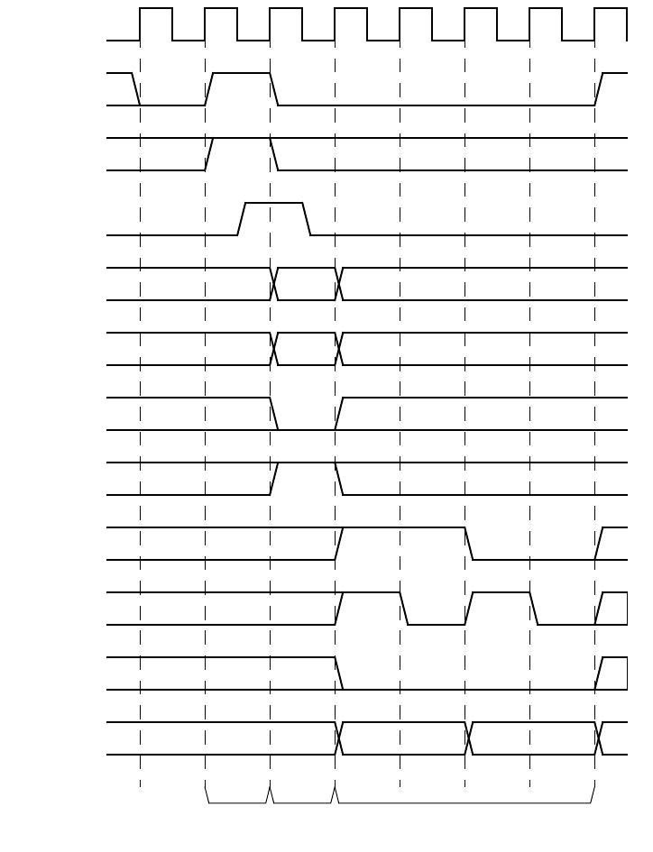
May 18, 2011 UVM 1.1 User’s Guide 179
Figure 45—Example Write Waveform
clock
req
gnt
addr
size
read
write
bip
wait
error
data
0b01
Address
Phase
Data
Phase
Arbitration
Phase
start
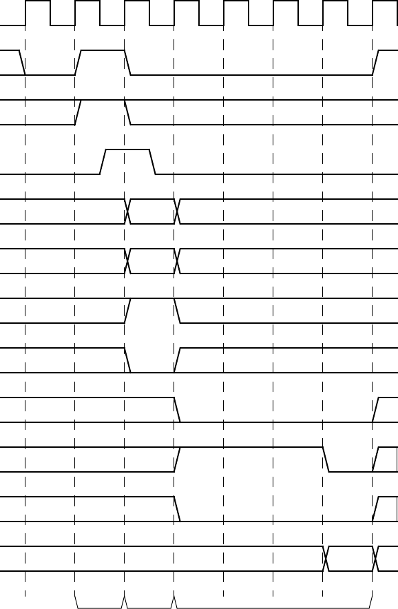
180 UVM 1.1 User’s Guide May 18, 2011
Figure 46—Example Read Waveform
clock
req
gnt
addr
size
write
read
bip
wait
error
data
0b00
Address
Phase
Data
Phase
Arbitration
Phase
start

May 18, 2011 UVM 1.1 User’s Guide 181
Appendix A
(informative)
Sequence Library
A.1 Creating the Sequencer
The sequencer generates stimulus data and passes it to a driver for execution. The UVM Class Library
provides the uvm_sequencer base class, which is parameterized by the request and response item
types. You should derive all sequencer classes directly or indirectly from this class.
To create a sequencer:
a) Derive a sequencer from the uvm_sequencer base class and specify the request and
response type parameters.
b) Use `uvm_sequencer_utils and `uvm_update_sequence_lib_and_item to indicate
the generated data item type and field desired automation.
This is all that is required to define baseline behavior for a sequencer. Refer to Section 3.10.2.1 for a
description of how a sequencer, driver, and sequences synchronize with each other to generate constrained-
random data.
The class simple_sequencer in the example below defines a sequencer class. The example derives it
from uvm_sequencer and parameterizes it to use the simple_item type.
class simple_sequencer extends uvm_sequencer #(simple_item);
// UVM automation macro for sequencers
`uvm_sequencer_utils(simple_sequencer)
// Constructor
function new (string name="simple_sequencer", uvm_component parent);
super.new(name, parent);
`uvm_update_sequence_lib_and_item(simple_item)
endfunction : new
endclass : simple_sequencer
The following also apply.
— In the class definition, by default, the response type is the same as the request type. If a different
response type is desired, the optional second parameter must be specified for the uvm_sequencer
base type:
class simple_sequencer extends uvm_sequencer #(simple_item, simple_rsp);
— The `uvm_component_utils macro should not be used here because its functionality is embed-
ded in `uvm_sequencer_utils. Instead of using the `uvm_component_utils, use
`uvm_sequencer_utils, as well as the regular general automation this macro provides
sequencer-specific infrastructure. Refer to “Macros” in the UVM 1.1 Class Reference for more
information.
—Call `uvm_update_sequence_lib_and_item from the constructor of your sequencer class.
This macro registers all the sequence types that are associated with the current sequencer and indi-
cates the sequencer's generated transaction type as a parameter. Refer to “Macros” in the UVM 1.1
Class Reference for more information.

182 UVM 1.1 User’s Guide May 18, 2011
A.2 Enabling Scenario Creation
The environment user will need to create many test scenarios to verify a given DUT. Since the verification
component developer is usually more familiar with the DUT’s protocol, the developer should facilitate the
test writing (done by the verification component’s user) by doing the following:
— Place knobs in the data item class to simplify declarative test control.
— Create a library of interesting reusable sequences.
The environment user controls the environment-generated patterns configuring its sequencers. The user can:
a) Add a sequence of transactions to a sequencer.
b) Modify the sequencer to use specific sequences more often than others.
c) Override the sequencer's main loop to start with a user-defined sequence instead.
In this section we describe how to create a library of reusable sequences and review their use. For more
information on how to control environments, see Section 4.7.
A.2.1 Declaring User-Defined Sequences
Sequences are made up of several data items, which together form an interesting scenario or pattern of data.
Verification components can include a library of basic sequences (instead of single-data items), which test
writers can invoke. This approach enhances reuse of common stimulus patterns and reduces the length of
tests. In addition, a sequence can call upon other sequences, thereby creating more complex scenarios.
NOTE—The UVM Class Library provides the uvm_sequence base class. You should derive all sequence classes
directly or indirectly from this class.
To create a user-defined sequence:
a) Derive a sequence from the uvm_sequence base class and specify the request and response item
type parameters. In the example below, only the request type is specified, simple_item. This will
result in the response type also being of type simple_item.
b) Use the `uvm_sequence_utils macro to associate the sequence with the relevant sequencer
type and to declare the various automation utilities. This macro also provides a p_sequencer
variable that is of the type specified by the second argument of the macro. This allows access to
derived type-specific sequencer properties.
c) Implement the sequence’s body task with the specific scenario you want the sequence to execute. In
the body task, you can execute data items and other sequences using `uvm_do (see
Section 3.10.2.2.1) and `uvm_do_with (see Section 3.10.2.2.2).
The class simple_seq_do in the following example defines a simple sequence. It is derived from
uvm_sequence and uses the `uvm_sequence_utils macro to associate this sequence with
simple_sequencer and declare the various utilities `uvm_object_utils would provide.
class simple_seq_do extends uvm_sequence #(simple_item);
rand int count;
constraint c1 { count >0; count <50; }
// Constructor
function new(string name="simple_seq_do");
super.new(name);
endfunction
// UVM automation macros for sequences
`uvm_sequence_utils(simple_seq_do, simple_sequencer)
// The body() task is the actual logic of the sequence.
virtual task body();

May 18, 2011 UVM 1.1 User’s Guide 183
repeat(count)
`uvm_do(req)
endtask : body
endclass : simple_seq_do
Once you define a sequence, it is registered inside its sequencer and may be generated by the sequencer’s
default generation loop. The `uvm_sequence_utils macro creates the necessary infrastructure to
associate this sequence with the relevant sequencer type and declares the various automation utilities. This
macro is similar to the `uvm_object_utils macro (and its variations), except it takes a second
argument, which is the sequencer type name this sequence is associated with.
NOTE—Do not use the `uvm_object_utils macro when using the `uvm_sequence_utils macro. The func-
tionality of `uvm_object_utils is included in `uvm_sequence_utils.
A.2.2 Configuring the Sequencer’s Default Sequence
Sequencers execute an uvm_random_sequence object by default. The sequencer has a string property
named default_sequence which can be set to a user-defined sequence-type name. This sequence is
used as the default sequence for the instance of the sequencer.
To override the default sequence:
a) Declare a user-defined sequence class which derives from an appropriate base sequence class.
The example in Section A.2.1 provides a declaration example of a sequence named
simple_seq_do.
b) Configure the default_sequence property for a specific sequencer or a group of sequencers.
Typically, this is done inside the test class before creating the component that includes the relevant
sequencer(s). For example,
set_config_string("*.master0.sequencer","default_sequence",
"simple_seq_do");
The first argument utilizes a wildcard mechanism. Here, any instance name containing
.master0.sequencer will have its default_sequence property (if it exists) set to the
value simple_seq_do.
A.2.3 Building a Reusable Sequence Library
A reusable sequence library is a set of user-defined sequences. Creating a verification component reusable
sequence library is an efficient way to facilitate reuse. The environment developer can create a meaningful
set of sequences to be leveraged by the test writer. Such sequence libraries avoid code duplication in tests,
making them more maintainable, readable, and concise.
Tips
— Try to think of interesting protocol scenarios that many test writers can use.
— Since some users may not want to use the reusable sequence library (because the sequences may not
match the design requirements of the user), do not include your reusable sequence library within the
verification component files. Leave it to the user to decide whether to use them.
A.2.4 Using Sequences
Constraint layering is an efficient way of uncovering bugs in your DUT. Having the constraint solver
randomly select values ensures a non-biased sampling of the legal input space. However, constraint layering

184 UVM 1.1 User’s Guide May 18, 2011
does not allow a user to control the order between consecutive data items. Many high-level scenarios can
only be captured using a stream of ordered transactions. For example, simply randomizing bus transactions
is unlikely to produce a legal scenario for your device. UVM sequences are library base classes that allow
you to create meaningful ordered scenarios. This section describes UVM sequencers and sequences.
A.2.4.1 Important Randomization Concepts and Sequence Requirements
The previous section described the sequencer as a generator that can generate data items in a loop. While
this is the default behavior, the sequencer actually generates sequences. User-defined sequences can be
added to the sequencer’s sequence library and randomly executed. If no user-defined sequences are added,
then the only executed sequence is the built-in sequence called simple_sequence that executes a single
data item.
Section A.2.4.2 shows how you can use the configuration mechanism to modify the count to adjust the
sequence generated pattern. Subsequent sections introduce other advanced ways to control the sequencer,
including:
— Creating and adding a new sequence to be executed.
— Changing the distribution of executed sequences.
— Adjust the sequencer to start from a sequence other than the pre-defined random sequence.
A.2.4.2 Controlling the Number of Sequences Created by uvm_random_sequence
The default number of generated sequences is a random number between 0 and
uvm_sequencer::max_random_count. The user can modify the number of generated sequences
(count). Use the configuration mechanism to change the value of count. For example, to generate and
send 10 sequences, use:
set_config_int("*.cpu_seqr", "count", 10);
You can disable a sequencer from generating any sequences by setting the count to 0.
set_config_int("*.cpu_seqr", "count", 0);
NOTE—Having more data items than count is not necessarily a bug. The sequencer does not generate data items
directly. By default, it generates count number of simple sequences that translate into count number of items. The
sequencer has more built-in capabilities, which are described in Section A.2.4.3.
A.2.4.3 Creating and Adding a New Sequence
To create a user-defined sequence:
a) Derive a sequence from the uvm_sequence base class.
b) Use the `uvm_sequence_utils macro to associate the sequence with the relevant sequencer
type and to declare the various automation utilities. This macro is similar to the
`uvm_object_utils macro (and its variations), except it takes another argument, which is the
sequencer type name this sequence is associated with. This macro also provides a p_sequencer
variable that is of the type specified by the second argument of the macro. This allows access to
derived type-specific sequencer properties.
c) Implement the sequence’s body task with the specific scenario you want the sequence to execute. In
the body, you can execute data items and other sequences using `uvm_do (see Section 3.10.2.2.1)
and `uvm_do_with (see Section 3.10.2.2.2).
May 18, 2011 UVM 1.1 User’s Guide 185
Example
The class retry_seq in this example a new sequence. It is derived from uvm_sequence and uses the
`uvm_sequence_utils macro to associate this sequence with uart_tx_sequencer and to declare
the various utilities `uvm_object_utils provides.
// Send one BAD_PARITY frame followed by a GOOD_PARITY
// frame with the same payload.
class retry_seq extends uvm_sequence #(uart_frame);
rand bit [7:0] pload; // Randomizable sequence parameter
...
// UVM automation for sequences
‘uvm_sequence_utils_begin(retry_seq, uart_tx_sequencer)
‘uvm_field_object(frame, UVM_ALL_ON)
‘uvm_field_int(pload, UVM_ALL_ON)
‘uvm_sequence_utils_end
// Constructor
function new(string name="retry_seq");
super.new(name);
endfunction
task body ( ); // Sequence behavior
‘uvm_do_with(req, {req.payload == pload; req.parity == BAD_PARITY;} )
‘uvm_do_with(req, {req.payload == pload; req.parity == GOOD_PARITY;} )
endtask : body
endclass: retry_seq
Sequences can have parameters which can be randomized (e.g., pload in this example). Use constraints to
control the randomization of these parameters. Then use the randomized parameters within the body() task
to guide the sequencer’s behavior.
The body task defines the main behavior of a sequence. Since it is a task, you can use any procedural code,
loops, fork and join, wait for events, and so on.
The `uvm_do_with macro randomizes and executes an item with inline constraints. The
`uvm_do_with also sends the data item to the driver, which sends it to the DUT. The execution of the
body task is blocked until the driver has sent the item to the DUT. Use the `uvm_do macro to randomize
the item without inline constraints.
In the example above, when the retry sequence is executed, it will randomize the payload, send a frame with
the generated payload having illegal parity, and follow it with a frame with a similar payload but with legal
parity.
A sequencer type is provided as the second parameter to the `uvm_sequence_utils macro, which
means that this sequence is added to the sequencer pool and could be randomly executed by the default
random sequence. Since the sequencer type is provided, the p_sequencer variable can be declared the
appropriate type and initialized.
A.2.4.4 Describing Nested Sequences
You can define more abstract sequences using existing sequences. Doing so provides additional reuse and
makes it easier to maintain the test suite. For example, after defining the configuration sequence per device
in a block-level testbench, the user may define a system-level configuration sequence which is a
combination of the already-defined sequences.
Executing (doing) a sequence is similar to doing a data item. For example:

186 UVM 1.1 User’s Guide May 18, 2011
// Call retry sequence wrapped with random frames.
class rand_retry_seq extends uvm_sequence #(uart_frame);
// Constructor, and so on
...
`uvm_sequence_utils(rand_retry_rand_seq, uart_tx_sequencer)
retry_seq retry_sequence; // Variable of a previously declared sequence
task body (); // Sequence behavior
`uvm_do (req)
`uvm_do_with(retry_sequence, {retry_sequence.pload inside {[0:31]};})
`uvm_do(req)
endtask
endclass
The rand_retry_seq has a field called retry_sequence. retry_seq is a user-predefined
sequence.
The body() task is do-ing this sequence and layering inline constraints from above. This layering from
above is one of many advantages that UVM sequences have.
A.2.4.5 Adjusting the Sequencer
The sequencer has a string property named default_sequence which can be set to a user-defined
sequence type. This sequence type is used as the default sequence for the current instance of the sequencer
(see Figure A1).
To override the default sequence:
a) Declare a user-defined sequence class which derives from an appropriate base sequence class.
b) Configure the default_sequence property for a specific sequencer or a group of sequencers.
This is typically done inside the test class, before creating the component that includes the relevant
sequencer(s). For example,
set_config_string("*.master0.sequencer", "default_sequence","retry_seq");
The first argument uses a wildcard to match any instance name containing
.master0.sequencer to set the default_sequence property (if it exists) to the value
retry_seq.

May 18, 2011 UVM 1.1 User’s Guide 187
Figure A1—Sequencer with a Sequence Library
A.2.4.6 Sequence Libraries and Reuse
Use of sequences is an important part of verification component reuse. The environment developer who
knows and understands the verification component protocol specifications can create interesting
parameterized reusable sequences. This library of sequences enables the environment user to leverage
interesting scenarios to achieve coverage goals more quickly. Check to see if your verification component’s
sequencer comes with a library of sequences. The example below shows a printout of a
sequencer.print() command.
uvm_random
default_sequence uvm_exhaustive
uvm_simple
retry_seq
rand_retry_seq
sequencer
interface
uvm_random
default_sequence uvm_exhaustive
uvm_simple
retry_seq
rand_retry_seq
sequencer
interface
In default mode, the sequencer executes the random
sequence, which randomly selects sequences and
executes them
Setting default_sequence to “retry_seq” using
set_config_string("*.sequencer", "default_sequence", "retry_seq");
causes the sequencer to execute the “retry_seq” sequence

188 UVM 1.1 User’s Guide May 18, 2011
----------------------------------------------------------------
Name Type Size Value
----------------------------------------------------------------
sequencer uart_tx_sequencer- @1011
default_sequence string 19 uvm_random_sequence
sequences da(string) 4 -
[0] string 19 uvm_random_sequence
[1] string 23 uvm_exhaustive_sequence
[2] string 19 uvm_simple_sequence
[3] string 9 retry_seq
[4] string 14 rand_retry_seq
count integral 32 -1
max_random_count integral 32 'd10
max_random_depth integral 32 'd4
The default sequence of this sequencer is uvm_random_sequence, which means sequences will be
randomly generated in a loop by default.
This sequencer has five sequences associated with it. Three sequences are built-in sequences
(uvm_random_sequence, uvm_exhaustive_sequence, and uvm_simple_sequence), and
two are user-defined (retry_seq and rand_retry_seq).
The built-in exhaustive sequence is similar to random sequence. It randomly selects and executes once each
sequence from the sequencer’s sequence library, excluding uvm_random_sequence and
uvm_exhaustive_sequence. If count equals 0, the sequencer will not automatically start a
sequence. If desired, the user may start a sequence manually. This operation typically is used for virtual
sequencers. If count is not equal to 0, the sequencer automatically starts the default sequence, which may
use the count variable.
The exhaustive sequence does not use the count variable. However, the subsequences started by the
exhaustive sequence may use count.
The value of count in this sequencer is -1, which means the number of generated sequences will be
between 0 and max_random_count (10, the default value, in this example).
For more information about sequences, refer to Section 6.5.
A.2.4.7 Directed-Test Style Interface
The sequence style discussed in Section A.2.4 is the recommended way to create tests. Focus on creating
reusable sequences you can use across many tests, instead of placing stimulus scenarios directly inside the
test. Each sequencer is preloaded with the default traffic that will be generated at run time and sent to the
DUT. Inside the tests, the test writer needs to touch only the sequencers that need to be modified.
Some test writers, however, are accustomed to writing directed tests. In directed tests, you write procedural
code in which you explicitly request each interface to generate and send items. While directed tests are not
the recommended test-creation style, UVM support this method using the sequencer’s execute_item()
task. Before using directed tests, consider their disadvantages compared to the UVM-recommended test-
creation method:
— Directed tests require more code to write and maintain. This becomes critical in system-level envi-
ronments.
— In directed tests, the high-level intention of the code is not as clear or as easy to read and understand.
In the recommended method, the code is focused on test-specific needs and other system-related
May 18, 2011 UVM 1.1 User’s Guide 189
aspects are present by default. For example, the arbitration logic for slaves that service requests does
not need to be coded in every test.
— Directed tests are less reusable because they contain specific and unreusable information.
— In the recommended method, tests are random by default. All declared sequences are candidates for
execution by default. You must explicitly exclude a sequence from being executed. This prevents
the problem of missing sequences and creates a more random pattern that can expose unanticipated
bugs.
— In the recommended method for many protocols, you should never have to touch the high-level
sequence, which serves as a template for other sub-sequences to be executed in a certain order.
The following code is an example of a directed test.
class directed_test extends ubus_example_base_test;
`uvm_component_utils(directed_test)
ubus_example_tb ubus_example_tb0;
function new (string name = "directed_test",
uvm_component parent = null);
super.new(name, parent);
endfunction
virtual function void build();
super.build();
set_config_int("*.sequencer", "count", 0);
// Create the testbench.
ubus_example_tb0 =
ubus_example_tb::type_id::create("ubus_example_tb0", this);
endfunction
virtual task run();
bit success; simple_item item;
#10;
item = new();
success = item.randomize();
tb.ahb.masters[1].sequencer.execute_item(item);
success = item.randomize() with { addr < 32'h0123; } ;
tb.ahb.masters[1].sequencer.execute_item(item);
endtask
endclass
The following also apply.
a) The execute_item() task can execute a data item or a sequence. It blocks until the item or the
sequence is executed by the sequencer. You can use regular SystemVerilog constructs such as fork/
join to model concurrency.
b) The default activity in the sequencers is disabled by setting the count parameters of all sequencers to
0. The execute_item() task is used to send traffic in a deterministic way.
c) Using default random activity is a good practice. It is straightforward and a good investment. The
use of execute_item() should be minimized and limited to specific scenarios.
A.2.5 Creating a Virtual Sequencer
For high-level control of multiple sequencers from a single sequencer, use a sequencer that is not attached to
a driver and does not process items itself. A sequencer acting in this role is referred to as a virtual sequencer.
To create a virtual sequencer that controls several subsequencers:
a) Derive a virtual sequencer class from the uvm_sequencer class.

190 UVM 1.1 User’s Guide May 18, 2011
b) Add references to the sequencers where the virtual sequences will coordinate the activity. These ref-
erences will be assigned by a higher-level component (typically the testbench).
The following example declares a virtual sequencer with two subsequencers. Two interfaces called eth and
cpu are created in the build function, which will be hooked up to the actual sub-sequencers.
class simple_virtual_sequencer extends uvm_sequencer;
eth_sequencer eth_seqr;
cpu_sequencer cpu_seqr;
// Constructor
function new(input string name="simple_virtual_sequencer",
input uvm_component parent=null);
super.new(name, parent);
// Automation macro for virtual sequencer (no data item)
`uvm_update_sequence_lib
endfunction
// UVM automation macros for sequencers
`uvm_sequencer_utils(simple_virtual_sequencer)
endclass: simple_virtual_sequencer
NOTE—The `uvm_update_sequence_lib macro is used in the constructor when defining a virtual sequencer.
This is different than (non-virtual) driver sequencers, which have an associated data item type. When this macro is used,
the uvm_simple_sequence is not added to the sequencer’s sequence library. This is important because the simple
sequence only does items and a virtual sequencer is not connected to a driver that can process the items. For driver
sequencers, use the `uvm_update_sequence_lib_and_item macro. See Section 3.4 for more information.
Subsequencers can be driver sequencers or other virtual sequencers. The connection of the actual
subsequencer instances via reference is done later, as shown in Section 4.8.4.
